
Microwaves and Radar Institute - DLR
202
1 Microwaves and Radar Institute Status Report 2006 – 2011 Research Results and Projects Status Report 2006 – 2011 Volume 1
-
Upload
khangminh22 -
Category
Documents
-
view
0 -
download
0
Transcript of Microwaves and Radar Institute - DLR

1
Microwaves and Radar Institute Status Report 2006 – 2011 Research Results and Projects
Stat
us R
epor
t 20
06 –
201
1
Vol
ume
1

German Aerospace Center A member of the Helmholtz Association
Microwaves and Radar Institute
Director of the Institute Prof. Dr.-Ing. habil. Alberto Moreira
Address Oberpfaffenhofen D-82234 Weßling www.dlr.de/HR
Editorial Team Gerhard Krieger Alberto Moreira
Proofreading David Hounam
Layout Renate Weist
Printed by Richard Thierbach Buch- und Offset-Druckerei GmbH, Mülheim an der Ruhr
August 2011
Cover TanDEM-X Mission
This brochure may be reprinted in whole or in part or otherweise used commercially only by previous agreement with the DLR.

Microwaves and Radar Institute Status Report 2006 – 2011 Research Results and Projects

Microwaves and Radar Institute
ii
PREFACE Since the last Institute’s evaluation in 2006, a new era started in Germany’s spaceborne radar program with the launch of TerraSAR-X and TanDEM-X. These missions are a result of a consistent radar technology program over more than 3 decades. Our Institute has participated and shaped this program from the very beginning, when Germany contributed with the X-band radar systems for the space shuttle missions Spacelab-1, SIR-C/X-SAR and SRTM in 1983, 1994 and 2000, respectively. Besides the great success of the Institute in the national radar missions, it has increased its benchmark values remarkably in the last 5 years with respect to scientific output, acquired projects and finances. The Institute is the driving force of the SAR activities at DLR and also holds the DLR recognition as a Center of Excellence on Synthetic Aperture Radar since 2000.
Let’s first take a look back to the last five years, which couldn’t be more fascinating: On June 15, 2007, TerraSAR-X was launched. The first images were acquired and processed just 4.5 days after launch. This was a world record. Since then, TerraSAR-X has surpassed all expectations in terms of operability, performance and image quality.
Just 3 years later, TanDEM-X, which was initiated by the Institute jointly with EADS Astrium GmbH, was launched and opened a new era in spaceborne radar remote sensing: It is the first bistatic radar in space and the first close formation flight of two satellites with the orbit concept being developed and patented by the Institute. With the systematic acquisition of interferometric data, the operational phase of TanDEM-X started in December 2010 after successful monostatic and bistatic radar calibration. TanDEM-X set a new world record as the first image was acquired and processed just 3.5 days after launch.
22 days later the first DEM was produced with a height accuracy of only a few decimeters, due to the large distance between the satellites at that time. The global digital elevation model with 2 m relative height accuracy at 12 m posting will be available by mid 2014 and will certainly become a standard data set for innumerable applications, as it is a unique product in terms of coverage and accuracy. With TerraSAR-X and TanDEM-X we are demonstrating several innovative techniques and applications, including the first vegetation height measurement from space using single-pass polarimetric SAR interferometry.
Our new airborne SAR, F-SAR, performed its first operational flight campaign in 2009 and is now flying in 4 different frequencies in a fully polarimetric acquisition mode. Following the successful history of the predecessor system, E-SAR, we have performed several international flight campaigns with F-SAR in the last few years for the demonstration of advanced techniques, technologies, and applications, as well as to simulate data from future spaceborne SAR systems.
According to the recommendation from the last Institute’s evaluation, the TechLab – a new building for high-tech microwave sensor development – has been built and was inaugurated in 2009. With the exception of the mechanical lab, all the Institute’s laboratories, facilities and microwave sensor develop-ments have been moved to the TechLab, providing a huge stimulus for our technology-related activities.
Let’s now take a look to the future. Tandem-L is a proposal of the Institute for an innovative radar mission that enables the systematic monitoring of dynamic processes on the Earth’s surface with unprecedented quality and resolution. The mission concept has been developed in the last 3 years in the scope of a pre-phase A study in cooperation with NASA/JPL. Tandem-L will answer key scientific questions about the biosphere,

Preface
iii
geosphere, hydrosphere and cryosphere and will close essential gaps in climate research. Besides the scientific com-ponent, Tandem-L is distinguished by its high degree of innovation with respect to methodology (e.g. polarimetric SAR interferometry and tomography) and technology (e.g. digital beamforming in combination with a large reflector).
Our vision is that Tandem-L represents the next major milestone in the develop-ment of spaceborne radar systems and will form the basis for future generations of SAR satellites. It will unlock the door to a future global remote sensing system for the continuous observation of the Earth’s surface, as currently exists for weather prediction, where a network of geostationary satellites is used.
Due to the high degree of innovation and success achieved with TerraSAR-X and TanDEM-X, I believe that the last 5 years have been the most successful in the 100-year history of our Institute. It has been an honor and pleasure to work together with a first-class team of highly motivated colleagues and to be guiding the Institute towards new challenges.
I wish you an enjoyable reading of this report.
Oberpfaffenhofen, August 2011
Prof. Dr.-Ing. habil. Alberto Moreira
Director DLR Microwaves and Radar Institute
Professor Karlsruhe Institute of Technology (KIT)

Microwaves and Radar Institute
iv
Contents
1 Overview
1.1 Institute’s Mission and Goals ......................................................................1
1.2 Major Achievements...................................................................................6
1.3 Benchmark ...............................................................................................11
1.4 Future Research Activities and Projects .....................................................12
2 Research and Project Results 2.1 Spaceborne SAR Missions.........................................................................15
2.1.1 TerraSAR-X...............................................................................................15
2.1.2 TanDEM-X................................................................................................23
2.1.3 Tandem-L .................................................................................................35
2.1.4 Sentinel-1.................................................................................................40
2.1.5 ALOS PalSAR ............................................................................................42
2.1.6 BIOMASS..................................................................................................44
2.1.7 CoReH2O .................................................................................................45
2.1.8 SIGNAL.....................................................................................................47
2.2 Microwave Systems: Research and Technology.........................................49
2.2.1 Digital Beamforming.................................................................................49
2.2.2 Bistatic Radar............................................................................................55
2.2.3 Traffic Monitoring ....................................................................................58
2.2.4 Experimental TanDEM-X SAR Processor ....................................................63
2.2.5 Calibration................................................................................................68
2.2.6 Polarimetric SAR Interferometry................................................................73
2.2.7 Tomography.............................................................................................78
2.2.8 Antennas..................................................................................................81
2.2.9 Compact Test Range Facility .....................................................................83
2.2.10 Radar-Based Surveillance of Space Debris .................................................85

Contents
v
2.3 Airborne SAR ...........................................................................................87
2.3.1 The DLR Experimental Airborne SAR: E-SAR .............................................87
2.3.2 The New Airborne SAR: F-SAR .................................................................88
2.3.3 Major Campaigns.....................................................................................92
2.3.4 Processing Algorithms ..............................................................................96
2.4 Reconnaissance and Security..................................................................101
2.4.1 Reconnaissance Missions........................................................................101
2.4.2 Mission Planning ....................................................................................103
2.4.3 SAR Analysis...........................................................................................107
2.4.4 SAR Simulation ......................................................................................108
2.4.5 SAR Image Analysis ................................................................................111
2.4.6 Protection of Spaceborne Systems..........................................................113
2.4.7 Ground-Based Radar Systems.................................................................114
2.4.8 Radiometry and Security Applications.....................................................116
2.4.9 Radar Signatures ....................................................................................123
2.4.10 Metamaterials ........................................................................................127
3 Documentation 3.1 Academic Degrees .................................................................................129
3.2 Guest Scientists ......................................................................................134
3.3 Scientific Awards....................................................................................135
3.4 Participation in Scientific and Technical Committees ..............................136
3.5 Conferences...........................................................................................138
3.6 Tutorials and Annual Courses.................................................................139
3.7 Lectures at Universities ...........................................................................140
3.8 Publications............................................................................................141
3.9 Journal Reviews and Editorial Boards......................................................173
3.10 Patents...................................................................................................174
3.11 Acronyms and Abbreviations..................................................................175


1 Overview
1.1 Institute’s Mission and Goals
1.2 Major Achievements
1.3 Benchmark
1.4 Future Research Activities and Projects


Overview
1
1 Overview This report has been prepared for the 5-year evaluation of the Microwaves and Radar Institute of the German Aerospace Center. It summarizes the research activities and projects in the timeframe between 2006 and 2011. The Institute is located in Oberpfaffenhofen near Munich and has a long history dating back to the beginning of the last century. Today, the Institute focuses its research on active and passive microwave techniques, sensors and applications related to remote sensing, environmental monitoring, reconnaissance and surveil-lance, as well as road traffic monitoring. The Institute has about 135 researchers, engineers, technicians and students and has become the driving force of the SAR Center of Excellence at DLR. It is a lead-ing institution in synthetic aperture radar remote sensing in Europe and worldwide.
1.1 Institute’s Mission and Goals Mission and Profile
With its know-how and expertise in passive and active microwave remote sensing, the Microwaves and Radar Institute contributes to the development and advancement of ground-based, airborne and spaceborne sensors. The focus of its research work is on the conception and development of new synthetic aperture radar (SAR) techniques and systems, as well as sensor-specific applications. The Institute‘s strength is the execution of long-term research programs with applications in remote sensing, aeronautics and traffic monitoring, as well as reconnaissance and security. In line with the German space program, the Institute works in close collaboration with other DLR institutes, the German Space Administration, the European Space Agency, German industry, and
responsible ministries. The education of young scientists in the form of hosting and supervising internships, as well as diploma and doctoral theses is also an important part of the Institute’s mission.
Expertise and Facilities
The Institute’s expertise encompasses the whole end-to-end system know-how in microwave sensors. This allows the Institute to play a key role in the conception and specification of new sensors, including the development of new technologies and techniques. In more than 30 years, experience in overall system competence reaching from the sensor and mission conception to sensor-related applications has been established and is being actively maintained and expanded.
In the last 5 years, the Institute has actively participated and also initiated several SAR missions and research programs that are decisive for its long-term strategy. Important examples are
Figure 1.1-1: Microwaves and Radar Institute.

Microwaves and Radar Institute
2
TerraSAR-X, TanDEM-X, ALOS/PALSAR (Carbon & Kyoto science team), F-SAR (new airborne SAR) and SAR-Lupe. It is also working on future remote sensing and reconnaissance systems, such as Sentinel-1 (ESA GMES program), TerraSAR-X2 (follow-on to TerraSAR-X), HRWS (next generation X-band SAR with high-resolution wide-swath imaging), Tandem-L (L-band mission proposal in cooperation with NASA/JPL), BIOMASS and CoReH2O (ESA Earth Explorer mission candidates), VABENE (DLR project for traffic monitoring with radar) and the SAR-Lupe follow-on program. These projects are accompanied by research programs that ensure the Institute keeps a step ahead in the development of new research fields. Examples of such research programs are bistatic and multistatic SAR systems, digital beamforming, inverse SAR, polarimetric SAR interferometry and tomography, calibration, signatures, propagation, antennas, as well as radiometry and imaging techniques for security.
The Institute has a number of large-scale facilities to support its research activities in microwave sensor development and
associated technologies. The airborne SAR system F-SAR is the successor of the well-known E-SAR system of DLR. F-SAR is fully reconfigurable and will include innovative operation modes with digital beamforming on receive in future system upgrades. The main objectives of F-SAR are the development of innovative SAR operational modes, the demonstration of novel techniques and new applications, as well as performing preparatory experiments for future SAR satellite systems, so supporting data product development and SAR system specification.
In 2009, all Institute’s facilities and technological developments have been concentrated in a new building – TechLab – a center for high-tech microwave sensor development with several laboratories and measurement facilities, and approx. 25 employees. The main facility is a compact test range for highly accurate antenna characteriz-ation, as well as for radar cross-section measurements. Further facilities are a microwave chamber for measuring monostatic and bistatic radar signatures of scaled target models, a facility for determining the dielectric properties of material samples and a pool of corner reflectors, ground receivers and trans-ponders for spaceborne SAR calibration. Also included in TechLab are several research laboratories, especially equipped for development, optimization, integration, testing and calibration of radar and radiometer systems.
The Institute operates in its main building a microwave mechanical laboratory for the design, development and manufacture of microwave components, instruments and models, using numerically controlled machines. It also allows for the manufacturing of miniaturized and hollow components using galvanic and galvanoplastic techniques. This lab provides valuable consultancy for the researchers and developers in the specification and design of microwave instruments and experi-mental setups.
Figure 1.1-2: Employees of the Microwaves and Radar Institute.

Overview
3
Facility Description
F-SAR
New airborne SAR system with polarimetric and interferometric operation in X, C, S, L and P-band. Geometric resolution varies from 4 meters to 25 centimeters depending on the frequency band and user requirements (section 2.3).
TechLab Center for microwave development, including several laboratories and facilities for sensor development, integration and testing for airborne radar, radiometers, antenna and calibration devices (sections 2.2 to 2.4).
Compact Test Range
Microwave anechoic chamber (24 m x 11.7 m x 9.7 m) with a dual cylindrical parabolic reflector configuration for highly accurate antenna characterization and radar cross-section measurements. The frequency range is from 300 MHz up to 100 GHz (section 2.2.9).
Bistatic Signatures Chamber
Microwave anechoic chamber (8.5 m x 5.7 m x 5 m) for measuring quasi-monostatic and bistatic polarimetric radar signatures of canonical test objects, as well as scaled target models operating in W-band under stable temperature conditions (section 2.4.9).
Material Properties Measurements
Material characterization using free-space transmission and reflection measurements at X-band, Ka-band and W-band. Waveguide measurements are also provided for frequencies from 1.1 GHz up to 110 GHz (section 2.4.9).
CALIF A suite of passive and active calibrators, as well as software tools for accurate calibration of spaceborne SAR sensors. The test site for the deployment of the calibration devices can cover a swath width of up to 450 km (section 2.2.5).
Mechanical Lab
Design, development and manufacture of microwave components, instruments and models in machining and electroforming techniques, as well as mechanical drives, positioning systems and various racks and housings (sections 2.2 to 2.4).
Table 1.1-1: Overview of the Institute’s facilities.

Microwaves and Radar Institute
4
Figure 1.1-3: Organization of the Microwaves and Radar Institute.
Organization
The Institute has 4 departments working in well established research programs, projects and external contracts. Fig. 1.1-3 shows the organization of the Institute with its research departments and associated infrastructure. The Institute has about 135 employees, comprising scientists, engineers, technicians, support personnel, as well as internship, diploma and doctoral students, and guest scientists.
Three Institute’s departments are working on Earth observation and one on reconnaissance and security. The SAR Technology department is responsible for the development of the airborne SAR system F-SAR and contributes to the spaceborne SAR projects with airborne campaigns to simulate new data products, to validate and cross-calibrate the satellite data and to demonstrate new techniques.
The Satellite SAR Systems department and the Radar Concepts department are engaged in new spaceborne SAR missions, and are developing new sensor concepts and techniques for future radar systems. The Satellite SAR Systems department is responsible for operating the radar instruments on TerraSAR-X and TanDEM-X and holds the position of the mission manager. The Radar Concepts department also contributes with the development of new sensor-related applications. For military spaceborne SAR activities, all major projects and activities are concentrated in the Reconnaissance and Security department. The Institute’s expertise in passive microwave systems is also in this department, as most of the passive microwave projects are presently related to security applications. The mechanical workshop is assigned to the central infrastructure, as it supports the research projects of all departments.
Microwaves and Radar InstituteAlberto Moreira
Satellite SAR Systems
Manfred Zink
TSX/TDX Mission Manager
Stefan Buckreuß
TanDEM-XDaniel Schulze
CalibrationMarco Schwerdt
System Performance
Benjamin Bräutigam
Reconnaissance and SecurityHelmut Süß
SAR AnalysisBjörn Dietrich
SAR SimulationRainer Speck
Microwave SensorsMarkus Peichl
Satellite Systems EngineeringThomas Neff
SignaturesErich Kemptner
Information Retrieval
K. Papathanassiou
Radar ConceptsGerhard Krieger
SAR TechniquesMarwan Younis
Pol-InSARIrena Hajnsek
SAR MissionsF. Lopez-Dekker
Signal ProcessingRolf Scheiber
SAR TechnologyAndreas Reigber
Airborne SARRalf Horn
ElectronicsAnton Nottensteiner
MultimodalAlgorithms
Pau Prats
Logistics & Personnel
Christian Schmidt
Infrastructure & Quality Management
Karl-Heinz Bethke
Mechanical Workshop
Peter Heitzer
IT ManagementChristoph Dahme

Overview
5
Department Competence Research fields
SAR Technology Airborne SAR Airborne synthetic aperture radar technology and development, antennas, multi-modal signal processing, airborne campaigns for demonstration of new technologies and applications
Radar Concepts New Radar Sensors New sensor concepts, spaceborne SAR mission conceptual design, performance estimation, digital beamforming, bistatic and multi- static systems, traffic monitoring with radar, information retrieval
Satellite SAR Systems
Spaceborne SAR Missions Spaceborne SAR techniques, system concepts, SAR missions and instrument operations, system engineering and performance, calibration
Reconnaissance and Security
Microwave Sensors for Reconnaissance and Security Applications
SAR data and mission simulation, mission planning, analysis and optimization, inverse SAR, radiometry, signatures, synthetic aperture radiometry
Table 1.1-2: Institute’s departments and their respective competence and research fields.
Table 1.1-2 summarizes the expertise of each department in the Institute. Today, about 70 percent of the Institute’s activities are concentrated on external contracts or DLR internal projects.
For many years, the Institute has established a matrix structure to allow the use of the expertise and personnel from different departments for the execution of large projects and research activities. The TerraSAR-X and TanDEM-X projects are notable examples. The project leadership for the Institute‘s contributions is under the responsibility of the Satellite SAR Systems department. In this department, approx. 75% of the personnel are allocated to the projects, including the project leader and mission manager; the remaining 25% are coming from two other departments in the Institute.
The Institute works closely with three other DLR institutes at Oberpfaffenhofen, especially within the framework of the
TerraSAR-X and TanDEM-X projects: German Space Operations Center, German Remote Sensing Data Center and Remote Sensing Technology Institute. Due to the airborne SAR campaigns, the Institute is also in close collaboration with DLR’s Flight Experiments facility.
The directorship of the Institute is linked to a full professorship at the Karlsruhe Institute of Technology (KIT), Institut für Hochfrequenztechnik und Elektronik. Several joint projects are being carried out in cooperation with this institute in the fields of digital beamforming, calibration transponders for TerraSAR-X and antenna development. In total, 7 scientists of the Institute are engaged with regular lectures at universities (see section 3.7). With these lecture activities, tutorials and short courses, as well as the hosting of internships, diploma and doctoral theses, the Institute enhances its cooperation with universities every year.

Microwaves and Radar Institute
6
Figure 1.2-2: TanDEM-X (TerraSAR-X add-on for Digital Elevation Measurement), initiated jointly by the Microwaves and Radar Institute and EADS Astrium GmbH in 2003, opens a new era in spaceborne radar remote sensing.
1.2 Major Achievements The Institute’s last twenty years were characterized by several highlights, particularly in the SAR field. In the follow-ing summary, the major achievements and projects within the last 5 years are given, corresponding to the timeframe of the Institute‘s evaluation. Section 2 complements this summary with a detailed description of the research activities and projects.
Following peer reviews by a board of examiners in 2006 and 2009, the Institute’s recognition as a DLR Center of Excellence for SAR has been ex-tended until 2009 and 2012, respectively. The German Remote Sensing Data Center and the Remote Sensing Technology Institute are partners of the Institute in this recognition. The focus of the research is on advanced high-resolution and 3-D SAR technologies and applications. With the continuity of successful work in SAR over 30 years, it has been possible to channel the experience gained from the planning and implementation of international space missions into a national SAR program. Due to the end-to-end system know-how from data acquisition (including the Institute’s airborne SAR) through data interpretation and research into new applications, the SAR Center of Excellence has become one of the leading international research facilities in SAR.
In June 2007, TerraSAR-X (section 2.1.1), the first German radar satellite, was launched and has since served an ever growing scientific community and commercial market with high-resolution radar products. TerraSAR-X is the fruit of the consistent development of German radar technology over several decades and is an example of successful cooperation with the German aerospace industry. Being carried out in a Public Private Partnership (PPP) between DLR and EADS Astrium GmbH, a flexible SAR
mission was developed featuring a number of basic modes but also offering the opportunity to investigate new experimental modes and products. Due to the close involvement in the sensor development, the Institute established the required expertise to precisely calibrate the system and to fully exploit its capabilities. Furthermore, the necessary flow of SAR know-how into the ground segment was ensured. All radar relevant tools have been imple-mented in the Instrument Operations and Calibration Segment (IOCS), as a dedicated part of the ground segment.
The TerraSAR-X project provided a major push for the R&D activities, resulting in a joint proposal by the Institute and EADS Astrium GmbH for TanDEM-X (TerraSAR-X add-on for Digital Elevation Measurement, section 2.1.2) in 2003. The mission proposal was finally ap-proved for implementation in con-tinuation of the TerraSAR-X PPP in 2006. The TanDEM-X satellite is a close copy of TerraSAR-X that allows formation of a single-pass SAR interferometer by flying in close formation with TerraSAR-X. The Institute has led the implementation of the mission from the very beginning, and has taken key responsibilities in the technical development and in managing the project. After a short development phase, TanDEM-X was launched in June 2010 and successfully commissioned in December 2010. Since October 2010, TerraSAR-X and TanDEM-X are operating in close formation at typical horizontal and vertical baselines between 200 and 400 m acquiring data for a global digital elevation model. Beyond this primary mission objective, the flexible interferometer is being used by an increasing number of scientists for the demonstration of new SAR techniques and applications. The successful imple-mentation of TanDEM-X represents an important milestone towards future radar satellite systems and manifests Germany’s leading role in SAR tech-nology (Fig. 1.2-1 and Fig. 1.2-2).
Figure 1.2-1: First radar image acquired and processed 3.5 days after the launch of the TanDEM-X satellite (Madagascar, June 24, 2010).

Overview
7
Figure 1.2-3: Tandem-L: Proposal for a highly innovative L-band SAR mission in cooperation with NASA/JPL. Data acquisition with differential interferometry as well as fully polari-metric radar interferometry in L-band allows the generation of high-value data products for a broad spectrum of scientific applications.
Tandem-L (section 2.1.3) is a mission proposal initiated by the Institute in 2007 in cooperation with NASA/JPL for an innovative interferometric L-band radar instrument that enables the systematic monitoring of dynamic Earth processes using advanced SAR techniques and technologies (see Fig. 1.2-3). The mission is science driven aiming to provide a unique data set for climate and environ-mental research, geodynamics, hydrology and oceanography. Important application examples are global forest height and biomass inventories, measurements of Earth deformations due to tectonic processes and/or anthropogenic factors, observations of ice/glacier velocity fields and 3-D structure changes, and the monitoring of soil moisture and ocean surface currents. It is planned to realize the Tandem-L mission in cooperation with NASA/JPL. The mission concept was developed in detail in a joint two-year pre-phase A study and it will be further studied in the next 18 months. This will allow a cost-effective implementation, whereby each partner contributes with its pre-developments and experience. According to current planning, the Tandem-L satellites could be launched in 2019.
The Institute has been actively supporting ESA’s Earth Explorer Missions BIOMASS (section 2.1.5) and CoReH2O (section 2.1.6) with various studies and is current-ly contributing to phase A studies as part of the industrial consortia providing SAR system engineering and calibration expertise, as well as retrieval algorithms.
Digital beamforming (section 2.2.1) is a key technology that will significantly boost the performance of future SAR missions (Fig. 1.2-4). Over the last 5 years, several innovative system architectures and SAR imaging modes have been proposed and analyzed by the Institute. One example is a new ultra wide-swath mode which enables the mapping of a 400 km swath with 5 m azimuth resolution, exceeding by far the capability of all current SAR satellites. Further examples are innovative multi-beam modes, employing time varying
pulse repetition intervals, as well as hybrid MIMO-SAR systems, which allow further improvement of the imaging capabilities. Another exciting develop-ment initiated and promoted by the Institute is the combination of digital beamforming with large unfurlable reflector antennas. Together with the aforementioned imaging modes, this new technology has the potential to enhance the performance of future SAR systems by more than one order of magnitude, if compared to state of the art SAR sensors like TerraSAR-X, ALOS, Radarsat-2 or Sentinel-1.
Bistatic and multistatic SAR systems (section 2.2.2) operate with distinct transmit and receive antennas that are mounted on separate platforms. This spatial separation enables the acquisition of new image products and has, more-over, the potential to increase the capability, reliability and flexibility of future SAR missions. Several pioneering bistatic SAR experiments have been conducted by the Institute, involving air-to-air, space-to-space, as well as highly challenging space-to-air configurations. A new fast factorized back-projection algorithm has been developed to efficiently focus the bistatic SAR data acquired in arbitrary configurations. A further remarkable innovation was the successful demonstration of a new auto-matic synchronization technique that enables the synchronization of multistatic SAR systems without any dedicated synchronization link. Excellent agreement has been achieved by comparing the results of this new technique with those obtained by the TanDEM-X synchronization link.
Traffic monitoring (section 2.2.3) has evolved to an important research and security topic during the past few years. Radar systems operated from airborne and spaceborne platforms are well suited to observe ship and land traffic independent of weather and sunlight illumination, as required by multiple applications. Several ground moving target indication (GMTI) experiments have been conducted by the

Microwaves and Radar Institute
8
Institute, operating its F-SAR sensor in a synthetic four-channel mode. A novel GMTI processor with real-time capability was developed to fulfill the timeliness requirements of the project VABENE, which is dedicated to traffic monitoring for major events and catastrophes. A recent highlight was the successful demonstration of ship and land traffic monitoring during the pursuit monostatic commissioning phase of TanDEM-X. Velocity estimates with accuracies below 1 km/h have been obtained in these spaceborne experiments.
A new development in the Institute is the experimental TanDEM-X SAR processor (TAXI) (section 2.2.4). TAXI is a highly flexible processing suite. Its primary objective is to focus TerraSAR-X and TanDEM-X SAR data acquired in non-nominal modes and configurations. Several unique experiments became possible with TAXI. Examples are the first demonstration of the TOPS mode, the processing of the very first TanDEM-X DEM acquired in a non-nominal crossing orbit configuration, the high-resolution imaging of the International Space Station (ISS), and many more bistatic and interferometric experiments performed during the monostatic and bistatic commissioning phase of TanDEM-X. TAXI also made important contributions to improve the operational TanDEM-X processor, e.g., the accurate evaluation of synchronization pulses and the consideration of relativistic effects in bistatic SAR processing.
Radar calibration (section 2.2.5) is an important field of the Institute since the 80s and experienced some important developments in response to the growing demands of multi-beam, multi-mode high-resolution sensors. New techniques like the antenna model approach or PN gating have been successfully demonstrated on TerraSAR-X (section 2.1.1) and TanDEM-X (section 2.1.2), leading to radiometric accuracies in the order of few tenths of a dB and geo-location accuracies of better than 10 cm. Meanwhile, these concepts have also
been implemented on ESA’s first GMES mission, Sentinel-1, a C-band SAR system, via the Institute’s contribution to the Sentinel-1 space segment develop-ment (section 2.1.4).
Polarimetric SAR interferometry (Pol-InSAR) (section 2.2.6) is a powerful SAR remote sensing technique that provides vertical structure information of natural and man-made objects by combining polarimetric and interfero-metric measurements. From the very beginning, the Institute was the driving force in the development and demonstration of Pol-InSAR techniques and applications. A rapidly increasing number of scientists and institutions are now adopting Pol-InSAR for improved parameter retrieval. Pol-InSAR is an essential component of the Tandem-L mission proposal. Significant advances have been achieved over the last few years in developing forest height measurements from pre-operational to operational products. At the same time, new applications, such as vertical forest structure, underlying ground topography, crop height, and ice extinction have been successfully developed and demonstrated.
Tomography (section 2.2.7) enables the three-dimensional imaging of volume scatterers by combining the data from multiple displaced SAR acquisitions. After the world’s first demonstration of airborne SAR tomography by the Institute in 1998, a new tomographic campaign with an improved setup was carried out in 2006. Based on this data set, several advanced tomographic processing tech-niques have been developed, improving both the vertical resolution and enabling the detection of objects camouflaged under a forest canopy (Fig. 1.2-5). Recent work concentrated on reducing the required number of acquisitions. It could be shown that a small number of irregularly distributed tracks can be sufficient to obtain high-resolution tomograms. These results are also of great interest for optimizing the acquisition plan of the Tandem-L mission.
Figure 1.2-4: Digital beamforming: schematic representation of transmit and receive events using a large reflector antenna in combination with a digital feed array.

Overview
9
2 0 0 0 2 2 0 0 2 4 0 0 2 6 0 0
0 0 0 1 2 0 0 1 4 0 0 1 6 0 0 1 8 0 0
Following the recommendation of the 2006 review, the TechLab was established - a new building integrating all microwave laboratories and facilities of the Institute. The most important tech-nical facility within TechLab is a large Compact Test Range (CTR, section 2.2.9), fully equipped to perform antenna and RCS (Radar Cross Section) characterization in the frequency range between 300 MHz and 100 GHz. The CTR forms the core of the Institute’s recently enhanced abilities in antenna design (section 2.2.8). For the production of prototype airborne radar antennas, a complete design and development chain has been established, currently focusing mainly on new wideband antennas for the F-SAR system. In addition, a series of design studies and performance estimations on different types of antennas have been carried out, applications ranging from high-frequency weather radar, via antennas for the autonomous landing of UAVs, to the simulation of spaceborne deployable membrane antennas.
Radar-based surveillance of space debris (section 2.2.10) is a new activity of the Institute. Over the last few years, and particularly after China’s intentional destruction of its Fengyun-1C weather satellite and the unintended collision between the Iridium 33 and Cosmos 2251 satellites, the number of space debris objects in low Earth orbit has significantly increased. Collision with space debris now causes a notable threat and new surveillance techniques are required to protect valuable space infrastructure. In this context, the Institute has investigated the feasibility of a dedicated space debris tracking radar that provides DLR’s satellite operators with all the necessary information to plan collision avoidance maneuvers. During this pre-phase A study, advanced concepts based on digital beamforming as well as bistatic and multistatic antenna configurations have been suggested, which have the
potential to significantly improve both the detection and the localization capabilities.
The Institute is currently completing the integration of a new airborne SAR system, the F-SAR (section 2.3). This new development was triggered by the strong demand of users and customers for data simultaneously acquired at different wavelengths and polarizations, as well as for very high resolution (Fig. 1.2-6). F-SAR utilizes the most modern hardware and commercial off-the-shelf components. It operates at 5 different frequencies (P, L, S, C and X-band) and has several new imaging modes with a resolution of up to 25 cm in both range and azimuth. F-SAR had its maiden flight in 2006 and replaces the E-SAR, which had to be decommissioned in 2010 (section 2.3.1). In the last few years, several major airborne campaigns in Europe and Asia have been carried out (section 2.3.3) either with E-SAR or F-SAR, demonstrating the high degree of maturity of the systems and their world-wide deployment. About half of the campaigns were dedicated to new research topics, while the other half was performed in standard operation modes. These campaigns covered a wide range of different applications, from agriculture (AGRISAR, OPAQUE, TERENO), via forestry (BIOSAR-1 and 2), sea ice and glaciers (SWISAR, MEGATOR, ICESAR), traffic monitoring (ARGOS, VABENE) to high-resolution imaging for defense applications (FINSAR, SARVISION, SWISAR10). In contrast to earlier years, the collection of multi-temporal time series has attracted more and more interest; at the same time, the availability of the very high-resolution X-band modes of F-SAR has opened up new possibilities in SAR image analysis and change detection. On board the aircraft, a real-time processor featuring distributed processing on multiple CPU boards ensures real-time image generation in streaming mode during data acquisition.
Figure 1.2-5: Forest height obtained with airborne L-band polarimetric SAR interferometry (black dotted points) overlaid with measurements from the helicopter-based HUTSCAT radar altimeter of the ALTO University, Finland [82].

Microwaves and Radar Institute
10
Figure 1.2-6: High-resolution fully polarimetric X-band F-SAR image of the DLR center in Oberpfaffenhofen (resolution: 25 cm x 25 cm). This image is used to simulate spaceborne data as well as to foster the development of new applications of the future generation of spaceborne X-band SAR systems.
Spaceborne reconnaissance SAR systems (section 2.4) differ significantly from civilian ones. For military purposes, the most important user requirements driving the technology and system design are the system response time and the highest possible spatial and radiometric resolution. In order to serve such specific and challenging military requirements, comprehensive and experimentally verified simulation tools are absolutely essential for system design, optimization, and operation. During the design and realization phases of the German recon-naissance system SAR-Lupe, various high-performance mission and SAR system simulators were developed and evaluated. For the SAR-Lupe follow-on reconnaissance SAR system, a novel and unique end-to-end simulation concept was realized. Primarily, it takes into account the requirements of high spatial resolution and sensitivity, as well as the improvement and acceleration of SAR image analysis by the human interpreter. Due to the high precision of the entire system chain, the simulation concept developed during the reporting period especially supports the SAR specific target analysis by the user.
The importance of new security technologies and research (section 2.4) is reflected in the establishment of the EU’s seventh framework program “Security” in 2007 and the DLR research program “Defense and Security” in 2010. Innovative solutions, like high-resolution, wide field-of-view and fast-imaging microwave sensors, are important requirements for this complex and challenging field. Hence, a number of experimental or prototype passive and active imaging sensors have been developed and constructed, mostly respecting the constraints of high performance with low effort and cost. High-quality personnel screening and wide-area surveillance were demonstrated by LPAS and SUMIRAD radiometer systems, while high-resolution and fully polarimetric imaging capabilities were proved by the Unirad and Gigarad radars. The most modern technologies were applied, like high-bandwidth digital signal generation, high-speed sampling, electronic beam steering, and MMIC circuit design. They are accompanied by new and innovative data processing algorithms, like 3-D imaging or advanced image reconstruction from sparsely sampled data. The research spectrum is completed by research on metamaterials, which have unique and unconventional microwave properties with respect to effectively camouflaging or protecting objects, or enhancing device performance.

Overview
11
maintain @ 0.75
maintain @ 6 Mio. €
increase to 3 – 5%
maintain @ 15
increase to 4
increase to 8
maintain @ 6
maintain @ 90
maintain @ 25
Goal for the next 5 years
(average per year)
1
7.8 Mio. €
7.9 Mio. €
21
5
7
6
90
33
Status 2010(value per year)
148%5.2 Mio. €2.1 Mio. €Revenues from third party contracts
0.28
7.4 Mio. €
7.5
1.7
3
5.2
51
11.8
Average A 2000 – 2005
125%
10%
103%
65%
58%
15%
107%
39%
IncreaseValue per year
Benchmark
0.63
8.2 Mio. €
15.2
2.8
5
6
105
16.4
Average B 2006 – 2010
DLR basic funding
Ratio third party funding
to DLR basic funding
Conference contributions
Diploma thesis
Lecturers at universities
Doctoral thesis
Patents
Journal papers
Scie
nti
fic
ou
tpu
tFi
nan
ces
Average B A100
Ave
rage A� ��
�� ��
1.3 Benchmark The Institute’s science output has been significantly increased in the last 5 years. Table 1.3-1 shows major benchmark values and their increase over the two intervals of the Institute’s evaluation: from 2000 to 2005 and 2006 to 2010. Despite several large-scale projects in the Institute, which demand for example, a large effort to ensure ECSS compliance, the Institute has been successful in increasing its benchmark values related to the scientific output. Due to the high qualification of the Institute’s researchers at a rather young age, the number of doctoral theses per year is expected to increase in the next few years. The same is also true for lectures at universities. Other benchmarks will be kept constant in order to ensure sufficient resources for fulfilling the Institute’s commitments and responsibilites in the major projects, especially for TerraSAR-X/TanDEM-X and future spaceborne radar missions.
As far as the finances are concerned, the Institute has more than doubled its third-party income in the last 5 years. The DLR basic funding coming from the program directorate increased by approx. 10% in the last 10 years, meaning an effective decrease, if the salary adjust-ments and inflation for the Institute’s consumables and investments are considered. However, it is expected that a compensation of the inflation will be committed to by the program directorate until 2015.
More important than the sole benchmark analysis is the development of the strategic positioning of the Institute. With the missions TerraSAR-X and TanDEM-X, the Institute has been playing a major role in the national radar program. In the next 5 years, it aims at increasing its participation and contribution to the development of future spaceborne radar missions in the national radar program, at ESA and in the scope of international collaborations (e.g. Tandem-L). More information about the strategic positioning, personnel, finances and goals of the Institute is provided in the second volume of this report.
Table 1.3-1: Overview of the benchmarks of the Institute from 2000 to 2010.

Microwaves and Radar Institute
12
Table 1.4-1: Most important projects in the Institute. Bars in orange show the planned continuation of the respective project. Satellite launches are indicated by triangles.
Airborne F-SAR
2006
PAZ
BIOMASS/CoReH2O
Sentinel-1a/b
201520142013
RSE
Tandem-L
VABENE
TerraSAR-X2/HRWS
TanDEM-X
TerraSAR-X
201220112010200920082007
Airborne F-SAR
2006
PAZ
BIOMASS/CoReH2O
Sentinel-1a/b
201520142013
RSE
Tandem-L
VABENE
TerraSAR-X2/HRWS
TanDEM-X
TerraSAR-X
201220112010200920082007
1.4 Future Research Activities and Projects Looking ahead to the next 5 years, the Institute will continue to initiate and contribute to several projects that will be decisive for its long-term strategy. Table 1.4-1 shows the most important projects in the Institute. The number of projects since 2006 has increased con-siderably. By means of the Institute’s contributions to the TerraSAR-X, TanDEM-X and SAR-Lupe projects, a highly qualified project team has been established. Due to the high degree of innovation in science and technology, the mission Tandem-L represents the most important project for the Institute in the years to come and can be seen as a next milestone in the national radar roadmap after TanDEM-X.
National Missions and Projects
TerraSAR-X and TanDEM-X are national high-resolution radar satellites launched in 2007 and 2010. The tandem operation of both satellites for DEM generation is planned until mid 2013, but an extension of the operation is expected, because TerraSAR-X is still fully functional and has sufficient resources available. Although the nominal lifetime of TerraSAR-X is
specified to be 5.5 years, an extension to more than 7 years could be potentially achieved.
Tandem-L is a radar mission proposal in L-band in partnership with NASA/JPL. A pre-phase A study has been jointly performed from 2008 to 2010. The study has been extended until 2012 in order to investigate a descoped version of the original Tandem-L mission concept. The decision for implementation depends on an approval of the required funding at both sides which is expected to occur by the end of 2012.
The project RSE is fully funded by the German MoD and encompasses all activities of the Institute related to security and reconnaissance. It includes the technical support, engineering and mission analysis of SAR-Lupe and its follow-on system, as well as the passive microwave sensor developments. A decision for implementation of the follow-on SAR-Lupe system is expected for the end of 2011.
Since 2009 the Institute has contributed to the TerraSAR-X2 phase A study. It is expected that TerraSAR-X2 will include new technological parts of a high-resolution wide-swath (HRWS) SAR system. Different to TanDEM-X, the requirements for TerraSAR-X2 are mainly driven by commercial applications. However, according to the PPP agree-ment, TerraSAR-X2 will ensure X-band data continuity for the scientific community.
European Projects
Sentinel-1a and Sentinel-1b are two C-band radar satellites from the EU/ESA GMES program with a launch scheduled for mid 2013 and 2015, respectively. The Institute’s contribution lies in the definition of the end-to-end system calibration concept and algorithms. It is expected that the Institute will participate in the calibration during the commis-sioning phase of the satellites and also contribute to the envisaged calibration and image quality control center of ESA.

Overview
13
Table 1.4-2: Resource allocation in the Institute for the projects and research programs. More than 70% of the Institute’s resources are allocated to internal and external projects.
BIOMASS (P-band SAR, fully polarimetric) and CoReH2O (X-band/Ku-band, dual polarimetric) are Earth Explorer candidate missions currently under phase A study. The Institute is involved in the calibration and several science studies for the two radar missions. For BIOMASS, the Institute is the prime contractor for the development of the complete end-to-end mission performance simulator. By the end of 2012, it is expected that ESA will select one out of 3 candidate missions for implementation.
The Institute also contributes to the Spanish PAZ satellite with the delivery of the SAR related software modules for instrument operations and calibration. The PAZ satellite is a TerraSAR-X based satellite and is scheduled for launch in summer 2013.
DLR Internal Projects
F-SAR is the new airborne SAR system of DLR that will become fully operational by 2012. It is planned to expand the F-SAR system to include a digital beam-forming capability by 2015. Although several internal and external flight campaigns have already been executed with F-SAR since 2008, the intensive operational phase will start in 2012.
F-SAR has been extended to a 4-channel system for road traffic monitoring (DLR internal project VABENE). The Institute has submitted a proposal for developing a low-cost, compact airborne SAR for road traffic monitoring based on the F-SAR technology. This project is expected to start mid 2012.
The DLR projects FaUSST and FFT-2 deal with UCAVs (Unmanned Combat Aerial Vehicles) and agile missiles, respectively. Several disciplines, like aerodynamics, flight control, material sciences, actuation, radar and infrared signatures are represented. The Institute's contributions are investigations concerning radar signatures, radar detection probabilities and radome microwave transmission.
Research Programs
The above mentioned projects are accompanied by several research pro-grams. Table 1.4-2 summarizes the internal and external projects as well as the research programs that are funded by the DLR program directorates in the areas of space, aeronautics and trans-portation. Examples of research programs are new SAR concepts, signal processing, airborne SAR, information retrieval, calibration, and signatures. The research programs are closely interconnected with the project activities. As a matter of fact, most of the current projects of the Institute have started as research programs with typical durations of 2 to 5 years. The long-term aspect and the need of establishing a roadmap for the research activities have become clear and are discussed in the second volume of this report. As of today, the Institute has more than 70% of its resources allocated to DLR projects and external projects (contracts). Due to the success in the approval of the new mid-term and long-term projects, it is expected that this percentage will be maintained above 70% in the next 5 years.
Airborne SAR, signal processing
Signatures, metamaterials
–
Spaceborne SAR concepts, digital beamforming,
signal processing, airborneSAR, information retrieval,
calibration, antennas
Institute’s research topics
5%
5%
22%
68%
Resourceallocation
VABENETraffic Monitoring
with RadarTransportation
FaUSST,FFT-2
Reconnaissance and SecurityAeronautics
Space-based reconnaissance and
security (RSE)
Reconnaissance and Security
TerraSAR-X, TanDEM-X, Tandem-L
Sentinel-1, PAZ, TerraSAR-X2/HRWS, BIOMASS/CoReH2O
Earth Observation
Space
Projects(internal & external)
Main research theme at the
Institute
DLR’s programmatic
area

Microwaves and Radar Institute
14
Figure 1.4-1: Concept for a future Earth observation system with a global and quasi-continuous coverage.
The Future
In a changing and dynamic world, high-resolution and timely geospatial information with global access and coverage becomes increasingly im-portant. Constellations of SAR satellites will play a major role in this task, since SAR is the only spaceborne sensor that has all-weather, day-and-night, high-resolution imaging capability. Examples of applications for such a constellation are environmental remote sensing, road traffic, hazard and disaster monitoring, as well as reconnaissance and security related applications.
One challenge for future spaceborne SAR systems is to optimize the performance/cost ratio as much as possible, so that a constellation of satellites becomes affordable. Innovative concepts with bistatic and multistatic system configurations represent an attractive solution exploiting the use of small receiver satellites, which acquire the backscattered signal of active MEO or GEO satellites (Fig. 1.4-1). Utilization of the same transmit signal for different applications can also be explored, as in the case of GPS reflectometry for ocean and land remote sensing. Digital beamforming on transmit and/or receive will solve the contradiction posed by the antenna size in traditional SAR systems that prohibits the SAR sensor from having high azimuth resolution and a large swath width at the same time. Digital beamforming is a clear trend for future systems, allowing enormous flexibility in the sensor imaging mode, sensor calibration, interference removal, and ambiguity suppression. These concepts will allow the implementation of a flexible SAR sensor network with a faster access time and almost continuous imaging capability, necessary for time-critical applications.
High-flying platforms and unmanned vehicles will certainly act as a comple-mentary platform for this network of sensors. Furthermore, radar satellites flying in close formation will allow the construction of sparse arrays with enhanced imaging capabilities.
Another important aspect for present and future microwave sensors is the ability to provide quantitative and reliable data products to the user community. Today, the sensor information becomes multi-dimensional, as different sensor sources, polarizations, temporal and spatial baselines, aspect angles and frequencies are used for parameter retrieval. The Institute will direct its efforts towards more accurate system calibration to improve product quality and reliability, as well as towards the development of algorithms for sensor-specific parameter retrieval, as in the case of multi-baseline polarimetric SAR interferometry and tomography.
In some respect, the vision of a SAR sensor network is not too far away. The successful TanDEM-X mission is an important milestone and the implementation of Tandem-L would be a further major step towards this vision. The Institute is committed to increase its role in the development of future microwave satellites for remote sensing, reconnaissance and traffic monitoring. It aims to expand its expertise and leadership in strategically important projects and research areas. Together with its cooperation partners in DLR, industry and science, the Institute will play a key role in the realization of this vision.

2 Research and Project Results
2.1 Spaceborne SAR Missions
2.2 Microwave Systems: Research and Technology
2.3 Airborne SAR
2.4 Reconnaissance and Security


15
Research and Project Results – Spaceborne SAR Missions
2.1 Spaceborne SAR Missions 2.1.1 TerraSAR-X On June 15, 2007, Germany's first operational radar satellite TerraSAR-X was launched into orbit. The mission is implemented in a Public Private Partner-ship (PPP) between DLR and EADS Astrium GmbH. The TerraSAR-X satellite was developed by EADS Astrium GmbH, and four DLR institutes in Oberpfaffen-hofen developed the ground segment and are operating the mission [21].
TerraSAR-X supplies high-quality radar data for the purpose of scientific obser-vation of the Earth for a mission lifetime of at least five years (current expectation is more than six years). At the same time, it is designed to satisfy the steadily grow-ing demand of the private sector for remote sensing data in the commercial market.
In this context, TerraSAR-X serves two main goals. The first goal is to provide the scientific community with multi-mode X-band SAR data. The broad spectrum of scientific application areas include hydrology, geology, climatology, oceanography, environmental monitoring and disaster monitoring as well as carto-graphy and interferometry. Representing the federal government, the DLR is the sole owner of the TerraSAR-X data and coordinates their scientific data utilization.
The second goal is the establishment of a commercial Earth Observation (EO) market in Europe and worldwide, i.e. the development of a sustainable EO business, so that follow-on systems can be financed by industry from the revenues.
On June 21, 2010 the virtually identical twin of TerraSAR-X, the satellite TanDEM-X, was launched. Both satellites are now flying in a close formation in order to act as SAR interferometer, which enables the generation of a global digital elevation model (DEM). In spite of this objective of the TanDEM-X mission, the original TerraSAR-X mission requirements quoted above are still maintained. Hence, both satellites serve both missions, namely to acquire single multi-mode X-band SAR data and to generate the global digital elevation model in bistatic operation.
Figure 2.1-1: Artist’s view of the TerraSAR-X satellite. Note the solar generator (upper left), the boom (lower left) with the X-band downlink antenna, and the X-band radar antenna (lower right).
Microwaves and Radar Institute
16
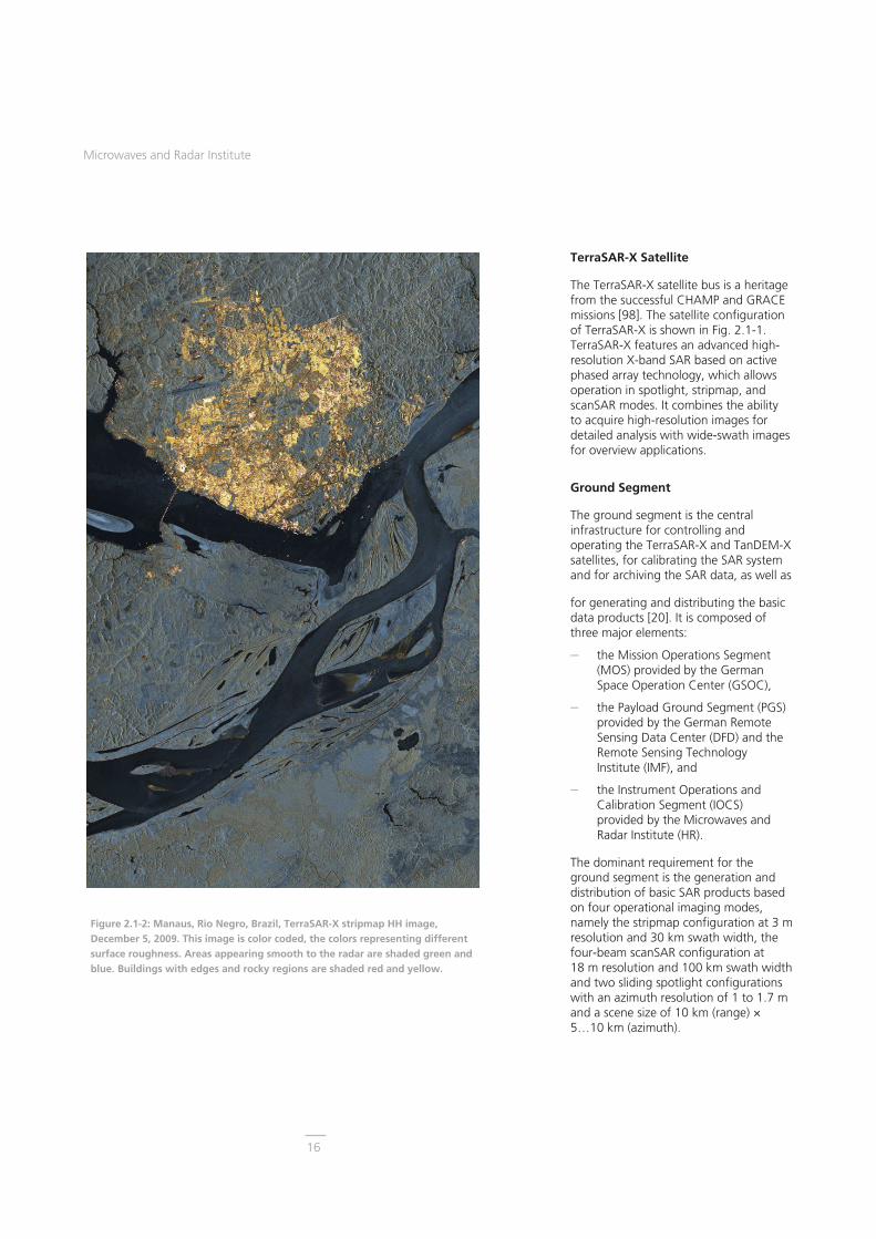
Figure 2.1-2: Manaus, Rio Negro, Brazil, TerraSAR-X stripmap HH image, December 5, 2009. This image is color coded, the colors representing different surface roughness. Areas appearing smooth to the radar are shaded green and blue. Buildings with edges and rocky regions are shaded red and yellow.
TerraSAR-X Satellite
The TerraSAR-X satellite bus is a heritage from the successful CHAMP and GRACE missions [98]. The satellite configuration of TerraSAR-X is shown in Fig. 2.1-1. TerraSAR-X features an advanced high-resolution X-band SAR based on active phased array technology, which allows operation in spotlight, stripmap, and scanSAR modes. It combines the ability to acquire high-resolution images for detailed analysis with wide-swath images for overview applications.
Ground Segment
The ground segment is the central infrastructure for controlling and operating the TerraSAR-X and TanDEM-X satellites, for calibrating the SAR system and for archiving the SAR data, as well as
for generating and distributing the basic data products [20]. It is composed of three major elements:
� the Mission Operations Segment (MOS) provided by the German Space Operation Center (GSOC),
� the Payload Ground Segment (PGS) provided by the German Remote Sensing Data Center (DFD) and the Remote Sensing Technology Institute (IMF), and
� the Instrument Operations and Calibration Segment (IOCS) provided by the Microwaves and Radar Institute (HR).
The dominant requirement for the ground segment is the generation and distribution of basic SAR products based on four operational imaging modes, namely the stripmap configuration at 3 m resolution and 30 km swath width, the four-beam scanSAR configuration at 18 m resolution and 100 km swath width and two sliding spotlight configurations with an azimuth resolution of 1 to 1.7 m and a scene size of 10 km (range) × 5…10 km (azimuth).

Research and Project Results – Spaceborne SAR Missions
17
Table 2.1-1: Main TerraSAR-X system parameters.
Figure 2.1-3: Tucson, USA, TerraSAR-X high resolution spotlight HH image, June 15, 2010.
Moreover, the Institute is dedicated to the goal of extending the existing imaging modes, of developing new SAR modes and of demonstrating their performance in space as a basis for future satellite SAR systems and missions. Examples are the Terrain Observation with Progressive Scan (TOPS) mode, an extended scanSAR mode with 200 km swath width, the quad polarized mode and the bi-directional SAR mode.
All SAR expertise and the related activities are concentrated in a dedicated part of the ground segment, a novel setup within the TerraSAR-X project. With more than three decades of experience in SAR systems and applications, the Microwaves and Radar Institute was well qualified to fully exploit the flexibility of the system in designing the basic and experimental modes and to contribute the following:
� dedicated SAR system engineering,
� the design, implementation and operation of the IOCS, and
� the development and execution of the end-to-end system calibration.
Beyond these tasks the Institute holds the position of the Mission Manager who chairs the Mission Board, incorporating the science and the commercial coordinators. The Mission Board decides on the strategic planning and all issues related to daily business, nominal operations, and contingencies.
TerraSAR-X System Parameters
Height/width 4.88 m / 2.4 m
Launch mass 1230 kg
Launch vehicle Dnepr 1
Launch site Baikonur, Kazakhstan
Power consumption 800 W (on average)
Orbit altitude 514 km
Orbital tube ± 250 m
Inclination 97.4 deg
Repeat cycle 11 days (167 orbits per repeat cycle)
Launch date June 15, 2007
Life time 5.5 years (consumables up to 7 years)
Radar frequency 9.65 GHz
Transmit bandwidth up to 300 MHz
Resolution 1 m, 3 m, 16 m (depending on image size)
Polarization HH / VV / HV / VH

Microwaves and Radar Institute
18
SAR System Engineering
SAR system engineering provides the SAR know-how to support and monitor the instrument development and to provide dedicated algorithms for the optimized SAR operation and data processing. In order to support the overall project objectives, a technical coordination function between the other TerraSAR-X/TanDEM-X project parts and the project management is provided by the following structure.
The SAR system performance support is responsible for the definition, per-formance estimation and optimization of all SAR modes and products w.r.t. radiometric and geometric performance, timing parameters, orbit and attitude information, beam shaping and polar-izations. Part of this activity is the generation of a global X-band backscatter map (see Fig. 2.1-4) to improve the gain setting of the acquisition and consequently the radio-metric quality of the data products.
The SAR system engineering support ensures the transfer of SAR instrument knowledge into the ground segment. Main tasks are the lead role in the ground segment / space segment integration, test, verification and validation program prior to launch and the harmonization of SAR instrument
related activities during the commissioning and operational phase [37] to maintain the specified overall SAR performance, develop new SAR modes and improve basic modes. The engineering support also provides recommendations for the mission management by regular reports, proposals for solutions w.r.t. mission scenarios, and trouble shooting in case of contingencies.
The SAR system engineering proved essential to ensure the quality, reliability and exploitation of the mission and is, therefore, a key factor to its success.
Instrument Operations and Calibration Segment (IOCS)
Correct operation and precise calibration of the radar instrument is essential to achieve and maintain the required quality of the SAR products. This includes the definition of robust general settings for the radar instrument and the determination of the instrument parameters, e.g. pulse repetition frequency, receiver gain, echo window position and echo window length for each individual image. During daily operations, corresponding commands for the radar instrument are systematically generated and the performance of the whole SAR system is continuously monitored. In the event of reduced performance, corrective measures and additional calibration activities are executed. Finally, instrument and calibration data are generated and provided as auxiliary information for the image processing. All mission data relevant for SAR system analysis and calibration are stored in a dedicated central archive and can be accessed by calibration, characterization, monitoring, and verification tools throughout the mission lifetime [50]. Instrument Operations
Each user request is analyzed and the appropriate sequence of radar para-meters expressed as engineering values (pulse repetition frequency, data window
Figure 2.1-4: Status of the global land backscatter (o [dB]) map before the launch of TanDEM-X. With the first global TanDEM-X DEM acquisition this map will be completed.

Research and Project Results – Spaceborne SAR Missions
19
Figure 2.1-5: TerraSAR-X “Christmas tree” image obtained by consecutive adjustments of the echo window position and length during the acquisition using the “expert” instrument commanding features.
Figure 2.1-6: TerraSAR-X image acquired in a special scanSAR configuration utilizing eight instead of four sub-swaths. The swath width is extended from nominally 100 km to 200 km, enabling the mapping of more than 80% of the area of Ireland during one single data take.
position, etc.) is generated. This sequence is then transformed into macro commands by the command generator and finally translated into the instrument’s binary language.
Beyond the operational instrument commanding, the IOCS features an “expert” version allowing full exploitation of the sensor capabilities. It was impressively demonstrated in December 2009, when TerraSAR-X was commanded to generate a “Christmas tree” shaped SAR image as shown in Fig. 2.1-5. A further example is the 200 km wide, eight sub-swath scanSAR image in Fig. 2.1-6.
SAR System Verification
SAR system verification is necessary in order to ensure the correct in-orbit operation of the entire SAR system from data take instrument command generation to image processing. To achieve this goal, the following main elements that compose the verification sub-system have been implemented:
� Data take verification: The correct execution of the commanded data take is verified by comparison of the monitored instrument operation with the commanded sequence and by an analysis of whether the statistics and main radar parameters of the acquired data are within their margins.
� Automatic transmit/receive module (TRM) monitoring: The actual condition of the TRMs is important for the final product quality. Therefore, a stringent and con-tinuous monitoring (see Fig. 2.1-7) is required, in order to trigger immediate action to compensate variations of individual TRMs and to recover the specified overall performance.
� Data take quality monitoring: Quality summaries of SAR acquisitions are issued per data take, per day, per satellite to allow immediate action in the case of
violated quality specifications. Long-term trends of various SAR system parameters are systematically monitored. Therefore data take relevant information from different sources within the ground segment is collected.
SAR Calibration
Calibration of SAR sensors requires the estimation and correction of systematic error contributions throughout the complete SAR system and to relate image information (amplitude and phase) to reference units in geophysical terms. TerraSAR-X features multitude of operating modes based on thousands of antenna beams that had to be calibrated to better than 1 dB (1) absolute radiometric accuracy within a commissioning phase of only six months. As the traditional beam-by-beam in-orbit calibration was not feasible within this short time period, new calibration techniques and procedures had to be developed.

Microwaves and Radar Institute
20
Figure 2.1-7: Statistics of the transmit phase of all TRMs in the TerraSAR-X front-end based on regular PN gating measurements. Each blue point indicates an individual measurement, the red line connects averaged values. No drifts or degradations have been observed so far.
-57,6
-57,4
-57,2
-57
-56,8
-56,6
-56,4
-56,2
-56
-55,8
-55,6
0 2 4 6 8 10 12 14Measurement ID
Abs
Cal
Fac
tor[
dB]
strip_002strip_007strip_013mean
�= -56.43 dB= 0.18 dB
Figure 2.1-8: Absolute calibration factors derived from all corner reflectors deployed for the 2009 re-calibration campaign. TerraSAR-X was operated in different stripmap beams.
Table 2.1-2: Comparison of results for the stripmap mode from the commissioning phase and the 2009 recalibration with the requirements for TerraSAR-X (CP: commissioning phase, DT: data take).
Key elements of this novel concept [157] are the antenna model [52] and the coding technique for front-end TRM monitoring called PN gating [53]. A detailed description of these innovative methods and techniques can be found in section 2.2.5.
Calibration Results
TerraSAR-X was calibrated first during the commissioning phase in 2007 [45] and recalibrated again in 2009 [433, 871]. Outstanding calibration per-formance was already achieved during the commissioning phase, especially regarding the geometric and radiometric performance of the system (see Table 2.1-2) [38]. The antenna model approach was successfully verified and proved essential in keeping the duration of the calibration campaign within the planned commissioning phase schedule [17].
In addition to the systematic monitoring of the instrument via internal calibration [19], TerraSAR-X regularly images two permanently installed corner reflectors, in order to identify performance drifts. The recalibration in 2009 was performed to estimate the long-term stability of the TerraSAR-X system at a high confidence level by measuring several beams and a number of reference targets. Based on the experience and the results achieved during the commissioning phase [294, 490, 491] the effort for the re-calibration campaign could be minimized. Geometric accuracies were clearly improved and radiometric accuracies were confirmed.
An estimate of the radiometric stability can be obtained by comparing the absolute calibration factor derived from measurements executed in 2009 (see Fig. 2.1-8) to the one derived from measurements executed during the commissioning phase in 2007 (see Tab. 2.1-2). The resulting radiometric stability of 0.15 dB over two years clearly surpasses the requirement of 0.5 dB over six months.
The absolute radiometric accuracy for stripmap and scanSAR basic products improves correspondingly, because the radiometric stability is one of the driving factors in the specification of this para-meter. For stripmap basic products, the absolute radiometric accuracy is improved from 0.6 dB down to 0.39 dB and for scanSAR basic products from 0.7 dB down to 0.52 dB. All require-ments have been met and in most cases exceeded.
In 2010, the calibration was repeated again during the so-called monostatic commissioning phase of TanDEM-X (see section 2.1.2) confirming the high calibration performance for TerraSAR-X and nearly identical accuracies for the TanDEM-X system [431, 816].
Calibration Procedure Goal CP 2007 Re-Cal 2009
Internal Calibration
Amplitude 0.05 dB < 0.05 dB < 0.05 dB
Phase 0.7° < 0.7° < 0.9°
Antenna Pointing Knowledge
Elevation/Azimuth [mdeg] 1,5 / 2 < 6 / <2 < 4 / <1
Pixel Localization Accuracy
Azimuth 2 m 0.53 m 0.1 m
Range 2 m 0.30 m 0.1 m
Antenna Model Verification
Two-way Pattern Accuracy ±0.2 dB < ±0.2 dB < ±0.2 dB
Radiometric Calibration
Radiometric Stability 0.5 dB 0.2 dB 0.15 dB
Relative Radiometric Accuracy 0.68 dB 0.3 dB 0.18 dB
Absolute Radiometric Accuracy 0.9 dB 0.6 dB 0.39 dB

Research and Project Results – Spaceborne SAR Missions
21
Compared Polarisation Channels
-8
-6
-4
-2
0
2
4
6
8
Res
idua
l Pha
se O
ffset
[deg
] CornerTransponderMean
CornerTransponderMean
HH-HH HH-VVHH-VHHH-HV
�= -0.83 deg= 1.14 deg
�= 1.37 deg= 0.89 deg
�= -1.01 deg= 0.93 deg
Figure 2.1-10: Residual phase offsets between different channels normalized to the HH channel.
Experimental Modes
Dual Receive Antenna Mode
The TerraSAR-X instrument design pro-vides the option to electrically split the radar antenna into two halves (fore and aft) in along-track direction and to realize two independent receive channels using the redundant receiver chain in parallel to the primary one. This so-called Dual Receive Antenna (DRA) mode allows applications such as ground moving target indication (GMTI), e.g. for traffic monitoring applications [187,188]. The DRA configuration also allows for receiving two different polarizations at the same time and therefore enables the realization of a fully polarimetric SAR in quad polarization mode. The use of the redundant receiver chain is restricted to experimental campaigns [652].
From April 11 to May 13, 2010, such a dedicated DRA mode campaign was performed, providing many valuable datasets, for example the quad-pol image of Los Angeles Huntington Beach, shown in Fig. 2.1-9. SAR polarimetry enhances the information content of the image, since it is possible to differentiate between the different scattering mechanisms. This can be shown very well by the colored image where the different polarization channels and consequently the different scattering mechanisms are represented by different colors (red = HH, green = VV, blue = (HV+VH)/2).
One objective of the 2009 DRA campaign was the inter-channel calibration of the system. Signals received by the fore and aft halves of the antenna are combined in a “magic T” providing the sum and difference of the input channels to the main and redundant receiver chains. Independent local oscillators in the receiver chains cause a random phase offset between the sum and difference channel data. Experimental data evaluation showed that this phase offset varies mainly when the DRA mode is switched off and on again. But slight
variations could also be observed from data take to data take. Since the trans-formation of the fore and aft channel data to the sum and difference channel data has to be known as accurately as possible, a data dependent recon-struction based on the use of the internal calibration pulses was developed [25].
Calibration measurements concentrated on estimating the imbalance and the cross-talk between the polarization channels [433]. For this polarimetric calibration, transponders were deployed providing different backscattering matrices [317] (section 2.2.5). Compen-sation of phase patterns derived from the antenna model resulted in phase imbalances below 2.2o (see Fig. 2.1-10). Furthermore, by reducing the antenna gain of all V polarized receive patterns by 0.18 dB, a channel imbalance between all polarization channels of 0.26 dB was achieved. Cross-polar isolation could be verified by measuring the transmit power using ground receivers and by evaluating the image RCS of reference targets in different polarization channels.
Figure 2.1-9: TerraSAR-X quad-polarization image of Los Angeles Huntington Beach (red = HH, green = VV, blue = (HV+VH)/2).

Microwaves and Radar Institute
22
Figure 2.1-11: The image shows an interferogram of Mexico City (scene size approximately 100 km x 100 km at 16 m resolution) generated by combining two data sets acquired on September 20, 2009 and January 30, 2010 in TOPS mode. Within this period, subsidence of up to 10 centimeters could be detected in some places. Areas of the Mexican capital in which TerraSAR-X has recorded the greatest changes in ground level are colored dark red. The green areas indicate those in which no change has been detected. The main reason for this subsidence is the extraction of ground water.
The one-way cross-polar isolation on transmit is better than 34 dB and 10 dB better than the space segment specification. The cross-polar isolation in SAR image products is at least 24.9 dB between all polarization channels. Considering further parameters such as the radiometric stability of TerraSAR-X, an absolute radiometric accuracy of 0.42 dB was derived for experimental DRA quad-pol products, close to that achieved for stripmap mode.
Terrain Observation with Progressive Scan (TOPS) Mode
The TOPS mode is a new and promising mode for wide-swath SAR operation for future SAR satellite missions [36], overcoming the drawbacks of the standard wide-swath scanSAR mode, i.e. an uneven distribution of the signal-to-noise ratio along azimuth, known as “scalloping” and an azimuth dependent distributed target ambiguity ratio. The TOPS mode has been selected as the baseline mode for ESA’s upcoming Sentinel-1 SAR system and was demonstrated with TerraSAR-X for the first time (see Fig. 2.1-11).
Aperture Switching Mode
The aperture switching mode for the TerraSAR-X satellite is used to create a virtual multi-channel system by switching between spatially diverse antenna halves from pulse to pulse. In practice the whole antenna is used for transmit and either the fore or aft half of the antenna is attenuated by 20 dB during receive. As for the aforementioned Dual Receive Antenna mode the main application is along-track interferometry used for traffic monitoring [49, 51].
Bi-directional SAR Mode
The bi-directional SAR mode enables an extension of the viewing angle range in the azimuth direction, which is nominally limited to ±0.75°. By means of an appropriate excitation of the transmit/ receive modules, symmetric grating lobes can be generated pointing in the forward and backward directions, thus extending the viewing angle range to ±2.2°. The backscattered signals of the forward and backward squinted lobes arrive simultaneously at the antenna. However the signals can be separated by evaluating the Doppler spectrum. Besides the extended azimuth angle range, a simultaneous acquisition of two images is achieved. In other words, the area of interest is imaged twice during one pass with an interval of several seconds under different squint angles.
Due to the high-resolution capability and flexible design, the TerraSAR-X mission provides a new class of high-quality X-band SAR products. The stability of the radar instrument, the outstanding radiometric performance and the unique geometric accuracy of the images are considerably outper-forming the initial specification. Combining SAR system engineering, calibration and verification, and the development of the IOCS have been a key factor to the success of the mission.

Research and Project Results – Spaceborne SAR Missions
23
2.1.2 TanDEM-X
TanDEM-X (TerraSAR-X add-on for Digital Elevation Measurement), initiated jointly by the Microwaves and Radar Institute and EADS Astrium GmbH in 2003, opens a new era in spaceborne radar remote sensing. A single-pass SAR interferometer with adjustable baselines in cross and along-track directions is formed by adding a second, almost identical spacecraft (TDX) to TerraSAR-X (TSX) and flying the two satellites in a closely controlled formation. Three years after TSX, TDX was launched on June 21, 2010 and since December 2010 the two satellites are orbiting at typical cross-track baselines of 200 – 400 m acquiring data for a global digital elevation model (DEM) with 2 m relative height accuracy at a 12 m posting1. Beyond that primary mission objective, TanDEM-X provides a configurable SAR interferometry test bed for demonstrating new SAR techniques and applications.
Local DEMs of even higher accuracy level (posting of 6 m and relative vertical accuracy of 0.8 m) and applications based on along-track interferometry (ATI), like measurements of ocean currents, are important secondary mission objectives. Along-track inter-ferometry will also allow innovative applications, such as improved detection, localization and ambiguity resolution for ground moving target indication and traffic monitoring applications. Furthermore, TanDEM-X supports the demonstration and application of new SAR techniques, with the focus on multistatic SAR, polarimetric SAR interferometry, digital beamforming, and super-resolution.
1 TanDEM-X DEM specification: relative vertical accuracy 2 m (90% linear point-to-point error over 1o x 1o lat/long cell), absolute vertical accuracy 10 m (90% linear error), absolute horizontal accuracy 10 m (90% circular error), post spacing 12 m x 12 m.
Starting from the proposal in 2003, the Institute was the driving force in per-forming detailed mission analyses and developing the mission concept into operational acquisition and processing scenarios and plans. Different to TerraSAR-X, the ground segment for TanDEM-X has been developed in a combined project, which was managed by the Institute. Furthermore, the Institute holds the position of the Mission Manager for the joint TerraSAR-X/ TanDEM-X missions and of the TanDEM-X Principal Investigator, and is also in charge of coordinating the scientific exploitation of TanDEM-X.
The TanDEM-X Spacecraft
The TDX satellite is a rebuild of TSX with only minor modifications. This offers the possibility for a flexible share of operational functions for both the TerraSAR-X and TanDEM-X missions among the two satellites.
During the last phase of the TerraSAR-X spacecraft development, the SAR instrument design was extended to allow the exchange of synchronization pulses to support coherent operation of both SAR instruments during bistatic operation. Six synchronization horn antennas on each satellite provide a quasi-omnidirectional coverage. An additional propulsion system based on high-pressure nitrogen gas is accommodated on TDX. This cold gas system provides finer impulses than the hydrazine system on both satellites (used for orbit maintenance) and supports formation flying by fine orbit control of the TDX satellite. The TDX solid state mass memory capacity is 768 Gbit which is double that of TSX in order to support the collection of the enormous amount of DEM data. The TDX satellite is designed for a nominal lifetime of 5 years. Predictions for TSX based on the current status of system resources indicate at least one extra year of lifetime (until the end of 2013), providing the required 3 years of joint operation.
Figure 2.1-12: TanDEM-X and TerraSAR-X flying in close formation.

Microwaves and Radar Institute
24
Figure 2.1-13: Helix formation seen from different perspectives; TSX orbit in red, TDX orbit in green.
Figure 2.1-14: Exclusion zones, orbit segments in which one satellite might be damaged by radar illumination of the other satellite, have to be strictly observed.
��
side-lobes
exclusion zone � all beam main lobes
HELIXHELIX
TSXTSX
TDXTDX
DEMDEM
DEMDEM0°
30°
50°
65°
“TDX may not transmit in
desc. orbit”
exclusionzones
(example)
TSX
TDX
“TSX may not transmit in asc. orbit”
TSX TDX
��
side-lobes
exclusion zone � all beam main lobes
HELIXHELIX
TSXTSX
TDXTDX
DEMDEM
DEMDEM0°
30°
50°
65°
“TDX may not transmit in
desc. orbit”
exclusionzones
(example)
TSX
TDX
“TSX may not transmit in asc. orbit”
TSX TDX
Close Formation Flight
An orbit configuration based on a Helix geometry has been selected for safe formation flying [81]. The Helix-like relative movement of the satellites along the orbit is achieved by combining an out-of-plane (horizontal) orbital displacement imposed by different ascending nodes with a radial (vertical) separation imposed by different eccentricities and arguments of perigee (see Fig. 2.1-13). Since the satellite orbits never cross, the satellites can be arbitrarily shifted along their orbits. This enables a safe spacecraft operation without the necessity for autonomous control. Cross- and along-track baselines ranging from 200 m to 10 km and from 0 m to several 100 km, respectively can be accurately adjusted depending on the measurement requirement.
Although, in principle, the passive stability of the Helix formation prevents collisions, a number of mechanisms have been introduced in the satellite design to safeguard against collision and mutual illumination risks: An additional safe mode based on the magnetic torquers for attitude control was introduced on both satellites. Unlike the hydrazine propulsion system, employing the
magnet torquers for attitude control does not lead to any orbit deviation.
According to this additional safety feature, the ground operating concept has been modified to ensure that the ground segment can respond swiftly enough to any problems on the space segment.
To avoid mutual irradiation, exclusion zones (see Fig. 2.1-14) have been defined, i.e. orbit segments in which one of the two satellites is not allowed to transmit radar pulses. Moreover, the synchronization link between the two satellites can be used to check each other's operating status. If the syn-chronization signals received do not exceed pre-defined thresholds, it is assumed that the partner satellite has problems and the radar transmission will be immediately suppressed. Lastly, TDX is equipped to receive telemetry data from TSX and to react on any non-nominal operating status.
The Ground Segment
The missions TerraSAR-X and TanDEM-X jointly share the same space segment consisting of the TSX and TDX satellites and are operated using a common ground segment, originally developed for TerraSAR-X (section 2.1.1) and which has been extended for the TanDEM-X mission. Specific new developments are described in the following.
The spatial baseline between TSX and TDX satellites is derived at millimeter accuracies from on-board GPS measurements and dedicated baseline calibration data takes. Key issues in operating both missions jointly are the different acquisition scenarios: whereas TerraSAR-X requests are typically single scenes for individual scientific and commercial customers, the global DEM requires a global mapping strategy. This strategy has also to account for the current formation flying geometry, which, in turn, depends on the orbit parameters selected. Any given orbit configuration permits generating a digital

Research and Project Results – Spaceborne SAR Missions
25
Figure 2.1-16: Radiometric cross-check between TSX (purple) and TDX (blue), based on three acquisitions over two different types of distributed targets (grass and urban area), � : mean value, : standard deviation.
-15
-13
-11
-9
-7
-5
-3
-1
Grass TDX� = -11.059 dB�= 0.819 dB
Urban TDX� = -4.261 dB = 1.927 dB
Grass Urban
Grass TSX� = -11.867 dB = 0.803 dB
Urban TSX� = -5.065 dB�= 1.846 dB
[d
B]
Area
�TDX = 6.799 dB
�TSX = 6.802 dB
-15
-13
-11
-9
-7
-5
-3
-1
Grass TDX� = -11.059 dB�= 0.819 dB
Urban TDX� = -4.261 dB = 1.927 dB
Grass Urban
Grass TSX� = -11.867 dB = 0.803 dB
Urban TSX� = -5.065 dB�= 1.846 dB
[d
B]
Area
�TDX = 6.799 dB
�TSX = 6.802 dB
0
100
200
300
400
500
2010-12-12 2011-02-16 2011-04-23 2011-06-28 2011-09-02Date
Form
atio
n Pa
ram
eter
[m]
30
40
50
60
70
80
90
100
Hei
ght o
f Am
bigu
ity [m
]
Horizontal [m]
Vertical [m]
Height Of Ambiguity
elevation model only within a certain latitude range. The two satellites down-link their data to a global network of ground stations: Kiruna in Sweden, Inuvik in Canada, O'Higgins in the Antarctic, and Chetumal in Mexico. The entire processing chain is a new TanDEM-X specific development. However, it consists of individual modules which strongly benefit from the TerraSAR-X and the Shuttle Radar Topography Mission (SRTM) heritage.
The Instrument Operations and Calibration Segment (see section 2.1.1) has been extended by modules to define the Helix geometry and to generate parameters defining the exclusion zones and the selection of the adequate sync horn combination. The definition of the Helix parameters is driven by the global DEM acquisition scenario and the required height of ambiguity2. The so-called TanDEM-X Acquisition Planner (TAP) incorporates these functionalities in a completely new IOCS sub-system. All TanDEM-X acquisitions for the global DEM but also for scientific experiments are planned using the TAP on a data take level and are provided to the mission planning system for combination with the requests for TerraSAR-X products. Fig. 2.1-15 shows the Helix parameters in close formation and the resulting height of ambiguity for all data takes since the start of the operational phase in December 2010.
The instrument operations required a major extension for bistatic commanding including synchronization pulse exchange at sufficient repetition frequencies. Modules for monitoring of the frequency drift between the local oscillators on TSX and TDX and a complete suite of tools to monitor the global acquisition performance have been developed. Another focus was the analysis of systematic errors in the bistatic system and their calibration as well as detailed
2 The height of ambiguity is defined as the height difference equivalent to a 2� phase cycle inside an interferogram.
investigations into the performance of the ICESat laser altimeter measurements, which serve as a global reference data set for absolute height calibration. Led by the Institute, a detailed plan of the commissioning phase was established and executed as planned.
Radiometric Calibration
In the first few weeks after launch the along-track distance was reduced from 16000 to 20 km and TDX was already maneuvered into a Helix orbit with 1.3 km horizontal separation. In this way, the Earth’s rotation during 3 seconds (corresponding to 20 km distance) was compensated for and the same ground tracks as TSX were achieved to facilitate cross-calibration between the two SAR systems. The same program as for the TerraSAR-X commissioning phase was repeated, but compressed to only 2.5 months duration. Most of the measurements for deriving the calibration parameters were made against reference targets and performed by both satellites.
For TDX the same pixel localization accuracy of 10 cm was achieved as for TSX, again almost one magnitude better than the product specification of 1 m. Furthermore, the geometric offset between TDX and TSX products is only 8.2 mm, i.e. both systems are geo-metrically matched to each other down to one quarter of a wavelength. For a radiometric cross check between both SAR systems, a scene with two different types of distributed targets, grass and urban area, was selected. Fig. 2.1-16 shows the expected higher backscattering coefficient for the urban area compared to the grass field. The offset between both SAR systems of around 0.8 dB corresponds to the calibration factor, which had not yet been matched at the time of this comparison (first three months of the commissioning phase).
Figure 2.1-15: Main Helix formation parameters (vertical and horizontal distance) and height of ambiguity (HoA) of all data takes since the start of the operational phase. The increase of the HoA lower limit to 45 m in April 2011 was necessary to cope with volume decorrelation over rain forest.

Microwaves and Radar Institute
26
Figure 2.1-17: Global coherence map of TanDEM-X data takes acquired between December 2010 and April 2011 over land.
Figure 2.1-18: Left: Bistatic rain forest data take geometries with ascending order of height of ambiguity (HoA) and corresponding incidence angles. Right: Coherence histograms for these data takes. Black samples have a very low occurrence of the respective coherence value, red and yellow colors mark a high density of coherence samples.
More importantly, Fig. 2.1-16 shows that the difference (cross-check) between urban area and grass for both satellites is almost identical (TSX: 6.802 dB and TDX: 6.799 dB). The deviation of only 0.003 dB is negligible, so the TDX SAR system is as accurately adjusted and calibrated as TSX. In terms of calibration TDX is a perfect copy of TSX. The evaluation of the data confirmed the unprecedented stability and accuracy of the TSX system three years after launch.
With TDX delivering identical single SAR product quality as TSX, the TerraSAR-X mission is running operationally with both satellites since October 25, 2010. That means that user orders for high-resolution SAR data are acquired by either TSX or TDX. The selection is performed by the mission planning depending on the available resources and by considering criteria like the exclusion zones.
In a Formation Flight Review in early October 2010 “green light” was given for entering the close formation, which was achieved on October 14. In the so-called bistatic commissioning phase, the validity of the calibration parameters were also verified in bistatic operation. A new algorithm for deriving the bistatic replica was developed and successfully
implemented in the operational interfero-metric processor. The internal calibration also relies on this procedure to precisely characterize the instrument phase drifts, which are essential to accurately derive the TanDEM-X digital elevation models. Finally, several dedicated calibration campaigns with corner reflectors were executed for precisely determining the instrument internal delays in monostatic and bistatic operation.
Interferometric Performance
The excellent SAR performance and stability of both satellites has been demonstrated in the monostatic commissioning phases of TerraSAR-X in 2007 [37, 38, 45] and TanDEM-X in 2010. Additional performance aspects arise for interferometric pairs of SAR images using the bistatic TanDEM-X configuration [27]. The key performance parameters of the final global DEM were optimized using a dedicated height error simulator and are systematically evaluated for the operational mission.
The fundamental quantity in analyzing the interferometric performance is the coherence between the monostatic and the bistatic SAR image. It includes error contributions due to volume, temporal and baseline decorrelation or limited signal-to-noise ratio. The coherence is directly correlated with the height accuracy of the corresponding DEM, where high coherence values translate into a low height error and vice versa.
Fig. 2.1-17 presents a global map of coherence for all the operational data takes acquired up to April 2011. Each scene coherence is derived by averaging over land surfaces only. Almost 80% of the acquired scenes are characterized by a mean coherence higher than 0.6, which assures good quality of the final DEM.
During the TanDEM-X commissioning phase, the impact of various acquisition scenarios was investigated. Different scattering characteristics as well as changing baseline configurations

Research and Project Results – Spaceborne SAR Missions
27
Figure 2.1-19: Coherence maps of an area in the Amazon rain forest acquired in HH polarization, but at different acquisition geometries. Low coherence is shown as dark color. Left/Right: height of ambiguity: 25 m/52 m, cross-track baseline: 182 m/162 m, incidence angle: 29.9°/47.7°.
Figure 2.1-20: Coherence in different polarizations as a function of the height of ambiguity.
influence the interferometric coherence. In vegetated areas, volume scattering is the primary reason for coherence loss.
Rain forests with varying tree heights of over 40 m have been measured in varying TanDEM-X bistatic acquisition configurations. The left plot in Fig. 2.1-18 shows the geometric parameter range of 92 bistatic data takes over the Amazon rain forest with incidence angles from 30° to almost 50° and the corresponding height of ambiguity at the scene centre coordinate. In the right plot of Fig. 2.1-18 the coherence distribution from 0 to 1 improves with increasing height of ambiguity. With this knowledge, the baseline geometry can be optimized for vegetated areas. Fig. 2.1-19 is an example where the interferometric performance improvement is particularly visible over the forested areas (lower part of the images), whereas in the clear-cuts almost the same high coherence is obtained.
The relationship between polarization and coherence has been analyzed from consecutive acquisitions over different ground vegetation types, in horizontal (HH) and vertical (VV) polarization. A summary of the coherence statistics for different polarizations as a function of height of ambiguity is presented in Fig. 2.1-20. The obtained results lead to the conclusion that final performance of HH and VV polarization channels is very similar. Since the mean backscatter is slightly higher in HH, this polarization has been selected for the global DEM acquisition.
Relative Height Error Determination
The requirement on the relative vertical accuracy of the global DEM depends on the terrain relief: 2 m for low and medium relief terrain (predominant slopes between 0 and 20%) and 4 m for high relief terrain (predominant slopes greater than 20%), whereby the accuracy is expressed as the linear errors in a 90% confidence interval within a 1° x 1° lati-tude/longitude cell.
The height error of TanDEM-X elevation data has been determined from the difference between two repeated DEM data takes over the same ground area acquired with the same configuration parameters. Two sources of errors mainly contribute to the difference and can be characterized in the frequency domain: low frequency errors and systematic offsets, describing slow-varying trends such as orbit errors and height shifts that will be removed during the final DEM calibration process; high frequency errors, characterizing the random error in relative vertical height, due to coherence losses and phase unwrapping problems.

Microwaves and Radar Institute
28
Figure 2.1-21: Approach for determining the relative height error. The difference of two repeated DEM acquisitions is derived, and discriminated into shallow and steep slopes.
Figure 2.1-22: Summary of the relative height error performance for data takes over bare soil & rock surfaces and a linear fit through the measured values in green; yellow bars indicate the predicted performance (HE: height error, HoA: height of ambiguity).
As shown in Fig. 2.1-21, the height difference between two DEMs is derived and a two-dimensional high-pass filter applied in the frequency domain, leading to the generation of the height error matrix. Since the relative accuracy depends on the terrain slope, an ap-propriate mask has to be applied, in order to discriminate flat and mount-ainous terrain. The two-dimensional gradient matrix of the input DEM is evaluated, and a threshold is set at 20% slope. Finally, the height error is derived from the 90% distribution interval.
Fig. 2.1-22 depicts the results obtained from the analysis of several test sites, acquired with different geometries and classified as soil and rock terrain. Even though the final DEM will be obtained by the combination of at least two global acquisitions, for some test sites one acquisition is already sufficient to meet the required specification. A linear fit through the height error estimates shows a good agreement with DEM performance simulations [81]: a height error of 1.7 m and 2.5 m is predicted for a height of ambiguity (HoA) of 30 m and 45 m, respectively (yellow bars in Fig. 2.1-22).
Calibration of the Bistatic Interferometer
In addition to the radiometric calibration of the single satellites as described above, the interferometric calibration of the bi-static system is an essential task for the TanDEM-X mission [29]. The processing relies on radargrammetry to resolve the correct height of ambiguity band in order to correctly tie down the interferogram and DEM. Thereby, the approximate height of a pixel is triangulated based on the travel times of the radar signals. The resulting slant range difference between the two SAR images represents the radar-grammetric shift. For comparison, the SRTM DEM is used to calculate reference shifts. Differential internal delays of the hardware components cause additional shifts. Although the design of both instruments is nearly identical, the components show slightly different characteristics. Deviations are only visible in the bistatic case by comparing both instruments directly and incorporating highly accurate baselines.
The radargrammetric shifts (Fig. 2.1-23) have been analyzed and different compensation parameters have been derived empirically. These corrections incorporate instrument effects like dependencies from the selected sync horn pair, the commanded receiver gain setting or the actual chirp rate. Also, a dependence on the satellite geometry and the compensation of the Earth’s rotation has been included. With all corrections applied, the measurements fall into the range required to unambiguously resolve the integer multiple of 2� phase cycles (Fig. 2.1-23).
The final interferograms and also the DEMs themselves are derived from the interferometric phase. DEMs acquired repeatedly over the same test site show stable phase behavior of the instrument. Solutions resolving a residual phase ambiguity of���on the sync link are currently being tested. Pending their operational implementation, the inter-ferometric phase and the differential delays will be fully calibrated.

Research and Project Results – Spaceborne SAR Missions
29
Figure 2.1-23: Radargrammetric shifts before and after correction of instrument specific and geometric effects. The red lines correspond to one ambiguity band.
Figure 2.1-25: Height error histogram of the DEM in several processing stages; red: raw DEM without correction, green: after offset removal, brown: after least-spuare fit to remove residual errors.
Figure 2.1-24: Baseline errors over argument of latitude during the TanDEM-X commissioning phase. Red dots correspond to the errors with the original “precise” baseline. Green dots are the residual errors obtained after the correction.
Baseline Calibration
As a rule of thumb, for TanDEM-X a 1-mm baseline error approximately translates into a 1-m height error in the DEM. Generation of precise DEMs therefore requires baselines at millimeter accuracies. The baseline is determined from GPS data provided by dual-frequency IGOR receivers on both satellites. Relative accuracies are within the 1 mm requirement, but offsets of several millimeters cannot be excluded if only the GPS data are considered. Regular baseline calibration data takes over globally distributed test sites with known height are therefore included in the global acquisition timeline. Reference heights are provided by the ICESat laser altimeter database [28]. Thorough work has been done in the last years to establish criteria for selecting highly accurate (typically better than 1 m) altimeter height information.
After delay and phase calibration, as described above, such a baseline bias is the main systematic height error con-tribution; a linear dependency between the mean height error and the baseline error in line-of-sight direction can be found. Over each test site, two near and far range beams are consecutively acquired. This provides two estimates in the line of sight direction from which the two-dimensional baseline bias in the plane perpendicular to the flight direction can be derived.
During the TanDEM-X commissioning phase, this procedure was systematically repeated over all test sites and repeat cycles. The results in Fig. 2.1-24 indicate a quite constant baseline offset over time. This means, on the one hand, that the error has the nature of a mechanical offset (e.g. error in the measurement of a reference point on the satellite), and that it can therefore be easily compensated, as shown in Fig. 2.1-24, for achieving the required 1 mm (1) accuracy. On the other hand, the stability of the error suggests that the calibrated baseline products would be valid for long time periods. However, the baseline
offset is being constantly monitored during nominal TanDEM-X operation and, if necessary, updated.
Height Error Model and Mosaicking
Although the baseline calibration method minimizes large height error contributions in the DEM, the DEM calibration is still needed to achieve the TanDEM-X height error requirements. Fig. 2.1-25 shows how the height error histogram of a so-called “raw” DEM improves with the two applied correction procedures. Raw DEMs have a large height error offset and a relative widely spread error histogram (red in the plot). After performing the baseline calibration, the histogram shifts towards zero (green in the plot), but could still have a remaining offset of around 1 m.
In order to correct the error spread, an offset correction is not sufficient. Therefore, a more complex height error model was developed, which considers the height error evolution along the data take and fits it with a two-dimensional polynomial function [29] (see Fig. 2.1-26). The fitting function is a third order polynomial in azimuth direction and a linear slope in range, as well as a small torsion component in azimuth. The coefficients of this model are obtained with a least-squares method based on the height references available. Applying this approach, the brown histogram in Fig. 2.1-25 becomes narrower and fulfills the TanDEM-X height error requirement of 2 m relative error.

Microwaves and Radar Institute
30
Figure 2.1-26: Height error model applied to the TanDEM-X DEMs based on a linear slope in range, a third order polynomial function in azimuth, as well as a small torsion in azimuth.
In the operational phase, the DEM calibration will be applied to thousands of overlapping raw DEMs covering large areas, i.e. complete continents. By solving the joint least-squares problem for all raw DEMs considered, the estimation of the height error model coefficients improves, since the height reference information is shared by all connected DEMs.
TanDEM-X Scientific Experiments
TanDEM-X is a highly capable SAR interferometer that can be operated in a multitude of modes and configurations. This flexibility enables the demonstration of advanced bistatic and multistatic radar techniques for the retrieval of novel bio- and geophysical parameters. First exciting results, which were obtained during the TanDEM-X commissioning phase, demonstrate the enormous potential of formation flying SAR missions to serve new remote sensing applications.
Velocity Measurements from Space
TanDEM-X has the capability to provide highly accurate velocity measurements of moving objects within a large coverage
area. This can be achieved by comparing the amplitude and phase of two SAR images acquired at slightly different times. By adjusting the along-track displacement between the TDX and TSX satellites from almost zero to several tens of kilometers, TanDEM-X can adapt its sensitivity to a broad spectrum of velocities ranging from less than a milli-meter per second to more than hundred kilometers per hour. The Helix satellite formation enables even a minimization of the effective cross-track baseline for a given latitude and incident angle, thereby reducing the complexity in the velocity estimation process. Furthermore, along-track interferometry can be enhanced by the dual-receive antenna mode in each of the two tandem satellites, providing additional phase centers separated by a short along-track baseline of 2.4 m. The combination of short and long baseline SAR data acquisitions improves both the detection and localization of moving objects and resolves phase ambiguities in the case of fast moving scatterers. TanDEM-X hence provides a unique SAR system with four phase centers separated in the along-track direction. Potential applications are ground moving target indication (GMTI), the measurement of ocean currents, and the monitoring of sea ice drift and rotation.
As a first example, Fig. 2.1-27 shows the observation of ship movements in the Strait of Gibraltar. The data were acquired during the monostatic commis-sioning phase where the satellites had an along-track separation of 20 km, corres-ponding to a time lag of three seconds. The 2-D velocity vector was measured with an accuracy of 1 km/h by comparing the ship positions in the TSX and TDX SAR images. The velocity measurements have been validated with independent data obtained from the Automatic Identification System (AIS).
Another unique example is the ob-servation of sea ice dynamics by along-track interferometry. The top of Fig. 2.1-28 shows an along-track inter-

Research and Project Results – Spaceborne SAR Missions
31
Figure 2.1-28: Top: Interferogram of rotating ice floes. Bottom: Rotation angle of individual ice floes; the angular range of measurements corresponds to a colored scale representing a rotation angle from -0.005 deg (yellow to red) to +0.005 deg (blue to violet) within three seconds.
Figure 2.1-27: Ship movements observed with TanDEM-X during the monostatic commissioning phase. The ship displacements can be seen from the insets showing overlays of TSX (red) and TDX (green) image patches. The estimated velocities are in excellent agreement with AIS reference data (right).
ferogram obtained in scanSAR mode near the east coast of Greenland. The data were again acquired during the monostatic commissioning phase. The interferogram reveals cyclic fringe patterns of individual ice floes while areas of land topography produce a less regular phase pattern with smaller variations. The cyclic patterns of the ice floes, which typically have a rather flat topography, are due to rotation about their vertical axes. From the fringe patterns, the rotation can be derived with high accuracy. The lower part of Fig. 2.1-28 shows such a rotation map

Microwaves and Radar Institute
32
Figure 2.1-29: Performance example for large baseline DEM acquisitions with TanDEM-X (cross-track baseline = 3000 m, posting = 12 m). A relative height accuracy (single point standard deviation) better than 10 cm is predicted.
Figure 2.1-30: Large baseline TanDEM-X DEM of the edge of October Revolution Island (top) and predicted (blue) vs. estimated (green) point-to-point height accuracy along a DEM slice (bottom) [11].
h(t1)
� �h ~ �2 - �1
no coherence between passes required
�1pass 1
pass 2
�h < 10 cm h(t2)
�2
Bistatic Strip mapB = 3000 m �x = 12 m
Bistatic Strip mapB = 3000 m �x = 12 m h(t1)
� �h ~ �2 - �1
no coherence between passes required
�1pass 1
pass 2
�h < 10 cm h(t2)
�2
Bistatic Strip mapB = 3000 m �x = 12 m
Bistatic Strip mapB = 3000 m �x = 12 m
where the color scale represents rotation angles between -0.005 deg (yellow to red) to +0.005 deg (blue to violet) within three seconds.
Large Baseline Cross-Track Interferometry
Large baseline interferometry takes advantage of the high RF bandwidth of the TSX and TDX satellites, allowing coherent data acquisitions with cross-track baselines of 5 km and more [105]. Note that less than 5% of the maximum possible (critical) baseline length is used during nominal DEM data acquisition. Large baseline interferograms can, hence, significantly improve the height accuracy beyond the standard TanDEM-X DEM quality. However, the associated low height of ambiguity typically requires a combination of multiple interferograms with different baseline lengths to resolve phase ambiguities, especially in hilly and mountainous terrain. Further opportunities arise from a comparison of multiple large baseline TanDEM-X interferograms acquired during different passes of the satellite formation (Fig. 2.1-29). This provides a sensitive measure for vertical scene and structure changes. Potential applications are detection of the grounding line which separates the shelf from the inland ice in polar regions, monitoring of vegetation growth,
mapping of atmospheric water vapour with high spatial resolution, measure-ment of snow accumulation or the detection of anthropogenic changes of the environment, e.g. due to deforestation. Note that most of these applications rely on a comparison of two or more single-pass (large baseline) cross-track interferograms and, hence, do not necessarily require coherence between the different passes. Further information can be gained from an evaluation of coherence changes, potentially aug-mented by polarimetric information. This is, for instance, well suited to reveal even slight changes in the soil and vegetation structure reflecting vegetation growth and loss, freezing and thawing, fire destruction, human activities, and so on. The combination of repeated TanDEM-X single-pass interferograms, hence, enables the entry into a new era of interferometric and tomographic 3-D and 4-D SAR imaging, as was the case with ERS-1/2 for the development of classical repeat-pass SAR interferometry.
As a first example, Fig. 2.1-30 shows a large baseline DEM, which was acquired by TanDEM-X on July 16, 2010 in the Russian Arctic (October Revolution Island) [11]. The DEM was part of a longer data take that required a sophisticated com-manding to obtain a large baseline interferogram while TDX was still drifting towards TSX from its initial along-track separation of 15700 km. At the time of data acquisition, the two satellites were 380 km apart from each other, resulting in a temporal separation of 50 seconds. Earth rotation caused a cross-track base-line of 2 km which corresponds to a height of ambiguity of only 3.8 m. A squinted operation was necessary to provide sufficient overlap of the Doppler spectra. The lower part of Fig. 2.1-30 shows the predicted (blue curve) and estimated (green curve) standard deviation of the point-to-point relative height error for a linear slice through the DEM. The predicted error was calculated from the coherence measurements and the estimated error was obtained by high-pass filtering the DEM slice [11].

Research and Project Results – Spaceborne SAR Missions
33
Figure 2.1-31: Polarimetric SAR interferometry with TanDEM-X. Left: amplitude of SAR image. Right: interferometric height difference between HH and VV channels for an agricultural area in the Kuma-Manych Depression (Russia).
Figure 2.1-32: Overlay of monostatic (magenta) and bistatic (green) SAR image of Brasilia.
Both results show a height accuracy in the order of 20 cm. This demonstrates the great potential of formation flying SAR missions to obtain high-resolution elevation information with decimeter accuracy, thereby enabling new remote sensing applications. An example is the monitoring of height changes over glaciers, ice caps or ice sheets to quantify their ice mass balance. A dedicated formation flying SAR mission has already been proposed for this purpose (see section 2.1.8).
Polarimetric SAR Interferometry
Polarimetric SAR interferometry combines interferometric with polarimetric measurements to gain 3-D structure information from semi-transparent volume scatterers in a single pass (see section 2.2.6). A prominent example is the measurement of vegetation height and density, which also forms the basis of future formation flying SAR missions dedicated to global environmental monitoring (see section 2.1.3). Fig. 2.1-31 shows, as an example, the height differences obtained for a dual-polarized TanDEM-X spotlight acquisition of an agricultural area in the Kuma-Manych Depression in Russia. The data were acquired during the monostatic commis-sioning phase with a perpendicular base-line of 275 m, demonstrating the poten-tial of crop height estimation. Future experiments will also employ fully polari-metric acquisitions.
Bistatic SAR Imaging
Bistatic SAR imaging provides additional observables for the extraction of im-portant scene and target parameters [95]. TanDEM-X allows for the simultaneous acquisition of bistatic and monostatic images in a single data take. A quantitative evaluation of the bistatic radar cross-section (RCS) and a com-parison with its monostatic equivalent facilitates the detection and recognition of targets. The segmentation and classification in radar images is expected to be improved by comparing the spatial statistics of mono and bistatic scattering
coefficients. A joint evaluation of mono and bistatic SAR images could also be used to isolate different scattering mechanisms. Moreover, bistatic SAR has potential for the retrieval of sea state parameters, the estimation of surface roughness and terrain slope, as well as stereogrammetric, meteorological and atmospheric applications. A first bistatic data take was acquired over Brasilia during the monostatic commissioning phase at 20 km along-track separation.

Microwaves and Radar Institute
34
Figure 2.1-33: Block diagram of the TanDEM-X Science Service Segment interfacing to the Instrument Operations and Calibration Segment (IOCS) and the Data and Information Management System (DIMS).
Scientific Topics Number of Proposals
Oceanography 1
Land Use 12
Vegetation 14
Hydrology 9
Geology 16
Cro
ss-T
rack
In
terf
ero
met
ry
Glaciology 23
Oceanography 10
Hydrology 3
Traffic Interferometry 5
Alo
ng
-Tra
ck
Inte
rfer
om
etry
Glaciology 3
Polarimetric Interferometry 10
Bistatic SAR 4
Digital Beamforming 1
Super Resolution 1
New
Tec
hn
iqu
es
Interferometric SAR 19
Other Applications 14
Oth
ers
Calibration & Validation 5
Table 2.1-3: First TanDEM-X Announce-ment of Opportunity (AO) - number of submitted proposals for the 17 different scientific topics.
Fig. 2.1-32 shows an overlay of the bistatic SAR image with its monostatic counterpart, demonstrating significant scattering differences, even for very small bistatic angles [15].
TanDEM-X Science Coordination
The Institute holds the position of the TanDEM-X Principal Investigator and is also coordinating the international science team. As mentioned above, the operational scenarios for the TanDEM-X mission differ from those of the TerraSAR-X mission in a variety of aspects. While future data acquisitions of the TerraSAR-X mission are ordered by the scientists using the EOWEB interface, an additional user interface has been implemented for the TanDEM-X mission. Science users can access the TanDEM-X ground segment via the TanDEM-X Science Service Segment (Fig. 2.1-33). Its infrastructure provides a communication platform between the scientists, the science coordinator, and the evaluators, as well as interfaces for data take ordering and access to processed data.
For TanDEM-X data provision, scientists need to submit a proposal with a detailed description of the test site and the requested data using the web interface to the Science Service System home page (https://tandemx-science.dlr.de). After evaluation and proposal acceptance the science coordinator translates the requests for acquisition planning by the ground segment. TanDEM-X constraints on imaging geometry and instrument settings, resource limitation and the priority mechanism in relation to the TerraSAR-X mission have all to be observed in this process. The scientists can then track the acquisition status and order the data product after data acquisition via EOWEB (https://www.eoweb.de).
In response to the first Announcement of Opportunity (AO) for user specific data requests (open from July 2010 until November 2010) 188 scientific proposals from 27 countries were received and
evaluated. The highest number of proposals came from the US (33), closely followed by Germany (27) and the UK (15). Canada, China, Finland and Spain are also participating with six proposals each. The scientists could select between 17 different scientific topics. The majo-rity of these proposals are in the domain of glaciology, geology, new techniques and vegetation (see Table 2.1-3).
In total more than 16.000 data takes (over 3 years) were requested in response to this first AO. As the quota for scientific acquisitions is limited to 5000 data takes per year, super test sites are being established where coordinated data take acquisition is performed and a larger number of scientists will be able to share these data. The super test site definition is currently being iterated with the scientists.
Proposal submissions are accepted at anytime. Dedicated future AOs are planned for the exploitation of the DEM and for special experiments using more extreme geometric configurations after the global DEM acquisition is completed. TanDEM-X Science Team meetings have been organized in 2006, 2008 and 2011. The next meeting is planned prior to IGARSS 2012 in Munich.
Outlook
Demonstrating Germany’s expertise in spaceborne radar technology, TanDEM-X is the result of a long-term focus in Germany’s national space program. The mission encompasses scientific and technological excellence in a number of aspects, including the first demonstration of a bistatic interferometric satellite formation in space, as well as the first close formation flight in operational mode. Beyond the primary objective to generate a global DEM, several new SAR techniques are also being demonstrated for the first time, such as digital beam-forming with two satellites, single-pass polarimetric SAR interferometry, as well as single-pass along-track interferometry with varying baseline.

Research and Project Results – Spaceborne SAR Missions
35
Figure 2.1-34: Artist’s view of Tandem-L formation employing two satellites.
Figure 2.1-35: Tandem-L provides a unique observatory to monitor dynamic processes in the bio, geo, cryo and hydrosphere. A highly innovative instrument technology enables short observation intervals, as required for systematic monitoring of the Earth system and its dynamics.
Ocean Currents*
Soil Moisture*
Sea Ice Extent*
Forest Biomasse Change*
Deforestation, Degradation, Fires* (REDD)
Glacier & Ice Cap Dynamics*
Volcanic ActivitiesEarthquakes
Permafrost*
Land Slides
Flooding
Biodiversity
*) Essential ClimateVariablesOcean Currents*
Soil Moisture*
Sea Ice Extent*
Forest Biomasse Change*
Deforestation, Degradation, Fires* (REDD)
Glacier & Ice Cap Dynamics*
Volcanic ActivitiesEarthquakes
Permafrost*
Land Slides
Flooding
Biodiversity
*) Essential ClimateVariables
2.1.3 Tandem-L Tandem-L is a proposal for a highly innovative interferometric and polari-metric SAR mission to monitor the Earth system and its intricate dynamics with unprecedented accuracy and resolution [448, 203, 32]. The Tandem-L mission proposal was initiated by the Microwaves and Radar Institute in 2007, and the Institute has since then been the driving force in developing the mission concept and conducting the pre-phase A studies. Important mission objectives are global inventories of forest height and above-ground biomass, large scale measure-ments of Earth surface deformations, systematic observations of glacial motion, soil moisture changes, and the monitoring of ocean surface currents. The Tandem-L mission concept builds on the know-how and experience gained with TanDEM-X. It also uses two fully polarimetric L-band SAR satellites flying in close formation to acquire a new generation of information products from space (see Fig. 2.1-34). Moreover, Tandem-L will employ a revolutionary radar instrument together with novel SAR imaging techniques that both have been suggested and developed at the Institute. This enables the mapping of wide image swaths with high spatial and radiometric resolution. The advanced imaging capabi-lities and the systematic data acquisition strategy will make Tandem-L a unique observatory to significantly advance the scientific understanding of environmental processes in the bio, geo, cryo and hydrosphere (see Fig. 2.1-35).
In its primary science objectives, the Tandem-L mission proposal has several commonalities with the DESDynI mission suggested by the US National Research Council in its Decadal Survey for Earth Science. In the scope of an extended pre-phase A study, DLR and NASA/JPL are currently investigating the feasibility of a joint mission that meets or even exceeds the science requirements of both proposals and, at the same time, provides a significant cost reduction for each partner. According to the current
planning, the Tandem-L satellites could be launched in 2019.
Scientific Requirements
The scientific requirements for Tandem-L have been elaborated and repeatedly refined during several international workshops that brought together representatives from multiple geoscience disciplines. It was concluded that Tandem-L has exceptional capabilities to acquire world-wide unique data products that enable innovative remote sensing applications and provide fundamental information to resolve urgent scientific questions related to climate research, geophysics, hydrology, glaciology, and vegetation monitoring. Leading scientists specified the observational requirements of their respective disciplines. The Tandem-L mission goals can be grouped in terms of the following target areas and applications [794]:
Biosphere (3-D vegetation monitoring):
� Measurement of forest height and structure
� Global inventory of above ground forest biomass
� Detection of vegetation disturbances and biomass changes

Microwaves and Radar Institute
36
Figure 2.1-36: Tandem-L imaging modes: Left: 3-D structure mode using single-pass SAR interferometry. Right: Deformation mode.
Differential SAR Interferometry
Polarimetric SAR Interferometry
Differential SAR Interferometry
Polarimetric SAR InterferometryPolarimetric SAR Interferometry
Table 2.1-4: Tandem-L data products (pre-phase A status).
PRODUCTS COVERAGE RESOLUTION ACCURACY
Forest height 50 m (global) 20 m (local) ~ 10 %
Above ground biomass
100 m (global) 50 m (regional)
~ 20 % (or 20 t/ha)
BIO
SPH
ERE
Vertical forest structure
all forest areas
50 m (global) 20 m (local) 3 layers
Plate tectonics all risk areas
100 m (global) < 20 m (local)
1 mm/year (after 5 years)
Volcanoes all land volcanoes 20 – 50 m 5 mm/week
Landslides risk areas 5 – 20 m 5 mm/week
GEO
/ LI
THO
SPH
ERE
Subsidence urban areas 5 – 20 m 1 mm/year
Glacier flow selected glaciers 100 – 500 m cm -–
m/year
Soil moisture selected areas 50 m 5 – 10 %
Water level change regional 50 m 10 cm
Snow water equivalent local (exp.) 100 – 500 m 10 – 20 %
Ice structure change local (exp.) 100 m > 1 layer
CR
YO &
HYD
RO
SPH
ERE
Ocean currents
selected areas ~ 100 m 0.1 m/s
GLO
BA
L Digital terrain & surface models
global
~ 20 m (bare) ~ 50 m (forest)
2 m (bare) 4 m (vegetation)
Geo/Lithosphere (deformation measurements):
� Understanding earthquake and volcano eruption cycles
� Quantifying the magnitude of events
� Determination and forecasting the probability of events
Hydro and Cryosphere (structure and deformation):
� Measurements of ice structure and its changes
� Monitoring of soil moisture and surface water changes
� Observation of ocean currents and wave field dynamics
A summary of the collected science requirements is provided in Table 2.1-4.
Mission Concept
The Tandem-L mission concept relies on a systematic data acquisition strategy using a pair of co-operating L-band SAR satellites flying in close formation. The satellite system will operate in two basic measurement modes:
The 3-D structure mode employs fully polarimetric single-pass SAR interfero-metry to acquire structure information and quasi-tomographic images of semi-transparent volume scatterers like vegetation, sand and ice (Fig. 2.1-36, left side).
The deformation mode employs repeat-pass interferometry in an ultra-wide swath mode to measure small shifts on the Earth’s surface with millimetric accuracy and short repetition intervals (Fig. 2.1.36, right side).
Fig. 2.1-37 shows an example of the predicted accuracy of forest height measurements using the Pol-InSAR 3-D structure mode [59]. The performance depends on both the forest height and the length of the cross-track baseline

Research and Project Results – Spaceborne SAR Missions
37
Figure 2.1-37: Performance prediction example for the 3-D structure mode.
+400
+250
320320
+400
-300
3232
+400
+1200
176176
+400
+800
256256
+400
+300
288288
+400
0
352352
+400+400+400a�e [m]
-1200-800-250a�i [m]
9696646400DayDay
+400
+250
320320
+400
-300
3232
+400
+1200
176176
+400
+800
256256
+400
+300
288288
+400
0
352352
+400+400+400a�e [m]
-1200-800-250a�i [m]
9696646400DayDay
����
��ii
Figure 2.1-39: Evolution of the horizontal cross-track baseline at the equator (top right) in response to varying inclination offsets (top left). The offsets planned for a period of one year are shown in the table.
Figure 2.1-38: Correspondence between the vertical wavenumber kz and the horizontal cross-track baselines B� as a function of the incidence angle for an orbit height of 760 km.
(expressed in terms of the vertical wavenumber kz). Accuracies below 10% can be achieved by combining multiple acquisitions with different vertical wavenumbers. The colored curves show the expected accuracy of vegetation height measurements for different vertical wavenumbers (red: kz = 0.05 rad/m, green: kz = 0.1 rad/m, blue: kz = 0.2 rad/m) and n = 30 looks. A Random Volume over Ground (RVoG) model has been assumed with an extinction of 0.3 dB/m. System errors (mainly from limited SNR) have been modelled by a decorrelation factor of 0.9. The domain of the individual curves is limited to those forest heights that can be measured without ambiguities.
The Tandem-L acquisition plan foresees a systematic variation of the horizontal cross-track baselines to optimize forest height and vegetation profile measure-ments in the 3-D structure mode. At least four acquisitions with vertical wavenumbers kz ranging from 0.05 to 0.4 rad/m are planned during each season. Fig. 2.1-38 shows the cor-respondence between kz and the horizontal baseline lengths, assuming an interferometric acquisition in bistatic mode. For an orbital altitude of 760 km and incidence angles ranging from 30° to 45°, the required baselines vary between 850 m and 14 km. An even larger separation of the ascending nodes will be required for accurate forest structure measurements in the mid-latitudes. Moreover, boreal forests at high latitudes can be imaged in the alternating bistatic mode, which doubles the phase-to-height scaling, thereby increasing the effective baseline by a factor of two.
An elegant technique to provide a wide range of cross-track baselines exploits the naturally occurring differential secular variations of the right ascension of the ascending nodes in response to slightly different inclinations. Fig. 2.1-39 shows the planned evolution of the horizontal baselines at the equator in response to different inclination offsets a��i for one year, where a is the semimajor axis of the satellite orbits and �i the deviation from
the nominal inclination. The fuel consumption for a one year cycle corresponds to a �v of only 7.0 m/s, if compared to the rather demanding �v of 36.2 m/s that is required for a direct shift of the ascending nodes.
Fig. 2.1-40 shows the predicted accuracy of one-dimensional line-of-sight displace-ments in the deformation mode. A linear deformation model has been assumed. It becomes clear that, for a large number of images, contributions from SNR decorrelation can be neglected while temporal decorrelation and atmospheric phase errors become the main limiting factors. Errors from temporal decorrelation can be reduced by increasing the number of independent looks, while highly correlated atmo-spheric errors require an increased number of acquisitions. A large number of high-resolution SAR images will be necessary to achieve the desired accuracy of 1 mm/year after a five to seven year mission time. 2-D and 3-D deformation measurements require additional observations from different incidence angles, as well as from ascending and descending orbits. Tandem-L improves the deformation measurements via innovative SAR modes, enabling frequent coverage with high geometric resolution.
kz = 0.05 rad/mkz = 0.1 rad/m
kz = 0.2 rad/m
k z= 0.4 rad/m
Incident Angle [deg]
Hor
izon
tal B
asel
ine
[km
]
kz = 0.05 rad/mkz = 0.1 rad/m
kz = 0.2 rad/m
k z= 0.4 rad/m
Incident Angle [deg]
Hor
izon
tal B
asel
ine
[km
]
Forest Height [m]
Hei
ghtE
rror
[%]
Forest Height [m]
Hei
ghtE
rror
[%]

Microwaves and Radar Institute
38
Figure 2.1-41: Tandem-L employs highly innovative SAR technologies. The combination of a reflector antenna with digital beamforming enables the imaging of wide swaths at high resolution.
Figure 2.1-40: Performance prediction example for the deformation mode. The colored curves show the individual error contributions from SNR (green), atmosphere (blue) and temporal decorrelation (red). The overall error is shown in grey. The model assumes an 8-day repeat orbit, an exponential coherence decay with � = 365 days, an atmospheric phase error standard deviation of 0.546 rad (~10 mm), an SNR of 10 dB and 32 independent looks. The total error after 5 years (200 images) is 1 to 2 mm/year.
SAR Instrument Innovations
A particular challenge for the Tandem-L mission is the development of two powerful but at the same time affordable SAR satellites able to meet the user demands. In addition to the innovative mission concept, a new technology for the SAR instruments has been developed to fulfill the requirements for a wide swath, short revisit time, high resolution and fully polarimetric operation. The decisive innovation with Tandem-L is the use of a large, deployable reflector antenna fed by an array with several parallel digital channels (Fig. 2.1-41). This technological revolution combines the advantages of digital beamforming with high sensitivity, due to the large aperture area of the deployable reflector, which is huge compared to the aperture of conventional SAR instruments [470, 442, 32].
Digital antenna synthesis using digital beamforming technology vastly improves the radar imaging flexibility and allows the implementation of extremely powerful operating modes, which can be
optimally adjusted to meet the different requirements of the 3-D structure mode and the deformation mode. For instance, the implementation of the latest SAR operating modes, whereby images are generated in parallel with variable pulse repetition frequencies and several antenna patterns, allows the imaging of extremely wide swaths at hitherto unknown spatial resolution without compromising other imaging parameters. In contrast, with conventional radar systems, the resolution worsens proportional to the swath width (or, conversely, the swath width reduces with an improvement in resolution). On top of this, the use of the large reflector increases the sensitivity and allows a considerable reduction in transmit power. In this way, the SAR instruments can be operated quasi-continuously. Further-more, the use of an unfurlable reflector antenna allows a compact satellite design, thereby reducing the launch costs (Fig. 2.1-42).
Fig. 2.1-43 illustrates the enormous advance in the imaging performance of Tandem-L compared to the TanDEM-X mission. TerraSAR-X and TanDEM-X satellites use the conventional technology of analogue beamforming and were designed to image small areas with high resolution. Due to energy and thermal limitations, their swath width and recording duration in the so-called stripmap mode are highly restricted. Because of this, the TanDEM-X mission, with a swath width of 30 km and a recording duration of 3 minutes per orbit, requires a whole year for global coverage, i.e. to record a complete digital elevation model of the Earth’s land masses. With the Tandem-L mission and the use of the latest beamforming techniques, a global coverage can be achieved after only 8 days. The swath width for Tandem-L is up to 350 km and, with a mean recording duration of 30 minutes per orbit, the areas to be observed can even be completely imaged twice in 8 days by utilizing both ascending and descending orbits. Thanks to the innovative design with Tandem-L,

Research and Project Results – Spaceborne SAR Missions
39
Ka-band antennafeed array
T/R modules
stowed mesh reflectorstowed mesh reflector
stowed solar arraystowed solar array
reflector boom
Figure 2.1-42: Complete satellite structure in stowed configuration (courtesy of Astrium GmbH).
Figure 2.1-43: Coverage of TanDEM-X and Tandem-L after one day. The considerably larger coverage capability of Tandem-L by a factor of ca. 100 is due to the larger swath width and the longer recording duration per orbit.
Table 2.1-5: Tandem-L time schedule.
Year Planning
2008 - 2012 Extended pre-phase A & technology studies
2013 Phase A (1 year)
2014 Phase B (1 year)
2015 - 2019 Phase C/D (4 years)
2019 Launch
2019 - 2024 Nominal operation
2025 - 2027 Possible prolongation
TanDEMTanDEM--XX
Day
2 global coverages / week1 global coverage / yearTandemTandem--LL
swath width:30 km
duty cycle:3 min / orbit
swath width:30 km
duty cycle:3 min / orbit
swath width:350 km
duty cycle:30 min / orbit
swath width:350 km
duty cycle:30 min / orbit
TanDEMTanDEM--XX
Day
2 global coverages / week1 global coverage / yearTandemTandem--LL
swath width:30 km
duty cycle:3 min / orbit
swath width:30 km
duty cycle:3 min / orbit
swath width:350 km
duty cycle:30 min / orbit
swath width:350 km
duty cycle:30 min / orbit
the imaging performance can be increased by two orders of magnitude compared to TanDEM-X.
Implementation Plan
It is planned to realise the Tandem-L mission together with NASA/JPL. This allows a cost effective implementation, whereby each partner contributes its predevelopments and experience. The cooperation with the USA means that a unique remote sensing system will be created, exceeding the performance of any existing systems by at least an order of magnitude. A mission concept has been developed during a two-year pre-phase A study together with NASA/JPL. According to current planning, the Tandem-L satellites could be launched in 2019.
Uniqueness and Programmatic Role
Tandem-L will firmly cement Germany’s international leadership in the area of spaceborne radar and even extend it. Thanks to the unique data products, the mission will be a milestone in remote sensing and the revolutionary techniques and technologies used on Tandem-L will form the basis for future generations of
satellite SAR systems. The Tandem-L mission will unlock the door to a future global remote sensing system for the continuous observation of the Earth’s surface, as currently exists for weather prediction, where a network of geostationary satellites is used.

Microwaves and Radar Institute
40
36.5°36.5°
Stripmap
5m x 5m
Interferometric
Wideswath
5m x 20m
Wave Mode
20m x 5m
Spacecraft Height~ 700km
375 km
Sub-Satellite Track
400 km
100 km
12
6
Flight Direction
Extra
Wideswath
25m x 100m
2
1
34
5250 km
> 80 km
20 km x 20 km
20°
45°
36.5°23°20°
25°
36.5°36.5°
Stripmap
5m x 5m
Interferometric
Wideswath
5m x 20m
Wave Mode
20m x 5m
Spacecraft Height~ 700km
375 km
Sub-Satellite Track
400 km
100 km
12
6
Flight Direction
Extra
Wideswath
25m x 100m
2
1
34
5250 km
> 80 km
> 80 km
20 km x 20 km
20 km x 20 km
20°
45°
36.5°23°20°
25°
2.1.4 Sentinel-1 The first of five ESA missions in the frame of the Global Monitoring for Environment and Security program (GMES) is Sentinel-1, a European satellite system on a polar orbit for the con-tinuation of SAR operational applications in C-band (Fig. 2.1-44). The Sentinel-1 SAR mission is designed to provide an independent and operational information capacity to the European Union to support environment and security policies and sustainable economic growth.
For ESA’s Sentinel-1 definition and implementation phases B2, C, D and E1, the Institute is in charge of developing the overall SAR system calibration and verification concept [819, 820, 847, 873] as a member of the industrial consortium led by Thales Alenia. The concept identifies and describes all procedures and facilities necessary to deliver calibrated and verified SAR data products.
Furthermore, the Institute used the special commanding capabilities of TerraSAR-X (see section 2.1.1) to demonstrate in two ESA funded studies the advantages of the innovative TOPS mode for Sentinel-1. All these activities are briefly described in the following.
Calibration Concept and Strategy
The Sentinel-1 calibration concept is based on the methodology developed for TerraSAR-X and TanDEM-X (see sec. 2.2.5) [45], which in turn builds on the Institute’s heritage from calibration work on ERS-1, SIR-C/X-SAR, SRTM, and ENVISAT/ASAR. Consequently, Sentinel-1 will employ innovative methods [157] successfully verified with TerraSAR-X in 2007 (see section 2.1.1) [490] and with TanDEM-X in 2010 (see section 2.1.2). But, considering sufficient reliability and confidence especially with respect to the absolute radiometric accuracy of 0.33 dB (1) in all four operation modes (see Fig. 2.1-45), the strategy for calibrating Sentinel-1 has been further developed [223, 451, 618].
As the minimum number of measure-ments against reference targets is driven by the radiometric accuracy requirement, a worst case scenario is assumed for deriving the end-to-end calibration budgets. Thus, the worst case parameters across all modes are combined. The end-to-end calibration budget for one specific mode will be better than the one derived by the minimum number of measure-ments, because not all worst case parameters are combined by one specific mode. Pursuing this strategy, only one set of suitable beams has to be measured in-flight. For defining this set of beams several recommendations have been established [432].
With respect to the radiometric accuracy: � measure at least one beam per
operation mode, and � against three reference targets
deployed within the swath, � measure each selected beam in
ascending and descending orbits,
Figure 2.1-44: Sentinel-1, the next C-band satellite of ESA as part of the Global Monitoring for Environment and Security program GMES (Image: courtesy of ESA).
Figure 2.1-45: Sentinel-1 operation modes (courtesy of Astrium GmbH).

Research and Project Results – Spaceborne SAR Missions
41
Figure 2.1-47: Timeline of the in-orbit calibration plan versus 12-day repeat cycles. The dashed arrows after the end of a calibration activity indicate additional time needed for evaluating the measurements.
DLROberpfaffenhofen
South Germany(Mid Latitude)Cross over region
IW1, IW3, S1, S6,EW1, WM1
(asc and des)
x xD04
x
D05D06
x xD04
x
D05D06
D01
x
D02
x
D03
x
D01
x
D02
x
D03
x
WM1 WM1
Pre-Phase
Rainforest
Launch T0 T4T3
RadiometricCalibration
Antenna ModelVerification
AntennaPointing
Cal Targets
GeoCal
T2T1
End ofCP
Internal Calibration
T51. 2. 3. 4. 5. 6. 7.
Pre-Phase
Rainforest
Launch T0 T4T3
RadiometricCalibration
Antenna ModelVerification
AntennaPointing
Cal Targets
GeoCal
T2T1
End ofCP
Internal Calibration
T51. 2. 3. 4. 5. 6. 7.
� measure one beam at low, one at mid and one at high incidence angle in order to cover the wide range of swath positions, and
� measure one beam in both transmit polarizations,
� perform measurements against two different types of targets (transponders and corner reflectors) in order to achieve a precise knowledge about the absolute radiometric reference.
With respect to the tight schedule: � select test sites within crossover areas
of ascending and descending swaths, in order to obtain at least two passes per repeat cycle,
� perform measurements against reference targets for both receiving channels of the instrument (co- and cross-polar) simultaneously. This can be realized by an appropriate transponder (see section 2.2.5).
Taking these aspects into account, a subset of six different beams has been selected for calibrating Sentinel-1. Furthermore, a test site with six targets deployed at mid-latitude is sufficient to cope with the tight requirements of commissioning Sentinel-1. As an example, the coverage of Sentinel-1 over the DLR calibration field in southern Germany has been investigated, as shown in Fig. 2.1-46. The coverage of all beams being selected is depicted by the blue hatched swaths, whereby the red framed area indicates a region covering all beams independently in both ascending and descending orbits. The position of the three transponders within this test site is finally defined by the coverage of the wave mode with its small vignettes (black framed boxes). The additional corner reflectors serve for achieving a precise knowledge about the absolute radiometric reference.
Assuming such a test site at mid-latitude, allows the execution of all activities shown in the timeline of the in-orbit calibration plan (see Fig. 2.1-47) within the three months commissioning phase.
Figure 2.1-46: Example coverage of Sentinel-1 at mid-latitude for all beams being selected for in-flight measurements (black crosses: transponder site, blue crosses: corner reflector site).

Microwaves and Radar Institute
42
TOPS Demonstration Activities
The Terrain Observation by Progressive Scan (TOPS) mode has been proposed for Sentinel-1 to overcome drawbacks of the more traditional scanSAR mode, namely the scalloping effect, which is responsible for azimuth dependent SNR and ambiguity rejection performance. The Institute, under contract from ESA, was the first to demonstrate the feasibility of the TOPS mode. The performance could be derived and optimized using the flexible commanding capabilities of TerraSAR-X along with dedicated in-house developed algorithms for processing the raw data [36, 40]. In a second study, additional critical performance details were analyzed for the TOPS mode: high quality processing algorithm comparison, Doppler centroid
behavior at high attitude steering angles, compensation of residual scalloping, interferometric burst alignment and co-registration, as well as interferometric time series analysis of TOPS data [146, 155, 424, 582]. In addition, a quantitative performance comparison of two block adaptive quantization (BAQ) methods imple-mented on-board of Sentinel-1, the entropy coded ECBAQ and the flexible dynamic FDBAQ, has been performed using full dynamics 8:8 bit TerraSAR-X data.
Fig. 2.1-48 presents a temporal com-posite of Flevoland TOPS data acquired by TerraSAR-X for the purpose of flashing fields analysis and investigating the suit-ability of TOPS time series for monitoring the growing season of agricultural crops. Interferometric TOPS time series for subsidence monitoring in Mexico City is demonstrated in Fig. 2.1-11.
2.1.5 ALOS PalSAR The Advanced Land Observing Satellite "DAICHI" (ALOS), an enhanced successor of the Japan Earth Resources Satellite 1 (JERS-1), was launched in January 2006 and operated successfully for over five years until May 2011. ALOS was carrying a payload of three remote sensing instruments: the Panchromatic Remote sensing Instrument for Stereo Mapping (PRISM), the Advanced Visible and Near-Infrared Radiometer type 2 (AVNIR-2) and the polarimetric Phased Array L-band Synthetic Aperture Radar (PalSAR). PalSAR was able to operate in a quad-pol mode allowing the acquisition of repeat-pass Pol-InSAR data, which were previously only available from the SIR-C/X-SAR missions in 1994.
The Institute has been involved in science, calibration and validation activities of the ALOS mission. It is part of the international science team of JAXA’s Kyoto & Carbon (K&C) Initiative and member of JAXA’s Calibration & Validation group.
Figure 2.1-48: RGB composite of three TOPS data takes over Flevoland, The Netherlands, acquired by TerraSAR-X. The acquisition dates are April 1, 2010, May 15, 2010, June 17, 2010, corresponding to the vegetation growth period. The four sub-swaths can be recognized due to their relative burst shift. Noteworthy is the absence of scalloping even on the water surface.

Research and Project Results – Spaceborne SAR Missions
43
Figure 2.1-49: Calibration of ionospheric effects and resulting improvement of the interferometric coherence. From left to right: Pauli RGB composite, interferometric coherence (HH channel) before and after calibration. Test Site: Collville, Alaska; Sensor: ALOS-PalSAR.
The Kyoto & Carbon Initiative aims to support data and information needs raised by international environmental conventions, Carbon Cycle Science and Conservation of the Environment. The initiative is led by JAXA and product development is undertaken jointly by JAXA and the international K&C science team that involves academic and research organizations from 13 countries. Thematically, the initiative is structured around the main areas: forest, wetlands, desert and water. The forest theme aims to support the UNFCCC Kyoto Protocol and the part of the carbon research community concerned with CO2 fluxes from terrestrial sinks and sources. Key areas considered include land cover (forest) mapping, forest change mapping and biomass and structure. Within the forest theme the Institute was leading the scientific activities on Polarimetric SAR Interferometry (Pol-InSAR) techniques and coordinating the Forest Height Map Product, i.e. the demonstration of pre-operational forest height mapping. However, the high level of temporal decorrelation induced by the 46-day repeat-pass cycle and the rather small spatial baselines available, limited the performance of quantitative Pol-InSAR applications, finally preventing a large scale demonstration. Never-theless, Pol-InSAR forest height inversion using two spatial baselines has been occasionally demonstrated and validated over individual sites.
Calibration and validation have been more successful activities, especially with respect to ionospheric induced distortions. SAR systems operating at lower frequencies like L and P-band are especially affected by the presence of an active ionosphere because the impact increases with decreasing carrier frequency. The successful compensation of the distortions induced by the ionosphere is therefore one critical issue for the performance of low frequency spaceborne SAR missions. The fact that PalSAR was operating in a quad-polarimetric repeat-pass interferometric
mode at L-band made it an ideal instrument for the investigation of ionospheric effects on polarimetric, as well as interferometric SAR data. Indeed, the data sets collected during the five years of operation provide an excellent and unique databox for the investigation of a wide range of iono-spheric effects. The activities in the Institute concentrated on the develop-ment of generic calibration schemes for the calibration of polarimetric and interferometric data sets. Combined assessment of ionospheric signatures on the whole of the available observation space led to the development of calibration techniques with an improved performance in terms of accuracy and stability. Fig. 2.1-49 shows the performance of the developed calibration scheme on interferometric coherence of an ALOS-PalSAR interferogram acquired over Collville, Alaska.

Microwaves and Radar Institute
44
Figure 2.1-51: Temporal decorrelation maps (HH channel) and the corresponding coherence histograms for all three polarizations for three different temporal baselines (2 hours, 30 and 56 days). The data were acquired in the frame of the BIOSAR-I airborne campaign over the Remningstorp test site located in Sweden.
2.1.6 BIOMASS BIOMASS is one of the three candidates for the 7th ESA Earth Explorer mission currently undergoing a (phase A) conceptual study. The objective of the BIOMASS mission is to perform global measurements of forest biomass for assessing terrestrial carbon stocks and fluxes. The mission concept is envisaged as a spaceborne P-band polarimetric SAR operating in a repeat-pass interferometric mode at 435 MHz and a 6 MHz band-width. Secondary mission objectives are the estimation of terrain elevation beneath vegetation, of ice-sheet thickness and internal structures in cold regions, as well as subsurface geology in arid regions.
From the very beginning, the Institute was actively involved in BIOMASS. It was part of the international team of scientists submitting the original proposal in 2005 and since then provides essential contributions to science development, validation campaigns, calibration, as well as instrument design and performance analysis for the entire BIOMASS mission. Since 2006 the Institute participates in the BIOMASS Mission Advisory Group.
The Institute was responsible for the development of an optimized Pol-InSAR inversion methodology for the estimation of forest height in the presence of temporal decorrelation and the limitations imposed by the small bandwidth of only 6 MHz. Indeed, Pol-InSAR techniques (section 2.2.6) play an essential role in BIOMASS as they enable the fulfillment of the mission objectives in high biomass forest con-ditions, for example in the critical tropical forest ecosystems. The Pol-InSAR development was strongly supported by a series of dedicated airborne experi-ments that provided the basis for many ESA supported studies (section 2.3.4). In Fig. 2.1-50 forest height maps estimated from Pol-InSAR data acquired at P-band over tropical (top) and boreal (bottom) test sites are shown.
Figure 2.1-50: Pol-InSAR forest height estimation at P-band. From left to right: P-band HV intensity image, Pol-InSAR forest height map and validation against Lidar H100 height (i.e, top canopy height); top: tropical Mawas test site; bottom: boreal Remningstorp test site.

Research and Project Results – Spaceborne SAR Missions
45
The differences in performance are attributed to differences in forest structure. A key element of the experiments was the estimation of the level of temporal decorrelation expected at P-band. Fig. 2.1-51 shows the temporal decorrelation maps and the corresponding histograms obtained for different temporal baselines over the boreal Remningstorp test site. The relatively high temporal stability obtained is an important factor for the performance of Pol-InSAR techniques and for the overall mission goal.
Since 2009 the Institute has been participating in all ESA studies issued in the frame of the phase A activities. It is leading and coordinating the activities on the development and validation of the Level-2 product generation algorithms, and is responsible for the calibration of system and propagation distortions of the Pol-InSAR Level-1 data. Especially the mitigation of ionosphere induced disturbances is a critical issue for the success of the BIOMASS mission. The experience gained from the ionospheric calibration of ALOS-PalSAR data (section 2.1.5) has been beneficial for the development of a dedicated BIOMASS calibration scheme. Since 2011 the Institute also participates in the definition of the secondary mission products.
Finally, an end-to-end mission per-formance simulator has been developed. The simulator comprises several modules, which have been developed in parallel in the context of the other studies (see block diagram in Fig. 2.1-52). Besides leading and coordinating the whole activity, the Institute is deeply involved in developing the most critical modules: the Observing System Simulator, which is a SAR performance analysis tool; the Scene Generation Module; the Level-2 Retrieval Module; an Ionospheric Simulation and Correction Module; and the Product Generation Module, which generates realistic stacks of Pol-InSAR data including all relevant disturbances.
2.1.7 CoReH2O The Cold Regions Hydrology High-Resolution Observatory (CoReH2O) is one of the three candidates for the 7th ESA Earth Explorer mission with the main objectives of estimating snow water equivalent and characterizing cold land processes. The sensor is a synthetic aperture radar operating at 9.6 GHz and 17.2 GHz, VV and VH polarizations. The dual-frequency and dual-polarization design enables the decomposition of the scattering signal for retrieving snow mass and other physical properties of snow and ice.
Snow is a critical component of the global water cycle and climate system, and a major source of water supply in many parts of the world. There is a lack of spatially distributed information on the accumulation of snow on land surfaces, glaciers, lake ice, and sea ice. Satellite missions for systematic and global snow
Figure 2.1-52: Block diagram of the BIOMASS end-to-end mission performance simulator.

Microwaves and Radar Institute
46
Figure 2.1-53: Two main sensor concepts that are under investigation for CoReH2O mission realization (Image: courtesy of ESA).
Figure 2.1-54: VV/VH ratio changes over a year collected over Sodanyklae (Finland) for three different test sites. (sensor: TerraSAR-X).
observations will be essential to improve the representation of the cryosphere in climate models and to advance the knowledge and prediction of the water cycle variability and changes that depend on snow and ice resources.
The main science requirements are based on a specific spatial resolution and temporal sampling. To consider both, two specific mission phases are foreseen with emphasis on either temporal or spatial coverage.
Orbit Phase 1 (year 1 and 2) with a three-day repeat orbit for snow and ice observations matching the time scale of typical mid and high-latitude weather systems. This phase focuses on the para-meterization of snow and ice processes related to rapid meteorological forcing. This is essential for improving mesoscale atmospheric models, hydrological models, and land surface process models in cold environment.
Phase 2 (year 3+) requires nearly complete (>90%) coverage of global snow and ice areas with a sampling interval of approximately 15 days.
The geophysical observation require-ments need a sensor that is sensitive to the physical properties of the snow volume at a comparatively high spatial resolution. This can be achieved by an
imaging radar operating at relatively high radar frequencies. The combination of Ku-band and X-band frequencies is particularly suitable because the two frequencies show different sensitivities to the various physical properties of the snow medium and support the separation of volume and surface backscatter contributions.
For the realization of the scientific requirements, two technical concepts are under investigation: one performed by Astrium GmbH (Germany) and a second by Thales Alenia Space (Italy). The first concept is based on a single reflector approach and the second one is based on a double reflector design (see Fig. 2.1-53). To obtain a convenient elliptical antenna with reasonable aspect ratio, the scanSAR mode of operation is the preferred solution for both concepts: six subswaths are used to cover the 100 km swath with a resolution of 50 m x 50 m for the Level-1 product after multilooking.
The Institute is actively participating in the ESA Mission Advisory Group and is involved in the Level-2 algorithm development, as well as phase A calibration and validation studies.
One of the main tasks is the validation of the radar backscattering signal for snow parameter retrieval. The objective is to quantify the sensitivity of the X-band radar backscatter signal to snow and non-snow conditions over different land cover types. For this, time series analyses were performed at X-band using TerraSAR-X in a dual polarisation mode (VV and VH) over three test sites (forested area – Sodankylae, Finland, high altitude located plateau Grand Mesa, USA and swamp area Churchill, Canada). In Fig. 2.1-54, the polarimetric ratio VV/VH is plotted versus time for different ground measurement points (blue, green, red) at the Sodankylae test site. The plot shows signal changes between snow and non-snow covered regions.

Research and Project Results – Spaceborne SAR Missions
47
Figure 2.1-56: Noise-equivalent sigma-zero performance computation for the dual-swath operation mode (sensor: SIGNAL).
Calibration Concept
Unlike the multitude of operating modes and antenna beams for TerraSAR-X/TanDEM-X (see secions 2.1.1, 2.1.2) or the very high radiometric accuracy for Sentinel-1 (see section 2.1.4), the challenge to calibrate the CoReH2O system is the dual frequency SAR system. As the retrieval algorithms rely on backscatter ratios in different polarization and frequency bands, cross-calibration between different channels has to be performed in addition to calibrating individual channels. For this purpose, the Institute has developed a calibration concept in the frame of the Astrium GmbH led phase A study. Based on the mission and system requirements, calibration requirements were identified and different calibration procedures and associated facilities defined (see also section 2.2.5). The in-orbit calibration scenario has been established, as well as first estimates of the end-to-end calibration budgets [821].
2.1.8 SIGNAL Mission Overview
The SIGNAL (SAR for Ice, Glacier aNd globAL Dynamics) mission concept was developed, prepared and proposed as a candidate for the 8th ESA Earth Explorer Opportunity Mission. The study was supported by the German Space Administration. SIGNAL is an innovative Ka-band SAR mission concept, the main objective being to accurately and repeatedly estimate the topography and topographic changes associated with mass change or other dynamic effects on glaciers, ice caps and polar ice sheets. Elevation measurements are complemented with glacier velocity measurements [160], providing valuable additional information for a better understanding of the hydrology of glacierized basins and of the Arctic and Antarctic water cycle.
SIGNAL will fill major gaps in the data base on mass balance and dynamics of global glacier ice and will help to advance the knowledge of the processes govern-ing the response of the ice masses to climate forcing. The mission addresses those components of the ice budget that have been subject to accelerated down-wasting during the last decade and where the knowledge of the present mass balance and temporal trends exhibits large error bars: the mountain glaciers and ice caps and the outlet glaciers of the boundary zones of the Greenland and Antarctic ice sheets.
The driver for the mission design is the generation of digital elevation models of all relevant areas with height accuracies in the order of a few decimetres. This goal justifies two fundamental choices: the use of Ka-band (35 GHz) to minimize the penetration into the ice or snow cover, in order to obtain a DEM that is truly representative of the surface; and the use of a pair of formation flying satellites, which is the only way to obtain the long baselines required to achieve the desired height sensitivity and measure-ment stability, avoiding temporal decorrelation effects. SIGNAL is planned as a systematic mapping mission with full coverage of latitudes above 60° North and below 60° South every two months and with a lifetime of at least five years, generating seasonal DEMs of the areas of interest.
SAR System Description
In order to provide the required SAR performance in terms of data sensitivity, ambiguity rejection and coverage, a reflector based system architecture is proposed that uses SCan On REceive (SCORE, see also section 2.2.1), in order to obtain a sufficiently wide swath despite the narrow, high-gain, receive beam. The total coverage is further increased by simultaneously acquiring two sub-swaths separated by a gap approximately twice the width of a single sub-swath (~25 km). Fig. 2.1-56 shows the expected sensitivity of the system.
Figure 2.1-55: Artist’s view of the SIGNAL mission.

Microwaves and Radar Institute
48
Figure 2.1-58: Geometry of ascending (blue) and descending (green) tracks and the corresponding crossings (red) for height calibration without ground control points.
Predicted height error (m)
Science requirement
(m) Application Product
resolution (m)
hamb
(m) dry snow wet snow M T
Notes
Ice dynamic 100 14 0.37 0.44 1.0 0.5 DEM difference
Mass balance 200 (100)
14 0.35
(0.37) 0.37
(0.44) 0.5 0.2 DEM difference
100 (50)
14 0.11
(0.21) 0.27
(0.52) 0.3 0.1
Relative DEM (high bandwidth)
Ice sheets DEM
100 14 0.29 0.49 0.3 0.1 Relative DEM
(low bandwidth)
Hazards 50 14 - 20 0.41-0.46 0.63-0.8 2 0.5 DEM difference
Interferometric Performance
In order to meet the science and user requirements, SIGNAL needs to achieve point-to-point relative height errors in the order of a few decimeters, which is an order of magnitude better than the TanDEM-X global DEM. The two keys to meet these highly demanding require-ments are the very the large number of available looks and large, relative to the wavelength, interferometric baseline. Fig. 2.1-57 shows the expected point- to-point relative height error for a 200-m resolution product, assuming a 150 m baseline and a dry snow covered surface.
Height Self-Calibration Concept
Aside from noise-like phase errors, which can be mitigated by averaging independent looks, the overall per-formance of SIGNAL is limited by low frequency systematic phase offsets and baseline uncertainties. In most InSAR scenarios, systematic errors are dealt with by tying the results to reference ground control points. However, in the Arctic and Antarctic regions there are large areas where only few or no ground control points are available. The innovative self-calibration approach is based on using areas imaged on crossing (ascending and descending) ground tracks (see Fig. 2.1-58). In this case, the baseline errors are uncorrelated and have different characteristics. However, there are also other errors affecting the height measurements, like coherence loss, height change due to snowfall between acquisitions, etc.
Therefore, a linear minimum mean square error estimator in combination with stochastic models for the error sources is used to separate the systematic errors from the real (desired) height variations. It has been shown that with this approach the residual height error can be reduced to decimeter level in areas without ground control points [112], enabling the mission to deliver products with the desired (relative) height accuracy.
Mission Performance
Table 2.1-6 shows the final performance of SIGNAL, comparing it to the minimum (M) and target (T) science requirements. In all cases, SIGNAL’s end-to-end performance exceeds the minimum requirements and reaches or comes near the target scientific requirements, in particular for the mission-critical ice-dynamics and mass balance applications.
ESA Assessment
In general, ESA’s assessment of the proposal was very positive, particularly with respect to the translation of the ambitious and valuable scientific goals into a sound mission concept. However, the technological readiness level (TRL) of some critical Ka-band components was regarded as too low to be selected for a phase A study. This TRL is expected to improve rapidly in the forthcoming years. Therefore, the current SIGNAL mission concept provides a strong foundation on which to base future mission proposals.
Table 2.1-6: Global interferometric performance (M – Minimum, T – Target).
Figure 2.1-57: Relative point-to-point height errors for dry snow (dual-swath design).

2 Research and Project Results
2.1 Spaceborne SAR Missions
2.2 Microwave Systems: Research and Technology
2.3 Airborne SAR
2.4 Reconnaissance and Security


Research and Project Results – Microwave Systems: Research and Technology
49
Figure 2.2-1: Top: Digital beamforming SAR employing a large multi-channel receiver array and a separate wide-area illuminator. Bottom: Advanced SAR concept based on the combination of a large reflector antenna with a digital feed array.
Figure 2.2-2: Basic block diagram of a DBF system. The case shown is for a reflector antenna illuminated by a two-dimensional digital feed array, but the same structure applies also for a planar antenna array.
2.2 Microwave Systems: Research and Technology
2.2.1 Digital Beamforming Digital beamforming (DBF) is a key technology that will boost the per-formance of future radar missions by at least one order of magnitude. The improvements are evident, both from research activities [70, 57, 67, 26, 56, 103] and space qualified technology demonstrations [523, 228]. A prominent example is the rapidly increasing user demand for wide-swath SAR images with high geometric resolution. State of the art SAR systems like TerraSAR-X, Radarsat-2 or Sentinel-1 cannot serve these requirements, since they are based on conventional phased array techno-logy, where the signals from multiple T/R-modules are combined in an analog beamforming network. This restricts the radar system to conventional SAR modes and one can either increase the swath width at the cost of an impaired azimuth resolution (scanSAR/TOPS) or improve the azimuth resolution at the cost of a non-contiguous imaging along the satellite track (spotlight mode). In con-trast, a DBF-SAR enables both an im-proved coverage and a high geometric resolution at the same time, as required by many scientific and commercial users.
The digital synthesis of the antenna pattern also increases the flexibility in operating the SAR system, allowing for novel and extremely powerful SAR imaging modes that can be adapted to different tasks and operational require-ments. Calibration, interference suppres-sion and performance optimization are implemented in software, and new imag-ing modes can even be uploaded a posteriori during the operational phase. The digital radar technology will cause a
paradigm shift in SAR system design and will revolutionize active microwave remote sensing, allowing for new Earth observation applications in the future.
The implementation of DBF-SAR systems can be based either on direct radiating antenna arrays or on reflector antennas illuminated by a digital feed array [470, 67] (Fig. 2.2-1). In both cases, the received signals from each sub-aperture element are separately amplified, down-converted, and digitized as illustrated in Fig. 2.2-2. This enables an a posteriori combination of the recorded sub-aperture signals to form multiple beams with adaptive shapes. The additional information about the arrival direction of the scattered radar echoes can be used to
� suppress spatially ambiguous signal returns from the ground,
� increase the receiving antenna gain without a reduction of the imaged area,
� suppress spatially localized interference by space-time adaptive processing, and
� gain additional information about the dynamic behavior of the scatterers.
DBF Techniques in Elevation
In a side-looking radar system, the direction of the received radar echo is a function of slant range and, therefore, pulse travel time. DBF in elevation exploits this one-to-one relationship by combining multiple sub-aperture signals such that at each instant of time a narrow beam is steered towards the echo’s expected direction of arrival. This enables a high antenna gain without losing the opportunity for wide-swath coverage. A narrow receive beam has the further advantage of attenuating range ambiguities. By combining this SCan-On-REceive (SCORE) technique with a broad transmit beam, a highly sensitive SAR system with wide-swath coverage can be built.
refle
ctor flight
direction
slant range
mem
ory
signal gen.
Nel
1
2
ADC
ADC
ADC
T/R-Module
single azimuth channel
Dig
ital
Bea
mfo
rmin
g
refle
ctor flight
direction
slant range
mem
ory
signal gen.
Nel
1
2
ADC
ADC
ADC
T/R-Module
single azimuth channel
Dig
ital
Bea
mfo
rmin
g

Microwaves and Radar Institute
50
Figure 2.2-3: Single azimuth channel SAR with DBF in elevation. Here, multiple sub-swaths are imaged with SCORE performed on each sub-swath. The gaps between the sub-swaths are due to timing constraints. These can be overcome by using a variation in the pulse repetition interval.
Figure 2.2-4: DBF in azimuth for a planar antenna system. Each receiving element covers a wide angular segment (beamwidth), while all beams have identical look directions such that they overlap. The signal of each channel is under-sampled in azimuth. It is only through multi-channel processing that the complete Doppler bandwidth is unambiguously reconstructed.
Figure 2.2-5: DBF in azimuth for a reflector system. Each receiving element covers a narrow angular segment (beamwidth), but the beams have different look directions such that they cover contiguous angular segments. The signal of each channel is adequately sampled but provides only a narrow Doppler bandwidth. By combining the individual channels the wide Doppler bandwidth and high resolution is achieved.
The specific SCORE implementation depends on the system involved, but can be described for both the planar and reflector system by a varying weighting of the sub-aperture signals followed by a linear summation [549, 171]. Special provisions may become necessary in case of strong topography variations where a single elevation beam may no longer be
sufficient to capture the radar echoes from all azimuth directions. One can, therefore, consider digital beamforming as a redundancy elimination in a multi-dimensional signal space [70].
For a reflector fed by an antenna array, the SCORE technique can be described as follows [470, 442, 67]: if a single feed element illuminates the complete reflector, a narrow high gain beam is generated, typically covering only a small portion of the swath. In contrast, activation of all feed elements illuminates only a small portion of the reflector resulting in a wide but low gain beam as required for full swath coverage in the transmit mode. On receive, the energy returned from a narrow portion of the ground is collected by the entire reflector and then focused on a small number of feed elements. Hence, a radar pulse traversing the swath causes the focused energy to sweep through all feed elements within the time period of one pulse repetition interval.
During the last few years, the Institute has proposed several extensions to the basic SCORE mode of operation [103, 471, 299, 441]. One of these extensions is to apply multiple receive beams simultaneously, each of which chases an echo while it traverses the ground. By this “multi-diamond SCORE” (the name originates from the timing diagram, also known as diamond diagram), the swath width can be significantly extended, since it now includes areas, which in a con-ventional SAR would be regarded as range ambiguities. The multi-diamond SCORE beams are digitally formed using one and the same raw data set, while maintaining the advantages of single-beam SCORE. A particularity of multi-diamond SCORE is the appearance of timing gaps caused by the transmit periods and which manifest themselves as blind strips in the SAR image; these gaps can be removed by operating the radar system in a burst mode (as de-scribed later) or through a variation of the pulse repetition frequency (PRF) [118].
Dopplerspan 4
beam 3
beam1
Dopplerspan 1
Dopplerspan 2
Dopplerspan 3
flight
direct
ion
beam2
beam 4 Dopplerspan 4
beam 3
beam1
Dopplerspan 1
Dopplerspan 2
Dopplerspan 3
flight
direct
ion
beam2
beam 4

Research and Project Results – Microwave Systems: Research and Technology
51
Hs,2(f)Hs,2(f)
Us(f )
Hs,1(f)Hs,1(f)
PRF
f- PRF PRF
|Us(f )|
P1(f)P1(f) P2(f)P2(f)
f- PRF PRF
|Us(f )|
Us(f )f
- PRF PRF
|Us(f )|
f- PRF PRF
|Us(f )|
Us(f )
PRFf
- PRF
aliasing!
receiver 1
Baz < 2·PRF
Figure 2.2-6: Reconstruction technique for the example of a two-channel SAR system. Here, the signal passes the channels HS,I (f) and is sampled at the PRF rate, which causes an aliased signal for each channel. It is only after the reconstruction through the Pi (f) filters that the original signal is obtained.
A possible SAR system that makes maximum use of the multi-diamond SCORE [470, 878] consists of a single azimuth channel, as shown in Fig. 2.2-3. Here, the PRF must be high enough so that a single channel samples the complete Doppler spectrum without azimuth ambiguities. Such a system is attractive, because it avoids the use of multiple receiver channels in azimuth. This reduces not only the required number of A/D-converters and, hence, the complexity of the digital hardware, but it also simplifies the burst mode operation or PRF variation for blind gap removal in an ultra-wide-swath SAR system. A particularly simple implementation can be obtained in a reflector-based architecture, and such a system will be used for the Tandem-L mission (see section 2.1.3) [32].
DBF Techniques in Azimuth
Multiple phase centers in along-track (azimuth) achieve an improved azimuth resolution, while requiring the data streams from each azimuth channel to be recorded separately for on-ground processing [57]. Here, and in contrast to SCORE operation in elevation, the multiple channels yield a higher data volume. The principle behind multi-azimuth channel operation is different for the planar and reflector systems, requiring a separate treatment in the following.
For the planar system, shown in Fig. 2.2-4, all sub-apertures cover the same angular segment, and thus “see” identical Doppler spectra. Considering only a single sub-aperture, the spatial separation between the samples, determined by the PRF, is such that the Doppler spectrum is undersampled, i.e. aliased or ambiguous. It is only through the combination of the signals from all sub-apertures that the Doppler spectrum can be recovered unambiguously (as described below).
A reflector system can also employ multiple azimuth channels by displacing the feeds in the along-track direction, as
shown in Fig. 2.2-5 [471, 67, 9]. In contrast to the planar case, each azimuth element now “looks” at a different – non-overlapping – angular segment. Thus, each element samples a narrow Doppler spectrum corresponding to the half-power-beamwidth of the cor-responding pattern. Hence, the PRF must be high enough for adequate sampling of each individual channel. Here also, each channel carries non-redundant information.

Microwaves and Radar Institute
52
SRA mode (sum-channel)SRA mode (sum-channel) DRA mode (reconstruction)DRA mode (reconstruction)DRA mode (reconstruction)DRA mode (reconstruction)
Figure 2.2-7: Demonstration of multi-channel reconstruction with TerraSAR-X dual receive antenna (DRA) mode. The data take shows part of the city of Barcelona (Spain) next to the Mediterranean Sea. The left image was acquired in the single-channel antenna (SRA) mode and is contaminated by azimuth ambiguities visible as the city appearing on top of the sea. To quantify the ambiguity level, the ambiguous response function of a ship (see zoomed image part and 2-D plot) is analyzed. The two-channel operation (right image) with reconstruction applied shows no azimuth ambiguities; the impulse response analysis shows that the ambiguity level is comparable to the noise level.
ssw1
ssw2
ssw3
ssw1
ssw2
ssw3
Figure 2.2-8: Burst mode DBF for ultra-wide-swath imaging. Successive sub-swaths (ssw) are illuminated in burst mode providing an ultra-wide swath. Multiple receive channels are needed to achieve a high azimuth resolution.
The application of the classical displaced phase center antenna (DPCA) technique for high-resolution wide-swath SAR imaging puts a stringent requirement on the PRF: it has to be chosen such that the SAR platform moves exactly one half of the total antenna length between subsequent radar pulses. However, such a rigid selection of the PRF may be in conflict with timing constraints; further-more, it will exclude the opportunity to increase the PRF for improved azimuth ambiguity suppression. To avoid such restrictions, a new reconstruction algorithm has been developed at the Institute which is based on a generalization of the sampling theorem. This enables the recovery of the unambiguous Doppler spectrum even in case of non-uniform sampling. The derivation of this reconstruction algorithm (Fig. 2.2-6) is based on modeling the raw data acquisition in a multi-aperture SAR by a linear multi-channel system model, where each
channel corresponds to the data acquisition of one antenna element. The reconstruction assumes a limitation of the Doppler bandwidth BDop � NRx·PRF, where NRx is the number of displaced receiver channels in the along-track direction. In a real system, this condition is only partially fulfilled, because of the antenna pattern shape. These effects have been studied in detail and are now well understood [56, 57, 70, 129, 168].
In addition to the theoretical analyses, the azimuth reconstruction has been validated experimentally using both DLR’s airborne F-SAR system and TerraSAR-X satellite data [5]. In the case of TerraSAR-X, the dual receive antenna mode [25] was used, which allows dual-channel sampling of the received signal. The processed image in Fig. 2.2-7 demonstrates that even a single additional channel can be used to im-prove the azimuth resolution or reduce the azimuth ambiguities.
Multi-channel SAR systems operating in stripmap mode are not suitable for the mapping of ultra-wide swaths of several hundred kilometers, as this would require antennas with an unreasonable length. A possible solution is the operation in burst modes, such as scanSAR or TOPS (Fig. 2.2-8). This requires, in turn, dedicated multi-channel burst mode processing algorithms [26, 724, 462]. Here, as the target position determines the spectral band of its echo, different targets are processed with different sub-bands of the processing filter’s colored spectrum. This results in a variation of the performance depending on the target position, introducing a scalloping-like effect both for TOPS and scanSAR. An innovative approach for processing multi-channel TOPS data is the adaptive “ramping” of the processing filter functions and adapting the multi-channel reconstruction to the squinted time-frequency characteristic of TOPS [26]. In the end, the multi-channel TOPS mode shows a similar performance as scanSAR with respect to coverage, geometric resolution, and azimuth ambiguity suppression, but reduced scalloping.

Research and Project Results – Microwave Systems: Research and Technology
53
arbitrary waveform generator
analog-to-digital converters
coupler signal generator
down converter
Figure 2.2-9: Block diagram of DBF hardware demonstrator setup allowing simultaneous sampling of multiple receive channels. The structure is scalable in order to add additional receive or transmit channels.
Hardware Demonstrator System
At the Institute, extensive theoretical analysis has been done in the area of multi-channel systems and signal processing. The concept of SAR systems using DBF, however, also requires practical experience, taking into account all real-world effects, such as system errors, noise, calibration errors, and non-ideal components [1048, 947, 1046, 346, 347]. For this reason, the Institute is working towards the implementation of a ground based digitial beamforming system [468, 469]. Here, the emphasis is not on the realization of the individual hardware components but rather on the implementation of a flexible and modular measurement setup, which allows experiments and validation of the theoretical results. Fig. 2.2-9 shows the block diagram of the DBF demonstrator, which is currently being set up by the Institute.
Data Reduction Strategies in Multi-Channel SAR Systems
An independent recording of the signals from a large antenna array with multiple sub-aperture elements results in a huge amount of data samples which, in general, by far exceeds the number of independent pixels in the final image. The recorded signals are, hence, redundant, and their mutual information can be regarded as being composed of two components. The first redundant component arises from the short duration of the transmitted radar pulse, which limits at each instant of time the extension of the scattering field on the ground. The restricted scattering area causes a strong spatial correlation among the signals from the different antenna elements. The second redundant com-ponent is an additional temporal correlation, which can be understood if we imagine the formation of a narrow receive beam that covers only a part of the instantaneous scattering field. Assuming now a transmitted radar pulse with linear frequency modulation, only part of the total range bandwidth will be
visible at each instant of time, thereby introducing a temporal correlation among the samples of the recorded signal. The data volume could be reduced onboard the satellite by a multi-channel data compression that exploits the mutual redundancies (here, mainly second-order cross-correlations) between the signals recorded from neighboring antenna elements. Optimum data compression algorithms and architectures can be derived from information theory by employing a rate distortion analysis, which has to take into account the desired performance of the final image product. This can be regarded as the more general view of the previously introduced SCORE algorithm. Advanced data reduction techniques are also of high interest in the context of hybrid SAR systems, employing spatially inhomogeneous resolutions to make optimum use of the available system resources [32]. Currently, research is

Microwaves and Radar Institute
54
Figure 2.2-10: Example of a MIMO-SAR system employing multi-dimensional waveform encoding. Multiple transmit channels enable advanced adaptive and hybrid SAR modes.
Figure 2.2-11: Multi-dimensional waveform encoding enables improved suppression of ambiguities.
range
azimuth range
azimuth range
azimuth
azimuth azimuth ambiguity at ambiguity at
--15 dB15 dB
range
azimuth range
azimuth range
azimuth
transfer of transfer of ambiguous ambiguous energy from energy from azimuth to azimuth to
rangerange
range
azimuth range
azimuth range
azimuth
residual residual ambiguity at ambiguity at
-- 30 dB30 dB
ongoing in this highly interesting field. This will ultimately lead to the design of digital radar architectures that are significantly influenced by algorithms from information theory [70, 870].
MIMO-SAR
An advanced mode to operate a multi-channel SAR is the use of spatio-temporally non-separable waveforms for each transmitted radar pulse [103, 70, 471]. Such waveforms are characterized by the inequality w(t,�el,�az) � h(t)�a(�el)�b(�az), where h(t) describes the temporal modulation of the transmitted radar pulse, a(�el) the weighting from the antenna pattern in elevation, and b(�az) the weighting from the antenna pattern in azimuth. A simple example for a non-separable waveform encoding in space and time is obtained by simply switching between different antenna beams and/or sub-aperture elements during each transmitted pulse. This allows a staggered illumination of a large area during each pulse, thereby supporting a systematic distribution of the available signal energy within this area. Fig. 2.2-10 shows a possible implementation of the transmit path of such a MIMO-SAR system.
Non-separable waveforms can be used for the formation of multiple narrow azimuth beams on transmission [501].
A sequence of full-bandwidth chirp signals is then transmitted while switching between different azimuth beams from sub-pulse to sub-pulse. This illumination sequence results in multiple and mutually delayed chirp signal returns. If we now consider a scatterer at a given range, at each instant of time, one will only receive the scattered signal from one sub-pulse, while the other sub-pulses lead to a superposition of the received signal with range ambiguous echoes from scatterers located at different ranges. These different ranges are in turn associated with different look angles in elevation. It is, hence, possible to suppress the ambiguous returns from different ranges by means of digital beamforming on receive in elevation, which enables a clear and unambiguous separation of the received echoes from the different azimuth beams (cf. Fig. 2.2-11). The echoes from multiple azimuth beams are finally coherently combined to recover the full Doppler spectrum for high azimuth resolution. This combination is equivalent to signal reconstruction from a multi-channel bandpass decomposition, where the individual bandpass signals correspond to narrow-band azimuth spectra with different Doppler centroids [70].

Research and Project Results – Microwave Systems: Research and Technology
55
Figure 2.2-12: Schematic view of a bistatic Earth observation radar.
Figure 2.2-13: Overlay of monostatic (magenta) and bistatic (green) images acquired by TanDEM-X. Note the differences in the monostatic and bistatic reflectivities of the buildings.
2.2.2 Bistatic Radar In contrast to monostatic radars, in the bistatic case, the transmitter and receiver are physically separated (Fig. 2.2-12). This separation leads to new bistatic observation geometries that are sensitive to different scattering mechanisms. Furthermore, different transmitter and receiver platforms can be exploited from a system-level point of view to develop multistatic and interferometric sensor configurations that share a common transmitter for a set of passive receivers [105, 95]. Successful implementation of bistatic and multistatic SAR systems requires a number of challenges to be solved. Important examples are time and phase synchronization between transmitter and receiver, coordinated antenna pointing towards a common footprint and SAR processing for generalized azimuth-variant geometries.
Bistatic SAR systems are sensitive to different information if compared to their monostatic counterparts. This is illustrated in Fig. 2.2-13, which shows a bistatic SAR image (green) of Brasilia overlaid on a monostatic one (magenta). The image pair was acquired during the commissioning phase of TanDEM-X. Despite the small bistatic angle of 1.6°, significant differences in the radar cross-sections of buildings can be observed. As an example, this effect can be ex-ploited for improved target identification, scene classification or feature extraction. Further applications of bistatic SAR systems include military reconnaissance, high-resolution forward-looking imaging and one-stationary imaging [152, 217].
Innovative Bistatic SAR Experiments
Bi- and multistatic SAR is one of the key directions in which future SAR systems may evolve. Having identified this trend, the Institute has conducted pioneering research in this field covering both theoretical and experimental aspects. Aside from the development of TanDEM-X, a series of bistatic experiments have been carried out using
aircraft-aircraft and, more recently, spacecraft-aircraft combinations. These unique experiments have provided first-hand information and experience concerning the particularities, challenges, potentials and limitations of bistatic SAR systems.
The series of bistatic experiments started with a challenging airborne-airborne experiment conducted in cooperation with ONERA [104]. This experiment not only demonstrated the feasibility of high resolution bistatic radar imaging, but also, for the first time, cross-platform bistatic SAR interferometry. In 2007, the Institute carried out the first X-band spaceborne-airborne experiment with TerraSAR-X as transmitter and F-SAR as receiver, proving a novel synchronization approach, as well as demonstrating high-resolution bistatic imaging in a challenging acquisition geometry [44]. In 2010, several bistatic experiments were conducted during the monostatic commissioning phase of TanDEM-X (cf. sections 2.1.2 and 2.2.4). These experiments, performed in non-nominal system configurations, provided excellent bistatic imaging and interferometric results comparable in quality to the monostatic TerraSAR-X ones [15]. Fig. 2.2-14 shows schematic plots of all bistatic SAR experiments, starting with the airborne-airborne (top) and ending with the last experiments performed with

Microwaves and Radar Institute
56
Figure 2.2-14: Schematic plots of the configurations flown in DLR bistatic experiments. Airborne-airborne E-SAR/RAMSES experiments; across-track (top left) and along-track (top right) configurations. Airborne-spaceborne TSX/F-SAR experiments (bottom left). TanDEM-X spaceborne-spaceborne experiments (bottom right).
Figure 2.2-15: Block diagram of the Bistatic Fast-Factorized Back-Projection (BFFBP) algorithm enabling efficient and accurate bistatic SAR focusing. The algorithm works in the time domain and is based on a recursive split of the synthetic aperture.
TanDEM-X (bottom right), illustrating the gradual evolution from all-airborne experiments to all-spaceborne ones.
Bistatic SAR Image Formation
General bistatic configurations lack the typical acquisition symmetries that are characteristic of conventional monostatic SAR systems. As a result, the imaging geometry may become highly time-variant and sensitive to scene topo-graphy. Consequently, the efficient focusing techniques developed for monostatic SAR systems can no longer be applied to bistatic SAR in general configurations. The rapid increase of publications addressing approximate bistatic SAR processing techniques shows that accurate accommodation of azimuth-variance and topography is a real challenge for efficient image formation algorithms working in the Fourier domain. As an alternative, a fast time-domain algorithm has been developed at the Institute, which allows for efficient focusing of bistatic SAR data. This new algorithm accommodates both azimuth variance and topography with (arbitrarily) high precision, thus
constituting an efficient and accurate solution to bistatic SAR image formation for general configurations [14, 151].
The algorithm, derived from an existing monostatic image formation approach, is named Bistatic Fast-Factorized Back-Projection (BFFBP). BFFBP is well suited for parallelized and real-time imple-mentations, independent of radar wavelength, scene size or desired resolution. Image formation is entirely performed in the time domain and is based on a recursive split of the synthetic aperture. BFFBP computes the images in an advantageous elliptical coordinate system that allows the display of the 3-D scene topography in monostatic radar coordinates, thus enabling focusing with precise topography accommodation, similar to that of conventional high-precision monostatic SAR processors.
Fig. 2.2-15 shows the block diagram of BFFBP. As a prior step to entering into its recursive kernel, the topographic information of the imaged scene needs to be back-geocoded into the monostatic radar coordinates of one of the radars, so that it is ready for use in the further computation of subimage grids. The quality of the final image is controlled by the accuracy of the inter-polation steps within the recursive kernel. If constant-order interpolators are used, the computational speed increase of BFFB is proportional to log2 N, like usual Fourier-domain approaches.
Fig. 2.2-16 shows the bistatic image of the spaceborne-airborne TerraSAR-X / F-SAR experiment focused using BFFBP. The processing was performed without any antenna pattern correction, and a wide scene exceeding the dimensions of the on-ground F-SAR antenna pattern was computed. As a consequence, the azimuth antenna pattern of F-SAR causes an amplitude modulation in the focused image [44]. For this example, BFFBP runs ca. 250 times faster than direct back-projection with a negligible phase error. To further illustrate the potential of bistatic acquisitions, Fig. 2.2-17 shows the monostatic (black) and bistatic (ideal

Research and Project Results – Microwave Systems: Research and Technology
57
Figure 2.2-17: Transponder responses in the TerraSAR-X/F-SAR experiment. Note that the synthetic resolution of the bistatic image is significantly better than the monostatic TerraSAR-X one.
Figure 2.2-18: Block diagram of the automatic synchronization approach based on the estimation of the 2-D deformation map of the bistatic image.
Figure 2.2-16: BFFBP-focused bistatic image of the TerraSAR-X/F-SAR experiment. Radar illumination is from the top with increasing bistatic range from top to bottom. Note that the F-SAR azimuth antenna pattern causes a modulation of the image intensity.
Figure 2.2-19: Comparison of the clock phase error measured by the TanDEM-X synchronization link (green solid) and the new AutoSync technique (dotted) using a TanDEM-X acquisition over Chile.
in blue, real in red) responses of a transponder placed at the center of the scene near the airport. The larger angular range with which the scene is scanned in the bistatic survey (compared to the TerraSAR-X monostatic) results in a significant improvement of the synthetic resolution.
Synchronization of Bistatic SAR Systems
One of the main challenges in the imple-mentation of a bistatic radar is the lack of synchronism between the reference oscillators of the transmitter and the receiver. Hence, no accurate bistatic range and Doppler information can be extracted from the received radar signals without additional provisions. To achieve a precision similar to that of a monostatic radar, a synchronization accuracy in the order of a few picoseconds is required [94]. One possible solution, which has been implemented in TanDEM-X, is the direct exchange of radar pulses between the transmitter and receiver via dedicated antennas [81]. For TanDEM-X, the required phase accuracy is in the order of 1°, and the results in Fig. 2.2-33 of section 2.2.4 show that such an accuracy
has indeed been achieved after careful interpolation and calibration of the periodically exchanged synchronization signals.
Bistatic radars can also be operated without a dedicated synchronization link. All of the previously described bistatic experiments were conducted in such a non-cooperative configuration and no synchronization signals were available for bistatic calibration. For non-cooperative systems (or as a backup solution for cooperative ones) a novel synchronization approach, based on the evaluation of the bistatic data, has been developed at the Institute [429, 449]. This automatic synchronization (AutoSync) algorithm has also been included as an operational module into the TAXI processor (cf. section 2.2.4) [430].
Fig. 2.2-18 shows the block diagram of the AutoSync algorithm, which is also suitable for other bistatic SAR systems, provided that an error-free reference image (e.g. monostatic) is available. The basic idea is that a 2-D deformation map of the bistatic image w.r.t. the reference is computed. After separation of the different error components and using an inversion model, the differential clock frequency and bistatic range errors are estimated. A further integration step provides the differential phase com-ponent, which allows for a precise correction of fast time and phase variations within the data. The algorithm works iteratively, since the corrected data yield a more accurate estimation of the initial time and phase errors. In the TanDEM-X case, usually 2 to 3 iterations suffice to estimate the differential clock phase error with a precision of around 1°. Fig. 2.2-19 shows the clock phase error for one TanDEM-X acquisition over Salar de Uyuni, Chile, as estimated by the AutoSync technique together with the independent estimation from the TanDEM-X synchronization link. Note the excellent agreement obtained by the two independent synchronization techniques.

Microwaves and Radar Institute
58
Figure 2.2-21: Quick-look SAR image of Memmingen airfield, Bavaria, acquired with F-SAR (left). The image contains three controlled cars (depicted as colored triangles) moving along the runway. The cars were automatically detected and repositioned to their actual positions using a four-channel ground moving target indication and parameter estimation algorithm (right).
2.2.3 Traffic Monitoring Monitoring of road and maritime traffic has evolved into an important research and security topic in recent years. Applications can be found in the civilian as well as in the military field. Civilian road traffic monitoring has the aim to ensure mobility and to increase the safety of road users. With maritime traffic monitoring the guidance of vessels can be improved and accidents could be avoided.
The following four subsections provide a short overview of the Institute’s activities in the field of traffic monitoring with synthetic aperture radar.
SAR and Moving Vehicles
Originally SAR was designed for imaging the stationary world with high resolution. Objects on ground which are not stationary but moving may cause some peculiar effects in the SAR images. For instance, moving vehicles appear blurred and displaced from their actual positions. The objectives of a radar-based traffic monitoring processor are to detect the moving vehicles and to determine their actual positions and velocities with high accuracy, preferably in real-time.
The Institute’s research activities in the field of traffic monitoring with air- and spaceborne radar already started in 2004 with the DLR project TRAMRAD (TRAffic Monitoring with RADar) [680, 1000]. Here, not only the effects caused by moving vehicles on SAR imagery have been studied in detail but also ground moving target indication (GMTI) techniques and methods have been extensively reviewed [91, 623]. Furthermore, promising multi-channel GMTI system concepts have been proposed and analyzed [378, 379]. Besides theoretical investigations and simulations, real X-band dual-channel SAR data acquired with DLR’s E-SAR sensor have been used to assess different GMTI algorithms with respect to their capabilities for traffic monitoring. The availability of real SAR data also provided a better understanding of real world effects caused by moving vehicle signals, not treated in the literature at that time. For example, it turned out that accelerations of the moving objects can significantly bias the velocity estimation [369] (Fig. 2.2-20). As a consequence, reliable velocity and heading estimation may become impossible under certain circumstances [370].
One of the main lessons learned from TRAMRAD was that existing GMTI algorithms and systems, which originated almost exclusively from the military field, cannot be applied without modifications for traffic monitoring applications. Besides the fact that the required hardware effort and the costs are enormous, so far most of the proposed GMTI algorithms can only measure the vehicle’s velocities in one dimension instead of the two needed for traffic monitoring.
Airborne Traffic Monitoring
The major aim of the follow-on project ARGOS (airborne wide area high altitude monitoring system), started in 2007, was to design a dedicated airborne GMTI algorithm fulfilling the special demands of traffic monitoring, i.e. the reliable estimation of the moving object’s velocity
Figure 2.2-20: Acceleration histogram of a common passenger car measured with an implemented inertial measurement unit (top) and along-track velocity estimation error for TerraSAR-X if accelerations are neglected during parameter estimation (bottom).

Research and Project Results – Microwave Systems: Research and Technology
59
Figure 2.2-22: Radar based traffic monitoring concept in VABENE.
in two dimensions together with its heading and its actual geographical position.
As a first step, an algorithm for two-dimensional velocity estimation was developed [18, 235, 454]. Its per-formance was verified using simulations and four-channel X-band data acquired with the new F-SAR sensor during several flight campaigns [303, 999].
Additional work was performed for investigating position and motion para-meter estimation techniques especially applicable to fast moving objects. The signals of fast objects are often ambiguous in Doppler owing to the limited PRF of the radar, therefore requiring different signal processing techniques to resolve ambiguities [319].
Another task within ARGOS was the generation of virtual receiving channels for improving clutter suppression, detection and parameter estimation performance [320]. Furthermore, constant false alarm rate detectors [733] and alternative parameter estimation algorithms have been investigated [1073].
The results obtained from ARGOS were very promising; one example is shown in Fig. 2.2-21. As a consequence, in 2010 the project VABENE (traffic monitoring in case of major events and catastrophes) was established as a successor.
In VABENE, the airborne system has the challenging tasks to acquire, process and deliver the relevant traffic products to a dedicated traffic management center in real-time. SAR and GMTI processing have to be carried out directly on board the aircraft (cf. Fig. 2.2-22). It is foreseen to transmit the traffic monitoring results via a laser communication terminal or a microwave data link to a ground station, where the data are further processed and forwarded to the traffic management center.
To fulfill the stringent requirements of the VABENE project, a novel GMTI algorithm with real-time capability was
developed [108, 109, 167]. The GMTI processing time on a conventional personal computer for a dual-channel scene of 15 km² containing 1231 vehicles is below 5 minutes [749]. This fast algorithm is based on a priori knowledge, operates on single as well as on multi-channel range-compressed SAR data and does not require SAR focusing at all.
The structure of the GMTI algorithm for a dual-channel system is shown in Fig. 2.2-24. As a first step, the a priori known road axis of interest is mapped into the range-compressed SAR data array using a special coordinate transformation. The geocoded position of each detected moving vehicle is obtained directly from the intersection of the road axis with the range-compressed moving vehicle signal. For parameter estimation, only a few azimuth samples around the intersection have to be taken and a single FFT performed. Thus, the algorithm needs low computational load. By estimating the Doppler frequency, the absolute velocity and heading can be computed with high accuracy.
The plots in Fig. 2.2-23 show the achievable velocity resolution as a function of vehicle heading, incidence angle and velocity [1]. At the top, the velocity resolution using no deramping of the moving target azimuth signal is shown. The velocity resolution can be improved by applying adaptive deramping, as shown at the bottom of Fig. 2.2-23. Here the Doppler slope of the signal was estimated and removed before performing the FFT.
In Fig. 2.2-25 one result obtained automatically from the a priori knowledge-based traffic processor is shown as a Google Earth overlay. Dual-channel data acquired with F-SAR were used as the input.
Current and future investigation topics in VABENE are the reduction of false detections and the improvement of the detection rate. For these tasks, more than two receiving channels are necessary.
Figure 2.2-23: Velocity resolution for two different incidence angles �i and for different numbers of azimuth samples N�r used for processing, top: simple velocity estimation algorithm without deramping, bottom: sophisticated algorithm with adaptive deramping; the areas in gray mark the velocity range from 10 (solid blue lines) to 180 km/h (dashed blue lines).

Microwaves and Radar Institute
60
Figure 2.2-24: Structure of the a priori knowledge-based traffic processor for a dual-channel system. DPCA denotes displaced phase center antenna processing.
Figure 2.2-25: Output of the traffic processor as Google Earth overlay. The image shows a part of the highway A96 near Ammersee, Bavaria. The color-coded symbols (color is velocity dependent) mark the estimated ‘true’ geographical positions of the automatically detected road vehicles. Dual-channel data acquired with the airborne SAR F-SAR were used.

Research and Project Results – Microwave Systems: Research and Technology
61
Figure 2.2-26: Moving target displacements in the SAR images acquired with TerraSAR-X at time t1 (top left) and TanDEM-X at time t2 (top right). The displacement differences are shown at the bottom.
Figure 2.2-27: Traffic monitoring results obtained from a data take of the Interstate 15 north-east of Las Vegas; top: processor output overlaid on Google Earth image; bottom: histograms of the positon differences (left) and heading differences (right).
Spaceborne Traffic Monitoring
The Institute was also involved in the TerraSAR-X traffic products project. Analyses of virtual multi-channel modes were conducted with the aim of im-proving the GMTI detection and parameter estimation performance [393]. One important topic was the fore and aft channel reconstruction and calibration for the dual receive antenna mode of TerraSAR-X [25, 187, 188]. Also, the GMTI capabilities of a possible TerraSAR-X2 mission have been investigated [854].
Of special research interest are the traffic monitoring capabilities of the TerraSAR-X/TanDEM-X satellite formation. An innovative GMTI method requiring a large along-track baseline in the order of 20 km has been developed [304]. With this GMTI method the two-dimensional velocity vector, the heading and the actual geographical position of moving vehicles can be estimated with high accuracy. Since no a priori knowledge is required, vehicles moving on open land and ships on open sea can also be monitored.
The basic principle of the new long-baseline GMTI method is sketched in Fig. 2.2-26. Having both satellites separated in along-track direction, the same area on the ground is imaged by TerraSAR-X and TanDEM-X at slightly different times. Thus, the same vehicle appears at different “displaced” positions in the images, having moved between both radar acquisitions (cf. Fig 2.2-26 bottom). The difference in the displace-ments of the moving vehicle can be measured with high accuracy. From the estimated displacement difference the position and motion parameters of the moving vehicles can be computed.
Preliminary evaluation results of a data take acquired north-east of Las Vegas are shown in Fig. 2.2-27. The along-track separation of the satellites was about 20 km. Detection and parameter estimation were performed automatically by the traffic processor

Microwaves and Radar Institute
62
Figure 2.2-29: Signal-to-interference plus noise ratio (SINR) [dB] versus ground range and moving target across-track velocity of a reference high-resolution wide-swath (HRWS) system.
without using a priori knowledge. As ground truth the known positions and headings of the roads have been used. The estimated mean value of the heading differences of 31 detected road vehicles is 0.55° (cf. Fig. 2.2-27, bottom right). The mean of the position differences is 10.97 m (cf. Fig. 2.2-27, bottom left), corresponding to a velocity difference of 0.57 km/h. The small mean value of only 10.97 m is really impressive, especially under the aspect that no other SAR satellite system has ever achieved such a moving vehicle position estimation accuracy, particularly as it is without the use of a road database or other a priori knowledge.
Future Spaceborne GMTI Systems
During the last years, a clear trend towards high-resolution wide-swath (HRWS) spaceborne SAR systems could be observed. These systems employ a multi-channel architecture as depicted in Fig. 2.2-28. Although the main design driver for such systems is SAR imaging, the GMTI capabilities are still of interest. Therefore, the potential of such systems for different GMTI applications has been analyzed in detail [257, 419].
As an example, Fig. 2.2-29 shows the moving target signal-to-interference plus noise ratio (SINR) after clutter suppression and target focusing for the HRWS system. The SINR indicates the GMTI capability and is related to the probability of detection. The small notch around zero velocity indicates that slowly moving vehicles can also be detected by an HRWS system.
A further challenge arises from the fact that the PRF of an HRWS system is, in general, kept low to provide a wide image swath. The azimuth ambiguities can be suppressed by appropriate combination of several azimuth channels using a special reconstruction algorithm. This algorithm is optimized for stationary targets. Owing to the low PRF, the moving target signals are highly ambiguous in Doppler frequency [460]. Thus, novel approaches for moving target signal detection and parameter estimation have to be found and investigated.
Figure 2.2-28: Example of a hardware concept of a high-resolution wide-swath (HRWS) system containing 7 azimuth channels.

Research and Project Results – Microwave Systems: Research and Technology
63
2.2.4 Experimental TanDEM-X SAR Processor Besides being a breakthrough for the remote sensing community, the TanDEM-X formation is also the perfect test-bed for future SAR missions. The built-in flexibility of both satellites allows the realization of many interesting experiments that will help to shape the future of Earth observation. In order to be able to process such challenging experiments, the experi-mental TanDEM-X Interferometric Processor, TAXI, was developed [145]. This versatile tool was conceived having in mind the needs of the researchers at the Institute. The following sections give some insight into TAXI, along with several interesting experimental results.
The TAXI Concept
TAXI has been designed as a modular, flexible, and upgradeable tool. Programmed in IDL and C, it combines the efficiency and manageability of these two programming languages, hence becoming the perfect companion for the experienced SAR researcher. Fig. 2.2-30 shows a block diagram with the main modules of TAXI.
As a first step, to process SAR raw data, auxiliary data need to be extracted. This is done using the long-term data base (LTDB). Information such as the state vectors and attitude of the satellite, azimuth and range antenna patterns, as well as further calibration parameters, are downloaded and stored for a later use. Then, the raw data are appropriately calibrated, including inverse BAQ, IQ balancing, replica compensation, correction of internal delays, and gain calibration. Before the focusing part, a geometric module takes care of several important aspects necessary for processing, namely the computation of the bounding polygon of the data take, the geometric mean squint, and the effective velocity. For the latter, an external DEM based on SRTM and Globe is used. Through a back-geocoding step employing the state vectors, the DEM information is converted
to slant-range geometry, in order to compute the effective velocity. Additional calibration steps are performed for data takes acquired in the dual receive antenna (DRA) mode of TerraSAR-X.
After all these steps, the focusing kernel is called. It is based on the so-called extended chirp scaling (ECS) algorithm, given its high efficiency and performance. For the non-stripmap imaging modes, namely sliding-spotlight, scanSAR and TOPS, the baseband azimuth scaling (BAS) algorithm [40] is used. This new approach has been developed at the Institute and is presented in detail below. Once the data have been focused, the Single Look Complex (SLC) image and several products are generated, including a multilook image and the geocoded reflectivity, which uses the external DEM information.
The interferometric processing chain is the second main block of TAXI, which also accepts level one (L1) products of the operational TanDEM-X processor (ITP), as well as of other sensors, e.g. ALOS. In a first step, the back-geocoding is performed, in order to compute the shifts in range and azimuth between the master and the slave images. Again, the state vectors and an external DEM are used. This approach is very precise, due to the high accuracy of both the TerraSAR-X orbit product (between 5 and 20 cm) and the external
Figure 2.2-31: Artistic representation of a TerraSAR-X repeat-pass DEM acquired over the Atacama Desert processed by TAXI. From bottom to top the image shows the reflectivity, the interferometric phase and the final DEM, respectively.
Figure 2.2-30: Block diagram showing the main components and products of TAXI.

Microwaves and Radar Institute
64
Figure 2.2-32: Perspective projection of the first single-pass bistatic TanDEM-X DEM acquired during the pursuit monostatic commissioning phase over the Turrialba Volcano, Costa Rica. The color-coded elevation and the reflectivity are overlaid. Four images were acquired in this experiment: two monostatic with zero squint, one squinted monostatic, and one bistatic with an equivalent squint angle of zero degrees (see sketch on the top-right). A new data-based synchronization approach was used, due to the lack of synchronization pulses in this experiment.
Figure 2.2-33: Difference between two single-pass DEMs over Uyuni salt flat, Bolivia, for the operational processor at an early stage (left) and TAXI (right). The result with TAXI helped to improve the evaluation of the synchronization pulses within the operational processor.
100 200 300 400 500 600Longitude [samples]
200
400
600
800
Latit
ude
[sam
ples
]
-1.5
0.0
1.5
Diff
eren
ce [m
]
100 200 300 400 500 600Longitude [samples]
200
400
600
800
Latit
ude
[sam
ples
]
100 200 300 400 500 600Longitude [samples]
200
400
600
800
Latit
ude
[sam
ples
]
-1.5
0.0
1.5
Diff
eren
ce [m
]
100 200 300 400 500 600Longitude [samples]
200
400
600
800
Latit
ude
[sam
ples
]
DEM, namely the SRTM DEM. For specific scenarios, a conventional cross-correlation approach applied to patches is also available during the interferometric processing. Besides the geometrical shifts, the back-geocoding step also produces the synthetic phase from the DEM, which is used to reduce the number of fringes before the filtering and phase unwrapping steps. Additional auxiliary data like the per-pendicular baseline and the phase-to-height scaling are also computed in a similar way.
Next, the conventional tasks of an inter-ferometric processor are performed: co-registration, spectral filtering, interferogram generation, coherence computation, phase unwrapping and geocoding. Each of them can be skipped depending on the scope of the experiment. Fig. 2.2-31 shows a geo-coded image, where the amplitude, the interferometric phase and the DEM have been fused together to visualize the different processing stages.
TAXI’s Bistatic Processing Chain
TAXI includes a bistatic processing chain, which extends from raw data focusing to DEM generation. This additional function-ality includes several modules, such as a numerical bistatic range-Doppler algorithm for extreme bistatic configurations, bistatic back-geocoding, bistatic computation of the effective velocity, as well as a new bistatic geocoding approach.
Furthermore, TAXI includes an automatic synchronization module for test purposes, which performs the bistatic synchronization without the use of synchronization pulses (see section 2.2.2). This module was used to produce the first single-pass bistatic DEM of the TanDEM-X mission during the monostatic commissioning phase. Due to the large spatial separation between the two satellites (20 km) in this phase, no common azimuth spectral overlap existed between a bistatic acquisition and a monostatic acquisition using a conventional configuration. However, by exploiting the flexibility of both satellites, it was possible to acquire a set of four images as depicted in the upper right part of Fig. 2.2-32: two monostatic images with zero squint, one bistatic image with an equivalent squint of zero degrees, and one squinted monostatic image. This was possible by toggling the squint angle when transmitting and receiving. The price to pay was the lack of synchronization information during the data take. Nevertheless, the automatic synchronization module made it possible to obtain an accurate bistatic DEM, which is shown in Fig. 2.2-32.
A further example of the great benefit of TAXI can be seen with regard to the TanDEM-X mission itself. Fig. 2.2-33 shows the difference between two single-pass DEMs obtained by the operational TanDEM-X processor (left) and TAXI (right). In the first case, undesired undulations of up to 2 m can be observed, hence violating the required accuracy of the final mission product. The better result achieved with TAXI helped to find an implementation error in the evaluation of the synchron-ization pulses within the operational processor.

Research and Project Results – Microwave Systems: Research and Technology
65
Figure 2.2-35: Bistatic sliding-spotlight interferogram with overlaid reflectivity over the Viaduc de Millau, France, the largest guyed bridge in the world. Range is horizontal, with near range on the left side. The data were processed by TAXI using baseband azimuth scaling (BAS).
Baseband Azimuth Scaling (BAS)
The BAS algorithm [40] was developed at the Institute with the goal of processing TOPS data. Nevertheless, due to the similar signal properties, BAS can also be used to process data acquired in the sliding-spot-light mode. Furthermore, BAS is efficient for the focusing of scanSAR data. Hence, the same kernel can process three different modes, easing the implementation and maintenance of the processor. For this reason, it has been implemented within TAXI to process these three acquisition modes.
Fig. 2.2-34 shows the block diagram of the processor. In order to accommodate the larger scene bandwidth in the TOPS and sliding-spotlight modes, the raw data are divided into azimuth blocks (sub-apertures). The sub-aperture size is selected taking advantage of the higher PRF with respect to the processed azimuth bandwidth. After the block division, the processing for each sub-aperture is continued with the correspond-ing Doppler centroid. The steps of range cell migration correction (RCMC), secondary range compression (SRC), and range compression are carried out using the standard phase functions of ECS. Once in the range-Doppler domain, baseband azimuth scaling is performed. The first step is the removal of the hyperbolic azimuth phase and its replacement with a purely quadratic one. This step scales the signal in the azimuth dimension, which can be used to select the desired final azimuth image sampling. After an inverse azimuth FFT, a demodulation takes the spectrum to baseband. The next step is a recombination of the individual sub-apertures. Thereafter, the data are converted again to the range-Doppler domain, where the azimuth compression is performed. An inverse azimuth FFT produces a focused signal. For phase preservation, a final phase multiplication is carried out.
Fig. 2.2-35 shows one of the first bistatic sliding-spotlight interferograms acquired by TanDEM-X and processed by TAXI using BAS. The data take was performed over the Viaduc de Millau, France, the largest guyed
Figure 2.2-34: Block diagram of the baseband azimuth scaling (BAS) algorithm implemented in TAXI to process data acquired in TOPS, sliding-spotlight and scanSAR, the latter not shown. The phase functions H1 to H3 correspond to the ECS algorithm, while H4 to H7 correspond to BAS.

Microwaves and Radar Institute
66
Figure 2.2-36: TOPS DEM over the Atacama Desert generated with two repeat-pass TerraSAR-X images using TAXI. DEM dimensions: 100 km x 160 km.
Figure 2.2-37: The ISS imaged by TerraSAR-X and processed with TAXI. Spotlight acquisition with 1 m x 1 m resolution.
bridge in the world. Note, the interesting layover and shadow effects of the bridge visible in the middle of the image as a white straight line and a black curved one, respectively. The scanSAR image shown in Fig. 2.1-28 and the TOPS image of Fig. 2.1-48 were also processed with TAXI using BAS.
Multi-Swath Interferometric Processing Chain
TAXI also includes an interferometric processing chain for non-stripmap modes. The sliding-spotlight mode uses the same modules as for stripmap, while the TOPS and scanSAR modes require an additional module, due to their burst-like operation fashion. Hence, for these two modes the interferometric burst pairs are coregistered and combined independently, and a mosaicking is performed at the end in order to generate the full size interferogram. Then, the image is processed again as a single one to perform the phase un-wrapping and geocoding steps. Fig. 2.2-36 shows a TOPS DEM over the Atacama
Desert, Chile, generated with two TerraSAR-X repeat-pass images.
The challenge in the interferometric processing of these modes is the highly demanding coregistration requirement, due to the azimuth-varying Doppler centroid. However, this variation may also provide a higher sensitivity to small shifts, if exploited within the overlap region of sequential bursts. Based on this observation, a new approach has been developed at the Institute [13, 146, 560] providing the required accuracy. Hence, coregistration will not be a show-stopper for TOPS interfero-metry in the frame of the Sentinel-1 mission, which uses TOPS as its nominal acquisition mode. As a further example, Fig. 2.1-48 shows a TOPS differential interferogram over Mexico City.
Further Experiments with TAXI
Since the launch of TerraSAR-X in 2007, many experiments have been performed and processed with TAXI. A small selection is provided in the following.
Fig. 2.2-37 shows the International Space Station (ISS) imaged by TerraSAR-X. On March 13th, 2008, the ISS crossed the field of view of TerraSAR-X, which orbits the Earth above the ISS. This opportunity was taken to image the ISS and to demonstrate the capabilities of TerraSAR-X, the highly flexible instrument commanding and the image processing performance. During imaging, the distance between the two platforms was about 195 km. Due to the extreme data take configuration with an equivalent squint angle of -21º, a dedicated processor was developed and implemented in TAXI. An additional processing step developed for point-like scatterers [35] was applied to the focused data in order to increase the image resolution, the final result being shown in Fig. 2.2-37.
A further experiment is shown in Fig. 2.2-38. A stripmap image with 1.5 m azimuth resolution was synthesized by coherently combining two monostatic TanDEM-X images. In order to improve the azimuth resolution, the antenna beam of one satellite was squinted to acquire two

Research and Project Results – Microwave Systems: Research and Technology
67
Figure 2.2-39: Reflectivity image (left) together with the backward (middle) and forward (right) interferometric phase acquired in a bi-directional mode over anchored ships in Singapore harbor. The noisy sea phase has been masked out in the interferograms. The phase shown is a differential measurement related to the motion of the ships between the acquisition of each corresponding master and slave.
Figure 2.2-38: High-resolution experiment by combining two TanDEM-X stripmap acquisitions with different Doppler centroids. Top left: Single satellite image and top right: combined one. Bottom: The measurement over a corner reflector reveals that the resolution in azimuth is almost halved. The images show the railway station of Vilanova i la Geltrú, Spain.
adjacent Doppler spectra with different Doppler centroids. The acquisitions were performed over Vilanova i la Geltrú, Spain, during the pursuit monostatic phase, i.e. with just 3 seconds difference.
Another innovative imaging technique is the bi-directional SAR mode (see section 2.1.1), which allows the acquisition of two inter-ferograms over the same area with a separation of a few seconds. A first example of the possibilities offered by such a configuration is provided in Fig. 2.2-39, which shows the interferometric phase of several anchored ships in Singapore harbor after removing the topographic fringes. The residual fringes are caused by the motion of the ships between the master and slave acquisitions, which were separated by 3 seconds during the pursuit monostatic phase (20 km along-track distance between the satellites). Note that the “forward” and “backward” inter-ferograms are clearly different. The different phase behavior is presumably caused by the changing motion of the sea. The two interferograms were acquired with a time lag of about 6 seconds.

Microwaves and Radar Institute
68
2.2.5 Calibration Calibration of SAR systems is a traditional R&D field at the Institute with more than 20 years of experience, starting from the calibration work on ERS-1, SIR-C/X-SAR, SRTM, ENVISAT/ASAR, ALOS/PALSAR up to recent missions like TerraSAR-X (section 2.1.1) [45, 491, 981], TanDEM-X (section 2.1.2) [416, 431, 818] and the forthcoming Sentinel-1 mission (section 2.1.4) [223, 451, 819]. The Institute contributes also to phase A studies like the development of a calibration concept for ESA’s CoReH2O mission that is based on a dual-frequency SAR system (section 2.1.6) [821].
The primary task of SAR system calibration is to transform the image information into geophysical units. During the last 20 years, the demand on high accuracy spaceborne SAR data products has increased tremendously (Fig. 2.2-40). At the same time, SAR systems have become more complex. While a passive slotted waveguide array
was used for ERS-1/2 and X-SAR to illuminate the Earth’s surface with a single, fixed antenna beam, recent SAR systems like TerraSAR-X and Sentinel-1 are based on an active phased array antenna employing several hundred transmit/receive modules (TRMs). This technical progress offers electronic beam steering capabilities and, thus, a multitude of different SAR modes like scanSAR, spotlight or the DRA mode (section 2.1.1).
Efficient Calibration Strategy
In the case of TerraSAR-X, more than six SAR modes with more than 12000 different antenna beams are feasible, and the radiometric accuracy achieved is in the order of a few tenths of a dB (section 2.1.1). A conventional calibration approach, i.e. the in-flight measurement of both the antenna pattern and the absolute calibration factor for each individual beam is not feasible in the case of a multiple beam SAR system like TerraSAR-X. This is especially true if only a limited period of time is available for system calibration during the commissioning phase (CP).
In order to keep up with these growing demands, the Institute has developed and established innovative calibration methods and an efficient and affordable calibration strategy [157, 817, 872]. This strategy is based on two key elements and has been successfully applied to both TerraSAR-X [45] and TanDEM-X [562]. A modified version will be used for ESA’s Sentinel-1 mission [432].
The first element is an accurate internal calibration facility, which employs calibration pulses for drift compensation and the so-called PN-gating method [238]. PN-gating enables accurate monitoring and characterization of the whole instrument down to individual TRMs. The second key element is a precise antenna model providing both the reference beam patterns, including the gain-offset between different beams, and the excitation coefficients of all TRMs
Figure 2.2-40: Motivation for the development of new SAR calibration concepts.

Research and Project Results – Microwave Systems: Research and Technology
69
Amplitude35.8
35.7
35.6
35.5A
mp
litu
de
[dB
] Amplitude35.8
35.7
35.6
35.5A
mp
litu
de
[dB
]
Amplitude < 0.1 dB
35.8
35.7
35.6
35.5
Am
plit
ud
e [d
B]
Amplitude < 0.1 dB
35.8
35.7
35.6
35.5
Am
plit
ud
e [d
B]
Phase0.0
-1.0
-2.0
-3.0
Phas
e [d
eg]
0.0 50.0 100.0 150.0Length of Data Take [s]
200.0 250.0 300.0
Phase0.0
-1.0
-2.0
-3.0
Phas
e [d
eg]
0.0 50.0 100.0 150.0Length of Data Take [s]
200.0 250.0 300.0
Phase < 1.0 deg
0.0
-1.0
-2.0
-3.0
Phas
e [d
eg]
0.0 50.0 100.0 150.0Length of Data Take [s]
200.0 250.0 300.0
Phase < 1.0 deg
0.0
-1.0
-2.0
-3.0
Phas
e [d
eg]
0.0 50.0 100.0 150.0Length of Data Take [s]
200.0 250.0 300.00.0 50.0 100.0 150.0Length of Data Take [s]
200.0 250.0 300.0
Figure 2.2-41: Left: instrument drift of TDX without drift compensation, right: residual drift error of the instrument by applying calibration pulses for drift compensation, blue lines: radar pulses within a data take, green line: fit derived from calibration pulses.
a)
b)
-1.0
-1.5
�R
ang
e[m
]
-10.0
-5.0
0.0
0.0
-0.5
�In
strum
entD
elay[n
sec]
� = + 0.14 nsec / + 2.1 cm1.0
0.5
1.5
s003s009
s016
s023
s005 s012
s019
s026
1.0
2.0
3.0
4.0
5.0
0.0
15 20 25 30 35 40 45 50 55
5.0
10.0
Look Angle [deg]
= 1.90 nsec / 28.5 cm
�R
ang
e[m
]
�
a)
b)
-1.0
-1.5
�R
ang
e[m
]
-10.0
-5.0
0.0
0.0
-0.5
�In
strum
entD
elay[n
sec]
� = + 0.14 nsec / + 2.1 cm1.0
0.5
1.5
s003s009
s016
s023
s005 s012
s019
s026
1.0
2.0
3.0
4.0
5.0
0.0
15 20 25 30 35 40 45 50 55
5.0
10.0
Look Angle [deg]
= 1.90 nsec / 28.5 cm
�R
ang
e[m
]
�
Figure 2.2-42: (a) Residual slant-range error of TSX as a function of the look angle after correcting for instrument delay and propagation effects. (b) Range offset derived from the range delay and measured for different beams of TerraSAR-X (triangles, without compensation of propagation effects). The theoretical path extension by hydrostatic effects is depicted by the pink line.
for best instrument performance [107, 224].
By applying these key elements, relative radiometric calibration can be performed during SAR data processing without any reference to external calibration targets. Thus, absolute radiometric calibration is independent of both the target position within the swath and the beam/mode being operated. Consequently, only one absolute calibration factor has to be derived from deployed reference targets, valid for all operation modes and beams.
Establishing this strategy, only a set of suitable beams has to be measured in flight (instead of thousands of possible antenna beams). In this way, the tight schedule of commissioning a complex SAR system like TerraSAR-X can be ensured and system monitoring can be performed effectively.
In order to realize this calibration concept, different calibration procedures, described in the following paragraphs, must be executed in flight. Interfero-metric calibration performed for TanDEM-X is described in section 2.1.2. Polarimetric calibration is described in the context of the DRA mode of TerraSAR-X in section 2.1.1 [433].
Internal Calibration
Temperature drifts and hardware characteristics influence the radar signal, causing gain and phase fluctuations. As an example, the left-hand side of Fig. 2.2-41 shows the amplitude and phase drifts of the TDX instrument within a data take. By evaluating the signals from internal calibration pulses, such drifts can be measured and compensated. For TDX, the achieved accuracy is 0.1 dB in amplitude and 1 deg in phase, similar to that achieved for TSX (Fig. 2.2-41, right) [490].
Furthermore, by using the PN-gating method, the actual settings of each TRM can be measured down to an accuracy of 0.2 dB for the amplitude and 2 deg for the phase [53].
Such an accurate internal calibration facility is the basis for stable and reliable operation of the SAR system and enables, moreover, a successful execution of all calibration activities within the tight schedule of the commissioning phase.
Geometric Calibration
The purpose of geometric calibration is the geometric registration of the SAR image data to the Earth's surface. Two major effects influence the correct localization of the product: the instrument delay and propagation effects. These effects can be precisely determined and compensated for by measuring the SAR system against passive targets with no internal delay (like corner reflectors) [45].
One example for the residual slant-range offset achieved for TSX is shown in Fig. 2.2-42 (a). The standard deviation of all measurements defines the pixel localization accuracy which for TSX is better than 30 cm [491].
Furthermore, the residual offset between the instrument delay derived by these measurements and the one derived precisely on ground in the laboratory is only 0.14 nsec, i.e. it was possible to

Microwaves and Radar Institute
70
a)
b)
30
40
50
60
70
80
0.24Look Angle [deg]
Gam
ma
Pro
file
[d
B]
0.26 0.28 0.30 0.32
Reference Pattern
MeasuredElevation Patterns
TSXProfiles
TDXProfiles
Pointing Offset-11.0 mdeg
Positionsof Minima
30
35
40
45
50
Gam
ma
Pro
file
[d
B]
-0.5 0.0 0.5 1.0
AmazonRainforest
Range
Azimuth
TDX Reference Pattern
ElevationPointing
Knowledge
< 1.7 mdeg
Figure 2.2-43: (a) Amazon rainforest illuminated by a notch pattern in stripmap operation of TanDEM-X. (b) Beam pointing in elevation of TanDEM-X determined by measured notch patterns across the rainforest.
determine the slant-range with a distance of more than 600 km down to a residual offset of 2.1 cm.
Thanks to this accurately calibrated TSX system, the impact of propagation effects on the range delay could be verified for the first time by a SAR system, as shown in Fig. 2.2-42 (b) by a comparison of the theoretical increase in path length caused by tropospheric refraction.
Hence, for the geometric calibration of a SAR system, accuracies in the order of one wavelength can be achieved by compensating not only the instrument delay, but also propagation effects.
Antenna Pointing
Beam pointing errors due to mechanical and electrical antenna mispointing as well as attitude control offsets are measured by using a notch pattern over the rainforest and by ground receivers [107]. One example of illuminating the rainforest with a notch pattern is shown in Fig. 2.2-43 (a).
The brightness in the middle of the scene is reduced due to the notch within the elevation pattern. Deriving the gamma profile from these data and applying the corresponding reference pattern derived using the antenna model, the actual pointing in elevation can be determined with high precision, in the case of TDX down to an accuracy of 1.7 mdeg, as shown in Fig. 2.2-43 (b). By this, a pointing offset of 11 mdeg observed after the launch of TDX could be removed by readjusting the attitude of the satellite and tuning the antenna model. Thus, the remaining pointing uncertainty is given by the achieved pointing knowledge of 1.7 mdeg, which is negligible.
The beam pointing in azimuth is determined by using a notch pattern in azimuth and measured by ground receivers. In the case of TDX, the precise knowledge of the pointing in azimuth better than 2 mdeg has also been achieved.
Antenna Model Approach
The characterization of the antenna is based on a precise antenna model. This model has to be developed before launch, validated on-ground and verified for the whole antenna in space by measuring a suitable set of selected beams.
The validation of the antenna model is performed against near field patterns precisely measured on-ground for parts of the antenna. This procedure was successfully demonstrated for TSX and TDX [17, 52].
An example of the in-flight verification of the model is shown in Fig. 2.2-44 for TSX. By operating the instrument in a scanSAR mode, more than one beam can be measured during a single pass. Thus, the shape of each beam can be determined together with the gain-offset between them. A comparison to the corresponding reference patterns derived from the antenna model finally yields the in-flight verification of the model for the whole antenna. For TSX and TDX, an accuracy better than +/-0.2 dB was achieved for both the shape within the main beam and the gain-offset between different beams.
As the thousands of reference patterns required for radiometric correction can be precisely derived by the antenna model, the time and the effort for calibrating a complex SAR system can be significantly reduced, since only few selected beams have to be measured in-flight, as successfully demonstrated for TSX and TDX.

Research and Project Results – Microwave Systems: Research and Technology
71
± 0.2dB
a)
b)
-56.6-56.4-56.2
-56-55.8-55.6-55.4-55.2
-55-54.8-54.6
Position within Swath
Abs
Cal
Fac
tor [
dB]
near mid far
�= -55.64 dB= 0.10 dB
�= -56.55 dB= 0.09 dB
�= -56.74 dB= 0.17 dB
± 0.2 dB
-57,6-57,4-57,2
-57-56,8-56,6-56,4-56,2
-56-55,8-55,6-55,4-55,2
12.08 14.08 16.08 18.08 20.08 22.08 24.08 26.08 28.08 30.08
Date (2010)
Abs
Cal
Fac
tor [
dB]
strip_002 TDXstrip_007 TDXstrip_013 TDXMean TDX
strip_002 TDXstrip_007 TDXstrip_013 TDXMean TDX
� = -56.59 dB = 0.14 dB
�= -55.63 dB = 0.12 dB
a)
b)
Absolute Radiometric Calibration
For absolute radiometric calibration, the whole SAR system is measured against reference targets with well known radar cross section (RCS). An example of the absolute calibration factor derived from targets deployed within one scene is shown in Fig. 2.2-45 (a). The standard deviation of all measurements within one scene defines the relative radiometric accuracy and 0.12 dB was achieved for TDX in stripmap operation. Concentrat-ing now on the mean values of all measurements at one position (near, mid and far position), the variation across the swath is less than +/- 0.2 dB. Thus, the antenna model could be verified again by a real end-to-end system test with reference targets.
In addition to the shape, the gain- offset between different beams is also compensated during SAR data processing. Hence, the absolute calibration factor is independent of both the target position within the swath and the beam being operated. Plotting this factor as function of the measurement date in Fig. 2.2-45 (b), no significant dependency can be observed. Thus, the absolute radiometric accuracy can be derived from the standard deviation of all measurements. For TDX, an accuracy of 0.14 dB was achieved in stripmap operation during the commissioning phase.
Applying the innovative TSX calibration concept also to TDX, a second satellite could be successfully adjusted and calibrated with the accuracy, normally associated with laboratory equipment, and this within a tight schedule of 2.5 months.
Highly Accurate Calibration Targets
As a SAR system will only be as accurate as our ability to verify this accuracy, the product quality essentially depends on the accuracy of the calibration targets used. In order to keep up with the increasing demand on accuracy and complexity of future SAR systems, the
Institute is continuously improving the functionality and accuracy of its reference targets [117, 252, 315 ].
In the case of passive reference targets like corner reflectors, mechanical tolerances and their impact on the RCS are carefully investigated. The aim is to develop new algorithms for deriving the effective RCS, e.g. from precise three dimensional measurements of the complete corner reflector structure, as input for calculating the effective RCS field pattern simulations. Finally, the RCS will be verified using the new compact range facility of the Institute [205] (section 2.2.9).
Furthermore, the Institute has taken the first steps in developing and building innovative active reference targets, so called transponders, see Fig. 2.2-46. The aim is to achieve a broadband (� 600 MHz), highly accurate and stable, RCS (in the order of one tenth of a dB), as well as autonomous operation.
As the transponder is used as a calibration standard, it must itself be accurately characterized and monitored during operation. This is achieved by an internal and external transponder calibration, comparable to the calibration process of a SAR instrument. The design of the antennas for receiving and re-transmitting the signal has an important impact on the transponder performance. A smooth-walled Potter horn design was chosen in order to provide the best com-promise between antenna size, ease of manufacture, wide flat main beam (for easy target alignment), and sufficient suppression of both side-lobes and cross-polarization.
Before the horn was precisely manu-factured by the mechanics workshop of the Institute, see Fig. 2.2-47, the antenna pattern was simulated using finite element analysis. The pattern was then measured on the compact range facility and compared to the simulation, see Fig. 2.2-48. The measured suppression is better than 20 dB for the side lobes and about 48 dB for the cross-polarization.
Figure 2.2-45: (a) Absolute calibration factor derived from reference targets deployed across the swath in stripmap mode. (b) Absolute calibration factor versus measurement ID derived from all reference targets deployed and all stripmap beams being measured.
Figure 2.2-44: (a) Comparison of measured TerraSAR-X scanSAR beams (blue and green curves) derived by gamma profiles from a rain forest scene and the reference elevation patterns (red line) derived from the antenna model. (b) Difference between reference and measured patterns, the blue lines are a fit of the differences.

Microwaves and Radar Institute
72
D01x
D02x D03 x
D04x
D05x
D06x
D07x
D01x
D02x D03 x
D04x
D05x
D06x
D07x
D24-D30
x xx
xx
xx
D24-D30
x xx
xx
xx
D08
x D09x D10
xD12
xD14
x
D17x
D18x
D19x
D20x D22 x
D11x
D13x D15
x
D16x
D21x D23
x
D08
x D09x D10
xD12
xD14
x
D17x
D18x
D19x
D20x D22 x
D11x
D13x D15
x
D16x
D21x D23
x
40km40km
120km120km
S007S007S007S007
30 Target Positions in South Germany (40 km x 120 km)
17 Corner Reflectors are permanently installed during CP
Munich
Figure 2.2-49: DLR calibration field deployed and maintained in southern Germany.
TransponderTransponder
Figure 2.2-46: Sketch of the mechanical transponder setup.
~ 40 cm~ 40 cm
These results demonstrate the precision of the design, manufacture and verification of the antenna, all executed in-house.
The development of the transponder prototype is shortly before completion. The next steps will concentrate on the external calibration and functionality tests.
DLR SAR Calibration Center (DSCC)
The success and efficiency of calibrating a complex SAR system are essentially dependent on the facilities available for executing the different procedures described above. Hence, the Institute is well equipped with a multitude of calibration targets and operates and maintains a large calibration site deployed in southern Germany, see Fig. 2.2-49.
Furthermore, different algorithms and corresponding software tools have been developed for analyzing the measure-ments and deriving the different calibration parameters. Only then, the SAR system can be precisely adjusted for optimum performance [512, 542, 820].
The third backbone is the infrastructure for preparing and executing extensive calibration campaigns even over extended test sites [873, 1037]. Several campaigns were performed in the past, but the most comprehensive campaigns were able to be successfully executed for TerraSAR-X in 2007 and TanDEM-X in 2010.
In recent years, the Institute has invested considerable effort to develop and establish a unique calibration facility based on innovative calibration procedures. The importance of this effort was demonstrated by supporting the successful calibration of missions like SRTM, ENVISAT/ASAR, TerraSAR-X and TanDEM-X. Consequently, the Institute is well prepared for the challenges of accurate quality system calibration of future SAR missions, and even of multi-satellite constellations.
Figure 2.2-47: Potter horn antenna manufactured in-house by the mechanics workshop of the Institute.
Figure 2.2-48: Normalized section through the E-plane of the simulated (for positive angles only due to symmetry) and measured Potter horn.

Research and Project Results – Microwave Systems: Research and Technology
73
Figure 2.2-50: Perspective view of the Traunstein Stadtwald forest obtained by the super-position of an aerial photograph (provided by the “Bayerische Vermessungsverwaltung”) on the 3-D Pol-InSAR forest height map.
2.2.6 Polarimetric SAR Interferometry Polarimetric SAR Interferometry (Pol-InSAR) is an innovative SAR remote sensing discipline based on the coherent combination of SAR interferograms at different polarizations with unique applications related to the vertical structure of natural and man-made volume scatterers.
In the last five years, Pol-InSAR experienced a dynamic development with a rapidly increasing number of scientists and institutions involved worldwide. In the same time, Pol-InSAR came to be umbrella term for a range of processing techniques and inversion algorithms for quantitative and qualitative remote sensing applications. Today, such applications promise a breakthrough in solving essential remote sensing problems [1033]. Indeed, structural parameters of volume scatterers in the biosphere and cryosphere, such as vegetation structure and biomass, snow depth, and ice layering, are critical inputs for ecological process modeling, and enable the monitoring and understanding of ecosystem change.
The dynamic development of Pol-InSAR is also reflected in the rapid increase of participants and topics covered by the Pol-InSAR workshops organized by ESA at ESRIN. The biannual workshops coordinate the European Pol-InSAR research activities and provide a forum for scientific exchange by assessing the state of the art in the field and making recommendations for future develop-ments and missions. More than 200 scientists participated in the 2011 workshop; even more impressive were the 64 “Young Scientists” and PhD students from European countries and Canada who attended the “Advanced Course on Radar Polarimetry and Polarimetric Interferometry” organized by ESA the week before the Workshop.
Since 2003, when the first workshop was held, the Institute has been actively involved in the scientific organization of the workshop and the associated courses with numerous contributions.
From the very beginning, the Institute has led the evolution of the physical understanding, the development of inversion techniques, and the validation of Pol-InSAR applications. This was done in close cooperation with international experts and institutions. The rapid development in the last few years was triggered by a series of demonstration and validation campaigns, co-organized by national and European partners, and based on flights with the Institute’s E-SAR sensor (cf. section 2.3.4). These campaigns produced unique Pol-InSAR data sets over a large number of test sites, which were made available to the wider scientific community.

Microwaves and Radar Institute
74
Figure 2.2-51: L-band HV intensity image of the Traunstein test site (left). Forest height map computed from Pol-InSAR data in 2003 (middle) and 2008 (right).
Today, Pol-InSAR techniques are be-coming more and more important, also in the context of spaceborne missions. TanDEM-X (cf. section 2.1.2) is the first single-pass Pol-InSAR mission, boosting the development of Pol-InSAR techniques and establishing DLR’s leading position in the field. The acquisition of single-pass multi-baseline Pol-InSAR data sets will allow the development of forest, agriculture and ice structure applications [131, 581]. Crucial is also the role of Pol-InSAR techniques in ESA’s BIOMASS mission proposal for global biomass mapping (cf. section 2.1.6), where forest height and structure estimates by means of Pol-InSAR are the key to obtain an inventory of forest biomass for the crucial tropical ecosystems. Moreover, Pol-InSAR techniques are an integral part of DLR’s Tandem-L mission proposal (cf. section 2.1.3), enabling systematic and global monitoring of dynamic structure processes in the Earth’s biosphere and cryosphere. The Institute participates actively in the development, application, calibration and validation of Pol-InSAR algorithms and techniques within the science teams of the TanDEM-X, Tandem-L, BIOMASS, and ALOS/PALSAR missions.
Forest Applications
Across the different application fields, forest parameter retrieval is by far the most developed one. In the last five years, applications such as forest height estimation matured and developed from pre-operational to operational Pol-InSAR products [59, 82, 391, 531, 614]. As an example, in Fig. 2.2-50 a perspective view of the Traunstein Stadtwald forest obtained by superimposing an aerial photograph (provided by the “Bayerische Vermessungsverwaltung”) on the 3-D Pol-InSAR forest height map is shown. At the same time, new products, such as the underlying ground topography and vertical forest structure, have been developed and validated to an experi-mental or even pre-operational status. This development was supported by an improved understanding of the sensitivity of the interferometric coherence to the vertical distribution of scatterers and the transition from single- to multi-baseline Pol-InSAR inversion techniques [132]. The possibility to coherently combine Pol-InSAR acquisitions at multiple base-lines was finally the key to improving the performance and allowing the estimation of the vertical structure from Pol-InSAR data.
An example of state of the art Pol-InSAR forest height products is shown in Fig. 2.2-51. On the left, an L-band SAR image of the Traunstein forest site, located in southern Germany, is shown. The Traunstein forest is characterized by a large variety of forest stand conditions in the presence of locally variable topography and is one of the early Pol-InSAR validation sites imaged several times in the recent years. The unique Pol-InSAR data base not only allows validation of the accuracy of Pol-InSAR forest height products but also demonstration of the potential to docu-ment forest ecosystem change. In this sense, in the center and on the right of Fig. 2.2-51, forest height maps derived from Pol-InSAR data acquired at L-band in 2003 and 2008, respectively, are shown. Comparing the two forest height maps, a number of changes within the
Figure 2.2-52: Top: Relationship between forest height and biomass for 200 individual inventory stands of the Traunstein test site. Bottom: Relationship between the structure-based biomass estimates and the inventory biomass.

Research and Project Results – Microwave Systems: Research and Technology
75
forest become visible: the logging of individual tall trees as a result of a change in forest management between 2003 and 2008 (marked by the green box); the damage caused in January 2007 by the hurricane Kyrill, which blew down large parts of the forest (marked by the orange box), and finally forest growth of the order of 3 to 5 m over young stands, as seen within the area marked by the white circle.
The availability of multiple Pol-InSAR interferograms at lower frequencies makes it possible not only to determine forest height and ground topography, but also the lower frequency components of the vertical scattering structure [483, 485] (cf. section 2.2.6). This is essential for many forest monitoring applications and contributes to the development of robust biomass estimators. Forest bio-mass is a key parameter for forest inventory and ecological modeling. Conventional SAR techniques do not provide the sensitivity, accuracy, and/or stability required to map biomass on a global scale. Also, the initially proposed forest height-to-biomass allometry, even if robust and unsaturated, crucially depends on forest stand density. This reduces the estimation accuracy in heterogeneous forest conditions, if only forest height is known. An important break-through was made by establishing the allometric relationship between forest biomass and vertical forest structure. This generalized allometry allows a robust and accurate biomass estimation independent of stand conditions. It is based on vertical structure components estimated from multi-baseline Pol-InSAR data [130, 554]. The effectiveness of the new allometry is illustrated in Fig. 2.2-52: on the top, the relationship between forest height and biomass is shown for 200 individual inventory stands of the Traunstein test site. The strong spread is mainly due to differences in stand density. At the bottom of Fig. 2.2-52, the relationship between the structure-based biomass estimates and the inventory biomass is shown. This performance improvement has been validated over a range of
natural and/or commercially exploited forests in the temperate and boreal zone.
An important step in achieving the optimum Pol-InSAR estimation per-formance and a critical element of the mission design and performance analysis is the calibration of non-volumetric decorrelation contributions. The most prominent of these is the temporal decorrelation. The estimation of temporal decorrelation and its dependency on environmental parameters and the temporal baseline at different wave-lengths has been the objective of a series of airborne experiments performed in the last few years [204, 474, 607]. Fig. 2.3-53 shows the resulting temporal decorrelation maps over the Traunstein test site for a set of temporal baselines at L-band.
Figure 2.2-53: Temporal decorrelation maps estimated at L-band over the Traunstein test site for different temporal baselines (high coherence is shown in white and low coherence in black).

Microwaves and Radar Institute
76
Figure 2.2-54: Crop height map obtained from the inversion of Pol-InSAR data acquired using large spatial baselines at L-band. The validation results for two rape fields (near and far range) are summarized in the table.
Agricultural Applications
The estimation of crop parameters, such as height, plant water content and density, is essential for the character-ization of the crop phenology stages for many crop types, especially in the growing and developing phase [646]. Knowledge of the phenology stage is important for condition monitoring, production prediction and other precision farming applications. In the last few years, the activities were focused on two main applications: crop height and soil moisture estimation in the presence of (agriculture) vegetation [10, 58, 121, 122, 200, 201, 575, 603, 911].
When compared to forests, Pol-InSAR monitoring of the shorter and faster developing crop volumes requires different acquisition parameters in terms of sensor frequency and spatial/temporal baselines. The use of high(er) frequencies is favored as they provide balanced volume and ground scattering contribut-ions, and, therefore, a better volume characterization. However, lower fre-quencies are often preferred in repeat-pass acquisitions, due to the higher temporal stability they provide. An im-portant result in this context was to demonstrate that, at lower frequencies, large spatial baselines may partially compensate for the strong ground con-tribution and increase the sensitivity to the crop volume. Fig. 2.2-54 shows the crop height maps obtained from the inversion of Pol-InSAR data acquired at L-band using large spatial baselines in the framework of the AGRISAR 2006 airborne campaign (cf. section 2.3.4). First validations with ground measured crop heights show an estimation accuracy of the order of 10-20%. The potential to use L-band Pol-InSAR for crop monitoring is relevant in the context of the Tandem-L mission proposal (cf. section 2.1.3).
Current activities focus on the evaluation of airborne and TanDEM-X quad-pol and dual-pol X-band Pol-InSAR data sets for the development of optimized inversion methods for crop height estimation.
Indeed, first investigations on TanDEM-X data takes confirmed the potential of the Pol-InSAR approach (cf. section 2.1.2). A successful demonstration will open the door to use future TanDEM-X-like satellite configurations for crop develop-ment monitoring with short repeat intervals on a regular basis.
Soil moisture is a key parameter in hydro-logical modeling that affects a variety of hydrological processes and is recognized as an emerging Essential Climate Variable (ECV) by the Intergovernmental Panel on Climate Change (IPCC). Today, system-atic monitoring of soil moisture with a high spatial and temporal resolution is a big challenge in Earth observation. SAR has the potential to provide such high-resolution soil moisture maps at short time intervals. However, the performance of conventional soil moisture inversion algorithms is strongly compromised by the presence of vegetation. The fact that for most of the year agriculture fields are covered by vegetation therefore makes the development of a distinct approach essential. A promising solution is the use of polarimetric SAR at lower frequencies, which provides an observation space allowing the interpretation and decom-position of different scattering con-tributions. Indeed, polarimetric decom-position techniques have been success-fully developed and used to “filter” the disturbing vegetation contribution and allow estimation of the moisture content on the isolated surface components [58, 10]. Fig. 2.2-55 shows the soil moisture maps obtained from polarimetric L-band data acquired at three different dates in the framework of the AGRISAR experi-ment in 2006 (cf. section 2.3.4). At the time of the first acquisition, the crop layer was still short and light. Crop height and density increased during the time up to the next acquisitions performed almost one and two months later. However, the comparison with the ground measure-ments indicated that, despite the variation of the vegetation cover, soil moisture has been estimated with an impressive root mean square error between 4 vol.% and 11 vol.%.

Research and Project Results – Microwave Systems: Research and Technology
77
Figure 2.2-55: Top: Soil moisture maps obtained after applying polarimetric decomposition techniques to polarimetric L-band data acquired at three different dates. Bottom: Ground soil moisture measurements vs. mean vegetation height performed on the field indicated by the red circle.
Ice Applications
Activities in recent years have been focused on a better understanding mainly of ice but also of snow Pol-InSAR signatures, in order to define geophysical products and establish the associated inversion algorithms [645, 158, 225, 295, 359, 47, 46]. The unique data base has primarily been provided by the ICESAR 2007 campaign [47, 46]. A first remarkable success was the robust estimation of the scattering extinction of ice volumes at different frequencies (L-band and P-band). The extinction coefficient is a key parameter linked to the dielectric properties of the ice volume, as well as to its vertical structure. The latter is influenced by near-surface melt features, including the presence of ice layers, lenses and pipes, as well as the size and shapes of ice crystals and trapped gas bubbles. A first successful validation of the ice extinction parameter was performed with P-band sounder intensity measurements, see Fig. 2.2-56. The knowledge of the ice extinction variation at a depth up to 30 m becomes important for missions with a systematic acquisition scenario (as proposed for Tandem-L, cf. section 2.1.3), allowing monitoring of seasonal and annual variability of such profiles on large spatial scales.
Figure 2.2-56: Comparison of P-band sounder intensities (blue) and ice extinction coefficients (red) along a profile.

Microwaves and Radar Institute
78
Figure 2.2-57: Flight geometry for 3-D imaging with SAR tomography using repeat-pass acquisitions. A bistatic configuration consisting of several microsatellites flying in formation can be used in the case of a spaceborne system realization.
Figure 2.2-58: A Capon tomogram showing two trucks placed inside and outside a forest. The targets share the same range coordinate. The flight path is parallel to the track where the two trucks were located. The hidden target, as well as the vegetation above it, are clearly represented. It is interesting to note how the ground contribution disappeared for the hidden target. This is due to the absence of the double bounce reflection (ground-trunk) along the track in the forest.
2.2.7 Tomography As presented in the previous section, polarimetric SAR interferometry is a promising technique for measuring vegetation height and for inferring the biomass using appropriate models. However, it does not provide direct measurement of the vertical structure of the backscatter volume. SAR tomography allows direct three-dimensional (3-D) imaging of the volume, i.e. without recourse to models, and is able to resolve the scattering centers at different heights.
The tomographic imaging technique can be understood as the formation of an additional synthetic aperture perpendicular to the flight track. This synthetic aperture consists of several parallel tracks or orbits with horizontal or vertical displacements (Fig. 2.2-57). A larger spatial extent of this aperture provides better resolution in the third dimension (height), while a closer spacing between adjacent tracks favorably influences the unambiguous height in the sense that it extends the range of
heights that can be reliably resolved. Therefore, it is beneficial to have as many tracks with appropriate spacing as possible. In the airborne case, the number of images is limited by the platform’s capacity for continuous acquisition and typically lies between 5 and 15. For the spaceborne case, the main constraint is the temporal decorrelation, limiting the applicability of tomography to targets with long-term stability, such as urban areas.
The first demonstration of airborne SAR tomography in the world was accomplished at DLR with an airborne campaign in 1998. In 2006, a new tomographic campaign with an improved setup was carried out in collaboration with the Electro-Magnetic Remote Sensing Defence Technology Centre and the eOsphere Limited UK. The principal objective was to determine whether SAR tomography is suitable for target detection purposes [195, 241, 326]. In such applications, where high-resolution tomograms are required, the standard Fourier-based processing is not ideal. Instead, several advanced high-resolution spectral estimators (e.g. Capon or MUSIC) and weighted subspace fitting have been employed [362]. Fig.2.2-58 summarizes the main results of this study. The depicted tomogram was obtained using the Capon method; the hidden target is plainly visible, while it is undetectable in a single SAR image. Its height can be roughly estimated (approx. 2.5 m).
It should be noted that the original Capon method, as most of the methods derived from direction of arrival (DOA) techniques, is not coherent and a polari-metric analysis cannot be carried out easily. However, polarimetric extensions are possible and have been developed for further analyzing the polarimetric signatures within the volumetric image. This makes it easier, for example, to identify the hidden truck, due to the fact that its signature is significantly different from that of the forest’s ground response.

Research and Project Results – Microwave Systems: Research and Technology
79
Figure 2.2-60: Comparison of tomograms achieved by means of conventional beamforming using 23 tracks (a) and distributed compressive sensing using only 5 tracks (b). Compressive sensing can preserve the coherent nature of the data and therefore the polarimetric response (c).
The repeat-pass scenario of this demonstration necessitates a relatively large effort in the acquisition of a single tomographic data set, both in the air-borne and in the spaceborne case. Recent research work therefore concentrated on reducing the required number of acquisitions without greatly sacrificing image quality. First, regular track distributions were analyzed. For the MUSIC estimator in particular, it was possible to show that an optimal minimum number of tracks can be determined from radial prolate spheroidal functions [62, 481]. Second, only a subset consisting of some small and some larger baselines was used [425], and it was shown that an optimum non-regular track distribution can be obtained by means of SVD optimization [206, 61]. Tomograms of a forested area, depicted in Fig. 2.2-59, clearly demonstrate that a suitable reduction in the number of tracks can still lead to almost identical imaging capabilities.
Recently, alternative imaging approaches have been developed to allow a further reduction in the number of required tracks. These methods exploit the relative simplicity of the target reflectivity in height as compared to the azimuth and range directions. As a matter of fact, point and distributed targets can be well approximated by a linear combination of a small number of basis functions, i.e. the tomographic signal is approximately sparse in a particular basis. Such a basis could, for instance, comprise a small number of point targets with unknown height, or a small set of wavelet funct-ions. In this way, the applicability of new sampling schemes, such as compressive sensing, becomes possible. In essence, this new sampling theorem tells us that the number of samples has to be in the order of the number of basis functions used to represent the signal. As a result, the number of tracks required for efficient tomographic reconstruction will depend on the sparsity of the reflectivity along the vertical dimension in a given basis. Fig. 2.2-60 (a) shows a tomo-graphic slice obtained by processing
23 tracks, using a conventional beam-forming approach, hence not exploiting the sparsity of our signal of interest. In contrast, Fig. 2.2-60 (b) presents the results of applying a wavelet-based compressive sensing approach using only 5 tracks, yielding a result of comparable quality. Like beamforming, compressive sensing is a coherent technique and can therefore preserve the polarimetric information (Fig. 2.2-60 (c)). Joint optimization of the polarimetric channels can further stabilize the estimation process and enable a further reduction in the required number of tracks.
Figure 2.2-59: Tomograms of a forested area. Top: Capon algorithm using 21 tracks. Bottom: MUSIC algorithm using a reduced aperture with only 8 tracks.

Microwaves and Radar Institute
80
Figure 2.2-61: Two examples of vertical scattering profiles obtained from the inversion of dual-baseline Pol-InSAR data at L-band over the Traunstein test site (cf. section 2.2.6). The profiles allow younger mixed forest stands (yellow rectangle) and mature spruce forest stands (red rectangle) to be distinguished.
Tomographic SAR has the ability to image virtually any vertical scatterer distribution. Although the inclusion of a priori information, such as back-scattering models in the tomographic inversion process, limits the capability to resolve the number of vertical scattering contributions, it can also minimize the number of required acquisitions. One attractive model-based approach is the so-called Polarization Coherence Tomography (PCT).
PCT is based on the combination of SAR interferograms at different polarizations. In addition to forest height and the underlying ground topography (cf. section 2.2.6), the availability of multiple Pol-InSAR interferograms makes it possible to determine the vertical distribution of scatterers within the volume. In the presence of a small number of interferograms, the vertical scattering function can be approximated by a normalized polynomial series such as the Lagrange polynomials. This rather inexpensive approach, in terms of the number of interferometric acquisitions required, provides low frequency vertical scattering profiles, that, despite their low vertical resolution, can be used for a variety of forest applications. Fig. 2.2-61 shows two such vertical profiles from the inversion of dual-baseline Pol-InSAR data at L-band acquired over the Traunstein test site (cf. section 2.2.6). The ground topography and forest height are both estimated from the inversion of Pol-InSAR interferograms. The structure information allows younger mixed and mature spruce forest stands to be distinguished [130, 483, 485].

Research and Project Results – Microwave Systems: Research and Technology
81
Figure 2.2-63: The F-SAR antenna carrier attached to the DLR DO228, equipped with the new L-band SAR antenna.
2.2.8 Antennas Antennas for Airborne Radar Systems
To date, the Institute’s airborne SAR activities cover microwave frequencies ranging from 300 MHz to 10 GHz. The physical antenna is a key element in any radar system and crucial for its performance. Over the past ten years, the Institute has built up know-how in this important technological field, establishing a complete design and development chain for the production of prototype airborne radar antennas, mainly for the benefit of the Institute’s airborne F-SAR system. Various antenna technologies like microstrip array, slotted waveguide and horn antennas, as well as specific designs are employed to fulfil the requirements of the system. A particular challenge in prototype antenna develop-ment for airborne SAR is the compliance with airworthiness requirements. The electrical qualification of the antennas is proved at the Institute’s Compact Test Range CTR (section 2.2.9). Airworthiness certification and payload approval are carried out in cooperation with other institutions.
Examples for on-going airborne SAR antenna designs are:
� A new dual-polarized P-band anten-na, providing 60 MHz bandwidth at a center frequency of 435 MHz (Fig. 2.2-62). This spectrum includes the frequency band available for ESA’s BIOMASS mission (section 2.1.6). Three beam positions with left, right and nadir looking are available for flexible airborne SAR operation. The antenna is designed for use with the F-SAR system mounted on a DLR DO228 aircraft and has a size of 1.4 m by 1.4 m. The design is strongly driven by minimum weight requirements. Different carefully selected dielectric materials and special single element designs are traded to minimize the weight, while keeping the antenna’s efficiency high.
� A new F-SAR dual-polarized L-band antenna was built for a center frequency of 1325 MHz and a bandwidth of 150 MHz to comply with application requirements for higher resolution in this frequency band. A phase switching network allows the L-band antenna to operate with four antenna depression angles (25°, 30°, 35° and 40°) that can be changed from pass to pass. The antenna consists of 24 double-stacked patch elements with a shunting pin in the center of each radiator. The shunt guarantees a cavity resonance only at the first order mode and is also used to absorb structural forces on the dielectric layers during flight. The switching network based on RF relays is installed on the rear side of the antenna in a separate box [394]. All RF relays are monitored to indicate proper switching and correct antenna pointing. The antenna is fully certified and first measurement campaigns showed promising results.
� A dual-polarized S-band antenna prototype provides a bandwidth of 300 MHz at a center frequency of 3250 MHz and is capable of handling a maximum RF pulse power of 2.2 kW. As a first proto-type, it was developed to operate together with the E-SAR system. The design has now been improved and optimized for F-SAR, mainly to handle the higher pulse power and duty cycle. A set of two antennas will be installed in the antenna carrier to form a polarimetric cross-track interferometer with a fixed mechanical baseline of about 1.6 m.
� A new dual-polarized C-band antenna is under development, which will provide a bandwidth of 500 MHz at a center frequency of 5300 MHz and which will be capable of handling a maximum RF pulse power of 2.2 kW [439]. Critical performance issues are feed network design and manufacturing
Figure 2.2-62: Measurement of a two-row P-band antenna prototype inside the Compact Test Range. For the very low frequency range, a particular test setup is necessary.
Figure 2.2-64: Model of an X-band antenna consisting of three radiating rows housed in a milled aluminum case.

Microwaves and Radar Institute
82
Figure 2.2-65: Principal design of an antenna with a reflecting patch array based on a 6 m by 10 m deployable membrane. Illuminated by a con-ventional horn antenna, the arrange-ment of several hundred reflecting elements forms the required antenna characteristic.
tolerances, as well as proper select-ion of dielectric materials and RF connectors. This antenna will be finished in 2011.
� The X-band F-SAR antennas operate at a center frequency of 9600 MHz and provide a bandwidth of 1000 MHz. The maximum pulse power is 2.5 kW. The antennas are assembled from existing linear eight-element sub-arrays, fed by a custom-built power dividing network (Fig. 2.2-64). Three units form two polarimetric interfero-meters in the antenna carrier, one in along-track and the other in cross-track direction.
All S, C and X-band antennas are mounted at a mechanically fixed depression angle of 35° and they are designed with an additional 10° electrical beam steering. Each antenna is built up of an array of three rows with six or eight patches each, providing a 30° minimum elevation half power beamwidth. A basic design for the antenna housing is used for all antennas to simplify airworthiness certification (Fig. 2.2-63).
Satellite Antennas
Although the Institute does not construct satellite antennas, an important field is the specification, prediction and optimization of antenna performance, particularly for active arrays and passive reflecting structures used by SAR instru-ments. An example is the request by the “Institut für Faserverbundleichtbau und Adaptronik“ for a spaceborne deployable membrane antenna. This was responded to with a specification for a reflecting array based on passive microstrip patch elements [180, 1054]. The size and rotation angle of each radiating element was calculated and optimized to achieve the desired amplitude and phase taper on a 6 m by 10 m deployable membrane antenna (see Fig. 2.2-65). Possible deformations and wrinkles of the membrane were taken into account and turned out to be critical design parameters for the membrane
development. The overall specification is based on an antenna that could possibly be used for L-band spaceborne SAR applications.
Further Projects
The characteristic of the 30 m near field Cassegrain antenna of the DLR ground station in Weilheim was investigated for operation far above the original design frequency in S-band (Fig. 2.2-66). Note, the Institute was originally responsible for the main contract and engineering of this antenna back in the 1970s. The optically measured shapes of the main and sub reflectors are used as the input for electromagnetic simulations. The goal is the estimation of the antenna gain up to X-band frequencies with respect to the current shape of the reflectors. The size of the antenna system is a challenging factor for an exact simulation. Apart from the measured data of the reflector surfaces, few information about the structure of the antenna system is available.
In addition, a series of design studies and performance estimations on different types of antennas for various applications like large airborne real aperture antennas in X-band, high frequency weather radar or antennas and radar sensors for the measurement of the altitude of a UAV for autonomous landing were carried out or are still under investigation [659].
Additional devices needed for antenna development and characterization of the Compact Test Range (c.f. section 2.2.9), like Ka-band quad ridged waveguide antennas for RCS measurements and a double ridged horn antenna for very low frequencies (200 MHz – 1.2 GHz), were designed in-house and manufactured at the Institute’s mechanical lab.
Figure 2.2-66: The 30-m antenna (bottom) and scanned surfaces of the three reflectors (top). The feed antenna illuminates the first reflector inside a tube structure; the subreflector is excited through a small aperture inside the apex of the main reflector.

Research and Project Results – Microwave Systems: Research and Technology
83
Figure 2.2-67: Compact Test Range: 6-axis model tower and the dual reflector system.
2.2.9 Compact Test Range Facility Following the recommendation of the last 5-year review in 2006, the Institute established the HR TechLab in 2009. The Compact Test Range (CTR), operated by the Institute, is the most important technical facility within TechLab (Fig. 2.2-67). The CTR is fully equipped to perform antenna radiation measure-ments and Radar Cross Section (RCS) characterization. As an indoor facility, it eliminates weather dependence and RF interference problems. It offers excellent measurement precision in both amplitude and phase well above that of a “standard” free-space antenna range at microwave frequencies.
For the Institute, the CTR has opened a new dimension in the development of antennas, as well as in radar calibration. Antenna performance, in general, determines image quality in SAR systems. The DLR CTR allows a very accurate measurement of the complex transfer function of a SAR antenna, which, usually, cannot be precisely included in radar system internal calibration routines. Hence, the CTR measurement closes a gap in the knowledgement of the trans-mission chain between radar and target.
For antenna design and development, access to an antenna measurement range is a basic requirement, represent-ing the interface between antenna simulation and the prototyped hardware. Furthermore, in any system, the exact knowledge of the radiation character-istics is essential for the determination of the system’s performance. For example, the calibrated antenna data, generally acquired in 3-D for the whole radar frequency band, enhances the quality in SAR and microwave imaging (Fig. 2.2-68). The backscatter coefficients of physically non-ideal RCS targets of large radar satellite calibration test sites can be corrected for by measurements in the CTR. The CTR facility is specified by the Institute to satisfy its specific
measurement requirements. It operates over a frequency range from 300 MHz to 100 GHz. As a “large-scale facility”, the Compact Test Range is open to both DLR internal and external customers. Together with other DLR institutes and industries in Europe, the utilization of the facility has reached a level of well above 200 days per year just one year after inauguration. By the end of 2012, a quality assurance system will be established and the CTR will be accredited as a standards and test laboratory.
Geometry
The core component of the CTR is a dual cylindrical parabolic reflector configuration. It provides far field conditions for accurate real-time measurements [205]. The reflector system is set up in a 24 m x 11.7 m x 9.7 m shielded anechoic chamber that is lined with pyramidal foam absorbers. Their design extends the frequency range down to 300 MHz for different types of measurements, like direct illumination or near field scanning. The reflectors are built of

Microwaves and Radar Institute
84
CTR SYSTEM SPECIFICATION Type Dual reflector compact
range Readings Antenna measurements
Radar cross section Frequency range 1 GHz up to 100 GHz Shielded, anechoic chamber
Height: Width: Length:
9,7 m 11.7 m 24 m
Main reflector Height (incl. serrations) Width (incl. serrations)
Sub reflector Width (incl. serrations) Height (incl. serrations)
8.0 m 7.4 m 6.0 m 7.4 m
Test Zone Diameter Up to 3.8 m at 10 GHz Amplitude ripple <± 0.5 (0.2*) dB Phase ripple <± 5 ° degree Cross-polar level -40 (-50*) dB
*) for the majority of practical applications
Model Tower Axis 6 (1 pick-up elevation
axis) Accuracy < 0.03° degree Max. load 300 kg Test Zone Scanner 5.4 m scan range +
polarization positioner
Software / RF equipment ARCS V 3.5
Data acquisition, Post-processing, Data display and analysis
Rohde & Schwarz ZVA 67
4-Port network analyzer used as RF / LO source and receiver
HP LO distribution unit and measurement mixers
HP 85301 B
Measurements Antenna measurements State of the art data
readings 2-D / 3-D Radar cross section RCS measurements in a
wide frequency range ISAR imaging 1 GHz up to 38 GHz Tomography 1 GHz up to 38 GHz
precisely shaped aluminum layers that cover aluminum honeycomb-core sub-structures. Their surface accuracy allows the reflectors to perform very well from 1 GHz (30 cm wavelength) up to 100 GHz (3 mm wavelength). The geo-metry results in a quiet zone with a diameter of up to 3.8 m at a height of about 5 m above ground floor level (Fig. 2.2-69).
A model tower with 6 degrees of freedom is used to handle the device under test. Its first linear axis is a rail system that allows the model tower to roll completely out of the chamber. To perform radar cross section measure-ments, styrofoam towers can be erected on the rails on a second independent linear slide. The model tower can handle loads up to 300 kg.
RF Measurement Equipment
The control and measurement equipment is housed close to the feed slide in a control room on the first floor. To change the feed antenna, two stacked linear slides are available for comfortable feed antenna handling. The antenna itself is mounted on a polarization turntable. A 4-port Rohde & Schwarz ZVA 67 vector network analyzer is used as the RF source, oscillator and receiver. Both the high measurement accuracy and fast sweep time enhance the performance of
the CTR. Measurements are executed using the control, post-processing and analysis software tool ARCS V3.5. The software is running on two identical quad-core personal computers for reliability and data handling during data acquisition. All measured data are archived on two specialized server PCs for data safety reasons. The software also allows time gating and ISAR imaging. Calibration and RCS imaging capabilities link the CTR to many research groups at the Institute.
Figure 2.2-68: F-SAR X-band antenna pattern (elevation over azimuth) measured in the Institute’s CTR.
Figure 2.2-69: Amplitude scan of the CTR’s quiet zone at X-band.

Research and Project Results – Microwave Systems: Research and Technology
85
Figure 2.2-70: Strategies for the detection of space debris using a radar based on a reflector antenna for a mechanical scanning single channel system (top) and a digital feed multi-channel system (bottom). Using a digital feed extends the instantaneous coverage.
factor 105factor 105
beamextension sc
anex
tensio
nsi
ngle
cha
nnel
sing
le c
hann
el
2.2.10 Radar-Based Surveillance of Space Debris Since the launch of the first satellite, Sputnik 1, more than 50 years ago, the risk due to space debris has increased significantly. Space debris objects range from spent rocket stages and dys-functional satellites to explosion and collision fragments; the debris includes dust from solid rocket motors, clusters of small needles, and objects released, due to the impact of micrometeoroids or fairly small debris onto spacecraft. Current estimates reveal about 600 000 objects larger than 1 cm orbiting the Earth with a concentration at heights between 700 km and 1000 km. As the orbits of these objects often cross the trajectories of spacecraft, debris is a potential collision risk; even small parts can result in complete destruction or a significant damage to active satellites.
Several flight maneuvers have been executed for TerraSAR-X and TanDEM-X to avoid potential collisions with space debris. These maneuvers influence the operation of the satellites and cost fuel. Due to the inaccurate orbit knowledge of the debris objects, large evasive maneuvers are mandatory; here an accurate knowledge of the debris orbit well ahead of time would significantly relax the maneuver planning.
There is currently no operational system available in Europe for systematic and accurate space debris tracking. The available information is mostly based on the NORAD (North American Aerospace Defense Command) catalog, which only provides coarse orbital information based on two-line elements. This was the reason for the DLR initiative for a radar system to track and catalog space debris.
Within this framework, the Institute investigated concepts for a reflector-based space debris detection and tracking system. Here, the Institute
profits from its experience in the area of reflector-based SAR systems with a digital feed array (see section 2.2.1), where the classical SAR limitations are already solved. These limitations (Fig. 2.2-70, top) originate from the need to monitor a large angular segment for space debris (high probability of detection) while simultaneously determining the position of objects with high accuracy. For current systems, this is solved through the use of huge reflector antennas, which have a narrow beam to obtain the high accuracy. However, this inherently limits the angular segment “seen” by the radar. Detected or known objects are tracked by mechanically steering the antenna to follow the object.
An alternative proposal developed in the Institute is shown at the bottom of Fig. 2.2-70 and is based on using a multi-channel digital feed together with a large reflector [142]. Each channel corresponds to a narrow and high gain beam enabling a high detection probability; since each channel “looks” at a different angle, a large angular segment can be monitored. Since there is a small overlap between the beams, super-resolution approaches can be used to obtain accurate angle-of-arrival information. In the framework of a pre-phase A study [803], the capabilities and performance of such a system were investigated. Furthermore, a system concept was proposed, that re-uses existing dish-antennas currently used for com-munication at the DLR ground station in Weilheim, by equipping them with a new feed array.
As a further extension, the system could use adaptive signals (specifically adaptive time-varying pulse repetition intervals are of interest) to maximize the energy return, while maintaining a large unambiguous range. In addition, multiple receiving antennas (Fig. 2.2-71) can provide interferometric information for high precision orbit determination.
Figure 2.2-71: Using multiple spatially separated reflector antennas in a bistatic operation enables an accurate orbit determination.
r1
r2
r1
r2
mu
lti-
chan
nel
mu
lti-
chan
nel
adaptive signalsadaptive signals
mu
lti-
chan
nel
mu
lti-
chan
nel
adaptive signalsadaptive signals


2 Research and Project Results
2.1 Spaceborne SAR Missions
2.2 Microwave Systems: Research and Technology
2.3 Airborne SAR
2.4 Reconnaissance and Security


Research and Project Results – Airborne SAR
87
2.3 Airborne SAR 2.3.1 The DLR Experi-mental Airborne SAR: E-SAR For nearly three decades, airborne SAR technology and its operation has been a major subject at the Institute. It began with the development of the airborne Experimental Synthetic Aperture Radar E-SAR in 1983, which was intended as a technology test-bed to establish expertise in SAR system design, signal processing and image analysis. In April 1988, after five years in development, E-SAR, having been installed on board a Dornier DO28 Skyservant, generated the first imagery in L-band during an experiment on oil slick detection in the North Sea. Only a year later, the instrument had been installed in a new Dornier DO228 aircraft and the first C-band imagery was obtained.
In the 12 years that followed, the E-SAR instrument was continuously upgraded, with RF segments in X-band and later in P-band. The system’s performance was gradually improved by integrating a more modern data recording system by re-placing the old 6-bit A/D-converters, implementing a new high power TWTA and the introduction of solid-state trans-mitter amplifiers. The integration of a DGPS/IMU-based precision navigation and positioning system in 1998, an IGI CCNS4/Aerocontrol system, resulted in a quantum leap in system performance and data quality.
In the final configuration, E-SAR operated in four frequency bands (X, C, L and P-band) covering a range of wavelengths from 3 to 85 cm and was fully calibrated. An arbitrary waveform generator pro-vided radar chirps with a programmable bandwidth between 1 MHz and 100 MHz. The polarization of the radar signal was selectable between horizontal or vertical. Data rate restrictions limited system operation in X-band to single
polarization (either HH or VV) per pass. C-band offered a dual polarization mode (either HH-HV or VV-VH). In polarimetric mode (L- and P-band only), the polari-zation was switched from pulse to pulse in a HH-HV-VV-VH sequence.
The DO228, which by the end of the 1980s had replaced the DO28, is a twin-engined short take-off and landing turbo-prop aircraft: a 900 m long landing strip is sufficient and the type of runway may be concrete, gravel or even grass. The cabin is not pressurized and the aircraft can carry a payload of up to 1000 kg. Special modifications (28 VDC and 220 VAC instrumentation power supply, hardpoints, bubble windows, circular mounts in the roof, and a hatch with a roller door) make it ideal for scientific payloads. With E-SAR installed on board, the maximum operating altitude was about 6000 m above sea level. For SAR operation, the average ground speed was 175 kt. Depending on E-SAR’s configuration, the endurance varied between 2.5 and 4 hours.
Figure 2.3-1: E-SAR on board the DLR DO228-212 aircraft touching down at Bern-Belp airport, Switzerland on a mission to measure the glacial flow of the Aletsch glacier.

Microwaves and Radar Institute
88
Table 2.3-1: F-SAR’s main system parameters.
The demand for high quality SAR data products by external partners and customers in research and industry, such as CNES, ESA and Infoterra, stimulated the progress of both the E-SAR instru-ment and processor. For many years, E-SAR was heavily used in SAR experiments and measurement campaigns. It evolved to be an important tool for SAR research and applications in Europe: more than 30 important scientific and technical SAR missions and projects were carried to completion with great success.
However, there is an end to every success story. The aging of key components in the instrument was the reason why the E-SAR system had to be decommissioned at the beginning of 2010. The mainten-ance and repair of up to 25-year old sub-systems and components were no longer feasible or economical. The future belongs to F-SAR, the new advanced DLR airborne SAR system.
In its last four years of operations, the period from 2006 to 2009, the E-SAR was employed in a number of important radar missions, which are summarized in section 2.3.3. There were no major changes to the instrument’s hardware in this period, except for experiment-specific adaptations and repairs.
2.3.2 The New Airborne SAR: F-SAR The Institute has built a new, advanced airborne SAR instrument named F-SAR, as a successor to the well known E-SAR system. The new instrument is mainly constructed from commercial-off-the-shelf components and sub-systems. However, design-critical parts, such as the antennas, are developed and built in-house. Like the old E-SAR system, F-SAR is installed and operated on board DLR’s Dornier DO228 aircraft as the platform of choice (Fig. 2.3-2).
F-SAR’s main design feature is fully polarimetric operation in five frequency bands, X, C, S, L and P-band, with the ability to measure different frequency bands and/or polarizations simul-taneously in four recording channels. Furthermore, the system design features two single-pass polarimetric across-track interferometers (XTI) with fixed baselines of approx. 1.6 m in X and S-band. In X-band, there is an additional along-track interferometer with an 89 cm fixed baseline. In all five bands, repeat-pass polarimetric interferometry is a standard mode of operation.
Another focus of the design is radar resolution. A resolution better than 30 cm in both slant range and azimuth can be achieved in X-band by using a step-frequency approach to yield an effective signal bandwidth of 760 MHz. Even at P-band, a resolution of 2 m is possible. Additional relevant technical parameters are summarized in Table 2.3-1.
X C S L P
Frequency [MHz] 9600 5300 3250 1325 350/435
Polarization all bands polarimetric
Bandwidth [MHz] 760 380 300 150 100/50
Peak power [kW] 2.5 2.2 2.2 0.7 0.7
PRF [kHz] 5 5 5 10 10
Duty cycle [%] 5 5 5 10 10
Pulse duration [�s] typically 5 or 10; programmable
Sampling 1000 MHz with 8 bit real on 4 channels,
max. 64k samples per record Range resolution
[m] 0.25 0.5 0.7 1.5 2 / 4
Azimuth resolution
[m] 0.25 0.3 0.35 0.4 1.5
Swath [km] 2 to 12.5 (depending on altitude)
Figure 2.3-3: The F-SAR core module.
Figure 2.3-2: The F-SAR instrument in the cabin of the DO228 aircraft. Standard instrumentation racks house the radar’s electronic units.

Research and Project Results – Airborne SAR
89
Figure 2.3-4: The various F-SAR radar modules: X-band (left), C/S-band (middle) and L-band (right).
The radar is inherently modular to allow system configurations that best suit a given mission. The components are as follows:
� Core module: this module is divided into two instrumentation racks containing the system control computer, an on-board real-time SAR processing unit, the precision timing unit, A/D-conversion and data recorders plus a DGPS/INS based precision navigation and positioning system. The core module must always be installed (Fig. 2.3-3).
� X-band radar module: installed in a single rack, this segment contains the combined X, C and S-band up- and-down converter units including an arbitrary waveform generator unit. In addition, it includes the X-band TWT transmitter amplifier and a WR-90 waveguide assembly able to feed three dual-polarized X-band antennas or six individual antennas for special applications.
� C/S-band radar module: this rack contains the S and C-band front-end segments which consist of a wide-band 2-6 GHz TWT transmitter amplifier and two separate wave-guide assemblies. In S-band, normal operation employs two dual polarized antennas; in general, up to four individual antennas can be fed. In C-band, a single dual-polarized antenna is the design goal. This radar module requires both the X-band and the core modules to be installed for operation.
� L-band radar module: this segment is installed in a single rack con-taining the up- and down-converter unit and a digital arbitrary waveform unit, in addition to the solid-state transmitter amplifier and a front-end assembly to feed a dual-polarized L-band antenna.
� P-band radar module: this segment is currently under development and will be ready for operation in November 2011. Like the L-band module, it will be installed in a
single rack. The segment will be designed for two separate frequency bands: 300 – 400 MHz or 410 – 460 MHz, selectable to accom-modate the application require-ments and frequency allocation regulations.
A number of operational SAR system configurations are obtained by appropriately combining the radar modules (Fig. 2.3-4):
� X-band SAR configuration
� X/C/S-band SAR configuration
� L-band SAR configuration (may be combined with any of the above)
� P-band SAR configuration (may be combined with any of the above)
This design concept also makes an extension of the F-SAR instrument to any other RF band, like Ku or Ka-bands, an easy task.
To meet the design requirements, the radar antennas must all look out of the same side of the aircraft. While the P-band antenna is mounted underneath the cockpit, a new antenna mount was needed for the other antennas. The new concept has the important advantage of facilitating changes in antenna
Figure 2.3-5: Close-up of a fully polari-metric F-SAR S-band image. The markings on four tennis courts are visible.

Microwaves and Radar Institute
90
Figure 2.3-6: The F-SAR system configuration for multi-frequency and polarimetric operation in X, C, S, L and P-band, including single-pass interferometry in X and S-band.
configuration. Special configurations, such as a ground moving target indication (GMTI) antenna array in the top frame, are planned.
The antenna mount (Fig. 2.3-7) is a frame construction consisting of two main beams connected by six cross-beams. It is attached to the aircraft via three restraint abutments (fore) and three expansion bearings (aft). This con-struction prevents relative motion between the mount and aircraft frame induced by air turbulence and shocks. X, C and S-band antennas are mounted in the frames between the cross-beams 1 and 2 (bottom) and cross-beams 5 and 6 (top) at a 35° depression angle. The L-band antenna fits between cross-beams 3 and 4. One aircraft window has been replaced by a feed-through plate to electrically connect the antennas to the radar inside the cabin. Once the cowling is in place, the carrier frame becomes a rigid structure and prevents relative motion between the antennas and the IMU fixed to seat rails inside the cabin.
Central key elements of the radar hardware are the Ethernet and CAN bus based control network, as well as a timing unit, which generates
synchronous timing and clock signals with extremely low jitter (< 6 ps) and short rise times (< 80 ps). A 50 MHz ultra-stable quartz oscillator acts as the reference for the clock signals and all frequency sources in the RF subsystems. The DGPS/INS based precision navigation system, an IGI CCNS4/Aerocontrol system, delivers a 1 PPS signal to the timing unit to trigger an absolute time stamp in the raw data frame.
In the basic configuration, the radar operates with four 1 GHz A/D-converters. The timing unit allows for two additional ADCs to give a total of six. Each ADC unit performs raw data formatting. Four high speed data recording units are connected via optical fiber while a second optical fiber, the monitoring bus, links the ADCs to the control computer for internal calibration and system monitoring.
The on-board processing runs on dedicated hardware, which is linked to the recording units by optical fiber. The on-board processor supports four-channel quick-look and high-resolution processing. Off-line quick-look and GMTI-processing have also been implemented.
The system features three powerful arbitrary waveform generators capable of producing pulsed waveforms of up to 800 MHz bandwidth and 32 �s pulse duration. In F-SAR, they normally generate linear down chirps (in radar mode) and pulsed CW signals (in test mode). The useful IF-frequency range is from 10 MHz to 410 MHz. In-flight internal calibration prior to radar operation is performed by measuring and recording chirp replicas via pro-grammable calibration loops. In addition, the peak transmit power in each radar segment is monitored and recorded.
The F-SAR maiden flight, where the system operated in X-band only, took place in November 2006. In the four years that followed, the system was supplemented with the C/S-band module and tested intensively in flight.
Figure 2.3-7: The F-SAR antenna mount. Top: without cowling, revealing its framework construction. Bottom: with cowling. In both cases, only the L-band antenna is mounted in the center between cross-beams 3 and 4.

Research and Project Results – Airborne SAR
91
Figure 2.3-8: A fully polarimetric F-SAR C-band image showing a forested area, acquired in 2009, south of Kaufbeuren, Germany. This cut-out of a larger scene features 65 cm x 65 cm resolution. The colors correspond to polarizations VV (red), HV (green) and HH (blue).
Figure 2.3-9: A fully polarimetric F-SAR X-band image, 760 MHz bandwidth in step-frequency mode, showing farm buildings and fields, acquired in 2009, south of Kaufbeuren, Germany. This cut-out of a larger scene features 25 cm x 25 cm resolution. The colors correspond to polarizations VV (red), HV (green) and HH (blue).
First radar missions under contract of customers in Finland, the UK and Switzerland were performed in 2009 and 2010 (see section 2.3.3). In May 2011, the new L-band module became operational. The P-band system is currently awaiting its maiden flight, which is planned for November 2011.
All radar segments have shown excellent performance in terms of resolution, as well as radiometric accuracy, both of which have proven far superior to E-SAR data quality. This fact gives confidence that the Institute’s F-SAR will continue the long-term success story of E-SAR in the coming years.

Microwaves and Radar Institute
92
2.3.3 Major Campaigns The years from 2006 to 2011 saw the transition from the E-SAR system to the new F-SAR system. While the E-SAR system was used for campaigns until 2009, the F-SAR system became operational in 2007. In the last five years, a total of 22 E-SAR campaigns with 100 flights and 9 F-SAR campaigns with 29 flights were carried out in addition to 54 calibration and system test flights over the Institute’s calibration test field at the airport in Kaufbeuren, Germany.
The campaigns covered a wide range of different applications. About half of the campaigns were dedicated to research topics, while the other half was per-formed in standard operation modes. Additionally, many system tests took place, especially in the first phase of the F-SAR operation. Calibration test flights were performed each time the SAR systems were installed in the aircraft,
as well as after changes to the SAR hardware.
While in earlier years most campaigns consisted of only few flights, several recent missions were carried out in a multi-temporal regime with flights covering days (SARTOM), months (AGRISAR) or even years (TEMPOSAR, URBANSAR) of temporal baseline. In addition to standard SAR data collection, a wide range of special SAR operation modes have been employed, among them differential interferometric SAR (MEGATOR: glacier flow, DINSAR: terrain subsidence), SAR tomography (SARTOM) [39, 326], along-track interferometry (TDXSIM), circular SAR (OP07DF), SAR at highly non-linear flight tracks (SWISAR), and a P-band sounder experiment (ICESAR) [46, 47]. The following sections detail the highlights of the airborne SAR missions of the last years.
Agriculture
The monitoring of agricultural areas and the retrieval of relevant biophysical and geophysical parameters using SAR and optical remote sensing is often limited by a lack of appropriate multi-temporal observations. A promising development in this respect are the ESA Sentinel missions, which constitute the first series of operational satellites responding to the Earth observation needs of the EU-ESA Global Monitoring for Environ-ment and Security (GMES) program. In order to support the development of such promising Earth observation capabilities, the AGRISAR airborne and ground campaign was conceived and carried out at the consolidated long- term test site Görmin near Demmin (approx. 150 km north of Berlin in Mecklenburg-Western Pomerania, Germany). Altogether, 16 measurement flights were carried out between April 18 and August 2, 2006, covering the entire vegetation growth cycle in an agricultural area. The main goal of the investigation was to generate an image and ground data base for the examination and validation of novel bio/geophysical
Figure 2.3-10: Overview over E-SAR and F-SAR campaigns 2006 – 2011.
Figure 2.3-11: AGRISAR campaign: A fully polarimetric L-band image of the predominantly agricultural test site Görmin/Germany (top) and time series of a cut-out between April and August 2006 (bottom).

Research and Project Results – Airborne SAR
93
parameter estimation techniques based on different radar frequencies and polarizations (X, C and L-band), as well as hyperspectral optical data. Some of the promising results of this campaign are presented in detail in section 2.2.6. The AGRISAR evaluation provides a basis for the quantitative assessment of the Sentinel-1 and Sentinel-2 sensors and general mission trade-off studies, e.g., spatial and radiometric resolution and revisit time. The joint research efforts involved 16 European research institutions and universities [355].
The E-SAR campaign OPAQUE in the Weisseritz catchment area near Dresden, Germany aimed at improving the operational predictions of rainfall run-off processes, as well as enhancing the management of reservoirs and retention basins for improved flood forecasting and hazard warning. The main objective in terms of soil parameter retrieval was the identification of critical catchment states caused by saturated top soil layers for improved flood warning. Multi-frequency measurements in X, C, L and P-band were carried out in May 2007 and repeated one year later. This test site is particularly challenging, due to the strong topographic height variation.
As part of the TERENO initiative of the Helmholtz association, the SARTEO project aimed at demonstrating the potential and sensitivity of a polarimetric L-band SAR in detecting and measuring soil moisture on bare soil and under vegetation. The SARTEO campaign was carried out in May 2008 by the Forschungszentrum Jülich (FZJ) and the Institute in the Rur catchment area (western Germany). The airborne E-SAR sensor recorded fully polarimetric SAR data in L-band using a triangular flight track that included about 390 km2 of rural landscape for investigation. In addition, FZJ collected airborne L-band radiometer data. In spring 2011, the SARTEO activities were resumed in form of the SOIMEX campaigns, this time using the F-SAR system in multi-parametric L-band mode. In addition to the Rur catchment area, the 2011
campaign covered two additional test sites of the TERENO consortium: the Bode catchment (Harz mountains, central Germany) and the Ammer catchment (southern Germany). All three test sites are equipped with a large number of automatic ground based soil moisture measurement units.
Forestry
Polarimetric SAR interferometry at longer wavelengths has shown great potential for estimating forest height, the under-lying ground topography, and biomass. The Institute has been a driving force worldwide in this technology for more than a decade. Recent studies mainly concentrated on analyses concerning the robustness of the method and on establishing it as an available operational tool for forest analysis.
In 2007 and 2008, two E-SAR campaigns, BIOSAR-1 and BIOSAR-2, were carried out in the framework of the BIOMASS mission proposal of the ESA’s Earth Explorer program. The campaigns took place over boreal forest test sites in the North and South of Sweden (Remningstorp near Lidköping and Krycklan near Umeå) to investigate the effect of temporal decorrelation and surface slopes on forest height and biomass estimation. Hence, airborne SAR data at longer wavelengths in L and P-band were acquired in polarimetric and interferometric modes with various temporal (15 min to 56 days) and spatial (0 m to 288 m) baselines. The selected consolidated test site Remningstorp represents a managed mixed forest with trees of large biomass values up to 400 t/ha, while the Krycklan test site shows a more boreal and less dense forest type on fairly hilly terrain. In both scenarios, Pol-InSAR based estimation of forest height and biomass showed very high correlation to the simultaneously collected ground truth.
The long-term project TEMPOSAR was initiated in 2005 and has involved up to date yearly repetitions over a temperate managed forest close to Traunstein,
Figure 2.3-12: Assembling one of the 5-m mesh corner reflectors before the BIOSAR campaign in the Krycklan test site.
Figure 2.3-13: A trihedral reflector mounted directly on the glacier during the SWISAR 2006 campaign.
Figure 2.3-14: Equipment for the MEGATOR campaign having just arrived at the Argentière glacier by helicopter.

Microwaves and Radar Institute
94
Figure 2.3-16: A polarimetric L-band image of the glacier Mère de Glace, acquired during the MEGATOR campaign in 2007
Germany (except for 2010, due to the decommissioning of the E-SAR). The project is being continued using the F-SAR sensor. L-band data are recorded over a forested area to study the yearly changes and the recovery from storm damages in support of the Tandem-L mission scenario. A multi-baseline approach was chosen for a performance analysis of SAR forest height measure-ments. The impact of temporal decor-relation on the estimation of forest height at L-band can be investigated with temporal baselines varying from 15 minutes to the current maximum of six years. Some of the results of this campaign are detailed in section 2.2.6.
Land and Sea Ice
Another important application of polari-metric SAR imaging lies in the remote sensing of ice. In this field, two main areas of interest have been investigated: alpine glaciers and arctic sea/land ice.
X-band interferometric and L/P-band measurements were carried out over several glaciers in Switzerland and France in the course of the SWISAR and MEGATOR campaigns in 2006 and 2007. SAR measurements with the E-SAR sensor were acquired in France in October 2006, when the glacier ice was not yet covered with fresh snow, and again in February 2007, when the glaciers were packed with a winter cover of snow. From the data acquired for SWISAR 2006, the flow velocities of the Aletsch glacier were extracted with high precision, as validation against GPS-tracked ground targets demonstrated [65, 76]. In addition, the MEGATOR data of the Argentière glacier was used to determine glacier topography and measure the penetration of radar into alpine glaciers [80, 324] (section 2.2.6).
The ICESAR campaign was carried out with the E-SAR sensor in Svalbard be-tween March 8 and April 26, 2007 and consisted of two parts that lasted three weeks in March and over two and a half weeks in April, respectively. The main objectives of ICESAR were to acquire SAR images and complementary data over sea and land ice in preparation of the Sentinel-1 mission. In addition, it pro-vided a basis for the assessment of potential applications of the Earth Explorer BIOMASS mission in monitoring the polar regions (ice thickness and bedrock topography measurements). The campaign was carried out in collabor-ation with AWI and ESA. Despite the rough arctic environment and the highly variable weather conditions, all data-takes were acquired successfully. Furthermore, some additional flights were carried out that were not included in the experiment plan, including data acquisitions over sea ice in the Fram Strait northwest of Svalbard and over land ice using a modified P-band antenna for nadir-looking operation (sounder mode). All SAR data acquired over sea and land ice were processed for further analysis and are of good quality. The absolute radiometric accuracy lay within ±2 dB and the relative accuracy within ±0.5 dB.
Figure 2.3-15: ICESAR campaign: E-SAR C-band (VH-VV) and L-band (fully polarimetric) images of sea ice in the Storfjorden near Svalbard. The ice floats rapidly; therefore ice conditions change between the two passes having a time difference of only 30 minutes.

Research and Project Results – Airborne SAR
95
Figure 2.3-18: Vehicles used for velocity measurements in the first F-SAR campaign TRAMRAD. The cars are equipped with corner reflectors and a Luneberg lense.
Security Related Applications
The first F-SAR measurement campaign, FINSAR in 2009, aimed to collect high-resolution data in three different areas of Finland for the Finish Ministry of Defense. Simultaneously acquired X and S-band data at 300 MHz bandwidth and X-band step-frequency data at 760 MHz band-width were recorded in extremely windy flight conditions with squint angles partly around 20°. In 2010, the F-SAR radar measurement campaign SARVISION was conducted in Porton Down, UK, over a three-day period. It was part of the HydraVision-II trials in cooperation with DSTL and eOsphere Ltd. High resolution X and S-band data were recorded simultaneously for purposes of coherent and incoherent change detect-ion, including small target movements and small target detection. Also in 2010, the SWISAR10 campaign, financed by Armasuisse and the University of Zurich, was carried out using the F-SAR. Very high-resolution SAR data were acquired in the area of Hinwil and Oensingen, Switzerland. SAR data with highly non-linear flight tracks were of special interest to the investigators.
Traffic Monitoring
Traffic monitoring using X-band along-track interferometry was initially shown to be possible on different highways in southern Germany during the TRAFFIC 2006 campaign using the E-SAR sensor. This study was continued in form of the F-SAR campaign TRAMRAD in February and July 2007. SAR data for traffic monitoring were acquired along various roads in southern Germany using
a pseudo 4-channel X-band ATI mode. The data allow determination of the velocity of vehicles using GMTI (ground moving target indication) processing. More traffic monitoring data were acquired during the ARGOS campaign in 2009, which was also carried out along different highways in southern Germany. In 2010, real-time on-board GMTI processing was demonstrated as part of the ARGOS project. In future, a down-link from the aircraft to a ground station will allow a near real-time distribution of SAR and GMTI data. Further details about traffic monitoring can be found in section 2.2.3.
Figure 2.3-17: Polarimetric S-band image acquired near Oensingen, Switzerland. The image shown was averaged over five repeated passes for speckle reduction without loss of spatial resolution. The image has been declassified for publication.

Microwaves and Radar Institute
96
Figure 2.3-20: Aletsch glacier surface flow velocities measured by airborne differential SAR interferometry. The data were acquired by the E-SAR sensor on October 16 and 17, 2006.
2.3.4 Processing Algorithms
In the last decade, several new applications of airborne SAR systems have emerged and the Institute’s E-SAR and F-SAR systems played a major role in demonstrating their capabilities. Examples include Pol-InSAR, differential SAR interferometry and SAR tomography. For these applications to be feasible and successful, there was a need for im-proved algorithms, which have been developed and refined in recent years. These consolidated algorithms have become core components of the modular processing framework for the Institute’s new F-SAR sensor, and can be flexibly configured to serve different user needs. The following sections describe the new achievements in detail.
Advanced Algorithms for Differential Airborne SAR Interferometry
Improved algorithms for motion com-pensation developed in recent years by the Institute and partly in cooperation with partners from European universities [71, 74, 88, 356] have made airborne differential SAR interferometry feasible. In consequence, advanced differential interferometry techniques, primarily developed for spaceborne data, can now also be applied to airborne data. This includes the use of the SBAS (small baseline technique) algorithm [74], as well as the first demonstration of the PS (permanent scatterer) technique [218].
Dedicated acquisitions have been performed and analyzed for mapping subsidence due to deep mining activities in central Germany in 2009. Fig. 2.3-19 presents a result of sub-sidence mapping with the E-SAR system. Despite the 6 months separation between the acquisitions, the coherence at L-band is still sufficient to allow clear delineation of the affected areas, even in non-urban areas. Mapping based on X or C-band SAR satellite data usually fails.
Figure 2.3-19: Measurement of subsidence in central Germany. Locally, up to 20 cm subsidence was measured using E-SAR differential interferometry with an image pair acquired in L-band with a 6-month temporal separation.

Research and Project Results – Airborne SAR
97
Figure 2.3-22: Comparison between stripmap (2 m x 3 m resolution) and circular SAR, CSAR (0.06 m x 0.06 m resolution) modes at L-band using Pauli decomposition (B: HH+VV, R: HH-VV, G : 2HV). Images (a) and (b) cover an area of 1500 m x 1500 m, while (c) - (f) correspond to areas of about 180 m x 180 m; (a,c,e) stripmap; (b,d,f) CSAR. Data acquired by the E-SAR sensor in October 2008.
A second application of airborne differential SAR interferometry has been established for the purpose of measuring glacier surface flow velocity components. Compared to satellite SAR interferometry with repeat-cycles in the order of 10 to 30 days, airborne mapping provides significantly more flexibility in terms of repeat-cycle (ranging from minutes and hours to several days). In addition, the observation geometry can be optimized to match the geographic orientation of the glacier flow. Data for the Aletsch glacier, acquired during two externally funded campaigns in Switzerland, were used to develop the required processing methodology [65, 76]. The multi-squint algorithm developed for the purpose of residual motion error estimation in repeat-pass interferometric data failed, due to the relative along-track motion of the glacier. Therefore, an extended multi-squint algorithm for the long temporal baseline data sets was developed [65]. The overall processing scheme makes use of three interferometric data sets (short term and long term pairs) and an external DEM. The processor employs topography-
adaptive and aperture-dependent motion compensation (TAD) within the Extended Chirp Scaling algorithm (ECS), as well as residual motion error estimation by multi-squint and extended multi-squint approaches. Glacier flow is then estim-ated in range direction by traditional differential SAR interferometry and in azimuth direction by spatially adaptive co-registration using spectral diversity (SD). The 3-D displacement vector is obtained by weighted least-squares estimation, assuming that the flow is tangential to the glacier surface.
Efficient Processing Algorithms for Data Acquired on Circular Tracks
Circular SAR (CSAR) has become a focus of research at the Institute, due to its capability to measure backscatter characteristics over the full 360° aspect angle range while achieving a resolution of up to ~�/4. However, to obtain high quality focused data, time-domain processing approaches are required, due to the non-ideal motion of the platform
and large observation times. To avoid the huge computational burden of direct Back-Projection (BP), the Fast Factorized Back-Projection (FFBP) algorithm was adapted to accommodate circular tracks. To further accelerate this process, the FFBP was parallelized on a Graphics Processing Unit (GPU).
Fully polarimetric CSAR data at L-band with a 100 MHz chirp bandwidth were acquired in Kaufbeuren, Germany using the E-SAR system in October 2008. They were subsequently processed to evaluate the FFBP algorithm with real data [213]. Fig. 2.3-21 compares the performance of the circular FFBP algorithm with the direct BP.
Figure 2.3-21: Speed-up factor between circular Fast Factorized Back-Projection (FFBP) and standard Back-Projection (BP) algorithm running conventionally (CPU) and on graphic card (GPU).
(a) Kaufbeuren airport, Germany (stripmap) (b) Kaufbeuren airport, Germany (CSAR)
(c) hangar (stripmap) (d) hangar (CSAR) (e) trees and building (stripmap)
(f) trees and building (CSAR)

Microwaves and Radar Institute
98
Figure 2.3-23: Ice sounder radargram of airborne VHF sounder data of the British Antartic Survey, processed by the Institute’s advanced coherent along-track focusing algorithm. The length of this profile acquired in 2002 near Pine Island, West Antarctica, is 60 km and the deepest bedrock is found at 3 km depth (left side). The image’s dynamic range is 100 dB.
Figure 2.3-24: The modular STEP (SAR TEchnology Processor) concept for high-resolution advanced processing of airborne F-SAR data.
Pre-Processing/Motion Compensation
&
SAR Focussing
incl.
Precise Topography Adaptive Motion Compensation,
Radiometric Calibration,
Step-Frequency Processing
X,C,S,L,P
F-SAR Data
SAR Data Quality Check
incl.
Quicklook,AUX and NAV Data
Annotation
Campaign&
Project Setup
3D Radiometric Calibration
NAVData Polarimetric Processing
Interferometric Processing
incl. Residual Motion Error Compensation
DEM
AUXData
Geo-coding
ApplicationSpecific
Post-Processing
e.g.
D-InSAR,Pol-InSAR,
Tomography
CoregisteredSlant Range
SAR Data
InterferogramCoherence
Geocoded SAR data
High LevelProducts
Ground Truth
Flexible STEP Setup for Fully Automated Batch F-SAR Data Processing
Processing Preparation
The benchmark reveals a speed-up factor of more than 1800 for a matrix size of 25 k x 25 k pixels. Further analysis con-firmed high accuracy in amplitude and phase. Thus, this approach allows one to obtain high-resolution and high-quality SAR images in a range from minutes to a few hours, depending on image dimensions. Fig. 2.3-22 shows a comparison of stripmap and CSAR modes with resolutions of 2 m x 3 m and 0.06 m x 0.06 m, respectively. The area covered is 1.5 km x 1.5 km. These images show the great potential of CSAR to obtain high-resolution images and tomographic information without the need for a high-bandwidth system.
High-Quality Focusing Algorithms for Ice Sounder Data
The Institute’s expertise in SAR signal processing, interferometry and tomo-graphy was of crucial importance to ESA’s Advanced Concept for Radar Sounder (ACRAS) project. Within this project, following the ICESAR 2007 campaign conducted by the Institute’s E-SAR system in Svalbard, several algorithms for radar ice sounder processing were developed and enabled the first polarimetric sounder data evaluation. The algorithms include along-track coherent focusing taking into account the refraction at the air-ice boundary, as well as coherent across-track clutter mitigation approaches based on multiple aperture antenna systems or multiple observations/tracks [357]. The latter approach was patented [2007/36]. Further investigations include the application of autofocus techniques to compensate for ionospheric scintillat-ions in ice sounder data, as well as polarimetric analysis techniques. The algorithms were also applied to data acquired by the E-SAR P-band system in nadir-looking mode during the ICESAR campaign in 2007.
Subsequent refinement of the along-track processing was carried out under contract for the British Antarctic Survey (BAS). Echo profiles of BAS-VHF sounder data acquired in Antarctica convincingly demonstrated the performance of the new algorithm (see Fig. 2.3-23).
Operational F-SAR Processing
Spatial resolution as well as radiometric and interferometric calibration accuracy have a direct impact on the ability to measure or infer physical parameters from SAR data. The F-SAR system will be routinely used to provide high quality data to support new applications and to demonstrate innovative operating modes (e.g. Pol-InSAR, tomography or circular SAR). To meet the processing needs, the development of the operational SAR TEchnology Processor (STEP) was initiated, integrating the most recent

Research and Project Results – Airborne SAR
99
Figure 2.3-25: Fully polarimetric F-SAR images acquired simultaneously in S-band (bottom) and X-band (top). S-band was acquired with 300 MHz and X-band with 780 MHz bandwidth in step-frequency mode (color composite RGB=VV-HV-HH).
Figure 2.3-26: The cut-out images of a power line pylon from X-band step- frequency data. Multiple reflections can be identified: single direct reflection leading to foreshortening, double bounce at the base of the pole and triple reflections pylon, water, pylon, leading to the faint echo pointing downwards (the direction of increasing range). The resolution improvement by a factor of two in step-frequency mode is evident (right image).
motion compensation and airborne SAR focusing algorithms available. Due to higher accuracy requirements, it was also necessary to develop new approaches for radiometric SAR data calibration. Due to the increased amount of SAR raw data acquired during one flight (up to 20 GByte per minute and 120 times more than the former E-SAR system), some effort has been expended on efficient implementation of time consuming processing steps.
The new, modular processor STEP was designed for highly automated, stream-lined operational campaign processing. Its main functional blocks are depicted in Fig. 2.3-24. In a first step, SAR and auxiliary data quality control is carried out and quick-look images at reduced resolution are generated. Then the campaign processing is set up, including the specification of which data takes should be interferometrically combined. The high-resolution data processing of advanced polarimetric and interfero-metric SAR modes (polarimetry, single- and repeat-pass interferometry, tomo-graphic stack processing) is the central part of the STEP processor, which includes precise topography-adaptive motion compensation. The processing of data acquired in step-frequency mode is also supported, as well as chirp replica and radiometric corrections. As an alternative to the standard Extended Chirp Scaling (ECS) algorithm, STEP also includes the somewhat less efficient Fast Factorized Back-Projection (FFBP) algorithm, used for reference processing and to accommodate data with severe motion errors. As an important step in operational processing, all products are subjected to an extensive set of analyses and stringent quality controls, which are also the basis for the fully automatic sensor calibration procedure in STEP.
Highly accurate radiometric and geometric calibration is ensured by an additional processing step after regular focusing. Calibration is based on the full, complex 3-D antenna pattern (in elevation/azimuth/frequency). It computes corrections taking into
account the flight track and sensor attitude, as well as any variations within the synthetic aperture during focusing. As a result, it can improve the radio-metric accuracy and, by correcting inter-channel phase offsets, the polari-metric calibration. Georeferencing and resampling to UTM grids are performed within STEP, whereas specific post-processing algorithms will be incorporated as applications become mature. Interfaces have also been established for GMTI processing, soil moisture retrieval, Pol-InSAR and tomographic SAR processing.

Microwaves and Radar Institute
100
Figure 2.3-27: The F-SAR on-board processor: processing tasks and their distribution between different computer boards.
The F-SAR processor has been adapted to run on multi-core LINUX-PCs. A batch queuing system can be used to efficiently distribute processing requests to the CPUs in a shared storage compute cluster.
For archiving purposes, each data product is transferred to the Data Ingestion and Management System (DIMS) of the German Remote Sensing Data Center (DLR-DFD) to facilitate world-wide access via EOWEB.
On-Board Processing for the New F-SAR Sensor
As a participant in the DLR traffic monitoring projects ARGOS and VABENE, the Institute has implemented a real-time processing facility for F-SAR data on board the aircraft (see also section 2.2.3). The real-time performance is achieved by means of distributed processing on multiple CPU boards and utilizes direct, streamed data exchange via TCP/IP ports to enable parallel execution of the tasks. A dedicated software architecture supports the flexible configuration of processing tasks. The algorithm used for real-time SAR image processing is based on a micro-subaperture approach, characterized by unfocused processing within each subaperture. It includes multi-look functionality for the image display. Execution in streaming mode is possible even for the high-resolution F-SAR modes. The example image in Fig. 2.3-28 shows a superposition of two F-SAR channels simultaneously acquired with 300 MHz bandwidth in S-band (red) and X-band (cyan) and processed at 5 m azimuth resolution on board the aircraft.
In addition to real-time image processing, the development led to the integration of near real-time ground moving target indication (GMTI) processing based on two pre-processed along-track interfero-metric F-SAR channels. GMTI was successfully demonstrated in a number of campaigns (see section 2.2.3). Finally, the on-board processor can also be configured for high-resolution images to allow an initial data analysis during the campaign, or fast image delivery in the case of emergencies and natural disasters.
Figure 2.3-28: An F-SAR real-time quicklook image with 5 m azimuth resolution (X-band cyan, S-band red). The image was acquired and processed during the SARVISION campaign at Porton-Down, Great Britain, on May 12, 2010.

2 Research and Project Results
2.1 Spaceborne SAR Missions
2.2 Microwave Systems: Research and Technology
2.3 Airborne SAR
2.4 Reconnaissance and Security


Research and Project Results – Reconnaissance and Security
101
Figure 2.4-2: Optimization and elements of the end-to-end system chain of an overall reconnaissance system.
2.4 Reconnaissance and Security 2.4.1 Reconnaissance Missions In a rapidly changing political, natural, and man-made environment, inde-pendent and sovereign information gathering for reconnaissance and security purposes is mandatory for many govern-ments. Satellite platforms equipped with optical or SAR sensors, with sufficiently high spatial and radiometric resolution, offer a reliable method to obtain such information unobtrusively and in accordance with international law. The importance of spaceborne recon-naissance is currently demonstrated by the increasing number of optical and radar satellite missions. Hence, the SAR-Lupe mission is of the highest importance. It is the first German operational space-based reconnaissance system consisting of a constellation of five satellites as shown in Fig. 2.4-1. SAR-Lupe is exclusively used for military purposes, whereas other missions, e.g. COSMO-SkyMed, Radarsat-2 and TerraSAR-X are either used for civil or dual-use applications. In the last five years, the complete SAR-Lupe system has become operational.
The Institute is strongly involved in the SAR-Lupe mission with the following scientific tasks: transformation of the military user requirements into high-level technical system specifications; develop-ment of new and innovative simulation tools for the mission planning; SAR system analysis and synthesis, target signature prediction and analysis, as well as target feature enhancement and extraction; matching and optimization of the system chain to reflect changing user requirements (see Fig. 2.4-2). These tools were also extensively used for technical analyses and shadow engineering of the industrial activities during the realization
phase. The access to mission and image data allows a reliable evaluation process.
The plan for the near and far future is to integrate the previously mentioned innovative tools in a pre-operational simulation environment. In parallel to the SAR-Lupe activities, similar research work is going on for the follow-on recon-naissance system having enhanced capabilities and functionalities. Increasing importance is also attached to the experimental verification of simulated results, e.g. the radar signatures of complex targets. For this purpose, two fully polarimetric and multi-band experimental radar systems have been realized allowing a spatial resolution of around 5 cm, and several high-performance measurement facilities are operated.
Figure 2.4-1: Artist’s view of the five SAR-Lupe satellites in orbit (constellation is not shown in the realistic situation; courtesy of OHB System AG).

Microwaves and Radar Institute
102
Figure 2.4-3: Unfolding procedure of the MAPSAR reflector breadboard (courtesy of LLB).
During the reporting period the second important research area was the Franco-German reconnaissance cooperation consisting of the optical Helios mission and SAR-Lupe. Under the new con-straints of a multi-user system, the research activities concentrated on the optimization of the overall system response time under limiting conditions, e.g. incidence angle, illumination con-ditions, satellite resources, orbit, and target geometry. The operational and technical experience acquired is the foundation for future follow-on missions.
Since 2007 the research activities sup-ported German MoD/BWB technology studies “Worldwide spaceborne recon-naissance (SARah)” and “Multinational spaceborne imaging system (MUSIS)”. Both ideas will merge into future multi-user and multi-sensor missions. Here, the new and challenging aspects are the involvement of the operational user in the complete mission chain to achieve an optimal information product. Special innovative algorithms are necessary, e.g. for the mission planning to generate time series and the registration of the images for the efficient fusion of complementary information sources.
In addition to the main activities, i.e. the SAR-Lupe constellation and the reconnaissance cooperation, the follow-ing supplementary research tasks have been carried out: threat to spaceborne systems and their possible protection; phase A and B studies for the Multi-Application Purpose SAR (MAPSAR), including foldable antenna technologies; the STRATOSAR study of innovative SAR systems on a long endurance, high altitude, stratospheric platform for recon-naissance, atmospheric observations, and communications. In the following, the important scientific results are outlined.
The study on threat and protection of spaceborne systems becomes of increasing importance, because of the growing number of spaceborne platforms for reconnaissance, com-munications and navigation. An evaluation tool was developed for
analyzing on the one hand, the natural and man-made threats in the space environment (e.g. space weather, debris, cyber attacks, high-power microwave and laser radiation, etc.) and, on the other hand, the necessary counter-measures for protection (e.g. shielding, orbit maneuvers, advanced system engineering, etc.). The requirements of this tool are to deliver the most efficient countermeasures for a specified degree of protection by trading-off between effectiveness and cost. This highlighted the importance of system engineering, which will influence future designs (see also section 2.4.6).
As a more technology-driven activity, the phase A and B studies for MAPSAR were carried out in cooperation with the Brazilian partner organization INPE. Regarding the broad application spectrum (e.g. cartography, hydrology, agriculture, forestry, oceans, security, reconnaissance, disaster monitoring, etc.) the general requirements for the MAPSAR mission were defined and transferred into a technical concept. INPE was responsible for the platform and DLR for the mission concept and the L-band SAR sensor. The most challenging element in the SAR sensor design was the identification of the necessary antenna performance and technology. The design-driving parameter was the reflector size of at least 37 m2. In order to accommodate the proposed reflector and the Brazilian Multi-Mission Platform into the payload fairing of a small to medium size launcher, the system requires foldable antenna technologies. Together with the Institute of Lightweight Construction (LLB) of the Technical University of Munich, a corresponding reflector system was developed and a demonstrator breadboard was built as part of the phase B study. The unfolding procedure is illustrated in Fig. 2.4-3.

Research and Project Results – Reconnaissance and Security
103
Figure 2.4-4: Sketch of the STRATOSAR platform with indicated phased-array antennas (red lines) and their respective access areas (red cones) for high-performance tracking radar applications in the lower hemisphere region (courtesy of COS-Systems).
STRATOSAR was a study [960] embed- ded in an external project to analyze advanced systems installed on military high-altitude aircraft. The multi-disciplinary goal was to design a stratospheric platform for unmanned missions, carrying several types of sensors and units for information collection and communications. The study was wide ranging: tracking radars had to be designed, as well as synthetic aperture radars for different applications, and a weather radar. All sensor concepts had to take into account the very slow velocity of the platform. The L-band tracking radar for surveillance all around the platform was designed with tens of transmit and receive antennas, as shown in Fig. 2.4-4. Since a stratospheric platform cannot be understood as highly maneuverable, electronically steerable antenna beams, i.e., phased array antennas had to be used. Lower and upper surveillance sectors were defined, as well as a horizontal zone with challenging requirements in terms of range and resolution. Aerodynamic needs of the platform lead to the consideration of conformal antennas capable of being integrated into the curvature of the platform structure. Automated on-board data processing was also addressed. In addition to standard SAR imagery, the sensor was extended and adapted to satisfy requirements on the derivation of accurate elevation models using interferometry, a change detection application, and a moving target indication. Due to the platform size (several tens of meters in each direction), it was possible to integrate a second V-shaped antenna pair for across-track interferometry. Due to requirements of moving-target indication, the antennas were subdivided into several channels. Together with the SAR sensor, a calibration concept adapted to the platform characteristics was delivered.
2.4.2 Mission Planning The development of new and advanced user-specific mission planning tools is an important research area for the design, evaluation and validation of future innovative missions based on satellite constellations. In the past few years, the algorithms and tools have attained a high degree of maturity and accuracy, enabling them to be used for the simulation and analysis of existing satellite systems, constellations, and net-works. Future systems can be designed and verified under consideration of the user requirements and new technologies.
Figure 2.4-5: Spherical shell model of the mission planning concept.

Microwaves and Radar Institute
104
Figure 2.4-7: Results of a lifetime analysis taking into account the variations in environmental conditions (atmospheric drag, solar flux, etc.). Red: most probable reentry path for the spacecraft, green: best case (longest stay in orbit), blue: worst case (fastest reentry).
Figure 2.4-6: Functional flow chart of the Multi-Satellite Mission Planner (MSMP) consisting of the orbit propagator, mission analysis, mission simulation, and mission planning tool for a constellation.
The concept of the advanced mission planning system can be described by means of a spherical shell model displayed in Fig. 2.4-5. The most challenging element from the scientific point of view is the orbit propagator, which is able to calculate the orbit of a satellite precisely. In the literature, different propagators are available considering a variety of perturbations, e.g. the gravitational attraction of the planets, of the sun (three-body problem), or the atmospheric drag. To analyze an existing satellite system, the use of the SGP4 (Simplified General Perturbation Model) is recommended. The orbit propagator included in the developed software tool VENI (Visibility, Ephemeris and Numerous other Investigations for satellite orbit analysis) can cover a huge variety of scenarios. The starting point for every trajectory calculation is a state vector consisting of position and velocity information, or a so-called Two-Line Element (TLE). Normally TLE data are
available online in the NORAD database, which includes over 16000 objects. About 900 of them are active satellites, the rest are identified space debris.
The next layer of the sphere (Fig. 2.4-5) represents the mission simulation. One or more satellites can be analyzed over a specified simulation period under consideration of perturbations. This simulation period can be in the past for investigations on existing missions or on designing planned missions. Optical or SAR sensors can be modeled with their specific-side or nadir-looking characteristics. The most important calculated results are the access times and the imaging geometry in elevation, azimuth and range, considering the sensor constraints for imaging a target or contacting a ground station. The higher performance of the tool VENI compared to that of commercially available tools is necessary to meet the demanding user requirements.
The mission analysis layer takes the times determined from the mission simulation to calculate the main performance parameters, like geographical or time-dependent coverage, in order to allow a comparison between different con-stellations. Further important perform-ance parameters are the system and mission response times, the information age, the revisit time, the maximum number of images deliverable per day, and the interferometric figure of merit, which is defined later in this section. A further application of the developed mission analysis tool is the design, analysis and optimization of different communication strategies. The main question here is how satellites receive a command file and how they download the image data to a ground station. An example is the use of a single ground station compared to the use of a geo-stationary data relay satellite (DRS). The number of contacts of a low Earth orbiting satellite with a single ground station is limited depending on its geographic position. An average contact time to the ground station for a space-craft in a low Earth orbit is about

Research and Project Results – Reconnaissance and Security
105
Figure 2.4-8: Access pattern of different reconnaissance systems (colored dots) shown as the scene centers within the time period of one month as a function of elevation and azimuth angle.
8 minutes per pass, while the amount of contact time with the DRS is about 40 minutes per orbit. Depending on the scenario, this leads to an accumulated contact time per 24 hours of about 30 minutes to a ground station and 600 minutes to a geostationary satellite. Regarding the fact that the expected volume of image data to be transmitted will increase dramatically for future missions, the contact times will play a major role in estimating the performance of future systems. Also the costs for the different data transmission possibilities have to be taken into account. For such a mission analysis, the comprehensive range of parameters installed in VENI is mandatory.
The highest level of the layer model in Fig. 2.4-5 is mission planning. The Multi-Satellite Mission Planner (MSMP) tool is able to create a realizable mission plan. Beside the contact times from the mission simulation and the sensor model, further constraints are considered, e.g. the data transfer rate, the useable power resources on the platform, as well as the amount of data to be downloaded and the limitation of the mass storage device. Other points to be considered are the thermal environment of the satellite and the pointing towards the sun, i.e., power generation constraints. For each level of detail, a different amount of computing effort is necessary. With challenging and well-selected simplifications in a post process, this effort can be reduced. Under further consideration of the different possible communication strategies, the tool output is an optim-ized and realistic mission plan. The functions of the MSMP are shown in Fig. 2.4-6.
Algorithms for Mission Analysis
Mission analysis (VENI): The advanced mission analysis algorithms form a high-performance tool to design satellite constellations with specified optimization criteria aspects. In the VENI environment, it is possible to analyze “empty” and “loaded” constellations. ln an “empty” system, single image tasks may not inter-
act with each other, whereas in a ”loaded” constellation possible conflicts caused by power constraints of the platform, limited on-board storage, etc., are allowed to achieve a reliable and executable mission plan. Also of interest is the in-orbit lifetime of a satellite with-out performing maneuvers to maintain its orbit. Using different atmospheric models, a trajectory is generated showing the decay (see Fig. 2.4-7). Furthermore, complete scenarios are calculated and performance parameters of the con-stellation are graphically displayed. Examples are contact times between a satellite and a ground station, a DRS or any other satellite, the times of eclipse or the times when a ground target can be observed by the satellite’s sensor (optical or SAR). In this way, it is easy to perform a variation analysis for a specific con-stellation by changing the number of satellites, the height of the orbit, or the satellite phasing in the constellation. A visualization of the complete system and of the performance can be done in a 2-D representation.
Contact pattern analysis: This new algo-rithm was developed for timeline analysis within a SAR satellite constellation for a specific target of interest. A scenario must be created and a report of the contact times generated by using VENI routines. The user can filter the results, e.g. for the generation of time series for the required incidence angles, and display them graphically. Fig. 2.4-8 shows the target area and the contacts of the satellites with the target under the desired elevation and azimuth angle. The orientation of the azimuth angle (0° equivalent to north) is influenced by user requirements to minimize the angular dependence of target signatures. For the timeline analysis, the maximum contact numbers in an elevation interval are created automatically. The cor-responding report can be transferred to a mission plan.
Figure 2.4-9: Baseline trend from different two-line elements TLE data sets. The curves show the variation of the baseline of the possible interferometry image pairs depending on the used TLE set.

Microwaves and Radar Institute
106
Algorithms for Mission Planning
Interferometric Analysis
In general an interferometric image pair will be achieved by a satellite system with a repeat-pass orbit. Considering con-stellations like COSMO-SkyMed, it is possible to generate interferometric pairs by using data takes from different satellites. In the analysis, all contacts to a target are displayed and the possible image pairs meeting the interferometry requirements are calculated. The allowed maximum baseline is determined from system parameters and acts as an initial reference point. It was possible to show that a single simulation and calculation of the baseline is not enough to get a correct result. For that reason, it is necessary to evaluate a baseline trend from different TLE datasets graphically (Fig. 2.4-9). By using these baseline charts it is possible to task single orders in the mission planning and generate data for an interferometric image pair. Other functions are: the calculation of the interferometric figure of merit, including incidence angle and the baseline of image pairs; the generation of a plot of the orbit height for post analysis to identify orbit maneuvers;the analysis of geographical regions to detect areas with a small baseline or a small time gap between an image pair.
Multi-Satellite Mission Planner (MSMP)
The purpose of the MSMP is to simulate the entire chain of a satellite system. To evaluate the performance of a satellite system, it is important to identify limitations of the system. Depending on the scenario and the system design, image requests can interfere with one another. For example, there can be some dead time before or after taking an image. If two targets are located too close together, only one image can be taken on one orbit. The acquisition of the other image has to wait at least one orbit (around 90 minutes). As a consequence, the system response time for the second image will be much worse than it would be without the first image.
The following constraints are taken into account within the MSMP: dead times of the satellite for performing different tasks, power and memory resources of each satellite, data rates, contact times between two objects, different com-manding and downloading strategies (direct, inter-satellite link, data relay satellite in a geostationary orbit), and different planning options for the image requests (e.g. priority). A flowchart of the simulator is shown in Fig. 2.4-6.
Another important and constraining factor is the available download capacity. It can happen that the satellites have a very good performance and are able to gather more images than can be trans-mitted to the ground stations. These aspects are taken into account in the MSMP. Different design possibilities can also be simulated to find the best solution for a satellite system. For ex-ample, one feasible option to boost the system performance is to use another ground station to increase the transmission capacity. Following the simulation, the result with one and two ground stations can be compared with respect to a cost-benefit equation. In Fig. 2.4-10 the increased number of images downloaded and the improve-ments to the information age by using Kiruna as a second ground station for the simulated system are depicted.
Figure 2.4-10: Increase of the number of images that can be taken by the system (top) and decrease of the average information age of the image data by using a second ground station (bottom).

Research and Project Results – Reconnaissance and Security
107
2.4.3 SAR Analysis The requirements on SAR systems for reconnaissance purposes are continuously pushing towards better image quality, in particular, higher geometrical resolution together with higher sensitivity. The SAR analyses are accompanied by the development and continuous improvement of an algorithms library to quickly respond to different types of design questions and user requests. This library, called the Performance Toolbox, is based on a new class of data types, which allows a more controlled method of coding. Variables are accompanied by their physical units and are checked for their compatibility. The links between variables are generated automatically to retrace dependencies within a variable pool.
Another characteristic of the new data type is the ability to handle the accuracies of variables. For example, the result’s confidence interval when the input parameters suffer from measuring errors can be derived as they occur in real systems. A similar but much more computationally intensive extension is the possibility to apply a probability density function (PDF) to a variable. The toolbox is able to take into account the probabilities during the derivation of a result, and delivers the PDF of the result in addition to its nominal value.
As an example, the effects of different quantization steps in an analog-to-digital converter to the image quality were analyzed. The simulated raw data of an airborne SAR system with idealized geometry illuminating a point target was chosen as the basis for the following observations. The theoretical analog raw data were digitally converted with 3, 4, 5, and 6 quantization bits. Each data set was processed to a SAR image and the PSLR (peak mainlobe-to-sidelobe ratio) of the point target was derived. Given an n-bit quantized data set, the correct value of each sample is somewhere within one quantization step with an equally distributed probability.
Again, an extended SAR processing was performed under the consideration of the PDF of each sample. In the end, the PSLR’s probability density function for one point target and for one SAR configuration showed the variance and the proximity to the correct PSLR value. As a tendency, the more quantization bits are invested, the smaller is the variance and the closer are the expectation values to the correct result. The chosen example illustrated the statistical random effect in the data set during quantization.
One of the major burdens in high-resolution SAR is the huge amount of raw data. The storage on board a satellite is usually manageable, due to evolving computer technology, but the bottleneck is always the downlink to the ground station. Therefore, the SAR analysis was used to perform tests on sparse arrays, where pulses along the synthetic aperture are dropped to reduce the data volume. Blockwise, periodic and random dropouts were simulated and the image quality was observed.
The basis for the ongoing analysis on sparse arrays is the Time Domain Analysis Tool (TimeDAT). This tool can be adapted to a wide variety of possible problems. It combines a raw data generator and a SAR processor in the time domain, which allows the analysis of image quality reduction due to the sparse array, positioning errors, A/D converter settings, and more. The drawback of a longer processing length in the time domain is balanced by the advantages of versatile configurable antenna pointing and radiation characteristics, even from pulse to pulse.

Microwaves and Radar Institute
108
2.4.4 SAR Simulation The recent operational experience of spaceborne SAR systems with submeter resolution (e.g. SAR-Lupe, COSMO-SkyMed, and TerraSAR-X) for recon-naissance purposes demonstrated the importance of the understanding of SAR-specific image effects, especially foreshortening and layover, as well as shadow characteristics for the inter-pretation of complex targets like ships, launchpads, towers, etc.
The earlier SAR End-To-End Simulator SETES [361] has become a valuable tool during the design, realization, and in-orbit verification phases of the recon-naissance system SAR-Lupe [800]. During the operational phase the military image interpreter has to understand the physical scattering mechanisms of complex target signatures as well as to determine their spatial location. Especially the localization of individual geometrical parts from scattered signals is a challenging task and will be emphasized by increasing spatial resolution.
An additional difficulty in the operational work of the image analyst is the limited time and the huge number and variety
of objects to be analyzed. The new knowledge gained during the reporting period caused a basic change of the existing simulation concept.
The new simulation concept developed tries to fulfill all the above demands to the highest possible degree to reflect reality. The main tool in the new concept (displayed in Fig 2.4-11) is the SAR effects simulator SAREF. The specialty of SAREF is computational efficiency while still retaining high level of details and accuracy. This is possible, because the effects of wave propagation for a SAR image are computed using a fast ray-tracing scheme. Next, the scattered fields are computed by application of geo-metrical and physical optics for every scattering center [600] and super-imposed, in order to generate SAR raw data or finely grained reflectivity maps. The SAR image simulator SARBIS takes these results to reconstruct the simulated SAR image with conventional SAR pro-cessors or with novel fast methods using the impulse response of the SAR system. For target signature analysis, SAREF’s graphical user interface provides new unique possibilities for the understanding of the underlying scattering processes. Using the SAR-specific image analysis toolset RADIAN, developed with the users, the overlay of simulation results with real signatures is possible for verification with the reality or target recognition purposes.
SAR Image Reconstruction Methods
To demonstrate the unique capabilities of SAR image simulation, results are shown for a simple test object (see Fig. 2.4-12 (a)). For the following results, the imaging parameters of the experimental tower turntable ISAR system in section 2.4.7 were assumed, i.e., a signal band-width of 4 GHz and a synthetic aperture angle of 25° corresponding to a spatial resolution of approximately 4 cm. The SAR raw data shown in Fig. 2.4-12 (b) were generated by SAREF and processed by the SAR processor used for the tower turntable measurements.
Figure 2.4-11: Overall conceptual diagram for SAR simulation with its major operational software modules SAREF, SARBIS and RADIAN. Conventional image reconstruction can be performed with the same SAR processors as developed for measured raw data. The blue path follows SAR image simulation and the red path SAR signature analysis.
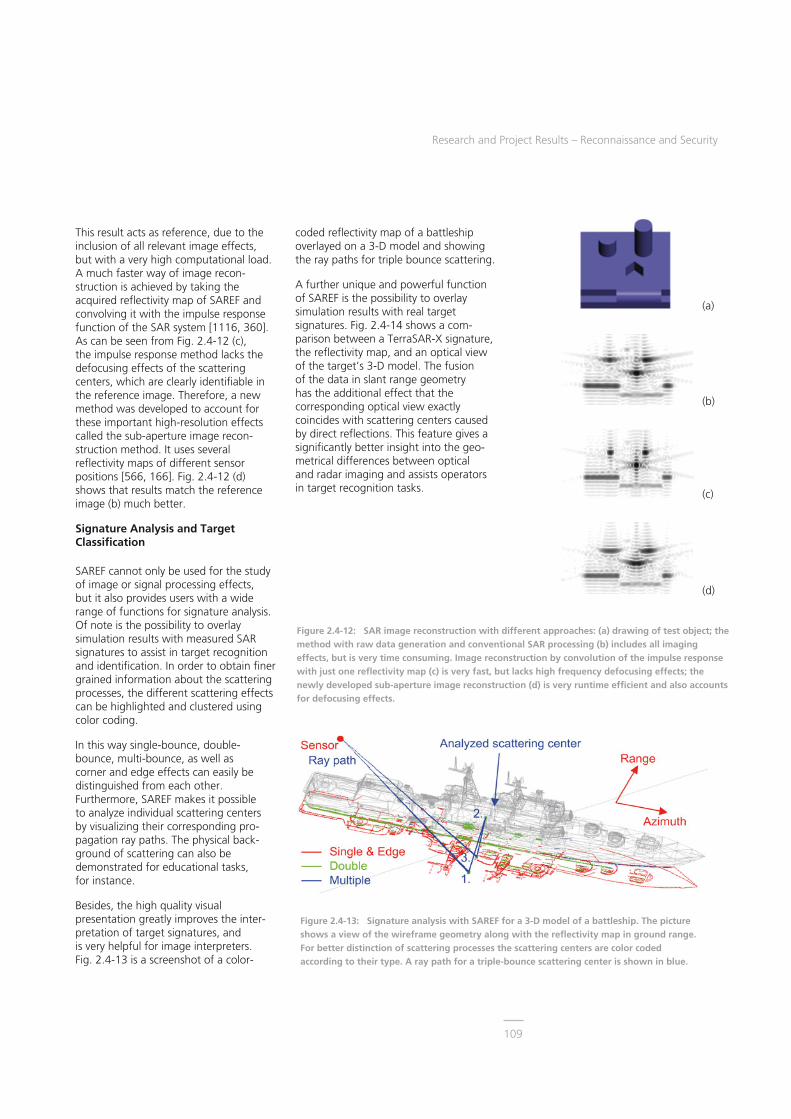
Research and Project Results – Reconnaissance and Security
109
(a)
(b)
(c)
(d)
Figure 2.4-13: Signature analysis with SAREF for a 3-D model of a battleship. The picture shows a view of the wireframe geometry along with the reflectivity map in ground range. For better distinction of scattering processes the scattering centers are color coded according to their type. A ray path for a triple-bounce scattering center is shown in blue.
Figure 2.4-12: SAR image reconstruction with different approaches: (a) drawing of test object; the method with raw data generation and conventional SAR processing (b) includes all imaging effects, but is very time consuming. Image reconstruction by convolution of the impulse response with just one reflectivity map (c) is very fast, but lacks high frequency defocusing effects; the newly developed sub-aperture image reconstruction (d) is very runtime efficient and also accounts for defocusing effects.
This result acts as reference, due to the inclusion of all relevant image effects, but with a very high computational load. A much faster way of image recon-struction is achieved by taking the acquired reflectivity map of SAREF and convolving it with the impulse response function of the SAR system [1116, 360]. As can be seen from Fig. 2.4-12 (c), the impulse response method lacks the defocusing effects of the scattering centers, which are clearly identifiable in the reference image. Therefore, a new method was developed to account for these important high-resolution effects called the sub-aperture image recon-struction method. It uses several reflectivity maps of different sensor positions [566, 166]. Fig. 2.4-12 (d) shows that results match the reference image (b) much better.
Signature Analysis and Target Classification
SAREF cannot only be used for the study of image or signal processing effects, but it also provides users with a wide range of functions for signature analysis. Of note is the possibility to overlay simulation results with measured SAR signatures to assist in target recognition and identification. In order to obtain finer grained information about the scattering processes, the different scattering effects can be highlighted and clustered using color coding.
In this way single-bounce, double-bounce, multi-bounce, as well as corner and edge effects can easily be distinguished from each other. Furthermore, SAREF makes it possible to analyze individual scattering centers by visualizing their corresponding pro-pagation ray paths. The physical back-ground of scattering can also be demonstrated for educational tasks, for instance.
Besides, the high quality visual presentation greatly improves the inter-pretation of target signatures, and is very helpful for image interpreters. Fig. 2.4-13 is a screenshot of a color-
coded reflectivity map of a battleship overlayed on a 3-D model and showing the ray paths for triple bounce scattering.
A further unique and powerful function of SAREF is the possibility to overlay simulation results with real target signatures. Fig. 2.4-14 shows a com-parison between a TerraSAR-X signature, the reflectivity map, and an optical view of the target’s 3-D model. The fusion of the data in slant range geometry has the additional effect that the corresponding optical view exactly coincides with scattering centers caused by direct reflections. This feature gives a significantly better insight into the geo-metrical differences between optical and radar imaging and assists operators in target recognition tasks.

Microwaves and Radar Institute
110
Figure 2.4-15: Optical view of the 3-D target scene with several aircraft added. The terrain geometry is textured with color-coded material settings that are used for the calculation of scattered fields.
Figure 2.4-16: Reflectivity distribution for the target scene, which contains all characteristic scattering effects.
Figure 2.4-14: Comparison of a TerraSAR-X signature of a battleship in slant-range geometry (left) with its corresponding reflectivity map (center) and an optical view of the target object (right). The positions of scattering centers in the reflectivity map closely match the ones in the real signature. Due to slant-range projection the optical view of the model data exactly coincides with direct reflection scatterers.
Simulations for Complex Target Scenes
SAREF’s highly efficient software modules and especially the optimized codes for ray tracing make it possible to process extended target scenes. For the setup of the airport scene in Fig. 2.4-15 a digital elevation model was used along with SAR and optical image data for the modeling of buildings, infrastructure, and material parameters. Furthermore, complex target objects like aircraft were included in the target scene. The reflectivity map of Fig. 2.4-16 was generated in the same way as for the target objects above. Like simulation results of single targets, it contains all relevant scattering processes, like edge and multi-bounce effects. This makes SAREF a unique multi-purpose tool for SAR simulation with a high degree of reality for a large number of recon-naissance problems.

Research and Project Results – Reconnaissance and Security
111
Figure 2.4-17: Detail of a TerraSAR-X image of the Olympic Park Munich: Filtered image with suppression of speckle noise and sidelobes using RADIAN (top); the color coding enhances the visual interpretation of the image; scatterers of corners and edges of artificial objects appear cyan while clutter areas are brown; Olympic Tower is indicated by the green frame (top), zoomed versions of the input image and the filtered one are shown bottom left and right.
2.4.5 SAR Image Analysis For reconnaissance and security applic-ations, SAR sensors have to deliver image products with sufficient quality, i.e. spatial and radiometric resolution, image size, and incidence angle for the assigned task (target detection, recognition or identification). During the operational phase of TerraSAR-X, specific image analysis tasks have been requested like time series analysis, enhancement of the radiometric resolution, such as change detection, indication of moving objects, etc. Therefore, new and innovative algorithms have been developed, especially for SAR-specific image analysis, in particular to avoid image degradation. Existing software tools and products in the open literature cannot completely fulfil the user requirements. Hence, the Radar Image Analysis (RADIAN) toolkit was developed. The development and implementation of these algorithms is based on the long-term knowledge and experience acquired with the data from the tower turntable radar Unirad (see section 2.4.7).
SAR Image Enhancement Techniques
Typical single-look SAR images are dominated by speckle noise and by clusters of strong scatterers, which make the interpretation of man-made objects more difficult than in, e.g. optical images. Also, strong scatterers can cause sidelobes, which usually have to be suppressed by weighted filtering. Such smoothing of signals is necessary, but loss of resolution should be avoided.
In RADIAN, the complex SAR image data are filtered in the spatial domain for speckle noise suppression, while pre-serving edges in the original resolution, see Fig. 2.4-17. For sidelobe suppression, a novel apodization algorithm was developed including the following principal steps: deconvolution of the slant range image in the spectral domain, estimation of a sequence of images with parameterized weighting functions serving as a basis for the optimization
criteria and generation of the resulting image by adaptive sidelobe suppression. This algorithm suppresses the sidelobes without blurring effects or mainlobe losses and it operates without any parameter estimation.

Microwaves and Radar Institute
112
Figure 2.4-18: Detail of a multi-temporal TerraSAR-X image of South Manhattan; construction activity is identifiable on Ground Zero; bright colors indicate the appearance in only one image, i.e. change has occurred.
Figure 2.4-19: Detail of the Statue of Liberty, single-look (left); four multitemporal looks superimposed (center); optical view by SAREF (right). The multitemporal image shows enhanced image qualtity as there is clear suppression of speckle noise at full resolution; statue, base, land and sea are well separated.
Multitemporal Image Analysis
Incoherent change detection is useful to identify changes in the mean back-scattered power of a scene on a pixel-to-pixel basis by using time series of images. A basic precondition of superimposing multitemporal images is the availability of almost identical observation angles for the scene of interest. Angle-dependent projection effects and anisotropic scattering behavior inherent in radar images can lead to false alarms, especially true when repeat-pass orbits are not available. The RADIAN tool has a very sophisticated co-registration algorithm and enables the generation of an image stack from a large number of single-look images, in order to monitor a scene by multi-temporal image analysis. This kind of SAR imaging is a significant aid for visually detecting individual objects and for extracting information concerning shape, size, context and temporal behavior within a high density of man-made structures. The example in Fig. 2.4-18 shows how construction activities are highlighted in multi-temporal images.
A further characteristic of multi-temporal image processing is the improvement of the radiometric resolution. Fig. 2.4-19 shows the comparison between a four- and a single-look image and demonstrates the speckle noise reduction inherent to multi-looking.
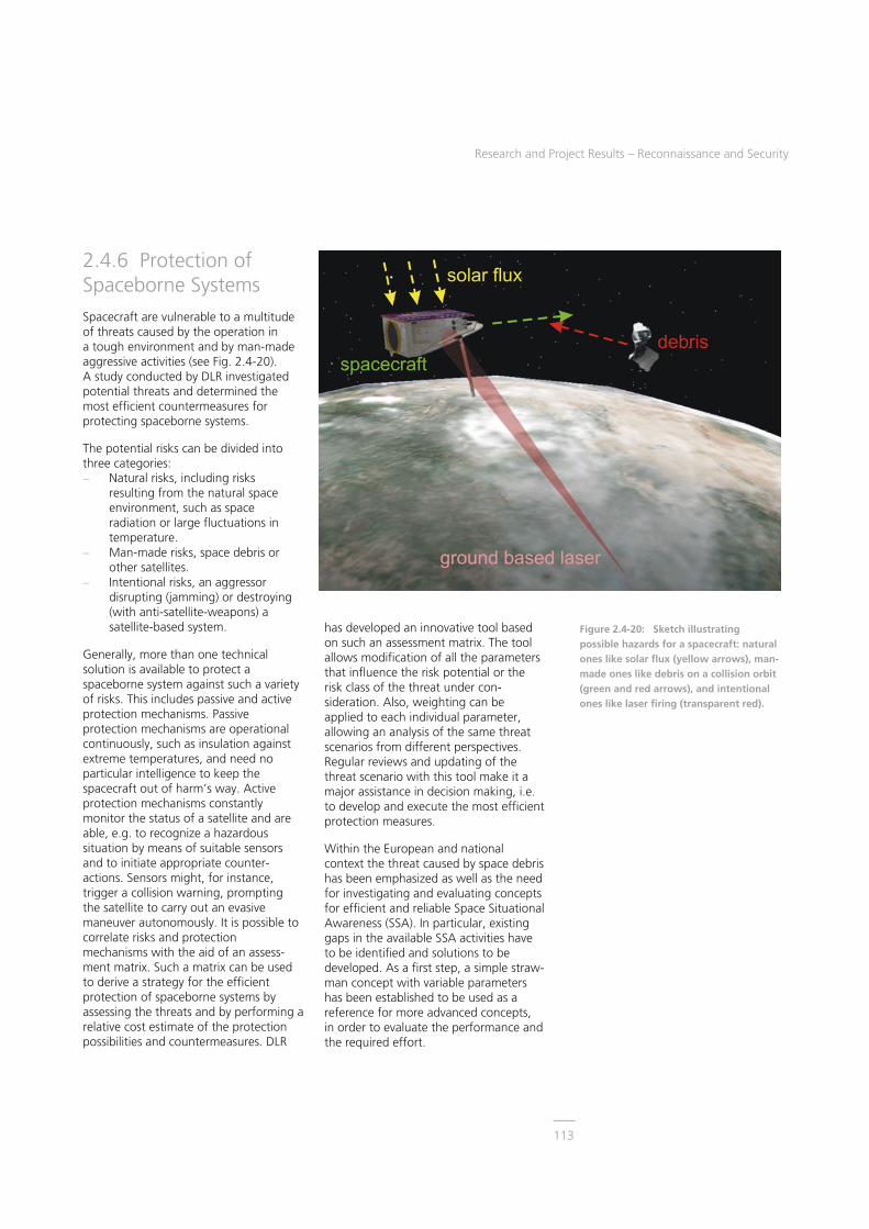
Research and Project Results – Reconnaissance and Security
113
2.4.6 Protection of Spaceborne Systems Spacecraft are vulnerable to a multitude of threats caused by the operation in a tough environment and by man-made aggressive activities (see Fig. 2.4-20). A study conducted by DLR investigated potential threats and determined the most efficient countermeasures for protecting spaceborne systems.
The potential risks can be divided into three categories: � Natural risks, including risks
resulting from the natural space environment, such as space radiation or large fluctuations in temperature.
� Man-made risks, space debris or other satellites.
� Intentional risks, an aggressor disrupting (jamming) or destroying (with anti-satellite-weapons) a satellite-based system.
Generally, more than one technical solution is available to protect a spaceborne system against such a variety of risks. This includes passive and active protection mechanisms. Passive protection mechanisms are operational continuously, such as insulation against extreme temperatures, and need no particular intelligence to keep the spacecraft out of harm’s way. Active protection mechanisms constantly monitor the status of a satellite and are able, e.g. to recognize a hazardous situation by means of suitable sensors and to initiate appropriate counter-actions. Sensors might, for instance, trigger a collision warning, prompting the satellite to carry out an evasive maneuver autonomously. It is possible to correlate risks and protection mechanisms with the aid of an assess-ment matrix. Such a matrix can be used to derive a strategy for the efficient protection of spaceborne systems by assessing the threats and by performing a relative cost estimate of the protection possibilities and countermeasures. DLR
has developed an innovative tool based on such an assessment matrix. The tool allows modification of all the parameters that influence the risk potential or the risk class of the threat under con-sideration. Also, weighting can be applied to each individual parameter, allowing an analysis of the same threat scenarios from different perspectives. Regular reviews and updating of the threat scenario with this tool make it a major assistance in decision making, i.e. to develop and execute the most efficient protection measures.
Within the European and national context the threat caused by space debris has been emphasized as well as the need for investigating and evaluating concepts for efficient and reliable Space Situational Awareness (SSA). In particular, existing gaps in the available SSA activities have to be identified and solutions to be developed. As a first step, a simple straw-man concept with variable parameters has been established to be used as a reference for more advanced concepts, in order to evaluate the performance and the required effort.
Figure 2.4-20: Sketch illustrating possible hazards for a spacecraft: natural ones like solar flux (yellow arrows), man-made ones like debris on a collision orbit (green and red arrows), and intentional ones like laser firing (transparent red).

Microwaves and Radar Institute
114
2.4.7 Ground-Based Radar Systems Universal Radar System (Unirad)
Modern radar applications for recon-naissance and security make use of highly resolved descriptions of the radar cross section (RCS) distribution, this being necessary for advanced target recognition. Polarimetric features can act as an additional information source, allowing primarily the identification of scattering mechanisms. The use of different wavebands, e.g. from P to Ku-band, enable different scattering and penetration phenomena to be revealed for complicated objects. To investigate the potential of these capabilities experimentally, and for collecting true radar signatures, the Unirad radar system was developed [679].
Unirad was designed as a stepped-frequency radar to be used for Inverse Synthetic Aperture Radar (ISAR) imaging in a tower-turntable environment, and for the application as a ground-based SAR mounted on a platform moving along a road or a railtrack. Unirad covers L/S, C, X, and Ku-band, where for L/S-band a total bandwidth of 3 GHz and for the others 4 GHz can be used. It has two transmit (TX) and two receive (RX) channels, which can be used for fully-polarimetric imaging, when both the two TX and the two RX channels are connected to a horizontally (H) and a vertically (V) linearly polarized antenna. In addition, the two TX and RX channels can be used as independent channels for the same polarization in order to investigate multi-channel radar architectures or bistatic modes. The high-frequency signals of all wavebands are down-converted to the identical inter-mediate frequency (IF) and split into the in-phase (I) and quadrature (Q) com-ponent prior to digitizing. A maximum of 4000 single frequencies can be adjusted per frequency sweep, resulting in a minimum step size of 1 MHz at maximum bandwidth. Hence, the
maximum unambiguous range is limited to 150 m.
Fig. 2.4-21 top shows a photograph of Unirad and its major subunits mounted on a railtrack for fully-polarimetric SAR imaging. The bottom image shows the RCS distribution of a car for 5 cm spatial resolution as a Red-Green-Blue (RGB) superimposition of all polarimetric signatures. Many details represented by tiny scattering centers can be observed. The VV channel in green appears to be dominant all over the car, while the front part roughly shows the same signal strength for the VV and HH polarization combination, shown in yellow. The left and right front parts also show some cross-polarising behavior especially around the headlight region, visible as small blue spots.
Fig. 2.4-22 shows a series of SAR images of the same car with open doors and open hatchback. The SAR images are superimposed on an optical image taken from a bird’s eye perspective, in order to relate individual scattering centers to physical objects on the car. The SAR images were processed to four different spatial resolutions, in order to illustrate the loss of information as the resolution decreases. While the 5 cm image allows the detection of many fine scattering centers around the car, the coarse resolution of 80 cm can only indicate the existence of one or two scatterers. Note that, today, the spatial resolution for civilian spaceborne SAR systems is still worse than 80 cm.
Digital Radar System (Gigarad)
High-resolution imaging for large fields of view is a challenging task for many modern radar systems, due to the technologically contradicting requirements. The use of digital technology can replace much of the analog hardware and allow flexible focusing in a computer. This requires high-speed analog-to-digital converters and a high analog bandwidth. The MIMO concept (Multiple Inputs Multiple Outputs) promises many advantages
Figure 2.4-21: Top: photograph of Unirad on a railtrack for SAR imaging; bottom: RGB superimposition of the X-band RCS of a car for all polarimetric channels (only the front part of the car is shown, radar illumination looking towards the car).
Figure 2.4-22: Series of X-band RCS images for HH polarization and different levels of spatial resolution (indicated top left). For better comparison, the SAR images have been made transparent below a certain RCS level, in order to superimpose them correctly in size in relation to their optical equivalent (radar illumination from bottom).

Research and Project Results – Reconnaissance and Security
115
Scene on rotatingplatform
Transmitantenna CH2
Transmitantenna CH1
Receiveantenna
Figure 2.4-24: Photograph of a small truck (top) and its 3-D ISAR image for the perspective of about 45° elevation and 45° azimuth (bottom).
compared to traditional radar architectures. The simultaneous trans-mission of appropriately designed signals in the same waveband allows their dis-crimination on receive. Especially, this requires high-speed digital-to-analog converters. Such techniques are realized in Gigarad by using both multiple wideband output and input channels [865, 1074, 1075].
For a first proof of concept, a simple X-band architecture using one input and two output channels based on the heterodyne principle was selected, as illustrated in Fig. 2.4-23 [779, 1053]. Basically, this system can be operated using two simultaneous transmit and up to four simultaneous receive channels with a maximum bandwidth of 3 GHz. In the configuration shown, two independent arbitrary signals are generated and transmitted in parallel, being simultaneously received by one common receiver. Further additional transmit and receive channels can be added on demand, due to a modular system concept. For coherent focusing, a simple matched filter approach is applied by correlating the received signal with a stored reference.
Fig. 2.4-25 shows the impulse response of a corner reflector at a distance of 28 m (top, center) with the radar trans-mitting two different noise signals of 2 GHz bandwidth. The correlation of the received signal with the matching
transmitted waveform shows the typical sinus(x)/x behavior as expected from theory (top). More interestingly, the correlation with the other unmatched waveform (center), which is also a noise sequence but with a different coding, is suppressed by about 50 dB. Hence, a high discrimination for various radar applications is possible, which can be additionally improved by using longer sequences. Similarly, an ISAR image of several locally distributed corner reflectors was generated (bottom) by coherently processing subsequent range profiles for one aspect angle, as measured by the tower-turntable arrangement shown in Fig. 2.4-23, right.
Data Processing and Advanced Imaging Modes
Inverse SAR (ISAR) allows the collection of very precise high-resolution radar signatures from objects. For a spaceborne radar system, the imaging geometry is similar, differing only by geometrical transformation and rotation. Using ISAR techniques, a high spatial resolution in the decimeter range or higher is accomplished by rotating an object on a turntable with respect to a spatially fixed broadband radar system, and by recording a sequence of corresponding range profiles within a specific azimuth angular range [389, 577, 578].
Despite the high resolution, visual object recognition is usually difficult, in
Figure 2.4-23, left: Block diagram of the first test configuration of Gigarad; right: measurement setup for the ISAR experiments.

Microwaves and Radar Institute
116
24 26 28 30 32Range [m]
0
-20
-40
-60
-80
Am
plit
ud
e [d
B]
24 26 28 30 32Range [m]
0
-20
-40
-60
-80
Am
plit
ud
e [d
B]
24 26 28 30 32Range [m]
0
-20
-40
-60
-80
Am
plit
ud
e [d
B]
24 26 28 30 32Range [m]
0
-20
-40
-60
-80
Am
plit
ud
e [d
B]
Figure 2.4-25: Measured X-band impulse responses (range profiles) for noise-coded transmit waveforms using the same frequency bands. Top: Both channels 1 and 2 were transmitting simultaneously using different coding, the received signal was correlated with both codes. Center: Only channel 2 was transmitting, the received signal was correlated with both codes. Bottom: ISAR reconstruction of five corner reflectors for channel 1, where two orthogonal signals were transmitted simultaneously in channel 1 and 2.
particular for the typical 2-D images of the RCS distribution. Therefore, specific tower-turntable ISAR measurements were carried out for generating 3-D datasets by spanning a synthetic aperture not only in azimuth (by rotating the turntable), but also in elevation (by sub-sequent tilting of the turntable). Hence, the acquired data consist of samples in the spatial frequency domain on a spherical grid. The image generation can now be accomplished by coherent integration of the calibrated raw data in the spatial frequency domain. The polar format method enables the use of a 3-D Fast Fourier Transform (FFT) with the correct localization of the raw data samples in the spectral domain. Therefore, interpolation is necessary, in order to transfer the spectral data onto an orthogonal equidistant grid. The interpolation is undertaken by over-sampling as follows. The spectral raw data samples are relocated on a finer zero-padded grid. A first 3-D FFT is applied to have the data in the image domain, yielding the image. The am-biguities depend on the oversampling factor. Now, by applying an inverse FFT of these data, the focused unambiguous area in the central area is extracted. A subsequent zero-padding procedure and another 3-D FFT enable the recon-struction of an up-sampled image.
High resolution 3-D images enable the analyst to arbitrarily change the perspective of the imaged object considerably, facilitating visual image interpretation. Now, the single scattering centers can be individually assigned to specific parts of the object under test. In order to enhance the visual perception, all single 3-D images for a complete turntable rotation can be incoherently superimposed. An example of such experiments is shown in Fig. 2.4-24. This projection of the 3-D image especially reveals the wheel rims, the front mud-guards, and the rear corners of the cargo area of the vehicle. Close to the vehicle sides, four additional small radar reference trihedrals on the turntable are visible in the radar image [725].
2.4.8 Radiometry and Security Applications Radiometry addresses the domain of the passive measurement of the natural, thermal electromagnetic radiation of matter at a physical temperature above 0 K. In the case of microwave or millimeter-wave Earth observation, significant contrasts can be observed between reflective and absorbing materials, due to the impact of reflected sky radiation of cosmic origin. The incident radiation power measured by a radiometer system is usually expressed in an apparent temperature, the brightness temperature. For Earth observation, an approximate range from 3 K to more than 300 K can be observed. The spatial two-dimensional brightness temperature distribution can be used as a daytime and almost weather independent indicator for many different physical phenomena [510]. Based on a large experience in using radiometric imaging, the focus now is more on various security applications [124, 211, 250, 282, 314, 403, 404].
The continuous threats by international terrorism increase the danger to the public and create a new and more complex threat dimension. This evolution can only be combatted by the application of new counter-measure methods like advanced imaging technologies for surveillance and the detection of concealed dangerous objects. For the observation of a variety of security critical premises, borders, and maritime coastal areas, there is a strong demand on wide field-of-view imaging for intruder detection under all adverse ambient conditions. The imaging of persons with respect to weapons and explosives detection is of increasing interest, particularly for airlines, transportation services, or public events with large crowds [281, 285].
The penetration capability of microwaves allows the detection of objects through atmospheric obstacles, like bad weather, fog, dust, vapor and smoke, as well as

Research and Project Results – Reconnaissance and Security
117
Figure 2.4-27: Top: SUMIRAD in an operational scenario, mounted on a vehicle while continuously observing the area of interest in front of the vehicle (orange). Bottom: System with the two facing dish antennas connected to radiometer receivers with a rotating deflection plate in the center.
through thin non-metallic materials and clothing. For the latter, the detection of hidden objects like weapons, explosives, and contraband is possible by monitoring dielectric anomalies. Furthermore, the acquisition of polarimetric object characteristics can increase the detection capability by gathering complementary object information. Based on the physical principles of microwave radiometry, images have a quasi-optical appearance, simplifying the image interpretation for the operator. In addition, the sensor operation is inherently passive and covert.
Concealed Object Detection
Various methods to record high-resolution and high-sensitivity images in close to real-time exist at least theoretically. Apart from performance, the hardware complexity and cost are a major driver for the system design. Nowadays, the full electronic scanning of a scene is still very expensive, so that fully mechanical imagers are still attractive, in particular for experimental equipment for signature measurements and pheno-menological studies. Consequently, various innovative mechanical imaging techniques have been developed. The LPAS-1 and LPAS-2 systems will be briefly discussed (LPAS – Laborsystem zur Personen-Abbildung mit Scanner).
LPAS-1 [1120] and LPAS-2 [1105, 1099] were primarily designed to be used for low-cost, near-field experiments on applications, like people screening at a distance of a few meters. Both imaging principles based on one receiver are shown in Fig. 2.4-26. For LPAS-1 a rotating metallic and flat deflection plate reflects the incoming radiation towards a Cassegrain antenna connected to the radiometer receiver, resulting in an image line. The second image dimension is recorded by moving the whole construction vertically up and down. At a distance of about 3 m, the spatial resolution is in the order of 2-3 cm and the sensitivity is in the order of 1 K for both systems.
For LPAS-2, the radiation is collected on a circular trajectory rotating the subreflector of a modified Cassegrain system at high speed. Vertical movement of the unit delivers the second image dimension. The advantage of the LPAS-2 principle is that the antenna beam is always kept on the target. The disadvantages are that the main reflector has to be larger than dictated by spatial resolution, and correct beamforming is much more difficult, due to beam distortion. The patented LPAS-2 principle is also applicable for high-resolution spaceborne Earth observation.
In addition to extensive laboratory use, the LPAS-1 system was run in a quasi-operational fashion together with other sensors on a national and NATO-related trial (Common Shield trial number 7 focused on “Defense Against Terrorism” - DAT#7) [182, 211]. One component of the comprehensive trial was the simulation of an operational portal or entrance area, as it can be found at checkpoints to sensitive or critical infrastructure and military camps and facilities. Such a portal was established by using a large standard military tent as shown in Fig. 2.4-28, together with a typical measured result. Different types of people, soldiers and civilians wearing uniforms or arbitrary clothing were asked to pass through the portal. The sensor operators were not informed about any object the test persons were carrying concealed or visible. Almost all concealed objects of 47 test persons were able to be detected, even in frequently changing background conditions dry tent and a very wet tent. However, in some cases the discrimination from false targets generated by skin reflections is ambiguous and needs further investigations.
Figure 2.4-26: Imaging principles of the fully mechanical radiometer scanners LPAS-1 (top) and the LPAS-2 (bottom).

Microwaves and Radar Institute
118
Figure 2.4-28: Photograph of a military tent simulating an entrance portal (top). Framed in orange the LPAS-1 scanner wrapped in black foil and an operator are visible inside the tent. LPAS-1 image and corresponding photograph (center), a person with a handgun in the belt, and (bottom) a person with a dummy explosives belt are shown. Both illicit objects are covered by clothing and identified by the orange ellipses.
The proof of concept and the capabilities of LPAS-2 have been demonstrated under laboratory conditions, as shown for selected results in Fig. 2.4-30. In principle, the higher image quality could be achieved. However, both LPAS systems have been constructed as robust, one-receiver devices without specified size and weight optimization. Conse-quently, the image acquisition time for an area of about 1.5 m x 1 m in height and width cannot be faster than about 10 s (for protection of the mechanical parts, mostly 20-25 s per image was used). It is expected that a suitable optimization would allow frame rates of up to one image per second. Sequences of images at such a rate and from several different perspectives can considerably improve detection and recognition capabilities of such sensor systems.
Surveillance of Critical Infrastructures and Situational Awareness
Nowadays, armed forces are confronted with a variety of military operations, especially in the context of the sur-veillance of critical infrastructure. The early detection of possible threats by means of advanced reconnaissance and surveillance sensors will be an important advance. The aim of the SUM project (Surveillance in an Urban environment using Mobile sensors), funded by the European Defence Agency (EDA), is to develop a low-cost multi-sensor, vehicle-based surveillance system in order to enhance situational awareness for moving military patrols, as well as for static checkpoints. The system will detect potential threats and present them via a man-machine-interface to an operator. For a reliable system that can operate 24 hours a day in various conditions (e.g. dust, fog, smoke, rain), the sensor suite includes an optical camera, an infrared camera, a radar and an imaging radiometer at millimeter wavebands [940, 845, 846, 844].
The SUM Imaging Radiometer (SUMIRAD) generates quasi-optical millimeter-wave images at W-band frequencies close to real time. SUMIRAD can detect and locate objects and persons under all atmospheric conditions and behind non-metallic materials like clothing, thin walls, and thin vegetation. A low-cost, innovative and light-weight, fully-mechanical scanning system using only two radiometer receivers provides a large field of view for high performance, two-dimensional imaging. As shown in Fig. 2.4-27 (bottom), two radiometer systems are positioned at the opposite sides of a rectangular frame orientated towards a rotating deflection plate located in the center. Thus, each receiver scans a corresponding part of a horizontal image line, both overlapping in front of the system. A vertical seesaw motion of the whole frame delivers the second image dimension and determines the achievable frame rate of the imager. Characteristic figures are: angular resolution 0.7°, sensitivity < 2 K, image acquisition time 1 s, field of view 80° x 30°. For final operation the SUMIRAD system will be mounted on a suitable vehicle as shown in Fig. 2.4-27 (top). SUMIRAD con-tinuously observes the area of interest in front of the vehicle (orange area) while the vehicle drives along the road [786, 781, 782, 785].
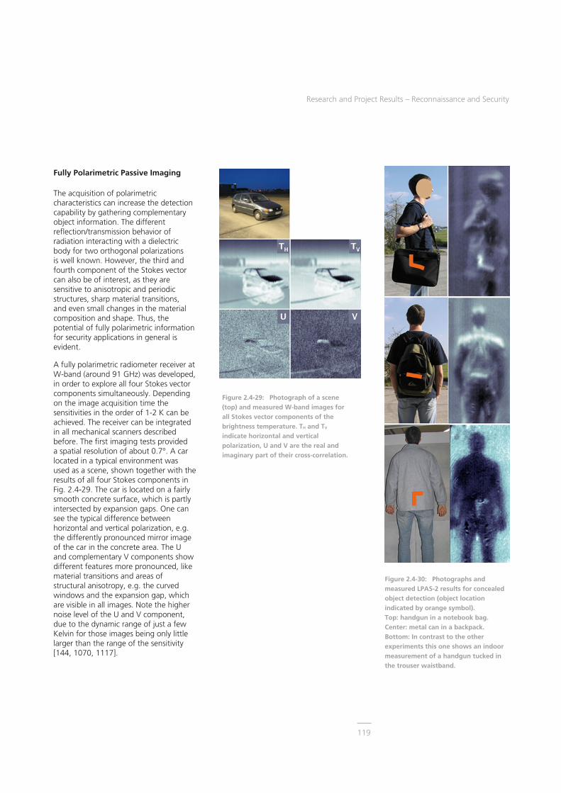
Research and Project Results – Reconnaissance and Security
119
Figure 2.4-30: Photographs and measured LPAS-2 results for concealed object detection (object location indicated by orange symbol). Top: handgun in a notebook bag. Center: metal can in a backpack. Bottom: In contrast to the other experiments this one shows an indoor measurement of a handgun tucked in the trouser waistband.
Fully Polarimetric Passive Imaging
The acquisition of polarimetric characteristics can increase the detection capability by gathering complementary object information. The different reflection/transmission behavior of radiation interacting with a dielectric body for two orthogonal polarizations is well known. However, the third and fourth component of the Stokes vector can also be of interest, as they are sensitive to anisotropic and periodic structures, sharp material transitions, and even small changes in the material composition and shape. Thus, the potential of fully polarimetric information for security applications in general is evident.
A fully polarimetric radiometer receiver at W-band (around 91 GHz) was developed, in order to explore all four Stokes vector components simultaneously. Depending on the image acquisition time the sensitivities in the order of 1-2 K can be achieved. The receiver can be integrated in all mechanical scanners described before. The first imaging tests provided a spatial resolution of about 0.7°. A car located in a typical environment was used as a scene, shown together with the results of all four Stokes components in Fig. 2.4-29. The car is located on a fairly smooth concrete surface, which is partly intersected by expansion gaps. One can see the typical difference between horizontal and vertical polarization, e.g. the differently pronounced mirror image of the car in the concrete area. The U and complementary V components show different features more pronounced, like material transitions and areas of structural anisotropy, e.g. the curved windows and the expansion gap, which are visible in all images. Note the higher noise level of the U and V component, due to the dynamic range of just a few Kelvin for those images being only little larger than the range of the sensitivity [144, 1070, 1117].
Figure 2.4-29: Photograph of a scene (top) and measured W-band images for all Stokes vector components of the brightness temperature. TH and TV indicate horizontal and vertical polarization, U and V are the real and imaginary part of their cross-correlation.

Microwaves and Radar Institute
120
Figure 2.4-31: Top: Photograph of the experimental aperture synthesis radiometer ANSAS using a rotating linear thinned array. Center: Fish-eye photo-graph of the observed scene. Bottom: Superimposed reconstruction result of the ANSAS instrument for nine different center frequencies.
Advanced Imaging Methods
Very often the main requirements for an imaging radiometer system are high resolution in parallel with low image acquisition time. Full electronic scanning would be preferred, but for budget constraints novel imaging principles using highly thinned arrays, like aperture synthesis, are also suitable. Consequent-ly, research on application-oriented, high-performance low-cost solutions is per-formed. Two concepts are outlined next, the imaging low-frequency spectrometer with aperture synthesis, ANSAS [124, 202, 268, 576, 653, 693, 939, 1096], and the fully electronic scanner with aperture synthesis, VESAS [156, 221, 1115, 1122].
In order to obtain comprehensive scene information coupled with concealed object detection, a spectral analysis at lower microwave bands (L to C-band) is suitable. Such requirements can be addressed by using a broadband, multi-channel aperture synthesis technique. The ANSAS proof-of-concept demonstrator is a one-dimensional aperture synthesis array working in the frequency range of 1.4–6.5 GHz. The second image dimension is per-formed by array rotation, leading to a hybrid system of mechanical scanning and electronic beam steering. This con-figuration was chosen as a compromise effort between short imaging time, hardware expense and cost. This approach allows the investigation of spectral imaging combined with high-resolution aperture synthesis beam-forming. The use of longer microwaves is essential for sufficient penetration of dielectric materials. Since a narrowband measurement around a single center frequency gives limited information with respect to dielectric constant and physical structure of an object, the use of multiple narrow-band channels is preferable. The different spectral images can be analyzed individually or in combination, and the detection of concealed objects like buried landmines is considerably improved.
Fig. 2.4-31 (top) shows a photograph of the realized ANSAS system. The linear array is rotatable by 360° and the tilt angle of the rotation plane is adjustable. ANSAS is mounted on a mobile base frame for transportation. The thinned array of 2.8 m length contains 15 individual receiver elements, providing a highest spacing of 79 times the minimum spacing. Hence, the theoretical angular resolution is about 0.9° for maximum frequency at boresight, and about 4.4° for lowest frequency. The corresponding 105 complex correlators are implemented digitally with 1-bit quantization on a FPGA (Field Programmable Gate Array). The complete system control and measurement procedure are performed on a personal computer.
For experiments, ANSAS was mounted at an elevation of 8 m above ground, providing a perspective to the scene as shown in Fig. 2.4-31 (center). The bore-sight direction was aligned to point about 12° below the horizon, which is consequently curved and shifted upward from the image center. The main parts of the scene are grassland and some irregular gravel heaps from building work. In a vertical direction the ground is divided by rail tracks pointing straight towards the horizon. Right of the image center, a 5 x 5 m2 metal plate was placed on ground, which appears as a 1.7 x 4 m2 trapezoid, due to the perspective. The metal plate reflects cold sky radiation towards the sensor providing a high contrast compared to the background. The reconstructed image in Fig. 2.4-31 (bottom) is a super-imposition of nine single-frequency images between 3 and 6.5 GHz, chosen to avoid radio interference. Many frequency bands in this range are used for communication and radar applications and, consequently, careful selection is important. No calibration has been applied yet. Hence, the color coding represents a linearly increasing brightness temperature from black to white. The horizon between the cold sky and the warm Earth region can be clearly identified. Also, a small tower and some

Research and Project Results – Reconnaissance and Security
121
Figure 2.4-32: Left: Drawing of the VESAS system; right: photograph and reconstructed brightness temperature map of a test scene consisting of various metallic and non-metallic objects located on grassland. The measurement was carried out by a two-element interferometer with variable baseline built by two channels of the VESAS instrument.
forested areas along the horizon are detectable. The metal plate appears as a cold target, being easily distinguishable from the warm background as a trapezoidal structure. The rail track region can be also identified. Not all the impacts of the non-ideal system have been compensated for, leading to some residual artifacts in the reconstructed images. In addition, it was shown that such a wideband imaging system can be used for the detection and localization of artificial transmitters.
By VESAS, a concept for novel, low- cost fully electronic scanning was investigated. Two-dimensional scanning is realized by frequency scanning in one direction, i.e. beam steering by changing the received frequency band, and one-dimensional aperture synthesis in the other direction, as illustrated in Fig. 2.4-32 (left). The design goals, in this case, are to achieve a frame rate of around one second at Ka-band, a spatial resolution of about 0.4° in both dimensions and a field of view around
15° x 30°. The frequency dependent beam steering of the slotted waveguide antenna provides an image line. Spatial frequency sampling in the orthogonal direction is achieved by a low-redundancy, thinned array of the antennas. In this direction, the recon-struction of the brightness temperature profile can be accomplished by a Fourier transform for an ideal system. Fig. 2.4-32, right, shows a first imaging result for a test scene consisting of several metallic and non-metallic objects surrounded by grassland. Note that here a two-element interferometer with variable baseline was used and the angular beam steering in the vertical direction (indicated in angles) was done by frequency steering. Many objects can be clearly identified. This result confirms the basic feasibility of combining aperture synthesis and frequency beam steering. However, improvements with respect to calibration, error correction, and image reconstruction are under investigation. Despite a high degree of thinning still more than 30 receivers will

Microwaves and Radar Institute
122
be required for an operational system, which would be very costly and bulky if constructed using discrete receiver components. Consequently, the development of a highly integrated Ka-band module using MMIC (Monolithic Microwave Integrated Circuit) technology was chosen.
The use of MMIC technology allows a very compact low-cost, low-weight, and compact construction for the complete receiver. Hence, for VESAS, the develop-ment of an integrated passive microwave radiometer receiver operating at a center frequency of 37 GHz was initiated [1049, 1072, 1097, 1107]. An RF bandwidth > 6 GHz is required for sufficient frequency beam steering, the rejection of the image frequency band must be higher than 15 dB for the application of aperture synthesis, and the receiver noise figure should be as low as possible for a sufficient radiometric sensitivity. The receiver design is kept rather general in order to be usable for other applications, like focal-plane-arrays or multi-channel coherent radar systems. At present the experimental layout version is split into two modules, in order to provide measurement interfaces for performance verification and modifications. Fig. 2.4-33 illustrates the in-house manufactured modules realized in microstrip and coplanar technology using wire bonds and ribbons for the electrical connection of the MMIC dies. The RF/IF part (top) of the receiver module consists of two low-noise amplifiers (LNA), an active in-phase/quadrature-phase (I/Q) mixer, and a 90° hybrid divider in order to perform the image frequency rejection. The LO section (bottom) consists of a phase shifter, an active frequency doubler, and a band-pass filter. The input LO frequency can be in the range of 8.5 GHz to 10 GHz. In combination with the external frequency doubler and a second one integrated in the mixer MMIC, the input frequency at the mixer itself is in the range of 34 GHz to 40 GHz. At the output of the RF/IF module it is possible to use either the upper sideband (USB), the lower sideband (LSB), or both, each
one with an IF bandwidth of maximum 500 MHz, at present limited by the IF hybrid. The circuit fulfils the require-ments and offers a low receiver noise temperature of less than 450 K across the whole band. The combination of the two modules on one common layer is planned next.
Figure 2.4-33: In-house designed and manufactured prototype of the integrated Ka-band radiometer receiver; top: RF/IF module; bottom: LO module.

Research and Project Results – Reconnaissance and Security
123
2.4.9 Radar Signatures Signature Simulation and Measurements
Numerical simulation of radar signatures is an important and integral part of the signature analysis. Scattering properties of many targets can be numerically estimated, thus avoiding the need for expensive manufacturing and measure-ments. Simulation of the scattering of microwaves is difficult, however, because of the large electrical size of targets of interest. Even with modern computational technologies, numerical simulation of scattering from targets such as an aircraft, a ship or a car is often impractical or even impossible. Radar imaging of electrically large targets is even more difficult because of the need for multiple evaluations of scattered fields over a range of frequencies and scattering angles. New applications at even higher frequencies (K and W-bands, Terahertz) and the use of advanced materials, e.g. metamaterial (MTM) anti-reflection coatings, further complicate the use of exact numerical methods like MoM, FEM and FDTD. Hence, the simulation of scattering of microwaves requires the development of approximate simulation tools, being physically justified, and rapid estimations, while providing acceptable accuracy.
BISTRO, a software package for the simulation of electromagnetic scattering from electrically large artificial scatterers, is being developed at the Institute. The package is based on Physical Optics (PO) and several extensions of PO. It is the result of extensive research work [63, 84, 86, 113, 401, 402, 509, 583, 584, 699]. Implemented features include monostatic and bistatic radar configurations, simulation of anti-reflection coatings made from advanced materials, targets in free space and over an underlying surface, as well as the calculation of fields, scattering matrices and various scattering cross sections. Compared to existing high-frequency scattering simulation codes, BISTRO provides a
number of unique features: (1) coatings of non-metallic and advanced materials (RAM, FSS, MTMs); (2) improved simulation of multiple scattering through multiple application of PO; (3) edge corrections for non-metallic surfaces.
The clear physical concept results in the modular structure of the package with every module responsible for a specific scattering mechanism. Further extensions can be made by simply adding corresponding extension modules. The developed modules of BISTRO have been verified in the framework of various DLR internal projects (TRAMRAD, UCAV-2010, FFT and FFT-2) through comparisons with experimental results and by application to canonical scatterers (spheres, discs, plates), for which exact solutions are available [139, 330, 402, 558, 633, 898]. Further features to be implemented in the future include rough scattering surfaces, electrically small features on the scattering surface and the generation of radar images.
Fig. 2.4-34 illustrates the accuracy and some of the features of BISTRO that have been developed in the past five years. The figure shows the bistatic scattering cross section of a metallic cube with a side length about 6� coated with a low-reflection metamaterial. The coating has been designed by using metamaterial technology such that its reflection co-efficient is at minimum at the frequency 36.925 GHz. The cube is illuminated by a plane wave incident at an angle 10° with respect to the normal to a face of the cube, and the observation point moves around the cube in the plane of incidence. The coating is applied to the three sides of the cube that are seen from the source and from the receiver. The bistatic scattering cross section of the cube without coating has been used as a reference (black line, red line, green line). The results for the coated cube (blue line, magenta line, yellow line) confirm a significant reduction in the scattering cross section due to the coating, giving good agreement between measurement and simulation, as well as
Figure 2.4-35: Polarimetric bistatic scattering measurement facility.
Fig. 2.4-34: Bistatic scattering cross section of a metallic cube with and without low-reflection coating. Bistatic angle 0° corresponds to the case of backscattering and the angle 20° to the direction of specular reflection from the front face of the cube.

Microwaves and Radar Institute
124
Figure 2.4-36: Clutter map simulation of mountainous region of �Hoher Freschen�, produced by DORTE.
Figure 2.4-37: Monostatic specific RCS of a fractal water surface (PO approximation for 3 GHz; pol.: VV, temp.: 15° C, salinity: 0%).
between exact (FEM solver HFSS®, ANSYS) and approximate (BISTRO) numerical simulations. As the cube is a configuration with long and sharp edges, simulation with BISTRO required the use of edge corrections. The simulation accuracy of BISTRO improves with increasing electrical size of targets.
Several simulations have been produced applying the bistatic RCS model SIGRAY, which is based on the Shooting and Bouncing Rays Method (SBR). SIGRAY itself as well as the corresponding GUI has been improved in many respects [1026]. Investigated targets were, e.g. deformed and wet trihedral corner reflectors, dihedrals and workshop test manufactured geometries [125, 600, 694].
The polarimetric bistatic scattering measurement facility operating in W frequency band is of great importance for validating numerical results. It has been rebuilt in the TechLab building (see Fig. 2.4-35). Several mechanical components have been replaced and new W-band front-ends are now used. Having stable temperature conditions, the accuracy of the new setup is considerably improved. Various signature measurements, quasi-monostatic, as well as bistatic, on different canonical test objects and scaled realistic targets have been performed successfully.
Clutter Simulation
To assess the radar cross section of extended targets (e.g. terrain, water surfaces) the simulation tool DORTE (Detection of Objects in Realistic Terrain) has been developed. It utilizes solely information on topography and land cover to estimate the position-dependent monostatic clutter return (see Fig. 2.4-36). It can be easily extended to also consider bistatic configurations.
The identification of shadowed regions results from employing a specialized hidden surface algorithm. Akima splines are used for rescaling digital elevation models, as well as for determining local normal vectors necessary for the calculation of the local clutter return. The computer code uses statistical and fractal, as well as (semi-)empirical clutter models to estimate the radar cross-section of each surface element (see Fig. 2.4-37). Semi-empirical and fully-empirical models are based on measure-ments possibly backed by theoretical considerations (e.g. Currie-Zehner, Attema-Ulaby, Billingsley, Kulemin, Georgia Institute of Technology, Technology Service Corporation). There exists a copious amount in literature ranging from very simple to highly specialized cases [354].
In order to examine the influence of certain environmental parameters, the surface may be modelled using statistical functions (RMS height and exponential or Gaussian correlation function) or fractal Weierstrass-Mandelbrot functions. These models are based on physical optics or the small perturbation method (fractal only). The scattering material is characterized by a mixture model of dielectric constants. For certain clutter models, statistical variation of the calculated clutter return may be added by setting a switch. In order to reduce calculation time, the pre-calculated RCS characteristics of azimuth independent clutter can be stored in a dedicated MySQL database. The program itself is operated by means of a graphical user interface.
To sum up, DORTE presents a novel and flexible tool for efficiently and quickly predicting the backscattering cross section of extended targets. A wide range of new diverse and freely assignable clutter models is utilized [77].
Figure 2.4-38, top: Drawing of a radome and the antenna inside. Individual wave paths indicated as rays are affected differently along the radome; bottom: phase shift at the antenna aperture (in degrees) for a Whipox® radome at 94.5 GHz; axial incidence.

Research and Project Results – Reconnaissance and Security
125
Radome Technology
Target detection by a radar seeker, which is mounted inside a missile’s nose, is a necessity for missile guidance, navigation, and aiming point deter-mination. Simulations and measurements concerning the radome’s transmission characteristics are of great importance and have, therefore, been performed for some time as part of DLR missile projects. Because of attenuation, phase shifting, diffraction, and depolarization of the transmitting wave, the accuracy of the radar system can be substantially degraded. The optimization of the radome material, shape, and thickness is a challenging task and still in progress. Fig. 2.4-38 shows a numerical result of the phase shift distribution of an incident plane wave caused by the radome, calculated by a new transmission simulation software tool.
Several material samples (e.g. Whipox®, Oxipol) were investigated experimentally. High accuracy transmission measure-ments have been performed on ceramic composites at room temperature. Also, samples of ceramic foam, intended to thermally protect the missile electronics, are under investigation.
In addition to static measurements for characterizing the electromagnetic properties of a radome, it is important to know its temporal and spatial per-formance during dynamic loading. At the supersonic speed of a missile, the radome will heat up considerably, and locally varying erosion effects can occur. These impacts can change the electro-magnetic properties of the radome and degrade the performance of a seeker radar during operation. In order to investigate such behavior for different radome materials, experiments in a supersonic wind tunnel were performed. A novel measurement method has been developed, in order to allow precise measurements of the radome trans-mission behavior on various parts of the radome structure and for a typical run time of 30 s in the harsh environment of the wind tunnel [615].
UCAV Technologies
To counter the detection of UAVs by hostile radars, RCS reduction is funda-mental. Therefore, contributions to two DLR projects on UCAVs (Unmanned Combat Aerial Vehicles) concerning their radar signature have been made. The monostatic RCS model, based on the PO method and developed at DLR, was used. The application of radar absorbing materials to some parts of the surface has been taken into account.
As the investigated target is very large compared to the applied wavelengths, the RCS is very sensitive to changes of the aspect angle (see Fig. 2.4-39). This fluctuation behavior makes it necessary to apply different fluctuation models to assess the detection probabilities for a set of predefined parameters (see Fig. 2.4-40).
In order to provide access for all of these tools to other project members, an interface to the executables for integration in a client-server software environment (ModelCenter®, Phoenix Integration, Inc.) was developed. A meshing tool is first executed to provide SIGMA with the necessary surface panel model, based on the geometry data part of the CPACS file.
Figure 2.4-39: RCS of UCAV DLR-F17; aspect angle dependency in the horizontal plane, including scattering contributions by double reflection and edge correction.
Figure 2.4-40: Single pulse detection probability; high values in the horizontal plane (elevation 90°) appear only for azimuth angles 53° and 127° because of perpendicular incidence to the edges.

Microwaves and Radar Institute
126
Figure 2.4-41: X-band transmission measurement setup.
Material Measurement Facilities
The measurement setups for material characterization (transmission and reflection properties for cm and mm waves) have been rebuilt and improved in the Institute’s TechLab. Free space transmission and reflection measure-ments are available for X, Ka, and W-band frequencies (Fig. 2.4-41). Waveguide measurements are now possible for frequencies from 1.1 GHz up to 110 GHz. All measurement procedures are PC controlled, including automatic data acquisition. New microwave absorbers have been installed in all labs to minimize disturbing signals, and temperature variation has been reduced dramatically. Extensive work has been done concerning optimal calibration procedures. The codes for calculating the frequency dependent electric material constants on the basis of transmission and/or reflection measurement data have been improved. An interactive material editor has been developed, in order to provide an easy to use tool to calculate and visualize the angle dependency of Fresnel’s transmission and reflection coefficients for single or multilayer materials [1025].
Besides fibre ceramics, glasses and other materials, several plastic samples have been investigated. To assess the accuracy of the permittivity determination, three polyamide samples of different thickness have been measured in free space and evaluated in the frequency domain. The three curves of the real and imaginary part of the permittivity have been compared. Maximum absolute deviations of 0.007 for the real part have been observed. High accuracy as a result of improved calibration procedures, very good measurement conditions, as well as high flexibility, due to benefiting from five different setups, are features of the material characterization work.

Research and Project Results – Reconnaissance and Security
127
2.4.10 Metamaterials Metamaterials (MTMs) are artificially assembled composites with tailored values of permittivity � and permeability �. They are assembled from periodic lattices of metallo-dielectric inclusions placed in a homogeneous substrate. The period of the lattice and the size of the inclusions are small compared to the wavelength of the incident wave, and the material appears to be almost homo-geneous with effective values of � and � which may be unavailable in natural materials. The effective material para-meters can be adjusted by a proper choice and arrangement of the inclusions in the substrate, thus leading to a material with the desired electromagnetic properties. MTMs have the potential of becoming an enabling technology for a broad variety of applications, and MTM superlenses and low reflection coatings (LRCs) are examples of novel devices for microwave imaging/sensing and radar cross section reduction or manipulation.
A superlense is a planar slab of MTM with relative � and � equal to -1 (Fig. 2.4-42). In contrast to conventional imaging devices, MTM superlenses are flat and their resolution is not subject to the diffraction limit of one wavelength. The superlense is an idealization that can never be reached in reality, since real MTMs are unavoidably narrow-band and lossy, limiting the performance of superlenses. Feasibility studies of the imaging capabilities of realistic MTM superlenses have addressed the influence of deviations of the relative � and � from the ideal value -1 [176, 243], the role of the lense size and thickness [245], as well as the imaging with broadband pulses [244].
MTMs are suitable to create electrically thin, low reflection coatings (LRCs), which can be made much thinner and, therefore, lighter than conventional absorbers [113, 801]. With a substrate made from a durable and flexible material such as Teflon, ceramic or a fiber/resin mixture, they can withstand
high mechanical stress and be applied to curved surfaces.
In its simplest form, an MTM LRC is composed of an array of electrically small metallic patches that are placed on top of a dielectric substrate, backed by a metallic plate. Using printed circuit board technology and standard FR4 as the dielectric substrate, an MTM LRC plate measuring 25 x 25 cm2 and composed of 178 x 178 unit cells was designed and fabricated (Fig. 2.4-43). The frequency dependent reflectivity of the sample is plotted in Figure 2.4-44. Maximum reduction in reflectivity of the sample occurs at 36.925 GHz and amounts to 10 dB. The electrical thickness of the LRC is about �/80 and the size of a unit cell �/6, with � being the free space wavelength at that frequency (about 8 mm). The performance of the LRC can be further enhanced by better matching of the surface impedance of the coating to vacuum (377 �).
Figure 2.4-42: Imaging by a DNG MTM slab with refraction index -1.
Figure 2.4-43: Realization of an MTM low reflection coating showing the metallic patches (inset).
Figure 2.4-44: Frequency dependent reflectivity of an MTM low-reflection coating.


3 Documentation
3.1 Academic Degrees
3.2 Guest Scientists
3.3 Scientific Awards
3.4 Participation in Scientific and Technical Committees
3.5 Conferences
3.6 Tutorials and Annual Courses
3.7 Lectures at Universities
3.8 Publications
3.9 Journal Reviews and Editorial Boards
3.10 Patents
3.11 Acronyms and Abbreviations


Documentation
129
3.1 Academic Degrees
Professorship Appointments Recent Professorship Appointments at universities
Name Professorship University Year
Krieger, Gerhard Professor (offer declined) Technische Universität München (TUM)
2010
Hajnsek, Irena Professor ETH Zurich, Switzerland 2009
Keydel, Wolfgang Honorary professor Universität München (LMU) 2008
Süß, Helmut Honorary professor Universität der Bundeswehr München
2006
Habilitations Habilitations completed at the Institute between 2006 and 2010
Name Subject University Year
Reigber, Andreas Multimodale Verarbeitung hochauflösender SAR-Daten Technische Universität Berlin (TUB) 2008
Süß, Helmut Mikrowellenradiometrie - Neue Verfahren und Anwendungsmöglichkeiten
Karlsruher Institut für Technologie (KIT)
2008
Doctoral Theses Doctoral Theses completed at the Institute between 2006 and 2010
Name Subject University Year
Di Maria, Alberto Fast Numerical Techniques for the Design of Planar and Quasiplanar Arrays
Università degli Studi di Siena, Italy 2010
Erten, Esra Information Theory of Multi-Temporal SAR Systems with Application to Motion Detection and Change Detection
Technische Universität Berlin (TUB)
Iribe, Koichi Investigation on Coherent Scatterers in Natural Environment for SAR Multi-Image Applications
University Tohoku, Japan
Jayanti, Sharma Estimation of Glacier Ice Extinction Coefficients using Long-Wavelength Polarimetric Interferometric Synthetic Aperture Radar
Karlsruher Institut für Technologie (KIT)
Villard, Ludovic Modelling and Analysis of Synthetic Aperture Radar Observables in Bistatic Configuration, Applications to Remote Sensing
Institute Supérieur de l’Aéronautique et de l’Espace, Toulouse, France
Beine, Christian Theoretische und experimentelle Untersuchungen zu einem vollpolarimetrischen, breitbandigen Mehrfrequenz-Radarsystem mit synthetischer Apertur zur Abbildung komplexer Szenarien
Ruhr-Universität, Bochum 2009
Galletti, Michele Fully Polarimetric Analyses of Weather Radar Signatures Technische Universität Chemnitz

Microwaves and Radar Institute
130
Name Subject University Year
Gebert, Nico Multi-Channel Azimuth Processing for High-Resolution Wide-Swath SAR Imaging
Karlsruher Institut für Technologie (KIT)
2009 (cont’d)
Nannini, Matteo Advanced Synthetic Aperture Radar Tomography: Processing Algorithms and Constellation Design
Karlsruher Institut für Technologie (KIT)
Danklmayer, Andreas Propagation Effects and Polarimetric Methods in Synthetic Aperture Radar Imaging
Technische Universität Chemnitz 2008
Ben Khadhra, Kais Surface Parameter Estimation using Bistatic Polarimetric X-Band Measurements
Technische Universität Chemnitz
Sauer, Stefan Interferometric SAR Remote Sensing of Urban Areas at L-Band Using Multibaseline and Polarimetric Spectral Analysis Techniques
Université de Rennes 1, France
Mette, Tobias Forest Biomass Estimation from Polarimetric SAR Interferometry
Technische Universität München (TUM)
2007
Camara de Macedo, Karlus New Processing Methodology for Airborne Repeat-Pass SAR Interferometry
Karlsruher Institut für Technologie (KIT)
Diploma, Master and Bachelor Theses Diploma, Master and Bachelor Theses completed at the Institute between 2006 and 2010
Name Subject University Year
Anger, Simon Weiterentwicklung eines integrierten Ka-Band-Empfängers für ein Apertursynthese-Radiometer
Hochschule Ulm 2010
Baumgarth, Christoph Erzeugung und Analyse von Interferometrieprodukten mit der Software SAR Scape
Universität der Bundeswehr München
Bertetich, Andres Investigation of Multi-Channel SAR Calibration Methods for Real-Time Traffic Monitoring
Università degli Studi di Trento, Italy
Calaminus, Bastian Entwicklung einer Software zur Missionsplanung eines Satellitenverbundes
Fachhochschule Albstadt-Sigmaringen
Castellanos, Alfonzo Weiterentwicklung eines digitalen Radars für SAR-Abbildungen
Karlsruher Institut für Technologie (KIT)
Heimann, Christian Extraktion und Analyse von Gebäude-, Brücken- und Flugzeugsignaturen aus TerraSAR-X-Daten
Universität der Bundeswehr München
Imbembo, Ernesto Effect of Temporal Decorrelation on Forest Height Inversion using Repeat Pass TerraSAR-X Data
Università degli Studi di Napoli Federico II, Italy
Jacobs, Grischa Multi-satellite Mission Scheduling, Software Development and Integration
Fachhochschule Albstadt-Sigmaringen
Kosc, Alicja Entwicklung und Fertigung von Baugruppen einer P-Band Antenne für das Flugzeug-SAR
Karlsruher Institut für Technologie (KIT)
Looser, Philipp HF Design eines Transponders zur Kalibrierung satellitengestützter SAR-Systeme
ETH Zurich, Switzerland
Orlowski, Lukas Entwicklung einer Software zur Missionsanalyse unter Verwendung des AC-Framework
Fachhochschule Albstadt-Sigmaringen

Documentation
131
Name Subject University Year
Ortlepp, Toni Änderungsdetektion unter Nutzung von TerraSAR-X Daten Universität der Bundeswehr München
2010 (cont’d)
Parrella, Giuseppe Studie von Pol-InSAR Invertierungsansätzen anhand vom Thüringer Wald Testfall
Università degli Studi di Napoli Federico II, Italy
Pisciottano, Iole Analyse der TerraSAR-X Quad Pol-Signaturen Università degli Studi di Napoli Federico II, Italy
Rudolf, Daniel Entwicklung und Aufbau eines abbildenden Radiometerscanners
Fachhochschule Würzburg-Schweinfurt
Sant Anna Arauja, Lais TOPS und ScanSAR Along-Track Interferometrie Instituto Tecnológico de Aeronáutica, Brazil
Scotto di Clemente, Francesco
Precise Motion Compensation for Very High Resolution Repeat-Pass Airborne SAR Interferometry in the Presence of High Topography Variations
Università degli Studi di Napoli Federico II, Italy
Stäudle, Jürgen Erzeugung von Höhenmodellen aus TerraSAR-X Daten mit ERDAS
Universität der Bundeswehr München
Schiller Lorande, Marcelo Schätzung der Bewegungsparameter von Bewegtzielen mit raumgestützten mehrkanaligen SAR-Systemen
Instituto Tecnológico de Aeronáutica, Brazil
Torano Caicoya, Astor Forest Biomass Estimation Derived from 3D Forest Structure Technische Universität München (TUM)
Walter Antony, John Radiometrische Untersuchung von polarimetrischen Signaturen im W-Band
Karlsruher Institut für Technologie (KIT)
Almeida, Felipe Multi-Channel Azimuth Processing in SAR Airborne Measured Data Demonstration and Analysis
Instituto Tecnológico de Aeronáutica, Brazil
2009
Bonetti, Giovanni Analysis of Moving Target Identification (MTI) Algorithms for Airborne SAR
Instituto Tecnológico de Aeronáutica, Brazil
Buss, Andreas Untersuchung von hierarchischen Datenstrukturen zur Beschleunigung von Raytracing
Fachhochschule Albstadt Sigmaringen
Dheenathayalan, Prabu Bistatische Satelliten-SAR-Prozessierung, Anwendung für TanDEM-X
Karlsruher Institut für Technologie (KIT)
Ellarat, Ishai Freitas Implementation, Evaluation and Optimization of a STAP-based Processing
Instituto Tecnológico de Aeronáutica, Brazil
Esposito, Daniela Characterisation of Ionosperic TEC Levels by means of ALOS-PolSAR Data
Università degli Studi di Napoli Federico II, Italy
Fontana, Anna On the Performance of Multibaseline SAR Interferometry for Vertical Structure Estimation by means of Polarization Coherence Tomography
Università degli Studi di Napoli Federico II, Italy
Gallo, Paola Untersuchung eines schnellen Zeitbereichverfahrens für die Prozessierung von Flugzeug-SAR Daten
Università degli Studi di Napoli Federico II, Italy
Kompaniec, Marina Simulation von Aufnahmegeometrie-bedingten SAR-Effekten mittels OpenGL
Fachhochschule Albstadt-Sigmaringen
Makhoul Varona, Eduardo Adaptive Digital Beam-Forming for High-Resolution Wide-Swath Synthetic Aperture Radar
Universitat Politécnica de Catalunya, UPC, Spain

Microwaves and Radar Institute
132
Name Subject University Year
Martone, Michele Modified Scattering Decompositon for Soil Moisture Estimation from Polarimetic X-band Data
Università degli Studi di Napoli Federico II, Italy
2009 (cont’d)
Profelt, Juliane Entwicklung und Realisierung von Filterfunktionen zur Anwendung auf hochaufgelöste SAR-Bilddaten
Fachhochschule Salzburg, Austria
Rudolf, Daniel Weiterentwicklung eines radiometrischen Abbildungssystems mit geringem Zeitbedarf
Fachhochschule Würzburg-Schweinfurt
Scappini, Andrea Design of an X-Band Shunt Slotted Waveguide Antenna Universitá degli Studi di Milano, Italy
Schmid, Nico Entwurf und Realisierung von Modulen zur Koregistrierung von SAR-Bilddaten
Fachhochschule Albstadt-Sigmaringen
Severino, Vincenzo Constellation Analysis for SAR Tomography with SVD and Parametric Reconstruction of Vegetated Areas
Università degli Studi di Napoli Federico II, Italy
Schwarz, Andreas Entwicklung und Analyse von Methoden zur adaptiven Redundanzreduktion in mehrkanaligen Radarsystemen
Universität Erlangen
Zanger, Matthias Supercomputing über Grafikkarten zur SAR-Bilderzeugung Fachhochschule Albstadt-Sigmaringen
Ghaemi, Hirad Synthetic Aperture Weather Radar Chalmers University, Sweden 2008
Herrmann, Raik Entwicklung und Implementierung der SAR Verarbeitung mit Geokodierung für das flugzeuggetragene F-SAR System
Duale Hochschule Baden-Württemberg, Mannheim
Laskowski, Piotr Bewegtzieldetektion mit konstanter Falschalarmrate für Mehrkanal Synthetisches Apertur Radar
Karlsruher Institut für Technologie (KIT)
De Limburg S., Philippe Image Reconstruction Approaches for Aperture Synthesis Radiometers
Royal Military Academy, Belgium
Orzel, Krzysztof Weiterentwicklung eines integrierten Ka-Band-Empfängers für ein Apertursynthese-Radiometer
Karlsruher Institut für Technologie (KIT)
Pinheiro, Muriel Spectral Diversity Algorithms for Interferometric Phase Ambiguites in Airborne Along and Across Track SAR Interferometry
Instituto Tecnológico de Aeronáutica, Brazil
Telzer, Sebastian Erstellen eines Tutorials für Fernerkundungsdaten Universität der Bundeswehr München
Tan Trung, Tôn Improvement of Radiometric Imagery using Digital Enhancement Techniques
Royal Military Academy, Belgium
Weigt, Mathias Entwicklung eines dual-polarisierten Antennenelements im P-Band für ein flugzeuggetragenes SAR
Karlsruher Institut für Technologie (KIT)
Zielska, Anna Entwicklung eines Omega-K Algorithmus zur Prozessierung von SAR-Rohdaten für den Strip-Map/Spotlight Hybrid Modus
Karlsruher Institut für Technologie (KIT)
Albuquerque, Marcelo Precision Time Domain SAR Focussing on Reduced Interferometric Data Sets
Instituto Tecnológico de Aeronáutica, Brazil
2007
Berthel, Dominik Aufbau eines radiometrischen Abbildungssystems für Nahfeldaufnahmen mit geringem Zeitbedarf
Fachhochschule Würzburg-Schweinfurt
Brosig, David Aufbau eines integrierten Ka-Band-Empfängers für ein Apertursynthese-Radiometer
Fachhochschule Würzburg-Schweinfurt

Documentation
133
Name Subject University Year
Calaminus, Bastian Entwicklung einer Software zur Erstellung und Auswertung von lokalen Überdeckungsdiagrammen von Satellitenbahnen bezüglich ausgewählter Beobachtungsstationen
Fachhochschule Albstadt-Sigmaringen
2007 (cont’d)
Coscia, Angelo Multi-Baseline SAR Interferometry for Structural Forest Parameter Estimation
Università degli Studi di Napoli Federico II, Italy
Gradinger, Till Characterization of the Syncronization Link of a Bistatic SAR using On-Ground Measurements
Karlsruher Institut für Technologie (KIT)
Jacobs, Grischa Analysis of the VENI, VIDI, VICI Orbit Analysis and Visualization Software Package
Fachhochschule Albstadt-Sigmaringen
Kunschke, Markus Analyse von SAR-Bildern Universität der Bundeswehr München
Kurvathodil, Manoj Investigation in Digital Receiver Concept for Microwave Radiometers
Hochschule Darmstadt
Orlowski, Lukas Entwicklung eines Frameworks, um die Verwendung von “VENI” für fachfremde User zu erleichtern
Fachhochschule Albstadt-Sigmaringen
Schmidt, Erich Entwurf und Realisierung einer eigenständigen Benutzeroberfläche für ein Bahnprogramm zur Distanzberechnung zweier Satelliten
Fachhochschule Albstadt-Sigmaringen
Schmid, Nico Entwurf und Realisierung einer eigenständigen Benutzeroberfläche für ein Bahnprogramm zur Berechnung der Umlaufbahn eines Satelliten
Fachhochschule Albstadt-Sigmaringen
Schreiber, Eric Entwicklung und Aufbau einer breitbandigen Hohlleiterschlitzantenne für radiometrische Anwendungen
Karlsruher Institut für Technologie (KIT)
Umerski, Adam Entwicklung eines SAR-Bildsimulators für variable Abbildungsgeometrien unter Verwendung einer nicht-separablen zweidimensionalen Impulsantwort
Karlsruher Institut für Technologie (KIT)
Weissbrodt, Ernst Investigation of the Influence of Multi-Path on Shadowing on the Performance of the TanDEM-X Synchronisation Link
Karlsruher Institut für Technologie (KIT)
Zwirello, Lukasz Aufbau eines vollpolarimetrischen Radioempfängers für das W-Band
Karlsruher Institut für Technologie (KIT)
Catillo, Mennato Performance Analysis of Phase Gradient Autofocus Algorithm for Repeat-Pass Airborne SAR Interferometry
Università degli Studi di Napoli Federico II, Italy
2006
Culhaoglu, Ali Eren A Vector Wave Function Solution to the Problem of Scattering of Electromagnetic Waves from an Infinitely Thin Perfectly Conducting Disc
Technische Universität München (TUM)
Fischer, Christian Realisierung eines neuartigen SAR End-to-End Bildsimulators unter Verwendung einer nicht separablen 2D-Impulsantwort
Rheinisch-Westfälische Technische Hochschule, Aachen
Greß, Thomas Aufbau eines radiometrischen Nahfeldscanners zur Untersuchung von Materialeigenschaften
Fachhochschule Würzburg-Schweinfurt
Krüger, Sabine Entwicklung und Fertigung eines Netzwerkes zum aktiven Strahlschwenk der L-Band SAR-Antenne
Fachhochschule München
Marino, Armando Analyse von Kronenstrukturen mit X-Band SAR Università degli Studi di Napoli Federico II, Italy

Microwaves and Radar Institute
134
Name Subject University Year
Marotti, Luca Vegetationsparameter-Bestimmung mit mehrfach Basislinien in der SAR Interferometrie
Università degli Studi di Napoli Federico II, Italy
2006 (cont’d)
Minguela, Rebeca Simulation von TerraSAR-X Imaging Parametern zur Verifikation der Radar Parameter Generierung
Universität Stuttgart
Schäfer, Dirk Bestimmung dielektrischer Materialeigenschaften mit Hilfe von passiven Mikrowellenverfahren
Technische Universität Chemnitz
Streicher, Veit Genauigkeitsuntersuchungen von Höhenmodellen erzeugt mit der SAR-Interferometrie
Universität der Bundeswehr München
Thompson, Philip Investigation of Spectral Estimation Techniques for SAR Applications
Instituto Tecnológico de Aeronáutica, Brazil
3.2 Guest Scientists Guest Scientists at the Institute between 2006 and 2010
Name Home Institution Period
Vinetti, Pietro Università degli Studi di Napoli Federico II, Italy Feb. 2010 – Mar. 2010
Pardini, Matteo Università di Pisa, Italy Jul. 2009 – Feb. 2010
Erten, Esra Technische Universität Berlin (TUB) Nov. 2009 – Apr. 2010
Kim, Junghyo Karlsruher Institut für Technologie (KIT) Aug. 2009 – Jul. 2012
Paradzayi, Charles University of Johannesburg, South Africa Apr. 2009 – Jul. 2009
Cores, Juan Francisco INTA, Spain Mar. 2008 – Oct. 2008
Hensley, Scott JPL/NASA, USA Sep. 2008
Praks, Jaan Helsinki University of Technology, Espoo, Finland Apr. 2008
Gonzalez, Maria Jose Universidad de Alcalá-Madrid, Spain Aug. 2007 – Oct. 2007
Iribe, Koichi University Tohoku, Sendai, Japan Jun. 2007 – May 2009
Lopez Sanchez, Juan M. Universidad de Alicante, Spain Jul. 2007 – Sep. 2008
Marquez-Martinez, José Starlab Barcelona S.L., Spain Nov. 2007
Lopéz-Martinez, Carlos Universitat Politécnica de Catalunya, UPC, Spain Oct. 2007 – Nov. 2007
Morrison, Keith University of Cranfield, UK Jan. 2007 – Apr. 2007
Di Maria, Alberto Università degli Studi di Siena, Italy Sep. 2007 – Feb. 2008
Ghami, Hirad Selex Systemintegrate GmbH, Neuss Jun. 2007 – Jun. 2008
Lee, Seungkuk Yonsei University, Dept. of Earth System Sciences, Japan Oct. 2006 – Aug. 2009
Stryker, Amie Ch. National Air Intelligence Center, USA Jan. 2006 – Dec. 2006

Documentation
135
3.3 Scientific Awards Scientific Awards of the Institute between 2006 and 2011
Award Institution Laureate Year
DLR Senior Scientist German Aerospace Center – DLR Papathanassiou, Konstantinos
DLR-Forschungssemester German Aerospace Center – DLR Mittermayer, Josef
Young Scientist Award URSI Open Symposium on Wave Propagation and Remote Sensing, Garmisch, Germany
Aguilera, Esteban Pedro
Erlacher-Förderpreis GvF – Gesellschaft von Freunden des DLR e.V. Torano Caicoya, Astor
Sustainable Resource Management Award Audi Stiftung für Umwelt GmbH Torano Caicoya, Astor
Deutscher Zukunftspreis Selected among the best 8 nominations Moreira, Alberto and Settelmeyer, Eckard
2011
Best Master Thesis Hochschule Albstadt-Sigmaringen, Germany Calaminus, Bastian
Best Master Thesis IEEE Gold Remote Sensing Conference, Italy Fontana, Anna
DLR-Wissenschaftspreis German Aerospace Center – DLR Gebert, Nico
Best Paper Award SEAS & EMRS DTC Conference, England Nannini, Matteo; Horn, Ralf
Best Bachelor Thesis Duale Hochschule Baden-Württemberg, Mannheim, Germany
Oberwallner, Thomas
IEEE Senior Member IEEE Geoscience and Remote Sensing Society Osipov, Andrey
IEEE Senior Member IEEE Geoscience and Remote Sensing Society Reigber, Andreas
IEEE Senior Member IEEE Geoscience and Remote Sensing Society Krieger, Gerhard
Best Student Paper Award EUSAR Conference, Germany Sharma, Jayanti
2010
ARGUS Prize for Diploma Thesis EADS Cassidian Queiroz de Almeida, Felipe
DLR-Forschungssemester German Aerospace Center – DLR Süß, Helmut
Best Paper Presentation Award IAA Symposium, Berlin Fiedler, Hauke
Center of Excellence on Advanced 3-D SAR Technologies and Applications
German Aerospace Center – DLR Microwaves and Radar Institute and Earth Observation Center
Otto-Lilienthal-Forschungssemester GvF – Gesellschaft von Freunden des DLR e.V. Krieger, Gerhard
IEEE Best Reviewer Transactions on Geoscience and Remote Sensing López-Dekker, Francisco
Election to GRSS President 2010 IEEE Geoscience and Remote Sensing Society Moreira, Alberto
Best Poster Award GeMIC Conference, Munich Schreiber, Eric
2009
Honorary Professor Universität München (LMU) Keydel, Wolfgang
Best Paper Award, IEEE Transactions on Geoscience and Remote Sensing
IEEE Geoscience and Remote Sensing Society Krieger, Gerhard; Moreira, Alberto; Fiedler, Hauke; Werner, Marian; Hajnsek, Irena; Younis, Marwan; Zink, Manfred
2008

Microwaves and Radar Institute
136
Award Institution Laureate Year
ARGUS Prize for Diploma Thesis EADS Cassidian Weissbrodt, Ernst 2008 (cont’d)
Best Paper Award EUSAR Conference, Germany Zink, Manfred; Krieger, Gerhard; Fiedler, Hauke; Hajnsek, Irena; Moreira, Alberto
Student Paper Contest Winner International Symposium on Antennas and Propagation, Japan
Danklmayer, Andreas
Award “Thurn and Taxis Förderpreis für Forstwirtschaft”
Scientific board of the Thurn and Taxis Beneficence, Munich
Mette, Tobias
IEEE Field Award 2007 „Kiyo Tomiyasu“ IEEE Geoscience and Remote Sensing Society Moreira, Alberto
Election to GRSS Executive Vice-President IEEE Geoscience and Remote Sensing Society Moreira, Alberto
DLR Senior Scientist German Aerospace Center – DLR Osipov, Andrey
DLR Quality Management Award German Aerospace Center – DLR Buckreuß, Stefan
2007
Third Best Diploma Thesis Universität Graz, Austria Andres, Christian
Honorary Professor Universität der Bundeswehr München Süß, Helmut
2006
3.4 Participation in Scientific and Technical Committees Participation in Scientific and Technical Committees of the Institute between 2006 and 2011
Name Committee and Function Year
Buckreuß, Stefan Head of the TerraSAR/TanDEM-X Mission Board since 2007
Member of TerraSAR-X/TanDEM-X Joint Steering Committee since 2007
Hajnsek, Irena Member of the TERENO Steering Committee since 2008
Member of the ESA Mission Advisory Group for CoReH20 since 2009
Member of the SCRS Swiss Commission of Remote Sensing since 2010
IEEE GRSS German Chapter Chair since 2008
Kempf, Timo Member of NATO RTO SET-111 Research Group 2005 - 2008
Moreira, Alberto Member of the Board of Directors of the ITG/VDE Society 2006 - 2008
Member of the URSI Commission F, German Chapter since 2007
Member of Technical Committee 7.3 on Microwave Techniques of ITG/VDE since 2001
Member of the ESA SAR Science Advisory Group (SAG) 2003 - 2010
Member of the ESA Sentinel-1 Mission Advisory Group (MAG) since 2011
Member of the Technical/Scientific Council (WTR) of DLR 2005 - 2011

Documentation
137
Name Committee and Function Year
Moreira, Alberto (cont’d) Chair of the Technical/Scientific Council (WTR) of DLR 2010 - 2011
Member of the Administrative Committee (AdCom) of the IEEE Geoscience and Remote Sensing Society (GRSS)
since 2004
President of the IEEE Geoscience and Remote Sensing Society (GRSS) 2010
Chair (and founder) of the IEEE GRSS German Chapter 2004 - 2008
Spokesman of the Leadership Team at DLR, Oberpfaffenhofen 2009 - 2011
Neff, Thomas Member of NATO RTO AVT-ET-087 Research Group 2005 – 2008
Member of NATO RTO AVT-TT-171 Research Group 2007 – 2010
Member of NATO RTO SCI-ET-205 Research Group since 2005
Member of NATO RTO SET-147 Research Group since 2008
Papathanassiou, Konstantinos Member of the Kyoto & Carbon Science Team, JAXA, Japan 2006 – 2010
Member of the ESA Mission Advisory Group for BIOMASS since 2008
Peichl, Markus Member of ESA-SAG in SMOS 2000 – 2010
Member of NATO RTO SET-083 and SET-113 Research Groups 2005 – 2008
Member of NATO RTO SET-135 and SET-163 Research Groups since 2009
Süß, Helmut Member of the NATO Strategic Space Technology Group since 2005
Member of the ESA Space Surveillance User Group since 2005
Member of NATO RTO SET-102 and SET-145 Research Groups since 2009
Member of EDA/EUCLID JP9-16 Research Group 2004 - 2008
Werner, Marian Member of the Review Board CSA Radarsat Constellation 2007
Zink, Manfred Member of TerraSAR-X/TanDEM-X Joint Steering Committee since 2006
Sentinel-1 CDR: Chairman of System Panel 2010
Member of the Sentinel-1 Ground Segment PDR Board 2009
Chairman of the CEOS SAR Working Group since May 2011
Younis, Marwan Co-Chair of IEEE Geoscience and Remote Sensing Society (GRSS) Working Group on Active Microwave – GRSS Technical Committee on Instrumentation and Future Technology (IFT-TC)
since 2008

Microwaves and Radar Institute
138
3.5 Conferences Major Conferences and workshops organized and supported by the Institute between 2006 and 2012
Function Event / Organization Years
Main Organizer, General Co-Chair and Technical Program Co-Chair
IEEE International Geoscience and Remote Sensing Symposium (IGARSS) 2012, Munich, Germany
2012
Main Organizer Agilent Workshop Committee, Oberpfaffenhofen, Germany 2011
General Chair International Conference Space Technologies, Greece 2011
Technical Programm Committee IEEE GRSS Instrumentation and Future Technologies (IFT) 2009, 2011
Special Session Chair Progress in Electromagnetics Research Symposium (PIERS) 2006, 2009
Technical Program Committee International Conference Space Technologies, Greece 2009
Technical Program Committee IEEE Radar Conference (RadarCon) 2008, 2011
Session Chair, Member of Program Committee SPIE Europe – MMW & THz Sensors Technology since 2008
Co-Chair European SAR Conference (EUSAR), Friedrichshafen, Germany 2008
Main Organizer, General Chair and Technical Program Committee Chair
CEOS SAR Workshop, Oberpfaffenhofen, Germany 2008
Co-Chair European Radar Conference, EuRAD, München 2007
Technical Program Committee Advanced SAR (ASAR) Workshop 2007, 2011
Member of the Technical Program Committee IEEE/ISPRS Joint Workshop on Remote Sensing and Data Fusion over Urban Areas (URBAN)
2007, 2011
Member of the Technical Program Committee, Session Chair
ESA Living Planet Symposium 2007, 2010
Member of the Technical Program Committee ESA FRINGE Workshop 2007, 2009, 2011
Member of the Technical Program Committee ESA Retrieval and Inversion of Geophysical Parameters Workshop 2007
Member of the Scientific Committee Physics in Signal and Image Processing Workshop (PSIP) 2007
Main Organizer, General Chair and Technical Program Committee Chair
European SAR Conference (EUSAR), Dresden, Germany 2006
Member of the Technical Program Committee, Session Chair
International Radar Symposium (IRS) since 2006
Member of the Technical Program Committee, Session Chair
CEOS SAR Workshop since 2006
Member of the Technical Program Committee, Session Chair
ESA PolinSAR Workshop since 2003
Member of the Technical Program Committee, Session Organizer, Session Chair
IEEE International Geoscience and Remote Sensing Symposium (IGARSS) since 2000
Member of the Technical Program Board, Technical Committee, Invited Session Organization
European SAR Conference (EUSAR) since 1996

Documentation
139
3.6 Tutorials and Annual Courses Tutorials and Annual Courses performed by the Institute between 2006 and 2011
Course Lecture Lecturer Years
SAR Basics SAR Theory Advanced and Future SAR Systems
Moreira, Alberto since 2001
Bistatic SAR Systems and Advanced Sensors Krieger, Gerhard since 2002
Polarimetric SAR Hajnsek, Irena since 2001
SAR Moving Target Techniques Baumgartner, Stefan since 2010
Polarimetric SAR Interferometry Papathanassiou, Konstantinos since 2001
TerraSAR-X & TanDEM-X Buckreuß, Stefan since 2005
CCG-Course: SAR Principles and Applications
DLR Airborne SAR Activities Horn, Ralf since 2001
Multisensor Image Registration and Data Fusion Süß, Helmut since 2006
Imaging Technologies and Applications of Microwave Radiometry
Peichl, Markus since 2007
Multi-Sensor Data Fusion – Principles and Applications Chiari, Martin v. since 2008
CCG-Course: Future Sensor Technology: Systems and Applications
SAR Systems: Review and Innovative Concepts Krieger, Gerhard since 2008
Numerische Methoden zur RCS-Simulation Kemptner, Erich since 2006
Grundlagen der elektromagnetischen Streuung Osipov, Andrey since 2006
CCG-Course: Radar- und Infrarottarnung: Technik und Anwendung
Radartarnung mit Metamaterialien Culhaoglu, Ali Eren since 2009
Synthetic Aperture Radar (SAR) Principles Younis, Marwan since 2010
SAR Processing Baumgartner, Stefan
SAR Performance Parameters, SAR Operation Modes and Configurations
CCG-Course: Radartechnik für Entwickler und Systememingenieure
SAR with Digital Beamforming
CCG-Course: Luft- und raumgestützte Bildaufklärung im Systemverbund
SAR-Grundlagen für Aufklärungssysteme Süß, Helmut Dietrich, Björn
since 2006
CCG-Course: Erfassungssysteme für Network Centric Intelligence
Grundlagen und Nutzung von SAR-Systemen für die raumgestützte Aufklärung
Süß, Helmut Dietrich, Björn
since 2006
CCG-Course: Radar- und Messtechnik Radarsignale und -systeme Younis, Marwan 2011
Intelligentes, DBF- und UWB-Radar Radar-Cross-Section
SAR-Systeme – Einführung/Übersicht Zink, Manfred
Kalibrierkonzepte Schwerdt, Marco
Instrument-Verifikation im Orbit Schulze, Daniel
Entwicklung eines Antennenmodells Bachmann, Markus
Interne Kalibrierung von SAR-Sensoren Bräutigam, Benjamin
Präzise Referenzziele Döring, Björn
Externe Kalibrierung von SAR-Systemen Schwerdt, Marco

Microwaves and Radar Institute
140
Course Lecture Lecturer Years
Invited Lecture Chinese Academy of Science, Beijing, China
SAR Systems and Applications Younis, Marwan May 2011
Lecture at Graduate School Course in Geomatics, Aalto University, Finland
SAR Theory & Polarimetry Papathanassiou, Konstantinos Sep 2010
Invited Tutorial at the European Conference on Synthetic Aperture Radar (EUSAR), Aachen, Germany
SAR Tomography
Polarimetric SAR Interferometry
Multistatic and Multi-Aperture SAR Systems
Reigber, Andreas
Papathanassiou, Konstantinos
Krieger, Gerhard
June 2010
Lecture Course at International Summer School on Very High Resolution Remote Sensing, Grenoble, France
Polarimetric SAR Interferometry Papathanassiou, Konstantinos
Sep 2008
Invited Tutorial at the European Conference on Synthetic Aperture Radar (EUSAR), Friedrichshafen, Germany
Applications of SAR Polarimetry Reigber, Andreas June 2008
Invited Tutorial at IET Radar Conference, Edinburgh, UK
Bistatic and Multistatic Synthetic Aperture Radar Krieger, Gerhard Oct 2007
Invited Tutorial at the European Conference on Synthetic Aperture Radar (EUSAR), Dresden, Germany
Polarimetric SAR Interferometry
Advanced Bistatic SAR Concepts and Applications
Papathanassiou, Konstantinos
Krieger, Gerhard May 2006
3.7 Lectures at Universities Lectures at Universities between 2006 and 2010
Lecturer University Subject 2006 2007 2008 2009 2010
Hajnsek, Irena Universität Jena Fernerkundung � � � �
Keydel, Wolfgang Universität Erlangen-Nürnberg Radarsysteme � � � � �
Keydel, Wolfgang Universität München (LMU) Mikrowellen-Fernerkundung � � �
Moreira, Alberto Karlsruher Institut für Technologie (KIT)
Spaceborne SAR Remote Sensing
� � � � �
Neff, Thomas Technische Universtität München (TUM)
Systemtechnik � �
Reigber, Andreas Technische Universität Berlin (TUB) Optical Remote Sensing � �
Reigber, Andreas Technische Universität Berlin (TUB) Microwave and Radar Remote Sensing
� �
Süß, Helmut Karlsruher Institut für Technologie (KIT)
Mikrowellenradiometrie � � � � �
Süß, Helmut Universität der Bundeswehr München
Radar- und Lasermethoden � � � � �
Younis, Marwan Karlsruher Institut für Technologie (KIT)
Advanced Radio Communication
� � � � �
Younis, Marwan Karlsruher Institut für Technologie (KIT)
Spaceborne SAR Remote Sensing
� � � � �

141
Documentation
3.8 Publications Authors of the Institute are marked in boldface.
Journal Articles
2011 – until July [1] Baumgartner, S., Krieger, G., Fast GMTI Algorithm For Traffic Monitoring Based on a priori Knowledge, Accepted for publication in IEEE Trans. Geosci. Rem. Sens., 2011.
[2] Bordoni, F., Younis, M., Krieger, G., Ambiguity Suppression by Azimuth Phase Cod-ing in Multichannel SAR Systems, Accepted for publication in IEEE Trans Geosci.Rem.Sens., 2011.
[3] De Zan, F., Coherent Shift Estimation for Stacks of SAR images, Accepted for public-ation in IEEE Geosci. Rem. Sens. Lett., 2011.
[4] De Zan, F., López Dekker, F., SAR Image Stacking for the Exploitation of Long-term Coherent Targets, IEEE Geosci. Rem. Sens. Lett., 8(3), pp. 502-506, 2011.
[5] Gebert, N., Queiroz de Almeida, F., Krieger, G., Airborne Demonstration of Multichannel SAR Imaging, IEEE Geosci. Rem. Sens. Lett., 8(5), pp. 963-967, 2011.
[6] Lopez-Sanchez, J., Ballester-Berman, J., Hajnsek, I., First Results of Rice Monitoring Practices in Spain by Means of Time Series of TerraSAR-X Dual-Pol Images, IEEE Journal of Selected Topics in Applied Earth Observations and Remote Sensing, 4(2), pp. 412-422, 2011.
[7] Bronstert, A., Creutzfeldt, C., Gräff, T., Hajnsek, I., Heistermann, M., Itzerott, S., Jagdhuber, T., Kneis, D., Lück, E., Reusser, D., Potentials and Constraints of Different Type of Soil Moisture Observations for Flood Simul-ations in Headwater Catchments, Accepted for publication in Nat. Hazards, 2011.
[8] Zacharias, S., Bogena, H., Samaniego, L., Mauder, M., Fuß, R., Pütz, T., Frenzel, M., Schwank, M., Baessler, C., Butterbach-Bahl, K., Bens, O., Borg, E., Brauer, A., Dietrich, P., Hajnsek, I., Helle, G., Kiese, R., Kunstmann, H., Klotz, S., Munch, J., Pappen, H., Priesack, E., Schmid, H., Steinbrecher, R., Rosenbaum, U., Teutsch, G., Vereecken, H., A Network of Terrestrial Environmental Observatories in Germany, Accepted for publication in Vadose Zone Journal, 2011.
[9] Huber, S., Younis, M., Krieger, G., Patyuchenko, A., Moreira, A., Spaceborne Reflector SAR Systems with Digital Beamforming, Submitted to IEEE Trans. Aero. Electron. Syst., 2011.
[10] Jagdhuber, T., Hajnsek, I., Bronstert, A., Papathanassiou, K., Soil Moisture Estim-ation under Vegetation Cover using a Multi-angular Polarimetric Decomposition, Submitted to IEEE Trans. Geosci. Rem. Sens., 2011.
[11] López Dekker, F., Prats, P., De Zan, F., Schulze, D., Krieger, G., Moreira, A., TanDEM-X First DEM Acquisition: A Crossing Orbit Experiment, IEEE Geosci. Rem. Sens. Lett., 8(5), pp. 943-947, 2011.
[12] Malz, E., Scheiber, R., Mittermayer, J., Snoeij, P., Attema, E., Sentinel-1 FDBAQ Performance Validation using TerraSAR-X Data, Submitted to IEEE Geosci. Rem. Sens. Lett., 2011.
[13] Prats, P., Scheiber, R., Marotti, L., Wollstadt, S., Reigber, A., TOPS Interfero-metry with TerraSAR-X, Submitted to IEEE Trans. Geosci. Rem. Sens., 2011.
[14] Rodríguez Cassolà, M., Prats, P., Krieger, G., Moreira, A., Efficient Time-Domain Image Formation with Precise Topography Accommodation for General Bistatic SAR Configurations, Accepted for public. in IEEE Trans.Aero.Electron.Syst., 2011.
[15] Rodríguez Cassolà, M., Prats, P., Schulze, D., Tous Ramon, N., Steinbrecher, U., Marotti, L., Nannini, M., Younis, M., López Dekker, F., Zink, M., Reigber, A., Krieger, G., Moreira, A., First Bistatic Spaceborne SAR Experiments with TanDEM-X, Accepted for publication in IEEE Geosci. Rem. Sens. Lett., 2011.
[16] Sauer, S., Ferro-Famil, L., Reigber, A., Pottier, E., Three-Dimensional Imaging and Scattering Mechanism Estimation Over Urban Scenes Using Dual-Baseline Polarimetric InSAR Observations at L-band, IEEE Trans. Geosci. Rem. Sens., pre-published on IEEE Xplore, 2011.
2010 [17] Bachmann, M., Schwerdt, M., Bräutigam, B., TerraSAR-X Antenna Calibration and Monitoring Based on a Precise Antenna Model, IEEE Trans. Geosci. Rem. Sens., 48(2), pp. 690-701, 2010.
[18] Baumgartner, S., Krieger, G., Acceleration-Independent Along-Track Velocity Estimation of Moving Targets, IET Radar, Sonar & Navigation, 4(3), pp. 474-487, 2010.
[19] Bräutigam, B., Hueso González, J., Schwerdt, M., Bachmann, M., TerraSAR-X Instrument Calibration Results and Extension for TanDEM-X, IEEE Trans. Geosci. Rem. Sens., 48(2), pp. 702-715, 2010.
[20] Buckreuß, S., Schättler, B., The TerraSAR-X Ground Segment, IEEE Trans. Geosci. Rem. Sens., 48(2), pp. 623-632, 2010.
[21] Werninghaus, R., Buckreuß, S., The TerraSAR-X Mission and System Design, IEEE Trans. Geosci. Rem. Sens., 48(2), pp. 606-614, 2010.
[22] Dmitrenko, I., Wegner, C., Kassens, H., Kirillov, S., Krumpen, T., Heinemann, G., Helbig, A., Schröder, D., Hölemann, J., Klagge, T., Tyshko, K., Busche, T., Observations of Supercooling and Frazil Ice Formation in the Laptev Sea Coastal Polynya, J. Geophys. Res., 115, pp. 1-9, 2010.
[23] Börner, T., Galletti, M., Marquart, N., Krieger, G., Concept Study of Radar Sensors for Near-Field Tsunami Early Warning, Nat. Hazards and Earth System Sciences NHESS, Special Issue: The GITEWS Project (German-Indonesian Tsunami Early Warning System), pp. 1957-1964, 2010.
[24] Erten, E., Reigber, A., Hellwich, O., Generation of Three-Dimensional Deformation Maps from InSAR Data Using Spectral Diversity Techniques, ISPRS Journal of Photogrammetry and Rem. Sens., 65(4), pp.388-394, 2010.
[25] Gabele, M., Bräutigam, B., Schulze, D., Steinbrecher, U., Tous Ramon, N., Younis, M., Fore and Aft Channel Reconstruction in the TerraSAR-X Dual Receive Antenna Mode, IEEE Trans. Geosci. Rem. Sens., 48(2), pp. 795-806, 2010.
[26] Gebert, N., Krieger, G., Moreira, A., Multichannel Azimuth Processing in ScanSAR and TOPS Mode Operation, IEEE Trans. Geosci. Rem. Sens., 48(7), pp. 2994-3008, 2010.
[27] Huber, S., Younis, M., Krieger, G., The TanDEM-X mission: Overview and Interferometric Performance, International Journal of Microwave and Wireless Technologies, 2(3-4), pp. 379-389, 2010.
[28] Hueso González, J., Bachmann, M., Scheiber, R., Krieger, G., Definition of ICESat Selection Criteria for their Use as Height References for TanDEM-X, IEEE Trans. Geosci. Rem. Sens., 48(6), pp. 2750-2757, 2010.
[29] Hueso González, J., Bachmann, M., Krieger, G., Fiedler, H., Development of the TanDEM-X Calibration Concept: Analysis of Systematic Errors, IEEE Trans. Geosci. Rem. Sens., 48(2), pp. 716-726, 2010.

Microwaves and Radar Institute
142
[30] Jochim, F., Fiedler, H., Krieger, G., Fuel Consumption and Collision Avoidance Strategy in Multi-Static Orbit Formations, Acta Astronautica, 68(7-8), pp. 1002-1014, 2010.
[31] Jochim, F., On One-way Doppler Measurements of Spacecraft and Celestial Objects, Acta Astronautica, 66(1-2), pp. 309-330, 2010.
[32] Krieger, G., Hajnsek, I., Papathanassiou, K., Younis, M., Moreira, A., Interferometric Synthetic Aperture Radar (SAR) Missions Employing Formation Flying, Proc. IEEE, 98(5), pp. 816-843, 2010.
[33] Duque, S., López Dekker, F., Mallorquí, J., Single-Pass Bistatic SAR Interferometry Using Fixed-Receiver Configurations: Theory and Experimental Validation, IEEE Trans. Geosc. Rem. Sens.,48(6), pp.2740-2749, 2010.
[34] Tello Alonso, M., López Dekker, F., Mallorquí, J., A Novel Strategy for Radar Imaging Based on Compressive Sensing, IEEE Trans. Geosci. Rem. Sens., 48(12), pp. 4285-4295, 2010.
[35] López Dekker, F., Mallorquí, J., Capon- and APES-Based SAR Processing: Performance and Practical Considerations, IEEE Trans. Geosc.Rem.Sens., 48(5), pp. 2388-2402, 2010.
[36] Meta, A., Mittermayer, J., Prats, P., Scheiber, R., Steinbrecher, U., TOPS Imaging with TerraSAR-X: Mode Design and Performance Analysis, IEEE Trans. Geosci. Rem. Sens., 48(2), pp. 759-769, 2010.
[37] Mittermayer, J., Schättler, B., Younis, M., TerraSAR-X Commissioning Phase Execution Summary, IEEE Trans. Geosci. Rem. Sens., 48(2), pp. 649-659, 2010.
[38] Mittermayer, J., Younis, M., Metzig, R., Wollstadt, S., Márquez-Martinez, J., Meta, A., TerraSAR-X System Performance Characterization and Verification, IEEE Trans. Geosci. Rem. Sens., 48(2), pp. 660-676, 2010.
[39] Nannini, M., Scheiber, R., Horn, R., Moreira, A., First 3D Reconstructions of Target Hidden Beneath Foliage by Means of Polarimetric SAR Tomography, Accepted for publication in IEEE Geosci. Rem. Sens. Lett., 2010.
[40] Prats, P., Scheiber, R., Mittermayer, J., Meta, A., Moreira, A., Processing of Sliding Spotlight and TOPS SAR Data Using Baseband Azimuth Scaling, IEEE Trans. Geosci. Rem. Sens., 48(2), pp. 770-780, 2010.
[41] López-Martínez, C., Ferro-Famil, L., Reigber, A., Advances in Multidimensional Synthetic Aperture Radar Signal Processing, EURASIP Journal on Advances in Signal Processing, Article ID 159350, pp. 1-3, 2010.
[42] Neumann, M., Ferro-Famil, L., Reigber, A., Estimation of Forest Structure, Ground, and Canopy Layer Characteristics From Multibaseline Polarimetric Interferometric SAR Data, IEEE Trans. Geosci. Rem. Sens., 48(3), pp. 1086-1104, 2010.
[43] Reigber, A., Jäger, M., Neumann, M., Ferro-Famil, L., Classification of Polarimetric SAR Data by Combining Expectation Methods with Spatial Context, Int. J. Rem. Sens., 31(3), pp. 727-744, 2010.
[44] Rodríguez Cassolà, M., Baumgartner, S., Krieger, G., Moreira, A., Bistatic TerraSAR-X/F-SAR Spaceborne-Airborne SAR Experiment: Description, Data Processing and Results, IEEE Trans. Geosci. Rem. Sens., 48(2), pp. 781-794, 2010.
[45] Schwerdt, M., Bräutigam, B., Bachmann, M., Döring, B., Schrank, D., Hueso González, J., Final TerraSAR-X Calibration Results Based on Novel Efficient Methods, IEEE Trans. Geosci. Rem. Sens., 48(2), pp. 677-689, 2010.
[46] Sharma, J., Hajnsek, I., Papathanassiou, K., Moreira, A., Polari-metric Decomposition Over Glacier Ice Using Long-wavelength Airborne PolSAR, IEEE Trans. Geosci. Rem. Sens., 49(1), pp. 519-535, 2010.
[47] Sharma, J., Hajnsek, I., Papathanassiou, K., Moreira, A., Estimation of Glacier Ice Extinction Using Long-Wave-length Airborne Pol-InSAR, Accepted for pub-lication in IEEE Trans. Geosci.Rem.Sens.,2010.
[48] Mason, D., Speck, R., Devereux, B., Schumann, G., Neal, J., Bates, P., Flood Detection in Urban Areas Using TerraSAR-X, IEEE Trans. Geosci. Rem. Sens., 48(2), pp. 882-894, 2010.
[49] Romeiser, R., Suchandt, S., Runge, H., Steinbrecher, U., Grünler, S., First Analysis of TerraSAR-X Along-Track InSAR-Derived Current Fields, IEEE Trans. Geosci. Rem. Sens., 48(2), pp. 820-829, 2010.
[50] Steinbrecher, U., Schulze, D., Böer, J., Mittermayer, J., TerraSAR-X Instrument Operations Rooted in the System Engineering and Calibration Project, IEEE Trans. Geosci. Rem. Sens., 48(2), pp. 633-641, 2010.
[51] Suchandt, S., Runge, H., Breit, H., Steinbrecher, U., Kotenkov, A., Balss, U., Automatic Extraction of Traffic Flows Using TerraSAR-X Along-Track Interferometry, IEEE Trans. Geosci. Rem. Sens., 48(2), pp. 807-819, 2010.
2009 [52] Bachmann, M., Schwerdt, M., Bräutigam, B., Accurate Antenna Pattern Modeling for Phased Array Antennas in SAR Applications - Demonstration on TerraSAR-X, Int. J. Antenn. Propag., pp. 1-9, 2009.
[53] Bräutigam, B., Schwerdt, M., Bachmann, M., An Efficient Method for Performance Monitoring of Active Phased Array Antennas, IEEE Trans. Geosci. Rem. Sens., 47(4), pp. 1236-1243, 2009.
[54] Danklmayer, A., Döring, B., Schwerdt, M., Chandra, M., Assessment of Atmospheric Propagation Effects in SAR Images, IEEE Trans. Geosci. Rem. Sens., 47(10), pp. 3507-3518, 2009.
[55] Erten, E., Reigber, A., Prats, P., Hellwich, O., Glacier Velocity Monitoring by Maximum Likelihood Texture Tracking, IEEE Trans. Geosci. Rem. Sens., 47(2), pp. 394-405, 2009.
[56] Gebert, N., Krieger, G., Azimuth Phase Center Adaptation on Transmit for High-Resol-ution Wide-Swath SAR Imaging, IEEE Geosci. Rem. Sens. Lett., 6(4), pp. 782-786, 2009.
[57] Gebert, N., Krieger, G., Moreira, A., Digital Beamforming on Receive: Techniques and Optimization Strategies for High-Resol-ution Wide-Swath SAR Imaging, IEEE Trans. Aero.Electron. Syst., 45(2), pp. 564-592, 2009.
[58] Hajnsek, I., Jagdhuber, T., Schön, H., Papathanassiou, K., Potential of Estimating Soil Moisture Under Vegetation Cover by Means of PolSAR, IEEE Trans. Geosci. Rem. Sens., 47(2), pp. 442-454, 2009.
[59] Hajnsek, I., Kugler, F., Lee, S., Papathanassiou, K., Tropical Forest Parameter Estimation by Means of Pol-InSAR: The INDREX-II Campaign, IEEE Trans. Geosci. Rem. Sens., 47(2), pp. 481-493, 2009.
[60] Su, Z., Timmermans, W., van der Tol, C., Dost, R., Bianchi, R., Gómez, J., House, A., Hajnsek, I., Menenti, M., Magliulo, V., Esposito, M., Haarbrink, R., Bosveld, F., Rothe, R., Baltink, H., Vekerdy, Z., Sobrino, J., Timmermans, J., Laake, P., Salama, S., van der Kwast, H., Claassen, E., Stolk, A., Jia, L., Moors, E., Hartogensis, O., Gillespie, A., EAGLE 2006 - Multi-purpose, Multi-angle and Multi-sensor In-situ, Airborne and Space-borne Campaigns over Grassland and Forest, Hydrology Earth System Science, 13(6), pp. 833-845, 2009.

Documentation
143
[61] Capozzoli, A., D'Elia, G., Liseno, A., Vinetti, P., Nannini, M., Reigber, A., Scheiber, R., Severino, V., SAR Tomography with Optimized Constellation and Its Applic-ation to Forest Scenes, Atti della Fondazione Giorgio Ronchi, LXV(3), pp. 367-375, 2009.
[62] Nannini, M., Scheiber, R., Moreira, A., Estimation of the Minimum Number of Tracks for SAR Tomography, IEEE Trans. Geosci. Rem. Sens., 47(2), pp. 531-543, 2009.
[63] Osipov, A., Senior, T., Diffraction and Reflection of a Plane Electromagnetic Wave by a Right-angled Impedance Wedge, IEEE Trans. Antenn. Propag., 57(6), pp. 1789-1797, 2009.
[65] Prats, P., Scheiber, R., Reigber, A., Andres, C., Horn, R., Estimation of the Surface Velocity Field of the Aletsch Glacier Using Multi-Baseline Airborne SAR Interferometry, IEEE Trans. Geosci. Rem. Sens., 47(2), pp. 419-430, 2009.
[66] Sauer, S., Ferro-Famil, L., Reigber, A., Pottier, E., Polarimetric Dual-Baseline InSAR Building Height Estimation at L-Band, IEEE Geosci Rem Sens. Lett.,6(3), pp.408-412,2009.
[67] Younis, M., Huber, S., Patyuchenko, A., Bordoni, F., Krieger, G., Performance Comparison of Reflector- and Planar-Antenna based Digital Beam-Forming SAR, Int. J. Antenn. Propag., 2009, pp. 1-13, 2009.
2008 [68] Galletti, M., Bebbington, D., Chandra, M., Börner, T., Measurement and Character-ization of Entropy and Degree of Polarization of Weather Radar Targets, IEEE Trans. Geosci. Rem. Sens., 46(10), pp. 12, 2008.
[69] Le Mouélic, S., Paillou, P., Janssen, M., Barnes, J., Rodriguez, S., Sotin, C., Brown, R., Baines, K., Buratti, B., Clark, R., Crapeau, M., Encrenaz, P., Geudtner, D., Jaumann, R., Paganelli, F., Soderblom, L., Tobie, G., Wall, S., Mapping and Interpretation of Sinlap Crater on Titan Using Cassini VIMS and Radar Data, J. Geophys. Res., 113, pp. 1-15, 2008.
[70] Krieger, G., Gebert, N., Moreira, A., Multidimensional Waveform Encoding: A New Digital Beamforming Technique for Synthetic Aperture Radar Remote Sensing, IEEE Trans. Geosci. Rem. Sens., 46(1), pp. 31-46, 2008.
[71] Camara de Macedo, K., Scheiber, R., Moreira, A., An Autofocus Approach for Residual Motion Errors with Application to Airborne Repeat-Pass SAR Interferometry, IEEE Trans. Geosci. Rem. Sens., 46(10), pp. 3151-3162, 2008.
[72] Marquart, N., Molinet, F., Pottier, E., A Refined GTD Ray System for an Embedded Object and its Polarimetric Behavior, IEEE Trans. Geosci. Rem. Sens., 46(9), pp. 2538-2546, 2008.
[73] Garestier, F., Dubois-Fernandez, P., Papathanassiou, K., Pine Forest Height Inversion Using Single-Pass X-Band Pol-InSAR Data, IEEE Trans. Geosci. Rem. Sens., 46(1), pp. 59-68, 2008.
[74] Prats, P., Reigber, A., Mallorquí, J., Scheiber, R., Moreira, A., Estimation of the Temporal Evolution of the Deformation Using Airborne Differential SAR Interferometry, IEEE Trans. Geosci. Rem. Sens., 46(4), pp. 1065-1078, 2008.
[75] Neumann, M., Ferro-Famil, L., Reigber, A., Multibaseline Polarimetric SAR Interferometry Coherence Optimization, IEEE Geosci. Rem. Sens Lett., 5(1), pp. 93-97, 2008.
[76] Reigber, A., Prats, P., Scheiber, R., Andres, C., Erten, E., Hellwich, O., Vermessung der Fließgeschwindigkeit alpiner Gletscher mit flugzeuggestützter differentieller SAR Interferometrie, Allgemeine Vermessungs-nachrichten, 2008(7), pp. 269-275, 2008.
[77] Rode, G., Site Specific Radar Clutter Backscattering Simulation, Frequenz, 1-2(62), 2008.
[78] Vandewal, M., Speck, R., Süß, H., Efficient SAR Raw Data Generation Including Low Squint Angles and Platform Instabilities, IEEE Geosci. Rem. Sens. Lett., 5(1), pp. 26-30, 2008.
2007 [79] Fischer, C., Herschlein, A., Younis, M., Wiesbeck, W., Detection of Antipersonnel Mines by Using the Factorization Method on Multistatic Ground-Penetrating Radar, IEEE Trans.Geosci.Rem.Sens.,45(1), pp.85-92, 2007.
[80] Vasile, G., Trouve, E., Petillot, I., Bolon, P., Nicolas, J., Gay, M., Chanussot, J., Landes, T., Grussenmeyer, P., Buzuloiu, V., Hajnsek, I., Andres, C., Keller, M., Horn, R., High-Resolution SAR Interferometry: Estimation of Local Frequencies in the Context of Alpine Glaciers, IEEE Trans. Geosci. Rem. Sens., 46(4), pp. 1079-1090, 2007.
[81] Krieger, G., Moreira, A., Fiedler, H., Hajnsek, I., Werner, M., Younis, M., Zink, M., TanDEM-X: A Satellite Formation for High Resolution SAR Interferometry, IEEE Trans. Geosc.Rem.Sens., 45(11), pp.3317-3341,2007.
[82] Praks, J., Kugler, F., Papathanassiou, K., Hajnsek, I., Hallikainen, M., Height Estimation of Boreal Forest: Interferometric Model Based Inversion at L- and X-band vs. HUTSCAT Profiling Scatterometer, IEEE Geosci. Rem. Sens. Lett., 4(3), pp. 466-470, 2007.
[83] Sanz-Marcos, J., López Dekker, F., Mallorquí, J., Aguasca, A., Prats, P., SABRINA: A SAR Bistatic Receiver for Interferometric Applications, IEEE Geosci. Rem. Sens. Lett., 4(2), pp. 307-311, 2007.
[84] Osipov, A., Senior, T., Diffraction by a Right-angled Impedance Wedge, Radio Sci., 43, 2007.
[85] Osipov, A., Senior, T., Plane Wave Solutions for Right-angled Interior Impedance Wedges, Radio Sci., 42, 2007.
[86] Osipov, A., Senior, T., Electromagnetic Diffraction by Arbitrary-angle Impedance Wedges, Proc. Math. Phys. Eng. Sci., 464, pp. 177-195, 2007.
[87] Osipov, A., Nepa, P., Manara, G., Armogida, A., High-frequency Asymptotic Solutions Benchmarking Skew Incidence Diffraction by Anisotropic Impedance Half and Full Planes, Radio Sci., 42(6), 2007.
[88] Prats, P., Camara de Macedo, K., Reigber, A., Scheiber, R., Mallorquí, J., Comparison of Topography- and Aperture-Dependent Motion Compensation Algorithms for Airborne SAR, IEEE Geosci. Rem. Sens. Lett., 4(3), pp. 349-353, 2007.
[89] Vandewal, M., Speck, R., Süß, H., Efficient and Precise Processing for Squinted Spotlight SAR through a Modified Stolt Mapping, EURASIP Journal on Advances in Signal Processing, pp. 1-7, 2007.
2006 [91] Bethke, K., Baumgartner, S., Gabele, M., Hounam, D., Kemptner, E., Klement, D., Krieger, G., Erxleben, R., Air- and Spaceborne Monitoring of Road Traffic using SAR Moving Target Indication - Project TRAMRAD, International Society for Photogrammetry and Remote Sensing, 61(3-4), pp. 243-259, 2006.
[92] Garestier, F., Dubois-Fernandez, P., Dupuis, X., Paillou, P., Hajnsek, I., Pol-InSAR Analysis of X-Band Data over Vegetated and Urban Areas, IEEE Trans. Geosci. Rem. Sens., 44(2), pp. 356-364, 2006.
[93] Hounam, D., A SAR Conjugate Mirror, IEEE Geosci. Rem. Sens. Lett., 3(3), pp. 373-376, 2006.

Microwaves and Radar Institute
144
[94] Krieger, G., Younis, M., Impact of Oscillator Noise in Bistatic and Multistatic SAR, IEEE Geosci. Rem. Sens. Lett., 3(3), pp. 424-428, 2006.
[95] Krieger, G., Moreira, A., Spaceborne Bi- and Multistatic SAR: Potential and Challenges, IEE Proceedings - Radar, Sonar and Navigation, 153(3), pp. 184-198, 2006.
[96] Marquart, N., Molinet, F., Pottier, E., Investigations on the Polarimetric Behavior of a Target Near the Soil, IEEE Trans. Geosci. Rem. Sens., 44(10), pp. 2899-2907, 2006.
[97] Marquart, N., Experimental Anechoic Chamber Measurements of a Target Near an Interface, Electromagn. Waves, 61, pp. 143-158, 2006.
[98] Stangl, M., Werninghaus, R., Schweizer, B., Fischer, C., Brandfass, M., Mittermayer, J., Breit, H., TerraSAR-X Technologies and First Results, IEE Proceedings - Radar, Sonar & Navigation, 153(2), pp. 86-95, 2006.
[99] Osipov, A., Salem, M., Kamel, A., Electromagnetic Fields in the Presence of an Infinite Dielectric Wedge, Proc. R. Soc. London Ser. A - Math. Phys. Eng. Sci., 462, pp. 2503-2522, 2006.
[100] Zandona Schneider, R., Papathanassiou, K., Hajnsek, I., Moreira, A., Polarimetric and Interferometric Characterization of Coherent Scatterers in Urban Areas, IEEE Trans. Geosci. Rem. Sens., 44(4), pp. 971-984, 2006.
[101] Younis, M., Metzig, R., Krieger, G., Performance Prediction of a Phase Syn-chronization Link for Bistatic SAR, IEEE Geosci. Rem. Sens. Lett., 3(3), pp. 429-433, 2006.
[102] Lenz, R., Schuler, K., Younis, M., Wiesbeck, W., TerraSAR-X Active Radar Ground Calibrator System, IEEE Aero. Electron. Syst. Mag., 21(5), pp. 30-33, 2006.
Books and Book Chapters [103] Krieger, G., Gebert, N., Moreira, A., Multidimensional Waveform Encoding for Spaceborne Synthetic Aperture Radar Remote Sensing, Series Principles of Waveform Diversity and Design, Publisher SciTech Publishing, Inc., pp.232-256, 2010.
[104] Dubois-Fernandez, P., Cantalloube, H., Vaizan, B., Krieger, G., Moreira, A., Airborne Bistatic Synthetic Aperture Radar, Series Bistatic Radar: Emerging Technology, Publisher Wiley & Sons, pp. 159-213, 2008.
[105] Krieger, G., Moreira, A., Spaceborne Interferometric and Multistatic SAR Systems, Series Bistatic Radar: Emerging Technology, Publisher John Wiley & Sons,pp.95-158, 2008.
[106] Osipov, A., Tretyakov, S., Applied Theory of Electromagnetic Scattering and Diffraction, Published in Helsinki University of Technology Radio Laboratory Reports, Publ-isher Helsinki University of Technology, 2006.
Conference Publications
2010 [107] Bachmann, M., Schwerdt, M., Döring, B., Schulz, C., Accurate Antenna Pattern Modelling for Spaceborne Active Phased Array Antennas, Proc. IEEE International Symposium on Phased Array Systems and Technology, Boston, Oct. 2010.
[108] Baumgartner, S., Krieger, G., Real-Time Road Traffic Monitoring Using A Fast A Priori Knowledge Based SAR-GMTI Algorithm, Proc. IGARSS, Honolulu, USA, Jul. 2010.
[109] Baumgartner, S., Krieger, G., A Priori Knowledge Based GMTI Algorithm For Traffic Monitoring Applications, Proc. EUSAR, Aachen, Germany, Jun. 2010.
[110] Bräutigam, B., Rizzoli, P., Gonzalez, C., Weigt, M., Schrank, D., Schulze, D., Schwerdt, M., SAR Performance Monitoring for TerraSAR-X Mission, Proc. IGARSS, Honolulu, USA, Jul. 2010.
[111] Gonzalez, M., Gomez, B., Garcia, M., Cuerda, J., del Castillo, J., Casal, N., Vega, E., Alfaro, N., Bräutigam, B., SIMSAR: INTA Simulator of SAR Missions, Proc. EUSAR, Aachen, Germany, Jun. 2010.
[112] Börner, T., De Zan, F., López Dekker, F., Krieger, G., Hajnsek, I., Papathanassiou, K., Villano, M., Younis, M., Danklmayer, A., Dierking, W., Nagler, T., Rott, H., Lehner, S., Fügen, T., Moreira, A., SIGNAL: SAR for Ice, Glacier and Global Dynamics, Proc. IGARSS, Hawaii, USA, Jul. 2010.
[113] Culhaoglu, A., Osipov, A., Russer, P., Towards Low Reflection Microwave Coatings with Lorentz Dispersive Metamaterials, Proc. Metamaterials - Fourth International Congress on Advanced Electromagnetic Materials in Microwaves and Optics, Karlsruhe, Germany, Sep. 2010.
[114] Danklmayer, A., Investigation of Propagation Effects for SIGNAL (SAR for Ice, Glacier and Global Dynamics), Proc. URSI Commission F Microwaves Signatures, Florence, Italy, Oct. 2010.
[115] Danklmayer, A., Chandra, M., Pricipitation Effects for X- and Ka-band SAR, Proc. EUSAR, Aachen, Germany, Jun. 2010.
[116] De Zan, F., Eineder, M., Krieger, G., Parizzi, A., Prats, P., Tandem-L: Mission Performance and Optimization for Repeat-pass Interferometry, Proc. EUSAR, Aachen, Germany, Jun. 2010.
[117] Döring, B., Looser, P., Jirousek, M., Schwerdt, M., Peichl, M., Highly Accurate Calibration Target for Multiple Mode SAR Systems, Proc. EUSAR, Aachen, Germany, Jun. 2010.
[118] Gebert, N., Krieger, G., Ultra-Wide Swath SAR Imaging with Continuous PRF Variation, Proc. EUSAR, Aachen, Germany, Jun. 2010.
[119] Sanjuan Ferrer, M., Hajnsek, I., Papathanassiou, K., Coherent Scatterers Detection in Glacier Environments by Means of TerraSAR-X Images, Proc. EUSAR, Aachen, Germany, Jun. 2010.
[120] Walker, N., Horn, R., Marino, A., Nannini, M., Woodhouse, I., The SARTOM Project: Tomography and Polarimetry for Enhanced Target Detection for Foliage Penetrating Airborne P-band and L-band SAR, Proc. EMRS DTC, Edinburgh, UK, Jul. 2010.
[121] Jagdhuber, T., Hajnsek, I., Papathanassiou, K., Bronstert, A., Estimation of Soil Moisture under Vegetation Cover applying a Hybrid Decomposition on Polarimetric SAR Data, Proc. European Conference on Moisture Measurement, Weimar, Germany, Oct. 2010.
[122] Jagdhuber, T., Hajnsek, I., Model-based Inversion of Soil Parameters under Vegetation using Ground-to-Volume Ratios, Proc. EUSAR, Aachen, Germany, Jun. 2010.
[123] Ticconi, F., Martone, M., Jagdhuber, T., Hajnsek, I., Investigation of Fully Polarimetric TerraSAR-X Data for Soil Parameters Estimation, Proc. EUSAR, Aachen, Germany, Jun. 2010.
[124] Jirousek, M., Peichl, M., Süß, H., A Microwave Imaging Spectrometer for Security Applications, Proc. Spie Defence & Security Symposium, Orlando, USA, Apr. 2010.
[125] Kemptner, E., RCS Simulations on Deformed Corner Reflectors Applying SBR Code Sigray, Proc. EuCAP, Barcelona, Spain, Apr. 2010.
[126] Kim, J., Papathanassiou, K., Faraday Rotation Estimation Performance Analysis, Proc. EUSAR, Aachen, Germany, Jun. 2010.

Documentation
145
[127] Krieger, G., Hajnsek, I., Papathanassiou, K., Eineder, M., Younis, M., De Zan, F., Huber, S., López Dekker, F., Prats, P., Werner, M., Shen, Y., Freeman, A., Rosen, P., Hensley, S., Johnson, B., Villeux, L., Grafmüller, B., Werninghaus, R., Bamler, R., Moreira, A., Tandem-L: An Innovative Inter-ferometric and Polarimetric SAR Mission to Monitor Earth System Dynamics with High Resolution, Proc. IGARSS, Hawaii, Jul. 2010.
[128] Krieger, G., Hajnsek, I., Papathanassiou, K., Eineder, M., Younis, M., De Zan, F., López Dekker, F., Huber, S., Werner, M., Prats, P., Fiedler, H., Werninghaus, R., Freeman, A., Rosen, P., Hensley, S., Grafmüller, B., Bamler, R., Moreira, A., Tandem-L: A Mission for Monitoring Earth System Dynamics with High Resolution SAR Interferometry, Proc. EUSAR, Aachen, Germany, Jun. 2010.
[129] Krieger, G., Younis, M., Gebert, N., Huber, S., Bordoni, F., Patyuchenko, A., Moreira, A., Advanced Concepts for High-Resolution Wide-Swath SAR Imaging, Proc. EUSAR, Aachen, Germany, Jun. 2010.
[130] Toraño Caicoya, A., Kugler, F., Papathanassiou, K., Biber, P., Pretzsch, H., Biomass Estimation as a Function of Vertical Forest Structure and Forest Height: Potential and Limitations for Radar Remote Sensing, Proc. EUSAR, Aachen, Jun. 2010.
[131] Kugler, F., Sauer, S., Lee, S., Papathanassiou, K., Hajnsek, I., Potential of TanDEM-X for Forest Parameter Estimation, Proc. EUSAR, Aachen, Germany, Jun. 2010.
[132] Lee, S., Kugler, F., Hajnsek, I., Papathanassiou, K., Multi-baseline Pol-InSAR Forest Height Estimation in the Presence of Temporal Decorrelation, Proc. EUSAR, Aachen, Jun. 2010.
[133] Lee, S., Kugler, F., Hajnsek, I., Papathanassiou, K., The Potential and Challenges of Polarimetric SAR Interferometry Techniques for Forest Parameter Estimation at P-band, Proc. EUSAR, Aachen, Jun. 2010.
[134] Broquetas, A., López Dekker, F., Mallorquí, J., Aguasca, A., Fortes, M., Merlano, J., Duque, S., SABRINA-X: Bistatic SAR Receiver for TerraSAR-X, Proc. EUSAR, Aachen, Jun. 2010.
[135] Monells, D., Centolanza, G., Mallorquí, J., Duque, S., López Dekker, F., Tomas, R., Herrera, G., Juan Manuel, L., Vicente, F., Victor D., N., Mulas, J., Application of TerraSAR-X Data to the Monitoring of Urban Subsidence in Murcia, Proc. IGARSS, Hawaii, Jul. 2010.
[136] Martone, M., Jagdhuber, T., Hajnsek, I., Iodice, A., Modified Scattering Decomposition for Soil Moisture Estimation from Polarimetric X-Band Data, Proc. IEEE GOLD Remote Sensing Conference, Livorno, Italy, Apr. 2010.
[137] Mittermayer, J., Wollstadt, S., Simultaneous Bi-directional SAR Acquisition with TerraSAR-X, Proc. EUSAR, Aachen, Germany, Jun. 2010.
[138] Osipov, A., Kobayashi, H., Suzuki, H., An improved image-based Near-Field-to-Far-Field Transformation, Proc. Asia-Pacific Micro-wave Conference, Yokohama, Japan, Dec.’10.
[139] Osipov, A., Low Frequency Electromagnetic Scattering from Metallic Discs, Proc. EMTS 2010, Berlin, Germany, Aug. 2010.
[140] Al-Kahachi, N., Papathanassiou, K., Polarimetric Investigation of a Two Surface Layer Structure, Proc. EUSAR, Aachen, Germany, Jun. 2010.
[141] Patyuchenko, A., Younis, M., Huber, S., Krieger, G., Reflector-Based Digital Beam-Forming SAR with Improved Azimuth Performance, Proc. ESA Antenna Workshop, Noordwijk, Netherlands, Oct. 2010.
[142] Patyuchenko, A., Younis, M., Krieger, G., Reflector-Based Digital Beam-Forming Radar System for Space Debris Detect-ion, Proc. IRS, Vilnius, Lithuania, Jun. 2010.
[143] Patyuchenko, A., Younis, M., Huber, S., Krieger, G., Optimization Aspects of the Reflector Antenna for the Digital Beam-Forming SAR System, Proc. EUSAR, Aachen, Germany, Jun. 2010.
[144] Peichl, M., Dill, S., Jirousek, M., Anthony, J., Süss, H., Fully-polarimetric passive MMW imaging systems for security applications, Proc. SPIE Security+Defence, Toulouse, France, vol. 7837, Sep. 2010.
[145] Prats, P., Rodríguez Cassolà, M., Marotti, L., Nannini, M., Wollstadt, S., Schulze, D., Tous Ramon, N., Younis, M., Krieger, G., Reigber, A., TAXI: A Versatile Processing Chain for Experimental TanDEM-X Product Evaluation, Proc. IGARSS, Honolulu, USA, Jul. 2010.
[146] Prats, P., Marotti, L., Wollstadt, S., Scheiber, R., TOPS Interferometry with TerraSAR-X, Proc. EUSAR, Aachen, Germany, Jun. 2010.
[147] Huang, Y., Ferro-Famil, L., Reigber, A., Polarimetric SAR Tomography of Natural Environments using Hybrid Spectral Estimators, Proc. IGARSS, Honolulu, USA, Jul. 2010.
[148] Reigber, A., Horn, R., Nottensteiner, A., Prats, P., Scheiber, R., Bethke, K., Baumgartner, S., Current Status of DLR´s New F-SAR Sensor, Proc. EUSAR, Aachen, Germany, Jun. 2010.
[149] Huang, Y., Ferro-Famil, L., Reigber, A., Under Foliage Object Imaging using SAR Tomography and Polarimetric Spectral Estimators, Proc. EUSAR, Aachen, Germany, Jun. 2010.
[150] Rizzoli, P., Bräutigam, B., Wollstadt, S., Mittermayer, J., X-Band Backscatter Map Generation Using TerraSAR-X Data, Proc. IGARSS, Honolulu, USA, Jul. 2010.
[151] Rodríguez Cassolà, M., Prats, P., Krieger, G., Moreira, A., Efficient Time-Domain Focussing for General Bistatic SAR Configurations: Bistatic Fast Factorised Backprojection, Proc. EUSAR, Aachen, Germany, Jun. 2010.
[152] Rodríguez Cassolà, M., Oswald, M., Younis, M., Krieger, G., del Monte, L., Spaceborne to UAV Bistatic Radar System for High-resolution Imaging and Autonomous Navigation, Proc. EUSAR, Aachen, Germany, Jun. 2010.
[153] Sauer, S., Kugler, F., Lee, S., Papathanassiou, K., Polarimetric Decom-position for Forest Biomass Retrieval, Proc. IGARSS, Honolulu, Hawaii, USA, Jul. 2010.
[154] Sauer, S., Kugler, F., Lee, S., Papathanassiou, K., Polarimetric Decomposition Applied to 3D SAR Images of Forested Terrain, Proc. EUSAR, Aachen, Germany, Jun. 2010.
[155] Scheiber, R., Wollstadt, S., Sauer, S., Malz, E., Mittermayer, J., Prats, P., Snoeij, P., Attema, E., Sentinel-1 Imaging Performance Verification with TerraSAR-X, Proc. EUSAR, Aachen, Germany, Jun. 2010.
[156] Schreiber, E., Peichl, M., Süß, H., Status of VESAS - A fully-electronic Microwave Imaging Radiometer System, Proc. SPIE 2010, Orlando, USA, vol. 7670, Apr. 2010.
[157] Schwerdt, M., Bachmann, M., Schrank, D., Döring, B., Bräutigam, B., Hueso González, J., Schulz, C., Precise Calibration Techniques for Complex SAR Systems Based on Active Phased Array Antennas, Proc. IEEE International Symposium on Phased Array Systems and Technology, Boston, USA, Oct. 2010.
[158] Sharma, J., Hajnsek, I., Papathanassiou, K., Long-wavelength Pol-InSAR for Glacier Ice Extinction Estimation, Proc. EUSAR, Aachen, Germany, Jun. 2010.

Microwaves and Radar Institute
146
[159] Griethe, W., Rieger, P., Dürr, W., Süß, H., Neff, T., Advanced Technologies And Satellite Services For Enhancing Space Surveillance, Proc. Data Systems in Aerospace (DASIA), Budapest, Hungary, Jun. 2010.
[160] Villano, M., Moreira, A., Miller, H., Rott, H., Hajnsek, I., Bamler, R., López Dekker, F., Börner, T., De Zan, F., Krieger, G., Papathanassiou, K., SIGNAL: Mission Concept and Performance Assessment, Proc. EUSAR, Aachen, Germany, Jun. 2010. [161] Süß, M., Ludwig, M., Schäfer, C., Younis, M., Wide Swath SAR Instrument for Global Monitoring based on Digital Beam Forming, Proc. IGARSS, Hawaii, Jul. 2010. [162] Younis, M., Patyuchenko, A., Huber, S., Krieger, G., Moreira, A., A Concept for High Performance Reflector-Based Synthetic Aperture Radar, Proc. IGARSS, Hawaii, Jul. 2010. [163] Younis, M., Patyuchenko, A., Huber, S., Krieger, G., High Performance Reflector-Based Synthetic Aperture Radar: A System Performance Analysis, Proc. IRS, Vilnius, Lithuania, Jun. 2010. [164] Younis, M., Patyuchenko, A., Huber, S., Krieger, G., Moreira, A., A Concept for a High Performance Reflector-Based X-Band SAR, Proc. EUSAR, Aachen, Germany, Jun.’10. [165] Kim, J., Younis, M., Moreira, A., Wiesbeck, W., A Novel OFDM Waveform for Fully Polarimetric SAR Data Acquisition, Proc. EUSAR, Aachen, Germany, Jun. 2010.
2009 [166] Anglberger, H., Speck, R., Kempf, T., Süß, H., Target Simulations for High Resolution SAR Systems, Proc. IRS, Hamburg, Germany, Sep. 2009.
[167] Baumgartner, S., Krieger, G., F-SAR GMTI Processor Concept for Traffic Monitoring Applications, Proc. IRS, Hamburg, Germany, Sep. 2009.
[168] Bordoni, F., Younis, M., Krieger, G., Calibration Issue in SMART Synthetic Aperture Radar Based on Scan-On-Receive, Proc. ARSI, Noordwijk, Netherlands, Nov. 2009.
[169] Bordoni, F., Younis, M., Makhoul, E., Krieger, G., Adaptive Digital Beam-Forming Algorithm for High-Resolution Wide-Swath Synthetic Aperture Radar, Proc. IRS, Hamburg, Germany, Sep. 2009.
[170] Bordoni, F., Younis, M., Makhoul, E., Krieger, G., Adaptive Scan-On-Receive Based on Spatial Spectral Estimation for High-Resolution Wide-Swath Synthetic Aperture Radar, Proc. IGARSS, Cape Town, South Africa, Jul. 2009.
[171] Bordoni, F., Younis, M., Varona, E., Gebert, N., Krieger, G., Performance Investigation on Scan-On-Receive and Adaptive Digital Beam-Forming for High-Resolution Wide-Swath Synthetic Aperture Radar, Proc. International ITG Workshop of Smart Antennas, Berlin, Germany, Feb. 2009.
[172] Bräutigam, B., Bachmann, M., Schwerdt, M., In-Flight Performance Monitoring of TerraSAR-X Active Phased Array Antenna, Proc. GeMiC, Munich, Germany, Mar. 2009.
[173] Bueso Bello, J., Dietrich, B., Jochim, F., Neff, T., Datashvili, L., Multi Application Purpose SAR (MAPSAR) Mission - Ongoing Work During Phase B, Proc. XIV SBSR, Natal, Brasil, Apr. 2009.
[174] Böer, J., Fiedler, H., Krieger, G., Zink, M., Bachmann, M., Hueso González, J., TanDEM-X: A Global Mapping Mission, Proc. IRS, Hamburg, Germany, Sep. 2009.
[175] Börner, T., Galletti, M., Marquart, N., Concept Study and Designs of Radar Sensors for Maritime Surveillance and Near-Field Tsunami Early Warning, Proc. German Indonesian Tsunami Early Warning System (GITEWS), Potsdam, Germany, May 2009.
[176] Culhaoglu, A., Osipov, A., Russer, P., Determination of Spectral Focusing Features of a Metamaterial Slab, Proc. ACES, Monterey, USA, Mar. 2009.
[177] Danklmayer, A., Chandra, M., Precipitation Induced Signatures in SAR Images, Proc. EuCAP, Berlin, Germany, Mar. 2009.
[178] De Zan, F., Interferometric Performance Aspects for Tandem-L, Proc. FRINGE, Frascati, Italy, Nov./Dec. 2009.
[179] De Zan, F., Papathanassiou, K., Lee, S., Tandem-L Forest Parameter Performance Analysis, Proc. Pol-InSAR Workshop, Frascati, Italy, Jan. 2009.
[180] Di Maria, A., Limbach, M., Horn, R., Reigber, A., Reflectarray Membrane Study for Deployable SAR Antenna, Proc. EuCAP, Berlin, Germany, Mar. 2009.
[181] Dill, S., Peichl, M., Schreiber, E., Süß, H., Passive MMW Imaging Systems for Security Applications, Proc. IRS, Hamurg, Germany, Sep. 2009.
[182] Dill, S., Peichl, M., Jirousek, M., Süß, H., Further Analysis and Evaluation of the Results of the NATO Common Shield – DAT 7 Experiment - Defence Against Terrorism, Proc. SPIE Europe Security+Defence, Berlin, Germany, vol. 7485, Aug./Sep. 2009.
[183] Dill, S., Peichl, M., Schreiber, E., Süß, H., Passive MMW Imaging Systems for Security Applications, Proc. ESA Workshop on Milli-metre Wave Technologies and Applications, Noordwijk, Netherlands, May 2009.
[184] Erten, E., Reigber, A., Hellwich, O., Prats, P., An Accuracy Assessment of ML Texture Tracking Algorithm over Multi-Temporal SAR Images, Proc. IGARSS, Cape Town, South Africa, Jul. 2009.
[185] Erten, E., Reigber, A., Zandona Schneider, R., A Joint Density of Interferometric and/or Polarimetric Images: Application to Change Detection, Proc. Pol-InSAR Workshop, Frascati, Italy, Jan. 2009.
[186] Erten, E., Reigber, A., Zandona Schneider, R., Statistical Characterisation of the Maximum Eigenvalue of a Wishart Distribution with Application to Multi-Channel SAR System, Proc. Pol-InSAR Workshop, Frascati, Italy, Jan. 2009.
[187] Gabele, M., Younis, M., TerraSAR-X Dual Receive Antenna Mode: Experimental Data Results on Azimuth Ambiguity Suppression and GMTI, Proc. EuMW, Rome, Italy, Sep./Oct. 2009.
[188] Gabele, M., Bräutigam, B., Schulze, D., Steinbrecher, U., Tous Ramon, N., Younis, M., TerraSAR-X Dual Receive Antenna Mode, Calibration and GMTI Performance Assessment, Proc. IGARSS, Cape Town, South Africa, Jul. 2009.
[189] Gebert, N., Almeida, F., Krieger, G., Advanced Multi-Channel SAR Imaging - Measured Data Demonstration, Proc. IRS, Hamburg, Germany, Sep. 2009.
[190] Ghaemi, H., Börner, T., Viberg, M., Galletti, M., Gekat, F., RELAX-Based Autofocus Algorithm for High-Resolution Strip-Map SAR, Proc. RadarCon, Pasadena, CA, USA, May 2009.
[191] Ghaemi, H., Börner, T., Galletti, M., Viberg, M., Gekat, F., CLEAN Technique in Strip-map SAR for High-quality Imaging, Proc. IEEE Aerospace Conference, Big Sky, USA, Mar. 2009.
[192] Gonzalez, C., Schulze, D., Polimeni, D., Bräutigam, B., TerraSAR-X Performance Status, Proc.IRS,Hamburg,Germany,Sep.2009.
[193] Bornstert, A., Creutzfeldt, B., Graeff, T., Hajnsek, I., Heistermann, M., Itzerott, S., Jagdhuber, T., Kneis, D., Lück, E., Reusser, D., Zehe, E., Multi-scale Observation Methods of Soil Moisture and their Possible Use for an Improved Flood Forecast in Mountainous Headwater Catchments, Proc. International Workshop on Patterns in Soil-Vegetation-Atmosphere Systems, Aachen, Jun. 2009.

Documentation
147
[194] Horn, R., Nottensteiner, A., Reigber, A., Fischer, J., Scheiber, R., F-SAR - DLR´s New Multifrequency Polarimetric Airborne SAR, Proc. IGARSS, Cape Town, South Africa, Jul. 2009.
[195] Horn, R., Marino, A., Nannini, M., Walker, N., Woodhouse, I., The SARTOM Project: Tomography and New Polarimetric Techniques for Enhanced Target Detection for Foliage Penetrating Airborne SAR, Proc. EMRS DTC, Edinburgh, UK, Jul. 2009.
[196] Huber, S., Krieger, G., The TanDEM-X Mission: Overview and Interferometric Performance, Proc. EuMW, Rome, Italy, Sep./Oct. 2009.
[197] Huber, S., Younis, M., Patyuchenko, A., Krieger, G., A Novel Digital Beam-Forming Concept for Spaceborne Reflector SAR Systems, Proc. EuMW, Rome, Italy, Sep.2009.
[198] Hueso González, J., Bachmann, M., Böer, J., Fiedler, H., Krieger, G., Zink, M., TanDEM-X Mission and DEM Accuracy, Proc. WFMN, Chemnitz, Germany, Nov. 2009.
[199] Neumann, M., Ferro-Famil, L., Jäger, M., Reigber, A., Pottier, E., A Polarimetric Vegetation Model to Retrieve Particle and Orientation Distribution Characteristics, Proc. IGARSS, Cape Town, South Africa, Jul. 2009.
[200] Jagdhuber, T., Hajnsek, I., Papathanassiou, K., Bronstert, A., Soil Moist-ure Estimation using a Multi-angular Modified Three Component Polarimetric Decomposition, Proc. IGARSS, Cape Town, Jul. 2009.
[201] Jagdhuber, T., Schön, H., Hajnsek, I., Papathanassiou, K., Soil Moisture Estimation under Vegetation Applying Polarimetric Decomposition Techniques, Proc. Pol-InSAR Workshop, Frascati, Italy, Jan. 2009.
[202] Jirousek, M., Peichl, M., Süß, H., ANSAS: A Microwave Imaging Spectrometer - First Measurment Results, Proc. IRS, Hamburg, Germany, Sep. 2009.
[203] Krieger, G., Hajnsek, I., Papathanassiou, K., Eineder, M., Younis, M., De Zan, F., Prats, P., Huber, S., Werner, M., Fiedler, H., Freeman, A., Rosen, P., Hensley, S., Johnson, W., Veilleux, L., Grafmüller, B., Werninghaus, R., Bamler, R., Moreira, A., The Tandem-L Mission Proposal: Monitoring Earth´s Dynamics with High Resolution SAR Interferometry, Proc. RadarCon, Pasadena, USA, May 2009.
[204] Lee, S., Kugler, F., Papathanassiou, K., Moreira, A., Forest Height Estimation by Means of Pol-InSAR Limitations Posed by Temporal Decorrelation, Proc. ALOS Kyoto & Carbon Initiative, Tsukuba, Japan, Jan. 2009.
[205] Limbach, M., Gabler, B., Horn, R., Reigber, A., DLR-HR Compact Test Range Facility, Proc.EuCAP, Berlin, Germany, Mar.’09.
[206] Camara de Macedo, K., Scheiber, R., Moreira, A., First Assessment of the Permanent Scatterer Linear Displacement Model in Airborne InSAR Time Series, Proc. IGARSS, Cape Town, South Africa, Jul. 2009.
[207] Nannini, M., Severino, V., Reigber, A., Scheiber, R., Capozzoli, A., D'Elia, G., Liseno, A., Vinetti, P., An Approach to SAR Tomography With Limited Number of Tracks, Proc. IGARSS, Cape Town, South Africa, Jul. 2009.
[208] Ossowska, A., Speck, R., Processing of Sliding Spotlight Mode Data with Consideration of Orbit Geometry, Proc. Signal Processing Symposium (SPS), Jachranka, Poland, May 2009.
[209] Patyuchenko, A., Younis, M., Huber, S., Krieger, G., Performance Optimization of the Reflector Antenna for the Digital Beam-Forming SAR System, Proc. ARSI, Noordwijk, Netherlands, Nov. 2009.
[210] Patyuchenko, A., Younis, M., Huber, S., Bordoni, F., Krieger, G., Design Aspects and Performance Estimation of the Reflector Based Digital Beam-Forming SAR System, Proc. IRS, Hamburg, Germany, Sep. 2009.
[211] Peichl, M., Dill, S., Jirousek, M., Süß, H., The NATO Common Shield – DAT 7 Experiment - Defence Against Terrorism - Results of a Radiometric Imager used for Personnel Inspection, Proc. Future Security, Karlsruhe, Germany, Sep./Oct. 2009.
[212] Peichl, M., Dill, S., Jirousek, M., Süß, H., Results and Experiences from the NATO Common Shield – DAT 7 Experiment - Defence Against Terrorism, Proc. SPIE Defence+Security Symposium, Orlando, USA, Apr. 2009.
[213] Pinheiro, M., Prats, P., Scheiber, R., Fischer, J., Multi-path Correction Model for Multi-Channel Airborne SAR, Proc. IGARSS, Cape Town, South Africa, Jul. 2009.
[214] Pinheiro, M., Prats, P., Scheiber, R., Nannini, M., Reigber, A., Tomographic 3D Reconstruction From Airborne Circular SAR, Proc. IGARSS, Cape Town, S.A., Jul.2009.
[215] Prats, P., Scheiber, R., Mittermayer, J., Moreira, A., Processing Multiple SAR Modes With Baseband Azimuth Scaling, Proc. IGARSS, Cape Town, South Africa, Jul. 2009.
[216] Reigber, A., Horn, R., Nottensteiner, A., Prats, P., Scheiber, R., F-SAR: DLR’s new Advanced Airborne SAR Aystem On-board Do228, Proc. IRS, Hamburg, Germany, Sep. 2009.
[217] Neumann, M., Ferro-Famil, L., Reigber, A., Forest Parameter Retrieval Using a General Repeat-Pass Polarimetric Interferometric Vegetation Model, Proc. IGARSS, Cape Town, South Africa, Jul. 2009.
[218] Rodríguez Cassolà, M., Oswald, M., Younis, M., del Monte, L., Krieger, G., Space-based Bistatic Radar for UAV Auto-nomous Navigation and Surveillance System, Proc.ARSI, Noordwijk, Netherlands, Nov. 2009.
[219] Tomiyasu, K., Scheiber, R., Detecting Weak Targets in a Speckled Distributed Scene by SAR Reconfiguration, Proc. RadarCon, Pasadena, USA, May 2009.
[220] Schrank, D., Schwerdt, M., Bachmann, M., Döring, B., Schulz, C., TerraSAR-X Calibration Status - 2 Years in Flight, Proc. CEOS SAR CalVal Workshop, Passadena, USA, Nov. 2009.
[221] Schreiber, E., Peichl, M., Süß, H., First Design Investigations on a fully-electronic Microwave Imaging Radiometer System., Proc. GeMiC, Munich, vol. 1, Mar. 2009.
[222] Schulze, D., Zink, M., Krieger, G., Böer, J., Moreira, A., TanDEM-X Mission Concept and Status, Proc. FRINGE, Frascati, Italy, Nov./Dec. 2009.
[223] Schwerdt, M., Döring, B., Zink, M., Schrank, D., Innovative and Efficient Strategy of Calibrating Sentinel-1, Proc. CEOS SAR CalVal Workshop, Pasadena, USA, Nov. 2009.
[224] Schwerdt, M., Bachmann, M., Bräutigam, B., Döring, B., Antenna Characterization Approach for High Accuracy of Active Phased Array Antennas on Spaceborne SAR Systems, Proc. EuCAP, Berlin, Germany, Mar. 2009.
[225] Sharma, J., Hajnsek, I., Papathanassiou, K., Characterisation of Oriented Volumes in Glacier Ice and Extinction Inversion with Pol-InSAR, Proc. Pol-InSAR Workshop, Frascati, Italy, Jan. 2009.
[226] Mason, D., Horritt, M., Speck, R., Bates, P., Improving Flood Inundation Models Using Remotely Sensed Data, Proc. International Conference of Space Technology (ICST), Thessaloniki, Greece, Aug. 2009.
[227] Romeiser, R., Suchandt, S., Runge, H., Steinbrecher, U., High-Resolution Current Measurements from Space with TerraSAR-X Along-Track InSAR, Proc. IEEE Oceans, Bremen, Germany, May 2009.
[228] Schäfer, C., Younis, M., Ludwig, M., Advanced SAR Instrument Based on Digital Beam Forming, Proc. Advanced RF Sensors For Earth Observation (ARSI), Noordwijk, Netherlands, Nov. 2009.

Microwaves and Radar Institute
148
[229] Younis, M., Huber, S., Patyuchenko, A., Bordoni, F., Krieger, G., Digital Beam-Forming for Spaceborne Reflector- and Planar-Antenna SAR - A System Performance Comparison, Proc. IGARSS, Cape Town, South Africa, Jul. 2009.
[230] Zink, M., Krieger, G., Fiedler, H., Moreira, A., Döring, B., TanDEM-X: Mission Overview and Status, Proc. CEOS SAR CalVal Workshop, Pasadena, USA, Nov. 2009.
2008 [231] Andres, C., Keller, M., Prats, P., Scheiber, R., Hajnsek, I., Separations of Residual Motion Errors Using a Stack of Interferometric Airborne SAR Images, Proc. IGARSS, Boston, USA, Jul. 2008.
[232] Andres, C., Scheiber, R., Bachmann, M., Hueso González, J., Krieger, G., Phase Unwrapping for Multiple Interferograms: An Airborne Experiment for TanDEM-X, Proc. EUSAR, Friedrichshafen, Germany, Jun. 2008.
[233] Bachmann, M., Schwerdt, M., Bräutigam, B., Spaceborne Active Phased Array Antenna Calibration using an Accurate Antenna Model, Proc. CEOS SAR CalVal Work-shop, Oberpfaffenhofen, Germany, Nov. 2008.
[234] Bachmann, M., Schwerdt, M., Bräutigam, B., Döring, B., Final Results of the TerraSAR-X In-Orbit Antenna Model Verification, Proc. EUSAR, Friedrichshafen, Germany, Jun. 2008.
[235] Baumgartner, S., Krieger, G., Acceleration Independent Along-Track Velocity Estimation of Moving Targets, Proc. EUSAR, Friedrichshafen, Germany, Jun. 2008.
[236] Baumgartner, S., Rodriguez-Cassolà, M., Nottensteiner, A., Horn, R., Scheiber, R., Steinbrecher, U., Metzig, R., Limbach, M., Mittermayer, J., Krieger, G., Moreira, A., Schwerdt, M., Bistatic Experiment Using TerraSAR-X and DLR´s New F-SAR System, Proc. EUSAR, Friedrichshafen, Germany, Jun. 2008.
[237] Bräutigam, B., Hueso González, J., Schwerdt, M., Impacts of Radar Echoes on Internal Calibration Signals in the TerraSAR-X Instrument, Proc. CEOS SAR CalVal Workshop, Oberpfaffenhofen, Germany, Nov. 2008.
[238] Bräutigam, B., Schwerdt, M., Bachmann, M., T/R Module Performance Monitoring of the TerraSAR-X Active Phased Array Antenna, Proc. CEOS SAR CalVal Work-shop, Oberpfaffenhofen, Germany, Nov. 2008.
[239] Bräutigam, B., Hueso González, J., Schwerdt, M., Bachmann, M., Radar Instrument Calibration of TerraSAR-X, Proc. EUSAR, Friedrichshafen, Germany, Jun. 2008.
[240] Buckreuß, S., Roth, A., Status Report on the TerraSAR-X Mission, Proc. IGARSS, Boston, USA, Jul. 2008.
[241] Busche, T., Sharma, J., Hajnsek, I., Papathanassiou, K., The Potential of Airborne Pol-InSAR Measurements to Derive Vertical Structure Parameters of Alpine Glaciers, Proc. EUSAR, Friedrichshafen, Germany, Jun. 2008.
[242] Böer, J., Fiedler, H., Krieger, G., Zink, M., Bachmann, M., Hueso González, J., TanDEM-X: A Global Mapping Mission, Proc. Fédération Internationale des Géomètres Conference (FIG), Stockholm, Sweden, Jun. 2008.
[243] Culhaoglu, A., Osipov, A., Russer, P., Numerical analysis of focusing by a metamaterial lens, Proc. International Workshop on Electromagnetic Wave Scattering (EWS), Antalya, Turkey, Oct. 2008.
[244] Culhaoglu, A., Osipov, A., Russer, P., Numerical Study of Focusing by a Composite Right Left Handed Metamaterial with Drude Dispersion Characterisctics, Proc. International Congress on Advanced Electromagnetic Materials in Microwaves and Optics, Pamplona, Spain, Sep. 2008.
[245] Culhaoglu, A., Zedler, M., Hoefer, W., Osipov, A., Russer, P., Full Wave Numerical Simulation of a Finite 3D Metamaterial Lens, Proc. ACES, Niagara Falls, Canada, Mar./Apr. 2008.
[246] Danklmayer, A., Study of Tropospheric Propagation Effects in Space-borne SAR Remote Sensing: Latest Results from TerraSAR-X, Proc. ESA Workshop on Radiowave Propagation Models, Tools and Data for Space Systems, Noordwijk, Netherlands, Dec. 2008.
[247] Danklmayer, A., Chandra, M., Signatures Of Extended Meterological Targets Measured With The Space-borne Synthetic Aperature Radar TerraSAR-X and Their Com-parison With Simultaneous Weather Radar Measurements, Proc. European Conference on Radar in Meteorology and Hydrology (ERAD), Helsinki, Finland, Jun./Jul. 2008.
[248] Danklmayer, A., Döring, B., Schwerdt, M., Chandra, M., Analysis of Propagation Effects in TerraSAR-X Images, Proc. IGARSS, Boston, USA, Jul. 2008.
[249] Danklmayer, A., Döring, B., Chandra, M., Automated Detection of Precipitation induced Artefacts in X-band SAR Images, Proc. EUSAR, Friedrichshafen, Germany, Jun. 2008.
[250] Dill, S., Peichl, M., Süß, H., Study of Passive MMW Personnel Imaging with Respect to Suspicious and Common Concealed Objects
for Security Applications, Proc. SPIE Europe Security+Defence, University of Wales, Cardiff, UK, vol. 7117, Sep. 2008.
[251] Döring, B., Schrank, D., Schwerdt, M., Bauer, R., Absolute Radiometric Calibration of TerraSAR-X - Approach and Ground Targets, Proc. GeMiC, Hamburg, Germany, Mar. 2008.
[252] Döring, B., Schwerdt, M., Schrank, D., Absolute Radiometric Calibration Approach using Different Types of Ground Targets, Proc. CEOS SAR CalVal Workshop, Oberpfaffenhofen, Germany, Nov. 2008.
[253] Erten, E., Reigber, A., Zandona Schneider, R., Hellwich, O., A Joint Test Statistic Considering Complex Wishart Distribution: Characterization of Temporal Polarimetric Data, Proc. International Society for Photogrammetry and Remote Sensing (ISPRS), Beijing, China, Jul. 2008.
[254] Fiedler, H., Fritz, T., Kahle, R., Verification of the Total Zero Doppler Steering, Proc. RADAR, Adelaide, Australia, Sep. 2008.
[255] Fiedler, H., Krieger, G., Zink, M., Younis, M., Bachmann, M., Huber, S., Hajnsek, I., Moreira, A., The TanDEM-X Mission: An Overview, Proc. RADAR, Adelaide, Australia, Sep. 2008.
[256] Fischer, J., Baumgartner, S., Reigber, A., Horn, R., Nottensteiner, A., Scheiber, R., Geometric, Radiometric, Polarimetric and Along-Track Interferometric Calibration of the New F-SAR System of DLR in X-Band, Proc. EUSAR, Friedrichshafen, Germany, Jun. 2008.
[257] Gabele, M., Krieger, G., GMTI Performance Of A High Resolution Wide Swath SAR Operation Mode, Proc. IGARSS, Boston, USA, Jul. 2008.
[258] Galletti, M., Börner, T., Krieger, G., Concept Design of a Near-Space Radar for Maritime Surveillance and Near-Field Tsunami Early-Warning, Proc. International Conference on Tsunami Warning (ICTW), Bali, Indonesia, Nov. 2008.
[259] Galletti, M., Bebbington, D., Chandra, M., Börner, T., Fully Polarimetric Analysis of Weather Radar Signatures, Proc. RadarCon, Rome, Italy, May 2008.
[260] Horn, R., Marino, A., Nannini, M., Walker, N., Woodhouse, I., The SARTOM Pro-ject: Tomography for Enhanced Target Detect-ion for Foliage Penetrating Airborne SAR, Proc. EMRS DTC, Edinburgh, UK, Jun. 2008.
[261] Horn, R., Nottensteiner, A., Scheiber, R., F-SAR - DLR´s Advanced Airborne SAR System onboard Do228, Proc. EUSAR, Friedrichshafen, Germany, Jun. 2008.

Documentation
149
[262] Huber, S., Younis, M., Krieger, G., TanDEM-X Performance Analysis, Proc. EUSAR, Friedrichshafen, Germany, Jun. 2008.
[263] Hueso González, J., Bachmann, M., Scheiber, R., Andres, C., Krieger, G., TanDEM-X DEM Calibration and Processing Experiments with E-SAR, Proc. IGARSS, Boston, USA, Jul. 2008.
[264] Wessel, B., Gruber, A., Hueso González, J., Bachmann, M., Wendleder, A., TanDEM-X: DEM Calibration Concept, Proc. IGARSS, Boston, USA, Jul. 2008.
[265] Hueso González, J., Bachmann, M., Fiedler, H., Krieger, G., Zink, M., TanDEM-X DEM Calibration Concept and Height References, Proc. EUSAR, Friedrichshafen, Germany, Jun. 2008.
[266] Iribe, K., Zandona Schneider, R., Papathanassiou, K., Hajnsek, I., Investigation of Multiple CSs Inside a Resolution Cell by means of Pol-InSAR, Proc. EUSAR, Friedrichshafen, Germany, Jun. 2008.
[267] Jagdhuber, T., Hajnsek, I., Schön, H., Papathanassiou, K., Pol-SAR Time Series for Soil Moisture Estimation under Vegetation, Proc. EUSAR, Friedrichshafen, Germany, Jun. 2008.
[268] Jirousek, M., Peichl, M., Süß, H., High-resolution spectral radiometer imaging system, Proc. Microwave Radiometry and Remote Sensing of the Environment, Florence, Italy, Mar. 2008.
[269] He, W., Jäger, M., Reigber, A., Hellwich, O., Building Extraction from Polarimetric SAR Data using Mean Shift and Conditional Random Fields, Proc. EUSAR, Friedrichshafen, Germany, Jun. 2008.
[270] Neumann, M., Ferro-Famil, L., Jäger, M., Reigber, A., Statistical Assessment of the Pol-InSAR Coherence Set for Geophysical Media, Proc. EUSAR, Friedrichshafen, Germany, Jun. 2008.
[271] Marino, A., Horn, R., Viergever, K., Walker, N., Woodhouse, I., Foliage Penetration Effect on Polarimetric SAR Interferometry Observation of Forest, Proc. EUSAR, Friedrichshafen, Germany, Jun. 2008.
[272] Marotti, L., Parizzi, A., Adam, N., Papathanassiou, K., Coherent vs. Persistent Scatterers: A Case Study, Proc. EUSAR, Friedrichshafen, Germany, Jun. 2008.
[273] Meta, A., Prats, P., Steinbrecher, U., Mittermayer, J., Scheiber, R., TerraSAR-X TOPSAR and ScanSAR Comparison, Proc. EUSAR, Friedrichshafen, Germany, Jun. 2008.
[274] Nannini, M., Scheiber, R., Horn, R., Imaging of Targets Beneath Foliage with SAR Tomography, Proc. EUSAR, Friedrichshafen, Germany, Jun. 2008.
[275] Neff, T., Jochim, F., Calaminus, B., Kirschner, M., Pietrass, A., The Local Coverage Diagram, Proc. AIAA / AAS Astrodynamics Expert Conference, Honolulu, Hawaii, USA, Aug. 2008.
[276] Ossowska, A., One-Bit Quantization for Synthetic Aperture Radar with DBF, Proc. EUSAR, Friedrichshafen, Germany, Jun. 2008.
[278] Ossowska, A., Speck, R., Hybrid Strip-map/SpotlightMode Processing based on Chirp Scaling Processing, Proc. IRS, Wroclaw, Poland, May 2008.
[279] Zandona Schneider, R., Papathanassiou, K., Ionospheric Correction by Means of Coherent Scatterers, Proc. EUSAR, Friedrichshafen, Germany, Jun. 2008.
[280] Peichl, M., Kempf, T., Dill, S., Radar Signature Analysis of Urban Structures, Proc. IGARSS, Boston, USA, Jul. 2008.
[281] Peichl, M., Dill, S., Jirousek, M., Süß, H., Passive Imaging Technology for the Pro-tection of Critical Infrastructures, Proc. Future Security, Karlsruhe, Germany, Sep. 2008.
[282] Peichl, M., Dill, S., Jirousek, M., Süß, H., Near-field Microwave Imaging Radiometers for Security Applications, Proc. EUSAR, Friedrichshafen, Germany, Jun. 2008.
[283] Peichl, M., Dill, S., Jirousek, M., Süß, H., Passive Imaging Systems in the "lower THz range", Proc. NATO RTO SET-29 Specialists Meeting, Bucharest, Romania, May 2008.
[284] Peichl, M., Dill, S., Jirousek, M., Süß, H., On the Use of Passive Microwave Systems for the Defence Against Terrorism, Proc. NATO RTO SET-125 Symposium, Mannheim, Germany, Apr. 2008.
[285] Peichl, M., Dill, S., Jirousek, M., Süß, H., The Monitoring of Critical Infrastructures using Microwave Radiometers, Proc. SPIE Security+Defence, Orlando, USA, vol. 6948, Mar. 2008.
[286] Albuquerque, M., Prats, P., Scheiber, R., Applications of Time-Domain Back-Projection SAR Processing in the Airborne Case, Proc. EUSAR, Friedrichshafen, Germany, Jun. 2008.
[287] Prats, P., Andres, C., Scheiber, R., Reigber, A., Horn, R., Estimation of the Surface Velocity Field of Temperate Glaciers Using Airborne SAR Interferometry, Proc. EUSAR, Friedrichshafen, Germany, Jun. 2008.
[288] Prats, P., Meta, A., Scheiber, R., Mittermayer, J., Sanz-Marcos, J., Moreira, A., A TOPSAR Processing Algorithm Based on Extended Chirp Scaling: Evaluation with TerraSAR-X Data, Proc. EUSAR, Friedrichs-hafen, Germany, Jun. 2008.
[289] Ferro-Famil, L., Reigber, A., Souyris, J., Comparison of Polarimetric Configurations for the Time-Frequency Analysis of Urban Areas at L-Band, Proc. IGARSS, Boston, USA, Jul. 2008.
[290] Neumann, M., Ferro-Famil, L., Reigber, A., Modeling and Interpretation of the Multitemporal and Multibaseline PolInsar Coherence, Proc. IGARSS, Boston, Jul.2008.
[291] Rodríguez Cassolà, M., Baumgartner, S., Nottensteiner, A., Horn, R., Schwerdt, M., Prats, P., Fischer, J., Steinbrecher, U., Metzig, R., Limbach, M., Krieger, G., Moreira, A., Bistatic Spaceborne-Airborne Experiment TerraSAR-X/F-SAR: Data Processing and Results, Proc. IGARSS, Boston, USA, Jul. 2008.
[292] Sauer, S., Ferro-Famil, L., Reigber, A., Pottier, E., 3D Urban Remote Sensing Using Dual-Baseline Pol-InSAR Images at L-Band, Proc. IGARSS, Boston, USA, Jul. 2008.
[293] Scheiber, R., Hajnsek, I., Horn, R., Papathanassiou, K., Prats, P., Moreira, A., Recent Developments and Applications of Multi-Pass Airborne Interferometric SAR using the E-SAR System, Proc. EUSAR, Friedrichshafen, Germany, Jun. 2008.
[294] Schwerdt, M., Bräutigam, B., Bachmann, M., Döring, B., Schrank, D., Hueso González, J., Final Results of the Efficient TerraSAR-X Calibration Method, Proc. RadarCon, Rome, Italy, May 2008.
[295] Sharma, J., Hajnsek, I., Papathanassiou, K., Extinction Estimation over Land Ice using Long-wavelength Pol-InSAR, Proc. EUSAR, Friedrichshafen, Germany, Jun. 2008.
[296] Mason, D., Speck, R., Schumann, G., Neal, J., Bates, P., Using TerraSAR-X Data for Improved Urban Flood Model Validation, Proc. TerraSAR-X Science Team Meeting, Oberpfaffenhofen, Germany, Nov. 2008.
[297] Wollstadt, S., Mittermayer, J., Nadir Margins in TerraSAR-X Timing Commanding, Proc. CEOS SAR CalVal Workshop, Oberpfaffenhofen, Germany, Nov. 2008.
[298] Younis, M., Böer, J., Ortega Míguez, C., Schulze, D., Huber, S., Mittermayer, J., Determining the Optimum Compromise between SAR Data Compression and Radiometric Performance - An Approach Based on the Analysis of TerraSAR-X Data, Proc. IGARSS, Boston, USA, Jul. 2008.

Microwaves and Radar Institute
150
[299] Younis, M., Bordoni, F., Gebert, N., Krieger, G., Smart Multi-Aperture Radar Techniques for Spaceborne Remote Sensing, Proc. IGARSS, Boston, USA, Jul. 2008.
2007 [300] Andres, C., Keil, T., Herrmann, R., Scheiber, R., A Multiprocessing Framework for SAR Image Processing, Proc. IGARSS, Barcelona, Spain, Jul. 2007.
[301] Bachmann, M., Schwerdt, M., Bräutigam, B., TerraSAR-X In-Orbit Antenna Model Verification Results, Proc. EuRAD, Munich, Germany, Oct. 2007.
[302] Bachmann, M., Schwerdt, M., Bräutigam, B., Grafmüller, B., Herschlein, A., Álvarez-Pérez, J., The TerraSAR-X Antenna Model Approach, Proc. International ITG-Conference on Antennas (INICA), Munich, Germany, Mar. 2007.
[303] Baumgartner, S., Gabele, M., Gebert, N., Scheiber, R., Krieger, G., Bethke, K., Moreira, A., Digital Beamforming and Traffic Monitoring Using the New F-SAR System of DLR, Proc. IRS, Cologne, Germany, Sep. 2007.
[304] Baumgartner, S., Krieger, G., Bethke, K., A Large Along-Track Baseline Approach for Ground Moving Target Indication Using TanDEM-X, Proc. IRS, Cologne, Germany, Sep. 2007.
[305] Ben Khadhra, K., Börner, T., Chandra, M., Hounam, D., Soil Parameter Estimation and Analysis of Bistatic Scattering X-Band Controlled Measurements, Proc. IGARSS, Barcelona, Spain, Jul. 2007.
[306] Bethke, K., Baumgartner, S., Gabele, M., Airborne Road Traffic Monitoring with Radar, Proc. World Congress on Intelligent Transport Systems (ITS), Beijing, China, Oct. 2007.
[307] Bräutigam, B., Schwerdt, M., Bachmann, M., Döring, B., Results from Geometric and Radiometric Calibration of TerraSAR-X, Proc. EuRAD, Munich, Germany, Oct. 2007.
[308] Bräutigam, B., Schwerdt, M., Bachmann, M., Döring, B., Results From TerraSAR-X Geometric And Radiometric Calibration, Proc.RADAR, Edinburgh, Oct.’07.
[309] Bräutigam, B., Schwerdt, M., Bachmann, M., Stangl, M., Individual T/R Module Characterisation of the TerraSAR-X Active Phased Array Antenna by Calibration Pulse Sequences with Orthogonal Codes, Proc. IGARSS, Barcelona, Spain, Jul. 2007.
[310] Bräutigam, B., Schwerdt, M., Bachmann, M., In-flight Monitoring of TerraSAR-X Radar Instrument Stability, Proc. IRS, Cologne, Germany, Sep. 2007.
[311] Werninghaus, R., Buckreuß, S., Pitz, W., TerraSAR-X Mission Status, Proc. IGARSS, Barcelona, Spain, Jul. 2007.
[312] Börner, T., Papathanassiou, K., Marquart, N., Zink, M., Meadows, P., Rye, A., Wright, P., Rosich Tell, B., Navas Traver, I., Meininger, M., ALOS PALSAR Products Verification, Proc. IGARSS, Barcelona, Spain, Jul. 2007.
[313] Danklmayer, A., Camara de Macedo, K., An Investigation on Atmospheric Effects in Airborne Interferometric SAR data, Proc. FRINGE, Frascati, Italy, Nov. 2007.
[314] Dill, S., Peichl, M., Süß, H., Determination of Dielectric Material Properties using Passive MMW Measurements for Security Applications, Proc. SPIE Defence+Security, Orlando, FL, USA, vol. 6548, Apr. 2007.
[315] Döring, B., Schwerdt, M., Bauer, R., Outdoor RCS Measurement Range for Spaceborne SAR Calibration Targets, Proc. Antenna Measurement Techniques Association (AMTA), St. Louis, USA, Nov. 2007.
[316] Döring, B., Schwerdt, M., Bauer, R., An Outdoor RCS Measurement Facility for Spaceborne SAR Calibration Purposes, Proc. IRS, Cologne, Germany, Sep. 2007.
[317] Döring, B., Schwerdt, M., Bauer, R., TerraSAR-X Calibration Ground Equipment, Proc. WFMN, Chemnitz, Germany, Jul. 2007.
[318] Fischer, J., Molkenthin, T., Chandra, M., A Direct Comparison of SAR Processing as Non-Orthogonal Transform to both Fourier and Wavelet Transform, Proc. WFMN, Chemnitz, Germany, Jul. 2007.
[319] Gabele, M., Sikaneta, I., Motion Parameter Estimation of Doppler-Ambiguous Moving Targets in SAR-GMTI, Proc. IRS, Cologne, Germany, Sep. 2007.
[320] Gabele, M., Sikaneta, I., A New Method to Create a Virtual Third Antenna from a Two-Channel SAR-GMTI System, Proc. International Waveform Diversity and Design Conference, Pisa, Italy, Jun. 2007.
[321] Galletti, M., Bebbington, D., Börner, T., Chandra, M., Degree of Polarisation for Weather Radars, Proc. IGARSS, Barcelona, Spain, Jul. 2007.
[322] Galletti, M., Marquart, N., Börner, T., Krieger, G., Concept Design of a Near-space Radar for Tsunami Detection, Proc. IGARSS, Barcelona, Spain, Jul. 2007.
[323] Gebert, N., Krieger, G., Moreira, A., Optimization Strategies for Multi-Aperture SAR Imaging With High Performance, Proc. IRS, Cologne, Germany, Sep. 2007.
[324] Landes, T., Gay, M., Trouve, E., Nicolas, J., Vasile, G., Hajnsek, I., Monitoring Temperate Glaciers by High Resolution Pol-InSAR Data: First Analysis of Argentière E-SAR Acquisitions and In-situ Measurements, Proc. IGARSS, Barcelona, Spain, Jul. 2007.
[325] Loew, A., Hoekmann, D., Hajnsek, I., Davison, M., Integration of L-band SAR Data into Land Surface Models, Proc. IGARSS, Barcelona, Spain, Jul. 2007.
[326] Horn, R., Fischer, J., Marino, A., Nannini, M., Partington, K., Walker, N., Woodhouse, I., The SARTOM Project: Tomography for Enhanced Target Detection for Foliage Penetrating Airborne SAR (First-Year Results), Proc. EMRS DTC, Edinburgh, UK, Jul. 2007.
[327] Huber, S., Fiedler, H., Krieger, G., Zink, M., TanDEM-X Performance Optimiz-ation, Proc. IRS, Cologne, Germany,Sep. 2007.
[328] Hueso González, J., Bachmann, M., Fiedler, H., Huber, S., Krieger, G., Wessel, B., Zink, M., Development of TanDEM-X DEM Calibration Concept, Proc. EuRAD, Munich, Germany, Oct. 2007.
[329] Hueso González, J., Bachmann, M., Fiedler, H., Huber, S., Krieger, G., Zink, M., DEM Calibration Concept for TanDEM-X, Proc. IGARSS, Barcelona, Spain, Jul. 2007.
[330] Kemptner, E., Osipov, A., Plane-of-Scattering Bistatic Scattering Matrix of Simply Shaped Targets, Proc. EuCAP, Edinburgh, UK, Nov. 2007.
[331] Keydel, W., Perspectives for future SAR Antenna Developement, Proc. WFMN, Chemnitz, Germany, Jul. 2007.
[332] Krieger, G., Fiedler, H., Zink, M., Bachmann, M., Younis, M., Huber, S., Hueso González, J., Hajnsek, I., Moreira, A., TanDEM-X: A Satellite Formation for High-Resolution SAR Interferometry, Proc. RADAR, Edinburgh, UK, Oct. 2007.
[333] Krieger, G., Fiedler, H., Zink, M., Hajnsek, I., Younis, M., Huber, S., Bachmann, M., Hueso González, J., Werner, M., Moreira, A., The TanDEM-X Mission: A Satellite Formation for High Resolution SAR interferometry, Proc. EuMW, Munich, Germany, Oct. 2007.
[334] Krieger, G., Gebert, N., Moreira, A., Digital Beamforming and Multidimensional Waveform Encoding for Sapceborne Radar Remote Sensing, Proc. EuMW, Munich, Germany, Oct. 2007.

Documentation
151
[335] Krieger, G., Gebert, N., Moreira, A., Multidimensional Waveform Encoding for Synthetic Aperture Radar Remote Sensing, Proc. RADAR, Edinburgh, UK, Oct. 2007.
[336] Cantalloube, H., Krieger, G., Elevation-Dependent Motion Compensation for Fre-quency-Domain Bistatic SAR Image Synthesis, Proc. IGARSS, Barcelona, Spain, Jul. 2007.
[337] Krieger, G., Gebert, N., Moreira, A., Multidimensional Radar Waveforms: A New Paradigm for the Design and Operation of Highly Performant Spaceborne Synthetic Aperture Radar Systems, Proc. IGARSS, Barcelona, Spain, Jul. 2007.
[338] Camara de Macedo, K., Scheiber, R., Moreira, A., An Autofocus Approach for Residual Motion Errors with Applications to Airborne Repeat-pass SAR Interferometry, Proc. IGARSS, Barcelona, Spain, Jul. 2007.
[339] Marotti, L., Parizzi, A., Adam, N., Papathanassiou, K., Coherent vs. Persistent Scatterers: A Case Study., Proc. FRINGE, Frascati, Italy, Nov. 2007.
[340] Marotti, L., Zandona Schneider, R., Papathanassiou, K., Analysis of the Temporal Behavior of Coherent Scatterers (CSs) in ALOS PalSAR Data, Proc. IGARSS, Barcelona, Spain, Jul. 2007.
[341] Marquart, N., Investigations on the Polarimetric Behavior of a Target near the Soil, Proc. WFMN, Chemnitz, Germany, Jul. 2007.
[342] Meta, A., Prats, P., Steinbrecher, U., Scheiber, R., Mittermayer, J., First TOPSAR Interferometry Results with TerraSAR-X, Proc. FRINGE, Frascati, Italy, Nov. 2007.
[344] Meta, A., Mittermayer, J., Steinbrecher, U., Prats, P., Investigations on the TOPSAR Acquisition Mode with TerraSAR-X, Proc. IGARSS, Barcelona, Spain, Jul. 2007.
[345] Capozzoli, A., D´Elia, G., Liseno, A., Moreira, A., Papathanassiou, K., A Novel Optimization Approach to Forest Height Reconstruction from Multi-baseline Data, Proc. IGARSS, Barcelona, Spain, Jul. 2007.
[346] Ossowska, A., Kim, J., Wiesbeck, W., Modeling of Nonidealities in Receiver Front-End for a Simulation of Multistatic SAR System, Proc. EuRAD, Munich, Germany, Oct. 2007.
[347] Ossowska, A., Kim, J., Wiesbeck, W., Influence of Mechanical Antenna Distortions on the Performance of the HRWS SAR System, Proc. IGARSS, Barcelona, Spain, Jul. 2007.
[348] Peichl, M., Dill, S., Jirousek, M., Süß, H., Microwave Radiometer Systems for Security Applications, Proc. FuSec 2007, Karlsruhe, Germany, Sep. 2007.
[349] Peichl, M., Dill, S., Jirousek, M., Süß, H., Passive Microwave Remote Sensing for Security Applications, Proc. EuMiC, Munich, Germany, Sep. 2007.
[350] Prats, P., Andres, C., Scheiber, R., Camara de Macedo, K., Fischer, J., Reigber, A., Glacier Displacement Field Estimation Using Airborne SAR Interferometry, Proc. IGARSS, Barcelona, Spain, Jul. 2007.
[351] Prats, P., Reigber, A., Mallorquí, J., Scheiber, R., Moreira, A., Advanced D-InSAR Techniques Applied to a Time Series of Airborne SAR Data, Proc. IGARSS, Barcelona, Spain, Jul. 2007.
[352] Prats, P., Scheiber, R., Mittermayer, J., Meta, A., Sanz-Marcos, J., Moreira, A., A SAR Processing Algorithm for TOPS Imaging Mode Based on Extended Chirp Scaling, Proc. IGARSS, Barcelona, Spain, Jul. 2007.
[353] Reigber, A., Jäger, M., Dietzsch, A., Hänsch, R., Weber, M., Przybyl, H., Prats, P., A Distributed Approach to Efficient Time-domain SAR Processing, Proc. IGARSS, Barcelona, Spain, Jul. 2007.
[354] Rode, G., Radar Clutter Backscattering Simulation for Specific Sites, Proc. IRS, Cologne, Germany, Sep. 2007.
[355] Scheiber, R., Keller, M., Fischer, J., Andres, C., Horn, R., Hajnsek, I., Radar Data Processing, Quality Analysis and Level-1b Product Generation for AGRISAR and EAGLE Campaigns, Proc. AGRISAR and EAGLE Campaigns Final Workshop, Noordwijk, Netherlands, Oct. 2007.
[356] Scheiber, R., Prats, P., Nannini, M., Camara de Macedo, K., Andres, C., Fischer, J., Horn, R., Advances in Airborne SAR Interferometry Using the Experimental SAR System of DLR, Proc. EuMW, Munich, Germany, Oct. 2007.
[357] Scheiber, R., Prats, P., Surface Clutter Suppression for Ice Sounding Radars by Coherent Combination of Repeat-Pass Data, Proc. IGARSS, Barcelona, Spain, Jul. 2007.
[358] Scheiber, R., Hajnsek, I., Horn, R., Oppelt, N., Mauser, W., Ben Baccar, B., Bianchi, R., AquiferEx: Results of the Optical and Radar Airborne Campaign in Tunisia, Proc. Pol-InSAR Workshop, Frascati, Italy, Jan. 2007.
[359] Sharma, J., Hajnsek, I., Papathanassiou, K., Multi-frequency Pol-InSAR Signatures of a Subpolar Glacier, Proc. Pol-InSAR Workshop, Frascati, Italy, Jan. 2007.
[360] Speck, R., Anglberger, H., Süß, H., Analysis of SAR images by Simulation, Proc. SPIE Europe Security+Defence, Florence, Italy, vol. 6749, Sep. 2007.
[361] Speck, R., Turchi, P., Süß, H., An End-to-End Simulator for High-Resolution Spaceborne SAR Systems, Proc. SPIE Defence +Security, Orlando, USA, vol. 6568, Apr. 2007.
[362] Thompson, P., Nannini, M., Scheiber, R., Target Separation in SAR Images with the MUSIC Algorithm, Proc. IGARSS, Barcelona, Spain, Jul. 2007.
[363] Werner, M., Zink, M., Krieger, G., Fiedler, H., Moreira, A., Hajnsek, I., The TanDEM-X Mission, a TerraSAR-X add-on for Digital Elevation Measurement, Proc. Intern. Symposium on Remote Sensing of Environ-ment (ISRSE), San Jose, Costa Rica, Jun. 2007.
[364] Younis, M., Krieger, G., Fiedler, H., Hajnsek, I., Werner, M., Zink, M., Moreira, A., TanDEM-X: A Satellite Formation for High-Resolution Radar Interferometry, Proc. IRS, Cologne, Germany, Sep. 2007.
[365] Younis, M., Metzig, R., Krieger, G., Bachmann, M., Klein, R., Performance Prediction and Verification for the Synchronization Link of TanDEM-X, Proc. IGARSS, Barcelona, Spain, Jul. 2007.
[366] Zink, M., Krieger, G., Fiedler, H., Hajnsek, I., Moreira, A., Werner, M., The TanDEM-X Mission: Overview and Status, Proc. ENVISAT Symposium, Montreux, Switzerland, Apr. 2007.
2006 [367] Andres, C., Scheiber, R., Inversion of Residual Motion Error in Airborne Single and Repeat Pass interferometry under the Presence of Squint and Large Topography Variations, Proc. EUSAR, Dresden, Germany, May 2006.
[368] Bachmann, M., Fiedler, H., Huber, S., Hueso González, J., Younis, M., Krieger, G., Zink, M., DEM Calibration Concept for TanDEM-X, Proc. CEOS SAR CalVal Workshop, Edinburgh, UK, Oct. 2006.
[369] Baumgartner, S., Gabele, M., Krieger, G., Bethke, K., Zuev, S., Impact of Road Vehicle Accelerations on SAR-GMTI Motion Parameter Estimation, Proc. IRS, Krakow, Poland, May 2006.
[370] Baumgartner, S., Gabele, M., Krieger, G., Bethke, K., Zuev, S., Traffic Monitoring with SAR: Implications of Target Acceleration, Proc. EUSAR, Dresden, Germany, May 2006.
[371] Boerner, W., Danklmayer, A., Mott, H., Cloude, S., Relations Between 3- and 4- Vectors and 3 x 3 and 4 x 4 Matrices, Proc. EWS, Gebze, Turkey, Sep. 2006.

Microwaves and Radar Institute
152
[372] Krogager, E., Staykova, D., Alberga, V., Danklmayer, A., Chandra, M., Comparison of Methods for Classification of Land Cover using Poarimetric SAR data, Proc. EUSAR, Dresden, Germany, May 2006.
[373] Dill, S., Peichl, M., Süß, H., Passive Microwave Imaging for Security Purposes, Proc. ONERA-DLR Aerospace Symposium (ODAS), Toulouse, France, Oct. 2006.
[374] Erxleben, R., Kemptner, E., RCS Simulations on Vehicles Applying Substitute Geometries, Proc. ONERA-DLR Aerospace Sympos. (ODAS), Toulouse, France, Oct. 2006.
[375] Enderle, W., Fiedler, H., De Florio, S., Krieger, G., Jochim, F., D'Amico, S., Dawson, S., Kellar, W., Next Generation GNSS For Navigation of Future SAR Constellations, Proc. International Astronautical Congress (IAC), Valencia, Spain, Oct. 2006.
[376] Fischer, J., Molkenthin, T., Chandra, M., SAR Image Formation as Wavelet Transform, Proc. EUSAR, Dresden, Germany, May 2006.
[377] Fischer, J., Pupeza, E., Scheiber, R., Sidelobe Suppression using the SVA Method for SAR Images and Sounding Radars, Proc. EUSAR, Dresden, Germany, May 2006.
[378] Gabele, M., Baumgartner, S., Krieger, G., Bethke, K., Comparison of System Concepts for Traffic Monitoring with Multi-Channel SAR, Proc. EUSAR, Dresden, Germany, May 2006.
[379] Gabele, M., Baumgartner, S., Krieger, G., Bethke, K., Study of System Design Parameters for Space-Based Traffic Monitoring, Proc. IRS, Krakow, Poland, May 2006.
[380] Galletti, M., Chandra, M., Danklmayer, A., Weather Radar Signatures obtained from Cloude-Pottier Decompositions, Proc. European Geosciences Union (EGU) General Assembly, Vienna, Austria, Apr. 2006.
[381] Gebert, N., Krieger, G., Moreira, A., Digital Beamforming for HRWS-SAR Imaging - System Design, Performance and Optimization Strategies, Proc. IGARSS, Denver, USA, Jul./Aug. 2006.
[382] Geudtner, D., Seguin, G., Capabilities of Canada's Planned RADARSAT Constellation, Proc. EUSAR, Dresden, Germany, May 2006.
[383] Hajnsek, I., Moreira, A., TanDEM-X: Mission and Science Exploration during the Phase A Study, Proc. EUSAR, Dresden, Germany, May 2006.
[384] Schröder, R., Puls, J., Hajnsek, I., Jochim, F., Bueso Bello, J., Datashvili, L., Baier, H., Quintino da Silva, M., Paradella, W.,
The MAPSAR Mission: Objectives, Design and Status, Proc. EUSAR, Dresden, Germany, May 2006.
[385] Zandona Schneider, R., Hajnsek, I., Comparison of Orientation Angle Estimation Methods over Coherent Scatterers, Proc. EUSAR, Dresden, Germany, May 2006.
[386] Burini, A., Del Frate, F., Minchella, A., Schiavon, G., Solimini, D., Bianchi, R., Fusco, L., Horn, R., Multi-temporal High-resolution Polarimetric L-band SAR Observation of a Wine-producing Landscape, Proc. IGARSS, Denver, USA, Jul./Aug. 2006.
[387] Runge, H., Suchandt, S., Horn, R., Eiglsperger, T., Clutter Suppression Techniques for River Surface Current Measurements, Proc. IGARSS, Denver, USA, Jul./Aug. 2006.
[388] Hounam, D., Bauer, R., Limbach, M., Sanae, P., Norman, H., A Miniaturised Coded SAR Transponder for Target Tracking, Proc. EUSAR, Dresden, Germany, May 2006.
[389] Kempf, T., Peichl, M., Dill, S., Süß, H., Inverse SAR and Automatic Target Recogn-ition, Proc. ONERA-DLR Aerospace Symposium (ODAS), Toulouse, France, Oct. 2006.
[390] Eineder, M., Krieger, G., Roth, A., First Data Acquisition and Processing Concepts for the TanDEM-X Mission,Proc. ISPRS,Paris,Jul’06.
[391] Kugler, F., Papathanassiou, K., Hajnsek, I., Hoekman, D., INDREX-II - Tropical Forest Height Estimation with L- and P-Band Polarimetric Interferometric SAR, Proc. EUSAR, Dresden, Germany, May 2006.
[392] Mette, T., Kugler, F., Papathanassiou, K., Hajnsek, I., Forest and the Random Volume over Ground - Nature and Effect of 3 Possible Error Types, Proc. EUSAR, Dresden, Germany, May 2006.
[393] Runge, H., Laux, C., Gabele, M., Metzig, R., Steinbrecher, U., Romeiser, R., Gottwald, M., Performance Analysis of Virtual Multi-Channel Modes for TerraSAR-X, Proc. EUSAR, Dresden, Germany, May 2006.
[394] Limbach, M., Bachmann, M., Gabler, B., Horn, R., A Polarimetric Phased Array Antenna for E-SAR in L-Band, Proc. EUSAR, Dresden, Germany, May 2006.
[395] Limbach, M., Gabler, B., Scheiber, R., Horn, R., Design of an Airborne Dual-Polarized Tripel Stacked Patch Antenna for Broadband SAR Application in P-band, Proc. GeMiC, Karlsruhe, Germany, Mar. 2006.
[396] Camara de Macedo, K., Scheiber, R., Moreira, A., First Evaluations of Airborne InSAR Time-Series, Proc. EUSAR, Dresden, Germany, May 2006.
[397] Zandona Schneider, R., Marotti, L., Papathanassiou, K., Coherent Scatterers at Different Polarizations and Frequencies, Proc. EUSAR, Dresden, Germany, May 2006.
[398] Marquart, N., Börner, T., Helzel, T., Concept for a Radar Groundbased Tsunami Early Warning Radar System, Proc. German Indonesian Tsunami Early Warning System (GITEWS), Potsdam, Germany, Jun. 2006.
[399] Moreira, A., Krieger, G., Fiedler, H., Hajnsek, I., Werner, M., Zink, M., Younis, M., TanDEM-X: A Satellite Formation for High Resolution Radar Interferometry, Proc. International Astronautical Congress (IAC), Valencia, Spain, Oct. 2006.
[400] Neff, T., De Florio, S., Brand, B., Zehetbauer, T., Mission Simulation Tool, Proc. EUSAR, Dresden, May 2006.
[401] Osipov, A., Kemptner, E., An Approximation for Bistatic Scattering Matrix of a Target Above a Ground Plane, Proc. EuCAP, Nice, France, Nov. 2006.
[402] Osipov, A., A Comparison of Several High-frequency Methods for Evaluating Edge Corrections in Electromagnetic Scattering from Thin Metallic Plates, Proc. ONERA-DLR Aerospace Symposium (ODAS), Toulouse, France, Oct. 2006.
[403] Peichl, M., Dill, S., Jirousek, M., Süß, H., Security Applications of Microwave Radiometry, Proc. Future Security, Karlsruhe, Germany, Jul. 2006.
[404] Peichl, M., Dill, S., Süß, H., Radiometric Measurements of Dielectric Material Properties at MMW Frequencies for Security Applications, Proc. SPIE, Kissimmee, USA, vol. 6206-6216, Apr. 2006.
[405] Prats, P., Reigber, A., Mallorquí, J., Blanco, P., Moreira, A., Estimation of the Deformation Temporal Evolution using Airborne Differential SAR Interferometry, Proc. IGARSS, Denver, USA, Jul./Aug. 2006.
[406] Prats, P., Reigber, A., Blanco, P., Mallorquí, J., Moreira, A., Advanced Differential SAR Interferometric Techniques Applied to Airborne Data, Proc. EUSAR, Dresden, Germany, May 2006.
[407] Scheiber, R., Barbosa, F., Nottensteiner, A., Horn, R., E-SAR Upgrade to Stepped-Frequency Mode: System Description and Data Processing Approach, Proc. EUSAR, Dresden, Germany, May 2006.
[408] Scheiber, R., Oppelt, N., Horn, R., Hajnsek, I., Ben Khadhra, K., Keller, M., Wegscheider, S., Mauser, W., Ben Baccar, B., Bianchi, R., AquiferEx Optical and Radar Campaign - Objectives and First Results, Proc. EUSAR, Dresden, Germany, May 2006.

Documentation
153
[409] Alvarez-Perez, J., Schwerdt, M., Bachmann, M., TerraSAR-X Antenna Pattern Estimation by a Complex Treatment of Rainforest Measurements, Proc. IGARSS, Denver, USA, Jul./Aug. 2006.
[410] Thölert, S., Hounam, D., A Passive Multistatic CW Radar System using Geostationary Illuminators, Proc. EUSAR, Dresden, Germany, May 2006.
[411] Runge, H., Fritz, T., Eineder, M., Spohn, T., Oberst, J., Werner, M., Potential Applications of State of the Art Synthetic Aperture Radar in Planetary Exploration, Proc. EGU General Assembly, Vienna, Austria, Apr. 2006.
[412] Zink, M., Krieger, G., Fiedler, H., Hajnsek, I., Moreira, A., Werner, M., TanDEM-X - The First Bistatic SAR Formation in Space, Proc. ARSI, Noordwijk, Netherlands, Dec. 2006.
[413] Zink, M., Krieger, G., Fiedler, H., Moreira, A., The TanDEM-X Mission, Proc. CEOS SAR CalVal Workshop, Edinburgh, UK, Oct. 2006.
Conference Publications, Invited Talks and Papers
2010 [414] Bachmann, M., Hofmann, H., Challenges of the TanDEM-X Commissioning Phase, Proc. EUSAR, Aachen, Germany, Jun. 2010.
[415] Bordoni, F., Younis, M., Gebert, N., Krieger, G., Fischer, C., Performance Investigation on the High-Resolution Wide-Swath SAR System with Monostatic Architecture, Proc. EUSAR, Aachen, Germany, Jun. 2010.
[416] Bräutigam, B., Rizzoli, P., Gonzalez, C., Polimeni, D., Schrank, D., Schwerdt, M., SAR Performance of TerraSAR-X Mission with Two Satellites, Proc. EUSAR, Aachen, Germany, Jun. 2010.
[417] Calaminus, B., Positionsgenauigkeit von GPS und Galileo für Aufklärungzwecke, Proc. Innovationstage Hochschule Albstadt-Sigmaringen, Albstadt, Germany, Jun. 2010.
[418] Gabele, M., Younis, M., Comparison of Techniques for Future Spaceborne GMTI, Proc. EUSAR, Aachen, Germany, Jun. 2010.
[420] Hajnsek, I., Krieger, G., Papathanassiou, K., Baumgartner, S., Rodríguez Cassolà, M., Prats, P., TanDEM-X: First Scientific Experiments during the Commissioning Phase, Proc. EUSAR, Aachen, Germany, Jun. 2010.
[421] Hueso González, J., Bachmann, M., Hofmann, H., TanDEM-X Commissioning Phase Status, Proc. IGARSS, Honolulu, USA, Jul. 2010.
[422] Krieger, G., Younis, M., Gebert, N., Huber, S., Bordoni, F., Patyuchenko, A., Moreira, A., Advanced Digital Beamforming Concepts for Future SAR Systems, Proc. IGARSS, Honolulu, USA, Jul. 2010.
[423] López Dekker, F., Duque, S., Merlano, J., Mallorquí, J., Fixed-Receiver Bistatic SAR Along-Track Interferometry: First Results, Proc. EUSAR, Aachen, Germany, Jun. 2010.
[424] Mittermayer, J., Prats, P., Davide, D., Piantanida, R., Sauer, S., Monti Guarnieri, A., Attema, E., Snoeij, P., TOPS Sentinel-1 and TerraSAR-X Processor Comparison based on Simulated Data, Proc. EUSAR, Aachen, Germany, Jun. 2010.
[425] Nannini, M., Reigber, A., Scheiber, R., A Study on Irregular Baseline Constellations in SAR Tomography, Proc. EUSAR, Aachen, Germany, Jun. 2010.
[426] Neff, T., Süß, H., Requirements and Technological Needs for Military Spaceborne Reconnaissance Systems, Proc. Multifunctional Structures and System Technologies for Small Spacecraft, NATO AVT 171, Antalya, Turkey, Apr. 2010.
[427] Lombardini, F., Pardini, M., Cai, F., Polarimetric Differential-TomoSAR Imaging, Proc. EUSAR, Aachen, Germany, Jun. 2010.
[428] Rizzoli, P., Bräutigam, B., Wollstadt, S., Mittermayer, J., Generation and Investigation of Backscatter Mosaics using TerraSAR-X Data, Proc. EUSAR, Aachen, Germany, Jun. 2010.
[429] Rodríguez Cassolà, M., Prats, P., López Dekker, F., Krieger, G., Moreira, A., General Processing Approach for Bistatic SAR Systems: Description and Performance Analysis, Proc. EUSAR, Aachen, Germany, Jun. 2010.
[430] Rodríguez Cassolà, M., Prats, P., Marotti, L., Nannini, M., Younis, M., Krieger, G., Reigber, A., A Versatile Processing Chain for Experimental TanDEM-X Product Evaluation, Proc. EUSAR, Aachen, Germany, Jun. 2010.
[431] Schwerdt, M., Bachmann, M., Schrank, D., Hueso González, J., Schulz, C., Döring, B., Monostatic Calibration of both TanDEM-X Satellites, Proc. IGARSS, Honolulu, USA, Jul. 2010.
[432] Schwerdt, M., Döring, B., Zink, M., Schrank, D., In-Orbit Calibration Plan of Sentinel-1, Proc. EUSAR, Aachen, Germany, Jun. 2010.
[433] Schwerdt, M., Schrank, D., Bachmann, M., Schulz, C., Döring, B., Hueso González, J., TerraSAR-X Re-Calibration and Dual Receive Antenna Campaigns Performed in 2009, Proc. EUSAR, Aachen, Germany, Jun. 2010.
[434] Zink, M., Bartusch, M., Miller, D., TanDEM-X: Mission Overview and Status, Proc. EUSAR, Aachen, Jun. 2010.
2009 [435] Danklmayer, A., Chandra, M., Precipitation Effects for Ka-band SAR, Proc. Advanced RF Sensors For Earth Observation (ARSI), Noordwijk, Netherlands, Nov. 2009.
[436] Danklmayer, A., Chandra, M., Comparison of Precipitation Effects in Space-borne X- and Ka-band SAR Imaging, Proc. IGARSS, Cape Town, South Africa, Jul. 2009.
[437] Danklmayer, A., Propagation Effects in Satellite Mounted Radar Remote Sensing, Proc. WFMN, Chemnitz, Germany, Nov. 2009.
[438] De Zan, F., Prats, P., Krieger, G., Mission Design and Performance for Systematic Deformation Measurements with a Spaceborne SAR System, Proc. IGARSS, Cape Town, South Africa, Jul. 2009.
[439] Di Maria, A., Efficient Design of a C-band Aperture-Coupled Stacked Microstrip Array Using Nexxim and Designer, Proc. ANSYS Conference & CADFEM User's Meeting (ACUM), Leipzig, Germany, Nov. 2009.
[440] Lopez-Sanchez, J., Ballester-Berman, J., Hajnsek, I., Rice Monitoring in Spain by means of Time Series of TerraSAR-X Dual-Pol Images, Proc. Pol-InSAR Workshop, Frascati, Italy, Jan. 2009.
[441] Krieger, G., Younis, M., Gebert, N., Bordoni, F., Huber, S., Patyuchenko, A., Moreira, A., Advanced Digital Beamforming Concepts for High Performance Synthetic Aperture Radar (SAR) Imaging, Proc. ARSI, Noordwijk, Netherlands, Nov. 2009.
[442] Freeman, A., Krieger, G., Rosen, P., Younis, M., Johnson, W., Huber, S., Jordan, R., Moreira, A., SweepSAR: Beam-forming on Receive using a Reflector-Phased Array Feed Combination for Spaceborne SAR, Proc. RadarCon, Pasadena, USA, May 2009.
[443] Krieger, G., Fiedler, H., Moreira, A., Earth Observation with SAR Satellite Formations: New Techniques and Innovative Products, Proc. IAA Symposium on Small Satellites for Earth Observation, Berlin, Germany, May 2009.

Microwaves and Radar Institute
154
[444] Krieger, G., Zink, M., Fiedler, H., Hajnsek, I., Younis, M., Huber, S., Bachmann, M., Hueso González, J., Schulze,D., Böer,J., Werner,M., Moreira,A., The TanDEM-X Mission: Overview and Status, Proc. RadarCon, Pasadena, USA, May 2009.
[445] Lee, S., Kugler, F., Hajnsek, I., Papathanassiou, K., The Impact of Temporal Decorrelation over Forest Terrain in Polarimetric SAR Interferometry, Proc. Pol-InSAR Workshop, Frascati, Italy, Jan. 2009.
[446] Lee, S., Kugler, F., Papathanassiou, K., Hajnsek, I., Polarimetric SAR Interferometry for Forest Application at P-Band: Potentials and Challenges, Proc. IGARSS, Cape Town, South Africa, Jul. 2009.
[447] Moreira, A., Tandem-L: Global Monitoring the Earth's Dynamics with Differ-ential and Polarimetric SAR Interferometry, Proc. IRS, Hamburg, Germany, Sep. 2009.
[448] Moreira, A., Hajnsek, I., Krieger, G., Papathanassiou, K., Eineder, M., De Zan, F., Younis, M., Werner, M., Tandem-L: Monitoring the Earth's Dynamics with InSAR and Pol-InSAR, Proc. Pol-InSAR Workshop, Frascati, Italy, Jan. 2009.
[449] Rodríguez Cassolà, M., Prats, P., Baumgartner, S., Krieger, G., Nottensteiner, A., Horn, R., Hajnsek, I., Moreira, A., New Processing Approach and Results for Bistatic TerraSAR-X/F-SAR Spaceborne-Airborne Experiments, Proc. IGARSS, Cape Town, South Africa, Jul. 2009.
[450] Scheiber, R., Lee, S., Papathanassiou, K., Floury, N., Extrapolation of Airborne Polarimetric and Interferometric SAR Data for Validation of Bio-Geo-Retrieval Algorithms for Future Spaceborne SAR Missions, Proc. IGARSS, Cape Town, S.A., Jul. 2009.
[451] Schwerdt, M., Bräutigam, B., Döring, B., Zink, M., Innovative and Efficient Strategy of Calibrating Sentinel-1, Proc. IGARSS, Cape Town, South Africa, Jul. 2009.
[452] Romeiser, R., Suchandt, S., Runge, H., Steinbrecher, U., Analysis of first TerraSAR-X Along-Track InSAR-derived Surface Current Fields, Proc. IGARSS, Cape Town, South Africa, Jul. 2009.
[453] Suchandt, S., Runge, H., Kotenkov, A., Breit, H., Steinbrecher, U., Extraction of Traffic Flows and Surface Current Information using TerraSAR-X Along-Track Interferometry Data, Proc. IGARSS, Cape Town, South Africa, Jul. 2009.
2008 [454] Baumgartner, S., Krieger, G., SAR Traffic Monitoring Using Time-Frequency Analysis for Detection and Parameter Estimation, Proc. IGARSS, Boston, Jul. 2008.
[455] Buckreuß, S., Werninghaus, R., Pitz, W., The German Satellite Mission TerraSAR-X, Proc. RadarCon, Rome, Italy, May 2008.
[456] Börner, T., GNSS Reflectometry and Passive Radar at DLR, Proc. ESA Workshop on ACES and FUTURE GNSS-Based Earth Observation and Navigation, Munich, Germany, May 2008.
[457] De Zan, F., Monti Guarnieri, A., Rocca, F., Tebaldini, S., Sentinel-1 Radar Interferometry Applications, Proc. EUSAR, Friedrichshafen, Germany, Jun. 2008.
[458] Ferretti, A., Novali, F., De Zan, F., Prati, C., Rocca, F., Moving from PS to Slowly Decor-relating Targets: A Prospective View, Proc. EUSAR, Friedrichshafen, Germany, Jun. 2008.
[459] Fiedler, H., Krieger, G., Zink, M., Geyer, M., Jäger, J., The TanDEM-X Acquisition Timeline and Mission Plan, Proc. EUSAR, Friedrichshafen, Germany, Jun. 2008.
[460] Gabele, M., Krieger, G., Moving Target Signals in High Resolution Wide Swath SAR, Proc. EUSAR, Friedrichshafen, Germany, Jun. 2008.
[461] Gebert, N., Krieger, G., Younis, M., Bordoni, F., Moreira, A., Ultra Wide Swath Imaging With Multi-Channel SAR Systems, Proc. IGARSS, Boston, USA, Jul. 2008.
[462] Gebert, N., Krieger, G., Moreira, A., Multi-Channel ScanSAR for High-Resolution Ultra-Wide-Swath Imaging, Proc. EUSAR, Friedrichshafen, Germany, Jun. 2008.
[463] Hajnsek, I., Papathanassiou, K., Exploring the Polarimetric Modes of TerraSAR-X for Quantitative Parameter Estimation, Proc. IGARSS, Boston, Jul. 2008.
[464] Hajnsek, I., Prats, P., Soil Moisture Estimation in Time With Airborne D-InSAR, Proc. IGARSS, Boston, USA, Jul. 2008.
[465] Hajnsek, I., Schön, H., Jagdhuber, T., Papathanassiou, K., Agricultural Vegetation Parameter Estimation Using Pol-InSAR, Proc. IGARSS, Boston, USA, Jul. 2008.
[466] Pottier, E., Ferro-Famil, L., Allain, S., Cloude, S., Hajnsek, I., Papathanassiou, K., Moreria, A., Williams, M., Minchella, A., Desnos, Y., PolSARpro v3.3 : The Educational Toolbox for Polarimetric and Interferometric Polarimetric SAR Data Processing, Proc. IGARSS, Boston, USA, Jul. 2008.
[467] Trouvé, E., Pétillot, I., Gay, M., Bombrun, L., Nicolas, J., Tupin, F., Walpersdorf, A., Cotte, N., Hajnsek, I., Keller, M., Monitoring Alpine Glacier Activity by a Combined Use of TerraSAR-X Images and Continuous GPS Measurements - The Argentière Glacier Experiment, Proc. EUSAR, Friedrichshafen, Germany, Jun. 2008.
[468] Kim, J., Younis, M., Wiesbeck, W., Experimental Performance Investigation of Digital Beamforming on Synthetic Aperture Radar, Proc. IGARSS, Boston, USA, Jul. 2008.
[469] Kim, J., Younis, M., Becker, D., Wiesbeck, W., Experimental Performance Analysis of Digital Beam Forming on Synthetic Aperture Radar, Proc. EUSAR, Friedrichshafen, Germany, Jun. 2008.
[470] Krieger, G., Gebert, N., Younis, M., Bordoni, F., Patyuchenko, A., Moreira, A., Advanced Concepts for Ultra-Wide-Swath SAR Imaging, Proc. EUSAR, Friedrichshafen, Germany, Jun. 2008.
[471] Krieger, G., Gebert, N., Younis, M., Moreira, A., Advanced Synthetic Aperture Radar Based on Digital Beamforming and Waveform Diversity, Proc. RadarCon, Rome, Italy, May 2008.
[472] Praks, J., Kugler, F., Hyypä, J., Papathanassiou, K., Hallikainen, M., SAR Coherence Tomography For Boreal Forest With Aid of Laser Measurements, Proc. IGARSS, Boston, USA, Jul. 2008.
[473] Praks, J., Hallikainen, M., Kugler, F., Papathanassiou, K., Coherence Tomography for Boreal Forest: Camparison with HUTSCAT Scatterometer Measurements, Proc. EUSAR, Friedrichshafen, Germany, Jun. 2008.
[474] Lee, S., Kugler, F., Papathanassiou, K., Hajnsek, I., Quantifying Temporal Decorrelation over Boreal Forest at L- and P-band, Proc. EUSAR, Friedrichshafen, Germany, Jun. 2008.
[475] Mittermayer, J., Metzig, R., Steinbrecher, U., Gonzalez, C., Polimeni, D., Böer, J., Younis, M., Márquez-Martinez, J., Wollstadt, S., Schulze, D., Meta, A., Tous Ramon, N., Ortega Míguez, C., TerraSAR-X Instrument, SAR System Performance and Command Generation, Proc. IGARSS, Boston, USA, Jul. 2008.
[476] Mittermayer, J., Steinbrecher, U., Meta, A., Tous Ramon, N., Wollstadt, S., Younis, M., Márquez-Martinez, J., Schulze, D., Ortega Míguez, C., TerraSAR-X System Performance and Command Generation, Proc. EUSAR, Friedrichshafen, Germany, Jun. 2008.

Documentation
155
[477] Mittermayer, J., Schättler, B., Younis, M., TerraSAR-X Commissioning Phase Execution and Results, Proc. IGARSS, Boston, USA, Jul. 2008.
[478] Mittermayer, J., Steinbrecher, U., Meta, A., Tous Ramon, N., Wollstadt, S., Younis, M., Márquez-Martinez, J., Schulze, D., Ortega Míguez, C., TerraSAR-X System Performance and Command Generation, Proc. EUSAR, Friedrichshafen, Germany, Jun. 2008.
[479] Moreira, A., Krieger, G., Fiedler, H., Hajnsek, I., Younis, M., Zink, M., Werner, M., Advanced Interferometric SAR Techniques with TanDEM-X, Proc. RadarCon, Rome, Italy, May 2008.
[480] Morrison, K., Rott, H., Nagler, T., Prats, P., Rebhan, H., Wursteisen, P., Pol-InSAR Signatures of Alpine Snow, Proc. EUSAR, Friedrichshafen, Germany, Jun. 2008.
[481] Nannini, M., Scheiber, R., Moreira, A., On the Minimum Number of Tracks for SAR Tomography, Proc. IGARSS, Boston, USA, Jul. 2008.
[482] Osipov, A., Senior, T., Diffraction and Reflection of a Plane Electromagnetic Wave in a Right-angle Corner with Impedance Walls, Proc. XXIXth URSI General Assembly, Chicago, USA, Aug. 2008.
[483] Cloude, S., Papathanassiou, K., Forest Vertical Structure Estimation Using Coherence Tomography, Proc. IGARSS, Boston, Jul. 2008.
[484] Lopez-Martinez, C., Papathanassiou, K., Pipia, L., Analysis and Correction of Speckle Noise Effects on Pol-InSAR Data Based on Coherent Modeling, Proc. IGARSS, Boston, USA, Jul. 2008.
[485] Papathanassiou, K., Lee, S., Kugler, F., Hajnsek, I., Polarimetric SAR Interferometry for Forest Structure Parameter Estimation: Potential and Limitations, Proc. IGARSS, Boston, USA, Jul. 2008.
[486] Reigber, A., Neumann, M., Ferro-Famil, L., Jäger, M., Prats, P., Multi-baseline Coherence Optimisation in Partial and Compact Polarimetric Modes, Proc. IGARSS, Boston, USA, Jul. 2008.
[487] Sauer, S., Ferro-Famil, L., Reigber, A., Pottier, E., 3D Urban Remote Sensing Using Spectral Analysis Techniques Applied to L-Band Dualbaseline POL-InSAR Images, Proc. EUSAR, Friedrichshafen, Germany, Jun. 2008.
[488] Sauer, S., Ferro-Famil, L., Reigber, A., Pottier, E., Multi-aspect Pol-InSAR 3D Urban Scene Reconstruction at L-Band, Proc. EUSAR, Friedrichshafen, Germany, Jun. 2008.
[489] Scheiber, R., Prats, P., Hélière, F., Surface Clutter Suppression Techniques for Ice Sounding Radars: Analysis of Airborne Data, Proc. EUSAR, Friedrichshafen, Jun.2008.
[490] Schwerdt, M., Bräutigam, B., Bachmann, M., Döring, B., Schrank, D., Hueso González, J., TerraSAR-X Calibration Results, Proc. IGARSS, Boston, USA, Jul. 2008.
[491] Schwerdt, M., Bräutigam, B., Bachmann, M., Döring, B., TerraSAR-X Calibration Results, Proc. EUSAR, Friedrichshafen, Germany, Jun. 2008.
[492] Runge, H., Suchandt, S., Kotenkov, A., Palubinskas, G., Steinbrecher, U., Weihing, D., Traffic Monitoring With TerraSAR-X, Proc. TerraSAR-X Science Team Meeting, Oberpfaffenhofen, Germany, Nov. 2008.
[493] Villard, L., Borderies, P., Hajnsek, I., Papathanassiou, K., Bistatic Pol-InSAR Scenario and Evaluation By Forest Scattering Simulations, Proc. IGARSS, Boston, Jul. 2008.
[494] Zink, M., Krieger, G., Fiedler, H., Moreira, A., The TanDEM-X Mission Concept, Proc. EUSAR, Friedrichshafen, Jun. 2008.
2007 [495] Brand, B., Zehetbauer, T., The "Mailbox Ground Station" A Procedure to Improve the Operational Key Requirements of Earth Observation Systems, Proc. International Symposium of the International Academy of Astronautics (IAA), Berlin, Germany, Apr. 2007.
[496] Buckreuß, S., Pitz, W., Werninghaus, R., TerraSAR-X Mission Status, Proc. IRS, Cologne, Germany, Sep. 2007.
[497] Boerner, W., Lüneburg, E., Danklmayer, A., Principal Component Analysis (PCA) in the Context of Radar Polarimetry, Proc. Progress in Electromagnetics Research Symposium (PIERS), Beijing, China, Mar. 2007.
[498] Lüneburg, E., Danklmayer, A., Boerner, W., On the Gersgorin Theorem applied to Radar Polarimetry, Proc. Progress in Electromagnetics Research Symposium (PIERS), Beijing, China, Mar. 2007.
[499] Geudtner, D., Seguin, G., Application Potential of the planned RADARSAT Constellation, Proc. IRS, Cologne, Germany, Sep. 2007.
[501] Krieger, G., Gebert, N., Moreira, A., Multidimensional Waveform Encoding for Spaceborne Synthetic Aperture Radar, Proc. International Waveform Diversity and Design Conference, Pisa, Italy, Jun. 2007.
[502] Kugler, F., Coscia, A., Papathanassiou, K., Hajnsek, I., Potential of Forest Height Estimation using X-Band by Means of Two Different Inversion Scenarios, Proc. IGARSS, Barcelona, Spain, Jul. 2007.
[503] Praks, J., Kugler, F., Papathanassiou, K., Hallikainen, M., X-Band Extinction in Boreal Forest: Estimation by Using E-SAR Pol-InSAR and HUTSCAT, Proc. IGARSS, Barcelona, Spain, Jul. 2007.
[504] Praks, J., Kugler, F., Papathanassiou, K., Hallikainen, M., Forest Height Estimates for Boreal Forest Using L- and X-Band Pol-InSAR and Hutscat Scatterometer, Proc. Pol-InSAR Workshop, Frascati, Italy, Jan. 2007.
[505] Márquez-Martinez, J., Gonzalez, C., Younis, M., Wollstadt, S., Metzig, R., Steinbrecher, U., Tous Ramon, N., Meta, A., Mittermayer, J., In-Orbit SAR Performance of TerraSAR-X, Proc. IGARSS, Barcelona, Spain, Jul. 2007.
[506] Meta, A., Hoogeboom, P., Ligthart, L., Sampling Quantization Analysis and Results for FMCW SAR, Proc. IGARSS, Barcelona, Spain, Jul. 2007.
[507] Moreira, A., Spaceborne Radar Technologies for Earth Remote Sensing, Proc. IRS, Cologne, Germany, Sep. 2007.
[508] Nannini, M., Scheiber, R., Height Dependent Motion Compensation and Co-registration for Airborne SAR Tomography, Proc. IGARSS, Barcelona, Spain, Jul. 2007.
[509] Osipov, A., Senior, T., Diffraction Coefficient of an Impedance Wedge, Proc. Union Radio-Scientifique Internationale (URSI) Commission B International Symposium on Electromagnetic Theory, Ottawa, Jul. 2007.
[510] Peichl, M., Dill, S., Jirousek, M., Süß, H., Microwave Radiometry - Imaging Technology and Applications, Proc. WFMN 2007, Chemnitz, Germany, Jul. 2007.
[511] Reigber, A., Neumann, M., Erten, E., Jäger, M., Prats, P., Multi-baseline Polarimetrically Optimised Phases and Scattering Mechanisms for InSAR Applications, Proc. IGARSS, Barcelona, Spain, Jul. 2007.
[512] Schwerdt, M., Bräutigam, B., Bachmann, M., Döring, B., TerraSAR-X Calibration - First Results, Proc. IGARSS, Barcelona, Spain, Jul. 2007.
[513] Sharma, J., Hajnsek, I., Papathanassiou, K., Vertical Profile Recon-struction with Pol-InSAR Data of a Subpolar Glacier, Proc. IGARSS, Barcelona, Spain,Jul.’07.
[514] Zink, M., Krieger, G., Fiedler, H., Moreira, A., The TanDEM-X Mission: Overview and Status, Proc. IGARSS, Barcelona, Spain, Jul. 2007.

Microwaves and Radar Institute
156
2006 [515] Bräutigam, B., Schwerdt, M., Bachmann, M., The External Calibration of TerraSAR-X, a Multiple Mode SAR-System, Proc. EUSAR, Dresden, Germany, May 2006.
[516] Buckreuß, S., Mühlbauer, P., Mittermayer, J., Balzer, W., Werninghaus, R., The TerraSAR-X Ground Segment, Proc. EUSAR, Dresden, Germany, May 2006.
[517] Dierking, W., Busche, T., van Saldern, C., Hartman, J., Haas, C., Lüpkes, C., Hajnsek, I., Scheiber, R., Horn, R., Fischer, J., Sea Ice Deformation Mapping by Means of SAR, Proc. EUSAR, Dresden, Germany, May 2006.
[518] Boerner, W., Danklmayer, A., Cloude, S., Principal Component Analysis (PCA) in Radar Polarimetry, Proc. EWS, Gebze, Turkey, Sep. 2006.
[519] Boerner, W., Danklmayer, A., Morisaki, J., Contribution of Ernst Lüneburg to Mathematical and Optical Radar Polarimetry, Proc. EWS, Gebze, Turkey, Sep. 2006.
[520] Danklmayer, A., Boerner, W., Morisaki, J., Cloude, S., Deficiencies of the Forward and Backscatter Alignment Conventions in Bistatic Radar Polarimetry, Proc. EWS, Gebze, Turkey, Sep. 2006.
[521] Danklmayer, A., Boerner, W., Chandra, M., On the Gersgorin Disc Theorem applied to Radar Polarimetry, Proc. EUSAR, Dresden, Germany, May 2006.
[522] Fiedler, H., Krieger, G., Werner, M., Reiniger, K., Eineder, M., D'Amico, S., Diedrich, E., Wickler, M., The TanDEM-X Mission Design and Data Acquisition Plan, Proc. EUSAR, Dresden, Germany, May 2006.
[523] Fischer, C., Heer, C., Krieger, G., Werninghaus, R., A High Resolution Wide Swath SAR, Proc. EUSAR, Dresden, Germany, May 2006.
[524] Molkenthin, T., Fischer, J., Hounam, D., Schwerdt, M., Weights Estimation of Phased Arrays moving in a Test Field, Proc. EUSAR, Dresden, Germany, May 2006.
[525] Gebert, N., Krieger, G., Moreira, A., High Resolution Wide Swath SAR Imaging with Digital Beamforming - Performance Analysis, Optimization, System Design, Proc. EUSAR, Dresden, Germany, May 2006.
[526] Nagler, T., Rott, H., Hajnsek, I., Papathanassiou, K., Scheiber, R., An Airborne Experiment on Snow Parameter Retrieval by Means of Multi-channel SAR Data, Proc. EUSAR, Dresden, Germany, May 2006.
[527] Horn, R., Scheiber, R., Gabler, B., Limbach, M., E-SAR P-band System Performance, Proc. EUSAR, Dresden, Germany, May 2006.
[528] Cantalloube, H., Dubois-Fernandez, P., Giroux, V., Krieger, G., Bistatic Moving Target Indication using Across-Track and Along-Track Interferometry, Proc. EUSAR, Dresden, Germany, May 2006.
[529] Krieger, G., Gebert, N., Moreira, A., Digital Beamforming Techniques for Spaceborne Radar Remote Sensing, Proc. EUSAR, Dresden, Germany, May 2006.
[530] Krieger, G., Moreira, A., Fiedler, H., Hajnsek, I., Zink, M., Werner, M., Eineder, M., TanDEM-X: Mission Concept, Product Definition and Performance Prediction, Proc. EUSAR, Dresden, Germany, May 2006.
[531] Kugler, F., Papathanassiou, K., Hajnsek, I., Hoekman, D., Forest Height Estimation in Tropical Forests using Pol-InSAR Techniques, Proc. IGARSS, Denver, USA, Jul./Aug. 2006.
[532] Praks, J., Hallikainen, M., Kugler, F., Papathanassiou, K., Hajnsek, I., L-band Polarimetric Interferometry in Boreal Forest Parameter Estimation, a Case study, Proc. IGARSS, Denver, USA, Jul./Aug. 2006.
[533] Ferro-Famil, L., Kugler, F., Pottier, E., Lee, J., Forest Mapping and Classification at L-Band using Pol-InSAR Optimal Coherence Set Statistics, Proc. EUSAR, Dresden, Germany, May 2006.
[534] Kugler, F., Koudogbo, F., Gutjahr, K., Papathanassiou, K., Frequency Effects in Pol-InSAR Forest Height Estimation, Proc. EUSAR, Dresden, Germany, May 2006.
[535] Márquez-Martinez, J., Alvarez-Perez, J., A First Study on the Use of TerraSAR-X for Meteorological Purposes, Proc. IGARSS, Denver, USA, Jul./Aug. 2006.
[536] Miller, D., Stangl, M., Metzig, R., On-Ground Testing of TerraSAR-X Instrument, Proc. EUSAR, Dresden, Germany, May 2006.
[537] Nannini, M., Scheiber, R., A Time Domain Beamforming for SAR Tomography, Proc. EUSAR, Dresden, Germany, May 2006.
[538] Neff, T., Dietrich, B., Bueso Bello, J., Hajnsek, I., Baier, H., Datashvili, L., The MAPSAR Mission: Objectives, Design and Status, Proc. Emerging and Future Technologies for Space Based Operations Support to NATO Military Operations, Bucharest, Romania, Sep. 2006.
[539] Osipov, A., Free Parameters in Maliuzhinets´ Theory of Diffraction by Wedges, Proc. EWS, Gebze, Turkey, Sep. 2006.
[540] Zandona Schneider, R., Papathanassiou, K., Pol-DinSAR: Polarimetric SAR Differential Interferometry Using Coherent Scatterers, Proc. IGARSS, Barcelona, Spain, Jul. 2006.
[541] Zandona Schneider, R., Papathanassiou, K., Hajnsek, I., Moreira, A., Characterisation of Coherent Scatterers in Urban Areas by Means of Angular Diversity, Proc. IGARSS, Denver, USA, Jul./Aug. 2006.
[542] Schwerdt, M., Bräutigam, B., Bachmann, M., Molkenthin, T., Hounam, D., Zink, M., The Calibration of the TerraSAR-X System, Proc. EUSAR, Dresden, Germany, May 2006.
[543] Younis, M., Metzig, R., Krieger, G., Klein, R., Performance Prediction and Verific-ation for Bistatic SAR Synchronization Link, Proc. EUSAR, Dresden, Germany, May 2006.
[544] Torres, R., Zink, M., Efficient Calibration of Active Phased Array SARs, Proc. EUSAR, Dresden, May 2006.
[545] Zink, M., Fiedler, H., Hajnsek, I., Krieger, G., Moreira, A., Werner, M., The TanDEM-X Mission Concept, Proc. IGARSS, Denver, USA, Jul./Aug. 2006.
Speeches
2010 [546] Buckreuß, S., The German Radar Missions TerraSAR-X and TanDEM-X, Invited speech at SAR Imagery to Support the European Security and Defence Policy, Madrid, Spain, Mar. 2010.
[547] Calaminus, B., Requirements and Technological Needs for Space-borne Recon-naissance Systems, Invited speech at AGI Tech Tour, Oberpfaffenhofen, Germany, Oct. 2010.
[548] Bogena, H., Zacharias, S., Kunstmann, H., Priesack, E., Haschberger, P., Bens, O., Vereecken, H., Pütz, T., Dietrich, P., Papen, H., Schmid, H., Munch, J., Hajnsek, I., Brauer, A., TERENO - A New Network of Terrestrial Observatories for Global Change Research, Speech at Continents under Climate Change - Conference on the Occasion of the 200th
Anniversary of the Humboldt-Universität zu Berlin, Berlin, Apr. 2010.
[549] Huber, S., Younis, M., Patyuchenko, A., Krieger, G., Digital Beam Forming Concepts with Application to Spaceborne Reflector SAR Systems, Speech at IRS, Vilnius, Lithuania, Jun. 2010.

Documentation
157
[550] Huber, S., Younis, M., Patyuchenko, A., Krieger, G., Digital Beam Forming Techniques for Spaceborne Reflector SAR Systems, Speech at EUSAR, Aachen, Germany, Jun. 2010.
[551] Krieger, G., Moreira, A., The Future of Spaceborne Synthetic Aperture Radar, Invited speech at IGARSS, Honolulu, USA, Jul. 2010.
[552] Krieger, G., TerraSAR-X, TanDEM-X & Tandem-L, Invited speech at NCU-CSRSR Mini-SAR Workshop, Jhongli, Taiwan, Jul. 2010.
[553] Krieger, G., Multistatic and Multi-Aperture SAR Systems, Invited speech at EUSAR, Aachen, Germany, Jun. 2010.
[554] Kugler, F., Hajnsek, I., Papathanassiou, K., Krieger, G., Moreira, A., Global 3D Forest Structure Mapping with Tandem-L: Monitoring the Earth's Dynamics, Speech at ForestSat 2010, Lugo, Spain, Sep. 2010.
[555] Neff, T., Printed Electronics for Space Applications, Invited speech at 22nd OE-A Workshop, Munich, Germany, Nov. 2010.
[556] Neff, T., Buckreuß, S., TerraSAR-X and TanDEM-X Mission Status, Invited speech at NATO RTO SET 147, Ottawa, Canada, Jul. 2010.
[557] Neff, T., Eilers, J., Bahnmechanik und Simulation, Invited speech at Qualitäts-sicherung in der Raumfahrt, Mannheim, Germany, Apr. 2010.
[558] Osipov, A., Elektromagnetische Streuung an einer ideal leitenden Kreisscheibe, Speech at Kleinheubacher Tagung 2010, Miltenberg, Germany, Oct. 2010.
[559] Peichl, M., Abbildende Mikrowellenradiometrie und ihre Anwendungen in der Fernerkundung, Invited speech at LHFT-Kolloquium 2010, Erlangen, Germany, Apr. 2010.
[560] Prats, P., Marotti, L., Wollstadt, S., Scheiber, R., Investigations on TOPS Interferometry with TerraSAR-X, Speech at IGARSS, Honolulu, USA, Jul. 2010.
[561] Schulze, D., Hajnsek, I., Status of the TanDEM-X Mission, Invited speech at SPIRIT Workshop (Spot5 Stereoscopic Survey of Polar Ice: Reference Images & Topographies), Toulouse, France, Apr. 2010.
[562] Schwerdt, M., Hueso González, J., Bachmann, M., Döring, B., Schrank, D., Bräutigam, B., First Calibration Results of the TanDEM-X Satellite, Speech at CEOS SAR CalVal Workshop, Zurich, Switzerland,Aug.’10.
[563] Brcic, R., Eineder, M., Bamler, R., Steinbrecher, U., Schulze, D., Metzig, R., Papathanassiou, K., Nagler, T., Mueller, F., Süß, M., Delta-k Wideband SAR Interferometry for DEM Generation and Persistent Scatterers using TerraSAR-X Data, Speech at FRINGE, Frascati, Italy, Dec. 2010.
[564] Zink, M., TanDEM-X: Zwei Radarsatelliten im Formationsflug für die 3D-Vermessung der Erde, Invited speech at Raumfahrttechnik Seminar, Technische Universität, Munich, Germany, Nov. 2010.
[565] Zink, M., TanDEM-X - ein Meilenstein der Radarfernerkundung, Invited speech at Wissenschaftliches Kolloquium im DLR Oberpfaffenhofen, DLR, Oberpfaffenhofen, Germany, Sep. 2010.
2009 [566] Anglberger, H., Speck, R., Kempf, T., Süß, H., Fast ISAR Image Generation through Localization of Persistent Scattering Centers, Speech at SPIE Defense+Security, Orlando, USA, Apr. 2009.
[567] Buckreuß, S., TerraSAR-X - Das deutsche Radarauge im All, Invited speech at Wissenschaft für Jedermann, Munich, Sep.’09.
[568] Chandra, M., Danklmayer, A., Propagation Effects in Microwave Radar Remote Sensing: Advantages and Disadvantages, Speech at GeMiC, Munich, Germany, Mar. 2009.
[569] Dill, S., Peichl, M., Jirousek, M., Ausbau eines radiometrischen Abbildungs-systems zur Personenkontrolle für die Teilnahme an der Dat 7 Tech Demo und Common Shield 08, Speech at NATO DAT 7, Common Shield 08 - Abschlußworkshop, Eckernförde, Germany, Mar./Apr. 2009.
[570] Eilers, J., Neff, T., Bahnmechanik und Simulation, Speech at Militärische Anwendun-gen in der Raumfahrt, Mannheim, Jul. 2009.
[571] Eilers, J., Neff, T., Schutz von Raumfahrtsystemen, Speech at Militärische Anwendungen in der Raumfahrt, Mannheim, Jul. 2009.
[572] Zacharias, S., Bogena, H., Kunstmann, H., Priesack, E., Haschberger, P., Bens, O., Dietrich, P., Vereecken, H., Papen, H., Schmid, H., Munch, J., Hajnsek, I., TERENO - A New Network of Terrestrial Observatories for Environmental Research, Speech at EGU, Vienna, Austria, Apr. 2009.
[573] Hajnsek, I., Busche, T., Moreira, A., Mission Status and Data Availability: TanDEM-X, Invited speech at Pol-InSAR Workshop, Frascati, Italy, Jan. 2009.
[574] Hajnsek, I., Mittermayer, J., Papathanassiou, K., Polarization Capabilities and Status of TERRASAR-X, Invited speech at Pol-InSAR Workshop, Frascati, Italy, Jan. 2009.
[575] Hajnsek, I., Papathanassiou, K., Crop Characterisation at Short Wavelength Pol-InSAR, Invited speech at Pol-InSAR Workshop, Frascati, Italy, Jan. 2009.
[576] Jirousek, M., Peichl, M., Süß, H., ANSAS- A Low Frequency Imaging Spectrometer using Aperture Synthesis, Speech at GeMiC, Munich, Mar. 2009.
[577] Kempf, T., Peichl, M., Dill, S., Süß, H., Highly Resolved Turntable ISAR Signature Extraction for ATR, Speech at SPIE, Orlando, USA, Apr. 2009.
[578] Kempf, T., Peichl, M., Dill, S., Süß, H., Microwave ISAR Signature Extraction, Invited speech at GeMiC 2009, Munich, Germany, Mar. 2009.
[579] Kempf, T., Alternative Visualisierungs-methoden für raumgestützte SAR-Bilder, Invited speech at Fachgespräche IMINT, Gelsdorf, Germany, May 2009.
[580] Krieger, G., Hajnsek, I., Moreira, A., The Interferometric SAR Missions TanDEM-X and Tandem-L, Invited speech at Workshop on SAR Ocean Remote Sensing (OceanSAR), Herrsching, Germany, Sep. 2009.
[581] Kugler, F., Hajnsek, I., Lee, S., Papathanassiou, K., Forest Height Estimation with X-band InSAR: Phase Center Location versus RVoG, Speech at Pol-InSAR Workshop, Frascati, Italy, Jan. 2009.
[582] Mittermayer, J., D'Aria, D., Monti Guarnieri, A., Piantanida, R., Prats, P., Sauer, S., Snoeij, P., Comparison of Sentinel-1 and TerraSAR-X TOPS Processor Implementations based on Simulated Data, Speech at CEOS SAR CalVal Workshop, Pasadena, USA, Nov. 2009.
[583] Osipov, A., Ein Vergleich von zwei hochfrequenten Methoden für die Simulation der Doppelreflexion, Invited speech at URSI Commission B German Section Meeting, Engelberg, Switzerland, Jun. 2009.
[584] Osipov, A., PO-based Analysis of Double-bounce Scattering, Speech at Progress in Electromagnetics Research Symposium, Beijing, China, Mar. 2009.
[585] Osipov, A., Senior, T., Reflection of a Plane Electromagnetic Wave in a Right-angled Interior Wedge with Anisotropic Faces, Speech at Progress in Electromagnetics Research Symposium, Beijing, China, Mar. 2009.
[586] Peichl, M., Dill, S., Passive Microwave Sensor Development and Applications at HR-AS, Invited speech at Kolloquium, Jena, Germany, Jun. 2009.

Microwaves and Radar Institute
158
[587] Neumann, M., Ferro-Famil, L., Reigber, A., Improvement of Vegetation Parameter Retrieval from Polarimetric SAR Interferometry using a Simple Polarimetric Scattering Model, Speech at Pol-InSAR Workshop, Frascati, Italy, Jan. 2009.
2008 [588] Bachmann, M., Hofmann, H., TanDEM-X Commissioning Phase Execution and First Results, Speech at CEOS SAR CalVal Workshop, Zurich, Switzerland, Aug. 2008.
[589] Buckreuß, S., TerraSAR-X Mission Status, Invited speech at TerraSAR-X Science Team Meeting, Oberpfaffenhofen, Germany, Nov. 2008.
[590] Buckreuß, S., TerraSAR-X - Das Deutsche Radarauge im All, Invited speech at DLR - Tag der offenen Tür, Oberpfaffenhofen, Germany, Oct. 2008.
[591] Wickler, M., Braun, A., Buckreuß, S., The TerraSAR-X Ground Segment: A Successful Story of Space Operations, Speech at SpaceOps, Heidelberg, Germany, May 2008.
[592] Buckreuß, S., The German Radar Mission TerraSAR-X, Invited speech at Civil Commercial Imagery Evaluation Workshop, Fairfax, USA, Mar. 2008.
[593] Buckreuß, S., Die Mission TerraSAR-X, Invited speech at EADS Radarforum, Ulm, Germany, Feb. 2008.
[594] Danklmayer, A., Döring, B., Schwerdt, M., Assessment of Tropospheric Effects for Calibrating Precisely Space-borne SAR Systems,Speech at CEOS SAR CalVal Work-shop, Oberpfaffenhofen, Germany, Nov. 2008.
[595] De Florio, S., Reduction of the Response Time of Earth Observation Satellite Constellations Using Inter-Satellite IINKS, Speech at SpaceOps, Heidelberg, Germany, May 2008.
[596] Dill, S., Peichl, M., Zwirello, L., Süß, H., Passive Microwave Remote Sensing - a Tool for Maritime Surveillance?, Invited speech at NATO Advanced Research Workshop on Piracy and Maritime Terrorism, Lissabon, Portugal, May 2008.
[597] Fiedler, H., Werner, M., Krieger, G., Zink, M., From TerraSAR-X To TanDEM-X, Invited speech at Jahrestagung der Deutschen Gesellschaft für Photogrammetrie, Fernerkundung und Geoinformation e.V. (DGPF), Oldenburg, Germany, Apr. 2008.
[598] Galletti, M., Bebbington, D., Chandra, M., Börner, T., Degree of Polarization: Theory and Applications for Weather Radar at Hybrid
Mode, Speech at Proceedings of the European Conference on Radar in Meteorology and Hydrology (ERAD), Helsinki, Finland, Jul. 2008.
[599] Geudtner, D., Rabus, B., Seguin, G., Feasibility and Application Potential of RADARSAT-1 and 2 Tandem Mission, Invited speech at CEOS SAR CalVal Workshop, Oberpfaffenhofen, Germany, Nov. 2008.
[600] Hager, M., Anglberger, H., Kemptner, E., Test Case 1: PLACYL, Invited speech at Workshop EM ISAE Radar Signatures, Toulouse, France, Nov. 2008.
[601] Hajnsek, I., Busche, T., Moreira, A., First Assessment of Simulated TanDEM-X Science Products, Invited speech at IGARSS, Boston, USA, Jul. 2008.
[602] Hajnsek, I., Busche, T., Moreira, A., TanDEM-X: Science Exploration during the Phase C/D, Invited speech at EUSAR, Friedrichshafen, Germany, Jun. 2008.
[603] Hajnsek, I., Papathanassiou, K., Crop Characterisation at X-band Pol-InSAR, Invited speech at EUSAR, Friedrichshafen, Germany, Jun. 2008.
[604] Bogena, H., Haschberger, P., Hajnsek, I., Dietrich, P., Priesack, E., Munch, J., Papen, H., Schmid, H., Vereecken, H., Zacharias, S., TERENO - A new Network of Terrestrial Observatories for Environmental Research, Invited speech at AGU Fall Meeting, San Francisco, USA, Dec. 2008.
[605] Hueso González, J., Bachmann, M., Schwerdt, M., TanDEM-X DEM Calibration Status and Commissioning Phase, Speech at CEOS SAR Workshop, Oberpfaffenhofen, Germany, Nov. 2008.
[606] Hueso González, J., Bräutigam, B., Schwerdt, M., Bachmann, M., TerraSAR X Internal Calibration Experience and Extension for TanDEM X, Speech at CEOS SAR Work-shop, Oberpfaffenhofen, Germany, Nov. 2008.
[607] Kugler, F., Lee, S., Papathanassiou, K., Hajnsek, I., Pol-InSAR Approaches at L-Band: Actual Status and the Impact of Temporal Decorrelation, Invited speech at IGARSS, Boston, USA, Jul. 2008.
[608] Kugler, F., Lopez-Martinez, C., Papathanassiou, K., Lee, S., Estimation of Ground Topography in Fortested Terrain by Means of Polarimetric SAR Interferometry, Invited speech at IGARSS, Boston, USA, Jul. 2008.
[609] Kugler, F., Lee, S., Papathanassiou, K., Hajnsek, I., Frequency and Bandwidth Effects in Pol-InSAR Forest Height Estimation, Invited speech at EUSAR, Friedrichshafen, Germany, Jun. 2008.
[610] Lee, S., Kugler, F., Hajnsek, I., Papathanassiou, K., Bandwidth Effects in Pol-InSAR Forest Height Estimation Performance at P-band, Invited speech at IGARSS, Boston, USA, Jul. 2008.
[611] Marotti, L., Zandona Schneider, R., Papathanassiou, K., Hajnsek, I., Coherent Scatterers (CSs) Detection in TerraSAR-X data., Invited speech at EUSAR, Friedrichshafen, Germany, Jun. 2008.
[612] Meyer, F., Papathanassiou, K., Nicoll, J., Correcting Ionospheric Effects in Interfero-metric SAR Data - Methods and Challenges, Speech at CEOS SAR CalVal Workshop, Oberpfaffenhofen, Germany, Nov. 2008.
[613] Papathanassiou, K., Hajnsek, I., Zandona Schneider, R., Polarisation Effects in Spaceborne Ice Sounding Configurations, Invited speech at EUSAR, Friedrichshafen, Germany, Jun. 2008.
[614] Papathanassiou, K., Recent Advances in Polarimetric SAR Interferometry for Forest Parameter Estimation, Invited speech at RadarCon, Rome, Italy, May 2008.
[615] Peichl, M., Kemptner, E., Fortschrittliche Flugkörper-Technologien (FFT): Arbeiten im Arbeitspaket Suchkopfsensorik, Speech at Wehrtechnisches Symposium, Mannheim, Germany, Nov. 2008.
[616] Prats, P., Meta, A., Scheiber, R., Mittermayer, J., Results of TOPSAR Acquisition with TerraSAR-X, Speech at IGARSS, Boston, USA, Jul. 2008.
[617] Schulze, D., Zink, M., Krieger, G., Fiedler, H., Böer, J., Moreira, A., TanDEM-X - TerraSAR-X add-on for Digital Elevation Measurements, Invited speech at Jahres-kongress Nutzung des Weltraums, Berlin, Germany, Jun. 2008.
[618] Schwerdt, M., Bräutigam, B., Döring, B., A First Assessment of an Efficient Strategy of Sentinel-1 Calibration, Speech at CEOS SAR CalVal Workshop, Oberpfaffen-hofen, Germany, Nov. 2008.
[619] Schwerdt, M., SAR Calibration in Example of TerraSAR-X, Invited speech at EADS Radarforum, Ulm, Germany, Feb. 2008.
[620] Sharma, J., Hajnsek, I., Papathanassiou, K., Sub-surface Glacial Structure over Nordaustlandet using Multi-frequency Pol-InSAR, Speech at International Symposium on Radioglaciology and its Applications, Madrid, Spain, Jun. 2008.
[621] Wendler, M., Schmidhuber, M., Wacker, H., Developing a Fast and Flexible Offline Telemetry Processing System, Speech at SpaceOps 2008, Heidelberg, Germany, May 2008.

Documentation
159
2007 [622] Bachmann, M., Hueso González, J., Fiedler, H., Huber, S., Krieger, G., Wessel, B., Zink, M., Interferometric DEM Calibration Concept for TanDEM-X, Speech at ASAR Workshop, Vancouver, Canada, Sep. 2007.
[623] Bethke, K., Airborne SAR and GMTI Techniques for Road Traffic and Disaster Management, Invited speech at Supelec - Onera - National University of Singapur - Defence Science Technology Agency Research Alliance Workshop (SONDRA), Aussois, France, Apr. 2007.
[624] Buckreuß, S., TerraSAR-X Mission Status, Invited speech at Jahreskongress Nut-zung des Weltraums, Berlin, Germany, Jun.’07.
[625] Buckreuß, S., Tollwood-Festival - Podiumsdiskussion "Die Welt von oben", Invited speech at Tollwood 2007 - Weltsalon, Munich, Germany, Dec. 2007.
[626] Buckreuß, S., Die deutsche Radarmission TerraSAR-X, Invited speech at Vortragsabend DGLR-Bezirksgruppe Bremen, Bremen, Germany, Nov. 2007.
[627] Buckreuß, S., TerraSAR-X - Die Mission, Invited speech at Wissenschaftliches Kolloquium, Oberpfaffenhofen, Nov. 2007.
[628] Buckreuß, S., The Missions TerraSAR-X and TanDEM-X, Invited speech at Kleinheubacher Tagung, Miltenberg, Germany, Sep. 2007.
[629] Werninghaus, R., Buckreuß, S., Pitz, W., TerraSAR-X Mission Status, Speech at ASAR Workshop, Vancouver, Canada, Sep. 2007.
[630] Buckreuß, S., Germany´s National SAR Satellite System TerraSAR-X, Invited speech at International Quality and Productivity Center (IQPC), Berlin, Germany, Jun. 2007.
[631] Buckreuß, S., Erste Ergebnisse der TerraSAR-X Mission, Invited speech at Tag der Luft- und Raumfahrt, Cologne, Germany, Sep. 2007.
[632] Börner, T., Galletti, M., New Concepts for Space-borne Tsunami Early Warning using Microwave Sensors, Invited speech at Workshop on New Earth Oberservation Techniques for Tsunami Detection and Geohazards Monitoring, Jakarta, Indonesia, Nov. 2007.
[633] Culhaoglu, A., Kemptner, E., Osipov, A., Electromagnetic Scattering from Metallic Disc: Numerical Analysis and Experimental Validation, Speech at ONERA-DLR Aerospace Symposium (ODAS), Göttingen, Germany, Oct. 2007.
[634] Danklmayer, A., Chandra, M., Investigations on Attenuation Effects in SAR imaging, Speech at Kleinheubacher Tagung, Miltenberg, Germany, Sep. 2007.
[635] Danklmayer, A., Chandra, M., On the Impairment of SAR Images caused by Propagation through Clouds, Speech at WFMN, Chemnitz, Germany, Jul. 2007.
[636] Tracksdorf, P., Chandra, M., Danklmayer, A., Statistical Aspects of Polarimetric Weather Radar Echoes, Speech at WFMN, Chemnitz, Germany, Jul. 2007.
[637] Danklmayer, A., Coordinate Systems and Alignment Conventions in Bistatic Radar Polarimetry, Invited speech at Workshop at the National Key Laboratory of Microwave Imaging Technology, IECAS, Beijing, China, Mar. 2007.
[638] Fiedler, H., Zink, M., Krieger, G., Moreira, A., The TanDEM-X Mission, Speech at FRINGE, Frascati, Italy, Nov. 2007.
[639] Gabele, M., Synthetic Aperture Radar on a UAS for Support in Emergency Responses, Invited speech at Unmanned Aircraft Systems (UAS) Conference, Albuquerque, USA, Dec. 2007.
[640] Gabele, M., Civil Application Potential of Radar on a UAV, Speech at Unmanned Aircraft Systems (UAS) Workshop, Brunswick, Germany, Sep. 2007.
[641] Galletti, M., Krieger, G., Marquart, N., Börner, T., Schulz-Stellenfleth, J., Zink, M., Concept Design of Space-Borne Radars for Tsunami Detection, Speech at International Geohazards Week, Frascati, Italy, Nov. 2007.
[642] Galletti, M., Bebbington, D., Börner, T., Chandra, M., Degree of Polarization for Operational Weather Radars, Speech at WFMN, Chemnitz, Germany, Jul. 2007.
[643] Hajnsek, I., Papathanassiou, K., TerraSAR-X: Exploration of Multitemporal PolSAR and Pol-InSAR Data, Invited speech at FRINGE, Frascati, Italy, Nov. 2007.
[644] Hajnsek, I., Andres, C., Papathanassiou, K., Exploring Pol-InSAR in C-band for Agricultural Parameter Estimation, Invited speech at IGARSS, Barcelona, Spain, Jul. 2007.
[645] Morisson, K., Rott, H., Nagler, T., Hajnsek, I., Papathanassiou, K., Pol-InSAR Signatures of Alpine Snow, Invited speech at IGARSS, Barcelona, Spain, Jul. 2007.
[646] Loew, A., Hajnsek, I., Hoekman, D., Viessers, M., L-Band SAR Data Assimilation for Improved Land Surface Modelling, Invited speech at ENVISAT Symposium, Montreux, Switzerland, Apr. 2007.
[647] Pottier, E., Ferro-Famil, L., Allain, S., Cloude, S., Hajnsek, I., Papathanassiou, K., Pearson, T., Desnos, Y., PolSARpro v2.0: The Versatile Educational Toolbox for Polarimetric and Interferometric Polarimetric SAR Data Processing, Invited speech at ENVISAT Symposium, Montreux, Switzerland, Apr. 2007.
[648] Hajnsek, I., Horn, R., Scheiber, R., Bianchi, R., Davidson, M., The AGRISAR Campaign: Monitoring the Vegetation Cycle using Polarimetric SAR Data, Invited speech at ENVISAT Symposium, Montreux, Switzerland, Apr. 2007.
[649] Hajnsek, I., Moreira, A., TanDEM-X: Mission and Science Exploration, Invited speech at Pol-InSAR Workshop, Frascati, Italy, Jan. 2007.
[650] Hajnsek, I., Moreira, A., Davidson, M., Airborne Campaigns for Pol-InSAR Applications Development, Invited speech at Pol-InSAR Workshop, Frascati, Italy, Jan. 2007.
[651] Hajnsek, I., Papathanassiou, K., Scheiber, R., Andres, C., Parameter Estimation from a Quad-pol C-band Acquired in Repeat Pass InSAR, Invited speech at Pol-InSAR Workshop, Frascati, Italy, Jan. 2007.
[652] Hajnsek, I., Papathanassiou, K., TerraSAR-X: Exploration of Dual and Quad Polarimetry, Invited speech at IGARSS, Barcelona, Spain, Jul. 2007.
[653] Jirousek, M., Peichl, M., Süß, H., A New Microwave Aperture Synthesis Radiometer for Spectral Imaging, Speech at European Microwave Conference, Munich, Oct. 2007.
[654] Kempf, T., Peichl, M., Dill, S., Süß, H., 3D Tower-Turntable ISAR Imaging, Speech at European Microwave Conference, Munich, Oct. 2007.
[655] Kempf, T., Peichl, M., Dill, S., Süß, H., Microwave Radar Signature Acquisition of Urban Structures, Speech at WFMN, Chemnitz, Jul. 2007.
[656] Krieger, G., Bistatic and Multistatic Synthetic Aperture Radar, Invited speech at RADAR, Edinburgh, UK, Oct. 2007.
[657] Krieger, G., Bistatic and Multistatic Synthetic Aperture Radar: Potentials and Challenges, Invited speech at Colloquium at University Pisa, Pisa, Italy, Jun. 2007.
[658] Kugler, F., Papathanassiou, K., Hajnsek, I., Forest Parameter Estimation in Tropical Forests by Means of Pol-InSAR: Evalu-ation on the INDREX II Campaign, Speech at Pol-InSAR Workshop, Frascati, Italy, Jan. 2007.

Microwaves and Radar Institute
160
[659] Limbach, M., Design of an Airborne SLAR Antenna in X-Band, Speech at WFMN, Chemnitz, Germany, Jul. 2007.
[660] Marotti, L., Papathanassiou, K., Zandona Schneider, R., Hajnsek, I., First Polarimetric and Interferometric Results from ALOS-PalSAR, Speech at Pol-InSAR Workshop, Frascati, Italy, Jan. 2007.
[661] Marquart, N., GITEWS: A Ground Based HF-Radar System, Invited speech at Workshop on New Earth Oberservation Techniques for Tsunami Detection and Geohazards Monitoring, Jakarta, Indonesia, Nov. 2007.
[662] Mittermayer, J., Younis, M., Márquez-Martinez, J., Bräutigam, B., Fritz, T., Kahle, R., Metzig, R., TerraSAR-X SAR System Verification, Speech at ASAR Workshop, Vancouver, Canada, Sep. 2007.
[663] Mittermayer, J., Younis, M., Bräutigam, B., Fritz, T., Kahle, R., Metzig, R., Verification of TerraSAR-X System, Invited speech at IGARSS, Barcelona, Spain, Jul. 2007.
[664] Moreira, A., Hajnsek, I., TerraSAR-X: Status Report and Polarimetric Data Exploitation, Invited speech at Pol-InSAR Workshop, Frascati, Italy, Jan. 2007.
[665] Osipov, A., Salem, M., Kamel, A., Electromagnetic Fields in the Presence of an Infinite Meta-material Wedge, Speech at Progress in Electromagnetics Research Symposium (PIERS), Prague, Czech Republic, Aug. 2007.
[666] Osipov, A., Senior, T., Elektromagnetische Beugung in einem rechtwinkligen Innenkeil mit anisotropen Seitenflächen, Invited speech at Workshop Felder und Wellen, Sankelmark, Germany, Jul. 2007.
[667] Osipov, A., Kontorovich-Lebedev Integrals in Electromagnetic Scattering and Radiation Problems, Invited speech at URSI North American Radio Science Meeting, Ottawa, Canada, Jul. 2007.
[668] Papathanassiou, K., Marotti, L., Zandona Schneider, R., Pol-InSAR Results from ALOS-PalSAR, Invited speech at IGARSS, Barcelona, Spain, Jul. 2007.
[669] Zandona Schneider, R., Papathanassiou, K., Physical Characterisation of Coherent Scatterers and Applications, Invited speech at IEEE-GRSS/ISPRS Workshop on Remote Sensing and Data Fusion over Urban Areas (URBAN), Paris, France, Apr. 2007.
[670] Zandona Schneider, R., Papathanassiou, K., A Study on LOS Rotation Angle Estimation Methods Using Coherent Scatterers, Invited speech at Pol-InSAR Workshop, Frascati, Italy, Jan. 2007.
[671] Peichl, M., Fernerkundung mit Mikrowellenradiometrie, Invited speech at Instituts-Kolloquium IfN, Brunswick, Germany, Nov. 2007.
[672] Peichl, M., Jirousek, M., Passive Millimetre-wave Sparse Synthesis Arrays for UAV Platforms, Invited speech at UAS Workshop, Brunswick, Germany, Sep. 2007.
[673] Peichl, M., Wittmann, V., An Approach for Spaceborne Aperture Synthesis Radiometer Calibration, Invited speech at IGARSS, Barcelona, Spain, Jul. 2007.
[674] Schwerdt, M., Bräutigam, B., Bachmann, M., Döring, B., Efficient Calibration and First Results of TerraSAR-X, Invited speech at ASAR Workshop, Vancouver, Canada, Sep. 2007.
[675] Werner, M., Spaceborne SAR, The Next Decade, Invited speech at ASAR Workshop, Vancouver, Canada, Sep. 2007.
[676] Younis, M., TanDEM-X: Die deutsche Satellitenmission zur Erdbeobachtung mit interferometrischem Radar, Invited speech at Vortragsreihe der IEEE Student Branch Karlsruhe, Karlsruhe, Germany, Jan. 2007.
[677] Zink, M., Krieger, G., Fiedler, H., The TanDEM-X Mission Concept, Invited speech at ASAR Workshop, Vancouver, Canada, Sep.’07.
[678] Zink, M., Buckreuß, S., The TerraSAR-X/TanDEM-X Program, Invited speech at WFMN, Chemnitz, Germany, Jul. 2007.
2006 [679] Beine, C., Dill, S., Kempf, T., Peichl, M., Süß, H., A New Experimental High-Performance Ground-based Synthetic Aperture Radar System, Speech at EUSAR, Dresden, Germany, May 2006.
[680] Bethke, K., Baumgartner, S., Erxleben, R., Gabele, M., Hounam, D., Kemptner, E., Krieger, G., Luft- und raumgestützte Verkehrsbeobachtung mit Radar, Speech at 2006 DGON Symposium System Verkehr - Steuern, Regeln,Entwickeln, Göttingen, Germany, Nov. 2006.
[681] Danklmayer, A., Chandra, M., Investigations on Precipitation Effects in Spaceborne SAR Imaging, Speech at Kleinheubacher Tagung, Miltenberg, Germany, Sep. 2006.
[682] Danklmayer, A., POLDIRAD und die Erforschung von SAR-Ausbreitungseffekten, Invited speech at 20 Jahre POLDIRAD, Oberpfaffenhofen, Germany, Oct. 2006.
[683] Danklmayer, A., Schwerdt, M., Tracksdorf, P., Chandra, M., On the Influence of the Atmosphere on Spaceborne - SAR System Calibration, Speech at Kleinheubacher Tagung, Miltenberg, Germany, Sep. 2006.
[684] Danklmayer, A., Chandra, M., Potential Application of the Gersgorin Disc Theorem in the Analysis of Polarimetric Weather Radar Measurements, Invited speech at European Geosciences Union (EGU) General Assembly, Vienna, Austria, Apr. 2006.
[685] Fiedler, H., Krieger, G., Zink, M., Constellation and Formation Flying Concepts for Radar Remote Sensing, Speech at ARSI, Noordwijk, Netherlands, Dec. 2006.
[686] Fiedler, H., Krieger, G., Zink, M., Eineder, M., Moreira, A., TanDEM-X: A New Satellite Mission for Deriving a Global DEM with Unprecedented Height Accuracy, Speech at Geodätische Woche, Munich, Germany, Oct. 2006.
[687] Fiedler, H., Bachmann, M., Huber, S., Krieger, G., Zink, M., Hueso González, J., DEM Calibration Concept for TanDEM-X, Invited speech at EUSAR, Dresden, May 2006.
[688] Gonzalez, C., Márquez-Martinez, J., Mittermayer, J., TerraSAR-X Performance, Invited speech at IGARSS, Denver, USA, Jul./Aug. 2006.
[689] Gonzalez, C., Márquez-Martinez, J., Mittermayer, J., TerraSAR-X Performance Update, Invited speech at EUSAR, Dresden, Germany, May 2006.
[690] Hajnsek, I., Papathanassiou, K., TerraSAR-X: Exploration of Polarimetric and Interferometric SAR over Agricultural Areas, Invited speech at IGARSS, Denver, USA, Jul./Aug. 2006.
[691] Hajnsek, I., Scheiber, R., Cloude, S., Concept of Vegetation Volume Removal for Surface Parameter Estimation: AquiferEx 2005, Invited speech at IGARSS, Denver, USA, Jul./Aug. 2006.
[692] Hajnsek, I., Papathanassiou, K., Sharma, J., Polarimetric and Interferometric SAR Effects on Land Ice, Invited speech at EUSAR, Dresden, Germany, May 2006.
[693] Jirousek, M., Peichl, M., Süß, H., A Multi-frequency Microwave Aperture Synthesis Radiometer for High-resolution Imaging, Speech at GeMiC, Karlsruhe, Mar. 2006.

Documentation
161
[694] Kemptner, E., Results to Test Case PLACYL at Workshop EM JINA, Speech at Workshop Journées Internationales de Nice sur les Antennes (EM JINA), Nice, France, Nov. 2006.
[695] Krieger, G., Advanced Bistatic and Multistatic SAR Concepts and Applications, Invited speech at EUSAR, Dresden, May 2006.
[696] Zandona Schneider, R., Marotti, L., Papathanassiou, K., Hajnsek, I., Moreira, A., Multi-Baseline CSs Characterisation: The Munich Test Site Case, Speech at IGARSS, Denver, USA, Jul./Aug. 2006.
[697] Marquart, N., Galletti, M., Börner, T., Schulz-Stellenfleth, J., Concepts for Spaceborne and Groundbased Radar Systems for Tsunami Detection, Speech at Geodätische Woche, Munich, Germany, Oct. 2006.
[698] Márquez-Martinez, J., Gonzalez, C., Mittermayer, J., TerraSAR-X Performance Update, Invited speech at EUSAR, Dresden, Germany, May 2006.
[699] Osipov, A., Simulation Results for the Test Case 5: Sphere above a Multilayered Medium, Speech at Workshop Journées Internationales de Nice sur les Antennes (EM JINA), Nice, France, Nov. 2006.
[700] Osipov, A., Nullification Theorem for the Sommerfeld Integral in the Theory of Electromagnetic Scattering by Impedance Wedges, Invited speech at Progress in Electromagnetics Research Symposium (PIERS), Tokyo, Japan, Aug. 2006.
[701] Papathanassiou, K., Zandona Schneider, R., Cloude, S., Calibration of ALOS PalSAR Data for Pol-InSAR Applications, Invited speech at EUSAR, Dresden, Germany, May 2006.
[702] Peichl, M., Survey of ISR (Intelligence, Surveillance, and Reconnaissance) related Work at DLR, Invited speech at ISRTA, Bonn, Germany, Jun. 2006.
[703] Peichl, M., Wittmann, V., An Image Reconstruction and Calibration Approach for the SMOS Aperture Synthesis Radiometer, Speech at Specialist Meeting on Microwave Radiometry and Remote Sensing Applications, San Juan, Puerto Rico, Feb./Mar. 2006.
[704] Peichl, M., Technologies for Passive Millimetre and Submillimetre Wave Instruments, Invited speech at Mapping/Roadmap Meeting, Noordwijk, Netherlands, Jun. 2006.
[705] Rodríguez Cassolà, M., Krieger, G., Moreira, A., Extension of Bistatic SAR Processing Techniques: Steps to an Interferometric Bistatic Processor, Invited speech at EUSAR, Dresden, Germany, May 2006.
[706] Schwerdt, M., Bräutigam, B., Bachmann, M., Zink, M., The In-Orbit Calibration Procedure of TerraSAR-X, Speech at CEOS SAR CalVal Workshop, Edingburgh, UK, Oct. 2006.
[707] Sharma, J., Hajnsek, I., Papathanassiou, K., Polarimetric and Inter-ferometric SAR Effects on Land Ice, Speech at EUSAR, Dresden, Germany, May 2006.
[708] Vandewal, M., Speck, R., Süß, H., A UAV-Based SAR Raw Data Simulator for Complex Scenes, Speech at EUSAR, Dresden, May 2006.
[709] Werner, M., Erforschung und Entwicklung von satellitengestützten SAR-Systemen, Invited speech at Workshop Anforderungen an geometrische Fusionsverfahren, Berlin, Germany, Nov. 2006.
[710] Zink, M., TanDEM-X: Ein großes Radarinterferometer im Weltall zur Ermittlung von hochgenauen digitalen Geländemodellen, Invited speech at Geodätisches Kolloquium, Universität Stuttgart, Stuttgart, Jan. 2006.
Research Reports, Brochures, Periodicals
2010 [711] Erten, E., Information Theory of Multi-Temporal SAR Systems with Application to Motion Detection and Change Detection, DLR Forschungsbericht, 138 pages, DLR-FB-2010-38, 2010.
[712] Galletti, M., Fully Polarimetric Analysis of Weather Radar Signatures, DLR Forschungsbericht, 98 pages, DLR-FB-2010-05, 2010.
[713] Kosc, A., Optimierung der Parameter einer P-Band Gruppenantenne für elektrisches Beam-Pointing für Flugzeug-SAR, DLR Interner Bericht, 61 pages, DLR-IB 551-3/2010, 2010.
[714] Kosc, A., Simulation, Aufbau und Test einer Antennenzeile als Untergruppe einer P-Band Antenne für Flugzeug-SAR-Anwendung, DLR Interner Bericht, 91 pages, DLR-IB 551-3/2011, 2010.
[715] Künemund, M., Beschleunigung der Verarbeitungsgeschwindigkeit flugzeug-gestützter SAR Daten durch Auslagerung rechenintensiver Verarbeitungsschritte auf eine Grafikkarte, DLR Interner Bericht, 49 pages, DLR-IB 551-8/2010., 2010.
[716] Looser, P., HF Design eines Transponders zur Kalibrierung satellitengestützter SAR-Systeme, DLR Interner Bericht, 111 pages, DLR-IB 551-7/2010, 2010.
[717] Moreira, A., President's Message, Newsletter of the IEEE Geoscience and Remote Sensing Society, 2010.
[718] Nannini, M., Advanced Synthetic Aperture Radar Tomography: Processing Algorithms and Constellation Design, DLR Forschungsbericht, 179 pages, DLR-FB-2010-06, 2010.
[719] Scheiber, R., Prats, P., Prozessordemonstrator für die weltweite raumgestützte Aufklärung: Jahresendbericht 2010, Technical Note, 40 pages, TN-DLR-2010-3-400-588, 2010.
[720] Sharma, J., Estimation of Glacier Ice Extinction Coefficients using Long-Wavelength Polarimetric Interferometric Synthetic Aperture Radar, DLR Forschungsbericht, 240 pages, DLR-FB-2010-24, 2010.
[721] Süß, H., Neff, T., Protection of Space-borne Systems, Published in Annual Military Scientific Research Report: 2009, 2010.
[722] Süß, H., Neff, T., Schutz von weltraumgestützten Systemen, Published in Wehrwissenschaft Forschung & Technologie: Jahresbericht 2009, 2010.
2009 [723] Dill, S., Anglberger, H., Passive multisensorielle Abbildungen von militärischen Fahrzeugen: Radiometrische Ka- und W-Band, infrarote, optische und Laserscanner-Abbildungen, DLR Interner Bericht, 23 pages, DLR-IB-2471142-DI1, 2009.
[724] Gebert, N., Multi-Channel Azimuth Processing for High-Resolution Wide-Swath SAR Imaging, DLR Forschungsbericht, 215 pages, DLR-FB-2009-13, 2009.
[725] Kempf, T., Süß, H., Signaturgewinnung mit hoch auflösendem Mikrowellenradar, Published in Wehrwissenschaft Forschung & Technologie: Jahresbericht 2008, 2009.
[726] Scappini, A., Design of an X-Band Shunt Slotted Waveguide Antenna, DLR Interner Bericht, 142 pages, DLR-IB 551-1/2010, 2009.
[727] Scheiber, R., Prats, P., Prozessordemonstrator für die weltweite raumgestützte Aufklärung: Jahresendbericht 2009, Technical Note, 44 pages, TN-DLR-2009-3-400-588, 2009.
[728] Scheiber, R., Prats, P., Prozessordemonstrator für die weltweite raumgestützte Aufklärung: Jahreskurzbericht 2009, Technical Note, 10 pages, TN-DLR-2009-3-400-588, 2009.

Microwaves and Radar Institute
162
2008 [729] Ben Khadhra, K., Surface Parameter Estimation using Bistatic Polarimetric X-Band Measurements, DLR Forschungsbericht, 157 pages, DLR-FB-2008-20, 2008. [730] Danklmayer, A., Propagation Effects and Polarimetric Methods in Synthetic Aperture Radar Imaging, DLR Forschungsbericht, 141 pages, DLR-FB-2008-14, 2008. [731] Gabler, B., Do228-212 D-CFFU Labormessungen an einem defekten FQT Typ VT087-1, DLR Interner Bericht, 12 pages, DLR-IB-551-2/2008, 2008. [732] Gabler, B., Flugzeug-SAR: Laboruntersuchungen zum Frequenzgang des X-Band-Sendepulses, DLR Interner Bericht, 15 pages, DLR-IB-551-3/2008, 2008. [733] Laskowski, P., Bewegtzieldetektion mit konstanter Falschalarmrate für Mehrkanal Synthetisches Apertur Radar, DLR Interner Bericht, 91 pages, DLR-IB-551-6/2008, 2008. [734] Moreira, A., Hajnsek, I., Krieger, G., Eineder, M., Kugler, F., Papathanassiou, K., Minet, F., Tandem-L: Eine Satellitenmission zur Erfassung von dynamischen Prozessen auf der Erdoberfläche, Published in DLR Brochure, 24 pages, 2008. [735] Pinheiro, M., Prats, P., Scheiber, R., Airborne SAR: The Multipath Effect and Circular SAR, DLR Interner Bericht, DLR-IB 551-8/2008, 2008. [736] Albuquerque, M., Prats, P., Scheiber, R., Applications of Time-Domain Back-Projection SAR Processing in the Airborne Case, DLR Interner Bericht, 44 pages, DLR-IB-551-7/2008, 2008. [737] Sauer, S., Interferometric SAR Remote Sensing of Urban Areas at L-Band Using Multibaseline and Polarimetric Spectral Analysis Techniques, DLR Forschungsbericht, 171 pages, DLR-FB-2008-26, 2008. [738] Scheiber, R., Prats, P., Schwerdt, M., Prozessordemonstrator für die weltweite raum-gestützte Aufklärung: Jahresendbericht 2008, Published in Final Report, Technical Note, 63 pages, TN-DLR-2008-3-400-588, 2008. [739] Weigt, M., Entwicklung eines dualpolarisierten Antennenelements im P-Band für flugzeuggetragenes SAR (Synthetic Aperture Radar), DLR Interner Bericht, 123 pages, DLR-IB-551-10/2008, 2008.
2007 [740] Bethke, K., Runge, H., Hightech beugt dem Infarkt vor,DLR-Nachrichten, vol.18,2007.
[741] Krüger, S., Entwicklung und Fertigung eines Netzwerkes zum aktiven Strahlschwenk der L-Band-SAR-Antenne, DLR Interner Bericht, 168 pages, DLR-IB-551-2-2007, 2007.
[742] Scheiber, R., Prats, P., Prozessor-demonstrator für die weltweite raumgestützte Aufklärung: Jahresendbericht 2007, Published in Final Report, Technical Note, 33 pages, TN-DLR-2007-3-400-588, 2007.
[743] Thompson, P., Nannini, M., Scheiber, R., Super-resolution for SAR based on the MUSIC Estimator, DLR Interner Bericht, 61 pages, DLR-IB-551-003/2007, 2007.
[744] Weissbrodt, E., Untersuchung der Auswirkung von Wellenausbreitungseffekten auf die Phasensynchronisierung der TanDEM-X Satelliten, DLR Interner Bericht, 89 pages, DLR-IB-551-5/2008, 2007.
2006 [745] Gabler, B., Horn, R., Scherf, D., DLR E-SAR: Messungen am P-Band für die Deutsche Flugsicherung, DLR Interner Bericht, 40 pages, DLR-IB-551-2/2006, 2006.
[746] Marotti, L., Detection and Character-ization of Coherent Scatterers, DLR Interner Bericht, 98 pages, DLR-IB-551-4/2006, 2006.
Technical and Project Reports
2010 [747] Bachmann, M., Bueso Bello, J., Antenna Model Tool Verification and Validation Plan, Technical Note, 18 pages, PZ-DLR-PL-1210, 2010.
[748] Bachmann, M., Bueso Bello, J., Antenna Model Tool User Manual and Functional Description, Technical Note, 22 pages, PZ-DLR-UM-1220, 2010.
[749] Baumgartner, S., SAR-GMTI Prozessor - Nachweis der Echtzeitfähigkeit, TN, 14 pages, VABENE-MST-3001-TP3300, 2010.
[750] Bordoni, F., Younis, M., Performance Parameters: Definitions and Numerical Analysis, Published in Technische Berichte, Technical Note, 45 pages, DLR-HRWS-TB-1002, 2010.
[751] Brand, B., Dietrich, B., Eilers, J., Neff, T., Ingenieurtechnisches Controlling von aktuellen raumgestützten Aufklärungs-systemen, Technical Note, 2010.
[752] Brand, B., Neff, T., Eilers, J., Simulationen und Experimente zu aktuellen raumgestützten Aufklärungssystemen, Technical Note, SL-DLRAS-AB-0016-01, 2010.
[753] Bräutigam, B., Schulze, D., Grigorov, C., Kraus, T., Krieger, G., Martone, M., Rizzoli, P., Steinbrecher, U., Weigt, M., Younis, M., TanDEM-X Instrument Operations & System Performance, Technical Note, 58 pages, TD-GS-RP-4007, 2010.
[754] Bräutigam, B., 9th Progress Report "SIMSAR Support", Published in Monthly Progress Report, Technical Note, 4 pages, SIMSAR-DLR-PR-0009, 2010.
[755] Bräutigam, B., Auxiliary Product Specification for SAR Processor, Published in Interface Description, Technical Note, 48 pages, PZ-DLR-ID-3005, 2010.
[756] Bräutigam, B., Data Format Types for SAR Cal & Ver Tools, Published in Interface Description, Technical Note, 33 pages, PZ-DLR-ID-0002, 2010.
[757] Bräutigam, B., List of On-Ground Characterisation Data for Calibration Tools, Published in Interface Description, Technical Note, 10 pages, PZ-DLR-ID-1010, 2010.
[758] Bräutigam, B., 8th Progress Report "SIMSAR Support", Published in Monthly Progress Report, Technical Note, 4 pages, SIMSAR-DLR-PR-0008, 2010.
[759] Bräutigam, B., 7th Progress Report "SIMSAR Support", Published in Monthly Progress Report, Technical Note, 4 pages, SIMSAR-DLR-PR-0007, 2010.
[760] Bräutigam, B., 6th Progress Report "SIMSAR Support", Published in Monthly Progress Report, Technical Note, 4 pages, SIMSAR-DLR-PR-0006, 2010.
[761] Bräutigam, B., 5th Progress Report "SIMSAR Support", Published in Monthly Progress Report, Technical Note, 4 pages, SIMSAR-DLR-PR-0005, 2010.
[762] Bräutigam, B., 4th Progress Report "SIMSAR Support", Published in Monthly Progress Report, Technical Note, 4 pages, SIMSAR-DLR-PR-0004, 2010.
[763] Buckreuß, S., Hofmann, H., Bollner, M., Schulze, D., Roth, A., Preuß, D., TerraSAR-X Projektstatusbericht 3. Quartal 2010, Technical Note, 52 pages, TX-GS-2010-03, 2010.

Documentation
163
[764] Buckreuß, S., Hofmann, H., Bollner, M., Schulze, D., Roth, A., Preuß, D., TerraSAR-X Projektstatusbericht 2. Quartal 2010, Technical Note, 51 pages, TX-GS-2010-02, 2010.
[765] Buckreuß, S., Hofmann, H., Bollner, M., Schulze, D., Roth, A., Preuß, D., TerraSAR-X Projektstatusbericht 1. Quartal 2010, Technical Note, 50 pages, TX-GS-2010-01, 2010.
[766] Buckreuß, S., Maurer, E., Bollner, M., Schulze, D., Roth, A., Preuß, D., TerraSAR-X Projektstatusbericht 4. Quartal 2009, Technical Note, 51 pages, TX-GS-2009-04, 2010.
[767] Bueso Bello, J., Bräutigam, B., External Calibration Tool Verification and Validation Test Report, Technical Note, 19 pages, PZ-DLR-TR-1130, 2010.
[768] Bueso Bello, J., Bräutigam, B., Antenna Model Tool Verification and Validation Test Report, Technical Note, 23 pages, PZ-DLR-TR-1230, 2010.
[769] Bueso Bello, J., Schrank, D., External Calibration Tool Interface Description, Tech-nical Note, 120 pages, PZ-DLR-ID-1100, 2010.
[770] Bueso Bello, J., Database Interface Specification for SAR Verification Tools, Tech-nical Note, 48 pages, PZ-DLR-ID-2010, 2010.
[771] Bueso Bello, J., Bachmann, M., Antenna Model Tool Interface Description, Technical Note, 88 pages, PZ-DLR-ID-1200, 2010.
[772] Bueso Bello, J., Böer, J., Data Take Verification Unit Interface Description, Technical Note, 240 pages, PZ-DLR-ID-2100, 2010.
[773] Bueso Bello, J., Gonzalez, C., Data Take Quality Monitor Interface Description, Technical Note, 20 pages, PZ-DLR-ID-2300, 2010.
[774] Bueso Bello, J., Hueso González, J., Internal Calibration Tool Interface Description, Technical Note, 13 pages, PZ-DLR-ID-1300, 2010.
[775] Bueso Bello, J., Polimeni, D., Automatic TRM Monitoring Tool Interface Description, Technical Note, 53 pages, PZ-DLR-ID-2200, 2010.
[776] Bueso Bello, J., Polimeni, D., Long-Term System Monitoring Tool Interface Description, Technical Note, 18 pages, PZ-DLR-ID-2400, 2010.
[777] Böer, J., Polimeni, D., Lenzen, C., GS Verification Report - Phase 3 - TanDEM-X Global DEM Acquisition Plan - AS-02304, Technical Note, 34 pages, TD-GS-RP-0118 Vol.2, 2010.
[778] Böer, J., Polimeni, D., Ortega Míguez, C., Rizzoli, P., Schulze, D., IOCS ITVV Test Reports: Vol.2 - Validation Test Report, Technical Note, 175 pages, TD-IOCS-RP-4437-2, 2010.
[779] Castellanos Alfonzo, G., Jirousek, M., Peichl, M., Performance investigation of a highly digitized radar at X-band, Technical Note, HR-AS, 78 pages, 2010.
[780] Danklmayer, A., Kim, J., Papathanassiou, K., Ionospheric Characterisation for Biomass, Technical Note, 34 pages, DLR-HR/RK_ADM1, 2010.
[781] Dill, S., Peichl, M., Rudolf, D., SUM Radiometer System Construction Report, Published in Technical reports of EDA JIP FP Project A-0444-RT-GC, Technical Note, 45 pages, SUM-RDMCR-TR010, 2010.
[782] Dill, S., Peichl, M., Rudolf, D., SUM Data Collection Report, Part: Imaging Radiometer system, Published in Technical reports of EDA JIP FP Project A-0444-RT-GC, Technical Note, HR-AS, 33 pages, SUM-DCRPV-TR009, 2010.
[783] Dill, S., SUMIRAD - mechanisches Scannersystem Anforderungen an die BLDC-Motoren für Drehzylinder und Excenterantrieb, Technical Note, HR-AS, 5 pages, 2010.
[784] Dill, S., SUMIRAD Scannerantrieb Theoretische Überlegungen zu Bildrate und Abtastung, Technical Note, HR-AS, 5 pages, 2010.
[785] Dill, S., Peichl, M., Rudolf, D., SUM Ground vehicle data processing report (preliminary version) Part: Imaging radiometer system, Published in Technical reports of EDA JIP FP Project A-0444-RT-GC, Technical Note, 40 pages, SUM-GVDPPV-TR005, 2010.
[786] Dill, S., Peichl, M., Rudolf, D., SUM Radiometer System Design, Published in Technical reports of EDA JIP FP Project A-0444-RT-GC, Technical Note, 24 pages, SUM-RDMSD-TR003, 2010.
[787] Fischer, J., Technologie Evaluierung - F-SAR - X-Band Datensatz, Published in Technical Note, 9 pages, DLR-HR-SASTRA-TR-001, 2010.
[788] Horn, R., Fischer, J., Scheiber, R., F-SAR Campaign in Southern Finland - FINSAR 2009, Published in Technical Note, 34 pages, DLR-HR-TR-FINSAR09-001, 2010.
[789] Horn, R., Nannini, M., SARTOM - Multi-frequency Tomography: Target Imaging and Processing Issues, Technical Note, 19 pages, DLR-HR-SARTOM-TR-007, 2010.
[790] Horn, R., Fischer, J., SARVIS Airborne Campaign 2010 - Experiment Plan and Data Acquisition Report, Technical Note, 24 pages, DLR-HR-SARVIS-TR-001, 2010.
[791] Hueso González, J., Walter Antony, J., Height Error Verification Report - TanDEM-X, Published in Technical Note, 38 pages, TD-SEC-RP-4246, 2010.
[792] Jirousek, M., Data transfer and Crosstalk Measurements of a Slip Ring, Technical Note, HR-AS, 2 pages, 2010.
[793] Jirousek, M., Requirements for the Positioner Control Unit, Technical Note, HR-AS, 4 pages, 2010.
[794] Krieger, G., Moreira, A., Papathanassiou, K., Hajnsek, I., Younis, M., Eineder, M., De Zan, F., Kugler, F., Minet, C., Werner, M., López Dekker, F., Börner, T., Kahle, R., Diedrich, E., Bamler, R., Wickler, M., Rott, H., Zink, M., Tandem-L: A Satellite Mission for Monitoring Dynamic Processes on the Earth´s Surface, Technical Note, HGF Mission Proposal, 83 pages, 2010.
[795] Malz, E., TN 5: Sentinel-1 FDBAQ Performance Demonstration with TerraSAR-X Algorithm Implementation, Published in TOPS Image Quality and Processor Verification Study, Technical Note, 38 pages, HR-SSE-TN-TOPS09-05, 2010.
[796] Martone, M., Schulze, D., Saturation and Power Analysis on TDX Level 0 Products - TanDEM-X Commissioning Phase Results, Technical Note, HR-SS, 28 pages, 2010.
[797] Mittermayer, J., SIMSAR Support - WP 400 - Prototype SAR Focusing Suite, Technical Note, 152 pages, DLR-SIMSAR-0400, 2010.
[798] Nannini, M., Horn, R., SARTOM: L-Band Data Phase Calibration Issues and Sector Interpolation for SAR Tomography, Technical Note, 19 pages, DLR-HR-SARTOM-TR-008, 2010.
[799] Nannini, M., Horn, R., Keller, M., - SARVIS: Airborne Campaign 2010 - Quantitative Change Detection Assessment Report, Technical Note, 24 pages, DLR-HR-SARVIS-TR-003, 2010.
[800] Neff, T., Dietrich, B., Peichl, M., Speck, R., Kempf, T., Anglberger, H., Simulationen und Experimente zu zukünftigen raumgestützten Aufklärungssystemen, Technical Note, DLR-AB-SARah-2010, 2010.

Microwaves and Radar Institute
164
[801] Neff, T., Eilers, J., Kemptner, E., Osipov, A., Thurner, S., Culhaoglu, A., Analyse des Bedrohungspotenzials und mögliche Tarnmaßnahmen von raumgestützten Aufklärungssystemen, Technical Note, DLR-ZB-SARahmin-2010, 2010.
[802] Neff, T., Eilers, J., Speck, R., Süß, H., Taihades, S., Entwicklung eines SAR-Prozessors und eines Missionsplanungswerkzeugs zur Aufnahme und Verarbeitung von Interferometrie-Bildpaaren, Technical Note, DLR-AB-SARahmin-2010, 2010.
[803] Patyuchenko, A., Younis, M., Concept Analysis for a DLR Reflector-Based System for Space Debris Detection and Tracking - Basic System, Technical Note, 16 pages, RK-MY-TN-02, 2010.
[804] Peichl, M., Berechnete Dämpfungs-eigenschaften von Rohacell und Styrodur im W-Band, Technical Note, 2010.
[805] Peichl, M., SUMIRAD-Kurbelantrieb - finale Ergebnisse der Simulation, Technical Note, 2010.
[806] Peichl, M., Dill, S., Radiometer System Design, Technical Note, GMV-SUM-RDMSD, 2010.
[807] Polimeni, D., Schulze, D., Ortega Míguez, C., Böer, J., TanDEM-X Acquisition Timeline, Technical Note, 22 pages, TD-GS-PL-0095, 2010.
[808] Prats, P., Marotti, L., Scheiber, R., Reigber, A., TOPS Image Quality and Processor Verification Study. Coregistration, Published in Technical Note, 30 pages, DLR-HR-SSE-TN3-TOPS09-03, 2010.
[809] Rizzoli, P., Analysis of Backscatter Dependency on Polarization for TanDEM-X Mission, Technical Note, 21 pages, TD-SEC-TN-4251, 2010.
[810] Rizzoli, P., NESZ Analysis for TerraSAR-X Level 1B Products, Technical Note, 55 pages, TX-IOCS-TN-4653, 2010.
[811] Rizzoli, P., NESZ Analysis of Level 1B Products for TSX-1 and TDX-1 Satellites, Technical Note, 28 pages, TD-SEC-TN-4252, 2010.
[812] Schrank, D., Bueso Bello, J., External Calibration Tool User Manual and Functional Description, Technical Note, 23 pages, PZ-DLR-UM-1120, 2010.
[813] Schrank, D., Bueso Bello, J., External Calibration Tool Verification and Validation Plan, Technical Note, 14 pages, PZ-DLR-PL-1110, 2010.
[814] Schulze, D., Bräutigam, B., Böer, J., Gonzalez, C., Grigorov, C., Kraus, T., Martone, M., Ortega Míguez, C., Polimeni, D., Rizzoli, P., Schrank, D., Steinbrecher, U., Weigt, M., TDX-1 Instrument Operations & SAR System Performance for TerraSAR-X Mission Report, Technical Note, 98 pages, TD-GS-RP-4005, 2010.
[815] Schulze, D., Kröger, S., Geyer, M., GS Verification Report - Volume 02: TanDEM-X Ordering / Acquisition Request Interfaces (AS-02001), Published in TanDEM-X ITVV Report, Technical Note, 217 pages, TD-GS-RP-0078-02, 2010.
[816] Schwerdt, M., Bachmann, M., Döring, B., Hueso Gonzalez, J., Schrank, D., Tous Ramon, N., TanDEM-X In-Orbit Calibration Report, Published in Project Report, TanDEM-X, Formation Flight Review, 112 pages, TD-GS-RP-4008, 2010.
[817] Schwerdt, M., SARah Kalibrierkonzept, Technical Note, 30 pages, Technischer Bericht zum Jahresbericht 2010 AP 6400-v01, 2010.
[818] Schwerdt, M., Bachmann, M., Döring, B., Hueso Gonzalez, J., Schrank, D., Tous Ramon, N., TDX-1 In-Orbit Calibration for TerraSAR-X Mission Report, Published in Project Report: TanDEM-X, Formation Flight Review, 90 pages, TD-GS-RP-4006, 2010.
[819] Schwerdt, M., Bräutigam, B., Döring, B., GMES Sentinel-1: Overall SAR System Calibration and Validation Plan and End to End Performance Budgets, Techn.Note, 96 pages, S1-PL-DLR-SY-0001, Issue 1.5, 2010.
[820] Schwerdt, M., Schulz, C., Bachmann, M., Schrank, D., GMES Sentinel-1: SAR Calibration Algorithms, Part A of IN-11, Published in Project Report, Technical Note, 57 pages, S1-DD-DLR-SY-0002, 2010.
[821] Schwerdt, M., CoReH2O: SAR Payload Calibration Analysis and Design, Technical Note, 36 pages, CRH.DLR.TN.00001, 2010.
[822] Scotto di Clemente, F., Scheiber, R., Precise Motion Compensation for Very High Resolution Repeat-Pass Airborne SAR Interfero-metry in the Presence of High Topography Variations, Published in DLR Interner Bericht, 87 pages, DLR-HR-IB-551-4/2010, 2010.
[823] Walter Antony, J., Jirousek, M., Peichl, M., Radiometrische Untersuchungen von polarimetrischen Signaturen im W-Band, Technical Note, 82 pages, 2010.
[824] Wollstadt, S., Prats, P., TOPS Image Quality and Processor Verification Study: Scalloping Reduction, Technical Note, 24 pages, HR-SSE-TN2-TOPS09-02, 2010.
2009 [825] Andres, C., Scheiber, R., Nottensteiner, A., ARGOS - Online mode processor documentation, Technical Note, 30 pages, ARGOS-TS-DOC-0001, 2009.
[826] Anglberger, H., Dill, S., Hager, M., Kempf, T., Radar-Turmdrehstandsmessungen am DLR e.V. in Oberpfaffenhofen., Technical Note, 2009.
[827] Bachmann, M., TanDEM-X Commissioning Phase Plan, Published in Technical Note, TanDEM-X, Technical Acceptance Review, 23 pages, TD-PD-PL-0022, 2009.
[828] Bordoni, F., Younis, M., HRWS SAR System Calibration, Published in Technische Berichte, Technical Note, 29 pages, DLR-HRWS-TB-1003, 2009.
[829] Brand, B., Dietrich, B., Eilers, J., Kempf, T., Neff, T., Speck, R., Abschlussbericht 2009 zum ingenieurtech-nischen Controlling während der Nutzungs-phase SAR-Lupe, Technical Note, 2009.
[830] Bräutigam, B., 3rd Progress Report "SIMSAR Support", Technical Note, 4 pages, SIMSAR-DLR-PR-0003, 2009.
[831] Bräutigam, B., 2nd Progress Report "SIMSAR Support", Technical Note, 4 pages, SIMSAR-DLR-PR-0002, 2009.
[832] Bräutigam, B., 1st Progress Report "SIMSAR Support", Technical Note, 4 pages, SIMSAR-DLR-PR-0001, 2009.
[833] Bräutigam, B., TDX GS-SS Technical Validation Report AS-1510 PN Gating Workflow, Technical Note, 68 pages, TD-PD-RP-0021-10, 2009.
[834] Bräutigam, B., TDX GS-SS Technical Validation Report, Overview, Technical Note, 13 pages, TD-PD-RP-0021-00, 2009.
[835] Bräutigam, B., Metzig, R., Schättler, B., Kahle, R., Hermann, J., Tous Ramon, N., Zimmermann, S., TanDEM-X Ground Segment - Space Segment ITVV Plan, Published in Project Plan, Technical Note, 67 pages, TD-PD-PL-0018, 2009.
[836] Buckreuß, S., Fritz, T., Diedrich, E., Eineder, M., Fiedler, H., Hofmann, H., Krieger, G., Younis, M., Zink, M., TerraSAR-X2 Study: Mission Scenarios and Applications, Technical Note, 26 pages, TX2-GS-TN-0086, 2009.
[837] Buckreuß, S., Maurer, E., Bollner, M., Schulze, D., Roth, A., Preuß, D., TerraSAR-X Projektstatusbericht 3. Quartal 2009, Technical Note, 46 pages, TX-GS-2009-03, 2009.

Documentation
165
[838] Buckreuß, S., Codazzi, A., Bollner, M., Schulze, D., Roth, A., Preuß, D., TerraSAR-X Projektstatusbericht 2. Quartal 2009, Technical Note, 47 pages, TX-GS-2009-02, 2009.
[839] Buckreuß, S., Codazzi, A., Bollner, M., Schulze, D., Roth, A., Preuß, D., TerraSAR-X Projektstatusbericht 1. Quartal 2009, Technical Note, 46 pages, TX-GS-2009-01, 2009.
[840] Buckreuß, S., Codazzi, A., Bollner, M., Schulze, D., Roth, A., Preuß, D., TerraSAR-X Projektstatusbericht 4. Quartal 2008, Technical Note, 45 pages, TX-GS-2008-04, 2009.
[841] Börner, T., Marquart, N., Galletti, M., Krieger, G., German Indonesian Tsunami Early Warning System - GITEWS - WPS 4430 and 4440 Final Report, Technical Note, 112 pages, GITW-STS-TEN-DLR-003-1.0, 2009.
[842] Danklmayer, A., Precipitation Effects for Ka-band SAR, Technical Note, 29 pages, DLR-HR-RK-ADE-1, 2009.
[844] Dill, S., Peichl, M., Rudolf, D., et. al., SUM Technical Requirements Document, Published in Reports of EDA JIP FP Project A-0444-RT-GC, Joint Investment Programme on Force Protection, 44 pages, SUM-TDR v1.0, 2009.
[845] Dill, S., Peichl, M., et. al., SUM Scenario and Operational Requirements for a Future Operational System, Published in Reports of EDA JIP FP Project A-0444-RT-GC, Joint Investment Programme on Force Pro-tection, 27 pages, SUM-SOR-FOS v1.0, 2009.
[846] Dill, S., Peichl, M., et. al., SUM Scenario and Operational Requirements for the Project Demonstrator, Published in Reports of EDA JIP FP Project A-0444-RT-GC, Joint Investment Programme on Force Protection, 25 pages, SUM-SOR v1.0, 2009.
[847] Döring, B., Zink, M., Schwerdt, M., GMES Sentinel-1 Calibration and Performance Budget, Published in Technical Note, Technical Note, 18 pages, S1-TN-DLR-SY-0003, Issue 1.2, 2009.
[848] Eilers, J., Neff, T., Konstellationsanalyse im Projekt SARah, Technical Note, HR-AS, 2009.
[849] Eilers, J., Neff, T., Analysen zur Gebietsabdeckung/Systemantwortzeit im Rahmen des Projektes SARah, Technical Note, HR-AS, 2009.
[850] Eilers, J., Satellitenanzahl, optimierte Konstellationen für regionale Abdeckungen in Adhoc Netzwerken, Technical Note, HR-AS, 2009.
[851] Eilers, J., Neff, T., Analysen bzgl. des wiederholbaren Einfallwinkels im Projekt SARah, Technical Note, HR-AS, 2009.
[852] Gabele, M., Fore and Aft Channel Reconstruction in the Dual Receive Antenna Mode, Technical Note, 89 pages, TX-SEC-TN-MG-01, 2009.
[853] Gallo, P., Prats, P., Scheiber, R., Fast Back-Projection SAR Processing Using Non-Uniform FFTs, Technical Note, 50 pages, DLR-HR-IB-551-1/2009, 2009.
[854] Gebert, N., Huber, S., Gabele, M., Bräutigam, B., TerraSAR-X2 Study: SAR System Performance, Multi-Channel, GMTI, Bistatic and Instrument, Technical Note, 63 pages, TX2-GS-TN-4004, 2009.
[855] Hajnsek, I., Scheiber, R., Keller, M., Horn, R., Lee, S., Ulander, L., Gustavsson, A., Sandberg, G., Le Toan, T., Tebaldini, S., Monte Guarnieri, A., Rocca, F., BIOSAR 2008: Final Report, Technical Note, 302 pages, 22052/08/NL/CT-002, 2009.
[856] Hajnsek, I., Keller, M., Lee, S., Horn, R., Scheiber, R., Papathanassiou, K., Gustavsson, A., Ulander, L., Sandberg, G., Le Toan, T., Tebaldini, S., Monte Guarnieri, A., Rocca, F., BIOSAR 2008: Data Acquisition and Processing Report, Technical Note, 128 pages, 22052/08/NL/CT-001, 2009.
[857] Horn, R., Keller, M., Fischer, J., SARTEO: Airborne SAR Campaign 2008 - Data Acquisition and Processing Report, Technical Note,43 pages,DLR-HR-TR-SARTEO-001, 2009.
[858] Horn, R., Nannini, M., SARTOM: Practical Issues Study for SAR Tomography, Technical Note, 39 pages, DLR-HR-TR-SARTOM-005, 2009.
[859] Hueso González, J., Kahle, R., Handling of Illumination Risks, Technical Note, 11 pages, TD-GS-TN-0072, 2009.
[860] Hueso González, J., Measures to Compensate Baseline Errors, Technical Note, 35 pages, TD-GS-TN-0073, 2009.
[861] Jagdhuber, T., Hajnsek, I., Kampagnen- und Prozessierungsbericht für die OPAQUE - Kampagne 2007, Technical Note, 30 pages, DLR-OPAQUE-2007, 2009.
[862] Jagdhuber, T., Hajnsek, I., Kampagnen- und Prozessierungsbericht für die OPAQUE - Kampagne 2008, Technical Note, 27 pages, DLR-OPAQUE-2008, 2009.
[863] Eckardt, A., Neff, T., Tailhades, S., Endbericht zu SARah AP 14, Techn., 2009.
[864] Neff, T., Abschlussbericht 2009 zu SARah und MUSIS, Technical Note, 2009.
[865] Peichl, M., Jirousek, M., Elsesser, A., Bericht zum Projekt "Entwicklungsarbeiten und ingenieurswissenschaftliches Controlling zum Systemdemonstrator Weltweite raumgestützte Aufklärung", Ergänzung: Option 13, Technical Note, 2009.
[866] Peichl, M., Dill, S., Bericht zur Verwendung der Forschungsprämie "Erweiterung eines Demonstrators für ein Sicherheitssystem", Technical Note, 2009.
[867] Prats, P., Sauer, S., Mittermayer, J., Piantanida, R., D'Aria, D., Monti Guarnieri, A., TOPS Image Quality and Processor Verification Study (WP 300 report) TOPS SAR Processor Comparison, Technical Note, 88 pages, DLR-HR-SSE-TN6-TOPS09-06, 2009.
[868] Rizzoli, P., X-Band Backscatter Map with TerraSAR-X Data Theoretical Analysis and Algorithm Description, Technical Note, 33 pages, TX-SEC-TN-PE01, 2009.
[869] Schulz, C., Bräutigam, B., TerraSAR-X/TanDEM-X Ground Segment G/S - S/S - ITVV Reports: Vol. 05 - AS-1504 - Instrument Configuration Conventions - FE & LAA TRM Number, Published in Test Report, Technical Note, 79 pages, TD-PD-RP-0021-05, 2009.
[870] Schwarz, A., Entwicklung und Analyse von Methoden zur adaptiven Redundanz-reduktion in mehrkanaligen Radarsystemen, Technical Note, HR-AS, 96 pages, 2009.
[871] Schwerdt, M., Bachmann, M., Döring, B., Hueso Gonzalez, J., Schrank, D., Schulz, C., TerraSAR-X Calibration Results 2009, Published in Project Report, TerraSAR-X, 2. Mission Status Review, 53 pages, TSX-IOCS-RP-4353, 2009.
[872] Schwerdt, M., Bachmann, M., TerraSAR-X2 Calibration Concept, Technical Note, TerraSAR-X2 Study, 16 pages, TX2-GS-TN-4000, 2009.
[873] Schwerdt, M., GMES Sentinel-1: In-Orbit Calibration Plan, Technical Note, 9 pages, S1-TN-DLR-SY-0004, 2009.
[874] Schwerdt, M., Bräutigam, B., Döring, B., GMES Sentinel-1: Overall SAR System Calibration and Validation Plan and End to End Performance Budgets, Technical Note, 94 pages, S1-PL-DLR-SY-0001, 2009.
[875] Weigt, M., Metzig, R., TerraSAR-X / TanDEM-X Mission Space Segment - IOCS ICD, Technical Note, 52 pages, TX-PD-ICD-0002, Issue 3.1, 2009.
[876] Wollstadt, S., TerraSAR-X Azimuth Antenna Steering and Antenna Pointing Geometry, Technical Note, 15 pages, HR-SSE-TN-SW05, 2009.
[877] Wollstadt, S., Sauer, S., TOPS Image Quality and Processor Verification Study: Doppler Centroid and High Azimuth Steering Angles, Technical Note, 31 pages, HR-SSE-TN1-TOPS09-01, 2009.

Microwaves and Radar Institute
166
[878] Younis, M., Krieger, G., Schäfer, C., DBF-SAR: Conceptual Design and Technology Requirements, Technical Note, 101 pages, TN-DBF-4000-AED/01, 2009.
[879] Zink, M., TanDEM-X Ground Segment Risk Register, Technical Note, 19 pages, TD-GS-LI-0032, 2009.
[880] Zink, M., TanDEM-X Ground Segment System Requirements Specification, Technical Note, 99 pages, TD-GS-RS-0017, 2009.
2008 [881] Andres, C., Scheiber, R., Nottensteiner, A., ARGOS - Online Mode Processor Architectural Design, Technical Note, 11 pages, ARGOS-ADD-0001, 2008.
[882] Andres, C., Scheiber, R., Nottensteiner, A., ARGOS - Interface Control Document for General Data Exchange, Technical Note, 15 pages, ARGOS-TS-ICD-0002, 2008.
[883] Andres, C., Scheiber, R., Nottensteiner, A., ARGOS - Requirements Specification and Interface Definition for Onboard SAR Processing, Technical Note, 13 pages, ARGOS-TS-0001, 2008.
[884] Bachmann, M., Fiedler, H., TanDEM-X Acquisition Planner Design Document - Vol. 1 - Overview, Published in Design Document, Technical Note, 15 pages, TD-IOCS-DD-4423-Vol01, 2008.
[885] Bachmann, M., Huber, S., Gonzalez, C., TanDEM-X Acquisition Planner Design Document - Vol. 4 - Height Error Predictor, Published in Design Document, Technical Note, 31 pages, TD-IOCS-DD-4423-Vol04, 2008.
[886] Bachmann, M., Schwerdt, M., Hueso González, J., In-Orbit Calibration Plan for the TDX Satellite, Technical Note, 15 pages, TD-SEC-PL-4328, 2008.
[887] Bräutigam, B., Schwerdt, M., Hueso González, J., GMES Sentinel-1: SAR Calibration Algorithms, Part A of IN-11, Technical Note, 28 pages, S1-DD-DLR-SY-0002, Issue 1.1, 2008.
[888] Bräutigam, B., TerraSAR-X IOCS: Magic T Hybrid Coupler Flight Model Characteristics, Technical Note, 20 pages, TX-IOCS-TN-ICAL-4318, 2008.
[889] Bräutigam, B., GMES Sentinel-1: Internal Calibration and SAR Instrument Characterisation, Technical Note, 15 pages, S1-TN-DLR-SY-0005, Issue 1.0, 2008.
[890] Buckreuß, S., Codazzi, A., Bollner, M., Schulze, D., Roth, A., Preuß, D., TerraSAR-X Projektstatusbericht 3. Quartal 2008, Technical Note, 37 pages, TX-GS-2008-03, 2008.
[891] Buckreuß, S., TerraSAR-X Projekt-statusbericht 2.+3. Quartal 2007, Technical Note, 10 pages, TX-GS-2007-02, 2008.
[892] Buckreuß, S., TerraSAR-X Projektstatusbericht 1.+2. Quartal 2008, Technical Note, 11 pages, TX-GS-2008-01, 2008.
[893] Buckreuß, S., TerraSAR-X Projektstatusbericht 1. Quartal 2007, Technical Note, 26 pages, TX-GS-2007-01, 2008.
[894] Buckreuß, S., TerraSAR-X Projektstatusbericht 4. Quartal 2007, Technical Note, 8 pages, TX-GS-2007-04, 2008.
[895] Böer, J., Steinbrecher, U., Schulze, D., IOCS Integration and Technical Verification and Validation Plan, Technical Note, 47 pages, TD-IOCS-PL-4427, 2008.
[896] Börner, T., Marquart, N., Galletti, M., Krieger, G., German Indonesian Tsunami Early Warning System, Technical Note, 108 pages, GITW-STS-TEN-DLR-002-1.1, 2008.
[897] Cores, J., Wollstadt, S., Investigation and Generation of a Backscattermap in X-Band with TerraSAR-X Data, Technical Note, 42 pages, HR-SSE-TN-JC01, 2008.
[898] Culhaoglu, A., Osipov, A., Thurner, S., Electromagnetic Scattering from Metallic Disc: Numerical Analysis and Experimental Validation, Technical Note, 34 pages, DLR-HR-IB-551-1/2008, 2008.
[899] Dill, S., Peichl, M., Jirousek, M., Ausbau eines radiometrischen Abbildungssystems zur Personenkontrolle für die Teilnahme an der NATO DAT 7 Techdemo und Common Shield 08, Technical Note, 33 pages, DLR-3471193, 2008.
[900] Dill, S., Testszenarien für SAR-Bildaufnahmen am 31. Okt. und 01. Nov. 2007, Technical Note, 13 pages, DLR-HR TDS-Meppen Okt.2007, 2008.
[901] Elsesser, A., Jirousek, M., Peichl, M., Vorbereitende Radio-Interferenz-Messungen vom 17.-18. September 2008 für eine SMOS-Flug-Kampagne, Technical Note, HR-AS, 23 pages, 2008.
[902] Gebert, N., Meta, A., Weiterentwicklung der Azimutprozessierung, Technical Note, 69 pages, HRWSII-HR-TB2300, 2008.
[903] Geudtner, D., Feasibility of Coherent Change Detection using the RADARSAT-2 Ultrafine Beam Mode, Technical Note, 12 pages, DLR-CSA-TN1, 2008.
[904] Geudtner, D., Support to the Development of innovative SAR Interferometry Applications for Canada's RADARSAT Missions – Part II, Technical Note, 145 pages, CSA-DLR-2008-02, 2008.
[905] Geudtner, D., Support to the Development of innovative SAR Interferometry Applications for Canada's RADARSAT Missions – Part I, Technical Note, 96 pages, CSA-DLR-2008-01, 2008.
[906] Geudtner, D., Feasibility of Coherent Change Detection using the RADARSAT-2 Ultrafine Beam Mode, Project Report, 14 pages, DLR-CSA-TN1-2008, 2008.
[907] Gonzalez, C., TanDEM-X Roll Steering, Technical Note, 41 pages, TD-SEC-TN-4236, 2008.
[908] Gonzalez, C., TanDEM-X System Command Generator Design Document, Published in Design Document, Technical Note, 40 pages, TD-IOCS-DD-4432, 2008.
[909] Grigorov, C., IOCS Internal Interface Control Document, Published in Interface Control Document, Technical Note, 355 pages, TD-IOCS-ICD-4431, 2008.
[910] Hajnsek, I., Horn, R., Scheiber, R., Sharma, J., ICESAR 2007: Technical Assistance for the Deployment of Airborne SAR and Geophysical Measurements during the IceSAR 2007, Published in ESA Study Final Report, vol. 1, 130 pages, 20655-07-NL-CB, 2008.
[911] Löw, A., Hajnsek, I., Hoekman, D., Exploiting Longer Wavelength SAR Data for the Improvement of Surface Modelling, Published in Final Report, Technical Note, vol. 1, 305 pages, 19569-06-NL-HE, 2008.
[912] Hajnsek, I., Scheiber, R., Lee, S., Ulander, L., Gustavsson, A., Tebaldini, S., Monte Guarnieri, A., BIOSAR 2007: Technical Assistance for the Development of Airborne SAR and Geophysical Measurements during the BIOSAR 2007 Experiment, Published in ESA Study Final Report, vol. 1, 219 pages, 20755-07-NL-CB, 2008.
[913] Herrmann, R., Scheiber, R., Entwicklung und Implementierung der SAR Verarbeitung mit Geokodierung für das flugzeuggetragene F-SAR System des DLR, Published in Interner Bericht, Technical Note, 58 pages, DLR-HR-IB-551-9/2008, 2008.
[914] Horn, R., Nannini, M., SARTOM - Tomography Data Analysis Report, Technical Note, 33 pages, DLR-HR-TR-SARTOM-004, 2008.
[915] Huber, S., Azimuth Ambiguity Analysis, Technical Note, 21 pages, TD-GS-TN-0065, 2008.
[916] Huber, S., Krieger, G., Younis, M., TanDEM-X Ground Segment Performance Report, Technical Note, 72 pages, TD-GS-RP-0041, 2008.

Documentation
167
[917] Hueso González, J., Bräutigam, B., TerraSAR-X Replica Model, Technical Note, 38 pages, TX-IOCS-TN-ICAL-4319, 2008.
[918] Hueso González, J., Weißbrodt, E., TanDEM-X Synchronization Performance - Different Helix Scenarios - Volume 2, Technical Note, 82 pages, TD-SEC-TN-4204, 2008.
[919] Hueso González, J., Bachmann, M., TanDEM-X DEM Height References, Technical Note, 40 pages, TD-SEC-TN-4329, 2008.
[920] Hueso González, J., Bachmann, M., TanDEM-X Height Error Simulation and Adjustment, Technical Note, 61 pages, TD-SEC-TN-4330, 2008.
[923] Jochim, F., Einweg Doppler bei Bahnstörungen, Versuch zur mathematischen Verifizierung der von Porsche veröffentlichten Formel, 2. Ansatz, Technical Note, 130 pages, DLR-TB-EWD-0003, 2008.
[924] Jochim, F., Orlando, V., Kolbeck, L., One Way Doppler Measurements of Earth Satellites using the Tracking Antennas in Weilheim and Alcantara: 2nd Attempt, Technical Note, 162 pages, DLR-TB-EWD-0002, 2008.
[925] Kempf, T., Vignaud, L., Sandirasegaram, N., D'Ercole, S., Dekker, J., Thoennessen, U., Sparr, T., Delahaye, B., Czarnecki, W., Schumacher, R., Pierson, W., Ground Target Automatic Recognition by Radar, Final Report of NATO RTO SET-053/RTG-29, 2008.
[926] Neff, T., Abschlussbericht 2008, Entwicklungsarbeiten und ingenieur-wissenschaftliches Controlling zum Systemdemonstrator Weltweite Raumgestützte Aufklärung (SARah) und zu MUSIS, Technical Note, 5 pages, DLR-AB-SARah-2008, 2008.
[927] Neff, T., Bericht über Zusatzarbeiten 2008, Arbeitspaket Zusatzarbeit 1, Entwicklungsarbeiten und ingenieurwissen-schaftliches Controlling zum System-demonstrator Weltweite Raumgestützte Aufklärung (SARah) und zu MUSIS, Technical Note, 9 pages, DLR-Z1B-SARah-2008, 2008.
[928] Neff, T., Brand, B., Eilers, J., Technischer Bericht, Entwurf von Szenarien zur Überprüfung der Leitsungsfähigkeit angebotener Missionen, Technical Note, 3 pages, DLR-TB2-SARah_2007, 2008.
[929] Neff, T., Brand, B., Dietrich, B., Endbericht Projekt SAR-Lupe, Technical Note, 5 pages, DLR-AB-SAR-Lupe-01_2009, 2008.
[930] Neff, T., Brand, B., Dietrich, B., Eilers, J., Sachstandsbericht Projekt SAR-Lupe, Technical Note, HR-AS, 2008.
[931] Neff, T., Quintino, M., et. al., MAPSAR Phase A Final Report, Technical Note, HR-AS, 2008.
[932] Neff, T., Speck, R., Süß, H., Systemübergreifende Aspekte der Satellitentechnik, Wehrwissenschaft Forschung und Technologie, Jahresbericht 2007, 72 pages, 2008.
[933] Ortega Míguez, C., TanDEM-X IOCS Auxiliary Products Specification, Published in Specification Document, Technical Note, 49 pages, TD-GS-PS-0042, 2008.
[934] Ortega Míguez, C., TanDEM-X Acquisition Planner Design Document. Volume 03 - Acquisition Parameters Calculator, Published in Design Document, Technical Note, 32 pages, TD-IOCS-DD-4423-Vol.03, 2008.
[935] Ortega Míguez, C., TanDEM-X IOCS Auxiliary Data Formatter Design Document, Published in Design Document, Technical Note, 21 pages, TD-IOCS-DD-4433, 2008.
[936] Papathanassiou, K., Zandona Schneider, R., Scheiber, R., Advanced Concept for Radar Sounder (ACRAS-WP320) Ionosphere: Investigation of Correction Means, Technical Note, 23 pages, TN-ACRAS-WP320, 2008.
[937] Peichl, M., Active and Passive Microwave Sensors, EDA B-0161-ESM3, 2008.
[938] Peichl, M., Effects of Civil RF Sources on Space Based Surveillance, EDA B-0161-ESM3, 33 pages, 2008.
[939] Peichl, M., Jirousek, M., Untersuchungen von extrem ausgedünnten Antennenarrays, Published in Ergänzung AP 12, Entwicklungsarbeiten und ingenieurs-wissenschaftliches Controlling zum System-demonstrator Weltweite raumgestützte Aufklärung, 30 pages, 2008.
[940] Peichl, M., Dill, S., Jirousek, M., et. al., SUM - Surveillance in an Urban Environment using Mobile Sensors, Published in Proposal, Joint Investment Programme on Force Protection, A-0444-RT-GC, 2008.
[941] Scheiber, R., Prats, P., Zandona Schneider, R., Papathanassiou, K., Advanced Concept for Radar Sounding (ACRAS - WP 410 report) Processing Definition and Implementation: Algorithm Definition and Processing Requirements, Technical Note, 49 pages, TN-ACRAS-WP410, 2008.
[942] Scheiber, R., Zandona Schneider, R., Papathanassiou, K., Prats, P., Advanced Concept for Radar Sounder (ACRAS - WP430 report) Processing for the Baseline Mission: Demonstration on Airborne Data, Technical Note, 36 pages, TN-ACRAS-WP430, 2008.
[943] Schwerdt, M., Bachmann, M., Bräutigam, B., Schrank, D., TSX Long-Term System Monitoring, Technical Note, 15 pages, TX-IOCS-RP-4353, 2008.
[944] Wollstadt, S., Comprehension of B-Parameter/Effective Velocity, Satellite- and Ground Velocity and Associated Performance Parameters w.r.t. Satellite Orbit Geometries, Technical Note, 28 pages, HR-SSE-TN-SW02, 2008.
[945] Wollstadt, S., TerraSAR-X Experiments, Technical Note, 21 pages, HR-SSE-TN-SW01, 2008.
[946] Younis, M., Krieger, G., Schäfer, C., DBF-SAR: Architectural Trade-Offs and Performance, Technical Note, 46 pages, TN-DBF-3300-AED/01, 2008.
[947] Younis, M., HRWS - Konzeptstudie: Fehleranalyse und Kalibrierkonzepte, Technical Note, 23 pages, HRWSII-HR-TB2200, 2008.
[948] Zink, M., TanDEM-X Ground Segment Critical Items List, Technical Note, 13 pages, TD-GS-LI-0052, 2008.
[949] Zwirello, L., Jirousek, M., Peichl, M., Vorbereitende Radio-Interferenz-Messungen vom 10. März 2008 für eine SMOS-Flug-Messkampagne, Technical Note, HR-AS, 2008.
2007 [950] Bachmann, M., Hueso González, J., DEM Calibration Concept, Technical Note, 93 pages, TD-SEC-PL-4309, 2007.
[951] Bräutigam, B., TerraSAR-X IOCS: Gain and Phase Analysis of Cal Pulses Depending on Rx Gain Setting, Technical Note, 19 pages, TX-IOCS-TN-ICAL-4315, 2007.
[952] Bräutigam, B., TerraSAR-X IOCS: Ground Segment Impacts on Calibration Baseline Change from Temperature Freeze to Temperature Compensation Mode, Technical Note, 9 pages, TX-IOCS-TN-ICAL-4316, 2007.
[953] Bräutigam, B., TS GS-SS Technical Validation Report AS-1510 PN Gating Workflow and Reference Measurements, Published in Test Report, Technical Note, 54 pages, TX-PD-RP-0150-10, 2007.
[954] Böer, J., TerraSAR-X Data Take Verification Unit User Manual, Published in User Manual, Technical Note, vol. 1, 15 pages, TX-IOCS-UM-4620, 2007.
[955] Meininger, M., Börner, T., Zink, M., ALOS PALSAR Products Verification - CALIX Software User Guide, Published in User Manual, Technical Note, 20 pages, PS-SW-DLR-MAN-001, 2007.

Microwaves and Radar Institute
168
[956] Börner, T., Papathanassiou, K., Marquart, N., Zink, M., Meadows, P., Rye, T., Wright, P., Rosich Tell, B., Navas Traver, I., ALOS PALSAR Products Verification - CAL/VAL Report, Technical Note, 110 pages, PS-CAL-TN-003, 2007.
[957] Börner, T., Zink, M., ALOS PALSAR Products Verification - CALIX Basic QC Tools - Test Procedure for Acceptance Test, Technical Note, 8 pages, PS-SW-DLR-TP-001, 2007.
[958] Börner, T., Bachmann, M., Zink, M., ALOS PALSAR Products Verification - Antenna Pattern Estimation - Detailed Design, Published in Design Document, Technical Note, 25 pages, PS-ALG-DLR-DDD-001, 2007.
[959] Börner, T., Zink, M., ALOS PALSAR Products Verification - Antenna Pattern Estimation - Test Report, Published in Test Report, Technical Note, 24 pages, PS-ALG-DLR-TR-001, 2007.
[960] Dietrich, B., Bueso Bello, J., Chiari v., M., Gabele, M., Kempf, T., Zeller, K., Peichl, M., Danklmayer, A., Börner, T., Schwerdt, M., Süß, H., StratoSAR-Endbericht, Technical Note, 131 pages, 2007.
[961] Fiedler, H., Geyer, M., Jäger, J., Joint TerraSAR-X and TanDEM-X Data Acquisition Planning Concept, Technical Note, 17 pages, TD-SEC-TN-4221, 2007.
[962] Fiedler, H., Analysis of the Shadowing Effects during Down Link for the TanDEM-X Mission, Technical Note, 8 pages, TD-SEC-TN-4210, 2007.
[963] Fischer, J., SARTOM Airborne Campaign 2006 - Data Exploitation Report, Technical Note, 43 pages, DLR-HR-SARTOM-TR-003, 2007.
[964] Fischer, J., Nannini, M., SARTOM Airborne Campaign 2006 - Data Processing Report, Technical Note, 28 pages, DLR-HR-SARTOM-TR-002, 2007.
[965] Jochim, F., Einweg Doppler bei Bahnstörungen, Technical Note, 136 pages, DLR-TB-EWD-0001, 2007.
[966] Kempf, T., Dill, S., Vermessung der Radarsignatur eines Fahrzeugprototypen mittels kohärentem 10GHz-Radar, Technical Note, 46 pages, 2007.
[967] Klink, H., Erstellung einer grafischen Benutzeroberfläche für das Radarclutter-simulationsprogramm DORTE, Technical Note, 105 pages, DLR-HR-IB-551-4/2007, 2007.
[968] Krieger, G., Fiedler, H., TanDEM-X Mission Analysis Report, Technical Note, 124 pages, TD-PD-RP-0012, 2007.
[969] Marquart, N., Galletti, M., Börner, T., Krieger, G., Concept Study about New Ground-based and Spaceborne HF and Microwave Systems for Tsunami Detection - Concept Study Report 2006, Technical Note, 41 pages, GITEWS-HR-DLR-001, 2007.
[970] Metzig, R., TerraSAR-X Ground Segment - Operational Phase Procedure, Instrument Contingency Recovery Guidelines Covering ICU, ACE, SSMM and XDA, Technical Note, 30 pages, TX-GS-PR-4120, 2007.
[971] Metzig, R., Polimeni, D., TerraSAR-X - Instrument Operations and Calibration Segment - TRM RxGain vs. RxDC Characterization Report, Technical Note, 21 pages, TX-IOCS-RP-4640, 2007.
[972] Metzig, R., G/S-S/S Technical Validation Report - Assembly AS-1503 - Instrument Redundancy Switching and Datatake, Published in Test Report, Technical Note, vol. 3, 32 pages, TX-PD-RP-0150-03, 2007.
[973] Metzig, R., G/S-S/S Technical Validation Report - Assembly AS-1504 - Instrument Configuration Conventions - FE and LAA TRM Numbering, Published in Test Report, Technical Note, vol. 4, 54 pages, TX-PD-RP-0150-04, 2007.
[974] Metzig, R., G/S-S/S Technical Validation Report - Assembly AS-1502 - Instrument Configuration Change and Datatake - Engineering Tables, Published in Test Report, Technical Note, vol. 2, 7 pages, TX-PD-RP-0150-02, 2007.
[975] Metzig, R., Tous Ramon, N., G/S-S/S Technical Validation Report - Assembly AS-1518 - Instrument FOP Validation, Published in Test Report, Technical Note, vol. 18, 748 pages, TX-PD-RP-0150-18, 2007.
[976] Mittermayer, J., Younis, M., CP Planning Tool UM, Technical Note, 11 pages, TX-TN-SEC-JM-06, 2007.
[977] Neff, T., Chiari v., M., Jochim, F., Süß, H., Hofschuster, G., Klädke, R., Möglichkeiten zur Errichtung eines Weltraumlagesystems der Bundeswehr, Technical Note, HR-AS, 2007.
[978] Ortega Míguez, C., TerraSAR-X Characterisation/Verification/Monitoring Parameter and Tools, Published in Design Document, Technical Note, 13 pages, TX-GS-DD-4617, 2007.
[979] Polimeni, D., Metzig, R., Long Term System Monitoring Design Document, Published in Design Document, Technical Note, 22 pages, TX-IOCS-DD-4621, 2007.
[980] Scheiber, R., Prats, P., Nannini, M., Advanced Concept for Radar Sounder (ACRAS-WP210 Report) Surface Clutter and New Concepts, Technical Note, 56 pages, ACRAS-TN-WP210, 2007.
[981] Schwerdt, M., Bräutigam, B., Bachmann, M., Döring, B., Hueso Gonzalez, J., Schrank, D., TerraSAR-X Calibration Results, TerraSAR-X, Operational Readiness Review, 99 pages, TSX-IOCS-RP-4352, 2007.
[982] Steinbrecher, U., Tous Ramon, N., Metzig, R., G/S-S/S ValAS - Instrument Configuration Change and Data Take - IOCS Tables, Published in Test Report, Technical Note, vol. 1, 127 pages, TX-PD-RP-0150-01, 2007.
[983] Tous Ramon, N., TS-X Table Upload Cycle 1 Day 11, Technical Note, 12 pages, TX-IOCS-RP-4631, 2007.
[984] Tous Ramon, N., TS-X Table Upload Cycle 8 Day 6, Published in Test Report, Technical Note, 96 pages, TX-IOCS-RP-4632, 2007.
[985] Tous Ramon, N., Assembly AS-1507 IOCS Spacecraft Customization, Published in Test Report, Technical Note, 61 pages, TX-PD-RP-0150-07, 2007.
[986] Younis, M., TanDEM-X Bistatic Synchronization System Performance, Techn. Note, 56 pages, TD-SEC-TN-4204, 2007.
[987] Younis, M., TerraSAR-X/TanDEM-X Interference, Technical Note, 15 pages, TD-SEC-TN-4214, 2007.
[988] Younis, M., Synchronization Path Characterization Measurements on TerraSAR-X, Published in Test Report, Technical Note, 29 pages, TD-SEC-RP-4215, 2007.
[989] Zink, M., TanDEM-X Ground Segment Baseline Definition Document, Technical Note, 95 pages, TD-GS-DD-0015, 2007.
[990] Zink, M., TanDEM-X Mission Operations Concept Document, Technical Note, 98 pages, TD-GS-DD-0016, 2007.
[991] Zink, M., TanDEM-X Ground Segment System Requirements Specification, Technical Note, 63 pages, TD-GS-RS-0017, 2007.
2006 [992] Bachmann, M., Bräutigam, B., GS-SS-Technical-Validation-Report_AS-1511, Published in Test Report, Technical Note, 54 pages, TX-PD-RP-0150-11, 2006.
[993] Bachmann, M., TerraSAR-X Antenna Model Harmonisation, Technical Note, 38 pages, TSX-IOCS-TN-AP-4313, 2006.

Documentation
169
[994] Bachmann, M., TerraSAR-X Leaf Offset Calibration, Technical Note, 12 pages, TX-IOCS-TN-AP-4312, 2006.
[995] Bachmann, M., TerraSAR-X Antenna Excitation Generator User Manual, Published in User Manual, Technical Note, 29 pages, TX-IOCS-UM-4329, 2006.
[996] Bachmann, M., TerraSAR-X Antenna Pattern Generator User Manual, Published in User Manual, Technical Note, 20 pages, TX-IOCS-UM-4328, 2006. [997] Barbosa, F., Scheiber, R., Assessment of Processing Methods for Stepped Frequency Airborne SAR, Technical Note, 91 pages, DLR-HR-IB-551-1/2006, 2006. [999] Baumgartner, S., TRAMRAD GMTI-Experimente mit F-SAR - Planung der Kampagne Okt./Nov. 2006, Technical Note, 71 pages, TRAMRAD-DLR-PD-411, 2006. [1000] Bethke, K., TRAMRAD Phase-1-Review-Bericht, Technical Note, 27 pages, TRAMRAD-DLR-PD-141, 2006. [1001] Bräutigam, B., Böer, J., TerraSAR-X IOCS: PN-Gating Data Takes Command Sets and Configuration, Technical Note, 15 pages, TX-IOCS-TN-PN-4314, 2006.
[1002] Bräutigam, B., Molkenthin, T., TerraSAR-X IOCS: Analysis of PN-Gating Data Take in Bore-Sight Beam, Technical Note, 21 pages, TX-IOCS-TN-PN-4311, 2006.
[1003] Buckreuß, S., TerraSAR-X Projektstatusbericht 2. Quartal 2006, Technical Note, 8 pages, TX-GS-2006-02, 2006.
[1004] Buckreuß, S., TerraSAR-X Projektstatusbericht 1. Quartal 2006, Technical Note, 4 pages, TX-GS-2006-01, 2006.
[1005] Buckreuß, S., TerraSAR-X Projektstatusbericht 3.+4. Quartal 2005, Technical Note, 8 pages, TX-GS-2005-03, 2006.
[1006] Böer, J., System Command Generator Design Document, Technical Note, 30 pages, TX-IOCS-DD-4402-Vol-05 1.3, 2006.
[1007] Börner, T., Marquart, N., Mette, T., Zink, M., Meadows, P., Rye, T., Wright, P., ALOS PALSAR Products Verification - Verification Plan, Technical Note, 12 pages, PS-CAL-TN-002, 2006.
[1008] Börner, T., Papathanassiou, K., Marquart, N., Zink, M., Meadows, P., Rye, T., Wright, P., Rosich Tell, B., Navas Traver, I., ALOS PALSAR Products Verification - CAL/VAL Report, Technical Note, 44 pages, PS-CAL-TN-003, 2006.
[1009] Börner, T., Bachmann, M., Zink, M., ALOS PALSAR Products Verification - Antenna Pattern Estimation - Detailed Design, Published in Design Document, Technical Note, 25 pages, PS-ALG-DLR-DDD-001, 2006.
[1010] Meininger, M., Börner, T., Zink, M., ALOS PALSAR Products Verification - CALIX Software User Guide, Published in User Manual, Technical Note, 16 pages, PS-SW-DLR-MAN-001, 2006.
[1011] Börner, T., Zink, M., ALOS PALSAR Products Verification - CALIX Basic QC Tools - Test Procedure for Acceptance Test, Technical Note, 9 pages, PS-SW-DLR-TP-001, 2006.
[1012] Börner, T., Zink, M., ALOS PALSAR Products Verification - Antenna Pattern Estimation - Test Report, Published in Test Report, Technical Note, 13 pages, PS-ALG-DLR-TR-001, 2006.
[1013] Börner, T., Marquart, N., Keller, M., Zink, M., ALOS PALSAR Products Verification - Measurement Report, Technical Note, 20 pages, PS-CAL-DLR-TN-003, 2006.
[1014] Börner, T., Danklmayer, A., Papathanassiou, K., Marquart, N., Mette, T., Hounam, D., Meadows, P., Rye, T., Wright, P., ALOS PALSAR Products Verification - List of Quality Control Tools, Technical Note, 17 pages, PS-CAL-TN-001, 2006.
[1015] Catillo, M., Scheiber, R., Camara de Macedo, K., The Phase Gradient Autofocus Algorithm for Strip-Map SAR Data, Technical Note, 42 pages, DLR-HR-IB-551-3/2006, 2006.
[1016] Danklmayer, A., Analysis of Propagation Effects during the External Calibration, Technical Note, 16 pages, TX-IOCS-TN-PE-4312, 2006.
[1017] Döring, B., Schwerdt, M., Calibration Ground Equipment, Test Report, TerraSAR-X, Ground Segment Readiness Review, 26 pages, TX-IOCS-RP-4323, 2006.
[1018] Fiedler, H., Analysis of the Partial File Deletion on the TanDEM-X Mission, Technical Note, 8 pages, TD-SEC-TN-4203, 2006.
[1019] Fiedler, H., Analysis of the Required Solid State Mass Memory Size on the TanDEM-X Satellite, Technical Note, 20 pages, TD-SEC-TN-4205, 2006.
[1020] Fiedler, H., Metzig, R., TerraSAR-X System Engineering and Calibration - TanDEM-X Mission TerraSAR-X Synchronisation Horn Preferences, Technical Note, TX-SEC-TN-4211, 2006.
[1021] Gonzalez, C., Márquez-Martinez, J., Current Status of TS-X SAR Performance, Technical Note, 105 pages, TX-SEC-RP-4205, 2006.
[1022] Horn, R., Nannini, M., Keller, M., SARTOM Airborne Campaign 2006 - Data Acquisition Report, Technical Note, 32 pages, DLR-HR-SARTOM-TR-001, 2006.
[1023] Horn, R., BACCHUS-DOC Radar and Optical Campaign - Final Report, Technical Note, 24 pages, DLR-HR-BACCHUS-TR-003, 2006.
[1024] Jochim, F., Kirschner, M., Fiedler, H., Estimation of Fuel Requirement for Bi-static Orbit Configurations, Published in Technical Notes DLR-RB, 78 pages, GSOC TN 2004-03 (revised 2005), 2006.
[1025] Klink, H., Erstellung einer GUI zur Konfiguration radarabsorbierender Beschichtungen, Technical Note, 20 pages, DLR-HR-IB-551-6/2006, 2006.
[1026] Klink, H., Weiterentwicklung der Benutzeroberfläche RCS Visual Control - Dreidimensionale Streuobjekt-Visualisierung mit Jogl, Technical Note, 26 pages, DLR-HR-IB-551-5/2006, 2006.
[1027] Metzig, R., Schättler, B., Younis, M., Stangl, M., TerraSAR-X System: Ground Segment - Space Segment Integration, Technical Verification and Validation Plan, Technical Note, 86 pages, TX-PD-PL-0001, 2006.
[1028] Metzig, R., G/S-S/S Technical Verification Report - Volume 02: Assembly AS-1102, Technical Note, 58 pages, TX-PD-RP-0110-02, 2006.
[1029] Mittermayer, J., IOCS Maintenance Plan, Published in Technical Plan, Technical Note, 16 pages, TX-IOCS-PL-4113, 2006.
[1030] Mittermayer, J., Bräutigam, B., Collection of Fixed Test Sites, Technical Note, 26 pages, TX-TN-SEC-JM-04, 2006.
[1031] Ortega Míguez, C., LTDB SAR Product Formatter, Published in Design Document, Technical Note, 15 pages, TX-IOCS-DD-4415, 2006.
[1032] Papathanassiou, K., Hajnsek, I., Mette, T., Cloude, S., Dall, J., Skriver, H., Ruiz, C., Borderies, P., Pretzsch, H., Bibber, P., Woodhouse, I., Analysis of Polarimetric and Interferometric SAR Data, Published in Final Report, Technical Note, 450 pages, 16924/02/NL/LvH, 2006.
[1033] Papathanassiou, K., Mette, T., Krieger, G., Hajnsek, I., Fiedler, H., Cloude, S., Pottier, E., Dall, J., Voelker, M., Pretzsch, H., Lumsdon, P., Pol-InSAR Mission and Application Study, Published in Final Report, Technical Note, 650 pages, 17893/03/I-LG, 2006.
[1034] Peichl, M., Schimpf, H., Burke, E., DeVillers, Y., Van den Broek, B., Britton, A., Huddleston, D., Jeuland, H., Kempf, T., Robust Acquisition of Relocatable Targets using Millimetre-wave Sensors, NATO RTO Technical Memorandum, 170 pages, 2006.

Microwaves and Radar Institute
170
[1035] Peichl, M., Dill, S., Jirousek, M., Section 2.3.10 Microwave Radiometry, Published in Microwaves and Radar Institute - Status Report 2000-2005, Technical Note, 131 pages, 2006.
[1036] Schulze, D., TerraSAR-X LTDB Verification Test Report, Technical Note, 101 pages, TX-IOCS-RP-4411, 2006.
[1037] Schwerdt, M., In-Orbit Calibration Plan, TerraSAR-X, Ground Segment Readiness Review, 32 pages, TX-IOCS-PL-4340, 2006.
[1038] Schwerdt, M., Döring, B., Bauer, R., Statusbericht des 1. Seriengerätes TX01, Projekt TerraSAR-X, 13 pages, TX-IOCS-RP-TX01-4351, 2006.
[1039] Steinbrecher, U., Schättler, B., Metzig, R., G/S-S/S VerAS - Instrument Commanding Using R2CC Prototype and CCS, Published in Test Report, Technical Note, vol. 1, 21 pages, TX-PD-RP-0110-01, 2006.
[1040] Tous Ramon, N., Get next free ICID Tool Functionality, Technical Note, 13 pages, TX-IOCS-DD-4416, 2006.
[1041] Wendler, M., Instrument Flight Operation Procedures - Development Rules, Validation Plan and Report, Published in Validation Plan, Technical Note, 18 pages, TX-IOCS-PL-4414, 2006.
[1042] Wendler, M., IOCS Auxiliary Product Verification Plan, Published in Verification Plan, Technical Note, 10 pages, TX-GS-PL-4112, 2006.
[1043] Wendler, M., IOCS Auxiliary Product Specification, Technical Note, 50 pages, TX-GS-RS-4111 1.2, 2006.
[1044] Wollstadt, S., Analysis for Close-Out of IOCS-NCR-117: Investigation of Results of RPG due to Change of Nadir Beamwidth, Techn.Note, 7 pages, TX-SEC-TN-SW02, 2006.
[1045] Wollstadt, S., Márquez-Martinez, J., TS-X Data Take Statistical Analysis, Techn. Note, 93 pages, TX-SEC-TN-MM04, 2006.
[1046] Younis, M., TanDEM-X Bistatic Synchronization System Performance, Techn. Note, 41 pages, TD-SEC-TN-4204, 2006.
[1047] Younis, M., TanDEM-X Bistatic Synchronization System Performance, Techn. Note, 41 pages, TD-SEC-TN-4204, 2006.
[1048] Younis, M., TerraSAR-X Block Adaptive Quantizer Performance, Technical Note, 23 pages, TX-SEC-TN-MY-01, 2006.
Academic Theses
2010 [1049] Anger, S., Weiterentwicklung eines integrierten Ka-Band-Empfängers für ein Apertursynthese-Radiometer, Bachelor Thesis, 95 pages, Hochschule Ulm, Fakultät Elektro-technik und Informationstechnik, Feb. 2010.
[1050] Baumgarth, C., Erzeugung und Analyse von Interferometrieprodukten mit der Software SARscape 4.1, Diploma Thesis, 168 pages, Universität der Bundeswehr München, Mar. 2010.
[1051] Bertetich, A., Investigation of Multi-Channel SAR Calibration Methods for Real-Time Traffic Monitoring, Master Thesis, 107 pages, University of Trento, Department of Information Engineering and Computer Science, Oct. 2010.
[1052] Calaminus, B., Entwicklung einer Software zur Missionsplanung eines Satellitenverbundes, Master Thesis, 96 pages, Hochschule Albstadt-Sigmaringen, Kommuni-kations- und Softwaretechnik, Apr. 2010.
[1053] Castellanos Alfonzo, G., Performance Investigation of a Highly Digitized Radar at X-band, Master Thesis, 78 pages, Karlsruher Institut für Technologie (KIT), Institut für Hochfrequenztechnik und Elektronik, Oct. 2010.
[1054] Di Maria, A., Fast Numerical Techniques for the Design of Planar and Quasiplanar Arrays, Dissertation, 139 pages, University of Siena, Dipartimento di Ingegneria dell'Informazione (Information Engineering Department), Apr. 2010.
[1055] Erten, E., Information Theory of Multi-temporal SAR Systems with Application to Motion Detection and Change Detection, Dissertation, 119 pages, Technische Universität Berlin, Elektrotechnik und Informatik, Nov.’10.
[1056] Galletti, M., Fully Polarimetric Ana-lysis of Weather Radar Signatures, Dissertation, 98 pages, Technische Universität Chemnitz, Fakultät für Elektrotechnik und Informations-technik - Hochfrequenztechnik und Photonik, Mar. 2010.
[1057] Heimann, C., Extraktion und Analyse von Gebäude-, Brücken- und Flugzeug-signaturen aus TerraSAR-X Daten, Diploma Thesis, 155 pages, Universität der Bundeswehr München, Mar. 2010.
[1058] Imbembo, E., Effect of Temporal Decorrelation on Forest Height Inversion using Repeat Pass TerraSAR-X Data, Master Thesis, 128 pages, Università degli Studi di Napoli Federico II, Jan. 2010.
[1059] Iribe, K., Investigation on Coherent Scatterers in Natural Environment for SAR Multi-Image Applications, Dissertation, 200 pages, Tohoku University, Sendai, Japan, Aug. 2010.
[1060] Jacobs, G., Multi-satellite Mission Scheduling, Software Development and Integration, Master Thesis, 85 pages, Hochschule Albstadt-Sigmaringen, Faculty Engineering, May 2010.
[1061] Kosc, A., Simulation, Aufbau und Test einer Antennenzeile als Untergruppe einer P-Band Antenne für Flugzeug-SAR, Diploma Thesis, 91 pages, Karlsruher Institut für Technologie (KIT), Institut für Hochfrequenztechnik und Elektronik, Nov. 2010.
[1062] Künemund, M., Beschleunigung der Verarbeitungsgeschwindigkeit flugzeug-gestützter SAR Daten durch Auslagerung rechenintensiver Verarbeitungsschritte auf eine Grafikkarte, Project Thesis, 49 pages, Duale Hochschule Baden-Württemberg Mannheim, Aug. 2010.
[1063] Nannini, M., Advanced Synthetic Aperture Radar Tomography: Processing Algorithms and Constellation Design, Dissertation, 179 pages, Jun. 2010.
[1064] Oberwallner, T., Erstellung einer Datenbank für Radarrückstreuwerte ausgedehnter Ziele, Bachelor Thesis, Duale Hochschule Baden-Württemberg Mannheim, Studiengang Informationstechnik, Sep. 2010.
[1065] Ortlepp, T., Änderungsdetektion unter Nutzung von TerraSAR-X-Datenmaterial, Diploma Thesis, 105 pages, Universität der Bundeswehr München, Mar. 2010.
[1066] Rudolf, D., Entwicklung und Aufbau eines abbildenden Radiometerscanners, Master Thesis, 108 pages, Fachhochschule Würzburg-Schweinfurt, Fachbereich Elektrotechnik, Apr. 2010.
[1067] Scotto di Clemente, F., Precise Motion Compensation for Very High Resolution Repeat-Pass Airborne SAR Inter-ferometry in the Presence of High Topography Variations, Diploma Thesis, 87 pages, Universita degli Studi di Napoli Federico II, , May 2010.

Documentation
171
[1068] Sharma, J., Estimation of Glacier Ice Extinction Coefficients using Long-Wavelength Polarimetric Interferometric Synthetic Aperture Radar, Dissertation, 240 pages, Karlsruher Institut für Technologie (KIT), Institut für Hochfrequenztechnik und Elektronik, Aug. 2010.
[1069] Stäudle, J., Erzeugung von Höhenmodellen aus TerraSAR-X Daten mit ERDAS, Diploma Thesis, 95 pages, Universität der Bundeswehr München, Mar. 2010.
[1070] Walter Antony, J., Radiometrische Untersuchung von polarimetrischen Signaturen im W-Band, Diploma Thesis, 2010.
2009 [1071] Almeida, F., Multi-Channel Azimuth Processing in SAR - Airborne Measured Data Demonstration and Analysis, Diploma Thesis, 187 pages, Instituto Tecnologico de Aeronautica (ITA), Sao Jose dos Campos, Brazil, Divisao de Engenharia Eletronica, 2009.
[1072] Anger, S., Weiterentwicklung eines integrierten Ka-Band-Empfängers, Project Thesis, 49 pages, Hochschule Ulm, Fakultät Elektrotechnik und Informationstechnik, Sep. 2009.
[1073] Bonetti, G., Analysis of Moving Target Identification (MTI) Algorithms for Airborne SAR, Bachelor Thesis, 100 pages, Instituto Technológico De Aeronáutica, Brazil, 2009.
[1074] Elsesser, A., Beschreibung der Ansteuerung für die Hochgeschwindigkeits-Analog-Digital-Wandlerkarte Aqiris DC252HF in C/C++ (Praktikumsbericht), Project Thesis, 35 pages, Fachhochschule Würzburg-Schweinfurt, Elektrotechnik, Sep. 2009.
[1075] Elsesser, A., Ansteuerung und Charakterisierung eines Hochgeschwindigkeits-abtasters (Praktikumsbericht), Project Thesis, 35 pages, Fachhochschule Würzburg-Schweinfurt, Elektrotechnik, Mar. 2009.
[1076] Fontana, A., On the Performance of Multibaseline SAR Interferometry for Vertical Structure Estimation by means of Polarization Coherence Tomography, Diploma Thesis, University of Naples Federico II, Department of Biomedical, Electronic and Telecommunication Engineering, 2009.
[1077] Gebert, N., Multi-Channel Azimuth Processing for High-Resolution Wide-Swath SAR Imaging, Dissertation, 215 pages, Karlsruher Institut für Technologie (KIT), Institut für Hochfrequenztechnik und Elektronik, Aug. 2009.
[1078] Kompaniec, M., Simulation von Aufnahmegeometrie-bedingten SAR-Effekten mittels OpenGL, Bachelor Thesis, Hochschule Albstadt-Sigmaringen, Nov. 2009.
[1079] Künemund, M., Bericht zu Modul Praxis I: Benutzeroberfläche zum simultanen Lesen und Schreiben von verschiedenen XML-Dokumenten und Aufrufen von Skripten auf mehreren Cluster-Nodes - Testen und Erweitern des Geokodierungsmoduls, Project Thesis, 34 pages, Duale Hochschule Baden-Württemberg Mannheim, Sep. 2009.
[1080] Varona, E., Adaptive Digital Beam-Forming for High-Resolution Wide-Swath Synthetic Aperture Radar, Master Thesis, Universitat Politècnica de Catalunya (UPC), Escola Tècnica Superior d´Enginyeria de Telecomunicacions de Barcelona, Jul. 2009.
[1081] Martone, M., Modified Scattering Decomposition for Soil Moisture Estimation from Polarimetric X-band Data, Master Thesis, 153 pages, University of Naples Federico II, School of Telecommunication Engineering, Oct. 2009.
[1082] Profelt, J., Entwicklung und Realisierung von Filterfunktionen zur Anwendung auf hochaufgelöste SAR-Bilddaten, Diploma Thesis, 75 pages, FH Salzburg, Informationstechnik und System-Management, May 2009.
[1083] Scappini, A., Design of an X-Band Shunt Slotted Waveguide Antenna, Master Thesis, 140 pages, Politecnico di Milano, Dipartimento di Elettronica e Informazione, 2009.
[1084] Schmid, N., Entwurf und Realisierung von Modulen zur Koregistrierung von SAR-Bilddaten, Master Thesis, 98 pages, Hochschule Albstadt-Sigmaringen, Fachbereich Engineering, Sep. 2009.
[1085] Severino, V., Constellation Analysis for SAR Tomography with SVD and Parametric Reconstruction of Vegetated Areas, Diploma Thesis, 63 pages, University of Naples Federico II, Jun. 2009.
[1086] Vatamaniuc, E., Experimenteller Aufbau und Untersuchungen eines Zwei-Elemente-Interferometers zur Apertursynthese, Project Thesis, 60 pages, Karlsruher Institut für Technologie (KIT), Institut für Hochfrequenz-technik und Elektronik, Sep. 2009.
[1087] Vatamaniuc, E., Untersuchungen diskreter Elemente eines Ka-Band-Empfänger-moduls, Project Thesis, 41 pages, Karlsruher Institut für Technologie (KIT), Institut für Hochfrequenztechnik und Elektronik, Mar. 2009.
[1088] Villard, L., Forward and Inverse Modeling for Synthetic Aperture Radar Observables in Bistatic Configuration. Applications in Forest Remote Sensing, Dissertation, 200 pages, Institut Supérieur de l'Aéronautique et de l'Espace, Toulouse, Dec. 2009.
[1089] Walter Antony, J., Vermessung von Komponenten für den Einbau in aktiven und passiven Mikrowellensystemen (Praktikums-bericht), Project Thesis, 41 pages, Universität Karlsruhe, Elektrotechnik und Informations-technik, Jul. 2009.
[1090] Zanger, M., Supercomputing über Grafikkarten zur SAR-Bilderzeugung, Master Thesis, 96 pages, Hochschule Albstadt-Sigmaringen, Fachbereich Engineering, Sep. 2009.
2008 [1091] Ben Khadhra, K., Surface Parameter Estimation using Bistatic Polarimetric X-band Measurements, Dissertation, 157 pages, TU Chemnitz, Elektrotechnik und Informations-technik, Oct. 2008.
[1092] Danklmayer, A., Propagation Effects and Polarimetric Methods in Synthetic Aperture Radar Imaging, Dissertation, 141 pages, Technische Universität Chemnitz, Elektrotechnik und Informationstechnik, Jun. 2008.
[1093] Ghaemi, H., Synthetic Aperture Weather Radar, Master Thesis, 78 pages, Chalmers University, Gothenburg, Sweden, Department of Signals and Systems, Jun. 2008.
[1094] Herrmann, R., Entwicklung und Implementierung der SAR Verarbeitung mit Geokodierung für das flugzeuggetragene F-SAR System des DLR, Diploma Thesis, 58 pages, Berufsakademie Mannheim, Informationstechnik, Sep. 2008.
[1095] De Limburg Stirum, P., Image Reconstruction Approaches for Aperture Synthesis Radiometers, Master Thesis, 63 pages, Royal Military Academy, Belgium, Signal Processing, Nov. 2008.
[1096] De Limburg Stirum, P., Approche dans la reconstruction d'images pour radiomètres à synthèse d'ouverture, Diploma Thesis, 63 pages, Ecole Royale Militaire, 2008.
[1097] Orzel, K., Weiterentwicklung eines integrierten Ka-Band-Empfängers für ein Apertursynthese-Radiometer, Diploma Thesis, 81 pages, Universität Karlsruhe (TH), Elektrotechnik, May 2008.

Microwaves and Radar Institute
172
[1098] Reigber, A., Multimodale Verarbei-tung hochauflösender SAR Daten, Habilitation, 141 pages, Technische Universität Berlin, Elektrotechnik und Informatik, Jul. 2008.
[1099] Rudolf, D., Weiterentwicklung eines radiometrischen Abbildungssystems mit geringem Zeitbedarf, Diploma Thesis, 97 pages, Fachhochschule Würzburg-Schweinfurt, Fachbereich Elektrotechnik, Dec. 2008.
[1100] Rudolf, D., Teil 1: Erprobung des Beschleunigungssensors MMA7260QT mit dem Evaluation Board KIT3109MMA7260QE Teil 2: Messungen der Richtcharakteristik und Phase von verschiedenen W-Band-Antennen (Praktikumsbericht), Project Thesis, 49 pages, Fachhochschule Würzburg-Schweinfurt, Fachbereich Elektrotechnik, Feb. 2008.
[1101] Sauer, S., Interferometric SAR Remote Sensing of Urban Areas at L-Band Using Multibaseline and Polarimetric Spectral Analysis Techniques, Dissertation, 171 pages, Université de Rennes 1, Elektrotechnik und Telekommunikation, Dec. 2008.
[1102] Telzer, S., Erstellen eines Tutorials für Fernerkundungsdaten, Diploma Thesis, 99 pages, Universität der Bundeswehr München, Feb. 2008.
[1103] Tan Trung, T., Improvement of Radiometric Imagery using Digital Enhancement Techniques, Master Thesis, 77 pages, Royal Military Academy, Belgium, Signal Processing, Nov. 2008.
[1104] Zielska, A., Entwicklung eines Omega-K Algorithmus zur Prozessierung von SAR-Rohdaten für den Strip-Map/Spotlight Hybrid-Modus, Diploma Thesis, 80 pages, Universität Karlsruhe (TH), Fakultät für Elektrotechnik und Informationstechnik, Aug. 2008.
2007 [1105] Berthel, D., Aufbau eines radiometrischen Abbildungssystems für Nahfeldaufnahmen mit geringem Zeitbedarf, Diploma Thesis, 143 pages, Fachhochschule Würzburg-Schweinfurt, Fachbereich Elektrotechnik, Nov. 2007.
[1106] Berthel, D., Entwicklung einer Antennenmessanlage für das Nahfeld, zur Bestimmung der Charakteristik des Personenscanner-Antennensystems (Praktikumsbericht), Project Thesis, 41 pages, Fachhochschule Würzburg-Schweinfurt, Fachbereich Elektrotechnik, Mar. 2007.
[1107] Brosig, D., Aufbau eines integrierten Ka-Band-Empfängers für ein Apertursynthese-Radiometer, Diploma Thesis, 151 pages, Fachhochschule Würzburg-Schweinfurt, Fachbereich Elektrotechnik, Nov. 2007.
[1108] Brosig, D., Einrichtung eines Antennenmessplatzes und Vermessung von Antennen im X-, Ku, K-, Ka-Band (Praktikumsbericht), Project Thesis, 38 pages, Fachhochschule Würzburg-Schweinfurt, Elektrotechnik, Jan. 2007.
[1109] Calaminus, B., Entwicklung einer Software zur Erstellung und Auswertung von lokalen Überdeckungsdiagrammen von Satellitenbahnen bezüglich ausgewählter Beobachtungsstationen, Diploma Thesis, 90 pages, Hochschule Albstadt-Sigmaringen, Kommunikations- und Softwaretechnik, Mar. 2007.
[1110] Gradinger, T., Characterisation of the Synchronisation Link of a Bistatic SAR using On-Ground Measurements, Project Thesis, 74 pages, Universität Karlsruhe (TH), Elektrotechnik und Informationstechnik, Aug. 2007.
[1111] Jacobs, G., Analysis of the VENI, VIDI, VICI Orbit Analysis and Visualization Software Packages, Diploma Thesis, 101 pages, Hochschule Albstadt-Sigmaringen, Kommunikations- und Softwaretechnik, Mar. 2007.
[1112] Kurvathodil, M., Investigation in Digital Receiver Concept for Microwave Radiometers, Master Thesis, 78 pages, Hochschule Darmstadt, Elektrotechnik und Informationstechnik, Oct. 2007.
[1113] Schmid, N., Entwurf und Realisierung einer eigenständigen Benutzeroberfläche für ein Bahnprogramm zur Berechnung der Umlaufbahn eines Satelliten, Diploma Thesis, 126 pages, Hochschule Albstadt-Sigmaringen, Engineering, Jul. 2007.
[1114] Schmidt, E., Entwurf und Realisierung einer eigenständigen Benutzer-oberfläche für ein Bahnprogramm zur Distanz-berechnung zweier Satelliten, Diploma Thesis, 95 pages, Hochschule Albstadt-Sigmaringen, Engineering, Jun. 2007.
[1115] Schreiber, E., Entwicklung und Aufbau einer breitbandigen Hohlleiterschlitz-antenne für radiometrische Anwendungen, Diploma Thesis, 126 pages, TU Karlsruhe, Elektrotechnik, Institut für Höchstfrequenz-technik und Elektronik, Nov. 2007.
[1116] Umerski, A., Entwicklung eines SAR-Bildsimulators für variable Abbildungs-geometrien unter Verwendung einer nicht-separablen zweidimensionalen Impulsantwort, Diploma Thesis, 128 pages, Universität Karlsruhe (TH), Institut für Höchstfrequenz-technik und Elektronik, Jun. 2007.
[1117] Zwirello, L., Aufbau eines vollpolarimetrischen Radiometerempfängers für das W-Band, Diploma Thesis, 87 pages, Universität Karlsruhe (TH), Institut für Höchstfrequenztechnik und Elektronik, Nov. 2007.
2006 [1118] Culhaoglu, A., A Vector Wave Function Solution to the Problem of Scattering of Electromagnetic Waves from an Infinitely Thin Perfectly Conducting Disc, Master Thesis, 82 pages, TU München, Computational Science and Engineering, Dec. 2006.
[1119] Fischer, C., Realisierung eines neuartigen SAR End-to-End Bildsimulators unter Verwendung einer nicht-separablen 2D-Impulsantwort, Diploma Thesis, 118 pages, RWTH Aachen, Elektrotechnik und Informationstechnik, Oct. 2006.
[1120] Greß, T., Aufbau eines radiometrischen Nahfeldscanners zur Untersuchung von Materialeigenschaften, Diploma Thesis, 50 pages, Fachhochschule Würzburg-Schweinfurt, Fachbereich Elektrotechnik, Apr. 2006.
[1121] Krüger, S., Entwicklung und Fertigung eines Netzwerkes zum aktiven Strahlschwenk der L-Band SAR-Antenne, Diploma Thesis, 167 pages, Fachhochschule München, Elektrotechnik und Informations-technik / Nachrichtentechnik, Dec. 2006.
[1122] Schreiber, E., Untersuchungen zu einer Hohlleiterschlitzantenne für radiometrische Anwendungen, Project Thesis, 117 pages, Universität Karlsruhe (TH), Institut für Höchstfrequenztechnik und Elektronik, Nov. 2006.
[1123] Schäfer, D., Bestimmung dielektrischer Materialeigenschaften mit Hilfe von passiven Mikrowellenverfahren, Diploma Thesis, 106 pages, Technische Universität Chemnitz, Fakultät für Elektrotechnik und Informationstechnik - Hochfrequenztechnik und Photonik, Jul. 2006.

173
Documentation
3.9 Journal Reviews and Editorial Boards
3.9.1 Guest and Associate Editor
� IEEE Geoscience and Remote Sensing Letters, Associate Editor, 2003 – 2007
� IEEE Transactions on Geoscience and Remote Sensing, Associate Editor, since 2005
� Guest Editor for the Special Issue on “Temporal Change Observation for Bio-Geophysical Parameters”, IEEE Journal of Selected Topics in Applied Earth Observations and Remote Sensing, 2011
� Guest Editor for the Special Issue on “TerraSAR-X: Mission, Calibration, and First Results”, IEEE Transactions on Geoscience and Remote Sensing, 2010
� Guest Editor for the Special Issue on “Advances in Multidimensional Synthetic Aperture Radar Signal Processing”, EURASIP Journal on Advances in Signal Processing, 2009
� Guest Co-Editor for the Special Issues on “Retrieval of Bio- and Geophysical Parameters from SAR Data for Land Applications”, IEEE Transactions on Geoscience and Remote Sensing, 2006 and 2009
� Guest Editor for the Special Issue on “Synthetic Aperture Radar (SAR) Technologies and Techniques”, IEEE Transactions on Geoscience and Remote Sensing, 2007
� Guest Editor for the Special Issue on “Mapping with SAR: Techniques and Applications”, ISPRS Journal on Photogrammetry and Remote Sensing, 2008
3.9.2 Journal Reviews
� Applied Optics
� Applied Physics B
� Canadian Journal of Remote Sensing
� Computers & Geosciences
� International Journal of Applied Earth Observation and Geoinformation - Elsevier
� Signal Processing - Elsevier
� EURASIP Journal on Advances of Signal Processing
� IEEE Antennas and Wireless Propagation Letters
� IEEE Geoscience and Remote Sensing Letters
� IEEE Proceedings
� IEEE Sensors Journal
� IEEE Journal of Selected Topics in Applied Earth Observations and Remote Sensing
� IEEE Transactions on Aerospace and Electronic Systems
� IEEE Transactions on Geoscience and Remote Sensing
� IEEE Transactions on Image Processing
� IEEE Transactions on Antennas and Propagation
� IEEE Transactions on Instrumentation and Measurement
� IET Proceedings - Radar, Sonar & Navigation (formely IEE Proceedings)
� Indian Journal of Radio and Space Physics
� International Journal of Remote Sensing
� ISPRS Journal of Photogrammetry and Remote Sensing
� Journal of Infrared, Millimeter, and Terahertz Waves
� Journal of Parallel Distributed Computing
� Journal of Zhejiang University Science C (Computers & Electronics)
� Metamaterials D
� Proceedings of the Royal Society A
� Pure and Applied Geophysics
� Radio Science
� Remote Sensing Journal
� Remote Sensing of Environment
� Journal of Electromagnetic Waves and Applications
� Journal on Applied Mathematics

174
Microwaves and Radar Institute
3.10 Patents
All patents below are listed as complete patent families with respect to individual inventions. For completeness nine patents granted outside the time span 2006 – 2010 are also listed. All inventors below belong to the Microwaves and Radar Institute.
Granted patents of the Microwaves and Radar Institute, in patent families belonging to individual inventions
Inventors Patent Patent No. Date Countries
Krieger, G., Gebert, N., Moreira, A.
High-Resolution Synthetic Aperture Side View Radar System Used By Means of Digital Beamforming
US000007944390 AT000000507490 EP000002018577 DE102006022814 WO002007131642
17/05/2011 15/05/2011 27/04/2011 15/11/2007 22/11/2007
US, AT, EP, DE, WO
Gebert, N., Krieger, G.
Synthetic Aperture Radar Process AT000000500522 EP000002191297 US020100164785 CA000002697609 WO002009030339 DE102007041373
15/03/2011 02/03/2011 01/07/2010 12/03/2009 12/03/2009 15/01/2009
AT, EP, US, CA, WO, DE
Fiedler, H., Börner, E., Mittermayer, J., Krieger, G.
Method for Reducing the Doppler Centroid for Coherent Pulsed Radar System
CA000002480752 EP000001515159 DE000010341893 CA000002480752
09/02/2010 04/06/2008 09/02/2006 09/03/2005
CA, EP, DE, CA
Prats, P., Mittermayer, J., Scheiber, R., Moreira, A.
Method for Processing TOPS (Terrain Observation by Progressive Scan) SAR (Synthetic Aperture Radar) Raw Data
AT000000485528 EP000002167989 US020100207808 CA000002691788 WO002009003628 DE102007031020
15/11/2010 20/10/2010 19/08/2010 08/01/2009 08/01/2009 24/12/2008
AT, EP, US, CA, WO, DE
Scheiber, R. Method for Examining an Ice Region or Dry Region Using Radar Echo Sounding
US020100171651 EP000002130062 WO002008119455 DE102007015561
08/07/2010 09/12/2009 09/10/2008 21/08/2008
US, EP, WO, DE
Peichl, M., Dill, S., Jirousek, M., Berthel, D.
Device for Two-Dimensional Imaging of Scenes by Microwave Scanning
DE102008013066B US020090224993 EP000002099095
01/10/2009 10/09/2009 09/09/2009
DE, US, EP
Hounam, D., Limbach, M.
Method for Localizing Objects by Means of an Imaging Radar System and Transponder for Localizing Objects by Means of such Radar Systems
EP000002018578 CA000002652142 WO002007131987
28/01/2009 22/11/2007 22/11/2007
EP, CA, WO
De Florio, S. Monitoring Data Delivery System for Earth Monitoring Satellite
DE102008006432 06/08/2009 DE
Brand, B., Zehetbauer, T.
Method for Reducing the Data Age of Image Products Obtained by Earth Observation Satellites
GB000002432486 FR000002893794 DE102005055918
14/11/2007 25/05/2007 03/05/2007
GB, FR, DE
Moreira, A., Krieger, G., Mittermayer, J.
Satellite Configuration for Interferometric and/or Tomographic Remote Sensing by Means of Synthetic Aperture Radar (SAR)
DE000010132723 AT000000283195 EP000001273518 US000006677884
30/03/2006 15/12/2004 24/11/2004 13/01/2004
DE, AT, EP, US
In total 10 inventions led to 39 individual patents in a time span from 2004 to 2011, 30 in the reporting period between 2006 and 2010.

175
Documentation
3.11 Acronyms and Abbreviations
Acronym Expansion
2-D Two-dimensional
3-D Three-dimensional
4-D Four-dimensional
A/D Analog/Digital
ACRAS Advanced Concept for RAdar Sounder (ESA project)
ADC Analog to Digital Converter
AIS Automatic Identification System
ALOS Advanced Land Observing Satellite, JAXA, Japan
ANSAS Abbildendes Niederfrequenz-Spektrometer mit Apertur-Synthese
AO Announcement of Opportunity
ARGOS Airborne wide area high altitude monitoring system (DLR project)
ASAR Advanced Synthetic Aperture Radar on-board ENVISAT
ATI Along-Track Interferometry
AWI Alfred Wegener Research Institute, Germany, www.awi-bremerhaven.de
BAQ Block Adaptive Quantization
BAS British Antarctic Survey
BAS Algorithm
Baseband Azimuth Scaling Algorithm
BIOMASS ESA Earth Explorer Mission Candidate (P-band SAR for forest biomass estimation)
BP Back-Projection
CAN Controller Area Network bus
CNES Centre National d’Études Spatiales, France, www.cnes.fr
CoReH2O ESA Earth Explorer Mission Candidate (Cold Regions Hydrology High-Resolution Observatory)
CP Commissioning Phase
CPACS Common Parametric Aircraft Configuration Standard
CPU Central Processing Unit
CR Corner Reflector
CSAR Circular SAR
CTR Compact Test Range
CW Continuous Wave
DAT Defence Against Terrorism
DBF Digital BeamForming
Acronym Expansion
DEM Digital Elevation Model
DFD German Remote Sensing Data Center, www.dlr.de/caf
D-GPS Differential Global Postioning System (GPS)
DIMS Data Information and Management System for Earth Observation
D-InSAR Differential Interferometric SAR
DLR German Aerospace Center, www.dlr.de
DO228 Dornier DO228-212 aircraft used for the E & F-SAR system
DO28 Dornier DO28 Skyservant (former aircraft used for E-SAR)
DOA Direction of Arrival
DPCA Displaced Phase Center Antenna
DRA Dual Receive Antenna mode
DSCC DLR SAR Calibration Center
DSTL Defence Science and Technology Laboratory, UK
DT Data Take
dual-pol radar operation mode with two polarizations (e.g. HH and HV)
EADS European Aeronautic Defence and Space Company, www.eads.com
ECCS European Cooperation for Space Standardization
ECS Extended Chirp Scaling algorithm
ECV Essential Climate Variable
EDA European Defence Agency
ENVISAT Environmental Satellite, ESA
EO Earth Observation
EOWEB User Interface for Earth Observation on the WEB, eoweb.dlr.de
ERS-1/2 European Remote Sensing Satellites, ESA
ESA European Space Agency, www.esa.int
E-SAR Experimental airborne SAR system of DLR (1988 - 2009)
EU European Union
FaUSST DLR project dealing with UCAVs
FDTD Finite-Difference Time-Domain method
FEM Finite-Element Method
FFBP Fast Factorized Back Projection

Microwaves and Radar Institute
176
Acronym Expansion
FFT-2 DLR project dealing with UCAVs
FFT Fast Fourier Transform
FPGA Field Programmable Gate Array
F-SAR New airborne SAR system being developed at the Microwaves and Radar Institute of DLR
FSS Frequency Selective Surface
FZJ Jülich Research Centre
GEO Geostationary Earth Orbit
GFZ GeoForschungsZentrum Potsdam, Germany, www.gfz-potsdam.de
Gigarad Digital radar system
GMES Global Monitoring for Environment and Security, www.gmes.info
GMTI Ground Moving Target Indication
GPS Global Positioning System
GPU Graphics Processing Unit
GSOC German Space Operations Center, www.gsoc.dlr.de
GTC Geocoded Terrain Corrected
GUI Graphical User Interface
HE Height Error
HH Horizontal transmit polarization, Horizontal receive polarization
HoA Height of Ambiguity
HR Microwaves and Radar Institute, www.dlr.de/HR
HRTI High-Resolution Terrain Information
HRWS High-Resolution Wide-Swath SAR
HV Horizontal transmit polarization, Vertical receive polarization
I/Q Inphase/Quadrature phase detector
IF Intermediate Frequency
IGARSS International Geoscience & Remote Sensing Symposium by IEEE, www.grss-ieee.org
IGI Ingenieur-Gesellschaft für Interfaces, www.igi-systems.com
IGOR Integrated GPS Occultation Receiver
IMF Remote Sensing Technology Institute, www.dlr.de/caf
IMU Inertial Measurement Unit
INS Inertial Navigation System
InSAR Interferometric SAR
IOCS Instrument Operations and Calibration Segment
IPCC Intergovernmental Panel on Climate Change
IRF Impulse Response Function
ISAR Inverse SAR
Acronym Expansion
ISLR Integrated Side-Lobe Ratio
ISS International Space Station
JAXA Japan Aerospace Exploration Agency, www.jaxa.jp
JERS-1 Japanese Earth Resources Satellite 1
JPL Jet Propulsion Laboratory, www.jpl.nasa.gov
K&C JAXA's Kyoto and Carbon initiative
LEO Low Earth Orbit
LIDAR LIght Detection And Ranging
LLB Institute of Lightweight Construction, TUM, www.llb.tum.de
LNA Low-Noise Amplifier
LO Local Oscillator
LPAS Laborsystem zur Personen-Abbildung mit Scanner
LRC Low-Reflection Coating
LSB Lower Side-Band
LTDB Long-Term Data Base
MEO Medium Earth Orbit
MIMO Multiple Input Multiple Output
MMIC Monolithic Microwave Integrated Circuit
MMW MilliMeter-Wave
MoD Ministry of Defense
MoM Method of Moments
MOS Mission Operations Segment
MSMP Multi-Satellite Mission Planner
MTI Moving Target Indication
MTM MeTaMaterial
MUSIS MUlti-national Spaceborne Imaging System
NASA National Aeronautics and Space Administration, www.nasa.gov
NESZ Noise Equivalent Sigma Zero
NORAD North American Aerospace Defense Command, www.norad.mil
ONERA Office National d’Études et de Recherches Aérospatiales, France, www.onera.fr
PALSAR Phased Array L-band Synthetic Aperture Radar on board ALOS
PCT Polarization Coherent Tomography
PDF Probability Density Function
PDR Preliminary Design Review
PGS Payload Ground Segment
PN Pseudo Noise
Pol-InSAR Polarimetric SAR Interferometry

177
Documentation
Acronym Expansion
PPP Public Private Partnership
PPS Pulse Per Second
PRF Pulse Repetition Frequency
PS Permanent Scatterer (processing technique)
PSLR Peak to Side Lobe Ratio
quad-pol fully polarimetric radar operation mode (HH, HV, VV, VH)
R&D Research and Development
Radarsat-2 Second Canadian SAR satellite, www.radarsat2.info
RADIAN RADar Image ANalysis
RAM Radar Absorbing Material
RCS Radar Cross-Section
RF Radio Frequency
RGB Red-Green-Blue
RGI Radar Geometry Image
rms Root Mean Square
RP Repeat-Pass
RSE Space-based surveillance and security (DLR project)
RVoG Random Volume over Ground
RX Receive
SAR Synthetic Aperture Radar
SAREF SAR EFfects simulator
SAR-Lupe Constellation of 5 high resolution X-band SAR satellites (Germany)
SBAS Small BASeline (processing technique)
SBR Shooting and Bouncing Rays
SCORE SCan-On-REceive
SD Spectral Diversity
Sentinel-1 C-band SAR satellite being developed by ESA in the scope of the GMES program
SGP4 Simplified General Perturbation model
SIGNAL SAR for Ice, Glacier, aNd globAL Dynamics
SIR-C Shuttle Imaging Radar - C
SLC Single Look Complex
SNR Signal-to-Noise Ratio
SRTM Shuttle Radar Topography Mission
SSA Space Situational Awareness
STEP SAR TEchnology Processor
STRATOSAR STRATOspheric Synthetic Aperture Radar
SUM Surveillance in an Urban environment using Mobile sensors
SUMIRAD SUM Imaging RADiometer
Acronym Expansion
TAD Topography adaptive and Aperture Dependent motion compensation
TanDEM-X TerraSAR-X add-on for Digital Elevation Measurement, www.dlr.de/HR/tdmx
TAP TanDEM-X Acquisition Planner
TAXI TanDEM-X Interferometric processor
TDX TanDEM-X spacecraft
TechLab New building for microwave sensor development with laboratories and large-scale measurement facilities
TERENO TERestrial ENvironmental Observatories (HGF project)
TerraSAR-X German high resolution X-band radar satellite
TimeDAT Time-Domain Analysis Tool
TLE Two-Line Elements
TOPS Terrain Observation by Progressive Scans
TRAMRAD TRAffic Monitoring with RADar
TRL Technological Readiness Level
TRM Transmit/Receive Module
TSX TerraSAR-X spacecraft
TUM Technical University of Munich
TWT Travelling Wave Tube
TX Transmit
UAV Unmanned Aerial Vehicle
UCAV Unmanned Combat Aerial Vehicle
UNFCCC United Nations Framework Convention on Climate Change
Unirad Universal radar system
USB Upper Side-Band
UTM Universal Transverse Mercator
VABENE traffic monitoring for major events and disasters
VAC Volts Alternating Current
VDC Volts Direct Current
VENI Visibility, Ephemeris and Numerous other Investigations for satellite orbit analysis
VESAS VollElektronischer Scanner mit AperturSynthese
VH Vertical transmit polarization, Horizontal receive polarization
VHF Very High Frequency
VV Vertical transmit polarization, Vertical receive polarization
WGS World Geodetic System
X-SAR X-band Synthetic Aperture Radar
XTI Across-Track Interferometry


Acknowledgement
A large team of Institute’s members contributed to this report and their names are recognized below:
Anglberger, Harald Hajnsek, Irena Osipov, Andrey
Bachmann, Markus Horn, Ralf Papathanassiou, Konstantinos
Baumgartner, Stefan Hueso González, Jaime Rizzoli, Paola
Börner, Thomas Jäger, Marc Prats, Pau
Bräutigam, Benjamin Jirousek, Matthias Reigber, Andreas
Buckreuss, Stefan Keller, Martin Schrank, Dirk
Calaminus, Bastian Kempf, Timo Rodríguez Cassolà, Marc
Culhaoglu, Ali Eren Kemptner, Erich Scheiber, Rolf
Dietrich, Björn Alexander Krieger, Gerhard Speck, Rainer
Dill, Stephan Limbach, Markus Schreiber, Eric
Döring, Björn López Dekker, Francisco Schwerdt, Marco
Eilers, Jan Nottensteiner, Anton Younis, Marwan
Fischer, Jens Nannini, Matteo Süß, Helmut
Gabler, Bernd Neff, Thomas Tailhades, Sebastien
Hager, Gabriele Peichl, Markus Zink, Manfred
I would also like to recognize the entire Institute’s staff for their exemplary engagement, hard work and outstanding research results
achieved in the last 5 years. The complete list of Institute’s members is given in the second volume of this report.
Alberto Moreira


DLR at a Glance
DLR is Germany´s national research center for aeronautics and space. Its extensive research and development work in Aeronautics, Space, Energy, Transport and Security is integrated into national and international cooperative ventures. As Germany´s space agency, DLR has been given responsibility for the forward planning and the implementation of the German space programme by the German federal government as well as for the international representation of German interests. Furthermore, Germany’s largest project-management agency is also part of DLR.
Approximately 6,900 people are employed at fifteen locations in Germany: Cologne (headquarters), Augsburg, Berlin, Bonn, Braunschweig, Bremen, Goettingen, Hamburg, Lampoldshausen, Neustrelitz, Oberpfaffenhofen, Stade, Stuttgart, Trauen, and Weilheim. DLR also operates offices in Brussels, Paris, and Washington D.C.
Microwaves and Radar Institute With its know-how and expertise in passive and active microwave remote sensing, the Microwaves and Radar Institute contributes to the development and advancement of ground-based, airborne and spaceborne sensors and missions. The Institute’s expertise encompasses the whole end-to-end system know-how in micro-wave sensors. It has a number of large-scale facilities to support its research activities, including the airborne SAR (F-SAR) and a new building for microwave sensor and technology development (TechLab).
The Institute is located in Oberpfaffenhofen near Munich and has a long history dating back to the beginning of the last century. Today, the Institute focuses its research on synthetic aperture radar (SAR) techniques, sensors and applications related to remote sensing, environmental monitoring, reconnaissance and surveillance, as well as road traffic monitoring. The Institute has about 135 employees and has become the driving force of the SAR Center of Excellence at DLR. It is a leading institution in synthetic aperture radar remote sensing in Europe and worldwide.
Microwaves and Radar Institute Oberpfaffenhofen D-82234 Weßling
www.dlr.de/HR Stat
us
Rep
ort
200
6 –
2011
, Vo
lum
e 1