Web Based Virtual Analog Modulation Lab
17
علومات المقية لتكنولوجيا الجمعية العراادسد السمجل ال- د العد الرابع- لسنة4102 801 Web Based Virtual Analog Modulation Lab Assist. Prof. Dr. Saeed Obied Assist.Prof. Dr. Ibtesam R.Karhiy.Al-Saedi Dhamya Hussam E-mail: [email protected] E-mail:[email protected] E-mail:[email protected] Al-Mansour Univesrity College University of Technology Al-Mansour Univesrity College Communication Dept. Elecromichanical Eng. Dept. Internet Unit Abstract The internet is considered as a very important mean to transfer the information especially in the distance learning and the self –learning that enables the student to receive the information and understand it in any place and time he or she is. Due to the importance of labs especially in the field of engineering education and because the equipments are not always available, their cost are high and many problems face the student during making the experiment .For all these reasons have motivated the researcher to design and implement a virtual lab (VL) to create an environment for distance learning through internet pages using HTML language. Computer techniques have been used to simulate the lab experiments. Due to the importance of the communications subject in the curriculum of communication engineering , the present work is directed to design and simulate a VL for communication experiments for analog modulation. A MATLAB package is used in design of the VL to carry out five experiments. This work is trying to prepare VL in communication subject as a tool in e-learning environment. صه: الخنترن يعتبر ام الذاتي التيتعلن بعد وطرق اللم ع التعومات وخاصه في مجالمعل المه جدا في نقل مه يت وسيله أي مكانمعلومات وفهمها فيم اللطالب من أست تمكن ا ووقت يتواجد فيه. تعل الت وخاصه في مجالميه المختبراه ونظرا يحيان وكلفتهازه في أكثر اجه م الهندسي ولعدم توفر اء أداء التجربهثنالب الطا التي قد تواجه امشاكل والابسب ، تلك ا دفعتلباحث ا الى وتنفيذ مختبريم تصمستخدام لغه تصميمها با التي تمرنيتنتت ام صفحال أستخدان بعد من خلم علتعق بيئه ل أفتراضي وخل.HTML تم أ المختبريهلتجاربه الحاسوب في محاكات ام تقنيا ستخدا المصممة. تتصاميه موضوع اه وتتصاج هندسة ا منه ضمن فقد ركزيمي على تصملحال البحث ا ومحاكاة مختبرضي لتجارب أفترا مادةتتصا اتماثلي ولموضوع التضمين ال. وقد تم أستخدام" “MATLAB في مختبريهء خمس تجاربجرا فتراضي المختبر ايم تصم. لحالي محاولة لبناء البحث ا يمثل مختبر افتراضيلكترونيتعليم احد ادوات ال كا. (VL), Analog Modulation, Amplitude Modulation, Angle Lab : Virtual Keywords Modulation, MATLAB 1.Introduction : The Internet provides many ways to enhance learning and expand educational opportunities for students. Distance education and non-traditional classrooms, for example, reach more students with specialized instruction and self-paced learning [1]. In engineering education, written exercises are necessary for undergraduate students to master conception while experimentations reinforce the understanding of the subject. Real experiments are indispensable for developing skills to deal with instrumentation and physical processes. There is
-
Upload
khangminh22 -
Category
Documents
-
view
0 -
download
0
Transcript of Web Based Virtual Analog Modulation Lab
لسنة -الرابعالعدد -المجلد السادس الجمعية العراقية لتكنولوجيا المعلومات4102
801
Web Based Virtual Analog Modulation Lab
Assist. Prof. Dr. Saeed Obied Assist.Prof. Dr. Ibtesam R.Karhiy.Al-Saedi Dhamya Hussam
E-mail: [email protected] E-mail:[email protected] E-mail:[email protected] Al-Mansour Univesrity College University of Technology Al-Mansour Univesrity College
Communication Dept. Elecromichanical Eng. Dept. Internet Unit
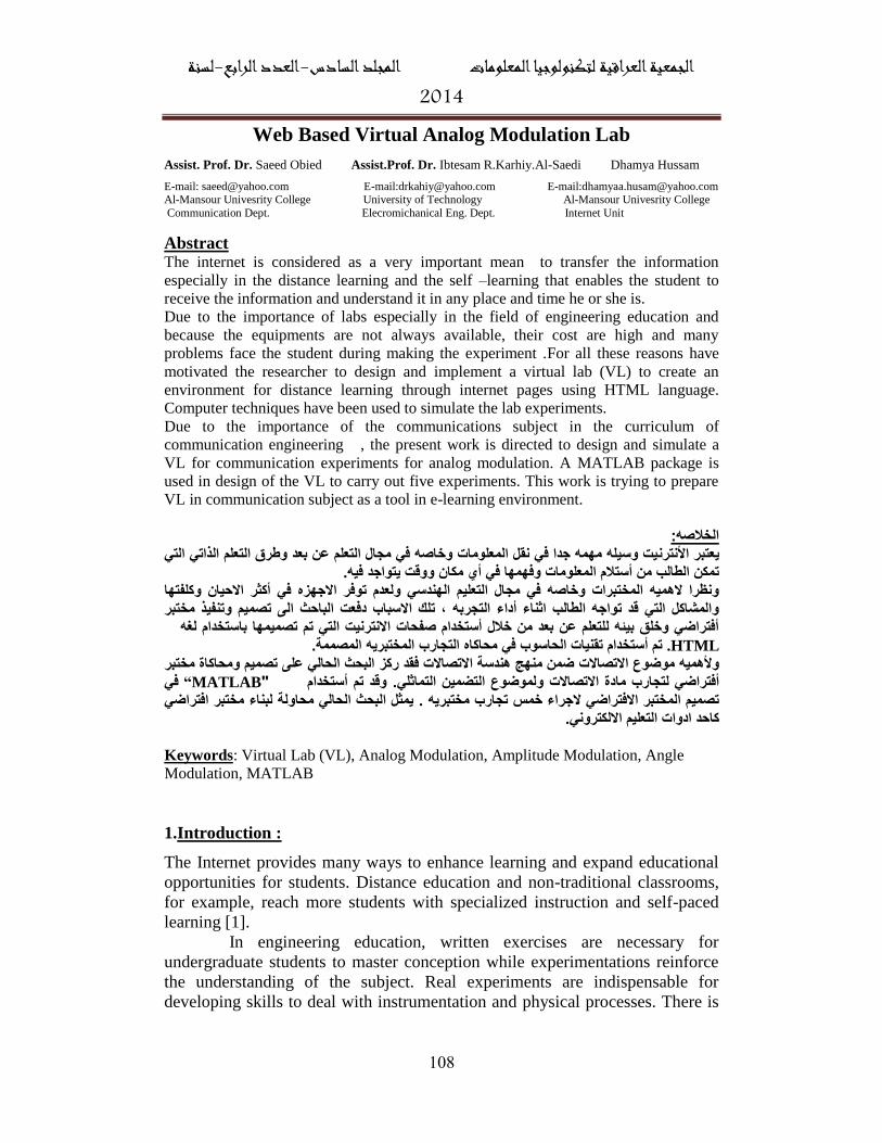
Abstract The internet is considered as a very important mean to transfer the information
especially in the distance learning and the self –learning that enables the student to
receive the information and understand it in any place and time he or she is.
Due to the importance of labs especially in the field of engineering education and
because the equipments are not always available, their cost are high and many
problems face the student during making the experiment .For all these reasons have
motivated the researcher to design and implement a virtual lab (VL) to create an
environment for distance learning through internet pages using HTML language.
Computer techniques have been used to simulate the lab experiments.
Due to the importance of the communications subject in the curriculum of
communication engineering , the present work is directed to design and simulate a
VL for communication experiments for analog modulation. A MATLAB package is
used in design of the VL to carry out five experiments. This work is trying to prepare
VL in communication subject as a tool in e-learning environment.
الخالصه:يت وسيله مهمه جدا في نقل المعلومات وخاصه في مجال التعلم عن بعد وطرق التعلم الذاتي التي يعتبر األنترن
.يتواجد فيهووقت تمكن الطالب من أستالم المعلومات وفهمها في أي مكان م الهندسي ولعدم توفر االجهزه في أكثر االحيان وكلفتها يونظرا الهميه المختبرات وخاصه في مجال التعل
تصميم وتنفيذ مختبر الىالباحث دفعت ، تلك االسبابوالمشاكل التي قد تواجه الطالب اثناء أداء التجربه أفتراضي وخلق بيئه للتعلم عن بعد من خالل أستخدام صفحات االنترنيت التي تم تصميمها باستخدام لغه
.HTML المصممة ستخدام تقنيات الحاسوب في محاكاه التجارب المختبريهتم أ. مختبر ومحاكاة البحث الحالي على تصميم ركزفقد ضمن منهج هندسة االتصاالت وألهميه موضوع االتصاالت
في MATLAB“ " وقد تم أستخدام . ولموضوع التضمين التماثلي االتصاالتمادة أفتراضي لتجاربمختبر افتراضي يمثل البحث الحالي محاولة لبناء .تصميم المختبر االفتراضي الجراء خمس تجارب مختبريه
.كاحد ادوات التعليم االلكتروني
(VL), Analog Modulation, Amplitude Modulation, Angle Lab: Virtual Keywords
Modulation, MATLAB
1.Introduction :
The Internet provides many ways to enhance learning and expand educational
opportunities for students. Distance education and non-traditional classrooms,
for example, reach more students with specialized instruction and self-paced
learning [1].
In engineering education, written exercises are necessary for
undergraduate students to master conception while experimentations reinforce
the understanding of the subject. Real experiments are indispensable for
developing skills to deal with instrumentation and physical processes. There is
لسنة -الرابعالعدد -المجلد السادس الجمعية العراقية لتكنولوجيا المعلومات4102
801
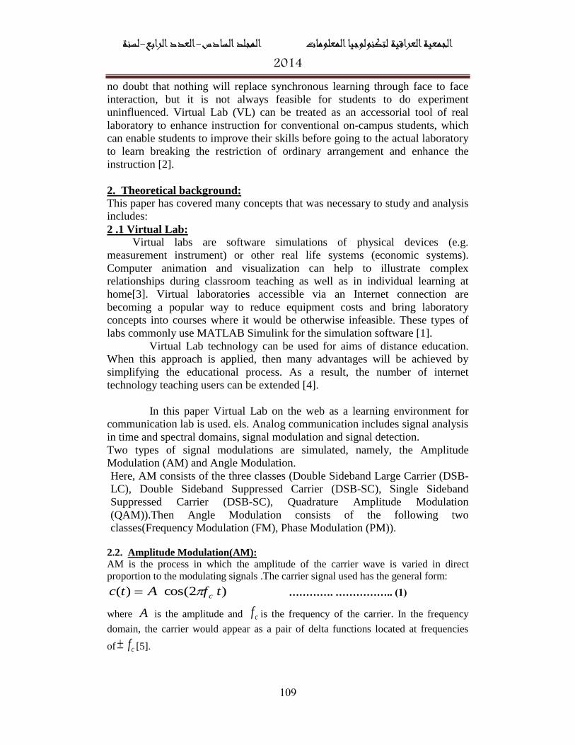
no doubt that nothing will replace synchronous learning through face to face
interaction, but it is not always feasible for students to do experiment
uninfluenced. Virtual Lab (VL) can be treated as an accessorial tool of real
laboratory to enhance instruction for conventional on-campus students, which
can enable students to improve their skills before going to the actual laboratory
to learn breaking the restriction of ordinary arrangement and enhance the
instruction [2].
2. Theoretical background:
This paper has covered many concepts that was necessary to study and analysis
includes:
2 .1 Virtual Lab:
Virtual labs are software simulations of physical devices (e.g.
measurement instrument) or other real life systems (economic systems).
Computer animation and visualization can help to illustrate complex
relationships during classroom teaching as well as in individual learning at
home[3]. Virtual laboratories accessible via an Internet connection are
becoming a popular way to reduce equipment costs and bring laboratory
concepts into courses where it would be otherwise infeasible. These types of
labs commonly use MATLAB Simulink for the simulation software [1].
Virtual Lab technology can be used for aims of distance education.
When this approach is applied, then many advantages will be achieved by
simplifying the educational process. As a result, the number of internet
technology teaching users can be extended [4].
In this paper Virtual Lab on the web as a learning environment for
communication lab is used. els. Analog communication includes signal analysis
in time and spectral domains, signal modulation and signal detection.
Two types of signal modulations are simulated, namely, the Amplitude
Modulation (AM) and Angle Modulation.
Here, AM consists of the three classes (Double Sideband Large Carrier (DSB-
LC), Double Sideband Suppressed Carrier (DSB-SC), Single Sideband
Suppressed Carrier (DSB-SC), Quadrature Amplitude Modulation
(QAM)).Then Angle Modulation consists of the following two
classes(Frequency Modulation (FM), Phase Modulation (PM)).
2.2. Amplitude Modulation(AM):
AM is the process in which the amplitude of the carrier wave is varied in direct
proportion to the modulating signals .The carrier signal used has the general form:
)2cos()( tfAtc c
…………. …………….. (1)
where A is the amplitude and cf is the frequency of the carrier. In the frequency
domain, the carrier would appear as a pair of delta functions located at frequencies
of cf [5].
لسنة -الرابعالعدد -المجلد السادس الجمعية العراقية لتكنولوجيا المعلومات4102
880
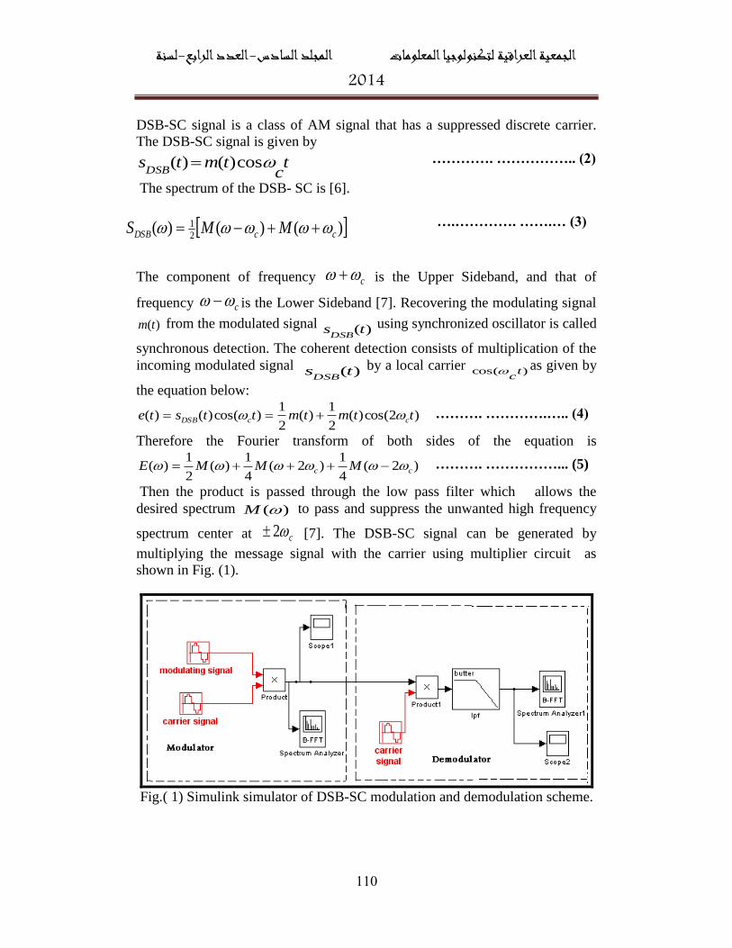
DSB-SC signal is a class of AM signal that has a suppressed discrete carrier.
The DSB-SC signal is given by
tc
tmtsDSB
cos)()( …………. …………….. (2)
The spectrum of the DSB- SC is [6].
….…………. …….… (3)
The component of frequency c is the Upper Sideband, and that of
frequency c is the Lower Sideband [7]. Recovering the modulating signal
)(tm from the modulated signal )(tsDSB
using synchronized oscillator is called
synchronous detection. The coherent detection consists of multiplication of the
incoming modulated signal )(tsDSB
by a local carrier )cos( tc
as given by
the equation below:
)2cos()(2
1)(
2
1)cos()()( ttmtmttste ccDSB ………. ………….….. (4)
Therefore the Fourier transform of both sides of the equation is
)2(4
1)2(
4
1)(
2
1)( cc MMME ………. ……………... (5)
Then the product is passed through the low pass filter which allows the
desired spectrum )(M to pass and suppress the unwanted high frequency
spectrum center at c2 [7]. The DSB-SC signal can be generated by
multiplying the message signal with the carrier using multiplier circuit as
shown in Fig. (1).
Fig.( 1) Simulink simulator of DSB-SC modulation and demodulation scheme.
)()()(2
1ccDSB MMS
لسنة -الرابعالعدد -المجلد السادس الجمعية العراقية لتكنولوجيا المعلومات4102
888
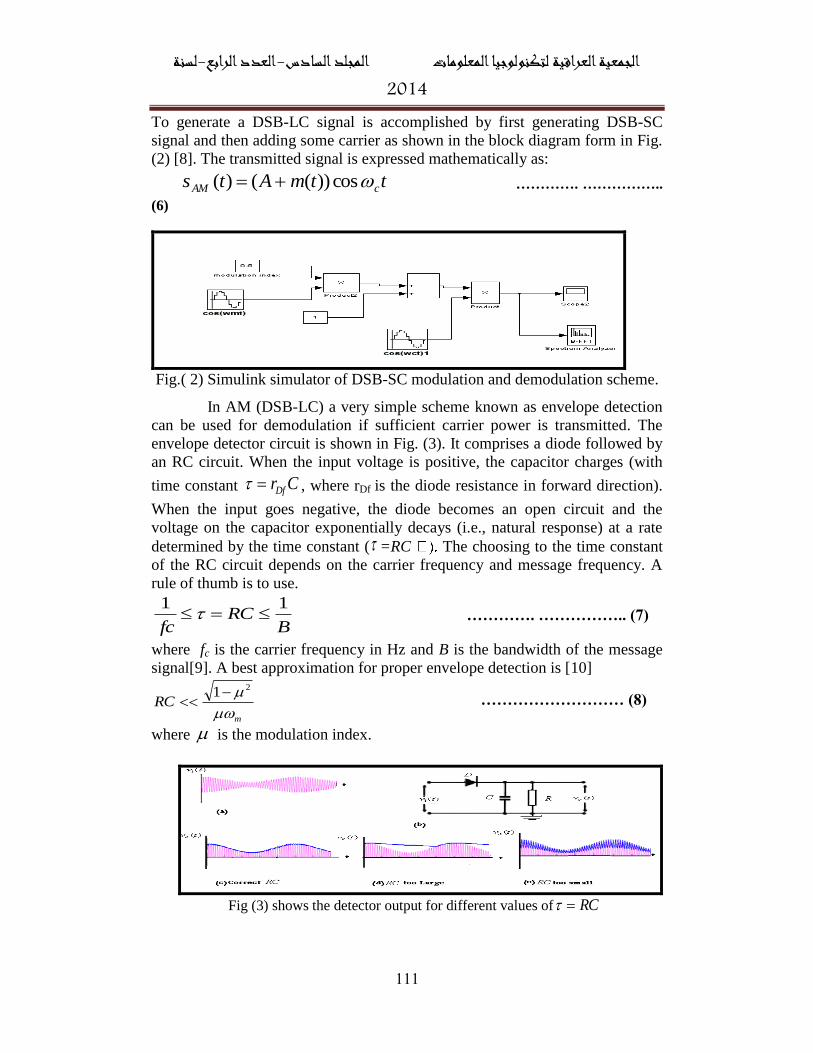
To generate a DSB-LC signal is accomplished by first generating DSB-SC
signal and then adding some carrier as shown in the block diagram form in Fig.
(2) [8]. The transmitted signal is expressed mathematically as:
ttmAts cAM cos))(()( …………. ……………..
(6)
Fig.( 2) Simulink simulator of DSB-SC modulation and demodulation scheme.
In AM (DSB-LC) a very simple scheme known as envelope detection
can be used for demodulation if sufficient carrier power is transmitted. The
envelope detector circuit is shown in Fig. (3). It comprises a diode followed by
an RC circuit. When the input voltage is positive, the capacitor charges (with
time constant CrDf , where rDf is the diode resistance in forward direction).
When the input goes negative, the diode becomes an open circuit and the
voltage on the capacitor exponentially decays (i.e., natural response) at a rate
determined by the time constant ( =RC The choosing to the time constant
of the RC circuit depends on the carrier frequency and message frequency. A
rule of thumb is to use.
BRC
fc
11 …………. …………….. (7)
where fc is the carrier frequency in Hz and B is the bandwidth of the message
signal[9]. A best approximation for proper envelope detection is [10]
m
RC
21 ……………………… (8)
where is the modulation index.
Fig (3) shows the detector output for different values of RC
لسنة -الرابعالعدد -المجلد السادس الجمعية العراقية لتكنولوجيا المعلومات4102
881
Because of AM modulation and DSB modulation require the double bandwidth
of a given signal. Since either the upper sideband or the lower sideband
contains the complete information about the message signal, therefore doubling
of the bandwidth using AM or DSB is a waste of the bandwidth, especially
when a given band of frequencies is crowded [10]. When only one sideband is
transmitted, the modulation is referred to as single sideband (SSB) modulation
SSB generation can be carried out by two methods: The filter method and the
phasing method:
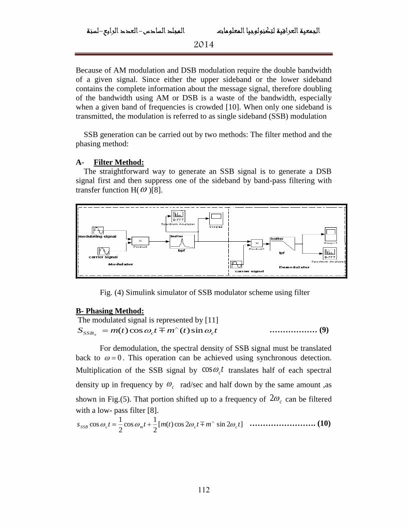
A- Filter Method:
The straightforward way to generate an SSB signal is to generate a DSB
signal first and then suppress one of the sideband by band-pass filtering with
transfer function H( )[8].
Fig. (4) Simulink simulator of SSB modulator scheme using filter
B- Phasing Method:
The modulated signal is represented by [11]
ttmttmS ccSSB sin)(cos)(
……………… (9)
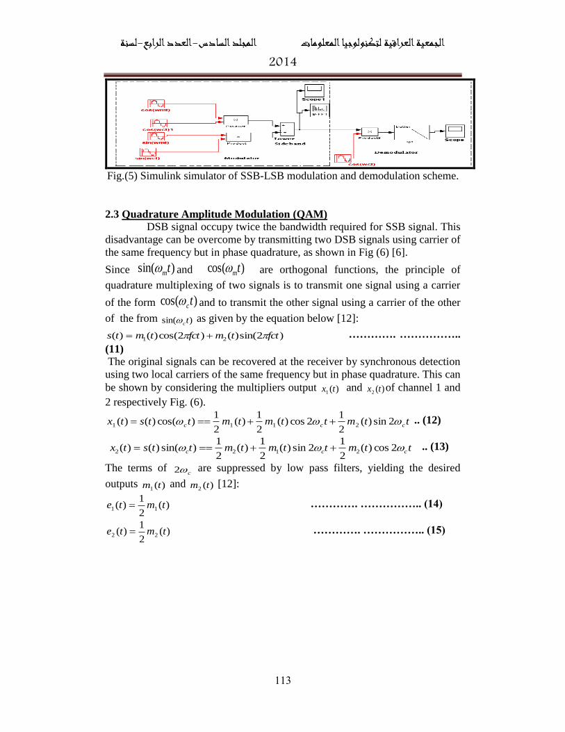
For demodulation, the spectral density of SSB signal must be translated
back to 0 . This operation can be achieved using synchronous detection.
Multiplication of the SSB signal by tccos translates half of each spectral
density up in frequency by c rad/sec and half down by the same amount ,as
shown in Fig.(5). That portion shifted up to a frequency of c2 can be filtered
with a low- pass filter [8].
]2sin2cos)([2
1cos
2
1cos tmttmtts ccmcSSB ……………………. (10)
لسنة -الرابعالعدد -المجلد السادس الجمعية العراقية لتكنولوجيا المعلومات4102
881
Fig.(5) Simulink simulator of SSB-LSB modulation and demodulation scheme.
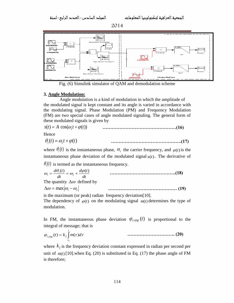
2.3 Quadrature Amplitude Modulation (QAM) DSB signal occupy twice the bandwidth required for SSB signal. This
disadvantage can be overcome by transmitting two DSB signals using carrier of
the same frequency but in phase quadrature, as shown in Fig (6) [6].
Since )sin( tm and )cos( tm are orthogonal functions, the principle of
quadrature multiplexing of two signals is to transmit one signal using a carrier
of the form )cos( tc and to transmit the other signal using a carrier of the other
of the from )sin( tc as given by the equation below [12]:
)2sin()()2cos()()( 21 fcttmfcttmts …………. ……………..
(11) The original signals can be recovered at the receiver by synchronous detection
using two local carriers of the same frequency but in phase quadrature. This can
be shown by considering the multipliers output )(1 tx and )(2 tx of channel 1 and
2 respectively Fig. (6).
ttmttmtmttstx ccc 2sin)(2
12cos)(
2
1)(
2
1)cos()()( 2111 .. (12)
ttmttmtmttstx ccc 2cos)(2
12sin)(
2
1)(
2
1)sin()()( 2122 .. (13)
The terms of c2 are suppressed by low pass filters, yielding the desired
outputs )(1 tm and )(2 tm [12]:
)(2
1)( 11 tmte …………. …………….. (14)
)(2
1)( 22 tmte …………. …………….. (15)
لسنة -الرابعالعدد -المجلد السادس الجمعية العراقية لتكنولوجيا المعلومات4102
881
Fig. (6) Simulink simulator of QAM and demodulation scheme
3. Angle Modulation:
Angle modulation is a kind of modulation in which the amplitude of
the modulated signal is kept constant and its angle is varied in accordance with
the modulating signal. Phase Modulation (PM) and Frequency Modulation
(FM) are two special cases of angle modulated signaling. The general form of
these modulated signals is given by
))(cos()( ttAts c …………………………………………(16)
Hence
)()( ttt ci ……………………………………….(17)
where )(ti is the instantaneous phase, c the carrier frequency, and )(t is the
instantaneous phase deviation of the modulated signal )(ts . The derivative of
)(ti is termed as the instantaneous frequency.
dt
td
dt
tdc
ii
)()(
…………………………………….(18)
The quantity defined by
ci max ……………………………………… (19)
is the maximum (or peak) radian frequency deviation[10].
The dependency of )(t on the modulating signal )(tm determines the type of
modulation.
In FM, the instantaneous phase deviation )(, tFMi is proportional to the
integral of message; that is
t
t
fFMi dmkt
0
)()(, …………………………. (20)
where fk is the frequency deviation constant expressed in radian per second per
unit of )(tm [10].when Eq. (20) is substituted in Eq. (17) the phase angle of FM
is therefore;
لسنة -الرابعالعدد -المجلد السادس الجمعية العراقية لتكنولوجيا المعلومات4102
881
t
t
fcFMi dmktt
0
)()(, ………………...………… (21)
The instantaneous frequency of FM signal is
)()(
,tmk
dt
tdfc
i
FMi
………………………………..(22)
Thus ; In FM the instantaneous frequency is proportional to the message .
From Eq.(19) the peak frequency deviation is
)(maxmax tmk fciFM ……………………………….(23)
The FM signal according to Eq. (16), can be expressed as
])(cos[)(
0
t
t
fcFM dmktAts ………………………..… (24)
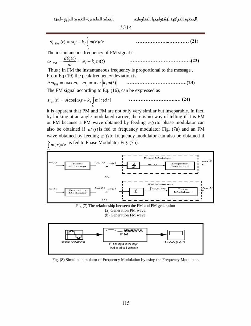
it is apparent that PM and FM are not only very similar but inseparable. In fact,
by looking at an angle-modulated carrier, there is no way of telling if it is FM
or PM because a PM wave obtained by feeding )(tm to phase modulator can
also be obtained if )(tm is fed to frequency modulator Fig. (7a) and an FM
wave obtained by feeding )(tm to frequency modulator can also be obtained if
t
t
dm
0
)( is fed to Phase Modulator Fig. (7b).
Fig (7) The relationship between the FM and PM generation
(a) Generation PM wave.
(b) Generation FM wave.
Fig. (8) Simulink simulator of Frequency Modulation by using the Frequency Modulator.
لسنة -الرابعالعدد -المجلد السادس الجمعية العراقية لتكنولوجيا المعلومات4102
881
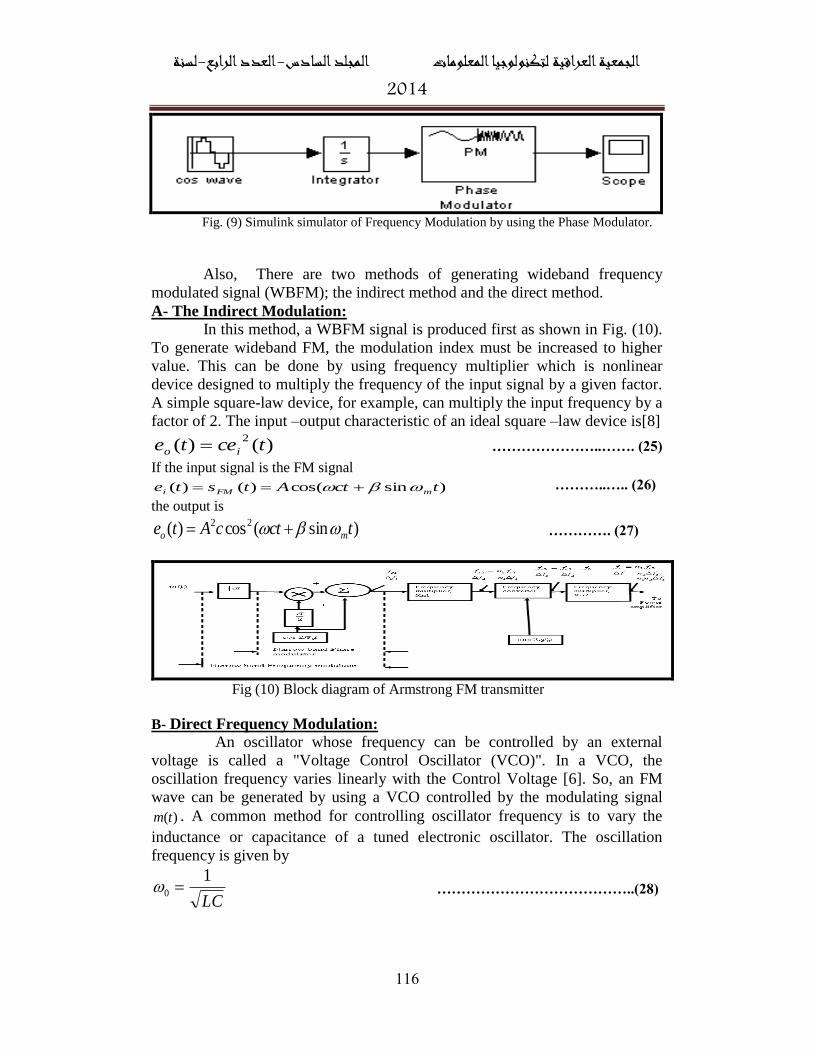
Fig. (9) Simulink simulator of Frequency Modulation by using the Phase Modulator.
Also, There are two methods of generating wideband frequency
modulated signal (WBFM); the indirect method and the direct method.
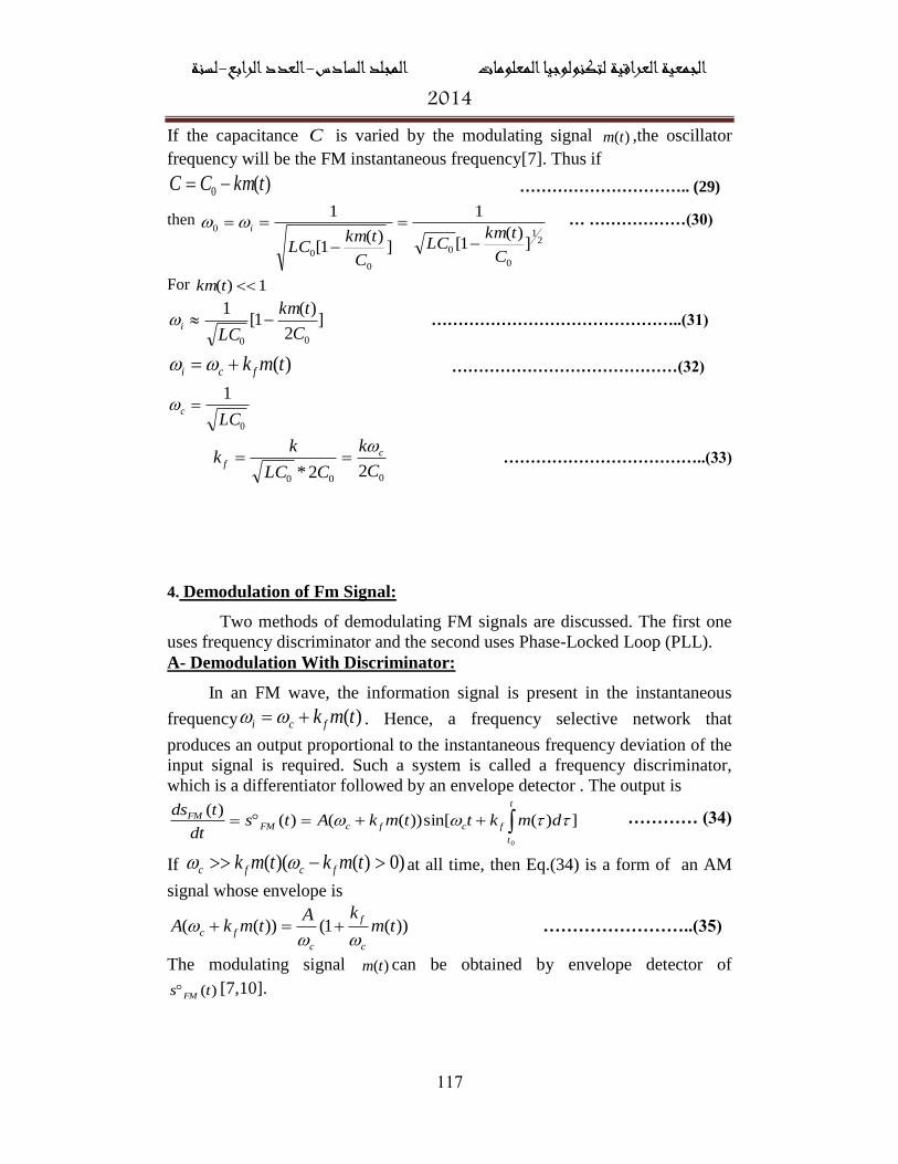
A- The Indirect Modulation:
In this method, a WBFM signal is produced first as shown in Fig. (10).
To generate wideband FM, the modulation index must be increased to higher
value. This can be done by using frequency multiplier which is nonlinear
device designed to multiply the frequency of the input signal by a given factor.
A simple square-law device, for example, can multiply the input frequency by a
factor of 2. The input –output characteristic of an ideal square –law device is[8]
)()(2
tcete io …………………..……. (25)
If the input signal is the FM signal
)sincos()()( tctAtste mFMi ………..….. (26)
the output is
)sin(cos)( 22 tctcAte mo …………. (27)
Fig (10) Block diagram of Armstrong FM transmitter
B- Direct Frequency Modulation:
An oscillator whose frequency can be controlled by an external
voltage is called a "Voltage Control Oscillator (VCO)". In a VCO, the
oscillation frequency varies linearly with the Control Voltage [6]. So, an FM
wave can be generated by using a VCO controlled by the modulating signal
)(tm . A common method for controlling oscillator frequency is to vary the
inductance or capacitance of a tuned electronic oscillator. The oscillation
frequency is given by
LC
10 …………………………………..(28)
لسنة -الرابعالعدد -المجلد السادس الجمعية العراقية لتكنولوجيا المعلومات4102
881
If the capacitance C is varied by the modulating signal )(tm ,the oscillator
frequency will be the FM instantaneous frequency[7]. Thus if
)(0 tkmCC ………………………….. (29)
then
21
0
0
0
0
0
])(
1[
1
])(
1[
1
C
tkmLC
C
tkmLC
i
… ………………(30)
For 1)( tkm
]2
)(1[
1
00C
tkm
LCi ………………………………………..(31)
)(tmk fci ……………………………………(32)
0
1
LCc
00022* C
k
CLC
kk c
f
………………………………..(33)
4. Demodulation of Fm Signal:
Two methods of demodulating FM signals are discussed. The first one
uses frequency discriminator and the second uses Phase-Locked Loop (PLL).
A- Demodulation With Discriminator:
In an FM wave, the information signal is present in the instantaneous
frequency )(tmk fci . Hence, a frequency selective network that
produces an output proportional to the instantaneous frequency deviation of the
input signal is required. Such a system is called a frequency discriminator,
which is a differentiator followed by an envelope detector . The output is
t
t
fcfcFMFM dmkttmkAtsdt
tds
0
])(sin[))(()()(
………… (34)
If )0)()(( tmktmk fcfc at all time, then Eq.(34) is a form of an AM
signal whose envelope is
))(1())(( tmkA
tmkAc
f
c
fc
……………………..(35)
The modulating signal )(tm can be obtained by envelope detector of
)(ts FM [7,10].

لسنة -الرابعالعدد -المجلد السادس الجمعية العراقية لتكنولوجيا المعلومات4102
881
B- Phase Locked Loop (PLL):
Phase locked loop is a circuit which synchronizes (locked state) the frequency
or phase of this inputs [11]. A PLL consists of multiplier that serves as a phase
comparator (PD), a loop filter and a VCO as shown in Fig. (11)[6].
Fig.(11) Basic PLL
The phase comparator produces an output signal )(1 tv that is a function of the
phase difference between the incoming signal )(tvinand the oscillator
output )(tvo. The filtered signal )(2 tv is the control signal that is used to
change the frequency of the VCO output.
Assume the input signal is
))(sin()( ttAtv iciin ………….. …… (36)
and that of the VCO output signal is
))(cos()( ttAtv ocoo ………….. ……… (37)
Where
t
t
vo dvkt
0
)()( 2 ……….…………… (38)
and vk is the VCO gain constant then the PD output is
))]()(2sin())()([sin(2
)(
))(cos())(sin()(
1
1
tttttAAk
tv
ttttAAktv
oicoioim
ocicoim
……… (39)
where mk is the gain of the multiplier circuit. The sum frequency term does not
pass through the LPF, so the LPF output is
)(*)]([sin)(2 tftktv ed …………………………….(40)
where )()()( ttt oie ………………………(41)
2
oimd
AAKk ……………………. (42)
and )(tf is the impulse response of the LPF. )(te is called the phase error,
لسنة -الرابعالعدد -المجلد السادس الجمعية العراقية لتكنولوجيا المعلومات4102
881
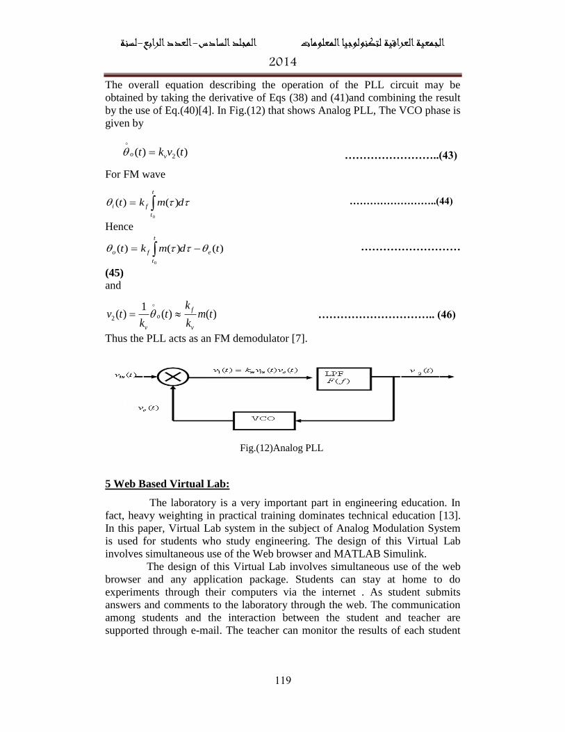
The overall equation describing the operation of the PLL circuit may be
obtained by taking the derivative of Eqs (38) and (41)and combining the result
by the use of Eq.(40)[4]. In Fig.(12) that shows Analog PLL, The VCO phase is
given by
……………………..(43)
For FM wave
dmkt
t
t
fi
0
)()( ……………………..(44)
Hence
)()()(
0
tdmkt e
t
t
fo ………………………
(45)
and
)()(1
)(2 tmk
kt
ktv
v
fo
v
………………………….. (46)
Thus the PLL acts as an FM demodulator [7].
Fig.(12)Analog PLL
5 Web Based Virtual Lab:
The laboratory is a very important part in engineering education. In
fact, heavy weighting in practical training dominates technical education [13].
In this paper, Virtual Lab system in the subject of Analog Modulation System
is used for students who study engineering. The design of this Virtual Lab
involves simultaneous use of the Web browser and MATLAB Simulink.
The design of this Virtual Lab involves simultaneous use of the web
browser and any application package. Students can stay at home to do
experiments through their computers via the internet . As student submits
answers and comments to the laboratory through the web. The communication
among students and the interaction between the student and teacher are
supported through e-mail. The teacher can monitor the results of each student
)()( 2 tvkt vo
لسنة -الرابعالعدد -المجلد السادس الجمعية العراقية لتكنولوجيا المعلومات4102
810
and help students with problems. Virtual Lab is used for experiment in
simulation and virtual instrumentation analysis and design.
Educational technology is a discipline whose main object is to study the
relation between education and technology. It includes instructional design and
planning, teaching methods (e.g. simulations), instructional media (such as
computers and hypermedia), instructional resources, learning (including study
skills, learning theories, motivation and problem solving), and assessment and
evaluation [14]. Therefore, this work depends on the principle of engineering
education in design, implementation, and evaluation.
The current Virtual Lab includes the following parts:
• Objective: This section contains the main objective of the experiment.
• Equipments: This section contains equipment used for implementing the
experiment from MATLAB Simulink.
• Background information: This section contains all necessary basic concepts
and theorems to perform experiments in the Virtual Lab. The students can
easily review the basic knowledge learned in the class before going to the
procedure section of the Virtual Lab or they can refer back to this section if
they find something that is not clear.
• Creating the Simulink model: This section includes procedure
implementation experiment by using MATLAB Simulink for students to
perform experiment at any time and any place and they can download
experiment from the web page and change the parameters and value.
• Interactive questions: This part includes questions of true or false answers. If
the answer is the true , the small window will appear to tell the reader that the
answer is true. If the answer is false, the small window will appear to tell the
reader that the answer is false.
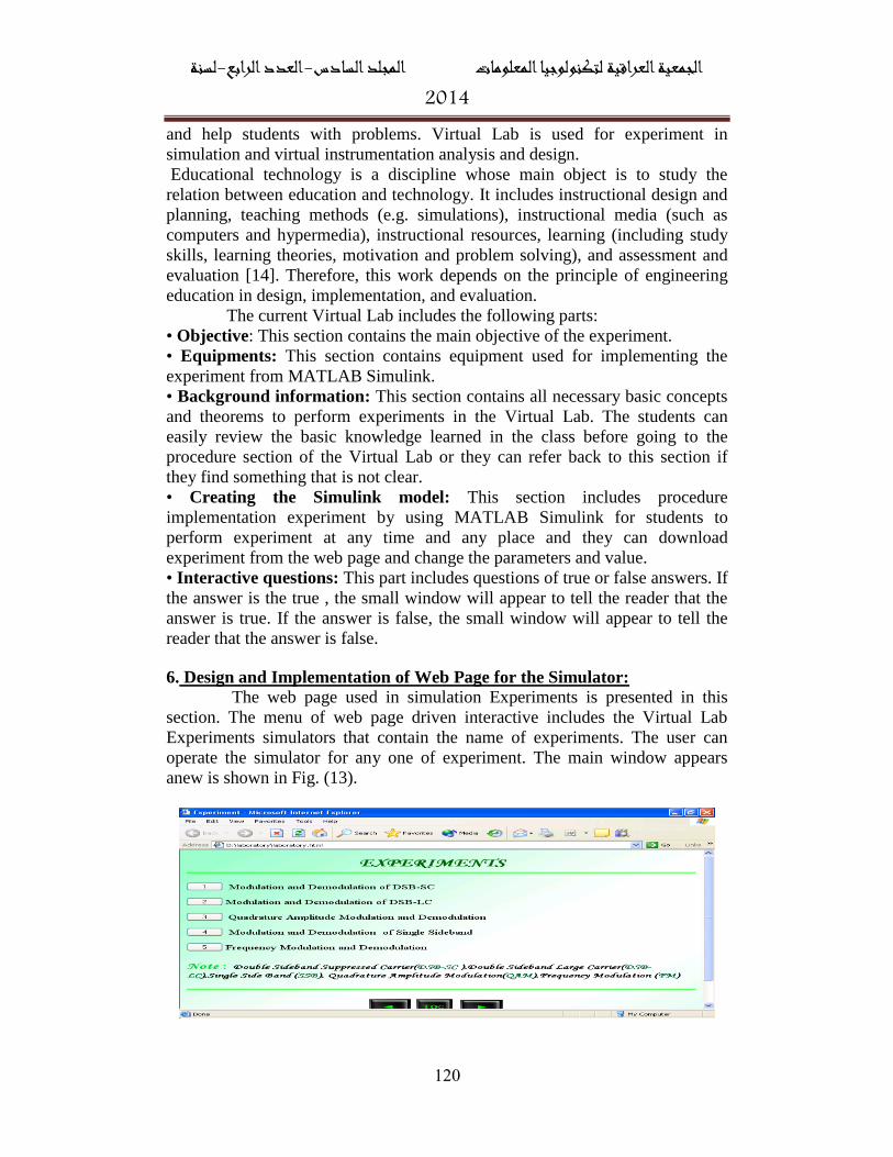
6. Design and Implementation of Web Page for the Simulator:
The web page used in simulation Experiments is presented in this
section. The menu of web page driven interactive includes the Virtual Lab
Experiments simulators that contain the name of experiments. The user can
operate the simulator for any one of experiment. The main window appears
anew is shown in Fig. (13).
لسنة -الرابعالعدد -المجلد السادس الجمعية العراقية لتكنولوجيا المعلومات4102
818
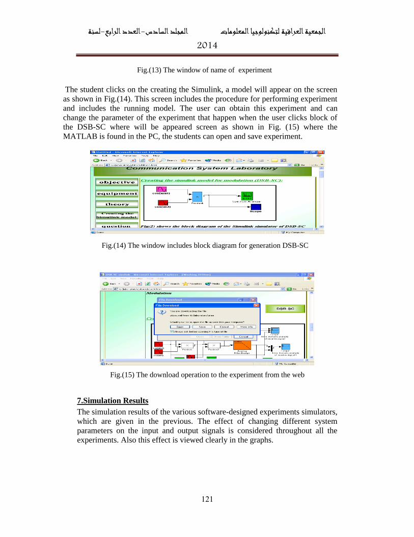
The student clicks on the creating the Simulink, a model will appear on the screen
as shown in Fig.(14). This screen includes the procedure for performing experiment
and includes the running model. The user can obtain this experiment and can
change the parameter of the experiment that happen when the user clicks block of
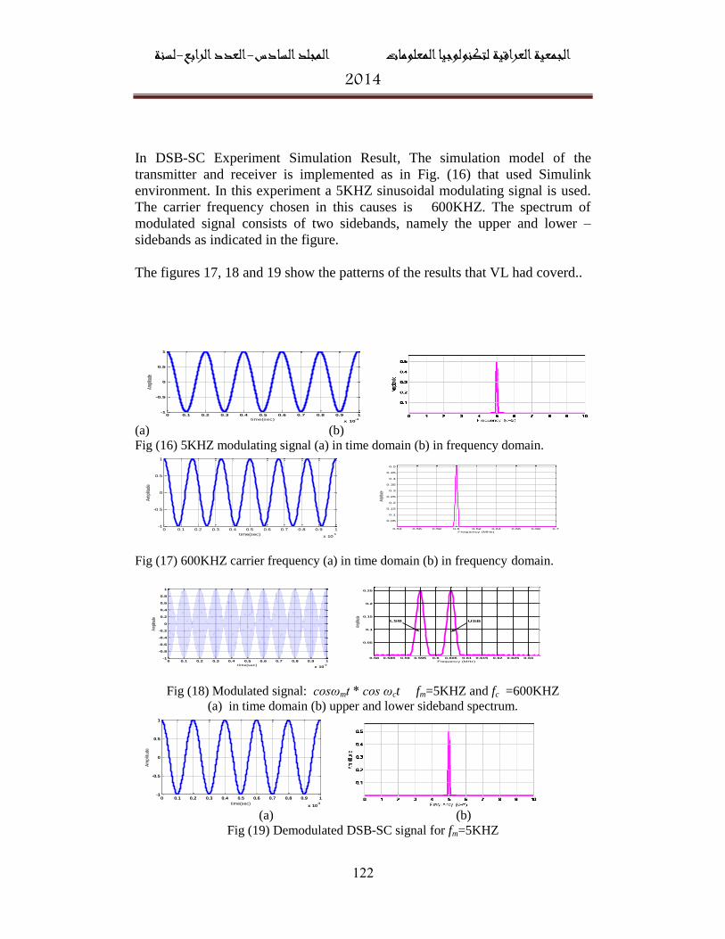
the DSB-SC where will be appeared screen as shown in Fig. (15) where the
MATLAB is found in the PC, the students can open and save experiment.
Fig.(15) The download operation to the experiment from the web
7.Simulation Results
The simulation results of the various software-designed experiments simulators,
which are given in the previous. The effect of changing different system
parameters on the input and output signals is considered throughout all the
experiments. Also this effect is viewed clearly in the graphs.
Fig.(13) The window of name of experiment
Fig.(14) The window includes block diagram for generation DSB-SC
لسنة -الرابعالعدد -المجلد السادس الجمعية العراقية لتكنولوجيا المعلومات4102
811
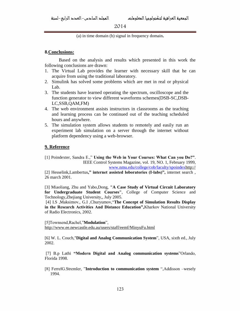
In DSB-SC Experiment Simulation Result, The simulation model of the
transmitter and receiver is implemented as in Fig. (16) that used Simulink
environment. In this experiment a 5KHZ sinusoidal modulating signal is used.
The carrier frequency chosen in this causes is 600KHZ. The spectrum of
modulated signal consists of two sidebands, namely the upper and lower –
sidebands as indicated in the figure.
The figures 17, 18 and 19 show the patterns of the results that VL had coverd..
0 0.1 0.2 0.3 0.4 0.5 0.6 0.7 0.8 0.9 1
x 10-3
-1
-0.5
0
0.5
1
time(sec)
Ampli
tude
(a) (b)
Fig (16) 5KHZ modulating signal (a) in time domain (b) in frequency domain.
0 0.1 0.2 0.3 0.4 0.5 0.6 0.7 0.8 0.9 1
x 10-5
-1
-0.5
0
0.5
1
time(sec)
Am
plitu
de
0.54 0.56 0.58 0.6 0.62 0.64 0.66 0.68 0.7
0.05
0.1
0.15
0.2
0.25
0.3
0.35
0.4
0.45
0.5
Frequency (MHz)
Ampli
tude
Fig (17) 600KHZ carrier frequency (a) in time domain (b) in frequency domain.
0 0.1 0.2 0.3 0.4 0.5 0.6 0.7 0.8 0.9 1
x 10-3
-1
-0.8
-0.6
-0.4
-0.2
0
0.2
0.4
0.6
0.8
1
time(sec)
Ampl
itude
0.58 0.585 0.59 0.595 0.6 0.605 0.61 0.615 0.62 0.625 0.63
0.05
0.1
0.15
0.2
0.25
Frequency (MHz)
Ampli
tude
USBLSB
Fig (18) Modulated signal: cosωmt * cos ωct fm=5KHZ and fc =600KHZ
(a) in time domain (b) upper and lower sideband spectrum.
0 0.1 0.2 0.3 0.4 0.5 0.6 0.7 0.8 0.9 1
x 10-3
-1
-0.5
0
0.5
1
time(sec)
Am
plitu
de
(a) (b)
Fig (19) Demodulated DSB-SC signal for fm=5KHZ
لسنة -الرابعالعدد -المجلد السادس الجمعية العراقية لتكنولوجيا المعلومات4102
811
(a) in time domain (b) signal in frequency domain.
Conclusions:.8
Based on the analysis and results which presented in this work the
following conclusions are drawn:
1. The Virtual Lab provides the learner with necessary skill that he can
acquire from using the traditional laboratory.
2. Simulink has solved some problems which are met in real or physical
Lab.
3. The students have learned operating the spectrum, oscilloscope and the
function generator to view different waveforms schemes(DSB-SC,DSB-
LC,SSB,QAM,FM)
4. The web environment assists instructors in classrooms as the teaching
and learning process can be continued out of the teaching scheduled
hours and anywhere.
5. The simulation system allows students to remotely and easily run an
experiment lab simulation on a server through the internet without
platform dependency using a web-browser.
9. Reference
[1] Poindexter, Sandra E.,” Using the Web in Your Courses: What Can you Do?”.
IEEE Control Systems Magazine, vol. 19, NO. 1, February 1999,
http://www.nmu.edu/college/cob/faculty/spoindex
[2] Hesselink,Lambertus,” internet assisted loboratories (I-labs)”, internet search ,
26 march 2001.
[3] Miaoliang, Zhu and Yabo,Dong, "A Case Study of Virtual Circuit Laboratory
for Undergraduate Student Courses", College of Computer Science and
Technology,Zhejiang University,, July 2005.
[4] I.S ,Maksimov., G.I ,Churyumov,“The Concept of Simulation Results Display
in the Research Activities And Distance Education”,Kharkov National University
of Radio Electronics, 2002.
[5]Townsend,Rachel,”Modulation”,
http://www.ee.newcastle.edu.au/users/staff/eemf/MinyuFu.html
[6] W. L. Couch,"Digital and Analog Communication System”, USA, sixth ed., July
2002.
[7] B.p Lathi “Modern Digital and Analog communication systems”Orlando,
Florida 1998.
[8] FerrelG.Stremler, ”Introduction to communication system “,Addisson –wesely
1994.
لسنة -الرابعالعدد -المجلد السادس الجمعية العراقية لتكنولوجيا المعلومات4102
811
[9] R. C. Hardie,” LAB 3: AM Modulation and Demodulation”
, Department of Electrical and Computer Engineering, University of Dayton, ECE
401L COMMUNICATIONS LABORATORY, 2003.
[10] Scham's,"Analog and Digital communications",MC GRAW-HiLL,2003
[11] ” angle modulation Lab” Electrical Engineering Department, University –
Multidisciplinary Initiative on Distance Learning – ASU, 2000.
http://www.eas.asu.edu/~midle/jdsp/commex/JDSP_NEW_thesis/LAB2_ANGLE_M
OD.htm
[12] “Analog Modulation”, internet search,
http://www.home.online.no/lilandh/hfKmm2/amfmmod.pdf
[13]K.C.Chu , Dennis Leung,"Flexible Learning Via Web-Based Virtual Teaching
and Virtual Lab System", Electrical and communication Engineering Department
,Hong Kong Technical College ,2001
[14]Multisilta,Jari,”Hypermedia Learning Environment for Mathematics”, Ph.D
Thesis, Technology Department, University of Technology, 1996.