W-RNO Analysis Mate V1 0
1165
Developed By: Aumpika Viun (Ice) 1. RRC,RB and UE Measurement Procedures 5. Call Procedure & L3-messages Contact: [email protected] W-RNO AnalysisMate Ver1.0 0. UTRAN Network Architecture and Protocols 1.1 UMTS Network Architecture 1.2 UTRAN Protocols 1.1 Mapping of UE state to 3GPP Specifications 1.2 RRC Tasks and Functions 1.3 RRC Modes and State Transitions including GSM 1.3 RRC Mode Description 1.4 RRC Connection Mobility Management and RRC Modes 1.5 RRC Procedures 1.6 RB Procedures 1.7 UE Measurement Procedures 2. Paging Messages 2.1 Paging Message Type 1 2.2 Paging Message Type 2 3. System Information Block (SIB) 4. Location Update Procedure & L3-messages 5.1 AMR Voice (MOC) 5.1 AMR Voice (MTC) 5.2 CS64/ Video Call 5.3 PS-R99 5.4 PS-HSDPA 5.5 PS-HSUPA
-
Upload
helwanuniversity -
Category
Documents
-
view
0 -
download
0
Transcript of W-RNO Analysis Mate V1 0

Developed By: Aumpika Viun (Ice)
1. RRC,RB and UE Measurement Procedures
5. Call Procedure & L3-messages
Contact: [email protected]
W-RNO AnalysisMate Ver1.00. UTRAN Network Architecture and Protocols
1.1 UMTS Network Architecture
1.2 UTRAN Protocols
1.1 Mapping of UE state to 3GPP Specifications
1.2 RRC Tasks and Functions
1.3 RRC Modes and State Transitions including GSM
1.3 RRC Mode Description
1.4 RRC Connection Mobility Management and RRC Modes
1.5 RRC Procedures
1.6 RB Procedures
1.7 UE Measurement Procedures
2. Paging Messages
2.1 Paging Message Type 1
2.2 Paging Message Type 2
3. System Information Block (SIB)
4. Location Update Procedure & L3-messages
5.1 AMR Voice (MOC)
5.1 AMR Voice (MTC)
5.2 CS64/ Video Call
5.3 PS-R99
5.4 PS-HSDPA
5.5 PS-HSUPA

6. HO Procedure & L3-messages (Intra-Freq HO)
7.HO Procedure & L3-messages (Inter-Freq HO)
8. HO Procedure & L3-messages (Inter-RAT HO)
9.SRNS Relocation Procedure & L3-messages
6.1 Intra-Frequency Soft Handover within a NodeB(Softer-HO)6.2 Intra-Frequency Soft Handover between NodeBs in an RNC
6.3 Intra-Frequency Soft Handover between RNCs
6.4 Intra-Frequency Hard Handover Between NodeBs in an RNC
6.5 Intra-Frequency Hard Handover Between RNCs
7.1 Inter-Frequency Hard Handover Between NodeBs in an RNC
7.2 Inter-Frequency Hard Handover Between RNCs
8.1 Inter-RAT CS Handover from WCDMA to GSM (Coveraged Based)
8.2 Inter-RAT CS Handover from GSM to WCDMA(Coveraged Based)
8.3 Inter-RAT PS Handover from WCDMA to GSM(Coveraged Based)
8.4 Inter-RAT PS Handover from GSM to WCDMA(Coveraged Based)
8.5 Inter-RAT CS&PS Handover from WCDMA to GSM (Intra-SGSN)
8.6 Inter-RAT CS&PS Handover from WCDMA to GSM (Inter-SGSN)
9.1 Static Relocation(UE not-involved relocation)
9.2 Relocation with Cell/URA Update (UE not-involved relocation)
9.3 Relocation with Hard Handover (UE involved relocation)

Convention Description
Underline Text
MML Command
Click to return to main page Click here to return to root topic Value= Give an acutal value includes the conversion schemesComments Extra comments for some topics
Tool Version Release Date Genex Probe Version
Ver1.0 25-Jun-09
Tool Version Change Type Change History
All texts with an Underline has a hyperlink function which link to other related information e.g. signalling procedure, signalling measages,parameter description, features algorithm etc.All bold texts with highlighted in "Orange" are MML command
Genex Assistant Version
V100R005C01B040 (V1.51 20090210 )
V100R005C01B040 (V1.52 20090210 )

;

Description
Click here to return to root topic Give an acutal value includes the conversion schemesExtra comments for some topics
RAN Version RNC Version
10.0 V200R010C01B061
Change Date Remark
has a hyperlink function which link to other related information e.g. signalling procedure, signalling measages,parameter description,
"Orange" are MML command

Change Type
CorrectionAdditionRemove

UMTS Network Architecture (Rel'99)Click to return to main page
The UMTS PLMN is logically divided into a Core Network (CN), a Radio Access Network (RAN) and the User Equipment UE.
The Core Network(CN) consists of an enhanced GSM Phase2+ with a Circuit Switched CS and Packet Switched PS (i.e. GPRS) domain The most important network elements of these GSM Phase 2+ CN are:- Mobile Service Switching Center(MSC)- Gateway Mobile Service Switching Center (GMSC)- Visitor Location Register (VLR)- Home Location Register (HLR)- Authentication Center (AuC)- Equipment Identity Register (EIR)- Serving GPRS Support Node (SGSN)- Gateway GPRS Support Node (GGSN)
The RAN of UMTS is the UMTS Terrestrial Radio Access Network (UTRAN) consists of,- Radio Network Controller (RNC), which is controlling a Radio Network Subsystem (RNS)- Node B, which is the physical entity to serve on or several cells
The User Equipment(UE) consists of,- Mobile Equipment (ME), The Mobile Equipment represents the partner of the NodeB and of the RNC. It is responsible for serving the radio interface. Some of the tasks of the Mobile Equipment ares CDMA coding and encoding,Modulation and demodulation on the carrier,Power control,Quality and field strenght measurements,Ciphering and authorization,Mobility management and equipment identification.
- UMTS Subscriber Identity Module (USIM), The USIM functions to save data and procedures in ther terminal equipment. It supports call handling,contains security parameters,user-specific data e.g. telephone directory entries, etc. The installed USIM is made available to the customer by the network operator and can be updated e.g. via SMS or cell broadcasting.Examples of USIM data and procedures,1.Data: International Mobile Subscriber Identity,Packet Switched Location Information,Security Information for authentication and chiphering for circuit and packet switched applications,PLMN selector and HPLMN search period,Call meters,Display Languages,Telephone directory,Forbidden PLMNs,Emergency Call Codes etc.2.Procedures: Application related procedures,Security related procedures,Subscription related procedures etc.
With UTRAN, four new interfaces were specified:- Iu, Iu connects UTRAN with the CN. A distinguishing is drawn between the Iu connection to the ps domain, which is labelled Iu-PS, and to the cs domain, which is called Iu-CS. In both cases, ATM is used as transmission network solution. Please note, that there are differences in the protocol stacks on the Iu-CS and Iu-PS interface.- Iub, this interface is used between the Node B and its controlling RNC.- Iur, this is an inter-RNS interface, connecting two neighbouring RNC. It is used among others in soft handover situations, where a UE‘s active cells are under the control of more than one RNC. One RNC is responsible for the UE; it is called S-RNC. The remaining RNCs are called D-RNC. - Uu, Uu is the acronym for the WCDMA radio interface. On the interfaces Iu, Iur, and Iub, ATM is used for the transport of user data and higher layer signalling information.

Radio Network Controller(RNC) Functionality
The RNC has many different tasks in the UTRAN. It is responsible for e.g. Radio Resource Management (RRM) and the control of itself and the connected NodeB (O&M functionality). It is connected to the CN , CS domain via Iu(CS) interface and to the PS domain via Iu(PS) interface. Signalling and data transfer to other RNCs are possible via Iur interface and to the connected Node Bs via Iub interface. The following are examples of RNC functions:- Power Control- Handover- Ciphering/Deciphering- Protocol conversion- Admission Control/Load Control- Macro Diversity- Geographical Coordinates
Logically,the RNC can be divided into different types, according to its current functionality as follows,1. Controlling RNC (C-RNC) : Every cell has only one C-RNC. The C-RNC of a cell is exactly the RNC that is connected with the NodeB serving the cell. The tasks of the C-RNC covers the following areas:- Admission Control based on UL interference and DL transmission power level- System Information Broadcasting- allocation/de-allocation of radio bearers- data transmission and reception- Congestion control in its own cell- Power control- Resource allocation and admission control for new radio links to be established in those cells
Summary: The C-RNC is the RNC controlling a Node B ( i.e. terminating the Iub interface towards the NodeB).This means the C-RNC of a cell is responsible for all lower layer funcions related to the radio technology2. Serving RNC (S-RNC) : An UE that is attached to an UTRAN is served by only one RNC. This RNC is called the serving RNC (S-RNC).The existence of a serving RNC does not imply that the UE is camped on a cell belonging to the S-RNC.The serving RNC handles all higher layer functions related to radio access and information transport through UTRAN. The S-RNC performs the following functions:- the S-RNC handles the Iu interface towards the CN for this UE- the S-RNC handles the completed Radio Resoruce Control (RRC) for this UE- Location/Mobility handling- Ciphering - Backward Error Correction (BEC, layer 2 functionality)- Radio bearer control- Handover decision- Power Control
The S-RNC is responsible for the handling of all decisions for the connection with the UE e.g. for the allocation/modification or release of radio resources,for Outer Loop Power Control and for Handover decisions/initiation.In the case of Soft Handover,S-RNC performs data splitting toward the different NodeBs and combining toward the CN. It decides to add or remove cells in the Soft Handover. The S-RNC is in most cases (but not always) the C-RNC of some NodeBs used for the connection toward an UE. The S-RNC is no anchor functionality. It can be re-allocated to another RNC with the S-RNS reallocation procedure.
Summary: The S-RNC for one UE is the RNC that terminates both Iu link for transport of user data and corresponding RANAP signalling to/from the core network per UE. The S-RNC terminates the RRC signalling(signalling protocol between UE and UTRAN)
3. Drift RNC (D-RNC): In UMTS it is possible that one UE is connected to more than one cell, or connected to a cell, that does not belong to the S-RNC. This means the UE is connected with a cell controlled by a RNC different to the S-RNC.This foreign RNC is called drift RNC ,D-RNC. In principle the D-RNC is the C-RNC of a cell the UE is connected to, but its not the S-RNC.Therefore D-RNC performs the C-RNC functions for the cells not controlled by S-RNC.
When a D-RNC is involved for a UE, then the data streams between UE-UTRAN and UE-CN always pass the S-RNC. In the downlink the S-RNC sends the data to own cells and to the D-RNC(soft HO),this is called splitting.The UE receives all the data streams from the cells,it is connected to and adds them together (RAKE Receiver, Maximum Ratio Combining). In the Uplink,the S-RNC receives data from the own cells and from the D-RNC ,the S-RNC takes only the data frame with the smallest bit error rate, all other data frames will be discarded (Selective combining). The usage of a D-RNC requires a Iur interface between D-RNC and S-RNC.Because the implementation of Iur interface is optional,i's matter of network planning, whether the usage of D-RNCs is allowed or not.
Summary: D-RNC is any RNC, other than SRNC that controls cells used by the UE. The D-RNC performs macro-diversity combining and splitting,if necessary. The D-RNC does not perform user plane data L2 processing,but routes the data transparently between the Iub and Iur interfaces.The UE can be connected to 0 ,one or more DRNCs. ( Macro Diversity is an operation state in which a UE simultaneously has radio links with two ormore UTRAN access points.

Node B Functionality
Geographical and UTRAN Entity Identifiers
2. Serving RNC (S-RNC) : An UE that is attached to an UTRAN is served by only one RNC. This RNC is called the serving RNC (S-RNC).The existence of a serving RNC does not imply that the UE is camped on a cell belonging to the S-RNC.The serving RNC handles all higher layer functions related to radio access and information transport through UTRAN. The S-RNC performs the following functions:- the S-RNC handles the Iu interface towards the CN for this UE- the S-RNC handles the completed Radio Resoruce Control (RRC) for this UE- Location/Mobility handling- Ciphering - Backward Error Correction (BEC, layer 2 functionality)- Radio bearer control- Handover decision- Power Control
The S-RNC is responsible for the handling of all decisions for the connection with the UE e.g. for the allocation/modification or release of radio resources,for Outer Loop Power Control and for Handover decisions/initiation.In the case of Soft Handover,S-RNC performs data splitting toward the different NodeBs and combining toward the CN. It decides to add or remove cells in the Soft Handover. The S-RNC is in most cases (but not always) the C-RNC of some NodeBs used for the connection toward an UE. The S-RNC is no anchor functionality. It can be re-allocated to another RNC with the S-RNS reallocation procedure.
Summary: The S-RNC for one UE is the RNC that terminates both Iu link for transport of user data and corresponding RANAP signalling to/from the core network per UE. The S-RNC terminates the RRC signalling(signalling protocol between UE and UTRAN)
3. Drift RNC (D-RNC): In UMTS it is possible that one UE is connected to more than one cell, or connected to a cell, that does not belong to the S-RNC. This means the UE is connected with a cell controlled by a RNC different to the S-RNC.This foreign RNC is called drift RNC ,D-RNC. In principle the D-RNC is the C-RNC of a cell the UE is connected to, but its not the S-RNC.Therefore D-RNC performs the C-RNC functions for the cells not controlled by S-RNC.
When a D-RNC is involved for a UE, then the data streams between UE-UTRAN and UE-CN always pass the S-RNC. In the downlink the S-RNC sends the data to own cells and to the D-RNC(soft HO),this is called splitting.The UE receives all the data streams from the cells,it is connected to and adds them together (RAKE Receiver, Maximum Ratio Combining). In the Uplink,the S-RNC receives data from the own cells and from the D-RNC ,the S-RNC takes only the data frame with the smallest bit error rate, all other data frames will be discarded (Selective combining). The usage of a D-RNC requires a Iur interface between D-RNC and S-RNC.Because the implementation of Iur interface is optional,i's matter of network planning, whether the usage of D-RNCs is allowed or not.
Summary: D-RNC is any RNC, other than SRNC that controls cells used by the UE. The D-RNC performs macro-diversity combining and splitting,if necessary. The D-RNC does not perform user plane data L2 processing,but routes the data transparently between the Iub and Iur interfaces.The UE can be connected to 0 ,one or more DRNCs. ( Macro Diversity is an operation state in which a UE simultaneously has radio links with two ormore UTRAN access points.
A nodeB is a physical unit for implementing a UMTS radio transmission. Depending on the sectoring of the cells ,one (omni) cell or multiple (sector) cells can be serviced by a Node B. Generally,up to six cells are serviced by a Node B in UMTS.
A Node B can be used for Frequency Division Duplex (Uplink and Downlink separated by different frequency bands),Time division Duplex (Uplink and Downlink in different timeslots) or dual mode operation. A Node B converts user and signalling information received from the RNC for transport via the radio interface,and in the opposite direction. Node Bs are involved in power control,NodeB measures the signal to noise ratio (SIR) of the User Equipment ,compares the value with a predefined one and instructs the UE to control its transmission power. The NodeB also measures the quality and strength of the links and determines the Frame Error Rate (FER). The following are examples of NodeB functions:
- Radio Channel functions: Transport to physical channel mappings. Encoding/Decoding – Spreading/De-spreading user traffic and signalling.- Air Interface management. Controlling Uplink and Downlink radio paths on the Uu Air Interface,Baseband to RF conversion,Antenna multi-coupling,Intra NodeB SofterHO,Power Control,Quality and signal strength measurements- O&M Processing,Interfacing with M2000 and RNC for alarm and control (Operations and Maintenance) functions.- Cellular Transmission management. Managing ATM switching and multiplexing over the Iub interface. Control of AAL2/AAL5 connections. Control of the physical transmission interfaces – E1, PDH, SDH or microwave.

1.International UMTS/GSM Service AreaInternational UMTS/GSM Service Area, i.e. the world-wide area where access to GSM and UMTS network is possible,is sub-divided into National Service Areas. 2.National Service AreaNational Service Area is the area of on country or region. It is identified by the Mobile Country Code (MCC) and Country Code (CC). The National Service Area is sub-divided into one or more PLMN Service Areas. 3. PLMN Service AreaPLMN Service Area is the service area of a single PLMN. It identified by the Mobile Country Code(MCC) and Country Code (CC). The National Service Area is sub-divided into one or more MSC and SGSN Service Areas.4. MSC/SGSN Service AreaAn MSC or SGSN Service Area is the area, which is served by a single MSC (CS-domain) or by a single SGSN (PS-domain). MSC and SGSN Service Area may differ, but they are on the same hierachical level. The MSCs andSGSNs have their own identifiers/addresses for singalling and user data transfer.5. Location Area (LA)A Location Area (LA) is the most precise UE location information,which is stored in the CS-domain (in the VLR) of UMTS. A Location Area is world-wide uniquely identified by its Location Area Identity LAI6. Routing Area (RA)The SGSN Service Area is sub-divided into one or more Routing Areas. A Routing Area (RA) is a subset of a Location Area i.e. one LA may contain one or more RAs. The RA is the most precise UE information, which isstored in the PS-domain (in the SGSN) of UMTS. It is world-wide uniquely identified by the Routing Area Identity. The RA is sub-divided into the Cell-Areas.7. Cell AreaIt is also essential to address different physical,geographical or logical entities within UMTS. The geographical and physical entities of UTRAN are described as follow,
1. PLMN Id = MCC +MNCThe PLMN-ID is used to address a PLMN in a world-wide unique manner. As in GSM the PLMN-ID consist of a MCC(mobile country code) and a MNC(mobile network code). MCC and MNC are allocated by ITU-T and are specified within ITU-T E212.2. CN-Domain Id:CS- and PS core network introduce their own regional area concept. This is the concept of Location Area for CS and the concept of Routing Area for PS. LAI= PLMN-ID + LAC (Location Area Identity Code)RAI= PLMN-ID + LAC +RAC ( Rotuing Area Identity Code)3. Cell Global Identity (CGI)The Cell Global Identity (CGI) is composed by the CGI=LAI+CellID. 4. RNC Id:Every RNC node has to be uniquely identified within UTRAN. Therefore every RNC gets a RNC-ID. Together with the PLMN-ID the RNC-ID is unique world wide. The RNC-ID will be used to address a RNC via Iu,Iur and Iubinterface. The RNC identifier is allocated by O&M. Global RNC-ID= PLMN-ID + RNC-ID5. Cell Id and UTRAN Cell Id:The cell-ID is used to address a cell within a RNS. The cell-ID is set by O&M in the C-RNC. Together with the RNC-ID the Cell-ID forms the UTRAN cell IDUTRAN Cell-ID= RNC-ID + Cell-ID

UTRAN Identifiers for UE
UTRAN Cell-ID= RNC-ID + Cell-ID6. Local Cell IdentifierThe local cell identifier is used in the Node B to identify resources. There is a unique relation UTRAN Cell-ID to local cell identifier7. Service Area Id:Serveral cells of one location area can be defined to form a service area. Such a service area is identified with a SAI(service area id):SAI= PLMN-ID+LAC+SAC8. URA ID:The UTRAN introduces its own area concept next to LA and RA. This is the UTRAN Registration Area (URA)
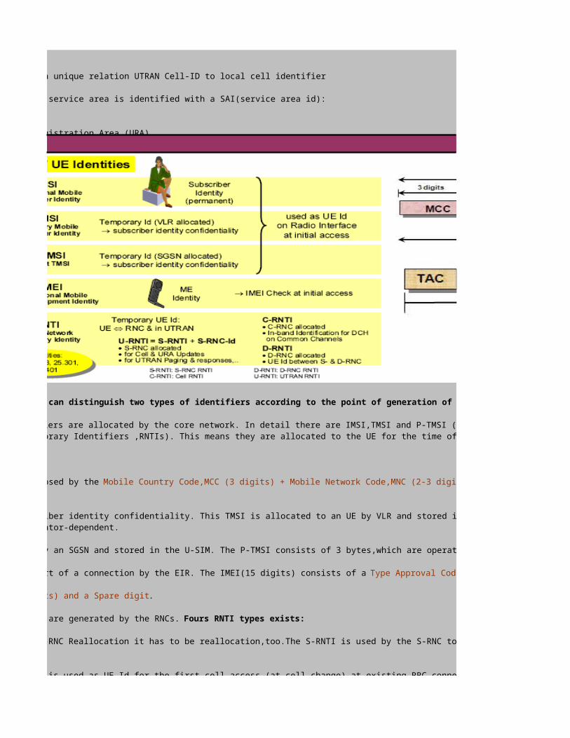
The UE and the Subscriber can have several identifiers for the PLMN. Typically we can distinguish two types of identifiers according to the point of generation of the identifier:
1. Core Network Identities or NAS (Non Access Stratum) Identifiers: These identifiers are allocated by the core network. In detail there are IMSI,TMSI and P-TMSI (and IMEI)2. UTRAN identifiers : UTRAN identifiers are always temporary (Radio Network Temporary Identifiers ,RNTIs). This means they are allocated to the UE for the time of the need. After the last procedure the identifiers are released.
- International Mobile Subscriber Identity (IMSI)The IMSI is the quasi-permanent subscriber identity in GSM/UMTS. The IMSI is composed by the Mobile Country Code,MCC (3 digits) + Mobile Network Code,MNC (2-3 digits)+Mobile Subscriber Identification Number,MSIN. The total length of the IMSI is less than 15 digits- Temporary Mobile Subscriber Identity (TMSI)The TMSI is used as temporary user identity instead of the IMSI to support subscriber identity confidentiality. This TMSI is allocated to an UE by VLR and stored in the U-SIM. It has only local significance i.e. within the area controlled by a VLR. The TMSI consists of 4 bytes, which are operator-dependent.- Packet Temporary Mobile Subscriber Identity (P-TMSI)The P-TMSI is used as temporary packet user identity. It is allocated to an UE b y an SGSN and stored in the U-SIM. The P-TMSI consists of 3 bytes,which are operator-dependent.- International Mobile Equipment Identity (IMEI)The IMEI is used as Mobile Equipment Identity. The IMEI can be checked at the start of a connection by the EIR. The IMEI(15 digits) consists of a Type Approval Code TAC (6 digits),the Final Assembly Code FAC(2 digits)whichidentifiers the place of manufacture or final assemblym,the Serial Number (6 digits) and a Spare digit.- Radio Network Temporary Identifiers (RNTI)The RNTIs are temporary UE identifier within UTRAN and between UE and UTRAN. They are generated by the RNCs. Fours RNTI types exists:
1. Serving RNC RNTI (S-RNTI) : The S-RNTI is allocated by the S-RNC,after every S-RNC Reallocation it has to be reallocation,too.The S-RNTI is used by the S-RNC to address the UE, by the D-RNC to identify the UE to theS-RNC and by the UE to identify itself ot the S-RNC2. UTRAN RNTI (U-RNTI): The U-RNTI is composed by the S-RNTI and the S-RNC-id. It is used as UE Id for the first cell access (at cell change) at existing RRC connection and for UTRAN originating Paging includingassociated response messages.3. Cell RNTI (C-RNTI): The C-RNTI is allocated by the C-RNC,when the UE accesses a new cell. It is used as an in-band UE identifier in all DCCH/DTCH common channel messages on Uu despite the first access (see U-RNTI)4. Drift RNC RNTI (D-RNTI): The D-RNTI is allocated by the D-RNC. It is used by the S-RNC to identify the UE to the D-RNC. It is never used on Uu.

UTRAN Protocols
UTRAN Protocol Architecture
UTRAN Interface Protocol Structure
The UE and the Subscriber can have several identifiers for the PLMN. Typically we can distinguish two types of identifiers according to the point of generation of the identifier:
1. Core Network Identities or NAS (Non Access Stratum) Identifiers: These identifiers are allocated by the core network. In detail there are IMSI,TMSI and P-TMSI (and IMEI)2. UTRAN identifiers : UTRAN identifiers are always temporary (Radio Network Temporary Identifiers ,RNTIs). This means they are allocated to the UE for the time of the need. After the last procedure the identifiers are released.
- International Mobile Subscriber Identity (IMSI)The IMSI is the quasi-permanent subscriber identity in GSM/UMTS. The IMSI is composed by the Mobile Country Code,MCC (3 digits) + Mobile Network Code,MNC (2-3 digits)+Mobile Subscriber Identification Number,MSIN. The total length of the IMSI is less than 15 digits- Temporary Mobile Subscriber Identity (TMSI)The TMSI is used as temporary user identity instead of the IMSI to support subscriber identity confidentiality. This TMSI is allocated to an UE by VLR and stored in the U-SIM. It has only local significance i.e. within the area controlled by a VLR. The TMSI consists of 4 bytes, which are operator-dependent.- Packet Temporary Mobile Subscriber Identity (P-TMSI)The P-TMSI is used as temporary packet user identity. It is allocated to an UE b y an SGSN and stored in the U-SIM. The P-TMSI consists of 3 bytes,which are operator-dependent.- International Mobile Equipment Identity (IMEI)The IMEI is used as Mobile Equipment Identity. The IMEI can be checked at the start of a connection by the EIR. The IMEI(15 digits) consists of a Type Approval Code TAC (6 digits),the Final Assembly Code FAC(2 digits)whichidentifiers the place of manufacture or final assemblym,the Serial Number (6 digits) and a Spare digit.- Radio Network Temporary Identifiers (RNTI)The RNTIs are temporary UE identifier within UTRAN and between UE and UTRAN. They are generated by the RNCs. Fours RNTI types exists:
1. Serving RNC RNTI (S-RNTI) : The S-RNTI is allocated by the S-RNC,after every S-RNC Reallocation it has to be reallocation,too.The S-RNTI is used by the S-RNC to address the UE, by the D-RNC to identify the UE to theS-RNC and by the UE to identify itself ot the S-RNC2. UTRAN RNTI (U-RNTI): The U-RNTI is composed by the S-RNTI and the S-RNC-id. It is used as UE Id for the first cell access (at cell change) at existing RRC connection and for UTRAN originating Paging includingassociated response messages.3. Cell RNTI (C-RNTI): The C-RNTI is allocated by the C-RNC,when the UE accesses a new cell. It is used as an in-band UE identifier in all DCCH/DTCH common channel messages on Uu despite the first access (see U-RNTI)4. Drift RNC RNTI (D-RNTI): The D-RNTI is allocated by the D-RNC. It is used by the S-RNC to identify the UE to the D-RNC. It is never used on Uu.
The UMTS network is split into the CN,UTRAN and the UE. CN and UTRAN are connected via Iu interface,UTRAN and the UE via Uu(radio) interface. User data (radio access bearer services) and control information (including requesting the service,controlling different transmission resources,handover etc) are exchanged between the CN and the UEs using the Radio protocols and the Iu protocols of the Access Stratum (AS).
The higher layer protocols of the Non-Access Stratum(NAS) handle control aspects e.g. (GPRS)Mobility Management (G)MM,Connection Management (CM) or Session Manangement (SM) tasks. The NAS procedures (of Rel. '99) are in most cases unchanged compared to the GSM Phase 2+procedures. The radio and Iu protocols contain mechanism for transparent NAS message transfer. So-called Direct Transfer (DT) procedures are used in the Iu and radio protocols for these these transparent NAS message transfer.

UTRAN Interface Protocol Overview
The protocol structures of the UTRAN interfaces are designed in horizontal layers and vertical planes. The general protocol model describes these layers and planes as logically independent of each other. The modularity of this model allows changing parts of the protocol structure in the future,if neccessary,while other parts remain intact.
The transport system used within UTRAN is ATM. There is difference between the usage of ATM and the use PCM lines in a GSM-BSS. ATM supportsdifferent types of bearer service labelled AAL type 1,AAL type 2, AAL type 3/4 and AAL type 5. In UTRAN only AAL type 2 and AAL Type 5 are used. Bearers of AAL type2 can be set up with explicit signalling. This means before a AAL type 2 virtual channel can be used,there might be signalling between the corresponding ATM switches. This behavior results in a new protocol model, where protocols for user bearer set up and release occur.
Horizontal Layer:The general protocol model consists of two main horizontal layers- the Radio Network Layer and Transport Network Layer.All UTRAN related issuesare visible in the Radio Network Layer only.The Transport Network Layer is used for UTRAN,offering transport technologies.It is without any UTRANspecific requirements.- Transport Network Layer : The Transport Network Layer consists of all protocols used for the transport network solution. This includes the physicallayer and its transport frame layer,also the bearer service protocols are included.- Radio Network Layer : The Radio Network Layer contains all protocols,that are specific to the radio access and transport stratum. Also all other datastreams, to be transported through UTRAN, belong to this layer.
Vertical Plane:There is also a vertical structure, the elements of this vertical structure are planes. A plane principle is protocol stack,more than one plane can coexistnext to eachother. The general protocol model consists of three vertical planes- the Control Plane,the User Plane and the Transport Network ControlPlane.-User Plane: The user plane supports the data streams for user data. Therefore the data streams are packed into frame protocols. These frameprotocols will be transmitted via data bearers. In contrast to the signalling bearers of the control plane,the data bearer can require to be set up withexplicit signalling.-Control Plane: The control plane consists of all application protocols that are used for radio network controlling. To transport the messages of anapplication protocol,one or several signaling bearers,provided by the transport network are neccesary. The Control Plane is used for all controlsignaling,which is UMTS-specific. It includes the Application Protocols (i.e. RANAP,RNSAP and NBAP) and the signaling bearer for transport theApplication Protocol messages.-Transport Network Control Plane: The transport network control plane contains the ALCAP (Access Link Control Application Part). The ALCAP protocols are used to set up and release the data bearers of the user plane. Also ALCAP messages require a signaling bearer for transmission. It is not necessary to use the ALCAP for all data bearers. Expecially the transport network control plane is not necessary when pre-configured bearers onlyare used. The Transport Network Control Plane is used for all control signaling within the Transport Layer. It contains no Radio Network Layer information.
The Transport Network Control Plane acts as plane between the Control Plane and User Plane, it enables the Application Protocol in the Control Planeto be total independent of the technology selected for data bearer in the User Plane.
Horizontal Layer
Vertical Layer

UMTS Protocol Stacks -> UE-UTRAN-CN for CS domain
The protocols can be divided into the following part according to the functions:
1. User Plane : User Plane protocol stacks for transport of the user information on the different interfaces.- Iu Interface : IuCS for Voice and Data and IuPS for Data- Iub Interface: Frame Protocols (DCH and CCH)- Radio Interface Uu: User Data Streams and Application2. Control Plane : Control can be subdivided into:-Control Plane for interface signaling (used for NE configuration)-Control Plane for radio signaling3. Transport Plane : Between user plance and control plane exist the transport plane. The task of transport plane is the setup of a data bearer for the user plane
The CS control plane is used for the exchange of control information which are related to CS services. In addition ,the CS control plane is used for controlling supplementary services and it can be used for the exchange of short messages. It contains of following important protocol layer as follows;-Physical Layer (PHY) : The physical layer (Layer1) on the air interface provides access to the WCDMA radio interface. Therefore it performs spreading,scrambling.modulation,channel conding,rate matching etc.-Medium Access Control (MAC) : The MAC protocol belongs to Layer 2. The tasks of MAC are the control of random access and the multiplexing/de-multiplexing of different UEs onto shared radio resources.-Radio Link Control (RLC) : As MAC also the RLC protocol is a Layer 2 protocol. RLC provides three reliabilty modes for every radio bearer. These modes are : Acknowledge (AM),Unacknowledge(UM) and Transparent (TM).-Radio Resource Control (RRC) : The RRC protocol is the first protocol of Layer 3. The RRC protocol performs all higher layer tasks related to the access stratum on the air interface (e.g. radio bearer setup)-NAS Protocols : On top of RRC there are the control protocols for the non-access stratum (NAS). For the CS service these are: MM (Mobility Management),CC (Call Control),SS(Supplementary Services) and SMS (ShortMessage Service), if it is not provided by the Packet Switched Protocol Stack.-Radio Access Network Application Part (RANAP) : RANAP is between UTRAN and CN. It performs all tasks related to transport stratum for control signaling and access stratum between UTRAN and CN. It is thecounterpart to RRC-Signaling Connection Control Part (SCCP): The SCCP has mainlu transport tasks. It is used to establish a singling connection for a UE. So the UE can then be identified by the signaling connection and not by an explicitidentifier.-MTP 3B,SAAL,AAL5, ATM : These protocols belong to transport network (ATM). They provide a signaling bearer to transport SCCP and RANAP.
Control Plane - CS

UMTS Protocol Stacks -> UE-UTRAN-CN for PS domain
The CS control plane is used for the exchange of control information which are related to CS services. In addition ,the CS control plane is used for controlling supplementary services and it can be used for the exchange of short messages. It contains of following important protocol layer as follows;-Physical Layer (PHY) : The physical layer (Layer1) on the air interface provides access to the WCDMA radio interface. Therefore it performs spreading,scrambling.modulation,channel conding,rate matching etc.-Medium Access Control (MAC) : The MAC protocol belongs to Layer 2. The tasks of MAC are the control of random access and the multiplexing/de-multiplexing of different UEs onto shared radio resources.-Radio Link Control (RLC) : As MAC also the RLC protocol is a Layer 2 protocol. RLC provides three reliabilty modes for every radio bearer. These modes are : Acknowledge (AM),Unacknowledge(UM) and Transparent (TM).-Radio Resource Control (RRC) : The RRC protocol is the first protocol of Layer 3. The RRC protocol performs all higher layer tasks related to the access stratum on the air interface (e.g. radio bearer setup)-NAS Protocols : On top of RRC there are the control protocols for the non-access stratum (NAS). For the CS service these are: MM (Mobility Management),CC (Call Control),SS(Supplementary Services) and SMS (ShortMessage Service), if it is not provided by the Packet Switched Protocol Stack.-Radio Access Network Application Part (RANAP) : RANAP is between UTRAN and CN. It performs all tasks related to transport stratum for control signaling and access stratum between UTRAN and CN. It is thecounterpart to RRC-Signaling Connection Control Part (SCCP): The SCCP has mainlu transport tasks. It is used to establish a singling connection for a UE. So the UE can then be identified by the signaling connection and not by an explicitidentifier.-MTP 3B,SAAL,AAL5, ATM : These protocols belong to transport network (ATM). They provide a signaling bearer to transport SCCP and RANAP.
UMTS transports the control signaling and the user data over the same transport network. So,there are some protocols supporting the user data transfer. In the lowest layers there are the same protocols as for the control plane. The following protocols involved into the user data transport,-PHY,MAC,RLC : The air interface transport system is built out of PHY,MAC and RLC as for the control plane. The same basic stack is used for the user plane.-User data stream : The user data streams are generated by the applications using the CS core network services (switched channels). These data streams are directly input to the RLC-ATM : The transport system for the Iu interface between UTRAN and CN is ATM-AAL 2 : To provide a circuit switched like transport bearer on Iu, The AAL 2 protocol is used. This adaptation layer provides a bearer channel (virtual channel of AAL type 2) with certain QOS gurantees. Additonally the AAL 2 cirtual channel includes time stamps in the transport frames. This allows synchronization and timing control between sender and receiver.-Iu User Plane protocol (Iu UP) : The Iu user Plane protocl is on top of AAL2. This protocal can provide different stages of user data stream support.
Please note that AAL 5 is used for all control functions on the Iu-CS interface ( <> RANAP) and the Iub interface (<>NBAP). On the other hand, the real time AAL 2 is used for relaying UE- data and UE-signaling messages (<> Iub-FP) between NodeB and RNC and for user data on Iu-CS interface between RNC and MSC.
User Plane- CS

UTRAN Interface Protocol -Uu (UE-UTRAN)
For Packet Switched (PS) service,there are different procedures. So there is a need for special proctocols for PS services. In fact these special protocols are on the higher layers,so that the lower layer will prove to be the same as for the CS services.The Packet Switched control plane consists of:- PHY,MAC,RLC,RRC : The transport and access stratum protocols on the air interface are the same for PS and CS. UMTS has been designed to support both types of services, so that there are no special protocols.- ATM,AAL 5, SAAL,MTP 3B : Also the transport and access stratum on the Iu-PS interface is similar to the Iu interface towards the MSC.- SCCP,RANAP : SCCP and RANAP are the same as for CS. The SCCP is mainlu used to setup a signaling conenction to the SGSN in the core network. RANAP handles all signaling transport and access related tasks.- NAS protocols : The only special protocols for the packet switched service are the non-access stratum protocols. Because there are essential differences how to handle a packet switched service request, the PS core network has its own mobility managment GMM ( GPRS Mobility Management). To set up a data session the SM (Session Management) protocol is used. The SMS is in fact the same as for CS.
In contrast to the control planes, that look very similar for PS and CS, the user plane has important differences. The Packet Switched User Plane consists of:- User data : The user data for PS services is usually dedicated to external packet data networks (e.g. internet). These external data network have their own special network protocols ( e.g. internet) . These external data network have their own special network protocols (e.g .TCP/IP). When a UMTS user wants want to be connected with such an external network, the UE has to send packets of this special network protocol, for the UMTS network this only data. But because of its special role, the network protocol of the external network is called Packet Data Protocol (PDP). It is the task of the UMTS network to provide a tunnel (PDP context) for transparent transport of the PDP packets.-Packet Data Convergence Protocol (PDCP) : This protocol performs header compression of the PDP packet header. This shall increase the efficiency of the air interface usage.-RLC,MAC,PHY : The transport layers are the same as for control plane-GPRS Tunneling Protocol User Plane (GTP-U): The PDP packets are transported in a GTP-U frame on Iu. GTP-U organizes addressing and identification of the originator and destination of the data between RNC and SGSN.-UDP/IP : To route from RNC to SGSN the standard UDP/IP protocol stack is used. This is a connection less unreliable transport service. In principle only routing is performed with UDP/IP-AAL5 /ATM : The UDP/IP datagrams (packets) are transmitted on ATM using the adaptaiton layer 5.
Control Plane - PS

Physical Layer (L1) Functions
L1 Functions The functions of L1 (physical layer) mainly includes:
A) Transport Channel Processing: The processing of the transport channels that come from the MAC layer has the following steps,that can be identified with the presented functional blocks:1. CRC attachement (error detection) : Every transport block of a transport block set get its own CRC,used for error detection2. Transport Block concatenation & code block segmentation : The transport blocks are concatenated after the CRC is appended. if the resulting data block is too long (e.g does not fit into one radio frame) a segmentation is performed afterwards3. Channel Coding : Channel coding can enhance symbol correlation to recover signals in the case of interference.UTRAN FDD and TDD offer four different channel coding schemes as FEC(Forward Error Correction). These are : no coding,Convolutional coder 1:2,Convolutionalcoder 1:3,Turbo coder 1:3.4. Rate matching (pucturing) : The physical layer can perform a puncturing of bits to reduce the data rate. the physical layer gets matching parameters from RRC layer5. Radio Frame Equalization : If the data block after rate matching is too short for one radio frame,some padding bits are appended6. Interleaving : Interleaving is used to damage symbol correlation and reduce the impact caused by fast fading and interference of the channel7. TrCH Multiplexing : This function multiplexes several transport channels to one CCTrCH (Code Composite Transport Channels)8. Physical Channel Segmentation : The CCTrCH are split to several physical channels,it there are any9. DTX bit insertion : If no information is to be transmitted by the network, so called DTX (Discontinuous transmission) bits are inserted. This is only for downlink10. Radio Frame segmentation : When a data block is too long for one radio frame(10ms), it is segmented to several radio frames11. Physial Channel Mapping : The data has to be mapped to the slot format of a physical channel or to several physical channels if neccesary
Transport Format CombinationsWhen multiple transport channels are multiplexed to CCTrCH (Coded Composite Transport Channel) and transmitted in physical channels,there has to be an indication which transport formats are used for every transport channel. Therefore the so called "Transport Format Combination Identifier (TFCI)" is used. In UE and NodeB the value of the TFCI can be translated into:- the number of transport channels- the transport format for every transport block of every transport channel in the combinationThis allows the de-multiplexing of CCTrCHs. the TFCI values and the assignment of transport format combination is signaled by RRC during radio bearer establishment. The definition of TFCIs runs in the following way.1. During radio bearer setup or reconfiguration the transport channels to be multiplexed are defined2. Now each transport channel has its transport format set. One transport format from each transport channel's transport format set build a "transport format comnination". Such a combination has to be chosen with care,taking UE radio capabilities into account.3. Several transport format combinations from a so called "transport format combination set" .Every transport format combination in the transport format combination set is uniquely identified with a transport format combination identifier TFCI.
Transport Channel Processing for FDD Uplink Transport Format Combinations

L1 Functions The functions of L1 (physical layer) mainly includes:
A) Transport Channel Processing: The processing of the transport channels that come from the MAC layer has the following steps,that can be identified with the presented functional blocks:1. CRC attachement (error detection) : Every transport block of a transport block set get its own CRC,used for error detection2. Transport Block concatenation & code block segmentation : The transport blocks are concatenated after the CRC is appended. if the resulting data block is too long (e.g does not fit into one radio frame) a segmentation is performed afterwards3. Channel Coding : Channel coding can enhance symbol correlation to recover signals in the case of interference.UTRAN FDD and TDD offer four different channel coding schemes as FEC(Forward Error Correction). These are : no coding,Convolutional coder 1:2,Convolutionalcoder 1:3,Turbo coder 1:3.4. Rate matching (pucturing) : The physical layer can perform a puncturing of bits to reduce the data rate. the physical layer gets matching parameters from RRC layer5. Radio Frame Equalization : If the data block after rate matching is too short for one radio frame,some padding bits are appended6. Interleaving : Interleaving is used to damage symbol correlation and reduce the impact caused by fast fading and interference of the channel7. TrCH Multiplexing : This function multiplexes several transport channels to one CCTrCH (Code Composite Transport Channels)8. Physical Channel Segmentation : The CCTrCH are split to several physical channels,it there are any9. DTX bit insertion : If no information is to be transmitted by the network, so called DTX (Discontinuous transmission) bits are inserted. This is only for downlink10. Radio Frame segmentation : When a data block is too long for one radio frame(10ms), it is segmented to several radio frames11. Physial Channel Mapping : The data has to be mapped to the slot format of a physical channel or to several physical channels if neccesary
Transport Format CombinationsWhen multiple transport channels are multiplexed to CCTrCH (Coded Composite Transport Channel) and transmitted in physical channels,there has to be an indication which transport formats are used for every transport channel. Therefore the so called "Transport Format Combination Identifier (TFCI)" is used. In UE and NodeB the value of the TFCI can be translated into:- the number of transport channels- the transport format for every transport block of every transport channel in the combinationThis allows the de-multiplexing of CCTrCHs. the TFCI values and the assignment of transport format combination is signaled by RRC during radio bearer establishment. The definition of TFCIs runs in the following way.1. During radio bearer setup or reconfiguration the transport channels to be multiplexed are defined2. Now each transport channel has its transport format set. One transport format from each transport channel's transport format set build a "transport format comnination". Such a combination has to be chosen with care,taking UE radio capabilities into account.3. Several transport format combinations from a so called "transport format combination set" .Every transport format combination in the transport format combination set is uniquely identified with a transport format combination identifier TFCI.
B) Radio Tasks:1. Provision for higher layers with measurements and indications (such as FER, SIR, interference power, and transmission power)2. Macro-diversity distribution/combination and soft handover execution 3. Frequency and time (chip, bit, slot, frame) synchronization 4. Closed-loop power control 5. Power weighting and multiplexing of physical channels6. Modulation,spreading,scrambling7. Scrambling and modualtion
Physical Layer ProceduresThe physical layer defines several procedures to control the radio interface on the lowest level. Most of these procedures are triggered and mastered by higher layers like MAC and RRC. The procedures can be devided into the following categories:1. Synchonization procedures : These types of procedures are used for cell search,radio frame/slot and chip synchronization to physical channels. In the TDD mode also timing advance procedures are used to synchronize the UE to the cell timing.2. Power Control Procedures : One of the most critical issues for CDMA systems is the near-far problem. The solution for this is a very fast power control mechanism,using a closed control loop ( UE<>NodeB<>UE)3. Random Access Procedures : Like all known mobile radio access technologies also WCDMA has to use random access mechanism to establish a radio connection between an UE and the Network. BNut also for shared resources between several UEs an access mechanism with collision risk is used.4. Radio Measurment : For the mobility handling within the radio network the UE and the Node B have to perform measurements of radio signal quality (bit error rate) and radio signal strength (signal interference ratio,interference power,signal power). These measurment are used as criteria for the cell reselection or handover procedures. For the measurments the UE physical layer has uses so called compressed mode mode radio frames. In such radio frames some slots are not used for transmission/reception,rather the measuement are then performed.L2 Functions L2 includes four sublayers, Medium Access Control (MAC), Radio Link Control (RLC), Broadcast/Multicast Control (BMC) and Packet Data Convergence Protocol (PDCP).
I. MAC, The functions of MAC include: 1.Mapping between logical channels and transport channels 2.Selection of appropriate transport format for each transport channel 3.Priority handling between data flows of one UE 4.Priority handling between UEs by means of dynamic scheduling 5.Priority handling between data flows of several UEs on FACH 6.Identification of UEs on common transport channels 7.Multiplexing/demultiplexing of upper layer PDUs into/from transport blocks delivered to/from the physical layer on common transport channels 8. Switching of the transport channel type for a radio berarer(controlled by RRC),means several transport channel types can be assigned to one radio bearer9.Traffic volume measurement 10.Ciphering/de-chipering for transparent mode RLC 11. Control of random access and CPCH access (e.g. priority classes)

UTRAN Interface Protocol - Iub ( RNC-NodeB)
UTRAN Interface Protocol - Iur ( RNC-RNC)
L2 Functions L2 includes four sublayers, Medium Access Control (MAC), Radio Link Control (RLC), Broadcast/Multicast Control (BMC) and Packet Data Convergence Protocol (PDCP).
I. MAC, The functions of MAC include: 1.Mapping between logical channels and transport channels 2.Selection of appropriate transport format for each transport channel 3.Priority handling between data flows of one UE 4.Priority handling between UEs by means of dynamic scheduling 5.Priority handling between data flows of several UEs on FACH 6.Identification of UEs on common transport channels 7.Multiplexing/demultiplexing of upper layer PDUs into/from transport blocks delivered to/from the physical layer on common transport channels 8. Switching of the transport channel type for a radio berarer(controlled by RRC),means several transport channel types can be assigned to one radio bearer9.Traffic volume measurement 10.Ciphering/de-chipering for transparent mode RLC 11. Control of random access and CPCH access (e.g. priority classes)
L3 FunctionsThe RRC performs the functions listed below:
1.Broadcast of information related to the non-access stratum (NAS:Core Network) 2.Broadcast of information related to the access stratum (AS)3.Establishment, maintenance and release of an RRC connection between the UE and UTRAN 4.Establishment, reconfiguration and release of Radio Bearers 5.Assignment, reconfiguration and release of radio resources for the RRC connection 6.RRC connection mobility functions 7.Route selection for the Protocol Data Unit (PDU) of upper layers 6.Control of requested QoS 7.UE measurement reporting and control of the reporting 8.Outer loop power control 9. Security Control 10. Paging 11. Initial cell selection and cell re-selection 12. Arbitration of radio resources on uplink DCH 13. RRC message integrity protection 14. CBS control
The control plane of the Iub interface contains the following protocols:
-NBAP (NodeB Application Part) : The NBAP protocol is the application protocol of the Iub interface. It organizes all controlling tasks between RNC and NodeB (e.g. code allocation,transceiver configuration).-SAAL,AAL 5, ATM : These protocols constitute the signalling bearer for the NBAP messages.
The user plane of the Iub interface has to transfer the downlink and uplink data to and from the UE. Therefore different frames are defined in the same way as on the Iur interface. The user plane consists of:
-Frame Protocols : The Frame Protocols encapsulate the UE data (UL&DL) on the Iub interface-AAL 2 ,ATM : The frame protocol,that encapsulate the UE data,are transported over AAL 2 virtual channels of ATM. These AAL 2 virtual channels have to be set up first-AAL type 2 signaling protocol : The AAL type 2 SP provides the messages and functions to setup, release and modify AAL 2 virtual channels.-STC, SAAL,AAL 5,ATM : The STC (Signaling Transport Converter),SAAL,AAL 5 and ATM provide the signaling bearer for AAL type 2 signaling protocol.
The physical layer is not standardized. it is up to the operator and verndor to choose an appropiate physical transmission system.

UTRAN Interface Protocol - Iu ( UTRAN-CN)
The control plane of the Iur interface contains the following protocols:
-RNSAP (Radio Network Subsystem Application Part) : The RNSAP protocol is responsible for the communication between S-RNC and D-RNC. This covers resource allocation for a UE in a cell of the D-RNC,soft handover procedures and procedures to transfer the S-RNC functionality to a D-RNC (SRNS relocation)- SCCP (Signaling Connection Control Part) : The SCCP is used to set up a signaling connection between S-RNC and D-RNC for the UE. This means the S-RNC sets up one SCCP signaling connection for every D-RNC and UE. The signaling connection will be used for fast identification of the UE in signaling messages-MTP 3B,SAAL,AAL5,ATM : These protocols form the signaling bearer used for the RNSAP protocol messages.
The user plane of the Iur interface has the tasks to transport uplink and downlink data for the UE connected to a D-RNC. This tasks requires the following protocols
-Frame Protocols : The data to and from the UE will be encapsulated into frame. These frames are defined by so called frame protocols. These frameprotocols allow traffic management with in-band signaling-AAL 2 ,ATM : The frame protocol packets are transmitted via Iub using AAL 2 virtual channels. So AAL 2 ,ATM form the data bearer on the Iub interface.-AAL type 2 signaling protocol : The AAL type 2 SP provides the messages and functions to setup, release and modify AAL 2 virtual channels.-STC,MTP3B, SAAL,AAL 5,ATM : These protocols provide the signaling bearer for the AAL type2 signaling protocol. The STC(Signaling Transport Converter) provides functionality for congestion handling and load control. The protocol suite MTP3B,SAAL,AAL5 and ATM can be shared with the signaling bearer of RNSAP of Control Plane
The following protocol model is applied to the UTRAN interfaces Iu, there are differences between Iu-CS toward the CS-core network domain and Iu-PS towards the PS-core network domain.
1. Iu-CS protocol stackThe control plane for Iu-CS is formed out of the following protocols:-RANAP ( Radio Access Network Application Part) : The RANAP protocol is responsible for all access and signaling transport related tasks. It is the application protocol of the Iu-CS interface-SCCP (Signaling Connection Control Part) : The SCCP is used to setup signaling connection between RNC and MSC. There will be one and only one SCCP connection UTRAN-MSC for every IE using CS service.-MTP 3B,SAAL,AAL5,ATM : Theses protocols provide the signaling bearer for RANAP/SCCP messages
The user plane on Iu-CS has to support the transfer of real time CS data streams. Therefore the Iu-CS plane has the following protocols:-Iu UP (User Plane) protocol : The Iu UP protocol is used to provide additional support functions for CS data streams on Iu. These functions can be : timing control,data rate control,backward error conrrection.-AAL2,ATM : For the data bearer to transport the data streams the AAL 2 virtual channels are used.
The transport network control plane is necessary ,because AAL2 virtual channels need to be setup and released. The protocol suite on the transportnetwork control plane consisting of:-AAL type 2 signaling protocol : used to setup ,modify and release AAL 2 virtual channels.-STC,MTP 3B,SAAL,AAL5,ATM : These protocols provide the signaling bearer for the AAL type 2 signalling protocol messages.
Iu-CS Protocol Stack

UMTS Protocol Stacks -> Application Part
2. Iu-PS protocol stackThe Iu-PS interface is the interface between RNC and SGSN. The control plane of Iu-PS is similar to the Iu-CS plane. It consists of:Iu-PS control plane-RANAP : The application protocol for Iu-CS and Iu-PS-SCCP : Provides signaling connection on Iu-PS. There will be one and only one SCCP connection between RNC and SGSN for every UE using PS service. SCCP connections on Iu-PS and Iu-CS do not affect each other.-MTP 3B,SAAL,AAL5,ATM : The signaling bearer for SCCP/RANAP
The user plane on Iu-PS is competely different to the user plane of Iu-CS. This is because the traffic to and from SGSN is PS, so routing layer are necessary. The UTRAN provides the following protocols on the Iu-PS user plane:-Iu UP protocol : As for Iu-CS the Iu UP protocol can provide additional support functions for the data stream.-GTP-U (GPRS Tunneling Protocol-User Plane): GTP-U provides a frame for the user data to be transported. In a GTP-U frame a reference number for the PDP context and sequence numbers for the data are contained.-UDP/IP : The UDP/IP protocol suite is used as network layer between RNC and SGSN. The task of these protocols is to route from RNC to SGSN and vice versa.-AAL 5,ATM : The ATM adaptation layer of type 5 is used as bearer for the packets of IP/UDP/GTP-U.The AAL 5 virtual channels do not need to be set up in a dynamic manner. Rather the operator is expected to pre-configure the AAL 5 bearer to be used for the packet transfer. Therefore on Iu-PS there is no need for a transport network control plane. no bearer set up with explicit signalling is necessary.
UMTS system has different application parts depending on interface being used and each application part controls signaling information for the call setup between nodes. Basically these applications message structure is similar to the SS7 signaling format, consisting each message of mandatory fixed part,variable fixed part and optional part.Between nodes, there are three application parts (NBAP,RANAP and RNSAP) to convert and transmit signaling for the control plane and one application part (ALCAP) to set up the transport bearer for the user plane.
1. RANAP (Radio Access Network Applciation Part) : This application part is the Iu interface signaling protocol that contains all the control information specified for the Radio Network Layer. The fucntions of RANAP are implemented by various Elementatry Procedures (EP). Each RANAP function requires the execution of one or more EP. The following RANAP functions are defined:-Relocation & Handover Control : Handles the relocation of RNC for soft handover and hard handover-RAB Management: Handles the RAB setup,modification characteristic of an existing RAB and clearing a connected RAB-Iu Release Control : Connected signaling link and the U-Plane resources will be released.-Paging : Sends paging messages from CN to an idle UE-UE-CN signaling Transfer : Provides transparent transfer of UE-CN signaling messages that are not interpreted by UTRAN, such as broadcast information,direct transfer etc.-Security Mode Control : Sets the ciphering on or off by encrypting signaling and user data connection in the radio interface
2. NBAP (NodeB Application Part): This application part is the Iub interface signaling protocol. It is divided into two procedures :-Common NBAP : Defines the signaling sequence across the common signaling link. Common NBAP defines all the procedures for the logical operation and maintenance of the Node-B, such as configuration and fault
Iu-PS Protocol Stack

-Common NBAP : Defines the signaling sequence across the common signaling link. Common NBAP defines all the procedures for the logical operation and maintenance of the Node-B, such as configuration and fault management-Dedicated NBAP : Sequence related to a specific UE signaling in the NodeB. Upon radio link setup procedure,the NodeB assigns a traffic termination point to control UE signaling. All of the subsequent signaling related to this mobile is exchanged by Dedicated NBAP function by the dedicated control channel.The following NBAP functions are defined:1.Cell Configuration Management ,this function gives the controlling RNC (CRNC) the possibility to manage the cell configuration information in a NodeB. 2.Common Transport Channel Management,this function gives the CRNC the possibility to manage the configuration of common transport channels in a NodeB. 3.System Information Management, this function gives the CRNC the ability to manage the scheduling of System Information to be broadcast in a cell. 4.Resource Event Management, this function gives the NodeB the ability to inform the CRNC about the status of NodeB resources. 5.Configuration Alignment ,this function gives the CRNC and the NodeB the possibility to verify and enforce that both nodes have the same information on the configuration of the radio resources. 6.Measurements on Common Resources,this function allows the NodeB to initiate measurements in the NodeB. The function also allows the NodeB to report the result of the measurements. 7.Radio Link Management, this function allows the CRNC to manage radio links using dedicated resources in a NodeB. 8.Radio Link Supervision ,this function allows the CRNC to report failures and restorations of a radio link. 9.Compressed Mode Control,this function allows the CRNC to control the usage of compressed mode in a NodeB. 10.Measurements on Dedicated Resources,this function allows the CRNC to initiate measurements in the NodeB. The function also allows the NodeB to report the result of the measurements.
3. RNSAP (Radio Network Subsystem Application Part) : This application part is the Iur interface signaling protocol that controls signaling transfer between two RNC (SRNC and DRNC) in order to support the inter RNC softhandover. The RNSAP protocol has the following functions:-Radio Link Management : Allows the SRNC to manage radio links using dedicated resoruces in a DRNC.-Physical Channel Reconfiguration : DRNC reallocates the physical channel resources for a radio link-Radio Link Supervision: Allows DRNC to report failures and restoration of a radio link-DL Power Drifting Correction : Allows SRNC to adjust the DL power level of one or more radio links in order to avoid DL power drifting between radio links-CCCH Signaling Transfer : Allows the SRNC and DRNC to pass information between UE and SRNC on a CCCH controlled by the DRNS-Paging : Allows the SRNC to page a UE in a URA-Relocation Execution: Allows the SRNC to finalize a relocation previously prepared via other interfaces.
4. ALCAP (Access Link Control Application Part) : This application part is the signaling protocol that provides the signaling capability to establish,release and maintain AAL2 connections by a series of ATM VCCs. In other words, ALCAP setup transport bearer such as AAL2 path between different nodes interfaces (Iu,Iur,Iub) in the UTRAN. The transport bearer in the User Plane are setup first sending signals by the Application Protocol in theControl Plane (NBAP,RANAP,RNSAP). And then,data bearer is setup by the ALCAP protocol.The use of the ALCAP is dependent on the type of bearer to be used. The signaling bearers are usually pre-configured. This means there is no dynamical setup and release for signaling bearers.
Data bearers have to be setup and released with ALCAP, when they are not pre-configured. In this case the setup runs in the following manner:The setup or release of a bearer is always controlled by an application protocol. But to avoid the restriction to a single transport system, the application protocols shall not be specific to a certain transport solution. Therefore the application protocol can control the bearer via abstract parameters (QOS parameters) only. This principle is the same as for BICC (Bearer Independent Call Control). to trigger the set up of a bearer first the application protocol starts a procedure to the destination node.
After the application protocol triggered the procedure,the ALCAP, that is specific to the bearer to be setup ,performs all necessary procedures to configure the bearer. When the application part receives the notification of a successful bearer setup, the application protocol procedure can be finished, and the application can be informed to start the data stream transmission.

UMTS Network Architecture (Rel'99)
Radio Access Network (RAN) and the User Equipment UE.
The Core Network(CN) consists of an enhanced GSM Phase2+ with a Circuit Switched CS and Packet Switched PS (i.e. GPRS) domain
The RAN of UMTS is the UMTS Terrestrial Radio Access Network (UTRAN) consists of,- Radio Network Controller (RNC), which is controlling a Radio Network Subsystem (RNS)
The Mobile Equipment represents the partner of the NodeB and of the RNC. It is responsible for serving the radio interface. Some of the tasks of the Mobile Equipment ares CDMA coding andencoding,Modulation and demodulation on the carrier,Power control,Quality and field strenght measurements,Ciphering and authorization,Mobility management and equipment identification.
The USIM functions to save data and procedures in ther terminal equipment. It supports call handling,contains security parameters,user-specific data e.g. telephone
entries, etc. The installed USIM is made available to the customer by the network operator and can be updated e.g. via SMS or cell broadcasting.
International Mobile Subscriber Identity,Packet Switched Location Information,Security Information for authentication and chiphering for circuit and packet switched applications,PLMN selector and HPLMN
period,Call meters,Display Languages,Telephone directory,Forbidden PLMNs,Emergency Call Codes etc. Application related procedures,Security related procedures,Subscription related procedures etc.
Iu connects UTRAN with the CN. A distinguishing is drawn between the Iu connection to the ps domain, which is labelled Iu-PS, and to the cs domain, which is called Iu-CS. In both cases, ATM is used as
Please note, that there are differences in the protocol stacks on the Iu-CS and Iu-PS interface.this interface is used between the Node B and its controlling RNC.this is an inter-RNS interface, connecting two neighbouring RNC. It is used among others in soft handover situations, where a UE‘s active cells are under the control of more than one RNC. One RNC is
On the interfaces Iu, Iur, and Iub, ATM is used for the transport of user data and higher layer signalling information.

Radio Network Controller(RNC) Functionality
The RNC has many different tasks in the UTRAN. It is responsible for e.g. Radio Resource Management (RRM) and the control of itself and the connected NodeB (O&M functionality). It is connected to the CN , CS domain via Iu(CS) interface and to the PS domain via Iu(PS) interface. Signalling and data transfer to other RNCs are possible via Iur interface and to the connected Node Bs via Iub interface.
Logically,the RNC can be divided into different types, according to its current functionality as follows,Every cell has only one C-RNC. The C-RNC of a cell is exactly the RNC that is connected with the NodeB serving the cell. The tasks of the C-RNC covers the following areas:
- Admission Control based on UL interference and DL transmission power level
- Resource allocation and admission control for new radio links to be established in those cells
Summary: The C-RNC is the RNC controlling a Node B ( i.e. terminating the Iub interface towards the NodeB).This means the C-RNC of a cell is responsible for all lower layer funcions related to the radio
An UE that is attached to an UTRAN is served by only one RNC. This RNC is called the serving RNC (S-RNC).The existence of a serving RNC does not imply that the UE is camped on a cell belonging to the S-RNC.The serving RNC handles all higher layer functions related to radio access and information transport through UTRAN. The S-RNC performs the following functions:
- the S-RNC handles the completed Radio Resoruce Control (RRC) for this UE
The S-RNC is responsible for the handling of all decisions for the connection with the UE e.g. for the allocation/modification or release of radio resources,for Outer Loop Power Control and for Handover
In the case of Soft Handover,S-RNC performs data splitting toward the different NodeBs and combining toward the CN. It decides to add or remove cells in the Soft Handover. The S-RNC is in most cases (but not
the C-RNC of some NodeBs used for the connection toward an UE. The S-RNC is no anchor functionality. It can be re-allocated to another RNC with the S-RNS reallocation procedure.
Summary: The S-RNC for one UE is the RNC that terminates both Iu link for transport of user data and corresponding RANAP signalling to/from the core network per UE. The S-RNC terminates the RRC signalling
In UMTS it is possible that one UE is connected to more than one cell, or connected to a cell, that does not belong to the S-RNC. This means the UE is connected with a cell controlled by a
to the S-RNC.This foreign RNC is called drift RNC ,D-RNC. In principle the D-RNC is the C-RNC of a cell the UE is connected to, but its not the S-RNC.Therefore D-RNC performs the C-RNC functions for the cells
When a D-RNC is involved for a UE, then the data streams between UE-UTRAN and UE-CN always pass the S-RNC. In the downlink the S-RNC sends the data to own cells and to the D-RNC(soft HO),this is called
The UE receives all the data streams from the cells,it is connected to and adds them together (RAKE Receiver, Maximum Ratio Combining). In the Uplink,the S-RNC receives data from the own cells and from the D-RNC
the S-RNC takes only the data frame with the smallest bit error rate, all other data frames will be discarded (Selective combining). The usage of a D-RNC requires a Iur interface between D-RNC and S-RNC.Because the implementation of Iur interface is optional,i's matter of network planning, whether the usage of D-RNCs is allowed or not.
Summary: D-RNC is any RNC, other than SRNC that controls cells used by the UE. The D-RNC performs macro-diversity combining and splitting,if necessary. The D-RNC does not perform user plane data L2 processing,but routes the data transparently between the Iub and Iur interfaces.The UE can be connected to 0 ,one or more DRNCs. ( Macro Diversity is an operation state in which a UE simultaneously has radio links with

Node B Functionality
Geographical and UTRAN Entity Identifiers
An UE that is attached to an UTRAN is served by only one RNC. This RNC is called the serving RNC (S-RNC).The existence of a serving RNC does not imply that the UE is camped on a cell belonging to the S-RNC.The serving RNC handles all higher layer functions related to radio access and information transport through UTRAN. The S-RNC performs the following functions:
- the S-RNC handles the completed Radio Resoruce Control (RRC) for this UE
The S-RNC is responsible for the handling of all decisions for the connection with the UE e.g. for the allocation/modification or release of radio resources,for Outer Loop Power Control and for Handover
In the case of Soft Handover,S-RNC performs data splitting toward the different NodeBs and combining toward the CN. It decides to add or remove cells in the Soft Handover. The S-RNC is in most cases (but not
the C-RNC of some NodeBs used for the connection toward an UE. The S-RNC is no anchor functionality. It can be re-allocated to another RNC with the S-RNS reallocation procedure.
Summary: The S-RNC for one UE is the RNC that terminates both Iu link for transport of user data and corresponding RANAP signalling to/from the core network per UE. The S-RNC terminates the RRC signalling
In UMTS it is possible that one UE is connected to more than one cell, or connected to a cell, that does not belong to the S-RNC. This means the UE is connected with a cell controlled by a
to the S-RNC.This foreign RNC is called drift RNC ,D-RNC. In principle the D-RNC is the C-RNC of a cell the UE is connected to, but its not the S-RNC.Therefore D-RNC performs the C-RNC functions for the cells
When a D-RNC is involved for a UE, then the data streams between UE-UTRAN and UE-CN always pass the S-RNC. In the downlink the S-RNC sends the data to own cells and to the D-RNC(soft HO),this is called
The UE receives all the data streams from the cells,it is connected to and adds them together (RAKE Receiver, Maximum Ratio Combining). In the Uplink,the S-RNC receives data from the own cells and from the D-RNC
the S-RNC takes only the data frame with the smallest bit error rate, all other data frames will be discarded (Selective combining). The usage of a D-RNC requires a Iur interface between D-RNC and S-RNC.Because the implementation of Iur interface is optional,i's matter of network planning, whether the usage of D-RNCs is allowed or not.
Summary: D-RNC is any RNC, other than SRNC that controls cells used by the UE. The D-RNC performs macro-diversity combining and splitting,if necessary. The D-RNC does not perform user plane data L2 processing,but routes the data transparently between the Iub and Iur interfaces.The UE can be connected to 0 ,one or more DRNCs. ( Macro Diversity is an operation state in which a UE simultaneously has radio links with
A nodeB is a physical unit for implementing a UMTS radio transmission. Depending on the sectoring of the cells ,one (omni) cell or multiple (sector) cells can be serviced by a Node B. Generally,up to six cells are serviced by a Node B in UMTS.
A Node B can be used for Frequency Division Duplex (Uplink and Downlink separated by different frequency bands),Time division Duplex (Uplink and Downlink in different timeslots) or dual mode operation. A Node B converts user and signalling information received from the RNC for transport via the radio interface,and in the opposite direction. Node Bs are involved in power control,NodeB measures the signal to noise ratio (SIR) of the User Equipment ,compares the value with a predefined one and instructs the UE to control its transmission power. The NodeB also measures the quality and strength of the links and determines the Frame Error Rate (FER). The following are examples of NodeB functions:
- Radio Channel functions: Transport to physical channel mappings. Encoding/Decoding – Spreading/De-spreading user traffic and signalling.- Air Interface management. Controlling Uplink and Downlink radio paths on the Uu Air Interface,Baseband to RF conversion,Antenna multi-coupling,Intra NodeB SofterHO,Power Control,Quality and signal strength measurements- O&M Processing,Interfacing with M2000 and RNC for alarm and control (Operations and Maintenance) functions.- Cellular Transmission management. Managing ATM switching and multiplexing over the Iub interface. Control of AAL2/AAL5 connections. Controlof the physical transmission interfaces – E1, PDH, SDH or microwave.

International UMTS/GSM Service Area, i.e. the world-wide area where access to GSM and UMTS network is possible,is sub-divided into National Service Areas.
National Service Area is the area of on country or region. It is identified by the Mobile Country Code (MCC) and Country Code (CC). The National Service Area is sub-divided into one or more PLMN Service Areas.
PLMN Service Area is the service area of a single PLMN. It identified by the Mobile Country Code(MCC) and Country Code (CC). The National Service Area is sub-divided into one or more MSC and SGSN Service Areas.
An MSC or SGSN Service Area is the area, which is served by a single MSC (CS-domain) or by a single SGSN (PS-domain). MSC and SGSN Service Area may differ, but they are on the same hierachical level. The MSCs
SGSNs have their own identifiers/addresses for singalling and user data transfer.
A Location Area (LA) is the most precise UE location information,which is stored in the CS-domain (in the VLR) of UMTS. A Location Area is world-wide uniquely identified by its Location Area Identity LAI
The SGSN Service Area is sub-divided into one or more Routing Areas. A Routing Area (RA) is a subset of a Location Area i.e. one LA may contain one or more RAs. The RA is the most precise UE information, which
stored in the PS-domain (in the SGSN) of UMTS. It is world-wide uniquely identified by the Routing Area Identity. The RA is sub-divided into the Cell-Areas.It is also essential to address different physical,geographical or logical entities within UMTS. The geographical and physical entities of UTRAN are described as follow,
The PLMN-ID is used to address a PLMN in a world-wide unique manner. As in GSM the PLMN-ID consist of a MCC(mobile country code) and a MNC(mobile network code). MCC and MNC are allocated by ITU-T and are
CS- and PS core network introduce their own regional area concept. This is the concept of Location Area for CS and the concept of Routing Area for PS.
Every RNC node has to be uniquely identified within UTRAN. Therefore every RNC gets a RNC-ID. Together with the PLMN-ID the RNC-ID is unique world wide. The RNC-ID will be used to address a RNC via Iu,Iur and
The cell-ID is used to address a cell within a RNS. The cell-ID is set by O&M in the C-RNC. Together with the RNC-ID the Cell-ID forms the UTRAN cell ID
UTRAN Identifiers for UE
The local cell identifier is used in the Node B to identify resources. There is a unique relation UTRAN Cell-ID to local cell identifier
Serveral cells of one location area can be defined to form a service area. Such a service area is identified with a SAI(service area id):
The UTRAN introduces its own area concept next to LA and RA. This is the UTRAN Registration Area (URA)
The UE and the Subscriber can have several identifiers for the PLMN. Typically we can distinguish two types of identifiers according to the point of generation of the identifier:
These identifiers are allocated by the core network. In detail there are IMSI,TMSI and P-TMSI (and IMEI) UTRAN identifiers are always temporary (Radio Network Temporary Identifiers ,RNTIs). This means they are allocated to the UE for the time of the need. After the last procedure the
The IMSI is the quasi-permanent subscriber identity in GSM/UMTS. The IMSI is composed by the Mobile Country Code,MCC (3 digits) + Mobile Network Code,MNC (2-3 digits)+Mobile Subscriber Identification
The TMSI is used as temporary user identity instead of the IMSI to support subscriber identity confidentiality. This TMSI is allocated to an UE by VLR and stored in the U-SIM. It has only local significance i.e. within the area controlled by a VLR. The TMSI consists of 4 bytes, which are operator-dependent.
The P-TMSI is used as temporary packet user identity. It is allocated to an UE b y an SGSN and stored in the U-SIM. The P-TMSI consists of 3 bytes,which are operator-dependent.
The IMEI is used as Mobile Equipment Identity. The IMEI can be checked at the start of a connection by the EIR. The IMEI(15 digits) consists of a Type Approval Code TAC (6 digits),the Final Assembly Code FAC(2
identifiers the place of manufacture or final assemblym,the Serial Number (6 digits) and a Spare digit.
The RNTIs are temporary UE identifier within UTRAN and between UE and UTRAN. They are generated by the RNCs. Fours RNTI types exists:
The S-RNTI is allocated by the S-RNC,after every S-RNC Reallocation it has to be reallocation,too.The S-RNTI is used by the S-RNC to address the UE, by the D-RNC to identify the
The U-RNTI is composed by the S-RNTI and the S-RNC-id. It is used as UE Id for the first cell access (at cell change) at existing RRC connection and for UTRAN originating Paging including
The C-RNTI is allocated by the C-RNC,when the UE accesses a new cell. It is used as an in-band UE identifier in all DCCH/DTCH common channel messages on Uu despite the first access
The D-RNTI is allocated by the D-RNC. It is used by the S-RNC to identify the UE to the D-RNC. It is never used on Uu.

UTRAN Protocols
UTRAN Protocol Architecture
UTRAN Interface Protocol Structure
The UE and the Subscriber can have several identifiers for the PLMN. Typically we can distinguish two types of identifiers according to the point of generation of the identifier:
These identifiers are allocated by the core network. In detail there are IMSI,TMSI and P-TMSI (and IMEI) UTRAN identifiers are always temporary (Radio Network Temporary Identifiers ,RNTIs). This means they are allocated to the UE for the time of the need. After the last procedure the
The IMSI is the quasi-permanent subscriber identity in GSM/UMTS. The IMSI is composed by the Mobile Country Code,MCC (3 digits) + Mobile Network Code,MNC (2-3 digits)+Mobile Subscriber Identification
The TMSI is used as temporary user identity instead of the IMSI to support subscriber identity confidentiality. This TMSI is allocated to an UE by VLR and stored in the U-SIM. It has only local significance i.e. within the area controlled by a VLR. The TMSI consists of 4 bytes, which are operator-dependent.
The P-TMSI is used as temporary packet user identity. It is allocated to an UE b y an SGSN and stored in the U-SIM. The P-TMSI consists of 3 bytes,which are operator-dependent.
The IMEI is used as Mobile Equipment Identity. The IMEI can be checked at the start of a connection by the EIR. The IMEI(15 digits) consists of a Type Approval Code TAC (6 digits),the Final Assembly Code FAC(2
identifiers the place of manufacture or final assemblym,the Serial Number (6 digits) and a Spare digit.
The RNTIs are temporary UE identifier within UTRAN and between UE and UTRAN. They are generated by the RNCs. Fours RNTI types exists:
The S-RNTI is allocated by the S-RNC,after every S-RNC Reallocation it has to be reallocation,too.The S-RNTI is used by the S-RNC to address the UE, by the D-RNC to identify the
The U-RNTI is composed by the S-RNTI and the S-RNC-id. It is used as UE Id for the first cell access (at cell change) at existing RRC connection and for UTRAN originating Paging including
The C-RNTI is allocated by the C-RNC,when the UE accesses a new cell. It is used as an in-band UE identifier in all DCCH/DTCH common channel messages on Uu despite the first access
The D-RNTI is allocated by the D-RNC. It is used by the S-RNC to identify the UE to the D-RNC. It is never used on Uu.The communication between the different domains can be divided according to their functions. The UTRAN has the functions to provide access links between UE and UTRAN and transport of signalling messages and user data between UE and CN. Therefore we can distiguish three types of signalling between UE,UTRAN and CN as follows,
1. Access Stratum(AS) : The Access Stratum covers all signalling exchange used to control the access of an UE to the network. Access Stratum messages occur between UE and UTRAN and between UTRAN and CN. The difference between the access stratum UE-UTRAN and UTRAN-CN is ,that the UTRAN-CN access stratum shall be independent of the radio technology used in UTRAN. Thisenables the CN to support several different radio access technologies.
2. Transport Stratum: The Transport Stratum protocols and messages have the task to transport higher layer PDUs (Protocol Data Unit)and user data. Because UTRAN has the task to transparently transport data between UE and CN,there will be transport stratummessages between UE and UTRAN and between UTRAN and CN.
3. Non-Access Stratum (NAS) : The Non-Access-Stratum covers all messages of higher layers and user data, that do not deal withaccess or transport tasks.This cover pure application control (application stratum), service request and control (serving stratum),handling of subscription data and subscriber specific services (home stratum).
The UMTS network is split into the CN,UTRAN and the UE. CN and UTRAN are connected via Iu interface,UTRAN and the UE via Uu(radio) interface. User data (radio access bearer services) and control information (including requesting the service,controlling different transmission resources,handover etc) are exchanged between the CN and the UEs using the Radio protocols and the Iu protocols of the Access Stratum (AS).
The higher layer protocols of the Non-Access Stratum(NAS) handle control aspects e.g. (GPRS)Mobility Management (G)MM,Connection Management (CM) or Session Manangement (SM) tasks. The NAS procedures (of Rel. '99) are in most cases unchanged compared to the GSM Phase 2+procedures. The radio and Iu protocols contain mechanism for transparent NAS message transfer. So-called Direct Transfer (DT) procedures are used in the Iu and radio protocols for these these transparent NAS message transfer.

UTRAN Interface Protocol Overview
The protocol structures of the UTRAN interfaces are designed in horizontal layers and vertical planes. The general protocol model describes these layers and planes as logically independent of each other. The modularity of this model allows changing parts of the protocol structure in the future,if neccessary,while other parts remain intact.
The transport system used within UTRAN is ATM. There is difference between the usage of ATM and the use PCM lines in a GSM-BSS. ATM supportsdifferent types of bearer service labelled AAL type 1,AAL type 2, AAL type 3/4 and AAL type 5. In UTRAN only AAL type 2 and AAL Type 5 are used. Bearers of AAL type2 can be set up with explicit signalling. This means before a AAL type 2 virtual channel can be used,there might be signalling between the corresponding ATM switches. This behavior results in a new protocol model, where protocols for user bearer set up and release occur.
Horizontal Layer:The general protocol model consists of two main horizontal layers- the Radio Network Layer and Transport Network Layer.All UTRAN related issuesare visible in the Radio Network Layer only.The Transport Network Layer is used for UTRAN,offering transport technologies.It is without any UTRANspecific requirements.- Transport Network Layer : The Transport Network Layer consists of all protocols used for the transport network solution. This includes the physicallayer and its transport frame layer,also the bearer service protocols are included.- Radio Network Layer : The Radio Network Layer contains all protocols,that are specific to the radio access and transport stratum. Also all other datastreams, to be transported through UTRAN, belong to this layer.
Vertical Plane:There is also a vertical structure, the elements of this vertical structure are planes. A plane principle is protocol stack,more than one plane can coexistnext to eachother. The general protocol model consists of three vertical planes- the Control Plane,the User Plane and the Transport Network ControlPlane.-User Plane: The user plane supports the data streams for user data. Therefore the data streams are packed into frame protocols. These frameprotocols will be transmitted via data bearers. In contrast to the signalling bearers of the control plane,the data bearer can require to be set up withexplicit signalling.-Control Plane: The control plane consists of all application protocols that are used for radio network controlling. To transport the messages of anapplication protocol,one or several signaling bearers,provided by the transport network are neccesary. The Control Plane is used for all controlsignaling,which is UMTS-specific. It includes the Application Protocols (i.e. RANAP,RNSAP and NBAP) and the signaling bearer for transport theApplication Protocol messages.-Transport Network Control Plane: The transport network control plane contains the ALCAP (Access Link Control Application Part). The ALCAP protocols are used to set up and release the data bearers of the user plane. Also ALCAP messages require a signaling bearer for transmission. It is not necessary to use the ALCAP for all data bearers. Expecially the transport network control plane is not necessary when pre-configured bearers onlyare used. The Transport Network Control Plane is used for all control signaling within the Transport Layer. It contains no Radio Network Layer information.
The Transport Network Control Plane acts as plane between the Control Plane and User Plane, it enables the Application Protocol in the Control Planeto be total independent of the technology selected for data bearer in the User Plane.

UMTS Protocol Stacks -> UE-UTRAN-CN for CS domain
The protocols can be divided into the following part according to the functions:
User Plane protocol stacks for transport of the user information on the different interfaces.
Between user plance and control plane exist the transport plane. The task of transport plane is the setup of a data bearer for the user plane
is used for the exchange of control information which are related to CS services. In addition ,the CS control plane is used for controlling supplementary services and it can be used for the exchange of short messages. It contains of following important protocol layer as follows;
The physical layer (Layer1) on the air interface provides access to the WCDMA radio interface. Therefore it performs spreading,scrambling.modulation,channel conding,rate matching etc. The MAC protocol belongs to Layer 2. The tasks of MAC are the control of random access and the multiplexing/de-multiplexing of different UEs onto shared radio resources.
As MAC also the RLC protocol is a Layer 2 protocol. RLC provides three reliabilty modes for every radio bearer. These modes are : Acknowledge (AM),Unacknowledge(UM) and Transparent
The RRC protocol is the first protocol of Layer 3. The RRC protocol performs all higher layer tasks related to the access stratum on the air interface (e.g. radio bearer setup) On top of RRC there are the control protocols for the non-access stratum (NAS). For the CS service these are: MM (Mobility Management),CC (Call Control),SS(Supplementary Services) and SMS (Short, if it is not provided by the Packet Switched Protocol Stack.
RANAP is between UTRAN and CN. It performs all tasks related to transport stratum for control signaling and access stratum between UTRAN and CN. It is the
The SCCP has mainlu transport tasks. It is used to establish a singling connection for a UE. So the UE can then be identified by the signaling connection and not by an
These protocols belong to transport network (ATM). They provide a signaling bearer to transport SCCP and RANAP.
Control Plane

UMTS Protocol Stacks -> UE-UTRAN-CN for PS domain
is used for the exchange of control information which are related to CS services. In addition ,the CS control plane is used for controlling supplementary services and it can be used for the exchange of short messages. It contains of following important protocol layer as follows;
The physical layer (Layer1) on the air interface provides access to the WCDMA radio interface. Therefore it performs spreading,scrambling.modulation,channel conding,rate matching etc. The MAC protocol belongs to Layer 2. The tasks of MAC are the control of random access and the multiplexing/de-multiplexing of different UEs onto shared radio resources.
As MAC also the RLC protocol is a Layer 2 protocol. RLC provides three reliabilty modes for every radio bearer. These modes are : Acknowledge (AM),Unacknowledge(UM) and Transparent
The RRC protocol is the first protocol of Layer 3. The RRC protocol performs all higher layer tasks related to the access stratum on the air interface (e.g. radio bearer setup) On top of RRC there are the control protocols for the non-access stratum (NAS). For the CS service these are: MM (Mobility Management),CC (Call Control),SS(Supplementary Services) and SMS (Short, if it is not provided by the Packet Switched Protocol Stack.
RANAP is between UTRAN and CN. It performs all tasks related to transport stratum for control signaling and access stratum between UTRAN and CN. It is the
The SCCP has mainlu transport tasks. It is used to establish a singling connection for a UE. So the UE can then be identified by the signaling connection and not by an
These protocols belong to transport network (ATM). They provide a signaling bearer to transport SCCP and RANAP.
UMTS transports the control signaling and the user data over the same transport network. So,there are some protocols supporting the user data transfer. In the lowest layers there are the same protocols as for the control plane. The following protocols involved into the user data transport,
: The air interface transport system is built out of PHY,MAC and RLC as for the control plane. The same basic stack is used for the user plane. The user data streams are generated by the applications using the CS core network services (switched channels). These data streams are directly input to the RLC
The transport system for the Iu interface between UTRAN and CN is ATM To provide a circuit switched like transport bearer on Iu, The AAL 2 protocol is used. This adaptation layer provides a bearer channel (virtual channel of AAL type 2) with certain QOS gurantees.
Additonally the AAL 2 cirtual channel includes time stamps in the transport frames. This allows synchronization and timing control between sender and receiver. The Iu user Plane protocl is on top of AAL2. This protocal can provide different stages of user data stream support.
Please note that AAL 5 is used for all control functions on the Iu-CS interface ( <> RANAP) and the Iub interface (<>NBAP). On the other hand, the real time AAL 2 is used for relaying UE- data and UE-signaling messages (<> Iub-FP) between NodeB and RNC and for user data on Iu-CS interface between RNC and MSC.

UTRAN Interface Protocol -Uu (UE-UTRAN)
For Packet Switched (PS) service,there are different procedures. So there is a need for special proctocols for PS services. In fact these special protocols are on the higher layers,so that the lower layer will
The transport and access stratum protocols on the air interface are the same for PS and CS. UMTS has been designed to support both types of services, so that there are no special protocols. Also the transport and access stratum on the Iu-PS interface is similar to the Iu interface towards the MSC.
SCCP and RANAP are the same as for CS. The SCCP is mainlu used to setup a signaling conenction to the SGSN in the core network. RANAP handles all signaling transport and access related tasks. The only special protocols for the packet switched service are the non-access stratum protocols. Because there are essential differences how to handle a packet switched service request, the PS
network has its own mobility managment GMM ( GPRS Mobility Management). To set up a data session the SM (Session Management) protocol is used. The SMS is in fact the same as for CS.
In contrast to the control planes, that look very similar for PS and CS, the user plane has important differences.
The user data for PS services is usually dedicated to external packet data networks (e.g. internet). These external data network have their own special network protocols ( e.g. internet) . These
network have their own special network protocols (e.g .TCP/IP). When a UMTS user wants want to be connected with such an external network, the UE has to send packets of this special network protocol, for the
network this only data. But because of its special role, the network protocol of the external network is called Packet Data Protocol (PDP). It is the task of the UMTS network to provide a tunnel (PDP context) for
This protocol performs header compression of the PDP packet header. This shall increase the efficiency of the air interface usage.
The PDP packets are transported in a GTP-U frame on Iu. GTP-U organizes addressing and identification of the originator and destination of the data between RNC and
To route from RNC to SGSN the standard UDP/IP protocol stack is used. This is a connection less unreliable transport service. In principle only routing is performed with UDP/IPThe UDP/IP datagrams (packets) are transmitted on ATM using the adaptaiton layer 5.
User Plane -PS

Physical Layer (L1) Functions
Uu interface is the interface between User Equipment (UE) and UMTS Terrestrial Radio Access Network (UTRAN) and it is the most important interface in the UMTS system.
The radio interface (Uu) is layered into three protocol layers:-the physical layer (L1)-the data link layer (L2)-the network layer (L3).
The layer 1 supports all functions required for the transmission of bit streams on the physical medium. It is also in charge of measurements function consisting in indicating to higher layers, for example, Frame Error Rate (FER), Signal to Interference Ratio (SIR),interference power, transmit power, … It is basically composed of a “layer 1 management” entity, a “transport channel” entity, and a“physical channel” entity.
The layer 2 protocol is responsible for providing functions such as mapping, ciphering, retransmission and segmentation. It is made of four sublayers: MAC (Medium Access Control), RLC (Radio Link Control), PDCP (Packet Data Convergence Protocol) and BMC (Broadcast/Multicast Control).
The layer 3 is split into 2 parts: the access stratum and the non access stratum. The access stratum part is made of “RRC (Radio Resource Control)” entity and “duplication avoidance” entity. The non access stratum part is made of CC, MM parts.The RRC functions of L3 are implemented by RNC, and the MM and CC functions of L3 are implemented by CN.
The protocol layers are located in the UE and the peer entities are in the node B or the RNC.
The processing of the transport channels that come from the MAC layer has the following steps,that can be identified with the presented functional blocks: Every transport block of a transport block set get its own CRC,used for error detection
The transport blocks are concatenated after the CRC is appended. if the resulting data block is too long (e.g does not fit into one radio frame) a
Channel coding can enhance symbol correlation to recover signals in the case of interference.UTRAN FDD and TDD offer four different channel coding schemes as FEC(Forward Error Correction).
are : no coding,Convolutional coder 1:2,Convolutionalcoder 1:3,Turbo coder 1:3.The physical layer can perform a puncturing of bits to reduce the data rate. the physical layer gets matching parameters from RRC layer
If the data block after rate matching is too short for one radio frame,some padding bits are appended Interleaving is used to damage symbol correlation and reduce the impact caused by fast fading and interference of the channel
This function multiplexes several transport channels to one CCTrCH (Code Composite Transport Channels)The CCTrCH are split to several physical channels,it there are any
If no information is to be transmitted by the network, so called DTX (Discontinuous transmission) bits are inserted. This is only for downlinkWhen a data block is too long for one radio frame(10ms), it is segmented to several radio frames
The data has to be mapped to the slot format of a physical channel or to several physical channels if neccesary
CCTrCH (Coded Composite Transport Channel) and transmitted in physical channels,there has to be an indication which transport formats are used for every
"Transport Format Combination Identifier (TFCI)" is used. In UE and NodeB the value of the TFCI can be translated into:
- the transport format for every transport block of every transport channel in the combinationThis allows the de-multiplexing of CCTrCHs. the TFCI values and the assignment of transport format combination is signaled by RRC during radio bearer establishment.
1. During radio bearer setup or reconfiguration the transport channels to be multiplexed are defined2. Now each transport channel has its transport format set. One transport format from each transport channel's transport format set build a "transport format comnination". Such a combination has to be chosen
"transport format combination set" .Every transport format combination in the transport format combination set is uniquely identified with a transport
Transport Format Combinations

The processing of the transport channels that come from the MAC layer has the following steps,that can be identified with the presented functional blocks: Every transport block of a transport block set get its own CRC,used for error detection
The transport blocks are concatenated after the CRC is appended. if the resulting data block is too long (e.g does not fit into one radio frame) a
Channel coding can enhance symbol correlation to recover signals in the case of interference.UTRAN FDD and TDD offer four different channel coding schemes as FEC(Forward Error Correction).
are : no coding,Convolutional coder 1:2,Convolutionalcoder 1:3,Turbo coder 1:3.The physical layer can perform a puncturing of bits to reduce the data rate. the physical layer gets matching parameters from RRC layer
If the data block after rate matching is too short for one radio frame,some padding bits are appended Interleaving is used to damage symbol correlation and reduce the impact caused by fast fading and interference of the channel
This function multiplexes several transport channels to one CCTrCH (Code Composite Transport Channels)The CCTrCH are split to several physical channels,it there are any
If no information is to be transmitted by the network, so called DTX (Discontinuous transmission) bits are inserted. This is only for downlinkWhen a data block is too long for one radio frame(10ms), it is segmented to several radio frames
The data has to be mapped to the slot format of a physical channel or to several physical channels if neccesary
CCTrCH (Coded Composite Transport Channel) and transmitted in physical channels,there has to be an indication which transport formats are used for every
"Transport Format Combination Identifier (TFCI)" is used. In UE and NodeB the value of the TFCI can be translated into:
- the transport format for every transport block of every transport channel in the combinationThis allows the de-multiplexing of CCTrCHs. the TFCI values and the assignment of transport format combination is signaled by RRC during radio bearer establishment.
1. During radio bearer setup or reconfiguration the transport channels to be multiplexed are defined2. Now each transport channel has its transport format set. One transport format from each transport channel's transport format set build a "transport format comnination". Such a combination has to be chosen
"transport format combination set" .Every transport format combination in the transport format combination set is uniquely identified with a transport
1. Provision for higher layers with measurements and indications (such as FER, SIR, interference power, and transmission power)2. Macro-diversity distribution/combination and soft handover execution
The physical layer defines several procedures to control the radio interface on the lowest level. Most of these procedures are triggered and mastered by higher layers like MAC and RRC. The procedures can be
These types of procedures are used for cell search,radio frame/slot and chip synchronization to physical channels. In the TDD mode also timing advance procedures are used to
One of the most critical issues for CDMA systems is the near-far problem. The solution for this is a very fast power control mechanism,using a closed control loop ( UE<>NodeB<>UE)Like all known mobile radio access technologies also WCDMA has to use random access mechanism to establish a radio connection between an UE and the Network. BNut also for
shared resources between several UEs an access mechanism with collision risk is used. For the mobility handling within the radio network the UE and the Node B have to perform measurements of radio signal quality (bit error rate) and radio signal strength (signal interference
ratio,interference power,signal power). These measurment are used as criteria for the cell reselection or handover procedures. For the measurments the UE physical layer has uses so called compressed mode mode
frames. In such radio frames some slots are not used for transmission/reception,rather the measuement are then performed.
L2 includes four sublayers, Medium Access Control (MAC), Radio Link Control (RLC), Broadcast/Multicast
7.Multiplexing/demultiplexing of upper layer PDUs into/from transport blocks delivered to/from the physical
8. Switching of the transport channel type for a radio berarer(controlled by RRC),means several transport
II. RLC, The functions of RLC include: 1. Segmentation, reassembly, concatenation, padding and transfer of user data2. Flow control Error correction, in-sequence delivery of upper layer PDUs and duplicate detection 3. Sequence numbers check 4. Protocol error detection and recovery 5. Ciphering 6. Suspend/resume function
III. PDCP, The functions of PDCP include: 1.Header compression and decompression of IP data streams at the transmit and receive entities respectively 2.Transfer of packet oriented user data using RLC transparent,unackowledge or acknowledged mode3.Forwarding of PDCP-SDUs from NAS to RLC, and multiplexing of different RBs to the same RLC entity
IV. BMC ,The functions of BMC include: 1.Storage of cell broadcast messages 2.Traffic volume monitoring and radio resource request for CBS 3.Scheduling of BMC messages 4.Transmission of BMC messages to UE 5. Delivery of cell broadcast messages to upper layer (NAS)

UTRAN Interface Protocol - Iub ( RNC-NodeB)
UTRAN Interface Protocol - Iur ( RNC-RNC)
L2 includes four sublayers, Medium Access Control (MAC), Radio Link Control (RLC), Broadcast/Multicast
7.Multiplexing/demultiplexing of upper layer PDUs into/from transport blocks delivered to/from the physical
8. Switching of the transport channel type for a radio berarer(controlled by RRC),means several transport
II. RLC, The functions of RLC include: 1. Segmentation, reassembly, concatenation, padding and transfer of user data2. Flow control Error correction, in-sequence delivery of upper layer PDUs and duplicate detection 3. Sequence numbers check 4. Protocol error detection and recovery 5. Ciphering 6. Suspend/resume function
III. PDCP, The functions of PDCP include: 1.Header compression and decompression of IP data streams at the transmit and receive entities respectively 2.Transfer of packet oriented user data using RLC transparent,unackowledge or acknowledged mode3.Forwarding of PDCP-SDUs from NAS to RLC, and multiplexing of different RBs to the same RLC entity
IV. BMC ,The functions of BMC include: 1.Storage of cell broadcast messages 2.Traffic volume monitoring and radio resource request for CBS 3.Scheduling of BMC messages 4.Transmission of BMC messages to UE 5. Delivery of cell broadcast messages to upper layer (NAS)
1.Broadcast of information related to the non-access stratum (NAS:Core Network)
3.Establishment, maintenance and release of an RRC connection between the UE and UTRAN
5.Assignment, reconfiguration and release of radio resources for the RRC connection
The control plane of the Iub interface contains the following protocols:
-NBAP (NodeB Application Part) : The NBAP protocol is the application protocol of the Iub interface. It organizes all controlling tasks between RNC and NodeB (e.g. code allocation,transceiver configuration).-SAAL,AAL 5, ATM : These protocols constitute the signalling bearer for the NBAP messages.
The user plane of the Iub interface has to transfer the downlink and uplink data to and from the UE. Therefore different frames are defined in the same way as on the Iur interface. The user plane consists of:
-Frame Protocols : The Frame Protocols encapsulate the UE data (UL&DL) on the Iub interface-AAL 2 ,ATM : The frame protocol,that encapsulate the UE data,are transported over AAL 2 virtual channels of ATM. These AAL 2 virtual channels have to be set up first-AAL type 2 signaling protocol : The AAL type 2 SP provides the messages and functions to setup, release and modify AAL 2 virtual channels.-STC, SAAL,AAL 5,ATM : The STC (Signaling Transport Converter),SAAL,AAL 5 and ATM provide the signaling bearer for AAL type 2 signaling protocol.
The physical layer is not standardized. it is up to the operator and verndor to choose an appropiate physical transmission system.
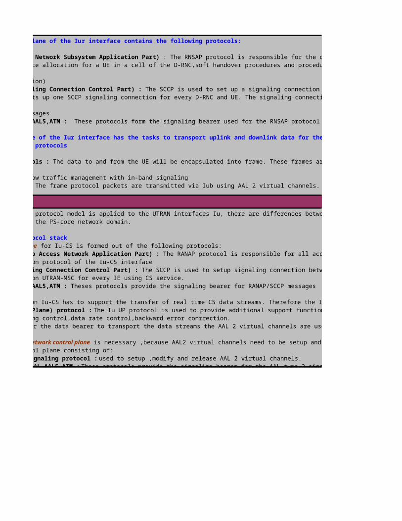
UTRAN Interface Protocol - Iu ( UTRAN-CN)
The control plane of the Iur interface contains the following protocols:
-RNSAP (Radio Network Subsystem Application Part) : The RNSAP protocol is responsible for the communication between S-RNC and D-RNC. This covers resource allocation for a UE in a cell of the D-RNC,soft handover procedures and procedures to transfer the S-RNC functionality to a D-
(SRNS relocation)- SCCP (Signaling Connection Control Part) : The SCCP is used to set up a signaling connection between S-RNC and D-RNC for the UE. This meansthe S-RNC sets up one SCCP signaling connection for every D-RNC and UE. The signaling connection will be used for fast identification of the
UE in signaling messages-MTP 3B,SAAL,AAL5,ATM : These protocols form the signaling bearer used for the RNSAP protocol messages.
The user plane of the Iur interface has the tasks to transport uplink and downlink data for the UE connected to a D-RNC. This tasks requires the following protocols
-Frame Protocols : The data to and from the UE will be encapsulated into frame. These frames are defined by so called frame protocols. These frameprotocols allow traffic management with in-band signaling-AAL 2 ,ATM : The frame protocol packets are transmitted via Iub using AAL 2 virtual channels. So AAL 2 ,ATM form the data bearer on the Iub interface.-AAL type 2 signaling protocol : The AAL type 2 SP provides the messages and functions to setup, release and modify AAL 2 virtual channels.-STC,MTP3B, SAAL,AAL 5,ATM : These protocols provide the signaling bearer for the AAL type2 signaling protocol. The STC(Signaling Transport Converter) provides functionality for congestion handling and load control. The protocol suite MTP3B,SAAL,AAL5 and ATM can be shared with the signaling bearer of RNSAP of Control Plane
The following protocol model is applied to the UTRAN interfaces Iu, there are differences between Iu-CS toward the CS-core network domain and Iu-PS towards the PS-core network domain.
1. Iu-CS protocol stackcontrol plane for Iu-CS is formed out of the following protocols:
-RANAP ( Radio Access Network Application Part) : The RANAP protocol is responsible for all access and signaling transport related tasks. It is the application protocol of the Iu-CS interface-SCCP (Signaling Connection Control Part) : The SCCP is used to setup signaling connection between RNC and MSC. There will be one and only one SCCP connection UTRAN-MSC for every IE using CS service.-MTP 3B,SAAL,AAL5,ATM : Theses protocols provide the signaling bearer for RANAP/SCCP messages
user plane on Iu-CS has to support the transfer of real time CS data streams. Therefore the Iu-CS plane has the following protocols:-Iu UP (User Plane) protocol : The Iu UP protocol is used to provide additional support functions for CS data streams on Iu. These functions can be : timing control,data rate control,backward error conrrection.AAL2,ATM : For the data bearer to transport the data streams the AAL 2 virtual channels are used.
transport network control plane is necessary ,because AAL2 virtual channels need to be setup and released. The protocol suite on the transportnetwork control plane consisting of:AAL type 2 signaling protocol : used to setup ,modify and release AAL 2 virtual channels.STC,MTP 3B,SAAL,AAL5,ATM : These protocols provide the signaling bearer for the AAL type 2 signalling protocol messages.

UMTS Protocol Stacks -> Application Part
2. Iu-PS protocol stackThe Iu-PS interface is the interface between RNC and SGSN. The control plane of Iu-PS is similar to the Iu-CS plane. It consists of:Iu-PS control plane-RANAP : The application protocol for Iu-CS and Iu-PS-SCCP : Provides signaling connection on Iu-PS. There will be one and only one SCCP connection between RNC and SGSN for every UE using PS service. SCCP connections on Iu-PS and Iu-CS do not affect each other.-MTP 3B,SAAL,AAL5,ATM : The signaling bearer for SCCP/RANAP
user plane on Iu-PS is competely different to the user plane of Iu-CS. This is because the traffic to and from SGSN is PS, so routing layer
necessary. The UTRAN provides the following protocols on the Iu-PS user plane:-Iu UP protocol : As for Iu-CS the Iu UP protocol can provide additional support functions for the data stream.-GTP-U (GPRS Tunneling Protocol-User Plane): GTP-U provides a frame for the user data to be transported. In a GTP-U frame a reference number
the PDP context and sequence numbers for the data are contained.-UDP/IP : The UDP/IP protocol suite is used as network layer between RNC and SGSN. The task of these protocols is to route from RNC to SGSN and vice versa.-AAL 5,ATM : The ATM adaptation layer of type 5 is used as bearer for the packets of IP/UDP/GTP-U.The AAL 5 virtual channels do not need to be set up in a dynamic manner. Rather the operator is expected to pre-configure the AAL 5 bearer to be usedfor the packet transfer. Therefore on Iu-PS there is no need for a transport network control plane. no bearer set up with explicit signalling
is necessary.
UMTS system has different application parts depending on interface being used and each application part controls signaling information for the call setup between nodes. Basically these applications message structure is similar to the SS7 signaling format, consisting each message of mandatory fixed part,variable fixed part and optional part.
to convert and transmit signaling for the control plane and one application part (ALCAP) to set up the transport bearer for the user plane.
This application part is the Iu interface signaling protocol that contains all the control information specified for the Radio Network Layer. The fucntions of
implemented by various Elementatry Procedures (EP). Each RANAP function requires the execution of one or more EP.
Handles the relocation of RNC for soft handover and hard handoverHandles the RAB setup,modification characteristic of an existing RAB and clearing a connected RAB
Connected signaling link and the U-Plane resources will be released.
Provides transparent transfer of UE-CN signaling messages that are not interpreted by UTRAN, such as broadcast information,direct transfer etc. Sets the ciphering on or off by encrypting signaling and user data connection in the radio interface
This application part is the Iub interface signaling protocol. It is divided into two procedures : Defines the signaling sequence across the common signaling link. Common NBAP defines all the procedures for the logical operation and maintenance of the Node-B, such as configuration and fault
RANAP

Defines the signaling sequence across the common signaling link. Common NBAP defines all the procedures for the logical operation and maintenance of the Node-B, such as configuration and fault
Sequence related to a specific UE signaling in the NodeB. Upon radio link setup procedure,the NodeB assigns a traffic termination point to control UE signaling. All of the subsequent signaling
this mobile is exchanged by Dedicated NBAP function by the dedicated control channel.
this function gives the controlling RNC (CRNC) the possibility to manage the cell configuration information in a NodeB. ,this function gives the CRNC the possibility to manage the configuration of common transport channels in a NodeB.
this function gives the CRNC the ability to manage the scheduling of System Information to be broadcast in a cell. this function gives the NodeB the ability to inform the CRNC about the status of NodeB resources. this function gives the CRNC and the NodeB the possibility to verify and enforce that both nodes have the same information on the configuration of the radio resources.
,this function allows the NodeB to initiate measurements in the NodeB. The function also allows the NodeB to report the result of the measurements. this function allows the CRNC to manage radio links using dedicated resources in a NodeB. ,this function allows the CRNC to report failures and restorations of a radio link. this function allows the CRNC to control the usage of compressed mode in a NodeB.
this function allows the CRNC to initiate measurements in the NodeB. The function also allows the NodeB to report the result of the measurements.
This application part is the Iur interface signaling protocol that controls signaling transfer between two RNC (SRNC and DRNC) in order to support the inter
Allows the SRNC to manage radio links using dedicated resoruces in a DRNC. DRNC reallocates the physical channel resources for a radio link
Allows DRNC to report failures and restoration of a radio link: Allows SRNC to adjust the DL power level of one or more radio links in order to avoid DL power drifting between radio links
Allows the SRNC and DRNC to pass information between UE and SRNC on a CCCH controlled by the DRNS
Allows the SRNC to finalize a relocation previously prepared via other interfaces.
This application part is the signaling protocol that provides the signaling capability to establish,release and maintain AAL2 connections by a series of ATM
words, ALCAP setup transport bearer such as AAL2 path between different nodes interfaces (Iu,Iur,Iub) in the UTRAN. The transport bearer in the User Plane are setup first sending signals by the Application
Control Plane (NBAP,RANAP,RNSAP). And then,data bearer is setup by the ALCAP protocol.The use of the ALCAP is dependent on the type of bearer to be used. The signaling bearers are usually pre-configured. This
Data bearers have to be setup and released with ALCAP, when they are not pre-configured. In this case the setup runs in the following manner:The setup or release of a bearer is always controlled by an application protocol. But to avoid the restriction to a single transport system, the application protocols shall not be specific to a certain
the application protocol can control the bearer via abstract parameters (QOS parameters) only. This principle is the same as for BICC (Bearer Independent Call Control). to trigger the set up of a bearer first
After the application protocol triggered the procedure,the ALCAP, that is specific to the bearer to be setup ,performs all necessary procedures to configure the bearer. When the application part receives the
successful bearer setup, the application protocol procedure can be finished, and the application can be informed to start the data stream transmission.

UMTS Network Architecture (Rel'99)
The Mobile Equipment represents the partner of the NodeB and of the RNC. It is responsible for serving the radio interface. Some of the tasks of the Mobile Equipment ares CDMA coding andencoding,Modulation and demodulation on the carrier,Power control,Quality and field strenght measurements,Ciphering and authorization,Mobility management and equipment identification.
The USIM functions to save data and procedures in ther terminal equipment. It supports call handling,contains security parameters,user-specific data e.g. telephone
International Mobile Subscriber Identity,Packet Switched Location Information,Security Information for authentication and chiphering for circuit and packet switched applications,PLMN selector and HPLMN
, and to the cs domain, which is called Iu-CS. In both cases, ATM is used as
this is an inter-RNS interface, connecting two neighbouring RNC. It is used among others in soft handover situations, where a UE‘s active cells are under the control of more than one RNC. One RNC is

Radio Network Controller(RNC) Functionality
The RNC has many different tasks in the UTRAN. It is responsible for e.g. Radio Resource Management (RRM) and the control of itself and the connected NodeB (O&M functionality). It is connected to the CN , CS domain via Iu(CS) interface and to the PS domain via Iu(PS) interface. Signalling and data transfer to other RNCs are possible via Iur interface and to the connected Node Bs via Iub interface.
Every cell has only one C-RNC. The C-RNC of a cell is exactly the RNC that is connected with the NodeB serving the cell. The tasks of the C-RNC covers the following areas:
Summary: The C-RNC is the RNC controlling a Node B ( i.e. terminating the Iub interface towards the NodeB).This means the C-RNC of a cell is responsible for all lower layer funcions related to the radio
An UE that is attached to an UTRAN is served by only one RNC. This RNC is called the serving RNC (S-RNC).The existence of a serving RNC does not imply that the UE is camped on a cell belonging to the S-RNC.The serving RNC handles all higher layer functions related to radio access and information transport through UTRAN. The S-RNC performs the following functions:
The S-RNC is responsible for the handling of all decisions for the connection with the UE e.g. for the allocation/modification or release of radio resources,for Outer Loop Power Control and for Handover
In the case of Soft Handover,S-RNC performs data splitting toward the different NodeBs and combining toward the CN. It decides to add or remove cells in the Soft Handover. The S-RNC is in most cases (but not
the C-RNC of some NodeBs used for the connection toward an UE. The S-RNC is no anchor functionality. It can be re-allocated to another RNC with the S-RNS reallocation procedure.
Summary: The S-RNC for one UE is the RNC that terminates both Iu link for transport of user data and corresponding RANAP signalling to/from the core network per UE. The S-RNC terminates the RRC signalling
In UMTS it is possible that one UE is connected to more than one cell, or connected to a cell, that does not belong to the S-RNC. This means the UE is connected with a cell controlled by a
to the S-RNC.This foreign RNC is called drift RNC ,D-RNC. In principle the D-RNC is the C-RNC of a cell the UE is connected to, but its not the S-RNC.Therefore D-RNC performs the C-RNC functions for the cells
When a D-RNC is involved for a UE, then the data streams between UE-UTRAN and UE-CN always pass the S-RNC. In the downlink the S-RNC sends the data to own cells and to the D-RNC(soft HO),this is called
The UE receives all the data streams from the cells,it is connected to and adds them together (RAKE Receiver, Maximum Ratio Combining). In the Uplink,the S-RNC receives data from the own cells and from the D-RNC
the S-RNC takes only the data frame with the smallest bit error rate, all other data frames will be discarded (Selective combining). The usage of a D-RNC requires a Iur interface between D-RNC and S-RNC.
Summary: D-RNC is any RNC, other than SRNC that controls cells used by the UE. The D-RNC performs macro-diversity combining and splitting,if necessary. The D-RNC does not perform user plane data L2 processing,but routes the data transparently between the Iub and Iur interfaces.The UE can be connected to 0 ,one or more DRNCs. ( Macro Diversity is an operation state in which a UE simultaneously has radio links with

Node B Functionality
Geographical and UTRAN Entity Identifiers
An UE that is attached to an UTRAN is served by only one RNC. This RNC is called the serving RNC (S-RNC).The existence of a serving RNC does not imply that the UE is camped on a cell belonging to the S-RNC.The serving RNC handles all higher layer functions related to radio access and information transport through UTRAN. The S-RNC performs the following functions:
The S-RNC is responsible for the handling of all decisions for the connection with the UE e.g. for the allocation/modification or release of radio resources,for Outer Loop Power Control and for Handover
In the case of Soft Handover,S-RNC performs data splitting toward the different NodeBs and combining toward the CN. It decides to add or remove cells in the Soft Handover. The S-RNC is in most cases (but not
the C-RNC of some NodeBs used for the connection toward an UE. The S-RNC is no anchor functionality. It can be re-allocated to another RNC with the S-RNS reallocation procedure.
Summary: The S-RNC for one UE is the RNC that terminates both Iu link for transport of user data and corresponding RANAP signalling to/from the core network per UE. The S-RNC terminates the RRC signalling
In UMTS it is possible that one UE is connected to more than one cell, or connected to a cell, that does not belong to the S-RNC. This means the UE is connected with a cell controlled by a
to the S-RNC.This foreign RNC is called drift RNC ,D-RNC. In principle the D-RNC is the C-RNC of a cell the UE is connected to, but its not the S-RNC.Therefore D-RNC performs the C-RNC functions for the cells
When a D-RNC is involved for a UE, then the data streams between UE-UTRAN and UE-CN always pass the S-RNC. In the downlink the S-RNC sends the data to own cells and to the D-RNC(soft HO),this is called
The UE receives all the data streams from the cells,it is connected to and adds them together (RAKE Receiver, Maximum Ratio Combining). In the Uplink,the S-RNC receives data from the own cells and from the D-RNC
the S-RNC takes only the data frame with the smallest bit error rate, all other data frames will be discarded (Selective combining). The usage of a D-RNC requires a Iur interface between D-RNC and S-RNC.
Summary: D-RNC is any RNC, other than SRNC that controls cells used by the UE. The D-RNC performs macro-diversity combining and splitting,if necessary. The D-RNC does not perform user plane data L2 processing,but routes the data transparently between the Iub and Iur interfaces.The UE can be connected to 0 ,one or more DRNCs. ( Macro Diversity is an operation state in which a UE simultaneously has radio links with
A nodeB is a physical unit for implementing a UMTS radio transmission. Depending on the sectoring of the cells ,one (omni) cell or multiple (sector) cells can be serviced by a Node B. Generally,up to six cells are serviced by a Node B in UMTS.
(Uplink and Downlink separated by different frequency bands),Time division Duplex (Uplink . A Node B converts user and signalling information received from the RNC for
transport via the radio interface,and in the opposite direction. Node Bs are involved in power control,NodeB measures the signal to noise ratio (SIR) of the User Equipment ,compares the value with a predefined one and instructs the UE to control its transmission power. The NodeB also measures the quality and strength of the links and determines the Frame Error Rate (FER). The following are examples of NodeB functions:
Transport to physical channel mappings. Encoding/Decoding – Spreading/De-spreading user traffic and signalling.. Controlling Uplink and Downlink radio paths on the Uu Air Interface,Baseband to RF conversion,Antenna multi-
,Interfacing with M2000 and RNC for alarm and control (Operations and Maintenance) functions.Managing ATM switching and multiplexing over the Iub interface. Control of AAL2/AAL5 connections. Control

International UMTS/GSM Service Area, i.e. the world-wide area where access to GSM and UMTS network is possible,is sub-divided into National Service Areas.
National Service Area is the area of on country or region. It is identified by the Mobile Country Code (MCC) and Country Code (CC). The National Service Area is sub-divided into one or more PLMN Service Areas.
PLMN Service Area is the service area of a single PLMN. It identified by the Mobile Country Code(MCC) and Country Code (CC). The National Service Area is sub-divided into one or more MSC and SGSN Service Areas.
An MSC or SGSN Service Area is the area, which is served by a single MSC (CS-domain) or by a single SGSN (PS-domain). MSC and SGSN Service Area may differ, but they are on the same hierachical level. The MSCs
A Location Area (LA) is the most precise UE location information,which is stored in the CS-domain (in the VLR) of UMTS. A Location Area is world-wide uniquely identified by its Location Area Identity LAI
The SGSN Service Area is sub-divided into one or more Routing Areas. A Routing Area (RA) is a subset of a Location Area i.e. one LA may contain one or more RAs. The RA is the most precise UE information, which
stored in the PS-domain (in the SGSN) of UMTS. It is world-wide uniquely identified by the Routing Area Identity. The RA is sub-divided into the Cell-Areas.It is also essential to address different physical,geographical or logical entities within UMTS. The geographical and physical entities of UTRAN are described as follow,
The PLMN-ID is used to address a PLMN in a world-wide unique manner. As in GSM the PLMN-ID consist of a MCC(mobile country code) and a MNC(mobile network code). MCC and MNC are allocated by ITU-T and are
Every RNC node has to be uniquely identified within UTRAN. Therefore every RNC gets a RNC-ID. Together with the PLMN-ID the RNC-ID is unique world wide. The RNC-ID will be used to address a RNC via Iu,Iur and

UTRAN Identifiers for UE
The UE and the Subscriber can have several identifiers for the PLMN. Typically we can distinguish two types of identifiers according to the point of generation of the identifier:
These identifiers are allocated by the core network. In detail there are IMSI,TMSI and P-TMSI (and IMEI) UTRAN identifiers are always temporary (Radio Network Temporary Identifiers ,RNTIs). This means they are allocated to the UE for the time of the need. After the last procedure the
Mobile Country Code,MCC (3 digits) + Mobile Network Code,MNC (2-3 digits)+Mobile Subscriber Identification
The TMSI is used as temporary user identity instead of the IMSI to support subscriber identity confidentiality. This TMSI is allocated to an UE by VLR and stored in the U-SIM. It has only local significance i.e.
The P-TMSI is used as temporary packet user identity. It is allocated to an UE b y an SGSN and stored in the U-SIM. The P-TMSI consists of 3 bytes,which are operator-dependent.
Type Approval Code TAC (6 digits),the Final Assembly Code FAC(2
The S-RNTI is allocated by the S-RNC,after every S-RNC Reallocation it has to be reallocation,too.The S-RNTI is used by the S-RNC to address the UE, by the D-RNC to identify the
The U-RNTI is composed by the S-RNTI and the S-RNC-id. It is used as UE Id for the first cell access (at cell change) at existing RRC connection and for UTRAN originating Paging including
The C-RNTI is allocated by the C-RNC,when the UE accesses a new cell. It is used as an in-band UE identifier in all DCCH/DTCH common channel messages on Uu despite the first access
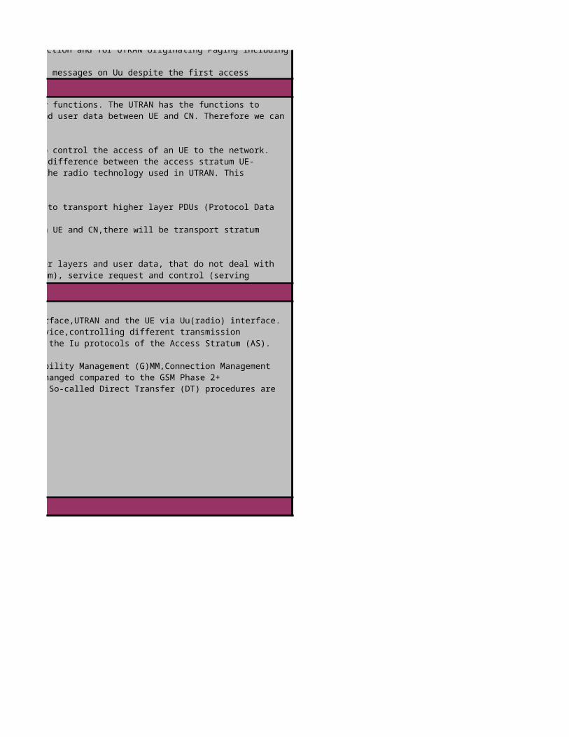
UTRAN Protocols
UTRAN Protocol Architecture
UTRAN Interface Protocol Structure
The UE and the Subscriber can have several identifiers for the PLMN. Typically we can distinguish two types of identifiers according to the point of generation of the identifier:
These identifiers are allocated by the core network. In detail there are IMSI,TMSI and P-TMSI (and IMEI) UTRAN identifiers are always temporary (Radio Network Temporary Identifiers ,RNTIs). This means they are allocated to the UE for the time of the need. After the last procedure the
Mobile Country Code,MCC (3 digits) + Mobile Network Code,MNC (2-3 digits)+Mobile Subscriber Identification
The TMSI is used as temporary user identity instead of the IMSI to support subscriber identity confidentiality. This TMSI is allocated to an UE by VLR and stored in the U-SIM. It has only local significance i.e.
The P-TMSI is used as temporary packet user identity. It is allocated to an UE b y an SGSN and stored in the U-SIM. The P-TMSI consists of 3 bytes,which are operator-dependent.
Type Approval Code TAC (6 digits),the Final Assembly Code FAC(2
The S-RNTI is allocated by the S-RNC,after every S-RNC Reallocation it has to be reallocation,too.The S-RNTI is used by the S-RNC to address the UE, by the D-RNC to identify the
The U-RNTI is composed by the S-RNTI and the S-RNC-id. It is used as UE Id for the first cell access (at cell change) at existing RRC connection and for UTRAN originating Paging including
The C-RNTI is allocated by the C-RNC,when the UE accesses a new cell. It is used as an in-band UE identifier in all DCCH/DTCH common channel messages on Uu despite the first access
The communication between the different domains can be divided according to their functions. The UTRAN has the functions to provide access links between UE and UTRAN and transport of signalling messages and user data between UE and CN. Therefore we can distiguish three types of signalling between UE,UTRAN and CN as follows,
: The Access Stratum covers all signalling exchange used to control the access of an UE to the network. Access Stratum messages occur between UE and UTRAN and between UTRAN and CN. The difference between the access stratum UE-UTRAN and UTRAN-CN is ,that the UTRAN-CN access stratum shall be independent of the radio technology used in UTRAN. This
The Transport Stratum protocols and messages have the task to transport higher layer PDUs (Protocol Data
and user data. Because UTRAN has the task to transparently transport data between UE and CN,there will be transport stratum
The Non-Access-Stratum covers all messages of higher layers and user data, that do not deal withaccess or transport tasks.This cover pure application control (application stratum), service request and control (serving
,handling of subscription data and subscriber specific services (home stratum).
The UMTS network is split into the CN,UTRAN and the UE. CN and UTRAN are connected via Iu interface,UTRAN and the UE via Uu(radio) interface. User data (radio access bearer services) and control information (including requesting the service,controlling different transmission resources,handover etc) are exchanged between the CN and the UEs using the Radio protocols and the Iu protocols of the Access Stratum (AS).
The higher layer protocols of the Non-Access Stratum(NAS) handle control aspects e.g. (GPRS)Mobility Management (G)MM,Connection Management (CM) or Session Manangement (SM) tasks. The NAS procedures (of Rel. '99) are in most cases unchanged compared to the GSM Phase 2+procedures. The radio and Iu protocols contain mechanism for transparent NAS message transfer. So-called Direct Transfer (DT) procedures are

UTRAN Interface Protocol Overview
and vertical planes. The general protocol model describes these layers and planes as logically independent of each other. The modularity of this model allows changing parts of the protocol structure in
The transport system used within UTRAN is ATM. There is difference between the usage of ATM and the use PCM lines in a GSM-BSS. ATM supportsdifferent types of bearer service labelled AAL type 1,AAL type 2, AAL type 3/4 and AAL type 5. In UTRAN only AAL type 2 and AAL Type 5 are used. Bearers of AAL type2 can be set up with explicit signalling. This means before a AAL type 2 virtual channel can be used,there might be signalling between the corresponding ATM switches. This behavior results in a new protocol model, where protocols for user bearer set up and
Radio Network Layer and Transport Network Layer.All UTRAN related issuesare visible in the Radio Network Layer only.The Transport Network Layer is used for UTRAN,offering transport technologies.It is without any
The Transport Network Layer consists of all protocols used for the transport network solution. This includes the
The Radio Network Layer contains all protocols,that are specific to the radio access and transport stratum. Also all
There is also a vertical structure, the elements of this vertical structure are planes. A plane principle is protocol stack,more than one plane
next to eachother. The general protocol model consists of three vertical planes- the Control Plane,the User Plane and the Transport Network
The user plane supports the data streams for user data. Therefore the data streams are packed into frame protocols. These frameprotocols will be transmitted via data bearers. In contrast to the signalling bearers of the control plane,the data bearer can require to be
The control plane consists of all application protocols that are used for radio network controlling. To transport the messages
application protocol,one or several signaling bearers,provided by the transport network are neccesary. The Control Plane is used for all
signaling,which is UMTS-specific. It includes the Application Protocols (i.e. RANAP,RNSAP and NBAP) and the signaling bearer for transport the
The transport network control plane contains the ALCAP (Access Link Control Application Part). The ALCAP protocols are used to set up and release the data bearers of the user plane. Also ALCAP messages require a signaling bearer for transmission.
not necessary to use the ALCAP for all data bearers. Expecially the transport network control plane is not necessary when pre-configured
are used. The Transport Network Control Plane is used for all control signaling within the Transport Layer. It contains no Radio Network Layer
The Transport Network Control Plane acts as plane between the Control Plane and User Plane, it enables the Application Protocol in the Control

UMTS Protocol Stacks -> UE-UTRAN-CN for CS domain
Between user plance and control plane exist the transport plane. The task of transport plane is the setup of a data bearer for the user plane
is used for the exchange of control information which are related to CS services. In addition ,the CS control plane is used for controlling supplementary services and it can be used for the
The physical layer (Layer1) on the air interface provides access to the WCDMA radio interface. Therefore it performs spreading,scrambling.modulation,channel conding,rate matching etc. The MAC protocol belongs to Layer 2. The tasks of MAC are the control of random access and the multiplexing/de-multiplexing of different UEs onto shared radio resources.
As MAC also the RLC protocol is a Layer 2 protocol. RLC provides three reliabilty modes for every radio bearer. These modes are : Acknowledge (AM),Unacknowledge(UM) and Transparent
The RRC protocol is the first protocol of Layer 3. The RRC protocol performs all higher layer tasks related to the access stratum on the air interface (e.g. radio bearer setup)MM (Mobility Management),CC (Call Control),SS(Supplementary Services) and SMS (Short
RANAP is between UTRAN and CN. It performs all tasks related to transport stratum for control signaling and access stratum between UTRAN and CN. It is the
The SCCP has mainlu transport tasks. It is used to establish a singling connection for a UE. So the UE can then be identified by the signaling connection and not by an

UMTS Protocol Stacks -> UE-UTRAN-CN for PS domain
is used for the exchange of control information which are related to CS services. In addition ,the CS control plane is used for controlling supplementary services and it can be used for the
The physical layer (Layer1) on the air interface provides access to the WCDMA radio interface. Therefore it performs spreading,scrambling.modulation,channel conding,rate matching etc. The MAC protocol belongs to Layer 2. The tasks of MAC are the control of random access and the multiplexing/de-multiplexing of different UEs onto shared radio resources.
As MAC also the RLC protocol is a Layer 2 protocol. RLC provides three reliabilty modes for every radio bearer. These modes are : Acknowledge (AM),Unacknowledge(UM) and Transparent
The RRC protocol is the first protocol of Layer 3. The RRC protocol performs all higher layer tasks related to the access stratum on the air interface (e.g. radio bearer setup)MM (Mobility Management),CC (Call Control),SS(Supplementary Services) and SMS (Short
RANAP is between UTRAN and CN. It performs all tasks related to transport stratum for control signaling and access stratum between UTRAN and CN. It is the
The SCCP has mainlu transport tasks. It is used to establish a singling connection for a UE. So the UE can then be identified by the signaling connection and not by an
UMTS transports the control signaling and the user data over the same transport network. So,there are some protocols supporting the user data transfer. In the lowest layers there are the same protocols as for
: The air interface transport system is built out of PHY,MAC and RLC as for the control plane. The same basic stack is used for the user plane. The user data streams are generated by the applications using the CS core network services (switched channels). These data streams are directly input to the RLC
To provide a circuit switched like transport bearer on Iu, The AAL 2 protocol is used. This adaptation layer provides a bearer channel (virtual channel of AAL type 2) with certain QOS gurantees. Additonally the AAL 2 cirtual channel includes time stamps in the transport frames. This allows synchronization and timing control between sender and receiver.
Please note that AAL 5 is used for all control functions on the Iu-CS interface ( <> RANAP) and the Iub interface (<>NBAP). On the other hand, the real time AAL 2 is used for relaying UE- data and UE-signaling

UTRAN Interface Protocol -Uu (UE-UTRAN)
For Packet Switched (PS) service,there are different procedures. So there is a need for special proctocols for PS services. In fact these special protocols are on the higher layers,so that the lower layer will
The transport and access stratum protocols on the air interface are the same for PS and CS. UMTS has been designed to support both types of services, so that there are no special protocols.
SCCP and RANAP are the same as for CS. The SCCP is mainlu used to setup a signaling conenction to the SGSN in the core network. RANAP handles all signaling transport and access related tasks. The only special protocols for the packet switched service are the non-access stratum protocols. Because there are essential differences how to handle a packet switched service request, the PS
network has its own mobility managment GMM ( GPRS Mobility Management). To set up a data session the SM (Session Management) protocol is used. The SMS is in fact the same as for CS.
The user data for PS services is usually dedicated to external packet data networks (e.g. internet). These external data network have their own special network protocols ( e.g. internet) . These
network have their own special network protocols (e.g .TCP/IP). When a UMTS user wants want to be connected with such an external network, the UE has to send packets of this special network protocol, for the
It is the task of the UMTS network to provide a tunnel (PDP context) for
This protocol performs header compression of the PDP packet header. This shall increase the efficiency of the air interface usage.
The PDP packets are transported in a GTP-U frame on Iu. GTP-U organizes addressing and identification of the originator and destination of the data between RNC and
To route from RNC to SGSN the standard UDP/IP protocol stack is used. This is a connection less unreliable transport service. In principle only routing is performed with UDP/IP

Physical Layer (L1) Functions
Uu interface is the interface between User Equipment (UE) and UMTS Terrestrial Radio Access Network (UTRAN) and it is the most
supports all functions required for the transmission of bit streams on the physical medium. It is also in charge of measurements function consisting in indicating to higher layers, for example, Frame Error Rate (FER), Signal to Interference Ratio (SIR),interference power, transmit power, … It is basically composed of a “layer 1 management” entity, a “transport
protocol is responsible for providing functions such as mapping, ciphering, retransmission and segmentation. It is made of four sublayers: MAC (Medium Access Control), RLC (Radio Link Control), PDCP (Packet Data Convergence Protocol) and BMC
is split into 2 parts: the access stratum and the non access stratum. The access stratum part is made of “RRC (Radio Resource Control)” entity and “duplication avoidance” entity. The non access stratum part is made of CC, MM parts.The RRC
L3 are implemented by RNC, and the MM and CC functions of L3 are implemented by CN.
The protocol layers are located in the UE and the peer entities are in the node B or the RNC.
The processing of the transport channels that come from the MAC layer has the following steps,that can be identified with the presented functional blocks:
The transport blocks are concatenated after the CRC is appended. if the resulting data block is too long (e.g does not fit into one radio frame) a
Channel coding can enhance symbol correlation to recover signals in the case of interference.UTRAN FDD and TDD offer four different channel coding schemes as FEC(Forward Error Correction).
The physical layer can perform a puncturing of bits to reduce the data rate. the physical layer gets matching parameters from RRC layer
If no information is to be transmitted by the network, so called DTX (Discontinuous transmission) bits are inserted. This is only for downlink
and transmitted in physical channels,there has to be an indication which transport formats are used for every
This allows the de-multiplexing of CCTrCHs. the TFCI values and the assignment of transport format combination is signaled by RRC during radio bearer establishment.
"transport format comnination". Such a combination has to be chosen
.Every transport format combination in the transport format combination set is uniquely identified with a transport
The physical layer defines several procedures to control the radio interface on the lowest level. Most of these procedures are triggered and mastered by higher layers like MAC and RRC. The procedures can be
These types of procedures are used for cell search,radio frame/slot and chip synchronization to physical channels. In the TDD mode also timing advance procedures are used to
One of the most critical issues for CDMA systems is the near-far problem. The solution for this is a very fast power control mechanism,using a closed control loop ( UE<>NodeB<>UE)Like all known mobile radio access technologies also WCDMA has to use random access mechanism to establish a radio connection between an UE and the Network. BNut also for
For the mobility handling within the radio network the UE and the Node B have to perform measurements of radio signal quality (bit error rate) and radio signal strength (signal interference ratio,interference power,signal power). These measurment are used as criteria for the cell reselection or handover procedures. For the measurments the UE physical layer has uses so called compressed mode mode
1. Segmentation, reassembly, concatenation, padding and transfer of user data2. Flow control Error correction, in-sequence delivery of upper layer PDUs and duplicate detection
1.Header compression and decompression of IP data streams at the transmit and receive entities
2.Transfer of packet oriented user data using RLC transparent,unackowledge or acknowledged mode3.Forwarding of PDCP-SDUs from NAS to RLC, and multiplexing of different RBs to the same RLC entity
2.Traffic volume monitoring and radio resource request for CBS
5. Delivery of cell broadcast messages to upper layer (NAS)

UTRAN Interface Protocol - Iub ( RNC-NodeB)
UTRAN Interface Protocol - Iur ( RNC-RNC)
1. Segmentation, reassembly, concatenation, padding and transfer of user data2. Flow control Error correction, in-sequence delivery of upper layer PDUs and duplicate detection
1.Header compression and decompression of IP data streams at the transmit and receive entities
2.Transfer of packet oriented user data using RLC transparent,unackowledge or acknowledged mode3.Forwarding of PDCP-SDUs from NAS to RLC, and multiplexing of different RBs to the same RLC entity
2.Traffic volume monitoring and radio resource request for CBS
5. Delivery of cell broadcast messages to upper layer (NAS)
The NBAP protocol is the application protocol of the Iub interface. It organizes all controlling tasks between
These protocols constitute the signalling bearer for the NBAP messages.
The user plane of the Iub interface has to transfer the downlink and uplink data to and from the UE. Therefore different frames are defined in
The Frame Protocols encapsulate the UE data (UL&DL) on the Iub interfaceThe frame protocol,that encapsulate the UE data,are transported over AAL 2 virtual channels of ATM. These AAL 2 virtual channels
The AAL type 2 SP provides the messages and functions to setup, release and modify AAL 2 virtual channels. The STC (Signaling Transport Converter),SAAL,AAL 5 and ATM provide the signaling bearer for AAL type 2 signaling
The physical layer is not standardized. it is up to the operator and verndor to choose an appropiate physical transmission system.

UTRAN Interface Protocol - Iu ( UTRAN-CN)
: The RNSAP protocol is responsible for the communication between S-RNC and D-RNC. This covers resource allocation for a UE in a cell of the D-RNC,soft handover procedures and procedures to transfer the S-RNC functionality to a D-
The SCCP is used to set up a signaling connection between S-RNC and D-RNC for the UE. This meansthe S-RNC sets up one SCCP signaling connection for every D-RNC and UE. The signaling connection will be used for fast identification of the
These protocols form the signaling bearer used for the RNSAP protocol messages.
The user plane of the Iur interface has the tasks to transport uplink and downlink data for the UE connected to a D-RNC. This tasks requires
The data to and from the UE will be encapsulated into frame. These frames are defined by so called frame protocols. These
The frame protocol packets are transmitted via Iub using AAL 2 virtual channels. So AAL 2 ,ATM form the data bearer on the Iub
The AAL type 2 SP provides the messages and functions to setup, release and modify AAL 2 virtual channels.These protocols provide the signaling bearer for the AAL type2 signaling protocol. The STC(Signaling Transport
Converter) provides functionality for congestion handling and load control. The protocol suite MTP3B,SAAL,AAL5 and ATM can be shared with the The following protocol model is applied to the UTRAN interfaces Iu, there are differences between Iu-CS toward the CS-core network domain and
The RANAP protocol is responsible for all access and signaling transport related tasks. It is
The SCCP is used to setup signaling connection between RNC and MSC. There will be one and only one
Theses protocols provide the signaling bearer for RANAP/SCCP messages
on Iu-CS has to support the transfer of real time CS data streams. Therefore the Iu-CS plane has the following protocols:The Iu UP protocol is used to provide additional support functions for CS data streams on Iu. These functions
For the data bearer to transport the data streams the AAL 2 virtual channels are used.
is necessary ,because AAL2 virtual channels need to be setup and released. The protocol suite on the transport
used to setup ,modify and release AAL 2 virtual channels.These protocols provide the signaling bearer for the AAL type 2 signalling protocol messages.

UMTS Protocol Stacks -> Application Part
The Iu-PS interface is the interface between RNC and SGSN. The control plane of Iu-PS is similar to the Iu-CS plane. It consists of:
Provides signaling connection on Iu-PS. There will be one and only one SCCP connection between RNC and SGSN for every UE using PS
on Iu-PS is competely different to the user plane of Iu-CS. This is because the traffic to and from SGSN is PS, so routing layer
As for Iu-CS the Iu UP protocol can provide additional support functions for the data stream. GTP-U provides a frame for the user data to be transported. In a GTP-U frame a reference number
The UDP/IP protocol suite is used as network layer between RNC and SGSN. The task of these protocols is to route from RNC to SGSN and
The ATM adaptation layer of type 5 is used as bearer for the packets of IP/UDP/GTP-U.The AAL 5 virtual channels do not need to be set up in a dynamic manner. Rather the operator is expected to pre-configure the AAL 5 bearer to
for the packet transfer. Therefore on Iu-PS there is no need for a transport network control plane. no bearer set up with explicit signalling
UMTS system has different application parts depending on interface being used and each application part controls signaling information for the call setup between nodes. Basically these applications message
to convert and transmit signaling for the control plane and one application part (ALCAP) to set up the transport bearer for the user plane.
This application part is the Iu interface signaling protocol that contains all the control information specified for the Radio Network Layer. The fucntions of
Provides transparent transfer of UE-CN signaling messages that are not interpreted by UTRAN, such as broadcast information,direct transfer etc.
Defines the signaling sequence across the common signaling link. Common NBAP defines all the procedures for the logical operation and maintenance of the Node-B, such as configuration and fault
NBAP

Defines the signaling sequence across the common signaling link. Common NBAP defines all the procedures for the logical operation and maintenance of the Node-B, such as configuration and fault
Sequence related to a specific UE signaling in the NodeB. Upon radio link setup procedure,the NodeB assigns a traffic termination point to control UE signaling. All of the subsequent signaling
this function gives the controlling RNC (CRNC) the possibility to manage the cell configuration information in a NodeB.
this function gives the CRNC and the NodeB the possibility to verify and enforce that both nodes have the same information on the configuration of the radio resources. ,this function allows the NodeB to initiate measurements in the NodeB. The function also allows the NodeB to report the result of the measurements.
this function allows the CRNC to initiate measurements in the NodeB. The function also allows the NodeB to report the result of the measurements.
This application part is the Iur interface signaling protocol that controls signaling transfer between two RNC (SRNC and DRNC) in order to support the inter
: Allows SRNC to adjust the DL power level of one or more radio links in order to avoid DL power drifting between radio links
This application part is the signaling protocol that provides the signaling capability to establish,release and maintain AAL2 connections by a series of ATM
words, ALCAP setup transport bearer such as AAL2 path between different nodes interfaces (Iu,Iur,Iub) in the UTRAN. The transport bearer in the User Plane are setup first sending signals by the Application
Control Plane (NBAP,RANAP,RNSAP). And then,data bearer is setup by the ALCAP protocol.The use of the ALCAP is dependent on the type of bearer to be used. The signaling bearers are usually pre-configured. This
The setup or release of a bearer is always controlled by an application protocol. But to avoid the restriction to a single transport system, the application protocols shall not be specific to a certain
the application protocol can control the bearer via abstract parameters (QOS parameters) only. This principle is the same as for BICC (Bearer Independent Call Control). to trigger the set up of a bearer first
After the application protocol triggered the procedure,the ALCAP, that is specific to the bearer to be setup ,performs all necessary procedures to configure the bearer. When the application part receives the

Mapping of UE state to 3GPP Specifications
RRC Tasks and Functions
After UE switch on, there are two basic operational modes of a UE, idle mode and connected mode.The connected mode can be further divided into 4 service states,which de ne what kind of physical channels a UE is using. The mapping fiof UE state to 3GPP speciafication is shown below:
The RRC protocol is the application part for the UMTS radio access technology. This means all controlling radio tasks are in the responsibility of RRC. The RRC has following functions:-broadcasting of system information for NAS stratum-establishment,maintenance and release of RRC signaling between UE and UTRAN connections-establishment,reconfiguration and release of radio bearers-RRC connection mobility functions-Quality of Service (QOS) control-UE measurement reports-outer loop power control-security control-paging-Initial cell selection and reselection-transport of NAS stratum control messages
With all these tasks the RRC protocol belongs to the access stratum when the radio oriented control tasks are performed and it belongs to the transport stratum,because it carriers the higher layer control plane protocol messages.
UE Switch on
UE Idle3GPP TS 25.304
UE Connected3GPP TS 25.331
GSM ConnectedGSM TS 04.18
GSM IdleGSM TS 05.08
UE Idle3GPP TS 25.3043GPP TS 25.331
Cell_DCH3GPP TS 25.331
Cell_PCH3GPP TS 25.3043GPP TS 25.331
Cell_FACH3GPP TS 25.3043GPP TS 25.331
URA_PCH3GPP TS 25.3043GPP TS 25.331
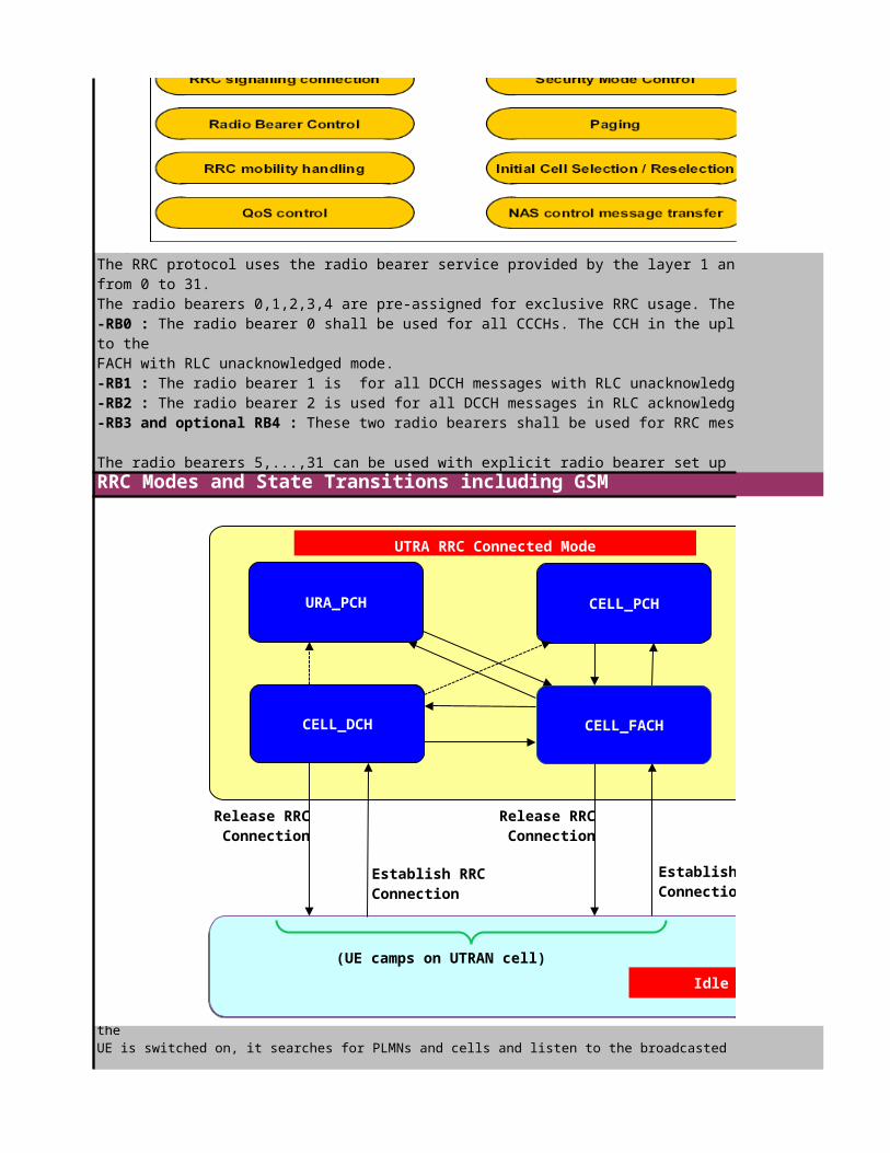
RRC Modes and State Transitions including GSM
Usage of Radio Bearer by the RRC protocolThe RRC protocol uses the radio bearer service provided by the layer 1 and layer 2 of the UMTS radio interface. The radio bearers in an UE will be numbered from 0 to 31. The radio bearers 0,1,2,3,4 are pre-assigned for exclusive RRC usage. The following is speified:-RB0 : The radio bearer 0 shall be used for all CCCHs. The CCH in the uplink is mapped to the RACH with RLC transparent mode, the downlink CCCH is mapped to the FACH with RLC unacknowledged mode.-RB1 : The radio bearer 1 is for all DCCH messages with RLC unacknowledged mode-RB2 : The radio bearer 2 is used for all DCCH messages in RLC acknowledged mode, but not for RRC messages that transport NAS messages inside.-RB3 and optional RB4 : These two radio bearers shall be used for RRC messages carrying NAS messages on DCCH in RLC acknowledged mode.
The radio bearers 5,...,31 can be used with explicit radio bearer set up for all purposes, e.g. traffic channels or control channels.For RRC messages the protocol specified which RLC mode and with this which radio bearer can be chosen for transport of this message.
the UE is switched on, it searches for PLMNs and cells and listen to the broadcasted system information of selected cells
Release RRCConnection
Release RRCConnection
Establish RRCConnection
Establish RRCConnection
URA_PCH
CELL_DCH CELL_FACH
CELL_PCH
UTRA RRC Connected Mode
Idle Mode(UE camps on UTRAN cell)

RRC Mode DescriptionRRC Idle Mode
RRC Connected Mode
2. UTRA RRC Connected Mode : In the connected mode the UE has a signaling connection with the UTRAN. The setup of this signaling conenction is done by a RRC procedure (RRCconnection set up). This procedure is the transistion from idle to connected mode. When the RRC connection is released, the connected mode is left and the idle more is entered.
For multi-mode mobile phones (e.g. UMTS,GSM/GPRS) the RRC states can be combined with the radio resource management states of GSM/GPRS. In GSM/GPRS the states of a mobile phone can be:1. Idle Mode : The idle mode of GSM/GPRS has the same meaning as the idle mode of UMTS. The only difference is, that the UE is camped on a GSM/GPRS cell2. GSM conected mode : In GSM the RR (Radio Resource Layer) performs the radio management. This protocol can setup a RR connection between network and mobile equipment.When such a connection exist,the UE is in GSM connected mode. A GSM-DCCH is allocated for the UE in this case.3. GPRS packet transfer mode : In GPRS the radio resources are allocated for a mobile temporary only. Such a temporary resource is called a temporary block flow (TBF). When a mobile is granted a temporary block flow ,the mobile is in GPRS packet transfer mode (GPRS-RLC state)
With a multi-mode UE it shall be possible to perform in-service-transitions between the different Radio Access Technology (RAT).Therefore it is possible to make a inter-system handover from UTRA connected mode to GSM connected mode and vice versa. A transistion from UTRA connected mode to GPRS packet transfer mode is simply done by stoppint thepacket transfer in UMTS, making a cell reselection to a GPRS cell and getting a GPRS temporary block flow.
When a UE is switched on, it enters the RRC idle mode. In the RRC idle mode, there is no connection on the access stratum level between the UE and UTRAN. UTRAN has no information about UEs in the RRC idle mode. If UTRAN wants to address the UE, it must use non-access stratum identifiers, such as IMSI or TMSI and LAI.
In the RRC idle mode, the UE monitors the BCCH, and when it is registered to the CN, it also listens to paging occasions on its PICH.
The transition from the RRC idle mode to the RRC connected mode can only be initiated by the UE by sending thetransport channels used to exchange messages and data between the UE and UTRAN, the UE is identified by a Radio Network Temporary Identity (RNTI). As can be seen in thefigure above, the UE can be in one of four sub-states, when it is in the RRC connected mode. The sub-states depend on the connectivity level between the UE and UTRAN. The set of usable transport channels depend also on the sub-states. For instance, the DCHs are not available in the sub-states CELL_PCH and CELL_URA. The UE leaves the RRC idle
The RRC connected Mode can be further decomposed into four different states. These four sub-states describe, on which level the UE is known by UTRAN and which resources are allocated by the UE. UTRAN can know any UE either on cell level (cell state) or on URA level (URA state). On the other hand any UE can have a DCH or a FACH or no transport channel for control message exchange. Therefore the four connected states are introduced:
CELL_DCHIn this sub-state, dedicated physical channels are allocated to the UE. DCCH and – if configured – DTCH information can be transmitted. There no need to identify the UE on a dedicated channel, because the physical channels are exclusively allocated to this UE. UTRAN knows the active set cells for the radio links and thus the location of the the UE. Also downlink shared channels can be allocated to the UE. In this state, the UE is capable to receive RRC messages on the DCCH (and BCCH, if it owns specific capabilities). The cell system information is broadcasted on the FACH. The UE reads the cell system information and acts accordingly. For instance, it determines the measurement quality and the reporting events from the cell system information. This state can only be entered from Cell_FACH by setting up a DCH. When the last DCH is released the UE enters Cell_FACH,Cell_PCH,URA_PCH or idle mode
In the CELL_DCH state the UE shall perform the following actions:if DCCH and DTCH are available:- read system information broadcast on FACH (applicable only to UEs with certain capabilities and camping on FDD cells);- perform measurements process according to measurement control informationCELL_FACHThis state was introduced for traffic situations, where only small amounts of data have to be transmitted. This is the case when only higher layer signalling information (NAS signalling) or small amount of user data (e.g. SMS messages) have to be transmitted. In this case, an exclusive allocation of one physical channel to the UE would result in a waste of resources. Only common transport channel FACH can be used by the UE to transmit higher layer data, which it has to share with other UEs. Each UE must be explicitly addressed, for instance by the RNTI. It has to monitor the FACH permanently in the downlink, not to miss user data for it. The UE‘s FACH is mapped on one S-CCPCH.
In the uplink, it uses the shared transport channels for user data transfer, such as the RACH. The UE is only connected to one cell, and this is the location information, known within UTRAN. No soft handover takes place in this sub-state. The UE is responsible for cell re-selection. By listening to the cell system information from the BCCH, it gains all relevant measurement qualities, threshold values, neighbourhood lists to perform the cell re-selection process. Other relevant information is also learned from the BCCH. The UE receives RRC messages on the BCCH, CCCH and DCCH channels. Due to the discontinuous type of traffic, UTRAN can command the UE to perform periodic cell updates.
In the CELL_FACH state the UE shall perform the following actions:if the UE is "in service area":- DCCH and DTCH are available- perform cell reselection process- perform measurements process according to measurement control information- run timer T305 (periodical cell update)- listen to all FACH transport channels mapped on S-CCPCH assigned to this UEif the UE is "out of service area":- perform cell reselection process- run timers T305 (periodical cell update), and T317 (cell update when re-entering "in service") or T307 (transition to Idle mode)

RRC Connection Mobility Management and RRC Modes
CELL_FACHThis state was introduced for traffic situations, where only small amounts of data have to be transmitted. This is the case when only higher layer signalling information (NAS signalling) or small amount of user data (e.g. SMS messages) have to be transmitted. In this case, an exclusive allocation of one physical channel to the UE would result in a waste of resources. Only common transport channel FACH can be used by the UE to transmit higher layer data, which it has to share with other UEs. Each UE must be explicitly addressed, for instance by the RNTI. It has to monitor the FACH permanently in the downlink, not to miss user data for it. The UE‘s FACH is mapped on one S-CCPCH.
In the uplink, it uses the shared transport channels for user data transfer, such as the RACH. The UE is only connected to one cell, and this is the location information, known within UTRAN. No soft handover takes place in this sub-state. The UE is responsible for cell re-selection. By listening to the cell system information from the BCCH, it gains all relevant measurement qualities, threshold values, neighbourhood lists to perform the cell re-selection process. Other relevant information is also learned from the BCCH. The UE receives RRC messages on the BCCH, CCCH and DCCH channels. Due to the discontinuous type of traffic, UTRAN can command the UE to perform periodic cell updates.
In the CELL_FACH state the UE shall perform the following actions:if the UE is "in service area":- DCCH and DTCH are available- perform cell reselection process- perform measurements process according to measurement control information- run timer T305 (periodical cell update)- listen to all FACH transport channels mapped on S-CCPCH assigned to this UEif the UE is "out of service area":- perform cell reselection process- run timers T305 (periodical cell update), and T317 (cell update when re-entering "in service") or T307 (transition to Idle mode)CELL_PCH and URA_PCHThe remaining two sub-states – CELL_PCH and URA_PCH – were introduced to cope with inactive data users. Just think about users, who surf in the Internet. After downloading some files, they work with the data, and for a longer time, no transmission takes place. If this is the case, access stratum resources can be released when moving in one of the two states. In both states, no DCCH nor DTCH is allocated to the UE. No exchange of data is possible between the UE and UTRAN. If the UE wants to transmit something, it must move first internally to the sub-state CELL_FACH.
The UE listens to the cell system information, broadcasted on the BCCH. It performs measurements accordingly, and is responsible for cell-reselection. In addition to that, it periodically looks for a PLMN with a higher priority. When UTRAN wants to transmit data to the UE, it must be paged first. Therefore, the UE has to monitor paging occasions on its PICH, i.e. it receives RRC messages both on the BCCH and the PCCH.
CELL_PCH In this sub-state, the UE‘s current cell is known to the RNC. If the RNC wants to exchange data with the UE, it only needs to page the UE there. If the UE changes the cell, itmust perform a cell update. Also periodical cell updates can be requested by UTRAN. To perform updates, the UE must change to the CELL_FACH sub-state. (Please note, that no uplink transmission is allowed in CELL_PCH/URA_PCH.)
URA_PCH URA stands for UTRAN Registration Area. This state is comparable to the Cell_PCH,only that the UTRAN knows the UE on URA level. If the UE is in the CELL_PCH and moving fast, a lot of cell updates have to be performed. URAs are a combination of one or several cells under one S-RNC. URAs may overlap, i.e. a cell may belong to several URAs. If UTRAN wants to transmit something to the UE, it must page the UE within the URA. The UE is responsible for URA updates – when it changes theURA – and periodic URA updates – when required by UTRAN.
In the URA_PCH or CELL_PCH state the UE shall perform the following actions:if the UE is "in service area":- maintain up-to-date system information as broadcast by the serving cell - perform cell reselection process- perform a periodic search for higher priority PLMNs- monitor the paging occasions according to the DRX cycle and receive paging information on the PCH- perform measurements process according to measurement control information- maintain up-to-date BMC data if it supports Cell Broadcast Service (CBS)- run timer T305 for periodical URA update if the UE is in URA_PCH or for periodical cell update if the UE is in CELL_PCHif the UE is "out of service area":
If the UE is in the RRC connected mode, but not in the CELL_DCH sub-state, it is responsible to inform UTRAN about a detected change of location. The UE then moves (or is) in the CELL_FACH state and send the RRC message Cell Update or URA Update.
Depending on the UE‘s RRC message, UTRAN returns the RRC message Cell Update Confirm or URA Update Confirm – if it accepts the UE‘s update request. Otherwise, it return the RRC Connection Release message.
The cell or URA update are conducted for several reasons:1. The UE is in the CELL_PCH or URA_PCH sub-state and re-entering the UMTS service area. Then the UE moves to the CELL_FACH state and notifies UTRAN.2. Periodical updates can be enforced by the operator for UEs in the sub-states CELL_FACH, CELL_PCH and URA_PCH. 3. There is an unrecoverable error at the UE‘s RLC-entity, used for acknowledge mode of operation. 4. A cell update is additionally triggered for several reasons:- The UE has performed cell-reselection. It is camping on a new cell, and UTRAN must be notified about it. - The UE was paged in the sub-states URA_PCH or CELL_PCH. - The UE informs UTRAN about its transition to the CELL_FACH state. Another reason for a CELL_FACH transition is an indication by the UE‘s higher layers, that data has to be transmitted uplink.- The UE is in the CELL_DCH and a radio link failed. - The UE was not capable to transmit the RRC message UE Capability Information.
If a cell update takes place, the UE may be requested to modify its RB configuration, TrCH configuration, etc. This must be confirmed by the UE. It may also include a re-establishments of RLC-entities in the acknowledged mode as figures below.
URA Update is conducted – next to re-entering the UMTS service area, due to an RRC acknowledged mode unrecoverable error and because of an periodic URA update – when the UE performs cell re-selection, and the „new“ cell does not belong the the UE‘s URA. An URA Update is then triggered by the UE to get a new URA assigned.
When a UE transmits a Cell Update or URA Update message, it starts the timer T302. It waits for the T302 period to get the Cell Update Confirm resp. URA Update confirm messageIf no confirmation message arrived within this time period, the UE retransmits the original message. The number of Cell Update or URA Update messages, the UE is allowed to send, it hereby limited to N302. The retransmission is of course only possible, when the UE is in the service area; if not, it must continue to search a service area.
Cell and URA updates performed according to the causes in the figure below. As you can see, a periodic update can be done not only, when the UE is in the CELL_PCH or URA_PCH sub-state, but also, when the UE is in the CELL_FACH sub-state. A periodic update is a supervision mechanism, which can be used by the mobile operator to keep track of the UE. If a cell or URA update was performed, a UE in the CELL_FACH sub-state may transit to the sub-states CELL_DCH, CELL_PCH or URA_PCH, or in the RRC mode idle.

UE Tasks in the CELL_FACH Sub-stateIn the CELL_FACH, but also in the CELL_PCH and URA_PCH, the timer T305 is used for periodical cell or URA updates. It is still active, when the UE is out of the service area. What happens, if this timer expires? The timer T307 is activated, and the UE starts the cell selection process. If the timer T307 expires, the UE moves into the idle mode and releases all resources.
The timers can be broadcasted with the System Information Block 1 (or as part of the UTRAN Mobility Information message):
Out-of-Service Area TimingIf the UE is out of service area, it runs the cell selection process. It keeps the timers T305 running and starts timer T316. The UE attempts to find a serving cell again. If it is successful,and the UE is in the service area again, the UE stops timer T316. It also stops timer T307, in case this timer is active. Being back in the service area can mean, that the UE is served by the same cell or URA, and no update is required. If the UE is in the service area, but the cell or URA has changed, the cell or URA update has to be initiated by the UE. But what happens, if the timer T316 expires? If the UE is still out of service area, it moves to the sub-state CELL_FACH and starts timer T317. If the UE is back in the service area, it performs the Cell Update with cause „re-entering service area.
In the CELL_FACH state, the UE acts like this: If the UE is in the service area and the timer T305 has expired, it performs a periodical cell update.
If the UE is out of service area, it performs the cell selection process. The timers T305 is still active, and the UE starts timer T317, if it was not yet active. If the UE enters the service area again, the timer T317 is stopped. Also timer T307 is stopped, when it was active. The UE has to transmit the RRC Cell Update message to UTRAN, indicating the cause of the cell update: re-entering service area. If the timer T317 expires, the UE moves to the idle mode. It releases all dedicated resources.

Mapping of UE state to 3GPP Specifications
RRC Tasks and Functions
Click to return to main page
After UE switch on, there are two basic operational modes of a UE, idle mode and connected mode.The connected mode can be further divided into 4 service states,which de ne what kind of physical channels a UE is using. The mapping fi
The RRC protocol is the application part for the UMTS radio access technology. This means all controlling radio tasks are in the responsibility of RRC. The RRC has
-establishment,maintenance and release of RRC signaling between UE and UTRAN connections
With all these tasks the RRC protocol belongs to the access stratum when the radio oriented control tasks are performed and it belongs to the transport stratum,because it
GSM ConnectedGSM TS 04.18
GSM Packet TransferGSM TS 04.50

RRC Modes and State Transitions including GSM
The RRC protocol uses the radio bearer service provided by the layer 1 and layer 2 of the UMTS radio interface. The radio bearers in an UE will be numbered
The radio bearers 0,1,2,3,4 are pre-assigned for exclusive RRC usage. The following is speified: The radio bearer 0 shall be used for all CCCHs. The CCH in the uplink is mapped to the RACH with RLC transparent mode, the downlink CCCH is mapped
The radio bearer 1 is for all DCCH messages with RLC unacknowledged modeThe radio bearer 2 is used for all DCCH messages in RLC acknowledged mode, but not for RRC messages that transport NAS messages inside.
These two radio bearers shall be used for RRC messages carrying NAS messages on DCCH in RLC acknowledged mode.
The radio bearers 5,...,31 can be used with explicit radio bearer set up for all purposes, e.g. traffic channels or control channels.For RRC messages the protocol specified which RLC mode and with this which radio bearer can be chosen for transport of this message.
UE is switched on, it searches for PLMNs and cells and listen to the broadcasted system information of selected cells
Establish RRCConnection
Release RRConnection
Establish RRConnection
CellReselection
Initiationof a TBF
Releaseof a TBF
Idle Mode
GSMConnected
Mode
GSM-UMTS Handover
UTRA: Inter-RAT Handover
(MS in GPRS Packet Idle Mode)
(MS camps on a GSM/GPRS cell)
GPRS PacketTransfer
Mode

RRC Mode Description
In the connected mode the UE has a signaling connection with the UTRAN. The setup of this signaling conenction is done by a RRC procedure (RRCconnection set up). This procedure is the transistion from idle to connected mode. When the RRC connection is released, the connected mode is left and the idle more is
For multi-mode mobile phones (e.g. UMTS,GSM/GPRS) the RRC states can be combined with the radio resource management states of GSM/GPRS. In GSM/GPRS the states of a mobile
The idle mode of GSM/GPRS has the same meaning as the idle mode of UMTS. The only difference is, that the UE is camped on a GSM/GPRS cell In GSM the RR (Radio Resource Layer) performs the radio management. This protocol can setup a RR connection between network and mobile equipment.
When such a connection exist,the UE is in GSM connected mode. A GSM-DCCH is allocated for the UE in this case. In GPRS the radio resources are allocated for a mobile temporary only. Such a temporary resource is called a temporary block flow (TBF). When
mobile is granted a temporary block flow ,the mobile is in GPRS packet transfer mode (GPRS-RLC state)
With a multi-mode UE it shall be possible to perform in-service-transitions between the different Radio Access Technology (RAT).Therefore it is possible to make a inter-
handover from UTRA connected mode to GSM connected mode and vice versa. A transistion from UTRA connected mode to GPRS packet transfer mode is simply done by stoppint thepacket transfer in UMTS, making a cell reselection to a GPRS cell and getting a GPRS temporary block flow.
When a UE is switched on, it enters the RRC idle mode. In the RRC idle mode, there is no connection on the access stratum level between the UE and UTRAN. UTRAN has no information about UEs in the RRC idle mode. If UTRAN wants to address the UE, it must use non-access stratum identifiers, such as IMSI or TMSI and LAI.
In the RRC idle mode, the UE monitors the BCCH, and when it is registered to the CN, it also listens to paging occasions on its PICH.
The transition from the RRC idle mode to the RRC connected mode can only be initiated by the UE by sending the "RRC Connection Request" message to UTRAN. If common transport channels used to exchange messages and data between the UE and UTRAN, the UE is identified by a Radio Network Temporary Identity (RNTI). As can be seen in thefigure above, the UE can be in one of four sub-states, when it is in the RRC connected mode. The sub-states depend on the connectivity level between the UE and UTRAN. The set of usable transport channels depend also on the sub-states. For instance, the DCHs are not available in the sub-states CELL_PCH and CELL_URA. The UE leaves the RRC
The RRC connected Mode can be further decomposed into four different states. These four sub-states describe, on which level the UE is known by UTRAN and which resources are allocated by the UE. UTRAN can know any UE either on cell level (cell state) or on URA level (URA state). On the other hand any UE can have a DCH or a FACH or no transport channel for control message exchange. Therefore the four connected states are introduced:
In this sub-state, dedicated physical channels are allocated to the UE. DCCH and – if configured – DTCH information can be transmitted. There no need to identify the UE on a dedicated channel, because the physical channels are exclusively allocated to this UE. UTRAN knows the active set cells for the radio links and thus the location of the the UE. Also downlink shared channels can be allocated to the UE. In this state, the UE is capable to receive RRC messages on the DCCH (and BCCH, if it owns specific capabilities). The cell system information is broadcasted on the FACH. The UE reads the cell system information and acts accordingly. For instance, it determines the measurement quality and the reporting events from the cell system information. This state can only be entered from Cell_FACH by setting up a DCH. When the last DCH is
- read system information broadcast on FACH (applicable only to UEs with certain capabilities and camping on FDD cells);- perform measurements process according to measurement control information
This state was introduced for traffic situations, where only small amounts of data have to be transmitted. This is the case when only higher layer signalling information (NAS signalling) or small amount of user data (e.g. SMS messages) have to be transmitted. In this case, an exclusive allocation of one physical channel to the UE would
can be used by the UE to transmit higher layer data, which it has to share with other UEs. Each UE must be explicitly addressed, for instance by the RNTI. It has to monitor the FACH permanently in the downlink, not to miss user data for it. The UE‘s FACH is mapped on one S-
In the uplink, it uses the shared transport channels for user data transfer, such as the RACH. The UE is only connected to one cell, and this is the location information, known within UTRAN. No soft handover takes place in this sub-state. The UE is responsible for cell re-selection. By listening to the cell system information from the BCCH, it gains all relevant measurement qualities, threshold values, neighbourhood lists to perform the cell re-selection process. Other relevant information is also learned from
RRC messages on the BCCH, CCCH and DCCH channels. Due to the discontinuous type of traffic, UTRAN can command the UE to perform periodic cell updates.
- perform measurements process according to measurement control information
- listen to all FACH transport channels mapped on S-CCPCH assigned to this UE
- run timers T305 (periodical cell update), and T317 (cell update when re-entering "in service") or T307 (transition to Idle mode)

RRC Connection Mobility Management and RRC Modes
This state was introduced for traffic situations, where only small amounts of data have to be transmitted. This is the case when only higher layer signalling information (NAS signalling) or small amount of user data (e.g. SMS messages) have to be transmitted. In this case, an exclusive allocation of one physical channel to the UE would
can be used by the UE to transmit higher layer data, which it has to share with other UEs. Each UE must be explicitly addressed, for instance by the RNTI. It has to monitor the FACH permanently in the downlink, not to miss user data for it. The UE‘s FACH is mapped on one S-
In the uplink, it uses the shared transport channels for user data transfer, such as the RACH. The UE is only connected to one cell, and this is the location information, known within UTRAN. No soft handover takes place in this sub-state. The UE is responsible for cell re-selection. By listening to the cell system information from the BCCH, it gains all relevant measurement qualities, threshold values, neighbourhood lists to perform the cell re-selection process. Other relevant information is also learned from
RRC messages on the BCCH, CCCH and DCCH channels. Due to the discontinuous type of traffic, UTRAN can command the UE to perform periodic cell updates.
- perform measurements process according to measurement control information
- listen to all FACH transport channels mapped on S-CCPCH assigned to this UE
- run timers T305 (periodical cell update), and T317 (cell update when re-entering "in service") or T307 (transition to Idle mode)The remaining two sub-states – CELL_PCH and URA_PCH – were introduced to cope with inactive data users. Just think about users, who surf in the Internet. After downloading some files, they work with the data, and for a longer time, no transmission takes place. If this is the case, access stratum resources can be released when moving in one of the two states. In both states, no DCCH nor DTCH is allocated to the UE. No exchange of data is possible between the UE and UTRAN. If the UE wants to transmit something, it
The UE listens to the cell system information, broadcasted on the BCCH. It performs measurements accordingly, and is responsible for cell-reselection. In addition to that, it periodically looks for a PLMN with a higher priority. When UTRAN wants to transmit data to the UE, it must be paged first. Therefore, the UE has to monitor paging occasions on its PICH, i.e. it receives RRC messages both on the BCCH and the PCCH.
In this sub-state, the UE‘s current cell is known to the RNC. If the RNC wants to exchange data with the UE, it only needs to page the UE there. If the UE changes
must perform a cell update. Also periodical cell updates can be requested by UTRAN. To perform updates, the UE must change to the CELL_FACH sub-state. (Please note, that no
This state is comparable to the Cell_PCH,only that the UTRAN knows the UE on URA level. If the UE is in the CELL_PCH and moving fast, a lot of cell updates have to be performed. URAs are a combination of one or several cells under one S-RNC. URAs may overlap,
cell may belong to several URAs. If UTRAN wants to transmit something to the UE, it must page the UE within the URA. The UE is responsible for URA updates – when it changes
In the URA_PCH or CELL_PCH state the UE shall perform the following actions:
- maintain up-to-date system information as broadcast by the serving cell
- monitor the paging occasions according to the DRX cycle and receive paging information on the PCH- perform measurements process according to measurement control information- maintain up-to-date BMC data if it supports Cell Broadcast Service (CBS)- run timer T305 for periodical URA update if the UE is in URA_PCH or for periodical cell update if the UE is in CELL_PCH
If the UE is in the RRC connected mode, but not in the CELL_DCH sub-state, it is responsible to inform UTRAN about a detected change of location. The UE then moves (or is) URA Update.
Cell Update Confirm or URA Update Confirm – if it accepts the UE‘s update request. Otherwise, it return the
1. The UE is in the CELL_PCH or URA_PCH sub-state and re-entering the UMTS service area. Then the UE moves to the CELL_FACH state and notifies UTRAN.2. Periodical updates can be enforced by the operator for UEs in the sub-states CELL_FACH, CELL_PCH and URA_PCH. 3. There is an unrecoverable error at the UE‘s RLC-entity, used for acknowledge mode of operation.
- The UE has performed cell-reselection. It is camping on a new cell, and UTRAN must be notified about it.
- The UE informs UTRAN about its transition to the CELL_FACH state. Another reason for a CELL_FACH transition is an indication by the UE‘s higher layers, that data has to
- The UE was not capable to transmit the RRC message UE Capability Information.
If a cell update takes place, the UE may be requested to modify its RB configuration, TrCH configuration, etc. This must be confirmed by the UE. It may also include a re-establishments of RLC-entities in the acknowledged mode as figures below.
URA Update is conducted – next to re-entering the UMTS service area, due to an RRC acknowledged mode unrecoverable error and because of an periodic URA update – when the UE performs cell re-selection, and the „new“ cell does not belong the the UE‘s URA. An URA Update is then triggered by the UE to get a new URA assigned.
When a UE transmits a Cell Update or URA Update message, it starts the timer T302. It waits for the T302 period to get the Cell Update Confirm resp. URA Update confirm
If no confirmation message arrived within this time period, the UE retransmits the original message. The number of Cell Update or URA Update messages, the UE is allowed to send, it hereby limited to N302. The retransmission is of course only possible, when the UE is in the service area; if not, it must continue to search a service area.
Cell and URA updates performed according to the causes in the figure below. As you can see, a periodic update can be done not only, when the UE is in the CELL_PCH or URA_PCH sub-state, but also, when the UE is in the CELL_FACH sub-state. A periodic update is a supervision mechanism, which can be used by the mobile operator to keep track of the UE. If a cell or URA update was performed, a UE in the CELL_FACH sub-state may transit to the sub-states CELL_DCH, CELL_PCH or URA_PCH, or in the RRC mode idle.

In the CELL_FACH, but also in the CELL_PCH and URA_PCH, the timer T305 is used for periodical cell or URA updates. It is still active, when the UE is out of the service area. What happens, if this timer expires? The timer T307 is activated, and the UE starts the cell selection process. If the timer T307 expires, the UE moves into the idle mode and releases all resources.
The timers can be broadcasted with the System Information Block 1 (or as part of the UTRAN Mobility Information message):
If the UE is out of service area, it runs the cell selection process. It keeps the timers T305 running and starts timer T316. The UE attempts to find a serving cell again.
It also stops timer T307, in case this timer is active. Being back in the service area can mean, that the
by the same cell or URA, and no update is required. If the UE is in the service area, but the cell or URA has changed, the cell or URA update has to be initiated by the UE.
happens, if the timer T316 expires? If the UE is still out of service area, it moves to the sub-state CELL_FACH and starts timer T317. If the UE is back in the service
If the UE is in the service area and the timer T305 has expired, it performs a periodical cell update.
If the UE is out of service area, it performs the cell selection process. The timers T305 is still active, and the UE starts timer T317, if it was not yet active. If the UE enters the service area again, the timer T317 is stopped. Also timer T307 is stopped, when it was active. The UE has to transmit the RRC Cell Update message to UTRAN,
cell update: re-entering service area. If the timer T317 expires, the UE moves to the idle mode. It releases all dedicated resources.

Click to return to main page

>>State Transistions Parameters Description (Module II)
Click to return to main page

Click to return to main page
Click to return to main page

>>UE&NodeB Timer and constant Parameters Description (Module II)
Click to return to main page

RRC Procedures
RRC Connection Establishment
Click to return to main page
Between the UE and the RNC, the Radio Resource Control (RRC) protocol is used to exchange signalling and control data to establish, maintain, and release connections. The UE gets informed about the radio bearer characteristics, the transport channel configurations, and the physical layer settings. With that, the UE knows how to receive and transmit data via the WCDMA radio interface. The RNC uses the NodeB Application Part (NBAP) protocol to inform the Node B about the radio interface configuration.
Following RRC procedures can be identified in accordance to the ETSI specification TS 25.331 V3.12.0:-RRC Connection Management Procedures :These procedures include the broadcasting of system information, paging, RRC connection establishment and release, UE capability inquiry, security mode control, Inter-RAT handover information transfer, etc.-Radio Bearer Control Procedures :These procedures for radio bearer establishment, transport channel and physical channel reconfiguration, physical channel failure, etc. can be found here.-RRC Connection Mobility Procedures :These procedures such as cell and URA updates, UTRAN mobility information, active set update, and various handover procedures are covered here.-Measurement Procedures Measurement control and report, etc. is managed here.
Radio Resource Control message contains of following groups of information elements :-CN information elements : NAS specific information is transmitted, such as the CN type and CN domain identity. -UTRAN mobility management information elements : Cell access restrictions, cell and URA identities are examples of data, associated with these IEs.-UE information elements: UE related information is exchanged here, including capability update requirements, PDCP and FDD RF capabilities, radio access capabilities, cell update causes,etc. -Radio Bearer information elements: These information elements mostly describe the characteristics of a radio bearer, such as RB information to setup.-Transport Channel information elements: Here, mainly the transport channel characteristics are described, such as the description of TFCs and TFCSs. -Physical Channel information elements: Here, everything relevant for the PHY-layer is covered, such as the description of CCTrCHs or compressed mode information. -Measurement information elements: Cell measured results, event results, filter coefficients etc. are exchanged here.-Other information elements
The purpose of the RRC Connection Establishment procedure is to create a RRC connection between the UE and UTRAN.
To do so, the UE sends the RRC Connection Request message to the RNC. The UE was in the RRC idle mode, and higher layer protocols in the UE request a signalling connection to UTRAN. Please note, that an RRC connection establishment is always initiated by the UE. It is transmitted via the logical channel CCCH. UTRAN returns a response. If UTRAN accepts the UE‘s RRC Connection Request, it returns the message RRC Connection Setup message. The UE gets all relevant parameters regarding the signalling bearers, transport channels, and physical channels.
From the RNC point of view, it is not just sufficient to inform the UE about the signalling resources. The Node B must also get all relevant parameters to serve the UE on the radio interface adequately, and to relay data between the Iub-interface and Uu-interface. Before the RNC returns the RRC Connection Setup message to the UE, it uses the UTRAN specific signalling protocol NBAP to send these parameters to the Node B. If UTRAN denies access to the UE, it returns the message RRC Connection Reject. Both messages are returned to the UE via a FACH. If the UE has received the message RRC Connection Setup, it returns the RRC Connection Setup Complete message to the RNC, using the transport channel DCH. Beforehand it performed a L1 Synchronization.

RRC Connection Request Message
RRC Connection Setup Message
The purpose of the RRC Connection Establishment procedure is to create a RRC connection between the UE and UTRAN.
To do so, the UE sends the RRC Connection Request message to the RNC. The UE was in the RRC idle mode, and higher layer protocols in the UE request a signalling connection to UTRAN. Please note, that an RRC connection establishment is always initiated by the UE. It is transmitted via the logical channel CCCH. UTRAN returns a response. If UTRAN accepts the UE‘s RRC Connection Request, it returns the message RRC Connection Setup message. The UE gets all relevant parameters regarding the signalling bearers, transport channels, and physical channels.
From the RNC point of view, it is not just sufficient to inform the UE about the signalling resources. The Node B must also get all relevant parameters to serve the UE on the radio interface adequately, and to relay data between the Iub-interface and Uu-interface. Before the RNC returns the RRC Connection Setup message to the UE, it uses the UTRAN specific signalling protocol NBAP to send these parameters to the Node B. If UTRAN denies access to the UE, it returns the message RRC Connection Reject. Both messages are returned to the UE via a FACH. If the UE has received the message RRC Connection Setup, it returns the RRC Connection Setup Complete message to the RNC, using the transport channel DCH. Beforehand it performed a L1 Synchronization.
1. RRC Connection Request message It is initiated by the UE and transmitted via the uplink CCCH. Two types of information element groups can be found in this message:-UE information elements and-Measurement information elements.
Following data about the UE is sent in this message:-Initial UE identity: The UE identities contains of 4 options- IMSI,IMEI,P-TMSI&RAI or TMSI&LAI. The operator can choice one of the UE identity to use
-Establishment cause :There is a huge list of causes for a connection request
-Protocol error indicator :This message can also indicate, whether a protocol error occurred. If so, this value is set to TRUE. The default value is FALSE.
The UE also delivers measurement results; the corresponding IE is called Measured Results on the RACH, because the measurement results are transmitted via the transport channel RACH. The measured quantity can be set by the operator, but it is an option. If set by the operator, it is broadcasted as cell system information. The cells, listed in the measurement result list, are ordered in accordance to the measurement results, with the best one in the beginning of the list.

The message itself holds 4 information elements groups:1. UE information elements to identify the UE (UE IEs)2. Radio bearer information elements (RB IEs), which specify the properties of the signalling bearers, which are established with this RRC message.3. Transport channel information elements(TrCH IEs: UL/DL) to define the transport channel characteristics, in other words the TFCS.4. Physical Channel information elements(PhyCH IEs: UL/DL), which specify parameters relevant for the PHY layer to make the physical channels available.

3. RRC Connection Setup message: TrCH IEs (UL/DL):Each RB set between a UE and UTRAN has a unique number. Each of them can be mapped on one or two logical channels. This was part of the RB setup information. The information carried on radio bearers must be mapped on transport channels. But on which transport channels can the higher layer information be transmitted? How can higher layer information be segmented? This is described with the information elements forTrCH UL/DL. This information is used by the RRC to configure the RLC-, MAC, and PHY layer.
A very important IE is the Transport Format Set (TFC). The Transport Format Set information element describes the the allowed TFs, which can be transmitted via this TrCH.This information element also describes, which logical channels are mapped on this TrCH.
The MAC layer is responsible to take the RLC PDUs (which hold the TBs), and to send them to their peer entity. RLC PDUs from several RBs (RLC layers) can be multiplexed on one transport channel. The MAC header of a MAC PDU holds relevant information to identify the receiver of the RLC PDU. For instance, if two DTCHs are multiplexed on one DCH, then field C/T is added in the MAC header to identify the logical channel, to which the RLC PDU has to be delivered to. Please note, that three different MAC entities exist: -MAC-b: This entity controls the BCH. It is located in the Node B.-MAC-c/sh : This MAC-entity controls the access to the common control channels PCH, FACH, RACH, CPCH, DSCH.-MAC-d: This MAC-entity control the access to the dedicated transport

RRC Connection Setup Complete message
4.RRC Connection Setup message: PhyCH IEs (UL/DL):
The Physical Channel information elements deliver relevant information for the PHY layer to configure the physical channels. One of the PhyCH IEs is the carrier frequency band, where the signalling connection is established. As can be seen, a UE can be immediately re-directed to another frequency band for the signalling bearer setup. Also the available UL and DL radio resources have to be described.
The Uplink DPCH info is an optional information element in the RRC Connection Setup message.
The UE can be informed about the downlink radio resources, when receiving the RRC Connection Setup message. When we have a closer look to the IE „Downlink information common for all radio links“, we detect following FDD-mode specific information elements:1. DPCH compressed mode If a UE has only one receiver, it can‘t make inter-frequency or inter-RAT measurements on neighbouring cells and at the same time receive data from the active set cells. If this is the case,the downlink transmission must be interrupted to give the UE time to make its measurements. Therefore, this mode is often called Slotted Mode. In order to transmit still the user data with a given data rate, more puncturing is done – if the required link quality can be kept up – or the spreading factor is halved for a short while. 2. Site Selection Diversity Transmit (SSDT) ,The UE is served by several active set cells. But while all active set cells receive the UE‘s signals, only one is making a transmission downlink. The UE tells the active set cells, which one shall serve it in the downlink. 3.Transmit Diversity Two-transmitter diversity is applied. The UE sends a feedback (FBI) to the Node B, so that this device can decide, how to set the weighting to the individual antennas. There are two different so-called „closed loop modes“: - closed loop mode 1: A phase adjustment is done with one antenna. Hereby, the feedback command rate is 1 bit per timeslot. - closed loop mode 2: Phase and amplitude adjustments are sent on four timeslots to the Node B.

L1 Synchonization on DPCCH and DPDCH (UL and DL)
After the UE transmits RRC CONNECTION REQUEST message, the T300 timer will be started, and the timer will be stopped after the UE receives RRC CONNECTION SETUP message. Once the timer times out, if RRC CONNECTION REQUEST message is retransmitted less than the number of times specified by the constant N300, the UE repeats RRC CONNECTION REQUEST; otherwise it will be in the idle mode,consider the procedure to be unsuccessful. The procedures in details are as follows:
if the UE has not yet received an RRC CONNECTION SETUP message with the value of the IE "Initial UE identity" equal to the value of the variable INITIAL_UE_IDENTITY; and if cell re-selection or expiry of timer T300 occurs;the UE shall:- check the value of V300; andif V300 is equal to or smaller than N300:- if cell re-selection occurred: set CFN in relation to SFN of current cell- set the IEs in the RRC CONNECTION REQUEST message - perform the mapping of the Access Class to an Access Service Class and- apply the given Access Service Class when accessing the RACH;- submit a new RRC CONNECTION REQUEST message to lower layers for transmission on the uplink CCCH;- increment counter V300;- restart timer T300 when the MAC layer indicates success or failure to transmit the message;if V300 is greater than N300:- enter idle mode.- consider the procedure to be unsuccessful;- Other actions the UE shall perform when entering idle mode from connected mode - The procedure ends.

Downlink synchronisation primitives
Uplink synchronisation primitives
For the dedicated channels, synchronisation primitives are used to indicate the synchronisation status of radio links, both in uplink and downlink. A UE Layer1 shall check the synchronisation status of every radio frame of downlink and uplink dedicated channels in order to detect a loss of the signal on Layer 1, as specified in TS 25.214. The synchronization state of a radio link is determined based on the physical channel BER of the DPCCH (The physical channel BER is the relation of the incorrectly detected pilot bits to the total number of pilot bits in a radio frame),the thresholdsQout and Qin specify at what DPCCH quality levels the UE shall shut its power off and when it shall turn its power on respectively. The synchronisation status is reported to the higher layer.
The criteria for reporting synchronisation status are defined in two different phases.Phase 1: -Starts when higher layers initiate physical dedicated channel establishment and lasts until 160 ms after the downlink dedicated channel is considered established by higher layers-During this time the Out-of-sync status shall not exist-During this time the In-sync status shall be reported using the CPHY-Sync-IND primitive if the following criterion is fulfilled:The UE estimates the DPCCH quality over the previous 40 ms period to be better than a threshold Qin. This criterion shall be assumed not to be fulfilled before 40 ms of DPCCH quality measurements have been collected. Qin is defined implicitly by the relevant tests. (def. 20% BER) . (The mapping of the Q_IN values to the actual physical channel BER is given in 3GPP TS 25.133)
Phase 2: -Starts 160 ms after the downlink dedicated channel is considered established by higher layers with In-sync status -During this phase the criteria for the Out-of-sync and In-sync status are as followsOut-of-sync shall be reported using the CPHY-Out-of-Sync-IND primitive if either of the following criteria are fulfilled:- The UE estimates the DPCCH quality over the previous 160 ms period to be worse than a threshold Qout. Qout is defined implicitly by the relevant tests(def. 15% BER)- The 20 most recently received transport blocks with a CRC attached, as observed on all TrCHs using CRC, have been received with incorrect CRC. In addition, over the previous 160 ms, all transport blocks with a CRCattached have been received with incorrect CRC. In case of no TFCI is used this criterion shall be considered only for TrCHs using CRC in all transport formats.
In-sync shall be reported using the CPHY-Sync-IND primitive if both of the following criteria are fulfilled:- The UE estimates the DPCCH quality over the previous 160 ms period to be better than a threshold Qin. Qin is defined implicitly by the relevant tests(def.20% BER)- At least one transport block with a CRC attached, as observed on all TrCHs using CRC, is received in a TTI ending in the current frame with correct CRC. If no transport blocks are received, or no transport block has a CRC attached, this criterion shall be assumed to be fulfilled. In case of no TFCI is used this criterion shall be considered only for TrCHs using CRC in all transport formats.
- when there is no existing radio link, i.e. when at least one downlink dedicated physical channel and one uplink dedicated physical channel are to be set up;- or when one or several radio links already exist, i.e. when at least one downlink dedicated physical channel is to be set up and an uplink dedicated physical channel already exists.
In Node B, each radio link set can be in three different states: initial state, out-of-sync state and is explain more details below.
20 last TBs transmitted with incorrect CRC transmittedUE Sycnchronization Status
At least one TB in the last radioframe with correct CRC transmitted

Radio Link Monitoring
explain more details below.1. No existing radio linkWhen one or several radio links are to be established and there is no existing radio link for the UE already, a dedicated physical channel is to be set up in uplink and at least one dedicated physical channel is to be set upin downlink. This corresponds to the case when a dedicated physical channel is initially set up on a frequency.The radio link establishment is as follows:a) Node B considers the radio link sets which are to be set up to be in the initial state. UTRAN shall start the transmission of the downlink DPCCH and may start the transmission of DPDCH if any data is to be transmitted.The initial downlink DPCCH transmit power is set by higher layers.Downlink TPC commands are generated.b) The UE establishes downlink chip and frame synchronisation of DPCCH, using the P-CCPCH timing and timing offset information notified from UTRAN. Frame synchronisation can be confirmed using the frame synchronisation word. Downlink synchronisation status is reported to higher layers every radio frame.c) If no activation time for uplink DPCCH has been signalled to the UE, uplink DPCCH transmission shall start when higher layers consider the downlink physical channel established. If an activation time has been given, uplink DPCCH transmission shall not start before the downlink physical channel has been established and the activation time has been reached. The initial uplink DPCCH transmit power is set by higher layers.d) UTRAN establishes uplink chip and frame synchronisation. Frame synchronisation can be confirmed using the frame synchronisation word. Radio link sets remain in the initial state until successive in-sync indications are received from layer 1, when Node B shall trigger the RL Restore procedure indicating which radio link set has obtained synchronisation. When RL Restore has been triggered the radio link set shall be considered to be in the in-sync state.The RL Restore procedure may be triggered several times, indicating when synchronisation is obtained for different radio link sets.
2. One or several existing radio linksWhen one or several radio links are to be established and one or several radio links already exist, there is an existing DPCCH/DPDCH in the uplink, and at least one corresponding dedicated physical channel shall be set up in the downlink. This corresponds to the case when new radio links are added to the active set and downlink transmission starts for those radio links.The radio link establishment is as follows:
a) Node B considers new radio link sets to be set up to be in initial state. If a radio link is to be added to an existing radio link set this radio link set shall be considered to be in the state the radio link set was prior to the addition of the radio link, i.e. if the radio link set was in the in-sync state before the addition of the radio link it shall remain in that state.b) UTRAN starts the transmission of the downlink DPCCH/DPDCH at a frame timing such that the frame timing received at the UE will be within T0 +/- 148 chips prior to the frame timing of the uplink DPCCH/DPDCH at the UE. Simultaneously, UTRAN establishes uplink chip and frame synchronisation of the new radio link. Frame synchronisation can be confirmed using the frame synchronization word. Radio link sets considered to bein the initial state shall remain in the initial state until N_INSYNC_IND successive in-sync indications are received from layer 1, when Node B shall trigger the RL Restore procedure indicating which radio link set has
Downlink radio link failure/restoreThe downlink radio links shall be monitored by the UE, to trigger radio link failure procedures. Radio link failure detection in DL is based on counter

Example of 3 common cases of L1 Synchonization
The downlink radio links shall be monitored by the UE, to trigger radio link failure procedures. Radio link failure detection in DL is based on counterin UE. In CELL_DCH State, after receiving N313 consecutive "out of sync" indications from layer 1 for the established DPCCH physical channel in FDD the UE->start timer T313->upon receiving N315 successive "in sync" indications from layer 1 and upon change of UE state:->stop and reset timer T313
In case of the expiry of T313 which means Radio Link Failure, how much time UE can re-establish a bearer. A bearer can be associated with a bearer re-establishment timer (time to re-establish it after a cell or URA update. T314 is controlling transparent and unacknowledged mode(UM) bearers. ->Timer T314 is started if radio bearer(s) that are associated with T314 exist or if only RRC connection exists, and stopped when the Cell Update procedure has been completed. ->Timer T315 is started only if radio bearer(s) that are associated with T315 exist, and stopped when the Cell Update procedure has been completed.
If T314 expires and T305 is not running, then all radio bearers associated with radio bearers with T314 value are locally released. If additionally T315 is not running, the UE is moved to the RRC idle mode.
If T315 expires and T305 is not running, then all radio bearers associated with radio bearers with T315 value are locally released. If additionally T314 is not running, the UE is moved to the RRC idle mode.
In case of the expiry of T314 (T315), the corresponding service Radio Bearers will be removed.
For UE in CELL_DCH state, In case of Radio link failure, if the Radio link cannot be successfully reconfigured by CELL UPDATE CONFIRM before the expiry of the corresponding resent for Radio link reconfiguration (this operation relates to T302 and N302). T314(T315) should be set greater than
The timer T302 is started when UE transmits CELL UPDATE/URA UPDATE, and stopped when UE receives a CELL UPDATE CONFIRM/URA UPDATE CONFIRM. When it expires, UE should retransmit CELL UPDATE/URA UPDATE if the counter V302 is no bigger than the Maximum number of retransmissions of the CELL UPDATE / URA UPDATE message N302, else, goes to idle modeUplink radio link failure/restoreThe uplink radio link sets are monitored by the Node B, to trigger radio link failure/restore procedures. Once the radio link sets have been established, they will be in the in-sync or out-of-sync states. Transitions between those two states are described below.-The uplink radio link failure/restore criteria is based on the synchronisation status primitives CPHY-Sync-IND and CPHY-Out-of-Sync-IND, indicating in-sync and out-of-sync respectively. Note that only one synchronisation status indication shall be given per radio link set.
-When the BTS L1 has detected N_INSYNC_IND consecutive indications with In-sync status, the radio link is moved from the initial state to an In-sync state. L1 informs BTS L3 about the established synchronization and BTS L3 sends the NBAP:SYNCHRONIZATION INDICATION message to the RNC
-When the radio link set is in the in-sync state, Node B shall start timer T_RLFAILURE after receiving N_OUTSYNC_IND consecutive out-of-sync indications. Node B shall stop and reset timer T_RLFAILURE upon receiving successive N_INSYNC_IND in-sync indications. If T_RLFAILURE expires, Node B shall trigger the RL Failure procedure and indicate which radio link set is out-of-sync. When the RL Failure procedure is triggered, the state of the radio link set change to the out-of-sync state. During the Out-of-sync state, L1 keeps on searching the synchronization as long as the synchronization has been re-established or the radio link is released by the RNC with the NBAP:RADIO LINK DELETION message
-When the radio link set is in the out-of-sync state, after receiving N_INSYNC_IND successive in-sync indications Node B shall trigger the RL Restore procedure and indicate which radio link set has re-established synchronisation. When the RL Restore procedure is triggered, the state of the radio link set change to the in-sync state. BTS L3 sends the NBAP:SYNCHRONIZATION INDICATION message to the RNC
After the BTS has established the frame synchronization to the uplink DPCH, the transmission power of the downlink DPCH is controlled based on the TPC bits transmitted by the UE. Also, the TPC bits transmitted in the downlink dedicated physical channel are based on the SIR measurements from the uplink DPCH. (The parameters Qin and Qout and N_INSYNC_IND, N_OUTSYNC_IND, T_RLFAILURE are given by the RNC to the BTSin the NBAP: CONFIGURATION DATA message)When the UE starts to set up the dedicated channel, it starts the T312 timer, and after the UE detects N312 synchronization indications from L1, it will stop the T312 timer. Once the timer times out, it means that the physical channel setup has failed.

->When a physical dedicated channel establishment is initiated by the UE, the UE starts a timer T312 and wait for layer 1 to indicate N312 "in sync" indications->On receiving N312 "in sync" indications, the physical channel is considered established and the timer T312 is stopped and reset ->On the BTS side after receiving N_INSYNC_IND synchronization indicators the BTS sends NBAP: SYNCHRONIZATION INDICATION –message to RNC after which the closed loop and outer loop PC start to control the powers
->In case UE is not able to establish synchronization within timer T312 it stops TX on the DCH->In case BTS is not able to establish synchronization it does not send NBAP:Synchronization Indication –message to RNCThe BTS tries to establish synchronization until timer in RNC expires and RNC sends NBAP:Radio Link Deletion -message
->In case BTS is able to establish synchronization it sends NBAP:Synchronization Indication –message to RNC->In case UE is not able to establish synchronization within timer T312 it stops TX on the DCH->As the UE TX is off the BTS looses the L1 synchronization and sends NPAB: Radio Link Failure –message to RNCAfter Timer expires in RNC the RNC sends NPAB: Radio Link Deletion to BTS which then stops searching for the synchronization
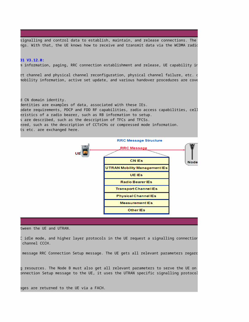
RRC Procedures
RRC Connection Establishment
Between the UE and the RNC, the Radio Resource Control (RRC) protocol is used to exchange signalling and control data to establish, maintain, and release connections. The UE gets informed about the radio bearer characteristics, the transport channel configurations, and the physical layer settings. With that, the UE knows how to receive and transmit data via the WCDMA radio interface. The RNC uses the NodeB
protocol to inform the Node B about the radio interface configuration.
Following RRC procedures can be identified in accordance to the ETSI specification TS 25.331 V3.12.0:These procedures include the broadcasting of system information, paging, RRC connection establishment and release, UE capability inquiry, security mode control, Inter-
These procedures for radio bearer establishment, transport channel and physical channel reconfiguration, physical channel failure, etc. can be found here. :These procedures such as cell and URA updates, UTRAN mobility information, active set update, and various handover procedures are covered here.
Radio Resource Control message contains of following groups of information elements : NAS specific information is transmitted, such as the CN type and CN domain identity.
Cell access restrictions, cell and URA identities are examples of data, associated with these IEs. UE related information is exchanged here, including capability update requirements, PDCP and FDD RF capabilities, radio access capabilities, cell update causes,etc.
These information elements mostly describe the characteristics of a radio bearer, such as RB information to setup. Here, mainly the transport channel characteristics are described, such as the description of TFCs and TFCSs. Here, everything relevant for the PHY-layer is covered, such as the description of CCTrCHs or compressed mode information.
Cell measured results, event results, filter coefficients etc. are exchanged here.
The purpose of the RRC Connection Establishment procedure is to create a RRC connection between the UE and UTRAN.
message to the RNC. The UE was in the RRC idle mode, and higher layer protocols in the UE request a signalling connection to UTRAN. Please note, that an RRC connection establishment is always initiated by the UE. It is transmitted via the logical channel CCCH.
UTRAN returns a response. If UTRAN accepts the UE‘s RRC Connection Request, it returns the message RRC Connection Setup message. The UE gets all relevant parameters regarding the signalling bearers, transport
From the RNC point of view, it is not just sufficient to inform the UE about the signalling resources. The Node B must also get all relevant parameters to serve the UE on the radio interface adequately, and to relay data between the Iub-interface and Uu-interface. Before the RNC returns the RRC Connection Setup message to the UE, it uses the UTRAN specific signalling protocol NBAP to send these parameters to the
. Both messages are returned to the UE via a FACH.
RRC Connection Setup Complete message to the RNC, using the transport channel DCH. Beforehand it performed a L1 Synchronization.
It is initiated by the UE and transmitted via the uplink CCCH. Two types of information element groups can be found in this message:
The UE identities contains of 4 options- IMSI,IMEI,P-TMSI&RAI or TMSI&LAI. The operator can choice one of the UE identity to use
; the corresponding IE is called Measured Results on the RACH, because the measurement results are transmitted via the transport channel RACH. The measured quantity can be set by the operator, but it is an option. If set by the operator, it is broadcasted as cell system information. The cells, listed in the measurement result list, are ordered in accordance to the
2.RRC Connection Setup messageIf the S-RNC accepts the UE‘s RRC Connection Establishment request. It starts an interaction with the Node B to establish a radio link connection over the interface Iub. This interaction is also used to inform the Node B about the radio link configuration parameters for uplink and downlink transmission via the interface Uu. In other words, the Node B is fully prepared to serve as intermediate mode between the mobile phone and the RNC. The UE gets the radio link configuration parameters with the RRC Connection Setup message, which is transmitted in the transport channel FACH. This message is used to establish signalling radio bearers between the UE and the RNC.
The RRC Connection Setup message is used to specify the (signalling) radio bearer, the transport channel and the physical channel characteristics both in the UL and downlink directions. The RRC Connection Setup message is sent from the RRC layer in the RNC to the RRC layer in the UE. The UE‘s RRC uses management interfaces to the configure the „lower“ layers accordingly.-If only the physical layer characteristics are modified, then the RRC layer only has to interact with the PHY layer. A modification may affect scrambling and modulation. A new channelisation code may be deployed for the connection, which has no impact to the higher layers. The PHY layer is for instance responsible for radio measurements, and the RNC can change measurement quantities or threshold values. Again, this has no impact on the higher layers.-If the transport channels are modified, then this has an effect both on the MAC (Medium Access Control) layer and thePHY layer. The MAC layer is responsible for Transport Format selection, identification of UEs on the common and shared resources, ciphering and de-ciphering, random access control, etc. -If a radio bearer is established, or modified, then following layer instances may receive parameters: - Radio Link Control (RLC) layer – for each radio bearer, an RLC instance is established - , - Packet Data Convergence Protocol (PDCP) layer, - Broadcast/Multicast Control (BMC) layer instances, - Medium Access Control (MAC) layer instances, and - PHY layer. With the RRC Connection Setup message, we establish several signalling radio bearers for the UE, so that we won‘t see the PDCP layer and BMC layer relevant parameters.
which specify the properties of the signalling bearers, which are established with this RRC message. to define the transport channel characteristics, in other words the TFCS.which specify parameters relevant for the PHY layer to make the physical channels available.
1. RRC Connection Setup message: UE IEs:1. Initial UE ID: The common transport channel FACH is used to send the RRC Connection Setup message from the RNC to the UE. All UEs listening to the same FACH bearing S-CCPCH must be capable to detect, whether the RRC message is for them. For UE identification, the IMSI or TMSI and LAI can be used. RRC Transaction ID: Several RRC transactions can run in parallel. This number associates the message to one transaction.2. Activation Time: The transmission of transport channel frames has to be synchronised between the UE and the S-RNC. This is also called L2 synchronisation. The Connection Frame Number (CFN) is an element of the L2 synchronisation. The network has to make sure, that the UE gets a radio frame with a specific CFN (approximately) To = 1024 chips before is starts to send a radio frame with the same CFN. The Activation Time indicates, when the UE can expect the transmission to start. 3. New U-RNTI and New C-RNTI: Common transport channels are shared resources, which can be used by several UEs. The MAC-layer will add the required addressing information U-RNTI and C-RNTI. UE, S-RNC, C-RNC and Node B identify each other by called Radio Network Temporary Identifiers (RNTI). The S-RNC allocatesa S-RNTI to the UE to address the UE. When the UE accesses a new cell, the C-RNC allocates aC-RNTI to the UE, with which it addresses the UE. The U-RNTI is a concatenation of the S-RNTI and the S-RNC‘s RNC-ID. The U-RNTI is unique worldwide, and is used by the S-RNC to address the UE on common radio channels, during paging, etc. 4. RRC State Indicator: This indicator tells the UE, in which internal RRC connected sub-state is has to move to. 5. Capability Update Requirement:
2.RRC Connection Setup message: RB IEs:Radio Bearer (RB) services are offered to the higher layers. Higher layers are:-RRC layer, which uses signalling radio bearers to exchange radio link management messages between the UE and the RNC. The RRC layer also takes NAS-signalling information to guarantee its transport in signalling radio bearers. -NAS layers for user SDU transfer.
When the RRC Connection Setup message is sent from the RNC to the UE, then the RB IEs describe, how the Radio Link Control layer(RLC) has to make the radio bearer service available to the RRC layer.
RLC sub-layer's tasks: For each RB, and RLC instance is established. Three different types are distinguished:1.Transparent Mode (TrM) RLC entities In this mode, data is buffered, when it arrives in the RLC entity. Segmentation at the transmitting RLC entity and re-assembly at the receiving RLC entity may occur, if being configured by higher layers and the RLC SDU is larger than required by the lower layers, given the TTI. No other service is offered.2. Unacknowledged Mode (UM) RLC entities Data transfer, segmentation and reassembly is done like in the TrM. But higher layer data is transmitted without guaranteeing its delivery. Sequence control and ciphering are. 3.Acknowledged Mode (AM) RLC entities A reliable bearer is offered in this mode. Its features can be seen in the figure on the right hand side.

Signalling radio bearers have to be set up. Three signalling radio bearers must be set up, the 4th one is optional. This is indicated with the IE Signalling RB to Setup List. Given the number, either 3 or 4 descriptions of radio bearers follow. They contain information, which must be made available for the RLC sub-layer.
-RB identity: Each RB has a unique identity. The identities for signalling radio bearers are ranging from 1 to 4. The total number of RBs, the UE can establish on command of the RNC, is 32. RB0 parameters are not transmitted,because there are fixed rules how to determine its RLC parameters.-Choice RLC info type: a RB is described: This is the case with the IE RLC info. Or its parameters are copied from an existing one, where only the RB identity has to be delivered to the UE.-RB mapping info Uplink, following transport channel types can be identified: DCH, RACH, and CPCH The mapping information describes, on which Transport Channels the given RB can be mapped to. UL DCH are get an identity (number). This number is used to describe, to which UL DCHs the RB can be mapped. Downlink, we can identify following transport channel types: DCH, FACH, DSCH and DCH + DSCH. DSCH and DCH receive an identity. There can be one or two logical channels per radio bearer or RLC entity. Therefore, there are also logical channel identities.
Each RB set between a UE and UTRAN has a unique number. Each of them can be mapped on one or two logical channels. This was part of the RB setup information. The information carried on radio bearers must be mapped on transport channels. But on which transport channels can the higher layer information be transmitted? How can higher layer information be segmented? This is described with the information elements
TrCH UL/DL. This information is used by the RRC to configure the RLC-, MAC, and PHY layer.
. The Transport Format Set information element describes the the allowed TFs, which can be transmitted via this TrCH.This information element also
The MAC layer is responsible to take the RLC PDUs (which hold the TBs), and to send them to their peer entity. RLC PDUs from several RBs (RLC layers) can be multiplexed on one transport channel. The MAC header of a MAC PDU holds relevant information to identify the receiver of the RLC PDU. For instance, if two DTCHs are multiplexed on one DCH, then field C/T is added in the MAC header to identify the logical
This MAC-entity controls the access to the common control channels PCH, FACH, RACH, CPCH, DSCH.

The Physical Channel information elements deliver relevant information for the PHY layer to configure the physical channels. One of the PhyCH IEs is the carrier frequency band, where the signalling connection
established. As can be seen, a UE can be immediately re-directed to another frequency band for the signalling bearer setup. Also the available UL and DL radio resources have to be described.
info is an optional information element in the RRC Connection Setup message.
The UE can be informed about the downlink radio resources, when receiving the RRC Connection Setup message. When we have a closer look to the IE „Downlink information common for all radio links“, we detect
it can‘t make inter-frequency or inter-RAT measurements on neighbouring cells and at the same time receive data from the active set cells. If this is the
the downlink transmission must be interrupted to give the UE time to make its measurements. Therefore, this mode is often called Slotted Mode. In order to transmit still the user data with a given data rate,
puncturing is done – if the required link quality can be kept up – or the spreading factor is halved for a short while. The UE is served by several active set cells. But while all active set cells receive the UE‘s signals, only one is making a transmission downlink. The UE tells the
. The UE sends a feedback (FBI) to the Node B, so that this device can decide, how to set the weighting to the individual antennas. There are two
A phase adjustment is done with one antenna. Hereby, the feedback command rate is 1 bit per timeslot. - closed loop mode 2: Phase and amplitude
3. RRC Connection Setup Complete message
The UE has received the RRC Connection Setup message and returns the RRC Connection Setup Complete message to the S-RNC. This message is transmitted via the logical channel DCCH on the radio signalling bearer, which offers acknowledged mode of operation (RB2). The information elements in the RRC Connection Setup Complete message can be grouped into -UE information elements and-Other information elements.
The UE can return its capabilities to the S-RNC with the IE Radio Access Capability, which contains -Transport channel capability: is distributed to the resource manager and to the admission control entity-RF capability: the RF capability is distributed to the resource manager, the power control entity and to the handover control entity-Physical channel entity: is distributed to resource manager-UE multi-mode/multi-RAT capability-Security capability-LCS capability-Measurement capability: is distributed to the handover control entity. Presence is mandatory if IE Multi-mode capability has the value "FDD" or "FDD/TDD" and a FDD capability update has been requested in a previous message. Otherwise this field is not needed in the message.
Among the optional other information elements, we find the Inter_RAT UE access capability. The RNC shall extract the inter-system message from the UE CAPABILITY INFORMATION message and transfer it to the handover control entity.

L1 Synchonization on DPCCH and DPDCH (UL and DL)
3. RRC Connection Setup Complete message
The UE has received the RRC Connection Setup message and returns the RRC Connection Setup Complete message to the S-RNC. This message is transmitted via the logical channel DCCH on the radio signalling bearer, which offers acknowledged mode of operation (RB2). The information elements in the RRC Connection Setup Complete message can be grouped into -UE information elements and-Other information elements.
The UE can return its capabilities to the S-RNC with the IE Radio Access Capability, which contains -Transport channel capability: is distributed to the resource manager and to the admission control entity-RF capability: the RF capability is distributed to the resource manager, the power control entity and to the handover control entity-Physical channel entity: is distributed to resource manager-UE multi-mode/multi-RAT capability-Security capability-LCS capability-Measurement capability: is distributed to the handover control entity. Presence is mandatory if IE Multi-mode capability has the value "FDD" or "FDD/TDD" and a FDD capability update has been requested in a previous message. Otherwise this field is not needed in the message.
Among the optional other information elements, we find the Inter_RAT UE access capability. The RNC shall extract the inter-system message from the UE CAPABILITY INFORMATION message and transfer it to the handover control entity.
After the UE transmits RRC CONNECTION REQUEST message, the T300 timer will be started, and the timer will be stopped after the UE receives RRC CONNECTION SETUP message. Once the timer times out, if RRC CONNECTION REQUEST message is retransmitted less than the number of times specified by the constant N300, the UE repeats RRC CONNECTION REQUEST; otherwise it will be in the idle mode,consider the procedure to
if the UE has not yet received an RRC CONNECTION SETUP message with the value of the IE "Initial UE identity" equal to the value of the variable INITIAL_UE_IDENTITY; and if cell re-selection or expiry of
- submit a new RRC CONNECTION REQUEST message to lower layers for transmission on the uplink CCCH;
- restart timer T300 when the MAC layer indicates success or failure to transmit the message;
- Other actions the UE shall perform when entering idle mode from connected mode

For the dedicated channels, synchronisation primitives are used to indicate the synchronisation status of radio links, both in uplink and downlink. A UE Layer1 shall check the synchronisation status of every radio frame of downlink and uplink dedicated channels in order to detect a loss of the signal on Layer 1, as specified in TS 25.214. The
(The physical channel BER is the relation of the incorrectly detected pilot bits to the total number of pilot bits in a radio
specify at what DPCCH quality levels the UE shall shut its power off and when it shall turn its power on respectively. The synchronisation status is reported to the higher layer.
-Starts when higher layers initiate physical dedicated channel establishment and lasts until 160 ms after the downlink dedicated channel is considered established by higher layers
During this time the In-sync status shall be reported using the CPHY-Sync-IND primitive if the following criterion is fulfilled:The UE estimates the DPCCH quality over the previous 40 ms period to be better than a threshold Qin. This criterion shall be assumed not to be fulfilled before 40 ms of DPCCH quality measurements have been
(The mapping of the Q_IN values to the actual physical channel BER is given in 3GPP TS 25.133)
-Starts 160 ms after the downlink dedicated channel is considered established by higher layers with In-sync status -During this phase the criteria for the Out-of-sync and In-sync status are as followsOut-of-sync shall be reported using the CPHY-Out-of-Sync-IND primitive if either of the following criteria are fulfilled:- The UE estimates the DPCCH quality over the previous 160 ms period to be worse than a threshold Qout. Qout is defined implicitly by the relevant tests(def. 15% BER)- The 20 most recently received transport blocks with a CRC attached, as observed on all TrCHs using CRC, have been received with incorrect CRC. In addition, over the previous 160 ms, all transport blocks
attached have been received with incorrect CRC. In case of no TFCI is used this criterion shall be considered only for TrCHs using CRC in all transport formats.
In-sync shall be reported using the CPHY-Sync-IND primitive if both of the following criteria are fulfilled:- The UE estimates the DPCCH quality over the previous 160 ms period to be better than a threshold Qin. Qin is defined implicitly by the relevant tests(def.20% BER)- At least one transport block with a CRC attached, as observed on all TrCHs using CRC, is received in a TTI ending in the current frame with correct CRC. If no transport blocks are received, or no transport
CRC attached, this criterion shall be assumed to be fulfilled. In case of no TFCI is used this criterion shall be considered only for TrCHs using CRC in all transport formats.
, i.e. when at least one downlink dedicated physical channel and one uplink dedicated physical channel are to be set up;i.e. when at least one downlink dedicated physical channel is to be set up and an uplink dedicated physical channel already exists.
out-of-sync state and in-sync state. Transitions between the different states is shown in figure above. The establishment of a radio link
NodeB Radio Link Set States and Transistions
20 last TBs transmitted with incorrect CRC transmitted
O ut-of-syncstate
In-syncstate
Initialstate
RL Restore
RL Restore
RL Failure
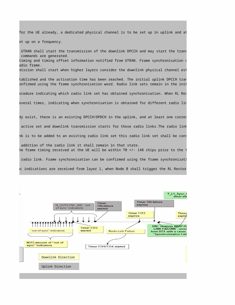
When one or several radio links are to be established and there is no existing radio link for the UE already, a dedicated physical channel is to be set up in uplink and at least one dedicated physical channel
in downlink. This corresponds to the case when a dedicated physical channel is initially set up on a frequency.
a) Node B considers the radio link sets which are to be set up to be in the initial state. UTRAN shall start the transmission of the downlink DPCCH and may start the transmission of DPDCH if any data is to be transmitted.The initial downlink DPCCH transmit power is set by higher layers.Downlink TPC commands are generated.b) The UE establishes downlink chip and frame synchronisation of DPCCH, using the P-CCPCH timing and timing offset information notified from UTRAN. Frame synchronisation can be confirmed using the frame synchronisation word. Downlink synchronisation status is reported to higher layers every radio frame.c) If no activation time for uplink DPCCH has been signalled to the UE, uplink DPCCH transmission shall start when higher layers consider the downlink physical channel established. If an activation time has
uplink DPCCH transmission shall not start before the downlink physical channel has been established and the activation time has been reached. The initial uplink DPCCH transmit power is set by higher layers.d) UTRAN establishes uplink chip and frame synchronisation. Frame synchronisation can be confirmed using the frame synchronisation word. Radio link sets remain in the initial state until
in-sync indications are received from layer 1, when Node B shall trigger the RL Restore procedure indicating which radio link set has obtained synchronisation. When RL Restore has been triggered the radio
shall be considered to be in the in-sync state.The RL Restore procedure may be triggered several times, indicating when synchronisation is obtained for different radio link sets.
When one or several radio links are to be established and one or several radio links already exist, there is an existing DPCCH/DPDCH in the uplink, and at least one corresponding dedicated physical channel
set up in the downlink. This corresponds to the case when new radio links are added to the active set and downlink transmission starts for those radio links.The radio link establishment is as follows:
a) Node B considers new radio link sets to be set up to be in initial state. If a radio link is to be added to an existing radio link set this radio link set shall be considered to be in the state the radio
addition of the radio link, i.e. if the radio link set was in the in-sync state before the addition of the radio link it shall remain in that state.b) UTRAN starts the transmission of the downlink DPCCH/DPDCH at a frame timing such that the frame timing received at the UE will be within T0 +/- 148 chips prior to the frame timing of the uplink DPCCH/DPDCH
the UE. Simultaneously, UTRAN establishes uplink chip and frame synchronisation of the new radio link. Frame synchronisation can be confirmed using the frame synchronization word. Radio link sets considered
successive in-sync indications are received from layer 1, when Node B shall trigger the RL Restore procedure indicating which radio
The downlink radio links shall be monitored by the UE, to trigger radio link failure procedures. Radio link failure detection in DL is based on counter N313 (counting “out of sync” indicator) and timer
Downlink Direction
Uplink Direction

The downlink radio links shall be monitored by the UE, to trigger radio link failure procedures. Radio link failure detection in DL is based on counter N313 (counting “out of sync” indicator) and timer consecutive "out of sync" indications from layer 1 for the established DPCCH physical channel in FDD the UE
->upon receiving N315 successive "in sync" indications from layer 1 and upon change of UE state:
much time UE can re-establish a bearer. A bearer can be associated with a bearer re-establishment timer ( is controlling transparent and unacknowledged mode(UM) bearers. T315 is controlling acknowledged(AM) mode bearers
->Timer T314 is started if radio bearer(s) that are associated with T314 exist or if only RRC connection exists, and stopped when the Cell Update procedure has been completed. d only if radio bearer(s) that are associated with T315 exist, and stopped when the Cell Update procedure has been completed.
If T314 expires and T305 is not running, then all radio bearers associated with radio bearers with T314 value are locally released. If additionally T315 is not running, the UE is moved to the RRC idle mode.
If T315 expires and T305 is not running, then all radio bearers associated with radio bearers with T315 value are locally released. If additionally T314 is not running, the UE is moved to the RRC idle mode.
In case of the expiry of T314 (T315), the corresponding service Radio Bearers will be removed.
For UE in CELL_DCH state, In case of Radio link failure, if the Radio link cannot be successfully reconfigured by CELL UPDATE CONFIRM before the expiry of the corresponding ). T314(T315) should be set greater than T302*N302
The timer T302 is started when UE transmits CELL UPDATE/URA UPDATE, and stopped when UE receives a CELL UPDATE CONFIRM/URA UPDATE CONFIRM. When it expires, UE should retransmit CELL UPDATE/URA UPDATE if the counter V302 is no bigger than the Maximum number of retransmissions of the CELL UPDATE / URA UPDATE message N302, else, goes to idle modeThe uplink radio link sets are monitored by the Node B, to trigger radio link failure/restore procedures. Once the radio link sets have been established, they will be in the in-sync or out-of-sync states.
-The uplink radio link failure/restore criteria is based on the synchronisation status primitives CPHY-Sync-IND and CPHY-Out-of-Sync-IND, indicating in-sync and out-of-sync respectively. Note that only one
consecutive indications with In-sync status, the radio link is moved from the initial state to an In-sync state. L1 informs BTS L3 about the established
T_RLFAILURE after receiving N_OUTSYNC_IND consecutive out-of-sync indications. Node B shall stop and reset timer T_RLFAILURE upon receiving successive N_INSYNC_IND in-sync indications. If T_RLFAILURE expires, Node B shall trigger the RL Failure procedure and indicate which radio link set is out-of-sync. When the RL Failure procedure is triggered, the state of the radio link set change to the out-of-sync state. During the Out-of-sync state, L1 keeps on searching the synchronization as long as the synchronization has been re-established or
-When the radio link set is in the out-of-sync state, after receiving N_INSYNC_IND successive in-sync indications Node B shall trigger the RL Restore procedure and indicate which radio link set has re-
synchronisation. When the RL Restore procedure is triggered, the state of the radio link set change to the in-sync state. BTS L3 sends the NBAP:SYNCHRONIZATION INDICATION message to the RNC
After the BTS has established the frame synchronization to the uplink DPCH, the transmission power of the downlink DPCH is controlled based on the TPC bits transmitted by the UE. Also, the TPC bits
downlink dedicated physical channel are based on the SIR measurements from the uplink DPCH. (The parameters Qin and Qout and N_INSYNC_IND, N_OUTSYNC_IND, T_RLFAILURE are given by the RNC to the BTS
When the UE starts to set up the dedicated channel, it starts the T312 timer, and after the UE detects N312 synchronization indications from L1, it will stop the T312 timer. Once the timer times out, it means
Successful Synchronization on UL and DL
Downlink Direction
Uplink Direction

->When a physical dedicated channel establishment is initiated by the UE, the UE starts a timer T312 and wait for layer 1 to indicate N312 "in sync" indications->On receiving N312 "in sync" indications, the physical channel is considered established and the timer T312 is stopped and reset ->On the BTS side after receiving N_INSYNC_IND synchronization indicators the BTS sends NBAP: SYNCHRONIZATION INDICATION –message to RNC after which the closed loop and outer loop PC start to control the
->In case UE is not able to establish synchronization within timer T312 it stops TX on the DCH->In case BTS is not able to establish synchronization it does not send NBAP:Synchronization Indication –message to RNCThe BTS tries to establish synchronization until timer in RNC expires and RNC sends NBAP:Radio Link Deletion -message
->In case BTS is able to establish synchronization it sends NBAP:Synchronization Indication –message to RNC->In case UE is not able to establish synchronization within timer T312 it stops TX on the DCH->As the UE TX is off the BTS looses the L1 synchronization and sends NPAB: Radio Link Failure –message to RNCAfter Timer expires in RNC the RNC sends NPAB: Radio Link Deletion to BTS which then stops searching for the synchronization
Failed Synchronization on UL and DL
Downlink Direction
Uplink Direction
ULSynchronization failed because of no DL synchronization
Downlink Direction
Uplink Direction

RRC Procedures
RRC Connection Establishment
Between the UE and the RNC, the Radio Resource Control (RRC) protocol is used to exchange signalling and control data to establish, maintain, and release connections. The UE gets informed about the radio bearer characteristics, the transport channel configurations, and the physical layer settings. With that, the UE knows how to receive and transmit data via the WCDMA radio interface. The RNC uses the NodeB
These procedures include the broadcasting of system information, paging, RRC connection establishment and release, UE capability inquiry, security mode control, Inter-
These procedures for radio bearer establishment, transport channel and physical channel reconfiguration, physical channel failure, etc. can be found here. :These procedures such as cell and URA updates, UTRAN mobility information, active set update, and various handover procedures are covered here.
UE related information is exchanged here, including capability update requirements, PDCP and FDD RF capabilities, radio access capabilities, cell update causes,etc.
Here, everything relevant for the PHY-layer is covered, such as the description of CCTrCHs or compressed mode information.
message to the RNC. The UE was in the RRC idle mode, and higher layer protocols in the UE request a signalling connection to UTRAN. Please note, that an RRC
message. The UE gets all relevant parameters regarding the signalling bearers, transport
From the RNC point of view, it is not just sufficient to inform the UE about the signalling resources. The Node B must also get all relevant parameters to serve the UE on the radio interface adequately, and to relay data between the Iub-interface and Uu-interface. Before the RNC returns the RRC Connection Setup message to the UE, it uses the UTRAN specific signalling protocol NBAP to send these parameters to the
message to the RNC, using the transport channel DCH. Beforehand it performed a L1 Synchronization.
; the corresponding IE is called Measured Results on the RACH, because the measurement results are transmitted via the transport channel RACH. The measured quantity can be set by the operator, but it is an option. If set by the operator, it is broadcasted as cell system information. The cells, listed in the measurement result list, are ordered in accordance to the
If the S-RNC accepts the UE‘s RRC Connection Establishment request. It starts an interaction with the Node B to establish a radio link connection over the interface Iub. This interaction is also used to inform the Node B about
configuration parameters for uplink and downlink transmission via the interface Uu. In other words, the Node B is
prepared to serve as intermediate mode between the mobile phone and the RNC. The UE gets the radio link
parameters with the RRC Connection Setup message, which is transmitted in the transport channel FACH. This message is used to establish signalling radio bearers between the UE and the RNC.
The RRC Connection Setup message is used to specify the (signalling) radio bearer, the transport channel and the physical channel characteristics both in the UL and downlink directions. The RRC Connection Setup message is sent from the RRC layer in the RNC to the RRC layer in the UE. The UE‘s RRC uses management interfaces to the configure
then the RRC layer only has to interact with the PHY layer.
modification may affect scrambling and modulation. A new channelisation code may be deployed for the connection,
has no impact to the higher layers. The PHY layer is for instance responsible for radio measurements, and the RNC can change measurement quantities or threshold values. Again, this has no impact on the higher layers.
then this has an effect both on the MAC (Medium Access Control) layer and
PHY layer. The MAC layer is responsible for Transport Format selection, identification of UEs on the common and
then following layer instances may receive parameters: - Radio Link
(RLC) layer – for each radio bearer, an RLC instance is established - , - Packet Data Convergence Protocol (PDCP)
Broadcast/Multicast Control (BMC) layer instances, - Medium Access Control (MAC) layer instances, and - PHY layer.
the RRC Connection Setup message, we establish several signalling radio bearers for the UE, so that we won‘t see the

If the S-RNC accepts the UE‘s RRC Connection Establishment request. It starts an interaction with the Node B to establish a radio link connection over the interface Iub. This interaction is also used to inform the Node B about
configuration parameters for uplink and downlink transmission via the interface Uu. In other words, the Node B is
prepared to serve as intermediate mode between the mobile phone and the RNC. The UE gets the radio link
parameters with the RRC Connection Setup message, which is transmitted in the transport channel FACH. This message is used to establish signalling radio bearers between the UE and the RNC.
The RRC Connection Setup message is used to specify the (signalling) radio bearer, the transport channel and the physical channel characteristics both in the UL and downlink directions. The RRC Connection Setup message is sent from the RRC layer in the RNC to the RRC layer in the UE. The UE‘s RRC uses management interfaces to the configure
then the RRC layer only has to interact with the PHY layer.
modification may affect scrambling and modulation. A new channelisation code may be deployed for the connection,
has no impact to the higher layers. The PHY layer is for instance responsible for radio measurements, and the RNC can change measurement quantities or threshold values. Again, this has no impact on the higher layers.
then this has an effect both on the MAC (Medium Access Control) layer and
PHY layer. The MAC layer is responsible for Transport Format selection, identification of UEs on the common and
then following layer instances may receive parameters: - Radio Link
(RLC) layer – for each radio bearer, an RLC instance is established - , - Packet Data Convergence Protocol (PDCP)
Broadcast/Multicast Control (BMC) layer instances, - Medium Access Control (MAC) layer instances, and - PHY layer.
the RRC Connection Setup message, we establish several signalling radio bearers for the UE, so that we won‘t see the The common transport channel FACH is used to send the RRC Connection Setup message
from the RNC to the UE. All UEs listening to the same FACH bearing S-CCPCH must be capable to detect, whether the RRC message is for them. For UE identification, the IMSI or TMSI and LAI can be used. RRC Transaction ID: Several RRC transactions can run in parallel. This number associates the message to
: The transmission of transport channel frames has to be synchronised between the UE and the S-RNC. This is also called L2 synchronisation. The Connection Frame Number (CFN) is an element of the L2 synchronisation. The network has to make sure, that the UE gets a radio frame with a specific CFN (approximately) To = 1024 chips before is starts to send a radio frame with the same CFN. The Activation
indicates, when the UE can expect the transmission to start. Common transport channels are shared resources, which can be used by
several UEs. The MAC-layer will add the required addressing information U-RNTI and C-RNTI. UE, S-RNC, C-RNC and Node B identify each other by called Radio Network Temporary Identifiers (RNTI). The S-RNC
a S-RNTI to the UE to address the UE. When the UE accesses a new cell, the C-RNC allocates aC-RNTI to the UE, with which it addresses the UE. The U-RNTI is a concatenation of the S-RNTI and the S-RNC‘s RNC-ID. The U-RNTI is unique worldwide, and is used by the S-RNC to address the UE on common radio channels,
This indicator tells the UE, in which internal RRC connected sub-state is has to Radio Bearer (RB) services are offered to the higher layers. Higher layers are:
which uses signalling radio bearers to exchange radio link management messages between the UE and the RNC. The RRC layer also takes NAS-signalling information to guarantee its transport in signalling
When the RRC Connection Setup message is sent from the RNC to the UE, then the RB IEs describe, how the has to make the radio bearer service available to the RRC layer.
For each RB, and RLC instance is established. Three different types are
RLC entities In this mode, data is buffered, when it arrives in the RLC entity. Segmentation at the transmitting RLC entity and re-assembly at the receiving RLC entity may occur, if
configured by higher layers and the RLC SDU is larger than required by the lower layers, given the TTI. No
RLC entities Data transfer, segmentation and reassembly is done like in the TrM. But higher layer data is transmitted without guaranteeing its delivery. Sequence control and
RLC entities A reliable bearer is offered in this mode. Its features can be seen

Three signalling radio bearers must be set up, the 4th one is
This is indicated with the IE Signalling RB to Setup List. Given the number, either 3 or 4 descriptions of radio bearers follow. They contain information, which must be made available for the RLC sub-layer.
Each RB has a unique identity. The identities for signalling radio bearers are ranging from
The total number of RBs, the UE can establish on command of the RNC, is 32. RB0 parameters are not transmitted,because there are fixed rules how to determine its RLC parameters.
a RB is described: This is the case with the IE RLC info. Or its parameters are
from an existing one, where only the RB identity has to be delivered to the UE.following transport channel types can be identified: DCH, RACH, and CPCH The
mapping information describes, on which Transport Channels the given RB can be mapped to. UL DCH are getan identity (number). This number is used to describe, to which UL DCHs the RB can be mapped. Downlink,
we can identify following transport channel types: DCH, FACH, DSCH and DCH + DSCH. DSCH and DCH receive an identity. There can be one or two logical channels per radio bearer or RLC entity. Therefore,
Each RB set between a UE and UTRAN has a unique number. Each of them can be mapped on one or two logical channels. This was part of the RB setup information. The information carried on radio bearers must be mapped on transport channels. But on which transport channels can the higher layer information be transmitted? How can higher layer information be segmented? This is described with the information elements
. The Transport Format Set information element describes the the allowed TFs, which can be transmitted via this TrCH.This information element also
The MAC layer is responsible to take the RLC PDUs (which hold the TBs), and to send them to their peer entity. RLC PDUs from several RBs (RLC layers) can be multiplexed on one transport channel. The MAC header of a MAC PDU holds relevant information to identify the receiver of the RLC PDU. For instance, if two DTCHs are multiplexed on one DCH, then field C/T is added in the MAC header to identify the logical

The Physical Channel information elements deliver relevant information for the PHY layer to configure the physical channels. One of the PhyCH IEs is the carrier frequency band, where the signalling connection
established. As can be seen, a UE can be immediately re-directed to another frequency band for the signalling bearer setup. Also the available UL and DL radio resources have to be described.
The UE can be informed about the downlink radio resources, when receiving the RRC Connection Setup message. When we have a closer look to the IE „Downlink information common for all radio links“, we detect
it can‘t make inter-frequency or inter-RAT measurements on neighbouring cells and at the same time receive data from the active set cells. If this is the
the downlink transmission must be interrupted to give the UE time to make its measurements. Therefore, this mode is often called Slotted Mode. In order to transmit still the user data with a given data rate,
The UE is served by several active set cells. But while all active set cells receive the UE‘s signals, only one is making a transmission downlink. The UE tells the
. The UE sends a feedback (FBI) to the Node B, so that this device can decide, how to set the weighting to the individual antennas. There are two
closed loop mode 2: Phase and amplitude
The UE has received the RRC Connection Setup message and returns the RRC Connection Setup Complete message to the S-RNC. This message is transmitted via the logical channel DCCH on the radio signalling bearer, which offers acknowledged mode of operation (RB2). The information elements in the RRC Connection Setup
The UE can return its capabilities to the S-RNC with the IE Radio Access Capability, which contains -Transport channel capability: is distributed to the resource manager and to the admission control entity-RF capability: the RF capability is distributed to the resource manager, the power control entity and to
-Measurement capability: is distributed to the handover control entity. Presence is mandatory if IE Multi-mode capability has the value "FDD" or "FDD/TDD" and a FDD capability update has been requested in a
Among the optional other information elements, we find the Inter_RAT UE access capability. The RNC shall extract the inter-system message from the UE CAPABILITY INFORMATION message and transfer it to the

L1 Synchonization on DPCCH and DPDCH (UL and DL) >>Synchronization Parameters Description (Module II)
The UE has received the RRC Connection Setup message and returns the RRC Connection Setup Complete message to the S-RNC. This message is transmitted via the logical channel DCCH on the radio signalling bearer, which offers acknowledged mode of operation (RB2). The information elements in the RRC Connection Setup
The UE can return its capabilities to the S-RNC with the IE Radio Access Capability, which contains -Transport channel capability: is distributed to the resource manager and to the admission control entity-RF capability: the RF capability is distributed to the resource manager, the power control entity and to
-Measurement capability: is distributed to the handover control entity. Presence is mandatory if IE Multi-mode capability has the value "FDD" or "FDD/TDD" and a FDD capability update has been requested in a
Among the optional other information elements, we find the Inter_RAT UE access capability. The RNC shall extract the inter-system message from the UE CAPABILITY INFORMATION message and transfer it to the
Click to return to main page
>>See More details of 1,2,3
After the UE transmits RRC CONNECTION REQUEST message, the T300 timer will be started, and the timer will be stopped after the UE receives RRC CONNECTION SETUP message. Once the timer times out, if RRC CONNECTION REQUEST message is retransmitted less than the number of times specified by the constant N300, the UE repeats RRC CONNECTION REQUEST; otherwise it will be in the idle mode,consider the procedure to
if the UE has not yet received an RRC CONNECTION SETUP message with the value of the IE "Initial UE identity" equal to the value of the variable INITIAL_UE_IDENTITY; and if cell re-selection or expiry of

A UE Layer1 shall check the synchronisation status of every radio frame of downlink and uplink dedicated channels in order to detect a loss of the signal on Layer 1, as specified in TS 25.214. The
(The physical channel BER is the relation of the incorrectly detected pilot bits to the total number of pilot bits in a radio
specify at what DPCCH quality levels the UE shall shut its power off and when it shall turn its power on respectively. The synchronisation status is reported to the higher layer.
-Starts when higher layers initiate physical dedicated channel establishment and lasts until 160 ms after the downlink dedicated channel is considered established by higher layers
The UE estimates the DPCCH quality over the previous 40 ms period to be better than a threshold Qin. This criterion shall be assumed not to be fulfilled before 40 ms of DPCCH quality measurements have been (The mapping of the Q_IN values to the actual physical channel BER is given in 3GPP TS 25.133)
- The UE estimates the DPCCH quality over the previous 160 ms period to be worse than a threshold Qout. Qout is defined implicitly by the relevant tests(def. 15% BER)- The 20 most recently received transport blocks with a CRC attached, as observed on all TrCHs using CRC, have been received with incorrect CRC. In addition, over the previous 160 ms, all transport blocks
- The UE estimates the DPCCH quality over the previous 160 ms period to be better than a threshold Qin. Qin is defined implicitly by the relevant tests(def.20% BER)- At least one transport block with a CRC attached, as observed on all TrCHs using CRC, is received in a TTI ending in the current frame with correct CRC. If no transport blocks are received, or no transport
CRC attached, this criterion shall be assumed to be fulfilled. In case of no TFCI is used this criterion shall be considered only for TrCHs using CRC in all transport formats.
i.e. when at least one downlink dedicated physical channel is to be set up and an uplink dedicated physical channel already exists.
. Transitions between the different states is shown in figure above. The establishment of a radio link
NodeB Radio Link Set States and Transistions
Out-of-syncstate
In-syncstate
Initialstate
RL Restore
RL Restore
RL Failure

When one or several radio links are to be established and there is no existing radio link for the UE already, a dedicated physical channel is to be set up in uplink and at least one dedicated physical channel
a) Node B considers the radio link sets which are to be set up to be in the initial state. UTRAN shall start the transmission of the downlink DPCCH and may start the transmission of DPDCH if any data is to be
b) The UE establishes downlink chip and frame synchronisation of DPCCH, using the P-CCPCH timing and timing offset information notified from UTRAN. Frame synchronisation can be confirmed using the frame
c) If no activation time for uplink DPCCH has been signalled to the UE, uplink DPCCH transmission shall start when higher layers consider the downlink physical channel established. If an activation time has
uplink DPCCH transmission shall not start before the downlink physical channel has been established and the activation time has been reached. The initial uplink DPCCH transmit power is set by higher layers.d) UTRAN establishes uplink chip and frame synchronisation. Frame synchronisation can be confirmed using the frame synchronisation word. Radio link sets remain in the initial state until N_INSYNC_IND
in-sync indications are received from layer 1, when Node B shall trigger the RL Restore procedure indicating which radio link set has obtained synchronisation. When RL Restore has been triggered the radio
shall be considered to be in the in-sync state.The RL Restore procedure may be triggered several times, indicating when synchronisation is obtained for different radio link sets.
When one or several radio links are to be established and one or several radio links already exist, there is an existing DPCCH/DPDCH in the uplink, and at least one corresponding dedicated physical channel
set up in the downlink. This corresponds to the case when new radio links are added to the active set and downlink transmission starts for those radio links.The radio link establishment is as follows:
a) Node B considers new radio link sets to be set up to be in initial state. If a radio link is to be added to an existing radio link set this radio link set shall be considered to be in the state the radio
b) UTRAN starts the transmission of the downlink DPCCH/DPDCH at a frame timing such that the frame timing received at the UE will be within T0 +/- 148 chips prior to the frame timing of the uplink DPCCH/DPDCH
the UE. Simultaneously, UTRAN establishes uplink chip and frame synchronisation of the new radio link. Frame synchronisation can be confirmed using the frame synchronization word. Radio link sets considered
successive in-sync indications are received from layer 1, when Node B shall trigger the RL Restore procedure indicating which radio
(counting “out of sync” indicator) and timer T313

(counting “out of sync” indicator) and timer T313
much time UE can re-establish a bearer. A bearer can be associated with a bearer re-establishment timer (T314 and T315), which defines the controlling acknowledged(AM) mode bearers
->Timer T314 is started if radio bearer(s) that are associated with T314 exist or if only RRC connection exists, and stopped when the Cell Update procedure has been completed.
If T314 expires and T305 is not running, then all radio bearers associated with radio bearers with T314 value are locally released. If additionally T315 is not running, the UE is moved to the RRC idle mode.
If T315 expires and T305 is not running, then all radio bearers associated with radio bearers with T315 value are locally released. If additionally T314 is not running, the UE is moved to the RRC idle mode.
For UE in CELL_DCH state, In case of Radio link failure, if the Radio link cannot be successfully reconfigured by CELL UPDATE CONFIRM before the expiry of the corresponding T314 (or T315), CELL UPDATE will be
The timer T302 is started when UE transmits CELL UPDATE/URA UPDATE, and stopped when UE receives a CELL UPDATE CONFIRM/URA UPDATE CONFIRM. When it expires, UE should retransmit CELL UPDATE/URA UPDATE if the counter V302 is no bigger than the Maximum number of retransmissions of the CELL UPDATE / URA UPDATE message N302, else, goes to idle modeThe uplink radio link sets are monitored by the Node B, to trigger radio link failure/restore procedures. Once the radio link sets have been established, they will be in the in-sync or out-of-sync states.
-The uplink radio link failure/restore criteria is based on the synchronisation status primitives CPHY-Sync-IND and CPHY-Out-of-Sync-IND, indicating in-sync and out-of-sync respectively. Note that only one
consecutive indications with In-sync status, the radio link is moved from the initial state to an In-sync state. L1 informs BTS L3 about the established
consecutive out-of-sync indications. Node B shall stop and reset timer T_RLFAILURE upon receiving successive N_INSYNC_IND in-sync indications. If T_RLFAILURE expires, Node B shall trigger the RL Failure procedure and indicate which radio link set is out-of-sync. When the RL Failure procedure is triggered, the state of the radio link set change to the out-of-sync state. During the Out-of-sync state, L1 keeps on searching the synchronization as long as the synchronization has been re-established or
-When the radio link set is in the out-of-sync state, after receiving N_INSYNC_IND successive in-sync indications Node B shall trigger the RL Restore procedure and indicate which radio link set has re-
synchronisation. When the RL Restore procedure is triggered, the state of the radio link set change to the in-sync state. BTS L3 sends the NBAP:SYNCHRONIZATION INDICATION message to the RNC
After the BTS has established the frame synchronization to the uplink DPCH, the transmission power of the downlink DPCH is controlled based on the TPC bits transmitted by the UE. Also, the TPC bits
(The parameters Qin and Qout and N_INSYNC_IND, N_OUTSYNC_IND, T_RLFAILURE are given by the RNC to the BTS
When the UE starts to set up the dedicated channel, it starts the T312 timer, and after the UE detects N312 synchronization indications from L1, it will stop the T312 timer. Once the timer times out, it means

->On the BTS side after receiving N_INSYNC_IND synchronization indicators the BTS sends NBAP: SYNCHRONIZATION INDICATION –message to RNC after which the closed loop and outer loop PC start to control the

Radio Bearer(RB) ProceduresClick to return to main page
The RB control procedures are used to establish additional radio bearers, modify them, or release them.
Radio Bearer is established, modified, and released with following RRC messages:1.Radio Bearer Setup,2.Radio Bearer Reconfiguration, and3.Radio Bearer Release.
If a radio bearer is setup or reconfigured, not only the RB parameters, but also the transport channel and physical channel parameters have to be set or modified. It is possible to modify the transport channel configuration. If this is done, the accessory RB parameters are not affected. But a transport channel modification always has an impact on the physical channel setting. A transport channel reconfiguration is triggered with the RRC message.
4. Transport Channel ReconfigurationIt is also possible to modify the physical channel characteristics of a radio bearer only. One exampleis a channelisation code re-allocation. This is done with the RRC message5. Physical Channel Reconfiguration.
Every RRC request, which is mentioned above, can be conducted successfully or fail.
Physical Channel Reconfiguration-on existing RBs

Radio Bearer(RB) ProceduresThe RB control procedures are used to establish additional radio bearers, modify them, or
Radio Bearer is established, modified, and released with following RRC messages:
If a radio bearer is setup or reconfigured, not only the RB parameters, but also the transport
It is possible to modify the transport channel configuration. If this is done, the accessory RB parameters are not affected. But a transport channel modification always has an impact on the physical channel setting. A transport channel reconfiguration is triggered with the RRC message.
It is also possible to modify the physical channel characteristics of a radio bearer only. One
Every RRC request, which is mentioned above, can be conducted successfully or fail.
RB Setup, Reconfiguration, and Release
Transport Channel Reconfiguration-on existing RBs

Radio Bearer(RB) Procedures

Measurement procedures
Measurement Control and Measurement Report
Click to return to main page
The UE measurements are grouped into 7 different categories, according to what the UE should measure. (TS 25.331-360) The different types of measurements are:- Intra-frequency measurements: measurements on downlink physical channels at the same frequency as the active set. - Inter-frequency measurements: measurements on downlink physical channels at frequencies that differ from the frequency of the active set. - Inter-RAT measurements: measurements on downlink physical channels belonging to another radio access technology than UTRAN, e.g. PDC or GSM. - Traffic volume measurements: measurements on uplink traffic volume. - Quality measurements: Measurements of quality parameters, e.g. downlink transport block error rate. - UE-internal measurements: Measurements of UE transmission power and UE received signal level. - UE positioning measurements: Measurements of UE position.
The UE shall support a number of measurements running in parallel. The UE shall also support that each measurement is controlled and reported independently of every other measurement.
Cells that the UE is monitoring (e.g. for handover measurements) are grouped in the UE into three different categories:1. Cells, which belong to the active set: User information is sent from all these cells. In FDD, the cells in the active set are involved in soft handover. 2. Cells, which are not included in the active set, but are monitored according to a neighbour list 3. Cells detected by the UE, which are neither included in the active set nor in the monitored set frequency measurements made by UEs in CELL_DCH state.
UTRAN controls the measurements in the UE, either by :-broadcasting system information on the BCCH, and/or by -transmitting a Measurement Control message on the DCCH.
If the UE is in the RRC idle mode, it receives relevant measurement information from the BCCH. The SIB type 3 contains parameters for cell selection and re-selection. In parallel, the SIB type 11 is used to deliver measurement control information to the UE for the serving cell. SIB 3 and SIB 11are read and valid in the RRC idle state.
If the UE is in the RRC sub-states CELL_FACH, CELL_PCH and URA_PCH, it is connected to one cell only and responsible for cell selection and re-selection. It retrieves the parameters for cell selection from SIB type 4. The measurement control information is broadcasted with SIB type 12. SIB 4 and SIB 12 are read and valid, when the UE is in the CELL_FACH, CELL_PCH and URA_PCH sub-state. If SIB 4 resp. SIB 12 isnot broadcasted, then SIB 3 resp. SIB 11 parameters are used instead. In the sub-state CELL_DCH, the UE is not reading the SIB type 3/4 and 11/12. The parameters of SIB 12 (SIB 11, if SIB is not available) canbe still valid in this state.
If the UE is in the RRC sub state CELL_DCH ,the RRC message Measurement Control can be transmitted to the UE. This message informs the UE about the type of measurement, which has to be conducted. Eachmeasurement command links a measurement with a measurement identity, quantity, objects, reporting quantities, reporting criteria, type, etc.
How does a UE perform measurements after a transition in the CELL_DCH state. Two cases have to be distinguished:1. Transition from the RRC idle state to the CELL_DCH sub-state

Measurement Control Contents
1. Transition from the RRC idle state to the CELL_DCH sub-stateIn the RRC idle state, the UE retrieved the measurement control parameters from the SIB type 11. Information Elements, which contain intra-frequency, inter-frequency, inter-RAT and traffic volume measurement system information, may be included in the SIB 11. If they are included, the UE can send a measurement report, when a measurement reporting criteria is fulfilled. As soon as the UE receives a Measurement Control message including one of the above mentioned measurement types, it replaces its internal stored data based on the SIB11 by the parameters delivered with the Measurement Control message.
2.Transition from the CELL_FACH to the CELL_DCH sub-state.In the CELL_FACH sub-state, the SIB 12 (or SIB 11, if there is no SIB 12) is valid including all relevant measurement control parameters. If the UE transits to the CELL_DCH sub-state, the system
UTRAN may control a measurement in the UE either by broadcast system information and/or by transmitting a MEASUREMENT CONTROL message. The latter message includes the following measurement control information:
1. Measurement identity: A reference number that should be used by the UTRAN when setting up, modifying or releasing the measurement and by the UE in the measurement report.

Reception of Measurement Control by the UE
Measurement Report Procedures
1. Measurement identity: A reference number that should be used by the UTRAN when setting up, modifying or releasing the measurement and by the UE in the measurement report.2. Measurement command: One out of three different measurement commands.- Setup: Setup a new measurement.- Modify: Modify a previously defined measurement, e.g. to change the reporting criteria.- Release: Stop a measurement and clear all information in the UE that are related to that measurement.3. Measurement type: One of the types listed above describing what the UE shall measure.Presence or absence of the following control information depends on the measurement type4. Measurement objects: The objects the UE shall measure, and corresponding object information.5. Measurement quantity: The quantity the UE shall measure. This also includes the filtering of the measurements.6. Reporting quantities: The quantities the UE shall include in the report in addition to the quantities that are mandatory to report for the specific event.7. Measurement reporting criteria: The triggering of the measurement report, e.g. periodical or event-triggered reporting.8. Measurement Validity: Defines in which UE states the measurement is valid.9. Measurement reporting mode: This specifies whether the UE shall transmit the measurement report using AM or UM RLC.10. Additional measurement identities: A list of references to other measurements. When this measurement triggers a measurement report, the UE shall also include the reporting quantities for the measurements referenced by the additional measurement identities.
The UTRAN may request a measurement by the UE to be setup, modified or released with a MEASUREMENT CONTROL message, which is transmitted on the downlink DCCH using AM RLC.The UTRAN should take the UE capabilities into account when a measurement is assigned to the UE.
When a new measurement is initiated, UTRAN should set the IE "Measurement identity" to a value, which is not used for other measurements. UTRAN may use several "Measurement identity" for the same "Measurement type". In case of setting several "Measurement identity" within a same "Measurement type", "Measurement object" can be set differently for each measurement with different "Measurement identity ".When a current measurement is modified or released, UTRAN should set the IE "Measurement identity" to the value, which is used for the measurement being modified or released. In case of modifying IEs within a "Measurement identity", it is not needed for UTRAN to indicate the IEs other than modifying IEs, and the UE continues to use the current values of the IEs that are not modified.
Upon reception of a MEASUREMENT CONTROL message the UE shall perform following actions :The UE shall:- read the IE "Measurement command"; if the IE "measurement command" has the value "setup":- store this measurement in the variable MEASUREMENT_IDENTITY according to the IE "measurement identity";- for measurement types "inter-RAT measurement" or "inter-frequency measurement":-->if, according to its measurement capabilities, the UE requires compressed mode to perform the measurements and a compressed mode pattern sequence with an appropriate measurement purpose is simultaneously activated by the IE "DPCH compressed mode status info"; or-->if, according to its measurement capabilities, the UE does not require compressed mode to perform the measurements: begin measurements according to the stored control information for this measurement identity;- for any other measurement type: begin measurements according to the stored control information for this measurement identity.if the IE "Measurement command" has the value "modify":- for all measurement control present in the MEASUREMENT CONTROL message:--> replace the corresponding information stored in variable MEASUREMENT_IDENTITY associated to the identity indicated by the IE "measurement identity";--> resume the measurements according to the new stored measurement control information.if the IE "measurement command" has the value "release":- terminate the measurement associated with the identity given in the IE "measurement identity";- clear all stored measurement control information related associated to this measurement identity in variable MEASUREMENT_IDENTITY. if the IE "DPCH Compressed Mode Status Info" is present, the UE shall:- if pattern sequence corresponding to IE "TGPSI" is already active (according to "TGPS Status Flag"): deactivate this pattern sequence at the beginning of the frame indicated by IE "TGPS reconfiguration CFN" received in the message;- after the time indicated by IE "TGPS reconfiguration CFN" has elapsed:-->activate the pattern sequence stored in the variable TGPS_IDENTITY corresponding to each IE "TGPSI" for which the "TGPS status flag" is set to "active" at the time indicated by IE "TGCFN"; and-->begin the inter-frequency and/or inter-RAT measurements corresponding to the pattern sequence measurement purpose of each activated pattern sequence;-->if the values of IE "TGPS reconfiguration CFN" and IE "TGCFN" are equal:start the concerned pattern sequence immediately at that CFN;
- not alter pattern sequences stored in variable TGPS_IDENTITY, but not identitifed in IE "TGPSI"Initiation:In CELL_DCH state, the UE shall transmit a MEASUREMENT REPORT message on the uplink DCCH when the reporting criteria stored in variable MEASUREMENT_IDENTITY are met for any ongoing measurements that are being performed in the UE.

measurements that are being performed in the UE.
In CELL_FACH state, the UE shall transmit a MEASUREMENT REPORT message on the uplink DCCH when the reporting criteria stored in variable MEASUREMENT_IDENTITY are met for any ongoingtraffic volume measurement that is being performed in the UE.
In CELL_PCH or URA_PCH state, the UE shall first perform the cell update procedure, using the cause "uplink data transmission", in order to transit to CELL_FACH state and then transmit a MEASUREMENT REPORT message on the uplink DCCH when the reporting criteria stored in variable MEASUREMENT_IDENTITY are fulfilled for any ongoing traffic volume measurement which is beingperformed in the UE.
The reporting criteria are fulfilled if either:- the first measurement has been completed for a newly initiated measurement with periodic reporting; or- the time period indicated in the stored IE "Periodical reporting" has elapsed since the last measurement report was transmitted for a given measurement; or- an event in stored IE "Measurement reporting criteria" was triggered. Events and triggering of reports for different measurement typesFor the measurement, which triggered the MEASUREMENT REPORT message, the UE shall:- set the IE "measurement identity" to the measurement identity, which is associated with that measurement in variable MEASUREMENT_IDENTITY;- set the IE "measured results" to include measurements according to the IE "reporting quantity" of that measurement stored in variable MEASUREMENT_IDENTITY; and--> if all the reporting quantities are set to "false": not set the IE "measured results";- set the IE "Measured results" in the IE "Additional measured results" according to the IE "reporting quantity" for all measurements associated with the measurement identities included in the IE "additional measurements" stored in variable MEASUREMENT_IDENTITY of the measurement that triggered the measurement report; and--> if more than one additional measured results are to be included:sort them in ascending order according to their IE "measurement identity" in the MEASUREMENT REPORT message;- if the MEASUREMENT REPORT message was triggered by an event (i.e. not a periodical report):set the IE "Event results" according to the event that triggered the report.The UE shall:- transmit the MEASUREMENT REPORT message on the uplink DCCH using either AM or UM RLC according to the stored IE "measurement reporting mode" associated with the measurement identity that triggered the report.When the MEASUREMENT REPORT message has been submitted to lower layers for transmission:-The procedure ends.

Measurement procedures
Measurement Control and Measurement Report
The UE measurements are grouped into 7 different categories, according to what the UE should measure. (TS 25.331-360)
: measurements on downlink physical channels at the same frequency as the active set. measurements on downlink physical channels at frequencies that differ from the frequency of the active set.
measurements on downlink physical channels belonging to another radio access technology than UTRAN, e.g. PDC or GSM.
Measurements of quality parameters, e.g. downlink transport block error rate. Measurements of UE transmission power and UE received signal level.
The UE shall support a number of measurements running in parallel. The UE shall also support that each measurement is controlled and reported independently of every other measurement.
Cells that the UE is monitoring (e.g. for handover measurements) are grouped in the UE into three different categories: User information is sent from all these cells. In FDD, the cells in the active set are involved in soft handover.
2. Cells, which are not included in the active set, but are monitored according to a neighbour list assigned by the UTRAN belong to the monitored set.3. Cells detected by the UE, which are neither included in the active set nor in the monitored set belong to the detected set. Reporting of measurements of the detected set is only required for intra-
it receives relevant measurement information from the BCCH. The SIB type 3 contains parameters for cell selection and re-selection. In parallel, the SIB type 11 is used to deliver measurement control information to the UE for the serving cell. SIB 3 and SIB 11are read and valid in the RRC idle state.
it is connected to one cell only and responsible for cell selection and re-selection. It retrieves the parameters for cell selection
type 4. The measurement control information is broadcasted with SIB type 12. SIB 4 and SIB 12 are read and valid, when the UE is in the CELL_FACH, CELL_PCH and URA_PCH sub-state. If SIB 4 resp. SIB 12 isnot broadcasted, then SIB 3 resp. SIB 11 parameters are used instead. In the sub-state CELL_DCH, the UE is not reading the SIB type 3/4 and 11/12. The parameters of SIB 12 (SIB 11, if SIB is not
Measurement Control can be transmitted to the UE. This message informs the UE about the type of measurement, which has to be conducted. Eachmeasurement command links a measurement with a measurement identity, quantity, objects, reporting quantities, reporting criteria, type, etc.
How does a UE perform measurements after a transition in the CELL_DCH state. Two cases have to be distinguished:
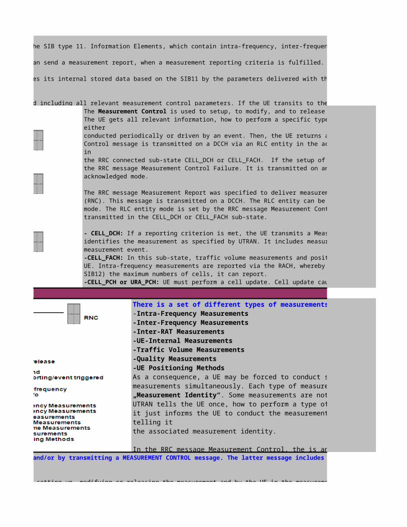
Measurement Control Contents
In the RRC idle state, the UE retrieved the measurement control parameters from the SIB type 11. Information Elements, which contain intra-frequency, inter-frequency, inter-RAT and traffic volume
system information, may be included in the SIB 11. If they are included, the UE can send a measurement report, when a measurement reporting criteria is fulfilled. As soon as the UE receives a
message including one of the above mentioned measurement types, it replaces its internal stored data based on the SIB11 by the parameters delivered with the Measurement Control message.
In the CELL_FACH sub-state, the SIB 12 (or SIB 11, if there is no SIB 12) is valid including all relevant measurement control parameters. If the UE transits to the CELL_DCH sub-state, the system The Measurement Control is used to setup, to modify, and to release a measurement in the UE. The UE gets all relevant information, how to perform a specific type of measurements. A measurement is either conducted periodically or driven by an event. Then, the UE returns a measurement report. The Measurement Control message is transmitted on a DCCH via an RLC entity in the acknowledged mode. I.e. the UE is either in the RRC connected sub-state CELL_DCH or CELL_FACH. If the setup of a measurement fails, the UE returns the RRC message Measurement Control Failure. It is transmitted on an UL DCCH via an RLC entity in the acknowledged mode.
The RRC message Measurement Report was specified to deliver measurement results from the UE to UTRAN (RNC). This message is transmitted on a DCCH. The RLC entity can be in the acknowledged or unacknowledgedmode. The RLC entity mode is set by the RRC message Measurement Control. Measurement results can be onlytransmitted in the CELL_DCH or CELL_FACH sub-state.
- CELL_DCH: If a reporting criterion is met, the UE transmits a Measurement Report. A measurement identityidentifies the measurement as specified by UTRAN. It includes measurement quantities and identifies the measurement event.-CELL_FACH: In this sub-state, traffic volume measurements and positioning measurements are reported by the UE. Intra-frequency measurements are reported via the RACH, whereby the UE learns from the BCCH (SIB11 or SIB12) the maximum numbers of cells, it can report. -CELL_PCH or URA_PCH: UE must perform a cell update. Cell update cause is „uplink data transmission“. Then they are in the CELL_FACH state, where the Measurement Report can be sent. The measurement report either holds traffic volume measurements or positioning measurements.
There is a set of different types of measurements, which can be conducted:-Intra-Frequency Measurements-Inter-Frequency Measurements-Inter-RAT Measurements-UE-Internal Measurements-Traffic Volume Measurements-Quality Measurements-UE Positioning MethodsAs a consequence, a UE may be forced to conduct several different types of measurements simultaneously. Each type of measurement is identified by an allocated „Measurement Identity“. Some measurements are not conducted continuously. UTRAN tells the UE once, how to perform a type of measurements. Whenever necessary, it just informs the UE to conduct the measurements of a measurement type by just telling it the associated measurement identity.
In the RRC message Measurement Control, the is an PhyCH information elements, where the UE can gain DPCH compressed mode status informationUTRAN may control a measurement in the UE either by broadcast system information and/or by transmitting a MEASUREMENT CONTROL message. The latter message includes the following measurement control
A reference number that should be used by the UTRAN when setting up, modifying or releasing the measurement and by the UE in the measurement report.

Reception of Measurement Control by the UE
Measurement Report Procedures
A reference number that should be used by the UTRAN when setting up, modifying or releasing the measurement and by the UE in the measurement report. One out of three different measurement commands.
- Modify: Modify a previously defined measurement, e.g. to change the reporting criteria.- Release: Stop a measurement and clear all information in the UE that are related to that measurement.
One of the types listed above describing what the UE shall measure.Presence or absence of the following control information depends on the measurement type The objects the UE shall measure, and corresponding object information. The quantity the UE shall measure. This also includes the filtering of the measurements. The quantities the UE shall include in the report in addition to the quantities that are mandatory to report for the specific event.
The triggering of the measurement report, e.g. periodical or event-triggered reporting.Defines in which UE states the measurement is valid.
This specifies whether the UE shall transmit the measurement report using AM or UM RLC. A list of references to other measurements. When this measurement triggers a measurement report, the UE shall also include the reporting quantities for the
The UTRAN may request a measurement by the UE to be setup, modified or released with a MEASUREMENT CONTROL message, which is transmitted on the downlink DCCH using AM RLC.The UTRAN should take the UE
When a new measurement is initiated, UTRAN should set the IE "Measurement identity" to a value, which is not used for other measurements. UTRAN may use several "Measurement identity" for the same "Measurement type". In case of setting several "Measurement identity" within a same "Measurement type", "Measurement object" can be set differently for each measurement with different "Measurement
When a current measurement is modified or released, UTRAN should set the IE "Measurement identity" to the value, which is used for the measurement being modified or released. In case of modifying IEs within a "Measurement identity", it is not needed for UTRAN to indicate the IEs other than modifying IEs, and the UE continues to use the current values of the IEs that are not modified.
Upon reception of a MEASUREMENT CONTROL message the UE shall perform following actions :
- store this measurement in the variable MEASUREMENT_IDENTITY according to the IE "measurement identity";- for measurement types "inter-RAT measurement" or "inter-frequency measurement":-->if, according to its measurement capabilities, the UE requires compressed mode to perform the measurements and a compressed mode pattern sequence with an appropriate measurement purpose is simultaneously activated by the IE "DPCH compressed mode status info"; or-->if, according to its measurement capabilities, the UE does not require compressed mode to perform the measurements: begin measurements according to the stored control information for this measurement
- for any other measurement type: begin measurements according to the stored control information for this measurement identity.
- for all measurement control present in the MEASUREMENT CONTROL message:--> replace the corresponding information stored in variable MEASUREMENT_IDENTITY associated to the identity indicated by the IE "measurement identity";--> resume the measurements according to the new stored measurement control information.
- terminate the measurement associated with the identity given in the IE "measurement identity";- clear all stored measurement control information related associated to this measurement identity in variable MEASUREMENT_IDENTITY.
- if pattern sequence corresponding to IE "TGPSI" is already active (according to "TGPS Status Flag"): deactivate this pattern sequence at the beginning of the frame indicated by IE "TGPS reconfiguration
- after the time indicated by IE "TGPS reconfiguration CFN" has elapsed:-->activate the pattern sequence stored in the variable TGPS_IDENTITY corresponding to each IE "TGPSI" for which the "TGPS status flag" is set to "active" at the time indicated by IE "TGCFN"; and-->begin the inter-frequency and/or inter-RAT measurements corresponding to the pattern sequence measurement purpose of each activated pattern sequence;-->if the values of IE "TGPS reconfiguration CFN" and IE "TGCFN" are equal:start the concerned pattern sequence immediately at that CFN;
- not alter pattern sequences stored in variable TGPS_IDENTITY, but not identitifed in IE "TGPSI"
, the UE shall transmit a MEASUREMENT REPORT message on the uplink DCCH when the reporting criteria stored in variable MEASUREMENT_IDENTITY are met for any ongoing

, the UE shall transmit a MEASUREMENT REPORT message on the uplink DCCH when the reporting criteria stored in variable MEASUREMENT_IDENTITY are met for any ongoing
the UE shall first perform the cell update procedure, using the cause "uplink data transmission", in order to transit to CELL_FACH state and then
MEASUREMENT REPORT message on the uplink DCCH when the reporting criteria stored in variable MEASUREMENT_IDENTITY are fulfilled for any ongoing traffic volume measurement which is
- the first measurement has been completed for a newly initiated measurement with periodic reporting; or- the time period indicated in the stored IE "Periodical reporting" has elapsed since the last measurement report was transmitted for a given measurement; or- an event in stored IE "Measurement reporting criteria" was triggered. Events and triggering of reports for different measurement typesFor the measurement, which triggered the MEASUREMENT REPORT message, the UE shall:- set the IE "measurement identity" to the measurement identity, which is associated with that measurement in variable MEASUREMENT_IDENTITY;- set the IE "measured results" to include measurements according to the IE "reporting quantity" of that measurement stored in variable MEASUREMENT_IDENTITY; and--> if all the reporting quantities are set to "false": not set the IE "measured results";- set the IE "Measured results" in the IE "Additional measured results" according to the IE "reporting quantity" for all measurements associated with the measurement identities
"additional measurements" stored in variable MEASUREMENT_IDENTITY of the measurement that triggered the measurement report; and--> if more than one additional measured results are to be included:sort them in ascending order according to their IE "measurement identity" in the MEASUREMENT REPORT message;- if the MEASUREMENT REPORT message was triggered by an event (i.e. not a periodical report):set the IE "Event results" according to the event that triggered the report.
- transmit the MEASUREMENT REPORT message on the uplink DCCH using either AM or UM RLC according to the stored IE "measurement reporting mode" associated with the measurement identity
When the MEASUREMENT REPORT message has been submitted to lower layers for transmission:

Measurement procedures
Measurement Control and Measurement Report
The UE shall support a number of measurements running in parallel. The UE shall also support that each measurement is controlled and reported independently of every other measurement.
User information is sent from all these cells. In FDD, the cells in the active set are involved in soft handover.
belong to the detected set. Reporting of measurements of the detected set is only required for intra-
it receives relevant measurement information from the BCCH. The SIB type 3 contains parameters for cell selection and re-selection. In parallel, the SIB type 11 is used
it is connected to one cell only and responsible for cell selection and re-selection. It retrieves the parameters for cell selection
type 4. The measurement control information is broadcasted with SIB type 12. SIB 4 and SIB 12 are read and valid, when the UE is in the CELL_FACH, CELL_PCH and URA_PCH sub-state. If SIB 4 resp. SIB 12 isnot broadcasted, then SIB 3 resp. SIB 11 parameters are used instead. In the sub-state CELL_DCH, the UE is not reading the SIB type 3/4 and 11/12. The parameters of SIB 12 (SIB 11, if SIB is not
can be transmitted to the UE. This message informs the UE about the type of measurement, which has to be conducted. Each

Measurement Control Contents
In the RRC idle state, the UE retrieved the measurement control parameters from the SIB type 11. Information Elements, which contain intra-frequency, inter-frequency, inter-RAT and traffic volume
system information, may be included in the SIB 11. If they are included, the UE can send a measurement report, when a measurement reporting criteria is fulfilled. As soon as the UE receives a
message including one of the above mentioned measurement types, it replaces its internal stored data based on the SIB11 by the parameters delivered with the Measurement Control message.
In the CELL_FACH sub-state, the SIB 12 (or SIB 11, if there is no SIB 12) is valid including all relevant measurement control parameters. If the UE transits to the CELL_DCH sub-state, the system is used to setup, to modify, and to release a measurement in the UE.
The UE gets all relevant information, how to perform a specific type of measurements. A measurement is
conducted periodically or driven by an event. Then, the UE returns a measurement report. The Measurement Control message is transmitted on a DCCH via an RLC entity in the acknowledged mode. I.e. the UE is either
the RRC connected sub-state CELL_DCH or CELL_FACH. If the setup of a measurement fails, the UE returns the RRC message Measurement Control Failure. It is transmitted on an UL DCCH via an RLC entity in the
The RRC message Measurement Report was specified to deliver measurement results from the UE to UTRAN (RNC). This message is transmitted on a DCCH. The RLC entity can be in the acknowledged or unacknowledgedmode. The RLC entity mode is set by the RRC message Measurement Control. Measurement results can be only
If a reporting criterion is met, the UE transmits a Measurement Report. A measurement identityidentifies the measurement as specified by UTRAN. It includes measurement quantities and identifies the
In this sub-state, traffic volume measurements and positioning measurements are reported by the UE. Intra-frequency measurements are reported via the RACH, whereby the UE learns from the BCCH (SIB11 or
UE must perform a cell update. Cell update cause is „uplink data transmission“. Then they are in the CELL_FACH state, where the Measurement Report can be sent. The measurement report either holds traffic volume measurements or positioning measurements.
There is a set of different types of measurements, which can be conducted:
As a consequence, a UE may be forced to conduct several different types of measurements simultaneously. Each type of measurement is identified by an allocated
. Some measurements are not conducted continuously. UTRAN tells the UE once, how to perform a type of measurements. Whenever necessary, it just informs the UE to conduct the measurements of a measurement type by just
In the RRC message Measurement Control, the is an PhyCH information elements, where the UE can gain DPCH compressed mode status informationUTRAN may control a measurement in the UE either by broadcast system information and/or by transmitting a MEASUREMENT CONTROL message. The latter message includes the following measurement control
A reference number that should be used by the UTRAN when setting up, modifying or releasing the measurement and by the UE in the measurement report.

Reception of Measurement Control by the UE
Measurement Report Procedures
A reference number that should be used by the UTRAN when setting up, modifying or releasing the measurement and by the UE in the measurement report.
One of the types listed above describing what the UE shall measure.Presence or absence of the following control information depends on the measurement type
The quantities the UE shall include in the report in addition to the quantities that are mandatory to report for the specific event.
A list of references to other measurements. When this measurement triggers a measurement report, the UE shall also include the reporting quantities for the
The UTRAN may request a measurement by the UE to be setup, modified or released with a MEASUREMENT CONTROL message, which is transmitted on the downlink DCCH using AM RLC.The UTRAN should take the UE
When a new measurement is initiated, UTRAN should set the IE "Measurement identity" to a value, which is not used for other measurements. UTRAN may use several "Measurement identity" for the same "Measurement type". In case of setting several "Measurement identity" within a same "Measurement type", "Measurement object" can be set differently for each measurement with different "Measurement
When a current measurement is modified or released, UTRAN should set the IE "Measurement identity" to the value, which is used for the measurement being modified or released. In case of modifying IEs within a "Measurement identity", it is not needed for UTRAN to indicate the IEs other than modifying IEs, and the UE continues to use the current values of the IEs that are not modified.
-->if, according to its measurement capabilities, the UE requires compressed mode to perform the measurements and a compressed mode pattern sequence with an appropriate measurement purpose is
-->if, according to its measurement capabilities, the UE does not require compressed mode to perform the measurements: begin measurements according to the stored control information for this measurement
- if pattern sequence corresponding to IE "TGPSI" is already active (according to "TGPS Status Flag"): deactivate this pattern sequence at the beginning of the frame indicated by IE "TGPS reconfiguration
-->activate the pattern sequence stored in the variable TGPS_IDENTITY corresponding to each IE "TGPSI" for which the "TGPS status flag" is set to "active" at the time indicated by IE "TGCFN"; and
, the UE shall transmit a MEASUREMENT REPORT message on the uplink DCCH when the reporting criteria stored in variable MEASUREMENT_IDENTITY are met for any ongoing

, the UE shall transmit a MEASUREMENT REPORT message on the uplink DCCH when the reporting criteria stored in variable MEASUREMENT_IDENTITY are met for any ongoing
the UE shall first perform the cell update procedure, using the cause "uplink data transmission", in order to transit to CELL_FACH state and then
MEASUREMENT REPORT message on the uplink DCCH when the reporting criteria stored in variable MEASUREMENT_IDENTITY are fulfilled for any ongoing traffic volume measurement which is
- the time period indicated in the stored IE "Periodical reporting" has elapsed since the last measurement report was transmitted for a given measurement; or
- set the IE "measurement identity" to the measurement identity, which is associated with that measurement in variable MEASUREMENT_IDENTITY;- set the IE "measured results" to include measurements according to the IE "reporting quantity" of that measurement stored in variable MEASUREMENT_IDENTITY; and
- set the IE "Measured results" in the IE "Additional measured results" according to the IE "reporting quantity" for all measurements associated with the measurement identities
--> if more than one additional measured results are to be included:sort them in ascending order according to their IE "measurement identity" in the MEASUREMENT REPORT message;- if the MEASUREMENT REPORT message was triggered by an event (i.e. not a periodical report):set the IE "Event results" according to the event that triggered the report.
- transmit the MEASUREMENT REPORT message on the uplink DCCH using either AM or UM RLC according to the stored IE "measurement reporting mode" associated with the measurement identity

Paging
Paging Message Type 1
Click to return to main page
Paging Type 1 -The RRC message Paging Type 1 is used, when a paging message has to be transmitted to a UE, which is either in the CELL_PCH or URA_PCH. There are several reasons, why this paging message type is initiated.
-Upper layers request the setup of an RRC signalling connection. This may be the cause, when a paging message from the CN has to be forwarded to the UE. . In this case, the UE adds the IE Paging Cause to the the paging message. Higher layers may also initiate paging, when user data has to be transmitted on an existing ps connection (PMM-IDLE or PMM-CONNECTED). UTRAN has to page theUEs in the CELL_PCH and URA_PCH sub-states to establish a connection before forwarding the user data.
-UTRAN wants to trigger a cell update for UEs in the CELL_PCH or URA_PCH sub-state. -UTRAN wants to notify UEs in the RRC idle mode and in the RRC connected mode CELL_PCH and URA_PCH about system information changes.
The UE monitors the paging channels (S-CCPCHs carrying PCCH) on all paging occasions. If the UE receives a paging message, it reads the UE identity to check, whether it is the receiver of the message. If so, it returns a paging response. The UTRAN may repeat the transmission of a PAGING TYPE 1 message to a UE on several paging occasions message on an appropriate paging occasion on the to increase the probability of proper reception of a page
Paging Type 2- This RRC message is used, when the UE is in the CELL_DCH or CELL_FACH stateOne example: The user is serving in the Internet, and due to the high download, the RNC has allocated one DDCH and one DCCH to the user. Consequently, a connection between the UE and the 3G-SGSN exists, and between the two network elements, dedicated transmission resources are available for the user. While the subscriber is serving, he receives a call. The 3G-MSC is sending a paging message to all RNCs, which participate in the LA where the UE is registered. This paging message is received by a RNC, which is currently serving the UE. It then uses the existing DCCH to forward the

Paging Message Type 2

Paging Paging includes CN orignated paging and UTRAN originated paging
The CN originated paging precedure: is used to establish a signaling connection. It is divided into co-ordination paging and non co-ordination paging. The CN indicates in the RANAP paging message whether the RNC shall perform the UTRAN co-ordination paging-Co-ordination paging, the RNC shall check whether the UE has other CN domain signaling connections besides the paging domain connection. If so and the UE is in Cell_DCH or Cell_FACH state, the paging message shall be transmitted on the already connected DCCH on the radio interface. if so and the UE is in Cell_PCH or URA_PCH state,the paging message shall be transmitted on the PCCH on the radio interface. If no, the paging message shall be transmitted on the PCCH.-Non-co-ordinating paging, the RNC need not check whether the UE has other CN domain signaling connectionsbesides the paging domain connection but directly transmit the paging message on the PCCH in the CN specified paging area.
The UTRAN orignated paing : The UTRAN may initiate paging for a UE in Cell_PCH or URA_PCH state to trgiger a cell update procedure to enable the transition to Cell_FACH state. In additon,the UTRAN may initiate paging fora UE to trigger reading of updated system information.
For a UE in idle mode or in CELL_PCH or URA_PCH state, the RNC initiates the paging procedure by transmittinga PAGING TYPE 1 message on the PCCH. For a UE in CELL_FACH or CELL_DCH state, the RNC initiates the paging procedure by transmitting a PAGING TYPE 2 message on the DCCH-The RRC message Paging Type 1 is used, when a paging message has to be transmitted to a UE, which is either in the RRC idle mode, or in the RRC connected mode sub-states
. There are several reasons, why this paging message type is initiated.
-Upper layers request the setup of an RRC signalling connection. This may be the cause, when a paging message from the CN has to be forwarded to the UE. . In this case, the UE adds the IE
Cause to the the paging message. Higher layers may also initiate paging, when user data has to be transmitted on an existing ps connection (PMM-IDLE or PMM-CONNECTED). UTRAN has to page theUEs in the CELL_PCH and URA_PCH sub-states to establish a connection before forwarding the user data.
-UTRAN wants to trigger a cell update for UEs in the CELL_PCH or URA_PCH sub-state. -UTRAN wants to notify UEs in the RRC idle mode and in the RRC connected mode CELL_PCH and URA_PCH about system information changes.
The UE monitors the paging channels (S-CCPCHs carrying PCCH) on all paging occasions. If the UE receives a paging message, it reads the UE identity to check, whether it is the receiver of
The UTRAN may repeat the transmission of a PAGING TYPE 1 message to a UE on several paging occasions message on an appropriate paging occasion on the to increase the probability of proper reception of a page
CELL_DCH or CELL_FACH state, i.e., when at least dedicated control channel resources were allocated to the UE. One example: The user is serving in the Internet, and due to the high download, the RNC has allocated one DDCH and one DCCH to the user. Consequently, a connection between the UE and the 3G-SGSN exists, and between the two network elements, dedicated transmission resources are available for the user. While the subscriber is serving, he receives a call. The 3G-MSC is sending a
message to all RNCs, which participate in the LA where the UE is registered. This paging message is received by a RNC, which is currently serving the UE. It then uses the existing DCCH to
Click to return to main page

"Or"
Click to return to main page

Paging >>Paging Procedure and Parameters Description (Module II)
is used to establish a signaling connection. It is divided into co- The CN indicates in the RANAP paging message whether the RNC shall
the RNC shall check whether the UE has other CN domain signaling connections besides the paging domain connection. If so and the UE is in Cell_DCH or Cell_FACH state, the paging message shall be transmitted on the already connected DCCH on the radio interface. if so and the UE is in Cell_PCH or URA_PCH state,the paging message shall be transmitted on the PCCH on the radio interface. If
the RNC need not check whether the UE has other CN domain signaling connectionsbesides the paging domain connection but directly transmit the paging message on the PCCH in the CN
The UTRAN may initiate paging for a UE in Cell_PCH or URA_PCH state to trgiger a cell update procedure to enable the transition to Cell_FACH state. In additon,the UTRAN may initiate
For a UE in idle mode or in CELL_PCH or URA_PCH state, the RNC initiates the paging procedure by
a PAGING TYPE 1 message on the PCCH. For a UE in CELL_FACH or CELL_DCH state, the RNC initiates the RRC idle mode, or in the RRC connected mode sub-states
-Upper layers request the setup of an RRC signalling connection. This may be the cause, when a paging message from the CN has to be forwarded to the UE. . In this case, the UE adds the IE
Cause to the the paging message. Higher layers may also initiate paging, when user data has to be transmitted on an existing ps connection (PMM-IDLE or PMM-CONNECTED). UTRAN has to page the
The UE monitors the paging channels (S-CCPCHs carrying PCCH) on all paging occasions. If the UE receives a paging message, it reads the UE identity to check, whether it is the receiver of
The UTRAN may repeat the transmission of a PAGING TYPE 1 message to a UE on several paging occasions message on an appropriate paging
, i.e., when at least dedicated control channel resources were allocated to the UE. One example: The user is serving in the Internet, and due to the high download, the RNC has allocated one DDCH and one DCCH to the user. Consequently, a connection between the UE and the 3G-SGSN exists, and between the two network elements, dedicated transmission resources are available for the user. While the subscriber is serving, he receives a call. The 3G-MSC is sending a
message to all RNCs, which participate in the LA where the UE is registered. This paging message is received by a RNC, which is currently serving the UE. It then uses the existing DCCH to

1
2 Scheduling Block (SB)
1.
2. System Scheduling Block 2 (SB2)
3 System Information Block (SIB)1.
2.
3.
4.
5.
6.
System Information Structure
Click to return to main page
System Information (3GPP-25.331)
Master Information Block (MIB)
System Scheduling Block 1 (SB1)
System Information Block 1 (SIB1)
System Information Block 2 (SIB2)
System Information Block 3 (SIB3)
System Information Block 5 (SIB5)
System Information Block 7 (SIB7)
System Information Block 11 (SIB11)According to 3GPP,there are total 18 SIBs , however in Huawei RAN 10, the SIBs 1, 3, 5, 6, 7, 11 are support. The optional SIBs-2,4,12 and 18 can be added by cell parameter "SIB switch". Below show example of MML commaned,
CELLSIBSWITCH:CELLID=X, SIBCFGBITMAP=SIB2-1&SIB4-1&SIB12-1&SIB18-1;(The SIB switch is only valid for SIB2,SIB4,SIB12 and SIB18)
The system information is organised as a tree. A Master Information Block(MIB) gives references and scheduling information to a number of system information blocks in a cell. The System Information Blocks (SIBs) contain the actual system information. The master information block may optionally also contain reference and scheduling information to one or two scheduling blocks(SBs), which give references and scheduling information for additional system information blocks. Scheduling information for a system information block may only be included in either the master information block or one of the scheduling blocks.

System Information Broadcast
System Information Update
The system information is organised as a tree. A Master Information Block(MIB) gives references and scheduling information to a number of system information blocks in a cell. The System Information Blocks (SIBs) contain the actual system information. The master information block may optionally also contain reference and scheduling information to one or two scheduling blocks(SBs), which give references and scheduling information for additional system information blocks. Scheduling information for a system information block may only be included in either the master information block or one of the scheduling blocks.System Information Monitor Mechanism1. For a SIB containing dynamic parameters (SIB7, SIB8, SIB9, SIB14, and SIB17), the scheduling occasion information is described in the scheduling information included in MIB or SB. The UE regularly reads the SIB on each occasion based on Timer2. For a SIB containing static parameters (SIB1–SIB6, SIB10–SIB13, SIB15, SIB16, and SIB18) is identified by a value tag. A value tag is included in MIB or SB as a part of the scheduling information. The UE checks whether the value tag for a SIB is different from that for the SIB the UE last reads.If so, the UE shall re-read the SIB. Therefore, the UE can know by monitoring the MIB whether a SIB containing static parameters is updated
UTRAN sends a SYSTEM INFORMATION message to UE . The message contain the scheduling information, area scope, system information content and so on.
The RRC layer in UTRAN performs segmentation and concatenation of encoded system information blocks. If the encoded system information blocks is larger than the size of a SYSTEM INFORMATION message, it will be segmented and transmitted in several messages.
If the encoded system information blocks is smaller than the size of a SYSTEM INFORMATION message, UTRAN may concatenate several system information blocks, or the first segment or the last segment into the same message
The UE shall read SYSTEM INFORMATION messages broadcast on a BCH transport channel in idle mode and in the connected mode in statesCELL_FACH, CELL_PCH, URA_PCH and CELL_DCH (TDD only).In addition, UEs which support simultaneous reception of one SCCPCH and one DPCH shall read system information on a FACH transport channel when in CELL_DCH state. In Idle mode and connected mode different combinations of SIBs are valid. The UE may store SIBs for different cells and different PLMNs forlater use when the UE returns to these cells or PLMNs
System Information ( )
UENode B
UTRAN
RNCNBAP: BCCH Information

Each step is explained as follows: 1) The RNC sends a NBAP: SYSTEM INFORMATION UPDATE REQUEST message to the associated NodeB, requesting for system information broadcst. 2) The NodeB returns a NBAP:SYSTEM INFORMATION UPDATE RESPONSE message to the RNC,confirming the system information broadcast 3) 4) 5) The NodeB sends SYSTEM INFORMATION messages on the air interface
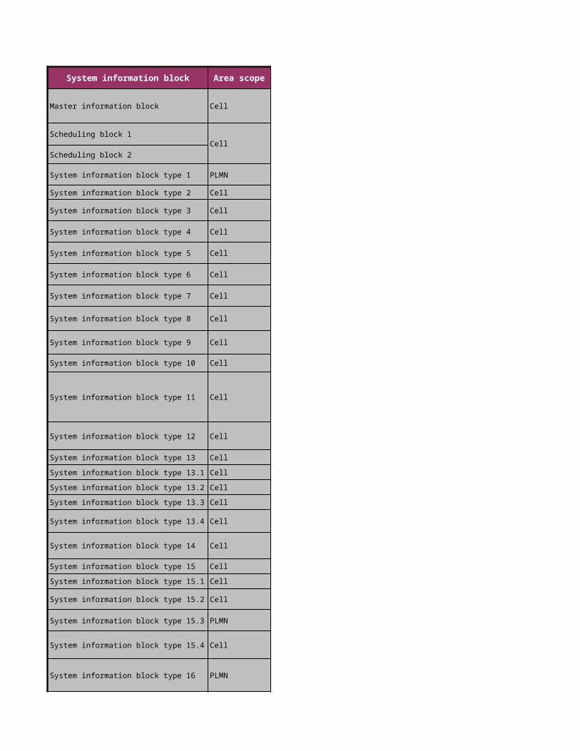
System information block Area scope
Master information block Cell
Scheduling block 1Cell
Scheduling block 2
System information block type 1 PLMN
System information block type 2 Cell
System information block type 3 Cell
System information block type 4 Cell
System information block type 5 Cell
System information block type 6 Cell
System information block type 7 Cell
System information block type 8 Cell
System information block type 9 Cell
System information block type 10 Cell
System information block type 11 Cell
System information block type 12 Cell
System information block type 13 CellSystem information block type 13.1 CellSystem information block type 13.2 CellSystem information block type 13.3 Cell
System information block type 13.4 Cell
System information block type 14 Cell
System information block type 15 CellSystem information block type 15.1 Cell
System information block type 15.2 Cell
System information block type 15.3 PLMN
System information block type 15.4 Cell
System information block type 16 PLMN

System information block type 17 Cell
System Information Block type 18 Cell
System Information Modification Notification
Additonal Information
There is a huge amount of SIBs, which have to be read by the UE. This requires a lot of battery power. Therefore, a Master Information Block (MIB) was introduced, which gives references and scheduling information about the SIBs. The MIB is transmitted in every 8th radio frame on the P-CCPCH (on position SFN mod 8 = 0, and with a TTI of 20 ms). For most of the SIBs used within the system, the MIB may carry a value tag. The only exceptions are SIB 15.2, SIB 15.3 and SIB 16. If a value tag is unchanged, the corresponding system information has not been modified. Thus, there is no need for the UE to read the SIB. For the SIBs which have no value tag e.g. SIB7, It changes with each occurrence (based on Timer). Scheduling information is used to inform the UE, where and when a specific system information is transmitted.
There are two ways of notifying a UE of system information modification: by a value tag and by a timer
1) Notification by a Value TagFor SIBs using value tags, UTRAN should notify the new value tag for the - To notify a UE in idle mode, CELL_PCH state or URA_PCHtransmit the new MIB value tag. - To notify a UE in CELL_FACH state, UTRAN sends a Upon reception of the PAGING TYPE 1 message or SYSTEM INFORMATCHANGE INDICATION message from UTRAN, the UE shall read the changed information according to the new MIB value tag.
2) Notification by a Timer
Other types of SIBs have timers respectively. When the timer expires, the UE shall consider the stored system information content invalid,start the timer, and re-acquirenew SIB information. Notification by a Timer consider the stored system information content invalid, start the timer, and re-acquire new SIB information. The UE may postpone reading the SIB until the content is needed
Actions upon reception of the Master Information Block and Scheduling Block(s):
When selecting a new cell, the UE shall read the master information block. The UE may use the pre-defined scheduling information to locate the master information block in the cell.
Action upon reception of the master information block, the UE shall:
1. if the "PLMN type" in the variable SELECTED_PLMN has the value "GSM-MAP" and the IE "PLMN Type" has the value "GSM-MAP" or "GSM-MAP and ANSI-41",:- check the IE "PLMN identity" in the master information block and verify that it is the selected PLMN, stored as "PLMN identity" in the variable SELECTED_PLMN.- if the "PLMN type" in the variable SELECTED_PLMN has the value "ANSI-41 "and the IE "PLMN Type" has the value "ANSI-41" or "GSM-MAP and ANSI-41",:- store the ANSI-41 Information 2.compare the value tag in the master information block with the value tag stored for this cell and this PLMN in the variable VALUE_TAG.3.if the value tags differ, or if no IEs for the master information block are stored: store the value tag into the variable VALUE_TAG for the master information block; read and store scheduling information included in the master information block;4. if the value tags are the same the UE may use stored system information blocks and scheduling blocks using value tag that were stored in this cell and this PLMN as valid system information.
For all system information blocks or scheduling blocks that are supported by the UE referenced in the master information block or the scheduling blocks, the UE shall perform the following actions:
1.for all system information blocks with area scope PLMN that use value tags:->compare the value tag read in scheduling information for that system information block with the value stored within the variable VALUE_TAG for that system information block;- if the value tags differ, or if no IEs for the corresponding system information block are stored,:store the value tag read in scheduling information for that system information block into the variable VALUE_TAG; read and store the IEs of that system information block.- if the value tags are the same ,the UE may use stored system information blocks using value tag that were stored in this PLMN as valid system information.2 for all system information blocks or scheduling blocks with area scope cell that use value tags:-> compare the value tag read in scheduling information for that system information block or scheduling block with the value stored within the variable VALUE_TAG for that system information block or scheduling block;- if the value tags differ, or if no IEs for the corresponding system information block or scheduling block are stored,store the value tag read in scheduling information for that system information block or scheduling block into the variable VALUE_TAG; read and store the IEs of that system information block or scheduling block;- if the value tags are the same, the UE may use stored system information blocks using value tags that were stored in this cell and this PLMN as valid system information.
For system information blocks, not supported by the UE, but referenced either in the master information block or in the scheduling blocks, the UE may- skip reading this system information block;- skip monitoring changes to this system information block
Actions upon reception of system information blocks:
The UE may use the scheduling information included within the master information block and the scheduling blocks to locate each system information block to be acquired.The UE should only expect one occurrence of the scheduling information for a system information block in the master information block and any of the scheduling blocks. However, to enable future introduction of new system information blocks, the UE shall also be able to receive system information blocks other than the ones indicated within the scheduling information. The UE may ignore contents of such system information block.If the UE- receives a system information block in a position according to the scheduling information for the system information block; and- this system information block uses a value tag according to the system information block typethe UE shall:- store the content of the system information block together with the value of its value tag in the scheduling information for the system information block; and- consider the content of the system information block valid until, if used, the value tag in the scheduling information for the system information block is changed or at most for 6 hours after reception.If the UE- receives a system information block in a position according to the scheduling information for the system information block; and- this system information block does not use a value tag according to the system information block typethe UE shall:- store the content of the system information block; and- start an expiration timer for that system information block type; and- consider the content of the system information block valid until, the expiration timer expires.If the UE- receives a system information block at a position different from its position according to the scheduling information for the system information block; or- receives a system information block for which scheduling information has not been received; and- this system information block uses a value tag according to the system information block typethe UE may:- store the content of the system information block with a value tag set to the value NULL; and- consider the content of the system information block as valid until it receives the same type of system information block in a position according to its scheduling information or at most for 6 hours after reception.
If the UE does not find a scheduling block in a position where it should be according to its scheduling information, but a transport block with correct CRC was found at that position, the UE shall read the scheduling information for this scheduling block.
If the UE does not find the master information block in a position fulfilling (SFN mod (MIB_REP*4) = 0),(but a transport block with correct CRC was found at that position),the UE shall,- consider the master information block as not found.- consider the cell to be barred according to [4] and- consider the barred cell as using the value "allowed" in the IE "Intra-frequency cell re-selection indicator", and the maximum value in the IE "Tbarred".

Main Functions
includes URA information.
This SIB holds mostly the same data fields as SIB 3, but it is read and valid only, when the UE is in the RRC connected mode
This SIB holds mostly the same data fields as SIB 5, but it is read and valid only, when the UE is in the RRC connected mode
includes static CPCH information of cell. Only in used FDD
includes CPCH information of cell. Only used in FDD
includes UE DCH information controlled by DRAC process. Only used in FDD
This SIB holds mostly the same data fields as SIB 11, but it is read and valid only, when the UE is in the RRC connected mode
includes ANSI-41 relevant information
includes UL outer loop control parameters of common and dedicated physical channels. Only used in TDD
includes information on UE-based or UE-assisted positioning method
The MIB informs the UE about the supported PLMN types and the PLMN identity. The UE finds in the MIB also references to up to maxSIB (=32) SIBs, including their scheduling information and type. A MIB is valid in one cell. If a UE changes the cell, is must read the new cell‘s MIB. A change of the MIB information is indicated by a value tag. The master information block may optionally also contain reference and scheduling information to one or two scheduling blocks (SBs), which give references and scheduling information for additional system information blocks. (The SBs are applied when the scheduling resources of MIB are insufficient) Scheduling information for a system information block may only be included in either the master information block or one of the scheduling blocksThis SIB is used to inform the UE about NAS system information. The NAS system information characterises the NAS domains. SIB 1 also delivers UE timers and counters, which have to be used by the UE in the RRC idle and RRC connected mode
includes relevant parameters for cell selection and re-selection. It also holds the cell identity and cell restriction data, such as „cell barred“ IEs. SIB 3 valid in the RRC connected , if SIB 4 is not broadcasted.
includes the configuration of physical channels. The parameters cover the PICH power offset, the AICH power offset, P-CCPCH, S-CCPCH and PRACH system information lists. It is read and valid in the RRC connected mode , if SIB 6 is not available.
includes rapidly changed parameters (UL interference and dynamic persistence level. This SIB holds fast changing parameters. Therefore no value tag is used for it. The UE has to read its parameters periodically
includes measurement control information of cell. The UE gets here the relevant date for traffic measurement, intra-frequency measurements, etc. It is also valid in the RRC sub-state CELL_DCH, as long as the UE did not get a Measurement Control message from UTRAN and SIB 12 is not broadcasted
includes parameters of radio bearer, transport channel and physical channel. These parameters are stored in UE (either in idle mode or connected mode). It used when UE is switched to UTRAN. RB, The parameters are used during a handover to UTRAN. Consequently, these parameters stay valid, when the UE is connected to GSM and GPRS.

includes the rapid changed parameters used to configure the shared physical channel in connected mode. Only used in TDD.
includes PLMN identity of neighbor cell
System Information Modification NotificationThere is a huge amount of SIBs, which have to be read by the UE. This requires a lot of battery power. Therefore, a Master Information Block (MIB) was introduced, which gives references and scheduling information about the SIBs. The MIB is transmitted in every 8th radio frame on the P-CCPCH (on position SFN mod 8 = 0, and with a TTI of 20 ms). For most of the SIBs used within the system, the MIB may carry a value tag. The only exceptions are SIB 15.2, SIB 15.3 and SIB 16. If a value tag is unchanged, the corresponding system information has not been modified. Thus, there is no need for the UE to read the SIB. For the SIBs which have no value tag e.g. SIB7, It changes with each occurrence (based on Timer). Scheduling information is used to inform the UE, where and when a specific system information is transmitted.
There are two ways of notifying a UE of system information modification: by a value tag and by a timer
For SIBs using value tags, UTRAN should notify the new value tag for the MIB to the UE. CELL_PCH state or URA_PCH state, UTRAN send a PAGING TYPE 1 message on the PCCH on all paging occasions in the cell to
- To notify a UE in CELL_FACH state, UTRAN sends a SYSTEM INFORMATION CHANGE INDICATION message on the BCCH to transmit the new MIB value tag. Upon reception of the PAGING TYPE 1 message or SYSTEM INFORMATCHANGE INDICATION message from UTRAN, the UE shall read the changed information according to the new MIB value tag.
Other types of SIBs have timers respectively. When the timer expires, the UE shall consider the stored system information content invalid,start the timer, and
new SIB information. Notification by a Timer consider the stored system information content invalid, start the timer, and re-acquire new SIB information. The UE
postpone reading the SIB until the content is needed
Actions upon reception of the Master Information Block and Scheduling Block(s):
When selecting a new cell, the UE shall read the master information block. The UE may use the pre-defined scheduling information to locate the master information
Action upon reception of the master information block, the UE shall:
1. if the "PLMN type" in the variable SELECTED_PLMN has the value "GSM-MAP" and the IE "PLMN Type" has the value "GSM-MAP" or "GSM-MAP and ANSI-41",:- check the IE "PLMN identity" in the master information block and verify that it is the selected PLMN, stored as "PLMN identity" in the variable SELECTED_PLMN.- if the "PLMN type" in the variable SELECTED_PLMN has the value "ANSI-41 "and the IE "PLMN Type" has the value "ANSI-41" or "GSM-MAP and ANSI-41",:
master information block with the value tag stored for this cell and this PLMN in the variable VALUE_TAG., or if no IEs for the master information block are stored: store the value tag into the variable VALUE_TAG for the master information
and store scheduling information included in the master information block; the UE may use stored system information blocks and scheduling blocks using value tag that were stored in this cell and this
For all system information blocks or scheduling blocks that are supported by the UE referenced in the master information block or the scheduling blocks, the UE shall perform the following actions:
1.for all system information blocks with area scope PLMN that use value tags:compare the value tag read in scheduling information for that system information block with the value stored within the variable VALUE_TAG for that system
, or if no IEs for the corresponding system information block are stored,:store the value tag read in scheduling information for that
information block into the variable VALUE_TAG; read and store the IEs of that system information block. ,the UE may use stored system information blocks using value tag that were stored in this PLMN as valid system information.
for all system information blocks or scheduling blocks with area scope cell that use value tags:compare the value tag read in scheduling information for that system information block or scheduling block with the value stored within the variable VALUE_TAG
that system information block or scheduling block; or if no IEs for the corresponding system information block or scheduling block are stored,store the value tag read in scheduling
that system information block or scheduling block into the variable VALUE_TAG; read and store the IEs of that system information block or scheduling block; the UE may use stored system information blocks using value tags that were stored in this cell and this PLMN as valid system
not supported by the UE, but referenced either in the master information block or in the scheduling blocks, the UE may- skip reading this system information block;- skip monitoring changes to this system information block
Actions upon reception of system information blocks:
The UE may use the scheduling information included within the master information block and the scheduling blocks to locate each system information block to be
The UE should only expect one occurrence of the scheduling information for a system information block in the master information block and any of the scheduling
However, to enable future introduction of new system information blocks, the UE shall also be able to receive system information blocks other than the ones
within the scheduling information. The UE may ignore contents of such system information block.
- receives a system information block in a position according to the scheduling information for the system information block; and- this system information block uses a value tag according to the system information block type
- store the content of the system information block together with the value of its value tag in the scheduling information for the system information block; and- consider the content of the system information block valid until, if used, the value tag in the scheduling information for the system information block is
- receives a system information block in a position according to the scheduling information for the system information block; and- this system information block does not use a value tag according to the system information block type
- store the content of the system information block; and- start an expiration timer for that system information block type; and- consider the content of the system information block valid until, the expiration timer expires.
- receives a system information block at a position different from its position according to the scheduling information for the system information block; or- receives a system information block for which scheduling information has not been received; and- this system information block uses a value tag according to the system information block type
- store the content of the system information block with a value tag set to the value NULL; and- consider the content of the system information block as valid until it receives the same type of system information block in a position according to its
information or at most for 6 hours after reception.
If the UE does not find a scheduling block in a position where it should be according to its scheduling information, but a transport block with correct CRC was
at that position, the UE shall read the scheduling information for this scheduling block.
If the UE does not find the master information block in a position fulfilling (SFN mod (MIB_REP*4) = 0),(but a transport block with correct CRC was found at that
- consider the master information block as not found.- consider the cell to be barred according to [4] and- consider the barred cell as using the value "allowed" in the IE "Intra-frequency cell re-selection indicator", and the maximum value in the IE "Tbarred".

UE mode/state when block is valid UE mode/state when block is read
Idle mode,CELL_FACH,CELL_PCH, URA_PCH Idle mode,CELL_FACH,CELL_PCH, URA_PCH
Idle mode,CELL_FACH,CELL_PCH, URA_PCH Idle mode,CELL_FACH,CELL_PCH, URA_PCH
Idle mode,CELL_FACH,CELL_PCH, URA_PCH Idle mode,CELL_FACH,CELL_PCH, URA_PCH
Idle
URA_PCH URA_PCH
Idle mode, (CELL_FACH, CELL_PCH, URA_PCH) Idle mode, (CELL_FACH, CELL_PCH, URA_PCH)
CELL_FACH, CELL_PCH, URA_PCH CELL_FACH, CELL_PCH, URA_PCH
CELL_FACH, CELL_PCH, URA_PCH CELL_FACH, CELL_PCH, URA_PCH
CELL_FACH, CELL_PCH, URA_PCH CELL_FACH, CELL_PCH, URA_PCH
CELL_DCH CELL_DCH
Idle mode (CELL_FACH, CELL_PCH, URA_PCH)
CELL_FACH, CELL_PCH, URA_PCH, CELL_DCH CELL_FACH, CELL_PCH, URA_PCH
Idle Mode, CELL_FACH, CELL_PCH, URA_PCH Idle Mode, CELL_FACH, CELL_PCH, URA_PCHIdle Mode, CELL_FACH, CELL_PCH, URA_PCH Idle Mode, CELL_FACH, CELL_PCH, URA_PCHIdle Mode, CELL_FACH, CELL_PCH, URA_PCH Idle Mode, CELL_FACH, CELL_PCH, URA_PCHIdle Mode, CELL_FACH, CELL_PCH, URA_PCH Idle Mode, CELL_FACH, CELL_PCH, URA_PCH
Idle Mode, CELL_FACH, CELL_PCH, URA_PCH Idle Mode, CELL_FACH, CELL_PCH, URA_PCH
Idle Mode, CELL_FACH, CELL_PCH, URA_PCH Idle Mode, CELL_FACH, CELL_PCH, URA_PCHIdle Mode, CELL_FACH, CELL_PCH, URA_PCH Idle Mode, CELL_FACH, CELL_PCH, URA_PCH
Idle Mode, CELL_FACH, CELL_PCH, URA_PCH Idle Mode, CELL_FACH, CELL_PCH, URA_PCH
Idle Mode, CELL_FACH, CELL_PCH, URA_PCH Idle Mode, CELL_FACH, CELL_PCH, URA_PCH
Idle Mode, CELL_FACH, CELL_PCH, URA_PCH Idle Mode, CELL_FACH, CELL_PCH, URA_PCH
Idle Mode, CELL_FACH, CELL_PCH, URA_PCH Idle Mode, CELL_FACH, CELL_PCH, URA_PCH
Idle mode,CELL_FACH,CELL_PCH, URA_PCH,CELL_DCH
Idle mode, (CELL_FACH, CELL_PCH, URA_PCH, CELL_DCH (TDD only))
Idle mode, (CELL_FACH, CELL_PCH, URA_PCH, CELL_DCH (TDD only))
CELL_FACH, CELL_PCH, URA_PCH, CELL_DCH (TDD only)
CELL_FACH, CELL_PCH, URA_PCH, CELL_DCH (TDD only)
Idle mode, CELL_FACH, CELL_PCH, URA_PCH, CELL_DCH (TDD only)
Idle mode, CELL_FACH, CELL_PCH, URA_PCH, CELL_DCH (TDD only)
Idle mode (CELL_FACH, CELL_PCH, URA_PCH, CELL_DCH)
Idle Mode, CELL_FACH, CELL_PCH, URA_PCH, CELL_DCH
Idle Mode, CELL_FACH, CELL_PCH, URA_PCH, CELL_DCH

CELL_FACH, CELL_PCH, URA_PCH, CELL_DCH CELL_FACH, CELL_PCH, URA_PCH, CELL_DCH
Idle mode, CELL_FACH, CELL_PCH, URA_PCHIdle mode, CELL_FACH, CELL_PCH, URA_PCH, CELL_DCH
Click to return to main page

Scheduling information
Value tag
Specified by the IE "Scheduling information" in MIB Value tag
Specified by the IE "Scheduling information" in MIB Value tag
Specified by the IE "Scheduling information" Value tag
Specified by the IE "Scheduling information" Value tag
Specified by the IE "Scheduling information" Value tag
Specified by the IE "Scheduling information" Value tag
Specified by the IE "Scheduling information" Value tag
Specified by the IE "Scheduling information" Value tag
Specified by the IE "Scheduling information"
Specified by the IE "Scheduling information" Value tag
Specified by the IE "Scheduling information"
Specified by the IE "Scheduling information"
Specified by the IE "Scheduling information" Value tag
Specified by the IE "Scheduling information" Value tag
Specified by the IE "Scheduling information" Value tagSpecified by the IE "Scheduling information" Value tagSpecified by the IE "Scheduling information" Value tagSpecified by the IE "Scheduling information" Value tag
Specified by the IE "Scheduling information" Value tag
Specified by the IE "Scheduling information"
Specified by the IE "Scheduling information" Value tagSpecified by the IE "Scheduling information" Value tag
Specified by the IE "Scheduling information" Value tag
Specified by the IE "Scheduling information" Value tag
Specified by the IE "Scheduling information" Value tag
Specified by the IE "Scheduling information" Value tag
Modification of system information
SIB_POS = 0,SIB_REP = 8 (FDD),SIB_REP = 8, 16, 32 (TDD),SIB_OFF=2
Expiration timer = MAX([320 ms],SIB_REP * ExpirationTimeFactor)
Expiration timer = SIB_REPExpiration timer = SIB_REP
Expiration timer = MAX([320 ms], SIB_REP * ExpirationTimeFactor)

Specified by the IE "Scheduling information"
Specified by the IE "Scheduling information" Value tag
Expiration timer = SIB_REP

Additional comment
This system information block is used in TDD mode only.
If System information block type 4 is not broadcast in a cell, the connected mode UE shall read System information block type 3
If system information block type 6 is not broadcast in a cell, the connected mode UE shall read System information block type 5.In TDD mode system information block type 7 shall only be read in CELL_DCH if shared transport channels are assigned to the UE.
If some of the optional IEs are not included in System information block type 12, the UE shall read the corresponding IEs in System information block type 11.
For this system information block there may be multiple occurrencesFor this system information block there may be multiple occurrences
For this system information block there may be multiple occurrences

This system information block is used in TDD mode only.

Master Information Block (MIB)

System Scheduling Block 1 (SB1)

System Information Block 1 (SIB1)

System Information Block 2 (SIB 2)
System Information Block 3 (SIB 3)

System Information Block 5 (SIB 5)


System Information Block 7 (SIB 7)
System Information Block 11(SIB 11)


Master Information Block (MIB)
value=hex2dec(5)=5 , hex2dec(2)=2 ,hex2dec(0)=0 --> MCC=520
value=hex2dec(0)=0 , hex2dec(1)=1 --> MNC=01
Click to return to main page

System Scheduling Block 1 (SB1) Click to return to main page

System Information Block 1 (SIB1)
>>Paging Procedure and Parameters Description (Module II)
Click to return to main page

value=3000msvalue=3value=40msvalue=40ms
value=6svalue=50value=20svalue=30svalue=infinity
value=2000msvalue=3
value=6svalue=1
System Information Block 2 (SIB 2)
value=hex2dec(0065)=101
System Information Block 3 (SIB 3)
Cell Identity=RNCid(12bits)+Cellid(16bits)
>>>Cell Selection and Reselection Algorithm and parameters description (Module II)
value=0value=250ms
Click to return to main page
Click to return to main page
value=0000000010110111011110010010 => RNCid=bin2dec(000000001011)=11 and Cellid=bin2dec(0111011110010010)=30610

value=2dB(step of 2 dB)
value=10dB(step of 2 dB)value=8dB(step of 2 dB)
value=4dB(step of 2 dB)
value=-18dBm
value= ((-58*2)+1)= –115 dBm e.g. –57 means –113 dBm; …; –13 means -25 dBmvalue=4dB(step of 2 dB)
value=1s(step of 1s)
value=24dBm>>>Cell Access Restriction parameters description (Module II)
System Information Block 5 (SIB 5)
>>>Cell Channel Power Configuration Parameters (Module II)
value=-7dB (relative to the PCPICH)
value=-6dB (relative to the PCPICH)
Click to return to main page

>>>Access Precedures and parameters description (Module II)


>>>Open Loop Power Control Algorithm and parameters description (Module II)
value=33dBm
value=-20dBmvalue=2dB(step of 1 dB)
value=20attempts
value=8attempts
value=


System Information Block 7 (SIB 7)
value=-105dBm
>>>see "Parameters description"
System Information Block 11(SIB 11)
Value= InterFreqMeasurement is unavailable
Click to return to main page
Click to return to main page

Value= IntraFreqMeasurement is based on CPICH Ec/No
>>> IntrafreqMeasurement description (Module II)
value=hex2dec(3b)=59 (Serving Cell's Primary Scrambling Code)
value=hex2dec(43)=67(Neighbour Cell's Primary Scrambling Code)
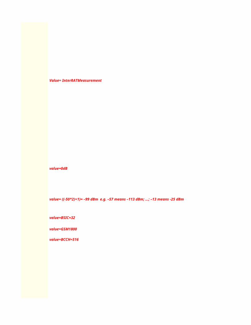
Value= InterRATMeasurement
value=0dB
value= ((-50*2)+1)= –99 dBm e.g. –57 means –113 dBm; …; –13 means -25 dBm
value=BSIC=32
value=GSM1800
value=BCCH=516


>>>Cell Selection and Reselection Algorithm and parameters description (Module II)
Cellid=bin2dec(0111011110010010)=30610

L3 Messages - Location Update ProcedureUE NodeB
Start Rx
5.ALCAP: Iub User Plane Setup
Start Tx
5.RRC: Uplink Direct Transfer
Click to return to main page
1.RRC: RRC Connection Request (RACH)
RRC Connection Establishment Timing
6.RRC: RRC Connection Setup (FACH)
L1 Synchonization
7.RRC: RRC Connection Setup Completed (DCH)
1.RRC: Initial Direct Transfer (MM: Location Update Request)
4.RRC: Downlink Direct Transfer (MM: Location Update Accept)
1.RRC: RRC Connection Release
Optional : Authentication and Securitty Mode Control may exist depends on Operator's setting (refer to signaling in AMR call precedures)

2.RRC: RRC Connection Release Complete
ALCAP: Iub User Plane Release
2.RRC: RRC Connection Release Complete
Note the following information about the procedure :
1.The RRC connection can be set up on a DCH or a CCH. This procedure takes the RRC connection set up on the DCH as an example.
2 If IP transport is applied to the Iub interface, no ALCAP procedure is performed on the Iub interface after radio links are set up or deleted.
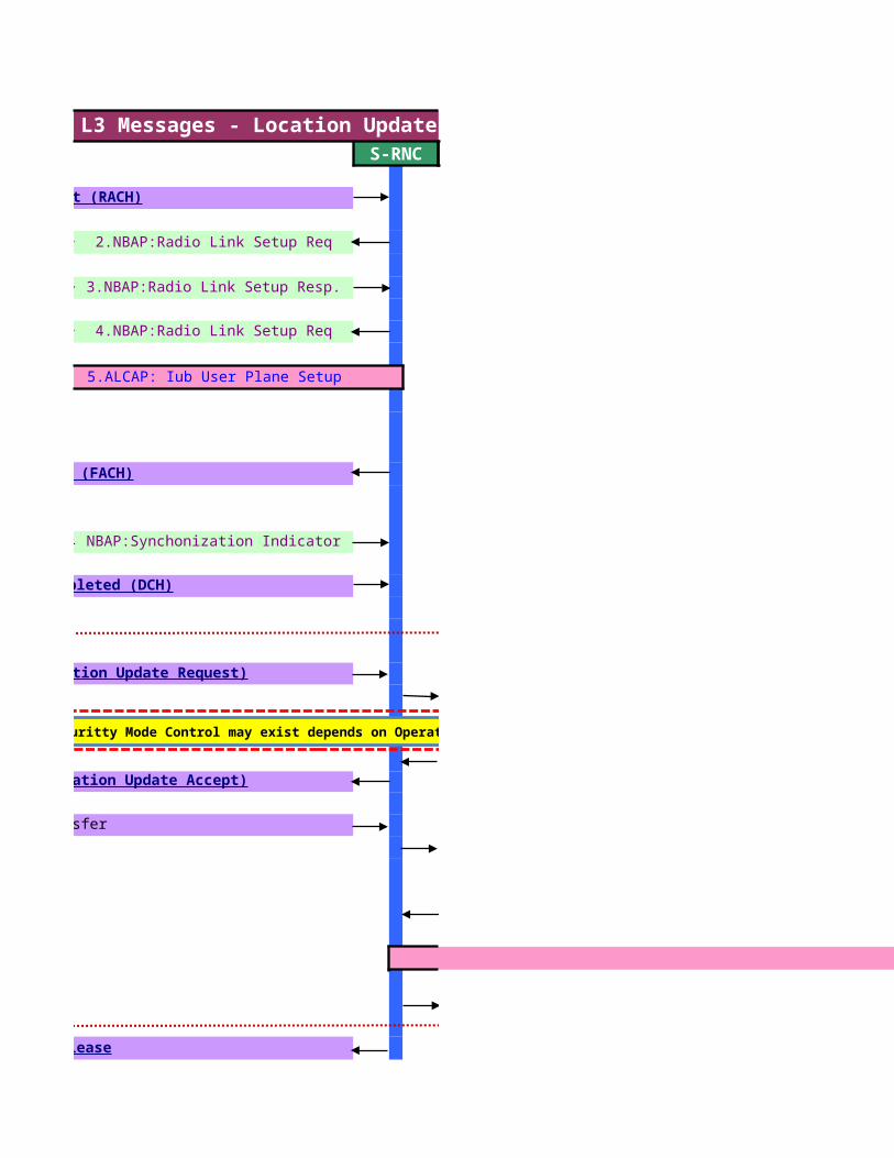
L3 Messages - Location Update ProcedureS-RNC
2.NBAP:Radio Link Setup Req
3.NBAP:Radio Link Setup Resp.
4.NBAP:Radio Link Setup Req
5.ALCAP: Iub User Plane Setup
NBAP:Synchonization Indicator
5.RRC: Uplink Direct Transfer
ALCAP: Iu User Plane Release
1.RRC: RRC Connection Request (RACH)
6.RRC: RRC Connection Setup (FACH)
7.RRC: RRC Connection Setup Completed (DCH)
1.RRC: Initial Direct Transfer (MM: Location Update Request)
4.RRC: Downlink Direct Transfer (MM: Location Update Accept)
1.RRC: RRC Connection Release
Optional : Authentication and Securitty Mode Control may exist depends on Operator's setting (refer to signaling in AMR call precedures)

2.RRC: RRC Connection Release Complete
ALCAP: Iub User Plane Release
2.RRC: RRC Connection Release Complete
3.NBAP: Radio Link Deletion Request
4.NBAP: Radio Link Deletion Response
1.The RRC connection can be set up on a DCH or a CCH. This procedure takes the RRC
2 If IP transport is applied to the Iub interface, no ALCAP procedure is performed on the Iub interface after radio links are set up or deleted.

L3 Messages - Location Update ProcedureCN
6.RANAP: Direct Transfer
1.RANAP: Iu Release Command
ALCAP: Iu User Plane Release
2..RANAP: Iu Release Complete
2.RANAP: Initial UE Message (MM: Location Update Request)
3.RANAP: Direct Transfer (MM: Location Update Accept)Optional : Authentication and Securitty Mode Control may exist depends on Operator's setting (refer to signaling in AMR call precedures)


RRC connection setup procedure is performed for the UE to set up a signaling connection to the SRNC. RRC connection setup is always initiated by the UE. One UE has a maximum of one RRC connection at a time.
Triggering Conditions : The UE in idle mode intitiates the RRC connection setup procedure when the NAS of the UE requests the establishment of a signaling connection
When the SRNC receives an RRC CONNECTION REQUEST message from the UE, the Radio Resource Management (RRM) module of the RNC determines whether to accept or reject theRRC connection request, based on a specific algorithm. If accepting the request, the RRM module further determines whether to set up the RRC connection on a Dedicated Channel (DCH)or on a Common Channel (CCH), based on a specific RRM algorithm. Typically, an RRC connection is set up on the DCH.
The procedure shown is described as follows:1.The UE sends an RRC CONNECTION REQUEST message to the SRNC through the uplink CCCH(RACH), requesting the establishment of an RRC connection.2.Based on the cause in the RRC connection request and the system resource status, the SRNC determines to set up the RRC connection on a DCH and allocates the Radio NetworkTemporary Identity(RNTI),radio resources, and L1 and L2 resources. Then the SRNC sends a RADIO LINK SETUP REQUEST message to the NodeB, requesting the NodeB to allocate the specific radio link resources required for an RRC connection.3.The NodeB responds with a RADIO LINK SETUP RESPONSE message to the SRNC after successfully preparing the resources.4.The SRNC uses the ALCAP protocol to set up the Iub user plane transport bearer and performs the synchronization between the SRNC and the NodeB. This procedure is optional. It is requiredfor the ATM-based Iub interface only.5.The SRNC sends an RRC CONNECTION SETUP message to the UE through the downlink CCCH (FACH). The message contains the information about the DCH allocated by the SRNC.6. UE and NodeB initiate L1 Synchronization. NodeB sends NBAP:Synchonization Indicator message to SRNC when the uplink enter "In-Sync" state7. The UE sends an RRC CONNECTION SETUP COMPLETE message to the SRNC through the uplink Dedicated Control Channel (DCCH) that is just set up. The message indicates that the RRC connection setup procedure ends.If the RNC judges that the RRC connection request cannot be set up (for instance, due to insufficient resources), it directly sends an RRC CONNECTION REJECT message to the UE, and indicates the reject reason in the message
>>RRC Procedure description
The location update procedure is performed to update the location of a UE.
Triggering Conditions : An RRC connection is set up between the UE and the Serving RNC (SRNC)
The procedure is described as follows:1.The UE sends an INITIAL DIRECT TRANSFER message to the SRNC through the RRC connection. The message contains the Non Access Stratum (NAS) information to be sent to the CN by the UE.2.The SRNC sends an INITIAL UE MESSAGE to the CS service domain of the CN through the Iu interface. The message indicates LOCATION UPDATE REQUEST and containsthe UE information, such as the Temporary Mobile Subscriber Identity (TMSI),International Mobile Subscriber Identity (IMSI), and Location Area Identity (LAI).The SRNC sends an INITIAL UE MESSAGE to the PS service domain of the CN throughthe Iu interface forrouting area update. The message indicates ATTACH REQUEST and contains the Routing Area Identity (RAI)3.The CN updates the location area information of the UE and saves the new LAI. The CN might also perform authentication and ciphering. Then, the CN sends a DIRECT TRANSFER message to the SRNC. The messageindicates LOCATION UPDATE ACCEPT and contains the TMSI that is assigned to the UE.For routing area update, the CN updates the routing area information of the UE and savesthe new RAI. The CN might also performauthentication and ciphering. Then, the CN sendsa DIRECT TRANSFER message to the SRNC. The message indicates ATTACH ACCEPTand contains the TMSI that is assigned to the UE
4.The SRNC transparently sends the contents of the DIRECT TRANSFER message to the UE through a DOWNLINK DIRECT TRANSFER message.5.The UE receives the LOCATION UPDATE ACCEPT information and sends an UPLINK DIRECT TRANSFER message to the SRNC. The message contains the information suchas the NAS information and the CN ID.For routingarea update, it is the ATTACH ACCEPT information that the UE receives.6.The SRNC transparently sends the contents of the UPLINK DIRECT TRANSFER messageto the CN through a DIRECT TRANSFER message. The DIRECT TRANSFER messageindicates TMSI REALLOCATION COMPLETE.
For routing area update, it is ATTACH COMPLETE that the DIRECT TRANSFER message indicates.
RRC Connection Setup
Location Update
Iu release

The Iu release procedure is performed for the CN to release an Iu connection and all the UTRAN resources related only to that Iu connection.
Triggering Conditions: The Iu release procedure can be triggered in one of the following conditions: The transaction between the UE and the CN is complete,The UTRAN requests the CN to release the resources on the Iu interface by, for example,sending an IU RELEASE REQUEST message,The Serving Radio Network Subsystem (SRNS) is relocated.4.The SRNS relocation is canceled after a relocation resource allocation procedure iscomplete.
The procedure shown is described as follows:1.The CN sends an IU RELEASE COMMAND message to the SRNC to initiate the Iu release procedure. The message indicates the cause for the release of the signaling connection.NOTE After sending the IU RELEASE COMMAND message, the CN will not send further RANAP connection-oriented messages on this particular connection.2.The SRNC releases the related UTRAN resources and then sends an IU RELEASE COMPLETE message to the CN.
The RRC Connection Release procedure is performed to release the signaling connection and all radio bearers between UE and the UTRAN
Triggering Conditions: After a n RAB is released,the SRNC judges whether the RRC connection carries any other RAB or the UE. If judging that the RRC connection does not carry other RAB of the UE,the SRNC initiates an RRC connection release procedure.
The procedure shown is described as follows: based on the resouce occupied by the RRC connection,there are two types of RRC connection release procedure: release of an RRCconnection from DCH and release of an RRC connection from CCH to be setup ,the RRC connection on the CCH is released)
1.The SRNC sends an RRC CONNECTION RELEASE message to the UE through the DCCH. (NOTE: The SRNC may send the RRC CONNECTION RELEASE message several times to increase the probability of proper reception of the message by the UE. The RRC SNs of these messages are the same. The number of retransmissions and the transmission intervals are determined by the SRNC. If the SRNC does not receive an RRC CONNECTION RELEASE COMPLETE message from the UE after sending the RRC CONNECTION RELEASE message for 2.The UE sends an RRC CONNECTION RELEASE COMPLETE message to the SRNC.3.The SRNC sends a RADIO LINK DELETION REQUEST message to the NodeB,requesting the NodeB to delete the radio link resources in the NodeB.4.After releasing the resources, the NodeB sends a RADIO LINK DELETION RESPONSE message to the SRNC.5.(Optional; required for the ATM-based Iub interface only) The SRNC uses the ALCAP protocol to initiate an Iub user plane transport bearer release procedure. Then, the RRC connection release procedureends.
RRC connection Release

is performed for the UE to set up a signaling connection to the SRNC. RRC connection setup is always initiated by the UE. One UE has a maximum of one RRC connection at a time.
The UE in idle mode intitiates the RRC connection setup procedure when the NAS of the UE requests the establishment of a signaling connection
When the SRNC receives an RRC CONNECTION REQUEST message from the UE, the Radio Resource Management (RRM) module of the RNC determines whether to accept or reject theRRC connection request, based on a specific algorithm. If accepting the request, the RRM module further determines whether to set up the RRC connection on a Dedicated Channel (DCH)or on a Common Channel (CCH), based on a specific RRM algorithm. Typically, an RRC connection is set up on the DCH.
The UE sends an RRC CONNECTION REQUEST message to the SRNC through the uplink CCCH(RACH), requesting the establishment of an RRC connection.Based on the cause in the RRC connection request and the system resource status, the SRNC determines to set up the RRC connection on a DCH and allocates the Radio NetworkTemporary Identity(RNTI),radio
resources, and L1 and L2 resources. Then the SRNC sends a RADIO LINK SETUP REQUEST message to the NodeB, requesting the NodeB to allocate the specific radio link resources required for an RRC connection.The NodeB responds with a RADIO LINK SETUP RESPONSE message to the SRNC after successfully preparing the resources.
.The SRNC uses the ALCAP protocol to set up the Iub user plane transport bearer and performs the synchronization between the SRNC and the NodeB. This procedure is optional. It is requiredfor the ATM-based Iub interface only.The SRNC sends an RRC CONNECTION SETUP message to the UE through the downlink CCCH (FACH). The message contains the information about the DCH allocated by the SRNC. UE and NodeB initiate L1 Synchronization. NodeB sends NBAP:Synchonization Indicator message to SRNC when the uplink enter "In-Sync" state
. The UE sends an RRC CONNECTION SETUP COMPLETE message to the SRNC through the uplink Dedicated Control Channel (DCCH) that is just set up. The message indicates that the
If the RNC judges that the RRC connection request cannot be set up (for instance, due to insufficient resources), it directly sends an RRC CONNECTION REJECT message to the UE, and indicates the reject reason in the message
is performed to update the location of a UE.
An RRC connection is set up between the UE and the Serving RNC (SRNC)
The UE sends an INITIAL DIRECT TRANSFER message to the SRNC through the RRC connection. The message contains the Non Access Stratum (NAS) information to be sent to the CN by the UE.The SRNC sends an INITIAL UE MESSAGE to the CS service domain of the CN through the Iu interface. The message indicates LOCATION UPDATE REQUEST and containsthe UE information, such as the Temporary
Mobile Subscriber Identity (TMSI),International Mobile Subscriber Identity (IMSI), and Location Area Identity (LAI).The SRNC sends an INITIAL UE MESSAGE to the PS service domain of the CN throughthe Iu interface
routing area update. The message indicates ATTACH REQUEST and contains the Routing Area Identity (RAI)The CN updates the location area information of the UE and saves the new LAI. The CN might also perform authentication and ciphering. Then, the CN sends a DIRECT TRANSFER message to the SRNC. The message
indicates LOCATION UPDATE ACCEPT and contains the TMSI that is assigned to the UE.For routing area update, the CN updates the routing area information of the UE and savesthe new RAI. The CN might also performauthentication and ciphering. Then, the CN sendsa DIRECT TRANSFER message to the SRNC. The message indicates ATTACH ACCEPTand contains the TMSI that is assigned to the UE
.The SRNC transparently sends the contents of the DIRECT TRANSFER message to the UE through a DOWNLINK DIRECT TRANSFER message.The UE receives the LOCATION UPDATE ACCEPT information and sends an UPLINK DIRECT TRANSFER message to the SRNC. The message contains the information suchas the NAS information and the CN ID.For routing
area update, it is the ATTACH ACCEPT information that the UE receives.The SRNC transparently sends the contents of the UPLINK DIRECT TRANSFER messageto the CN through a DIRECT TRANSFER message. The DIRECT TRANSFER messageindicates TMSI REALLOCATION COMPLETE.
For routing area update, it is ATTACH COMPLETE that the DIRECT TRANSFER message indicates.

is performed for the CN to release an Iu connection and all the UTRAN resources related only to that Iu connection.
The Iu release procedure can be triggered in one of the following conditions: The transaction between the UE and the CN is complete,The UTRAN requests the CN to release the resources on the Iu interface by, for example,sending an IU RELEASE REQUEST message,The Serving Radio Network Subsystem (SRNS) is relocated.4.The SRNS relocation is canceled after a relocation resource allocation procedure
.The CN sends an IU RELEASE COMMAND message to the SRNC to initiate the Iu release procedure. The message indicates the cause for the release of the signaling connection. After sending the IU RELEASE COMMAND message, the CN will not send further RANAP connection-oriented messages on this particular connection.
The SRNC releases the related UTRAN resources and then sends an IU RELEASE COMPLETE message to the CN.
is performed to release the signaling connection and all radio bearers between UE and the UTRAN
After a n RAB is released,the SRNC judges whether the RRC connection carries any other RAB or the UE. If judging that the RRC connection does not carry other RAB of the UE,the SRNC initiates an RRC connection release procedure.
based on the resouce occupied by the RRC connection,there are two types of RRC connection release procedure: release of an RRCconnection from DCH and release of an RRC connection from CCH (If an RRC connection needs to be released after a successful outgoing call,, the RRC connection on the DCH is released and if a radio bearers fails to be setup ,the RRC connection on the CCH is released)
.The SRNC sends an RRC CONNECTION RELEASE message to the UE through the DCCH. The SRNC may send the RRC CONNECTION RELEASE message several times to increase the probability of proper reception of the message by the UE. The RRC SNs of these messages are the same. The number of
retransmissions and the transmission intervals are determined by the SRNC. If the SRNC does not receive an RRC CONNECTION RELEASE COMPLETE message from the UE after sending the RRC CONNECTION RELEASE message for four times, the SRNC judges that the UE has released the RRC connection.).The UE sends an RRC CONNECTION RELEASE COMPLETE message to the SRNC.The SRNC sends a RADIO LINK DELETION REQUEST message to the NodeB,requesting the NodeB to delete the radio link resources in the NodeB.
.After releasing the resources, the NodeB sends a RADIO LINK DELETION RESPONSE message to the SRNC.
.(Optional; required for the ATM-based Iub interface only) The SRNC uses the ALCAP protocol to initiate an Iub user plane transport bearer release procedure. Then, the RRC connection release procedure

is performed for the UE to set up a signaling connection to the SRNC. RRC connection setup is always initiated by the UE. One UE has a maximum of one RRC connection at a time.
The UE in idle mode intitiates the RRC connection setup procedure when the NAS of the UE requests the establishment of a signaling connection
When the SRNC receives an RRC CONNECTION REQUEST message from the UE, the Radio Resource Management (RRM) module of the RNC determines whether to accept or reject theRRC connection request, based on a specific algorithm. If accepting the request, the RRM module further determines whether to set up the RRC connection on a Dedicated Channel (DCH)or on a Common Channel (CCH), based on a specific RRM algorithm. Typically,
The UE sends an RRC CONNECTION REQUEST message to the SRNC through the uplink CCCH(RACH), requesting the establishment of an RRC connection.Based on the cause in the RRC connection request and the system resource status, the SRNC determines to set up the RRC connection on a DCH and allocates the Radio NetworkTemporary Identity(RNTI),radio
resources, and L1 and L2 resources. Then the SRNC sends a RADIO LINK SETUP REQUEST message to the NodeB, requesting the NodeB to allocate the specific radio link
The NodeB responds with a RADIO LINK SETUP RESPONSE message to the SRNC after successfully preparing the resources..The SRNC uses the ALCAP protocol to set up the Iub user plane transport bearer and performs the synchronization between the SRNC and the NodeB. This procedure is optional. It is required
The SRNC sends an RRC CONNECTION SETUP message to the UE through the downlink CCCH (FACH). The message contains the information about the DCH allocated by the SRNC. UE and NodeB initiate L1 Synchronization. NodeB sends NBAP:Synchonization Indicator message to SRNC when the uplink enter "In-Sync" state. The UE sends an RRC CONNECTION SETUP COMPLETE message to the SRNC through the uplink Dedicated Control Channel (DCCH) that is just set up. The message indicates that the
If the RNC judges that the RRC connection request cannot be set up (for instance, due to insufficient resources), it directly sends an RRC CONNECTION REJECT message to the UE, and
The UE sends an INITIAL DIRECT TRANSFER message to the SRNC through the RRC connection. The message contains the Non Access Stratum (NAS) information to be sent to the CN by the UE.The SRNC sends an INITIAL UE MESSAGE to the CS service domain of the CN through the Iu interface. The message indicates LOCATION UPDATE REQUEST and containsthe UE information, such as the Temporary
Mobile Subscriber Identity (TMSI),International Mobile Subscriber Identity (IMSI), and Location Area Identity (LAI).The SRNC sends an INITIAL UE MESSAGE to the PS service domain of the CN throughthe Iu interface
The CN updates the location area information of the UE and saves the new LAI. The CN might also perform authentication and ciphering. Then, the CN sends a DIRECT TRANSFER message to the SRNC. The messageindicates LOCATION UPDATE ACCEPT and contains the TMSI that is assigned to the UE.For routing area update, the CN updates the routing area information of the UE and savesthe new RAI. The CN might also performauthentication and ciphering. Then, the CN sendsa DIRECT TRANSFER message to the SRNC. The message indicates ATTACH ACCEPTand contains the TMSI that is assigned to the UE
.The SRNC transparently sends the contents of the DIRECT TRANSFER message to the UE through a DOWNLINK DIRECT TRANSFER message.The UE receives the LOCATION UPDATE ACCEPT information and sends an UPLINK DIRECT TRANSFER message to the SRNC. The message contains the information suchas the NAS information and the CN ID.For routing
The SRNC transparently sends the contents of the UPLINK DIRECT TRANSFER messageto the CN through a DIRECT TRANSFER message. The DIRECT TRANSFER messageindicates TMSI REALLOCATION COMPLETE.

is performed for the CN to release an Iu connection and all the UTRAN resources related only to that Iu connection.
The Iu release procedure can be triggered in one of the following conditions: The transaction between the UE and the CN is complete,The UTRAN requests the CN to release the resources on the Iu interface by, for example,sending an IU RELEASE REQUEST message,The Serving Radio Network Subsystem (SRNS) is relocated.4.The SRNS relocation is canceled after a relocation resource allocation procedure
.The CN sends an IU RELEASE COMMAND message to the SRNC to initiate the Iu release procedure. The message indicates the cause for the release of the signaling connection. After sending the IU RELEASE COMMAND message, the CN will not send further RANAP connection-oriented messages on this particular connection.
is performed to release the signaling connection and all radio bearers between UE and the UTRAN
After a n RAB is released,the SRNC judges whether the RRC connection carries any other RAB or the UE. If judging that the RRC connection does not carry other RAB of the UE,the SRNC
based on the resouce occupied by the RRC connection,there are two types of RRC connection release procedure: release of an RRC(If an RRC connection needs to be released after a successful outgoing call,, the RRC connection on the DCH is released and if a radio bearers fails
The SRNC may send the RRC CONNECTION RELEASE message several times to increase the probability of proper reception of the message by the UE. The RRC SNs of these messages are the same. The number of retransmissions and the transmission intervals are determined by the SRNC. If the SRNC does not receive an RRC CONNECTION RELEASE
, the SRNC judges that the UE has released the RRC connection.)
The SRNC sends a RADIO LINK DELETION REQUEST message to the NodeB,requesting the NodeB to delete the radio link resources in the NodeB.
.(Optional; required for the ATM-based Iub interface only) The SRNC uses the ALCAP protocol to initiate an Iub user plane transport bearer release procedure. Then, the RRC connection release procedure

is performed for the UE to set up a signaling connection to the SRNC. RRC connection setup is always initiated by the UE. One UE has a maximum of one RRC connection at a time.
When the SRNC receives an RRC CONNECTION REQUEST message from the UE, the Radio Resource Management (RRM) module of the RNC determines whether to accept or reject theRRC connection request, based on a specific algorithm. If accepting the request, the RRM module further determines whether to set up the RRC connection on a Dedicated Channel (DCH)or on a Common Channel (CCH), based on a specific RRM algorithm. Typically,
Based on the cause in the RRC connection request and the system resource status, the SRNC determines to set up the RRC connection on a DCH and allocates the Radio NetworkTemporary Identity(RNTI),radio
.The SRNC uses the ALCAP protocol to set up the Iub user plane transport bearer and performs the synchronization between the SRNC and the NodeB. This procedure is optional. It is required
The SRNC sends an INITIAL UE MESSAGE to the CS service domain of the CN through the Iu interface. The message indicates LOCATION UPDATE REQUEST and containsthe UE information, such as the Temporary Mobile Subscriber Identity (TMSI),International Mobile Subscriber Identity (IMSI), and Location Area Identity (LAI).The SRNC sends an INITIAL UE MESSAGE to the PS service domain of the CN throughthe Iu interface
The CN updates the location area information of the UE and saves the new LAI. The CN might also perform authentication and ciphering. Then, the CN sends a DIRECT TRANSFER message to the SRNC. The messageindicates LOCATION UPDATE ACCEPT and contains the TMSI that is assigned to the UE.For routing area update, the CN updates the routing area information of the UE and savesthe new RAI. The CN might also perform
The UE receives the LOCATION UPDATE ACCEPT information and sends an UPLINK DIRECT TRANSFER message to the SRNC. The message contains the information suchas the NAS information and the CN ID.For routing
The SRNC transparently sends the contents of the UPLINK DIRECT TRANSFER messageto the CN through a DIRECT TRANSFER message. The DIRECT TRANSFER messageindicates TMSI REALLOCATION COMPLETE.

The Iu release procedure can be triggered in one of the following conditions: The transaction between the UE and the CN is complete,The UTRAN requests the CN to release the resources on the Iu interface by, for example,sending an IU RELEASE REQUEST message,The Serving Radio Network Subsystem (SRNS) is relocated.4.The SRNS relocation is canceled after a relocation resource allocation procedure
After a n RAB is released,the SRNC judges whether the RRC connection carries any other RAB or the UE. If judging that the RRC connection does not carry other RAB of the UE,the SRNC
(If an RRC connection needs to be released after a successful outgoing call,, the RRC connection on the DCH is released and if a radio bearers fails
The SRNC may send the RRC CONNECTION RELEASE message several times to increase the probability of proper reception of the message by the UE. The RRC SNs of these messages are the same. The number of
.(Optional; required for the ATM-based Iub interface only) The SRNC uses the ALCAP protocol to initiate an Iub user plane transport bearer release procedure. Then, the RRC connection release procedure

RRC:RRC Connection Request (RACH)Click to return to main page

RRC:RRC Connection Setup (FACH)


RRC:RRC Connection Setup Complete (DCCH)


RANAP: Initial UE Message (MM: Location Update Request)

RRC: Initial Direct Transfer (MM: Location Update Request)

RANAP: Direct Transfer (MM: Location Update Accept)
RRC: Downlink Direct Transfer (MM: Location Update Accept)

RRC: RRC Connection Release
.RRC: RRC Connection Release Complete


value=hex2dec(4)=4 , hex2dec(5)=5 ,hex2dec(6)=6 --> MCC=456
value=hex2dec(0)=0 , hex2dec(2)=2 --> MNC=02
value=hex2dec(75 AA)= 30122
value= registration(Location update)
value=(-24+ (36/2))= -6 dB (Serving cell's CPICH Ec/No)
value=hex2dec(91)=145 (Neighbour's Primary Scrambling Code)
>>"RRC Connection Request Description"
>>"Geographical and UTRAN Entity Identifiers"

value=CPICH Ec/Io invalid
value=hex2dec(4)=4 , hex2dec(5)=5 ,hex2dec(6)=6 --> MCC=456
value=hex2dec(0)=0 , hex2dec(2)=2 --> MNC=02
value=hex2dec(75 AA)= 30122
>>"RRC Connection Setup Description"
>>"Geographical and UTRAN Entity Identifiers"

value=UE capable to support FDD , not TDD
value=UE capable to support GSM
value=Signaling Radio Bearer Information Setup ,RB-1
value=Radio Bearer Mapping

value=Signaling Radio Bearer Information Setup ,RB-2

value=Signaling Radio Bearer Information Setup ,RB-3

value=Signaling Radio Bearer Information Setup ,RB-4

value=BLER Target= -20 dB
value=MaxAllowedULTxPower=24 dBm
value=(-37*2)= -74 dBm (step of 2 dB) Default Constant DPCCH_Power_offset

-22 -74-22 -74
Note :DPCCH_Power_offset is configured by RNC and delivered to UE in RRC Connection Setup.
value= use Closed Loop Power Control Algorithm1
value= use long SC on Uplink
value=Spreading Factor 64 (Uplink)
value=Spreading Factor 128 (Downlink)

value=Primary Scrambling code=385
value=Spreading Factor 128 (Downlink)
Cell Identity=RNCid(12bits)+Cellid(16bits)value=0000000000010101101011001010 => RNCid=bin2dec(000000000001)=1 and Cellid=bin2dec(0111011110010010)=23242
>>"RRC Connection Setup Complete Description"

value= UE (Powerclass3) maximum transmitted power =24 dBm

value= support GSM (Dual Mode UMTS<>GSM)
value= Chipering Algorithm A5/3
value= support Compressed Mode (CM) uplink and downlink

RANAP: Initial UE Message (MM: Location Update Request)
value= MCC=456value= MNC=02value=hex2dec(75AA)=30122


RRC: Downlink Direct Transfer (MM: Location Update Accept)

RRC: RRC Connection Release
.RRC: RRC Connection Release Complete


CPICH_RSCP PCPICH Power UL Interference UL DPCCH Initial Power

-80 33 -85 6-70 33 -85 -4
Note :DPCCH_Power_offset is configured by RNC and delivered to UE in RRC Connection Setup.

Cellid=bin2dec(0111011110010010)=23242


L3 Messages - AMR Voice (MOC) Call ProcedureUE NodeB
Start Rx
4.ALCAP: Iub User Plane Setup
Start Tx
Click to return to main page
1.RRC: RRC Connection Request (RACH)
RRC Connection Establishment Timing
5.RRC: RRC Connection Setup (FACH)
L1 Synchonization
6.RRC: RRC Connection Setup Completed (DCH)
1.RRC: Initial Direct Transfer (MM: CM Service Request)
2.RRC: Downlink Direct Transfer (MM: Authentication Request)
3.RRC: Uplink Direct Transfer (MM: Authentication Response)
6.RRC: Security Mode Command
7.RRC: Security Mode Completed

5.ALCAP: Iub User Plane Setup
Apply new transport format set
Call Established
RRC:Measurement Control
RRC:Measurement Report
1.RRC: Uplink Direct Transfer (CC: Setup)
4.RRC: Downlink Direct Transfer (CC: Call Proceeding)
6.RRC: Radio Bearer Setup
8.RRC: Radio Bearer Setup Complete
7.RRC: Downlink Direct Transfer (CC: Alerting)
9.RRC: Downlink Direct Transfer (CC: Connect)
10.RRC: Uplink Direct Transfer (CC: Connect Acknowledge)
Intra-Frequency Soft Handover
Inter-Frequency Hard Handover

5,.ALCAP: Iub User Plane Release
Inter-RAT Hard Handover
1.RRC: Uplink Direct Transfer (CC: Disconnect)
4.RRC: Downlink Direct Transfer (CC: Release)
5.RRC: Uplink Direct Transfer (CC: Release Complete)
1.RRC: RRC Connection Release
2.RRC: RRC Connection Release Complete
2.RRC:RRC Connection Release Complete
Note the following information about the procedure ,
1.The RRC connection can be set up on a DCH or a CCH. This procedure takes the RRC connection set up on the DCH as an example.2. If IP transport is applied to the Iub interface, no ALCAP procedure is performed on the Iubinterface after radio links are set up, reconfigured, or deleted. 3. If IP transport is applied to the Iu-CS interface, no ALCAP procedure is performed on the

L3 Messages - AMR Voice (MOC) Call ProcedureS-RNC
2.NBAP:Radio Link Setup Req
3.NBAP:Radio Link Setup Resp.
4.ALCAP: Iub User Plane Setup
NBAP:Synchonization Indicator
1.RRC: RRC Connection Request (RACH)
5.RRC: RRC Connection Setup (FACH)
6.RRC: RRC Connection Setup Completed (DCH)
1.RRC: Initial Direct Transfer (MM: CM Service Request)
2.RRC: Downlink Direct Transfer (MM: Authentication Request)
3.RRC: Uplink Direct Transfer (MM: Authentication Response)
6.RRC: Security Mode Command
7.RRC: Security Mode Completed

5.ALCAP: Iub User Plane Setup
Apply new transport format set
Call Established
RRC:Measurement Control
RRC:Measurement Report
1.RRC: Uplink Direct Transfer (CC: Setup)
4.RRC: Downlink Direct Transfer (CC: Call Proceeding)
3.NBAP: Radio Link Reconfiguration Prepare
4.NBAP: Radio Link Reconfiguration Ready
6.RRC: Radio Bearer Setup
7.NBAP: Radio Link Reconfiguration Commit
8.RRC: Radio Bearer Setup Complete
7.RRC: Downlink Direct Transfer (CC: Alerting)
9.RRC: Downlink Direct Transfer (CC: Connect)
10.RRC: Uplink Direct Transfer (CC: Connect Acknowledge)
Intra-Frequency Soft Handover
Inter-Frequency Hard Handover

8.ALCAP: Iu User Plane Release
5,.ALCAP: Iub User Plane Release
Inter-RAT Hard Handover
1.RRC: Uplink Direct Transfer (CC: Disconnect)
4.RRC: Downlink Direct Transfer (CC: Release)
5.RRC: Uplink Direct Transfer (CC: Release Complete)
1.RRC: RRC Connection Release
2.RRC: RRC Connection Release Complete
2.RRC:RRC Connection Release Complete
3.NBAP: Radio Link Deletion Request
4.NBAP: Radio Link Deletion Response
1.The RRC connection can be set up on a DCH or a CCH. This procedure takes the RRC
2. If IP transport is applied to the Iub interface, no ALCAP procedure is performed on
Iubinterface after radio links are set up, reconfigured, or deleted. 3. If IP transport is applied to the Iu-CS interface, no ALCAP procedure is performed

L3 Messages - AMR Voice (MOC) Call ProcedureCN
SCCP: CR (Connection Request)
3.SCCP: CC (Connection Confirm)
RANAP: Common ID (IMSI)
5.RANAP: Security Mode Command
8.RANAP: Security Mode Complete
2.RANAP: Initial UE Message (MM: CM Service Request)
1.RANAP: Direct Transfer (MM: Authentication Request)
4.RANAP: Direct Transfer (MM: Authentication Response)

1.RANAP: RAB Assignment Request
2.ALCAP : Iu User Plane Setup
9.RANAP: RAB Assignment Response
Call Established
2.RANAP: Direct Transfer (CC: Setup)
3.RANAP: Direct Transfer (CC: Call Proceeding)
6.RANAP: Direct Transfer (CC: Alerting)
8.RANAP: Direct Transfer (CC: Connect)
11.RANAP: Direct Transfer (CC: Connect Acknowledge)
5. Radio Bearer Setup

7.RANAP: Iu Release Command
8.ALCAP: Iu User Plane Release
9.RANAP: Iu Release Complete
2.RANAP: Direct Transfer (CC: Disconnect)
3.RANAP: Direct Transfer (CC: Release)
6.RANAP: Direct Transfer (CC: Release Complete)

RRC connection setup procedure is performed for the UE to set up a signaling connection to the SRNC. RRC connection setup is always initiated by the UE. One UE has a maximum of one RRC connection at a time.
Triggering Conditions : The UE in idle mode intitiates the RRC connection setup procedure when the NAS of the UE requests the establishment of a signaling connection When the SRNC receives an RRC CONNECTION REQUEST message from the UE, the Radio Resource Management (RRM) module of the RNC determines whether to accept or reject theRRC connection request, based on a specific algorithm. If accepting the request, the RRM module further determines whether to set up the RRC connection on a Dedicated Channel (DCH)or on a Common Channel (CCH),based on a specific RRM algorithm. Typically, an RRC connection is set up on the DCH.
The procedure shown is described as follows:1.The UE sends an RRC CONNECTION REQUEST message to the SRNC through the uplink CCCH(RACH), requesting the establishment of an RRC connection.2.Based on the cause in the RRC connection request and the system resource status, the SRNC determines to set up the RRC connection on a DCH and allocates the Radio NetworkTemporary Identity(RNTI),radio resources, and L1 and L2 resources. Then the SRNC sends a RADIO LINK SETUP REQUEST message to the NodeB, requesting the NodeB to allocate the specific radio link resourcesrequired for an RRC connection.3.The NodeB responds with a RADIO LINK SETUP RESPONSE message to the SRNC after successfully preparing the resources.4.The SRNC uses the ALCAP protocol to set up the Iub user plane transport bearer and performs the synchronization between the SRNC and the NodeB. This procedure is optional. It is requiredfor the ATM-based Iub interface only.5.The SRNC sends an RRC CONNECTION SETUP message to the UE through the downlink CCCH (FACH). The message contains the information about the DCH allocated by the SRNC.6. UE and NodeB initiate L1 Synchronization. NodeB sends NBAP:Synchonization Indicator message to SRNC when the uplink enter "In-Sync" state7. The UE sends an RRC CONNECTION SETUP COMPLETE message to the SRNC through the uplink Dedicated Control Channel (DCCH) that is just set up. The message indicates that the RRC connection setup procedure ends.If the RNC judges that the RRC connection request cannot be set up (for instance, due to insufficient resources), it directly sends an RRC CONNECTION REJECT message to the UE, and indicates the reject reason in the message
>>RRC Procedure Description
The signaling connection setup procedure is performed to exchange the NAS (Non Access Stratum) information between the UE and the CN.
Triggering Conditons: The UE sends a direct transfer message to initiate the signaling connection setup procedure.
The procedure shown is described as follows:1.The UE sends an INITIAL DIRECT TRANSFER message to the SRNC through the RRC connection. The message contains the initial NAS information to be sent to the CN by the UE.2.The SRNC receives the INITIAL DIRECT TRANSFER message from the UE and sends an INITIAL UE MESSAGE to the CN over the Iu interface. The INITIAL UE MESSAGE contains the NAS information to be sent to the CN by the UE. The content of the NAS information is CM SERVICE REQUEST.3.The CN sends a response message to the SRNC.-If accepting the request, the CN sends a CONNECTION CONFIRM (CC) message to the SRNC. The message indicates that the SCCP connection is set up. After receivingthe message, the SRNC confirms that the signaling connection is set up.-If rejecting the request, the CN sends a CONNECTION REJECT (CJ) message to the SRNC. The message indicates that the SCCP connection fails to be set up. After receiving the message, the SRNC confirms that the signaling connection fails to be setup and then initiates the RRC release procedure.
The authentication and security mode control procedureprotection algorithm and ciphering algorithm. This procedure ensures integrity and correctness of signaling
Triggerring Conditions: The UE and the CN exchange signaling. The network initiates the authentication and securitymode control procedure
The procedure shown is described as follows:
1.RRC Connection Setup
2.Signalling Connection Setup
3.Authentication &Security Mode Control

The procedure shown is described as follows:1.The CN sends a DIRECT TRANSFER message to the SRNC. The message indicates AUTHENTICATION REQUEST.2.The SRNC transparently sends the contents of the DIRECT TRANSFER message to the UE through a DOWNLINK DIRECT TRANSFER message.3.The UE sends an UPLINK DIRECT TRANSFER message to the SRNC.4.The SRNC transparently sends the contents of the UPLINK DIRECT TRANSFER messageto the CN through a DIRECT TRANSFER message, indicating AUTHENTICATION RESPONSE. If the UMTSSubscriber Identity Module (USIM) judges that the authentication is successful, the UE returns a message with an XRES IE.5.The CN sends a SECURITY MODE COMMAND message to the SRNC to initiate the security mode control procedure. The message contains the information about the supported ciphering and integrity protection algorithms.6.The SRNC sends a SECURITY MODE COMMAND message to the UE to inform the UE of the integrity protection and ciphering algorithms that the UTRAN selects.7.The UE sends a response message to the SRNC.-If the integrity protection and ciphering algorithms are configured successfully,MODE COMMAND COMPLETE message to the CN.The message contains the information about the integrity protection and ciphering algorithms that the UE uses.-If the UE does not support the integrity protection and ciphering algorithms,
The call setup procedure is performed to set up a call.
Triggering Conditions: The UE initiates a call
The procedure shown is described as follows:1.The UE sends an UPLINK DIRECT TRANSFER message to the SRNC. The message contains the number of the called party and the information about the bearer capability of the call.2.The SRNC transparently sends the contents of the UPLINK DIRECT TRANSFER messageto the CN through a DIRECT TRANSFER message.3.The CN sends a DIRECT TRANSFER message to the SRNC. The message indicates CALL PROCEEDING and contains the information about the negotiated bearer capability of the call.4.The SRNC transparently sends the contents of the DIRECT TRANSFER message to the UE through a DOWNLINK DIRECT TRANSFER message.5. A Radio Access Bearer (RAB) is set up. (see more details in RAB Setup Procedure below)6. When the called terminal rings, the CN sends a DIRECT TRANSFER message to the SRNC. The message indicates ALERTING.7.The SRNC transparently sends the contents of the DIRECT TRANSFER message to the UE through a DOWNLINK DIRECT TRANSFER message.8.The CN sends a DIRECT TRANSFER message to the SRNC. The message indicates CONNECT, which means that the called party has answered the call.9.The SRNC transparently sends the contents of the DIRECT TRANSFER message to the UE through a DOWNLINK DIRECT TRANSFER message.10.The UE sends an UPLINK DIRECT TRANSFER message to the SRNC.11.The SRNC transparently sends the contents of the UPLINK DIRECT TRANSFER message to the CN through a DIRECT TRANSFER message, indicating CONNECT ACKNOWLEDGE.
The Radio Bearer Setup procedure shown is described as follows:1.The CN sends an RAB ASSIGNMENT REQUEST message to the SRNC to initiate the RAB setup procedure.2.(Optional; applicable to the ATM-based Iu-CS interface only) The SRNC maps the Quality of Service (QoS) parameters for the RAB to the AAL2 link characteristic parameters and radio resource characteristic parameters. Based on the AAL2 link characteristic parameters,the ALCAP on the Iu interface initiates an Iu user plane transport bearer setup procedure.3.The SRNC sends a RADIO LINK RECONFIGURATION PREPARE message to the NodeB, requesting the NodeB to prepare for adding one or more DCHs to the existing radio links for carrying the RAB.4.The NodeB allocates the associated resources and then sends a RADIO LINKRECONFIGURATION READY message to the SRNC.5.(Optional; required for the ATM-based Iub interface only) The Iub ALCAP at the SRNC initiates an Iub user plane transport bearer setup procedure. The NodeB and the SRNC perform synchronization by exchanging uplink and downlink synchronization frames in the DCH frame protocol.6.The SRNC sends a RADIO BEARER SETUP message to the UE.7.The SRNC sends a RADIO LINK RECONFIGURATION COMMIT message to theNodeB.8.After performing the radio bearer setup, the UE sends a RADIO BEARER SETUP COMPLETE message to the SRNC.9.The SRNC sends an RAB ASSIGNMENT RESPONSE message to the CN. The RAB isset up.The procedure when RAB Setup Failure shown is described as follows:1.The CN sends an RAB ASSIGNMENT REQUEST message to the SRNC to initiate the RAB setup procedure.2.The SRNC sends an RAB ASSIGNMENT RESPONSE message to the CN. The message indicates the ID of the RAB that fails to be set up and the reason for the failure.The call release procedure is performed to release services and resources after a call ends.
Triggering Conditions : A call ends and the calling party hangs up
The procedure shown is described as follows:1.The UE sends an UPLINK DIRECT TRANSFER message to the SRNC.2.The SRNC transparently sends the contents of the UPLINK DIRECT TRANSFER messageto the CN through a DIRECT TRANSFER message, indicating DISCONNECT. This content informs the CN that the UE has hanged up.3.The CN sends a DIRECT TRANSFER message to the SRNC. The message indicates RELEASE to request release of the call.4.The SRNC transparently sends the contents of the DIRECT TRANSFER message to the UE through a DOWNLINK DIRECT TRANSFER message.5.The UE sends an UPLINK DIRECT TRANSFER message to the SRNC.6.The SRNC transparently sends the contents of the UPLINK DIRECT TRANSFER messageto the CN through a DIRECT TRANSFER message, indicating RELEASE COMPLETE.7.The CN sends an IU RELEASE COMMAND message to the SRNC to request call release on the Iu interface. The message indicates the reason for the Iu release8.(Optional; applicable to the ATM-based Iu-CS interface only) The ALCAP protocol on the Iu interface initiates an Iu data transport bearer release procedure.9.The SRNC sends an IU RELEASE COMPLETE message to the CN.
6.Conversation
4.Call Setup
5. Radio Bearer Setup

The call release procedure is performed to release services and resources after a call ends.
Triggering Conditions : A call ends and the calling party hangs up
The procedure shown is described as follows:1.The UE sends an UPLINK DIRECT TRANSFER message to the SRNC.2.The SRNC transparently sends the contents of the UPLINK DIRECT TRANSFER messageto the CN through a DIRECT TRANSFER message, indicating DISCONNECT. This content informs the CN that the UE has hanged up.3.The CN sends a DIRECT TRANSFER message to the SRNC. The message indicates RELEASE to request release of the call.4.The SRNC transparently sends the contents of the DIRECT TRANSFER message to the UE through a DOWNLINK DIRECT TRANSFER message.5.The UE sends an UPLINK DIRECT TRANSFER message to the SRNC.6.The SRNC transparently sends the contents of the UPLINK DIRECT TRANSFER messageto the CN through a DIRECT TRANSFER message, indicating RELEASE COMPLETE.7.The CN sends an IU RELEASE COMMAND message to the SRNC to request call release on the Iu interface. The message indicates the reason for the Iu release8.(Optional; applicable to the ATM-based Iu-CS interface only) The ALCAP protocol on the Iu interface initiates an Iu data transport bearer release procedure.9.The SRNC sends an IU RELEASE COMPLETE message to the CN.
The RRC Connection Release procedure is performed to release the signaling connection and all radio bearers between UE and the UTRAN
Triggering Conditions: After a n RAB is released,the SRNC judges whether the RRC connection carries any other RAB or the UE. If judging that the RRC connection does not carry other RAB of the UE,the SRNC initiates an RRC connection release procedure.
The procedure shown is described as follows: based on the resouce occupied by the RRC connection,there are two types of RRC connection release procedure: release of an RRC connection from DCH and release of an RRC connection from CCH (If an RRC connection needs to be released after a successful outgoing call,, the RRC connection on the DCH is released and if a radio bearers fails to be setup ,the RRC connection on the CCH is released)
1.The SRNC sends an RRC CONNECTION RELEASE message to the UE through the DCCH. (NOTE: The SRNC may send the RRC CONNECTION RELEASE message several times to increase the probability of proper reception of the message by the UE. The RRC SNs of these messages are the same. The number of retransmissions and the transmission intervals are determined by the SRNC. If the SRNC does not receive an RRC CONNECTION RELEASE COMPLETE message from the UE after sending the RRC CONNECTION RELEASE message for
2.The UE sends an RRC CONNECTION RELEASE COMPLETE message to the SRNC.3.The SRNC sends a RADIO LINK DELETION REQUEST message to the NodeB,requesting the NodeB to delete the radio link resources in the NodeB.4.After releasing the resources, the NodeB sends a RADIO LINK DELETION RESPONSE message to the SRNC.5.(Optional; required for the ATM-based Iub interface only) The SRNC uses the ALCAP protocol to initiate an Iub user plane transport bearer release procedure. Then, the RRC connection release procedure ends.
7.Call Release
8.RRC Connection Release

RRC connection setup procedure is performed for the UE to set up a signaling connection to the SRNC. RRC connection setup is always initiated by the UE. One UE has a maximum of one RRC
The UE in idle mode intitiates the RRC connection setup procedure when the NAS of the UE requests the establishment of a signaling connection When the SRNC receives an RRC CONNECTION REQUEST message from the UE, the Radio Resource Management (RRM) module of the RNC determines whether to accept or reject theRRC connection request, based on a specific algorithm. If accepting the request, the RRM module further determines whether to set up the RRC connection on a Dedicated Channel (DCH)or on a Common Channel (CCH),based on a specific RRM algorithm. Typically, an RRC connection is set up on the DCH.
The procedure shown is described as follows:The UE sends an RRC CONNECTION REQUEST message to the SRNC through the uplink CCCH(RACH), requesting the establishment of an RRC connection.Based on the cause in the RRC connection request and the system resource status, the SRNC determines to set up the RRC connection on a DCH and allocates the Radio NetworkTemporary
Identity(RNTI),radio resources, and L1 and L2 resources. Then the SRNC sends a RADIO LINK SETUP REQUEST message to the NodeB, requesting the NodeB to allocate the specific radio link resourcesrequired for an RRC connection.
The NodeB responds with a RADIO LINK SETUP RESPONSE message to the SRNC after successfully preparing the resources..The SRNC uses the ALCAP protocol to set up the Iub user plane transport bearer and performs the synchronization between the SRNC and the NodeB. This procedure is optional. It is required
for the ATM-based Iub interface only.The SRNC sends an RRC CONNECTION SETUP message to the UE through the downlink CCCH (FACH). The message contains the information about the DCH allocated by the SRNC. UE and NodeB initiate L1 Synchronization. NodeB sends NBAP:Synchonization Indicator message to SRNC when the uplink enter "In-Sync" state. The UE sends an RRC CONNECTION SETUP COMPLETE message to the SRNC through the uplink Dedicated Control Channel (DCCH) that is just set up. The message indicates that the
RRC connection setup procedure ends.If the RNC judges that the RRC connection request cannot be set up (for instance, due to insufficient resources), it directly sends an RRC CONNECTION REJECT message to the UE, and indicates the
The signaling connection setup procedure is performed to exchange the NAS (Non Access Stratum) information between the UE and the CN.
The UE sends a direct transfer message to initiate the signaling connection setup procedure.
The procedure shown is described as follows:.The UE sends an INITIAL DIRECT TRANSFER message to the SRNC through the RRC connection. The message contains the initial NAS information to be sent to the CN by the UE..The SRNC receives the INITIAL DIRECT TRANSFER message from the UE and sends an INITIAL UE MESSAGE to the CN over the Iu interface. The INITIAL UE MESSAGE contains the NAS informationto be sent to the CN by the UE. The content of the NAS information is CM SERVICE REQUEST..The CN sends a response message to the SRNC.
the CN sends a CONNECTION CONFIRM (CC) message to the SRNC. The message indicates that the SCCP connection is set up. After receivingthe message, the SRNCconfirms that the signaling connection is set up.
the CN sends a CONNECTION REJECT (CJ) message to the SRNC. The message indicates that the SCCP connection fails to be set up. After receiving the message, the SRNCconfirms that the signaling connection fails to be setup and then initiates the RRC release procedure.
The authentication and security mode control procedure is performed for the UE and the network to implement bi-directional authentication and to negotiate and configure the integrity
algorithm and ciphering algorithm. This procedure ensures integrity and correctness of signaling
The UE and the CN exchange signaling. The network initiates the authentication and securitymode control procedure
The procedure shown is described as follows:

The procedure shown is described as follows:The CN sends a DIRECT TRANSFER message to the SRNC. The message indicates AUTHENTICATION REQUEST.The SRNC transparently sends the contents of the DIRECT TRANSFER message to the UE through a DOWNLINK DIRECT TRANSFER message..The UE sends an UPLINK DIRECT TRANSFER message to the SRNC..The SRNC transparently sends the contents of the UPLINK DIRECT TRANSFER messageto the CN through a DIRECT TRANSFER message, indicating AUTHENTICATION RESPONSE. If the UMTS
Subscriber Identity Module (USIM) judges that the authentication is successful, the UE returns a message with an XRES IE.The CN sends a SECURITY MODE COMMAND message to the SRNC to initiate the security mode control procedure. The message contains the information about the supported ciphering and integrity
.The SRNC sends a SECURITY MODE COMMAND message to the UE to inform the UE of the integrity protection and ciphering algorithms that the UTRAN selects.The UE sends a response message to the SRNC.
-If the integrity protection and ciphering algorithms are configured successfully, the UE sends a SECURITY MODE COMMAND COMPLETE message to the SRNC. The SRNC then sends a SECURITYMODE COMMAND COMPLETE message to the CN.The message contains the information about the integrity protection and ciphering algorithms that the UE uses.-If the UE does not support the integrity protection and ciphering algorithms, the UE sends a SECURITY MODE COMMAND FAILURE message to the SRNC. The message contains the error
performed to set up a call.
The UE initiates a call
The procedure shown is described as follows:The UE sends an UPLINK DIRECT TRANSFER message to the SRNC. The message contains the number of the called party and the information about the bearer capability of the call..The SRNC transparently sends the contents of the UPLINK DIRECT TRANSFER messageto the CN through a DIRECT TRANSFER message.The CN sends a DIRECT TRANSFER message to the SRNC. The message indicates CALL PROCEEDING and contains the information about the negotiated bearer capability of the call.The SRNC transparently sends the contents of the DIRECT TRANSFER message to the UE through a DOWNLINK DIRECT TRANSFER message.. A Radio Access Bearer (RAB) is set up. (see more details in RAB Setup Procedure below). When the called terminal rings, the CN sends a DIRECT TRANSFER message to the SRNC. The message indicates ALERTING..The SRNC transparently sends the contents of the DIRECT TRANSFER message to the UE through a DOWNLINK DIRECT TRANSFER message..The CN sends a DIRECT TRANSFER message to the SRNC. The message indicates CONNECT, which means that the called party has answered the call..The SRNC transparently sends the contents of the DIRECT TRANSFER message to the UE through a DOWNLINK DIRECT TRANSFER message..The UE sends an UPLINK DIRECT TRANSFER message to the SRNC.The SRNC transparently sends the contents of the UPLINK DIRECT TRANSFER message to the CN through a DIRECT TRANSFER message, indicating CONNECT ACKNOWLEDGE.
The Radio Bearer Setup procedure shown is described as follows:.The CN sends an RAB ASSIGNMENT REQUEST message to the SRNC to initiate the RAB setup procedure.(Optional; applicable to the ATM-based Iu-CS interface only) The SRNC maps the Quality of Service (QoS) parameters for the RAB to the AAL2 link characteristic parameters and radio resource
characteristic parameters. Based on the AAL2 link characteristic parameters,the ALCAP on the Iu interface initiates an Iu user plane transport bearer setup procedure.The SRNC sends a RADIO LINK RECONFIGURATION PREPARE message to the NodeB, requesting the NodeB to prepare for adding one or more DCHs to the existing radio links for carrying the RAB.The NodeB allocates the associated resources and then sends a RADIO LINKRECONFIGURATION READY message to the SRNC.(Optional; required for the ATM-based Iub interface only) The Iub ALCAP at the SRNC initiates an Iub user plane transport bearer setup procedure. The NodeB and the SRNC perform synchronization
by exchanging uplink and downlink synchronization frames in the DCH frame protocol.The SRNC sends a RADIO BEARER SETUP message to the UE..The SRNC sends a RADIO LINK RECONFIGURATION COMMIT message to theNodeB..After performing the radio bearer setup, the UE sends a RADIO BEARER SETUP COMPLETE message to the SRNC..The SRNC sends an RAB ASSIGNMENT RESPONSE message to the CN. The RAB isset up.
The procedure when RAB Setup Failure shown is described as follows:.The CN sends an RAB ASSIGNMENT REQUEST message to the SRNC to initiate the RAB setup procedure..The SRNC sends an RAB ASSIGNMENT RESPONSE message to the CN. The message indicates the ID of the RAB that fails to be set up and the reason for the failure.
is performed to release services and resources after a call ends.
A call ends and the calling party hangs up
The procedure shown is described as follows:The UE sends an UPLINK DIRECT TRANSFER message to the SRNC.The SRNC transparently sends the contents of the UPLINK DIRECT TRANSFER messageto the CN through a DIRECT TRANSFER message, indicating DISCONNECT. This content informs the CN that the UE has
The CN sends a DIRECT TRANSFER message to the SRNC. The message indicates RELEASE to request release of the call..The SRNC transparently sends the contents of the DIRECT TRANSFER message to the UE through a DOWNLINK DIRECT TRANSFER message.The UE sends an UPLINK DIRECT TRANSFER message to the SRNC.The SRNC transparently sends the contents of the UPLINK DIRECT TRANSFER messageto the CN through a DIRECT TRANSFER message, indicating RELEASE COMPLETE..The CN sends an IU RELEASE COMMAND message to the SRNC to request call release on the Iu interface. The message indicates the reason for the Iu release.(Optional; applicable to the ATM-based Iu-CS interface only) The ALCAP protocol on the Iu interface initiates an Iu data transport bearer release procedure..The SRNC sends an IU RELEASE COMPLETE message to the CN.
The RRC Connection Release procedure is performed to release the signaling connection and all radio bearers between UE and the UTRAN
After a n RAB is released,the SRNC judges whether the RRC connection carries any other RAB or the UE. If judging that the RRC connection does not carry other RAB of the UE,the SRNC initiates an RRC connection release procedure.
The procedure shown is described as follows: based on the resouce occupied by the RRC connection,there are two types of RRC connection release procedure: release of an RRC connection from DCH and release (If an RRC connection needs to be released after a successful outgoing call,, the RRC connection on the DCH is released and if a radio bearers
fails to be setup ,the RRC connection on the CCH is released)
1.The SRNC sends an RRC CONNECTION RELEASE message to the UE through the DCCH. The SRNC may send the RRC CONNECTION RELEASE message several times to increase the probability of proper reception of the message by the UE. The RRC SNs of these messages are
the same. The number of retransmissions and the transmission intervals are determined by the SRNC. If the SRNC does not receive an RRC CONNECTION RELEASE COMPLETE message from theUE after sending the RRC CONNECTION RELEASE message for four times, the SRNC judges that the UE has released the RRC connection.)
2.The UE sends an RRC CONNECTION RELEASE COMPLETE message to the SRNC.3.The SRNC sends a RADIO LINK DELETION REQUEST message to the NodeB,requesting the NodeB to delete the radio link resources in the NodeB.4.After releasing the resources, the NodeB sends a RADIO LINK DELETION RESPONSE message to the SRNC.5.(Optional; required for the ATM-based Iub interface only) The SRNC uses the ALCAP protocol to initiate an Iub user plane transport bearer release procedure. Then, the RRC connection release

is performed for the UE to set up a signaling connection to the SRNC. RRC connection setup is always initiated by the UE. One UE has a maximum of one RRC
The UE in idle mode intitiates the RRC connection setup procedure when the NAS of the UE requests the establishment of a signaling connection When the SRNC receives an RRC CONNECTION REQUEST message from the UE, the Radio Resource Management (RRM) module of the RNC determines whether to accept or reject theRRC connection request, based on a specific algorithm. If accepting the request, the RRM module further determines whether to set up the RRC connection on a Dedicated Channel (DCH)or on a Common Channel (CCH),based on a specific RRM
The UE sends an RRC CONNECTION REQUEST message to the SRNC through the uplink CCCH(RACH), requesting the establishment of an RRC connection.Based on the cause in the RRC connection request and the system resource status, the SRNC determines to set up the RRC connection on a DCH and allocates the Radio NetworkTemporary
Identity(RNTI),radio resources, and L1 and L2 resources. Then the SRNC sends a RADIO LINK SETUP REQUEST message to the NodeB, requesting the NodeB to allocate the specific radio link resources
The NodeB responds with a RADIO LINK SETUP RESPONSE message to the SRNC after successfully preparing the resources..The SRNC uses the ALCAP protocol to set up the Iub user plane transport bearer and performs the synchronization between the SRNC and the NodeB. This procedure is optional. It is required
The SRNC sends an RRC CONNECTION SETUP message to the UE through the downlink CCCH (FACH). The message contains the information about the DCH allocated by the SRNC. UE and NodeB initiate L1 Synchronization. NodeB sends NBAP:Synchonization Indicator message to SRNC when the uplink enter "In-Sync" state. The UE sends an RRC CONNECTION SETUP COMPLETE message to the SRNC through the uplink Dedicated Control Channel (DCCH) that is just set up. The message indicates that the
If the RNC judges that the RRC connection request cannot be set up (for instance, due to insufficient resources), it directly sends an RRC CONNECTION REJECT message to the UE, and indicates the
is performed to exchange the NAS (Non Access Stratum) information between the UE and the CN.
The UE sends a direct transfer message to initiate the signaling connection setup procedure.
message to the SRNC through the RRC connection. The message contains the initial NAS information to be sent to the CN by the UE..The SRNC receives the INITIAL DIRECT TRANSFER message from the UE and sends an INITIAL UE MESSAGE to the CN over the Iu interface. The INITIAL UE MESSAGE contains the NAS information
the CN sends a CONNECTION CONFIRM (CC) message to the SRNC. The message indicates that the SCCP connection is set up. After receivingthe message, the SRNC
the CN sends a CONNECTION REJECT (CJ) message to the SRNC. The message indicates that the SCCP connection fails to be set up. After receiving the message, the SRNC
is performed for the UE and the network to implement bi-directional authentication and to negotiate and configure the integrity
The UE and the CN exchange signaling. The network initiates the authentication and securitymode control procedure

The SRNC transparently sends the contents of the DIRECT TRANSFER message to the UE through a DOWNLINK DIRECT TRANSFER message.
.The SRNC transparently sends the contents of the UPLINK DIRECT TRANSFER messageto the CN through a DIRECT TRANSFER message, indicating AUTHENTICATION RESPONSE. If the UMTSSubscriber Identity Module (USIM) judges that the authentication is successful, the UE returns a message with an XRES IE.The CN sends a SECURITY MODE COMMAND message to the SRNC to initiate the security mode control procedure. The message contains the information about the supported ciphering and integrity
.The SRNC sends a SECURITY MODE COMMAND message to the UE to inform the UE of the integrity protection and ciphering algorithms that the UTRAN selects.
the UE sends a SECURITY MODE COMMAND COMPLETE message to the SRNC. The SRNC then sends a SECURITYMODE COMMAND COMPLETE message to the CN.The message contains the information about the integrity protection and ciphering algorithms that the UE uses.
the UE sends a SECURITY MODE COMMAND FAILURE message to the SRNC. The message contains the error
The UE sends an UPLINK DIRECT TRANSFER message to the SRNC. The message contains the number of the called party and the information about the bearer capability of the call..The SRNC transparently sends the contents of the UPLINK DIRECT TRANSFER messageto the CN through a DIRECT TRANSFER message.The CN sends a DIRECT TRANSFER message to the SRNC. The message indicates CALL PROCEEDING and contains the information about the negotiated bearer capability of the call.The SRNC transparently sends the contents of the DIRECT TRANSFER message to the UE through a DOWNLINK DIRECT TRANSFER message.
. When the called terminal rings, the CN sends a DIRECT TRANSFER message to the SRNC. The message indicates ALERTING.
.The SRNC transparently sends the contents of the DIRECT TRANSFER message to the UE through a DOWNLINK DIRECT TRANSFER message.
.The CN sends a DIRECT TRANSFER message to the SRNC. The message indicates CONNECT, which means that the called party has answered the call.
.The SRNC transparently sends the contents of the DIRECT TRANSFER message to the UE through a DOWNLINK DIRECT TRANSFER message.
The SRNC transparently sends the contents of the UPLINK DIRECT TRANSFER message to the CN through a DIRECT TRANSFER message, indicating CONNECT ACKNOWLEDGE.
(Optional; applicable to the ATM-based Iu-CS interface only) The SRNC maps the Quality of Service (QoS) parameters for the RAB to the AAL2 link characteristic parameters and radio resource characteristic parameters. Based on the AAL2 link characteristic parameters,the ALCAP on the Iu interface initiates an Iu user plane transport bearer setup procedure.The SRNC sends a RADIO LINK RECONFIGURATION PREPARE message to the NodeB, requesting the NodeB to prepare for adding one or more DCHs to the existing radio links for carrying the RAB.The NodeB allocates the associated resources and then sends a RADIO LINKRECONFIGURATION READY message to the SRNC.(Optional; required for the ATM-based Iub interface only) The Iub ALCAP at the SRNC initiates an Iub user plane transport bearer setup procedure. The NodeB and the SRNC perform synchronization
.The SRNC sends an RAB ASSIGNMENT RESPONSE message to the CN. The message indicates the ID of the RAB that fails to be set up and the reason for the failure.
The SRNC transparently sends the contents of the UPLINK DIRECT TRANSFER messageto the CN through a DIRECT TRANSFER message, indicating DISCONNECT. This content informs the CN that the UE has
The CN sends a DIRECT TRANSFER message to the SRNC. The message indicates RELEASE to request release of the call..The SRNC transparently sends the contents of the DIRECT TRANSFER message to the UE through a DOWNLINK DIRECT TRANSFER message.
The SRNC transparently sends the contents of the UPLINK DIRECT TRANSFER messageto the CN through a DIRECT TRANSFER message, indicating RELEASE COMPLETE..The CN sends an IU RELEASE COMMAND message to the SRNC to request call release on the Iu interface. The message indicates the reason for the Iu release.(Optional; applicable to the ATM-based Iu-CS interface only) The ALCAP protocol on the Iu interface initiates an Iu data transport bearer release procedure.
is performed to release the signaling connection and all radio bearers between UE and the UTRAN
After a n RAB is released,the SRNC judges whether the RRC connection carries any other RAB or the UE. If judging that the RRC connection does not carry other RAB of the
based on the resouce occupied by the RRC connection,there are two types of RRC connection release procedure: release of an RRC connection from DCH and release (If an RRC connection needs to be released after a successful outgoing call,, the RRC connection on the DCH is released and if a radio bearers
The SRNC may send the RRC CONNECTION RELEASE message several times to increase the probability of proper reception of the message by the UE. The RRC SNs of these messages arethe same. The number of retransmissions and the transmission intervals are determined by the SRNC. If the SRNC does not receive an RRC CONNECTION RELEASE COMPLETE message from the
, the SRNC judges that the UE has released the RRC connection.)
3.The SRNC sends a RADIO LINK DELETION REQUEST message to the NodeB,requesting the NodeB to delete the radio link resources in the NodeB.
5.(Optional; required for the ATM-based Iub interface only) The SRNC uses the ALCAP protocol to initiate an Iub user plane transport bearer release procedure. Then, the RRC connection release
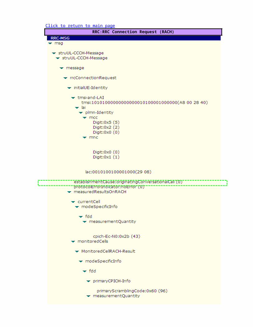
RRC:RRC Connection Request (RACH)Click to return to main page

RRC:RRC Connection Setup (FACH)


RRC:RRC Connection Setup Complete (DCCH)


RRC: Initial Direct Transfer (MM: CM Service Request)

RANAP:Initial UE Message (MM: CM Service Request)
RANAP: Direct Transfer (MM: Authentication Request)

RRC: Downlink Direct Transfer (MM: Authentication Request)
RRC: Uplink Direct Transfer (MM: Authentication Response)

RANAP: Direct Transfer (MM: Authentication Response)
RRC: Security Mode Command

RRC: Security Mode Complete
RANAP: Direct Transfer (CC: Setup)

RRC: Uplink Direct Transfer (CC: Setup)

RRC: Downlink Direct Transfer (CC: Call Proceeding)
RANAP: Direct Transfer (CC: Call Proceeding)
RRC: Radio Bearer Setup


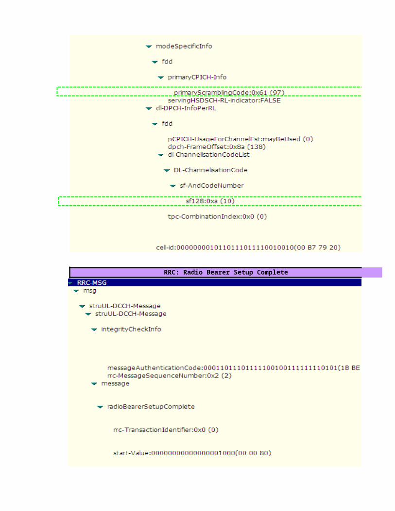
RRC: Radio Bearer Setup Complete

RANAP: Direct Transfer (CC: Alerting)
RRC: Downlink Direct Transfer (CC: Alerting)

RANAP: Direct Transfer (CC: Connect)
RRC: Downlink Direct Transfer (CC: Connect)
RANAP: Direct Transfer (CC: Connect Acknowledge)

RRC: Uplink Direct Transfer (CC: Connect Acknowledge)
RANAP: Direct Transfer (CC: Disconnect)
RRC: Uplink Direct Transfer (CC: Disconnect)

RANAP: Direct Transfer (CC: Release)
RRC: Downlink Direct Transfer (CC: Release)

RANAP: Direct Transfer (CC: Release Complete)
RRC: Uplink Direct Transfer (CC: Release Complete)
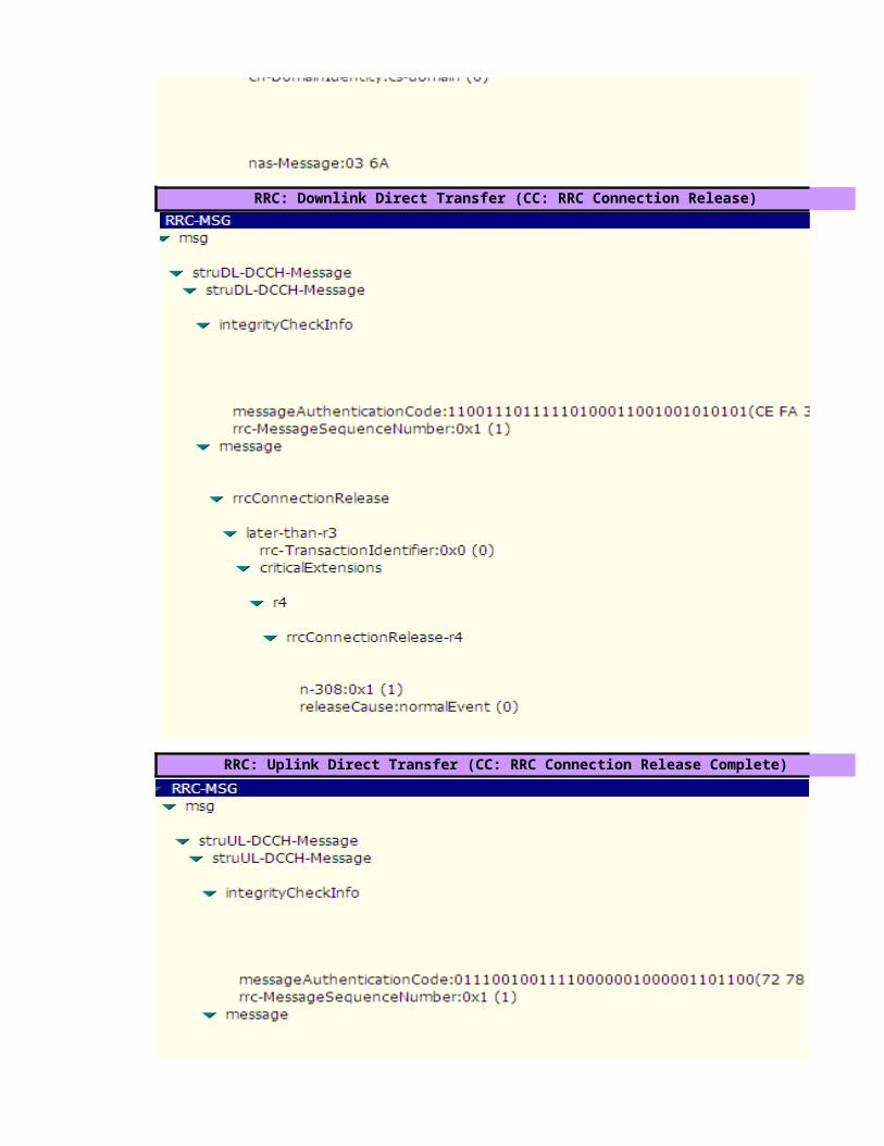
RRC: Downlink Direct Transfer (CC: RRC Connection Release)
RRC: Uplink Direct Transfer (CC: RRC Connection Release Complete)


value=hex2dec(5)=5 , hex2dec(2)=2 ,hex2dec(0)=0 --> MCC=520
value=hex2dec(0)=0 , hex2dec(1)=1 --> MNC=01
value=hex2dec(2908)= 10504
value= OriginatingConversationalcall (CS MOC)
value=(-24+ (43/2))=-2.5 dB
value=hex2dec(60)=96(Neighbour's Primary Scrambling Code)
>>"RRC Connection Request Description"
>>"Geographical and UTRAN Entity Identifiers"

value=CPICH Ec/Io invalid
value=hex2dec(5)=5 , hex2dec(2)=2 ,hex2dec(0)=0 --> MCC=520
value=hex2dec(0)=0 , hex2dec(1)=1 --> MNC=01
value=hex2dec(2908)= 10504
>>"RRC Connection Setup Description"
>>"Geographical and UTRAN Entity Identifiers"

value=UE capable to support FDD , not TDD
value=UE capable to support GSM
value=Signaling Radio Bearer Information Setup ,RB-1
value=Radio Bearer Mapping

value=Signaling Radio Bearer Information Setup ,RB-2

value=Signaling Radio Bearer Information Setup ,RB-3

value=Signaling Radio Bearer Information Setup ,RB-4


value=BLER Target= -20 dB
value=MaxAllowedULTxPower=24 dBm
value=(-47*2)= -94 dBm (step of 2 dB) Default Constant DPCCH_Power_offset-22 -94-22 -94
Note :DPCCH_Power_offset is configured by RNC and delivered to UE in RRC Connection Setup.
value= use Closed Loop Power Control Algorithm1
value= use long SC on Uplink
value=Spreading Factor 64 (Uplink)
value=Spreading Factor 128 (Downlink)

value=Primary Scrambling code=97
value=Spreading Factor 128 (Downlink)
Cell Identity=RNCid(12bits)+Cellid(16bits)value=0000000010110111011110010010 => RNCid=bin2dec(000000001011)=11 and Cellid=bin2dec(0111011110010010)=30610
>>"RRC Connection Setup Complete Description"

value= not support GSM (Locked UMTS Mode)
value= Chipering Algorithm A5/3
value= UE support Band fdd2100 MHzvalue= UE (Powerclass3) maximum transmitted power =24 dBm
value= support Compressed Mode (CM) uplink and downlink

value= UE support Band fdd1800 MHz
RANAP:Initial UE Message (MM: CM Service Request)
RANAP: Direct Transfer (MM: Authentication Request)

RRC: Downlink Direct Transfer (MM: Authentication Request)
RRC: Uplink Direct Transfer (MM: Authentication Response)

RANAP: Direct Transfer (MM: Authentication Response)
RRC: Security Mode Command

RRC: Security Mode Complete
RANAP: Direct Transfer (CC: Setup)

value= Call B-Party number = 0812713339
RRC: Uplink Direct Transfer (CC: Setup)

RRC: Downlink Direct Transfer (CC: Call Proceeding)
RANAP: Direct Transfer (CC: Call Proceeding)
RRC: Radio Bearer Setup >>"Radio Bearer Description"


value= SF64(uplink)-> AMR 12.2

value=Primary Scrambling code=97
value= SF128(downlink)-> AMR 12.2
Cell Identity=RNCid(12bits)+Cellid(16bits)
RRC: Radio Bearer Setup Complete
value=0000000010110111011110010010 => RNCid=bin2dec(000000001011)=11 and Cellid=bin2dec(0111011110010010)=30610

RANAP: Direct Transfer (CC: Alerting)
RRC: Downlink Direct Transfer (CC: Alerting)

RANAP: Direct Transfer (CC: Connect)
RRC: Downlink Direct Transfer (CC: Connect)
RANAP: Direct Transfer (CC: Connect Acknowledge)

RRC: Uplink Direct Transfer (CC: Connect Acknowledge)
RANAP: Direct Transfer (CC: Disconnect)
RRC: Uplink Direct Transfer (CC: Disconnect)

RANAP: Direct Transfer (CC: Release)
RRC: Downlink Direct Transfer (CC: Release)

RANAP: Direct Transfer (CC: Release Complete)
RRC: Uplink Direct Transfer (CC: Release Complete)

RRC: Downlink Direct Transfer (CC: RRC Connection Release)
RRC: Uplink Direct Transfer (CC: RRC Connection Release Complete)


CPICH_RSCP PCPICH Power UL Interference UL DPCCH Initial Power-80 33 -105 -14-70 33 -105 -24
Note :DPCCH_Power_offset is configured by RNC and delivered to UE in RRC Connection Setup.

Cellid=bin2dec(0111011110010010)=30610


Cellid=bin2dec(0111011110010010)=30610


L3 Messages -AMR Voice Call (MTC) Call ProcedureUE NodeB
*** The different messages between MOC & MTC are highlighted in "Red" color
Start Rx
4. ALCAP: Iub User Plane Setup
RRC Connection Establishment Timing Start Tx
Click to return to main page
2. RRC: Paging Type 1
1. RRC: RRC Connection Request (RACH)
5. RRC: RRC Connection Setup (FACH)
L1 Synchonization
6. RRC: RRC Connection Setup Completed (DCH)
1.RRC: Initial Direct Transfer (MM: Paging Response)
2.RRC: Downlink Direct Transfer (MM: Authentication Request)
3.RRC: Uplink Direct Transfer (MM: Authentication Response)
6.RRC: Security Mode Command
7.RRC: Security Mode Completed

5. ALCAP: Iub User Plane Setup
Apply new transport format set
Call Established
RRC:Measurement Control
RRC:Measurement Report
2. RRC: Downlink Direct Transfer (CC: Setup)
3. RRC: Uplink Direct Transfer (CC: Call Confirmed)
6. RRC: Radio Bearer Setup
8. RRC: Radio Bearer Setup Complete
6. RRC: Uplink Direct Transfer (CC: Alerting)
8.RRC: Uplink Direct Transfer (CC: Connect)
11. RRC: Downlink Direct Transfer (CC: Connect Acknowledge)
RRC: Downlink Direct Transfer (CC: Disconnect)

ALCAP: Iub User Plane Release
RRC: Uplink Direct Transfer (CC: Release)
RRC: Downlink Direct Transfer (CC: Release Complete)
RRC: Downlink Direct Transfer (CC: RRC Connection Release)
RRC: Uplink Direct Transfer (CC: RRC Connection Release Complete)
RRC: Uplink Direct Transfer (CC: RRC Connection Release Complete)
Note the following information about the procedure ,
1.The RRC connection can be set up on a DCH or a CCH. This procedure takes the RRC connection set up on the DCH as an example.2. If IP transport is applied to the Iub interface, no ALCAP procedure is performed on the Iubinterface after radio links are set up, reconfigured, or deleted. 3. If IP transport is applied to the Iu-CS interface, no ALCAP procedure is performed on theIu-CS interface after an RAB is set up or a call is released

L3 Messages -AMR Voice Call (MTC) Call ProcedureS-RNC
*** The different messages between MOC & MTC are highlighted in "Red" color
2.NBAP:Radio Link Setup Req
3.NBAP:Radio Link Setup Resp.
4. ALCAP: Iub User Plane Setup
NBAP:Synchonization Indicator
2. RRC: Paging Type 1
1. RRC: RRC Connection Request (RACH)
5. RRC: RRC Connection Setup (FACH)
6. RRC: RRC Connection Setup Completed (DCH)
1.RRC: Initial Direct Transfer (MM: Paging Response)
2.RRC: Downlink Direct Transfer (MM: Authentication Request)
3.RRC: Uplink Direct Transfer (MM: Authentication Response)
6.RRC: Security Mode Command
7.RRC: Security Mode Completed

5. ALCAP: Iub User Plane Setup
Apply new transport format set
Call Established
RRC:Measurement Control
RRC:Measurement Report
2. RRC: Downlink Direct Transfer (CC: Setup)
3. RRC: Uplink Direct Transfer (CC: Call Confirmed)
3. NBAP: Radio Link Reconfiguration Prepare
4. NBAP: Radio Link Reconfiguration Ready
6. RRC: Radio Bearer Setup
7. NBAP: Radio Link Reconfiguration Commit
8. RRC: Radio Bearer Setup Complete
6. RRC: Uplink Direct Transfer (CC: Alerting)
8.RRC: Uplink Direct Transfer (CC: Connect)
11. RRC: Downlink Direct Transfer (CC: Connect Acknowledge)
RRC: Downlink Direct Transfer (CC: Disconnect)

ALCAP: Iur User Plane Release
ALCAP: Iub User Plane Release
RRC: Uplink Direct Transfer (CC: Release)
RRC: Downlink Direct Transfer (CC: Release Complete)
RRC: Downlink Direct Transfer (CC: RRC Connection Release)
RRC: Uplink Direct Transfer (CC: RRC Connection Release Complete)
RRC: Uplink Direct Transfer (CC: RRC Connection Release Complete)
NBAP: Radio Link Deletion Request
NBAP: Radio Link Deletion Response
1.The RRC connection can be set up on a DCH or a CCH. This procedure takes the RRC
2. If IP transport is applied to the Iub interface, no ALCAP procedure is performed on the Iubinterface after radio links are set up, reconfigured, or deleted. 3. If IP transport is applied to the Iu-CS interface, no ALCAP procedure is performed on theIu-CS interface after an RAB is set up or a call is released

L3 Messages -AMR Voice Call (MTC) Call ProcedureCN
1. RANAP: Paging
2.SCCP: CR (Connection Request)
3.SCCP: CC (Connection Confirm)
RANAP: Common ID (IMSI)
5.RANAP: Security Mode Command
2. RANAP: Initial UE Message (MM: Paging Response)
1.RANAP: Direct Transfer (MM: Authentication Request)
4.RANAP: Direct Transfer (MM: Authentication Response)
1.Paging

7.RANAP: Security Mode Complete
1. RANAP: RAB Assignment Request
2. ALCAP: Iur User Plane Setup
9.RANAP: RAB Assignment Response
Call Established
1. RANAP: Direct Transfer (CC: Setup)
4. RANAP: Direct Transfer (CC: Call Confirmed)
7. RANAP: Direct Transfer (CC: Alerting)
9. RANAP: Direct Transfer (CC: Connect)
10. RANAP: Direct Transfer (CC: Connect Acknowledge)
RANAP: Direct Transfer (CC: Disconnect)
5.Radio Bearer Setup
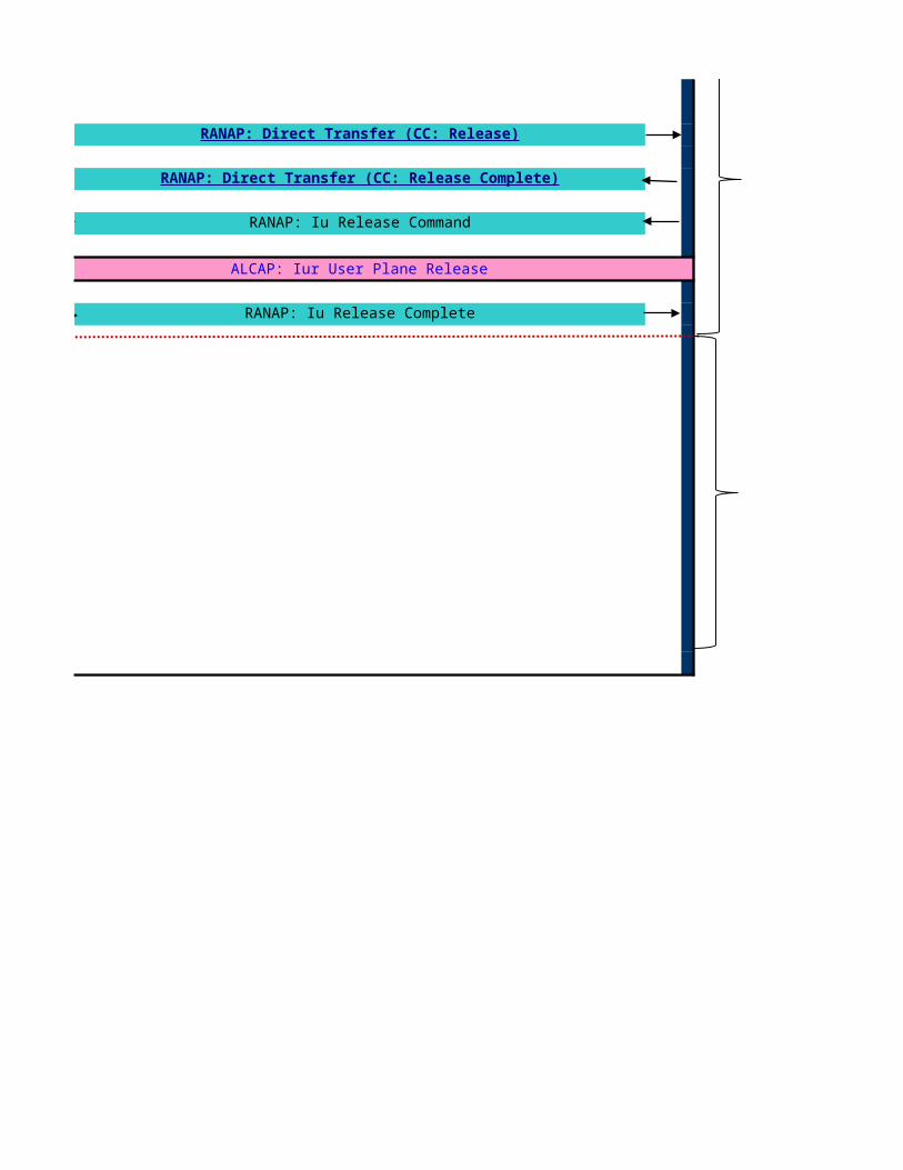
RANAP: Iu Release Command
ALCAP: Iur User Plane Release
RANAP: Iu Release Complete
RANAP: Direct Transfer (CC: Release)
RANAP: Direct Transfer (CC: Release Complete)

Paging Procedure The paging procedure is performed when the CN calls a UE.
Triggering Conditions: A Terminal calls the UE
The Paging Procedure in Idle, Cell_PCH and URA-PCH modes is described as follows;1.The CN sends a PAGING message to the SRNC.2.The SRNC initiates the paging procedure by sending a PAGING TYPE 1 message to the UE through the Paging Control Channel (PCCH) on an appropriate occasion.paging occasion is related to the International Mobile Subscriber Identity (IMSI) of the UE. The UTRAN may page the same UE on several occasions to increase the probability of proper receptionof the paging message by the UE.)3.The UE in idle mode or in PCH state monitors the paging and receives the paging message from the network layer.The paging procedure ends.
The Paging Procedure in Cell_DCH and Cell_FACH mode is described as follows;1.The CN sends a PAGING message to the SRNC.2.The SRNC initiates the paging procedure by sending a PAGING TYPE 2 message to the UE through the DCCH.3.The UE receives the PAGNG TPYE 2 message, reads it, and then reports to the NAS the information such as the paging cause and the paging record type identifier.The paging
>>RRC Procedure DescriptionRRC connection setup procedure is performed for the UE to set up a signaling connection to the SRNC. RRC connection setup is always initiated by the UE. One UE has a maximum of one RRC connection at a time.
Triggering Conditions: The UE in idle mode intitiates the RRC connection setup procedure when the NAS of the UE requests the establishment of a signaling connection
When the SRNC receives an RRC CONNECTION REQUEST message from the UE, the Radio Resource Management (RRM) module of the RNC determines whether to accept or reject theRRC connection request, based on a specific algorithm. If accepting the request, the RRM module further determines whether to set up the RRC connection on a DedicatedChannel (DCH)or on a Common Channel (CCH), based on a specific RRM algorithm. Typically, an RRC connection is set up on the DCH.
The procedure shown is described as follows:1.The UE sends an RRC CONNECTION REQUEST message to the SRNC through the uplink CCCH(RACH), requesting the establishment of an RRC connection.2.Based on the cause in the RRC connection request and the system resource status, the SRNC determines to set up the RRC connection on a DCH and allocates the Radio NetworkTemporary Identity (RNTI), radio resources, and L1 and L2 resources. Then the SRNC sends a RADIO LINK SETUP REQUEST message to the NodeB, requesting the NodeB to allocate the specific radio link resources required for an RRC connection.3.The NodeB responds with a RADIO LINK SETUP RESPONSE message to the SRNC after successfully preparing the resources.4.The SRNC uses the ALCAP protocol to set up the Iub user plane transport bearer and performs the synchronization between the SRNC and the NodeB. This procedure is optional. It is required for the ATM-based Iub interface only.5.The SRNC sends an RRC CONNECTION SETUP message to the UE through the downlink CCCH (FACH). The message contains the information about the DCH allocated by theSRNC.6. UE and NodeB initiate L1 Synchronization. NodeB sends NBAP:Synchonization Indicator message to SRNC when the uplink enter "In-Sync" state7. The UE sends an RRC CONNECTION SETUP COMPLETE message to the SRNC through the uplink Dedicated Control Channel (DCCH) that is just set up. The message indicates that the RRC connection setup procedure ends.If the RNC judges that the RRC connection request cannot be set up (for instance, due to insufficient resources), it directly sends an RRC CONNECTION REJECT message to the UE, and indicates the reject reason in the messageThe signaling connection setup procedure is performed to exchange the NAS (Non Access Stratum) information between the UE and the CN.
Triggering Conditions: The UE sends a direct transfer message to initiate the signaling connection setup procedure.
The procedure shown is described as follows:1.The UE sends an INITIAL DIRECT TRANSFER message to the SRNC through the RRC connection. The message contains the initial NAS information to be sent to the CN by the UE.2.The SRNC receives the INITIAL DIRECT TRANSFER message from the UE and sendsan INITIAL UE MESSAGE to the CN through the Iu interface. The INITIAL UEMESSAGEcontains the NAS information to be sent to the CN by the UE. The content ofthe NAS information is PAGING RESPONSE.3.The CN sends a response message to the SRNC.-If accepting the request, the CN sends a CONNECTION CONFIRM (CC) message tothe SRNC. The message indicates that the SCCP connection is set up. After receiving the message, the SRNC confirms that the signaling connection is set up.-lf rejecting the request, the CN sends a CONNECTION REJECT (CJ) message to the SRNC. The message indicates that the SCCP connection fails to be set up. After receiving the message, the SRNC confirms that the signaling connection fails to be setup and then initiates the RRC release procedure.
2.RRC ConnectionSetup
3.Signalling Connection Setup
4.Authentication & Security Mode Control
1.Paging

The signaling connection setup procedure is performed to exchange the NAS (Non Access Stratum) information between the UE and the CN.
Triggering Conditions: The UE sends a direct transfer message to initiate the signaling connection setup procedure.
The procedure shown is described as follows:1.The UE sends an INITIAL DIRECT TRANSFER message to the SRNC through the RRC connection. The message contains the initial NAS information to be sent to the CN by the UE.2.The SRNC receives the INITIAL DIRECT TRANSFER message from the UE and sendsan INITIAL UE MESSAGE to the CN through the Iu interface. The INITIAL UEMESSAGEcontains the NAS information to be sent to the CN by the UE. The content ofthe NAS information is PAGING RESPONSE.3.The CN sends a response message to the SRNC.-If accepting the request, the CN sends a CONNECTION CONFIRM (CC) message tothe SRNC. The message indicates that the SCCP connection is set up. After receiving the message, the SRNC confirms that the signaling connection is set up.-lf rejecting the request, the CN sends a CONNECTION REJECT (CJ) message to the SRNC. The message indicates that the SCCP connection fails to be set up. After receiving the message, the SRNC confirms that the signaling connection fails to be setup and then initiates the RRC release procedure.
The authentication and security mode control procedure is performed for the UE and the network to implement bi-directional authentication and to negotiate and configure the integrity protection algorithm and ciphering algorithm. This procedure ensures integrity and correctness of signaling.
Triggerring Conditions: The UE and the CN exchange signaling. The network initiates the authentication and securitymode control procedure
The procedure shown is described as follows:1.The CN sends a DIRECT TRANSFER message to the SRNC. The message indicates AUTHENTICATION REQUEST.2.The SRNC transparently sends the contents of the DIRECT TRANSFER message to the UE through a DOWNLINK DIRECT TRANSFER message.3.The UE sends an UPLINK DIRECT TRANSFER message to the SRNC.4.The SRNC transparently sends the contents of the UPLINK DIRECT TRANSFER messageto the CN through a DIRECT TRANSFER message, indicating AUTHENTICATION RESPONSE. If the UMTS Subscriber Identity Module (USIM) judges that the authentication is successful, the UE returns a message with an XRES IE.5.The CN sends a SECURITY MODE COMMAND message to the SRNC to initiate the security mode control procedure. The message contains the information about the supported ciphering and integrity protection algorithms.6.The SRNC sends a SECURITY MODE COMMAND message to the UE to inform the UE of the integrity protection and ciphering algorithms that the UTRAN selects.7.The UE sends a response message to the SRNC.-If the integrity protection and ciphering algorithms are configured successfully, the UE sends a SECURITY MODE COMMAND COMPLETE message to the SRNC. The SRNC then sends a SECURITY MODE COMMAND COMPLETE message to the CN.The message contains the information about the integrity protection and ciphering algorithms that the UE uses.-If the UE does not support the integrity protection and ciphering algorithms, the UE sends a SECURITY MODE COMMAND FAILURE message to the SRNC. The message contains the error information and the reason for the failure. The SRNC then sends a SECURITY MODE COMMAND REJECT message to the CN
The RANAP:Common ID message is used to transport the permanent UE Identity(IMSI) to SRNCCall Setup Procedure(Incoming Call) is performed to setup a call.
Triggering Conditions : A UE receiveds a call from the CN
The procedure shown is described as follows:1.The CN sends a DIRECT TRANSFER message to the SRNC. The message indicates SETUP and contains the number of the calling party and the bearer capability of the call.2.The SRNC transparently sends the contents of the DIRECT TRANSFER message to the UE through a DOWNLINK DIRECT TRANSFER message.3.The UE sends an UPLINK DIRECT TRANSFER message to the SRNC.4.The SRNC transparently sends the contents of the UPLINK DIRECT TRANSFER messageto the CN through a DIRECT TRANSFER message. The DIRECT TRANSFER messageindicates CALL CONFIRM and contains the information about the negotiated bearer capability of the call.5. A Radio Access Bearer (RAB) is set up. (see more details in RAB Setup Procedure below)6. The UE sends an UPLINK DIRECT TRANSFER message to the SRNC.7.The SRNC transparently sends the contents of the UPLINK DIRECT TRANSFER messageto the CN through a DIRECT TRANSFER message, indicating ALERTING to request thecalled terminal to ring.8.The UE sends an UPLINK DIRECT TRANSFER message to the SRNC.9.The SRNC transparently sends the contents of the UPLINK DIRECT TRANSFER messageto the CN through a DIRECT TRANSFER message, indicating CONNECT. This meansthat the called party has answered the call.10.The CN sends a DIRECT TRANSFER message to the SRNC. The message indicatesCONNECT ACKNOWLEDGE.11.The SRNC transparently sends the contents of the DIRECT TRANSFER message to the UE through a DOWNLINK DIRECT TRANSFER message.
The Radio Bearer Setup procedure shown is described as follows:1.The CN sends an RAB ASSIGNMENT REQUEST message to the SRNC to initiate the RAB setup procedure.2.(Optional; applicable to the ATM-based Iu-CS interface only) The SRNC maps the Quality of Service (QoS) parameters for the RAB to the AAL2 link characteristic parameters andradio resource characteristic parameters. Based on the AAL2 link characteristic parameters,the ALCAP on the Iu interface initiates an Iu user plane transport bearer setup procedure.3.The SRNC sends a RADIO LINK RECONFIGURATION PREPARE message to the NodeB, requesting the NodeB to prepare for adding one or more DCHs to the existing radio links for carrying the RAB.4.The NodeB allocates the associated resources and then sends a RADIO LINKRECONFIGURATION READY message to the SRNC.5.(Optional; required for the ATM-based Iub interface only) The Iub ALCAP at the SRNC initiates an Iub user plane transport bearer setup procedure. The NodeB and the SRNC perform synchronization by exchanging uplink and downlink synchronization frames in the DCH frame protocol.6.The SRNC sends a RADIO BEARER SETUP message to the UE.7.The SRNC sends a RADIO LINK RECONFIGURATION COMMIT message to the NodeB.8.After performing the radio bearer setup, the UE sends a RADIO BEARER SETUP COMPLETE message to the SRNC.9.The SRNC sends an RAB ASSIGNMENT RESPONSE message to the CN. The RAB isset up.
The procedure when RAB Setup Failure shown is described as follows:1.The CN sends an RAB ASSIGNMENT REQUEST message to the SRNC to initiate the RAB setup procedure.2.The SRNC sends an RAB ASSIGNMENT RESPONSE message to the CN. The message indicates the ID of the RAB that fails to be set up and the reason for the failure.
6.Conversation
4.Call Setup
5.Radio Bearer Setup

Call Setup Procedure(Incoming Call) is performed to setup a call.
Triggering Conditions : A UE receiveds a call from the CN
The procedure shown is described as follows:1.The CN sends a DIRECT TRANSFER message to the SRNC. The message indicates SETUP and contains the number of the calling party and the bearer capability of the call.2.The SRNC transparently sends the contents of the DIRECT TRANSFER message to the UE through a DOWNLINK DIRECT TRANSFER message.3.The UE sends an UPLINK DIRECT TRANSFER message to the SRNC.4.The SRNC transparently sends the contents of the UPLINK DIRECT TRANSFER messageto the CN through a DIRECT TRANSFER message. The DIRECT TRANSFER messageindicates CALL CONFIRM and contains the information about the negotiated bearer capability of the call.5. A Radio Access Bearer (RAB) is set up. (see more details in RAB Setup Procedure below)6. The UE sends an UPLINK DIRECT TRANSFER message to the SRNC.7.The SRNC transparently sends the contents of the UPLINK DIRECT TRANSFER messageto the CN through a DIRECT TRANSFER message, indicating ALERTING to request thecalled terminal to ring.8.The UE sends an UPLINK DIRECT TRANSFER message to the SRNC.9.The SRNC transparently sends the contents of the UPLINK DIRECT TRANSFER messageto the CN through a DIRECT TRANSFER message, indicating CONNECT. This meansthat the called party has answered the call.10.The CN sends a DIRECT TRANSFER message to the SRNC. The message indicatesCONNECT ACKNOWLEDGE.11.The SRNC transparently sends the contents of the DIRECT TRANSFER message to the UE through a DOWNLINK DIRECT TRANSFER message.
The Radio Bearer Setup procedure shown is described as follows:1.The CN sends an RAB ASSIGNMENT REQUEST message to the SRNC to initiate the RAB setup procedure.2.(Optional; applicable to the ATM-based Iu-CS interface only) The SRNC maps the Quality of Service (QoS) parameters for the RAB to the AAL2 link characteristic parameters andradio resource characteristic parameters. Based on the AAL2 link characteristic parameters,the ALCAP on the Iu interface initiates an Iu user plane transport bearer setup procedure.3.The SRNC sends a RADIO LINK RECONFIGURATION PREPARE message to the NodeB, requesting the NodeB to prepare for adding one or more DCHs to the existing radio links for carrying the RAB.4.The NodeB allocates the associated resources and then sends a RADIO LINKRECONFIGURATION READY message to the SRNC.5.(Optional; required for the ATM-based Iub interface only) The Iub ALCAP at the SRNC initiates an Iub user plane transport bearer setup procedure. The NodeB and the SRNC perform synchronization by exchanging uplink and downlink synchronization frames in the DCH frame protocol.6.The SRNC sends a RADIO BEARER SETUP message to the UE.7.The SRNC sends a RADIO LINK RECONFIGURATION COMMIT message to the NodeB.8.After performing the radio bearer setup, the UE sends a RADIO BEARER SETUP COMPLETE message to the SRNC.9.The SRNC sends an RAB ASSIGNMENT RESPONSE message to the CN. The RAB isset up.
The procedure when RAB Setup Failure shown is described as follows:1.The CN sends an RAB ASSIGNMENT REQUEST message to the SRNC to initiate the RAB setup procedure.2.The SRNC sends an RAB ASSIGNMENT RESPONSE message to the CN. The message indicates the ID of the RAB that fails to be set up and the reason for the failure.
The Call Release procedure is performed to release services and resources after a call ends.
Triggering Conditions: A call ends and the calling party hangs up.
The procedure shown is described as follows:1.The CN sends a DIRECT TRANSFER message to the SRNC. The message indicates DISCONNECT to inform the UE that the calling party has hanged up.2.The SRNC transparently sends the contents of the DIRECT TRANSFER message to the UE through a DOWNLINK DIRECT TRANSFER message.3.The UE sends an UPLINK DIRECT TRANSFER message to the SRNC.4.The SRNC transparently sends the contents of the UPLINK DIRECT TRANSFER messageto the CN through a DIRECT TRANSFER message. The DIRECT TRANSFER messageindicates RELEASE which requests release of the call.5.The CN sends a DIRECT TRANSFER message to the SRNC. The message indicatesRELEASE COMPLETE.6.The SRNC transparently sends the contents of the DIRECT TRANSFER message to theUE through a DOWNLINK DIRECT TRANSFER message.7.The CN sends an IU RELEASE COMMAND message to the SRNC to request call releaseon the Iu interface. The message indicates the reason for the Iu release.8.(Optional; applicable to the ATM-based Iu-CS interface only) The ALCAP protocol on theIu interface initiates an Iu data transport bearer release procedure.9.The SRNC sends an IU RELEASE COMPLETE message to the CN.
The RRC Connection Release procedure
Triggering Conditions: After a n RAB is released,the SRNC judges whether the RRC connection carries any other RAB or the UE. If judging that the RRC connection does not carry other RAB of the UE,the SRNC initiates an RRC connection release procedure.
The procedure shown is described as follows: connection from DCH and release of an RRC connection from CCH
7.Call Release
8.RRC Connection Release

connection from DCH and release of an RRC connection from CCH is released and if a radio bearers fails to be setup ,the RRC connection on the CCH is released)
1.The SRNC sends an RRC CONNECTION RELEASE message to the UE through the DCCH. (NOTE: The SRNC may send the RRC CONNECTION RELEASE message several times to increase the probability of proper reception of the message by the UE. The RRC SNs of these messages are the same. The number of retransmissions and the transmission intervals are determined by the SRNC. If the SRNC does not receive an RRC CONNECTION RELEASE COMPLETE message from the UE after sending the RRC CONNECTION RELEASE message for connection.)
2.The UE sends an RRC CONNECTION RELEASE COMPLETE message to the SRNC.3.The SRNC sends a RADIO LINK DELETION REQUEST message to the NodeB,requesting the NodeB to delete the radio link resources in the NodeB.4.After releasing the resources, the NodeB sends a RADIO LINK DELETION RESPONSE message to the SRNC.

The paging procedure is performed when the CN calls a UE.
A Terminal calls the UE
The Paging Procedure in Idle, Cell_PCH and URA-PCH modes is described as follows;1.The CN sends a PAGING message to the SRNC.2.The SRNC initiates the paging procedure by sending a PAGING TYPE 1 message to the UE through the Paging Control Channel (PCCH) on an appropriate occasion.paging occasion is related to the International Mobile Subscriber Identity (IMSI) of the UE. The UTRAN may page the same UE on several occasions to increase the
proper receptionof the paging message by the UE.)3.The UE in idle mode or in PCH state monitors the paging and receives the paging message from the network layer.The paging procedure ends.
The Paging Procedure in Cell_DCH and Cell_FACH mode is described as follows;1.The CN sends a PAGING message to the SRNC.2.The SRNC initiates the paging procedure by sending a PAGING TYPE 2 message to the UE through the DCCH.3.The UE receives the PAGNG TPYE 2 message, reads it, and then reports to the NAS the information such as the paging cause and the paging record type identifier.The paging
RRC connection setup procedure is performed for the UE to set up a signaling connection to the SRNC. RRC connection setup is always initiated by the UE. One UE has a maximum of one RRC connection at a time.
The UE in idle mode intitiates the RRC connection setup procedure when the NAS of the UE requests the establishment of a signaling connection
When the SRNC receives an RRC CONNECTION REQUEST message from the UE, the Radio Resource Management (RRM) module of the RNC determines whether to accept or reject theRRC connection request, based on a specific algorithm. If accepting the request, the RRM module further determines whether to set up the RRC connection on a
Channel (DCH)or on a Common Channel (CCH), based on a specific RRM algorithm. Typically, an RRC connection is set up on the DCH.
The procedure shown is described as follows:1.The UE sends an RRC CONNECTION REQUEST message to the SRNC through the uplink CCCH(RACH), requesting the establishment of an RRC connection.2.Based on the cause in the RRC connection request and the system resource status, the SRNC determines to set up the RRC connection on a DCH and allocates the Radio NetworkTemporary Identity (RNTI), radio resources, and L1 and L2 resources. Then the SRNC sends a RADIO LINK SETUP REQUEST message to the NodeB, requesting the NodeB to allocate the specific radio link resources required for an RRC connection.3.The NodeB responds with a RADIO LINK SETUP RESPONSE message to the SRNC after successfully preparing the resources.4.The SRNC uses the ALCAP protocol to set up the Iub user plane transport bearer and performs the synchronization between the SRNC and the NodeB. This procedure is
It is required for the ATM-based Iub interface only.5.The SRNC sends an RRC CONNECTION SETUP message to the UE through the downlink CCCH (FACH). The message contains the information about the DCH allocated by the
6. UE and NodeB initiate L1 Synchronization. NodeB sends NBAP:Synchonization Indicator message to SRNC when the uplink enter "In-Sync" state7. The UE sends an RRC CONNECTION SETUP COMPLETE message to the SRNC through the uplink Dedicated Control Channel (DCCH) that is just set up. The message indicates that the RRC connection setup procedure ends.If the RNC judges that the RRC connection request cannot be set up (for instance, due to insufficient resources), it directly sends an RRC CONNECTION REJECT message to the UE, and indicates the reject reason in the messageThe signaling connection setup procedure is performed to exchange the NAS (Non Access Stratum) information between the UE and the CN.
The UE sends a direct transfer message to initiate the signaling connection setup procedure.
The procedure shown is described as follows:1.The UE sends an INITIAL DIRECT TRANSFER message to the SRNC through the RRC connection. The message contains the initial NAS information to be sent to the CN by the
2.The SRNC receives the INITIAL DIRECT TRANSFER message from the UE and sendsan INITIAL UE MESSAGE to the CN through the Iu interface. The INITIAL UEMESSAGEcontains the NAS information to be sent to the CN by the UE. The content ofthe NAS information is PAGING RESPONSE.3.The CN sends a response message to the SRNC.-If accepting the request, the CN sends a CONNECTION CONFIRM (CC) message tothe SRNC. The message indicates that the SCCP connection is set up. After receiving the message, the SRNC confirms that the signaling connection is set up.-lf rejecting the request, the CN sends a CONNECTION REJECT (CJ) message to the SRNC. The message indicates that the SCCP connection fails to be set up. After receiving
message, the SRNC confirms that the signaling connection fails to be setup and then initiates the RRC release procedure.

The signaling connection setup procedure is performed to exchange the NAS (Non Access Stratum) information between the UE and the CN.
The UE sends a direct transfer message to initiate the signaling connection setup procedure.
The procedure shown is described as follows:1.The UE sends an INITIAL DIRECT TRANSFER message to the SRNC through the RRC connection. The message contains the initial NAS information to be sent to the CN by the
2.The SRNC receives the INITIAL DIRECT TRANSFER message from the UE and sendsan INITIAL UE MESSAGE to the CN through the Iu interface. The INITIAL UEMESSAGEcontains the NAS information to be sent to the CN by the UE. The content ofthe NAS information is PAGING RESPONSE.3.The CN sends a response message to the SRNC.-If accepting the request, the CN sends a CONNECTION CONFIRM (CC) message tothe SRNC. The message indicates that the SCCP connection is set up. After receiving the message, the SRNC confirms that the signaling connection is set up.-lf rejecting the request, the CN sends a CONNECTION REJECT (CJ) message to the SRNC. The message indicates that the SCCP connection fails to be set up. After receiving
message, the SRNC confirms that the signaling connection fails to be setup and then initiates the RRC release procedure.
The authentication and security mode control procedure is performed for the UE and the network to implement bi-directional authentication and to negotiate and configure the integrity protection algorithm and ciphering algorithm. This procedure ensures integrity and correctness of signaling.
The UE and the CN exchange signaling. The network initiates the authentication and securitymode control procedure
The procedure shown is described as follows:1.The CN sends a DIRECT TRANSFER message to the SRNC. The message indicates AUTHENTICATION REQUEST.2.The SRNC transparently sends the contents of the DIRECT TRANSFER message to the UE through a DOWNLINK DIRECT TRANSFER message.3.The UE sends an UPLINK DIRECT TRANSFER message to the SRNC.4.The SRNC transparently sends the contents of the UPLINK DIRECT TRANSFER messageto the CN through a DIRECT TRANSFER message, indicating AUTHENTICATION RESPONSE. If the UMTS Subscriber Identity Module (USIM) judges that the authentication is successful, the UE returns a message with an XRES IE.5.The CN sends a SECURITY MODE COMMAND message to the SRNC to initiate the security mode control procedure. The message contains the information about the supported ciphering and integrity protection algorithms.6.The SRNC sends a SECURITY MODE COMMAND message to the UE to inform the UE of the integrity protection and ciphering algorithms that the UTRAN selects.7.The UE sends a response message to the SRNC.-If the integrity protection and ciphering algorithms are configured successfully, the UE sends a SECURITY MODE COMMAND COMPLETE message to the SRNC. The SRNCthen sends a SECURITY MODE COMMAND COMPLETE message to the CN.The message contains the information about the integrity protection and ciphering algorithms that the
-If the UE does not support the integrity protection and ciphering algorithms, the UE sends a SECURITY MODE COMMAND FAILURE message to the SRNC. The message contains the error information and the reason for the failure. The SRNC then sends a SECURITY MODE COMMAND REJECT message to the CN
The RANAP:Common ID message is used to transport the permanent UE Identity(IMSI) to SRNCCall Setup Procedure(Incoming Call) is performed to setup a call.
Triggering Conditions : A UE receiveds a call from the CN
The procedure shown is described as follows:1.The CN sends a DIRECT TRANSFER message to the SRNC. The message indicates SETUP and contains the number of the calling party and the bearer capability of the call.2.The SRNC transparently sends the contents of the DIRECT TRANSFER message to the UE through a DOWNLINK DIRECT TRANSFER message.3.The UE sends an UPLINK DIRECT TRANSFER message to the SRNC.4.The SRNC transparently sends the contents of the UPLINK DIRECT TRANSFER messageto the CN through a DIRECT TRANSFER message. The DIRECT TRANSFER messageindicates CALL CONFIRM and contains the information about the negotiated bearer capability of the call.5. A Radio Access Bearer (RAB) is set up. (see more details in RAB Setup Procedure below)6. The UE sends an UPLINK DIRECT TRANSFER message to the SRNC.7.The SRNC transparently sends the contents of the UPLINK DIRECT TRANSFER messageto the CN through a DIRECT TRANSFER message, indicating ALERTING to request the
8.The UE sends an UPLINK DIRECT TRANSFER message to the SRNC.9.The SRNC transparently sends the contents of the UPLINK DIRECT TRANSFER messageto the CN through a DIRECT TRANSFER message, indicating CONNECT. This meansthat the called party has answered the call.10.The CN sends a DIRECT TRANSFER message to the SRNC. The message indicatesCONNECT ACKNOWLEDGE.11.The SRNC transparently sends the contents of the DIRECT TRANSFER message to the UE through a DOWNLINK DIRECT TRANSFER message.
The Radio Bearer Setup procedure shown is described as follows:1.The CN sends an RAB ASSIGNMENT REQUEST message to the SRNC to initiate the RAB setup procedure.
(Optional; applicable to the ATM-based Iu-CS interface only) The SRNC maps the Quality of Service (QoS) parameters for the RAB to the AAL2 link characteristic parameters
radio resource characteristic parameters. Based on the AAL2 link characteristic parameters,the ALCAP on the Iu interface initiates an Iu user plane transport bearer setup
RADIO LINK RECONFIGURATION PREPARE message to the NodeB, requesting the NodeB to prepare for adding one or more DCHs to the existing radio links for carrying the RAB.4.The NodeB allocates the associated resources and then sends a RADIO LINKRECONFIGURATION READY message to the SRNC..(Optional; required for the ATM-based Iub interface only) The Iub ALCAP at the SRNC initiates an Iub user plane transport bearer setup procedure. The NodeB and the SRNC
perform synchronization by exchanging uplink and downlink synchronization frames in the DCH frame protocol.6.The SRNC sends a RADIO BEARER SETUP message to the UE.7.The SRNC sends a RADIO LINK RECONFIGURATION COMMIT message to the NodeB.8.After performing the radio bearer setup, the UE sends a RADIO BEARER SETUP COMPLETE message to the SRNC.9.The SRNC sends an RAB ASSIGNMENT RESPONSE message to the CN. The RAB isset up.
The procedure when RAB Setup Failure shown is described as follows:1.The CN sends an RAB ASSIGNMENT REQUEST message to the SRNC to initiate the RAB setup procedure.2.The SRNC sends an RAB ASSIGNMENT RESPONSE message to the CN. The message indicates the ID of the RAB that fails to be set up and the reason for the failure.

Call Setup Procedure(Incoming Call) is performed to setup a call.
Triggering Conditions : A UE receiveds a call from the CN
The procedure shown is described as follows:1.The CN sends a DIRECT TRANSFER message to the SRNC. The message indicates SETUP and contains the number of the calling party and the bearer capability of the call.2.The SRNC transparently sends the contents of the DIRECT TRANSFER message to the UE through a DOWNLINK DIRECT TRANSFER message.3.The UE sends an UPLINK DIRECT TRANSFER message to the SRNC.4.The SRNC transparently sends the contents of the UPLINK DIRECT TRANSFER messageto the CN through a DIRECT TRANSFER message. The DIRECT TRANSFER messageindicates CALL CONFIRM and contains the information about the negotiated bearer capability of the call.5. A Radio Access Bearer (RAB) is set up. (see more details in RAB Setup Procedure below)6. The UE sends an UPLINK DIRECT TRANSFER message to the SRNC.7.The SRNC transparently sends the contents of the UPLINK DIRECT TRANSFER messageto the CN through a DIRECT TRANSFER message, indicating ALERTING to request the
8.The UE sends an UPLINK DIRECT TRANSFER message to the SRNC.9.The SRNC transparently sends the contents of the UPLINK DIRECT TRANSFER messageto the CN through a DIRECT TRANSFER message, indicating CONNECT. This meansthat the called party has answered the call.10.The CN sends a DIRECT TRANSFER message to the SRNC. The message indicatesCONNECT ACKNOWLEDGE.11.The SRNC transparently sends the contents of the DIRECT TRANSFER message to the UE through a DOWNLINK DIRECT TRANSFER message.
The Radio Bearer Setup procedure shown is described as follows:1.The CN sends an RAB ASSIGNMENT REQUEST message to the SRNC to initiate the RAB setup procedure.
(Optional; applicable to the ATM-based Iu-CS interface only) The SRNC maps the Quality of Service (QoS) parameters for the RAB to the AAL2 link characteristic parameters
radio resource characteristic parameters. Based on the AAL2 link characteristic parameters,the ALCAP on the Iu interface initiates an Iu user plane transport bearer setup
RADIO LINK RECONFIGURATION PREPARE message to the NodeB, requesting the NodeB to prepare for adding one or more DCHs to the existing radio links for carrying the RAB.4.The NodeB allocates the associated resources and then sends a RADIO LINKRECONFIGURATION READY message to the SRNC..(Optional; required for the ATM-based Iub interface only) The Iub ALCAP at the SRNC initiates an Iub user plane transport bearer setup procedure. The NodeB and the SRNC
perform synchronization by exchanging uplink and downlink synchronization frames in the DCH frame protocol.6.The SRNC sends a RADIO BEARER SETUP message to the UE.7.The SRNC sends a RADIO LINK RECONFIGURATION COMMIT message to the NodeB.8.After performing the radio bearer setup, the UE sends a RADIO BEARER SETUP COMPLETE message to the SRNC.9.The SRNC sends an RAB ASSIGNMENT RESPONSE message to the CN. The RAB isset up.
The procedure when RAB Setup Failure shown is described as follows:1.The CN sends an RAB ASSIGNMENT REQUEST message to the SRNC to initiate the RAB setup procedure.2.The SRNC sends an RAB ASSIGNMENT RESPONSE message to the CN. The message indicates the ID of the RAB that fails to be set up and the reason for the failure.
The Call Release procedure is performed to release services and resources after a call ends.
A call ends and the calling party hangs up.
The procedure shown is described as follows:1.The CN sends a DIRECT TRANSFER message to the SRNC. The message indicates DISCONNECT to inform the UE that the calling party has hanged up.2.The SRNC transparently sends the contents of the DIRECT TRANSFER message to the UE through a DOWNLINK DIRECT TRANSFER message.3.The UE sends an UPLINK DIRECT TRANSFER message to the SRNC.4.The SRNC transparently sends the contents of the UPLINK DIRECT TRANSFER messageto the CN through a DIRECT TRANSFER message. The DIRECT TRANSFER messageindicates RELEASE which requests release of the call.5.The CN sends a DIRECT TRANSFER message to the SRNC. The message indicatesRELEASE COMPLETE.6.The SRNC transparently sends the contents of the DIRECT TRANSFER message to theUE through a DOWNLINK DIRECT TRANSFER message.7.The CN sends an IU RELEASE COMMAND message to the SRNC to request call releaseon the Iu interface. The message indicates the reason for the Iu release.8.(Optional; applicable to the ATM-based Iu-CS interface only) The ALCAP protocol on theIu interface initiates an Iu data transport bearer release procedure.9.The SRNC sends an IU RELEASE COMPLETE message to the CN.
The RRC Connection Release procedure is performed to release the signaling connection and all radio bearers between UE and the UTRAN
After a n RAB is released,the SRNC judges whether the RRC connection carries any other RAB or the UE. If judging that the RRC connection does not
other RAB of the UE,the SRNC initiates an RRC connection release procedure.
The procedure shown is described as follows: based on the resouce occupied by the RRC connection,there are two types of RRC connection release procedure: release of an RRC connection from DCH and release of an RRC connection from CCH (If an RRC connection needs to be released after a successful outgoing call,, the RRC connection on the DCH

connection from DCH and release of an RRC connection from CCH (If an RRC connection needs to be released after a successful outgoing call,, the RRC connection on the DCH is released and if a radio bearers fails to be setup ,the RRC connection on the CCH is released)
1.The SRNC sends an RRC CONNECTION RELEASE message to the UE through the DCCH. The SRNC may send the RRC CONNECTION RELEASE message several times to increase the probability of proper reception of the message by the UE. The RRC SNs of
these messages are the same. The number of retransmissions and the transmission intervals are determined by the SRNC. If the SRNC does not receive an RRC CONNECTION RELEASE COMPLETE message from the UE after sending the RRC CONNECTION RELEASE message for four times, the SRNC judges that the UE has released the RRC
2.The UE sends an RRC CONNECTION RELEASE COMPLETE message to the SRNC.3.The SRNC sends a RADIO LINK DELETION REQUEST message to the NodeB,requesting the NodeB to delete the radio link resources in the NodeB.4.After releasing the resources, the NodeB sends a RADIO LINK DELETION RESPONSE message to the SRNC.

2.The SRNC initiates the paging procedure by sending a PAGING TYPE 1 message to the UE through the Paging Control Channel (PCCH) on an appropriate occasion.(NOTE The paging occasion is related to the International Mobile Subscriber Identity (IMSI) of the UE. The UTRAN may page the same UE on several occasions to increase the
3.The UE in idle mode or in PCH state monitors the paging and receives the paging message from the network layer.The paging procedure ends.
3.The UE receives the PAGNG TPYE 2 message, reads it, and then reports to the NAS the information such as the paging cause and the paging record type identifier.The paging
is performed for the UE to set up a signaling connection to the SRNC. RRC connection setup is always initiated by the UE. One UE has a
The UE in idle mode intitiates the RRC connection setup procedure when the NAS of the UE requests the establishment of a signaling connection
When the SRNC receives an RRC CONNECTION REQUEST message from the UE, the Radio Resource Management (RRM) module of the RNC determines whether to accept or reject theRRC connection request, based on a specific algorithm. If accepting the request, the RRM module further determines whether to set up the RRC connection on a
Channel (DCH)or on a Common Channel (CCH), based on a specific RRM algorithm. Typically, an RRC connection is set up on the DCH.
1.The UE sends an RRC CONNECTION REQUEST message to the SRNC through the uplink CCCH(RACH), requesting the establishment of an RRC connection.2.Based on the cause in the RRC connection request and the system resource status, the SRNC determines to set up the RRC connection on a DCH and allocates the Radio NetworkTemporary Identity (RNTI), radio resources, and L1 and L2 resources. Then the SRNC sends a RADIO LINK SETUP REQUEST message to the NodeB, requesting the
3.The NodeB responds with a RADIO LINK SETUP RESPONSE message to the SRNC after successfully preparing the resources.4.The SRNC uses the ALCAP protocol to set up the Iub user plane transport bearer and performs the synchronization between the SRNC and the NodeB. This procedure is
5.The SRNC sends an RRC CONNECTION SETUP message to the UE through the downlink CCCH (FACH). The message contains the information about the DCH allocated by the
to SRNC when the uplink enter "In-Sync" state7. The UE sends an RRC CONNECTION SETUP COMPLETE message to the SRNC through the uplink Dedicated Control Channel (DCCH) that is just set up. The message
If the RNC judges that the RRC connection request cannot be set up (for instance, due to insufficient resources), it directly sends an RRC CONNECTION REJECT message to the is performed to exchange the NAS (Non Access Stratum) information between the UE and the CN.
The UE sends a direct transfer message to initiate the signaling connection setup procedure.
1.The UE sends an INITIAL DIRECT TRANSFER message to the SRNC through the RRC connection. The message contains the initial NAS information to be sent to the CN by the
2.The SRNC receives the INITIAL DIRECT TRANSFER message from the UE and sendsan INITIAL UE MESSAGE to the CN through the Iu interface. The INITIAL UEMESSAGEPAGING RESPONSE.
the CN sends a CONNECTION CONFIRM (CC) message tothe SRNC. The message indicates that the SCCP connection is set up. After receiving the
the CN sends a CONNECTION REJECT (CJ) message to the SRNC. The message indicates that the SCCP connection fails to be set up. After receiving
message, the SRNC confirms that the signaling connection fails to be setup and then initiates the RRC release procedure.

is performed to exchange the NAS (Non Access Stratum) information between the UE and the CN.
The UE sends a direct transfer message to initiate the signaling connection setup procedure.
1.The UE sends an INITIAL DIRECT TRANSFER message to the SRNC through the RRC connection. The message contains the initial NAS information to be sent to the CN by the
2.The SRNC receives the INITIAL DIRECT TRANSFER message from the UE and sendsan INITIAL UE MESSAGE to the CN through the Iu interface. The INITIAL UEMESSAGEPAGING RESPONSE.
the CN sends a CONNECTION CONFIRM (CC) message tothe SRNC. The message indicates that the SCCP connection is set up. After receiving the
the CN sends a CONNECTION REJECT (CJ) message to the SRNC. The message indicates that the SCCP connection fails to be set up. After receiving
message, the SRNC confirms that the signaling connection fails to be setup and then initiates the RRC release procedure.
is performed for the UE and the network to implement bi-directional authentication and to negotiate and configure the integrity protection algorithm and ciphering algorithm. This procedure ensures integrity and correctness of signaling.
The UE and the CN exchange signaling. The network initiates the authentication and securitymode control procedure
2.The SRNC transparently sends the contents of the DIRECT TRANSFER message to the UE through a DOWNLINK DIRECT TRANSFER message.
4.The SRNC transparently sends the contents of the UPLINK DIRECT TRANSFER messageto the CN through a DIRECT TRANSFER message, indicating AUTHENTICATION RESPONSE. If the UMTS Subscriber Identity Module (USIM) judges that the authentication is successful, the UE returns a message with an XRES IE.5.The CN sends a SECURITY MODE COMMAND message to the SRNC to initiate the security mode control procedure. The message contains the information about the supported
6.The SRNC sends a SECURITY MODE COMMAND message to the UE to inform the UE of the integrity protection and ciphering algorithms that the UTRAN selects.
the UE sends a SECURITY MODE COMMAND COMPLETE message to the SRNC. The SRNCthen sends a SECURITY MODE COMMAND COMPLETE message to the CN.The message contains the information about the integrity protection and ciphering algorithms that the
the UE sends a SECURITY MODE COMMAND FAILURE message to the SRNC. The message contains the error information and the reason for the failure. The SRNC then sends a SECURITY MODE COMMAND REJECT message to the CN
1.The CN sends a DIRECT TRANSFER message to the SRNC. The message indicates SETUP and contains the number of the calling party and the bearer capability of the call.2.The SRNC transparently sends the contents of the DIRECT TRANSFER message to the UE through a DOWNLINK DIRECT TRANSFER message.
4.The SRNC transparently sends the contents of the UPLINK DIRECT TRANSFER messageto the CN through a DIRECT TRANSFER message. The DIRECT TRANSFER messageindicates CALL CONFIRM and contains the information about the negotiated bearer capability of the call.
7.The SRNC transparently sends the contents of the UPLINK DIRECT TRANSFER messageto the CN through a DIRECT TRANSFER message, indicating ALERTING to request the
9.The SRNC transparently sends the contents of the UPLINK DIRECT TRANSFER messageto the CN through a DIRECT TRANSFER message, indicating CONNECT. This
11.The SRNC transparently sends the contents of the DIRECT TRANSFER message to the UE through a DOWNLINK DIRECT TRANSFER message.
The SRNC maps the Quality of Service (QoS) parameters for the RAB to the AAL2 link characteristic parameters
radio resource characteristic parameters. Based on the AAL2 link characteristic parameters,the ALCAP on the Iu interface initiates an Iu user plane transport bearer setup
RADIO LINK RECONFIGURATION PREPARE message to the NodeB, requesting the NodeB to prepare for adding one or more DCHs to the existing radio
4.The NodeB allocates the associated resources and then sends a RADIO LINKRECONFIGURATION READY message to the SRNC.The Iub ALCAP at the SRNC initiates an Iub user plane transport bearer setup procedure. The NodeB and the SRNC
perform synchronization by exchanging uplink and downlink synchronization frames in the DCH frame protocol.
8.After performing the radio bearer setup, the UE sends a RADIO BEARER SETUP COMPLETE message to the SRNC.
2.The SRNC sends an RAB ASSIGNMENT RESPONSE message to the CN. The message indicates the ID of the RAB that fails to be set up and the reason for the failure.
1.The CN sends a DIRECT TRANSFER message to the SRNC. The message indicates DISCONNECT to inform the UE that the calling party has hanged up.2.The SRNC transparently sends the contents of the DIRECT TRANSFER message to the UE through a DOWNLINK DIRECT TRANSFER message.
4.The SRNC transparently sends the contents of the UPLINK DIRECT TRANSFER messageto the CN through a DIRECT TRANSFER message. The DIRECT TRANSFER messageindicates RELEASE
6.The SRNC transparently sends the contents of the DIRECT TRANSFER message to theUE through a DOWNLINK DIRECT TRANSFER message.7.The CN sends an IU RELEASE COMMAND message to the SRNC to request call releaseon the Iu interface. The message indicates the reason for the Iu release.8.(Optional; applicable to the ATM-based Iu-CS interface only) The ALCAP protocol on theIu interface initiates an Iu data transport bearer release procedure.
is performed to release the signaling connection and all radio bearers between UE and the UTRAN
After a n RAB is released,the SRNC judges whether the RRC connection carries any other RAB or the UE. If judging that the RRC connection does not
based on the resouce occupied by the RRC connection,there are two types of RRC connection release procedure: release of an RRC (If an RRC connection needs to be released after a successful outgoing call,, the RRC connection on the DCH

(If an RRC connection needs to be released after a successful outgoing call,, the RRC connection on the DCH
The SRNC may send the RRC CONNECTION RELEASE message several times to increase the probability of proper reception of the message by the UE. The RRC SNs of these messages are the same. The number of retransmissions and the transmission intervals are determined by the SRNC. If the SRNC does not receive an RRC CONNECTION
, the SRNC judges that the UE has released the RRC
3.The SRNC sends a RADIO LINK DELETION REQUEST message to the NodeB,requesting the NodeB to delete the radio link resources in the NodeB.

RRC: Paging Type 1
RRC: RRC Connection Request (RACH)
Click to return to main page

RRC: RRC Connection Setup (FACH)


RRC:RRC Connection Setup Complete (DCCH)


RANAP: Initial UE Message (MM: Paging Response)

RRC: Initial Direct Transfer (MM: Paging Response)
RRC: Security Mode Command

RRC: Security Mode Complete

RRC: Downlink Direct Transfer (CC: Setup)
RANAP: Direct Transfer (CC: Setup)

RANAP: Direct Transfer (CC: Call Confirmed)

RRC: Uplink Direct Transfer (CC: Call Confirmed)
RRC: Radio Bearer Setup


RRC: Radio Bearer Setup Complete
RANAP: Direct Transfer (CC: Alerting)
RRC: Uplink Direct Transfer (CC: Alerting)

RANAP: Direct Transfer (CC: Connect)
RRC: Uplink Direct Transfer (CC: Connect)
RANAP: Direct Transfer (CC: Connect Acknowledge)

RRC:Downlink Direct Transfer (CC: Connect Acknowledge)
RANAP: Direct Transfer (MM: Authentication Request)
RRC: Downlink Direct Transfer (MM: Authentication Request)

RRC: Uplink Direct Transfer (MM: Authentication Response)
RANAP: Direct Transfer (MM: Authentication Response)
RANAP: Direct Transfer (CC: Disconnect)

RRC: Downlink Direct Transfer (CC: Disconnect)
RRC: Uplink Direct Transfer (CC: Release)
RANAP: Direct Transfer (CC: Release)

RANAP: Direct Transfer (CC: Release Complete)
RRC: Uplink Direct Transfer (CC: Release Complete)
RRC: Downlink Direct Transfer (CC: RRC Connection Release)

RRC: Uplink Direct Transfer (CC: RRC Connection Release)

value=hex2dec(5)=5 , hex2dec(2)=2 ,hex2dec(0)=0 --> MCC=520
value=hex2dec(0)=0 , hex2dec(1)=1 --> MNC=01
value=hex2dec(2908)= 10504
>>"RRC Connection Request Description"
>>"Geographical and UTRAN Entity Identifiers"

value= terminatingConversationalcall (CS MTC)
value=(-24+ (44/2))=-2.0 dB
value=hex2dec(6d)=109(Neighbour's Primary Scrambling Code)
value=CPICH Ec/Io invalid
>>"RRC Connection Setup Description"

value=hex2dec(5)=5 , hex2dec(2)=2 ,hex2dec(0)=0 --> MCC=520
value=hex2dec(0)=0 , hex2dec(1)=1 --> MNC=01
value=hex2dec(2908)= 10504
value=UE capable to support FDD , not TDD
value=UE capable to support GSM
value=Signaling Radio Bearer Information Setup ,RB-1
>>"Geographical and UTRAN Entity Identifiers"

value=Radio Bearer Mapping

value=Signaling Radio Bearer Information Setup ,RB-2

value=Signaling Radio Bearer Information Setup ,RB-3

value=Signaling Radio Bearer Information Setup ,RB-4

value=BLER Target= -20 dB
value=MaxAllowedULTxPower=24 dBm
value=(-48*2)= -96 dBm (step of 2 dB) Default Constant DPCCH_Power_offset
-22 -96
-22 -96
value= use Closed Loop Power Control Algorithm1 Note :DPCCH_Power_offset is configured by RNC and delivered to UE in RRC Connection Setup.
value= use long SC on Uplink
value=Spreading Factor 64 (Uplink)

value=Spreading Factor 128 (Downlink)
value=Primary Scrambling code=97

value=Spreading Factor 128 (Downlink)
Cell Identity=RNCid(12bits)+Cellid(16bits)
value=0000000010110111011110010010 => RNCid=bin2dec(000000001011)=11 and Cellid=bin2dec(0111011110010010)=30610
>>"RRC Connection Setup Complete Description"

value= not support GSM (Locked UMTS Mode)
value= Chipering Algorithm A5/3

value= UE support Band fdd2100 MHzvalue= UE (Powerclass3) maximum transmitted power =24 dBm
value= support Compressed Mode (CM) uplink and downlink


value= Call B-Party number = 0813713339

>>"Radio Bearer Description"


value= SF64(uplink)-> AMR 12.2

value=Primary Scrambling code=97
value= SF128(downlink)-> AMR 12.2

Cell Identity=RNCid(12bits)+Cellid(16bits)value=0000000010110111011110010010 => RNCid=bin2dec(000000001011)=11 and Cellid=bin2dec(0111011110010010)=30610


RANAP: Direct Transfer (MM: Authentication Request)
RRC: Downlink Direct Transfer (MM: Authentication Request)

RRC: Uplink Direct Transfer (MM: Authentication Response)
RANAP: Direct Transfer (MM: Authentication Response)
RANAP: Direct Transfer (CC: Disconnect)

RRC: Downlink Direct Transfer (CC: Disconnect)
RRC: Uplink Direct Transfer (CC: Release)
RANAP: Direct Transfer (CC: Release)

RANAP: Direct Transfer (CC: Release Complete)
RRC: Uplink Direct Transfer (CC: Release Complete)
RRC: Downlink Direct Transfer (CC: RRC Connection Release)

RRC: Uplink Direct Transfer (CC: RRC Connection Release)

CPICH_RSCP PCPICH Power UL InterferenceUL DPCCH Initial Power
-80 33 -107 -16
-70 33 -107 -26
Note :DPCCH_Power_offset is configured by RNC and delivered to UE in RRC Connection Setup.


Cellid=bin2dec(0111011110010010)=30610

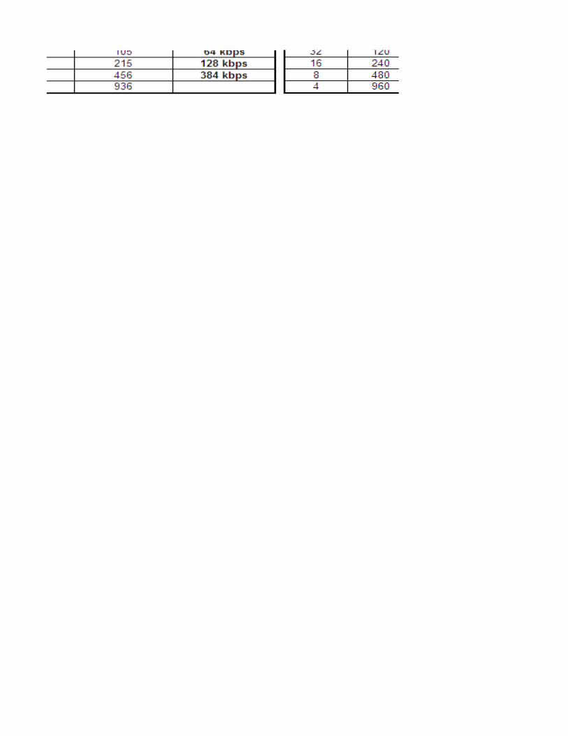

Cellid=bin2dec(0111011110010010)=30610

UL DPCCH Initial Power
Note :DPCCH_Power_offset is configured by RNC and delivered to UE in RRC Connection Setup.


L3 Messages - Video Call (CS64) Call ProcedureUE NodeB
Start Rx
4.ALCAP: Iub User Plane Setup
Start Tx
Click to return to main page
1.RRC: RRC Connection Request (RACH)
RRC Connection Establishment Timing
5.RRC: RRC Connection Setup (FACH)
L1 Synchonization
6.RRC: RRC Connection Setup Completed (DCH)
1.RRC: Initial Direct Transfer (MM: CM Service Request)
2.RRC: Downlink Direct Transfer (MM: Authentication Request)
3.RRC: Uplink Direct Transfer (MM: Authentication Response)
6.RRC: Security Mode Command
7.RRC: Security Mode Completed
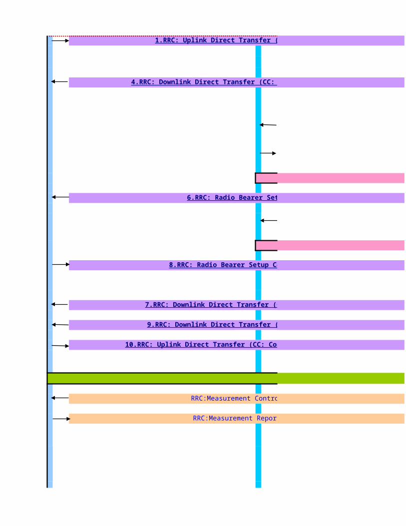
5.ALCAP: Iub User Plane Setup
Apply new transport format set
Call Established
RRC:Measurement Control
RRC:Measurement Report
1.RRC: Uplink Direct Transfer (CC: Setup)
4.RRC: Downlink Direct Transfer (CC: Call Proceeding)
6.RRC: Radio Bearer Setup
8.RRC: Radio Bearer Setup Complete
7.RRC: Downlink Direct Transfer (CC: Alerting)
9.RRC: Downlink Direct Transfer (CC: Connect)
10.RRC: Uplink Direct Transfer (CC: Connect Acknowledge)

5,.ALCAP: Iub User Plane Release
1.RRC: Uplink Direct Transfer (CC: Disconnect)
4.RRC: Downlink Direct Transfer (CC: Release)
5.RRC: Uplink Direct Transfer (CC: Release Complete)
1.RRC: RRC Connection Release
2.RRC: RRC Connection Release Complete
2.RRC:RRC Connection Release Complete
Note the following information about the procedure ,
1.The RRC connection can be set up on a DCH or a CCH. This procedure takes the RRC connection set up on the DCH as an example.2. If IP transport is applied to the Iub interface, no ALCAP procedure is

L3 Messages - Video Call (CS64) Call ProcedureS-RNC
2.NBAP:Radio Link Setup Req
3.NBAP:Radio Link Setup Resp.
4.ALCAP: Iub User Plane Setup
NBAP:Synchonization Indicator
1.RRC: RRC Connection Request (RACH)
5.RRC: RRC Connection Setup (FACH)
6.RRC: RRC Connection Setup Completed (DCH)
1.RRC: Initial Direct Transfer (MM: CM Service Request)
2.RRC: Downlink Direct Transfer (MM: Authentication Request)
3.RRC: Uplink Direct Transfer (MM: Authentication Response)
6.RRC: Security Mode Command
7.RRC: Security Mode Completed

5.ALCAP: Iub User Plane Setup
Apply new transport format set
Call Established
RRC:Measurement Control
RRC:Measurement Report
1.RRC: Uplink Direct Transfer (CC: Setup)
4.RRC: Downlink Direct Transfer (CC: Call Proceeding)
3.NBAP: Radio Link Reconfiguration Prepare
4.NBAP: Radio Link Reconfiguration Ready
6.RRC: Radio Bearer Setup
7.NBAP: Radio Link Reconfiguration Commit
8.RRC: Radio Bearer Setup Complete
7.RRC: Downlink Direct Transfer (CC: Alerting)
9.RRC: Downlink Direct Transfer (CC: Connect)
10.RRC: Uplink Direct Transfer (CC: Connect Acknowledge)

8.ALCAP: Iu User Plane Release
5,.ALCAP: Iub User Plane Release
1.RRC: Uplink Direct Transfer (CC: Disconnect)
4.RRC: Downlink Direct Transfer (CC: Release)
5.RRC: Uplink Direct Transfer (CC: Release Complete)
1.RRC: RRC Connection Release
2.RRC: RRC Connection Release Complete
2.RRC:RRC Connection Release Complete
3.NBAP: Radio Link Deletion Request
4.NBAP: Radio Link Deletion Response
1.The RRC connection can be set up on a DCH or a CCH. This procedure takes the RRC
2. If IP transport is applied to the Iub interface, no ALCAP procedure is

L3 Messages - Video Call (CS64) Call ProcedureCN
SCCP: CR (Connection Request)
3.SCCP: CC (Connection Confirm)
RANAP: Common ID (IMSI)
5.RANAP: Security Mode Command
8.RANAP: Security Mode Complete
2.RANAP: Initial UE Message (MM: CM Service Request)
1.RANAP: Direct Transfer (MM: Authentication Request)
4.RANAP: Direct Transfer (MM: Authentication Response)

1.RANAP: RAB Assignment Request
2.ALCAP : Iu User Plane Setup
9.RANAP: RAB Assignment Response
Call Established
2.RANAP: Direct Transfer (CC: Setup)
3.RANAP: Direct Transfer (CC: Call Proceeding)
6.RANAP: Direct Transfer (CC: Alerting)
8.RANAP: Direct Transfer (CC: Connect)
11.RANAP: Direct Transfer (CC: Connect Acknowledge)
5. Radio Bearer Setup

7.RANAP: Iu Release Command
8.ALCAP: Iu User Plane Release
9.RANAP: Iu Release Complete
2.RANAP: Direct Transfer (CC: Disconnect)
3.RANAP: Direct Transfer (CC: Release)
6.RANAP: Direct Transfer (CC: Release Complete)

RRC connection setup procedure is performed for the UE to set up a signaling connection to the SRNC. RRC connection setup is always initiated by the UE. One UE has a maximum of one RRC connection at a time.
Triggering Conditions : The UE in idle mode intitiates the RRC connection setup procedure when the NAS of the UE requests the establishment of a signaling connection When the SRNCreceives an RRC CONNECTION REQUEST message from the UE, the Radio Resource Management (RRM) module of the RNC determines whether to accept or reject theRRC connectionrequest, based on a specific algorithm. If accepting the request, the RRM module further determines whether to set up the RRC connection on aDedicated Channel (DCH)or on a Common Channel (CCH),based on a specific RRM algorithm. Typically, an RRC connection is set up on the DCH.
The procedure shown is described as follows:1.The UE sends an RRC CONNECTION REQUEST message to the SRNC through the uplink CCCH(RACH), requesting the establishment of an RRC connection.2.Based on the cause in the RRC connection request and the system resource status, the SRNC determines to set up the RRC connection on a DCH and allocates the Radio NetworkTemporary Identity(RNTI),radioresources, and L1 and L2 resources. Then the SRNC sends a RADIO LINK SETUP REQUEST message to the NodeB, requesting the NodeB to allocate the specific radio link resources required for an RRC connection.3.The NodeB responds with a RADIO LINK SETUP RESPONSE message to the SRNC after successfully preparing the resources.4.The SRNC uses the ALCAP protocol to set up the Iub user plane transport bearer and performs the synchronization between the SRNC and the NodeB. This procedure is optional. It is required for the ATM-based Iub interface only.5.The SRNC sends an RRC CONNECTION SETUP message to the UE through the downlink CCCH (FACH). The message contains the information about the DCH allocated by the SRNC.6. UE and NodeB initiate L1 Synchronization. NodeB sends NBAP:Synchonization Indicator message to SRNC when the uplink enter "In-Sync" state7. The UE sends an RRC CONNECTION SETUP COMPLETE message to the SRNC through the uplink Dedicated Control Channel (DCCH) that is just set up. The message indicates that the RRC connection setup procedure ends.If the RNC judges that the RRC connection request cannot be set up (for instance, due to insufficient resources), it directly sends an RRC CONNECTION REJECT message to theUE, and indicates the reject reason in the message
>>RRC Procedure Description
The signaling connection setup procedure is performed to exchange the NAS (Non Access Stratum) information between the UE and the CN.
Triggering Conditons: The UE sends a direct transfer message to initiate the signaling connection setup procedure.
The procedure shown is described as follows:1.The UE sends an INITIAL DIRECT TRANSFER message to the SRNC through the RRC connection. The message contains the initial NAS information to be sent to the CN by the UE.2.The SRNC receives the INITIAL DIRECT TRANSFER message from the UE and sends an INITIAL UE MESSAGE to the CN over the Iu interface. The INITIAL UE MESSAGE contains the NAS information to be sent to theCN by the UE. The content of the NAS information is CM SERVICE REQUEST.3.The CN sends a response message to the SRNC.-If accepting the request, the CN sends a CONNECTION CONFIRM (CC) message to the SRNC. The message indicates that the SCCP connection is set up. After receivingthe message, the SRNC confirms that the signaling connection is set up.-If rejecting the request, the CN sends a CONNECTION REJECT (CJ) message to the SRNC. The message indicates that the SCCP connection fails to be set up. After receiving the message, the SRNC confirms that the signaling connection fails to be setup and then initiates the RRC release procedure.
The authentication and security mode control procedure is performed for the UE and the network to implement bi-directional authentication and to negotiate and configure the integrity protection algorithm and ciphering algorithm. This procedure ensures integrity and correctness of signaling
Triggerring Conditions: The UE and the CN exchange signaling. The network initiates the authentication and securitymode control procedure
The procedure shown is described as follows:1.The CN sends a DIRECT TRANSFER message to the SRNC. The message indicates AUTHENTICATION REQUEST.2.The SRNC transparently sends the contents of the DIRECT TRANSFER message to the UE through a DOWNLINK DIRECT TRANSFER message.3.The UE sends an UPLINK DIRECT TRANSFER message to the SRNC.4.The SRNC transparently sends the contents of the UPLINK DIRECT TRANSFER messageto the CN through a DIRECT TRANSFER message, indicating AUTHENTICATION RESPONSE. If the UMTS Subscriber IdentityModule (USIM) judges that the authentication is successful, the UE returns a message with an XRES IE.5.The CN sends a SECURITY MODE COMMAND message to the SRNC to initiate the security mode control procedure. The message contains the information about the supported ciphering and integrity protectionalgorithms.6.The SRNC sends a SECURITY MODE COMMAND message to the UE to inform the UE of the integrity protection and ciphering algorithms that the UTRAN selects.7.The UE sends a response message to the SRNC.-If the integrity protection and ciphering algorithms are configured successfully, the UE sends a SECURITY MODE COMMAND COMPLETE message to the SRNC. The SRNC then sends a SECURITY MODE COMMAND COMPLETE message to the CN.The message contains the information about the integrity protection and ciphering algorithms that the UE uses.-If the UE does not support the integrity protection and ciphering algorithms, the UE sends a SECURITY MODE COMMAND FAILURE message to the SRNC. The message contains the error information and the reason for the failure. The SRNC then sends a SECURITY MODE COMMAND REJECT message to the CNThe RANAP:Common ID message is used to transport the permanent UE Identity(IMSI) to SRNC
1.RRC Connection Setup
2.Signalling Connection Setup
3.Authentication &Security Mode Control

The authentication and security mode control procedure is performed for the UE and the network to implement bi-directional authentication and to negotiate and configure the integrity protection algorithm and ciphering algorithm. This procedure ensures integrity and correctness of signaling
Triggerring Conditions: The UE and the CN exchange signaling. The network initiates the authentication and securitymode control procedure
The procedure shown is described as follows:1.The CN sends a DIRECT TRANSFER message to the SRNC. The message indicates AUTHENTICATION REQUEST.2.The SRNC transparently sends the contents of the DIRECT TRANSFER message to the UE through a DOWNLINK DIRECT TRANSFER message.3.The UE sends an UPLINK DIRECT TRANSFER message to the SRNC.4.The SRNC transparently sends the contents of the UPLINK DIRECT TRANSFER messageto the CN through a DIRECT TRANSFER message, indicating AUTHENTICATION RESPONSE. If the UMTS Subscriber IdentityModule (USIM) judges that the authentication is successful, the UE returns a message with an XRES IE.5.The CN sends a SECURITY MODE COMMAND message to the SRNC to initiate the security mode control procedure. The message contains the information about the supported ciphering and integrity protectionalgorithms.6.The SRNC sends a SECURITY MODE COMMAND message to the UE to inform the UE of the integrity protection and ciphering algorithms that the UTRAN selects.7.The UE sends a response message to the SRNC.-If the integrity protection and ciphering algorithms are configured successfully, the UE sends a SECURITY MODE COMMAND COMPLETE message to the SRNC. The SRNC then sends a SECURITY MODE COMMAND COMPLETE message to the CN.The message contains the information about the integrity protection and ciphering algorithms that the UE uses.-If the UE does not support the integrity protection and ciphering algorithms, the UE sends a SECURITY MODE COMMAND FAILURE message to the SRNC. The message contains the error information and the reason for the failure. The SRNC then sends a SECURITY MODE COMMAND REJECT message to the CNThe RANAP:Common ID message is used to transport the permanent UE Identity(IMSI) to SRNCThe call setup procedure is performed to set up a call.
Triggering Conditions: The UE initiates a call
The procedure shown is described as follows:1.The UE sends an UPLINK DIRECT TRANSFER message to the SRNC. The message contains the number of the called party and the information about the bearer capability of the call.2.The SRNC transparently sends the contents of the UPLINK DIRECT TRANSFER messageto the CN through a DIRECT TRANSFER message.3.The CN sends a DIRECT TRANSFER message to the SRNC. The message indicates CALL PROCEEDING and contains the information about the negotiated bearer capability of the call.4.The SRNC transparently sends the contents of the DIRECT TRANSFER message to the UE through a DOWNLINK DIRECT TRANSFER message.5. A Radio Access Bearer (RAB) is set up. (see more details in RAB Setup Procedure below)6. When the called terminal rings, the CN sends a DIRECT TRANSFER message to the SRNC. The message indicates ALERTING.7.The SRNC transparently sends the contents of the DIRECT TRANSFER message to the UE through a DOWNLINK DIRECT TRANSFER message.8.The CN sends a DIRECT TRANSFER message to the SRNC. The message indicates CONNECT, which means that the called party has answered the call.9.The SRNC transparently sends the contents of the DIRECT TRANSFER message to the UE through a DOWNLINK DIRECT TRANSFER message.10.The UE sends an UPLINK DIRECT TRANSFER message to the SRNC.11.The SRNC transparently sends the contents of the UPLINK DIRECT TRANSFER message to the CN through a DIRECT TRANSFER message, indicating CONNECT ACKNOWLEDGE.
The Radio Bearer Setup procedure shown is described as follows:1.The CN sends an RAB ASSIGNMENT REQUEST message to the SRNC to initiate the RAB setup procedure.2.(Optional; applicable to the ATM-based Iu-CS interface only) The SRNC maps the Quality of Service (QoS) parameters for the RAB to the AAL2 link characteristic parameters and radio resource characteristicparameters. Based on the AAL2 link characteristic parameters,the ALCAP on the Iu interface initiates an Iu user plane transport bearer setup procedure.3.The SRNC sends a RADIO LINK RECONFIGURATION PREPARE message to the NodeB, requesting the NodeB to prepare for adding one or more DCHs to the existing radio links for carrying the RAB.4.The NodeB allocates the associated resources and then sends a RADIO LINKRECONFIGURATION READY message to the SRNC.5.(Optional; required for the ATM-based Iub interface only) The Iub ALCAP at the SRNC initiates an Iub user plane transport bearer setup procedure. The NodeB and the SRNC perform synchronization by exchanginguplink and downlink synchronization frames in the DCH frame protocol.6.The SRNC sends a RADIO BEARER SETUP message to the UE.7.The SRNC sends a RADIO LINK RECONFIGURATION COMMIT message to theNodeB.8.After performing the radio bearer setup, the UE sends a RADIO BEARER SETUP COMPLETE message to the SRNC.9.The SRNC sends an RAB ASSIGNMENT RESPONSE message to the CN. The RAB isset up.The procedure when RAB Setup Failure shown is described as follows:1.The CN sends an RAB ASSIGNMENT REQUEST message to the SRNC to initiate the RAB setup procedure.2.The SRNC sends an RAB ASSIGNMENT RESPONSE message to the CN. The message indicates the ID of the RAB that fails to be set up and the reason for the failure.The call release procedure is performed to release services and resources after a call ends.
Triggering Conditions : A call ends and the calling party hangs up
The procedure shown is described as follows:1.The UE sends an UPLINK DIRECT TRANSFER message to the SRNC.2.The SRNC transparently sends the contents of the UPLINK DIRECT TRANSFER messageto the CN through a DIRECT TRANSFER message, indicating DISCONNECT. This content informs the CN that the UE has hanged up.3.The CN sends a DIRECT TRANSFER message to the SRNC. The message indicates RELEASE to request release of the call.4.The SRNC transparently sends the contents of the DIRECT TRANSFER message to the UE through a DOWNLINK DIRECT TRANSFER message.5.The UE sends an UPLINK DIRECT TRANSFER message to the SRNC.6.The SRNC transparently sends the contents of the UPLINK DIRECT TRANSFER messageto the CN through a DIRECT TRANSFER message, indicating RELEASE COMPLETE.7.The CN sends an IU RELEASE COMMAND message to the SRNC to request call release on the Iu interface. The message indicates the reason for the Iu release8.(Optional; applicable to the ATM-based Iu-CS interface only) The ALCAP protocol on the Iu interface initiates an Iu data transport bearer release procedure.9.The SRNC sends an IU RELEASE COMPLETE message to the CN.
6.Conversation
4.Call Setup
5. Radio Bearer Setup

The call release procedure is performed to release services and resources after a call ends.
Triggering Conditions : A call ends and the calling party hangs up
The procedure shown is described as follows:1.The UE sends an UPLINK DIRECT TRANSFER message to the SRNC.2.The SRNC transparently sends the contents of the UPLINK DIRECT TRANSFER messageto the CN through a DIRECT TRANSFER message, indicating DISCONNECT. This content informs the CN that the UE has hanged up.3.The CN sends a DIRECT TRANSFER message to the SRNC. The message indicates RELEASE to request release of the call.4.The SRNC transparently sends the contents of the DIRECT TRANSFER message to the UE through a DOWNLINK DIRECT TRANSFER message.5.The UE sends an UPLINK DIRECT TRANSFER message to the SRNC.6.The SRNC transparently sends the contents of the UPLINK DIRECT TRANSFER messageto the CN through a DIRECT TRANSFER message, indicating RELEASE COMPLETE.7.The CN sends an IU RELEASE COMMAND message to the SRNC to request call release on the Iu interface. The message indicates the reason for the Iu release8.(Optional; applicable to the ATM-based Iu-CS interface only) The ALCAP protocol on the Iu interface initiates an Iu data transport bearer release procedure.9.The SRNC sends an IU RELEASE COMPLETE message to the CN.
The RRC Connection Release procedure is performed to release the signaling connection and all radio bearers between UE and the UTRAN
Triggering Conditions: After a n RAB is released,the SRNC judges whether the RRC connection carries any other RAB or the UE. If judging that the RRC connection does not carry other RAB of the UE,the SRNC initiates an RRC connection release procedure.
The procedure shown is described as follows: based on the resouce occupied by the RRC connection,there are two types of RRC connection release procedure: release of an RRC connection from DCH and release of an RRC connection from CCH (If an RRC connection needs to be released after a successful outgoing call,, the RRC connection on the DCH is released and if a radio bearers fails to be setup ,the RRC connection on the CCH is released)
1.The SRNC sends an RRC CONNECTION RELEASE message to the UE through the DCCH. (NOTE: The SRNC may send the RRC CONNECTION RELEASE message several times to increase the probability of proper reception of the message by the UE. The RRC SNs of these messages are the same. The number of retransmissions and the transmission intervals are determined by the SRNC. If the SRNC does not receive an RRC CONNECTION RELEASE COMPLETE message from the UE after sending the RRC CONNECTION RELEASE message for four times, the SRNC judges that the UE has released the RRC connection.)
2.The UE sends an RRC CONNECTION RELEASE COMPLETE message to the SRNC.3.The SRNC sends a RADIO LINK DELETION REQUEST message to the NodeB,requesting the NodeB to delete the radio link resources in the NodeB.4.After releasing the resources, the NodeB sends a RADIO LINK DELETION RESPONSE message to the SRNC.5.(Optional; required for the ATM-based Iub interface only) The SRNC uses the ALCAP protocol to initiate an Iub user plane transport bearer release procedure. Then, the RRC connection release procedure ends.
7.Call Release
8.RRC Connection Release

RRC connection setup procedure is performed for the UE to set up a signaling connection to the SRNC. RRC connection setup is always initiated by the UE. One UE has amaximum of one RRC connection at a time.
The UE in idle mode intitiates the RRC connection setup procedure when the NAS of the UE requests the establishment of a signaling connection When the SRNCreceives an RRC CONNECTION REQUEST message from the UE, the Radio Resource Management (RRM) module of the RNC determines whether to accept or reject theRRC connectionrequest, based on a specific algorithm. If accepting the request, the RRM module further determines whether to set up the RRC connection on aDedicated Channel (DCH)or on a Common Channel (CCH),based on a specific RRM algorithm. Typically, an RRC connection is set up on the DCH.
The procedure shown is described as follows:The UE sends an RRC CONNECTION REQUEST message to the SRNC through the uplink CCCH(RACH), requesting the establishment of an RRC connection.Based on the cause in the RRC connection request and the system resource status, the SRNC determines to set up the RRC connection on a DCH and allocates the Radio NetworkTemporary
resources, and L1 and L2 resources. Then the SRNC sends a RADIO LINK SETUP REQUEST message to the NodeB, requesting the NodeB to allocate the specific radio link resources required for an RRC
The NodeB responds with a RADIO LINK SETUP RESPONSE message to the SRNC after successfully preparing the resources..The SRNC uses the ALCAP protocol to set up the Iub user plane transport bearer and performs the synchronization between the SRNC and the NodeB. This procedure is optional. It is requiredfor the ATM-based Iub interface only.The SRNC sends an RRC CONNECTION SETUP message to the UE through the downlink CCCH (FACH). The message contains the information about the DCH allocated by the SRNC. UE and NodeB initiate L1 Synchronization. NodeB sends NBAP:Synchonization Indicator message to SRNC when the uplink enter "In-Sync" state. The UE sends an RRC CONNECTION SETUP COMPLETE message to the SRNC through the uplink Dedicated Control Channel (DCCH) that is just set up. The message
indicates that the RRC connection setup procedure ends.If the RNC judges that the RRC connection request cannot be set up (for instance, due to insufficient resources), it directly sends an RRC CONNECTION REJECT message totheUE, and indicates the reject reason in the messageThe signaling connection setup procedure is performed to exchange the NAS (Non Access Stratum) information between the UE and the CN.
The UE sends a direct transfer message to initiate the signaling connection setup procedure.
The procedure shown is described as follows:.The UE sends an INITIAL DIRECT TRANSFER message to the SRNC through the RRC connection. The message contains the initial NAS information to be sent to the CN by the UE..The SRNC receives the INITIAL DIRECT TRANSFER message from the UE and sends an INITIAL UE MESSAGE to the CN over the Iu interface. The INITIAL UE MESSAGE contains the NAS information to be
CN by the UE. The content of the NAS information is CM SERVICE REQUEST..The CN sends a response message to the SRNC.
the CN sends a CONNECTION CONFIRM (CC) message to the SRNC. The message indicates that the SCCP connection is set up. After receivingthe message, theSRNC confirms that the signaling connection is set up.
the CN sends a CONNECTION REJECT (CJ) message to the SRNC. The message indicates that the SCCP connection fails to be set up. After receiving the message,the SRNC confirms that the signaling connection fails to be setup and then initiates the RRC release procedure.
The authentication and security mode control procedure is performed for the UE and the network to implement bi-directional authentication and to negotiate and configurethe integrity protection algorithm and ciphering algorithm. This procedure ensures integrity and correctness of signaling
The UE and the CN exchange signaling. The network initiates the authentication and securitymode control procedure
The procedure shown is described as follows:The CN sends a DIRECT TRANSFER message to the SRNC. The message indicates AUTHENTICATION REQUEST.The SRNC transparently sends the contents of the DIRECT TRANSFER message to the UE through a DOWNLINK DIRECT TRANSFER message..The UE sends an UPLINK DIRECT TRANSFER message to the SRNC..The SRNC transparently sends the contents of the UPLINK DIRECT TRANSFER messageto the CN through a DIRECT TRANSFER message, indicating AUTHENTICATION RESPONSE. If the UMTS Subscriber
Module (USIM) judges that the authentication is successful, the UE returns a message with an XRES IE.The CN sends a SECURITY MODE COMMAND message to the SRNC to initiate the security mode control procedure. The message contains the information about the supported ciphering and integrity
.The SRNC sends a SECURITY MODE COMMAND message to the UE to inform the UE of the integrity protection and ciphering algorithms that the UTRAN selects.The UE sends a response message to the SRNC.
-If the integrity protection and ciphering algorithms are configured successfully, the UE sends a SECURITY MODE COMMAND COMPLETE message to the SRNC. The SRNCthen sends a SECURITY MODE COMMAND COMPLETE message to the CN.The message contains the information about the integrity protection and ciphering algorithms that the UE uses.
-If the UE does not support the integrity protection and ciphering algorithms, the UE sends a SECURITY MODE COMMAND FAILURE message to the SRNC. The messagecontains the error information and the reason for the failure. The SRNC then sends a SECURITY MODE COMMAND REJECT message to the CN
The RANAP:Common ID message is used to transport the permanent UE Identity(IMSI) to SRNC

The authentication and security mode control procedure is performed for the UE and the network to implement bi-directional authentication and to negotiate and configurethe integrity protection algorithm and ciphering algorithm. This procedure ensures integrity and correctness of signaling
The UE and the CN exchange signaling. The network initiates the authentication and securitymode control procedure
The procedure shown is described as follows:The CN sends a DIRECT TRANSFER message to the SRNC. The message indicates AUTHENTICATION REQUEST.The SRNC transparently sends the contents of the DIRECT TRANSFER message to the UE through a DOWNLINK DIRECT TRANSFER message..The UE sends an UPLINK DIRECT TRANSFER message to the SRNC..The SRNC transparently sends the contents of the UPLINK DIRECT TRANSFER messageto the CN through a DIRECT TRANSFER message, indicating AUTHENTICATION RESPONSE. If the UMTS Subscriber
Module (USIM) judges that the authentication is successful, the UE returns a message with an XRES IE.The CN sends a SECURITY MODE COMMAND message to the SRNC to initiate the security mode control procedure. The message contains the information about the supported ciphering and integrity
.The SRNC sends a SECURITY MODE COMMAND message to the UE to inform the UE of the integrity protection and ciphering algorithms that the UTRAN selects.The UE sends a response message to the SRNC.
-If the integrity protection and ciphering algorithms are configured successfully, the UE sends a SECURITY MODE COMMAND COMPLETE message to the SRNC. The SRNCthen sends a SECURITY MODE COMMAND COMPLETE message to the CN.The message contains the information about the integrity protection and ciphering algorithms that the UE uses.
-If the UE does not support the integrity protection and ciphering algorithms, the UE sends a SECURITY MODE COMMAND FAILURE message to the SRNC. The messagecontains the error information and the reason for the failure. The SRNC then sends a SECURITY MODE COMMAND REJECT message to the CN
The RANAP:Common ID message is used to transport the permanent UE Identity(IMSI) to SRNC performed to set up a call.
The UE initiates a call
The procedure shown is described as follows:The UE sends an UPLINK DIRECT TRANSFER message to the SRNC. The message contains the number of the called party and the information about the bearer capability of the call..The SRNC transparently sends the contents of the UPLINK DIRECT TRANSFER messageto the CN through a DIRECT TRANSFER message.The CN sends a DIRECT TRANSFER message to the SRNC. The message indicates CALL PROCEEDING and contains the information about the negotiated bearer capability of the call.The SRNC transparently sends the contents of the DIRECT TRANSFER message to the UE through a DOWNLINK DIRECT TRANSFER message.. A Radio Access Bearer (RAB) is set up. (see more details in RAB Setup Procedure below). When the called terminal rings, the CN sends a DIRECT TRANSFER message to the SRNC. The message indicates ALERTING..The SRNC transparently sends the contents of the DIRECT TRANSFER message to the UE through a DOWNLINK DIRECT TRANSFER message..The CN sends a DIRECT TRANSFER message to the SRNC. The message indicates CONNECT, which means that the called party has answered the call..The SRNC transparently sends the contents of the DIRECT TRANSFER message to the UE through a DOWNLINK DIRECT TRANSFER message..The UE sends an UPLINK DIRECT TRANSFER message to the SRNC.The SRNC transparently sends the contents of the UPLINK DIRECT TRANSFER message to the CN through a DIRECT TRANSFER message, indicating CONNECT ACKNOWLEDGE.
The Radio Bearer Setup procedure shown is described as follows:.The CN sends an RAB ASSIGNMENT REQUEST message to the SRNC to initiate the RAB setup procedure.(Optional; applicable to the ATM-based Iu-CS interface only) The SRNC maps the Quality of Service (QoS) parameters for the RAB to the AAL2 link characteristic parameters and radio resource
parameters. Based on the AAL2 link characteristic parameters,the ALCAP on the Iu interface initiates an Iu user plane transport bearer setup procedure.The SRNC sends a RADIO LINK RECONFIGURATION PREPARE message to the NodeB, requesting the NodeB to prepare for adding one or more DCHs to the existing radio links for carrying the RAB.The NodeB allocates the associated resources and then sends a RADIO LINKRECONFIGURATION READY message to the SRNC.(Optional; required for the ATM-based Iub interface only) The Iub ALCAP at the SRNC initiates an Iub user plane transport bearer setup procedure. The NodeB and the SRNC perform
uplink and downlink synchronization frames in the DCH frame protocol.The SRNC sends a RADIO BEARER SETUP message to the UE..The SRNC sends a RADIO LINK RECONFIGURATION COMMIT message to theNodeB..After performing the radio bearer setup, the UE sends a RADIO BEARER SETUP COMPLETE message to the SRNC..The SRNC sends an RAB ASSIGNMENT RESPONSE message to the CN. The RAB isset up.
The procedure when RAB Setup Failure shown is described as follows:.The CN sends an RAB ASSIGNMENT REQUEST message to the SRNC to initiate the RAB setup procedure..The SRNC sends an RAB ASSIGNMENT RESPONSE message to the CN. The message indicates the ID of the RAB that fails to be set up and the reason for the failure.is performed to release services and resources after a call ends.
A call ends and the calling party hangs up
The procedure shown is described as follows:The UE sends an UPLINK DIRECT TRANSFER message to the SRNC.The SRNC transparently sends the contents of the UPLINK DIRECT TRANSFER messageto the CN through a DIRECT TRANSFER message, indicating DISCONNECT. This content informs the CN that the UE
The CN sends a DIRECT TRANSFER message to the SRNC. The message indicates RELEASE to request release of the call..The SRNC transparently sends the contents of the DIRECT TRANSFER message to the UE through a DOWNLINK DIRECT TRANSFER message.The UE sends an UPLINK DIRECT TRANSFER message to the SRNC.The SRNC transparently sends the contents of the UPLINK DIRECT TRANSFER messageto the CN through a DIRECT TRANSFER message, indicating RELEASE COMPLETE..The CN sends an IU RELEASE COMMAND message to the SRNC to request call release on the Iu interface. The message indicates the reason for the Iu release.(Optional; applicable to the ATM-based Iu-CS interface only) The ALCAP protocol on the Iu interface initiates an Iu data transport bearer release procedure..The SRNC sends an IU RELEASE COMPLETE message to the CN.

is performed to release services and resources after a call ends.
A call ends and the calling party hangs up
The procedure shown is described as follows:The UE sends an UPLINK DIRECT TRANSFER message to the SRNC.The SRNC transparently sends the contents of the UPLINK DIRECT TRANSFER messageto the CN through a DIRECT TRANSFER message, indicating DISCONNECT. This content informs the CN that the UE
The CN sends a DIRECT TRANSFER message to the SRNC. The message indicates RELEASE to request release of the call..The SRNC transparently sends the contents of the DIRECT TRANSFER message to the UE through a DOWNLINK DIRECT TRANSFER message.The UE sends an UPLINK DIRECT TRANSFER message to the SRNC.The SRNC transparently sends the contents of the UPLINK DIRECT TRANSFER messageto the CN through a DIRECT TRANSFER message, indicating RELEASE COMPLETE..The CN sends an IU RELEASE COMMAND message to the SRNC to request call release on the Iu interface. The message indicates the reason for the Iu release.(Optional; applicable to the ATM-based Iu-CS interface only) The ALCAP protocol on the Iu interface initiates an Iu data transport bearer release procedure..The SRNC sends an IU RELEASE COMPLETE message to the CN.
The RRC Connection Release procedure is performed to release the signaling connection and all radio bearers between UE and the UTRAN
After a n RAB is released,the SRNC judges whether the RRC connection carries any other RAB or the UE. If judging that the RRC connection does not carry other RAB of theUE,the SRNC initiates an RRC connection release procedure.
The procedure shown is described as follows: based on the resouce occupied by the RRC connection,there are two types of RRC connection release procedure: release of an RRC connection from DCH and release of an RRC connection from CCH (If an RRC connection needs to be released after a successful outgoing call,, the RRC connection on the DCH is released and if a radiobearers fails to be setup ,the RRC connection on the CCH is released)
1.The SRNC sends an RRC CONNECTION RELEASE message to the UE through the DCCH. The SRNC may send the RRC CONNECTION RELEASE message several times to increase the probability of proper reception of the message by the UE. The RRC SNs of these messages are the same.
The number of retransmissions and the transmission intervals are determined by the SRNC. If the SRNC does not receive an RRC CONNECTION RELEASE COMPLETE message from the UE after sending the RRC CONNECTION RELEASE message for four times, the SRNC judges that the UE has released the RRC connection.)
2.The UE sends an RRC CONNECTION RELEASE COMPLETE message to the SRNC.3.The SRNC sends a RADIO LINK DELETION REQUEST message to the NodeB,requesting the NodeB to delete the radio link resources in the NodeB.4.After releasing the resources, the NodeB sends a RADIO LINK DELETION RESPONSE message to the SRNC.5.(Optional; required for the ATM-based Iub interface only) The SRNC uses the ALCAP protocol to initiate an Iub user plane transport bearer release procedure. Then, the RRC connection release

is performed for the UE to set up a signaling connection to the SRNC. RRC connection setup is always initiated by the UE. One UE has a
The UE in idle mode intitiates the RRC connection setup procedure when the NAS of the UE requests the establishment of a signaling connection When the SRNCreceives an RRC CONNECTION REQUEST message from the UE, the Radio Resource Management (RRM) module of the RNC determines whether to accept or reject theRRC connectionrequest, based on a specific algorithm. If accepting the request, the RRM module further determines whether to set up the RRC connection on aDedicated Channel (DCH)or on a Common Channel (CCH),based on a specific RRM algorithm. Typically, an RRC connection is set up on the DCH.
The UE sends an RRC CONNECTION REQUEST message to the SRNC through the uplink CCCH(RACH), requesting the establishment of an RRC connection.Based on the cause in the RRC connection request and the system resource status, the SRNC determines to set up the RRC connection on a DCH and allocates the Radio NetworkTemporary
resources, and L1 and L2 resources. Then the SRNC sends a RADIO LINK SETUP REQUEST message to the NodeB, requesting the NodeB to allocate the specific radio link resources required for an RRC
The NodeB responds with a RADIO LINK SETUP RESPONSE message to the SRNC after successfully preparing the resources..The SRNC uses the ALCAP protocol to set up the Iub user plane transport bearer and performs the synchronization between the SRNC and the NodeB. This procedure is optional. It is required
The SRNC sends an RRC CONNECTION SETUP message to the UE through the downlink CCCH (FACH). The message contains the information about the DCH allocated by the SRNC. UE and NodeB initiate L1 Synchronization. NodeB sends NBAP:Synchonization Indicator message to SRNC when the uplink enter "In-Sync" state. The UE sends an RRC CONNECTION SETUP COMPLETE message to the SRNC through the uplink Dedicated Control Channel (DCCH) that is just set up. The message
If the RNC judges that the RRC connection request cannot be set up (for instance, due to insufficient resources), it directly sends an RRC CONNECTION REJECT message tois performed to exchange the NAS (Non Access Stratum) information between the UE and the CN.
The UE sends a direct transfer message to initiate the signaling connection setup procedure.
message to the SRNC through the RRC connection. The message contains the initial NAS information to be sent to the CN by the UE..The SRNC receives the INITIAL DIRECT TRANSFER message from the UE and sends an INITIAL UE MESSAGE to the CN over the Iu interface. The INITIAL UE MESSAGE contains the NAS information to be
the CN sends a CONNECTION CONFIRM (CC) message to the SRNC. The message indicates that the SCCP connection is set up. After receivingthe message, the
the CN sends a CONNECTION REJECT (CJ) message to the SRNC. The message indicates that the SCCP connection fails to be set up. After receiving the message,the SRNC confirms that the signaling connection fails to be setup and then initiates the RRC release procedure.
is performed for the UE and the network to implement bi-directional authentication and to negotiate and configurethe integrity protection algorithm and ciphering algorithm. This procedure ensures integrity and correctness of signaling
The UE and the CN exchange signaling. The network initiates the authentication and securitymode control procedure
The SRNC transparently sends the contents of the DIRECT TRANSFER message to the UE through a DOWNLINK DIRECT TRANSFER message.
.The SRNC transparently sends the contents of the UPLINK DIRECT TRANSFER messageto the CN through a DIRECT TRANSFER message, indicating AUTHENTICATION RESPONSE. If the UMTS Subscriber
The CN sends a SECURITY MODE COMMAND message to the SRNC to initiate the security mode control procedure. The message contains the information about the supported ciphering and integrity
.The SRNC sends a SECURITY MODE COMMAND message to the UE to inform the UE of the integrity protection and ciphering algorithms that the UTRAN selects.
the UE sends a SECURITY MODE COMMAND COMPLETE message to the SRNC. The SRNCthen sends a SECURITY MODE COMMAND COMPLETE message to the CN.The message contains the information about the integrity protection and ciphering algorithms that the UE uses.
the UE sends a SECURITY MODE COMMAND FAILURE message to the SRNC. The messagecontains the error information and the reason for the failure. The SRNC then sends a SECURITY MODE COMMAND REJECT message to the CN
The UE sends an UPLINK DIRECT TRANSFER message to the SRNC. The message contains the number of the called party and the information about the bearer capability of the call..The SRNC transparently sends the contents of the UPLINK DIRECT TRANSFER messageto the CN through a DIRECT TRANSFER message.The CN sends a DIRECT TRANSFER message to the SRNC. The message indicates CALL PROCEEDING and contains the information about the negotiated bearer capability of the call.The SRNC transparently sends the contents of the DIRECT TRANSFER message to the UE through a DOWNLINK DIRECT TRANSFER message.
. When the called terminal rings, the CN sends a DIRECT TRANSFER message to the SRNC. The message indicates ALERTING.
.The SRNC transparently sends the contents of the DIRECT TRANSFER message to the UE through a DOWNLINK DIRECT TRANSFER message.
.The CN sends a DIRECT TRANSFER message to the SRNC. The message indicates CONNECT, which means that the called party has answered the call.
.The SRNC transparently sends the contents of the DIRECT TRANSFER message to the UE through a DOWNLINK DIRECT TRANSFER message.
The SRNC transparently sends the contents of the UPLINK DIRECT TRANSFER message to the CN through a DIRECT TRANSFER message, indicating CONNECT ACKNOWLEDGE.
(Optional; applicable to the ATM-based Iu-CS interface only) The SRNC maps the Quality of Service (QoS) parameters for the RAB to the AAL2 link characteristic parameters and radio resource
parameters. Based on the AAL2 link characteristic parameters,the ALCAP on the Iu interface initiates an Iu user plane transport bearer setup procedure.The SRNC sends a RADIO LINK RECONFIGURATION PREPARE message to the NodeB, requesting the NodeB to prepare for adding one or more DCHs to the existing radio links for carrying the RAB.The NodeB allocates the associated resources and then sends a RADIO LINKRECONFIGURATION READY message to the SRNC.(Optional; required for the ATM-based Iub interface only) The Iub ALCAP at the SRNC initiates an Iub user plane transport bearer setup procedure. The NodeB and the SRNC perform
.The SRNC sends an RAB ASSIGNMENT RESPONSE message to the CN. The message indicates the ID of the RAB that fails to be set up and the reason for the failure.
The SRNC transparently sends the contents of the UPLINK DIRECT TRANSFER messageto the CN through a DIRECT TRANSFER message, indicating DISCONNECT. This content informs the CN that the UE
The CN sends a DIRECT TRANSFER message to the SRNC. The message indicates RELEASE to request release of the call..The SRNC transparently sends the contents of the DIRECT TRANSFER message to the UE through a DOWNLINK DIRECT TRANSFER message.
The SRNC transparently sends the contents of the UPLINK DIRECT TRANSFER messageto the CN through a DIRECT TRANSFER message, indicating RELEASE COMPLETE..The CN sends an IU RELEASE COMMAND message to the SRNC to request call release on the Iu interface. The message indicates the reason for the Iu release.(Optional; applicable to the ATM-based Iu-CS interface only) The ALCAP protocol on the Iu interface initiates an Iu data transport bearer release procedure.
is performed to release the signaling connection and all radio bearers between UE and the UTRAN
After a n RAB is released,the SRNC judges whether the RRC connection carries any other RAB or the UE. If judging that the RRC connection does not carry other RAB of the
based on the resouce occupied by the RRC connection,there are two types of RRC connection release procedure: release of an RRC connection from DCH and (If an RRC connection needs to be released after a successful outgoing call,, the RRC connection on the DCH is released and if a radio
The SRNC may send the RRC CONNECTION RELEASE message several times to increase the probability of proper reception of the message by the UE. The RRC SNs of these messages are the same. The number of retransmissions and the transmission intervals are determined by the SRNC. If the SRNC does not receive an RRC CONNECTION RELEASE
, the SRNC judges that the UE has released the RRC connection.)
3.The SRNC sends a RADIO LINK DELETION REQUEST message to the NodeB,requesting the NodeB to delete the radio link resources in the NodeB.
5.(Optional; required for the ATM-based Iub interface only) The SRNC uses the ALCAP protocol to initiate an Iub user plane transport bearer release procedure. Then, the RRC connection release

RRC:RRC Connection Request (RACH)Click to return to main page

RRC:RRC Connection Setup (FACH)


RRC:RRC Connection Setup Complete (DCCH)


RRC: Initial Direct Transfer (MM: CM Service Request)

RANAP:Initial UE Message (MM: CM Service Request)
RANAP: Direct Transfer (MM: Authentication Request)
RRC: Downlink Direct Transfer (MM: Authentication Request)

RRC: Uplink Direct Transfer (MM: Authentication Response)
RANAP: Direct Transfer (MM: Authentication Response)
RRC: Security Mode Command

RRC: Security Mode Complete

RANAP: Direct Transfer (CC: Setup)

RRC: Uplink Direct Transfer (CC: Setup)

RRC: Downlink Direct Transfer (CC: Call Proceeding)
RANAP: Direct Transfer (CC: Call Proceeding)
RRC: Radio Bearer Setup


RRC: Radio Bearer Setup Complete

RANAP: Direct Transfer (CC: Alerting)
RRC: Downlink Direct Transfer (CC: Alerting)
RANAP: Direct Transfer (CC: Connect)

RRC: Downlink Direct Transfer (CC: Connect)
RANAP: Direct Transfer (CC: Connect Acknowledge)
RRC: Uplink Direct Transfer (CC: Connect Acknowledge)

RANAP: Direct Transfer (CC: Disconnect)
RRC: Uplink Direct Transfer (CC: Disconnect)

RANAP: Direct Transfer (CC: Release)
RRC: Downlink Direct Transfer (CC: Release)
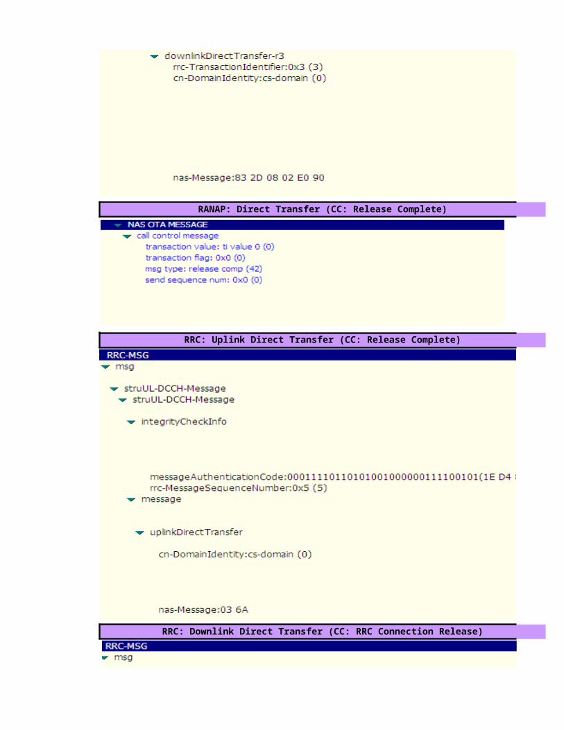
RANAP: Direct Transfer (CC: Release Complete)
RRC: Uplink Direct Transfer (CC: Release Complete)
RRC: Downlink Direct Transfer (CC: RRC Connection Release)

RRC: Uplink Direct Transfer (CC: RRC Connection Release Complete)

value=hex2dec(5)=5 , hex2dec(2)=2 ,hex2dec(0)=0 --> MCC=520
value=hex2dec(0)=0 , hex2dec(1)=1 --> MNC=01
value=hex2dec(2908)= 10504
value= OriginatingConversationalcall (CS MOC)
value=(-24+ (44/2))=-2.0 dB
>>"RRC Connection Request Description"
>>"Geographical and UTRAN Entity Identifiers"

value=hex2dec(5)=5 , hex2dec(2)=2 ,hex2dec(0)=0 --> MCC=520
value=hex2dec(0)=0 , hex2dec(1)=1 --> MNC=01
value=hex2dec(2908)= 10504
value=UE capable to support FDD , not TDD
>>"RRC Connection Setup Description"
>>"Geographical and UTRAN Entity Identifiers"

value=UE capable to support GSM
value=Signaling Radio Bearer Information Setup ,RB-1
value=Radio Bearer Mapping

value=Signaling Radio Bearer Information Setup ,RB-2

value=Signaling Radio Bearer Information Setup ,RB-3

value=Signaling Radio Bearer Information Setup ,RB-4
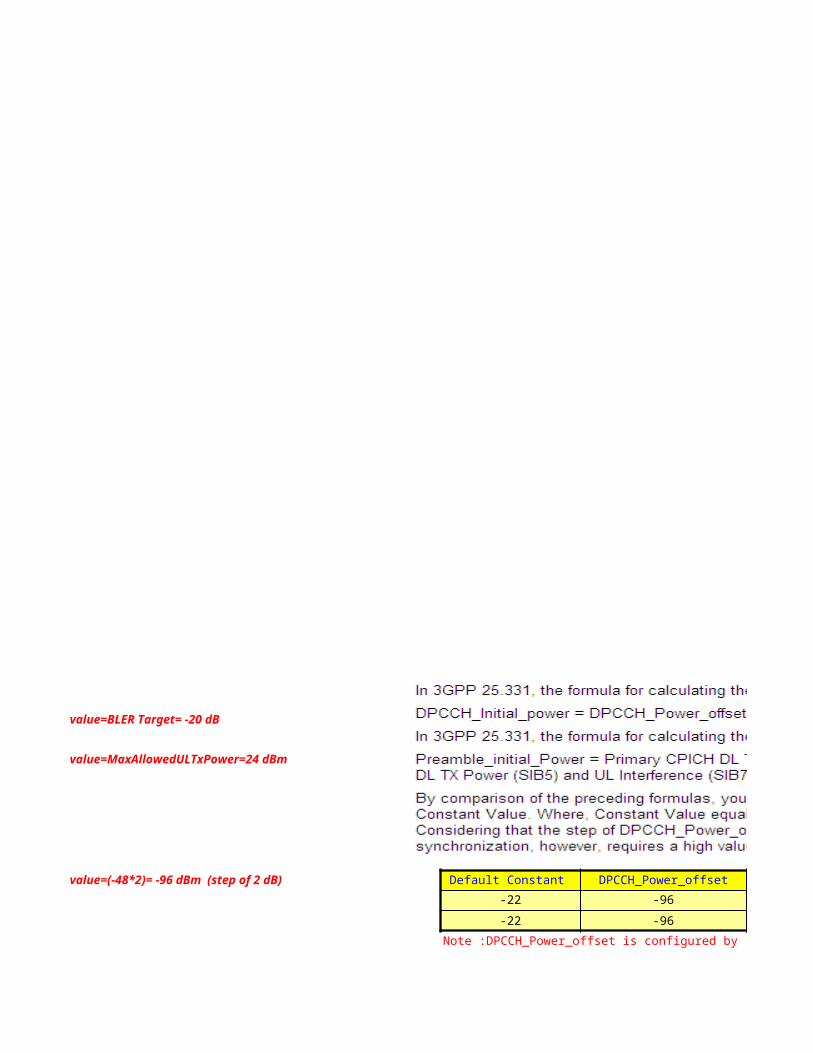
value=BLER Target= -20 dB
value=MaxAllowedULTxPower=24 dBm
value=(-48*2)= -96 dBm (step of 2 dB) Default Constant DPCCH_Power_offset-22 -96-22 -96
Note :DPCCH_Power_offset is configured by RNC and delivered to UE in RRC Connection Setup.

value= use Closed Loop Power Control Algorithm1
value= use long SC on Uplink
value=Spreading Factor 64 (Uplink)
value=Spreading Factor 128 (Downlink)

value=Primary Scrambling code=97
value=Spreading Factor 128 (Downlink)
Cell Identity=RNCid(12bits)+Cellid(16bits)value=0000000010110111011110010010 => RNCid=bin2dec(000000001011)=11 and Cellid=bin2dec(0111011110010010)=30610
>>"RRC Connection Setup Complete Description"

value= not support GSM (Locked UMTS Mode)

value= Chipering Algorithm A5/3
value= UE support Band fdd2100 MHzvalue= UE (Powerclass3) maximum transmitted power =24 dBm
value= support Compressed Mode (CM) uplink and downlink
value= UE support Band fdd1800 MHz

RANAP:Initial UE Message (MM: CM Service Request)
RANAP: Direct Transfer (MM: Authentication Request)
RRC: Downlink Direct Transfer (MM: Authentication Request)
RRC: Uplink Direct Transfer (MM: Authentication Response)
RANAP: Direct Transfer (MM: Authentication Response)
RRC: Security Mode Command

RRC: Security Mode Complete

RANAP: Direct Transfer (CC: Setup)

value= Call B-Party number = 0812713339
RRC: Uplink Direct Transfer (CC: Setup)

RRC: Downlink Direct Transfer (CC: Call Proceeding)
RANAP: Direct Transfer (CC: Call Proceeding)
RRC: Radio Bearer Setup >>"Radio Bearer Description"


value= SF16(uplink)-> CS64 (VP)

value=Primary Scrambling code=97
value= SF32(downlink)-> CS64 (VP)
Cell Identity=RNCid(12bits)+Cellid(16bits)
RRC: Radio Bearer Setup Complete
value=0000000010110111011110010010 => RNCid=bin2dec(000000001011)=11 and Cellid=bin2dec(0111011110010010)=30610

RANAP: Direct Transfer (CC: Alerting)
RRC: Downlink Direct Transfer (CC: Alerting)
RANAP: Direct Transfer (CC: Connect)

RRC: Downlink Direct Transfer (CC: Connect)
RANAP: Direct Transfer (CC: Connect Acknowledge)
RRC: Uplink Direct Transfer (CC: Connect Acknowledge)

RANAP: Direct Transfer (CC: Disconnect)
RRC: Uplink Direct Transfer (CC: Disconnect)

RANAP: Direct Transfer (CC: Release)
RRC: Downlink Direct Transfer (CC: Release)

RANAP: Direct Transfer (CC: Release Complete)
RRC: Uplink Direct Transfer (CC: Release Complete)
RRC: Downlink Direct Transfer (CC: RRC Connection Release)

RRC: Uplink Direct Transfer (CC: RRC Connection Release Complete)

CPICH_RSCP PCPICH Power UL Interference UL DPCCH Initial Power-80 33 -107 -16-70 33 -107 -26
Note :DPCCH_Power_offset is configured by RNC and delivered to UE in RRC Connection Setup.


Cellid=bin2dec(0111011110010010)=30610


Cellid=bin2dec(0111011110010010)=30610


L3 Messages - PS(R99) Call ProcedureUE NodeB
Start Rx
4.ALCAP: Iub User Plane Setup
RRC Connection Establishment Timing Start Tx
RRC: Downlink Direct Transfer (GMM: GPRS Identity Request)
RRC: Uplink Direct Transfer (GMM: GPRS Identity Response)
Click to return to main page
1.RRC: RRC Connection Request (RACH)
5.RRC: RRC Connection Setup (FACH)
L1 Synchonization
8.RRC: RRC Connection Setup Completed (DCH)
RRC: Initial Direct Transfer (GMM: Attach Request)
RRC: Downlink Direct Transfer (MM: Authentication & Ciphering Request)
RRC: Uplink Direct Transfer (MM: Authentication & Ciphering Response)
RRC: Security Mode Command
RRC: Security Mode Completed
If UE already attached to GPRS CN, the UE will only send "GMM:Service Request" message to N/W

ALCAP: Iub User Plane Setup
Apply new transport format set
RRC:Measurement Control
PS Session Established
RRC:Measurement Report
ALCAP: Iub User Plane Setup
RRC: Downlink Direct Transfer (MM: Attach Accept)
RRC: Uplink Direct Transfer (MM: Attach Completed)
RRC: Uplink Direct Transfer (SM: Activate PDP Context Request)
RRC: Radio Bearer Setup
RRC: Radio Bearer Setup Complete
RRC: Downlink Direct Transfer (SM: Activate PDP Context Accept)

ALCAP: Iub User Plane Setup
RRC: Uplink Direct Transfer (CC: RRC Connection Release Complete)
RRC: Radio Bearer Reconfiguration
RRC: Radio Bearer Reconfiguration Complete
RRC: Uplink Direct Transfer (SM: Deactivate PDP Context Request)
RRC: Downlink Direct Transfer (SM: Deactivate PDP Context Accept)
RRC: Uplink Direct Transfer (MM: Detach Request)
RRC: Radio Bearer Release
RRC: Downlink Direct Transfer (MM: Detach Accept)
RRC: Radio Bearer Release Completed
RRC: Downlink Direct Transfer (CC: RRC Connection Release)
RRC: Uplink Direct Transfer (CC: RRC Connection Release Complete)

ALCAP: Iub User Plane Release

L3 Messages - PS(R99) Call ProcedureS-RNC
2.NBAP:Radio Link Setup Req
3.NBAP:Radio Link Setup Resp.
4.ALCAP: Iub User Plane Setup
7.NBAP:Synchonization Indicator
RRC: Downlink Direct Transfer (GMM: GPRS Identity Request)
RRC: Uplink Direct Transfer (GMM: GPRS Identity Response)
1.RRC: RRC Connection Request (RACH)
5.RRC: RRC Connection Setup (FACH)
8.RRC: RRC Connection Setup Completed (DCH)
RRC: Initial Direct Transfer (GMM: Attach Request)
RRC: Downlink Direct Transfer (MM: Authentication & Ciphering Request)
RRC: Uplink Direct Transfer (MM: Authentication & Ciphering Response)
RRC: Security Mode Command
RRC: Security Mode Completed

ALCAP: Iub User Plane Setup
Apply new transport format set
RRC:Measurement Control
PS Session Established
RRC:Measurement Report
ALCAP: Iub User Plane Setup
RRC: Downlink Direct Transfer (MM: Attach Accept)
RRC: Uplink Direct Transfer (MM: Attach Completed)
RRC: Uplink Direct Transfer (SM: Activate PDP Context Request)
NBAP: Radio Link Reconfiguration Prepare
NBAP: Radio Link Reconfiguration Ready
RRC: Radio Bearer Setup
NBAP: Radio Link Reconfiguration Commit
RRC: Radio Bearer Setup Complete
RRC: Downlink Direct Transfer (SM: Activate PDP Context Accept)
NBAP: Radio Link Reconfiguration Prepare
NBAP: Radio Link Reconfiguration Ready

ALCAP: Iub User Plane Setup
ALCAP: Iu User Plane Release
RRC: Uplink Direct Transfer (CC: RRC Connection Release Complete)
NBAP: Radio Link Reconfiguration Commit
RRC: Radio Bearer Reconfiguration
RRC: Radio Bearer Reconfiguration Complete
RRC: Uplink Direct Transfer (SM: Deactivate PDP Context Request)
RRC: Downlink Direct Transfer (SM: Deactivate PDP Context Accept)
NBAP: Radio Link Reconfiguration Prepare
NBAP: Radio Link Reconfiguration Ready
NBAP: Radio Link Reconfiguration Commit
RRC: Uplink Direct Transfer (MM: Detach Request)
RRC: Radio Bearer Release
RRC: Downlink Direct Transfer (MM: Detach Accept)
RRC: Radio Bearer Release Completed
RRC: Downlink Direct Transfer (CC: RRC Connection Release)
RRC: Uplink Direct Transfer (CC: RRC Connection Release Complete)
NBAP: Radio Link Deletion Request

ALCAP: Iub User Plane Release
NBAP: Radio Link Deletion Response

L3 Messages - PS(R99) Call ProcedureCN
RANAP: GMM: GPRS Identity Request
RANAP: GMM: GPRS Identity Response
RANAP: Security Mode Command
RANAP: Security Mode Complete
RANAP: Initial UE Message GMM: (Attach Request)
RANAP: MM: Authentication & Ciphering Request
RANAP:MM: Authentication&Ciphering Response
2.GPRS Attach Procedure
3.Authentication & Security Mode Control

RANAP: Common ID(IMSI)
RANAP: RAB Assignment Request
ALCAP : Iu User Plane Setup
RANAP: RAB Assignment Response
PS Session Established
RANAP: MM: Attach Accept
RANAP: MM: Attach Completed
RANAP: SM: Activate PDP Context Request
RANAP: SM: Activate PDP Context Accept
5. Radio Bearer Setup

RANAP: Iu Release Command
ALCAP: Iu User Plane Release
RANAP: Iu Release Complete
RANAP: SM: Deactivate PDP Context Request
RANAP: SM: Deactivate PDP Context Accept
RANAP: MM: Detach Request
RANAP: MM: Detach Accept
Radio Bearer Reconfiguration to Upgrade/Downgrade Bit Rate


RRC connection setup procedure maximum of one RRC connection at a time.
Triggering Conditions : The UE in idle mode intitiates the RRC connection setup procedure when the NAS of the UE requests the establishment of a signaling connection When theSRNC receives an RRC CONNECTION REQUEST message from the UE, the Radio Resource Management (RRM) module of the RNC determines whether to accept or reject the RRCconnection request, based on a specific algorithm. If accepting the request, the RRM module further determines whether to set up the RRC connection on a Dedicated Channel(DCH)or on a Common Channel (CCH),based on a specific RRM algorithm. Typically, an RRC connection is set up on the DCH.
The procedure shown is described as follows:1.The UE sends an RRC CONNECTION REQUEST message to the SRNC through the uplink CCCH(RACH), requesting the establishment of an RRC connection.2.Based on the cause in the RRC connection request and the system resource status, the SRNC determines to set up the RRC connection on a DCH and allocates the RadioNetworkTemporary Identity(RNTI),radio resources, and L1 and L2 resources. Then the SRNC sends a RADIO LINK SETUP REQUEST message to the NodeB, requesting the NodeB toallocate the specific radio link resources required for an RRC connection.3.The NodeB responds with a RADIO LINK SETUP RESPONSE message to the SRNC after successfully preparing the resources.4.The SRNC uses the ALCAP protocol to set up the Iub user plane transport bearer and performs the synchronization between the SRNC and the NodeB. This procedure is optional. Itis required for the ATM-based Iub interface only.5.The SRNC sends an RRC CONNECTION SETUP message to the UE through the downlink CCCH (FACH). The message contains the information about the DCH allocated by the SRNC.6. UE and NodeB initiate L1 Synchronization. NodeB sends NBAP:Synchonization Indicator message to SRNC when the uplink enter "In-Sync" state7. The UE sends an RRC CONNECTION SETUP COMPLETE message to the SRNC through the uplink Dedicated Control Channel (DCCH) that is just set up. The message
>>RRC Procedure Description
The GPRS Attach procedure is performed in order to make UE presence known to the network by performing a Packet Service Attach (GPRS attach). This makes the UE available for SMS over PS data paging via the SGSN, and notification of incoming PS Data.In the attach procedure, the UE shall provide its identity and an indication of which type of attach that is to be executed. PS attach and combined PS / CS attach.The identity provided to the network shall be the UE's Packet TMSI (P-TMSI) or IMSI
Triggering Conditons: The UE sends a GPRS Attach Request message to initiate the signaling connection setup procedure.
The procedure shown is described as follows:1.UE initiates the attach procedure by the transmission of an Attach Request message to the RNC. IMSI shall be included if the UE does not have a valid P-TMSI (Packet Temporary IMSI) available. RNC opens an SCCP (Signalling Connection Control Part) connection and sends the Attach request to SGSN 2.If the UE identifies itself with P-TMSI and the SGSN has changed since detach, the new SGSN sends an Identification Request (P-TMSI, old RAI, old P-TMSI Signature) to the old SGSN torequest the IMSI. The old SGSN responds with Identification Response (IMSI, Authentication vector). The old SGSN also validates the old P-TMSI3.If the UE is unknown in both the old and new SGSN, the SGSN sends an Identity Request (Identity Type = IMSI) to the UE. The UE responds with Identity Response (IMSI).4. The new SGSN asks the HLR to authenticate the UE. HLR sends back to SGSN the Authentication data received from AUC (Authentication Center). The HLR contains GSM and WCDMAsubscriber information The SGSN sends the Authentication and Ciphering Request to the UE. At authentication of a WCDMA subscriber, the SGSN transmitts the RAND (Random Number) and AUTN (Authentication Token) to the UE. At reception of this message, the UE (USIM, WCDMA Subscriber Identity module in the UE) verifies AUTN and if accepted the UE returns anAuthentication and Ciphering response (RES) message to the SGSN. During generation of authentication vectors, the USIM in the UE also computes a new Ciphering Key. CK, and a new Integrity Key, IK. These keys are stored together with the CKSN (Ciphering key sequence number of Kc) until CKSN is updated at the next authentication. The SGSN verifies the transmission security. A known bit stream is encrypted and decrypted in SGSN and UE.5. If the SGSN number has changed since the GPRS detach, or if it is the very first attach, then the SGSN informs the HLR:
-The SGSN sends an Update Location (SGSN Number, SGSN Address, IMSI) to the HLR.-The HLR sends Cancel Location (IMSI, Cancellation Type) to the old SGSN with Cancellation Type set to Update Procedure.-The old SGSN acknowledges with Cancel Location Ack (IMSI). If there are any ongoing procedures for that UE, the old SGSN shall wait until these procedures are finished before removing the MM (Mobility Management) and PDP contexts-The HLR sends Insert Subscriber Data (IMSI, GPRS subscription data) to the new SGSN.-The new SGSN validates the UE's presence in the (new) RA (Routing Area). If all checks are successful then the SGSN constructs an MM context for the UE and returns an Insert Subscriber Data Ack (IMSI) message to the HLR.-The HLR acknowledges the Update Location message by sending an Update Location Ack to the SGSN after the canceling of old MM context and insertion of new MM context are finished.If the Update Location is rejected by the HLR, the SGSN rejects the Attach Request from the UE with an appropriate cause code6. If Attach Type in step 1 indicated PS Attach while already CS attached, or combined PS/CS attach, then the VLR shall be updated. The VLR number is received from the RA information. The SGSN starts the location update procedure towards the new MSC/VLR upon receipt of the first Insert Subscriber Data message from the HLR. This operation marks the UE as GPRS-attached in the VLR.
a. The SGSN sends a Location Update Request (new LAI, IMSI, SGSN Number, Location Update Type) message to the VLR. Location Update Type shall indicate CS attach if Attach Type indicated combined PS / CS attach. Otherwise, Location Update Type shall indicate normal location update. The VLR creates an association with the SGSN by storing SGSN Number.b. If the LA update is inter-MSC, the new VLR sends Update Location (IMSI, new VLR) to the HLR.c. If the LA update is inter-MSC, the HLR sends a Cancel Location (IMSI) to the old VLR.d. The old VLR acknowledges with Cancel Location Ack (IMSI). If there are any ongoing procedures for that MS, the old SGSN shall wait until these procedures are finished before removing the MM and PDP contexts.e. If the LA update is inter-MSC, the HLR sends Insert Subscriber Data (IMSI, GSM subscriber data) to the new VLR.f. The VLR acknowledges with Insert Subscriber Data Ack (IMSI).g. After finishing the inter-MSC location update procedures, the HLR responds with Update Location Ack (IMSI) to the new VLR.h. The VLR responds with Location Update Accept (VLR TMSI) to the SGSN. 7. The SGSN sends an Attach Accept (P-TMSI, VLR TMSI, P-TMSI Signature, Radio Priority SMS) message to the UE. P-TMSI is included if the SGSN allocates a new P-TMSI. If the Attach Request cannot be accepted, the SGSN returns an Attach Reject (IMSI, Cause) message to the UE
8. If P-TMSI or VLR TMSI was changed, the UE acknowledges the received TMSI(s) with Attach Complete (P-TMSI, VLR TMSI).
9. If VLR TMSI was changed, the SGSN confirms the VLR TMSI re-allocation by sending TMSI Reallocation Complete (VLR TMSI) to the VLR.
10. Iu (Iu Interface) and SCCP signalling connections are released
1.RRC Connection Establishment
2.GPRS Attach Procedure
3.Authentication & Security Mode Control

The GPRS Attach procedure is performed in order to make UE presence known to the network by performing a Packet Service Attach (GPRS attach). This makes the UE available for SMS over PS data paging via the SGSN, and notification of incoming PS Data.In the attach procedure, the UE shall provide its identity and an indication of which type of attach that is to be executed. PS attach and combined PS / CS attach.The identity provided to the network shall be the UE's Packet TMSI (P-TMSI) or IMSI
Triggering Conditons: The UE sends a GPRS Attach Request message to initiate the signaling connection setup procedure.
The procedure shown is described as follows:1.UE initiates the attach procedure by the transmission of an Attach Request message to the RNC. IMSI shall be included if the UE does not have a valid P-TMSI (Packet Temporary IMSI) available. RNC opens an SCCP (Signalling Connection Control Part) connection and sends the Attach request to SGSN 2.If the UE identifies itself with P-TMSI and the SGSN has changed since detach, the new SGSN sends an Identification Request (P-TMSI, old RAI, old P-TMSI Signature) to the old SGSN torequest the IMSI. The old SGSN responds with Identification Response (IMSI, Authentication vector). The old SGSN also validates the old P-TMSI3.If the UE is unknown in both the old and new SGSN, the SGSN sends an Identity Request (Identity Type = IMSI) to the UE. The UE responds with Identity Response (IMSI).4. The new SGSN asks the HLR to authenticate the UE. HLR sends back to SGSN the Authentication data received from AUC (Authentication Center). The HLR contains GSM and WCDMAsubscriber information The SGSN sends the Authentication and Ciphering Request to the UE. At authentication of a WCDMA subscriber, the SGSN transmitts the RAND (Random Number) and AUTN (Authentication Token) to the UE. At reception of this message, the UE (USIM, WCDMA Subscriber Identity module in the UE) verifies AUTN and if accepted the UE returns anAuthentication and Ciphering response (RES) message to the SGSN. During generation of authentication vectors, the USIM in the UE also computes a new Ciphering Key. CK, and a new Integrity Key, IK. These keys are stored together with the CKSN (Ciphering key sequence number of Kc) until CKSN is updated at the next authentication. The SGSN verifies the transmission security. A known bit stream is encrypted and decrypted in SGSN and UE.5. If the SGSN number has changed since the GPRS detach, or if it is the very first attach, then the SGSN informs the HLR:
-The SGSN sends an Update Location (SGSN Number, SGSN Address, IMSI) to the HLR.-The HLR sends Cancel Location (IMSI, Cancellation Type) to the old SGSN with Cancellation Type set to Update Procedure.-The old SGSN acknowledges with Cancel Location Ack (IMSI). If there are any ongoing procedures for that UE, the old SGSN shall wait until these procedures are finished before removing the MM (Mobility Management) and PDP contexts-The HLR sends Insert Subscriber Data (IMSI, GPRS subscription data) to the new SGSN.-The new SGSN validates the UE's presence in the (new) RA (Routing Area). If all checks are successful then the SGSN constructs an MM context for the UE and returns an Insert Subscriber Data Ack (IMSI) message to the HLR.-The HLR acknowledges the Update Location message by sending an Update Location Ack to the SGSN after the canceling of old MM context and insertion of new MM context are finished.If the Update Location is rejected by the HLR, the SGSN rejects the Attach Request from the UE with an appropriate cause code6. If Attach Type in step 1 indicated PS Attach while already CS attached, or combined PS/CS attach, then the VLR shall be updated. The VLR number is received from the RA information. The SGSN starts the location update procedure towards the new MSC/VLR upon receipt of the first Insert Subscriber Data message from the HLR. This operation marks the UE as GPRS-attached in the VLR.
a. The SGSN sends a Location Update Request (new LAI, IMSI, SGSN Number, Location Update Type) message to the VLR. Location Update Type shall indicate CS attach if Attach Type indicated combined PS / CS attach. Otherwise, Location Update Type shall indicate normal location update. The VLR creates an association with the SGSN by storing SGSN Number.b. If the LA update is inter-MSC, the new VLR sends Update Location (IMSI, new VLR) to the HLR.c. If the LA update is inter-MSC, the HLR sends a Cancel Location (IMSI) to the old VLR.d. The old VLR acknowledges with Cancel Location Ack (IMSI). If there are any ongoing procedures for that MS, the old SGSN shall wait until these procedures are finished before removing the MM and PDP contexts.e. If the LA update is inter-MSC, the HLR sends Insert Subscriber Data (IMSI, GSM subscriber data) to the new VLR.f. The VLR acknowledges with Insert Subscriber Data Ack (IMSI).g. After finishing the inter-MSC location update procedures, the HLR responds with Update Location Ack (IMSI) to the new VLR.h. The VLR responds with Location Update Accept (VLR TMSI) to the SGSN. 7. The SGSN sends an Attach Accept (P-TMSI, VLR TMSI, P-TMSI Signature, Radio Priority SMS) message to the UE. P-TMSI is included if the SGSN allocates a new P-TMSI. If the Attach Request cannot be accepted, the SGSN returns an Attach Reject (IMSI, Cause) message to the UE
8. If P-TMSI or VLR TMSI was changed, the UE acknowledges the received TMSI(s) with Attach Complete (P-TMSI, VLR TMSI).
9. If VLR TMSI was changed, the SGSN confirms the VLR TMSI re-allocation by sending TMSI Reallocation Complete (VLR TMSI) to the VLR.
10. Iu (Iu Interface) and SCCP signalling connections are released
The authentication and security mode control procedure is performed for the UE and the network to implement bi-directional authentication and to negotiate and configure the integrity protection algorithm and ciphering algorithm. This procedure ensures integrity and correctness of signaling
Triggerring Conditions: The UE and the CN exchange signaling. The network initiates the authentication and securitymode control procedureThe procedure shown is described as follows:1.The CN sends a DIRECT TRANSFER message to the SRNC. The message indicates AUTHENTICATION REQUEST.2.The SRNC transparently sends the contents of the DIRECT TRANSFER message to the UE through a DOWNLINK DIRECT TRANSFER message.3.The UE sends an UPLINK DIRECT TRANSFER message to the SRNC.4.The SRNC transparently sends the contents of the UPLINK DIRECT TRANSFER messageto the CN through a DIRECT TRANSFER message, indicating AUTHENTICATION RESPONSE. If the UMTS Subscriber Identity Module (USIM) judges that the authentication is successful, the UE returns a message with an XRES IE.5.The CN sends a SECURITY MODE COMMAND message to the SRNC to initiate the security mode control procedure. The message contains the information about the supported ciphering and integrity protection algorithms.6.The SRNC sends a SECURITY MODE COMMAND message to the UE to inform the UE of the integrity protection and ciphering algorithms that the UTRAN selects.7.The UE sends a response message to the SRNC.-If the integrity protection and ciphering algorithms are configured successfully, the UE sends a SECURITY MODE COMMAND COMPLETE message to the SRNC. The SRNC then sends a SECURITY MODE COMMAND COMPLETE message to the CN.The message contains the information about the integrity protection and ciphering algorithms that the UE uses.-If the UE does not support the integrity protection and ciphering algorithms, the UE sends a SECURITY MODE COMMAND FAILURE message to the SRNC. The message contains the error information and the reason for the failure. The SRNC then sends a SECURITY MODE COMMAND REJECT message to the CNThe RANAP:Common ID message is used to transport the permanent UE Identity(IMSI) to SRNCThe PS Session Setup procedure is performed to set up a PS session
Triggering Conditions: The UE send Activate PDP context request message to RNC. PDP Context Activation is performed when the UE initiates a packet call setup. The UE has the state PacketMobility Management Connected that enables the user to transmitt and receive data while moving within a PLMN. and starts the PDP context activation procedure used to set up and remove avirtual data channel between a terminal connected to a UE and a GGSN. PDP contexts deal with allocation of IP addresses to the UE and Quality of Service, QoS, parameters. A Radio Accessbearer establishes on request of the SGSN in order to realize the air interface connection. At the end the UE has an IP address NSAPI (Network layer Service Access Point Identifier) and a TLLI (Temporary Logical Link Identity) associated to IMSI.
IP addresses can be allocated dynamically or statistically. If allocated dynamically, this significantly reduces the total number of IP addresses required per PLMN. Support of static IP address allocation enables subscribers to provide their own IP addresses. This can be useful when accesing secure networks that use the calling IP address as a form of security check. The support ofQoS enables the operator to differentiate GPRS services.
When dynamic addressing from the home PLMN or the Visitor PLMN is used, it is the responsibility of the GGSN to allocate and release the dynamic PDP address.
The procedure shown is described as follows:1.The UE sends an Activate PDP Context Request (NSAPI, TI(Teardown Indication), PDP Type, Address, APN (Access Point Name), QoS (Quality of Service) Requested, PDP ConfigurationOptions) message to the SGSN The UE shall use PDP Address to indicate whether it requires the use of a static PDP address or whether it requires the use of a dynamic PDP address.2. The SGSN sends a RAB Assignment Request message to the RNC to establish a RABs3.The RNC establishes the appropriate radio bearer In WCDMA, RAB setup is done by the RAB Assignment procedure4.The RNC returns a RAB Assignment Response message to the SGSN5. The SGSN validates the active PDP Context Request using PDP Type (optional), PDP Address, APN (Access Point Name (optional) provided by the UE and the PDP context subscriptionrecords.The SGSN sends a Create PDP Context Request message to the affected GGSN. Access Point Name shall be the APN Network Identifier of the APN. The GGSN may use Access Point Name to find an external network and optionally to activate a service for this APN6. The GGSN creates a new entry in its PDP context table and generates a Charging Id. The new entry allows the GGSN to route PDP PDUs (Policy Decision Point Protocol Data Units) between the SGSN and the external PDP network, and to start charging 7.The SGSN inserts the Network layer Service Access Point Identifier, NSAPI along with the GGSN address in its PDP context and informs the UE via RNC that the PDP Context is Accepted. TheSGSN selects Radio Priority and Packet flow Id based on QoS Negotiated, and returns an Activate PDP Context Accept message to the UE. The SGSN is now able to route PDP PDUs between theGGSN and the UE and to start charging
The Radio Bearer Setup procedure shown is described as follows:1.The CN sends an RAB ASSIGNMENT REQUEST message to the SRNC to initiate the RAB setup procedure.2.(Optional; applicable to the ATM-based Iu-CS interface only) The SRNC maps the Quality of Service (QoS) parameters for the RAB to the AAL2 link characteristic parameters and radio resourcecharacteristic parameters. Based on the AAL2 link characteristic parameters,the ALCAP on the Iu interface initiates an Iu user plane transport bearer setup procedure.3.The SRNC sends a RADIO LINK RECONFIGURATION PREPARE message to the NodeB, requesting the NodeB to prepare for adding one or more DCHs to the existing radio links for carrying theRAB.4.The NodeB allocates the associated resources and then sends a RADIO LINKRECONFIGURATION READY message to the SRNC.5.(Optional; required for the ATM-based Iub interface only) The Iub ALCAP at the SRNC initiates an Iub user plane transport bearer setup procedure. The NodeB and the SRNC perform synchronization by exchanging uplink and downlink synchronization frames in the DCH frame protocol.6.The SRNC sends a RADIO BEARER SETUP message to the UE.7.The SRNC sends a RADIO LINK RECONFIGURATION COMMIT message to theNodeB.8.After performing the radio bearer setup, the UE sends a RADIO BEARER SETUP COMPLETE message to the SRNC.9.The SRNC sends an RAB ASSIGNMENT RESPONSE message to the CN. The RAB isset up.The procedure when RAB Setup Failure shown is described as follows:1.The CN sends an RAB ASSIGNMENT REQUEST message to the SRNC to initiate the RAB setup procedure.2.The SRNC sends an RAB ASSIGNMENT RESPONSE message to the CN. The message indicates the ID of the RAB that fails to be set up and the reason for the failure.
6.Downlink and Uplink Data Transfer
4.PS Session Setup
5. Radio Bearer Setup

The PS Session Setup procedure is performed to set up a PS session
Triggering Conditions: The UE send Activate PDP context request message to RNC. PDP Context Activation is performed when the UE initiates a packet call setup. The UE has the state PacketMobility Management Connected that enables the user to transmitt and receive data while moving within a PLMN. and starts the PDP context activation procedure used to set up and remove avirtual data channel between a terminal connected to a UE and a GGSN. PDP contexts deal with allocation of IP addresses to the UE and Quality of Service, QoS, parameters. A Radio Accessbearer establishes on request of the SGSN in order to realize the air interface connection. At the end the UE has an IP address NSAPI (Network layer Service Access Point Identifier) and a TLLI (Temporary Logical Link Identity) associated to IMSI.
IP addresses can be allocated dynamically or statistically. If allocated dynamically, this significantly reduces the total number of IP addresses required per PLMN. Support of static IP address allocation enables subscribers to provide their own IP addresses. This can be useful when accesing secure networks that use the calling IP address as a form of security check. The support ofQoS enables the operator to differentiate GPRS services.
When dynamic addressing from the home PLMN or the Visitor PLMN is used, it is the responsibility of the GGSN to allocate and release the dynamic PDP address.
The procedure shown is described as follows:1.The UE sends an Activate PDP Context Request (NSAPI, TI(Teardown Indication), PDP Type, Address, APN (Access Point Name), QoS (Quality of Service) Requested, PDP ConfigurationOptions) message to the SGSN The UE shall use PDP Address to indicate whether it requires the use of a static PDP address or whether it requires the use of a dynamic PDP address.2. The SGSN sends a RAB Assignment Request message to the RNC to establish a RABs3.The RNC establishes the appropriate radio bearer In WCDMA, RAB setup is done by the RAB Assignment procedure4.The RNC returns a RAB Assignment Response message to the SGSN5. The SGSN validates the active PDP Context Request using PDP Type (optional), PDP Address, APN (Access Point Name (optional) provided by the UE and the PDP context subscriptionrecords.The SGSN sends a Create PDP Context Request message to the affected GGSN. Access Point Name shall be the APN Network Identifier of the APN. The GGSN may use Access Point Name to find an external network and optionally to activate a service for this APN6. The GGSN creates a new entry in its PDP context table and generates a Charging Id. The new entry allows the GGSN to route PDP PDUs (Policy Decision Point Protocol Data Units) between the SGSN and the external PDP network, and to start charging 7.The SGSN inserts the Network layer Service Access Point Identifier, NSAPI along with the GGSN address in its PDP context and informs the UE via RNC that the PDP Context is Accepted. TheSGSN selects Radio Priority and Packet flow Id based on QoS Negotiated, and returns an Activate PDP Context Accept message to the UE. The SGSN is now able to route PDP PDUs between theGGSN and the UE and to start charging
The Radio Bearer Setup procedure shown is described as follows:1.The CN sends an RAB ASSIGNMENT REQUEST message to the SRNC to initiate the RAB setup procedure.2.(Optional; applicable to the ATM-based Iu-CS interface only) The SRNC maps the Quality of Service (QoS) parameters for the RAB to the AAL2 link characteristic parameters and radio resourcecharacteristic parameters. Based on the AAL2 link characteristic parameters,the ALCAP on the Iu interface initiates an Iu user plane transport bearer setup procedure.3.The SRNC sends a RADIO LINK RECONFIGURATION PREPARE message to the NodeB, requesting the NodeB to prepare for adding one or more DCHs to the existing radio links for carrying theRAB.4.The NodeB allocates the associated resources and then sends a RADIO LINKRECONFIGURATION READY message to the SRNC.5.(Optional; required for the ATM-based Iub interface only) The Iub ALCAP at the SRNC initiates an Iub user plane transport bearer setup procedure. The NodeB and the SRNC perform synchronization by exchanging uplink and downlink synchronization frames in the DCH frame protocol.6.The SRNC sends a RADIO BEARER SETUP message to the UE.7.The SRNC sends a RADIO LINK RECONFIGURATION COMMIT message to theNodeB.8.After performing the radio bearer setup, the UE sends a RADIO BEARER SETUP COMPLETE message to the SRNC.9.The SRNC sends an RAB ASSIGNMENT RESPONSE message to the CN. The RAB isset up.The procedure when RAB Setup Failure shown is described as follows:1.The CN sends an RAB ASSIGNMENT REQUEST message to the SRNC to initiate the RAB setup procedure.2.The SRNC sends an RAB ASSIGNMENT RESPONSE message to the CN. The message indicates the ID of the RAB that fails to be set up and the reason for the failure.
The PS session release procedure is performed to release services and resources after a session ends.
Triggering Conditions : The UE send Deactivate PDP context request message to RNC. A PDP Context Deactivation is performed when the UE terminates a packet call. Before the deactivation,the UE has the state Active. After the PDP Context deactivation procedure the state becomes Packet Mobility Management Connected.The RAB will be released if there are no otherPDP contexts activated.PDP Deactivation may be initiated by a:UE procedure,SGSN procedure,GGSN procedure
The procedure shown is described as follows:1.The UE sends a Deactivate PDP Context Request (TI, Teardown Indication) message to the SGSN via the RNC2.The SGSN sends a Delete PDP Context Request (TEID, NSAPI, Teardown Indication) message to the GGSN. If Teardown Indication was included by the UE in the Deactivate PDP Context Request message, then the SGSN deactivates all PDP contexts associated with this PDP address by including Teardown Indication in the Delete PDP Context Request message3.The GGSN removes the PDP context(s) and returns a delete PDP Context Response (TEID) message to the SGSN. The Delete PDP Context messages are sent over the backbone network4.The SGSN returns a Deactivate PDP Context Accept (TI) message to the UE via the RNC5. In Iu mode, radio access bearer release is done by the RAB Assignment procedure6. The SCCP connection between RNC and SGSN is released. At GPRS detach, all PDP contexts for the UE are implicitly deactivated
7.PS Session Release
8.RRC Connection Release
Radio Bearer Reconfiguration to Upgrade/Downgrade Bit Rate

The PS session release procedure is performed to release services and resources after a session ends.
Triggering Conditions : The UE send Deactivate PDP context request message to RNC. A PDP Context Deactivation is performed when the UE terminates a packet call. Before the deactivation,the UE has the state Active. After the PDP Context deactivation procedure the state becomes Packet Mobility Management Connected.The RAB will be released if there are no otherPDP contexts activated.PDP Deactivation may be initiated by a:UE procedure,SGSN procedure,GGSN procedure
The procedure shown is described as follows:1.The UE sends a Deactivate PDP Context Request (TI, Teardown Indication) message to the SGSN via the RNC2.The SGSN sends a Delete PDP Context Request (TEID, NSAPI, Teardown Indication) message to the GGSN. If Teardown Indication was included by the UE in the Deactivate PDP Context Request message, then the SGSN deactivates all PDP contexts associated with this PDP address by including Teardown Indication in the Delete PDP Context Request message3.The GGSN removes the PDP context(s) and returns a delete PDP Context Response (TEID) message to the SGSN. The Delete PDP Context messages are sent over the backbone network4.The SGSN returns a Deactivate PDP Context Accept (TI) message to the UE via the RNC5. In Iu mode, radio access bearer release is done by the RAB Assignment procedure6. The SCCP connection between RNC and SGSN is released. At GPRS detach, all PDP contexts for the UE are implicitly deactivated The RRC Connection Release procedure
Triggering Conditions: After a n RAB is released,the SRNC judges whether the RRC connection carries any other RAB or the UE. If judging that the RRC connection does not carry other RABof the UE,the SRNC initiates an RRC connection release procedure.
The procedure shown is described as follows: connection from DCH and release of an RRC connection from CCH is released and if a radio bearers fails to be setup ,the RRC connection on the CCH is released)
1.The SRNC sends an RRC CONNECTION RELEASE message to the UE through the DCCH. (NOTE: The SRNC may send the RRC CONNECTION RELEASE message several times to increase the probability of proper reception of the message by the UE. The RRC SNs of these messages are the same. The number of retransmissions and the transmission intervals are determined by the SRNC. If the SRNC does not receive an RRC CONNECTION RELEASE COMPLETE message from the UE after sending the RRC CONNECTION RELEASE message for
2.The UE sends an RRC CONNECTION RELEASE COMPLETE message to the SRNC.3.The SRNC sends a RADIO LINK DELETION REQUEST message to the NodeB,requesting the NodeB to delete the radio link resources in the NodeB.4.After releasing the resources, the NodeB sends a RADIO LINK DELETION RESPONSE message to the SRNC.5.(Optional; required for the ATM-based Iub interface only) The SRNC uses the ALCAP protocol to initiate an Iub user plane transport bearer release procedure. Then, the

RRC connection setup procedure is performed for the UE to set up a signaling connection to the SRNC. RRC connection setup is always initiated by the UE. One UE has amaximum of one RRC connection at a time.
Triggering Conditions : The UE in idle mode intitiates the RRC connection setup procedure when the NAS of the UE requests the establishment of a signaling connection
SRNC receives an RRC CONNECTION REQUEST message from the UE, the Radio Resource Management (RRM) module of the RNC determines whether to accept or reject the RRCconnection request, based on a specific algorithm. If accepting the request, the RRM module further determines whether to set up the RRC connection on a Dedicated Channel(DCH)or on a Common Channel (CCH),based on a specific RRM algorithm. Typically, an RRC connection is set up on the DCH.
The procedure shown is described as follows:The UE sends an RRC CONNECTION REQUEST message to the SRNC through the uplink CCCH(RACH), requesting the establishment of an RRC connection.Based on the cause in the RRC connection request and the system resource status, the SRNC determines to set up the RRC connection on a DCH and allocates the Radio
NetworkTemporary Identity(RNTI),radio resources, and L1 and L2 resources. Then the SRNC sends a RADIO LINK SETUP REQUEST message to the NodeB, requesting the NodeB toallocate the specific radio link resources required for an RRC connection.
The NodeB responds with a RADIO LINK SETUP RESPONSE message to the SRNC after successfully preparing the resources..The SRNC uses the ALCAP protocol to set up the Iub user plane transport bearer and performs the synchronization between the SRNC and the NodeB. This procedure is
is required for the ATM-based Iub interface only.The SRNC sends an RRC CONNECTION SETUP message to the UE through the downlink CCCH (FACH). The message contains the information about the DCH allocated by the SRNC. UE and NodeB initiate L1 Synchronization. NodeB sends NBAP:Synchonization Indicator message to SRNC when the uplink enter "In-Sync" state
. The UE sends an RRC CONNECTION SETUP COMPLETE message to the SRNC through the uplink Dedicated Control Channel (DCCH) that is just set up. The message
The GPRS Attach procedure is performed in order to make UE presence known to the network by performing a Packet Service Attach (GPRS attach). This makes the UE available for SMS over PS data paging via the SGSN, and notification of incoming PS Data.In the attach procedure, the UE shall provide its identity and an indication of which type of attach that is to be executed. PS attach and combined PS / CS attach.The identity provided to the network shall be the UE's Packet TMSI (P-TMSI) or IMSI
The UE sends a GPRS Attach Request message to initiate the signaling connection setup procedure.
The procedure shown is described as follows:UE initiates the attach procedure by the transmission of an Attach Request message to the RNC. IMSI shall be included if the UE does not have a valid P-TMSI (Packet
available. RNC opens an SCCP (Signalling Connection Control Part) connection and sends the Attach request to SGSN .If the UE identifies itself with P-TMSI and the SGSN has changed since detach, the new SGSN sends an Identification Request (P-TMSI, old RAI, old P-TMSI Signature) to
request the IMSI. The old SGSN responds with Identification Response (IMSI, Authentication vector). The old SGSN also validates the old P-TMSI.If the UE is unknown in both the old and new SGSN, the SGSN sends an Identity Request (Identity Type = IMSI) to the UE. The UE responds with Identity Response (IMSI). The new SGSN asks the HLR to authenticate the UE. HLR sends back to SGSN the Authentication data received from AUC (Authentication Center). The HLR contains GSM and
subscriber information The SGSN sends the Authentication and Ciphering Request to the UE. At authentication of a WCDMA subscriber, the SGSN transmitts the RAND (Random
and AUTN (Authentication Token) to the UE. At reception of this message, the UE (USIM, WCDMA Subscriber Identity module in the UE) verifies AUTN and if accepted the UE
Authentication and Ciphering response (RES) message to the SGSN. During generation of authentication vectors, the USIM in the UE also computes a new Ciphering Key. CK, and
Integrity Key, IK. These keys are stored together with the CKSN (Ciphering key sequence number of Kc) until CKSN is updated at the next authentication. The SGSN verifies
transmission security. A known bit stream is encrypted and decrypted in SGSN and UE. If the SGSN number has changed since the GPRS detach, or if it is the very first attach, then the SGSN informs the HLR:
-The SGSN sends an Update Location (SGSN Number, SGSN Address, IMSI) to the HLR.-The HLR sends Cancel Location (IMSI, Cancellation Type) to the old SGSN with Cancellation Type set to Update Procedure.-The old SGSN acknowledges with Cancel Location Ack (IMSI). If there are any ongoing procedures for that UE, the old SGSN shall wait until these procedures are finished
the MM (Mobility Management) and PDP contexts-The HLR sends Insert Subscriber Data (IMSI, GPRS subscription data) to the new SGSN.-The new SGSN validates the UE's presence in the (new) RA (Routing Area). If all checks are successful then the SGSN constructs an MM context for the UE and returns an
Subscriber Data Ack (IMSI) message to the HLR.-The HLR acknowledges the Update Location message by sending an Update Location Ack to the SGSN after the canceling of old MM context and insertion of new MM context are
If the Update Location is rejected by the HLR, the SGSN rejects the Attach Request from the UE with an appropriate cause code If Attach Type in step 1 indicated PS Attach while already CS attached, or combined PS/CS attach, then the VLR shall be updated. The VLR number is received from the RA
SGSN starts the location update procedure towards the new MSC/VLR upon receipt of the first Insert Subscriber Data message from the HLR. This operation marks the UE as
a. The SGSN sends a Location Update Request (new LAI, IMSI, SGSN Number, Location Update Type) message to the VLR. Location Update Type shall indicate CS attach if Attach
indicated combined PS / CS attach. Otherwise, Location Update Type shall indicate normal location update. The VLR creates an association with the SGSN by storing SGSN
b. If the LA update is inter-MSC, the new VLR sends Update Location (IMSI, new VLR) to the HLR.c. If the LA update is inter-MSC, the HLR sends a Cancel Location (IMSI) to the old VLR.d. The old VLR acknowledges with Cancel Location Ack (IMSI). If there are any ongoing procedures for that MS, the old SGSN shall wait until these procedures are finished
removing the MM and PDP contexts.e. If the LA update is inter-MSC, the HLR sends Insert Subscriber Data (IMSI, GSM subscriber data) to the new VLR.f. The VLR acknowledges with Insert Subscriber Data Ack (IMSI).g. After finishing the inter-MSC location update procedures, the HLR responds with Update Location Ack (IMSI) to the new VLR.h. The VLR responds with Location Update Accept (VLR TMSI) to the SGSN. . The SGSN sends an Attach Accept (P-TMSI, VLR TMSI, P-TMSI Signature, Radio Priority SMS) message to the UE. P-TMSI is included if the SGSN allocates a new P-TMSI. If
Request cannot be accepted, the SGSN returns an Attach Reject (IMSI, Cause) message to the UE
8. If P-TMSI or VLR TMSI was changed, the UE acknowledges the received TMSI(s) with Attach Complete (P-TMSI, VLR TMSI).
9. If VLR TMSI was changed, the SGSN confirms the VLR TMSI re-allocation by sending TMSI Reallocation Complete (VLR TMSI) to the VLR.
10. Iu (Iu Interface) and SCCP signalling connections are released
The authentication and security mode control procedure is performed for the UE and the network to implement bi-directional authentication and to negotiate and
the integrity protection algorithm and ciphering algorithm. This procedure ensures integrity and correctness of signaling
Triggerring Conditions: The UE and the CN exchange signaling. The network initiates the authentication and securitymode control procedureThe procedure shown is described as follows:
The CN sends a DIRECT TRANSFER message to the SRNC. The message indicates AUTHENTICATION REQUEST.The SRNC transparently sends the contents of the DIRECT TRANSFER message to the UE through a DOWNLINK DIRECT TRANSFER message.
.The UE sends an UPLINK DIRECT TRANSFER message to the SRNC.
.The SRNC transparently sends the contents of the UPLINK DIRECT TRANSFER messageto the CN through a DIRECT TRANSFER message, indicating AUTHENTICATION RESPONSE. If theUMTS Subscriber Identity Module (USIM) judges that the authentication is successful, the UE returns a message with an XRES IE.The CN sends a SECURITY MODE COMMAND message to the SRNC to initiate the security mode control procedure. The message contains the information about the supported
and integrity protection algorithms..The SRNC sends a SECURITY MODE COMMAND message to the UE to inform the UE of the integrity protection and ciphering algorithms that the UTRAN selects.The UE sends a response message to the SRNC.
-If the integrity protection and ciphering algorithms are configured successfully, the UE sends a SECURITY MODE COMMAND COMPLETE message to the SRNC. The SRNCthen sends a SECURITY MODE COMMAND COMPLETE message to the CN.The message contains the information about the integrity protection and ciphering algorithms that the UE
-If the UE does not support the integrity protection and ciphering algorithms, the UE sends a SECURITY MODE COMMAND FAILURE message to the SRNC. The messagecontains the error information and the reason for the failure. The SRNC then sends a SECURITY MODE COMMAND REJECT message to the CN
The RANAP:Common ID message is used to transport the permanent UE Identity(IMSI) to SRNCThe PS Session Setup procedure is performed to set up a PS session
The UE send Activate PDP context request message to RNC. PDP Context Activation is performed when the UE initiates a packet call setup. The UE has
Mobility Management Connected that enables the user to transmitt and receive data while moving within a PLMN. and starts the PDP context activation procedure used to set
virtual data channel between a terminal connected to a UE and a GGSN. PDP contexts deal with allocation of IP addresses to the UE and Quality of Service, QoS, parameters.
bearer establishes on request of the SGSN in order to realize the air interface connection. At the end the UE has an IP address NSAPI (Network layer Service Access Point Identifier) and a TLLI (Temporary Logical Link Identity) associated to IMSI.
IP addresses can be allocated dynamically or statistically. If allocated dynamically, this significantly reduces the total number of IP addresses required per PLMN. Support of static IP address allocation enables subscribers to provide their own IP addresses. This can be useful when accesing secure networks that use the calling IP address as a form of security check. The support ofQoS enables the operator to differentiate GPRS services.
When dynamic addressing from the home PLMN or the Visitor PLMN is used, it is the responsibility of the GGSN to allocate and release the dynamic PDP address.
The procedure shown is described as follows:The UE sends an Activate PDP Context Request (NSAPI, TI(Teardown Indication), PDP Type, Address, APN (Access Point Name), QoS (Quality of Service) Requested, PDP
Options) message to the SGSN The UE shall use PDP Address to indicate whether it requires the use of a static PDP address or whether it requires the use of a dynamic PDP
The SGSN sends a RAB Assignment Request message to the RNC to establish a RABs.The RNC establishes the appropriate radio bearer In WCDMA, RAB setup is done by the RAB Assignment procedure.The RNC returns a RAB Assignment Response message to the SGSN The SGSN validates the active PDP Context Request using PDP Type (optional), PDP Address, APN (Access Point Name (optional) provided by the UE and the PDP context
records.The SGSN sends a Create PDP Context Request message to the affected GGSN. Access Point Name shall be the APN Network Identifier of the APN. The GGSN may use Access
Name to find an external network and optionally to activate a service for this APN The GGSN creates a new entry in its PDP context table and generates a Charging Id. The new entry allows the GGSN to route PDP PDUs (Policy Decision Point Protocol Data
the SGSN and the external PDP network, and to start charging The SGSN inserts the Network layer Service Access Point Identifier, NSAPI along with the GGSN address in its PDP context and informs the UE via RNC that the PDP Context
SGSN selects Radio Priority and Packet flow Id based on QoS Negotiated, and returns an Activate PDP Context Accept message to the UE. The SGSN is now able to route PDP
theGGSN and the UE and to start charging
The Radio Bearer Setup procedure shown is described as follows:.The CN sends an RAB ASSIGNMENT REQUEST message to the SRNC to initiate the RAB setup procedure.(Optional; applicable to the ATM-based Iu-CS interface only) The SRNC maps the Quality of Service (QoS) parameters for the RAB to the AAL2 link characteristic parameters
characteristic parameters. Based on the AAL2 link characteristic parameters,the ALCAP on the Iu interface initiates an Iu user plane transport bearer setup procedure.The SRNC sends a RADIO LINK RECONFIGURATION PREPARE message to the NodeB, requesting the NodeB to prepare for adding one or more DCHs to the existing radio links for
The NodeB allocates the associated resources and then sends a RADIO LINKRECONFIGURATION READY message to the SRNC.(Optional; required for the ATM-based Iub interface only) The Iub ALCAP at the SRNC initiates an Iub user plane transport bearer setup procedure. The NodeB and the SRNC
synchronization by exchanging uplink and downlink synchronization frames in the DCH frame protocol.The SRNC sends a RADIO BEARER SETUP message to the UE.
.The SRNC sends a RADIO LINK RECONFIGURATION COMMIT message to theNodeB.
.After performing the radio bearer setup, the UE sends a RADIO BEARER SETUP COMPLETE message to the SRNC.
.The SRNC sends an RAB ASSIGNMENT RESPONSE message to the CN. The RAB isset up.The procedure when RAB Setup Failure shown is described as follows:.The CN sends an RAB ASSIGNMENT REQUEST message to the SRNC to initiate the RAB setup procedure..The SRNC sends an RAB ASSIGNMENT RESPONSE message to the CN. The message indicates the ID of the RAB that fails to be set up and the reason for the failure.

The PS Session Setup procedure is performed to set up a PS session
The UE send Activate PDP context request message to RNC. PDP Context Activation is performed when the UE initiates a packet call setup. The UE has
Mobility Management Connected that enables the user to transmitt and receive data while moving within a PLMN. and starts the PDP context activation procedure used to set
virtual data channel between a terminal connected to a UE and a GGSN. PDP contexts deal with allocation of IP addresses to the UE and Quality of Service, QoS, parameters.
bearer establishes on request of the SGSN in order to realize the air interface connection. At the end the UE has an IP address NSAPI (Network layer Service Access Point Identifier) and a TLLI (Temporary Logical Link Identity) associated to IMSI.
IP addresses can be allocated dynamically or statistically. If allocated dynamically, this significantly reduces the total number of IP addresses required per PLMN. Support of static IP address allocation enables subscribers to provide their own IP addresses. This can be useful when accesing secure networks that use the calling IP address as a form of security check. The support ofQoS enables the operator to differentiate GPRS services.
When dynamic addressing from the home PLMN or the Visitor PLMN is used, it is the responsibility of the GGSN to allocate and release the dynamic PDP address.
The procedure shown is described as follows:The UE sends an Activate PDP Context Request (NSAPI, TI(Teardown Indication), PDP Type, Address, APN (Access Point Name), QoS (Quality of Service) Requested, PDP
Options) message to the SGSN The UE shall use PDP Address to indicate whether it requires the use of a static PDP address or whether it requires the use of a dynamic PDP
The SGSN sends a RAB Assignment Request message to the RNC to establish a RABs.The RNC establishes the appropriate radio bearer In WCDMA, RAB setup is done by the RAB Assignment procedure.The RNC returns a RAB Assignment Response message to the SGSN The SGSN validates the active PDP Context Request using PDP Type (optional), PDP Address, APN (Access Point Name (optional) provided by the UE and the PDP context
records.The SGSN sends a Create PDP Context Request message to the affected GGSN. Access Point Name shall be the APN Network Identifier of the APN. The GGSN may use Access
Name to find an external network and optionally to activate a service for this APN The GGSN creates a new entry in its PDP context table and generates a Charging Id. The new entry allows the GGSN to route PDP PDUs (Policy Decision Point Protocol Data
the SGSN and the external PDP network, and to start charging The SGSN inserts the Network layer Service Access Point Identifier, NSAPI along with the GGSN address in its PDP context and informs the UE via RNC that the PDP Context
SGSN selects Radio Priority and Packet flow Id based on QoS Negotiated, and returns an Activate PDP Context Accept message to the UE. The SGSN is now able to route PDP
theGGSN and the UE and to start charging
The Radio Bearer Setup procedure shown is described as follows:.The CN sends an RAB ASSIGNMENT REQUEST message to the SRNC to initiate the RAB setup procedure.(Optional; applicable to the ATM-based Iu-CS interface only) The SRNC maps the Quality of Service (QoS) parameters for the RAB to the AAL2 link characteristic parameters
characteristic parameters. Based on the AAL2 link characteristic parameters,the ALCAP on the Iu interface initiates an Iu user plane transport bearer setup procedure.The SRNC sends a RADIO LINK RECONFIGURATION PREPARE message to the NodeB, requesting the NodeB to prepare for adding one or more DCHs to the existing radio links for
The NodeB allocates the associated resources and then sends a RADIO LINKRECONFIGURATION READY message to the SRNC.(Optional; required for the ATM-based Iub interface only) The Iub ALCAP at the SRNC initiates an Iub user plane transport bearer setup procedure. The NodeB and the SRNC
synchronization by exchanging uplink and downlink synchronization frames in the DCH frame protocol.The SRNC sends a RADIO BEARER SETUP message to the UE.
.The SRNC sends a RADIO LINK RECONFIGURATION COMMIT message to theNodeB.
.After performing the radio bearer setup, the UE sends a RADIO BEARER SETUP COMPLETE message to the SRNC.
.The SRNC sends an RAB ASSIGNMENT RESPONSE message to the CN. The RAB isset up.The procedure when RAB Setup Failure shown is described as follows:.The CN sends an RAB ASSIGNMENT REQUEST message to the SRNC to initiate the RAB setup procedure..The SRNC sends an RAB ASSIGNMENT RESPONSE message to the CN. The message indicates the ID of the RAB that fails to be set up and the reason for the failure.
The PS session release procedure is performed to release services and resources after a session ends.
: The UE send Deactivate PDP context request message to RNC. A PDP Context Deactivation is performed when the UE terminates a packet call. Before
deactivation,the UE has the state Active. After the PDP Context deactivation procedure the state becomes Packet Mobility Management Connected.The RAB will be released if
PDP contexts activated.PDP Deactivation may be initiated by a:UE procedure,SGSN procedure,GGSN procedure
The procedure shown is described as follows:.The UE sends a Deactivate PDP Context Request (TI, Teardown Indication) message to the SGSN via the RNC.The SGSN sends a Delete PDP Context Request (TEID, NSAPI, Teardown Indication) message to the GGSN. If Teardown Indication was included by the UE in the Deactivate PDP
Context Request message, then the SGSN deactivates all PDP contexts associated with this PDP address by including Teardown Indication in the Delete PDP Context Request
.The GGSN removes the PDP context(s) and returns a delete PDP Context Response (TEID) message to the SGSN. The Delete PDP Context messages are sent over the backbone
.The SGSN returns a Deactivate PDP Context Accept (TI) message to the UE via the RNC In Iu mode, radio access bearer release is done by the RAB Assignment procedure
. The SCCP connection between RNC and SGSN is released. At GPRS detach, all PDP contexts for the UE are implicitly deactivated

The PS session release procedure is performed to release services and resources after a session ends.
: The UE send Deactivate PDP context request message to RNC. A PDP Context Deactivation is performed when the UE terminates a packet call. Before
deactivation,the UE has the state Active. After the PDP Context deactivation procedure the state becomes Packet Mobility Management Connected.The RAB will be released if
PDP contexts activated.PDP Deactivation may be initiated by a:UE procedure,SGSN procedure,GGSN procedure
The procedure shown is described as follows:.The UE sends a Deactivate PDP Context Request (TI, Teardown Indication) message to the SGSN via the RNC.The SGSN sends a Delete PDP Context Request (TEID, NSAPI, Teardown Indication) message to the GGSN. If Teardown Indication was included by the UE in the Deactivate PDP
Context Request message, then the SGSN deactivates all PDP contexts associated with this PDP address by including Teardown Indication in the Delete PDP Context Request
.The GGSN removes the PDP context(s) and returns a delete PDP Context Response (TEID) message to the SGSN. The Delete PDP Context messages are sent over the backbone
.The SGSN returns a Deactivate PDP Context Accept (TI) message to the UE via the RNC In Iu mode, radio access bearer release is done by the RAB Assignment procedure
. The SCCP connection between RNC and SGSN is released. At GPRS detach, all PDP contexts for the UE are implicitly deactivated The RRC Connection Release procedure is performed to release the signaling connection and all radio bearers between UE and the UTRAN
Triggering Conditions: After a n RAB is released,the SRNC judges whether the RRC connection carries any other RAB or the UE. If judging that the RRC connection does not
of the UE,the SRNC initiates an RRC connection release procedure.
The procedure shown is described as follows: based on the resouce occupied by the RRC connection,there are two types of RRC connection release procedure: release of an RRC connection from DCH and release of an RRC connection from CCH (If an RRC connection needs to be released after a successful outgoing call,, the RRC connection on the DCH
a radio bearers fails to be setup ,the RRC connection on the CCH is released)
1.The SRNC sends an RRC CONNECTION RELEASE message to the UE through the DCCH. The SRNC may send the RRC CONNECTION RELEASE message several times to increase the probability of proper reception of the message by the UE. The RRC SNs of these
messages are the same. The number of retransmissions and the transmission intervals are determined by the SRNC. If the SRNC does not receive an RRC CONNECTION RELEASE COMPLETE message from the UE after sending the RRC CONNECTION RELEASE message for four times, the SRNC judges that the UE has released the RRC connection.)
2.The UE sends an RRC CONNECTION RELEASE COMPLETE message to the SRNC.3.The SRNC sends a RADIO LINK DELETION REQUEST message to the NodeB,requesting the NodeB to delete the radio link resources in the NodeB.4.After releasing the resources, the NodeB sends a RADIO LINK DELETION RESPONSE message to the SRNC.5.(Optional; required for the ATM-based Iub interface only) The SRNC uses the ALCAP protocol to initiate an Iub user plane transport bearer release procedure. Then, the

is performed for the UE to set up a signaling connection to the SRNC. RRC connection setup is always initiated by the UE. One UE has a
The UE in idle mode intitiates the RRC connection setup procedure when the NAS of the UE requests the establishment of a signaling connection
SRNC receives an RRC CONNECTION REQUEST message from the UE, the Radio Resource Management (RRM) module of the RNC determines whether to accept or reject the RRCconnection request, based on a specific algorithm. If accepting the request, the RRM module further determines whether to set up the RRC connection on a Dedicated Channel(DCH)or on a Common Channel (CCH),based on a specific RRM algorithm. Typically, an RRC connection is set up on the DCH.
The UE sends an RRC CONNECTION REQUEST message to the SRNC through the uplink CCCH(RACH), requesting the establishment of an RRC connection.Based on the cause in the RRC connection request and the system resource status, the SRNC determines to set up the RRC connection on a DCH and allocates the Radio
NetworkTemporary Identity(RNTI),radio resources, and L1 and L2 resources. Then the SRNC sends a RADIO LINK SETUP REQUEST message to the NodeB, requesting the NodeB to
The NodeB responds with a RADIO LINK SETUP RESPONSE message to the SRNC after successfully preparing the resources..The SRNC uses the ALCAP protocol to set up the Iub user plane transport bearer and performs the synchronization between the SRNC and the NodeB. This procedure is
The SRNC sends an RRC CONNECTION SETUP message to the UE through the downlink CCCH (FACH). The message contains the information about the DCH allocated by the SRNC. UE and NodeB initiate L1 Synchronization. NodeB sends NBAP:Synchonization Indicator message to SRNC when the uplink enter "In-Sync" state. The UE sends an RRC CONNECTION SETUP COMPLETE message to the SRNC through the uplink Dedicated Control Channel (DCCH) that is just set up. The message
is performed in order to make UE presence known to the network by performing a Packet Service Attach (GPRS attach). This makes the UE available for SMS over PS data paging via the SGSN, and notification of incoming PS Data.In the attach procedure, the UE shall provide its identity and an indication of
PS attach and combined PS / CS attach.The identity provided to the network shall be the UE's Packet TMSI (P-TMSI) or IMSI
The UE sends a GPRS Attach Request message to initiate the signaling connection setup procedure.
UE initiates the attach procedure by the transmission of an Attach Request message to the RNC. IMSI shall be included if the UE does not have a valid P-TMSI (Packet
available. RNC opens an SCCP (Signalling Connection Control Part) connection and sends the Attach request to SGSN .If the UE identifies itself with P-TMSI and the SGSN has changed since detach, the new SGSN sends an Identification Request (P-TMSI, old RAI, old P-TMSI Signature) to
request the IMSI. The old SGSN responds with Identification Response (IMSI, Authentication vector). The old SGSN also validates the old P-TMSI.If the UE is unknown in both the old and new SGSN, the SGSN sends an Identity Request (Identity Type = IMSI) to the UE. The UE responds with Identity Response (IMSI). The new SGSN asks the HLR to authenticate the UE. HLR sends back to SGSN the Authentication data received from AUC (Authentication Center). The HLR contains GSM and
subscriber information The SGSN sends the Authentication and Ciphering Request to the UE. At authentication of a WCDMA subscriber, the SGSN transmitts the RAND (Random
and AUTN (Authentication Token) to the UE. At reception of this message, the UE (USIM, WCDMA Subscriber Identity module in the UE) verifies AUTN and if accepted the UE
Authentication and Ciphering response (RES) message to the SGSN. During generation of authentication vectors, the USIM in the UE also computes a new Ciphering Key. CK, and
Integrity Key, IK. These keys are stored together with the CKSN (Ciphering key sequence number of Kc) until CKSN is updated at the next authentication. The SGSN verifies
If the SGSN number has changed since the GPRS detach, or if it is the very first attach, then the SGSN informs the HLR:
-The HLR sends Cancel Location (IMSI, Cancellation Type) to the old SGSN with Cancellation Type set to Update Procedure.-The old SGSN acknowledges with Cancel Location Ack (IMSI). If there are any ongoing procedures for that UE, the old SGSN shall wait until these procedures are finished
-The new SGSN validates the UE's presence in the (new) RA (Routing Area). If all checks are successful then the SGSN constructs an MM context for the UE and returns an
-The HLR acknowledges the Update Location message by sending an Update Location Ack to the SGSN after the canceling of old MM context and insertion of new MM context are
If the Update Location is rejected by the HLR, the SGSN rejects the Attach Request from the UE with an appropriate cause code If Attach Type in step 1 indicated PS Attach while already CS attached, or combined PS/CS attach, then the VLR shall be updated. The VLR number is received from the RA
SGSN starts the location update procedure towards the new MSC/VLR upon receipt of the first Insert Subscriber Data message from the HLR. This operation marks the UE as
a. The SGSN sends a Location Update Request (new LAI, IMSI, SGSN Number, Location Update Type) message to the VLR. Location Update Type shall indicate CS attach if Attach
indicated combined PS / CS attach. Otherwise, Location Update Type shall indicate normal location update. The VLR creates an association with the SGSN by storing SGSN
d. The old VLR acknowledges with Cancel Location Ack (IMSI). If there are any ongoing procedures for that MS, the old SGSN shall wait until these procedures are finished
e. If the LA update is inter-MSC, the HLR sends Insert Subscriber Data (IMSI, GSM subscriber data) to the new VLR.
g. After finishing the inter-MSC location update procedures, the HLR responds with Update Location Ack (IMSI) to the new VLR.
. The SGSN sends an Attach Accept (P-TMSI, VLR TMSI, P-TMSI Signature, Radio Priority SMS) message to the UE. P-TMSI is included if the SGSN allocates a new P-TMSI. If
8. If P-TMSI or VLR TMSI was changed, the UE acknowledges the received TMSI(s) with Attach Complete (P-TMSI, VLR TMSI).
9. If VLR TMSI was changed, the SGSN confirms the VLR TMSI re-allocation by sending TMSI Reallocation Complete (VLR TMSI) to the VLR.
is performed for the UE and the network to implement bi-directional authentication and to negotiate and
the integrity protection algorithm and ciphering algorithm. This procedure ensures integrity and correctness of signaling
The UE and the CN exchange signaling. The network initiates the authentication and securitymode control procedure
The SRNC transparently sends the contents of the DIRECT TRANSFER message to the UE through a DOWNLINK DIRECT TRANSFER message.
.The SRNC transparently sends the contents of the UPLINK DIRECT TRANSFER messageto the CN through a DIRECT TRANSFER message, indicating AUTHENTICATION RESPONSE. If theUMTS Subscriber Identity Module (USIM) judges that the authentication is successful, the UE returns a message with an XRES IE.The CN sends a SECURITY MODE COMMAND message to the SRNC to initiate the security mode control procedure. The message contains the information about the supported
.The SRNC sends a SECURITY MODE COMMAND message to the UE to inform the UE of the integrity protection and ciphering algorithms that the UTRAN selects.
the UE sends a SECURITY MODE COMMAND COMPLETE message to the SRNC. The SRNCthen sends a SECURITY MODE COMMAND COMPLETE message to the CN.The message contains the information about the integrity protection and ciphering algorithms that the UE
the UE sends a SECURITY MODE COMMAND FAILURE message to the SRNC. The messagecontains the error information and the reason for the failure. The SRNC then sends a SECURITY MODE COMMAND REJECT message to the CN
The UE send Activate PDP context request message to RNC. PDP Context Activation is performed when the UE initiates a packet call setup. The UE has
Mobility Management Connected that enables the user to transmitt and receive data while moving within a PLMN. and starts the PDP context activation procedure used to set
virtual data channel between a terminal connected to a UE and a GGSN. PDP contexts deal with allocation of IP addresses to the UE and Quality of Service, QoS, parameters.
bearer establishes on request of the SGSN in order to realize the air interface connection. At the end the UE has an IP address NSAPI (Network layer Service Access Point
IP addresses can be allocated dynamically or statistically. If allocated dynamically, this significantly reduces the total number of IP addresses required per PLMN. Support of static IP address allocation enables subscribers to provide their own IP addresses. This can be useful when accesing secure networks that use the calling IP
When dynamic addressing from the home PLMN or the Visitor PLMN is used, it is the responsibility of the GGSN to allocate and release the dynamic PDP address.
The UE sends an Activate PDP Context Request (NSAPI, TI(Teardown Indication), PDP Type, Address, APN (Access Point Name), QoS (Quality of Service) Requested, PDP
Options) message to the SGSN The UE shall use PDP Address to indicate whether it requires the use of a static PDP address or whether it requires the use of a dynamic PDP
.The RNC establishes the appropriate radio bearer In WCDMA, RAB setup is done by the RAB Assignment procedure
The SGSN validates the active PDP Context Request using PDP Type (optional), PDP Address, APN (Access Point Name (optional) provided by the UE and the PDP context
records.The SGSN sends a Create PDP Context Request message to the affected GGSN. Access Point Name shall be the APN Network Identifier of the APN. The GGSN may use Access
The GGSN creates a new entry in its PDP context table and generates a Charging Id. The new entry allows the GGSN to route PDP PDUs (Policy Decision Point Protocol Data
The SGSN inserts the Network layer Service Access Point Identifier, NSAPI along with the GGSN address in its PDP context and informs the UE via RNC that the PDP Context
SGSN selects Radio Priority and Packet flow Id based on QoS Negotiated, and returns an Activate PDP Context Accept message to the UE. The SGSN is now able to route PDP
(Optional; applicable to the ATM-based Iu-CS interface only) The SRNC maps the Quality of Service (QoS) parameters for the RAB to the AAL2 link characteristic parameters
characteristic parameters. Based on the AAL2 link characteristic parameters,the ALCAP on the Iu interface initiates an Iu user plane transport bearer setup procedure.The SRNC sends a RADIO LINK RECONFIGURATION PREPARE message to the NodeB, requesting the NodeB to prepare for adding one or more DCHs to the existing radio links for
The NodeB allocates the associated resources and then sends a RADIO LINKRECONFIGURATION READY message to the SRNC.(Optional; required for the ATM-based Iub interface only) The Iub ALCAP at the SRNC initiates an Iub user plane transport bearer setup procedure. The NodeB and the SRNC
.After performing the radio bearer setup, the UE sends a RADIO BEARER SETUP COMPLETE message to the SRNC.
.The SRNC sends an RAB ASSIGNMENT RESPONSE message to the CN. The message indicates the ID of the RAB that fails to be set up and the reason for the failure.
is performed to release services and resources after a session ends.
The UE send Deactivate PDP context request message to RNC. A PDP Context Deactivation is performed when the UE terminates a packet call. Before
deactivation,the UE has the state Active. After the PDP Context deactivation procedure the state becomes Packet Mobility Management Connected.The RAB will be released if
PDP contexts activated.PDP Deactivation may be initiated by a:UE procedure,SGSN procedure,GGSN procedure
.The UE sends a Deactivate PDP Context Request (TI, Teardown Indication) message to the SGSN via the RNC
.The SGSN sends a Delete PDP Context Request (TEID, NSAPI, Teardown Indication) message to the GGSN. If Teardown Indication was included by the UE in the Deactivate PDP Context Request message, then the SGSN deactivates all PDP contexts associated with this PDP address by including Teardown Indication in the Delete PDP Context Request
.The GGSN removes the PDP context(s) and returns a delete PDP Context Response (TEID) message to the SGSN. The Delete PDP Context messages are sent over the backbone
. The SCCP connection between RNC and SGSN is released. At GPRS detach, all PDP contexts for the UE are implicitly deactivated

is performed to release services and resources after a session ends.
The UE send Deactivate PDP context request message to RNC. A PDP Context Deactivation is performed when the UE terminates a packet call. Before
deactivation,the UE has the state Active. After the PDP Context deactivation procedure the state becomes Packet Mobility Management Connected.The RAB will be released if
PDP contexts activated.PDP Deactivation may be initiated by a:UE procedure,SGSN procedure,GGSN procedure
.The UE sends a Deactivate PDP Context Request (TI, Teardown Indication) message to the SGSN via the RNC
.The SGSN sends a Delete PDP Context Request (TEID, NSAPI, Teardown Indication) message to the GGSN. If Teardown Indication was included by the UE in the Deactivate PDP Context Request message, then the SGSN deactivates all PDP contexts associated with this PDP address by including Teardown Indication in the Delete PDP Context Request
.The GGSN removes the PDP context(s) and returns a delete PDP Context Response (TEID) message to the SGSN. The Delete PDP Context messages are sent over the backbone
. The SCCP connection between RNC and SGSN is released. At GPRS detach, all PDP contexts for the UE are implicitly deactivated is performed to release the signaling connection and all radio bearers between UE and the UTRAN
After a n RAB is released,the SRNC judges whether the RRC connection carries any other RAB or the UE. If judging that the RRC connection does not
based on the resouce occupied by the RRC connection,there are two types of RRC connection release procedure: release of an RRC (If an RRC connection needs to be released after a successful outgoing call,, the RRC connection on the DCH
The SRNC may send the RRC CONNECTION RELEASE message several times to increase the probability of proper reception of the message by the UE. The RRC SNs of these messages are the same. The number of retransmissions and the transmission intervals are determined by the SRNC. If the SRNC does not receive an RRC CONNECTION RELEASE
, the SRNC judges that the UE has released the RRC connection.)
3.The SRNC sends a RADIO LINK DELETION REQUEST message to the NodeB,requesting the NodeB to delete the radio link resources in the NodeB.
5.(Optional; required for the ATM-based Iub interface only) The SRNC uses the ALCAP protocol to initiate an Iub user plane transport bearer release procedure. Then, the

RRC:RRC Connection Request (RACH)Click to return to main page

RRC:RRC Connection Setup (FACH)


RRC:RRC Connection Setup Complete (DCCH)


RANAP: Initial UE Message GMM: (Attach Request)

RRC: Initial Direct Transfer (GMM: Attach Request)
RANAP: MM: Authentication & Ciphering Request

RRC: Downlink Direct Transfer (MM: Authentication & Ciphering Request)
RRC: Uplink Direct Transfer (MM: Authentication & Ciphering Response)
RANAP:MM: Authentication&Ciphering Response

RRC: Security Mode Command

RRC: Security Mode Complete
RANAP: MM: Attach Accept

RRC: Downlink Direct Transfer (MM: Attach Accept)
RRC: Uplink Direct Transfer (MM: Attach Completed)

RANAP: MM: Attach Completed
RRC: Uplink Direct Transfer (SM: Activate PDP Context Request)
RANAP: SM: Activate PDP Context Request

RRC: Radio Bearer Setup


RRC: Radio Bearer Setup Complete

RANAP: SM: Activate PDP Context Accept
RRC: Downlink Direct Transfer (SM: Activate PDP Context Accept)

RRC: Radio Bearer Reconfiguration
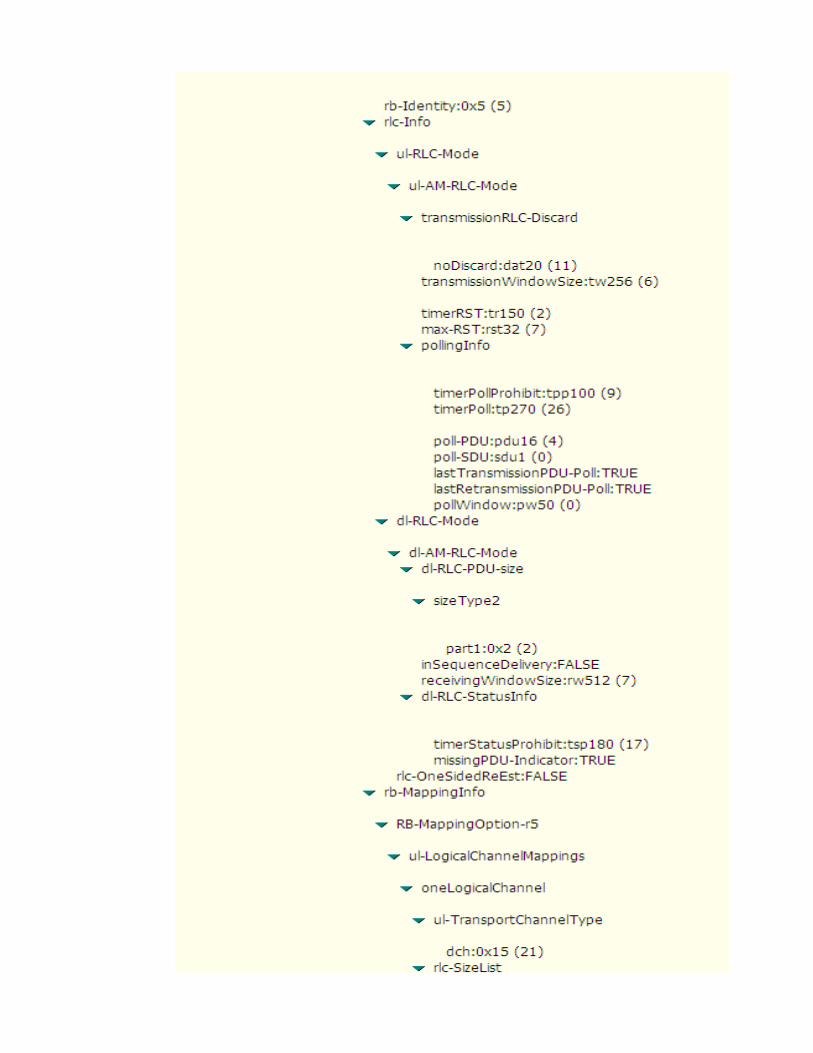


RRC: Radio Bearer Reconfiguration Complete

RRC: Uplink Direct Transfer (SM: Deactivate PDP Context Request)
RANAP: SM: Deactivate PDP Context Request
RANAP: SM: Deactivate PDP Context Accept

RRC: Downlink Direct Transfer (SM: Deactivate PDP Context Accept)
RRC: Radio Bearer Release


RRC: Radio Bearer Release Completed

RRC: Downlink Direct Transfer (CC: RRC Connection Release)
RRC: Uplink Direct Transfer (CC: RRC Connection Release Complete)

RRC: Uplink Direct Transfer (MM: Detach Request)
RANAP: MM: Detach Request

RANAP: MM: Detach Accept
RRC: Downlink Direct Transfer (MM: Detach Accept)

value=hex2dec(5)=5 , hex2dec(2)=2 ,hex2dec(0)=0 --> MCC=520
value=hex2dec(0)=0 , hex2dec(1)=1 --> MNC=01
value=hex2dec(2908)= 10504
value= OriginatingBackgroundCall (PS MOC)
value=(-24+ (33/2))=-7.5 dB
>>"RRC Connection Request Description"
>>"Geographical and UTRAN Entity Identifiers"

value=hex2dec(5)=5 , hex2dec(2)=2 ,hex2dec(0)=0 --> MCC=520
value=hex2dec(0)=0 , hex2dec(1)=1 --> MNC=01
value=hex2dec(2908)= 10504
>>"RRC Connection Setup Description"
>>"Geographical and UTRAN Entity Identifiers"

value=UE capable to support FDD , not TDD
value=UE capable to support GSM
value=Signaling Radio Bearer Information Setup ,RB-1
value=Radio Bearer Mapping

value=Signaling Radio Bearer Information Setup ,RB-2

value=Signaling Radio Bearer Information Setup ,RB-3

value=Signaling Radio Bearer Information Setup ,RB-4

value=BLER Target= -20 dB

value=MaxAllowedULTxPower=24 dBm
value=(-48*2)= -96 dBm (step of 2 dB) Default Constant DPCCH_Power_offset-22 -96-22 -96
Note :DPCCH_Power_offset is configured by RNC and delivered to UE in RRC Connection Setup.
value= use Closed Loop Power Control Algorithm1
value= use long SC on Uplink
value=Spreading Factor 64 (Uplink)
value=Spreading Factor 128 (Downlink)

value=Primary Scrambling code=97
value=Spreading Factor 128 (Downlink)
Cell Identity=RNCid(12bits)+Cellid(16bits)value=0000000010110111011110010010 => RNCid=bin2dec(000000001011)=11 and Cellid=bin2dec(0111011110010010)=30610
>>"RRC Connection Setup Complete Description"

value= not support GSM (Locked UMTS Mode)
value= Chipering Algorithm A5/3
value= UE support Band fdd2100 MHzvalue= UE (Powerclass3) maximum transmitted power =24 dBm
value= support Compressed Mode (CM) uplink and downlink

value= UE support Band fdd1800 MHz

value= not support HSDPA
RANAP: Initial UE Message GMM: (Attach Request)

RRC: Initial Direct Transfer (GMM: Attach Request)
RANAP: MM: Authentication & Ciphering Request

RRC: Downlink Direct Transfer (MM: Authentication & Ciphering Request)
RRC: Uplink Direct Transfer (MM: Authentication & Ciphering Response)
RANAP:MM: Authentication&Ciphering Response

RRC: Security Mode Command

RRC: Security Mode Complete
RANAP: MM: Attach Accept
RRC: Downlink Direct Transfer (MM: Attach Accept)
RRC: Uplink Direct Transfer (MM: Attach Completed)

RANAP: MM: Attach Completed
RRC: Uplink Direct Transfer (SM: Activate PDP Context Request)
RANAP: SM: Activate PDP Context Request

RRC: Radio Bearer Setup >>"Radio Bearer Description"


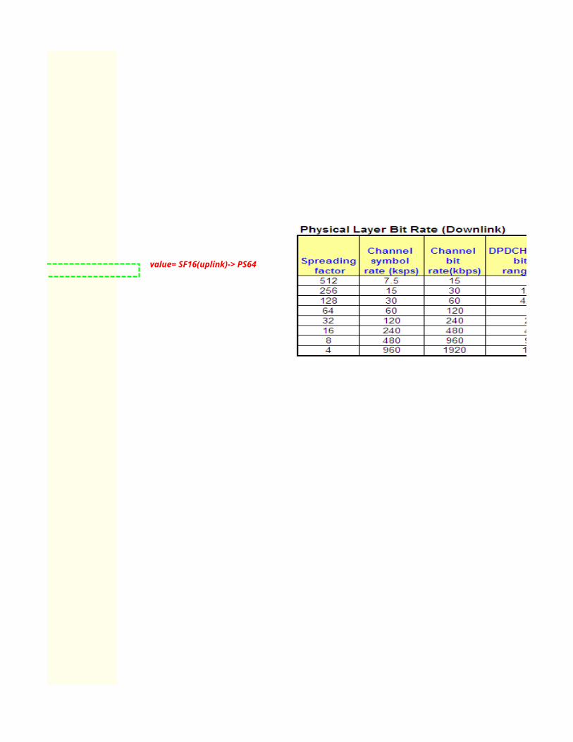
value= SF16(uplink)-> PS64

value=Primary Scrambling code=97
value= SF32(downlink)-> PS64
Cell Identity=RNCid(12bits)+Cellid(16bits)
RRC: Radio Bearer Setup Complete
value=0000000010110111011110010010 => RNCid=bin2dec(000000001011)=11 and Cellid=bin2dec(0111011110010010)=30610

RANAP: SM: Activate PDP Context Accept
RRC: Downlink Direct Transfer (SM: Activate PDP Context Accept)

RRC: Radio Bearer Reconfiguration


value= SF16(uplink)-> PS64

value= SF16(downlink)-> PS128
RRC: Radio Bearer Reconfiguration Complete

RRC: Uplink Direct Transfer (SM: Deactivate PDP Context Request)
RANAP: SM: Deactivate PDP Context Request
RANAP: SM: Deactivate PDP Context Accept

RRC: Downlink Direct Transfer (SM: Deactivate PDP Context Accept)
RRC: Radio Bearer Release


RRC: Radio Bearer Release Completed

RRC: Downlink Direct Transfer (CC: RRC Connection Release)
RRC: Uplink Direct Transfer (CC: RRC Connection Release Complete)

RRC: Uplink Direct Transfer (MM: Detach Request)
RANAP: MM: Detach Request

RANAP: MM: Detach Accept
RRC: Downlink Direct Transfer (MM: Detach Accept)


CPICH_RSCP PCPICH Power UL Interference UL DPCCH Initial Power-80 33 -107 -16-70 33 -107 -26
Note :DPCCH_Power_offset is configured by RNC and delivered to UE in RRC Connection Setup.

Cellid=bin2dec(0111011110010010)=30610


Cellid=bin2dec(0111011110010010)=30610


L3 Messages - PS(HSDPA) Call ProcedureUE NodeB
Start Rx
4.ALCAP: Iub User Plane Setup
RRC Connection Establishment Timing Start Tx
Click to return to main page
1.RRC: RRC Connection Request (RACH)
5.RRC: RRC Connection Setup (FACH)
L1 Synchonization
8.RRC: RRC Connection Setup Completed (DCH)
RRC: Initial Direct Transfer (GMM: Service Request)
RRC: Security Mode Command
RRC: Security Mode Completed
RRC: Uplink Direct Transfer (SM: Activate PDP Context Request)

ALCAP: Iub User Plane Setup
Apply new transport format set
RRC:Measurement Control
PS Session Established
RRC:Measurement Report (e1d)
ALCAP: Iub User Plane Setup
RRC: Radio Bearer Setup
RRC: Radio Bearer Setup Complete
RRC: Downlink Direct Transfer (SM: Activate PDP Context Accept)
RRC: Physical Channel Reconfiguration (DCCH)
RRC:Physical Channel Reconfiguration Complete (DCCH)
RRC: Uplink Direct Transfer (SM: Deactivate PDP Context Request)
RRC: Downlink Direct Transfer (SM: Deactivate PDP Context Accept)

ALCAP: Iub User Plane Setup
RRC: Uplink Direct Transfer (CC: RRC Connection Release Complete)
ALCAP: Iub User Plane Release
RRC: Radio Bearer Release
RRC: Radio Bearer Release Completed
RRC: Downlink Direct Transfer (CC: RRC Connection Release)
RRC: Uplink Direct Transfer (CC: RRC Connection Release Complete)

L3 Messages - PS(HSDPA) Call ProcedureS-RNC
2.NBAP:Radio Link Setup Req
3.NBAP:Radio Link Setup Resp.
4.ALCAP: Iub User Plane Setup
7.NBAP:Synchonization Indicator
1.RRC: RRC Connection Request (RACH)
5.RRC: RRC Connection Setup (FACH)
8.RRC: RRC Connection Setup Completed (DCH)
RRC: Initial Direct Transfer (GMM: Service Request)
RRC: Security Mode Command
RRC: Security Mode Completed
RRC: Uplink Direct Transfer (SM: Activate PDP Context Request)
NBAP: Radio Link Reconfiguration Prepare

ALCAP: Iub User Plane Setup
Apply new transport format set
RRC:Measurement Control
PS Session Established
RRC:Measurement Report (e1d)
ALCAP: Iub User Plane Setup
NBAP: Radio Link Reconfiguration Ready
RRC: Radio Bearer Setup
NBAP: Radio Link Reconfiguration Commit
RRC: Radio Bearer Setup Complete
RRC: Downlink Direct Transfer (SM: Activate PDP Context Accept)
NBAP: Radio Link Reconfiguration Prepare
NBAP: Radio Link Reconfiguration Ready
NBAP: Radio Link Reconfiguration Commit
RRC: Physical Channel Reconfiguration (DCCH)
RRC:Physical Channel Reconfiguration Complete (DCCH)
RRC: Uplink Direct Transfer (SM: Deactivate PDP Context Request)
RRC: Downlink Direct Transfer (SM: Deactivate PDP Context Accept)

ALCAP: Iub User Plane Setup
ALCAP: Iu User Plane Release
RRC: Uplink Direct Transfer (CC: RRC Connection Release Complete)
ALCAP: Iub User Plane Release
NBAP: Radio Link Reconfiguration Prepare
NBAP: Radio Link Reconfiguration Ready
NBAP: Radio Link Reconfiguration Commit
RRC: Radio Bearer Release
RRC: Radio Bearer Release Completed
RRC: Downlink Direct Transfer (CC: RRC Connection Release)
RRC: Uplink Direct Transfer (CC: RRC Connection Release Complete)
NBAP: Radio Link Deletion Request
NBAP: Radio Link Deletion Response

L3 Messages - PS(HSDPA) Call ProcedureCN
RANAP: Security Mode Command
RANAP: Security Mode Complete
RANAP: Common ID(IMSI)
RANAP: RAB Assignment Request
ALCAP : Iu User Plane Setup
RANAP: GMM:Service Request
RANAP: SM: Activate PDP Context Request

RANAP: RAB Assignment Response
PS Session Established
RANAP: SM: Activate PDP Context Accept
RANAP: SM: Deactivate PDP Context Request
RANAP: SM: Deactivate PDP Context Accept
HSDPA's Serving Cell Change
3. Radio Bearer Setup
4. Downlink and Uplink Data Transfer

RANAP: Iu Release Command
ALCAP: Iu User Plane Release
RANAP: Iu Release Complete

RRC connection setup procedure is performed for the UE to set up a signaling connection to the SRNC. RRC connection setup is always initiated by the UE. One UE has a maximum of one RRC connection at a time.
Triggering Conditions : The UE in idle mode intitiates the RRC connection setup procedure when the NAS of the UE requests the establishment of a signaling connection When theSRNC receives an RRC CONNECTION REQUEST message from the UE, the Radio Resource Management (RRM) module of the RNC determines whether to accept or reject the RRCconnection request, based on a specific algorithm. If accepting the request, the RRM module further determines whether to set up the RRC connection on a Dedicated Channel(DCH)or on a Common Channel (CCH),based on a specific RRM algorithm. Typically, an RRC connection is set up on the DCH.
The procedure shown is described as follows:1.The UE sends an RRC CONNECTION REQUEST message to the SRNC through the uplink CCCH(RACH), requesting the establishment of an RRC connection.2.Based on the cause in the RRC connection request and the system resource status, the SRNC determines to set up the RRC connection on a DCH and allocates the RadioNetworkTemporary Identity(RNTI),radio resources, and L1 and L2 resources. Then the SRNC sends a RADIO LINK SETUP REQUEST message to the NodeB, requesting the NodeB toallocate the specific radio link resources required for an RRC connection.3.The NodeB responds with a RADIO LINK SETUP RESPONSE message to the SRNC after successfully preparing the resources.4.The SRNC uses the ALCAP protocol to set up the Iub user plane transport bearer and performs the synchronization between the SRNC and the NodeB. This procedure is optional. Itis required for the ATM-based Iub interface only.5.The SRNC sends an RRC CONNECTION SETUP message to the UE through the downlink CCCH (FACH). The message contains the information about the DCH allocated by the SRNC.6. UE and NodeB initiate L1 Synchronization. NodeB sends NBAP:Synchonization Indicator message to SRNC when the uplink enter "In-Sync" state7. The UE sends an RRC CONNECTION SETUP COMPLETE message to the SRNC through the uplink Dedicated Control Channel (DCCH) that is just set up. The message indicates that the RRC connection setup procedure ends.If the RNC judges that the RRC connection request cannot be set up (for instance, due to insufficient resources), it directly sends an RRC CONNECTION REJECT message to theUE, and indicates the reject reason in the message
>>RRC Procedure Description
The PS Session Setup procedure is performed to set up a PS session
Triggering Conditions: The UE send Activate PDP context request message to RNC. PDP Context Activation is performed when the UE initiates a packet call setup. The UE has the state PacketMobility Management Connected that enables the user to transmitt and receive data while moving within a PLMN. and starts the PDP context activation procedure used to set up and remove avirtual data channel between a terminal connected to a UE and a GGSN. PDP contexts deal with allocation of IP addresses to the UE and Quality of Service, QoS, parameters. A Radio Accessbearer establishes on request of the SGSN in order to realize the air interface connection. At the end the UE has an IP address NSAPI (Network layer Service Access Point Identifier) and a TLLI (Temporary Logical Link Identity) associated to IMSI.
IP addresses can be allocated dynamically or statistically. If allocated dynamically, this significantly reduces the total number of IP addresses required per PLMN. Support of static IP address allocation enables subscribers to provide their own IP addresses. This can be useful when accesing secure networks that use the calling IP address as a form of security check. The support ofQoS enables the operator to differentiate GPRS services.
When dynamic addressing from the home PLMN or the Visitor PLMN is used, it is the responsibility of the GGSN to allocate and release the dynamic PDP address.The procedure shown is described as follows:1. The UE initiates the PS Session by using the Service Request (Service Type=Data) message. After the RR setup completion the UE asks for initial direct transfer to the serving node. The RNC sets-up an SCCP connection with the SGSN and transfers the initial service request (Authentication and ciphering may performed depends on operator's setting)2.The UE sends an Activate PDP Context Request (NSAPI, TI(Teardown Indication), PDP Type, Address, APN (Access Point Name), QoS (Quality of Service) Requested, PDP ConfigurationOptions) message to the SGSN The UE shall use PDP Address to indicate whether it requires the use of a static PDP address or whether it requires the use of a dynamic PDP address.3. The SGSN sends a RAB Assignment Request message to the RNC to establish a RABs4.The RNC establishes the appropriate radio bearer In WCDMA, RAB setup is done by the RAB Assignment procedure5.The RNC returns a RAB Assignment Response message to the SGSN6. The SGSN validates the active PDP Context Request using PDP Type (optional), PDP Address, APN (Access Point Name (optional) provided by the UE and the PDP context subscriptionrecords.The SGSN sends a Create PDP Context Request message to the affected GGSN. Access Point Name shall be the APN Network Identifier of the APN. The GGSN may use Access Point Name to find an external network and optionally to activate a service for this APN7. The GGSN creates a new entry in its PDP context table and generates a Charging Id. The new entry allows the GGSN to route PDP PDUs (Policy Decision Point Protocol Data Units) between the SGSN and the external PDP network, and to start charging 8.The SGSN inserts the Network layer Service Access Point Identifier, NSAPI along with the GGSN address in its PDP context and informs the UE via RNC that the PDP Context is Accepted. TheSGSN selects Radio Priority and Packet flow Id based on QoS Negotiated, and returns an Activate PDP Context Accept message to the UE. The SGSN is now able to route PDP PDUs between theGGSN and the UE and to start charging
The Radio Bearer Setup procedure shown is described as follows:1.The CN sends an RAB ASSIGNMENT REQUEST message to the SRNC to initiate the RAB setup procedure.2.(Optional; applicable to the ATM-based Iu-CS interface only) The SRNC maps the Quality of Service (QoS) parameters for the RAB to the AAL2 link characteristic parameters and radio resourcecharacteristic parameters. Based on the AAL2 link characteristic parameters,the ALCAP on the Iu interface initiates an Iu user plane transport bearer setup procedure.3.The SRNC sends a RADIO LINK RECONFIGURATION PREPARE message to the NodeB, requesting the NodeB to prepare for adding one or more DCHs to the existing radio links for carrying theRAB.4.The NodeB allocates the associated resources and then sends a RADIO LINKRECONFIGURATION READY message to the SRNC.5.(Optional; required for the ATM-based Iub interface only) The Iub ALCAP at the SRNC initiates an Iub user plane transport bearer setup procedure. The NodeB and the SRNC perform synchronization by exchanging uplink and downlink synchronization frames in the DCH frame protocol.6.The SRNC sends a RADIO BEARER SETUP message to the UE.7.The SRNC sends a RADIO LINK RECONFIGURATION COMMIT message to theNodeB.8.After performing the radio bearer setup, the UE sends a RADIO BEARER SETUP COMPLETE message to the SRNC.9.The SRNC sends an RAB ASSIGNMENT RESPONSE message to the CN. The RAB isset up.The procedure when RAB Setup Failure shown is described as follows:1.The CN sends an RAB ASSIGNMENT REQUEST message to the SRNC to initiate the RAB setup procedure.2.The SRNC sends an RAB ASSIGNMENT RESPONSE message to the CN. The message indicates the ID of the RAB that fails to be set up and the reason for the failure.
1.RRC Connection Establishment
2.PS Session Setup

The PS Session Setup procedure is performed to set up a PS session
Triggering Conditions: The UE send Activate PDP context request message to RNC. PDP Context Activation is performed when the UE initiates a packet call setup. The UE has the state PacketMobility Management Connected that enables the user to transmitt and receive data while moving within a PLMN. and starts the PDP context activation procedure used to set up and remove avirtual data channel between a terminal connected to a UE and a GGSN. PDP contexts deal with allocation of IP addresses to the UE and Quality of Service, QoS, parameters. A Radio Accessbearer establishes on request of the SGSN in order to realize the air interface connection. At the end the UE has an IP address NSAPI (Network layer Service Access Point Identifier) and a TLLI (Temporary Logical Link Identity) associated to IMSI.
IP addresses can be allocated dynamically or statistically. If allocated dynamically, this significantly reduces the total number of IP addresses required per PLMN. Support of static IP address allocation enables subscribers to provide their own IP addresses. This can be useful when accesing secure networks that use the calling IP address as a form of security check. The support ofQoS enables the operator to differentiate GPRS services.
When dynamic addressing from the home PLMN or the Visitor PLMN is used, it is the responsibility of the GGSN to allocate and release the dynamic PDP address.The procedure shown is described as follows:1. The UE initiates the PS Session by using the Service Request (Service Type=Data) message. After the RR setup completion the UE asks for initial direct transfer to the serving node. The RNC sets-up an SCCP connection with the SGSN and transfers the initial service request (Authentication and ciphering may performed depends on operator's setting)2.The UE sends an Activate PDP Context Request (NSAPI, TI(Teardown Indication), PDP Type, Address, APN (Access Point Name), QoS (Quality of Service) Requested, PDP ConfigurationOptions) message to the SGSN The UE shall use PDP Address to indicate whether it requires the use of a static PDP address or whether it requires the use of a dynamic PDP address.3. The SGSN sends a RAB Assignment Request message to the RNC to establish a RABs4.The RNC establishes the appropriate radio bearer In WCDMA, RAB setup is done by the RAB Assignment procedure5.The RNC returns a RAB Assignment Response message to the SGSN6. The SGSN validates the active PDP Context Request using PDP Type (optional), PDP Address, APN (Access Point Name (optional) provided by the UE and the PDP context subscriptionrecords.The SGSN sends a Create PDP Context Request message to the affected GGSN. Access Point Name shall be the APN Network Identifier of the APN. The GGSN may use Access Point Name to find an external network and optionally to activate a service for this APN7. The GGSN creates a new entry in its PDP context table and generates a Charging Id. The new entry allows the GGSN to route PDP PDUs (Policy Decision Point Protocol Data Units) between the SGSN and the external PDP network, and to start charging 8.The SGSN inserts the Network layer Service Access Point Identifier, NSAPI along with the GGSN address in its PDP context and informs the UE via RNC that the PDP Context is Accepted. TheSGSN selects Radio Priority and Packet flow Id based on QoS Negotiated, and returns an Activate PDP Context Accept message to the UE. The SGSN is now able to route PDP PDUs between theGGSN and the UE and to start charging
The Radio Bearer Setup procedure shown is described as follows:1.The CN sends an RAB ASSIGNMENT REQUEST message to the SRNC to initiate the RAB setup procedure.2.(Optional; applicable to the ATM-based Iu-CS interface only) The SRNC maps the Quality of Service (QoS) parameters for the RAB to the AAL2 link characteristic parameters and radio resourcecharacteristic parameters. Based on the AAL2 link characteristic parameters,the ALCAP on the Iu interface initiates an Iu user plane transport bearer setup procedure.3.The SRNC sends a RADIO LINK RECONFIGURATION PREPARE message to the NodeB, requesting the NodeB to prepare for adding one or more DCHs to the existing radio links for carrying theRAB.4.The NodeB allocates the associated resources and then sends a RADIO LINKRECONFIGURATION READY message to the SRNC.5.(Optional; required for the ATM-based Iub interface only) The Iub ALCAP at the SRNC initiates an Iub user plane transport bearer setup procedure. The NodeB and the SRNC perform synchronization by exchanging uplink and downlink synchronization frames in the DCH frame protocol.6.The SRNC sends a RADIO BEARER SETUP message to the UE.7.The SRNC sends a RADIO LINK RECONFIGURATION COMMIT message to theNodeB.8.After performing the radio bearer setup, the UE sends a RADIO BEARER SETUP COMPLETE message to the SRNC.9.The SRNC sends an RAB ASSIGNMENT RESPONSE message to the CN. The RAB isset up.The procedure when RAB Setup Failure shown is described as follows:1.The CN sends an RAB ASSIGNMENT REQUEST message to the SRNC to initiate the RAB setup procedure.2.The SRNC sends an RAB ASSIGNMENT RESPONSE message to the CN. The message indicates the ID of the RAB that fails to be set up and the reason for the failure.
The PS session release procedure
Triggering Conditions : The UE send Deactivate PDP context request message to RNC. A PDP Context Deactivation is performed when the UE terminates a packet call. Before the deactivation,the UE has the state Active. After the PDP Context deactivation procedure the state becomes Packet Mobility Management Connected.The RAB will be released if there are no otherPDP contexts activated.PDP Deactivation may be initiated by a:UE procedure,SGSN procedure,GGSN procedure
The procedure shown is described as follows:1.The UE sends a Deactivate PDP Context Request (TI, Teardown Indication) message to the SGSN via the RNC2.The SGSN sends a Delete PDP Context Request (TEID, NSAPI, Teardown Indication) message to the GGSN. If Teardown Indication was included by the UE in the Deactivate PDP Context Request message, then the SGSN deactivates all PDP contexts associated with this PDP address by including Teardown Indication in the Delete PDP Context Request message3.The GGSN removes the PDP context(s) and returns a delete PDP Context Response (TEID) message to the SGSN. The Delete PDP Context messages are sent over the backbone network4.The SGSN returns a Deactivate PDP Context Accept (TI) message to the UE via the RNC5. In Iu mode, radio access bearer release is done by the RAB Assignment procedure
The RRC Connection Release procedure is performed to release the signaling connection and all radio bearers between UE and the UTRAN
Triggering Conditions: After a n RAB is released,the SRNC judges whether the RRC connection carries any other RAB or the UE. If judging that the RRC connection does not carry other RABof the UE,the SRNC initiates an RRC connection release procedure.
The procedure shown is described as follows: based on the resouce occupied by the RRC connection,there are two types of RRC connection release procedure: release of an RRC connection from DCH and release of an RRC connection from CCH (If an RRC connection needs to be released after a successful outgoing call,, the RRC connection on the DCH is released and if a radio bearers fails to be setup ,the RRC connection on the CCH is released)
1.The SRNC sends an RRC CONNECTION RELEASE message to the UE through the DCCH. (NOTE: The SRNC may send the RRC CONNECTION RELEASE message several times to increase the probability of proper reception of the message by the UE. The RRC SNs of these messages are the same. The number of retransmissions and the transmission intervals are determined by the SRNC. If the SRNC does not receive an RRC CONNECTION RELEASE COMPLETE message from the UE after sending the RRC CONNECTION RELEASE message for four times, the SRNC judges that the UE has released the RRC connection.)
2.The UE sends an RRC CONNECTION RELEASE COMPLETE message to the SRNC.3.The SRNC sends a RADIO LINK DELETION REQUEST message to the NodeB,requesting the NodeB to delete the radio link resources in the NodeB.4.After releasing the resources, the NodeB sends a RADIO LINK DELETION RESPONSE message to the SRNC.5.(Optional; required for the ATM-based Iub interface only) The SRNC uses the ALCAP protocol to initiate an Iub user plane transport bearer release procedure. Then, the RRC connection releaseprocedure ends.
HSDPA's Serving Cell Change
3. Radio Bearer Setup
4. Downlink and Uplink Data Transfer

The RRC Connection Release procedure is performed to release the signaling connection and all radio bearers between UE and the UTRAN
Triggering Conditions: After a n RAB is released,the SRNC judges whether the RRC connection carries any other RAB or the UE. If judging that the RRC connection does not carry other RABof the UE,the SRNC initiates an RRC connection release procedure.
The procedure shown is described as follows: based on the resouce occupied by the RRC connection,there are two types of RRC connection release procedure: release of an RRC connection from DCH and release of an RRC connection from CCH (If an RRC connection needs to be released after a successful outgoing call,, the RRC connection on the DCH is released and if a radio bearers fails to be setup ,the RRC connection on the CCH is released)
1.The SRNC sends an RRC CONNECTION RELEASE message to the UE through the DCCH. (NOTE: The SRNC may send the RRC CONNECTION RELEASE message several times to increase the probability of proper reception of the message by the UE. The RRC SNs of these messages are the same. The number of retransmissions and the transmission intervals are determined by the SRNC. If the SRNC does not receive an RRC CONNECTION RELEASE COMPLETE message from the UE after sending the RRC CONNECTION RELEASE message for four times, the SRNC judges that the UE has released the RRC connection.)
2.The UE sends an RRC CONNECTION RELEASE COMPLETE message to the SRNC.3.The SRNC sends a RADIO LINK DELETION REQUEST message to the NodeB,requesting the NodeB to delete the radio link resources in the NodeB.4.After releasing the resources, the NodeB sends a RADIO LINK DELETION RESPONSE message to the SRNC.5.(Optional; required for the ATM-based Iub interface only) The SRNC uses the ALCAP protocol to initiate an Iub user plane transport bearer release procedure. Then, the RRC connection releaseprocedure ends.
5.PS Session Release
6.RRC Connection Release

RRC connection setup procedure is performed for the UE to set up a signaling connection to the SRNC. RRC connection setup is always initiated by the UE. One UE has amaximum of one RRC connection at a time.
Triggering Conditions : The UE in idle mode intitiates the RRC connection setup procedure when the NAS of the UE requests the establishment of a signaling connection
SRNC receives an RRC CONNECTION REQUEST message from the UE, the Radio Resource Management (RRM) module of the RNC determines whether to accept or reject the RRCconnection request, based on a specific algorithm. If accepting the request, the RRM module further determines whether to set up the RRC connection on a Dedicated Channel(DCH)or on a Common Channel (CCH),based on a specific RRM algorithm. Typically, an RRC connection is set up on the DCH.
The procedure shown is described as follows:The UE sends an RRC CONNECTION REQUEST message to the SRNC through the uplink CCCH(RACH), requesting the establishment of an RRC connection.Based on the cause in the RRC connection request and the system resource status, the SRNC determines to set up the RRC connection on a DCH and allocates the Radio
NetworkTemporary Identity(RNTI),radio resources, and L1 and L2 resources. Then the SRNC sends a RADIO LINK SETUP REQUEST message to the NodeB, requesting the NodeB toallocate the specific radio link resources required for an RRC connection.
The NodeB responds with a RADIO LINK SETUP RESPONSE message to the SRNC after successfully preparing the resources..The SRNC uses the ALCAP protocol to set up the Iub user plane transport bearer and performs the synchronization between the SRNC and the NodeB. This procedure is
is required for the ATM-based Iub interface only.The SRNC sends an RRC CONNECTION SETUP message to the UE through the downlink CCCH (FACH). The message contains the information about the DCH allocated by the SRNC. UE and NodeB initiate L1 Synchronization. NodeB sends NBAP:Synchonization Indicator message to SRNC when the uplink enter "In-Sync" state
. The UE sends an RRC CONNECTION SETUP COMPLETE message to the SRNC through the uplink Dedicated Control Channel (DCCH) that is just set up. The message indicates that the RRC connection setup procedure ends.If the RNC judges that the RRC connection request cannot be set up (for instance, due to insufficient resources), it directly sends an RRC CONNECTION REJECT message totheUE, and indicates the reject reason in the messageThe PS Session Setup procedure is performed to set up a PS session
The UE send Activate PDP context request message to RNC. PDP Context Activation is performed when the UE initiates a packet call setup. The UE has
Mobility Management Connected that enables the user to transmitt and receive data while moving within a PLMN. and starts the PDP context activation procedure used to set
virtual data channel between a terminal connected to a UE and a GGSN. PDP contexts deal with allocation of IP addresses to the UE and Quality of Service, QoS, parameters.
bearer establishes on request of the SGSN in order to realize the air interface connection. At the end the UE has an IP address NSAPI (Network layer Service Access Point Identifier) and a TLLI (Temporary Logical Link Identity) associated to IMSI.
IP addresses can be allocated dynamically or statistically. If allocated dynamically, this significantly reduces the total number of IP addresses required per PLMN. Support of static IP address allocation enables subscribers to provide their own IP addresses. This can be useful when accesing secure networks that use the calling IP address as a form of security check. The support ofQoS enables the operator to differentiate GPRS services.
When dynamic addressing from the home PLMN or the Visitor PLMN is used, it is the responsibility of the GGSN to allocate and release the dynamic PDP address.The procedure shown is described as follows:
The UE initiates the PS Session by using the Service Request (Service Type=Data) message. After the RR setup completion the UE asks for initial direct transfer to the
sets-up an SCCP connection with the SGSN and transfers the initial service request (Authentication and ciphering may performed depends on operator's setting)The UE sends an Activate PDP Context Request (NSAPI, TI(Teardown Indication), PDP Type, Address, APN (Access Point Name), QoS (Quality of Service) Requested, PDP
Options) message to the SGSN The UE shall use PDP Address to indicate whether it requires the use of a static PDP address or whether it requires the use of a dynamic PDP
The SGSN sends a RAB Assignment Request message to the RNC to establish a RABs.The RNC establishes the appropriate radio bearer In WCDMA, RAB setup is done by the RAB Assignment procedure.The RNC returns a RAB Assignment Response message to the SGSN The SGSN validates the active PDP Context Request using PDP Type (optional), PDP Address, APN (Access Point Name (optional) provided by the UE and the PDP context
records.The SGSN sends a Create PDP Context Request message to the affected GGSN. Access Point Name shall be the APN Network Identifier of the APN. The GGSN may use Access
Name to find an external network and optionally to activate a service for this APN The GGSN creates a new entry in its PDP context table and generates a Charging Id. The new entry allows the GGSN to route PDP PDUs (Policy Decision Point Protocol Data
the SGSN and the external PDP network, and to start charging The SGSN inserts the Network layer Service Access Point Identifier, NSAPI along with the GGSN address in its PDP context and informs the UE via RNC that the PDP Context
SGSN selects Radio Priority and Packet flow Id based on QoS Negotiated, and returns an Activate PDP Context Accept message to the UE. The SGSN is now able to route PDP
theGGSN and the UE and to start charging
The Radio Bearer Setup procedure shown is described as follows:.The CN sends an RAB ASSIGNMENT REQUEST message to the SRNC to initiate the RAB setup procedure.(Optional; applicable to the ATM-based Iu-CS interface only) The SRNC maps the Quality of Service (QoS) parameters for the RAB to the AAL2 link characteristic parameters
characteristic parameters. Based on the AAL2 link characteristic parameters,the ALCAP on the Iu interface initiates an Iu user plane transport bearer setup procedure.The SRNC sends a RADIO LINK RECONFIGURATION PREPARE message to the NodeB, requesting the NodeB to prepare for adding one or more DCHs to the existing radio links for
The NodeB allocates the associated resources and then sends a RADIO LINKRECONFIGURATION READY message to the SRNC.(Optional; required for the ATM-based Iub interface only) The Iub ALCAP at the SRNC initiates an Iub user plane transport bearer setup procedure. The NodeB and the SRNC
synchronization by exchanging uplink and downlink synchronization frames in the DCH frame protocol.The SRNC sends a RADIO BEARER SETUP message to the UE.
.The SRNC sends a RADIO LINK RECONFIGURATION COMMIT message to theNodeB.
.After performing the radio bearer setup, the UE sends a RADIO BEARER SETUP COMPLETE message to the SRNC.
.The SRNC sends an RAB ASSIGNMENT RESPONSE message to the CN. The RAB isset up.The procedure when RAB Setup Failure shown is described as follows:.The CN sends an RAB ASSIGNMENT REQUEST message to the SRNC to initiate the RAB setup procedure..The SRNC sends an RAB ASSIGNMENT RESPONSE message to the CN. The message indicates the ID of the RAB that fails to be set up and the reason for the failure.
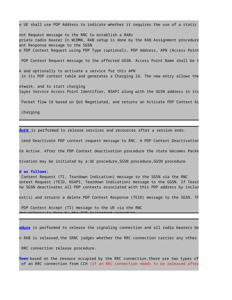
The PS Session Setup procedure is performed to set up a PS session
The UE send Activate PDP context request message to RNC. PDP Context Activation is performed when the UE initiates a packet call setup. The UE has
Mobility Management Connected that enables the user to transmitt and receive data while moving within a PLMN. and starts the PDP context activation procedure used to set
virtual data channel between a terminal connected to a UE and a GGSN. PDP contexts deal with allocation of IP addresses to the UE and Quality of Service, QoS, parameters.
bearer establishes on request of the SGSN in order to realize the air interface connection. At the end the UE has an IP address NSAPI (Network layer Service Access Point Identifier) and a TLLI (Temporary Logical Link Identity) associated to IMSI.
IP addresses can be allocated dynamically or statistically. If allocated dynamically, this significantly reduces the total number of IP addresses required per PLMN. Support of static IP address allocation enables subscribers to provide their own IP addresses. This can be useful when accesing secure networks that use the calling IP address as a form of security check. The support ofQoS enables the operator to differentiate GPRS services.
When dynamic addressing from the home PLMN or the Visitor PLMN is used, it is the responsibility of the GGSN to allocate and release the dynamic PDP address.The procedure shown is described as follows:
The UE initiates the PS Session by using the Service Request (Service Type=Data) message. After the RR setup completion the UE asks for initial direct transfer to the
sets-up an SCCP connection with the SGSN and transfers the initial service request (Authentication and ciphering may performed depends on operator's setting)The UE sends an Activate PDP Context Request (NSAPI, TI(Teardown Indication), PDP Type, Address, APN (Access Point Name), QoS (Quality of Service) Requested, PDP
Options) message to the SGSN The UE shall use PDP Address to indicate whether it requires the use of a static PDP address or whether it requires the use of a dynamic PDP
The SGSN sends a RAB Assignment Request message to the RNC to establish a RABs.The RNC establishes the appropriate radio bearer In WCDMA, RAB setup is done by the RAB Assignment procedure.The RNC returns a RAB Assignment Response message to the SGSN The SGSN validates the active PDP Context Request using PDP Type (optional), PDP Address, APN (Access Point Name (optional) provided by the UE and the PDP context
records.The SGSN sends a Create PDP Context Request message to the affected GGSN. Access Point Name shall be the APN Network Identifier of the APN. The GGSN may use Access
Name to find an external network and optionally to activate a service for this APN The GGSN creates a new entry in its PDP context table and generates a Charging Id. The new entry allows the GGSN to route PDP PDUs (Policy Decision Point Protocol Data
the SGSN and the external PDP network, and to start charging The SGSN inserts the Network layer Service Access Point Identifier, NSAPI along with the GGSN address in its PDP context and informs the UE via RNC that the PDP Context
SGSN selects Radio Priority and Packet flow Id based on QoS Negotiated, and returns an Activate PDP Context Accept message to the UE. The SGSN is now able to route PDP
theGGSN and the UE and to start charging
The Radio Bearer Setup procedure shown is described as follows:.The CN sends an RAB ASSIGNMENT REQUEST message to the SRNC to initiate the RAB setup procedure.(Optional; applicable to the ATM-based Iu-CS interface only) The SRNC maps the Quality of Service (QoS) parameters for the RAB to the AAL2 link characteristic parameters
characteristic parameters. Based on the AAL2 link characteristic parameters,the ALCAP on the Iu interface initiates an Iu user plane transport bearer setup procedure.The SRNC sends a RADIO LINK RECONFIGURATION PREPARE message to the NodeB, requesting the NodeB to prepare for adding one or more DCHs to the existing radio links for
The NodeB allocates the associated resources and then sends a RADIO LINKRECONFIGURATION READY message to the SRNC.(Optional; required for the ATM-based Iub interface only) The Iub ALCAP at the SRNC initiates an Iub user plane transport bearer setup procedure. The NodeB and the SRNC
synchronization by exchanging uplink and downlink synchronization frames in the DCH frame protocol.The SRNC sends a RADIO BEARER SETUP message to the UE.
.The SRNC sends a RADIO LINK RECONFIGURATION COMMIT message to theNodeB.
.After performing the radio bearer setup, the UE sends a RADIO BEARER SETUP COMPLETE message to the SRNC.
.The SRNC sends an RAB ASSIGNMENT RESPONSE message to the CN. The RAB isset up.The procedure when RAB Setup Failure shown is described as follows:.The CN sends an RAB ASSIGNMENT REQUEST message to the SRNC to initiate the RAB setup procedure..The SRNC sends an RAB ASSIGNMENT RESPONSE message to the CN. The message indicates the ID of the RAB that fails to be set up and the reason for the failure.
The PS session release procedure is performed to release services and resources after a session ends.
: The UE send Deactivate PDP context request message to RNC. A PDP Context Deactivation is performed when the UE terminates a packet call. Before
deactivation,the UE has the state Active. After the PDP Context deactivation procedure the state becomes Packet Mobility Management Connected.The RAB will be released if
PDP contexts activated.PDP Deactivation may be initiated by a:UE procedure,SGSN procedure,GGSN procedure
The procedure shown is described as follows:.The UE sends a Deactivate PDP Context Request (TI, Teardown Indication) message to the SGSN via the RNC.The SGSN sends a Delete PDP Context Request (TEID, NSAPI, Teardown Indication) message to the GGSN. If Teardown Indication was included by the UE in the Deactivate PDP
Context Request message, then the SGSN deactivates all PDP contexts associated with this PDP address by including Teardown Indication in the Delete PDP Context Request
.The GGSN removes the PDP context(s) and returns a delete PDP Context Response (TEID) message to the SGSN. The Delete PDP Context messages are sent over the backbone
.The SGSN returns a Deactivate PDP Context Accept (TI) message to the UE via the RNC In Iu mode, radio access bearer release is done by the RAB Assignment procedure
The RRC Connection Release procedure is performed to release the signaling connection and all radio bearers between UE and the UTRAN
Triggering Conditions: After a n RAB is released,the SRNC judges whether the RRC connection carries any other RAB or the UE. If judging that the RRC connection does not
of the UE,the SRNC initiates an RRC connection release procedure.
The procedure shown is described as follows: based on the resouce occupied by the RRC connection,there are two types of RRC connection release procedure: release of an RRC connection from DCH and release of an RRC connection from CCH (If an RRC connection needs to be released after a successful outgoing call,, the RRC connection on the DCH
a radio bearers fails to be setup ,the RRC connection on the CCH is released)
1.The SRNC sends an RRC CONNECTION RELEASE message to the UE through the DCCH. The SRNC may send the RRC CONNECTION RELEASE message several times to increase the probability of proper reception of the message by the UE. The RRC SNs of these
messages are the same. The number of retransmissions and the transmission intervals are determined by the SRNC. If the SRNC does not receive an RRC CONNECTION RELEASE COMPLETE message from the UE after sending the RRC CONNECTION RELEASE message for four times, the SRNC judges that the UE has released the RRC connection.)
2.The UE sends an RRC CONNECTION RELEASE COMPLETE message to the SRNC.3.The SRNC sends a RADIO LINK DELETION REQUEST message to the NodeB,requesting the NodeB to delete the radio link resources in the NodeB.4.After releasing the resources, the NodeB sends a RADIO LINK DELETION RESPONSE message to the SRNC.5.(Optional; required for the ATM-based Iub interface only) The SRNC uses the ALCAP protocol to initiate an Iub user plane transport bearer release procedure. Then, the

is performed for the UE to set up a signaling connection to the SRNC. RRC connection setup is always initiated by the UE. One UE has a
The UE in idle mode intitiates the RRC connection setup procedure when the NAS of the UE requests the establishment of a signaling connection
SRNC receives an RRC CONNECTION REQUEST message from the UE, the Radio Resource Management (RRM) module of the RNC determines whether to accept or reject the RRCconnection request, based on a specific algorithm. If accepting the request, the RRM module further determines whether to set up the RRC connection on a Dedicated Channel(DCH)or on a Common Channel (CCH),based on a specific RRM algorithm. Typically, an RRC connection is set up on the DCH.
The UE sends an RRC CONNECTION REQUEST message to the SRNC through the uplink CCCH(RACH), requesting the establishment of an RRC connection.Based on the cause in the RRC connection request and the system resource status, the SRNC determines to set up the RRC connection on a DCH and allocates the Radio
NetworkTemporary Identity(RNTI),radio resources, and L1 and L2 resources. Then the SRNC sends a RADIO LINK SETUP REQUEST message to the NodeB, requesting the NodeB to
The NodeB responds with a RADIO LINK SETUP RESPONSE message to the SRNC after successfully preparing the resources..The SRNC uses the ALCAP protocol to set up the Iub user plane transport bearer and performs the synchronization between the SRNC and the NodeB. This procedure is
The SRNC sends an RRC CONNECTION SETUP message to the UE through the downlink CCCH (FACH). The message contains the information about the DCH allocated by the SRNC. UE and NodeB initiate L1 Synchronization. NodeB sends NBAP:Synchonization Indicator message to SRNC when the uplink enter "In-Sync" state. The UE sends an RRC CONNECTION SETUP COMPLETE message to the SRNC through the uplink Dedicated Control Channel (DCCH) that is just set up. The message
If the RNC judges that the RRC connection request cannot be set up (for instance, due to insufficient resources), it directly sends an RRC CONNECTION REJECT message to
The UE send Activate PDP context request message to RNC. PDP Context Activation is performed when the UE initiates a packet call setup. The UE has
Mobility Management Connected that enables the user to transmitt and receive data while moving within a PLMN. and starts the PDP context activation procedure used to set
virtual data channel between a terminal connected to a UE and a GGSN. PDP contexts deal with allocation of IP addresses to the UE and Quality of Service, QoS, parameters.
bearer establishes on request of the SGSN in order to realize the air interface connection. At the end the UE has an IP address NSAPI (Network layer Service Access Point
IP addresses can be allocated dynamically or statistically. If allocated dynamically, this significantly reduces the total number of IP addresses required per PLMN. Support of static IP address allocation enables subscribers to provide their own IP addresses. This can be useful when accesing secure networks that use the calling IP
When dynamic addressing from the home PLMN or the Visitor PLMN is used, it is the responsibility of the GGSN to allocate and release the dynamic PDP address.
The UE initiates the PS Session by using the Service Request (Service Type=Data) message. After the RR setup completion the UE asks for initial direct transfer to the
sets-up an SCCP connection with the SGSN and transfers the initial service request (Authentication and ciphering may performed depends on operator's setting)The UE sends an Activate PDP Context Request (NSAPI, TI(Teardown Indication), PDP Type, Address, APN (Access Point Name), QoS (Quality of Service) Requested, PDP
Options) message to the SGSN The UE shall use PDP Address to indicate whether it requires the use of a static PDP address or whether it requires the use of a dynamic PDP
.The RNC establishes the appropriate radio bearer In WCDMA, RAB setup is done by the RAB Assignment procedure
The SGSN validates the active PDP Context Request using PDP Type (optional), PDP Address, APN (Access Point Name (optional) provided by the UE and the PDP context
records.The SGSN sends a Create PDP Context Request message to the affected GGSN. Access Point Name shall be the APN Network Identifier of the APN. The GGSN may use Access
The GGSN creates a new entry in its PDP context table and generates a Charging Id. The new entry allows the GGSN to route PDP PDUs (Policy Decision Point Protocol Data
The SGSN inserts the Network layer Service Access Point Identifier, NSAPI along with the GGSN address in its PDP context and informs the UE via RNC that the PDP Context
SGSN selects Radio Priority and Packet flow Id based on QoS Negotiated, and returns an Activate PDP Context Accept message to the UE. The SGSN is now able to route PDP
(Optional; applicable to the ATM-based Iu-CS interface only) The SRNC maps the Quality of Service (QoS) parameters for the RAB to the AAL2 link characteristic parameters
characteristic parameters. Based on the AAL2 link characteristic parameters,the ALCAP on the Iu interface initiates an Iu user plane transport bearer setup procedure.The SRNC sends a RADIO LINK RECONFIGURATION PREPARE message to the NodeB, requesting the NodeB to prepare for adding one or more DCHs to the existing radio links for
The NodeB allocates the associated resources and then sends a RADIO LINKRECONFIGURATION READY message to the SRNC.(Optional; required for the ATM-based Iub interface only) The Iub ALCAP at the SRNC initiates an Iub user plane transport bearer setup procedure. The NodeB and the SRNC
.After performing the radio bearer setup, the UE sends a RADIO BEARER SETUP COMPLETE message to the SRNC.
.The SRNC sends an RAB ASSIGNMENT RESPONSE message to the CN. The message indicates the ID of the RAB that fails to be set up and the reason for the failure.
is performed to release services and resources after a session ends.
The UE send Deactivate PDP context request message to RNC. A PDP Context Deactivation is performed when the UE terminates a packet call. Before
deactivation,the UE has the state Active. After the PDP Context deactivation procedure the state becomes Packet Mobility Management Connected.The RAB will be released if
PDP contexts activated.PDP Deactivation may be initiated by a:UE procedure,SGSN procedure,GGSN procedure
.The UE sends a Deactivate PDP Context Request (TI, Teardown Indication) message to the SGSN via the RNC
.The SGSN sends a Delete PDP Context Request (TEID, NSAPI, Teardown Indication) message to the GGSN. If Teardown Indication was included by the UE in the Deactivate PDP Context Request message, then the SGSN deactivates all PDP contexts associated with this PDP address by including Teardown Indication in the Delete PDP Context Request
.The GGSN removes the PDP context(s) and returns a delete PDP Context Response (TEID) message to the SGSN. The Delete PDP Context messages are sent over the backbone
is performed to release the signaling connection and all radio bearers between UE and the UTRAN
After a n RAB is released,the SRNC judges whether the RRC connection carries any other RAB or the UE. If judging that the RRC connection does not
based on the resouce occupied by the RRC connection,there are two types of RRC connection release procedure: release of an RRC (If an RRC connection needs to be released after a successful outgoing call,, the RRC connection on the DCH
The SRNC may send the RRC CONNECTION RELEASE message several times to increase the probability of proper reception of the message by the UE. The RRC SNs of these messages are the same. The number of retransmissions and the transmission intervals are determined by the SRNC. If the SRNC does not receive an RRC CONNECTION RELEASE
, the SRNC judges that the UE has released the RRC connection.)
3.The SRNC sends a RADIO LINK DELETION REQUEST message to the NodeB,requesting the NodeB to delete the radio link resources in the NodeB.
5.(Optional; required for the ATM-based Iub interface only) The SRNC uses the ALCAP protocol to initiate an Iub user plane transport bearer release procedure. Then, the

RRC:RRC Connection Request (RACH)Click to return to main page

RRC:RRC Connection Setup (FACH)


RRC:RRC Connection Setup Complete (DCCH)

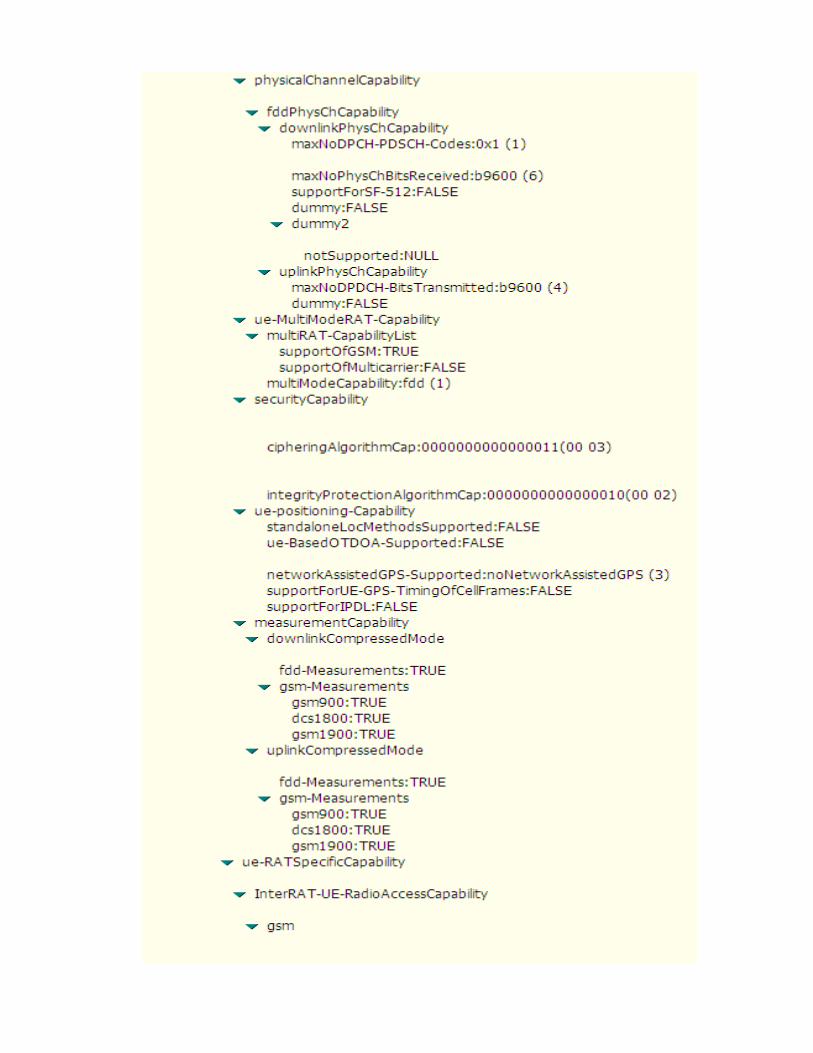


RRC: Initial Direct Transfer (GMM: Service Request)
RANAP: GMM:Service Request

RRC: Security Mode Command

RRC: Security Mode Complete
RRC: Uplink Direct Transfer (SM: Activate PDP Context Request)
RANAP: SM: Activate PDP Context Request

RRC: Radio Bearer Setup


RRC: Radio Bearer Setup Complete

RANAP: SM: Activate PDP Context Accept
RRC: Downlink Direct Transfer (SM: Activate PDP Context Accept)

RRC: Physical Channel Reconfiguration (DCCH)


RRC:Physical Channel Reconfiguration Complete (DCCH)
RRC: Uplink Direct Transfer (SM: Deactivate PDP Context Request)

RANAP: SM: Deactivate PDP Context Request
RANAP: SM: Deactivate PDP Context Accept
RRC: Downlink Direct Transfer (SM: Deactivate PDP Context Accept)
RRC: Radio Bearer Release


RRC: Radio Bearer Release Completed

RRC: Downlink Direct Transfer (CC: RRC Connection Release)
RRC: Uplink Direct Transfer (CC: RRC Connection Release Complete)


value=hex2dec(4)=4 , hex2dec(1)=1 ,hex2dec(3)=3 --> MCC=413
value=hex2dec(0)=0 , hex2dec(1)=1 --> MNC=01
value=hex2dec(7594)= 30100
value= OriginatingBackgroundCall (PS MOC)
value=(-24+ (37/2))=-5.5 dB
>>"RRC Connection Request Description"
>>"Geographical and UTRAN Entity Identifiers"

value= HSDPA Release5
value=hex2dec(4)=4 , hex2dec(1)=1 ,hex2dec(3)=3 --> MCC=413
value=hex2dec(0)=0 , hex2dec(1)=1 --> MNC=01
value=hex2dec(7594)= 30100
>>"RRC Connection Setup Description"
>>"Geographical and UTRAN Entity Identifiers"

value=UE capable to support FDD , not TDD
value=UE capable to support GSM
value=Signaling Radio Bearer Information Setup ,RB-1
value=Radio Bearer Mapping

value=Signaling Radio Bearer Information Setup ,RB-2

value=Signaling Radio Bearer Information Setup ,RB-3

value=Signaling Radio Bearer Information Setup ,RB-4

value=BLER Target= -20 dB

value=MaxAllowedULTxPower=24 dBm
value=(-48*2)= -96 dBm (step of 2 dB)Default Constant
-22-22
Note :DPCCH_Power_offset is configured by RNC and delivered to UE in RRC Connection Setup. value= use Closed Loop Power Control Algorithm1
value= use long SC on Uplink
value=Spreading Factor 64 (Uplink)
value=Spreading Factor 128 (Downlink)

value=Primary Scrambling code=30
value=Spreading Factor 128 (Downlink)
Cell Identity=RNCid(12bits)+Cellid(16bits)value=0000000000010001010100101111 => RNCid=bin2dec(000000000001)=1 and Cellid=bin2dec(0001010100101111)=5423
>>"RRC Connection Setup Complete Description"

value=support GSM (Dual Mode GSM<>UMTS)
value= Chipering Algorithm A5/3
value= support Compressed Mode (CM) uplink and downlink

value= support HSDPA, UE Category 6
RRC: Initial Direct Transfer (GMM: Service Request)
RANAP: GMM:Service Request
RRC: Security Mode Command

RRC: Security Mode Complete
RRC: Uplink Direct Transfer (SM: Activate PDP Context Request)
RANAP: SM: Activate PDP Context Request

RRC: Radio Bearer Setup >>"Radio Bearer Description"


value= SF16(uplink)-> PS64

value= HSDPA Channel Information
value= hs-SCCH , Fixed SF 128 , Code No=4,5,6,7In theory, one cell can configure up to 15 HS-SCCH. But now commercial UE can only monitor up to 4 HS-SCCH channels simultaneously. So one cell only configure up to 4 HS-SCCH channels
value= SF256(downlink)

value= HSDPA Serving Cell's Primary SC = 30
value= SF256(downlink)
Cell Identity=RNCid(12bits)+Cellid(16bits)
RRC: Radio Bearer Setup Complete
value=0000000000010001010100101111 => RNCid=bin2dec(000000000001)=1

RANAP: SM: Activate PDP Context Accept
RRC: Downlink Direct Transfer (SM: Activate PDP Context Accept)

RRC: Physical Channel Reconfiguration (DCCH)


value= PrimarySC=30, no longer a HSDPA serving cell ( HSDPA Serving Cell Change)
(Old HSDPA's Serving Cell)Cell Identity=RNCid(12bits)+Cellid(16bits)
value= PrimarySC=9 is a new HSDPA serving cell ( HSDPA Serving Cell Change)
value=0000000000010001010100101111 => RNCid=bin2dec(000000000001)=1 and Cellid=bin2dec(0001010100101111)=5423

(New HSDPA's Serving Cell)Cell Identity=RNCid(12bits)+Cellid(16bits)
RRC:Physical Channel Reconfiguration Complete (DCCH)
RRC: Uplink Direct Transfer (SM: Deactivate PDP Context Request)
value=0000000000010001000111011100=> RNCid=bin2dec(000000000001)=1 and Cellid=bin2dec(0001000111011100)=4572

RANAP: SM: Deactivate PDP Context Request
RANAP: SM: Deactivate PDP Context Accept
RRC: Downlink Direct Transfer (SM: Deactivate PDP Context Accept)
RRC: Radio Bearer Release


RRC: Radio Bearer Release Completed

RRC: Downlink Direct Transfer (CC: RRC Connection Release)
RRC: Uplink Direct Transfer (CC: RRC Connection Release Complete)


DPCCH_Power_offset CPICH_RSCP PCPICH Power UL Interference-96 -80 33 -107-96 -70 33 -107
Note :DPCCH_Power_offset is configured by RNC and delivered to UE in RRC Connection Setup.

Cellid=bin2dec(0001010100101111)=5423


In theory, one cell can configure up to 15 HS-SCCH. But now commercial UE can only monitor up to 4 HS-SCCH channels simultaneously. So one cell only configure up to 4 HS-SCCH channels

RNCid=bin2dec(000000000001)=1 and Cellid=bin2dec(0001010100101111)=5423

value= PrimarySC=30, no longer a HSDPA serving cell ( HSDPA Serving Cell Change)
value= PrimarySC=9 is a new HSDPA serving cell ( HSDPA Serving Cell Change)
RNCid=bin2dec(000000000001)=1 and Cellid=bin2dec(0001010100101111)=5423

RNCid=bin2dec(000000000001)=1 and Cellid=bin2dec(0001000111011100)=4572


UL DPCCH Initial Power-16-26
Note :DPCCH_Power_offset is configured by RNC and delivered to UE in RRC Connection Setup.


In theory, one cell can configure up to 15 HS-SCCH. But now commercial UE can only monitor up to 4 HS-SCCH channels simultaneously. So one cell only configure up to 4 HS-SCCH channels


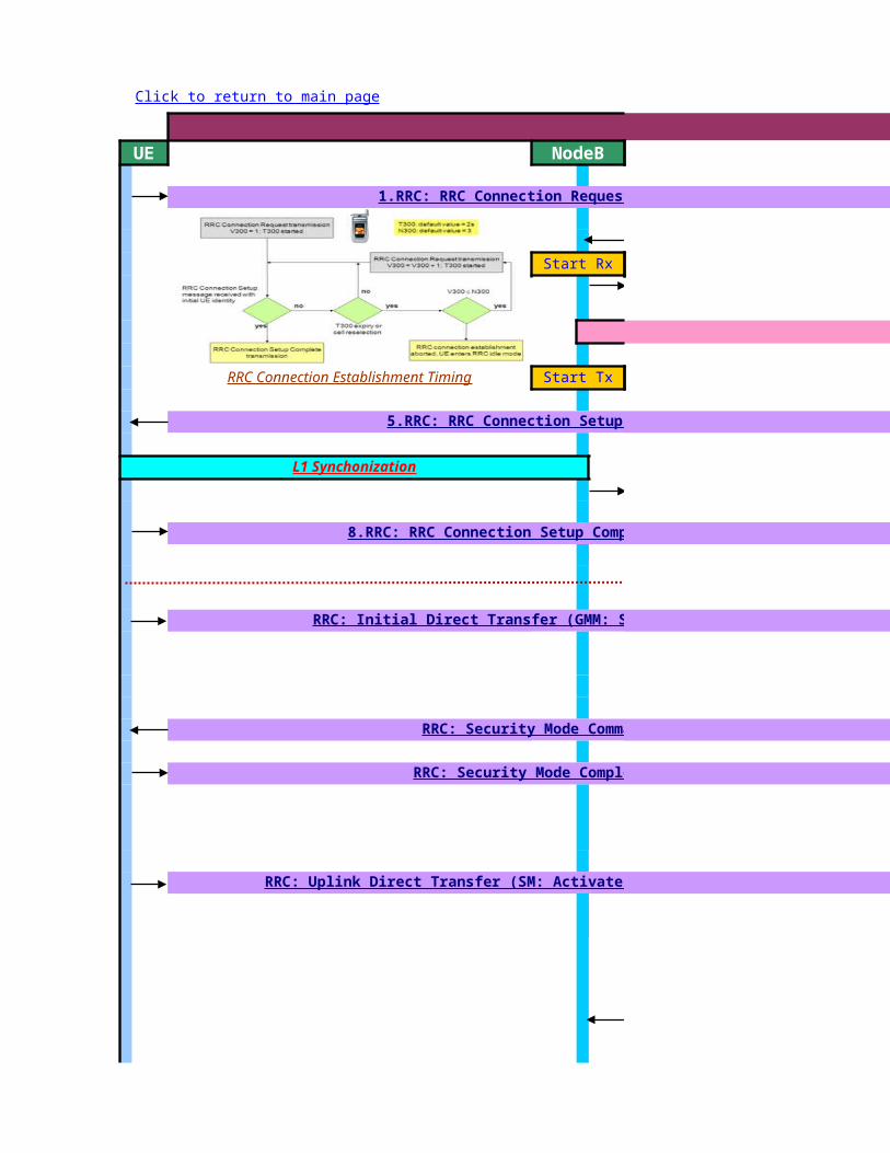
L3 Messages - PS(HSUPA) Call ProcedureUE NodeB
Start Rx
4.ALCAP: Iub User Plane Setup
RRC Connection Establishment Timing Start Tx
Click to return to main page
1.RRC: RRC Connection Request (RACH)
5.RRC: RRC Connection Setup (FACH)
L1 Synchonization
8.RRC: RRC Connection Setup Completed (DCH)
RRC: Initial Direct Transfer (GMM: Service Request)
RRC: Security Mode Command
RRC: Security Mode Completed
RRC: Uplink Direct Transfer (SM: Activate PDP Context Request)

ALCAP: Iub User Plane Setup
Apply new transport format set
PS Session Established
ALCAP: Iub User Plane Setup
RRC: Radio Bearer Setup
RRC: Radio Bearer Setup Complete
RRC:Measurement Control
RRC: Downlink Direct Transfer (SM: Activate PDP Context Accept)
RRC:Measurement Report (e1d)
RRC: Physical Channel Reconfiguration (DCCH)
RRC:Physical Channel Reconfiguration Complete (DCCH)
RRC: Uplink Direct Transfer (SM: Deactivate PDP Context Request)
RRC: Downlink Direct Transfer (SM: Deactivate PDP Context Accept)

ALCAP: Iub User Plane Setup
RRC: Uplink Direct Transfer (CC: RRC Connection Release Complete)
ALCAP: Iub User Plane Release
RRC: Radio Bearer Release
RRC: Radio Bearer Release Completed
RRC: Downlink Direct Transfer (CC: RRC Connection Release)
RRC: Uplink Direct Transfer (CC: RRC Connection Release Complete)

L3 Messages - PS(HSUPA) Call ProcedureS-RNC
2.NBAP:Radio Link Setup Req
3.NBAP:Radio Link Setup Resp.
4.ALCAP: Iub User Plane Setup
7.NBAP:Synchonization Indicator
1.RRC: RRC Connection Request (RACH)
5.RRC: RRC Connection Setup (FACH)
8.RRC: RRC Connection Setup Completed (DCH)
RRC: Initial Direct Transfer (GMM: Service Request)
RRC: Security Mode Command
RRC: Security Mode Completed
RRC: Uplink Direct Transfer (SM: Activate PDP Context Request)
NBAP: Radio Link Reconfiguration Prepare

ALCAP: Iub User Plane Setup
Apply new transport format set
PS Session Established
ALCAP: Iub User Plane Setup
NBAP: Radio Link Reconfiguration Ready
RRC: Radio Bearer Setup
NBAP: Radio Link Reconfiguration Commit
RRC: Radio Bearer Setup Complete
RRC:Measurement Control
RRC: Downlink Direct Transfer (SM: Activate PDP Context Accept)
RRC:Measurement Report (e1d)
NBAP: Radio Link Reconfiguration Prepare
NBAP: Radio Link Reconfiguration Ready
NBAP: Radio Link Reconfiguration Commit
RRC: Physical Channel Reconfiguration (DCCH)
RRC:Physical Channel Reconfiguration Complete (DCCH)
RRC: Uplink Direct Transfer (SM: Deactivate PDP Context Request)
RRC: Downlink Direct Transfer (SM: Deactivate PDP Context Accept)

ALCAP: Iub User Plane Setup
ALCAP: Iu User Plane Release
RRC: Uplink Direct Transfer (CC: RRC Connection Release Complete)
ALCAP: Iub User Plane Release
NBAP: Radio Link Reconfiguration Prepare
NBAP: Radio Link Reconfiguration Ready
NBAP: Radio Link Reconfiguration Commit
RRC: Radio Bearer Release
RRC: Radio Bearer Release Completed
RRC: Downlink Direct Transfer (CC: RRC Connection Release)
RRC: Uplink Direct Transfer (CC: RRC Connection Release Complete)
NBAP: Radio Link Deletion Request
NBAP: Radio Link Deletion Response

L3 Messages - PS(HSUPA) Call ProcedureCN
RANAP: Security Mode Command
RANAP: Security Mode Complete
RANAP: Common ID(IMSI)
RANAP: RAB Assignment Request
ALCAP : Iu User Plane Setup
RANAP: GMM:Service Request
RANAP: SM: Activate PDP Context Request

RANAP: RAB Assignment Response
PS Session Established
RANAP: SM: Activate PDP Context Accept
RANAP: SM: Deactivate PDP Context Request
RANAP: SM: Deactivate PDP Context Accept
HSPA's Serving Cell Change
3. Radio Bearer Setup
4. Downlink and Uplink Data Transfer

RANAP: Iu Release Command
ALCAP: Iu User Plane Release
RANAP: Iu Release Complete

RRC connection setup procedure is performed for the UE to set up a signaling connection to the SRNC. RRC connection setup is always initiated by the UE. One UE has a maximum of one RRC connection at a time.
Triggering Conditions : The UE in idle mode intitiates the RRC connection setup procedure when the NAS of the UE requests the establishment of a signaling connection When theSRNC receives an RRC CONNECTION REQUEST message from the UE, the Radio Resource Management (RRM) module of the RNC determines whether to accept or reject the RRCconnection request, based on a specific algorithm. If accepting the request, the RRM module further determines whether to set up the RRC connection on a Dedicated Channel(DCH)or on a Common Channel (CCH),based on a specific RRM algorithm. Typically, an RRC connection is set up on the DCH.
The procedure shown is described as follows:1.The UE sends an RRC CONNECTION REQUEST message to the SRNC through the uplink CCCH(RACH), requesting the establishment of an RRC connection.2.Based on the cause in the RRC connection request and the system resource status, the SRNC determines to set up the RRC connection on a DCH and allocates the RadioNetworkTemporary Identity(RNTI),radio resources, and L1 and L2 resources. Then the SRNC sends a RADIO LINK SETUP REQUEST message to the NodeB, requesting the NodeB toallocate the specific radio link resources required for an RRC connection.3.The NodeB responds with a RADIO LINK SETUP RESPONSE message to the SRNC after successfully preparing the resources.4.The SRNC uses the ALCAP protocol to set up the Iub user plane transport bearer and performs the synchronization between the SRNC and the NodeB. This procedure is optional. Itis required for the ATM-based Iub interface only.5.The SRNC sends an RRC CONNECTION SETUP message to the UE through the downlink CCCH (FACH). The message contains the information about the DCH allocated by the SRNC.6. UE and NodeB initiate L1 Synchronization. NodeB sends NBAP:Synchonization Indicator message to SRNC when the uplink enter "In-Sync" state7. The UE sends an RRC CONNECTION SETUP COMPLETE message to the SRNC through the uplink Dedicated Control Channel (DCCH) that is just set up. The message indicates that the RRC connection setup procedure ends.If the RNC judges that the RRC connection request cannot be set up (for instance, due to insufficient resources), it directly sends an RRC CONNECTION REJECT message to theUE, and indicates the reject reason in the message
>>RRC Procedure Description
The PS Session Setup procedure is performed to set up a PS session
Triggering Conditions: The UE send Activate PDP context request message to RNC. PDP Context Activation is performed when the UE initiates a packet call setup. The UE has the state PacketMobility Management Connected that enables the user to transmitt and receive data while moving within a PLMN. and starts the PDP context activation procedure used to set up and remove avirtual data channel between a terminal connected to a UE and a GGSN. PDP contexts deal with allocation of IP addresses to the UE and Quality of Service, QoS, parameters. A Radio Accessbearer establishes on request of the SGSN in order to realize the air interface connection. At the end the UE has an IP address NSAPI (Network layer Service Access Point Identifier) and a TLLI (Temporary Logical Link Identity) associated to IMSI.
IP addresses can be allocated dynamically or statistically. If allocated dynamically, this significantly reduces the total number of IP addresses required per PLMN. Support of static IP address allocation enables subscribers to provide their own IP addresses. This can be useful when accesing secure networks that use the calling IP address as a form of security check. The support ofQoS enables the operator to differentiate GPRS services.
When dynamic addressing from the home PLMN or the Visitor PLMN is used, it is the responsibility of the GGSN to allocate and release the dynamic PDP address.The procedure shown is described as follows:1. The UE initiates the PS Session by using the Service Request (Service Type=Data) message. After the RR setup completion the UE asks for initial direct transfer to the serving node. The RNC sets-up an SCCP connection with the SGSN and transfers the initial service request (Authentication and ciphering may performed depends on operator's setting)2.The UE sends an Activate PDP Context Request (NSAPI, TI(Teardown Indication), PDP Type, Address, APN (Access Point Name), QoS (Quality of Service) Requested, PDP ConfigurationOptions) message to the SGSN The UE shall use PDP Address to indicate whether it requires the use of a static PDP address or whether it requires the use of a dynamic PDP address.3. The SGSN sends a RAB Assignment Request message to the RNC to establish a RABs4.The RNC establishes the appropriate radio bearer In WCDMA, RAB setup is done by the RAB Assignment procedure5.The RNC returns a RAB Assignment Response message to the SGSN6. The SGSN validates the active PDP Context Request using PDP Type (optional), PDP Address, APN (Access Point Name (optional) provided by the UE and the PDP context subscriptionrecords.The SGSN sends a Create PDP Context Request message to the affected GGSN. Access Point Name shall be the APN Network Identifier of the APN. The GGSN may use Access Point Name to find an external network and optionally to activate a service for this APN7. The GGSN creates a new entry in its PDP context table and generates a Charging Id. The new entry allows the GGSN to route PDP PDUs (Policy Decision Point Protocol Data Units) between the SGSN and the external PDP network, and to start charging 8.The SGSN inserts the Network layer Service Access Point Identifier, NSAPI along with the GGSN address in its PDP context and informs the UE via RNC that the PDP Context is Accepted. TheSGSN selects Radio Priority and Packet flow Id based on QoS Negotiated, and returns an Activate PDP Context Accept message to the UE. The SGSN is now able to route PDP PDUs between theGGSN and the UE and to start charging
The Radio Bearer Setup procedure shown is described as follows:1.The CN sends an RAB ASSIGNMENT REQUEST message to the SRNC to initiate the RAB setup procedure.2.(Optional; applicable to the ATM-based Iu-CS interface only) The SRNC maps the Quality of Service (QoS) parameters for the RAB to the AAL2 link characteristic parameters and radio resourcecharacteristic parameters. Based on the AAL2 link characteristic parameters,the ALCAP on the Iu interface initiates an Iu user plane transport bearer setup procedure.3.The SRNC sends a RADIO LINK RECONFIGURATION PREPARE message to the NodeB, requesting the NodeB to prepare for adding one or more DCHs to the existing radio links for carrying theRAB.4.The NodeB allocates the associated resources and then sends a RADIO LINKRECONFIGURATION READY message to the SRNC.5.(Optional; required for the ATM-based Iub interface only) The Iub ALCAP at the SRNC initiates an Iub user plane transport bearer setup procedure. The NodeB and the SRNC perform synchronization by exchanging uplink and downlink synchronization frames in the DCH frame protocol.6.The SRNC sends a RADIO BEARER SETUP message to the UE.7.The SRNC sends a RADIO LINK RECONFIGURATION COMMIT message to theNodeB.8.After performing the radio bearer setup, the UE sends a RADIO BEARER SETUP COMPLETE message to the SRNC.9.The SRNC sends an RAB ASSIGNMENT RESPONSE message to the CN. The RAB isset up.The procedure when RAB Setup Failure shown is described as follows:1.The CN sends an RAB ASSIGNMENT REQUEST message to the SRNC to initiate the RAB setup procedure.2.The SRNC sends an RAB ASSIGNMENT RESPONSE message to the CN. The message indicates the ID of the RAB that fails to be set up and the reason for the failure.
1.RRC Connection Establishment
2.PS Session Setup

The PS Session Setup procedure is performed to set up a PS session
Triggering Conditions: The UE send Activate PDP context request message to RNC. PDP Context Activation is performed when the UE initiates a packet call setup. The UE has the state PacketMobility Management Connected that enables the user to transmitt and receive data while moving within a PLMN. and starts the PDP context activation procedure used to set up and remove avirtual data channel between a terminal connected to a UE and a GGSN. PDP contexts deal with allocation of IP addresses to the UE and Quality of Service, QoS, parameters. A Radio Accessbearer establishes on request of the SGSN in order to realize the air interface connection. At the end the UE has an IP address NSAPI (Network layer Service Access Point Identifier) and a TLLI (Temporary Logical Link Identity) associated to IMSI.
IP addresses can be allocated dynamically or statistically. If allocated dynamically, this significantly reduces the total number of IP addresses required per PLMN. Support of static IP address allocation enables subscribers to provide their own IP addresses. This can be useful when accesing secure networks that use the calling IP address as a form of security check. The support ofQoS enables the operator to differentiate GPRS services.
When dynamic addressing from the home PLMN or the Visitor PLMN is used, it is the responsibility of the GGSN to allocate and release the dynamic PDP address.The procedure shown is described as follows:1. The UE initiates the PS Session by using the Service Request (Service Type=Data) message. After the RR setup completion the UE asks for initial direct transfer to the serving node. The RNC sets-up an SCCP connection with the SGSN and transfers the initial service request (Authentication and ciphering may performed depends on operator's setting)2.The UE sends an Activate PDP Context Request (NSAPI, TI(Teardown Indication), PDP Type, Address, APN (Access Point Name), QoS (Quality of Service) Requested, PDP ConfigurationOptions) message to the SGSN The UE shall use PDP Address to indicate whether it requires the use of a static PDP address or whether it requires the use of a dynamic PDP address.3. The SGSN sends a RAB Assignment Request message to the RNC to establish a RABs4.The RNC establishes the appropriate radio bearer In WCDMA, RAB setup is done by the RAB Assignment procedure5.The RNC returns a RAB Assignment Response message to the SGSN6. The SGSN validates the active PDP Context Request using PDP Type (optional), PDP Address, APN (Access Point Name (optional) provided by the UE and the PDP context subscriptionrecords.The SGSN sends a Create PDP Context Request message to the affected GGSN. Access Point Name shall be the APN Network Identifier of the APN. The GGSN may use Access Point Name to find an external network and optionally to activate a service for this APN7. The GGSN creates a new entry in its PDP context table and generates a Charging Id. The new entry allows the GGSN to route PDP PDUs (Policy Decision Point Protocol Data Units) between the SGSN and the external PDP network, and to start charging 8.The SGSN inserts the Network layer Service Access Point Identifier, NSAPI along with the GGSN address in its PDP context and informs the UE via RNC that the PDP Context is Accepted. TheSGSN selects Radio Priority and Packet flow Id based on QoS Negotiated, and returns an Activate PDP Context Accept message to the UE. The SGSN is now able to route PDP PDUs between theGGSN and the UE and to start charging
The Radio Bearer Setup procedure shown is described as follows:1.The CN sends an RAB ASSIGNMENT REQUEST message to the SRNC to initiate the RAB setup procedure.2.(Optional; applicable to the ATM-based Iu-CS interface only) The SRNC maps the Quality of Service (QoS) parameters for the RAB to the AAL2 link characteristic parameters and radio resourcecharacteristic parameters. Based on the AAL2 link characteristic parameters,the ALCAP on the Iu interface initiates an Iu user plane transport bearer setup procedure.3.The SRNC sends a RADIO LINK RECONFIGURATION PREPARE message to the NodeB, requesting the NodeB to prepare for adding one or more DCHs to the existing radio links for carrying theRAB.4.The NodeB allocates the associated resources and then sends a RADIO LINKRECONFIGURATION READY message to the SRNC.5.(Optional; required for the ATM-based Iub interface only) The Iub ALCAP at the SRNC initiates an Iub user plane transport bearer setup procedure. The NodeB and the SRNC perform synchronization by exchanging uplink and downlink synchronization frames in the DCH frame protocol.6.The SRNC sends a RADIO BEARER SETUP message to the UE.7.The SRNC sends a RADIO LINK RECONFIGURATION COMMIT message to theNodeB.8.After performing the radio bearer setup, the UE sends a RADIO BEARER SETUP COMPLETE message to the SRNC.9.The SRNC sends an RAB ASSIGNMENT RESPONSE message to the CN. The RAB isset up.The procedure when RAB Setup Failure shown is described as follows:1.The CN sends an RAB ASSIGNMENT REQUEST message to the SRNC to initiate the RAB setup procedure.2.The SRNC sends an RAB ASSIGNMENT RESPONSE message to the CN. The message indicates the ID of the RAB that fails to be set up and the reason for the failure.
The PS session release procedure is performed to release services and resources after a session ends.
Triggering Conditions : The UE send Deactivate PDP context request message to RNC. A PDP Context Deactivation is performed when the UE terminates a packet call. Before the deactivation,the UE has the state Active. After the PDP Context deactivation procedure the state becomes Packet Mobility Management Connected.The RAB will be released if there are no otherPDP contexts activated.PDP Deactivation may be initiated by a:UE procedure,SGSN procedure,GGSN procedure
The procedure shown is described as follows:1.The UE sends a Deactivate PDP Context Request (TI, Teardown Indication) message to the SGSN via the RNC2.The SGSN sends a Delete PDP Context Request (TEID, NSAPI, Teardown Indication) message to the GGSN. If Teardown Indication was included by the UE in the Deactivate PDP Context Request message, then the SGSN deactivates all PDP contexts associated with this PDP address by including Teardown Indication in the Delete PDP Context Request message3.The GGSN removes the PDP context(s) and returns a delete PDP Context Response (TEID) message to the SGSN. The Delete PDP Context messages are sent over the backbone network4.The SGSN returns a Deactivate PDP Context Accept (TI) message to the UE via the RNC5. In Iu mode, radio access bearer release is done by the RAB Assignment procedure6. The SCCP connection between RNC and SGSN is released. At GPRS detach, all PDP contexts for the UE are implicitly deactivated
The RRC Connection Release procedure is performed to release the signaling connection and all radio bearers between UE and the UTRAN
Triggering Conditions: After a n RAB is released,the SRNC judges whether the RRC connection carries any other RAB or the UE. If judging that the RRC connection does not carry other RABof the UE,the SRNC initiates an RRC connection release procedure.
The procedure shown is described as follows: based on the resouce occupied by the RRC connection,there are two types of RRC connection release procedure: release of an RRC connection from DCH and release of an RRC connection from CCH (If an RRC connection needs to be released after a successful outgoing call,, the RRC connection on the DCH is released and if a radio bearers fails to be setup ,the RRC connection on the CCH is released)
1.The SRNC sends an RRC CONNECTION RELEASE message to the UE through the DCCH. (NOTE: The SRNC may send the RRC CONNECTION RELEASE message several times to increase the probability of proper reception of the message by the UE. The RRC SNs of these messages are the same. The number of retransmissions and the transmission intervals are determined by the SRNC. If the SRNC does not receive an RRC CONNECTION RELEASE COMPLETE message from the UE after sending the RRC CONNECTION RELEASE message for four times, the SRNC judges that the UE has released the RRC connection.)
2.The UE sends an RRC CONNECTION RELEASE COMPLETE message to the SRNC.3.The SRNC sends a RADIO LINK DELETION REQUEST message to the NodeB,requesting the NodeB to delete the radio link resources in the NodeB.4.After releasing the resources, the NodeB sends a RADIO LINK DELETION RESPONSE message to the SRNC.5.(Optional; required for the ATM-based Iub interface only) The SRNC uses the ALCAP protocol to initiate an Iub user plane transport bearer release procedure. Then, the RRC connection releaseprocedure ends.
HSPA's Serving Cell Change
3. Radio Bearer Setup
4. Downlink and Uplink Data Transfer

The RRC Connection Release procedure is performed to release the signaling connection and all radio bearers between UE and the UTRAN
Triggering Conditions: After a n RAB is released,the SRNC judges whether the RRC connection carries any other RAB or the UE. If judging that the RRC connection does not carry other RABof the UE,the SRNC initiates an RRC connection release procedure.
The procedure shown is described as follows: based on the resouce occupied by the RRC connection,there are two types of RRC connection release procedure: release of an RRC connection from DCH and release of an RRC connection from CCH (If an RRC connection needs to be released after a successful outgoing call,, the RRC connection on the DCH is released and if a radio bearers fails to be setup ,the RRC connection on the CCH is released)
1.The SRNC sends an RRC CONNECTION RELEASE message to the UE through the DCCH. (NOTE: The SRNC may send the RRC CONNECTION RELEASE message several times to increase the probability of proper reception of the message by the UE. The RRC SNs of these messages are the same. The number of retransmissions and the transmission intervals are determined by the SRNC. If the SRNC does not receive an RRC CONNECTION RELEASE COMPLETE message from the UE after sending the RRC CONNECTION RELEASE message for four times, the SRNC judges that the UE has released the RRC connection.)
2.The UE sends an RRC CONNECTION RELEASE COMPLETE message to the SRNC.3.The SRNC sends a RADIO LINK DELETION REQUEST message to the NodeB,requesting the NodeB to delete the radio link resources in the NodeB.4.After releasing the resources, the NodeB sends a RADIO LINK DELETION RESPONSE message to the SRNC.5.(Optional; required for the ATM-based Iub interface only) The SRNC uses the ALCAP protocol to initiate an Iub user plane transport bearer release procedure. Then, the RRC connection releaseprocedure ends.
5.PS Session Release
6.RRC Connection Release

RRC connection setup procedure is performed for the UE to set up a signaling connection to the SRNC. RRC connection setup is always initiated by the UE. One UE has amaximum of one RRC connection at a time.
Triggering Conditions : The UE in idle mode intitiates the RRC connection setup procedure when the NAS of the UE requests the establishment of a signaling connection
SRNC receives an RRC CONNECTION REQUEST message from the UE, the Radio Resource Management (RRM) module of the RNC determines whether to accept or reject the RRCconnection request, based on a specific algorithm. If accepting the request, the RRM module further determines whether to set up the RRC connection on a Dedicated Channel(DCH)or on a Common Channel (CCH),based on a specific RRM algorithm. Typically, an RRC connection is set up on the DCH.
The procedure shown is described as follows:The UE sends an RRC CONNECTION REQUEST message to the SRNC through the uplink CCCH(RACH), requesting the establishment of an RRC connection.Based on the cause in the RRC connection request and the system resource status, the SRNC determines to set up the RRC connection on a DCH and allocates the Radio
NetworkTemporary Identity(RNTI),radio resources, and L1 and L2 resources. Then the SRNC sends a RADIO LINK SETUP REQUEST message to the NodeB, requesting the NodeB toallocate the specific radio link resources required for an RRC connection.
The NodeB responds with a RADIO LINK SETUP RESPONSE message to the SRNC after successfully preparing the resources..The SRNC uses the ALCAP protocol to set up the Iub user plane transport bearer and performs the synchronization between the SRNC and the NodeB. This procedure is
is required for the ATM-based Iub interface only.The SRNC sends an RRC CONNECTION SETUP message to the UE through the downlink CCCH (FACH). The message contains the information about the DCH allocated by the SRNC. UE and NodeB initiate L1 Synchronization. NodeB sends NBAP:Synchonization Indicator message to SRNC when the uplink enter "In-Sync" state
. The UE sends an RRC CONNECTION SETUP COMPLETE message to the SRNC through the uplink Dedicated Control Channel (DCCH) that is just set up. The message indicates that the RRC connection setup procedure ends.If the RNC judges that the RRC connection request cannot be set up (for instance, due to insufficient resources), it directly sends an RRC CONNECTION REJECT message totheUE, and indicates the reject reason in the messageThe PS Session Setup procedure is performed to set up a PS session
The UE send Activate PDP context request message to RNC. PDP Context Activation is performed when the UE initiates a packet call setup. The UE has
Mobility Management Connected that enables the user to transmitt and receive data while moving within a PLMN. and starts the PDP context activation procedure used to set
virtual data channel between a terminal connected to a UE and a GGSN. PDP contexts deal with allocation of IP addresses to the UE and Quality of Service, QoS, parameters.
bearer establishes on request of the SGSN in order to realize the air interface connection. At the end the UE has an IP address NSAPI (Network layer Service Access Point Identifier) and a TLLI (Temporary Logical Link Identity) associated to IMSI.
IP addresses can be allocated dynamically or statistically. If allocated dynamically, this significantly reduces the total number of IP addresses required per PLMN. Support of static IP address allocation enables subscribers to provide their own IP addresses. This can be useful when accesing secure networks that use the calling IP address as a form of security check. The support ofQoS enables the operator to differentiate GPRS services.
When dynamic addressing from the home PLMN or the Visitor PLMN is used, it is the responsibility of the GGSN to allocate and release the dynamic PDP address.The procedure shown is described as follows:
The UE initiates the PS Session by using the Service Request (Service Type=Data) message. After the RR setup completion the UE asks for initial direct transfer to the
sets-up an SCCP connection with the SGSN and transfers the initial service request (Authentication and ciphering may performed depends on operator's setting)The UE sends an Activate PDP Context Request (NSAPI, TI(Teardown Indication), PDP Type, Address, APN (Access Point Name), QoS (Quality of Service) Requested, PDP
Options) message to the SGSN The UE shall use PDP Address to indicate whether it requires the use of a static PDP address or whether it requires the use of a dynamic PDP
The SGSN sends a RAB Assignment Request message to the RNC to establish a RABs.The RNC establishes the appropriate radio bearer In WCDMA, RAB setup is done by the RAB Assignment procedure.The RNC returns a RAB Assignment Response message to the SGSN The SGSN validates the active PDP Context Request using PDP Type (optional), PDP Address, APN (Access Point Name (optional) provided by the UE and the PDP context
records.The SGSN sends a Create PDP Context Request message to the affected GGSN. Access Point Name shall be the APN Network Identifier of the APN. The GGSN may use Access
Name to find an external network and optionally to activate a service for this APN The GGSN creates a new entry in its PDP context table and generates a Charging Id. The new entry allows the GGSN to route PDP PDUs (Policy Decision Point Protocol Data
the SGSN and the external PDP network, and to start charging The SGSN inserts the Network layer Service Access Point Identifier, NSAPI along with the GGSN address in its PDP context and informs the UE via RNC that the PDP Context
SGSN selects Radio Priority and Packet flow Id based on QoS Negotiated, and returns an Activate PDP Context Accept message to the UE. The SGSN is now able to route PDP
theGGSN and the UE and to start charging
The Radio Bearer Setup procedure shown is described as follows:.The CN sends an RAB ASSIGNMENT REQUEST message to the SRNC to initiate the RAB setup procedure.(Optional; applicable to the ATM-based Iu-CS interface only) The SRNC maps the Quality of Service (QoS) parameters for the RAB to the AAL2 link characteristic parameters
characteristic parameters. Based on the AAL2 link characteristic parameters,the ALCAP on the Iu interface initiates an Iu user plane transport bearer setup procedure.The SRNC sends a RADIO LINK RECONFIGURATION PREPARE message to the NodeB, requesting the NodeB to prepare for adding one or more DCHs to the existing radio links for
The NodeB allocates the associated resources and then sends a RADIO LINKRECONFIGURATION READY message to the SRNC.(Optional; required for the ATM-based Iub interface only) The Iub ALCAP at the SRNC initiates an Iub user plane transport bearer setup procedure. The NodeB and the SRNC
synchronization by exchanging uplink and downlink synchronization frames in the DCH frame protocol.The SRNC sends a RADIO BEARER SETUP message to the UE.
.The SRNC sends a RADIO LINK RECONFIGURATION COMMIT message to theNodeB.
.After performing the radio bearer setup, the UE sends a RADIO BEARER SETUP COMPLETE message to the SRNC.
.The SRNC sends an RAB ASSIGNMENT RESPONSE message to the CN. The RAB isset up.The procedure when RAB Setup Failure shown is described as follows:.The CN sends an RAB ASSIGNMENT REQUEST message to the SRNC to initiate the RAB setup procedure..The SRNC sends an RAB ASSIGNMENT RESPONSE message to the CN. The message indicates the ID of the RAB that fails to be set up and the reason for the failure.

The PS Session Setup procedure is performed to set up a PS session
The UE send Activate PDP context request message to RNC. PDP Context Activation is performed when the UE initiates a packet call setup. The UE has
Mobility Management Connected that enables the user to transmitt and receive data while moving within a PLMN. and starts the PDP context activation procedure used to set
virtual data channel between a terminal connected to a UE and a GGSN. PDP contexts deal with allocation of IP addresses to the UE and Quality of Service, QoS, parameters.
bearer establishes on request of the SGSN in order to realize the air interface connection. At the end the UE has an IP address NSAPI (Network layer Service Access Point Identifier) and a TLLI (Temporary Logical Link Identity) associated to IMSI.
IP addresses can be allocated dynamically or statistically. If allocated dynamically, this significantly reduces the total number of IP addresses required per PLMN. Support of static IP address allocation enables subscribers to provide their own IP addresses. This can be useful when accesing secure networks that use the calling IP address as a form of security check. The support ofQoS enables the operator to differentiate GPRS services.
When dynamic addressing from the home PLMN or the Visitor PLMN is used, it is the responsibility of the GGSN to allocate and release the dynamic PDP address.The procedure shown is described as follows:
The UE initiates the PS Session by using the Service Request (Service Type=Data) message. After the RR setup completion the UE asks for initial direct transfer to the
sets-up an SCCP connection with the SGSN and transfers the initial service request (Authentication and ciphering may performed depends on operator's setting)The UE sends an Activate PDP Context Request (NSAPI, TI(Teardown Indication), PDP Type, Address, APN (Access Point Name), QoS (Quality of Service) Requested, PDP
Options) message to the SGSN The UE shall use PDP Address to indicate whether it requires the use of a static PDP address or whether it requires the use of a dynamic PDP
The SGSN sends a RAB Assignment Request message to the RNC to establish a RABs.The RNC establishes the appropriate radio bearer In WCDMA, RAB setup is done by the RAB Assignment procedure.The RNC returns a RAB Assignment Response message to the SGSN The SGSN validates the active PDP Context Request using PDP Type (optional), PDP Address, APN (Access Point Name (optional) provided by the UE and the PDP context
records.The SGSN sends a Create PDP Context Request message to the affected GGSN. Access Point Name shall be the APN Network Identifier of the APN. The GGSN may use Access
Name to find an external network and optionally to activate a service for this APN The GGSN creates a new entry in its PDP context table and generates a Charging Id. The new entry allows the GGSN to route PDP PDUs (Policy Decision Point Protocol Data
the SGSN and the external PDP network, and to start charging The SGSN inserts the Network layer Service Access Point Identifier, NSAPI along with the GGSN address in its PDP context and informs the UE via RNC that the PDP Context
SGSN selects Radio Priority and Packet flow Id based on QoS Negotiated, and returns an Activate PDP Context Accept message to the UE. The SGSN is now able to route PDP
theGGSN and the UE and to start charging
The Radio Bearer Setup procedure shown is described as follows:.The CN sends an RAB ASSIGNMENT REQUEST message to the SRNC to initiate the RAB setup procedure.(Optional; applicable to the ATM-based Iu-CS interface only) The SRNC maps the Quality of Service (QoS) parameters for the RAB to the AAL2 link characteristic parameters
characteristic parameters. Based on the AAL2 link characteristic parameters,the ALCAP on the Iu interface initiates an Iu user plane transport bearer setup procedure.The SRNC sends a RADIO LINK RECONFIGURATION PREPARE message to the NodeB, requesting the NodeB to prepare for adding one or more DCHs to the existing radio links for
The NodeB allocates the associated resources and then sends a RADIO LINKRECONFIGURATION READY message to the SRNC.(Optional; required for the ATM-based Iub interface only) The Iub ALCAP at the SRNC initiates an Iub user plane transport bearer setup procedure. The NodeB and the SRNC
synchronization by exchanging uplink and downlink synchronization frames in the DCH frame protocol.The SRNC sends a RADIO BEARER SETUP message to the UE.
.The SRNC sends a RADIO LINK RECONFIGURATION COMMIT message to theNodeB.
.After performing the radio bearer setup, the UE sends a RADIO BEARER SETUP COMPLETE message to the SRNC.
.The SRNC sends an RAB ASSIGNMENT RESPONSE message to the CN. The RAB isset up.The procedure when RAB Setup Failure shown is described as follows:.The CN sends an RAB ASSIGNMENT REQUEST message to the SRNC to initiate the RAB setup procedure..The SRNC sends an RAB ASSIGNMENT RESPONSE message to the CN. The message indicates the ID of the RAB that fails to be set up and the reason for the failure.
The PS session release procedure is performed to release services and resources after a session ends.
: The UE send Deactivate PDP context request message to RNC. A PDP Context Deactivation is performed when the UE terminates a packet call. Before
deactivation,the UE has the state Active. After the PDP Context deactivation procedure the state becomes Packet Mobility Management Connected.The RAB will be released if
PDP contexts activated.PDP Deactivation may be initiated by a:UE procedure,SGSN procedure,GGSN procedure
The procedure shown is described as follows:.The UE sends a Deactivate PDP Context Request (TI, Teardown Indication) message to the SGSN via the RNC.The SGSN sends a Delete PDP Context Request (TEID, NSAPI, Teardown Indication) message to the GGSN. If Teardown Indication was included by the UE in the Deactivate PDP
Context Request message, then the SGSN deactivates all PDP contexts associated with this PDP address by including Teardown Indication in the Delete PDP Context Request
.The GGSN removes the PDP context(s) and returns a delete PDP Context Response (TEID) message to the SGSN. The Delete PDP Context messages are sent over the backbone
.The SGSN returns a Deactivate PDP Context Accept (TI) message to the UE via the RNC In Iu mode, radio access bearer release is done by the RAB Assignment procedure
. The SCCP connection between RNC and SGSN is released. At GPRS detach, all PDP contexts for the UE are implicitly deactivated
The RRC Connection Release procedure is performed to release the signaling connection and all radio bearers between UE and the UTRAN
Triggering Conditions: After a n RAB is released,the SRNC judges whether the RRC connection carries any other RAB or the UE. If judging that the RRC connection does not
of the UE,the SRNC initiates an RRC connection release procedure.
The procedure shown is described as follows: based on the resouce occupied by the RRC connection,there are two types of RRC connection release procedure: release of an RRC connection from DCH and release of an RRC connection from CCH (If an RRC connection needs to be released after a successful outgoing call,, the RRC connection on the DCH
a radio bearers fails to be setup ,the RRC connection on the CCH is released)
1.The SRNC sends an RRC CONNECTION RELEASE message to the UE through the DCCH. The SRNC may send the RRC CONNECTION RELEASE message several times to increase the probability of proper reception of the message by the UE. The RRC SNs of these
messages are the same. The number of retransmissions and the transmission intervals are determined by the SRNC. If the SRNC does not receive an RRC CONNECTION RELEASE COMPLETE message from the UE after sending the RRC CONNECTION RELEASE message for four times, the SRNC judges that the UE has released the RRC connection.)
2.The UE sends an RRC CONNECTION RELEASE COMPLETE message to the SRNC.3.The SRNC sends a RADIO LINK DELETION REQUEST message to the NodeB,requesting the NodeB to delete the radio link resources in the NodeB.4.After releasing the resources, the NodeB sends a RADIO LINK DELETION RESPONSE message to the SRNC.5.(Optional; required for the ATM-based Iub interface only) The SRNC uses the ALCAP protocol to initiate an Iub user plane transport bearer release procedure. Then, the

is performed for the UE to set up a signaling connection to the SRNC. RRC connection setup is always initiated by the UE. One UE has a
The UE in idle mode intitiates the RRC connection setup procedure when the NAS of the UE requests the establishment of a signaling connection
SRNC receives an RRC CONNECTION REQUEST message from the UE, the Radio Resource Management (RRM) module of the RNC determines whether to accept or reject the RRCconnection request, based on a specific algorithm. If accepting the request, the RRM module further determines whether to set up the RRC connection on a Dedicated Channel(DCH)or on a Common Channel (CCH),based on a specific RRM algorithm. Typically, an RRC connection is set up on the DCH.
The UE sends an RRC CONNECTION REQUEST message to the SRNC through the uplink CCCH(RACH), requesting the establishment of an RRC connection.Based on the cause in the RRC connection request and the system resource status, the SRNC determines to set up the RRC connection on a DCH and allocates the Radio
NetworkTemporary Identity(RNTI),radio resources, and L1 and L2 resources. Then the SRNC sends a RADIO LINK SETUP REQUEST message to the NodeB, requesting the NodeB to
The NodeB responds with a RADIO LINK SETUP RESPONSE message to the SRNC after successfully preparing the resources..The SRNC uses the ALCAP protocol to set up the Iub user plane transport bearer and performs the synchronization between the SRNC and the NodeB. This procedure is
The SRNC sends an RRC CONNECTION SETUP message to the UE through the downlink CCCH (FACH). The message contains the information about the DCH allocated by the SRNC. UE and NodeB initiate L1 Synchronization. NodeB sends NBAP:Synchonization Indicator message to SRNC when the uplink enter "In-Sync" state. The UE sends an RRC CONNECTION SETUP COMPLETE message to the SRNC through the uplink Dedicated Control Channel (DCCH) that is just set up. The message
If the RNC judges that the RRC connection request cannot be set up (for instance, due to insufficient resources), it directly sends an RRC CONNECTION REJECT message to
The UE send Activate PDP context request message to RNC. PDP Context Activation is performed when the UE initiates a packet call setup. The UE has
Mobility Management Connected that enables the user to transmitt and receive data while moving within a PLMN. and starts the PDP context activation procedure used to set
virtual data channel between a terminal connected to a UE and a GGSN. PDP contexts deal with allocation of IP addresses to the UE and Quality of Service, QoS, parameters.
bearer establishes on request of the SGSN in order to realize the air interface connection. At the end the UE has an IP address NSAPI (Network layer Service Access Point
IP addresses can be allocated dynamically or statistically. If allocated dynamically, this significantly reduces the total number of IP addresses required per PLMN. Support of static IP address allocation enables subscribers to provide their own IP addresses. This can be useful when accesing secure networks that use the calling IP
When dynamic addressing from the home PLMN or the Visitor PLMN is used, it is the responsibility of the GGSN to allocate and release the dynamic PDP address.
The UE initiates the PS Session by using the Service Request (Service Type=Data) message. After the RR setup completion the UE asks for initial direct transfer to the
sets-up an SCCP connection with the SGSN and transfers the initial service request (Authentication and ciphering may performed depends on operator's setting)The UE sends an Activate PDP Context Request (NSAPI, TI(Teardown Indication), PDP Type, Address, APN (Access Point Name), QoS (Quality of Service) Requested, PDP
Options) message to the SGSN The UE shall use PDP Address to indicate whether it requires the use of a static PDP address or whether it requires the use of a dynamic PDP
.The RNC establishes the appropriate radio bearer In WCDMA, RAB setup is done by the RAB Assignment procedure
The SGSN validates the active PDP Context Request using PDP Type (optional), PDP Address, APN (Access Point Name (optional) provided by the UE and the PDP context
records.The SGSN sends a Create PDP Context Request message to the affected GGSN. Access Point Name shall be the APN Network Identifier of the APN. The GGSN may use Access
The GGSN creates a new entry in its PDP context table and generates a Charging Id. The new entry allows the GGSN to route PDP PDUs (Policy Decision Point Protocol Data
The SGSN inserts the Network layer Service Access Point Identifier, NSAPI along with the GGSN address in its PDP context and informs the UE via RNC that the PDP Context
SGSN selects Radio Priority and Packet flow Id based on QoS Negotiated, and returns an Activate PDP Context Accept message to the UE. The SGSN is now able to route PDP
(Optional; applicable to the ATM-based Iu-CS interface only) The SRNC maps the Quality of Service (QoS) parameters for the RAB to the AAL2 link characteristic parameters
characteristic parameters. Based on the AAL2 link characteristic parameters,the ALCAP on the Iu interface initiates an Iu user plane transport bearer setup procedure.The SRNC sends a RADIO LINK RECONFIGURATION PREPARE message to the NodeB, requesting the NodeB to prepare for adding one or more DCHs to the existing radio links for
The NodeB allocates the associated resources and then sends a RADIO LINKRECONFIGURATION READY message to the SRNC.(Optional; required for the ATM-based Iub interface only) The Iub ALCAP at the SRNC initiates an Iub user plane transport bearer setup procedure. The NodeB and the SRNC
.After performing the radio bearer setup, the UE sends a RADIO BEARER SETUP COMPLETE message to the SRNC.
.The SRNC sends an RAB ASSIGNMENT RESPONSE message to the CN. The message indicates the ID of the RAB that fails to be set up and the reason for the failure.

The UE send Activate PDP context request message to RNC. PDP Context Activation is performed when the UE initiates a packet call setup. The UE has
Mobility Management Connected that enables the user to transmitt and receive data while moving within a PLMN. and starts the PDP context activation procedure used to set
virtual data channel between a terminal connected to a UE and a GGSN. PDP contexts deal with allocation of IP addresses to the UE and Quality of Service, QoS, parameters.
bearer establishes on request of the SGSN in order to realize the air interface connection. At the end the UE has an IP address NSAPI (Network layer Service Access Point
IP addresses can be allocated dynamically or statistically. If allocated dynamically, this significantly reduces the total number of IP addresses required per PLMN. Support of static IP address allocation enables subscribers to provide their own IP addresses. This can be useful when accesing secure networks that use the calling IP
When dynamic addressing from the home PLMN or the Visitor PLMN is used, it is the responsibility of the GGSN to allocate and release the dynamic PDP address.
The UE initiates the PS Session by using the Service Request (Service Type=Data) message. After the RR setup completion the UE asks for initial direct transfer to the
sets-up an SCCP connection with the SGSN and transfers the initial service request (Authentication and ciphering may performed depends on operator's setting)The UE sends an Activate PDP Context Request (NSAPI, TI(Teardown Indication), PDP Type, Address, APN (Access Point Name), QoS (Quality of Service) Requested, PDP
Options) message to the SGSN The UE shall use PDP Address to indicate whether it requires the use of a static PDP address or whether it requires the use of a dynamic PDP
.The RNC establishes the appropriate radio bearer In WCDMA, RAB setup is done by the RAB Assignment procedure
The SGSN validates the active PDP Context Request using PDP Type (optional), PDP Address, APN (Access Point Name (optional) provided by the UE and the PDP context
records.The SGSN sends a Create PDP Context Request message to the affected GGSN. Access Point Name shall be the APN Network Identifier of the APN. The GGSN may use Access
The GGSN creates a new entry in its PDP context table and generates a Charging Id. The new entry allows the GGSN to route PDP PDUs (Policy Decision Point Protocol Data
The SGSN inserts the Network layer Service Access Point Identifier, NSAPI along with the GGSN address in its PDP context and informs the UE via RNC that the PDP Context
SGSN selects Radio Priority and Packet flow Id based on QoS Negotiated, and returns an Activate PDP Context Accept message to the UE. The SGSN is now able to route PDP
(Optional; applicable to the ATM-based Iu-CS interface only) The SRNC maps the Quality of Service (QoS) parameters for the RAB to the AAL2 link characteristic parameters
characteristic parameters. Based on the AAL2 link characteristic parameters,the ALCAP on the Iu interface initiates an Iu user plane transport bearer setup procedure.The SRNC sends a RADIO LINK RECONFIGURATION PREPARE message to the NodeB, requesting the NodeB to prepare for adding one or more DCHs to the existing radio links for
The NodeB allocates the associated resources and then sends a RADIO LINKRECONFIGURATION READY message to the SRNC.(Optional; required for the ATM-based Iub interface only) The Iub ALCAP at the SRNC initiates an Iub user plane transport bearer setup procedure. The NodeB and the SRNC
.After performing the radio bearer setup, the UE sends a RADIO BEARER SETUP COMPLETE message to the SRNC.
.The SRNC sends an RAB ASSIGNMENT RESPONSE message to the CN. The message indicates the ID of the RAB that fails to be set up and the reason for the failure.
is performed to release services and resources after a session ends.
The UE send Deactivate PDP context request message to RNC. A PDP Context Deactivation is performed when the UE terminates a packet call. Before
deactivation,the UE has the state Active. After the PDP Context deactivation procedure the state becomes Packet Mobility Management Connected.The RAB will be released if
PDP contexts activated.PDP Deactivation may be initiated by a:UE procedure,SGSN procedure,GGSN procedure
.The UE sends a Deactivate PDP Context Request (TI, Teardown Indication) message to the SGSN via the RNC
.The SGSN sends a Delete PDP Context Request (TEID, NSAPI, Teardown Indication) message to the GGSN. If Teardown Indication was included by the UE in the Deactivate PDP Context Request message, then the SGSN deactivates all PDP contexts associated with this PDP address by including Teardown Indication in the Delete PDP Context Request
.The GGSN removes the PDP context(s) and returns a delete PDP Context Response (TEID) message to the SGSN. The Delete PDP Context messages are sent over the backbone
. The SCCP connection between RNC and SGSN is released. At GPRS detach, all PDP contexts for the UE are implicitly deactivated
is performed to release the signaling connection and all radio bearers between UE and the UTRAN
After a n RAB is released,the SRNC judges whether the RRC connection carries any other RAB or the UE. If judging that the RRC connection does not
based on the resouce occupied by the RRC connection,there are two types of RRC connection release procedure: release of an RRC (If an RRC connection needs to be released after a successful outgoing call,, the RRC connection on the DCH
The SRNC may send the RRC CONNECTION RELEASE message several times to increase the probability of proper reception of the message by the UE. The RRC SNs of these messages are the same. The number of retransmissions and the transmission intervals are determined by the SRNC. If the SRNC does not receive an RRC CONNECTION RELEASE
, the SRNC judges that the UE has released the RRC connection.)
3.The SRNC sends a RADIO LINK DELETION REQUEST message to the NodeB,requesting the NodeB to delete the radio link resources in the NodeB.
5.(Optional; required for the ATM-based Iub interface only) The SRNC uses the ALCAP protocol to initiate an Iub user plane transport bearer release procedure. Then, the

RRC:RRC Connection Request (RACH)Click to return to main page

RRC:RRC Connection Setup (FACH)


RRC:RRC Connection Setup Complete (DCCH)


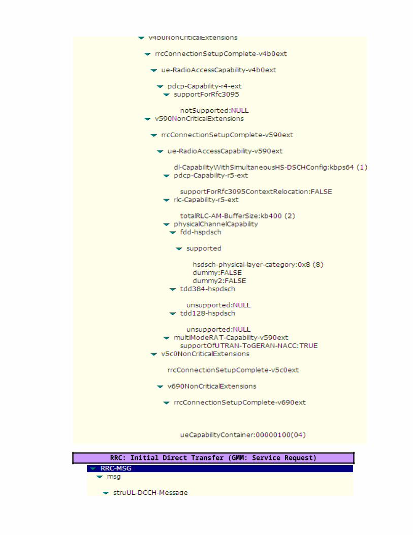
RRC: Initial Direct Transfer (GMM: Service Request)

RANAP: GMM:Service Request
RRC: Security Mode Command

RRC: Security Mode Complete

RRC: Uplink Direct Transfer (SM: Activate PDP Context Request)

RANAP: SM: Activate PDP Context Request
RRC: Radio Bearer Setup


RRC: Radio Bearer Setup Complete
RANAP: SM: Activate PDP Context Accept

RRC: Downlink Direct Transfer (SM: Activate PDP Context Accept)
RRC: Physical Channel Reconfiguration (DCCH)


RRC:Physical Channel Reconfiguration Complete (DCCH)

RRC: Uplink Direct Transfer (SM: Deactivate PDP Context Request)
RANAP: SM: Deactivate PDP Context Request
RANAP: SM: Deactivate PDP Context Accept

RRC: Downlink Direct Transfer (SM: Deactivate PDP Context Accept)
RRC: Radio Bearer Release


RRC: Radio Bearer Release Completed
RRC: Downlink Direct Transfer (CC: RRC Connection Release)
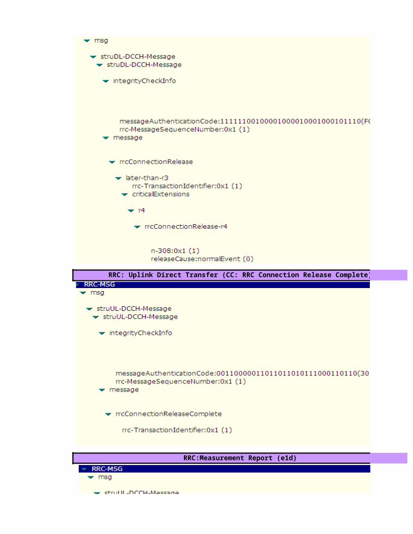
RRC: Uplink Direct Transfer (CC: RRC Connection Release Complete)
RRC:Measurement Report (e1d)


RRC:Measurement Control


value=hex2dec(5)=5 , hex2dec(2)=2 ,hex2dec(0)=0 --> MCC=520
value=hex2dec(9)=9 , hex2dec(9)=9 --> MNC=99
value=hex2dec(03EA)= 1002
value= OriginatingBackgroundCall (PS MOC)
value=(-24+ (39/2))=-4.5 dB
value=Primary Scrambling Code=60 ( Neighbour's SC)
>>"RRC Connection Request Description"
>>"Geographical and UTRAN Entity Identifiers"
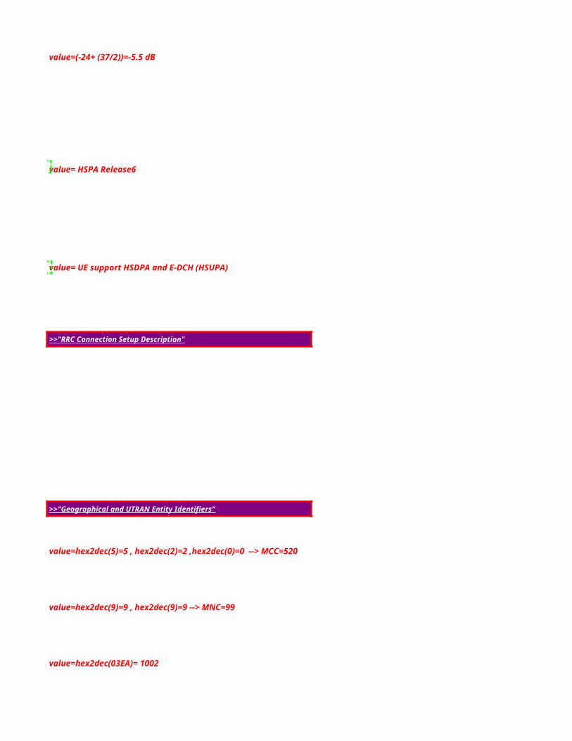
value=(-24+ (37/2))=-5.5 dB
value= HSPA Release6
value= UE support HSDPA and E-DCH (HSUPA)
value=hex2dec(5)=5 , hex2dec(2)=2 ,hex2dec(0)=0 --> MCC=520
value=hex2dec(9)=9 , hex2dec(9)=9 --> MNC=99
value=hex2dec(03EA)= 1002
>>"RRC Connection Setup Description"
>>"Geographical and UTRAN Entity Identifiers"

value=UE capable to support FDD , not TDD
value=Signaling Radio Bearer Information Setup ,RB-1
value=Radio Bearer Mapping

value=Signaling Radio Bearer Information Setup ,RB-2

value=Signaling Radio Bearer Information Setup ,RB-3

value=Signaling Radio Bearer Information Setup ,RB-4

value=BLER Target= -20 dB
value=MaxAllowedULTxPower=24 dBm
value=(-47*2)= -94 dBm (step of 2 dB)
Default Constant value= use Closed Loop Power Control Algorithm1 -22
-22Note :DPCCH_Power_offset is configured by RNC and delivered to UE in RRC Connection Setup.
value= use long SC on Uplink
value=Spreading Factor 64 (Uplink)

value=Spreading Factor 128 (Downlink)
value=Primary Scrambling code=60
value=Spreading Factor 128 (Downlink)
Cell Identity=RNCid(12bits)+Cellid(16bits)
>>"RRC Connection Setup Complete Description"
value=0000011001100000010100101001 => RNCid=bin2dec(000001100110)=102 and Cellid=bin2dec(0000010100101001)=1321

value= not support GSM (Locked UMTS Mode)
value= Chipering Algorithm A5/3

value= support Compressed Mode (CM) uplink and downlink

value= support HSDPA, UE Category 8

RRC: Security Mode Command

RRC: Security Mode Complete

RRC: Uplink Direct Transfer (SM: Activate PDP Context Request)

RANAP: SM: Activate PDP Context Request
RRC: Radio Bearer Setup >>"Radio Bearer Description"


value= Uplink e-DPDCH (HSUPA) channel information

value= Downlink HS-PDSCH channel information

value= HSDPA and HSUPA Serving Cell's Primary SC = 68

RRC: Radio Bearer Setup Complete
RANAP: SM: Activate PDP Context Accept

RRC: Downlink Direct Transfer (SM: Activate PDP Context Accept)
RRC: Physical Channel Reconfiguration (DCCH)


value= PrimarySC=68, no longer a HSDPA & HSUPA serving cell ( HSPA Serving Cell Change)

value= PrimarySC=60 is a new HSDPA&HSUPA serving cell ( HSPA Serving Cell Change)
RRC:Physical Channel Reconfiguration Complete (DCCH)
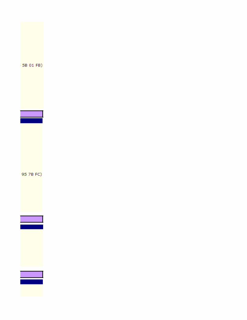
RRC: Uplink Direct Transfer (SM: Deactivate PDP Context Request)
RANAP: SM: Deactivate PDP Context Request
RANAP: SM: Deactivate PDP Context Accept

RRC: Downlink Direct Transfer (SM: Deactivate PDP Context Accept)
RRC: Radio Bearer Release


RRC: Radio Bearer Release Completed
RRC: Downlink Direct Transfer (CC: RRC Connection Release)
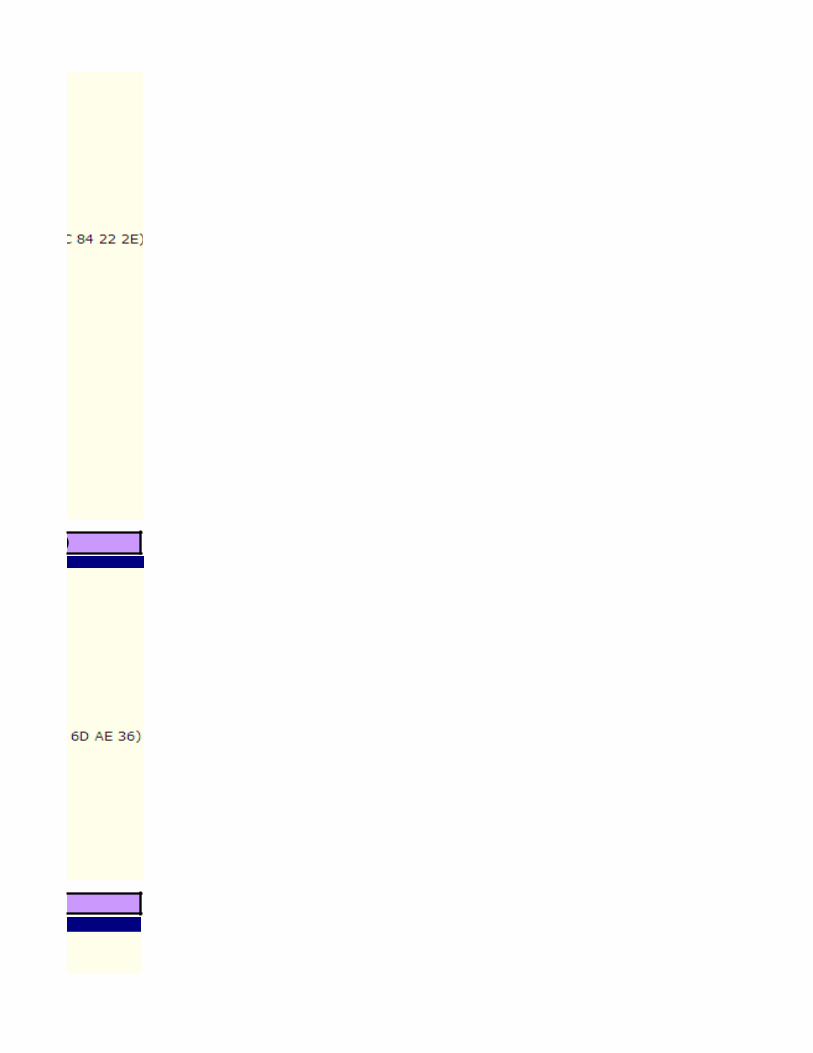
RRC: Uplink Direct Transfer (CC: RRC Connection Release Complete)
RRC:Measurement Report (e1d)


RRC:Measurement Control


DPCCH_Power_offset CPICH_RSCP PCPICH Power UL InterferenceUL DPCCH Initial Power-94 -80 33 -105 -14-94 -70 33 -105 -24
Note :DPCCH_Power_offset is configured by RNC and delivered to UE in RRC Connection Setup.

Cellid=bin2dec(0000010100101001)=1321


value= PrimarySC=68, no longer a HSDPA & HSUPA serving cell ( HSPA Serving Cell Change)


L3 Messages - Intra-Frequency Soft Handover ProcedureUE
Intra-Frequency Soft Handover within NodeB(Softer-HO)
"or"
RRC:Measurement Control
1.RRC: Active Set Update (DCCH)
2. RRC: Active Set Update Complete (DCCH)
Click to return to main page
RRC:Measurement Control
RRC:Measurement Report (e1a)
RRC:Measurement Report (e1c)
2. RRC: Active Set Update Complete (DCCH)
RRC:Measurement Report (e1b)

L3 Messages - Intra-Frequency Soft Handover ProcedureUE NodeB1
Intra-Frequency Soft Handover between NodeBs in a RNC
RRC:Measurement Control
RRC:Measurement Report (e1a)"or"
RRC:Measurement Report (e1c)
1.RRC: Active Set Update (DCCH)
2. RRC: Active Set Update Complete (DCCH)
RRC:Measurement Control
RRC:Measurement Report (e1b)
1.RRC: Active Set Update (DCCH)
2. RRC: Active Set Update Complete (DCCH)

L3 Messages - Intra-Frequency Soft Handover ProcedureUE NodeB2
Intra-Frequency Soft Handover between RNCs
RRC:Measurement Control
RRC:Measurement Report (e1a)"or"
RRC:Measurement Report (e1c)
Note: the following information about the procedure ,
1. During the handover, NodeB 1 is the source NodeB and NodeB 2 is the target NodeB.
2.If IP transport is applied to the Iub interface, no ALCAP procedure is performed on the Iubinterface after radio links are set up or deleted.

ALCAP: Iub User Plane Setup
1.NBAP:Radio Link Restore Indication
1.RRC: Active Set Update (DCCH)
2.RRC: Active Set Update Complete (DCCH)
RRC:Measurement Control
RRC:Measurement Report (e1b)
1.RRC: Active Set Update (DCCH)
2. RRC: Active Set Update Complete (DCCH)

ALCAP: Iub User Plane Release
Note :the following information about the procedure ,
1.During the handover, NodeB 1 is the source NodeB and NodeB 2 is the target NodeB.2. If IP transport is applied to the Iub interface, no ALCAP procedure is performed on the Iub interface after radio links are set up or deleted.3.If IP transport is applied to the Iur interface, no ALCAP procedure is performed on the Iurinterface after radio links are set up or deleted.

L3 Messages - Intra-Frequency Soft Handover ProcedureNodeB1 S-RNC
Intra-Frequency Soft Handover within NodeB(Softer-HO)
1.NBAP:Radio Link Setup Req
2.NBAP:Radio Link Setup Resp
RRC:Measurement Control
1.RRC: Active Set Update (DCCH)
2. RRC: Active Set Update Complete (DCCH)
1.NBAP:Radio Link Deletion Req
2.NBAP:Radio Link Deletion Resp
RRC:Measurement Control
RRC:Measurement Report (e1a)Decision to setup new radio
link
RRC:Measurement Report (e1c)
1.RRC: Active Set Update (DCCH)
2. RRC: Active Set Update Complete (DCCH)
RRC:Measurement Report (e1b)Decision to delete old radio
link

L3 Messages - Intra-Frequency Soft Handover Procedure*Source NodeB2 *Target S-RNC
Intra-Frequency Soft Handover between NodeBs in a RNC
RRC:Measurement Control
RRC:Measurement Report (e1a)
RRC:Measurement Report (e1c)
1.NBAP:Radio Link Setup Req
2.NBAP:Radio Link Setup Resp
ALCAP: Iub User Plane Setup
QAAL2 Establish Request
QAAL2 Establish Confirm
NBAP:Radio Link Restore Indication
1.RRC: Active Set Update (DCCH)
2. RRC: Active Set Update Complete (DCCH)
RRC:Measurement Control
RRC:Measurement Report (e1b)
1.RRC: Active Set Update (DCCH)
2. RRC: Active Set Update Complete (DCCH)
Decision to setup new radio
link
Decision to delete old radio
link

1.NBAP:Radio Link Deletion Req
2.NBAP:Radio Link Deletion Resp
ALCAP: Iub User Plane Release
QAAL2 Release Request
QAAL2 Release Confirm
L3 Messages - Intra-Frequency Soft Handover Procedure*Target D-RNC *Target NodeB1
Intra-Frequency Soft Handover between RNCs
RRC:Measurement Control
RRC:Measurement Report (e1a)
RRC:Measurement Report (e1c)
the following information about the procedure ,
1. During the handover, NodeB 1 is the source NodeB and NodeB 2 is the target NodeB.
2.If IP transport is applied to the Iub interface, no ALCAP procedure is performed on the Iubinterface after radio links are set up or deleted.

1.RNSAP:Radio Link Setup Request
2.NBAP:Radio Link Setup Request
3.NBAP:Radio Link Setup Response
ALCAP: Iub User Plane Setup
1.QAAL2 Establish Request
2.QAAL2 Establish Confirm
1.NBAP:Radio Link Restore Indication4.RNSAP:Radio Link Setup Response
ALCAP: Iur User Plane Setup
1.QAAL2 Establish Request
2.QAAL2 Establish Confirm
2.RNSAP:Radio Link Restore Indication
1.RRC: Active Set Update (DCCH)
2.RRC: Active Set Update Complete (DCCH)
RRC:Measurement Control
RRC:Measurement Report (e1b)
1.RRC: Active Set Update (DCCH)
2. RRC: Active Set Update Complete (DCCH)
1.RNSAP:Radio Link Deletion ReqNBAP:Radio Link Deletion Req
NBAP:Radio Link Deletion Resp

ALCAP: Iub User Plane Release
QAAL2 Release Request
QAAL2 Release Confirm
2.NBAP:Radio Link Deletion Resp
ALCAP: Iur User Plane Release
QAAL2 Release Request
QAAL2 Release Confirm
1.During the handover, NodeB 1 is the source NodeB and NodeB 2 is the target NodeB.2. If IP transport is applied to the Iub interface, no ALCAP procedure is performed on the Iub interface after radio links are set up or deleted.3.If IP transport is applied to the Iur interface, no ALCAP procedure is performed on the Iurinterface after radio links are set up or deleted.

>>Intra-Frequency SHO Algorithm and related parameters (Module II)
S-RNC
Measurement Control: is used to notify the UE of the objects to be measured, neighbor cell list, report method, and event parameters.When measurement conditions are changed, the RNC notifies the UE of new conditions.
Measurement Report: the UE continue measure the radio link condition of serving and neighbour cell and when the measurement reporting criterias are met, the UE reports the results to the RNC as an event. The Measurement report is also can be sent in periodic mode.
Decision to setup new radio
link
Radio Link Addition Procedure is performed to add one or more radio links towards a UE.
Triggering Conditions: The CRNC sends a RADIO LINK ADDITION REQUEST message.
The procedure of radio link setup is described as follows:1.The CRNC sends a RADIO LINK ADDITION REQUEST message to the NodeB. After receiving the message, the NodeB reserves the necessary resources and configures the new radio link or links according to the parameters given in the message.2.The NodeB sends a response message to the CRNC.-If all the requested radio links are added, the NodeB saves the value of the Configuration Generation ID IE contained in the RADIO LINK ADDITION REQUEST message andsends a RADIO LINK ADDITION RESPONSE message.-If any radio link fails to be added, the NodeB sends a RADIO LINK ADDITION FAILURE message. The message contains the failure cause in the Cause IE.
The active set update procedure
Triggering Conditions: The active set update procedure can be triggered in either of the following conditions: Radio link addition or Radio link deletionThe procedure is described as follows:1.The SRNC sends an ACTIVE SET UPDATE message to the UE. If a radio link needs to be added, the message indicates radio link addition. If a radio link needs to be deleted, themessage indicates radio link deletion.2.The UE adds or deletes the radio links according to the Radio Link Addition Informationor Radio Link Removal Information IE contained in the ACTIVE SET UPDATE message.3.The UE sends a response message to the SRNC.-lf adding or deleting the radio links successfully,(AM)Radio Link Control (RLC).-If the ACTIVE SET UPDATE message contains the configuration not supported by the UE or if the active set does not contain the radio links specified by the Radio Link Removal Information IE
Decision to delete old radio
link
Radio Link Deletion Procedure is performed to release resources in a NodeB for one or more established radio links towards a UE
Triggering Conditions: The CRNC sends a RADIO LINK DELETION REQUEST message.The procedure of radio link deletion is described as follows:1.The CRNC sends a RADIO LINK SETUP REQUEST message to the NodeB. After receiving the message, the NodeB deletes the radio links specified by the message2.The NodeB sends a response message to the CRNC.-If the radio link are deleted, the NodeB sends a RADIO LINK DELETION RESPONSE message.-If the radio link fails to be deleted, the NodeB sends a RADIO LINK DELETION RESPONSE message. The message contains the failure cause.
Radio Link Addition
Radio Link Deletion
Measurement Control & Measurement Report
Measurement Control& Measurement Report
Active Set Update
Active Set Update

S-RNC
Radio Link Deletion Procedure is performed to release resources in a NodeB for one or more established radio links towards a UE
Triggering Conditions: The CRNC sends a RADIO LINK DELETION REQUEST message.The procedure of radio link deletion is described as follows:1.The CRNC sends a RADIO LINK SETUP REQUEST message to the NodeB. After receiving the message, the NodeB deletes the radio links specified by the message2.The NodeB sends a response message to the CRNC.-If the radio link are deleted, the NodeB sends a RADIO LINK DELETION RESPONSE message.-If the radio link fails to be deleted, the NodeB sends a RADIO LINK DELETION RESPONSE message. The message contains the failure cause.
Click to return to main pageMeasurement Control: is used to notify the UE of the objects to be measured, neighbor cell list, report method, and event parameters.When measurement conditions are changed, the RNC notifies the UE of new conditions.
Measurement Report: the UE continue measure the radio link condition of serving and neighbour cell and when the measurement reporting criterias are met, the UE reports the results to the RNC as an event. The Measurement report is also can be sent in periodic mode.
The radio link setup procedure (intra-RNC handover or GSM to WCDMA CS handover) is performed to set up a radio link in an SRNC-controlled NodeB for a UE
Triggering Conditions: The CRNC sends a RADIO LINK SETUP REQUEST message.The procedure of radio link setup is described as follows:1.The CRNC sends a RADIO LINK SETUP REQUEST message to the NodeB. After receiving the message, the NodeB reserves the necessary resources and configures the new radio link according to the parameters given in the message.2.The NodeB sends a response message to the CRNC.-If the radio link is set up, the NodeB saves the value of the Configuration Generation ID IE contained in the RADIO LINK SETUP REQUEST message and sends a RADIOLINK SETUP RESPONSE message.-If the radio link fails to be set up, the NodeB sends a RADIO LINK SETUP FAILURE message. The message contains the failure cause.
Decision to setup new radio
link
The Iub user plane setup procedure
Triggering Conditions: The Iub user plane setup procedure can be triggered in one of the following conditions:1. The common transport channels are setup2. The dedicated transport channels are setupThe procedure is described as follows:1.The CRNC uses the ALCAP protocol to send a 2.The NodeB uses the ALCAP protocol to send a response message to the CRNC.-If the Iub data transport bearers are set up,-If an Iub data transport bearer fails to be set up
The radio link restoration procedure (intra-RNC handover or GSM to WCDMA CS handover)synchronization of one or more radio links is achieved or re-achieved
Triggering Conditions: The nodeB detect UL signals from the UE. That is ,the NodeB finishs UL synchronization with the UE
After performing UL synchronization with the UE, the NodeB sends a RADIO LINK RESTORE INDICATION message to the CRNC.
Decision to delete old radio
link
The active set update procedure
Radio Link Setup
Active Set Update
Iub user plane Setup
Iub radio link restore Indication
Measurement Control & Measurement Report
Measurement Control& Measurement Report
Active Set Update

L3 Messages - Intra-Frequency Soft Handover ProcedureNodeB1 *Source S-RNC
Intra-Frequency Soft Handover between RNCs
RRC:Measurement Control
RRC:Measurement Report (e1a)
RRC:Measurement Report (e1c)
Triggering Conditions: The active set update procedure can be triggered in either of the following conditions: Radio link addition or Radio link deletionThe procedure is described as follows:1.The SRNC sends an ACTIVE SET UPDATE message to the UE. If a radio link needs to be added, the message indicates radio link addition. If a radio link needs to be deleted, themessage indicates radio link deletion.2.The UE adds or deletes the radio links according to the Radio Link Addition Informationor Radio Link Removal Information IE contained in the ACTIVE SET UPDATE message.3.The UE sends a response message to the SRNC.-lf adding or deleting the radio links successfully,(AM)Radio Link Control (RLC).-If the ACTIVE SET UPDATE message contains the configuration not supported by the UE or if the active set does not contain the radio links specified by the Radio Link Removal Information IE
Radio Link Deletion Procedure is performed to release resources in a NodeB for one or more established radio links towards a UE
Triggering Conditions: The CRNC sends a RADIO LINK DELETION REQUEST message.The procedure of radio link deletion is described as follows:1.The CRNC sends a RADIO LINK SETUP REQUEST message to the NodeB. After receiving the message, the NodeB deletes the radio links specified by the message2.The NodeB sends a response message to the CRNC.-If the radio link are deleted, the NodeB sends a RADIO LINK DELETION RESPONSE message.-If the radio link fails to be deleted, the NodeB sends a RADIO LINK DELETION RESPONSE message. The message contains the failure cause.
The Iub user plane release procedure is performed to release data transport bearers from the Iub interface.
Triggering Conditions: The transport channels on the Iub user plane need to be removedThe procedure is described as follows:1.The CRNC uses the ALCAP protocol to send a QAAL2 RELEASE REQUEST messageto the NodeB.2.The NodeB uses the ALCAP protocol to send a response message to the CRNC.-If the Iub data transport bearers are released, the NodeB sends a QAAL2 RELEASE CONFIRM message to confirm the release.-lf an Iub data transport bearer fails to be released, the NodeB sends a QAAL2 RELEASECONFIRM message that indicates the failure cause
Click to return to main page
Decision to setup new radio
link
Iub user plane release
Radio Link Deletion
Measurement Control & Measurement Report

1.RNSAP:Radio Link Setup Request
4.RNSAP:Radio Link Setup Response
ALCAP: Iur User Plane Setup
1.QAAL2 Establish Request
2.QAAL2 Establish Confirm
2.RNSAP:Radio Link Restore Indication
1.RRC: Active Set Update (DCCH)
2.RRC: Active Set Update Complete (DCCH)
RRC:Measurement Control
RRC:Measurement Report (e1b)
1.RRC: Active Set Update (DCCH)
2. RRC: Active Set Update Complete (DCCH)
1.RNSAP:Radio Link Deletion Req
Decision to setup new radio
link
Decision to delete old radio
link
Active Set Update
Iub user plane Setup
Iur Radio Link Restore Indication
Iur user plane Setup
Iub Radio Link Restore Indication
Active Set Update
Measurement Control & Measurement Report
Radio Link Setup

2.NBAP:Radio Link Deletion Resp
ALCAP: Iur User Plane Release
QAAL2 Release Request
QAAL2 Release Confirm
Iur user plane release
Iub user plane release
Radio Link Deletion


is used to notify the UE of the objects to be measured, neighbor cell list, report method, and event parameters.When measurement conditions are changed, the RNC notifies the UE of new conditions.
the UE continue measure the radio link condition of serving and neighbour cell and when the measurement reporting criterias are met, the UE reports the results to the RNC as an event. The Measurement report is also can be sent in periodic mode.
Radio Link Addition Procedure is performed to add one or more radio links towards a UE.
Triggering Conditions: The CRNC sends a RADIO LINK ADDITION REQUEST message.
The procedure of radio link setup is described as follows:1.The CRNC sends a RADIO LINK ADDITION REQUEST message to the NodeB. After receiving the message, the NodeB reserves the necessary resources and configures the new radio link or links according to the parameters given in the message.2.The NodeB sends a response message to the CRNC.-If all the requested radio links are added, the NodeB saves the value of the Configuration Generation ID IE contained in the RADIO LINK ADDITION REQUEST message andsends a RADIO LINK ADDITION RESPONSE message.-If any radio link fails to be added, the NodeB sends a RADIO LINK ADDITION FAILURE message. The message contains the failure cause in the Cause IE.
The active set update procedure is performed to update the active set of radio links between theUE and the UTRAN.
Triggering Conditions: The active set update procedure can be triggered in either of the following conditions: Radio link addition or Radio link
The procedure is described as follows:1.The SRNC sends an ACTIVE SET UPDATE message to the UE. If a radio link needs to be added, the message indicates radio link addition. If a radio link needs to be deleted, themessage indicates radio link deletion.2.The UE adds or deletes the radio links according to the Radio Link Addition Informationor Radio Link Removal Information IE contained in the ACTIVE SET UPDATE message.3.The UE sends a response message to the SRNC.-lf adding or deleting the radio links successfully, the UE sends an ACTIVE SETUPDATE COMPLETE message on the DCCH by using Acknowledged Mode (AM)Radio Link Control (RLC).-If the ACTIVE SET UPDATE message contains the configuration not supported by the UE or if the active set does not contain the radio links specified by the Radio Link Removal Information IE, the UE sends an ACTIVE SET UPDATE FAILURE message.
Radio Link Deletion Procedure is performed to release resources in a NodeB for one or more established radio links towards a UE
Triggering Conditions: The CRNC sends a RADIO LINK DELETION REQUEST message.The procedure of radio link deletion is described as follows:1.The CRNC sends a RADIO LINK SETUP REQUEST message to the NodeB. After receiving the message, the NodeB deletes the radio links specified by the
2.The NodeB sends a response message to the CRNC.-If the radio link are deleted, the NodeB sends a RADIO LINK DELETION RESPONSE message.-If the radio link fails to be deleted, the NodeB sends a RADIO LINK DELETION RESPONSE message. The message contains the failure cause.
is used to notify the UE of the objects to be measured, neighbor cell list, report method, and event parameters.When measurement conditions are changed, the RNC notifies the UE of new conditions.
the UE continue measure the radio link condition of serving and neighbour cell and when the measurement reporting criterias are met, the UE reports the results to the RNC as an event. The Measurement report is also can be sent in periodic mode.
The radio link setup procedure (intra-RNC handover or GSM to WCDMA CS handover) is performed to set up a radio link in an SRNC-controlled NodeB for
Triggering Conditions: The CRNC sends a RADIO LINK SETUP REQUEST message.The procedure of radio link setup is described as follows:1.The CRNC sends a RADIO LINK SETUP REQUEST message to the NodeB. After receiving the message, the NodeB reserves the necessary resources and configures the new radio link according to the parameters given in the message.2.The NodeB sends a response message to the CRNC.-If the radio link is set up, the NodeB saves the value of the Configuration Generation ID IE contained in the RADIO LINK SETUP REQUEST message and sends a RADIOLINK SETUP RESPONSE message.-If the radio link fails to be set up, the NodeB sends a RADIO LINK SETUP FAILURE message. The message contains the failure cause.
The Iub user plane setup procedure is performed to set up bearers for data transmission on the Iub interface
Triggering Conditions: The Iub user plane setup procedure can be triggered in one of the following conditions:1. The common transport channels are setup2. The dedicated transport channels are setupThe procedure is described as follows:1.The CRNC uses the ALCAP protocol to send a QAAL2 ESTABLISH REQUEST messageto the NodeB.2.The NodeB uses the ALCAP protocol to send a response message to the CRNC.-If the Iub data transport bearers are set up, the NodeB sends a QAAL2 ESTABLISH CONFIRM message.-If an Iub data transport bearer fails to be set up, the NodeB sends a QAAL2 ESTABLISH RELEASE CONFIRM message.
The radio link restoration procedure (intra-RNC handover or GSM to WCDMA CS handover) is performed for a NodeB to notify the CRNC that the uplink synchronization of one or more radio links is achieved or re-achieved
Triggering Conditions: The nodeB detect UL signals from the UE. That is ,the NodeB finishs UL synchronization with the UE
After performing UL synchronization with the UE, the NodeB sends a RADIO LINK RESTORE INDICATION message to the CRNC.
The active set update procedure is performed to update the active set of radio links between theUE and the UTRAN.

Triggering Conditions: The active set update procedure can be triggered in either of the following conditions: Radio link addition or Radio link
The procedure is described as follows:1.The SRNC sends an ACTIVE SET UPDATE message to the UE. If a radio link needs to be added, the message indicates radio link addition. If a radio link needs to be deleted, themessage indicates radio link deletion.2.The UE adds or deletes the radio links according to the Radio Link Addition Informationor Radio Link Removal Information IE contained in the ACTIVE SET UPDATE message.3.The UE sends a response message to the SRNC.-lf adding or deleting the radio links successfully, the UE sends an ACTIVE SETUPDATE COMPLETE message on the DCCH by using Acknowledged Mode (AM)Radio Link Control (RLC).-If the ACTIVE SET UPDATE message contains the configuration not supported by the UE or if the active set does not contain the radio links specified by the Radio Link Removal Information IE, the UE sends an ACTIVE SET UPDATE FAILURE message.
Radio Link Deletion Procedure is performed to release resources in a NodeB for one or more established radio links towards a UE
Triggering Conditions: The CRNC sends a RADIO LINK DELETION REQUEST message.The procedure of radio link deletion is described as follows:1.The CRNC sends a RADIO LINK SETUP REQUEST message to the NodeB. After receiving the message, the NodeB deletes the radio links specified by the
2.The NodeB sends a response message to the CRNC.-If the radio link are deleted, the NodeB sends a RADIO LINK DELETION RESPONSE message.-If the radio link fails to be deleted, the NodeB sends a RADIO LINK DELETION RESPONSE message. The message contains the failure cause.
The Iub user plane release procedure is performed to release data transport bearers from the Iub interface.
Triggering Conditions: The transport channels on the Iub user plane need to be removedThe procedure is described as follows:1.The CRNC uses the ALCAP protocol to send a QAAL2 RELEASE REQUEST messageto the NodeB.2.The NodeB uses the ALCAP protocol to send a response message to the CRNC.-If the Iub data transport bearers are released, the NodeB sends a QAAL2 RELEASE CONFIRM message to confirm the release.-lf an Iub data transport bearer fails to be released, the NodeB sends a QAAL2 RELEASECONFIRM message that indicates the failure cause
Measurement Control: is used to notify the UE of the objects to be measured, neighbor cell list, report method, and event parameters.When measurement conditions are changed, the RNC notifies the UE of new conditions.
Measurement Report: the UE continue measure the radio link condition of serving and neighbour cell and when the measurement reporting criterias are met, the UE reports the results to the RNC as an event. The Measurement report is also can be sent in periodic mode.
The radio link setup procedure for inter-RNC handover is performed to set up a radio link in a DRNC-controlled NodeB for a UE
Triggering Conditions: The SRNC sends a RADIO LINK SETUP REQUEST messageThe procedure is described as follows:1.The SRNC sends a RADIO LINK SETUP REQUEST message to the DRNC.2.The DRNC sends a RADIO LINK SETUP REQUEST message to the target NodeB.3.The NodeB reserves the necessary resources and configures the new radio link accordingto the parameters given in the message.4.The NodeB reports the radio link setup result to the DRNC-If the radio link is set up, the NodeB saves the value of the Configuration GenerationID IE contained in the RADIO LINK SETUP REQUEST message and sends a RADIOLINK SETUP RESPONSE message.-If the radio link fails to be set up, the NodeB sends a RADIO LINK SETUP FAILURE message.5.The DRNC reports the radio link setup result to the SRNC-If the radio link is set up, the DRNC sends a RADIO LINK SETUP RESPONSEmessage.-If the radio link fails to be set up, the DRNC sends a RADIO LINK SETUP FAILUREmessage, indicating the failure cause.
The Iub user plane setup procedure is performed to set up bearers for data transmission on the Iub interface
Triggering Conditions: The Iub user plane setup procedure can be triggered in one of the following conditions:1. The common transport channels are setup2. The dedicated transport channels are setup
The procedure is described as follows:1.The CRNC uses the ALCAP protocol to send a QAAL2 ESTABLISH REQUEST messageto the NodeB.2.The NodeB uses the ALCAP protocol to send a response message to the CRNC.-If the Iub data transport bearers are set up, the NodeB sends a QAAL2 ESTABLISH CONFIRM message.-If an Iub data transport bearer fails to be set up, the NodeB sends a QAAL2 ESTABLISH RELEASE CONFIRM message.
The radio link restoration procedure for inter-RNC handover is performed for a NodeB to notify the SRNC that the uplink synchronization of one or more radio links is achieved or re-achieved.
Triggering Conditons: The NodeB detects UL signals from the UE. That is, the NodeB finishes UL synchronizationwith the UE.
The procedure is described as follows:1.After performing UL synchronization with the UE, the NodeB sends a RADIO LINKRESTORE INDICATION message to the DRNC.2.The DRNC sends a RADIO LINK RESTORE INDICATION message to the SRNC.
The Iur user plane setup procedure is performed to set up bearers for data transmission on the Iur interface
Triggering Conditons: The DCHs are set up
The procedure is described as follows:1.The SRNC uses the ALCAP protocol to send a QAAL2 ESTABLISH REQUEST messageto the DRNC.2.The DRNC uses the ALCAP protocol to send a response message to the SRNC.-If the Iur data transport bearers are set up, the DRNC sends a QAAL2 ESTABLISHCONFIRM message.-If an Iur data transport bearer fails to be set up, the DRNC sends a QAAL2 ESTABLISHRELEASE CONFIRM message.
Iur Radio Link Restore Indication
Iub Radio Link Restore Indication

The active set update procedure is performed to update the active set of radio links between the UE and the UTRAN.
Triggering Conditions: The active set update procedure can be triggered in either of the following conditions: Radio link addition or Radio link deletion
The procedure is described as follows:1.The SRNC sends an ACTIVE SET UPDATE message to the UE. If a radio link needs to be added, the message indicates radio link addition. If a radio link needs to be deleted, themessage indicates radio link deletion.2.The UE adds or deletes the radio links according to the Radio Link Addition Informationor Radio Link Removal Information IE contained in the ACTIVE SET UPDATE message.3.The UE sends a response message to the SRNC.-lf adding or deleting the radio links successfully, the UE sends an ACTIVE SETUPDATE COMPLETE message on the DCCH by using Acknowledged Mode (AM)Radio Link Control (RLC).-If the ACTIVE SET UPDATE message contains the configuration not supported by the UE or if the active set does not contain the radio links specified by the Radio Link Removal Information IE, the UE sends an ACTIVE SET UPDATE FAILURE message.
The radio link deletion procedure is performed to release resources in a NodeB for one or more established radio links towards a UE.
Triggering Conditions: The CRNC sends a RADIO LINK DELETION REQUEST message.The procedure is described as follows:1.The CRNC sends a RADIO LINK DELETION REQUEST message to the NodeB. After receiving the message, the NodeB deletes the radio links specified by the message.2.The NodeB sends a response message to the CRNC.-If all the radio links are deleted, the NodeB sends a RADIO LINK DELETION RESPONSE message-If any radio link fails to be deleted, the NodeB sends a RADIO LINK DELETIONRESPONSE message. The Criticality Diagnostics field in the message indicates the failure cause.The Iub user plane release procedure is performed to release data transport bearers from the Iub interface.
Triggering Conditions: The transport channels on the Iub user plane need to be removed.The procedure is described as follows:1.The CRNC uses the ALCAP protocol to send a QAAL2 RELEASE REQUEST messageto the NodeB.2.The NodeB uses the ALCAP protocol to send a response message to the CRNC.-If the Iub data transport bearers are released, the NodeB sends a QAAL2 RELEASECONFIRM message to confirm the release.-If an Iub data transport bearer fails to be released, the NodeB sends a QAAL2 RELEASECONFIRM message that indicates the failure cause.
The Iur user plane release procedure is performed to releaseto release data transport bearers from the Iur interface.
Triggering Conditions: The transport channels on the Iub user plane need to be removed.The procedure is described as follows:1.The CRNC uses the ALCAP protocol to send a QAAL2 RELEASE REQUEST messageto the NodeB.2.The NodeB uses the ALCAP protocol to send a response message to the CRNC.-If the Iub data transport bearers are released, the NodeB sends a QAAL2 RELEASECONFIRM message to confirm the release.-If an Iub data transport bearer fails to be released, the NodeB sends a QAAL2 RELEASECONFIRM message that indicates the failure cause.
Iur user plane release

is used to notify the UE of the objects to be measured, neighbor cell list, report method, and event parameters.When
the UE continue measure the radio link condition of serving and neighbour cell and when the measurement reporting criterias are met, the UE reports the results to the RNC as an event. The Measurement report is also can be sent in periodic mode.
1.The CRNC sends a RADIO LINK ADDITION REQUEST message to the NodeB. After receiving the message, the NodeB reserves the necessary resources and
, the NodeB saves the value of the Configuration Generation ID IE contained in the RADIO LINK ADDITION
the NodeB sends a RADIO LINK ADDITION FAILURE message. The message contains the failure cause in the Cause IE.
is performed to update the active set of radio links between theUE and the UTRAN.
The active set update procedure can be triggered in either of the following conditions: Radio link addition or Radio link
1.The SRNC sends an ACTIVE SET UPDATE message to the UE. If a radio link needs to be added, the message indicates radio link addition. If a radio
2.The UE adds or deletes the radio links according to the Radio Link Addition Informationor Radio Link Removal Information IE contained in the
ACTIVE SETUPDATE COMPLETE message on the DCCH by using Acknowledged Mode
-If the ACTIVE SET UPDATE message contains the configuration not supported by the UE or if the active set does not contain the radio links specified
is performed to release resources in a NodeB for one or more established radio links towards a UE
1.The CRNC sends a RADIO LINK SETUP REQUEST message to the NodeB. After receiving the message, the NodeB deletes the radio links specified by the
the NodeB sends a RADIO LINK DELETION RESPONSE message. The message contains the failure cause.

s
is performed to release resources in a NodeB for one or more established radio links towards a UE
1.The CRNC sends a RADIO LINK SETUP REQUEST message to the NodeB. After receiving the message, the NodeB deletes the radio links specified by the
the NodeB sends a RADIO LINK DELETION RESPONSE message. The message contains the failure cause.
is used to notify the UE of the objects to be measured, neighbor cell list, report method, and event parameters.When
the UE continue measure the radio link condition of serving and neighbour cell and when the measurement reporting criterias are met, the UE reports the results to the RNC as an event. The Measurement report is also can be sent in periodic mode.
is performed to set up a radio link in an SRNC-controlled NodeB for
1.The CRNC sends a RADIO LINK SETUP REQUEST message to the NodeB. After receiving the message, the NodeB reserves the necessary resources and
the NodeB saves the value of the Configuration Generation ID IE contained in the RADIO LINK SETUP REQUEST message and
the NodeB sends a RADIO LINK SETUP FAILURE message. The message contains the failure cause.
is performed to set up bearers for data transmission on the Iub interface
The Iub user plane setup procedure can be triggered in one of the following conditions:
QAAL2 ESTABLISH RELEASE CONFIRM message.
is performed for a NodeB to notify the CRNC that the uplink
The nodeB detect UL signals from the UE. That is ,the NodeB finishs UL synchronization with the UE
After performing UL synchronization with the UE, the NodeB sends a RADIO LINK RESTORE INDICATION message to the CRNC.
is performed to update the active set of radio links between theUE and the UTRAN.

The active set update procedure can be triggered in either of the following conditions: Radio link addition or Radio link
1.The SRNC sends an ACTIVE SET UPDATE message to the UE. If a radio link needs to be added, the message indicates radio link addition. If a radio
2.The UE adds or deletes the radio links according to the Radio Link Addition Informationor Radio Link Removal Information IE contained in the
ACTIVE SETUPDATE COMPLETE message on the DCCH by using Acknowledged Mode
-If the ACTIVE SET UPDATE message contains the configuration not supported by the UE or if the active set does not contain the radio links specified
is performed to release resources in a NodeB for one or more established radio links towards a UE
1.The CRNC sends a RADIO LINK SETUP REQUEST message to the NodeB. After receiving the message, the NodeB deletes the radio links specified by the
the NodeB sends a RADIO LINK DELETION RESPONSE message. The message contains the failure cause.
is performed to release data transport bearers from the Iub interface.
the NodeB sends a QAAL2 RELEASE CONFIRM message to confirm the release. the NodeB sends a QAAL2 RELEASECONFIRM message that indicates the failure cause
is used to notify the UE of the objects to be measured, neighbor cell list, report method, and event parameters.When measurement conditions are changed, the RNC notifies the UE of new conditions.
the UE continue measure the radio link condition of serving and neighbour cell and when the measurement reporting criterias are met, the UE reports the results to the RNC as an event. The Measurement report is also can be sent in periodic mode.
is performed to set up a radio link in a DRNC-controlled NodeB for a UE
The SRNC sends a RADIO LINK SETUP REQUEST message
1.The SRNC sends a RADIO LINK SETUP REQUEST message to the DRNC.2.The DRNC sends a RADIO LINK SETUP REQUEST message to the target NodeB.3.The NodeB reserves the necessary resources and configures the new radio link accordingto the parameters given in the message.4.The NodeB reports the radio link setup result to the DRNC
, the NodeB saves the value of the Configuration GenerationID IE contained in the RADIO LINK SETUP REQUEST message and sends
, the NodeB sends a RADIO LINK SETUP FAILURE message.5.The DRNC reports the radio link setup result to the SRNC
the DRNC sends a RADIO LINK SETUP RESPONSEmessage. the DRNC sends a RADIO LINK SETUP FAILUREmessage, indicating the failure cause.
is performed to set up bearers for data transmission on the Iub interface
The Iub user plane setup procedure can be triggered in one of the following conditions:
1.The CRNC uses the ALCAP protocol to send a QAAL2 ESTABLISH REQUEST messageto the NodeB.2.The NodeB uses the ALCAP protocol to send a response message to the CRNC.
, the NodeB sends a QAAL2 ESTABLISH CONFIRM message., the NodeB sends a QAAL2 ESTABLISH RELEASE CONFIRM message.
The radio link restoration procedure for inter-RNC handover is performed for a NodeB to notify the SRNC that the uplink synchronization of one or more
The NodeB detects UL signals from the UE. That is, the NodeB finishes UL synchronizationwith the UE.
1.After performing UL synchronization with the UE, the NodeB sends a RADIO LINKRESTORE INDICATION message to the DRNC.2.The DRNC sends a RADIO LINK RESTORE INDICATION message to the SRNC.
is performed to set up bearers for data transmission on the Iur interface
1.The SRNC uses the ALCAP protocol to send a QAAL2 ESTABLISH REQUEST messageto the DRNC.2.The DRNC uses the ALCAP protocol to send a response message to the SRNC.
, the DRNC sends a QAAL2 ESTABLISHCONFIRM message., the DRNC sends a QAAL2 ESTABLISHRELEASE CONFIRM message.
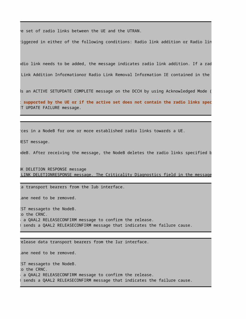
is performed to update the active set of radio links between the UE and the UTRAN.
The active set update procedure can be triggered in either of the following conditions: Radio link addition or Radio link
1.The SRNC sends an ACTIVE SET UPDATE message to the UE. If a radio link needs to be added, the message indicates radio link addition. If a radio link needs to be deleted, themessage indicates radio link deletion.2.The UE adds or deletes the radio links according to the Radio Link Addition Informationor Radio Link Removal Information IE contained in the ACTIVE
, the UE sends an ACTIVE SETUPDATE COMPLETE message on the DCCH by using Acknowledged Mode (AM)Radio
-If the ACTIVE SET UPDATE message contains the configuration not supported by the UE or if the active set does not contain the radio links specified by the UE sends an ACTIVE SET UPDATE FAILURE message.
is performed to release resources in a NodeB for one or more established radio links towards a UE.
The CRNC sends a RADIO LINK DELETION REQUEST message.
1.The CRNC sends a RADIO LINK DELETION REQUEST message to the NodeB. After receiving the message, the NodeB deletes the radio links specified by the
the NodeB sends a RADIO LINK DELETION RESPONSE message the NodeB sends a RADIO LINK DELETIONRESPONSE message. The Criticality Diagnostics field in the message
is performed to release data transport bearers from the Iub interface.
The transport channels on the Iub user plane need to be removed.
1.The CRNC uses the ALCAP protocol to send a QAAL2 RELEASE REQUEST messageto the NodeB.2.The NodeB uses the ALCAP protocol to send a response message to the CRNC.
the NodeB sends a QAAL2 RELEASECONFIRM message to confirm the release. the NodeB sends a QAAL2 RELEASECONFIRM message that indicates the failure cause.
is performed to releaseto release data transport bearers from the Iur interface.
The transport channels on the Iub user plane need to be removed.
1.The CRNC uses the ALCAP protocol to send a QAAL2 RELEASE REQUEST messageto the NodeB.2.The NodeB uses the ALCAP protocol to send a response message to the CRNC.
the NodeB sends a QAAL2 RELEASECONFIRM message to confirm the release. the NodeB sends a QAAL2 RELEASECONFIRM message that indicates the failure cause.


is used to notify the UE of the objects to be measured, neighbor cell list, report method, and event parameters.When measurement
the UE continue measure the radio link condition of serving and neighbour cell and when the measurement reporting criterias are met,
, the NodeB saves the value of the Configuration GenerationID IE contained in the RADIO LINK SETUP REQUEST message and sends

, the NodeB saves the value of the Configuration GenerationID IE contained in the RADIO LINK SETUP REQUEST message and sends
is performed for a NodeB to notify the SRNC that the uplink synchronization of one or more

The active set update procedure can be triggered in either of the following conditions: Radio link addition or Radio link
1.The SRNC sends an ACTIVE SET UPDATE message to the UE. If a radio link needs to be added, the message indicates radio link addition. If a radio link
2.The UE adds or deletes the radio links according to the Radio Link Addition Informationor Radio Link Removal Information IE contained in the ACTIVE
, the UE sends an ACTIVE SETUPDATE COMPLETE message on the DCCH by using Acknowledged Mode (AM)Radio
-If the ACTIVE SET UPDATE message contains the configuration not supported by the UE or if the active set does not contain the radio links specified by
1.The CRNC sends a RADIO LINK DELETION REQUEST message to the NodeB. After receiving the message, the NodeB deletes the radio links specified by the
the NodeB sends a RADIO LINK DELETIONRESPONSE message. The Criticality Diagnostics field in the message
the NodeB sends a QAAL2 RELEASECONFIRM message that indicates the failure cause.
the NodeB sends a QAAL2 RELEASECONFIRM message that indicates the failure cause.

RRC:Measurement ControlClick to return to main page


RRC:Measurement Report (e1a)


RRC:Measurement Report (e1b)


RRC:Measurement Report (e1c)


RRC: Active Set Update (DCCH)

RRC: Active Set Update Complete (DCCH)


RRC: Active Set Update (DCCH)

RRC: Active Set Update Complete (DCCH)


RRC:Measurement Control
value=intraFrequencyMeasurement
value=intraFrequencyCell List
value=IntraFreqCellID of Serving Cell=0
value=Primary Scrambling Code of Serving Cell=74
>>"Measurement Control and Measurement Report"

value=IntraFreqCellID of Serving 1st neighbourCell=1
value=CIO=0 (No offset on this neighbour cell)
value=Primary Scrambling Code of 1st Neighbour Cell=106


value=Intra-freq meas L3 filter coeff=3
value=Intra-freq Measure Quantity use CPICH Ec/No

>>Intra-Frequency SHO Algorithm and related parameters (Module II)
value=event1a triggered by detected and MonitorSet Cells ( DETSET_ADD_TO_ACTSET_SWITCH and DETSET_RPRT_SWITCH is "Active")value=3 dB (IntraRelThdFor1A),step: 0.5
value=0value=Maximum active set size =3 ( if number of cell in Active Set more than 2 then cannot trigger e1a)value=16value=4000msvalue=0value=320ms
value=UE report All Active Set Cells + 6 Monitor/Detected Set Cells
value=event1b triggered by Active Set Cells Onlyvalue=6 dB (IntraRelThdFor1B) ,step: 0.5value=0value=0value=640ms
value=UE report All 3 Active Set Cells
value=event1C triggered when Active Set is full (Maximum 3 cells in Active Set)value=16
value=4000msvalue=4 dB (1C hysteresis),step: 0.5

value=640ms
value=UE report All Active Set Cells + 6 Monitor/Detected Set Cells
value=4dB (1D hysteresis),step: 0.5value=640ms
value=UE report All Active Set Cells +3 Monitor Set Cells
value=event1f triggered by Active Set Cells Only
value= 1F event absolute EcNo threshold = -24 dBvalue= 4 dB,step: 0.5value=640ms
value=UE report All 3 Active Set Cells
RRC:Measurement Report (e1a) >>"Measurement Report"

value=CPICH Ec/No= -24+(25/2) = -11.5 dBvalue=CPICH RSCP= -115+32= -83 dBm


value=Event1a is triggered

value=To add neighbour Primary Scrambling Code=13 into Active Set
RRC:Measurement Report (e1b)

value=CPICH Ec/No= -24+(31/2) = -8.5 dBvalue=CPICH RSCP= -115+34= -81 dBm
value=CPICH Ec/No= -24+(7/2) = -20.5 dBvalue=CPICH RSCP= -115+22= -93 dBm
value=Event1b is triggered

value=To delete neighbour Primary Scrambling Code=74 from Active Set
RRC:Measurement Report (e1c)

value=CPICH Ec/No= -24+(23/2) = -12.5 dBvalue=CPICH RSCP= -115+30= -85 dBm

value=CPICH Ec/No= -24+(20/2) = -14 dBvalue=CPICH RSCP= -115+29= -86 dBm
value=CPICH Ec/No= -24+(8/2) = -20 dBvalue=CPICH RSCP= -115+23= -92 dBm
value=Event1c is triggered
value=To replace Cell Primary Scrambling Code=56 by Cell Primary Scrambling Code=106

RRC: Active Set Update (DCCH)

RRC: Active Set Update Complete (DCCH)


RRC: Active Set Update (DCCH)

RRC: Active Set Update Complete (DCCH)


value=event1a triggered by detected and MonitorSet Cells ( DETSET_ADD_TO_ACTSET_SWITCH and DETSET_RPRT_SWITCH is "Active")
value=Maximum active set size =3 ( if number of cell in Active Set more than 2 then cannot trigger e1a)

L3 Messages - Intra-Frequency Hard Handover ProcedureUE NodeB1
Intra-Frequency Hard Handover between NodeBs in a RNC
RRC:Measurement Control
RRC:Measurement Report (e1d)
1.RRC: Physical Channel Reconfiguration (DCCH)
2. RRC:Physical Channel Reconfiguration Complete (DCCH)
Click to return to main page
Stop Rx/Tx

ALCAP: Iub User Plane Release
L3 Messages - Intra-Frequency Hard Handover ProcedureUE NodeB2
Intra-Frequency Hard Handover between RNCs
RRC:Measurement Control
RRC:Measurement Report (e1d)
Start Rx
Note: the following information about the procedure ,
1. During the handover, NodeB 1 is the source NodeB and NodeB 2 is the target NodeB.
2.If IP transport is applied to the Iub interface, no ALCAP procedure is performed on the Iub interface after radio links are set up or deleted.

ALCAP: Iub User Plane Setup
1.NBAP:Radio Link Restore Indication
Start Tx
1. RRC:Physical Channel Reconfiguration (DCCH)
2. RRC:Physical Channel Reconfiguration Complete (DCCH)

Note :the following information about the procedure ,
1.During the handover, NodeB 1 is the source NodeB and NodeB 2 is the target NodeB.2. If IP transport is applied to the Iub interface, no ALCAP procedure is performed on the Iub interface after radio links are set up or deleted.3.If IP transport is applied to the Iur interface, no ALCAP procedure is performed on the Iurinterface after radio links are set up or deleted.

L3 Messages - Intra-Frequency Hard Handover Procedure*Source NodeB2 *Target S-RNC
Intra-Frequency Hard Handover between NodeBs in a RNC
RRC:Measurement Control
RRC:Measurement Report (e1d)
1.NBAP:Radio Link Setup Req
Start Rx
2.NBAP:Radio Link Setup Resp
ALCAP: Iub User Plane Setup
1.QAAL2 Establish Request
2.QAAL2 Establish Confirm
NBAP:Radio Link Restore Indication
Start Tx
1.RRC: Physical Channel Reconfiguration (DCCH)
2. RRC:Physical Channel Reconfiguration Complete (DCCH)
1.NBAP:Radio Link Deletion Req
Decision to setup new radio
link
Decision to delete old radio
link

2.NBAP:Radio Link Deletion Resp
ALCAP: Iub User Plane Release
1.QAAL2 Release Request
2.QAAL2 Release Confirm
L3 Messages - Intra-Frequency Hard Handover Procedure*Target D-RNC *Target NodeB1
Intra-Frequency Hard Handover between RNCs
RRC:Measurement Control
RRC:Measurement Report (e1d)
1.RNSAP:Radio Link Setup Request
2.NBAP:Radio Link Setup Request
the following information about the procedure ,
1. During the handover, NodeB 1 is the source NodeB and NodeB 2 is the target NodeB.
2.If IP transport is applied to the Iub interface, no ALCAP procedure is performed on the Iub interface after radio links are set up or deleted.
M easurem ent Control& M easurem ent Report
Active SetUpdate
Iub user plane Setup
Iur Radio Link Restore Indication
Iur user plane Setup
Iub Radio Link Restore Indication
Radio Link Setup
M easurem ent Control& M easurem ent Report
Active SetUpdate
Iub user plane Setup
Iur Radio Link Restore Indication
Iur user plane Setup
Iub Radio Link Restore Indication
Radio Link Setup

3.NBAP:Radio Link Setup Response
ALCAP: Iub User Plane Setup
1.QAAL2 Establish Request
2.QAAL2 Establish Confirm
1.NBAP:Radio Link Restore Indication2.RNSAP:Radio Link Setup Response
ALCAP: Iur User Plane Setup
1.QAAL2 Establish Request
2.QAAL2 Establish Confirm
2.RNSAP:Radio Link Restore Indication
1. RRC:Physical Channel Reconfiguration (DCCH)
2. RRC:Physical Channel Reconfiguration Complete (DCCH)
ALCAP: Iub User Plane Release
Stop Rx/Tx

ALCAP: Iur User Plane Release
1.QAAL2 Release Request
2.QAAL2 Release Confirm
1.During the handover, NodeB 1 is the source NodeB and NodeB 2 is the target NodeB.2. If IP transport is applied to the Iub interface, no ALCAP procedure is performed on the Iub interface after radio links are set up or deleted.3.If IP transport is applied to the Iur interface, no ALCAP procedure is performed on the Iurinterface after radio links are set up or deleted.

>>Intra-Frequency HHO Algorithm and related parameters
S-RNCMeasurement Control is used to notify the UE of the objects to be measured, neighbor cell list, report method, and event parameters.When measurement conditions are changed, the RNC notifies the UE of new conditions.
Measurement Report, the UE continue measure the radio link condition of serving and neighbour cell and when the measurement reporting criterias are met, the UE reports the results to the RNC as an event. The Measurement report is also can be sent in periodic mode.
The radio link setup procedure (intra-RNC handover or GSM to WCDMA CS handover) is performed to set up a radio link in an SRNC-controlled NodeB for a UE
The procedure of radio link setup is described as follows:
1.The CRNC sends a RADIO LINK SETUP REQUEST message to the NodeB. After receiving the message, the NodeB reserves the necessary resources and configures the new radio link according to the parameters given in the message.2.The NodeB sends a response message to the CRNC.If the radio link is set up, the NodeB saves the value of the Configuration Generation ID IE contained in the RADIO LINK SETUP REQUEST message and sends a RADIOLINK SETUP RESPONSE message.If the radio link fails to be set up, the NodeB sends a RADIO LINK SETUP FAILURE message. The message contains the failure cause.
Decision to setup new radio
link
The Iub user plane setup procedure is performed to set up bearers for data transmission on the Iub interface
The procedure is described as follows:1.The CRNC uses the ALCAP protocol to send a QAAL2 ESTABLISH REQUEST messageto the NodeB.2.The NodeB uses the ALCAP protocol to send a response message to the CRNC.lIf the Iub data transport bearers are set up, the NodeB sends a QAAL2 ESTABLISH CONFIRM message.If an Iub data transport bearer fails to be set up, the NodeB sends a QAAL2 ESTABLISH RELEASE CONFIRM message.
The radio link restoration procedure (intra-RNC handover or GSM to WCDMA CS handover)is performed for a NodeB to notify the CRNC that the uplink synchronization of one or more radio links is achieved or re-achieved
After performing UL synchronization with the UE, the NodeB sends a RADIO LINK RESTOREINDICATION message to the CRNC.
Decision to delete old radio
link
The physical channel reconfiguration procedure is performed to set up, reconfigure, or releasea physical channelThe procedure is described as follows:1.The SRNC sends a PHYSICAL CHANNEL RECONFIGURATION message to the UE to request reconfiguration of a physical channel.2.The UE saves the IEs of the UE, Radio Bearer (RB), transport channel, and physical channel.The UE sends a response message to the SRNC.->If successfully reconfiguring the physical channels specified by the PHYSICALCHANNEL RECONFIGURATION message, the UE sends a PHYSICAL CHANNELRECONFIGURATION COMPLETE message on the uplink DCCH by using AM RLC ->If failing to reconfigure the physical channels specified by the PHYSICAL CHANNELRECONFIGURATION message, the UE restores the configuration to the old physicalchannel configuration and sends a PHYSICAL CHANNEL RECONFIGURATION FAILURE message on the DCCH by using AM RLC. The value of the Failure cause IE contained in the PHYSICAL CHANNEL RECONFIGURATION FAILURE message is "physical channel failure".
Radio Link Setup
Physical Reconfiguration
Radio Link Deletion
Iub user plane Setup
Iub radio link restore Indication
Measurement Control & Measurement Report

L3 Messages - Intra-Frequency Hard Handover ProcedureNodeB1 *Source S-RNC *Source
Intra-Frequency Hard Handover between RNCs>>Measurement Control&Report Description
RRC:Measurement Control
RRC:Measurement Report (e1d)
1.RNSAP:Radio Link Setup Request
The physical channel reconfiguration procedure is performed to set up, reconfigure, or releasea physical channelThe procedure is described as follows:1.The SRNC sends a PHYSICAL CHANNEL RECONFIGURATION message to the UE to request reconfiguration of a physical channel.2.The UE saves the IEs of the UE, Radio Bearer (RB), transport channel, and physical channel.The UE sends a response message to the SRNC.->If successfully reconfiguring the physical channels specified by the PHYSICALCHANNEL RECONFIGURATION message, the UE sends a PHYSICAL CHANNELRECONFIGURATION COMPLETE message on the uplink DCCH by using AM RLC ->If failing to reconfigure the physical channels specified by the PHYSICAL CHANNELRECONFIGURATION message, the UE restores the configuration to the old physicalchannel configuration and sends a PHYSICAL CHANNEL RECONFIGURATION FAILURE message on the DCCH by using AM RLC. The value of the Failure cause IE contained in the PHYSICAL CHANNEL RECONFIGURATION FAILURE message is "physical channel failure".
The radio link deletion procedure is performed to release resources in a NodeB for one or more established radio links towards a UE.The procedure is described as follows:1.The CRNC sends a RADIO LINK DELETION REQUEST specified by the message.2.The NodeB sends a response message to the CRNC.lf all the radio links are deleted, the NodeB sends a message.3. lf any radio link fails to be deleted, the NodeB sends a Rthe message indicates the failure cause.
The Iub user plane release procedure is performed to release data transport bearers from the Iubinterface.The procedure is described as follows:1.The CRNC uses the ALCAP protocol to send a QAAL2 RELEASE REQUEST messageto the NodeB.2.The NodeB uses the ALCAP protocol to send a response message to the CRNC.->If the Iub data transport bearers are released, the NodeB sends a QAAL2 RELEASE CONFIRM message to confirm the release.->lf an Iub data transport bearer fails to be released, the NodeB sends a QAAL2 RELEASECONFIRM message that indicates the failure cause
Click to return to main page
Decision to setup new radio link
Iub user plane release
Measurement Control & Measurement Report

2.RNSAP:Radio Link Setup Response
ALCAP: Iur User Plane Setup
1.QAAL2 Establish Request
2.QAAL2 Establish Confirm
2.RNSAP:Radio Link Restore Indication
1. RRC:Physical Channel Reconfiguration (DCCH)
2. RRC:Physical Channel Reconfiguration Complete (DCCH)
1.NBAP:Radio Link Deletion Req
2.NBAP:Radio Link Deletion Resp
ALCAP: Iub User Plane Release
1.QAAL2 Release Request
2.QAAL2 Release Confirm
Decision to delete old radio link
Stop Rx/Tx
Physical Reconfiguration
Iub user plane Setup
Iur Radio Link Restore Indication
Iur user plane Setup
Iub Radio Link Restore Indication
Radio Link Deletion
Iub user plane release
Radio Link Setup

ALCAP: Iur User Plane Release
1.QAAL2 Release Request
2.QAAL2 Release Confirm
Iur user plane release

Measurement Control is used to notify the UE of the objects to be measured, neighbor cell list, report method, and event parameters.When measurement conditions are changed, the RNC notifies the UE of new conditions.
Measurement Report, the UE continue measure the radio link condition of serving and neighbour cell and when the measurement reporting criterias are met, the UE reports the results to the RNC as an event. The Measurement report is also can be sent in periodic mode.
radio link setup procedure (intra-RNC handover or GSM to WCDMA CS handover) is performed to set up a radio link in an SRNC-controlled
The procedure of radio link setup is described as follows:
1.The CRNC sends a RADIO LINK SETUP REQUEST message to the NodeB. After receiving the message, the NodeB reserves the necessary resources and configures the new radio link according to the parameters given in the message.2.The NodeB sends a response message to the CRNC.If the radio link is set up, the NodeB saves the value of the Configuration Generation ID IE contained in the RADIO LINK SETUP REQUEST message and sends a RADIOLINK SETUP RESPONSE message.If the radio link fails to be set up, the NodeB sends a RADIO LINK SETUP FAILURE message. The message contains the failure cause.
Iub user plane setup procedure is performed to set up bearers for data transmission on the Iub interface
The procedure is described as follows:1.The CRNC uses the ALCAP protocol to send a QAAL2 ESTABLISH REQUEST messageto the NodeB.2.The NodeB uses the ALCAP protocol to send a response message to the CRNC.lIf the Iub data transport bearers are set up, the NodeB
QAAL2 ESTABLISH CONFIRM message.If an Iub data transport bearer fails to be set up, the NodeB sends a QAAL2 ESTABLISH RELEASE
radio link restoration procedure (intra-RNC handover or GSM to WCDMA CS handover)is performed for a NodeB to notify the CRNC that the uplink synchronization of one or more radio links is achieved or re-achieved
After performing UL synchronization with the UE, the NodeB sends a RADIO LINK RESTOREINDICATION message to the CRNC.
physical channel reconfiguration procedure is performed to set up, reconfigure, or releasea physical channelThe procedure is described as follows:1.The SRNC sends a PHYSICAL CHANNEL RECONFIGURATION message to the UE to request reconfiguration of a physical channel.2.The UE saves the IEs of the UE, Radio Bearer (RB), transport channel, and physical channel.The UE sends a response message to the
->If successfully reconfiguring the physical channels specified by the PHYSICALCHANNEL RECONFIGURATION message, the UE sends a PHYSICAL CHANNELRECONFIGURATION COMPLETE message on the uplink DCCH by using AM RLC ->If failing to reconfigure the physical channels specified by the PHYSICAL CHANNELRECONFIGURATION message, the UE restores the configuration to the old physicalchannel configuration and sends a PHYSICAL CHANNEL RECONFIGURATION FAILURE message on the DCCH by using AM RLC. The value of the Failure cause IE contained in the PHYSICAL CHANNEL RECONFIGURATION FAILURE message is "physical

>>Measurement Control&Report Description
physical channel reconfiguration procedure is performed to set up, reconfigure, or releasea physical channelThe procedure is described as follows:1.The SRNC sends a PHYSICAL CHANNEL RECONFIGURATION message to the UE to request reconfiguration of a physical channel.2.The UE saves the IEs of the UE, Radio Bearer (RB), transport channel, and physical channel.The UE sends a response message to the
->If successfully reconfiguring the physical channels specified by the PHYSICALCHANNEL RECONFIGURATION message, the UE sends a PHYSICAL CHANNELRECONFIGURATION COMPLETE message on the uplink DCCH by using AM RLC ->If failing to reconfigure the physical channels specified by the PHYSICAL CHANNELRECONFIGURATION message, the UE restores the configuration to the old physicalchannel configuration and sends a PHYSICAL CHANNEL RECONFIGURATION FAILURE message on the DCCH by using AM RLC. The value of the Failure cause IE contained in the PHYSICAL CHANNEL RECONFIGURATION FAILURE message is "physical
radio link deletion procedure is performed to release resources in a NodeB for one or more established radio links towards a UE.The procedure is described as follows:1.The CRNC sends a RADIO LINK DELETION REQUEST message to the NodeB. After receiving the message, the NodeB deletes the radio links specified by the message.2.The NodeB sends a response message to the CRNC.lf all the radio links are deleted, the NodeB sends a RADIO LINK DELETION RESPONSE
3. lf any radio link fails to be deleted, the NodeB sends a RADIO LINK DELETION RESPONSE message. The Criticality Diagnostics field in the message indicates the failure cause.
Iub user plane release procedure is performed to release data transport bearers from the Iubinterface.The procedure is described as follows:1.The CRNC uses the ALCAP protocol to send a QAAL2 RELEASE REQUEST messageto the NodeB.2.The NodeB uses the ALCAP protocol to send a response message to the CRNC.->If the Iub data transport bearers are released, the NodeB sends a QAAL2 RELEASE CONFIRM message to confirm the release.->lf an Iub data transport bearer fails to be released, the NodeB sends a QAAL2 RELEASECONFIRM message that indicates the failure
Click to return to main page
Measurement Control is used to notify the UE of the objects to be measured, neighbor cell list, report method, and event parameters.When measurement conditions are changed, the RNC notifies the UE of new conditions.
Measurement Report, the UE continue measure the radio link condition of serving and neighbour cell and when the measurement reporting criterias are met, the UE reports the results to the RNC as an event. The Measurement report is also can be sent in periodic mode.
The radio link setup procedure for inter-RNC handover is performed to set up a radio link in a DRNC-controlled NodeB for a UEThe procedure is described as follows:1.The SRNC sends a RADIO LINK SETUP REQUEST message to the DRNC.2.The DRNC sends a RADIO LINK SETUP REQUEST message to the target NodeB.3.The NodeB reserves the necessary resources and configures the new radio link according to the parameters given in the message.The NodeB reports the radio link setup result to the DRNC.->If the radio link is set up, the NodeB saves the value of the Configuration GenerationID IE contained in the RADIO LINK SETUP REQUEST message and sends a RADIOLINK SETUP RESPONSE message.->If the radio link fails to be set up, the NodeB sends a RADIO LINK SETUP FAILUREmessage.4.The DRNC reports the radio link setup result to the SRNC.->If the radio link is set up, the DRNC sends a RADIO LINK SETUP RESPONSEmessage.->If the radio link fails to be set up, the DRNC sends a RADIO LINK SETUP FAILURE message, indicating the failure cause.

The radio link setup procedure for inter-RNC handover is performed to set up a radio link in a DRNC-controlled NodeB for a UEThe procedure is described as follows:1.The SRNC sends a RADIO LINK SETUP REQUEST message to the DRNC.2.The DRNC sends a RADIO LINK SETUP REQUEST message to the target NodeB.3.The NodeB reserves the necessary resources and configures the new radio link according to the parameters given in the message.The NodeB reports the radio link setup result to the DRNC.->If the radio link is set up, the NodeB saves the value of the Configuration GenerationID IE contained in the RADIO LINK SETUP REQUEST message and sends a RADIOLINK SETUP RESPONSE message.->If the radio link fails to be set up, the NodeB sends a RADIO LINK SETUP FAILUREmessage.4.The DRNC reports the radio link setup result to the SRNC.->If the radio link is set up, the DRNC sends a RADIO LINK SETUP RESPONSEmessage.->If the radio link fails to be set up, the DRNC sends a RADIO LINK SETUP FAILURE message, indicating the failure cause.
The Iub user plane setup procedure is performed to set up bearers for data transmission on the Iub interfaceThe procedure is described as follows:
1.The CRNC uses the ALCAP protocol to send a QAAL2 ESTABLISH REQUEST messageto the NodeB.2.The NodeB uses the ALCAP protocol to send a response message to the CRNC.->If the Iub data transport bearers are set up, the NodeB sends a QAAL2 ESTABLISH CONFIRM message.->If an Iub data transport bearer fails to be set up, the NodeB sends a QAAL2 ESTABLISH RELEASE CONFIRM message
The radio link restoration procedure for inter-RNC handover is performed for a NodeB to notify the SRNC that the uplink synchronization of one or more radio links is achieved or re-achieved.
1.After performing UL synchronization with the UE, the NodeB sends a RADIO LINKRESTORE INDICATION message to the DRNC.2.The DRNC sends a RADIO LINK RESTORE INDICATION message to the SRNC.
The Iur user plane setup procedure is performed to set up bearers for data transmission on the Iur interfaceThe procedure is described as follows:
1.The SRNC uses the ALCAP protocol to send a QAAL2 ESTABLISH REQUEST message to the DRNC.2.The DRNC uses the ALCAP protocol to send a response message to the SRNC.->If the Iur data transport bearers are set up, the DRNC sends a QAAL2 ESTABLISHCONFIRM message.->If an Iur data transport bearer fails to be set up, the DRNC sends a QAAL2 ESTABLISHRELEASE CONFIRM message.
The physical channel reconfiguration procedure is performed to set up, reconfigure, or releasea physical channel
The procedure is described as follows:1.The SRNC sends a PHYSICAL CHANNEL RECONFIGURATION message to the UE to request reconfiguration of a physical channel.2.The UE saves the IEs of the UE, Radio Bearer (RB), transport channel, and physical channel.The UE sends a response message to the SRNC.->If successfully reconfiguring the physical channels specified by the PHYSICALCHANNEL RECONFIGURATION message, the UE sends a PHYSICAL CHANNELRECONFIGURATION COMPLETE message on the uplink DCCH by using AM RLC ->If failing to reconfigure the physical channels specified by the PHYSICAL CHANNELRECONFIGURATION message, the UE restores the configuration to the old physicalchannel configuration and sends a PHYSICAL CHANNEL RECONFIGURATION FAILURE message on the DCCH by using AM RLC. The value of the Failure cause IE contained in the PHYSICAL CHANNEL RECONFIGURATION FAILURE message is "physical channel failure".
The radio link deletion procedure is performed to release resources in a NodeB for one or more established radio links towards a UE.
The procedure is described as follows:1.The CRNC sends a RADIO LINK DELETION REQUEST message to the NodeB. After receiving the message, the NodeB deletes the radio links specified by the message.2.The NodeB sends a response message to the CRNC.
Iur Radio Link Restore Indication
Iub Radio Link Restore Indication

2.The NodeB sends a response message to the CRNC.->lf all the radio links are deleted, the NodeB sends a RADIO LINK DELETION RESPONSE ->lf any radio link fails to be deleted, the NodeB sends a RADIO LINK DELETION RESPONSEfailure cause.
The Iub user plane release procedure is performed to release data transport bearers from the Iubinterface.
The procedure is described as follows:1.The CRNC uses the ALCAP protocol to send a QAAL2 RELEASE REQUEST messageto the NodeB.2.The NodeB uses the ALCAP protocol to send a response message to the CRNC.->If the Iub data transport bearers are released, the NodeB sends a QAAL2 RELEASE CONFIRM->lf an Iub data transport bearer fails to be released, the NodeB sends a QAAL2 RELEASECONFIRM message that indicates the failure cause
The Iur user plane release procedure is performed to release data transport bearers from the Iur interface
The procedure is described as follows:1.The SRNC uses the ALCAP protocol to send a QAAL2 RELEASE REQUEST messageto the DRNC.2.The DRNC uses the ALCAP protocol to send a response message to the SRNC.->If the Iur data transport bearers are released, the DRNC sends a QAAL2 RELEASECONFIRM message to confirm the release.->If an Iur data transport bearer fails to be released, the DRNC sends a QAAL2 RELEASECONFIRM message that indicates the failure cause.

is used to notify the UE of the objects to be measured, neighbor cell list, report method, and event
the UE continue measure the radio link condition of serving and neighbour cell and when the measurement reporting criterias are met, the UE reports the results to the RNC as an event. The Measurement report is also can be sent in periodic mode.
(intra-RNC handover or GSM to WCDMA CS handover) is performed to set up a radio link in an SRNC-controlled
1.The CRNC sends a RADIO LINK SETUP REQUEST message to the NodeB. After receiving the message, the NodeB reserves the necessary
2.The NodeB sends a response message to the CRNC.If the radio link is set up, the NodeB saves the value of the Configuration Generation ID IE contained in the RADIO LINK SETUP REQUEST message and sends a RADIOLINK SETUP RESPONSE message.If the radio link fails to be set up, the NodeB sends a RADIO LINK SETUP FAILURE message. The message contains the failure cause.
procedure is performed to set up bearers for data transmission on the Iub interface
2.The NodeB uses the ALCAP protocol to send a response message to the CRNC.lIf the Iub data transport bearers are set up, the NodeB message.If an Iub data transport bearer fails to be set up, the NodeB sends a QAAL2 ESTABLISH RELEASE
procedure (intra-RNC handover or GSM to WCDMA CS handover)is performed for a NodeB to notify the CRNC that the
After performing UL synchronization with the UE, the NodeB sends a RADIO LINK RESTOREINDICATION message to the CRNC.
procedure is performed to set up, reconfigure, or releasea physical channel
1.The SRNC sends a PHYSICAL CHANNEL RECONFIGURATION message to the UE to request reconfiguration of a physical channel.2.The UE saves the IEs of the UE, Radio Bearer (RB), transport channel, and physical channel.The UE sends a response message to the
->If successfully reconfiguring the physical channels specified by the PHYSICALCHANNEL RECONFIGURATION message, the UE sends a
->If failing to reconfigure the physical channels specified by the PHYSICAL CHANNELRECONFIGURATION message, the UE restores the configuration to the old physicalchannel configuration and sends a PHYSICAL CHANNEL RECONFIGURATION FAILURE message on the DCCH by using AM RLC. The value of the Failure cause IE contained in the PHYSICAL CHANNEL RECONFIGURATION FAILURE message is "physical
procedure is performed to release resources in a NodeB for one or more established radio links towards a UE.
message to the NodeB. After receiving the message, the NodeB deletes the radio links
2.The NodeB sends a response message to the CRNC.lf all the radio links are deleted, the NodeB sends a RADIO LINK DELETION RESPONSE
message. The Criticality Diagnostics field in
->If the Iub data transport bearers are released, the NodeB sends a QAAL2 RELEASE CONFIRM message to confirm the release.->lf an Iub data transport bearer fails to be released, the NodeB sends a QAAL2 RELEASECONFIRM message that indicates the failure
is used to notify the UE of the objects to be measured, neighbor cell list, report method, and event parameters.When measurement conditions
the UE continue measure the radio link condition of serving and neighbour cell and when the measurement reporting criterias are met, the UE reports the results to the RNC as an event. The Measurement report is also can be sent in periodic mode.
The radio link setup procedure for inter-RNC handover is performed to set up a radio link in a DRNC-controlled NodeB for a UE
1.The SRNC sends a RADIO LINK SETUP REQUEST message to the DRNC.2.The DRNC sends a RADIO LINK SETUP REQUEST message to the target NodeB.3.The NodeB reserves the necessary resources and configures the new radio link according to the parameters given in the message.The NodeB reports the radio
->If the radio link is set up, the NodeB saves the value of the Configuration GenerationID IE contained in the RADIO LINK SETUP REQUEST message and sends a
->If the radio link fails to be set up, the NodeB sends a RADIO LINK SETUP FAILUREmessage.
->If the radio link is set up, the DRNC sends a RADIO LINK SETUP RESPONSEmessage.->If the radio link fails to be set up, the DRNC sends a RADIO LINK SETUP FAILURE message, indicating the failure cause.
procedure is performed to set up bearers for data transmission on the Iub interface
1.The CRNC uses the ALCAP protocol to send a QAAL2 ESTABLISH REQUEST messageto the NodeB.2.The NodeB uses the ALCAP protocol to send a response message to the CRNC.->If the Iub data transport bearers are set up, the NodeB sends a QAAL2 ESTABLISH CONFIRM message.->If an Iub data transport bearer fails to be set up, the NodeB sends a QAAL2 ESTABLISH RELEASE CONFIRM message
procedure for inter-RNC handover is performed for a NodeB to notify the SRNC that the uplink synchronization of one or more radio links
1.After performing UL synchronization with the UE, the NodeB sends a RADIO LINKRESTORE INDICATION message to the DRNC.2.The DRNC sends a RADIO LINK RESTORE INDICATION message to the SRNC.
procedure is performed to set up bearers for data transmission on the Iur interface
1.The SRNC uses the ALCAP protocol to send a QAAL2 ESTABLISH REQUEST message to the DRNC.2.The DRNC uses the ALCAP protocol to send a response message to the SRNC.->If the Iur data transport bearers are set up, the DRNC sends a QAAL2 ESTABLISHCONFIRM message.->If an Iur data transport bearer fails to be set up, the DRNC sends a QAAL2 ESTABLISHRELEASE CONFIRM message.
procedure is performed to set up, reconfigure, or releasea physical channel
1.The SRNC sends a PHYSICAL CHANNEL RECONFIGURATION message to the UE to request reconfiguration of a physical channel.2.The UE saves the IEs of the UE, Radio Bearer (RB), transport channel, and physical channel.The UE sends a response message to the SRNC.->If successfully reconfiguring the physical channels specified by the PHYSICALCHANNEL RECONFIGURATION message, the UE sends a PHYSICAL CHANNELRECONFIGURATION
->If failing to reconfigure the physical channels specified by the PHYSICAL CHANNELRECONFIGURATION message, the UE restores the configuration to the old physicalchannel configuration and sends a PHYSICAL CHANNEL RECONFIGURATION FAILURE message on the DCCH by using AM RLC. The value of the Failure cause IE contained in the PHYSICAL CHANNEL RECONFIGURATION FAILURE message is "physical channel failure".
procedure is performed to release resources in a NodeB for one or more established radio links towards a UE.
message to the NodeB. After receiving the message, the NodeB deletes the radio links specified by the message.

RADIO LINK DELETION RESPONSE message.ADIO LINK DELETION RESPONSE message. The Criticality Diagnostics field in the message indicates the
procedure is performed to release data transport bearers from the Iubinterface.
QAAL2 RELEASE REQUEST messageto the NodeB.2.The NodeB uses the ALCAP protocol to send a response message to the CRNC.->If the Iub data transport bearers are released, the NodeB sends a QAAL2 RELEASE CONFIRM message to confirm the release.->lf an Iub data transport bearer fails to be released, the NodeB sends a QAAL2 RELEASECONFIRM message that indicates the failure cause
procedure is performed to release data transport bearers from the Iur interface
1.The SRNC uses the ALCAP protocol to send a QAAL2 RELEASE REQUEST messageto the DRNC.2.The DRNC uses the ALCAP protocol to send a response message to the SRNC.->If the Iur data transport bearers are released, the DRNC sends a QAAL2 RELEASECONFIRM message to confirm the release.->If an Iur data transport bearer fails to be released, the DRNC sends a QAAL2 RELEASECONFIRM message that indicates the failure cause.

is used to notify the UE of the objects to be measured, neighbor cell list, report method, and event parameters.When measurement conditions
the UE continue measure the radio link condition of serving and neighbour cell and when the measurement reporting criterias are met, the UE
3.The NodeB reserves the necessary resources and configures the new radio link according to the parameters given in the message.The NodeB reports the radio
->If the radio link is set up, the NodeB saves the value of the Configuration GenerationID IE contained in the RADIO LINK SETUP REQUEST message and sends a
procedure for inter-RNC handover is performed for a NodeB to notify the SRNC that the uplink synchronization of one or more radio links
->If successfully reconfiguring the physical channels specified by the PHYSICALCHANNEL RECONFIGURATION message, the UE sends a PHYSICAL CHANNELRECONFIGURATION
->If failing to reconfigure the physical channels specified by the PHYSICAL CHANNELRECONFIGURATION message, the UE restores the configuration to the old physicalchannel configuration and sends a PHYSICAL CHANNEL RECONFIGURATION FAILURE message on the DCCH by using AM RLC. The value of the Failure cause IE
message to the NodeB. After receiving the message, the NodeB deletes the radio links specified by the message.

message. The Criticality Diagnostics field in the message indicates the

L3 Messages - Inter-Frequency Hard Handover ProcedureUE NodeB1
Inter-Frequency Hard Handover between NodeBs in a RNC
RRC:Measurement Control
RRC:Measurement Report (e2d)
RRC:Physical Channel Reconfiguration (DCCH)
RRC:Physical Channel Reconfiguration Complete (DCCH)
RRC:Measurement Control
RRC:Measurement Report
RRC:Measurement Report
Click to return to main page

1.RRC: Physical Channel Reconfiguration (DCCH)
2. RRC:Physical Channel Reconfiguration Complete (DCCH)
ALCAP: Iub User Plane Release
L3 Messages - Inter-Frequency Hard Handover Procedure
Stop Rx/Tx
Note: the following information about the procedure ,
1.The radio link setup procedure shown in the figure applies when the source and target cellsof the handover are controlled by different NodeBs. If the source and target cells arecontrolled by the same NodeB, the radio link setup procedure should be replaced by theradio link addition procedure, and the radio link restoration procedure is excluded.2.During the handover, NodeB 1 is the source NodeB and NodeB 2 is the target NodeB.3.If IP transport is applied to the Iub interface, no ALCAP procedure is performed on the Iub interface after radio links are set up or deleted.

UE NodeB2
Inter-Frequency Hard Handover between RNCs
Start Rx
ALCAP: Iub User Plane Setup
1.NBAP:Radio Link Restore Indication
Start Tx
1. RRC:Physical Channel Reconfiguration (DCCH)
2. RRC:Physical Channel Reconfiguration Complete (DCCH)

Note :the following information about the procedure ,
1.During the handover, NodeB 1 is the source NodeB and NodeB 2 is the target NodeB.2. If IP transport is applied to the Iub interface, no ALCAP procedure is performed on the Iub interface after radio links are set up or deleted.3.If IP transport is applied to the Iur interface, no ALCAP procedure is performed on the Iurinterface after radio links are set up or deleted.

L3 Messages - Inter-Frequency Hard Handover Procedure*Source NodeB2 *Target S-RNC
Inter-Frequency Hard Handover between NodeBs in a RNC
RRC:Measurement Control
RRC:Measurement Report (e2d)
NBAP: Radio Link Reconfiguration Prepare
NBAP: Radio Link Reconfiguration Ready
NBAP: Radio Link Reconfiguration Commit
RRC:Physical Channel Reconfiguration (DCCH)
RRC:Physical Channel Reconfiguration Complete (DCCH)
NBAP: Compressed Mode Command
RRC:Measurement Control
RRC:Measurement Report
RRC:Measurement Report
1.NBAP:Radio Link Setup Req
Start Rx
2.NBAP:Radio Link Setup Resp
ALCAP: Iub User Plane Setup
1.QAAL2 Establish Request
2.QAAL2 Establish Confirm
Decision to setup new radio
link

NBAP:Radio Link Restore Indication
Start Tx
1.RRC: Physical Channel Reconfiguration (DCCH)
2. RRC:Physical Channel Reconfiguration Complete (DCCH)
1.NBAP:Radio Link Deletion Req
2.NBAP:Radio Link Deletion Resp
ALCAP: Iub User Plane Release
1.QAAL2 Release Request
2.QAAL2 Release Confirm
L3 Messages - Inter-Frequency Hard Handover Procedure
Decision to delete old radio
link
the following information about the procedure ,
1.The radio link setup procedure shown in the figure applies when the source and target cellsof the handover are controlled by different NodeBs. If the source and target cells arecontrolled by the same NodeB, the radio link setup procedure should be replaced by theradio link addition procedure, and the radio link restoration procedure is excluded.2.During the handover, NodeB 1 is the source NodeB and NodeB 2 is the target NodeB.3.If IP transport is applied to the Iub interface, no ALCAP procedure is performed on the Iub interface after radio links are set up or deleted.
M easurem ent Control& M easurem ent Report
Active SetUpdate
Iub user plane Setup
Iur Radio Link Restore Indication
Iur user plane Setup
Iub Radio Link Restore Indication
Radio Link Setup
M easurem ent Control& M easurem ent Report
Active SetUpdate
Iub user plane Setup
Iur Radio Link Restore Indication
Iur user plane Setup
Iub Radio Link Restore Indication
Radio Link Setup

*Target D-RNC *Target NodeB1
Inter-Frequency Hard Handover between RNCs
1.RNSAP:Radio Link Setup Request
2.NBAP:Radio Link Setup Request
3.NBAP:Radio Link Setup Response
ALCAP: Iub User Plane Setup
1.QAAL2 Establish Request
2.QAAL2 Establish Confirm
1.NBAP:Radio Link Restore Indication2.RNSAP:Radio Link Setup Response
ALCAP: Iur User Plane Setup
1.QAAL2 Establish Request
2.QAAL2 Establish Confirm
2.RNSAP:Radio Link Restore Indication
1. RRC:Physical Channel Reconfiguration (DCCH)
2. RRC:Physical Channel Reconfiguration Complete (DCCH)

ALCAP: Iub User Plane Release
ALCAP: Iur User Plane Release
1.QAAL2 Release Request
2.QAAL2 Release Confirm
Stop Rx/Tx
1.During the handover, NodeB 1 is the source NodeB and NodeB 2 is the target NodeB.2. If IP transport is applied to the Iub interface, no ALCAP procedure is performed on the Iub interface after radio links are set up or deleted.3.If IP transport is applied to the Iur interface, no ALCAP procedure is performed on the Iurinterface after radio links are set up or deleted.

>>Intrer-Frequency HHO Algorithm and related parameters
S-RNC
>>Compressed Mode Description Module II
Measurement Control is used to notify the UE of the objects to be measured, neighbor cell list, report method, and event parameters.When measurement conditions are changed, the RNC notifies the UE of new conditions.
Measurement Report, the UE continue measure the radio link condition of serving and neighbour cell and when the measurement reporting criterias are met, the UE reports the results to the RNC as an event. The Measurement report is also can be sent in periodic mode.
Compressed Mode was introduced to WCDMA to allow inter-frequency and Inter-RAT Handovers. It is used to create idle periods (gaps) in the transmission during which neighbour cells measurements on another frequency can be made.
The radio link setup procedure (intra-RNC handover or GSM to WCDMA CS handover) is performed to set up a radio link in an SRNC-controlled NodeB for a UE
The procedure of radio link setup is described as follows:
1.The CRNC sends a RADIO LINK SETUP REQUEST message to the NodeB. After receiving the message, the NodeB reserves the necessary resources and configures the new radio link according to the parameters given in the message.2.The NodeB sends a response message to the CRNC.If the radio link is set up, the NodeB saves the value of the Configuration Generation ID IE contained in the RADIO LINK SETUP REQUEST message and sends a RADIOLINK SETUP RESPONSE message.If the radio link fails to be set up, the NodeB sends a RADIO LINK SETUP FAILURE message. The message contains the failure cause.
Decision to setup new radio
link
The Iub user plane setup procedure is performed to set up bearers for data transmission on the Iub interface
The procedure is described as follows:1.The CRNC uses the ALCAP protocol to send a QAAL2 ESTABLISH REQUEST messageto the NodeB.2.The NodeB uses the ALCAP protocol to send a response message to the CRNC.lIf the Iub data transport bearers are set up, the NodeB sends a QAAL2 ESTABLISH CONFIRM message.If an Iub data transport bearer fails to be set up, the NodeB sends a QAAL2 ESTABLISH RELEASE CONFIRM message.
The radio link restoration procedure (intra-RNC handover or GSM to WCDMA CS handover)is performed for a NodeB to notify the CRNC that the uplink synchronization of one or more radio links is achieved or re-achieved
After performing UL synchronization with the UE, the NodeB sends a RADIO LINK RESTOREINDICATION message to the CRNC.
Radio Link Setup
Iub user plane Setup
Iub radio link restore Indication
Measurement Control & Measurement Report
Initial Compressed Mode Configuration
Inter-Freq Neighbour cells measurement

L3 Messages - Inter-Frequency Hard Handover Procedure
The physical channel reconfiguration procedure is performed to set up, reconfigure, or releasea physical channelThe procedure is described as follows:1.The SRNC sends a PHYSICAL CHANNEL RECONFIGURATION message to the UE to request reconfiguration of a physical channel.2.The UE saves the IEs of the UE, Radio Bearer (RB), transport channel, and physical channel.The UE sends a response message to the SRNC.->If successfully reconfiguring the physical channels specified by the PHYSICALCHANNEL RECONFIGURATION message, the UE sends a PHYSICAL CHANNELRECONFIGURATION COMPLETE message on the uplink DCCH by using AM RLC ->If failing to reconfigure the physical channels specified by the PHYSICAL CHANNELRECONFIGURATION message, the UE restores the configuration to the old physicalchannel configuration and sends a PHYSICAL CHANNEL RECONFIGURATION FAILURE message on the DCCH by using AM RLC. The value of the Failure cause IE contained in the PHYSICAL CHANNEL RECONFIGURATION FAILURE message is "physical channel failure".Decision
to delete old radio
linkThe radio link deletion procedure is performed to release resources in a NodeB for one or more established radio links towards a UE.The procedure is described as follows:1.The CRNC sends a RADIO LINK DELETION REQUEST message to the NodeB. After receiving the message, the NodeB deletes the radio links specified by the message.2.The NodeB sends a response message to the CRNC.lf all the radio links are deleted, the NodeB sends a RADIO LINK DELETION RESPONSE message.3. lf any radio link fails to be deleted, the NodeB sends a RADIO LINK DELETION RESPONSE message. The Criticality Diagnostics field in the message indicates the failure cause.
The Iub user plane release procedure is performed to release data transport bearers from the Iubinterface.The procedure is described as follows:1.The CRNC uses the ALCAP protocol to send a QAAL2 RELEASE REQUEST messageto the NodeB.2.The NodeB uses the ALCAP protocol to send a response message to the CRNC.->If the Iub data transport bearers are released, the NodeB sends a QAAL2 RELEASE CONFIRM message to confirm the release.->lf an Iub data transport bearer fails to be released, the NodeB sends a QAAL2 RELEASECONFIRM message that indicates the failure cause
Click to return to main page
Physical Reconfiguration
Iub user plane release
Radio Link Deletion
Iub radio link restore Indication

NodeB1 *Source S-RNC *Source
Inter-Frequency Hard Handover between RNCs
1.RNSAP:Radio Link Setup Request
2.RNSAP:Radio Link Setup Response
ALCAP: Iur User Plane Setup
1.QAAL2 Establish Request
2.QAAL2 Establish Confirm
2.RNSAP:Radio Link Restore Indication
1. RRC:Physical Channel Reconfiguration (DCCH)
2. RRC:Physical Channel Reconfiguration Complete (DCCH)
Decision to setup new radio link
Decision to delete old radio link
Physical Reconfiguration
Iub user plane Setup
Iur Radio Link Restore Indication
Iur user plane Setup
Iub Radio Link Restore Indication
Radio Link Setup

1.NBAP:Radio Link Deletion Req
2.NBAP:Radio Link Deletion Resp
ALCAP: Iub User Plane Release
1.QAAL2 Release Request
2.QAAL2 Release Confirm
ALCAP: Iur User Plane Release
1.QAAL2 Release Request
2.QAAL2 Release Confirm
Stop Rx/Tx
Radio Link Deletion
Iub user plane release
Iur user plane release

Measurement Control is used to notify the UE of the objects to be measured, neighbor cell list, report method, and event parameters.When measurement conditions are changed, the RNC notifies the UE of new conditions.
Measurement Report, the UE continue measure the radio link condition of serving and neighbour cell and when the measurement reporting criterias are met, the UE reports the results to the RNC as an event. The Measurement report is also can be sent in periodic mode.
Compressed Mode was introduced to WCDMA to allow inter-frequency and Inter-RAT Handovers. It is used to create idle periods (gaps) in the transmission during which neighbour cells measurements on another frequency can be made.
radio link setup procedure (intra-RNC handover or GSM to WCDMA CS handover) is performed to set up a radio link in an SRNC-controlled NodeB for a UE
The procedure of radio link setup is described as follows:
1.The CRNC sends a RADIO LINK SETUP REQUEST message to the NodeB. After receiving the message, the NodeB reserves the necessary resources and configures the new radio link according to the parameters given in the message.2.The NodeB sends a response message to the CRNC.If the radio link is set up, the NodeB saves the value of the Configuration Generation ID IE contained in the RADIO LINK SETUP REQUEST message and sends a RADIOLINK SETUP RESPONSE message.If the radio link fails to be set up, the NodeB sends a RADIO LINK SETUP FAILURE message. The message contains the failure cause.
Iub user plane setup procedure is performed to set up bearers for data transmission on the Iub interface
The procedure is described as follows:1.The CRNC uses the ALCAP protocol to send a QAAL2 ESTABLISH REQUEST messageto the NodeB.2.The NodeB uses the ALCAP protocol to send a response message to the CRNC.lIf the Iub data transport bearers are set up, the NodeB sends a QAAL2 ESTABLISH CONFIRM message.If an Iub data transport bearer fails to be set up, the NodeB sends a QAAL2 ESTABLISH RELEASE CONFIRM message.
radio link restoration procedure (intra-RNC handover or GSM to WCDMA CS handover)is performed for a NodeB to notify the CRNC that the uplink synchronization of one or more radio links is achieved or re-achieved
After performing UL synchronization with the UE, the NodeB sends a RADIO LINK RESTOREINDICATION message to the CRNC.

physical channel reconfiguration procedure is performed to set up, reconfigure, or releasea physical channelThe procedure is described as follows:1.The SRNC sends a PHYSICAL CHANNEL RECONFIGURATION message to the UE to request reconfiguration of a physical channel.2.The UE saves the IEs of the UE, Radio Bearer (RB), transport channel, and physical channel.The UE sends a response message to the
->If successfully reconfiguring the physical channels specified by the PHYSICALCHANNEL RECONFIGURATION message, the UE sends a PHYSICAL CHANNELRECONFIGURATION COMPLETE message on the uplink DCCH by using AM RLC ->If failing to reconfigure the physical channels specified by the PHYSICAL CHANNELRECONFIGURATION message, the UE restores the configuration to the old physicalchannel configuration and sends a PHYSICAL CHANNEL RECONFIGURATION FAILURE message on the DCCH by using AM RLC. The value of the Failure cause IE contained in the PHYSICAL CHANNEL RECONFIGURATION FAILURE message is "physical channel failure".
radio link deletion procedure is performed to release resources in a NodeB for one or more established radio links towards a UE.The procedure is described as follows:1.The CRNC sends a RADIO LINK DELETION REQUEST message to the NodeB. After receiving the message, the NodeB deletes the radio links specified by the message.2.The NodeB sends a response message to the CRNC.lf all the radio links are deleted, the NodeB sends a RADIO LINK DELETION RESPONSE message.3. lf any radio link fails to be deleted, the NodeB sends a RADIO LINK DELETION RESPONSE message. The Criticality Diagnostics field in the message indicates the failure cause.
Iub user plane release procedure is performed to release data transport bearers from the Iubinterface.The procedure is described as follows:1.The CRNC uses the ALCAP protocol to send a QAAL2 RELEASE REQUEST messageto the NodeB.2.The NodeB uses the ALCAP protocol to send a response message to the CRNC.->If the Iub data transport bearers are released, the NodeB sends a QAAL2 RELEASE CONFIRM message to confirm the release.->lf an Iub data transport bearer fails to be released, the NodeB sends a QAAL2 RELEASECONFIRM message that indicates the failure cause
Click to return to main page
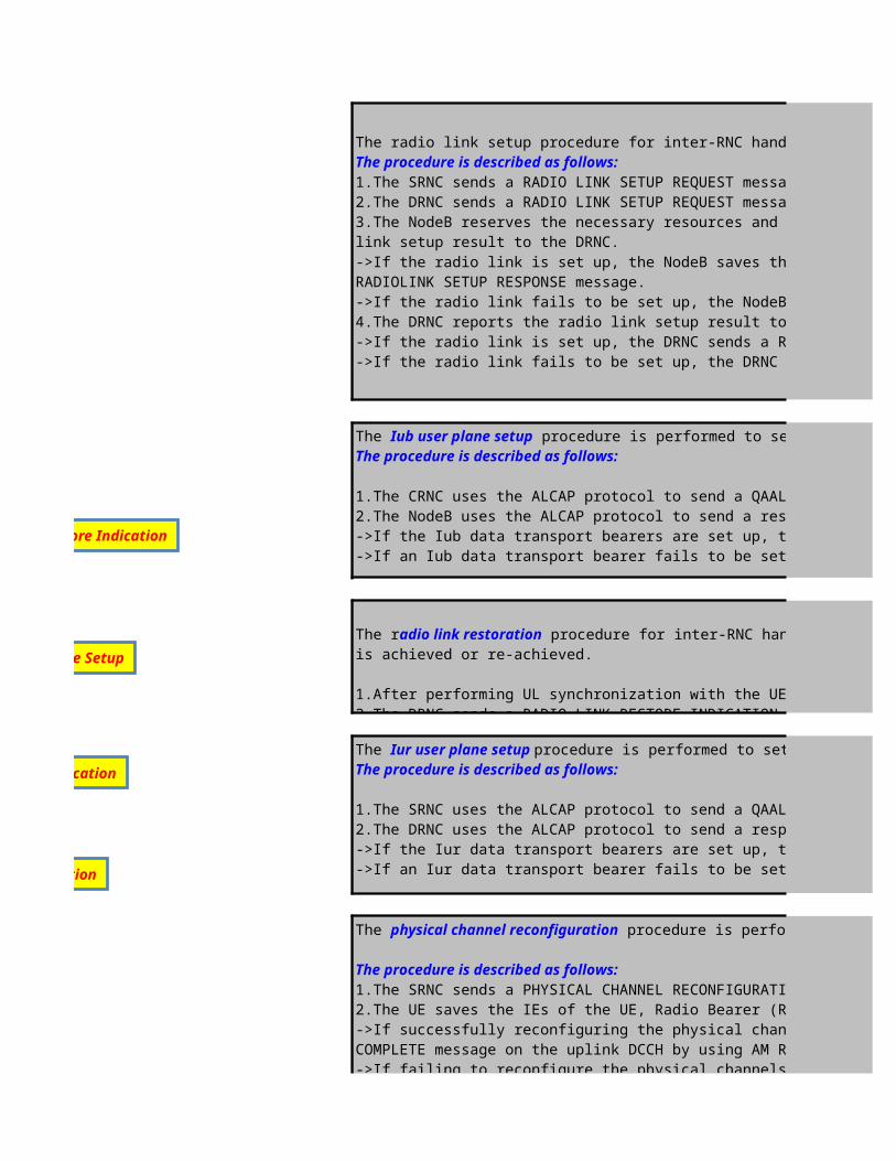
The radio link setup procedure for inter-RNC handover is performed to set up a radio link in a DRNC-controlled NodeB for a UEThe procedure is described as follows:1.The SRNC sends a RADIO LINK SETUP REQUEST message to the DRNC.2.The DRNC sends a RADIO LINK SETUP REQUEST message to the target NodeB.3.The NodeB reserves the necessary resources and configures the new radio link according to the parameters given in the message.The NodeB reports the radio link setup result to the DRNC.->If the radio link is set up, the NodeB saves the value of the Configuration GenerationID IE contained in the RADIO LINK SETUP REQUEST message and sends a RADIOLINK SETUP RESPONSE message.->If the radio link fails to be set up, the NodeB sends a RADIO LINK SETUP FAILUREmessage.4.The DRNC reports the radio link setup result to the SRNC.->If the radio link is set up, the DRNC sends a RADIO LINK SETUP RESPONSEmessage.->If the radio link fails to be set up, the DRNC sends a RADIO LINK SETUP FAILURE message, indicating the failure cause.
The Iub user plane setup procedure is performed to set up bearers for data transmission on the Iub interfaceThe procedure is described as follows:
1.The CRNC uses the ALCAP protocol to send a QAAL2 ESTABLISH REQUEST messageto the NodeB.2.The NodeB uses the ALCAP protocol to send a response message to the CRNC.->If the Iub data transport bearers are set up, the NodeB sends a QAAL2 ESTABLISH CONFIRM message.->If an Iub data transport bearer fails to be set up, the NodeB sends a QAAL2 ESTABLISH RELEASE CONFIRM message
The radio link restoration procedure for inter-RNC handover is performed for a NodeB to notify the SRNC that the uplink synchronization of one or more radio links is achieved or re-achieved.
1.After performing UL synchronization with the UE, the NodeB sends a RADIO LINKRESTORE INDICATION message to the DRNC.2.The DRNC sends a RADIO LINK RESTORE INDICATION message to the SRNC.
The Iur user plane setup procedure is performed to set up bearers for data transmission on the Iur interfaceThe procedure is described as follows:
1.The SRNC uses the ALCAP protocol to send a QAAL2 ESTABLISH REQUEST message to the DRNC.2.The DRNC uses the ALCAP protocol to send a response message to the SRNC.->If the Iur data transport bearers are set up, the DRNC sends a QAAL2 ESTABLISHCONFIRM message.->If an Iur data transport bearer fails to be set up, the DRNC sends a QAAL2 ESTABLISHRELEASE CONFIRM message.
The physical channel reconfiguration procedure is performed to set up, reconfigure, or releasea physical channel
The procedure is described as follows:1.The SRNC sends a PHYSICAL CHANNEL RECONFIGURATION message to the UE to request reconfiguration of a physical channel.2.The UE saves the IEs of the UE, Radio Bearer (RB), transport channel, and physical channel.The UE sends a response message to the SRNC.->If successfully reconfiguring the physical channels specified by the PHYSICALCHANNEL RECONFIGURATION message, the UE sends a PHYSICAL CHANNELRECONFIGURATION COMPLETE message on the uplink DCCH by using AM RLC ->If failing to reconfigure the physical channels specified by the PHYSICAL CHANNELRECONFIGURATION message, the UE restores the configuration to the old physicalchannel configuration and sends a PHYSICAL CHANNEL RECONFIGURATION FAILURE message on the DCCH by using AM RLC. The value of the Failure cause IE contained in the PHYSICAL CHANNEL RECONFIGURATION FAILURE message is "physical channel failure".
Physical Reconfiguration
Iur Radio Link Restore Indication
Iur user plane Setup
Iub Radio Link Restore Indication

The physical channel reconfiguration procedure is performed to set up, reconfigure, or releasea physical channel
The procedure is described as follows:1.The SRNC sends a PHYSICAL CHANNEL RECONFIGURATION message to the UE to request reconfiguration of a physical channel.2.The UE saves the IEs of the UE, Radio Bearer (RB), transport channel, and physical channel.The UE sends a response message to the SRNC.->If successfully reconfiguring the physical channels specified by the PHYSICALCHANNEL RECONFIGURATION message, the UE sends a PHYSICAL CHANNELRECONFIGURATION COMPLETE message on the uplink DCCH by using AM RLC ->If failing to reconfigure the physical channels specified by the PHYSICAL CHANNELRECONFIGURATION message, the UE restores the configuration to the old physicalchannel configuration and sends a PHYSICAL CHANNEL RECONFIGURATION FAILURE message on the DCCH by using AM RLC. The value of the Failure cause IE contained in the PHYSICAL CHANNEL RECONFIGURATION FAILURE message is "physical channel failure".
The radio link deletion procedure is performed to release resources in a NodeB for one or more established radio links towards a UE.
The procedure is described as follows:1.The CRNC sends a RADIO LINK DELETION REQUEST message to the NodeB. After receiving the message, the NodeB deletes the radio links specified by the message.2.The NodeB sends a response message to the CRNC.->lf all the radio links are deleted, the NodeB sends a ->lf any radio link fails to be deleted, the NodeB sends a Rfailure cause.
The Iub user plane release procedure is performed to release data transport bearers from the Iubinterface.
The procedure is described as follows:1.The CRNC uses the ALCAP protocol to send a QAAL2 RELEASE REQUEST messageto the NodeB.2.The NodeB uses the ALCAP protocol to send a response message to the CRNC.->If the Iub data transport bearers are released, the NodeB sends a QAAL2 RELEASE CONFIRM message to confirm the release.->lf an Iub data transport bearer fails to be released, the NodeB sends a QAAL2 RELEASECONFIRM message that indicates the failure cause
The Iur user plane release procedure is performed to release data transport bearers from the Iur interface
The procedure is described as follows:1.The SRNC uses the ALCAP protocol to send a QAAL2 RELEASE REQUEST messageto the DRNC.2.The DRNC uses the ALCAP protocol to send a response message to the SRNC.->If the Iur data transport bearers are released, the DRNC sends a QAAL2 RELEASECONFIRM message to confirm the release.->If an Iur data transport bearer fails to be released, the DRNC sends a QAAL2 RELEASECONFIRM message that indicates the failure cause.
Radio Link Deletion
Iub user plane release
Iur user plane release

is used to notify the UE of the objects to be measured, neighbor cell list, report method, and event parameters.When
the UE continue measure the radio link condition of serving and neighbour cell and when the measurement reporting criterias are met, the UE reports the results to the RNC as an event. The Measurement report is also can be sent in periodic mode.
was introduced to WCDMA to allow inter-frequency and Inter-RAT Handovers. It is used to create idle periods (gaps) in the transmission during which neighbour cells measurements on another frequency can be made.
(intra-RNC handover or GSM to WCDMA CS handover) is performed to set up a radio link in an SRNC-controlled
1.The CRNC sends a RADIO LINK SETUP REQUEST message to the NodeB. After receiving the message, the NodeB reserves the necessary resources and configures the new radio link according to the parameters given in the message.2.The NodeB sends a response message to the CRNC.If the radio link is set up, the NodeB saves the value of the Configuration Generation ID IE contained in the RADIO LINK SETUP REQUEST message and sends a RADIOLINK SETUP RESPONSE message.If the radio link fails to be set up, the NodeB sends a RADIO LINK SETUP FAILURE message. The message contains the failure cause.
procedure is performed to set up bearers for data transmission on the Iub interface
2.The NodeB uses the ALCAP protocol to send a response message to the CRNC.lIf the Iub data transport bearers are set up, the NodeB message.If an Iub data transport bearer fails to be set up, the NodeB sends a QAAL2 ESTABLISH RELEASE CONFIRM
procedure (intra-RNC handover or GSM to WCDMA CS handover)is performed for a NodeB to notify the CRNC that the
After performing UL synchronization with the UE, the NodeB sends a RADIO LINK RESTOREINDICATION message to the CRNC.

procedure is performed to set up, reconfigure, or releasea physical channel
1.The SRNC sends a PHYSICAL CHANNEL RECONFIGURATION message to the UE to request reconfiguration of a physical channel.2.The UE saves the IEs of the UE, Radio Bearer (RB), transport channel, and physical channel.The UE sends a response message to the
->If successfully reconfiguring the physical channels specified by the PHYSICALCHANNEL RECONFIGURATION message, the UE sends a PHYSICAL
->If failing to reconfigure the physical channels specified by the PHYSICAL CHANNELRECONFIGURATION message, the UE restores the configuration to the old physicalchannel configuration and sends a PHYSICAL CHANNEL RECONFIGURATION FAILURE message on the DCCH by using AM RLC. The value of the Failure cause IE contained in the PHYSICAL CHANNEL RECONFIGURATION FAILURE message is "physical channel
procedure is performed to release resources in a NodeB for one or more established radio links towards a UE.
message to the NodeB. After receiving the message, the NodeB deletes the radio links
2.The NodeB sends a response message to the CRNC.lf all the radio links are deleted, the NodeB sends a RADIO LINK DELETION RESPONSE message. message. The Criticality Diagnostics field in the
procedure is performed to release data transport bearers from the Iubinterface.
1.The CRNC uses the ALCAP protocol to send a QAAL2 RELEASE REQUEST messageto the NodeB.
->If the Iub data transport bearers are released, the NodeB sends a QAAL2 RELEASE CONFIRM message to confirm the release.->lf an Iub data transport bearer fails to be released, the NodeB sends a QAAL2 RELEASECONFIRM message that indicates the failure cause

The radio link setup procedure for inter-RNC handover is performed to set up a radio link in a DRNC-controlled NodeB for a UE
1.The SRNC sends a RADIO LINK SETUP REQUEST message to the DRNC.2.The DRNC sends a RADIO LINK SETUP REQUEST message to the target NodeB.3.The NodeB reserves the necessary resources and configures the new radio link according to the parameters given in the message.The NodeB reports the radio
->If the radio link is set up, the NodeB saves the value of the Configuration GenerationID IE contained in the RADIO LINK SETUP REQUEST message and sends a
->If the radio link fails to be set up, the NodeB sends a RADIO LINK SETUP FAILUREmessage.4.The DRNC reports the radio link setup result to the SRNC.->If the radio link is set up, the DRNC sends a RADIO LINK SETUP RESPONSEmessage.->If the radio link fails to be set up, the DRNC sends a RADIO LINK SETUP FAILURE message, indicating the failure cause.
procedure is performed to set up bearers for data transmission on the Iub interface
1.The CRNC uses the ALCAP protocol to send a QAAL2 ESTABLISH REQUEST messageto the NodeB.2.The NodeB uses the ALCAP protocol to send a response message to the CRNC.->If the Iub data transport bearers are set up, the NodeB sends a QAAL2 ESTABLISH CONFIRM message.->If an Iub data transport bearer fails to be set up, the NodeB sends a QAAL2 ESTABLISH RELEASE CONFIRM message
procedure for inter-RNC handover is performed for a NodeB to notify the SRNC that the uplink synchronization of one or more radio links
1.After performing UL synchronization with the UE, the NodeB sends a RADIO LINKRESTORE INDICATION message to the DRNC.2.The DRNC sends a RADIO LINK RESTORE INDICATION message to the SRNC.
procedure is performed to set up bearers for data transmission on the Iur interface
1.The SRNC uses the ALCAP protocol to send a QAAL2 ESTABLISH REQUEST message to the DRNC.2.The DRNC uses the ALCAP protocol to send a response message to the SRNC.->If the Iur data transport bearers are set up, the DRNC sends a QAAL2 ESTABLISHCONFIRM message.->If an Iur data transport bearer fails to be set up, the DRNC sends a QAAL2 ESTABLISHRELEASE CONFIRM message.
procedure is performed to set up, reconfigure, or releasea physical channel
1.The SRNC sends a PHYSICAL CHANNEL RECONFIGURATION message to the UE to request reconfiguration of a physical channel.2.The UE saves the IEs of the UE, Radio Bearer (RB), transport channel, and physical channel.The UE sends a response message to the SRNC.->If successfully reconfiguring the physical channels specified by the PHYSICALCHANNEL RECONFIGURATION message, the UE sends a PHYSICAL CHANNELRECONFIGURATION COMPLETE message on the uplink DCCH by using AM RLC ->If failing to reconfigure the physical channels specified by the PHYSICAL CHANNELRECONFIGURATION message, the UE restores the configuration to the old physicalchannel configuration and sends a PHYSICAL CHANNEL RECONFIGURATION FAILURE message on the DCCH by using AM RLC. The value of the Failure cause IE contained in the PHYSICAL CHANNEL RECONFIGURATION FAILURE message is "physical channel failure".
procedure is performed to release resources in a NodeB for one or more established radio links towards a UE.
RADIO LINK DELETION REQUEST message to the NodeB. After receiving the message, the NodeB deletes the radio links specified by the message.2.The NodeB sends a response message to the CRNC.->lf all the radio links are deleted, the NodeB sends a RADIO LINK DELETION RESPONSE message.->lf any radio link fails to be deleted, the NodeB sends a RADIO LINK DELETION RESPONSE message. The Criticality Diagnostics field in the message indicates the
procedure is performed to release data transport bearers from the Iubinterface.
1.The CRNC uses the ALCAP protocol to send a QAAL2 RELEASE REQUEST messageto the NodeB.2.The NodeB uses the ALCAP protocol to send a response message to the CRNC.->If the Iub data transport bearers are released, the NodeB sends a QAAL2 RELEASE CONFIRM message to confirm the release.->lf an Iub data transport bearer fails to be released, the NodeB sends a QAAL2 RELEASECONFIRM message that indicates the failure cause
procedure is performed to release data transport bearers from the Iur interface
1.The SRNC uses the ALCAP protocol to send a QAAL2 RELEASE REQUEST messageto the DRNC.2.The DRNC uses the ALCAP protocol to send a response message to the SRNC.->If the Iur data transport bearers are released, the DRNC sends a QAAL2 RELEASECONFIRM message to confirm the release.->If an Iur data transport bearer fails to be released, the DRNC sends a QAAL2 RELEASECONFIRM message that indicates the failure cause.

The radio link setup procedure for inter-RNC handover is performed to set up a radio link in a DRNC-controlled NodeB for a UE
3.The NodeB reserves the necessary resources and configures the new radio link according to the parameters given in the message.The NodeB reports the radio
->If the radio link is set up, the NodeB saves the value of the Configuration GenerationID IE contained in the RADIO LINK SETUP REQUEST message and sends a
procedure for inter-RNC handover is performed for a NodeB to notify the SRNC that the uplink synchronization of one or more radio links
2.The UE saves the IEs of the UE, Radio Bearer (RB), transport channel, and physical channel.The UE sends a response message to the SRNC.->If successfully reconfiguring the physical channels specified by the PHYSICALCHANNEL RECONFIGURATION message, the UE sends a PHYSICAL CHANNELRECONFIGURATION
->If failing to reconfigure the physical channels specified by the PHYSICAL CHANNELRECONFIGURATION message, the UE restores the configuration to the old physicalchannel configuration and sends a PHYSICAL CHANNEL RECONFIGURATION FAILURE message on the DCCH by using AM RLC. The value of the Failure cause IE
procedure is performed to release resources in a NodeB for one or more established radio links towards a UE.
message to the NodeB. After receiving the message, the NodeB deletes the radio links specified by the message.
message. The Criticality Diagnostics field in the message indicates the
->lf an Iub data transport bearer fails to be released, the NodeB sends a QAAL2 RELEASECONFIRM message that indicates the failure cause
->If an Iur data transport bearer fails to be released, the DRNC sends a QAAL2 RELEASECONFIRM message that indicates the failure cause.

L3 Messages - Inter-RAT Handover ProcedureUE NodeB
Inter-RAT CS Handover from WCDMA to GSM
RRC:Measurement Report (e2d)
RRC:Measurement Report
Click to return to main page
RRC:Measurement Control
RRC:Measurement Report (e2d)
RRC:Measurement Report (e2f)
1. RRC:Physical Channel Reconfiguration (DCCH)
2. RRC: Physical Channel Reconfiguration Complete (DCCH)
RRC:Measurement Control
RRC:Measurement Report
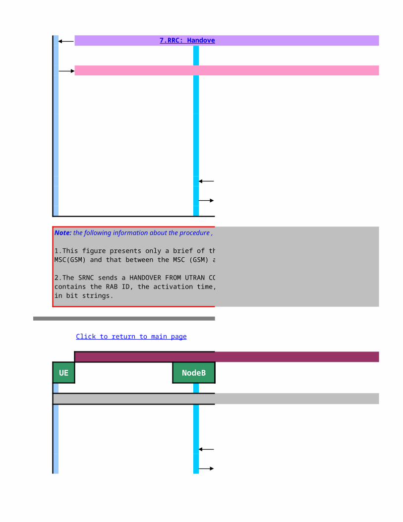
L3 Messages - Inter-RAT Handover ProcedureUE NodeB
Inter-RAT CS Handover from GSM to WCDMA
7.RRC: Handover from UTRAN Command
9.Handover Completed
Note: the following information about the procedure ,
1.This figure presents only a brief of the signaling between the MSC server and the MSC(GSM) and that between the MSC (GSM) and the BSC (GSM).
2.The SRNC sends a HANDOVER FROM UTRAN COMMAND message to the UE. The message contains the RAB ID, the activation time, the GSM frequency, and the GSM information in bit strings.
Click to return to main page

9.Inter-System to UTRAN Handover Command
12.RRC: Handover to UTRAN Complete(DCCH)
13.RRC: UE Capability Enquiry(DCCH)
14.RRC: UE Capability Information (DCCH)
15.RRC: UE Capability Information Confirm (DCCH)
16.RRC: Security Mode Command(DCCH)
17.RRC: Security Mode Complete(DCCH)
23.RRC: UTRAN Mobility Information (DCCH)
24.RRC: UTRAN Mobility Information Confirm (DCCH)
Note: the following information about the procedure ,
1.This figure presents only a brief of the signaling between the MSC server and the MSC(GSM) and that between the MSC (GSM) and the BSC (GSM).2.After receiving a RADIO LINK RESTORE INDICATION message, the RNC sends a RELOCATION DETECT message to the MSC server to inform the MSC server that the UE has been handed over from GSM to WCDMA.3.After the UE is handed over, it sends a HANDOVER TO UTRAN COMPLETE message to the RNC. If the handover fails, the UE reports the failure to the GSM system.4.After receiving a HANDOVER TO UTRAN COMPLETE message, the RNC sends a RELOCATION COMPLETE message to the MSC server. In addition, the RNC controls the UE to perform the UTRAN mobility information procedure, the UE capability enquiry procedure, and the security mode control procedure.5.In practice, the signaling messages traced may differ from the signaling message shown inthe figure in terms of the sequence

L3 Messages - Inter-RAT Handover ProcedureS-RNC
Inter-RAT CS Handover from WCDMA to GSM
RRC:Measurement Report (e2d)
NBAP: Radio Link Reconfiguration Prepare
NBAP: Radio Link Reconfiguration Ready
NBAP: Radio Link Reconfiguration Commit
NBAP: Compressed Mode Command
RRC:Measurement Report
1.RANAP: Relocation Required
6.RANAP:Relocation Command
RRC:Measurement Control
RRC:Measurement Report (e2d)
RRC:Measurement Report (e2f)
1. RRC:Physical Channel Reconfiguration (DCCH)
2. RRC: Physical Channel Reconfiguration Complete (DCCH)
RRC:Measurement Control
RRC:Measurement Report
Decision to HO to GSM cell

12.RANAP: IU Release Command
13.RANAP: IU Release Complete
NBAP:Radio Link Deletion Request
NBAP:Radio Link Deletion Response
L3 Messages - Inter-RAT Handover ProcedureS-RNC
Inter-RAT CS Handover from GSM to WCDMA
3.RANAP: Relocation Request4.NBAP:Radio Link Setup Request
5.NBAP:Radio Link setup Response
7.RRC: Handover from UTRAN Command
9.Handover Completed
the following information about the procedure ,
1.This figure presents only a brief of the signaling between the MSC server and the MSC(GSM) and that between the MSC (GSM) and the BSC (GSM).
2.The SRNC sends a HANDOVER FROM UTRAN COMMAND message to the UE. The message contains the RAB ID, the activation time, the GSM frequency, and the GSM information
M easurem ent Control& M easurem ent Report
Active SetUpdate
Iub user plane Setup
Iur Radio Link Restore Indication
Iur user plane Setup
Iub Radio Link Restore Indication
RadioLink Setup
M easurem ent Control& M easurem ent Report
Active SetUpdate
Iub user plane Setup
Iur Radio Link Restore Indication
Iur user plane Setup
Iub Radio Link Restore Indication
Radio Link Setup

9.Inter-System to UTRAN Handover Command
10.NBAP:Radio Link Restore Indication11.RANAP:Relocation Detect
12.RRC: Handover to UTRAN Complete(DCCH)
13.RRC: UE Capability Enquiry(DCCH)
14.RRC: UE Capability Information (DCCH)
15.RRC: UE Capability Information Confirm (DCCH)
16.RRC: Security Mode Command(DCCH)
17.RRC: Security Mode Complete(DCCH)
23.RRC: UTRAN Mobility Information (DCCH)
24.RRC: UTRAN Mobility Information Confirm (DCCH)
6.RANAP:Relocation Request Acknowledge
18.RANAP:Relocation Complete
the following information about the procedure ,
1.This figure presents only a brief of the signaling between the MSC server and the MSC(GSM) and that between the MSC (GSM) and the BSC (GSM).2.After receiving a RADIO LINK RESTORE INDICATION message, the RNC sends a RELOCATION DETECT message to the MSC server to inform the MSC server that the UE has been handed
3.After the UE is handed over, it sends a HANDOVER TO UTRAN COMPLETE message to the RNC. If the handover fails, the UE reports the failure to the GSM system.4.After receiving a HANDOVER TO UTRAN COMPLETE message, the RNC sends a RELOCATION COMPLETE message to the MSC server. In addition, the RNC controls the UE to perform the UTRAN mobility information procedure, the UE capability enquiry procedure, and the security mode control procedure.5.In practice, the signaling messages traced may differ from the signaling message shown inthe figure in terms of the sequence
M easurem ent Control& M easurem ent Report
Active SetUpdate
Iub user plane Setup
Iur Radio Link Restore Indication
Iur user plane Setup
Iub Radio Link Restore Indication
RadioLink Setup
M easurem ent Control& M easurem ent Report
Active SetUpdate
Iub user plane Setup
Iur Radio Link Restore Indication
Iur user plane Setup
Iub Radio Link Restore Indication
Radio Link Setup

M easurem ent Control& M easurem ent Report
Active SetUpdate
Iub user plane Setup
Iur Radio Link Restore Indication
Iur user plane Setup
Iub Radio Link Restore Indication
RadioLink Setup
M easurem ent Control& M easurem ent Report
Active SetUpdate
Iub user plane Setup
Iur Radio Link Restore Indication
Iur user plane Setup
Iub Radio Link Restore Indication
Radio Link Setup

>>Inter-RAT HO Algorithm and related parametersL3 Messages - Inter-RAT Handover Procedure
MSC 3G
Inter-RAT CS Handover from WCDMA to GSM>>Measurement Control&Report (Inter-RAT) Description
>>Compressed Mode Description
2.Prepare Handover3.Handover Request
MSC 2G
BSC2G
4.Handover Request Acknowledge
5.Prepare Handover Response
Measurement Control & Measurement Report
GSM RSSI Measurement and BSIC Verification
Relocation Preparation

8.Handover Detect
10.Handover Complete
>>Inter-RAT HO Algorithm and related parameters
L3 Messages - Inter-RAT Handover ProcedureMSC-3G MSC-2G
Inter-RAT CS Handover from GSM to WCDMA
1.Handover Required2.Prepare Handover
11.Send End Signal Request
14.Send End Signal Response
BSC2G
Handover
Iu release
Radio Link Deletion
Relocation Resource allocation

8.Handover Command
9.Handover Complete
9.Inter-System to UTRAN Handover Command
20.Clear Command
21.Clear Complete
7.Prepare Handover Response
19.Send End Signal Request
22.Send End Signal Response
Relocation Resource allocation
UTRAN Mobility Information
Radio Link Restoration
UE Capability Enquiry
Security Mode Control

>>Inter-RAT HO Algorithm and related parameters
>>Measurement Control&Report (Inter-RAT) Description
>>Compressed Mode Description
Measurement Control is used to notify the UE of the objects to be measured, neighbor cell list, report method, and event parameters.When measurement conditions are changed, the RNC notifies the UE of new conditions.
Measurement Report, the UE continue measure the radio link condition of serving and neighbour cell and when the measurement reporting criterias are met, the UE reports the results to the RNC as an event. The Measurement report is also can be sent in periodic mode.
Compressed Mode was introduced to WCDMA to allow inter-frequency and Inter-RAT Handovers. It is used to create idle periods (gaps) in the transmission during which neighbour cells measurements on another frequency can be made.
The relocation preparation procedure is performed to prepare resources for relocation of the SRNS
The procedure is described as follows:
1.The SRNC sends a RELOCATION REQUIRED message to the CN. The message contains certain information such as relocation type, relocation cause, source PLMN, source LAC,source SAC, target PLMN, and target CI,LAC.2.The CN interacts with the target RNC or the target network system, such as the GSM system, to prepare relevant resources.3.The CN sends a response message to the SRNC.->If the target RNC or the target network system prepares the relevant resources successfully, the CN sends a RELOCATION COMMAND message when the preparation is complete. The message contains the L3 information IE, which carries the information about the relevant resources allocated by the target RNC or the target network system.->If the resources partially or totally fail to be allocated, the CN sends a RELOCATIONPREPARATION FAILURE message.
The Inter-RAT Handover procedure
1. The SRNC sends the 3G MSC a RANAP message "Relocation Required" if the condition of Inter-RAT Outgoing HO is met 2. As indicated in the received message,the 3G MSC forwards this request to the 2G MSC on the MAP/E interface through a MAP message "Prepare Handover"3. The 2G MSC forwards the request to the BSC. The message shown in the figure is for reference only and is subject to the actual conditon of the GSM4. The BSC responds to this request. The message shown in the figure is for reference only and is subject to the actual conditon of the GSM5. Once the initial procedures are completed in the 2G MSC/BSS,the 2G MSC returns a MAP/E message 'Prepare Handover Response"6. The 3G MSC sends the SRNC a RANAP message "Relocation Command"7. The SRNC send the UE and RRC message "Handover from UTRAN" through the existing RRC connection. This message may include information from one or several other systems8. The BSC performs handover detection. The figure does not show such procedures as GSM BSS synchronization. The message shown in the figure is for reference and is subject to the actual conditon of GSM9. The UE send the BSC a "Handover Complete" message10. The BSC sends the MSC a 'Handover Complete" message. The message shown in the figure for reference only and is subject to the actual condition
Measurement Control & Measurement Report
Initial Compressed Mode Configuration
GSM RSSI Measurement and BSIC Verification
Relocation Preparation

>>Inter-RAT HO Algorithm and related parameters
10. The BSC sends the MSC a 'Handover Complete" message. The message shown in the figure for reference only and is subject to the actual condition of the GSM11. After detecting the UE in the coverage area of the GSM,the MSC sends the CN a MAP/E message "Send End Signal Request"12. The CN sends the former SRNC and "Iu Release Command" message , requesting the former SRNC to release the allocated resource13. After the bearer resource is related in the UMTS, the former SRNC sends the CN an "Iu Release Complete" message14. After the call ends, the CN sends the MSC a MAP/E message "Send End Signal Response"
The Iu release procedure is performed for the CN to release an Iu connection and all the UTRANresources related only to that Iu connection
The procedure is described as follows:1.The CN sends an IU RELEASE COMMAND message to the SRNC to initiate the Iu release procedure. The message indicates the cause for the release of the signaling connection.NOTE: After sending the IU RELEASE COMMAND message, the CN will not send further RANAP connection-oriented messages on this particular connection.
2.The SRNC releases the related UTRAN resources and then sends an IU RELEASE COMPLETE message to the CN.
The radio link deletion procedure is performed to release resources in a NodeB for one or more established radio links towards a UE.The procedure is described as follows:1.The CRNC sends a RADIO LINK DELETION REQUEST message to the NodeB. After receiving the message, the NodeB deletes the radio links specified by the message.2.The NodeB sends a response message to the CRNC.->If all the radio links are deleted, the NodeB sends a RADIO LINK DELETION RESPONSE message.->If any radio link fails to be deleted, the NodeB sends a RADIO LINK DELETIONRESPONSE message. The Criticality Diagnostics field in the message indicates the failure cause.
The relocation resource allocation procedure is performed to allocate resources from the targetRNS for an SRNS relocation.The relocation resource allocation procedure can be triggered in either of the followingconditions:1. During an SRNS relocation, the CN applies for resources from the target RNC2. During an inter-RAT CS handover from GSM to WCDMA, the CN applies for resources from the target RNC
The procedure is described as follows:1.The CN sends a RELOCATION REQUEST message to the target RNC. The message contains certain information, such as the IMSI of the UE, CN domain indicator, target cell identifier, encryption, integrity protection, Iu signaling connection ID, handover cause, andRAB parameters.2.The target RNC allocates radio resources for the relocation.3.The target RNC sends a response message to the CN.->If the resources are allocated, the target RNC sends a RELOCATION REQUEST ACKNOWLEDGE message. The message contains the radio resources and other parameters allocated to the UE. The parameters include the UTRAN Radio NetworkTemporary Identifier (U-RNTI), RAB, transport layer and physical layer information,chosen encryption algorithm, and chosen integrity protection algorithm.->If the resources partially or totally fail to be allocated or the target RNC rejects the SRNS relocation for some reason, the target RNC sends a RELOCATION FAILURE message,indicating the failure cause
Handover
Iu release
Radio Link Deletion
Relocation Resource allocation

The relocation resource allocation procedure is performed to allocate resources from the targetRNS for an SRNS relocation.The relocation resource allocation procedure can be triggered in either of the followingconditions:1. During an SRNS relocation, the CN applies for resources from the target RNC2. During an inter-RAT CS handover from GSM to WCDMA, the CN applies for resources from the target RNC
The procedure is described as follows:1.The CN sends a RELOCATION REQUEST message to the target RNC. The message contains certain information, such as the IMSI of the UE, CN domain indicator, target cell identifier, encryption, integrity protection, Iu signaling connection ID, handover cause, andRAB parameters.2.The target RNC allocates radio resources for the relocation.3.The target RNC sends a response message to the CN.->If the resources are allocated, the target RNC sends a RELOCATION REQUEST ACKNOWLEDGE message. The message contains the radio resources and other parameters allocated to the UE. The parameters include the UTRAN Radio NetworkTemporary Identifier (U-RNTI), RAB, transport layer and physical layer information,chosen encryption algorithm, and chosen integrity protection algorithm.->If the resources partially or totally fail to be allocated or the target RNC rejects the SRNS relocation for some reason, the target RNC sends a RELOCATION FAILURE message,indicating the failure cause
The radio link setup procedure (intra-RNC handover or GSM to WCDMA CS handover) isperformed to set up a radio link in an SRNC-controlled NodeB for a UE
The procedure is described as follows:1.The CRNC sends a RADIO LINK SETUP REQUEST message to the NodeB. Afterr eceiving the message, the NodeB reserves the necessary resources and configures the new radio link according to the parameters given in the message.2.The NodeB sends a response message to the CRNC.->If the radio link is set up, the NodeB saves the value of the Configuration GenerationID IE contained in the RADIO LINK SETUP REQUEST message and sends a RADIO LINK SETUP RESPONSE message.->If the radio link fails to be set up, the NodeB sends a RADIO LINK SETUP FAILURE message. The message contains the failure cause.
The radio link restoration procedure (intra-RNC handover or GSM to WCDMA CS handover)is performed for a NodeB to notify the CRNC that the uplink synchronization of one or moreradio links is achieved or re-achieved
After performing UL synchronization with the UE, the NodeB sends a RADIO LINK RESTOREINDICATION message to the CRNC
The UE capability enquiry procedure is performed to request a UE to transmit its capability information related to any radio access network so that the network can perform data configuration based on the UE capability
The procedure is described as follows:1.The SRNC sends a UE CAPABILITY ENQUIRY message to the UE through the downlink DCCH using AM RLC.2.The UE sends a UE CAPABILITY INFORMATION message to the SRNC through the uplink DCCH using AM or UM RLC. The message contains the information about UE capabilities.3.The SRNC reads the UE capability information and then sends a UE CAPABILITYINFORMA CONFIRM message to the UE through the downlink DCCH using AM or UMRLC.
The security mode control procedure is performed to configure or reconfigure one or both of the ciphering algorithm and the integrity protection algorithm for a UE. The triggered conditon is when the ciphering algorithm or the integrity protection algorithm has changedThe procedure is described as follows:1.Through a SECURITY MODE COMMAND message sent to the UE, the SRNC starts or reconfigures one or both of the ciphering and integrity protection configurations for theRBs or one CN domain and for all Signaling Radio Bearers (SRBs).2.The UE sends a response message to the SRNC.->If the UE completes configuring or reconfiguring the relevant parameters for one orboth of the ciphering and integrity protection algorithms, the UE sends a SECURITYMODE COMPLETE message to inform the SRNC of the completion.->If the SECURITY MODE COMMAND message contains neither Ciphering mode info IE nor Integrity protection mode info IE or if each of the two IEs has inconsistent information, the UE sends a SECURITY MODE FAILURE message, indicating the failure of the security mode control procedure as well as the failure cause.
Relocation Resource allocation
UTRAN Mobility Information
Radio Link Restoration
UE Capability Enquiry
Security Mode Control

The UTRAN mobility information procedure is performed for the network to allocate a newUTRAN Radio Network Temporary Identifier (U-RNTI) or Cell Radio Network TemporaryIdentifier (C-RNTI) to a UE or to inform the UE of mobility-related information such as timervalues and CN domain–related information
1.The SRNC sends a UTRAN MOBILITY INFORMATION message to the UE.2.The UE starts to update the related fields according to the values of the IEs carried in themessage.3.The UE sends a response message to the SRNC.->If the UE succeeds in conducting the operations specified by the UTRAN MOBILITYINFORMATION message, the UE sends a UTRAN MOBILITY INFORMATION CONFIRM message.->If the UE fails to conduct the operations specified by the UTRAN MOBILITYINFORMATION message, the UE sends a UTRAN MOBILITY INFORMATIONFAILURE

is used to notify the UE of the objects to be measured, neighbor cell list, report method, and event parameters.When measurement conditions are changed, the RNC notifies the UE of new conditions.
the UE continue measure the radio link condition of serving and neighbour cell and when the measurement reporting criterias are met, the UE reports the results to the RNC as an event. The Measurement report is also can be sent in periodic mode.
was introduced to WCDMA to allow inter-frequency and Inter-RAT Handovers. It is used to create idle periods (gaps) in the transmission during which neighbour cells measurements on another frequency can be made.
relocation preparation procedure is performed to prepare resources for relocation of the SRNS
The procedure is described as follows:
1.The SRNC sends a RELOCATION REQUIRED message to the CN. The message contains certain information such as relocation type, relocation cause, source PLMN, source LAC,source SAC, target PLMN, and target CI,LAC.2.The CN interacts with the target RNC or the target network system, such as the GSM system, to prepare relevant resources.3.The CN sends a response message to the SRNC.->If the target RNC or the target network system prepares the relevant resources successfully, the CN sends a RELOCATION COMMAND message when the preparation is complete. The message contains the L3 information IE, which carries the information about the relevant resources allocated by the target RNC or the target network system.->If the resources partially or totally fail to be allocated, the CN sends a RELOCATIONPREPARATION FAILURE message.
Handover procedure is described as follows:
1. The SRNC sends the 3G MSC a RANAP message "Relocation Required" if the condition of Inter-RAT Outgoing HO is met 2. As indicated in the received message,the 3G MSC forwards this request to the 2G MSC on the MAP/E interface through a MAP message "Prepare
3. The 2G MSC forwards the request to the BSC. The message shown in the figure is for reference only and is subject to the actual conditon of the
4. The BSC responds to this request. The message shown in the figure is for reference only and is subject to the actual conditon of the GSM5. Once the initial procedures are completed in the 2G MSC/BSS,the 2G MSC returns a MAP/E message 'Prepare Handover Response"6. The 3G MSC sends the SRNC a RANAP message "Relocation Command"7. The SRNC send the UE and RRC message "Handover from UTRAN" through the existing RRC connection. This message may include information from one orseveral other systems
8. The BSC performs handover detection. The figure does not show such procedures as GSM BSS synchronization. The message shown in the figure is forreference and is subject to the actual conditon of GSM
9. The UE send the BSC a "Handover Complete" message10. The BSC sends the MSC a 'Handover Complete" message. The message shown in the figure for reference only and is subject to the actual condition

10. The BSC sends the MSC a 'Handover Complete" message. The message shown in the figure for reference only and is subject to the actual condition
11. After detecting the UE in the coverage area of the GSM,the MSC sends the CN a MAP/E message "Send End Signal Request"12. The CN sends the former SRNC and "Iu Release Command" message , requesting the former SRNC to release the allocated resource13. After the bearer resource is related in the UMTS, the former SRNC sends the CN an "Iu Release Complete" message14. After the call ends, the CN sends the MSC a MAP/E message "Send End Signal Response"
procedure is performed for the CN to release an Iu connection and all the UTRANresources related only to that Iu connection
The procedure is described as follows:1.The CN sends an IU RELEASE COMMAND message to the SRNC to initiate the Iu release procedure. The message indicates the cause for the release of the signaling connection.
After sending the IU RELEASE COMMAND message, the CN will not send further RANAP connection-oriented messages on this particular connection.
2.The SRNC releases the related UTRAN resources and then sends an IU RELEASE COMPLETE message to the CN.
procedure is performed to release resources in a NodeB for one or more established radio links towards a UE.The procedure is described as follows:1.The CRNC sends a RADIO LINK DELETION REQUEST message to the NodeB. After receiving the message, the NodeB deletes the radio links specified by the
2.The NodeB sends a response message to the CRNC.->If all the radio links are deleted, the NodeB sends a RADIO LINK DELETION RESPONSE message.->If any radio link fails to be deleted, the NodeB sends a RADIO LINK DELETIONRESPONSE message. The Criticality Diagnostics field in the message indicates the failure cause.
relocation resource allocation procedure is performed to allocate resources from the targetRNS for an SRNS relocation.The relocation resource allocation procedure can be triggered in either of the followingconditions:1. During an SRNS relocation, the CN applies for resources from the target RNC2. During an inter-RAT CS handover from GSM to WCDMA, the CN applies for resources from the target RNC
The procedure is described as follows:1.The CN sends a RELOCATION REQUEST message to the target RNC. The message contains certain information, such as the IMSI of the UE, CN domain indicator, target cell identifier, encryption, integrity protection, Iu signaling connection ID, handover cause, andRAB parameters.2.The target RNC allocates radio resources for the relocation.3.The target RNC sends a response message to the CN.->If the resources are allocated, the target RNC sends a RELOCATION REQUEST ACKNOWLEDGE message. The message contains the radio resources and other parameters allocated to the UE. The parameters include the UTRAN Radio NetworkTemporary Identifier (U-RNTI), RAB, transport layer and physical layer information,chosen encryption algorithm, and chosen integrity protection algorithm.->If the resources partially or totally fail to be allocated or the target RNC rejects the SRNS relocation for some reason, the target RNC sends a
FAILURE message,indicating the failure cause
procedure (intra-RNC handover or GSM to WCDMA CS handover) isperformed to set up a radio link in an SRNC-controlled NodeB for a UE
The procedure is described as follows:1.The CRNC sends a RADIO LINK SETUP REQUEST message to the NodeB. Afterr eceiving the message, the NodeB reserves the necessary resources and configures the new radio link according to the parameters given in the message.2.The NodeB sends a response message to the CRNC.->If the radio link is set up, the NodeB saves the value of the Configuration GenerationID IE contained in the RADIO LINK SETUP REQUEST message and sends a RADIO LINK SETUP RESPONSE message.->If the radio link fails to be set up, the NodeB sends a RADIO LINK SETUP FAILURE message. The message contains the failure cause.
radio link restoration procedure (intra-RNC handover or GSM to WCDMA CS handover)is performed for a NodeB to notify the CRNC that the uplink synchronization of one or moreradio links is achieved or re-achieved
After performing UL synchronization with the UE, the NodeB sends a RADIO LINK RESTOREINDICATION message to the CRNC
procedure is performed to request a UE to transmit its capability information related to any radio access network so that the network can perform data configuration based on the UE capability
The procedure is described as follows:1.The SRNC sends a UE CAPABILITY ENQUIRY message to the UE through the downlink DCCH using AM RLC.2.The UE sends a UE CAPABILITY INFORMATION message to the SRNC through the uplink DCCH using AM or UM RLC. The message contains the information about UE capabilities.3.The SRNC reads the UE capability information and then sends a UE CAPABILITYINFORMA CONFIRM message to the UE through the downlink DCCH using AM or
security mode control procedure is performed to configure or reconfigure one or both of the ciphering algorithm and the integrity protection algorithm for a UE. The triggered conditon is when the ciphering algorithm or the integrity protection algorithm has changedThe procedure is described as follows:1.Through a SECURITY MODE COMMAND message sent to the UE, the SRNC starts or reconfigures one or both of the ciphering and integrity protection configurations for theRBs or one CN domain and for all Signaling Radio Bearers (SRBs).2.The UE sends a response message to the SRNC.->If the UE completes configuring or reconfiguring the relevant parameters for one orboth of the ciphering and integrity protection algorithms, the UE sends a SECURITYMODE COMPLETE message to inform the SRNC of the completion.->If the SECURITY MODE COMMAND message contains neither Ciphering mode info IE nor Integrity protection mode info IE or if each of the two IEs has inconsistent information, the UE sends a SECURITY MODE FAILURE message, indicating the failure of the security mode control procedure as well as the

UTRAN mobility information procedure is performed for the network to allocate a newUTRAN Radio Network Temporary Identifier (U-RNTI) or Cell Radio Network TemporaryIdentifier (C-RNTI) to a UE or to inform the UE of mobility-related information such as timervalues and CN domain–related
1.The SRNC sends a UTRAN MOBILITY INFORMATION message to the UE.2.The UE starts to update the related fields according to the values of the IEs carried in themessage.3.The UE sends a response message to the SRNC.->If the UE succeeds in conducting the operations specified by the UTRAN MOBILITYINFORMATION message, the UE sends a UTRAN MOBILITY INFORMATION
->If the UE fails to conduct the operations specified by the UTRAN MOBILITYINFORMATION message, the UE sends a UTRAN MOBILITY INFORMATIONFAILURE

is used to notify the UE of the objects to be measured, neighbor cell list, report method, and event parameters.When measurement
the UE continue measure the radio link condition of serving and neighbour cell and when the measurement reporting criterias are met, the UE reports the results to the RNC as an event. The Measurement report is also can be sent in periodic mode.
was introduced to WCDMA to allow inter-frequency and Inter-RAT Handovers. It is used to create idle periods (gaps) in the
1.The SRNC sends a RELOCATION REQUIRED message to the CN. The message contains certain information such as relocation type, relocation cause, source
2.The CN interacts with the target RNC or the target network system, such as the GSM system, to prepare relevant resources.
->If the target RNC or the target network system prepares the relevant resources successfully, the CN sends a RELOCATION COMMAND message when the preparation is complete. The message contains the L3 information IE, which carries the information about the relevant resources allocated by the
->If the resources partially or totally fail to be allocated, the CN sends a RELOCATIONPREPARATION FAILURE message.
1. The SRNC sends the 3G MSC a RANAP message "Relocation Required" if the condition of Inter-RAT Outgoing HO is met 2. As indicated in the received message,the 3G MSC forwards this request to the 2G MSC on the MAP/E interface through a MAP message "Prepare
3. The 2G MSC forwards the request to the BSC. The message shown in the figure is for reference only and is subject to the actual conditon of the
4. The BSC responds to this request. The message shown in the figure is for reference only and is subject to the actual conditon of the GSM5. Once the initial procedures are completed in the 2G MSC/BSS,the 2G MSC returns a MAP/E message 'Prepare Handover Response"
7. The SRNC send the UE and RRC message "Handover from UTRAN" through the existing RRC connection. This message may include information from one or
8. The BSC performs handover detection. The figure does not show such procedures as GSM BSS synchronization. The message shown in the figure is for
10. The BSC sends the MSC a 'Handover Complete" message. The message shown in the figure for reference only and is subject to the actual condition

10. The BSC sends the MSC a 'Handover Complete" message. The message shown in the figure for reference only and is subject to the actual condition
11. After detecting the UE in the coverage area of the GSM,the MSC sends the CN a MAP/E message "Send End Signal Request"12. The CN sends the former SRNC and "Iu Release Command" message , requesting the former SRNC to release the allocated resource13. After the bearer resource is related in the UMTS, the former SRNC sends the CN an "Iu Release Complete" message
procedure is performed for the CN to release an Iu connection and all the UTRANresources related only to that Iu connection
1.The CN sends an IU RELEASE COMMAND message to the SRNC to initiate the Iu release procedure. The message indicates the cause for the release of
After sending the IU RELEASE COMMAND message, the CN will not send further RANAP connection-oriented messages on this particular connection.
2.The SRNC releases the related UTRAN resources and then sends an IU RELEASE COMPLETE message to the CN.
procedure is performed to release resources in a NodeB for one or more established radio links towards a UE.
1.The CRNC sends a RADIO LINK DELETION REQUEST message to the NodeB. After receiving the message, the NodeB deletes the radio links specified by the
->If any radio link fails to be deleted, the NodeB sends a RADIO LINK DELETIONRESPONSE message. The Criticality Diagnostics field in the message
procedure is performed to allocate resources from the targetRNS for an SRNS relocation.
1.The CN sends a RELOCATION REQUEST message to the target RNC. The message contains certain information, such as the IMSI of the UE, CN domain indicator, target cell identifier, encryption, integrity protection, Iu signaling connection ID, handover cause, andRAB parameters.
->If the resources are allocated, the target RNC sends a RELOCATION REQUEST ACKNOWLEDGE message. The message contains the radio resources and other parameters allocated to the UE. The parameters include the UTRAN Radio NetworkTemporary Identifier (U-RNTI), RAB, transport layer and physical layer
->If the resources partially or totally fail to be allocated or the target RNC rejects the SRNS relocation for some reason, the target RNC sends a
procedure (intra-RNC handover or GSM to WCDMA CS handover) isperformed to set up a radio link in an SRNC-controlled NodeB for a UE
1.The CRNC sends a RADIO LINK SETUP REQUEST message to the NodeB. Afterr eceiving the message, the NodeB reserves the necessary resources and
->If the radio link is set up, the NodeB saves the value of the Configuration GenerationID IE contained in the RADIO LINK SETUP REQUEST message and
->If the radio link fails to be set up, the NodeB sends a RADIO LINK SETUP FAILURE message. The message contains the failure cause.
procedure (intra-RNC handover or GSM to WCDMA CS handover)is performed for a NodeB to notify the CRNC that the uplink
After performing UL synchronization with the UE, the NodeB sends a RADIO LINK RESTOREINDICATION message to the CRNC
procedure is performed to request a UE to transmit its capability information related to any radio access network so that the
2.The UE sends a UE CAPABILITY INFORMATION message to the SRNC through the uplink DCCH using AM or UM RLC. The message contains the information
3.The SRNC reads the UE capability information and then sends a UE CAPABILITYINFORMA CONFIRM message to the UE through the downlink DCCH using AM or
procedure is performed to configure or reconfigure one or both of the ciphering algorithm and the integrity protection algorithm for a UE. The triggered conditon is when the ciphering algorithm or the integrity protection algorithm has changed
1.Through a SECURITY MODE COMMAND message sent to the UE, the SRNC starts or reconfigures one or both of the ciphering and integrity protection
->If the UE completes configuring or reconfiguring the relevant parameters for one orboth of the ciphering and integrity protection algorithms, the
->If the SECURITY MODE COMMAND message contains neither Ciphering mode info IE nor Integrity protection mode info IE or if each of the two IEs has inconsistent information, the UE sends a SECURITY MODE FAILURE message, indicating the failure of the security mode control procedure as well as the

procedure is performed for the network to allocate a newUTRAN Radio Network Temporary Identifier (U-RNTI) or Cell Radio Network TemporaryIdentifier (C-RNTI) to a UE or to inform the UE of mobility-related information such as timervalues and CN domain–related
->If the UE succeeds in conducting the operations specified by the UTRAN MOBILITYINFORMATION message, the UE sends a UTRAN MOBILITY INFORMATION
->If the UE fails to conduct the operations specified by the UTRAN MOBILITYINFORMATION message, the UE sends a UTRAN MOBILITY INFORMATIONFAILURE

RRC:Measurement ControlClick to return to main page

RRC:Measurement Report (e2d)

RRC:Measurement Report (e2f)
RRC:Physical Channel Reconfiguration (DCCH)


RRC: Physical Channel Reconfiguration Complete (DCCH)
RRC:Measurement Control


RRC:Measurement Report

RRC: Handover from UTRAN Command

Handover Completed

RRC:Measurement Control
value=Inter-freq meas L3 filter coeff=3
value=Inter-freq meas based on CPICH Ec/No
>>"Measurement Control and Measurement Report"
value=interFrequencyMeasurement (RNC send mearuement control of InterFrequency because parameter CoexistMeasThdChoice="COEXIST_MEAS_THD_CHOICE_INTERFREQ")

value=Event2D ( Start Compressed Mode)
value= InterFreqCSThd2DEcN0=-14 dB
value= 0value=2 dB ,Step: 0.5value=320ms
value=Event2f ( Stop Compressed Mode)
value= InterFreqCSThd2FEcN0=-12 dB
value= 0value=2 dB ,Step: 0.5value=320ms
RRC:Measurement Report (e2d)

value=UE trigger Event2D to start Compressed Mode
RRC:Measurement Report (e2f)
value=UE trigger Event2f to stop Compressed Mode
RRC:Physical Channel Reconfiguration (DCCH)

value=Compressed Mode Inforamtion


RRC: Physical Channel Reconfiguration Complete (DCCH)
RRC:Measurement Control

value=interRATMeasurement (RNC send mearuement control of InterRAT after enter Compressed Mode)
value=InterRAT cell list
value=InterRAT cell Index
value=InterRATCIO=0value=NCC=6value=BCC=4value=GSM900 ( GSM1800 not used)
value=BCCH=64


value=UE measure on GSM RSSIvalue=InterRATFilterCoef=3value=UE need to verify BSIC
value=InterRATPeriodReportInterval= 1000ms
value=UE report 6 InterRATcells to RNC

RRC:Measurement Report

value=RSSI= -110 + hex2dec(1E) = -80 dBm
value=BSIC=35 ( BCCH=112) refer to InterRAT CellID=7 in Measurement Control (GSM900)
RRC: Handover from UTRAN Command

Handover Completed

value=interFrequencyMeasurement (RNC send mearuement control of InterFrequency because

value=interRATMeasurement (RNC send mearuement control of InterRAT after enter Compressed Mode)

L3 Messages - Inter-RAT Handover ProcedureUE BSS S-RNC
Inter-RAT PS Handover from WCDMA to GSM
1.RRC:Cell Change Order from UTRAN
2.Routing Area Update Request
6.Security Functions
Click to return to main page
The procedure in this stage is simiilar to Inter-RAT CS Handover from WCDMA to GSM ( "RRC: Handover from UTRAN Command " message is equivalent to "RRC:Cell Change Order from UTRAN" )
UE Connected
UE Connected
UE Connected

19.Routing Area Update Accept
20.Routing Area Update Complete
22. BSS Packet Flow Context Procedure
L3 Messages - Inter-RAT Handover ProcedureUE BSC S-RNC
Note: the following information about the procedure ,
1.When the PS data volume is low, the UE may be in CELL_PCH, URA_PCH, or Cell_FACH state or when UE in Idle state. Based on the parameters in the system information, the UE can initiate cell reselection to perform a handover to GSM. The cell reselection is initiated with an SRNS CONTEXT REQUEST message sent from the SGSN to SRNC.
When the UE in Idle ,URA_PCH.Cell_PCH or Cell_FACH states, the cell reselection procedure does not include the sub-procedires which marked with "UE Connected)
2.After cell reselection to a GSM cell, the NodeB sends a RADIO LINK FAILURE INDICATION message because the UE stops the transmission towards the WCDMA cell.This message, however, is unnecessary to the procedure of inter-RAT PS handover from WCDMA to GSM.3. After the UE accesses a GSM cell, the SGSN directly sends an IU RELEASE COMMAND message to the SRNC, if the Packet Data Protocol (PDP) context does not need to be transferred.4.The SRNS context transfer is unnecessary to the procedure of inter-RAT PS handover from WCDMA to GSM.
Click to return to main page

Inter-RAT PS Handover from GSM to WCDMA
2.Routing Area Update Request
5.Security Functions
1. Inter-RAT Handover Decision

16.Routing Area Update Accept
17.Routing Area Update Complete
19.Service Request
Setup Radio Resources

L3 Messages - Inter-RAT Handover ProcedureSGSN-2G SGSN-3G
Inter-RAT PS Handover from WCDMA to GSM
2.Routing Area Update Request3.SGSN Context Request
4.SRNS Context Request
4.SRNS Context Response
5.SGSN Context Response
6.Security Functions
7.SGSN Context Acknowledge
C1
8.SRNS Data Forward Command
8.Forward Packets
9. Forward Packets
10. Update PDP Context Request
10. Update PDP Context Response
11. Update GPRS Location
13.Iu Release Command
13. Iu Release Complete
The procedure in this stage is simiilar to Inter-RAT CS Handover from WCDMA to GSM ( "RRC: Handover from UTRAN Command " message is equivalent to "RRC:Cell Change Order from UTRAN" )
UE Connected
UE Connected
UE Connected

14. Insert Subscriber Data
14. Insert Subscriber Data Acknowledge
15. Update GPRS Location Acknowledge
16. Location Update Request
18 Location Update Accept19.Routing Area Update Accept
20.Routing Area Update Complete
21. TMSI Reallocation Complete22. BSS Packet Flow Context Procedure
L3 Messages - Inter-RAT Handover ProcedureSGSN-3G SGSN-2G
1.When the PS data volume is low, the UE may be in CELL_PCH, URA_PCH, or Cell_FACH state or when UE in Idle state. Based on the parameters in the system information, the UE can initiate cell reselection to perform a handover to GSM. The cell reselection is initiated with an SRNS CONTEXT REQUEST message sent from the SGSN to SRNC.
When the UE in Idle ,URA_PCH.Cell_PCH or Cell_FACH states, the cell reselection procedure does not include the sub-procedires which marked with "UE Connected)
2.After cell reselection to a GSM cell, the NodeB sends a RADIO LINK FAILURE INDICATION message because the UE stops the transmission towards the WCDMA cell.This message, however, is unnecessary to the procedure of inter-RAT PS handover from WCDMA to GSM.3. After the UE accesses a GSM cell, the SGSN directly sends an IU RELEASE COMMAND message to the SRNC, if the Packet Data Protocol (PDP) context
4.The SRNS context transfer is unnecessary to the procedure of inter-RAT PS handover from WCDMA to GSM.

Inter-RAT PS Handover from GSM to WCDMA
2.Routing Area Update Request3.SGSN Context Request
4.SGSN Context Response
5.Security Functions
6.SGSN Context Acknowledge
C1
7. Forward Packets
8. Update PDP Context Request
8 Update PDP Context Response
9. Update GPRS Location
11. Insert Subscriber Data
11. Insert Subscriber Data Acknowledge
12. Update GPRS Location Acknowledge
13. Location Update Request

15 Location Update AcceptC2
16.Routing Area Update Accept
C3
17.Routing Area Update Complete
18. TMSI Reallocation Complete
19.Service Request
20. RAB Assignement Request
20. RAB Assignement Response

L3 Messages - Inter-RAT Handover ProcedureGGSN MSC-2G HLR
Inter-RAT PS Handover from WCDMA to GSM
6.Security Functions
10. Update PDP Context Request
10. Update PDP Context Response
11. Update GPRS Location
12. Cancel Location
The procedure in this stage is simiilar to Inter-RAT CS Handover from WCDMA to GSM ( "RRC: Handover from UTRAN Command " message is equivalent to "RRC:Cell Change Order from UTRAN" )

12. Cancel Location Acknowledge
14. Insert Subscriber Data
14. Insert Subscriber Data Acknowledge
15. Update GPRS Location Acknowledge
16. Location Update Request17. Update Location
18 Location Update Accept
21. TMSI Reallocation Complete
L3 Messages - Inter-RAT Handover ProcedureGGSN MSC-3G HLR
1.When the PS data volume is low, the UE may be in CELL_PCH, URA_PCH, or Cell_FACH state or when UE in Idle state. Based on the parameters in the system information, the UE can initiate cell reselection to perform a handover to GSM. The cell reselection is initiated with an SRNS CONTEXT
2.After cell reselection to a GSM cell, the NodeB sends a RADIO LINK FAILURE INDICATION message because the UE stops the transmission towards the
3. After the UE accesses a GSM cell, the SGSN directly sends an IU RELEASE COMMAND message to the SRNC, if the Packet Data Protocol (PDP) context

Inter-RAT PS Handover from GSM to WCDMA
5.Security Functions
8. Update PDP Context Request
8 Update PDP Context Response
9. Update GPRS Location
10. Cancel Location
10. Cancel Location Acknowledge
11. Insert Subscriber Data
11. Insert Subscriber Data Acknowledge
12. Update GPRS Location Acknowledge
13. Location Update Request14a. Update Location
14d. Insert Subscriber Data
14e. Insert Subscriber Data Ack

14f. Update Location Ack
15 Location Update Accept
18. TMSI Reallocation Complete

L3 Messages - Inter-RAT Handover Procedure >>Inter-RAT HO Algorithm and related parameters
Inter-RAT PS Handover from WCDMA to GSM
MSC-3G
The procedure in this stage is simiilar to Inter-RAT CS Handover from WCDMA to GSM ( "RRC: Handover from UTRAN Command " message is equivalent to "RRC:Cell Change Order from UTRAN" )
SRNS Context Transfer
Iu release

17. Update Location
L3 Messages - Inter-RAT Handover Procedure >>Inter-RAT HO Algorithm and related parametersMSC-2G

Inter-RAT PS Handover from GSM to WCDMA
14b.Cancel Location
14c. Cancel Location Ack


>>Inter-RAT HO Algorithm and related parameters
The Inter-RAT PS handover from WCDMA to GSM procedure is described as follows:
1.The UE in Cell_DCH state, the UTRAN decides to initiate an inter-RAT handover in the PS domain be sending "Cell Change Order from UTRAN' messge to UE to handover to a new GSM cell and stop the data transmission between the UE and the network
2. The UE sends a "Routing Area Update Request" message to the 2G SGSN. The update type in the message indicates RA update, combined RA/LA update, or combined RA/LA update with IMSI attach. The BSS adds the CGI including the RAC and LAC of the cell to the received message before forwarding the message to a new 2G SGSN
3. The new 2G SGSN sends an "SGSN Context Request" message to the old 3G SGSN to obtain the MM and PDP contexts. The old 3G SGSN validates the old P-TMSI signature. If the old P-TMSI Signature is valid, the old 3G SGSN starts a timer. Otherwise, the old 3G SGSN respons with an error cause.
4. If the UE stay in connected mode before handover, the old 3G SGSN sends an "SRNS Context Request" message. After receiving this message, the SRNS buffers the PDUs, stops sending the PDUs to the UE, and send an "SRNS Context Response" message to the old 3G SGSN
5. The old 3G SGSN sends an "SGSN Context Response" message to the 2G SGSN including the MM and PDP context6. The security functions can be excuted7. The new 2G SGSN sends an 'SGSN Context Acknowledge" message to the old 3G SGSN. This inform the old 3G SGSN that the new 2G SGSN is ready to receive PDUs belonging to the activated PDP contexts
8. The old 3G SGSN sends a "Data Forward Command" message to the SRNS. The SRNS starts a data-forwarding timer and sends the buffers PDUs to the old 3G SGSN
9. The old 3G SGSN tunnels the GTP PDUs to the new 2G SGSN. In the PDUs, the sequence number in the GTP hearder remain unchange
10. the new 2G SGSN sends an "Update PDP Context Request" message to each related GGSN. Each GGSN sends an "Update PDP Context Response" message after updating it's PDP Context fields
11. The new 2G SGSN sends an "Update GPRS Location" message ,requesting the HLR to modify the SGSN number12. The HLR sends a "Cancel Location" message to the old 3G SGSN. the old 3G SGSN responds with a "Cancel Location AcK" message. After the timer expires,the old 3G SGSN removes the MM and PDP contexts.
13. The old 3G SGSN sends an "Iu release command" message to the SRNS. After data-forwarding timer expires,the SRNS responds with an "Iu Release complete"
14. The HLR sends an "Insert Subscriber Data" message to the new 2G SGSN. The 2G SGSN constructs an MM context and PDP context for the UE and returen an "Insert Subscriber Data Ack" message to the HLR
15.The HLR sends an "Update GPRS Location ACK" message to the new 2G SGSN16. If the association has to be established, the new 2G SGSN sens a 'Location Update Request" message to the VLR. The VLR stores the SGSN number for creating or updating the association
17. If the subscriber data in VLR is marked as not confirmed by the HLR. the new VLR informs the HLP. The HLR cancel the old VLR and inserts subscriber data in the new VLR- The new VLR sends an "Update Location" message to the HLR- The HLR cancels the data in the old VLR by sending a "Cancel Location" message to the old VLR- The old VLR acknowledge the message by responding with a "Cancel Location ACK" message- The HLR sends an "Insert Subscriber Data" message to the new VLR- The new VLR acknowledge the message by responding with an "Insert Subscriber Data ACK" message- The HLR responds with an "Update Location Ack" message to the new VLR
18. The new VLR allocates a new TMSI and responds with a "Location Update Accept" message to the 2G SGSN19. The new 2G SGSN checks the presence of the MS in the new RA. If all checks area successful,the new 2G SGSN constructs the MM and PDP contexts for the MS. A logical link is established between the new 2G SGSN and the UE. The 2G SGSN responds to the UE with a "Routing Area Update Accept" message
20. The UE acknowledge the new P-TMSI by returning a "Routing Area Update Complete" message, including all PDUs successfully sent to the UE before the routing area update procedure21. The new 2G SGSN sends a "TMSI Reallocation Complete" message to the new VLR if the UE confirms the VLR TMSI22. The 2G SGSN and the BSS perform the "BSS Packet Flow Context" procedure
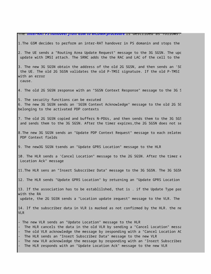
The Inter-RAT PS handover from GSM to WCDMA procedure is described as follows:
1.The GSM decides to perform an inter-RAT handover in PS domanin and stops the data transmission between the UE and the network
2. The UE sends a "Routing Area Update Request" message to the 3G SGSN. The update type in the message indicates RA update, combined RA/LA update, or combined RA/LA update with IMSI attach. The SRNC adds the the RAC and LAC of the cell to the received message before forwarding the message to a new 3G SGSN
3. The new 3G SGSN obtain the address of the old 2G SGSN, and then sends an 'SGSN Context Request" message to the old 2G SGSN to construct the MM and PDP contects for the UE. The old 2G SGSN validates the old P-TMSI signature. If the old P-TMSI Signature is valid, the old 2G SGSN starts a timer. Otherwise, the old 2G SGSN respons with an error cause.
4. The old 2G SGSN response with an "SGSN Context Response" message to the 3G SGSN including the MM and PDP context
5. The security functions can be excuted6. The new 3G SGSN sends an 'SGSN Context Acknowledge" message to the old 2G SGSN. This inform the old 2G SGSN that the new 3G SGSN is ready to receive PDUs belonging to the activated PDP contexts
7. The old 2G SGSN copied and buffers N-PDUs, and then sends them to the 3G SGSN. Before the timer expires ,if there are other N-PDUs from the GGSN,the 2G SGSN compies and sends them to the 3G SGSN. After the timer expires,the 2G SGSN does not send N-PDUs to the 3G SGSN anymore
8.The new 3G SGSN sends an "Update PDP Context Request" message to each related GGSN. Each GGSN sends an "Update PDP Context Response" message after updating it's PDP Context fields
9. The new3G SGSN tsends an "Update GPRS Location" message to the HLR
10. The HLR sends a 'Cancel Location" message to the 2G SGSN. After the timer expires,the 2G SGSN removes the MM and PDP contexts. The 2G SGSN response with a 'Cancel Location Ack" message
11.The HLR sens an "Insert Subscriber Data" message to the 3G SGSN. The 3G SGSN constructs an MM context and sends an "Insert Subscriber Data Ack" message to the HLR
12. The HLR sends "Update GPRS Location" by returning an "Update GPRS Location Ack" message to the 3G SGSN
13. If the association has to be establilshed, that is . if the Update Type parameter indicates a combined RA/LA update with IMSI attach requested, or if the LA changed with the RA update, the 2G SGSN sends a "Location update request" message to the VLR. The VLR stores the SGSN number for creating or updating the association
14. If the subscriber data in VLR is marked as not confirmed by the HLR. the new VLR informs the HLP. The HLR cancel the old VLR and inserts subscriber data in the new VLR
- The new VLR sends an "Update Location" message to the HLR- The HLR cancels the data in the old VLR by sending a "Cancel Location" message to the old VLR- The old VLR acknowledge the message by responding with a "Cancel Location ACK" message- The HLR sends an "Insert Subscriber Data" message to the new VLR- The new VLR acknowledge the message by responding with an "Insert Subscriber Data ACK" message- The HLR responds with an "Update Location Ack" message to the new VLR
15. The new VLR allocates a new TMSI and responds with a "Location Update Accept" message to the 3G SGSN

15. The new VLR allocates a new TMSI and responds with a "Location Update Accept" message to the 3G SGSN16. The new 3G SGSN checks the presence of the MS in the new RA. If all checks area successful,the new 3G SGSN constructs the MM and PDP contexts for the MS. A logical link is established between the new 3G SGSN and the UE. The 3G SGSN responds to the UE with a "Routing Area Update Accept" message
17. The UE sends a "Routing Area Update Complete" message to confirm the allocated P-TMSI18. The new 3G SGSN sends a "TMSI Reallocation Complete" message to the new VLR if the UE confirms the VLR TMSI19. If the UE has uplink data or signalling to send, the UE sends a "Service Request" message to the SGSN. The service type indicates the required service
20. The 3G SGSN sends a "RAB Assignment Request" message to the SRNS. The SRNS sens a 'Radion Beare Setup Request" message to the UE. The UE responds with a 'Radio Bearer Setup Complete" message. The SRNS sends a 'RAB assignment Response" message to the SGSN. The SRNS sends N-PCDS to the UE

is described as follows:
1.The UE in Cell_DCH state, the UTRAN decides to initiate an inter-RAT handover in the PS domain be sending "Cell Change Order from UTRAN' messge to UE to handover to a new GSM cell and stop the data transmission between the UE and the network
2. The UE sends a "Routing Area Update Request" message to the 2G SGSN. The update type in the message indicates RA update, combined RA/LA update, or combined RA/LA update with IMSI attach. The BSS adds the CGI including the RAC and LAC of the cell to the received message before forwarding the message to a new 2G SGSN
3. The new 2G SGSN sends an "SGSN Context Request" message to the old 3G SGSN to obtain the MM and PDP contexts. The old 3G SGSN validates the old P-TMSI signature. If the old P-TMSI Signature is valid, the old 3G SGSN starts a timer. Otherwise, the old 3G SGSN respons with an error cause.
4. If the UE stay in connected mode before handover, the old 3G SGSN sends an "SRNS Context Request" message. After receiving this message, the SRNS buffers the PDUs, stops sending the PDUs to the UE, and send an "SRNS Context Response" message to the old 3G SGSN
5. The old 3G SGSN sends an "SGSN Context Response" message to the 2G SGSN including the MM and PDP context
7. The new 2G SGSN sends an 'SGSN Context Acknowledge" message to the old 3G SGSN. This inform the old 3G SGSN that the new 2G SGSN is
8. The old 3G SGSN sends a "Data Forward Command" message to the SRNS. The SRNS starts a data-forwarding timer and sends the buffers PDUs to
9. The old 3G SGSN tunnels the GTP PDUs to the new 2G SGSN. In the PDUs, the sequence number in the GTP hearder remain unchange
10. the new 2G SGSN sends an "Update PDP Context Request" message to each related GGSN. Each GGSN sends an "Update PDP Context Response"
11. The new 2G SGSN sends an "Update GPRS Location" message ,requesting the HLR to modify the SGSN number12. The HLR sends a "Cancel Location" message to the old 3G SGSN. the old 3G SGSN responds with a "Cancel Location AcK" message. After the
13. The old 3G SGSN sends an "Iu release command" message to the SRNS. After data-forwarding timer expires,the SRNS responds with an "Iu
14. The HLR sends an "Insert Subscriber Data" message to the new 2G SGSN. The 2G SGSN constructs an MM context and PDP context for the UE and
15.The HLR sends an "Update GPRS Location ACK" message to the new 2G SGSN16. If the association has to be established, the new 2G SGSN sens a 'Location Update Request" message to the VLR. The VLR stores the SGSN
17. If the subscriber data in VLR is marked as not confirmed by the HLR. the new VLR informs the HLP. The HLR cancel the old VLR and inserts
- The HLR cancels the data in the old VLR by sending a "Cancel Location" message to the old VLR- The old VLR acknowledge the message by responding with a "Cancel Location ACK" message
- The new VLR acknowledge the message by responding with an "Insert Subscriber Data ACK" message- The HLR responds with an "Update Location Ack" message to the new VLR
18. The new VLR allocates a new TMSI and responds with a "Location Update Accept" message to the 2G SGSN19. The new 2G SGSN checks the presence of the MS in the new RA. If all checks area successful,the new 2G SGSN constructs the MM and PDP contexts for the MS. A logical
established between the new 2G SGSN and the UE. The 2G SGSN responds to the UE with a "Routing Area Update Accept" message
20. The UE acknowledge the new P-TMSI by returning a "Routing Area Update Complete" message, including all PDUs successfully sent to the UE before the routing area
21. The new 2G SGSN sends a "TMSI Reallocation Complete" message to the new VLR if the UE confirms the VLR TMSI22. The 2G SGSN and the BSS perform the "BSS Packet Flow Context" procedure

is described as follows:
1.The GSM decides to perform an inter-RAT handover in PS domanin and stops the data transmission between the UE and the network
2. The UE sends a "Routing Area Update Request" message to the 3G SGSN. The update type in the message indicates RA update, combined RA/LA update, or combined RA/LAupdate with IMSI attach. The SRNC adds the the RAC and LAC of the cell to the received message before forwarding the message to a new 3G SGSN
3. The new 3G SGSN obtain the address of the old 2G SGSN, and then sends an 'SGSN Context Request" message to the old 2G SGSN to construct the MM and PDP contects forthe UE. The old 2G SGSN validates the old P-TMSI signature. If the old P-TMSI Signature is valid, the old 2G SGSN starts a timer. Otherwise, the old 2G SGSN respons
4. The old 2G SGSN response with an "SGSN Context Response" message to the 3G SGSN including the MM and PDP context
6. The new 3G SGSN sends an 'SGSN Context Acknowledge" message to the old 2G SGSN. This inform the old 2G SGSN that the new 3G SGSN is ready to receive PDUs
7. The old 2G SGSN copied and buffers N-PDUs, and then sends them to the 3G SGSN. Before the timer expires ,if there are other N-PDUs from the GGSN,the 2G SGSN compiesand sends them to the 3G SGSN. After the timer expires,the 2G SGSN does not send N-PDUs to the 3G SGSN anymore
8.The new 3G SGSN sends an "Update PDP Context Request" message to each related GGSN. Each GGSN sends an "Update PDP Context Response" message after updating it's
10. The HLR sends a 'Cancel Location" message to the 2G SGSN. After the timer expires,the 2G SGSN removes the MM and PDP contexts. The 2G SGSN response with a 'Cancel
11.The HLR sens an "Insert Subscriber Data" message to the 3G SGSN. The 3G SGSN constructs an MM context and sends an "Insert Subscriber Data Ack" message to the HLR
12. The HLR sends "Update GPRS Location" by returning an "Update GPRS Location Ack" message to the 3G SGSN
13. If the association has to be establilshed, that is . if the Update Type parameter indicates a combined RA/LA update with IMSI attach requested, or if the LA changed
update, the 2G SGSN sends a "Location update request" message to the VLR. The VLR stores the SGSN number for creating or updating the association
14. If the subscriber data in VLR is marked as not confirmed by the HLR. the new VLR informs the HLP. The HLR cancel the old VLR and inserts subscriber data in the new
- The HLR cancels the data in the old VLR by sending a "Cancel Location" message to the old VLR- The old VLR acknowledge the message by responding with a "Cancel Location ACK" message
- The new VLR acknowledge the message by responding with an "Insert Subscriber Data ACK" message- The HLR responds with an "Update Location Ack" message to the new VLR
15. The new VLR allocates a new TMSI and responds with a "Location Update Accept" message to the 3G SGSN

15. The new VLR allocates a new TMSI and responds with a "Location Update Accept" message to the 3G SGSN16. The new 3G SGSN checks the presence of the MS in the new RA. If all checks area successful,the new 3G SGSN constructs the MM and PDP contexts for the MS. A logical
established between the new 3G SGSN and the UE. The 3G SGSN responds to the UE with a "Routing Area Update Accept" message
17. The UE sends a "Routing Area Update Complete" message to confirm the allocated P-TMSI18. The new 3G SGSN sends a "TMSI Reallocation Complete" message to the new VLR if the UE confirms the VLR TMSI19. If the UE has uplink data or signalling to send, the UE sends a "Service Request" message to the SGSN. The service type indicates the required service
20. The 3G SGSN sends a "RAB Assignment Request" message to the SRNS. The SRNS sens a 'Radion Beare Setup Request" message to the UE. The UE responds with a 'Radio
Setup Complete" message. The SRNS sends a 'RAB assignment Response" message to the SGSN. The SRNS sends N-PCDS to the UE

1.The UE in Cell_DCH state, the UTRAN decides to initiate an inter-RAT handover in the PS domain be sending "Cell Change Order from UTRAN' messge to UE to handover to a
2. The UE sends a "Routing Area Update Request" message to the 2G SGSN. The update type in the message indicates RA update, combined RA/LA update, or combined RA/LA update with IMSI attach. The BSS adds the CGI including the RAC and LAC of the cell to the received message before forwarding the message to a new 2G SGSN
3. The new 2G SGSN sends an "SGSN Context Request" message to the old 3G SGSN to obtain the MM and PDP contexts. The old 3G SGSN validates the old P-TMSI signature. If
4. If the UE stay in connected mode before handover, the old 3G SGSN sends an "SRNS Context Request" message. After receiving this message, the SRNS buffers the PDUs,
19. The new 2G SGSN checks the presence of the MS in the new RA. If all checks area successful,the new 2G SGSN constructs the MM and PDP contexts for the MS. A logical
20. The UE acknowledge the new P-TMSI by returning a "Routing Area Update Complete" message, including all PDUs successfully sent to the UE before the routing area

2. The UE sends a "Routing Area Update Request" message to the 3G SGSN. The update type in the message indicates RA update, combined RA/LA update, or combined RA/LA
3. The new 3G SGSN obtain the address of the old 2G SGSN, and then sends an 'SGSN Context Request" message to the old 2G SGSN to construct the MM and PDP contects forthe UE. The old 2G SGSN validates the old P-TMSI signature. If the old P-TMSI Signature is valid, the old 2G SGSN starts a timer. Otherwise, the old 2G SGSN respons
6. The new 3G SGSN sends an 'SGSN Context Acknowledge" message to the old 2G SGSN. This inform the old 2G SGSN that the new 3G SGSN is ready to receive PDUs
7. The old 2G SGSN copied and buffers N-PDUs, and then sends them to the 3G SGSN. Before the timer expires ,if there are other N-PDUs from the GGSN,the 2G SGSN compies
8.The new 3G SGSN sends an "Update PDP Context Request" message to each related GGSN. Each GGSN sends an "Update PDP Context Response" message after updating it's
10. The HLR sends a 'Cancel Location" message to the 2G SGSN. After the timer expires,the 2G SGSN removes the MM and PDP contexts. The 2G SGSN response with a 'Cancel
11.The HLR sens an "Insert Subscriber Data" message to the 3G SGSN. The 3G SGSN constructs an MM context and sends an "Insert Subscriber Data Ack" message to the HLR
13. If the association has to be establilshed, that is . if the Update Type parameter indicates a combined RA/LA update with IMSI attach requested, or if the LA changed
14. If the subscriber data in VLR is marked as not confirmed by the HLR. the new VLR informs the HLP. The HLR cancel the old VLR and inserts subscriber data in the new

16. The new 3G SGSN checks the presence of the MS in the new RA. If all checks area successful,the new 3G SGSN constructs the MM and PDP contexts for the MS. A logical
19. If the UE has uplink data or signalling to send, the UE sends a "Service Request" message to the SGSN. The service type indicates the required service
20. The 3G SGSN sends a "RAB Assignment Request" message to the SRNS. The SRNS sens a 'Radion Beare Setup Request" message to the UE. The UE responds with a 'Radio

L3 Messages - Inter-RAT Handover ProcedureUE BSS
Inter-RAT CS&PS Handover from WCDMA to GSM (Intra-SGSN)
1. Inter-RAT Handover
2.Suspend
3.Suspend
3. Suspend Ack
4. Resume
4. Resume NAck
5.Channel Release
6. Routing Area Update Request
L3 Messages - Inter-RAT Handover ProcedureUE BSS
Inter-RAT CS&PS Handover from WCDMA to GSM (Inter-SGSN)
1. Inter-RAT Handover
2.Suspend
3.Suspend
Click to return to main page
2G/3GSGSN
Click to return to main page
2GSGSN
M easurem ent Control& M easurem ent Report
Active SetUpdate
Iub user plane Setup
Iur Radio Link Restore Indication
Iur user plane Setup
Iub Radio Link Restore Indication
Radio Link Setup
M easurem ent Control& M easurem ent Report
Active SetUpdate
Iub user plane Setup
Iur Radio Link Restore Indication
Iur user plane Setup
Iub Radio Link Restore Indication
Radio Link Setup

3. Suspend Ack
4. Resume
4. Resume NAck
5.Channel Release
6. Routing Area Update Request
M easurem ent Control& M easurem ent Report
Active SetUpdate
Iub user plane Setup
Iur Radio Link Restore Indication
Iur user plane Setup
Iub Radio Link Restore Indication
Radio Link Setup
M easurem ent Control& M easurem ent Report
Active SetUpdate
Iub user plane Setup
Iur Radio Link Restore Indication
Iur user plane Setup
Iub Radio Link Restore Indication
Radio Link Setup

M easurem ent Control& M easurem ent Report
Active SetUpdate
Iub user plane Setup
Iur Radio Link Restore Indication
Iur user plane Setup
Iub Radio Link Restore Indication
Radio Link Setup
M easurem ent Control& M easurem ent Report
Active SetUpdate
Iub user plane Setup
Iur Radio Link Restore Indication
Iur user plane Setup
Iub Radio Link Restore Indication
Radio Link Setup

M easurem ent Control& M easurem ent Report
Active SetUpdate
Iub user plane Setup
Iur Radio Link Restore Indication
Iur user plane Setup
Iub Radio Link Restore Indication
Radio Link Setup
M easurem ent Control& M easurem ent Report
Active SetUpdate
Iub user plane Setup
Iur Radio Link Restore Indication
Iur user plane Setup
Iub Radio Link Restore Indication
Radio Link Setup

>>Inter-RAT HO Algorithm and related parametersL3 Messages - Inter-RAT Handover Procedure
SRNS
Inter-RAT CS&PS Handover from WCDMA to GSM (Intra-SGSN)
1. Inter-RAT Handover
3. SRNS Context Request
3. SRNS Context Response
>>Inter-RAT HO Algorithm and related parametersL3 Messages - Inter-RAT Handover Procedure
SRNS
Inter-RAT CS&PS Handover from WCDMA to GSM (Inter-SGSN)
1. Inter-RAT Handover
MSC/VLR
MSC/VLR
M easurem ent Control& M easurem ent Report
Active SetUpdate
Iub user plane Setup
Iur Radio Link Restore Indication
Iur user plane Setup
Iub Radio Link Restore Indication
RadioLink Setup
M easurem ent Control& M easurem ent Report
Active SetUpdate
Iub user plane Setup
Iur Radio Link Restore Indication
Iur user plane Setup
Iub Radio Link Restore Indication
Radio Link Setup
3G SGSN

M easurem ent Control& M easurem ent Report
Active SetUpdate
Iub user plane Setup
Iur Radio Link Restore Indication
Iur user plane Setup
Iub Radio Link Restore Indication
RadioLink Setup
M easurem ent Control& M easurem ent Report
Active SetUpdate
Iub user plane Setup
Iur Radio Link Restore Indication
Iur user plane Setup
Iub Radio Link Restore Indication
Radio Link Setup

M easurem ent Control& M easurem ent Report
Active SetUpdate
Iub user plane Setup
Iur Radio Link Restore Indication
Iur user plane Setup
Iub Radio Link Restore Indication
RadioLink Setup
M easurem ent Control& M easurem ent Report
Active SetUpdate
Iub user plane Setup
Iur Radio Link Restore Indication
Iur user plane Setup
Iub Radio Link Restore Indication
Radio Link Setup

>>Inter-RAT HO Algorithm and related parameters
>>Inter-RAT HO Algorithm and related parameters
For a UE in Cell_DCH state using both CS and PS domain services,the inter-RAT handover procedure is based on the measurement reports from the UE but is initiated from the UTRAN. The UE performs the inter-RAT handover from UTRA RRC Connected Mode to GSM Connected Mode first. After the UE sends a handover complete message to the GSM/BSS, the UE initiates a temporary block flow (TBF) towards the GPRS to suspend the GPRS services. After the CS domain services are released on the GSM side, the inter-RAT handover in the PS domain resumes, which indicates that the handover is completed.
if the inter-RAT handover from UTRA RCC Conencted Mode to GSM Connected Mode succeeds,the handover is regards as successful.no matter whether the UE inititates a TBF towards the GPRS or not. In case of inter-RAT handover failure, the UE may go back to the UTRA RRC Connected Mode and re-establish the connection in the original state.
The signalling procedures are described as follows,1. The UE in connection with both CS and PS domain perrforms the UMTS to GSM handover during which the CS service is handed over to the GSM
2. The UE sends a suspend message to the BSS
3. The BSS forwards the 'Suspend" message to the SGSN. The SGSN sends a "SRNS Context Request" message to the SRNS, requesting the SRNS to stop sending downlink PDUs. After receiving the message, the SRNS buffers downlink PDUs and respons to the SGSN with an 'SRNS Context Response" messge. The SGSN returns a "Suspend Ack" message to the BSS
4. When the CS connection is terminated , the BSS may send a 'Resume" message to the SGSN. However,resume is impossible since the radio access system has changed. Therefore,the SGSN acknowledge the resume through a 'Resume NACK"
5. The BSS sens an RR message 'Channel Release" to the UE, indicating that the BSS fails to request the SGSN to resume the GPRS service for the UE
6. The UE sends a 'Routing Area Update Request" message to the SGSN to resume the GPRS service. The update mode depends on the network operation mode in use.
For a UE in Cell_DCH state using both CS and PS domain services,the inter-RAT handover procedure is based on the measurement reports from the UE but is initiated from the UTRAN. The UE performs the inter-RAT handover from UTRA RRC Connected Mode to GSM Connected Mode first. After the UE sends a handover complete message to the GSM/BSS, the UE initiates a temporary block flow (TBF) towards the GPRS to suspend the GPRS services. After the CS domain services are released on the GSM side, the inter-RAT handover in the PS domain resumes, which indicates that the handover is completed.
if the inter-RAT handover from UTRA RCC Conencted Mode to GSM Connected Mode succeeds,the handover is regards as successful.no matter whether the UE inititates a TBF towards the GPRS or not. In case of inter-RAT handover failure, the UE may go back to the UTRA RRC Connected Mode and re-establish the connection in the original state.
The signalling procedures are described as follows,1. The UE in connection with both CS and PS domain perrforms the UMTS to GSM handover during which the CS service is handed over to the GSM
2. The UE sends a suspend message to the BSS
3. The BSS forwards the 'Suspend" message to the SGSN. The SGSN returns a "Suspend Ack" message to the BSS
4. When the CS connection is terminated , the BSS may send a 'Resume" message to the SGSN. However,resume is impossible since the radio access system has changed. Therefore,the SGSN acknowledge the resume through a 'Resume NACK"
5. The BSS sens an RR message 'Channel Release" to the UE, indicating that the BSS fails to request the SGSN to resume the GPRS service for the UE
6. The UE sends a 'Routing Area Update Request" message to the SGSN to resume the GPRS service. The update mode depends on the network operation mode in use.
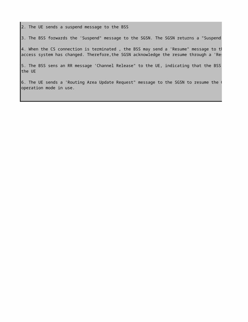

For a UE in Cell_DCH state using both CS and PS domain services,the inter-RAT handover procedure is based on the measurement reports from the UE but is initiated from the UTRAN. The UE performs the inter-RAT handover from UTRA RRC Connected Mode to GSM Connected Mode first. After the UE sends a handover complete message to the GSM/BSS, the UE initiates a temporary block flow (TBF) towards the GPRS to suspend the GPRS services. After the CS domain services are released on the GSM side, the inter-RAT handover in the PS domain resumes, which indicates that
if the inter-RAT handover from UTRA RCC Conencted Mode to GSM Connected Mode succeeds,the handover is regards as successful.no matter whether the UE inititates a TBF towards the GPRS or not. In case of inter-RAT handover failure, the UE may go back to the UTRA RRC Connected Mode and
1. The UE in connection with both CS and PS domain perrforms the UMTS to GSM handover during which the CS service is handed over to the GSM
3. The BSS forwards the 'Suspend" message to the SGSN. The SGSN sends a "SRNS Context Request" message to the SRNS, requesting the SRNS to stop sending downlink PDUs. After receiving the message, the SRNS buffers downlink PDUs and respons to the SGSN with an 'SRNS Context
4. When the CS connection is terminated , the BSS may send a 'Resume" message to the SGSN. However,resume is impossible since the radio access system has changed. Therefore,the SGSN acknowledge the resume through a 'Resume NACK"
5. The BSS sens an RR message 'Channel Release" to the UE, indicating that the BSS fails to request the SGSN to resume the GPRS service for
6. The UE sends a 'Routing Area Update Request" message to the SGSN to resume the GPRS service. The update mode depends on the network
For a UE in Cell_DCH state using both CS and PS domain services,the inter-RAT handover procedure is based on the measurement reports from the UE but is initiated from the UTRAN. The UE performs the inter-RAT handover from UTRA RRC Connected Mode to GSM Connected Mode first. After the UE sends a handover complete message to the GSM/BSS, the UE initiates a temporary block flow (TBF) towards the GPRS to suspend the GPRS services. After the CS domain services are released on the GSM side, the inter-RAT handover in the PS domain resumes, which indicates that
if the inter-RAT handover from UTRA RCC Conencted Mode to GSM Connected Mode succeeds,the handover is regards as successful.no matter whether the UE inititates a TBF towards the GPRS or not. In case of inter-RAT handover failure, the UE may go back to the UTRA RRC Connected Mode and
1. The UE in connection with both CS and PS domain perrforms the UMTS to GSM handover during which the CS service is handed over to the GSM
3. The BSS forwards the 'Suspend" message to the SGSN. The SGSN returns a "Suspend Ack" message to the BSS
4. When the CS connection is terminated , the BSS may send a 'Resume" message to the SGSN. However,resume is impossible since the radio access system has changed. Therefore,the SGSN acknowledge the resume through a 'Resume NACK"
5. The BSS sens an RR message 'Channel Release" to the UE, indicating that the BSS fails to request the SGSN to resume the GPRS service for
6. The UE sends a 'Routing Area Update Request" message to the SGSN to resume the GPRS service. The update mode depends on the network

L3 Messages - Intra-Frequency Hard Handover ProcedureUE SRNC
SRNS Static Relocation (UE not-involved relocation)
7. RRC:UTRAN Mobility Information
8. RRC:UTRAN Mobility Information Confirm
9. RRC:UE Capability Enquiry (DCCH)
10. RRC:UE Capability Information (DCCH)
11. RRC:UE Capability Information Confirm (DCCH)
Click to return to main page

L3 Messages - Intra-Frequency Hard Handover ProcedureUE SRNC
SRNS Relocation with Cell/URA Update (UE not-involved relocation)
1. Cell Update/URA Update
Click to return to main page

9. RRC:Cell Update Confirm/URA Update Confirm
11. RRC:UE Capability Enquiry (DCCH)
12. RRC:UE Capability Information (DCCH)
13. RRC:UE Capability Information Confirm (DCCH)
10. RRC:Physical Channel Reconfiguration Complete/UTRAN Mobility Information Confirm
Note the following information about the procedure :1.The DRNC acquires the SRNC ID of the UE from the URNTI IE in the CELL UPDATEmessage and then sends an UPLINK SIGNALLING TRANSFER INDICATION messageto the SRNC to indicate that the UE requests a cell update.
2.To initiate a cell update, the UE sends a CELL UPDATE message to the DRNC. To initiate a URA update, the UE sends a URA UPDATE message to the DRNC.
3.After a successful cell update, the DRNC sends a CELL UPDATE CONFIRM message tothe UE. After a successful URA update, the DRNC sends a URA UPDATE CONFIRM message to the UE.
4.After receiving the CELL UPDATE CONFIRM or URA UPDATE CONFIRM messagefrom the DRNC, the UE can send a PHYSICAL CHANNEL RECONFIGURATION COMPLETE message (for the cell update) or a UTRAN MOBILITY INFORMATION CONFIRM message (for the URA update) to the DRNC. This response from the UE is optional.
Cell Update/URA Update

Note the following information about the procedure :1.The DRNC acquires the SRNC ID of the UE from the URNTI IE in the CELL UPDATEmessage and then sends an UPLINK SIGNALLING TRANSFER INDICATION messageto the SRNC to indicate that the UE requests a cell update.
2.To initiate a cell update, the UE sends a CELL UPDATE message to the DRNC. To initiate a URA update, the UE sends a URA UPDATE message to the DRNC.
3.After a successful cell update, the DRNC sends a CELL UPDATE CONFIRM message tothe UE. After a successful URA update, the DRNC sends a URA UPDATE CONFIRM message to the UE.
4.After receiving the CELL UPDATE CONFIRM or URA UPDATE CONFIRM messagefrom the DRNC, the UE can send a PHYSICAL CHANNEL RECONFIGURATION COMPLETE message (for the cell update) or a UTRAN MOBILITY INFORMATION CONFIRM message (for the URA update) to the DRNC. This response from the UE is optional.

L3 Messages - Intra-Frequency Hard Handover ProcedureUE SRNC
SRNS Relocation with Hard Handover(UE involved relocation)
9. RRC:Physical Channel Reconfiguration Complete
9. RRC:UE Capability Enquiry (DCCH)
10. RRC:UE Capability Information (DCCH)
11. RRC:UE Capability Information Confirm (DCCH)
Click to return to main page
7.RRC:Physical Channel ReconfigurationPhysicalCha
nnel Reconfig
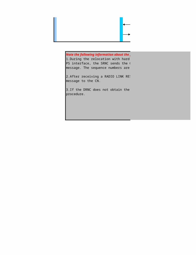
Note the following information about the procedure :1.During the relocation with hard handover, if an RAB supporting lossless SRNS relocation is available on the Iu-PS interface, the SRNC sends the GTP-U and PDCP sequence numbers to the DRNC through the FORWARD SRNS CONTEXT message. The sequence numbers are required for data forwarding.
2.After receiving a RADIO LINK RESTORE INDICATION message from the NodeB, theDRNC sends a RELOCATION DETECT message to the CN.
3.If the DRNC does not obtain the information about the UE capability, the DRNC initiatesa UE capability enquiry procedure.

L3 Messages - Intra-Frequency Hard Handover ProcedureDRNC CN
SRNS Static Relocation (UE not-involved relocation)
1.RANAP: Relocation Required
2.RANAP Relocation Request
3.RANAP Relocation Request Ack
4.RANAP: Relocation Command
5. RNSAP: Relocation Commit6. RANAP:Relocation Detect
7. RRC:UTRAN Mobility Information
8. RRC:UTRAN Mobility Information Confirm
9. RRC:UE Capability Enquiry (DCCH)
10. RRC:UE Capability Information (DCCH)
11. RRC:UE Capability Information Confirm (DCCH)12. Relocation Complete
13. RANAP: Iu Release Command
14. RANAP: Iu Release Complete
UE capability enquiry
UTRAN mobility information

L3 Messages - Intra-Frequency Hard Handover ProcedureDRNC CN
SRNS Relocation with Cell/URA Update (UE not-involved relocation)
1. Cell Update/URA Update

3RANAP: Relocation Required
4.RANAP Relocation Request
5.RANAP Relocation Request Ack
6.RANAP: Relocation Command
7. RNSAP: Relocation Commit8. RANAP:Relocation Detect
9. RRC:Cell Update Confirm/URA Update Confirm
11. RRC:UE Capability Enquiry (DCCH)
12. RRC:UE Capability Information (DCCH)
13. RRC:UE Capability Information Confirm (DCCH)14. Relocation Complete
15. RANAP: Iu Release Command
16. RANAP: Iu Release Complete
2. RNSAP: Signalling Transfer Indication
10. RRC:Physical Channel Reconfiguration Complete/UTRAN Mobility Information Confirm
Note the following information about the procedure :1.The DRNC acquires the SRNC ID of the UE from the URNTI IE in the CELL UPDATEmessage and then sends an UPLINK SIGNALLING TRANSFER INDICATION messageto the SRNC to indicate that the UE requests a cell update.
2.To initiate a cell update, the UE sends a CELL UPDATE message to the DRNC. To initiate a URA update, the UE sends a URA UPDATE message to the DRNC.
3.After a successful cell update, the DRNC sends a CELL UPDATE CONFIRM message tothe UE. After a successful URA update, the DRNC sends a URA UPDATE CONFIRM message to the UE.
4.After receiving the CELL UPDATE CONFIRM or URA UPDATE CONFIRM messagefrom the DRNC, the UE can send a PHYSICAL CHANNEL RECONFIGURATION COMPLETE message (for the cell update) or a UTRAN MOBILITY INFORMATION CONFIRM message (for the URA update) to the DRNC. This response from the UE is optional.
UE capability enquiry
Note the following information about the procedure :1.The DRNC acquires the SRNC ID of the UE from the URNTI IE in the CELL UPDATEmessage and then sends an UPLINK SIGNALLING TRANSFER INDICATION messageto the SRNC to indicate that the UE requests a cell update.
2.To initiate a cell update, the UE sends a CELL UPDATE message to the DRNC. To initiate a URA update, the UE sends a URA UPDATE message to the DRNC.
3.After a successful cell update, the DRNC sends a CELL UPDATE CONFIRM message tothe UE. After a successful URA update, the DRNC sends a URA UPDATE CONFIRM message to the UE.
4.After receiving the CELL UPDATE CONFIRM or URA UPDATE CONFIRM messagefrom the DRNC, the UE can send a PHYSICAL CHANNEL RECONFIGURATION COMPLETE message (for the cell update) or a UTRAN MOBILITY INFORMATION CONFIRM message (for the URA update) to the DRNC. This response from the UE is optional.
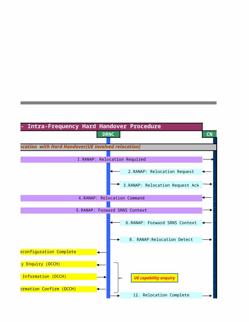
L3 Messages - Intra-Frequency Hard Handover ProcedureDRNC CN
SRNS Relocation with Hard Handover(UE involved relocation)
1.RANAP: Relocation Required
2.RANAP: Relocation Request
3.RANAP: Relocation Request Ack
4.RANAP: Relocation Command
5.RANAP: Forward SRNS Context
6.RANAP: Forward SRNS Context
8. RANAP:Relocation Detect
9. RRC:Physical Channel Reconfiguration Complete
9. RRC:UE Capability Enquiry (DCCH)
10. RRC:UE Capability Information (DCCH)
11. RRC:UE Capability Information Confirm (DCCH)12. Relocation Complete
UE capability enquiry

13. RANAP: Iu Release Command
14. RANAP: Iu Release Complete
Note the following information about the procedure :1.During the relocation with hard handover, if an RAB supporting lossless SRNS relocation is available on the Iu-PS interface, the SRNC sends the GTP-U and PDCP sequence numbers to the DRNC through the FORWARD SRNS CONTEXT message. The sequence numbers are required for data forwarding.
2.After receiving a RADIO LINK RESTORE INDICATION message from the NodeB, theDRNC sends a RELOCATION DETECT
3.If the DRNC does not obtain the information about the UE capability, the DRNC initiatesa UE capability enquiry

>>SRNC Relocation Algorithm and related parameters
The relocation preparation procedure can be triggered in either of the following conditions:->During an SRNS relocation, the SRNC sends a RELOCATION REQUIRED message.->During an inter-RAT CS handover from WCDMA to GSM, the SRNC sends aRELOCATION REQUIRED message.
The procedure is described as follows:1.The SRNC sends a RELOCATION REQUIRED message to the CN. The message containscertain information such as relocation type, relocation cause, source PLMN, source LAC,source SAC, target PLMN, and target LAC2.The CN interacts with the target RNC or the target network system, such as the GSMsystem, to prepare relevant resources.3.The CN sends a response message to the SRNC.lIf the target RNC or the target network system prepares the relevant resourcessuccessfully, the CN sends a RELOCATION COMMAND message when thepreparation is complete. The message contains the L3 information IE, which carries theinformation about the relevant resources allocated by the target RNC or the targetnetwork system.lIf the resources partially or totally fail to be allocated, the CN sends a RELOCATIONPREPARATION FAILURE message.The relocation resource allocation procedure can be triggered in either of the following conditions:->During an SRNS relocation, the CN applies for resources from the target RNC->During an inter-RAT CS handover from GSM to WCDMA, the CN applies for resourcesfrom the target RNC
The procedure is described as follows:1.The CN sends a RELOCATION REQUEST message to the target RNC. The messagecontains certain information, such as the IMSI of the UE, CN domain indicator, target cellidentifier, encryption, integrity protection, Iu signaling connection ID, handover cause, and RAB parameters.2.The target RNC allocates radio resources for the relocation.3.The target RNC sends a response message to the CN.lIf the resources are allocated, the target RNC sends a RELOCATION REQUESTACKNOWLEDGE message. The message contains the radio resources and otherparameters allocated to the UE. The parameters include the UTRAN Radio NetworkTemporary Identifier (U-RNTI), RAB, transport layer and physical layer information,chosen encryption algorithm, and chosen integrity protection algorithm.lIf the resources partially or totally fail to be allocated or the target RNC rejects the SRNSrelocation for some reason, the target RNC sends a RELOCATION FAILURE message,indicating the failure cause.
The relocation commit procedure is performed to execute the change of control from the SRNCof a UE to the DRNC
The procedure is described as follows:1.The SRNC sends a RELOCATION COMMIT message to the DRNC. If an RAB supportinglossless SRNS relocation is available on the Iu-PS interface, the RELOCATION COMMITmessage carries the GTP-U and PDCP sequence numbers required for data forwarding.Then, the SRNC initiates data forwarding.2.The DRNC sends a RELOCATION DETECT message to the CN to notify the CN of thedetection of the relocation commitment.3.The original DRNC sends a RELOCATION COMPLETE message to the CN to notify thatthe relocation is successful.
The UTRAN mobility information procedure is performed for the network to allocate a newUTRAN Radio Network Temporary Identifier (U-RNTI) or Cell Radio Network TemporaryIdentifier (C-RNTI) to a UE or to inform the UE of mobility-related information such as timer values and CN domain–related information.
The procedure is described as follows:1.The SRNC sends a UTRAN MOBILITY INFORMATION message to the UE2.The UE starts to update the related fields according to the values of the IEs carried in themessage.3.The UE sends a response message to the SRNC.
->If the UE succeeds in conducting the operations specified by the UTRAN MOBILITYI NFORMATION message, the UE sends a UTRAN MOBILITY INFORMATIONCONFIRM message.->If the UE fails to conduct the operations specified by the UTRAN MOBILITYINFORMATION message, the UE sends a UTRAN MOBILITY INFORMATIONFAILURE message, indicating the failure cause.
Relocation Preparation
Relocation Resource Allocation
Relocation Commit
Iu release

The UTRAN mobility information procedure is performed for the network to allocate a newUTRAN Radio Network Temporary Identifier (U-RNTI) or Cell Radio Network TemporaryIdentifier (C-RNTI) to a UE or to inform the UE of mobility-related information such as timer values and CN domain–related information.
The procedure is described as follows:1.The SRNC sends a UTRAN MOBILITY INFORMATION message to the UE2.The UE starts to update the related fields according to the values of the IEs carried in themessage.3.The UE sends a response message to the SRNC.
->If the UE succeeds in conducting the operations specified by the UTRAN MOBILITYI NFORMATION message, the UE sends a UTRAN MOBILITY INFORMATIONCONFIRM message.->If the UE fails to conduct the operations specified by the UTRAN MOBILITYINFORMATION message, the UE sends a UTRAN MOBILITY INFORMATIONFAILURE message, indicating the failure cause.
The UE capability enquiry procedure is performed to request a UE to transmit its capabilityinformation related to any radio access network so that the network can perform dataconfiguration based on the UE capability.
The procedure is described as follows:1.The SRNC sends a UE CAPABILITY ENQUIRY message to the UE through the downlink DCCH using AM RLC.2.The UE sends a UE CAPABILITY INFORMATION message to the SRNC through theuplink DCCH using AM or UM RLC. The message contains the information about UE capabilities.3.The SRNC reads the UE capability information and then sends a UE CAPABILITYINFORMA CONFIRM message to the UE through the downlink DCCH using AM or UMRLC.
The Iu release procedure can be triggered in one of the following conditions:->The transaction between the UE and the CN is complete.->The UTRAN requests the CN to release the resources on the Iu interface by, for example,sending an IU RELEASE REQUEST message.->The Serving Radio Network Subsystem (SRNS) is relocated.->The SRNS relocation is canceled after a relocation resource allocation procedure iscomplete.
The procedure is described as follows:1.The CN sends an IU RELEASE COMMAND message to the SRNC to initiate the Iu releaseprocedure. The message indicates the cause for the release of the signaling connection.NOTE After sending the IU RELEASE COMMAND message, the CN will not send further RANAPconnection-oriented messages on this particular connection.
2.The SRNC releases the related UTRAN resources and then sends an IU RELEASE COMPLETE message to the CN.
Click to return to main page
The relocation preparation procedure can be triggered in either of the following conditions:->During an SRNS relocation, the SRNC sends a RELOCATION REQUIRED message.->During an inter-RAT CS handover from WCDMA to GSM, the SRNC sends aRELOCATION REQUIRED message.
The procedure is described as follows:1.The SRNC sends a RELOCATION REQUIRED message to the CN. The message containscertain information such as relocation type, relocation cause, source PLMN, source LAC,source SAC, target PLMN, and target LAC2.The CN interacts with the target RNC or the target network system, such as the GSMsystem, to prepare relevant resources.3.The CN sends a response message to the SRNC.lIf the target RNC or the target network system prepares the relevant resourcessuccessfully, the CN sends a RELOCATION COMMAND message when thepreparation is complete. The message contains the L3 information IE, which carries theinformation about the relevant resources allocated by the target RNC or the targetnetwork system.lIf the resources partially or totally fail to be allocated, the CN sends a RELOCATIONPREPARATION FAILURE message.
The relocation resource allocation procedure can be triggered in either of the following conditions:->During an SRNS relocation, the CN applies for resources from the target RNC->During an inter-RAT CS handover from GSM to WCDMA, the CN applies for resourcesfrom the target RNC
The procedure is described as follows:1.The CN sends a RELOCATION REQUEST message to the target RNC. The messagecontains certain information, such as the IMSI of the UE, CN domain indicator, target cellidentifier, encryption, integrity protection, Iu signaling connection ID, handover cause, and RAB parameters.2.The target RNC allocates radio resources for the relocation.3.The target RNC sends a response message to the CN.lIf the resources are allocated, the target RNC sends a RELOCATION REQUESTACKNOWLEDGE message. The message contains the radio resources and otherparameters allocated to the UE. The parameters include the UTRAN Radio NetworkTemporary Identifier (U-RNTI), RAB, transport layer and physical layer information,chosen encryption algorithm, and chosen integrity protection algorithm.lIf the resources partially or totally fail to be allocated or the target RNC rejects the SRNSrelocation for some reason, the target RNC sends a RELOCATION FAILURE message,indicating the failure cause.
The cell update procedure is performed to update the UE-related information on the UTRANside when the location of a UE changes. In addition, the cell update procedure takes the role ofmonitoring the RRC connection, switching the status of the RRC connection, reporting errors,and transferring information
The cell update procedure can be triggered in one of the following conditions:Cell reselection,Re-entering the service area,Periodical cell updatelRadio link failure,Paging response,Uplink data transmission and RLC unrecoverable error
The procedure is described as follows:1.The UE sends a CELL UPDATE message to the RNC. The message contains the information such as the Serving RNC Radio Network Temporary Identifier (S-RNTI) andthe SRNC ID.2.The RNC sends a CELL UPDATE CONFIRM message to the UE. The message containsthe information such as the U-RNTI and the IEs about the transport channels, physicalchannels, and radio bearers.3.According to related IEs in the received message, the UE may respond with messages ornot. If the UE responds, the message can be one of the following messages:->UTRAN MOBILITY INFORMATION CONFIRM->PHYSICAL CHANNEL RECONFIGURATION COMPLETE->TRANSPORT CHANNEL RECONFIGURATION COMPLETE->RADIO BEARER RECONFIGURATION COMPLETE->RADIO BEARER RELEASE COMPLETE
The URA update procedure is performed to update the URA-related location information on thenetwork side when the location of a UE changes. The URA update procedure can be triggered in either of the following conditions:URA reselection or Periodical URA update
The procedure is described as follows:1.The UE sends a URA UPDATE message to the RNC to initiate the URA update. The message contains the cause for the URA update and the IEs such as the U-RNTI.2.The RNC sends a URA UPDATE CONFIRM message to the UE. The message containsthe new C-RNTI and U-RNTI or the information about the new ciphering and integrityprotection modes.3.The UE responds optionally. If there is a response, the UE sends a UTRAN MOBILITY INFORMATION CONFIRM message to the RNC after taking the new parameters intoeffect.
Relocation Preparation
Relocation Resource Allocation
Relocation Commit
Iu release

The URA update procedure is performed to update the URA-related location information on thenetwork side when the location of a UE changes. The URA update procedure can be triggered in either of the following conditions:URA reselection or Periodical URA update
The procedure is described as follows:1.The UE sends a URA UPDATE message to the RNC to initiate the URA update. The message contains the cause for the URA update and the IEs such as the U-RNTI.2.The RNC sends a URA UPDATE CONFIRM message to the UE. The message containsthe new C-RNTI and U-RNTI or the information about the new ciphering and integrityprotection modes.3.The UE responds optionally. If there is a response, the UE sends a UTRAN MOBILITY INFORMATION CONFIRM message to the RNC after taking the new parameters intoeffect.
The relocation commit procedure is performed to execute the change of control from the SRNCof a UE to the DRNC
The procedure is described as follows:1.The SRNC sends a RELOCATION COMMIT message to the DRNC. If an RAB supportinglossless SRNS relocation is available on the Iu-PS interface, the RELOCATION COMMITmessage carries the GTP-U and PDCP sequence numbers required for data forwarding.Then, the SRNC initiates data forwarding.2.The DRNC sends a RELOCATION DETECT message to the CN to notify the CN of thedetection of the relocation commitment.3.The original DRNC sends a RELOCATION COMPLETE message to the CN to notify thatthe relocation is successful.
The UTRAN mobility information procedure is performed for the network to allocate a newUTRAN Radio Network Temporary Identifier (U-RNTI) or Cell Radio Network TemporaryIdentifier (C-RNTI) to a UE or to inform the UE of mobility-related information such as timer values and CN domain–related information.
The procedure is described as follows:1.The SRNC sends a UTRAN MOBILITY INFORMATION message to the UE2.The UE starts to update the related fields according to the values of the IEs carried in themessage.3.The UE sends a response message to the SRNC.
->If the UE succeeds in conducting the operations specified by the UTRAN MOBILITYI NFORMATION message, the UE sends a UTRAN MOBILITY INFORMATIONCONFIRM message.->If the UE fails to conduct the operations specified by the UTRAN MOBILITYINFORMATION message, the UE sends a UTRAN MOBILITY INFORMATIONFAILURE message, indicating the failure cause.
The UE capability enquiry procedure is performed to request a UE to transmit its capabilityinformation related to any radio access network so that the network can perform dataconfiguration based on the UE capability.
The procedure is described as follows:1.The SRNC sends a UE CAPABILITY ENQUIRY message to the UE through the downlink DCCH using AM RLC.2.The UE sends a UE CAPABILITY INFORMATION message to the SRNC through theuplink DCCH using AM or UM RLC. The message contains the information about UE capabilities.3.The SRNC reads the UE capability information and then sends a UE CAPABILITYINFORMA CONFIRM message to the UE through the downlink DCCH using AM or UMRLC.
The Iu release procedure can be triggered in one of the following conditions:->The transaction between the UE and the CN is complete.->The UTRAN requests the CN to release the resources on the Iu interface by, for example,sending an IU RELEASE REQUEST message.->The Serving Radio Network Subsystem (SRNS) is relocated.->The SRNS relocation is canceled after a relocation resource allocation procedure iscomplete.
The procedure is described as follows:1.The CN sends an IU RELEASE COMMAND message to the SRNC to initiate the Iu releaseprocedure. The message indicates the cause for the release of the signaling connection.NOTE After sending the IU RELEASE COMMAND message, the CN will not send further RANAPconnection-oriented messages on this particular connection.
2.The SRNC releases the related UTRAN resources and then sends an IU RELEASE COMPLETE message to the CN.
Click to return to main page The relocation preparation procedure can be triggered in either of the following conditions:->During an SRNS relocation, the SRNC sends a RELOCATION REQUIRED message.->During an inter-RAT CS handover from WCDMA to GSM, the SRNC sends aRELOCATION REQUIRED message.
The procedure is described as follows:1.The SRNC sends a RELOCATION REQUIRED message to the CN. The message containscertain information such as relocation type, relocation cause, source PLMN, source LAC,source SAC, target PLMN, and target LAC2.The CN interacts with the target RNC or the target network system, such as the GSMsystem, to prepare relevant resources.3.The CN sends a response message to the SRNC.lIf the target RNC or the target network system prepares the relevant resourcessuccessfully, the CN sends a RELOCATION COMMAND message when thepreparation is complete. The message contains the L3 information IE, which carries theinformation about the relevant resources allocated by the target RNC or the targetnetwork system.lIf the resources partially or totally fail to be allocated, the CN sends a RELOCATIONPREPARATION FAILURE message.
The relocation resource allocation procedure can be triggered in either of the following conditions:->During an SRNS relocation, the CN applies for resources from the target RNC->During an inter-RAT CS handover from GSM to WCDMA, the CN applies for resourcesfrom the target RNC
The procedure is described as follows:1.The CN sends a RELOCATION REQUEST message to the target RNC. The messagecontains certain information, such as the IMSI of the UE, CN domain indicator, target cellidentifier, encryption, integrity protection, Iu signaling connection ID, handover cause, and RAB parameters.2.The target RNC allocates radio resources for the relocation.3.The target RNC sends a response message to the CN.lIf the resources are allocated, the target RNC sends a RELOCATION REQUESTACKNOWLEDGE message. The message contains the radio resources and otherparameters allocated to the UE. The parameters include the UTRAN Radio NetworkTemporary Identifier (U-RNTI), RAB, transport layer and physical layer information,chosen encryption algorithm, and chosen integrity protection algorithm.lIf the resources partially or totally fail to be allocated or the target RNC rejects the SRNSrelocation for some reason, the target RNC sends a RELOCATION FAILURE message,indicating the failure cause.
The relocation commit procedure is performed to execute the change of control from the SRNCof a UE to the DRNC.
The procedure is described as follows:1.When an RAB supporting lossless SRNS relocation is available on the Iu-PS interface, theSRNC sends a FORWARD SRNS CONTEXT message to the SGSN to ask the SGSN totransfer the GTP-U and PDCP sequence numbers to the DRNC. The sequence numbers arerequired for data forwarding.2.After receiving the FORWARD SRNS CONTEXT message, the SGSN forwards themessage to the DRNC.3.The UE is handed over from the SRNC to the DRNC through a physical channelreconfiguration procedure. After receiving a RADIO LINK RESTORE INDICATIONmessage from the NodeB, the DRNC sends a RELOCATION DETECT message to theCN.4.The original DRNC sends a RELOCATION COMPLETE message to the CN to notify thatthe relocation is successful.
Relocation Preparation
Relocation Resource Allocation
Relocation Commit

The relocation commit procedure is performed to execute the change of control from the SRNCof a UE to the DRNC.
The procedure is described as follows:1.When an RAB supporting lossless SRNS relocation is available on the Iu-PS interface, theSRNC sends a FORWARD SRNS CONTEXT message to the SGSN to ask the SGSN totransfer the GTP-U and PDCP sequence numbers to the DRNC. The sequence numbers arerequired for data forwarding.2.After receiving the FORWARD SRNS CONTEXT message, the SGSN forwards themessage to the DRNC.3.The UE is handed over from the SRNC to the DRNC through a physical channelreconfiguration procedure. After receiving a RADIO LINK RESTORE INDICATIONmessage from the NodeB, the DRNC sends a RELOCATION DETECT message to theCN.4.The original DRNC sends a RELOCATION COMPLETE message to the CN to notify thatthe relocation is successful.
The physical channel reconfiguration procedure is performed to set up, reconfigure, or releasea physical channel.
The procedure is described as follows:1.The SRNC sends a PHYSICAL CHANNEL RECONFIGURATION message to the UE to request reconfiguration of a physical channel.2.The UE saves the IEs of the UE, Radio Bearer (RB), transport channel, and physical channel.3.The UE sends a response message to the SRNC.->If successfully reconfiguring the physical channels specified by the PHYSICALCHANNEL RECONFIGURATION message, the UE sends a PHYSICAL CHANNELRE CONFIGURATION COMPLETE message on the uplink DCCH by using AM RLC.->If failing to reconfigure the physical channels specified by the PHYSICAL CHANNELRECONFIGURATION message, the UE restores the configuration to the old physicalchannel configuration and sends a PHYSICAL CHANNEL RECONFIGURATION FAILURE message on the DCCH by using AM RLC. The value of the Failure causeIE contained in the PHYSICAL CHANNEL RECONFIGURATION FAILURE message is "physical channel failure".
The UE capability enquiry procedure is performed to request a UE to transmit its capabilityinformation related to any radio access network so that the network can perform dataconfiguration based on the UE capability.
The procedure is described as follows:1.The SRNC sends a UE CAPABILITY ENQUIRY message to the UE through the downlink DCCH using AM RLC.2.The UE sends a UE CAPABILITY INFORMATION message to the SRNC through theuplink DCCH using AM or UM RLC. The message contains the information about UE capabilities.3.The SRNC reads the UE capability information and then sends a UE CAPABILITYINFORMA CONFIRM message to the UE through the downlink DCCH using AM or UMRLC.
The Iu release procedure can be triggered in one of the following conditions:->The transaction between the UE and the CN is complete.->The UTRAN requests the CN to release the resources on the Iu interface by, for example,sending an IU RELEASE REQUEST message.->The Serving Radio Network Subsystem (SRNS) is relocated.->The SRNS relocation is canceled after a relocation resource allocation procedure iscomplete.
The procedure is described as follows:1.The CN sends an IU RELEASE COMMAND message to the SRNC to initiate the Iu releaseprocedure. The message indicates the cause for the release of the signaling connection.NOTE After sending the IU RELEASE COMMAND message, the CN will not send further RANAPconnection-oriented messages on this particular connection.
2.The SRNC releases the related UTRAN resources and then sends an IU RELEASE COMPLETE message to the CN.
Iu release

The Iu release procedure can be triggered in one of the following conditions:->The transaction between the UE and the CN is complete.->The UTRAN requests the CN to release the resources on the Iu interface by, for example,sending an IU RELEASE REQUEST message.->The Serving Radio Network Subsystem (SRNS) is relocated.->The SRNS relocation is canceled after a relocation resource allocation procedure iscomplete.
The procedure is described as follows:1.The CN sends an IU RELEASE COMMAND message to the SRNC to initiate the Iu releaseprocedure. The message indicates the cause for the release of the signaling connection.NOTE After sending the IU RELEASE COMMAND message, the CN will not send further RANAPconnection-oriented messages on this particular connection.
2.The SRNC releases the related UTRAN resources and then sends an IU RELEASE COMPLETE message to the CN.

procedure can be triggered in either of the following conditions:->During an SRNS relocation, the SRNC sends a RELOCATION REQUIRED message.->During an inter-RAT CS handover from WCDMA to GSM, the SRNC sends aRELOCATION REQUIRED message.
The procedure is described as follows:1.The SRNC sends a RELOCATION REQUIRED message to the CN. The message containscertain information such as relocation type, relocationcause, source PLMN, source LAC,source SAC, target PLMN, and target LAC
2.The CN interacts with the target RNC or the target network system, such as the GSMsystem, to prepare relevant resources.3.The CN sends a response message to the SRNC.lIf the target RNC or the target network system prepares the relevant resourcessuccessfully, the CN sends a RELOCATION COMMAND message when thepreparation is complete. The message contains the L3 information IE, which carries theinformation about the relevant resources allocated by the target RNC or the targetnetwork system.lIf the resources partially or totally fail to be allocated, the CN sends a RELOCATIONPREPARATION FAILURE message.
relocation resource allocation procedure can be triggered in either of the following conditions:->During an SRNS relocation, the CN applies for resources from the target RNC->During an inter-RAT CS handover from GSM to WCDMA, the CN applies for resourcesfrom the target RNC
The procedure is described as follows:1.The CN sends a RELOCATION REQUEST message to the target RNC. The messagecontains certain information, such as the IMSI of the UE, CN domain indicator, target cellidentifier, encryption, integrity protection, Iu signaling connection ID, handover cause, and RAB
2.The target RNC allocates radio resources for the relocation.3.The target RNC sends a response message to the CN.lIf the resources are allocated, the target RNC sends a RELOCATION REQUESTACKNOWLEDGE message. The message contains the radio resources and otherparameters allocated to the UE. The parameters include the UTRAN Radio NetworkTemporary Identifier (U-RNTI), RAB, transport layer and physical layer information,chosen encryption algorithm, and chosen integrity protection algorithm.lIf the resources partially or totally fail to be allocated or the target RNC rejects the
some reason, the target RNC sends a RELOCATION FAILURE message,indicating the failure cause.
is performed to execute the change of control from the SRNCof a UE to the DRNC
The procedure is described as follows:1.The SRNC sends a RELOCATION COMMIT message to the DRNC. If an RAB supportinglossless SRNS relocation is available on the Iu-PS interface, the RELOCATION COMMITmessage carries the GTP-U and PDCP sequence numbers required for data forwarding.Then, the SRNC
2.The DRNC sends a RELOCATION DETECT message to the CN to notify the CN of thedetection of the relocation commitment.3.The original DRNC sends a RELOCATION COMPLETE message to the CN to notify thatthe relocation is successful.
procedure is performed for the network to allocate a newUTRAN Radio Network Temporary Identifier (U-RNTI) or Cell Radio Network TemporaryIdentifier (C-RNTI) to a UE or to inform the UE of mobility-related information such as timer values and CN
The procedure is described as follows:1.The SRNC sends a UTRAN MOBILITY INFORMATION message to the UE2.The UE starts to update the related fields according to the values of the IEs carried in themessage.3.The UE sends a response message to the SRNC.
->If the UE succeeds in conducting the operations specified by the UTRAN MOBILITYI NFORMATION message, the UE sends a UTRAN MOBILITY
->If the UE fails to conduct the operations specified by the UTRAN MOBILITYINFORMATION message, the UE sends a UTRAN MOBILITY INFORMATIONFAILURE message, indicating the failure cause.
procedure is performed to request a UE to transmit its capabilityinformation related to any radio access network so that the network can perform dataconfiguration based on the UE capability.
The procedure is described as follows:1.The SRNC sends a UE CAPABILITY ENQUIRY message to the UE through the downlink DCCH using AM RLC.2.The UE sends a UE CAPABILITY INFORMATION message to the SRNC through theuplink DCCH using AM or UM RLC. The message contains the information about UE capabilities.3.The SRNC reads the UE capability information and then sends a UE CAPABILITYINFORMA CONFIRM message to the UE through the downlink DCCH
procedure can be triggered in one of the following conditions:->The transaction between the UE and the CN is complete.->The UTRAN requests the CN to release the resources on the Iu interface by, for example,sending an IU RELEASE REQUEST message.->The Serving Radio Network Subsystem (SRNS) is relocated.->The SRNS relocation is canceled after a relocation resource allocation procedure iscomplete.
The procedure is described as follows:1.The CN sends an IU RELEASE COMMAND message to the SRNC to initiate the Iu releaseprocedure. The message indicates the cause for the release of the signaling connection.NOTE After sending the IU RELEASE COMMAND message, the CN will not send further RANAPconnection-oriented messages on this particular connection.
2.The SRNC releases the related UTRAN resources and then sends an IU RELEASE COMPLETE message to the CN.
procedure can be triggered in either of the following conditions:->During an SRNS relocation, the SRNC sends a RELOCATION REQUIRED message.->During an inter-RAT CS handover from WCDMA to GSM, the SRNC sends aRELOCATION REQUIRED message.
The procedure is described as follows:1.The SRNC sends a RELOCATION REQUIRED message to the CN. The message containscertain information such as relocation type, relocation cause, source PLMN, source LAC,source SAC, target PLMN, and target LAC2.The CN interacts with the target RNC or the target network system, such as the GSMsystem, to prepare relevant resources.3.The CN sends a response message to the SRNC.lIf the target RNC or the target network system prepares the relevant resourcessuccessfully, the CN sends a RELOCATION COMMAND message when thepreparation is complete. The message contains the L3 information IE, which carries theinformation about the relevant resources allocated by the target RNC or the targetnetwork system.lIf the resources partially or totally fail to be allocated, the CN sends a RELOCATIONPREPARATION FAILURE message.
relocation resource allocation procedure can be triggered in either of the following conditions:->During an SRNS relocation, the CN applies for resources from the target RNC->During an inter-RAT CS handover from GSM to WCDMA, the CN applies for resourcesfrom the target RNC
The procedure is described as follows:1.The CN sends a RELOCATION REQUEST message to the target RNC. The messagecontains certain information, such as the IMSI of the UE, CN domain indicator, target cellidentifier, encryption, integrity protection, Iu signaling connection ID, handover cause, and RAB
2.The target RNC allocates radio resources for the relocation.3.The target RNC sends a response message to the CN.lIf the resources are allocated, the target RNC sends a RELOCATION REQUESTACKNOWLEDGE message. The message contains the radio resources and otherparameters allocated to the UE. The parametersinclude the UTRAN Radio NetworkTemporary Identifier (U-RNTI), RAB, transport layer and physical layer information,chosen encryption
, and chosen integrity protection algorithm.lIf the resources partially or totally fail to be allocated or the target RNC rejects the
some reason, the target RNC sends a RELOCATION FAILURE message,indicating the failure cause.
procedure is performed to update the UE-related information on the UTRANside when the location of a UE changes. In addition, the cell update procedure takes the role ofmonitoring the RRC connection, switching the status of the RRC connection, reporting errors,and transferring information
The cell update procedure can be triggered in one of the following conditions:Cell reselection,Re-entering the service area,Periodical cell updatelRadio link failure,Paging response,Uplink data transmission and RLC unrecoverable error
The procedure is described as follows:1.The UE sends a CELL UPDATE message to the RNC. The message contains the information such as the Serving RNC Radio Network Temporary Identifier (S-RNTI) andthe SRNC ID.2.The RNC sends a CELL UPDATE CONFIRM message to the UE. The message containsthe information such as the U-RNTI and the IEs about the transport channels, physicalchannels, and radio bearers.3.According to related IEs in the received message, the UE may respond with messages ornot. If the UE responds, the message can be one
->UTRAN MOBILITY INFORMATION CONFIRM->PHYSICAL CHANNEL RECONFIGURATION COMPLETE->TRANSPORT CHANNEL RECONFIGURATION COMPLETE->RADIO BEARER RECONFIGURATION COMPLETE->RADIO BEARER RELEASE COMPLETE
procedure is performed to update the URA-related location information on thenetwork side when the location of a UE changes. The URA update procedure can be triggered in either of the following conditions:URA reselection or Periodical URA update
The procedure is described as follows:1.The UE sends a URA UPDATE message to the RNC to initiate the URA update. The message contains the cause for the URA update and the IEs
2.The RNC sends a URA UPDATE CONFIRM message to the UE. The message containsthe new C-RNTI and U-RNTI or the information about the new ciphering and integrityprotection modes.3.The UE responds optionally. If there is a response, the UE sends a UTRAN MOBILITY INFORMATION CONFIRM message to the RNC after taking the new parameters intoeffect.
is performed to execute the change of control from the SRNCof a UE to the DRNC
The procedure is described as follows:1.The SRNC sends a RELOCATION COMMIT message to the DRNC. If an RAB supportinglossless SRNS relocation is available on the Iu-PS interface, the RELOCATION COMMITmessage carries the GTP-U and PDCP sequence numbers required for data forwarding.Then, the SRNC
2.The DRNC sends a RELOCATION DETECT message to the CN to notify the CN of thedetection of the relocation commitment.3.The original DRNC sends a RELOCATION COMPLETE message to the CN to notify thatthe relocation is successful.
procedure is performed for the network to allocate a newUTRAN Radio Network Temporary Identifier (U-RNTI) or Cell Radio Network TemporaryIdentifier (C-RNTI) to a UE or to inform the UE of mobility-related information such as timer values and CN
The procedure is described as follows:1.The SRNC sends a UTRAN MOBILITY INFORMATION message to the UE2.The UE starts to update the related fields according to the values of the IEs carried in themessage.3.The UE sends a response message to the SRNC.
->If the UE succeeds in conducting the operations specified by the UTRAN MOBILITYI NFORMATION message, the UE sends a UTRAN MOBILITY
->If the UE fails to conduct the operations specified by the UTRAN MOBILITYINFORMATION message, the UE sends a UTRAN MOBILITY INFORMATIONFAILURE message, indicating the failure cause.
procedure is performed to request a UE to transmit its capabilityinformation related to any radio access network so that the network can perform dataconfiguration based on the UE capability.
The procedure is described as follows:1.The SRNC sends a UE CAPABILITY ENQUIRY message to the UE through the downlink DCCH using AM RLC.2.The UE sends a UE CAPABILITY INFORMATION message to the SRNC through theuplink DCCH using AM or UM RLC. The message contains the information about UE capabilities.3.The SRNC reads the UE capability information and then sends a UE CAPABILITYINFORMA CONFIRM message to the UE through the downlink DCCH
procedure can be triggered in one of the following conditions:->The transaction between the UE and the CN is complete.->The UTRAN requests the CN to release the resources on the Iu interface by, for example,sending an IU RELEASE REQUEST message.->The Serving Radio Network Subsystem (SRNS) is relocated.->The SRNS relocation is canceled after a relocation resource allocation procedure iscomplete.
The procedure is described as follows:1.The CN sends an IU RELEASE COMMAND message to the SRNC to initiate the Iu releaseprocedure. The message indicates the cause for the release of the signaling connection.NOTE After sending the IU RELEASE COMMAND message, the CN will not send further RANAPconnection-oriented messages on this particular connection.
2.The SRNC releases the related UTRAN resources and then sends an IU RELEASE COMPLETE message to the CN.
procedure can be triggered in either of the following conditions:->During an SRNS relocation, the SRNC sends a RELOCATION REQUIRED message.->During an inter-RAT CS handover from WCDMA to GSM, the SRNC sends aRELOCATION REQUIRED message.
The procedure is described as follows:1.The SRNC sends a RELOCATION REQUIRED message to the CN. The message containscertain information such as relocation type, relocation cause, source PLMN, source LAC,source SAC, target PLMN, and target LAC2.The CN interacts with the target RNC or the target network system, such as the GSMsystem, to prepare relevant resources.3.The CN sends a response message to the SRNC.lIf the target RNC or the target network system prepares the relevant resourcessuccessfully, the CN sends a RELOCATION COMMAND message when thepreparation is complete. The message contains the L3 information IE, which carries theinformation about the relevant resources allocated by the target RNC or the targetnetwork system.lIf the resources partially or totally fail to be allocated, the CN sends a RELOCATIONPREPARATION FAILURE message.
relocation resource allocation procedure can be triggered in either of the following conditions:->During an SRNS relocation, the CN applies for resources from the target RNC->During an inter-RAT CS handover from GSM to WCDMA, the CN applies for resourcesfrom the target RNC
The procedure is described as follows:1.The CN sends a RELOCATION REQUEST message to the target RNC. The messagecontains certain information, such as the IMSI of the UE, CN domain indicator, target cellidentifier, encryption, integrity protection, Iu signaling connection ID, handover cause, and RAB
2.The target RNC allocates radio resources for the relocation.3.The target RNC sends a response message to the CN.lIf the resources are allocated, the target RNC sends a RELOCATION REQUESTACKNOWLEDGE message. The message contains the radio resources and otherparameters allocated to the UE. The parametersinclude the UTRAN Radio NetworkTemporary Identifier (U-RNTI), RAB, transport layer and physical layer information,chosen encryption
and chosen integrity protection algorithm.lIf the resources partially or totally fail to be allocated or the target RNC rejects the
some reason, the target RNC sends a RELOCATION FAILURE message,indicating the failure cause.
procedure is performed to execute the change of control from the SRNCof a UE to the DRNC.
The procedure is described as follows:1.When an RAB supporting lossless SRNS relocation is available on the Iu-PS interface, theSRNC sends a FORWARD SRNS CONTEXT message to the SGSN to ask the SGSN totransfer the GTP-U and PDCP sequence numbers to the DRNC. The sequence numbers arerequired for
2.After receiving the FORWARD SRNS CONTEXT message, the SGSN forwards themessage to the DRNC.3.The UE is handed over from the SRNC to the DRNC through a physical channelreconfiguration procedure. After receiving a RADIO LINK RESTORE INDICATIONmessage from the NodeB, the DRNC sends a RELOCATION DETECT message to theCN.4.The original DRNC sends a RELOCATION COMPLETE message to the CN to notify thatthe relocation is successful.
physical channel reconfiguration procedure is performed to set up, reconfigure, or releasea physical channel.
The procedure is described as follows:1.The SRNC sends a PHYSICAL CHANNEL RECONFIGURATION message to the UE to request reconfiguration of a physical channel.2.The UE saves the IEs of the UE, Radio Bearer (RB), transport channel, and physical channel.3.The UE sends a response message to the SRNC.->If successfully reconfiguring the physical channels specified by the PHYSICALCHANNEL RECONFIGURATION message, the UE sends a PHYSICAL CHANNELRE CONFIGURATION COMPLETE message on the uplink DCCH by using AM RLC.->If failing to reconfigure the physical channels specified by the PHYSICAL CHANNELRECONFIGURATION message, the UE restores the configuration to the old physicalchannel configuration and sends a PHYSICAL CHANNEL RECONFIGURATION FAILURE message on the DCCH by using AM RLC. The value of the Failure causeIE contained in the PHYSICAL CHANNEL RECONFIGURATION FAILURE message is "physical channel
procedure is performed to request a UE to transmit its capabilityinformation related to any radio access network so that the network can perform dataconfiguration based on the UE capability.
The procedure is described as follows:1.The SRNC sends a UE CAPABILITY ENQUIRY message to the UE through the downlink DCCH using AM RLC.2.The UE sends a UE CAPABILITY INFORMATION message to the SRNC through theuplink DCCH using AM or UM RLC. The message contains the information about UE capabilities.3.The SRNC reads the UE capability information and then sends a UE CAPABILITYINFORMA CONFIRM message to the UE through the downlink DCCH
procedure can be triggered in one of the following conditions:->The transaction between the UE and the CN is complete.->The UTRAN requests the CN to release the resources on the Iu interface by, for example,sending an IU RELEASE REQUEST message.->The Serving Radio Network Subsystem (SRNS) is relocated.->The SRNS relocation is canceled after a relocation resource allocation procedure iscomplete.
The procedure is described as follows:1.The CN sends an IU RELEASE COMMAND message to the SRNC to initiate the Iu releaseprocedure. The message indicates the cause for the release of the signaling connection.NOTE After sending the IU RELEASE COMMAND message, the CN will not send further RANAPconnection-oriented messages on this particular connection.
2.The SRNC releases the related UTRAN resources and then sends an IU RELEASE COMPLETE message to the CN.

procedure can be triggered in one of the following conditions:->The transaction between the UE and the CN is complete.->The UTRAN requests the CN to release the resources on the Iu interface by, for example,sending an IU RELEASE REQUEST message.->The Serving Radio Network Subsystem (SRNS) is relocated.->The SRNS relocation is canceled after a relocation resource allocation procedure iscomplete.
The procedure is described as follows:1.The CN sends an IU RELEASE COMMAND message to the SRNC to initiate the Iu releaseprocedure. The message indicates the cause for the release of the signaling connection.NOTE After sending the IU RELEASE COMMAND message, the CN will not send further RANAPconnection-oriented messages on this particular connection.
2.The SRNC releases the related UTRAN resources and then sends an IU RELEASE COMPLETE message to the CN.

1.The SRNC sends a RELOCATION REQUIRED message to the CN. The message containscertain information such as relocation type, relocation
2.The CN interacts with the target RNC or the target network system, such as the GSMsystem, to prepare relevant resources.3.The CN sends a response message to the SRNC.lIf the target RNC or the target network system prepares the relevant resourcessuccessfully, the CN sends a RELOCATION COMMAND message when thepreparation is complete. The message contains the L3 information IE, which carries theinformation about the relevant resources allocated by the target RNC or the targetnetwork system.lIf
1.The CN sends a RELOCATION REQUEST message to the target RNC. The messagecontains certain information, such as the IMSI of the UE, CN domain indicator, target cellidentifier, encryption, integrity protection, Iu signaling connection ID, handover cause, and RAB
3.The target RNC sends a response message to the CN.lIf the resources are allocated, the target RNC sends a RELOCATION REQUESTACKNOWLEDGE message. The message contains the radio resources and otherparameters allocated to the UE. The parameters include the UTRAN Radio NetworkTemporary Identifier (U-RNTI), RAB, transport layer and physical layer information,chosen encryption algorithm, and chosen integrity protection algorithm.lIf the resources partially or totally fail to be allocated or the target RNC rejects the
1.The SRNC sends a RELOCATION COMMIT message to the DRNC. If an RAB supportinglossless SRNS relocation is available on the Iu-PS interface, the RELOCATION COMMITmessage carries the GTP-U and PDCP sequence numbers required for data forwarding.Then, the SRNC
2.The DRNC sends a RELOCATION DETECT message to the CN to notify the CN of thedetection of the relocation commitment.3.The original DRNC sends a RELOCATION COMPLETE message to the CN to notify thatthe relocation is successful.
procedure is performed for the network to allocate a newUTRAN Radio Network Temporary Identifier (U-RNTI) or Cell Radio Network TemporaryIdentifier (C-RNTI) to a UE or to inform the UE of mobility-related information such as timer values and CN
->If the UE succeeds in conducting the operations specified by the UTRAN MOBILITYI NFORMATION message, the UE sends a UTRAN MOBILITY
->If the UE fails to conduct the operations specified by the UTRAN MOBILITYINFORMATION message, the UE sends a UTRAN MOBILITY
procedure is performed to request a UE to transmit its capabilityinformation related to any radio access network
2.The UE sends a UE CAPABILITY INFORMATION message to the SRNC through theuplink DCCH using AM or UM RLC. The message contains the
3.The SRNC reads the UE capability information and then sends a UE CAPABILITYINFORMA CONFIRM message to the UE through the downlink DCCH
->The UTRAN requests the CN to release the resources on the Iu interface by, for example,sending an IU RELEASE REQUEST message.
1.The CN sends an IU RELEASE COMMAND message to the SRNC to initiate the Iu releaseprocedure. The message indicates the cause for the After sending the IU RELEASE COMMAND message, the CN will not send further RANAPconnection-
1.The SRNC sends a RELOCATION REQUIRED message to the CN. The message containscertain information such as relocation type, relocation
2.The CN interacts with the target RNC or the target network system, such as the GSMsystem, to prepare relevant resources.3.The CN sends a response message to the SRNC.lIf the target RNC or the target network system prepares the relevant resourcessuccessfully, the CN sends a RELOCATION COMMAND message when thepreparation is complete. The message contains the L3 information IE, which carries theinformation about the relevant resources allocated by the target RNC or the targetnetwork system.lIf the resources partially or totally fail to be allocated, the CN sends a RELOCATIONPREPARATION FAILURE message.

>>Cell Update Description
1.The SRNC sends a RELOCATION REQUIRED message to the CN. The message containscertain information such as relocation type, relocation
2.The CN interacts with the target RNC or the target network system, such as the GSMsystem, to prepare relevant resources.3.The CN sends a response message to the SRNC.lIf the target RNC or the target network system prepares the relevant resourcessuccessfully, the CN sends a RELOCATION COMMAND message when thepreparation is complete. The message contains the L3 information IE, which carries theinformation about the relevant resources allocated by the target RNC or the targetnetwork system.lIf the resources partially or totally fail to be allocated, the CN sends a RELOCATIONPREPARATION FAILURE message.
1.The CN sends a RELOCATION REQUEST message to the target RNC. The messagecontains certain information, such as the IMSI of the UE, CN domain indicator, target cellidentifier, encryption, integrity protection, Iu signaling connection ID, handover cause, and RAB
3.The target RNC sends a response message to the CN.lIf the resources are allocated, the target RNC sends a RELOCATION REQUESTACKNOWLEDGE message. The message contains the radio resources and otherparameters allocated to the UE. The parametersinclude the UTRAN Radio NetworkTemporary Identifier (U-RNTI), RAB, transport layer and physical layer information,chosen encryption
, and chosen integrity protection algorithm.lIf the resources partially or totally fail to be allocated or the target RNC rejects the
procedure is performed to update the UE-related information on the UTRANside when the location of a UE changes. In addition, the cell update procedure takes the role ofmonitoring the RRC connection, switching the status of the RRC connection,
The cell update procedure can be triggered in one of the following conditions:Cell reselection,Re-entering the service area,Periodical
1.The UE sends a CELL UPDATE message to the RNC. The message contains the information such as the Serving RNC Radio Network Temporary
2.The RNC sends a CELL UPDATE CONFIRM message to the UE. The message containsthe information such as the U-RNTI and the IEs about the
3.According to related IEs in the received message, the UE may respond with messages ornot. If the UE responds, the message can be one
procedure is performed to update the URA-related location information on thenetwork side when the location of a UE changes. The URA update procedure can be triggered in either of the following conditions:URA reselection or Periodical URA update
1.The UE sends a URA UPDATE message to the RNC to initiate the URA update. The message contains the cause for the URA update and the IEs
2.The RNC sends a URA UPDATE CONFIRM message to the UE. The message containsthe new C-RNTI and U-RNTI or the information about the new
3.The UE responds optionally. If there is a response, the UE sends a UTRAN MOBILITY INFORMATION CONFIRM message to the RNC after taking
1.The SRNC sends a RELOCATION COMMIT message to the DRNC. If an RAB supportinglossless SRNS relocation is available on the Iu-PS interface, the RELOCATION COMMITmessage carries the GTP-U and PDCP sequence numbers required for data forwarding.Then, the SRNC
2.The DRNC sends a RELOCATION DETECT message to the CN to notify the CN of thedetection of the relocation commitment.3.The original DRNC sends a RELOCATION COMPLETE message to the CN to notify thatthe relocation is successful.
procedure is performed for the network to allocate a newUTRAN Radio Network Temporary Identifier (U-RNTI) or Cell Radio Network TemporaryIdentifier (C-RNTI) to a UE or to inform the UE of mobility-related information such as timer values and CN
->If the UE succeeds in conducting the operations specified by the UTRAN MOBILITYI NFORMATION message, the UE sends a UTRAN MOBILITY
->If the UE fails to conduct the operations specified by the UTRAN MOBILITYINFORMATION message, the UE sends a UTRAN MOBILITY
procedure is performed to request a UE to transmit its capabilityinformation related to any radio access network
2.The UE sends a UE CAPABILITY INFORMATION message to the SRNC through theuplink DCCH using AM or UM RLC. The message contains the
3.The SRNC reads the UE capability information and then sends a UE CAPABILITYINFORMA CONFIRM message to the UE through the downlink DCCH
->The UTRAN requests the CN to release the resources on the Iu interface by, for example,sending an IU RELEASE REQUEST message.
1.The CN sends an IU RELEASE COMMAND message to the SRNC to initiate the Iu releaseprocedure. The message indicates the cause for the After sending the IU RELEASE COMMAND message, the CN will not send further RANAPconnection-
1.The SRNC sends a RELOCATION REQUIRED message to the CN. The message containscertain information such as relocation type, relocation
2.The CN interacts with the target RNC or the target network system, such as the GSMsystem, to prepare relevant resources.3.The CN sends a response message to the SRNC.lIf the target RNC or the target network system prepares the relevant resourcessuccessfully, the CN sends a RELOCATION COMMAND message when thepreparation is complete. The message contains the L3 information IE, which carries theinformation about the relevant resources allocated by the target RNC or the targetnetwork system.lIf the resources partially or totally fail to be allocated, the CN sends a RELOCATIONPREPARATION FAILURE message.
1.The CN sends a RELOCATION REQUEST message to the target RNC. The messagecontains certain information, such as the IMSI of the UE, CN domain indicator, target cellidentifier, encryption, integrity protection, Iu signaling connection ID, handover cause, and RAB
3.The target RNC sends a response message to the CN.lIf the resources are allocated, the target RNC sends a RELOCATION REQUESTACKNOWLEDGE message. The message contains the radio resources and otherparameters allocated to the UE. The parametersinclude the UTRAN Radio NetworkTemporary Identifier (U-RNTI), RAB, transport layer and physical layer information,chosen encryption
and chosen integrity protection algorithm.lIf the resources partially or totally fail to be allocated or the target RNC rejects the
procedure is performed to execute the change of control from the SRNCof a UE to the DRNC.
1.When an RAB supporting lossless SRNS relocation is available on the Iu-PS interface, theSRNC sends a FORWARD SRNS CONTEXT message to the SGSN to ask the SGSN totransfer the GTP-U and PDCP sequence numbers to the DRNC. The sequence numbers arerequired for
3.The UE is handed over from the SRNC to the DRNC through a physical channelreconfiguration procedure. After receiving a RADIO LINK
4.The original DRNC sends a RELOCATION COMPLETE message to the CN to notify thatthe relocation is successful.
procedure is performed to set up, reconfigure, or releasea physical channel.
1.The SRNC sends a PHYSICAL CHANNEL RECONFIGURATION message to the UE to request reconfiguration of a physical channel.
->If successfully reconfiguring the physical channels specified by the PHYSICALCHANNEL RECONFIGURATION message, the UE sends a PHYSICAL
->If failing to reconfigure the physical channels specified by the PHYSICAL CHANNELRECONFIGURATION message, the UE restores the configuration to the old physicalchannel configuration and sends a PHYSICAL CHANNEL RECONFIGURATION FAILURE message on the DCCH by using AM RLC. The value of the Failure causeIE contained in the PHYSICAL CHANNEL RECONFIGURATION FAILURE message is "physical channel
procedure is performed to request a UE to transmit its capabilityinformation related to any radio access network
2.The UE sends a UE CAPABILITY INFORMATION message to the SRNC through theuplink DCCH using AM or UM RLC. The message contains the
3.The SRNC reads the UE capability information and then sends a UE CAPABILITYINFORMA CONFIRM message to the UE through the downlink DCCH
->The UTRAN requests the CN to release the resources on the Iu interface by, for example,sending an IU RELEASE REQUEST message.
1.The CN sends an IU RELEASE COMMAND message to the SRNC to initiate the Iu releaseprocedure. The message indicates the cause for the After sending the IU RELEASE COMMAND message, the CN will not send further RANAPconnection-

->The UTRAN requests the CN to release the resources on the Iu interface by, for example,sending an IU RELEASE REQUEST message.
1.The CN sends an IU RELEASE COMMAND message to the SRNC to initiate the Iu releaseprocedure. The message indicates the cause for the After sending the IU RELEASE COMMAND message, the CN will not send further RANAPconnection-