Machinist's Mate 3 & 2 (Surface) - MilitaryNewbie.com
552
FOR INDIVIDUAL USE ONLY NOT TO BE FURTHER DISSEMINATED DISTRIBUTION STATEMENT B: Distribution is authorized to U.S. Government agencies only; administrative/operational use; 03 April 2003. Other requests for this document must be referred to Commanding Officer, Naval Education and Training Professional Development and Technology Center, N314, 6490 Saufley Field Road, Pensacola, FL 32509-5237. NONRESIDENT TRAINING COURSE Machinist's Mate 3 & 2 (Surface) NAVEDTRA 14151 NOTICE Pages 9-20, 9-21, 9-22, 9-23, 9-24, 9-25, 11-4, 11-6, and 12-11 must be printed on a COLOR printer.
-
Upload
khangminh22 -
Category
Documents
-
view
5 -
download
0
Transcript of Machinist's Mate 3 & 2 (Surface) - MilitaryNewbie.com

FOR INDIVIDUAL USE ONLY NOT TO BE FURTHER DISSEMINATED
DISTRIBUTION STATEMENT B: Distribution is authorized to U.S. Government agencies only; administrative/operational use; 03 April 2003. Other requests for this document must be referred to Commanding Officer, Naval Education and Training Professional Development and Technology Center, N314, 6490 Saufley Field Road, Pensacola, FL 32509-5237.
NONRESIDENTTRAININGCOURSE
Machinist's Mate 3 & 2 (Surface)
NAVEDTRA 14151
NOTICE
Pages 9-20, 9-21, 9-22, 9-23, 9-24, 9-25, 11-4, 11-6, and 12-11 must be printed on a COLOR printer.

PREFACE
About this course:
This is a self-study course. By studying this course, you can improve your professional/military knowledge, as well as prepare for the Navywide advancement-in-rate examination. It contains subject matter about day-to-day occupational knowledge and skill requirements and includes text, tables, and illustrations to help you understand the information. An additional important feature of this course is its references to useful information to be found in other publications. The well-prepared Sailor will take the time to look up the additional information.
Any errata for this course can be found at https://www.advancement.cnet.navy.mil under Products.
History of the course:
• Feb 1997: Original edition released. • Mar 2004: Administrative update released. Technical content was reviewed by
MMC(SW/AW) Jay Yedrysek. Content was not revised.
Published by NAVAL EDUCATION AND TRAINING
PROFESSIONAL DEVELOPMENT AND TECHNOLOGY CENTER https://www.cnet.navy.mil/netpdtc
POINTS OF CONTACT ADDRESS • E-mail: [email protected]• Phone:
Toll free: (877) 264-8583 Comm: (850) 452-1511/1181/1859 DSN: 922-1511/1181/1859 FAX: (850) 452-1370
COMMANDING OFFICER NETPDTC N331 6490 SAUFLEY FIELD ROAD PENSACOLA, FL 32509-5000
NAVSUP Logistics Tracking Number0504-LP-026-8040

TABLE OF CONTENTS
CHAPTER PAGE
1. Introduction to the Machinist's Mate (Surface) Rating .......................................... 1-1
2. Steam Turbines....................................................................................................... 2-1
3. Reduction Gears and Related Equipment............................................................... 3-1
4. Lubrication and Associated Equipment ................................................................. 4-1
5. Pumps..................................................................................................................... 5-1
6. Heat Exchangers and Air Ejectors ......................................................................... 6-1
7. Engineering Operations.......................................................................................... 7-1
8. Engineering Administration ................................................................................... 8-1
9. Steam Operated Distilling Plants ........................................................................... 9-1
10. Piping System ........................................................................................................ 10-1
11. Refrigeration .......................................................................................................... 11-1
12. Air Conditioning .................................................................................................... 12-1
13. Compressed Air Systems ....................................................................................... 13-1
14. Additional Auxiliary Equipment............................................................................ 14-1
15. Propulsion Boilers.................................................................................................. 15-1
16. Boiler Fittings and Instruments .............................................................................. 16-1
17. Automatic Boiler Controls ..................................................................................... 17-1
18. Boiler Water/Feedwater Test and Treatment ......................................................... 18-1
APPENDIX
AI. Glossary ................................................................................................................. I-1
AII. References .............................................................................................................. II-1
INDEX.........................................................................................................................................INDEX-1
ASSIGNMENT QUESTIONS follow Index.


CHAPTER 1
INTRODUCTION TO THE MACHINIST’S MATE(SURFACE) RATING
The fleet needs capable men and women in allratings. A modern naval force is only as good as thepeople who man the ships, and the most modern shipsare almost powerless without competent operators andtechnicians. We always have a lot of good people, butthey are only as effective as their training.Well-trained people mean a combat-ready Navy,which can guarantee victory at sea.
This NRTC conta ins bas ic t ra in inginformation. It helps you to build the platform onwhich you can stand while you reach out foradditional knowledge through other publicationsand training systems, and through daily contact withyour more knowledgeable seniors who will workwith you and help you along.
The Navy wants you to advance because youradvancement is the badge of confidence thatensures the best seagoing defense force that wecan have.
THE MACHINIST’S MATE RATING
The Machinist’s Mate rating is a general rating.This means it covers a broad occupational field ofrelated duties and functions.
Machinist’s Mates are assigned to all types ofships. Most of you will be assigned to M division,where you operate and maintain ship propulsionmachinery and associated equipment such as pumps,distilling plants, compressors, valves, oil purifiers,heat exchangers, governors, reduction gears, shafts,
and shaft bearings, marine boilers and their associatedequipment, transfer, test, and inventory fuel oil, lubeoil and water. You also will maintain records andreports.
If you are assigned duties other than in theenginerooms, you will maintain and repair machinerysuch as steering engines, anchor windlasses, cranes,winches, elevators, laundry equipment, galleyequipment, and air conditioning and refrigerationequipment.
Your duties depend largely on the type of ship orstation to which you are assigned. As an example,repair ships and tenders furnish other ships with spareparts, repairs, and other services that are beyond thecapabilities of the ship’s crew. Your duties on a repairship or tender may consist mainly of repairs and otherservices to ships assigned to the tender or repair ships.As a Machinist’s Mate, you may choose an area ofspecialization.
As you advance to MM3 and then to MM2, yourresponsibilities for military leadership will be aboutthe same as those of petty officers in other ratings,since every petty officer has military as well astechnical duties. Your responsibilities for technicalleadership will be special to your rating and directlyrelated to your work as a Machinist’s Mate. Your jobrequires teamwork, along with a special kind ofleadership ability that can be developed only if youhave a high degree of technical competence and adeep sense of personal responsibility. Work toimprove your leadership ability and technicalknowledge through study, observation, andpractical application.
1-1
This nonresident training course (NRTC) isdesigned to help you increase your knowledge in thevarious aspects of the Machinist’s Mate (MM)rating and to help you advance in rating toMM3 and MM2. Your contribution to the Navydepends on your willingness and ability to acceptincreasing responsibilities as you advance in rate.When you assume the duties of a Machinist’sMate, you begin to accept certain responsibilities for the work of others. As you advancein your career, you acquire responsibilities in military matters as well as in the occupational requirements of the Machinist’s Mate rating. This NRTC will give you a systematic
understanding of your job. The occupational standardsused in preparing the text are found in the Manualof Navy Enlisted Manpower and PersonnelClassifications and Occupational Standards, NAVPERS18068F, found online at https://buperscd.technology.navy.mil/ bup_updt/upd_CD/BUPERS/enlistedManOpen.htm. Studythe Machinist’s Mate section of NAVPERS 18068F togain an understanding of the skills you must have. Then,study the subject matter carefully. You will become abetter operator and the Navy will profit from your skills.

Technical leadership means more than just givingorders. You can demonstrate some of the mostimportant aspects of technical leadership even if youare not required to tell anyone else what to do. As anMM3 and MM2, you demonstrate technical leadershipwhen you follow orders exactly, when you observesafety precautions, when you accept responsibility,when you continue to increase your knowledge of yourjob, and when you perform every detail of your workwith integrity and reliability.
Integrity of work is really a key factor in technicalleadership, and all other factors relate to it in someway. Integrity of work is demonstrated in big ways andlittle ways-the way you stand a messenger watch, theway you perform PMS, the way you deal withmachinery failures and casualties, and the way youwipe up deckplates. When you perform every job justas well as you can, and when you constantly work toincrease your knowledge, you demonstrate integrityof work in a concrete, practical, every day sort of way.When your work has integrity, you are demonstratingtechnical leadership. That leadership will berecognized.
NAVY ENLISTEDCLASSIFICATION CODES
STANDARDS
The Navy has established certain standards to helpyou obtain the best results from your training program.These standards provide a step-by-step procedure for
you to follow in order to gain the maximumknowledge available as you progress in your rate.
OCCUPATIONALSTANDARDS
Occupational standards are requirements that aredirectly related to the work of each rating.
Both the naval standards and the occupationalstandards are divided into subject matter groups.
The Manual of Navy Enlisted Manpower andPersonnel Classifications and OccupationalStandards, NAVPERS 18068F, has replaced the“quals manual” and the NEC manual. Section Icontains the occupational and naval standards foradvancement to each paygrade in each enlisted rating.Section II contains the NECs.
Your educational services officer should have acurrent edition of the occupational standards whichapply to your rating at this time.
PERSONNEL QUALIFICATIONSTANDARDS (PQS)
The PQS exist to “Let every man know his job, hisplace in the ship, his responsibilities to his shipmatesand his purpose in fighting.” The system places mostof the responsibility for learning on the individual andencourages self-achievement. The PQS describe theknowledge and skills that you must have to correctlyperform your duties. They provide a convenient recordof accomplishment, and provide a means wherebyyour progress can be monitored regularly by yourseniors.
The qualification standard for a specific piece ofequipment or an organized group of watch-standingrequirements is in booklet form. Each PQS is designed
1-2
The Machinist’s Mate rating is a source of anumber of Navy enlisted classification (NEC) codes.NECs reflect special knowledge and skill in certainratings. The NEC coding system is a form ofmanagement control over enlisted skills. It identifiesskills and training required for specific types ofoperations or equipment. The Chief of NavalPersonnel details skilled personnel to those ships thatrequire these skills. There are a number of NECs thatyou may earn at certain grade levels by satisfactorilycompleting an applicable course of instruction at aNavy school. Your personnel office will havecomplete information on NECs and qualificationprocedures. NECs and occupational standards are onlineat https://buperscd.technology.navy.mil/bup_updt/upd_CD/BUPERS/enlistedManOpen.htm.
The Personnel Qualification Standards (PQS)program is the result of an increasing need for greatertechnical know-how within the Navy, and the PQSdocuments are the guides to the qualification ofpersonnel for this purpose. The PQS program is foundat https://wwwcfs.cnet.navy.mil/pqs.
NAVAL STANDARDS
Naval standards are requirements that apply to allratings rather than to any one particular rating. Navalrequirements for advancement to third class andsecond class petty officer deal with military conduct,naval organization, military justice, security,watchstanding, and other subjects which are requiredof petty officers in all ratings.

to guide trainees toward qualification by telling themexactly what they must learn to achieve that goal.
The PQS are separated into four mainsubdivisions:
100 Series—THEORY
200 Series—SYSTEMS
300 Series—WATCHSTATIONS
400 Series—QUALIFICATlON CARDS
Theory
The 100 series describes the basic knowledgeneeded to understand your specific equipment orduties as a Machinist’s Mate. It is a list of questionsabout all of the various engineering fundamentals,including safety. Figure 1-1 is a portion of a turbinetheory section from a PQS guide.
Each portion of the theory section has a list ofreferences which contain the answers to the individualitems listed.
Systems
In the 200 series, the machinery is broken downinto functional sections as the basic building blocks inthe learning process. For a complete understanding ofa system, you must study all of its functional parts.
This series uses a pattern in the numbers to theright of the decimal. A typical system qualificationstandard is shown in figure 1-2.
The system section will include:
.l Explain SYSTEM FUNCTION.
.ll Draw a simplified version of the system frommemory.
.2 SYSTEM COMPONENTS-GENERAL.Notice that a series of items about components is given,followed by a list of components with a matrix toidentify the items that you are to apply to eachcomponent. For example, look at component .21(metering orifice). In the matrix, you notice Xs belowA, B, and C, indicating that items A, B, and C, listedunder System Components-General, apply to themetering orifice.
1-3
.3 COMPONENT PARTS. This section breaksdown the system components into their component parts,and shows you what you must learn about each part.
.4 PRINCIPLES OF OPERATION. Up to thispoint, you have considered the system from a purely"static" point of view (what the system is and does).In this section, you will analyze the system on a"dynamic" basis (how the components andcomponent parts work together to perform thefunction of the system).
.5 MAJOR PARAMETERS. In this section youwill learn the meanings of measurements such astemperatures, pressures, flow rates, etc., and how theseparameters or limits are monitored.
.6 SYSTEM INTERRELATIONS. Now you arerequired to fit the system into the "big picture." That is,how this system affects and is affected by other systemsin the engineering plant.
.7 SAFETY PRECAUTIONS. Do NOT neglectsafety precautions; they are written in bitter experienceto protect you and your equipment. Here you will findthe safety precautions that are unique to this system
Watchstations
The 300 series describes the procedures that youmust know to properly operate and maintain themachinery. Figure 1-3 is the first portion of awatchstation standard. You should not think that youstand watch only if your name is on a watch bill. Inthe qualification standards usage, you are consideredto be at your watchstation any time you face themachinery and use your intelligence to cause it toperform correctly or try to analyze malfunctions. Allpossible procedures may not be detailed in thissection, but those that you can reasonably be expectedto complete are covered by the OPERATOR andTECHNICIAN watchstations described below.
OPERATOR WATCHSTATION.—Your studyof the 200 series showed you what the systems do, howthey do it, and many other aspects of their operation.That knowledge is of little value to you and the Navyunless you are able to use it to perform in an efficientmanner. In this section, you will be directed to performand discuss various aspects of procedures and todemonstrate your ability to cope with the machineryat your watchstation.

7103 TURBINE THEORY
This section identifies the terms, principles, and laws that will give you a foundationof understanding of Turbine Theory upon which a working knowledge can be built.The following references were used:a. Fireman (NAVEDTRA 14104)b. Machinist’s Mate 3 & 2 (NAVEDTRA 14151)c. Machinist's Mate 1 & C (NAVEDTRA 14150)d. NAVSHIPS Technical Manuale. Manufacturer’s instruction books
7103.1 DRAWINGS, SYMBOLS, PUBLICATIONS
.l l Describe the following type of drawings:a. Isometricb. Exploded viewc. Perspective
.12 List the manuals and instructions books used most often by your unit.
7103.2 EQUIPMENT, DEVICES
.21 Explain the application and service use of the following:a. Nozzlesb. Reversing chambersc. Shroudingd. Bladinge. Rotorf. Diaphragmg. Labyrinth shroudingh. Carbon packingi. Bearingj. Casingk. Foundations
.22 Explain the protective functions of the following:a. Speed regulating governorb. Overspeed tripc. Relief valved. Back pressure tripe. Emergency hand trip
7103.3 TERMS, DEFINITIONS
.31 Define the following terms as used in engineering:a. Impulse and reactionb. Nozzlec. Stagingd. Pressure compoundinge. Velocity compoundingf. Rateau
Figure 1-1.—Personnel qualification standard—Theory section.
1-4

7232
7232.1
MAIN FEED PUMP RECIRCULATION CONTROL SYSTEM
Explain the functions(s) of the MAIN FEED PUMP RECIRCULATION CONTROL SYSTEM as statedin Manufacturer’s Instruction Manual.
. l l Draw one line schematic diagram of this system from memory using appropriate symbols and showing allcomponents listed in 7232.2.
.12 Refer to a standard print of this system during the rest of this discussion.
7232.2 SYSTEM COMPONENTS—GENERAL
Discuss the designated items for each component listed below:
A. Explain the function(s) of the component in terms of what it does for the system.B. Describe the functional location of the component with respect to its position in the system and the reasons(s)
for its location in this position.C. Show or describe the actual physical location of this component.D. List or describe the source(s) of control signal(s).E. Describe the modes of control.F. Discuss the protection provided by this component.G. List the positions and functions(s) of each position of this component.H. Describe the “fail” position of the component on loss of control signal and the reason(s) it fails in this
position.I. Describe the physical location of the sensing points for the component.J. List the ratings of this component.
A B C D E F G H I J.21.22.23.24.25.26
7232.3
1232.4
Metering orifice X X XFlow transmitter X X X X XToggle relay X X X X XTransfer valve X X X X XRecirculation control valve X X X X X X X X XMultiple orifice X X X
COMPONENT PARTS
A. There are no component parts in this system to be discussed.
PRINCIPLES OF OPERATION
Demonstrate an understanding of the internal operation of this system by describing:
.41 Feedwater from the discharge side of feed pump to deaerating feed tank during recirculation.
.42 How Recirculation Control System functions to maintain adequate flow of feed water through the main feedpump.
7232.5 MAJOR PARAMETERS
A. Show or describe the physical location of the sensing point.B. Show or describe the physical location at which the parameter is displayed for monitoring.C. State the setpoint(s).D. State the reason(s) for the setpoint(s) in terms of the effect of operating above or below them.
A B C D.51 Recirculation valve position X X X X.52 Feed pump f low X X X X
7232.6 SYSTEM INTERRELATIONS
A. Describe the effect on this system due to the following:1. Variation in boiler load2. Loss of control air
B. Describe the effect(s) on the following system(s) due to the operation of this system:1. Main Feed Pump System2. Deaerating Feed Tank System
7232.7 SAFETY PRECAUTIONS
A. There are no safety precautions unique to this system.
Figure 1-2.—Personnel qualification standard—System section.
1-5

7312 WATCHSTATION—DISTILLING PLANT WATCH
7312.1 OPERATING INSTRUCTIONS
For the operating instructions listed below:
A. Explain the reasons for each step of this procedure.B. Discuss the control/coordination required while performing this procedure.C. Discuss the communications that must be established and/or utilized.D. Discuss the parameter indications(s) that must be monitored.E. Discuss the safety precautions that must be observed.F. Perform the steps of this procedure.G. Perform the steps of this procedure when practicable.
A B C D E F G.11 Line up, warm up, operate and secure the distilling plant X X X X X X.12 Line up distilling plant distillate for distribution X X X X X X X.13 Perform chemical test on distillate X X X X X.14 Operate salinity indicating panel X X X X X X.15 Observe and record temperatures, pressures and levels on
distilling plant and associated machinery X.16 Turn all pumps by hand or power (PMS) X
Figure 1-3.—Personnel qualification standard—Watchstation section.
.l NORMAL OPERATIONS. In this section, youare directed to describe existing conditions that indicatethe system is functioning properly.
.2 ABNORMAL CONDITIONS that could lead toEMERGENCIES and/or CASUALTIES. An abnormalcondition is the first stage of a sequence of events thatwill lead to an emergency and/or casualty. You mustrecognize the symptoms of these conditions, and youmust know what immediate corrective action to take. Inthis section, you will be required to discuss the mostpertinent of the abnormal conditions.
TECHNICIAN WATCHSTATION.—Whenstudying to be a technician, your qualifications as anoperator will be expanded to include the routinemaintenance of your equipment. In this section, youare directed to discuss and perform the routinemaintenance checks, tests, alignments, repairs, andreplacements that keep the equipment and machineryassigned to you in a combat-ready condition.
.3 EMERGENCIES and/or CASUALTlES. In thissection, you will discuss and/or perform, whenpracticable, the procedures used to limit the damagefrom the emergencies and casualties most pertinent tothe watchstation.
INFREQUENT and/or ABNORMAL MAIN-TENANCE OPERATIONS. As in the operatorwatchstation, there are infrequent and/or abnormalmaintenance operations that are too time-consumingto make them mandatory performance items. In thissection, you are asked to discuss and perform thoseprocedures when practicable.
Qualification Cards
.4 INFREQUENT and/or ABNORMALOPERATIONS. In this section, you will discuss and/orperform, when practicable, those procedures that are tootime-consuming or that occur too infrequently to bemade mandatory performance items.
The recommended steps to be performed by aship’s service turbogenerator operator at a designatedwatchstation are found in the 400 series.
When you complete all sections of thequalification standards, you will be able to both
1-6

SOURCES OF INFORMATION
One of the most useful things you can learn abouta subject is how to find out more about it. No singlepublication can give you all the information you needto perform the duties of your rating. You should learnwhere to look for accurate, authoritative, up-to-dateinformation on all subjects related to the navalrequirements for advancement and the occupationalstandards of your rating.
In this section, we will discuss most of thepublications you will use for detailed information, foradvancement, and for everyday work. Some arechanged or revised from time to time, some at regularintervals, others as the need arises. Be sure that youhave the latest edition. When using any publicationthat is kept current by means of changes, be sure youhave a copy in which all official changes have beenmade. Canceled or obsolete information will not helpyou to do your work or to advance in rate. At best, itis a waste of time; at worst, it is likely to bedangerously misleading.
NETPDTC PUBLICATIONS
The naval training publications described hereinclude some that are absolutely essential for anyoneseeking advancement and some not essential, butextremely helpful.
Nonresident Training Courses (NRTCs)
Each time an NRTC is revised, it is broughtinto conformance with the official publicationsand directives on which it is based. However,during the life of any edition of an NRTC, changeswill be made to the official sources, and discrepancieswill arise. You should always refer to the appro-priate official publication or directive. If the officialsource is listed in the Bib, NETPDTC uses it as a sourceof questions in preparing the fleetwide examinationsfor advancement.
1. Study the occupational standards for yourrating before you study the NRTC, and refer to thestandards frequently as you study. Remember, youare studying the NRTC primarily to meet thesestandards.
2. Set up a regular study plan. It will probably beeasier for you to stick to a schedule if you can plan tostudy at the same time each day. Try to schedule yourstudying for a time of day when you will not have toomany interruptions or distractions.
3. Before you study any part of the NRTCintensively, become familiar with the entire book. Read
1-7
The Naval Education andTraining ProfessionalDevelopment and Technology Center (NETPDTC)comes directly under the command of the commander,Naval Education and Training command (NETC) insteadof the Chief of Naval Personnel. Training materialspublished by NETPDTC are designated as NAVEDTRA.
NRTCs are revised from time to time to keep themup to date technically. The revision of an NRTCis identified by a letter following the NAVEDTRAnumber. You can tell whether any particular copyof an NRTC is the latest edition by checking theNAVEDTRA number and the letter following this numberin the List of Training Manuals and Correspondence
There are two general types of NRTCs. RATINGmanuals (such as this one) are prepared for mostenl is ted ra t ings . A rat ing manual givesinformation that is directly related to the occupationalstandards on one rating. SUBJECT MATTER manualsor BASIC manuals give information that applies tomore than one rating. (Example: Use and Care of Hand
operate and maintain the machinery at yourwatchstation(s). In practice, however, where you startin the standard will be determined by your command,depending upon the immediate need for your services.You will be given a qualification card that will tell youwhich section you must complete first.
The qualification cards list the items you mustcomplete in the 100, 200, and 300 series of thestandard. These cards are your guide, reference, andrecord of achievement. The qualification cards arepackaged separately from the standard and should beretained by you at all times to permit you to takeadvantage of every opportunity to complete therequirements.
Tools and Measuring Tools, NAVEDTRA 14256).
Courses , NAVEDTRA 12061 found onl ine a thttps://www.advancement.cnet.navy.mil. (NAVEDTRA12061 is actually a catalog that lists all currenttraining manuals and courses; you will find thiscatalog usefulin planning your study program).
NRTCs are designed to help you prepare foradvancement. The following suggestions may helpyou to make the best use of this manual and other Navytraining publications when you prepare foradvancement.
the preface and the table of contents. Check through theindex. Thumb through the book without any particular

plan. Look at the illustrations and read bits here andthere as you see things that interest you. Review theglossary, which provides definitions that apply to wordsor terms as they are used within the engineering fieldand within the text. There are many words with morethan one meaning. Do not assume that you know themeaning of a word. Look it up in the glossary.
4. Look at the NRTC in more detail to see how it isorganized. Look at the table of contents again. Then, chapterby chapter, read the introduction, the headings, and thesubheadings. This will give you a pretty clear pictureof the scope and content of the book. As you look throughthe book, ask yourself some questions:
What do I need to learn about this?
What do I already know about this?
How is this information related to informationgiven in other chapters?
How is this information related to the occupationalstandards?
5. When you have a general idea of what is in theNRTC and how it is organized, fill in the detailsby intensive study. Try to cover a complete unit in eachstudy period—it may be a chapter, a section of a chapter,or a subsection. The amount of material that you can coverat one time will depend on how well you know the subject.
6. In studying any one unit—chapter, section, orsubsection—write down questions as they occur to you.
1-8
Most of you will find it helpful to make a written outlineof the unit, or, at least, to write down the most importantideas.
7. As you study, relate the information in theNRTC to the knowledge you already have. Whenyou read about a process, a skill, or a situation, try tosee how this information ties in with your own pastexperience.
8. When you have finished studying a unit, taketime out to see what you have learned. Look back overyour notes and questions. Maybe some of yourquestions have been answered, but perhaps you stillhave some that are not answered. Without looking at theNRTC, write down the main ideas that you havegotten from studying this unit. Don’t just quote the book.If you can’t give these ideas in your own words, the chancesare that you have not really mastered the information.
9. Think of your future as you study NRTCs.You are working for advancement to third class orsecond class right now, but you will soon be workingtoward higher rates. Anything extra that you can learnnow will also help you later.
Other NAVEDTRA Publications
There are additional and useful NAVEDTRApublications, and you may want to consult the trainingmanuals for other ratings in occupational fields 3 and4 (Engineering and Hull). These manuals will add toyour knowledge of the duties of others in theengineering department and help you prepare for yournext promotion.
NAVSEA PUBLICATIONS
The publications issued by the Naval Sea SystemsCommand are of particular importance to engineeringdepartment personnel. Although you do not need toknow everything in these publications, you shouldhave a general idea of where to find the informationin them.
Naval Ships’ Technical Manual
The Naval Ships’ Technical Manual is the basicengineering doctrine publication of the Naval SeaSystems Command. The manual is kept up-to-date bymeans of quarterly changes. As new chapters areissued they are being designated by a new chapternumbering system.
The following chapters of the Naval Ships’Technical Manual are of particular importance toMachinist’s Mates; both the new and old numbers foreach chapter are listed.
NEW
075079( 3)
OLD CHAPTER
Threaded Fasteners
(9880.III) Engineering CasualtyControl
231 (9411)
254 (9460)
262 (9450)
502 (9500)
Propulsion Turbines(Steam)
Condensers and AirEjectors
Lubricating Oils,Greases, and HydraulicFluids and LubricatingSystems
Auxiliary SteamTurbines
503 (9470)
505 (9480)
516 (9590)
531 (9580)
550 (9230)
551 (9490)556 (9210)
588 (9830)
Pumps
Piping Systems
Refrigeration Systems
Distilling Plants
Industrial Gases
Compressed Air Plants
Hydraulic Equipment
Elevators

Deckplate
The Deckplate is a monthly publication thatcontains interesting and useful articles on all aspectsof shipboard engineering. This magazine isparticularly useful because it presents information thatsupplements and clarifies information contained in theNaval Ships’ Technical Manual. It also presentsinformation on new developments in navalengineering.
Manufacturers’ Technical Manuals
The manufacturers’ technical manuals furnishedwith most machinery units and many items ofequipment are valuable sources of information onconstruction, operation, maintenance, and repair. Themanufacturers’ technical manuals that are furnishedwith most shipboard engineering equipment are givenNAVSEA numbers.
Drawings
As a Machinist’s Mate, you will read and workfrom mechanical drawings. You will find informationon how to read and interpret drawings in BlueprintReading and Sketching, NAVEDTRA 14040.
You must also know how to locate applicabledrawings. For some purposes, the drawings includedin the manufacturers’ technical manuals for themachinery or equipment may give you the informationyou need. In many cases, however, you will find itnecessary to consult the onboard drawings. These aresometimes referred to as ship’s plans or ship’sblueprints, and they are listed in an index called theship drawing index (SDI). The SDI lists all workingdrawings that have a NAVSHIPS drawing number, allmanufacturers’ drawings designated as certificationdata sheets, equipment drawing lists, and assemblydrawings that list detail drawings. The onboarddrawings are identified in the SDI by an asterisk (*).
Drawings are listed in numerical order in the SDI.Onboard drawings are filed according to numericalsequence. There are two types of numbering systemsin use for drawings that have NAVSHIPS numbers.The older system is an S-group numbering system.The newer system, used on all NAVSHIPS drawingssince 1 January 1967, is a consolidated indexnumbering system. A cross-reference list of S-groupnumbers and consolidated index numbers is given inNAVSHIPS’ Consolidated Index of Materials andServices Related to Construction and Conversion.
You should know about some manuals andinstructions in addition to those we have alreadycovered. Here are those that will probably be mostimportant to you: The Engineering MaintenanceManual, The Engineering Department OrganizationManual, Propulsion Examining Board Guidelines,and Plan of Action and Milestones. Become familiarwith these publications so that you will have a betterunderstanding of your department and the role youshould play in an efficient and combat-readyorganization. You can usually find these publicationsand instructions in your engineering logroom.
SAFETY PRECAUTIONS
Many of the Naval Ships’ Technical Manuals(NSTMs), manufacturer’s technical manuals, andevery Planned Maintenance System (PMS)maintenance requirement card (MRC) include safetyprecautions. Additionally, OPNAVINST 5100.19,Naval Occupational Safety and Health (NAVOSH)Program Manual for Forces Afloat, and OPNAVINST5100.23, NAVOSH Program Manual, provide safetyand occupational health information. The safetyprecautions are for your protection and to protectequipment.
During prevention and corrective maintenance,the procedures may call for personal protectionequipment (PPE) such as goggles, gloves, hearingprotection, and respirators. When specified, your useof PPE is mandatory. You must select PPE appropriatefor the job since the equipment is manufactured andapproved for different levels of protection. If theprocedure does not specify the PPE, and your aren’tsure, ask your safety officer.
Most machinery, spaces, and tools requiring youto wear hearing protection are posted with hazardousnoise signs or labels. Eye hazardous areas requiringyou to wear goggles or safety glasses are also posted.In areas where corrosive chemicals are mixed or used,an emergency eye wash station must be installed.
All lubricating agents, oils, cleaning materials,and chemicals used in maintenance and repair arehazardous materials. Hazardous materials requirecareful handling, storage, and disposal. PMSdocumentation provides hazard warnings or refers themaintenance personnel to the Hazardous MaterialsUser’s Guide (HMUG). Material Safety Data Sheets(MSDSs) also provide safety precautions forhazardous materials. All commands are required tohave an MSDS for each hazardous material they have
1-9

in their inventory. You must be familiar with the machinery or equipment. Procedures normallydangers associated with the hazardous materials you include special precautions and tag-out requirementsuse in your work. Additional information is available for electrical safety. You should review yourfrom your command’s Hazardous Material/Hazardous command’s electrical safety program instruction andWaste Coordinator. procedures before beginning any work on electrical or
Workers must always consider electrical safety electronic equipment or before working with portablewhen working around any electrical or electronic electrical tools.
1-10

CHAPTER 2
STEAM TURBINES
Steam turbines convert the thermal energy ofsteam into mechanical energy to perform usefulwork. Steam turbines produce power for shippropulsion. They are also prime movers of someauxiliary machinery associated with the pro-pulsion plant, such as forced draft blowers,ship’s service generators, and certain largepumps.
As a Machinist’s Mate, you will need athorough understanding of the engineering plant.This chapter will provide general backgroundinformation. It will give you a foundation uponwhich to build as you learn more about thespecific propulsion machinery aboard your shipand work toward your PQS qualification.
This chapter covers turbine theory; types andclassifications of turbines; turbine construction;support systems and controls; and general turbineoperation, maintenance, and care. You will findsome basic information on propulsion units andtheir principles of operation in Fireman,NAVEDTRA 14104.
Before we discuss the operating principles ofthe steam turbine, let us briefly describe energyand its relationship to work, power, andhorsepower.
ENERGY
Energy is the ability to do work. In thephysical sense, work is done when a force acts onmatter and moves it. We use heat energy to turna steam turbine and electric energy to drivemotors. The mechanical energy of the pistons inan automobile engine is transmitted to the wheelsby the crankshaft, transmission, drive shaft,differential gears, and rear axles. Nuclear energyis used to generate electric power and to drivenaval ships.
The most important characteristic of energyis that it can neither be created nor destroyed; itcan only change its form.
For example, look at figure 2-1. Chemicalenergy (stored in the fuel oil) is converted tothermal energy in the boiler. This thermal energyis then transferred to the feedwater and steamwithin the boiler. The steam is used to carry thisthermal energy to the ship’s turbines, where thethermal energy is converted to mechanical energy.(You will learn how this is done in the turbinetheory section of this chapter.) The mechanicalenergy of the turbines is used to turn the propeller,which pushes the ship through the water.
STORED ENERGY
Stored energy is energy that is actuallycontained in, or stored in, an object. Thereare two kinds of stored energy: potential andkinetic.
Potential Energy
Potential energy is energy within an objectwaiting to be released, while kinetic energy isenergy that has been released. For example,potential energy exists in a rock resting on the edgeof a cliff, in water behind a dam, and in steambehind a closed turbine throttle valve. Storedenergy in steam is called ENTHALPY and isusually expressed in British thermal units (Btu).Specific enthalpy is the stored energy of a givenamount of steam expressed in units of Btu perpound.
Kinetic Energy
Kinetic energy exists because of the relativevelocities of two or more objects. If you push the
2-1

Fig
ure
2-1.
—E
nerg
y re
lati
onsh
ips
in t
he b
asic
pro
puls
ion
cycl
e.

rock, open the gate of the dam, or open theturbine throttle valve in the examples above,something will move. The rock will fall, the waterwill flow, and the steam will jet through theturbine’s nozzle valves. Thus, the potential energyof the rock, the water, and the steam is convertedinto kinetic energy.
WORK AND POWER
Work is simply moving an object through aresisting force. The unit of measure for work isthe foot-pound (ft-lb).
Power is an amount of work done over aperiod of time. The most common unit of poweris the HORSEPOWER. One horsepower isequivalent to 550 ft-lb per second, or 33,000 ft-lbper minute.
One important factor involving ship propul-sion is the relationship between the speed of theship and the power that the plant must produceto attain that speed.
To understand this relationship, look atfigure 2-2. Look at the percentage of horsepowerrequired to run at 40 percent speed; about7 percent power is required. Now, double thespeed to 80 percent and look at the percentageof horsepower required; it has increased to50 percent. You can see that doubling the speedcauses the required power to increase a lot morethan double.
This relationship is due to the inherentcharacteristic of a propeller pushing a shipthrough the water, and it holds true for allpropeller-driven ships.
TURBINE THEORY
Generally, two methods are used in turbinedesign and construction to get the desired resultsfrom a turbine. These are the impulse principleand the reaction principle. Both methods convertthe thermal energy stored in the steam into usefulwork, but they differ somewhat in the way theydo it.
IMPULSE PRINCIPLE
Let’s use a simple experiment to explain theimpulse principle. Imagine that you are runninga stream of water through a regular garden hoseand you direct the stream of water onto the bladesof a toy windmill. The windmill wheel begins tospin due to the impulse of the water stream onthe blades. If you put your thumb over the endof the hose to get a farther (faster) shootingstream, the wheel will spin faster. You are creatinga greater pressure differential between the hosepressure and the atmosphere through which thewater must expand as it exits the hose past yourthumb. The expansion through the greaterpressure differential gives the water stream agreater velocity, which results in the windmill’sspinning faster. To state the principle simply: Thepressure of the water stream drops from hosepressure to atmospheric pressure, and the resultingincrease in velocity of the stream is equal to thedecrease in pressure. A greater pressuredifferential, therefore, will cause a greater velocityincrease.
The same principle applies to the operation ofan impulse turbine. The thermal energy of steamwill be converted into mechanical energy inessentially four steps. The steam in an impulseturbine (1) passes through stationary nozzles,
Figure 2-2.—Horsepower-speed cube relationship.
2-3

which (2) converts some of the thermal energycontained in the steam (indicated by its pressureand temperature) into kinetic energy (velocity),and (3) directs the steam flow into the blades ofthe turbine wheel (fig. 2-3). The blades andmoving wheel (4) then convert the kinetic energyof the steam into mechanical energy in the formof the actual movement of the turbine wheel andshaft or rotor.
Later in the chapter, we will show how setsof nozzles and wheels can be used in series toutilize the energy of the steam as efficiently aspossible. For now, let us see why an impulseturbine uses a certain amount of reactive forceas opposed to operating purely on the principleof impulse.
REACTION PRINCIPLE
Newton’s third law of motion states that forevery action there is an equal but opposite
Figure 2-3.—Pressure-velocity relationship across the nozzles and moving blades of an impulse type turbine.
reaction. The recoil of a fired gun is a simpleexample of this law. If you let loose a pressurizedfirehose with the nozzle wide open, the velocityof the water leaving the end of the nozzle willcause the nozzle and hose to kick back and flyall over the place.
In a reaction turbine, steam passes through arow of FIXED BLADES which act as nozzles andEXPAND the steam (decrease pressure). Thisincreases the steam’s VELOCITY and directs itinto the MOVING BLADES, which are almostidentical in shape to the fixed blades (fig. 2-4).You can see that until the steam flows into themoving blades, we have only an impulse turbine.However, the moving blades act as nozzles. Morethermal energy of the steam will be convertedinto kinetic energy, and the steam will counteractor kick back onto the moving blades, giving themand the wheel to which they are attached moreenergy. This is the reason you see a drop (fig.2-4) in both pressure and velocity across the
2-4
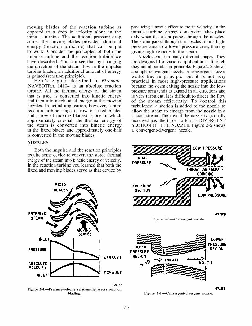
moving blades of the reaction turbine asopposed to a drop in velocity alone in theimpulse turbine. The additional pressure dropacross the moving blades provides additionalenergy (reaction principle) that can be putto work. Consider the principles of both theimpulse turbine and the reaction turbine wehave described. You can see that by changingthe direction of the steam flow in the impulseturbine blades, an additional amount of energyis gained (reaction principle).
Hero’s engine, described in Fireman,NAVEDTRA 14104 is an absolute reactionturbine. All the thermal energy of the steamthat is used is converted into kinetic energyand then into mechanical energy in the movingnozzles. In actual application, however, a purereaction turbine stage (a row of fixed bladesand a row of moving blades) is one in whichapproximately one-half the thermal energy ofthe steam is converted into kinetic energyin the fixed blades and approximately one-halfis converted in the moving blades.
NOZZLES
Both the impulse and the reaction principlesrequire some device to convert the stored thermalenergy of the steam into kinetic energy or velocity.In the reaction turbine you learned that both thefixed and moving blades serve as that device by
Figure 2-4.—Pressure-velocity relationship across reactionblading. Figure 2-6.—Convergent-divergent nozzle.
producing a nozzle effect to create velocity. In theimpulse turbine, energy conversion takes placeonly when the steam passes through the nozzles.The steam passes through the nozzles from a high-pressure area to a lower pressure area, therebygiving high velocity to the steam.
Nozzles come in many different shapes. Theyare designed for various applications althoughthey are all similar in principle. Figure 2-5 showsa simple convergent nozzle. A convergent nozzleworks fine in principle, but it is not verypractical in most high-pressure applicationsbecause the steam exiting the nozzle into the low-pressure area tends to expand in all directions andis very turbulent. It is difficult to direct the flowof the steam efficiently. To control thisturbulence, a section is added to the nozzle toallow the steam to emerge from the nozzle in asmooth stream. The area of the nozzle is graduallyincreased past the throat to form a DIVERGENTSECTION OF THE NOZZLE. Figure 2-6 showsa convergent-divergent nozzle.
Figure 2-5.—Convergent nozzle.
2-5

TURBINE CLASSIFICATION
Thus far we have classified turbines intotwo general groups-impulse turbines andreaction turbines-depending on the methodused to cause the steam to do useful work.Turbines may be further classified according tothe following:
1. Type and arrangement of staging
2. Direction of steam flow
3. Repetition of steam flow
4. Division of steam flow
A turbine may also be classified as towhether it is a condensing unit (exhausts toa condenser at a pressure below atmospheric
Figure 2-7.—Pressure-velocity relationships in a velocity-compounded impulse turbine.
pressure) or a noncondensing unit (exhauststo another system such as the auxiliary ex-haust steam system at a pressure above atmos-pheric pressure).
STAGING ARRANGEMENTS
An IMPULSE turbine STAGE is one setof nozzles and the succeeding row or rowsof either fixed or moving blades. Fixed bladesin an impulse turbine do nothing more thanredirect the steam flow from one row ofmoving blades to the next. A simple impulsestage (one set of nozzles and one row ofmoving blades) is commonly referred to asa RATEAU stage.
A REACTION turbine STAGE is one row offixed blades and a succeeding row of movingblades. From these descriptions you can see oneimportant difference between an impulse and areaction stage: An impulse stage has only onepressure drop, since a pressure drop will occuronly in a nozzle; whereas, a reaction stage has twopressure drops.
To efficiently utilize the energy of the steam,a turbine must normally have blading and nozzlesthat will cause more than one pressure dropand/or more than one velocity drop as the steam
Figure 2-8.—Pressure-velocity relationships in a pressure-compounded impulse turbine.
2-6
passes through it. This is called COMPOUND-ING. A turbine that has more than one velocitydrop is classified as velocity compounded, and aturbine that has more than one pressure drop isclassified as pressure compounded. A combina-tion of pressure and velocity drops is calledpressure-velocity compounding.
From our definitions of stages, we can see thatan impulse stage may be velocity compounded butis never pressure compounded; and a reactionstage is always pressure compounded but is nevervelocity compounded. This applies only to stagesand NOT to the turbines. Turbines may bedesigned and constructed to incorporate practi-cally any combination of stages. Let’s look atsome of the combinations.
Velocity-Compounded Impulse Turbine
A velocity drop in an impulse turbine occursonly in the moving blades; therefore, to obtainmore than one velocity drop across an impulseturbine, there must be more than one row ofmoving blades. (Velocity compounding can alsobe achieved when only one row of moving bladesis used if the steam is directed in such a way that
it passes through the blades more than once. Thispoint will be taken up in greater detail in thediscussion on the direction of steam flow.) Figure2-7 shows a velocity-compounded impulse turbinewith two rows of moving blades. (NOTE: Twosectional views of the same blading are shown.)This type of arrangement is called a Curtis stage,and, of course, two velocity drops occur across it.
Pressure-Compounded Impulse Turbine
Another method of increasing the efficiencyof an impulse turbine is to put two or more Rateau(simple impulse) stages in a row. This combina-tion produces a pressure-compounded impulseturbine which has as many pressure drops as ithas stages. Figure 2-8 shows a pressure-compounded impulse turbine.
Pressure-Velocity-Compounded ImpulseTurbine
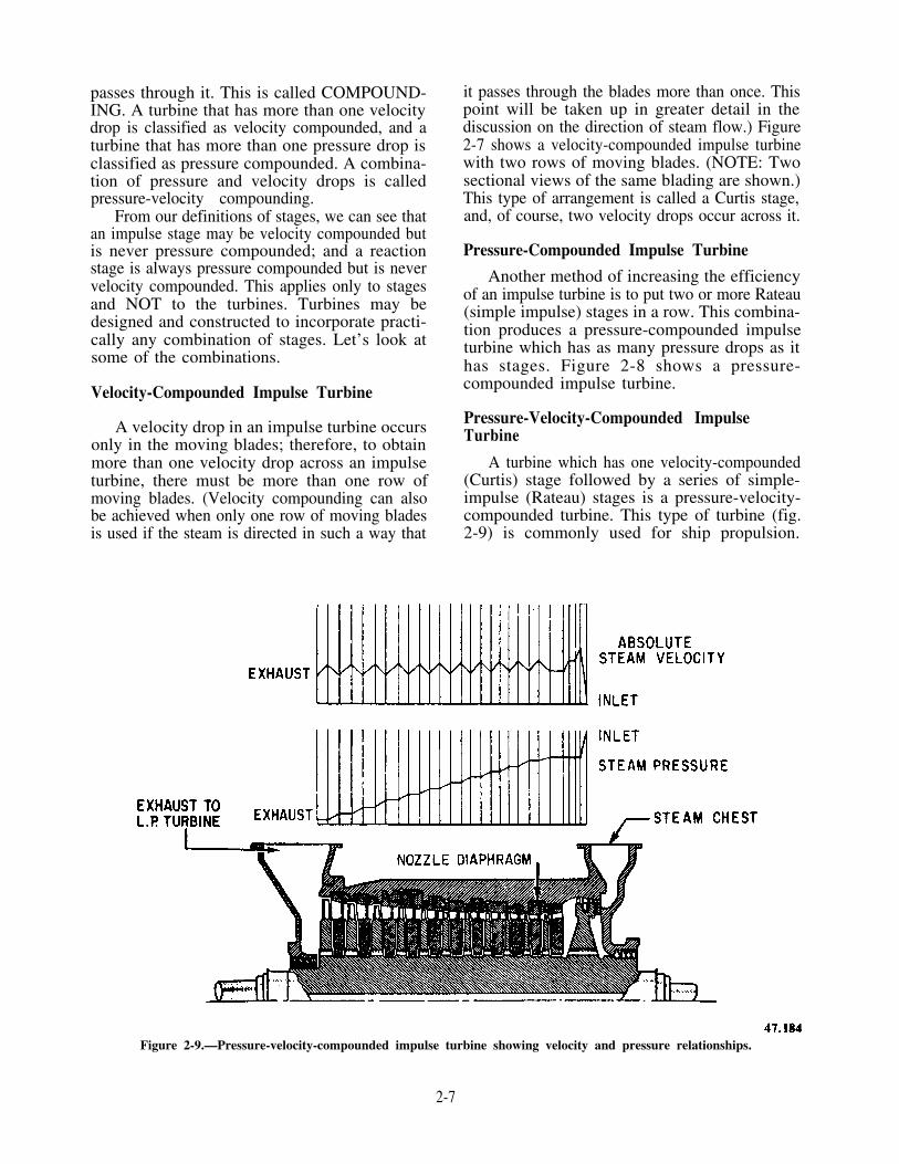
A turbine which has one velocity-compounded(Curtis) stage followed by a series of simple-impulse (Rateau) stages is a pressure-velocity-compounded turbine. This type of turbine (fig.2-9) is commonly used for ship propulsion.
Figure 2-9.—Pressure-velocity-compounded impulse turbine showing velocity and pressure relationships.
2-7

(NOTE: Only the upper half of the rotor andblading is shown.)
Pressure-Compounded Reaction Turbine
All reaction turbines are pressure com-pounded. This means they are arranged sothe pressure drop across the turbine frominlet to exhaust is divided into many stepsby means of alternate rows of fixed andmoving blades (figure 2-10). (Note the smallcurved arrows between the blades and casingand the stator blades and rotor. The arrowsindicate that a small amount of steam leaksaround these areas and does no work.)
Impulse and Reaction CombinationTurbine
Another type of turbine is a combina-tion impulse and reaction type (figure 2-11).This turbine design uses a velocity-compoundedimpulse (Curtis) stage at the high-pressureend of the turbine followed by reaction blading.The impulse blading causes a large pressureand temperature drop at the beginning,using a large amount of thermal energy.The reaction part of the turbine is moreefficient at the lower steam pressure exist-ing at the low-pressure end of the turbine.Therefore, you can see that for certain appli-cations this would be a highly efficient machinewith the advantages of both impulse and
Figure 2-10.—Diagrammatic arrangement of reaction blading showing velocity and pressure relationships.
2-8

Figure 2-11.—Diagrammatic arrangement of combination impulse and reaction turbine showing pressure velocity relationships.
2-9

reaction blading. Figure 2-12 illustrates a type ofthe combination turbine commonly called amodified Parson’s turbine.
DIRECTION OF STEAM FLOW
There are three different ways in which steamcan flow through a turbine: axial flow, helicalflow, and radial flow.
Axial Flow
Most turbines are the axial-flow type.This means the flow of steam is in a directionthat is almost parallel to the axis of the turbineshaft. Figure 2-12 illustrates an axial-flowturbine.
Helical Flow
The steam in a helical-flow turbine flows ata tangent (angle) to the rotor. This tangential flow
is directed into buckets fixed onto the turbinewheel and then back out of the buckets intostationary reversing chambers to be directed backinto the buckets. The process is repeated severaltimes. Figure 2-13 illustrates a helical-flowturbine. This turbine may be used to drive mainand auxiliary equipment such as pumps andforced draft blowers. This turbine is efficientwhere a wide speed range is required.
Radial Flow
In the radial-flow turbine, the flow of steamis directed either toward or away from the rotor.This turbine may be used for driving some smallauxiliary equipment.
REPETITION OF STEAM FLOW
Most turbines are of the single-entry type,since the steam only passes once through theblades. All multistage turbines are of the single-entry type. However, some turbines, such as the
Figure 2-12.—Combination impulse and reaction turbine.
2-10

Figure 2-13.—Cutaway view of steam path in a helical flowturbine.
helical-flow, are the reentry type. In a reentryturbine, the steam is passed more than oncethrough the blades.
DIVISION OF STEAM FLOW
If the steam in a turbine flows in only onedirection, it is classified as a single-flow unit.Most turbines are of this type.
Another commonly used method is thedouble-flow design. Steam from the high-pressure(HP) turbine enters at the center of the low-pressure (LP) turbine and flows outward in bothdirections through two identical sets of turbinestaging. Figure 2-14 shows the steam flow througha double-axial flow, low-pressure turbine.
The double-flow turbine has very little, if any,axial thrust and is quite a bit smaller than a single-flow turbine designed for the same capacity andlow-exhaust pressure. The double-flow turbine isgenerally of the reaction type, because the single-flow reaction-type turbine develops considerableaxial thrust from the pressure drop(s) across themoving blades.
TURBINE COMPONENTS ANDCONSTRUCTION
Now that you are familiar with basicturbine theory, we will briefly discuss turbine
Figure 2-14.—Low-pressure double-axial flow reaction turbine.
2-11

components, parts, and construction. This infor-mation is supplementary to information inFireman, NAVEDTRA 14104.
TURBINE SUPPORT
A turbine must be securely attached to theship. However, it must also be free to expand andcontract as necessary to prevent severe damagedue to distortion caused by the large temperatureand torsional changes that occur in the turbine.Usually, it is undesirable to allow a turbine toexpand in the aft direction, because of turbine-reduction gear alignments, so the aft end of aturbine is secured rigidly to the structure.
There are two basic methods and designs thatmeet both the rigidity and expansion requirementsof turbine foundations.
1. The forward end of the turbine may bemounted with a flexible I-beam, as shown infigure 2-15. The I-beam will flex either fore oraft as the turbine expands or contracts.
2. Elongated bolt holes or grooved slidingseats may be used instead of the I-beam arrange-ment to do the same job. Steam lines connectedto the turbine will normally be curved or loopedin some way to allow for expansion of the steamline and prevent excessive strain between the steamline connection and the turbine. The strain couldhave serious consequences.
There are modifications to these two basicmethods. In many ships, the main condenser issupported by the low-pressure turbine, which isrigidly mounted on beams that form integral
Figure 2-15.—Turbine foundation, showing flexible I-beam.
part of the hull structure. In other ships, the low-pressure turbine may be mounted on thecondenser, which, in turn, forms an integral partof the hull. In general, the expansion arrangementof the low-pressure turbine is similar to that ofthe high-pressure turbine except that the flexibleforward support is seldom used. Instead, somearrangements use keys at the center of the low-pressure casing as the fixed point, with ex-pansions occurring equally in the forward and aftdirections from the keys. Some arrangements fixthe after end of the casing by fitted bolts, whilethe forward end uses clearance bolts to allow for
Figure 2-16.—Turbine nozzle diaphragms. A. Impulsenozzles and nozzle diaphragms. B. Internal construction.
2-12

the expansion motion. Another arrangementuses fitted bolts at each end; these bolts fixthe ends to flexible twin inlet necks on thecondenser.
NOZZLE DIAPHRAGMS
Nozzle diaphragms, illustrated in figure 2-16,are installed in front of the rotating blades of eachstage of a pressure-compounded impulse turbine.The diaphragms contain the nozzles which admitsteam to the rotating blades of each stage in muchthe same way as the nozzle groups of the firststage. Some nozzle diaphragms admit steam in anarc of a circle and are called PARTIALADMISSION DIAPHRAGMS; other nozzle
Figure 2-17.—Turbine gland.
diaphragms have nozzles extending around theentire circle of blades and are called FULLADMISSION DIAPHRAGMS. Because of thepressure drop that exists across each diaphragm,a labyrinth packing ring, similar to the shaft glandpacking, is placed in a groove in the innerperiphery of the diaphragm to minimize theleakage of steam across the diaphragm and alongthe rotor. Any leakage through the innerperiphery of the diaphragm will reduce theamount of the steam thermal energy beingconverted to mechanical energy and, therefore,reduce the work developed by the stage. Figure2-16 shows the placement of these rings, whichare installed in sections and are spring-backed tohold them together and in place.
SHAFT PACKING GLANDS
When the pressure inside the turbine casing isgreater than atmospheric pressure, shaft packingglands are used to prevent the escape of steam fromthe casing. The packing glands also help to preventair from entering the turbine when pressure withinthe casing is below atmospheric pressure.
In general, three types of shaft glands are usedon naval turbines: labyrinth packing glands, carbonpacking glands, or a combination of both labyrinthand carbon packing glands. The labyrinth packinggland is the most widely used method of sealing aturbine shaft in naval turbines; therefore, this is themethod discussed here.
LABYRINTH PACKING is used in theglands and interstages of modern steam turbines.Labyrinth packing consists of machined packingstrips of fins mounted on the casing surroundingthe shaft to make a very small clearancebetween the shaft and the strip. Figure 2-17shows a labyrinth packing gland. The principleof labyrinth packing seals is that as steamleaks through the very narrow spaces betweenthe packing strips and the shaft, the steampressure drops. As the steam passes fromone packing strip to the next, its pressureis gradually reduced and any velocity thatit might gain through the nozzling effect islost by the action of the steam as it ricochets
2-13

Figure 2-18.—HP-IP turbine cylinder base with lower sections of seals and diaphragms installed, viewed from thrust end.
back and forth in the gland. Figure 2-18 is thelower half casing of a high-pressure, intermediatepressure (HP-IP) turbine showing the interstageand gland packing installed.
Gland Seal
Packing alone will neither stop the flow ofsteam from the turbine nor prevent the flow ofair into the turbine. Gland sealing steam is usedto prevent the entrance of outside air into theturbine, which would reduce or destroy thevacuum in the main condenser. Figure 2-17 showshow gland sealing steam of approximately 2 psig(17 psi absolute) is led into a space between twosets of gland packing. (In older ships, steam issupplied from the auxiliary exhaust steam line
through a stop valve.) Two weight-loaded valvesoperate automatically to maintain a pressure ofl/2 to 2 psig on the glands.
During periods of warming-up, low-speedoperation, backdown, and securing, these weight-loaded valves are open. When the turbine isspeeded up and the steam flowing from thelabyrinth gland of the high-pressure turbinereaches 2 psig, the valve supplying the high-pressure turbine closes automatically, admittingno more gland steam from the auxiliary exhaustline. The high-pressure turbine gland is thensupplying enough steam leakage to seal thelow-pressure glands. As the turbine speed is in-creased still further and the pressure in thesealing system rises to approximately 2 l/2 psig,the excess steam is led, by a manually operated
2-14

or an automatically operated valve, either to themain condenser or to the low-pressure turbine(depending on the ship).
The leak-off connections are linked to theGLAND LEAK-OFF PIPING, which collects andcondenses the steam that leaks from the gland,thus preventing the escape and loss of steam tothe atmosphere.
A fan-type GLAND SEAL EXHAUSTERputs a slight vacuum on the leak-off piping. Thevacuum draws the leak-off steam through aGLAND EXHAUST CONDENSER where thesteam is condensed and returned to the feedsystem.
Most ships use two different methods tosupply gland seal to the propulsion and generatorturbines. Both methods are basically the sameas previously described in that steam is suppliedto the glands when the pressure drops to a point
that it is needed, and excess steam is relievedfrom the system when the pressure increases toohigh.
Steam from the 150 psig steam system isadmitted to the gland sealing system through anair-operated supply valve. If the pressure inthe system becomes excessive, as in high-poweroperation, excess steam is “dumped” to thecondenser through the LP turbine. This is doneby means of another air-operated valve calledthe excess valve or excess steam unloading valve.The supply and excess valves both have pilotactuators which sense the pressure in the glandseal steam piping. Figure 2-19 shows the valvesin greater detail. This system may be used on mainpropulsion units or steam turbine generators. Youwill find more detailed information on the actualoperation of air-operated valves in chapter 10 ofthis manual.
Figure 2-19.—Gland seal regulator mechanism.
2-15

Another type of gland seal supply andunloading regulator, the hydraulic type (fig.2-20), senses the gland seal steam pressure in abellows assembly and uses lube oil pressure andspring pressure to control the opening andclosing of the supply and exhaust (unloading)valves. Both valves are located in a single manifoldand are mechanically operated through a lever.The lever is operated by a piston which usesspring pressure to travel downward (which shutsthe exhaust and opens the supply). The piston useslube oil pressure (through a pilot valve) to travelupward (which shuts the supply and opens theexhaust). A detailed explanation of the internalworking of the valve is in chapter 10 of thismanual. This type of regulator may be found in
either main propulsion units or steam turbinegenerators.
Gland exhaust from main propulsion units isdirected to a gland exhaust condenser or the airejector condenser, and from steam turbinegenerators to the gland exhaust section of theauxiliary air ejector condenser. In both cases, thesteam is condensed and returned to the feedsystem. Air and other noncondensable gases aredischarged to the atmosphere.
TURBINE MATERIALS
The materials used to construct turbines willvary somewhat depending on the steam and powerconditons for which the turbine is designed.
Figure 2-20.—Hydraulic type turbine gland seal regulator.
2-16
Turbine casings are generally made of castcarbon steel for nonsuperheated steam applications.Superheated applications use casings made ofcarbon molybdenum steel.
Turbine rotors (forged wheels and shaft) aremade of carbon steel for low-temperature steam(less than 650°F). High-temperature steam designsuse carbon molybdenum or some othercreep-resistant alloy.
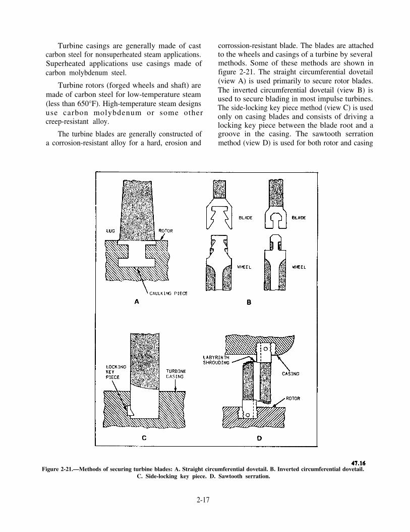
The turbine blades are generally constructed ofa corrosion-resistant alloy for a hard, erosion and
corrossion-resistant blade. The blades are attachedto the wheels and casings of a turbine by severalmethods. Some of these methods are shown infigure 2-21. The straight circumferential dovetail(view A) is used primarily to secure rotor blades.The inverted circumferential dovetail (view B) isused to secure blading in most impulse turbines.The side-locking key piece method (view C) is usedonly on casing blades and consists of driving alocking key piece between the blade root and agroove in the casing. The sawtooth serrationmethod (view D) is used for both rotor and casing
Figure 2-21.—Methods of securing turbine blades: A. Straight circumferential dovetail. B. Inverted circumferential dovetail.C. Side-locking key piece. D. Sawtooth serration.
2-17

Figure 2-22.—Turbine cylinder base with rotor installed, viewed from thrust end.
blades. Figures 2-22 and 2-23 show the lowerhalves of an HP-IP and low-pressure turbinecasing with the rotor installed.
Shrouding
Shrouding is a thin metal strip coveringthe ends of the turbine blades (shown infig. 2-23). It is installed to reduce vibrationstress, which will cause turbine damage. Theshrouding is installed by fitting it over tenonslocated on the end of each blade; it is then rivetedin place.
TURBINE CONTROL
Turbines operate at different speeds.Therefore, they must have a method of steaminlet control to allow fairly small changes ofturbine speed. A system of nozzle control valvesperforms this function. Although the turbinespeed control system aboard your ship maydiffer from those described here, you shouldunderstand the basic principles by studying thefollowing discussion.
NOZZLE CONTROLVALVES
One type of nozzle control valve systemis shown in figure 2-24. It controls speedby varying the number of nozzle valves thatare opened. A lifting beam mechanism, drilledwith holes, fits over the nozzle valve stems.These stems are of varying lengths and arefitted with shoulders or "buttons" at theupper ends. The nozzle valves are commonlyreferred to as POPPETS. (A poppet valvehas a disc that moves axially, or parallel,with the flow of fluid through the valve.)When the beam is lowered, all valves restupon their seats. The individual poppets areheld tightly shut against their seats by steampressure. The mushroom shape of the poppetsgives the steam pressure adequate surfacearea to "hold down" the valves. When thebeam is raised, the valves open in succes-sion; the shorter ones open first, then thelonger ones. Several types of valve linkagearrangements are used to change throttlevalve handwheel rotary motion into liftingmotion to raise and lower the beam.
2-18

Figure 2-23.—L. P. turbine cylinder base with rotor installed, viewed from thrust end.
Figure 2-24.—Arrangement of nozzle control valves.
2-19
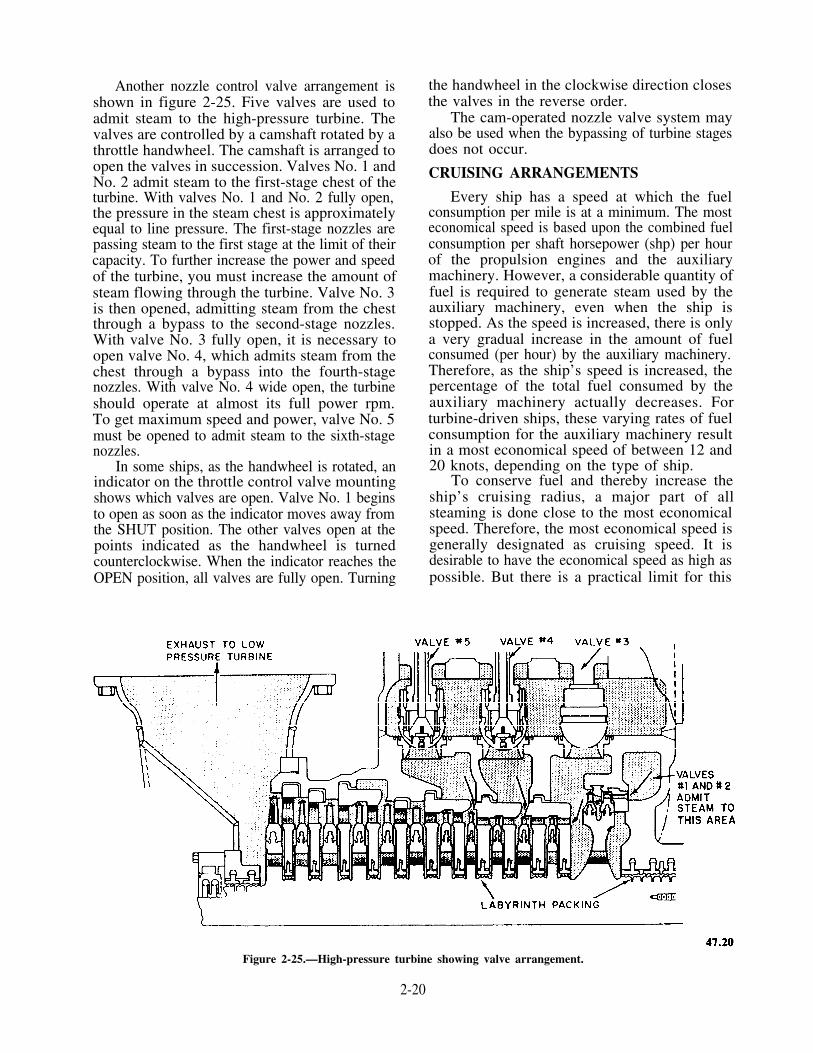
Another nozzle control valve arrangement isshown in figure 2-25. Five valves are used toadmit steam to the high-pressure turbine. Thevalves are controlled by a camshaft rotated by athrottle handwheel. The camshaft is arranged toopen the valves in succession. Valves No. 1 andNo. 2 admit steam to the first-stage chest of theturbine. With valves No. 1 and No. 2 fully open,the pressure in the steam chest is approximatelyequal to line pressure. The first-stage nozzles arepassing steam to the first stage at the limit of theircapacity. To further increase the power and speedof the turbine, you must increase the amount ofsteam flowing through the turbine. Valve No. 3is then opened, admitting steam from the chestthrough a bypass to the second-stage nozzles.With valve No. 3 fully open, it is necessary toopen valve No. 4, which admits steam from thechest through a bypass into the fourth-stagenozzles. With valve No. 4 wide open, the turbineshould operate at almost its full power rpm.To get maximum speed and power, valve No. 5must be opened to admit steam to the sixth-stagenozzles.
In some ships, as the handwheel is rotated, anindicator on the throttle control valve mountingshows which valves are open. Valve No. 1 beginsto open as soon as the indicator moves away fromthe SHUT position. The other valves open at thepoints indicated as the handwheel is turnedcounterclockwise. When the indicator reaches theOPEN position, all valves are fully open. Turning
the handwheel in the clockwise direction closesthe valves in the reverse order.
The cam-operated nozzle valve system mayalso be used when the bypassing of turbine stagesdoes not occur.
CRUISING ARRANGEMENTS
Every ship has a speed at which the fuelconsumption per mile is at a minimum. The mosteconomical speed is based upon the combined fuelconsumption per shaft horsepower (shp) per hourof the propulsion engines and the auxiliarymachinery. However, a considerable quantity offuel is required to generate steam used by theauxiliary machinery, even when the ship isstopped. As the speed is increased, there is onlya very gradual increase in the amount of fuelconsumed (per hour) by the auxiliary machinery.Therefore, as the ship’s speed is increased, thepercentage of the total fuel consumed by theauxiliary machinery actually decreases. Forturbine-driven ships, these varying rates of fuelconsumption for the auxiliary machinery resultin a most economical speed of between 12 and20 knots, depending on the type of ship.
To conserve fuel and thereby increase theship’s cruising radius, a major part of allsteaming is done close to the most economicalspeed. Therefore, the most economical speed isgenerally designated as cruising speed. It isdesirable to have the economical speed as high aspossible. But there is a practical limit for this
Figure 2-25.—High-pressure turbine showing valve arrangement.
2-20

speed because of the progressively increasingresistance of water to the ship’s hull as the speedof the ship is increased. Increasing the efficiencyof the main engines will tend to raise the mosteconomical speed. The propulsion turbines aredesigned to have their best steam rate at the cruis-ing speed.
Combatant ships should be able to steam ator near full power for long periods of time. Thismeans that propulsion plants must be designedwith a relatively high turbine efficiency at highspeeds.
A turbine gets maximum efficiency at theoptimum ratio of blade speed to steam speed.Therefore, to obtain the lowest possible fuel con-sumption per shaft horsepower per hour at cruis-ing speed AND at full power, propulsion turbinesmust be designed so the optimum ratio of bladespeed to steam speed will be approached at boththese speeds. This may be accomplished by usingcruising stages: high-pressure, intermediate-pressure, low-pressure (HP-IP-LP) turbinecombinations.
ASTERN (REVERSING)
Except for electric-drive propulsion units,astern elements are provided with steam propul-sion turbine units for emergency stopping, back-ing, and maneuvering. In units using low-pressureturbine (all except type I), there is an astern ele-ment in each exhaust end of the double-flow, low-pressure turbine. The single-casing turbine unitshave an astern element in the exhaust end of eachturbine. Astern elements are usually Curtis stages(velocity-compounded impulse), which develophigh torque but have low efficiency. An asternturbine normally is designed to produce from one-fifth to one-half of the ahead turbine full power.
AUXILIARY STEAM TURBINES
In this chapter, we have described the generalprinciples and construction features of the varioustypes of turbines in use by the Navy. We empha-sized the larger types of turbines used for mainpropulsion. There are, of course, a considerablenumber of small turbines employed in all navalengineering plants for driving auxiliarymachinery.
Most auxiliary machinery units outside theengineering spaces on modern naval ships, andmany units within these spaces, are driven byelectric motors.
EFFICIENCY OF AUXILIARYTURBINES
There are two major advantages in using tur-bines to drive auxiliary machinery:
1. Turbines ensure greater reliability thanmotor-driven units. The possibility of interrup-tion or loss of electric power supply is greater thanthe possibility of loss of steam supply—especiallyduring general quarters and special details.
2. Turbines improve the overall efficiency ofthe plant by supplying exhaust steam for suchauxiliary machinery units as deaerating feed tanksand evaporators, where low pressure is required.
The efficiency of most auxiliary turbines is in-creased with the use of reduction gears. Those tur-bines are designed to have comparatively fewstages (sometimes only one) to conserve space.This results in a large pressure drop in each stage,and a high steam velocity. To obtain maximumefficiency, the blade speed must also be high.Hence, the reduction gears reconcile the twoconflicting speed requirements and increase thegeneral efficiency.
AUXILIARY TURBINECLASSIFICATION
In general, auxiliary turbines in naval use maybe classified (in a manner similar to the generalturbine-type classifications) according to thefollowing characteristics:
1.2.
3.4.5.
6.
7.8.9.
Speed (constant or variable)Exhaust conditions (condensing or non-condensing)Shaft position (horizontal or vertical)Type (impulse or reaction)Steam flow direction (axial, radial, orhelical)Stages (single or multiple)
Drive (direct or geared)Service (based upon driven auxiliary)Power output capacity, limiting speeds,and so forth
Except for turbine-driven electric generators,the auxiliary turbines are usually impulse turbinesof either the helical-flow or axial-flow type. Theyoperate against a back pressure of approximately
2-21

Figure 2-26.—Main lube oil pump turbine.
15 psig, depending upon the auxiliary exhaust lineoperating pressure of the ship in which they areinstalled. In later ships, this back pressure is 15-17psi. Turbines for driving the ship’s servicegenerators are ordinarily of the impulse, axial-flow, multistage, geared type.
USES OF AUXILIARYTURBINES
The principle pumps driven by auxiliaryturbines include the main condensate pumps,main condenser circulating pumps, main feedpumps, main feed booster pumps, main fueloil service pumps, forced draft blowers, andmain lube or service pumps.
Main Condensate Pump Turbines
On some ships, identical turbines are used todrive main condensate, main feed booster, and thelube oil service pumps. The bucket wheels (turbinewheels) and many other parts, such as governors,bearings, and turbine and gear casings, are inter-changeable. Figure 2-26 shows the wheel and blad-ing diagram of a turbine used to drive the maincondensate, main feed booster, and lube oilservice pumps. These turbines are single-pressurestage, radial-flow, single-entry turbines. Althoughdestroyers and other ships have changed radicallysince World War II, the basic design of theseturbines has changed little. Improved metals areused, however, to withstand the higher pressuresand temperatures of steam on modern warships.
2-22
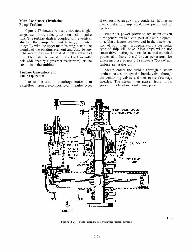
Main Condenser CirculatingPump Turbine
Figure 2-27 shows a vertically mounted, single-stage, axial-flow, velocity-compounded, impulseunit. The turbine shaft is coupled to the verticalshaft of the pump. A thrust bearing, mountedintegrally with the upper main bearing, carries theweight of the rotating element and absorbs anyunbalanced downward thrust. A throttle valve anda double-seated balanced inlet valve (normallyheld wide open by a governor mechanism) lets thesteam into the turbine.
Turbine Generators andTheir Operation
The turbine used on a turbogenerator is anaxial-flow, pressure-compounded, impulse type.
It exhausts to an auxiliary condenser having itsown circulating pump, condensate pump, and airejectors.
Electrical power provided by steam-driventurbogenerators is a vital part of a ship’s opera-tion. Many factors are involved in the determina-tion of how many turbogenerators a particulartype of ship will have. Most ships which usesteam-driven turbogenerators for normal electricalpower also have diesel-driven generators foremergency use. Figure 2-28 shows a 750 kW acturbine generator unit.
Steam enters the turbine through a steamstrainer, passes through the throttle valve, throughthe controlling valves, and then to the first-stagenozzles. The steam then passes from initialpressure to final or condensing pressure.
Figure 2-27.—Main condenser circulating pump turbine.
2-23

Figure 2-28.—750 KW a.c. turbine generator set.
The speed of the unit is controlled by aconstant-speed governor.
The throttle valve is provided with ahand-wheel for manual control and for resettingthe valve after it has been tripped. The throttlevalve closes when the overspeed trip orback-pressure trip functions, or when the manualtrip lever is pushed.
Operation of turbogenerators should be inaccordance with the Engineering OperationalSequencing System (EOSS).
General Precautions onTurbogenerator Operation
The following precautions should be followedcarefully when you operate turbogenerators:
1. Test the manual trip to ensure that it isfunctioning properly.
2. Under no circumstances should you admitsteam to the turbine rotor for any appreciable lengthof time without rolling it. Uneven heating willdistort the rotor and cause vibration when the turbineis started.
3. After the turbine is started, test the manual tripfor proper operation.
4. When bringing a generator turbine up to speed,you should always accelerate rapidly through thecritical speed of the unit; the slight vibration whichmay occur when going through the critical speed willdisappear when the turbine is up to speed.
2-24

Figure 2-29.—Speed limiting governor, main condensate pump.
5. The maximum temperature of oil leavingany bearing should NOT exceed 180°F (82 °C).
6. The temperature rise of oil passing throughany bearing should NOT exceed 50°F (28 °C).
7. Be sure that all control and safety devicesare in proper operating condition. If they are not,the unit should be stopped and the trouble shouldbe located and corrected before the unit is startedagain.
AUXILIARY TURBINE CONTROL
Auxiliary turbine control differs from thatof propulsion turbines in that auxiliary turbinesmust have some type of automatic speed-controlgovernor or device. There are two types ofgovernors in general use: speed-limiting governorsand constant-speed governors.
Speed-Limiting Governor
A speed-limiting governor is a device thatlimits the maximum speed at which a turbine willoperate. This type of governor does not control
steam flow to the turbine until it approaches themaximum designed speed. Figure 2-29 shows oneof the more common types used on main conden-sate, main feed booster, and lube oil service pumpturbines.
The governor shaft is driven directly by anauxiliary shaft in the reduction gear and rotatesat the same speed as the pump shaft. Twoflyweights are pivoted to a yoke on the governorshaft and carry arms which bear on a push rodassembly. The push rod assembly is held downby a strong spring and nut. Centrifugal force onthe flyweights causes them to move outward. Thislifts the arms, which pivot on rollers, against thespring tension on the governor stem whenever thepreset speed of the governor is reached. If theturbine speed begins to exceed that for which thegovernor is set, increased centrifugal force actingon the rotating flyweights will cause them to movefarther out. This causes the governor valve tothrottle down on the steam. On the other hand,when the turbine slows down, as from an increasein load, the centrifugal force on the flyweights isreduced, and the governor push rod spring actsto pull the flyweights inward. This rotates the leverabout its pivot and opens the governor valve, thus
2-25
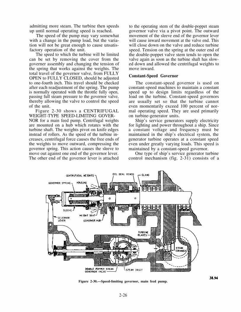
admitting more steam. The turbine then speedsup until normal operating speed is reached.
The speed of the pump may vary somewhatwith a change in the pump load, but the varia-tion will not be great enough to cause unsatis-factory operation of the unit.
The speed to which the turbine will be limitedcan be set by removing the cover from thegoverner assembly and changing the tension ofthe spring that works against the weights. Thetotal travel of the governor valve, from FULLYOPEN to FULLY CLOSED, should be adjustedto one-fourth inch. This travel should be checkedafter each readjustment of the spring. The pumpis normally operated with the throttle fully open,passing full steam pressure to the governor valve,thereby allowing the valve to control the speedof the unit.
Figure 2-30 shows a CENTRIFUGALWEIGHT-TYPE SPEED-LIMITING GOVER-NOR for a main feed pump. Centrifugal weightsare mounted on a hub which rotates with theturbine shaft. The weights pivot on knife edgesinstead of rollers. As the speed of the turbine in-creases, centrifugal force causes the free ends ofthe weights to move outward, compressing thegovernor spring. This action causes the sleeve tomove out against one end of the governor lever.The other end of the governor lever is attached
to the operating stem of the double-poppet steamgovernor valve via a pivot point. The outwardmovement of the sleeve end of the governor leverwill cause inward movement at the valve end. Thiswill close down on the valve and reduce turbinespeed. Tension on the spring at the outer end ofthe double-poppet valve stem tends to open thevalve again as soon as the turbine shaft has slow-ed down and allowed the centrifugal weights tomove inward.
Constant-Speed Governor
The constant-speed governor is used onconstant-speed machines to maintain a constantspeed up to design limits regardless of theload on the turbine. Constant-speed governorsare usually set so that the turbine cannoteven momentarily exceed 100 percent of nor-mal operating speed. They are used primarilyon turbine-generator units.
Ship’s service generators supply electricityfor lighting and power throughout a ship. Sincea constant voltage and frequency must bemaintained in the ship’s electrical system, thegenerator turbine operates at a constant speedeven under greatly varying loads. This speed ismaintained by a constant-speed governor.
One type of ship’s service generator turbinecontrol mechanism (fig. 2-31) consists of a
Figure 2-30.—Speed-limiting governor, main feed pump.
2-26
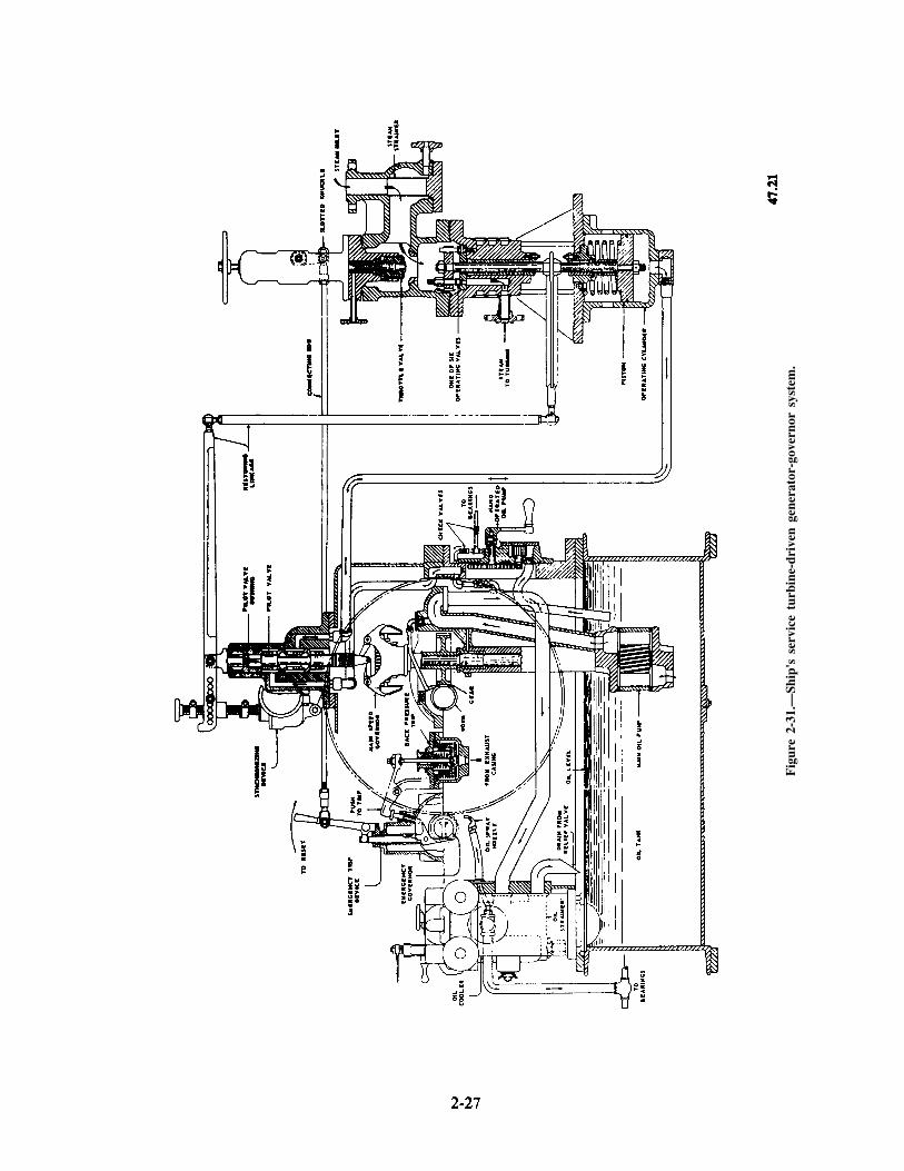
Fig
ure
2-31
.—Sh
ip's
ser
vice
tur
bine
-dri
ven
gene
rato
r-go
vern
or s
yste
m.

centrifugal governor which operates a pilot valve.This valve controls the flow of oil to an operatingcylinder, which, in turn, controls the amount ofopening or closing of the turbine nozzle valves.
A gear-type oil pump and the main governor,mounted on the same shaft, are driven througha worm and gear (fig. 2-31). The worm isdirectly connected to the low-speed gear shaft ofthe turbine reduction gear. It drives the governorat a speed directly proportional to the turbinespeed
When the governor tends to slow because ofan increased load on the generator, the governorweights move inward and cause the pilot valveto move upward, permitting oil to enter theoperating cylinder. The operating piston rises and,through the controlling-valve lever, the liftingbeam is raised. The nozzle valves open andadmit additional steam to the turbine. Theupward motion of the controlling-valve levercauses the governor lever to rise, thus raising thebushing. Upward motion of the bushing tends toclose the upper port. This shuts off the oil flowto the operating cylinder and stops the upwardmotion of the operating piston. This followupmotion of the bushing regulates the governingaction of the pilot valve. Without this featurethe pilot valve would operate, with each slight
variation in turbine speed, to alternately fullyopen and fully close the nozzle valves.
When the turbine tends to speed up becauseof a decreased load on the generator, the gover-nor weights move outward. This moves the pilotvalve downward, opens the lower ports, andallows oil to flow out of the operating cylinder.This action causes the controlling-valve lever tolower the lifting beam, thereby reducing theamount of steam delivered to the turbine. Thedownward motion of the controlling-valve levercauses the governor lever to lower, thereby lower-ing the bushing. The downward motion of thebushing tends to close the lower port, preventingoil from flowing out of the operating cylinder.
Another type of constant-speed governoris the ELECTROHYDRAULIC LOAD-SENSING SPEED GOVERNOR. This governorproduces the same end result as the flyweighttype; that is, it maintains constant turbinespeed with varying loads on the generator.Basically, the governor uses an attached gear-typeoil pump to provide actuating oil pressure to ahydraulic actuator. The hydraulic actuator is con-trolled by an electrical signal from the system con-trol box. The control box sends a signal (increasedelectrical load on the generator) to the actuatorto admit more steam to the turbine. The actuatorthen allows control oil to pass to a remote servopiston in the hydraulic valve actuator (fig. 2-32).
Figure 2-32.—Mechanical diagram of hydraulic valve operator.
2-28

The remote servo piston moves a pilot valveplunger. This allows operating oil to move anoperating piston which mechanically opens thesteam valve. The whole system is designed so thata failure will close the steam valve to the turbine.A cutout valve minimizes the manual pumping ofoil required when starting the turbine. It shutsoff the path for the running oil pressure to thebottom of the operating piston, which will tendto counteract the starting oil pressure on the topof the piston. More detailed information aboutelectrohydraulic load-sensing speed governors iscontained in Electrician’s Mate NAVEDTRA 14344.
SAFETY DEVICES
Safety devices differ from control devices inthat they have no control over the turbine undernormal operating conditions. They come into useonly during some abnormal condition to eitherstop the unit or control its speed.
All turbogenerators have four safety devices:an overspeed trip, a back-pressure trip, a low-oilpressure trip or alarm, and an emergency handtrip.
The OVERSPEED TRIP shuts off the steamsupply to the turbine after a predeterminedspeed has been reached, thus stopping theunit. Overspeed trips are set to trip out atapproximately 110 percent of normal operatingspeed.
The BACK-PRESSURE TRIP closes thethrottle automatically whenever the back orexhaust pressure reaches a set pressure.
The LOW-OIL PRESSURE TRIP closes thethrottle if the lubricating oil pressure drops belowa specified pressure. Some turbogenerators onlyhave low-oil pressure alarms.
The EMERGENCY HAND TRIP providesfor manually closing the throttle quickly in caseof damage to either the turbines or generators.The emergency hand trip may also be used to closethe throttle valve when the turbogenerator issecured.
Some MAIN turbines that use a hydraulicsystem of throttle control have control featureswhich include a speed-limiting function, an over-speed trip, and a hand trip. This system is foundon propulsion turbines which can be inadvertentlyunloaded (1) by unclutching from the propellershaft in geared-turbine drives, (2) by electrical loadloss in turbine-electric drives, or (3) if the turbineis remotely located from the controlling station(bridge control of automated ships).
TURBINE MAINTENANCE
The maintenance of turbine installations is asimportant as their proper operation. If propermaintenance procedures are followed, abnormalconditions may be prevented. You will beconcerned with major adjustments, as well asmeasurements, of turbines. In addition, you mustknow how to fit carbon packing rings to turbines.For more information about the maintenance andrepair of auxiliary turbines, you should refer toNSTM, chapter 502, and the manual furnished withthe unit.
MAJOR ADJUSTMENTSOF A TURBINE
All propulsion turbines installed on ships in theNavy have two major adjustments: the fixing of theproper radial and axial positions of the rotor. Theradial position of the rotor is maintained by the journalbearings and the axial position by the thrust bearings.
The clearances in all shaft and diaphragmpackings are small, and they will be altered if theposition of the rotor changes as a result of wear,either of the journal or of the thrust bearings. Thischange results in reduced efficiency of the turbinebecause of the steam leakage from the glands, andrepairs will eventually be necessary.
The major reason for maintaining a turbinerotor in its proper position is to prevent damage tothe turbine. If the rotor touches the casing at anytime because of failure of the thrust or journalbearings while the turbine is in operation, damagewill result, and it will be necessary to lift the turbinecasing for repairs. Some turbine parts areparticularly subject to damage because of closeclearances involved. They are the rotor blading,diaphragm packing rings, shaft packing rings, andoil deflector or oil seal rings.
Radial Position of the Rotor
The depth gauge micrometer is the quickestmeans of detecting any change in the radial positionof the rotor resulting from bearing wear. When theturbines were installed, depth gage readings weretaken and recorded. Any difference between theoriginal and the new readings will be the amount ofbearing wear in the lower half. For additionalinformation on the use of micrometers refer toTools and Their Uses, NAVEDTRA 14256.
2-29

Figure 2-33.—Beariug wear micrometer depth gauge.
To take new readings (fig. 2-33), a depthgauge spindle is inserted into the depth gauge welluntil the bridge of the gage rests evenly on thereference boss; the knurled handle of themicrometer is then turned until the spindle touchesthe journal. Read the micrometer and comparethe new and the original readings.
Another means of checking bearing wear is bymeasuring the crown thickness with a ball-attached outside micrometer. When the turbinebearings were installed originally, the radialposition of the turbine rotor was set. By using amicrometer, the combined thickness of thebearing shells and liners (at designated places)was measured and stamped on the bearing shell.To take new readings, the bearing cap must beremoved, the top half of the bearing lifted off,and the lower half of the bearing rolled out.Radial lines are scribed on one end of eachbearing to indicate the measurement points, whichare always 1 l/4 inches from the end of thebearing. Any difference between the shipboardand the factory measurements will be the amountof bearing wear.
Another way of measuring bearing wear is byusing an inside micrometer to measure the insidediameter of the bearing and an outside micrometerto measure the outside diameter of the journal.The difference between the readings will be theoil clearance. The difference between the old and
the new oil clearances will be the amount ofbearing wear.
Axial Position of the Rotor
The axial position of a turbine rotor ismaintained by means of a thrust bearing, usually
Figure 2-34.—Axial clearance indicator.
2-30

of the Kingsbury type. With this type of bearing,the axial position of the rotor is adjusted bymachining from the filler piece or by installinga thicker filler piece.
Rotor position indicators are installed on mostmain turbines, allowing a quick and constantmeans of checking rotor position. Figure 2-34shows one type of indicator used.
The most accurate means of determiningwhether the rotor is operating within safe limitsis to check the total oil clearance of the thrustbearing. This clearance can be obtained bymeasuring the end play of the rotor. Methods oftaking this measurement for various installationsmay differ, but the basic principle is the same.With the thrust bearing completely assembled andthe unit not in operation, the rotor is moved(jacked) as far as it will go, first in one directionand then in the opposite direction. The length oftravel is measured with a precision instrument,such as a dial indicator.
One method of moving the rotor is as follows:Remove the upper half of the coupling guard andattach the dial indicator to the flanged surface ofthe bearing cap. To move the rotor forward, applya bar between the after face of the coupling flangeand the face of the adjacent cover. To move therotor aft, the bar is applied between the forwardface of the coupling flange and the face of thebearing cap. In each case, a wooden block isused to prevent marring the metal surfaces. Theend play (thrust bearing clearance) is obtainedfrom the two readings of the dial indicator. If theend play is within designed limits, the rotor isoperating within its allowable limits.
You can get additional information on journaland bearing clearances from the manufacturer’stechnical manual for the specific installation, orfrom Naval Ships’ Technical Manual, chapter231.
MAINTENANCE OF LABYRINTHAND CARBON PACKING RINGS
Worn labyrinth packing may be repaired witha chisel bar and a hand chisel. The chisel is struckwith a hammer, and then advanced around theperiphery of the packing a trifle less than thetool’s width. Care must be taken that each newposition of the chisel overlaps the precedingposition. This procedure expands the LAND(surface area of the packing) in height anddraws it out to its original featheredge. Thedrawing out of the LANDS must be continuedto give the packing clearance specified onmanufacturer’s drawings, instruction books,
or maintenance requirements cards. If theclearance is not available from plans, instructionbooks, or maintenance requirements cards, thedrawing of LANDS should be continued untilthey come within 0.005 of an inch of touchingthe casing.
CAUTION: This procedure should only beused by experienced individuals. When possible,damaged or worn labyrinth packing should bereplaced with new.
When overhauling carbon packing, it isrecommended that the removed segments beimmediately placed in a box in such a manner thatadjacent segments of a ring will be next to eachother, as shown by the marks on each end of eachsegment. Each segment is marked with thenumber of the ring of which it is a part:
1. Examine all sections of the carbon pack-ing for scores, grooves, and wear in general. Ifnecessary, renew or refit rings in accordance withmanufacturer’s plans, instruction books, ormaintenance requirements cards.
2. The springs must be carefully examinedand tested. If they are found to be weak orcorroded, they must be renewed.
PLANT MAINTENANCE
Maximum operational reliability and effi-ciency of steam propulsion plants require acarefully planned and executed program of inspec-tions and planned (preventive) maintenance inaddition to strict adherence to prescribedoperating instructions and safety precautions.When proper maintenance procedures arefollowed, abnormal conditions should beprevented.
Continuous and detailed inspection proceduresare necessary not only to discover partly damagedparts which may fail at a critical time, but alsoto eliminate the underlying conditions which leadto early failure (maladjustment, improper lubrica-tion, corrosion, erosion, and other enemies ofmachinery reliability). Particular and continuousattention must be paid to the following symptomsof malfunctioning:
1. Unusual noises2. Vibrations3. Abnormal temperatures4. Abnormal pressures5. Abnormal operating speeds
2-31

You should familiarize yourself with thespecific temperatures, pressures, and operatingspeeds of equipment required for normal opera-tion, so that departures from normal operationwill be more readily apparent.
If a gauge or other instrument gives anabnormal reading, the cause must be fullyinvestigated. You can install a spare instrumentor do a calibration test to learn whether theabnormal reading is due to instrument error.However, you must believe the indications andtake action accordingly until the indication isproven wrong. Any other cause must be tracedto its source.
Because of the safety factor commonlyincorporated in pumps and similar equipment,considerable loss of capacity can occur before yousee any external evidence. In case of pressure-governor-controlled equipment, changes in theoperating speeds from normal for the existing loadshould be viewed with suspicion. Variations fromnormal pressures, lubricating oil temperatures,and system pressures indicate either inefficientoperation or poor condition of machinery.
When a material failure occurs in any unit,promptly inspect all similar units to determinewhether there is any danger of a similar failure.Prompt inspection may eliminate a wave ofrepeated casualties.
Abnormal wear, fatigue, erosion, or corrosionof a particular part may indicate a failure to
operate the equipment within its designed limitsor loading, velocity, and lubrication. It also mayindicate a design or material deficiency. Unlesscorrective action can be taken which will ensurethat such failures will not occur, specialinspections to detect damage should be under-taken as a routine matter.
Pay strict attention to the proper lubricationof all equipment. This includes frequent inspectionand sampling to determine that the correctquantity of the proper lubricant is in the unit.
Salt water in the oil can be detected by draw-ing off the settled water by means of a pipette andby running a standard chloride test. A samplelarge enough for test purposes can be obtainedby adding distilled water to the oil sample,shaking vigorously, and then allowing the water tosettle before draining off the test sample. Becauseof its corrosive effects, salt water in the lubricatingoil is far more dangerous to a unit than is an equalquantity of freshwater. Salt water is particularlyharmful to units containing oil-lubricated ballbearings.
You will find more information on routineturbine checks and operations in chapter 7 of thismanual and more in-depth information onturbines in the Naval Ships’ Technical Manual,chapter 231 (9411) for propulsion turbines andchapter 502 (9500) for auxiliary turbines.
2-32

CHAPTER 3
REDUCTION GEARS ANDRELATED EQUIPMENT
This chapter deals primarily with reductiongears used in geared turbine-driven propulsionsystems and related equipment such as bearingsand shafting. We will discuss the construction,operation, and precautionary care of mainreduction gears and reduction gears used onauxiliary turbines. Unless otherwise noted, theinformation deals with steam turbine drives.
High-speed propellers are less efficient thanlow-speed propellers. They waste much of theirhorsepower just churning up water instead ofusing it to move the ship. Therefore, turbines usereduction gears to gear down to the appropriatespeed for the size propeller the ship can carry.
REDUCTION GEARS
Reduction gears are coupled to the turbineshaft through various arrangements of gearing.These gears reduce the speed of the turbine to thelow speed required by the propulsion shaft andpropeller. Reduction gears may be driven by oneor more turbines. A combination of gears isknown as a train, and that term will be used inthis chapter.
Reduction gears are classified according to thenumber of steps used to reduce speed and thearrangement of the gearing. When two gears aremeshed and the driving gear (called a pinion) islarger than the mating gear, the driving gear iscalled a speed increaser. A driving gear that issmaller than the mating gear is called a speeddecreaser. The ratio of the speeds is proportionalto the diameters of the pinion and gear. Whenthere are just two gears, the train is known as asingle-reduction gear (single-speed increaser ordecreaser). Double-reduction gears have morethan two gears working together. They keep thesize of the bull gear (large gear attached to thepropeller shaft) from becoming too large.
PROPULSION REDUCTION GEARS
Turbine drives normally use double-reductiongears. The articulated locked train, double-reduction
gear (fig. 3-1) is the most common. All propul-sion reduction gears in combatant ships usedouble-helical gears, which are shown in figure3-1. These gears produce smoother action of thereduction gearing and avoid tooth shock. Adouble-helical gear has two sets of teeth atcomplementary angles to each other; therefore,axial thrust is eliminated. Each member of adouble-helical gear set should be capable ofaxial float to prevent excessive tooth loadscaused by a mismatch of the meshing elements.(Axial float means "capable of free motion,neither supporting nor supported by other gearsaxially.") There is a groove around the center ofthe gear where the teeth sets come together. Thisgroove provides a path for oil flow, so that ahydraulic pressure is not created between the gearswhere they mesh.
When the first-reduction gear and the second-reduction pinion each have two bearings and areconnected by a quill shaft and flexible coupling(s),the design is called ARTICULATED. A quillshaft is essentially a gear coupling. It has twoshaft rings with internal teeth and a shaft withexternal teeth around each end. The shaft ringsare bolted on the far ends of each of the two gearsto be connected. The floating member, now called
Figure 3-1.—Articulated locked train, double-reduction gear.
3-1

Figure 3-2.—Typical destroyer-type propulsion gear.
a quill shaft, passes through the hollow centersof both gears. It is supported only at the endswhere its teeth mesh with the shaft ends. The quillshaft can be seen in figures 3-4 and 3-8, later inthis chapter.
An articulated LOCKED TRAIN GEAR hastwo high-speed pinions. Each pinion drives twofirst-reduction gears connected by quill shafts totwo separate second-reduction pinions. Each gearand pinion is mounted in its own two bearings.Figure 3-2 shows the major parts of a mainreduction gear unit.
The term locked train means that the twofirst-reduction pinions are locked between the twofirst-reduction gears and transmit the power fromthe turbines equally to the two gears. This methodreduces the load on each gear tooth by 50 percent.
Construction of Main Reduction Gears
The main rotating elements in a propulsiongear unit (main gears and pinions) operate at highrotational speeds. They transmit tremendous
power loads. Very slight unevenness of tooth
contour and tooth spacing will cause the gears tooperate noisily or even to fail. Therefore, thesegears are manufactured to very close tolerances.They are cut in rooms in which the temperaturesand humidity are closely controlled. Expansionand contraction of the gear-blank, duringmachining, are negligible. Oxidation, due tomoisture in the air, is nearly eliminated. Inaddition, all gears are carefully checked forerrors.
CASINGS.—Except for some small units,gear casings are of welded construction. Mostgears have an upper and a lower casing and gearcase covers. These casings are of box-girderconstruction with integral-bearing blocks. Thelow-speed bull-gear bearing housing is an integralpart of the lower casing. Gear case covers arebolted and securely locked to the upper casing.They are arranged so that they can be removedfor access to gearing and bearing caps. Inspectionplates are usually provided in covers and gearcases so that the rotating parts may be inspected.
3-2

Figure 3-3.—Single forged-steel pinion.
Casings are arranged for access to oil sprayfittings so that the fittings may be cleaned.Turning gears, tachometer drives, lube oil pumpdrives, sight-flow and thermometer fittings,thermocouples or resistance temperature element(RTE) junction boxes, and electrostatic precipitatorvent connections are attached to gear casings.
GEARS.—In general, gears are forged-steel,one-piece constructions, as shown in figure 3-3.
The gear wheel construction and materialsdepend on the size of the gear. For small gears,the entire gear wheel may be made from a singlesteel forging. Figure 3-3 shows an example of asingle forged-steel pinion. Large gears are generallybuilt up by welding. These gear sections usuallyare the shaft, the hub or center (which may beomitted when the webs are welded to the shaft),the webs, and the rim in which teeth are cut.The shaft is always of forged steel. Whenpropeller-thrust bearings are located within thepropulsion gear casing, a collar is located at theforward end of the low-speed gear shaft. Or, anintegral flange for attachment of thrust bearing
facing collars is located on the other end of theshaft, forward of the line shaft flange. Other typesof construction consist of a close-grained cast-steelbody. The body is welded to a shaft, with teethcut directly in the casting, or a cast-steel body ispressed on a shaft and secured by fore- and aft-shrink rings and a locknut. Figure 3-4 illustratesa typical first-reduction gear. Figure 3-5 shows abull gear with a flange for an after-thrust bearing.
Figure 3-5.—Bull gear assembly with shaft.
Figure 3-4.—Cutaway view of intermediate rotor assembly articulated gear.
3-3

Figure 3-6.—Gear-type flexible coupling.
In a double-reduction, articulated, divided-power path gear set, the high-speed and second-reduction pinions are usually machined fromforgings. The first- and second-reduction gearsare usually fabricated. The gear shaft and rim aremade of steel forgings. The rim and the shaft areassembled with steel webs, welded to the shaft andrim. In wide-faced gears, the position of the steelwebs, with respect to the gear teeth, is importantin that it may affect gear tooth wear patterns. Thisassembly is stress relieved and heat treated fordesired hardness.
Some gears are rough cut before heat treat-men;, and the final finish operation brings themto the proper size. The journals are then cutslightly oversize to permit a final finishingoperation. The teeth are cut in a temperature-controlled room. The cutting operation iscontinuous. This prevents heat that is generatedin cutting from affecting the roundness of thefinished gear. The air temperature controlprevents changes in the ambient temperature fromaffecting the roundness of the gear. When thetooth cutting and the finishing operations arecompleted, the journals are finished so that theyare concentric with the shaft axis. The assemblyis then balanced. The bull gear is made in a similarfashion. Some first-reduction gears and bull gearsin naval use are keyed and locked to the shaft witha locking device. This is done before the teeth arecut and before balancing. When the gears are all
completed, the contact between pinion and gearis usually checked in a gear rolling machine beforethey are assembled in the gear case.
FLEXIBLE COUPLINGS.—Flexible couplingsprovide longitudinal and angular flexibilitybetween the turbine shafts and the pinion shafts.This permits each shaft to be adjusted axially toits proper position to obtain total axial float.
Most installations have gear-tooth type offlexible couplings. Power is transmitted througha floating intermediate member with externalteeth. These teeth mesh with the internal teeth ofthe shaft rings (sleeves) mounted on the drivingand driven shafts.
Figure 3-6 illustrates a design of the gear-typeflexible couplings that connect the main turbinesto the high-speed pinions of the main reductiongear. The couplings also allow for expansion ofthe turbine shafts. This takes care of any slightmisalignment between the main turbines and thereduction gears, such as thermal expansion andhull movements. Another type of flexible couplingis shown in figure 3-7. In this coupling the floatingmember is the two sleeves that are bolted together.The internal teeth of the sleeve mesh with theexternal teeth of the hubs mounted on the shaft.This type of coupling is used most often in dieselengine gears and where self-contained lubricationis advantageous.
3-4

Figure 3-7.—Another gear-type flexible coupling.
Figure 3-8.—Quill shaft assembly.
The design of the flexible couplings, whichconnect the first-reduction gears and the second-reduction pinions, is shown in figures 3-8 and 3-4.In this case, a quill shaft of high torsionalflexibility is used as the floating member. Thisshaft provides equal distribution of the loadamong the several elements of the gear train. Thequill shaft runs inside the hollow bore of thehigh-speed gear and the slow-speed pinion. Figure3-8 shows how flexibility is obtained between thefirst-reduction gear and the second-reductionpinion.
A steady flow of oil from the supply passagesof adjacent bearings is directed into the flexiblecouplings when the reduction gears are turning.The oil is caught by projecting lips of the turbineand pinion flanges (fig. 3-6) or sleeves. Centrifugalaction forces oil through the horizontal holesin the flanges to the coupling teeth. Oil isdischarged from the teeth into coupling guardsand then flows into the oil drain system.
TURNING GEARS.—All geared-turbine instal-lations are equipped with an electric motor-driven
3-5

Figure 3-9.—Propulsion gear after end, high-pressure side, showing turning gear and propeller-locking mechanism.
jacking or turning gear (fig. 3-9). The unit isused to turn the main engine during warming upand securing periods so that the turbine rotor canheat or cool evenly. (The rotor of a hot turbine,or of one that is in the process of being warmedup with gland-sealing steam cut in, will becomebowed or distorted if left stationary even for afew minutes.) The turning gear is used for otherroutine purposes. One example is turning thereduction gear to bring the reduction gear teethinto view during routine inspection. Another isthe required periodic rotation of the main engineswhen they are secured.
The turning gear is mounted on top and at theafter end of the reduction gear casing. A shaftextends from the end of the high-pressure, first-reduction pinion to the after end of the reductiongear casing. It connects to the turning gear by amanually operated jaw clutch.
Engaging this clutch connects the pinion to anelectric motor through a train of gears. Thesegears usually consist of one or more sets of worm
gears and one or more sets of spur or helical gears.Engaging the clutch and operating the motor willturn one first-reduction pinion. This turns thereduction gears, the main turbines, and the mainpropeller shaft.
On some installations, the reduction ratiobetween the main shaft and the electric motor maybe as high as 17,000 to 1. With the motor turningand the turning gear engaged, the main shaft willmake 1 1/4 turns in approximately 15 minutes.Because of the gearing arrangement, the turbinesshould never be turned with steam while theturning gear is engaged. It will cause seriousdamage to the turning mechanism.
The turning gear is equipped with a shaft-locking device (fig. 3-9). This device is used tolock the shaft against rotation while the ship isunderway. (On multiscrew ships, if one shaft isstopped with the other(s) operating, the stoppedshaft must be locked or it will rotate due topropeller drag through the water.) For thispurpose, a friction brake is usually installed on
3-6

Figure 3-10.—Vertical propeller type of main condensercirculating pump.
the first-reduction worm shaft. Either a brakedrum is mounted on the worm shaft or the shaftcoupling serves as a drum. When the turning gearis engaged and the brake is set, a ship can go aheadon its other engines and the idle shaft will be heldstationary.
Some turning gears have positive lockingdevices which use internal and external gear teethin engagement. Turning gears operated by airmotors or by hand are generally used wherecontinuous turning is not required.
To engage the jacking gear clutch, firststop the shaft. This can be done either bystopping the ship or by using the astern turbineto stop and then hold the shaft stationary.NEVER, UNDER ANY CIRCUMSTANCES,
ATTEMPT TO ENGAGE THE JACKINGGEAR WITH THE SHAFT TURNING. Regard-less of how slow the propeller shaft movementmay be, damage to the motor or gears, or both,will occur.
REDUCTION GEARS FORAUXILIARY MACHINERY
Earlier in this chapter, we discussed thedouble-helix, double-reduction type of propulsiongears. Smaller engine-room machinery, such asturbogenerators and turbine-driven pumps, usesdifferent types of reduction gears.
Most pumps are electrically driven and requireno reduction gears. Or, the ship may use a designwhere one pump of a type is electrically drivenand the other is turbine driven. If four pumps ofa type are used, the design may be a two and twoarrangement. Because of the many differentdesigns of auxiliary reduction gears, selectedexamples are used in these explanations.
Turbogenerators
A ship’s service turbogenerator may use asingle-reduction, single-helical gear unit, or asingle-reduction, double-helical unit. On thesingle-reduction, single-helical unit the pinionshaft is flanged and bolted rigidly to the turbineshaft. On the other end, a high-speed thrustbearing is mounted to maintain the axial positionof the pinion and turbine rotor. The gear wheelis a steel forging, pressed and keyed on the shaft.One end of the shaft is coupled solidly to thegenerator shaft. The turbine end is extended tocarry the gear that drives the oil pump andgovernor.
Main Circulating Pumps
Some turbine-driven main circulating pumpsuse single-reduction, double-helical gears with aratio of about 8 to 1. These gears (fig. 3-10) reducethe turbine speed of about 5000 rpm to the pumpspeed of 600 rpm. A gear-type pump mounted onthe lower end of the pinion shaft lubricates thereduction gear.
REDUCTION GEAR CAREAND OPERATION
Reduction gears require very little care whencompared with other units of engine-roommachinery. They need clean pure oil at the
3-7

designed pressure and temperature, and they needproper alignment. If these requirements are met,reduction gears should give reliable service for thelifetime of the ship.
Lubrication
Proper lubrication of reduction gears isextremely important. Oil at the designatedworking pressure and temperature must besupplied to the gears at all times while they arebeing turned over, with or without load. Navysymbol 2190 TEP lubricating oil is used for thepropulsion gears as well as for the turbines.
Clean, pure oil is essential for long life andsuccessful operation of the gear. Oil must be freefrom all impurities—especially water, dirt, grit,and metallic particles. Metal flakes, dirt, lint, andfine chips must be removed when new gears arebeing worn into a working fit or after work onthe gearing or lubrication system. Lint or dirt willclog the spray nozzles and damage the gear teeth.Fine metallic particles may not be picked up bythe magnets in the lube oil strainers. Dirt mayget through the strainers. These may becomeembedded in the babbitted bearings and eventuallyscore the journals. In addition, the mixture of dirtand metallic particles may erode metal from thegear tooth surfaces.
The solution is clean, purified oil. For thisreason, a lube oil purifier is installed in theengine room. It is used to remove water and otherimpurities from the oil that lubricates the bearingsof the main engine turbines and the bearing andteeth of the main reduction gears. Lube oilpurifiers and lube oil purification are discussedin more detail in chapter 4 of this manual.
Sump Oil Level
Some reduction gears are located directlyabove the lubricating oil sump tank or in a casingwhich also serves as the sump. You must be surethat the bull gear wheel will not rotate in the oil.If it does, the churning action will aerate the oiland cause the oil temperature to rise. Oil churningcan also prevent full-speed operation of the shaft.This condition can be identified by high bearingtemperatures and too much air (bubbles) in thesight-flow glasses. If this occurs, the engines mustbe slowed or stopped until the excess oil can beremoved and normal conditions restored. Manybull gears have an oil exclusion pan. It is fittedat the time of manufacture to ensure againstrotation of the gears in the oil. Other reduction
gear constructions separate the reduction gearsfrom the main sump completely and have oilreturn lines from the reduction gear casing tothe sump. Ensure the proper oil level in the sumpby checking the liquid level indicator. (Someinstallations may use a dipstick.)
Unusual Sounds
A properly operating reduction gear has acertain definite sound. You should be familiarwith that sound, and investigate any unusualnoises. When you hear one, operate the gears withcaution until the cause is discovered and remedied.
REDUCTION GEAR CASINGOPENING AND ACCESS
Access into reduction gear casings is strictlycontrolled. In most cases the engineer officer mustbe present before any inspection or work on oraround the reduction gears is done where accessis possible. Access is not limited to an openingof the inspection covers. Work on oil bubblerepair or flexible couplings or gear vents on someships allow access to the gears. Chapter 241 (9420)of the Naval Ships’ Technical Manual (NSTM)lists the requirements, suggested procedures, andprecautions for access control to main reductiongearing. The maintenance requirements cards(MRCs) are another reference for maintenance onreduction gearing where access is required.
The following procedures are examples of therules which may be in force when reduction gearaccess is required. Actual approved procedureswill differ somewhat, but the basic rules andconcepts will apply.
Usually, a controlled area will be set uparound the work area. This area may also requirethe use of some type of tent to surround and coverthe access being opened. This tent will protectagainst material dropped from above or throwninto the area. Flashlights, wrenches, inspectionmirrors, and other tools should be securely tiedwith a lanyard to either a person or a fixedobject. Items with potentially loose parts, suchas a flashlight, should be taped so that the partswill not fall free if it comes apart. Personnelentering the controlled area should not have itemssuch as watches, rings, necklaces, arm bracelets,or unsecured eyeglasses on their persons. Pocketsshould be empty and taped. T-shirts or plain,pocketless undershirts should be worn in the area,or all buttons and pockets on the shirts shouldbe securely taped. A watch should be posted at
3-8

the entrance to the controlled area at all times thatthe reduction gear access is in progress. This isto ensure that procedures are followed and to limitaccess to the area to those persons designated bythe engineer officer. These procedures (and thosesimilar) are necessary. Reduction gear casualtiescan be caused when even a small piece of foreignmaterial gets into the wrong place. You learnedsome of these reasons in the discussion ofreduction gear construction.
BEARINGS
Bearings in main propulsion units vary greatlyin size, composition, and lubrication require-ments, but their purposes are the same. Bearingsguide and support rotating elements and preventfree axial or radial movement of these elements.Radial or journal bearings carry loads applied ina plane perpendicular to the axis of the shaft.Thrust bearings carry loads applied in the samedirection as the axis of the shaft and restrictaxial movement.
The rotor of every turbine must be positionedradially and axially by bearings. Radial bearingscarry the weight of the rotor and maintain thecorrect radial clearance between the rotor and thecasing. Thrust bearings limit the axial movementof the rotor.
Some small auxiliary turbines use antifrictionbearings, including ball and roller bearings. Ourdiscussion, however, will be limited to friction-type bearings, whose dissmililar metallic surfacesare separated by, and depend upon, an interveningfluid oil film for lubrication and cooling.
Fluid oil-film lubrication is illustrated andexplained in chapter 4 of this manual. Its effective-ness depends on a number of factors: thelubricant’s properties of cohesion, adhesion, andviscosity; its temperature; its cleanliness; theclearance, alignment, and surface condition of thebearing and journal; the load; and the speed. Figure 3-11.—Turbine rotor bearings. A. Cylindrical-seated
bearing. B. Adjustable spherical-seated bearing.
RADIAL BEARINGS
Most turbines, including all main turbines, A typical cylindrical-seated bearing ishave a radial bearing at each end of the rotor. illustrated in figure 3-11, view A. The shellThese bearings are generally known as JOURNAL is lined with BABBIT METAL (a compostionBEARINGS and may be either the sleeve type or of tin, lead, and antimony), which quicklythe tilting-pad type. Each type may be either disposes of the friction heat by transferringcylindrical seated or spherical seated. Except for it to the lubricating oil passing through thethe momentary metal-to-metal contact at the time bearing. The bearing cap, or upper half of thethe turbine is started, the two metal surfaces of bearing housing, is bolted securely to the lowerthe journal and bearing are constantly separated half of the bearing housing. The bolts are notby a film of oil. shown in the figure.
3-9

The adjustable, spherical-seated, self-aligningbearing figure 3-11, view B, is used in most mainturbines. The shell assembly consists of upper andlower cylindrical shells, around which are fittedadjusting keys, or bushings, with spherical-shapedouter surfaces or seats. The male spherical seatfits into a similarly shaped female seat in thebearing housing; the spherical shape permits asmall amount of shell movement to compensatefor minor misalignment of the shaft.
In some designs of the self-aligning bearing,radial adjustment of the bearing is accomplishedeither by varying the thickness of the adjustingseats or by placing shims between the adjustingseats and the shells. In other designs, adjustmentis initially set by the manufacturer and cannot bechanged. This eliminates misadjustments inservice. Since the bearings are located close to theshaft glands, oil deflector rings (fig. 3-11) arefitted to the housing. These rings serve twopurposes. First, they prevent the oil frommoving along the rotor and entering the steamside of the turbine, which would result incontamination of the condensate. Second, theyprevent gland-sealing steam from leaking into thejournal bearing and contaminating the lubricationoil.
THRUST BEARINGS
You have learned about radial bearings thatsupport and hold the rotor in correct radialposition relative to the casing. A turbine also hasan axial, or thrust, bearing, which limits the fore-and-aft travel of the rotor. This maintains thenecessary clearance between the moving andstationary parts within the turbine.
In some auxiliary turbines, thrust bearings ofthe ball and roller type are used. In others, theradial bearing is designed with a small thrustbearing surface, along with the radial bearingsurface. This type of bearing is actually acombination radial and thrust bearing.
In a small thrust bearing, the babbit-facedthrust plate is rigidly attached to the bearinghousing, To provide a path for lubricating oil tothe running surface, the babbit-faced surfaceusually has radial grooves. This type of bearingworks satisfactorily for light loads and slow shaftspeeds. However, in a thrust bearing of a large,high-speed turbine or propeller shaft, a rigidlymounted thrust plate, even though grooved, willnot maintain an adequate oil film between thethrust face of the bearing and the thrust face ofthe collar. To overcome this difficulty, main
Figure 3-12.—Diagrammatic arrangement of a pivoted-shoethrust bearing showing oil film.
turbine and propeller shafts are equipped withpivoted shoe-type thrust bearings. In this type ofbearing, the thrust plate, instead of being a singlerigidly mounted babbit-faced piece, consists of anumber of babbit-faced segments, or shoes, thatare free to assume a slight tilt. This freedom toassume a tilt helps maintain an adequate oil filmbetween the shoe faces and the thrust collar.
The thrust bearing shoes pivot on the upperleveling plates in such a way that they may tilt veryslightly (approximately 0.001 to 0.002 inch or0.025 to 0.050 millimeter). Because the entireassembly is submerged in oil, the pivoting arrang-ment allows a continuous wedge-shaped oil filmto form between the shoes and thrust collar (fig.3-12). Whenever the shaft rotates, oil is draggedin (between the shoes and collar and each shoe)at the leading edge of the shoe, which is beveled30 degrees to allow the oil to enter. The thruston the shaft or collar has a tendency to squeezethe oil out again. Since the oil streams in at theedge and goes out at the sides and at the trailingedge, the oil film under the leading edge of theshoe is thicker than at the leading edge. In otherwords, as long as the shaft is rotating, each ofthe shoes is riding on the oil wedge.
Turbine thrust is usually in one directiononly. However, most pivoted-shoe thrust bearingshave shoes on both sides of the collar to take careof axial thrust in either direction. In someturbines, where the rotor thrust is always in onedirection, or only slightly in the other direction,pivoted shoes may be used on the thrust-absorbingside only. The nonthrust side may have fewershoes or a smaller diameter thrust bearing.
3-10

A thrust bearing may be installed in a separatehousing, or it may be enclosed within the radialbearing housing.
Lubrication of bearings differs according totype. Babbitt-lined bearings are lubricated by anapproved lubricating oil. Stern tube and strutbearings, which are lined with hardwood,phenolic, or a rubber composition, are lubricatedby salt water. Bearings operate with a smalllubricant clearance, which is the differencebetween the outside diameter of the journal andthe inside diameter of the bearing. This clearancemust always be maintained within specified limits.With proper clearances and proper lubrication,bearings will last for many years.
The information in this training manual is ofa general nature. You can find additional infor-mation in chapters 241 (9420), 243 (9430), and 244of NSTM. For details concerning a particularunit, consult the manufacturer’s technical manualand current MRCs.
MAIN REDUCTION GEAR ANDPROPULSION TURBINE BEARINGS
Reduction gear bearings must support theweight of the gears and their shafts. They mustalso hold the shafts in place against tremendousforces. These forces are exerted by the shafts andgears when they are transmitting power from theturbine shaft to the propeller shaft. Like otherradial bearings in main engine installations, thesebearings are of the babbitt-lined split type.However, the bearings are not spherically seatedand self-aligning. Instead, they are rigidlymounted into the bearing housings by dowels orby locking screws and washers. The angulardirection of the forces acting upon a mainreduction gear bearing changes with the amountof propulsion power being transmitted by thegear. In some designs, thermocouples or RTEs areinstalled in bearings. Or, they may be installedin sight-flow fittings.
To avoid wiping, reduction gear bearings mustbe positioned so that the heavy shaft load is notbrought against the area where the bearing halvesmeet (the split). For this reason, most bearingsin reduction gears are placed so that the split isat an angle to the horizontal plane.
Turbine bearings, unlike reduction gear bear-ings, are self-aligning by a spherical seat for the
bearing shells. Turbine bearings are pressurelubricated by the same forced-feed system thatlubricates the reduction gear bearings.
MAIN THRUST BEARINGS
The main thrust bearing is usually located inthe reduction gear casing. It absorbs the axialthrust transmitted through the shaft from thepropeller.
Segmental pivoted-shoe thrust bearings (fig.3-13), are commonly used for main thrustbearings. This bearing consists of pivotedsegments or shoes (usually six or eight) againstwhich the thrust collar revolves. The actionof the thrust shoes against the thrust collarrestrains the ahead or astern axial motionof the shaft to which the thrust collar issecured. These bearings operate on the principlethat a wedge-shaped film of oil is more readilyformed and maintained than a flat film, and thatit can, therefore, carry a heavier load for any givensize.
The upper leveling plates, upon which theshoes rest, and the lower leveling plates equalize
Figure 3-13.—Pivoted-shoe thrust bearing.
3-11
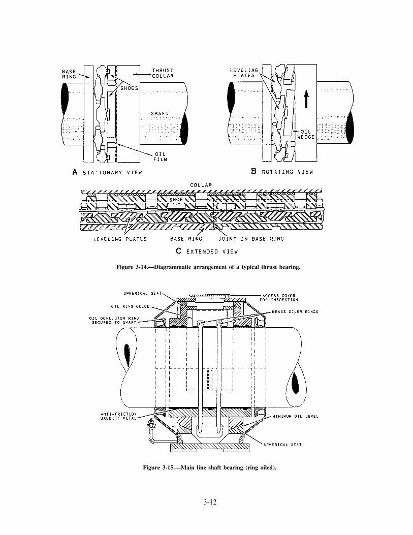
Figure 3-14.—Diagrammatic arrangement of a typical thrust bearing.
Figure 3-15.—Main line shaft bearing (ring oiled).
3-12

1. Bearing Pedestal 5. Oil Retaining End Cover 9. Sight Hole2. Bearing Cap 6. Oil Disc 10. Hand Hole3. Upper Bearing Shell 7. Oil Scraper 11. Pipe Plug4. Lower Bearing Shell 8. Oil Gauge
Figure 3-16.—Line shaft bearing (disc oiled).
the thrust load among the shoes (fig. 3-14). Thebase ring, which supports the lower leveling plates,holds the plates in place. This ring transmits thethrust on the plates to the ship’s structurevia housing members, which are bolted to thefoundation. Shoe supports (hardened steel buttonsor pivots), located in the shoes, separate the shoesand the upper leveling plates. This separationenables the shoe segments to assume the anglerequired to pivot the shoes against the upperleveling plates. Pins and dowels hold the upperand lower leveling plates in position. This allowsample play between the base ring and the platesto ensure freedom of movement (oscillation only)of the leveling plates. The base ring is kept fromturning by its keyed construction, which securesthe ring to its housing.
MAIN PROPULSIONSHAFT BEARINGS
You will be required to watch and maintainthe main propeller shaft bearings. These bearingssupport and hold the propulsion shafting inalignment. They are divided into two generalgroups. One group is made up of the main line
shaft bearings, or spring bearings. The other isthe stern tube bearings and the strut bearings.
Main Line Shaft Bearingsor Spring Bearings
Most of these bearings are of the ring- or disc-oiled, babbitt-faced, spherical seat, or shell type.This bearing (fig. 3-15) is designed primarily toalign itself to support the weight of the shafting.
The brass oiler rings, shown in figure 3-15, area loose fit. The rings are retained in an axialposition by guides or grooves in the outer bearingshell. As the shaft rotates, the friction betweenthe rings and the shaft is enough to cause the ringsto rotate with the shaft. The rings dip into the oilin the sump. Oil is retained on the inside diameterof the rings and is carried to the upper bearingsby the rings. The action of the oil ring guides andcontact of the rings on the upper shaft causes theoil to be removed from the rings and to lubricatethe bearings.
The disc-oiled spring bearing (fig. 3-16) isbasically the same as the ring-oiled type exceptthat it uses an oil disc to lubricate the bearing.The oil disc is attached to, and rotates with, the
3-13
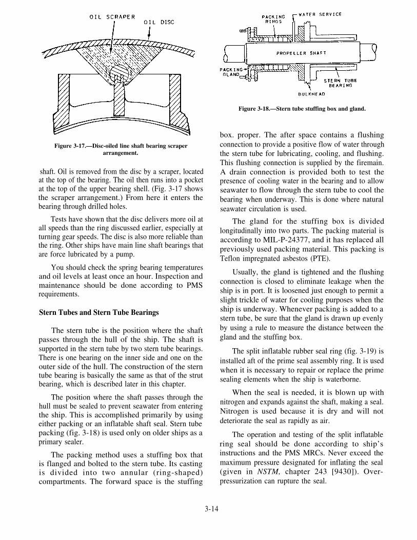
Figure 3-17.—Disc-oiled line shaft bearing scraperarrangement.
shaft. Oil is removed from the disc by a scraper, locatedat the top of the bearing. The oil then runs into a pocketat the top of the upper bearing shell. (Fig. 3-17 showsthe scraper arrangement.) From here it enters thebearing through drilled holes.
Tests have shown that the disc delivers more oil atall speeds than the ring discussed earlier, especially atturning gear speeds. The disc is also more reliable thanthe ring. Other ships have main line shaft bearings thatare force lubricated by a pump.
You should check the spring bearing temperaturesand oil levels at least once an hour. Inspection andmaintenance should be done according to PMSrequirements.
Stern Tubes and Stern Tube Bearings
The stern tube is the position where the shaftpasses through the hull of the ship. The shaft issupported in the stern tube by two stern tube bearings.There is one bearing on the inner side and one on theouter side of the hull. The construction of the sterntube bearing is basically the same as that of the strutbearing, which is described later in this chapter.
The position where the shaft passes through thehull must be sealed to prevent seawater from enteringthe ship. This is accomplished primarily by usingeither packing or an inflatable shaft seal. Stern tubepacking (fig. 3-18) is used only on older ships as aprimary sealer.
The packing method uses a stuffing box thatis flanged and bolted to the stern tube. Its castingis divided into two annular (ring-shaped)compartments. The forward space is the stuffing
Figure 3-18.—Stern tube stuffing box and gland.
box. proper. The after space contains a flushingconnection to provide a positive flow of water throughthe stern tube for lubricating, cooling, and flushing.This flushing connection is supplied by the firemain.A drain connection is provided both to test thepresence of cooling water in the bearing and to allowseawater to flow through the stern tube to cool thebearing when underway. This is done where naturalseawater circulation is used.
The gland for the stuffing box is dividedlongitudinally into two parts. The packing material isaccording to MIL-P-24377, and it has replaced allpreviously used packing material. This packing isTeflon impregnated asbestos (PTE).
Usually, the gland is tightened and the flushingconnection is closed to eliminate leakage when theship is in port. It is loosened just enough to permit aslight trickle of water for cooling purposes when theship is underway. Whenever packing is added to astern tube, be sure that the gland is drawn up evenlyby using a rule to measure the distance between thegland and the stuffing box.
The split inflatable rubber seal ring (fig. 3-19) isinstalled aft of the prime seal assembly ring. It is usedwhen it is necessary to repair or replace the primesealing elements when the ship is waterborne.
When the seal is needed, it is blown up withnitrogen and expands against the shaft, making a seal.Nitrogen is used because it is dry and will notdeteriorate the seal as rapidly as air.
The operation and testing of the split inflatablering seal should be done according to ship’sinstructions and the PMS MRCs. Never exceed themaximum pressure designated for inflating the seal(given in NSTM, chapter 243 [9430]). Over-pressurization can rupture the seal.
3-14

Figure 3-19.—Shaft seal and inflatable sealing ring.
In some installations, mechanical seals are used toseal the stem tube. Two of the major advantages ofthese seals are (1) they will operate maintenance freefor extended periods; (2) they accommodate grossmisalignment and allow for excessive bearing wear,high vibration, and large radial and axial movement ofthe shaft. Figure 3-20 shows a typical shaft seal thathas received SHIPALT acceptance for approved useon FFG-7 ships and for retrofit aboard the DD-963class ships. Refer to the manufacturer’s technicalmanual for further information.
Strut Bearings
Strut bearings, as well as the stem tube bearings,are equipped with composition bushings which aresplit longitudinally into two halves. The outer surfaceof the bushing is machined with steps to bear onmatching landings in the bore of the strut. One end isbolted to the strut.
Since it is usually not practical to-use oil or greaseas a lubricant for underwater bearings, some otherfrictionless material must be used. There are certainmaterials that become slippery when wet. Theyinclude synthetic rubber; lignum vitae, a hard tropicalwood with excellent wearing qualities; or laminatedphenolic material, consisting of layers of cotton fabricimpregnated and bonded with phenolic resin. Stripsmade from any of these materials are fitted inside thebearing. Most Navy installations use rubbercomposition strips (fig. 3-21).
CARE OF BEARINGSAND JOURNALS
Properly operated bearings will give years ofsatisfactory service. However, like all units ofengine-room machinery, they require periodic tests,inspections, and maintenance. When bearings areoriginally installed, the manufacturer takes oilclearance readings. These are recorded according tothe PMS. At regular intervals the ship’s force mustalso take these readings. Any difference between theold and the new readings will be the amount of bearingwear.
Main engine bearing clearances may be taken bydepth gauge, crown thickness readings, or leads.Normally, the depth gauge method is used. Crownthickness readings are taken only when bearings areremoved and marked for these readings. In other cases,leads are taken. Crown thickness readings are almostalways used for the main gear bearings. Leads may beused in a few older installations. They may also beused on auxiliary machinery or main shaft bearings. Afew line shaft bearings have provisions for depthgauge readings as well.
For another example, a dial indicator is used totake thrust bearing clearances.
In all cases, bearings must be inspected at regularintervals according to the PMS MRCs.
In most cases, the first indication of bearingtrouble is an abnormal or rapid rise in temperature.
3-15

1. M
ount
ing
Rin
g2.
Alig
nmen
t P
in3.
Inn
er B
utt
Bol
t4.
Out
er B
utt
Bol
t5.
Ada
ptor
Rin
g6.
Bol
t7.
Inf
lata
ble
Seal
8. I
.S.
Su
pp
ort
Rin
g9.
Fla
nge
Con
nect
or10
. F
lang
e C
onne
ctor
11.
Mai
n C
lam
p R
ing
12.
But
t B
olt
13.
Nut
14.
Com
pres
sion
Ada
ptor
(not
sho
wn)
15.
Bac
king
Spr
ing
Ass
embl
y16
. B
ridg
ing
Spri
ng A
ssem
bly
17.
Supp
ort
Spri
ng A
ssem
bly
18. I
nter
laye
r19
. F
ace
Car
rier
20. A
lignm
ent
Pin
21.
But
t B
olt
22.
Fac
e D
rive
Pin
23.
Fac
e Se
alin
g St
rip
24.
Fac
e In
sert
25. S
plas
h G
uard
26.
Seat
27.
But
t B
olt
28.
Alig
nmen
t P
in29
. A
lignm
ent
Pin
Scr
ew30
. “O
”-R
ing
31.
Dri
ve C
lam
p R
ing
32.
But
t B
olt
33.
Dri
ve B
olt
Fig
ure
3-20
.—A
typ
ical
sha
ft s
eal.
34.
Alig
nmen
t B
olt
35.
Loc
knut
36.
Gla
nd F
ollo
wer
37.
But
t B
olt
38.
Stud
ding
39.
Nut
40.
Was
her
41.
Plu
g42
. P
acki
ng43
. B
ack-
up R
ing
44.
Too
lbox
(not
sho
wn)

Figure 3-21.—Details of a strut bearing. A. Longitudinal view. B. Cross-sectional View. C. Rubber stripping in a bearing.
The temperature of oil discharged from a bearing, asmeasured by thermometer, must not exceed 180°Fmaximum or a rise of 50°F maximum above the oilcooler outlet temperature, whichever is less. This istrue unless otherwise stated in the applicable technicalmanual or waived by NAVSEA on a case basis.
In addition to local-reading thermometers, somegear units have thermocouples or RTEs primarily forremote temperature indication. The element detectormay be located either in the sight-flow fitting ormounted directly in the bearing babbitt. Theapplicable gear technical manual should be consultedfor information on maximum allowable temperaturelimits.
If the temperature of a bearing increases abovethe normal running temperature, the quantity andquality of the lubricant supplied to the bearing shouldbe checked. The temperature of the oil from thecooler should be maintained at the temperaturerecommended by the applicable gear technical
manual. In most cases, this will range from 120°F to130°F.
Erratic flow and/or a complete loss of flow of oilto a single sight-flow indicator at partial- to full-loadconditions can cause a casualty. This can occurfollowing reinstallation of a bearing that has beenremoved for inspection or renewal. This problem isgenerally caused by a restriction in the oil line fromthe bearing to the sight-flow fitting. The restriction isnormally caused by improper assembly of the bearingcap on the shell. The oil passages are not exactly inline or improper handling has caused a nick or a burrat the edge of the passage. This condition should bechecked and corrected at the earliest opportunity.Without the indicator, there is no positive way todetermine that the bearing is receiving its propersupply of oil.
Chapter 241 (9420) of the NSTM containsinformation on wiped and otherwise damagedbearings and the requirements for repair and renewal.
3-17

SAFETY PRECAUTIONS energy. This mechanical energy is used through theFOR BEARINGS propulsion shafting and the propeller.
Most bearings are similar in operation. Therefore,these safety precautions apply to all main engine, mainshaft, and auxiliary machinery bearings. Thefollowing safety precautions help prevent mostcasualties:
MAIN PROPULSION SHAFTING
The main propulsion shafting may be up to 30inches in diameter. It is divided into twoenvironmental sections: the inboard or line shaftingand the outboard or waterborne shafting (fig. 3-22).The main propulsion shafting is made of forged steeland is usually hollow in sizes of more than 6 inches indiameter.
1.
2.
3.
4.
5.
6.
7.
8.
9.
10.
11.
12.
NEVER use a piece of machinery if the bearingsare known to be in poor condition.
Where possible, be sure that bearings have theproper quality and quantity of lube oil beforestarting the machinery.
Be sure the operating temperature of eachbearing is not above the specified normal for theparticular load and speed conditions. Investigateand report abnormal temperature immediately.
Remember that rapid heating of the bearing is adanger sign. A bearing that feels hot to the handafter an hour’s operation may be all right, butthe same heat reached in 10 or 15 minutesindicates trouble.
Newly installed bearings should be given arun-in period with no load applied.
Use clean rags (lint free) to clean bearings,shafting, and sumps.
When you assemble and install bearings withsymmetrical halves, take care NOT toend-to-end one of the halves or to reverse theassembled bearing in its pedestal. This maycover the lube oil inlet passage.
Clean out wells of self-lubricated sliding-surface bearings at frequent intervals. See thatthe rings run freely and do not drag.
Refit or renew a wiped bearing.
When taking leads, be sure that the bearinghalves are set up metal to metal.
Do not file or machine bearing joints.
After spotting-in a bearing, be sure that allshavings and dirt are cleaned from the parts.
PROPELLERS AND MAINPROPULSION SHAFTING
The turbines and reduction gears convert thethermal energy of steam into usable mechanical
The line shafting consists of several sections ofshaft. These include the thrust shaft when the mainthrust bearing is not located in the reduction gearcasing. These sections are usually joined together bybolts through FLANGE COUPLINGS, which areforged integral with the shaft sections.
The outboard shafting consists of the propellershaft, or tailshaft, upon which the propeller ismounted; the stern tube shaft, which penetrates thehull of the ship and thus makes the transition betweeninboard and outboard shafting; and in some cases, anintermediate, or dropout, shaft located between thepropeller shaft and the stem tube shaft. In somesingle-shaft surface ships, the propeller shaft alsofunctions as the stern tube shaft. The outboard shaftingis protected from seawater corrosion by a covering ofeither plastic or rubber. Outboard shafting sections areusually joined to each other by integral flanges,although some older ships may have a removableoutboard shaft coupling known as a MUFF-TYPEOUT- BOARD COUPLING. The stern tube shaft isconnected to the line shafting by a removable couplingknown as the INBOARD STERN TUBE COUPLING.
Circular steel or composition shields known asfair-waters are secured to the after end of the stern tubeand to the struts. They are "faired in" to the shaftingto reduce turbulence. This fairing is accomplished bya gradual reduction in diameter from that of the sterntube or strut to that of the shaft. In some cases, a flangeis adjacent to a strut or the aft end of the stern tube. Inthese cases, the fairwater may either extend beyondthe flange (either forward or aft as applicable) and fairinto the shaft, it may fair into a rotating coupling coverthat is attached to the flange and shaft. Some shipshave watertight rotating coupling covers filled withtallow, which seals the flanged coupling fromseawater.
3-18

Fig
ure
3-22
.—D
iagr
amm
atic
arr
ange
men
t of
a m
ain
prop
ulsi
on s
yste
m.
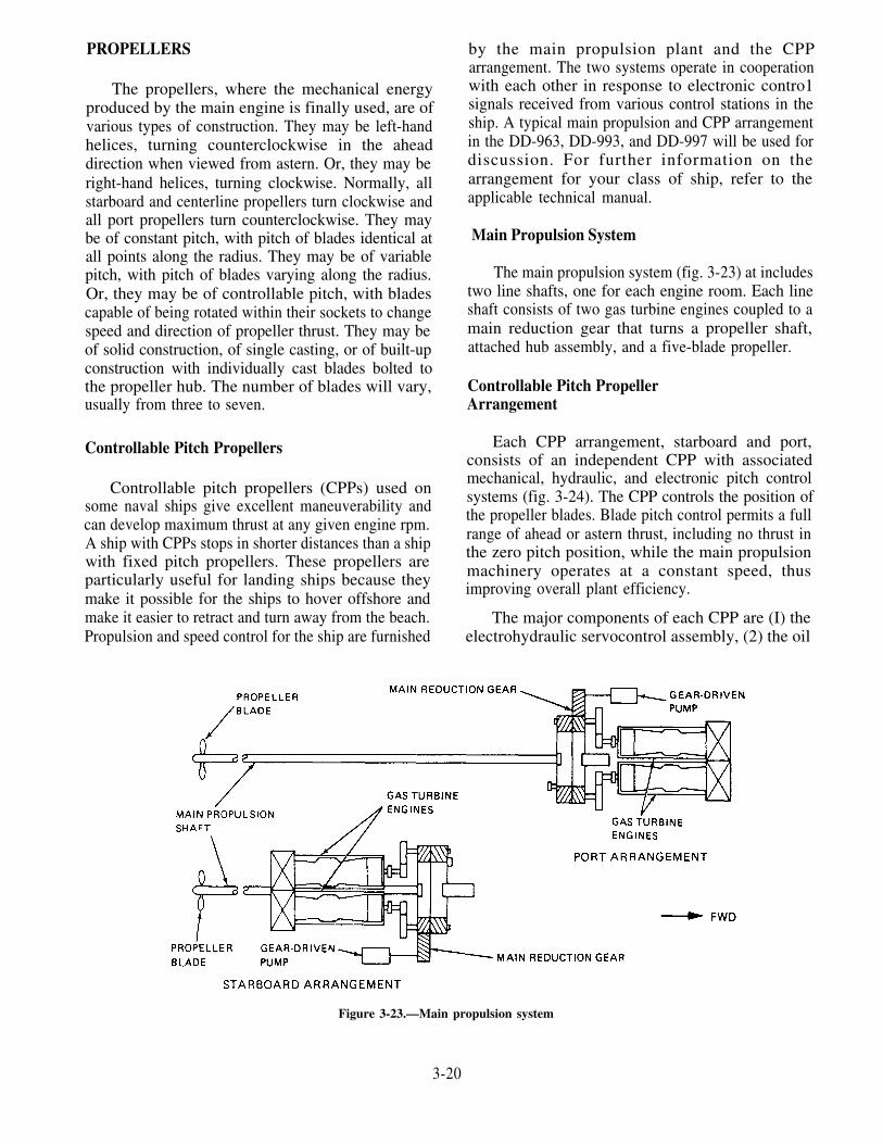
PROPELLERS
The propellers, where the mechanical energyproduced by the main engine is finally used, are ofvarious types of construction. They may be left-handhelices, turning counterclockwise in the aheaddirection when viewed from astern. Or, they may beright-hand helices, turning clockwise. Normally, allstarboard and centerline propellers turn clockwise andall port propellers turn counterclockwise. They maybe of constant pitch, with pitch of blades identical atall points along the radius. They may be of variablepitch, with pitch of blades varying along the radius.Or, they may be of controllable pitch, with bladescapable of being rotated within their sockets to changespeed and direction of propeller thrust. They may beof solid construction, of single casting, or of built-upconstruction with individually cast blades bolted tothe propeller hub. The number of blades will vary,usually from three to seven.
Controllable Pitch Propellers
Controllable pitch propellers (CPPs) used onsome naval ships give excellent maneuverability andcan develop maximum thrust at any given engine rpm.A ship with CPPs stops in shorter distances than a shipwith fixed pitch propellers. These propellers areparticularly useful for landing ships because theymake it possible for the ships to hover offshore andmake it easier to retract and turn away from the beach.Propulsion and speed control for the ship are furnished
by the main propulsion plant and the CPParrangement. The two systems operate in cooperationwith each other in response to electronic contro1signals received from various control stations in theship. A typical main propulsion and CPP arrangementin the DD-963, DD-993, and DD-997 will be used fordiscussion. For further information on thearrangement for your class of ship, refer to theapplicable technical manual.
Main Propulsion System
The main propulsion system (fig. 3-23) at includestwo line shafts, one for each engine room. Each lineshaft consists of two gas turbine engines coupled to amain reduction gear that turns a propeller shaft,attached hub assembly, and a five-blade propeller.
Controllable Pitch PropellerArrangement
Each CPP arrangement, starboard and port,consists of an independent CPP with associatedmechanical, hydraulic, and electronic pitch controlsystems (fig. 3-24). The CPP controls the position ofthe propeller blades. Blade pitch control permits a fullrange of ahead or astern thrust, including no thrust inthe zero pitch position, while the main propulsionmachinery operates at a constant speed, thusimproving overall plant efficiency.
The major components of each CPP are (I) theelectrohydraulic servocontrol assembly, (2) the oil
Figure 3-23.—Main propulsion system
3-20

Figure 3-24.—Controllable pitch propeller in DD-963, DD-993, and DD-997 class ship.
distribution (OD) box, (3) the hydraulic oil powermodule assembly (HOPM), (4) the valve rodassembly, (S) the hub assembly, and (6) the prairie airsystem assembly, which is used to mask propellersounds. Each of these will be described in thefollowing sections:
1. The electrohydraulic servocontrol assembly isin an enclosure located in each engine room,which electronically controls, monitors, andactuates the display of propeller pitch settingsand changes.
3. The HOPM provides low-pressure (LP) controloil to the OD box to operate the valve rodactuating mechanism and provides HP oil to theOD box to operate the hub piston mechanism.The HOPM is a self-contained, resilientlymounted unit consisting of various hydrauliccomponents installed in a welded structure. TheHOPM is connected by hydraulic piping to thesump tank, standby screw pump (gear driven),and manifold block assembly. C The maincomponents of the HOPM are the ac motor,steelflex coupling, screw pump (main pump),
2. The OD box and its major components directs pressure control assembly, suction strainer, oil
high-pressure (HP) oil to and from the hub filters, sensors, and indicators.
assembly through the propeller shaft, operates 4. The valve rod assembly provides passage for thethe valve rod assembly, and provides passage HP hydraulic oil from the OD box to the hubfor the prairie air tubing. assembly, and it also translates hydraulic pitch
3-21

control commands in the OD box into pitchchanges by the bladeturning mechanism in thehub assembly.
5. The hub assembly is attached to the aft end ofeach propulsion shaft. Five propellor blades arebolted symmetrically to each hub. A blade portcover and blade seal ring prevent seawater fromentering the hub around each blade. Each hubcontains a piston, piston rod assembly, pistonnut, and propeller blade turning mechanism tochange pitch and hold the pitch position of theblade. The piston and the aft end of the pistonrod are located in the hub cone. The forward endof the piston rod is attached to the crosshead ofthe blade turning mechanism. Thesecomponents move axially when HP oil is
6.
directed to either the forward or aft face of thehub piston. Five sliding blocks are fitted into themachined slots in the crosshead. An eccentricpin on the underside of each crankpin ring fitsinto the hole in the sliding block. Two dowelpins transmit torque from the crankpin ring tothe blade, and eight blade bolts attach the bladeto the crankpin ring.
The prairie air assembly tubing enters the CPPthrough the end cover at the forward end of theOD box. The tubing passes through the centerof the OD box, and then through the bore of thevalve rod to the propeller hub. The tubingconsists of fabricated sections of seamless steelpiping joined by threads and setscrews.
3-22
CHAPTER 4
LUBRICATION AND ASSOCIATEDEQUIPMENT
Lubrication reduces friction between movingparts by substituting fluid friction for sliding orrolling friction. Without lubrication, you wouldhave difficulty moving a 100-pound weight acrossa rough surface; however, with lubrication andproperly designed bearing surfaces, with a verysmall motor you could move a 1,000,000-poundload. By reducing friction, lubrication lowers theamount of energy required to perform mechanicalactions and causes less heat to be produced.
Lubrication is a matter of vital importancethroughout the shipboard engineering plant.Moving surfaces must be steadily supplied withthe proper kinds of lubricants. Lubricants mustbe maintained at specified standards of purity andat designed pressures and temperatures. Withoutproper lubrication, many units of shipboardmachinery would grind to a screeching halt.
The lubrication requirements of shipboardmachinery are met in various ways, depending onthe machinery. In this chapter we will discuss thebasic theories of lubrication, the lubricants usedaboard ship, and the lubrication systems installedfor many shipboard units. Also we will discussthe devices used to maintain lubricating oils in therequired condition of purity. At the end of thischapter, you will find information on the LubeOil Management Program.
THEORY OF LUBRICATION
Friction is the natural resistance to motioncaused by surface contact, and the purpose oflubrication is to reduce this friction. The frictionthat exists between a body at rest and the surfaceupon which it rests is called STATIC friction. Thefriction that exists between moving bodies (orbetween one moving body and a stationarysurface) is called KINETIC friction. Staticfriction is greater than kinetic friction. Staticfriction and inertia must be overcome to put abody in motion. To keep a body in motion, youmust overcome kinetic friction.
There are three types of kinetic friction: slidingfriction, rolling friction, and fluid friction. Slidingfriction occurs when one solid body slides acrossanother solid body. Rolling friction occurs whena curved body, such as a cylinder or a sphere, rollsacross a surface. Fluid friction is the resistanceto motion exhibited by a fluid.
Fluid friction occurs because of twoproperties of a lubricant: cohesion and adhesion.COHESION is the molecular attraction betweenparticles which tends to hold a substance together.ADHESION is the molecular attraction betweenparticles which tends to cause unlike surfaces tostick together. If a paddle is used to stir a fluid,for example, cohesion between particles of thefluid tends to hold the molecules together. Thisretards motion of the fluid. But adhesion of fluidparticles causes the fluid to stick to the paddle.This further causes friction between the paddleand the fluid. In the theory of lubrication,cohesion and adhesion have a major role.Adhesion is the property of a lubricant whichcauses it to stick (or adhere) to the parts beinglubricated; cohesion is the property which holdsthe lubricant together and enables it to resistbreakdown under pressure. Later in this chapter,we will discuss other important properties of alubricant.
Different materials have varying degrees ofcohesion and adhesion. In general, solid bodiesare highly cohesive but only slightly adhesive.Most fluids are highly adhesive but only slightlycohesive.
FLUID LUBRICATION
One of the qualities of a liquid is that itcannot be forced into a smaller space than italready occupies. A liquid is incompressible. Thisfact allows moving metal surfaces to be separatedfrom each other. Because of this, liquid is usedfor most lubrication needs. As long as thelubricant film remains unbroken, fluid frictionreplaces sliding friction and rolling friction.
4-1

In any process involving friction, some poweris consumed and some heat is produced. Over-coming sliding friction consumes the greatestamount of power and produces the greatestamount of heat. Overcoming fluid frictionconsumes the least power and produces the leastamount of heat.
LANGMUIR THEORY
A presently accepted theory of lubrication isbased on the Langmuir theory of the action offluid films of oil between two surfaces, one orboth of which are in motion. Theoretically, threeor more layers or films of oil exist between twolubricated bearing surfaces. Two of the films areBOUNDARY films (indicated as I and V in figure4-1A), one of which clings to the surface of therotating journal and one of which clings to thestationary lining of the bearing. Between these twoboundary films are one or more FLUID films(indicated as II, III, and IV in fig. 4-1A).
When the rotating journal is set in motion, awedge of oil is formed (fig. 4-1B). Contactbetween the two metal surfaces is prevented whenoil films II, III, and IV (fig. 4-1A) slidebetween the two boundary films. The theory isagain illustrated in figure 4-1C. The position ofthe oil wedge, W, is shown with respect to theposition of the journal as it starts and continuesin motion.
The views shown in figure 4-1C represent ajournal or shaft rotating in a solid bearing. Theclearances are enlarged in the drawing to showthe formation of the oil film. The shaded portionrepresents the clearance filled with oil. Thestationary view shows the film in the process ofbeing squeezed out while the journal is at rest.As the journal begins to turn and to increasespeed, oil adhering to the surfaces of the journalis carried into the film. The film increases inthickness and tends to lift the journal, as shownin the starting view. As the speed increases, thejournal takes the position shown in the runningview. Varying temperatures cause changes in oilviscosity. These changes modify the film thicknessand position of the journal. Viscosity will bediscussed later in this chapter.
If conditions are correct, the two surfaces areproperly separated. A momentary contact mayoccur at the time the motion is started.
FACTORS AFFECTINGLUBRICATION
A number of factors determine the effective-ness of oil film lubrication. They include pressure,temperature, viscosity, speed, alignment,condition of the bearing surfaces, runningclearances, and the purity of the lubricant. Manyof these factors are interrelated and inter-dependent. For example, the viscosity of any givenoil is affected by temperature, and the temperatureis affected by running speed. Therefore, theviscosity is partially dependent on the runningspeed.
A lubricant must stick to the bearing surfacesand support the load at operating speeds. Moreadhesiveness is required to make a lubricantadhere to bearing surfaces at high speeds than atlow speeds. At low speeds, greater cohesivenessis required to keep the lubricant from beingsqueezed out from between the bearing surfaces.
Large clearances between bearing surfacesrequire high viscosity and cohesiveness in thelubricant to ensure maintenance of the lubricatingoil film. The larger the clearance, the greater mustbe the lubricant’s resistance to being pounded out,
Figure 4-1.—Oil film lubrication.
4-2

with consequent destruction of the lubrication oilfilm.
High unit load on a bearing requires highviscosity of the lubricant. A lubricant subjected tohigh loading must be sufficiently cohesive to holdtogether and maintain the oil film.
LUBRICANTS
Although synthetic lubricants are used today, theNavy uses petroleum as their main source of oils andgreases. By various refining processes, lubricatingoils are extracted from crude petroleum and blendedinto a number of products. Sometimes additives(chemical compounds) are included in the process.Lubricating oils have to meet a wide range oflubrication requirements.
CAUTION
Al1 lubricants are hazardous materials. Alllubricants, especially synthetics, are toxicand hazardous to health. You should avoidprolonged skin and eye contact. Removelubricant-soaked clothing promptly andwash skin thoroughly with soap and water.The Material Safety Data Sheet (MSDS)for each item includes precautions, disposalinformation, and hazards. If you need anMSDS, ask your supervisor.
Lubricating Oils
Lubricating oils approved for shipboard use arelimited to those grades and types that are necessaryto provide proper lubrication under all anticipatedoperating conditions.
Diesel engines use a detergent-dispersant typeof additive oil to keep the engines clean. Theselubrication oils must be fortified with oxidation andcorrosion inhibitors. This allows long periodsbetween oil changes and prevents corrosion ofbearing materials.
Steam turbines use an oil of high initial filmstrength. This oil is fortified with anti-foamingadditives and additives that control oxidation andcorrosion. Also, extreme pressure (EP) additives areused. These additives help the oil carry the very highloading found in the reduction gear.
For general lubrication and in hydraulic systemsusing petroleum lubricants, the Navy must usecertain oils. These special viscosity series of oils arestrengthened with oxidation and corrosion inhibitors
and antifoam additives. Deck machinery usescompounded oils, which are mineral oils withadditives.
Special lubricating oils are available for a widevariety of services. The Federal Supply catalog has alist of these oils. Among the most important specialtyoils are those used for lubricating refrigerantcompressors. These oils must have a very low pourpoint and must be maintained with a high degree offreedom from moisture.
The main synthetic lubricants in naval use are(1) a phosphate-ester type of fire-resistant hydraulicfluid, used chiefly in the deck-edge elevators ofcarriers, and (2) a water-base glycol hydraulic fluid,used chiefly in the catapult retracting gears.
CLASSIFICATION OF LUBRICATINGOILS.—The Navy identifies lubricating oils bynumber symbols. Each identification symbolconsists of four digits and, in some cases, appendedletters. The first digit shows the class of oilaccording to type and use; the last three digitsshow the viscosity of the oil. The viscosity digitsare actually the number of seconds required for 60milliliters (mL) of the oil to flow through astandard orifice at a certain temperature. Symbol3080, for example, shows that the oil is in the 3000series. It also shows that a 60-mL sample flowsthrough a standard orifice in 80 seconds when theoil is at a certain temperature (210°F, in thisinstance). Another example is symbol 2135 TH.This symbol shows that the oil is in the 2000 series.It also shows that a 60-mL sample flows through astandard orifice in 135 seconds when the oil is at acertain temperature (130°F, in this case). The lettersH, T, TH, or TEP added to a basic number showthat the oil contains additives for special purposes.
PROPERTIES OF LUBRICATING OILS.—Lubricating oils used by the Navy are tested for anumber of properties. These include (1) viscosity,(2) pour point, (3) flashpoint, (4) fire point, (5)auto-ignition point, (6) demulsibility, (7) neutrali-zation number, and (8) precipitation number.Standard test methods are used for making all tests.The properties of lube oil are briefly explained in thefollowing paragraphs.
1. VISCOSITY—The viscosity of an oil is itstendency to resist flow or change of shape. A liquidof high viscosity flows very slowly. In variableclimates, automobile owners, for example,change oils in accordance with prevailingseasons. Oil changes are necessary becauseheavy oil becomes too sluggish in cold weather,
4-3

and light oil becomes too thin in hot weather.The higher the temperature of an oil, thelower its viscosity becomes; lowering thetemperature increases the viscosity. The highviscosity or stiffness of the lube oil on acold morning makes an automobile enginedifficult to start. The viscosity must alwaysbe high enough to keep a good oil filmbetween the moving parts. Otherwise frictionwill increase, resulting in power loss and rapidwear on the parts.
Oils are graded by their viscosities at acertain temperature. Grading is set up by notingthe number of seconds required for a givenquantity (60 mL) of the oil at the given temperatureto flow through a standard orifice. The rightgrade of oil, therefore, means oil of the properviscosity.
Every oil has a viscosity index based on theslope of the temperature-viscosity curve. Theviscosity index depends on the rate of change inviscosity of a given oil with a change intemperature. A low index figure means a steepslope of the curve, or a great variation of viscositywith a change in temperature; a high index figuremeans a flatter slope, or lesser variation of vis-cosity with the same changes in temperatures. Ifyou are using an oil with a high viscosity index,its viscosity or body will change less when thetemperature of the engine increases.
2. POUR POINT—The pour point of anoil is the lowest temperature at which theoil will barely flow from a container. Ata temperature below the pour point, oilcongeals or solidifies. Lube oils used in coldweather operations must have a low pour point.(NOTE: The pour point is closely related to theviscosity of the oil. In general, an oil of highviscosity will have a higher pour point than anoil of low viscosity.)
3. FLASHPOINT—The flashpoint of an oilis the temperature at which enough vapor is givenoff to flash when a flame or spark is present. Theminimum flashpoints allowed for Navy lube oilsare all above 315 °F. However, the temperaturesof the oils are always far below that undernormal operating conditions.
4. FIRE POINT—The fire point of an oil isthe temperature at which the oil will continue toburn when ignited.
5. AUTO-IGNITION POINT—The auto-ignition point of an oil is the temperature at whichthe flammable vapors given off from the oil willburn. This kind of burning will occur without theapplication of a spark or flame. For mostlubricating oils, this temperature is in the rangeof 465° to 815°F.
6. DEMULSIBILITY—The demulsibility, oremulsion characteristic, of an oil is its ability toseparate cleanly from any water present—animportant factor in forced-feed systems. Youshould keep water (fresh or salt) out of oils.
7. NEUTRALIZATION NUMBER—Theneutralization number of an oil is the measure ofthe acid content. The number of milligrams ofpotassium hydroxide (KOH) required to neutralize1 gram of the oil defines the neutralizationnumber. All petroleum products oxidize in thepresence of air and heat. The products of thisoxidation include organic acids. High amounts oforganic acids have harmful results on galvanizedsurfaces and on alloy bearings at high tempera-tures. The demulsibility of the oil with respect tofresh water and seawater also relies on the amountof organic acids. High organic acid levels maycause decreased demulsibility. The formation ofsludge and emulsions too stable to be broken byavailable means may result. This last problem mayoccur in turbine installations. An increase inacidity is a sign that the lubricating oil is break-ing down.
8. PRECIPITATION NUMBER—Theprecipitation number of an oil is a measure of theamount of solids classified as asphalts or carbonresidue contained in the oil. The number isreached by diluting a known amount of oil withnaphtha and separating the precipitate bycentrifuging—the volume of separated solidsequals the precipitation number. The test helpsyou find out quickly the presence of foreignmaterials in used oils. An oil with a high pre-cipitation number may cause trouble in an engine.It could leave deposits or plug up valves andpumps.
Lubricating Greases
Some lubricating greases are simple mixturesof soaps and lubricating oils. Others are moreunusual, such as silicones and dibasic acids, which
4-4

are exotic liquids. These may be thickened withmetals or inert materials to provide enoughlubrication. Requirements for oxidation inhibi-tion, corrosion prevention, and extreme pressureperformance are met by adding special substances(additives).
LUBRICATING SYSTEMS
Lubricating greases are supplied in threegrades: soft, medium, and hard. The soft greasesare used for high speeds and low pressures; themedium greases are used for medium speeds andmedium pressures; the hard greases are used forslow speeds and high pressures.
The following paragraphs contain infor-mation about different lubricating systemsand their related equipment. We will dis-cuss the important functions and use ofeach system and describe their operatingprocedures.
MAIN LUBRICATING OIL SYSTEMS
CLASSIFICATION OF LUBRICATINGGREASES.—Navy specifications have beendrawn to cover the several grades of lubricatinggreases. The grades most common in engineroomuse are ball and roller bearing grease and extremepressure grease.
Main lubricating oil systems in steam-drivenships provide lubrication for the turbine bearingsand the reduction gears. In some ships, the mainlube oil system also provides control oil for themain engine throttle control system and hydraulicgland seal regulators.
1. BALL AND ROLLER BEARINGGREASE, MIL-G-24508—Ball and rollerbearing grease is for general use in equip-ment designated to operate at temperaturesup to 300°F. For temperature applicationsabove 300°F, high-temperature, electric-motor, ball and roller bearing grease (MIL-L-15719) must be used.
The main lube oil system generally includesa filling and transfer system, a purifying system,and separate service systems for each propulsionplant.
2. EXTREME PRESSURE GREASE,MIL-G-17740—Extreme pressure grease has anti-rust properties and is suitable for lubrication ofsemi-enclosed gears, or any sliding or rolling metalsurfaces where loads may be high and where theequipment may be exposed to salt spray ormoisture. It is intended for use in a temperaturerange of 0° to 140°F.
Most ships have three positive displacementpumps for main lube oil service. One pump is anattached pump driven by either the propulsionshaft or the quill shaft of the reduction gear. Thispump provides main lube oil service when themain engines are turning fast enough for the pumpto supply the required pressure. The other twopumps may be both electric-motor driven or acombination of one turbine-driven and oneelectric-motor driven. These pumps are used whenlighting off, securing, and at low speeds when theattached pump is not supplying enough pressure.Another use is as a standby pump when theattached pump has the load.
GRAPHITE GREASE, VV-G-671.—Graph- Some ships have automatic features whichite grease may be applied with compression grease provide for electric pumps to start and stop orcups to bearings operating at temperatures not to shift speeds at various pressures and shaft rpm.exceed 150 °F. The three grades of this grease are This system automatically provides enough mainlisted below: lube oil pressure for all operating conditions.
Grade 1 Soft For light pressuresand high speeds
Grade 2 Medium For medium pres-sures and mediumspeeds
Some ships have only two electric-motordriven main lube oil pumps. One pump issupplied by ac electrical power and the other bydc electrical power. One pump is always instandby for the running pump and willautomatically start if oil pressure drops below acertain value.
Grade 3 Medium Hard For high pressuresand slow speeds
Lube oil pressures which provide controlfeatures for the main lube oil system (such as
4-5

Figure 4-2.—Typical lube oil system.
Figure 4-3.—Duplex strainer.
4-6

alarms, pump standby features, etc.) aremonitored at or near the bearing farthest fromthe lube oil supply (main lube oil pumps); this isknown as the most remote bearing.
In a typical main lube oil system (fig. 4-2),the pump takes suction from the main sump anddischarges the lube oil into the duplex strainers(fig. 4-3). From the strainer, the lube oil goesto the oil cooler (discussed in chapter 6 of thismanual). The oil is cooled to 120 to 130°. Thistemperature is maintained by using the overboardvalve to adjust the flow of seawater through thecooler. After leaving the cooler, the oil goes tothe turbine and reduction gear bearings. In themain lube oil service line between the cooler andthe bearing supply lines, an unloading valve isinstalled to dump excess pressure back to the mainsump. This valve is set to maintain designedoperating pressure to the most remote bearing andis normally spring loaded or air pilot controlled.After leaving the bearings, the lube oil returns tothe main sump by gravity flow. Also, relief valvesare installed in each pump discharge line toprotect the pump against excessive pressure. Anorifice or a needle valve is installed in each bear-ing supply line to regulate the flow of oil to theindividual bearing. Figure 4-4 shows a forced-feedlubricated bearing.
AUXILIARY MACHINERYLUBRICATION SYSTEMS
Lube oil systems for auxiliary machinery havethe same components as the main lube oil systemand serve the same purpose. However, theconstruction and size of the components aredifferent.
The lube oil pump is normally of the simplegear type and is driven by a pinion on the gearshaft. The lube oil filter is of the stacked disk type.You should keep this filter clean in accordancewith PMS requirements. The cooler is a double-pass water-tube type. The water for this cooleris supplied by the auxiliary machinery coolingwater system. The temperature of the lube oilleaving the cooler is controlled by regulating thecooling water flow with the inlet valve to thecooler. By using the inlet valve, you will notsubject the lube oil cooler to the full pressure ofthe cooling water system. If you allow fullpressure on the cooler, it could rupture. An orifice
is installed in the cooling water line leaving theoil cooler. This orifice ensures that the coolerremains full so that no air pocket will formand reduce the performance of the cooler. A lubeoil relief valve is located in the upper trans-mission housing. This valve protects the systemfrom excessive pressure and should be set tomaintain designed bearing oil pressure. The shipservice turbogenerator and the main feed pumpmay have a different system. Their systems mayuse a duplex lube oil strainer and may also havea hand or electric lube oil pump for startup andsecuring.
Duplex lube oil strainers are installed in themain lube oil system and in some auxiliary lubeoil systems to trap foreign matter. The installa-tion of strainers prevents damage to the gears,bearings, and journals. The strainers (fig. 4-3)are of the duplex basket type. They are designedso that one strainer can be opened for inspectionand cleaning while the other is in service. Also
Figure 4-4.—Adjustable spherical-seated bearing lubricatedby force feed.
4-7
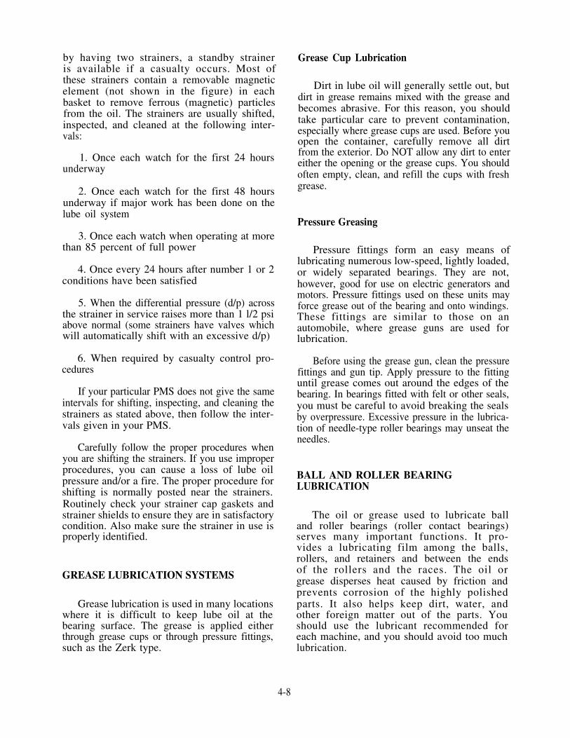
by having two strainers, a standby straineris available if a casualty occurs. Most ofthese strainers contain a removable magneticelement (not shown in the figure) in eachbasket to remove ferrous (magnetic) particlesfrom the oil. The strainers are usually shifted,inspected, and cleaned at the following inter-vals:
1. Once each watch for the first 24 hoursunderway
2. Once each watch for the first 48 hoursunderway if major work has been done on thelube oil system
3. Once each watch when operating at morethan 85 percent of full power
4. Once every 24 hours after number 1 or 2conditions have been satisfied
5. When the differential pressure (d/p) acrossthe strainer in service raises more than 1 l/2 psiabove normal (some strainers have valves whichwill automatically shift with an excessive d/p)
6. When required by casualty control pro-cedures
If your particular PMS does not give the sameintervals for shifting, inspecting, and cleaning thestrainers as stated above, then follow the inter-vals given in your PMS.
Carefully follow the proper procedures whenyou are shifting the strainers. If you use improperprocedures, you can cause a loss of lube oilpressure and/or a fire. The proper procedure forshifting is normally posted near the strainers.Routinely check your strainer cap gaskets andstrainer shields to ensure they are in satisfactorycondition. Also make sure the strainer in use isproperly identified.
GREASE LUBRICATION SYSTEMS
Grease lubrication is used in many locationswhere it is difficult to keep lube oil at thebearing surface. The grease is applied eitherthrough grease cups or through pressure fittings,such as the Zerk type.
Grease Cup Lubrication
Dirt in lube oil will generally settle out, butdirt in grease remains mixed with the grease andbecomes abrasive. For this reason, you shouldtake particular care to prevent contamination,especially where grease cups are used. Before youopen the container, carefully remove all dirtfrom the exterior. Do NOT allow any dirt to entereither the opening or the grease cups. You shouldoften empty, clean, and refill the cups with freshgrease.
Pressure Greasing
Pressure fittings form an easy means oflubricating numerous low-speed, lightly loaded,or widely separated bearings. They are not,however, good for use on electric generators andmotors. Pressure fittings used on these units mayforce grease out of the bearing and onto windings.These fittings are similar to those on anautomobile, where grease guns are used forlubrication.
Before using the grease gun, clean the pressurefittings and gun tip. Apply pressure to the fittinguntil grease comes out around the edges of thebearing. In bearings fitted with felt or other seals,you must be careful to avoid breaking the sealsby overpressure. Excessive pressure in the lubrica-tion of needle-type roller bearings may unseat theneedles.
BALL AND ROLLER BEARINGLUBRICATION
The oil or grease used to lubricate balland roller bearings (roller contact bearings)serves many important functions. It pro-vides a lubricating film among the balls,rollers, and retainers and between the endsof the rollers and the races. The oil orgrease disperses heat caused by friction andprevents corrosion of the highly polishedparts. It also helps keep dirt, water, andother foreign matter out of the parts. Youshould use the lubricant recommended foreach machine, and you should avoid too muchlubrication.
4-8

LUBE OIL PURIFICATION
The forced-feed lubrication systems inmodern naval ships rely on pure oil. Oil thatstays pure can be used for a long time. LUBEOIL DOES NOT WEAR OUT—it is merelyrobbed of its lubricating properties by foreignsubstances.
Contaminants interfere with the abilityof the oil to maintain a good lubricatingfilm between metal surfaces. These contam-inants must be removed or the oil will notmeet lubrication requirements. Dirt, sludge,and other contaminants will act as abra-sives to score and scratch the rubbing metalsurfaces within engines, generators, pumps,and blowers. Water is the greatest sourceof contamination. Strainers, filters, set-tling tanks, and centrifugal purifiers areused in lubrication systems to keep the oilpure. Filters and strainers were discussedearlier in the chapter. This section willdeal with settling tanks and centrifugal puri-fiers.
Lubricating oil piping is generally arrangedto permit two methods of purification: batchpurification and continuous purification. Thebatch process uses settling tanks while thecontinuous process uses centrifugal purifiers.
SETTLING TANKS
In the batch process, the lube oil istransferred from the sump to a settling tankby a purifier or transfer pump. Settling tankspermit oil to stand while water and otherimpurities settle out. Settling is caused bythe force of gravity. A number of layersof contaminants may form in the bottomof the tank. The number of layers dependson the specific gravity of the various contaminat-ing substances. For example, a layer of metalmay form on the bottom, followed by a layerof sludge, a layer of water, and then theclean oil on top. Settling tanks are normallyused when the ship is in port. After theoil is heated and allowed to settle for severalhours, water and other impurities that haveaccumulated in the settling tanks are removed.The oil that is left in the tanks is then
centrifuged and returned to the sump orstorage tank.
CENTRIFUGAL PURIFIERS
When a ship is at sea or when time doesnot permit batch purification in the settlingtanks, the continuous purification processis used. Centrifugal purifiers are used in thisprocess. The purifier takes the oil from thesump in a continuous cycle. Before enteringthe purifier, the oil is heated to help removethe impurities.
Detailed instructions on constructing,operating, and maintaining purifiers arefurnished by manufacturers’ technical man-uals, PMS, and the Engineering OperationSequencing System (EOSS). Carefully followthese documents when you are operatingor performing maintenance on purifiers.The following general information will helpyou understand the purification and thepurposes and principles of purifier opera-tion.
A purifier may be used to remove waterand/or sediment from oil. When water must beremoved, the purifier is called a SEPARATOR.When the main source of contamination issediment, the purifier is used as a CLARIFIER.When used to purify lubricating oil, a purifier maybe used as either a separator or a clarifier. Aboardship, a purifier is almost always operated as aseparator.
TYPES OF CENTRIFUGALPURIFIERS AND THEIR OPERATINGCHARACTERISTICS
Two types of purifiers are used in Navyinstallations. Both types operate on the sameprinciple. The principal difference is in thedesign of the rotating units. In one typethe rotating element is a bowl-like containerwhich encases a stack of disks. This is thedisk-type DeLaval purifier. In the othertype, the rotating element is a hollow, tubu-lar rotor and is the tubular-type Sharplespurifier.
4-9

Disk-Type Purifier
A sectional view of a disk-type centrifugalpurifier is shown in figure 4-5. The bowlis mounted on the upper end of the verticalbowl spindle, which is driven by means ofa worm wheel and friction clutch assembly. Aradial thrust bearing at the lower end of the bowlspindle carries the weight of the bowl spindle andabsorbs any thrust created by the driving action.The parts of a disk-type bowl are shown in figure4-6.
The flow of oil through the bowl andadditional parts is shown in figure 4-7. Con-taminated oil enters the top of the revolvingbowl through the regulating tube. The oil
then passes down the inside of the tubularshaft and out at the bottom into the stackof disks. As the dirty oil flows up throughthe distribution holes in the disks, the highcentrifugal force exerted by the revolving bowlcauses the dirt, sludge, and water to moveoutward. The purified oil flows inward andupward, discharging from the neck of thetop disk. The water forms a seal betweenthe top disk and the bowl top. (The topdisk is the dividing line between the waterand the oil.) The disks divide the space withinthe bowl into many separate narrow passagesor spaces. The liquid confined within eachpassage is restricted so that it can flowonly along that passage. This arrangementminimizes agitation of the liquid as it passes
Figure 4-5.—Disk-type centrifugal purifier.
4-10

Figure 4-6.—Part of a disk-type purifier bowl.
47.85Figure 4-7.—Path of oil through disk-type purifier.
4-11

through the bowl. It also makes shallow settlingdistances between the disks.
Most of the dirt and sludge remains inthe bowl and collects in a more or less uniformlayer on the inside vertical surface of the bowlshell. Any water, along with some dirt and sludge,separated from the oil, is discharged through thedischarge ring at the top of the bowl.
Tubular-Type Purifier
A cross section of a tubular-type centrifugalpurifier is shown in figure 4-8. This type ofpurifier consists essentially of a hollow rotoror bowl which rotates at high speeds. The
rotor has an opening in the bottom to allowthe dirty lube oil to enter. It also has twosets of openings at the top to allow theoil and water (separator) or the oil by it-self (clarifier) to discharge (see insert, fig.4-8). The bowl, or hollow rotor, of thepurifier is connected by a coupling unit toa spindle. The spindle is suspended froma ball bearing assembly. The bowl is belt-driven by an electric motor mounted on theframe of the purifier.
The lower end of the bowl extends into aflexibly mounted guide bushing. The assemblyrestrains movement of the bottom of the bowl.But is also allows the bowl enough movement tocenter itself during operation. Inside the bowl is
Figure 4-8.—Tubular-type centrifugal purifier.
4-12

a device consisting of three flat plates equallyspaced radially. This device is commonly referredto as the three-wing device, or just the three-wing.The three-wing rotates with the bowl and forcesthe liquid in the bowl to rotate at the same speedas the bowl. The liquid to be centrifuged is fed,under pressure, into the bottom of the bowlthrough the feed nozzle.
When the purifier is used as a lube oilclarifier, the three-wing has a cone on the
bottom. The feed jet strikes against this conein order to bring the liquid smoothly up tobowl speed without making an emulsion. Thistype of three-wing device is shown in figure4-9.
Separation is basically the same in the tubular-type purifier as in the disk-type purifier. In bothtypes, the separated oil assumes the innermostposition and the separated water moves outward.Both liquids are discharged separately from the
47.87
Figure 4-9.—Principles of a centrifugal purifier.
4-13

bowls, and the solids separated from the liquidremain in the bowl (fig. 4-10).
GENERAL NOTES ON PURIFIEROPERATIONS
You should get the specific details from theinstructions provided for operating a givenpurifier. The information provided here is general,and you can apply it to both types of purifiers.
For maximum efficiency, run purifiers atmaximum designed speed and rated capacity.Since turbine oils are always contaminated withwater from condensation, you should operate thepurifier as a separator and not as a clarifier.However, do not run a purifier at designed rated
capacity when a unit is used as a separator of 9000series (compounded- or additive-type heavy-dutylube oils) detergent oil. Some engine installationsusing oils of the 9000 series are exposed to largequantities of water. If the oil becomes con-taminated with water, the oil has a tendency toemulsify. The tendency is greater when the oil isnew. This condition decreases during the first 50to 75 hours of engine operation. When an emul-sion appears, you should lower the purifier to 80percent of the rated capacity. You should con-tinue this operation as long as a noticeable amountof free water discharges along with the emulsion.
When a purifier is run as a separator, youshould prime the bowl with fresh water before youopen the suction valve. The water serves to seal
47.88Figure 4-10.—Path of oil through the bowl-type purifier.
4-14

the bowl and to make the liquid layers equal. Ifyou do not prime the bowl, you will lose oilthrough the water discharge ports.
Influencing Factors in PurifierOperation
The time required for purification and the out-put of a purifier depend on many factors. Theviscosity of the oil and the pressure applied to theoil are such factors. Two other important factorsare the size of the sediment particles and thedifference in the specific gravity of the oil.
The viscosity of the oil determines to a greatextent the length of time required to purify lubeoil. The more viscous the oil, the longer the timerequired to purify it to a given degree of purity.Decreasing the viscosity of the oil by heating willhelp purification.
Even though certain oils may be properlypurified at operating temperatures, you will getgreater purification by heating the oil to a highertemperature. To do this, the oil is passed througha heater. The oil reaches the proper temperaturein the heater before it enters the purifier bowl.
Oils used in naval installations may be heatedto specified temperatures without adverse effects.Prolonged heating at higher temperatures,however, is not recommended because of thetendency of such oils to oxidize. In general, oilshould be heated enough to produce a viscosityof about 90 seconds, Saybolt Universal (90 SSU).
Pressure should not be increased abovenormal in order to force a high viscosity oilthrough the purifier. Instead, viscosity should bedecreased by heating the oil. The use of excesspressure to force oil through the purifier will resultin poor purification. But if you reduce thepressure of the oil as it is forced into the purifier,you will improve purification. This happensbecause you have increased the length of time theoil is under the influence of centrifugal force.
For clean oil to be discharged from a purifierand for the water discharged to be free of oil, youmust use the proper size discharge ring (RINGDAM). The size of the discharge ring depends onthe specific gravity of the oil being purified. Alldischarge rings have the same outside diameter,but they have inside diameters of different sizes.Ring sizes are shown by even numbers; the smallerthe number, the smaller the ring size. The size,in millimeters, of the inside diameter is stampedon each ring. Sizes vary by 2-mL steps. Charts pro-vided in manufacturers’ technical manuals showthe proper ring size to be used with an oil of a
specific gravity. Generally, the ring size shown ona chart will produce good results. However, therecommended ring may not produce goodpurification. In that case, you must determine thecorrect size by trial and error. In general, purifica-tion is best when you use the ring of the largestpossible size to prevent loss of oil.
MAINTENANCE OF PURIFIERS
Proper care of an oil purifier requires that thebowl be cleaned often and that all sediment becarefully removed. How often you clean a purifierdepends on the amount of foreign matter in theoil to be purified. If the amount of foreignmatter in an oil is not known, you should shutdown the machine and check it. The amount ofsediment found in the bowl at this time willindicate how often you should clean the purifier.Thoroughly clean the bowl assembly each timelube oil is run through for batch purification fromthe settling tank.
While the purifier is operating on a sump ofan operating unit, you should make checks to en-sure that the purifier has not lost its seal. Acasualty caused by a loss of lube oil can occurfairly rapidly. This happens if all the lube oil froma sump is dumped to the bilge or drain tank byan improperly operating purifier.
THE LUBE OIL MANAGEMENTPROGRAM
The Lube Oil Management Program wasdeveloped because of the importance of goodquality lubricating oil. This program is in the formof an instruction. These instructions may varysomewhat in procedure, but their objectives arethe same. Some of the major points covered bythis instruction are listed below:
1. How often you should take oil samples2. The type of equipment on which you
should take oil samples3. The required logs and records of lube oil4. The type of testing you are required to do
on oil samples5. Your required action as a result of the tests
If this program is properly maintained, youcan reduce the down time of your machinerycaused by oil related failures. You should becomevery familiar with the Lube Oil Management Pro-gram and carefully follow each step and detaillisted.
4-15


CHAPTER 5
PUMPS
Pumps are vital to the operation of the ship. If theyfail, the plant they serve also fails. You will have tokeep the pumps in good working order.
In this chapter, we will discuss the principles ofoperation, classification, and maintenance of some ofthe pumps you may have to maintain.
PRINCIPLES OF PUMPOPERATION
Pumps are used to move any substance which flowsor which can be made to flow. Most pumps are used tomove water, oil, and other liquids. However, air, steam,and other gases are also fluid and can be moved withpumps, as can such substances as molten metal, sludge,and mud.
A pump is essentially a device which uses anexternal source of power to apply a force to a fluid inorder to move the fluid form one place to another. Apump develops no energy of its own; it merelytransforms energy from the external source (steamturbine, electric motor, and so forth) into mechanicalkinetic energy, which is manifested by the motion of thefluid. This kinetic energy is then used to do work. Hereare some examples: to raise a liquid from one level toanother, as when water is raised from a well; to transporta liquid through a pipe, as when oil is carried throughan oil pipeline; to move a liquid against some resistance,as when water is pumped to a boiler under pressure; orto force a liquid through a hydraulic system, againstvarious resistances, for the purpose of doing work atsome point. Every pump has a POWER END, whetherit is a steam turbine, a reciprocating steam engine, asteam jet, or some kind of electric motor. Every pumpalso has a FLUID END, where the fluid enters (suction)and leaves (discharges) the pump.
When a pump delivers energy to a liquid, it usuallycauses an increase in pressure, which is generallyreferred to as HEAD. There are four types of heads: (1)net positive suction head, (2) suction head, (3) dischargehead, and (4) total discharge head.
The NET POSITIVE SUCTION HEAD (NPSH) isthe suction pressure minus the vapor pressure expressedin feet of liquid at the pump suction. An example is afeed booster pump with a deaerating feed tank operationat saturated conditions. The NPSH on this pump equalsthe pressure resulting from the height of the water abovethe booster pump suction.
The SUCTION HEAD on a pump means thetotal pressure of the liquid entering the pump. Ina deaerating feed tank operating under satu-rated conditions, the suction head of the feed boosterpump is equal to the NPSH plus the auxiliary exhaustpressure.
The DISCHARGE HEAD means the pressure ofliquid leaving the pump and/or the level of liquid withrespect to the level of the pump on the discharge side.
The TOTAL HEAD is the net difference betweenthe suction head and the discharge head.
Suction head is usually expressed in feet of water ifpositive, and in inches of mercury if negative. When apump operates below the level of a liquid, its suctionend receives the liquid under a gravity flow. When thepump is located above the level of the liquid beingpumped, the pump must be able to establish a vacuumat the inlet to move the liquid into the pump.Atmospheric pressure, acting on the surface of theliquid, will then provide the necessary pressure to movethe liquid into the pump.
5-1
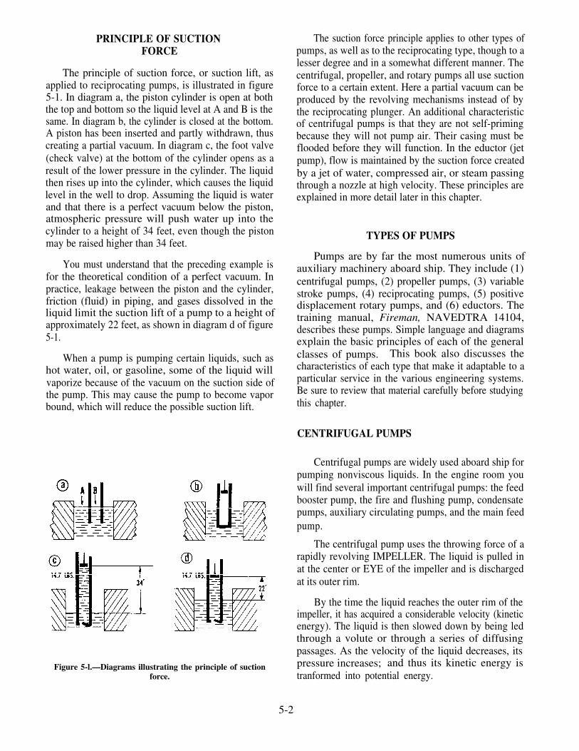
PRINCIPLE OF SUCTIONFORCE
The principle of suction force, or suction lift, asapplied to reciprocating pumps, is illustrated in figure5-1. In diagram a, the piston cylinder is open at boththe top and bottom so the liquid level at A and B is thesame. In diagram b, the cylinder is closed at the bottom.A piston has been inserted and partly withdrawn, thuscreating a partial vacuum. In diagram c, the foot valve(check valve) at the bottom of the cylinder opens as aresult of the lower pressure in the cylinder. The liquidthen rises up into the cylinder, which causes the liquidlevel in the well to drop. Assuming the liquid is waterand that there is a perfect vacuum below the piston,atmospheric pressure will push water up into thecylinder to a height of 34 feet, even though the pistonmay be raised higher than 34 feet.
You must understand that the preceding example isfor the theoretical condition of a perfect vacuum. Inpractice, leakage between the piston and the cylinder,friction (fluid) in piping, and gases dissolved in theliquid limit the suction lift of a pump to a height ofapproximately 22 feet, as shown in diagram d of figure5-1.
When a pump is pumping certain liquids, such ashot water, oil, or gasoline, some of the liquid willvaporize because of the vacuum on the suction side ofthe pump. This may cause the pump to become vaporbound, which will reduce the possible suction lift.
Figure 5-l.—Diagrams illustrating the principle of suctionforce.
The suction force principle applies to other types ofpumps, as well as to the reciprocating type, though to alesser degree and in a somewhat different manner. Thecentrifugal, propeller, and rotary pumps all use suctionforce to a certain extent. Here a partial vacuum can beproduced by the revolving mechanisms instead of bythe reciprocating plunger. An additional characteristicof centrifugal pumps is that they are not self-primingbecause they will not pump air. Their casing must beflooded before they will function. In the eductor (jetpump), flow is maintained by the suction force createdby a jet of water, compressed air, or steam passingthrough a nozzle at high velocity. These principles areexplained in more detail later in this chapter.
TYPES OF PUMPS
Pumps are by far the most numerous units ofauxiliary machinery aboard ship. They include (1)centrifugal pumps, (2) propeller pumps, (3) variablestroke pumps, (4) reciprocating pumps, (5) positivedisplacement rotary pumps, and (6) eductors. Thetraining manual, Fireman, NAVEDTRA 14104,describes these pumps. Simple language and diagramsexplain the basic principles of each of the generalclasses of pumps. This book also discusses thecharacteristics of each type that make it adaptable to aparticular service in the various engineering systems.Be sure to review that material carefully before studyingthis chapter.
CENTRIFUGAL PUMPS
Centrifugal pumps are widely used aboard ship forpumping nonviscous liquids. In the engine room youwill find several important centrifugal pumps: the feedbooster pump, the fire and flushing pump, condensatepumps, auxiliary circulating pumps, and the main feedpump.
The centrifugal pump uses the throwing force of arapidly revolving IMPELLER. The liquid is pulled inat the center or EYE of the impeller and is dischargedat its outer rim.
By the time the liquid reaches the outer rim of theimpeller, it has acquired a considerable velocity (kineticenergy). The liquid is then slowed down by being ledthrough a volute or through a series of diffusingpassages. As the velocity of the liquid decreases, itspressure increases; and thus its kinetic energy istranformed into potential energy.
5-2

Types of Centrifugal Pumps
There are many different types of centrifugalpumps, but the two which you are most likely toencounter aboard ship are the volute pump and thevolute turbine, or diffuser, pump.
VOLUTE PUMP.—In the volute pump, shown infigure 5-2, the impeller discharges into a volute (agradually widening spiral channel in the pump casing).As the liquid passes through the volute and into thedischarge nozzle, a great part of its kinetic energy isconverted into potential energy.
DIFFUSER PUMP.—In the diffuser pump, shownin figure 5-3, the liquid leaving the impeller is firstslowed down by the stationary diffuser vanes whichsurround the impeller. The liquid is forced throughgradually widening passages in the diffuser ring (notshown) and into the volute. Since both the diffuservanes and the volute reduce the velocity of the liquid,there is an almost complete conversion of kinetic energyto potential energy.
Classification of Centrifugal Pumps
Centrifugal pumps may be classified in severalways . For example , they may be e i therSINGLE-STAGE or MULTISTAGE. A single-stagepump has only one impeller. A multistage pump hastwo or more impellers housed together in one casing; asa rule, each impeller acts separately, discharging to thesuction of the next stage impeller. This arrangement iscalled series staging. Centrifugal pumps are alsoclassified as HORIZONTAL or VERTICAL,depending upon the position of the pump shaft.
Figure 5-2.—Simple volute pump.
Generally, large, multistage, high-capacity pumps arehorizontal. Most other pumps are vertical.
The impellers used on centrifugal pumps may beclassified as SINGLE SUCTION or DOUBLESUCTION. The single-suction impeller allows liquidto enter the eye from one direction only; thedouble-suction type allows liquid to enter the eye fromtwo directions.
Impellers are also classified as CLOSED or OPEN.Closed impellers have side walls which extend from theeye to the outer edge of the vane tips; open impellers donot have these side walls. Most centrifugal pumps usedin the Navy have closed impellers.
Construction of Centrifugal Pumps
As a rule, the casing for the liquid end of a pumpwith a single-suction impleller is made with an end platewhich can be removed for inspection and repair of thepump. A pump with a double-suction impeller isgenerally made so that one-half of the casing may belifted without disturbing the pump.
The impellers rotate at very high speed. Thereforethey must be carefully machined in order to minimizefriction, and they must be balanced in order to avoidvibration. A close radial clearance must be maintainedbetween the outer hub of the impeller and that part ofthe pump casing in which the hub rotates. This isnecessary in order to minimize leakage from thedischarge side of the pump casing to the suction side.
Figure 5-3.—Diffuser (volute turbine) pump.
5-3

The impeller has a high rotational speed andnecessarily close clearance. Therefore the runningsurfaces of both the impeller hub and the casing at thatpoint are subjected to relatively rapid wear. Toeliminate the need to renew an entire impeller and pumpcasing solely because of wear in this location,centrifugal pumps are designed with replaceablewearing rings. One ring is attached to the hub of theimpeller, and rotates with the impeller. A matching ringis attached to the casing, and is therefore stationary. Thereplaceable ring on the hub of the impeller is called theIMPELLER WEARING RING, and the ring attachedto the casing is called the CASING WEARING RING.(Wearing rings are shown on the main feed pumpillustrated in fig. 5-4.)
Some small pumps with single-suction impellersare made with a casing wearing ring only and noimpeller ring. In this type of pump, the casing wearingring is fitted into the end plate.
In many cases the pump shaft is fitted with shaftsleeves (fig. 5-5). These sleeves protect the shaftfrom becoming grooved. A shaft that is in direct contactwith the packing will become grooved because of itsrotation in the packing. It is much cheaper to replacethe shaft sleeves than to replace pump shaft. The shaftsleeves are also used to position the impeller axially onthe pump shaft.
Recirculating lines are installed on somecentrifugal pumps to prevent them from overheatingand becoming vapor bound when the discharge isentirely shut off. Seal piping (liquid seal) is alsoinstalled to cool the shaft and the packing, to lubricatethe packing, and to seal the joint between the shaft andthe packing against air leakage. A lantern ring (spacer)is inserted between the rings of the packing in thestuffing box. Seal piping (fig. 5-5) leads liquid fromthe discharge side of the pump to the annular spacewithin the lantern ring. The web of the ring is
Figure 5-4.—Two-stage main feed pump.
5-4

Figure 5-5.—Stuffing box on a centrifugal pump.
perforated so that water can flow in either directionalong the shaft, between the shaft and the packing.
Mechanical seals are used instead of packing in avariety of centrifugal pumps. One type of mechanicalseal is shown in figure 5-6. Spring pressure keeps therotating seal face snug against the stationary seal face.The rotating seal and all of the assembly below it areaffixed to the pump shaft. The stationary seal face isheld stationary by the seal gland and packing ring. Astatic seal is formed between the two seal faces and thesleeve. System pressure within the pump helps thespring keep the rotating seal face tight against thestationary seal face. The type of material used for theseal faces will depend upon the service of the pump.Most water service pumps use a carbon material for theseal faces. When the seals wear out, they are simplyreplaced. New seals should not be touched on thesealing face because body acid and grease will cause theseal face to prematurely pit and go bad.
Bearings support the weight of the impeller andshaft, and maintain the position of the impeller, bothradially and axially. Some centrifugal pumps have abuilt-in bearing lubrication system, complete with lubeoil pump, sump, cooler, strainer, and temperature andflow indicators. Other bearings are grease-lubricated
Figure 5-6.—Type-1 mechanical seal.
with grease cups and vent plugs in the housing to allowfor periodic relubrication.
The power end of a centrifugal pump may be eithera steam turbine or an electric motor. For mostconstant-speed applications, the turbine drive has noparticular advantage over the motor drive.
5-5

The turbines used for centrifugal pumps are usuallysingle-stage impulse turbines. As a rule, high-pressurecentrifugal pumps are direct drive-that is, the impellerrotates at the same rpm as the turbine. However, somelow-pressure centrifugal pumps have reduction gearsbetween the turbine and the impeller.
Centrifugal Pump Maintenance
When properly installed, maintained (using PMS),and operated, centrifugal pumps are usually troublefree. Some of the corrective maintenance actions thatwill be required are discussed in the following sections.
REPACKING.—Lubrication of the pump packingis extremely important. The quickest way to wear outthe packing is to forget to open the water piping to theseals or stuffing boxes. If the packing is allowed to dryout, it will score the shaft. When operating a centrifugalpump, be sure that there is always a slight trickle ofwater coming out of the stuffing box or seal.
How often the packing in a centrifugal pump shouldbe renewed depends on several facts-such as the typeof pump, condition of the shaft sleeve, and hours in use.
To ensure the longest possible service from pumppacking, make certain that the shaft or sleeve is smoothwhen packing is removed from a gland. Rapid wear ofthe packing may be caused by roughness of the shaftsleeve (or shaft where no sleeve is installed). If the shaftis rough, it should be sent to the shop for a finishing cutto smooth the surface. If it is very rough, or has deepridges in it, it will have to be renewed. It is absolutelynecessary to use the correct packing. Navy packing isidentified by symbol numbers as explained in chapter10 of this manual. To find the right packing, check themaintenance requirement card (MRC) or packing chartfor the particular pump. The MRC lists the symbolnumbers and the size and number of rings required.
When replacing packing, be sure that the packingfits uniformly around the stuffing box. If you have toflatten the packing with a hammer, YOU ARE NOTUSING THE RIGHT SIZE.
Packing the box loosely, and set up the packinggland lightly. Allow a liberal leak-off for stuffing boxesthat operate above atmospheric pressure. Next, start thepump. Let it operate for about 30 minutes before youadjust the leak-off. This gives the packing time torun-in and swell, if it is going to. When this requirementhas been satisfied, you may begin to adjust the packinggland. Tighten the adjusting nuts one flat at a time.Wait about 30 minutes between adjustments. Be sureto tighten the same amount on both adjusting nuts. Ifyou pull up the packing gland unevenly (or cocked), itwill cause the packing to overheat and score the shaftsleeves. Once you have the desired leak-off, all youhave to do is check it regularly to ensure that sufficientflow is maintained.
MECHANICAL SEALS.—Mechanical seals arerapidly replacing conventional packing as the means ofcontrolling leakage on centrifugal pumps. Mechanicalseals eliminate the problem of excessive stuffing boxleakage which causes failure of pump and motorbearings and motor windings. Mechanical seals areideal for pumps operating in closed systems (such as airconditioning, chilled water systems, and various sonar,radar, and other electronic cooling systems). They notonly conserve the fluid being pumped but also improvesystem operation. Mechanical seals are well suited forpumps operating under varying discharge pressuressuch as submarine sea-connected pumps.
Mechanical seals are now used for most centrifugalpumps that may operate under vacuum conditions (suchas condensate and ships’ potable water pumps).
Fire pumps and all seawater pumps in surface shipsare being provided with mechanical shaft seals withcyclone separators. The glands incorporate two or morerings of packing for use in the event of a mechanicalshaft seal failure. Opposing seal faces are constructedof tungsten carbide against carbon, or tungsten carbideagainst tungsten carbide. The tungsten carbide sealring(s) are of solid construction. The cycloneseparators are constructed of nickel-copper alloy.Fittings for abrasive separators and pump casing are ofthe straight thread type with O-ring seal. They areconstructed of nickel-copper alloy. Tubing is copper-nickel (70-30), according to MIL-F-16420.
5-6

Replace mechanical seals whenever the seal isremoved for any reason or whenever the leakage rateexceeds 5 drop per minute.
Mechanical shaft seals are positioned on the shaftby stub or step sleeves. Mechanical shaft seals shall notbe positioned by setscrews. Shaft sleeves arechamfered on outboard ends for easy mechanical sealmounting.
Mechanical shaft seals are positioned on the shaftby stub or step sleeves. Mechanical shaft seals shall notbe positioned by setscrews. Shaft sleeves arechamfered on outboard ends for easy mechanical sealmounting.
Where mechanical shaft seals are used, they ensurethat positive liquid pressure is supplied to the seal facesunder all conditions of operation. They also ensureadequate circulation of the liquid at the seal faces tominimize the deposit of foreign matter on the seal parts.
CARE OF LANTERN RINGS, SLEEVES, ANDFLINGERS.—When a stuffing box is fitted with alantern ring, be sure to replace the packing beyond thelantern ring at the bottom of the stuffing box. Also besure that the sealing water connection to the lantern ringis not blanked off by the packing. (See fig. 5-5.)Sleeves fitted at the packing on the pump shafts mustalways be tight. These sleeves are usually made secureby shrinking or keying them to the shaft. Ensure thatwater does not leak between the shaft and shaft sleeve.
Water flinger rings are fitted on the shaft betweenthe packing gland and the pump bearing housing.These flingers prevent water from the stuffing box fromfollowing along the shaft and entering the bearinghousing.
Shaft sleeves are made fast to the pump shaft invarious ways. Some slip on and are held in place by anut. Some may screw on. In this case, the threads willbe cut so that the sleeve tightens in the oppositedirection from the pump rotation.
Some sleeves have O-rings between the shaft andthe abutting shoulder to prevent water leakage betweenthe shaft and the sleeve. Others may use packing ortight-fitting threads. Use the manufacturers' technicalmanual for detailed information.
ALIGNMENT OF SHAFTING ANDCOUPLINGS.—Shaft alignment must be checkedfrequently. If the shafts are out of line, the unit must berealigned. This will prevent shaft breakage and damageto bearings, pump casing wearing rings, throatbushings. Check the shaft alignment with all piping in
place. If the pump is turbine driven, or if it pumps a hotliquid, recheck the alignment after it has operated forseveral hours and is up to operating temperature.
The driving unit may be connected to the pump bya FLEXIBLE COUPLING. Remember that flexiblecouplings (fig. 5-7) are intended to take care of onlyslight misalignment. Misalignment should neverexceed the amount specified by the pump manufacturer.If the misalignment is excessive the coupling parts aresubjected to severe punishment, which causes frequentrenewal of pins, bushings, and bearings.
The driving unit may be connected, or coupled, tothe pump by a FLANGE COUPLING. Here too,frequent realignment of the shafting may be necessary.Each pump shaft must be kept in proper alignment withthe shaft of the driving unit. Misalignments areindicated by such things as abnormal temperatures,abnormal noises, and worn bearings or bushings.
Shims are placed on the bushings of both the drivenand driving units to facilitate alignment when themachinery is installed. Jacking screws may also beused to level the units. The pump or driving unit, orboth, may need to be shifted sidewise to align thecouplings. This is made easier by side brackets weldedin convenient spots on the foundations, and largesetscrews used to shift the units sidewise or endwise.
Figure 5-7.—Grid-type flexible coupling.
5-7

The shims must be adjusted so that the outsidediameters and faces of the coupling flanges run true asthey are manually revolved. When that is done, thechocks should be fastened, the units should be securelybolted to the foundation, and the coupling flangesshould be bolted together.
The ALIGNMENTS MUST BE CHECKED fromtime to time, and misalignments must be promptlycorrected. There are three methods in general practicefor checking the alignments:
1. Use of a 6-inch scale
2. Use of a thickness gauge
3. Use of a dial indicator
Shaft alignment should be checked whenever thepump is opened up and whenever you feel a noticeablevibration. If shafts are found out of line or inclined atan angle to each other, the unit should be realigned.This will avoid shaft breakages and renewal of bearings,pump casing wearing rings, and throat bushings.Consult the appropriate MRC or technical manual inaligning the pump.
MEASURING BEARING CLEARANCES.—Some centrifugal pump installations are fitted with awater-lubricating bearing inside the pump casing (suchas condensate pumps). An adequate supply of cleanwater must be supplied to this bearing for lubricatingand cooling.
Check the condition of the internal water-lubricatedbearings frequently to guard against excessive wearwhich results in misalignment and possible shaftfailure.
On oil-lubricated sleeve or shell-bearings, measurethe bearing clearances following procedures describedon the MRC for the pump. Maintain clearances withinthe limits shown on the MRC or in the manufacturer’stechnical manual.
RENEWAL OF WEARING RINGS.—Theclearance between the impeller wearing ring and thecasing wearing ring (figure 5-8) must be maintained asshown in the manufacturer’s plans. When themaximum allowable clearance is exceeded the wearingrings must be replaced. In most cases, this can be doneby the ship’s force. However, if your machine shopdoes not have the proper lathe, then you must send thepump out for repairs.
All necessary information on disassembly of theunit, dimensions of the wearing rings, and reassembly
of the pump is specified by PMS. It can also be foundin the manufacturer’s technical manual.
In deciding whether the wearing rings needrenewing, you must consider the capacity and dischargepressure of the pump. On low-pressure pumps thewearing ring diametral clearance may be 0.015 to 0.030inch more than the designed amount without anyappreciable effect on the pump's capacity. For pumpshaving a discharge pressure up to 75 psi, a wear of 0.030to 0.050 inch is permissible.
The percentage of capacity loss, with a wearing ringclearance of 0.030 inch in excess of standard, may belarge with a small pump, but comparatively small witha large pump. Increased wearing ring clearance on ahigh-pressure boiler feed pump is readily noticeable inthe efficiency and maximum capacity of the pump. Thewearing rings on high-pressure pumps should berenewed when the clearance shown on themanufacturer’s plans is exceeded by 100 percent. It isusually not necessary to renew wearing rings unless thewear is at least 0.015 inch.
If a pump has to be diassembled because of someinternal trouble, check the wearing rings for clearance.Measure the outside diameter of the impeller wearingring with an outside micrometer and the inside diameterof the casing wearing ring with an inside micrometer.The difference between the two diameters is the actualwearing ring diametral clearance. By comparing theactual wearing ring clearance with the maximumallowable clearance, you can decide whether to renewthe rings before you reassemble the pump. The
Figure 5-8.—Impeller, impeller wearing ring, and casingwearing ring for a centrifugal pump.
5-8

applicable MRCs are a readily available source ofinformation on the proper clearances.
Wearing rings for most small pumps are carried aspart of the ship’s repair parts allowance. These mayneed only a slight amount of machining before they canbe installed. For some pumps, such as main condensateand main feed booster pumps, spare rotors are carriedaboard. The new rotor can be installed and the old rotorsent to a repair activity for overhaul. Overhauling arotor includes renewing the wearing rings, the bearings,and the shaft sleeve.
TROUBLESHOOTING TECHNIQUES.—Some of the operating troubles you may have to dealwith in centrifugal pumps, together with the probablecauses, are described in the following paragraphs.
If a centrifugal pump DOES NOT DELIVER ANYLIQUID, the trouble may be caused by (1) insufficientpriming; (2) insufficient speed of the pump; (3)excessive discharge pressure, such as might be causedby a partially closed valve or some other obstruction inthe discharge line; (4) excessive suction lift; (5) cloggedimpeller passages; (6) the wrong direction of rotation;(7) clogged suction screen (if used); (8) ruptured suctionline; or (9) loss of suction pressure.
If a centrifugal pump delivers some liquid butoperates at INSUFFICIENT CAPACITY, the troublemay be caused by (1) air leakage into the suction line;(2) air leakage into the stuffing boxes in pumpsoperating at less than atmospheric pressure; (3)insufficient speed of the pump; (4) excessive suctionlift; (5) insufficient liquid on the suction side; (6)clogged impeller passages; (7) excessive dischargepressure; or (8) mechanical defects such as wornwearing rings, impellers, stuffing box packing, orsleeves.
If a pump DOES NOT DEVELOP ENOUGHDISCHARGE PRESSURE, the trouble may be causedby (1) insufficient speed of the pump; (2) air or gas inthe liquid being pumped; or (3) mechanical defects suchas worn wearing rings, impellers, stuffing box packing,or sleeves.
If a pump WORKS FOR A WHILE AND THENFAILS TO DELIVER LIQUID, the trouble may becaused by (1) air leakage into the suction line; (2) airleakage in the stuffing boxes; (3) clogged water sealpassages; (4) insufficient liquid on the suction side; or(5) excessive heat in the liquid being pumped.
If a motor-driven centrifugal pump TAKES TOOMUCH POWER, the trouble will probably be indicated
by overheating of the motor. The basic cause may be(1) operation of the pump to excess capacity andinsufficient discharge pressure; (2) too high viscosity orspecific gravity of the liquid being pumped; or (3)misalignment, a bent shaft, excessively tight stuffingbox packing, worn wearing rings, or other mechanicaldefects.
VIBRATION of a centrifugal pump is often causedby (1) misalignment; (2) a bent shaft; (3) a clogged,eroded, or otherwise unbalanced impeller; or (4) lack ofrigidity in the foundation. Insufficient suction pressuremay also cause vibration, as well as noisy operation andfluctuating discharge pressure, particularly in pumpsthat handle hot or volatile liquids.
If the pump fails to build up pressure when thedischarge valve is opened and the pump speed isincreased, proceed as follows:
1. Secure the pump.
2. Prime the pump and be sure that all air isexpelled through the air cocks on the pump casing.
3. Open all valves on the pump suction line.
4. Start the pump again. If the pump is electricdriven be sure the pump is rotating in the correctdirection. If the discharge pressure is not normal whenthe pump is up to its proper speed, the suction line maybe clogged, or an impeller may be broken. It is alsopossible that air is being drawn into the suction line orinto the casing. If any of these conditions exist, stop thepump, try to find the source of the trouble, and correctit, if possible.
Centrifugal Pump Control andSafety Devices
Turbines, used to drive pumps, are fitted withdevices to control or limit the speed of the turbine, or toregulate the discharge pressure of the unit.
These devices are seldom found on reciprocatingpumps. However, all turbine-driven rotary andcentrifugal pumps have some type of governor. Wheredischarge pressure has to be controlled, both aconstant-pressure governor and a speed-limitinggovernor are installed.
The speed-limiting governor was covered inchapter 2. Therefore we will discuss only theconstant-pressure governor in this chapter.
CONSTANT-PRESSURE GOVERNOR.—Many turbine-driven pumps are fitted withconstant-pressure pump governors which maintain a
5-9

constant pump discharge pressure under varyingconditions of load. The governor is installed in thesteam line to the pump. It controls the pump dischargepressure by controlling the amount of steam admittedto the driving turbine.
The operating principles for the types ofconstant-pressure pump governors are discussed infollowing paragraphs.
A constant-pressure pump governor for a main feedpump is shown in figure 5-9. The governors used onfuel oil service pumps, lube oil service pumps, fire andflushing pumps, and various other pumps are almostidentical. The chief difference between governors usedfor different services is in the size of the upperdiaphragm. A governor used for a pump that operateswith a high discharge pressure has a smaller upperdiaphragm than one used for a pump that operates witha low discharge pressure.
Two opposing forces are involved in the operationof a constant-pressure pump governor. Fluid from thepump discharge, at discharge pressure, is led through anactuating line to the space below the upper diaphragm.The pump discharge pressure thus exerts an UPWARDforce on the upper diaphragm. Opposing this, anadjusting spring exerts a DOWNWARD force on theupper diaphragm.
When the downward force of the adjusting springis greater than the upward force of the pump dischargepressure, the spring forces both the upper diaphragmand the upper crosshead downward. A pair ofconnecting rods connects the upper crosshead rigidly tothe lower crosshead, so the entire assembly of upper andlower crossheads moves together. When the crossheadassembly moves downward, it pushes the lowermushroom and the lower diaphragm downward. Thelower diaphragm is in contact with the controllingvalve. When the lower diaphragm is moved downward,the controlling valve is forced down and open.
The controlling valve is supplied with a smallamount of steam through a port from the inlet side ofthe governor. When the controlling valve is open,steam passes to the top of the operating piston. Thesteam pressure acts on the top of the piston, forcing itdown and opening the main valve. The extent to whichthe main valve is open controls the amount of steamadmitted to the driving turbine. Increasing the openingof the main valve therefore increases the supply ofsteam to the turbine and so increases the speed of theturbine.
The increased speed of the turbine produces anincreased discharge pressure from the pump. Thispressure is exerted against the under side of the upperdiaphragm. The pump discharge pressure increases tothe point that the upward force acting on the undersideof the upper diaphragm is greater than the downwardforce exerted by the adjusting spring. The upperdiaphragm is then moved upward. This action allows aspring to start closing the controlling valve. Thisaction, in turn, allows the main valve spring to startclosing the main valve against the now-reducedpressure on the operating piston. When the main valvestarts to close, the steam supply to the turbine, the speedof the turbine, and the pump discharge pressure arereduced.
It might seem that the controlling valve and themain valve would be constantly opening and closingand that the pump discharge pressure would becontinually varying over a wide range. This does nothappen, however, because the governor preventsexcessive opening or closing of the controlling valve.An intermediate diaphragm bears against anintermediate mushroom which, in turn, bears againstthe top of the lower crosshead. Steam is led from thegovernor outlet to the bottom of the lower diaphragmand also, through a needle valve, to the top of theintermediate diaphragm. A steam chamber is providedto ensure a continuous supply of steam at the requiredpressure to the top of the intermediate diaphragm.
Any up or down movement of the crossheadassembly is therefore opposed by the force of the steampressure acting on either the intermediate diaphragm orthe lower diaphragm. The whole arrangement preventsextreme reactions of the controlling valve in responseto variations in pump discharge pressure.
Limiting the movement of the controlling valve inthis manner, reduces the amount of hunting thegovernor must do to find each new position. Underconstant-load conditions, the controlling valve takes aposition that causes the main valve to remain open bythe required amount. A change in load conditons resultsin momentary hunting by the governor until it finds thenew position required to maintain pump dischargepressure at the new load.
A pull-open device, consisting of a valve stem anda handwheel, is fitted to the bottom of the governor.Turning the handwheel to the open position draws themain valve open and allows full steam flow to theturbine. When the main valve is opened by this bypass,the turbine must be controlled manually. Under allnormal operating conditions, the bypass remains closed
5-10

Figure 5-9.—Constant-pressure governor for main feed pump.
5-11

and the pump discharge pressure is raised or lowered,as necessary, by increasing or decreasing the tension onthe ajusting spring.
The mainfeed pumps on some newer ships are fittedwith a differential-pressure governing system instead ofthe constant-pressure governor. This system maintainsa constant differential pressure across the feedwaterregulating valve. This valve is located in the dischargepiping of the pump. When this system is used, themainfeed pump will normally be located in the fireroom.
AUTOMATIC SHUTDOWN DEVICE.—Anautomatic shutdown device shuts down the main feedpump. This protects the pump from damage in the eventof loss of feed booster pump pressure (which is the sameas main feed pump suction pressure).
The device consists of an auxiliary pilot valve anda constant-pressure pump governor, arranged as shownin figure 5-10. The governor is similar to the governorjust described except that it has a special top cap. In theregular governor, the steam for the operating piston issupplied to the controlling valve through a port in thegovernor valve body. In the automatic shut-downdevice, the steam for the operating piston is supplied tothe controlling valve through the auxiliary pilot valve.The auxiliary pilot valve (fig. 5-11) is actuated by thefeed booster pump discharge pressure. When thebooster pump discharge pressure is inadequate, theauxiliary pilot valve will not deliver steam to thecontrolling valve of the governor. Thus, inadequatefeed booster pump pressure allows the main valve in thegovernor to close, shutting off the flow of steam to thefeed pump turbine.
Figure 5-10.—Automatic shutdown device for main feed pump.
5-12
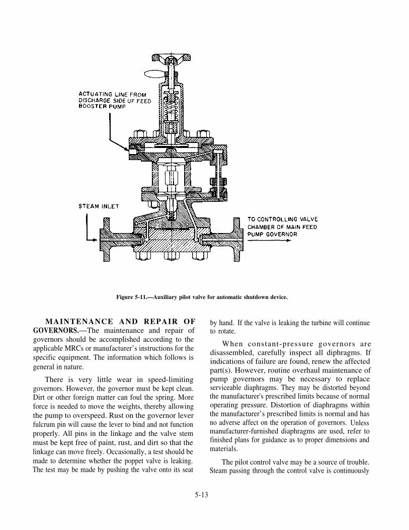
MAINTENANCE AND REPAIR OFGOVERNORS.—The maintenance and repair ofgovernors should be accomplished according to theapplicable MRCs or manufacturer’s instructions for thespecific equipment. The information which follows isgeneral in nature.
There is very little wear in speed-limitinggovernors. However, the governor must be kept clean.Dirt or other foreign matter can foul the spring. Moreforce is needed to move the weights, thereby allowingthe pump to overspeed. Rust on the governor leverfulcrum pin will cause the lever to bind and not functionproperly. All pins in the linkage and the valve stemmust be kept free of paint, rust, and dirt so that thelinkage can move freely. Occasionally, a test should bemade to determine whether the poppet valve is leaking.The test may be made by pushing the valve onto its seat
Figure 5-11.—Auxiliary pilot valve for automatic shutdown device.
by hand. If the valve is leaking the turbine will continueto rotate.
When constant-pressure governors aredisassembled, carefully inspect all diphragms. Ifindications of failure are found, renew the affectedpart(s). However, routine overhaul maintenance ofpump governors may be necessary to replaceserviceable diaphragms. They may be distorted beyondthe manufacturer's prescribed limits because of normaloperating pressure. Distortion of diaphragms withinthe manufacturer’s prescribed limits is normal and hasno adverse affect on the operation of governors. Unlessmanufacturer-furnished diaphragms are used, refer tofinished plans for guidance as to proper dimensions andmaterials.
The pilot control valve may be a source of trouble.Steam passing through the control valve is continuously
5-13

throttled, and the valve is subjected to considerableerosion (wiredrawing). Inspect the control valve andvalve seat frequently. When reassembling the controlvalve or installing a new one, it is very important tomaintain the correct clearance between the controlvalve stem and the lower diaphragm. If the clearanceis excessive, the lower diaphragm cannot fully open thecontrol valve, and the pump capacity is reduced. Ifthere is not enough clearance, the diaphragm will holdthe control valve open and the pump cannot be stoppedwithout closing the root steam valve. It is alsonecessary that steam does not leak through the controlvalve bushing. Leaking steam will hold the main valveopen, allowing steam to flow to the turbine.
Faulty governor operation may also result from thewearing of grooves in the cylinder liner. The grooves,which limit the travel of the main valve, become wornwhen the piston is moved through a short travel. Thisreduces the capacity of the pump and causes failure ofthe governor. Whenever a constant-pressure governoris disassembled, check the liner carefully. If it isgrooved excessively, replace the liner according to themanufacturer’s recommendations for the specific unit.
Inspect control valve springs frequently. If thespring breaks or is weak, it cannot close the controlvalve, which allows a full flow of steam to the turbine.
Centrifugal Pump Safety Precautions
The following safety precautions must be observedin connection with the operation of centrifugal pumps.
1. Ensure that all relief valves are tested at theappropriate intervals as required by the PMS. Ensurethat relief valves function at the designated pressure.
2. Never attempt to jack over a pump by handwhile the throttle valve to the turbine is open or thepower is on.
3. Do not attempt to operate a pump while eitherthe speed-limiting governor or the constant-pressuregovernor is inoperable. Be sure that the speed-limitinggovernor and the constant-pressure governor areproperly set.
4. Do not use any boiler feed system pump for anyservice other than boiler or feed water service, exceptin an emergency.
PROPELLER PUMPS
Propeller pumps are used primarily where there isa large volume of liquid with a relatively low total head
requirement. These pumps are usually limited towhere the total head does not exceed 40 to 60 feet.
The chief use of the propeller pump is for the maincondenser circulating pump (illustrated in Fireman,NAVEDTRA 14104). In most ships this has anemergency suction for pumping out the engineroom.
The main condenser circulating pump is of thevertical propeller type. The pump unit consists of threemajor parts: the propeller, together with its bearingsand shaft; the pump casing; and the driving unit,which may be an auxiliary steam turbine or electricmotor.
The propeller is a multibladed screw propellerhaving a large pitch. The blades are thick at the rootsand flare out toward the tips. The blades and hubs arecast or forged in one piece and are then machined andbalanced. The lower shaft bearing is a water-lubricated,sleeve bearing. The shaft packing gland preventsexcessive leakage of water between the casing and theshaft.
RECIPROCATING PUMPS
A reciprocating pump moves water or other liquidby a plunger or piston that reciprocates (travels backand forth) inside a cylinder. Reciprocating pumps arepositive-displacement pumps; each stroke displaces adefinite quantity of liquid, regardless of the resistanceagainst which the pump is operating.
Classification of Reciprocating Pumps
Reciprocating pumps are usually classified as thefollowing:
1. Direct acting or indirect acting
2. Simplex (single) or duplex (double)
3. Single acting or double acting
4. High pressure or low pressure
5. Vertical or horizontal
The reciprocating pump shown in figure 5-12 is adirect-acting, simplex, double-acting, high-pressure,vertical pump. Now let’s see what all these terms meanabout the pump shown in the illustration.
DIRECT-ACTING AND INDIRECT-ACTINGPUMPS.—The pump shown is direct acting becausethe pump rod is a DIRECT extension of the piston rodand, therefore, the piston in the power end is
5-14

Figure 5-12.—Reciprocating pump.
DIRECTLY connected to the plunger in the liquid end. or a cam. This arrangement can be used to change theMost reciprocating pumps used in the Navy are direct relative length of the strokes of piston and plunger or toacting. In an indirect-acting pump, there is some vary the relative speed between piston and plunger. Orintermediate mechanism between the piston and pump the pump may use a rotating crankshaft such as aplunger. The intermediate mechanism may be a lever chemical proportioning pump in a distilling unit.
5-15

SIMPLEX AND DUPLEX PUMPS.—The pumpshown in figure 5-12 is called a single or simplex pumpbecasue it has only one liquid cylinder. Simplex pumpsmay be either direct acting or indirect acting. A doubleor duplex pump is an assembly of two single pumpsplaced side by side on the same foundation; the twosteam cylinders are cast in a single block, and the twoliquid cylinders are cast in another block. Duplexreciprocating pumps are seldom found in moderncombatant ships, but were commonly used in olderships.
SINGLE-ACTING AND DOUBLE-ACTINGPUMPS.—In a single-acting pump, the liquid is drawninto the liquid cylinder on the first or SUCTION strokeand is forced out of the cylinder on the return orDISCHARGE stroke. In a double-acting pump, eachstroke serves both to draw in liquid and to dischargeliquid. As one end of the cylinder is filled, the other endis emptied; on the return stroke, the end which was justemptied is filled and the end which was just filled isemptied.
The pump shown in figure 5-12 is double acting.(NOTE: Only one of two sets of valves is shown infig. 5-12.)
HIGH-PRESSURE AND LOW-PRESSUREPUMPS.—The pump shown in figure 5-12 is designedto operate with a discharge pressure which is higherthan the pressure of the steam operating the piston inthe steam cylinder; in other words, it is a high-pressurepump. In a high-pressure pump the steam piston islarger in diameter than the plunger in the liquid cylinder.Since the area of the steam piston is greater than the areaof the plunger in the liquid cylinder, the total forceexerted by the steam against the steam piston isconcentrated on the smaller working area of the plungerin the liquid cylinder. Therefore, the pressure persquare inch is greater in the liquid cylinder than thesteam cylinder. A high-pressure pump discharges acomparatively small volume of liquid against a highpressure. A low-pressure pump, on the other hand, hasa comparatively low discharge pressure but a largervolume of discharge. In a low-pressure pump, thesteam piston is smaller than the plunger in the liquidcylinder.
The standard way of designating the size of areciprocating pump is by giving three dimensions, inthe following order:
1. The diameter of the steam piston
2. The diameter of the pump plunger
3. The length of the stroke
For example, a 12 × 11 × 18-inch reciprocating pumphas a steam piston which is 12 inches in diameter, apump plunger which is 11 inches in diameter and astroke which is 18 inches in length. The designationenables you to tell immediately whether the pump is ahigh-pressure or a low-pressure pump.
VERTICAL AND HORIZONTAL PUMPS.—Finally, the pump shown in figure 5-12 is classified asvertical because the steam piston and the pump plungermove up and down. Most reciprocating pumps in navaluse are vertical; however, you may occasionallyencounter a horizontal pump, in which the piston movesback and forth rather than up and down.
The following discussion of reciprocating pumps isgenerally concerned with direct-acting, simplex,double-acting, vertical pumps. Most reciprocatingpumps used in the Navy are of this type.
Construction of Reciprocating Pumps
The power end of a reciprocating pump consists ofa bored cylinder in which the steam piston reciprocates.The steam cylinder is fitted with heads at each end; onehead has an opening to accommodate the piston rod.Steam inlet and exhaust ports connect each end of thesteam cylinder with the steam chest. Drain valves areinstalled in the steam cylinder so that water fromcondensation may be drained off.
Automatic timing of the admission and release ofsteam to and from each end of the steam cylinder isaccomplished by a valve operating assembly. Thisassembly connects the pilot valve operating rod and thepump rod (fig. 5-13). As the crosshead arm(sometimes called the rocker arm) is moved up anddown by the movement of the pump rod, the movingtappet slides up and down on the pilot valve rod. Thetappet collars are adjusted so that the pump will makethe full designed stroke.
The piston valve gear, commonly used forautomatic timing, consists of a piston slide valve and apilot slide valve. The position of the pilot slide valve iscontrolled by the position of the main piston in the
5-16
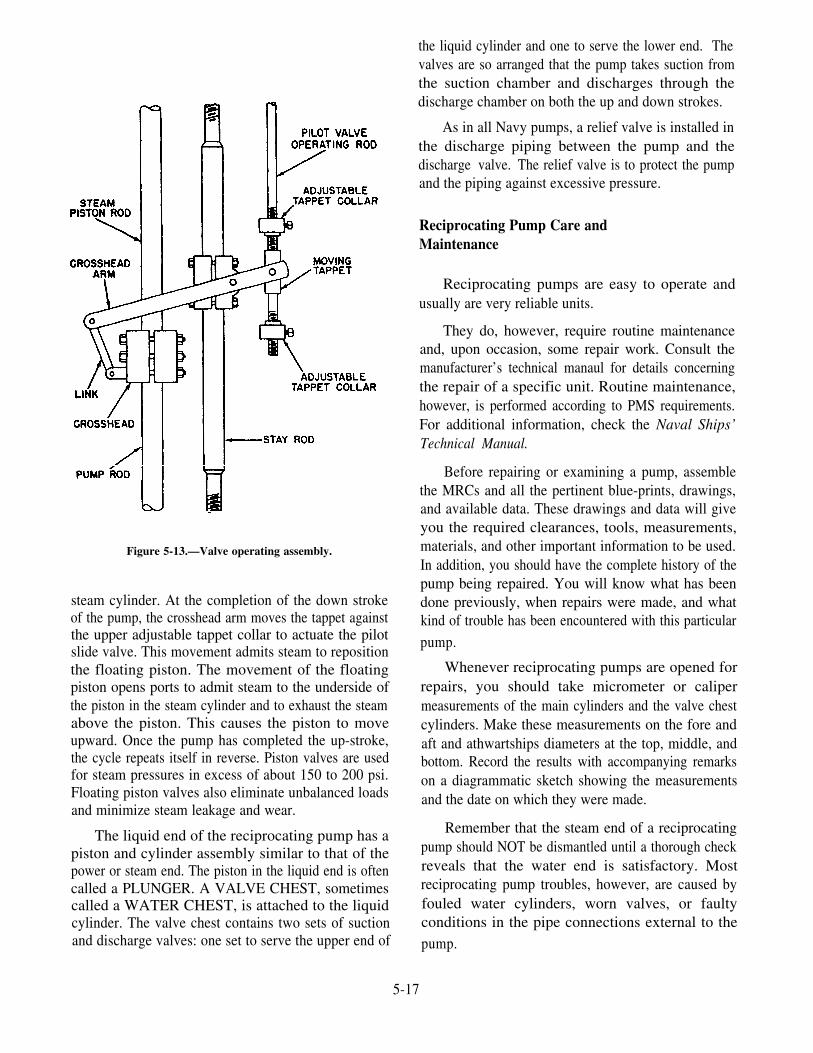
Figure 5-13.—Valve operating assembly.
steam cylinder. At the completion of the down strokeof the pump, the crosshead arm moves the tappet againstthe upper adjustable tappet collar to actuate the pilotslide valve. This movement admits steam to repositionthe floating piston. The movement of the floatingpiston opens ports to admit steam to the underside ofthe piston in the steam cylinder and to exhaust the steamabove the piston. This causes the piston to moveupward. Once the pump has completed the up-stroke,the cycle repeats itself in reverse. Piston valves are usedfor steam pressures in excess of about 150 to 200 psi.Floating piston valves also eliminate unbalanced loadsand minimize steam leakage and wear.
The liquid end of the reciprocating pump has apiston and cylinder assembly similar to that of thepower or steam end. The piston in the liquid end is oftencalled a PLUNGER. A VALVE CHEST, sometimescalled a WATER CHEST, is attached to the liquidcylinder. The valve chest contains two sets of suctionand discharge valves: one set to serve the upper end of
the liquid cylinder and one to serve the lower end. Thevalves are so arranged that the pump takes suction fromthe suction chamber and discharges through thedischarge chamber on both the up and down strokes.
As in all Navy pumps, a relief valve is installed inthe discharge piping between the pump and thedischarge valve. The relief valve is to protect the pumpand the piping against excessive pressure.
Reciprocating Pump Care andMaintenance
Reciprocating pumps are easy to operate andusually are very reliable units.
They do, however, require routine maintenanceand, upon occasion, some repair work. Consult themanufacturer’s technical manaul for details concerningthe repair of a specific unit. Routine maintenance,however, is performed according to PMS requirements.For additional information, check the Naval Ships’Technical Manual.
Before repairing or examining a pump, assemblethe MRCs and all the pertinent blue-prints, drawings,and available data. These drawings and data will giveyou the required clearances, tools, measurements,materials, and other important information to be used.In addition, you should have the complete history of thepump being repaired. You will know what has beendone previously, when repairs were made, and whatkind of trouble has been encountered with this particular
pump.
Whenever reciprocating pumps are opened forrepairs, you should take micrometer or calipermeasurements of the main cylinders and the valve chestcylinders. Make these measurements on the fore andaft and athwartships diameters at the top, middle, andbottom. Record the results with accompanying remarkson a diagrammatic sketch showing the measurementsand the date on which they were made.
Remember that the steam end of a reciprocatingpump should NOT be dismantled until a thorough checkreveals that the water end is satisfactory. Mostreciprocating pump troubles, however, are caused byfouled water cylinders, worn valves, or faultyconditions in the pipe connections external to thepump.
5-17

VARIABLE STROKE PUMPS Variable Stroke Axial-Piston Pump
Variable stroke (also called variable dis-placement) pumps are most commonly used on navalships as part of an electrohydraulic transmission. Theyare used on anchor windlasses, cranes, winches,steering gear, and other equipment. You will have tomaintain and make minor repairs to hydraulic andrelated equipment outside your ship’s engineeringspaces.
There are two general types of variable strokepumps in common use: the axial-piston pump and theradial-piston pump. In the axial-piston pump (fig.5-14), the pistons are arranged parallel to each other andto the pump shaft. In the radial-piston pump, the pistonsare arranged radially from the shaft.
The variable stroke axial-piston pump usually haseither seven or nine single-acting pistons which areevenly spaced around a cylinder barrel. An unevennumber of pistons is always used in order to avoidpulsations in the discharge flow. (Note that the term"cylinder barrel," as used here, actually refers to acylinder block which holds all the cylinders.) Thepiston rods make a ball-and-socket connection wiht asocket ring. The socket ring rides on a thrust bearingcarried by a casting called the TILTING BOX orTILTING BLOCK.
When the tilting box is at a right angle to the shaft,and the pump is rotating, the pistons do not reciprocate;therefore, no pumping takes place. When the box istilted away from a right angle, however, the pistonsreciprocate and the liquid is pumped.
Figure 5-14.—Axial piston hydraulic speed gear.
5-18

The variable stroke axial-piston pump is often usedas a part of a variable speed gear such aselectrohydraulic anchor windlasses, cranes, winches,and the power transmitting unit in electrohydraulicsteering engines. In those cases, the tilting box is soarranged that it may be tilted in either direction. Thusit may be used to transmit power hydraulically topistons or rams, or it may be used to drive a hydraulicmotor. In the latter use, the pump is driven by aconstant-speed electric motor and is called the A-end ofthe variable speed gear. The hydraulic motor is calledthe B-end.
The B-end unit of the hydraulic speed gear isexactly the same as the A-end of the variable strokepump mentioned previously. However, it generallydoes not have a variable stroke feature. The tilting boxis installed at a permanently fixed angle. Thus, theB-end becomes a fixed-stroke axial-piston pump.Figure 5-14 illustrates an axial-piston hydraulic gearwith the A-end and B-end as a single unit. It is used inturrets for train and elevation driving units. For electro-hydraulic winches and cranes, the A-end and B-end arein separate housings connected by hydraulic piping.
Hydraulic fluid introduced under pressure to acylinder causes the piston to be pushed out. In beingpushed out, the piston, through its connecting rod, willseek the point of greatest distance between the cylinderbarrel and the socket ring. The resultant pressure of thepiston against the socket ring will cause the cylinderbarrel and the socket ring to rotate. This action occursduring the half revolution while the piston is passing theintake port of the motor, which is connected to thepressure port of the pump. After the piston of the motorhas taken all the hydraulic fluid it can from the pump,the piston passes the valve plate land and starts todischarge oil through the outlet ports of the motor to thesuction inlet of the pump, and thence to suction pistonsof the pump. The pump is constantly putting pressureon one side of the motor while it is constantly receivinghydraulic fluid from the other side. The fluid is merelycirculated from pump to motor and back again.
Variable Stroke Radial-Piston Pump
The variable stroke radial-piston (fig. 5-15)pump is similar in general principle to the axial-piston
Figure 5-15.—Nine-piston radial piston pump.
5-19

pump just described, but the arrangement of componentparts is different. In the radial-piston pump, thecylinders are arranged radially in a cylinder body whichrotates around a nonrotating central cylindrical valve.Each cylinder communicates with horizontal ports inthe central cylindrical valve. Plungers or pistons, whichextend outward from each cylinder, are pinned at theirouter ends to slippers which slide around the inside ofa rotating floating ring and housing.
The floating ring is so constructed that it can beshifted off center from the pump shaft When it iscentered, or in the neutral position, the pistons do notreciprocate and the pump does not function, eventhough the electric motor is still causing the pump torotate. If the floating ring is forced off center to one sideof the pump shaft, the pistons reciprocate and the pumpoperates. If the floating ring is forced off center to theother side, the pump also operates but the direction ofthe flow is reversed. Therefore, the direction of flowand the amount of flow are both determined by theposition of the cylinder body relative to the position ofthe floating ring.
The shipboard application of reversible variablestroke pumps is in such hydraulic transmission gear assteering mechanisms and windlasses.
For further information, refer to Naval Ships’Technical Manual (chapter 556) and the manufacturer’stechnical manual.
ROTARY PUMPS
Rotary pumps, like reciprocating pumps, arepositive displacement pumps. The rotary pump is usedto pump liquids over a wide range of viscosities. As anexample, it is used in the engine room to pump lube oil.These pumps may be steam- or motor-driven.
Rotary pumps are designed with very smallclearances between rotating parts and stationary parts.This minimizes leakage (slippage) from the dischargeside back to the suction side. They operate at relativelyslow speeds to maintain these clearances. Operation athigher speeds causes excessive wear, which results in in-creased clearances with a decrease in pumping capacity.
Classification of rotary pumps is generally based onthe type of rotating element. In the followingparagraphs, the main features of some common typesof rotary pumps are discussed.
Simple Gear Pump
The simple gear pump (fig. 5-16) has two spurgears which mesh together and revolve in opposite
directions. One is the DRIVING GEAR, and the otheris the DRIVEN GEAR. Clearances between the gearteeth (outside diameter of gear) and the casing andbetween the end face and the casing are only a fewthousandths or an inch. As the gears turn, the gearsunmesh and liquid flows into the pockets which arevacated by the meshing gear teeth. This creates thesuction that draws the liquid into the pump. The liquidis then carried along in the pockets formed by the gearteeth and the casing. On the discharge side, the liquidis displaced by the meshing of the gears, and forced outthrough the discharge side of the pump.
HERRINGBONE GEAR PUMP.—In theherringbone gear pump (fig. 5-17), a modification ofthe simple gear pump, one discharge phase beginsbefore the previous discharge phase is entirelycomplete; this overlapping tends to give a steadierdischarge pressure than is found in the simple gearpump. Power-driven pumps of this type are sometimesused for low-pressure fuel oil service, lubricating oilservice, and diesel oil service.
HELICAL GEAR PUMP.—The helical gearpump (fig. 5-18) is still another modification of thesimple gear pump. Because of the helical gear design,
Figure 5-16.—Simple gear rotary pump.
5-20

Figure 5-17.—Herringbone gear pump.
Figure 5-18.—Helical gear pump.
5-21

the overlapping of successive discharges from spacesbetween the teeth is even greater than it is in theherringbone gear pump. The discharge flow is,accordingly, even smoother. Since the discharge flowis smooth in the helical gear pump, the gears can bedesigned with a small number of large teeth, thusallowing increased capacity without sacrificingsmoothness of flow.
The pumping gears in this type of pump are drivenby a set of timing and driving gears, which also functionto maintain the required close clearances whilepreventing actual metallic contact between the pumpinggears. Metallic contact between the teeth of thepumping gears would provide a tighter seal againstleakage. However, it would cause rapid wear of theteeth because foreign matter in the pumped liquidwould be present on the contact surfaces.
Roller bearings at both ends of the gear shaftsmaintain proper alignment, thereby minimizing thefriction loss in the transmission of power. Stuffingboxes are used to prevent leakage at the shafts. Thehelical gear pump is used to pump nonviscous liquidsand light oils at high speed. At lower speed, it can beused to pump heavy, viscous materials.
LOBE PUMP.—The lobe pump is still anothervariation of the simple gear pump. A lobe pump(heliquad type) is illustrated in figure 5-19. The lobesare considerably larger than gear teeth, but there areonly two or three lobes on each rotor. The rotors aredriven by external spur gears on the rotor shafts. Somelobe pumps are made with replaceable inserts (gibs) atthe extremities of the lobes. These inserts take up the
wear which would otherwise be sustained by the endsof the lobes. In addition, they maintain a tight sealbetween the lobe ends and the casing. The inserts areusually seated on a spring. In this way, theyautomatically compensate for considerable wear ofboth the gibs and the casing. Replaceable cover plates(liner plates) are fitted at each end of the casing wherethe lobe faces cause heavy wear.
Screw Pump
There are several types of screw pumps. The mainpoints of difference between the various types are thenumber of intermeshing screws and the pitch of thescrews. Figures 5-20 and 5-20A show a positivedisplacement, double-screw, low-pitch pump. Screwpumps are primarily used for pumping all viscous fluidssuch as JP-5 and diesel oil. Hydraulic systems on someships use the screw pump as the pressure supply for thesystem. The pump may be either motor-driven orturbine-driven.
In the screw pump, liquid is trapped and forcedthrough the pump by the action of rotating screws. Asthe rotor turns, the liquid flows in between the threadsat the outer end of each pair of screws. The threadscarry the liquid along within the housing to the centerof the pump where it is discharged.
Information on the operation may be obtained fromthe EOSS; NSTM, chapter 503; and the manufacturer’smanuals. Maintenance should be performed accordingto PMS requirements.
Figure 5-19.—Lobe pump (heliquad type).Figure 5-20.—Positive displacement, double-screw, low-pitch
pump.
5-22

Safety Precautions
All personnel concerned with the operation of rotarypumps MUST observe the following safety precautions:
1. Before they are fitted, test relief valves to see thatthey function at the designed pressure or as PMSdirects.
Figure 5-20A.—Triple-screw high-pitch pump.
2.
3.
4.
EDUCTORS
Although the pumps that we have discussed so farin this chapter were either motor- or steam-driven, theeductor (fig. 5-21) is a jet pump and has no moving
NEVER attempt to jack a pump by hand while thesteam valve to the driving unit is open.
Do NOT tie down, or otherwise render inoperative,the overspeed trip, the speed-limiting governor, orthe speed-regulating governor.
NEVER operate a postive-displacement rotary pumpwith the discharge valve closed unless the dischargeis protected by a properly set relief valve of a sizesufficient to prevent a dangerous rise in pressure.
Figure 5-21.—Eductor.
5-23

parts. It is actuated by steam or water. It basicallyoperates on the same principle as the air ejector nozzleassembly discussed in chapter 6.
Eductors are designed to pump large volumes ofwater. In modern ships, eductors have replaced fire andbilge pumps as a primary means for pumping bilges,deballasting, and dewatering compartments. Educatorsallow centrifugal fire pumps to serve indirectly asdrainage pumps without the risk of becoming fouledwith debris from the bilges. The centrifugal pumpspressurize the fire main, and water from the fire main isused to actuate the eductors. The eductors in moderncombat ships have a much larger pumping capacity thanfire and bilge pumps. They are installed as part of thepiping in the drainage system and are flanged to permiteasy removal and disassembly when repairs arenecessary.
CAUTION: Improper lighting off and securing ofan eductor can cause rapid flooding of the space beingpumped. Always follow the proper procedure!
FORCED DRAFT BLOWERS
A forced draft blower is essentially a large-volume,LP, high-speed fan. In steam-driven ships, forced draftblowers are used to furnish the large amount of airrequired for combustion of the fuel oil. As a rule, twoblowers are furnished for each boiler; they aresynchronized for equal distribution of load.
Most forced draft blowers are driven by steamturbines. However, blowers that are used in port orduring light-off and some main forced draft blowers inauxiliary ships are driven by electric motors. Mostturbine-driven blowers are direct-drive rather thangeared.
Balanced automatic shutters are installed in thedischarge ducts between each blower and the boilercasings. As a precaution, these shutters are locked inthe closed position when the blower is taken out ofservice to keep the blower from being rotated in reverseby another operating blower.
The air intake is screened to prevent the entrance offoreign objects. The blower casing merges into thedischarge duct, and the discharge duct is joined to theboiler casing. Diffuser vanes are installed justdownstream from the fan wheel to straighten theairstream as it leaves the blower. Additional divisionsin the curving sections of the discharge duct also helpto control the flow of air.
TYPES OF FORCED DRAFT BLOWERS
Two main types of forced draft blowers are used innaval ships: centrifugal blowers and propeller blowers.The main difference between the two types is in thedirection of airflow. The centrifugal blower takes air inaxially at the center of the fan and discharges ittangentially off the outer edge of the blades. Thepropeller blower moves air axially—that is, it propelsthe air straight ahead in a direction parallel to the axisof the shaft. Most forced draft blowers now in use areof the propeller type; however, some older ships andsome auxiliaries have centrifugal blowers.
Centrifugal Blowers
Centrifugal blowers can be either horizontal orvertical. A centrifugal unit consists of the drivingturbine (or other driving unit) at one end of the shaft andthe centrifugal fan wheel at the other end of the shaft.Inlet trunks and diffusers are fitted around the blowerfan wheel to direct the air into the fan wheel and toreceive and discharge air from the fan. Centrifugalblowers are fitted with automatic shutters (flaps) in thedischarge ducts. In the event of a casualty to onecentrifugal blower, air from another blower blows backtoward the damaged blower and closes the flaps.
Propeller Blowers
Propeller blowers are large propeller-type fansnormally powered by a steam turbine. All the blowersshown in this section are propeller type.
FORCED DRAFT BLOWER TURBINE.—Thefollowing is a general description of one type ofhorizontal propeller blower. The forced draft blowerturbine (fig. 5-22) is a Curtis-type turbine having tworows of blading mounted on one wheel. The turbineassembly consists of the casing, turbine elements, steamseals, combined exhaust and relief valve, blowergovernor, and steam inlet valve.
Casing.—The casing supports and encloses therotating parts and directs the flow of steam and air.There are three main divisions of the casing: (1) thethrust bearing bracket and cover, with lubricating oildrive assembly and governor assembly; (2) the turbinecase, which includes the exhaust case, the turbine casecover, and the exhaust case cover with inlet valves andnozzle valves attached; and (3) the discharge elbow,which forms the center barrel of the unit and carries thetwo main shaft bearings. The turbine casing assembly
5-24

Fig
ure
5-22
.—F
orce
d dr
aft
blow
er t
urbi
ne.

Turbine Elements.—The working elements of theturbine consist of a bucket wheel with two rows ofmoving blades mounted on its outer rim and the statorring, which carries the stationary blading and nozzleblock and contains two sets of nozzles.
Steam Seals.—The steam seals used on the turbine
bolts to one end of the elbow, and the blower casing Blower Governor. —The governor controlsbolts to the other end. blower speed by throttling the turbine inlet steam valve.
The governor is essentially a centrifugal flyweight type.The spring tension controlling the flyweight is variedby hydraulic force, which is controlled by a pneumaticsignal pressure. The hydraulic force can be controlledby a manual knob, located on the front of the Woodwardgovernor, when the pneumatic signal pressure is notused.
are of the labyrinth type. Each brass labyrinth seal ismade in four spring-loaded sections. The annular space
Steam Inlet Valve.—The steam inlet valve (fig.
between the two sealing elements in each packing gland5-24) is a 2-inch, single-seated valve with a lever
is connected to the leak-off connection.mechanism that is operated by the blower governor. Itsfunction is to admit steam to the turbine and to control
Combined Exhaust and Relief Valve.—This the speed of the turbine.valve (fig. 5-23), is a combined spring-loaded exhaustand relief valve installed in the exhaust line from theforced draft blower. The valve body, seat, and yoke aremade of cast carbon steel. The screw spindle, maindisk, and spring are made of corrosion-resistant steel.The stem packing is made of asbestos rod braid withwire inserted. The combined exhaust and relief valveis designed to function with inlet pressure up to 50 psig,outlet pressure up to 35 psig, and steam temperature upto 700°F.
Figure 5-23.—Combined exhaust and relief valve.
V E R T I C A L - T Y P E P R O P E L L E RBLOWER.—High-powered, two-stage or three-stagevertical-type propeller blowers are installed in mostcombatant ships. One model of a two-stage verticalpropeller blower is shown in figure 5-25. This model
Figure 5-25.—View of a two-stage vertical propeller-typeblower from the steam chest side.
5-26

Figure 5-24.—Steam inlet valve.
5-27

of forced draft blower is a self-contained unit consistingof a two-stage, axial-flow, vertical-type propellerblower mounted on a common shaft with a two-stageturbine rotor.
The first-stage and second-stage propellers take airfrom on deck and deliver it into airtight casingssurrounding the boilers. Each propeller consists of aforged propeller disk and forged propeller blades. Theblades have bulb-shaped roots, which are entered inmatching grooves, broached across the hub at a suitableangle.
The blades are secured in place by a shear-typelocking pin and a spring. As the blade is set into place,the pin is depressed, automatically rising into its lockingposition by the spring as the slot in the blade root passesover the pin. The blades are tightened in place byunsetting the metal in the disk at one point immediatelybeneath the blades on both inlet and outlet sides of thehub.
This vertical propeller-type blower is driven by aturbine. The rotor, mounted with a shrink fit, is securedto the rotor shaft by a key; the lower face of the rotor isheld against a shoulder on the shaft by a nut, which isthreaded on the shaft and pressed against the upper face.The nut is secured in place by a setscrew. The turbineblading consists of two rows of moving blades securedto the rotor disk by a “Christmas-tree” type of rootfastening (pine-tree dovetail). The rotor disk is madefrom a steel forging. Each of the rows contains evenlyspaced grooves parallel to the axis of the disk.
Another model of a two-stage vertical propellerblower is shown in figure 5-26. The blower elementconsists of two propeller-type fan wheels. Each fanwheel is followed by a set of stationary stator blades orguide vanes, which serve to straighten the airflow for
the following fan wheel. Stator blades for this stagehave shanks, which are pressed into the casing sectionand secured by square plates to the shank ends. Theseplates are a safety retainer for the blades since one flatside of each plate bears against a register. The bladesare locked at the correct angle. The second-stage stator
assembly has heavy blading welded to both the outerand inner annular members. The inner member formsthe support for the uppermost or blower bearing.
The fan wheels are steel-forged, tin-plated, withradial slots into which the roots of the stainless-steelblades are inserted. The blades are retained by dowels.The second-stage fan wheels have an integral spacershrunk onto the wheel rim, thus forming a faringbetween the wheels. Both fan wheels are mounted onthe shaft in one continuous taper. The lower- orsecond-stage fan wheel bears against a shoulder on theshaft, and the first-stage bears against the second and isretained by a nut and lock plate.
The diameter of the tapered bores and the length ofthe central bosses of all fan wheels are accuratelycontrolled during manufacture to ensure the correctamount of prestressing.
This vertical propeller-type blower is driven by areaction turbine. The working elements of the turbineare the bucket wheel, six nozzles, and reversing bucketassemblies.
Three journal bearings support the rotatingelement, the lower bearing being combined with adouble-acting thrust bearing. Of the two remainingbearings, one is mounted on top of the turbine casing,and the other is mounted just below the fan wheel. Bothof these bearings have split shells with locating dowels,and all bearing shells are interchangeable. The thrust
bearing consists of a central housing containing ababbitted journal bearing. The two sets of equalizingbabbitted bearing shoes are arranged one at the top andone at the bottom. A differential pressure transmitter isattached which is used to provide an oil pressure signalindicating the speed to the blower. The signaltransmitted is produced by the pressure drop across an
orifice. The pressure signal from this unit will dependon the blower overspeed setting and, to some extent, onthe viscosity of the oil. For information on the controlsystem for a blower with a specific combustion controlsystem, consult the technical manual on the applicablefeedwater and combustion control system.
5-28

Figure 5-26.—Sectional view of a two-stage vertical propeller-type blower.
5-29

A three-stage vertical propeller blower is shown infigure 5-27. As you may see, there are three propellersat the fan end. Each propeller consists of a solid forgeddisk to which are attached a number of forged blades.The blades have bulb-shaped roots, which are enteredin grooves machined across the hub; the blades are keptfirmly in place by locking devices. Each propeller diskis keyed to the shaft and secured by lockingdevices.
This vertical propeller-type blower is driven by avelocity-compounded impulse turbine (Curtis stage)with two rows of moving blades. The turbine wheel iskeyed to the shaft. The lower face of the turbine wheelbears against a shoulder on the shaft; a nut screwed ontothe shaft presses against the upper face of the turbinewheel.
The entire rotating assembly is supported by twomain bearings. One bearing is just below the propellers,and one is just above the thrust bearing in the oilreservoir.
The blower casing is built up of welded plates.From the upper flange down to a little below the lowestpropeller, the casing is cylindrical in shape. The shapeof the casing changes from cylindrical to cone and thento square. The discharge opening of the blower casingis rectangular in shape. Guide vanes in the casing notonly control the flow of air but also serve to stiffen thecasing. The part of the casing near the propellers ismade in sections and is split vertically to allowinspection of the three propellers. The lower part of thecasing, below the air duct, houses the turbines. Thelower part of the turbine casing is welded to the oilreservoir structure.
Although all vertical propeller blowers operate onthe same principle and may look very much the samefrom the outside, they are not identical in all details.The major differences to be found among verticalforced draft blowers are in connection with thelubrication systems. Some of these differences arediscussed in the following section.
BLOWER LUBRICATIONSYSTEMS
Since forced draft blowers must operate at veryhigh speeds, correct lubrication of the bearings isabsolutely essential. A complete pressure lubrication
5-30
system for supplying oil to the bearings is an integralpart of every forced draft blower. Most forced draftblowers have at least two radial bearings and one thrustbearing. Some blowers have two turbine bearings, twofan bearings, and a thrust bearing.
Horizontal-Type Blowers
The lubrication system for a horizontal forced draftblower includes a pump, an oil filter, an oil cooler, afilling connection, relief valves, oil level indicators,thermometers, pressure gauges, oil sight-flowindicators, and all necessary piping. The pump, whichis usually turned by the forced draft blower shaft, isgeared down approximately one-fourth the speedof the turbine. The lube oil is pumped to the bearingsfrom the oil reservoir through the oil filter and the oilcooler. Oil then drains back to the reservoir bygravity.
The gear pump uses an internal gear as the driver,an idler gear as the driver member, and a crescent forthe sealing between the two members. For all practicalpurposes, the delivery of this pump is directlyproportional to the speed. The idler gear is supportedby a pin which, in turn, is supported by a rotating partcalled the IDLER CARRIER. The crescent is integralwith the idler carrier. As the shaft changes its rotation,the idler carrier rotates in the pump cover 180° aboutthe shaft at centerline. The rotation of the idler carrieris governed by stops, cast in the pump cover, which limitthe arc of travel. In reversing, the crescent alwaystravels through the suction zone of the pump if the boss,or the direction arrow cast in the pump cover, is pointingin the direction of the suction side of the pump. If thisis not the case, the idler carrier will not shift when theshaft reverses; when the idler carrier does not shift, thepump takes a suction on the bearings, causing the unitto fail.
Vertical-Type Blowers
Although some vertical blowers are fitted with agear pump and lubrication system similar to the systemused on horizontal blowers, most vertical blowers havedifferent lubrication systems.
HOLLOW SHAFT ARRANGEMENT.—Onetype of lubrication system used on some vertical forced

Figure 5-27.—Sectional view of a three-stage vertical propeller-type blower.
5-31

draft blowers is shown in figure 5-28. In this system,the gear pump is replaced by a centrifugal pump and ahelical-groove viscosity pump. The centrifugal pumpimpeller is located on the lower end of the main shaft,just below the lower main bearing. The viscosity pump(also called friction pump or screw pump) is located onthe shaft, just above the centrifugal pump impeller,inside the lower part of the main bearing. As the mainshaft turns, lubricating oil flows to the lower bearingand from there, by way of the hollow shaft, to the upperbearing. In addition, part of the oil is pumped directlyto the upper bearing through an external supply line.The oil is returned from the upper bearing to the oilreservoir through an external return line.
In this system, the oil from the reservoir isconstantly being circulated through an external filterand an external cooler and then back to the reservoir.
The viscosity pump is needed because the pumpingaction of the centrifugal pump impeller is dependent onthe rpm of the shaft. At low speeds, the centrifugalpump cannot develop enough oil pressure to adequatelylubricate the bearings. At high speeds, the centrifugal
Figure 5-28.—Lubrication system for a vertical forced draft
blower (oil supplied through hollow shaft and through
external supply line).
pump would develop more oil pressure than is neededfor lubrication, and the excessive pressure would tendto cause flooding of the bearings and loss of oil fromthe lubrication system. The viscosity pump, which is ashallow helical thread (groove) on the lower part of theshaft, assures sufficient lubrication at low speeds andprevents the development of excessive oil pressures athigh speeds.
EXTERNAL OIL SUPPLY.—The hollow-shaftlubrication system just described is still found on somevertical forced draft blowers made before 1952. Newervertical blowers do not use a hollow shaft to supply oilto the upper bearings. The oil is pumped to the bearingsthrough an external supply line and passes through anoil filter and an oil cooler on the way to the bearings.Most new vertical blowers have, in addition to a gearpump, an oscillating-vane type of hand pump, which isused to initiate lubrication when the blower is beingstarted. Other vertical blowers have a centrifugal pumpand a viscosity pump, which have a completelyexternal oil supply to the bearings.
ANTIROTATION DEVICE.—Some verticalblowers have an antirotation device on the shaft of thelubricating pump. This device prevents windmilling ofthe blower in a reverse direction in the event of leakagethrough the automatic shutters. This antirotation deviceis continuously lubricated through a series ofpassageways, which trap some of the leakage from thethrust bearing.
NONREVERSING CLUTCH.—Some ver-tical blowers’ lube oil systems have a nonreversingclutch mounted in the oil reservoir. The clutchassembly is a driving gear, which is secured to the rotorshaft and drives the gear with the clutch assemblymounted in the hub. The inner race of the clutchassembly is securely keyed to the shaft. The shaft issupported in and keyed to the fabricated structure of thereservoir and to a cover plate.
The nonreversing clutch is constructed of a fullcomplement of sprags inserted in the annular spacebetween the inner and outer concentric race. Contactwith both surfaces is maintained by energizing springs.Torque is delivered from one concentric race memberto the other through the full complement of sprags.With any reversing motion of the blower shaft, thesprags are instantaneously engaged between the innerand outer races. When the torque is removed, all thesprags are released instantaneously.
5-32

During normal operation, the speed is such that thecentrifugal force overcomes the force of the energizingsprings, and the sprags are held away from thestationary shaft. This action reduces wear to aminimum.
Oil is supplied to the clutch from the main oil pumpthrough an internal passage from the reservoir to theshaft, the upper end of which forms an oil spray. Clutchlubrication is constant while the blower is in operation.
CONTROL OF BLOWER SPEED
Forced draft blowers are manually controlled in allnaval ships except those that have automaticcombustion control systems for their boilers.Speed-limiting governors are fitted to all forced draftblowers to prevent the turbine from exceeding themaximum safe operating speed.
One type of blower speed control device used inships that have automatic combustion control systemsregulates the blower speed by determining the positionof the steam admission valve in the steam chest. Theinitial speed settings and subsequent speed adjustmentsare made by remote manual signal air pressure from theconsole or, automatically, by demands of the ship’scombustion and feedwater control systems. Once asetting is made, the governor maintains this settingwithin close limits.
Blower speed is manually controlled by a valvearrangement that controls the amount of steam admittedto the turbines. In some blowers, a full head of steamis admitted to the steam chest; steam is then admitted tothe turbine nozzles through nozzle valves that arecontrolled by a manually operated lever or handwheel.The lever or handwheel may be connected by linkagefor remote operation. The nozzle valves are so arrangedthat they open in sequence, rather than all at the sametime. The position of the manually operated lever orhandwheel determines the number of valves that willopen, and thus controls the amount of steam that will beadmitted to the driving turbine. The steam chest nozzlevalve shafts of all blowers serving one boiler aremechanically coupled to provide synchronizedoperation of the blowers. If only one blower is to beoperated, the cutout valve in the steam line to the idleblower must remain closed so that steam will not beadmitted to the line.
In other installations, a single throttle valve controlsthe admission of steam to the steam chest. From thesteam chest, the steam enters the turbine casing throughall of the nozzles. Thus the nozzle area is fixed and
cannot be changed. Varying the opening of the throttlevalve varies the steam pressure to the steam chest andthus varies the speed of the turbine. For emergencycontrol of blowers (and for normal control of blowersin a few older ships) the same throttle valve controls theadmission of steam to all blowers serving any oneboiler. This throttle valve is installed in the blowersteam line. If only one blower is to be operated, thecutout valve in the branch line to the idle blower mustbe kept closed.
When the admission of steam is controlled by amultiple-nozzle valve arrangement, no additionalnozzle area is required to bring the blower up tomaximum speed. In the single valve arrangement, aspecial hand-operated nozzle valve is provided forhigh-speed operation. This nozzle valve, which issometimes called an overload nozzle valve, is usedwhenever it is necessary to increase the blower speedbeyond that obtainable with the fixed nozzles. The useof the overload nozzle valve is required only whensteam pressure is below normal or when the boiler mustbe fired above its full-power rating.
Most ships have been equipped or refitted withpneumatic diaphragm-actuated steam throttle valves,which provide excellent control of blowers operating inparallel. The most recent forced draft blowers combinethe functions of speed-limiting and throttling in a singlegovernor.
CHECKING BLOWER SPEED
Use constant-reading, pressure-gauge, electric,portable, stroboscopic, and vibrating-reed tachometersto check blower speed.
Constant-Reading Tachometer
Many forced draft blowers are fitted withconstant-reading, permanently mounted tachometersfor checking blower speed. Sometimes the tachometeris mounted on top of the governor and is driven by thegovernor spindle. The governor spindle is driven by themain shaft through a reduction gear and, therefore, doesnot rotate at the same speed as the main shaft. However,the rpm of the governor spindle is proportional to therpm of the main shaft. The tachometer is calibrated togive readings that indicate the speed of the main shaftrather than the speed of the governor spindle.
5-33

Pressure-Gauge Tachometer
Some blowers are equipped with a special kind oftachometer called a pressure-gauge tachometer. Thisinstrument, which may be seen in figure 5-28, isactually a pressure gauge that is calibrated in both psiand rpm. The pressure-gauge tachometer depends forits operation on the fact that the oil pressure built up bythe centrifugal lube oil pump has a definite relation tothe speed of the pump impeller; the speed of theimpeller, of course, is determined by the speed of themain shaft. Thus, the pressure-gauge tachometer canbe calibrated in both psi and rpm.
Electric Tachometer
Some forced draft blowers of recent design areequipped with electric tachometers that have indicatinggauges at the blower and at the boiler operating station.The electric tachometer (generator) consists of a woundstator and a permanent magnet rotor mounted on theblower shaft. The electric tachometer generates its ownpower and does not require an external power source.
Portable Tachometers
Occasionally, you may have to use portabletachometers to check the speed of forced draft blowers.On some blowers, the tachometer can be applieddirectly to the end of the main shaft. On others, aportable tachometer must be applied to a separate shaftfrom which readings may be taken. The small shaft isdriven by the main shaft, through gearing. It may rotateat the same speed as the main shaft or its speed may bereduced by the gear arrangement. If the small shaftrotates at a speed different from the speed of the mainshaft, the tachometer reading must be converted toobtain the speed of the main shaft.
Stroboscopic Tachometer
A stroboscopic tachometer is sometimes used tomeasure the rpm of a forced draft blower. Thisinstrument may be adjusted so that a mark on the mainshaft of the blower appears to be motionless. At thispoint, the rpm of the shaft may be read directly from thedial.
Vibrating-Reed Tachometer
Vibrating-reed tachometers are another type oftachometer used as onboard tools for many blowers onwhich the other types of portable tachometers cannot beused.
SAFETY PRECAUTIONS
Some of the most important safety precautions tobe observed in connection with forced draft blowers areas follows:
1.
2.
3.
4.
5.
6.
BEFORE starting a blower, always be sure thatthe fan is free of dirt, tools, rags, and otherforeign objects or materials. Check the blowerroom for loose objects that might be drawn intothe fan when the blower is started.
Do NOT try to move the automatic shutters byhand if no other blower serving the same boileris already in operation.
When only one blower on a boiler is to beoperated, be sure that the automatic shutters onthe idle blower are CLOSED and LOCKED.
NEVER try to turn a blower by hand whensteam is being admitted to the unit.
Keep the speed-limiting governor in goodoperating condition and ensure it is properly setat all times.
Observe all safety precautions required inconnection with the operation of a drivingturbine.
PUMP CARE AND OPERATION
Pump operation and safety precautions should beaccording to the Engineering Operational Procedures(EOP) subsystem of the Engineering OperationalSequencing System (EOSS) if your ship has EOSS, orNaval Ships’ Technical Manual and/or the instructionsposted on or near each individual pump. Themanufacturer’s technical manual or MRCs (for PMSrelated maintenance) should be followed for allmaintenance work
Now that you have read this chapter, youunderstand the relationship of a pump to the system itserves. You can readily see the importance of pumpsand, therefore, you can see the necessity to keep themoperating at top efficiency through proper maintenance.
5-34

CHAPTER 6
HEAT EXCHANGERS AND AIR EJECTORS
A heat exchanger is any device or apparatus thatallows the transfer of heat from one substance toanother. Boilers, distilling plants, and deaerating feedtanks (DFTs) are examples of heat exchangers.
For heat to transfer from one substance to another,there must be a difference in the temperature of the twosubstances. Heat flow or heat transfer can occur onlyfrom a substance at a higher temperature to a substanceat a lower temperature. Assume two objects at differenttemperatures are placed in contact with (or near) eachother. Heat will flow from the warmer object to thecooler one until both objects are at the sametemperature. Heat transfer occurs at a faster rate whenthere is a larger temperature difference. As thetemperature difference approaches zero, the rate of heatflow also approaches zero.
Heat exchangers may raise or lower the temperatureof a substance depending on the purpose of the heatexhanger.
CLASSIFICATION OF HEATEXCHANGERS
Heat exchangers may be classified in many ways.Those in common use by the Navy are described in thefollowing sections in terms of the basic method ofclassification.
PATH OF HEAT FLOW
When classified according to the path of heat flow,heat exchangers are of two basic types. In theINDIRECT or SURFACE type of heat exchanger, theheat flows from one fluid to the other through some kindof tube, plate, or other surface that separates the twofluids. In the DIRECT-CONTACT type of heatexchanger, the heat is transferred directly from one fluidto another as the two fluids mix. The DFT is adirect-contact heat exchanger. Practically all other heat
exchangers used aboard ship are of the indirect orsurface type.
DIRECTION OF FLUID FLOW
In surface heat exchangers, the fluids may flowparallel to each other, counter to each other, or at rightangles to each other (crossflow).
Parallel Flow
In parallel flow (fig. 6-l), both fluids flow in thesame direction. Initially, there is a large temperaturedifference between the two fluids. This results in a highrate of heat transfer at the inlet end of the cooler. As theflow continues, the fluid temperatures approach acommon value. As the temperatures of the fluidsbecome closer, the heat transfer is slower and the cooleris less effective at this point.
Figure 6-1.—Parallel flow in a heat exchanger.
6-1

Counterflow
In counterflow (fig. 6-2), the two fluids flow inopposite directions. Less area is required than in theparallel flow to remove the same amount of heat. Thehighest temperatures of both fluids occur at the sameend of the cooler. Therefore, the temperature differenceand the heat transfer is at a maximum throughout thecooler.
Crossflow
In crossflow (fig. 6-3), one fluid flows at rightangles to the other. Crossflow is particularly useful forremoving latent heat. Crossflow is used for mostcondensers, including the main and auxiliarycondensers.
Counterflow and crossflow heat exchangers aremore commonly used aboard ship than the parallel flow.In many heat exchangers, the types of flow arecombined in various ways so that it is not always easyto determine whether the flow is basically parallel,counter, or cross.
NUMBER OF PASSES
Surface heat exchangers may be classified asSINGLE-PASS units if one fluid passes another onlyonce. They are MULTIPASS units if one fluid passesanother more than once. Multipass flow may beobtained in one of two ways. One is through thearrangement of the tubes and the fluid inlets and outlets.The other is by the use of baffles to guide a fluid so itpasses the other fluid more than once before it leavesthe heat exchanger.
TYPE OF SURFACE
Surface heat exchangers are known as PLAINSURFACE units if the surface is relatively smooth.They are known as EXTENDED SURFACE units if the
Figure 6-2.—Counterflow in a heat exchanger.
Figure 6-3.—Crossflow in a heat exchanger.
surface is fitted with rings, fins, studs, or some otherkind of extension. The main advantage of the extendedsurface is that the extensions increase the heat transferarea without requiring any substantial increase in theoverall size and weight of the unit. The choice dependson the situation.
TYPE OF CONSTRUCTION
Surface heat exchangers are often given names thatindicate general features of design and construction.Basically, all surface heat exchangers are ofSHELL-AND-TUBE construction. These include (1)straight-tube, (2) U-bend tube, (3) helical- orspiral-tube, (4) double-tube, (5) strut-tube, and (6)plate-tube heat exchangers.
Straight Tube
In straight-tube heat exchangers, the tubes areusually arranged in a bundle and enclosed in acylindrical shell. The ends of the tubes may beexpanded into a tube sheet at each end of the bundle.They may also be expanded into one tube sheet andpacked and ferruled into the other.
The ferrules allow the tube to expand and contractslightly with temperature changes.
U-Bend Tube
U-bend tube heat exchangers, sometimes calledRETURN BEND heat exchangers, consist of a bundleof U-shaped tubes inside a shell. Since the tube areU-shaped, there is only one tube sheet. The shape ofthe tubes provides enough allowance for expansion andcontraction.
6-2
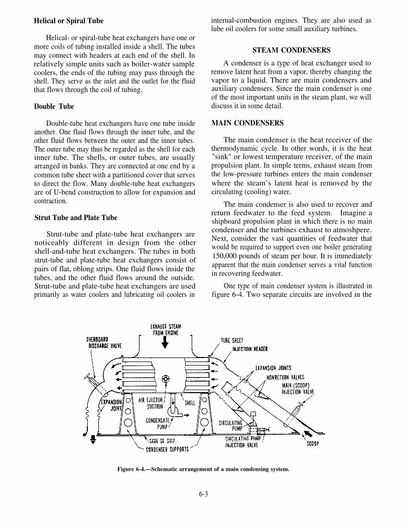
Helical or Spiral Tube internal-combustion engines. They are also used aslube oil coolers for some small auxiliary turbines.
Helical- or spiral-tube heat exchangers have one ormore coils of tubing installed inside a shell. The tubesmay connect with headers at each end of the shell. Inrelatively simple units such as boiler-water samplecoolers, the ends of the tubing may pass through theshell. They serve as the inlet and the outlet for the fluidthat flows through the coil of tubing.
Double Tube
Double-tube heat exchangers have one tube insideanother. One fluid flows through the inner tube, and theother fluid flows between the outer and the inner tubes.The outer tube may thus be regarded as the shell for eachinner tube. The shells, or outer tubes, are usuallyarranged in banks. They are connected at one end by acommon tube sheet with a partitioned cover that servesto direct the flow. Many double-tube heat exchangersare of U-bend construction to allow for expansion andcontraction.
Strut Tube and Plate Tube
Strut-tube and plate-tube heat exchangers arenoticeably different in design from the othershell-and-tube heat exchangers. The tubes in bothstrut-tube and plate-tube heat exchangers consist ofpairs of flat, oblong strips. One fluid flows inside thetubes, and the other fluid flows around the outside.Strut-tube and plate-tube heat exchangers are usedprimarily as water coolers and lubricating oil coolers in
STEAM CONDENSERS
A condenser is a type of heat exchanger used toremove latent heat from a vapor, thereby changing thevapor to a liquid. There are main condensers andauxiliary condensers. Since the main condenser is oneof the most important units in the steam plant, we willdiscuss it in some detail.
MAIN CONDENSERS
The main condenser is the heat receiver of thethermodynamic cycle. In other words, it is the heat"sink" or lowest temperature receiver, of the mainpropulsion plant. In simple terms, exhaust steam fromthe low-pressure turbines enters the main condenserwhere the steam’s latent heat is removed by thecirculating (cooling) water.
The main condenser is also used to recover andreturn feedwater to the feed system. Imagine ashipboard propulsion plant in which there is no maincondenser and the turbines exhaust to atmoshpere.Next, consider the vast quantities of feedwater thatwould be required to support even one boiler generating150,000 pounds of steam per hour. It is immediatelyapparent that the main condenser serves a vital functionin recovering feedwater.
One type of main condenser system is illustrated infigure 6-4. Two separate circuits are involved in the
Figure 6-4.—Schematic arrangement of a main condensing system.
6-3

Fig
ure
6-5.
—C
utaw
ay v
iew
of
a m
ain
cond
ense
r.

condensation of steam in a condenser of this type. Theyare vapor-condensate and cooling-water circuits.
Vapor-Condensate Circuit
The first circuit is the vapor-condensate circuit.Exhaust steam from the propulsion turbines iscondensed as it comes in contact with tubes throughwhich seawater is flowing. The condensate then fallsto the bottom of the condenser, drains into a space calledHOTWELL (seen in fig. 6-5), and is removed by thecondensate pump. Air and other noncondensatablegases, which enter with the exhaust steam, are drawnoff by the air ejector (discussed later in this chapter).
Cooling-Water Circuit
The second circuit in the condenser is thecooling-water circuit. During normal operation,seawater flow through the condenser is providedautomatically by the INJECTION SCOOP. The scoopis located below the waterline. The forward motion ofthe ship (at a sufficient speed) causes seawater to flowthrough the condenser. A major advantage of scoopinjection is that it provides a flow of cooling water at arate that is controlled by the speed of the ship and,therefore, is automatically correct for variousconditions. Scoop injection is standard for navalcombatant ships, except submarines, and for many ofthe auxiliary ships. STRAINER BARS are installed inthe sea chest to strain out debris which could foul thepiping and the condenser tubes. The injection andoverboard discharge lines are provided with expansionjoints. These prevent undue strains which could resultfrom a change in either the temperature or the workingof the hull.
Circulating Pump
A main circulating pump provides a flow of waterthrough the condenser at times when scoop injection isinadequate. Examples are when a ship is stopped,backing down, or moving ahead at a very slow speed.A large SWING-CHECK VALVE or NONRETURNVALVE in the main injection line prevents backflow ofwater. Another one is installed in the main circulatingpump discharge line. Water flows into the condenserthrough the main injection line. The nonreturn valve inthe main circulating pump discharge line prevents thebackflow of water through the pump. When thecirculating pump is in operation, the nonreturn valve inthe main injection line prevents backflow of waterthrough that line.
In all cases, the main circulating pump must have alarge capacity. The pump is usually of the propellertype. It is provided with a bilge suction line so that itcan be used to pump water overboard in case of seriousflooding in the engine room.
Construction
Proper maintenance of a condenser requires certaininstallation and construction features that you shouldunderstand. Most installations suspend the condenserfrom the turbine rather than have the condenser supportthe turbine. This provision allows for greatly reducedweight and makes an expansion joint between theturbine and the condenser unnecessary.
All main condensers that have scoop injection areof the straight-tube, single-pass type. They are usuallyof the general construction shown in figure 6-5.
A main condenser may contain from 2,000 to10,000 copper-nickel alloy tubes, usually of 5/8-inchdiameter. The length of the tubes and the number oftubes depend on the size of the condenser. This, in turn,depends on the capacity requirements. The tube endsare usually expanded into the tube sheet at the inlet endand are flared after expansion. The outlet tube ends areeither expanded or packed and ferruled into the tubesheet. Condensers having tubes ferruled into each tubesheet are found in some older ships.
The tube sheet serves as a divider between thesaltwater side and the freshwater side of the condenser.Access to the tube sheets is through manholes found ineach header.
Various methods of construction are used to allowfor expansion and construction. It is sometimes enoughto pack the tubes at the outlet end, which allows thetubes to slide within the tube sheet. The shell may havean expansion joint where the tubes are expanded intoeach tube sheet. In some condensers, the tubes arebowed upward in the middle. This allows for expansionand contraction and also provides a means of drainingthe tubes. Expansion joints are also provided in thescoop injection and overboard lines, as shown in figure6-4. In other installations, additional means areprovided to allow for expansion and contractionbetween the condenser and its supporting structure.Examples are a flexible support foot or sliding feet.
6-5

As the steam is condensed on the tubes, thecondensate drips down and collects on the receivingtray. There is a section in the main condenser where notubes are installed. It is called the central steam lane.This allows some of the turbine exhaust to get to thereceiving tray and reheat the condensate. Thecondensate drains from the receiving tray into thehotwell where it is removed by the condensate pump.
Main condensers have internal baffle arrangementsto separate air and steam. This is done so that the airejector will not become overloaded by having to pumplarge quantities of steam. One arrangement thatprovides separate air-cooling sections is shown infigure 6-6. The air baffles are extended up the side ofthe condenser shell.
For further information on condenser construction,refer to the manufacturer’s technical manual and theNaval Ships’ Technical Manual (NSTM), chapter 254.
Operation
Under conditions of warming up, standing by,getting underway, cooling down, and securing the mainengines, the condenser vacuum should be regulatedaccording to the engineering operational procedures(EOP).
You should keep in mind two basic rules that applyto the operation of single-pass main condensers: (1)The overboard temperature should be approximately10°F higher than the injection temperature. (This mayvary depending on the ship.) (2) The condensatetemperature leaving the hotwell should be within 2°Fof the condensing temperature corresponding to thevacuum in the condenser. If this temperature isexceeded, you have excessive condensate depression.This means that you are removing unnecessary heat thatmust be put back somewhere in the system. Excessive
Figure 6-6.—Cross-sectional view of the internals of a main condenser.
6-6

condensate depression will normally occur only whenthe ship is operating in cold water.
NOTE: The accompanying chart lists vacuums(based on a 20.00-inch barometer) and corresponding(steam) condensing temperatures.
Condenser Vacuum(Inches of mercury)
29.6
29.4
29.2
29.0
28.8
28.6
28.4
28.2
28.0
27.8
27.6
26.5
Corresponding SaturationTemperature
(°F) (°C)
53 11.7
64 17.8
72 22.2
79 26.1
85 29.3
90 32.2
94 34.4
98 36.6
101 38.3
104 40.0
107 41.7
120 48.9
If the condenser vacuum is not as high as it shouldbe in relation to the condenser load and the coolingwater overboard temperature, some part of thecondensing system is not functioning properly. Airejectors may not be properly removing air from thecondenser. The condensate pump may not be keepingthe correct condensate level. There may be an air leakin the condenser or in some other part of the systemunder vacuum.
The condensate should be kept at the correct level Condensers into which turbogenerators exhaustat all times. Condensate should not rise into the are known as auxiliary condensers. Although muchcondenser shell. If you allow the level to rise slightly smaller than main condensers, auxiliary condensershigher than the top of the hotwell, the condensate operate on the same principle. In an auxiliarytemperature will be lower than normal. This happens condenser, however, the cooling water is pumpedbecause the path for the flow of reheating steam is through the condenser at all times instead of beingpartially blocked by the condensate. Reheating steam scoop injected. Also, most auxiliary condensers areis the steam that enters the hotwell by way of the central of two-pass rather than single-pass construction.
steam lane. If the condensate level is allowed to rise tothe bottom row of tubes, the flow of reheating steam isfurther restricted. This means an even greater drop incondensate temperature. At this point, the highcondensate level begins to interfere with the flow of airtoward the air removal areas. This causes a gradual lossof vacuum. If the condensate level rises to the lowerend of the air baffles, it will cause a rapid loss ofvacuum. This loss will be accompanied by a rapidincrease in condenser shell and exhaust trunktemperatures.
You must maintain an adequate flow of coolingwater to the main condenser during operation.Insufficient cooling water will cause overheating, lossof vacuum, and a pressure buildup in the freshwater sideof the main condenser.
Steam or air connections are provided to clearforeign matter from sea chests. Sometimes, however,thick accumulations of marine growth on or around seavalve openings cannot be blown clear. When maximumpressure fails to clear a sea chest, the obstruction mustbe removed by a diver.
Air vents must be kept open under all operatingconditions where air is vented overboard through thehull or where the inlet water chest is vented to thedischarge water chest or piping. This will minimize airerosion of the tubes and keep the condenser frombecoming air bound. Vents that are piped to the bilgesshould be kept slightly open at all times when thecondenser is in use. As long as a trickle of waterescapes, the unit will not become air bound and thecirculating water flow will not be obstructed.
AUXILIARY CONDENSERS
6-7

Figure 6-7 shows a two-pass auxiliary condenser. Theseawater chest is divided into an inlet chamber and adischarge chamber. In other construction features,including the metals used, auxiliary condensers similarto main condensers.
Auxiliary exhaust steam, in excess of that requiredfor units such as the DFT and the distilling plants, maybe directed either to the auxiliary condenser or to themain condenser. When the ship is in port, the auxiliaryexhaust goes only to the auxiliary condenser. When theship is getting underway, the exhaust goes to theauxiliary condenser until the vacuum in the maincondenser is high enough to accept it.
Plant efficiency depends a great deal on the properoperation of the condenser. You should always use yourEOP when you light off, operate, or secure a condenser.
MAINTENANCE OF STEAMCONDENSERS‘
Proper maintenance of condensers is necessary toensure continuous ship operation and equipmentlongevity. PMS should be conducted according to the3-M systems, as described in the following sections.
Air Leaks
The desired condenser vacuum cannot bemaintained if the condenser leaks. Leaks at flangejoints and through porous castings can usually bestopped temporarily with an application of shellac whenthe condenser is under vacuum. Leaks around valvestems can sometimes be eliminated by tightening thepacking. Small leaks around porous castings, flangenuts, and valve stems can sometimes be located by thecandle test. Hold a lighted candle close to areas whereleaks are suspected and see whether the flame flickers.
Figure 6-7.—Auxiliary condenser (turbogenerator).
6-8
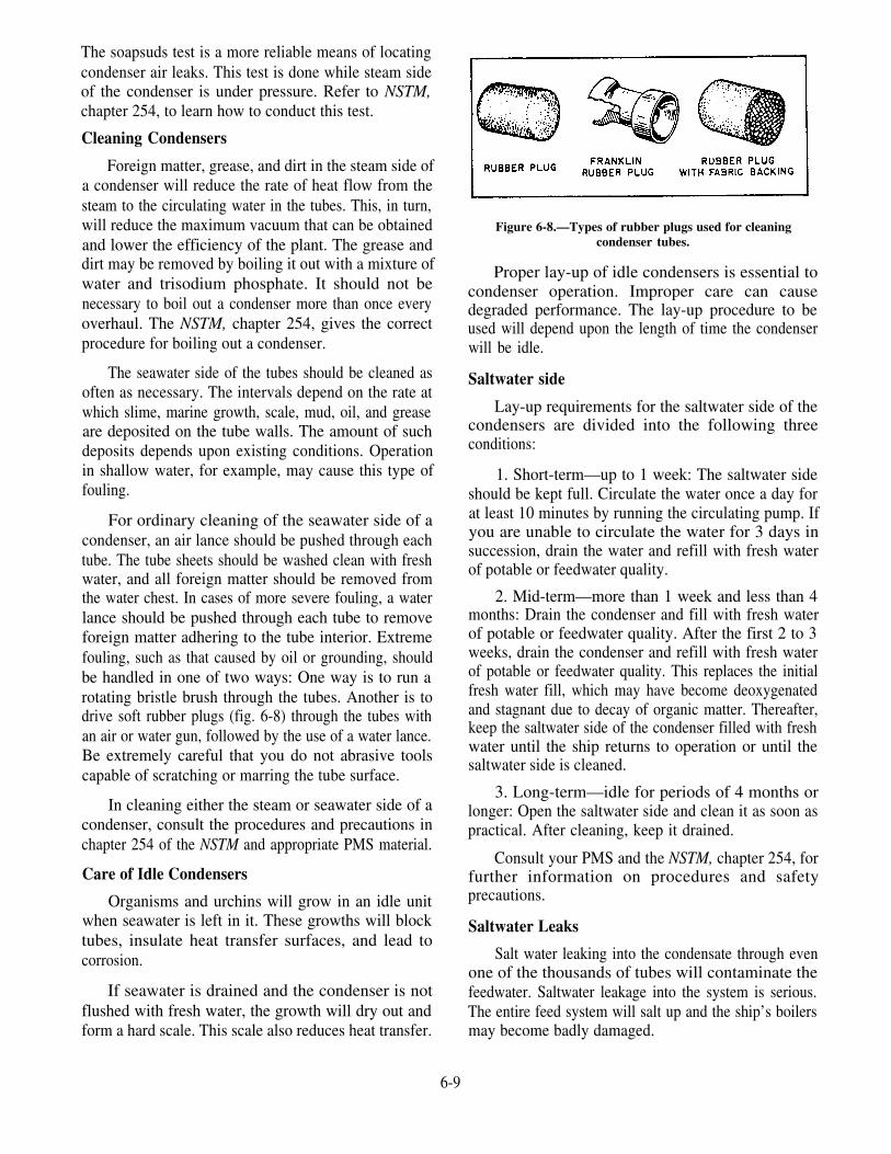
The soapsuds test is a more reliable means of locatingcondenser air leaks. This test is done while steam sideof the condenser is under pressure. Refer to NSTM,chapter 254, to learn how to conduct this test.
Cleaning Condensers
Foreign matter, grease, and dirt in the steam side ofa condenser will reduce the rate of heat flow from thesteam to the circulating water in the tubes. This, in turn,will reduce the maximum vacuum that can be obtainedand lower the efficiency of the plant. The grease anddirt may be removed by boiling it out with a mixture ofwater and trisodium phosphate. It should not benecessary to boil out a condenser more than once everyoverhaul. The NSTM, chapter 254, gives the correctprocedure for boiling out a condenser.
The seawater side of the tubes should be cleaned asoften as necessary. The intervals depend on the rate atwhich slime, marine growth, scale, mud, oil, and greaseare deposited on the tube walls. The amount of suchdeposits depends upon existing conditions. Operationin shallow water, for example, may cause this type offouling.
For ordinary cleaning of the seawater side of acondenser, an air lance should be pushed through eachtube. The tube sheets should be washed clean with freshwater, and all foreign matter should be removed fromthe water chest. In cases of more severe fouling, a waterlance should be pushed through each tube to removeforeign matter adhering to the tube interior. Extremefouling, such as that caused by oil or grounding, shouldbe handled in one of two ways: One way is to run arotating bristle brush through the tubes. Another is todrive soft rubber plugs (fig. 6-8) through the tubes withan air or water gun, followed by the use of a water lance.Be extremely careful that you do not abrasive toolscapable of scratching or marring the tube surface.
In cleaning either the steam or seawater side of acondenser, consult the procedures and precautions inchapter 254 of the NSTM and appropriate PMS material.
Care of Idle Condensers
Organisms and urchins will grow in an idle unitwhen seawater is left in it. These growths will blocktubes, insulate heat transfer surfaces, and lead tocorrosion.
If seawater is drained and the condenser is notflushed with fresh water, the growth will dry out andform a hard scale. This scale also reduces heat transfer.
Figure 6-8.—Types of rubber plugs used for cleaningcondenser tubes.
Proper lay-up of idle condensers is essential tocondenser operation. Improper care can causedegraded performance. The lay-up procedure to beused will depend upon the length of time the condenserwill be idle.
Saltwater side
Lay-up requirements for the saltwater side of thecondensers are divided into the following threeconditions:
1. Short-term—up to 1 week: The saltwater sideshould be kept full. Circulate the water once a day forat least 10 minutes by running the circulating pump. Ifyou are unable to circulate the water for 3 days insuccession, drain the water and refill with fresh waterof potable or feedwater quality.
2. Mid-term—more than 1 week and less than 4months: Drain the condenser and fill with fresh waterof potable or feedwater quality. After the first 2 to 3weeks, drain the condenser and refill with fresh waterof potable or feedwater quality. This replaces the initialfresh water fill, which may have become deoxygenatedand stagnant due to decay of organic matter. Thereafter,keep the saltwater side of the condenser filled with freshwater until the ship returns to operation or until thesaltwater side is cleaned.
3. Long-term—idle for periods of 4 months orlonger: Open the saltwater side and clean it as soon aspractical. After cleaning, keep it drained.
Consult your PMS and the NSTM, chapter 254, forfurther information on procedures and safetyprecautions.
Saltwater Leaks
Salt water leaking into the condensate through evenone of the thousands of tubes will contaminate thefeedwater. Saltwater leakage into the system is serious.The entire feed system will salt up and the ship’s boilersmay become badly damaged.
6-9

You may learn of a leak by watching the salinityindicator (described in chapter 9 of this manual). Theindicator is usually located at a position convenient tothe main control station in the engine room. It must bekept in operative condition at all times. Salinity cellsmust be checked frequently. When the salinity readinggoes above normal, determine the cause as soon aspossible.
Saltwater leakage cannot always be detected by theconductivity type of salinity indicators installed in thecondensate system. This is because of the largequantity of condensate that generally flows. The firstindications of saltwater leakage in the active tube lengthbetween the tube sheets may be a chloride buildup inthe boiler.
Make a careful investigation to make sure thesource of chloride contamination is not in the pipingconnected to the condenser rather than in the condensertubes. Pay special attention to those sections of thecondensate, drain, or makeup tied piping, which arenormally under vacuum and located in the bidge area.Experience shows bilge water may leak into joints ofthis piping and not be detected until after considerabletime and effort have been used to search for a tube leak.Any of these pipes and joints located in the bilge areashould be uncovered by lowering the level of water inthe bilges. All joints should be inspected while thecondenser and the piping are filled with fresh waterunder pressure. This should be done when using one ofthe leakage detection methods described in chapter 254(9460) of the NSTM.
CONDENSER SAFETY PRECAUTIONS
The following safety precautions apply to all con-densers in the engineering plant and must be followed:
1.
2.
3.
4.
Always be on the alert to detect and eliminateair leaks in the vacuum system.
If a large air leak occurs, the condenser vacuumwill be immediately reduced by a largeamount. Take corrective measuresimmediately.
If, at any time, a loss of vacuum isaccompanied by a hot or flooded condenser,slow down or stop the unit, exhausting into ituntil the condensing unit is again put intoproper working order. Examine and lift byhand the condenser shell relief valves beforeyou test a condenser or put it into operation.
Do NOT subject condenser saltwater chests ofsurface ships to a pressure in excess of 15 psig.
5.
6.
7.
8.
9.
10.
11.
12.
13.
14.
15.
Examine and lift by hand the saltwater chestrelief valves whenever you secure condensers.
Keep the condensate level in condensers at thecorrect lever under all operating conditions.Make sure condensate does not collect incondensers and overflow into turbines orengines. Keep the steam side of idlecondensers drained and dry.
Make sure sufficient circulating water flow iscontinuously provided when a condenser is inoperation.
Keep the saltwater side of operatingcondensers free of air.
Do not make any permanent connectionbetween any condenser and a water supplysystem that could subject the seawater side toa pressure of more than 15 psig.
Make every effort to ensure that salt water isNOT fed into the feed system. Electrically testthe condensate from main condenser every 15minutes underway and every 30 minutes whilestanding by. Test auxiliary condenser con-densate every 30 minutes. Keep the salinityindicator systems in continuous operationwhen there is flow in the condensate system.
Keep idle condensers dry and clean wheneverpractical, especially in polluted waters.
Close valves admitting steam to an idlecondenser.
Follow the tag-out procedures described inOPNAVINST 3120.32, make sure all seaopenings are tightly shut, tagged, and wiredagainst accidental opening.
Before entering a freshly opened condenser, besure the gas free engineer has tested it.
NEVER bring an open flame or anything thatwill cause a spark close to a freshly openedsaltwater side of a condenser until it has beenthorougly blown out with steam or air.Hydrogen and/or methane (sewer) gases maybe present.
These and other safety precautions are contained inchapter 254 (9460) of the NSTM.
OTHER HEAT EXCHANGERS
Some of the variety of heat exchangers aboard shipare discussed in this manual in relation to the systems
6-10

of which they are a part. Information on some of theother shipboard heat exchangers is given in thefollowing sections.
DEAERATING FEED TANK
The DFT is a direct-contact heat exchanger. Itserves three purposes: (1) It frees the condensate ofoxygen and noncondensate gases, (2) it heats thefeedwater, and (3) it stores the feedwater.
The feedwater is heated by direct contact withauxiliary exhaust. The DFT operates at approximately15 psig and 250°F. In the FF-1052 and FF-1078 class
ships, the DFT is not located high enough to givesufficient static head for the booster pump suction.Therefore, the booster pump will cavitate. To preventcavitation, a feedwater cooler is installed between thefeedwater outlet and the booster pump suction. Thecondensate passes through the feedwater cooler beforeentering the DFT. This preheats the condensate andcools the feedwater so that it does not flash to steam asit enters the booster pump suction.
One type of DFT is shown in figure 6-9. Thecondensate enters the DFT through an inlet pipe andflows into the spray manifold. The spray manifold
Figure 6-9.—Deaerating feed tank.
6-11

contains a number of spring-loaded poppet-type sprayvalves. These valves form the flow stream first intoconical sheets, then into jet streams, and finally into fineparticles directly in contact with steam. Thus, thecondensate is heated to approximately the steamtemperature. The efficient heating and counterflowpatterns of the steam and water in the spray chamberrelease all but a small amount of oxygen and otherdissolved gases. The water spray surface is partiallyenclosed by baffles to maintain this strict counterflowrelationship and to provide a zone for cooling thereleased gases before they are ventilated from the tank.
The spray is directed into the water collection cone.The water in the cone drains by gravity through adowntake pipe to the deaerating compartment. Fromthere it is drawn up into the steam scrubbing and mixingpassage by the adductor action of steam leaving andsteam passage. This high-velocity steam and water
mixture is jetted from the water passage through thebaffle space and strikes on the conical impingementbaffle. The baffle deflects the flow of water downwardinto the storage section of the DFT. The water is nowdeaerated, heated, and ready to be pumped to the boiler.
The steam from the auxiliary exhaust line, to enterthe initial heating chamber, must break through thebaffle section. The steam carries with it any gasesreleased from the water by its jet action; this preventsgas accumulation above the deaerated water in thestorage compartment. After starting its upward travel,the steam and released gases break through the waterfilm into the spray chamber. There they come in directcontact with cold water entering the spray chamber.The spray chamber is where the initial heating anddeaeration take place.
The major portion of the steam entering the spraychamber is condensed. the uncondensed steam andgases released from the water pass along the spray watersurfaces within the confines of the flow restrictivesurfaces. The steam and gas mixture passes through aseries of holes in the flow restrictive surfaces and isdirected into the water spray. Here further condensationof the steam and cooling of the released gases takesplace. The gas passes to the collection chamber wherethe released gases and a trace of uncondensed steam isvented out of the DFT.
A strainer is located in the bottom of the tank toprevent any foreign matter from entering the feedbooster pump suction.
Operation
During normal operation of the DFT, the onlycontrol necessary is to maintain the proper water level.If the water level is too high, the tank cannot properlyremove the air from the feedwater. A low water levelmay endanger the main feed booster pumps, the mainfeed pumps, and the boilers.
A common method of DFT level control is the useof automatic makeup feed and excess feed valves.When the tank level drops to a specified point, thelevel-sensing system will transmit an air signal to themakeup feed valve. The valve will then open and allowvacuum drag to draw water into the associatedcondenser from the reserve feedwater tank on service.As the DFT level increases, the makeup feed valve willshut. If the level continues to rise, the level-sensingsystem will cause the excess feed valve to open. Thiswill dump condensate into the on-service reserve feedtank.
The DFT removes gases from the feedwater byusing the principle that the solubility of gases infeedwater approaches zero when the water temperatureapproaches the boiling point. During operation, wateris sprayed so that it comes in contact and mixes with thesteam from the auxiliary exhaust line. The quantity ofsteam must always be proportional to the quantity ofwater. If not, the result will be faulty operation or acasualty.
In most DFTs, a manhole provides access forinspection of spray nozzles; other tanks are so designedthat the spray nozzle chamber and the vent condenser(if installed) must be removed for inspection of thenozzle.
Auxiliary exhaust steam flows directly into thedeaerating unit. A check valve is located either in thedeaerating tank or in the line leading to the tank. Thisvalve allows the steam to flow from the auxiliaryexhaust line whenever the pressure inside the deaeratingtank is less than the pressure in the exhaust line. Thecheck vavle also prevents the return flow of water intothe auxiliary exhaust line, in the event that thedeaerating tank becomes flooded. Specific proceduresfor lining up, warming up, and securing the DFT arecontained in the EOP.
GLAND EXHAUST CONDENSER
Condensate from the steam expelled by the turbineglands and DFT is recovered by a gland exhaustcondenser. This condenser is normally located in the
6-12

same shell as the aftercondenser of the air ejector(discussed later in this chapter). However, in somecases it may be a separate condenser. The steamcondensed in the gland exhaust condenser drains to thefreshwater drain collecting tank. The air andnoncondensable gases are drawn out by a glandexhauster, a small motor-driven fan. The glandexhauster will normally discharge to a main exhaustvent in the engine room or fireroom.
The lube oil cooler consists of a cylindrical shellwith a header at each end. Inside the shell is a bundleof straight, copper-nickel tubes through which thecooling water flows from one header to the other. Hotlube oil enters at the top of the shell, at the end oppositethe water outlet, and flows across the tubes and aroundthe annular jacket. The cooled oil comes out of the topof the cooler at the other end, near the water inlet. Thebaffles and tube support plates direct the oil flow.
TURBOGENERATOR LUBE OIL COOLERSMAIN LUBE OIL COOLERS
Main lube oil coolers are usually of theshell-and-tube type and may be of single-pass ormultipass construction. Figure 6-10 is an example of acounterflow heat exchanger. Notice that the flow of oiland cooling water is in opposite directions. The size ofan oil cooler depends on the quantity of heat that mustbe removed per unit of time from the lube oil to maintainproper bearing temperature.
Turbogenerator lube oil coolers are similar to mainlube oil coolers in construction, but much smaller insize. A three-way selector valve is placed in the oil lineto route oil through the cooler or to bypass oil aroundthe cooler. Each turbogenerator is served by a singlelube oil cooler.
Salt water is pumped through the turbogeneratorlube oil cooler by the auxiliary condenser circulatingpump. If this pump should fail, cooling water may be
Figure 6-10.—Main lube oil cooler.
6-13
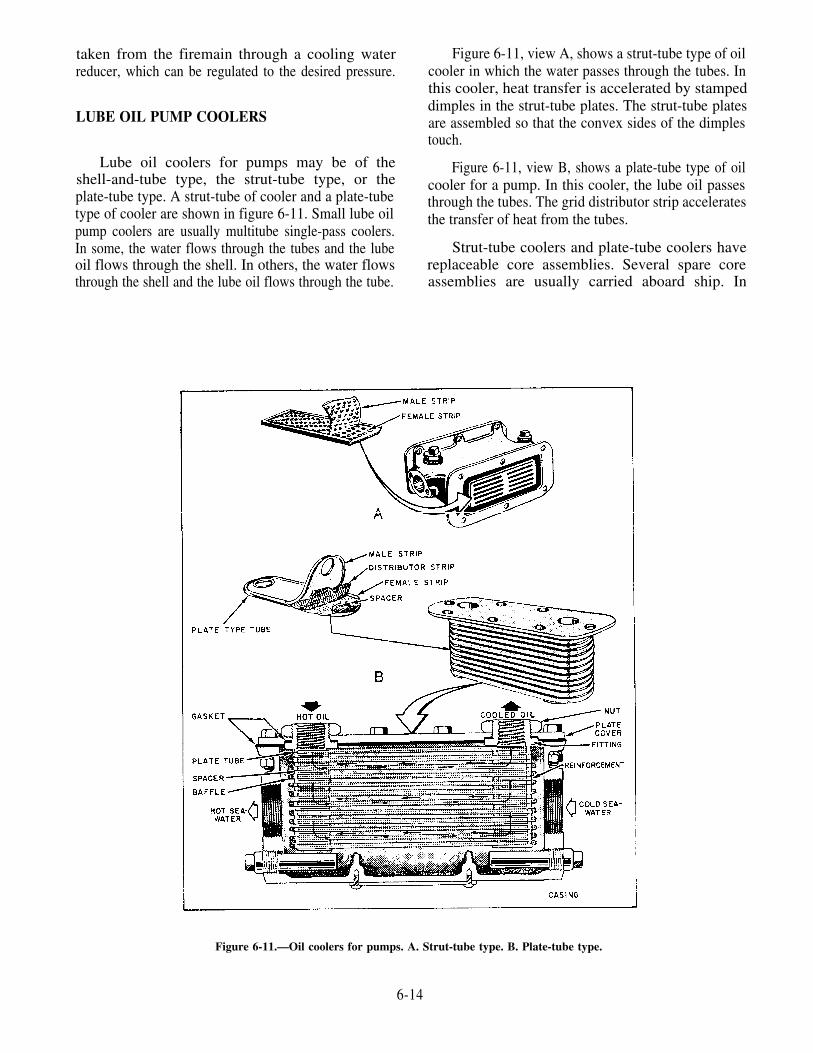
taken from the firemain through a cooling waterreducer, which can be regulated to the desired pressure.
LUBE OIL PUMP COOLERS
Lube oil coolers for pumps may be of theshell-and-tube type, the strut-tube type, or theplate-tube type. A strut-tube of cooler and a plate-tubetype of cooler are shown in figure 6-11. Small lube oilpump coolers are usually multitube single-pass coolers.In some, the water flows through the tubes and the lubeoil flows through the shell. In others, the water flowsthrough the shell and the lube oil flows through the tube.
Figure 6-11, view A, shows a strut-tube type of oilcooler in which the water passes through the tubes. Inthis cooler, heat transfer is accelerated by stampeddimples in the strut-tube plates. The strut-tube platesare assembled so that the convex sides of the dimplestouch.
Figure 6-11, view B, shows a plate-tube type of oilcooler for a pump. In this cooler, the lube oil passesthrough the tubes. The grid distributor strip acceleratesthe transfer of heat from the tubes.
Strut-tube coolers and plate-tube coolers havereplaceable core assemblies. Several spare coreassemblies are usually carried aboard ship. In
Figure 6-11.—Oil coolers for pumps. A. Strut-tube type. B. Plate-tube type.
6-14

practically all cases of failure, core replacement is allthat is required to correct the trouble. It is seldomnecessary to replace the entire cooler.
AIR COOLERS
Air coolers are installed on shipboard propulsionmotors and generators to keep them from overheating.The air cooler is connected to the air intake and airdischarge openings of the motor or generator by suitableducts. The only characteristic difference between alube oil cooler and a propulsion motor or generator aircooler is that the latter is of double-tube construction,with the outer tubes having high fins.
The air cooler consists of double-wall fin tubesthrough which the cooling water flows. The ends of thetubes at the front and rear of the cooler are enclosed byheaders. Cooling water may make one or more passesthrough the cooler. Hot air from the motor or generatorpasses through the air cooler tube bank in a pathperpendicular (crossflow) to the tubes (fig. 6-12).
The tubes are of double-wall construction. Theinner tube is of a copper-nickel alloy, and the outer tubeis of brass or other nonferrous material. Thesmooth-surfaced inner tube carries the water. The outertube has internal longitudinal ribs or lands that makecontact with the outer surface of the inner tube. Theinternal ribs of the outer tube and the cooling fins
Figure 6-12.—Air cooler for a motor generator.
6-15

mounted on the outside surface of the outer tubefacilitate the transfer of heat to the cooling water.
The failure of an inner tube can be detected by waterleakage from the telltale drains in the front and rearheaders.
A connection for draining water from the cooler islocated at the bottom of the front header, and to the rightof the leakage drain plug. A vent plug is located at thetop of the front and rear header. These air relief plugsshould be removed whenever the cooler, after havingbeen drained of water, is to be refilled. The plugs shouldbe removed from the telltale drain system to allowdetection of leaks from the tube section of the cooler.
AIR EJECTORS
The air ejector removes air and noncondensablegases from the condenser. The Navy uses various typesof air ejectors. All of them remove air from thecondenser in basically the same way. Some ships use avacuum pump to remove air from the condenser.However, the air ejector is the most common means ofremoving air and noncondensable gases from thecondenser. The most commonly used air ejector will bediscussed in the following section.
In this section we will often say that the air ejector“take a suction.” Actually, it creates a low pressure areainto which the air and noncondensable gases canexhaust. Vacuum does not suck anything. The flow ofa substance from a higher pressure area to a lowerpressure area gives you the impression that the lowpressure area (vacuum) is sucking the substance. Forexample, when you open the make-up feed valve, thevacuum in the main condenser (lower pressure area)does not suck the water in.
Instead, the water flows from the reserve feedbottom (higher pressure area) to the main condenser.However, for the sake of familiarity, we will continueto use the word suction.
An air ejector is a jet pump. Figure 6-13 shows theflow of the steam, air, and noncondensable gases in onetype of air ejector unit. Keep in mind that this is only aflow diagram and does not resemble an actual air ejectorunit. In most cases all of the components of the unit arecontained in one shell (fig. 6-14).
The shell is rectangular and is divided by alongitudinal plate into the intercondenser andaftercondenser sections. In many ships, the glandexhaust condenser is incorporated within the shell of theaftercondenser.
Figure 6-13.—Flow diagram of a two-stage air ejector.
6-16

Figure 6-14.—A main air ejector and condenser assembly.
To provide continuous operation, two sets ofnozzles and diffusers are furnished for each stage of theair ejectors. Only one set is necessary for the plant tooperate. The other set is maintained ready for use incase of damage or unsatisfactory operation of the set inuse. The two sets can be used simultaneously whenexcessive air leakage into the condenser calls foradditional pumping capacity.
PRINCIPLES OF OPERATION
The first-stage air ejector nozzle takes a suction onthe main condenser and discharges it to theintercondenser. The steam is condensed and drainsthrough a U-shaped line (the loop seal line) to the maincondenser. The air and noncondensable gases pass onto the suction of the second stage. The second-stagenozzle takes a suction on the intercondenser anddischarges to the aftercondenser. The steam from thesecond-stage nozzle is condensed in the aftercondenserand drains to a freshwater drain collecting system. The
air and noncondensable gases are vented to theatmosphere normally by way of the gland exhauster fan.
Condensate from the main condenser is used as thecooling water in the air ejector intercondenser andaftercondenser. The air ejectors remove air only fromthe condenser, not from the condensate.
The intercondenser is under a vacuum ofapproximately 26 inches of mercury. Theaftercondenser is at approximate atmospheric pressure.
Sufficient cooling water for proper operation of theair ejectors is necessary when raising vacuum, whilestanding by, and at fractional power (cruising); this isdone by a condensate recirculating line and valveinstalled either at the cooling water outlet from theaftercondenser or on the vent condenser inlet header.Most air ejector recirculating lines are fitted withthermostatically controlled valves, discussed in chapter10 of this manual. These make recirculation automaticand prevent overheating of the air ejector condenser.
6-17

A manually controlled valve allows bypassing ofthe thermostatic recirculating valve during thewarming-up period. This bypass valve is also used incase the thermostatic valve is inoperative. When therequired condenser vacuum is obtained, the manuallycontrolled bypass valve is secured. Under normaloperating conditions, recirculation to the maincondenser at light loads is automatically controlled bythe thermostatic recirculating valve.
As previously noted, the condensate formed in theintercondenser is returned to the main condenserthrough the loop seal. If there were a direct connectionbetween the intercondenser and the main condenser, thevacuum would be equalized in the two condensers.Since the main condenser carries a higher vacuum thanthe intercondenser, some form of seal must bemaintained in this drain line to prevent this equaliationof vacuum. A water level in the U-shaped loop seal lineprovides this seal.
Refer to the operating procedures for lining up,starting, shifting, and securing air ejectors for the mainand auxiliary condensers. You can find them in the EOPsubsystem of the EOSS.
CARE AND MAINTENANCE OF AIREJECTORS
If an air ejector fails to maintain the proper vacuum,the problem may be traced to one of the followingcauses:
1. Faulty steam pressure
2. Clogged steam strainer
3. Insufficient cooling water
4. Air leaks
5. Fouled nozzles
6. Unstable loop seal
AIR EJECTOR SAFETY PRECAUTIONS
The following safety precautions should be usedwith air ejectors:
1.
2.
When starting an air ejector, always open thedischarge valves before admitting steam to thenozzles. When securing an air ejector, alwaysclose tightly the steam supply valves to thenozzles before closing the discharge valves.
Before starting an air ejector, always drain thesteam supply line, and open the drain valves in
the intercondenser and aftercondenser drainlines.
3. Should retubing or any other major repairs to anair ejector assembly be necessary,hydrostatically test all parts followingreassembly.
CONDENSATE SYSTEM
The condensate system starts in the condenser andends after the water is deaerated in the DFT. The steamcondensed in the condenser, the freshwater drains, andmakeup feed are all pumped through the condensatesystem to the DFT.
The objective is to deliver the cleanest, purest waterpossible to the boiler. Three pieces of equipment do it:(1) The DFT takes the air out of the water; (2) themorpholine injection system treats the condensatesystem; (3) the demineralization unit treats the makeupfeed. (NOTE: All ships do not have the morpholinesystem and the demineralization unit.) We discussedthe DFT in the previous section. The following sectionsdiscuss the morpholine injection system and thedemineralization unit.
MORPHOLINE INJECTION SYSTEM
Morpholine is a water treatment chemical thatraises the pH of the water. When water has a low pH,it is acidic and causes corrosion of the condensate andfeedwater piping. The morpholine is injected into thefreshwater drain collecting tank (FWDCT). From thedrain tank, it goes to the condenser and is pumpedthrough the condensate system by the condensate pump.
Morpholine is hazardous to personnel andequipment if it is not handled and used properly. Followthe appropriate instructions and safety precautionswhen mixing and injecting morpholine into the system.Goggles and protective gloves are mandatory whenmixing and handling morpholine. An emergency eyewash station must be installed in the vicinity in case ofeye contact with the chemical.
DEMINERALIZATION UNIT
The markup feed demineralizer is an automaticon-line system. The process is also known asdeionization. It is an extremely useful process, since itappreciably reduceds the sludge buildup in the boilerwater.
6-18

The makeup feedwater to be treated enters the tankthrough the demineralizer inlet valve. It is distributedby the water inlet strainer and flows down through theresin bed. The resin is retained within the mixed beddemineralizer and is prevented from passing throughthe outlet connection in the bottom of the tank by theunderdrain strainer.
The mixed bed resin consists of a chemicallyequivalent mixture of a strong acidic cation and a strongbasic anion resin. The water to be treated passedthrough the resin bed. All of the metallic andnonmetallic substances are removed, and the positivelycharged hydrogen ions (H5+4) and the negativelycharged hydroxide ions (OH4-5) are substituted.These combine with the water that is taken from thebottom of the unit as the discharge effluent. Togetherthey form water of an extremely high degree or purity.The anion resin will exchange hydroxide for anions,such as sulfite, carbonate, chlorides, and nitrates. Whenwater containing calcium chloride is run through a
mixed resin, the calcium is captured by the cation resin,and a hydrogen ion is released in its place. Thehydrogen chloride then encounters the anion resin inwhich the chloride is captured, and a hydroxide ion isreleased. The hydrogen and hydroxide ions combine toform water. Similar reactions occur with otherdissolved salts.
As the resin bed uses up its exchange capacity, themakeup feed conductivity will quickly rise above 1.0micromho/cm. At this time the resin must be replaced.
NOTE: If the reserve feedwater has a consistentlyhigh suspended solids content, the filtration action mayclog the resin bed. When that happens, the resin willneed to be changed sooner than it normally would.
You can see that by using the demineralizer and themorpholine we have improved our chances of reachingour goal, which is to deliver clean, pure water to theboiler.
6-19


CHAPTER 7
ENGINEERING OPERATIONS
In this chapter we will deal primarily with theengineering operational sequencing system (EOSS),watch standing, operating notes, and casualty control.All of these are very important in proper operation ofthe engine room/fireroom.
All steam-turbine propulsion plants are basicallythe same. There are many differences in the specificdetails of operation, but it would not be practical to tryto cover them all in detail. The information in thischapter will be general and will apply to moststeam-turbine driven, multiscrew, surface ships.
ENGINEERING OPERATIONALSEQUENCING SYSTEM (EOSS)
Each new ship that joins the Navy is moretechnically advanced and complex than the one before.The main propulsion plants call for engineering skillsat ever higher levels of competence. That means moreand better training of personnel who must keep the shipscombat ready. The need for training and the problemof frequent turnover of trained personnel call for somekind of system that can be used to keep things goingsmoothly during the confusion. The EOSS wasdeveloped for that purpose.
EOSS is a set of manuals that were designed toeliminate problems because of operator error whenaligning piping systems and starting and stoppingmachinery. It involves the participation of all personnelfrom the department head to the fireman on watch.EOSS consists of a set of detailed written procedures,using charts, instructions, and diagrams. These aidswere developed for safe operation and casualty controlof a specific ship’s engineering plant and configuration.EOSS improves the operational readiness of the ship’sengineering plant by providing positive control of theplant. This, in turn, reduces operational casualties andextends machinery life.
EOSS is divided into two subsystems: (1) en-gineering operational procedures (EOP) and (2) en-gineering operational casualty control (EOCC).
ENGINEERING OPERATIONALPROCEDURES (EOP)
EOPs are prepared specifically for each level ofoperation: plant supervision (level l), spacesupervision (level 2), and component/system operator(level 3). The materials for each level or stage ofoperation contain only the information necessary at thatlevel. All materials are interrelated. They must be usedtogether to maintain the proper relationship and toensure positive control and sequencing of operationalevents within the plant. Ships that do not have EOSSshould use operating instructions and a casualty controlmanual for plant operations.
ENGINEERING OPERATIONALCASUALTY CONTROL (EOCC)
This subsystem of EOSS enables plant and spacesupervisors to RECOGNIZE the symptoms of apossible casualty. They can then CONTROL thecasualty to prevent possible damage to machinery, andRESTORE plant operation to normal. The documentsof the EOCC subsystem contain procedures andinformation that describe symptoms, causes, andactions to be taken in the most common engineeringplant casualties.
WATCH STANDING
You will spend much of your time aboard ship as awatch stander. How you stand your watch is veryimportant to the reliability of the engineering plant andthe entire ship. You must have the skills to detectunusual noises, vibrations, or odors which may indicatefaulty machinery operation. You must also takeappropriate and prompt corrective measures. You mustbe ready, in emergencies, to act quickly andindependently. You must know the ship’s piping
7-1
systems and HOW, WHERE, and WHY they arecontrolled. You must know each piece of machinery:how it is constructed, how it operates, how it fits intothe engineering plant, and where related equipment iscontrolled. You must read and interpret measuringinstruments. You must understand how and whyprotective devices function (relief valves,speed-limiting governors, overspeed trips, cut-in andcutout devices). You must recognize and remove firehazards, stow gear that is adrift, and keep deck platesclean and dry. You must NEVER try to operate a pieceof equipment that is defective. You must report allunsafe conditions to the space and/or plant supervisor.
Whatever your watch station, you must know thestatus of every piece of machinery at your station. Youmust promptly handle any necessary change in speed orsetup and record correctly all data concerning theoperation and maintenance of the machinery. You mustbe sure that the log is up-to-date and that the statusboards are correct. You must know what machinery isoperating and what the night orders and standing ordersare before you relieve the watch. Above all, if you don’tknow—ASK. A noise, odor, or condition may seemabnormal to you, but you may not be certain whether itis a problem. When that happens call your immediatewatch supervisor.
You can best gain the respect and confidence ofyour supervisors and shipmates if you stand a goodwatch. Relieve the watch on time or even a little earlyif possible to be sure you know the condition of themachinery and what you need to do. DON’T TRY TORELIEVE THE WATCH FIRST AND FIGURE OUTTHE SCORE LATER. The same applies when you arebeing relieved; don’t be in a big hurry to take off. Besure your relief understands the situation completely.Before you are relieved, make sure your station is cleanand squared away. These little considerations will getyou a good reputation and improve the overall qualityof watch standing within the department.
PREPARATION FOR GETTINGUNDERWAY
The procedures discussed in the following sectionsare basic steps of plant operation. They do not containevery step that must be taken when lighting off,operating, or combating casualties in the engineeringplant. During plant light off and operation, use yourEOSS.
Normally, the first step in lighting off a turbine unitis to check the cold rotor positions of the turbines. Logthese readings in the operating log and indicate that theyare cold readings. Next, check the main lube oil systemfor the following: proper sump level, system integrity(that is, strainers cleaned, inspected, and closed; drainsshut; valves properly lined up), and proper temperature.This check normally requires you to start a lube oilpump to establish normal system pressure. If the lubeoil is too cold, you will need to energize electricalimmersion heaters, or line up steam to the heater for thelube oil purifier and direct the flow through this heatexchanger. Check oil delivery to all turbine and gearbearings by observing flow through the bearing oilsight-flow glasses.
Check low lube oil pressure alarm, standby andemergency pump pickup set points, and alternate pumppower supplies during or before oil warmup.
Some installations require a lube oil temperature of70°F (21 °C) before the main engine is rotated with theturning gear, and 90°F (32°C) before turning withsteam. Others require a lube oil temperature of 90°F(32°C) before the engine is turned by any method.CAUTION: You must have permission from the OODbefore turning the main shaft. Divers or otherobstructions may be in the vicinity of the screw. In shipswith a main shaft clutch, the main engines may beturned with the clutch disengaged without OODpermission, in most cases.
Ensure that the main shaft bearings have sufficientoil level and the stem tube has the proper leak off.
Properly line up all turbine and associated mainsteam drains for warmup of the main engines. Engagethe turning gear and start the drive motor.
The next step is to establish a vacuum in theassoicated condenser(s). First, you must provideadequate circulating cooling water. Start the maincirculating pump or main seawater pump(s), dependingon the plant. Cut in the gland sealing steam and startthe gland exhaust fan (if provided). NOTE: Any timesteam is being supplied to the turbine (including glandsealing steam), the turbine must be rotating. Stationaryperiods of more than a few (usually 3 minutes areallowed by the manufacturer) will cause uneven heating(temperature gradients) along the length of the rotor andwill result in rotor bowing.
7-2

During the turbine warmup period, a reducedcondenser vacuum is normally maintained to providefor maximum heating of the turbine rotors.
After the turbine rotors have been turned with theturning gear motor for the specified period, the turbinesare ready to be turned with steam. First (with OOD’spermission), stop the drive motor and disengage theturning gear from the turbines. Next, admit steam to thethrottle valves and, then, spin the turbines astern andahead. Remember that only 3 minutes are normallyallowed from the time the turning gear is disengaged tothe time the turbines roll with steam. Steam passingthrough the turbine with the rotors stationary will comein contact with only a small portion of the blading andcause uneven heating. Therefore, the throttle openingshould be wide enough to cause the turbine rotors tobegin rotating quickly. The turbines are to be spunalternately astern and ahead. This facilitates evenheating of the rotor and prevents putting way on theship. Maximum shaft rpm limits may also be specifiedwhile spinning to help reduce ship movement. Someships may specify spinning ahead first, then astern, thenahead. Other ships use the reverse order. Unless theequipment technical manual is specific as to whichthrottle valve to open first, the engineer officer willdecide.
When the main engines have been tested andwarmed up, you are ready to answer all bells. Open thefirst stage of the air ejector by following the EOSS.
During standby to answer all bells, spin the mainengines every 3 to 5 minutes.
CAUTION: If for any reason the turbine rotorscannot be rotated within 5 minutes, secure the engine.
Take the "hot rotor positions" and log them in theoperating log after the turbines are warmed up. Whenunderway, realign the turbine and associated mainsteam drains.
PROCEDURES FOR STANDING BY
When you receive orders to stand by, the procedureto be followed will depend on the length of time the shipwill be in standby.
If the ship will be in standby for only a short periodof time, you may be required to (1) spin the main engineuntil the ship gets underway again, or (2) get permissionfrom the OOD and secure the guarding valve andengage the jacking gear. When standing by forextended periods of time, you may be required to secureone of the engineering plants (on a two-plant ship).
NOTE: When standing by with the jacking gearengaged, secure the first stage of the main airejector.
UNDERWAY OPERATION
Carry out underway procedures in a manner thatenables the ship to accomplish its mission with thegreatest economy possible. Economical and efficientoperation of a propulsion plant under varyingconditions and speeds calls for a high vacuum.
Importance of High Vacuum
To attain the greatest operating economy, you mustmaintain the vacuum for which the turbines weredesigned. Therefore, you should realize the necessityfor the prevention and detection of air leaks in thevacuum system.
When the steam pressure within the turbinebecomes greater than atmospheric pressure, steam tendsto leak from the turbine to the surrounding atmosphere.On the other hand, when the pressure in the turbine isless than that of the atmosphere, air tends to leak intothe turbine and impair the vacuum. To prevent airleakage into the turbine, maintain pressure on the glandsslightly greater than atmospheric pressure, generallyl/2 to 2 psi.
To ensure that you maintain optimum vacuum, takecare that the astern throttles do not leak. Any leakageof steam past a closed throttle tends to raise thetemperature and increase the pressure within theturbine. Observe the following precautions to maintainthe prescribed vacuum:
1. Keep gland packing in good condition.
2. Maintain a steam pressure between l/2 and 2 psion the glands when the engines are lit off.
3. Ensure that there are no air leaks in thecondenser, exhaust trunks, throttles, lines to air ejectors,gauge lines, idle condensate pump packing and valves,makeup feed lines and related components.
4. Maintain adequate water in the drain collectingor reserve feed tank on which the vacuum drag is beingtaken.
5. Supply adequate cooling water to the maincondenser and air ejector condenser.
7-3

Routine Underway Inspections
Make periodic inspections of the propulsion plantto keep it operating efficiently. When a ship isunderway, check the following items at short intervalsduring each watch:
1. Check all main engine and reduction gearbearing thermometers to detect signs of overheating.
2. Check oil sight-flow indicators for proper oilflow.
3. Check clearance indicators for proper rotorposition.
4. Check all thermometers, pressure gauges, andvacuum gauges for a normal reading.
5. Check the oil level in the main sump for anormal indication.
6. Keep a constant check on salinity indicators.
7. Check the lube-oil temperature from thelube-oil cooler; maintain oil temperature at 120° to130°F by throttling the cooling water as required.
8. Check the auxiliary machinery cooling waterfor proper pressure.
9. Be constantly alert for unusual sounds andvibrations.
10. Clean lube-oil strainers at prescribedintervals.
A sight-flow indicator is fitted on most units in thelube oil line of each main engine bearing and eachreduction gear bearing. When a lube-oil service pumpis in operation, each indicator should show a steady flowof lube oil. Make frequent inspections of the sight-flowindicators to detect any interruption to the flow of lubeoil.
At a specified frequency, check the rotor-positionindicator for each turbine and log the rotor position inthe operating log to determine the position of the rotorin respect to casing. Thoroughly investigate anyabnormal reading. If the axial movement of the rotor isallowed to exceed the safe limit in either direction, themoving blades will strike the stationary blades ornozzles and cause great internal damage to theturbine.
One of the first indications of trouble in any steamplant is abnormal readings on thermometers or gauges.Check all thermometers and gauges frequently to detectand prevent casualties. NEVER take for granted that an
abnormal reading is due to the fault of the gauge orthermometer.
NOTE: Many severe machinery casualties in anengineering plant can be traced directly to uncalibrated,inoperative, or missing instruments.
Check and log the oil level in the main engine sumpat least each hour. However, you should make morefrequent checks. An increase in the oil level may meanthat water is entering the lube-oil system or that thesystem is gaining oil in some improper manner. Thelube-oil transfer and purification system may be linedup improperly. A decrease in the oil level of the mainengine sump usually indicates that there is a leak in thelube-oil system or that the lube oil purifier isdischarging oil to the contaminated drain system. Anincrease or a decrease in the main sump oil level shouldNEVER be neglected. It could mean costly repairs tomain engine bearings and reduction gears.
A properly operating main engine and reductiongear installation has a definite sound which trainedpersonnel can recognize. Investigate any abnormalsound. Operate the unit with caution until you find thecause of the sound and correct the problem.
For safe efficient operation, keep the water level ina steaming deaerating feed tank (DFT) within thenormal operating range. This is controlledautomatically on most ships by an automatic excessfeed valve and makeup feed valve. During abnormal orcasualty situations, however, the operator will need tocontrol DFT level. If the water is allowed to go abovethe maximum level, the deaerating effect is lost. Largequantities of comparatively cold water admitted to theDFT will reduce the pressure in the tank. This reducesthe main feed booster pressure, which may result incasualties to the main feed pump and boiler.CAUTION: A vacuum can be created in a DFT byadmitting cold water to a hot DFT which has theauxiliary exhaust steam supply secured. This action canreduce pressure within 6 seconds to the point that DFTdeformation will result This situation can, in mostcases, be avoided by observing the followingprecautions:
1. Do not refill the DFT after plant shutdown untilshell temperature drops to ambient.
2. When carrying out propulsion plant casualtycontrol procedures, secure the condensate to the DFT.Do this before you secure the auxiliary exhaust steam,and cut in the auxiliary exhaust steam before cutting inthe condensate.
7-4

If the water level is below minimum, a suddendemand for feedwater for the boilers may empty theDFT. This will cause casualties to the boiler, the mainfeed booster pump, and the main feed pump.
Most ships have a salinity indicator meter and alarmpanel near the throttle board in each engine room. Thissystem detects the entrance of chemical contaminationinto the condensate system. Check the meter frequencybecause a small amount of salt in the condensate systemwill contaminate a steaming boiler beyond allowablelimits. Check an abnormal reading; seek and isolate thesource of contamination. You will find moreinformation about salinity indicators in chapter 9 of thismanual and in the appropriate manufacturer’s technicalmanuals.
SECURING THE PLANT
Before entering port and shutting down a plant, youneed to make certain preparations to ensure a smoothand orderly shutdown. Certain auxiliary machinery tobe used in port must be placed in standby operation,system lineups must be altered, and many other tasksmust be accomplished. These procedures are outlinedin the EOP.
A cool-down procedure is specified for the mainengines of each ship type. Normally, you must circulatemain lube oil until it cools to near-ambient (room)temperature.
Circulate seawater through the main condenseruntil the exhaust trunk temperature cools to nearambient. Rotate the main turbines with the turning gearfor a specified length of time or specified temperaturedecrease.
NEVER break vacuum in a condenser through theturbine glands by securing the gland sealing steam. Theshock of cold air flowing over the hot turbine glandsand rotor can cause damage to the glands.
Open all turbine drains and leave them open for theperiod of time specified by EOP procedures. Do not getin a big hurry to shut down. You can cause seriouscasualties when you have your hand on a valve and yourmind somewhere else. Shut down in a controlled,orderly fashion and save yourself a lot possible grieflater.
ENGINEERING CASUALTYCONTROL
The best form of casualty control is prevention. Ifyou do not let it happen, you will not have to fix it.
Preventive maintenance is one of the principalfactors of casualty control. Preventive inspections,tests, and maintenance are vital to casualty control.These actions minimize casualties caused byMATERIAL failures. Continuous detailed inspectionsare necessary to discover worn or partly damaged parts,which may fail at a critical time. These inspectionseliminate maladjustment, improper lubrication,corrosion, erosion, and other enemies which couldcause early failure of a vital piece of machinery.
The inspections, tests, and maintenance called forin the 3-M System must be conscientiously performedsince they are based on the known requirements ofpreventive maintenance.
Still, casualties do happen. When they do, thesuccess of your mission, the safety of your ship, and thelives of your shipmates may depend on your ability tohandle the situation. That means continuous trainingand frequent refresher drills to be sure you can do yourpart, and do it well.
Engineering casualty control is used to prevent,minimize, and correct the effects of operational andbattle casualties. These casualties will be onengineering space machinery, related machineryoutside of engineering spaces, and the pipinginstallations relative to the various pieces of machinery.The mission of engineering department personnel is tomaintain all engineering services in a state of maximumreliability under all conditions. If you cannot providethese services, the ship may not be able to fight.
The use of EOCC procedures was discussed at thebeginning of this chapter. These procedures areprepared and approved for your ship.
Steps involved in handling engineering casualtiescan be divided into three general phrases:
1. Immediate action to prevent further damage.
2. Supplementary action to stabilize the plantcondition.
3. Restoration action to restore equipment tooperation after a casualty. Where equipment damagehas occurred, repairs may be necessary to restoremachinery, plants, or systems to their originalcondition.
7-5

Communication of accurate information is one ofthe major problems in casualty control. Be sure youknow the names and operations of the equipment at yournormal watch station and your battle station. Be sureyou know what the casualty is before you takecorrective action. If you are reporting a casaulty to thebridge or main control, be sure that you use the correctterminology and that they understand what yourcasualty is.
The primary sources of instructions used to handleany engineering casualty and to maintain the overalldamage resistance to your ship are listed below.
1.
2.
3.
4.
5.
The engineering operation and casualty control(EOCC) procedure
The ship’s casualty control manual (for shipswithout EOCC)
The ship’s damage control manual
The ship’s damage control bills
The ship’s organization and regulation manual(SORM)
SYMPTOMS OF OPERATIONALCASUALTIES
You must always be on the alert for even the mostminor sign of faulty operation of machinery. Payparticular and continuous attention to the followingsymptoms of malfunctioning.
1. Unusual noises
2. Vibrations
3. Abnormal temperatures
4. Abnormal pressures
5. Abnormal operating speeds
6. Leakage from systems or associated equipment
You should become thoroughly familiar with thenormal operating temperatures, pressure, and speeds ofequipment specified for each condition of operation;departures from normal will then be readily apparent.NEVER assume that an abnormal reading on a gaugeor other indicating instrument is due to a problem withthe instrument. Investigate each case to learn the casueof the abnormal reading. Substitute a spare instrumentor perform a calibration test to quickly show whetheran instrument error exists. Trace abnormal readingsthat are not caused by faulty instruments to their source.Some specific advance warnings of failure are outlinedin the following paragraphs.
The safety factor commonly incorporated in pumpsand similar equipment can allow a considerable loss ofcapacity before you see any external evidence oftrouble. In pressure-governor-controlled equipment,changes in operating speeds from normal for theexisting load should be viewed with suspicion.Variations from normal in chest pressures, lubricatingoil temperatures, and system pressures indicate eitherimproper operation or poor condition of the machinery.When a material failure occurs in any unit, promptlyinspect all similar units to determine whether they aresubject to the same type of failure. Prompt inspectionmay eliminate a wave of similar casualties.
Abnormal wear, fatigue, erosion, or corrosion of apart may indicate that the equipment is not beingoperated within its designed limits of loading, velocity,and lubrication. It also may indicate a design ormaterial deficiency. If any of these symptoms haveappeared, you should routinely carry out specialinspections to detect damage unless you can take actionto ensure that such a condition will not recur.
ENGINE ROOM CASUALTIES
Even with the best-trained personnel and thebest-planned maintenance programs, casualties willoccur. In the following section we will discuss some ofthe most common casualties and the action to be taken.However, the action will be general in nature andshould not be used as standard procedure. Whencombating an engine room casualty, use your EOCC.
When a casualty occurs in a space other than maincontrol, make all reports to main control. They willkeep the bridge informed.
To keep things simple, we will assume thefollowing conditions for the casualties that we discussin this chapter.
1.
2.
3.
4.
The ship is underway under normal steamingconditions.
The ship is multiscrew.
The ship is steam turbine driven.
All casualties will occur in main engine control.
Locking and Unlocking the MainEngine Shaft
Normally the ship will have a maximum designatedsafe speed at which a shaft can be locked. If a speed isnot designated, slow the ship’s speed to not more thanone-half of full-power speed. However, if you have to
7-6

lock the shaft, you can begin your stopping and lockingprocedure while you are waiting for the unaffectedshaft(s) to slow to the proper speed.
There are five casualties that require you to stop andlock the shaft immediately. These casualties are (1) lossof lube oil pressure to the engine, (2) an uncontrollablehot bearing, (3) a metallic sound in the turbine, (4) aloud roaring noise in the reduction gears, and (5) a majorlube-oil leak.
CAUTION: If the shaft is locked for more than 5minutes, you must break vacuum and secure the glandseal. If this is not done the turbine rotor may becomebowed.
Never secure the lube oil to an engine whose shaftis locked while the ship is underway.
When stopping and locking a shaft while underway,take the following steps:
1. Notify the bridge and ring up STOP on theengine order telegraph (EOT).
2. Close the ahead throttle and open the asternthrottle, or reverse the procedure if operating astern.
3. When the shaft is stopped and holding, thethrottleman should note the astern steam pressure, andnote and record the unaffected shaft rpm.
CAUTION: The shaft must remain stationarywhile being locked.
4. When the affected shaft is stopped and theunaffected shaft is at ordered rpm, engage the jackinggear and set the brake.
5. When the shaft is locked, have everyone clearthe area of the jacking gear and slowly close the asternthrottle valve.
6. Notify the bridge that the shaft is locked, andreport the maximum speed available on the unaffectedshaft or shafts.
When unlocking the shaft use the followingprocedure:
If possible, unlock the shaft with no way on the ship.To use this method, bring the unaffected shaft(s) to astop. When the ship has stopped moving in the water,disengage the jacking gear and let the shaft trail. If theengine has been secured, restore it to service followingthe EOP.
When it is not permissible to stop the ship to unlockthe shaft, use the following steps:
1. Return the unaffected shaft(s) to the rpm thatwas in use when the affected shaft was locked.
2. Remove the lockpin from the engaging lever.
3. Apply a steady pressure toward the disengagingposition on the jacking-gear engaging lever.
4. Slowly increase astern steam pressure until thejacking gear disengages. When the jacking gear isdisengaged, slowly close the astern throttle valve.
5. Report to the bridge that the shaft is unlockedand trailing.
6. Return unaffected shaft(s) back to the orderedspeed.
CAUTION: Maintain control of the shaft speed.You can do this with astern steam or, when possible, byslowing the unaffected shafts. Increase the shaft speedin increments. Inspect the engine at each increment. Ifthe inspection is satisfactory, you may increase the shaftspeed another increment. Continue this procedure untilthe engine is ready to answer all bells.
7. Report to bridge that the engine is ready toanswer all bells, and report the maximum speedavailable.
Remember that locking and unlocking a shaft canbe very dangerous to equipment and personnel if it isdone improperly. Use you EOCC. Remember that thissection and the sections to follow are very general andcover only the major steps.
Loss of Lube-Oil Pressure to the Main Engine
If you lose lube-oil pressure to the main engine, takethe following steps:
1. Notify the bridge of the casualty; tell them thatyou are stopping and locking the shaft.
2. Ring up STOP on the EOT.
3. Stop and lock the affected main engine shaft.
4. When the shaft is locked, report that fact to thebridge.
5. Report the maximum speed available on theunaffected engines.
6. Shift the lube-oil strainers.
7. Investigate and determine the cause of thecasualty. Use the EOCC to make your checks. Someof the major checks and action to be taken are listedbelow.
7-7

a. If the shaft is to be locked for more than 5minutes, cross-connect the drains and exhaust and cutthem out of the main condenser. When this has beendone, secure the turbine gland seal and the main airejector.
b. Get a sample of water from the main lube oilcooler and a sample of oil from the sump. Check thewater for signs of lube oil and the lube oil for water.
c. Check the lube-oil strainer that was in use atthe time of the casualty. Determine if there is anybearing metal present.
d. Check the bearing temperatures and therotor-position indicators.
e. Check out the lube-oil pump that was in useand the standby lube-oil pump.
f. Check the main engine sump level.
g. If the lube-oil purifier is in operation, checkit for proper operation and proper line up.
h. Check all lube-oil piping for leaks.
i. Make repairs when the cause has beendetermined.
j. Check the turbine and reduction gearbearings for wiping.
k. Report any bearing damage and the estimatetime for repairs.
1. Complete the bearing repairs under thesupervision of the engineer officer (if required).
m. Report to the OOD that repairs have beenmade and request permission to light off and test themain engine.
n. If permission is granted, light off and test themain engine using the EOSS.
o. When the engine test is satisfactory, reportto bridge that the engine is ready to answer all bells.
Metallic Noise in the Main Turbine
When a metallic noise is heard in the main turbines,take the following actions:
1. Ring up STOP on the EOT.
2. Report that casualty to the bridge: tell them thatyou are stopping and locking the affected main shaft.
3. Report to the bridge when the shaft is locked.
4. Report the maximum speed available on theunaffected engines.
5. Check all bearing temperatures, sight-flowindicators, and rotor-position indicators.
6. Shift and inspect the lube-oil strainer.Determine if any metal is present.
7. Check foundation bolts and inspection coversfor tightness.
NOTE: If there is no apparent external cause of thenoise, then you must inspect the internals.
8. When the cause has been determined, reportthe estimated time of repairs to the bridge.
9. When repairs have been made, requestpermission to light off (if secured) and test the mainengine.
10. If permission is granted, light off and test themain engine using the EOSS.
11. If the main engine test is satisfactory, report tothe bridge that the main engine is ready to answer allbells, and report the maximum speed available.
Hot Bearing on the Main Engine
A hot bearing exists under these conditions: (1) thebearing lube-oil outlet temperature is above normaloperating temperature but less than 180°F; (2) theinlet/outlet temperature differential is less than 50°F. Ahot bearing condition also exists when normal operatingtemperatures can be maintained only by adjusting thelube-oil supply temperature and/or pressure, by usingartificial cooling, or by slowing the shaft. On bearingswhich have a babbitt-implanted RTD, a hot bearingexists when the bearing temperature is above normalbut less than 20°F above the maximum bearingtemperature measured on sea trials. It also must be lessthan 250°F for journal bearings and 270°F for thrustbearings. Other criteria is the same as previously statedfor a hot bearing. If a hot bearing condition exists, takethe following actions:
1. Notify the bridge of the casualty.
2. Increase oil flow to the hot bearing by:
a. Increasing the pressure on the lube-oilsystem.
b. Increasing the opening of the needle controlvalve, if one is installed.
3. Increase the flow of cooling water through themain lube-oil cooler. (The temperature of the lube oil
7-8

leaving the cooler will be maintained between 120°Fand 130°F.)
4. Slow the main engine as necessary to a speedwhich will maintain the temperature of the bearingwithin safe limits. Indicate speed changes on the EOT.
5. Station a person to watch the bearingtemperature continuously.
6. Shift and inspect the lube-oil strainers.
7. Determine if any bearing metal is present.
8. Get a sample of lube oil from the system andcheck for water and debris.
9. Place the lube-oil purifier on sump-to-sumpoperation.
10. Apply artificial cooling using portable blowersand/or water-soaked rags.
NOTE: Do not spray cold water over the bearingcover except in an emergency.
When the bearing temperature is controllable andhas been reduced to a safe temperature range, take thefollowing actions:
1. Remove the artificial means of cooling.
2. Restore the lube-oil pressure to the normaloperating limits.
3. Reduce the excess cooling-water flow throughthe lube-oil cooler.
4. Proceed at an engine speed which will keep thebearing temperature within a satisfactory range.
5. Indicate speed changes on the EOT
6. Monitor the bearing continuously whileincreasing engine speed.
7. Shift and inspect the lube-oil strainers.
8. Determine if any bearing metal is present.
9. Inform the bridge of the maximum speedavailable on the affected engine.
10. Request permission from the bridge to adjustspeed as necessary.
11. Notify the bridge when repairs have beenmade.
Uncontrolled Hot Main Engine Bearing
An uncontrolled hot bearing exists under theseconditions: (1) the temperature of the oil leaving thebearing is 180°F or more, and/or (2) the inlet/outlet
temperature differential of the bearing oil is 50°F ormore.
On bearings with babbitt-implanted RTDs, anuncontrolled hot bearing exists under these conditions:(1) the bearing temperature is equal to or exceeds 20°Fabove the maximum bearing temperature measured onsea trials, (2) the bearing temperature equals or exceeds250°F for journal bearings and 270°F for thrustbearings. If an uncontrolled hot bearing exists on themain engine, take the following actions:
1. Ring up STOP on the EOT.
2. Notify the bridge of the casualty and tell themyou are stopping and locking the shaft.
3. When the shaft is stopped and locked, notify thebridge and tell them the maximum speed available.
4. Notify the bridge of the estimated time forinspection and repair.
5. When repairs have been made, requestpermission to light off and test the affected main engine.
6. With permission, light off and test the mainengine using EOSS.
7. If the test is satisfactory, report to the bridge thatthe engine is ready to answer all bells. Tell them themaximum speed available.
Jammed Throttle
The throttle is jammed when it will not control thespeed of the turbine.
CAUTION: Do not use the opposite throttle tocontrol the engine speed except when it is necessary tostop the shaft in an emergency.
In case of a jammed throttle, take the followingactions:
1. Notify the bridge of what throttle is jammed(ahead or astern) and at what rpm.
2. Take control of the main engine speed with theguarding valve.
3. Report to the bridge when you have controlwith the guarding valve and the maximum speedavailable.
4. Check for the cause of the casualty using theEOCC. Some of the causes for a jammed throttle arelisted below:
a. Pins fallen out of the linkage
7-9

b. Sheared gears
c. Broken cams
d. Broken cam springs
e. Bent, seized, or broken valve stems
5. When the cause of the casualty has beendetermined, tell the bridge and give the estimated timeof repairs.
6. When repairs have been made, requestpermission from the bridge to test the throttle.
7. With permission, test the throttle.
8. If the throttle test is satisfactory, take controlwith the throttle valve.
9. When you have control with the throttle valve,open the guarding valve all the way.
10. Report to the bridge that you have control withthe throttle valve and that you are ready to answer allbells.
Loss of Main Condenser Vacuum
A loss of vacuum in the main condenser that is nothandled properly can be very damaging to the turbinesand the engineering plant. If a loss of vacuum occursto the main condenser, take the following actions:
1. Notify the bridge of the casualty.
2. Make checks using the EOCC.
Some of the major causes of loss of vacuum arelisted below:
1. Improper operation of the air ejectors
2. Improper operation of the main circulatingwater pump (if lit off)
3. A dry makeup feed bottom
4. Improper operation of the freshwater draincollecting tank
5. The appropriate non-return valve not open
6. The non-return valve not in use is stuck open
7. Leaks in vacuum lines
8. A broken condenser sight glass
9. A flooded condenser
10. Improper operation of the main condensatepump
11. Improper lineup of the standby condensatepump
12. Improper recirculation of condensate
If the cause is not found and corrected and thevacuum continues to drop, take the following actions:
1. At 21 inches of mercury, reduce to two-thirdsspeed.
2. At 18 inches of mercury, reduce to one-thirdspeed.
3. At 15 inches of mercury, indicate stop on theEOT and isolate the steam side of the main condenser.
4. When the cause of the casualty is found, informthe bridge and tell them the estimated time of repair.
5. When the cause is corrected and vacuum isreturning, cut in the exhaust and drains using the EOCC.
6. When the condenser vacuum reaches 16 inchesof mercury, come to one-third speed.
7. When the condenser vacuum reaches 19 inchesof mercury, come to two-thirds speed.
8. When the condenser vacuum reaches 22 inchesof mercury, bring the engine to ordered speed and reportto the bridge that you are ready to answer all beds.
NOTE: Indicate all speed changes on the EOT.
Hot Condenser
You have a hot condenser casualty if the maincondenser inlet and seawater overboard temperature is140°F or higher or if only the overboard temperature is140°F or higher. If a hot condenser casualty occurs,take the
1.
2.
3.
4.
5.
6.
following actions:
Report the casualty to the bridge.
Ring up STOP on the EOT.
Close the throttle valve.
Cross-connect the exhausts and drains.
Isolate the steam side of the condenser.
Stop the main circulating pump (if anoperation).
NOTE: On ships with a main circulating pump thatstarts automatically, the auto-start feature must bedisabled to prevent an unwanted start.
7. Open the air vents on the overboard header.
8. Close the overboard valve.
CAUTION: Do not use the main circulating pumpto restore normal or increased seawater flow throughthe condenser before the condenser overboard
7-10

temperature is below 140°F. It could cause chillshocking and tube failure.
9. Investigate and determine the cause of thecasualty. Some causes of a hot condenser are listedbelow:
a. The improper securing of the maincondenser when securing the plant
b. The improper securing of main condenserduring a casualty
c. The steam valve(s) leaking through to anidle condenser
d. The overboard or injection valve closedduring operation
e. The improper operation or failure of themain circulating pump when it was in use
f. A plugged sea chest or tubes
g. A flapper valve stuck open or closed
h. An air-bound condenser
i. A loss of way on the ship
10. When the cause of a casualty has beencorrected and the condenser overboard temperature isless than 140°F. place the main condenser back intooperation using the EOSS.
11. When the condenser is back in operation andthe plant is in a normal operating status, report to thebridge that you are ready to answer all bells.
Turbogenerator Casualties
Turbogenerator casualties are handled in basicallythe same way as main engine casualties. Of course, youcannot stop and lock the rotor of a turbogenerator.Therefore, in nearly all turbogenerator casualties, theelectrical load will be shifted and the generator will bemanually tripped.
In some casualties, such as a hot bearing or vibra-tion, it is necessary to keep the generator rolling at areduced speed. This is done by using the throttle valve.
For further information on turbogeneratorcasualties, refer to Naval Ships’ Technical Manual,chapter 079, volume 3. To combat a casualty to theturbogenerator, use the procedures in the EOCC.
Engine Room Fires
An engine room fire is a very serious casualty. Youmust take the proper action immediately to get the fireunder control and put out. Equipment damage,
personnel injuries and even deaths have been caused byengine room fires. Some actions to be taken to reducefire hazards in the engine room are listed below:
1.
2.
3.
4.
Keep the bilge clean and oil free.
Keep flange shielding properly installed.
Keep strainer shielding in good condition.
Do not store paint or flammable liquids in theengine room.
5. Replace oil-soaked lagging.
6. Keep oil wiped off of machinery.
7. Keep rags properly stored.
If a fire occurs, it is vital that you know what to do.Study and practice the procedures set forth in NavalShips’ Technical Manual, chapter 079, volume 2, andchapter 555 (9930), The Main Space Fire Doctrine, andThe Ship Damage Control Manual.
PROPULSION BOILERPRELIGHT OFF
Cold plant prelight-off checks are conducted beforethe boiler is lit off. They are incorporated in the EOSSprelight-off checklist and are designed to help you findproblems that cannot be corrected after the plant is putin operation. They also preclude the operation of equip-ment that has inoperative or ineffective safety devices.Cold plant checks are conducted according to the EOP.These checks include such items as the safety walk-through, safety valve hand easing gear, remote operat-ing gear for valves, fuel oil system piping and strainers,burner front fuel valves, and safety shut off devices.
NOTE: The contents of the above checklist shouldnot be construed as the minimum requirements for coldplant prelight-off checks. Use your EOSS.
BOILER INSPECTION
The furnace should be inspected with a boilerinspection device (BID) to verify that the boiler deck isclear of unburned fuel before inserting the torch. Thepresence of visible wet spots, the smell of fuel, thefogging of the inspection device, or the presence ofwhite or black smoke indicates unburned fuel. Fuel canleak into the bottoms of air casings and go undetecteduntil there is a serious casing fire. You can prevent thiscondition by frequently inspecting casing bottoms.Take every precaution to prevent unburned oil fromcollecting in the furnace since hot brick gasifies the oiland can cause a violent explosion. Proper precautions
7-11

will eliminate such dangers. Do not assume that thefurnace purge period will eliminate unburned fuelcollected in the furnace. This is especially true after anunsuccessful burner light-off attempt in a boiler that ishot from previous steaming or in a boiler in whichburner fires have been suddenly extinguished.
BOILER PURGE
The boiler is purged by an airflow through the boilerfiresides that continues long enough to clear explosivevapors from the furnace and uptakes. To accomplishthis, five volumetric air changes of the boiler furnace,uptake, and smoke pipe associated with each boiler arerequired. Because of differences in boiler size andequipment, each boiler requires a different purge time.These times have been calculated, together with windbox pressure, as an index of airflow.
Purge times have been issued to all ships. Purgetimes are printed on metal plates that are installed inclear view of the operator. The proper minimum purgetime is listed next to the wind box pressure.Periodically, you should observe the periscope duringpurge. This is especially important before light off of ahot boiler. By doing this, you can spot white smoke.White smoke indicates there are combustible gases inthe firebox that might explode on burner light off.
BOILER LIGHT OFF
Purging and preparing the boiler front for lightingfires should be completed simultaneously. If necessary,continue to purge until boiler front preparations arecomplete. If fires are not lighted within 5 minutes aftercompletion of the purge, purge the boiler again. The5-minute period begins when all registers except No. 1are closed.
Initial burner light off is a two-man procedure—oneman operates the burner fuel oil supply manifold valveand the other man inserts the lighting off torch, opensthe safety shutoff device/atomizer valve, and operatesthe air register. The torch man wears fire-retardantengineering coveralls, eye shield, and gloves. Whenlighting fires, he should stand well clear of the burnerair register and the lighting off port to avoid injury incase of a flareback.
If ignition fails to occur within 2 to 3 seconds, youshould shut the burner fuel oil supply manifold valveand safety shutoff device/atomizer valve. Make surethe fuel oil manifold recirculating valve remains open.Before making any further attempt to relight the fires,
you must determine the reason for the unsuccessfulignition and correct this condition.
Light-off procedures vary from ship to ship. Tohave a safe light off on your ship, use your EOSS forevery light off.
RAISING PRESSURE
Do not exceed the boiler firing rate of 5 percent fullpower until the boiler is on the line unless a higher lightoff and pressure raising cycle firing rate is authorized.When the boiler is cold, the elapsed time required tobring it to operating pressure is generally 2 l/2 to 3hours. Lighting off from a steam blanket usuallyrequires 1 l/2 to 2 hours. The boiler heat-up rate shouldbe controlled by regulating the superheater protectionsteam and fuel oil pressure. Do not secure fires toachieve slower heat-up rates.
PLACING THE BOILER ON THE LINE
To place the boiler on the line, you should take thefollowing steps:
When the steam drum reaches 50 psi, you shouldshift the superheater from the low-pressure drainto the high-pressure drain main.
At 160 psi, open the main and auxiliary steamstop warmup/bypass valve to warm up the steampiping.
When the drain lines are clear of condensate,shift the main and auxiliary drains from thefreshwater drain main/bilge to the high-pressuredrain main.
When the drum pressure reaches 200 psi, blowdown the gauge glass.
When the boiler steamdrum pressure is between200 and 400 psi, you are ready to bring the boileron the line.
To bring the boiler on the line, open the boilerauxiliary steam stop valve and shut the boiler auxiliarystop warmup/bypass valve. Then, start the first mainfeed pump and maintain normal steam drum waterlevel. Next, start the first steam-driven forced-draftblower (FDB). Place it on the line and stopmotor-driven FDB.
NOTE: Make sure the motor-driven FDB airshutters are shut and locked just before stopping theextricable FDB.
the
7-12

Next, you are ready to start placing all reducingstations on the line. Report to the EOOW when thereducers are in operation and the crossover valve is shut.Shift boiler combustion from air atomization to steamatomization. Shift automatic boiler combustion controlto remote manual one knob control. When the steamdrum pressure is at set point, shift the automatic boilercombustion control from manual one knob control toautomatic. Finally, place the remaining requiredequipment on standby.
PROPULSION BOILER SECURITYPROCEDURES
In an emergency, a boiler can be shut down quicklyby tripping the boiler fuel supply quickclosing valve.After tripping this valve, you should shut the burnersafety shutoff devices/atomizer valves, crack open thefuel oil manifold recirculating valve, and shut theburner fuel oil and atomizing steam (if applicable)manifold valves. Visually verify that fires are out andshut all air registers.
The general procedures for cutting out and securingan oil-fired boiler when burning distillate fuel are asfollows:
1.
2.
3.
4.
Blow tubes with steam soot blowers, ifpractical.
Sample, test, and chemically treat the boileraccording to NSTM, chapter 220, volume 2.
Before you secure the last burner on the lastboiler on the ship (or in the propulsion group),raise the water level to plus 8 inches.
When steam is no longer required, secure theburners using the following procedures:
a. Shut the burner fuel oil manifold valve.
b. Open the fuel oil manifold recirculationvalve when securing the last burner in theboiler.
c. Shut the burner atomizing steam manifoldvalve, if applicable.
d. Shut the safety shutoff device/atomizer.
e. Shut the burner air register.
f. Remove atomizers from the burner.
g. When the last burner is secured, visuallyverify that fires are out.
5.
6.
7.
8.
9.
10.
11.
12.
13.
14.
When the last boiler in a space is secured, stopthe fuel oil service pump according to theEOSS or the applicable technical manual.
Remove all atomizers from the registers assoon as possible after the burner is secured.Intense heat from the furnace rapidlycarbonizes the oil remaining in tips and maycause the expanding oil to drip down the boilerfront. Carbonization injures plugs and sprayertips, making them difficult to clean.
Supply combustion air until all burners are cutout. Then, you may stop the blowers. Aftershutting off the oil supply, run the blower longenough to make sure that residual fires burn outand that the furnace is clear of all gases.
Tightly close the air doors on the boiler frontand other openings to the furnace when allatomizers are extinguished and all blowers aresecure. This action prevents entry of air intothe heated interior, which might cause suddencooling. Sudden cooling causes seriousdamage to the hot refractory lining of thefurnace.
Shut the boiler steam stops.
After securing the boilers (except the lastboiler), raise the water level to plus 8 inches.Do not secure the feed system while the boileris still generating steam. Carefully watch thehot well or feed tank level until all boilers beingsecured have completed this operation. Afterhard steaming, it may be necessary tooccasionally pump additional water into theboiler to maintain the desired water levelbecause the intense heat of brick walls maycontinue to form steam.
Bottom blow the boiler according to theNSTM, chapter 220, volume 2.
Clean out the oil accumulations in all drip pans.Wipe up floor plates before the watch leavesthe fireroom. Clean out any oil accumulationsin the bottom of the air casings and drips on theinner fronts of all air-encased boilers.
Put on the stack cover when all boilersconnecting with that stack have been secured.
When boilers have been secured and the spaceis on cold iron or otherwise not manned, oilshould be drained from the torch pots.
7-13

FIREROOM CASUALTIES
Most casualties that occur to a boiler will requirethat the boiler be secured. Therefore, it will requireaction by engine room personnel. Here are someexamples of these actions:
1. Cross-connecting the plant
2. Conserving steam by closing down on thethrottle
3. Draining steam lines
4. Splitting out the plant once the boiler is back onthe line
5. The EOOW keeping the bridge and unaffectedspaces informed of the plant condition.
Boiler casualties that are not handled properly cancause boiler damage, personnel injury, or death. For
example, if a boiler has a ruptured tube and youcross-connect the plant before the affected boiler issecured, you would put the steam from the unaffectedboiler into the affected boiler. This could cause the lossof the unaffected boiler. It could also cause injury ordeath to the fire room personnel in the affected space.
Familiarize yourself with the casualties that mayoccur to the boiler. Know the actions that you may berequired to perform in case of a casualty. When a boilercasualty occurs, use procedures in the EOCC.
If you have read this chapter, you should understandthe importance of casualty prevention and control.When done properly, it will reduce equipment downtime due to casualties. When it is not done properly, itcan be unbearably expensive in the cost of equipment,mission, and, perhaps, human life.
7-14

CHAPTER 8
ENGINEERING ADMINISTRATION
There are many things to be done to ensure theproper and safe operation of the engineering plant.There are management programs to follow, logs andrecords to be maintained, reports to be made to higherauthority, and operating orders to be carried out.
This chapter discusses some of these programs, logsand records, and operating orders. It also discussessome of the systems and programs that reduceequipment downtime and protect personnel duringoperation and maintenance.
ENGINE ROOM/FIREROOM LOGS ANDRECORDS
Logs should be properly maintained and kept as arecord. They can warn you of upcoming equipmentproblems or help you troubleshoot an existing problem.They can also give you the information you need tomake reports to higher authority. There are also legalrequirements for certain logs, which will be discussedlater in this chapter.
In most cases, each major piece of machinery in theengineering plant will be covered by an operating log.This is a daily log, which runs from midnight tomidnight. Readings are normally taken every hourwhen the equipment is in operation. The log will havea place to record important data about the piece ofequipment covered by that log. Some examples aresteam pressure, bearing temperatures, oil pressure, andso on. Also, the log will have the minimum andmaximum readings allowed for normal operation.These readings give you a quick reference point fordetecting abnormal operation. If a reading is below theminimum or above the maximum, circle it in red andtake the necessary action to correct the problem. Notein the Remarks section what you did or are doing tocorrect it. For reasons previously mentioned, youshould make sure that you enter the correct reading inthe appropriate block on the log. Most operating logsare retained onboard ship for a period of 2 years. Afterthis time they can be destroyed according to part III of
the Disposal of Navy and Marine Corps Records,SECNAVINST P 5212.5.
LEGAL RECORDS
The Engineering Log, NAVSHIP 3120/2, and theEngineer’s Bell Book, NAVSHIPS 3120/1, are legalrecords of the engineering department. CompletedEngineering Log and Engineer’s Bell Book sheets arepreserved on board as permanent records. They will begiven up only in obedience to a demand from a Navycourt or board, or from the Navy Department.Sometimes these records or any portions thereof mayneed to be removed from the ship. If so, a photostaticcopy of the material to be removed is prepared for theship’s files and certified as a true copy by the engineerofficer. Completed Engineering Log and Bell Booksheets may be destroyed 3 years after the date of the lastentries. Current Engineering Log and Bell Book sheetsare forwarded to the nearest naval records managementcenter when a ship is stricken from the list of navalships. Sheets less than 3 years old (at time ofinactivation) are retained on board when a ship is placedin an inactive status.
Engineering Log
The Engineering Log is in three parts: NAVSEA3120/2A, Title Page; NAVSEA 3120/2B, EngineeringLog; and NAVSEA 3120/2C, Continuation Sheet. Theinstructions for filling out these forms are in NAVSEA3120/2D.
The Engineering Log is a complete daily record, bywatches. It covers important events and data pertainingto the engineering department and the operation of theship’s propulsion plant. The log must show thefollowing information:
1. The total engine miles steamed for the day
2. Draft and displacement upon getting underwayand anchoring
8-1

3. The disposition of the engines, boilers, andprincipal auxiliaries and any changes in theirdisposition
4. Any injuries to engineering departmentpersonnel
5. Any casualties to engineering departmentmachinery, equipment, or material
6. Such other matters as may be specified bycompetent authority
Entries in the Engineering Log must be madeaccording to instructions given in (1) 3120/2D; (2) theNaval Ships’ Technical Manual (NSTM), chapter 090;and (3) directives issued by the type commander(TYCOM). Each entry must be a complete statementusing standard phraseology. The TYCOM’s directivescontain other specific requirements pertaining to theRemarks section of Engineering Logs for ships of thetype; the engineer officer must ensure compliance withthese directives.
NOTE: Do not keep a rough log. Keep theEngineering Log current. Enter each event into theEngineering Log as it happens.
The original Engineering Log, prepared neatly andlegibly in ink or pencil, is the legal record. The remarksshould be prepared by—and signed by—the engineer-ing officer of the watch (EOOW) (underway) or theengineering duty officer (EDO) (in port). No erasuresare permitted in the log. When a correction is necessary,draw a single line through the original entry so that theentry remains legible. The correct entry must be clearand legible. Corrections, additions, or changes aremade only by the person required to sign the log for thewatch. This person then initials the margin of the page.
The engineer officer verifies the accuracy andcompleteness of all entries and signs the log daily. Thecommanding officer approves the log and signs it on thelast calendar day of each month and on the date he orshe relinquishes command. The log sheets must besubmitted to the engineer officer in time to allow himor her to check and sign them before noon of the firstday following the date of the log sheet(s). Completedpages of the log, filed in a post-type binder, arenumbered consectively. They begin with the first dayof each month and run through the last day of the month.
When the commanding officer (or engineer officer)directs a change or addition to the Engineering Log, theperson concerned must comply unless he or she believesthe proposed change or addition to be incorrect. In thatevent, the commanding officer (or engineer officer) en-
ters his or her comments and signs the log. After the loghas been signed by the commanding officer, it may notbe changed without his or her permission or direction.
Engineer’s Bell Book
The Engineer’s Bell Book, NAVSHIPS 3120/l, isa record of all bells, signals, and other orders receivedby the throttleman for movement of the ship’spropellers. Entries are made in the Bell Book by thethrottleman (or an assistant) as soon as an order isreceived. Entries are usually made by the assistantwhen the ship is entering or leaving port, or engagingin any maneuver that is likely to involve numerous orrapid speed changes. This procedure allows thethrottleman to devote his or her undivided attention toanswering the signals.
The Bell Book is mainained in the followingmanner:
1. A separate bell sheet is used for each shaft eachday, except where more than one shaft is controlled bythe same throttle station. In that case, the same bellsheet is used to record the orders for all shafts controlledby the station. All sheets for the same date are filedtogether as a single record.
2. The time of receipt of the order is recorded incolumn number 1.
3. The order received is recorded in columnnumber 2. Minor speed changes (generally received viarevolution indicator) are recorded by entering thenumber of rpm ordered. Major speed changes(normally received via engine order telegraph) arerecorded using the following symbols:
a. l/3—ahead l/3 speedb. 2/3—ahead 2/3 speedc. I—ahead standard speedd. II—ahead full speede. III—ahead flank speedf. Z—Stopg. B1/3—back l/3 speedh. B2/3—back 2/3 speedi. BF—back full speedj. BEM—back emergency speed
4. The number of revolutions corresponding to themajor speed change ordered is entered in column 3.When the order received is recorded as rpm in column2 (minor speed changes), no entry is made in column 3.
5. The shaft revolution counter reading (totalrevolutions) at the time of the speed change is recordedin column 4. The shaft revolution counter reading—as
8-2
taken hourly on the hour while underway-also isentered in column 4.
Ships and craft equipped with controllablereversible pitch propellers record in column 4 thepropeller pitch in feet and fractions of feet set inresponse to a signaled speed change, rather than theshaft revolution counter readings. The entries for asternpitch are preceded by the letter B. Each hour on thehour, entries are made of counter readings. This helpsin the calculation of engine miles steamed during thosehours when the propeller pitch remains constant at thelast value set in response to a signaled order.
On ships with gas turbine propulsion plants, a belllogger provides an automatic printout each hour. Thisprintout is also provided whenever propeller rpm orpitch is changed by more than 5 percent, when theengine order telegraph is changed, or when thecontrolling station is shifted. Provision must be madefor manual logging of data in the event the bell loggeris out of commision (OCC).
Before going off watch, the EOOW signs the BellBook on the line following the last entry for his or herwatch. The next officer of the watch continues therecord immediately thereafter. In machinery spaceswhere an EOOW is not stationed, the bell sheet is signedby the watch supervisor.
NOTE: A common practice is also to have thethrottle man sign the Bell Book before it is signed by theEOOW or his or her relief.
The Bell Book is maintained by bridge personnelin ships and craft equipped with controllable reversiblepitch propellers and those in which the engines aredirectly controlled from the bridge. When control isshifted to the engine room, however, the Bell Book ismaintained by the engine room personnel. The lastentry made in the Bell Book on the bridge shows thetime that control is shifted. The first entry made in theBell Book in the engine room shows the time thatcontrol is taken by the engine room. Similarly, the lastentry made by engine room personnel shows whencontrol is shifted to the bridge. When the Bell Book ismaintained by bridge personnel, it is signed by theofficer of the deck (OOD) in the same manner asprescribed for the EOOW.
Alterations or erasures are not permitted in the BellBook. An incorrect entry is corrected by drawing asingle line through the entry and recording the correctentry on the following line. Deleted entries are initialedby the EOOW, the OOD, or the watch supervisor, asappropriate.
OPERATING ORDERS
There are two important operating orders that areissued by the engineer officer. They are the steamingorders and the night orders.
Steaming Orders
Steaming orders are written orders issued by the en-gineer officer. They list the major machinery units andreadiness requirements of the engineering departmentbased upon the time set for getting the ship underway.The orders normally specify the following information:
1.
2.
3.
4.
5.
6.
The engine combinations to be used
Times for lighting fires and cutting-in boilers
Times for warming up and testing main engines
Times for starting and paralleling ship’s servicegenerators
Standard speed
EOOW and principal watch supervisors
Steaming orders should be posted early to get a shipwith a large engineering plant underway with aminimum of confusion.
Engineer Officer’s Night Order Book
The engineer officer keeps a Night Order Book,which is preserved as a part of the engineering records.The engineer officer’s orders are entered with respectto (1) operation of the engineering plant, (2) any specialorders or precautions concerning the speed andoperation of the main engines, and (3) all other ordersfor the night for the EOOW. The Night Order Book isprepared and maintained according to instructionsissued by the TYCOM. Some instructions specify thatthe Night Order Book use a specific format that isstandard for ships of the type. Other commands allowuse of a locally prepared (mimeographed) form butspecify certain contents of the book.
The engineer officer’s Night Order Book mustcontain orders covering routine situations of a recurringnature (engineering department standing orders) as wellas orders for the night for the EOOW. Standing ordersare issued by the engineer officer as a letter-typedirective (instruction), according to the ship’s directivessystem. A copy of the instruction is posted in the frontof the Night Order Book. Orders for the night for theEOOW generally specify the boilers and other majoritems of machinery to be used during the night watches.
8-3

The Night Order Book is maintained in port and atsea. In the temporary absence of the engineer officer inport, the book may be maintained by the engineeringdepartment duty officer. Underway, the Night OrderBook is delivered to the EOOW before 2000 and isreturned to the log room before 0800 of the followingday. In addition to the EOOW, principal engineeringwatch supervisors and the oil king should read andinitial the night orders for the watch. In port, the nightorders should be read and initialed by each leading dutypetty officer of each engineering division. Each watchsupervisor will also read and initial the Night OrderBook
EQUIPMENT AND INSTRUMENTTAG-OUT
Whenever you make repairs to piping systems, youwill be required to isolate and tag-out that section of the
system. The tag-out program provides a procedure tobe used when a component, a piece of equipment, asystem, or a portion of a system must be isolatedbecause of some abnormal condition. The tag-outprogram also provides a procedure to be used when aninstrument becomes unreliable or is not operatingproperly. The major difference between equipmenttag-out and instrument tag-out is that labels are used forinstrument tag-out and tags are used for equipmenttag-out.
Tag-out procedures are described in OPNAVINST3120.32 and represent the minimum requirements fortag-out. These procedures are mandatory and arestandardized aboard ships and repair activities. Thefollowing definitions are used in the tag-out bill:
1. Authorizing officer—This officer has theauthority to sign tags and labels and to cause tags andlabels to be issued or cleared. The authorizing officer
Figure 8-1.—CAUTION tag.
8-4

is always the officer responsible for supervising thetag-out log. The commanding officer designatesauthorizing officers by billet or watch station. Theauthorizing officer for engineering is normally theEOOW underway and the EDO in port.
2. Department duty officer (DDO) (repairactivities only)—This officer is designated as DDO onthe approved watch bill or plan for the day.
3 . Engineer ing off icer of the watch(EOOW)—This officer may be either the EOOW or theEDO, depending on engineering plant conditions.
4. Officer of the deck (OOD)—This officer maybe either the OOD or the ship’s duty officer, dependingon the ship’s condition.
5. CAUTION tag (See fig. 8-1.)—This is aYELLOW tag used as a precautionary measure. Itprovides temporary special instructions or warns thatunusual caution must be used to operate the equipment.These instructions must state exactly why the tag isinstalled. Use of phrases such as DO NOT OPERATEWITHOUT EOOW PERMISSION is not appropriate.Equipment or systems are not operated withoutpermission from the responsible supervisor. TheCAUTION tag may not be used if personnel orequipment can be endangered while working undernormal operating procedures. In such cases, aDANGER tag is used.
6. DANGER tag (See fig. 8-2.)—This is a REDtag used to prohibit the operation of equipment thatcould jeopardize the safety of personnel or endanger
Figure 8-2.—DANGER tag.
8-5

Figure 8-3.—OUT-OF-CALIBRATION label.
Figure 8-4.—OUT-OF-COMMISSION label.
equipment, systems, or components. Equipment maynot be operated or removed when tagged withDANGER tags.
7. OUT-OF-CALIBRATION label (See fig.8-3.)—This is an ORANGE label used to identifyinstruments that are out of calibration and do not giveaccurate readings. These labels warn that theinstruments may be used for system operation, but onlywith extreme caution.
8. OUT-OF-COMMISSION label (See fig.8-4.)—This is a RED label used to identify instrumentsthat will not give accurate readings because they areeither defective or isolated from the system.
9. Repair activity—This is any activity other thanthe ship’s force that is involved in the construction,
testing, repair, overhaul, refueling, or maintenance ofthe ship (intermediate or depot level maintenanceactivities).
10. Ship’s force—These are personnel who areassigned to the ship and are responsible for themaintenance and operation of the ship’s systems andequipment. Only qualified personnel are authorized tomake a tag-out.
11. Tag-out log—This is the control documentused to administer the entire tag-Out procedure.
TAG-OUT LOGS
The number of tag-out logs on a ship depends onthe ship’s size. For example, a minesweeper may needonly one tag-out log; a major surface combatant mayneed a separate log for each major department.Individual force commanders specify the number oflogs needed and their location.
A tag-out is a record of authorization of eacheffective tag-out action. It includes the followinginformation:
1. A copy of OPNAVlNST 3120.32 and anyamplifying directives needed to administer the system.
2. The DANGER/CAUTION tag-out index andrecord of audits (index/audit record). This is asequential list of all tag-outs issued. It provides a readyreference of existing tag-outs, ensures that serialnumbers are sequentially issued, and is useful inconducting audits of the log. A sample of this index isshown in figure 8-5. Index pages with all tag-outs listedas cleared may be removed by the department head.
3. DANGER/CAUTION tag-out record sheets(figs. 8-6A and 8-6B). All tags that have been used inthe tag-out of a system are logged on one
Figure 8-5.—DANGER/CAUTION tag-out index and record of audits.
8-6

Figure 8-6A.—DANGER/CAUTION tag-out record sheet (front).
8-7

Figure 8-6B.—DANGER/CAUTION tag-out record sheet (back).
8-8

DANGER/CAUTION tag-out record sheet along withthe reason for the tag-out. All effective sheets are keptin one section of the log.
4. Instrument log (fig. 8-7). Those tags used withOUT-OF-CALIBRATION (f ig . 8-3) andOUT-OF-COMMISSION (fig. 8-4) instruments arelogged in the instrument log.
5. Cleared DANGER/CAUTION tag-out recordsheets. The sheets that have been cleared andcompleted are transferred to this section of the log untilthey are reviewed and removed by the department head.
TAG-OUT INFORMATION
A tag-out procedure is necessary because of thecomplexity of modem ships and the cost, delays, andhazards to personnel that can result from the improperoperation of equipment. Learn and use the followingguidelines:
1. Enforce the tag-out procedures at all times. Itis necessary during normal operations as well as duringconstruction, testing, repair, or maintenance.
2. Do not use tags or labels as a substitute forother safety measures. Examples are chaining orlocking valves, removing fuses, or racking out circuitbreakers. However, you must attach tags to the fusepanel, the racked-out circuit breaker cabinet, or a lockedvalve to show a need for action. You do not need to use
tags where a device will be locked during normaloperations.
3. Use tags to show the presence of, and therequirement for, freeze seals, blank flanges, or similarsafety devices. When equipment or components areplaced out of commission, use the tag-out proceduresto control the status of the affected equipment.Examples are disconnecting electrical leads, providingjumpers, or pulling fuses for testing or maintenance.
4. Never use tag-outs to identify valves, to markleaks, or for any purpose not specified in the tag-outprocedure.
5. Do not laminate tags or labels for reuse. Thereuse of tags or labels is not allowed.
6. The absence of a tag or label may not be takenas permission for unauthorized operation of equipment.
7. Whenever a tag or label is issued, correct thesituation requiring the tag or label so that it can beremoved as soon as possible.
8. The tag-out procedure is for use by the ship’spersonnel on the equipment and systems for which theyare responsible. However, repair activity personnelshould use the procedure to the maximum extentpracticable with systems and equipment that are stillunder construction.
9. OPNAV Instruction 3120.32 is also requiredwhen work is being done by an intermediate level
Figure 8-7.—Instrument log.
8-9
maintenance activity on equipment or systems that arethe responsibility of the ship’s force. Sometimes a shipis under construction or assigned to a repair activity notunder the control of the TYCOM. When that happens,the ship’s force and the repair activity may have to agreeon the use of tags and labels. In this case, the tag-outsystem should be formal in nature and familiar to boththe repair activity and the ship’s force.
10. Any person who knows of a situation requiringtags or labels should request that they be issued andapplied.
11. When using labels, you should list on the logany associated requirements specified for installationprocedures, test procedures, work permits (rip-out orreentries), or system turnover agreements.
12. Make each decision on a case-by-case basis asto whether an OUT-OF-COMMISSION or anOUT-OF-CALIBRATION instrument label is to beused. In general, if the instrument error is small andconsistent, you can use an OUT-OF-CALIBRATIONlabel and the operator may continue to use theinstrument. When an OUT-OF-CALIBRATION labelis used, mark on the label the magnitude and units ofthe required correction. However, when you use anOUT-OF-COMMISSION label, the instrument shouldnot be used.
13. Use enough tags to completely isolate a sectionof piping or circuit being worked on, or to prevent theoperation of a system or component from all stationsthat could exercise control. Use system diagrams orcircuit schematics to determine the adequacy of alltag-out actions.
14. Careful planning of tag-outs can significantlyreduce the number of record sheets and tags. Planningcan also reduce the effort required to perform auditsparticularly during periods of overhaul or repair. Forexample, a system and the equipment serviced by thesystem can be isolated and tagged-out at its boundarieswith other systems. Then several different actions canbe performed within the boundaries. Also, only onetag-out record sheet with associated tags will berequired for the work within the boundaries. When thetag-out is initiated, include all known work items in theOperations/Work Items Included in Tag-out section.When work items are added to a tag-out record sheetafter initial issue, take the following action:
a. If no additional tags are required for the newwork, the authorizing officer and, if required, the repairactivity representative must make sure that the work isconsistent with the purpose of the tag-out. New work
must be fully described in the Operations/Work ItemsIncluded in Tag-out section of the record sheet. Thereason for the tag-out, the hazards involved, amplifyinginstructions, and the work necessary to clear the tags onthe record sheet must reflect the added work. Theauthorizing officer should make a thorough review toensure the completeness and accuracy of the existingtag-out. This is the same procedure used to initiate anew tag-out record sheet for the added work. Theauthorizing officer (and repair activity representative)should sign the appropriate blocks next to the addeditem.
b. Additional tags may be needed to provideenough isolation for work that is to be added. If so, youmust follow the procedures described later in thischapter for adding tags to an existing record sheet.
Some work to be added to a tag-out includes workon an already tagged component. In these cases, addadditional tags providing isolation for all of the work,including the added work, to the tag-out record sheet.Issue the additional tags and install them before youremove the tag from the components alreadytagged.
PROCEDURES
Assume that a requirement for tags has beenidentified, and the affected system will be out ofcommission as a result of the tag-out action. At thattime, the authorizing officer must ask the commandingofficer and the responsible department head forpermission to begin the tag-out. The authorizing officermust also notify the responsible division officer of therequirement for the tag-out. On ships having damagecontrol central (DCC), the authorizing officer mustnotify the DCC if the affected system or component willbe out of commission. The authorizing officer shouldhave approval from either the OOD or the EOOW if thetag-out will affect systems under their responsibility.After permission has been obtained, the authorizingofficer should direct the preparation of the tag-outrecord sheet and tags. The following procedures shouldbe used. These procedures may be modified duringoverhaul periods at the discretion of the commandingofficer.
1. PREPARATION OF TAGS AND RECORDSHEET. DANGER and CAUTION tags and theassociated tag-out record sheet should be prepared asfollows:
a. The person designated to prepare the tag-outis normally the ship’s force petty officer in charge of the
8-10

work. This person fills out and signs the record sheetand prepares the tags. Ditto marks, arrows, or similardevices may not be used on the tag-out recordsheet.
b. A tag-out record sheet is prepared for astated purpose. All tags used for that purpose are listedon one record sheet and continued on additional sheetsas necessary. The stated purpose may include severalwork items. Each record sheet is assigned a log serialnumber in sequence. The index/audit record is used toassign log serial numbers. Log serial numbers are alsoused to identify all tags associated with a given purpose.Each tag is given its own sequential number as it isentered in the record sheet. For example, tag 7-16would be the sixteenth tag issued on a single recordsheet with the log serial number seven. To differentiateamong tag-out logs, a prefix system, approved by thecommanding officer, is used with the log serialnumbers.
c. The tag-out record sheet includes referencesto other documents that apply. Some examples arework permits, work procedures, repair directives,reentry control forms, test forms, and rip-out forms.Certain information should be gotten either fromreference documents or from the personnel requestingthe work Some examples are the reasons for thetag-out, the hazards involved, the amplifyinginstructions, and the work necessary to clear the tags.This information should be detailed enough to givewatch standers a clear understanding of the purpose of,and necessity for, each tag-out action.
d. Use enough tags to completely isolate thesystem, piping, or circuit being worked on. Be sure youuse tags to prevent the operation of a system orcomponent from all the stations that could exercisecontrol. Use system diagrams or circuit schematics todetermine the number of tags needed. Indicate thelocation and position/condition of each tagged item byan easily identifiable means. Some example are MS-1,STBD TG BKR, OPEN, SHUT, BLANK FLANGEINSTALLED.
e. After the tags and the tag-out record sheethave been filled out, have a second person make anindependent check of the tag-out coverage and usage.That person should use the appropriate circuitschematics and system diagrams. The second personverifies the completeness of the tag-out action bysigning the record sheet.
The authorizing officer then reviews the record sheetand tags for adequacy and accuracy. When satisfied,the officer signs the record sheet and the tags.
(1) If a tag-out is requested by a repairactivity, the repair activity representative (shopsupervisor or equivalent) must sign the tag-out recordsheet. This shows that the repair activity is satisfiedwith the completeness of the tag-out. Verified tags alertall personnel that the repair activity must approve theremoval of the tags.
(2) If the repair activity representative’sconcurrence is not required, this space on the recordsheet need not be filled in.
(3) On ships with DCC, the authorizingofficer annotates the tag-out record sheet in the upperright-hand concer with the words DCC notified, andthen initials it. This ensures that DCC knows the extentof the tag-out and the status of the material condition ofthe unit.
(4) The authorizing officer then authorizesinstallation of the tags.
g. The person attaching the tag must make surethe item tagged is in the prescribed position/condition.If not, get permission from the authorizing officer tochange an item to the prescribed condition or position.As each tag is attached and the position/conditionverified, the person attaching the tag must sign the tagand initial the record sheet.
NOTE: Only qualified ship’s force personnel mayposition equipment and affix tags and labels. Attach thetags so they will be noticed by anyone who wants tooperate the component. Do not attach tags to breakercovers or valve caps that may be removed later.
h. After all tags have been attached, a secondperson must independently verify proper positioningand tag attachment, sign each tag, and initial the recordsheet. If repair activity concurrence is required, a repairactivity representative must witness a verification, signthe tags, and initial the tag-out record sheet.
NOTE: Only qualified ship’s force personnel mayperform the second check of tag installation.
i. Sometimes additional tags are requiredbecause of added work on an existing tag-out recordsheet. In that case, the DANGER and CAUTION
8-11

tags and tag-out record sheet must be handled asfollows:
(1) The person preparing the change to theexisting tag-out record sheet must ensure that thepurpose of the existing record sheet remains unchangedby the new work and associated tags.
(2) Fill out the tag-out record sheet to reflectthe added work Prepare whatever additional tags arerequired. Review the reason for the tag-out, thehazards involved, the amplifying instructions, and thework necessary to clear tags. Do this on the existingtag-out record sheet to ensure that it reflects the oldwork and the new work being added to the recordsheet. After this review of the record sheet com-pleted, the petty officer in charge of the work signsthe first coverage check block next to the added workitem.
(3) Number each tag added to the existingtag-out sequentially in the tag series for the originaltag-out. Annotate the serial numbers of these tags nextto the associated new work item on the record sheet.Enter the updated number of effective tags at the top ofthe record sheet by crossing through the previousnumber and adding the new number.
(4) After the new tags and the tag-out recordsheet have been filled out and signed by the petty officerin charge of the work, a second review is made. Thesecond person makes an independent check of the tagcoverage and usage by referring to appropriateschematics and diagrams. This person signs the recordsheet in the block for the new work item to showsatisfaction with the completeness of the tag-outactions. This includes both the additional and thepreviously issued tags.
(5) The authorizing officer and the repairactivity representative, when required, review the entirerecord sheet and new tags for completeness andaccuracy. They then sign their respective blocks for theadded work item. The authorizing officer then issuesthe tags.
j. Do not start work until all the DANGER tagsrequired for the protection of personnel or equipmenthave been attached according to established proce-dures.
2. REMOVING DANGER AND CAUTIONTAGS. Remove these tags immediately after thesituation requiring the tag-out has been corrected. Aseach work item identified on the tag-out record sheet iscompleted, delete it from the tag-out record sheet.
Completed work items listed in the Operations/WorkItems Included in tag-out section of the record sheetmust be signed off. This is done by the authorizingofficer (and repair activity representative, whenrequired) in the designated Signature block. AllDANGER tags must be properly cleared and removedbefore a system or portion of a system can beoperationally tested and restored to service. To removeindividual tags, the authorizing officer must ensure thatthe remaining tags provide adequate protection forwork, testing, or operations that still remain to beperformed. Tags may only be removed following thesigned authorization of the authorizing officer. When atag-out action was initiated by a repair activity, anauthorized representative of that repair activity mustconcur that the job is complete. A shop supervisor orequivalent must sign the tag-out record sheet before thetags may be removed. As the tags are removed, thedate/time of removal must be initialed. Ditto marks arenot allowed. All tags must be returned immediately tothe authorizing officer. This officer then requires asystem lineup or a lineup check. Tags that have beenremoved must be destroyed after they have beendelivered to the authorizing officer. All tags associatedwith one tag-out action must be destroyed and thesystem or component returned to normal operating(shutdown) condition. The authorizing officer thencertifies these actions by entering the date and the timewhen the system lineup or lineup check was completed.In a case where a system or component restoration wasperformed according to a specific document, referenceto that document is made in the Condition PrescribedBy block. Inapplicable portions of the statements onthe record sheet are lined out and initialed when a valvelineup check is not required or the system is not returnedto a normal condition. The authorizing officer mustalso enter the date and time cleared on the appropriateline of the tag-out index/audit record. The completedrecord sheets must be removed from the effectivesection of the log and placed in the completed section.They will be reviewed and removed by a designatedofficer. On ships having DCC, the authorizing officermust notify DCC that the tag-out has been cleared. Theauthorizing officer annotates the completed tag-outrecord sheet in the lower right-hand comer on thereverse side with the words DCC notified, and theninitials it.
a. When any component is tagged more thanonce, the DANGER tag takes precedence over all othertags. All DANGER tags must be removed and clearedaccording to this procedure before the equipment maybe operationally tested or operated.
8-12

b. A missing or damaged tag is reissued byindicating on the tag-out record sheet, on the linecorresponding to the tag, that the tag was missing ordamaged and that a replacement was issued. The newtag is issued using the next number in the tag-out recordsheet. The authorizing officer should sign the tag-outrecord sheet to authorize the clearing of the damaged ormissing tags and to authorize their replacement.Concurring repair activity signatures must be obtainedas appropriate.
3. LABELS. Labels are issued and removed in amanner similar to that required for tags.
a. The authorizing officer authorizes the use oflabels by signing the label and the instrument log.When required for reactor plant systems and reactorplant support systems, the repair activity representativeconcurs by signing on the label and in the instrumentlog next to that of the authorizing officer.
b. Second check signatures are not required onthe label and the instrument log.
c. When labels like those shown in figures 8-3and 8-4 are assigned, they must be affixed to the exteriorsurfaces of the affected instrument. This must be doneso that operators can easily determine the instrument’sstatus.
d. A different procedure is used for installedinstruments not associated with propulsion plants onnuclear-powered ships and for portable test and radiacequipment. In these cases, the labels shown in figures8-3 and 8-4 may be replaced by those affixed by aqualified instrument repair or calibration facility.
ENFORCEMENT
Tag-out logs are kept in the spaces designated.Supervisory watch standers must review the logs duringwatch relief.
A check of outstanding tags/labels and an audit ofthe tag-out log are conducted as described in thefollowing sections. The authorizing officer ensures thatthe checks and audits are performed at the requiredfrequency and that the results are reported to thecognizant officer.
1. All outstanding tags listed on each tag-outrecord sheet are checked as correctly installed. This isdone by comparing the information on the tag with therecord sheet and the item on which each tag is posted.When a valve or switch position is prescribed, a visualcheck of the item is made unless a cover, cap, or closuremust be removed. Checking the operation of a valve or
switch is not authorized as part of a routine tag-outaudit. A spot check of installed tags must be conductedto ensure that the tags are effective; that is, that they arecovered by an active tag-out record sheet. Alldiscrepancies in actual position must be reported at onceto the responsible watch/duty officer before continuingwith the tag audit. The date, time, type of discrepancies(including corrective action), and signature of theperson conducting the check must be logged on eachtag-out record sheet.
2. All outstanding tag-out record sheets areaudited against the index/audit record section. As partof the audit, each tag-out record sheet is checked bothfor completeness and to ensure that the installed tagswere checked. The date, discrepancies noted, and thesignature of the person conducting the audit must belogged by a line entry in the index/audit record sectionof the tag-out log.
3. The installation of instrument labels and theauditing of logs are also checked. A line entry is madein the instrument log containing the date, the time, thediscrepancies noted, and the signature.
4. Checks and audits of all tag-outs are usuallyperformed every 2 weeks.
5. Results of audits are reported to the responsibledepartment head.
The responsible department head should frequentlycheck the tag-out log, note errors, and bring them to theattention of the persons responsible. This is to ensurethat tag-out/label procedures are being enforcedproperly. Completed tag-out record sheets andinstrument logs should be removed after the review.
A violation of any tag-out compromises the entiretag-out system and may have serious consequences.Therefore, strict adherence to the tag-out procedure,without exception, is required of all personnel.
1. Labels must be removed immediately when theaffected instrument has been satisfactorily repaired,corrected, replaced, and/or aligned or calibrated.
2. Tags that have been removed must be destroyed.
Remember, always insist on proper tag-out. Ithelps to prevent accidents, especially if the peopleinvolved are paying attention to the conditions statedon the tags.
8-13

Fig
ure
8-8A
.—M
RC
(fr
ont)
.F
igur
e 8-
8B—
MR
C (
back
).

SHIP’S MAINTENANCE
There are basically two types of maintenanceaboard ship: preventive and corrective. Correctivemaintenance speaks for itself; therefore, we will discussthe preventive maintenance programs. When properlyperformed, preventive maintenance will minimizecorrective maintenance.
SHIPS’ MAINTENANCE ANDMATERIAL MANAGEMENT (3-M)SYSTEMS
The primary objective of the ship’s 3-M systems isto manage maintenance and maintenance support in amanner that will ensure maximum equipmentoperational readiness. There are basically two systemsthat make up the 3-M systems. They are the PlannedMaintenance System (PMS) and the Maintenance DataSystem (MDS).
Planned Maintenance System
The PMS provides each user with a simple andstandard means of planning maintenance on equipment.It is the most efficient program developed to date to
minimize equipment downtime due to unexpectedfailure.
PMS dictates the minimum required maintenanceto keep the equipment in a fully operational conditionwithin specifications. If performed according toschedule, it will help you to identify and replace partsbefore they fail. PMS is therefore a preventive type ofmaintenance.
The PMS procedures and the frequency ofaccomplishment are developed for each piece ofequipment. PMS is based on good engineeringpractice, practical experience, and technical standards.These procedures are written on cards calledmaintenance requirement cards (MRCs) (figs. 8-8A and8-8B). MRCs provide the detailed procedures neededto perform preventive maintenance on a given piece ofequipment. They will also contain such things as whoshould do the maintenance (rate and rating), what toolsand material will be needed, and the safety precautionsto be observed. When there are a number of the sametype of items, it would not be practical to schedule eachone. Therefore, an equipment guide list (EGL) (fig.8-9) is used. This is a card to be attached to the MRC.The EGL is filled out by the ship’s force. This card will
Figure 8-9.—Equipment guide list.
8-15

contain a list of each component by number and thelocation. If, for any reason, a change is needed to theMRC (except tools), you must submit a feedback report,which will be discussed later in this section.
PMS is a tool of command. The commandingofficer uses it to determine whether his or her ship isbeing properly maintained. Reliability is greatlyimproved. Preventive maintenance reduces the needfor major corrective maintenance, increases economy,and saves the cost of repairs.
Better leadership and management can be realizedby reducing frustrating breakdowns and irregular hoursof work. PMS offers a means of improving morale andthus enhances the effectiveness of all hands.
The PMS is not self-starting. It will notautomatically produce good results; considerableprofessional guidance is required. Continuousdirection at each echelon must be maintained. Oneindividual must be assigned both the authority and theresponsibility at each level of the system’s operation.
Training in the maintenance steps as well as in thesystem will be necessary. However, no system is asubstitute for the actual technical ability required of thepetty officers who direct and perform the upkeep of theequipment.
Feedback Form
The PMS Feedback Report Form, OPNAV Form4790/7B, is used to report discrepancies and problems,and to request PMS software. All PMS feedbackreports are sent to NAVSEACENs or TYCOMs, basedon the category of the feedback report.
Feedback reports are originated in the work centerand must be signed by the originator. They are thenscreened and signed by the division officer and theengineer officer before being forwarded to the 3-Mcoordinator. The 3-M coordinator will date and sign thefeedback report, serialize it, and return the green copyto the originating work center. The originating workcenter must file the green copy until an answer to thefeedback report is received.
Maintenance Data System
The MDS is exactly what it implies. The system isused to collect maintenance data and store it for futureuse. From the MDS comes the current ship’smaintenance project (CSMP), the automated workrequest, pre-INSURV deficiency, and a means for thefleet to report configuration changes to equipment.
These are just some of the major uses of the MDS. Inthe following sections we will discuss two of the reportsthat make up the MDS. They are the ship’s maintenanceaction form and the CSMP.
SHIP’S MAINTENANCE ACTION FORM.—The Ship’s Maintenance Action Form, OPNAV Form4790/2K, is used by maintenance personnel to reportdeferred maintenance and completed maintenance(including those previously deferred). This form alsoallows the entry of screening and planning informationfor management and control of intermediatemaintenance activity (IMA) workloads.
The OPNAV Form 4790/2K is originated in thework center. It is screened by the division officer andengineer officer for accuracy and legibility. It is theninitialed by the division officer and engineer officerbefore being forwarded to the 3-M coordinator. Whenthe form is used to defer maintenance, the 3-Mcoordinator will send two copies of the form back to theoriginating work center to hold on file. When thedeferred maintenance is completed, one of the copies isused to document the completion of the maintenance.
CURRENT SHIP’S MAINTENANCE PRO-JECT.—The standard CSMP is a computer-producedreport. It lists deferred maintenance and alterations thathave been identified through Maintenance DataCollection System (MDCS) reporting. Copies of theCSMP should be received monthly. The engineerofficer gets a copy for each of the engineeringdepartment work centers. Each work center gets a copywith its own deferred maintenance only.
The purpose of the CSMP is to provide shipboardmaintenance managers with a consolidated listing ofdeferred corrective maintenance so they can manageand control its accomplishment. The work centersupervisor is responsible for ensuring the CSMPaccurately describes the material condition of his or herwork center.
Each month when a new CSMP is received,verified, and updated, the old CSMP may be destroyed.
OPNAVINST 4790.4, volumes I, II, and III,contains complete instructions and procedures forcompleting and routing all 3-M systems forms.
QUALITY ASSURANCE PROGRAM
The quality assurance (QA) program wasestablished to provide personnel with information andguidance necessary to administer a uniform policy ofmaintenance and repair of ships and submarines. The
8-16
QA program is intended to impact discipline into therepair of equipment, safety of personnel andconfiguration control, thereby enhancing ship’sreadiness.
Purpose of QA Manuals
The various QA manuals set forth minimum QArequirements for both the surface fleet and thesubmarine force. If more stringent requirements areimposed by higher authority, such requirements takeprecedence. If conflicts exist between the QA manualand previously issued letters and transmittals by theappropriate force commanders, the QA manual takesprecedence. Such conflicts should be reported to theappropriate officials.
The instructions contained in the QA manual applyto every ship and activity of the force. Although therequirements are primarily applicable to the repair andmaintenance done by the force IMAs, they also applyto maintenance done aboard ship by ship’s force. In allcases where specifications cannot be met, adeparture-from-specifications request must becompleted and reported.
Because of the wide range of ship types andequiqment and the varied resources available formaintenance and repair, the instructions set forth in theQA manual are necessarily general in nature. Eachactivity must implement a QA program to meet theintent of the QA manual. The goal should be to haveall repairs conform to QA specifications.
Program Components
The basic thrust of the QA program is to ensure thatyou comply with technical specifications during allwork on ships of both the surface fleet and submarineforce. The key elements of the program are as follows:
1. Administrative. This includes training andqualifying personnel, monitoring and auditingprograms, and completing the QA forms and records.
2. Job execution. This includes preparing workprocedures, meeting controlled material requirements,requisitioning material, conducting in-process controlof fabrication and repairs, testing and recertifying, anddocumenting any departure from specifications.
A properly functioning QA program points outproblem areas to maintenance managers so they cantake appropriate action to accomplish the follow-ing:
1. Improve the quality, uniformity, and reliabilityof the total maintenance effort.
2. Improve work environment, tools, andequipment used in the performance of maintenance.
3. Eliminate unnecessary man-hour and dollarexpenses.
4. Improve the training, work habits, andprocedures of maintenance personnel.
5. Increase the excellence and value of reports andcorrespondence originated by the maintenance activity.
6. Distribute required technical information moreeffectively.
7. Establish realistic material and equipmentrequirements in support of the maintenance effort.
THE QUALITY ASSURANCEORGANIZATION
The QA program for naval forces is organized intodifferent levels of responsibility. For example, theCOMNAVSURFPAC QA program is organized into thefollowing levels of responsibility: type commander,readiness support group/area maintenance coordinator,and the IMAs. The QA program for the Naval SurfaceForce for the Atlantic Fleet is organized into five levelsof responsibility: force commander, audits, squadronscommanders, IMAs, and force ships.
The QA program organization (Navy) begins withthe commander in chief of the fleets, who provides thebasic QA program organization responsibilities andguidelines.
The type commanders (TYCOMs) provideinstruction, policy, and overall direction forimplementation and operation of the force QA program.TYCOMs have a force QA officer assigned toadminister the force QA program.
The commanding officers (COs) are responsibleto the force commander for QA in the maintenance andrepair of the ships. The CO is responsible fororganizing and implementing a QA program within theship to carry out the provisions of the TYCOMs QAmanual.
8-17

The CO ensures that all repair actions performed byships force conform to provisions of the QA manual aswell as other pertinent technical requirements.
The quality assurance officer (QAO) isresponsible to the commanding officer for theorganization, administration, and execution of theship’s QA program according to the QA manual.
The QAO is responsible for coordinating the ship’sQA training program, maintaining ship’s QA records,and for test and inspection reports. The QAO conductsQA audits as required and follows up on correctiveactions to ensure compliance with the QA program.
The ship quality control inspectors (SQCIs),usually the work center supervisor and two others fromthe work center, must have a thorough understanding ofthe QA program. Some of the other responsibilities anSQCI will have are as follows:
1. Inspect all work for compliance tospecifications.
2. Maintain ship records to support the QAprogram.
3. Ensure that only calibrated equipment is used inacceptance testing and inspection of work.
4. Witness and document all tests.
5. Ensure that all materials or test results that failto meet specifications are recorded and reported.
LEVELS OF ESSENTIALITY
A number of early failures in certain submarine andsurface ship systems are traced to use of the wrongmaterials. This led to a system for prevention involvinglevels of essentiality. A level of essentiality is simply arange of controls in two broad categories representinga certain high degree of confidence that procurementspecifications have been met. These categories are
1. verification of material, and
2. confirmation of satisfactory completion of testand inspections required by the ordering data.
Levels of essentiality are codes, assigned by theship according to the QA manual, that indicate thedegree to which the ship’s system, subsystem, orcomponents are necessary in the performance of theship’s mission. They also indicate the impact thatcatastrophic failure of the associated part or equipmentwould have on the ship’s mission capability andpersonnel safety.
LEVELS OF ASSURANCE
Quality assurance is divided into three levels: A,B, or C. Each level reflects certain quality verificationrequirements of individual fabrication in process orrepair items. Here, verification refers to the total ofquality of controls, tests and/or inspections. Level Aassurance provides for the most stringent of restrictiveverification techniques. This normally will requireboth quality controls and test or inspection methods.Level B assurance provides for adequate verificationtechniques. This normally will require limited qualitycontrols and may or may not require tests or inspections.Level C assurance provides for minimum or "asnecessary" verification techniques. This normally willrequire very little quality control of tests or inspec-tions.
The QA concept involves preventing theoccurrence of defects. Quality assurance covers allevents from the start of a maintenance action to itscompletion and is the responsibility of all maintenancepersonnel.
By carefully following the methods and proceduresoutlined in your QA program manuals and by payingcareful attention to the quality of work in your area, youwill contribute greatly to the operational effectivenessof your ship as well as tended units. For further in-depthknowledge concerning the QA procedures andpractices, consult your area COMNAVSURFLANT/PACINST QA manual.
MEASURE PROGRAM
All equipment requiring calibration and/orservicing should be maintained at maximumdependability. To meet this need, the Chief of NavalMaterial implemented the Metrology AutomatedSystem for Uniform Recall and Reporting(MEASURE).
As an MM you will be required to read gauges.These gauges must be accurate in order for you todetermine if the equipment is operating properly. Thegauges must be calibrated periodically to assure theiraccuracy. The MEASURE program helps you do this.In this section, we will discuss some of the major partsof the MEASURE system.
8-18

Meter Card meter card for every item aboard ship that requirescalibration.
The meter card (fig. 8-10) is a five-part color-coded This card is used to record a calibration action, toform to which the equipment identification and add or delete items from inventory, to reschedulereceipt tag is attached. It is filled out by either the calibration, to transfer custody, or to record man-hourscustomer or the calibrating activity. You will have a for a completed calibration.
Figure 8-10.—MEASURE meter card.
8-19

The white copy of a completed meter card is sent tothe Measure Operational Control Center (MOCC),where the information is keypunched into a computerto update the measure data base. The new informationis then printed on another meter card and sent back tothe customer activity to be used the next time anothertransaction is to be completed. Accurate data,completeness, and legibility in filling out the meter cardis essential. Remember, a computer CANNOT think
Format 310
This format is sent to you every month and is aninventory of all your items, including overdue anddelayed items. All additions, deletions, and correctionsto this format are submitted to the MOCC on either themeter card or on the add-on-inventory form.
Format 350
This format is also received monthly and is forinformation purposes. It is prepared in acustomer/subcustodian sequence to readily identify allitems held on subcustodian basis by other activities.This format is produced concurrently with format 310.Both format 310 and 350 will have the last calibrationdates of all items and the due dates of their nextcalibrations.
Format 802
Format 802 is a recall schedule. It is updated anddistributed monthly. It tells you what equipment is duefor calibration that month. It is sequenced by customeractivity, by subcustodian, and by calibrationlaboratories.
The MEASURE system is a tool for your use. It isonly as good as the information that is put into it. It isimportant that all the information be legible, accurate,and consistent.
NAVY OCCUPATIONAL SAFETY ANDHEALTH PROGRAM
There are two health programs with which you willbe directly involved in day-to-day operations in theengine room: heat stress and hearing conservation.
HEAT STRESS
Heat stress is a combination of air temperature,thermal radiation, humidity, air flow, and work loadwhich strains the body as it attempts to regulate body
temperature. Unwarranted excessively high heat andhumidity in the engineroom are usually caused by thefollowing correctable deficiencies:
Excessive steam and water leaks.
Missing, damaged, improperly installed, ordeteriorated thermal insulation on steam piping,valves, and machinery.
Ventilation systems deficiencies such as missingor damaged duct work, misdirected terminals,improper or clogged screens, closed or partiallyclosed "Circle William" dampers, dirtyventilation ducting, and inoperative fan motorsand controllers.
As an engineroom watch stander, you can helpreduce excessively high temperatures and humidity bythe following means:
Perform corrective or preventative maintenanceon piping, valves, pumps, and other componentsin accordance with proper procedures.
When you work on a protected system, ensurethat you restored thermal insulation to its propercondition to allow only for designed leakage.
Look for, report, and correct when possible thosesystem deficiencies that cause heat stress.
You can also take the following additional measuresto protect yourself against heat stress.
Ensure that a hanging dry bulb thermometer ispermanently mounted to show the correcttemperature at the watch station.
Read and record the temperature at least onceeach watch period. (Take these readings hourlyduring space casualties, full power runs, casualtycontrol exercises, during unusually hot and/orhumid weather, and when doing hard work)
Report to the EOOW a dry bulb temperature of100°F or greater.
Start WGBT meter monitoring whenever the drybulb temperature is at least 100°F.
Know your Physiological Heat Exposure Limit(PHEL), determined from WGBT metermonitoring at your watch station.
Notify your supervisor if you expect to exceedthe PHEL for your watch station.
8-20

If you are exposed to heat stress, take the followingprecautions:
Eat three adequate, well-balanced meals daily.
Drink plenty of water (a scuttlebutt must bereadily available to you and workingproperly)—if not, notify your supervisor.
Do not take salt tablets.
Do not drink commercially prepared electrolytesupplements in place of water.
Get at least 6 hours continuous sleep every 24hours.
Do not wear starched clothing.
Wear clean clothing composed of at least 35%cotton (more natural fiber content means moreevaporation). Work clothing issued and sold bythe Navy meets this criteria.
Be aware of the symptoms of heat injury and takecorrective action if you detect these symptoms withinyourself or your shipmates. Obtain treatment for heatrash or heat cramps from sick bay. Heat exhaustion(indicated by profuse sweating, headache, tinglingsensation in extremities, paleness, nausea, or vomiting)should be reported to supervisors and the individualshould receive medical treatment. Heat stroke is amedical emergency; the individual should be cooled byany possible means and medical help should beimmediately requested.
HEARING CONSERVATION
The loud, high-pitched noise produced by anoperating propulsion plant can cause hearing loss. Ahearing loss can seldom be restored. For this reason,ear protection must be worn in all areas where soundlevel is 84 dB or greater. In these places, warning signsmust be posted cautioning about noise hazard that maycause loss of hearing.
Labeling of Hazardous NoiseAreas and Equipment
Hazardous noise areas and equipment, whichproduce sound levels greater than 84 dB(A) or 140 dBpeak sound pressure level, must be so designated andappropriately labeled. NAVMED 6260/2, HazardousNoise Warning Decal, 8″ × 10-1/2″, and NAVMED6260/2A, Hazardous Noise Labels (displayed on hand
tools), 1″ × 1-1/2″, are the approved decals and labelsfor marking hazardous noise areas or equipment.
Personal HearingProtective Devices
Hearing protective devices should be worn whenentering or working in an area where noise levels aregreater than 84 dB(A) sound level or when soundpressure level is 140 dB peak or greater.
A combination of insert-type and circumaural-typehearing protective services (double protection) shouldbe worn in all areas where noise levels exceed 104dB(A) sound level.
For further information on occupational safety andhealth programs, refer to OPNAVINST 5100.19,NAVOSH Program Manual for Forces Afloat, orOPNAVINST 5100.23, NAVOSH Program Manual(shore activities).
LUBE-OIL MANAGEMENT
Lube-oil management procedures were developedbecause of the importance of good quality lubricatingoil. If these procedures are properly followed, they willsignificantly reduce the down time of machinery causedby oil related failures. You should become very familiarwith the lube-oil management procedures outlined inNSTM, chapter 262.
SAMPLING
Proper oil sampling is very important. An impropersample produces unreliable test results. Thus, theresponsibility of taking and preparing samples shouldbe carefully delegated.
Samples should be representative of the oil to betested. The most representative samples are obtainedfrom an operating system. Standard sample bottlesshould be thoroughly cleaned, inspected, and flushedwith the oil to be sampled, before use. All containersshould be capped or closed promptly after the sampleis taken to prevent contamination. Label the samplebottle to identify the following:
Equipment
Oil type
Date
Time
8-21

CAUTION
after sampling.Always check for proper oil levels before and
VISUAL OBSERVATION
A visual observation of an oil sample is used todetermine the presence of free water and solidparticulate matter. The criteria for this observation is aclear and bright apprearance of the oil. The term clearrefers to the absence of solid particulate matter in an oilsample. The term bright refers to the absence of visiblefree water in an oil sample.
TRANSPARENCY TEST
The transparency test is conducted only onauxiliary machinery oil samples that have failed theclear and bright criteria. The transparency test isconducted by placing a clean PMS card behind thesample bottle in a well-lighted area. The PMS cardmust be held against the sample bottle. You should thenattempt to read the printed words on the PMS cardthrough the bottle. If you can read the printed words onthe PMS card, the oil sample has passed thetransparency test.
BOTTOM SEDIMENT AND WATER TEST
A bottom sediment and water (BS&W) test will beconducted on all oil samples that fail the tranparencytest. When an oil sample fails the BS&W test (BS&Wgreater than 0.01 mL or 0.1 percent), you must securethe machinery and transfer the contaminated oil to thesettling tank for renovation. You must then determinethe problem and clean the sump if necessary. After youhave corrected the problem, replenish the sump withnew or renovated oil and resample the system after 30minutes of operation.
CAUTION
be renovated.Lube oil contaminated with salt water cannot
All test results, cause of contamination, andcorrective actions must be annotated in the REMARKSsection of the Lube-Oil Log.
For additional information on lube-oilmanagement, refer to NSTM, chapter 262.
FUEL OIL MANAGEMENT
Personnel involved in fuel-oil management musthave a thorough understanding of fuel-oilcharacteristics, and receiving, sampling, testing, andrecord maintenance procedures. Figure 8-11 shows anexample of a locally prepared Fuel-Oil ManagementLog.
FUEL-OIL CHARACTERISTICS
Certain characteristics must be known with respectto each consignment of fuel oil. The most important ofthese are viscosity, flash point, gravity, and water andsediment content. These characteristics are determinedby various tests. Some of the tests are so complicatedthat they can be performed only in a fully equippedlaboratory; others are relatively simple and can be madeaboard ship. You should known the purpose of eachfuel-oil test and the procedures for performing thosetests that are made on your own ship.
Viscosity
Viscosity is the measure of resistance to flow.There are numerous methods by which viscosity ismeasured. Observations in each case are recorded onan individual scale adapted to suit the instrument. Withthe majority of instruments, viscosity is stated as thetime in seconds required for a given quantity of thesample fuel at a stated temperature to flow through asmall orifice. Or, viscosity may be stated as a ratio ofthe flow time of the fuel sample to the flow time of wateror oil (used as a standard at a stated temperature). Whenrecording viscosity as determined by an orifice, thename of the viscometer used must be given, as well asthe temperature at which the viscosity was determined.The most accurate method of measuring viscosity is toobserve the slow flow of the liquid through capillarytubes.
Fuel viscosity is a primary concern, because itaffects the fuel’s behavior both when the fuel is pumpedfrom storage tanks and when the fuel reaches theatomizing mechanism of the burners.
Flash Point
Flash point is the lowest temperature at which aliquid gives off sufficient vapor to form a flammablemixture with air above the liquid surface. A fuel willnot form a flammable vapor-air mixture by evaporationat temperatures below its flash point temperature butwill do so at the flash point temperature and above.
8-22

Fig
ure
8-11
.—F
uel-
Oil
Man
agem
ent
Log
(ex
ampl
e).

Flash points are determined by the use of aclosed-cup flash point tester on most combatant ships.A minimum flash point 60°C (140°F) is required forF-76 and JP-5 fuel oil.
Gravity
The gravity of a petroleum oil is an index of theweight of a given volume of the material at atemperature of 60°F (15.6°C). There are two scalesused with petroleum products, specific gravity and APIgravity.
Bottom Sediment and Water
Water and isoluble impurities are often present inheavy fuels. These materials are objectionable becauseof the danger of possible nozzle blockage and thelikelihood of poor fuel combustion.
Although water is slightly soluble in fuels, onlywater in mechanical suspension in the fuel is of practicalinterest to the engineer. This suspended water isreferred to as FREE WATER. Water and sediment aregenerally expressed as a single percentage by combinedvolume. However, it is more accurate to record themseparately.
RECEIVING FUEL OIL
When fuel oil is coming aboard, the oil king mustkeep a constant check on all of the tanks receiving fuel.On large ships in particular, the oil king must follow asystematic procedure. The procedure allows all tanksto be properly filled without unnecessary loss of time.Also, the oil king must make sure that the stability ofthe ship is not impaired.
Each tank has a sounding rod or a tank capacityindicator. As oil is being received, a person should beassigned to each tank that is receiving fuel. If asounding rod is being used, the tank should be soundedevery 3 or 4 minutes. This is done until the tank isnearly three-fourths full. From this point on, soundingsshould be made continuously.
Tanks should be filled to the 95 percent level. Thefinal level of oil in any tank should be at the 95 percentmark. Service tanks should never be filled directly fromthe deck filling connections. They should only be filledby transferring from the storage tanks.
When the last fuel oil tank is being filled, thesending ship is notified to drop the pump pressure or toslow the pump, as appropriate. The amount of fuel oilbeing received per minute is then determined and thesending ship is given a “stop pump” time.
SAMPLING AND TESTING FUELOIL
The water and sediment that collects in fuel tanksare major factors contributing to the gradualdeterioration of shipboard fuel service pumps, dieselengines, gas turbines, and steam boilers. It is essentialthat ship fuel tanks be regularly tested for contaminationand that they be stripped whenever contamination isdetected. Figure 8-12 shows shipboard sampling andtesting requirements.
Fuel quality maintenance is an ongoing process,because fuel tanks can be contaminated by rust particlesinduced by ballasting or moisture drawn in through airvents, leakage of valves and tank seams, condensationon tank surfaces, and the setting of solids and residuespicked up during fuel transfer. It cannot be assumedthat the BS&W content will remain the same as thatdetermined by the testing during initial dockside orat-sea refueling operations. Fuel quality maintenanceprocedures must be strictly followed to ensure thecontinued quality of fuel stowed in shipboard tanks.
RECORDING FUEL OIL SAMPLES ANDTEST RESULTS
The Fuel-Oil Management Log (fig. 8-11) isprepared locally. It should have space for entering theresults of all shipboard fuel tests. When test resultsexceed maximum parameters, a notation should bemade indicating what action was taken to correct theproblem.
The Fuel-Oil Management Log should include thefollowing information:
1. A sequential listing of sample analysis
a. Visual inspection
b. Shipboard analysis
c. Laboratory analysis
2. An operational procedure check-off list
3. Date and time centrifugal purifier was cleaned
4. Prefilter and filter/separator replacementactions
8-24

Figure 8-12.—Shipboard sampling and testing requirements.
8-25
Fuel Source/Location
Sampling/TestingFrequency
Type of Sample/Location
Ship ApplicabilityTest/Procedures
See Note 1Requirements
SteamPropelled
GasTurbine
DieselPropelled
Shore storage Each receipt froma commercialsupplier
Or, every timeemergency sub-stitute fuelreceived
Thief/All levels
Each refueling(a) At start
midpoint,and end
DeckConnection(s)
Line/Deckconnection
(b) Every15minutes
Line/Deckconnection
Ship storagetanks (notapplicableto watercompensatedtanks. SeeNote 2).
(a) 24 hoursafter receivingfuel
Sounding/Bottom
Sounding/Bottom
Sounding/Bottom
(b) Beforetransfer toservice tank
Thief/Bottom
Sounding/Bottom
Thief/Bottom
Thief/Bottom
(c) Weekly
(d) Monthly
Ship Servicetanks
Prior to use
Prior to use
Fuel Purifier Every 30 minutes
Filter-separator Every 4 hours
Line Purifierdischarge
Line-Filter-separatordischarge
Flashpoint/Pensky-Martens
API Gravity/60 F (15.6 C)
BS&W/Centrifuge
BS&W/Centrifuge
BS&W/Centrifuge
Visual/Glasssample bottle
Visual/Glasssample bottleFree water/AELMK1Contaminatedfuel/AEK-MK III
Visual/Glasssample bottle
Water level/Waterindicating paste
Water level/Waterindicating paste
Water level/Waterindicating paste
BS&W/Centrifuge
Water level/Waterindicating paste
60 C (140 F)Minimum
Record
0.1% (Maximum)
0.1% (Maximum)
0.1% (Maximum)
0.1% (Maximum)
No free waterClear and Bright
See Note 7
See Note 7
See Note 7
See Note 7
Clear and bright
Clear and bright
40 ppm(Maximum)**
2.64 mg/L(Maximum)**
X
X
X
X
X
X
X
X
X
X
X
X
X
X
X
X
X
X
X
X
X*
X
XX
X
X
XSee
Note 4
XSee
Note 6
XSee
Note 3
XSee
Note 5
X X
X
X
*Diesel propelled ships without fuel purifier.
**AEL modified procedure calibration chart readings for F-76 of 5 ppm or less equates to approximately 40 ppm free water; 5 mg/L orless equates to 2.64mg/L sediment.
NOTE 1: JP-5 (F-44) that has been downgraded to F-76 for use in ship propulsion systems shall meet sampling and testing requirements for F-76.
NOTE 2: Ascertain sufficient fuel is available in tank group prior to transfer in order to eliminate the possibility of transfer of compensatingwater (ballast) to fuel service tanks.
NOTE 3: Applicable only to ship classes FF-1040, FF-1089, and FFG-1. Sample every 15 minutes during transfer operations.
NOTE 4: For MSO-422 Class ships, test with water indicating paste prior to initial transfer. Additional testing (water indication paste) isrequired only when the storage tank has not been on suction for 24 hours.
NOTE 5: For MSO-442 Class ships, and other ships with small service tanks that shall be filled every 24 hours or less, test by visual inspection.
NOTE 6: For MSO-422 Class ships, test once each time fuel is transferred from the storage tank to the service tank.
NOTE 7: If the water indicating paste test indicates a water level higher then the lowest recorded tank suction level, the tank must be stripped.Stripping must be continued until the BS&W content has fallen below 0.1% by volume.
SHIPBOARD SAMPLING AND TESTING REQUIREMENTS

5. Tank inspections and findings NOTE: More frequent fuel tank testing is often
Fuel in ship stowage and service tanks must betested according to the requirement set forth in NSTM,chapter 541.
required during wartime operations (that is, after theship has been subjected to shock, near misses, depthcharge, explosions, direct battle damage, or collision).
8-26

CHAPTER 9
STEAM OPERATED DISTILLING PLANTS
Fresh water is needed aboard ship for boiler/steamgenerator feed, drinking, cooking, bathing, washing,and cleaning. Therefore, a naval ship must beself-sufficient in producing fresh water. Spacelimitations permit only enough storage tanks for acouple of days’ supply. The ship, therefore, depends ondistilling plants to produce fresh water of high purityfrom seawater.
PRINCIPLES OF DISTILLATION
The principle by which distilling plants producefresh water from seawater is quite simple. There areseveral different types of distilling plants. Each mayappear very complicated at first, but they all work onthe same basic principles. When water is boiled, it givesoff steam vapor which is relatively free of salt andminerals. The distillation process heats seawater to theboiling point and condenses the vapor (steam) into freshwater. This leaves behind the impurities of theseawater. The process for a shipboard plant isillustrated very simple in figure 9-1. Notice that theseawater after boiling is identified as brine.
Seawater is a solution of water and various mineralsand salts. Seawater also contains suspended mattersuch as vegetable and animal growths and bacteria andother microorganisms. When properly operated, navaldistilling plants produce fresh water that contains onlyslight traces of chemical salts and no biologicalcontaminants.
Distilling plants are not effective, however, inremoving volatile gases or liquids which have a lowerboiling point than water. These dissolved gases andliquids will simply boil into the vapor and be combinedwith the fresh water (distillate).
At this point, we need to mention the problem ofdistilling plant “carryover.” Practically all cases of highsalinity (salt content) in the distillate (fresh water)output of a distilling unit will be caused by internalseawater leakage (from a tube, basket, and so forth) orby carryover. Carryover actually consists of molecules
of seawater. These are not filtered out of the vaporproduced in a distilling plant before the vapor iscondensed into distillate. All types of distilling plantshave some type of device to prevent carryover. Theyare usually called moisture separators or vaporseparators. If the plant is operated improperly, theseseparators will not function properly. Some seawaterwill pass through them and show up as high salinity inthe distillate. This may occur when you attempt toincrease the output of the plant beyond rated capacity.
Salinity, which is caused by chemical salts inseawater, is undesirable. Chemical salts in boilerfeedwater will cause corrosion of the tubes. In addition,the normal operating temperature of a naval distillingplant may not be high enough to completely sterilize thedistillate. Therefore, any carryover (or leakage) ofseawater is a potential health hazard. Many types ofmicroorganisms (primarily coliform bacteria) may bepresent. For these reasons, restrictions are placed on theoperation of distilling plants aboard ships whileoperating in either contaminated water or fresh water.
Figure 9-1.—Simplified diagram of shipboard distillation
process.
9-1

Freshwater carryover may not have enough salinity tobe detected by either the operator or the salinityindicating system. Restrictions for operation underthese conditions are found in chapter 531 (9580) of theNaval Ships’ Technical Manual.
There are two reasons why naval distilling plantsare designed to operate at low pressures and low boilingtemperatures. One is that low temperatures help toprevent the formation of harmful scale. Scale is formedwhen certain sea salts crystallize out of solution at hightemperatures. The other reason is that a low-pressureplant is more efficient. Less heat is required to raise thetemperature of the feedwater (seawater) to make it boil;therefore, less heat is wasted by the plant.
COMMON TERMS
Before getting into the discussion on the process ofdistillation, you should learn the meanings of the termsin the following paragraphs. These terms applybasically to all types of distilling plants now is in navalservice. You should not try to read the rest of thischapter until you understand them.
DISTILLATION: The process of boiling seawaterand then cooling and condensing the resulting vapor toproduce fresh water.
EVAPORATION: The process of boiling seawaterto separate it into freshwater vapor and brine.Evaporation is the first half of the process of distillation.
CONDENSATION: The process of cooling thefreshwater vapor produced by evaporation to produceusable fresh water. Condensation is the second half ofthe process of distillation.
FEED: The seawater, which is the raw material ofthe distilling unit; also called SEAWATER FEED orEVAPORATOR FEED. Be careful how you use theseterms. Do not confuse the “feed” (water) for thedistilling units with the “feed’ (water) for the boilers.Feed for the distilling units is nothing but raw seawater.Feed for the boilers is distilled water of very highpurity.
VAPOR: The product of the evaporation ofseawater feed.
DISTILLATE: The product resulting from thecondensation of the steam (vapor) produced by theevaporation of seawater.
BRINE: As seawater feed is evaporated in thedistilling plant, the concentration of chemical salts inthe remaining seawater feed becomes greater. Any
water in which the concentration of chemical salts ishigher than it is in seawater is called brine.
SALINITY: The concentration of chemical salts inwater is called salinity and is measured by electricaldevices, called salinity cells (discussed later in thischapter), of either equivalents per million (epm) or partsper million ppm).
EFFECT: In a distilling plant, an effect is that partof a unit where a distillation process occurs. Forexample, the first place where boiling (or evaporation)of feed into vapor occurs is in the first effect. Mostdistilling plants have two, three, four, or five effects.This means that the feed is boiled more than once withinthe plant. An effect may also be called a STAGE.
SATURATED STEAM: The properties ofsaturated steam are defined in table 9-1 according topressure and temperature.
SUPERHEATED STEAM: Vapor which is notadjacent or next to its liquid source and has been heatedto a temperature above its saturation temperature.
DEGREE OF SUPERHEAT: The temperaturedifference of a superheated vapor between its saturationtemperature and its existing temperature.
Let’s take an example: The steam pressure past anorifice is 16 in.Hg and auxiliary exhaust steamtemperature is 240°F (116°C). Table 9-1 gives theproperties of saturated steam. Look in the column"Vacuum Inches of Hg Gage" and find 16.69 and 15.67.By interpolation (estimation), we find the saturationtemperature (at the right) to be 176°F(80°C). However,the auxiliary exhaust steam is approximately 240°F(116°C). In this case, then, there is about 64°F(36°C) of superheat in the incoming steam(240°F - 176°F = 64°F).
TYPES OF DISTILLINGPLANTS
Naval ships use two general types of distillingplants: the vapor compression type and thelow-pressure steam distilling unit. The majordifferences between the two are the kinds of energy usedto operate the units and the pressure under whichdistillation takes place. Vapor compression units useelectrical energy (for heaters and a compressor). Steamdistilling units use low-pressure steam from either theauxiliary exhaust sytems or the auxiliary steam system.In addition, vapor compression units boil the feedwaterat a pressure slightly above atmospheric while the
9-2

Table 9-1.—Properties of Saturated Steam
Absolute Pressure Temperature
Lb. per Inches Vacuum InchesSq. In. of Hg of Hg Gage °C °F
0.20 0.41 29.51 11.74 53.140.25 0.51 29.41 15.17 59.300.30 0.61 29.31 18.04 64.470.35 0.71 29.21 20.52 68.930.40 0.81 29.11 22.70 72.860.45 0.92 29.00 24.66 76.38
0.50 1.02 28.90 26.43 79.580.60 1.22 28.70 29.56 85.210.70 1.43 28.49 32.27 90.080.80 1.63 28.29 34.66 94.380.90 1.83 28.09 36.80 98.24
1.0 2.04 27.88 38.74 101.741.2 2.44 27.48 42.18 107.921.4 2.85 27.06 45.14 113.261.6 3.26 26.66 47.77 117.991.8 3.66 26.26 50.13 122.23
2.0 4.07 25.85 52.27 126.082.2 4.48 25.44 54.23 129.622.4 4.89 25.03 56.05 132.892.6 5.29 24.63 57.74 135.942.8 5.70 24.22 59.33 138.79
3.0 6.11 23.81 60.82 141.483.5 7.13 22.79 64.21 147.574.0 8.14 21.78 67.21 152.974.5 9.16 20.76 69.91 157.835.0 10.18 19.74 72.36 162.24
5.5 11.20 18.72 74.61 166.306.0 12.22 17.70 76.70 170.066.5 13.23 16.69 78.64 173.567.0 14.25 15.67 80.47 176.857.5 15.27 14.65 80.52 176.94
8.0 16.29 13.63 83.81 182.868.5 17.31 12.61 85.36 185.649.0 18.32 11.60 86.82 188.289.5 19.34 10.58 88.22 190.80
10.0 20.36 9.56 89.57 193.21
11.0 22.40 7.52 92.08 197.7512.0 24.43 5.49 94.42 201.9613.0 26.47 3.45 96.60 205.8814.0 28.50 1.42 98.64 209.56
9-3
low-pressure steam units depend on a relatively highvacuum for operation.
The low-pressure steam distilling unit is used in allsteam-driven and gas turbine-driven surface ships.MMs usually have prime responsibility for themaintenance and operation of the low-pressure plants.
Low-pressure steam distilling units are "lowpressure" from two points of view: First, they uselow-pressure steam as the source of energy; and second,their operating shell pressure is less than atmosphericpressure.
There are three major types of low-pressure steamdistilling units: (1) submerged tube, (2) flash-type, and(3) vertical basket.
SUBMERGED TUBE DISTILLINGPLANTS
There are three classifications, or arrangements, ofsubmerged tube distilling plants: (1) two-shelldouble-effect, (2) double-effect, and (3) triple-effect.The principal difference between the double-effect typeand the triple-effect type is the number of stages ofevaporation.
In a submerged tube distilling plant, feed floods intothe bottom of the unit and surrounds the tubes whichcontain circulating low-pressure steam. The steam inthe tubes causes the surrounding feed to boil andproduce steam (vapor). The vapor passes up into themoisture separators where any entrained (drawn in)seawater droplets are removed. The clean vapor thenpasses on and is condensed into distillate. Submergedtube distilling plants are found on older ships. We willuse the double-effect plant as an example of distillationin a submerged tube plant.
As the name implies, the double-effect plant (fig.9-2) is a double-effect distilling unit contained in asingle shell. A division wall separates the two effects.Each effect has a set, or nest, of steam tubes in thebottom of its shell and a vapor separator unit in theupper part of its shell.
Follow along in figure 9-3 (foldout at the end of thischapter) as we trace the feed through several circuits onits way to becoming distillate. You may have to gothrough this material a few times before you get the “bigpicture,” but stick with it.
Locate the exhaust steam in figure 9-3 and trace itto the tubes of the first effect via a reducing valve. Thissteam may be from either the auxiliary exhaust systemor the auxiliary steam system. The reducing valvecontrols the steam pressure going to the orifice locatedbelow the reducing valve in the supply to the first-effecttube nest. The orifice controls the quantity of steam tothe first-effect tube nest. The output capacity of theplant can be altered by changing the size of the orificeplate. By passing through the orifice, the steampressure is decreased to a vacuum. This is caused bythe throttling (expanding) action of the orifice. Sincethe temperature of the steam is still at saturationtemperature for existing auxiliary exhaust pressure, thesteam is now superheated. Therefore, the steam isdesuperheated in the inlet line by a spray of water fromthe tube nest drain pump. The desuperheated steamthen passes on through the first-effect tubes. The steamin the tubes is indicated on the figure by the blackdashed line. The first-effect tubes can be seen in detailin figure 9-2. The area surrounding the steam tubes isflooded with feed (seawater), indicated by the whitearea in figure 9-3. The steam gives up its heat to thefeed and then condenses in the tubes. The condensatethat forms in the tubes is continuously being removedby the tube nest drain pump. A portion of thiscondensate is used to desuperheat incoming steam, asdescribed earlier; the rest is sent to the freshwater draincollecting tank or the main or auxiliary condenser. Adrain regulator controls the discharge of the pump tomaintain a water seal in the first-effect tubes. Thisprevents steam from entering the pump and prevents thesteam from “blowing through” the tubes withoutcondensing. As the surrounding feedwater absorbslatent heat from the steam, the steam condenses and thewater boils.
Vapor Circuit
Some of the feed surrounding the tubes in the firsteffect will boil into vapor. The vapor, indicated by thelight green area in the first-effect shell, passes up intothe first-effect vapor separator via baffles. Located nearthe surface of the feedwater, these baffles trap some ofthe entrained moisture from the vapor near thefeedwater surface. The vapor separator removes therest. The vapor separator contains a series of battles orvanes which cause the vapor to change its direction offlow often and rapidly. Centrifugal force (caused by thesteam changing directions) forces moisture droplets outof the vapor and onto the sides of the separator wherethe moisture collects and drains back down into the feedsection of the first effect.
9-4

Figure 9-2.—Internal construction of a double-effect distilling plant.
The clean moisture-free vapor passes into the vaporfeed heater. The vapor feed heater and vapor separatorcan also be seen in figure 9-2. In this section, incomingfeedwater (flowing through tubes) is preheated by thefirst-effect vapor (surrounding the tubes). Some of thevapor will condense in this process.
The vapor and condensate leave the vapor feedheater through the line labeled 2ND EFFECTEVAPORATOR STEAM and pass into the tube nest ofthe second effect. As you can see, vapor from the firsteffect is used as a heating medium for the second effect.The shell pressure of the second effect is a vacuum ofapproximately 26 in.Hg. This lower pressure allows theuse of the first-effect vapor to heat and boil thefeedwater in the second effect. According to table 9-1,at a pressure of 26 in.Hg, the boiling point of water isapproximately 125°F (52°C). As it passes through thesecond-effect tube nest, the vapor from the first effectis condensed.
Vapor produced in the shell of the second effectpasses through baffles into the second-effect vaporseparator. Then it passes into the distilling condenser.In the distilling condenser, the second-effect vaporcondenses into distillate by circulating seawater andevaporator feed. (This also preheats the feed.)Distillate from the distilling condenser leaves via thered line labeled DISTILLATE FROM DISTILLER andis piped into the flash chamber. Distillate in thesecond-effect tubes (which was first-effect vapor) isalso piped, via a drain regulator, into the flash chamber.The drain regulator maintains a water seal between thesecond-effect tube nest and the shell. The flashchamber has a line (green) labeled FLASH VAPOR TODISTILLER. This line passes any flash vapors thatmay form from the hot distillate back to the distillingcondenser. The vapors are vented to the condenser andrecooled into distillate.
9-5

Distillate Circuit
Distillate that collects in the flash chamber ispumped by the distillate pump through a distillatecooler (red line) and to the test tank. From the test tank,the distillate is directed by a valve manifold (not shown)to either the potable water system or reserve feedwatertanks by the freshwater pump. If the water in the testtanks is contaminated with chloride, it can be sent to thebilge.
Seawater and Feed Circuits
Locate the sea chest (blue) at the lowerright of figure 9-3 (two pages at the end of thischapter). Seawater is brought in thedistilling condenser circulating water pumpfrom the sea chest and strainer. The water ispumped through the distillate cooler into thedistilling condenser (blue line) and overboardt h r o u g h a s p r i n g - l o a d e d b a c k p r e s s u r eregulating valve. A back- pressure regulatingvalve provides a 5 psi backpressure on thecirculating water. This valve sets the pressurehead required for the evaporator feed(blue-striped line) which is tapped off thecirculating water line as it leaves the distillingcondenser. The evaporator feed passes throughthe feed heater section of the distillingcondenser, through the tubes of the air ejectorcondenser, the vapor feed heater, and into thebottom of the shell of the first effect. Leavingthe first effect, feed passes through a loop sealand manual regulating valve, into the bottom ofthe second-effect shell. The direction of flowfrom the first effect to the second effect is dueto the pressure difference between the twoeffects (1st effect—16 in.Hg, 2nd effect—26in.Hg).
Brine Circuit
Brine is removed (orange line) from the evaporatorby the brine pump. The pump takes suction from thebottom of the second-effect shell and discharges thebrine overboard. Gland sealing water for the brinepump is provided by the circulating water system.
Air Ejector Circuit
A two-stage air ejector unit (black-striped line) islocated at the top of the plant. The air ejectors removeair and noncondensable gases such as carbon dioxide(CO2) from the evaporator which helps maintain a highvacuum in the shell of the second effect. Steamdischarged from the air ejector is condensed by theevaporator feed. The resulting condensate is returned(yellow line) to the ship’s feed system through thefreshwater drain collecting system.
The distillation process is similar for all submergedtube plants, whether they are two-shell, double-effect,or triple-effect. As a rule, submerged tube distillingplants are very large compared to other plant types ofthe same capacity. They have problems with scaleformation on the steam tubes. For these reasons,primarily, the submerged tube plants are being phasedout for naval use. You may, however, be assigned to aship with these plants aboard.
FLASH-TYPE DISTILLING PLANTS
The flash-type distilling plant is widely usedthroughout the Navy. Flash-type plants have somedistinct advantages over the submerged tube plant. Oneis that the flash type "flashes" the feed into vapor(steam) rather than boiling it inside the evaporator shell.The flashing process involves heating the feed before itenters the evaporator shell. The shell is under arelatively high vacuum. The feed is heated to atemperature at which it will flash into vapor when itenters the vacuum. This design has no submerged heattransfer surfaces within the evaporator shell, such as thesteam tubes in the submerged tube unit. Theelimination of these surfaces greatly reduces the scaleformation problem of evaporators and allows prolongedoperation at maximum efficiency. Any scale that mayform is composed mainly of soft calcium carbonatecompounds that are relatively easy to remove.
Two-Stage Flash
Figure 9-4 is an illustration of the majorcomponents of the two-stage flash distilling plant.Figure 9-5 (two pages at the end of this chapter) shows themajor flowpaths through the two-stage, 12,000 gpdflash distilling plant. Follow along on the diagramduring the explanation of the plant which follows.
9-6

Figure 9-4.—Two-stage, 12,000 gpd flash-type distilling plant.
SEAWATER FEED CIRCUIT.—The seawaterfeed pump (upper left of fig. 9-5) takes a suctionthrough a sea chest and strainer. It discharges theseawater into the tubes of the condensing section of thesecond stage of the evaporator. The seawater feed thenflows into the tubes of the first-stage condensingsection. The condensing section of the evaporator is ashell and tube heat exchanger. It extends the full lengthof the evaporator shell; that is, through both the firststage and the second stage.
In the condensing sections, the seawater feedcondenses the surrounding vapor. As a result of the heatexchanger process, the feed increases in temperature.When the incoming seawater feed has a temperature of
85°F (29°C). the feed leaving the first-stage condensingsection of the evaporator should be approximately138°F (59°C).
Upon leaving the first-stage condensing section, thefeed enters the air ejector condenser/seawater heaterassembly. In this double-flow shell and tube heatexhanger, the feed picks up heat by condensing steamfrom the air ejectors and from steam admitted to theseawater heater from the auxiliary exhaust steamsystem.
The feedwater leaves the a i r e jec torcondenser/seawater heater assembly at a temperature ofapproximately 170°F (77°C). It is then fed to the firststage of the evaporator shell. The feed enters the
9-7

bottom of the shell through two spray pipes. Thesepipes partially atomize the water, which aids in flashingthe feed into vapor. Feed that does not flash in the firststage goes to the second stage through an internal loopseal located at the bottom of the shell. Water flows tothe second stage because it has a higher vacuum thanthe first stage. The first stage shell pressure isapproximately 27 in.Hg, while the second stage isapproximately 27 in.Hg. Also assisting is the head dueto the higher water level in the first stage whichoverflows into the second stage. This loop seal methodprevents the pressure from equalizing between thestages. The water to the first stage is controlled by amanually operated valve. Feedwater that does not flashin the second stage becomes brine which is pumpedoverboard.
VAPOR CIRCUIT.—Vapor is formed in thefirst-stage shell by the hot feedwater (170°F [77°C]) asit enters the shell, which is under a vacuum (23 in.Hg).Saturation temperature for 23 in.Hg is approximately148°F (64°C). The feed enters the first-stage shellthrough two spray pipes. These pipes are fitted withdeflector plates which cause the feed to spraydownward and form a thin, circular curtain of water.This partially atomized curtain of spray results inmore complete transformation of the water intovapor steam. The vapor then rises through copper-nickel (Monel) mesh-type demisters (moistureseparators) which remove entrained moisture from thevapor. (The moisture removed from the vapor drainsback into the bottom [feed] section of the evaporatorshell.) The vapor then passes into the condensingsection of the evaporator shell where it is condensedinto distillate by the cooling action of the incomingfeedwater. Vapor produced in the second stage goesthrough the same process. The shell pressure is lower(27 in.Hg) in the second stage, however, with asubsequent lowered saturation temperature ofapproximately 115°F (46°C).
DISTILLATE CIRCUIT.—Distillate is formedin the condensing section of both stages of theevaporator. The distillate from the first stage collectsin the bottom of the first-stage condensing section in ahotwell-like area (trough). This area is formed by thejoint between the evaporator shell division plate and thefirst-stage collection tray. The distillate passes througha loop seal into a lower trough (or tray) in the secondstage. The piping between the two stages contains anorifice plate with a 5/8-inch diameter hole. This orificecontrols the flow rate and assists in preventingequalization of pressure between the stage. It also
prevents premature flashing of the distillate as it entersthe lower pressure area of the second stage.
The distillate is then pumped out of thesecond-stage distillate trough by the distillate pump.The distillate pump discharges the water through athree-way solenoid-operated trip valve (figure 9-6).This valve, when tripped, will automatically divert theflow of distillate to the bilge if the salinity contentreaches a predetermined setpoint (usually 0.065 epm).When the valve is in the reset (normal) position,distillate passing through it goes on through aflowmeter and into an interlock two-valve manifold.This manifold directs the distillate to either the potablewater system or the reserve feed system. The manifoldis interlocked to prevent opening of both valves at thesame time. The potable water system can becontaminated by chloride from a shore water source,which may be suitable for drinking but not for boilerfeed. The potable water system and the reserve feedsystem, therefore, should NEVER be cross-connectedin any way.
AIR EJECTOR CIRCUIT.—A two-stage airejector unit, using auxiliary steam, is located at the topof the distilling plant. It draws vacuum and maintainsthe vacuum in the evaporator shell. The air ejectorsecond stage discharges into the air ejector condenserseawater heater assembly. The air ejector condensercondenses the steam and vents air and noncondensables(such as CO2) to the atmosphere. The condensate isformed from the steam. It then drains to either the bilgeor the steam drain collecting system through athree-way solenoid-operated trip valve.
BRINE CIRCUIT.—Brine (dark green) ispumped out from the bottom of the second-stage shell.A centrifugal pump is used for this purpose.
HEATING STEAM CIRCUIT.—Auxiliaryexhaust steam is used in the seawater heater toprovide the heat required to raise the temperatureof the seawater feed to approximately 170°F (77°C).The auxiliary exhaust steam entering the seawaterheater passes through an orifice which controls thequantity of the steam admitted to the heater. The steampressure upstream of the orifice is approximately 3psig.
The seawater heater is vented to the first-stageevaporator through a line with a 1/4-inch orifice. Thisbrings the seawater heater pressure to approximately 9in.Hg (10 psia). The pressure differential between theauxiliary exhaust steam pressure above the orifice andthe seawater heater pressure is critical in providing
9-8

Figure 9-6.—Three-way solenoid trip valve.
proper steam flow to the heater. Improper steam flowwill cause the distilling plant output to vary.
Before it enters the seawater heater, the auxiliaryexhaust steam is desuperheated by water sprayed intothe steam inlet piping. The amount of water is adjustedby an automatic control valve. This valve maintains the
the seawater feed relatively constant as it leaves the airejector condenser/seawater heater assembly.
The water supply for the desuperheating water is aportion of the discharge from the seawater heater drainpump. During plant startup, water from the seawaterheater drain pump may not be available. At that time,the ship’s condensate system furnishes the water supply.
steam temperature 5° to 10°F higher than seawater There is a two-valve interlock between the supply fromheater shell temperature. This keeps the temperature of the seawater heater drain pump and the supply from the
9-9

condensate system. This interlock preventscross-connecting of these two systems. The interlockis similar to that described for the distillate circuit.
SEAWATER HEATER DRAIN CIR-CUIT.—Condensed auxiliary exhaust steam is pumpedfrom the shell of the seawater heater by the seawaterdrain pump. A drain regulator serves as a hotwell andassures a constant suction head for the pump. The drainregulator is a ball float-operated valve attached belowthe condensate drain connection of the seawater heater.The ball float in the drain regulator operates the valve.This maintains a relatively constant water level in thehousing, which is indicated by a gauge glass. Adecrease in water level will tend to close the valve inthe drain regulator. Therefore, the amount ofcondensate discharge by the drain pump will bethrottled until the water level in the float housing risesagain. The water level in the regulator maintains asuction head for the seawater heater drain pumps. Thisprevents loss of vacuum in the seawater heater bymaintaining a water seal between the heater and thepump.
The drain pump discharges condensate from theseawater heater to the condensate system (startup only),to the steam drain collecting system (normal lineup), orto the bilge.
Other Applications of the Flash-TypeDistilling Unit
Flash-type distilling plants may have any numberof stages and output capacities. For example, the Navyuses a three-stage, 30,000 gpd plant as well as afive-stage, 50,000 gpd unit. All flash-type plantsoperate on the same basic principles as those describedfor the two-stage plant.
Operating Notes for Flash-TypeUnits
The rate of feed to the first-stage inlet box shouldbe kept constant at all times if the plant is producing itsnormal capacity or less. Distilling plants operate at adefinite number of gallons of feed per minute. The feedrate is indicated by rotameters in the feed line betweenthe distilling condenser circulating water pump and thedistillate cooler. All other valves in the feed line shouldbe opened wide. This prevents interference with theproper flow of feed through the plant.
With proper feed flow and a clean plant, thetemperature of the feed entering the first-stage feed inletbox will be 175°F (79°C) or less, depending on the
temperature of the seawater. Plants operate with a feedtemperature of 175°F (79°C) maximum when thetemperature of the seawater is 85°F (29°C). When theseawater temperature is lower, the feed temperature willbe correspondingly lower.
Do not attempt to control the feedwater temperatureafter it leaves the feedwater heater and enters thefirst-stage flash box. The temperature should adjustitself to the varying plant conditions. Full capacity willbe realized with proper feed flow, proper vacuumsthroughout the plant, and proper steam pressure abovethe orifice.
The feed temperature should never be allowed toexceed 175°F (79°C). Higher operating temperaturewill greatly increase the amount of scale formation.
The capacity of the flash-type distilling plantdepends on (1) the quantity of evaporator feedwaterentering the first-stage feed box and (2) the differencein temperature between the feedwater entering the firststage and the vapor in succeeding stages. However, thecapacity can be changed only by increasing ordecreasing the amount of heat added to the seawater bythe feedwater heater.
VERTICAL BASKET DISTILLINGPLANT
Single-stage, vertical basket distilling plantshave a capacity of approximately 8,000 gpd and aresometimes referred to as the "8K evaporators."
Vertical basket distilling units use 150 psigauxiliary steam, reduced to 20 psi for the heat source.The steam is fed into the basket of the evaporator. Thebasket is a cylindrical, corrugated shell, located withinthe bottom of the evaporator shell. The corrugationprovides a greater surface area for heat transfer betweenthe basket and the surrounding feedwater. Figure 9-7shows a top view of the basket. It is completely sealedto prevent the escape of steam into the evaporator shellwhile operating and to prevent seawater from leakinginto the basket when shut down.
Figure 9-8 (two pages at end of this chapter) is aschematic drawing of a single-stage, vertical basketdistilling plant, showing the major flowpaths andcomponents. Follow along on the schematic during thediscussion of the various flow circuits through thesystem.
9-10

Figure 9-7.—Section view of basket.
Steam Circuit
Steam (yellow) from the 150 psig steam systementers through an isolation valve, a steam strainer, anda solenoid-operated overpressure trip valve. These arelocated at the lower right corner of figure 9-8. Thesolenoid-operated trip valve protects the basket fromoverpressurization. With a steam supply of 150 psig,the basket could be ruptured if pressure downstream ofthe reducing valve rose unaccountably. Theover-pressure trip valve is actuated by a pressure switchlocated downstream of the reducing valve. Thereducing valve reduces the 150 psig steam pressure to20 psig. The steam then passes through an orifice,which regulates the amount of steam flow into thebasket. The steam flows into the corrugated heatingsection of the basket and gives up its heat to thesurrounding feedwater. The condensed steam collectsat the bottom of the basket. It then flows back into eitherthe port or starboard main condenser through afloat-operated drain regulator, and a three-way,solenoid-operated trip valve.
During normal operation, steam pressure in theevaporator basket should never exceed 15 psig.
Vapor Circuit
Vapors produced by the heating and boiling of thefeedwater rise from the corrugated heating sectionsurrounding the basket. This area is enclosed by a skirt(see fig. 9-7). The area between the skirt and thebasket is the actual boiling section. Hot water andvapors travel upwards between the skirt and the basketas the feed is heated. The vapor rises above the basket
and passes through a corrugated, perforated plate whichacts as the first stage of moisture separation. (See fig.9-8.) The plate traps moisture particles in the vapor andreturns them to the brine trough of the plant The troughsends the brine down into the brine gutter via brinedowncomers.
The vapor continues to rise and passes through misteliminators made of copper-nickel mesh. This is thefinal stage of moisture separation. Any droplets ofmoisture are screened out of the vapor. They are thenreturned to the boiling section of the plant. The cleanvapor then passes into the distiller condenser where itis condensed into distillate. The mist eliminators andthe distiller condenser can be seen better in figure 9-9.Also note the distillate trough section directly below thecondenser.
Figure 9-9.—Side view (cutaway) of vertical basket distillingplant.
9-11

The shell of the unit is under a vacuum ofapproximately 18 in.Hg depending on seawater inlettemperature. Boiling will take place at approximately166°F (74°C) in this vacuum.
Distillate Circuit
Return to figure 9-8. Distillate (dark blue)produced in the distiller condenser collects in thetrough. It then flows out of the evaporator shell in thesuction of the distillate pump. The distillate pumpmoves the distillate into the distillate cooler. There aportion of the incoming seawater cools the distillate.Next, the distillate leaves the distillate cooler and passesthrough a three-way, solenoid-operated trip valve and aflowmeter. After passing the flowmeter, the distillateenters a two-valve interlocked manifold where thedistillate can be directed to either the potable watersystem or the reserve feed and pure water system.
Brine Circuit
Brine (dark green) leaves the bottom of the unit andflows toward the low-pressure (LP) brine pump. Whenthe submarine is on the surface, brine is pumpedoverboard via the auxiliary seawater (ASW) system bythe LP brine pump. When submerged, the brine is firstpumped into a brine tank, then pumped overboard viaASW by the high-pressure (HP) brine pump.Additional seawater is added to the brine in the brinetank on a continuous basis to prevent clogging orscaling in downstream piping. This is called brinedilution water. The HP brine pump has a variable speedmotor with an automatic level control system. Thecontrol system will automatically vary the motor speedas necessary to maintain a constant level in the brinetank. Manual speed control is also provided for thepump for startup, shutdown, or failure of the automaticfeature.
Seawater Circulating and FeedCircuit
Seawater (light green) for plant cooling and feed istapped off the auxiliary seawater system. A portion ofthe incoming water passes through the tubes of thedistillate cooler. The total seawater requirement for theplant is much greater than that required for the distillatecooler. Therefore, a bypass device (shown as an orificein fig. 9-8) is used to limit the amount of water which
flows through the cooler. The bypass device is actuallya "backing ring" which changes the inside diameter ofthe pipe from 2 l/2 inches to 2 inches. This restrictiondiverts part of the total seawater flow to the distillatecooler which has inlet and outlet connections for1 1/2-inch pipe.
The seawater flows next into the tubes of thedistiller condenser. The amount of seawater flowingthrough the distiller condenser is controlled by atemperature control valve. This valve opens or closesas necessary to maintain a desired condensertemperature. A temperature monitoring bulb is locatedat the top of the distiller condenser to control thetemperature control valve. The seawater flowingthrough the temperature control valve goes into theASW system to overboard.
A portion of the seawater leaving the distillercondenser is tapped off to be used as air ejectorcondenser cooling water and evaporator feed. Theseawater first passes through a reducing valve whichreduces and regulates the pressure to approximately 20psig. Next, the seawater flows through the tubes of theair ejector condenser. There it picks up heat by coolingand condensing air ejector discharge steam. Theseawater is now ready for use as evaporator feed. Thefeed flows out of the air ejector condenser. Then itflows past a manual feed control valve and a feedcontrol orifice, and into the bottom of the evaporatorfeed section. Flow rate is indicated by a differentialgauge connected across the orifice. This two-elementgauge contains two Bourdon tubes but has only onepointer. It is connected to sense the pressure differenceacross the orifice plate, that is, the difference betweeninlet pressure (7 to 9 psig) and outlet pressure (a vacuumof 18 in.Hg during normal operation of the unit). Thegauge is calibrated to indicate pressure that is equivalentto the flow rate of seawater passing through the orifce.The operator can check the differential pressure on thegauge against a flow chart and determine the flow rateof the feed in gallons per minute. In this way, theoperator can properly adjust the feed rate into theevaporator.
A bypass in the feed line bypasses some of the feeddirectly into the brine outlet of the evaporator. Thisbypass can be used during startup or shutdown and cooldown of the evaporator to maintain level in the feedsection while still providing adequate cooling waterflow through the air ejector condenser.
9-12

Air Ejector Circuit
A single-stage air ejector establishes and assists inmaintaining a vacuum in the evaporator shell. The airejector is supplied with 150 psig steam from justupstream of the evaporator basket’s steam supply firstisolation valve. The air ejector takes a suction from thetop of the distiller condenser and discharges into the airejector condenser. Steam is condensed in the air ejectorcondenser. The air and noncondensables are vented tothe atmosphere. The condensate produced in the airejector condenser is directed to a drain pan located ontop of the brine tank or the bilge. This condensate is notreturned to the feed system.
DISTILLINGPLANT OPERATION AND
MAINTENANCE
You have seen that the distillate must meet specificstandards of chloride content. To ensure that thosestandards are met, the distillate must be monitoredcontinuously by the salinity indicator and chemicallytested periodically.
The results of distillate tests for chloride areexpressed in terms of either equivalents per million(epm) or parts per million ppm).
Parts per million is a weight-per-weight unitdenoting the number of parts of a specified substancein a million parts of water. For example, 58.5 poundsof salt in 1,000,000 pounds of water represents aconcentration of 58.5 ppm. Note also that 58.5 ouncesof salt dissolved in 1,000,000 ounces of water or 58.5tons of salt dissolved in 1,000,000 tons of waterrepresents the same concentration—58.5 ppm.
Equivalents per million can be defined as thenumber of equivalent parts of a substance per millionparts of water. (The word “equivalent” refers to thechemical equivalent weight of a substance.) Thechemical equivalent weight is different for each elementor compound. The chemical equivalent weight ofsodium chloride (common table salt) is 58.5. A solutioncontaining 58.5 ppm of this salt is said to contain 1 epm.If a substance has a chemical equivalent weight of 35.5,a solution of that substance containing 35.5 ppm isdescribed as having a concentration of 1 epm.
SALINITY MONITORING
The salinity of distillate is monitored continuouslyby an electrical salinity monitoring system. A salinitycell (fig. 9-10) is placed in the distillate line inconstant contact with the distillate flowing out of the
Figure 9-10.—Salinity indicator cell
9-13

evaporator. The details of salinity cell installation intothe line are shown in figure 9-11.
A salinity cell actually measures the ability of waterto conduct electrical current (conductivity). The higherthe concentration of chemical impurities in the water,the higher the conductivity of the water. Thismeasurement is read out on a salinity monitoring panelwhich may be of the type shown in figure 9-12. Theelectrical reading from the cell is converted to eitherepm or ppm chloride on the meter face. The chloridereading is based on the assumption that all of theimpurities in the distillate are from seawater; however,a salinity cell cannot differentiate between seawater orany other impurity. For this reason, the salinity cellreadings are checked frequently by a chemical test forchloride. You must always believe a high salinity cellreading (such as an alarm or tripped valve situation)until it is proven absolutely false. Some older salinityindicator panels have scales calibrated in grains pergallon (gpg) of sea salt. To convert a reading of gpg toepm, multiply the gpg reading by 0.261.
In practically all cases, the measurement made bythe distillate salinity cell will also operate the tripfunction of a three-way, solenoid-operated trip valve(fig. 9-6). If the salinity of the distillate reaches apreset value (0.5 ppm for some ships, 0.065 epm forothers), the solenoid in the valve will de-energize. Thiswill allow spring pressure to disengerize the latchinglinkage from the engaging lever, and the valve stem
Figure 9-11.—Salinity cell installation.
assembly will drop due to main spring pressure. Whenthe stem assembly drops, the valve seat shuts off thewater path of distillate to the freshwater tanks or reservefeed system and opens a path to the bilge or suitabledirty drain system. This type of three-way valve is alsoused on the air ejector condenser drains of manydistilling plants. These valves have locking pins whichcan be used to lock the main valve engaging lever in thereset position. The locking pins should NEVER be usedwithout the specific permission of the engineeringofficer. Contaminated water can be put into clean tanksand systems at an excessive rate if these pins are usedto prevent the trip valves from tripping.
Salinity cells are normally installed in other placesin the evaporator system to monitor the salinity levels.Two examples are (1) the seawater heater drain pumpdischarge and (2) the loop seal between the first andsecond stages of the two-stage, flash-type distillingplant described earlier in the chapter. Cells installed inthese places have a meter readout and an alarm, but donot actuate trip valves.
The temperature of the water affects the reading ofthe salinity cell. The higher the temperature of thewater, the higher its conductivity. Salinity cells aredesigned to automatically compensate for changes inwater temperature.
CHEMICAL TEST FOR CHLORIDES
The importance of keeping chloride contaminationout of the reserve feed tanks cannot be overemphasized.As mentioned earlier in this chapter, serious damage canoccur to boilers and steam generators if chlorides arenot kept to an absolute minimum in the feed andcondensate systems. High chloride concentration inboiler feedwater or condensate indicates that seawaterhas gotten into the system some place, which meansother impurities are present as well. The process ofboiling in boilers and steam generators causes largebuildups of chlorides, as well as other impurities. Thishappens even with very small concentrations in the feedsystem.
One source of chloride contamination may beseawater leaks in the main and auxiliary condensers.Another major source is a faulty or improperly operateddistilling plant
In our discussion of salinity and the salinitymonitoring system, we described one method ofpreventing contamination by the evaporators. In thatsituation, salinity cells were used to continuouslymonitor the salinity content of water in piping systems
9-14

Figure 9-12.—Salinity indicator panel.
connected to the evaporator and to set alarms andtripping valves if the salinity concentration rose abovea setpoint. Another method is to chemically test waterfor chloride concentration. The chemical tests may beperformed at some interval dictated by specificoperating procedures. One chemical analysis is used todetermine the actual chloride concentration in a sampleof water by titration. When performed properly, thetitration method is extremely accurate. This test can beused on distillate, air ejector drains, main condensate,or any other water that is not greatly discolored. (Evendiscolored water can be used if it is filtered.)
Additional specific information on water and watertesting can be found in chapter 220, volume II, of theNaval Ships’ Technical Manual.
BRINE DENSITY
Not all of the seawater feed which is fed into anevaporator is changed into distillate. That portion of the
feed which does not become distillate is called brine.The concentration of sea salts in this water is calledbrine density. It has a direct bearing on the quality ofthe distillate produced by the evaporator. A low brinedensity indicates that not enough of the feedwater isbeing converted to distillate. It means poor efficiencyin the plant which results in a reduced output capacity.
A high brine density indicates that too much of thefeedwater is being converted into distillate. Operationwith a high brine density causes excessive scale on heattransfer surfaces. This causes poor quality distillate dueto excessive vapor formation. There is possiblecarryover and reduced efficiency due to the loss of heatenergy carried over with the brine.
The ideal value of brine density is just under 1.5thirty-seconds. The density should never exceed thislevel. Since the average seawater containsapproximately 1 part of dissolved sea salt to 32 parts ofwater (l/32 by weight), the brine density should be just
9-15

under 1 l/2 times the density of average seawater, or1.5/32.
Brine density is measured with a salinometer,which works on the same principle as a hydrometer.The float, or hydrometer, is a hollow metal shellattached to a square stem, weighted with shot at one end.Each side of the stem is graduated in thirty-seconds,from 0/32 to 5/32, and calibrated for four differenttemperatures: 110°, 115°, 120° and 125°F.
happen particularly in the air ejector condenser and thefirst-effect feed heater. Every 6 months, or wheneverthe plant is secured to descale the evaporator tubes, theinside surfaces of the heat exchanger tubes should beinspected and cleaned if necessary. Neglect can lead tothick scale deposits which will be difficult to remove.
Scale Formation
Figure 9-13 shows a salinometer and a brinesampling pot. A brine sample is drained into the potfrom a test valve and the temperature is measured. Thetemperature must be adjusted to correspond with one ofthe temperature scales on the salinometer to accuratelymeasure the density. The salinometer is then placed inthe pot, weighted end down, and allowed to float in thebrine. The brine density is read where the brine waterlevel crosses the scale on the side of the graduated stemwhich corresponds to the brine temperature.
Very little hard scale should form in a distillingplant that uses seawater as feed if (1) feedwaterdistribution is proper, (2) steam pressure above the
Salinometers should be checked monthly bymeasuring the density of distilled water. A sample atthe proper temperature can be obtained by bypassingthe distillate cooler, or a sample of the distillate may beheated. The reading of the pure water should always bezero.
Different evaporator types will have differentmethods for adjusting the brine density. Follow theinstructions and procedures in the EOSS for your plantand ship.
HEAT EXCHANGER SURFACES
Scale deposits on heat transfer surfaces will notappreciably reduce the output of a low-pressuresubmerged tube distilling plant until the deposits havecaused the vacuum in the first-effect tube nest to bereduced to 1 or 2 inches of mercury. When thefirst-effect tube nest vacuum is lost entirely, thereduction in plant output becomes very great. Thereduction in vacuum is due to scale, and is not the resultof improper operating conditions. If so, the evaporatortubes must be cleaned when the tube nest vacuumapproaches zero.
When the plant is properly operated and theevaporation feed is treated, the interval betweencleanings should be 6 months or more.
Salt water flows inside the tubes of the distillingcondenser, air ejector condenser, and vapor feedheaters. Under some operating conditions, scaledeposits may accumulate inside these tubes. This may Figure 9-13.—Salinometer and sampling pot.
9-16

orifice is not more than 5 psi, (3) a high vacuum ismaintained, and (4) the brine density is not over 1.5thirty-seconds.
During normal operating conditions, scale depositswill form at a certain rate on the distilling plantevaporator tubes. The rate of scaling depends on theconcentration of suspended matter and carbonatespresent in the water used to feed the distilling plant.However, excessive scaling of the evaporator can beused by improper operation of the plant.
Scale deposits increase as the density of the brinein last-effect shell increases. The brine concentration isdependent mainly on the quantity of brine pumpedoverboard and on the amount of distillate produced. Ifthe brine concentration is too high, there will be anincrease in the rate of scaling of the evaporator tubes.The quality of the distillate may be impaired.
To retarded the formation of scale on evaporatortubes and to minimize priming, solutions arecontinuously injected into the evaporator.
A chemical compound, Ameroyal, is used in allNavy evaporators that are feed-treated. Ameroyalincreases the production of distilled water bydecreasing downtime of plants for scale removal.
A proportioning pump and tank assembly are usedto mix Ameroyal and inject it into the evaporator feedat a controlled rate. The tank has a gauge glass or aninternal, fixed measuring plate which is marked off ingallons. The tank usually holds 24 gallons of mixturewith room left for expansion.
The proportioning pump is a small, motor-operatedreciprocating pump unit and may be either simplex (onepump) or duplex (two pumps) in design. The maximumcapacity of the proportioning pump is 2.5 gallons per
hour (gph) per pump.
The simplex pump consists of one pump and onemotor. The duplex pump consists of two pumps, drivenby one motor, served by the same mixing tank. Duplexpumps may serve two distilling plants ONLY when thetwo plants have the same design distillate capacity andare located in the same compartment. In all other cases,simplex pumps must be installed.
The length of the stroke determines the pumpcapacity of either the simplex or duplex pump. Thestroke can be adjusted, but is never set at less than 20percent. This assures accuracy of the injection rate andlubrication of the pump plunger. If possible, the pumpstroke (or strokes on a duplex pump) should be set toempty the mixing tank, from the top to the bottom ofthe gage glass, in exactly 24 hours. If this rate ofinjection requires a stroke of less than 20 percent, thestroke should be set to empty the tank in less than 24hours.
If the pump stroke must be changed, the setting canbe made from the indicator scale mounted on theconnecting rod. The stroke can be verified by checkingthe amount of time required to empty the mixing tank.The indicator scale is calibrated from 0 to 10. If thepump has a maximum capacity of 17 gph, set theindicator pointer at 5 to deliver 3 l/2 gph. To changethe stroke, stop the pump and loosen the connecting rodlocknut. Watch the pointer on the indicator scale andturn the adjusting screw the required amount. Tightenthe connecting rod locknut and restart the pump. Checkthe time required to empty the tank and reset the pumpstroke if necessary.
A vacuum drag injection line, used when theproportioner pump fails, runs from the mixing tank toa point downstream (vacuum side) of the feed controlvalve. A needle valve is installed in the line. It allowsthe operator to make relatively fine adjustments in theamount of solution that flows into the evaporator.
Ameroyal comes in concentrated liquid form.Therefore it is not necessary to premix it before puttingit in the tank pour the correct amount into the injectiontank and stir thoroughly. The injection rate forAmeroyal is 1 pint per 4,000 gpd output.
CAUTION: Ameroyal is an alkaline chemical. (Amore familiar form of an alkaline chemical is lye.) Useextreme care when handling and mixing Ameroyal toprevent splashing the liquid into the eyes or on the skin.Rubber gloves and a chemical splash goggles MUST beworn when handling this chemical. DO NOT dumpexcess Ameroyal in the bilges.
In accordance with the Planned MaintenanceSystem, the mixing tank should be drained to the bilgesand flushed out with fresh water weekly, or more often
9-17
if necessary. This process prevents accumulation ofsludge in the tank.
Scale Removal
As previously stated, the evaporator tubes of asubmerged tube unit MUST be cleaned when thefirst-effect tube nest vacuum approaches zero. Thevertical basket unit should be cleaned when it becomesnecessary to use a basket steam pressure of 8 psig toproduce rated capacity. The flash-type unit will requirecleaning when it becomes necessary to use a steampressure of 4 psig in the evaporator feedwater heater.Assuming these reductions in capacity are due to scaleand not the result of improper operation, an approvedcleaning method should be used to remove the scale.
CHILL SHOCKING.—The temperature in thefirst-effect nest is near that of the steam supply. Thistube nest tends to scale up more quickly than other partsof the plant. Chill shocking (cold shocking) the tubesis generally used to combat this scale. Drain the brinefrom all shells, then reflood them by means of a hoseline connected to a flushing pipe or flooding connectionon the shell. This reflooding chills the tube nestbundles. Next, quickly admit steam into the tubes,causing differential expansion and contraction to takeplace. This process breaks the scale loose from thetubes.
If a feed treatment is not used, the distilling plantshould be chill shocked daily. If the Navy standard feedtreatment is used, daily chill shocking may be desirablebut longer intervals are satisfactory.
MECHANICAL CLEANING.—Mechanicalcleaning should be used only as a last resort. Clean withchemicals if possible. The chemical cleaning processis covered later in this chapter. The evaporator tube nestmust be withdrawn from the shell for mechanicalcleaning. Lifting gear suitable to the type of installationis usually provided to help remove the tube nest.
Submerged Tube Type.—Some evaporators ordistilling plants are provided with an overhead trolleyfrom which the tube nest can be suspended for cleaning.Another type is provided with tracks and roller bracketswhich bolt to the front head of the tube nest. In smallinstallations, chain falls can be used to handle the tubenest.
When you withdraw the tube nest beyond thesupport plate, bolt the tube nest stop in place. Thisprevents accidental dropping of the rear head. Cleanthe tubes with a light scaling tool operated by a light airhammer. Hold the tool against the tube with moderatepressure and move it over the entire length of the tube.Clean every tube in the nest. If you miss one, it willimpair the output of the plant and make cleaning moredifficult in the future.
NEVER use a torch to descale a tube nest made upof straight tubes. The expansion and contraction causedby the heat may cause the tubes to loosen at their joints.
After cleaning the tubes, apply a hydrostatic test of50 psi to the bundle before replacing it within the shell.
When you pull the evaporator tubes for cleaning,inspect and clean the distillate condenser, air ejectorcondenser, the vapor feed heaters, if necessary. Undersome operating conditions, scale deposits mayaccumulate in these tubes. This is particularly true inthe air ejector condenser and the first-effect feed heater.
The distillate condenser on end-pull plants must beremoved for inspection and cleaning. On other types ofplants you can inspect and clean the distillate condenserby removing the heads at both ends. You can clean theair ejector condensers on all plants by removing bothheads. You must remove the vapor feed heater tubes onpractically all designs for cleaning.
Clean these tube nests by using an extended shankdrill, driven by a reversible motor at 250 or 300 rpm.You may also use standard tube-cleaning equipmentadapted for use with 5/8-inch outside diametercondenser tubes.
Flash-Type. —In the flash-type distilling plant,scale formation is reduced to a minimum because thefeed is heated under pressure. This prevents boiling,and vapor is formed by free flashing under vacuum.The heat exchanger tubes require periodic cleaning.Remove the front and rear water boxes to gain accessto the tube sheet outer surfaces and tube interiors of thedistilling condensers, air ejector condensers, evaporatorfeedwater heater, and distillate cooler. Then, push anelectric or air-driven cleaning tool through the tubes toremove scale deposits.
9-18

CHEMICAL CLEANlNG.—Chemical cleaningis faster, more economical, more effective, and lessdamaging to evaporator parts than mechanical cleaning.In chemical cleaning, a heated, diluted acid solutioncirculates through the saltwater circuits of the system.The three acids used are hydrochloric, sulfamic, andcitric.
CAUTION: These acids may be harmful topersonnel. Observe the safety precautions and followthe procedures listed in chapter 670(9580-I) of NavalShips’ Technical Manual.
Hydrochloric acid comes in liquid form andpresents hazards in both handling and storing.Hydrochloric acid is authorized ONLY when properlysupervised by qualified naval shipyard personnel;NEVER by ship’s force alone.
Sulfamic acid comes in powdered form and is safefor storage aboard ship when stored in the originalcontainers. Sulfamic acid is authorized under thesupervision of qualified tender or naval shipyardpersonnel. At the discretion of type commanders,individual ships may be authorized to carry sulfamicacid and cleaning may be performed by qualifiedpersonnel in the ship’s crew.
Citric acid comes in powder form. It allows you toacid clean the plant while it is in operation. However,it cannot be used in port because the pH of the effluentexceeds the limits for discharge in port.
Citric acid is injected into the plant through theinstalled injection system or by vacuum drag. Theinjection rate is adjusted to obtain a distilling plant feedor brine pH which is monitored by a pH meter or pHpaper. Normally, successful cleaning can beaccomplished within 8 hours. If the plant is not cleanafter 20 hours the distilling plant should be opened andinspected at the first opportunity.
Citrus acid may be used on nuclear power plants ofsurface ships. However, when using it on nuclearpower plants, the distillate must be sent to the potablewater system or to the bilge. Also, the distilling plantsteam drains must be sent to the bilge while cleaning.
When using citric acid you should refer to the NavalShips’ Technical Manual, chapter 670 (9580).
CAUTION: Unnecessary use of citric acid mayresult in tube metal waste.
Testing for Saltwater Leaks
If a leak is detected in a heat exchanger, thedefective tube(s) should be located by an air test or ahydrostatic test. This should be done following therecommended procedure in the manufacturer’sinstructions. Blueprints should also be used to study theconstruction details of the individual heat exchanger.
As soon as a leaky tube has been located, it shouldbe plugged at both ends.
Plugging the tubes reduces the amount of heatingsurface. Therefore, the heat exchanger will fail to givesatisfactory performance after a number of tubes havebeen plugged. It will then become necessary to retubethe heat exchanger. Under normal conditions, this workshould be accomplished by a naval shipyard or tender.However, repair parts and a number of special tools areincluded in the ship’s allowance so that emergencyrepairs can be made to the heat exchangers and to otherparts of the distilling plant.
To find which of the tubes within a removable tubebundle is leaking, test the individual bundleshydrostatically. The leak may be in a removablebundle. These bundles may be in vapor feed heaterswithin an evaporator shell, evaporator tube nests, ordistillate condensers on end-pull plants. If so, thebundle must be withdrawn and a hydrostatic test at fullpressure (50 psi) must be applied on the tube side.
The leak may occur in a nonremovable tube bundle.These bundles may be in the distillate cooler, air ejectorcondenser, or external vapor feed heaters. If so, the tubenest covers must be removed, and the full test pressure(50 psi) applied on the shell side of the unit.
If a nonremovable distillate condenser bundle iswithin an evaporator shell, the tube nest covers must beremoved and a full test pressure of 30 psi should beapplied to the evaporator shell.
The proper instructions should be followed at alltimes when operating and maintaining distilling plants.A properly operated and maintained distilling plant willgive many years of satisfactory service.
9-19

Figure 9-3.—Schematic diagram of a double-effect distilling plant.
9-20

Figure 9-3.—Schematic diagram of a double-effect distilling plant-(cont.)
9-21

Figure 9-5.—Two-stage, flash-type distilling plant 12,000 gpd capacity.
9-22
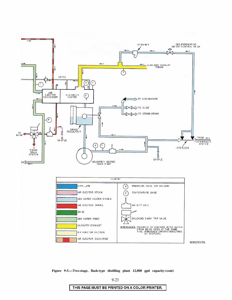
Figure 9-5.—Two-stage, flash-type distilling plant 12,000 gpd capacity-(cont)
9-23

Figure 9-8.—Single-stage, vertical basket distilling plant 8,000 gpd capacity.
9-24

Figure 9-8.—Single-stage, vertical basket distilling plant 8,000 gpd capacity-(cont)
9-25


CHAPTER 10
PIPING SYSTEMS
As a Machinist’s Mate, you will work withpiping, fittings, valves, packing, gaskets, andinsulation. You will be responsible for routinemaintenance of this equipment in your spaces andpossibly throughout the ship. The machinery ofa system cannot work properly unless the pipingand valves are in good working order.
This chapter contains general information.You should refer to the appropriate manu-facturer’s technical manuals, ship’s plans,information books, and plant or valve manualsfor more specific information. Naval Ships’Technical Manual, Chapter 505 (9480), "PipingSystems," is one good source of information.
PIPING AND TUBING
The Naval Sea Systems Command definespiping as an assembly of pipe or tubing, valves,fittings, and related components. These form awhole or a part of a system used to transfer fluids(liquids and gases).
IDENTIFICATION
In commercial usage, there is no cleardistinction between pipe and tubing; the correctdesignation for each tubular product is establishedby the manufacturer. If the manufacturers call aproduct pipe, it is pipe; if they call it tubing, itis tubing. In the Navy, however, a distinction ismade between pipe and tubing based on theirdimensions.
There are three important dimensions of anytubular product: outside diameter (OD), insidediameter (ID), and wall thickness. A tubularproduct is called TUBING if its size is identifiedby actual measured OD and by actual measuredwall thickness. A tubular product is called PIPEif its size is identified by a nominal dimensioncalled nominal pipe size (NPS) and by referenceto a wall thickness schedule designation.
The size identification of tubing is simpleenough, since it consists of actual measureddimensions. However, the terms used to identifypipe sizes require some explanation. ANOMINAL dimension such as NPS is close to—but not necessarily identical with—an actualmeasured dimension. For example, a pipe withan NPS of 3 inches has an actual measured ODof 3.50 inches. A pipe with an NPS of 2 incheshas an actual measured OD of 2.375 inches. Inthe larger sizes (about 12 inches) the NPS and theactual measured OD are the same, For example,a pipe with an NPS of 14 inches has an actualmeasured OD of 14 inches, Nominal dimensionsare used to simplify the standardization of pipefittings, pipe taps, and threading dies.
The wall thickness of pipe is identified byreference to wall thickness schedules (notshown) established by the American StandardsAssociation. For example, a reference to schedule40 for a steel pipe with an NPS of 3 inchesindicates that the wall thickness of the pipe is0.216 inch. A reference to schedule 80 for a steelpipe of the same NPS (3 inches) indicates that thewall thickness of the pipe is 0.300 inch.
A schedule designation does not identify anyone particular wall thickness unless the NPS is alsospecified. For example, we have said that aschedule 40 steel pipe of NPS 3 inches has anactual wall thickness of 0.216 inch. But if we lookup schedule 40 for a steel pipe of NPS 4 inches,we will find that the wall thickness is 0.237 inch.These examples are used merely to illustrate themeaning of wall thickness schedule designations.Many other values can be found in pipe tablesgiven in engineering handbooks.
You have probably seen pipe identified asSTANDARD (Std), EXTRA STRONG (XS), andDOUBLE EXTRA STRONG (XXS). Thesedesignations, which are still used to some extent,also refer to wall thickness. However, pipe ismanufactured in a number of different wallthicknesses; some pipe does not fit into thestandard, extra strong, and double extra strong
10-1

Figure 10-1.—Unions.
Figure 10-2.—Bolted flange piping joints.
classifications. The wall thickness schedules arebeing used increasingly to identify the wallthickness of pipe. They provide identification ofmore wall thicknesses than can be identified underthe strong, extra strong, and double extra strongclassifications.
We have briefly described the standard waysof identifying the size and wall thickness of pipeand tubing. However, you will sometimes see pipeand tubing identified in other ways. For example,you may see some tubing identified by ID ratherthan by OD.
PIPING FITTINGS
Piping sections are connected by variousstandard fittings, including several types ofthreaded union, bolted, welded, silver-brazed, andexpansion joints.
Threaded Union Joints
The threaded union joint is the simplest pipefitting. Threaded fittings are not widely usedaboard modern ships except in low-pressure waterpiping systems. The union fittings are used inpiping systems to allow the piping to be takendown for repairs and alterations. Unions areavailable in many different materials and designsto withstand a wide range of pressure andtemperature. Figure 10-1 shows some commonlyused types of unions. The union is used a greatdeal to join piping up to 2 inches in size. The pipeends connected to the union are threaded, silver-brazed, or welded into the tail pieces (unionhalves); then the two ends are joined by settingup (engaging and tightening up on) the union nut.The male and female connecting ends of the tailpieces are carefully ground to make a tight
10-2

metal-to-metal fit. Welding or silver-brazing theends to the tail pieces prevents contact of thecarried liquid or gas with the union threading.
Bolted Flange Joints
Bolted flange joints are suitable for allpressures now in use. The flanges are attached tothe piping by welding, brazing, or rolling andbending into recesses. Screw threads are used forsome low-pressure piping. Those illustrated infigure 10-2 are the most common types of flangejoints used. They are manufactured for allstandard fitting shapes, such as the tee, cross,elbow, and return bend. The welded neck-typeflange joints are used extensively where piping is
subject to high pressures and heavy expansionstrains.
Welded Joints
The majority of joints found in subassembliesof piping systems are welded joints, especiallyin high-pressure piping. The welding is doneaccording to standard specifications which definethe materials and techniques. There are threegeneral classes of welded joints: butt-weld, fillet-weld, and socket-weld (fig. 10-3).
Silver-Brazed Joints
Silver-brazed joints (fig. 10-4) are commonlyused to join nonferrous piping when the pressure
Figure 10-3.—Various types of welded joints.
Figure 10-4.—Silver-brazed joints.
10-3

and temperature in the lines make their usepracticable. The temperature must not exceed425°F; for cold lines, pressure must notexceed 3000 psi. The alloy is melted by heatingthe joint with an oxyacetylene torch. This causesthe molten metal to fill the few thousandths ofan inch annular space between the pipe and thefitting.
Expansion Joints
Expansion joints of various types may beinstalled at suitable intervals in long steam
lines. They are used because metal contracts orexpands during changes in temperature. Theyinclude corrugated and bellows joints andexpansion bends.
CORRUGATED JOINTS AND BELLOWSJOINTS.—The corrugated and bellows types ofexpansion joints (fig. 10-5) are used for bothmedium and high pressure and temperature. Theprinciple of these joints is simple; the expansion-contraction movement is absorbed by thechanging curvature of the corrugations or bellows
Figure 10-5.—Expansion joints.
10-4

(as in an accordion). The internal sleeves, free toslide axially in these joints, prevent excessiveturbulence and erosion of the expansion parts.Figure 10-6 illustrates a corrugated bulkheadexpansion joint. This joint provides for bothradial and axial movement of piping with respectto the bulkhead.
EXPANSION BENDS.—Expansion bends A fire in the fireroom or engine room can beare used for high-pressure and high-temperaturesteam piping in preference to the corrugated or
caused by a leak at a fuel-oil or lube-oil pipe-flange connection. Even the smallest leak can
bellows joint. Expansion bends are merely loops spray fine droplets of oil on nearby hot surfaces.
of piping of proper length and configuration; theytake up the changes in pipe length caused bytemperature changes. The expansion bends takemany shapes—most common are the U-bend, Z-bend, and L-bend.
FLANGE SAFETY SHIELDS
Figure 10-6.—Corrugated bulkhead expansion joints, showing details of installation.
10-5

Fig
ure
10-7
.—F
lang
e sa
fety
shi
elds
.

Figure 10-8.—Types of globe valve bodies.
To reduce this possibility, spray shields (flangeshields) (fig. 10-7) are provided around pipingflanges of flammable liquid systems, especially inareas where the fire hazard is apparent. The sprayshields are usually made of aluminized glass clothand are simply wrapped and wired around theflange.
PIPELINE STRAINERS
Strainers are fitted in many piping lines toprevent the passage of grit, scale, dirt, and otherforeign matter. Such matter could obstruct pumpor throttle valves, or damage machinery parts.Various types of strainers are used, depending onthe service intended.
VALVES
Valves are usually made of bronze or steel.Steel valves are either cast or forged and are madeof either plain steel or alloy steel. Alloy steel valvesare used in high-pressure, high-temperaturesystems. The disks and seats (internal sealingsurfaces) of these valves are usually surfaced witha chromium-cobalt alloy known as Stellite. Stelliteis extremely hard.
Bronze valves are never used in systems wheretemperatures exceed 550°F. Steel valves are usedfor all services above 550°F. Bronze valves areused almost exclusively in systems that carry saltwater. The seats and disks of these valves areusually made of Monel, a metal that has excellentcorrosion- and erosion-resistant qualities. Sub-marine seawater valves are an exception to thenormal use of bronze in seawater valves; most aremade of 70-30 copper-nickel alloy.
STOP VALVES
Stop valves are used to shut off or, in somecases, control the flow of fluid. They arecontrolled by the movement of the valve stem.
Stop valves can be divided into four generalcategories: globe, gate, butterfly, and ball valves.Plug valves and needle valves may also beconsidered stop valves, but they are covered inFireman, NAVEDTRA 14104.
Globe Valves
Globe valves are probably the most commonvalves in existence. They are used throughout theengineering plant and other parts of the ship. Theglobe valve gets its name from the globular shapeof the valve body. However, you have to lookinside the valve for a positive identificationbecause other valve types may also have globularbodies. Globe valve inlet and outlet openings arearranged in several ways to suit varying require-ments of flow. Figure 10-8 shows the commontypes: straight-flow, angle-flow, and cross-flow.Figure 10-9 shows a pressure-seal bonnet globe
Figure 10-9.—1500-pound pressure seal bonnet globe valve.
10-7
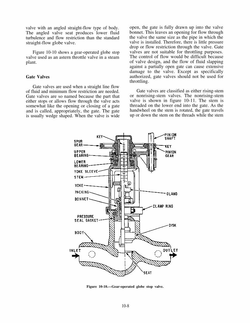
Gate Valves
valve with an angled straight-flow type of body.The angled valve seat produces lower fluidturbulence and flow restriction than the standardstraight-flow globe valve.
Figure 10-10 shows a gear-operated globe stopvalve used as an astern throttle valve in a steamplant.
Gate valves are used when a straight line flowof fluid and minimum flow restriction are needed.Gate valves are so named because the part thateither stops or allows flow through the valve actssomewhat like the opening or closing of a gateand is called, appropriately, the gate. The gateis usually wedge shaped. When the valve is wide
open, the gate is fully drawn up into the valvebonnet. This leaves an opening for flow throughthe valve the same size as the pipe in which thevalve is installed. Therefore, there is little pressuredrop or flow restriction through the valve. Gatevalves are not suitable for throttling purposes.The control of flow would be difficult becauseof valve design, and the flow of fluid slappingagainst a partially open gate can cause extensivedamage to the valve. Except as specificallyauthorized, gate valves should not be used forthrottling.
Gate valves are classified as either rising-stemor nonrising-stem valves. The nonrising-stemvalve is shown in figure 10-11. The stem isthreaded on the lower end into the gate. As thehandwheel on the stem is rotated, the gate travelsup or down the stem on the threads while the stem
Figure 10-10.—Gear-operated globe stop valve.
10-8

Figure 10-11.—Cross-sectional views of gate stop valves (nonrising stem).
10-9

Figure 10-12.—Cutaway view of a gate stop valve (risingstem).
remains vertically stationary. This type of valvewill almost always have a pointer type of indicatorthreaded onto the upper end of the stem toindicate valve position.
The rising-stem gate valve is shown in figure10-12. It has the stem attached to the gate. Thegate and stem rise and lower together as the valveis operated.
Gate valves used in steam systems have flexiblegates. This type of gate prevents binding of thegate within the valve when the valve is in theclosed position. When steam lines are heated, theywill expand, causing some distortion of valvebodies. A solid gate fits snugly between the seatof a valve in a cold steam system. When thesystem is heated and pipes elongate, the seats willcompress against the gate. The gate will be wedgedbetween the seats and clamps the valve shut. Thisproblem is overcome by using a flexible gate. Thistype of gate is best described as two circular platesthat are flexible around the hub. These two platesare attached to each other. The gate can then flexas the valve seat compresses it. This preventsclamping.
Figure 10-13.—Butterfly valve.
The major problem with flexible gates (ifinstalled with the stem below the horizontal) isthat water tends to collect in the body neck. Then,under certain conditions, the admission of steammay cause the valve body neck to rupture, thebonnet to lift off, or the seat ring to collapse. Toprevent this, you must follow correct warming-upprocedures. Also, some very large gate valves havea three-position vent and bypass valve. This valveallows venting of the bonnet either upstream ordownstream of the valve and has a position forbypassing the valve.
Butterfly Valves
One type of butterfly valve is shown in figure10-13. It may be used in a variety of systemsaboard ship. These valves can be used effectivelyin fresh water; seawater; JP-5; Diesel Fuel, Marine(DFM) lube oil; and chill water systems aboardship. The butterfly valve is light in weight,relatively small, and relatively quick-acting.It provides positive shutoff, and can be usedfor throttling. However, throttling is notrecommended.
10-10

This type of butterfly valve consists of a body,a resilient seat, a butterfly-type disk, a stem,packing, a notched positioning plate, and ahandle. The resilient seat is under compressionwhen it is mounted in the valve body. This makesa seal around the periphery of the disk and bothupper and lower points where the stem passesthrough the seat. Packing forms a positive sealaround the stem for added protection in case theseal formed by the seat is damaged.
To close or open a butterfly valve, turn thehandle only one quarter turn to rotate the disk90°. Some larger butterfly valves may have ahandwheel that operates through a gearing arrange-ment. This method is used especially where spacelimitation precludes the use of a long handle.
Butterfly valves are relatively easy to maintain.The resilient seat is held in place by mechanicalmeans, and neither bonding nor cementing isnecessary. Because the seat is replaceable, thevalve seat does not require lapping, grinding, ormachine work.
Ball Valves
Ball valves, as the name implies, are stopvalves that use a ball to stop or start the flow offluid. The ball, shown in figure 10-14, performsthe same function as the disk in the globe valve.When the valve handle is operated to open thevalve, the ball rotates to a point where the holethrough the ball is in line with the valve bodyinlet and outlet. The valve is shut by a 90-degreerotation of the handwheel for most valves. Theball is rotated so that the hole is perpendicularto the flow openings of the valve body, and flowis stopped.
Most ball valves are of the quick-acting type.They require only a 90-degree turn to operate thevalve either completely open or closed. However,many are planetary gear operated. This type ofgearing allows the use of a relatively small hand-wheel and operating force to operate a fairly largevalve. The gearing does, however, increase theoperating time for the valve. Some ball valves
Figure 10-14.—Typical seawater ball valve.
10-11

contain a swing check located within the ball togive the valve a check valve feature. Figure 10-15shows a ball-stop swing-check valve with planetarygear operation. Ball valves are normally found inthe following systems aboard ship: seawater,sanitary, trim and drain, air, hydraulic, and oiltransfer.
CHECK VALVES
Check valves allow fluid to flow in a systemin only one direction. They are operated by the
flow of fluid in the piping. A check valve maybe of the swing type, lift type, or ball type.
AUTOMATIC PRESSURECONTROL VALVES
There are many types of automatic pressurecontrol valves. Some of them merely provide anescape for excessive pressures; others reduce orregulate pressure.
Figure 10-15.—Typical ball stop swing-check valve for seawater service.
10-12

Figure 10-16.—Relief valve.
Relief Valves
Relief valves are installed in most systems toprotect them from excessive pressure. These valveshave an adjusting screw, a spring, and a disk. Theforce exerted on the disk by the spring sets therelieving pressure. Most relief valves simply openwhen the preset pressure is reached and close whenthe pressure drops slightly below the liftingpressure. Many relief valves will also have alever so the valve can be opened by hand for testpurposes. Figure 10-16 shows a relief valve of thistype.
Sentinel Valves
Sentinel valves are simply small relief valvesinstalled in some systems to warn of impendingoverpressure. Sentinel valves do not relieve thepressure of the system. If the situation causingthe sentinel valve to lift is not corrected, arelief valve (if installed) will lift to protectthe system or component. If a relief valve isnot installed, action must be taken quickly tosecure the piece of equipment or system to reducethe pressure.
Pressure-Reducing Valves
Reducing valves are automatic valves thatprovide a steady pressure into a system thatis at a lower pressure than the supply system.Reducing valves of one type or another are foundin steam, air, lube-oil, seawater, and othersystems. A reducing valve can normally be set forany desired downstream pressure within the designlimits of the valve. Once the valve is set, thereduced pressure will be maintained. This is trueregardless of changes in the supply pressure aslong as the supply pressure is at least as high asthe reduced pressure desired. It is also trueregardless of the amount of reduced pressure fluidthat is used.
There are three basic designs of pressure-reducing valves in use. They are spring-loadedreducing valves, pneumatic-pressure-controlled(gas-loaded) reducing valves, and air-pilotoperated diaphragm-type reducing valves. Thereare many different styles within these threetypes.
SPRING-LOADED REDUCING VALVES.—One type of spring-loaded reducing valve is
10-13

Figure 10-17.—Pressure-reducing (spring-loaded) valve.
shown in figure 10-17. These valves are used ina wide variety of applications. Low-pressure airreducers, distilling plant seawater reducers, somereduced-steam system reducers, and others are ofthis type. The valve simply uses spring pressureagainst a diaphragm to open the valve. On thebottom of the diaphragm, outlet pressure (thepressure in the reduced pressure system) of thevalve forces the disk upward to shut the valve.When outlet pressure drops below the set pointof the valve, spring pressure overcomes outletpressure and forces the valve stem downward,opening the valve. As outlet pressure increases,approaching the desired value, the pressure underthe diaphragm begins to overcome springpressure. This forces the valve stem upwards,
shutting the valve. Downstream pressure can beadjusted by removing the valve cap and turningthe adjusting screw, which varies the springpressure against the diaphragm. This particularspring-loaded valve will fail in the open positionin the case of a diaphragm rupture.
Another, more complex, spring-loaded reducingvalve is shown in figure 10-18. The principal partsof this spring-loaded reducing valve are (1) themain valve, an upward-seating valve which hasa piston on top of its stem; (2) an upward-seatingauxiliary (or controlling) valve; (3) a controllingdiaphragm; and (4) an adjusting spring.
High-pressure steam (or other gas or fluid)enters the valve on the inlet side and acts against
10-14

Figure 10-18.—Spring-loaded reducing valve.
the main valve disk, tending to close themain valve. However, high-pressure steam isalso led through ports to the auxiliary valve.This valve controls the admission of high-pressure steam to the top of the main valvepiston. The piston has a larger surface areathan the main valve disk. Therefore, high-pressure steam acting on the top of the mainvalve piston will tend to open the main valve.This allows steam at reduced pressure to flowout the discharge side.
But what makes the auxiliary valve open toallow high-pressure steam to get to the top of themain valve piston? The controlling diaphragmexerts a downward pressure upon the auxiliaryvalve stem. This tends to open the valve.However, reduced-pressure steam is led back tothe chamber beneath the diaphragm. The steamthen exerts a pressure upward on the diaphragm.
This tends to close the auxiliary valve. Theposition of the auxiliary valve, therefore, isdetermined by the position of the controllingdiaphragm.
The position of the diaphragm at anygiven moment is determined by the relativestrength of two opposing forces, The firstis the downward force exerted by the adjustingspring. The second is the upward force thatis exerted on the underside of the diaphragmby the reduced-pressure steam. These twoforces are continually seeking a state ofbalance. Because of this, the discharge pressureof steam is kept constant as long as theamount of steam used is kept within thecapacity of the valve.
INTERNAL PILOT-ACUATED PRESSUREREDUCING VALVE.—This valve, shown in
10-15

Figure 10-19.—Reducing valve (Atlas Valve Company).
figure 10-19, uses a pilot valve to control themain valve. The pilot valve controls the flowof upstream fluid, which is ported to thepilot valve, to the operating piston that operatesthe main valve. The main valve is openedby the operating piston and closed by themain valve spring. The pilot valve opens whenthe adjusting spring pushes downward on thepilot diaphragm. It closes when downstreampressure exerts a force that exceeds the forceof the adjusting spring. When the pilot valveshuts off or throttles the flow of upstreamfluid to the operating piston, the main valvethen pushes the valve and stem upward, tothrottle or close the main valve. When down-stream pressure drops off, the adjusting springforce acts downward on the diaphragm. Thisaction overcomes the force of the downstreamsystem pressure, which is acting upward onthe diaphragm. This opens the pilot valve,allowing upstream pressure to the top of theoperating piston to open the main valve.
PNEUMATIC-PRESSURE CONTROLLEDREDUCING VALVES.—There are two types ofthe pneumatic-pressure-controlled (or gas-loaded)
reducing valve. One type regulates low-temperaturefluids, such as air, water, or oil (fig. 10-20). Theother type (not shown) regulates high-temperaturefluids, such as steam or hot water. The high-temperature fluid reducer is found only in olderships.
Air-controlled regulators operate on theprinciple that the pressure of an enclosed gasvaries inversely to its volume. A reductionin volume results in an immediate increasein pressure. Conversely, an increase in volumeresults in an immediate decrease in pressure. Arelatively small change in the large volumewithin the dome loading chamber producesonly a slight pressure variation, while theslightest variation in the small volume withinthe actuating chamber creates an enormouschange in pressure. The restricting orificeconnecting these two chambers governs therate of pressure equalization by retardingthe flow of gas from one chamber to theother.
The dome loading chamber is charged withair or other compressible gases (such as nitrogen)at a pressure equal to the desired reducedpressure. When the chamber is loaded andwhen the loading valve is closed, the domewill retain its charge almost indefinitely. Whenthe regulator is in operation, the trappedpressure within the dome passes into theactuating chamber through the small separationplate orifice. This pressure moves the largeflexible diaphragm, which forces the reverseacting valve off its seat. The pressure enteringthe regulator is then permitted to flow throughthe open valve into the reduced pressure line.A large pressure equalizing orifice transmitsthis pressure directly to the underside of thediaphragm. When the delivered pressure approx-imates the loading pressure in the dome andthe unbalanced forces equalize, the valve willclose. With the slightest drop in deliveredpressure, the pressure charge in the domeinstantly forces the valve open. This allowssystem fluid to pass through and therebymaintains the outlet pressure relatively con-stant.
To charge the loading chamber, back offslightly on the dome needle valve. Connectthe specially furnished hand pump (either 300or 600 psi), and fill the dome to the desired
10-16
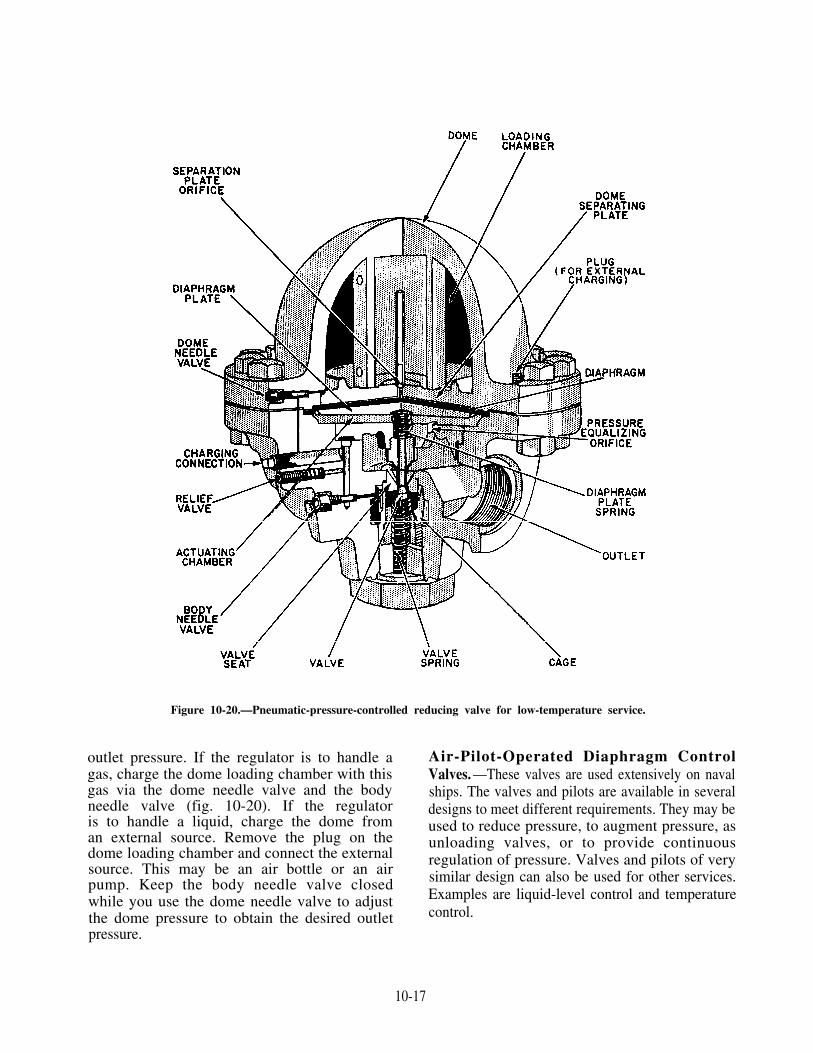
Figure 10-20.—Pneumatic-pressure-controlled reducing valve for low-temperature service.
outlet pressure. If the regulator is to handle agas, charge the dome loading chamber with thisgas via the dome needle valve and the bodyneedle valve (fig. 10-20). If the regulatoris to handle a liquid, charge the dome froman external source. Remove the plug on thedome loading chamber and connect the externalsource. This may be an air bottle or an airpump. Keep the body needle valve closedwhile you use the dome needle valve to adjustthe dome pressure to obtain the desired outlet
Air-Pilot-Operated Diaphragm ControlValves. —These valves are used extensively on navalships. The valves and pilots are available in severaldesigns to meet different requirements. They may beused to reduce pressure, to augment pressure, asunloading valves, or to provide continuousregulation of pressure. Valves and pilots of verysimilar design can also be used for other services.Examples are liquid-level control and temperaturecontrol.
pressure.
10-17

Figure 10-21.—Air-operated control pilot.
The air-operated control pilot may be eitherdirect acting or reverse acting. A direct-actingpilot is shown in figure 10-21. In this type of pilot,the controlled pressure—that is, the pressure fromthe discharge side of the diaphragm controlvalve—acts on top of a diaphragm in the controlpilot. This pressure is balanced by the pressureexerted by the pilot adjusting spring. If thecontrolled pressure increases and overcomes thepressure exerted by the pilot adjusting spring, thepilot valve stem is forced downward. This actionopens the pilot valve. This action increases theamount of operating air pressure going from thepilot to the diaphragm control valve. A reverse-acting pilot has a lever that reverses the pilotaction. In a reverse-acting pilot, therefore, anincrease in controlled pressure produces a decreasein operating air pressure.
In the diaphragm control valve, operating airfrom the pilot acts on the valve diaphragm. Thesuperstructure contains the diaphragm. It is directacting in some valves and reverse acting in others.If the superstructure is direct acting, the operatingair pressure from the control pilot is applied to
the TOP of the valve diaphragm. If the super-structure is reverse acting, the operating airpressure from the pilot is applied to the UNDER-SIDE of the valve diaphragm.
Figure 10-22 shows a very simple type ofdirect-acting diaphragm control valve. Theoperating air pressure from the control pilot isapplied to the top of the valve diaphragm. Thevalve in the figure is a downward-seating valve.Therefore, any increase in operating air pressurepushes the valve stem downward. This tends toclose the valve.
Now look at figure 10-23. This is also a direct-acting valve. The operating air pressure from thecontrol pilot is applied to the top of the valvediaphragm. But the valve shown in figure 10-23is more complicated than the one shown in figure10-22. The valve shown in figure 10-23 is anupward-seating valve rather than a downward-seating valve. Therefore, any increase in operatingair pressure from the control pilot tends to OPENthis valve rather than to close it.
As we have seen, the air-operated control pilotmay be either direct acting or reverse acting. The
10-18

Figure 10-22.—Diaphragm control valve (downward seating).
superstructure of the diaphragm control valvemay be either direct acting or reverse acting. And,the diaphragm control valve may be either upwardseating or downward seating. These three factors,as well as the purpose of the installation,determine how the diaphragm control valve andits air-operated control pilot are installed inrelation to each other.
To see how these factors are related, let’sconsider an installation; a diaphragm controlvalve and its air-operated control pilot are usedto supply reduced steam pressure. Figure 10-24shows one arrangement that we might use. Wewill assume that the service requirements indicatethe need for a direct-acting, upward-seating,diaphragm control valve. Can you figure outwhich kind of control pilot—direct acting orreverse acting—should be used in this installation?
Let’s try it first with a direct-acting controlpilot. The controlled pressure (discharge pressurefrom the diaphragm control valve) increases.When that happens, increased pressure is appliedto the diaphragm of the direct-acting control pilot.The valve stem is pushed downward and the valvein the control pilot is opened. This sends anincreased amount of operating air pressure from
Figure 10-23.—Diaphragm control valve (upward seating).
Figure 10-24.—Arrangement of control pilot and diaphragmcontrol valve for supplying reduced steam pressure.
10-19
the control pilot to the top of the diaphragmcontrol valve. The increased operating air pressureacting on the diaphragm of the valve pushes thestem downward. Since this is an upward-seatingvalve, this action OPENS the diaphragm controlvalve still wider. Obviously, this won’t work—for this application, an INCREASE in controlledpressure must result in a DECREASE in operatingair pressure. Therefore, we made a mistake inchoosing the direct-acting control pilot. For thisparticular pressure-reducing application, weshould choose a REVERSE-ACTING controlpilot.
You will probably not need to decide whichtype of control pilot and diaphragm control valveare needed in any particular installation. But youmust know how and why they are selected so thatyou will not make mistakes in repairing orreplacing these units.
Thermostatically ControlledRecirculating Valves
When the ship is at fractional power, orcruising power, recirculating condensate mustmove from the discharge side of the main airejector condenser to the main condenser.Recirculation prevents excessive loss of feedwateras vapor discharged from the air ejector after-condenser vent. This ensures proper operation ofthe air ejectors at fractional power. We need tomake recirculation automatic. This will avoidexcessive recirculation with attendant excessiveloss of heat. To ensure this, most air ejectorrecirculating lines are fitted with thermostaticallycontrolled valves.
We can avoid excessive heat loss by recir-culating condensate from the discharge side of themain air ejector condenser to the main condenser.The air ejector condensers must be supplied withcooling water (condensate) during their operation.A hand-controlled valve allows us to bypass thethermostatic recirculating valve during thewarming-up period. We will also use this bypassvalve when the thermostatic valve is inoperative.
Under normal operating conditions, recir-culation to the main condenser at light loads isautomatically controlled by the thermostaticrecirculating valves. These valves are actuated bythe temperature of the condensate dischargedfrom the air ejector aftercondenser. A rise in thewater temperature, above the temperature atwhich the valve is set, results in automaticopening of the valve. This allows recirculation ofthe heated water back to the condenser and
through the air ejector again. The thermostaticallycontrolled recirculating valves are adjustedthrough a range of approximately 40°F. Theyshould be individually set to open at the highesttemperature at which the air ejectors will operatewithout loss of condenser vacuum or excessivevapor from the air ejector aftercondenser vent.
In the interest of economy, be sure thethermostatically controlled valve is in goodcondition and properly set. Keep the manualbypasses closed under all normal operatingconditions. The control bulbs of the valvesshould be located in the condensate line asclose as possible to the aftercondenser discharge.Preferably, when space is available, they shouldbe located within the last pass of the air ejectoraftercondenser water chest.
Hydraulically OperatedGland Seal Regulator
Figure 10-25 shows a gland seal regulator ofthe type used on some ships for main engineand/or turbine generator gland seal steamcontrol. The regulator is actually a type of specialvalve.
During low load, when the pressure in the sealingsystem drops below the desired value, pressure onthe BELLOWS ASSEMBLY is reduced and thePIVOT RODS move downward. Spring-loadedaction on the LEVER tends to keep the PIVOTBLOCK hard against the pivot rod. The lever thenmoves with the pivot rod, raising the links andthe PILOT VALVE. This action drains oil frombeneath the PISTON, causing the piston to movedownward and shut the exhaust valve. After theexhaust valve has been shut, the makeup steamvalve opens and admits supply steam into the sealsystem to increase pressure.
When the gland seal pressure rises to thedesired value, the reverse of these events takesplace. The increased pressure on the bellows raisesthe pivot rods and causes the pilot valve to admitoil to the piston. The piston moves upward to shutthe makeup steam valve, after which the exhaustvalve opens.
In case of a failure of the bellows, the pivotrods move downward to their furthest travel, andthe pilot valve is raised to dump oil pressure fromunder the piston. The piston moves downward toshut the exhaust valve and to open the makeupsteam valve. This action provides a supply ofgland seal to the shaft packing. The position ofthe valves can then be controlled manually by thecontrol knob.
10-20

REMOTE-OPERATED VALVES
Remote-operating gear provides a means ofoperating certain valves from distant stations.Remote-operating gear may be mechanical,hydraulic, pneumatic, or electric.
Some remote-operating gear for valves isused in normal operation of valves. For example,the main engine throttle valves are opened andclosed by a reach rod or a series of reach rods andgears. Reach rods may be used to operate engine-room valves in instances where the valves aredifficult to reach from operating stations.
Other remote-operating gear is installed asemergency equipment. Some split-plant valves,
Figure 10-25.—Hydraulic steam seal regulator.
main drainage valves, and main condenserinjection and overboard valves are equipped withremote-operating gear. These valves can beoperated normally or, in an emergency, they maybe operated from remote stations. Remote-operating gear also includes a valve positionindicator to show whether the valve is open orclosed.
STEAM TRAPS
Steam traps in steam lines drain condensatefrom the lines without allowing steam to escape.There are many different kinds of steam traps.
10-21

They all consist essentially of a valve and somedevice or arrangement that will cause the valveto open and close as necessary to drain thecondensate without allowing the escape of steam.Some designs are suitable for low pressures andlow temperatures, others for high pressures andhigh temperatures. A few common types of steamtraps are the mechanical, thermostatic, andorifice.
MECHANICAL STEAM TRAPS
Mechanical steam traps may be of the ball-float type or the bucket type.
Ball-Float Trap
In a ball-float steam trap, figure 10-26, thevalve of the trap is connected to the float in sucha way that the valve opens when the float rises.When the trap is in operation, the steam and anywater that may be mixed with it flow into the floatchamber. As the water level rises, the float lifts,thereby lifting the valve plug and opening thevalve. The condensate drains out and the floatmoves down to a lower position, closing the valve.The condensate that passes out of the trap returnsto the feed system.
Bucket-Type Trap
In a bucket-type steam trap, figure 10-27, thebucket floats when condensate enters the trapbody. The valve is connected to the bucket in such
Figure 10-26.—A ball-float steam trap.
Figure 10-27.—Bucket-type steam trap.
a way that the valve closes as the bucket rises. Ascondensate continues to flow into the trap body,the valve remains closed until the bucket is full.When the bucket is full, it sinks, thus opening thevalve. The valve remains open until enough con-densate has passed out to allow the bucket tofloat, thus closing the valve.
THERMOSTATIC STEAM TRAPS
There are several types of thermostatic steamtraps. In general, these traps are more compactand have fewer moving parts than mostmechanical steam traps. The operation of abellows-type thermostatic trap is controlled byexpansion of the vapor of a volatile liquidenclosed in a bellows-type element. Steam entersthe trap body and heats the volatile liquid in thesealed bellows, thus causing expansion of thebellows. The valve is attached to the bellows insuch a way that the valve closes when the bellowsexpands. The valve remains closed, trappingsteam in the trap body. As the steam cools andcondenses, the bellows cools and contracts,thereby opening the valve and allowing thecondensate to drain.
10-22

Figure 10-28.—Impulse steam trap.
The impulse and bimetallic steam traps are twoexamples of those that use the thermostaticprinciple.
Impulse Steam Traps
Impulse steam traps of the type shown infigure 10-28 are commonly used in steam draincollecting systems aboard ship. Steam andcondensate pass through a strainer beforeentering the trap. A circular baffle keeps theentering steam and condensate from impingingon the cylinder or on the disk.
The impulse trap operates on the principle thathot water under pressure tends to flash into steamwhen the pressure is reduced. So that you under-stand how this principle is used, let’s consider thearrangement of the parts shown in figure 10-28and see what happens to the flow of condensateunder various conditions.
The only moving part in the steam trap is thedisk, which is rather unusual in design. Near thetop of the disk is an insert that acts as a piston.As you can see in the inset, the working surfaceabove the insert is larger than the workingsurface below the insert. The importance ofhaving this larger effective area above the insertis brought out later in this discussion.
A control orifice runs through the disk fromtop to bottom and is considerably smaller at thetop than at the bottom. The bottom part of thedisk extends through and beyond the orifice inthe seat. The upper part of the disk (including theinsert) is inside a cylinder. The cylinder tapersinward, so the amount of clearance between theinsert and the cylinder varies according to theposition of the valve. When the valve is open,the clearance is greater than when the valve isclosed.
When the trap is first cut in (put in service),pressure from the inlet (chamber A) acts againstthe underside of the insert and lifts the disk offthe valve seat. Condensate is thus allowed to passout through the orifice in the seat. At the sametime, a small amount of condensate (CONTROLFLOW) flows up past the insert and into chamberB, The control flow discharges through thecontrol orifice, into the outlet side of the trap.The pressure in chamber B remains lower thanthe pressure in chamber A.
As the line warms up, the temperature of thecondensate flowing through the trap increases.The reverse taper of the cylinder varies the amountof flow around the insert. This continues until abalanced position is reached in which the totalforce exerted above the insert is equal to the total
10-23

force exerted below the insert. It is important tonote that there is still a PRESSURE DIF-FERENCE between chamber A and chamber B.The FORCE is equalized because the effectivearea above the insert is larger than the effectivearea below the insert. The difference in workingarea is such that the valve maintains an open,balanced position when the pressure in chamberB is 86 percent of the pressure in chamber A.
As the temperature of the condensateapproaches its boiling point, some of the controlflow going to chamber B flashes into steam as itenters the low-pressure area. The steam has amuch larger volume than the water from whichit is generated. Therefore, pressure is built up inthe space above the insert (chamber B). Thepressure in this space becomes greater than86 percent of the inlet pressure. At that time, theforce exerted on the top of the insert pushes theentire disk downward and closes the valve.
With the valve closed, the only flow throughthe trap is past the insert and through thecontrol orifice. When the temperature of thecondensate entering the trap drops slightly,condensate enters chamber B without flashing intosteam. Pressure in chamber B is thus reduced tothe point that the valve opens and allowscondensate to flow through the orifice in the valveseat. Thus the entire cycle is repeated.
With a normal condensate load, the valveopens and closes at frequent intervals. A smallamount of condensate discharges at each opening.With a heavy condensate load, the valve remainswide open and allows a heavy, continuousdischarge of condensate.
Bimetallic Steam Traps
These traps are used in many ships to draincondensate from main steam lines, auxiliary steamlines, and other steam components. The mainworking parts of this steam trap are a segmentedbimetallic element and a ball-type check valve(fig. 10-29).
The bimetallic element consists of severalbimetallic strips fastened together in a segmentedfashion. One end of the bimetallic element isfastened rigidly to a part of the valve body. Theother end, which is free to move, is fastened tothe top of the stem of the ball-type check valve.
Line pressure acting on the check valve tendsto keep the valve open. When steam enters thetrap body, the bimetallic element expands un-equally because of the different response totemperature of the two metals. The bimetallic
Figure 10-29.—Bimetallic steam trap.
element deflects upward at its free end. Thismoves the valve stem upward and closes the valve.As the steam cools and condenses, the bimetallicelement moves downward toward the horizontalposition. This opens the valve and allows somecondensate to flow out through the valve. As theflow of condensate begins, an unbalance of linepressure across the valve is created. Since the linepressure is greater on the upper side of the ballof the check valve, the valve now opens wide andallows a full capacity flow of condensate.
ORIFICE-TYPE STEAM TRAPS
Figure 10-30 shows the assembly of an orifice-type steam trap. Constant-flow drain orifices maybe used in systems of 150 psi and above wherecondensate load and pressure remain nearconstant.
The constant-flow drain orifice operates ona thermodynamic principle; the variable densityof condensate helps its operation. Density changeswith temperature. As the temperature of the con-densate decreases, the density of the condensateincreases, as well as the flow of the condensatethrough the orifice. The reverse is also true. Asthe temperature of the condensate increases, thedensity of the condensate decreases, as well as theflow of the condensate through the orifice.
Because of the difference in densities betweenthe steam and the condensate, the condensate willflow through the orifice at a faster rate.
10-24
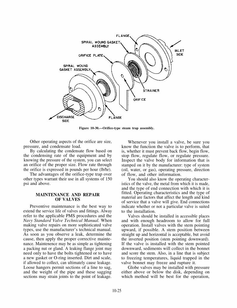
Figure 10-30.—Orifice-type steam trap assembly.
Other operating aspects of the orifice are size,pressure, and condensate load.
By calculating the condensate flow based onthe condensing rate of the equipment and byknowing the pressure of the system, you can selectan orifice of the proper size. Flow rate throughthe orifice is expressed in pounds per hour (lb/hr).
The advantages of the orifice-type trap overother types warrant their use in all systems of 150psi and above.
MAINTENANCE AND REPAIROF VALVES
Preventive maintenance is the best way toextend the service life of valves and fittings. Alwayrefer to the applicable PMS procedures and theNavy Standard Valve Technical Manual. Whenmaking valve repairs on more sophisticated valvetypes, use the manufacturer’s technical manual.As soon as you observe a leak, determine thecause, then apply the proper corrective mainte-nance. Maintenence may be as simple as tighteninga packing nut or gland. A leaking flange joint mayneed only to have the bolts tightened or to havea new gasket or O-ring inserted. Dirt and scale,if allowed to collect, can ultimately cause leakage.Loose hangers permit sections of a line to sag,and the weight of the pipe and these saggingsections may strain joints to the point of leakage.
Whenever you install a valve, be sure youknow the function the valve is to perform, thatis, whether it must prevent back flow, begin flow,stop flow, regulate flow, or regulate pressure.Inspect the valve body for information that isstamped on it by the manufacturer: type of system(oil, water, or gas), operating pressure, directionof flow, and other information.
You should also know the operating character-istics of the valve, the metal from which it is made,and the type of end connection with which it isfitted. Operating characteristics and the type ofmaterial are factors that affect the length and kindof service that a valve will give. End connectionsindicate whether or not a particular valve is suitedto the installation.
Valves should be installed in accessible placesand with enough headroom to allow for fulloperation. Install valves with the stem pointingupward, if possible. A stem position betweenstraight up and horizontal is acceptable, but avoidthe inverted position (stem pointing downward).If the valve is installed with the stem pointeddownward, sediments will collect in the bonnetand score the stem. Also, in a line that is subjectto freezing temperatures, liquid trapped in thevalve bonnet may freeze and rupture it.
Globe valves may be installed with pressureeither above or below the disk, depending onwhich method will be best for the operation,
10-25
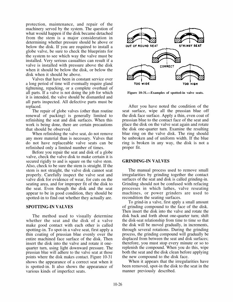
protection, maintenance, and repair of themachinery served by the system. The question ofwhat would happen if the disk became detachedfrom the stem is a major consideration indetermining whether pressure should be above orbelow the disk. If you are required to install aglobe valve, be sure to check the blueprints forthe system to see which way the valve must beinstalled. Very serious casualties can result if avalve is installed with pressure above the diskwhen it should be below the disk, or below thedisk when it should be above.
Valves that have been in constant service overa long period of time will eventually require glandtightening, repacking, or a complete overhaul ofall parts. If a valve is not doing the job for whichit is intended, the valve should be dismantled andall parts inspected. All defective parts must bereplaced.
The repair of globe valves (other than routinerenewal of packing) is generally limited torefinishing the seat and disk surfaces. When thiswork is being done, there are certain precautionsthat should be observed.
When refinishing the valve seat, do not removeany more material than is necessary. Valves thatdo not have replaceable valve seats can berefinished only a limited number of times.
Before you repair the seat and disk of a globevalve, check the valve disk to make certain it issecured rigidly to and is square on the valve stem.Also, check to be sure the stem is straight. If thestem is not straight, the valve disk cannot seatproperly. Carefully inspect the valve seat andvalve disk for evidence of wear, for cuts on theseating area, and for improper fit of the disk tothe seat. Even though the disk and the seatappear to be in good condition, they should bespotted-in to find out whether they actually are.
SPOTTING-IN VALVES
The method used to visually determinewhether the seat and the disk of a valvemake good contact with each other is calledspotting-in. To spot-in a valve seat, first apply athin coating of prussian blue evenly over theentire machined face surface of the disk. Theninsert the disk into the valve and rotate it one-quarter turn, using light downward pressure. Theprussian blue will adhere to the valve seat at thosepoints where the disk makes contact. Figure 10-31shows the appearance of a correct seat when itis spotted-in. It also shows the appearance ofvarious kinds of imperfect seats.
Figure 10-31.—Examples of spotted-in valve seats.
After you have noted the condition of theseat surface, wipe all the prussian blue offthe disk face surface. Apply a thin, even coat ofprussian blue to the contact face of the seat andplace the disk on the valve seat again and rotatethe disk one-quarter turn. Examine the resultingblue ring on the valve disk. The ring shouldbe unbroken and of uniform width. If the bluering is broken in any way, the disk is not aproper fit.
GRINDING-IN VALVES
The manual process used to remove smallirregularities by grinding together the contactsurfaces of the seat and disk is called grinding-in.Grinding should not be confused with refacingprocesses in which lathes, valve reseatingmachines, or power grinders are used torecondition the seating surfaces.
To grind-in a valve, first apply a small amountof grinding compound to the face of the disk.Then insert the disk into the valve and rotate thedisk back and forth about one-quarter turn; shiftthe disk-seat relationship from time to time so thatthe disk will be moved gradually, in increments,through several rotations. During the grindingprocess, the grinding compound will gradually bedisplaced from between the seat and disk surfaces;therefore, you must stop every minute or so toreplenish the compound. When you do this, wipeboth the seat and the disk clean before applyingthe new compound to the disk face.
When it appears that the irregularities havebeen removed, spot-in the disk to the seat in themanner previously described.
10-26

Grinding-in is also used to follow up allmachining work on the valve seats of disks. Whenthe valve seat and disk are first spotted-in afterthey have been machined, the seat contact will bevery narrow and will be located close to the bore.Grinding-in, using finer and finer compounds asthe work progresses, causes the seat contact tobecome broader. The contact area should be aperfect ring covering approximately one-third ofthe seating surface.
Do not overgrind a valve seat or disk. Over-grinding tends to produce a groove in the seatingsurface of the disk; it also tends to round off thestraight, angular surface of the disk. Machiningis the only process by which overgrinding can becorrected.
LAPPING VALVES
When a valve seat contains irregularities thatare slightly larger than can be satisfactorilyremoved by grinding-in, the irregularities can beremoved by lapping. A cast-iron tool of exactlythe same size and shape as the valve disk is usedto true the valve seat surface. Two lapping toolsare shown in figure 10-32.
Observe the following operating instructionswhen you use a lapping tool:
1. Do not bear down heavily on the handleof the lapping tool.
2. Do not bear sideways on the handle of thelapping tool.
3. Rotate the lapping tool so that the lap willgradually and uniformly cover the entireseat.
4. Keep a check on the working surface of thelapping tool. If a groove develops, have thetool refaced.
Figure 10-32.—Lapping tools.
5. Always use clean compound for lapping.6. Replace the compound frequently.7. Spread the compound evenly and lightly.8. Do not lap more than is necessary to
produce a smooth, even seat.9. Always use a fine grinding compound to
finish the lapping job.10. Upon completion of the lapping job,
spot-in and grind-in the disk to the seat.
Use only approved abrasive compounds torecondition valve seats and disks. Compounds forlapping and grinding valve disks and seats aresupplied in various grades. A course gradecompound is used when extensive corrosion ordeep cuts are found on the disks and seats. Acompound of medium grade is used to follow upthe coarse grade; it may also be used to start thereconditioning process on valves that are not tooseverely damaged. A fine grade compound shouldbe used when the reconditioning process nearscompletion. A microscopic-fine grade should beused for finish lapping and for all grinding-in.
REFACING VALVES
Badly scored valve seats must be refaced ina lathe, with a power grinder, or with a valvereseating machine. However, the lathe rather thanthe reseating machine should be used to reface allvalve disks and all hard-surfaced valve seats.
Work that must be done on a lathe or witha power grinder should be turned over to machineshop personnel.
REPACKING VALVES
If the stem and packing of a valve are in goodcondition, you can normally stop packing glandleaks by tightening up on the packing gland ornut. You must be careful, however, to avoidexcessive thread engagement of the packing glandstuds (if used) and to avoid tightening old,hardened packing which will cause the valve toseize. Subsequent operation of such a valve mayscore or bend the stem.
Coils, rings, and corrugated ribbon arecommon forms of packing used on valves. Theform of packing to be used to repack a particularvalve will depend on the valve size, application,and type.
Basically, valve repacking involves removal ofthe old packing (this must be done carefully toavoid scoring of the gland or stem), inspecting andcleaning the valve stem and gland, and installing
10-27
new packing. Adding the packing is not difficult,but it must be done properly or the valve will leakor bind.
When using ring packing, cut the packing sothe ends fit flush and stagger the splits from eachother to prevent leakage.
Some special-purpose valves are provided withprecut packing available through the supplysystem, which must be soaked in pure (distilled)water for several hours before installation. Manyvalves require the use of packing pushers (eitherwooden or brass bushings) to ensure that thebottom rings of packing are compressed properly.These packing pushers fit into the packing glandstuffing box and the gland is tightened up withthe pusher inside. After compression of thepacking, the gland and pushers are removed andmore packing is added. Different lengths ofpacking pushers are required to provide for thedecreasing depths of the gland stuffing box aspacking is added.
PACKING AND GASKETMATERIALS
Packing and gasket materials are required toseal joints in steam, water, gas, air, oil, and otherlines. They are also used to seal connections thatslide or rotate under operating conditions. Thereare many commercial types and forms of packingand gasket material. The Navy has simplified theselection of packing and gasket materialscommonly used in naval service. The Naval SeaSystems Command has prepared a packing andgasket chart (Mechanical Standard DrawingB0153, Rev 9). This chart shows the symbolnumbers and the recommended applications ofall types and kinds of packing and gasketmaterials. A copy of the chart should be locatedin all engineering spaces.
A four-digit symbol number identifies eachtype of packing and gasket. The first digitindicates the class of service with respect to fixedand moving joints. For example, if the first digitis 1, it indicates a moving joint (moving rods,shafts, valve stems, and so forth). If the first digitis 2, it indicates a fixed joint (such as a flange ora bonnet). The second digit indicates the materialof which the packing or gasket is primarilycomposed. This may be asbestos, vegetable fiber,rubber, metal, and so on. The third and fourthdigits indicate the different styles or forms of thepacking or gaskets made from the material.
Practically all shipboard packing and gasketproblems can be solved if the correct material isselected from the listings on the packing andgasket chart.
CAUTION
NEVER use low-pressure packing inplace of high-pressure packing; however,some high-pressure packing may be usedto repack low-pressure steam valves.
The following examples show the kind ofinformation you can get from the packing andgasket chart.
Suppose you are required to repack and installa valve in a 300-psi saturated steam line. Byreferring to the packing and gasket chart, you willfind several materials that are suitable forrepacking the valve:
Symbol 1103 Asbestos rod, braided, plainSymbol 1104 Asbestos rod, braided, wire
insertionSymbol 1430 Metallic, flexible
Notice that the first digit is 1 in each case, toindicate that the packing is suitable for a movingjoint.
To install a valve, you will need suitablegaskets. In this case, the first digit will be 2,indicating that the gasket material is suitable forfixed joints. By referring to the packing and gasketchart, you will find that you can use any of thefollowing gasket materials:
Symbol 2150 Asbestos, sheet, compressedSymbol 2151 Asbestos, metallic, cloth sheetSymbol 2410 Gasket, metallic, asbestos,
spiral wound
In addition to the standard packing and gasketchart, most ships have a packing and gasket chartmade up specifically for that ship. The shipboardchart shows the symbol numbers and the sizes ofpacking and gaskets required in the ship’s pipingsystems, machinery, and hull fittings.
PACKING
Corrugated ribbon packing (CRP) is a relativelynew packing material; it is a 100 percent graphitematerial expressly suited for installation in steam,feed, and condensate valves. CRP (fig. 10-33)
10-28

Figure 10-33.—Corrugated ribbon packing.
Figure 10-34.—Sectional views of corrugated ribbon packing after restructuring.
contains no binders, resins, fillers, lubricants, orother additives. It has the lubricating qualitytypical of pure graphite with the capability forrapid heat dissipation, thus reducing wear. Unlikeconventional graphite, which is brittle, CRP isflexible and highly resilient. When CRP is formedin a valve stuffing box, it restructures as illustratedin figure 10-34,
This restructuring capability allows CRP tobe wrapped around the valve stem in any size valvestuffing box and to be formed into a ring bycompression. It forms a solid endless packing ringwhen it is compressed.
CRP is easily cut to a predetermined length.It does not turn rock hard or shrink at any
temperature. Once installed and after run-in, itnormally needs no further adjustment. This meansgreatly reduced maintenance. The resiliency andno-lint structure of CRP remain unchanged at anytemperature. There is no lubricant or additive tobe squeezed out, vaporized, or carbonized. Also,it has a long shelf and service life.
WARNING
CRP conducts electricity. Identifica-tion and warning stickers must be clearlyvisible on all containers to assure preven-tion of its use for electrical insulation.
10-29

Use CRP with anti-extrusion rings made ofgraphite filament yarn (GFY) packing. Install therings at the bottom (first ring) and at the top (lastring) of every stuffing box. Set the GFY toprevent the CRP from being forced out of thestuffing box (extruded) through stem-stuffing,stem-gland, and gland-stuffing box clearances.
If GFY is not available, you can install a ringof conventional packing as anti-extrusion rings.However, the use must be temporary. At theearliest opportunity, disassemble, inspect, andrepack the valve using GFY anti-extrusion ringswith CRP.
GFY packing, figure 10-35, is a severe servicepacking ideal for use in difficult fluid-handlingapplications. It is unaffected by the mostdestructive corrosive fluid substances. It willwithstand extreme temperatures of over 1000°Fencountered in valve stuffing boxes. GFY packingis self-lubricating. It has exceptional heatdissipation characteristics. This allows tightpacking adjustment to make leakage almost non-existent. It also provides maximum protectionagainst stem scoring. This packing greatly reducessystem fluid loss, maintenance, and downtime toprovide longer, trouble-free valve life. GFY isavailable in sizes from 1/8 inch to 1 inch squareon spools.
NOTE: Regardless of how good the packingmaterial may be, if the surface of the shaft passing
through the stuffing box is scored or damaged inany way, the packing will not last long. Whenreplacing packing, carefully inspect the shaft inthe area where it passes through the stuffing box.Inspect the interior of the stuffing box itself. Takewhatever steps you can to ensure that the packingwill make contact with the straightest, smoothestpossible surface. (You may have to have the shaftrepaired and refinished, or replaced.)
GASKETS
At one time, fixed steam joints could besatisfactorily sealed with gaskets of compressedasbestos sheet packing (fig. 10-36, view A).However, the 15 percent rubber content of thegasket makes it unsatisfactory for modern high-temperature steam equipment. Gaskets ofcorrugated copper or of asbestos and copper aresometimes used on low- and medium-pressurelines. The serrated-face metal gasket (view B) andthe spiral-wound metallic-asbestos gasket (viewC) are used in present-day high-temperature, high-pressure installations.
Plain Full-Faced Gaskets
When cutting a plain full-faced gasket fromcompressed asbestos sheet, lay an appropriate sizepiece of the asbestos sheet on the flange. Scribein the bolt holes and flange circle lines with light
Figure 10-35.—Graphite filament yarn.
10-30

Figure 10-36.—Fixed joint gaskets. A. Sheet asbestos gaskets. B. Serrated-face metal gasket. C. Spiral-wound metallic asbestosgasket.
blows of a ball peen hammer. Using a gasketpunch, about l/16 inch larger in diameter thanthe bolts, cut the bolt holes into the gasketmaterial. Use a piece of hardwood as thesupporting and backing surface for the materialwhile punching it to prevent damage to the lipsof the punch. After the holes have been punched,use shears or a sharp knife to cut the center andoutside circles to form the ring.
Serrated-Face Metal Gasket
Serrated-face metal gaskets (fig. 10-36, viewB) are made of steel, Monel, or soft iron. Theyhave raised serrations to make a better seal at thepiping flange joints. These gaskets have resiliency;line pressure tends to force the serrated facestighter against the adjoining flange. Two variationsof serrated-face metal gaskets are shown: thesingle-plate type and the expanding type (double-plate).
Spiral Wound Metallic Asbestos Gaskets
Spiral-wound metallic-asbestos gaskets (fig.10-36, view C) are made of two parts. The firstis interlocked piles of preformed corrugated metaland asbestos strips, spirally wound, called aFILLER. The second is a solid metal outer orcentering ring, sometimes called a RETAININGRING. The filler piece is replaceable. Whenrenewing a gasket, remove the filler piece fromthe retaining metal ring and replace it with a newrefill. Do not discard the solid metal retainingouter ring unless it is damaged. Then place thegasket into a retainer or centering ring. Thesolid steel centering also acts as reinforcement toprevent blowouts. The gaskets can be compressedto the thickness of the centering ring.
Precautions
When renewing a gasket in a flanged joint, usespecial precautions. When breaking the joint,
10-31

particularly in steam and hot water lines, or insaltwater lines that have a possibility of directconnection with the sea, be sure of the followingconditions:
1.2.
3.4.
5.
6.
There is no pressure on the line.The line pressure valves, including thebypass valves, are firmly secured, wiredclosed, and tagged.The line is completely drained.At least two flange-securing bolts and nutsdiametrically opposite remain in place untilthe others are removed. These bolts arethen slackened to allow breaking of thejoint. They are removed after the line isclear.Precautions are taken to prevent explosionsor fire when breaking joints of flammableliquid lines.Proper ventilation is ensured before jointsare broken in closed compartments.
These precautions may prevent seriousexplosions, severe scalding of personnel, orflooding of compartments. Thoroughly clean allsealing and bearing surfaces for the gasketreplacement. Then check the gasket seats with asurface plate. Scrape as necessary to ensureuniform contact. Replace all damaged bolt studsand nuts. In flanged joints that have raised faces,the edges of gaskets may extend beyond the edgeof the raised face.
WARNING
Asbestos materials are health hazardousand require special storage, handling anddisposal according to Chapter 635 of NavalShips’ Technical Manual and OP-NAVINST 5100.19B, NAVOSH ProgramManual for Forces Afloat.
PACKING PRECAUTIONS
Observe the following general precautions withregard to the use of packing:
1. Do NOT use metallic or semimetallicpacking on bronze or brass shafts, rods,plungers, or sleeves. If these materials areused, scoring may result. Use a braidedpacking that is lubricated throughout. Or,use a nonmetallic plastic packing in thecenter of the box with an end ring of thebraided packing at each end of the box.
2. Do NOT use a packing frictioned withrubber or synthetic rubber of any kind on
3.
4.
5.
6.
7.
rotary or centrifugal shafts. Such packingwill overheat.Do NOT use braid-over-braid packing onrotary or centrifugal shafts. The outer layerwill wear through quickly and eventuallythe packing will become rags.Do NOT use packing with a rubber binderon rotary-type compressors. It will swelland bind, thereby developing excessivefrictional heat. The use of flexible metallicpacking is recommended. Or, you may usea lead-base plastic packing alternated withthe flexible metallic packing.On hydraulic lifts, rams, and accumulators,use a V-type packing or O-ring. For water,this packing should be frictioned withcrude, reclaimed, or synthetic rubber. Foroils, the packing should be frictioned withoil-resistant synthetic rubber.Do NOT use a plastic packing, such assymbol 1433 or 1439, alone on worn equipment or out-of-line rods; it will not hold.Use a combination of 1433 with end ringsof plain braided asbestos (1103) or flexiblemetallic packing (1430). These will besatisfactory for temporary service untildefective parts can be repaired or replaced.Do NOT use a soft packing againstthick or sticky liquids or against liquidshaving solid particles. This packing is toosoft to hold back liquids, such as coldboiler fuel oil, and it usually getstorn. Some of the solid particles may besuspended in these liquids. They willembed themselves in the soft packing.These particles then act as an abrasive onthe rod or shaft. Flexible metallic packingis best for these conditions.
INSULATION
The purpose of insulation is to retard thetransfer of heat FROM piping that is hotter thanthe surrounding atmosphere or TO piping that iscooler than the surrounding atmosphere. Insulationhelps to maintain the desired temperatures in allsystems. In addition, it prevents sweating ofpiping that carries cool or cold fluids. Insulationalso protects personnel from being burned by hotsurfaces. Piping insulation is the composite pipingcovering that consists of the insulating material,lagging, and fastening. The INSULATINGMATERIAL offers resistance to the flow of heat.The LAGGING, usually of painted canvas, is theprotective and confining covering placed over the
10-32

insulating material. The FASTENING attachesthe insulating material to the piping and to thelagging.
Insulation covers a wide range of temperatures.They range from the extremely low temperaturesof the refrigerating plants to the very hightemperatures of the ship’s boilers. No one materialcould possibly be used to meet all the conditionswith the same efficiency.
The following QUALITY REQUIREMENTSfor the various insulating materials are taken intoconsideration by the Navy in the standardizationof these materials:
1. Low heat conductivity2. Noncombustibility3. Lightweight material4. Easy molding and installation capability5. Moisture repellent6. Noncorrosive, insoluble, and chemically
inactive7. Composition, structure, and insulating
properties unchanged by the temperaturesat which it is to be used
8. Once installed, it should not cluster,become lumpy, disintegrate or build up inmasses from vibration
9. Verminproof10. Hygienically safe to handle
Insulating material is available in preformedpipe coverings, blocks, batts, blankets, and felts.Chapter 635 of the Naval Ships’ Technical Manualcontains all of the insulating materials, along withtheir application and precautions.
INSULATION AND CEMENTS
The insulating cements are composed of avariety of materials. They differ widely amongthemselves as to the conductivity, weight, andother physical characteristics. Typical variationsare the asbestos cements, diatomaceous cements,and mineral and slag wool cements. These cementsare less efficient than other high-temperatureinsulating materials. However, they are valuablefor patchwork emergency repairs and for coveringsmall irregular surfaces, such as valves, flanges,and joints. The cements are also used as asurface finish over block or sheet forms ofinsulation, to seal joints between the blocks, andto provide a smooth finish over which asbestosor glass cloth lagging may be applied (fig. 10-37).
Figure 10-37.—Permanent-type insulation of pipe fittings, flanges, and valves.
10-33

Removable insulation is usually installed in thefollowing locations:
1. Manhole covers, inspection openings,turbine casing flanges, drain plugs, strainercleanouts, and spectacle flanges
2. Flanged pipe joints adjacent to machineryor equipment that must be broken whenunits are opened for inspection or overhaul
3. Valve bonnets of valves larger than 2inches NPS that operate at 300 psi andabove, or at 240°F and above
4. All pressure-reducing and pressure-regulatingvalves, pump pressure governors, andstrainer bonnets
A small unit of machinery or equipment, suchas an auxiliary turbine, requires a differentapproach. It would be difficult to install bothpermanent insulation over the casing andremovable and replaceable covers over the casingflanges. Therefore, the entire insulation may bemade removable and replaceable. Covers shouldfit accurately and should project over adjacentpermanent insulation.
Observe the following general precautions inthe application and maintenance of insulation:
1. Fill and seal all air pockets and cracks.Failure to do this will cause large losses inthe effectiveness of the insulation.
2. Seal the ends of the insulation and taperoff to a smooth, airtight joint. At jointends or other points where insulation isliable to damage, use sheet metal lagging.Cuff flanges and joints with 6-inch lagging.
3. Keep moisture out of all insulation work.Moisture is an enemy of heat insulation fullyas much as it is of electrical insulation. Anydampness increases the conductivity of allheat-insulating materials.
4. Insulate all hangers and other supports attheir point of contact from the pipe orother unit they are supporting. Otherwise,a considerable quantity of heat will be lostvia conduction through the support.
5. Keep sheet metal covering bright andunpainted unless the protecting surface
has been damaged or has worn off. Theradiation from bright-bodied and light-colored objects is considerably less thanfrom rough and dark-colored objects.
6. Carefully inspect, provide upkeep, andrepair heat insulation once it is installed.Replace lagging and insulation removed tomake repairs just as carefully as when itwas originally installed. When replacinginsulation, make certain that the replace-ment material is the same type that hadbeen used originally.
7. Insulate all flanges with easily removableforms. These can be made up as pads ofinsulating material, wired or bound inplace. The whole can be covered with sheetmetal casings that are in halves and easilyremoved.
The main steam, auxiliary steam, auxiliaryexhaust, feedwater, and steam heating pipingsystems are lagged to hold in the heat. Thecirculating drainage, fire, and sanitary pipingsystems are lagged to prevent condensation ofmoisture on the outside of the piping.
CAUTION
Inhaled asbestos filler can cause severelung damage in the form of disabling orfatal fibrosis of the lungs. Asbestos hasalso been found to be a causal factor inthe development of cancer of the membranelining the chest and abdomen. Lungdamage and disease usually develop slowlyand often do not become apparent untilyears after the initial exposure. Ripping outor handling asbestos is restricted to thetrained emergency asbestos removal teamor an Intermediate Maintenance Activity(IMA). Chapter 635 of Naval Ships’Technical Manual (NSTM) and ChapterB1 of OPNAVINST 5100.19, NAVOSHProgram Manual for Forces Afloat, in-clude asbestos removal precautions andprocedures.
10-34

CHAPTER 11
REFRIGERATION
As a Machinist’s Mate (MM), you must have aknowledge of refrigeration and air-conditioningsystems. When you are assigned to a ship, you willlearn how to start, operate, and stand watch on, andsecure these systems. Before you can do that, you musthave a thorough understanding of the operatingprinciples. You can learn these principles if you studythis chapter thoroughly and carefully.
Most refrigeration systems used by the Navy useR-12, R-114, and R-134 as a refrigerant. Chemically,R-12 is dichlorodifluoromethane (CCI2F2). R-12 hassuch a low boiling point that it cannot exist as a liquidunless it is confined in a container under pressure. Thischapter is primarily concerned with R-12 systems.However, the cycle of operation and the maincomponents of R-12 systems are basically the same asthose in other refrigeration and air-conditioning plants.For more detailed information on refrigeration, refer toNSTM 516.
FUNDAMENTALS OFREFRIGERATION
Refrigeration is a general term. It describes theprocess of removing heat from spaces, objects, ormaterials and maintaining them at a temperature belowthat of the surrounding atmosphere. To produce arefrigeration effect, the material to be cooled needs onlyto be exposed to a colder object or environment. Theheat will flow in its NATURAL direction—that is, fromthe warmer material to the colder material.Refrigeration, then, usually means an artificial way oflowering the temperature. Mechanical refrigeration isa mechanical system or apparatus that transfers heatfrom one substance to another.
You will find it easier to understand refrigeration ifyou know the relationships among temperature,pressure, and volume, and how pressure affects liquidsand gases.
HEAT
The purpose of refrigeration is to maintain spacesat low temperatures. Remember, you cannot coolanything by adding coolness to it; you have toREMOVE HEAT from it. Therefore, refrigerationcools by removing heat.
Heat and Temperature
It is important to know the difference between heatand temperature. HEAT is a form of energy.TEMPERATURE is the intensity of heat. The quantityor amount of heat energy in a substance is measured inBRITISH THERMAL UNITS (Btu). The Btu is theamount of heat required to raise the temperature of 1pound of pure water 1°F. Temperature, as you know, ismeasured in degrees, which indicate the intensity of theheat in a given substance. It does not indicate thenumber of Btu in the substance. For example, let’sconsider a spoonful of very hot water and a bucketfulof warm water. Which has the higher temperature?Which has more heat? The heat in the spoonful of hotwater is more intense; therefore, its temperature ishigher. The bucketful of warm water has more Btu(more heat energy), but its heat is less intense.
Sensible Heat and Latent Heat
In the study of refrigeration, you must distinguishbetween sensible heat and latent heat. Sensible heat isthe heat absorbed or given off by a substance that isNOT in the process of changing its physical state. Theaddition or removed of heat always causes a change inthe temperature of the substance. Sensible heat can besensed, or measured, with a thermometer.
Latent heat is the heat absorbed or given off by asubstance while it is changing its physical state. Theheat absorbed or given off does NOT cause atemperature change in the substance—the heat is latentor hidden. In other words, sensible heat is the heat thataffects the temperature of things; latent heat is the heat
11-1

that affects they physical state of things. You will findmore information on sensible heat and latent heat inFireman NAVEDTRA 14104.
Specific Heat
Substances vary with respect to their ability toabsorb or lose heat. The ability of a substance to absorbheat or to lose it is known as the specific heat of thesubstance. The specific heat of water is 1.0 (1Btu/lb/°F), and the specific heat of every othersubstance is measured by comparison with thisstandard. Thus, if it takes only l/2 Btu to raise thetemperature of 1 pound of a substance l°F, the specificheat of that substance is 0.5 or one-half the specific heatof water. If you look up the specific heat of ice in atable, you will find it to be approximately 0.5.
Heat Flow
Heat flows only from objects of higher tempera-ture to objects of lower temperature. This wasdescribed earlier as the natural flow of heat. When twoobjects at different temperatures are placed near eachother, heat will flow from the warmer object to thecooler one until both objects are at the sametemperature. Heat flows at a greater rate when there isa large temperature difference. As the temperaturedifference approaches zero, the rate of heat flow alsoapproaches zero. Heat flow may take place byradiation, by conduction, by convection, or by somecombination of these methods.
Refrigeration Ton
The unit of measure for the amount of heatremoved is known as the refrigeration ton. The capacityof a refrigeration unit is usually stated in refrigera-tion tons. The refrigeration ton is based on the coolingeffect of 1 ton (2,000 pounds) of ice at 32°F melting in24 hours. The latent heat of fusion of ice (or water) is144 Btu. Therefore, the number of Btu required tomelt 1 ton of ice is 144 × 2,000 = 288,000. Thestandard refrigeration ton is defined as the transfer of288,000 Btu in 24 hours. On an hourly basis, therefrigeration ton is 12,000 Btu per hour (288,000 isdivided by 24).
The refrigeration ton is the standard unit of measureused to designate the heat-removal capacity of arefrigeration unit. It is not a measure of the ice-makingcapacity of a machine, since the amount of ice that can
be made depends on the initial temperature of the waterand other factors.
PRESSURE, TEMPERATURE, ANDVOLUME
We said earlier, that it is important that youunderstand some of the ways pressure affects liquidsand gases and some of the relationships betweenpressure, temperature, and volume in gases.
The boiling point of any liquid varies according tothe pressure on the liquid—the higher the pressure, thehigher the boiling point. It is well to remember thatcondensing a gas to a liquid is just the reverse processof boiling a liquid until it vaporizes. The same pressureand temperature relationship is required to produceeither change of state.
Water boils at 80°F under a vacuum of 29 inches ofmercury and at 489°F at a pressure of 600 psig.Refrigerants used in vapor compressor cycle equipmentusually have much lower boiling points than waterunder any given pressure. However, these boilingpoints also vary according to pressure. R-12, forexample, boils at -21.6°F at atmospheric pressure andat 0°F at 9.17 psig. You can see that R-12 cannot existas a liquid at ordinary temperatures unless it is confinedin a container to maintain its own pressure.
If the temperature of a liquid is raised to the boilingpoint corresponding to its pressure and if application ofheat is continued, the liquid begins to boil and vaporize.The vapor that is formed remains at the sametemperature as the boiling liquid as long as it is incontact with the liquid. A vapor CANNOT besuperheated as long as it is in contact with the liquidfrom which it is being generated.
The pressure-temperature-volume relationships ofgases are expressed by Boyle’s law, Charles’ law, andthe general gas law or equation.
BOYLE’S LAW states that the volume of any drygas varies inversely with its absolute pressure, providedthe temperature remains constant. This law may alsobe expressed as
V1P1 = V2P2
where V1 is the original volume of the gas, P1 its orignalabsolute pressure, V2 with its new volume, P2 its newabsolute pressure.
CHARLES’ LAW states that the volume of a gas isdirectly proportional to its absolute temperature,
11-2

provided the pressure is kept constant. The equation forthis law is
V1T2 = V2T1
The GENERAL GAS EQUATION combinesBoyle’s law and Charles’ law. It expresses theinterrelationship of the volume, the absolute pressure,and the absolute temperature of gases. The general gaslaw is expressed by
P1V1 P2V2
T 1
= T 2
These equations indicate the nature of theinterrelationship of the pressure, the volume, and thetemperature of any gas. You probably will not find itnecessary to use the equations themselves, but youshould have a thorough understanding of the principleswhich they express. Let’s summarize them:
1. When temperature is held constant, increasingthe pressure on a gas causes a proportional decrease involume. Decreasing the pressure causes a proportionalincrease in volume.
2. When pressure is held constant, increasing thetemperature of a gas causes a proportional increase involume. Decreasing the temperature causes aproportional decrease in volume.
3. When the volume is held constant, increasingthe temperature of a gas causes a proportional increasein pressure. Decreasing the temperature causes aproportional decrease in pressure.
In this discussion of the effects of pressure on a gas,we have pointed out that the volume and thetemperature of gas are different AFTER the pressurehas been changed. It is important to note, however, thata temperature change normally occurs in a gas WHILEthe pressure is being changed. Compressing a gas raisesits temperature; allowing a gas to expand lowers itstemperature. As you will see, this fact is important inthe refrigeration cycle.
MECHANICAL REFRIGERATIONSYSTEMS
Various types of refrigerating systems are used fornaval shipboard refrigeration and air conditioning. Theone used most for refrigeration purposes is the vaporcompression cycle with reciprocating compressors.
Figure 11-1 shows a general idea of this type ofrefrigeration cycle. As you study this system, try tounderstand what happens to the refrigerant as it passesthrough each part of the cycle. In particular, be sure thatyou understand why the refrigerant changes from liquidto vapor and from vapor to liquid and what happens itterms of heat because of these changes of state. We willtrace the refrigerant through its entire cycle, beginningwith the thermostatic expansion valve (TXV).
Liquid refrigerant enters the expansion valve whichseparates the high side of the system and the low sideof the system. This valve regulates the amount ofrefrigerant which enters the cooling coil. Because ofthe pressure differential, as the refrigerant passesthrough the TXV, some of it flashes to a vapor.
From the TXV, the refrigerant passes into thecooling coil (or evaporator). The boiling point of therefrigerant under the low pressure in the evaporator isabout 20°F lower than the temperature of space inwhich the cooling coil is installed. As the liquid boilsand vaporizes, it picks up its latent heat of vaporizationfrom the space being cooled. The refrigerant continuesto absorb latent heat of vaporization until all the liquidhas been vaporized. By the time the refrigerant leavesthe cooling coil, it has not only absorbed this latent heatof vaporization but has also picked up some additionalheat-that is, the vapor has become superheated. As arule, the amount of superheat is 4° to 12°F.
The refrigerant leaves the evaporator aslow-pressure superheated vapor. The remainder of thecycle is used to dispose of this heat and convert therefrigerant back into a liquid state so that it can againvaporize in the evaporator and absorb the heat again.
The low-pressure superheated vapor is drawn outthe evaporator by the compressor, which also keeps therefrigerant circulating through the system. In thecompressor cylinders, the refrigerant is compressedfrom a low-pressure, low-temperature vapor to ahigh-pressure vapor, and its temperature risesaccordingly.
The high-pressure R-12 vapor is discharged fromthe compressor into the condenser. Here the refrigerantcondenses, giving up its superheat (sensible heat) andits latent heat of condensation. The condenser may beair or water cooled. The refrigerant, still at highpressure, is now a liquid again.
11-3

Fig
ure
11-1
.—Sc
hem
atic
rep
rese
ntat
ion
of r
efri
gera
tion
cyc
le.

From the condenser, the refrigerant flows into a TXV up to and including the intake side of thereciever which serves as a storage place for the liquid compressor cylinders. The HIGH-PRESSURE SIDErefrigerant in the system. From the receiver, the extends from the discharge valve of the compressor torefrigerant goes to the TXV and the cycle begins again. the TXV. Figure 11-2 shows most of the components
This type of refrigerant system has two pressure on the high-pressure side of an R-12 system as it issides. The LOW-PRESSURE SIDE extends from the installed aboard ship.
Figure 11-2.—High-pressure side of R-12 installation aboard ship.
11-5

Fig
ure
11-3
.—D
iagr
am o
f an
R-1
2 re
frig
erat
ion
syst
em.

MAIN PARTS OF THE R-12SYSTEM
The main parts of an R-12 refrigeration sys-tem are shown diagrammatically in figure 11-3. Theprimary components of the system are the TXV, theevaporator, the compressor, the condenser, and thereceiver. Additional equipment required to completethe plant includes piping, pressure gauges,thermometers, various types of control switchesand control valves, strainer, relief valves, sight-flow indicators, dehydrators, and charging con-nections.
In this chapter, we will deal with the R-12 sys-tem as though it had only one evaporator, onecompressor, and one condenser. As you can see fromfigure 11-3, however, a refrigeration system may (andusually does) include more than one evaporator, and itmay include an additional compressor and condenserunits.
Thermostatic Expansion Valve(TXV)
We mentioned earlier that the TXV regulates theamount of refrigerant to the cooling coil. The amountof refrigerant needed in the coil depends, of course, onthe temperature of the space being cooled.
The thermal control bulb, which controls theopening and closing of the TXV, is clamped to thecooling coil near the outlet. The substance in thethermal bulb will vary depending on the refrigerantused. The expansion and contraction (because oftemperature change) transmit a pressure to thediaphragm. This causes the diaphragm to be moveddownward, opening the valve and allowing morerefrigerant to enter the cooling coil. When thetemperature at the control bulb falls, the pressure abovethe diaphragm decreases and the valve tends to close.Thus, the temperature near the evaporator outletcontrols the operation of the TXV.
Evaporator
The evaporator consists of a coil of copper,aluminum, or aluminum alloy tubing installed in thespace to be refrigerated. Figure 11-4 shows some of thistubing. As mentioned before, the liquid R-12 enters thetubing at a reduced pressure and, therefore, with a lowerboiling point. As the refrigerant passes through theevaporator, the heat flowing to the coil from thesurrounding air causes the rest of the liquid refrigerant
to boil and vaporize. After the refrigerant has absorbedits latent heat of vaporization (that is, after it is entirelyvaporized), the refrigerant continues to absorb heat untilit becomes superheated by approximately 10°F. Theamount of superheat is determined by the amount ofliquid refrigerant admitted to the evaporator. This, inturn, is controlled by the spring adjustment of the TXV.A temperature range of 4° to 12°F of superheat isconsidered desirable. It increases the efficiency of theplant and evaporates all of the liquid. This preventsliquid carryover into the compressor.
Compressor
The compressor in a refrigeration system isessentially a pump. It is used to pump heat "uphill"from the cold side to the hot side of the system.
The heat absorbed by the refrigerant in theevaporator must be removed before the refrigerant canagain absorb latent heat. The only way the vaporizedrefrigerant can be made to give up the latent heat ofvaporization that is absorbed in the evaporator is bycooling and condensing it. Because of the relativelyhigh temperature of the available cooling medium, theonly way to make the vapor condense is by firstcompressing it.
Figure 11-4.—Evaporator tubing.
11-7

When we raised the pressure, we also raise thetemperature. Therefore, we have raised its condensingtemperature, which allows us to use seawater as acooling medium in the condenser.
In addition to this primary function, the compressoralso keeps the refrigerant circulating and maintains therequired pressure difference between the high-pressureand low-pressure sides of the system.
Many different types of compressors are used inrefrigeration systems. The designs of compressors varydepending on the application of the refrigerants used inthe system. Figure 11-5 shows a motor-driven,single -acting, two-cylinder, reciprocating compressor,
such as those commonly used in naval refrigerationplants.
Compressors used in R-12 systems may belubricated either by splash lubrication or by pressurelubrication. Splash lubrication, which depends onmaintaining a fairly high oil level in the compressorcrankcase, is uaually satisfactory for smallercompressors. High speed or large capacity compressorsuse pressure lubrication systems.
SHAFT SEALS.—Where the crankshaft extendsthrough the crankcase, a seal is used to prevent therefrigerant from escaping and also to prevent air fromentering the crankcase when the pressure in the
Figure 11-5.—Reciprocating compressor.
11-8
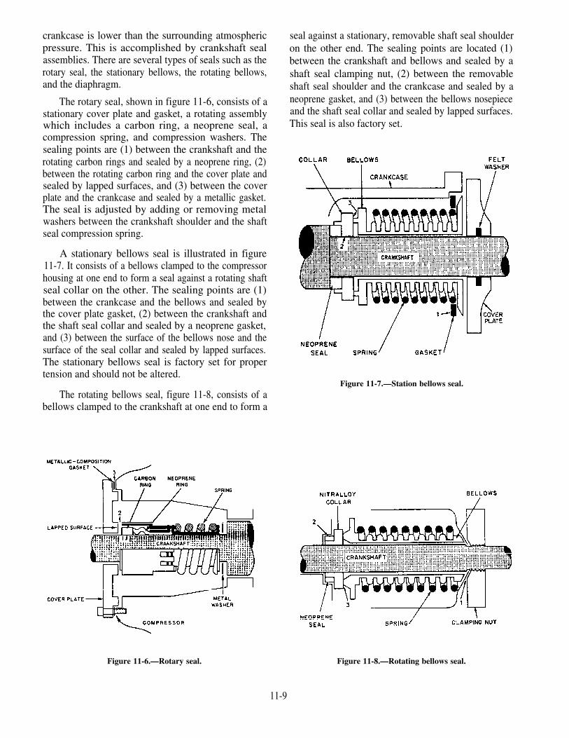
crankcase is lower than the surrounding atmosphericpressure. This is accomplished by crankshaft sealassemblies. There are several types of seals such as therotary seal, the stationary bellows, the rotating bellows,and the diaphragm.
The rotary seal, shown in figure 11-6, consists of astationary cover plate and gasket, a rotating assemblywhich includes a carbon ring, a neoprene seal, acompression spring, and compression washers. Thesealing points are (1) between the crankshaft and therotating carbon rings and sealed by a neoprene ring, (2)between the rotating carbon ring and the cover plate andsealed by lapped surfaces, and (3) between the coverplate and the crankcase and sealed by a metallic gasket.The seal is adjusted by adding or removing metalwashers between the crankshaft shoulder and the shaftseal compression spring.
A stationary bellows seal is illustrated in figure11-7. It consists of a bellows clamped to the compressorhousing at one end to form a seal against a rotating shaftseal collar on the other. The sealing points are (1)between the crankcase and the bellows and sealed bythe cover plate gasket, (2) between the crankshaft andthe shaft seal collar and sealed by a neoprene gasket,and (3) between the surface of the bellows nose and thesurface of the seal collar and sealed by lapped surfaces.The stationary bellows seal is factory set for propertension and should not be altered.
seal against a stationary, removable shaft seal shoulderon the other end. The sealing points are located (1)between the crankshaft and bellows and sealed by ashaft seal clamping nut, (2) between the removableshaft seal shoulder and the crankcase and sealed by aneoprene gasket, and (3) between the bellows nosepieceand the shaft seal collar and sealed by lapped surfaces.This seal is also factory set.
Figure 11-7.—Station bellows seal.The rotating bellows seal, figure 11-8, consists of a
bellows clamped to the crankshaft at one end to form a
Figure 11-6.—Rotary seal. Figure 11-8.—Rotating bellows seal.
11-9

The diaphragm seal, figure 11-9, consists of adiaphragm clamped to the crankcase at its outercircumference and to a fulcrum ring at its center. Thefulcrum ring forms a seal collar which is locked to thediaphragm. The sealing points are located (1) betweenthe outer circumference of the diaphragm and thecrankcase and sealed by a copper ring gasket, (2)between the fulcrum ring and the diaphragm-sealed atthe factory and not to be broken, (3) between thefulcrum ring and the rotating shaft seal collar and sealedby lapped surfaces, and (4) between the shaft seal collarand the crankshaft shoulder and also sealed by lappedsurfaces.
The tension in a diaphragm seal is adjusted byadding or removing diaphragm-to-crankcase gaskets toobtain the specified deflection. For information onhandling, cleaning, and replacing shaft seal assemblies,consult the manufacturer’s technical manual or thedirections enclosed with the new seal.
CAPACITY CONTROL SYSTEM.—Mostcompressors are equipped with an oil pressure operatedautomatic capacity control system. This systemunloads or cuts cylinders out of operation followingdecreases in the refrigerant load requirements of theplant. A cylinder is unloaded by a mechanism thatholds the suction valve open so that no gas can becompressed.
Since oil pressure is required to load or putcylinders into operation, the compressor will start withall controlled cylinders unloaded. But as soon as thecompressor comes up to speed and full oil pressure isdeveloped, all cylinders will become operative. Afterthe temperature pulldown period, the refrigeration loadimposed on the compressor will decrease, and thecapacity control system will unload cylindersaccordingly. The unloading will result in reducedpower comsumption. On those applications wherenumerous cooling coils are supplied by one compressor,the capacity control system will prevent the suctionpressure from dropping to the low-pressure cutoutsetting. This will prevent stopping the compressorbefore all solenoid valves are closed.
Several designs of capacity control systems are inuse. One of the most common is shown in figure 11-10.The capacity control system consists of a power elementand its linkage for each controlled cylinder, a stepcontrol hydraulic relay, and a capacity control valve.
The system’s components are all integrally attachedto the compressor. The suction or crankcase pressureof the refrigeration plant is sensed by the capacity
control valve to control the system. In other words, achange in the refrigeration load on the plant will causea change in suction pressure. This change in suctionpressure will then cause the capacity control system toreact according to whether the suction pressureincreased or decreased. The working fluid of thesystem is compressor oil pump pressure. Compressoroil pump pressure is metered into the system through anorifice. Once the oil passes the orifice, it becomes thesystem control oil and does work.
Locate the following components on figure 11-10,and use them to read the next two paragraphs.
(1) Compressor oil pump pressure tap-off
(2) Control oil strainer
(3) Hydraulic relay
(4) Hydraulic relay piston
(5) Unloader power element
(6) Unloader power element piston
(7) Lifting fork
(8) Unloader sleeve
(9) Suction valve
(10) Capacity control valve
(11) Crankcase (suction) pressure sensing point
The following functions take place when thecompressor is started with a warm load on therefrigeration system.
Compressor oil (1) is pumped through the controloil strainer (2) into the hydraulic relay (3). There the
11-10
Figure 11-9.—Diaphragm-type seal.
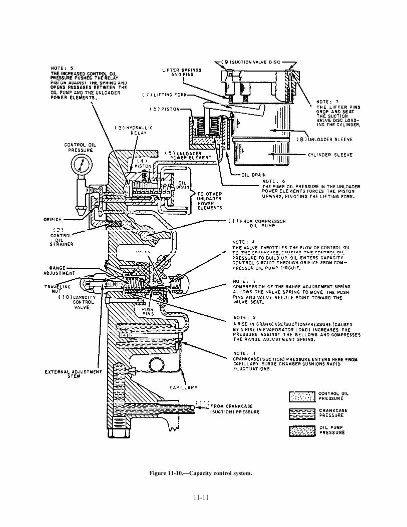
Figure 11-10.—Capacity control system.
11-11

oil flow to the unloader power elements is controlled insteps by the movement of the hydraulic relay piston (4).As soon as pump oil pressure reaches a power element(5), the piston (6) rises, the lifting fork (7) pivots, andthe unloader sleeve (8) lowers, permitting the suctionvalve (9) to seat. The system is governed by suctionpressure which actuates the capacity control valve (10).This valve controls the movement of the hydraulic relaypiston by metering the oil bleed from the control oil sideof the hydraulic relay back to the crankcase.
Suction pressure increases or decreases accordingto increases or decreases in the refrigeration loadrequirements of the plant. After the temperaturepulldown period with a subsequent decrease in suctionpressure, the capacity control valve moves to increasethe control oil bleed to the crankcase from the hydraulicrelay. There is a resulting decrease in control oilpressure within the hydraulic relay. This decreaseallows the piston to be moved by spring action. Thisaction successively closes oil ports and preventscompressor oil pump pressure from reaching theunloader power elements. As oil pressure leaves apower element, the suction valve rises and that cylinder
A. Cutaway view.B. Water-flow diagram.C. Arrangement of heat joint.
Figure 11-11.—Watercooled condenser for R-12refrigeration system. Figure 11-12.—Receiver.
11-12
unloads. With an increase in suction pressure, theabove process is reversed, and the controlled cylinderswill load in succession. The loading process is detailedin steps 1 through 7 in figure 11-10.
Condenser
The compressor discharges the high-pressure,high-temperature refrigerant vapor to the condenser,where it flows around the tubes through which seawateris being pumped. As the vapor gives up its superheat(sensible heat) to the seawater, the temperature of thevapor drops to the condensing point. The refrigerant,now in liquid form, it subcooled slightly below itscondensing point. This is done at the existing pressureto ensure that it will not flash into vapor.
A watercooled condenser for an R-12 refrigerationsystem is shown in figure 11-11. Circulating water isobtained through a branch connection from the firemain or by means of an individual pump taking suctionfrom the sea. The purge connection, shown in figure11-11, is on the refrigerant side. It is used to remove airand other noncondensable gases that are lighter than theR-12 vapor.
Most condensers used for naval refrigeration plantsare of the watercooled type. However, some smallunits have air-cooled condensers. These consist oftubing with external fins to increase the heat transfersurface. Most air-cooled condensers have fans toensure positive circulation of air around the condensertubes.

Receiver
The receiver, shown in figure 11-12, acts as atemporary storage space and surge tank for the liquidrefrigerant. The receiver also serves as a vapor seal tokeep vapor out of the liquid line to the expansion valve.Receivers may be constructed for either horizontal orvertical installation.
ACCESSORIES
In addition to the five main components justdescribed, a refrigeration system requires a number ofcontrols and accessories. The most important of thesewill be described briefly in the following paragraphs.
Dehydrator
A dehydrator, or dryer, containing silica-gel oractivated alumina, is placed in the liquid refrigerant linebetween the receiver and TXV. In older installations,bypass valves allow the dehydrator to be cut in or outof the system. In newer installations, the dehydrator isinstalled in the liquid refrigerant line without anybypass arrangement. A dehydrator is shown in figure11-13.
Moisture Indicator
A moisture indicator is either located in the liquidrefrigerant line or built into the dehydrator. Themoisture indicator contains a chemically treated
Figure 11-13.—Refrigeration dehydrator.
element which changes color when there is an increaseof moisture in the refrigerant. The color change isreversible and will change back to a DRY reading whenthe moisture is removed from the refrigerant. Excessivemoisture or water will damage the moisture indicatorelement and turn it pink, which indicates it must bereplaced.
Solenoid Valve and Thermostatic ControlSwitch
A solenoid valve is installed in the liquid lineleading to each evaporator. Figure 11-14 shows a
Figure 11-14.—Solenoid valve and thermostatic controlswitch.
11-13

solenoid valve and the thermostatic control switch thatoperates it. The thermostatic control switch isconnected by long flexible tubing to a thermal controlbulb which is located in the refrigerated space. Whenthe temperature in the refrigerated space drops to thedesired point, the thermal control bulb causes thethermostatic control switch to open. This action closesthe solenoid valve and shuts off all flow of liquidrefrigerant to the TXV. When the temperature in therefrigerated space rises above the desired point, thethermostatic control switch closes, the solenoid valveopens, and liquid refrigerant once again flows to theTXV.
The solenoid valve and its related thermostaticcontrol switch maintain the proper temperature inthe refrigerated space. You may wonder why thesolenoid valve is necessary if the TXV controls theamount of refrigerant admitted to the evaporator.Actually, the solenoid valve is not necessary on unitsthat have only one evaporator. In systems that havemore than one evaporator, where there is wide variationin load, the solenoid valve provides additional controlto prevent the spaces from becoming too cold at lightloads.
In addition to the solenoid valve installed in the lineto each evaporator, a large refrigeration plant usuallyhas a main liquid line solenoid valve installed just afterthe receiver. If the compressor stops for any reasonexcept normal suction pressure control, the main liquidsolenoid valve closes. This prevents liquid refrigerantfrom flooding the evaporator and flowing to thecompressor suction. Extensive damage to thecompressor can result if liquid is allowed to enter thecompressor suction.
Evaporator Pressure RegulatingValve
In some ships, several refrigerated spaces ofvarying temperatures are maintained by onecompressor. In these cases, an evaporator pressureregulating valve is installed at the outlet of eachevaporator EXCEPT the evaporator in the space inwhich the lowest temperature is to be maintained. Theevaporator pressure regulating valve is set to keep thepressure in the coil from falling below the pressurecorresponding to the lowest evaporator temperaturedesired in that space.
The evaporator pressure regulating valve is usedmostly on water coolers, on units where high humidityis required (such as fruit and vegetable stowage spaces),
and in installations where two or more rooms aremaintained at different temperatures by the use of thesame refrigeration unit.
A cross section of a common evaporator pressureregulating valve (commonly called EPR valve) isshown in figure 11-15. The tension of the spring abovethe diaphragm is adjusted so that when the evaporator
Figure 11-15.—Exploded view of a typical evaporatorpressure regulating valve (EPR).
11-14

coil pressure drops below the desired minimum, thespring will shut the valve.
The EPR valve is not really a temperaturecontrol—that is, it does not regulate the temperature inthe space. It is only a device to prevent the temperaturefrom becoming too low.
Low-Pressure Cutout Switch
The low-pressure cutout switch is also knownas a suction pressure control switch. It is thecontrol that causes the compressor to go on oroff as required for normal operation of therefrigeration plant. This switch is located on thesuction side of the compressor and is actuated bypressure changes in the suction line. When thesolenoid valves in the lines to the various evaporatorsare closed so that the flow of refrigerant to theevaporators is stopped, the pressure of thevapor in the compressor suction line drops quickly.When the suction pressure has dropped to thedesired pressure, the low-pressure cutout switch causesthe compressor motor to stop. When the temperaturein the refrigerated spaces has risen enough tooperate one or more of the solenoid valves,refrigerant is again admitted to the cooling coils,and the compressor suction pressure builds up again.At the desired pressure, the low-pressure cutoutswitch closes, starting the compressor again andrepeating the cycle.
High-Pressure Cutout Switch
A high-pressure outout switch is connected tothe compressor discharge line to protect thehigh-pressure side of the system against excessivepressures. The design of this switch is essentiallythe same as that of the low-pressure cutout switch.However, the low-pressure cutout switch is madeto CLOSE when the suction pressure reaches itsupper normal limit. The high-pressure cutout switchis made to OPEN when the discharge pressure is toohigh. As mentioned before, the low-pressure cutoutswitch is the compressor control for normal operationof the plant. The high-pressure cutout switch, on theother hand, is a safety device only and does not havecontrol of compressor operation under normalconditions.
Oil Failure Switch
An oil failure switch is provided with high-speedcompressors. The switch is designed to prevent
operation of the compressor in the event of low oilpressure. The switch has one bellows connected to theoil pressure on the discharge of the compressor oil pumpand the other connected to the compressor suctionrefrigeration pressure. The switch is set to open theelectrical circuit and stop the compressor when the oilpressure drops to a low-pressure set point.. It closes theelectrical circuit and starts the compressor when the oilpressure reaches the reset set point.
To start the compressor after it has been stopped andthe contacts of the oil failure switch have opened, a timedelay mechanism is used with the compressor motorstarter. The time delay switch will open 10 to 30seconds after the compressor motor has been started.The oil pressure normally will be built up in this timeinterval. The oil pressure switch will have made contactto keep the compressor motor electrical circuitenergized after the time delay switch opens. If the oilpressure has not built up within about 30 seconds afterthe compressor is started, the contacts of the oil pressuredifferential switch will not have closed. Thecompressor will stop because the time delay relayswitch is open.
Water Failure Switch
A water failure switch stops the compressor in theevent of failure of the circulating water supply. This isa pressure-actuated switch. It is generally similar to thelow-pressure cutout switch and the high-pressure cutoutswitch previously described. If the water failure cutoutswitch fails to function, the refrigerant pressure in thecondenser will quickly build up to the point that thehigh-pressure switch stops the compressor.
Strainer
Because of the solvent action of R-12, any particlesof grit, scale, dirt, or metal that the system may containare readily circulated through the refrigerant lines. Toavoid damage to the compressor from such foreignmatter, a strainer is installed in the compressor suctionconnection.
Spring-Loaded Relief Valve
A spring-loaded relief valve is installed in thecompressor discharge line as an additional precautionagainst excessive pressures. The relief valve is set toopen at approximately 225 psig. Therefore, it functionsonly in case of failure or improper setting of thehigh-pressure cutout switch. If the relief valve opens,
11-15

it discharges high-pressure vapor to the suction side ofthe compressor.
The type of pressure-actuated control switch usedin all of the above installations is the general type shownin figure 11-16 with its cover removed. (The oilpressure failure switch has two bellows instead of theone shown in the illustration.) These switches operateat various pressure ranges. Some switches have manualreset buttons to prevent the automatic restoration ofpower after a pressure failure, such as a high dischargepressure.
Water Regulating Valve
A water regulating valve controls the quantity ofcirculating water flowing through the refrigerantcondenser. The water regulating valve is actuated bythe refrigerant pressure in the compressor dischargeline. This pressure acts upon a diaphragm (or, in somevalves, a bellows arrangement) which transmits motionto the valve stem.
The primary function of the water regulating valveis to maintain a constant refrigerant condensingpressure. Basically, two variable conditions exist:(1) the amount of refrigerant to be condensed and(2) changing water temperatures. The valve maintains
Figure 11-16.—Pressure-actuated control switch. Figure 11-17.—Strainer of liquid refrigerant.
11-16
a constant refrigerant condensing pressure bycontrolling the water flow through the condenser. Bysensing the refrigerant pressure, the valve permits onlyenough water through the condenser to condense theamount of refrigerant vapor coming from thecompressor. The quantity of water required tocondense a given amount of refrigerant varies with thewater temperature. Thus, the flow of cooling waterthrough the condenser is automatically maintained atthe rate actually required to condense the refrigerantunder varying conditions of load and temperature.
Liquid Strainer
A liquid strainer of the type shown in figure 11-17is also installed in the liquid line leading to eachevaporator. These strainers protect the solenoid valvesand the TXV.
Pressure Gages and Thermometers
A number of pressure gages and thermometers areused in refrigeration systems. Figure 11-18 shows acompound R-12 gage. The temperature markings onthis gage show the boiling point (or condensing point)of the refrigerant at each pressure; the gage cannotmeasure temperature directly. The red pointer is a

Figure 11-18.—Compound R-12 pressure gauge.
stationary marker that can be set manually to indicatethe maximum working pressure.
A water pressure gauge is installed in thecirculating water line to the condenser to indicate failureof the circulating water supply.
Standard thermometers of appropriate range areprovided for the refrigerant system.
Refrigerant Piping
Refrigerant piping in modern naval installations ismade of ACR seamless copper. Copper is good for thispurpose because (1) it does not become corroded byrefrigerants; (2) the internal surface of the tubing issmooth enough to minimize friction; and (3) coppertubing is easily shaped to meet installationrequirements.
Packless Valves
Nearly all hand-operated valves in largerefrigeration systems are packless valves of the typeshown in figure 11-19. In this type of valve, the upperpart is sealed off from the lower part by a diaphragm.An upward-seating ball check in the lower valve stemmakes it possible for the spring to lift the lower stemregardless of pressure differences developed while thevalve was closed. Thus, the valve will operate properlyregardless of direction of flow. By backseating the
Figure 11-19.—Packless valve for refrigeration system.
valve, the diaphragm can be changed without placingthe system or unit out of operation.
OPERATING PROCEDURES FOR ANR-12 SYSTEM
You will need some very specific training beforeyou become a good refrigeration system operator. First,you need a lot of practical experience on the systems.Second, you need to pay close attention to theprocedures followed by qualified personnel.
Your first responsibility with an R-12 system willprobably require you to check temperatures andpressures, maintain the plant operating log, detectsymptoms of faulty operation, and check conditions inthe spaces or units being cooled.
The intervals of time between plant inspections willvary depending on the purpose of the plant. Thetemperatures and pressures throughout the system andthe oil level in the compressor crankcase are checkedevery hour. The results are recorded unless watchstanding instructions specify otherwise. These checksare used to determine whether the plant is operatingproperly. One of the best methods for checking is tocompare the existing temperatures and pressures withthose recorded when the plant was known to beoperating properly, under conditions similar to thepresent conditions.
11-17

OPERATING AN R-12 PLANT INAUTOMATIC
After the prescribed operating pressures andtemperatures have been established with thecompressor running in MANUAL, place the selectorswitch in the AUTOMATIC position.
NOTE: A refrigeration compressor shouldNEVER be left unattended when in the MANUALmode of operation.
The suction-pressure control (low-pressure cutoutswitch) is connected electrically to start and stop thecompressor automatically on the basis of loadconditions. If the automatic control valves andswitches are in proper adjustment, the operation of theplant, after proper starting, will be entirely automatic.
When the selector switch is set for automaticoperation, the water failure switch, the high-pressureswitch, or the low-pressure switch will close andenergize their respective circuits.
In some installations, the supply of condensercooling water comes directly from a centrifugal pumpor from the fire and flushing main. If cooling water isobtained from the fire and flushing main, the pumpcontroller switch is opened manually. The water failureswitch remains closed regardless of the source ofcondenser cooling water.
In systems not equipped with water regulatingvalves, normal operating conditions generally producecondensing pressures of less than 125 psi. This happensbecause the condensing water temperature is usuallyless than 85°F. Where the system does have thesevalves, they should be adjusted to maintain thecondensing pressure at 125 psi. When the valves are soadjusted, the quantity of cooling water requireddecreases rapidly with decreasing circulating watertemperatures. In systems equipped with air-cooledcondensers, condensing pressures may exceed 125 psiwhen the temperature of the surrounding air is higherthan normal.
NOTES ON COMPRESSOROPERATION
An R-12 compressor should not remain idle for anextended period of time. When a plant has two or morecompressors, they should be operated alternately. Thetotal operating time on each of the compressors shouldbe approximately the same. An idle compressor shouldbe operated at least once a week.
Only one compressor should serve a cooling coilcircuit. When compressors are operated in parallel ona common cooling circuit, lubricating oil may betransferred from one compressor to another. This maycause serious damage to all compressors on the circuit.
MAINTENANCE OF R-12SYSTEMS
You will be expected to do some of the maintenancethat keeps a refrigeration plant operating efficiently.You will need to understand and use the procedureslisted below and described in the following paragraphs:
1. Defrosting cooling coils
2. Pumping down refrigeration systems
3. Testing for refrigeration leaks
4. Testing for air and noncondensable gases
5. Checking compressor oil
6. Caring for V-belts
7. Setting control and safety devices
8. Testing and renewing compressor valves
9. Caring for shaft seals
DEFROSTING COOLING COILS
The cooling coils should be defrosted as often asnecessary to maintain the effectiveness of the coolingsurface. Too much frost on the coils results in reducedcooling capacity, low compressor-suction pressure, anda tendency for the compressor to short cycle. Themaximum permissible time interval between defrostingoperations depends on many factors. Some of these arerefrigerant evaporating temperature, free-moisturecontent of supplies placed in the refrigerated space,temperature of refrigerated spaces, frequency ofopening of cold-storage compartment doors, andatmospheric humidity.
The most common method of defrosting a coolingcoil in the average refrigeration installation requirestwo steps: (l)shut off the supply of R-12 to the coil tobe defrosted by closing the liquid-line stop valve aheadof the expansion valve and (2) leave the entrance dooropen to permit the temperature in the compartment torise above 32°F. The frost will melt off the coils or maybe easily brushed off. Since the cooling coils are madeof tinned copper or galvanized steel tubing, take carenot to damage the evaporator coil.
11-18

Most refrigeration systems now in use are providedwith HOT-GAS DEFROSTING lines. These linesfacilitate defrosting where compartment temperaturesare maintaned at 32°F or less. The principal advantageof hot-gas defrosting is that the freeze-room coils canbe defrosting while the rest of the plant operatesnormally.
In the following paragraphs, defrosting procedureswill refer only to freeze-room coils.
A hot-gas defrosting line leads from the compressordischarge piping to the tail coil of the freeze-roomcooling coil. The hot-gas line joins the suction linebetween the freeze room and the suction valve.Therefore, hot gas admitted to the freeze-room coolingcoil flows “backwards” through the coil. In otherwords, the hot gas flows in the direction opposite theflow of refrigerant under normal operating conditions.
To defrost the coils of the freeze room, follow thesesteps. Close the normal refrigerant-liquid supply andthe suction return-line valves of the freeze-roomcooling coil. Then, open the valve in the hot-gas supplyline to admit compressed refrigerant gas to the coil. Asthe frost melts on the exterior coil surfaces, the gas iscondensed in the coils and becomes a liquid. The liquidis led from the inlet end of the freeze-room cooling coilto the main liquid supply line. It is used in the othercompartments.
When the defrosting has been completed, return thesystem to its normal operating condition. Do this by (1)closing the defrosting valves and (2) opening the valvesin the refrigerant-liquid supply line to the freeze-roomcoil and the suction return valve from the freeze-roomcoil. Take care that all liquid refrigerant has beendischarged from the freeze-room coil before the suctionline valve from the compartment is opened. If all theliquid has not been discharged, liquid slugs may bereturned to compressor.
PUMPING DOWN A REFRIGERANTSYSTEM
The pumping-down procedure will depend on themaintenance to be done. In some cases, maintenancecan be performed on the charged system after a part tobe repaired or replaced has been isolated. Generally, itis possible to pump down any part of a charged system(except the condenser, the liquid receiver, and thecompressor discharge line) by the use of cutout valves.When repairs are to be made to a major portion of thesystem, the system must be pumped down to return allrefrigerant to the receiver.
If repairs are to be made to the receiver, thecondenser, or the compressor discharge line, the entiresystem must be drained into spare refrigerant drums.However, the procedure is different when a system hasvalves to isolate the compressor discharge line andcondenser and when it is not objectionable to releaserefrigerant to the atmosphere. (This refers to refrigerantwhich may be trapped in the condenser after the systemhas been pumped down to the receiver.) In this case,repairs to the compressor discharge line and condensermay be made with this section isolated.
It is sometimes necessary to open a charged systemto make repairs or replacements or to clean strainers. Inthis case, the refrigerant pressure within the part of thesystem to be opened should be pumped down to apressure slightly above atmospheric (l/2 psig to 2 psig)before any connections are broken. As a part of thesystem that contains liquid R-12 is pumped down, thesystem’s temperature will decrease as a result of theevaporation of the liquid refrigerant. When thetemperature of such a part of the system begins to riseto normal again, while the low pressure in the part ismaintained, it is reasonably certain that all R-12 liquidwithin the part has evaporated.
During the final evacuation of the system, youmay reach a pressure of less than 0 psig. If so, youshould immediately bleed enough refrigerant into theevacuated part of the system to raise the pressure tobetween l/2 psig and 2 psig. Connections may bethen be opened, and repairs, replacements of parts, orother necessary service operations may be accom-plished.
When a refrigerant system is opened, you shouldtemporarily plug the free ends of the refrigerant lines tokeep out air and dirt When remaking the connections,make one tight and leave the other loose temporarily.This will help sweep air and other foreign matter out ofthe free end as the system is slowly purged withrefrigerant gas bled from the charge in the system.Then, quickly tighten the remaining looseconnection(s). Refrigerant lines, oil-charging lines,gage lines, and control lines are generally of smallsize and short length. Still, they should be purgedwith refrigerant gas immediately before they areconnected to the system. You may remove someconnecting lines that you plan to use again. If so, capthe ends to protect the threads and keep the inside of thelines clean.
When major repairs are to be made to a majorportion of the system or when the system is to be secured
11-19

for an extended period, the refrigerant system must bepumped down to return all refrigerant to the reciever.Keep enough refrigerant gas within the system tocreate a positive pressure of approximately 2 psigthroughout the circuit. The exception is the areaswithin the compressor discharge line and thecondenser and between the receiver and the mainliquid-line shutoff valve. To pump down the system,close to main liquid-line shutoff valve and thedehydrator-bypass valve (if installed), and open thecooling-coil solenoid valves. Allow the compressorto operate on manual control until the suction pressurereaches approximately l/2 psig to 2 psig; then stopthe compressor. Repeat the operation until the liquidrefrigerant in the circuit has evaporated, and thesuction pressure remains relatively constant at l/2 psigto 2 psig.
During the pump-down period, you can tracethe evaporation of liquid refrigerant in the liquid lineback to the main liquid-line shutoff valve. Youcan see frost forming and then melting as the liquidrefrigerant is evaporated and super-heated. Open thepower-supply switch to the compressor; close thecompressor suction and discharge shutoff valves.Shut off the water supply to the condenser anddrain the condenser water. When the amount ofliquid refrigerant contained in the system is in excess ofthe capacity of the receiver, the surplus liquidrefrigerant must be drawn off into separate refrigerantdrums.
You will need to drain the refrigerant chargefrom the system when it is necessary to make repairs.These repairs may be to the condenser, the liquidreceiver, or the compressor discharge line, or forany other reason. Use the following proce-dures:
1. Close the liquid-line valve at the recieveroutlet. Start the compressor and pump down thecooling coil and suction-line pressure to the point atwhich the low-pressure control switch stops theunit.
2. The compressor will be stopped by thelow-pressure cutout switch. Restart the unit manuallyand continue the pumping-down procedure until thesuction pressure reaches approximately 2 psig andstops the compressor. Repeat the operation inperiodic cycles until the liquid refrigerant in thecircuit has evaporated and the suction pressureremains relatively constant between l/2 psig and 5psig.
3. Close the compressor discharge line valve,and close all liquid valves at the cooling coils.
4. Connect an empty R-12 service drum to therefrigerant drain valve. (Before connecting the drum tothe R-12 system, cool the drum thorougly so therefrigerant will drain rapidly into the drum.) Alwaysuse a clean R-12 service drum, containing no air orwater, so that the drained R-12 is kept in suitablecondition for future use.
5. Purge the air out of the line connecting the drainvalve and the drum. Do this by leaving the connectionat the drum valve open as you slowly flush refrigerantthrough the line and out at the connection. Close theconnection. Drain the R-12 into the cooled drum byopening the drain valve and the service drum valve.
6. When the service drum is full, close the drainvalve and permit the R-12 liquid in the drain line toevaporate. Close the service drum valve and disconnectthe drum from the system.
7. Weigh the drum while filling to be certain thatit is not overcharged. The net and gross weights arestamped on the drum. (These weights include that ofthe cast iron protector cap which fits over the cylindervalve.)
CAUTION: NEVER fill a service drum beyond itsrated capacity. Drum rupture may result from hydraulicpressure caused by a rise in temperature.
TESTING FOR REFRIGERANTLEAKS
Refrigerant leaks mean the loss of refrigerationand refrigerant. Various tests are used to determinethe existence of leaks in refrigerant systems. Pressuretests are used after a system has been installed andafter extensive repairs or replacement of parts hasbeen made. Pressure tests are made BEFORE thesystem is charged with refrigerant. Charged systemsare tested for leakage with either an electronicrefrigerant gas detector or with soapsuds. The methodto be used depends largely upon the size of the leak andupon the type of space in which the test is to beperformed.
You will be required to use the detectors andsoapsuds to check for the refrigerant leakage.
In addition to tests for leaks that are made atperiodic intervals, tests should be made before thecompressors are started and at any other time that ashortage of refrigerant in the system is suspected. Here
11-20

are some unusual operating conditions which indicatea shortage of refrigerant in the system.
1. High suction-line temperatures
2. Relatively high crankcase and cylindertemperatures
3. Excessively high refrigerant temperature in theliquid line
4. Bubbles in the refrigerant sight-flow indicator
5. Liquid refrigerant carrying parially through thecoil with considerable superheat at the thermal element
6. A short cycle or a compressor runningcontinuously
7. Excessive oil seepage at the shaft sealconnection
8. Oil seepage at the refrigerant-system piping andcompressor connections
A shortage of refrigerant in the system nearlyalways indicates leaks. When a shortage is found, theentire system should be tested for leaks by one of thefollowing methods.
Electronic Leak Detector
The electronic leak detector (not shown) is batteryoperated and has an exploring tube similar to the halidedetector. It has an on-and-off switch and a sensitivityswitch. When you put it into operation, the detectorwill make a clicking sound. When it picks up aconcentration of refrigerant, it produces a high pitchsqueal. For further information on the electronicleak detector, refer to the manufacturer’s technicalmanual.
CAUTION: Do NOT use a halide or electronic leakdetector in any ammunition spaces. Soapsuds is theONLY method of leak detection to be used in thesespaces.
A halide torch or an electronic refrigerant gasdetector is so sensitive that it is useless if the atmosphereis contaminated by excessive leakage of R-12. This ismost likely to happen in a small or poorly ventilatedcompartment. If a compartment is contaminated byR-12 and cannot be ventilated, or if in an ammunitionspace, the soapsuds test must be used.
Soapsuds Test
When using the soapsuds test, prepare thesoap-and-water solution so that it has the consistency
of liquid hand soap and will work up a lather on a brush.(The lather will remain wet for a longer period if a fewdrops of glycerine are added to the solution.)
Apply the lather all the way around the joint; thenlook carefully for bubbles. If a joint is so located that apart of it is not visible, use a small mirror to inspect thatpart.
Remember that it sometimes takes a minute or morefor bubbles to appear if the leak is small. Doubtful spotsshould be lathered and examined a second time.
Always follow a definite procedure in testing forrefrigerant leaks so that you do not miss any joints. Ifavailable, use a ship’s plan or authorized drawing of thesystem to map out your search. The extra time spent intesting all joints will be justified. The smallest leak isimportant. However, insignificant the leak may seem,it eventually empties the system of its charge to the pointof faulty plant operation. Because R-12 is practicallyodorless, the first indication of a leak is the loss ofrefrigerating effect. A refrigerant system should neverbe recharged until all leaks are discovered and repaired.
NEVER use oil to test for R-12 leaks. Oil is notreliable because of its capacity to absorb R-12. If asmall leak should exist where oil has been applied, theR-12 will be absorbed by the oil and will show noindication (bubbles) of the leak until the oil is saturatedwith R-12. However, the presence of oil on a line orjoint is a good indication of a leak.
TESTING FOR AIR ANDNONCONDENSABLE GASES
You MUST take precautions to keep air andnoncondensable gases out of a refrigerant system.When air enters the system, you must purge thecondenser and that means a loss of refrigerant.Atmospheric air always contains some moisture whichwill enter the system when air does. A refrigerantsystem must be kept as moisture free as possible. Thiswill eliminate such troubles as water freezing at theexpansion valves, internal oxidation or corrosion ofparts, and emulsification or sludging of lubricating oils.
Air and noncondensable gases in a refrigerantsystem are pumped through the system and aredischarged by the compressor into the condenser.These gases are trapped in the condenser by the liquidseal maintained over the receiver outlet. Generally,these gases are lighter than the relatively dense R-12vapor. Therefore, they tend to collect in the upper partof the condenser when the compressor is stopped. The
11-21

purge valve for discharging these gases to theatmosphere is located either in the upper part of thecondenser shell or in the compressor discharge lineabove the condenser. While the compressor is inoperation, any noncondensable gases in the system arethoroughly mixed with the R-12 vapor. This mixing iscaused by the turbulence produced by the rapidlypulsating discharge of refrigerant into the condenser.Therefore, you should not try to purge noncondensablegases from the system while the compressor is inoperation. Noncondensable gases in a condenser causeexcessive condensing pressures and a loss in plantefficiency.
The best time to check an R-12 system fornoncondensable gases is immediately before thecompressor starts after a shutdown period. When acondenser is to be checked for noncondensable gases,the gauges and thermometers used must be incalibration. The system must have sufficient refrigerantcharge so that the liquid refrigerant present in thereceiver will seal the liquid-line connection.
The following procedure should be followed tocheck a refrigerant system for noncondensablegases:
1. Close the liquid-line valve.
2. Shut off the compressor and close thesuction-line valves.
3. Determine the actual condensing temperature ofthe refrigerant. Install a service gauge in thec o m p r e s s o r d i s c h a r g e c o n n e c t i o n i f adischarge-pressure gauge is not already provided. Anapproximation of the actual condensing temperature ofthe refrigerant has been reached when there is no furtherdecrease in the discharge pressure. (On watercooledcondensers, you can speed up on the reduction inpressure by circulating the condenser water until thedischarge pressure is reduced.) In most ships thethermometer in the liquid line at the receiver indicatesthe actual condensing temperature. If a thermometer isnot installed in an air-cooled condenser application, oneshould be placed near the condenser to record theambient temperature at that location. When thetemperature of an air-cooled condenser has dropped tothe ambient temperature, the reading of thethermometer will approximate the actual condensingtemperature.
4. On the compound-pressure gauge, read thecondensing temperature which corresponds to thecondensing pressure registered by the high-pressuregauge. The temperature indicated on the temperature
scale is the condensing temperature of pure R-12 at thepressure indicated by the gauge.
5. Subtract the existing condensing temperaturefrom the condensing temperature of pure R-12 at theexisting condenser pressure. If the difference betweenthese two temperatures is more than 5°F, it will benecessary to purge the condenser of noncondensablegases.
If the above test indicates the need for purging,slowly release the noncondensable gases. When apurge valve is not provided, purge the gases by openingthe discharge-pressure gauge connection.
Some of the R-12 gas will mix with the condensablegases and escape while the condenser is being purged.The amount will depend on the rate or purging and uponthe concentration of the noncondensable gases in thecondenser. There is no practical test aboard ship todetermine definitely when an excessively highproportion of R-12 gas is being purged with thenoncondensable gases. To keep the R-12 loss to aminimum when the condenser is being purged, purgeslowly and frequently check the condenser fornoncondensable gases. R-12 is odorless inconcentrations of less than 20 percent by volume in air.In heavier concentrations, however, it resembles carbontetrachloride in odor.
CHECKING COMPRESSOR OIL
If the apparent oil level is lower than normal aftera prolonged shutdown, it is almost certain that the actualworking oil level is far too low. After you have addedenough oil to raise the apparent oil level to the center ofthe bull’s eye sight glass, check the actual oil level asfollows:
1. Operate the compressor on MANUAL controlfor at least 1 hour. If the compressor is operating on awater cooler or other coil that is apt to freeze, observethe temperature and interrupt compressor operation asnecessary to prevent freezing. Repeat cycling until thetotal running time (1 hour) is obtained. Then slowlyclose the suction line stop valve.
2. Stop the compressor. If the compressor is forcelubricated, immediately observe the oil level in the sightglass. If the compressor is splash lubricated, turn theflywheel until the crankshaft and connecting rod endsare immersed in the lubricating oil, then check the oillevel.
11-22

To check the oil level when the compressor has beenrunning on its normal cycle with no abnormal shutdownperiod, proceed as follows:
1. Wait until the end of a period of operation to stopthe compressor. If the operation is continuous, waituntil the compressor has been in operation at leastone-half hour.
2. As soon as the compressor stops, observe the oillevel in the sight glass on force-lubricated compressors.If the compressor is splash lubricated, turn the flywheeluntil the crankshaft and connecting rod ends aresatisfactorily immersed in the lubricating oil; thencheck the oil level.
compressor crankcase is under a slight pressure, doNOT fully remove the drain plug from the compressor.Allow the oil to seep out around the threads of theloosened plug. When the desired amount of oil has beenremoved, tighten the drain plug, open the suction anddischarge line valves, and start the compressor. If an oildrain valve is provided instead of a plug, you can drainthe required amount of oil without pumping down thecompressor.
Renewing the Oil
Do NOT remove oil from the crankcase because ofan apparent high level unless too much oil has beenpreviously added or unless it is apparent that oil fromthe crankcase of one compressor of the plant has beeninadvertently deposited in the crankcase of another.
However, if the oil level is lower than itsrecommended height on the glass, add enough oil toobtain the desired level. Do NOT add more oil than isnecessary. Too much oil can cause excessive oiltransfer to the cooling coils.
Adding Oil
Clean copper tubing should be used for R-12systems, and reasonable care should be taken to preventthe entrance of foreign matter and moisture duringinstallation. If this was done, the oil in the compressorcrankcase will probably not become so contaminatedthat it requires renewal more than once a year. Wheniron or steel pipe and fittings are used in the R-12system, a sample of oil from the compressor crankcaseshould be withdrawn into a clean glass container every3 months. If the sample shows contamination, all thelubricating oil should be renewed. It is good practiceto check the cleanliness of the lubricating oil after eachcleaning of the compressor suction scale trap.
Removing Oil
11-23
There are two common methods of adding oil to acompressor. In one type of installation, a smalloil-charging pump is used for adding oil to thecompressor crankcase. In another type, a clean,well-dried funnel is used. In either installation, youmust be careful to prevent air or foreign matter fromentering the compressor.
CARE OF V-BELTS
When performing hourly checks of thecompressors, you may observe either no oil in thecrankcase or a very low oil level on the sight glass. Thisindicates that the oil has left the compressor and iscirculating in the system. It will be necessary to add oiland operate the system. After the compressor hasreclaimed the excessive oil in the system, the excess oilshould be drained.
Excessive looseness will cause slippage, rapidwear, and deterioration of V-belts. On the other hand,a belt that is too tight will cause excessive wear of boththe belt and the main bearing of the compressor. Inextreme cases it may cause a bad seal leak. Whenproperly tightened, a belt can be depressed l/2 to 3/4inch by the pressure of one finger at a point midwaybetween the flywheel and the motor pulleys.
To remove oil from the compressor crankcase,reduce the pressure in the crankcase to approximately1 psi by gradually closing the suction line stop valve.Then stop the compressor and close the suction anddischarge line valves. Loosen the lubricating oil drainplug near the bottom of the compressor crankcase andallow the required amount of oil to drain out. Since the
When you need to replace one belt of a multipleV-belt drive, install a complete new set of matchedbelts. Belts stretch considerably during the first fewhours of operation. Replacement of a single belt willupset the load balance between the new and old beltsand will be a potential source of trouble. It is better torun the unit temporarily with a defective belt removedthan to operate a new belt with two or more seasonedbelts.
V-belts, motor pulleys, and compressor flywheelsshould be kept dry and free of oil. Belt dressing shouldNEVER be used.

NOTE: Other units use flexible couplings toconnect the motor to the compressor. The maintenanceon these couplings should be done following thePlanned Maintenance System (PMS).
SETTING CONTROL AND SAFETYDEVICES
A refrigeration plant cannot operate efficiency andsafely unless the control and safety devices are in goodworking order and set properly. When a new control orsafety device is installed, it must be adjusted or set tofunction at pressures or temperatures following theplant design. Periodic tests and inspections may indi-cate faulty plant operation that is caused by improperlyadjusted control or safety devices. You must know howthese devices operate and how to adjust them.
This section contains information on these commontypes of control and safety devices used by the Navy.
1. High-pressure switch
2. Low-pressure switch
3. Water failure switch
4. Thermostatic expansion valve
5. Water regulating valve
6. Thermostatic switch
7. Automatic reducing valve
The methods of setting the low-pressure switch, thewater failure switch, and the thermostatic switch aresimilar. However, these switches differ as to operatingrange, purpose, and setting. Also, the high-pressureswitch and the water failure switch are safety deviceswhile the low-pressure switch and the thermostaticswitches are control devices. For detailed information,consult Naval Ships’ Technical Manual and themanufacturer’s technical manuals.
High-Pressure Switch
The high-pressure switch has an operating range of60 psig to 350 psig and an adjustable differential(difference between the cut-in point and cutout point).Turn the range adjusting screw clockwise to raise boththe cut-in point and cutout point. Turn itcounterclockwise to lower these points. Thedifferential adjustment affects only the cutout point.Turn it clockwise to raise the cutout point andcounterclockwise to lower the cutout point.
To set the switch, first remove the cover plate. Thenthe two adjusting screws labeled DIFFERENTIAL andRANGE are easily accessible.
1. Start the compressor and control the dischargepressure by throttling the circulating water through thecondenser.
2. Turn the differential screw to its limitcounterclockwise and turn the range screw to its limitclockwise.
3. Raise the compressor discharge to about 10 psigabove the desired cut-in pressure.
4. Turn the range screw counterclockwise until thecontactor in the switch opens, thereby stopping thecompressor.
5. When the discharge pressure drops to thedesired cut-in pressure, turn the range screw clockwiseuntil the contacts close, starting the compressor. Thecut-in point is now set.
6. With the compressor running, turn thedifferential screw to its limit clockwise.
7. Raise the discharge pressure to the desiredcutout pressure.
8. Turn the differential screw counterclockwiseuntil the contacts open, stopping the compressor. Thecutout point is now set.
Low-Pressure Switch
The low-pressure switch has an operating range of20 inches of vacuum to 80 psig and an operatingdifferential of 9 psig to 30 psig.
To set the low-pressure switch, start the compressorand control the suction pressure by throttling thecompressor suction valve.
1. Turn the range and differential adjustmentscrews counterclockwise.
2. Lower the suction pressure to about 10 psigbelow the desired cut-in pressure.
3. Turn the range screw clockwise until the switchcontacts open, stopping the compressor.
4. Allow the suction pressure to rise to the desiredcut-in pressure.
5. Turn the range screw counterclockwise until theswitch contacts close, starting the compressor. Thecut-in point is now set.
6. Turn the differential screw to its limit clockwise.
7. Throttle the suction valve to lower the suctionpressure to the desired cutout pressure.
11-24

8. Turn the differential screw counterclockwiseuntil the switch contacts open, stopping the compressor.The cutout point is now set.
Water Failure Switch
The water failure switch should be set to cut in at15 psig and to cut out at 5 psig. To set the water failureswitch, turn the differential screw to its limitcounterclockwise for minimum differential since therequired differential (difference between cut-in andcutout points) is 10 psig.
1. Throttle the water overboard valve until apressure of 15 psig is maintained at the condenser inlet.
2. Turn the range screw clockwise until the switchcontacts open.
3. Turn the screw counterclockwise slowly untilthe contacts close.
4. Slowly shut off the water supply, decreasing thepressure. The contacts should open at 5 psig.
Thermostatic Expansion Valve
The TXV is generally factory set and seldom needsadjustment. The design and construction of expansionvalves vary greatly. Figure 11-20 shows across-sectional assembly view of a type that is generallyused aboard ship. Other designs may have differentarrangements for adjustment, sealing, and control.
When the TXV is operating properly, thetemperature at the outlet side of the valve is much lower
than that at the inlet side. If this temperature differencedoes not exist when the system is in operation, the valveseat is probably dirty and clogged with foreign matter.
The major trouble encountered can usually betraced to a collection of moisture or dirt at the valve seatand orifice. Carefully analyze the symptoms ofimproper valve operation before you conclude that thevalve is out of adjustment. Once a valve is properlyadjusted, additional adjustment should not be necessaryunless changes are made to the cooling-coilarrangement or thermal element location.
The TXV is adjusted to maintain a superheatranging from approximately 4° to 12°F at thecooling-coil outlet. This is done by means of a gear andscrew arrangement. The proper superheat adjustmentvaries with the design and service-operating conditionsof the valve anad the design of the particular plant.Increased spring pressure increases the degree ofsuperheat at the coil outlet, and decreased pressure hasthe opposite effect. Many TXVs are initially adjustedby the manufacturer to maintain a predetermined degreeof superheat. In these cases, there is provision forfurther adjustments in service.
If expansion valves are adjusted to give a highdegree of superheat at the coil outlet or if the valve isstuck shut, the amount of refrigerant admitted to thecooling coil will be reduced. When there is not enoughrefrigerant, the coil will be "starved" and will operate ata reduced capacity. Compressor lubricating oil carriedwith the refrigerant may collect at the bottom of the
Figure 11-20.—Thermostatic expansion valve.
11-25

cooling coils. This robs the compressor crankcase andprovides a condition whereby slugs of lubricating oilmay be drawn back to the compressor. If the expansionvalve is adjusted for a too-low degree of superheat or itthe valve is stuck open, liquid refrigerant may floodfrom the cooling coils back to the compressor. If theliquid collects at a low point in the suction line or coiland is drawn back to the compressor intermittenly inslugs, there is danger of injury to the moving parts ofthe compressor.
In general, the expansion valves for air-conditioning and water cooling plants (high-temperature installations) must be adjusted for highersuperheat than those for cold storage refrigeration andship’s service store equipment (low-temperatureinstallations).
Water Regulating Valve
The water regulating valve should be adjusted tomaintain a compressor discharge pressure ofapproximately 125 psig. An increase in the tension onthe main spring increases the amount of pressurerequired to open the valve; a decrease in tensiondecreases the required amount of pressure. Turn theadjusting nuts clockwise to increase tension andcounterclockwise to decrease it. If the ambienttemperature is high, pressure (gas) in the compressordischarge line and the condenser may remain high. Thismay cause the water regulating valve to partly openwhen the compressor is idle. In such instances, thepoint of the valve opening should be raised just enoughto cause the valve to close during compressor shutdown.
The valve can be flushed by opening it with anoutside force. A screwdriver or similar tool may beused to force the spring yoke.
Thermostatic Switch
The thermostatic switch which operates thesolenoid valve is similar to the low-pressure switch.Tubing connects a bellows in the thermostatic switch toa thermobulb in the compartment being cooled. Thethermobulb and tubing are charged with R-12 or someother volatile liquid. Temperature changes in therefrigerated compartment cause correspondingpressure changes of the actuating medium in thethermobulb. These pressure changes are transmitted tothe thermostatic switch through the connecting tubing.Set or adjust the cut-in and cutout points of thethermostatic switch the same way you did with thelow-pressure switch.
Automatic Reducing Valve
When condenser circulating water comes from afire main, the pressure must be reduced. The branchline leading from the fire main to the condenser has anautomatic reducing valve for this purpose. It is installedjust ahead of the regulating valve. The outlet pressurecan be varied by turning the adjusting screw, which islocated under the cap. Turn it clockwise to increase thepressure applied by the spring to the top of thediaphragm. This opens the valve wider and increasesthe outlet pressure. Turn the screw counterclockwise todecrease the spring pressure on the top of thediaphragm. This tends to decrease the dischargepressure.
TESTING AND RENEWINGCOMPRESSOR DISCHARGE ANDSUCTION VALVES
An R-12 compressor SHOULD NOT BE OPENEDfor valve inspection or replacement until it has beendetermined that the faulty operation of the system iscaused by improper functioning of the valves. Faultycompressor valves may be indicated by either anincrease in discharge temperature or decrease in thenormal compressor capacity. Either the compressorwill fail to pump at all or the suction pressure cannot bepumped down to the designed value; the compressorwill run for abnormally long intervals (or evencontinuously). If the compressor shuts down for shortperiods (short cycles), the compressor valves may beleaking.
If the refrigeration plant is not operatingsatisfactorily, you should first shift the compressor andthen check the operation of the plant. If the operationof the plant is satisfactory when the compressors havebeen shifted, the trouble is probably with thecompressor.
To test the compressor discharge valves, pumpdown the compressor to 2 psig. Then stop thecompressor and quickly close the suction and dischargeline valves. If the discharge pressure drops at a rate inexcess of 3 psi per minute and the crankcase suctionpressure rises, you probably have compressor dischargevalve leakage. If it is necessary to remove the dischargevalves with the compressor pumped down, break theconnection to the discharge pressure gauge to releasedischarge pressure on the head. Then remove thecompressor top head and discharge valve plate, beingcareful not to damage the gaskets.
11-26

If the discharge valves are defective, the entiredischarge valve assembly should be replaced. Anyattempt to repair the valve would probably involverelapping and would require highly specializedequipment. Except in an emergency, do not attemptsuch repair aboard ship.
You can check the compressor internal suctionvalves for leakage by performing these steps:
1. Start the compressor by using the MANUALcontrol switch on the motor controller.
2. Close the suction line stop valve gradually toprevent violent foaming of the compressor crankcaselubricating oil.
3. Rump a vacuum of approximately 20 inches ofmercury. If this vacuum can be readily obtained, thecompressor suction valves are satisfactory.
Do not expect the vacuum to be maintained afterthe compressor stops because R-12 being released fromthe crankcase oil will cause the pressure to rise. DoNOT attempt to check compressor suction valveefficiency of new R-12 units until after the compressorhas been in operation for at least 3 days. It may benecessary for the valves to wear in.
However, if any of the compressor valves aredefective, the compressor should be pumped down,opened, and the valves inspected. Defective valves orpistons should be replaced with spare assemblies.
CARING FOR SHAFT SEALS
The first indication of shaft seal failure is excessiveoil leaking at the shaft. When the seal requiresreplacement or when there are signs of abnormal wearor damage to the running surfaces, then there is adefinite reason for the abnormal conditions. Aninspection should be made to locate and correct thetrouble, or the failure will recur.
Seal faiure is very often due to the condition of thecrankcase oil. Dirty or acidic oil is generally caused byone or both of the following conditions:
1. Dirt or foreign material is in the system orsystem piping. Dirt frequently enters the system atthe time of installation. After a period ofoperation, any foreign material present in thesystem accumulates in the compressor crankcase. Ittends to concentrate in the oil chamber surrounding theshaft seal. When the oil contains grit, it is only a matterof time until the highly finished running faces becomedamaged, causing failure of the shaft seal. Whenever
foreign material is found in the lubricating oil, the entiresystem (piping, valves, and strainers) should be cleanedthoroughly.
2. Moisture frequently causes an acid condition ofthe lubricating oil. Oil in this condition will notpromote failure of the compressor parts. If moisture issuspected, use a dryer when the compressor is put intooperation.
Removing the Shaft Seal
Use the following procedure to repair or renew ashaft seal.
If the seal is broken to the extent that it permitsexcessive oil leakage, do not attempt to pump therefrigerant out the compressor. If you do, air containingmoisture will be drawn into the system through thedamaged seal. This moisture may cause expansionvalves to freeze. If oil is leaking excessively, close thecompressor suction and discharge valves. Relieve thepressure to the atmosphere by loosening a connectionon the compressor discharge gauge line. If thecondition of the seal permits, pump down thecompressor as explained earlier in this chapter.
Next, drain and measure the oil from thecompressor crankcase so that an equal amount can hereplaced. Since the oil contains refrigerant, it will foamwhile being drained. The oil drain valve or plug shouldbe left open while you are working on the seal. In thisway, the refrigerant escaping from the oil remaining inthe crankcase will not build up pressure andunexpectedly blow out the seal while it is beingremoved.
Remove the compressor flywheel (or coupling) andcarefully remove the shaft seal assembly. If theassembly cannot be readily removed, build up a slightpressure in the compressor crankcase. Slightly open thecompressor suction valve, taking the necessaryprecautions to support the seal to prevent it from beingblown from the compressor and damaged.
Installing the Shaft Seal
When you have to replace a seal, replace the entireseal assembly. Clean the parts and replace themfollowing the manufacturer’s instructions.
Wipe the shaft clean with a cloth. Do NOT use adirty or lint-bearing cloth. Unwrap the seal, beingcareful not to touch the bearing surfaces with yourhands. (This can be done by using surgical gloves.)Rinse the seal in an approved solvent and allow it to
11-27

air-dry. (Do NOT wipe the seal dry.) Dip the seal inclean refrigerant oil Insert the assembly following themanufacturer’s instructions and bolt the seal cover inplace, tightening the bolts evenly. Replace the fly-wheel and or coupling belts and all the amount of oilremoved. Then test the unit for leaks by opening thesuction and discharge valves and using an electronicleak detector.
CHARACTERISTICS OFREFRIGERANTS
Pure R-l 2 (CC12F2) is colorless. It is odorless inconcentrations of less then 20 percent by volume in air.In higer concentrations, its odor resembles that ofcarbon tetrachloride. It has a boiling point of -21.6°Fat atmospheric pressure. At ordinary temperaturesR-l 2 is a liquid when under a pressure of approximately70 psig to 75 psig.
Mixtures of R-12 vapor and air, in all proportions,are nonirritating to the eyes, nose, throat, and lungs.The refrigerant will not contaminate or poison foods orother supplies with which it may come in contact. Thevapor is nonpoisonous. However, if R-12concentration becomes excessive, unconsciousness oreven death may result because of lack of oxygen to thebrain. In view of R-l2’s low boiling point atatmospheric pressure, you must always protect youreyes from contact with liquid R-12; the liquid willfreeze the tissues of the eyes. Always wear goggles ifyou are to be exposed to R-12.
R-12 in either a liquid or vapor state isnonflammable and nonexplosive. R-12 will notcorrode the metals commonly used in refrigeratingsystems.
R-l 2 is a stable compound capable of undergoing(without decomposition) the physical changes requiredof it in refrigeration service. It is an excellent solventand has the ability to loosen and remove all particles ofdirt, scale, and oil with which it comes in contact withina refrigerating system.
R-22 (CHC1F2) and R- 11 (CC13F) are colorless,nonexplosive, nonpoisonous refrigerants with manyproperties similar to those of R-12.
SAFETY PRECAUTIONS
Personnel working with refrigerants may be injuredor killed if proper precautions are not taken.REFRIGERANTS ARE HALOCARBONS.
HALOCARBONS
Halocarbons are organic chemical compoundscontaining hydrogen and one or more atoms of carbon,fluorine, bromine, chlorine, or iodine which may bepresent in various combinations in the compound.
You may be more familiar with their brand names,such as Freon(s) (refrigerants), Gentron, Gension D.,Frigen, AFFF, or Carbon Tetrachloride. You will workwith these compounds regularly aboard ship. Becauseyou use these frequently, you may gain a false sense ofsecurity which lets you forget the dangerous potentialof halocarbons. They are especially dangerous whenused in high concentration in confined or poorlyventilated spaces.
HANDLING OF REFRIGERANTCYLINDERS (BOTTLES)
Refrigerants are furnished in cylinders for use inshipboard refrigeration systems. The followingprecautions MUST BE OBSERVED in the handling,use, and storage of these cylinders:
NOTE: Before handling refrigerant bottles, readOPNAVINST 5100.19 and chapters 516 and 670 ofNaval Ships’ Technical Manual (NSTM).
l. NEVER drop cylinders nor permit them tostrike each other violently.
2. NEVER use a lifting magnet or a sling (rope orchain) when you are handling cylinders. A crane maybe used if a safe cradle or platform is provided to holdthe cylinders.
3. Caps provided for valve protection must bekept on cylinders except when the cylinders are beingused.
4. Whenever refrigerant is discharged from acylinder, the cylinder should be weighed immediately,and the weight of the refrigerant remaining in thecylinder should be recorded.
5. NEVER attempt to mix gases in a cylinder.
6. NEVER put the wrong refrigerant into arefrigeration system! NO REFRIGERANT EXCEPTTHE ONE FOR WHICH A SYSTEM WASDESIGNED SHOULD EVER BE INTRODUCEDINTO THE SYSTEM. Check the equipmentnameplate or the manufacturer’s technical manual todetermine the proper refrigerant type and charge.Putting the wrong refrigerant into a system may causea violent explosion.
11-28

7. When a cylinder has been emptied, close thecylinder valve immediately to prevent the entrance ofair, moisture, or dirt. Also, be sure to replace the valveprotection cap.
8. NEVER use cylinders for any purpose otherthan their intended purpose. Do NOT use them asrollers and supports.
9. Do NOT tamper with the safety devices in thevalves or cylinders.
10. Open cylinder valves slowly. NEVER usewrenches or other tools except those provided by themanufacturer.
11. Be sure that the threads on regulators or otherconnections are the same as those on the cylinder valveoutlets. NEVER force connections that do not fit.
12. Regulators and pressure gauges provided foruse with a particular gas must NOT be used on cylinderscontaining other gases.
13. NEVER attempt to repair or alter cylinders orvalves.
14. NEVER fill R-12 cylinders beyond 85 percentcapacity.
15. Store cylinders in a cool, dry place, in anUPRIGHT position. If the cylinders are exposed toexcessive heat, a dangerous increase in pressure willoccur. If cylinders must be stored in the open, ensure
that they are protected against extremes of weather.NEVER allow a cylinder to be subjected to atemperature above 130°F.
16. NEVER allow R-12 to come in contact with aflame or red-hot metal! When exposed to excessivelyhigh temperatures, R-12 breaks down into PHOSGENEgas, an extremely POISONOUS substance.
R-12 is such a powerful freezing agent that even avery small amount can freeze the delicate tissues of theeye, causing permanent damage. It is essential thatgoggles be worn by all personnel who may be exposedto a refrigerant, particularly in its liquid form. Ifrefrigerant does get into the eyes, the person sufferingthe injury should receive IMMEDIATE medicaltreatment to avoid permanent damage. MAKE SUREthat the person does NOT rub his eyes.
CAUTION: Do NOT use anything except cleanwater at room temperature for this type of eye injury.
If R-12 comes in contact with the skin, it may causefrostbite. This injury should be treated as any othercause of frostbite. Immerse the affected part in a warmbath for about 10 minutes, then dry carefully. Do NOTrub or massage the affected area.
Know, understand, and use these safetyprecautions, and you can safely operate and maintainrefrigeration plants.
11-29


CHAPTER 12
AIR CONDITIONING
Air conditioning is a field of engineering thatdeals with the design, construction, and opera-tion of equipment used to establish and maintaindesirable indoor air conditions. It is used to main-tain the environment of an enclosure at any re-quired temperature, humidity, and purity. Simplystated, air conditioning involves the cooling,heating, dehumidifying, ventilating, and purify-ing of air. This chapter deals with that process.
THE PURPOSES OF AIRCONDITIONING AND RELATED
FACTORS
One of the chief purposes of air conditioningaboard ship is to keep the crew comfortable, alert,and physically fit. None of us can long maintaina high level of efficiency under adverseenvironmental conditions. We have to maintaina variety of compartments at a prescribedtemperature with proper circulation. They musthave proper moisture content, the correct propor-tion of oxygen and an acceptable level of air con-tamination (dust, airborne dirt, etc.). We alsohave to provide mechanical cooling or ventilationin ammunition spaces to prevent deterioration ofammunition components. We have to providethem in gas storage spaces to prevent excessivepressure buildup in containers and contaminationin the space caused by gas leakage. Finally, wemust provide cooling and ventilation in elec-trical/electronic equipment spaces. This isdone to maintain the ambient temperature andhumidity as specified for the equipment.
Proper air conditioning must considerhumidity, heat of the air, temperature, body heatbalance, the effect of air motion, and the sensa-tion of comfort.
HUMIDITY
Humidity is the vapor content of the atmos-phere; it has a great influence on human comfort.
The common expression, “It isn’t the heat, it’sthe humidity,” indicates discomfort produced bymoisture-laden air in hot weather. Extremely lowmoisture content also has undesirable effects onthe human body. The measurement and controlof moisture in the air is an important phase ofair conditioning. To understand this phase, youshould become familiar with the meaning ofsaturated air, absolute and specific humidity, andrelative humidity.
Saturated Air
Air can hold varying amounts of water vapor.It depends on the air’s temperature at a givenatmospheric pressure. As the temperature rises,the amount of moisture that the air can holdincreases (assuming no change in atmosphericpressure). But for every temperature there is adefinite limit to the amount of moisture that theair can hold. When air contains the maximumamount of moisture that it can hold at a specifictemperature and pressure, it is said to besaturated.
The saturation point is usually called theDEWPOINT. If the temperature of saturated airfalls below its dewpoint, some of the vapor in theair must condense to water. An example is the dewthat appears on decks and bulkheads in the earlymorning. This happens when there is a drop intemperature. Another is the “sweating” of coldwater pipes as water vapor from the relativelywarm air condenses on the cold surface of thepipes.
Absolute and Specific Humidity
The amount of water vapor in the air isexpressed in terms of the weight of the moisture.The weight is usually given in grains (7,000grains = 1 pound). ABSOLUTE humidity is theweight in grains of water vapor per cubic foot ofair. SPECIFIC humidity is the weight in grainsof water vapor per pound of air. (The weight of
12-1

water vapor refers only to moisture that may bepresent in the liquid state, such as rain or dew.)
Relative Humidity
Relative humidity is the ratio of the weight ofwater vapor in a sample of air to the weight ofwater vapor the same sample of air would con-tain if saturated at the existing temperature. Thisratio is usually stated as a percentage. Forexample, when air is fully saturated, the relativehumidity is 100%. When air contains no moistureat all, its relative humidity is 0%. If air is half-saturated, the relative humidity is 50%. Thenormal comfort range of relative humidity forhumans is between 30% and 70%.
The deciding factor in human comfort is therelative humidity-not the absolute or specifichumidity.
Just as heat flows from a higher temperatureto a lower temperature, moisture always travelsfrom areas of greater wetness to areas of lesserwetness. If the air above a liquid is saturated, thetwo are in balance and no moisture can travelfrom the liquid to the air; that is, the liquidcannot evaporate. If the air is only partiallysaturated, some moisture can travel to the air; thatis, some evaporation can take place.
When the temperature of the air is 76°F andthe relative humidity is nearly 90%, the air isnearly saturated. At such a relative humidity, thebody may perspire freely but the perspiration doesnot evaporate rapidly; thus a general feeling ofdiscomfort results.
However, when the temperature of the sameair is 86°F, the relative humidity would then beonly 64%. Although the absolute amount ofmoisture in the air is the same, the relativehumidity is lower, because at 86°F the air iscapable of holding more water vapor than it canhold at 76°F. The body is now able to evaporateits excess moisture and the general feeling is muchmore agreeable, even though the temperature ofthe air is 10° higher. (The cooling effect on thebody is brought about by the absorption oflatent heat during the evaporating process.)
In both examples, the specific humidity is thesame, but the ability of the air to evaporateliquid is quite different at the two temperatures.The ability to evaporate moisture is directlyindicated by the relative humidity. This is thereason that the control of relative humidity is ofextreme importance in air conditioning.
HEAT OF AIR
The heat of air is considered from threestandpoints—sensible, latent, and total heat.
SENSIBLE HEAT is the amount of heatwhich, when added to or removed from air,changes the temperature of the air. Sensible heatchanges can be measured by the common (dry-bulb) thermometer.
Air always contains some water vapor. Anywater vapor in the air contains the LATENTHEAT OF VAPORIZATION. (The amount oflatent heat present has no effect on temperatureand it cannot be measured with a dry-bulbthermometer.)
Any mixture of dry air and water vapor con-tains both sensible and latent heat. The sum ofthe sensible heat and the latent heat in anysample of air is called the TOTAL HEAT of theair.
TEMPERATURES
To test the effectiveness of air-conditioningequipment and to check the humidity of a space,two different temperatures are considered. Theseare the dry-bulb and wet-bulb temperatures.
Measurement of Temperatures
The DRY-BULB TEMPERATURE is thetemperature of sensible heat of the air, asmeasured by an ordinary thermometer. Such athermometer in air conditioning is referred to asa dry-bulb thermometer because its sensing bulbis dry, in contrast with the wet-bulb type describednext.
The WET-BULB TEMPERATURE is bestexplained by a description of a wet-bulbthermometer. It is an ordinary thermometer witha loosely woven cloth sleeve or wick placed aroundits bulb which is then wet with distilled water. Thewater in the sleeve or wick is caused to evaporateby a current of air (see next paragraph) at highvelocity. This evaporation withdraws heat fromthe thermometer bulb, lowering the temperatureby several degrees. The difference between thedry-bulb and the wet-bulb temperatures is calledthe wet-bulb depression. When the wet-bulbtemperature is the same as the dry-bulb, the airis saturated (that is, evaporation cannot takeplace). The condition of saturation is unusual,however, and a wet-bulb depression is normallyexpected.
12-2

The wet-bulb and dry-bulb thermometers areusually mounted side by side on a frame that hasa handle and a short chain attached. This allowsthe thermometers to be whirled in the air, thusproviding a high-velocity air current to promoteevaporation. Such a device is known as a SLINGPSYCHROMETER. When using the slingpsychrometer, whirl it rapidly—at least four timesper second. Observe the wet-bulb temperature atintervals. The point at which there is no furtherdrop in temperature is the wet-bulb temperaturefor that space.
MOTORIZED PSYCHROMETERS are pro-vided with a small motor-driven fan and dry cellbatteries. Motorized psychrometers are generallypreferred and are gradually replacing slingpsychrometers.
Relationships Between Temperatures
You should clearly understand the definiterelationships of the three temperatures—dry-bulb,wet-bulb, and dewpoint.
1. When air contains some moisture but is notsaturated, the dewpoint temperature is lower thanthe dry-bulb temperature; the wet-bulbtemperature lies between them.
2. As the amount of moisture in the air in-creases, the difference between the dry-bulbtemperature and the wet-bulb temperaturebecomes less.
3. When the air is saturated, all threetemperatures are the same.
4. By using both the wet-bulb and the dry-bulb temperature readings, the relative humidity
and the dewpoint temperature can be found ona psychrometric chart (see fig. 12-1). The wet-bulb temperature lines are angled across the chart.The dewpoint temperature lines are straight acrossthe chart. This is indicated by the arrows for wet-bulb and dewpoint. Find where the wet-bulb anddry-bulb lines cross, interpolate the relativehumidity from the nearest humidity lines to thetemperature-line crossing point. Then to find thedewpoint, follow the straight dewpoint line closestto the intersection across to the left of the chartand read the dewpoint temperature. For instance,find the wet-bulb temperature of 70°F and tracethe line angling down to the right to the dry-bulbtemperature of 95°F. Next, to find the dewpointtemperature, follow the dewpoint temperaturelines nearest the intersection straight across to theleft of the chart. The dewpoint line falls aboutG-third of the way between the 55° mark andthe 60° mark. By interpolation, you can deter-mine the dewpoint temperature to be about 57°F.To find the relative humidity, first find the dry-bulb temperature. Read across the bottom, find95°F and follow straight up to the intersection ofthe wet- and dry-bulb readings. The relativehumidity arc nearest the intersection is 30%.However, the intersecting line is below 30% andhigher than 20%. By interpolation, we determinethe relative humidity to be 28%.
BODY HEAT BALANCE
Ordinarily the body remains at a fairlyconstant temperature of 98.6°F. It is veryimportant that this body temperature be main-tained and, since there is a continuous heat gain
Figure 12-1.—Simplified psychometric chart.
12-3

from internal body processes, there must also bea continuous loss to maintain body heat inbalance. Excess heat must be absorbed by the sur-rounding air or lost by radiation. As thetemperature and humidity of the environmentvary, the body automatically regulates the amountof heat that it gives off. However, the body’sability to adjust to varying environmental condi-tions is limited. Furthermore, although the bodymay adjust to a certain (limited) range ofatmospheric conditions, it does so with a distinctfeeling of discomfort. The discussion whichfollows will help you understand how atmosphericconditions affect the body’s ability to maintaina heat balance.
Body Heat Gains
The body gains heat (1) by radiation, (2) byconvection, (3) by conduction, and (4) as a by-product of physiological processes that take placewithin the body.
The heat gain by radiation comes from oursurroundings. However, heat always travels fromareas of higher temperature to areas of lowertemperature. Therefore, the body receives heatfrom those surroundings that have a temperaturehigher than body’ surface temperature. Thegreatest source of heat radiation is the sun. Somesources of indoor heat radiation are heatingdevices, operating machinery, and hot steampiping.
The heat gain by convection comes only fromcurrents of heated air. Such currents of air maycome from a galley stove or an engine.
The heat gain by conduction comes fromobjects with which the body comes in contact.
Most body heat comes from within the bodyitself. Heat is produced continuously inside thebody by the oxidation of foodstuffs and by otherchemical processes, by friction and tension withinthe muscle tissues, and by other causes as yet notcompletely identified.
Body Heat Losses
There are two types of body heat losses: lossof sensible heat and loss of latent heat. Sensibleheat is given off by (1) radiation, (2) convection,and (3) conduction. Latent heat is given off in thebreath and by evaporation of perspiration.
EFFECT OF AIR MOTION
In perfectly still air, the layer of air arounda body absorbs the sensible heat given off by thebody and increases in temperature. The layer ofair also absorbs some of the water vapor givenoff by the body, thus increasing in relative
humidity. This means the body is surrounded byan envelope of moist air which is at a highertemperature and relative humidity than theambient air. Therefore, the amount of heat thatthe body can lose to this envelope is less than theamount it can lose to the ambient air. When theair is set in motion past the body, the envelopeis continually being removed and replaced by theambient air, thereby increasing the rate of heatloss from the body. When the increased heat lossimproves the heat balance, the sensation of a"breeze" is felt; when the increase is excessive,the rate of heat loss makes the body feel cool andthe sensation of a "draft" is felt.
SENSATION OF COMFORT
From the foregoing discussion, it is evidentthat the three factors-temperature, humidity,and air motion-are closely interrelated in theireffects upon the comfort and health of personnelaboard ship. In fact, a given combination oftemperature, humidity, and air motion will pro-duce the same feeling of warmth or coolness asa higher or lower temperature in conjunction witha compensating humidity and air motion. Theterm given to the net effect of these three factorsis known as the EFFECTIVE TEMPERATURE.Effective temperature cannot be measured by aninstrument, but can be found on a specialpsychrometric chart when the dry-bulbtemperatures and air velocity are known.
The combinations of temperature, relativehumidity, and air motion of a particularly effec-tive temperature may produce the same feeling ofwarmth or coolness. However, they are NOT allequally comfortable. Relative humidity below15% produces a parched condition of the mucousmembranes of the mouth, nose, and lungs, andincreases susceptibility to disease germs. Relativehumidity above 70% causes an accumulation ofmoisture in clothing. For best health conditions,you need a relative humidity ranging from 40%to 50% for cold weather and from 50% to 60%for warm weather. An overall range from 30%to 70% is acceptable.
VENTILATION EQUIPMENT
Proper circulation is the basis for allventilating and air-conditioning systems andrelated processes. Therefore, we shall firstconsider methods used aboard ship to circulateair. In the following sections, you will findinformation on shipboard equipment used tosupply, circulate, and distribute fresh air, and toremove used, polluted, and overheated air.
12-4

Fans used in Navy ships in conjunction withsupply and exhaust systems are divided into twogeneral classes—axial flow and centrifugal.
Most fans in duct systems are of the axial-flowtype because they generally require less space forinstallation.
Centrifugal fans are generally preferred for ex-haust systems that handle explosive or hot gases.The motors of these fans, being outside the air
stream, cannot ignite the explosive gases. Thedrive motors for centrifugal fans are subject tooverheating to a lesser degree than are motors ofvane-axial fans.
VANE-AXIAL FANS
Vane-axial fans (fig. 12-2) are high-pressurefans, generally installed in duct systems. Theyhave vanes at the discharge end to straighten out
Figure 12-2.—Vane-axial ventilating fan: A. Exterior view. B. Cutaway view. C. Cutaway view of the fan motor.
12-5

rotational air motion caused by the impeller. Themotors for these fans are cooled by the air in theduct and will overheat if operated with all air overthe fan shut off.
TUBE-AXIAL FANS
Tube-axial fans are low-pressure fans,usually installed without duct work. However,they do have sufficient pressure for a short lengthof duct.
CENTRIFUGAL FANS
Centrifugal fans (part A of fig. 12-3) areused primarily to exhaust explosive or hot gases.
However, they may be used in lieu of axial-flowfans if they work better with the arrangement orif their pressure-volume characteristics suit theinstallation better than an axial-flow fan.Centrifugal fans are also used in some fan-coilassemblies, which are discussed later in thischapter.
PORTABLE FANS
Portable-axial fans (part B of fig. 12-3) withflexible air hoses are used aboard ship forventilating holds and cofferdams. They are alsoused in unventilated spaces to clear out stale
Figure 12-3.—Miscellaneous ventilating fans: A. Centrifugal fan. B. Portable axial fan.
12-6

air or gases before personnel enter, and foremergency cooling of machinery.
Most portable fans are of the axial-flow type,driven by electric, "explosion-proof" motors. Onships carrying gasoline, a few air turbine-drivencentrifugal fans are normally provided. You canplace greater confidence in the explosion-proofcharacteristics of these fans. (CAUTION: Neveruse a dc-driven fan to exhaust air that containsexplosive vapor.)
WATERPROOF VENTILATOR
The waterproof ventilator, shown in figure12-4, consists of an outer housing, an innerventilator shaft extending up to the otherhousing, and a bucket-type closure supported overthe ventilator shaft by a compression spring. Thebucket has drain tubes which extend into a sumpbetween the ventilator shaft and the outerhousing. The sump has scupper valves which drainonto the weather deck.
47.108
Figure 12-4.—Waterproff ventilators: A. Exterior view. B. Cutaway view.
12-7
The ventilator operates automatically andis normally open. Small amounts of water,which enter the ventilator, fall into the bucketand drain out through the drain tubes andscuppers. In heavy seas, when water enters thebucket faster than it drains out, the weightof water forces the bucket down against thetop of the ventilator shaft. Thus, a watertightseal is formed and maintained until sufficientwater drains out to permit the force of thespring to raise the bucket to the open position.Normally, some provision is made so thatthe ventilator can also be closed manually.With slight variations in construction, ventilationof this type may be used for both the supplyand exhaust of air.
BRACKET FANS
Bracket fans are used in hot weather to pro-vide local circulation. These fans are normallyinstalled in living, hospital, office, commissary,supply, and berthing spaces. Where air-condi-tioning systems are used, bracket fans aresometimes used to facilitate proper circulation anddirection of cold air.
EXHAUSTS
Many local exhausts are used to remove heatand odors. Machinery spaces, laundries, andgalleys are but a few of the spaces aboard shipwhere local exhausts are used.
Most exhausts used on Navy ships aremechanical (contain an exhaust fan), althoughnatural exhausts are sometimes used in ship’sstructures and on small craft.
MECHANICAL COOLINGEQUIPMENT
Almost all working and living spaces on newerships are air conditioned. The equipment used onthese ships was carefully tested to see which typeswould best dehumidify and cool ship compart-ments. Two basic types of equipment have beenfound most effective and are now in general use.They are chilled water circulating systems and self-contained air conditioners.
CHILLED WATER CIRCULATINGSYSTEMS
Two basic types of chilled water air-conditioning systems are now in use. They are avapor compression unit and a lithium bromideabsorption unit. In the vapor compression unit,the primary refrigerant cools the secondaryrefrigerant (chilled water) that is used to cool thespaces. This type uses the vapor compressioncycle and R-11 or R-114 as the primaryrefrigerant. The type of primary refrigerantdepends on the size and type of compressor. Thelithium bromide unit operates on the absorptioncycle and uses water as the primary refrigerant.Lithium bromide is used as an absorbent.
Vapor compression plants are used in mostships. However, lithium bromide plants areused in submarines because they require nocompression, which means a quieter operation.
Vapor Compression Units
The vapor compression chilled water cir-culating system differs from a refrigerantcirculating (direct expansion) air-conditioningsystem in this way: The air is conditioned byusing a secondary refrigerant (chilled water) whichis circulated to the various cooling coils. Heatfrom the air-conditioned space is absorbed by thecirculating chilled water. Heat is then removedfrom the water by the primary refrigerant systemin the water chiller. In large tonnage vaporcompression systems, the compressor is a cen-trifugal type that uses R-11 or R-114 as theprimary refrigerant.
The operating cycle of the centrifugalrefrigeration plant (fig. 12-5) is basically thesame as other refrigeration plants except for themethod of compression. The refrigerant gas ispressurized in the centrifugal turbocompressor.This then is discharged into the condenser whereit is condensed by circulating seawater flowingthrough the condenser tubes. The condensedliquid refrigerant drains to the bottom of thecondenser into a float chamber. When therefrigerant level is high enough, a float-operatedvalve opens. (NOTE: In some R-l 1 units an orificeis installed instead of a float valve.) This allowsthe liquid high-pressure refrigerant to spray outinto the water chiller (evaporator). Water to be
12-8

158.130
Figure 12-5.—Vapor compressor (centrifugal) unit.
chilled flows through the tubes of the waterchiller. As the refrigerant from the condensersprays out over the tubes, the water within thetubes is chilled or cooled due to the vaporizationof the liquid refrigerant. The vaporized refrigerantthen reenters the suction side of the compressorto start the cycle again.
The load on the air-conditioning plant is deter-mined by the desired chilled water temperature.The compressor load is changed by either an
increased or decreased demand of the chilledwater temperature. Upon demand the load ischanged by the use of adjustable prerotationvanes. The vanes are located on the suction sideof the compressor. The vanes act as dampers toincrease or decrease the flow of refrigerant vaporinto the suction of the compressor. This throttlingaction at the compressor suction allows an in-crease or decrease of the capacity of the com-pressor without changing the compressor speed.
12-9

Figure 12-6 shows a centrifugal compressorwith the inlet piping removed. Note that the pre-rotation vanes are in the fully open position. Thevane position is normally controlled automaticallythrough an electropneumatic control system. Thecontrol system senses and maintains the chilledwater outlet temperature of the chiller at a presetvalue by varying the position of the vanes.
In some plants, the electric motor used to drivethe compressor is hermetically sealed and is cooledby a flow of refrigerant through it. The com-pressor is lubricated by a forced feed lubricationsystem. This system normally consists of anauxiliary oil pump, an attached oil pump (integralwith compressor), an oil cooler, and a set of oilfilters. The auxiliary oil pump is used for startingand securing the plant.
Several automatic controls are built into thecentrifugal compressor control system. Thesedevices increase the self-operating ability of theplant by automatically shutting down the com-pressor if a hazardous situation develops. Someof these conditions are high condenser pressure,low compressor lube oil pressure, seawater loss
168.14 to the condenser, loss of chilled water, lowFigure 12-6.—Suction end of a centrifugal compressor refrigerant temperature, low chilled water
showing prerotation vanes. temperature, and high discharge temperature.
47.217Figure 12-7.—R-114 centrifugal air-conditioning plant.
12-10

An oil heater keeps the oil warm in the oilsump of the compressor during plant shutdown.If the oil is not kept heated, it absorbs largeamounts of refrigerant. This results in excessiveoil foaming when the unit is started. The heatersin most plants are connected so that they areautomatically turned on when the compressor isoff, and off when the compressor is on.
Figure 12-7 shows a centrifugal compressorair-conditioning unit. This particular plant has a150-ton capacity and uses R-114 as the refrigerant.The gauges and controls for the plant are on the otherside of the unit.Lithium Bromide Absorption Unit
Water is used as a refrigerant in the lithiumbromide absorption cycle. The absorption system
differs from the compression-type refrigerationmachines in this way: The absorption cycle usesheat energy instead of mechanical energy to causethe change in conditions necessary for a completerefrigeration cycle. In other words, the com-pressor is replaced by steam heat.
These two principles are the basis for thelithium bromide absorption refrigeration cycle:
1. Lithium bromide has the ability to absorblarge quantities of water vapor.
2. When under a high vacuum, water boils(vaporizes) at a low temperature and, in doing so,absorbs heat.
To understand the lithium bromide absorp-tion cycle, follow along on figure 12-8 duringthe following explanation. Notice that the
Figure 12-8.—Basic absorption cycle.
12-11

sections labeled EVAPORATOR and ABSORBERare in a common shell. The sections are separatedby the refrigerant tray and baffles. This shell isunder a high vacuum of about 29.8 in. Hg. Waterboils at 35°F (1.7°C) at this pressure. (Note thatthis is only 3°F above the freezing point of water.)The refrigerant pump circulates the refrigerant(water) through the evaporator. The water issprayed out over the chilled water tubes througha spray header. This causes the water to vaporize(or flash) more readily. As the water vaporizesaround the chilled water tubes, it removes heatfrom the circulating chilled water. The watervapor is now floating about in the evaporator/absorber shell. Now, the absorber comes intoplay.
Lithium bromide solution is sprayed out froma spray header in the absorber. The absorberpump provides the driving head for the spray. Asthe lithium bromide solution is sprayed out, itabsorbs the water vapor which is in the shellfrom the evaporation process. As the lithiumbromide absorbs more and more water vapor, itsability to absorb decreases. This is known as aWEAK solution. Here, in the generator sectionof the plant, the weak solution is rejuvenatedfor reuse as a STRONG solution. The generatorpump pumps the weak solution from the weaksolution section of the absorber up to thegenerator.
In the generator, the weak lithium bromidesolution is sprayed out over steam tubeswhich heat the solution and drive the watervapor out of solution. The strong solutionthus produced flows back into the absorberfor reuse. The water vapor driven out of thesolution flows from the generator into thecondenser where it is condensed by circulatingseawater for reuse as a refrigerant. The condensedvapor flows into the evaporator and down to therefrigerant tray.
A regenerative heat exchanger is provided inthe system for the lithium bromide solution. Theweak solution must be heated to drive out thewater vapor; the strong solution must be cooledto absorb water vapor. The regenerative heatexchanger aids in this process by cooling thestrong solution and preheating the weak solutionin the cycle.
Seawater (condensing) flow is providedthrough the absorber section. It cools the strongsolution returning from the generator andremoves the heat produced as the lithium bromidesolution absorbs the water vapor. The outletseawater from the absorber is the inlet water forthe condenser.
The absorber pump and the generator pumpare driven by a common electric motor.
Figure 12-9.—Fan-coil assembly.
12-12

Therefore, the two pumps are referred tocumulatively as the absorber/generator pump.
A purge system (not shown) consists of apump, an eductor, and a purge tank. The systemis provided with the lithium bromide absorptionsystem to keep air and noncondensables out ofthe evaporator/absorber shell. The maintenanceof the high vacuum within the shell is ofutmost importance to the proper operation of theplant.
Fan-Coil Assemblies
Fan-coil assemblies use chilled water for theair conditioning of spaces. These assemblies areknown as “spot coolers.” The chilled water ispiped through the cooling coils of the units anda fan forces air over the coils. One type of fan-coil assembly is shown in figure 12-9. Note thechilled water connections, the vent cock at the top,and the condensate collection tray at the bottomof the unit.
The condensate collection tray collectsthe moisture condensed out of the air. Thecondensate is generally piped to the bilge ora waste water drain system. It is importantthat the drain for the collection tray bekept clear. If the condensate cannot drainout of the tray, it collects and evaporates,leaving impurities which rapidly lead to thecorrosion of the tray.
SELF-CONTAINED AIRCONDITIONERS
Ships without central-type air conditioningmay use self-contained air-conditioning units.NAVSEA approval is required.
A self-contained air-conditioning unit issimply the type of air conditioner you see installedin the windows of many homes. All that isrequired for installation is to mount the properbrackets for the unit case and provide electricalpower.
These units use nonaccessible hermeticallysealed compressors (motor and compressor arecontained in a welded steel shell). For this reason,shipboard maintenance of the motor-compressorunit is impractical. The thermal expansion valveused in these units is preset and nonadjustable.However, a thermostat and fan speed control arenormally provided for comfort adjustment.
HEATING EQUIPMENT
Ventilation heaters are installed in ventilationducting to heat spaces in cold weather and tocontrol humidity. The two types of heat incurrent use are steam and electrical heat.
There are three types of steam heaters incurrent use—the S-type, the T-type, and theconvection type. The S- and T-types are shownin figure 12-10. The S-type is used in small
Figure 12-10.—Ventilation heater: A. Exterior view of S-type heater. B. Tube arrangement cf S-type heater.C. Tube arrangement of T-type heater.
12-13

47.112
Figure 12-11.—Convection heater: A. Cutaway view. B. Exterior view.
installations while the T-type is used wherelarger heaters are needed. Figure 12-11 shows aconvection heater which is used in small spacesand in spaces where mechanical ventilation is notused. All three of these heaters can be used withsteam pressures of up to 150 psi.
Electric heaters are simply banks of heatingelements installed in the airflow of a ventilationsystem.
MAINTENANCE OF VENTILATIONEQUIPMENT
Ventilation equipment that fails to performproperly may jeopardize the health or life of crewmembers. Therefore, the individuals responsiblefor inspection and maintenance must bethoroughly familiar with the ventilationequipment.
12-14

GUARDING AGAINSTOBSTRUCTIONS TO VENTILATION
Items such as swabs, deck gear, and trashstowed in fan rooms or ventilation trunks restrictairflow and increase dirt and odors taken inboard.Ventilation terminals must NEVER be used forstowage. Wet clothing secured to ventilationterminals increases the moisture content of thecompartment air and restricts the airflow.Stowage arrangements should be such thatventilation weather openings are NEVERrestricted.
KEEPING THE SYSTEM CLEAN
Dirt accumulation in a ventilation systemrestricts the flow of air and creates a serious firehazard. In a clean duct, the cooling effect of themetal tends to act as a flame arrester, but anaccumulation of foreign matter within a duct isa potential source of combustion. One method ofreducing the amount of dirt and combustiblematter, which may be carried into a ventilationsystem, is to wet down the areas near the airintakes before sweeping.
Since a great volume of air passes through orover the elements of a ventilation system, dirtcollects in the various units in spite of all precau-tionary measures. The greatest accumulation ofdirt is found within trunks and ducts where it isnot readily noticeable. Therefore, periodic inspec-tions and a definite service procedure arenecessary to keep the system clean.
Filters help to keep ventilation systems free ofdust and dirt. Navy standard air filters havepressure taps on each side of the filter bank. Byusing a portable differential pressure gauge, you
can quickly read the pressure drop across thefilter. When the pressure drop increases to threetimes that of a clean filter, the filter must becleaned. Ships carry spare filters so that a cleanone may be substituted for the dirty one. Asystematic procedure should be set up for clean-ing all filters in the ship.
Special cleaning sinks are installed in shipswith enough filters to justify the space, expense,and weight. These sinks are probably one of twotypes—steam or ultrasonic. In the steam type,steam is used to heat and agitate the water. In theultrasonic type, cleaning is done by vibrationcaused by sound waves passing through the clean-ing fluid.
Navy standard air filters have a thin film ofoil applied to the wires. The oil film retains fineparticles of dust and lint. After washing, the filtersshould be reoiled by spraying with filter oil.Sprayers furnished for oiling air filters must NOTbe used for any other purpose. This is to avoidthe possibility of contaminating the filters withtoxic, flammable, or smelly materials.
FLAME ARRESTERS AND GREASEFILTERS SHOULD NEVER BE OILED.
MAINTENANCE OF COOLINGEQUIPMENT
Since air-conditioning systems are similar inmany ways to refrigeration plants, much of theinformation in this manual concerning refrigera-tion is equally applicable to air-conditioningequipment.
To ensure proper maintenance of any air-conditioning plant, you should strictly follow therequirements of the 3-M Systems.
12-15


CHAPTER 13
COMPRESSED AIR SYSTEMS
As a Machinist’s Mate, you should havea thorough knowledge of air compressors.Compressed air serves many purposes aboardship. These purposes include, but are notlimited to, the operation of pneumatic toolsand equipment, prairie-masker systems, dieselengine starting and/or speed control, airdeballasting, torpedo charging and ejecting,aircraft starting and cooling, and the opera-tion of pneumatic boiler and propulsion controlsystems. Compressed air is supplied to thevarious systems by high-, medium-, or low-pressure air compressors, depending on theneeds of the ship. Reducing valves may beused to reduce high-pressure air to a lowerpressure for a specific use.
AIR COMPRESSORS
The compressor is the heart of any com-pressed air system. It takes in atmospheric air,compresses it to the pressure desired, and pumpsthe air into supply lines or into storage for lateruse.
Air compressors come in different designs,construction, and methods of compression.Some of the most common types used inNavy ships will be discussed in this chapter.
COMPRESSOR CLASSIFICATION
An air compressor is generally classifiedaccording to capacity (high, medium, or low),the type of compressing element, the typeof driving unit, how it is connected to thedriving unit, the pressure developed, andwhether the discharged air is oil free. Be-cause of our increasing need for oil-freeair aboard ship, the oil-free air compressoris replacing most of the standard low-pressureair compressors. For this reason we willdiscuss it in some detail further along inthis chapter.
Types of Compressing Elements
Shipboard air compressors may be centrifugal,rotary, or reciprocating. The reciprocating typeis generally selected for capacities from 200 to 800cubic feet per minute (cfm) and for pressures of100 to 5,000 psi. The rotary lobe type is selectedfor capacities up to 8,800 cfm and for pressuresof no more than 20 psi. The centrifugal type isselected for 800 cfm or greater capacities (up to2,100 cfm in a single unit) and for pressures upto 125 psi.
Most general-service-use air compressorsaboard ship are reciprocators (figure 13-1). In thistype of compressor the air is compressed in oneor more cylinders. This is very much like thecompression that takes place in an internal-combustion engine.
Sources of Power
Compressors may be driven by electric motorsor steam turbines. Aboard ship, most low- andhigh-pressure air compressors are driven by elec-tric motors.
Drive Connections
The driving unit may be connected to the com-pressor by one of several methods. When the com-pressor and the driving unit are mounted on thesame shaft, they are close coupled. This methodis usually restricted to small capacity compressorsdriven by electric motors. However, the high-speed, single-stage, centrifugal, turbine-drivenunits serving prairie-masker systems in FF 1052and similar ships are close coupled. Flexiblecouplings join the driving unit to the compressorwhen the speed of the compressor and the speedof the driving unit are the same. This is called adirect-coupled drive.
V-belt drives are commonly used with small,low-pressure, motor-driven compressors, and withsome medium-pressure compressors. In a few
13-l

installations, a rigid coupling is used between thecompressor and the electric motor of a motor-driven compressor. In a steam-turbine drive, com-pressors are usually (not always) driven throughreduction gears. In centrifugal (high speed) com-pressors they are usually driven through speed in-creasing gears.
Pressure Classification
According to Naval Ships’ TechnicalManual, compressors are classified as low,medium, or high pressure. Low-pressure com-pressors have a discharge pressure of 150 psior less. Medium-pressure compressors have a
Figure 13-1.—A simple two-stage reciprocating low-pressure air compressor.
discharge pressure of 151 psi to 1,000 psi. Com-pressors that have a discharge pressure above1,000 psi are classified as high pressure.
Most low-pressure reciprocating air com-pressors are of the two-stage type. They haveeither a vertical V (fig. 13-l) or a vertical W(fig. 13-2) arrangement of cylinders. The V-typecompressors have one cylinder for the first (lowerpressure) stage of compression and one cylinderfor the second (higher pressure) stage of compres-sion. The W-type compressors have two cylindersfor the first stage of compression and one cylinderfor the second stage. This arrangement is alsoshown in part A of figure 13-3. Notice that the
13-2
41.152

Figure 13-2.—Low-pressure reciprocating air compressor, vertical W configuration.47.218
47.153
Figure 13-3.—Air compressor cylinder arrangements: (A) Low- and medium-pressure compressors; (B) High-pressure compressor.
13-3

pistons in the lower pressure stage (1) have a largerdiameter than the pistons in the higher pressurestage (2).
Medium-pressure air compressors are of thetwo-stage, vertical, duplex, single-acting type.Many medium-pressure compressors have dif-ferential pistons. This type of piston has morethan one stage of compression during each strokeof the piston. (See fig. 13-3A.)
Most high-pressure compressors are motor-driven, liquid-cooled, four-stage, single-actingunits with vertical cylinders. Figure 13-3B showsthe cylinder arrangements for high-pressure aircompressors installed in Navy ships. Smallcapacity, high-pressure air systems may havethree-stage compressors. Large capacity, high-pressure air systems may be equipped with four-,five-, or six-stage compressors.
OPERATING CYCLE OFRECIPROCATING AIRCOMPRESSORS
Reciprocating air compressors are similar indesign and operation. The following discussiondescribes the operating cycle during one stage ofcompression in a single-stage, single-actingcompressor.
The cycle of operation, or compression cycle,within an air compressor cylinder (shown in figure13-4) includes two strokes of the piston: asuction stroke and a compression stroke. Thesuction stroke begins when the piston moves awayfrom top dead center (TDC). The air underpressure in the clearance space (above the piston)expands rapidly until the pressure falls below thepressure on the opposite side of the inlet valve.At this point, the difference in pressure causes theinlet valve to open, and air is admitted to thecylinder. Air continues to flow into the cylinderuntil the piston reaches bottom dead center(BDC).
The compression stroke starts as the pistonmoves away from BDC and continues until thepiston reaches TDC again. When the pressure inthe cylinder equals the pressure on the oppositeside of the air inlet valve, the inlet valve closes.Air continues to be compressed as the pistonmoves toward TDC. The pressure in the cylinderbecomes great enough to force the discharge valveopen against the discharge line pressure and thepressure of the valve springs. (The discharge valveopens shortly before the piston reaches TDC.)During the remainder of the compression stroke,the air which has been compressed in the cylinder
47.219
Figure 13-4.—The compression cycle.
13-4

is discharged at almost constant pressure throughthe open discharge valve.
The basic operating cycle just described iscompleted twice for each revolution of thecrankshaft in double-acting compressors, once onthe down stroke and once on the up stroke.
COMPONENT PARTS OFRECIPROCATING AIRCOMPRESSORS
Reciprocating air compressors consist of asystem of connecting rods, a crankshaft, and aflywheel. These parts transmit power developedby the driving unit to the pistons as well as lubrica-tion systems, cooling systems, control systems,and unloading systems.
Compressing Element
The compressing element of a reciprocatingcompressor consists of the air valves, cylinders,and pistons.
VALVES.—The valves are made of specialsteel and come in a number of different types. Theopening and closing of the valves is caused by thedifference between (1) the pressure of the air inthe cylinder and (2) the pressure of the externalair on the intake valve or the pressure of thedischarged air on the discharge valve.
Two types of valves commonly used in high-pressure air compressors are shown in figure 13-5.The strip, or feather, type valve is shown in partA. It is used for the suction and discharge valvesof the lower pressure stages, that is, 1 and 2. Thevalve shown in the figure is a suction valve; thedischarge valve assembly (not shown) is identicalexcept that the positions of the valve seat and theguard are reversed. At rest, the thin strips lie flatagainst the seat. They cover the slots and seal anypressure applied to the guard side of the valve.The following action works in either a suction ordischarge operation (depending on the valveservice). As soon as pressure on the seat sideof the valve exceeds the pressure on the guard side,the strips flex against the contoured recesses inthe guard. As soon as the pressure equalizes orreverses, the strips unflex and return to theiroriginal position, flat against the seat.
The disk-type valve in figure 13-5B is used forthe suction and discharge valves of the higherpressure stages, that is, 3 and 4. The fourth stageassembly is shown. These valves are of the spring-loaded, dished-disk type. At rest, the disk is held
against the seat by the spring. It is sealed bypressure applied to the keeper side of the valve.The following action works in either a suction ordischarge operation (depending on the valveservice). As soon as the pressure on the seat sideof the valve exceeds the pressure on the keeperside, the disk lifts against the stop in the keeper.This compresses the spring, and permits air to passthrough the seat, around the disk and through theopenings in the sides of the keeper. As soon asthe pressure equalizes or reverses, the springreturns the disk to the seat.
CYLINDERS.—The designs of cylindersdepend mostly upon the number of stages ofcompression required to produce the maximumdischarge pressure. Several common cylinderarrangements for low- and medium-pressure aircompressors are shown in figure 13-3A. Severalarrangements for cylinders and pistons of high-pressure compressors are shown in figure 13-3B.The stages are numbered 1 through 4, and a three-and a four-stage arrangement are shown. In five-and six-stage compressors, the same basic stagearrangement is followed.
PISTONS.—The pistons may be of two types:trunk pistons or differential pistons. TRUNKPISTONS (fig. 13-6A) are driven directly bythe connecting rods. The upper end of a connect-ing rod is fitted directly to the piston by a wristpin. This causes a tendency for the piston todevelop a side pressure against the cylinder walls.To distribute the side pressure over a wide areaof the cylinder walls or liners, pistons with longskirts are used. This type of piston minimizescylinder wall wear. DIFFERENTIAL PISTONS(fig. 13-6B) are modified trunk pistons with twoor more different diameters. These pistons arefitted into special cylinders. They are arranged sothat more than one stage of compression isachieved by one piston. The compression for onestage takes place over the piston crown;compression for the other stage(s) takes place inthe annular space between the large and smalldiameters of the piston.
Lubrication System
There are generally three types of lubricationsystems in reciprocating compressors. They arefor high-pressure, low-pressure, and nonlubri-cated systems. High-pressure air compressorcylinders are generally lubricated by an adjustablemechanical force-feed lubricator (except for
13-5

Figure 13-5.—High-pressure air compressor valves: (A) Valve arrangement for lower pressure stages (suction shown);(B) Valve arrangement for higher pressure stages (both suction and discharge shown).
13-6
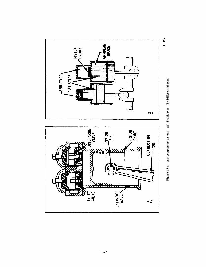
Fig
ure
13-6
.—A
ir c
ompr
esso
r pi
ston
s:
(A)
Tru
nk t
ype;
(B
) D
iffe
rent
ial
type
.

nonlubricated compressors). This unit is drivenfrom a reciprocating or rotary part of thecompressor. Oil is fed from the cylinderlubricator by separate lines to each cylinder.A check valve at the end of each feed linekeeps the compressed air from forcing theoil back into the lubricator. Each feed linehas a sight-glass oil flow indicator. Lubri-cation begins automatically as the compressorstarts up. The amount of oil that must befed to the cylinder depends on the cylinder
the viscosity of the oil. Figure 13-7 showsthe lubrication connections for the cylinders.The type and grade of oil used in compressorsis specified in the equipment technical manual.The correct type is vital to the operationand reliability of the compressor.
The running gear is lubricated by an oil pumpwhich is attached to the compressor and drivenfrom the compressor shaft. This pump is usuallya gear type. It draws oil from the reservoir (oil
diameter, the cylinder wall temperature, and sump) in the compressor base and delivers it
47.221Figure 13-7.—High-pressure air compressor.
13-8

through a filter to an oil cooler (if installed). Fromthe cooler, the oil is distributed to the top of eachmain bearing, to spray nozzles for the reductiongears, and to the outboard bearings. Thecrankshaft is drilled so that oil fed to themain bearings is picked up at the main bear-ing journals and carried to the crank journals.The connecting rods contain passages whichconduct lubricating oil from the crank bear-ings up to the piston pin bushings. As oilleaks out from the various bearings, it dripsback into the oil sump (in the base of thecompressor) and is recirculated. Oil from theoutboard bearings is carried back to the sumpby drain lines.
Low-pressure air compressor lubrication isshown in figure 13-8. This system is similar to therunning gear lubrication system for the high-pressure air compressor.
Nonlubricated reciprocating compressorshave lubricated running gear (shaft and
bearings) but no lubrication for the pistonsand valves. This design produces oil-freeair.
Cooling Systems
Most high- and medium-pressure recipro-cating compressors are cooled by the ship’sauxiliary fresh water or by seawater suppliedfrom the ship’s fire main or machinerycooling water system. Compressors locatedoutside the larger machinery spaces maybe equipped with an attached circulatingwater pump as a standby source of cool-ing water. Small low-pressure compressorsare air-cooled by a fan driven by the com-pressors.
The path of water in the cooling water systemof a typical four-stage compressor is illustrated
41.222
Figure 13-8.—Lubricating oil system of a low-pressure air compressor.
13-9

in figure 13-9. Not all cooling water systems haveidentical path-of-water flow. However, in systemsequipped with oil coolers it is important that thecoldest water be available for circulation throughthe cooler. Valves usually control the water to thecooler independently of the rest of the system.Thus, oil temperature can be controlled withoutharmful effects to the other parts of the com-pressor. It is very important to cool the air in theintercoolers and aftercoolers as well as the cylinderjackets and heads. The amount of cooling waterrequired depends on the capacity (cfm) andpressure. High-pressure air compressors requiremore cooling water (for the same cfm) than thelow-pressure units.
When seawater is used as the cooling agent,all parts of the circulating system must be ofcorrosion-resistant materials. The cylinders andheads are therefore composed of a bronze alloywith water jackets cast integral with the cylinders.Each cylinder is generally fitted with a liner ofspecial cast iron or steel to withstand the wear ofthe piston. Wherever practicable, cylinder jacketsare fitted with handholes and covers so that thewater spaces can be inspected and cleaned.Jumpers are usually used to make water connec-tions between the cylinders and heads because they
prevent possible leakage into the compressionspaces. In some compressors, however, the waterpasses directly through the joint between thecylinder and the head. With this latter type, thejoint MUST be properly gasketed to preventleakage which, if allowed to continue, will damagethe compressor.
The INTERCOOLERS and AFTER-COOLERS remove heat generated during com-pression and promote condensation of any vaporthat may be present. Figure 13-10 is a diagram ofa basic cooler and separator unit. It shows the col-lected condensate in the separator section. Thecondensate must be drained at regular intervals toprevent carryover into the next stage. If it accumu-lates at low points it may cause water hammer orfreezing and bursting of pipes in exposed loca-tions. It may also cause faulty operation of pneu-matic tools and possible damage to electricalapparatus when air is used for cleaning. Theremoval of heat is also required for economicalcompression. During compression the tempera-ture of the air increases. The air expands to alarger volume, which requires a corresponding in-crease of work to compress it. Multistaging, there-fore, with interstage cooling of the air, reducesthe power requirement for a given capacity.
Figure 13-9.—Cooling water system in a typical multistage air compressor.
13-10

The interstage cooling reduces the maximumtemperature in each cylinder. This reduces theamount of heat that must be removed by the waterjacket at the cylinder. Also, the resulting lowertemperature in the cylinder ensures better lubrica-tion of the piston and the valves. Figure 13-11illustrates the pressures and temperatures througha four-stage compressor. The intercoolers and theaftercoolers (on the output of the final stage) areof the same general construction. The exceptionis that the aftercoolers are designed to withstanda higher working pressure than the intercoolers.
Water-cooled intercoolers may be the straighttube and shell type (fig. 13-10) or, if size dic-tates, the coil type. In coolers with an air discharge
pressure below 150 psi, the air may flow eitherthrough the tubes or over and around them. Incoolers with an air discharge pressure above 250psi, the air generally flows through the tubes.In tubular coolers, baffles deflect the air or waterin its course through the cooler. In coil-typecoolers, the air passes through the coil and thewater flows around the coils.
Some air-cooled intercoolers and aftercoolersare the radiator type. Others may consist of abank of finned copper tubes located in the pathof cooling air supplied by the compressor cool-ing fan.
Each intercooler and aftercooler is generallyfitted with relief valves on both the air and the
Figure 13-10.—Basic cooler and separator.
47.223
41.224
Figure 13-11.—Pressure and temperature resulting from multistaging and interstage cooling.
13-11

water sides. The relief valve must be set accord-ing to PMS.
As seen earlier, intercoolers and aftercoolersare normally fitted with moisture separators onthe discharge side. These remove the condensedmoisture and oil from the air stream. Theseparators come in a variety of designs. Liquidis removed by centrifugal force, impact, orsudden changes in velocity and/or direction offlow of the air stream. Drains on each separatorremove the water and oil.
Oil coolers are the coil type, tube and shelltype, or a variety of commercial types. Althoughexternal oil coolers are generally used, some com-pressors are fitted with a base-type oil cooler.These circulate cooling water through a coil placedin the oil sump. As with the intercoolers and after-coolers, the materials of the tubes, coils, or coresare made of copper-nickel alloy. The shell andtube sheets are of bronze composition. On all latemodel compressors the circulating water system isarranged so that the quantity of cooling waterpassing through the oil cooler can be regulated.This can be done without disturbing the quantityof water passing through the cylinder jackets,intercoolers, or aftercoolers. Thermometers orother temperature measuring devices are fitted tothe circulating water inlet and outlet connections,to the intake and discharge of each stage of com-pression, to the final air discharge, and to the oilsump.
Control Systems
The control system of a reciprocating air com-pressor may include one or more control devices.These may include start-stop control, constant-speed control, speed-pressure governing, andautomatic high-temperature shut-down devices.
Control or regulating systems for air com-pressors in use by the Navy are largely of the start-stop type. In these, the compressor starts andstops automatically as the receiver pressure fallsor rises within predetermined set points. On elec-trically driven compressors the system is verysimple. The receiver pressure operates against apressure switch that opens when the pressure uponit reaches a given limit. It closes when the pressuredrops a predetermined amount. Centrifugal com-pressors do not have automatic start-stop controlsmainly because of their high horsepower. Anautomatic load/unload control system is usedinstead.
Some electrically driven units, such as themedium-pressure system, are required to start ateither of two pressures. In these, one of twopressure switches is selected with a three-way valve
or cock that admits pressure from the air accumu-lator to the selected pressure switch. Anothermethod is to direct the air from the receiverthrough a three-way valve to either of two controlvalves set for the respective range of pressures. Aline is run from each control valve to a singlepressure switch may be set at any convenientpressure; the setting of the control valve selectedwill determine the operation of the switch.
The CONSTANT-SPEED CONTROL regu-lates the pressure in the air receiver by control-ling the output of the compressor. This is donewithout stopping or changing the speed of theunit. This control prevents frequent starting andstopping of compressors when there is a fairlyconstant but low demand for air. Control is pro-vided by directing air to unloading devices througha control valve set to operate at a predeterminedpressure.
AUTOMATIC HIGH-TEMPERATURESHUTDOWN DEVICES are fitted on all recentdesigns of high-pressure air compressors. If thecooling water temperature rises above a safe limit,the compressor will stop and will not restartautomatically. Some compressors have a devicethat will shut down the compressor if thetemperature of the air leaving any stage exceedsa preset value.
Unloading Systems
Reciprocating air compressor unloadingsystems remove all but the friction loads on thecompressor. In other words, they automaticallyremove the compression load from the compressorwhile the unit is starting and automatically applythe compression load after the unit is up tooperating speed. Units with start-stop control havethe unloading system separate from the controlsystem. Compressors with constant-speed controlhave the unloading and control systems as integralparts of each other.
We cannot give a detailed explanation forevery type of unloading device used to unload aircompressor cylinders. Still, you should knowsomething about several of the unloadingmethods. These include closing or throttling thecompressor intake, holding intake valves off theirseats, relieving intercoolers to the atmosphere,relieving the final discharge to the atmosphere (oropening a bypass from the discharge to the in-take), opening cylinder clearance pockets, usingmiscellaneous constant-speed unloading devices,and various combinations of these methods.
We will discuss one example of a typical com-pressor unloading device; the MAGNETIC-TYPEUNLOADER. Figure 13-12 illustrates the
13-12

47.158
Figure 13-12.—Magnetic type unloader.
unloader valve arrangement. This unloader con-sists of a solenoid-operated valve connected withthe motor starter. When the compressor is at rest,the solenoid valve is de-energized. This admits airfrom the receiver to the unloading mechanism.
When the compressor reaches near-normal speed,the solenoid valve is energized. This releases thepressure from the unloading mechanism and loadsthe compressor again.
The pertinent manufacturers’ technicalmanuals contain the details of the unloadingdevices for the compressors in your ship.
ROTARY-CENTRIFUGAL AIRCOMPRESSORS
A nonreciprocating type of air compressoraboard ship is variously called a rotary com-pressor, a centrifugal compressor, or a liquidpiston compressor. Actually, the unit is somethingof a mixture. It operates partly on rotaryprinciples and partly on centrifugal principles. Itmay, more accurately, be called a rotary-centrifugal compressor.
The rotary-centrifugal compressor supplieslow-pressure compressed air. It can supply air thatis completely free of oil. Therefore, it is often usedas the compressor for pneumatic control systemsand for other applications where oil-free air isrequired.
The rotary-centrifugal compressor, shown infigure 13-13, consists of a round, multibladedrotor which revolves freely in an elliptical casing.
Figure 13-13.—Rotary-centrifugal compressor.
13-13
47.119

The elliptical casing is partially filled with high-purity water. The curved rotor blades projectradially from the hub. The blades, together withthe side shrouds, form a series of pockets orbuckets around the periphery. The rotor is keyedto the shaft of an electric motor. It revolves ata speed high enough to throw liquid out from thecenter by centrifugal force. This causes a solid ringof liquid to revolve in the casing at the same speedas the rotor but following the elliptical shape ofthe casing. This action alternately forces theliquid to enter and recede from the buckets in therotor at high velocity.
To follow through a complete cycle of opera-tion, look at figure 13-13. Start at point A (locatedat right center). The chamber [1] is full of liquid.The liquid, because of centrifugal force, followsthe casing, withdraws from the rotor, and pullsair in through the inlet port. At [2] the liquid hasbeen thrown outward from the chamber in therotor and has been replaced with atmospheric air.As the rotation continues, the converging wall [3]of the casing forces the liquid back into the rotorchamber. This compresses the trapped air andforces it out through the discharge port. The rotorchamber [4] is now full of liquid and ready torepeat the cycle which takes place twice in eachrevolution.
A small amount of water must be constantlysupplied to the compressor to make up for thatwhich is carried over with the compressed air. Thewater that is carried over with the compressed airis removed in a refrigeration-type dehydrator.
COMPRESSED AIR RECEIVERS
An air receiver is installed in each space thathouses air compressors (except centrifugal androtary lobe types). The receiver is an air storagetank. If demand is greater than the compressorcapacity, some of the stored air is supplied to thesystem. If demand is less than the compressorcapacity, the excess is stored in the receiver oraccumulator until the pressure is raised to itsmaximum setting. At that time, the compressorunloads or stops. Thus, in a compressed airsystem, the receiver minimizes pressure variationsin the system and supplies air during peakdemand. This will minimize start-stop cyclingof air compressors. Air receivers may behorizontal or vertical. Vertically mountedreceivers have convex bottoms. These permitproper draining of accumulated moisture, oil, andforeign matter.
All receivers have fittings such as inlet andoutlet connections and drain connections andvalves. They have connections for an operatingline to compressor regulators, pressure gauges,relief valves (set at approximately 12 percentabove normal working pressure of the receiver).They also have manhole plates (depending on thesize of the receiver). The discharge line betweenthe compressor and the receiver is as short andstraight as possible. This eliminates vibrationcaused by pulsations of air and reduces pressurelosses caused by friction.
In high-pressure air systems, air receiversare called AIR FLASKS. Air flasks are usuallycylindrical in shape, with belled ends and female-threaded necks. The flasks are constructed inshapes to conform to the hull curvature forinstallation between hull frames.
One or more air flasks connected togetherconstitute an air BANK.
COMPRESSED AIR SUPPLYSYSTEMS
The remainder of the compressed air systemis the piping and valves which distribute thecompressed air to the points of use.
HIGH-PRESSURE AIR
Figure 13-14A shows the first part of a high-pressure air system aboard a surface ship. The3,000/150 psi reducing station is used foremergencies or abnormal situations to provide airto the low-pressure air system.
LOW-PRESSURE AIR
Low-pressure air (sometimes referred to as LPship’s service air) is the most widely used airsystem aboard the ship. Figure 13-14B shows thefirst part of a low-pressure air system. Many ofthe low-pressure air systems are divided into sub-systems; vital and nonvital air.
Vital air is used primarily for engineeringpurposes such as automatic boiler controls, waterlevel controls, and air pilot-operated controlvalves. Vital air is also supplied to electronicssystems. Vital air systems are split between allmain machinery groups with cross-connectcapability.
Nonvital air has many different purposes, suchas laundry equipment, tank-level indicatingsystems, and airhose connection. Air for a
13-14

Figure 13-14.—HP and LP air compressor and receiver.
13-15
nonvital air system is supplied through aPRIORITY VALVE. This valve will shutautomatically to secure air to nonvital componentswhen the pressure in the air system drops to aspecified set point. It will reopen to restore non-vital air when pressure in the system returns tonormal. This system gives the vital air first priorityon all the air in the low-pressure system.
PRAIRIE-MASKER AIR SYSTEMS
A special purpose air system installed in manysurface ships is the prairie-masker air system. Thissystem supplies “disguise” air to a system ofemitter rings or belts surrounding the hull and tothe propeller blades through the propulsion shafts.
The emitter rings contain small holes whichrelease the masker air into the sea, coating the hullwith air bubbles. These bubbles disguise the shapeof the ship so that it cannot be seen accuratelyby enemy sonar.
The prairie air passing through the propulsionshafts is emitted to sea by small holes in thepropeller blades.
The air supply for the prairie-masker systemis provided by a turbocompressor. The turbocom-pressor is composed of five major parts containedin one compact unit. They are the turbine-drivencompressor, lube water tanks, air inlet silencer,lube water system, and control system.
The turbine-driven compressor consists of asingle-stage centrifugal compressor driven by asingle-stage impulse turbine. The compressorimpeller and the turbine wheel are mounted atopposite ends of the same shaft. Two water-lubricated bearings support the rotor assembly.The compressor runs at speeds approaching40,000 rpm. A control system for the unit pro-vides constant steam admission, overspeed trip,overspeed alarm, low lube pressure trip andalarm, and a high lube water temperature alarm.
MOISTURE REMOVAL
The removal of moisture from compressed airis an important part of compressed air systems.If air at atmospheric pressure, with even a verylow relative humidity, is compressed to 3,000 psior 4,500 psi, it becomes saturated with water
vapor. Some moisture is removed by the inter-coolers and aftercoolers, as seen earlier in thischapter. Also, air flasks, receivers, and banks areprovided with low point drains to periodicallydrain any collected moisture. However, manyshipboard uses of air require air with an evensmaller moisture content than is obtained throughthese methods. In addition, moisture in air linescan create other problems which are potentiallyhazardous, such as the freezing of valves andcontrols. This can occur, for example, if very-high-pressure air is throttled to a very low pressureat a high flow rate. The venturi effect of thethrottled air produces very low temperatureswhich will cause any moisture in the air to freezeinto ice. This makes the valve (especially anautomatic valve) either very difficult or im-possible to operate. Also, droplets of water in anair system with a high pressure and high flow ratecan cause serious water hammer within thesystem. For these reasons, air dryers ordehydrators are used to dry the compressed air.Two basic types of air dehydrators are in use: thedesiccant type and the refrigerated type.
Desiccant-Type Dehydrators
A desiccant is a drying agent. More practically,a desiccant is a substance with a high capacity toremove (absorb) water or moisture. It also has ahigh capacity to give off that moisture so that thedesiccant can be reused.
Compressed air system dehydrators use a pairof desiccant towers (flasks full of desiccant). Oneis on service dehydrating the compressed air whilethe other is being reactivated. A desiccant toweris normally reactivated by passing dry, heated airthrough the tower being reactivated in thedirection opposite to normal dehydration airflow.The hot air evaporates the collected moisture andcarries it out of the tower to the atmosphere. Thepurge air is heated by electrical heaters. Once thetower that is reactivating has completed thereactivation cycle, it is placed on service todehydrate air and the other tower is reactivated.
Another type of desiccant dehydrator in useis the Heat-Les Dryer. These units require noelectrical heaters or external source of purge air.Figure 13-15A shows the compressed air enteringat the bottom of the left tower. It then passesupward through the desiccant where it is dried toa very low moisture content. The dry air passes
13-16

through the check valve to the dry air outlet.Simultaneously, a small percentage of the dry airpasses through the orifice between the towers andflows down through the right tower. This dry airreactivates the desiccant and passes out throughthe purge exhaust. At the end of the cycle, thetowers are automatically reversed, as shown inpart B of figure 13-15.
Refrigerated-Type Dehydrators
Refrigeration is another method of removingmoisture from compressed air. We pass the com-pressed air over a set of refrigerated cooling coils.Oil and moisture vapors will condense from theair and can be collected and removed via a lowpoint drain.
Some installations may use a combination ofa refrigerated dehydrator and desiccantdehydrators to purify the compressed air.
OIL-FREE LOW-PRESSURE AIRCOMPRESSOR
The oil-free air compressors, like allreciprocating air compressors, have a compres-sion and running gear chamber. The oil-freeair compressors (fig. 13-16) have two major
components that provide oil-free discharged air.They are the guide piston and the guide pistonseal assembly.
The compression piston (fig. 13-17) ishollow, and is connected to the guide piston viathe guide piston seal assembly. The piston ringsare made from a Teflon-bronze material that willbecome damaged if contacted with lube oil.
The guide piston seal assembly (fig. 13-18)contains oil control rings, retainer rings, cup, andcover. This seal prevents oil from entering thecompression chamber by scraping the pistonconnecting rod of oil from the running gearchamber.
The running gear chamber consists of a systemof connecting rods, a crankshaft, and a flywheel.(NOTE: The connecting rods are connected to theguide piston in the oil-free air compressor.)
The valve assemblies are of the strip/feathertype previously discussed in this chapter.
UNLOADER SYSTEM
The oil-free low-pressure air compressorunloader system consists of three suction valveunloaders. There is one for each cylinder headlocated directly above the suction
47.226
Figure 13-15.—Heat-les dehydrator.
13-17
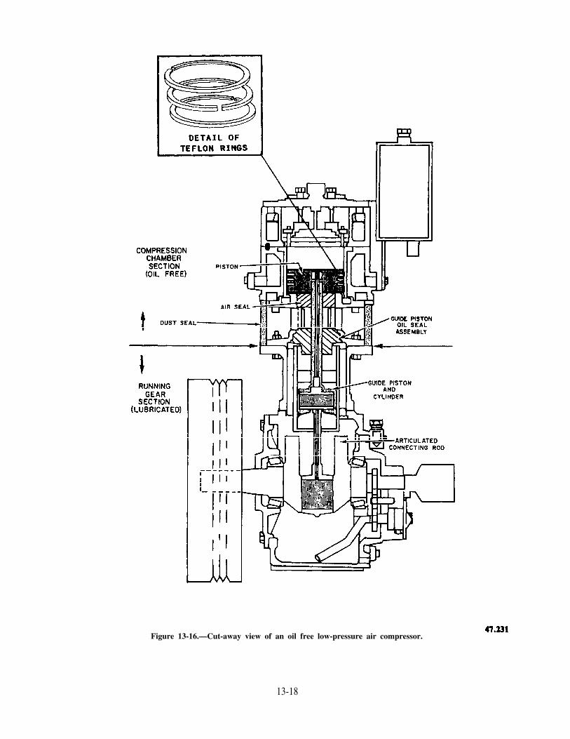
Figure 13-16.—Cut-away view of an oil free low-pressure air compressor.
13-18

Figure 13-17.—Hollow-type piston assembly.
13-19

41.233
Figure 13-18.—Guide piston scale assembly. Figure 13-19.—Valve assembly.47.234
13-20

valve assemblies (fig. 13-19). The majorcomponents of the unloader assembly are thepiston (108), springs (105, 106, and 107), andfinger. The unloader assemblies (fig. 13-20) areactuated by a solenoid-operated valve that admitsair to the top of the piston, forcing the piston andfinger downward, unseating the suction valves,and causing the air compressor to be in an un-loaded condition. The compressor becomesloaded when the solenoid-operated valve bleedsthe air off the top of the piston in the unloader
assemblies. The pistons and fingers are forced up-ward by a spring, causing the suction valves toseat. A flow control valve is provided to preventinstant full loading of the compressor. This isdone by controlling the amount of airflow fromthe unloader assemblies and the solenoid-operatedvalve.
The oil-free air compressors have a moistureseparator (fig. 13-21A) that receives air froman air cooler. It drains the collected moisture toa drain collecting holding bottle where it is
Figure 13-20.—Unloaded system from the oil-free low-pressure air compressor.
47.235
Figure 13-21A.—Separator.
13-21

removed by either the automatic drain system orthe manual drain valves. The separator has a levelprobe that shuts off the air compressor in theevent that the drains are backed up because ofa malfunction of the automatic drain system.
The automatic drain system operates using asolenoid-operated valve and a three-way air-operated valve (fig. 13-21B). The solenoid-operated valve is energized by a time relay devicein the motor controller. The solenoid-operatedvalve admits air to the three-way air-operatedvalve which allows drainage of the moistureseparator and the holding bottle.
Oil-free air compressors have a freshwatercooling system that provides cooling of thecylinder walls. The fresh water is mixed with anantifreeze solution that allows continuouscleaning of the water passages and piping. Thefreshwater cooling system (fig. 13-22) consistsof a pump, expansion tank, heat exchanger, and
thermostatic valve. The thermostatic valve main-tains freshwater temperature at a prescribedsetting by recirculating the fresh water througha heat exchanger.
COMPRESSED AIR PLANTOPERATION AND MAINTENANCE
Any air compressor or air system must beoperated in strict compliance with approvedoperating procedures. Compressed air ispotentially very dangerous. Cleanliness is ofutmost importance in all maintenance thatrequires opening compressed air systems.
SAFETY PRECAUTIONS
There are many hazards associated withpressurized air, particularly high-pressure air.
Figure 13-21B.—Condensate drain system.
13-22
47.236
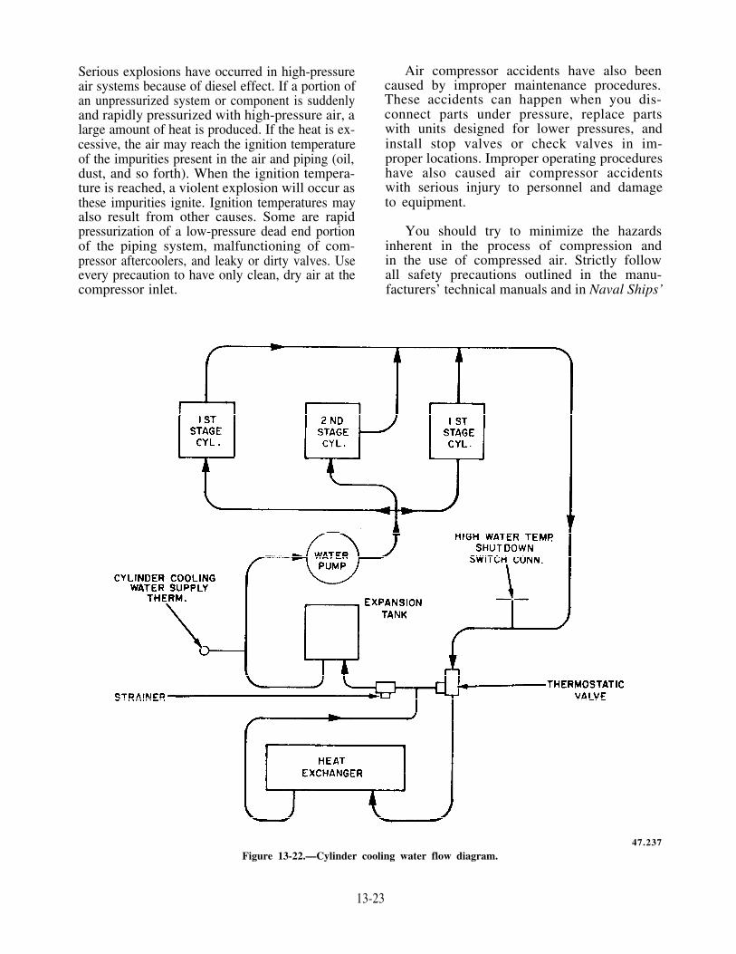
Serious explosions have occurred in high-pressureair systems because of diesel effect. If a portion ofan unpressurized system or component is suddenlyand rapidly pressurized with high-pressure air, alarge amount of heat is produced. If the heat is ex-cessive, the air may reach the ignition temperatureof the impurities present in the air and piping (oil,dust, and so forth). When the ignition tempera-ture is reached, a violent explosion will occur asthese impurities ignite. Ignition temperatures mayalso result from other causes. Some are rapidpressurization of a low-pressure dead end portionof the piping system, malfunctioning of com-pressor aftercoolers, and leaky or dirty valves. Useevery precaution to have only clean, dry air at thecompressor inlet.
Air compressor accidents have also beencaused by improper maintenance procedures.These accidents can happen when you dis-connect parts under pressure, replace partswith units designed for lower pressures, andinstall stop valves or check valves in im-proper locations. Improper operating procedureshave also caused air compressor accidentswith serious injury to personnel and damageto equipment.
You should try to minimize the hazardsinherent in the process of compression andin the use of compressed air. Strictly followall safety precautions outlined in the manu-facturers’ technical manuals and in Naval Ships’
47.237
Figure 13-22.—Cylinder cooling water flow diagram.
13-23

Technical Manual, chapter 551 (9490). Some ofthese hazards and precautions are as follows:
1. Explosions may be caused by dust-ladenair or by oil vapor in the compressor or receiver.The explosions are triggered by abnormally hightemperatures, which may be caused by leaky ordirty valves, excessive pressurization rates, andfaulty cooling systems.
2. NEVER use distillate fuel or gasoline asa degreaser to clean compressor intake filters,cylinders, or air passages. These oils vaporizeeasily and will form a highly explosive mixturewith the air under compression.
3. Secure a compressor immediately if youobserve that the temperature of the air dischargedfrom any stage exceeds the maximum temperaturerecommended.
4. NEVER leave the compressor stationafter starting the compressor unless you are surethat the control, unloading, and governing devicesare operating properly.
5. To prevent damage because of over-heating, do NOT run compressors at excessivespeeds. Maintain proper cooling water circulation.
6. If the compressor is to remain idle for anylength of time and is in an exposed position in
freezing weather, thoroughly drain the compressorcirculating water system.
7. Before working on a compressor, be surethat the compressor is secured and cannot startautomatically or accidentally. Completely blow
down the compressor, then secure all valves (in-cluding control or unloading valves) between thecompressor and the receiver. Follow appropriatetag-out procedures for the compressor control andthe isolation valves. (Leave the pressure gauge open atall times the gauges are in place.)
8. When cutting air into the whistle, siren,or a piece of machinery, be sure the supply lineto the equipment has been properly drained ofmoisture. When securing the supply of air to theaffected equipment, be sure all drains are leftopen.
9. Prior to disconnecting any part of an airsystem, be sure that the part is not under pressure.
Always leave the pressure gauge cutout valves open tothe sections to which they are attached.
10. Avoid rapid operation of manual valves.The heat of compression caused by sudden flowof high pressure into an empty line or vessel cancause an explosion if oil or other impurities arepresent. Slowly crack open the valves until flowis noted, and keep the valves in this positionuntil pressure on both sides has equalized. Keepthe rate of pressure rise under 200 psi per second.
In this chapter we have discussed the manyuses of compressed air aboard ship. We have alsodiscussed how the air is compressed, and someof the safety precautions to be used whenoperating or working on a compressed air plantor system.
13-24

ADDITIONAL AUXILIARY EQUIPMENT
CHAPTER 14
As a Machinist’s Mate, you will work with avariety of equipment that is not directly relatedto the propulsion plant. Some examples aresteering gear, cargo or weight-handling equip-ment, hydraulic systems, and laundry and galleyequipment. Some equipment such as that in thelaundrv and galley will be maintained by operatingand maintenance personnel. However, you willbe expected to handle preventive maintenance andrepairs.
In general, the operator will clean the equip-ment and make minor adjustments. In some cases,the operator will perform routine maintenance.You, the Machinist’s Mate, will handle anyrepairs, replacements, or adjustments. AnElectrician’s Mate will handle electrical workon all machinery, and may be responsible forthe entire machine if its operation is primarilyelectrical.
ELECTROHYDRAULIC DRIVEMACHINERY
Hydraulic units drive or control steering gears,windlasses, winches, capstans, airplane cranes,ammunition hoists, and distant control valves.This chapter contains information on somehydraulic units that will concern you.
The electrohydraulic type of drive operatesseveral different kinds of machinery. Here aresome of the advantages of electrohydraulicmachinery.
1. Tubing, which can readily transmit fluidsaround corners, conducts the liquid thattransmits the force. Tubing requires verylittle space.
2. The machinery operates at variable speeds.3. Operating speed can be closely controlled
from minimum to maximum limits.4. The controls can be shifted from no load
to full load rapidly without damage tomachinery.
ELECTROHYDRAULIC SPEED GEAR
An electrohydraulic speed gear is mostfrequently used in electrohydraulic applications.Different variations of the basic design are usedfor specific applications, but the principles remainthe same. Basically, the unit consists of anelectric motor-driven hydraulic pump (A-end) anda hydraulic motor (B-end). (See chapter 5 of thismanual for a discussion on axial-piston variable-stroke pumps.)
The B-end (fig. 14-1) is already on stroke andwill be made to rotate by the hydraulic force ofthe oil acting on the pistons. Movement of thepistons’ A-end is controlled by a tilt box (alsocalled a swash plate) in which the socket ring ismounted, as shown in part A of figure 14-1.
The length of piston movement, one way orthe other, is controlled by movement of the tiltbox and by the amount of angle at which the tiltbox is placed. The length of the piston movementcontrols the amount of fluid flow. When the drivemotor is energized, the A-end is always inmotion. However, with the tilt box in a neutralor vertical position, there is no reciprocatingmotion of the pistons. Therefore, no oil is pumpedto the B-end. Any movement of the tilt box, nomatter how slight, causes pumping action to start.This causes immediate action in the B-end becauseof the transmission of force by the hydraulic fluid.
When you need reciprocating motion, such asin a steering gear, the B-end is replaced by a pistonor ram. The force of the hydraulic fluid causesthe movement of the piston or ram. The tilt boxin the A-end can be controlled locally (as on theanchor windlass) or by remote control (as on thesteering gear).
ELECTROHYDRAULICSTEERING GEAR
The steering gear transmits power from thesteering engine to the rudder stock. The termsteering gear frequently includes the driving engineand the transmitting mechanism.
14-1

Many different designs of steering gear are inuse, but the principle of operation for all of themis similar. One type of electrohydraulic steeringgear is shown in figure 14-2. It consists essentiallyof (1) a ram unit and (2) a power unit.
Ram Unit
The ram unit is mounted athwartship andconsists of a single ram operated by opposedcylinders. The ram is connected by links to thetillers of the twin rudders. When oil pressure isapplied to one end of the operating cylinder, theram will move, causing each rudder to move alongwith it. Oil from the opposite end of the cylinderis returned to the suction side of the mainhydraulic pump in the power unit.
Figure 14-1.—Electrohydraulic speed gear.
Power Unit
The power unit consists of two independentpumping systems. Two systems are used forreliability. One pump can be operated while theother is on standby.
Each pumping system consists of a variable-delivery, axial-piston main pump and a vane-typeauxiliary pump. Both are driven by a singleelectric motor through a flexible coupling. Eachsystem also includes a transfer valve withoperating gear, relief valves, a differentialcontrol box, and trick wheels. The whole unitis mounted on a bedplate, which serves asthe top of an oil reservoir. Steering power istaken from either of the two independentpumping systems.
14-2

Fig
ure
14-2
.—E
lect
rohy
drau
lic s
teer
ing
gear
.

The pumps of the power unit are connectedto the ram cylinders by high-pressure piping. Thetwo transfer valves are placed in the piping systemto allow for the lineup of one pump to the ramcylinders with the other pump isolated. A handlever and mechanical linkage (not shown) areconnected to the two transfer valves in such a waythat both valves are operated together. This allowsfor rapid shifting from the on-service pumpingunit to the standby unit; it also prevents liningup both pumps to the ram at the same time. Thehand lever is usually located between the trickwheels. It has three positions marked P, N, andS. P denotes the port pump connected to the ram;N denotes neutral (neither pump connected tothe ram); and S denotes the starboard pumpconnected to the ram. Also, the hand lever isusually connected to motor switches. This permitsthe operator to connect the selected pump to theram and start the pump drive motor in one quickoperation. In most modern ships this valve iselectrically controlled by the motor controller andby pressure switches.
The pinions drive follow-up shafts, which feedinto the differential box. This feedback or servosystem tells the differential control box when thesteering operation has been completed. Asthe ordered rudder angle is approached, thedifferential control box will begin realigning thetilt box of the main hydraulic pump. By the timethe desired rudder angle is reached, the tilt boxis at zero stroke. This means that the orderedsignal (from the pilothouse or trick wheel) andthe actual signal (from the follow-up shafts) arethe same. If either of these change, the differentialcontrol box will react accordingly to cause themain hydraulic unit to pump oil to one end or theother of the ram.
The trick wheels provide local-hydrauliccontrol of the steering system in case of failureof the remote steering system. A hand pump andassociated service lines are also provided for local-manual operation of the ram in case of failureof both hydraulic pump units.
Operation and MaintenancePrinciples of Operation
The on-service hydraulic pump is running atall times and is a constant-speed pump. Unlesssteering is actually taking place, the tilt box ofthe main hydraulic pump is at zero stroke, andno oil is being moved within the main system. Theauxiliary pump provides control oil and super-charge flows for the system. Assume that asteering order signal comes into the differentialcontrol box. It can come from either the remotesteering system in the ship’s wheelhouse orthe trick wheel. The control box mechanicallypositions the tilt box of the main hydraulic pumpto the required angle and position. Remember thatdirection of fluid and flow may be in eitherdirection in a hydraulic speed gear. It depends onwhich way the tilt box is angled. For this reason,the constant speed, unidirectional motor can beused to drive the main hydraulic pump. The pumpwill still have the capability to drive the ram ineither direction.
With the main hydraulic pump now pumpingfluid into one of the ram cylinders, the ram willmove, moving the rudders. A rack and gear areattached to the rudder yoke between the rudderlinks. As the ram and the rudder move, the rackgear moves, driving the follow-up pinion gear.
The Machinist’s Mate watch stander usuallyoperates the steering equipment only in abnormaland emergency situations. For this reason, youshould be thoroughly familiar with all emergencyprocedures. Examples are local-hydraulic steeringwith the trick wheel and local-manual steeringwith the hand pump. Operating instructions andsystem diagrams are normally posted near thesteering gear. The diagrams describe the variousprocedures and lineups for operation of thesteering gear. Be sure that the standby equipmentis ready for instant use.
General maintenance of the steering gearrequires that you clean, inspect, and lubricate themechanical parts and maintain the hydraulic oilat the proper level and purity. The PlannedMaintenance System (PMS) lists the individualrequirements for the equipment. The electriciansmaintain the electrical portion of the steeringsystem, including the control system.
WEIGHT-HANDLING EQUIPMENT
To qualify for advancement in rating, youmust be familiar with the construction, operation,and maintenance of anchor windlasses, cranes,
14-4

and winches. The following discussion of suchmachinery and other weight-handling equipmentis supplementary to that given in Fireman,NAVEDTRA 14104. Most steam-powered weight-handling equipment is obsolete. If your ship hassteam-powered equipment, refer to the technicalmanual for information.
Anchor Windlasses
In a typical electrohydraulic mechanism,one constant-speed electric motor drives twovariable-stroke pumps through a couplingand reduction gear. Other installations includetwo motors, one for driving each pump.Each pump normally drives one wildcat. How-ever, if you use a three-way plug cock-typevalve, either pump may drive either of thetwo wildcats. The hydraulic motors drivethe wildcat shafts with a multiple-spur gearingand a locking head. The locking head allowsyou to disconnect the wildcat shaft and permitsfree operation of the wildcat, as when droppinganchor.
Each windlass pump is controlled either fromthe weather deck or locally. The controls arehandwheels on shafting leading to the pumpcontrol. The hydraulic system will require yourattention. Be certain the hydraulic system isalways serviced with the specified type of cleanoil.
You will normally have to maintain threetypes of anchor windlasses. They are theelectric, electrohydraulic, and hand-drivenwindlasses. Hand-driven windlasses are usedonly on small ships where the anchor gear canbe handled without excessive effort by operatingpersonnel.
The major work on a hand windlass is to keepthe linkage, friction shoes, locking head, andbrake in proper adjustment and in satisfactoryoperating condition at all times. In an electro-hydraulic windlass, your principal concern is thehydraulic system.
A windlass is used intermittently and forshort periods of time. However, it musthandle the required load under severe conditions.This means that you must maintain and adjustthe machinery when it is not in use. This practice
will prevent deterioration and ensure dependableuse.
Windlass brakes must be kept in satisfactorycondition if they are to function properly. Wearand compression of brake linings will increase theclearance between the brake drum and band aftera windlass has been in operation. Brake liningsand clearances should be inspected frequently.Adjustments should be made according to themanufacturer’s instructions.
Follow the lubrication instructions furnishedby the manufacturer. If a windlass has been idlefor some time, it should be lubricated. Thisprotects finished surfaces from corrosion andprevents seizure of moving parts.
The hydraulic transmissions of electro-hydraulic windlasses and other auxiliaries aremanufactured with close tolerances betweenmoving and stationary parts. Use every pre-caution to keep dirt and other abrasive materialout of the system. When the system is replenishedor refilled, use only clean oil. Strain it asit is poured into the tank. If a hydraulictransmission has been disassembled, cleanthoroughly before reassembly. Before installingpiping or valves, clean their interiors toremove any scale, dirt, preservatives, or otherforeign matter.
Winches
Winches are used to heave in on mooringlines, to hoist boats, as top lifts on jumbobooms of large auxiliary ships, and to handlecargo. Power for operating shipboard winchesis usually furnished by electricity and, onsome older ships, by steam. Sometimes delicatecontrol and high acceleration without jerkingare required, such as for handling aircraft.Electrohydraulic winches are usually installedfor this purpose. Most auxiliary ships areequipped with either electrohydraulic or electricwinches.
CARGO WINCHES.—Some of the mostcommon winches used for general cargo handlingare the double-drum, double-gypsy and thesingle-drum, single-gypsy units. Four-drum,two-gypsy machines are generally used forminesweeping.
14-5

Figure 14-3.—Electrohydraulic winch unit.
ELECTROHYDRAULIC WINCHES.—Elec-trohydraulic winches (fig. 14-3) are always thedrum type. The drive equipment is like mosthydraulic systems. A constant-speed electricmotor drives the A-end (variable-speed hydraulicpump), which is connected to the B-end (hydraulicmotor) by suitable piping. The drum shaft isdriven by the hydraulic motor through reductiongearing.
Winches normally have one horizontallymounted drum and one or two gypsy heads. Ifonly one gypsy is required, it may be easilyremoved from or assembled on either end of thedrum shaft. When a drum is to be used, it isconnected to the shaft by a clutch.
ELECTRIC WINCHES.—An electricallydriven winch is shown in figure 14-4. This winchis a single-drum, single-gypsy type. The electricmotor drives the unit through a set of reductiongears. A clutch engages or disengages the drumfrom the drum shaft. Additional features includean electric brake and a speed control switch.
Capstans
The terms capstan and winch should not beconfused. A winch has a horizontal shaft and acapstan has a vertical shaft. The type of capstaninstalled aboard ship depends on the loadrequirements and type of power available. Ingeneral, a capstan consists of a single headmounted on a vertical shaft, reduction gearing,and a power source. The types, classifiedaccording to power source, are electric and steam.
Electric capstans are usually of the reversibletype. They develop the same speed and power ineither direction. Capstans driven by alternating-current motors run at either full, one-half, or one-third speed. Capstans driven by direct-currentmotors usually have from three to five speeds ineither direction of rotation.
Maintenance of Winches and Capstans
In several respects, the maintenance of a winchor a capstan is similar to that for a windlass.
14-6

Figure 14-4.—Electric winch.
Where band brakes are used on the drums,inspect the friction linings regularly and replacewhen necessary. Take steps to prevent oil or greasefrom accumulating on the brake drums. Checkthe operation of brake-actuating mechanisms,latches, and pawls periodically.
Frequently inspect winch drums driven byfriction clutches for deterioration in the frictionmaterial. Check also to see if oil and grease arepreventing proper operation. Lubricate the slidingparts of positive clutches properly. Check thelocking device on the shifting gear to see if it willhold under load.
Cranes are designed to meet the followingconditions:
1. Hoist, lower, top, and rotate a rated loadat the specified speed and against aspecified list of the ship.
2. Handle 150 percent of the rated load at nospecified speed.
3. Withstand a static, suspended load of 200percent of the rated load without damageor distortion to any part of the crane orstructure.
The types of cranes installed on ships varyaccording to the equipment handled.
The crane equipment generally includes theboom, king post, king post bearings, sheaves,hook, and rope, machinery platforms, rotatinggear, drums, hoisting, topping and rotating drives,and controls. The important components aredescribed in the paragraphs that follow.
BOOMS.—A boom, used as a mechanicalshipboard appliance, is a structural unit used tolift, transfer, or support heavy weights. A boomis used in conjunction with other structures orstructural members that support it, and variousropes and pulleys, called blocks, that control it.
KING POST BEARINGS.—Bearings onstationary king posts take both vertical load andhorizontal strain at the collar, located at thetop of the king post. On rotating king posts,bearings take both vertical and horizontal loadsat the base and horizontal reactions at a higherdeck level.
SHEAVES AND ROPES.—The hoisting andtopping ropes are led from the drums over sheavesto the head of the boom. The sheaves and ropesare designed according to recommendations bythe Naval Sea Systems Command. This command
14-7
Cranes

sets the criteria for selection of sheave diameter,size, and flexibility of the rope. Sufficient fair-lead sheaves are fitted to prevent fouling of therope. A shock absorber is installed in the line,hoisting block, or sheave at the head of the boomto take care of shock stresses.
MACHINERY PLATFORMS.—Machineryplatforms carry the power equipment andoperator’s station. These platforms are mountedon the king post above the deck.
ROTATING GEAR AND PINIONS.—Rota-tion of the crane is accomplished by verticalshafts with pinions engaging a large rotatinggear.
DRUMS.—The drums of the hoisting andtopping winches are generally grooved for theproper size wire rope. The hoisting system usessingle or multiple part lines as required. Thetopping system uses a multiple purchase asrequired.
OPERATION AND MAINTENANCE OFCRANES.— The hoisting whips and topping liftsof cranes are usually driven by hydraulic variable-speed gears through gearing of various types. Thisprovides the wide range of speed and delicatecontrol required for load handling. The cranes areusually rotated by an electric motor connected toworm and spur gearing. They may also be rotatedby an electric motor and hydraulic variable-speedgear connected to reduction gearing.
Some electrohydraulic cranes have automaticslack line take-up equipment. This consists of anelectric torque motor geared to the drum. Thesecranes are used to lift boats, aircraft, or otherloads from the water. The torque motor assiststhe hydraulic motor drive to reel in the cable incase the load is lifted faster by the water than itis being hoisted by the crane.
Electrohydraulic equipment for the craneconsists of one or more electric motors runningat constant speed. Each motor drives one or moreA-end variable-displacement hydraulic pumps.The pump strokes are controlled through oper-ating handwheels. START, STOP, and EMER-GENCY RUN push buttons at the operator’sstation control the electric motors. Interlocksprevent starting the electric motors when thehydraulic pumps are on stroke. B-end hydraulicmotors are connected to the A-end pumps bypiping. They drive the drums of the hoisting andtopping units or the rotating machinery.
Reduction gears are located between theelectric motor and the A-end pump and betweenthe B-end hydraulic motor and the rotatingpinion. Each hoisting, topping, and rotating drivehas an electric brake on the hydraulic motoroutput shaft. This brake is interlocked with thehydraulic pump control. It will set when thehydraulic control is on neutral or when electricpower is lost. A centering device is used to findand retain the neutral position of the hydraulicpump.
Relief valves protect the hydraulic system.These valves are set according to the requirementsof chapter 556 of the Naval Ships’ TechnicalManual.
Cranes usually have a rapid slack take-updevice consisting of an electric torque motor.This motor is connected to the hoist drum throughreduction gearing. This device works in con-junction with the pressure stroke control on thehydraulic pump. It provides for fast accelerationof the hook in the hoisting direction under lighthook conditions. Thus, slack in the cable isprevented when hoisting is started.
Some cranes have a light-hook paying-outdevice mounted on the end of the boom. It paysout the hoisting cables when the weight of thehook and cable beyond the boom-head sheave isinsufficient to overhaul the cable as fast as it isunreeled from the hoisting drum.
When the mechanical hoist control is inneutral, the torque motor is not energized and thecable is gripped lightly by the action of a spring.Moving the hoist control to LOWER energizes thetorque motor. The sheaves clamp and pay out thecable as it is unreeled from the hoist drum. Whenthe hoist control is moved to HOIST, the torquemotor is reversed and unclamps the sheaves. Alimit switch opens and automatically de-energizesthe paying-out device.
Maintain cranes according to the PMS require-ments or the manufacturers’ instructions. Keepthe oil in the replenishing tanks at the prescribedlevels. Keep the system clean and free of air.Check the limit stop and other mechanical safetydevices regularly for proper operation. Whencranes are not in use, secure them in their stowedpositions. Secure all electric power to thecontrollers.
Elevators
Some of the hydraulic equipment that youmaintain will be found in electrohydraulic elevatorinstallations. Modern carriers use elevators of this
14-8

type. The elevators described in this chapter arenow in service in some of the ships of the CV class.These ships are equipped with four deck-edgeairplane elevators that have a maximum liftingcapacity of 79,000 to 105,000 pounds. The cablelift platform of each elevator projects over the sideof the ship and is operated by an electrohydraulicplant.
ELECTROHYDRAULIC POWER PLANT.—The electrohydraulic power plant for the elevatorsconsists of the following components:
1. A horizontal plunger-type hydraulic engine2. Multiple variable-delivery parallel piston-
type pumps3. Two high-pressure tanks4. One low-pressure tank5. A sump tank system6. Two constant-delivery vane-type pumps
(sump pumps)7. An oil storage tank8. A piping system and valves9. A nitrogen supply
The hydraulic engine is operated by pressuredeveloped in a closed hydraulic system. Oil issupplied to the system in sufficient quantity tocover the baffle plates in the high-pressure tanksand allow for piston displacement. Nitrogen isused because air and oil in contact under highpressure form an explosive mixture. Air shouldnot be used except in an emergency. Nitrogen,when used, should be kept at 97 percent purity.
The hydraulic engine has a balanced piston-type valve with control orifices and a differentialcontrol unit. This control assembly is actuated byan electric motor and can be operated by hand.To raise the elevator, move the valve off-centerto allow high-pressure oil to enter the cylinder.High-pressure oil entering the cylinder moves theram. The ram works through a system of cablesand sheaves to move the platform upward. Thespeed of the elevator is controlled by the amountof pressure in the high-pressure tank and thecontrol’ valve.
When the elevator starts upward, the pressurein the the high-pressure tank drops. The pressuredrop automatically starts the main pumps. Thesepumps transfer oil from the low-pressure tank tothe high-pressure system until the pressure isrestored. An electrical stopping deviceautomatically limits the stroke of the ram andstops the platform at the proper position at theflight deck level.
To lower the elevator, move the control valvein the opposite direction. This permits the oil inthe cylinder to flow into the exhaust tank. As theplatform descends, oil is discharged to the low-pressure tank (exhaust tank). The original oillevels and pressures, except for leakages, arereestablished. The speed of lowering is controlledby the control valve and the cushioning effect ofthe pressure in the exhaust tank. Leakage isdrained to the sump tanks. It is then automaticallytransferred to the pressure system by the sumppumps. An electrically operated stopping deviceautomatically slows down the ram and stops theplatform at its lower level (hangar deck).
SAFETY FEATURES.—Some of the majorsafety features incorporated into modern deckedge elevators are as follows:
1. If the electrical power fails while theplatform is at the hangar deck, there willbe enough pressure in the system to movethe platform to the flight deck one timewithout the pumps running.
2. Some platforms have serrated safety shoes.If all the hoisting cable should break onone side, the shoes will wedge the platformbetween the guide rails. This will stop theplatform with minimum damage.
3. A main pump may have a pressure-actuated switch to stop the pump motorswhen the discharge pressure is excessive.They may also have to relieve the pressurewhen the pressure switch fails to operate.
4. The sump pump system has enoughcapacity to return the unloaded platformfrom the hangar deck to the flight deck.
5. The oil filter system may be usedcontinuously while the engine is running.This allows part of the oil to be cleanedwith each operation of the elevator.
CONVEYORS
Two types of conveyors are used for shipboardhandling: gravity and powered.
GRAVITY CONVEYORS
Gravity conveyors may be wheel, roller, or balltype with straight, curved, or angular sectionsprovided in the quantities and lengths required tofacilitate stores strikedown. Folding conveyorstands are furnished with each conveyor section.
14-9

Figure 14-5.—Gravity conveyor.
Conveyors are usually 18 inches wide, but theymay be 12 inches wide for use in restrictedpassageways. Most conveyors are of the rollertype and are used to handle dry provisions andchilled and frozen food (fig. 14-5).
POWERED CONVEYORS
Powered conveyors are configured eithervertically or horizontally.
Vertical Conveyors
Vertical conveyors (figs. 14-6 and 14-7), forshipboard use, consist of the following compo-nents:
1. Structural frame (head, tail, and inter-mediate sections)
2. Drive system3. Conveyor system4. Operating controls5. Safety devices
The structural frame may be designed as atruss frame installed in a trunk closure. Shieldsrunning the length of the conveyor provide asmooth unbroken surface in the area of themoving tray loads and isolate the load side fromthe idle return side of the conveyor tray cycle.
The drive system components are the frictionclutch (package conveyor), magnetic clutch (palletconveyor), speed reducer, motor brake, driveshafts with chain sprockets, and connecting rollerchain. The drive units are located at the headsection of the conveyor frame and can bepositioned at the side, back, or top of theconveyor.
The conveying system consists of the chainsprockets mounted in the head and tail sectionsof the conveyor frame. The carrier (tray) chainis driven by the head chain sprockets. Each trayis supported on two sides by the carrier chain, andeach tray is guided on two sides by cam guide armswith rollers that ride in guide tracks mounted tothe conveyor frame.
14-10
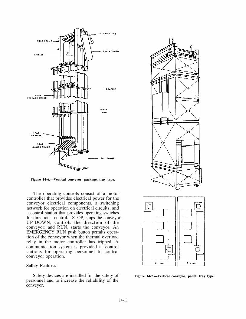
Figure 14-6.—Vertical conveyor, package, tray type.
The operating controls consist of a motorcontroller that provides electrical power for theconveyor electrical components, a switchingnetwork for operation on electrical circuits, anda control station that provides operating switchesfor directional control. STOP, stops the conveyor;UP-DOWN, controls the direction of theconveyor; and RUN, starts the conveyor. AnEMERGENCY RUN push button permits opera-tion of the conveyor when the thermal overloadrelay in the motor controller has tripped. Acommunication system is provided at controlstations for operating personnel to controlconveyor operation.
Safety Features
Safety devices are installed for the safety ofpersonnel and to increase the reliability of theconveyor.
Figure 14-7.—Vertical conveyor, pallet, tray type.
14-11

The lockout device, located at each controlstation, secures the operating controls fromunauthorized operation. When secured, thelockout device permits operation of the STOPpush button from each control station to stop theconveyor motion.
The package conveyor has a load and unloaddevice capable of loading and unloading theconveyor at each load station, and it can beplaced in three positions:
1. Load position (horizontal) for UP directionloading
2. Unload position (30-degree incline) forDOWN direction unloading
3. Stowed position (vertical)
An interlock switch is placed at each load-unload device to prevent downward operation ofthe conveyor when the load-unload device is inthe load position.
A door block device is provided at eachpackage conveyor load station equipped with aload-unload device so that the trunk door will notclose unless the load-unload device is in the stowedposition.
Two-way communication should continuouslybe maintained between operating levels to preventinjury to personnel or damage to equipment.
Horizontal Conveyors
Horizontal conveyors arc similar to verticalconveyors except that belts or driven rollers (figs.14-8 and 14-9) are used in place of chains and traysto support the loads. Powered conveyors canbridge a span and operate at an incline.
To ensure accident-free conveyor operation,use the following procedures:
1. Inspect all interlocks and safety devices
2. Verify all warning plates are in place.
3. Establish positive communications between
4. Do not use the conveyor trunk as a voice
5. Use the two-man rule at all times while
to make sure they are operational beforefurther conveyor operations, as per PMSrequirements,
all operating control stations using sound-powered telephones or intercom systems.
tube.
operating the conveyor.
Figure 14-8.—Powered belt conveyor.
14-12

GALLEY AND LAUNDRYEQUIPMENT
The Navy uses a variety of galley and laundryequipment. The type of equipment depends on thesize of the ship, the availability of steam, andother factors. You will need the equipment manu-facturer’s technical manual for each differentpiece of gear aboard. Schedule and performpreventive maintenance according to the 3-Msystems.
STEAM-JACKETED KETTLES
Steam-jacketed kettles (fig. 14-10) come insizes from 5 to 80 gallons. The kettles are madeof corrosion-resisting steel. They operate at amaximum steam pressure of 45 psi. A relief valvein the steam line leading to the kettles is set tolift at 45 psi. Maintenance on these units isnormally limited to the steam lines and valvesassociated with the kettles.
Figure 14-10.—Steam-jacketed kettles.
Figure 14-9.—Powered roller conveyor.
14-13

Figure 14-11.—Steamer.
Other steam-operated cooking equipmentincludes steamers (fig. 14-11) and steam tables(fig. 14-12). Steamers use steam at a pressure of5 to 7 psi; steam tables use steam at a pressureof 40 psi or less.
DISHWASHING EQUIPMENT
Dishwashing machines used in the Navy areclassified as one-, two-, or three-tank machines.The three-tank machine is a fully automatic,continuous racking machine. It scrapes, brushes,and provides two rinses. It is used at largeactivities.
Figure 14-12.—Steam table.
Bacteria in these tanks must be controlled ata satisfactory level. This is done by controllingthe temperature of the water. The temperatureranges will vary in one-, two- and three-tankmachines.
Single Tank
Single-tank machines (fig. 14-13) are used onsmall ships where larger models are not feasible.
The temperature of the washwater must be atleast 140°F and no greater than 160°F.
14-14

Figure 14-13.—Typical semiautomatic single-tank dishwashing machine.
Lower temperatures will not control bacteria, andhigher temperatures are not efficient at remov-ing some foods. These temperatures are controlledby a thermostat. The washing time is 40 secondsin the automatic machines.
For rinsing, hot water is sprayed on the dishesfrom an external source. It is controlled by anadjustable automatic steam-mixing valve that
maintains the rinse water between 180°F and195°F.
To conserve fresh water, the rinse time intervalis usually limited to 10 seconds. When watersupply is not a problem, a rinse of 20 seconds isrecommended.
Wash and rinse sprays are controlled separatelyby automatic, self-opening and closing valves inthe automatic machine.
14-15
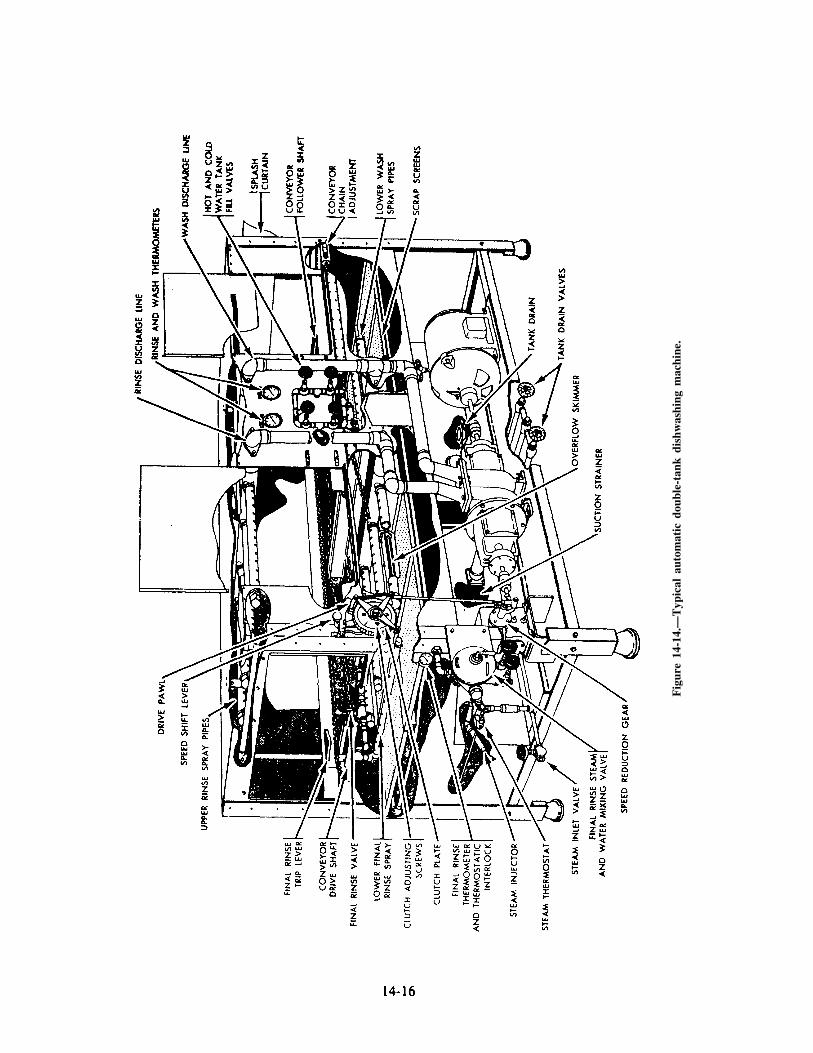
Fig
ure
14-1
4.—
Typ
ical
aut
omat
ic d
oubl
e-ta
nk d
ishw
ashi
ng m
achi
ne.

Double Tank
Double-tank machines (fig. 14-14) are availablein several capacities. They are used when morethan 150 persons are to be served at one meal.These machines have separate wash and rinsetanks. They also have a final rinse of hot waterthat is sprayed on the dishes from an outsidesource. This spray is opened by the racks as theypass through the machines. The spray auto-matically closes when the rinse cycle is completed.The final rinse is controlled by an adjustableautomatic steam-mixing valve that maintains thetemperature between 180°F and 195°F. Double-tank machines are also equipped with a ther-mostatically operated switch in the rinse tank.This switch prevents operation of the machine ifthe temperature of the rinse water falls below180°F. The racks pass through the machineautomatically on conveyor chains. Utensils shouldbe exposed to the machine sprays for not less than40 seconds (20-second wash, 20-second rinse).
Descaling Dishwashers
You should prevent the accumulation of scaledeposits in dishwashing machines for at least tworeasons. First, excessive scale deposit on theinside of pipes and pumps will clog them. Thiswill interfere with the efficient performance of themachine by reducing the volume of water thatcomes in contact with the utensils during thewashing and sanitizing process. Second, scaledeposits provide a haven for harmful bacteria.
The supplies needed for descaling are availablethrough Navy supply channels. See the followingsupply list:
Stock Number
9G6810-00-264-6722
9Q7930-00-282-9699
Description of Material
Orthophosphoric acid, 85percent technical, 7-poundbottle
Detergent, general-purpose,1-gallon can
9Q7930-00-985-6911 Detergent, general-purpose,5-gallon pail
You should know the capacity of the dish-washing machine tanks. Measure (in inches) theinside dimensions of each tank and apply thefollowing formula: length × width × depth (towaterline) ÷ 231 = capacity in gallons.
Use the following steps and key points indescaling the machine:
1. Fill the tanks halfway to the overflow levelwith hot, clean water. If tanks do not havewater level indicators, remove a section ofthe scrap tray in each tank so that you cansee the overflow pipe.
2. Add the required amount of acid anddetergent to the water to prepare the clean-ing solution. Measure amounts carefully.Use 7 fluid ounces of orthophosphoric acid85 percent plus l/2 fluid ounce of deter-gent, general-purpose. Use this measure foreach gallon capacity of the tank when it isfilled to the overflow level.
3. Complete filling the tanks. Fill to theover flow level.
4. Put scrap screens, spray pipes, and splashcurtains in place. Remove scale deposits onall attachments.
5. Turn on the machine. Operate the machineat the highest permissible operating temper-ature for 60 minutes.
6. Turn off and drain the machine. Open thedrain valves and allow all the cleaningsolution to drain from the tanks.
7. Refill. Use fresh hot water.8. Turn on the machine. Operate the machine
at the highest temperature for 5 minutes.
Repeat steps 7 and 8 several times. Repeat theentire method at such intervals as may be requiredfor operation of the dishwashing machine.
LAUNDRY EQUIPMENT
Equipment used in the cleaning, drying, andpressing of clothing includes washers, extractors,dryers, dry-cleaning machines, and various typesof presses.
Most of the maintenance on this equipmentis concerned with inspecting and lubricating thevarious parts.
Most laundry equipment is equipped with anumber of safety devices. If disabled, these safetydevices can and have caused shipboard fires anddamage to equipment, clothing, and personnel.Pay special attention to these safety devicesduring preventive and corrective maintenance.Pay extra special attention to those devicesdesigned to protect operator personnel.
14-17


CHAPTER 15
PROPULSION BOILERS
As a Machinist Mate (MM) Surface, you will needto know a great deal about the design, construction, andoperating principles of naval boilers. Begin by learningall you can about the boilers in your own ship, but don’tstop there. Learn as much as possible about all types ofboilers used in the Navy.
Some things about boilers, such as the circulationof water and steam, you will learn through studying thismanual, while there are other things you will learnthrough observation and practical experience. Neithermethod alone is completely satisfactory. Studyeverything you can find on the subject of boilers andtake every opportunity to look at different boilerinstallations. When you go aboard other ships, take alook at the boilers. Although all boilers serve the samegeneral purpose, there are many interesting differencesin design and construction. Look for the differences aswell as for the similarities.
This chapter deals primarily with the types ofboilers commonly used in the propulsion plants of navalsteam-driven surface ships. Chapter 221 of the NavalShips’ Technical Manual is the basic doctrine referenceon boilers. For detailed information on the boilers inany particular ship, consult the manufacturer’stechnical manuals furnished with the boilers.
BOILER DEFINITIONS
Some of the terms used in connection withboilers are defined here. It is important that youunderstand these definitions and that you use the termscorrectly.
BOILER FULL-POWER CAPACITY
Boiler full-power capacity, as specified in thecontract specifications of the ship, is expressed as thenumber of pounds of steam generated per hour at thepressure and temperature required for all purposes todevelop contract shaft horsepower of the ship dividedby the number of boilers installed. Boiler full-powercapacity is listed in the design data section of themanufacturer’s technical manual for the boilers in each
ship. It may be listed either as the capacity at full poweror as the designed rate of actual evaporation per boilerat full power.
BOILER OVERLOAD CAPACITY
Boiler overload capacity is specified in the designof the boiler. It is given in terms of either steaming rateor firing rate, depending on the individual installation.Boiler overload capacity is usually 120 percent of boilerfull-power capacity.
SUPERHEATER OUTLET PRESSURE
Superheater outlet pressure is the actual pressure atthe superheater outlet at any given time.
STEAM DRUM PRESSURE
Steam drum pressure is the actual pressure in theboiler steam drum at any given time.
OPERATING PRESSURE
Operating pressure is the constant pressure at whichthe boiler is being operated. The constant pressure maybe carried at either the steam drum or the superheateroutlet, depending on the design features of the boiler.Therefore, operating pressure is the same as either thesteam drum or the superheater outlet pressure(depending on which is used as the controllingpressure). Operating pressure is specified in the designof a boiler and is indicated in the manufacturer’stechnical manual.
DESIGN PRESSURE
Design pressure is a pressure specified by the boilermanufacturer as a criterion for boiler design. Designpressure is NOT the same as operating pressure. It issomewhat higher than operating pressure. Designpressure is given in the manufacturer’s technicalmanual for the boiler.
15-1

DESIGN TEMPERATURE
Design temperature is the intended maximumoperating temperature at the superheater outlet at somespecified rate of operation. For combatant ships thespecified rate of operation is normally full-powercapacity.
OPERATING TEMPERATURE
Operating temperature is the actual temperature atthe superheater outlet. Operating temperature is thesame as design temperature ONLY when the boiler isoperating at the rate specified in the definition of designtemperature.
BOILER EFFICIENCY
The efficiency of a boiler is the amount of Britishthermal units (Btu) per pound of fuel absorbed by thewater and steam divided by the Btu per pound of fuelfired. In other words, boiler efficiency is output dividedby input, or heat used divided by heat available. Boilerefficiency is expressed as a percentage.
FIREROOM
A fireroom is a compartment that contains boilers,associated auxiliary equipment, and the operatingstation for operating them.
BOILER OPERATING STATION
The station from which a boiler or boilers areoperated is referred to as a boiler operating station.
STEAMING HOURS
The term steaming hours indicates the time duringwhich the boiler has fires lighted for raising steam andthe time during which it is generating steam. Timeduring which fires are not lighted is NOT included insteaming hours.
TOTAL HEATING SURFACE
The total heating surface of any steam generatingunit consists of that portion of the heat transferapparatus (tubes) that is exposed on one side to the gasesof combustion and on the other side to the water orsteam being heated. Thus the total heating surfaceequals the sum of the generating (tubes) surface,superheater (tubes) surface, and economizer (tubes)surface, as measured on the combustion gas side.
SUPERHEATER SURFACE
The superheater surface is that portion of the totalheating surface where the steam is heated after leavingthe boiler steam drum.
ECONOMIZER SURFACE
The economizer surface is that portion of the totalheating surface where the feedwater is heated before itenters the boiler steam drum.
MAXIMUM STEAM DRUM PRESSURE
Maximum steam drum pressure is that point atwhich the first boiler safety valve lifts.
MINIMUM STEAM DRUM PRESSURE
Minimum steam drum pressure is usually 85percent of the boiler operating pressure.
BOILER CLASSIFICATION
Although boilers may vary considerably in detailsof design, most of them may be classified and describedin terms of a few basic features or characteristics. Someknowledge of the methods of classification provides auseful basis for understanding the design andconstruction of the various types of naval boilers.
INTENDED SERVICE
A good place to begin classifying boilers is toconsider their intended service. By this method ofclassification, naval boilers are divided into two classes:propulsion boilers and auxiliary boilers. Propulsionboilers are used to provide steam for ship propulsionand for vital auxiliary services. Auxiliary boilers areinstalled in diesel-driven ships and in manysteam-driven combatant ships to supply steam or hotwater for galley, heating, and other hotel services andfor other auxiliary requirements in port.
LOCATION OF FIRE ANDWATER SPACES
One of the basic classifications of boilers isaccording to the relative location of the fire and waterspaces. By this method of classification, boilers aredivided into two classes: fire-tube boilers andwater-tube boilers. In the fire-tube boilers, the gases ofcombustion flow through the tubes and thereby heat thewater that surrounds the tubes. In water-tube boilers,the water flows through the tubes and is heated by thegases of combustion that fill the furnace and heat theoutside metal surfaces of the tubes.
15-2

All propulsion boilers used in modern naval shipsare of the water-tube type. Auxiliary boilers may beeither fire-tube or water-tube boilers.
TYPE OF CIRCULATION
Water-tube boilers are further classified accordingto the method of water circulation. Water-tube boilersmay be classified as natural-circulation boilers or asforced-circulation boilers.
In natural-circulation boilers, the circulation ofwater depends on the difference between the density ofan ascending mixture of hot water and steam and adescending body of relatively cool and steam-freewater. The difference in density occurs because thewater expands as it is heated, and thus becomes lessdense. Another way to describe natural circulation is tosay that it is caused by convection currents which resultfrom the uneven heating of the water contained in theboiler.
Natural circulation may be either free oraccelerated. In a boiler with free natural circulation, thegenerating tubes are installed almost horizontally, withonly a slight incline toward the vertical. When thegenerating tubes are installed at a much greater angle ofinclination, the rate of water circulation is definitelyincreased. Therefore, boilers in which the tubes slopequite steeply from the steam drum to the water drum aresaid to have natural circulation of the accelerated type.
Most modern naval boilers are designed foraccelerated natural circulation. In such boilers, largetubes (3 inches or more in diameter) are installedbetween the steam drum and the water drum. Theselarge tubes, or DOWNCOMERS, are located outsidethe furnace and away from the heat of combustion.They serve as pathways for the downward flow ofrelatively cool water. When a sufficient number ofdowncomers are installed, all small tubes can begenerating tubes, carrying steam and water upward, andall downward flow can be carried by the downcomers.The size and number of downcomers installed variesfrom one type of boiler to another, but downcomers areinstalled in all modern naval boilers.
Forced-circulation boilers are, as their nameimplies, quite different in design from the boilers thatuse natural circulation. Forced-circulation boilersdepend upon pumps, rather than upon naturaldifferences in density, for the circulation of water withinthe boiler. Because forced-circulation boilers are notlimited by the requirement that hot water and steammust be allowed to flow upward while cooler water
flows downward, a great variety of arrangements maybe found in forced-circulation boilers.
Forced-circulation boilers have been used in a fewnaval ships during the past few years. In general,however, they are still considered more or lessexperimental for naval use.
ARRANGEMENT OF STEAMAND WATER SPACES
Natural-circulation water-tube boilers areclassified as drum-type boilers or header-type boilers,depending upon the arrangement of the steam and waterspaces. Drum-type boilers have one or more waterdrums (and usually one or more water headers as well).Header-type boilers have no water drum; instead, thetubes enter a great many headers, which serve the samepurpose as water drums.
What is a header, and what is the difference betweena header and a drum? The term header is commonlyused in engineering to describe any tube, chamber,drum, and similar piece to which tubes or pipes areconnected in such a way as to permit the flow of fluidfrom one tube (or group of tubes) to another.Essentially, a header is a type of MANIFOLD orcollection point. As far as boilers are concerned, theonly distinction between a drum and a header is size.Drums may be entered by a person, while headerscannot. But both serve basically the same purpose.
Drum-type boilers are further classified accordingto the overall shape formed by the steam and waterspaces—that is, by the tubes. For example, double-furnace boilers are often called M-type boilers becausethe arrangement of tubes is roughly M-shaped. Single-furnace boilers are often called D-type boilers becausethe tubes form a shape that looks like the letter D.
NUMBER OF FURNACES
All boilers commonly used in the propulsion plantsof naval ships may be classified as either single-furnaceboilers or double-furnace boilers. The D-type boiler isa single-furnace boiler; the M-type boiler is adouble-furnace (divided-furnace) boiler.
BURNER LOCATION
Another recent development in naval boilers makesit convenient to classify boilers on the basis of wherethe burners are located. (Most burners in navalpropulsion plants are located at the front of the boiler.)However, newer design ships (AO-177 and LKA-113classes) have their burners located on the top of theboilers. These are called topfired boilers.
15-3

FURNACE PRESSURE
Recent developments in naval boilers make itconvenient to classify boilers on the basis of the airpressure used in the furnace. Most boilers now in usein naval propulsion plants operate with a slight airpressure (seldom over 5 psig) in the boiler furnace. Thisslight pressure is produced by forced draft blowers thatsupply combustion air to the boilers. This pressure isnot sufficient enough to justify calling these boilerspressurized-furnace boilers.
TYPE OF SUPERHEATERS
On almost all boilers currently used in thepropulsion plants of naval ships, the superheater tubesare protected from radiant heat by water screen tubes.The water screen tubes absorb the intense radiant heatof the furnace, and the superheater tubes are heated byconvection currents rather than by direct radiation.Hence, these superheaters are referred to asconvection-type superheaters.
In a few older ships, the superheater tubes are notscreened by water screen tubes but are exposed directlyto the radiant heat of the furnace. Superheaters of thiskind are called radiant-type superheaters. Althoughradiant-type superheaters are rarely used at present, it ispossible that they may be used again in future boilerdesigns.
CONTROL OF SUPERHEAT
A boiler that provides some means of controllingthe degree of superheat independently of the rate ofsteam generation is said to have CONTROLLEDSUPERHEAT. A boiler in which such seperate controlis not possible is said to have UNCONTROLLEDSUPERHEAT.
Normally, the term superheat control boiler is usedto identify a double-furnace boiler and the termuncontrolled superheat boiler or noncontrolledsuperheat boiler is used to identify a single-furnaceboiler.
OPERATING PRESSURE
For some purposes, it is convenient to classifyboilers according to operating pressure. Mostclassifications of this type are approximate rather thanexact. Header-type boilers and some older drum-typeboilers are often called 400-psi boilers even though theoperating pressures may range from 30 psi (or evenlower) to approximately 450 psi. The term 600-psiboiler is often applied to various double-furnace and
single-furnace boilers with operating pressures rangingfrom approximately 435 psi to approximately 700 psi.
The term high-pressure boiler is at present usedrather loosely to identity any boiler that operates at asubstantially higher pressure than the so-called 600-psiboilers. In general, we will consider any boiler thatoperates at 751 psi or above as a high-pressure boiler.Many boilers recently installed in naval ships operateat approximately 1200 psi. These boilers are referredto as 1200-psi boilers.
As you can see, classifying boilers by operatingpressure is not very precise since actual operatingpressures may vary widely within any one group. Also,any classification based on operating pressure mayeasily become obsolete. What is called a high-pressureboiler today may well be called a low-pressure boilertomorrow.
BOILER COMPONENTS
Most propulsion boilers now used by the Navy haveessentially the same components: steam and waterdrums, generating and circulating tubes, superheaters,economizers, and a number of accessories and fittingsrequired for boiler operation and control.
DRUMS AND HEADERS
Drum-type boilers are installed in the ship in sucha way that the long axis of the boiler drum runs fore andaft, rather than athwartships, so that the water will notsurge from one end of the drum to the other as the shiprolls.
Steam Drum
The steam drum is located at the top of the boiler.It is cylindrical in shape, except that on some boilers thesteam drum may be slightly flattened along its lowercurved surface. The steam drum receives feedwater andserves as a place for the accumulation of the saturatedsteam which is generated in the tubes. The tubes enterthe steam drum below the normal water level of thedrum. The steam and water mixture from these tubesgoes through separators, where the water is separatedfrom the steam.
Figure 15-1 shows the construction of a steamdrum. Two sheets of steel are rolled or bent to therequired semicircular shape and are then weldedtogether. The upper sheet is called the WRAPPERSHEET, the lower sheet is called the TUBE SHEETNotice that the tube sheet is thicker than the wrappersheet. The extra thickness is required in the tube sheet
15-4

Figure 15-1.—Boiler steam drum.
to ensure adequate strength of the tube sheet after theholes for the generating tubes have been drilled.
The ends of the drums are closed with drumheadswhich are welded to the shell (as shown in fig. 15-2).At least one of the drumheads contains a manhole whichpermits access to the drum for inspection, cleaning, andrepair; recently built boilers have a manhole in eachdrumhead.
Figure 15-2.—Drumhead secured to steam drum. Figure 15-3.—Header handhole and handhole plate.
15-5
The steam drum either contains or is connected tomany of the important fittings and instruments requiredfor boiler operation. Boiler fittings and instruments arediscussed in chapter 16 of this training manual.
Water Drums and Headers
Water drums and headers equalize the distributionof water to the generating tubes and provide a place forthe accumulation of loose scale and other solid matterthat may be present in the boiler water. In drum-typeboilers with natural circulation, the water drums andwater headers are at the bottom of the boiler. Waterdrums are usually round. Headers may be round, oval,or square. Headers are provided with access openings,called handholes, of the type shown in figure 15-3.Water drums are usually provided with manholessimilar to the manholes in steam drums.
GENERATING AND CIRCULATING TUBES
Most of the tubes in a boiler are generating andcirculating tubes. There are four main kinds ofgenerating and circulating tubes: (1) generating tubesin the main generating tube bank, (2) water wall tubes,(3) water screen tubes, and (4) downcomers. Thesetubes are made of steel similar to the steel used for thedrums and headers. Most tubes in the main generatingbank are about 1 inch or 1 l/4 inches in outsidediameter. Water wall tubes, water screen tubes, and thetwo or three rows of generating tubes next to the furnaceare generally a little larger. Downcomers are larger still,being approximately 3 to 11 inches in outside diameter.

Fig
ure
15-4
.—P
art
of a
boi
ler
tube
ren
ewal
she
et f
or a
sin
gle-
furn
ace
boile
r, s
how
ing
tube
iden
tifi
cati
on.

Since the steam drum is at the top of the boiler andthe water drums and headers are at the bottom, thegenerating and circulating tubes must be installedmore or less vertically. In most cases, each tube entersthe steam drum and the water drum, or header, normalto (that is, at right angles to) the drum surfaces. Thismeans that all the tubes in any one row are curved inexactly the same way, but the curvature of differentrows is not the same. Tubes are usually installednormal to the drum surfaces to allow the maximumnumber of tube holes to be drilled in the tube sheetswith a minimum weakening of the drums. However,nonnormal installation is permitted if certainadvantages in design can be achieved.
What purpose do all these generating andcirculating tubes serve? Generating tubes provide thearea in which most of the saturated steam is generated.The function of water wall tubes is to protect thefurnace refractories, thus allowing higher heat releasethan would be possible without this protection. Thewater wall tubes are also generating tubes at highfiring rates. Water screen tubes protect the superheaterfrom direct radiant heat. Water screen tubes, like waterwall tubes, are generating tubes at high firing rates.Downcomers are installed between the inner and outercasings of the boiler to carry the downward flow ofrelatively cool water and thus maintain the boilercirculation. Downcomers are not designed to begenerating tubes.
In addition to the four main types of generatingand circulation tubes just mentioned, there are a fewlarge superheater support tubes which, in addition toproviding partial support for the steam drum and forthe superheater, serve as downcomers at low firingrates and as generating tubes at high firing rates.
Since a modern boiler is likely to contain between1000 and 2000 tubes, some system of tubeidentification is essential. Generating and circulatingtubes are identified by LETTERING on the rows oftubes and NUMBERING on the individual tubes ineach row. A tube row runs from the front to the rear ofthe boiler. The row of tubes next to the furnace is rowA, the next row is row B, the next is row C, and soforth. If there are more than 26 rows in a tube bank,the rows after 2 are lettered AA, BB, CC, DD, EE, andso forth. Each tube in each row is then designated bya number, beginning with 1 at the front of the boilerand numbering back toward the rear.
The letter that identifies a tube row is oftenpreceded by an R or an L, particularly in the case ofwater screen tubes, superheater support tubes, andfurnace division wall tubes. These letters may indicatethat the tube is bent for either a right-hand or left-handboiler. You should check your boiler manufacturer’stechnical manual to determine which boilers on yourship are right-or left-handed boilers.
Figures 15-4 and 15-5 show part of a boiler tuberenewal sheet for a single-furnace boiler and illustratethe method use to identify tubes.
Figure 15-5.—Part of a boiler tube renewal sheet for a single-furnace boiler, showing tube identification.
15-7
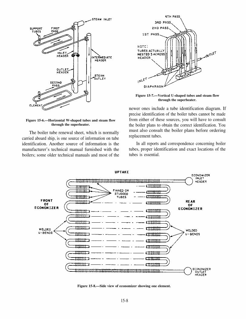
Figure 15-6.—Horizontal W-shaped tubes and steam flowthrough the superheater.
The boiler tube renewal sheet, which is normallycarried aboard ship, is one source of information on tubeidentification. Another source of information is themanufacturer’s technical manual furnished with theboilers; some older technical manuals and most of the
Figure 15-7.—Vertical U-shaped tubes and steam flowthrough the superheater.
newer ones include a tube identification diagram. Ifprecise identification of the boiler tubes cannot be madefrom either of these sources, you will have to consultthe boiler plans to obtain the correct identification. Youmust also consult the boiler plans before orderingreplacement tubes.
In all reports and correspondence concerning boilertubes, proper identification and exact locations of thetubes is essential.
Figure 15-8.—Side view of economizer showing one element.
15-8

SUPERHEATERS
Propulsion boilers now in naval service haveconvection-type superheaters, with water screen tubesinstalled between the superheater tubes and the furnaceto absorb the intense radiant heat and protect thesuperheater.
Most convection-type superheaters have U-shapedtubes, which are installed horizontally in the boiler, andtwo headers, which are installed more or less verticallyat the rear of the boiler. One end of each U-shaped tubeenters one superheater header, and the other end entersthe other header. The superheater headers are dividedinternally by one or more division plates which act asbaffles to direct the flow of steam. Some superheaterheaders are divided externally as well as internally.
The superheaters of some boilers have a WALK-INor CAVITY-TYPE feature—an access space or cavityin the middle of the superheater tube bank. This cavity,which runs the full length and height of the superheater,provides accessibility for cleaning, maintenance, andrepair. Some of the walk-in superheaters haveU-shaped tubes; others have W-shaped tubes.
Some boilers have vertical, rather than horizontal,convection-type superheaters. In these boilers, theU-bend superheater tubes are installed almostvertically, with the U-bends near the top of the boiler;the tubes are approximately parallel to the main bank ofgenerating tubes and the water screen tubes. Twosuperheater headers are near the bottom of the boiler,running horizontally from the front of the boiler to therear.
Figures 15-6 and 15-7 illustrate the U- and theW-shaped tubes. U-shaped tubes are used with avertical superheater, while the W-shaped tubes are usedwith a horizontal superheater. The arrows in theillustrations trace the steam flow through thesuperheater and show the number of passes the steammakes through the superheater.
ECONOMIZERS
An economizer is found on practically everypropulsion boiler now in use by the Navy. Theeconomizer is an arrangement of tubes installed in theuptake space from the furnace. The economizer tubesare heated by the rising gases of combustion. Allfeedwater flows through the economizer tubes beforeentering the steam drum and is warmed by heat, whichwould otherwise be wasted, as the combustion gasespass up the stack.
One type of economizer commonly used on navalpropulsion boilers consists of two headers and a numberof tube assemblies (or elements). The headers are at therear of the economizer, with the inlet header at the topand the outlet header at the bottom. Each tube assembly(element) consists of a number of horizontal tubes, oneabove the other. The individual tubes are connected insequence by U-bends at the tube ends, both at the rearof the economizer and at the front. The tube assemblies(elements) are arranged side by side in a casing. Thetop tube of each element is welded into the top, or inlet,header; the bottom tube of each element is welded intothe bottom, or outlet, header. Thus, each element formsone continuous loop between the inlet header and theoutlet header. The arrangement of one economizerelement of this type is shown in figure 15-8.
Almost all economizer tubes have some sort ofmetal projections from the outer tube surfaces. Theseprojections are called by various names, includingFINS, STUDS, RINGS, and DISKS. They are made ofaluminum, steel, or other metals, in a variety of shapes.Figure 15-9 illustrates three types of metal projections
Figure15-9.—Three types of metal projections used oneconomizer.
15-9

that are used on economizer tubes. These projectionsserve to extend the heat transfer surface of the tubes onwhich they are installed.
FURNACES ANDREFRACTORIES
A boiler furnace is a space provided for the mixingof fuel and air and for the combustion of the fuel. Aboiler furnace consists of a more or less rectangularsteel casing which is lined on the floor, frontwall, side walls, and rear wall with refractorymaterials.
The refractory materials confine the heat to thefirebox and protect the casing and structural membersfrom overheating. Refractories are also used to formbaffles, which direct the flow of combustion gases andprotect drums, headers, and tubes from excessive heatand flame impingement.
REFRACTORY LINING LIFEFACTORS
The life of the furnace lining is influencedprimarily by the quality of installation, the serviceenvironment, and the proper application of inspectioncriteria.
Quality of Installation
New refractory arangement drawings have beendistributed widely for most boiler classes. Thesedrawings include numerous improved arrangementsand standardization features. They supersede allprevious refractory arrangement drawings forapplicable boilers and must be used when refractory iscompletely renewed and when major repairs are made.Before installing refractory, you should consult thedrawing applicable to your boiler class for detailssuch as location and type of anchors, thicknesses andtypes of materials, expansion joints, and clearances totubes.
Service Environment
Service environment refers to the operation ofboilers.
SUSTAINED HIGH FURNACE TEM-PERATURE.—Refractory materials obtained fromthe Naval Supply System are tested and selected toprovide a margin of safety relative to maximumtemperature attainable at areas where they aredesignated on refractory arrangement drawings. It isunlikely that designated refractory can be damaged byoverheating in a properly maintained and operatedboiler.
RAPID CHANGES IN TEMPERA-TURE.—Ability to withstand sudden temperaturechanges is a factor in selecting the refractories for navalboiler use. However, rapid changes in temperature canbe reduced to a minimum by intelligent boileroperation. Steam should never be formed in a coldboiler any faster than necessary. Refractoriespreviously baked out and fired are more sensitive torapid cooling than to rapid heating. When a boiler issecured, it should be closed up as tightly as possible andthe furnace should be allowed to cool slowly. Since,however, emergencies do arise, occasionally theseprecautions must be ignored. The brickwork willprobably stand the abuse, but its life will be shortened.Continued abuse could bring on furnace problems thatwill necessitate repairs.
SHOCK AND VIBRATION.—As shown onapplicable drawings, all areas of refractory must beanchored or held in position by one of the followingmethods:
1. Brick bolts. Applicable to firebrick laid 4 l/2inches thick and to burner tile.
2. Anchor strips. Applicable to castable refractoryand plastic refractory.
3. Boiler tubes. As an example, superheaterscreen tubes, rear wall, and side wall tubes in D-typeboilers do retain adjacent refractory.
Relatively small areas of castable refractory andplastic refractory may be keyed-in by cutting back thesides of adjacent brickwork.
Where other methods are not adequate, nichromewire may be used to anchor small areas of castablerefractory.
NOTE: Nichrome wire is considered an anchoringdevice, not a reinforcement. Also, nichrome wire mustnot be used with plastic because it interferes with properpounding of the plastic.
15-10

PANTING OF THE BOILER.—Vibration orpanting must be provided for by carefully laying up andsecurely anchoring the refractory; however, thestrongest refractory will not withstand continuous andheavy vibration indefinitely. This is especially true ofplastic or castable settings, such as burner fronts.Burner-front plates must be sufficiently rigid to reducepanting and vibration effects to a minimum.
If undue panting or vibration occurs, an effortshould be made to determine its cause and, if practical,correct it. Panting is usually attributable to deficiencyof air, excessive oil temperature, or poor air-oilintermixture.
Poor air-oil intermixture may be caused byimproper register settings, improper atomizerwithdrawal, or severe warping of burner parts. If thedifficulty cannot be corrected by the ship’s force,NAVSEA must be advised, and all pertinentinformation available which may aid in determiningcorrective measures must be given.
SLAG ACTION.—Slag does not form onrefractories when distillate fuel is burned unless thereis heavy and prolonged seawater contamination of theoil. Slagging is a slow, progessive action which isaccelerated by oils having high ash content and by fullpower operation. The mere presence of molten slag onrefractory is not a sound basis for refractory renewal;thickness of refractory remaining or other factorsshould govern the need for renewal. Mixtures ofdistillate fuel and Navy special fuel oil (NSFO) mayresult in slagging, depending on the proportions of themixture and the duration of burning the mixture.
SCALE AND SOOT.—Scale and soot removedwhen cleaning firesides must be swept out of thefurnace. Presence of this refuse on refractories lowerstheir melting point and contributes to slag formation.Sweeping of the furnace should be followed by cleaningthe refuse from the expansion joints to allow thebrickwork to expand freely when it is heated. Hard slagshould not be chipped from refractory, except whereinterfering on burner throat rings or where slagaccumulation on a floor causes carbon accumulation.
TYPES OF REFRACTORYMATERIALS
The following refractory and insulation materialsare stocked in the Navy supply system and are approved
for use as shown on applicable refractory arrangementdrawings. Other materials are not used except in anemergency.
Firebrick
The purpose of firebrick is to provide structuralstability and to protect backup insulation frommaximum temperatures, flame erosion, slag attack, andrapid temperature change. Firebrick must not besubstituted if drawings specify insulating brick;increased heat loss and higher casing temperaturewould result. MIL-B-15606, grade A, is the typemost generally used and shown on refractoryarrangement drawings. MIL-B-15606, grade B, has aslightly lower maximum use temperature and is lessresistant to slag attack, but it is equivalent to grade A inother respects. Grade A firebrick is used in furnaceareas. Grade B is used in the superheater cavities ofD-type boilers.
Firebrick have relatively poor insulation value, lessthan l/10 that of insulation block MIL-I-2819.
Insulating Brick
Two types of insulating brick are commonly usedin naval boilers: MIL-B-16008 and MIL-B-16305,class B.
MIL-B-16008 is used only for back-up insulationbehind firebrick, plastic, or castable refractory.
MIL-B-16305, class B, is used as a gas-side layerat such lower temperature areas of D-type boilers as atthe main generating bank areas and behind tangentsidewall and roof tubes. MIL-B-16008 brick havebetter insulating value but less strength and hightemperature capability than MIL-B-16305, class B,brick. The insulating value of both types is intermediatebetween that of firebrick and insulation block.
Insulation Block MIL-I-2819,Class 3
Insulation block, used as the first layer on the insideof inner casings, is capable of withstanding surfacetemperatures up to 815°C (1500°F) when protected byother refractory from gas erosion and slag attack. Its
15-11

physical strength is relatively low but adequate for itsintended use. Its insulating value is much greater thanother furnace lining components.
Refractory Mortar MIL-M-15842
Class 1 mortar is shipped in dry form and requiresmixing with water before its use. Class 2 mortar isfurnished ready-mixed, but may require mixing withadditional water to obtain the proper consistency. Class1 mortar is preferred in general use. Class 2 mortar isused when laying MIL-B-16305, class 2, insulatingbrick. Insulating brick absorbs moisture from class 1mortar so quickly that proper thin joints cannot beobtained easily. Both types of mortar are air-setting;that is, they develop strength after drying without beingheated. The primary purpose of mortar is to seal jointsin brickwork or tile installations and to cushion thepieces against concentrated stresses.
Burner Tile
MIL-B-15606, grade A, tile are available in varioussizes and shapes for specific burner types. They can beused only with specific burner types for which they aredesigned.
Castable Fireclay RefractoryMIL-C-717
Castable refractory is about equal to firebrick inmaximum use temperature, but it is usually less durablebecause of lower strength. It contains ahydraulic-setting binder and develops strength withoutheating in a manner similar to concrete. It is installedby casting, tampering, or ramming, depending oncircumstances. Large areas, such as a complete burnerfront, require use of a suitable form. Castable refractoryis preferred to plastic refractory for small repairs orwhere standard size brick or tile cannot be used.Castable refractory must be air-cured for 2 days orlonger before baking out. Baking out after an air cureof only 1 day may cause poor performance because oflow strength. Performance is sensitive to installationtechnique and anchoring. Castable fireclay refractoryMIL-C-717 is now used in other areas where plasticchrome ore was formerly used.
Plastic Fireclay RefractoryMIL-P-15731
Plastic refractory has lower strength and slightlymore shrinkage than castable refractory. It developsstrength only after heating at about 1095°C (2000°F) orhigher temperatures. Plastic refractory use should beavoided in low temperature areas. Plastic refractory’sperformance is sensitive to installation technique andanchoring.
Baffle Tile
Baffle tile is made of silicon carbide. They arecharacterized by high strength, good dimensionalstability, and resistance to rapid temperature change,and low insulating value. Baffle tile is available inseveral sizes and is shaped to fit between 2-inch outsidediameter (OD) tubes.
Castable Insulation MIL-C-19794
Castable insulation has good insulating value,moderate temperature resistance, but low strength. It isan approved substitute for insulating brick andinsulating block (but not for insulating block only) incertain boiler walls. It is not suitable for use in a wallpreviously provided with 2-inch thick insulation block,in floors, or as a gas-side layer. Its advantage is thespeed and economy of installation since handcutting ofinsulation or brick bolts is eliminated.
Plastic Chrome Ore MIL-P-15384
Plastic chrome ore is composed of chrome ore(rather than fireclay or aluminum silicates) andbonding agents which give it pronounced air-settingproperties. It is used primarily on studded tubes individed furnace boilers. Prolonged air-drying of plasticchrome ore (periods of a week or longer) should beavoided to minimized shrinkage and migration ofchemical binder.
Chrome Castable MIL-C-15413
Chrome castable is composed of chromium ore anda hydraulic-setting binder. It is used primarily onstudded tube walls in M-type boilers when earlybake-out is not feasible. It is also used for repairingplastic chrome ore on studded tube walls. Chromecastable can be replaced with castable fireclayrefractory MIL-C-717 in areas where chrome castable
15-12

was formerly used. Chrome castable must be given 2days or more air-curing before baking out.
Anchor Devices
Anchor devices come in several forms to
Insulating Cement MIL-C-2861 accommodate various specific anchoring require-ments.
Insulating cement is composed of mineral woolfibers and clay binder. It is an insulating space-fillerused between insulation block and casing in certainboiler classes (as shown on applicable drawings). It isalso used to fill voids in insulation block layers atmissing corners or at cut-outs for anchor devices and toprovide a straight backing for insulation block whereminor casing warping has occurred. Insulating cementmay also be used with certain other machineryinsulation arrangements.
Anchor bolts and retainers for firebrick and burnertile are as shown in figure 15-10. Only one of the twoanchor bolt slots in 9-inch long brick need to be used.In some instances, when indicated on applicablerefractory arrangement drawings, the two end slots on13 9/16-inch long brick may be used. Brick boltretaining strips must be welded to inner casing by ringfillet welds, not merely by tack welds.
Anchors for castable or plastic refractory must beof the pennant type or suitable modification as shown
Figure 15-10.—Refractory anchor devices.
15-13

in figure 15-11. At furnace areas, the unsupported end refractory unless the pennant type shown in figureof the anchor must extended to l/2 to 1 inch from the 15-10 is not available.gas-side surface of the refractory. The anchors may becut or compressed slightly in length by bending to suitconditions. For large areas, anchors should be spacedabout 10 to 12 inches apart, but optimum spacing isinfluenced by configuration. Brick or burner tileanchors should be used to anchor castable or plastic
HANDLING AND STORAGEREFRACTORY MATERIALS
Refractory bricks are packed in cartons forconvenient storage and handling. All refractory
Figure 15-11.—Boiler saddle, support, and sliding feet.
15-14

materials should be stored in a weatherproof enclosedor compartment protected from seawater spray oraccidental flooding. Insulating brick, insulating block,and material in bags are especially sensitive to moisture.Castable refractory in damaged or previously openedbags absorbs moisture from the atmosphere. The resultis deterioration and hardening. If a bag of castablerefractory contains hard, clustered lumps, the entirecontents must be discarded. Plastic refractory requiresonly protection from drying out before installation andmay be used regardless of age, as long as its workabilityis satisfactory. Remixing dried plastic refractory withadditional water is likely to result in poor service.Plastic refractory and class 2 refractory mortar aresubjected to freezing. If frozen, the material must beslowly and completely thawed before use.
EXPANSION JOINTS
Unless shown otherwise on the applicablerefractory arrangement drawing, expansion joints in thefirebrick layer should be l/4 inch wide. Expansionjoints are constructed by either of two ways: Styrofoamor a l/5-inch thick, 3- to 5-foot piece of metal.
1. Styrofoam must be carefully cut to provide auniform l/5-inch thickness. The Styrofoam is left inplace to burn away during boiler operation. When thismethod is used, installation of insulating layers isstarted at an expansion joint, and a split firebrick (1 l/4inches thick by 4 l/2 inches by 9 inches) is placedimmediately behind the expansion joint.
2. The l/5-inch thick by approximately 3- or5-foot long piece of metal is equipped with handleswhich are used to remove the metal when brickwork atan area is completed. When all brickwork in the boileris completed, the expansion spaces are filled withloosely packed Fiberfrax FC-25. Whenever thismethod is used, installation of insulation need not startat an expansion joint, and the use of a split firebrickbehind the joint is not necessary.
CASINGS, UPTAKES, ANDSMOKEPIPES
In modern boiler installations, each boiler isenclosed in two steel casings. The inner casing is linedwith refractory materials, and the enclosed space formsthe boiler furnace. The outer casing extends aroundmost of the inner casing, with an air space in between.
At the boiler front, the outer casing usually comes up toa line just above the level of the top burner opening. Airfrom the forced draft blowers is forced into the spacebetween the inner and the outer casings; from there theair flows through the registers into the furnace.
The inner casing encloses most of the boiler up tothe uptakes. The uptakes join the boiler to thesmokepipe. As a rule, the uptakes from two or moreboilers connect with one smokepipe.
Both the inner and the outer casings are made ofsteel panels. The panels may be either flanged andbolted together (with gaskets used at the joints to makean airtight seal) or they may be of welded construction(except for the access doors).
SADDLES AND SUPPORTS
Each water drum and water header rests upon twosaddles, one at the front of the drum or header and oneat the rear. The upper flanges of the saddles are curvedto fit the curvature of the drum or header and are weldedto the drum or header. The bottom flanges are flat andrest on huge beams built up from the ship’s structure.The bottom flange of one of the saddles is bolted rigidlyto its support. The bottom flange of the other saddle isalso bolted to its support, but the bolt holes areelongated in a fore-and-aft direction. As the drumexpands or contracts, the saddle that is not rigidlyfastened to the support accommodates to the changinglength of the drum by sliding forward or backward overthe support. The flanges that are not rigidly fastenedare known as BOILER SLIDING FEET. Figure 15-11shows the general arrangement of the saddle, support,and sliding feet.
OTHER BOILER COMPONENTS
The major boiler components previously describedin this chapter could not function properly withoutcertain accessories, fittings, instruments, and controldevices. Although these additional boiler parts arediscussed in detail in other chapters of this manual, theyare mentioned briefly at this point to provide a completepicture of what a boiler is and what components itrequires.
FUEL-OIL BURNERS
Fuel-oil burners are discussed in chapter 16 of thismanual. Several types of fuel-oil burners are nowin use by the Navy. All serve the same basic purpose
15-15

of mixing fuel and air so that combustion can takeplace.
INTERNAL FITTINGS
Internal fittings installed in the steam drum includeequipment for (1) distributing the incoming feedwater,(2) separating and drying the steam, (3) giving surfaceblows to remove solid matter from the water, (4)directing the flow of steam and water within the steamdrum, and (5) injecting chemicals for boiler watertreatment. In addition, single-furnace boilers havedesuperheaters for desuperheating the steam needed forauxiliary purposes. The desuperheater, which may beinstalled in either the steam drum or in the water drum,is referred to as an internal fitting.
EXTERNAL FITTINGS ANDINSTRUMENTS
External fittings and instruments include drains andvents, sampling connections, feed stop and checkvalves, steam stop valves, safety valves, soot blowers,water gauge glasses and remote water level indicators,pressure and temperature gauges, superheatertemperature alarms, superheater steam flow indicators,smoke indicators, oil drip detector periscopes, andfeedwater regulators. These external fittings andinstruments are also discussed in chapter 16 of thismanual.
BOILER CONTROL SYSTEMS
Boiler control systems are installed on most boilersfor the automatic control of combustion and water level.These systems are discussed in chapter 17 of thismanual.
SINGLE-FURNACE PROPULSIONBOILERS
Now that we have examined the basic componentsused in most naval boilers, let’s put them together andsee how they are arranged to form the boilers now inuse in the propulsion plants of naval ships.
Since the majority of propulsion boilers used in theNavy are of the single-furnace type, we will discussonly this type. If your ship has another type, consult the
appropriate manufacturer’s manual or Naval Ships’Technical Manual, chapter 221.
COMBUSTION AIR AND GASFLOW
Study figure 15-12 as you read this section.Combustion air is discharged from forced air draftblowers through duct work to the rear wall casing ofeach boiler. There are two blowers per boiler. In theduct work from each blower there are automatic shuttersthat permit the flow of air to the boiler but preventreverse flow, air loss to an idle blower, and windmillingof the idle blower. The combustion air flows betweenthe inner casing and the outer casing of the rear wall.The greater portion of the air travels down under theboiler between the boiler floor and the ship’s hull to thefront of the boiler. A small portion of the air flowsbetween the two casings, around the side or back of theboiler to the front wall. The air circulating between thecasings picks up some of the heat lost by the boiler andreduces the temperature of the outer casing. The heatrecovered increases the temperature combustion andhelps increase the overall boiler efficiency.
The primary combustion air passes through theregisters and the burner diffuser to be mixed with theatomized oil. The boiler throat ring is equipped withvanes or blades, which give a swirling motion to the airby bypassing the diffuser (secondary air) to providebetter mixing with the fuel. When the burner is inoperation, the register doors should always be wideopen to permit unrestricted airflow. When the burner issecured, the doors should be closed tightly.
It is at this point that the ignition takes place.Complete combustion takes place within the furnace.The gases of combustion heat the side and rear walltubes. Water circulating within the tubes preventsoverheating and tube burn-up.
The gases of combustion exit the furnace throughthe screen tubes. The function of the screen tubes is togreatly reduce direct flame impingement on thesuperheater tubes when the boiler is operating. Fromthe screen tubes the gas flows through the superheaterits cavity to the main generating bank. From the mainbank the gas flows upward through the economizer andinto the uptakes.
15-16

Figure 15-12.—Combustion air and gas flow.
15-17

BOILER WATER AND STEAMCIRCULATION
Study figure 15-13 as you read this section.Feedwater enters the economizer inlet header located atthe top of the economizer. The inlet header connects tohorizontal aluminum finned tubes which runperpendicular to the gas flow. Feedwater travelsthrough these tubes and back through another set offinned tubes by U-bends. Each plane of 13 tubes isreferred to as a row of economizer tubes. The feedwater
passes through these rows of tubes before exiting theeconomizer through the outlet header. During fullpower conditions, the feedwater temperature isincreased approximately 190°F (from 250°F to 440°F).
Feedwater enters the steam drum through a nozzlelocated in the rear drum head. Inside the steam drum,the water is directed below the normal water level by aninternal pipe. This internal pipe, called a feed pipe, hasholes which allow the water to disperse evenly alongthe length of the drum.
Figure 15-13.—Boiler water and steam flow.
15-18

The boiler in figure 15-13 is a natural-circulationtype. The cooler, denser water flows downward to thewater drum, while the heated, less dense mixture ofsteam and water in the tubes rises to the steam drum.
Downcomers are large distribution pipes. Theyensure a positive flow of water to the lower parts of theboiler. Downcomers extend from the steam drum to thewater drum, screen header, lower rear wall header, andsidewall header. They are located between the innerand outer casings and are kept relatively cool by theflow of combustion air to the burners.
The hot gases of combination heat the water in thegenerating, side wall, rear wall, and screen tubes. Asthe water is heated in these areas, the density isdecreased and the water starts to rise. Continuing upthe tubes, a portion of the water changes to steam. Thewater and steam mixture from the side wall screen tubesand generating bank enters the steam drum under thedeflection plate assembly. The water and steam mixturefrom the rear wall travels upward to the upper rear wallheader to the lower portion of the steam drum throughriser pipes.
Steam separators connected to the deflection plateassembly permit steam to flow from under thedeflection plate assembly to the top half of the steamdrum. The steam separators separate the steam andwater mixture by centrifugal action. The water fallsback into the lower half of the steam drum while thesteam rises to the dry box. The dry box extendslongitudinally along the top of the drum. Saturatedsteam leaves the dry box through the saturated steamoutlet nozzle located on top of the steam drum.
The saturated steam is piped from the steam drumnozzle to the superheater inlet/outlet header. The steam
is directed through the superheater tubes by diaphragmslocated in the inlet/outlet and intermediate headers. Thesteam makes four passes, during which it is heated tosuperheat temperature.
Once the steam leaves the superheater via theinlet/outlet header it is split in two directions. Themajority of the steam is directed to the main engines. Asmall portion of the steam is directed to thedesuperheater. The desuperheater, located in the waterdrum, reduces the temperature of the superheated steamto that needed for use with auxiliary equipment.
How would you classify this boiler? On the basisof the classification methods previously discussed, wemay consider this single-furnace boiler as one that hasthe following characteristics. It is a water-tube boilerwith natural circulation of the accelerated type. It is adrum-type boiler with tubes that are arranged rougly inthe shape of the letter D; hence, it is often called aD-type boiler. It has a convection-type superheater. Ithas only one furnace, which is not pressurized. Thistype boiler is used on 600-psi ships and 1200-psi ships.
Keep an open mind on the subject of boilers. Newtypes of boilers are constantly being designed andtested, and existing boiler types are subject tomodification. If you think the desuperheater is alwaysinstalled in the steam drum of a single-furnace boiler,look again. You may find it installed in the water drum.If you think all superheater tubes are U-shaped, look atsome of the W-shaped superheater tubes on newerboilers. And so it goes. You will have to be constantlyon the alert to keep up with new developments in boilerdesign.
15-19

CHAPTER 16
BOILER FITTINGS AND INSTRUMENTS
Many fittings and instruments are used on navalboilers. Boiler fittings are attachments installed in, orclosely connected to, the boiler. They are usuallyreferred to as either internal or external fittings. Internalfittings (or internals) are installed inside the steam andwater spaces of the boiler. External fittings (orexternals) are installed outside the steam and waterspaces. Boiler instruments, such as pressure gauges andtemperature gauges, are regarded as external boilerfittings.
After reading this chapter, you will be able toidentify internal and external fittings, and you willunderstand how each fitting operates with the boiler.You will also understand the basic procedures that mustbe followed when operating a boiler.
INTERNAL FITTINGS
The internal fittings installed in the steam druminclude equipment for distributing the incomingfeedwater, for giving surface blows, for separatingsteam and water, and for directing the flow of steam andwater within the steam drum. Desuperheaters are heatexchangers that lower the temperature of superheatedsteam. The steam can then be used by auxiliarymachinery. Desuperheaters are located in either thewater drum or the steam drum of a boiler.
Internal fittings in some boilers also includeequipment that injects chemicals for boiler- watertreatment.
The specific design and arrangement of boilerinternal fittings vary somewhat from one typeof boiler to another and from one boilermanufacturer to another. Figures 16-1, 16-2, and16-3 show typical arrangements of internals forsingle-furnace boilers. For comparison, figure 16-4shows another arrangement of internals in asingle-furnace boiler.
The following sections describe boiler fittingsmost commonly used on naval boilers.
STEAM DRUM INTERNAL FITTINGS
Follow the numbers on figure 16-2 as we discussthe operation of steam drum internals.
The internal feedwater pipe (9) extends along theentire length of the bottom of the steam drum.Feedwater enters the pipe from the economizer and isevenly distributed throughout the length of the drum.
The chemical feed pipe (11) extends straightthrough approximately 90 percent of the length of thedrum just below the normal water level. It connects tothe chemical feed nozzle on the end of the drum. A rowof holes is located along the top center line. Theprescribed chemicals, consistent with the requirementsof the periodic feedwater analysis, are injected throughthe chemical feed pipe into the boiler.
The dry pipe (15), which collects the steam, issuspended near the top of the steam drum and runs theentire length of the drum. The top of the dry pipe isperforated throughout its entire length. The holes arelocated along the top of the dry pipe to prevent moisturefrom entering the pipe. Connections from the dry pipepass through the top of the steam drum to the saturatedsteam outlet (l), where the steam passes to thesuperheater.
The surface blow pipe (8), located just below thenormal water level of the drum, also extends the fulllength of the drum. It has a single row of holes drilledinto its top. When the surface blow valve is open, thispipe carries off scum and foam from the surface of thewater in the drum.
A continuous baffle (5) is fitted approximately 3inches from the drum’s internal surface. The baffleextends from just forward of the generating tubes to justaft of them. It does not extend as far as the downcomersin each end. The forward and after ends of the space
16-1

Figure 16-1.—Arrangement of internal fittings in a single-furnace boiler.
16-2

1. SATURATED STEAM OUTLET TO SUPERHEATER2. STEAM3. PERFORATED STRAINER4. CYCLONE SEPARATOR5. BAFFLE6. SCREEN TUBES7. SUPERHEATER SUPPORT TUBES8. SURFACE BLOW PIPE9. INTERNAL FEEDWATER PIPE
10. GENERATING TUBES11. CHEMICAL FEED PIPE12. STEAM INLET TO SEPARATOR13. SCRUBBER14. STEAM15. DRY PIPE
Figure 16-2.—A steam drum.
1. SATURATED STEAM OUTLET TO SUPERHEATER2. STEAM3. PERFORATED STRAINER4. CYCLONE SEPARATOR5. BAFFLE6. SCREEN TUBES7. SUPERHEATER SUPPORT TUBES8. SURFACE BLOW PIPE9. INTERNAL FEEDWATER PIPE
10. GENERATING TUBES11. CHEMICAL FEED PIPE12. STEAM INLET TO SEPARATOR13. SCRUBBER14. DRY PIPE15. DESUPERHEATER TUBES
Figure 16-3.—A steam drum with a desuperheater in thesteam drum.
left between the baffle and the drum are closed. Thebaffle is attached at both sides to a flat bar, which is hungfrom the drum as shown, and extends the full length ofthe baffle. Ports are cut into each of these flat bars.Over each of these ports is placed a cyclone separator(4). This arrangement makes the space between thesteam drum and the baffle an entirely enclosed space,with the exception of the ports leading to the cycloneseparators.
The flow of steam and water through the drum is asfollows: Water enters the drum through the internalfeedwater pipe and flows through the downcomers tothe water drum and to the side and rear wall headers.The generating tubes (10) discharge a mixture of steamand water upward into the space behind the baffle in thesteam drum. The circulation from the sidewall headersis upward through the sidewall to the spaces in the drumbehind the baffle. The circulation from the rear wall
16-3

Figure 16-4.—Arrangement of steam drum internals in asingle-furnace boiler.
header is up through the tubes to the upper rear wallheader where tubes distribute the mixture of steam andwater to the space behind the baffle in the steam drum.Since this space is entirely enclosed, the only passage(12) available for the steam and water is through theports opening to the the cyclone separators. Theseparators on each side of the drum have sufficientcapacity to pass all the steam and water that may flowthrough them. As the mixture passes through thecyclone separators, the steam is separated from thewater and passes through the top of the separator. Thewater discharges from the bottom of the separator. Asthe steam leaves the cyclone separator, it passes througha scrubber (13) where it is further dried and then,finally, is led to the top of the drum where it enters thedry pipe.
Another interesting feature is illustrated in figure16-1. It is the vortex eliminator, which reduces theswirling motion of the water as it enters the
downcomers. A vortex eliminator consists of a seriesof gridlike plates arranged in a semicircle to conform tothe shape of the lower half of the steam drum. Onevortex eliminator is located at the front of the steamdrum and another is located at the rear of the drum. Ineach case, the vortex eliminator is fitted over the endsof the downcomers.
As mentioned earlier, the desuperheater may belocated in either the steam drum or in the waterdrum. The purpose of the desuperheater is to reducethe temperature of a portion of the superheatedsteam intended to be used in auxiliary steamsystems. Figure 16-2 illustrates a steam drumwithout the desuperheater, and figure 16-3 showsone with the desuperheater (2). This is the onlydifference between the two steam drums.
STEAM DRUM INTERNALS
The internals in this section operate similarly tothe ones discussed previously.
Primary Separators
The first step in the separation of steam and waterin some boilers is performed by two primary separators(fig. 16-4). Each primary separator consists of acylindrical shell with four inside spinner blades securedto dished heads.
The mixture of steam and water is directed into theprimary separator through a lower support (not shown).As the steam passes up through the separator, the fixedspinner blades force the steam into a swirling motion.The heavier water is thrown to the sides, where itcollects and drops back into the lower half of the drum.The lighter steam rises into the secondary separator.
Secondary Separators
Secondary separators are made of severalcorrugated plates in the shape of an inverted basket.They are located on top of, and are bolted to, the primaryseparators. The corrugated plates further separate thesteam and water mixture by creating rapid changes insteam flow direction. The steam can adapt to theserapid changes but the heavier water cannot. The watercollects and falls back into the lower portion of thesteam drum.
16-4

Cyclone Separators
The purpose of the cyclone separators is to deliverdry saturated steam to the dry pipe with minimumagitation of the water, thereby reducing the possibilityof priming. Priming takes place when boiler water iscarried over into the superheater of a boiler.
The details of a cyclone separator with its strainerand scrubber are shown on the drawings of the internalfittings (figs. 16-1, 16-2, and 16-3). The steam enters theseparator through its inlet connection, which is tangentto the separator body. Entering on this tangent, thesteam meets the water, and the blades of the separatorcreate a rotating motion in the mixture. Due to itsweight, the water is thrown toward the side of thecyclone separator body, where the rapid change indirection helps to separate the water from the steam.Being lighter, the steam rises through the center towardthe perforated strainer, while the heavy water dropsdown toward the base of the separator.
Curved stationary vanes near the bottom of theseparator maintain the rotary motion of the water untilit is finally discharged from the bottom of the separator.In the center of the separator, there is a flat plate to whichthe curved vanes are attached. The plate keeps thesteam in the center of the separator and prevents itsbeing carried out of the bottom by the water. The vanes,being located around the periphery of the plate, allowthe water to pass from the separator around the outeredges of the body only.
The two end cyclone separators, one on each side,are fitted at their bases with a flat baffle. The baffledirects the flow of water from the separator to the centerof the steam drum, where it is mixed thoroughly withthe rest of the water in the steam drum and is kept fromflowing directly from the separator into thedowncomers.
Dry Box
The dry box is designed to separate any steam andwater mixture not separated by the separators. The drybox works on the same principle as the separator (rapid
change in direction). At either end of the dry box, thereis a drain hole where collected water may drop back intothe lower half of the steam drum.
Since there are other boiler manufacturers, andthere are other differences between designs andarrangements which we have not covered, it isimportant that you be aware of these differences andconsult the manufacturers’ technical manuals whenworking on the boilers on your ship.
EXTERNAL FITTINGS ANDCONNECTIONS
External fittings and connections commonly usedon naval boilers include drains and vents, samplingconnections, feed stop and check valves, steam stopvalves, safety valves, soot blowers, blow valves, watergauge glasses, remote water-level indicators,superheater steam flow indicators, pressure andtemperature gauges, superheater temperature alarms,smoke indicators, oil-drip detector periscopes,three-element feedwater regulators, steam-smotheringsystems, and other devices that are closely connected tothe boiler but not installed in the steam and waterspaces.
Any listing of boiler external fittings andconnections tends to sound like a catalog ofmiscellaneous and unrelated hardware. Actually,however, all of the external fittings and connectionsserve purposes that are related to boiler operation.Some of the fittings and connections allow you tocontrol the flow of feedwater and steam. Others serveas safety devices. Still others allow you to performoperational procedures—removing soot from thefiresides, for example, or giving surface blows—thatare necessary for efficient functioning of the boiler. Theinstruments attached to or installed near the boiler giveyou essential information concerning the conditionsexisting inside the boiler. To understand the purposesof the external fittings and connections, you must knowhow each item is related to boiler operation.
16-5
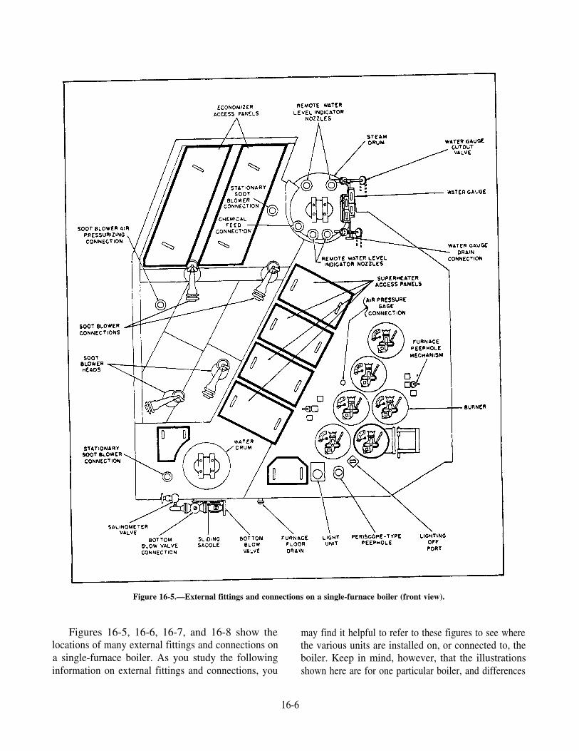
Figure 16-5.—External fittings and connections on a single-furnace boiler (front view).
Figures 16-5, 16-6, 16-7, and 16-8 show the may find it helpful to refer to these figures to see wherelocations of many external fittings and connections on the various units are installed on, or connected to, thea single-furnace boiler. As you study the following boiler. Keep in mind, however, that the illustrationsinformation on external fittings and connections, you shown here are for one particular boiler, and differences
16-6
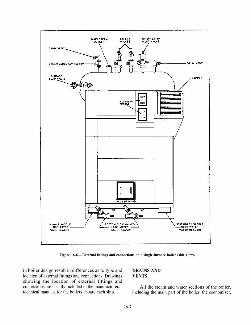
Figure 16-6.—External fittings and connections on a single-furnace boiler (side view).
in boiler design result in differences as to type andlocation of external fittings and connections. Drawingsshowing the location of external fittings andconnections are usually included in the manufacturers’technical manuals for the boilers aboard each ship.
DRAINS ANDVENTS
All the steam and water sections of the boiler,including the main part of the boiler, the economizer,
16-7

Figure 16-7.—External fittings and connections on a single-furnace boiler (economizer side view).
and the superheater, must be provided with drains andvents.
The main part of the boiler may be drained throughthe bottom blow valve and through water wall headerdrain valves. Normally, a boiler is vented through theaircock, which is a high-pressure globe valve installedat the highest point of the steam drum. The aircockallows air to escape when the boiler is being filled and
The economizer is vented through a vent valve onthe economizer inlet piping. It is drained through adrain line from the economizer outlet header. Anotherdrain line, coming from the drain pan installed belowthe headers, serves as an indicator of possibleeconomizer leakage.
Superheater vents are installed at or near the top ofeach superheater header or header section; superheaterdrains are installed at or near the bottom of each header
when steam is first forming; it also allows air to enter or header section. Thus, each pass of the superheater isthe steam drum when the boiler is being emptied. vented and drained.
16-8

Figure 16-8.—External fittings and connections on a single-furnace boiler (rear view).
Superheater drains discharge through gravity(open-funnel) drains to the freshwater drain collectingsystem while steam is being raised in the boiler. Aftera specified pressure has been reached, the superheater
drains are shifted to discharge through steam traps tothe high-pressure drain system. The steam traps allowcontinuous drainage of the superheater withoutexcessive loss of steam or pressure.
16-9

Figure 16-9 shows the arrangment of superheatervents and drains on a single-furnace boiler, as well asthe superheater protection steam connections.
SAMPLING CONNECTIONS
To determine and condition of boiler water, testsmust be performed on a representative sample of theboiler water. One can easily see that a sample can beobtained from the steam drum, the gauge glass, thewater drum, or a header. A sample of boiler water takenfrom the water drum has the greatest probability ofbeing representative of the water in the boiler.However, a sample from the water drum is only
representative of the dissolved solids (material) in theboiler water. No sample can be consideredrepresentative of the suspended solids (sludge) in theboiler.
The boiler water sample cooling coil is placed on aline that is connected to the blowdown line from thewater drum. At least two valves are on the sample linebetween the water drum and the cooling coil. Thecooling coil brings the temperature of the sample waterbelow the boiling point at atmospheric pressure andthus keeps the water from flashing into steam as it isdrawn from the higher pressure of the boiler to the lowerpressure of the fireroom.
Figure 16-9.—Diagrammatic arrangement of superheater vents, drains, and protection steam connections.
16-10
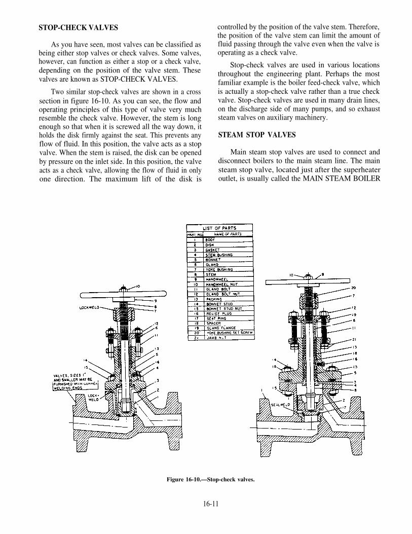
STOP-CHECK VALVES
As you have seen, most valves can be classified asbeing either stop valves or check valves. Some valves,however, can function as either a stop or a check valve,depending on the position of the valve stem. Thesevalves are known as STOP-CHECK VALVES.
Two similar stop-check valves are shown in a crosssection in figure 16-10. As you can see, the flow andoperating principles of this type of valve very muchresemble the check valve. However, the stem is longenough so that when it is screwed all the way down, itholds the disk firmly against the seat. This prevents anyflow of fluid. In this position, the valve acts as a stopvalve. When the stem is raised, the disk can be openedby pressure on the inlet side. In this position, the valveacts as a check valve, allowing the flow of fluid in onlyone direction. The maximum lift of the disk is
controlled by the position of the valve stem. Therefore,the position of the valve stem can limit the amount offluid passing through the valve even when the valve isoperating as a check valve.
Stop-check valves are used in various locationsthroughout the engineering plant. Perhaps the mostfamiliar example is the boiler feed-check valve, whichis actually a stop-check valve rather than a true checkvalve. Stop-check valves are used in many drain lines,on the discharge side of many pumps, and so exhauststeam valves on auxiliary machinery.
STEAM STOP VALVES
Main steam stop valves are used to connect anddisconnect boilers to the main steam line. The mainsteam stop valve, located just after the superheateroutlet, is usually called the MAIN STEAM BOILER
Figure 16-10.—Stop-check valves.
16-11

STOP. Figure 16-11 shows a cross-sectional view of agate-type main steam stop (motor-operated).
The main steam boiler stop is either fully open orfully closed—that is, it is not used as a throttling valve.The valve can be operated manually either at the valveor at a remote operating station or by remote operatinggear, which is also provided. Many steam stops are nowfitted with pneumatic (air) motors which are actuatedthrough toggle operating gear to close the valve from aremote position. The toggle operating gear provides themechanical advantage required to close the valve againstboiler pressure. These valves are opened manually.
Main steam boiler stops, like other main steam stopvalves, are specifically designed for high-pressure andhigh-temperature service. The seating surfaces of thedisks and seats are usually made of Stellite, a hard,erosion-resistant alloy.
Two-valve protection for each boiler is required onall ships built to U.S. Navy specifications. A secondsteam stop valve is therefore provided in the main steamline just beyond the main steam boiler stop. This sec-ond valve is called the main steam stop guarding valve.
Figure 16-11.—Cross section of motor-operated gauge valve(main steam stop).
Auxiliary steam stop valves are smaller than mainsteam stop valves but are otherwise similar.
SOOT BLOWERS
Soot blowers are installed on boilers to remove sootfrom the firesides while the boiler is steaming. The sootblowers must be used regularly and in proper sequenceto prevent the accumulation of heavy deposits of soot.Soot is an effective insulator, and any soot despositedon boiler tubes seriously interferes with heat transferand thus reduces boiler efficiency. If the soot blowersare not used often enough, soot accumulates betweenthe tubes on top of the lower drums and headers. Soottends to absorb moisture from the air. The moisturecombines with the soot to form sulfuric acid, whichcorrodes the boiler tubes. Moisture also tends to makethe soot pack down into such a solid mass that it cannotbe removed by the soot blowers. Another importantreason that soot must be removed at regular intervals isthat any large accumulation of soot on the boilerfiresides constitutes a serious fire hazard.
When distillate fuel is being burned, soot blowersmust be used to blow tubes on the steaming boilers atleast once each week while the ship is underway and,when in port or at anchor, just after leaving or just beforeentering port. In addition, if practical, tubes should beblown as soon as possible after heavy smoke has beenmade.
Soot blowers must be used in the proper sequenceso that the soot will be swept progressively toward theuptakes. Normally, the uppermost soot blowers areused at the beginning and then again at the end of theblowing sequence. The exact sequence for blowingtubes should be obtained from the manufacturer’stechnical manual for the boilers aboard each ship.
Before tubes are blown, due consideration must begiven to the effect that the discharge of soot will haveupon the upper decks. The engineering officer of thewatch must obtain permission from the officer of thedeck before instructing fireroom personnel to blowtubes.
Some ships are designed with stackdampers, whichenable the bridge to direct soot from either the port orstarboard side as desired.
There are two basic kinds of soot blowers: (1) therotary (multinozzle) type and (2) the stationary type.Rotary soot blowers are used in most outlet locations ofthe boiler. The stationary type is used in a few speciallocations.
16-12
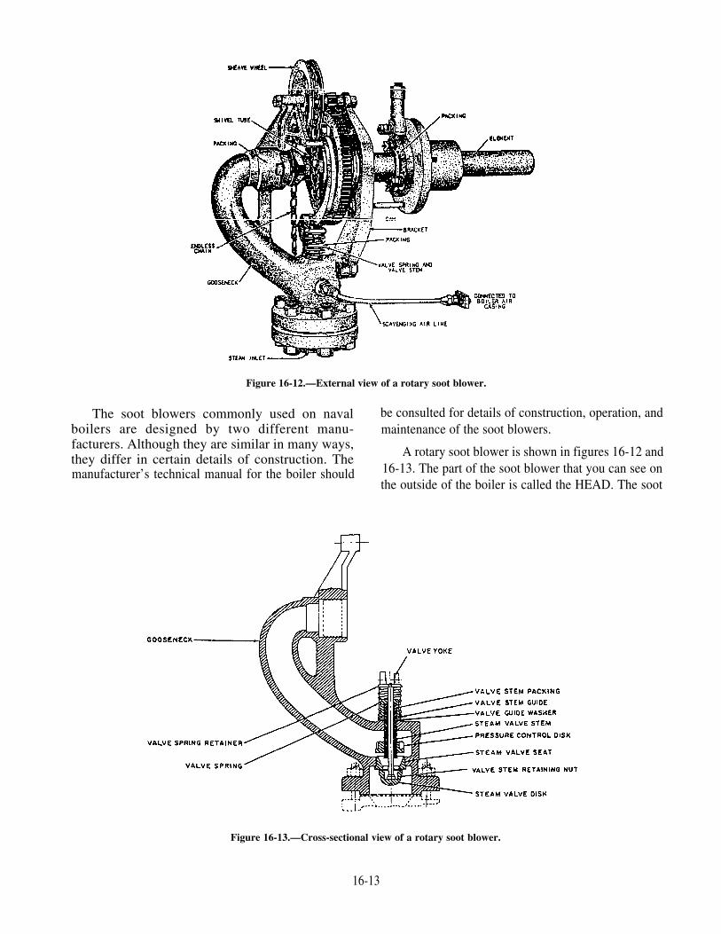
Figure 16-12.—External view of a rotary soot blower.
The soot blowers commonly used on naval be consulted for details of construction, operation, andboilers are designed by two different manu- maintenance of the soot blowers.facturers. Although they are similar in many ways,they differ in certain details of construction. Themanufacturer’s technical manual for the boiler should
A rotary soot blower is shown in figures 16-12 and16-13. The part of the soot blower that you can see onthe outside of the boiler is called the HEAD. The soot
Figure 16-13.—Cross-sectional view of a rotary soot blower.
16-13

blower ELEMENT, a long pipe with multiple outlets,or nozzles, projects into the tube banks of the boiler.This soot blower is operated by an endless chain, whichruns in a sheave wheel (as shown in fig. 6-12). Whenthe chain is pulled, steam admitted through a steamvalve (shown in fig. 16-13) and is discharged at highvelocity from the nozzles in the element. The nozzlesdirect the jets of steam so that they sweep around thetubes, thus preventing direct impingement of steam onthe tubes. The soot is thus loosened so that it can beblown out of the boiler.
Each steaming boiler uses its own steam to supplyits own soot blowers. However, the steam used forblowing tubes is reduced from boiler pressure toapproximately 300 psi. The pressure is reduced eitherby a pressure control disk above the steam valve (fig.16-13) or by a pressure control orifice below the steamvalve.
Some soot blowers are operated by manual turningof a crank, while others are operated by manual pullingon a chain. Aboard some ships, the soot blowers areoperated by push buttons. A press on the button admitsair to an air motor that drives the unit.
On some soot blowers, the admission and cutoff ofsteam is controlled so that the tubes are swept onlyduring a part of each rotation of the element. The partof each rotation during which steam is admitted, and
BLOWING ARC. Blowing arcs are controlled by camsor stops. Figure 16-14 shows two cam-and-gearassemblies for controlling the blowing arcs on rotarysoot blowers. The arrangement shown on the left is fora blowing arc of less than 360°; the arrangement on theright is for a blowing arc of 360°.
The scavenging air connection shown in figure16-12 supplies air to the soot blower element and thuskeeps combustion gases from backing up into the sootblower heads or the steam piping. A check valve isinstalled in the scavenging air piping, near the sootblower head. When tubes are being blown, steam entersthe short length of air piping between the soot blowerhead and the check valve, closing the valve. Whentubes are not being blown, air pressure in the scavengingair line keeps the check valve open.
On many boilers, the copper tubing for thescavenging air is connected to the boiler casing at thefront of the boiler. On some boilers, however, thetubing is connected to some other part of the boilercasing so that a shorter length of tubing can be used.
The number of soot blowers installed, the way inwhich they are arranged, and the blowing arcs for eachunit differ from one type of boiler to another. Figure16-15 indicates the soot blower sequence for a
during which the tubes are swept, is called the single-furnace boiler.
Figure 16-14.—Cam-and-gear assemblies for controlling blowing arcs on multinozzle soot blowers.
16-14

Figure 16-15.—Sequence of soot blowers on a single-furnaceboiler.
BLOW VALVES
Some solid matter is always present in boiler water.Since most of the solid matter is heavier than water, ittends to settle in the water drums and headers. Solidmatter that is lighter than water rises and forms a scumon the surface of the water in the steam drum. Sincemost of the solid matter is not carried over with thesteam, the concentration of solids remaining in theboiler water gradually increases as the boiler is steamed.For the sake of efficiency and for the protection of the
removed from time to time. Blow valves and blow linesare installed below the boiler for this purpose.
Light solids and scum are removed from the surfaceof the water in the steam drum by the surface blow linewhich, as we have already seen, is an internal boilerfitting. Heavy solids and sludge are removed byopening bottom blow valves, which are fitted to eachwater drum and header. Both surface blow valves andbottom blow valves on modern naval boilers areglobe-type stop valves.
Both the surface blow valves and the bottom blowvalves discharge to a system of piping called theBOILER BLOW PIPING. The boiler blow pipingsystem is common to all boilers in any one fireroom.Guarding valves are installed in the line to preventleakage from a steaming boiler into the blow piping andto prevent leakage from the blow piping into a securedboiler. A guarding valve installed at the outboardbulkhead of the fireroom gives protection againstsaltwater leakage into the blow piping. After passingthrough this guarding valve, the water is dischargedthrough an overboard discharge valve (sometimescalled a skin valve), which leads overboard below theship’s waterline. Figure 16-16 shows the general
boiler pressure parts, some of this solid matter must be arrangement of boiler blow piping.
Figure 16-16.—Boiler blow piping.
16-15

INSTRUMENTS AND MONITORINGDEVICES
Some of the instruments and monitoring devicesthat enable the Machinist’s Mate (Surface) to determinehow the boiler is working are water gauge glasses,remote water-level indicators, superheater temperaturealarms, smoke indicators, and oil-drip detectorperiscopes.
WATER GAUGE GLASSES
Various combinations of water-level indicatingdevices are used on naval boilers. On older boilers,perhaps the most common arrangment has two watergauge glasses, one 10 inches long and one 18 incheslong. Newer boilers may have two water gauge glassesand one remote water-level indicator, or they may haveone water gauge glass and two remote water-levelindicators.
Every boiler must be equipped with at least twoindependent devices that show the water level in thesteam drum, so that a false water level may be detectedthrough a comparison of the two. At least one of thesedevices must be a water gauge glass. Some boilershave more than two devices for indicating water level.
Several types of water gauge glasses are used onnaval boilers. Gauges are identified by the amount ofvisibility permitted and usually are installed in pairs:two 10-inch gauges or two 18-inch gauges at the samelevel, or one 10-inch and one 18-inch gauge, or two10-inch gauges staggered vertically to provide a totalvisibility of 18 inches.
A more recent type of water gauge glass is shownin figure 16-17. This gauge is assembled with springs,as shown in the illustration. This type of assemblymakes it unnecessary to retorque the studs after thegauge has warmed up. (Notice the numbering of thestuds in fig. 16-17; the numbers indicate the proper
Figure 16-17.—Water gauge glass
16-16

sequence of tightening the studs in assembling thegauge.)
Each water gauge is connected to the steam drumthrough two cutout valves, one at the top of the drumand one at the bottom. The bottom cutout valveconnection contains a ball-check valve. The ball restson a holder. As long as there is equal pressure on eachside of the ball, the ball remains on its holder. But if thewater gauge breaks, the sudden rush of water throughthe bottom connection forces the ball upward onto itsseat and thus prevents further escape of hot water. Nocheck valve is installed in the top cutout connection.
Detailed information on the water glasses installedon any particular boiler is found in the appropraitemanufacturer’s technical manual.
Figure 16-18.—General arrangement of a remote water-levelindicator.
REMOTE WATER-LEVELINDICATORS
Remote water-level indicators are used aboardmost ships so that the boiler water level can beobserved from the lower level of the fireroom oroperating station. There are two types of remotewater level indicators commonly used aboardcombatant ships; other types may be found aboardauxiliary ships.
For information on specific remote water-levelindicators, refer to the manufacturer’s manuals.
The general arrangement of remote water-levelindicators is shown in figure 16-18. The mainparts of the unit are (1) the constant-headchamber, which is mounted on the steam drum at ornear the vertical center line of the drum; (2) thegraduated indicator, which is usually mounted on aninstrument panel; and (3) two reference legs thatconnect the constant-head chamber to the indicator.The reference legs are marked A and B in figure16-18.
A constant water level is maintained in leg A(constant-pressure leg), since the water level in theconstant-head chamber does not vary. The level inleg B (variable-pressure leg) is free to fluctuate withchanges in the steam drum water level. The upperhemisphere of the constant-head chamber isconnected to the steam drum at a point above thehighest water level to be indicated; because of thisconnection, boiler pressure is exerted equally on thewater in the two legs. Variable leg B is connected to thesteam drum at a point below the lowest water level tobe indicated; because of this connection, the water levelin leg B is equalized with the water level in the steamdrum.
As you can see in figure 16-18, each leg isconnected by piping to the indicator. In the indicator,the two columns of water terminate at opposite sides ofa diaphragm.
16-17

Another type of remote water-level indicator isshown in figure 16-19. The operating principles of thisdevice are very similar to the operating principles of theremote water-level indicator previously discussed.
The main difference is the differential pressuresensing unit (DPU) (fig. 16-20). This unit can be usedeither as a pneumatic transmitting unit by attaching apneumatic transmitter to the DPU output shaft, orstrictly as an indicator by attaching a gauge to the DPUoutput shaft. The bellows are liquid-filled and canwithstand much more pressure than the diaphragm usedin the first remote water-level indicator we discussed.
PRESSURE AND TEMPERATUREGAUGES
To operate a boiler, you must be constantly awareof pressures and temperatures in the boiler and in itsassociated machinery and systems. Pressure gauges areinstalled on or near each boiler to indicate steam drum
pressure, superheater outlet pressure, auxiliary steampressure, auxiliary exhaust pressure, feedwaterpressure, steam pressure to the forced draft blowers, airpressure in the double casings, and fuel-oil pressure.Temperature gauges are installed to indicatesuperheated steam temperature, desuperheated steamtemperature (if the boiler has a desuperheater),feedwater temperature at the economizer inlet andoutlet, and—in some ships—uptake temperatures.Most of these pressure and temperature gauges areclassified as boiler external fittings.
In some firerooms, the gauges that indicate steamdrum pressure, superheater outlet pressure, superheateroutlet temperature, and combustion air pressure areinstalled on the boiler front. As a rule, however, theindicating units of all pressure gauges are mounted ona boiler gauge board that is easily visible from the firingaisle. Distant-reading thermometers are also installedwith the indicating unit mounted on the boiler gaugeboard. Direct-reading thermometers must, of course,
Figure 16-19.—Typical drum-level measurement installation for a second type of remote water-level indicator.
16-18

be read at their actual locations. In some installations,a common gauge board is used for all the boilers in onespace, instead of having separate gauge boards for eachboiler. Duplicate gauges for all major boiler operatingparameters are located in the console operator’sbooth for ships with automatic boiler control (ABC)systems.
Most of the pressure gauges used in connectionwith boilers are of the Bourdon-tube type. However,some manometers and some diaphragm gauges are alsoused in the fireroom.
The temperature gauges most commonly used inthe fireroom are (1) direct-reading liquid-in-glassthermometers and (2) distant-reading Bourdon-tubethermometers. However, bimetallic expansionthermometers are also used.
Some thermometers are of the bare-bulb type—thatis, the bulb is in direct contact with the steam or otherfluid being measured. Bare-bulb thermometers mustNEVER be removed while the boiler is under pressure.Other thermometers are of the well or separable-sockettype—that is, the bulb is inserted into a well or socket
in the line where the temperature is to be measured.These thermometers are not designed to be used asbare-bulb thermometers; they must always be used inthe well or socket.
SUPERHEATER TEMPERATUREALARMS
Superheater temperature alarms are installed onmost boilers to warn operating personnel ofdangerously high temperatures in the superheater.
SMOKE INDICATORS
Naval boilers have smoke indicators (sometimescalled smoke periscopes), which permit visualobservation of the gases of combustion as they passthrough the uptakes. Single-furnace boilers have onesmoke indicator installed in the uptake.
OIL-DRIP DETECTOR PERISCOPES
Some boilers are equipped with oil-drip detectorperiscope, which allow operating personnel to inspect
Figure 16-20.—Differential Pressure-Sensing Unit (DPU).
16-19
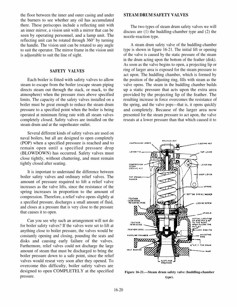
the floor between the inner and outer casing and underthe burners to see whether any oil has accumulatedthere. These periscopes include a reflecting unit withan inner mirror, a vision unit with a mirror that can beseen by operating personnel, and a lamp unit. Thereflecting unit can be rotated through 360° by turningthe handle. The vision unit can be rotated to any angleto suit the operator. The mirror frame in the vision unitis adjustable to suit the line of sight.
SAFETY VALVES
Each boiler is fitted with safety valves to allowsteam to escape from the boiler (escape steam pipingdirects steam out through the stack, or mack, to theatmosphere) when the pressure rises above specifiedlimits. The capacity of the safety valves installed on aboiler must be great enough to reduce the steam drumpressure to a specified point when the boiler is beingoperated at minimum firing rate with all steam valvescompletely closed. Safety valves are installed on thesteam drum and at the superheater outlet.
Several different kinds of safety valves are used onnaval boilers, but all are designed to open completely(POP) when a specified pressure is reached and toremain open until a specified pressure drop(BLOWDOWN) has occurred. Safety valves mustclose tightly, without chattering, and must remaintightly closed after seating.
It is important to understand the difference betweenboiler safety valves and ordinary relief valves. Theamount of pressure required to lift a relief valveincreases as the valve lifts, since the resistance of thespring increases in proportion to the amount ofcompression. Therefore, a relief valve opens slightly ata specified pressure, discharges a small amount of fluid,and closes at a pressure that is very close to the pressurethat causes it to open.
Can you see why such an arrangement will not dofor boiler safety valves? If the valves were set to lift atanything close to boiler pressure, the valves would beconstantly opening and closing, pounding the seats anddisks and causing early failure of the valves.Furthermore, relief valves could not discharge the largeamount of steam that must be discharged to bring theboiler pressure down to a safe point, since the reliefvalves would reseat very soon after they opened. Toovercome this difficulty, boiler safety valves aredesigned to open COMPLETELY at the specifiedpressure.
STEAM DRUM SAFETY VALVES
The two types of steam drum safety valves we willdiscuss are (1) the huddling-chamber type and (2) thenozzle-reaction type.
A steam drum safety valve of the huddling-chambertype is shown in figure 16-21. The initial lift or openingof the valve is caused by the static pressure of the steamin the drum acting upon the bottom of the feather (disk).As soon as the valve begins to open, a projecting lip orring of larger area is exposed for the steam pressure toact upon. The huddling chamber, which is formed bythe position of the adjusting ring, fills with steam as thevalve opens. The steam in the huddling chamber buildsup a static pressure that acts upon the extra areaprovided by the projecting lip of the feather. Theresulting increase in force overcomes the resistance ofthe spring, and the valve pops—that is, it opens quicklyand completely. Because of the larger area nowpresented for the steam pressure to act upon, the valvereseats at a lower pressure than that which caused it to
Figure 16-21.—Steam drum safety valve (huddling-chamber
type).
16-20

lift initially. After the specified blowdown hasoccurred, the valve closes cleanly, with a slight snap.
The amount of compression on the springdetermines the pressure at which the valve will pop.The position of the adjusting ring determines the shapeof the huddling chamber and thereby determines theamount of blowdown that must occur before the valvewill reseat.
A steam drum safety valve of the nozzle-reactiontype is shown in figure 16-22. The initial lift of thisvalve occurs when the static pressure of the steam in thedrum acts upon the disk insert with sufficient force to
overcome the tension of the spring. As the disk insertlifts, the escaping steam strikes the nozzle ring andchanges direction. The resulting force of reactioncauses the disk to lift higher, up to approximately 60percent of rated capacity. Full capacity is reached as theresult of a secondary, progressively increasing lift,which occurs as an upper adjusting ring is exposed. Thering deflects the steam downward, and the resultingforce of reaction causes the disk to lift still higher.Blowdown adjustment in this type of valve is made byraising or lowering the adjusting ring and by raising orlowering the nozzle ring.
Figure 16-22.—Steam drum safety valve (nozzle-reaction type).
16-21

SUPERHEATER SAFETY VALVES
Safety valves are always installed at the superheateroutlet as well as on the steam drum. To ensure anadequate steam flow through the superheater when thesteam drum safety valves are lifted, superheater safetyvalves are sometimes set to lift at a lower pressure thanwhich lifts the steam drum safety valves. We willdiscuss two kinds of superheater safety valvearrangements: (1) the two-valve superheater outletsafety valve assembly and (2) the three-valvesuperheater outlet safety valve assembly.
Most single-furnace boilers are equipped withtwo-valve superheater outlet safety valve assemblies ofthe type shown in figure 16-23. In an assembly of thistype, both the valves are spring-loaded. The pilot valveon the steam drum and the superheater valve at thesuperheater outlet are connected by a pressuretransmitting line, which runs from the discharge side ofthe drum pilot valve to the underside of the piston,which is attached to the spindle of the superheater safetyvalve.
The superheater valve is set to pop at a pressureapproximately 2 percent higher than the pressure thatcauses the drum pilot valve to pop. When the drum pilotvalve pops, the steam pressure is transmittedimmediately through the pressure line to the piston; thusthe superheater valve is actuated. If, for any reason, thedrum pilot valve should fail to open, the superheatervalve will open at a pressure approximately 2 percenthigher to protect the superheater.
The three-valve superheater outlet safety valveassembly shown in figure 16-24 is used on some1200-psi single-furnace boilers. The assembly consistsof a pilot valve, a piston actuator, and an unloadingvalve.
The spring-loaded pilot valve is mounted on the topcenter line of the steam drum. The piston actuator andthe unloading valve are assembled as a unit andmounted on the piping at the superheater outlet; theyare connected to each other by a rocker arm. The pistonacutuator has a cylinder with a piston inside it. Theunloading valve contains (1) an actuating valveconnected to the rocker arm by a stem and (2) apiston-type disk without a stem, which is held in line bythe cylinder in which it works. The unloading valve ispressure-loaded, not spring-loaded.
Steam from the superheater outlet enters theunloading valve cylinder and gathers around the valvedisk above the seat. The steam bleeds through smallports to the space above the disk. When the actuatingvalve is closed, the steam above the disk of theunloading valve cannot escape, so the pressure abovethe disk equalizes with the pressure below thedisk—that is, the pressure above the disk is equal to thesuperheater outlet pressure.
Excessive pressure in the steam drum—NOT theexcessive pressure in the superheater—causes thesafety valve in this assembly to lift. When the pilotvalve on the steam drum opens, pressure is transmittedfrom the pilot valve to the cylinder of the pistonactuator. Pressure in the piston actuator cylinder isapplied under the piston, causing the spring tocompress. The rocker arm moves upward at the endover the piston actuator and downward at the end overthe unloading valve, thus opening the actuating valve.
When the actuating valve opens, pressure above thepiston-type unloading valve disk bleeds off to theatmosphere. The unloading valve therefore opens,allowing steam to flow from the superheater to theatmosphere, and thus protects the superheater tubesfrom excessive temperatures. When the pilot valve
Figure 16-23.—Two-valve superheater outlet safety valve assembly.
16-22

Figure 16-24.—Three-valve superheater outlet safety valve assembly.
reseats, the actuating valve also reseats. As steambleeds through the ports to the space above the disk inthe unloading valve, pressure builds up and rapidlyequals the pressure below the disk. Then the unloadingvalve closes. In summary, then, the superheaterunloading valve always opens immediately after thesteam drum pilot valve opens, and closes immediatelyafter the pilot valve closes.
Burners are essential to effective fuel-oilcombustion. They provide combustible mixtures of
FUEL-OIL BURNERS
fuel oil and air by reducing the liquid to finely dividedparticles with an atomizer, and mixing air with thesedroplets with a register.
ATOMIZERS
Mechanical as well as steam atomizers are in useon naval ships. With one exception, these are pressureatomizers. The exception, the use of which is confinedto auxiliary boilers, is the rotary atomizer.
Underlying Principle of PressureAtomization
In the type of pressure atomizers most commonlyfound in the Navy, oil is forced under high pressurethrough passages in the atomizer. The passages arearranged to give the oil a high rotation velocity, thusbreaking up the oil by centrifugal force. Rotation isaccomplished by either spiral or tangential groovesthrough which oil is discharged at high pressure into asmall cylindrical chamber. The tip end of this chamberis coned out. The orifice through which oil isdischarged is at the apex of the cone. As oil leaves theorifice, it breaks up into fog or mistlike particles andforms a hollow cone of finely atomized oil. A blast ofair, which has been given a whirling motion in passingthrough the register, catches the oil mist, mixes with it,and enters the furnace, where combustion takes place.There are three most common types of atomizers: (1)the vented-plunger type, (2) the straight-through-flowtype, and (3) the steam-assist type.
16-23

Figure 16-25.—Vented-plunger atomizer.
Vented-Plunger Atomizer
This atomizer is designed to permit wide-rangeoperation using the straight mechanical pressureatomization principle, but it requires a maximum supplyoil pressure of only (approximately) 350 psig. Refer tofigure 16-25 as we describe the operation of thevented-plunger atomizer. Oil flows down the atomizerbarrel around the atomizer cartridge and enters the whirlchamber through tangential holes drilled around itscircumference. The piston in the whirl chamber isspring-loaded and is moved to cover or uncover thetangential holes in the whirl chamber by varying the oilsupply pressure. Increasing oil pressure moves thepiston to uncover more holes and increase oil rate;
Figure 16-26.—Parts of a straight-through-flow atomizerassembly.
decreasing oil pressure does the opposite. Goodatomization is maintained at all firing rates due to a highpressure drop maintained through the tangential holesby varying the tangential hole flow area. A hole isdrilled through the length of the piston to vent the springchamber to the furnace, allowing the spring to becompressed. This is possible due to the air core formedin the whirl chamber by the whirling oil. Any oilleakage along the piston into the spring chamber isvented into the furnace in the same manner.
Straight-Through-Flow Atomizer
In the straight-through-flow atomizer, all oilpumped to the atomizer is sprayed into the furnace. Thefiring rate of this type of burner is controlled by varyingthe supply fuel-oil pressure and/or changing sprayerplates. These atomizers have been standardized toobtain maximum performance without unduecomplexity. Standard atomizer parts consist of thefollowing: (See fig. 16-26.)
1. Tip. The tip serves to center the sprayer platewhirling chamber on the atomizer nozzle box and tohold the sprayer plate face tightly against the front faceof the atomizer nozzles, preventing passage of oil intothe whirling chamber anywhere except through the slotsof the sprayer plate.
2. Nozzle. The nozzle serves to lead the oil fromthe atomizer barrel into the slots of the sprayer plate.The standard nozzle has a 0.5-inch diameter boss andhas four oil lead holes.
3. Sprayer plate. The sprayer plate transformssolid streams of oil under high pressure into a cone offine, foglike particles.
16-24

Figure 16-27.—Y-jet steam atomizer.
Steam-Assist Atomizer
In the steam-assist atomizer, steam is used to breakup the oil mass into minute particles and to project theoil particles, in the shape of a cone, into the furnace.Two basic types of steam-assisted atomizers are in usein the fleet today: the Y-jet steam atomizer (fig. 16-27)and the LVS steam atomizer (fig. 16-28).
In the Y-jet steam atomizer, steam is suppliedthrough the inner tube of the atomizer to the steam portsof the sprayer plate; oil is delivered to the sprayer plateoil ports through the annulus formed between the innerand outer atomizer tubes. Each steam port meets withan oil port and the mixture of oil and steam exits froma common hole. Six such exit ports are inclined at anangle of 40° around the axis of the sprayer plate.
In the LVS steam atomizer, a sprayer plate is usedto spray oil from the inner tube of the atomizer into amixing chamber. Steam from the atomizer outer tubealso passes through the sprayer plate and into the mixingchamber. The steam and oil blend in the mixing nozzle.
The mixture leaves the nozzle as a fine spray throughconcentrically drilled holes in the mixing nozzle.
When steam is not available, steam atomizationburner systems have the capability to use low-pressurecompressed air as a substitute for 150-psi auxiliarysteam for cold plant light-off. After steam is cut intothe atomizing steam system, precaution must be takento ensure that the steam is thoroughly drained ofcondensate at the atomizing steam header before theatomizing steam is cut inot an individual burneratomizer.
Advantages of Steam Atomization
Steam atomization has the following advantagesover other types of atomization:
1. High turndown (see NOTE)
2. Clean burning of residual fuel
3. Less fireside deposits
4. Satisfactory combustion in a cold furnace
5. Wide range with lower pressures
NOTE: Turndown, or turndown ratio when usedin the modern sense, is a measure of the ability of aparticular burner to operate satisfactorily over a widerange from low to high firing rates. To the boilerdesigner, it is the ratio of the maximum satisfactoryfiring rate to the minimum firing rate of a burner.
Character of Atomization
Factors affecting the character of atomization,including capacity, spray angle, and particle fineness,are primarily determined by size and relative passage
Figure 16-28.—LVS steam atomizer.
16-25

proportions in atomizer parts. They are alsodetermined, to an important extent, by fuel-oil viscosity,steam pressure, steam dryness, and oil pressure. Theangle of atomization required differs in various types ofregisters and boiler furnaces. For this reason, instandardized atomizer parts (all other conditionsremaining unchanged), the relationship between thediameter of the orifice area and the combinedcross-sectional area of the tangential slots is highlyimportant because it controls the character of the spray.The size of the orifice of a sprayer plate and the ratio ofthe combined cross-sectional area of the slots to the areaof the orifice are indicated by four numerals stenciledon the face of the plate. The first two digits indicatethe bore of the orifice in United States standard drillsize; the second two numbers are the quotient (omittingthe decimal point) of the combined cross-sectional areaof the tangential slots divided by the area of the orifice.
Care of Atomizers
As far as possible, operating personnel mustmaintain the atomizers in their original mechanicalcondition and polished finish. The importance of theproper care and cleanliness of the atomizer parts cannotbe overemphasized. Atomizers are frequently ruinedbecause personnel do not understand the importance offineness of atomization and do not appreciate howeasily an excellent atomizer may be ruined by carelesshandling. The following instructions must be observedin the operation and maintenance of the atomizers.
Under no circumstances must operating personnelmake any changes in dimensions of atomizers orotherwise tamper with them. Slight variations from aset standard may have a noticeable effect on results.The engineer officer must make frequent inspections toensure that sprayer plates and nozzles are in goodcondition. Inspection should include checking oil andsteam orifice holes of sprayer plates with a Go/No-Gogauge. This gauge indicates proper sizing of orificeswith the gauge being manufactured on the basis of wiredrill sizes. Penetration into the orifice by the smallerend (green color) of the gauge indicates that the orificeis larger than the minimum acceptable size. Lack ofpenetration by smaller end of the gauge indicates thatthe orifice is undersized and that the plate must bediscarded. Lack of penetration by the larger end (redcolor) of the gauge indicates that the orifice is smallerthan the maximum acceptable size. Penetration by thelarger end of the gauge indicates that the orifice isoversized and that the plate must be discarded.
Steel wire or steel tools must not be employed incleaning sprayer plates, nozzles, or other atomizer parts.
Atomizers using DFM fuel, when withdrawn fromburners, must not be cleaned by blowing through withsteam or compressed air. Unless the atomizer barrelsmust be immediately put into service again with cleansprayer plates, allow the withdrawn atomizer barrels tocool at the burner bench for 15 minutes. After thiscooling period, remove the sprayer plates, orifices,adaptor plates, and removable sliding nozzles, and placethem in a pan of DFM or kerosene to soak until thecarbon has become soft and they can be cleaned. Theslots in the sprayer plates and the supply holes in thenozzles may be cleaned with matchsticks withoutdanger of damaging the parts. Properly fitted woodencleaning sticks may be used for cleaning and polishingthe orifices and whirling chambers of sprayer plates, theannular grooves of the nozzles, and the faces of all parts.When you polish atomizers, use only a light lubricatingoil. Never use emery paper or any other substance thatwill cut the metal. After the atomizer parts have beencleaned, wipe them with heavy lubricating oil tominimize the possibility of rusting.
If, after being carefully cleaned, a sprayer plate failsto give an even and finely atomized spray, discard it.
In assembling atomizers, take care not toovertighten the tips. Permanent deformation of thesprayer plate at the outer edge of the face and on thearea of overlap of the sprayer plate and the nozzle bosscan occur. Repeated over-tightening will undercut thesprayer plate to such an extent that oil will leak into thewhirling chamber without traversing the slots and causedrooling, smoking, and carbon formation.
Never leave disconnected atomizers in place sincethe atomizer or valve may be unintentionally opened,allowing oil to run into firerooms, with disastrousresults. On newly constructed ships, burners are fittedwith safety shutoff devices which prevent the flow ofoil when an atomizer is not in place. To light fires, lineup safety shutoff devices (where provided) to admit fuelwhen putting atomizers in place. To cut in and securefuel to individual atomizers, use root valves. A safetyshutoff device is not normally used for this purpose.
Atomizer root valves should be either fully open (inlighted-off burners) or fully closed (in secured burners).Both the atomizer valve (safety shutoff) and theatomizer root valve should be closed on a securedburner and the atomizer should be entirely removedwhen not in use.
16-26

To maintain satisfactory atomizer machined edgesand threads, atomizers should be stowed properly onstowage racks installed in the vicinity of the burneratomizer bench. Before placing cleaning atomizers inthe stowage rack, loosely thread the cap nut or tip ontothe end of the atomizer to prevent damage to the nozzleand the threads. Before any atomizer is placed in theboiler burners, it should be checked by the top watchfor tightness and proper makeup. Whenever possible,the top watch should also visually sight through thepeep sights or sight glasses to ensure that newlyinstalled and cut-in atomizers are firing properly. Theflame pattern is indicative of proper installation. Thesevital functions should not be delegated to inexperiencedpersonnel.
REGISTERS
Air registers, when open, direct airflow from theforced draft blowers through the double casing into andaround the stream of foglike oil particles produced bythe atomizer. When closed, they prevent air fromentering the furnace. Air registers employing standardatomizers consist of two principal parts: the diffuserand the air foils. Use of two separate air streams, theprimary through the diffuser and the secondary through
the air foils, has enabled capacity and flexibility to beincreased greatly over that permitted by conicalregisters. The diffuser causes primary mixing offuel-oil droplets with air and prevents blowing of theflame from the atomizer; the air foils guide the majorquantity of air to mix with the oil particles after theyleave the diffuser. Figure 16-29 shows one of mostcommon air registers in use in the Navy today.
Air foils of some types of registers are fixed blades castintegrally in a cone which forms the entering side of theregister throat. The principal purpose of the air doorsin all registers of that design and manufacture is to closethe registers.
Other types air foils of registers consist ofcurvilinear surfaces (or air scoops) welded to the airdoors.
OPERATION AND CARE OF BURNERSAND REGISTERS
Use the following precautions in operating andcaring for burners and air registers:
Check all parts of the register before the operationof any new installation of air registers and at frequentintervals thereafter. Register air doors should be
Figure 16-29.—Fuel-oil burner assembly.
16-27

examined periodically and any air doors found warpedshould be straightened or replaced.
All foil surfaces (blades of the bladed cones, airscoops, or air doors) and diffusers should be maintainedfree of oil, carbon, and dirt. Air slots in the impellersshould be kept entirely clear and free of encumbrances.
Since diffusers which are heavily clogged withcarbon or are not properly machined, especially in vaneopenings, can cause improper combustion andvibrations, duplicate and machine to the sametolerances all diffusers installed in any boiler. This is afurnace inspection item.
BURNER AND ATOMIZER SAFETYSHUTOFF DEVICE
The burner and atomizer safety shutoff device (fig.16-30) is provided on most fuel-oil burner fronts toaccept and position the atomizer. It functions solely toprevent personnel from accidentally cutting-in fuel to aburner that does not have an atomizer in place and toprevent uncoupling a fuel pressurized atomizer, withconsequent spraying of fuel around the burner front,
which could precipitate a fire. Do not use these safetyshutoff devices to admit fuel to the atomizer or to shutoff fuel; use the burner lead root valves for that purpose.If the Planned Maintenance System (PMS) is installed,preventive maintenance should be according to themaintenance requirement card (MRC). Safety shutoffdevices were not designed for zero leakage. Presentleakage criteria/test is as follows: When pressurized tofuel-oil service system pressure, there should be noexternal leakage in the form of a spray or constantstream. If such leakage occurs, corrective action mustbe taken. Weeping or dripping, not exceeding 8 ouncesper hour per burner, is permissible and is not sufficientreason to prohibit steaming the affected or adjacentboiler, but the safety shutoff should be repaired aspracticable by dismantling the shutoff device to replaceseals, replace vitron O-rings, examine internal parts forscoring, and so forth. Normal dismantling period for asafety shutoff device for rebuilding is 1800 hours.Check the clevis (vise handle) of shutoff safety devicesto ensure it’s in the proper position after the atomizer iswithdrawn. This could permit the safety shutoff slidevalve to be accidentally opened.
Figure 16-30.—Cutaway view of fuel-oil safety shutoff device.
16-28

CHAPTER 17
AUTOMATIC BOILER CONTROLS
Automatic combustion and feedwater controlsystems for boilers are installed on most navalships. Boilers are now being constructed towithstand higher pressures and temperaturesand require a rapid and sensitive responseto feedwater, fuel oil, and combustion air.Automatic controls are almost a necessity.Automatic controls for naval boilers operate witha high degree of accuracy and reliability. They aredefinitely an aid to operating personnel.
This chapter contains basic informationon boiler control systems, components, andterminology. Because of the variation in systemsand equipment, the information is limited togeneral principles and examples.
You will find detailed information on eachboiler control system in the manufacturer’stechnical manual furnished with the equipment.The manufacturer’s technical manual is the
authoritative source of information. Thesemanuals are sometimes difficult to understand.This chapter will provide you with some ofthe background knowledge you will need tounderstand the information in these manuals. Itwill not make a control board operator out of youor make you an expert in the maintenance andadjustment of boiler control components. Toachieve these goals, you will have to studythe manufacturers’ technical manuals and getpractical experience.
SIMPLE CONTROL SYSTEMS
Look at the man shown in figure 17-1. He isan example of a control system. He is controllingthe temperature of the water being dischargedfrom a heating tank. By holding one hand on the
Figure 17-1.—A human control system.
17-1

discharge piping, he can tell how hot the wateris. When he feels a change in the temperature, hedetermines how much he must open or close thesteam valve to bring the temperature of the waterback to the proper temperature. With his otherhand, he will open or close the steam valve untilhe finds a position that will bring the temperatureof the water back to the desired value. This manis accomplishing four basic procedures:
1. He is measuring the temperature of thewater in the discharge piping from thetank.
2. He is comparing the measured temperaturewith the temperature he is trying tomaintain.
3. He is determining (computing) the amountand direction he must turn the steam valve.
4. He is correcting the steam input byrepositioning the steam valve.
He is controlling a simple heat exchangeprocess manually rather than automatically. Thefour basic procedures this man is accomplishingare the same that must be done by any controlsystem, whether human or automatic. Any controlsystem must be designed to accomplish thefollowing:
1. MEASURE a value (temperature, pressure,or level) on the output side of a process.
2. COMPARE the measured value with thedesired value.
3. COMPUTE the amount and direction ofchange required to bring the measuredoutput value to the desired output value.
4. CORRECT the value on the input side ofthe process to bring the output side of theprocess back to the desired value.
Measurement, comparison, computation, andcorrection: these are the basic operationsperformed by any control system. Taken together,they constitute a CLOSED LOOP of action andcounteraction by which some quantity orcondition is measured and controlled. The closedcontrol loop is often called a FEEDBACK LOOPbecause it requires a feedback signal from theoutput side of the process to correct the value onthe input side. The closed loop concept isillustrated in figure 17-2.
Any quantity or condition that is measured isa VARIABLE. Any quantity or condition that ismeasured and controlled by a control system isa CONTROLLED VARIABLE. The controlledvariable in the heat exchange process of figure 17-lis the temperature of the water leaving the heatingtank. The hot water is called the CONTROLLEDMEDIUM. The controlled variable is always somecondition or characteristic of the controlledmedium.
Figure 17-2.—Closed loop of control.
17-2

Any quantity or condition that is varied by acontrol system to affect the value of a controlledvariable is called a MANIPULATED VARI-ABLE. In our heat exchange process, the rate ofsteam flow is the manipulated variable. The steamitself is called the CONTROL AGENT. Themanipulated variable is always some condition orcharacteristic of the control agent.
At this point we might stop and ask: Why doesthe process shown in figure 17-1 require a controlsystem? Why can’t we just set the steam valve inone position and let the process take care of itself?If the energy input equals the energy output, theprocess is balanced. If a balanced process couldbe kept entirely free of all disturbing influences,one position of the steam valve could be foundthat would control the rate of steam flow and,thus, control the temperature of the hot water.
But everyday experience tells us that variousdisturbances will affect the process if it is left toitself. The disturbances may come from the input(supply) side of the process, from the output(demand) side, or from other sources. Forexample, what would happen if there were achange in steam pressure or temperature, changein temperature or in the rate of flow of the coldwater, or a change in the demand for hot water?These and other changes, directly or indirectlyassociated with the process, would affect theoutput side of the process-that is, they wouldaffect the temperature of the water leaving theheating tank. If we want to keep the hot waterat a specified temperature, we need a controlsystem. Until we can develop a better one, thatman in figure 17-l will have to stay.
As long as he stays there, though, with onehand on the pipe and one hand on the valve, heis going to have problems. Many of theseproblems are caused by the fact that things do nothappen instantly or all at once. Everything in theprocess and in the control of the process takestime. It takes time for a disturbance to becomeknown. After the man recognizes that thetemperature has changed, he must take time tocompare the new temperature with the desiredtemperature. He must take time to compute thenew steam valve position required to correct thetemperature deviation. He must take time toreposition the steam valve.
Even after he has repositioned the steam valve,the man cannot just walk away. Now he muststand there and wait for the effects of hiscorrective action. If by chance he has made exactlythe right correction, the water in the dischargepiping will return to the desired value. On the
other hand, suppose the man notices that thewater is colder than it should be. He opens thesteam valve approximately one-half turn, butmust wait quite a while before he can tell whetherhis action was correct. Time is required foradditional steam to flow to the heating coil. Timeis required for heat to be transferred from thesteam to the heating coil and from the heating coilto the water. Time is required for the hotter waterin the discharge line to raise the temperature ofthe discharge piping. Time is required for the manto feel the change in temperature.
In reality, of course, it is rather unlikely thatthe man’s first corrective action will be preciselycorrect. Since he has no way to know exactly howmuch to open the steam valve, he may open it toomuch or not enough. In either case, more timeis required for the man to wait, note the effectof his action, reposition the valve, wait again, andnote the effect.
And so it goes, round and round the closedcontrol loop of measurement, comparison, com-putation, and correction. The man would find hisjob a good deal easier if each disturbance and eachcorrection were immediately reflected in thetemperature of the discharge piping, but we knowthat this is not possible. In this process-as indeedin all processes—there are bound to be delays allalong the closed control loop. We understand thiswithout question when a human operator isinvolved, and we allow for such things as reactiontime, time required to take corrective action, andtime required for the change to take effect. Aswe will soon see, the same thing applies to anautomatic controller; the measuring means cannotimmediately reflect a disturbance, the controllingmeans cannot immediately bring about a change,and the measuring means cannot immediatelyreflect the change after it has occurred.
Many of the things that slow down changesin a process, or the control of a process, arerelated to the various capacities and resistancesof equipment and substances. For example, waterhas the capacity to store thermal energy, but timeis required for this storage to take place. Piping,valves, and other equipment have the capacity toallow the flow of a certain quantity of water but,at the same time, they offer some resistance toflow. The slowing-down effects associated withcapacity and resistance are referred to as LAG(capacity lag, process lag, transfer lag, and soforth).
The man in figure 17-l who is acting as ahuman control system must also think aboutDEAD TIME-the time required to transport a
17-3

change from one place to another. Dead time canoccur in various parts of the process. When theman opens the steam valve, a certain amount oftime is required for the steam to travel from thevalve to the heat exchanger. This period of timeis dead time. Similarly, after the steam has heatedthe water, a certain amount of time is requiredfor the hot water to travel from the heat exchangerto the discharge piping where the man is holdinghis hand. This, again, is dead time. Dead time isany definite delay between two related actions.
To distinguish between dead time and lag,remember that dead time is basically travel timeand that lag is related to the capacity and theresistance of the equipment or substances involvedin the process.
The heat exchange process shown in figure 17-1could be controlled by various kinds of automaticcontrol systems employing either electrical,hydraulic, or pneumatic methods of signaltransmission, or some combination of these. Sincewe will later be concerned almost entirely withpneumatic systems used for boiler controls, let’stake a simple pneumatic system such as the one
shown in figure 17-3 and apply it to the control of theheat exchange process.
The automatic system must perform all thecontrol functions performed by the humanoperator in figure 17-1, and it must perform themwithout human assistance. To perform thesefunctions automatically, the system must havea measuring means, some arrangement forcomparison and computation, and a controllingmeans.
The measuring means of the system shownin figure 17-3 consists of a thermometer bulb, aBourdon tube, and connecting capillary tubing.A change in the controlled variable (temperatureof the hot water) leads to a change in the pressuretransmitted to the Bourdon tube. This leads toa change in the position of the Bourdon tube.Through a series of mechanical linkages, theposition of the Bourdon tube affects the positionof the vane in a nozzle-and-vane assembly locatedin the pneumatic transmitter.
The set point knob is linked to the nozzle ofthe nozzle-and-vane assembly in such a way thatthe setting of the set point knob affects theposition of the nozzle. The set point knob is
Figure 17-3.—Simple automatic control system (pneumatic) for control of heat exchange process.
17-4

positioned to represent the desired value of thecontrolled variable.
The nozzle-and-vane assembly is the com-paring and computing device in this pneumatictransmitter. Since the position of the Bourdontube affects the position of the vane, and thesetting of the set point knob affects the positionof the nozzle, the distance between the nozzle andthe vane at all times represents a COMPARISONof the actual measured value (Bourdon tube) andthe desired value (set point knob). The distancebetween the tip of the nozzle and the vane isresponsible for the COMPUTATION of theamount and direction of change that must bemade in the position of the steam valve, because(1) the rate of airflow from the nozzle dependson the distance between the nozzle and the vane,and (2) the rate of airflow from the nozzledetermines how much pneumatic pressure will gofrom the transmitter to the valve motor operator.When the vane and nozzle are relatively far apart,a good deal of air flows out of the nozzle and thereis relatively little air pressure going to the valvemotor operator. If, on the other hand, when thevane and nozzle are closer together, the flowof air from the nozzle is restricted and moreair pressure is directed to the valve motoroperator.
The amount of air pressure going from thetransmitter to the motor operator determines theposition of the steam valve, since the motoroperator positions the valve according to airpressure received from the transmitter. Thus themotor operator and the steam valve together formthe controlling means of this system.
The nozzle-and-vane assembly discussed hereis only one of many pneumatic devices that canaccomplish the functions of comparison andcomputation. Bellows, escapement valves, andvarious other devices are also used in pneumaticsystems to compare the measured value with thedesired value and to compute the amount ofcorrection required.
BASIC TERMINOLOGY
In considering the human control systemshown in figure 17-1, we introduced a number ofideas and terms that are common to any type ofcontrol system, human or automatic. At this
point, stop a few minutes and check yourunderstanding of the following terms:
PROCESS
DESIRED VALUE
CLOSED LOOP (or FEEDBACK LOOP)
CONTROLLED VARIABLE
CONTROLLED MEDIUM
MANIPULATED VARIABLE
CONTROL AGENT
BALANCED PROCESS
DISTURBANCE
DEVIATION
CORRECTIVE ACTION
LAG
DEAD TIME
Do you have a clear understanding of themeaning of these terms? If not, go back and studythe human control system again. These terms areeither defined in that discussion or are used in sucha way that you should be able to understand whatthey mean. The meaning of these terms is basicto any real understanding of automatic control.
In the simple automatic control systemillustrated in figure 17-3, we touched upon severalnew ideas. Let us explore these ideas a little moreand establish some basic definitions. Insofar aspossible, the definitions given here follow theusage established by the American Society ofMechanical Engineers (ASME).
To begin with, an AUTOMATIC CONTROLSYSTEM is any operable arrangement of one ormore automatic controllers connected in closedloops and used with one or more processes.
An AUTOMATIC CONTROLLER is adevice that measures the value of a variablequantity or condition and operates to correct orlimit deviation of this measured value from aselected reference. An automatic controller,therefore, must include both the measuring meansand the controlling means.
17-5
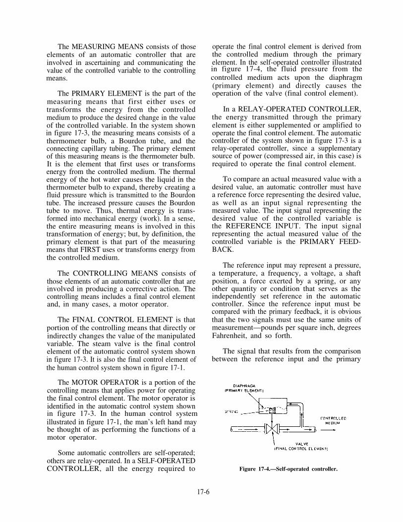
The MEASURING MEANS consists of thoseelements of an automatic controller that areinvolved in ascertaining and communicating thevalue of the controlled variable to the controllingmeans.
The PRIMARY ELEMENT is the part of themeasuring means that first either uses ortransforms the energy from the controlledmedium to produce the desired change in the valueof the controlled variable. In the system shownin figure 17-3, the measuring means consists of athermometer bulb, a Bourdon tube, and theconnecting capillary tubing. The primary elementof this measuring means is the thermometer bulb.It is the element that first uses or transformsenergy from the controlled medium. The thermalenergy of the hot water causes the liquid in thethermometer bulb to expand, thereby creating afluid pressure which is transmitted to the Bourdontube. The increased pressure causes the Bourdontube to move. Thus, thermal energy is trans-formed into mechanical energy (work). In a sense,the entire measuring means is involved in thistransformation of energy; but, by definition, theprimary element is that part of the measuringmeans that FIRST uses or transforms energy fromthe controlled medium.
The CONTROLLING MEANS consists ofthose elements of an automatic controller that areinvolved in producing a corrective action. Thecontrolling means includes a final control elementand, in many cases, a motor operator.
The FINAL CONTROL ELEMENT is thatportion of the controlling means that directly orindirectly changes the value of the manipulatedvariable. The steam valve is the final controlelement of the automatic control system shownin figure 17-3. It is also the final control element ofthe human control system shown in figure 17-1.
The MOTOR OPERATOR is a portion of thecontrolling means that applies power for operatingthe final control element. The motor operator isidentified in the automatic control system shownin figure 17-3. In the human control systemillustrated in figure 17-1, the man’s left hand maybe thought of as performing the functions of amotor operator.
Some automatic controllers are self-operated;others are relay-operated. In a SELF-OPERATEDCONTROLLER, all the energy required to
operate the final control element is derived fromthe controlled medium through the primaryelement. In the self-operated controller illustratedin figure 17-4, the fluid pressure from thecontrolled medium acts upon the diaphragm(primary element) and directly causes theoperation of the valve (final control element).
In a RELAY-OPERATED CONTROLLER,the energy transmitted through the primaryelement is either supplemented or amplified tooperate the final control element. The automaticcontroller of the system shown in figure 17-3 is arelay-operated controller, since a supplementarysource of power (compressed air, in this case) isrequired to operate the final control element.
To compare an actual measured value with adesired value, an automatic controller must havea reference force representing the desired value,as well as an input signal representing themeasured value. The input signal representing thedesired value of the controlled variable isthe REFERENCE INPUT. The input signalrepresenting the actual measured value of thecontrolled variable is the PRIMARY FEED-BACK.
The reference input may represent a pressure,a temperature, a frequency, a voltage, a shaftposition, a force exerted by a spring, or anyother quantity or condition that serves as theindependently set reference in the automaticcontroller. Since the reference input must becompared with the primary feedback, it is obviousthat the two signals must use the same units ofmeasurement—pounds per square inch, degreesFahrenheit, and so forth.
The signal that results from the comparisonbetween the reference input and the primary
Figure 17-4.—Self-operated controller.
17-6

feedback is called the ACTUATING SIGNAL.The actuating signal is the difference, at any giventime, between the reference input and the primaryfeedback. The actuating signal leads to correctiveaction-that is, the variation of the manipulatedvariable produced by the controlling means.
The SET POINT is the position to which thecontrol-point setting mechanism is set to providea reference input. The control-point settingmechanism shown in figure 17-3 is called a SETPOINT KNOB. Set point knobs are used in someautomatic controllers, but there are other typesof control-point setting mechanisms that are usedin other controllers. In some controllers, the setpoint is built in to the controller so that it cannotbe changed unless the controller is taken apart andthe mechanism is readjusted.
DEVIATION is the instantaneous differencebetween the actual value of the controlled variableand the value of the controlled variable cor-responding to the set point.
The CONTROL POINT is the value of thecontrolled variable that, under any fixed set ofconditions, the automatic controller operates tomaintain.
So that you do not confuse set point andcontrol point, think of set point as the referenceforce required to maintain the control point at adesired value. However, both are expressed inunits of the controlled variable. So why do weneed to make a distinction between the two?
For some automatic controllers the distinctionbetween set point and control point is not reallynecessary, since the points coincide. But incontrollers that have other types of controlleraction, set point and control point do NOTcoincide; the distinction is necessary for thesecontrollers. The steady-state difference betweenthe control point and the value of the controlledvariable corresponding to the set point is calledOFFSET. Offset is an essential characteristic ofcertain types of controller action. Set point,deviation, control point, and offset are illustratedfigure 17-5.
Another term that you will find in connectionwith automatic control is CYCLING. Cycling isa continuous changing of the controlled variable.Cycling occurs more with some types of controlleraction than with others.
Figure 17-5.—Set point, deviation, control point, and offsetin an automatic controller.
TYPES OF AUTOMATICCONTROLLER ACTION
When the man in figure 17-1 notices a deviationin the temperature of the hot water, he can doseveral things to take corrective action. He mayimmediately open the valve wide or close itcompletely, depending on the direction of thedeviation. He may open or close the valve quicklyor slowly, at a constant rate or at a varying rate,by a constant amount or by a varying amount.He may continue opening or closing the valve untilhe can feel that the temperature has returned tothe desired value, or he may stop his correctiveaction before the temperature has returned tonormal so that he will not overcorrect. In short,there are a great many types of corrective actionthis man can take. Not all of them will be equallyeffective, of course, but all of them will work,more or less.
Automatic controllers, like human beings, arecapable of various kinds of actions. The type ofcontroller selected for any given system dependson the requirements of the system. The automaticcontroller actions discussed in this chapter includethe following:
1. Positioning action2. Floating action3. Rate action4. Multiple action
To make it simple, we will discuss the variouskinds of controller action as they relate to theposition of a final control element. Remember,however, that the terms and definitions used herecan be applied equally well to other aspects ofautomatic control. They may apply to the value
17-7

of a manipulated variable, for example, or to asignal sent from one controller to another.
As you study the material on the types ofcontroller action, be sure to study the diagramsand illustrations that accompany the text. Therelationship between the controlled variable andthe controller action can often be understoodmore clearly from diagrams than from a meredescription.
POSITIONING ACTION
Positioning action is any controller action inwhich there is predetermined relation between thevalue of the controlled variable and the positionof the final control element. We will discuss twokinds of positioning action: two-position action(two types) and proportional-position action.
Two-Position Action
In two-position action, a final control elementis moved from one of two fixed positions to theother. There are two kinds of two-position action.One is two-position single-point, and the other istwo-position differential-gap action.
TWO-POSITION SINGLE-POINT ACTION.—Two-position single-point action is action in whicha final control element is moved from one of twofixed positions to the other whenever thecontrolled variable reaches one certain value.
Figure 17-6 illustrates the two-position single-pointaction. When the temperature of the water is ator above set point, the valve immediately closes;when it is below set point, the valve opens. Asyou can see, a two-position single-point controllercannot make exact corrections. Instead, it mustalways overcorrect; thus the process neverachieves stability and the value of the controlledvariable cycles continuously.
TWO-POSITION DIFFERENTIAL-GAPACTION.—Two-position differential-gap actionis action very much like two-position single-pointaction except that the controlled variable has aRANGE of values instead of a single value (orsingle point) to reach. This range of values iscalled the differential gap. No action of the finalcontrol element occurs when the value of thecontrolled variable is within the differential gap.But when the value of the controlled variable goesabove the highest value of the differential gap orbelow the lowest value, the final control elementis moved from one fixed position to the other.Obviously, this type of action must also result inovercorrection and consequent cycling of thecontrolled variable.
To illustrate the difference between the twotypes of two-position action, let’s consider figure17-6 again. Assume that the set point is 140°F. Ifthe controller has two-position single-point action,the valve will close whenever the temperature ofthe hot water is 140°F or above and open
Figure 17-6.—Action of two-position single-point controller : valve position (top) and controlled variable (bottom).
17-8
whenever the temperature is below 140°F. If thecontroller has two-position differential-gapaction, with a differential gap of 20°, the valvewill close whenever the temperature of the waterreaches 150°F and open whenever it reaches130°F.
In both types of two-position action, the twofixed positions of the final control element canbe something other than the zero or 100 percentpositions. For example, the valve positionsillustrated in figure 17-6 indicate that the valve mustgo from fully open to fully closed or from fullyclosed to fully open. The amount of cycling canbe reduced by narrowing the range of the valveopening—that is, by having the valve move fromone-fourth open to three-fourths open, instead offrom fully closed to fully open. However, anarrow range will work well only for a very steadyand constant process. If a process is subject toconsiderable load changes, a narrow range of thefinal control element will require constant manualreadjustment.
Proportional-Position Action
Proportional-position action is that in whichthere is a continuous linear relationship betweenthe value of the controlled variable and theposition of the final control element. The amountof change in the value of the controlled variablethat is necessary to cause a specified change inthe position of the final control element dependson the PROPORTIONALITY ADJUSTMENTof the controller.
The proportionality adjustment of a controllermay be expressed as (1) PROPORTIONALBAND or (2) GAIN or SENSITIVITY adjust-ment. Gain and sensitivity mean the same thing.Proportional band and gain are not identical, butboth have to do with the proportionalityadjustment of a controller. Some manufacturerscalibrate their controllers in such a way that theproportionality adjustment is made in terms ofthe proportional band, while other manufacturersuse gain. In general, you will find that oldercontrollers are calibrated to indicate proportionalband, while newer ones are calibrated to indicategain.
The term PROPORTIONAL BAND refers tothe amount of change in the value of thecontrolled variable that is required to produce aspecified change in the position of the final controlelement. Proportional band may be expressedeither in units of the controlled variable or as a
percentage of the controller scale range. Forexample, suppose a controller for a heat exchangeprocess has a scale range of 100 percent,corresponding to a temperature range of 100°F,if the proportional band adjustment of thiscontroller is set at 5 percent, a temperature changeof 5°F will produce a 100 percent change in theposition of the steam valve (fully open or fullyclosed). If the proportional band adjustment isset at 100 percent, a temperature change of 100 °Fis required to produce the same change in theposition of the valve. If the proportional bandadjustment of this controller is 120 percent, atemperature of 120 °F is required to produce a 100percent change in the position of the valve.
GAIN (or SENSITIVITY) describes the ratiobetween the input to a controller and the outputfrom that controller. Gain is the RECIPROCALof proportional band.
Although we define proportional-positionaction and proportional band (or gain, if thecontroller is so calibrated) in relation to theposition of the final control element, rememberthat the controller actions and adjustments aredescribed in the same way when they apply toother aspects of automatic control. For example,consider a proportional-position controller thatreceives a pneumatic input signal and sends aproportional pneumatic output signal to some unitthat is NOT a final control element. Thiscontroller still has a proportionality adjustment—that is, it still has either a proportional bandadjustment or a gain (sensitivity) adjustment.
Since proportional-position action causes acorrective action proportional to the amount ofdeviation, it is a very stable kind of controlleraction and is sometimes used for automaticcontrol. However, proportional-position actionhas one serious disadvantage: it can make exactcorrections for deviations of the controlledvariable ONLY when there is no load change.
Under all conditions of load except theone for which the set point is established,proportional-position action produces a correctiveaction that stabilizes the controlled variable atsome value other than the desired set point value.The new value is called the CONTROL POINT.The difference between the control point and theset point is called OFFSET. It is important tounderstand that offset is a basic characteristic ofproportional-position action under conditions ofload change.
17-9

Offset has been previously defined andillustrated (figure 17-5.) At this point, you mayunderstand the whole idea more easily if weconsider a sequence of events in a heat exchangeprocess that is under the control of an automaticcontroller with proportional-position action.
Figure 17-7 illustrates such a heat exchangeprocess. The original set point is 150°F. To beginwith, the process is stable and is balanced tomaintain the value of the controlled variable atthe set point. Then, after 1 minute a deviationoccurs. There is no change in load, but thetemperature of the water drops to 140°F,corresponding with set point. The process is againstable and balanced at set point.
So far, so good. But at 5 minutes there is asudden change in the demand for hot water—that is, there is a load change. Since proportional-position action is proportional only to the changein the controlled variable and NOT to the changein load, the process levels off and becomesstabilized at a new value that is somewhat belowthe original set point and, therefore, somewhatbelow the desired value. The new set point atwhich the process has stabilized is called theCONTROL POINT. The difference between thecontrol point and the set point is called theOFFSET.
Two or three minutes later, someone com-plains about the temperature of the water; it isonly 145°F when it should be 150°F. At 9minutes, the set point is readjusted manually toestablish a new and higher set point. Theproportional-position action of the controllercauses the steam valve to open wider, and theprocess stabilizes and levels off at the desiredvalue—that is, the OLD set point and the NEWcontrol point. Thus the temperature of the wateris returned to the desired value. But notice thatwe have not gotten rid of the offset. There is stilla difference between control point and set point;the whole thing has just been shifted upward.
Since the water is now at the propertemperature, the complaints may be expected tostop, for a while. But they will start up again assoon as there is another change in the demand forhot water. As long as we use proportional-positionaction alone to control this heat exchange process,we will need to station someone nearby to readjustthe set point whenever necessary. For any processthat is subject to frequent load changes, this wouldseem to be a rather poor form of control.
However, there are ways to overcome thisdifficulty. Instead of combining proportional-position action with MANUAL reset action, wecan combine it with a floating action to producean AUTOMATIC reset action.
Figure 17-7.—Proportional-position action applied to a heat exchanged process.
17-10

FLOATING ACTION
A controller is said to have floating actionwhen there is a predetermined relationshipbetween the deviation and the speed (or rate oftravel) of a final control element. With this typeof action, the position of the final control elementhas no fixed relationship to the value of thecontrolled variable. Rather, the final controlelement is continuously floated in the requireddirection whenever the value of the controlledvariable deviates from the set point.
In proportional-speed floating action, the finalcontrol element is moved at a rate of speed thatis proportional to the deviation. In other words,the greater the amount of deviation, the fasterthe movement of the final control element.Proportional-speed floating action is capable ofproducing an exact correction for any loadchange.
The relationship between the amount ofdeviation and the rate of motion of the finalcontrol element is illustrated in figure 17-8. Assumethat the graph refers to a controller used in a heatexchange process and that the final controlelement is a steam valve. Assume also that thecontroller has a 40 percent proportional band andthat the set point is at the middle of the controlledscale. A temperature deviation of 20 percentcauses the valve to move at maximum speed tothe open or closed position. A temperaturedeviation of 5 percent causes the valve to move
Figure 17-8.—Proportional-speed floating action.
to the open or closed position at 30 percent of themaximum rate of travel.
In connection with proportional-speed floatingaction, the term FLOATING RATE describes theratio of the speed of the final control element tothe deviation.
RATE ACTION
Rate action is that action in which there is acontinuous linear relationship between the RATEOF CHANGE of the controlled variable and theposition of the final control element. Rate actionmay be combined with proportional action toform a multiple action.
MULTIPLE ACTION
Multiple action is that in which two or moretypes of controller action are combined. Threetypes of multiple action are discussed here: (1)proportional plus reset, (2) proportional plus rate,and (3) proportional plus reset plus rate.
Proportional Plus Reset
In discussing proportional-position action, wenoted that a change in load causes offset thatrequires a new set point position if the controlledvariable is to be maintained at the desired value.On the other hand, the floating action continuesto correct the position of the final control element,even with load changes, until there is no furtherdeviation.
A combination of some type of floatingaction, usually proportional-speed floating action,and proportional-position action producesa multiple action that has the stability ofproportional-position action PLUS the con-tinuous correction of deviation of the floatingaction. This combined or multiple action is calledPROPORTIONAL PLUS RESET action.
Proportional plus reset action gives controlwithout offset under all conditions of load. Theproportional-position action makes the initialcorrection in the position of the final controlelement; the floating action makes the final exactcorrection by operating the final control elementat a rate that is proportional to the deviation. Inmany controllers with proportional plus resetaction, the floating action causes the proportionalband to shift gradually up or down the scale untilthe controlled variable returns to the set point.
Many controllers with proportional plus resetaction have a reset rate adjustment for changing
17-11

the floating rate of the proportional-speed floatingcomponent. Reset rate is usually expressed as theNUMBER OF REPEATS PER MINUTE—thenumber of times per minute that the effect of theproportional-position action upon the finalcontrol element is repeated by the proportional-speed floating action.
Proportional Plus Rate
Proportional plus rate action is a multipleaction that combines proportional-positionaction and rate action. As you have seen, theproportional-position action positions the finalcontrol element according to the value of thecontrolled variable, while the rate action positionsthe final control element according to the rate ofchange of the controlled variable. In a controllerwith proportional plus rate action, the generaleffect of rate action is to adjust the final controlelement more rapidly and to move it farther inresponse to sudden load changes than would theproportional-position action alone.
The time interval that it takes the rate actionto advance the effect of the proportional-positionaction upon the final control element is calledRATE TIME. Rate time is commonly expressedin minutes.
Proportional Plus Reset Plus Rate
When the proportional-position action, resetaction, and rate action are combined in onecontroller, the resulting action is calledPROPORTIONAL PLUS RESET PLUS RATEaction. The effects of this multiple action areillustrated in figure 17-9.
AUTOMATIC BOILER CONTROLSYSTEMS
Thus far, we have considered some of thebasic elements of an automatic control system andsome of the types and characteristics of automaticcontrollers. We have applied these controlconcepts to a simple heat exchange process, sinceit is easier to understand automatic control whenthe process itself is not too complicated. Now wemust consider how the principles of control areapplied to the more complex boiler controlsystems found aboard ship.
FUNCTIONS OF BOILER CONTROLSYSTEMS
Functionally, a boiler control system may beconsidered as having two parts: a combustion
Figure 17-9.—Proportional plus reset plus rate action.
17-12
control system and a feedwater control system. Allcombustion control systems for boilers serve thesame purpose-they maintain the fuel-oil input andthe combustion-air input to the boiler according tothe demand for steam. A related function of thecombustion control system is to proportion theamount of combustion air to the amount of fuel toprovide maximum combustion efficiency. Likewise,all feedwater control systems for boilers serve asimilar purpose—to supply the right amount offeedwater to the boiler under all conditions ofoperation.
Although we may regard the combustion controlsystem and the feedwater control system separatelyfor some purposes, we must not forget that they areclosely related and that they usually function to-gether rather than separately.
METHODS OF CONTROLOPERATION
The components of the two control systems foreach boiler are designed for three methods of controloperation: (1) local manual, (2) remote manual, and(3) automatic control. Either one or both boilers maybe operated under any one, or a combination, of thethree methods. These methods of operation will bediscussed later in this chapter.
The two control systems contain an airlocksystem designed to lock the setting to the forceddraft blower, the fuel-oil control valve, and thefeedwater flow control valve so as to maintainair, fuel, and water flows at a boiler rate ofoperation that existed at the instant of an airsupply failure.
On diaphragm failure of the feedwater regulat-ing valve, the valve will go to the full open positionand on diaphragm failure of the fuel-oil controlvalve, the valve will go to the closed position.
TYPES OF BOILER CONTROLSYSTEMS
There are several manufacturers of controlsystems used aboard naval ships. The rest of thischapter will deal primarily with one type of boilercontrol. Remember, no two systems are identical inall details, even when they are made by the samemanufacturer. The only authoritative source of
information on the boiler control system of anyparticular ship is the manufacturer’s technicalmanual for the equipment on that ship.
COMPRESSED AIR FOR BOILERCONTROL SYSTEMS
Obviously, any pneumatic boiler controlsystem depends on compressed air for itsoperation. Compressed air is the controlling orbalancing force for the operation of pneumaticunits. At somewhat higher pressures, compressedair is the source of power for the operation ofsome, or all, of the final control elements.
In some systems, the main compressed airsupply for the boiler controls is obtained fromthe ship’s service compressed air system atapproximately 100 psi. It is then reduced to thepressure required to operate the boiler controls.In most installations, a separate combustioncontrol air system is installed to supply com-pressed air for boiler controls only. A combustioncontrol system consists of an air compressor, anair dryer and/or drain regulator, an air receiver,and sufficient tubing to supply air to allcomponents of the boiler control system. The aircompressor for a combustion control system isusually installed in the fireroom.
Any pneumatic boiler control system consistsof a number of pneumatic units that develop,transmit, and receive pneumatic "messages" orsignals in the form of variable air pressures. Thepneumatic units are interconnected by coppertubing. Each pneumatic unit operates by receivingone or more pneumatic pressures (signals) fromone or more sources (frequently from otherpneumatic units), altering and/or combining thepressure or pressures it receives, and then sendingthe resulting new pneumatic pressure to anotherpneumatic unit.
In considering the action of any pneumaticunit, it is necessary to distinguish three kinds ofair pressure. Unfortunately, the manufacturers ofboiler controls do not always identify these threekinds of pressure signals in quite the same way.For the purposes of this chapter we will definethe three air pressure signals as follows:
SUPPLY AIR PRESSURE is the compressedair pressure that is supplied to each pneumatic unitso that it can develop the appropriate pneumaticmessages or signals in the form of variable airpressure.
17-13

LOADING PRESSURE is the compressed airpressure that goes from one pneumatic unit toanother pneumatic unit, EXCEPT when thepressure is imposed upon a motor operator orupon a final control element.
CONTROL PRESSURE is the compressed airpressure that goes from a pneumatic unit to amotor operator of a final control element.
To illustrate the three kinds of air pressureused in pneumatic control systems, let’s constructa simple control system. It really doesn’t matterwhich process we are trying to control. Althoughthe number and arrangement of the pneumaticunits will vary, depending on the nature of theprocess and the variables to be controlled, thebasic principles are the same for any process. Allunits in the system except the final controlelement receive SUPPLY PRESSURE from thecompressed air source. Each of the pneumatictransmitters develops and transmits LOADINGPRESSURE signals to one or more of thepneumatic relays. These loading pressure signals,which represent the basic variables in the system,are altered and/or combined in various ways bythe pneumatic relays. The output signal of oneof the relays shown in figure 17-10 is a CONTROLPRESSURE signal because it goes to the motoroperator of the final control element.
COMBUSTION CONTROL SYSTEMOPERATION
A combustion control system consists ofpneumatic metering devices (transmitters),controllers, relays, and actuators. This equipmentis arranged and interconnected to produce anintegrated system designed to monitor the steampressure and control the flow of air and fuel tothe steam generating units to maintain steampressure at the set point. Additionally, a controlsystem is designed to maintain fuel/air (F/A) ratiothroughout the operating range at a value thatensures optimum combustion.
The combustion control system serves allboilers located in the same machinery spaceor fireroom. There is only one boiler shownin figure 17-10. This system consists of com-ponents that (1) sense the steam drum pressure;(2) determine the loading signal for the air andfuel control loop of each boiler, which is necessaryto hold steam pressure at the set point; and(3) control these variables accordingly.
This system is divided into three groups—thesteam pressure control loop, the airflow controlloop, and the fuel flow control loop. Componentitem numbers shown on the control systemdiagram (fig. 7-10) appear in parentheses in thisdiscussion. So that you will understand thesystem, let us discuss each group individually.
Steam Pressure Control Loop
The steam pressure control loop consists ofthe following:
Two steam pressure transmitters (1 and 2)
One high signal selector (3)
One steam pressure controller (4)
One boiler master A/M station (5)
The steam pressure transmitters (1 and 2) areconnected to their respective boiler steam drums.These components sense steam drum pressure,compare it with a set point force, apply pro-portional action to any error that may exist, anddevelop an output signal that, in conjunction withthe rest of the control system, regulates the rateof combustion to the amount required to maintaina constant drum pressure.
The output signals from the direct-actingsteam pressure transmitters are transmitted to thehigh signal selector (3). The high signal selectorselects the higher of the pressure signals and sendsit on to the steam pressure controller (4).
The steam pressure transmitter is direct-acting.When there is an increase in steam pressure, thesteam pressure transmitter sends out an increasedsignal. Once this signal reaches the steam pressurecontroller, this increased input signal results in adecreased output.
From the steam pressure controller the signalis fed to the boiler master A/M station (5), whereit is passed through and becomes the masterdemand signal. This completes the steam pressurecontrol loop.
Airflow Control Loop
At the airflow controller (6), two signals arecompared—the master demand signal, which istelling the system what it wants, and the airflowfeedback signal from the airflow transmitter,which represents what the system has available.If these signals are equal, the output remains
17-14

Fig
ure
17-1
0.—
Com
bust
ion
cont
rol s
yste
m (
FF
107
8) f
or o
ne b
oile
r.
constant at the value required. If the signals aredifferent, the controller changes its output in theproper direction to the extent necessary to reducethe difference to zero; and, once again, the systemis balanced.
For the airflow controller to match thedemand signal with the feedback signal, theairflow to the burners must change. Toaccomplish this, the following components arerequired:
One airflow controller (6)
One steam flow rate relay (9)
One forced draft blower control station (10)
Two forced draft blower A/M stations (11 and12)
One airflow transmitter (13)
One F/A ratio signal generator (14)
One signal range modifier (7)
Let us start with the airflow transmitter (13),which is located on the bottom left part of yourdiagram. It measures the differential between thewind box and the fire box and sends out a signalrepresenting airflow for each burner. This airflowsignal passes to the F/A ratio signal generator(14).
The F/A ratio signal generator provides you(the operator) with a means of modifying theairflow signal as necessary to provide the F/Aratio needed for optimum combustion throughoutthe firing range of the boiler. In other words,if some adverse condition results in poorcombustion, you have the means to readjust theairflow and restore combustion to an acceptablestate until corrective action can be taken or excessair can be added for blowing tubes.
The output of the F/A ratio signal generatoris called the airflow feedback signal (a loadingsignal). The airflow feedback signal goes directlyto the low signal selector (8) and to the airflowcontroller (6).
The airflow controller receives the masterdemand signal and the airflow feedback signal,compares these two signals, and applies pro-portional plus reset action to correct anydifference between them. As long as the differenceis zero, the output will remain constant.
The output of the airflow controller is fed tothe steam flow rate relay (9). The steam flow raterelay also receives a signal from the steam flowtransmitter. The steam flow transmitter is locatedin the steam flow, or demand, loop of thefeedwater control system.
The output of the steam flow rate relay goesto the two-way forced draft blower master A/M(10). This signal then goes to the signal rangemodifier (7).
This signal must be modified because theairflow demand signal has a range of 0 to 60 psigwhile the forced draft blower governor (finalcontrol element) has a range of 9 to 60 psig. Thesignal must be modified so that a given airflowdemand signal may produce the same change inthe governor.
The signal range modifier sends a signal to thetwo forced draft blower A/M stations (11 and 12).From here the signals go to the final controlelement, to control the speed of the forced draftblowers.
Fuel Flow Control Loop
The fuel flow control loop consists of thefollowing:
One low signal selector (8)
One fuel-oil A/M transfer station (15)
One characterizing relay (16)
One fuel pressure control valve (17)
The first component in the fuel control loopis the low signal selector (8). The two inputs tothis device are the master demand signal (A) andthe airflow feedback signal (B). The low signalselector transmits an output equal to the lowerof its two input signals. The low signal selectorensures that the fuel flow never exceeds airflow,thereby preventing black smoke from occurringunder all conditions.
If the boiler load is decreased, the masterdemand signal to the airflow controller and thelow signal selector will also decrease. The lowsignal selector will transmit the lower masterdemand as a fuel demand signal. This action willdecrease the amount of air and oil, preventingblack smoke.
The fuel flow demand signal now passes to thefuel flow A/M selector station (15). Again, youcan select the mode of operation; if it is automatic,
17-16

the signal passes directly to the characterizingrelay (16). To maintain efficient combustion, thefuel-oil flow to the burners must be regulated sothat it is proportional to the airflow supplied tothe burners. The fuel-oil control valve, as in thecase of the forced draft blower governor, operateson a different signal range. The signal is modifiedin the characterizing relay. The output of thecharacterizing relay goes directly to the fuelpressure control valve (17) final control element.
This valve receives the output of the charac-terizing relay and develops an oil pressure thatvaries in a manner directly proportional to anypneumatic change in its input.
Now that you have a basic understanding ofwhat each component does in the system, let ussee what they do together when the boiler loadincreases. Look again at figure 17-10 and follow thesignal, component by component.
INCREASE IN BOILER LOAD
In the following paragraphs we will discuss theeffects of boiler load increase in the demand loop,the air loop, and the fuel loop.
Demand Loop
When the boiler load increases, the boilersteam drum pressure begins to drop. This changein pressure is sensed by the two steam pressuretransmitters, which begin to generate decreasingsignal pressures. Let’s assume that in this case thedecreasing pressures are 27 psig on boiler A and28 psig on boiler B. These two signals aretransmitted to the high signal selector, which willselect the higher of the two signals. On yourworksheet mark the output of the high signalselector as 28 psig. The 28 psig signal is trans-mitted to the steam pressure controller. Herea decrease input will result in an increase in theoutput (the output of the steam pressure controllermay be anywhere between 0 and 60 psig,depending on what is needed to bring the pressuresinto balance). For the purpose of this discussion,let’s say that the steam pressure controller is inbalance with 40 psig output. This signal istransmitted to the boiler master A/M station,where the signal will pass unchanged through theA/M station (since it is in automatic) to theairflow controller and to the low signal selector.
Air Loop
The increase in the boiler load signal causesthe airflow controller to generate a signal that is
proportional to the difference between the boilerdemand and the actual airflow signals. The 40 psigsignal to the airflow controller will cause anincrease in blower speed due to the action of thecontroller. Mark the output of the airflowcontroller at 40 psig. (The output may beanywhere between 0 and 60 psig.) The airflowcontroller signal is transmitted to the steam flowrate relay. The increased signal from the airflowcontroller and the input from the steam flowtransmitter, which sensed the steam demandchange instantly when the change occurred, causean increase in output from the steam flow raterelay. The output from the steam flow rate relayis transmitted through the forced draft blowermaster A/M station to the signal range modifier.
The signal range modifier sends out anincreased signal that is transmitted through theforced draft blower A/M stations to the finalcontrol elements, thus speeding up the forceddraft blowers.
Fuel Loop
In the fuel control loop, the airflow signalgenerated by the airflow transmitter is still at thevalue it had before the steam pressure dropped.Mark it at 30 psig. The airflow signal is passingto the F/A ratio signal generator, which is a1:1 ratio (or 1 pound in, 1 pound out). You have30 psig to the low signal selector and the airflowcontroller. Since this 30 psig signal is less than the40 psig demand signal, the low signal selector isstill selecting the 30 psig. (The air pressure isincreasing, but the oil pressure is holding. Thiscondition eliminates smoking.)
The output of the airflow transmitter willbegin to change as the differential between thewind box and the fire box changes. Mark it at 32psig. This increase is transmitted through the F/Aratio signal generator to the airflow controller andthe low signal selector. The low signal selector willpass this increased signal to the fuel-oil loop, thusincreasing the oil pressure. The output of theairflow transmitter will continue to rise until airand oil flow have balanced and steam pressurehas returned to normal. Mark the signal outputof the airflow transmitter at 40 psig and pass itthrough the F/A ratio signal generator airflowcontroller and the low signal selector.
As the signal to the low signal selectorincreases, the signal passing through the fuel-oilA/M station to the characterizing relay is allowedto increase and to send out a higher signal to thefuel-oil control valve (final control element), thusincreasing fuel pressure to the boiler.
17-17
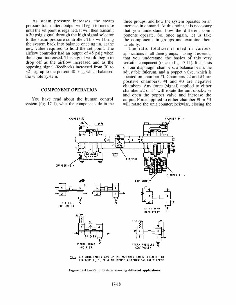
As steam pressure increases, the steampressure transmitters output will begin to increaseuntil the set point is regained. It will then transmita 30 psig signal through the high signal selectorto the steam pressure controller. This will bringthe system back into balance once again, at thenew value required to hold the set point. Theairflow controller had an output of 45 psig whenthe signal increased. This signal would begin todrop off as the airflow increased and as theopposing signal (feedback) increased from 30 to32 psig up to the present 40 psig, which balancedthe whole system.
COMPONENT OPERATION
You have read about the human controlsystem (fig. 17-1), what the components do in the
three groups, and how the system operates on anincrease in demand. At this point, it is necessarythat you understand how the different com-ponents operate. So, once again, let us takethe components in groups and examine themcarefully.
The ratio totalizer is used in variousapplications in all three groups, making it essentialthat you understand the basics of this veryversatile component (refer to fig. 17-11). It consistsof four diaphragm chambers, a balance beam, theadjustable fulcrum, and a poppet valve, which islocated on chamber #l. Chambers #2 and #4 arepositive chambers; #l and #3 are negativechambers. Any force (signal) applied to eitherchamber #2 or #4 will rotate the unit clockwiseand open the poppet valve and increase theoutput. Force applied to either chamber #l or #3will rotate the unit counterclockwise, closing the
Figure 17-11.—Ratio totalizer showing different applications.
17-18

poppet valve and decreasing the output. Bychanging fulcrum position we can change the ratioof output (l:l, 1:15, and so on).
PRESSURE-SENSING GROUP
Look at the steam pressure transmitter (direct-acting) in figure 17-12. Steam pressure is introducedto the metallic bellows. Upward force resultingfrom the steam pressure is transmitted throughthe bellows post to the beam. Tension on thespring pulls downward and opposes the upwardforce. The amount of tension on the loadingspring determines the steam header pressuresetting at which the unit is balanced. Beammovement is transmitted through the flexibleconnector and adjustment screw to the upper endof the escapement valve.
Supply air at 65 psig is connected to the lowerend of the escapement valve. The valve stemmoves between the inlet and the exhaust seat. Therelative position of the valve stem and the twoseats determines the openings of the inlet andexhaust ports and controls the output loadingpressure. The change in header pressure requiredto move the beam and escapement valve stembetween zero and maximum loading pressure isthe proportional band. This factor must bepresent in every control system to ensure stableoperation.
The required gain (proportional band) isadjusted by the proportional band unit. Theproportional band unit exerts a downward force
Figure 17-13.—High signal selector.
on the beam, thereby opposing the tendency ofthe beam to move upward on an increase in headerpressure.
High Signal Selector
The high signal selector is used when thehigher of two input signals is to be selected. Theneoprene O-rings are placed in the two innermostgrooves on the spool and pressure rises in eitherA or B input (one toward the lesser pressure port).As this occurs, the O-ring on the side of the lesserpressure will be forced against the circular portmade by the casing and the spool, thus blockingthat passage and allowing only the high pressureinput to pass out port C to the steam pressurecontroller.
Figure 17-12.—Steam pressure transmitter.
17-19

Steam Pressure Controller
The steam pressure controller fig. 17-11 is theset point for the system. There is a 30-psig springon chamber #3 which acts as a positive force. Theoutput is fed back to chamber #4 through a needlevalve and volume tank. The signal from the highsignal selector is piped to chamber #3, so anyincrease in pressure from the high signal selectorresults in a decrease in output pressure. The needlevalve controls the reset or speed at which thecontroller acts. The output from the steam flowcontroller goes to the boiler master A/M stationas the master demand signal.
Boiler Master A/M Station (Four-way)
This component is used to select the mode ofoperation, either manual or automatic. When itis set for manual operation, the master demandsignal is dead-ended and the manually generatedsignal is sent out to the rest of the system tocontrol air and oil flow. When it is set forautomatic operation, the master demand signalpasses through the transfer section to the relaysender (hand generator), there the signal istransmitted through diaphragms and springs tothe poppet valve. The output of the poppet valveis then sent back through the transfer station outto the combustion system. In the relay sender, biascan be added when the system is in automatic tocompensate for small pressure differences betweenboilers. (A four-way A/M station is shown infig.17-14.)
You must reset the transfer valve beforeshifting to automatic or remote manual. Whenthe transfer valve is in the reset position, theoutput loading signal is locked out from thestation.
Airflow Loop
The following paragraphs will discuss theoperation of the components in the airflow loop.
AIRFLOW CONTROLLER.—The outputsignal from the boiler transfer station is connectedto chamber #2 of the airflow controller, and theoutput signal from the airflow transmitter isconnected to chamber #3 of the airflow controller.(See fig. 17-11.)
The two loading pressures exert a net force(the difference between the steam flow demandand the actual airflow) on the beam of thecontroller.
The controller transmits an output loadingpressure that adjusts the actual airflow. Tocomplete the balance of forces in the controller,the loading pressure in chamber #l is balancedby connecting chamber #l to chamber #4 througha needle valve and a volume tank, which is locatedbetween the two chambers. The delay introducedby the needle valve controls the speed of change(reset rate) in the output loading pressure atapproximately the rate at which the controlelement can change the controlled airflow.
A small opening has a slower rate of reset; alarge opening has a faster rate of reset.
The output loading signal is connected tochamber #4 of the steam flow rate relay.
STEAM FLOW RATE RELAY.—Theoutput signal from the airflow controller isconnected to chamber #4, which repeats it as theoutput signal under steady steaming conditions.When steam demand changes, this is the firstcomponent in the combustion control system toreceive a change. The output from the steam flowtransmitter in the feedwater control system ispiped to chamber #2 and through a needle valveand volume tank to chamber #3. When a steamdemand change occurs, the steam flow is the firstto change, thus the steam flow rate relay (fig.l7-11)cuts down lag time caused by forced draft blowerinertia. During steady steaming the pressures inchambers #2 and #3 are equal and do not affectthe output signal. During load changes, when thesteam flow signal changes, the output of the raterelay will temporarily change until the pressuresin chambers #2 and #3 become equal againthrough the needle valve.
The output loading signal is connected to theforced draft blower transfer A/M station.
FORCED DRAFT BLOWER CONTROLSTATION (TWO-WAY).—This station appearsthe same as a four-way station, except no resetis required when a shift is made from automaticto manual or manual to automatic and there isno biasing capability.
SIGNAL RANGE MODIFIER.—The signalrange modifier relay (fig. 17-11) is a four-chambertotalizer with a spring mounted on chamber #3.The spring force is adjusted to equal 9-psi loadingsignal force so that the output of the totalizer is
17-20

Figure 17-14.—Boiler four-way A/M station.
9 psi when the signal from the forced draft blower blower operates on a 0 to 60 psi signal rangeA/M station to chamber #2 of the totalizer is value.0 psi.
The adjustable fulcrum is off-center to the leftto give a 0.85 gain in output, so that the outputof the signal range modifier will be 60 psi whenthe input signal value is 60 psi. When properlyadjusted, the signal to the final control elementof the forced draft blower will be 9 psi when theairflow controller output is less than 9 psi,thus preventing dead band, which occurs whenthe Woodward governor of the forced draft
FORCED DRAFT BLOWER A/M STATIONS(FOUR-WAY).—The same information appliesas that listed for the boiler master four-way station(fig. 17-14), except bias is used to parallel forceddraft blowers.
AIRFLOW TRANSMITTER.—The forceapplied at the measuring diaphragm is transmittedthrough the assembly as a force pushingdownward on the beam. An escapement-type pilot
17-21

valve is located so that the stem follows theslightest movement of the beam. (See fig. 17-15.)
The output loading pressure from the pilotvalve is connected to the balancing diaphragm.Diaphragm movement is transmitted through thestem to the cam bar. The cam bar is forced to theright; the force of the cam pushes upward on theroller attached to the bell crank rotating arounda bearing point. The bell crank pulls upward onthe loading spring, which is connected to thebeam. The force from the balancing diaphragmpulls upward on the same beam and opposes theforce from the measuring diaphragm. The twoopposing forces are in balance when the value ofthe output loading pressure is proportional to theflow causing the pressure differential.
F/A RATIO SIGNAL GENERATOR.—Thebeam rests on an adjustable ball bearing fulcrum.When the fulcrum is located midway under thebeam between the two diaphragm chambers, theratio of balance will be 1:1 (1 pound in, 1 poundout). If the fulcrum is shifted (by the turn of ahandwheel) toward the input chamber, the beamwill be unbalanced, causing it to tilt in a clockwisedirection. The output pressure decreases as thediaphragm moves away from the exhaust seat. If
the fulcrum is shifted toward the output chamber,the beam will be unbalanced, causing it to tilt inthe counterclockwise direction and to increase theoutput loading pressure until the force once againbalances and increases the ratio. The ratio remainsthe same over the entire operating range.
The F/A ratio signal generator (fig. 17-16) isused to make fine adjustment in the combustioncontrol system for blowing tubes, changingburners, or changing from underway steaming toin-port steaming conditions.
Fuel Flow Control Loop
The following paragraphs will discuss theoperation of the components in the fuel flowcontrol loop.
LOW SIGNAL SELECTOR.—A minimumsignal selector (fig. 17-17) is used when thelower of two signal is to be selected. In thisapplication, the neoprene O-rings are placed inthe outer grooves on the spool. As the pressureof either A input or B input rises (one towardthe lesser pressure port), the O-ring on the sideof the greater pressure will be forced againstthe outer seat of the circular port made by the
Figure 17-15.—Wind box airflow transmitter.
17-22

Figure 17-16.—F/A ratio signal generator (excess air adjuster).
Figure 17-17.—Low signal selector.
casing and the spool, thus blocking that passageand allowing only the lower pressure input to passout, through port C, to the fuel-oil A/M station.
FUEL-OIL A/M TRANSFER STATION(TWO-WAY). —The same information applies asthat for the forced draft blower control station.
CHARACTERIZING RELAY.—To main-tain efficient combustion, the fuel-oil flow to theburners must be regulated so that it is proportionalto the airflow supplied to the burners. In thissystem, the signal generated by the wind boxairflow transmitter (fig. 17-15) is proportional toactual combustion airflow and represents the oilflow demand signal. If the wind box airflowtransmitter output signal were applied directly tothe oil valve, this valve would act to regulate aproportional oil pressure. Since the oil flow variesin relation to the oil pressure, due to thecharacteristics of the burners, under this conditionthe oil flow will not be proportional to the airflow.Therefore, it is necessary to convert the outputsignal of the wind box airflow transmitter from
17-23

an oil flow demand signal to an oil pressuredemand signal. This is done by the actions of thecharacterizing relay (fig. 17-18).
FUEL-OIL CONTROL VALVE.—The fuel-oilcontrol valve (fig. 17-19) receives the signal fromthe characterizing relay. This signal acts on thediaphragm and post, and changes the position ofthe piston, which in turn causes changes in oil flowthrough the fuel oil valve.
With an increase in the control pressure, thefuel-oil pressure will increase in the line betweenthe control valve and the burners. The oil pressurewill exert an upward force on the valve pistonin opposition to the downward force of thediaphragm. The downward force of the oilpressure on the valve piston is eliminated bybleeding this pressure through the piston and intothe barrel below by a hole drilled through thelower section of the piston. When the upwardforce, caused by the action of the burner pressureon the area of the piston, is equal to the downwardforce, caused by the action of the input signal onthe area of the diaphragm, the valve piston stopsmoving and controls the flow of fuel oil throughthe valve to that quantity that holds the burner
Figure 17-18.—Characterizing relay.
17-24
pressure at a value corresponding to the inputpressure.
The oil control valve is fitted with a handjackoperated by a handwheel that is used to manuallyposition the valve piston. The handjack isnormally used when the signal pressure is lost orshut off. The position of the valve piston can beset at any point in the full travel, but there is nocontrol of burner oil pressure at a definite value.If pressure is on the diaphragm, the handjack canbe used to limit the closing of the valve. Forautomatic operation, the handjack is moved clearof the head of the post.
Minimum burner pressure can be set byadjusting the spring tension. Minimum pressureis 40 psi. A minimum setting is necessary so thatoil flow will never be reduced to the point thatthe burner operation will become unstable or willcause flame failure.
This completes our discussion on components.Before we go back to our increase and decreasein demand, let’s cover a few things associated withthe system.
BIASING
Biasing, used to bias machinery or boilers, canbe done only from a four-way transfer station(boiler master and forced draft blowers) and canbe done only when in the automatic mode. If youhave two pieces of machinery and one is runningslower than the other, you would bias the slowerto the faster. This is done by manual adjustmentof the handwheel of the compensating relay onthe A/M station, which causes the loadingpressure leaving the station to differ from thepressure coming to it. Biasing is simply parallelingto keep one piece of machinery or boiler fromtrying to overcome the other.
AIR LOCKS
An air lock system is provided to lock thesettings of the forced draft blower valve operators,the fuel-oil control valve, and the feedwater flowcontrol valve to maintain airflow, fuel flow, andwater flow at values that existed at the instant ofsupply air failure. As a result, these flows are heldconstant until the control air supply has beenrestored and the air lock system is reset for normaloperation, or until the boilers are transferred tolocal manual operation.
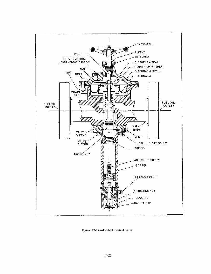
Figure 17-19.—Fuel-oil control valve
17-25

MODES OF OPERATION
There are three modes of operation: auto-matic, remote manual, and local manual.
Automatic
A system is in complete automatic operationwhen it operates without human assistance.
Remote Manual
All of the system, or individual components,are operated in remote manual by shifting theA/M station from automatic to manual andoperating the station by manually generating thesignal required.
Local Manual
Local manual is a method for operating theboilers and machinery from operating stationswithout the assistance of the automatic system.
GLOSSARY OF COMMONAUTOMATIC CONTROL TERMS
This is a glossary of common terms used inconjunction with automatic controls. It willprovide you with a better understanding of theterms used in automatic control systems technicalmanuals.
ACTUATOR—That component part of afinal control element that converts energy intoa mechanical position change to change theoperating point of the final control element.
ACTUATING SIGNAL—The differencebetween the reference input (set point) and theforces representing the controlled variable, whichwill cause a change (pneumatic or mechanical).
AUTOMATIC BOILER CONTROL (ABC)—Pneumatic components throughout theengineering plant that automatically monitor andcontrol the operation of the main boilers andsupporting auxiliaries.
AUTOMATIC COMBUSTION CONTROL(ACC)—Interconnected pneumatic componentsthat automatically monitor and control the flowof air and fuel at the proper ratio for optimumcombustion and that maintain steam pressure ata set point value.
AUTOMATIC CONTROL—The operationin which the value of a control condition iscompared with a desired value and correctiveaction, dependent on the difference, is takenwithout human intervention.
BIAS—Increasing or decreasing a pneumaticsignal a set amount while the system is inautomatic operation.
CALIBRATION—The procedure for check-ing readings and/or adjusting an instrument toconform to an accepted standard.
CONTROL AGENT—Process energy ormaterial used in controlling a controlled variable.
CONTROL POINT—The value of thecontrolled variable which, under any fixed set ofconditions, the automatic controller operates tomaintain.
CONTROL PRESSURE—The pneumaticpressure to the final control element.
CONTROLLER, AUTOMATIC—A devicethat operates automatically to regulate a con-trolled variable in response to a command and afeedback signal.
CONTROLLED MEDIUM—That processmaterial in which a variable is controlled.
CONTROLLED VARIABLE—That processmaterial in which a variable is controlled.
CYCLING—A periodic change of thecontrolled variable.
DEAD TIME—The interval of time betweeninitiation of an input change and the start of theresulting response.
DEMAND SIGNAL—A signal generated byone component in a control system at the startof the resulting response.
DEVIATION—The difference between theinstantaneous value of the controlled variable andthe value of the controlled variable correspondingto the set point.
DIFFERENTIAL —The difference of two ormore motions or forces.
17-26

ERROR—The difference between a value thatresults from a measurement and the correspond-ing true value.
FEEDBACK—Part of a closed loop systemthat provides information about a given conditionfor comparison with the desired condition.
FEEDBACK SIGNAL—A signal that isreturned to the input of the system and comparedwith the reference signal to obtain an actuatingsignal that returns the controlled variable to thedesired value.
FEEDWATER CONTROL (FWC)—Inter-connected pneumatic components that auto-matically monitors and regulates the flow offeedwater to the boiler to maintain normal waterlevel.
FINAL CONTROL ELEMENT—Thatportion of the controlling means that directlychanges the value of the manipulated variable.
GAIN—The ratio of the signal change thatoccurs at the output of a device to the change atthe input.
Hg—The symbol for the element mercury; asilvery, poisonous, metallic element, liquid atroom temperature.
H2O—The symbol for water.
HUNTING—The undesireable oscillation ofan automatic control system. The controlledvariable swings on both sides of set point withoutseeming to approach it.
INERTIA —The property of any material toresist a change in its state or motion (or rest).
INFERENTIAL —Deduced or deducible byinference. Measurements made in terms differentfrom those we seek, or measurements inferred ordeduced from other measurements.
LAG TIME—The interval of time between thestart of a response and its completion.
LINEAR—A linear relationship existsbetween two quantities when a change in onequantity is proportional to the other quantity.
LOADING PRESSURE—The pneumaticsignal between two items of pneumatic controlequipment, except to the final control element.
MAIN FEED PUMP CONTROL (MFPC)/RECIRCULATION CONTROL—Interconnectedpneumatic components that control main feedpump speed recirculation control to maintain apredetermined feedwater discharge pressure underall load conditions and automatically ensuresadequate flow of feedwater through the main feedpumps under low load conditions.
MANIPULATED VARIABLE—The quantityor condition that is varied by a controller to affectthe value of the controlled variable.
OFFSET—The steady state differencebetween control point and the value of thecontrolled variable corresponding to the set point(any permanent excursion from the set point).
PARAMETER—A controllable or variablecharacteristic of a system, temporarily regardedas a constant, the respective values of which serveto distinguish the various specific states of thesystem.
PNEUMATIC—Run by or using compressedair.
POSITIONER—Serves to position the finalcontrol element in proportion to loading pressure.
PRIMARY ELEMENT—That part of ameasuring device that affects or is affected by thevariable being measured to produce a signalcapable of being sensed by a transmitter orindicator.
PROCESS—The collective functions per-formed in and by the equipment in which avariable is controlled.
PROPORTIONAL—Being in proportion;relation of one part to another with respect tomagnitude, quantity, or degree; ratio.
PROPORTIONAL BAND—The amount ofdeviation of the controlled variable from the setpoint required to move the final control elementthrough the full range. An expression of gain ofan instrument.
17-27

RANGE—The difference between themaximum and minimum values of physical outputover which an instrument is designed to operatenormally.
RATIO—The relation in degree or numberbetween two similar things.
RELAY—A pneumatic device that receivesone or more signals, alters and/or combines thesignals in various ways, and produces an outputsignal proportional to the input.
RESET—The action of a controller that isproportional to the product of the error at theinput and the amount of time the error exists.
SET POINT—The desired value of thecontrolled variable.
SPAN—The difference between the top andbottom scale values of an instrument. Oninstruments starting at zero, the span is equal tothe range.
TRANSMITTER—A device that measuresone of the basic variables in the control processand develops and transmits a pneumatic signalproportional to that measurement.
VARIABLE—A process condition, such astemperature, pressure, level, or flow, that issusceptible to change and that can be measured,altered, and controlled.
VELOCITY—Time rate of linear motion ina given direction.
17-28
CHAPTER 18
BOILER WATER/FEEDWATER TEST ANDTREATMENT
Modern naval boilers cannot be operatedsafely and efficiently without quality boiler water.If the chemical conditions of boiler water are notexactly right, rapid deterioration of the boiler canoccur.
Maintaining the required condition of boilerwater is an extremely important part of your job.It is not an easy job. It involves a great deal morethan just dumping chemicals into the boiler water.To control the quality of boiler water by propertreatment, you must have a good understandingof feedwater and boiler water chemistry. Youmust be able to perform the required feedwaterand boiler water tests.
Let’s take a moment to consider what you canexpect from this chapter. After studying thischapter carefully, you will be able to answer thefollowing questions:
Why is it important to control the quality ofboiler water?
How does boiler water get contaminated?
How much boiler water/feedwater contamina-tion is allowable?
What tests are used to measure boiler water/feedwater contamination?
How are the boiler water test results used todetermine the need for boiler water treatment?
What special boiler water problems ariseaboard certain types of ships, and how are theproblems handled?
NOTE: This chapter will NOT provide youwith any actual skill in making water tests orcertify you to test and treat boiler water. You willacquire those skills with on-the-job training andpractice. To become certified, you must gothrough the required certification course.
WATER IN THE SHIPBOARDWATER CYCLE
You must be able to distinguish between thedifferent kinds of water at various points in theshipboard water cycle. There are differentstandards for the treatment of water at differentpoints in the system. To identify the kinds ofwater at various points, look at figure 18-1. Youshould also study and become familiar with thefollowing terms and definitions.
Distillate: Distillate is the evaporated waterthat is discharged from the ship’s distilling plant.Water in the shipboard water cycle normallybegins as distillate. This distillate is stored in thereserve feedwater tanks until needed in the mainsteam cycle.
Reserve feedwater and makeup feedwater:Distillate, while stored in the feedwater tanks,is called reserve feedwater. In ships withoutdemineralizers, the water in all tanks (includingthe tank supplying makeup feedwater) is alsocalled reserve feedwater. When the water isdirected to the condensate system, it is calledmakeup feedwater. In ships equipped withdemineralizers, the water entering the demineral-izers from any tank is called reserve feedwater.The water flowing out of the demineralizerto the condensate system is called makeupfeedwater.
Condensate: After the steam has done itswork, it is returned to the liquid state by coolingin a condenser. The condenser is a heat exchangerin which steam, at a pressure below atmospheric,flows over and is condensed on tubes throughwhich seawater flows. Any water condensed fromsteam is called condensate. Water from othersources (such as makeup feedwater and low-pressure drains) that is mixed with the condensatebecomes part of the condensate.
18-1

The principal sources of condensate are themain and auxiliary condensers. Other sources ofcondensate include the gland exhaust system,heating drains, distilling unit drains, steam coils,and other miscellaneous or service steam systemdrains. To maintain the proper quantity of waterin the system, condensate from various sourcesis combined with makeup feedwater. It is then sentto a deaerating feed tank (DFT), where dissolvedoxygen and other gases are removed from thewater. The discharge from the DFT is calleddeaerated feedwater. When properly operated, theDFT will maintain the dissolved oxygen contentof the deaerated feedwater at or below 15 partsper billion (ppb) (15 micrograms per liter (g/L).
Feedwater (deaerated feedwater) system: In abroad sense, the term feedwater system includesthe makeup feed and transfer systems, the mainand auxiliary condensate systems, and the
Figure 18-1.—Shipboard water cycle.
deaerated feedwater system. In a narrow sense,it includes only the deaerated feedwater system.The two usages of the term feedwater systemshould not be confused.
Boiler water: Boiler water is the name of thedeaerated feedwater as it enters the boiler steamdrum. The term boiler water describes the waterin the steam drum, water drum, headers, andgenerating tubes of the boiler.
Fresh water: Aboard ship the term fresh watergenerally refers to potable water. However,certain steam drains that are returned to thecondensate system are called freshwater drains.
PROPULSION BOILER WATER FLOW
Most naval boilers have an economizerthrough which the feedwater, under feed pump
18-2
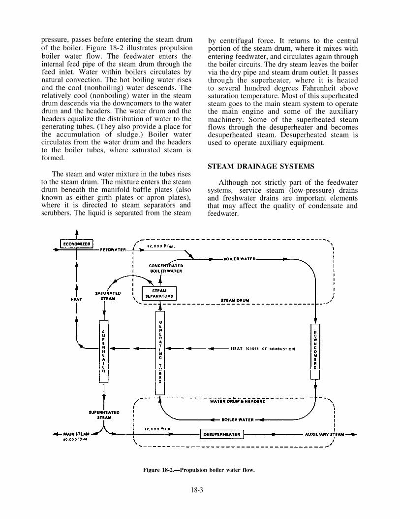
pressure, passes before entering the steam drumof the boiler. Figure 18-2 illustrates propulsionboiler water flow. The feedwater enters theinternal feed pipe of the steam drum through thefeed inlet. Water within boilers circulates bynatural convection. The hot boiling water risesand the cool (nonboiling) water descends. Therelatively cool (nonboiling) water in the steamdrum descends via the downcomers to the waterdrum and the headers. The water drum and theheaders equalize the distribution of water to thegenerating tubes. (They also provide a place forthe accumulation of sludge.) Boiler watercirculates from the water drum and the headersto the boiler tubes, where saturated steam isformed.
The steam and water mixture in the tubes risesto the steam drum. The mixture enters the steamdrum beneath the manifold baffle plates (alsoknown as either girth plates or apron plates),where it is directed to steam separators andscrubbers. The liquid is separated from the steam
by centrifugal force. It returns to the centralportion of the steam drum, where it mixes withentering feedwater, and circulates again throughthe boiler circuits. The dry steam leaves the boilervia the dry pipe and steam drum outlet. It passesthrough the superheater, where it is heatedto several hundred degrees Fahrenheit abovesaturation temperature. Most of this superheatedsteam goes to the main steam system to operatethe main engine and some of the auxiliarymachinery. Some of the superheated steamflows through the desuperheater and becomesdesuperheated steam. Desuperheated steam isused to operate auxiliary equipment.
STEAM DRAINAGE SYSTEMS
Although not strictly part of the feedwatersystems, service steam (low-pressure) drainsand freshwater drains are important elementsthat may affect the quality of condensate andfeedwater.
Figure 18-2.—Propulsion boiler water flow.
18-3

Service Steam (Low-Pressure) Drains
The service steam drain system collectsdrainage from steam piping systems and steamequipment outside machinery spaces that operateat pressures under 150 pounds per square inch(psi). These include such services as waterheaters, space heaters, laundry, and food serviceequipment. Usually the service steam drainsdischarge into the freshwater drain-collectingtanks. On aircraft carriers they discharge intoservice steam drain-collecting tanks. The contentsof these tanks are then either discharged bytransfer pumps to the condensate discharge systemor vacuum dragged into the main and auxiliarycondensers. Service steam drains are subject toshore water and other types of contamination.
Freshwater Drains
Freshwater drain systems collect drainagefrom various piping systems and equipment inmachinery spaces that operate at pressures under150 psi. The drainage is discharged into thefreshwater drain-collecting tanks and is pumpedor vacuum dragged into the condensate system.
First Effect Tube Nest Drains (SaltwaterHeater Drains) and Evaporator Air EjectorCondenser Drains
The saltwater feed heater drains and the airejector condenser drains of the distilling plantdischarge to the DFT and the freshwater draintank. These drains may be subject to seawatercontamination because of tube leakage orcarryover within the evaporator.
transmits the energy by which steam-propelledships operate. Water chemistry control is vital toprevent damage to boilers and other plantcomponents by corrosion, fouling of heat transfersurfaces, and carryover of water with steam.
Water used in naval steam propulsion plantsis relatively pure. However, within the steamcycle, it comes in contact with several metalsat various temperatures and pressures. Theseconditions promote several chemical reactions thatmust be prevented or controlled by the use ofspecific chemicals.
EFFECTS OF BOILING ON DISSOLVEDSOLIDS
When heat is applied to a boiler tube, athermal gradient develops. The outside surface ofthe tube is hotter than the inside surface of thetube which, in turn, is hotter than the bulk of theboiler water. If the water contains dissolved solids,a film of nonboiling liquid forms at the tubesurface. This liquid film contains a higherconcentration of solids than that which iscontained in the bulk of the boiler water. Whenboiling begins, steam bubbles form at the tubesurface and further concentrate the solids aroundthe bubbles. As the steam bubbles are released tothe adjacent bulk boiler water, the solids that wereconcentrated around them are left behind.Normally, fresh boiler water redissolves thesesolids and prevents concentration or dry-out ofchemicals.
Anything that interferes with the free flow ofwater through the tube surface prevents the lessconcentrated boiler water from washing the metal.In boiler water treatment, the bulk boiler waterchemistry must be controlled so that corrosiveconditions or fouling will not result when thewater is concentrated at the tube surface.
WATER IN THE PLANTENVIRONMENT
CONTAMINANT CONCENTRATIONThe chemical makeup of any water depends
upon its past history. The chemistry of water isinfluenced by the amount and type of dissolvedsolids, suspended solids, and dissolved gases thatcontaminate it. Water is known as the universalsolvent. Its solvent action is so great that it tendsto dissolve everything that it touches, includingany container holding it. Additionally, water willalso dissolve gases, such as ammonia, hydrogensulfide, oxygen, and carbon dioxide contained inthe atmosphere. Water is the working fluid that
As a boiler is steamed, the chemical com-position of the boiler water continuously changesbecause the level of contamination builds up. Inmost naval plants, if a boiler is producing steamat about 50 percent of its capacity, the dissolvedand suspended materials brought into the boilerwith the feedwater will concentrate in the boilerwater at the rate of tenfold per hour. In 100 hours(a little more than 4 days of steaming) the chlorideconcentration will increase to 10 epm. The
18-4

Figure 18-3.—Schematic diagram of a simple atom.
concentration of suspended solids in the boilerwater will also increase in the same manner.
EFFECTS OF CONTAMINANTS
Modern naval boilers cannot be operatedsafely and efficiently without proper control ofwater chemistry. With proper control of waterchemistry and proper layup during idle periods,naval boilers should last the life of the ship. Whenwater conditions are not controlled withinallowable limits, deterioration of watersidesurfaces could cause boiler casualties. Boiler waterquality depends directly upon the control offeedwater quality.
THE CHEMICAL NATURE OF WATER
To understand water chemistry, we must first under-stand the concept of atoms and molecules. A moleculeis the smallest particle into which a compound canbe dissolved without changing its chemicalidentity. A small amount of water is composedof a tremendously large number of molecules.
Atoms are extremely small, electrically neutralparticles consisting of a positively charged nucleussurrounded by negatively charged electrons. Thenucleus is composed of positively charged protonsand uncharged neutrons. (See fig. 18-3.)
Normally, the number of electrons equals thenumber of protons contained in the nucleus, andtheir positive and negative charges cancel eachother. The electrons are bound in the atom byelectrostatic action, so the atom remains neutralunless some external force causes a change in thenumber of electrons.
Electrons, which are in constant motionaround the nucleus, contain both kinetic andpotential energy. Their total energy is the sum ofboth energies.
It will help us to visualize these states of energyas spherical shells surrounding the nucleus andseparated by forbidden areas where the electronscannot exist in a stable status. (See fig. 18-4.) Eachshell contains one or more subshells (calledorbitals), each with a slightly different energy. Inorder of increasing energy the orbitals aredesignated by small letters: s, p, d, f, g, h, andso on. The first shell contains only one orbital-the s orbital. The second shell contains an s anda p orbital. The third shell consists of the d orbitalplus the orbitals in the first two subshells(s and p). This is true for all additional shells.
Figure 18-4.—Electron shells of atoms.
18-5

Each new shell contains its own orbital and allthe others it encloses. Each orbital can holda definite maximum number of electrons. (Seetable 18-1.)
Electrons closer to the nucleus have a lowerenergy state than those in the outermost shell—the furthest shell from the nucleus. Chemicalreactions like those that occur in feedwater andboiler water involve primarily the electrons in theoutermost shell of each atom in each molecule ofwater.
The forces that hold atoms together in amolecule (such as water) are called chemicalbonds. Chemical bonds in which one or moreelectrons are transferred from one atom toanother are called IONIC bonds. When suchtransfers occur, they cause imbalances ofelectrostatic charges of these atoms. Single atomsor groups of atoms that have either an excess ora deficiency of electrons relative to the chargeson their nucleus are called ions.
pH Value
One important aspect of water is its capabilityfor partial ionization. Pure water may break apart
(ionize) slightly to yield hydrogen (H) ions andhydroxyl (OH) ions. The concentration ofhydrogen ions and hydroxyl ions is determinedby measuring pH.
The pH scale ranges from 0 to 14. A pH of7 signifies that the solution is neutral. It has thesame amount of hydrogen ions and hydroxyl ions.The pH number indicates the degree of alkalinityor acidity of water. If the pH is below 7, the waterhas more hydrogen ions and is acid. If the pH isabove 7, the water has more hydroxyl ions andis alkaline. (See fig. 18-5.)
The combination of chemicals present in thewater plus heat may contribute to the acidificationof water. When this happens inside the boilers,corrosion takes place.
Let’s see what happens. When pure, oxygen-free, water enters a boiler, an initial reaction takesplace between the water and the iron in the boiler.This results in the formation of a microscopicallythin layer of magnetic iron oxide (magnetite). Thislayer of magnetite protects the iron it covers, andfurther corrosion is limited. However, anydamage to this coat of magnetite will allowcorrosion to spread.
Table 18-1.—Electron, Orbital, and Shell Relationships in Atomic Structure
Shell Number Type of OrbitalsMaximum Number of
Electrons in each OrbitalMaximum Total
Electrons in Shell
1 s 2 2
2 s 2p 6 8
3 s 2pd 10
618
4 s 2p 6d 10f 14 32
5 s 2p 6d 10f 14g 18 50
18-6

Figure 18-5.—pH effect on boiler metal corrosion.
Suppose, for instance, that the feedwaterallowed to enter the boiler contains magnesium.The high temperature of the water makes themagnesium ions react with the hydroxyl ions inthe water. The reaction produces magnesiumhydroxide and hydrogen ions. The magnesiumhydroxide forms a scale. The hydrogen ions, nowin excess, acidify the water. Acidic boiler waterdissolves the coating of magnetite on the boilermetals and attacks the metal itself.
The very small hydrogen gas moleculesreleased during the corrosion process react withthe carbon in the metal to form methane gas.Molecules of methane gas permeate the metal. Asexcessive pressures develop, they cause tuberuptures. If porous deposits are present on themetal surfaces, the acid in the boiler water canconcentrate under the deposits. This can causebrittle failures known as hydrogen damage.
Both high and low pH can cause damage toboiler tubing. Normally, excessively high pH iscaused by accidental overaddition of caustic sodaand shore water contamination. Shore waters haverelatively large amounts of bicarbonate. In theboiler the bicarbonate breaks into carbon dioxideand hydroxyl ions. Carbon dioxide is carried offwith the steam, while the hydroxyl ions increasethe pH. Excess hydroxyl ions can cause caustic
corrosion, a damage as severe as that caused byacidic water corrosion.
Hardness (Scale Formation)
All scale deposits act as insulators and reducethe heat transfer across any surface. Depositscause the temperature of the metal to increaseuntil overheating, metal softening, blistering, andfailure occur, Figure 18-6 illustrates such a situation
Figure 18-6.—Effect of boiler deposit.
18-7
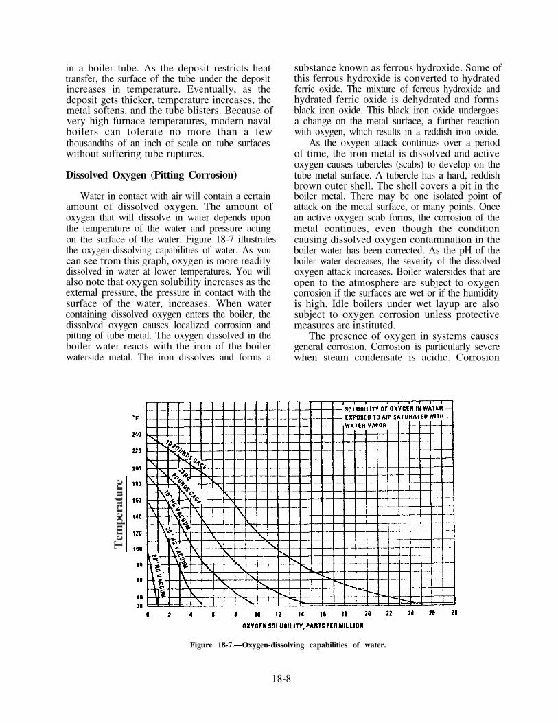
in a boiler tube. As the deposit restricts heattransfer, the surface of the tube under the depositincreases in temperature. Eventually, as thedeposit gets thicker, temperature increases, themetal softens, and the tube blisters. Because ofvery high furnace temperatures, modern navalboilers can tolerate no more than a fewthousandths of an inch of scale on tube surfaceswithout suffering tube ruptures.
Dissolved Oxygen (Pitting Corrosion)
Water in contact with air will contain a certainamount of dissolved oxygen. The amount ofoxygen that will dissolve in water depends uponthe temperature of the water and pressure actingon the surface of the water. Figure 18-7 illustratesthe oxygen-dissolving capabilities of water. As youcan see from this graph, oxygen is more readilydissolved in water at lower temperatures. You willalso note that oxygen solubility increases as theexternal pressure, the pressure in contact with thesurface of the water, increases. When watercontaining dissolved oxygen enters the boiler, thedissolved oxygen causes localized corrosion andpitting of tube metal. The oxygen dissolved in theboiler water reacts with the iron of the boilerwaterside metal. The iron dissolves and forms a
substance known as ferrous hydroxide. Some ofthis ferrous hydroxide is converted to hydratedferric oxide. The mixture of ferrous hydroxide andhydrated ferric oxide is dehydrated and formsblack iron oxide. This black iron oxide undergoesa change on the metal surface, a further reactionwith oxygen, which results in a reddish iron oxide.
As the oxygen attack continues over a periodof time, the iron metal is dissolved and activeoxygen causes tubercles (scabs) to develop on thetube metal surface. A tubercle has a hard, reddishbrown outer shell. The shell covers a pit in theboiler metal. There may be one isolated point ofattack on the metal surface, or many points. Oncean active oxygen scab forms, the corrosion of themetal continues, even though the conditioncausing dissolved oxygen contamination in theboiler water has been corrected. As the pH of theboiler water decreases, the severity of the dissolvedoxygen attack increases. Boiler watersides that areopen to the atmosphere are subject to oxygencorrosion if the surfaces are wet or if the humidityis high. Idle boilers under wet layup are alsosubject to oxygen corrosion unless protectivemeasures are instituted.
The presence of oxygen in systems causesgeneral corrosion. Corrosion is particularly severewhen steam condensate is acidic. Corrosion
Figure 18-7.—Oxygen-dissolving capabilities of water.
18-8

products from the piping systems are carried intothe boiler where they contribute to sludgeformation.
Chloride (Pitting Corrosion and StressCorrosion Cracking)
Chloride is used primarily as an indicator ofseawater contamination. Chloride is an aggressiveion that causes dissolution of the protectivemagnetite layer on boiler metal and inhibits itsreformation. Pitting corrosion rather than generalcorrosion occurs. The sulfate ion, always present,tends to inhibit the destructive effects of smallamounts of chloride on generating tube surfaces.Chloride can cause stress corrosion cracking ofstainless steel.
When stainless steel is subjected to chlorideand oxygen, it will suffer transgranular crackingof its crystals. When chloride concentrates in theboiler water, the chloride may carry over with thesaturated steam and deposit on the superheatertube surfaces. If the superheater has stainless steeltubes, chloride stress corrosion may begin andeventually lead to failure of the tubes.
Chloride stress corrosion of stainless steelcomponents of the desuperheated steam systemcan also occur. If a desuperheater develops a leak,boiler water, containing chloride, will seep intothe desuperheater. This will cause contaminationof many systems.
Conductivity (General Corrosionand Carryover)
The ability to conduct an electrical current iscalled conductivity and is expressed in micromhosper centimeter (mho/cm). For a solution toconduct a current, ions must be present. Virtuallyall materials dissolved in seawater, shore water,feedwater, and boiler water are ionic and doconduct a current. An exception is silica which,since it is a nonionic dissolved solid, does notconduct electricity.
Boiler metal corrosion also results fromelectrolytic action. Electrolytic action depends onthe presence of anodes and cathodes (positive andnegative terminals). The chemical and physicalvariations in the boiler metal surface generateanodic and cathodic areas on the metal so thatthe surface of the metal has slight differences inelectrical potential. For electrons to flow from thecathode to the anode, a conducting medium isneeded. Since pure water has high resistance andlow conductivity (about 0.1 mho/cm), metal
corrosion rate is low in pure water. Asconductivity increases, the resistance to electronflow decreases and corrosion increases. Some ionsin boiler water, notably controlled hydroxyl andphosphate ions, suppress corrosion. Others,particularly chloride and hydrogen (acid) ions,increase it. Most of the conductivity in feedwaterresults from chloride, sulfate, and bicarbonatecompounds of sodium, calcium, and magnesium.Boiler water conductivity results from thesecontaminants and from treatment chemicals.
High conductivity water causes carryover.Boiling water produces bubbles that contain steamencircled by the water. The bubbles break torelease the steam and the water falls back into thevessel holding the water. If the water is very pure,the steam bubbles break easily and an almostcomplete separation of water from steam isachieved. However, if the concentrations ofdissolved and suspended solids or oil increase inthe water, the steam bubbles become stabilizedand more difficult to break. The effectiveness ofthe separation of contaminated water from steamthen deteriorates. Dissolved solids and suspendedsolids in boiler water increase in concentrationwith continued steaming. (They are controlled byblowdown.) As the steam drum area above thesurface of the boiler water fills up with thesestabilized bubbles, some boiler water is carriedalong with the saturated steam into the dry pipe.This type of boiler water carryover is termedfoaming. Since the stabilized bubbles break athigh superheat temperatures, the boiler waterentrained with the saturated steam evaporates inthe superheater. Particles of material that weredissolved and suspended in the boiler water arecarried by the velocity of the steam to differentparts of the superheater to be deposited on thesuperheater surfaces, primarily on those in thefirst pass. Restriction of heat transfer, blistering,and eventual superheater failure can resultwhenever a deposit builds up. Additionally, oneof the materials dissolved in the boiler water,sodium chloride, can cause stress corrosioncracking if it is deposited on stainless steelsuperheaters.
Another type of boiler water carryover iscalled priming. Priming is caused by high waterlevel in the steam drum, extreme rolling andpitching of the ship, or mechanical failure of thesteam separators or other steam drum internalparts. Priming consists of slugs of boiler watercarried into the dry pipe. A slug of water mayreach as far as the turbine and cause damage tothe unit.
18-9

Silica (Scale Formation)
Distillate contains only a small amount ofsilica. However, shore source feedwater, shorewater, and condensed shore steam can containsilica. The silica is usually dissolved and istherefore considered to be a dissolved solid. Sinceit is not ionized, it does not conduct an electriccurrent. Silica in the boiler water forms scale andcan also be deposited in steam lines and on turbineblades. Silica scale behaves in the same manneras other scales and the deposits illustrated in figure
18-6. The DR-100 silica test kit is used to measurethe silica content of shore source feedwater. Thisis done to assure that the use of unacceptableshore source feedwater is avoided. Poor qualityshore source feedwater is the major cause of silicacontamination. Suppliers of shore source feed arerequired to certify that the silica content of thewater does not exceed 0.2 ppm. Ship personnelmust test the water for silica to make sure thewater meets this requirement.
water and oil to carryover. They also cause baked-on carbon deposits on the tubes and oily deposits(sludge balls) in the drums and headers. Detergentlube oils, like 9250, will not rise into the steamdrum. They will emulsify throughout the boilerwater and then will cause baked-on carbondeposits, blistering, and eventually tube failure.Conductivity equipment and pH electrodes willnot work when coated with oil.
Ion Exchange Resin (Acidic or CausticCorrosion Deposits)
The desiccant used in dry layup and sandblastgrit can contain silica contamination. To avoidpH and silica control problems caused bydesiccant, the desiccant should be removed fromthe boiler after dry layup.
The demineralizer contains both anion(negatively charged ions) and cation (positivelycharged ions) exchange resins. When heated, theanion resin forms mildly alkaline (caustic)decomposition products and the cation resinforms strongly acidic decomposition products.When heated, all calcium, magnesium, chloride,sulfate, and bicarbonate previously removed fromthe makeup water are released from the resin asit decomposes.
Dirt and Debris
Suspended Solids (Sludge Formationand Carryover)
18-10
Dirt, debris, and other foreign matter cancause feedwater problems. Water treatment mayor may not be successful. It will not compensatefor refractory brick, washers, wire brushes, bagsof desiccant, or other such items left in the boiler.
Seawater and shore waters contain variableamounts of suspended materials. In the case ofthe seawater, most of the suspended solidsare discharged overboard with the brine upondistillation of the water. Suspended solids fromshore source potable water are generally removedby municipal pretreatment. Most suspended solidsin the boiler result from corrosion and erosion offeed system metals when the water is not treatedwith morpholine. Suspended solids in boiler watercause the water to carryover and contribute tosludge formation.
SOURCES OF FEEDWATERCONTAMINANTS
The major feedwater contaminants areseawater, shore water, metal corrosion products,suspended solids, and oxygen. Other contami-nants include fuel and lubricating oil, preserva-tives, ion exchange resin, dirt, and debris.
Seawater
After overhaul or long-term dry layup, rustcan carry into boiler water during systemoperation. The hydroxide ion in boiler waterreacts with rust to form magnetite, and the pHof boiler water decreases because of the loss ofhydroxide ions.
Contaminated seawater can enter the feed-water system from carryover in the distilling plantand seawater leakage into the main and auxiliarycondensers. It can also come from malfunctioningor improper operation of units in the feedwatersystems, and bilge water leakage into the tanks,piping, and pumps.
Fuel, Lubricating Oil, and Preservatives(Deposits and Carryover)
Fuel oil and 2190 TEP lubricating oilaccumulate in the steam drum to cause boiler
Seawater contamination requires increasedchemical treatment of’ the boiler water. Suchtreatment increases the amount of dissolved andsuspended solids in the boiler water, and the boilerrequires more frequent blowdown. Excessive

seawater contamination results in the consump-tion of all of the protective treatment chemicalsin the boiler water. It is the cause of corrosion,scale formation, and sludge formation. Highconcentrations of dissolved and suspended solidsresult in carryover. If the problem is allowed tocontinue, generating and superheater tubes willcorrode, blister, and eventually rupture.
Shore Water
Shore water can contaminate the feedwatersystem by leakage through malfunctioning swingcheck valves, galley mixing valves, laundryequipment, and water heaters. Shore watercontains high concentrations of dissolved solidsand silica and may have either high or low pH.In the boiler, shore water causes high pH.Excessively high pH will cause boiler metalcorrosion. High concentrations of dissolved solidscause boiler water carryover. Hardness in shorewater leads to excessive usage of boiler watertreatment chemicals and causes corrosion, scale,and sludge buildup. Shore water contaminationcan also cause deposit buildup in auxiliary steamlines.
Metal Corrosion Products andSuspended Solids
The metal surfaces of the feedwater system aresources for metal corrosion found in feedwater.Water in the feed system that is not treated hasa pH of approximately 5 and tends to causecorrosion of the metal surfaces. Also some erosionand mechanical washing of particles from themetal surface occur. The metal corrosion anderosion products contribute directly to sludgebuildup in the boiler water.
Dissolved Oxygen
Figure 18-7 illustrates the solubility of oxygenin water at various temperatures and pressures.Air, the source of dissolved oxygen, enters thefeedwater system with the makeup feed andthrough various parts of the condensate system.Excessive dissolved oxygen in feedwater is causedby malfunctioning or improper operation of theDFT. When feedwater containing dissolvedoxygen enters the boiler, it causes localizedcorrosion of the boiler metal. This is describedas active oxygen attack and can become sosevere that eventually the tube wall will becompletely penetrated. The use of temperature
and pressure control in the DFT can minimize theconcentration of dissolved oxygen in feedwaterentering a boiler.
Fuel Oil
Naval distillate F-76 and JP-5 are potentialsources of contamination to the feedwater systembecause of their presence in the bilges. Fuel oilcarries over with the steam, recycles in the system,and eventually decomposes to form carbondeposits on boiler waterside surfaces and insuperheater tubes. Fuel oil may coat salinity cellsand cause them to malfunction.
Lubricating Oil
Lubricating oil (2190 TEP) is used extensivelyin steam plant machinery. Gland seals and oil sealrings are provided to keep lubricating oil fromcoming in contact with steam and condensate.Worn out seals and rings will allow oil tocontaminate the feedwater system. As in the caseof fuel oil, lubricating oil leaks and spillsaccumulating in the bilges can also cause lube oilcontamination of the feedwater. Since 2190 TEPlube oil tends to rise in water, it will accumulatein the steam drum and will carry over. The oilrecycles in the system to eventually decompose,leaving carbon deposits in the boiler orsuperheater. It also coats salinity cells, causingthem to malfunction.
Preservatives
Metal preservative coatings are used to protectthe boiler piping and system equipment duringconstruction. Contaminants of this type aregenerally found on new ships when the preboilersystem is not properly flushed. Water con-tamination of this type can also result from thereplacement of a system component withoutremoving the preservative. If not removed, theseorganic materials will bake on the watersidesurfaces of boiler tubes to cause blistering and,eventually, tube failure.
Ion Exchange Resin
If not handled properly, resin beads can breakand cause fine particles of resin to pass throughthe retention screen. Damaged screens also permitpassage of intact resins into the makeup feed.When anion resin decomposes at 60°C (140°F)and cation resin at 121°C (250°F), they release
18-11

alkaline and acidic products in addition tocalcium, magnesium, chloride, sulfate, andbicarbonate. Water contaminated by granules ofion exchange resin will have a fishy odor.
Dirt and Debris
Poor housekeeping can lead to dirt and debriscontamination. If a boiler or piping system isopen, dirt can enter. Openings should be coveredunless required to be open. Components must beproperly cleaned before they are installed inboilers or piping systems. Care must be taken toavoid contaminating treatment chemicals and toensure that the right chemicals are used.
CONTROL OF FEEDWATERCONTAMINANTS
Feedwater conditions must be controlled ifcorrosion and scale in the feed system are to beminimized. More importantly, corrosion, scale,various deposits, and carryover in high-pressureboiler systems will advance if care of feedwaterpurity is neglected. Boiler water treatment protectsthe boiler against feed system upsets fromcontamination. It does not replace properpreboiler plant operation. Feedwater having lowconcentrations of dissolved and suspended solids,and no oxygen, is considered good qualityfeedwater. This type of feedwater is obtainedwhen all units in the preboiler system arefunctioning properly.
Contaminant Testing
Feedwater quality is determined by testingsamples for chloride, conductivity, salinity,hardness, dissolved oxygen, and pH from variouspoints in the system. All of these tests arenecessary for rapid location and correction ofcontaminant sources.
Morpholine Condensate/FeedwaterTreatment
Morpholine is a water treatment chemical thatraises pH and reduces corrosion in the condensateand deaerated feedwater lines of the preboilersystem. Preboiler system corrosion is causedprincipally by the reaction of carbon dioxide withthe water in which it is dissolved. There are twosources of carbon dioxide: air containing carbondioxide, which can enter at almost all points inthe preboiler system, and the bicarbonate ion in
seawater, which is released when the water isheated in distilling plants, thereby acidifying thereserve feedwater.
Seawater and shore water are the majorcontributors of bicarbonate. Carbon dioxidereacts with water and forms carbonic acid, whichdecreases the pH. By raising the pH of thecondensate and deaerated feedwater, corrosion inthese parts of the preboiler system is reduced.
Morpholine is a neutralizing amine that isadded to the freshwater drain-collecting tank. Itcombines with hydrogen ions produced from thereaction of carbon dioxide in water. It alsocombines with some hydrogen ions present fromwater’s ionization. As the concentration ofhydrogen ions decreases, pH increases andcorrosion is reduced. This reduces the amount ofsludge that will form in the boiler. Themorpholine added to the condensate enters theboiler with the deaerated feedwater; it isvolatilized along with the steam; it dispersesthroughout the steam plant; it is condensed; andfinally it is recycled. Although the cycle iscontinuous, additional morpholine must be fedto the condensate to compensate for losses thatoccur in the air ejectors, DFT vents, and leaks.
Demineralization of Makeup Feed
Makeup feed of very high purity is producedby the use of a demineralizer. When makeup feedis being taken on, reserve feedwater is passedthrough a mixed bed ion exchange resin called ademineralizer. The mixed bed ion exchange resinconsists of a chemically balanced mixture of bothcation exchange resins and anion exchange resins.The cation exchange resin, whose surface is richin hydrogen ions, exchanges with cations such asmagnesium and calcium. The anion exchangeresin, whose surface is rich in hydroxyl ions,exchanges with anions such as chloride andsulfate. As the water passes over the mixed bedion exchange resin, the dissolved cations andanions exchange with the hydrogen and hydroxylions and become attached to the exchange resins.The hydrogen ions displaced from the cationexchange resin combine with the hydroxyl ionsdisplaced from the anion resin to form water. Themixed bed ion exchange resin removes all thecations and anions from the reserve feedwaterand exchanges them with pure water. Besidesremoving the ions, the resin acts as a filter andremoves the suspended solids from the reservefeedwater. This demineralization (also calleddeionization) is an extremely useful process that
18-12

appreciably reduces the rate of sludge buildup inthe boiler water. As the resin bed exhausts itsexchange capacity, the makeup feed conductivityquickly rises above 1.0 mho/cm, indicating that theresin is spent and has to be replaced. If the reservefeedwater has a consistently high suspended solidscontent, the filtration action may clog the resin bedand will result in an early replacement of the resin.
BOILER WATER CONTROL
The boiler acts as a receiver far all of the materialsthat the feed system pours into it. Only the water and(if the condensate is treated) morpholine leave theboiler. All contaminants remain behind to advance thedamaging conditions (corrosion, scale formation, andcarryover) already discussed. To minimize damage,boiler water treatment programs have been estab-lished. The Navy treatment is based on regimen knownas coordinated phosphate-pH control (more simply,coordinated phosphate control). The methodis designed to serve the following purposes:
1. Maintain the pH and phosphate levels so thatcaustic corrosion cannot occur.
2. Maintain the pH sufficiently high to limit boilermetal corrosion and to protect against acid-formingmagnesium reactions. (When magnesium hydroxideforms under alkaline conditions, it is in a sludgelikestate unlike the scale that precipitates under neutralor acidic conditions.)
3. Maintain a phosphate residual in the water toprecipitate calcium and magnesium as phosphatesludges, which are less adherent than scale.
Since water conditions are maintained in a mannerconducive to precipitation of sludges, coordinatedphosphate control is referred to as a phosphate pre-cipitating program. Though the boiler water canaccommodate some contamination, the boiler shouldnot be considered a safe reaction vessel for the gen-eration of sludge. Sludge is a deposit that has most ofthe objectionable properties of scale. Another boilerwater control method, blowdown, helps to remove it.
Coordinated Phosphate-pH Control
The Navy uses two types of water treatment. Theolder treatment method is the coordinated phosphate(COPHOSO) treatment. The newer method isCHELANT treatment. In this chapter, we will onlydiscuss the COPHOS method. For information on theCHELANT see NSTM, chapter 220, vol. 2, “BoilerWater/Feedwater Test and Treatment.”
Coordinated phosphate-pH control preventsdevelopment of water having excess hydroxylions, which leads to caustic corrosion. The
treatment chemicals are trisodium phosphate,dodecahydrate, and anhydrous disodiumphosphate. The trisodium phosphate reacts withwater to form sodium hydroxide and disodiumphosphate. The sodium hydroxide contributeshydroxyl ions, which raise pH, while thedisodium phosphate provides some of the neededphosphate. Although sodium hydroxide anddisodium phosphate could be used in thetreatment to produce the same results, the weightsof sodium hydroxide needed would be so smallthat weighing errors would be large. In addition,accidental overaddition of sodium hydroxidewould lead to caustic corrosion.
When boiler water containing the correctamount of sodium hydroxide and disodiumphosphate is concentrated by heating, orevaporated to dryness, only the trisodiumphosphate concentrate remains behind. There isno excess of hydroxyl ions (called free caustic).A primary aim in coordinated phosphate controlis the elimination of free caustic, which forms inconcentrated boiler water when pH is too high.
The calculations for trisodium phosphate isbased on a curve (fig. 18-8). This curve divides thechart into two regions: the FREE CAUSTICregion, on the top, and the COORDINATEDPHOSPHATE region, on the bottom. If 9.54ppm of phosphate from trisodium phosphate weredissolved in water, the pH would be 10.00. Youcan determine this by locating 9.54 ppm on thebottom line between 9 ppm and 10 ppm, drawinga vertical line straight up until it crosses thecoordinated phosphate curve, then drawinganother line from that point to the pH scale onthe left. You will see that it crosses pH 10. If99.17 ppm of phosphate from trisodiumphosphate were dissolved in water, the pH wouldbe 11.00. As long as boiler water phosphate andpH levels are maintained BELOW the coordinatedphosphate curve in figure 18-8, free caustic cannotresult. When pH rises above the curve, free causticis present and caustic corrosion of boiler metalcan result.
If trisodium phosphate alone were used intreatment, boiler water control would have tofollow exactly along the curve. The addition ofextra disodium phosphate does not detectablychange the pH of the water and permits assign-ment of a range for boiler water control.When added to boiler water, neither trisodiumphosphate nor disodium phosphate can forceboiler water into the free caustic region.
All naval boilers have boiler water controlledunder the coordinated phosphate curve. Control
18-13

Fig
ure
18-8
.—C
oord
inat
ed p
hosp
hate
cur
ve.

limits are based on heat transfer characteristicsof the boiler. Boilers whose tube heat absorptionis 150,000 Btu or less are classed as type A. Theseinclude all boilers having up to 600 psi nominaldrum pressure. All 1,200 psi boilers have higherheat absorption and are classed as type B. Thehigh heat transfer boilers have less tolerance toany chemical in the water, whether from treatmentor contamination. In addition, the higher pressureboilers cannot tolerate as much conductivity aslower pressure boilers because of carryover. Forthese reasons, operating limits for type B boilersare lower than for type A boilers.
Reactions in Treated Boiler Water
The behavior of treatment chemicals in generaland under various contaminant conditions aredescribed in the following paragraphs.
PRECIPITATION REACTIONS (SLUDGEFORMATION).—The alkaline pH level in boilerwater serves to minimize boiler metal corrosion.It also provides hydroxyl ions needed to react withthe magnesium that would otherwise turn neutralwater acidic. The magnesium hydroxide forms asludge as long as the water remains alkaline. Boththe sodium hydroxide and disodium phosphatein the water react with calcium and magnesiumto form various phosphate sludges. Sludge inboiler water is an agglomeration of reactionproducts of boiler water treatment chemicals withcalcium and magnesium contaminants as well asthe suspended matter entering with the feedwater.The amount of sludge, if allowed to accumulatein the headers and water drum, will grow so largethat particles will circulate with the boiler water.As sludge circulates, it begins to adhere to thegenerating surfaces. The adhering sludge is at firstsoft and is removable by mechanical cleaning. Ifallowed to remain on generating surfaces, the softsludge is converted by heat to hard, baked-onsludge. Although baked-on sludge is physicallydifferent from scale (scale forms in place; sludgeis carried to high heat transfer areas), it acts justlike scale in that it restricts heat transfer andcauses blistering and eventual rupture of the tube.Mechanical cleaning of the watersides will notremove baked-on sludge or scale. Scale isprevented by proper chemical treatment, andsludge is kept low in concentration by maintainingfeedwater purity and by effective blowdown,primarily by bottom blowdown of a securedboiler.
EFFECT OF SEAWATER ON BOILERWATER CHEMICALS.—Seawater that entersboiler water contains contaminating chemicals,magnesium, calcium, and chloride, all of whichraise the conductivity of the water. Because of thelarge amount of magnesium, the chemical reactiondue to seawater contamination causes pH to drop.Both magnesium and calcium cause phosphate todecrease because the phosphate causes theformation of sludge. Chloride and conductivityincrease. The pH and phosphate must always bekept under the coordinated phosphate curve andwithin specified limits. Damage will result if eitherpH becomes acidic or the concentration ofphosphate falls below a safe value.
Salt will increase chloride and conductivity butwill not affect pH or phosphate. Salt will notcause scale formation or acid attack.
EFFECT OF SHORE WATER ON BOILERWATER CHEMICALS.—The relatively largeamount of calcium in shore water in comparisonto magnesium causes phosphate to react first. ThepH increases, conductivity increases slowly, andchloride does not change. Since shore waterdepletes phosphate, and increases pH, boiler watercontrol parameters are forced into the free causticrange. To prevent scale formation and causticcorrosion, the pH and phosphate must always bekept under the coordinated phosphate curve andwithin specified limits.
CHEMICAL HIDEOUT.—Chemical hideoutdisrupts control of boiler water treatment. It isusually indicated by a diminishing level ofphosphate as the boiler steaming rate increases.Phosphate returns when the steaming ratedecreases or when the boiler is secured. Thereasons for its occurrence are not well defined,but two likely mechanisms have considerable datato support them. Both are probably correct.
One mechanism shows that circumstance mustallow concentration of chemicals. The othershows that reaction with the magnetite protectivelayer occurs.
If tube surfaces are smooth and free ofdeposits, boiler water circulates freely and iseffective in continuously washing tube metal.Porous deposits, crevices, pits, and leakage sitesinterfere with circulation, creating areas conduciveto concentration of boiler water. All of thenormally soluble chemicals concentrate. If theinterference is severe, localized dry-out of boilerwater treatment chemicals and contaminants canoccur. When such localized concentration of
18-15

boiler water occurs, pH, phosphate, and con-ductivity decrease. A decrease in chloride may ormay not be detected. As heat input to the boilertubes increases, the concentrating effect at themetal increases. As heat transfer rate decreases,the chemicals return to the bulk boiler water.
Phosphates react directly with magnetite toform a solid sodium iron phosphate compound.This is a high-temperature reaction, and thecompound decomposes when temperatures arereduced. When a reaction with magnetite isoccurring, pH increases when the phosphatedecreases; it decreases when the phosphateincreases.
Virtually all instances of chemical hideout innaval boilers are reported after each of thefollowing events has occurred:
1. Overhaul or boiler repair2. Acid cleaning3. Initiation of morpholine4. Contamination
These events can cause generation of deposits inthe boiler and the appearance of chemical hideout.Mechanical cleaning (via water-jet) alleviates thiscondition when it is caused by soft deposits.However, if contamination causes hard deposits,only acid cleaning will remove them. Harddeposits represent a hazard to boiler operation andin themselves cause hideout.
The reason for development of hideout soonafter acid cleaning is not clear. Either or both ofthe previously described mechanisms may be atwork when sensitized metal surfaces and softdeposits are present.
Blowdown
Blowdown provides control of accumulatedboiler water solids, both suspended and dissolved.
SURFACE BLOWDOWN.—Surface blow-down reduces materials that have dissolved in theboiler water. Contamination and treatmentchemicals contribute to the dissolved material, andthe total amounts of them are measured byconductivity. Surface blowdown keeps con-ductivity, pH, and phosphate within limits.Surface blowdown must never be performed if thepH or phosphate drops below lower limits or ifpH is above the coordinated phosphate curve(except in response to a high water casualty).Chemicals must first be added as necessary to raisepH or phosphate, and then the surface blowdownmay be accomplished.
Surface blowdown also removes suspendedsolids and oil. Oil can be removed effectively onlyby blowing down through the surface blow pipe.Refer to Naval Ships’ Technical Manual (NSTM),chapter 220, for detailed surface blowdownprocedures.
BOTTOM BLOWDOWN.—The amount ofsludge in the boiler is normally controlled bybottom blowdown. For a bottom blowdown tobe effective, the boiler should be secured as longas possible before initiation of the blowdown. Thiswill ensure that there is sufficient pressure on theboiler to accomplish the action. If the boiler isbeing secured for bottom blowdown and is thento be returned to the line, the blowdown is to beinitiated when the boiler has been secured for atleast 1 hour.
In a boiler where proper chemical treatmenthas been accomplished, the amount of sludgeproduced over a specified steaming perioddepends upon the amount and quality of itsmakeup feedwater. Refer to NSTM, chapter 220,for detailed bottom blowdown procedures.
Idle Boiler Maintenance
The primary consideration of idle boilermaintenance is the prevention of oxygen corrosionof the boiler metal. Wet iron exposed to air(oxygen) will corrode. Corrosion of the iron canbe eliminated by removing either the air or themoisture through either one of two forms of idleboiler layup, dry and wet. These are summarizedin the following paragraphs. However, fordetailed procedures on idle boiler layup, refer toNSTM, chapter 221.
DRY LAYUP.—Dry layup of a boiler isaccomplished either by using desiccant, in the caseof a closed-up boiler, or by blowing warm airthrough circuits of the open watersides. Bothmethods prevent water condensation on thewatersides and control oxygen corrosion.
In preparing for a dry layup of a propulsionboiler, 25 pounds of sodium nitrite are injectedinto the boiler when the drum pressure drops toless than 100 psi. The sodium nitrite solutionreacts with the boiler waterside surfaces to forma passivating film. When dumped, this passivatingfilm remains on the watersides to retard ironoxidation as long as the surfaces are kept perfectlydry.
18-16

WET LAYUP.—Wet layup of a boiler isaccomplished by excluding oxygen from thewater. After securing a boiler, one of thefollowing wet layup methods is used to keep theboiler operational:
1. A steam blanket is applied when the boiler
2. A nitrogen blanket is applied when boiler
3. Hot deaerated feedwater is added via the
4. Boilers with stainless steel superheaters,
5. After the DFT is secured, and hot
pressure reduces to steam blanket pressure.The superheater is drained.
pressure reduces to nitrogen blanketpressure.
main feed connection until the boiler andsuperheater are filled, and a hydrostaticpressure between 15 and 50 psi is main-tained. This method must not be used forboilers having stainless steel superheatersand is not normally recommended forother propulsion boilers.
except the last boiler to be secured, arebackfilled through the superheater with hotdeaerated feedwater when the boilerpressure reduces to 15 psi. When the boilerand superheater are completely filled, apressure not to exceed 100 psi is maintainedon the boiler through the backfillconnection.
deaerated feedwater is not available, thelast boiler to be laid up is backfilled withreserve feedwater. A positive pressure notto exceed 100 psi is maintained through thebackfill connection.
NOTE: Methods 4 and 5 may be used for allpropulsion boilers, including those with stainlesssteel superheaters.
6. The boiler, the superheater, and the The feedwater and boiler water chemistry logseconomizer are filled via the feed con- and records are very important. Data collectednection with reserve feedwater containing and reflected in the logs and records are used byhydrazine and morpholine. A minimum of the engineer officer and assistants to measure the15 psi hydrostatic pressure is maintained performance, stability, efficiency, and state ofon the boiler using the treated water in material readiness of the engineering plant. Thesethe reserve feed tank. This method is logs and records support the decision-makingauthorized for use by industrial activities process involved in an effective water chemistryonly. program.
Hydrazine is a liquid oxygen scavenger thatdoes not add to the dissolved solids content ofwater. Hydrazine and morpholine are added toan empty reserve feed tank, which is then filledwith cold feedwater. The solution is pumped tothe boiler and a minimum 15 psi is maintained.This method is used for complete wet layup ofa propulsion boiler that has completed overhauland has had a successful hydrostatic test. Thehydrazine reacts, under alkaline conditions, withoxygen in the feedwater to produce nitrogen andwater. The alkaline condition is obtained by theaddition of morpholine. If the boiler is steamedwith water containing a high concentrationof hydrazine, the hydrazine is converted toammonia, which can be harmful to copper alloysin the condensate system. Therefore, beforelight-off, water containing hydrazine is com-pletely drained from the boiler and the reservefeed tank before it is refilled with fresh feed-water.
The positive pressure of the wet layup keepsthe air from entering the boiler watersides. An idleboiler under wet layup is not maintained withinsteaming boiler chemical treatment requirements.This is because a high heat flux is not beingapplied and contaminated feedwater is notcontinuously entering the boiler.
TEST PROCEDURES
Since you must complete the prescribedcertification course to conduct boiler water andfeedwater tests, the test procedures will notbe covered in this chapter. The testing procedurescan be found in NSTM, chapter 220. Youshould always use this manual when conductingtests.
LOGS AND RECORDS
18-17

RECORDS MAINTENANCE
There are five forms available for recordingdata used to assist in maintaining proper waterconditions in a steam propulsion plant.
1. Water Treatment Log (figs. 18-9A and 18-9B)2. Feedwater Chemistry Worksheet/Log (figs.
18-10A and 18-10B)3. Boiler Water Chemistry Worksheet/Log
(figs. 18-1lA and 18-1lB)4. Reserve/Makeup Feedwater Tests Log (figs.
18-12A and 18-12B)5. Fuel and Water Report (figs. 18-12A and 18-13B)
A complete Machinery Plant Water TreatmentLog Package for a month is compiled for eachmachinery space. This package consists of thefollowing:
1. The cover sheet and monthly boiler data2. The daily Feedwater Chemistry Work-
sheet/Log3. The daily Boiler Water Chemistry Work-
sheet/Log for each boiler in the space
The Machinery Plant Water Treatment LogPackage is retained for 2 years.
The daily log for the reserve/makeup feed-water tests is retained for 3 months, and the dailyFuel and Water Report is retained for 1 month.
Figure 18-9A.—Water Treatment Log (front).
18-18

Figure 18-9B.—Water Treatment Log (back).
18-19

Fig
ure
l8-1
0A.—
Fee
dwat
er C
hem
istr
y W
orks
heet
/Log
(fr
ont)
.

Fig
ure
18-1
0B.—
Fee
dwat
er C
hem
istr
y W
orks
heet
/Log
( b
ack)
.

Fig
ure
18-1
1A.—
Boi
ler
Wat
er C
hem
istr
y W
orks
heet
/Log
(fr
ont)
.

Fig
ure
18-1
1B.—
Boi
ler
Wat
er C
hem
istr
y W
orks
heet
/Log
(ba
ck).

Fig
ure
18-1
2A.—
Res
erve
/Mak
eup
Fee
dwat
er T
est
Log
(fr
ont)
.

Fig
ure
18-1
2B.—
Res
erve
/Mak
eup
Fee
dwat
er T
est
Log
(ba
ck).

Figure 18-13A.—Fuel and Water Report (front).
18-26

Figure 18-13B.—Fuel and Water Report (back).
18-27

Water Treatment Log
The Water Treatment Log is to be completedas follows:
1. On the cover sheet (fig. 18-9A) the followingdata are entered:
a. The machinery plant number.b. The ship’s name and hull number.c. The month and the year.d. The total number of pages for the
complete Machinery Plant Water Treat-ment Package at the end of the month.(Each page in the package is numbered,beginning each month with the number1.)
2. On the reverse side (fig. 18-9B) are enteredthe appropriate data for each boilerassociated with this machinery plant system.Data that have changed during the monthmust be updated. Data that have notchanged from the previous month must bebrought forward. Additional blocks areprovided in the areas of Dates of ImportantEvolutions and Governor Settings to recorddata that may be generated by repeatedtesting of equipment during a given month.
Feedwater Chemistry Worksheet Log
The Feedwater Chemistry Worksheet/Log(figs. 18-10A and 18-10B) consists of the followingsections:
1. Chemical tests and salinity indicatorcomparison
2. Feedwater chemical tests
3. Shore feedwater/steam chemical test data
4. Remarks
A daily log is initiated by inserting the systemnumber, ship’s name and hull number, and date.When there is more than one condensate/feedwater system, a separate log is required foreach system.
CHEMICAL TESTS AND SALINITYINDICATOR COMPARISON SECTION.—Thissection applies to all feedwater components that
are monitored by a salinity indicator and is usedto enter the following information:
1. The location of any additional salinityindicators.
2. The time of simultaneous chemicalsampling and reading of the salinityindicator; for makeup feed, the time of thesalinity indicator reading.
3. The mL of mercuric nitrate used in testingand the calculated chloride chemical testresult.
4. The salinity indicator result. In addition,the satisfactory or unsatisfactory blocks arechecked and, when necessary, the mL ofEDTA used in testing and the calculatedhardness chemical test result are insertedin the appropriate blocks. Finally, the oilking initials this section and notifies theEOOW/EDO of the test results.
FEEDWATER CHEMICAL TESTSSECTION.—This section is for all feedwatersystem components except reserve/makeup. Thefollowing information is entered in theappropriate blocks:
1. The time of completion of sampling2. The appropriate code as given on the back
of the log3. The location from which the sample was
drawn4. The test result, if the sample was taken to
analyze it for dissolved oxygen content5. The morpholine rotameter setting at the
time of sampling and the test result
The Chloride column is used to record dataobtained whenever a salinity indicator is faultyand it becomes necessary to chemically test forchloride once each watch. It is also used to recordthe data obtained when samples are tested tolocate contamination sources:
1. When the chemical test for chloride isperformed, CH is entered in the Codecolumn; and the mL of mercuric nitrateused in testing and the calculated chloridechemical test result are entered in theChloride column.
2. When a salinity indicator reading isobtained, SI is entered in the Code column,and the salinity indicator reading in theEPM column. The mL Mercuric Nitratecolumn is left blank.
18-28

The Hardness column is used to record thedata obtained when samples are tested to locatethe contamination sources. Hardness is notdetermined routinely for feedwater components(except for reserve feedwater, which is recordedon the Reserve/Makeup Feedwater Log). Resultsthat exceed 0.10 epm (0.10 meq/L) hardnessindicate unacceptable water quality. In such case,CH is entered in the Code column and the mLof EDTA used in testing for hardness and thecalculated hardness test results are entered in theEDTA column.
The oil king initials this section and notifiesthe EOOW/EDO of the test results.
SHORE FEEDWATER/STEAM CHEMI-CAL TEST DATA SECTION.—In this section,used for shore source feedwater or shore steam,the following information is entered:
1.
2.
3.
The pH, hardness, conductivity, and silicaresults provided by the activity supplyingthe shore source feedwater or shore steam.
The pH, hardness, silica, and conductivityas determined by ship’s force. The lowestreading measurable on the shipboardconductivity meter is 40 mho/cm (40 s/cm).
The activity providing the shore feedwateror shore steam.
REMARKS SECTION.—The Remarkssection contains an explanation of each test resultthat is out of limits, a brief summary of feedsystem repairs accomplished, the status of repairsor replacement for any malfunctioning salinityindicator, and a description of any unusualcondition. All remarks are accompanied by thetime as appropriate. Additional pages for remarksare inserted as necessary.
The Feedwater Chemistry Worksheet/Logneed not be prepared on a daily basis if a plantis in a cold iron status and no testing is required.When no testing is required, the inclusive datesare entered on the front of one log and the reasonsare given in the Remarks section.
For every day that there is a log, the LCPOand MPA must review and initial the log, and thelog must be reviewed and signed by the engineerofficer.
Boiler Water Chemistry Worksheet Log
The daily Boiler Water Chemistry WorksheetLog (figs. 18-11A and 18-11B) consists of thefollowing sections:
1. Chemical test results
2. Chemical treatment
3. Blowdown
4. pH meter standardization
5. Steaming hour data
6. Remarks
The daily log for each boiler is initiated byinserting the boiler number, the ship’s name andhull number, and the date.
CHEMICAL TEST RESULTS SECTION.—This section is maintained as follows:
1. The time is entered on a 2400-hour clockbasis for completion of boiler watersampling, actual commencement of fulllayup conditions, light-off, on line,securing, completion of dumping a boiler,and completion of freshly filling a boiler.
2. The appropriate code as given on the backof the log for the boiler condition, thereason for testing, or the method of layupare given.
3. For each boiler water sample, the followinginformation is recorded:
a. The pH meter reading, the sampletemperature, the pH correction for thattemperature, and the corrected pH
b. The sample temperature and theconductivity
c. The mL of nitric acid needed to changephenolphthalein from pink to colorless,the mL of nitric acid needed to changemethyl purple from green to purple, andthe calculated phosphate test result
d. The mL of mercuric nitrate used and thecalculated chloride test result
The oil king and the reviewing EOOW/EDOenter their initials upon completion of the tests.
18-29

CHEMICAL TREATMENT SECTION.—This section is maintained by entering thefollowing information:
1. The amount of trisodium phosphate
2.
3.
4.
5.
6.
7.
8.
required to raise pH to the upper limitThe phosphate correction that will becaused by the addition of trisodiumphosphateThe phosphate reading obtained from theoriginal sample resultsThe added correction to the originalphosphate reading and the correctedphosphateThe amount of disodium phosphaterequiredThe time of completion of the 10-minuteflush when injecting boiler water treatmentchemicalsThe initials of the person who performedthe chemical treatment calculationsThe total amounts of chemicals used forthe day
NOTE: If it is necessary to inject caustic soda,the weight of caustic soda is entered in theTrisodium Phosphate (ounces) column followedby c/s; for example, 1.0 c/s.
6. The reason for using an emergency pH orBLOWDOWN SECTION.—In the Blow-
down section the following information is indi-cated:
1. The times of initiation and completion ofa surface, bottom, or header blowdownoperation. If a blowdown spans two dates,both times are recorded on the date ofcompletion.
2. The appropriate code, as given on the backof the log, for the type of blowdown.
3. The conductivity before blowdown, theconductivity after blowdown, and thecalculated percent blowdown.
pH METER STANDARDIZATION SEC-TION.—For this section the following informa-tion is entered: the time of completion of thestandardization and the percent slope readingfrom the meter; the initials of the personperforming the standardization; and thestandardization data on the logs for all steamingboilers.
STEAMING HOURS DATA SECTION.—In this section, in addition to other data, the
number of hours to the nearest 0.1 hour fromlight-off to securing is entered in the SteamingHours Today block. If more than one log is usedfor the boiler on any one day, these data areentered on the last log sheet for the day.
REMARKS SECTION.—The Remarkssection is used to describe significant events of theday related to that boiler. Additional pages forremarks are inserted as necessary. All remarks areaccompanied by the time as appropriate. Whena doubt exists as to whether or not an entry shouldbe made in the Remarks section, it should beentered. The following types of events should berecorded:
1. The setting of boiler safety valves.
2. Hydrostatic tests, including purpose andpressure, and the signature of thewitnessing individual.
3. A brief summary of boiler repairs
4. Boiler inspection.
5. Explanation of each test result that is outof limits.
phosphate test and the action taken tocorrect the situation causing the use of theemergency tests.
7. Description of unusual conditions.
accomplished.
8. The results of tests of the boiler water/feedwater chemicals against standards,except the quarterly tests, are entered onthe log for the 1 or 1A boiler. (Thequarterly standard test results are enteredon the monthly boiler data log for thenumber 1 plant.)
The Boiler Water Chemistry Worksheet/Logneed not be prepared on a daily basis when theboiler is idle. When no testing is required and nochange in boiler condition is occurring, theinclusive dates are entered on the front of one log,the type of layup applied is entered in the Codecolumn, and any significant event occuring duringthe idle period is described.
For every day that there is a log, the LCPOand MPA must review and initial the log and thelog must be reviewed and signed by the engineerofficer.
18-30

Reserve Makeup Feedwater Tests Log
The daily Reserve/Makeup Feedwater TestsLog (figs. 18-12A and 18-12B) consists of the followingsections:
1. Reserve/makeup feedwater tests (withoutdemineralizers)
2. Reserve/makeup feedwater tests (withdemineralizers)
3. Feedwater tank soundings4. Remarks
The daily log is initiated by inserting the ship’sname and hull number, and the date.
RESERVE/MAKEUP FEEDWATER SEC-TION (WITHOUT DEMINERALIZERS).—This section is designed for systems withoutdemineralizers, and it is maintained as follows:
1. For a reserve feedwater tank that requiresa daily chemical test, the tank number, thetime of sampling, CH for chemical testcode, the mL of mercuric nitrate used, thecalculated chloride test result, the mL ofEDTA used, and the calculated hardnesstest result are entered in the Daily section.
2. When the makeup feedwater salinityindicator is satisfactory and another reservefeedwater tank is placed on makeup feed,the tank number, the time the tank isplaced on makeup, and SI for salinityindicator test code are entered below theDaily section. The salinity indicator readingis entered in the EPM column, and theMercuric Nitrate column is left blank.
3. When the salinity indicator is faulty andthe reserve feedwater tank is sampledwithin 30 minutes before being placed onmakeup, the tank number, the time ofsampling, CH for chemical test code, themL of mercuric nitrate used, and thecalculated chloride test result are enteredbelow the Daily section.
RESERVE/MAKEUP FEEDWATER SEC-TION (WITH DEMINERALIZERS).—Thissection is designed for systems with demineral-izers, and it is maintained as follows:
1. For a reserve feedwater tank that requiresa daily chemical test, the tank number, thetime of sampling, CH for chemical testcode, the mL of mercuric nitrate used, the
2.
3.
calculated chloride test result, the mL ofEDTA used, and the calculated hardnesstest result are entered in the Daily section.When a reserve feedwater tank is placed onmakeup feed, the tank number, the timethe tank is placed on makeup, the inletconductivity reading, and the outletconductivity reading are entered below theDaily section.When the demineralizer system is not inoperation, or is being bypassed, this factis noted in the Remarks section and therequirements for reserve/makeup feed-water (without demineralizers) then apply.
RESERVE FEEDWATER TANK SOUND-INGS SECTION.—This section is provided forconvenience and may be used to enter thefollowing:
1. The tank numbers2. The hourly tank soundings (in gallons), the
total amount of reserve feedwater on board(in gallons), and the percent reservefeedwater on board
The Reserve/Makeup Feedwater Tests Logneed not be prepared on a daily basis if all tanksare empty and no testing is required. When notesting is required, the inclusive dates are enteredon the front of one log and the reason is givenin the Remarks section.
For every day that there is a log, the LCPOand MPA must review and initial the log, and thelog must be reviewed and signed by the engineerofficer.
Fuel and Water Report
A daily report of the fuel and water status isprepared to reflect the conditions at 0000 hours.This report also provides information onfeedwater and boiler water conditions. The dailyFuel and Water Report (figs. 18-13A and 18-13B)is prepared as follows:
1. On the front side (fig. 18-13A) are enteredthe date, and the ship’s name and hullnumber.
a. From the previous day’s report, and theusage data as of 0000, the amount ofboiler fuel and diesel fuel on board isdetermined and the onboard percentageis calculated and entered.
18-31

b. From the previous day’s report, and theusage data as of 0000, the amount oflube oil on board is determined. Theamount of lube oil should reflect thatwhich is in all storage and settling tanks.Lube oil located in the main engine andthe auxiliary sumps should be recordedas expended as of the time the lube oilis placed in the particular sump. Theonboard percentage is calculated andentered. If desired, there is adequatespace at the bottom of the form toindicate the amount of oil in the mainengine sumps.
c. From the previous day’s report, theamount distilled, and the usage data asof 0000, the amount of potable waterand reserve feedwater on board isdetermined and the onboard percentageof capacity is calculated and entered.
NOTE: The total amount distilled should beequal to the total evaporator output during theday.
d. In the transfers/receipts section isentered the appropriate data on theapplicable product line.
e. The amount of potable water expendedand the number of personnel on boardare used to determine the number ofgallons used per person. These areentered. Each class ship has a standardusage that is based on a normalcomplement. This is entered.
f. Feedwater consumption in gallons perhour is entered.
g. Remarks concerning unusual conditionsare entered.
2. On the reverse side (fig. 18-13B), thefollowing information is entered:
a. The boiler designation.b. The fireside hours since the last cleaning
for each boiler.c. The waterside hours since the last
mechanical and chemical cleaning foreach boiler.
d. The boiler water chemical test resultsfor the last sample for each boiler fromthe previous day; the minimum andmaximum values for the chemical testresults obtained for each boiler fromthe preceding day. A boiler out of
commission is so indicated. This datais determined from the Boiler WaterChemistry Worksheet/Log.
e. The layup code for the type of layupapplied to each idle boiler.
f. The number of steaming hours since thelast bottom blowdown. (See followingnote.)
NOTE: This log form was recently changedto require listing of hours since the last bottomblowdown instead of total steaming hours foreach boiler. The remaining stock of logs with thecolumn headed Total Steaming Hours will beissued until the supply is exhausted. The samestock number applies to the old and new forms.Cross out Total Steaming Hours and insertSteaming Hours Since Bottom Blow until retitledforms replace current forms.
g. The range of results obtained forfeedwater in each system for theprevious day ending at 0000. If only theMethod C dissolved oxygen test is inuse, the dissolved oxygen blocks maycontain a single number rather than arange.
h. The oil king initials on the back ofthe report. The MPA and engineerofficer review andreport.
sign the back of the
DATA EVALUATION
The logs serve to record the past history andpresent condition of the steam plant waterchemistry. The evaluation of the data of aparticular log enables the engineer officer andassistants to provide proper treatment and othercorrective action to maintain the water chemistryof the steam plants within the proper ranges.
Fuel and Water Report
The following information may be drawnfrom an analysis of the Fuel and Water Reportdata:
1. Waterside and fireside hours serve as an aidin scheduling required maintenance andsteaming of specific boilers.
2. Boiler water and feedwater data provide anoverview of current water chemistryconditions.
18-32

3. Fuel and feedwater consumption is relatedto plant efficiency. These also serve as aguide for computing fuel and feedwaterrequirements.
4. Potable water and reserve feedwaterconsumption are two factors that must becompared to distilling plant output andcapacity. Any unusual use in either potablewater or reserve feedwater usage should beinvestigated.
Feedwater Chemistry Worksheet/Log
Analysis of the Feedwater ChemistryWorksheet/Log provide the following informa-tion, which may lead to appropriate actions:
1. Chemical tests and salinity indicatorcomparison. This section shows the relia-bility of the salinity indicating system.Salinity indicators detect an increase incontaminant level rapidly. Any salinityindicators that test unsatisfactory must berepaired as soon as possible.
2. Feedwater chemical tests. The dissolvedoxygen test indicates the effectivenessof the DFT. Any reading above 15 ppb(15 g/L) must be investigated. Continuallyhigh or low pH results require a review oftest procedures or a proportional adjust-ment in morpholine flow rate. The chlorideresult indicates the general level of seawatercontamination. Since increasing chloridelevel or results above 0.02 epm (0.02meq/L) indicate that seawater contami-nation is entering the feedwater system,the source of contamination must bedetermined and corrected. A hardnessresult above 0.02 epm (0.02 meq/L) witha normal chloride result indicates shorewater contamination. When hardness ispresent in deaerated feedwater, the servicesteam system must be checked for hard-ness. A high salinity indicator reading witha low chemical chloride test result is alsoan indicator of shore water contamination.If shore water contamination is suspected,the affected component should be testedfor hardness. The salinity indicator systemwill assist in locating both seawater andshore water contamination. Contaminationof the feedwater will have an effect onboiler water chemistry and will thereforebe reflected in the boiler water log and inthe trend analysis graphs.
3. Shore feedwater/steam chemical test data.The results for shore feedwater or shoresteam indicate the quality of the feedwateror steam that will be used.
Reserve Makeup Feedwater Tests Log
The quality of the reserve feedwater availablefor use or the actual quality of the makeupbeing used is reflected in the Reserve/MakeupFeedwater Tests Log. The makeup feed salinityindicator reading or the inlet conductivity readingof the reserve feed demineralizer represents theoverall quality of reserve feedwater. Increasingor high values of either of these two readingsindicate poor quality reserve or distillate. A fastrise of the outlet conductivity is a warning thatthe resin bed is about to be exhausted. Ifconsistent low readings on the outlet conductivityare not obtained shortly after placing a fresh resinbed in the demineralizer, the resin may be of poorquality or the resin bed may not have beenprepared properly. An increase in the dailychloride and/or hardness value of an unusedreserve feedwater tank indicates that tank integrityis questionable.
ROUGH AND SMOOTH RECORDS
Every time that data is transferred from onesheet of paper to another, the likelihood of errorexists. Any practice of increasing the number oftimes data is transferred, by maintaining roughworking logs and then preparing smooth logs forfile, is prohibited. The individual who is recordingdata should record data on the appropriate logonly. The logs may be prepared either in ink orpencil at the option of the person who isdeveloping the data. No erasure is permitted onthe Feedwater Chemistry Worksheet/Log or theBoiler Water Chemistry Worksheet/Log. If anerror is made, it should be lined through andinitialed, then the correct data should be entered.
The oil king who is performing the analysesmust maintain the Feedwater Chemistry Work-sheet/Log and the Boiler Water ChemistryWorksheet/Log. It is permissible for convenienceto record these data in another area, such asmain/central control; however, the Boiler Waterand Feedwater Chemistry Worksheet/Logssubmitted in the log package must be those thatwere maintained in the laboratory by the oil king.
18-33
DISPOSAL/RETENTIONREQUIREMENTS FOR WATERCHEMISTRY RECORDS
The Monthly Water Treatment Log Packageincluding the Cover Sheet and Monthly BoilerData, the Feedwater Chemistry Worksheet/Log,the Boiler Water Chemistry Worksheet/Log, andthe trend analysis graphs are retained on boardfor 2 years, at which time they may be discarded.The Reserve/Makeup Feedwater Tests Log isretained for 3 months and may then be discarded.The Fuel and Water Report is retained for1 month and may then be discarded.
OPERATION/SAFETY PLACARDS
Operation and safety placards for treatmentand sampling procedures must be posted inappropriate places as follows:
1. Boiler water sampling—each boiler watersample cooler area
2. Desuperheater sampling—each desuper-heater sample cooler area
3. Dissolved oxygen sampling—each DFTsample cooler area
4. Feedwater sampling—each DFT samplecooler area
5. Boiler chemical injection system—eachinjection tank area
6. Morpholine condensate treatment—eachmorpholine treatment tank
7. Makeup feed demineralizer operation andmaintenance—each demineralizer tankarea
Placards are normally supplied by theinstalling activity at the time of equipmentinstallation. If placards are missing, they shouldbe prepared locally. The necessary technicalinformation for placards may be found in NSTM,chapter 220.
NOTE: This chapter does not certify you totest and treat boiler water or feedwater. It isdesigned to give you a basic understanding of thewater chemistry program and make the certi-fication course easier.
18-34

APPENDIX I
GLOSSARY
A
ABSOLUTE PRESSURE—Actual pressure(includes atmospheric pressure).
ABT (AUTOMATIC BUS TRANSFER)—Anautomatic electrical device that supplies power tovital equipment. This device will shift from thenormal power supply to an alternate power supplyanytime the normal supply is interrupted.
AFTERCOOLER—A terminal heat-transfer unitafter the last stage.
AIR CHAMBER—A chamber, usually bulbshaped,on the suction and discharge sides of a pump. Airin the chamber acts as a cushion and preventssudden shocks to the pump.
AIR EJECTOR—A jet pump that removes air andnoncondensable gases.
AIR LOCK SYSTEM—A system of control devicescombined to hold all final operating elements inthe position existing prior to loss of air supplypressure.
AIR REGISTER—A device in the casing of a boilerwhich regulates the amount of air for combustionand provides a circular motion to the air.
ALLOY—A mixture of two or more metals.
ALTERNATING CURRENT (ac)—Current that isconstantly changing in value and direction atregularly recurring intervals.
AMBIENT TEMPERATURE—The air temperatureof the room or shipboard space.
AMPLIFIER —An instrument or device whoseoutput is an enlarged reproduction of an inputsignal.
AMPLIFY—To increase the energy level of a signalby a proportional factor.
ATMOSPHERE ESCAPE PIPING—Piping thatleads from safety or large volume relief valves inmachinery spaces, up the outer stack to theatmosphere.
ATMOSPHERIC PRESSURE—The pressureexerted by the atmosphere in all directions, asindicated by a barometer. Standard atmosphericpressure is considered to be 14.7 pounds persquare inch, which is equivalent to 29.92 inchesof mercury.
ATOMIZATION—The spraying of a liquid througha nozzle so that the liquid is broken into tinydroplets or particles.
AUTOMATIC BUS TRANSFER—See ABT.
AUTOMATIC CONTROLLER—An instrument ordevice that operates automatically to regulate acontrolled variable in response to a set pointand/or input signal.
AUTOMATIC CONTROL SYSTEMS—Acombination of instruments or devices arrangedsystematically to control a process or operation ata set point without assistance from operatingpersonnel.
AUTOMATIC OPERATION—Operation of acontrol system and the process under controlwithout assistance from the operator.
AUXILIARIES—Propulsion plant equipment notpowered by main steam.
AUXILIARY—Systems or components functioningin a secondary capacity to the main boilers andpropulsion turbines (such as pumps, air ejectors,blowers, and so forth).
AUXILIARY MACHINERY—Any system or unitof machinery that supports the main propulsionunits or helps support the ship and the crew.Example: Pump, evaporator, steering engine,air—conditioning and refrigeration equipment,laundry and galley equipment, deck winch, and soforth.
AXIAL—In a direction parallel to the axis.
B
BABBITTED —Lined with a babbitt metal (containingtin, copper, and antimony).
AI-1

BACK PRESSURE—(l) Refers to the resistance tothe flow of exhaust fluids through the exhaustsystem. (2) The pressure exerted on the exhaustside of a pump or engine.
BAFFLE—A plate installed to disperse (scatter)motion and/or change direction of flow of fluids.
BALLASTING—The process of filling empty tankswith salt water to protect the ship from underwaterdamage and to increase its stability. SeeDEBALLASTING.
BDC (BOTTOM DEAD CENTER)—The positionof a reciprocating piston at its lowest point oftravel.
BEARING—A mechanical component that supportsand guides the location of another rotating orsliding member.
BELL BOOK—An official record of engine ordersreceived and answered.
BIAS OR BIASING—The act of adding to orsubtracting from a control system signal.
BIMETALLIC—Two dissimilar metals withdifferent rates of expansion when subjected totemperature changes.
BLEEDER—A small cock, valve, or plug that drainsoff small quantities of air or fluids from acontainer or system.
BLOCK DIAGRAM—A drawing of a system usingblocks for components to show the relationship ofcomponents.
BLOWING OF TUBES—A procedure that usessteam to remove soot and carbon from the tubesof steaming boilers.
BLUEPRINT—Reproduced copy of drawing(usually having white lines on a blue background).
BOILER—A strong metal tank or vessel composedof tubes, drums, and headers, in which water isheated by the gases of combustion to form steam.
BOILER BLOW PIPING—Piping from theindividual boiler blow valves to the overboardconnection at the skin of the ship.
BOILER CENTRAL CONTROL STATION—Acentrally located station for directing the controlof all boilers in the fireroom.
BOILER DESIGN PRESSURE—Pressure specifiedby the manufacturer, usually about 103 percent ofnormal steam drum operating pressure.
BOILER EFFICIENCY—The efficiency of a boileris the ratio of the Btu per pound of fuel absorbedby the water and steam to the Btu per pound of fuelfired. In other words, boiler efficiency is outputdivided by input, or heat utilized divided by heatavailable. Boiler efficiency is expressed as apercentage.
BOILER FEEDWATER—Deaerated water in thepiping system between the deaerating feed tankand the boiler.
BOILER FULL-POWER CAPACITY—The totalquantity of design steam flow required to developspecified horsepower of the ship, divided by thenumber of boilers installed in the ship. Alsoexpressed as the number of pounds of steamgenerated per hour at a specified pressure andtemperature.
BOILER INTERNAL FITTINGS—All parts insidethe boiler which control the flow of steam andwater.
BOILER LOAD—The steam output demanded froma boiler, generally expressed in pounds per hour(lb/hr).
BOILER MASTER—A steam pressure controller.
BOILER OPERATING PRESSURE—The pressurerequired to be maintained in a boiler while inservice.
BOILER OPERATING STATION—A locationfrom which boilers are operated.
BOILER OVERLOAD CAPACITY—As specifiedin design of a boiler, usually 120 percent of boilerfull-power capacity, either in steaming or firingrate as specified for the individual installation.
BOILER RECORD SHEET—A NAVSHIPS formmaintained for each boiler, which serves as amonthly summary of operation.
BOILER REFRACTORY—Materials used in theboiler furnace to protect the boiler from heat ofcombustion.
BOILER ROOM—A compartment containingboilers but not containing a station for operatingor firing the boilers. Refers specifically tobulkhead enclosed boiler installations.
BOILER TUBE CLEANER—A cylindrical brushthat is used to clean the insides of boiler tubes.
BOILER WATER—The water actually contained inthe boiler.
AI-2

BONNET—A cover used to guide and enclose the tailend of a valve spindle.
BOTTOM BLOW—A procedure used to removesuspended solids and sludge from a boiler.
BOURDON TUBE—A C-shaped hollow metal tubethat is used in a gauge for measuring pressures of15 psi and above. One end of the C is welded orsilver-brazed to a stationary base. Pressure on thehollow section forces the tube to try to straighten.The free end moves a needle on the gauge face.
BRAZING—A method of joining two metals at hightemperature with a molten alloy.
BRINE—Any water in which the concentration ofchemical salts is higher than seawater.
BRITISH THERMAL UNIT (Btu)—A unit of heatused to measure the efficiency of combustion. Itis equal to the quantity of heat required to raise 1pound of water 1°F.
BRITTLENESS—That property of a material whichcauses it to break or snap suddenly with little orno prior sign of deformation.
BUCKET WHEEL—The steel wheel or disc, fittedto a turbine shaft, to which the blading is attached.
BULL GEAR—The largest gear in a reduction geartrain-the main gear, as in a geared turbine drive.
BURNERMAN—Person in the fireroom who tendsthe burners in the boilers.
BUS—The common connection between a group ofline cutout switches. The bus may be in one singlepiece or it may be divided; may be free or directlyconnected to a jack outlet.
BUSHING—A renewable lining for a hole throughwhich a moving part passes.
BUS TRANSFER—A device for selecting either oftwo available sources of electrical power. It maybe accomplished either manually or automatically.
BUTTERFLY VALVE—A light-weight, relativelyquick acting, positive shutoff valve.
BYPASS—To divert the flow of gas or liquid. Also,the line that diverts the flow.
C
CALIBRATION—The procedure required to adjustan instrument or device to produce a standardizedoutput with a given input. The amount of
deviation from the standard must first bedetermined in order to ascertain the propercorrection requirements.
CAPILLARY TUBE—A slender, thinwalled,small-bored tube used with remote-readingindicators.
CARBON MONOXIDE—A deadly, colorless,odorless, and tasteless gas formed by incompleteburning of hydrocarbons.
CARBON PACKING—Pressed segments ofgraphite used to prevent steam leakage aroundshafts.
CARRYOVER—(1) Boiler water entrained with thesteam (by foaming or priming). (2) Particles ofseawater trapped in vapor in a distilling plant andcarried into the condensate.
CASING—A housing that encloses the rotatingelement (rotor) of a pump or turbine.
CASING THROAT—An opening in a turbine orpump casing through which the shaft protrudes.
CASUALTY—An event or series of events inprogress during which equipment damage and/orpersonnel injury has already occurred. The natureand speed of these events are such that proper andcorrect procedural steps will serve only to limitequipment damage and/or personnel injury.
CASUALTY POWER SYSTEM—Portable cablesthat are rigged to transmit power to vitalequipment in an emergency.
CELSIUS—Thermometer scale on which the boilingpoint of water is 100° and the freezing point is O°.
CENTIGRADE—See CELSIUS.
CENTRIFUGAL FORCE—The outward force on arotating body.
CHARACTERIZER—A control system componentthat acts to alter a signal in a predeterminedmanner to match a nonlinear parameter in theprocess under control.
CHECK VALVE—A valve that permits a flow ofliquid in one direction only.
CHEMICAL ENERGY—Energy stored inchemicals (fuel) and released during combustionof the chemicals.
CHILL SHOCKING—A method that uses steam andcold water to remove scale from the tubes of adistilling plant.
AI-3

CHLORIDE—A compound of the chemical elementchlorine with another element or radical.
CHLORINE—A heavy, greenish-yellow gas used inwater purification, sewage disposal, and in thepreparation of bleaching solutions. Poisonous inconcentrated form.
CIRCUIT BREAKER—An electrical switchingdevice that provides circuit overload protection.
CIRCULATING WATER—Water circulatedthrough a heat exchanger (condenser or cooler) totransmit heat away from an operating component.
CLARIFIER—A water tank containing baffles thatslow the rate of water flow sufficiently to allowheavy particles to settle to the bottom and lightparticles to rise to the surface. This separationpermits easy removal, thus leaving the clarifiedwater. The clarifier is sometimes referred to as asettling tank or sedimentation basin.
CLASSIFICATION AND/OR TYPE—A method ofidentifying and sorting various equipment andmaterials. For example:
a. Check valves-swing, stop, and so forth.
b. Valve-solenoid, manual, and so forth.
CLUTCH—A form of coupling that is designed toconnect or disconnect a driving or driven member.
COLD IRON CONDITION—An idle plant as in adestroyer when all port services are received froman external source, such as shore or tender.
COMBINING TUBES—Short open-ended tubes inwhich the inner surfaces are paralleled, or nearlyso, and used to combine two inlets into a singleoutlet.
COMBUSTIBLE—A material that can burn.
COMBUSTION—The burning of fuel in a chemicalprocess accompanied by the evolution of light andheat.
COMBUSTION CONTROL SYSTEM—A systemthat regulates fuel rate and combustion air flow toa boiler so that steam is produced at a constantpressure and fuel is burned with optimumcombustion efficiency.
COMBUSTION EFFICIENCY—The ratio of theenergy in the combustion gases, theoreticallyavailable for absorption by the boiler under actualoperating conditions, to the energy available had
the fuel been burned with the minimum theoreticalcombustion air.
COMPONENT—Individual unit, or part, of asystem; also, the major units which, when suitablyconnected, comprise a system.
COMPONENT PART—The integral parts of acomponent.
CONDENSATE —Water produced in the coolingsystem of the steam cycle from steam that hasreturned from the turbine or from steam that hasreturned from various heat exchangers. The wateris used over again to generate steam in the boilerfor an endless repetitive cycle.
CONDENSATE DEPRESSION—The differencebetween the temperature of condensate in thecondenser hot well and the saturation temperaturecorresponding to the vacuum maintained in thecondenser.
CONDENSATION —The process of cooling thevapors to produce a denser form (vapor to liquid).
CONDENSER —A heat transfer device in whichvapor is condensed to liquid.
CONDUCTANCE —The ability of a substance topass an electrical current.
CONDUCTIVITY (of water)—The ability of waterto conduct an electric current. It is expressed inmicromhos/cm. Generally, the amount ofdissolved solids is directly proportional to theconductivity.
CONSOLE—A panel equipped with remote manualcontrols and visual indicators of systemperformance.
CONSTANT-PRESSURE GOVERNOR—Adevice that maintains a constant pump dischargepressure under varying loads.
CONTROL ACTION—The nature of the change ofthe output of a control element or system affectedby its input signal.
CONTROL AIR SUPPLY—Clean, dry air at properpressure for operation of pneumatic controlequipment.
CONTROLLER (AUTOMATIC)—A device orgroup of devices arranged to automaticallyregulate a controlled variable in accordance witha command or set point signal.
AI-4

CONTROLLER (ELECTRICAL)—A device usedto stop, start, and protect motors from overloadswhile they are running.
CONTROLLER (PNEUMATIC)—(1) A controlsystem component or group of componentsarranged to sense two or more control systemvariables, which acts to provide a pneumatic (air)output signal, tending to reduce the differencebetween these signals to some predeterminedvalue. (2) An arrangement of control systemcomputing elements designed to perform apredetermined set of mathematical functions.
CONTROL POWER—Power that controls oroperates a component or component part.
CONTROL SIGNAL (ELECTRICAL)—A signalthat activates control circuitry or indicators; forexample, the signal from a pressure switch.
CONTROL SIGNAL (PNEUMATIC)—A loadingsignal applied to a final control element.
CONVECTION—The transmission of heat by thecirculation of a liquid or a gas, such as air.Convection may be forced by use of a pump or fan,or it may occur naturally due to heated air or liquidrising and forcing the colder air or liquiddownward.
COOLANT —Liquid in the cooling system.
COOLER—Any device that removes heat. Somedevices, such as oil coolers, remove heat to wastein over-board seawater discharge; other devices,such as ejector coolers, conserve heat by heatingcondensate for boiler feedwater.
COOLING SYSTEM—Heat removal process thatuses mechanical means to remove heat to maintainthe desired air temperature. The process may alsoresult in dehumidification.
CORROSION —A gradual wearing away ora l te ra t ion of meta l by a chemical orelectrochemical process. Essentially, it is anoxidizing process, such as the rusting of iron bythe atmosphere.
COUNTERSINK —A cone-shaped tool used toenlarge and bevel one end of a drilled hole.
COUPLING—A device for securing togetheradjoining ends of piping, shafting, and so forth, ina manner to permit disassembly when necessary.
CRITICAL SPEED—The speed at which thecentrifugal force of a rotating element tends to
overcome the natural weight of the element,causing distortion and vibration.
CROSS-CONNECT —To align piping of systems toprovide flow between machinery groups.
CROSS-CONNECTED PLANT—A method ofoperating two or more plants as one unit from acommon steam supply.
CROSS PIPING (OR VALVES)—Piping thatprovides flow between port and starboard systemsor between systems having different purposes.
CURTIS STAGE—A velocity-compounded impulseturbine stage having one pressure drop in thenozzles and two velocity drops in the blading.
CUTOUT VALVE—A valve that is intendednormally to be fully open or fully closed.
D
DAMPER—A device for reducing the motion oroscillations of moving parts, air, or liquid.
DAMPING—A characteristic of a system that resultsin dissipation of energy and causes decay inoscillations. The negative feedback of an outputrate of change.
DEAERATE—Process of removing dissolvedoxygen.
DEAERATING FEED TANK (DFT)—A unit in thesteam-water cycle used to (1) free the condensateof dissolved oxygen, (2) heat the feedwater, and(3) act as a reservoir for feedwater.
DEBALLASTING—The process by which salt wateris emptied from tanks.
DEFORMATION—Permanent alteration of form orshape.
DEGREE OF SUPERHEAT—The amount by whichthe temperature of steam exceeds the saturationtemperature.
DEHUMIDIFICATION—The mechanical processof removing water vapor from air.
DENTAL COUPLING—A flexible couplingassembly, consisting of a set of external/internalgear teeth that compensates for slight shaftmisalignment between a driver and a drivenmachinery component.
DESIGN PRESSURE (BOILER)—The pressurespecified by a manufacturer as a criterion in
AI-5

design. (In a boiler it is approximately 103 percentoperating pressure.)
DESIGN TEMPERATURE (BOILER)—Theintended operating steam temperature at thesuperheater outlet at some specified rate ofoperation. The specified rate of operation isnormally full-power capacity.
DESUPERHEATED STEAM—Steam from whichsome of the superheat has been removed.
DIAL GAUGE OR INDICATOR—A precisionmicrometer-type instrument that indicates thereading via a needle moving across a dial face.
DIESEL ENGINE—An engine using the diesel cycleof operation; air alone is compressed and dieselfuel is injected at the end of the compressionstroke. Heat of compression produces ignition.
DIFFUSER—A device that spreads a fluid out in alldirections and increases fluid pressure whiledecreasing fluid velocity.
DIRECT CURRENT (dc)—Current that moves inone direction only.
DIRECT DRIVE—One in which the drivemechanism is coupled directly to the drivenmember.
DIRECT-DRIVEN—Driven at the same speed as thedriver (not having reduction gears).
DISTILLATE—The product (freshwater) resultingfrom the condensation of vapors produced by theevaporation of seawater.
DISTILLATION—The process of evaporatingseawater, then cooling and condensing theresulting vapors. Produces freshwater fromseawater by separating the salt from the water.
DISTILLING PLANTS—Units commonly calledevaporation used to convert seawater intofreshwater.
DOUBLE REDUCTION—A reduction gearassembly that reduces the high input rpm to alower output rpm in two stages.
DOUBLE SUCTION IMPELLER—An impellerwith a suction inlet on each side.
DRUM WATER—A tank at the bottom of a boiler.Also called MUD DRUM.
DRY PIPE—A perforated pipe, at the highest pointin a steam drum, that collects dry steam fromsteam separators.
DUPLEX PUMP—A pump that has two liquidcylinders and is referred to as double-acting.
DUPLEX STRAINER—A strainer containing twoseparate elements, independent of each other.
E
ECONOMIZER—A heat transfer device that usesthe gases of combustion to preheat the feedwaterin the boiler before it enters the steam drum.
EDUCTOR—A jet-type pump (no moving parts)used to empty flooded spaces.
EFFICIENCY—The ratio of the output to the input.Also, the degree of conversion of heat of steam tousable mechanical power output.
ELASTICITY—The ability of a material to return toits original size and shape.
ELECTRICAL ENERGY—Energy derived fromthe forced induction of electrodes from one atomto another.
ELECTROHYDRAULIC STEERING—A systemhaving a motor-driven hydraulic pump thatcreates the force needed to actuate the rams toposition the ship’s rudder.
ELECTROLYSIS —A chemical action that takesplace between unlike metals in systems using saltwater.
EMERGENCY—An event or series of events inprogress which will cause damage to equipmentunless immediate, timely, and correct proceduralsteps are taken.
EMULSIFIED OIL—A chemical condition of oil inwhich the molecules of the oil have been brokenup and suspended in a foreign substance (usuallywater).
ENERGY—The capacity for doing work.
ENGINEERING LOG—A legal record of importantevents and data concerning the machinery of aship.
ENGINEER’S BELL BOOK—A legal record,maintained by the throttle watch, of all orderedmain engine speed changes.
ENGINE ORDER TELEGRAPH—A device on theship’s bridge to give orders to the engineroom.Also called ANNUNCIATOR.
AI-6

EPM (EQUIVALENT PER MILLION)—A termused to describe the chemical concentration ofdissolved material; used in reporting sample testresults. It expresses the chemical equivalent unitweight of material dissolved in a million unitweights of solution. (The chemical equivalentweight of chloride is 35.5. If 35.5 pounds ofchloride were dissolved in 1,000,000 pounds ofwater, the water would contain 1.00 epmchloride.)
ERROR—The difference between a set point and afeedback signal.
EVAPORATION—The action that takes place whena liquid changes to a vapor or gas.
EVAPORATOR—A distilling device used toproduce freshwater from seawater.
EXCESS FEED—Excess feedwater that is returnedto storage tanks.
EXPANSION JOINT—A junction in a piping systemwhich allows for expansion and contraction.
F
FAHRENHEIT—Thermometer scale on which theboiling point of water is 212°, and the freezingpoint is 32° above zero.
FAIL—(l) The loss of control signal or power to acomponent. (2) The breakage or breakdown of acomponent or component part.
FAIL POSITION—The operating or physicalposition to which a device will go upon loss of itsactuating electrical, electronic, pneumatic, orhydraulic control signal.
FATIGUE—The tendency of a material to breakunder repeated strain.
FEEDBACK—Information about a process outputwhich is communicated to the process input.
FEEDER—An electrical conductor or group ofconductors between different generating ordistributing units of a power system.
FEED HEATER—A heat transfer device that heatsthe feedwater before it goes to the boiler.
FEEDWATER—Water that meets the requirementsof Naval Ship’s Technical Manual, Chapter 220(9560) for use in a boiler.
FEEDWATER SYSTEM—A system for storing,heating, and delivering feedwater to boilers.
FERROUS METAL—Metal with a high ironcontent.
FILTER—A device through which gas or liquid ispassed; dirt, dust, and other impurities areremoved by the separating action.
FIREBOX—The section of a ship’s boiler where fueloil combustion takes place.
FIRE MAIN—The salt water line that provides firefighting and flushing water throughout the ship.Raw water is used at Great Lakes in lieu of saltwater.
FIREROOM—A compartment containing boilersand stations for “firing” or operating same.
FIRE-TUBE BOILER—Boiler in which the gases ofcombustion pass through the tubes and heat thewater surrounding them.
FLAMMABLE—A combustible material that burnseasily, intensely or quickly.
FLAREBACK—A backfire of flame and hot gasesinto a ship’s fireroom from the firebox, caused bya fuel oil explosion in the firebox.
FLASH POINT OF OIL—The temperature at whichoil vapor will flash into fire although the mainbody of the oil will not ignite.
FLEXIBLE COUPLING—A coupling thattransmitts rotary motion from one shaft to anotherwhile compensating for minor misalignmentbetween the two units.
FLEXIBLE I-BEAM—An I-shaped steel beam onwhich the forward end of a turbine is mounted; itallows for longitudinal expansion and contraction.
FLOOR PLATES—The removable deck plating of afireroom or engineroom aboard ship.
FLUID—A substance capable of flowing orconforming to the shape of its container (a liquidor gas).
FOAMING—Failure of steam bubbles to break,caused by either dissolved solids or lightsuspended solids in the boiler water, causing smallamounts of continuous boiler water carryoverwith the steam.
FORCE—Anything that tends to produce or modifymotion.
FORCED DRAFT—A term that describes thecombustion air supplied under pressure to the
AI-7

burners in a ship’s boiler by the forced draftblowers.
FREQUENCY—The number of vibrations, cycles,or changes in direction in a unit of time.
FRESHWATER —Water of relatively low dissolvedsolids content as compared to seawater. There aretwo types of shipboard feedwater (thelow-pressure drains of the steam generatorcondensate system) and potable water (suppliedfrom either a shore water source or a shipboarddistilling plant).
FRESHWATER DRAINS—A collective term whichrefers to drainage from steam heating systems andwarming-up drainage from other higher pressuresteam systems. These drains are of feedwaterquality and are returned to the boiler condensatesystem.
FRESHWATER SYSTEM—A piping system thatsupplies freshwater throughout the ship.
FRICTION—Resistance to relative motion betweentwo bodies in contact with each other.
FUEL OIL MICROMETER VALVE—A valve,installed at the burner manifold, that controls thefuel oil pressure to the burners.
FUEL OIL SERVICE TANKS—Tanks from whichthe fuel oil service pumps take suction forsupplying oil to the burners.
FUNCTION—To perform the normal orcharacteristic action of anything, or special dutyor performance required of a person or thing in thecourse of work.
FUSE—A protective device that will open a circuit ifthe current flow exceeds a predetermined value.
G
GAIN—The ratio of the signal change, which occursat the output of a device, to the change at the input.
GAS FREE—A term that describes a space which hasbeen tested and found safe for entry.
GASKETS—(l) A class of material which providesa seal between two stationary parts. (2) Packingmaterials, by which air, water, oil, or steamtightness is secured in such places as on doors,hatches, cylinders, manhole covers, or in valves,between the flanges of pipes, etc. Such materialsas rubber, canvas, asbestos, paper, short lead and
copper, soft iron, and commercial products areextensively used.
GAUGE GLASS—A device for indicating the liquidlevel in a tank.
GAUGE PRESSURE—Pressure above atmosphericpressure.
GEARED TURBINE—A turbine coupled to itsdriven unit through a gear assembly.
GEARED-TURBINE DRIVE—A turbine thatdrives a pump, generator, or other machinerythrough reduction gears.
GENERATOR —A machine that convertsmechanical energy into electrical energy.
GLAND SEAL REGULATOR—A device thatautomatically regulates the steam flow of theturbine glands to meet the flow requirements forthe various operating conditions.
GLAND SEALING—Water piped to a pump casingstuffing box to maintain a seal against air enteringthe pump casing. Also, low pressure steam pipedto the glands of steam turbines to prevent airleakage into turbines.
GOVERNOR—A speed-sensitive device designed tocontrol or limit the speed of a turbine or engine.
GROUNDED PLUG—A three-pronged electricalplug used to ground portable tools to the ship’sstructure. It is a safety device which always mustbe checked prior to your using portable tools.
GUARDING VALVE—A valve installed upstream ofthe throttle valves. This valve permits stoppingsteam flow to the turbines if the throttle valves areleaking or damaged.
H
HANDHOLE —An opening large enough for thehand and arm to enter the boiler for making slightrepairs and for inspection purposes.
HARDENING—The heating and rapid cooling(quenching) of metal to induce hardness.
HARDNESS—A quality exhibited by watercontaining various dissolved salts, principallycalcium and magnesium. Can result in a heattransfer resistant scale on the steam generatingsurfaces.
HEADER—A chamber or tank located within aboiler, to which tubes are connected so that water
AI-8

or steam may pass freely from one tube to theother(s). Similar to, but smaller than, a waterdrum.
HEAT—A form of energy.
HEAT EXCHANGER—Any device that is designedto allow the transfer of heat from one fluid (liquidor gas) to another.
HEATING SURFACE—A system for adding heat tomaintain the desired air temperature, asdistinguished from heat added incidentally orunavoidably.
HERTZ (Hz)—Frequency per second of alternatingcurrent. Formerly referred to as “cycles persecond.”
HORSEPOWER (Hp)—A unit to indicate the timerate of doing work equal to 550 foot-pounds persecond or 33,000 foot-pounds per minute.
HOT WELL—Reservoir attached to the bottom of acondenser for collecting condensate.
HUMIDITY—The vapor content of the atmosphere.Humidity can vary depending on air temperature;the higher the temperature, the more vapor the aircan hold.
HUNTING—An undesirable oscillation, such as inthe speed of a machine or in the position of anautomatic valve, and so forth.
HYDRAULICS—The study of liquid in motion.
HYDROCARBON —Chemical compound ofhydrogen and carbon; all petroleum fuels arecomposed of hydrocarbons.
HYDROGEN—A highly explosive, light, invisible,nonpoisonous gas used in underwater welding andcutting operations.
HYDROMETER —An instrument used to determinethe specific gravity of liquids.
HYDROSTATIC —Static (nonmoving) pressuregenerated by pressurizing liquid.
HYDROSTATIC TEST—A test using pressurizedwater to detect leaks in a boiler or other closedsystems.
I
IGNITION, COMPRESSION—When the heat generatedby compression in an internal-combustion engineignites the fuel (as in a diesel engine).
IGNITION, SPARK—When the mixture of air andfuel in an internal-combustion engine is ignited byan electric spark (as in a gasoline engine.)
IGNITION TEMPERATURE—The minimumtemperature to which the substance (solid, liquid,or gas) must be heated to cause self-sustainedcombustion.
IMPELLER—An encased, rotating elementprovided with vanes which draw in fluid at thecenter and expel it at a high velocity at the outeredge.
IMPULSE LINES—Piping that connects a sensingelement to the point at which it is desired to sensepressure, flow, temperature, and so forth.
IMPULSE TURBINE—A turbine in which the majorpart of the driving force is receivd from theimpulse of incoming steam.
INDICATORS—Panel-mounted pressure gauges.
INDIRECT DRIVE—A drive mechanism coupled tothe driven member by gears or belts.
INERT—Inactive.
INERTIA—The tendency of a stationary object toremain stationary and of moving objects to remainin motion.
INJECTOR—A device that uses a jet of steam toforce water into the boiler. Injectors are also usedin a diesel engine to force fuel into the cylinders.
INSULATION—A material that retards heat transfer.
INTERCOOLER—An intermediate heat transferunit between two successive stages, as in an aircompressor.
INTERFACE—Surface or area between two abuttingparts usually of different materials or systems.
INTERLOCK—A feature or device in one system orcomponent that affects the operation of anothersystem or component. Generally, a safety devicebut it may be used to control the operatingsequence of components.
J
JACK BOX—Receptacle, usually secured to abulkhead, in which telephone jacks are mounted.
JACKING—Mechanically rotating a turbine at verylow speed.
AI-9

JOB ORDER—An order issued by a repair activityto its own subdivision to perform a repair job inresponse to a work request.
JOURNAL—That part of a shaft that is prepared toaccept a bearing (connecting rod, main bearing).
JUMPER—Any connecting pipe, hose, or wire,normally used in emergencies aboard ship tobypass damaged sections of a pipe, a hose, or awire. See BYPASS.
JURY RIG—Any temporary or makeshift device.
LIFT CHECK VALVE—A valve having aguide-mounted, spring-loaded disc wherein aliquid exerting pressure on the bottom of the discwill lift the disc and pass through. Pressureexerted against the top of the disc shuts the discand ensures only one direction of flow.
LIGHT OFF—Start. Literally, “to start a fire in,” asin “light off a boiler.”
K
KEY—A parallel-sided piece inserted into a groovecut part way into each of two parts, which preventsslippage between the two parts.
KEYWAY—A slot cut in a shaft, pulley hub, wheelhub, and so forth. A square key is placed in theslot and engages a similar keyway in the matingpiece. The key prevents slippage between the twoparts.
LIMIT SWITCH—A switch that is actuated by themechanical motion of an element.
LINE CUTOUT SWITCH—The device in aswitchbox which disconnects an individual linefrom a group of circuits.
KINETIC ENERGY—Energy in motion producingwork.
LOAD—Steam production demanded of a boiler bythe operation of steam-driven equipment.
LOADING—The act of transferring energy into orout of a system.
AI-10
LOADING SIGNAL—An input air signal to acontrol system element.
L
LABYRINTH—A system of metal packing in whichthe inside diameter of a series of rings contacts therotating surface of the turbine shaft. The passageof air or steam along the shaft is thereby reducedor inhibited.
LABYRINTH PACKING—A soft metal ringinstalled in the casing throat in such a manner thatthe lateral teeth of the inside diametrical surfacewill be presented to the surface of the rotatingshaft. The teeth run either in close proximity tothe shaft or in grooves machined in the shaft.
LAGGING—A protective and confining coverplaced over insulating material.
LATENT HEAT—Heat that is given off or absorbedby a substance while it is changing its state.
LATENT HEAT OF CONDENSATION—Theamount of heat (energy) required to change thestate of a substance from a vapor to a liquidwithout a change in temperature.
LATENT HEAT OF VAPORIZATION—Theamount of heat (energy) required to change the
LOCAL MANUAL OPERATION—Direct manualpositioning of a control valve or power operatorby means of a handwheel or lever.
LOCKED TRAIN—A gear arrangement that has thehigh-speed pinions “locked” between thehigh-speed gears so that the only load on thepinion since the tooth loads cancel one another.
LOG BOOK—Any chronological record of events,such as an engineering watch log.
LOG ROOM—Engineer’s office aboard ship.
LOOP SEAL—A vertical U-bend in drain piping inwhich a water level is maintained to create anairtight seal.
LUBRICANT—Any material, usually of a petroleumnature such as grease, oil, and so forth, that isplaced between two moving parts in an effort toreduce friction.
LUBRICATING OIL PURIFIER—A unit thatremoves water and sediment from lubricating oilby centrifugal force.
state of a substance from a liquid to vapor withouta change in temperature.

M
MACHINABILITY—The ease with which a metalmay be turned, planed, milled, or otherwiseshaped.
MACHINERY GROUP—One single self-containedsteam plant consisting of one engine room and onefireroom.
MAIN CONDENSATE—Condensate from the maincondenser. Although this is the principle sourceof feedwater, water from other drains as well aswater from reserve makeup tanks and the SSTGcondensers are also included in feedwater.
MAIN CONDENSER—A heat exchanger thatconverts exhaust steam to feedwater.
MAIN DRAIN SYSTEM—System used forpumping bilges; consists of pumps and associatedpiping.
MAIN INJECTION (SCOOP INJECTION)—Anopening in the skin of a ship designed to delivercooling water to the main condenser and mainlubricating oil cooler by the forward motion of theship.
MAIN STEAM—The major steam system whichoperates at boiler pressure.
MAKEUP FEED—Water from reserve feed tanksadded to the condensate-feedwater system tomake up for water losses from the steam generatorsystem.
MALLEABILITY—That property of a materialwhich enables it to be stamped, hammered, orrolled into thin sheets.
MANIFOLD—A fitting with numerous branchesused to convey fluids between a large pipe andseveral smaller pipes.
MAXIMUM OPERATING PRESSURE—Thehighest pressure that can exist in a system orsubsystem under normal operating conditions.This pressure is determined by such influences aspump or compressor shutoff pressures, pressureregulating valve lockup (no-flow) pressure, andmaximum chosen pressure at the system source.
MAXIMUM SYSTEM PRESSURE—The highestpressure that can exist in a system or subsystemduring any condition. Normal, abnormal, andemergency operation and casualty conditionsshall be considered in determining the maximumsystem pressure. In any system or subsystem with
relief valve protection, the nominal setting of therelief valve shall be taken as the maximum systempressure (relief valve accumulation may beignored).
MECHANICAL ADVANTAGE (MA)—Theadvantage (leverage) gained by the use of devicessuch as a wheel to open a large valve, chain fallsand block and tackle to lift heavy weights, andwrenches to tighten nuts on bolts.
MECHANICAL CLEANING—A method ofcleaning the firesides of boilers by scraping andwirebrushing.
MECHANICAL ENERGY—Energy derived frommechanical force or impact.
MICROMHO —Electrical unit used with salinityindicators for measuring the conductivity ofwater. Is equivalent to the quantity of one dividedby the resistance of the water to electricalconductivity.
MONITORING POINT—The physical location atwhich any indicating device displays the value ofa parameter at some control station. SeePARAMETER.
MORPHOLINE—A chemical that prevents sludgein boilers by neutralizing the acidic quality ofcondensate, thereby reducing corrosion incondensate and feedwater piping, which forms assludge in boilers.
MOTIVE STEAM—Steam that performs work in theturbine steam path.
MOTOR CONTROLLER—A device or group ofdevices that governs, in some predeterminedmanner, the operation of the motor to which it isconnected.
MOTOR GENERATOR SET—A machine thatconsists of a motor mechanically coupled to agenerator and usually mounted on the same base.
N
NAVAL STANDARDS (NAVSTDs)—Requirementsfor advancement for all ratings including militaryconduct, naval organization, military justice,security, and watch standing.
NAVY BOILER COMPOUND—A powderedchemical mixture used in boiler water treatment toconvert scale-forming salts into sludge.
AI-11

NAVY DISTILLATE FUEL—Navy distillate (ND)fuel is used in steam-powered ships of the Navy.ND is a fuel of the middle to higher distillationrange. Military specification MIL-F-24397(ships), NATO Symbol F85 covers therequirements for Navy distillate fuel.
NAVY SPECIAL FUEL OIL—Navy Special fuel oil(NSFO) is used in steam-powered ships of theNavy. NSFO is a blend of heavy residuum andheavy distillates (both cracked and virgin) withcutter stock distillate, used to adjust viscosity.The blend is made at the refinery in properproportions to comply with Military specificationMIL-F-859 NATO Symbol F77.
NEEDLE VALVE—Type of valve with rod-shaped,needle-pointed valve body which works into avalve seat so shaped that the needle-point fits intoit and closes the passage. Suitable for precisecontrol of flow.
NIGHT ORDER BOOK—A notebook containingstanding and special instructions from theengineer officer to the night engineering officer ofthe watch.
NITROGEN—An inert gas that will not support lifeor combustion. Used in’ recoil systems and otherspaces that require an inert atmosphere.
NOMINAL OPERATING PRESSURE—Theapproximate pressure at which an essentiallyconstant-pressure system operates whenperforming its normal function. The pressure isused for the system basic pressure identification.
NONFERROUS METAL—Metals that arecomposed primarily of some element or elementsother than iron.
NOZZLE—That portion of a turbine that convertsheat energy of steam into a directed steam and setsthe amount of steam flow.
NOZZLE AREA—Smallest opening (area) of anozzle that is at right angles to the direction ofsteam flow.
NOZZLE-BLOCK —Turbine part that takes steamfrom the turbine chest and directs it into the firststage of the turbine.
NOZZLE DIAPHRAGM—A removable metal ringinserted in the casing between the stages of theturbine. This ring contains the nozzles by whichsteam flows from one stage to another.
OOCCUPATIONAL STANDARDS (OCCSTDs)—Requirements that are directly related to the workof each rating.
OFFICER OF THE WATCH (OOW)—Officer onduty in the engineering spaces.
OIL KING—A petty officer who receives transfers,discharges, and tests fuel oil and maintains fuel oilrecords.
OIL POLLUTION ACTS—The Oil Pollution Act of1924 (as amended), the Oil Pollution Act of 1961,and the Water Quality Improvement Act of 1970prohibit the overboard discharge of oil or waterthat contains oil, in port, in any sea area within 12miles of land, and in special prohibited zones.
OIL STRAINER—A strainer placed at the inlet endof the oil pump to prevent dirt and other particlesfrom getting into moving parts.
ONE-LINE SCHEMATIC DIAGRAM—Adrawing of a system using only one line to showthe tie-in of various components; for example, thethree conductors needed to transmit three-phasepower are represented by a single line.
OPERATING CHARACTERISTICS—Thecombination of a parameter and its set points. SeePARAMETER.
OPERATING PRESSURE—The constant pressureat which a component is designed to operate inservice.
OPERATING TEMPERATURE—The actualtemperature of a component during operation.
ORIFICE—A circular opening in a flow passagewhich acts as a flow restriction.
ORIFICE PLATE—A place with an opening fittedbetween flanges in piping systems to reducevelocity and pressure in steam traps and steamsupply to distilling plants.
OVERLOAD RELAY—An electrical protectivedevice which automatically trips when a circuitdraws excessive current.
OXIDATION—The process of various elements andcompounds combining with oxygen. Thecorrosion of metals is generally a form ofoxidation; rust on iron, for example, is iron oxide,or oxidation.
OXYGEN-FREE FEEDWATER—Water in whichdissolved oxygen has been removed.
AI-12

P
PANT, PANTING—A series of pulsations caused byminor, recurrent explosions in the firebox of aship’s boiler. Usually caused by a shortage of air.
PARALLEL CIRCUIT—An electrical circuit withtwo or more resistance units wired to permitcurrent flow through both units at the same time.Unlike the series circuit, the current in the parallelcircuit does not have to pass through one unit toreach the other.
PARALLEL OPERATION—Two or more unitsoperating simultaneously and connected so theiroutput forms a common supply, as opposed toseries or independent operation.
PARAMETER—A variable, such as temperature,pressure, flow rate, voltage, current, frequency,and so forth, that may be indicated, monitored,checked or sensed in any way during operation ortesting.
PARTICULATE—Minute particles or quantities ofmatter resulting from incomplete combustion.Carbon, sulphur, ash, and various othercompounds are all referred to as particulate, eithercollectively or individually, when discharged intoa flue or into the atmosphere.
PERIPHERY—The curved line which forms theboundry of a circle (circumference), ellipse, orsimilar figure. Also, the outer bounds ofsomething as distinguished from the center orinternal regions.
pH—A chemistry term that denotes the degree ofacidity or alkalinity of a solution. The pH of watersolution may have any value between 0 and 14. Asolution with a pH of 7 is neutral. Above 7, it isalkaline. Below 7, it is acidic.
PILOT VALVE—A small valve disk and seat, usuallylocated within a larger disk, which opens to reducethe steam pressure across, and therefore reduce theeffort required to unseat the main disk.
PINION—A gear that meshes with a larger matinggear.
PIPING—An assembly of pipe or tubing, valves,fittings, and related components that forms awhole or a part of a system for transferring fluids.
PIPING MAIN—The larger or primary piping,extending throughout the boundaries of a system,
to which components or subsystems areinterconnected by smaller branch lines.
PITOMETER LOG—Device that indicates thespeed of a ship and the distance traveled bymeasuring water pressure on a tube projectedoutside the ship’s hull.
PLUG-COCK —A valve that has a rotating plugwhich is drilled for passage of flushes.
PNEUMATIC—Driven or operated by air pressure.
PNEUMERCATOR—A type of manometer thatmeasures the volume of liquid in tanks.
POSITIONER—That part of a control drive, loadedby a control signal, which supplies energy to anactuator in such a manner that the final controlelement is positioned in accordance with thecontrol signal.
POTENTIAL ENERGY—Energy at rest; storedenergy.
POTABLE WATER—Water that is suitable fordrinking. The potable water system suppliesscuttlebutts, sinks, showers, sculleries, andgalleys and provides makeup water for variousfreshwater cooling systems.
POWER—The time rate of doing work.
PPM (PARTS PER MILLION)—Concentration ofthe number of parts of a substance dissolved in amillion parts of another substance. Used tomeasure the salt content of water. If 1 pound ofsea salt were dissolved in 1,000,000 pounds ofwater, the sea salt concentration would be 1.00ppm.
PREHEATING—The application of heat to the basemetal before it is welded or cut.
PRESSURE—The amount of force distributed overeach unit of area. Pressure is expressed in poundsper square inch (psi), atmospheric units, orkilograms per square contractor, inches ofmercury, and other ways.
PRESSURE FEED SYSTEM—A system in whichpressure (rather gravity) is used to maintain flow.
PRESSURE RELIEF VALVE—A valve designed toopen when pressure in the system exceeds acertain limit.
PRESSURE SWITCH—An electrical switchoperated by the increase or decrease of pressure.
AI-13

PRIMARY ELEMENT—That part of a measuringdevice that affects, or is affected by, the quantitybeing measured to produce a signal capable ofbeing sensed by a transmitter or indicator.
PRIMARY SENSING ELEMENT—The controlcomponent that transforms energy from thecontrolled medium to produce a signal which is afunction of the value of the controlled variable.
PRIME MOVER—The source of motion, such as aturbine, automobile engine, and so forth.
PRIMING—Unevaporated boiler water carried outof the steam drum with the steam. It is caused bymalfunctioning steam drum internals, high waterlevel, sudden steam demand, or rough weather.
PROPELLER—A propulsion device consisting of aboss or hub carrying two or more radial blades.Also called a sensor.
PROPULSION OR STEAM PLANT—The entiresteam propulsion plant.
PROTECTIVE FEATURE—A feature of acomponent or component part designed to protecta component or system from damage.
PULSATION—A rhythmical throbbing or vibrating.
PUMP—A device that raises, transfers, or compressesfluids or gases.
PUMP CAPACITY—The amount of fluid a pumpcan move in a given period of time, usually statedin gallons per minute (gpm).
PUMP RISER—The section of piping from the pumpdischarge valve to the piping main.
PUNCHING TUBES—Process for cleaning theinteriors of boiler tubes.
PURGE—To make free of an unwanted substance; asto bleed air out of a fuel system.
PURPLE-K-POWDER (PKP)—A purple powdercomposed of potassium bicarbonate that is usedon class B fires. Can be used on class C fires;however, C02 is a better agent for such electricalfires because it leaves no residue.
Q
QUILL SHAFT—A reduction gear shaft thatconnects the first reduction gear to the secondreduction pinion.
R
RABBET—A machined joint that fits a protrudingpart of one joint into a groove in another joint.
RACE (BEARING)—The inner or outer ring thatprovides a contact surface for the balls or rollersin a bearing.
RADIAL BEARINGS—Bearings designed to carryloads applied in a plane perpendicular to the axisof the shaft and used to prevent movement in aradial direction.
RADIAL THRUST BEARINGS—Bearingsdesigned to carry a combination of radial andthrust loads. The loads are applied both radiallyand axially with a resultant angular component.
RADIATION—Transfer of heat in the form of wavessimilar to light and radio waves, without physicalcontact between the emitting and the receivingregions.
RADIATION, HEAT—Heat emitted in the form ofheat waves.
RAW WATER—City water used in lieu of salt water.
REACH ROD—A length of pipe or bar stock used asan extension on valve stems.
REACTION TURBINE—A turbine in which themajor part of the driving force is received from thereactive force of steam as it leaves the blading.
RECEIVER INDICATORS—Pressure sensitiveinstruments indicating the loading pressuresignals in percentage.
RECIPROCATING—Moving back and forth, as apiston reciprocating in a cylinder.
RECIRCULATION SYSTEM—The process ofremoving heat and moisture with cooled air bymeans of mechanical or natural distributionductwork. The process may include filtering,heating, and dehumidifying.
RECTIFIER—A device for converting alternatingcurrent into direct current.
RECTIFY—To make an alternating current flow inone direction only.
REDUCER—(l) Any coupling or fitting thatconnects a large opening to a smaller pipe or hose.(2) A device that reduces pressure in a fluid (gasor liquid) system.
AI-14

REDUCING STATION—An assembly consisting ofa reducing valve, isolation valves, and bypassvalves for the reducer.
REDUCING VALVES—Automatic valves thatprovide a steady pressure lower than the supplypressure.
REDUCTION GEARS—Combination of gears andshafting that reduce the speed of the input shaft tothe output shaft.
REFRACTORY—Various types of heat resistant,insulating material used to line the insides ofboiler furnaces.
REFRIGERATION TON—Unit of measure for theamount of heat removed. (12,000 Btu per hour).
REGULATOR (GAS)—An instrument that controlsthe flow of gases from a compressed gas cylinder.
RELATIVE HUMIDITY (RH)—The ratio of theweight of water vapor in a quantity of air to theweight of water vapor which that quantity of airwould hold if saturated at the existingtemperature. Usually expressed as a percentage;for example, if air is holding half the moisture itis capable of holding at the existing temperature,the RH is 50 percent.
RELAY—A magnetically operated switch that makesand breaks the flow of current in a circuit. Alsocalled cutout and circuit breaker.
RELAY SENDER—A control system componentthat provides a means for manually setting asignal.
REMOTE MANUAL OPERATION—Humanoperation of a process by manual manipulation ofloading signals to the final control elements.
REMOTE OPERATING GEAR—Rods or flexiblecables attached to valve wheels so the valves canbe operated from another compartment or level.
RESERVE FEEDWATER—Water stored in tanksfor use in the boiler feedwater system as needed.
RISER—A vertical pipe leading off a large one; forexample, fire main riser.
ROOT VALVE—A valve located where a branch linecomes off the main line.
ROTARY SWITCH—An electrical switch thatcloses or opens the circuit by a rotating motion.
ROTOR—The rotating element of a motor, pump, orturbine.
S
SAFETY VALVE—An automatic, quick opening andclosing valve that has a reset pressure lower thanthe lift pressure.
SALINE/SALINITY —(1) constituting, or characteristicof salt. (2) Relative salt content of water.
SALINOMETER—A hydrometer that measures theconcentration of salt in a solution.
SATURATED AIR—Air that contains the maximumamount of moisture it can hold at a specifiedtemperature.
SATURATED STEAM—Steam at the saturationtemperature.
SATURATION PRESSURE—The pressurecorresponding to the saturation temperature.
SATURATION TEMPERATURE—The temperatureat which a liquid boils under a given pressure. Fora given pressure there is a correspondingsaturation temperature.
SAYBOLT VISCOMETER—An instrument thatdetermines the fluidity or viscosity (resistance toflow) of an oil.
SCALE—Undesirable deposit, mostly calciumsulfate, which forms in the tubes of boilers.
SEA CHEST—An arrangement for supplyingseawater to engines, condensers, and pumps andfor discharging waste water from the ship to thesea. It is a cast fitting or a built-up structurelocated below the waterline of the vessel andhaving means for attachment of the piping.Suction sea chests are fitted with strainers orgratings.
SEAWATER —Seawater is an aqueous solution ofvarious minerals and salts (chlorides). Insuspension also, but not dissolved in the water,may be various types of vegetable and animalgrowths, including, in many cases, bacteria andorganisms harmful or actually dangerous tohealth.
SECURE—(l) To make fast or safe. (2) The ordergiven on completion of a drill or exercise. (3) Theprocedure followed with any piece of equipmentthat is to be shut down.
SEDIMENT—An accumulation of matter whichsettles to the bottom of a liquid.
AI-15

SELECTOR SWITCH—Usually a rotary-typeswitch with more than two line connections. Theselector switch permits the connection of apermanently connected handset to any othercircuit selected; that is, wired in, by means of ajack outlet. In some stations, where only twocircuits are involved, a double-throw toggleswitch is sufficient.
SENSIBLE HEAT—Heat that is given off orabsorbed by a substance without changing itsstate.
SENSING POINT—The physical and/or functionalpoint in a system at which a signal may be detectedand monitored or may cause some automaticoperation to result.
SENTINEL VALVE—A relief valve designed to emitan audible sound; does not have substantialpressure-relieving capacity.
SEPARATOR—A trap for removing oil and waterfrom compressed gas before it can collect in thelines or interfere with the efficient operation ofpneumatic systems.
SERIES CIRCUIT—A circuit with two or moreresistance units so wired that the current must passthrough one unit before reaching the other.
SERIES-PARALLEL CIRCUIT—A circuit of threeor more resistance units in which a series and aparallel circuit are combined.
SERVICE TANKS—Tanks in which fluids for use inthe service systems are stored.
SET POINT—The level or value at which acontrolled variable is to be maintained.
SHAFT ALLEY—The long compartment of a ship inwhich the propeller shafts revolve.
SHAFT GLANDS AND PACKING—Used tominimize steam leakage from the turbine casingand/or the entrance of air into the turbine casing.
SHELL INSERT BEARING—A bearing in whichthe wearing surface is installed on a thin shell.This shell is removable from the bearing body.
SHORE WATER—A broad term for classifyingwater originating from a source ashore.
SHRINK—In a boiler, a short-term decrease in drumwater level which results from a change in thefiring rate or steam flow without anycorresponding change in the feeding rate. Sinceflow of water into the boiler must correspond to
the outflow of steam, the feeding rate must bedecreased when shrink occurs.
SIMPLE SKETCH—A simplified pictorialillustration of a system.
SIMPLEX PUMP—A pump that has only one liquidcylinder.
SKETCH—A rough drawing indicating majorfeatures of an object to be constructed.
SLIDING FEET—A mounting for turbines andboilers to allow for expansion and contraction.
SLUDGE—(l) The sediment in the lower portion ofa secured boiler resulting from the settling ofsuspended solids in the boiler water. Thesediment may include, besides the suspendedsolids, oil and other contaminants. (2) Thesediment left in fuel oil tanks.
SOLID COUPLING—A device that joins two shaftsrigidly.
SOOT BLOWER—A soot removal device using asteam jet to clean the firesides of a boiler.
SPECIAL FUNCTION—A unique serviceperformed by a system usually above and beyondthe intended design of the system. Specialfunctions are usually provided by smallmodifications to a simple system as opposed tomaking a separate system to perform a singleoperation.
SPECIFIC GRAVITY—The relative weight of agiven volume of a specific material as comparedto the weight of an equal volume of water.
SPECIFIC HEAT—The amount of heat required toraise the temperature of 1 pound of a substance1°F. All substances are compared to water whichhas a specific heat of 1 Btu/lb/°F.
SPEED-LIMITING GOVERNOR—A device forlimiting the rotational speed of a prime mover.
SPEED-REGULATING GOVERNOR—A devicethat maintains a constant speed on a piece ofmachinery that is operating under varying loadconditions.
SPLIT PLANT—A method of operating propulsionplants so that they are divided into two or moreseparate and complete units.
SPRING BEARINGS—Bearings positioned atvarying intervals along a propulsion shaft to helpkeep it in alignment and to support its weight.
AI-16

STANDING CASING—The half of a split casing thatis bolted to the foundation, as opposed to the half,or cover, which can be removed with minimumdisturbance to other elements of the equipment.
STANDARD PRINT—A standard drawing,schematic, or blueprint produced in the applicabletechnical manual, or other official technicalpublication.
STANDBY EQUIPMENT—Two identicalauxilaries that perform one function. When oneauxiliary is running, the standby is so connectedthat it may be started if the first fails.
STATIC—A force exerted by reason of weight aloneas related to bodies at rest or in balance.
STATIC FORCE—A balanced force characteristic ofbodies at rest.
STATOR—The stationary element of a motor orgenerator.
STEAM—Vapor of water, invisible, odorless,tasteless, and expansive.
STEAM DRUM—The large tank in which the steamcollects in the boiler.
STEAM DRUM PRESSURE—The actual steampressure in the boilers steam drum.
STEAM LANCE—A device for using low-pressuresteam inside boilers to remove soot and carbonfrom boiler tubes.
STEAMING WATCH—Watches stood when themain engines are in use and the ship is under way.
STEP-TOOTHED LABYRINTH—Labyrinth typepacking having each alternate tooth ring installedon the shaft and running in close proximity to thefixed packing ring.
STEERING ENGINE—The machinery that turns therudder.
STERN TUBE—A watertight enclosure for thepropeller shaft.
STERN TUBE FLUSHING WATER—Watercirculated through the stern tubes from inboard toprevent accumulation of debris in the stem tubewhile the ship is at rest or backing down.
STRAIN—The deformation, or change in shape, of amaterial which results from the weight of theapplied load.
STRENGTH —The ability of material to resist strain.
STRESS—A force which produces, or tends toproduce, deformation in a metal.
STRIPPING SYSTEM—A system provided to stripall oil tanks and service systems of water andsediment.
STUFFING BOX—A device to prevent fluid leakagebetween a moving and a fixed part in a steamengineering plant.
STUFFING TUBE—A packed tube that makes awatertight fitting for a cable or small pipe passingthrough a bulkhead.
SUMP—A container, compartment, or reservoir usedas a drain or receptacle for fluids.
SUPERHEAT—Amount of heat applied to steam toraise its temperature above the saturationtemperature while maintaining constant pressure.
SUPERHEATED STEAM—Steam heated to atemperature above the saturated temperature ofthe given pressure.
SUPERHEATER—That part of the boilerspecifically designed to raise the temperature ofthe steam to a predetermined figure above thesaturation point for a design pressure of the boiler.
SUPERHEAT TEMPERATURE—Temperature ofsteam heated above the saturated temperature ofthe given pressure.
SUPPLY AIR—Compressed air required for theproper operation of pneumatic controlcomponents.
SWASH PLATES—Metal plates in the lower part ofthe steam drum that prevent the surging of boilerwater with the motion of the ship.
SWELL—A short-term increase in boiler drum waterlevel which results from a change in the firing rateor steam flow without any corresponding changein the feeding rate. Since flow of water into theboiler must correspond to the outflow of steam,the feeding rate must be increased when swelloccurs.
SWING-CHECK VALVE—A valve having aguide-mounted disc swung from the top by ahorizontal pin. A liquid exerting pressure againstthe disc will cause it to open, allowing a flow.Pressure exerted in the opposite direction willclose the valve, ensuring only one direction offlow.
AI-17

SWITCHBOARD —A panel or group of panels withautomatic protective devices, used to distributethe electrical power throughout the ship.
SWITCHGEAR GROUP—Two or moreswitchboards in close proximity, mechanicallyindependent but electrically connected, to form adesignated unit.
SYNCHRO—An electromagnetic device for thetransmission of mechanical motions to a remotelocation.
SYNTHRON SEAL—A rubber strip seal installed onthe shaft to prevent seawater from leaking into theship along the shaft.
SYSTEM—A grouping of components or equipmentjoined to serve a common purpose.
SYSTEM ALIGNMENT—The operation oradjustment of components within a system toroute flow to a designated point.
SYSTEM DESIGN PRESSURE—The pressureused in the calculation of minimum sectionthickness of piping and piping components.
SYSTEM DESIGN TEMPERATURE—Thetemperature for which all equipment in the systemor subsystem is intended.
SYSTEM INTERRELATION—Specific individualoperations in one system affecting the operationin another system under normal conditions whichare not fully described in emergency or casualtyprocedures or in the functional discussion of thesystem.
T
TAKE LEADS—A method of determining bearingclearance.
TANK TOP—Top side of tank section of doublebottom of a ship.
TDC (TOP DEAD CENTER)—The position of areciprocating piston at its uppermost point oftravel.
TEFLON®—A plastic with excellent selflubricatingbearing properties.
TEMPERING—The heating and controlled coolingof a metal to produce the desired hardness.
THERMAL CYCLE—The cycle in which the wateris formed into steam, back to water and back tosteam again by the addition or removal of heat.
THERMAL ENERGY—Energy contained in, orderived from, heat.
THIEF SAMPLE—A sample of oil or water takenfrom a ship’s tank for analysis.
THREE-ELEMENT FEEDWATER CONTROL—Anautomatic feedwater flow control system whichsenses steam flow, feedwater flow and drum waterlevel, and acts to maintain boiler drum water levelat a constant set point.
THROAT—Openings in the cylinder block throughwhich the crankshaft ends are extended.
THROTTLEMAN —Person in the engine room whooperates the throttles to control the main engines.
THROTTLE VALVE—A type of valve especiallydesigned to control rate of flow.
THROTTLING—Operating a valve partially opensuch as to produce a pressure drop with flow.
THRUST BEARINGS—Bearings that serve to limitthe axial (longitudinal) movement of the rotorwithin the casing and to absorb the thrust impartedto the rotor by the steam.
TIE CUTOUT SWITCH—Normally closed, the tiecutout switch is opened to disconnect a tie line,usually under casualty conditions.
TIE LINES—The connection between the tie and thetie cutout switches.
TIE SWITCH—Connects two circuits when closed.
TOP OFF—To fill up, as a ship tops off, with fuel oilbefore leaving port.
TOUGHNESS—The property of a material whichenables it to withstand shock as well as to bedeformed without breaking.
TRANSFER SWITCH—(l) Used to transfer theconnections of individual lines from one group ofcircuits to another group. Used primarily in firecontrol telephone circuits. (2) When used with asound-powered telephone amplifier, the transferswitch selects a single line from two or more linesfor amplification. Communications on theremaining lines continue at normal level ofvolume.
TRANSFER VALVE—Manually operated valveused to switch automatic control systems fromautomatic to manual operation and vice versa.
TRANSFORMER—An electrical device used to stepup or down an ac voltage.
AI-18

TRANSMITTER—A device that produces an outputsignal proportional to the measured variable.
TUBE EXPANDER—A tool that expandsreplacement tubes into their seats in boiler drumsand headers.
TURBINE—A multibladed rotor, driven by steam,hot gas, or water.
TURBINE AHEAD ELEMENT—Bladed section ofturbine that provides torque or power to drive theship ahead (fwd).
TURBINE ASTERN ELEMENT—Bladed sectionof turbine that provides torque or power to drivethe ship aft (astern).
TURBINE CASING—Shell that houses blading andother internals.
TURBINE JACKING GEAR—A motor-driven geararrangement that slowly rotates idle propulsionshafts and turbines.
TURBINE STAGE—The term applied to one set ofnozzles and the succeeding row or rows of movingblades.
U
UNBURNABLE OIL—That quantity of oil belowthe stripping suction in storage tanks and belowthe service suction in service tanks.
UNSTABLE—That action of an automatic controlsystem and controller process that is characterizedby a continuous cycling of one or more systemvariables to a degree greater than a specifiedmaximum.
UPTAKES (EXHAUST TRUNKS)—Largeenclosed passages for exhaust gases from boilersto the stacks.
V
VACUUM—Pressures lower than atmospheric; insteam plant, a mixture of very little air and lowdensity steam.
VALVE—A mechanism that can be opened or closedto control or stop the flow of a liquid, gas, or vaporfrom one to another place.
VALVE SEAT—The surface, normally curved,against which the valve disc operating face comesto rest to provide a seal against leakage of liquid,gas or vapor.
VALVE SEAT INSERT—Metal ring inserted intovalve seat; made of special metal that canwithstand operating temperatures satisfactorily.
VALVE SPRING—The compression-type spring thatcloses the valve when the valve-operating camassumes a closed-valve position.
VANE—A thin plate that is affixed to a rotatable uniteither to throw off air or liquid (in a pump) or toreceive the thrust imparted by moving air or liquidstriking the vane (in a turbine).
VAPOR—The gaseous state of a substance that isusually a liquid or solid at atmospherictemperature and pressure.
VELOCITY—Speed in a definite direction.
VENT—A valve in a tank or compartment usedprimarily to permit air to escape.
VENTILATION SYSTEM—The process ofremoving heat and stale air and providing fresh airby means of mechanical or natural distributionductwork. The process may also include filteringand heating.
VENTURI—That part of a tube, channel, pipe, and soforth, tapered to form a smaller or constricted area.A liquid or a gas moving through this constrictedarea will speed up and, as it passes the narrowestpoint, a partial vacuum will be formed. The taperfacing the flow of air is much steeper than the taperfacing away from the flow of air.
VENTURI INJECTOR—A device used to wash thefiresides of boilers.
VISCOSIMETER—A device that determines theviscosity of a given sample of oil. The oil isheated to a specific temperature and then allowedto flow through a set orifice. The length of timerequired for a certain amount to flow determinesthe oil’s viscosity.
VITAL CIRCUITS—Electrical circuits that providepower or lighting to equipment and spacesnecessary for propulsion, ship, control, andcommunications.
VOID—A small empty compartment below decks.
VOLATILE—The term that describes a liquidvaporizes quickly.
VOLTAGE TESTER—A portable instrumentdetects electricity.
VOLUTE—A gradually widening spiral.
that
that
AI-19

W
WATCH STATION—Duties, assignments, orresponsibilities that an individual or group ofindividuals may be called upon to carry out. Notnecessarily a normally manned position with a“watchbill” assignment.
WATER DRUM—A tank at the bottom of a boiler,sometimes called MUD DRUM, that equalizesdistribution of water to the generating tubes andcollects loose scale and other solids in boilerwater.
WATER JACKET—Internal passages and cavitiescast into the cylinder block of engines or aircompressors through which water is circulatedaround and adjacent to friction (heat) areas.
WATER LEG—The water that condenses in adead-end pressure gauge line.
WATER TUBE BOILER—Boilers in which thewater flows through the tubes where it is heatedby the gases of combustion.
WATER WASHING—A method of cleaning thefiresides of boilers to remove soot and carbon.
WIPED BEARINGS—A bearing in which thebabbitt has melted because of excess heat.
WIREWAYS—Passageways between decks and onthe overheads of compartments that containelectric cables.
WORK—The result of force moving throughdistance.
WORK REQUEST—Request issued to navalshipyard, tender, or repair ship for repairs.
WYE GATE—A fitting with two separatelycontrolled hose fittings, designed to connect to anoutlet.
Z
ZERK FITTING—A small fitting to which a greasegun can be applied to force lubricating grease intobearings or moving parts of machinery.
ZINC—A metal placed in salt water systems tocounteract the effects of electrolysis.
AI-20

AII-1
APPENDIX II
REFERENCES
NOTE: Although the following references were current when this NRTC was published, their continued currency cannot be assured. When consulting these references, keep in mind that they may have been revised to reflect new technology or revised methods, practices, or procedures; therefore, you need to ensure that you are studying the latest references.
CHAPTER 1
Engineering Department Organization and Regulations Manual (EDORM),COMNAVSURFORINST 3540.3, Command Naval Surface Force, San Diego, CA, August 2003.
Continuous Maintenance (CM) Policy, Process, Roles and Responsibilities,COMNAVSURFLANTINST 9000.20, Command Naval Surface Force, Norfolk, VA, August 2000.
CHAPTER 2
Naval Ship’s Technical Manual (NSTM), S9086-G9-STM-010, Chapter 231, R4, “Propulsion and SSTG Turbines,” Naval Sea Systems Command, Washington, D.C., November 1997.
Naval Ships’ Technical Manual (NSTM), S9086-RG-STM-010, Chapter 502, R1, “Auxiliary Steam Turbines,” Naval Sea Systems Command, Washington, D.C., September 1996.
CHAPTER 3
Naval Ships’ Technical Manual (NSTM), S9086-HK-STM-010, Chapter 241, “Propulsion Reduction Gears, Couplings, Clutches and Associated Components,” Naval Sea Systems Command, Washington, D.C., August 1997.
Naval Ships’ Technical Manual (NSTM), S9086-HM-STM-010, Chapter 243, “Propulsion Shafting,” Naval Sea Systems Command, Washington, D.C., December 1996.
Naval Ships’ Technical Manual (NSTM), S9086-HN-STM-010, Chapter 244, R7, “Propulsion Bearings and Seals,” Naval Sea Systems Command, Washington, D.C., May 2002.
Naval Ships’ Technical Manual (NSTM), S9086-HP-STM-010, Chapter 245, R4, “Propellers,” Naval Sea Systems Command, Washington, D.C., December 2001.
Naval Ships’ Technical Manual (NSTM), S9245-BF-MMM-010, CHG E, “Controllable Pitch Propeller,” Naval Sea Systems Command, February 1996.
CHAPTER 4
Naval Ships’ Technical Manual (NSTM), S9086-H7-STM-010, Chapter 262, R6, “Lubricating Oils, Greases, Specialty Lubricants and Lubrication Systems,” Naval Sea Systems Command, Washington, D.C., December 2001.

AII-2
CHAPTER 5
Naval Ships’ Technical Manual (NSTM), S9086-RH-STM-010, Chapter 503, R3, “Pumps,” Naval Sea Systems Command, Washington, D.C., December 2000.
CHAPTER 6
Naval Ships’ Technical Manual (NSTM), S9086-HY-STM-010, Chapter 254, R2, “Condensers, Heat Exchangers, and Air Ejectors,” Naval Sea Systems Command, Washington, D.C., October 1996.
Naval Ships’ Technical Manual (NSTM), S9086-HZ-STM-010, Chapter 255, V1R1, “Feedwater System and Apparatus—Feed and Condensate Systems,” Naval Sea Systems Command, Washington, D.C., February 1998.
Naval Ships’ Technical Manual (NSTM), S9086-HZ-STM-020, Chapter 255, V2R1, “Feedwater System and Apparatus—Deaerating Feed Tanks,” Naval Sea Systems Command, Washington, D.C., September 1997.
CHAPTER 7
Naval Ships’ Technical Manual (NSTM), S9086-S3-STM-010, Chapter 555, V1R9, “Surface Ship Firefighting,” Naval Sea Systems Command, Washington, D.C., December 2001.
Naval Ships’ Technical Manual (NSTM), S9086-CN-STM-030, Chapter 079, V3R2, “Damage Control Engineering Casualty Control,” Naval Sea Systems Command, Washington, D.C., September 1999.
CHAPTER 8
Naval Ships’ Technical Manual (NSTM), S9086-CZ-STM-010, Chapter 090, R2, “Inspections, Tests, Records, and Reports,” Naval Sea Systems Command, Washington, D.C., September 1999.
CHAPTER 9
Naval Ships’ Technical Manual (NSTM), S9086-SC-STM-010, Chapter 531, V1R2, “Desalination Low Pressure Distilling Plants,” Naval Sea Systems Command, Washington, D.C., September 1999.
Naval Ships’ Technical Manual (NSTM), S9086-SC-STM-020, Chapter 531, V2R2, “Desalination Vapor Compression Distilling Plants,” Naval Sea Systems Command, Washington, D.C., September 1999.
CHAPTER 10
Naval Ships’ Technical Manual (NSTM), S9086-RK-STM-010, Chapter 505, R2, “Piping Systems,” Naval Sea Systems Command, Washington, D.C., December 2001.
Naval Ships’ Technical Manual (NSTM), S9086-CJ-STM-010, Chapter 075, R2, “Fasteners,” Naval Sea Systems Command, Washington, D.C., December 1997.
Naval Ships’ Technical Manual (NSTM), S9086-CM-STM-010, Chapter 078, V1R3, “Seals,” Naval Sea Systems Command, Washington, D.C., July 2002.
Naval Ships’ Technical Manual (NSTM), S9086-CM-STM-020, Chapter 078, V2, “Gaskets and Packings,” Naval Sea Systems Command, Washington, D.C., September 1998.
AII-3
CHAPTER 11
Naval Ships’ Technical Manual (NSTM), S9086-RW-STM-010, Chapter 516, R4, “Refrigeration Systems,” Naval Sea Systems Command, Washington, D.C., December 1997.
CHAPTER 12
Naval Ships’ Technical Manual (NSTM), S9086-RQ-STM-010, Chapter 510, R4, “Heating, Ventilating and Air Conditioning Systems For Surface Ships,” Naval Sea Systems Command, Washington, D.C., December 2001.
CHAPTER 13
Naval Ships’ Technical Manual (NSTM), S9086-SY-STM-010, Chapter 551, R3, “Compressed Air Plants and Systems,” Naval Sea Systems Command, Washington, D.C., April 2002.
CHAPTER 14
“Fireman,” NAVEDTRA 14104, Naval Education and Training Professional Development and Technology Center, Pensacola, FL, 1992.
Naval Ships’ Technical Manual (NSTM), S9086-S4-STM-010, Chapter 556, R4, “Hydraulic Equipment (Power Transmission and Control),” Naval Sea Systems Command, Washington, D.C., December 2000.
Naval Ships’ Technical Manual (NSTM), S9086-TM-STM-010, Chapter 573, R1, “Booms,” Naval Sea Systems Command, Washington, D.C., November 1998.
Naval Ships’ Technical Manual (NSTM), S9086-T4-STM-010, Chapter 589, R6, “Cranes,” Naval Sea Systems Command, Washington, D.C., May 2002.
Naval Ships’ Technical Manual (NSTM), S9086-T3-STM-010, Chapter 588, R2, “Aircraft Elevators,” Naval Sea Systems Command, Washington, D.C., December 2001.
Naval Ships’ Technical Manual (NSTM), S9086-VZ-STM-020, Chapter 651, “Commissary Equipment,” Naval Sea Systems Command, Washington, D.C., September 1999.
Naval Ships’ Technical Manual (NSTM), S9086-ZN-STM-010, Chapter 772, R3, “Cargo and Weapons Elevators,” Naval Sea Systems Command, Washington, D.C., December 2000.
Naval Ships’ Technical Manual (NSTM), S9086-V4-STM-010, Chapter 655, R2, “Laundry and Dry Cleaning,” Naval Sea Systems Command, Washington, D.C., December 2000.
Naval Ships’ Technical Manual (NSTM), S9086-TL-STM-010, Chapter 572, R2, “Shipboard Stores and Provision Handling,” Naval Sea Systems Command, Washington, D.C., March 2002.
CHAPTER 15
NAVSEA 59221-C1-GTP-010, V1, CHG A, “Main Boiler—Repair and Overhaul Manual,” Naval Sea Systems Command, Washington, D.C., November 1990.
NAVSEA 59221-C1-GTP-020, V2, “Main Boiler—Repair and Overhaul Manual,” Naval Sea Systems Command, Washington, D.C., November 1990.
“Steam and Gas Turbines for Marine Propulsion,” United States Naval Institute, Annapolis, MD, 1987.

AII-4
CHAPTER 16
NAVSEA 59221-C1-GTP-010, V1, CHG A, “Main Boiler—Repair and Overhaul Manual,” Naval Sea Systems Command, Washington, D.C., November 1990.
NAVSEA 59221-C1-GTP-020, V2, “Main Boiler—Repair and Overhaul Manual,” Naval Sea Systems Command, Washington, D.C., November 1990.
“Steam and Gas Turbines for Marine Propulsion,” United States Naval Institute, Annapolis, MD, 1987.
CHAPTER 17
NAVSEA 59221-C1-GTP-010, V1, CHG A, “Main Boiler—Repair and Overhaul Manual,” Naval Sea Systems Command, Washington, D.C., November 1990.
NAVSEA 59221-C1-GTP-020, V2, “Main Boiler—Repair and Overhaul Manual,” Naval Sea Systems Command, Washington, D.C., November 1990.
Naval Ships’ Technical Manual (NSTM), S9086-GY-STM-010, Chapter 221, R4, “Boilers,” Naval Sea Systems Command, Washington, D.C., December 2000.
CHAPTER 18
Naval Ships’ Technical Manual (NSTM), S9086-GX-STM-010, Chapter 220, V1R1, “Boiler water and Feedwater Water Chemistry,” Naval Sea Systems Command, Washington, D.C., September 1999.
Naval Ships’ Technical Manual (NSTM), S9086-GX-STM-020, Chapter 220, V2R8, “Boiler water/Feedwater Test and Treatment,” Naval Sea Systems Command, Washington, D.C., December 2000.
Naval Ships’ Technical Manual (NSTM), S9086-GY-STM-010, Chapter 221, R4, “Boilers,” Naval Sea Systems Command, Washington, D.C., December 2000.
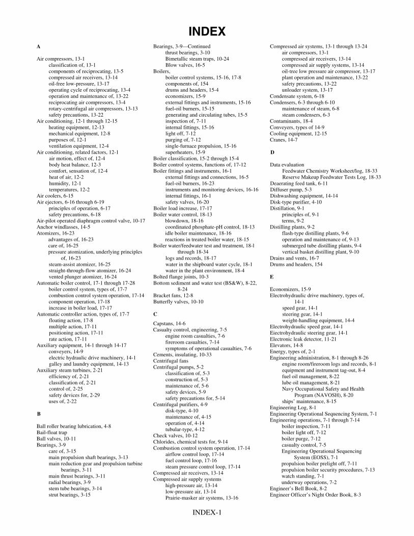
INDEXBearings, 3-9—ContinuedA Compressed air systems, 13-1 through 13-24
thrust bearings, 3-10 air compressors, 13-1Air compressors, 13-1 Bimetallic steam traps, 10-24 compressed air receivers, 13-14
classification of, 13-1 Blow valves, 16-5 compressed air supply systems, 13-14components of reciprocating, 13-5 Boilers, oil-tree low pressure air compressor, 13-17compressed air receivers, 13-14 boiler control systems, 15-16, 17-8 plant operation and maintenance, 13-22oil-free low-pressure, 13-17 components of, 154 safety precautions, 13-22operating cycle of reciprocating, 13-4 drums and headers, 15-4 unloader system, 13-17operation and maintenance of, 13-22 economizers, 15-9 Condensate system, 6-18reciprocating air compressors, 13-4 external fittings and instruments, 15-16 Condensers, 6-3 through 6-10rotary-centrifugal air compressors, 13-13 fuel-oil burners, 15-15 maintenance of steam, 6-8safety precautions, 13-22 generating and circulating tubes, 15-5 steam condensers, 6-3
Air conditioning, 12-1 through 12-15 inspection of, 7-11 Contaminants, 18-4heating equipment, 12-13 internal fittings, 15-16 Conveyers, types of 14-9mechanical equipment, 12-8 light off, 7-12 Cooling equipment, 12-15purposes of, 12-1 purging of, 7-12 Cranes, 14-7ventilation equipment, 12-4 single-furnace propulsion, 15-16
Air conditioning, related factors, 12-1 superheaters, 15-9 DBoiler classification, 15-2 through 15-4air motion, effect of, 12-4Boiler control systems, functions of, 17-12body heat balance, 12-3 Data evaluationBoiler fittings and instruments, 16-1 comfort, sensation of, 12-4 Feedwater Chemistry Worksheet/log, 18-33
external fittings and connections, 16-5 Reserve Makeup Feedwater Tests Log, 18-33heat of air, 12-2fuel-oil burners, 16-23humidity, 12-1 Deaerating feed tank, 6-11
temperatures, 12-2 instruments and monitoring devices, 16-16 Diffuser pump, 5-3Air coolers, 6-15 internal fittings, 16-1 Dishwashing equipment, 14-14
safety valves, 16-20Air ejectors, 6-16 through 6-19 Disk-type purifier, 4-10Boiler load increase, 17-17 Distillation, 9-1 principles of operation, 6-17
safety precautions, 6-18 Boiler water control, 18-13 principles of, 9-1blowdown, 18-16 terms, 9-2Air-pilot operated diaphragm control valve, 10-17coordinated phosphate-pH control, 18-13Anchor windlasses, 14-5 Distilling plants, 9-2
Atomizers, 16-23 idle boiler maintenance, 18-16 flash-type distilling plants, 9-6reactions in treated boiler water, 18-15advantages of, 16-23 operation and maintenance of, 9-13
care of, 16-25 Boiler water/feedwater test and treatment, 18-l through 18-34
submerged tube distilling plants, 9-4vertical basket distilling plant, 9-10 pressure atomization, underlying principles
of, 16-23 logs and records, 18-17 Drains and vents, 16-7water in the shipboard water cycle, 18-1 Drums and headers, 154 steam-assist atomizer, 16-25water in the plant environment, 18-4 straight-through-flow atomizer, 16-24
vented plunger atomizer, 16-24 Bolted flange joints, 10-3 EAutomatic boiler control, 17-1 through 17-28 Bottom sediment and water test (BS&W), 8-22,
8-24 Economizers, 15-9boiler control system, types of, 17-7Bracket fans, 12-8combustion control system operation, 17-14 Electrohydraulic drive machinery, types of,
14-1Butterfly valves, 10-10component operation, 17-18increase in boiler load, 17-17 speed gear, 14-1
steering gear, 14-1CAutomatic controller action, types of, 17-7weight-handling equipment, 14-4floating action, 17-8
Capstans, 14-6Electrohydraulic speed gear, 14-1 multiple action, 17-11
Casualty control, engineering, 7-5Eiectrohydraulic steering gear, 14-1positioning action, 17-11
engine room casualties, 7-6rate action, 17-11 Electronic leak detector, 11-21
fireroom casualties, 7-14Elevators, 14-8Auxiliary equipment, 14-1 through 14-17
conveyers, 14-9symptoms of operational casualties, 7-6
Energy, types of, 2-1Cements, insulating, 10-33
Engineering administration, 8-1 through 8-26electric hydraulic drive machinery, 14-1Centrifugal fans
galley and laundry equipment, 14-13 engine room/fireroom logs and records, 8-1Centrifugal pumps, 5-2
equipment and instrument tag-out, 8-4 Auxiliary steam turbines, 2-21classification of, 5-3
fuel oil management, 8-22efficiency of, 2-21construction of, 5-3
lube oil management, 8-21classification of, 2-21maintenance of, 5-6
control of, 2-25 Navy Occupational Safety and Health Program (NAVOSH), 8-20
safety devices, 5-9safety devices for, 2-29
safety precautions for, 5-14 uses of, 2-22 ships’ maintenance, 8-15
Centrifugal purifiers, 4-9Engineering Log, 8-1
disk-type, 4-10Engineering Operational Sequencing System, 7-1B maintenance of, 4-15Engineering operations, 7-1 through 7-14
operation of, 4-14Ball roller bearing lubrication, 4-8 boiler inspection, 7-11
tubular-type, 4-12Bail-float trap boiler light off, 7-12
Check valves, 10-12Ball valves, 10-11 boiler purge, 7-12
Chlorides, chemical tests for, 9-14Bearings, 3-9 casualty control, 7-5
Combustion control system operation, 17-14care of, 3-15 Engineering Operational Sequencing
System (EOSS), 7-1airflow control loop, 17-14
main propulsion shaft bearings, 3-13fuel control loop, 17-16
propulsion boiler prelight off, 7-11main reduction gear and propulsion turbinebearings, 3-11
steam pressure control loop, 17-14propulsion boiler security procedures, 7-13
Compressed air receivers, 13-14main thrust bearings, 3-11 watch standing, 7-1
Compressed air supply systemsradial bearings, 3-9 underway operations, 7-2
high-pressure air, 13-14stem tube bearings, 3-14 Engineer’s Bell Book, 8-2
low-pressure air, 13-14strut bearings, 3-15 Engineer Officer’s Night Order Book, 8-3
Prairie-masker air systems, 13-16
INDEX-1

Engine room casualties, types of, 7-6 Heat stress, 8-20 NAVEDTRA publications, 1-7 and l-10Hydraulically operated gland seal regulator, 10-20 NAVSEA publications, 1-8 main engine shaft, 7-6
Navy enlisted classification codes, 1-2loss of lube oil pressure in main engine, 7-7Imetallic noise in main turbine, 7-8 Navy Occupational Safety and Health Program
(NAVOSH), 8-20 hot bearing on main engine, 7-8Impulse steam traps, 10-23 Hearing conservation, 8-21uncontrolled hot main engine bearing, 7-9
Heat stress, 8-20 jammed throttle, 7-9 Instruments and monitoring devicesNight Order Book loss of main condenser vacuum, 7-10 oil-drip detector periscopes, 16-19Nozzles, 2-5 hot condenser, 7-10 pressure and temperature gauges, 16-18
turbogenerator casual ties, 7-11 remote water-level indicators, 16-17engine room fires, 7-11 Osmoke indicators, 16-19
Expansion joints, 10-4 superheater temperature alarms, 16-19Occupational Standards (OCCSTDs), 1-2
water gauge glasses, 16-16External fittings and connectionsOil-drip periscopes, 16-19
Insulation, 10-32blow valves, 16-15Oil-free low-pressure air compressor, 13-17
drains and vents, 16-17Operating orders, 8-3
Lsoot blowers, 16-12Engineer Officer’s Night Order Book, 8-3
steam stop valves, 16-11steaming orders, 8-3Langmuir theory, 4-2
Laundry equipment, 14-17F PLegal records, 8-2Engineer’s Bell Book, 8-2Feedwater contaminants, control of, 18-12 Packing material, 10-28Engineering Log, 8-1 Personnel Qualification Standards (PQS), 1-2Fireroom casualties, 17-14
Logs and records, 8-1, 18- 17 pipe fittings of, 10-2 Flange safety shields, 10-5flange shields, 10-5Flash-type distilling plants, 9-6 Boiler Water Chemistry Worksheet Log,
18-29 identification of, 10-1 Fluid lubrication, 4-1Forced draft blowers, 5-24 strainers, 10-7Feedwater Chemistry Worksheet Log, 18-28,
18-33 Piping systems, 10-1 through 10-34types of, 5-24lubrication systems, 5-30 fuel and water report, 18-31, 18-32 insulation, 10-30
legal records, 8-1 packing and gasket materials, 10-28Fuel-oil burners, 16-23records maintenance, 18-17 piping and tubing, 10-latomizers, 16-23
steam traps, 10-21burners and registers, operation and care of,16-27
Reserve Makeup Feedwater Test Log, 18-31, 18-33 valves, 10-7
tag out log, 8-6 Planned Maintenance System (PMS), 8-15fuel oil characteristics, 8-22water treatment log, 18-28 Plant maintenance, steam turbines, 2-31registers, 16-27
safety shutoff device, 16-28 Lube Oil Management Program, 4-15, 8-21 Portable fans, 12-6Lube oil purification, 4-9 Prairie-masker air systems, 13-16 Furnace pressure, 154
centrifugal purifiers, 4-9 Pressure gauges, 16-18Furnaces and refractories, 15-10settling tanks, 4-9 Pressure-reducing valves, 10-13casings, uptakes, and smokepipes, 15-15
expansion joints, 15-15 types of, 4-9 Pressure-sensing group, boilers, 17-19Lube oil pump coolers, 6-14refractory lining life factors, 15-10 Propulsion boilers, 15-l through 15-19Lubricants, types of, 4-3refractory materials, handling and storage
of, 15-14classification of, 15-2
greases, 4-4 components of, 15-4oils, 4-3refractory materials, types of, 15-11 definitions of, 15-1
saddles and supports, 15-15 Lubrication and associated equipment, 4-1through 4-15
furnaces and refractories, 15-10prelightoff, 7-11
G factors affecting, 4-2 Propeller pumps, 5-14lubricating systems, 4-5 Propellers and main propulsion shafting, 3-18
Galley, 14-13lube oil purification, 4-9 controllable pitch propellers, 3-20
steam-jacketed kettles, 14-13Lube Oil Management Program, 4-15 Propulsion reduction gears, 3-1
dishwashing equipment, 14-14theory of, 4-1 construction of, 3-2
Gaskets, 10-30Lubricating systems, 4-5, 13-5 Pumps, 5-1 through 5-34
Gate valves, 10-8auxiliary machinery lubrication systems, 4-7 forced draft blowers (DFTs), 5-24
Gauges, pressure and temperature, 11-16, 16-18ball and roller bearing lubrication, 4-8 operating principles, 5-1
Generating and circulating tubes, 15-5grease lubrication systems, 4-8 types of, 5-2
Gland exhaust condenser, 6-12main lubricating oil systems, 4-5 Pumps, types of, 5-2
Globe valves, 10-7centrifugal pumps, 5-2
Grease lubrication systems, 4-8 M propeller pumps, 5-14reciprocating pumps, 5-14
H Machinist’s Mate (Surface) rating, introduction to, 1-1 through 1-11
rotary pumps, 5-20variable-stroke pumps, 5-18Halocarbons, 11-28
Navy enlisted classification codes (NECs),1-2
Hearing conservation, 8-21Q
labeling areas and equipment, 8-21Naval standards (NAVSTDs), 1-2
Protective devices, 8-21 Quality Assurance Program, 8-16occupational standards (QCCSTDs), 1-2
Heating equipment, 12-13personnel qualification standards (PQS), 1-2
RHeat exchangers and air ejectors, 6-1 through 6-19Main lube oil coolers, 6-13
air coolers, 6-15Maintenance Data System, 8-16
air ejectors, 6-16 R-12 refrigeration system, 11-17MEASURE Program, 8-18
classification of, 6-1 maintenance of, 11-18Mechanical cooling equipment, 12-8
operation of, 11-17construction of, 6-2chilled water circulating systems, 12-8
deaerating feed tank, 6-11 Reciprocating air compressors, 13-4self-contained air conditioners, 12-13
gland exhaust condenser, 6-12 cooling systems, 13-9Mechanical refrigeration systems, 11-3
lube oil pump coolers, 6-14 components of, 13-5accessories of, 11-13
operating cycle of, 13-4main lube oil coolers, 6-13components of, 11-7
maintenance of, 6-8 Reciprocating pumps, 5-14Nsteam condensers, 6-3 care and maintenance of, 5-17
turbogenerator lube oil coolers, 6-1 classification of, 5-14types of, 6-10 construction of, 5-16Naval standards, 1-2
INDEX-2

INDEX-3
Records maintenance Boiler Water Chemistry Worksheet/log, 18-29 Feedwater Chemistry Worksheet, 18-28,
18-33 Fuel and Water Report, 18-31 Reserve Makeup Feedwater Tests Log, 18-31,
18-33 water treatment log, 18-28
Reduction gears and related equipment, 3-1 through 3-22
auxiliary machinery, 3-7 care and operation of, 3-7 propulsion reduction gears, 3-1 reduction gear casing, opening and access
of, 3-8 Refractory materials
anchor devices, 15-13 handling and storage of, 15-14 types of, 15-11
Refrigeration, 11-1 through 11-29 characteristics of refrigerants, 11-28 components of, 11-7 fundamentals of, 11-1 halocarbons, 11-28 maintenance of, 11-18 mechanical refrigeration systems, 11-3 operating procedures, 11-7 safety precautions, 11-28 tests for refrigerant leaks, 11-20
Registers, 16-27 Relief valves, 10-13, 11-15 Remote-operated valves, 10-21 Remote water-level indicators, 16-17 Rotary-centrifugal air compressors, 13-13 Rotary pumps, 5-20
S
Safety valves, 16-20 steam drum safety valves, 16-20 superheater safety valves, 16-22
Salinity, monitoring of, 9-13 Self-contained air conditioners, 12-13 Sentinel valves, 10-13 Shaft seals, 11-27 Ships’ Maintenance and Material Management
(3-M) systems, 8-15 Maintenance Data System, 8-16 MEASURE Program, 8-18 Planned Maintenance System (PMS), 8-15 Quality Assurance Program, 8-16
Silver-brazed joints, 10-3 Single-furnace propulsion boilers, 15-16
boiler water and steam circulation, 15-l 8 combustion air and gas flow, 15-16
Soot blowers, 16-12 Steam condensers, 6-3
construction of, 6-5 main condensers, 6-3 maintenance of, 6-8 operation of, 6-6
Steam-jacketed kettles, 14-13 Steaming orders, 8-3 Steam operated distilling plants, 9-1 through 9-25
principles of, 9-1 operation and maintenance of, 9-13 types of, 9-2
Steam traps, 10-21 mechanical, 10-22 orifice, 10-24 thermostatic, 10-22
Steam turbines, 2-1 through 2-32 auxiliary steam turbines, 2-21 classification of, 2-6 components and construction of, 2-11 control of, 2-18 energy, types of, 2-1 maintenance of, 2-29 plant maintenance of, 2-32 theory of, 2-3 work and power, 2-3
Steam turbine maintenance, 2-29 adjustments of, 2-29 labyrinth and carbon pacing rings, 2-31
Stop valves, 10-7 Submerged tube distilling plants, 9-4 Superheaters, 15-9 Superheater safety valves, 16-22
T
Tag-out program, 8-4 enforcement of, 8-13 procedures for, 8-10 tag-out information, 8-9 tag-out logs, 8-6
Temperature gauges, 16-18 Thermostatically controlled recirculating valves,
10-20 Threaded union joints, 10-2 Tube-axial fans, 12-6 Tubing, identification of, 10-1 Tubular-type purifier, 4-12 Turbines, theory of, 2-3
impulse principle, 2-3 nozzles, 2-5 reaction principle, 2-4
Turbines, classification of, 2-6 staging arrangements, 2-6 direction of steam flow, 2-10 repetition of steam flow, 2-10 division of steam flow, 2-11
Turbine, components and construction of, 2-11 materials of, 2-16 nozzle diaphragms, 2-13 shaft packing glands, 2-13 support, 2-12
Turbines, control of, 2-18 astern (reversing), 2-21 cruising arrangements of, 2-20 nozzle control valves, 2-18
Turbogenerator lube oil coolers, 6-13
U
Underway, preparations for securing the plant, 7-5 standing by, 7-3 underway operations, 7-3
V
Valute pump, 5-3
Valvesautomatic reducing valve, 11-26 ball valves, 10-11 blow valves, 16-15 butterfly valves, 10-10 check valves, 10- 12 evaporator pressure regulating valve, 11-14 gate valves, 10-8 globe valves, 10-7 hydraulically operated glad seal regulator,
10-28 maintenance and repair of, 10-25 pressure-reducing valves, 10-13 relief valves, 10-13, 11-15 remote-operated valves, 10-21 safety valves, 16-20 sentinel valves, 10-13 steam stop valves, 16 11 stop valves, 10-7 suction valves 11-26 superheater safety valves, 16-22 thermostatically controlled recirculating
valves, 10-20 water regulating valve, 11-16, 11-26
Vane-axial fans, 12-5 Variable stroke pumps, 5-18 V-belts, care of, 11-23 Ventilation equipment, 12-4
exhausts, 12-8 maintenance of, 12-14 types of, 12-5 waterproof ventilation, 12-7
Vertical basket distilling plant, 9-10
W
Watch standing, 1-3, 7-1 Water gauge glasses, 16-16 Water in the plant environment, 18-4
boiler water control, 18-13 contaminant concentration, 18-4 contaminants, effects of, 18-5 dissolved solids, effects of boiling on, 18-4 feedwater contaminants, control of, 18-12 feedwater contaminants, sources of, 18-10 test procedures, 18-17
Water in the shipboard water cycle, 18-l Water, the chemical nature of, 18-5
chloride, 18-9 conductivity, 18-9 dirt and debris, 18-10 dissolved oxygen, 18-8 hardness, 18-7 fuel, lubricating oil, preservatives, 18-10 ion exchange, 18-10 pH value, 18-6 silica, 18-10 suspended solids, 18-10
Weight-handling equipment, types of, 14-4 anchor windlasses, 14-5 capstans, 14-6cranes, 14-7elevators, 14-8 winches, 14-5
Welded joints, 10-3 Winches, 14-5


ASSIGNMENT 1Textbook Assignment: “Introduction to the Machinist’s Mate (Surface) Rate” and “Steam Turbines,” chapters 1 and 2,
pages 1-1 through 2-32.
1-1. If you are assigned to the M division, which ofthe following terms best describes your rating?
1. General2. Special3. Selective4. Standard
1-2. A Machinist’s Mate (MM) (Surface) in theM division will most likely maintain whichof the following equipment?
1. Steering engine(s)2. Laundry equipment3. Refrigeration equipment4. Propulsion machinery
1-3. As you move up the promotion ladder to MM3and then to MM2, your technical leadershipresponsibilities will change in what way?
1. They will be more directly relatedto your work
2. They will be more general in nature3. They will include more military
responsibilities4. They will require only that you tell
others what to do
1-4. You can best demonstrate technical leadershipin which of the following ways?
1. Develop military leadership2. Work with integrity and increase
your knowledge3. Complete the NRTCs for the MM rate4. Pass the Navywide Advancement
Examination for your rate
1-5. What is the purpose of the Navy EnlistedClassification Codes (NECs)?
1. To identify skills and training required forspecific types of operations or equipment
2. To recruit Navy men and women3. To determine who will advance4. To classify information about ships
1-6. Which of the following offices details personnelwith special NECs?
1. Chief of Naval Operations2. Chief of Naval Personnel3. Naval Sea Systems Command4. Naval Weapons Command
1-7. Which of the following subjects is coveredby the Naval Standards?
1. Security2. Pump operation3. Boiler operation4. 3-M
1-8. Before you can take the Navywide AdvancementExamination for MM2, you must be aware ofwhich of the following types of information?
1. Military conduct2. Naval organization3. Military justice4. Each of the above
1-9. The PQS program has which of the followingfunctions?
1. To describe the knowledge and skills youneed to perform your duties correctly
2. To describe the steps to be taken foradvancement
3. To acquaint you with your military duties4. To eliminate the need for examinations
1-10. What person is responsible for the safekeepingof your qualification records?
1. The commanding officer2. The engineer officer3. Your supervisor4. Yourself
1

1-11. What is the most useful thing to know abouta piece of equipment?
1. Clearances2. Pressures3. Where to find the name plate data4. Where to find the necessary information
on the equipment
1-12. The required and recommended training coursesto study for advancement in rating can be foundin what publication?
1. Navy Enlisted Manpower and PersonnelClassifications and Occupational Standards,NAVPERS 18068
2. Bibliography for Advancement Study,NAVEDTRA 12061
3. Guide for Enlisted Classification4. Shipboard Training Manual
1-13. If extensive changes occur in the qualificationsfor a rating between annual revisions ofNAVEDTRA 12061, where can you finda list of current study material?
1. NAVSEA notices2. BUPERS notices3. NAVEDTRA 12061 supplements4. Naval Ships’ Technical Manual (NSTM)
1-14. Which of the following hints for studying shouldhelp you get the most from your Navy trainingcourse?
1. Devote your time exclusively to importantmilitary topics
2. Try not to cover a complete unit in anyone study period
3. Omit easy material; study only the mostdifficult and the unfamiliar
4. Make notes as you study, putting the mainideas in your own words; then review yournotes
1-15. As you study a Navy training course, which ofthe following study practices should you follow?
1. Set up a fixed number of pages tostudy in each and every study period
2. Prepare notes exactly as stated in theTRAMAN
3. Memorize as much as you can froma chapter and repeat it to a shipmate
4. Skip over the illustrations and savethem until the end of your course
1-16. You should find useful articles about shipboardengineering and new developments each monthin which of the following publications?
1. Changes to the NSTM2. NAVSEA’s Deckplate3. Supplements to the applicable Navy
training course4. Bibliography for Advancement Study
1-17. Aboard ship, blueprints are filed according to
1. month and year of issue2. SHIP/ALT number3.4.
numerical sequence in the SDIrevision number or letter
1-18. You will most likely find the NSTM in whatspace in the engineering department?
1. The engine room2. The fireroom3. The pump room4. The log room
THIS SPACE LEFT BLANK INTENTIONALLY.
2

A. ENERGYB. POWERC . W O R KD. KINETIC ENERGYE. ENTHALPYF. POTENTIAL ENERGYG. STORED ENERGY
Figure 1A
IN ANSWERING QUESTIONS 1-19 THROUGH 1-24,REFER TO FIGURE 1A AND SELECT THE TERMDEFINED BY THE QUESTION.
1-19. The ability to do work.
1. A2. B only3. B and C4. E, F, and G
1-20. Work done within a specified period of time.
1. A2. B3. C4. D
1-21. A force that acts on matter and moves it.
1. A and B2. C only3. C and D4. F and G
1-22. Energy that has been released.
1. A and C2. D3. E and F only4. E, F, and G
1-23. Stored energy within steam.
1. B, C, and F2. A, B, and C3. C, D, F, and G4. E
1-24. Stored energy in an object.
1. D2. E3. F4. G
1-25. What type of energy is found in the waterof an operating boiler?
1. Chemical2. Thermal3. Mechanical4. Specific
IN ANSWERING QUESTIONS 1-26 AND 1-27,REFER TO FIGURE 2-1 IN THE TEXTBOOK.
1-26. Chemical energy is converted to thermal energyin what component?
1. The furnace2. The superheater3. The steam drum4. The economizer
1-27. Thermal energy of steam is converted tomechanical energy in which of the followingcomponents?
1. The condensate pump2. The main feed pump3. The feed booster pump4. Each of the above
IN ANSWERING QUESTIONS 1-28 AND 1-29,REFER TO FIGURE 2-2 IN THE TEXTBOOK.
1-28. If you are operating at 30 percent speed, you areusing what percentage of rated horsepower?
1. 1%2. 10%3. 40%4. 4%
3

1-29. If you increase the percentage of speed to60 percent, you are using what percentageof rated horsepower?
1. 10%2. 20%3. 30%4. 40%
1-30. What parts of a reaction turbine serve the samepurpose as the nozzle of an impulse turbine?
1. Fixed nozzles2. Fixed blades only3. Moving blades only4. Fixed blades and moving blades
1-31. As the steam passes across the moving blades in areaction turbine, what happens to the pressure andvelocity?
1. They increase2. They decrease3. They remain constant4. The velocity increases and
the pressure decreases
1-32. In the impulse turbine, what device convertsthermal energy to kinetic energy?
1. Moving blades2. Fixed blades3. Nozzles4. Valves
1-33. Convergent-divergent nozzles are used inhigh-pressure turbine applications for whichof the following reasons?
1. They are easy to manufacture2. They are less susceptible to steam erosion
than other types because of their shape3. They produce a larger pressure drop and
therefore are more efficient than other types4. They direct the steam flow more efficiently
than other types
1-34. What is a Rateau stage on a turbine?
1. One set of nozzles and two rowsof moving blades
2. One set of nozzles and one rowof moving blades
3. Two sets of nozzles and two rowsof moving blades
4. Two sets of nozzles and one rowof moving blades
1-35. What is the cause of large temperature andpressure drops in the first-stage nozzles of acombination impulse and reaction turbine?
1. Two rows of moving blades2. Steam passing through a single
row of blades more than once3. Using a dummy piston cylinder
to offset axial thrust4. A velocity-compounded impulse
stage at the high-pressure end of theturbine followed by reaction blading
1-36. The turbine wheel uses the steam more thanonce in which of the following turbines?
1. Helical flow only2. Axial flow only3. Helical and axial flow4. Axial and radial flow
1-37. Double-flow reaction turbines have very littleaxial thrust for which of the following reasons?
1. No axial thrust develops2. Partially expanded steam is
exhausted to a low-pressure turbinewhere the expansion is completed
3. The axial thrusts developed at eachend counterbalance each other
4. Equalizing holes are provided inthe turbine wheel
1-38. The after end of most main engine turbines arerigidly mounted for which of the followingreasons?
1. Because of the steam line connection2. Because of the drain line connection3. Because of the blading and casing alignment4. Because of the turbine and reduction gear
alignment
4

1-39. Because of the pressure drop existing across eachdiaphragm in a turbine, the flow of steam betweenthe nozzle diaphragm and the rotor is held to aminimum by what means?
1. A fluid seal2. A deflector ring3. A babbitt liner4. A labyrinth packing ring
1-40. The labyrinth packing in a turbine serves whichof the following purposes?
1. It maintains rotor alignment2. It relieves excessive pressure along the rotor3. It assists in sealing the area where the rotor
passes through the casing4. It allows for rotor expansion
1-41. What is the purpose of gland sealing steam?
1. To stop air from entering a turbinecasing operating under a vacuum
2. To cool the packing gland3. To assist turbine warmup4. To preheat the packing gland before
the ship gets under way
1-42. What causes the gland leak-off steam in apropulsion turbine to pass through the glandexhaust condenser?
1. Steam pressure from the low-pressureturbine
2. Steam pressure from the high-pressureturbine
3. Compressed air in the air pilot4. The gland exhauster
IN ANSWERING QUESTION 1-43, REFER TOFIGURE 2-24 IN THE TEXTBOOK.
1-43. The poppet valves in nozzle control valvesare held closed by what means?
1. The lifting beam2. Springs3. Steam pressure4. Oil pressure
IN ANSWERING QUESTIONS 1-44 AND 1-45,REFER TO FIGURE 2-25 IN THE TEXTBOOK.
1-44. When valves #1 and #2 are wide open, whatshould be the steam pressure in the steam chest?
1. About the same as the line pressure2. In excess of the line pressure3. Increasing in intensity4. Sufficient for maximum turbine speed
and power
1-45. Of the following cam-operated valves, whichone admits steam directly into the sixth stage?
1. No. 52. No. 23. No. 34. No. 4
1-46. What is the range of economic operationfor turbine-driven ships?
1. 5 to 10 Kt2. 10 to 26 Kt3. 12 to 20 Kt4. 20 to 25 Kt
1-47. In a main engine using a double-flowlow-pressure turbine, where are the asternelements located?
1. In the forward end of the high-pressureturbine only
2. In the after end of the high-pressureturbine only
3. In the forward and after ends of thelow-pressure turbine
4. In the forward and after ends of thehigh-pressure turbine
1-48. Astern turbines are normally made upof what type of staging?
1. Reversing2. Reaction3. Velocity-compounded impulse4. Pressure-compounded impulse
5

1-49. Auxiliary turbines improve overall plantefficiency by supplying steam to whichof the following components?
1. The main air ejector2. The fuel oil service pump3. The DFT4. The fuel oil heater
1-50. The efficiency is increased in some auxiliaryturbines by using which of the following devices?
1. Reduction gears2. Speed-limiting governors3. Convergent nozzles4. Divergent nozzles
1-51. Auxiliary turbines are classified accordingto which of the following characteristics?
1. Weight displacement2. Length and height3. Number of blades4. Number of stages
1-52. Which of the following pieces of equipment ismost likely to be driven by an auxiliary turbine?
1. A low-pressure air compressor2. A cooling water pump3. A force draft blower4. An exhaust fan
1-53. What type of turbine is most often usedto drive the main lube oil pump?
1. Single stage2. Multistage3. Condensing4. Noncondensing
1-54. Which of the following factors is a meansused to classify turbogenerator turbines?
1. Condensing2. Noncondensing3. Both 1 and 2 above4. Kilowatts per hour
1-55. If a turbogenerator is in operation with a faultysafety device, you should take which of thefollowing actions?
1. Secure the generator2. Place an out-of-commission sign on
the safety device and continue to operatethe generator
3. Place a caution tag on the safety deviceand continue to operate the generator
4. Bypass the safety device and continueto operate the generator
1-56. On a turbogenerator, what type of governorensures a steady frequency output?
1. Constant-pressure2. Constant-speed3. Speed-limiting4. Overspeed
1-57. When the electrical load is increased on aturbogenerator equipped with a centrifugalgovernor, the flyweights initially move inwhat direction?
1. Inward2. Outward3. Downward4. Upward
1-58. On the turbogenerator, what safety device willcause the trip throttle valve to close when itreaches its set point?
1. The overspeed trip2. The low lube oil pressure trip3. The back-pressure trip4. The constant-speed trip
1-59. If a turbogenerator operates at 1,200 rpm, whatshould be the setting of the overspeed trip?
1. 1,220 rpm2. 1,320 rpm3. 1,440 rpm4. 1,520 rpm
6
1-60. The quickest way to determine bearing wear onthe main turbines is to take what type of reading?
1. Crown thickness2. Lead gauge3. Depth gauge4. Bridge gauge
1-61. When you use inside and outside micrometersto measure bearing wear, you are actually takingwhat measurement?
1. The oil clearance2. The crown thickness3. The amount of babbitt remaining4. The amount of shaft wear
1-62. When using a Kingsbury thrust bearing to axiallyposition the turbine rotor, you should makeadjustments by adjusting the thickness of whatpart(s)?
1. The thrust shoes2. The base roughness3. The filler piece4. The thrust collar
1-63. The thrust measurement on a turbine shouldbe taken with what instrument?
1. A dial indicator2. A feeler gauge3. A depth micrometer4. An outside micrometer
1-64. You should use which of the following toolsto repair labyrinth packing?
1. A chisel bar and a hand chisel2. Files and stones3. A hammer and files4. Stones and emery paper
1-65. Which of the following suggestions will helpyou recognize the symptoms of a casualty morereadily?
1. Be familiar with the normal pressures,temperatures, and operating speeds ofthe equipment
2. Know your casualty control procedures3. Study the ship’s organization manual4. Study the damage control manual
7

ASSIGNMENT 2Textbook Assignment: “Reduction Gears and Related Equipment” and “Lubrication and Associated Equipment,”
chapters 3 and 4, pages 3-1 through 4-8.
2-1. What is the purpose of reduction gears?
1. To change rotary motion into linear action2. To reduce high speed to low speed3. To minimize thrust on the main turbines4. To transmit thrust from the main shaft to
the ship’s hull
2-2. What is the purpose of double helical gearsin reduction gears?
1. To produce smoother action andeliminate tooth shock
2. To produce double reduction3. To eliminate misalignment4. To eliminate radial stress
2-3. In reference to reduction gears, the term axialfloat has what meaning?
1. The gears aren’t subject to excessive toothloads due to mismatch of the journal bearinghalves
2. The gears are double-helical and axial thrustis eliminated
3. The gears are capable of free motion, neithersupporting nor supported by other gearsradially
4. The gears are capable of free motion, neithersupporting nor supported by other gearsaxially
2-4. The first reduction gear and the second reductionpinion each have two bearings and are connectedby a quill shaft and flexible coupling. They areknown as what type of gearing?
1. Double-reduction2. Single-reduction3. Nested4. Articulated
2-5. What is the meaning of the term lock-train?
1. The main shaft can be locked2. The main turbines can be locked3. The two first reduction pinions are locked
between the two first reduction gears4. The second reduction gear is locked between
the two first reduction pinions
2-6. In a main reduction gear, the gear case covers arebolted and securely locked to the upper casings.What mean(s) is/are provided to inspect therotating pairs?
1. Inspection plates2. Bullseye covers3. RTE junction boxes4. A tachometer drive
2-7. In an articulated, double-reduction, divided-powerpath gear set, the first and second reduction gearsare usually of fabricated construction. The teethare cut in a temperature-controlled room for whatreason?
1. To prevent stress buildup2. To prevent the effects of temperature
and humidity3. To control the size of the journals4. To control stress in the webbing
2-8. In propulsion systems, the shaft for a mainreduction gear may be made from what typeof material?
1. Aluminum-bronze2. Forged steel3. Aluminum4. Monel
8
2-9. The type of construction for gear wheels usedin reduction gear mechanisms aboard ship isdetermined by which of the following factors?
1. The size of the gear wheel2. The type of the reduction gear3. The type of ship in which they will be used4. The type of gear to be driven
2-10. What type of flexible couplings are used inmost turbine reduction gear installations?
1. Friction clutch2. Gear tooth3. Bend4. Flange
2-11. The expansion and minor misalignments thatoccur between the main turbines and thereduction gears are compensated by what device?
1. A sleeve2. A flexible coupling3. An expansion gear4. A pinion gear
2-12. Failure to use the turning gear during turbinestartup may result in which of the followingcasualties?
1. A hot condenser2. A hot bearing3. A bowed rotor4. Bowed reduction shafts
2-13. Geared turbine installations are equipped withturning mechanisms for which of the followingreasons?
1. To jack the main engine periodicallywhen it is secured
2. To turn the main engine during routineinspections
3. To turn the main engine during warmupand securing periods
4. Each of the above
2-14. In the type of turning gear discussed in the text,what component connects the turning gear to thehigh-pressure pinion?
1. A manually operated hand brake2. A manually operated jaw clutch3. A sleeve coupling4. A quill shaft
2-15. What type of reduction gearing is used forturbogenerators?
1. External spur2. Bevel3. Helix4. Screw
2-16. In the reduction gearing for a typical ship’sturbogenerator, the gear that drives the oil pumpand governor is mounted on the turbine end ofwhat component?
1. The pinion shaft2. The turbine shaft3. The generator shaft4. The gear wheel shaft
2-17. The reduction gears on the turbine-driven maincirculating pump are lubricated by what type ofpump?
2-18.
1. Gear2. Centrifugal3. Hand4. Screw
To keep the reduction gear operating properly,what should be your principle concern?
1. Keeping a constant reduction ratio betweenthe speed of the turbine and the speed of thedriven unit
2. Keeping the upper half of the gear casingsecured to the lower half of the casing
3. Keeping the gear supplied with pure oilat the proper pressure and temperature
4. Keeping the drive gear aligned with thedrive shaft
9
2-19. Dirt and/or metallic particles in a reductiongear lubrication system may cause whichof the following problems?
1. Scored journals2. Clogged spray journals3. Eroded gear teeth4. All of the above
2-20. On a reduction gear unit, the main sump is locateddirectly below the gears. When adding lube oil,you must take which of the followingprecautions?
1. Don’t use 2190-TEP oil2. Don’t raise the oil level to the point where
it will come in contact with the bull gear3. Don’t add oil using the lube-oil purifier4. Don’t strike down oil from the storage tank
2-21. Which of the following casualties indicatesthat oil is churning in the main sump?
1. High bearing temperatures2. Water in the lube oil3. A low sump level4. A hot line shaft bearing
2-22. What person is required to be present whenthe reduction gear casing is opened?
1. The division officer2. The officer of the deck3. The damage control officer4. The engineer officer
2-23. Which of the following precautions is/arerequired when you are working on reductiongears?
1. Work in a T-shirt2. Work in clothes with all buttons
and pockets taped3. Secure tools to your person with
a lanyard4. All of the above
2-25. Turbine bearings and reduction gear bearingshave separate lubrication systems.
1. True2. False
2-26. In the main engine installations, the mainreduction gear bearings and other bearingshave which of the following characteristicsin common?
1. They are of the single-casting type2. They are babbitt lined3. They are self aligning4. They are spherically seated
2-27. Reduction gear bearings are mounted rigidlyin their housings by what means?
1. Keyways and keys2. Spherical housings3. Dowels or locking screws and washers4. Notched construction
2-28. The splits in the main reduction gear bearings aremounted at an angle to the horizontal to preventwhich of the following problems?
1. Oil loss2. Steam loss3. Axial stress4. Wiping
2-29. A main thrust bearing of a ship’s propulsion plantlocated in the reduction gear casing has which ofthe following purposes?
1. To support the weight of the reduction gears2. To absorb the radial thrust developed when
power is transmitted3. To absorb the axial thrust transmitted
through the shaft from the propeller4. To allow for shaft misalignment
2-24. Thrust bearings provide free shaft movementin the direction of the shaft axis.
1. True2. False
10

QUESTIONS 2-30 THROUGH 2-33 REFER TOSEGMENTAL PIVOTED-SHOE-TYPE THRUSTBEARINGS.
2-30. Which of the following is the principleof operation of these bearings?
1. A flat film of oil is more readily formedand maintained than a wedge-shaped film
2. A flat film of oil can carry heavier loadsthan a wedge-shaped film
3. A wedge-shaped film of oil absorbs lessheat than does a flat film
4. A wedge-shaped film of oil is more readilyformed and maintained than a flat film
2-31. Which of the following parts equalizesthe thrust load between the shoes?
1. The leveling plates2. The thrust collar3. The base ring4. The oil wedge
2-32. Which of the following parts transmitsthe thrust to the ship’s structure?
1. The thrust collar2. The leveling plates3. The base ring4. The oil wedge
2-33. What base ring feature prevents it fromturning and secures it to its housing?
1. The pin only2. The dowel only3. The combination of pin and dowel4. The keyed construction
2-34. Most main line shaft bearings have whichof the following features?
2-35. In the disc-oiled spring bearing, the oil isremoved from the disc by what means?
1. Shaft rotation2. A scraper3. The oil ring4. Disc guides
2-36. While underway, the temperature and oil levelsof spring bearings should be checked at whatspecified interval?
1. Hourly2. Daily3. Weekly4. Monthly
2-37. Water is prevented from entering the ship’s hullvia the propulsion shaft by which of the followingdevices?
1. Stem tube packing or automatic shaft seal2. A deflector ring and drain3. Spring bearings4. Oiler rings
2-38. Water flowing through the stem tube stuffingbox serves which of the following purposes?
1. Cools2. Lubricates3. Flushes4. All of the above
2-39. When the ship is in port and cold iron, whatshould be the condition of the stern-tube packinggland?
1. Tight2. Loose3. Disassembled4. Tagged out
1. Ring-oiled or disc-oiled2. Nonself-aligning3. Segmental-pivoted shoe4. Rigidly mounted sleeve
11

2-40. When packing is added to the stern tube. whatmeans should you use to ensure that the glandis taken up evenly?
1. Listen for a smooth, regular sound2. Measure the distance between the gland
and stuffing box with a rule3. Judge by, the feel of the gland as it is being
tightened4. Open the drain connection to let seawater
flow in and make the distance even
2-41. The automatic shaft sealing system has whichof the following advantages over the stuffingbox and backing gland method?
1. It eliminates the repairing or renewingof the shaft sleeve
2. It is fully automatic in operation3. It allows for removal and reinstallation
of ail parts without dismantling the shafts4. Each of the above
2-42. In most cases, what is the first indicationof bearing trouble?
1. White looking lube oil2. Abnormal or rapid temperature rise3. Excessive lube oil pressure4. Misalignment of the turbine rotor
2-43. Normally, what method is used to connectthe sections of line shafting?
1. Banding2. Unions3. Welding4. Couplings
2-44. The exposed portion of the outboard shaft isprotected against seawater corrosion by whichof the following means?
1. A heavy lubricant2. A covering of plastic or rubber3. A bronze sleeve4. A strut tube
2-45. Which of the following statements describesship propellers?
1. The number of blades varies from twoto four
2. The number of blades varies from threeto seven
3. Controllable pitch propellers are of thesingle- casting type
4. Left-hand helices as viewed from asternturning counterclockwise to move the shipforward
2-46. Which of the following is a descriptionof controllable pitch propellers?
1. They give excellent maneuverability2. They can develop maximum thrust
at any given rpm3. They stop the ship in a shorter distance4. All of the above
2-47. The controllable pitch propeller controls theposition of which of the following units?
1. Propeller blades2. Propeller3. Propeller hub assembly4. Propeller and shafting
2-18. Which of the following components providespassage for the prairie air tubing?
1. The hydraulic oil power module2. The manifold block assembly3. The OD box4. The valve rod assembly
2-49. Which of the following components prevent(s)seawater from entering the hub assembly?
1. The piston rod assembly2. The blade port cover3. The blade seal ring4. Both 2 and 3 above
12

2-50. What is kinetic friction?
1. Friction between two bodies at rest2. Friction that must be overcome to
generate motion3. Friction between moving bodies or
between a moving body and a stationarysurface
4. Friction that must be overcome to stopa body in motion
Figure 2A
IN ANSWERING QUESTIONS 2-51 THROUGH 2-56,REFER TO FIGURE 2A.
2-51. What type of friction must be overcometo put boxes A and B in motion?
1. Fluid2. Rolling3. Sliding4. Static
2-52. What type of friction exists between the deckand the bottom of box A as the box is draggedto point X?
1. Fluid2. Rolling3. Sliding4. Static
2-53. What type of friction exists between the deckand the pipes under box B as the box is pushedto point X?
1. Fluid2. Rolling3. Sliding4. Static
2-54. What type of friction exists between the waterand the sides and bottom of box C as the boxis floated to point Y?
1. Fluid2. Rolling3. Sliding4. Static
2-55. Friction exists between the water and the sidesand bottom of floating box C. This friction iscreated by the forces that cause molecules ofwater to have which of the followingcharacteristics?
1. Attract one another2. Stick to the box3. Both 1 and 2 above4. Repel one another
2-56. Boxes A and B are identical in every respect.Compare the amounts of power consumed andheat produced to overcome friction in movingbox A with the corresponding amounts forovercoming friction in moving box B. Whatconclusion should you draw from thecomparison?
1. More power is consumed and more heatis produced in moving box A
2. More power is consumed and more heatis produced in moving box B
3. More power is consumed and less heatis produced in moving box A
4. More power is consumed and less heatis produced in moving box B
13

2-57. By introducing an unbroken film of oil betweentwo moving parts that are making metal-to-metalcontact, you reduce the friction between them.Theoretically, what kinds of friction areexchanged?
1. Sliding to rolling2. Rolling to sliding3. Sliding or rolling to fluid4. Fluid to sliding or rolling
2-58. According to the Langmuir theory, which of thefollowing statements best describes the effectsof lubricating oil on two moving surfaces?
1. The outside layers adhere to the movingsurfaces and the inside layer(s) slidebetween the outside layers and forcethe moving surface apart
2. One layer slides on the other and eachlayer clings to one of the moving surfaces
3. One layer prevents metal-to-metal contactand acts as a roller between the twomoving surfaces
4. A flat-shaped layer forces the movingsurfaces apart in the same way as a solidwedge
2-59. Temperature has what effect on lubricating oil?
1. The oil changes viscosity2. The oil absorbs more condensation3. The oil turns milky in color4. The oil erodes the component parts
2-60. A water-based glycol hydraulic fluid is chieflyused in which of the following components?
1. Catapult retracting gears2. Deck-edge elevators3. Refrigerator compressors4. Machinery reduction gears
2-61. What does the digit 2 in the lube oil symbol2190T represent?
1. The principal synthetic additive in the oil2. The class of the oil according to type and use3. The diameter, in centimeters, of the standard
orifice used to measure the oil’s viscosity4. The number of minutes it takes a 60-mL
sample of the oil to flow through a standardorifice at a specified temperature
2-62. What part of the lube oil symbol 2190T representsthe viscosity of the oil?
1. 192. 903. 1904. 219
2-63. What minimum flashpoint temperature is allowedfor Navy lube oils?
1. 315°F2. 400°F3. 500°F4. 600°F
2-64. What term describes the lowest temperatureat which the vapors of an oil will bum in theabsence of a spark or flame?
1. Fire point2. Flashpoint3. Combustion point4. Autoignition point
2-65. What type of content is shown by theprecipitation number of an oil?
1. Acid2. Additive3. Moisture4. Asphalt or carbon residue
2-66. When a lubrication system aboard ship has threelube oil service pumps, the electrical- and turbine-driven-pumps are used in what way?
1. As lube oil service pumps all the time2. Secured when the shaft-driven pump
has the load3. As standbys, at normal speeds, for the
shaft-driven pumps4. To supply the auxiliary
2-67. The sensing point for the low-pressure alarmis located in what part of a lube oil system?
1. The lube oil pump suction2. Between the lube oil pump and the
lube oil cooler3. At or near the most remote bearing4. At or near the lube oil pump discharge
14

2-68. What device in the main lube oil systemmaintains the desired pressure to the mostremote bearing?
1. A needle valve2. An orifice3. An unloading valve4. A check valve
2-69. In a force-feed lubrication system, what devicecontrols the amount of oil to each individualbearing?
1. A pump2. An unloading valve3. A needle or orifice valve4. An expansion valve
2-70. What type of lube oil pump is normallyused on a turbine-driven pump?
2-71. What type of strainer is normally used in themain lube oil system?
1. Duplex2. Single-wire mesh3. V4. Y
2-72. On a turbine-driven pump, what device in thecooling water line leaving the cooler preventsair pockets in the cooler?
1. A needle valve2. A check valve3. An orifice4. A vent
1. Screw2. Simple gear3. Lobe4. Jet
15
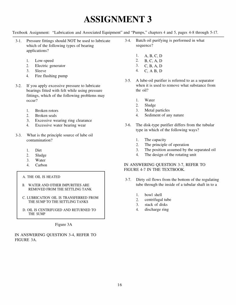
ASSIGNMENT 3Textbook Assignment: “Lubrication and Associated Equipment” and “Pumps,” chapters 4 and 5, pages 4-8 through 5-17.
3-1. Pressure fittings should NOT be used to lubricate 3-4.which of the following types of bearingapplications?
Batch oil purifying is performed in whatsequence?
1. Low-speed2. Electric generator3. Sleeve4. Fire flushing pump
3-5.3-2. If you apply excessive pressure to lubricate
bearings fitted with felt while using pressurefittings, which of the following problems mayoccur?
1. A, B, C, D2. B, C, A, D3. C, B, A, D4. C, A B, D
A lube-oil purifier is referred to as a separatorwhen it is used to remove what substance fromthe oil?
1. Broken rotors2. Broken seals3.4.
Excessive wearing ring clearanceExcessive water bearing wear 3-6.
1. Water2. Sludge3. Metal particles4. Sediment of any nature
The disk-type purifier differs from the tubulartype in which of the following ways?
3-3. What is the principle source of lube oilcontamination?
1. Dirt2. Sludge3. Water4. Carbon
1. The capacity2. The principle of operation3. The position assumed by the separated oil4. The design of the rotating unit
IN ANSWERING QUESTION 3-7, REFER TOFIGURE 4-7 IN THE TEXTBOOK.
A. THE OIL IS HEATED
B. WATER AND OTHER IMPURITIES AREREMOVED FROM THE SETTLING TANK
C. LUBRICATION OIL IS TRANSFERRED FROMTHE SUMP TO THE SETTLING TANKS
D. OIL IS CENTRIFUGED AND RETURNED TOTHE SUMP
3-7. Dirty oil flows from the bottom of the regulatingtube through the inside of a tubular shaft in to a
1. bowl shell2. centrifugal tube3. stack of disks4. discharge ring
Figure 3A
IN ANSWERING QUESTION 3-4, REFER TOFIGURE 3A.
16

3-8. When a disk purifier is used, the clean oil passesthrough which of the following processes?
1. Clean oil is discharged through the dischargering; water mixes with sludge and dirt flowsupward and is discharged from the neck ofthe top disk; and most of the dirt and sludgecollects on the vertical surface of the bowlshell
2. Water and most dirt and sludge aredischarged through the drains; some dirtcollects on the vertical surface of the bowl;and clean oil is discharged through thedischarge ring
3. Water mixed with dirt and sludge passesthrough the discharge ring; most of the dirtand sludge is collected on the vertical wallsof the bowl shell; and purified oil flowsinward and upward through the disk and isdischarged through the neck of the top disk
4. Clean oil flows inward and upward and isdischarged through the top disk; and water,dirt, and sludge are discharged through thedrains
3-9. What is the function of the three-wing devicein the tubular-type centrifugal purifier?
1. To maintain a constant oil pressure2. To restrain movement of the bottom
of the bowl3. To cause the liquid to rotate at bowl speed4. To accelerate emulsification
3-10. A tubular-type purifier is being used as a lube-oilclarifier. You should change which, if any, of thefollowing devices to make a clarifier?
1. The bowl2. The three-wing device3. The drag bushing4. None of the above
3-11. Oil purifiers give maximum efficiency whenoperating at their rated capacity and at whatspeed?
1. The maximum design speed2. A speed between minimum and maximum3. The minimum speed4. A speed determined by prevailing conditions
3-12. When a purifier is operated as a separator, whatessential action precedes the admittance of oil?
1. The bowl is primed with fresh waterto prevent losing the oil
2. The bowl is primed with air to preventwater from entering the oil
3. Condensate is removed from the bowlto prevent contamination of the oil
4. The bowl is vented to the atmosphereto ensure free flow of oil into the bowl
3-13. The amount of time required to purify a lubeoil depends on which of the following conditionsof the oil?
1. Density2. Specific gravity3. Viscosity4. All of the above
3-14. What action tends to occur if oil is overheatedduring purification?
1. It oxidizes2. It emulsifies3. It evaporates excessively4. It clarifies
3-15. When heating oil for purification, you shouldadd enough heat to decrease its viscosity to whatspecified level?
1. 60 SSU2. 75 SSU3. 90 SSU4. 120 SSU
3-16. The size of the discharge ring for the oil in usefails to give satisfactory purification. What actionshould you take to correct this problem?
1. Use the largest possible size ring thatwill produce oil-free water discharge
2. Use the smallest possible size ring thatwill produce oil-free water discharge
3. Use the next smaller size4. Use the next larger size
17
3-17. Which of the following statements does NOTapply to the operation of a pump?
1. To be pumped, a substance must be madeto flow
2. To be pumped, a substance must be cold3. The kinetic energy transformed by the
pump can be used to force a substancethrough a hydraulic system
4. A pump must receive its energy froman external source
3-18. Which of the following terms is/are commonto all kinds of pumps?
1. Power end and fluid end2. Propeller and eductor3. Volute vane impeller4. Turbine and piston
A.
B.
C.
D.
E.
HEAD
PUMP HEAD
SUCTION HEAD
DISCHARGE HEAD
NET POSITIVE SUCTIONHEAD
Figure 3B
IN ANSWERING QUESTIONS 3-19 THROUGH 3-21, 3-25. With respect to impellers, centrifugal pumpsREFER TO FIGURE 3B. have which of the following classifications?
3-19. Subtract the vapor pressure from the suctionpressure at the pump suction, and you obtainthis pressure.
1. B2. C3. D4. E
3-20. What term indicates the total pressureof liquid entering a pump?
1. B2. C3. D4. E
3-21. The pressure of liquid leaving a pump.
1. A2. C3. D4. E
3-22. What unit of measurement is used to expressthe (a) positive and (b) negative suction heads?
1 . (a) In.Hg (b) feet of water2. (a) Feet of water (b) in.Hg3. (a) In.Hg (b) in.Hg4. (a) Feet of water (b) feet of water
3-23. Which of the following problems will preventa shipboard pump from achieving its maximumsuction lift?
1. A jammed suction valve2. Friction in the pipes3. An open vent valve4. Excessive pump speed
3-24. A centrifugal pump is used for which of thefollowing purposes?
1. Lube-oil service2. Main feed pump3. Air ejector4. Bilge pump
1. Single stage2. Multistage3. Both 1 and 2 above4. Horizontal or vertical
3-26. Which of the following functions appliesto closed impellers?
1. They allow liquid to enter the eye fromone direction
2. They have side walls that extend fromthe eye to the outer edge of the vane tips
3. They have small impeller eyes4. They are not vented above the impeller eye
18

3-27. Centrifugal pumps have the followingconstruction features for which of thefollowing reasons?
1. They are carefully machined tominimize friction
2. They are balanced to prevent vibration3. The close radial clearance between the
outer hub of the impeller and the part ofthe pump casing in which the hub rotatesminimizes leakage from the discharge sideof the pump casing to the suction side
4. All of the above
3-28. What centrifugal pump feature reduces the needto renew worn impellers and pump casings?
1. The close radial clearance betweenthe impeller hub and casing
2. The rotational speed of the impeller3. The removable end plate4. The replaceable wearing ring
3-29. Removable sleeves are put on a centrifugal pumpshaft for what reason?
1. To make it easier to maintain the pump2. To make replacements more economical3. To lighten the weight of the pump, when
needed4. To increase the strength of the shaft
3-30. Air leakage between the shaft and stuffing boxpacking in a pump is prevented by what means?
1. Compressed packing glands2. Lantern rings between the packing rings3. Liquid seal4. Stuffing box glands
3-31. The seal piping takes liquid from the dischargeside of the pump and delivers it to which of thefollowing components?
1. The flinger ring2. The wearing ring3. The shaft sleeve4. The lantern ring
3-32. In mechanical seals, a snug fit is maintainedbetween the rotating and stationary seal bywhat means?
1. A notch and keyway2. Spring pressure and system pressure3. A bellows4. A seal retaining ring
3-33. What type of material is used in the mechanicalseal of most centrifugal water pumps?
1. Mild steel2. Copper3. Carbon4. Bronze
3-34. Turbine-driven centrifugal pumps used inNavy ships are usually powered by whichof the following kinds of turbine?
1. Two-stage2. Single-stage3. Reaction4. Combination impulse and reaction
3-35. The pump stuffing box packing is lubricatedby which of the following means?
1. Gravity and feed oil cups2. Grease cups3. The land during installation4. The liquid being pumped
3-36. Mechanical seals are ideal for use in pumpsin closed systems for which of the followingreasons?
1. There is no excessive loss of fluid2. The pumps can be run slower3. The pumps can be run faster4. Both 2 and 3 above
3-37. Water from leaking stuffing box glands iskept out of the bearing housing by whichof the following devices?
1. Shaft sleeves2. Lantern rings3. Water flingers4. Water seals
19

3-38. Before checking the shaft alignment of acentrifugal pump, you must be sure thatwhich of the following conditions exists?
1. Spare parts for the pump are available2. The shaft sleeve fits snugly3. Some water is leaking between the
shaft and sleeve4. Each of the above
3-39. Assume that the coupling flanges are notaligned. What action should you take tomake the necessary adjustments?
1. Raise or lower the pump with shims2. Raise or lower the motor with shims3. Move the two units in the direction
necessary by means of the jackswelded on the foundation
4. Raise or lower either unit with shimsand shift them horizontally by meansof the jacks welded to the foundation
3-40. What instrument should you use to checkpump shaft alignment?
1. A strobotac2. A thickness gauge3. A strobe light4. A reed tachometer
3-41. The misalignment of shafts of a pump and itsprime mover can cause which of the followingproblems?
1. A cracked casing2. Improper wear of a throat bushing3. A broken impeller4. A warped pump foundation
3-42. What instruments are used to measure wearingring clearances?
1. Inside and outside micrometers2. A dial indicator and an outside micrometer3. A dial indicator and an inside micrometer4. Inside and depth micrometers
3-43. Which of the following problems can causea pump to fail to deliver liquid?
1. Wrong direction of rotation2. A ruptured suction line3. Insufficient priming4. Each of the above
3-44. A centrifugal pump is operating at a lowercapacity than it should and sometimes failsto deliver any liquid. What condition is theprobable cause of this trouble?
1. A shaft is bent2. The stuffing box is packed too tightly3. The discharge pressure is too low4. There is air leakage
3-45. Which of the following conditions indicatesthat a motor-driven centrifugal pump is usingtoo much power?
1. The speed of the pump decreases2. The viscosity of the liquid being
pumped decreases3. The motor overheats4. The stuffing box packing is loose
3-46. A vibrating and noisy pump could indicate a lossof suction. Which of the following actions shouldhelp you eliminate this possibility?
1. Checking the alignment2. Priming the pump3. Checking the foundation bolts4. Checking the lubrication of the bearings
3-47. A constant-pressure pump governor on aturbine-driven pump has (a) what functionthat is accomplished in (b) what way?
1. (a) Controls the amount of steamdischarged from the driving turbine
(b) by regulating the pressure2. (a) Controls the pump discharge pressure
(b) by regulating the pressure3. (a) Controls the pump discharge pressure
(b) by controlling the amount of steamadmitted to the driving turbine
4. (a) Controls the amount of steamdischarged from the driving turbine
(b) by controlling the amount of steamadmitted to the driving turbine
20

3-48. Constant-pressure governors differ mainlyby the size of what components?
1. The crosshead connecting rods2. The operating pistons3. The indicator plates4. The upper diaphragms
3-49. The speed of the driving turbine increasesunder which of the following conditions?
1. The governor operating piston moves up2. The lower diaphragm moves down3. The fluid pressure against the upper
diaphragm increases4. The steam to the controlling valve decreases
3-50. As the speed of the turbine increases, what forceinitiates the action to reduce the steam supply tothe operating turbine?
1. The discharge pressure2. The operating piston movement3. The intermediate diaphragm4. The steam chamber pressure
3-51. The top of the intermediate diaphragm of thepump governor will function at the requiredpressure because of a continuous supply ofsteam at the required pressure that is suppliedby which of the following components?
1. The turbine2. The crosshead3. The controlled valve4. The steam chamber
3-52. The automatic shutdown device is essentially aconstant-pressure governor equipped with whichof the following devices?
1. A steam chamber2. A crosshead3. A pull open device4. A special top cap
3-53. Steam is supplied to the controlling valve ofthe automatic shutdown device through whatcomponent?
1. A port2. An auxiliary pilot valve3. A needle valve4. A main feed valve
3-54. Aboard ship, which of the following pumpswill most likely be a propeller-type pump?
1. A hydraulic transmission pump2. A main condenser circulating pump3. A steering engine pump4. A fuel booster pump
3-55. Propeller pumps are used primarily where thereis a large volume of liquid, but their use is usuallylimited to what total amount of head?
1. 50 to 70 feet2. 20 to 30 feet3. 30 to 50 feet4. 40 to 60 feet
3-56. Which of the following terms is/are usedto classify reciprocating pumps?
1. High or low pressure2. Direct or indirect drive3. Steam or electric driven4. Direction of rotation
3-57. In a reciprocating pump, the term direct actingindicates that the pump has which of thefollowing characteristics?
1. A cam between the piston and the pumpplunger
2. A single pump rod connecting the pistonand the pump plunger
3. A water chest directly mounted to the pump4. A one-piece piston and pump plunger
3-58. A reciprocating pump designated as a14 x 12 x 18-inch pump has which of thefollowing characteristics?
1. An 18-inch diameter piston2. A 12-inch diameter plunger3. A high-pressure pump4. A low-pressure pump
21

3-59. What component of a reciprocating pump 3-61.admits steam to the cylinder?
1. The valve operating assembly2. The crosshead arm3. The pump rod4. The pilot valve operating rod
3-60. What part of a reciprocating pump controlsthe position of the pilot valve? 3-62.
1. The moving tappet2. The adjustable tappet collar3. The stay rod4. The main piston in the steam cylinder
On a reciprocating pump, the moving tappetslides down the pilot valve operating rod untilit comes in contact with what component?
1. The link2. The adjustable tappet collar3. The moving tappet4. The crosshead
Before examining or repairing a reciprocatingpump, you should first take which of thefollowing actions?
1. Mark the piston stroke adjustment2. Take micrometer and caliper
measurements of the valve cylinders3. Study all available data on the pump
including blueprints and drawings4. Dismantle the suction end of the pump
22

ASSIGNMENT 4Textbook Assignment: “Pumps (continued)” and “Heat Exchangers and Air Ejectors,” chapters 5 and 6, pages
5-18 through 6-19.
4-1. Variable stroke pumps are commonly used as partof electrohydraulic transmissions and in which ofthe following systems?
1. Lube oil2. Steering gear3. Fuel oil4. Salt water
4-2. Normally, a variable-stroke axial-piston pumphas what total number of single-acting pistons?
1. 3 or 52. 5 or 73. 7 or 94. 9 or 11
4-3. An odd number of pistons are used in mostvariable-stroke axial-piston pumps for whichof the following reasons?
1. To keep down the size of the pump2. To maintain axial alignment3. To prevent pulsations in the discharge flow4. To prevent the pump from becoming air
bound
4-4. The tilting box of a variable-stroke axial-pistonpump is at right angles to the shaft while thepump is rotating. Which of the followingconditions exists?
1. The pistons are reciprocating2. The B-end cylinder barrel is rotating3. No liquid is being pumped4. Power is being transmitted hydraulically
IN ANSWERING QUESTION 4-5, REFER TOFIGURE 5-14 IN THE TEXTBOOK.
4-5. The tilting box on the B-end is installed in whatconfiguration?
1. Free to tilt in one direction only2. Free to tilt in either direction3. In a fixed position vertical to the shaft4. In a permanent fixed angle to the shaft
4-6. In variable-stroke radial-piston pumps, both thedirection and amount of fluid flow are determinedby the relative position of which of the followingparts?
1. The pump shaft relative to the central valve2. The horizontal ports3. The pump shaft and couplings4. The cylinder body relative to the float ring
4-7. A variable-stroke radial-piston pump functionswhen what part is moved off center?
1. The nonrevolving ring2. The floating ring3. The cylinder body4. The central cylindrical valve
4-8. Increasing the speed of rotary pumps above therated speed will cause which of the followingeffects?
1. Loss of suction2. Increased clearances3. Decreased clearances4. Decreased slippage
23

4-9. What characteristic of a herringbone pump makesthe discharge pressure steadier than that of asimple gear pump?
1. The clearance between the gear teethand the casing is smaller
2. The gear teeth are smaller3. One discharge phase starts before the
previous discharge phase is completed4. It has four spur gears while the simple
gear pump has two
4-10. The helical gear pump has what advantage overthe simple gear pump?
1. It maintains a steadier speed2. It delivers liquids over greater distances3. It operates for longer periods of time4. It produces an increased capacity without
sacrificing a smoother discharge flow
4-11. Liquid is kept from leaking at the shaft of ahelical gear pump by which of the followingfeatures?
1. Overlapping spaces betweengear teeth
2. A roller bearing3. A stuffing box4. Large gear teeth
4-12. In a lobe-type rotary pump, which of thefollowing parts prevent wear on the lobe ends?
1. Gibs2. Spur gears3. Casing seals4. Liner plates
4-13. What is the main difference in the varioustypes of screw pumps?
1. The thickness of the screws2. The pitch of the screws only3. The number and pitch of the screws4. The material of the screws
4-14. The liquid is discharged from which ofthe following parts of a screw pump?
1. The top2. The bottom3. Both 1 and 2 above4. The middle
4-15. What unique feature does an eductor pump have?
1. A discharge end that is largerthan the suction end
2. A retractable crank handle3. A lack of moving parts4. A rotating plunger
4-16. In modern ships, what type of pump is theprimary means of dewatering spaces?
1. Main circulating2. Eductor3. Fire and bilge4. P-500
4-17. The operation of an eductor is basically the sameas which of the following components?
1. An air ejector nozzle assembly2. A main engine loop seal3. A gland exhauster4. A centrifugal pump
4-18. Labyrinth steam seals are used on turbines and theannular space between the two sealing elementsin each packing gland is connected to the leak-offconnection. What total number of spring-loadedsections are used to form a steam seal?
1. One2. Two3. Three4. Four
4-19. The combined exhaust and relief valve functionswith an inlet pressure up to 50 psig and an outletpressure up to 35 psig. What is the maximumdesigned steam pressure for this valve?
1. 600°F2. 700°F3. 800°F4. 900°F
24

4-20. Blower governors control the blower speed bythrottling the turbine inlet steam valve. Whattype of governor is used for this purpose?
1. Centrifugal ball weight2. Horizontal bucket3. Centrifugal flyweight4. Horizontal flyweight
4-21. The rate of heat transfer is fastest per unit oftime between which of the following objectsor substances?
1. Iron at 200°F and a metal sheet at 150°F2. A brick at 200°F and a block of ice at 32°F3. Ice and salt water at 35°F4. Boiling water and a steel rod at 230°F
4-22. Heat exchangers are classified by whichof the following factors?
1. Construction features2. Path of heat flow3. Relative direction of fluid flow4. Each of the above
4-23. Which of the following is a direct-contactheat exchanger?
1. A deaerating feed tank2. A lube oil cooler3. An air ejector condenser4. An air cooler
4-24. The return band type of heat exchanger haswhich of the following distinctive features?
1. Coils of tubing2. Pairs of flat oblong strips3. One tube inside another4. U-shaped tubes in one tube sheet
4-25. The helical tube-type heat exchanger haswhich of the following distinctive features?
1. Pairs of flat oblong strips2. Coils of tubing3. One tube inside another4. U-shaped tubes in one tube sheet
4-26. The double-tube type of heat exchanger has whichof the following features?
1. U-shaped tubes in one tube sheet2. One tube inside another3. Pairs of oblong strips4. Coils of tubing
4-27. A condenser changes a gas to a liquid by causingthe gas to
1. gain sensible heat2. lose its latent heat3. gain latent heat4. lower the rate of heat flow
4-28. After leaving the bottom of the main condenser,the condensate flows into which of the followingcomponents?
1. The circulating pump2. The auxiliary cooling water pump3. The hot well4. The overboard discharge valve
4-29. In a main condenser that is operating on scoopinjection, the flow rate of the cooling water iscontrolled by what means?
1. The main circulating pump2. The auxiliary cooling water pump3. The forward speed of the ship4. The flow rate valve
4-30. When the circulating pump is operating, what isthe function of the large swing-check valve on themain injection line?
1. To permit water to flow through the pump2. To permit water to flow through the main
injection line3. To prevent backflow of water through the
pump4. To prevent backflow of water through the
main injection line
4-31. Main condensers equipped with scoop injectionare of what type?
1. Curved-tube, single-pass2. Straight-tube, single-pass3. Straight-tube, double-pass4. Curved-tube, double-pass
25

4-32. What part of a main condenser serves as adivider between the saltwater circuit and thevapor-condenser circuit?
1. The baffle arrangement2. The strainer bars3. The tube sheet4. The Monel metal plates
4-33. What part of a main condenser collects thecondensate as the steam condenses on the tube?
1. The receiving tray2. The hot well3. The air baffles4. The condensate pump
4-34. Air and steam mixtures are separated in maincondensers by what component(s)?
1. Air ejectors2. Baffle arrangements3. A receiving tray4. Strainer bars
4-35. In a properly operating single-pass maincondenser, the overboard temperature should havewhat relationship to the injection temperature?
1. Higher2. Lower3. Alternately higher and lower4. Approximately the same
4-36. Which of the following problems may causea condenser to function improperly?
1. Air is not being properly removed fromthe condenser
2. An air leakage exists in the condenser3. The condensate level remains excessively
high4. Each of the above
4-37. If the condensate level in the main condenser isallowed to rise to the bottom row of tubes, whichof the following problems will occur?
1. A gradual loss of vacuum2. A rapid loss of vacuum3. A loss of condensate pressure4. A clogging of the air ejector nozzle
4-38. For a temporary repair of air leakage at a flangejoint of a condenser, which of the followingmethods should you use?
1. Apply shellac to the flange2. Apply Devcon to the flange3. Drive a soft wood wedge into the flange
at the point where the air is entering4. Wrap the faulty flange with rags
4-39. Although a lighted candle is sometimes asatisfactory device for locating air leaks in acondenser, a more reliable method is to coatthe suspected area with (a) what substancewhile the condenser is under (b) what vacuumor pressure?
1. (a) Shellac (b) vacuum2. (a) Shellac (b) pressure3. (a) Soapsuds (b) pressure4. (a) Soapsuds (b) vacuum
4-40. Boiling out the steam side of a condenser toremove grease and dirt is usually done at whatminimum interval?
1. 1 to 2 years2. 6 to 9 weeks3. 3 to 6 weeks4. Each overhaul cycle
4-41. The seawater side of the condenser tubes maybe cleaned by which of the following methods?
1. Force soft rubber plugs through the tubesby means of compressed air
2. Scrub the tubes with a rotating bristle brush3. Push an air lance through the tubes4. Each of the above
4-42. If the seawater side of a main condenser isnot layed up properly, which of the followingproblems may result?
1. Oxidized turbine blading2. Reduced heat transfer of the tubes3. Increased heat transfer of the tubes4. A bowed turbine rotor
26

4-43. A chloride buildup in the steam generator of anewly constructed conventional propulsion plantindicates what condition?
1. Poor ventilation of the seawater sideof the condenser
2. Excessive foreign matter depositson the condenser tube walls
3. Poor water circulation in the steamside of the condenser
4. Seawater leakage in the active condensertube lengths between the tube sheet
4-44. In the interest of safety when a loss of vacuumoccurs in a hot condenser, you should take whichof the following actions?
1. Increase the pressure in the seawater chest2. Close all sea connections3. Partly close the sea suction-line valve4. Secure exhausting to the engine
4-45. Which of the following safety precautions appliesto steam condensers in the engineering plant?
1. Keep at least 15 psig pressure in theseawater chest
2. Avoid metal contact with the zincs3. Keep air pressure in the saltwater sides
of the condensers that are in use4. Ensure that no open flame or sparking
object is near a freshly opened condenser
4-46. Personnel may enter the seawater side of a newlyopened condenser only after which of thefollowing safety precautions have been taken?
1. It must be inspected by the engineer officer2. It must be tested and certified safe by the
gas free engineer3. It must be washed out with fresh water4. It must be blown out with steam or air
4-47. The DFT serves which of the following purposes?
1. To cool the feedwater2. To store the feedwater3. To remove the chloride from the feedwater4. To add oxygen to the feed water
4-48. What is the purpose of the spring-loaded poppetvalves in the DFT?
1. To form the condensate into a conical spray2. To form the steam into a conical spray3. To remove gas from the steam4. To remove gas from the condensate
4-49. Water is removed from the collection coneof the DFT by what means?
1. Eductor action2. Gravity3. Booster pump suction4. Condensate pump suction
4-50. Initial deaeration takes place in what partof the DFT?
1. The gas collection chamber2. The baffle section3. The storage compartment4. The spray chamber
4-51. During DFT operation, you should maintain theproper water level for which of the followingreasons?
1. Steam and water will not mix properlyunless the tank is at least 3/4 full
2. Excessive water will prevent the efficientremoval of air
3. With insufficient water, damage to themain feed pumps and boilers may result
4. Both 2 and 3 above
4-52. The check valve installed in the auxiliary exhaustsupply to the DFT serves which of the followingpurposes?
1. To meter the flow of exhaust2. To prevent water from entering the
exhaust line3. To prevent exhaust from entering the
condensate4. To allow for a quick securing of the DFT
27

4-53. Normally, the main lube oil cooler is acounterflow type. The term counterflowrefers to which of the following functions?
1. The oil and the cooling water flowin opposite directions
2. The oil and the cooling water flowin the same direction
3. The oil flows horizontally4. The oil flows vertically
4-54. The three-way valve in the oil line of aturbogenerator oil cooler acts as a bypassfor what component?
1. The strainer2. The heater3. The cooler4. The pump
4-55. Which of the following heat exchangershas tubes with fins?
1. A main condenser2. A turbogenerator lube oil cooler3. A pump lube oil cooler4. A generator air cooler
4-56. What is the purpose of the main air ejector?
1. To remove air and noncondensablegases from the condensate
2. To remove air and noncondensablegases from the main condenser
3. To cool the condensate before itenters the DFT
4. To control the temperature of thecondensate going to the DFT
4-57. An air ejector is what type of pump?
1. Centrifugal2. Reciprocating3. Jet4. Propeller
4-58. Two sets of nozzles and diffusers are installedin a main air ejector for what reason?
1. To have a standby set2. To allow for efficient operation3. To maintain vacuum4. To preheat the condensate
4-59. Condensate formed in the intercondenser isdischarged to (a) what component through(b) what part of the unit?
1. (a) The aftercondenser(b) the second stage
2. (a) The main condenser(b) the loop seal line
3. (a) The aftercondenser(b) the loop seal line
4. (a) The main condenser(b) the second stage
4-60. When the ship is cruising at low speeds, whatmeans is used to provide adequate cooling?
1. The condensate is recirculated2. The condensate pump is energized3. The auxiliary steam-air mixture is
pumped to the main condenser4. The seawater is cut into the air ejector
4-61. A loss of vacuum in the main condenser isindicated by which of the following conditions?
1. The vacuum is equalized between the maincondenser and the air ejector intercondenser
2. The vacuum is equalized between theintercondenser and the aftercondenserof the air ejector
3. The condensate has lost suction4. The condenser hot well is dry
4-62. If an air ejector is not operating properly, whichof the following problems is a probable cause?
1. The DFT is low on water2. The air ejector has a fouled nozzle3. The intercondenser is draining to
the main condenser4. The aftercondenser is draining to
the low-pressure drain system
4-63. Before admitting steam to a nozzle of an airejector, you should take which of the followingactions?
1. Open the suction valve2. Close the discharge valve3. Open the discharge valve4. Close the loop seal valve
28

4-64. After making major repairs to an air ejector unit,you should take which of the following actions?
1. Wash it down with hot soapy water2. Perform a hydrostatic test3. Operate it for 2 hours before taking
a suction on the condenser4. Boil out the intercondensers and
aftercondensers
4-65. Which of the following devices helps to deliverpure water to the boiler?
1. The economizer2. The condenser3. The water drum4. The morpholine injection pump
4-66. A low pH in the condensate causes whichof the following problems in the piping?
1. Corrosion2. Leaking3. Stretching4. Flexing
4-67. Which of the following is a purposeof the demineralizer unit?
1. To treat the condensate2. To treat the makeup feedwater3. To clean the condenser4. To clean the boiler
4-68. Which of the following is a purpose of thedemineralizer unit?
1. To reduce sludge buildup in the boiler water2. To eliminate the use of blowdowns3. To reduce the chance of low boiler water4. To eliminate the need for boiler water testing
4-69. In the demineralizer, the resin must be changedwhen what condition occurs?
1. The low-pressure drains back up2. The main condenser loses vacuum3. The makeup feedwater conductivity
quicklyrises above 1.0 micromho/cm4. The condensate’s conductivity quickly
rises above 1.0 micromho/cm
29
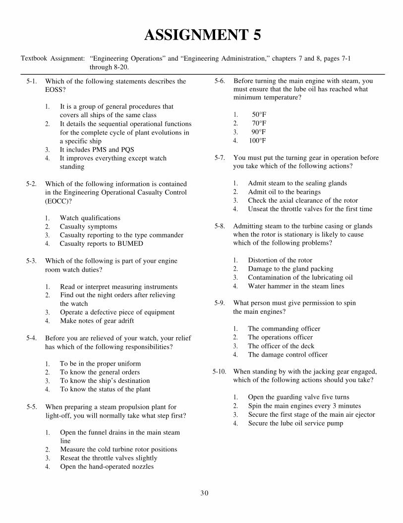
ASSIGNMENT 5Textbook Assignment: “Engineering Operations” and “Engineering Administration,” chapters 7 and 8, pages 7-1
through 8-20.
5-1. Which of the following statements describes theEOSS?
1. It is a group of general procedures thatcovers all ships of the same class
2. It details the sequential operational functionsfor the complete cycle of plant evolutions ina specific ship
3. It includes PMS and PQS4. It improves everything except watch
standing
5-2. Which of the following information is containedin the Engineering Operational Casualty Control(EOCC)?
1. Watch qualifications2. Casualty symptoms3. Casualty reporting to the type commander4. Casualty reports to BUMED
5-3. Which of the following is part of your engineroom watch duties?
1. Read or interpret measuring instruments2. Find out the night orders after relieving
the watch3. Operate a defective piece of equipment4. Make notes of gear adrift
5-4. Before you are relieved of your watch, your reliefhas which of the following responsibilities?
1. To be in the proper uniform2. To know the general orders3. To know the ship’s destination4. To know the status of the plant
5-5. When preparing a steam propulsion plant forlight-off, you will normally take what step first?
1. Open the funnel drains in the main steamline
2. Measure the cold turbine rotor positions3. Reseat the throttle valves slightly4. Open the hand-operated nozzles
5-6. Before turning the main engine with steam, youmust ensure that the lube oil has reached whatminimum temperature?
1. 50°F2. 70°F3. 90°F4. 100°F
5-7. You must put the turning gear in operation beforeyou take which of the following actions?
1. Admit steam to the sealing glands2. Admit oil to the bearings3. Check the axial clearance of the rotor4. Unseat the throttle valves for the first time
5-8. Admitting steam to the turbine casing or glandswhen the rotor is stationary is likely to causewhich of the following problems?
1. Distortion of the rotor2. Damage to the gland packing3. Contamination of the lubricating oil4. Water hammer in the steam lines
5-9. What person must give permission to spinthe main engines?
1. The commanding officer2. The operations officer3. The officer of the deck4. The damage control officer
5-10. When standing by with the jacking gear engaged,which of the following actions should you take?
1. Open the guarding valve five turns2. Spin the main engines every 3 minutes3. Secure the first stage of the main air ejector4. Secure the lube oil service pump
30

5-11. When a turbine is in operation, 1/2 to 2 psi ofsteam pressure is maintained on the glands forwhat reason?
1. To eliminate the need for a vacuum2. To keep air from leaking into the turbine3. To increase the pressure and/or vacuum
within the turbine4. To prevent steam leakage at the astern
throttle
5-12. When a ship is under way, the temperature of thelube oil cooler should be maintained within whatrange?
1. 90°F to 100°F2. 100°F to 110°F3. 110°F to 120°F4. 120°F to 130°F
5-13. If the rotor’s axial movement is allowed to exceedthe safe limits, damage will occur to which of thefollowing parts?
1. The stationary blades2. The main thrust bearing3. The quill shaft4. The convergent nozzles
5-14. Which of the following conditions indicatesthat water is entering a lube-oil system?
1. An increase in oil pressure2. A decrease in oil temperature3. A rise in the oil sump level4. A drop in the oil sump level
5-15. Large quantities of cold water in the deaeratingfeed tank may cause which of the followingcasualties?
1. A temporary loss of a main engine2. A gain of pressure in the tank3. A loss of main feed pressure4. A sudden demand for feedwater
for the boilers
5-16. After the plant is secured, the main circulatingpump is normally left running until which ofthe following conditions has been met?
1. The turbine bearing temperatureis near ambient
2. The exhaust trunk temperatureis near ambient
3. The rotor position indicator returnsto normal
4. It is no longer needed to condenseturbine steam
5-17. If vacuum is broken on the main engine bysecuring the gland seal, which of the followingparts may be damaged?
1. The condenser tubes2. The turbine bearings3. The relief valve4. The turbine glands
5-18. What is the best form of casualty control?
1. Casualty prevention2. Effective organization3. Minimizing the casualty4. Restoring the casualty
5-19. Which of the following sources is best forstudying casualty control?
1. The training manual2. The Watch, Quarter, and Station Bill3. The EOCC4. The NSTM
5-20. What is one of the major problems in dealingwith casualty control?
1. Communications2. Combating the casualty3. Cross-connecting the plant4. Changing equipment
31

5-21. Under normal steaming conditions, you will stopand lock the shaft immediately for which of thefollowing conditions?
1. A loss of vacuum2. A hot bearing3. An uncontrollable hot bearing4. A turbine vibration
5-22. You can reduce the chance of an engine room fireby taking which of the following precautions?
1. Keep flange shielding properly installed2. Replace oil-soaked lagging3. Keep the bilge oil free4. All of the above
5-23. Which of the following types of checks shouldyou perform before the boiler is lit off?
1. Boiler water high and low alarm checks2. Steam drum pressure gauge checks3. Hot plant checks4. Cold plant prelight-off checks
5-24. Cold plant checks are conducted according to theEOP and should include which of the followingitems?
1. Safety walkthroughs2. Safety valve hand-easing gear3. Remote-operating gear for valves4. Each of the above
5-25. What device should you use to verify that theboiler deck is clear of unburned fuel beforeinserting a torch?
1. A BOD2. A BID3. A DIB4. A BED
5-26. To accomplish a boiler purge, you are required tomake what total number of volumetric air changesof the boiler furnace, uptake, and smoke pipe?
5-27. After completion of a purge, you must purgethe boiler again if fires are not lit off withinwhat specified number of minutes?
1. 52. 23. 34. 4
5-28. What total number of persons are requiredduring a burner light off?
1. One2. Two3. Three4. Four
5-29. During initial burner light off, the torch manshould wear which of the following equipment?
1. Fire-retardant engineering coveralls2. Eye shields3. Gloves4. All of the above
5-30. You have shut the burner fuel oil supply manifoldvalve and safety shutoff device because theignition failed to occur within 3 seconds afterburner light off. What step, if any, should youtake next?
1. Make sure the fuel-oil recirculating valveis closed
2. Determine the reason for the unsuccessfulignition and correct it
3. Increase the fuel-oil manifold pressure4. None; you do not have to take corrective
action until the burner fails to ignite threetimes
5-31. Unless authorized, the boiler firing rate shouldnot exceed what percentage of full power untilthe boiler is on line?
1. 1%2. 5%3. 3%4. 10%
1. Six2. Five3. Three4. Four
32

QUESTIONS 5-32 THROUGH 5-34 REFER TOPLACING A BOILER ON LINE.
5-32. What action should you perform when the steamdrum pressure reaches 50 psi?
1. Open the main and auxiliary steam stop2. Blow down the gauge glass3. Shift the superheater from the low-pressure
drain to the high-pressure drain4. Bring the boiler on line
5-33. When the drum pressure reaches 200 psi, whataction should you take?
1. Blow down the gauge glass2. Shift the main and auxiliary drains to HP3. Open the main bypass4. Open the auxiliary bypass
5-34. The steam drum pressure is between 200 and400 psi. What action should you take next?
1. Blow down the gauge glass2. Bring the boiler on line3. Open the main bypass4. Open the auxiliary bypass
5-35. If a boiler casualty has occurred, you may berequired to perform which of the following tasks?
1. Cross-connect the plant2. Split the plant3. Drain the steam lines4. Each of the above
5-36. Properly maintained operating logs can providewhich of the following information?
1. Information on a piece of equipmentthat is not operating properly
2. The ship’s schedule3. Your PQS requirements4. The requirements for general quarters
5-37. If an operating log has one of the readings out oflimits, which of the following actions should youtake?
1. Circle the reading in red2. Call the commanding officer3. Mark through the reading4. Circle the reading in black
5-38. What records in the engineering departmentare considered to be legal records?
1. The evaporator and ac logs2. The main engine and boiler logs3. The air compressor and generator logs4. The Engineering Log and Engineer’s
Bell Book
5-39. The Engineering Log and the Engineer’s BellBook should be retained on board a ship for whatminimum number of years?
1. 12. 23. 34. 4
5-40. A ship has been placed on inactive status. Whatis done with the Engineering Log and Engineer’sBell Book sheets that are less than 3 years old?
1. They are destroyed2. They are retained on board the ship3. They are sent to the Naval Records
Management Center4. They are sent to the Naval Sea Data
Support Activity
5-41. Which of the following information is enteredin the Engineering Log?
1. The ship’s horsepower2. The miles steamed during each watch3. The amount of fuel on board before
getting underway4. The equipment out of commission
in the engineering department
33

5-42. Injuries to engineering department personnelshould be recorded in which of the followinglogs?
1. The fireroom operating log2. The Engineering Log3. The Engineer’s Bell Book4. The rough log
5-43. Entries in the Engineering Log should be madeaccording to instructions contained in what NSTMchapter?
1. 2202. 2213. 0904. 041
5-44. Which of the following officers approves andsigns the Engineering Log on the last day ofeach month?
1. The commanding officer2. The executive officer3. The engineer officer4. The engineer duty officer
5-45. Orders received by the throttleman for movementof the ship’s propellers are recorded in which ofthe following logs?
1. The Engineering Log2. The Engineer’s Bell Book3. The Engine Room Operating Log4. The Fireroom Operating Log
5-46. The time that an order was received is recordedin what column of the Engineer’s Bell Book?
1. 12. 23. 34. 4
5-47. The EOOW signs the Engineer’s Bell Bookbefore going off watch. What person signsthe Engineer’s Bell Book in machineryspaces where an EOOW is not stationed?
1. The commanding officer2. The executive officer3. The engineer officer4. The watch supervisor
5-48. If there is an incorrect entry in the Engineer’s BellBook, what action is taken to correct it?
1. A single line is drawn through the incorrectentry and the correct entry is recorded on thefollowing line
2. Two lines are drawn through the incorrectentry and the correct entry is recordedabove the incorrect entry
3. The incorrect entry is erased and thecorrect entry is recorded on the same line
4. The correct entry is written on top ofthe incorrect entry
5-49. Which of the following information is containedin the steaming orders?
1. The time to light off the condensate pump2. The time to light off boilers3. The name of the commanding officer4. The name of the lower-level watch
5-50. The engineer’s night order book is filled outaccording to whose instructions?
1. The CNO2. The TYCOM3. The commanding officer4. The operations officer
5-51. A piece of equipment is put out of commission.What action should be taken before repair of theequipment can begin?
1. Isolate and tag out the piece of equipment2. Notify the commanding officer3. Submit OPNAV Form 4790/204. Request permission from the OOD
to begin work
34

5-52. Equipment tagged with a CAUTION tagmay be operated as long as there is no dangerto personnel.
1. True2. False
5-53. Equipment tagged with a DANGER tag maybe operated as long as there is no danger topersonnel.
1. True2. False
5-54. What person specifies the number of tag-outlogs needed and their location?
1. The CNO2. The individual force commander3. The commanding officer4. The engineer officer
5-55. Before starting the tag-out procedure, theauthorizing officer must get permissionfrom what person?
1. The type commander2. The commanding officer3. The chief in charge of the space4. The supervisor of the space
5-56. When repairs have been completed on a piece ofequipment that was tagged with a DANGER tag,which of the following actions must be takenbefore it can be tested?
1. The work request must be completed2. The tag must be properly cleared and
removed3. Clear the piece of equipment from
the out-of-commission log4. Warm up the system
5-57. What two systems basically make up the3-M Systems?
2. The EOSS and propulsion operating systems3. The PQS and the PMSsystems4. The EOSS and the PMS
1. The Planned Maintenance System (PMS)and the Maintenance Data System
5-58. What does PMS dictate?
1. The maximum required maintenanceto keep a piece of equipment in a fullyoperational condition within specifications
2. The minimum required maintenance tokeep a piece of equipment in a fullyoperational condition within specifications
3. The Q-1 can only be performed once aquarter
4. The amount of time required to completea repair
5-59. PMS is what type of maintenance?
1. Corrective2. Preventive3. Calculated4. Instructional
5-60. Ship’s force personnel may make which of thefollowing changes to the MRC without submittinga feedback report?
1. The man-hours required to do the job2. The rate required to do the job3. The safety precautions related to the job4. The tools required to do the job
5-61. In order for PMS to produce good results, whichof the following actions must be taken?
1. Continuous direction at each echelonmust be maintained
2. The machinery must be corrected when timepermits
3. All personnel must make the requiredchanges to the quarterly board
4. All casualties must be corrected immediately
5-62. What OPNAV form is used to request PMSsoftware?
1. 4790/2K2. 4790/2Q3. 4790/7B
35

5-63. Where does OPNAV Form 4790/2K originate?
1. The captain’s office2. The engineer’s office3. The work center4. The 3-M coordinator’s office
5-64. What is the purpose of the current ship’smaintenance project (CSMP)?
1. To provide a consolidated list of deferredcorrective maintenance
2. To provide a list for preparing the ship bills3. To serve as a management tool for PMS4. To serve as a management tool for PQS
5-65. The QA Program organization (Navy) beginswith which of the following officers?
1. Type commanders2. Commander in chief of the fleet3. Commanding officers4. QA officer
5-66. Which of the following officers provideinstruction, policy, and overall directionfor the implementation and operation ofthe force QA Program?
1. Commander in chief of the fleets2. Commanding officers3. Type commanders4. Both 2 and 3 above
5-67. The QA officer is responsible to which ofthe following officers for the organization,administration, and execution of the ship’sQA Program?
1. Type commander2. Commander in chief of the fleets3. Commanding officer4. Each of the above
5-68. Which of the following is a responsibilityof the QA officer?
1. Coordinating the ship’s QA training program2. Maintaining ship’s records and for test and
inspection reports3. Conducting QA audits as required4. Each of the above
5-69. Which of the following persons is/are assignedas the ship’s quality control inspectors (SQCIs)?
1. The division officer2. The engineer officer3. The work center supervisor and two others4. The 3-M coordinator
5-70. Level A assurance provides which of thefollowing levels of assurance?
1. The most stringent restrictive verification2. The least verification3. Limited verification4. Minimum verification
5-71. Level B assurance provides which of thefollowing levels of assurance?
1. Minimum verification2. Most restrictive verification3. No verification4. Adequate verification
5-72. Level C assurance provides for which of thefollowing levels of assurance?
1. Minimum verification2. Limited verification3. No verification4. Most stringent verification
5-73. Which of the following devices are included inthe MEASURE program?
1. HP cutout switches2. Motor controllers3. Gauges4. Bearings
36

5-74. Which of the following actions is/are reported by 5-75. In the MEASURE program, what is the purpose
a meter card? of the Format 802?
1. Bearing readings 1. To report out-of-commission gauges
2. Gauge calibration 2. To record gauge calibrations
3. Pump test 3. To recall gauges for calibration
4. Trials 4. To report gauge serial number changes
37

ASSIGNMENT 6Textbook Assignment: “Engineering Administration” and “Steam Operated Distilling Plants,” chapters 8 and 9,
pages 8-20 through 9-25.
6-1. Heat stress can be controlled somewhat by 6-6. What information should be recorded on lube-oiltaking which of the following actions? sample bottles?
1. Running exhaust vents on low2. Repairing steam and hot water leaks3. Closing all exterior hatches4. Soaking the lagging with cold water
6-2. Hearing protection must be worn where thenoise level is above what minimum numberof decibels?
1. Equipment, oil type, date, and time2. Equipment, oil type, date, and test results3. Oil type, test results, date, and time
and lube-oil4. Time, equipment. date,temperature
lly inspecting a6-7. What is the purpose of visualube-oil sample?
1. 55 dB2. 64 dB3. 78 dB4. 84 dB
6-3. Lube-oil management procedures are outlinedin what NSTM chapter?
1. To determine the presence of carbon2. To determine the percentage of free water3. To determine the presence of free water
and solid particulate matter4. To determine the presence of salt water
6-8. The transparency test is conducted only onauxiliary machinery oil samples that havefailed what criteria?
1. 2622. 5053. 5414. 543
6-4. Samples of lube oil should be representativeof the oil to be tested. The most representativesamples are obtained from what source?
1. Clean and water-free2. Water-free and bright3. Clear and bright4. Bright and smooth
6-9. Which of the following procedures must beconducted on all lube-oil samples that fail thetransparency test run on auxiliary machines?
1. The outlet side of the lube-oil cooler2. The lube-oil purifier3. An operating system4. An idle system
1. BS&W test2. Hot oil bath3. Dilution test4. API gravity test
6-5. You have just taken an oil sample. To preventcontamination, what action should you promptlytake with all the containers?
6-10. If lube oil is contaminated with salt water,you should take what action?
1. Cap or close them 1. Renovate it2. Empty them into other containers 2. Transfer it to a settling tank3. Place them in a dust-free space 3. Dispose of it4. Heat them 4. Pump it overboard
38

6-11. Which of the following statements describes theterm viscosity?
1. The highest temperature at which a fluidwill flow
2. The lowest temperature at which a fluidwill flow
3. The velocity at which a fluid will flow4. The measure of resistance to flow
6-12. What is the most accurate method you canuse to measure viscosity?
1. Observe the color of the liquid2. Observe the slow flow of liquid through
capillary tubes3. Conduct an API gravity test4. Conduct a BS&W test
6-13. A fuel will not form a flammable vapor-airmixture by evaporation if its temperature isbelow which of the following points?
1. Burn point2. Conduction point3. Flash point4. Thermal energy point
6-14. What is the minimum flash point required forF-76 and JP-5 fuel?
1. 70°C2. 60°C3. 50°C4. 40°C
6-15. The gravity of a petroleum oil is an index of theweight of a given volume of the material at whattemperature?
1. 60°F2. 55°F3. 50°F4. 40°F
6-16. What scales are used with petroleum products?
1. PHEL curves and specific gravity2. API gravity and PHEL curves3. SAE and API gravity4. API gravity and specific gravity
6-17. Although water is slightly soluble in fuels, onlywater in mechanical suspension in the fuel is ofpractical interest to the engineer. This suspendedwater is referred to by which of the followingterms?
1. Excess water2. Insoluble water3. Contaminated water4. Free water
6-18. When a ship is receiving fuel, what personis responsible for ensuring that the stabilityof the ship isn’t impaired?
1. The gas free engineer2. The oil king3. The senior damage controlman4. The senior burnerman
6-19. If a sound rod is being used when oil is beingreceived, the fuel oil tanks should be soundedevery 3 or 4 minutes. After the tank is nearlythree-fourths full, the soundings should be madeat what specified interval?
1. Every minute2. Every 2 minutes3. Every 30 seconds4. Continuously
6-20. Fuel oil tanks should be filled to what maximumlevel?
1. 65%2. 75%3. 85%4. 95%
6-21. Where is the Fuel Oil Management Log prepared?
1. NETPDTC2. NAVSUPSYSCOM3. NAVPERS4. Locally
6-22. The Fuel Oil Management Log should containwhich of the following information?
1. A sequential listing of sample analyses2. An operational procedure check-off list3. Tank inspections and findings4. All of the above
39

6-23. Fuel in ship stowage and service tanks must betested according to the requirements in whatNSTM chapter?
1. 2202. 2213. 5034 . 541
6-24. A steam-operated distilling plant producesdistilled water from seawater by which of thefollowing means?
1. By boiling the seawater and condensingthe vapors
2. By boiling the fresh water and condensingthe vapors
3. By filtering the seawater4. By filtering the fresh water
6-25. Which of the following contaminants is NOTcontained in fresh water produced by Navydistilling plants?
1. Vegetable and animal growths2. Bacteria3. Both 1 and 2 above4. Slight traces of chemical salts
6-26. Distilling plants can separate volatile gasesfrom distillate.
1. True2. False
6-27. If there is salt water in the distillate fromcarryover, which of the following is theprobable cause?
1. Faulty salinity cells2. Leaks in the tube nests3. Leaks in the basket4. Improper plant operation
6-28. Carryover is undesirable for which of thefollowing reasons?
1. The chemical salts will cause corrosionof the boiler tubes
2. Coliform bacteria may be present3. The distillate is not sterilized4. All of the above
6-29.
6-30.
6-31.
6-32.
6-33.
Navy distillate plants are operated at low pressureand low boiling temperatures for which of thefollowing reasons?
1. To prevent carryover2. To increase efficiency3. To sterilize the distillate4. To keep down the size of the unit
Which of the following terms defines the first halfof the distillation process?
1. Condensation2. Evaporation3. Feed4. Distillate
Which of the following terms best describes theproduct of the separation of seawater into vapor?
1. Distillation2. Evaporation3. Feed4. Distillate
Which of the following terms best describes themeasure of the concentration of chemical salts?
1. Brine2. Salinity3. Effect4. Evaporator feed
Which of the following terms describes anywater in which the salt content is higher thanit is in seawater?
1. Brine2. Salinity3. Effect4. Evaporator feed
6-34. A stage in the distilling process where distillationactually occurs is known as
1. brine2. salinity3. effect4. evaporator feed
40

6-35. Low-pressure distilling plants are termed lowpressure for what reason?
1. They use low pressure only2. They operate below atmospheric pressure3. They use low-pressure steam, and their
operating shell pressure is less thanatmospheric pressure
4. There is low pressure on the feed
QUESTIONS 6-36 THROUGH 6-45 REFER TOSUBMERGED TUBE DISTILLING PLANTS.
6-36. What substance is contained in the evaporator?
1. Feed2. Low-pressure steam3. Brine4. Distillate
6-37. In the soloshell evaporator, what device(s)control(s) the amount of steam admitted tothe tubes?
1. Relief valves2. A reducing valve3. A drain regulator4. An orifice
6-38. You can increase the output capacity by usingwhich of the following means?
1. Install a bigger vapor condenser2. Install a bigger vapor-feed heater3. Increase the size of the weight-loaded
reducer4. Increase the size of the orifice plate
6-39. Before passing into the first-effect tube nest,low-pressure steam is subjected to what process?
1. Heating by steam from the 150-psi system2. Superheating by a spray of water3. Desuperheating by a spray of water4. Volume reducing by increased steam
pressure
6-40. Before entering the second-effect evaporator,vapor from the first-effect separator passes intowhat component(s)?
1. The first-effect drain regulator2. The vapor feed heater3. The boiler feed system4. The freshwater tanks
6-41. What change takes place in the first-effect vaporthat reaches the tube nests of the second-effectevaporator?
1. It gains latent heat of vaporization fromthe second-effect feed
2. It gains latent heat of vaporization froma second-effect steam supply
3. It loses its latent heat of vaporization tothe second-effect feed
4. It loses its latent heat of vaporization toa second-effect steam supply
6-42. Vapor produced in the shell of the second effectpasses through which of the followingequipment?
1. Baffles2. Demisters3. Flash towers4. Distillate tray
6-43. The first-effect vapor boils and vaporizes theseawater feed in the second-effect shell throughwhich of the following actions?
1. Higher pressure in the first-effect shellthan in the second-effect shell
2. Lower pressure in the first-effect shellthan in the second-effect shell
3. Superheating vapor and distillate onentering the second-effect shell
4. Desuperheating vapor and distillateon entering the second-effect shell
4 1

6-44. After entering the first-effect shell, some ofthe feedwater is evaporated. The rest of thefeedwater (brine) is forced into the second-effectshell by which of the following means?
1. Gravity2. The condenser circulating pump3. The pressure difference between
the first effect and second effect4. A tube nest drain pump
6-45. Vacuum in the shell of the second effect ismaintained by what means?
1. The air ejector2. The condensation of steam in the vapor feed3. The cooling effect of carbon dioxide4. The steam condensed by the evaporator feed
QUESTIONS 6-46 THROUGH 6-54 REFER TOFLASH-TYPE DISTILLING PLANTS.
6-46. The flash distilling plant has which of thefollowing advantages over the submerged-tubedistilling plant?
1. It can run with a lower vacuum; therefore,scale formation is reduced
2. It has no submerged heat transfer surfaces;therefore, scale formation is reduced
3. It requires less space4. No operator is required
6-47. Feedwater for the distilling plant is preheatedbefore it reaches the feedwater heater by passingthrough what component?
1. The distillate cooler2. The first-effect tube nest3. The first-stage distilling condenser4. The second-effect tube nest
6-48. As feedwater passes through the evaporatorfeedwater heater, final heating occurs by whichof the following means?
1. An electric heater2. Auxiliary exhaust steam3. High-pressure steam4. Brine overflow
6-49. Heated feedwater enters the first-stage shellthrough the spray pipes in which of the followingcomponents?
1. The stage distilling condenser2. The stage vapor separators3. The bottom of the first-stage shell4. The second-stage internal feed box
6-50. The moisture removed by the demisters of thefirst stage drains to what part of the unit?
1. The distillate of the first stage2. The feed section of the first stage3. The feed section of the second stage4. The hotwell
6-51. In a two-stage flash evaporator, the two three-waysolenoid trip valves are located at the
1. loop seal and the distillate pump2. loop seal and the air ejector drain3. distillate pump outlet and the air ejector
drain4. seawater heater drain and loop seal
6-52. If the maximum allowable salinity (usually0.65 epm) of the distillate is exceeded, a salinitycell automatically trips the solenoid valve,dumping the contaminated water to the bilge.What is the location of the salinity cell?
1. In the inlet to the distillate pump2. In the outlet from the distillate pump3. In the inlet to the first-stage drain regulator4. In the outlet to the feedwater heater drain
pump
6-53. What is the maximum design feedwatertemperature?
1. 75°F2. 85°F3. 165°F4. 175°F
42

6-54. What means can be used to increase the capacityof a flash-type evaporator?
1. Increasing the volume of the feed tothe first stage
2. Increasing the heat of the seawaterby the feedwater heater
3. Decreasing the vacuum in the first stage4. Decreasing the heat of the feedwater
QUESTIONS 6-55 THROUGH 6-59 REFER TOVERTICAL BASKET DISTILLING PLANTS.
6-55. Vertical basket distilling plants have whatapproximate capacity?
1. 4,000 gpd2. 6,000 gpd3. 8,000 gpd4. 10,000 gpd
A. BASKET
B. DISTILLER CONDENSER
C. DISTILLATE OUTLET
D. DISTILLATE TROUGH
E. MAIN CONDENSER
F. MIST ELIMINATOR
G. PERFORATED PLATE
Figure 6A
IN ANSWERING QUESTIONS 6-56 THROUGH 6-58,REFER TO FIGURE 6A AND SELECT THECOMPONENT THAT IS DESCRIBED BY THEQUESTION.
6-56. The condensed steam in the bottom of thebasket flows into this component.
1. C2. D3. E4. F
6-57. This device acts as the first stage of moistureseparation.
1. G2. F3. E4. D
6-58. This device changes the vapor to distillate.
1. A2. B3. C4. D
6-59. The steam condensed in the air ejector condenserdrains into which of the following locations?
1. The main condenser or the LP drain tank2. The LP drain tank or the condensate system3. The condensate system or the feed system4. The brine tank or the bilge
6-60. The evaporator distillate should be monitored bya salinity indicator at what minimum interval?
1. Hourly2. Daily3. Weekly4. Continuously
6-61. What characteristic of water is actually measuredby a salinity cell?
1. Density2. Purity3. Conductivity4. Brine
6-62. If a distilling plant is operated with a high brinedensity, which of the following problems willoccur?
1. Loss of vacuum in the unit2. Excessive scale formation in the unit3. Excessive brine pump discharge pressure4. Excessive heat loss
43
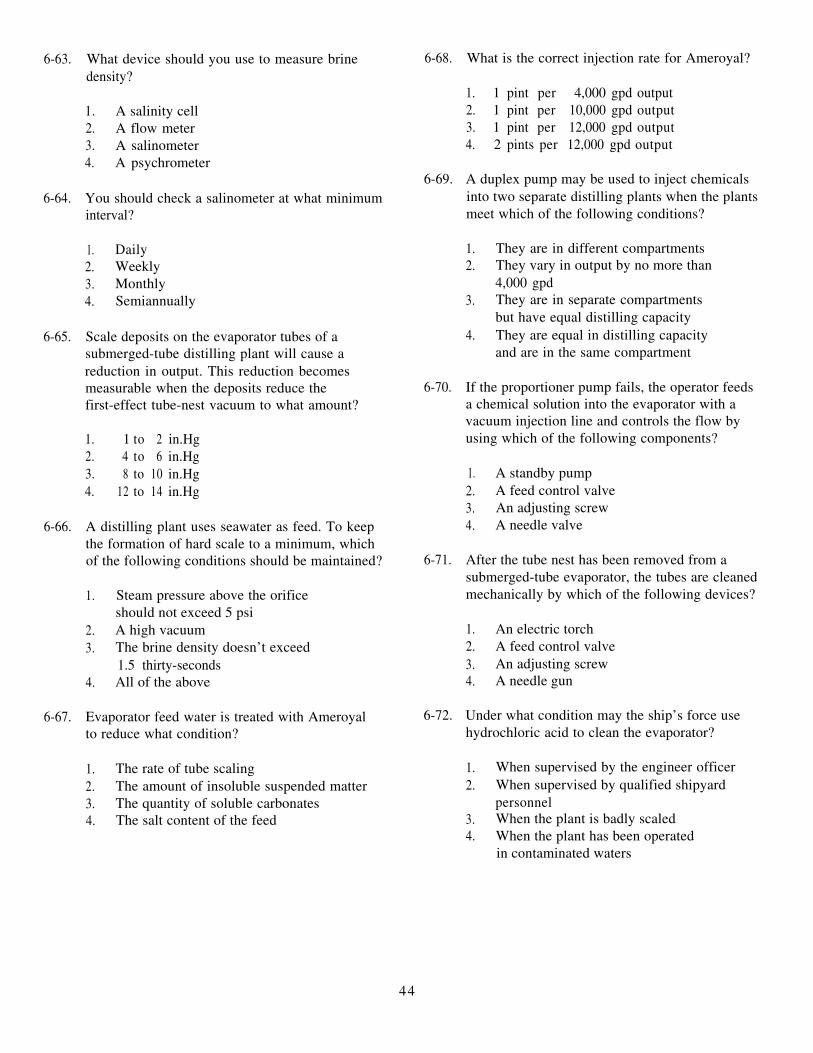
6-63. What device should you use to measure brinedensity?
1. A salinity cell2. A flow meter3. A salinometer4. A psychrometer
6-64. You should check a salinometer at what minimuminterval?
1. Daily2. Weekly3. Monthly4. Semiannually
6-65. Scale deposits on the evaporator tubes of asubmerged-tube distilling plant will cause areduction in output. This reduction becomesmeasurable when the deposits reduce thefirst-effect tube-nest vacuum to what amount?
1. 1 to 2 in.Hg2. 4 to 6 in.Hg3. 8 to 10 in.Hg4. 12 to 14 in.Hg
6-66. A distilling plant uses seawater as feed. To keepthe formation of hard scale to a minimum, whichof the following conditions should be maintained?
1. Steam pressure above the orificeshould not exceed 5 psi
2. A high vacuum3. The brine density doesn’t exceed
1.5 thirty-seconds4. All of the above
6-67. Evaporator feed water is treated with Ameroyalto reduce what condition?
1. The rate of tube scaling2. The amount of insoluble suspended matter3. The quantity of soluble carbonates4. The salt content of the feed
6-68. What is the correct injection rate for Ameroyal?
1. 1 pint per 4,000 gpd output2. 1 pint per 10,000 gpd output3. 1 pint per 12,000 gpd output4. 2 pints per 12,000 gpd output
6-69. A duplex pump may be used to inject chemicalsinto two separate distilling plants when the plantsmeet which of the following conditions?
1. They are in different compartments2. They vary in output by no more than
4,000 gpd3. They are in separate compartments
but have equal distilling capacity4. They are equal in distilling capacity
and are in the same compartment
6-70. If the proportioner pump fails, the operator feedsa chemical solution into the evaporator with avacuum injection line and controls the flow byusing which of the following components?
1. A standby pump2. A feed control valve3. An adjusting screw4. A needle valve
6-71. After the tube nest has been removed from asubmerged-tube evaporator, the tubes are cleanedmechanically by which of the following devices?
1. An electric torch2. A feed control valve3. An adjusting screw4. A needle gun
6-72. Under what condition may the ship’s force usehydrochloric acid to clean the evaporator?
1. When supervised by the engineer officer2. When supervised by qualified shipyard
personnel3. When the plant is badly scaled4. When the plant has been operated
in contaminated waters
44
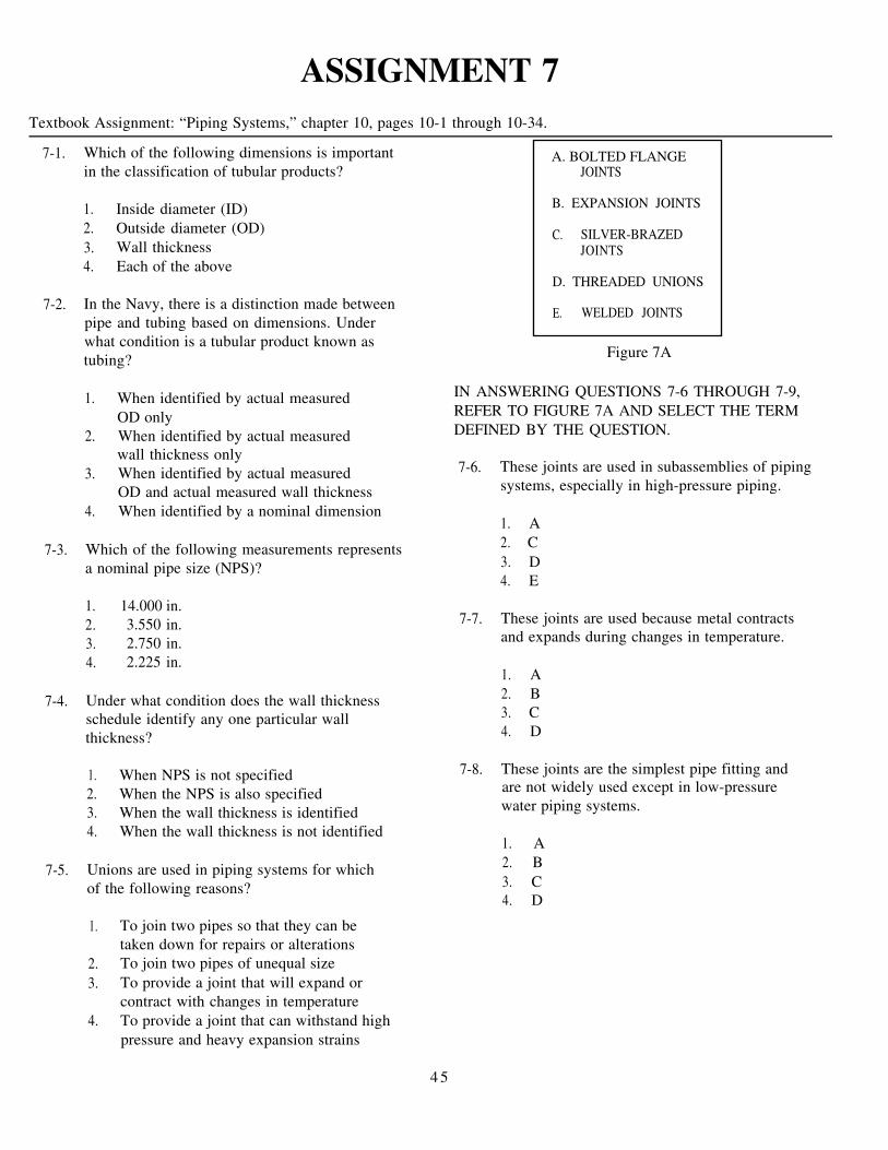
ASSIGNMENT 7Textbook Assignment: “Piping Systems,” chapter 10, pages 10-1 through 10-34.
7-1. Which of the following dimensions is importantin the classification of tubular products?
A. BOLTED FLANGEJOINTS
1. Inside diameter (ID)2. Outside diameter (OD)3. Wall thickness4. Each of the above
7-2. In the Navy, there is a distinction made betweenpipe and tubing based on dimensions. Underwhat condition is a tubular product known astubing?
1. When identified by actual measuredOD only
2. When identified by actual measuredwall thickness only
3. When identified by actual measuredOD and actual measured wall thickness
4. When identified by a nominal dimension
7-3. Which of the following measurements representsa nominal pipe size (NPS)?
1. 14.000 in.2. 3.550 in.3. 2.750 in.4. 2.225 in.
7-4. Under what condition does the wall thicknessschedule identify any one particular wallthickness?
1. When NPS is not specified2. When the NPS is also specified3. When the wall thickness is identified4. When the wall thickness is not identified
7-5. Unions are used in piping systems for whichof the following reasons?
1. To join two pipes so that they can betaken down for repairs or alterations
2. To join two pipes of unequal size3. To provide a joint that will expand or
contract with changes in temperature4. To provide a joint that can withstand high
pressure and heavy expansion strains
B. EXPANSION JOINTS
C. SILVER-BRAZEDJOINTS
D. THREADED UNIONS
E. WELDED JOINTS
Figure 7A
IN ANSWERING QUESTIONS 7-6 THROUGH 7-9,REFER TO FIGURE 7A AND SELECT THE TERMDEFINED BY THE QUESTION.
7-6. These joints are used in subassemblies of pipingsystems, especially in high-pressure piping.
1. A2. C3. D4. E
7-7. These joints are used because metal contractsand expands during changes in temperature.
1. A2. B3. C4. D
7-8. These joints are the simplest pipe fitting andare not widely used except in low-pressurewater piping systems.
1. A2. B3. C4. D
4 5

7-9. One type of this type of joint is used extensivelywhere piping is subject to high pressures andheavy expansion strains.
1. A2. B3. D4. E
7-10. The expansion-contraction movement in thecorrugated joints or bellows joints is absorbedby what means?
1. Installed expansion plates2. The foundation bolts3. The changing curvature of the
corrugations or bellows4. The foundation sliding feet
7-11. Expansion bends are used in which of thefollowing types of steam piping?
1. High-pressure, high-temperature2. High-pressure, low-temperature3. Low-pressure, high-temperature4. Low-pressure, low-temperature
7-12. What is the purpose of flange safety shields?
1. To reduce the possibility of a leak ata lube-oil pipe connection only
2. To reduce the possibility of a leak ata fuel-oil pipe connection only
3. To reduce the possibility of engineroom fires casued by a leak at a fuel-oilor lube-oil pipe-flange connection
4. To reduce the possibility of a fire at thelube-oil connection
7-13. Valves used in high-pressure systems and suitablefor temperatures above 550°F are made fromwhat metal?
1. Steel2. Cast iron3. Copper4. Brass
7-14. Normally, valves used in systems that carrysalt water are made from what metal?
1. Steel2. Copper3. Bronze4. Brass
A. GLOBE VALVE
B. GATE VALVE
C. BUTTERFLY VALVE
D. BALL VALVE
Figure 7B
IN ANSWERING QUESTIONS 7-15 THROUGH 7-18,REFER TO FIGURE 7B AND SELECT THE VALVEDEFINED BY THE QUESTION.
7-15. The common types of this valve include thestraight-flow, angle-flow, and cross-flow.
1. A2. B3. C4. D
7-16. These valves can be used in fresh water, seawater, JP-5 fuel, diesel fuel, and marine lubeoil, and chill water systems aboard ship.
1. A2. B3. C4. D
7-17. These valves are used when a straight line flowof fluid and minimum flow restriction are needed.
1. A2. B3. C4. D
46

7-19. Gate valves are suitable as throttling valvesbecause they close in small increments.
1. True2. False
7-20. Gate valves are classified as either rising stemor nonrising stem. Which of the following isa description of a nonrising-stem gate valve?
1. The gate is connected to the stem andmoves with it
2. The gate is free floating3. The gate travels up or down the stem
on threads while the stem remainsvertically stationary
7-21. Which of the following is a description ofa butterfly valve?
1. This valve is recomended for throttling use2. This valve is light-weight, relatively small,
and relatively quick acting3. This valve is heavy and has a slow reactance
time4. This valve is recommended for use in steam
systems
7-22. The use of what type of gear to operate a ballvalve allows the use of a relatively small hand-wheel and operating force to operate a fairly largevalve?
1. Helical gear2. Planetary gear3. Worm gear4. Herringbone gear
7-23. What type of spring-loaded valve is installed insome systems to warn of dangerous pressures?
1. Sentinel valves2. Spring-loaded reducing valves3. Pressure-reducing valves4. Air-operated valves
7-18. DELETED 7-24. Reducing valves used in reduced pressures linesaboard ship are designed for what purpose?
1. To prevent damage to the lines dueto excessive pressure
2. To keep the operating pressure equalto the supply pressure
3. To vary the operating pressure accordingto the demand
4. To provide a steady pressure lower thanthe supply pressure
A. AIR-PILOT OPERATEDDIAPHRAGM REDUCINGVALVE
B. PNEUMATIC-PRESSURE-CONTROL REDUCINGVALVE
C. SPRING-LOADEDREDUCING VALVE
Figure 7C
IN ANSWERING QUESTIONS 7-25 THROUGH 7-27,REFER TO FIGURE 7C AND SELECT THE TYPE OFVALVE DESCRIBED IN THE QUESTION.
7-25. In this valve, the main valve is opened by theoperating piston and closed by the main valvespring.
1. A2. B3. C
7-26. Applications include low-pressure air reducers,distilling plant seawater reducers, and somereduced-steam system reducers.
1. A2. B3. C
7-27. One type of this valve is used to regulate low-temperature fluids, such as air, water, or oil.
1. A2. B3. C
4 7
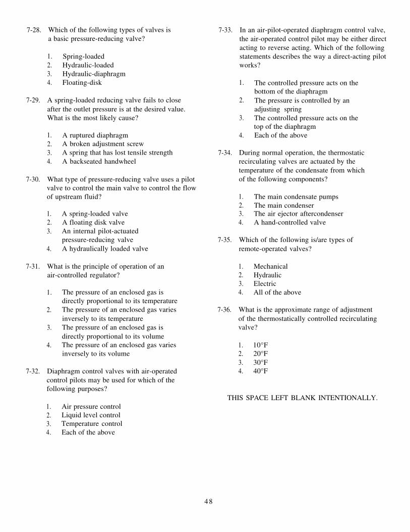
7-28. Which of the following types of valves isa basic pressure-reducing valve?
1. Spring-loaded2. Hydraulic-loaded3. Hydraulic-diaphragm4. Floating-disk
7-29. A spring-loaded reducing valve fails to closeafter the outlet pressure is at the desired value.What is the most likely cause?
1. A ruptured diaphragm2. A broken adjustment screw3. A spring that has lost tensile strength4. A backseated handwheel
7-30. What type of pressure-reducing valve uses a pilotvalve to control the main valve to control the flowof upstream fluid?
1. A spring-loaded valve2. A floating disk valve3. An internal pilot-actuated
pressure-reducing valve4. A hydraulically loaded valve
7-31. What is the principle of operation of anair-controlled regulator?
1. The pressure of an enclosed gas isdirectly proportional to its temperature
2. The pressure of an enclosed gas variesinversely to its temperature
3. The pressure of an enclosed gas isdirectly proportional to its volume
4. The pressure of an enclosed gas variesinversely to its volume
7-32. Diaphragm control valves with air-operatedcontrol pilots may be used for which of thefollowing purposes?
7-33. In an air-pilot-operated diaphragm control valve,the air-operated control pilot may be either directacting to reverse acting. Which of the followingstatements describes the way a direct-acting pilotworks?
1. The controlled pressure acts on thebottom of the diaphragm
2. The pressure is controlled by anadjusting spring
3. The controlled pressure acts on thetop of the diaphragm
4. Each of the above
7-34. During normal operation, the thermostaticrecirculating valves are actuated by thetemperature of the condensate from whichof the following components?
1. The main condensate pumps2. The main condenser3. The air ejector aftercondenser4. A hand-controlled valve
7-35. Which of the following is/are types ofremote-operated valves?
1. Mechanical2. Hydraulic3. Electric4. All of the above
7-36. What is the approximate range of adjustmentof the thermostatically controlled recirculatingvalve?
1. 10°F2. 20°F3. 30°F4. 40°F
THIS SPACE LEFT BLANK INTENTIONALLY.1. Air pressure control2. Liquid level control3. Temperature control4. Each of the above
48

A. IMPULSE
B. BIMETALLIC
C. ORIFICE-TYPE
D. THERMOSTATIC
Figure 7D
IN ANSWERING QUESTIONS 7-37 THROUGH 7-40,REFER TO FIGURE 7D.
7-37. What type of steam trap is best described asoperating on the principle that hot water underpressure flashes into steam when the pressure isreduced?
1. A2. B3. C4. D
7-38. What type of steam trap is made of material thatreacts to close the trap when steam is present andto open the trap when condensate is present?
1. A2. B3. C4. D
7-39. What type of trap has no moving parts and issuitable only for service in which the condensateformation is continuous?
1. A2. B3. C4. D
7-40. What type of steam trap depends on the expansionof a sealed bellows for its operation?
1. A2. B3. C4. D
7-41. When installing a valve, you should be sureyou know which of the following information?
1. The material the valve shaft is made from2. The length of the stem3. The size of the valve disk4. The function the valve is to perform
7-42. What method should you use to visuallydetermine whether a valve seat and disk aremaking good contact?
1. Die tapping2. Spotting-in3. Prussian bluing4. Machine marking
7-43. As part of the process when grinding in a valve,you apply grinding compound to the valve disk.At what interval should you apply the NEBUcompound?
1. At 1-minute intervals2. At 2-minute intervals3. At 3-minute intervals4. At 4-minute intervals
7-44. What is the difference between the processsof grinding in and lapping in valve seats?
1. Grinding in requires special tools2. Lapping in requires special tools3. Grinding in is done on a lathe4. Lapping in is done on a lathe
7-45. Which of the following machines should you useto reface all valve disks and hard-surfaced valveseats?
1. A power grinder2. A reseating machine3. A lapping-in tool4. A lathe
7-46. What digits of the packing gland identificationsymbol will help you make the proper selectionwith respect to the type of joint and type ofpacking material, respectively?
1. First and second digits only2. First and third digits only3. Second and third digits only4. Second, third, and fourth digits
4 9
7-47. Carbon ribbon packing (CRP) is highly resilient,flexible, may be wrapped around valves stems ofany size, and will not shrink at any temperature.
1. True2. False
7-48. When repacking a valve, you can ignore a scoredor damaged shaft because CRP will fill grooves inthe shaft.
1. True2. False
7-49. Which of the following gaskets is being usedby the Navy in high-temperature, high-pressureinstallations?
1. Corrugated copper2. Teflon®3. Spiral-bound metallic-asbestos4. Plastic nonmetallic asbestos
7-50. Lagging for piping insulation serves whatpurpose?
1. It resists the flow of heat2. It secures the insulation material to the pipe3. It repels water4. It protects and confines the heat-resistant
material
7-51. Sheet metal pipe covering is kept unpainted forwhat reason?
1. To increase heat radiation2. To decrease heat radiation3. To reduce the danger of fire4. To avoid condensation
7-52. Aboard ship, lagging of the fire main pipingsystem serves what purpose?
1. It keeps the heat in2. It keeps the heat out3. It prevents moisture of condensation
on the outside of the pipes4. It protects the pipes against accidental
damage
50

ASSIGNMENT 8Textbook Assignment: “Refrigeration,” chapter 11, pages 11-1 through 11-29.
8-1. Refrigeration functions on which of the followingprinciples?
1. Heat flows in its natural direction fromwarmer material to colder material
2. Heat is removed from spaces, objects,and material
3. Both 1 and 2 above4. Heat is converted into work
8-2. A refrigeration unit cools water in what way?
1. It reduces the pressure of the water2. It adds coolness to the water3. It increases the pressure of the water4. It removes heat from the water
8-3. What standard unit is used to measure theamount of heat energy in a substance?
1. A refrigeration ton2. A British thermal unit (Btu)3. Total heat4. Sensible heat
8-4. What is the latent heat of fusion of a poundof ice?
1. 288 Btu2. 144 Btu3. 72 Btu4. 36 Btu
8-5. To change 1 ton of water at 32°F to ice,approximately what amount of heat mustbe removed?
1. 288,000 Btu2. 12,000 Btu3. 72 Btu4. 36 Btu
8-6. Water will boil under which of the followingconditions?
1. At 80°F under a vacuum of 29 in.Hg2. At 100°F at a pressure of 14.7 psig3. At 350°F at a pressure of 600 psig4. At 50°F under a vacuum of 10 in.Hg
8-7. A vapor can be superheated only under whichof the following conditions?
1. When allowed to decrease in volume2. When held at a constant pressure3. When remaining in contact with the
boiling liquid4. When separating from the liquid from
which it was generated.
8-8. When the temperature of a gas is increased, inwhat way will its (a) volume and (b) pressurereact?
1. ( a ) Increase (b) decrease2. (a) Decrease (b) increase3. (a ) Decrease (b) decrease4. ( a ) Increase (b) increase
8-9. When the volume of a gas is held constant,an increase in the temperature of the gas causeswhat reaction in the (a) pressure; and, a decreasein temperature causes the pressure to react in(b) what way?
1. (a) Decrease (b) increase2. (a) Increase (b) decrease3. (a) Decrease (b) decrease4. (a) Increase (b) increase
8-10. Which of the following refrigeration systemsis generally used for shipboard refrigeration?
1. Vapor compression cycle with centrifugalcompressors
2. Vapor compression cycle with reciprocatingcompressors
3. Steam-jet with reciprocating compressors4. Steam-jet with centrifugal compressors
51

IN ANSWERING QUESTIONS 8-11 THROUGH 8-13REFER TO FIGURE 11-1 OF THE TEXTBOOK.
8-11. Refrigeration flows through parts of the systemin which of the following sequences?
1. Receiver, evaporator, expansion valve,condenser, compressor, receiver
2. Receiver, expansion valve, evaporator,compressor, condenser, receiver
3. Receiver, condenser, compressor,evaporator, expansion valve, receiver
4. Receiver, expansion valve, compressor,condenser, evaporator, receiver
8-12. Heat is absorbed by the R-12 refrigerant in whatcomponent?
1. Thermostatic expansion valve (TXV)2. Receiver3. Condenser4. Evaporator
8-13. The low-pressure side of the refrigeration systemis located between what components?
1. The TXV up to and including the intakeside of the compressor cylinders
2. The suction side of the compressor andthe receiver
3. The suction side of the compressor andthe condenser
4. The discharge valve of the compressorto the TXV
8-14. What change occurs in the physical state ofthe R-12 as it passes through the evaporator?
1. It changes from a superheated vaporto a boiling liquid
2. It changes from a boiling liquid to asuperheated vapor
3. It changes from a cool liquid to a hot vapor4. It changes from a hot vapor to a cool liquid
8-15. What component pumps heat, absorbed by therefrigerant, from the evaporator to the condenser?
1. Receiver2. Condenser3. Suction side of the compressor4. Evaporator
8-16. What is the primary function of a compressor?
1. To raise the temperature of liquid R-12 tothe point where it will boil and vaporizecompletely before entering the condenser
2. To raise the pressure of liquid R-12 to thepoint where its temperature at this pressureis high enough to cause it to boil andvaporize completely before entering thecondenser
3. To raise the pressure of vaporized R-12to the point where its temperature at thispressure is high enough above thetemperature to use seawater as a coolingmedium
4. To raise the pressure of vaporized R-12to the point where its superheat amountsto 10°F
8-17. What change takes place in the R-12 as it passesthrough the condenser?
1. It condenses and gives up its latent heatof condensation only
2. It condenses and gives up its superheat only3. It condenses and gives up its superheat and
its latent heat of condensation4. It gives up its sensible heat, then it
condenses and gives off its latent heat
8-18. What type of lubrication is used on high-speedcompressors?
1. Gravity feed lubrication2. Splash lubrication3. Self-lubrication4. Pressure lubrication
IN ANSWERING QUESTION 8-19, REFER TOFIGURE 11-8 IN THE TEXTBOOK.
8-19. The surfaces between the removable shaft sealshoulder and the crankcase are sealed by whatmeans?
1. The shaft seal clamping nut2. The neoprene gasket3. The lapped surface4. The mitralloy collar
52

8-20. Of the forces listed below, which one is usedto load compressors?
1. Refrigerant pressure2. Oil pressure3. Refrigerant suction4. Water pressure
8-21. The compressor has reached full speed. At whatpoint does the capacity control system start tounload the compressor?
1. When the shaft seal bursts2. When the system is overcharged3. When the pulldown period begins4. When the pulldown period is complete
8-22. Which of the following components governsthe capacity control system?
1. The capacity control valve2. The unloader power element3. The hydraulic relay4. The suction pressure
A. SPRING-LOADED RELIEF VALVE
B. WATER REGULATING VALVE
C. LOW-PRESSURE CUTOUT SWITCH
D. EVAPORATOR PRESSURE REGULATING VALVE
E. HIGH-PRESSURE CUTOUT SWITCH
F. WATER FAILURE SWITCH
G. OIL FAILURE SWITCH
Figure 8A
IN ANSWERING QUESTIONS 8-23 THROUGH 8-28,REFER TO FIGURE 8A AND SELECT THE DEVICEDESCRIBED BY THE QUESTION.
8-23. The water in a water cooler will freezeif the pressure setting is too low.
1. B2. D3. E4. F
8-24. Under normal conditions, this device controlsthe operation of the compressor.
1. C2. D3. E4. G
8-25. Provided you correctly set this device,the compressor will stop when the pressurereaches the cutout point and start when thepressure drops to the reset point.
1. B2. C3. D4. E
8-26. The function of this device depends on thefailure of the high-pressure cutout switch.
1. A2. B3. D4. G
8-27. This device maintains the proper rate of coolingwater flow through the condenser.
1. A2. B3. D4. F
8-28. If device F fails to function, this device willperform its intended function.
1. A2. B3. C4. E
8-29. The solenoid valve and the thermostaticexpansion valves are protected from foreignmatter by what means?
1. A TXV2. A liquid strainer3. A dehydrator4. A thermometer
53

8-30. Although intervals between plant inspectionsvary, you should check the refrigeration system’stemperature and pressure at what minimuminterval?
1. Each hour2. Every 2 hours3. Once a watch4. Daily
8-31. A refrigeration compressor may be leftunattended in the manual mode of operation.
1. True2. False
8-32. An R-12 refrigeration plant is supplied withcooling water from either a centrifugal pump orfrom a fire and flushing main. When, if ever, isthe pump controller switch of this plant openedmanually?
1. When the cooling water is from thecentrifugal pump only
2. When cooling water is from the fire andflushing main only
3. When cooling water is from the centrifugalpump or the fire and flushing main
4. Never
8-33. Refrigeration systems that are equipped withwater-regulating valves should be maintainedat what condensing pressure?
1. 50 to 60 psi2. 100 to 110 psi3. 125 psi4. 175 psi
8-34. If an R-12 compressor is idle, it should beoperated at what minimum interval?
8-35. Two compressors serving the same coolingsystem should not be operated at the same timefor which of the following reasons?
1. Because oil may be transferred from onecompressor to another and cause seriousdamage
2. Because of the compressor dischargedifferential pressure
3. Because of the compressor motor electricalinterlock
4. All of the above
8-36. An MM3 or MM2 is responsible for which of thefollowing maintenance jobs on R-12 systems?
1. Pumping down refrigeration systems2. Testing for refrigerant leaks3. Adjusting refrigeration systems controls4. All of the above
8-37. During hot gas defrosting, the hot gas entersthe refrigeration system through which of thefollowing components?
1. The compressor discharge valve2. The compressor suction valve3. The liquid line4. The tail coil
8-38. What action must be taken before repairs aremade to the receiver of a refrigeration system?
1. The entire system must be drained intospare refrigerant drums
2. The receiver must be pumped down toreturn all refrigerant to the condenser
3. All valves in the lines leading to thereceiver must be opened
4. Line valves must be closed and therefrigerant in the receiver must bereleased to the atmosphere
1. Monthly2. Every 2 weeks3. Weekly4. Daily
54

8-39. You are pumping down a system to make minorrepairs on lines between the receiver and coolingcoils. Which of the following precautions shouldyou observe before making repairs?
1. Blow out all R-12 gas from the isolatedsection that has been opened
2. Allow the lines to return to normaltemperature after pumping them downand before opening them
3. Pump the lines down to a pressure slightlyabove atmospheric pressure before openingthem
4. Cap removed sections of lines to preventloss of refrigerant
8-40. When a refrigerant system is opened, the freeends of the refrigerant lines should be temporarilyplugged to prevent the entrance of air and dirt.
1. True2. False
8-41. After a line in the refrigerant system has beenopened, it must be purged with gas from acylinder.
1. True2. False
8-42. When you must pump down an entirerefrigeration system for major repairs, whatvalve is used to interrupt the flow of R-12 tobegin the purging operations?
1. The suction line stop valve2. The discharge line stop valve3. The main liquid-line shut-off valve4. The cooling coil solenoid valve
8-43. You are draining the refrigerant charge from arefrigeration system. What action should youtake after the compressor has been stopped bythe low-pressure control switch?
1. Close the compressor discharge line valve2. Close all liquid valves at the cooling coil3. Connect an empty R-12 service drum to
the refrigerant drain valve4. Restart the compressor manually and
continue pumping down until suctionpressure reaches approximately 2 psig
8-44. Before connecting an R-12 service drum to therefrigerant drain valve, you should take whichof the following steps?
1. Cool the drum to expedite draining2. Weigh the drum to determine its capacity3. Adjust the temperature of the drum to that
of the refrigerant4. Vent the drum to the atmosphere
8-45. Which of the following conditions may indicateloss of refrigerant from a refrigeration system?
1. Short cycling2. Frosting of the compressor suction line3. Excessive lubrication oil pressure4. Relatively low crankcase temperature
8-46. When using the soap test to search for leaks, youshould wait for what minimum period of time forbubbles to form from a small leak?
1. 1 minute2. 15 seconds3. 30 seconds4. 45 seconds
8-47. A mixture of air and R-12 containing 20 percentor more refrigerant has an odor resembling whatgas?
1. Chloride2. Ammonia3. Carbon tetrachloride4. Methane
8-48. Oil was added to a force-lubricated compressor,which has been inoperative for several weeks.What procedure should you use to check theactual oil level?
1. Observe the oil level in the sight glass beforestarting the compressor
2. Operate the compressor on manual controlfor 1 hour or more and observe the oil levelin the sight glass immediately after stoppingthe compressor
3. Stop the compressor and check the oil levelwith the crankshaft and connecting rod endsimmersed in the lubricating oil
4. Stop the compressor and check the oil levelwith the crankshaft and connecting rod endsout of the lubricating oil
55

8-49. Which of the following means should you useto remove oil from a compressor that doesn’tcontain a drain valve?
1. Stop the compressor and close the suctionand discharge line valves
2. Reduce crankcase pressure to about 1 psiby slowly closing the suction line stop valve
3. Loosen the drain plug just enough for oilto seep out
4. All of the above
8-50. A refrigeration system has steel connections.You should check the compressor crankcase oilfor contamination at what minimum interval?
1. Once a year2. Once each 6-month period3. Once each 3-month period4. Once each week
8-51. A compressor V-belt is tightened correctly whenyou can use one finger to depress the belt midwaybetween the flywheel and motor pulleys whatdistance?
1. 1/8 inch2. 3/8 inch3. 1/2 to 3/4 inch4. 7/8 to 1 inch
8-52. When one belt in a multiple-V-belt drive isstretched excessively, what means shouldyou use to correct the problem?
1. Replace the defective belt2. Replace all the belts3. Tighten the defective belt4. Treat the defective belt with belt dressing
8-53. What adjustment in the high-pressure switch willraise the cutout point without affecting the cut-inpoint?
1. Turn the range adjusting screw clockwise2. Turn the range adjusting screw
counterclockwise3. Turn the differential adjusting screw
counterclockwise4. Turn the differential adjusting screw
clockwise
8-54. You are adjusting the high-pressure switchof a refrigeration plant. You have raised thecompressor discharge to 10 psig above thedesired cut-in pressure. What action shouldyou take immediately?
1. Turn the range screw counterclockwiseuntil the contactor opens
2. Turn the range screw clockwise until thecontacts close
3. Turn the differential screw counterclockwiseall the way
4. Turn the differential screw clockwise all the
way
8-55. When setting the high-pressure switch ofa refrigeration plant, you should turn thedifferential switch in what sequence?
1. Counterclockwise, then clockwise only2. Clockwise, then counterclockwise only3. Counterclockwise, clockwise, and
counterclockwise4. Clockwise, counterclockwise, and clockwise
8-56. You want to set the low-pressure switch of arefrigeration plant so that it will cut out at 50 psig.With the compressor operation you should (a) setwhat suction pressure and (b) turn the differentialscrew to what position?
1. (a) 30 psig(b) clockwise until the switch contacts close
2. (a) 40 psig(b) counterclockwise until the switch
contacts open3. (a) 40 psig
(b) clockwise, then counterclockwise4. (a) 30 psig
(b) clockwise until the switch contacts open
8-57. What is the most likely result of an expansionvalve adjusted for a too low degree of superheat?
1. A coil operating at reduced capacity2. A damaged expansion valve3. A damaged compressor4. An excessive amount of refrigerant in the
coil
56

8-58. Pressure changes that are brought about by achange in the temperature in the refrigeratorcompartment cause a reaction in which of thefollowing control/safety devices?
1. The thermostatic switch2. The water failure switch3. The thermal expansion valve4. The automatic reducing valve
8-59. The refrigeration plant is not operatingsatisfactorily. Normally, what step shouldyou take first when checking the system?
1. Test the discharge valves2. Test the suction valves3. Short cycle the compressor4. Shift the compressors
8-60. You are testing for a leaking discharge valve.What procedure should you conduct (a) firstand (b) last?
1. (a) Pump the compressor down to 2 psig(b) check the discharge pressure drop rate
2. (a) Stop the compressor(b) close the suction valves
3. (a) Pump the compressor down to 2 psig(b) close the suction valves
4. (a) Stop the compressor(b) check the discharge pressure drop rate
8-61. You have pumped a vacuum to approximately20 in.Hg, and the compressor stops. The vacuumcan’t be maintained for which of the followingreasons?
1. The discharge valve leaks2. The suction valve leaks3. The shaft seals leak releasing R-12
to the atmosphere4. The R-12 being released from the crank-
case oil causes the pressure to rise
8-62. You have replaced a shaft seal on a compressor.What action should you take to check for leaks?
1. Pump down the compressor and look for oil2. Run the compressor and look for oil3. Open the suction and discharge valves and
check with an electronic leak detector4. Fill the crankcase and look for oil
8-63. In excessive concentrations, gaseous R-12 causeswhich of the following health hazards?
1. It poisons on contact any food that containsmilk or eggs
2. It irritates the eyes unless it is diluted withat least an equal amount of air
3. It explodes when it comes in direct contactwith a high-temperature open flame
4. It will not support respiration
8-64. An R-12 cylinder should be filled to whatmaximum percentage of capacity?
1. 90%2. 85%3. 80%4. 75%
8-65. Which of the following safety gear must beworn when you work with R-12?
1. Apron and gloves2. Goggles3. Mouthpiece4. Safety shoes
8-66. When R-12 touches your skin, you shouldadminister what first-aid treatment?
1. Rub or massage the affected area2. Immerse the affected part in a warm bath3. Apply nonirritating oil to the affected area4. Bathe the affected area with strong soap
and water
57

ASSIGNMENT 9Textbook Assignment: “Air Conditioning” and “Compressed Air Systems,” chapters 12 and 13, pages 12-1 through 13-24.
9-1. Which of the following is a function of airconditioning?
1. It prevents deterioration of ammunition instorage spaces
2. It maintains temperatures at specified levelsin electrical and electronic equipment spaces
3. It prevents excessive pressure buildup incontainers in gas storage spaces
4. All of the above
9-2. Which of the following is a definition of the term
9-3
9-4.
9-5.
dew point of air?
1. The temperature at which the specifichumidity is 100 grains per pound of dry air
2. The temperature at which the air is saturatedwith moisture
3. The temperature at which any increase intemperature will cause moisture to vaporize
4. The temperature at which dew vaporizes intothe air
The relative humidity of air is the ratio betweenthe actual amount of water vapor in a sample ofair and
1. the weight of the sample2. the volume of the sample3. the amount of water vapor the sample
would hold if it were saturated4. the dew point of the sample
The deciding factor in human comfort is therelative humidity.
1. True2. False
It is possible to feel more comfortable at 90°Fthan at 70°F
9-6. What is your body’s continuous source of heat?
1. Surroundings that radiate heat2. Currents of heated air3. Physiological processes within the body4. Objects your body comes into contact with
9-7. What is the best overall range of relative humidityfor human comfort and health?
1. 15% to 50%2. 30% to 40%3. 40% to 60%4. 30% to 70%
9-8. In the duct systems of Navy ships, axial-flowfans are used instead of centrifugal fans for whatreason?
1. They require less installation space2. They blow more air3. They are less complicated4. They tend to decrease humidity
9-9. Onboard Navy ships, which of the followingfans are used primarily to exhaust explosiveor hot gases?
1. Tube-axial2. Centrifugal3. Valve-axial4. Bracket
9-10. Vane-axial ventilating fans are operated with theair ducts open for which of the following reasons?
1. Less electrical current will be used2. A larger volume of air can be moved3. The motor will not overheat4. The air distribution can be limited
2. False1. True
58

9-11. Excess water accumulated in heavy seas isautomatically sealed out of waterproof ventilatorsby what means?
1. Sump valves2. Drain tubes3. The weight of the water in the bucket4. Scupper valves draining onto the deck
9-12. In chilled water circulating systems, the type ofprimary refrigerant depends on the size and typeof the compressor.
1. True2. False
9-13. Where is the heat removed from the secondaryrefrigerant of a vapor compression unit?
1. In the water chiller2. In the condenser3. In the refrigerant receivers4. In the float chambers
9-14. In a centrifugal refrigeration plant, what valvereleases the refrigerant to the chiller?
1. Compressor2. Suction3. Float4. Differential compression
9-15. The lithium bromide unit operates on theabsorption cycle. What is used as the primaryrefrigerant?
1. R-112. R-123. R-1144. Water
9-16. When there is a 29.9-inch vacuum in thecontainer of a lithium bromide absorption unit,what is the lowest temperature at which waterwill boil?
9-17. In a lithium bromide absorption unit, theregeneration heat exchanger performs whatfunction on the lithium bromide?
1. It cools both the weak and the strongsolutions
2. It cools the weak and heats the strongsolutions
3. It preheats the weak and cools the strongsolutions
4. It preheats both the weak and the strongsolutions
9-18. Which of the following is the purpose of thecollection tray on the spot cooler?
1. To collect water from the vent cock2. To collect condensation from the air
around the cooling coils3. To allow condensate to evaporate4. To collect impurities from condensation
9-19. Dirt should be kept out of a ventilation systemfor which of the following reasons?
1. It restricts airflow2. It creates a fire hazard3. Both 1 and 2 above4. It damages the filters
9-20. Which of the following maintenance actions isproper for air-conditioning equipment?
1. Periodically oil flame arresters and greasefilters
2. Wash, steam, and then rinse dirty air filters3. After washing, oil the filters with filter oil4. Both 2 and 3 above
9-21. Aboard Navy ships, compressed air is usedfor which of the following purposes?
1. Starting diesel engines2. Charging and firing torpedoes3. Operating pneumatic tools4. All of the above
1. 212°F2. 100°F3. 35°F4. 10°F
59

9-22. A reciprocating air compressor is generallyselected for which of the following capacityrequirements?
1. 8,800 cfm and 20 psi2. 5,000 cfm and 100 psi3. 2,100 cfm and 125 psi4. 800 cfm and 5,000 psi
9-23. What is the usual source of power for operatingair compressors aboard ship?
1. Steam turbines only2. Electrical motors only3. Steam turbines and electric motors4. Internal combustion engines
9-24. What device is generally used to connect thesource of power to an air compressor when thespeed of the driving unit and compressor is thesame?
1. A flexible coupling2. A rigid coupling3. A V-belt4. A reduction gear
9-25. Which of the following is the classificationof a medium-pressure air compressor?
1. Two-stage, vertical, duplex single-actingwith a discharge pressure of 151 psi to1,000 psi
2. Two-stage, vertical V-type with a dischargepressure of 150 psi or less
3. Three-stage, vertical, single-acting with adischarge pressure of 1,500 psi or higher
4. Three-stage, vertical, double-acting with adischarge pressure of 1,500 psi to 10,000 psi
9-26. What cylinder arrangement is used in two-stage,W-type air compressors?
1. One cylinder per stage2. Two cylinders per stage3. Two cylinders for the first stage and
one cylinder for the second stage4. One cylinder for the first stage and
two cylinders for the second stage
9-27. A piston makes what total number of strokesduring each operating cycle of a single-actingair compressor?
1. One2. Two3. Three4. Four
9-28. Which of the following parts is NOT included inthe compressing elements of an air compressor?
1. Cylinder2. Piston3. Unloader4. Air valve
9-29. The operation of the automatic valves of anair compressor is initiated by what means?
1. A lack of air pressure2. An air pressure differential3. A high air pressure4. A camming action
9-30. What device is used to lubricate the high-pressureair compressor cylinders?
1. A cylinder splash lubricator2. A compressor oil pump3. A sight-glass oil-flow indicator4. An adjustable mechanical force-fed
lubricator
9-31. Which of the following means is/are usedto cool most high- and medium-pressure aircompressors?
1. Oil2. Fresh water or sea water3. Air4. Distilled water
9-32. The cylinders and heads of some shipboard aircompressors are made from bronze alloy for whatreason?
1. To provide cooling2. To minimize friction3. To reduce wear4. To minimize corrosion
60
9-33. What is the function of the intercoolers of an aircompressor?
1. To remove heat generated duringcompression and to condense existing vapor
2. To remove heat from the incoming waterand to condense existing vapor
3. To cool air before compression4. To cool the air after the final stage of
compression
9-34. The quantity of water that passes through the oilcooler can’t be regulated without changing thequantity that passes through the intercoolers.
1. True2. False
9-35. What is the purpose of using baffles in tube-typewater-cooled intercoolers?
1. To remove oil contaminants from the air2. To deflect air or water passing through the
cooler3. To prevent the tube nest from expanding4. To prevent the tube nest from contracting
9-36. The control system for an electrically drivenreciprocating air compressor will automaticallystop the compressor when the pressure in thereceiver causes what action?
1. The governor valve to open2. The governor valve to close3. The pressure switch to open4. The pressure switch to close
9-37. The automatic temperature shutdown device of ahigh-pressure reciprocating air compressor stopsthe compressor under which of the followingconditions?
1. When the accumulator temperature risesa predetermined amount
2. When the accumulator temperature dropsa predetermined amount
3. When the cooling water temperature risesabove a preset limit
4. When the cooling water temperature dropsbelow a preset limit
9-38. In rotary-type centrifugal compressors, air iscompressed by which of the following forces?
1. Water2. Centrifugal force3. An impeller4. A piston
9-39. Which of the following is the purpose ofthe air receiver in an air compressor?
1. To cool the air2. To minimize pressure variations3. To remove foreign matter4. To filter moisture and oil from the air
9-40. Which of the following systems is suppliedby nonvital air?
1. Automatic boiler control2. Water level control3. Air pilot-operated control valves4. Laundry equipment
9-41. What type of compressor supplies air to theprairie-masker system?
1. A turbocompressor2. A multistage compressor3. An angle compressor4. A vertical compressor
9-42. When very high-pressure air is throttled to lowpressure at a high flow rate, the throttling valvefreezes. Which of the following is the reasonfor the valves freezing?
1. Charles’ effect2. Venturi effect3. Herbst effect4. Boyle’s effect
9-43. What is the cooling medium for the oil-freecompressor?
1. Seawater2. Air3. Fresh water4. Oil
61

9-44. What device controls the movement of theA-end of an electrohydraulic speed gear?
1. A throttle2. A tilt box3. A piston4. A hydraulic ram
9-45. The A-end hydraulic pump and B-end hydraulicmotor combination provides rotary motion. Whatchange is made in the hydraulic system to providereciprocating motion?
1. The angle of tilt of the socket ring isreversed
2. The tilt box is placed in a neutral position3. The A-end is replaced by a piston or a ram4. The B-end is replaced by a piston or a ram
IN ANSWERING QUESTION 9-46, REFER TOFIGURE 14-2 IN THE TEXTBOOK.
9-46. When the ram is moving, oil is forced intoone ram cylinder and out of the other cylinderto what destination?
1. The operating tank2. The output side of the main pump3. The suction side of the auxiliary pump4. The suction side of the main hydraulic pump
9-47. Which of the following devices maintainshydraulic pressure in the ram-typeelectrohydrualic steering gear?
1. Centrifugal pumps2. A rudder yoke3. A variable-stroke pump4. A hydraulic ram
9-48. If the remote steering system fails, what deviceis used for local hydraulic control of the steeringgear?
1. A hand pump2. An auxiliary pump3. A trick wheel4. A differential control box
9-49. If electrical power is lost to the hydraulic pumpmotor, what device can be used to control thesteering gear?
1. A hand pump2. An auxiliary pump3. A trick wheel4. A differential control box
9-50. Some electrohydraulic anchor windlasses havetwo motors. One motor drives each of the pumps,which normally drives one wildcat. However,each pump can drive either wildcat with the useof what device?
1. A locking head2. A three-way plug, cock-type valve3. A multiple-spur gearing4. A special coupling
9-51. A windlass has been idle for several months.Before operating this windlass, which of thefollowing maintenance actions should youperform?
1. Replace the friction shoes2. Adjust the brake3. Remove, clean, and lubricate
the locking head only4. Lubricate the equipment
9-52. What type of winch is normally usedto hoist aircraft aboard the ship?
1. Steam2. Electric3. Electrohydraulic4. Land
9-53. The horizontally mounted drum of anelectrohydraulic winch is connected tothe shaft by what device?
1. A chin drive2. A key3. A ratchet lock4. A clutch
62

9-54. Electric capstans are usually reversible. Thosepowered by dc motors usually have what totalnumber of speeds in either direction of rotation?
1. One to three2. Two to four3. Three to five4. Four to six
9-55. The boom of a crane is controlled by whatmeans?
1. A king post2. Blocks3. A rotating gear4. Sheaves
9-56. Fouling of the hoisting ropes is preventedby what means?
1. Fair-lead sheaves2. Blocks3. A king post4. A grooved drum
9-57. The delicate control often required to handleloads with a crane is usually provided by whatmeans?
1. An electric motor for rotating the crane2. Reduction gearing in the crane rotating
mechanism3. Hydraulic variable-speed gears for driving
the hoisting whips and topping lifts4. Electric motors for driving the hoisting
whips and topping lifts
9-58. On a crane, what device is provided to holdthe load when electric power fails?
1. An A-end hydraulic pump2. A hydraulic torque motor3. A hand brake4. An electric brake
9-59. What device finds and retains the neutral positionof the A-end hydraulic pump on a crane?
1. A B-end hydraulic motor2. A centering device3. An electric torque motor4. A slack, take-up device
9-60. When a crane is used to raise light loads, thecable has a tendency to develop slack whenhoisting is started. What means is used toprevent slack?
1. An electric torque motor2. A hydraulic torque motor3. A high-hook paying-out device4. A pressure stroke control device
9-61. CV class aircraft carriers are equipped withairplane elevators that have what maximumlifting capacity?
1. 135,000 lb2. 125,000 lb3. 115,000 lb4. 105,000 lb
9-62. In the closed hydraulic system of anelectrohydraulic power plant, nitrogen isused with oil instead of air for which ofthe following reasons?
1. To increase the efficiency of the oil2. To prevent a possible explosive mixture3. To ensure a constant pressure within the
system4. To eliminate contamination of the oil
usually caused by air
9-63. An electrohydraulic elevator is raised byhigh-pressure oil acting directly againstwhat component?
1. A hydraulic engine valve piston2. A high-pressure tank baffle plate3. A ram4. A platform
9-64. On modem deck-edge elevators, what built-insafety feature limits the damage caused by thepossible breaking of all hoisting cables on oneside of the elevator?
1. An electrical stopping device, which willblock the platform
2. Serrated safety shoes, which will wedgethe platform between the guide rails
3. Pressure-actuated switches, which willdisconnect the electrical power source
4. A high-pressure tank, which will cushionthe platform as it is lowered
63

9-65. Power conveyors are configured either verticallyor horizontally.
1. True2. False
9-66. Conveyors are used to handle which of thefollowing supplies?
1. Dry provisions2. Chilled and frozen food3. Both 1 and 2 above4. Ammunition
9-67. While loading a vertical conveyor, what isthe position of the load-unload device?
1. At a 30° incline2. Vertical3. Horizontal4. At a 45° incline
9-68. What is the purpose of the interlock switch ona vertical conveyor?
1.
2.3.
4.
To prevent upward operation of the conveyorwhen the load-unload device is in the loadpositionTo ensure that the trunk door won’t openTo prevent downward operation of theconveyor when the load-unload device isin the load positionTo allow the truck door to be opened whilethe conveyor is in operation
9-69. Which of the following safety precautions mustyou take to ensure accident-free operation ofhorizontal conveyors?
1. Establish positive communicationsbetween all operating control stationsusing sound-powered telephones orintercom systems
2. Use the two-man rule at all times whileoperating the conveyor
3. Do not use the conveyor trunk as a voicetube
4. All of the above
9-70. The final rinse in a double-tank dishwasheris activated by what means?
1. A manual control2. A thermostat control3. The movement of dish racks4. A can on the conveyor belt
9-71. In the double-tank dishwashing machine, the finalrinse is controlled by an adjustable automaticsteam-mixing valve that maintains which of thefollowing temperature ranges?
1. 170°F to 175°F2. 180°F to 185°F only3. 180°F to 190°F4. 190°F to 195°F
9-72. The rinse tank of a double-tank dishwashingmachine contains a thermostatically operatedswitch that prevents machine operation if therinse water drops below what temperature?
1. 180°F2. 190°F3. 200°F4. 210°F
64

ASSIGNMENT 10Textbook Assignment: “Propulsion Boilers,” chapter 15, pages 15-1 through 15-13.
10-1. For information about boilers, you shouldrefer to which of the following references?
1. NSTM, chapter 2212. NSTM, chapter 5933. NAVEDTRA 120774. NAVEDTRA 12097
10-2. To what publication should you refer to findyour ship’s boiler full-power capacity?
1. NSTM, chapter 2212. Manufacturer’s technical manual3. Boiler repair manual4. PMS card
10-3. Boiler overload is specified in the design of theboiler. Depending on its installation, boileroverload capacity is given as either the firingrate or the
1. operating pressure2. steaming rate3. design pressure4. design rate of full power
10-4. The boiler overload capacity is usually whatpercentage of boiler full-power capacity?
1. 150%2. 140%3. 130%4. 120%
10-5. What term describes the actual pressure inthe boiler steam drum at any given time?
1. Operating pressure2. Steam drum pressure3. Superheater outlet pressure4. Superheater inlet pressure
10-6. The constant pressure at which a boileris being operated is known as the
1. actual pressure2. operating pressure3. outlet pressure4. inlet pressure
10-7. Which of the following statements definesthe design pressure of a boiler?
1. The design pressure is the sameas the operating pressure
2. The design pressure is the normalfull-power capacity
3. The design pressure is lower thanthe operating pressure
4. The design pressure is specified bythe boiler manufacturer as a criteriafor boiler design
10-8. The amount of Btu per pound of fuel absorbedby the water and steam divided by the Btu perpound of fuel is known as
1. the operating temperature2. the design temperature3. the design pressure4. boiler efficiency
10-9. If you were to state the efficiency of a boiler,you would use which of the followingexpressions?
1. 90%2. 90:13. 90 is equal to 14. 0.90
10-10. Which of the following terms defines thestatement: “The time during which the boilerhas fires lighted for raising steam and the timeduring which it is generating steam”?
1. Operating period2. Steaming hours3. Cruising time4. Generating time
65

10-11. The total heating surface equals the sumof the generating, superheater. and economizersurfaces, You measure the total heating surfaceof a steam-generating unit on the side that isexposed to the
1. steam being heated2. water3. gases of combustion4. firebox
10-12. At the maximum steam drum pressure point,what boiler safety valve lifts?
1. The first2. The second3. The third4. The fourth
10-13. Minimum steam drum pressure is usually whatpercentage of the boiler operating pressure?
1. 70%2. 75%3. 80%4. 85%
10-14. Naval boilers can be classified in several ways.One way is to divide them into two classes,auxiliary boilers and what other class?
1. Propulsion2. Heat and steam3. Fire tube4. Water tube
10-15. Boilers can be classified according to theirlocation relative to the fire and water spaces.In this type of classification, what class ofboiler pertains to all propulsion spaces?
1. Forced natural circulation2. Fire tube3. Water tube4. Forced circulation
10-16. Boilers whose tubes slope steeply from the steamdrum to the water drum will have what type ofcirculation?
1. Natural circulation only2. Accelerated natural circulation3. Forced natural circulation4. Forced circulation
10-17. What factor determines the classificationof natural-circulation water-tube boilers aseither a header- or drum-type boiler?
1. The number of downcomers2. The arrangement of the steam
and water spaces3. The arrangement of the superheater4. The arrangement of the desuperheater
10-18. Which of the following statements is adescription of a header?
1. It is a type of drum2. It is a type of collection point3. It is a type of manifold4. Both 2 and 3 above
10-19. What is the only distinction between a headerand a drum?
1. Shape2. Number of tubes3. Number of downcomers4. Size
10-20. For what reason are single furnace boilersknown as D-type boilers?
1. The tubes form a shape that lookslike the letter D
2. They serve a dual purpose3. They have double-acting tubes
10-21. Because of the shape or arrangement of itstubes, a double-furnace boiler is known aswhat type of boiler?
1. A2. B3. D4. M
66

10-22. On most boilers, superheater tubes are protectedfrom radiant heat by what means?
1. Baffle plates, which prevent the radiantheat from escaping
2. Water screen tubes, which absorb theintense radiant heat of the furnace
3. Heat deflectors, which deflect the heataway from the superheater
4. Radiant heat suppressors, which preventradiant heat from leaving the boiler
10-23. To be considered a high-pressure boiler, itmust be operated at what minimum pressure?
1. 450 psi2. 600 psi3. 700 psi4. 751 psi
10-24. What is the purpose of the steam drum locatedat the top of the boiler?
1. To receive feedwater and as a place wheresaturated steam (generated in the tube) isaccumulated
2. To separate the water from the steam3. To equalize the distribution of water to
the generating tubes4. To provide a place for loose scale to
accumulate
10-25. On a steam drum, tube sheets are required to bethicker than the wrapper sheet for which of thefollowing reasons?
1. Because the extra thickness providesbetter insulation
2. Because the extra thickness providesbetter heat transfer
3. To form a continuous loop of thesteam drum
4. To ensure adequate strength after theholes for the generating tubes are drilled
10-26. The steam drum is located on the top of theboiler. Where are the water drums and headerslocated?
10-27. Which of the following are types of generatingand circulating tubes?
1. Main generating tube bank tubes2. Water wall and water screen tubes3. Downcomers4. Each of the above
10-28. What is the function of water wall tubes?
1. To strengthen the furnace walls2. To protect the furnace refractories3. To transmit fuel oil4. To protect the economizer
10-29. A modem boiler contains approximatelywhat number of tubes?
1. Between 1,000 and 2,000 tubes2. Between 2,000 and 3,000 tubes3. Between 3,000 and 4,000 tubes4. Between 4,000 and 5,000 tubes
10-30. In relation to the boiler, tube rows run inwhat sequence?
1. From the front to the rear of the boiler2. From the rear to the front of the boiler3. From the left side to the right side of
the boiler4. From the right side to the left side of
the boiler
10-31. Which of the following is a source ofinformation you can use to identify boiler tubes?
1. Manufacturer’s technical manuals2. Boiler tube renewal sheets3. Boiler plans4. Each of the above
THIS SPACE LEFT BLANK INTENTIONALLY.
1. At the top of the boiler2. On the sides of the boiler3. At the bottom of the boiler4. On the front of the boiler
67

A. H-SHAPED SUPERHEATERTUBE
B. T-SHAPED SUPERHEATERTUBE
C. U-SHAPED SUPERHEATERTUBE
D. W-SHAPED SUPERHEATERTUBE
Figure 10A
IN ANSWERING QUESTIONS 10-32 AND 10-33,REFER TO FIGURE 10A AND SELECT THE TYPEOF SUPERHEATER TUBE DESCRIBED IN THEQUESTION.
10-32. Used with convection-type vertical superheaters.
1. A2. B3. C4. D
10-33. Used with convection-type horizontalsuperheaters.
1. A2. B3. C4. D
10-34. What boiler component uses heat fromcombustion gases to heat the feedwaterbefore it enters the steam drum?
1. Air preheater2. Deaerating feed heater3. Economizer4. Superheater
10-35. What is the purpose of the projections onthe outer tube surface of an economizer?
1. To strengthen the tube2. To extend the heat transfer area of the tube3. To protect the tube from radiant heat4. To direct the flow of combustion gases to
the atmosphere
10-36. Which of the following are factors that affectrefractory service life?
1. Shock and vibration2. Panting3. Sustained high furnace temperature4. All of the above
10-37. To withstand shock and vibration, all areasof refractory must be anchored or held inplace by one of three methods-by anchorstrips, by boiler tubes, and by what othermethod?
1. By cutting back the sides of adjacentbrickwork
2. By nichrome wire3. By brick bolts4. By plastic settings
10-38. Which of the following problems contributesto undue panting of a boiler?
1. Poor air-oil intermixture2. Deficiency of air3. Excessive oil temperature4. Each of the above
A. FIREBRICK
B. INSULATING BRICK
C. INSULATION BLOCK
D. REFRACTORY MORTAR
E. BURNER TILE
F. CASTABLE FIRECLAYREFRACTORY
G. PLASTIC FIRECLAY REFRACTORY
H. BAFFLE TILE
I. CASTABLE INSULATION
J. PLASTIC CHROME ORE
K. CHROME CASTABLE
L. INSULATING CEMENT
Figure 10B
68

IN ANSWERING QUESTIONS 10-39 THROUGH10-44, REFER TO FIGURE 10B AND SELECT THETYPE OF REFRACTORY MATERIAL DESCRIBEDBY THE QUESTION.
10-39. Can only be used with specific burner types.
1. E2. F3. G4. H
10-40. Used to provide structural stability andto protect backup insulation.
1. K2. F3. D4. A
10-41. Its advantage is the speed and economy ofinsulation because handcutting insulation orbrick bolts is eliminated.
1. H2. I3. J4. K
10-42. Used as an insulating space filler betweeninsulation block and the casing in some boilers.
1. B2. C3. K4. L
10-43. Used primarily on studded tubes in dividedfurnace boilers.
1. A2. C3. E4. J
10-44. In D-type burners, used in superheater cavities?
1. A2. B3. C4. D
10-45. When used, castable firelay refractory shouldbe air-cured for what minimum period of timebefore it is baked out?
1. 5 days2. 2 days3. 3 days4. 4 days
10-46. Which of the following types of refractorymortar develop(s) its strength after dryingwithout being heated?
1. Nonair-setting mortar2. Class 13. Class 24. Both 2 and 3 above
10-47. Baffle tile is made from what material?
1. Copper2. Plastic3. Steel4. Silicon carbide
10-48. Styrofoam expansion joints must be cutto what uniform thickness?
1. 1/3 inch2. 1/4 inch3. 1/5 inch4. 1/8 inch
10-49. The majority of propulsion boilers havewhat total number of furnaces?
1. One2. Two3. Three4. Four
10-50. What steam drum fitting dispersers feedwaterevenly in the steam drum?
1. Water separators2. Internal feed pipe3. Baffle plates4. Blowdown piping
69

ASSIGNMENT 11Textbook Assignment: “Propulsion Boilers” and “Boiler Fittings and Instruments,” chapters 15 and 16, pages 15-14
through 16-28.
11-1. Unless a different criteria is shown in anapplicable refractory arrangement drawing,what should the width of the expansion jointsin the firebrick layer be?
1. 1/4 in.2. 1/3 in.3. 1/2 in.4. 3/4 in.
11-2. Expansion joints are constructed of whattwo materials?
1. Metal or wood2. Styrofoam or plastic3. Styrofoam or metal4. Plastic or metal
11-3. In modem boiler installations, each boiler isenclosed in two steel casings. The inner casingis lined with refractory materials, and the outercasing extends around most of the inner casing.What is between the inner and out casings?
4. Baffle tile
1. Air space2. Styrofoam fill3. Fireclay
11-4. As a rule, the uptakes from two or more boilersin the same space connect with what totalnumber of smokepipes?
1. One2. Two3. Three4. Four
11-5. Which of the following boiler componentssupports each water drum and water header?
1. Beams built up from the structure2. Saddles3. Sliding feet4. I-beams
11-6. Desuperheaters are referred to as whattype of fitting?
1. Indirect2. Direct3. External4. Internal
11-7. In most single-furnace propulsion boilers,what total number of forced draft blowersare there per boiler?
1. One2. Two3. Three4. Four
11-8. When the burner is in operation, the registerdoors should be in what position to permitunrestricted airflow?
1. Closed tightly2. Quarter-way open3. Halfway open4. Wide open
11-9. What component lets air flow to the boilerbut prevents reverse flow and windmillingof the idle blower?
1. Automatic shutters2. Check valve3. Ductwork4. Uptakes
11-10. Combustion gases leave the furnace through thescreen tubes. What is the purpose of the screentubes during boiler operation?
1. To protect the furnace refractories2. To support the water drum3. To reduce direct flame impingement
on the superheater tubes4. To direct the gas flow into the uptakes
70

11-11. During full power conditions, feedwatertemperature is increased approximatelywhat amount?
1. 190°F2. 200°F3. 210°F4. 220°F
IN ANSWERING QUESTION 11-12, REFERTO FIGURE 15-13 IN THE TEXTBOOK.
11-12. Feedwater travels through a series of tubesand back through another set of finned tubesby U-bends. Each plane of 13 tubes is knownas a row of
1. economizer tubes2. generating tubes3. superheater tubes4. screen tubes
11-13. What components ensure a positive flowof water to the lower parts of the boiler?
1. Feedwater pipes2. Economizers3. Downcomers4. Generating tubes
11-14. In order to be heated to superheat temperature,steam must make what number of passes throughthe superheater tubes?
1. One2. Two3. Three4. Four
11-15. When steam leaves the superheater via theinlet/outlet header, it is split in two directions.The majority of steam leaving the superheateris directed to what component?
1. The desuperheater2. The FEB3. The SSTG4. The main engines
11-16. The chemical feedpipe is used to injectchemicals into the boiler. This pipe extendsthrough approximately what percentage ofthe length of the steam drum?
1. 50%2. 75%3. 90%4. 100%
11-17. What is the purpose of the holes located on topof the dry pipe in a boiler?
1. To inject chemicals into the boiler2. To prevent moisture from entering the pipe3. To prevent chemicals from entering the
superheater4. To carry off scum and foam
11-18. On the boiler discussed in the text, the surfaceblow pipe is located just below the normal waterlevel of the drum. This pipe extends for the fulllength of the drum. What total number of rowsof holes is drilled into the top of the pipe?
1. One2. Two3. Three4. Four
11-19. Which of the following steam drum internals isdesigned to reduce the swirling motion of wateras it enters the downcomers?
1. The economizer2. The desuperheater3. The vortex eliminator4. The separator
11-20. What is the purpose of the desuperheater?
1. To reduce the temperature of a portionof the superheated steam
2. To turn the superheated steam back intosaturated steam
3. To supply steam to the SSTGs4. To lower the steam pressure for the FDBs
71

11-21. In a single-furnace boiler, the desuperheateris located in the
1. superheater tube bank2. steam drum or water drum3. economizer4. furnace
11-22. When the boiler is being emptied, whatcomponent lets air enter the steam drum?
1. The vent valve2. The header drain valve3. The aircock4. The superheater drain
11-23. The aircock is used to vent the boiler. At whatpoint on a steam drum is it located?
1. At the highest point2. At the three-quarter point3. At the midpoint4. At the lowest point
11-24. What component(s) allow(s) the superheaterto be vented and drained with each pass?
1. Blow valves2. Air cock only3. Vent valves and aircock4. Superheater vents and drains
11-25. At what point should you obtain a sampleof boiler water that has the greatest possibilityof being representative?
1. Superheater drains2. Gauge glass3. Steam drum4. Water drum
11-26. Stop-check valves are used throughout theengineering plant. One of the most familiarstop-check valves is also known as the
1. boiler steam-stop valve2. boiler feed-check valve3. check valve
11-27. What is the purpose of steam-stop valves?
1. To disconnect boilers to the main steamline only
2. To connect boilers to the main steam lineonly
3. To connect and disconnect boilers to themain steam line
4. To connect and disconnect boilers to thesecondary steam lines
11-28. What is the required number of valve protectionsfor each boiler on ships built to US. Navyspecifications?
1. One2. Two3. Three4. Four
11-29. What is the purpose of the soot blowers installedon boilers?
1. To remove soot from the superheaterwhile the boiler is steaming
2. To remove soot from the superheaterwhile the boiler is not steaming
3. To remove soot from the firesides whilethe boiler is steaming
4. To remove soot from the firesides whilethe boiler is not steaming
11-30. Soot blowers should be used in the propersequence for which of the following reasons?
1. To prevent fire hazards2. To prevent heavy smoke3. So the soot will be swept
progressively toward the uptakes4. So the soot will be swept
progressively toward the firebox
11-31. Before tubes are blown, the EOOW must obtainpermission from what individual before givingthe order to blow tubes?
1. CO2. XO3. OOD4. DCA
72
11-32. Each steaming boiler uses its own steam tosupply its own soot blowers. To what pressure isthe steam used in the blowing tubes reduced?
1. 100 psi2. 200 psi3. 300 psi4. 400 psi
11-33. What is the purpose of the surface and bottomblow valves?
1. To remove solid matter from the superheater2. To remove solid matter from the boiler3. To remove liquid impurities from the boiler
water4. To remove liquid-waste buildup from the
superheater
11-34. Each boiler should be equipped with whatminimum number of indicating devices?
1. One2. Two3. Three4. Four
11-35. What is the purpose of remote-water-levelindicators?
1. To monitor the boiler water level from thelower level of the fireroom or operatingstation
2. To provide a control station3. For use during a casualty4. For use aboard auxiliary ships
11-36. In firerooms, which of the following is/are themost commonly used temperature gauges?
1. Direct-reading2. Distant-reading3. Both 1 and 2 above
11-37. What number of smoke periscopes are requiredto be installed in the uptake for a single-furnaceboiler?
1. One2. Two3. Three4. Four
11-38. What force causes the huddling-chamber safetyvalve to lift?
1. The static pressure of the steam2. The amount of compression on the spring3. The set pressure of the nozzle4. The pressure on the disk
11-39. What factor determines the amount of blowdownin a huddling-chamber safety valve?
1. The position of the adjusting ring2. The compression on the spring3. The shape of the nozzle4. The shape of the huddling chamber
11-40. The superheater safety valve is set to pop atapproximately what percentage higher thanthe drum pilot valve?
1. 1%2. 2%3. 3%4. 4%
11-41. Which of the following is a type of atomizer?
1. Steam-assist2. Vented-plunger3. Straight-through4. Each of the above
11-42. The three-valve superheater outlet safety valveassembly consists of a pilot valve, a pistonactuator, and an unloading valve. This valve isused on which of the following types of boilers?
1. 450 psi2. 750 psi3. 1,200 psi4. 1,500 psi
11-43. A spring-loaded pilot valve is mounted on thetop center line of the steam drum. What causesthe safety valve in this assembly to lift?
1. Excessive pressure in the steam drum2. Excessive pressure in the superheater3. Excessive pressure in the economizer4. Excessive pressure in the downcomers
73

11-44. What is the principle of operation of thevented-plunger atomizer?
1. Steam is used to project the oil mass2. Steam is used to break up the oil mass3. The straight mechanical pressure
atomization principle4. The straight-through-flow atomizer principle
11-47. If steam is not available, the steam atomizationburner systems can use which of the followingsubstitutes for the 150 psi auxiliary steam forcold plant light off?
1. Low-pressure compressed air2. Shore steam3. High-pressure compressed air4. Medium-pressure compressed air
A. VENTED-PLUNGERATOMIZER
B. STRAIGHT-THROUGH-FLOWATOMIZER
C. STEAM-ASSIST ATOMIZER
Figure 11A
IN ANSWERING QUESTIONS 11-45 AND 11-46,REFER TO FIGURE 11A.
11-45. In this type of atomizer, all oil is sprayedinto the furnace.
1. A2. B3. C
11-46. In this type of atomizer, steam is suppliedthrough the inner tube of the atomizer tothe steam ports of the sprayer plate.
1. A2. B3. C
11-48. Which of the following factors affect thecharacter of atomization?
1. The size and relative passage proportionsin the atomizer parts
2. The fuel-oil viscosity3. The size of the orifice of a sprayer plate4. Each of the above
11-49. In what position will the atomizer root valvebe on a secured burner?
1. Halfway open2. Fully open3. Fully closed
11-50. Which of the following phrases describes thefunction(s) of the burner/atomizer safety shutoffdevice?
1. To admit fuel to the atomizer2. To prevent uncoupling a fuel-pressurized
atomizer3. To prevent personnel from accidentally
cutting-in fuel to a burner without anatomizer
4. Both 2 and 3 above
74

ASSIGNMENT 12Textbook Assignment: “Automatic Boiler Controls” chapter 17, pages 17-1 through 17-26.
12-1. Which of the following types of combustion andfeedwater control systems are installed on mostnaval ships?
1. Automatic2. Manual3. Local-manual4. Remote-manual
12-2. To find detailed information about each boilercontrol system, you should refer to which of thefollowing publications?
1. NSTM, chapter 5532. NSTM, chapter 2203. Manufacturer’s training manual4. Each of the above
12-3. Which of the following is a purpose of controlsystems?
1. To measure a value on the output sideof a process
2. To compare the measured value withthe desired value and compute the amountof required change
3. To correct the value on the input side ofa process so the output side is back to thedesired value
4. Each of the above
12-4. What term defines a quantity or condition thatis measured and controlled by a control system?
1. Controlled variable only2. Variable3. Controlled medium only4. Medium
12-5. What term defines any quantity or condition thatis varied by a control system to affect the valueof a controlled variable?
1. An open loop2. A closed loop3. A manipulated variable only4. A variable
12-6. What term defines the slowing down effectthat is associated with capacity and resistance?
1. Dead time2. Transfer time3. Lag4. Flow
12-7. What is the difference, if any, between deadtime and lag time?
1. Dead time is resistance time, while lagtime is travel time
2. Dead time is the time from the input to theoutput, while lag time is resistance time
3. Dead time is travel time, while lag time isrelated to the capacity and resistance ofequipment
4. None; dead time and lag time are the same
12-8. An operable arrangement of one or moreautomatic controllers connected to functionas a closed loop and used with one or moreprocesses is known as a/an
1. automatic controller2. automatic control system3. manual controller4. manual control system
12-9. What type of device measures the value ofa variable and operates to correct or limitdeviation of this measured value from a selectedreference?
1. An automatic closed loop2. An automatic controller3. A control agent4. A closed loop
12-10. The elements of an automatic controller thatfind and communicate the value of the controlledvariable to the controller are known as the
1. measuring means2. primary element3. automatic controller4. automatic control system
75

12-11. What part of the measuring means first uses ortransforms energy from the controlled medium?
1. The final control element2. The controlling means3. The set point4. The primary element
12-12. Refer to figure 17-3 in your text. The primaryelement of the automatic controller uses ortransforms energy from the controlled mediumto produce a desired change in the controlledvariable. What is the primary element in thissystem?
1. The motor operator2. A Bourdon tube3. The capillary tubing4. A thermometer bulb
12-13. The controlling means of an automatic controllerproduce what type of action?
1. Correcting2. Measuring3. Computing4. Controlling
12-14. Refer to figures 17-2 and 17-3 in your text. Thefinal control element of a control means changesthe value of the manipulated variable. Which ofthe following is an example of a final controlelement?
1. The motor operator2. The Bourdon tube3. The steam valve4. The thermometer bulb
12-15. What part of the controlling means appliespower to operate the control element?
1. The motor operator2. The relay-operated controller3. The automatic controller4. The self-operated controller
12-16. In an automatic control system, what typeof signal represents the desired value of thecontrolled variable?
1. The output signal2. The input signal3. The feedback signal4. The secondary feedback signal
12-17. Which of the following types of signals isan example of a primary feedback signal?
1. The input signal used as a reference2. The output signal used as a reference3. The input signal that represents the actual
measured value of the controlled variable4. The output signal that represents the actual
measured value of the controlled variable
12-18. The comparison between the reference inputand the primary feedback produces which ofthe following signals?
1. The reference input signal2. The feedback signal3. The actuating signal4. The primary feedback signal
12-19. The position to which the control-point settingmechanism is set to provide a reference inputis known as the
1. controlling means2. control point3. controller4. set point
12-20. What term defines the instantaneous differencebetween the actual value of the controlledvariable and the value of the controlled variablecorresponding to the set point?
1. Deviation2. Control point3. Set point4. Feedback
76

12-21. The purpose of the automatic controlleris to maintain what component?
1. The set point2. The controller3. The control point4. The controlling means
12-22. What is meant by the term cycling?
1. The ratio of a signal change betweenthe control point and set point
2. A difference between the control pointand set point
3. The oscillation of an automatic controlsystem
4. A continuous changing of the controlledvariable
12-23. Whenever a controlled variable reaches a certainvalue, a final control element is moved from oneof two fixed positions to the other. What type ofpositioning action is taking place?
1. Two-position, differential-gap action2. Two-position action3. Two-position, single-point action4. Two-position, two-point action
12-24. A two-position, single-point controller is notcapable of making an exact correction. Whatcorrection action does this controller alwaysmake?
1. Undercorrects2. Overcorrects3. Creates dead time4. Cycles
12-25. In what type of positioning action does thecontrolled variable have a range of valuesinstead of a single value to reach?
1. Two-position, differential-gap2. Two-position, single-point3. Two-position, double-point4. One-position, single-point
12-26. A controlled variable is required to producea specified change in the position of the finalcontrol element. Which of the following termsdefines this change?
1. Proportional band2. Ratio3. Actuating signal4. Reference input
12-27. Which of the following is a description of a rateaction?
1. An action that produces an approximatecorrection
2. An action that gives control without offset3. The action in which there is a continuous
linear relationship between the controlvariable and the position of the finalcontrol element
4. The action in which two or more typesof controller action are combined
12-28. What action combines two or more typesof controller action?
1. Rate action2. Floating-rate action3. Proportional action4. Multiple action
12-29. What type of action gives control withoutoffset under all load conditions?
1. Rate2. Proportional only3. Proportional plus reset4. Floating rate
12-30. What action combines proportional-positionaction and rate action?
1. Rate2. Proportional only3. Proportional plus rate4. Floating rate
77

12-31. The time that it takes the rate action to advancethe effect of the proportional-position action onthe final control element is known as what typeof time?
1. Reset time2. Lag time3. Dead time4. Rate time
12-32. One part of a boiler control system consists ofthe combustion control. What is the other part?
1. Fuel2. Air3. Feedwater4. Air lock
12-33. The components of the two control systems foreach boiler are designed for what total numberof methods of control operation?
1. One2. Two3. Three4. Four
12-34. If there is a diaphragm failure in the feedwaterregulating valve, the valve will go to which, ifany, of the following positions?
1. Full open2. Full close3. Set point4. None of the above
12-35. If there is a diaphragm failure of the fuel-oilcontrol valve, the valve will go to which, ifany, of the following positions?
1. Full open2. Close3. Set point4. None of the above
12-36. What is the controlling or balancing forcefor the operation of pneumatic units?
1. Sea water2. Oil3. High-pressure air4. Compressed air
A. CONTROL PRESSURE
B. LOADING PRESSURE
C. SUPPLY AIR PRESSURE
D. VARIABLE AIR PRESSURE
Figure 12A
IN ANSWERING QUESTIONS 12-37 THROUGH12-39, SELECT FROM FIGURE 12A THE TYPESOF PRESSURES DEFINED IN THE QUESTION.
12-37. This compressed air pressure is supplied to eachpneumatic unit to develop pneumatic messagesor signals.
1. A2. B3. C4. D
12-38. This compressed air pressure goes from onepneumatic unit to another, unless the pressureis imposed on a motor operator of a final controlelement.
1. A2. B3. C4. D
12-39. This compressed air pressure goes from apneumatic unit to a motor operator of a finalcontrol element.
1. A2. B3. C4. D
12-40. The output signals from the direct-acting steampressure transmitter is transmitted by whatdevice?
1. The steam pressure control2. The steam pressure transmitter3. The high signal selector4. The boiler master
78

12-41. The high signal selector selects the higher of thepressures, then this signal is sent to what device?
1. The boiler master2. The steam pressure transmitter3. The steam pressure controller4. The low signal selector
12-42. Of the following components, which onemeasures the differential between the windbox and the fire box?
1. The forced draft blower A/M station2. The F/A ratio signal generator3. The range modifier4. The airflow transmitter
12-43. Because of an adverse condition, you needto readjust the airflow to restore combustionto an acceptable state until excess air can beadjusted. By what means can you modifythe airflow signal?
1. The airflow transmitter2. The signal range modifier3. The F/A ratio signal generator4. The ratio fuel relay
12-44. The airflow feedback signal goes to whichof the following components?
1. The airflow rate relay2. The low signal selector3. The airflow transmitter4. The steam flow transmitter
12-45. Which of the following actions describesthe purpose of the airflow controller?
1. To compare the master demand signaland the airflow signal
2. To apply proportional pulse reset actionto correct differences between the masterdemand and airflow signals
3. Both 1 and 2 above4. To measure the differential between
the wind box and the fire box
12-46. The output of the steam flow rate relay goesto what component?
1. The range modifier2. The airflow rate relay3. The two-way, forced draft
blower master A/M4. The proportional band
12-47. The signal range modifier sends out an increasedsignal that is transmitted through the forced draftblower A/M stations to what component(s)?
1. The final control elements2. The range modifier3. The airflow transmitters4. The airflow rate relay
12-48. What is the input of the first component inthe fuel control loop low signal selector?
1. The master demand signal only2. The airflow feedback signal only3. The master demand and airflow
feed back signals4. The differential signal
12-49. What is the purpose of the low signal selector?
1. To compare the feedback signal and thedemand signal
2. To ensure that the fuel flow never exceedsairflow, preventing black smoke
3. To send a signal to the characterizing relay4. To control fuel-oil pressure below 50%
12-50. Depending on need, what is the output rangeof the steam pressure controller?
1. Between 0 and 60 psig2. Between 20 and 80 psig3. Between 50 and 100 psig4. Between 60 and 120 psig
12-51. In the air loop, the airflow controller signalis transmitted to what component?
1. The steam flow rate relay2. The fuel flow rate relay3. The master A/M station4. The signal range modifier
79

12-52. An increase in signal for the airflow controllerand the input from the steam flow transmittercauses the steam flow rate relay output toincrease. This output is transmitted to whatcomponent?
1. The airflow master signal2. The master demand signal3. The signal range modifier4. The master A/M control
12-53. In the fuel control loop, the airflow signal is stillat which of the following values?
1. The value it had before the steam pressuredropped
2. The value is the same as the primaryfeedback
3. The value is the same as the reference input4. The value is the same as the controlled
variable
12-54. The output of the characterizing relay goesdirectly to what component?
1. The fuel-oil A/M station2. The low signal selector3. The fuel pressure control
valve final control element4. The master control
12-55. In the pressure-sensing group, what forceopposes the tendency of the beam to moveupward on an increase in header pressure?
1. Bellows2. Proportional band3. Signal gain4. Steam pressure transmitter
12-56. Which of the following are componentsof the airflow loop?
1. Steam flow rate relay, high signalselector, and airflow controller
2. Signal range modifier, high signalselector, and steam flow rate relay
3. Airflow transmitter, signal rangemodifier, and high signal selector
4. Airflow controller, airflow transmitter,and steam flow rate relay
12-57. The fulcrum of the signal range modifier isproperly adjusted. If the airflow controlleroutput is less than 9 psi, what is the signal to thefinal control element of the forced draft blower?
1. 15 psi2. 12 psi3. 9 psi4. 6 psi
12-58. From what component does the fuel-oil controlvalve receive its signal?
1. The high signal selector2. The low signal selector3. The master selector4. The characterizing relay
12-59. The oil control valve is fitted with a handjackoperated by a handwheel that serves which ofthe following purposes?
1. To manually position the valve piston2. To automatically position the valve3. To maintain the set point4. To select the mode of operation
12-60. From which of the following positions canbiasing be done?
1. A two-way transfer station2. A four-way transfer station3. A boiler master4. A forced draft blower control station
12-61. Biasing can only be accomplished when theboiler is in which of the following modes?
12-62.
1. Remote-manual2. Local-manual3. Manual4. Automatic
A system is completely automatic when it isoperating in which of the following ways?
1. Biasing2. Hunting3. With human assistance4. Without human assistance
80

ASSIGNMENT 13Textbook Assignment: “Automatic Boiler Controls” and “Boiler Water/Feedwater Test and Treatment,” chapters 17
and 18, pages 17-26 through 18-34.
13-1. Throughout the engineering plant, what systemautomatically monitors and controls theoperation of the main boilers and supportingauxiliaries?
1. The automatic boiler control2. The automatic combustion control3. The automatic control
13-2. The value of a control condition is comparedwith a desired value. The corrective action thatis taken depends on the difference. What termdescribes this type of operation?
1. Automatic2. Control agent3. Automatic control4. Automatic controller
A. AUTOMATIC CONTROL
B. AUTOMATICCONTROLLER
C. ACTUATOR
Figure 13A
IN ANSWERING QUESTIONS 13-3 AND 13-4,REFER TO FIGURE 13A AND SELECT THE TERMDESCRIBED IN THE QUESTION.
13-3. The component part of the final control elementthat converts energy into a mechanical positionchange.
1. A2. B3. C
13-4. The device that operates automatically toregulate a controlled variable in responseto a feedback signal.
1. A2. B3. C
A. CYCLING
B. DEAD TIME
C. DEVIATION
D. HUNTING
Figure 13B
IN ANSWERING QUESTIONS 13-5 THROUGH 13-8,REFER TO FIGURE 13B AND SELECT THE TERMDESCRIBED IN THE QUESTION.
13-5. The undesirable oscillation of an automaticcontrol system.
1. A2. B3. C4. D
13-6. A periodic change in a controlled variable.
1. A2. B3. C4. D
13-7. The time interval between initiation of aninput change and the start of the response.
1. A2. B3. C4. D
13-8. The difference between the instantaneousvalue of the controlled variable and thevalue of the controlled variable correspondingto the set point.
1. A2. B3. C4. D
8 1
13-9. Which of the following is a definition of the termdifferential ?
1. The difference between a value that resultsfrom a measurement and the correspondingtrue value
2. The difference between the signal generatedby one component of a control system andanother component of the same system
3. The difference of two or more motionsor forces
4. The difference of the periodic changesof the controlled variable
13-10. A signal is returned to the input of the system,where it is compared with the reference signalto get the actuating signal. The actuating signalreturns the controlled variable to the desiredvalue. What signal performs these actions?
1. A final control element signal2. A feedback signal3. A gain signal4. A hunting signal
13-11. What term defines the ratio of the signal changeat the output of a device to the change at theinput of the device?
1. Gain2. Hunting3. Feedback4. Demand
13-12. The property of any material to resist achange in its state or motion is known as
1. the lag time2. inertia3. mass4. the loading effect
13-13. What term describes the steady state differencebetween the control point and the value of thecontrolled variable that corresponds to the setpoint?
13-14. What type of equipment is run by air or usescompressed air?
1. Pneumatic2. Hydraulic3. Manual4. Mechanical
13-15. Which of the following statements definesthe term process?
1. A collection of functions performedin and by the equipment in which avariable is controlled
2. The function that serves to positionthe final control element in proportionto the loading pressure
3. The respective values that distinguisha specific system
4. A quantity that controls the controlledvariables in a system
13-16. What component/system positions the finalcontrol element in proportion to the loadingpressure?
1. The demand system2. The pneumatic system3. The positioner4. The processor
13-17. The amount of deviation of the controlledvariable from the set point required to movethe final control element through the fullrange is known as the
1. range2. relay3. proportional band4. process
13-18. What term describes the difference betweenthe maximum and minimum values of physicaloutput over which an instrument is designed tooperate normally?
1. Parameter2. Positioner3. Process4. Offset
1. Ratio2. Relay3. Reset4. Range
82

13-19. On an instrument whose scale starts at zerowith the span equal to the range, the differencebetween the top and bottom scale values of theinstrument is known as the
1. variable2. span3. ratio4. relay
13-20. Which of the following terms defines the timerate of linear motion in a given direction?
1. Speed2. Acceleration3. Vector4. Velocity
13-21. Service steam and freshwater drains affectcondensate and feedwater in what way?
1. They are subject to pressure from thefreshwater drain-collecting tank
2. They are subject to shore water andother types of contamination
3. They will increase the chloride by10 epm in 4 days while steaming
4. They contain a higher concentrationof solids
13-22. Because its solvent strength is great enoughto dissolve everything it touches, which of thefollowing substances is known as the universalsolvent?
1. Liquid wrench2. Oil3. Water
13-23. If a boiler is producing steam at about 50 percentof its capacity, the amount of dissolved andsuspended materials brought into the boiler withthe feedwater will be concentrated in the boilerat what rate?
1. 5 times per hour2. 2 times per hour3. 10 times per hour4. 20 times per hour
13-24. Boiler water quality depends directly on whatfactor?
1. The quality of the feedwater2. The quality of the boiler water3. Effective feedwater control4. Effective shore water control
13-25. In a boiler, a microscopically thin layer ofwhat material protects the iron it covers fromcorrosion?
1. Magnetite2. Electrons3. Scale4. Carfan
A. SILICA IN SHORE SOURCE FEEDWATER
B. DISSOLVED OXYGEN IN BOILER WATERAND WATER HAS LOW pH
C. CHLORIDE ON STAINLESS STEEL TUBESOF A SUPERHEATER
D. HIGH CONDUCTIVITY WATER CAUSINGINEFFECTIVE SEPARATION OFCONTAMINATED WATER FROM STEAM
E. SUSPENDED SOLIDS IN THE BOILERWATER
F. LUBRICATION OIL THAT ACCUMULATESIN THE STEAM DRUM
Figure 13C
IN ANSWERING QUESTIONS 13-26 THROUGH13-31, SELECT FROM FIGURE 13C THE CAUSEFOR THE CONDITION LISTED IN THE QUESTION.
13-26. Stress corrosion.
1. B2. C3. D4. E
13-27. Baked on carbon deposits.
1. A2. B3. D4. F
83

13-28. Pitting corrosion.
1. B2. C3. D4. E
13-29. Scale formation.
1. A2. B3. C4. D
13-30. Sludge formation.
1. A2. C3. D4. E
13-31. Carryover.
1. A2. C3. D4. F
13-32. By what means is water acidity or alkalinitydetermined?
1. pH2. Chloride3. Phosphate4. Silica
13-33. Which of the following is a description of theterm priming?
1. Failure of the steam bubbles to break2. Water bubbles are carried into the dry pipe3. Slugs of boiler water are carried into the dry
pipe and reach as far as the turbine4. High water when it reaches the superheater
13-34. Which of the following are the major feedwatercontaminants?
1. Fuel, ion exchange resin, shore water,and seawater
2. Preservatives, fuel, seawater, andlubricating oil
3. Shore water, suspended solids,seawater, and metal corrosion products
4. Metal corrosion products, dirt, shorewater, and debris
13-35. By what means can you tell if feedwater hasbeen contaminated with ion exchange resin?
1. Chloride in the water2. The water smells fishy3. The water feels gritty4. Yellowish water
13-36. Which of the following is an amine that, whenadded to freshwater drain-collecting tanks, raisespH and reduces corrosion in the condensate anddeareated feedwater lines of the preboilersystem?
1. Morpholine2. Caustic soda3. Trisodium phosphate4. Disodium phosphate
13-37. What is the purpose of the Navy treatment ofboiler water known as coordinated phosphatecontrol?
1. Maintaining pH and phosphate levelsso caustic corrosion cannot occur
2. Maintaining a phosphate residual inthe water causes calcium and magnesiumphosphate sludges
3. Maintaining pH high enough to limitboiler metal corrosion
4. All of the above
84
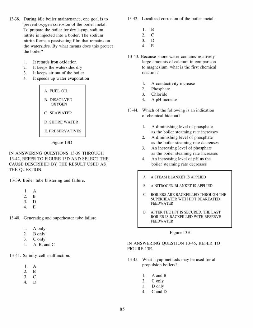
13-38. During idle boiler maintenance, one goal is toprevent oxygen corrosion of the boiler metal.To prepare the boiler for dry layup, sodiumnitrite is injected into a boiler. The sodiumnitrite forms a passivating film that remains onthe watersides. By what means does this protectthe boiler?
1. It retards iron oxidation2. It keeps the watersides dry3. It keeps air out of the boiler4. It speeds up water evaporation
A. FUEL OIL
B. DISSOLVEDOXYGEN
C. SEAWATER
D. SHORE WATER
E. PRESERVATIVES
Figure 13D
IN ANSWERING QUESTIONS 13-39 THROUGH13-42, REFER TO FIGURE 13D AND SELECT THECAUSE DESCRIBED BY THE RESULT USED ASTHE QUESTION.
13-39. Boiler tube blistering and failure.
1. A2. B3. D4. E
13-40. Generating and superheater tube failure.
1. A only2. B only3. C only4. A, B, and C
13-41. Salinity cell malfunction.
1. A2. B3. C4. D
13-42. Localized corrosion of the boiler metal.
1. B2. C3. D4. E
13-43. Because shore water contains relativelylarge amounts of calcium in comparisonto magnesium, what is the first chemicalreaction?
1. A conductivity increase2. Phosphate3. Chloride4. A pH increase
13-44. Which of the following is an indicationof chemical hideout?
1. A diminishing level of phosphateas the boiler steaming rate increases
2. A diminishing level of phosphateas the boiler steaming rate decreases
3. An increasing level of phosphateas the boiler steaming rate increases
4. An increasing level of pH as theboiler steaming rate decreases
A. A STEAM BLANKET IS APPLIED
B. A NITROGEN BLANKET IS APPLIED
C. BOILERS ARE BACKFILLED THROUGH THESUPERHEATER WITH HOT DEAREATEDFEEDWATER
D. AFTER THE DFT IS SECURED, THE LASTBOILER IS BACKFILLED WITH RESERVEFEEDWATER
Figure 13E
IN ANSWERING QUESTION 13-45, REFER TOFIGURE 13E.
13-45. What layup methods may be used for allpropulsion boilers?
1. A and B2. C only3. D only4. C and D
85

13-46. What record should be retained for a minimumperiod of 2 years?
1. The Fuel and Water Report2. The Reserve/Makeup Feedwater Test Log3. The Machinery Plant Water Treatment Log
Package4. The Fireroom Operating Log
13-47. For what minimum period of time should thedaily fuel and water report be retained?
1. 1 month2. 2 months3. 3 months4. 4 months
13-48. What is the purpose of surface blowdown?
1. To provide control of boiler water solids,both suspended and dissolved
2. To increase the materials dissolved inthe water
3. To decrease materials that have dissolvedin the water
4. To reduce the amount of sludge in the water
13-49. What is the purpose of a bottom blowdown?
1. To reduce the amount of sludgein the boiler
2. To decrease materials that havedissolved in the water
3. To increase materials that havedissolved in the water
4. To complete an overhaul
13-50. What chemicals are added to a boiler duringa complete wet layup of a propulsion boiler?
1. Morpholine only2. Hydrazine only3. Morpholine and hydrazine4. Magnetite
13-51. When a chemical test is performed for chloride,what code is entered in the code column of theFeedwater Chemical Tests section of theFeedwater Chemistry Worksheet Log?
1. SI2. ML3. EPM4. CH
13-52. Which of the following documents containsa section for pH meter standardization?
1. The Feedwater Chemistry Worksheet Log2. The Daily Fuel and Water Report3. The Boiler Water Chemistry Worksheet
Log4. The Monthly Cover sheet
13-53. If you find an error on the Boiler WaterChemistry Worksheet Log, what methodshould you use to correct it?
1. Erase the error, then make the correct entry2. Write the correct entry over the error3. Line through the error, initial it, and
make the correct entry4. Recopy the entire log
13-54. What type of test indicates the effectivenessof the DFT?
1. Dissolved oxygen test2. pH test3. Chemical chloride test4. Salinity indicator comparison
13-55. If you suspect that there is shore watercontamination, you should test the affectedcomponent for what property?
1. pH2. Conductivity3. Hardness4. Salinity
86

13-56. What information is reflected in the Reserve 13-57. By what means can you determine the integrityMakeup Feedwater Test Log? of an unused reserve feedwater tank?
1. Quality of the reserve feedwater 1. Daily silica valueactually being used 2. Daily hardness value only
2. Comparison test 3. Daily chloride value only
3. Conductivity test 4. Daily hardness and/or chloride value4. Silica test
87