Slugbotics - MATE ROV Competition
25
t Slugbotics Team Members Mentors: Prof. Ricardo Sanfelice, Michael Matkin Rohan Tuli (2nd year): CEO, Topside Electronics Lead Theo Kell (2nd year): COO, Underwater Electronics Lead Ryan Meckel (2nd year): CFO, Business Lead Isaac Trimble-Pederson (1st year): Software Lead (Motor control) Wren Sakai (2nd year): Mechanical Lead (Pneumatics) Kanoa Nakama (2nd year): Mechanical Lead (Frame) Daniel Walton (2nd year): Mechanical/Electrical (μROV) Andrew Gavgavian (1st year): Software (Cameras) Ash Whipple (1st year): Mechanical (μROV) Jeremy Diamzon (4th year): Mechanical (Buoyancy) Kyle Worcester-Moore (1st year): Mechanical (Claws) Matthew Bennett (2nd year): Mechanical/Electrical (Control Box) Natalie Rutz (1st year): Mechanical (μROV) Jack Lin (1st year): Mechanical (Mechanised item dispenser) Nathen Ly (3rd year): Electrical (Power conversion) Phil Datte (3rd year): Electrical (Power conversion) David Prager (2nd year): Electrical (Power conversion) Robert Meier (2nd year): Mechanical/Software (User input) Sean Layno (2nd year): Mechanical (Frame) Sophia Faulder (1st year): Mechanical (Claws) Surya Auroprem (1st year): Software/Business University of California, Santa Cruz | Santa Cruz, CA
-
Upload
khangminh22 -
Category
Documents
-
view
1 -
download
0
Transcript of Slugbotics - MATE ROV Competition

t
Slugbotics
Team Members
Mentors: Prof. Ricardo Sanfelice, Michael Matkin
Rohan Tuli (2nd year): CEO, Topside Electronics Lead Theo Kell (2nd year): COO, Underwater Electronics Lead
Ryan Meckel (2nd year): CFO, Business Lead Isaac Trimble-Pederson (1st year): Software Lead (Motor control)
Wren Sakai (2nd year): Mechanical Lead (Pneumatics) Kanoa Nakama (2nd year): Mechanical Lead (Frame)
Daniel Walton (2nd year): Mechanical/Electrical (μROV) Andrew Gavgavian (1st year): Software (Cameras)
Ash Whipple (1st year): Mechanical (μROV) Jeremy Diamzon (4th year): Mechanical (Buoyancy)
Kyle Worcester-Moore (1st year): Mechanical (Claws) Matthew Bennett (2nd year): Mechanical/Electrical (Control Box)
Natalie Rutz (1st year): Mechanical (μROV) Jack Lin (1st year): Mechanical (Mechanised item dispenser)
Nathen Ly (3rd year): Electrical (Power conversion) Phil Datte (3rd year): Electrical (Power conversion)
David Prager (2nd year): Electrical (Power conversion) Robert Meier (2nd year): Mechanical/Software (User input)
Sean Layno (2nd year): Mechanical (Frame) Sophia Faulder (1st year): Mechanical (Claws)
Surya Auroprem (1st year): Software/Business
University of California, Santa Cruz | Santa Cruz, CA
2
AbstractBIG SLAB is Slugbotics’ first competition-ready Remotely Operated Vehicle (ROV). Our company has 21 members from a variety of fields, who have worked tirelessly throughout the past academic year to design and build an ROV that is fully equipped to perform the tasks required by the request for proposals (RFP) from MATE and the Eastman Company. Our ROV is designed specifically for dam inspection and repair, water quality monitoring, assisting the marine ecosystem, and recovering a Civil War-era cannon from a riverbed. To perform these tasks, BIG SLAB has several mechanisms for manipulating items underwater. Two pneumatic claws and a lift bag enable it to move large items, such as a cannon or tire, and a mechanized item dispenser allows for the precise deployment of smaller items like trout fry and cannon shell markers.
BIG SLAB also features a micro-ROV (μROV) that can detach from the frame and inspect small spaces that are too small for the main ROV. We have optimized the size and weight of BIG SLAB so that it is as compact as possible while simultaneously providing enough space for all of the onboard mechanisms. Overall, it is an efficient and capable ROV, tailored specifically for the needs of the Eastman Company.
Electronics enclosure
Item dispenser
Detachable frame piece
Vertical thrusterClaw
PistonHorizontal thruster
Frame
Fig. 1: An exploded view of BIG SLAB, rendered using Solidworks

Table of Contents3
Abstract 2Theme Significance 4Project Management 4 Team Structure 4 Scheduling and Organization 5Safety 5 Philosophy 5 Features 6 Procedures 6Design Rationale 7 Frame 7 Motors 7 Pneumatics 8 Claws/Cannon Lifting 8 Item Dispenser 9 Analog Sensor Package (ASP) 10 μROV 10 Bouyancy and Ballast 11 Onboard Electronics 12 Original Design / Issues 12 Current Design 13 Main Board 13 Power Conversion 13 Thermal Design 14 Electronics Enclosure 14 Cameras 15 Tether 15 Control Box 16 Software 17 Motor Control 17 Cameras 17
Controls/User Experience 17
Autonomous Operation 18
New vs. Reused 18
Build vs. Buy 19
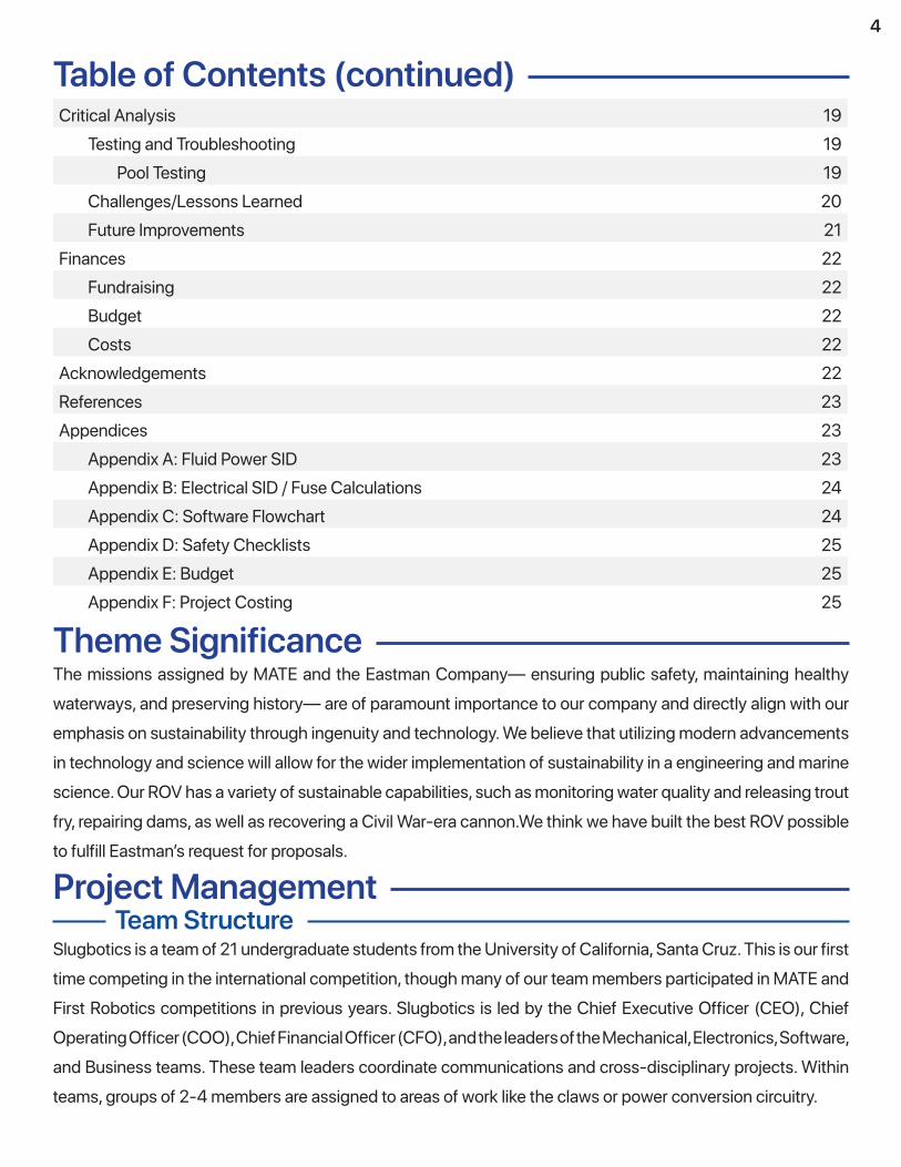
Table of Contents (continued)Critical Analysis 19 Testing and Troubleshooting 19 Pool Testing 19 Challenges/Lessons Learned 20 Future Improvements 21Finances 22 Fundraising 22 Budget 22 Costs 22Acknowledgements 22References 23Appendices 23 Appendix A: Fluid Power SID 23 Appendix B: Electrical SID / Fuse Calculations 24 Appendix C: Software Flowchart 24 Appendix D: Safety Checklists 25 Appendix E: Budget 25 Appendix F: Project Costing 25
4
Theme SignificanceThe missions assigned by MATE and the Eastman Company— ensuring public safety, maintaining healthy waterways, and preserving history— are of paramount importance to our company and directly align with our emphasis on sustainability through ingenuity and technology. We believe that utilizing modern advancements in technology and science will allow for the wider implementation of sustainability in a engineering and marine science. Our ROV has a variety of sustainable capabilities, such as monitoring water quality and releasing trout fry, repairing dams, as well as recovering a Civil War-era cannon.We think we have built the best ROV possible to fulfill Eastman’s request for proposals.
Project ManagementTeam Structure
Slugbotics is a team of 21 undergraduate students from the University of California, Santa Cruz. This is our first time competing in the international competition, though many of our team members participated in MATE and First Robotics competitions in previous years. Slugbotics is led by the Chief Executive Officer (CEO), Chief Operating Officer (COO), Chief Financial Officer (CFO), and the leaders of the Mechanical, Electronics, Software, and Business teams. These team leaders coordinate communications and cross-disciplinary projects. Within teams, groups of 2-4 members are assigned to areas of work like the claws or power conversion circuitry.

5
Scheduling and Organization
Milestone Date
First Meeting Sep. 29, 2018
Team Onboarding Begins Oct. 13, 2018
Manual Release / Design Begins Nov. 15, 2018
Preliminary Mechanical Design Complete Jan. 26, 2019
Preliminary Electronic Design Complete Feb. 28, 2019
Frame Fabrication Complete Apr. 2, 2019
PCB Designs Complete Apr. 15, 2019
Switched to Commercial ESCs Apr. 18, 2019
Switched to New Electronics Enclosure Apr. 29, 2019
Tether Complete May 2, 2019
Control Box Completed May 8, 2019
ROV Pool Tested May 15, 2019
UC Santa Cruz operates on the quarter system, which influenced our scheduling. The normal school year is three ten-week quarters, so we planned to spend the first quarter training new members, the second quarter designing and prototyping, and the third quarter manufacturing, assembling, and testing the ROV. We developed a more granular schedule with Trello (a task scheduling webapp) which allowed us to communicate deadlines and tasks to the whole team. For the most part, we adhered to this schedule. However, we ran low on time in the second quarter, because the prototyping cycle for some parts took longer than anticipated (Fig. 2).Despite this, the ROV was still ready for testing by the middle of the third quarter, allowing us time to practice all the tasks. Team members would work on the ROV during both scheduled weekend meetings, scheduled collaboration sessions during the week, and individually. Work was coordinated via Slack and Trello, facilitating asynchronous communication across differing schedules of team members. We also used version control with GitLab for software and GrabCAD for our mechanical designs, further enabling asynchronous and independent work. Additionally, general meetings were held at regular intervals in order to keep ROV development on schedule and discuss between teams. Additionally, the team worked on creating comprehensive
Fig. 2: A timeline of key milestones during the process of designing and building the ROV
documentation, especially for software systems. This documentation enabled people to easily extend systems which they were unfamiliar with, and prevented us from losing progress, such as when our control box storage drive failed and we had to reinstall the operating system.
SafetyPhilosophy
Safety is always our top priority. Our organization was founded last year and many of our new members were unfamiliar to robotics and working in a shop environment. With this in mind, we made sure that every step of design and development of the ROV was undertaken with attention to safety. All team members underwent comprehensive safety training from our lab organization before beginning work, and team administrators are continually monitoring the workspace to improve safety protocols. Our workspace is a converted chemistry lab and has a number of shortcomings, but through proactive measures, such as purchasing portable ground-fault interrupters and air filters, we have ensured the safety and well-being of our members at all times.

6
FeaturesBIG SLAB has a variety of safety features, intrinsic to its design. There are no wire disconnect points underwater, to avoid the risk of a loose connection causing a short. Both the waterproof chamber and the surface control station are transparent, allowing for easy troubleshooting if an electrical issue occurs. The thrusters are fully shrouded to prevent damage to propellers and injury to divers near the ROV. If the propulsion system
encounters a problem, BIG SLAB’s slight positive buoyancy will cause it to float to the surface so it can be recovered, and the motors will halt preventing it from running into another object. There are no sharp points on the frame, and all wires that are in contact with the frame have strain relief and abrasion protection (Fig. 3). Above water, the pneumatics system includes a discrete pressure regulator and relief valve, in addition to the built-in safety features of the air compressor. In the control station, AC and DC wiring are completely separated, with layers of wire sheathing preventing them from ever coming in contact with each other.
They are switched separately, but both are additionally disconnected when the emergency-stop button is pressed. DC voltage is switched by a 9-volt relay powered by an alkaline battery, so that the user is protected from coming near the high-current DC power line. In addition to the strain relief on where the wires enter the ROV, the wires entering the control box also have strain relief, and all tether wires have locking connectors.
ProceduresBefore entering the lab workspace, team members must complete online training courses as required by the Office of Environmental Health and Safety in relevant areas, including electrical safety, tool usage, and personal protective equipment. When working in the lab, team members are required to wear safety glasses at all times when operating hand and power tools, as well as when using any skin irritants such as epoxy. Irritants and adhesives also require the use of cloth gloves. Chemicals like epoxy, which emit hazardous fumes, must be used in a fume hood and the user must wear an R95 face mask (Fig. 4). Our 48-volt power supply does not have a power switch, and immediately powers on when plugged in. To address this hazard, we require that it be plugged into a power strip with a switch. Any ROV electrical components must be plugged into a portable ground-fault interrupter, not directly into a wall outlet. When work is being performed on the ROV, it must be powered off for at least 30 seconds to allow the capacitors in the power supply and circuitry to drain. When testing the ROV in water, the power supply and control system must be at least five feet away from the water, and wires must be taped to the pool deck to prevent tripping. The ROV must be carefully inspected every time before powering it on and submerging it in the pool.Safety checklists can be found in Appendix C. Fig. 4: Theo using protection
Fig. 3: Carabiner used for strain relief and rubber tape to prevent tether wires from
abrading against frame edge
7
Design RationaleFrame
To create a more compact design this year for our frame (Fig. 5) we decided only two main levels were needed: one level for mounting mechanisms and hardware and another level for structural support and the rear motor. Four vertical supports that join the top and bottom panels were made from two pairs of individual parts. One pair would provide a structure for the Electronics enclosure and the other pair would support the removable rear motor, as well as the rest of the structure. Lastly two larger side panels, joined with tab and slots in combination with T-nuts, mounting to each of the sides of the top and bottom panels, create a rigid structure and act as a physical buffer for the bottom and rear cameras and as mechanisms to prevent damage during pool operations. BIG SLAB’s bottom panel holds both claws, a mechanized item dispenser, and two magnetic mounts for the movable camera. Special consideration was taken to ensure that all mechanisms would be viewable from at least one of the cameras. The top panel is two parts. One provides structural support for the rest of the frame, and the other can be quickly slid on or off. It needed to be easily removable as one of the vertical motors mounts to it, and when mounted it prevents access to the electronics enclosure. To fabricate the frame, we selected 0.25” High Density Polyethylene (HDPE) plastic sheet stock due to our limited manufacturing capabilities regarding metals, HDPE’s relatively low density (930-970 kg/m^3), ease of machinability, and sufficient stiffness were found to be suitable for our needs. To optimize our use of material within the the allowable dimensions, we utilized Solidworks Simulation to take full advantage of the mechanical properties of HDPE and t-joints, while minimizing the usage of material we would need to create a structure to support the strain induced by external forces on our vehicle.
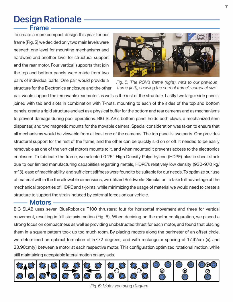
MotorsBIG SLAB uses seven BlueRobotics T100 thrusters: four for horizontal movement and three for vertical movement, resulting in full six-axis motion (Fig. 6). When deciding on the motor configuration, we placed a strong focus on compactness as well as providing unobstructed thrust for each motor, and found that placing them in a square pattern took up too much room. By placing motors along the perimeter of an offset circle, we determined an optimal formation of 57.72 degrees, and with rectangular spacing of 17.42cm (x) and 23.90cm(y) between a motor at each respective motor. This configuration optimized rotational motion, while still maintaining acceptable lateral motion on any axis.
Fig. 5: The ROV’s frame (right), next to our previous frame (left), showing the current frame’s compact size
Fig. 6: Motor vectoring diagram

8
While the concept of implementing three vertical motors was relatively clear, we had to take into account several factors, mainly aligning the center of thrust, mass, and buoyancy. This was to account for the offset in thrust the two frontal and single rear motor presented With our longer frame and shorter enclosure length, this was convenient as it allowed us to position our electronics enclosure forwards in the frame to have a clear driving camera view and align the center of thrust and buoyancy. To account for our center of mass being slightly behind the COB with our improvised enclosure, we utilized weights. These were to account for
additional changes of the final weight of the ROV outside the CAD and were adjustable via rails cut into the base of the frame to be able to pinpoint the ideal alignment in pool testing. We were also able to greatly improve the compactness and safety of the shrouds (Fig. 7) we used for our motors this year. We opted to design them around the concept of mounting them directly to the thrusters rather than having a larger enclosure mounted to the frame. By utilizing a clip-on mount design as well as using the existing bolts on the thrusters we were able to achieve a 170% weight and material reduction from last years design. As a result the design and manufacturing time was decreased with the simplified geometry, leading us to be able to assess prototype models quicker and produce finalized parts ahead of schedule.
Fig. 7: BlueRobotics T100 thruster with attached 3d-printed shroud,
mounted to the frame
PneumaticsPneumatics are heavily used on BIG SLAB due to their reliability and ability to operate in the water with little modification. Both claws use a 31.75mm stroke, 27mm bore piston to open and close each claw, with both pistons controlled by a single 5/2 pneumatic solenoid which is located in the topside control box. The lift bag inflates using a specially selected pressure relief valve, fixed inside a commercial lift bag. This “inflator” unit lies downstream from a 2-way NC solenoid which also resides in the topside control box. Both solenoids are regulated to 40 psi (2.76 bar) via a pressure regulator. In addition to the pressure relief valve, a hand controlled pressure vent lies upstream of the pressure regulator plug which can easily be accessed by an ROV pilot in the event of an emergency. Once opened, the entire pneumatic system will depressurize. The entire pneumatic system utilizes 6.35mm outer diameter pneumatic tubing. The fluid power SID can be found in Appendix B.
Claws/Cannon LiftingWe designed the claws with the goal of handling a wide variety of grip sizes with minimal complexity. Our claws were designed in Solidworks and then 3D-printed in PETG plastic. We printed them as this allowed us to manufacture precise designs more quickly. The claws are 31.75mm thick, and can grip objects between 152.4mm to 25.4mm in diameter, allowing us to fit all of the props in the competition. We decided early on that we would use only one pneumatic piston for each claw, as two pistons would cost more, weigh more, and require bulkier mounting hardware. We accomplished this by actuating both halves of the claw with a central pin connected to the piston head. We started with a 75mm claw prototype and worked our way up to

The item dispenser (Fig. 9) is the primary method of completing the grout insertion, trout fry transportation and release, and cannon shell marking tasks. In these tasks, we decided that having the ROV hold multiple objects at once would be more time efficient than returning to the surface to retrieve new objects for each challenge. As such, the design focused on being able to store and release objects of varying sizes. In the early stages of its design, we debated on two variations of the mechanism. One was a vertical cylinder with multiple slices to hold objects in. The floor of this cylinder would have a hole that rotates, allowing for objects to drop. The other design is what we are currently using, the linear item dispenser. We chose this design because it was space-efficient and was easier for the pilot to use, as the location where the object is dropped from does not change. Throughout the design process of the item dispenser, we encountered multiple issues. Prototyping led us to conclude that purchasing and attaching a rack would allow for more consistent meshing between the gear and the rack compared to printing a rack ourselves. We 3D-printed a custom pipe of the exact size necessary to fit all 3 types of deployables. Using a 3D-printed outer tube rather than a PVC pipe allowed us to print the mounting structures directly onto the tube, simplifying manufacturing. The rail and its notch in the tube were moved opposite of the rack, as early prototypes tended to derail easily. The servo for extending the dispenser also proved to be a challenge, as it required a waterproof 360° continuous rotation servo. We originally wanted to buy a waterproof servo, but quickly discovered that commercial servos with these qualities would be
9
the 152.4mm final claw (Fig. 8). While testing the claws, we discovered that they did not have enough grip strength. To fix this, we switched to pistons with a larger bore diameter as well as changed the claw and piston geometry to increase the mechanical advantage of the lever arm that the pistons acted on. This increased the grip strength of our claw by 400%. In order to lift the cannon, an 11.5 L lift bag capable of lifting up to 11.33 kg is attached on the top panel of the frame, which is used to lift the cannon once it is secured in the claws. The lift bag is held to the top of the frame with carabiners and is inflated with a one way valve that allows air out and prevents water from entering. The claws are mounted to the frame using two HDPE plates. These plates anchor the claw pivots in front of the ROV and hold the piston securely at the rear. The plate assembly is mounted into the underside of the frame by four slot joints. We chose the double plate design to reduce flexing and misalignment of the claw and piston.
Fig. 8: An exploded view render of the large claw, with HDPE mount, piston, and gripper
Item Dispenser
Fig. 9: Item dispenser

10
prohibitively expensive. So instead, we waterproofed a normal 360° servo motor with Plasti-Dip and dielectric grease (Fig. 10). We put the grease in the gearbox and at the point of connection between the shaft and casing to waterproof the rotating shaft. The rest of the servo is covered in Plasti-Dip to seal any small cracks or holes. We also encountered issues with mounting the the gear and the servo to the mechanism. The waterproofing process added thickness to the servo, which we compensated for by making one of the holes a slot. We experimented with multiple methods of securing the gear to the servo, but ultimately settled on printing a gear that press-fits onto a servo horn.
In order to massively simplify electronics and electronics enclosure hardware, the ROV utilizes several analog sensors to complete the pH, water temperature, and cannon shell identification tasks. These devices make up the Analog Sensor Package, or ASP. The ASP contains a commercial refrigerator thermometer for sensing water temperature, a soil pH meter to measure the pH sample, and a small neodymium magnet mounted to a 3D printed scale for detecting magnetic cannon shells. These sensors have visual gauges on them, which are positioned in view of a camera onboard BIG SLAB. The readings are then shown onscreen as part of the camera feed. Although there are more sophisticated sensors available, we determined that the improved functionality of electric probes was greatly outweighed by the complexity of waterproofing and wiring said sensors. The analog probes were nearly as functional as the electric probes but only a fraction of the complexity.
Analog Sensor Package (ASP)
The μROV (Fig. 11) is form fitting to the inside of the drain pipe. This ensures that the μROV is physically incapable of getting turned around or tangled up inside the pipe. Rather than allowing the μROV to slide down the pipe, we chose to use a three-point roller cage design. We specifically chose compliant (pliable) wheels for our design as they allow the roller cage to compress when going over the corrugation, whereas hard wheels would have issues with jamming against the uneven walls. The roller cage is used strictly for positioning/aligning the μROV; the actual power for the μROV comes from the bilge pump motor mounted in the center of the roller cage. We chose a bilge pump motor because it is electrically simple, easily sourceable, low cost, and reliable for underwater use. We decided to have propulsion come from a propeller rather than the wheels because it was vastly easier to have one waterproof
μROV
Fig. 11: Front view of the μROV
Fig. 10: Waterprofed servo with rack and pinion system

11
motor with a propeller on the end rather attempting to propel it through belts or multiple motors. We used a waterproof USB endoscope as it was readily available and is equipped with a built in light and a 3 meter waterproof cable that integrates into the rest of the μROV tether. The μROV tether is made of insulated copper cables to power the motor and the cable for the endoscope. To account for the μROV’s size , the μROV’s tether is detachable via a waterproof quick-disconnect plug, making it removable The claw has inserts that can be quickly fitted and removed; these work as a sort of adapter that allow the claw to hold the μROV by the back of the bilge pump motor. This allows the μROV to be held much closer to the main ROV, making deployment much easier for the pilot. The μROV’s tether spool was originally going to use a spring to keep tension on the μROV tether, but this proved unreliable. Thus, we decided that instead the servo could be used to actively power the spool for μROV tether since it would have a more constant force. The spool spans the width of the main ROV and is situated behind the claws. In order to keep the tether neat, the spool is grooved so that the tether will slot into the grooves and avoid overlapping and tangling as much as possible.
BIG SLAB was designed to be slightly positively buoyant, but not enough to affect normal operation. This was done because in the event of the ROV completely failing in the water, it is much nicer to have the ROV float to the surface for easy retrieval rather than have to go diving in potentially electrified water. The main source of buoyancy is the electronics enclosure, which is mounted as far to the top of BIG SLAB as possible. This gives BIG SLAB passive roll and pitch correction, as the heavier frame components will naturally want to sink underneath the buoyant enclosure. Small amounts of flotation foam were added to one side of the frame to counteract the weight of a servo also mounted on that side of the frame.
Buoyancy/Ballast
The buoyant force of the ROV was deduced using the well known relation given by Archimedes’ Principle:
The volume of the ROV was determined by the water displacement method:
Where the mass of the container that stored the fluid used to measure the ROV’s volume was deduced not to play a role in the derivation as follows:
The value of the mass of the fluid before the displacement and after were reported respectively as mtotal before = 15.63 kg and mtotal after = 7.31 kg. Using the density off water 997 kg/m3, the volume of the fluid displaced and therefore the volume of the ROV was calculated to be 8.34 x 10⁻³ m3. Hence the buoyant force comes out to a positive value of 81.56 N, which is slightly greater in magnitude than the gravitational force on the ROV.

Initially, we planned to develop five custom circular printed circuit boards (Fig. 12), which would contain all of the onboard electronics. One board would house the input and output for the tether, followed by a board to house the 48-volt to 12-volt power conversion circuitry. The next two boards would house the Blue Robotics speed controllers (originally intended to be custom ESCs designed in-house (Fig. 13)) for the main motors, and the H-bridge for controlling the μROV. The frontmost disk would hold the Raspberry Pi, Arduino, and a mount for the camera which would point forwards out of the enclosure. It would also contain an array of LEDs to indicate the status of the ROV, visible through the front of the tube. These disks would be structurally connected by four standoffs, three of which would be electrically-conductive, for 12-volt, 5-volt, and ground. The disks would plug into each other with a standardized block of pin headers, carrying data between the various systems. A fan at the back end of the tube would push air through a duct to the front of the tube, where it would return to the back through a series of holes in the PCBs. The airflow from this fan would contact the aluminum end cap, which would act as a heat exchanger, cooling the inside of the enclosure. We designed and went through several prototyping cycles for these boards and many were in a partially-working state by the end of our planned design phase. However, the extremely time-consuming nature of designing custom PCBs ultimately prevented us from including most of them in our final ROV. Several of the boards ended up with major issues. The final design of the mainboard was, as a result of a miscommunication, flipped in relation to the rest of the PCBs. Since we didn’t have enough time to manufacture a replacement, we attempted to adapt it, soldering components through the board backwards, but it was ultimately unsuccessful. Some parts would require additional wiring to be soldered and run across the board in unsafe ways, so we abandoned it and opted to adapt our prototype system to replace it. At the time when we needed to begin pool testing, only the power conversion board was fully functional, and is the only one included in the ROV currently.In addition to our PCB issues, we also had problems with the physical electronics enclosure. Our original waterproof enclosure was an acrylic tube, with a flange affixed to the end, which an aluminum end cap would bolt on to (Fig. 14). When the bolts were tightened, the acrylic deflected while the aluminum stayed rigid,
12
Onboard ElectronicsOriginal Design / Issues
Fig. 12: PCB disk stack, with power standoffs, data interconnects, I/O screw terminals, and cooling fan
Fig. 13: Two different attempts at custom ESCs
Fig. 14: Original electronics tube

13
Current DesignWith limited time remaining until the ROV needed to be functional, we decided to abandon the PCBs and custom electronics enclosure in favor of a simpler solution. We quickly worked on finding a replacement enclosure, deciding to utilize a commercial waterproof container from Lexan (Fig. 15) to house our electronics. This container is intended for camping and diving, and has a large gasket to form a watertight seal. After drilling holes into the new enclosure and installing our penetrators, the new design proved completely waterproof, and could fit in the frame with minor modifications. Additionally, we redesigned our electronics to be just two boards: the power conversion PCB from the previous design, and a main board to house all the other electronics.
Main BoardThe new mainboard is a slab of HDPE stock, left over from machining the ROV’s frame. The power conversion disk is attached to it with conductive standoffs, which transmit power to the Raspberry Pi, Arduino, and speed controllers that make up the internal electronics. These are affixed to the slab with zip ties and are wired together with sturdy electrical crimps to ensure no wires come loose inside the enclosure. Despite being an unplanned replacement for another system, we ensured that all the wires have disconnectable plugs and all the components are modular, so they can be replaced if an issue arises. There is an interior wide-angle camera attached to the front of the enclosure with duct tape, which is fixed at an angle so that the pilot can see the claws and have enough field of view to drive the ROV. There are several small perfboards with minor circuitry for μROV control and power-cycling the Arduino
leading to leaks in between the bolts. There would be no way to address this issue without permanently affixing the endcap to the tube, making it impossible to swap parts or fix problems inside the tube.
Fig. 15: Onboard electronics inside commercial enclosure
Power ConversionThe power conversion design process was straight forward. Our main goals were to step down 48-volt to 12-volt, as well as 12-volt to 5-volt. For both conversions, we decided to use buck convertors rather than linear ones since switching converters are much more efficient in terms of power and physical space. We sourced an integrated circuit (IC) from Texas Instruments that includes automatic duty cycle adjustment as well as a switching mechanism to maintain a 5-volt output. This IC was paired with the general buck converter topology using the recommended values for the inductors and capacitors found in the datasheet. This buck converter will be referred to as the 12v-5v converter. We chose to directly construct the 12v-5v converter onto the PCB because it was cheaper than purchasing a separate converter while being able to perform as expected. For the 48v-12v conversion, we decided to source a standalone circuit since there were no reasonably small IC’s that would have been able to tolerate the high current draw from the motors. The 48v-12v converter we found from Delta Electronics suited our needs with a relatively high power rating while being user friendly since it also includes automatic duty cycle adjustment in order to keep the output at 12-volt.
14
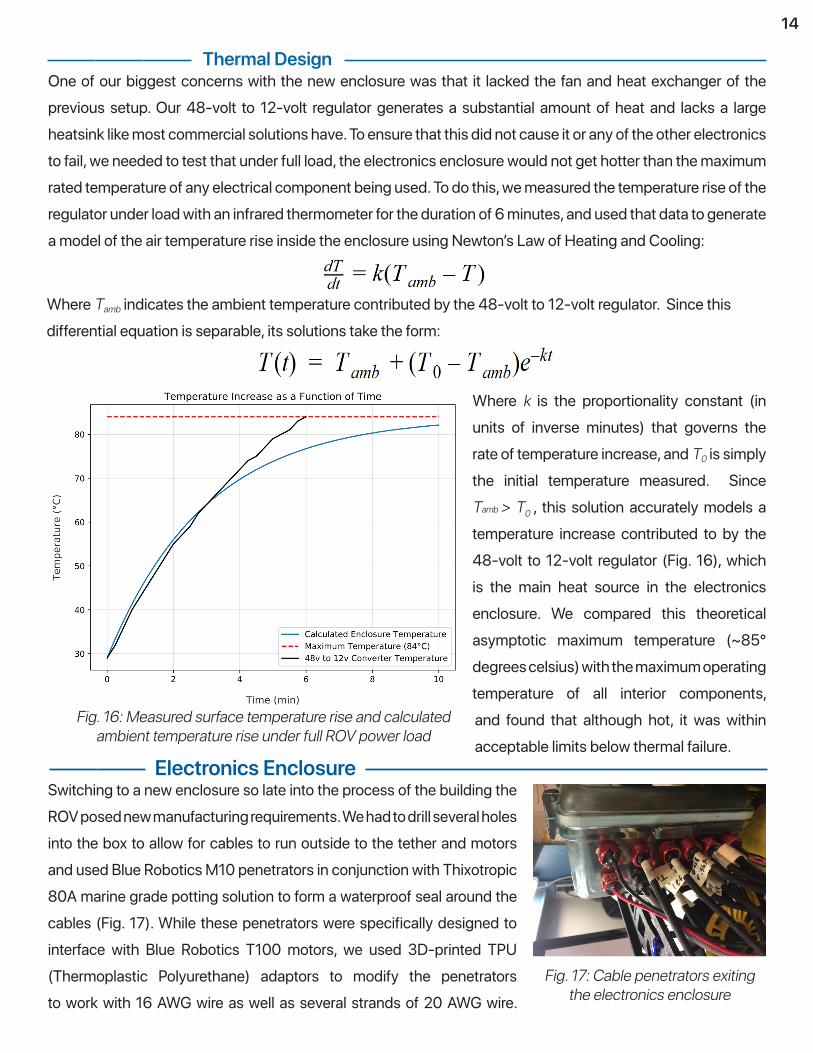
Thermal DesignOne of our biggest concerns with the new enclosure was that it lacked the fan and heat exchanger of the previous setup. Our 48-volt to 12-volt regulator generates a substantial amount of heat and lacks a large heatsink like most commercial solutions have. To ensure that this did not cause it or any of the other electronics to fail, we needed to test that under full load, the electronics enclosure would not get hotter than the maximum rated temperature of any electrical component being used. To do this, we measured the temperature rise of the regulator under load with an infrared thermometer for the duration of 6 minutes, and used that data to generate a model of the air temperature rise inside the enclosure using Newton’s Law of Heating and Cooling:
Where Tamb indicates the ambient temperature contributed by the 48-volt to 12-volt regulator. Since this differential equation is separable, its solutions take the form:
Where k is the proportionality constant (in units of inverse minutes) that governs the rate of temperature increase, and T0 is simply the initial temperature measured. Since Tamb > T0 , this solution accurately models a temperature increase contributed to by the 48-volt to 12-volt regulator (Fig. 16), which is the main heat source in the electronics enclosure. We compared this theoretical asymptotic maximum temperature (~85° degrees celsius) with the maximum operating temperature of all interior components, and found that although hot, it was within acceptable limits below thermal failure.
Fig. 16: Measured surface temperature rise and calculated ambient temperature rise under full ROV power load
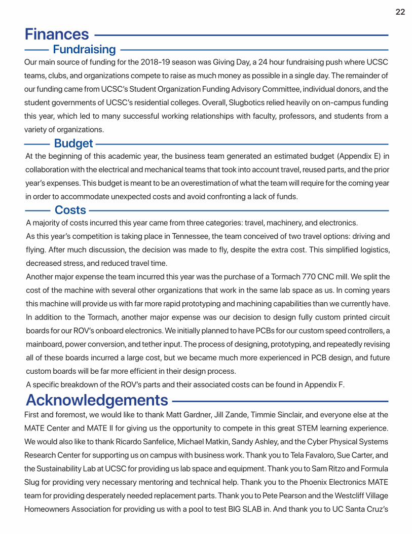
Electronics EnclosureSwitching to a new enclosure so late into the process of the building the ROV posed new manufacturing requirements. We had to drill several holes into the box to allow for cables to run outside to the tether and motors and used Blue Robotics M10 penetrators in conjunction with Thixotropic 80A marine grade potting solution to form a waterproof seal around the cables (Fig. 17). While these penetrators were specifically designed to interface with Blue Robotics T100 motors, we used 3D-printed TPU (Thermoplastic Polyurethane) adaptors to modify the penetrators to work with 16 AWG wire as well as several strands of 20 AWG wire.
Fig. 17: Cable penetrators exiting the electronics enclosure

15
CamerasOur ROV uses two digital HD cameras: a primary wide angle (120°) Raspberry Pi camera, and a secondary USB camera. The primary camera is mounted to the inside of the electronics enclosure and is used primarily for piloting BIG SLAB. It is positioned inside the electronics enclosure for increased reliability, negating the need for separate waterproofing, and to provide a clear view out of the front of the ROV to the claw and sensor package. We chose to use a Raspberry Pi camera as our main camera since it is compact and doesn’t require any additional USB bandwidth. The secondary camera is held in place with a detachable magnetic mount, which allows us to move the camera to multiple points on the frame. This makes the ROV very flexible. This camera is housed in a 3D-printed enclosure with an acrylic front, and waterproofed by filling the enclosure with dielectric grease and capping it with epoxy. This enclosure also contains the neodymium magnet needed for the detachable mount (Fig. 19). While testing BIG SLAB in the pool, we encountered an issue where condensation would form in the small gap between the lens of the camera and the acrylic front, making the entire image appear foggy. In order to prevent this from happening in the future, we inserted silica gel beads into the gap to absorb the moisture in the air.
These TPU adaptors (Fig. 18) proved to be an effective solution for forming waterproof connections between the electronics enclosure and a variety of wire sizes, as TPU is very pliable and forms a tight seal between the wire and the inside of the penetrator .The physical enclosure had a variety of its own challenges. The penetrators were very difficult to tighten and fit into the limited space on the side of the box, especially since the wires were already potted in the penetrators from the previous tube attempt. Since the electronics were designed to fit into a tube rather than a box,
manipulating all of the components into their new enclosure was difficult. When troubleshooting or doing repairs on the electronics,
it has been difficult to access certain components without removing everything, which is about a lengthy process. After our first test in the pool, we had to put silica gel packets inside the enclosure to absorb excess moisture as miniscule amounts of water entered the enclosure after prolonged submersion.
Fig. 18: 10x magnified view of a 16AWG TPU adapter
Fig. 19: Exteral camera detached, with magnetic
mount visible above
TetherThe ROV’s tether (Fig. 20) is made up of 3 pneumatic lines to power the claws and lift bag, DC power for the onboard electronics, and an ethernet cable for data transmission between the control box and on-board Raspberry Pi. The DC wires are individually double-redundant insulated, then wrapped together for organization. The combined power cables, ethernet, and pneumatics lines are sheathed together to form the

16
The tether is split at each end for hooking up the pneumatics lines and attaching cables to the control box on the surface end, and on the far end to allow us to properly route the pneumatics lines and allow for our wires to function with the penetrators into the electronics enclosure.
Fig. 20: Cross sectional diagam of the tether. +48v and GND
wires are 12AWG. Pneumatics lines are 1/4” diameter
Control BoxThe control station consists of a control box and an external monitor, to match display standards and increase versatility.. The control box (Fig. 21) itself consists of a 3D-printed inner frame enclosed by acrylic panels; the panels provide full visibility of the electronics for diagnosing issues.. Some of these panels have grids of holes for ventilation, small enough to prevent someone from accidentally touching the inside of the control box while it is on.The control box is divided into two internal zones: a top layer that houses the main computer, and a bottom layer that contains the power distribution system and pneumatics controls. This separation prevents the magnetic fields generated from high-current wires from interfering with sensitive electronics in the computer. Additionally, all AC wiring is enclosed in orange wire sheathing, while DC wires are in blue sheathing, preventing confusing the two during modifications. We decided to use a miniature x86 system running Ubuntu Linux as our control computer due to its low power usage and compact size, as well as its versatility and performance. Our control box uses an AIMB-272 small form factor computer, which we obtained from an embedded camera system slated to be recycled. AC power is distributed to both the internal SFF computer power supply and an outlet on the rear of the control box for plugging in a monitor via a terminal block. The only component that the 48-volt DC runs through is a relay. Both the AC and DC circuits run through their own covered power switch and a common emergency stop button (E-stop) capable of halting the flow of current to all systems. The AC circuit also has a 15-Amp resettable fuse for redundancy. The purpose of the DC relay is so that the 48-volt current isn’t running through the power switch and E-stop button, as it is
Fig. 21: Side and top views of the control box, showing various components: A: cooling fan, B: AIMB-272 computer motherboard, C: SFF power supply, D: orange sheathed AC wiring, E: 48v/9v relay, F: solenoids, G: blue sheathed DC wiring, H: AC fuse, I: DC and AC power switches, J: emergency stop, K:
fan intake grill, L: claw toggle switch, M: inflator button

17
significantly safer to have 1-watt running right next to the pilot’s hands than a theoretical maximum of 1440 watts. We decided to use a 9-volt battery for this circuit instead of using 12-volt power from the computer power supply so that the control box computer would not need to be on for the ROV to be turned on. One if the issues we initially encountered with setup was that the 9-volt battery drained quickly when the ROV was turned on, and replacing it required a time-consuming disassembly of the control box. We solved this issue by switching to a rechargeable lithium ion battery, which can be charged off of the computer power from the control box power supply when AC power is switched on. This circuit is completely electrically isolated from the 48-volt circuit that powers the ROV. The pneumatics control system consists of two solenoids: one for the claws and one for the lift bag inflator. These solenoids are controlled with a simple DC circuit, with a momentary push button being used to activate the inflator and toggle switch to control the claw. We chose this over controlling the solenoids with software for simplicity’s sake.. The power for the solenoids comes from the computer power supply.
SoftwareMotor Control
The motors used on BIG SLAB are controlled through Electronic Speed Controllers (ESCs) that send PWM signals corresponding to motor thrust. The control of the motors was accomplished through the use of an Xbox One controller allowing for six degrees of freedom in control. We converted the controller axis input into PWM output for the motors. Then depending on active axes, we calculated motor strings based on the motor vectoring diagram (Fig. 6), such that each axis would handle a specific movement such as strafing left or moving up. Before the string was complete, the PWM values were rounded in increments to work correctly with the ESCs and any repeated motor commands were ignored. Once the controller input has been translated into PWM values, the data is sent from the control box to the ROV using ethernet and UDP to the onboard Raspberry Pi Model B+. Instead of doing motor calculations on the Pi, we decided to accomplish this on the control box because of the lower input latency, and ability to reuse our controls system on future ROVs. The system used UDP sockets to receive strings to be processed by programs onboard the Pi. This enabled us to keep data easy to read, and enabled us to develop a fault-tolerant motor data format for our control system. Once the data is received on the Pi, it is sent over serial to the Arduino, which interprets, and checks the signal for errors using a checksum, and continuously forwards the verified signal to the ESCs until the Arduino receives a new signal.
CamerasBoth the Raspberry Pi wide angle camera and the USB camera use interfaces with GStreamer, a framework that allows us to effectively stream video to the control box in real-time. These commands were chosen over writing code because of ease of use and meeting our needs. Since static IPs were already established for the UDP connection, it was straightforward streaming the video feeds over ethernet through the local network.
Controls / User EperienceThe ROV is controlled by an Xbox Controller plugged into the control box. This controller was picked mainly because we found a library which allowed us to easily read data from the controller and use its input in C on our control box, running Ubuntu MATE. Another reason the Xbox controller was selected to control the ROV was

18
for the various axis on the sticks and the triggers of the controller. These axis allowed us to control the ROV with analog precision (as opposed to digital keypresses). With this precise input, we were able to generate varying speeds for the motors that allowed us to fine tune the movement of the ROV. The layout for the controller is such that the left stick on the controller moves the ROV forward, backwards, left, and right. The left trigger turns the ROV to the left and the right trigger turns the ROV to the right. The right stick moves the ROV up and down. If the left bumper is pressed and you use the right stick then it changes the pitch of the ROV instead of moving the ROV up and down. These controls were chosen because they seemed the most comfortable and easy to learn to the team. Our control box runs Ubuntu Linux, enabling us to perform development tasks with ease. This helps us in cases such as for fixing an issue in code or restarting the camera streams, which can be done by connecting to the ROV’s onboard computer. This makes it easier to address issues as they may arise.
Autonomous OperationTo identify the benthic species, we saved individual images of each benthic species (circle, triangle, square, rectangle) as ‘templates’ before identification happens. We then used the template matching algorithm in OpenCV to identify shapes with a 2D convolution technique which takes the template and compares it to a small segment of the image and repeats this process by sliding the template over the input image until all pixels are examined. When the templates and the image segment pass a certain threshold, they are considered a match, and the outline of the shape is highlighted to indicate detection. We keep track of how many of each species are identified, ensuring that each species does not exceed 6 and the total is not greater than 15, and the results are printed after the frame is analyzed. The crack in the dam wall is detected through the use of canny edge detection, as implemented in the OpenCV standard library. Because the crack is the only blue shape on the dam wall, a simple filter is applied to easily isolate the crack from the black grid marks and the red path lines. Because the grid lines have a fixed (specified) width, we compare the width of the grid line to the width and length of the crack to determine the exact dimensions of the crack. The video feed from the ROV is analyzed in real-time using the OpenCV library. For each frame captured, the coordinate nearest to red, the color of the line, is marked. Controller inputs are emulated using Python such that the marked coordinate is moved to the center of the frame. For this to be the case implies that the ROV is either on top of line or that the ROV is turning towards the direction of the line to compensate for the increased red one vertical partition of the frame. The ROV moves forward only when the red marker is in the center of the screen. This heuristic allows for the ROV to make harsh 90 degree turns without overshooting the line. Before pool testing, the functionality of the line following algorithm was verified using a simulated environment made in OpenGL, piped into OpenCV as a camera feed.
New vs. ReusedWe re-used the T100 thrusters from our previous ROV, as they are highly reliable and were the most expensive single purchase we have made as a team. Additionally, we re-used some small components, such as Arduinos, solenoids, and switches since they still worked and there was no reason to purchase new ones. However, we did not re-use any mechanisms or large parts from our previous ROV, as we wanted to iterate and improve upon our previous designs. In the future, we will not re-use any mechanisms from BIG SLAB, as we want to be able to improve upon them even further.

19
Build vs. BuyThe majority of parts on the ROV were designed and built in-house by Slugbotics, however there were some situations where we decided that a commercial solution would be significantly superior to our own. BIG SLAB uses commercial T100 thrusters from Blue Robotics as opposed to integrating motors into custom-designed thruster assemblies due to the advanced knowledge necessary to create effective motors. Additionally, there are two components on the ROV where we attempted to build our own but were ultimately unable to do so. We designed and fabricated a cylindrical electronics enclosure to house the electronics on the ROV, but were unable to make it perfectly waterproof within scheduled deadlines, so we decided to purchase a commercial waterproof enclosure to use as our electronics enclosure instead.Additionally, we attempted to build our own ESCs to drive the brushless DC motors in the T100 thrusters, as we have found the ESCs offered by Blue Robotics to be somewhat unreliable. However, designing our own ESCs was dramatically more time consuming that we initially expected, so halfway through the year, we decided to switch to using our previous BlueRobotics ESCs so we could spend more time working on BIG SLAB’s other electronic systems.
Critical AnalysisTesting and Troubleshooting
Throughout the design process, we implemented a strict design review procedure, where multiple team members review a CAD model, PCB design, or section of code (as applicable). For example, with PCB and control box CAD designs, we printed each one on a sheet of paper at 1:1 scale and laid out all the parts to ensure that everything fit together. For mechanical designs, we always drew sketched ideas out first before trying to implement them in CAD (Fig. 22). Additionally, PCB designs were tested on a breadboard, to ensure that all circuits were functional. Only after this thorough testing were designs approved to be manufactured. After manufacturing, PCBs and mechanisms were tested independently before integrating them into the ROV.
Fig. 22: An early whiteboard sketch of the frame. Sketches like this are a critical
part of our design processPool Testing
Prior to submerging BIG SLAB in the pool, we ran extensive testing to ensure it would be fully waterproof. We used a vacuum pump to pull a vacuum inside the electronics enclosure, adjusting the seal if there was any sign of pressure change. Next, we covered the enclosure in soapy water and pressurized the interior, so that escaping air would create bubbles and be easy to detect. We also allowed the ROV to run for 15 minutes with the enclosure sealed, to ensure that the interior did not get too hot. Once the ROV had passed all of these tests to satisfaction, we submerged it in a bin of water, with the power turned off in case there was a short we hadn’t detected. After leaving it in the water for 45 minutes, there was no sign of water inside the enclosure, so we

Prior to submerging BIG SLAB in the pool, we ran extensive testing to ensure it would be fully waterproof. We used a vacuum pump to pull a vacuum inside the electronics enclosure, adjusting the seal if there was any sign of pressure change. Next, we covered the enclosure in soapy water and pressurized the interior, so that escaping air would create bubbles and be easy to detect. We also allowed the ROV to run for 15 minutes with the enclosure sealed, to ensure that the interior did not get too hot. Once the ROV had passed all of these tests to satisfaction, we submerged it in a bin of water (Fig. 23), with the power turned off in case there was a leak we hadn’t detected. After leaving it in the water for 45 minutes, there was no sign of water inside the enclosure, so we deemed it ready for pool-testing. Our first priority in the pool was to test motor control. Initially, the ROV moved sluggishly when
strafing left and right because of mis-identified motors in software. After the motor issues had been resolved, we refined the ROV’s buoyancy by adding pipe insulation foam, until it was stable and slightly positively buoyant. With the ROV working optimally, we moved on to practicing the tasks required for the MATE qualifier video (Fig. 24). We developed a sequence of tasks for the video that required the least amount of returning to the pool side to maximize our use of time. At regular intervals, we surfaced the ROV and checked for leaks, bending in the frame, and heat levels inside the electronics enclosure. After filming and submitting the video, we tested the ROV over other tasks. A major issue we encountered was that all electronic systems in the ROV would periodically reset. We investigated the issue by probing electronic connections when the issue occurred and narrowed it down to an electricity-conducting steel standoff. It had high resistance, which likely caused inconsistent current at higher amperages. We replaced it with a aluminum standoff with much lower resistance, and the power issues were resolved.
20
Fig. 23: Using a bin to test the ROV for leaks
Fig. 24: The completed ROV in the pool, with its lift bag partially inflated
Challenges / Lessons Learned This year introduced many new challenges and complexities to our team, as we aimed to create a competition-capable ROV for the first time. These involved technical challenges, as we learned new techniques and explored different possibilities for developing our ROV, as well as interpersonal and organizational issues, as the team rapidly grew in members.

21
A significant technical challenge that our team faced was complexity in the electronics design, particularly due to ambitious design goals. Our original design involved many custom components, including a home-developed clear cylindrical enclosure, as well as custom ESCs to improve upon the Blue Robotics ESCs. However, we hit multiple setbacks in our design process, mainly due to the complexity and lack of experience in developing components. Our custom ESCs were not functional, and due to issues in prototyping, were ultimately scrapped to stay on target for completing the ROV. This also applied to our custom enclosure, leading us to choose a premade solution, and modify our design to adapt the equipment used for prototyping into the final design. This adaption allowed us to construct a functional ROV, and taught us to avoid complexity. We have consequently learned to minimize complexity and set more realistic goals for development of the ROV.A significant organizational challenge of the team was the rapid expansion of members during the year. Previously, eight founding members of the team largely controlled the development process of the ROV. This year, that number expanded to over 100 members entering the team, and 21 core members sticking through onboarding to make significant contributions to the ROV. This expansion resulted in various issues in communication, such as delegating and synchronizing tasks between subteams, which were new issues for a previously more tight-knit team. These flaws in communication led to work being duplicated or done improperly, which reduced the efficiency of the team as a whole. To resolve this, we focused on bringing members into the lab to discuss progress more regularly, and increased our use of Slack and Trello. In future years, we intend to further address this by putting a greater emphasis on team logistics, as well as investing in comprehensive issue tracking, in order to ensure that team members are caught up on the status of the team as a whole.
Future ImprovementsOne important area for future improvements revolves around the team structure, and successfully collaboration. Despite some communications infrastructure in place (Slack), different team members were not always aware of the status of different aspects of the ROV, and this resulted in some duplicated work. There were also issues regarding delegating tasks clearly between different teams. Going forward, we aim to communicate more clearly between teams, and consistently share statuses on different projects, such that team efficiency is increased.Another area for improvements to the team is setting more realistic goals for electronics and design. As previously mentioned, our team faced serious challenges trying to reach ambitious and ultimately unrealistic goals. Thus, we want to focus on developing reliable long-term strategies between competitions and keeping the design simpler, such that we can develop our ROV more each year. Ideally, by focusing on developing long-term strategies, we will be able to improve our ROVs each year while ensuring that each iteration is fully functional for the competition.In regards to financing the team, Slugbotics relied heavily on on-campus funding and families this year to support our company. While this was a successful and hopefully sustainable method of fundraising, looking for off-campus community sponsors would greatly expand our name recognition and relationships, including with local businesses. This would greatly increase the value of working with Slugbotics for students and has the potential to connect our team members with potential employers after graduation.
22
FinancesFundraising
Our main source of funding for the 2018-19 season was Giving Day, a 24 hour fundraising push where UCSC teams, clubs, and organizations compete to raise as much money as possible in a single day. The remainder of our funding came from UCSC’s Student Organization Funding Advisory Committee, individual donors, and the student governments of UCSC’s residential colleges. Overall, Slugbotics relied heavily on on-campus funding this year, which led to many successful working relationships with faculty, professors, and students from a variety of organizations.
BudgetAt the beginning of this academic year, the business team generated an estimated budget (Appendix E) in collaboration with the electrical and mechanical teams that took into account travel, reused parts, and the prior year’s expenses. This budget is meant to be an overestimation of what the team will require for the coming year in order to accommodate unexpected costs and avoid confronting a lack of funds.
CostsA majority of costs incurred this year came from three categories: travel, machinery, and electronics. As this year’s competition is taking place in Tennessee, the team conceived of two travel options: driving and flying. After much discussion, the decision was made to fly, despite the extra cost. This simplified logistics, decreased stress, and reduced travel time.Another major expense the team incurred this year was the purchase of a Tormach 770 CNC mill. We split the cost of the machine with several other organizations that work in the same lab space as us. In coming years this machine will provide us with far more rapid prototyping and machining capabilities than we currently have. In addition to the Tormach, another major expense was our decision to design fully custom printed circuit boards for our ROV’s onboard electronics. We initially planned to have PCBs for our custom speed controllers, a mainboard, power conversion, and tether input. The process of designing, prototyping, and repeatedly revising all of these boards incurred a large cost, but we became much more experienced in PCB design, and future custom boards will be far more efficient in their design process.A specific breakdown of the ROV’s parts and their associated costs can be found in Appendix F.
Acknowledgements First and foremost, we would like to thank Matt Gardner, Jill Zande, Timmie Sinclair, and everyone else at the MATE Center and MATE II for giving us the opportunity to compete in this great STEM learning experience. We would also like to thank Ricardo Sanfelice, Michael Matkin, Sandy Ashley, and the Cyber Physical Systems Research Center for supporting us on campus with business work. Thank you to Tela Favaloro, Sue Carter, and the Sustainability Lab at UCSC for providing us lab space and equipment. Thank you to Sam Ritzo and Formula Slug for providing very necessary mentoring and technical help. Thank you to the Phoenix Electronics MATE team for providing desperately needed replacement parts. Thank you to Pete Pearson and the Westcliff Village Homeowners Association for providing us with a pool to test BIG SLAB in. And thank you to UC Santa Cruz’s

23
Electrical and Computer Engineering Department, Jay Patel and DeVeera Technologies, Javan Bernstein and Katy Aquino, the Nakama Family, Bruce Ungari and Kathy Hardy, Dale Sakai and Lori Jenkins, the Meckel Family, and Michael Calbert for their extremely generous donations. BIG SLAB, and Slugbotics as a whole, would never have been possible without all the support we’ve received thus far - we cannot express our gratitude enough. Thank you.
References“Anderson Powerpole Connector Standards.” VARA W2VTM - RACES 30A Standard Anderson Powerpole Connector, www.qsl.net/w2vtm/powerpole.html.“Cat5e Cable Wiring Schemes.” Cat5e Cable Wiring Schemes - B&B Electronics, www.bb-elec.com/Learning-Center/All-White-Papers/Ethernet/Cat5e-Cable-Wiring-Schemes.aspx.Delphi Series, “DC/DC Power Modules: 36~75V in, 12V/33A out, 400W,” Q48SQ datasheet, https://www.mouser.com/datasheet/2/632/DS_Q48SQ12033-611221.pdf. “IEC 60320 Reference Chart.” Stayonline, https://www.stayonline.com/product-resources/reference-iec320.aspM. Tollmien, “XBox Controller Linux Interface.” GitHub, https://github.com/MauriceGit/XBox_Controller_Linux_Interface/graphs/code-frequency“OpenCV Modules.” OpenCV, docs.opencv.org/master/.
R.Tuli, et al. “Artaboki Technical Documentation,” Bentley Upper School, Tech. Report. https://www.marinetech.org/files/marine/files/ROV%20Competition/2017%20competition/2017%20Technical%20Documentation/RANGER%20class/BentleyUpperSchool_PhoenixElectronics_TechnicalReport_2017.pdf“Serial.” Arduino Reference, www.arduino.cc/reference/en/language/functions/communication/serial/.
“SFF Specifications.” SNIA, 9 May 2019, www.snia.org/technology-communities/sff/specifications.
“Standards ANSI 568-B Commercial Building Telecommunications Cable Standard.” Cablinggb.com, https://www.csd.uoc.gr/~hy435/material/Cabling%20Standard%20-%20ANSI-TIA-EIA%20568%20B%20-%20Commercial%20Building%20Telecommunications%20Cabling%20Standard.pdf“T100 Thruster.” Blue Robotics, https://www.bluerobotics.com/store/thrusters/t100-thruster/
“Understanding ANSI/ISO Schematic Symbols For Fluid Power Components.” Clippard Training, https://clippard.com/downloads/PDF_Documents/Application_and_Training/Clippard%20Schematic%20symbols.pdf
Appendix A: Fluid Power SID

24
Appendix B: Electrical SID / Fuse Calculations
ESC
ESC
ESC
ESC
ESC
ESC
ESC
Mot
or
Mot
or
Mot
or
Mot
or
Mot
or
Mot
or
Mot
or
Arduino
Raspberry PiPi Camera
USB Camera H-Bridge
Endo
scop
e Ca
mer
a
Bilg
e Pu
mp
Mot
or
μROV
Serv
o fo
r Ite
m D
ispen
ser
Raspberry Pi
H-B
ridge
Bilg
e Pu
mp
Mot
or fo
r μRO
V Sp
ool
48v → 12v Converter
12v → 5v Converter
Power Conversion
Cameras
Mechanisms
USB
USBCSI
PWM
PWM
PWM
PWM
PWM
PWM
PWM
PWM
SFF PC Power Supply
Monitor
AIMB-272 x86 Computer
Claw SolenoidInflator Solenoid
Xbox One Controller
Claw Toggle SwitchInflator Button
AC Terminal Block
9v / 48v DC Relay
9v Battery
DC Power SwitchAC Power Switch
AC DCEmergency Stop
Seria
lTT
LH
DMI
20 Amp DC Fuse15A AC Fuse
USB
UDP
Motor ControlPo
wer
Cor
d
Anderson Powerpole ConnectorIEC C14 Connector
AC Wiring
DC Wiring
Powered from 12-volt
Powered from 5-volt
Powered from ConnectedDevice (Voltage VariesDepending on Device)
Powered from AC
ROV DC Power Fuse Calculations
- Seven motors x 4.4 Amps each = 30.8 Amps- One Arduino = 0.2 Amps- One Raspberry Pi with Pi Camera = 2.0 Amps- Two bilge pump motors x 1.1 Amps each = 2.2 Amps - Two USB cameras x 0.5 Amps each = 1.0 Amps- One servo = 0.3 Amps
Current draw from a 12-volt power:
Current draw from 48-volt powerthrough 48v to 12v regulator:36.5 Amps x (12v / 48v) = 9.13 Amps (Ideal)
Total current draw at 12-volts = 36.5 Amps
9.13 Amps / 98% regulator effeciency = 9.32 Amps9.32 Amps x 150% = 13.98 Amps maximumNearest fuse size: 20 AmpsThe ROV uses a 20 Amp fuse.
Legend:
Topside
Underwater
Appendix C: Software Flowchart

25
Appendix D: Safety ChecklistsU
sing
a p
ower
dis
trib
utio
n un
it (p
ower
sup
ply)
:Tu
rnin
g on
RO
V:
□ In
stal
l saf
ety
cove
r□
Clea
r the
wor
kspa
ce o
f any
clu
tter, e
nsur
e te
ther
is n
ot k
notte
d or
tang
led
□ En
sure
pow
er sw
itch
is in
arm
s rea
ch, o
r plu
g in
to a
pow
er st
rip if
PDU
lack
s sw
itch
□ Co
nsul
t “U
sing
a PD
U”
chec
klist
for 4
8-vo
lt PD
U
□ En
sure
all t
hree
AC
wire
s are
cor
rect
ly a
ttach
ed□
Verif
y fu
se is
inst
alle
d an
d no
t blo
wn
□ En
sure
DC
devi
ces a
re p
lugg
ed in
bef
ore
plug
ging
in A
C po
wer
cab
le□
Conn
ect A
nder
son
conn
ecto
rs
Prio
r to
subm
ergi
ng R
OV:
□ Co
nnec
t pow
er c
onne
ctor
to c
ontro
l sta
tion
□ Co
nsul
t “Tu
rnin
g on
RO
V” c
heck
list a
nd p
ower
on
ROV
□ En
sure
E-s
top
butto
n is
not a
ctua
ted
□ Li
sten
for E
SC a
rmin
g to
nes,
imm
edia
tely
pow
er o
ff if
they
are
not
hea
rd□
Call o
ut “O
K to
pow
er o
n?” a
nd re
ceive
aud
io c
onfir
mat
ion
from
all t
eam
m
embe
rs in
are
a
□ In
spec
t gas
ket i
n el
ectro
nics
cha
mbe
r, ens
urin
g th
at it
app
ears
eve
nly-
seal
ed
□ Ch
eck
clip
s on
elec
troni
cs e
nclo
sure
Appendix E: Budget
Appendix F: Costing