The MIT ROV Team - MATE ROV Competition
16
The MIT ROV Team presents MTHR & JR Built by the MIT ROV Team Massachusetts Institute of Technology Cambridge, Massachusetts Team Members: Heather Brundage, Lauren Cooney, Keith Durand, Eddie Huo, Pete Kruskall, Harry Lichter, Olayemi Oyebode, Pranay Sinha, Jordan Stanway, Kurt Stiehl, Thaddeus Stefanov-Wagner, Daniel Walker Advisor: Dr. Franz Hover
-
Upload
khangminh22 -
Category
Documents
-
view
1 -
download
0
Transcript of The MIT ROV Team - MATE ROV Competition

The MIT ROV Team presents
MTHR & JR
Built by the MIT ROV Team
Massachusetts Institute of Technology
Cambridge, Massachusetts
Team Members: Heather Brundage, Lauren Cooney, Keith Durand, Eddie Huo, Pete Kruskall,
Harry Lichter, Olayemi Oyebode, Pranay Sinha, Jordan Stanway, Kurt Stiehl, Thaddeus
Stefanov-Wagner, Daniel Walker
Advisor: Dr. Franz Hover

Abstract
This year, the MIT ROV team designed our main ROV, MTHR, not only to compete in
the MATE competition, but also to be used afterwards for both didactic and practical purposes.
To this end, the team aimed to keep MTHR easy to operate and the sub-systems modular so that
they could be improved or expanded upon, allowing MTHR to act as a test bed for new
technology in the future. On top of this, the team also placed size constraints, in order to keep it
maneuverable and easy to transport, and monetary constraints, in order to keep it affordable.
These design considerations led our team to build a small, battery-powered ROV intuitively
controlled through a fiber optic tether that utilizes counter-rotating propellers. In addition to
MTHR, a second ROV, JR, was built to act as a flying-eye to aid in navigation during the
competition. Working together, these two ROVs can successfully compete in the Annual MATE
ROV Competition, while also providing a platform for future development.
Design Rationale
In past years, the MIT ROV Team has started by dismantling the robot from the previous
year. There have been relatively few subsystems reused between years, and our primary goal for
this year was to change that. We decided that we wanted to produce a modular, extensible robot
using components that could be improved and upgraded individually. We identified three main
subsystems we wanted to solidify this year so that they could continue to be used in future years:
power, propulsion, and control. Other subsystems were necessary to construct MTHR and
complete mission objectives. These systems were: structural frame, manipulator, and tether.
Besides MTHR, the team also decided to build a simple PVC ROV, JR to act as a ‘flying-
eye’ for the mission. JR allows an overall view of the competition site, aiding in navigation and
mission planning.
Power System
MTHR's power is provided by ten Nickel Metal-Hydride (NiMH) batteries connected in
series with a 25-amp thermal resetting fuse. Each cell provides 20 amp-hours (Ah) of power at
1.2 volts, combining to make a 12 volt battery pack (See Figure 1). There are two battery packs,
so that one can be used while the other is being charged. The batteries are housed in the same
enclosure as the control hardware, to minimize the need for expensive, high-current, underwater
connectors. MTHR uses batteries instead of surface-supplied power so that the tether can be
smaller. Our robot is restricted to lower voltage because of its onboard power, but it
was determined to be the better option. To support a 25 amp load at the end of
a 30 meter tether, 14 gauge or thicker wire is necessary, not to mention
dealing with the voltage drop and ohmic losses across the tether. It
would be inflexible, heavy, and thick, compared to any tether that
did not have to carry power to the vehicle. Furthermore, a
longer tether would only make the problem worse. Choosing
battery power enables MTHR to have a smaller, lighter tether,
enhancing overall maneuverability while at the same time
conserving energy by avoiding power loss over the tether. Figure 1 MTHR Battery Pack

Propulsion System
One of the aspects of ROV design that we have found most difficult in the past is finding
reliable, efficient propulsion. Few commercial systems exist in the size required by our robot,
and they are prohibitively expensive. We have used bilge pumps and trolling motors in the past,
but found that they work well only in one direction and are very power-hungry, which is a big
problem for a battery powered robot.. We've also been unsatisfied by the performance of model
airplane propellers underwater. We decided to design and build a more efficient thruster from the
ground up.
We took estimates of size constraints, operating speed, drag, and power available from
the early stages of MTHR's design. From these estimates, we chose a design condition for the
propulsor: propeller diameter - 11.43 cm (4.5 in.), inflow velocity - 1.03 m/s (2 knots),
continuous current - 6 amps. This design point means that our propulsor will be operating at a
fairly high thrust coefficient (Ct = 3.8 where it is 1 or less for most ships). To maximize the
efficiency of the propulsor, we use contrarotating propellers surrounded by a duct. By rotating a
second propeller in the opposite direction, energy lost to swirl in the flow can be minimized.
Having two propellers also distributes the load, enabling more efficient propellers in the first
place.
We conducted a full parametric study using computational tools, exploring different
diameters, rotational speeds, duct loading, and numbers of blades. Hydrodynamic modeling with
lifting line theory showed that our design should achieve 57% efficiency. The maximum
theoretical efficiency of any propulsor at our operating point is 62%. Computational Fluid
Dynamic (CFD) analysis (see Figures 2a & 2b) showed that our design almost completely
canceled swirl, minimizing energy wasted in that way.
Figure 2a Axial velocities in the Figure 2b Tangential velocities in the
propulsor (thrust) propulsor (swirl)

The propellers were CNC milled and the duct was turned on a CNC lathe to keep the
final products true to the hydrodynamic modeling. We matched small-diameter 12 volt DC
motors to the propellers during the parametric study. We chose Maxon RE40 brushed motors
with a 4.3:1 gearbox to give the appropriate torque at about 1000 rpm. They are housed in close-
tolerance aluminum tubes to enhance cooling, and power is
provided through Impulse Enterprises wet-pluggable
connectors. The shaft is sealed by a Parker FlexiSeal
spring-loaded PTFE o-ring. A custom miter gearbox is
integrated into the propulsor hub to reverse the direction of
rotation for one of the propellers. Two rows of stators hold
the duct and protect the propellers from debris or curious
fingers (important for safety and because MTHR has a
small tether). Figure 3 Thruster Model
Control System
The main control system is broken into two parts. The topside control system is based on
a custom Cocoa application running on an Apple laptop. The applications is highly flexible and
gives the user for very fine control on how the robot is manipulated. The bottomside is driven by
a PIC 18F4431 via RS-232 serial communication. The serial commands are then sent to four
motor controllers that drive the thrusters. Please refer to the appendix for the control system flow
chart.
Bottomside Controls
A PIC18F4431 microcontroller communicates with the topside controls through the
tether. It actuates four ST Microelectronics VNH2SSP30-E integrated h-bridge motor drivers,
defining the duty cycle for each propulsor by pulse-width modulation (PWM). It also drives two
video multiplexers, allowing the operator to choose any of four cameras on either of two video
channels. The system design was kept simple to increase reliability, ease of manufacturing, and
simplicity of operation.
The bottomside controls and power system share a cylindrical, double o-ring sealed
housing. This minimizes the use of expensive connectors and also takes advantage of the
buoyancy inherent in the air cavity surrounding the control hardware. (The housing was designed
to weigh approximately 1-2 lbs. submerged.) The housing is made of polycarbonate for
lightweight strength and easy fabrication. It has room for the battery pack and up to four standard
PC\104 boards. The main bottomside controls are on one board, the multiplexer for the fiber
optic tether is on another, and two are available for payload. The PC/104 boards use stacking
connectors to minimize wire clutter and signal degradation within the housing.
Topside Controls
Topside controls are driven by a custom Cocoa application on an Apple laptop (See
Figure 4). The user provides input via joystick and buttons, which the application then maps to
propulsor duty cycles and sends to the bottomside controller. Sensitivity settings can be changed
by the user so that each pilot is able to customize the feel of the control to their own liking. It

also has control for auxiliary motors and servos, along
with calibration and display of sensors for depth,
temperature, battery charge, and motor feedback. If a
joystick is unavailable, the user can fly MTHR using the
keyboard.
This application was developed to be portable and
extensible. It can handle two ROVs at once if the user
desires, driving each from a separate joystick.
Figure 4 Screen Shot of Top Side Controls
Structural Frame
The frame was designed to use simple, similar parts
in every case possible (See Figure 5). Two sideplates were
laser-cut from acrylic and are connected at angles to seven
crossbars, forming a strong trapezoidal frame. The
sideplates and overall layout were designed to hold the
vertical motors at a 30 degree angle so that they can
provide sideways translation in addition to ascent and
descent capability. The sideplates were cut out to be rid of
excess material that would add drag and make them act as
unwanted wings during ROV flight. Clear water in front of
the thrusters is maximized, to reduce unwanted wake and
unsteady hydrodynamic effects that could otherwise
interfere with propulsive efficiency. Figure 5 Frame Solid Model
Manipulator
We originally planned a complex 5-degree of freedom manipulator arm for MTHR's first
payload. This would allow us to carry the science package to the trawl-resistant frame and insert
the connectors. To provide simple control for this arm, we built a topside master arm modeled
after the manipulator arm (See Figure 6). Each joint was fitted with a potentiometer to give the
angular position at that joint. The arm on the robot would then use servos to move to the same
position. We believed that this master-slave configuration
provided the simplest method of controlling a complex arm.
Unfortunately, time and manpower constraints prevented
this manipulator from being completed in time for the
competition. Instead, we are using a simple solenoid to draw the
package flush to the bottom of our frame and will release the
solenoid once the package is in place. A small, simple gripper is
mounted at the bottom front of the frame to pick up the
connector and place it in the science package.
Figure 6 Topside
Manipulator Controller

Tether
Our tether is a single strand of fiber optic cable. It passively spools out of a
disposable 500 meter long coil (See Figure 7). If the tether becomes tangled during a
mission, it can simply be cut and re-terminated for the next use. Signals are encoded
and decoded by MiniMux2 boards, donated by Prizm Advanced Communication
Electronics Inc. This setup provides MTHR with 2 video channels, 2 RS-232 serial
channels, and one RS-485 serial channel. The tiny tether has negligible
drag and weight, so it does not change vehicle dynamics, but care
must be taken to avoid tangling or pinching the fiber so that
communication is not interrupted or destroyed. Figure 7 Fiber Spooler and Mux
Video
MTHR has three cameras, but the video hardware can support one more as part of the
payload, if desired. The color cameras include a ring of LED lights in the housing, providing
good visibility with low power consumption. Two Analog Devices ADG604 video multiplexers
on the control board choose which camera signals are sent up the two video channels through the
fiber. The video is displayed, and can be recorded, on computer monitors topside at the pilot's
station.
JR
JR is our “flying eye.” Using a second robot as a support ROV for an external frame of
reference should enhance our teams ability to perform any mission. Since we are using onboard
power for MTHR and JR has a very simple function, we decided to make it surface powered. JR
is actually just our version of the SeaPerch ROV that many of us have built as freshmen in the
Discover Ocean Engineering Pre-Orientation Program (which is kept going partly due to heavy
ROV Team involvement).1
JR is built on a PVC frame with pool floats and small 12 volt DC motors potted in wax.
The tether is CATV cable, directly connecting each motor to the corresponding switch on the
pilot’s controller. Video is sent up a separate coaxial cable to protect the signal from
interference. The goal of the SeaPerch design is a simple, cheap, robot that can be built in a
minimum amount of time with a minimum amount of tools. We chose to make JR a SeaPerch
because we have all the parts, it didn’t need to meet any strenuous performance requirements,
and it was a bit nostalgic for many of the team members.
Description of a Challenge
Our decision to design our own propellers came with a lot of extra headaches. The actual
design didn’t prove too bad; we used a series of existing propeller design tools, several custom
MATLAB and Java programs, and our team knowledge of hydrodynamics and propeller design.
1 This design has also become the cornerstone of one of MIT SeaGrant’s outreach programs, and
they provide all the information necessary to build and operate one on their website at
web.mit.edu/seagrant/www/outreach/seaperch/buildingsp/buildingsp.htm

The first big problem came with the last computational tool we were using. PBD 14.36
(Propeller Blade Designer) did not output a file of blade surface coordinates, which we needed
for CAD and to machine the physical product. Unfortunately, the subprogram that translates one
of PBD’s outputs to what we needed was missing, and it would have taken a long time to rewrite.
Fortunately, one of the Navy propeller designers at the Naval Surface Warfare Center in
Carderock offered to process the files for us and send us CAD files of the blade surfaces. This
wasn’t the most streamlined process, but it was the best solution for our timescale, and it worked
out well.
Once we finally had the necessary geometry coordinates from our model, we were able to
generate a surface model. Unfortunately, we still couldn’t make a full solid model because of
some software subtlety. SolidWorks wasn’t designed for complex hydrodynamic shapes and did
not handle them well. We tried other CAD packages but were largely unsuccessful. Without an
actual solid model, we couldn’t have the propellers rapid prototyped or 3D printed. However, the
surface coordinates did allow us to generate G-code for computer numerical controlled (CNC)
machining.
The first plan was to make hard plastic/metal molds from the geometry, and then cast
propellers in rigid urethane. This would save some trouble because each mold half only involved
a single setup for machining much easier than realigning a part halfway. Unfortunately, we were
unable to get sharp enough corners on the inside of the molds for it to close and fill properly.
This was quite frustrating, as each mold half took about four hours to machine. Multiply that be a
few iterations, and we had ourselves a major time sink.
The next idea was to make physical masters from plastic. In other words, we would
machine the propellers directly, then either use as is, or create a soft mold for casting from the
propeller. While this would involve multi-sided machining, it also would not require sharp inside
corners, and reduced the CNC code to about 5000 lines per side (from 15000 to 100,000 for the
molds!). The only problem was how to hold the propeller for the second side of machining. The
first side is easy, just clamp the sides of the stock. In order to cut the second side, we made a jig
that clamped the inside of the shaft bore, and added an alignment pin so we could have the part
in the proper rotation. This way, we were able to manufacture the propellers, and implement our
design on our robot.
Troubleshooting Technique
In any complex system, troubleshooting a problem can be challenging and time
consuming. Rarely will you be able to build a system from the ground up and have it work the
first time you try it, especially if you have not tested each part along the way. Electrical systems
can be especially tricky, since the cause of an apparent problem can be difficult to pinpoint. One
electrical troubleshooting issue the MIT ROV team had was getting the bottomside control
boards to function properly. Though the correct serial signals were being sent to the bottomside
board, the motors were not responding as expected.
In order to troubleshoot this problem, we looked at the system in parts – assuming
nothing worked, we started from the input signal and followed the flow of control, checking each
point along the way, until we found the source of the problem. Breaking down the problem and
looking at each part gave us a systematical and efficient way of finding the non-functional part of
the system.

We started by confirming that serial data was being sent to the bottomside board (using
an oscilloscope), then, wrote a simple test code, utilizing LED indicators, to confirm that the PIC
microcontroller was receiving the serial communications. Next, we checked that the PIC was
handling the serial communications correctly by looking at the output of the specified pins.
Finding all of these parts to be in working order, we next checked that the motor control chip
was receiving the signals from the PIC. What we found was that there was an error in the PCB
layout, which prevented a needed signal from reaching the chip. Once we compensated for this
mistake, the boards operated as expected.
Had we not systematically gone about checking each point in the control flow diagram to
make sure it acted as expected, we would have spent a significantly greater amount of time
trying to troubleshoot our control system. Breaking down large systems into parts and checking
each node along a pathway is a time (and sanity!) saving troubleshooting technique that we
employed throughout the integration process to ensure a working system.
Lesson Learned
by Pranay Sinha
Electronics dominate every aspect of our lives today and yet, when I first came to MIT,
this was one field which I had really not explored at all; had not even considered majoring in.
Having enjoyed the Discover Ocean Engineering pre-orientation program, I decided to join the
MIT Underwater ROV Team. This is where I first came received some hands-on training and
actually got to work with circuits for a practical purpose for the first time. One of the circuits that
I learned about was basic H-bridges for motor control. We needed to test these to see how well
they worked with our thruster systems.
One of the seniors on the team, Jordan, took on the task of teaching me the basic concepts
behind the design, functions and construction of the circuits. The preliminary layout was done
using four transistors and resistors. Two of the transistors were of the PNP type while the others
were NPN. We laid out the components on a proto-board and tested it using a power supply and
motor comparable to the ones we were actually planning to use on our ROV. The circuit worked
well after a little bit of debugging, something that did a world of good to my confidence in
working with this kind of technology.
It is true that H-bridges are probably some of the simplest circuits one can make, but the
same or remarkably similar concepts are used in switchgear of all kinds, simply because they
provide full functionality, including coast and hard brake capabilities. They are generally very
stable and if the ratings of the components used are right, they can take a lot of punishment
before actually giving out. From a personal perspective though, I give H-bridges a place of great
importance because they allowed me to truly understand how critical knowledge of such
electronic systems is in the real world and how much fun their construction and application could
be. I am such a firm believer in the necessity of learning about such systems that I am even
planning to declare electrical engineering as a major. I am therefore truly grateful to the MATE
ROV competition and the MIT Underwater ROV team, since without these entities, my
education would probably not be headed in the exciting directions that it currently is.

Future Improvements
Though MTHR has incorporated many subsystems into a single working unit, there is
always room for improvement. As mentioned earlier, we tried to keep our components modular
for simplicity and to allow easier upgrades later. Some of the areas we've thought of improving
are power, payload, autonomous operation, and pilot training.
Power Although MTHR uses NiMH batteries this year, we have considered adopting a different
battery chemistry. Other chemistries can provide more power with the same weight or volume.
Since our primary concern with MTHR is volume, I'll focus on the potential improvements in
volumetric energy density. Our current NiMH chemistry generally provides 100 W·h/L (360
MJ/m3); Lithium ion chemistry, commonly used in laptop and cell phone batteries, provides 250
to 530 W·h/L (900 to 1900 MJ/m3), that's almost 3-5 times the energy in the same volume! Using
Lithium Ion batteries, we could greatly increase our mission time or reduce the size of our
battery pack. There are drawbacks, however. Lithium ion chemistry requires more complex
protective circuitry for safe charging an discharging. Lithium polymer batteries are also
promising. With volumetric energy densities in the same range as lithium ion technology, these
batteries could provide the same mission time or battery volume advantages. They have similar
concerns during charging and discharging, but offer the added advantage of a less flammable
(when compared to lithium ion) solid polymer electrolyte that can be molded to any desired
shape.
Payload MTHR's modular design allows for a wide variety of missions and associated payloads.
Special payload sleds could be designed for a given mission and standardized to facilitate easy
switching. For example, a water quality sled might include a CTD (which we have done some
preliminary work on), a dissolved oxygen sensor, a turbidity probe, a pH probe, and other
instruments. Its associated control and data logging hardware would be a 2-board PC\104 stack,
housed in the main electronics enclosure. The first payload, the one that we built for the
competition, is our manipulator setup.
Autonomous Operation Since the payload includes two PC\104 boards, there is a possibility that MTHR could be
used in an autonomous or semi-autonomous mode, similar to WHOI's new HROV. MTHR would
be an ideal platform for testing new autonomous control systems, since it has a simple serial
interface to drive the motors directly. This autonomous operation payload would have to include
all the necessary navigational instruments (electronic compass, gyros, accelerometers, etc.) on
the two boards, along with all the required computing power.
Pilot Training Last but certainly not least, our team hopes to develop a pilot training program to
improve our team members' capabilities in driving MTHR. An ROV can be the most advanced
piece of equipment on a boat, but if the pilot is not proficient, the mission will suffer. Since we
focused on making a generally capable ROV this year, we hope to have team members practice
flying it during the term as we are developing the additions for next year, instead of dismantling
it at the beginning of the term.

Ocean Observing system
An important organization involved with ocean observing is The National Oceanic and
Atmospheric Administration (NOAA). A government organization responsible for monitoring
oceans and atmospheres, NOAA is under the Department of Commerce and accomplishes its
goal through six organizations: National Weather Service, National Marine Fisheries Service,
National Environmental Satellite, Data and Information Service, NOAA Research, and Program
Planning and Integration. In order to accomplish its tasks, NOAA works with governments on
all levels: local, state, federal and international. NOAA uses its observations and measurements
on the world’s seas and atmospheres to generate information such as forecasts, weather warnings
and weather advisories. They also monitor long-term trends as they study the issue of global
warming and the ozone. NOAA also works in maintaining a balance in the ecosystems
throughout the United States, such as fish.
NOAA is very active in research. They research issues related to weather such as
hurricanes, tornadoes and other issues such as the marine ecosystem, the ozone, air pollution and
ocean currents. For their information, NOAA relies on information gathered on its centers
throughout the United States, partnerships with other government organizations as well as
partnerships with academic institutions and various companies. NOAA releases some of its
information, free of charge, to the public.
References
http://www.noaa.gov
http://en.wikipedia.org/wiki/Noaa
Acknowledgements
All the members of the MIT ROV Team would like to thank our sponsors and advisors for their
support, without which we would not be able to continue our hands-on education in marine
robotics.
ExxonMobil Dr Franz Hover
Prizm Advanced Communication Electronics Christiaan Adams
Altium Dr. Rich Kimball
MIT Center for Ocean Engineering Prof. Jake Kerwin
MIT Department of Mechanical Engineering Thad Michael, NSWCCD
MIT Sea Grant College Program
The Edgerton Center and Student Shop
Fiber Instrument Sales, Inc
The Ocean Engineering Design Lab
The Ocean Engineering Teaching Lab

Appendix Table of Contents
I. Budget
II. Power Electrical Schematics
III. Bottom Side Control Board Schematics
IV. Top Side Software Flow Chart
V. Bottom Side Software Flow Chart
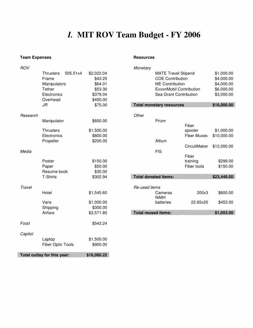
I. MIT ROV Team Budget - FY 2006
Team Expenses Resources
ROV Monetary
Thrusters 505.51x4 $2,022.04 MATE Travel Stipend $1,000.00
Frame $43.25 COE Contribution $4,000.00
Manipulators $64.01 ME Contribution $4,000.00
Tether $53.30 ExxonMobil Contribution $6,000.00
Electronics $379.04 Sea Grant Contribution $3,000.00
Overhead $450.00
JR $75.00 Total monetary resources $18,000.00
Research Other
Manipulator $600.00 Prizm
Thrusters $1,500.00 Fiber spooler $1,000.00
Electronics $800.00 Fiber Muxes $10,000.00
Propeller $200.00 Altium
CircuitMaker $12,000.00
Media FIS
Poster $150.00 Fiber training $299.00
Paper $50.00 Fiber tools $150.00
Resume book $30.00
T-Shirts $302.94 Total donated items: $23,449.00
Travel Re-used items
Hotel $1,545.60 Cameras 200x3 $600.00
Vans $1,000.00 NiMH batteries 22.65x20 $453.00
Shipping $300.00
Airfare $3,571.80 Total reused items: $1,053.00
Food $543.24
Capitol
Laptop $1,500.00
Fiber Optic Tools $900.00
Total outlay for this year: $16,080.22

II. Power Electrical Schematics
MTHR Power Electrical Schematic
JR Power Electrical Schematic
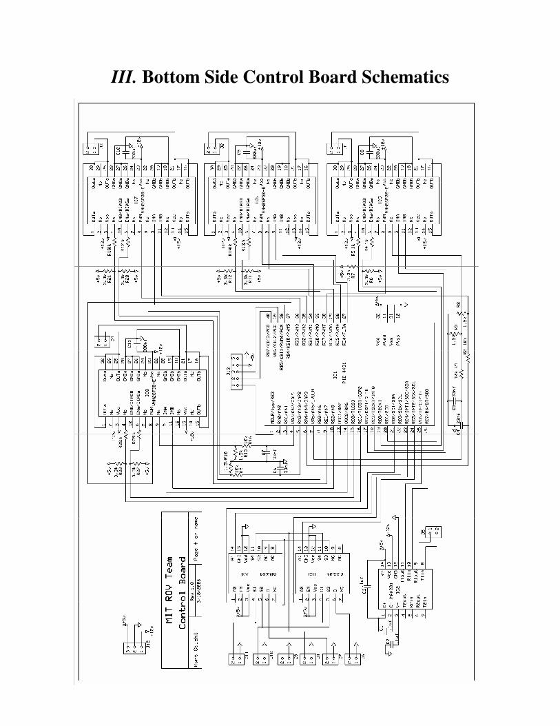
III. Bottom Side Control Board Schematics

IV. Topside Control Flow Chart

V. Bottom Side Control Flow Chart