Advanced capabilities of the multimodal adaptive optics imager (Proceedings Paper)
Upload
khangminh22Category
view
0download
0
VLTi Spectro-Imager
Technical Proposal for a second generation VLTI instrument
in response to ESO Call for Phase-A Proposalsfor 2nd generation VLTI instruments
Document No VSI-PRO-001Issue: 1.0
Date: 30/01/2006
from a consortium composed of the following institutes:
– Laboratoire d’Astrophysique de Grenoble (LAOG, France)
– Cavendish Laboratory, University of Cambridge (United Kingdom)
– Max-Planck Institut fur Radioastronomie in Bonn (MPIfR, Germany)
– Centro de Astrofısica da Universidade do Porto (CAUP, Portugal)
– Istituto Nazionale di Astrofisica (INAF, Italy)
– Institut d’Astrophysique et de Geophysique de Liege (IAGL, Belgium)
– Institut fur Astronomie, Universitat Wien (IfA, Austria)
– Astrophysikalisches Institut und Universitats-Sternwarte (AIU Jena, Germany)
LAOG CavendishCAUP MPIfR INAFIAGL IfA AIU
VLTi Spectro-Imager Doc. No VSI-PRO-001Issue : 1.0
Proposal for a second generation VLTI instrumentDate : 30/01/2006Page : 2 / 118
Change record
Issue Date Update sections Reason / remarks
Draft 0.3 05/01/2006 all first draft (PKe)1.0 30/01/2006 all validation (FMa)
LAOG CavendishCAUP MPIfR INAFIAGL IfA AIU
VLTi Spectro-Imager Doc. No VSI-PRO-001Issue : 1.0
Proposal for a second generation VLTI instrumentDate : 30/01/2006Page : 3 / 118
Table of contents
Change record 2
Executive summary 7
1 Introduction 91.1 Scope of the document . . . . . . . . . . . . . . . . . . . . . . . . . . . . . . . . . . . . . . . . . . . . . 91.2 VLTi Spectro-Imager objectives . . . . . . . . . . . . . . . . . . . . . . . . . . . . . . . . . . . . . . . . 91.3 VLTI infrastructure . . . . . . . . . . . . . . . . . . . . . . . . . . . . . . . . . . . . . . . . . . . . . . 101.4 Context . . . . . . . . . . . . . . . . . . . . . . . . . . . . . . . . . . . . . . . . . . . . . . . . . . . . . 11
1.4.1 Pre-phase A studies, EII colloquium . . . . . . . . . . . . . . . . . . . . . . . . . . . . . . . . . 111.4.2 Presentation to the 60th meeting of the ESO Science Technical Committee . . . . . . . . . . . 111.4.3 Consortium . . . . . . . . . . . . . . . . . . . . . . . . . . . . . . . . . . . . . . . . . . . . . . . 121.4.4 International complementarity and competition . . . . . . . . . . . . . . . . . . . . . . . . . . . 13
1.5 Glossary . . . . . . . . . . . . . . . . . . . . . . . . . . . . . . . . . . . . . . . . . . . . . . . . . . . . . 131.6 References . . . . . . . . . . . . . . . . . . . . . . . . . . . . . . . . . . . . . . . . . . . . . . . . . . . . 13
1.6.1 Applicable and Reference Documents . . . . . . . . . . . . . . . . . . . . . . . . . . . . . . . . 131.6.2 Abbreviations and Acronyms . . . . . . . . . . . . . . . . . . . . . . . . . . . . . . . . . . . . . 15
2 Science cases 172.1 Summary from science cases . . . . . . . . . . . . . . . . . . . . . . . . . . . . . . . . . . . . . . . . . . 17
2.1.1 The formation of stars and planets . . . . . . . . . . . . . . . . . . . . . . . . . . . . . . . . . . 172.1.2 Imaging stellar surfaces . . . . . . . . . . . . . . . . . . . . . . . . . . . . . . . . . . . . . . . . 172.1.3 Evolved stars, stellar remnants & stellar winds . . . . . . . . . . . . . . . . . . . . . . . . . . . 182.1.4 Active galactic nuclei & supermassive black holes . . . . . . . . . . . . . . . . . . . . . . . . . . 18
2.2 Comparison with existing instrument capabilities . . . . . . . . . . . . . . . . . . . . . . . . . . . . . . 182.3 Astrophysical specifications . . . . . . . . . . . . . . . . . . . . . . . . . . . . . . . . . . . . . . . . . . 192.4 Required tasks for Phase A . . . . . . . . . . . . . . . . . . . . . . . . . . . . . . . . . . . . . . . . . . 19
2.4.1 Top level requirements . . . . . . . . . . . . . . . . . . . . . . . . . . . . . . . . . . . . . . . . . 192.4.2 Operational model . . . . . . . . . . . . . . . . . . . . . . . . . . . . . . . . . . . . . . . . . . . 202.4.3 Image reconstruction . . . . . . . . . . . . . . . . . . . . . . . . . . . . . . . . . . . . . . . . . . 202.4.4 Science cases . . . . . . . . . . . . . . . . . . . . . . . . . . . . . . . . . . . . . . . . . . . . . . 20
3 System analysis 213.1 High level specification . . . . . . . . . . . . . . . . . . . . . . . . . . . . . . . . . . . . . . . . . . . . . 21
3.1.1 The imaging paradigm . . . . . . . . . . . . . . . . . . . . . . . . . . . . . . . . . . . . . . . . . 223.1.2 Recall: VLTI infrastructure . . . . . . . . . . . . . . . . . . . . . . . . . . . . . . . . . . . . . . 223.1.3 Image complexity . . . . . . . . . . . . . . . . . . . . . . . . . . . . . . . . . . . . . . . . . . . . 233.1.4 Dynamic range . . . . . . . . . . . . . . . . . . . . . . . . . . . . . . . . . . . . . . . . . . . . . 233.1.5 Spectral coverage and dispersion requirement . . . . . . . . . . . . . . . . . . . . . . . . . . . . 233.1.6 Limiting magnitude . . . . . . . . . . . . . . . . . . . . . . . . . . . . . . . . . . . . . . . . . . 233.1.7 Field of view . . . . . . . . . . . . . . . . . . . . . . . . . . . . . . . . . . . . . . . . . . . . . . 233.1.8 Time resolution . . . . . . . . . . . . . . . . . . . . . . . . . . . . . . . . . . . . . . . . . . . . . 24
3.2 VLTi Spectro-Imager external constraints . . . . . . . . . . . . . . . . . . . . . . . . . . . . . . . . . . 243.2.1 Atmospheric refraction and dispersion . . . . . . . . . . . . . . . . . . . . . . . . . . . . . . . . 24
LAOG CavendishCAUP MPIfR INAFIAGL IfA AIU
VLTi Spectro-Imager Doc. No VSI-PRO-001Issue : 1.0
Proposal for a second generation VLTI instrumentDate : 30/01/2006Page : 4 / 118
3.2.2 Atmospheric dispersion . . . . . . . . . . . . . . . . . . . . . . . . . . . . . . . . . . . . . . . . 253.2.3 Field of View . . . . . . . . . . . . . . . . . . . . . . . . . . . . . . . . . . . . . . . . . . . . . . 253.2.4 Pupil properties . . . . . . . . . . . . . . . . . . . . . . . . . . . . . . . . . . . . . . . . . . . . 253.2.5 Beam optical quality . . . . . . . . . . . . . . . . . . . . . . . . . . . . . . . . . . . . . . . . . . 253.2.6 OPD . . . . . . . . . . . . . . . . . . . . . . . . . . . . . . . . . . . . . . . . . . . . . . . . . . . 253.2.7 Polarization . . . . . . . . . . . . . . . . . . . . . . . . . . . . . . . . . . . . . . . . . . . . . . . 253.2.8 VLTI throughput . . . . . . . . . . . . . . . . . . . . . . . . . . . . . . . . . . . . . . . . . . . . 26
3.3 Functional analysis . . . . . . . . . . . . . . . . . . . . . . . . . . . . . . . . . . . . . . . . . . . . . . . 263.3.1 Atmospheric dispersion compensator . . . . . . . . . . . . . . . . . . . . . . . . . . . . . . . . . 263.3.2 Spatial filtering . . . . . . . . . . . . . . . . . . . . . . . . . . . . . . . . . . . . . . . . . . . . . 273.3.3 Optical path scanner . . . . . . . . . . . . . . . . . . . . . . . . . . . . . . . . . . . . . . . . . . 283.3.4 Wavefront correction . . . . . . . . . . . . . . . . . . . . . . . . . . . . . . . . . . . . . . . . . . 283.3.5 Beam injection . . . . . . . . . . . . . . . . . . . . . . . . . . . . . . . . . . . . . . . . . . . . . 283.3.6 Fringe tracking . . . . . . . . . . . . . . . . . . . . . . . . . . . . . . . . . . . . . . . . . . . . . 293.3.7 Beam combination . . . . . . . . . . . . . . . . . . . . . . . . . . . . . . . . . . . . . . . . . . . 303.3.8 Polarization control . . . . . . . . . . . . . . . . . . . . . . . . . . . . . . . . . . . . . . . . . . 313.3.9 Spectral dispersion . . . . . . . . . . . . . . . . . . . . . . . . . . . . . . . . . . . . . . . . . . . 323.3.10 Detection . . . . . . . . . . . . . . . . . . . . . . . . . . . . . . . . . . . . . . . . . . . . . . . . 323.3.11 Control software . . . . . . . . . . . . . . . . . . . . . . . . . . . . . . . . . . . . . . . . . . . . 333.3.12 Data processing . . . . . . . . . . . . . . . . . . . . . . . . . . . . . . . . . . . . . . . . . . . . . 333.3.13 Image reconstruction . . . . . . . . . . . . . . . . . . . . . . . . . . . . . . . . . . . . . . . . . . 333.3.14 Calibration and alignment tools . . . . . . . . . . . . . . . . . . . . . . . . . . . . . . . . . . . . 33
3.4 Expected performances . . . . . . . . . . . . . . . . . . . . . . . . . . . . . . . . . . . . . . . . . . . . . 343.5 VLTi Spectro-Imager and PRIMA . . . . . . . . . . . . . . . . . . . . . . . . . . . . . . . . . . . . . . 343.6 General system studies . . . . . . . . . . . . . . . . . . . . . . . . . . . . . . . . . . . . . . . . . . . . . 343.7 Summary of required tasks for phase A . . . . . . . . . . . . . . . . . . . . . . . . . . . . . . . . . . . . 34
3.7.1 Wavefront Quality . . . . . . . . . . . . . . . . . . . . . . . . . . . . . . . . . . . . . . . . . . . 343.7.2 Spatial filter module . . . . . . . . . . . . . . . . . . . . . . . . . . . . . . . . . . . . . . . . . . 353.7.3 Optical path compensation . . . . . . . . . . . . . . . . . . . . . . . . . . . . . . . . . . . . . . 353.7.4 Beam injection module . . . . . . . . . . . . . . . . . . . . . . . . . . . . . . . . . . . . . . . . . 353.7.5 Beam combination module . . . . . . . . . . . . . . . . . . . . . . . . . . . . . . . . . . . . . . 353.7.6 Fringe tracker . . . . . . . . . . . . . . . . . . . . . . . . . . . . . . . . . . . . . . . . . . . . . . 353.7.7 Polarization control . . . . . . . . . . . . . . . . . . . . . . . . . . . . . . . . . . . . . . . . . . 353.7.8 Spectrometer . . . . . . . . . . . . . . . . . . . . . . . . . . . . . . . . . . . . . . . . . . . . . . 353.7.9 Detector . . . . . . . . . . . . . . . . . . . . . . . . . . . . . . . . . . . . . . . . . . . . . . . . . 353.7.10 Data Reduction . . . . . . . . . . . . . . . . . . . . . . . . . . . . . . . . . . . . . . . . . . . . . 353.7.11 Image Reconstruction . . . . . . . . . . . . . . . . . . . . . . . . . . . . . . . . . . . . . . . . . 363.7.12 Calibration requirements . . . . . . . . . . . . . . . . . . . . . . . . . . . . . . . . . . . . . . . 363.7.13 Performances . . . . . . . . . . . . . . . . . . . . . . . . . . . . . . . . . . . . . . . . . . . . . . 363.7.14 PRIMA . . . . . . . . . . . . . . . . . . . . . . . . . . . . . . . . . . . . . . . . . . . . . . . . . 363.7.15 Global System Studies . . . . . . . . . . . . . . . . . . . . . . . . . . . . . . . . . . . . . . . . . 36
4 Beam combiner conceptual design: Integrated Optics solution 384.1 Overall description . . . . . . . . . . . . . . . . . . . . . . . . . . . . . . . . . . . . . . . . . . . . . . . 384.2 Atmospheric dispersion compensator . . . . . . . . . . . . . . . . . . . . . . . . . . . . . . . . . . . . . 384.3 Beam injection module . . . . . . . . . . . . . . . . . . . . . . . . . . . . . . . . . . . . . . . . . . . . . 404.4 Spatial filtering . . . . . . . . . . . . . . . . . . . . . . . . . . . . . . . . . . . . . . . . . . . . . . . . . 404.5 Integrated Optics science beam combiners . . . . . . . . . . . . . . . . . . . . . . . . . . . . . . . . . . 41
4.5.1 IO combiners . . . . . . . . . . . . . . . . . . . . . . . . . . . . . . . . . . . . . . . . . . . . . . 414.5.2 Combining concept . . . . . . . . . . . . . . . . . . . . . . . . . . . . . . . . . . . . . . . . . . . 414.5.3 Preliminary results . . . . . . . . . . . . . . . . . . . . . . . . . . . . . . . . . . . . . . . . . . . 414.5.4 IO combiner mechanical support . . . . . . . . . . . . . . . . . . . . . . . . . . . . . . . . . . . 424.5.5 Phase A studies . . . . . . . . . . . . . . . . . . . . . . . . . . . . . . . . . . . . . . . . . . . . 42
4.6 Polarization control . . . . . . . . . . . . . . . . . . . . . . . . . . . . . . . . . . . . . . . . . . . . . . . 434.7 Spectrograph and detector . . . . . . . . . . . . . . . . . . . . . . . . . . . . . . . . . . . . . . . . . . . 44
4.7.1 Spectrograph . . . . . . . . . . . . . . . . . . . . . . . . . . . . . . . . . . . . . . . . . . . . . . 44
LAOG CavendishCAUP MPIfR INAFIAGL IfA AIU
VLTi Spectro-Imager Doc. No VSI-PRO-001Issue : 1.0
Proposal for a second generation VLTI instrumentDate : 30/01/2006Page : 5 / 118
4.7.2 Detector . . . . . . . . . . . . . . . . . . . . . . . . . . . . . . . . . . . . . . . . . . . . . . . . . 454.7.3 Cryostat . . . . . . . . . . . . . . . . . . . . . . . . . . . . . . . . . . . . . . . . . . . . . . . . . 45
4.8 Calibration and alignment tools . . . . . . . . . . . . . . . . . . . . . . . . . . . . . . . . . . . . . . . . 454.8.1 Calibration tools . . . . . . . . . . . . . . . . . . . . . . . . . . . . . . . . . . . . . . . . . . . . 454.8.2 Alignment tools . . . . . . . . . . . . . . . . . . . . . . . . . . . . . . . . . . . . . . . . . . . . . 46
4.9 Degrees of freedom . . . . . . . . . . . . . . . . . . . . . . . . . . . . . . . . . . . . . . . . . . . . . . . 464.10 Software . . . . . . . . . . . . . . . . . . . . . . . . . . . . . . . . . . . . . . . . . . . . . . . . . . . . . 46
4.10.1 Control command . . . . . . . . . . . . . . . . . . . . . . . . . . . . . . . . . . . . . . . . . . . 464.10.2 Data reduction . . . . . . . . . . . . . . . . . . . . . . . . . . . . . . . . . . . . . . . . . . . . . 47
4.11 Additional functionalities . . . . . . . . . . . . . . . . . . . . . . . . . . . . . . . . . . . . . . . . . . . 474.11.1 Option 6T/8T . . . . . . . . . . . . . . . . . . . . . . . . . . . . . . . . . . . . . . . . . . . . . 474.11.2 Beam shaper with adaptive optics . . . . . . . . . . . . . . . . . . . . . . . . . . . . . . . . . . 48
4.12 General means . . . . . . . . . . . . . . . . . . . . . . . . . . . . . . . . . . . . . . . . . . . . . . . . . 494.13 Interfaces . . . . . . . . . . . . . . . . . . . . . . . . . . . . . . . . . . . . . . . . . . . . . . . . . . . . 49
4.13.1 VLTI interfaces . . . . . . . . . . . . . . . . . . . . . . . . . . . . . . . . . . . . . . . . . . . . . 494.13.2 Subsystem interfaces . . . . . . . . . . . . . . . . . . . . . . . . . . . . . . . . . . . . . . . . . . 50
4.14 Phase A tools . . . . . . . . . . . . . . . . . . . . . . . . . . . . . . . . . . . . . . . . . . . . . . . . . . 504.14.1 Experimental setup . . . . . . . . . . . . . . . . . . . . . . . . . . . . . . . . . . . . . . . . . . . 504.14.2 Numerical simulator . . . . . . . . . . . . . . . . . . . . . . . . . . . . . . . . . . . . . . . . . . 50
4.15 Required tasks for phase A . . . . . . . . . . . . . . . . . . . . . . . . . . . . . . . . . . . . . . . . . . 504.15.1 Atmospheric dispersion compensator . . . . . . . . . . . . . . . . . . . . . . . . . . . . . . . . . 514.15.2 Injection module . . . . . . . . . . . . . . . . . . . . . . . . . . . . . . . . . . . . . . . . . . . . 514.15.3 Beam combiner . . . . . . . . . . . . . . . . . . . . . . . . . . . . . . . . . . . . . . . . . . . . . 514.15.4 Polarization control . . . . . . . . . . . . . . . . . . . . . . . . . . . . . . . . . . . . . . . . . . 514.15.5 Spectrograph . . . . . . . . . . . . . . . . . . . . . . . . . . . . . . . . . . . . . . . . . . . . . . 514.15.6 Detector . . . . . . . . . . . . . . . . . . . . . . . . . . . . . . . . . . . . . . . . . . . . . . . . . 514.15.7 Data reduction . . . . . . . . . . . . . . . . . . . . . . . . . . . . . . . . . . . . . . . . . . . . . 514.15.8 Additional functionalities . . . . . . . . . . . . . . . . . . . . . . . . . . . . . . . . . . . . . . . 51
5 Beam combiner conceptual design: Bulk Optics solution 545.1 Overall description . . . . . . . . . . . . . . . . . . . . . . . . . . . . . . . . . . . . . . . . . . . . . . . 545.2 Atmospheric dispersion compensator . . . . . . . . . . . . . . . . . . . . . . . . . . . . . . . . . . . . . 565.3 Alignment/calibration module . . . . . . . . . . . . . . . . . . . . . . . . . . . . . . . . . . . . . . . . . 565.4 Beam switchyard . . . . . . . . . . . . . . . . . . . . . . . . . . . . . . . . . . . . . . . . . . . . . . . . 565.5 Bulk Optics science beam combiner . . . . . . . . . . . . . . . . . . . . . . . . . . . . . . . . . . . . . . 565.6 Path modulators . . . . . . . . . . . . . . . . . . . . . . . . . . . . . . . . . . . . . . . . . . . . . . . . 575.7 Spatial filtering/Beam injection module . . . . . . . . . . . . . . . . . . . . . . . . . . . . . . . . . . . 575.8 Detector and Spectrograph . . . . . . . . . . . . . . . . . . . . . . . . . . . . . . . . . . . . . . . . . . 575.9 Software . . . . . . . . . . . . . . . . . . . . . . . . . . . . . . . . . . . . . . . . . . . . . . . . . . . . . 575.10 Other tasks . . . . . . . . . . . . . . . . . . . . . . . . . . . . . . . . . . . . . . . . . . . . . . . . . . . 575.11 Interfaces . . . . . . . . . . . . . . . . . . . . . . . . . . . . . . . . . . . . . . . . . . . . . . . . . . . . 585.12 Required tasks for phase A . . . . . . . . . . . . . . . . . . . . . . . . . . . . . . . . . . . . . . . . . . 58
5.12.1 Beam switchyard . . . . . . . . . . . . . . . . . . . . . . . . . . . . . . . . . . . . . . . . . . . . 585.12.2 Beam combiner . . . . . . . . . . . . . . . . . . . . . . . . . . . . . . . . . . . . . . . . . . . . . 585.12.3 Path modulators . . . . . . . . . . . . . . . . . . . . . . . . . . . . . . . . . . . . . . . . . . . . 585.12.4 Spatial filtering/Beam injection module . . . . . . . . . . . . . . . . . . . . . . . . . . . . . . . 585.12.5 Other tasks . . . . . . . . . . . . . . . . . . . . . . . . . . . . . . . . . . . . . . . . . . . . . . . 58
6 Internal fringe tracker conceptual design 596.1 Role of the fringe tracker . . . . . . . . . . . . . . . . . . . . . . . . . . . . . . . . . . . . . . . . . . . 59
6.1.1 Fringe acquisition . . . . . . . . . . . . . . . . . . . . . . . . . . . . . . . . . . . . . . . . . . . . 596.1.2 Hardware phase tracking . . . . . . . . . . . . . . . . . . . . . . . . . . . . . . . . . . . . . . . 596.1.3 Hardware coherencing . . . . . . . . . . . . . . . . . . . . . . . . . . . . . . . . . . . . . . . . . 60
6.2 System analysis . . . . . . . . . . . . . . . . . . . . . . . . . . . . . . . . . . . . . . . . . . . . . . . . . 606.3 Dichroics . . . . . . . . . . . . . . . . . . . . . . . . . . . . . . . . . . . . . . . . . . . . . . . . . . . . 616.4 Beam switchyard . . . . . . . . . . . . . . . . . . . . . . . . . . . . . . . . . . . . . . . . . . . . . . . . 61
LAOG CavendishCAUP MPIfR INAFIAGL IfA AIU
VLTi Spectro-Imager Doc. No VSI-PRO-001Issue : 1.0
Proposal for a second generation VLTI instrumentDate : 30/01/2006Page : 6 / 118
6.5 Fringe-tracking combiner . . . . . . . . . . . . . . . . . . . . . . . . . . . . . . . . . . . . . . . . . . . . 626.6 Fast pathlength modulators . . . . . . . . . . . . . . . . . . . . . . . . . . . . . . . . . . . . . . . . . . 626.7 Low-resolution spectrograph and detector . . . . . . . . . . . . . . . . . . . . . . . . . . . . . . . . . . 626.8 Control system . . . . . . . . . . . . . . . . . . . . . . . . . . . . . . . . . . . . . . . . . . . . . . . . . 62
6.8.1 User interface . . . . . . . . . . . . . . . . . . . . . . . . . . . . . . . . . . . . . . . . . . . . . . 636.8.2 Quasi-static control of motorised elements . . . . . . . . . . . . . . . . . . . . . . . . . . . . . . 636.8.3 Real-time servo loops . . . . . . . . . . . . . . . . . . . . . . . . . . . . . . . . . . . . . . . . . 636.8.4 Mode switching . . . . . . . . . . . . . . . . . . . . . . . . . . . . . . . . . . . . . . . . . . . . . 636.8.5 Data archiving . . . . . . . . . . . . . . . . . . . . . . . . . . . . . . . . . . . . . . . . . . . . . 63
6.9 OPD corrector . . . . . . . . . . . . . . . . . . . . . . . . . . . . . . . . . . . . . . . . . . . . . . . . . 636.10 Required studies for Phase-A . . . . . . . . . . . . . . . . . . . . . . . . . . . . . . . . . . . . . . . . . 64
6.10.1 System analysis . . . . . . . . . . . . . . . . . . . . . . . . . . . . . . . . . . . . . . . . . . . . . 646.10.2 Dichroics . . . . . . . . . . . . . . . . . . . . . . . . . . . . . . . . . . . . . . . . . . . . . . . . 646.10.3 Low-resolution spectrographs and detectors . . . . . . . . . . . . . . . . . . . . . . . . . . . . . 64
7 Preliminary development plan 657.1 Project organization . . . . . . . . . . . . . . . . . . . . . . . . . . . . . . . . . . . . . . . . . . . . . . 657.2 Manpower . . . . . . . . . . . . . . . . . . . . . . . . . . . . . . . . . . . . . . . . . . . . . . . . . . . . 66
7.2.1 Required manpower for VLTi Spectro-Imager . . . . . . . . . . . . . . . . . . . . . . . . . . . . 667.2.2 Estimation of the available manpower in the consortium . . . . . . . . . . . . . . . . . . . . . . 68
7.3 Tentative planning . . . . . . . . . . . . . . . . . . . . . . . . . . . . . . . . . . . . . . . . . . . . . . . 687.4 Documentation and deliverable . . . . . . . . . . . . . . . . . . . . . . . . . . . . . . . . . . . . . . . . 707.5 Financial budget . . . . . . . . . . . . . . . . . . . . . . . . . . . . . . . . . . . . . . . . . . . . . . . . 70
7.5.1 Cost evaluation . . . . . . . . . . . . . . . . . . . . . . . . . . . . . . . . . . . . . . . . . . . . . 707.5.2 Financial contributions . . . . . . . . . . . . . . . . . . . . . . . . . . . . . . . . . . . . . . . . 71
7.6 Requirements on VLTI infrastructure . . . . . . . . . . . . . . . . . . . . . . . . . . . . . . . . . . . . . 71
8 Phase-A management plan 738.1 Scope of the chapter . . . . . . . . . . . . . . . . . . . . . . . . . . . . . . . . . . . . . . . . . . . . . . 738.2 Organization of the phase A study . . . . . . . . . . . . . . . . . . . . . . . . . . . . . . . . . . . . . . 738.3 Planning of the phase A . . . . . . . . . . . . . . . . . . . . . . . . . . . . . . . . . . . . . . . . . . . . 748.4 Financial needs . . . . . . . . . . . . . . . . . . . . . . . . . . . . . . . . . . . . . . . . . . . . . . . . . 748.5 Summary of phase A studies . . . . . . . . . . . . . . . . . . . . . . . . . . . . . . . . . . . . . . . . . 758.6 Consortium contribution to the studies . . . . . . . . . . . . . . . . . . . . . . . . . . . . . . . . . . . . 758.7 Phase A deliverable . . . . . . . . . . . . . . . . . . . . . . . . . . . . . . . . . . . . . . . . . . . . . . 75
A Experience from the proposing consortium 81A.1 Laboratoire d’Astrophysique de Grenoble . . . . . . . . . . . . . . . . . . . . . . . . . . . . . . . . . . 81A.2 Cavendish Laboratory, University of Cambridge . . . . . . . . . . . . . . . . . . . . . . . . . . . . . . . 83A.3 Infrared Interferometry Group at the Max-Planck Institute for Radioastronomy . . . . . . . . . . . . . 84A.4 Centro de Astrofısica da Universidade do Porto . . . . . . . . . . . . . . . . . . . . . . . . . . . . . . . 85A.5 Istituto Nazionale di Astrofisica . . . . . . . . . . . . . . . . . . . . . . . . . . . . . . . . . . . . . . . . 86A.6 Institut d’Astrophysique et de Geophysique de Liege . . . . . . . . . . . . . . . . . . . . . . . . . . . . 87A.7 Institut fur Astronomie, Universitat Wien . . . . . . . . . . . . . . . . . . . . . . . . . . . . . . . . . . 88A.8 Astrophysikalisches Institut und Universitats-Sternwarte . . . . . . . . . . . . . . . . . . . . . . . . . . 89
B Bibliography 91B.1 Astrophysical drivers . . . . . . . . . . . . . . . . . . . . . . . . . . . . . . . . . . . . . . . . . . . . . . 91B.2 Optical interferometry and related techniques . . . . . . . . . . . . . . . . . . . . . . . . . . . . . . . . 94B.3 Instrumental projects . . . . . . . . . . . . . . . . . . . . . . . . . . . . . . . . . . . . . . . . . . . . . 101B.4 Observations and Interpretation . . . . . . . . . . . . . . . . . . . . . . . . . . . . . . . . . . . . . . . . 108B.5 Other technical papers . . . . . . . . . . . . . . . . . . . . . . . . . . . . . . . . . . . . . . . . . . . . . 116
LAOG CavendishCAUP MPIfR INAFIAGL IfA AIU
VLTi Spectro-Imager Doc. No VSI-PRO-001Issue : 1.0
Proposal for a second generation VLTI instrumentDate : 30/01/2006Page : 7 / 118
Executive summary
VLTi Spectro-Imager is proposed as second generation VLTI instrument providing the ESO community withthe capability of performing image synthesis at milli-arcsecond angular resolution. Image synthesis is the standardoperation of radio and (sub-)mm interferometers. VLTi Spectro-Imager is the result of the merging of two previousconcept studies, VITRUV and BOBCAT, led by Grenoble and Cambridge, respectively. They where previouslypresented at the ESO workshop in 2005 and at the 60th meeting of the ESO Science and Technical Committee.
VLTi Spectro-Imager provides the VLTI with an instrument able to combine 4 telescopes in a baseline version andoptionally up to 6 telescopes in the near-infrared spectral domain with moderate to high spectral resolution. Theinstrument contains its own fringe tracker in order to relax the constraints onto the VLTI infrastructure.
VLTi Spectro-Imager will do imaging at the milli-arcsecond scale with spectral resolution of: a) the close environ-ments of young stars probing the initial conditions for planet formation; b) the surfaces of stars; c) the environment ofevolved stars, stellar remnants and stellar winds, and d) the central region of active galactic nuclei and supermassiveblack holes. The science cases allowed us to specify the astrophysical requirements of the instrument and to define thenecessary studies of the science group for phase A.
A preliminary system analysis of the VLTi Spectro-Imager, allowed us to clarify the high level specifications of thesystem, the external constraints and to perform a functional analysis. In particular, the instrument was separated into14 functions, the context of PRIMA was addressed and the system tasks for the required phase-A study were defined.
Two solutions for the science beam combiner where identified one based on integrated optics and another on bulkoptics:
• The integrated optics science beam combiner solution has been validated with astrophysical results at highperformance on IOTA and VLTI. It emphasizes the maintainability of the instrument (apart from the injectiondevices, there are no degrees of freedom left for the beam combination); it is well suited to feed a conventionalinfrared spectrograph; enhancing the number of telescopes from 4 to 6 just requires a different IO device whichcan be fed by different fibers and the duplication of 2 more injection modules.
• The bulk optics science beam combiner solution has an emphasis on the commonality with the integrated opticssolution. It is based on a 4-way working prototype in Cambridge. Although having a larger number of degreesof freedom, it has high optical throughput and interferometric contrast. To work with 6 telescopes, the beamcombiner requires fast switching optics in order to select subsets of the input beams to feed the 4-way beamcombiner. The 4 outputs of the beam combiner are injected in fibers to feed a similar spectrograph as the onedesigned for the IO solution.
These two solutions are inherited from the two concepts merged. One of the goals of the Phase A study is to definewhich of them will be used by the VLTi Spectro-Imager.
VLTi Spectro-Imager have an internal fringe tracker which relaxes the constraints on the VLTI interfaces byallowing to servo optical path length differences of the input beams to the required level. An optical switchyard allowsthe operator to choose the best configuration of the VLTI co-phasing scheme in order to allow phase bootstrappingfor the longest baseline on over-resolved objects.
In this proposition, a preliminary development plan is presented, based on our system analysis to estimate the financial,manpower costs and the foreseen planning. The instrument has been divided in 6 subsystems for which 3 subsystemmanagers have already been identified. We think that we will be able to deliver the VLTi Spectro-Imager atParanal by the end of 2010 for a budget of 3251 ke for the IO solution or 3173 ke for the bulk optics option, and, a
LAOG CavendishCAUP MPIfR INAFIAGL IfA AIU
VLTi Spectro-Imager Doc. No VSI-PRO-001Issue : 1.0
Proposal for a second generation VLTI instrumentDate : 30/01/2006Page : 8 / 118
total of 54.8 FTE. Based on the Letters of Intent from the consortium institutes, we estimated that the consortiumcan provide at least 62 FTE. On the financial side, the institutes will submit proposals to their funding agencies.Minimum ESO contribution will be requested for procurements of ESO standard control boards and eventually fordetectors and controllers of the science and the fringe tracker cameras.
All scientific and technical chapters of the proposal end with a summary of the tasks to be fulfilled during the phase-Astudy. The organization proposed is based on a science group and a system group coordinated by a managementteam. Several meetings during the expected 9 months of the phase A are planned, for which we request 51ke to ESO.The estimation of the required manpower is 122 men-months matching the available man power of the consortium (asstated in the Letters of Intent).
LAOG CavendishCAUP MPIfR INAFIAGL IfA AIU
VLTi Spectro-Imager Doc. No VSI-PRO-001Issue : 1.0
Proposal for a second generation VLTI instrumentDate : 30/01/2006Page : 9 / 118
Chapter 1
Introduction
1.1 Scope of the document
This document describes a proposal to ESO for a second generation VLTI instrument in response to ESO Call forPhase-A Proposals for 2nd generation VLTI instruments published on the ESO web site [AD1]. The main driverfor this call is long-baseline interferometry at the VLTI in the available 1-20 microns spectral regions, and aims atcombining a number of telescopes between 4 and 6.
What is expected in the Call for Phase A Proposal is reproduced below:
ESO requests the project to be conceived with the goal of developing end-to-end general use facilities,operated inside the ESO data flow system [REF3, Chap. 10] in place at Paranal and Garching and based onthe VLTI interface description [AD2]. The project should underline the instrument concept, its capabilitiesand operating modes, with a basic description of calibration & data reduction strategy and a compellingscientific case, spelling out the significant astronomical advances that the proposed facility should permit.The response for the call for proposal should include a description of any technical area that would requiresignificant R&D advances and/or prior prototyping, and the strategy to pursue it, and, a preliminaryimplementation plan and cost estimate. Of particular importance is to establish the likely availability ofan adequate team to carry out the project, and possible time scale including the earliest starting date.Finally, the proposal should outline the requirements on the VLTI infrastructure, observing strategies,telescope configurations and observing time requirements required to conduct the key scientific programs.
The proposal for the VLTi Spectro-Imager is composed of 3 documents:
– The technical and managerial proposition [VSI-PRO-001, this volume];
– The science cases [VSI-PRO-002] which details the science objectives of the instrument;
– The document which gathers all Letters of Intent [VSI-PRO-003] from the institutes involved in the consortium.
This document has been written with contributions from all participating institutes with main contributions from theScience Group, LAOG and Cavendish Laboratory.
1.2 VLTi Spectro-Imager objectives
The VLT interferometric facility is unique in the world, since it offers giant 8m telescopes, 2m auxiliary telescopesand the necessary infrastructure to combine them. With four 8m unit telescopes (UTs) equipped with adaptive opticssystems, four 1.8m auxiliary relocatable telescopes (ATs) equipped with tip-tilt correction, a maximum separation of130m for UTs and 200m for ATs, 6 available delay lines, slots foreseen for 2 more ones, a dual feed capability (PRIMA)and a complete system control, the VLTI is the best site to propose the first optical interferometer to deliver
LAOG CavendishCAUP MPIfR INAFIAGL IfA AIU
VLTi Spectro-Imager Doc. No VSI-PRO-001Issue : 1.0
Proposal for a second generation VLTI instrumentDate : 30/01/2006Page : 10 / 118
routinely aperture synthesis images like the millimeter wave interferometers are already doing for more than 10years. The quality of the images will be as good as the ones delivered by the IRAM Plateau de Bure Interferometerwith six 15m antennas and a maximum baseline of 500m at 1-3mm. The VLTI will be for a long time the only facilitywith four 10m class telescopes able to provide 1mas angular resolution in optical wavelength. It is interesting to noticethat the VLTi Spectro-Imager will have similar and even better resolution than ALMA of the order of 1 mas.
We propose a spectro-imager for the VLTI aimed at taking the best profit of the imaging capability of the array,especially in the PRIMA framework. The science objectives of the instrument are focused on the kinematics andmorphology of compact astrophysical objects at optical wavelengths like the environment of AGN, star forming regions,stellar surfaces and circumstellar environments. The instrument will aim at delivering aperture synthesis images withspectral resolution as the final data product to the astronomer. The baseline for the specifications is:
• beam combiners for 4T (specification) and 6T (goal) operation,
• a temporal resolution of the order of 1 day,
• 2 or 3 spectral resolutions from 100 to 10000,
• internal fringe tracking
• image dynamics from 100 to 1000,
• a field of view corresponding to a few hundred of milli-arcsec
• wavelength coverage from 1 to 2.5 microns
One of the interesting feature of this instrument is the possibility to use integrated optics technology (contemplated atthis stage for the beam combination) because this proved technology offers simplicity, stability especially for phases,operational liability, and high performances. This technology was successfully validated on the 3 telescope IOTAinterferometer where the system delivers routinely visibilities for 3 baselines and a closure phase (Monnier et al. 2004[REF19]; Kraus et al. 2005 [REF18]) and at VLTI to replace the fiber coupler of VINCI (Le Bouquin et al. 2004[REF21], 2005 [REF22]). However in the phase A study, we plan to compare the integrated optics solution (chapter4) with the bulk optics one (chapter 4) not only on performances but also in terms of actual implementation andmaintainability. A decision will be made during phase A.
Our strategy is to provide an instrument which combines in a first phase 4 telescopes and secondly 6 telescopes. Thedesign opens also the way to operation with the full VLTI array, i.e. 4 UTs and 4ATs, providing that 2 more delaylines are installed to fulfill the initial VLTI implementation plan.
1.3 VLTI infrastructure
The VLTI infrastructure is the one described by the VLT white-book [REF3] and updated in the appendix of the callfor proposals [AD1].
The Very Large Telescope Interferometer (VLTI) offers a facility with a collecting power significantly greater than anyother interferometer available at present or being planned at visible and infrared wavelengths. It is based on an arrayof the four identical, 8.2-m VLT Unit Telescopes (UT) and four dedicated 1.8-m Auxiliary Telescopes (AT).
The main elements of the VLTI are:
• Four 8.2-m Unit Telescopes (UT), all with Adaptive Optics (AO) correction at their Coude focus.
• Four 1.8-m Auxiliary Telescopes (AT). AO for ATs is being considered.
• Six Delay Lines (DL) installed. Variable Curvature Mirrors (VCM) in the cat’s eye of the DL are used to relaythe pupil. VCMs are currently operational on 2 DLs, and will be extended to all DLs.
• two Differential Delay Lines (DDL) units have been contracted and are under development.
• The Test instrument VINCI with an integrated optics beam combiner in the K-band (IONIC).
• The mid-infrared two beam combiner MIDI in regular science operation.
• The near-infrared three beam combiner AMBER in commissioning and offered in the Call for Proposals forscience operations starting in October 2005.
LAOG CavendishCAUP MPIfR INAFIAGL IfA AIU
VLTi Spectro-Imager Doc. No VSI-PRO-001Issue : 1.0
Proposal for a second generation VLTI instrumentDate : 30/01/2006Page : 11 / 118
• A Fringe Tracker with on-axis guide star (FINITO) under extensive testing at Paranal.
• A near-infrared tip-tilt sensor (IRIS) in the lab.
• PRIMA is a dual-feed system to perform accurate relative phase measurements between objects separated byup to 1 arcminute. Star Separators Systems (STS) for two ATs and two UTs are under development; a thirdSTS/UT (and possibly a fourth one) are externally financed; Fringe Sensor Units (FSU) A&B in development.Metrology in development.
The call for proposal specifies that if properly justified by the scientific case, proposers may consider extensions to theabove VLTI infrastructure in the scenarios of their Phase-A studies.
1.4 Context
1.4.1 Pre-phase A studies, EII colloquium
The project which we are presenting in this document does not come from nowhere. Some initial ideas have alreadybeen published in 2001 at the ESO workshop on Scientific Drivers for ESO Future VLT/VLTI Instrumentation1.These ideas have been developed since in several SPIE conferences. In the OPTICON FP6 European program,the European Interferometry Initiative (EII) Joint Research Activity (JRA) was proposed to focused on Europeaninterferometry development. Its main objective, namely Integrating interferometry into mainstream astronomy2, isto help preparing the future of European Interferometry including the VLTI. One of the work package, AdvancedInstruments, is dedicated to the study of new generation instruments. In this framework, two concepts of near-infraredimager have been proposed:
• VITRUV [REF5] a concept for a near-infrared integrated optics combiner designed for imaging with 4 to 8telescopes.
• BOBCAT [REF9] a concept for a near-infrared (JHK) bulk-optics combiner designed for efficient model-indepen-dent imaging of faint sources.
In April 2005, ESO in collaboration with EII has organized a workshop on The power of optical/IR interferometry:recent scientific results and 2nd generation VLTI instrumentation in Garching. The purpose of the Workshop wasto present and discuss the additional instrumentation required in the next 5-8 years to optimize the scientific returnof the VLTI. For the EII, this Workshop doubled as an internal reviewing process of the instrumental projects thatwere currently being studied as possible VLTI Instruments at the conceptual level in the frame of the Joint ResearchActivity #4 (Interferometry) of the OPTICON FP6 program (see above). On the ESO side, this was the startingpoint of the process for selecting and building 2nd generation VLTI instruments since the Scientific and TechnicalCommittee (STC) of ESO has recommended the extension of PRIMA facility to more than 2 ATs and 2 UTs and thedevelopment of a 4-way fringe tracker.
The instruments proposed through the JRA4 work package, in particular the two proposals VITRUV [REF10] andBOBCAT [REF11], were presented with addition of new instrument concepts. The result of this workshop has beensent to the ESO Science Technical Committee (STC) which decided that the next generation instruments should focuson infrared wavelength. It was the first step before the presentation at the 60th meeting of STC on 17 October 2005.
1.4.2 Presentation to the 60th meeting of the ESO Science Technical Committee
VITRUV and BOBCAT have then been presented to the committee together with two other instrumental concepts,MATISSE and GRAVITY. After deliberation, STC recommended to ESO:
The STC appreciates the presentations by the four groups working on second generation instruments forVLTI, and underlines the importance these instruments could have for the development of the VLTI pro-grams in the next decade. In this framework, the STC acknowledge the relevance of instruments with
1See Haniff & Buscher p. 293; Malbet et al. p. 3032JRA4 see website at eii-jra4.ujf-grenoble.fr
LAOG CavendishCAUP MPIfR INAFIAGL IfA AIU
VLTi Spectro-Imager Doc. No VSI-PRO-001Issue : 1.0
Proposal for a second generation VLTI instrumentDate : 30/01/2006Page : 12 / 118
imaging and spectroscopic capabilities for the near- and mid-IR, exploiting the extensive multi-beam ca-pabilities of VLTI. The STC also recognize the importance of the science cases presented, including inparticular the Galactic center case for general relativity, and those for star and planet formation, and ac-tive galactic nuclei. In these fields the unique characteristics of VLTI may allow important breakthroughs,that should not be unnecessarily delayed.
The STC recommends that ESO solicit formal proposals for Phase A studies for next generation instru-ments with a deadline early in 2006, so that they can be reviewed by ESO in time for the April STCmeeting. These proposals should address not only the scientific capabilities and technical descriptions ofthe proposed instruments, but also the requirements on the VLTI infrastructure, observing strategies, tele-scope configurations and observing time requirements required to conduct the key scientific programs. ESOshould continue to engage with the instrument teams and encourage them to search for possible synergiesbetween the different projects.
Preceding STC request, the VITRUV and BOBCAT teams met in October 2005 in Cambridge to discuss the possibilityto collaborate. The merging of the two concepts was finalized in a meeting organized by ESO staff in November 2005to find synergies among the different NIR concepts. The agreement was based on the fact that the two teams hadcomplementary objectives in their instrument: integrated optics beam combination and control software for LAOG,and, bulk optics beam combination and fringe tracking for Cavendish Laboratory with a common interest in the systemdesign. This is the basis of our common today proposition. Additionally, including fringe tracking in the instrumentbecame a strong requirement. It can be seen also as a willing to relax the interfaces between the instrument and theVLTI infrastructure both in OPD but also in the quality of the incoming wavefront. By relaxing these constraints wethink that the chances to have working up to 6 telescopes and DLs are largely increased.
We do believe that this association between the two proposals is a very strong commitment that will help to definean instrument with the best instrumental design and performance, and, with the experience of the two groups. Giventhe limited amount of time, we chose to postpone some decisions on the system design to the phase A. Therefore theproposition which is made here is, for the moment, a mere juxtaposition of the two proposals where the common partshave to be worked out. We are conscious that this might be a weak point, but on the other hand merging the twoconcepts was also a strong requirement from STC and the ESO community. Anyhow, we tried as much as possible tohave a common project path (for example see Chapter 3 in the system analysis), but for the conceptual design of thebeam combiner we decided to separate the integrated optics solution from the bulk optics solution. As a matter of fact,depending on which solution is finally chosen, the organization of the project might change completely as indicated inthe preliminary development plan (see Chapter 7).
1.4.3 Consortium
The main partners of this proposition are the ones which have been proposing VITRUV and BOBCAT, respectivelyLAOG/CAUP and Cavendish Laboratory. Since the 2005 ESO workshop, other partners have expressed their intereststo be part of such a project. The name of the institutes are listed below, with their contact person:
– Laboratoire d’Astrophysique de Grenoble (France): Dr. F. Malbet
– Cavendish Laboratory, University of Cambridge (United Kingdom): Dr. D. Buscher
– Max-Planck Institut fur Radioastronomie in Bonn (Germany): Pr. G. Weigelt
– Centro de Astrofısica da Universidade do Porto (Portugal): Dr. P. Garcia
– Istituto Nazionale di Astrofisica (Italy): Dr. M. Gai
– Institut d’Astrophysique et de Geophysique de Liege (Belgium): Pr. J. Surdej
– Institut fur Astronomie, Universitat Wien (Austria): Dr. J. Hron
– Astrophysikalisches Institut und Universitats-Sternwarte in Jena (Germany): Pr. R. Neuhauser
More details about the competences, experience and resources of the different institutes are given in Appendix A.
LAOG CavendishCAUP MPIfR INAFIAGL IfA AIU
VLTi Spectro-Imager Doc. No VSI-PRO-001Issue : 1.0
Proposal for a second generation VLTI instrumentDate : 30/01/2006Page : 13 / 118
1.4.4 International complementarity and competition
The VLTi Spectro-Imager will be competing with several other interferometers: the Keck interferometer when theoutriggers will be operational, but also the CHARA and phase-I MROI arrays. The latter instruments howeverwill be less sensitive because of smaller apertures, will provide less (u, v) coverage with 6 telescope, although theirmaximal baselines are about 10% to 75% longer. As the spectro-imaging instrument of PRIMA, the VLTiSpectro-Imager will have no other competitors for a few years.
More quantitative details on the comparison with existing facilities are given in the science cases [REF1 and Chapter 2].
1.5 Glossary
In this section we clarify some key points of the instrument by defining what we mean under specific terms.
– Beam combination. Beam combination is the heart of the instrument. This is the subsystem which is incharge to combine the different beams carried individually by the VLTI to the interferometric lab. By combiningthe beams, we can measure complex visibilities, that means the correlation of the electric field sampled by thedifferent telescopes and gives the astronomer information on the spatial distribution of intensity of the source.
– Visibilities. Visibilities are complex quantities which correspond to the value of the Fourier transforms of thespatial intensity distribution of the source sampled at different spatial frequencies (= baselines, i.e. pairs oftelescopes, divided by the wavelength). The interferometric fringes are overimposed on the total photometricflux coming from all beams. A fringe is characterized by its period, its amplitude and its phase. The period ofthe fringe is given by the instrumental setup and is chosen in order to distinguish between the different pairs oftelescopes. The fringe amplitude is measured in intensity unit whereas the phase is measured in radian. Thevisibility amplitude is the fringe amplitude normalized by the total photometric flux coming from the source.
– Integrated optics. Integrated optics is a particular type of optics. It is part of guided optics which also includesfiber optics. Like in fiber optics, the light propagates in integrated optics devices within optical guides. Butin addition integrated optics can perform different functions on the light: beam splitting, beam combination,mirrors, chromatic coupling,...in one single solid substrate. It is the analog of integrated circuits in micro-electronics, when fibers are the analog of electrical wires.
– Bulk optics. Traditional optics where the light propagates freely in the air and the functions are applied byindividual optical elements like lenses, mirrors, beam splitters,...
– Fringe tracking. Due to atmospheric turbulence, the fringes are jittering: the optical path difference (OPD)between two telescopes varies because of the changes of the refractive index of the air both spatially and tem-porally. The result is that the fringes move. A fringe tracker is a subsystem which is able to measure theinstantaneous phase of the fringes and send a command to an OPD actuator which will compensate the motion.When the loop is closed, the fringes are frozen. There are different flavors of fringe tracking, mainly phasetracking and group delay tracking (see Chapter 6). In phase tracking, one measures the phase and one ensuresthat the fringe does not move more than a small percentage of the fringe so that the science beam combinercan increase the SNR with long integration time. In group delay tracking, data is recorded only if the fringe iswithin the coherence length of the interferometer (a few fringes) and one ensures that it does not escape fromthis length. The requirements are less stringent than those for fringe tracking, but since the fringe is alwayspresent, the idea is to average many short exposures to increase the SNR. In the VLTi Spectro-Imager, wecontemplate using both techniques so that we can have access both to high sensitivity (group delay tracking)and high spectral resolution on relatively bright objects (phase tracking).
1.6 References
1.6.1 Applicable and Reference Documents
[AD1] ESO call for Proposalshttp://www.eso.org/projects/vlti/instru/2ndgeneration/cfp-2ndgeneration-vlti-instruments.htm
LAOG CavendishCAUP MPIfR INAFIAGL IfA AIU
VLTi Spectro-Imager Doc. No VSI-PRO-001Issue : 1.0
Proposal for a second generation VLTI instrumentDate : 30/01/2006Page : 14 / 118
[AD2] Interface Control Document between the VLTI and its instruments, VLT-ICD-ESO-15000-1826, Issue 4,date: 11/08/2005http://www.eso.org/projects/vlti/instru/2ndgeneration/vlt-icd-eso-15000-1826 iss4.pdf
[REF1] VLTI Spectro-Imager - Science Cases VSI-PRO-002, Issue 1.0, Date: 27/01/2006 (companion docu-ment).
[REF2] VLTI Spectro-Imager - Letters of Intent from the Institutes of the consortium VSI-PRO-003, Issue 1.0,Date: 26/01/2006 (companion document).
[REF3] The VLT White Bookhttp://www.eso.org/outreach/ut1fl/whitebook
[REF4] PRIMA Reference Mission Report by the VLTI Implementationhttp://www.eso.org/gen-fac/commit/stc/stc-58th/8-STCPRIMA2004.pdf
[REF5] VITRUV - Concept Study ReportEII-JRA4 document, JRA4-TRE-1160-0001, Issue 1, date: 15/02/2005http://eii-jra4.ujf-grenoble.fr/doc/approved/JRA4-TRE-1160-0001.pdf
[REF6] VITRUV - Science casesEII-JRA4 document, JRA4-TRE-1160-0002, Issue 1, date: 03/2005http://eii-jra4.ujf-grenoble.fr/doc/approved/JRA4-TRE-1160-0002.pdf
[REF7] VITRUV - Preliminary Management PlanEII-JRA4 document, JRA4-TRE-1160-0003, Issue 1, date: 25/03/2005http://eii-jra4.ujf-grenoble.fr/doc/approved/JRA4-TRE-1160-0003.pdf
[REF8] VITRUV - Preliminary System StudiesEII-JRA4 document, JRA4-TRE-1160-0004, Issue 1, date: 03/2005http://eii-jra4.ujf-grenoble.fr/doc/approved/JRA4-TRE-1160-0004.pdf
[REF9] Bulk-Optics - Concept Study ReportEII-JRA4 document, JRA4-TRE-1120-0001, Issue 1, date: 03/03/2005http://eii-jra4.ujf-grenoble.fr/doc/approved/JRA4-TRE-1120-0001.pdf
[REF10] VITRUV - Imaging close environments of stars and galaxies with the VLTI at milli-arcsec resolutionin Proc. of ESO/EII workshop on “ The power of optical/IR interferometry: recent scientific results and2nd generation VLTI instrumentation”http://arxiv.org/abs/astro-ph/0507233
[REF11] BOBCAT - a photon-efficient multi-way beam combiner for the VLTIin Proc. of ESO/EII workshop on “ The power of optical/IR interferometry: recent scientific results and2nd generation VLTI instrumentation”
[REF12] AMBER ESO/VLTI Conceptual Design Review (AMB-REP-004)http://amber.obs.ujf-grenoble.fr/IMG/pdf/amb-rep-004.pdf
[REF13] AMBER Instrument Analysis Report, VLT-TRE-AMB-15830-0001, Issue 2.0, DATE: 19/06/2001http://amber.obs.ujf-grenoble.fr/PLAIN/pae/Documents FDR/Documents/1 TRE IAR.pdf
[REF14] J.-B. Le Bouquin PhD thesis “Imagerie par synthese d ouverture optique, application aux etoileschimiquement particulieres”. Part II: “Un spectro-polarimetre imageur au VLTI”http://www-laog.obs.ujf-grenoble.fr/ jblebou/These/these LeBouquin 2005.pdf
[REF15] Improvements for group delay fringe tracking,Basden, A. G. and Buscher, D. F., MNRAS 357, 656 (2005)
[REF16] Low light level limits to tracking atmospheric fringe wanderBuscher, D.F., in “Quantum Limited Imaging and Information Processing”, 1989 Technical Digest Series(OSA), vol. 13, 67 (1989)
LAOG CavendishCAUP MPIfR INAFIAGL IfA AIU
VLTi Spectro-Imager Doc. No VSI-PRO-001Issue : 1.0
Proposal for a second generation VLTI instrumentDate : 30/01/2006Page : 15 / 118
[REF17] An introduction to closure phase in Principles of long Baseline Interferometry, JPL Publication 00-00907/00http://olbin.jpl.nasa.gov/iss1999/coursenotes.html
[REF18] Infrared Imaging of Capella with the IOTA Closure Phase InterferometerKraus, S. et al., AJ 130, 246 (2005)
[REF19] First Results with the IOTA3 Imaging Interferometer: The Spectroscopic Binaries lambda Virginisand WR 140,Monnier, J. -D., ApJ 602, L57 (2005)
[REF20] The calibration of interferometric visibilities obtained with single-mode optical interferometers. Com-putation of error bars and correlations,Perrin, G., A&A 400, 1173 (2003)
[REF21] First observations with an H-band integrated optics beam combiner at the VLTI,Le Bouquin, J.B. et al., A&A 424, 719 (2004)
[REF22] Integrated optics for astronomical interferometry - VI. Coupling the light of the VLTI in K band,Le Bouquin, J.B. et al., A&A in press, astro-ph/0512544 (2006)
[REF23] Fringe Visibility Estimators for the Palomar Testbed Interferometer,Colavita M.M., PASP 111, 111 (1999)
1.6.2 Abbreviations and Acronyms
ADC Atmospheric Dispersion CompensatorAGN Active Galactic NucleusAIT Assembly Integration and TestsAIU Astrophysikalisches Institut und Universitats-Sternwarte in JenaALMA Atacama Large Millimeter ArrayAMBER Astronomical Multi-BEam RecombinerAO Adaptive OpticsAPRES-MIDI Instrumental concept for an upgrade of MIDIAT Auxiliary telescopes (1.8m)AU Astronomical UnitBLR Broad-Line RegionsBO Bulk OpticsBOBCAT Bulk Optics Beam Combiner And Tracker, project of an instrument of second generation.CAUP Centro de Astrofısica da Universidade do PortoCHARA Center for High Angular Resolution AastronomyCONICA COude Near Infrared CAmeraCRIRES Cryogenic High-Resolution IR Echelle SpectrometerDDL Differential Delay LinesDL Delay LinesEGP Extra-Solar Giant PlanetEII European Interferometry InitiativeESO European Southern ObservatoryFDR Final Design RevewFINITO First generation fringe tracking unitFOV Field of ViewFP6 Sixth Framework Programme (European)FPA Focal Plane ArrayFSU Fringe Sensor UnitFT Fringe TrackerFTU Fringe Tracker UnitFTE Full Time EquivalentFWHM Full Width at Half Maximum
LAOG CavendishCAUP MPIfR INAFIAGL IfA AIU
VLTi Spectro-Imager Doc. No VSI-PRO-001Issue : 1.0
Proposal for a second generation VLTI instrumentDate : 30/01/2006Page : 16 / 118
GRAVITY One of the proposed concepts for the 2ng generation VLTI instrumentHR Hertzsprung-Russell (effective temperature-luminosity diagram)HST Hubble Space TelescopeIAGL Institut d’Astrophysique et de Geophysique de LiegeICD Interface Control DocumentIfA Institut fur Astronomie, Universitat WienINAF Istituto Nazionale di AstrofisicaIO Integrated OpticsIONIC Integrated Optics Near-Infrared CombinerIOTA Infrared Optical Telescope ArrayIR Infra-RedIRAM Institut de Radio-Astronomie MillimetriqueIRIS Infra-Red Image SensorJMMC Jean-Marie Mariotti CenterJRA Joint Research ActivityKI Keck InterferometerLAOG Laboratoire d’Astrophysique de l’Observatoire de GrenobleLCU Local Control UnitLETI Laboratoire d’Electronique et de Technologies de l’InformationLN2 Liquid NitrogenMATISSE One of the proposed concepts for the 2ng generation VLTI instrumentMHD Magneto-Hydro-DynamicsMIDI MID-Infrared VLTI first generation instrumentMOS Multi-Object SpectroscopyMPIfR Max-Planck Institut fur RadioastronomieMROI Magdalena Ridge Observatory InterferometerMS Main SequenceNACO NAOS/CONICANAOS Nasmyth Adaptive Optics SystemNGST New Generation Space TelescopeNIR Near InfraredNPOI Navy Prototype Optical InterferometerOPD Optical Path DifferenceOPTICON Optical Infrared Coordination Network for AstronomyPAE Preliminary Acceptance EuropePdBI Plateau de Bure InterferometerPDR Preliminary Design RevewPMS Pre-Main SequencePNe Planetary NebulaePRIMA Phase-Reference Imaging and Micro-arcsecond AstrometryPSF Point Spread FunctionRV Radial VelocitySINFONI Spectrograph for INtegral Field Observations in the Near InfraredSNR Signal to Noise RatioSPIE International Society for Optical EngineeringSR Strehl RatioSTC Science and Techincal CommitteeSTS Star Telescope SeparatorTBC To Be ConfirmedTBD To Be DefinedTBW To Be WrittenUT Unit Telescope (8m)VCM Variable Curvature MirrorVINCI VLT Interferometer Near-Infrared Commissioning InstrumentVITRUV Not an acronym. Project of an instrument of second generation.VLT Very Large TelescopeVLTI Very Large Telescope InterferometerWBS Work Breakdown StructureWFS Wavefront Sensor

LAOG CavendishCAUP MPIfR INAFIAGL IfA AIU
VLTi Spectro-Imager Doc. No VSI-PRO-001Issue : 1.0
Proposal for a second generation VLTI instrumentDate : 30/01/2006Page : 17 / 118
Chapter 2
Science cases
2.1 Summary from science cases
VLTi Spectro-Imager concept is a general purpose instrument aimed at exploiting the full capability of the VLTIinfrastructure including the faint science space enabled by PRIMA. VLTi Spectro-Imager is up to 5 times faster thancurrent interferometric instrumentation (AMBER) because it combines up to 6 telescopes. The wavelength range isJHK. Three spectral resolutions are available ∼100, ∼1000 and ∼10000. The dynamic range of the reconstructedimages is 10-100 with a goal of 100-1000. There is a goal of retaining polarization information.
The current science cases definition methodology was to concentrate in a few fields where VLTi Spectro-Imager canmake a substantial contribution, without being exhaustive. In this respect the PRIMA reference mission document[REF4] is highly complementary to this one. A detailed presentation of the science cases is given in “Science Cases- VSI-PRO-002” [REF1] accompanying this document. The main science cases for VLTi Spectro-Imager are listedbelow.
2.1.1 The formation of stars and planets
The early evolution of stars and the initial conditions for planet formation are determined by the interplay of accretionand outflow processes. Due the small spatial scales where these processes engines actuate, very little is known aboutthe actual physical and chemical mechanisms at work. Interferometric imaging at 1 mas (milli-arcsecond) will directlyprobe the regions responsible for the bulk of continuum emission excess from these objects therefore constraining thecurrently highly degenerate models for the spectral energy distribution. In the emission lines a variety of processeswill be probed, in particular outflow and accretion magnetospheres. The inner few AUs of evolved planetary systemswill also be studied, providing additional information on their formation and evolution processes, as well as on thephysics of extrasolar planets.
2.1.2 Imaging stellar surfaces
Optical imaging instruments are a powerful means to resolve stellar features at the generally patchy surfaces ofstars throughout the HR diagram. Optical interferometry has already proved its ability to derive surface structureparameters such as limb darkening or others atmosphere parameters. VLTi Spectro-Imager, as an imaging device,is of strong interest to study various specific features as vertical and horizontal temperature profiles, abundanceinhomogeneities and detect their variability as the star rotates and pulsates. This will provide important keys to addressstellar activity processes, mass-loss events, magneto-hydrodynamic mechanisms, pulsation and stellar evolution.
LAOG CavendishCAUP MPIfR INAFIAGL IfA AIU
VLTi Spectro-Imager Doc. No VSI-PRO-001Issue : 1.0
Proposal for a second generation VLTI instrumentDate : 30/01/2006Page : 18 / 118
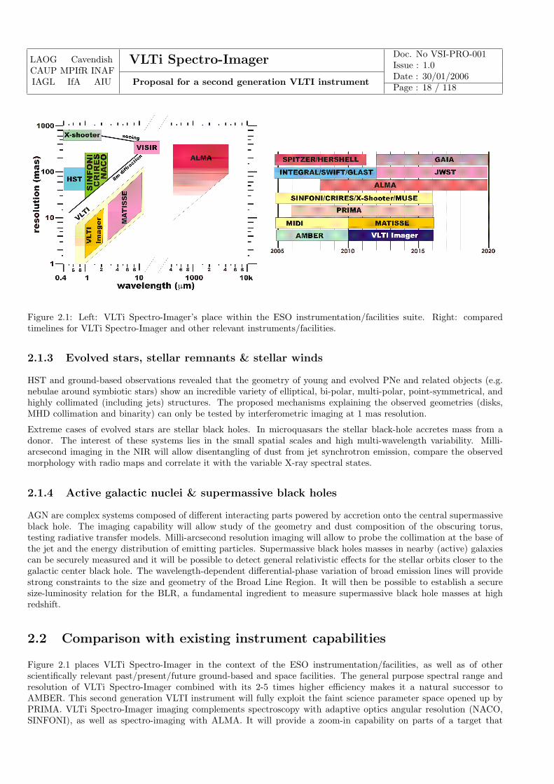
Figure 2.1: Left: VLTi Spectro-Imager’s place within the ESO instrumentation/facilities suite. Right: comparedtimelines for VLTi Spectro-Imager and other relevant instruments/facilities.
2.1.3 Evolved stars, stellar remnants & stellar winds
HST and ground-based observations revealed that the geometry of young and evolved PNe and related objects (e.g.nebulae around symbiotic stars) show an incredible variety of elliptical, bi-polar, multi-polar, point-symmetrical, andhighly collimated (including jets) structures. The proposed mechanisms explaining the observed geometries (disks,MHD collimation and binarity) can only be tested by interferometric imaging at 1 mas resolution.
Extreme cases of evolved stars are stellar black holes. In microquasars the stellar black-hole accretes mass from adonor. The interest of these systems lies in the small spatial scales and high multi-wavelength variability. Milli-arcsecond imaging in the NIR will allow disentangling of dust from jet synchrotron emission, compare the observedmorphology with radio maps and correlate it with the variable X-ray spectral states.
2.1.4 Active galactic nuclei & supermassive black holes
AGN are complex systems composed of different interacting parts powered by accretion onto the central supermassiveblack hole. The imaging capability will allow study of the geometry and dust composition of the obscuring torus,testing radiative transfer models. Milli-arcsecond resolution imaging will allow to probe the collimation at the base ofthe jet and the energy distribution of emitting particles. Supermassive black holes masses in nearby (active) galaxiescan be securely measured and it will be possible to detect general relativistic effects for the stellar orbits closer to thegalactic center black hole. The wavelength-dependent differential-phase variation of broad emission lines will providestrong constraints to the size and geometry of the Broad Line Region. It will then be possible to establish a securesize-luminosity relation for the BLR, a fundamental ingredient to measure supermassive black hole masses at highredshift.
2.2 Comparison with existing instrument capabilities
Figure 2.1 places VLTi Spectro-Imager in the context of the ESO instrumentation/facilities, as well as of otherscientifically relevant past/present/future ground-based and space facilities. The general purpose spectral range andresolution of VLTi Spectro-Imager combined with its 2-5 times higher efficiency makes it a natural successor toAMBER. This second generation VLTI instrument will fully exploit the faint science parameter space opened up byPRIMA. VLTi Spectro-Imager imaging complements spectroscopy with adaptive optics angular resolution (NACO,SINFONI), as well as spectro-imaging with ALMA. It will provide a zoom-in capability on parts of a target that
LAOG CavendishCAUP MPIfR INAFIAGL IfA AIU
VLTi Spectro-Imager Doc. No VSI-PRO-001Issue : 1.0
Proposal for a second generation VLTI instrumentDate : 30/01/2006Page : 19 / 118
remain unresolved by AO and/or ALMA, which is often critical for the interpretation of the large scale imaging andspectroscopy.
Once equipped with VLTi Spectro-Imager, the VLTI will be more capable than any competing near-infrared imagingarray. For example, the VLTI will be much more sensitive than NPOI, and will provide better image fidelity thanCHARA and the Keck Interferometer, thanks to its relocatable ATs. With regard to future arrays, the augmentedVLTI will be more than competitive with the six-telescope MROI Phase I since the inclusion of the larger diameterUTs will provide better sensitivity.
2.3 Astrophysical specifications
The top level astrophysical specifications identified at this stage are:
• Three spectral resolution modes: ∼100, ∼1000, ∼10 000.
• Three imaging modes: parametric (no images and only a list of visibility measurements including V2, closurephase, differential phase or visibility phase), snapshot imaging (dynamic range up to ∼100), high dynamic rangeimaging (up to ∼1000).
• Field of view a few times the diffraction limit of a UT: ∼0.1 arcsec.
• Limiting K magnitude of at least 13 at low spectral resolution.
2.4 Required tasks for Phase A
The science cases and astrophysical specifications presented form a framework where VLTi Spectro-Imager is a plausibleinstrument with an outstanding scientific potential. However, they remain in some aspects very qualitative andincomplete. It is therefore clear that a Phase-A study is required. It should focus, quantify and complete the presentscience cases, top level requirements, operational model and image reconstruction. In the following subsections, wepass in review the science group tasks for the Phase-A study already identified allowing a more precise and systematicapproach than the current document.
2.4.1 Top level requirements
The following tasks quantify the instrument top level requirements.
[Task 1] Define the three spectral resolution modesThe science cases identified a low, intermediate and high spectral resolution modes. The exact valuesfor the instrument resolutions setup will be defined balancing sensitivity and parametric versus imagingmodes.
[Task 2] CalibratorsIdentify calibrators that allow baseline bootstrapping (can calibrate large/small simultaneous baselines).Statistical study of faint calibrators and very large baseline calibrators.
[Task 3] Define the maximum time in which an image must be takenLimiting factors can be the movement of the object (e.g. binary rotation) or connected to calibration issues.
[Task 4] Define data productsThere are two possible end data products for the instrument: a) calibrated spectrally dispersed visibili-ties/(closure) phases and b) data cubes. Is b) viable? What is the use of the ALMA experience?
[Task 5] PolarizationWill linear polarization be a data product?
LAOG CavendishCAUP MPIfR INAFIAGL IfA AIU
VLTi Spectro-Imager Doc. No VSI-PRO-001Issue : 1.0
Proposal for a second generation VLTI instrumentDate : 30/01/2006Page : 20 / 118
2.4.2 Operational model
[Task 6] Observing modesWe can anticipate three observing modes: parametric visibility, snapshot image, high dynamic range image.How do they translate in terms of operations and calibrations?
[Task 7] Complementary observationsPre-imaging is a natural precursor observation to MOS observations. Is AO pre-imaging required forour science? How important are the incoherent/coherent contributions for image reconstruction? Howcontemporary must it be? Same question applies to (spectro)photometry.
[Task 8] Target of opportunityThe feasibility of a target of opportunity mode will be assessed.
2.4.3 Image reconstruction
The following tasks have to be shared between the science and system groups. We will accomplish these tasks thanksto a strong connection to the JMMC image reconstruction group and thanks to the EII-JRA4 effort.
[Task 9] Science image strategyDefine array configurations, imaging time requirements, number of simultaneous telescopes used, dynamicrange and image quality.
[Task 10] Image reconstruction algorithm selectionSeveral image reconstruction algorithms are already developed in the context of optical interferometrywithin the consortium. They should bench-marked and one of them will be selected for open use.
[Task 11] AO dataHow can the AO data be used for the image reconstruction process? Study data combination with AOand other interferometers.
[Task 12] FOV and mosaicingIdentify the required FOV and the viability of mosaicing.
2.4.4 Science cases
[Task 13] Define legacy programmesThe science case will be focused in a few (∼10) key legacy programmes in representative areas of astro-physics. These programmes can be undertaken under GTO, large programme or public survey mode.
[Task 14] Target listsFor each programme, target lists will be built including relevant information (e.g. position, multi-bandmagnitude, spectra, variability, geometry, statistical significance) for the end-to-end simulation.
[Task 15] Generate synthetic imagesRadiative transfer models (in the lines or continuum), hydrocode simulations or simple geometrical modelswill be used to generate synthetic images for the science cases.
[Task 16] End-to-end simulation and feedbackThe target information and an end-to-end simulation tool will allow to feedback the analysis on: a)attainability of scientific goals; b) top level requirements; c) operational model.
[Task 17] Identify preparatory programmes relevant for the instrumentPreparatory programmes for the instrument using AMBER/SINFONI/NACO/CRIRES with an intrinsicscientific potential will be identified and pursued.
[Task 18] Complementary and competitionQuantify the level of competition from other optical interferometers (MROI, CHARA) and complementaryfrom existing/planned ESO/space instrumentation.
LAOG CavendishCAUP MPIfR INAFIAGL IfA AIU
VLTi Spectro-Imager Doc. No VSI-PRO-001Issue : 1.0
Proposal for a second generation VLTI instrumentDate : 30/01/2006Page : 21 / 118
Chapter 3
System analysis
We have carried out a system study aimed at defining a preliminary conceptual design for a multipurpose near-infraredspectro-imager for the VLTI. These studies, matching as much as possible the science case requirements, have raisedseveral mandatory questions that will have to be addressed during the phase A study.
The simple idea behind this work is to provide the astronomical community with an efficient spectro imager able tofulfill a broad science program. One additional important constraint has been and will be continuously taken intoconsideration: the requirement that VLTi Spectro-Imager should be an easy to maintain instrument.
This system study has taken benefit of the extensive experience of members of the consortia past experience in previoussuccessful facilities and instruments (e.g. COAST, AMBER/VLTI, IONIC/IOTA and IONIC/VLTI).
In the initial VITRUV study the fringe tracking instrument was not included, BOBCAT study included it. It appearsthat the capability of VLTi Spectro-Imager to carry out its science program depends heavily on the VLTI abilityto cophase its telescopes. We have therefore considered that a phase-A study should include an analysis of what isexpected as far as VLTI cophasing is concerned.
As required by the call for proposal, the VLTi Spectro-Imager is conceived with the goal of developing end-to-endgeneral use facility. In the following four chapters, we describe the instrument system analysis and a preliminaryconceptual design encompassing hardware description, science capabilities, calibration strategy and data reductionstrategy.
3.1 High level specification
Although the initial work done by the science group has allowed us to better constrain what should be the range ofperformance of VLTi Spectro-Imager further work is needed, the science case phase-A study will have to answer thefollowing questions that will directly impact the instrument observing modes.
1. expected image complexity;
2. dynamic range;
3. spectral coverage and dispersion requirement;
4. limiting magnitude;
5. field of view;
6. time resolution (i.e duration to obtain an image);
This in turn will allow the system study to define high-level technical requirements. These requirements will concernmainly
1. what is the level of (u,v) coverage expected to access to a given complexity;
LAOG CavendishCAUP MPIfR INAFIAGL IfA AIU
VLTi Spectro-Imager Doc. No VSI-PRO-001Issue : 1.0
Proposal for a second generation VLTI instrumentDate : 30/01/2006Page : 22 / 118
2. what is the level of visibility and phase (closure-phase) accuracy expected;
3. what is the level of array cophasing accuracy that is expected.
At the time of the study we consider that the VLTi Spectro-Imager should be able to combine fourtelescopes as a basic requirement but should include a detailed description of its ability to combine sixtelescopes (goal).
In the following subsections we recall what can be said about the different science requirements from the system study.
3.1.1 The imaging paradigm
VLTi Spectro-Imager is intended to be an imager with spectral resolution. The final astronomical product shouldtherefore be an image at each spectral channel.
VLTi Spectro-Imager will be able to measure sufficient visibilities and phase information to permit model-independentimage reconstruction. This puts a strong constraint on the number of (u,v) points for which one needs to obtainvisibility, closure phase and differential-phase measurements. In particular increasing the number of telescopes hasan immediate impact on the amount of phase information that can be retrieve through the use of closure phasesquantities.
The importance of retrieving phase information is considerable and three options arise:
1. using a second source as a phase reference;
2. using the closure phase technique;
3. in peculiar cases using spectral differential phases;
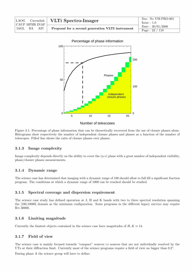
The closure-phase technique [REF17] allows us to retrieve atmosphere-free phase information. In a standard inter-ferometer absolute phase information is lost due to multiple wave-front perturbations, (optomechanical instability,atmospheric piston). Using combination of at least three telescopes allows to extract the so-called closure-phases bysumming up each baseline interferogram phases. This summation cancels out all the parasitic phase perturbationand produces the closure phase. Figure 3.1 shows how using an increasing number of telescopes allows to reduce theamount of phase information difference between phase and closure phases.
Although extracting phase information from closure phase measurements is a tough work a considerable amount ofresearch to find efficient algorithms has been carried (radio) and is still underway. We believe that the considerablerelaxation of instrumental/operation constraints introduced by the use of closure phase quantities instead of phases isworth the already successful effort to find numerical ways to reduce the degeneracy when phases are extracted fromclosure phases.
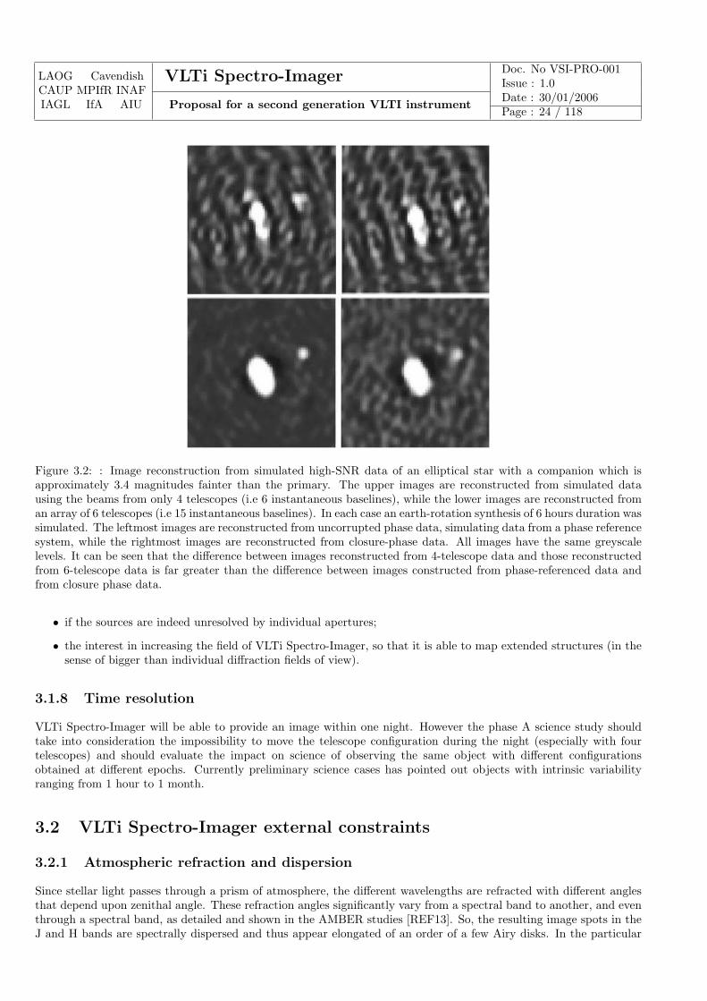
Of course the possibility of accessing directly to phase measurements is very interesting and the phase-A study shouldinclude a detailed study of the impact of phase vs. closure phase measurements on the final image reconstructioncapability. However we can anticipate that the gain in terms of image quality due to the use of phase instead ofclosure phase might not be as important as the gain due to the increase in the number of telescopes. See figure 3.2and caption for an illustration. It should be remembered that imaging with the VLTI, which requires a good level ofcophasing will have an important impact on VLTI operation.
3.1.2 Recall: VLTI infrastructure
VLTI can provide 4 UT telescope and 4 AT telescope. Six delay lines are available. Our starting point is consideringthat VLTi Spectro-Imager should be able to manage the combination of four telescopes. An additional mode whereVLTi Spectro-Imager can combine six telescopes to take full benefit of the current infrastructure will be also considered.This latter should not be taken lightly since the impact on imaging capability of switching from 4T to 6T is considerable.VLTI offers the possibility of phase referencing thanks to the PRIMA mode. Two Star Separator Systems (STS) arealready available but two additional ones are foreseen (see Sect. 1.3).
LAOG CavendishCAUP MPIfR INAFIAGL IfA AIU
VLTi Spectro-Imager Doc. No VSI-PRO-001Issue : 1.0
Proposal for a second generation VLTI instrumentDate : 30/01/2006Page : 23 / 118
5 10 15 20 0
50
100
Independent closure phases
Phases
0
100
200
Percentage of phase information
Number of telescopes
Figure 3.1: Percentage of phase information that can be theoretically recovered from the use of closure phases alone.Histograms show respectively the number of independent closure phases and phases as a function of the number oftelescopes. Filled line shows the ratio of closure phases over phases.
3.1.3 Image complexity
Image complexity depends directly on the ability to cover the (u,v) plane with a great number of independent visibility,phase/closure phases measurements.
3.1.4 Dynamic range
The science case has determined that imaging with a dynamic range of 100 should allow to full fill a significant fractionprogram. The conditions at which a dynamic range of 1000 can be reached should be studied.
3.1.5 Spectral coverage and dispersion requirement
The science case study has defined operation at J, H and K bands with two to three spectral resolution spanningthe [100,10000] domain as the minimum configuration. Some programs in the different legacy surveys may requireR≈ 30000.
3.1.6 Limiting magnitude
Currently the faintest objects contained in the science case have magnitudes of H,K ≈ 14.
3.1.7 Field of view
The science case is mainly focused towards “compact” sources i.e sources that are not individually resolved by theUTs at their diffraction limit. Currently most of the science programs require a field of view no bigger than 0.2”.
During phase A the science group will have to define:
LAOG CavendishCAUP MPIfR INAFIAGL IfA AIU
VLTi Spectro-Imager Doc. No VSI-PRO-001Issue : 1.0
Proposal for a second generation VLTI instrumentDate : 30/01/2006Page : 24 / 118
Figure 3.2: : Image reconstruction from simulated high-SNR data of an elliptical star with a companion which isapproximately 3.4 magnitudes fainter than the primary. The upper images are reconstructed from simulated datausing the beams from only 4 telescopes (i.e 6 instantaneous baselines), while the lower images are reconstructed froman array of 6 telescopes (i.e 15 instantaneous baselines). In each case an earth-rotation synthesis of 6 hours duration wassimulated. The leftmost images are reconstructed from uncorrupted phase data, simulating data from a phase referencesystem, while the rightmost images are reconstructed from closure-phase data. All images have the same greyscalelevels. It can be seen that the difference between images reconstructed from 4-telescope data and those reconstructedfrom 6-telescope data is far greater than the difference between images constructed from phase-referenced data andfrom closure phase data.
• if the sources are indeed unresolved by individual apertures;
• the interest in increasing the field of VLTi Spectro-Imager, so that it is able to map extended structures (in thesense of bigger than individual diffraction fields of view).
3.1.8 Time resolution
VLTi Spectro-Imager will be able to provide an image within one night. However the phase A science study shouldtake into consideration the impossibility to move the telescope configuration during the night (especially with fourtelescopes) and should evaluate the impact on science of observing the same object with different configurationsobtained at different epochs. Currently preliminary science cases has pointed out objects with intrinsic variabilityranging from 1 hour to 1 month.
3.2 VLTi Spectro-Imager external constraints
3.2.1 Atmospheric refraction and dispersion
Since stellar light passes through a prism of atmosphere, the different wavelengths are refracted with different anglesthat depend upon zenithal angle. These refraction angles significantly vary from a spectral band to another, and eventhrough a spectral band, as detailed and shown in the AMBER studies [REF13]. So, the resulting image spots in theJ and H bands are spectrally dispersed and thus appear elongated of an order of a few Airy disks. In the particular
LAOG CavendishCAUP MPIfR INAFIAGL IfA AIU
VLTi Spectro-Imager Doc. No VSI-PRO-001Issue : 1.0
Proposal for a second generation VLTI instrumentDate : 30/01/2006Page : 25 / 118
case of a single-mode instrument this leads to a coupling efficiency degradation at the extreme wavelengths of thesebands. Another consequence lies in the fact that the angle between the beam direction provided by the adaptive opticsdevice to the image sensor and the direction of the actual observing wavelength varies with time, inducing a variationof the coupling efficiency.
3.2.2 Atmospheric dispersion
Since stellar light does not follow the same horizontal optical path in the air, an optical path difference (OPD)proportional to the interferometric baseline and to the projection of the zenithal angle on the meridian plane exists.As computed in the AMBER studies [REF13], this effect is rather negligible with the exception of long baselines andat low spectral resolution. In these cases, visibility loss can reach several percents but quickly decrease with spectralresolution. Moreover the corresponding bias can be well modeled.
3.2.3 Field of View
Whatever the telescopes, the unvigneted field of view (FOV) at the instrument input has a diameter of 2”. The ESOfacility PRIMA allows a dual-feed mode with two FOV of 2”, separated by an Airy disk at least and picked up anywayon the global Coude field of 2’ [AD2].
3.2.4 Pupil properties
Whatever the instrumental configuration, the pupil at the instrument input has a diameter of 18 mm. Thanks to theVariable Curvature Mirrors, the pupil can be re-imaged at any location in the focal lab with a precision of ± 6.4 mmwith the UTs, and of ± 125 mm with the ATs in the single feed mode. The nominal lateral position lies 1.46 ± 0.01m above the lab floor level and depends upon the considered beam. The lateral distance between beams equals 240mm. Accuracy and stability of these pupil positions are provided in [AD2].
3.2.5 Beam optical quality
The typical tip-tilt error budget provides errors smaller than 21 mas rms on the sky with the UTs, and than 30 masrms on the sky with the ATs, in the single feed mode. Details on tip-tilt corrections and wave front error correctionsare given in [AD2].
Based on the current experience with AMBER it seems reasonable to reassess the tip/tilt performances at VLTI inorder to determine the need for an additional module integrated to VLTi Spectro-Imager that would allow additionaltip/tilt and/or higher order modes adjustment.
3.2.6 OPD
The VLTI has been designed to be intrinsically stable and, without fringe tracking, internal VLTI OPD fluctuationsof 338 nm in K band are expected for an exposure time of 48 ms [AD2].
3.2.7 Polarization
The VLTI has been designed to minimize the differential polarization effects thanks to symmetric optical trains.Nevertheless due to multiple reflections in each arm, various optical coatings, aging of these coatings, etc. residual po-larization effects as partial polarization and phase shifts between the two perpendicular directions of linear polarizationand/or between two different interferometric arms remain. Estimations are provided in the ICD [AD2]:
• partial polarization rate of 10%,
• absolute linear retardation in one arm lower than 100◦ in H band and than 80◦ in K band: cross talks betweenlinear and circular polarizations can occur throughout the propagation along the optical train,
LAOG CavendishCAUP MPIfR INAFIAGL IfA AIU
VLTi Spectro-Imager Doc. No VSI-PRO-001Issue : 1.0
Proposal for a second generation VLTI instrumentDate : 30/01/2006Page : 26 / 118
• differential linear retardation between two arms smaller than 20◦ in H band and than 10◦ in K band: instrumentalpolarization induces a slight instrumental contrast decrease (smaller than 1.5% in H band and than 0.4% in Kband).
3.2.8 VLTI throughput
The VLTI throughput with the UTs and the ATs equals from 20% up to 35% over the J, H and K bands, accordingto the wavelength and the optical configuration [AD2].
3.3 Functional analysis
We have carried out a sub-system breakdown in order to define for each of the instrument functions what were thestudies that had to be addressed during the phase A study.
At the current level of the study we have not merged any of the two different concepts (BOBCAT and VITRUV) butwe can reasonably agree on the following subsystem breakdown illustrated in Fig. 3.3. As we will see in next chapterthe preliminary conceptual designs arising from that are quite different and the phase A study will have to define thebest concept.
The VLTi Spectro-Imager 14 subfunctions are made of:
1. atmospheric dispersion compensator;
2. spatial filtering;
3. wavefront correction;
4. fringe tracking;
5. optical path scanner;
6. beam injection;
7. beam combiner;
8. polarization control;
9. spectral dispersion;
10. detector;
11. data processing;
12. calibration and alignment tools;.
13. control module;
14. image reconstruction.
It should be stated that some of the previous subsystems might be irrelevant depending on the final beam combinationconcept adopted. Also the fringe tracking instrument should be seen as an instrument by itself (see section 3.3.6).
3.3.1 Atmospheric dispersion compensator
While the atmospheric refraction is quite negligible for the K band, it has been shown in section 3.2.1 that the effect ismore critical in the J and H band. The scientific instrument operating one band at a time, no compensation is requiredfor the atmospheric refraction effect between two bands. In the case of the fringe tracker, the operating spectral bandshave to be defined in the next study phase. Nevertheless, if this one needs to work simultaneously with two spectralbands, the atmospheric refraction will have to be compensated on a larger band. As a consequence, an atmosphericcompensator will have to be implemented and its specifications must have to be defined in the next phase taking intoaccount the scientific instrument and the fringe tracker.
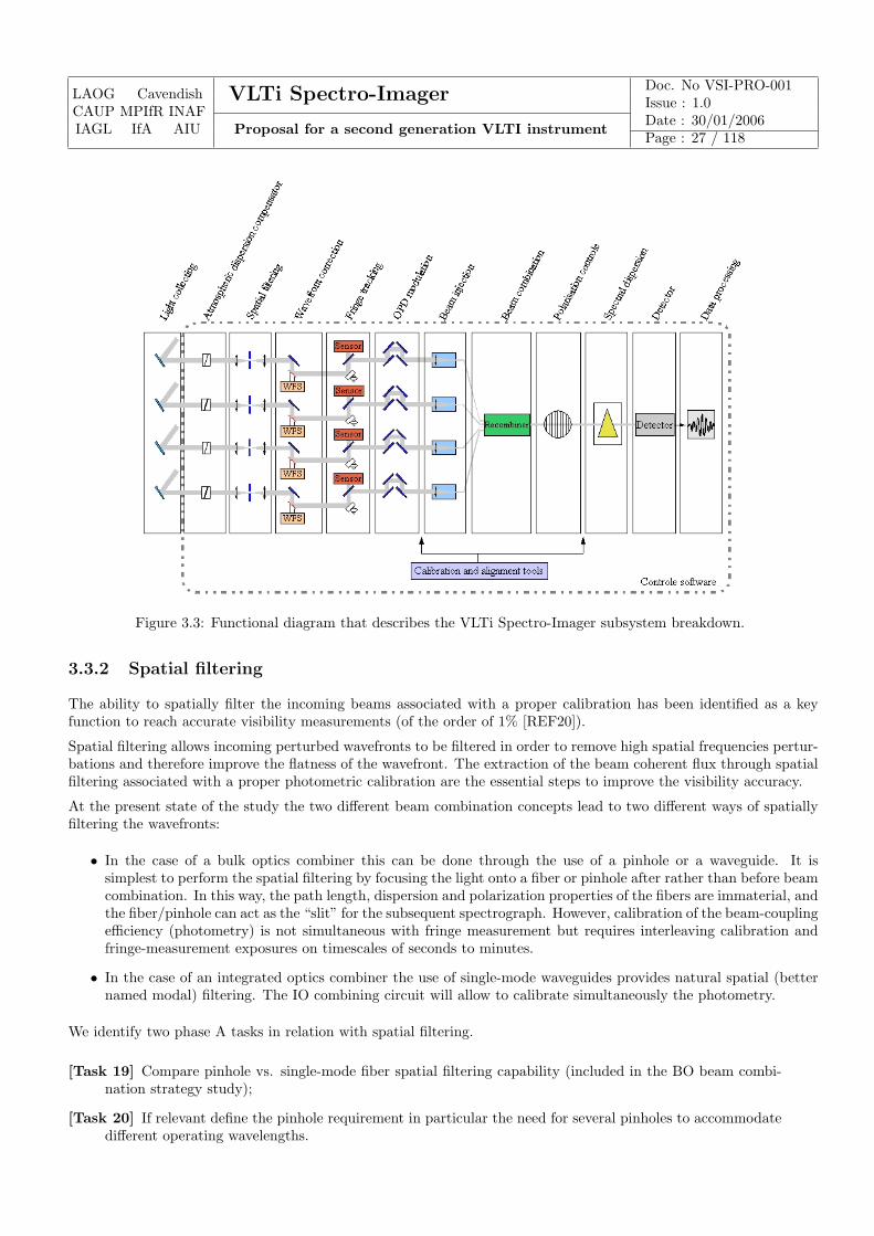
LAOG CavendishCAUP MPIfR INAFIAGL IfA AIU
VLTi Spectro-Imager Doc. No VSI-PRO-001Issue : 1.0
Proposal for a second generation VLTI instrumentDate : 30/01/2006Page : 27 / 118
Figure 3.3: Functional diagram that describes the VLTi Spectro-Imager subsystem breakdown.
3.3.2 Spatial filtering
The ability to spatially filter the incoming beams associated with a proper calibration has been identified as a keyfunction to reach accurate visibility measurements (of the order of 1% [REF20]).
Spatial filtering allows incoming perturbed wavefronts to be filtered in order to remove high spatial frequencies pertur-bations and therefore improve the flatness of the wavefront. The extraction of the beam coherent flux through spatialfiltering associated with a proper photometric calibration are the essential steps to improve the visibility accuracy.
At the present state of the study the two different beam combination concepts lead to two different ways of spatiallyfiltering the wavefronts:
• In the case of a bulk optics combiner this can be done through the use of a pinhole or a waveguide. It issimplest to perform the spatial filtering by focusing the light onto a fiber or pinhole after rather than before beamcombination. In this way, the path length, dispersion and polarization properties of the fibers are immaterial, andthe fiber/pinhole can act as the “slit” for the subsequent spectrograph. However, calibration of the beam-couplingefficiency (photometry) is not simultaneous with fringe measurement but requires interleaving calibration andfringe-measurement exposures on timescales of seconds to minutes.
• In the case of an integrated optics combiner the use of single-mode waveguides provides natural spatial (betternamed modal) filtering. The IO combining circuit will allow to calibrate simultaneously the photometry.
We identify two phase A tasks in relation with spatial filtering.
[Task 19] Compare pinhole vs. single-mode fiber spatial filtering capability (included in the BO beam combi-nation strategy study);
[Task 20] If relevant define the pinhole requirement in particular the need for several pinholes to accommodatedifferent operating wavelengths.
LAOG CavendishCAUP MPIfR INAFIAGL IfA AIU
VLTi Spectro-Imager Doc. No VSI-PRO-001Issue : 1.0
Proposal for a second generation VLTI instrumentDate : 30/01/2006Page : 28 / 118
3.3.3 Optical path scanner
The science instrument should have an internal path scanner in order to allow to:
1. cophase fringe tracker and science instrument (residual OPDs can be caused by differential longitudinal disper-sion, mechanical instability etc...)
2. scan through the fringe packet for calibration purposes.
In the current view of the instrument the OPD scanner will be included in the beam injection module in the case ofan IO combiner and will be an independent module in the case of a Bulk Optics combiner.
In addition to that the fringe tracker/science instrument might require a common optical path scanner in order toservo the OPD control commands sent by the fringe tracker.
[Task 21] Specify the different optical path compensation requirements.
3.3.4 Wavefront correction
The wavefront correction will be a particularly sensitive issue in the context of a spatially filtering instrument. StrehlRatios performances will have to be carefully monitored since they affect the global throughput and photometricstability.
[Task 22] During the phase A, the VLTI ability to deliver stable and sufficiently flat wavefronts will have to beassessed;
[Task 23] If this study demonstrates that a significant gain could be obtained with an internal active opticssystem, the phase A will have to specify it (expected performances).
3.3.5 Beam injection
This module is required in the context of a single-mode instrument where light coming from the telescope has tobe injected into single-mode fibers. We have voluntarily split the beam injection module and spatial filtering modulealthough both of them have common functionalities. However the conceptual design of such a module differs betweenthe integrated optics and the bulk optics option (see next two chapters).
The beam injection module will have to ensure several other functions which are described below:
• light injection in the fibers;
• coupling optimization;
• spatial filtering (in the IO-based concept);
• fiber selection (J, H or K);
• orientation of the fiber neutral axis;
• OPD correction;
• OPD scan;
Specific comments:
Injection and optimization of the flux: The opto-mechanical design of the injection unit have to be defined toensure the coupling of the 18 mm VLTI beams in the fibers. It should allow also a fine adjustment of the flux on aregular basis.
Wavelength selection: As described in the ”beam combination” section, two/three IO components are needed tocover the three spectral bands. As a consequence, depending on the operating band, the injection unit will have to
LAOG CavendishCAUP MPIfR INAFIAGL IfA AIU
VLTi Spectro-Imager Doc. No VSI-PRO-001Issue : 1.0
Proposal for a second generation VLTI instrumentDate : 30/01/2006Page : 29 / 118
direct the flux in the corresponding fiber J,H or K. A motorized mechanical stage must therefore ensure the switchingfrom the different fibers.
Polarization direction adjustment: Due to polarization control constraints the single mode fibers used beforethe combination are polarization-maintaining type. Therefore their birefringence axis need to be aligned at the beaminjection position. Whether this should be a degree of freedom or an imposed feature is still to be defined.
OPD scanning In the integrated optics version of the instrument we consider implementing an optical path explo-ration capability to the beam injection module. This is motivated by the interest in being able to retrieve instrumentinternal fringes and correct for optical path differences between the fringe tracker and science instrument.
[Task 24] Specify the precise functionalities of the beam injection module.
3.3.6 Fringe tracking
A fringe tracker, which measures and actively corrects time-varying OPD errors arising from atmospheric phaseperturbations and instrumental effects, is essential for the proper functioning of the instrument. VLTi Spectro-Imagerincorporates a fringe tracker as part of the instrument, as an alternative to using an external fringe tracker such as anupgraded version of PRIMA capable of tracking fringes on up to 6 telescopes. This allows the operation of the fringetracker to be tailored to the science mission of the instrument, and reduces the demands on VLTI infrastructure.
The fringe tracker will have at minimum the following distinct modes:
1. “Fringe acquisition” in which a finite region of OPD space is scanned in order to find the fringe coherenceenvelope in the presence of atmospheric and instrumental delay uncertainties.
2. “Hardware phase tracking” in which the delay errors are actively compensated at high speed so that the level ofstability of the science combiner fringes is sufficient to allow on-chip integration of the fringe signal over periodsof many atmospheric coherence times.
3. “Hardware coherencing” in which the delay errors are compensated in real time but at a lower speed, withsufficient precision to ensure that the loss in fringe contrast due to temporal coherence effects is small overincoherent integration periods of many minutes.
The hardware coherencing mode will use group-delay tracking to allow access to the faintest objects, while the hardwarephase tracking mode will be used for high-spectral-resolution observation of brighter objects. The fringe tracker willbe able to switch automatically between these modes based on the SNR in the fringe-tracking channels. In all modes,the fringe-tracker fringe sensing data will be time-tagged and archived with the science data in order to allow “softwarephase tracking” and “software coherencing” to be used to “phase up” and coherently integrate the science fringe dataduring post-processing.
The on-board fringe tracker unit (FTU) will use light from the science target, but in a different near-infrared bandpassfrom the science bandpass, in order to determine the OPD errors. It will use the H band for fringe tracking whenthe J or K bands are being used for science and will use the K band for fringe tracking when H-band science isrequired. Ultra-efficient (> 98% throughput in both transmission and reflection) dichroics will be used to separate thefringe-tracking light from the science combiner light.
The fringe tracker should track the fringes on at least 3 connected baselines in order to cophase 4 telescopes, andat least 5 connected baselines in order to cophase 6 telescopes. The fringe tracker will be based on a pairwise beamcombination scheme, which can be readily expanded from a 4-telescope fringe tracker to a 6-telescope fringe tracker.A “beam switchyard” will allow the telescope pairs used for fringe tracking to be selected so as to track fringes onbaselines where the source is least resolved, in a “baseline bootstrapping” configuration. The fringe tracker unit willbe optimized for the highest-possible SNR for tracking on faint objects. It does not need to be optimized for visibilitycalibration accuracy or baseline coverage.
We have identified the following tasks to be carried out during the phase A study.
[Task 25] specify high level requirements (group delay vs. phase tracking, limiting magnitude performancesetc...);
LAOG CavendishCAUP MPIfR INAFIAGL IfA AIU
VLTi Spectro-Imager Doc. No VSI-PRO-001Issue : 1.0
Proposal for a second generation VLTI instrumentDate : 30/01/2006Page : 30 / 118
[Task 26] specify the fringe tracker in detail (operating wavelength, combination concept, bootstrapping strat-egy, performances).
3.3.7 Beam combination
In the four telescope configuration VLTi Spectro-Imager should measure simultaneously six visibilities and threeindependent closure phases. In the six telescope configuration it should measure fifteen visibilities and ten independentclosure phases1.
The beam combiner encodes the fringe signal into a recordable format, the interferogram, from which visibilities andphases are later extracted. Beam combination schemes are numerous but two major characteristics can be pointedout:
• Interferogram fringe encoding strategy: spatial, temporal or matricial;
• Beam combining strategy: all-in-one, pairwise, intermediate.
At the present level of the study we consider two technical options presented in the BOBCAT and VITRUV propo-sitions. The first one is based on compact adhesive bulk optics technology the second one on integrated opticstechnologies.
Although the phase A study will have to refine the numbers it is reasonable to say based on the already existing sciencethat: the beam combiner should be capable of combining 4 to 6 beams (goal) and retrieve all visibilities and closurephases with an accuracy of 1% for the visibilities (goal 0.1%) and 1 degree for the closure phase (goal: 0.1 degree) onmost of science targets2.
These specifications will have to be translated into throughput, instrumental contrast, visibility and phase stability,coherent and incoherent crosstalk, biases requirements.
Bulk optics combiner
The design of the bulk optics combiner proposed is based on the 4-way beam combiners used at COAST to makethe first optical and infrared aperture synthesis images. The “all in one” combination mode characteristic of thisdesign means that the measured closure phases are free of instrumental systematics to first order, yielding sub-degreeclosure phase accuracy without calibration. This design has subsequently been improved to use contacted optics formechanical stability and to use improved coatings for ultra-high throughput. A prototype combiner demonstratinghigh throughput and requiring no adjustment of any parts has been demonstrated in the laboratory in Cambridge.
An additional component of the bulk optics concept that has been developed as part of the preliminary system studyis the use of a “beam switchyard” which allows a straightforward upgrade to 6-telescope operation by rapidly selectingsubsets of beams to feed into the existing 4-way combiner. In this way all the u-v coverage offered by the 6-telescopearray is exploited with good observing efficiency and minimal hardware changes. It should be noted that it would alsobe possible to use this switchyard design to upgrade the 4-way integrated optics combiner to use more telescopes.
Integrated optics combiner
Integrated optics beam combiners have been used successfully at VLTI and IOTA for the combination of respectivelytwo and three telescopes. This experience associated with extensive laboratory experimentation has brought animportant amount of experience on the actual performances that are to be expected from an IO combiner.
The motivation behind the use of IO beam combiner is that it is expected and demonstrated that the combinationof modal filtering, proper photometric calibration and intrinsic stability leads to excellent visibility and closure phaseaccuracy measurements. Science oriented image reconstructions using the IOTA interferometer equipped with anIO 3-way beam combiner have already been published and demonstrate that IO technologies have reach a maturedevelopment[REF18, REF19].
1In the eight telescope case the number of visibilities amounts to 28 and 21 independent closure phases.2An additional information on what are the smallest visibilities to be measured will have to be provided

LAOG CavendishCAUP MPIfR INAFIAGL IfA AIU
VLTi Spectro-Imager Doc. No VSI-PRO-001Issue : 1.0
Proposal for a second generation VLTI instrumentDate : 30/01/2006Page : 31 / 118
For the purpose of the VITRUV preliminary system study on beam combination strategy we have carried out an ex-tensive analysis of all the beam combination scheme possible with a focus on signal to noise efficiency and technologicalfeasibility. Our starting point was the requirement that all visibilities and closure phases should be simultaneouslyrecorded [REF14]. The conclusion of this system study together with preliminary laboratory experiments are detailedin section 4.5. Our analysis pointed out a 4-way (matricial-ABCD) pairwise combiner as our best combining schemewhile for more beams the competition between matricial-ABCD and multi-axial all-in-one is opened.
It should be recalled that the overall performances will be evaluated once the fringe tracker performances will beknown but also once several issues related to the use of bandpass limited, birefringent and dispersive waveguides havebeen demonstrated to be controllable to the required levels. An optical end-to-end simulator and numerical end-toend simulator are already being exploited to address these questionings.
[Task 27] The phase A study will have to define a common grid and carry out a detailed comparison ofthe two concepts taking into account pure throughput efficiency, beam combination scheme, practicalimplementation; expected visibility/phase accuracy, the logistical aspects of their operation (etc...). Theend product should be a decision on the beam combination concept.
[Task 28] Study on the best beam combination concept for 6 telescopes and specify how the 4T version of theinstrument could be upgraded.
3.3.8 Polarization control
Due to potential residual polarization effects of the VLTI optical trains, polarimetric behavior of the instrument topartially polarized light has to be controlled at the instrument level. In fact cross talks between polarization directionscan significantly damage the instrumental contrast, produce beat phenomena between these directions and/or parasiticinterferograms.
In the IO version of the combination two important considerations argue in favor of some level of polarization control.
1. Planar integrated optics components exhibit two neutral axes corresponding to the normal to the componentplane and the direction in this plane that is perpendicular to the propagation direction. As such they behave aspolarization-maintaining fibers. We thus plug each input of integrated optics beam combiner to a polarization-maintaining fiber. For maintenance purpose, an additional fiber cord is plugged from the injection device toeach fibered input of the beam combiner, and the neutral axes are aligned together. Cross-talks can occur due tomisalignment of these neutral axes at the fiber connection level. With such a device, we have shown in laboratoryand modeled with a numerical simulator (VITRUVSim) that fiber birefringence can induce contrast degradationif the different polarization directions are not separated. Moreover due to fiber sensitivity to temperature andpressure variation, instrumental contrast can fluctuate with time [REF14].
2. As far as science is concerned, it could be of great interest to couple polarimetric measurements with high angularresolution to be able to partially resolve polarized structures at the surface or in the environment of stars. Thisimplies to access to the linear and/or circular polarization emitted by the target. Our preliminary study of thewhole instrumental polarization (including the VLTI optical train and the focal instrument) shows [REF14]:
• for astrophysical circular polarization, the large number of reflections in the VLTI optical train which couplesboth circular polarizations together and converts a part of them in linear ones seems to make impossiblethe interpretation of the obtained polarized visibilities.
• for astrophysical linear polarization, the large number of reflections in the VLTI optical train only induces asmall partial polarization (10%). Polarized visibilities, which would be biased, may be used in a parametricapproach to bring new constraints on object models.
To summarize, we recommend to simultaneously record visibilities in two perpendicular linear polarization directionssince it appears as a diagnosis tool for better understanding and modeling the instrumental contrast answer. Wehave also proved in lab and at VLTI and IOTA that such a polarization separation allows to significantly improvethe instrumental contrast stability with time. Finally, the simultaneous record of polarized visibilities can bring newconstraints on astrophysical polarizing phenomena as scattering, dichroism, etc.
LAOG CavendishCAUP MPIfR INAFIAGL IfA AIU
VLTi Spectro-Imager Doc. No VSI-PRO-001Issue : 1.0
Proposal for a second generation VLTI instrumentDate : 30/01/2006Page : 32 / 118
[Task 29] interact with VLTI to constrain as much as possible VLTI optical train effect on polarization;
[Task 30] simulate polarization behavior of IO combiner;
[Task 31] assess bulk optics combiner polarization behavior.
3.3.9 Spectral dispersion
The scientific goals impose to cover the J, H and K bands but no specific requirements have been made to observein two or more bands simultaneously. The amount of complexity required to observe in two or more of these bandssimultaneously is therefore not worth of consideration (strengthened by AMBER experience).
At the present level we are considering two to three spectral resolutions in the [100,10000] range (extension to 30000to be confirmed) that need to be specified. A particular care should be taken by the science group to describe preciselythe specific need as far as spectral resolution is required. As an example the calibration requirements to measure aradial velocity or measure a line profile are not the same and have a direct incidence on the spectrometer calibrationunit design.
[Task 32] specify the exact spectral resolution requirements (both min and max) as recommended by the sciencegroup;
[Task 33] specify the calibration constraint required for each spectral mode (in particular stability).
3.3.10 Detection
Detection performance will depend on fringe tracker performances and we can already anticipate two major modeswhere fringe tracker is performing group-delay tracking and fringe tracking. In the first case readout will have to befast whatever the beam combination scheme in order to avoid fringe blurring, in the second case (required for highspectral resolution) it will be possible to integrate the coherent flux.
One of the critical aspects of this sub-system is the strong requirement to include from the beginning of the phase-Astudy the need for adequate calibration. This statement is reinforced by our current experience with AMBER.
The science detector is located inside the spectrograph cryostat, local calibrations must be possible :
• bias calibration (shutter or dark position)
• flat-field calibration (extended flat illumination with integrated sphere)
• bad pixel calibration (idem)
• pixel linearity calibration (idem)
Science detector characteristics to be taken into consideration
• Spectral range
• Read-out noise
• Read-out time
• Number of pixels and pixel size: The preliminary analysis shows that the HAWAII format could complywith the integrated optics combiners specifications. The complete system analysis led during the A phase willhave to confirm this choice.
[Task 34] define the detector required performance and operating modes in relation with the fringe trackerperformances;
LAOG CavendishCAUP MPIfR INAFIAGL IfA AIU
VLTi Spectro-Imager Doc. No VSI-PRO-001Issue : 1.0
Proposal for a second generation VLTI instrumentDate : 30/01/2006Page : 33 / 118
3.3.11 Control software
Software control role will be to:
• control instrument degrees of freedom (filter wheels, gratings, scanners, translations);
• control the data acquisition (camera control, both fringe tracker and science instrument);
• provide data quick-look capability;
• dialog with the super OS;
• control calibration tools (light sources, scanners, degrees of freedom);
3.3.12 Data processing
Data processing for the instrument includes image cosmetics, ABCD- like algorithms for extraction of correlated fluxes,algorithms for real-time estimates of pistons, and further computation of all available interferometry observables, V 2,differential visibilities, closure phases. The final products will be delivered in the OI FITS format for further dataanalysis (image reconstruction, etc...) with available public-domain packages. The consortium benefits here of thestrong expertise deployed within the data processing software for the AMBER instrument at ESO and for the IONICbeam combiner at IOTA.
[Task 35] specify the observable expected accuracy (visibility, phases, closure phases) in terms of data reductionrequirements (algorithms , etc ...).
3.3.13 Image reconstruction
At the present level of our evaluation we consider sub-contracting the study of image reconstruction tools to JMMCwhich manages a European effort (JRA4/OPTICON) to provide the community with image reconstruction softwaretools. We will therefore interact with JMMC in order to carry on the following task in close collaboration with thescience group:
[Task 36] specify the incidence of imaging requirements on system choices and VLTI operation. In particularassess the importance of the number of telescopes and PRIMA availability on imaging capability. In closeinteraction with science group.
3.3.14 Calibration and alignment tools
This is an essential part of the instrument that needs improvements with respect to what has been donefor AMBER. The overall stability of the instrument will act directly on the need for complex and time-consumingcalibration steps an important amount of phase A time should therefore be spent on assessing the level of calibrationrequirement.
VLTi Spectro-Imager will require several layers of alignment/calibration:
1. aligning VLTi Spectro-Imager and fringe tracker with VLTI;
2. VLTi Spectro-Imager internal alignment (here we can note that both beam combination concepts are considerablysimpler to align than any previous beam combiner);
3. VLTi Spectro-Imager internal interferometric response calibration;
4. spectrometer calibration;
5. detector calibration.
[Task 37] Define the alignment/calibration requirements, specify the corresponding subsystems.
LAOG CavendishCAUP MPIfR INAFIAGL IfA AIU
VLTi Spectro-Imager Doc. No VSI-PRO-001Issue : 1.0
Proposal for a second generation VLTI instrumentDate : 30/01/2006Page : 34 / 118
3.4 Expected performances
At the current level of the study the expected performances evaluation of the VLTi Spectro-Imager instrument is notavailable since several critical subsystems are still to be defined (e.g beam combiner). However preliminary work carriedby VITRUV [REF10] and BOBCAT [REF11] teams on their specific concepts shows that expected performances arecompatible with the science cases.
[Task 38] Assess expected performances including the science instrument and the fringe tracker description;
3.5 VLTi Spectro-Imager and PRIMA
When used in association with PRIMA, VLTi Spectro-Imager operation mode will differ from the standard one inthe sense that the fringe tracker will be fed with light coming from a different object than the one observed with thescience instrument. Figure 3.4 shows two different implementation schematics of VLTi Spectro-Imager, on the leftimplementation without PRIMA, on the right with PRIMA. It should be noted that extension to 6 beams is not fullycompatible with a PRIMA mode.
[Task 39] Assess the system consequences of the availability of PRIMA.
3.6 General system studies
We identify here the studies which are transverse to all subsystems and which needs to be tackled at the general level.
[Task 40] general design: translation of science requirements into high level system and subsystems specifica-tions;
[Task 41] selection of observing modes;
[Task 42] consistency of system choices: error budget distribution, subsystem specification, critical vs. routinestudies definition;
[Task 43] assessing control requirements in particular the dialog between internal fringe tracker, science com-biner and VLTI;
[Task 44] assessing the instrumental stability requirements in order to reach expected performances;
[Task 45] interface with the VLTI: identify all the instrument characteristics that have direct impact on theVLTI or are sensitive to VLTI system (footprint, wavefront quality, beam stability, cophasing);
3.7 Summary of required tasks for phase A
We summarize all tasks which have been listed in this chapter.
3.7.1 Wavefront Quality
Task 22: Assessing wavefront quality;
Task 23: If relevant specify Additional beam shaper module.
LAOG CavendishCAUP MPIfR INAFIAGL IfA AIU
VLTi Spectro-Imager Doc. No VSI-PRO-001Issue : 1.0
Proposal for a second generation VLTI instrumentDate : 30/01/2006Page : 35 / 118
3.7.2 Spatial filter module
Task 19 Compare pinhole vs. single-mode fiber spatial filtering capability (included in the BO beam combinationstrategy study);
Task 20: If relevant specify pinhole subsystem.
3.7.3 Optical path compensation
Task 21: Specify the different optical path compensation requirements.
3.7.4 Beam injection module
Task 24: Specify the beam injection module functionalities.
3.7.5 Beam combination module
Task 27: Beam combiners concept comparisons, final recommendation.
Task 28: Evaluation of the upgrading to 6/8 beams
3.7.6 Fringe tracker
Task 25: Specify high level requirements (group delay vs. phase tracking, limiting magnitude performances);
Task 26: Specify the fringe tracker in detail (operating wavelength, combination concept, bootstrapping strategy,performances).
3.7.7 Polarization control
Task 29: interact with VLTI to constrain as much as possible the polarizing properties of the VLTI train;
Task 30: Simulate polarization behavior of IO combiner;
Task 31: Assess bulk optics combiner polarization behavior.
3.7.8 Spectrometer
Task 32: Specify the spectral resolution requirements in collaboration with science group;
Task 33: Specify the calibration level required for each spectral mode.
3.7.9 Detector
Task 34: Define the detector required performances and operating modes;
3.7.10 Data Reduction
Task 35: Specify the observable expected accuracy (visibility, phases, closure phases) in terms of data reductionrequirements;.
LAOG CavendishCAUP MPIfR INAFIAGL IfA AIU
VLTi Spectro-Imager Doc. No VSI-PRO-001Issue : 1.0
Proposal for a second generation VLTI instrumentDate : 30/01/2006Page : 36 / 118
3.7.11 Image Reconstruction
Task 36: Specify the incidence of imaging requirements on system choices and VLTI operation.
3.7.12 Calibration requirements
Task 37: Define the alignment/calibration requirements;
3.7.13 Performances
Task 38: Assess expected performances;
3.7.14 PRIMA
Task 39: Assess the system consequences of the availability of PRIMA.
3.7.15 Global System Studies
Task 40: general design: translation of science requirements into high level system and subsystems specifications;
Task 41: selection of observing modes;
Task 42: consistency of system choices;
Task 43: assessing control requirements;
Task 44: assessing the instrumental stability requirements;
Task 45: interface with the VLTI;
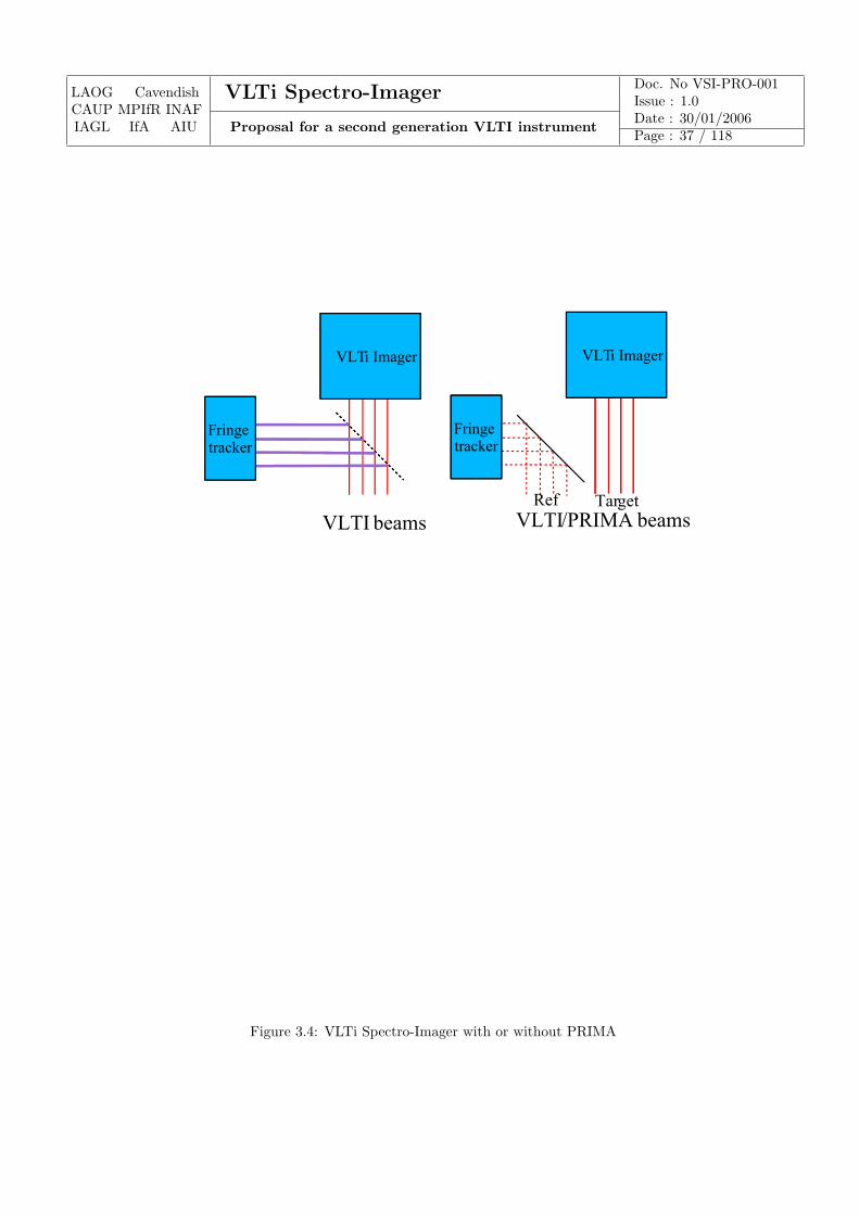
LAOG CavendishCAUP MPIfR INAFIAGL IfA AIU
VLTi Spectro-Imager Doc. No VSI-PRO-001Issue : 1.0
Proposal for a second generation VLTI instrumentDate : 30/01/2006Page : 37 / 118
VLTI beams
VLTi Imager
Fringetracker
VLTi Imager
Fringetracker
VLTI/PRIMA beams
VLTi Imager
Fringetracker
VLTi Imager
Fringetracker
Ref Target
Figure 3.4: VLTi Spectro-Imager with or without PRIMA
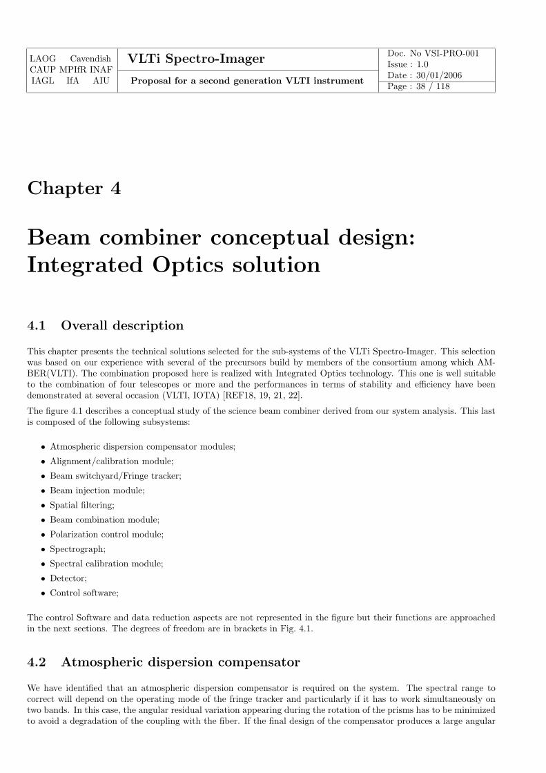
LAOG CavendishCAUP MPIfR INAFIAGL IfA AIU
VLTi Spectro-Imager Doc. No VSI-PRO-001Issue : 1.0
Proposal for a second generation VLTI instrumentDate : 30/01/2006Page : 38 / 118
Chapter 4
Beam combiner conceptual design:Integrated Optics solution
4.1 Overall description
This chapter presents the technical solutions selected for the sub-systems of the VLTi Spectro-Imager. This selectionwas based on our experience with several of the precursors build by members of the consortium among which AM-BER(VLTI). The combination proposed here is realized with Integrated Optics technology. This one is well suitableto the combination of four telescopes or more and the performances in terms of stability and efficiency have beendemonstrated at several occasion (VLTI, IOTA) [REF18, 19, 21, 22].
The figure 4.1 describes a conceptual study of the science beam combiner derived from our system analysis. This lastis composed of the following subsystems:
• Atmospheric dispersion compensator modules;
• Alignment/calibration module;
• Beam switchyard/Fringe tracker;
• Beam injection module;
• Spatial filtering;
• Beam combination module;
• Polarization control module;
• Spectrograph;
• Spectral calibration module;
• Detector;
• Control software;
The control Software and data reduction aspects are not represented in the figure but their functions are approachedin the next sections. The degrees of freedom are in brackets in Fig. 4.1.
4.2 Atmospheric dispersion compensator
We have identified that an atmospheric dispersion compensator is required on the system. The spectral range tocorrect will depend on the operating mode of the fringe tracker and particularly if it has to work simultaneously ontwo bands. In this case, the angular residual variation appearing during the rotation of the prisms has to be minimizedto avoid a degradation of the coupling with the fiber. If the final design of the compensator produces a large angular
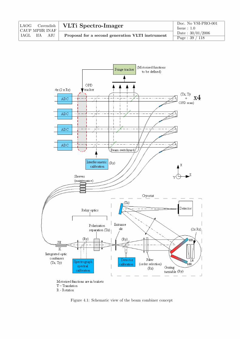
LAOG CavendishCAUP MPIfR INAFIAGL IfA AIU
VLTi Spectro-Imager Doc. No VSI-PRO-001Issue : 1.0
Proposal for a second generation VLTI instrumentDate : 30/01/2006Page : 39 / 118
Figure 4.1: Schematic view of the beam combiner concept
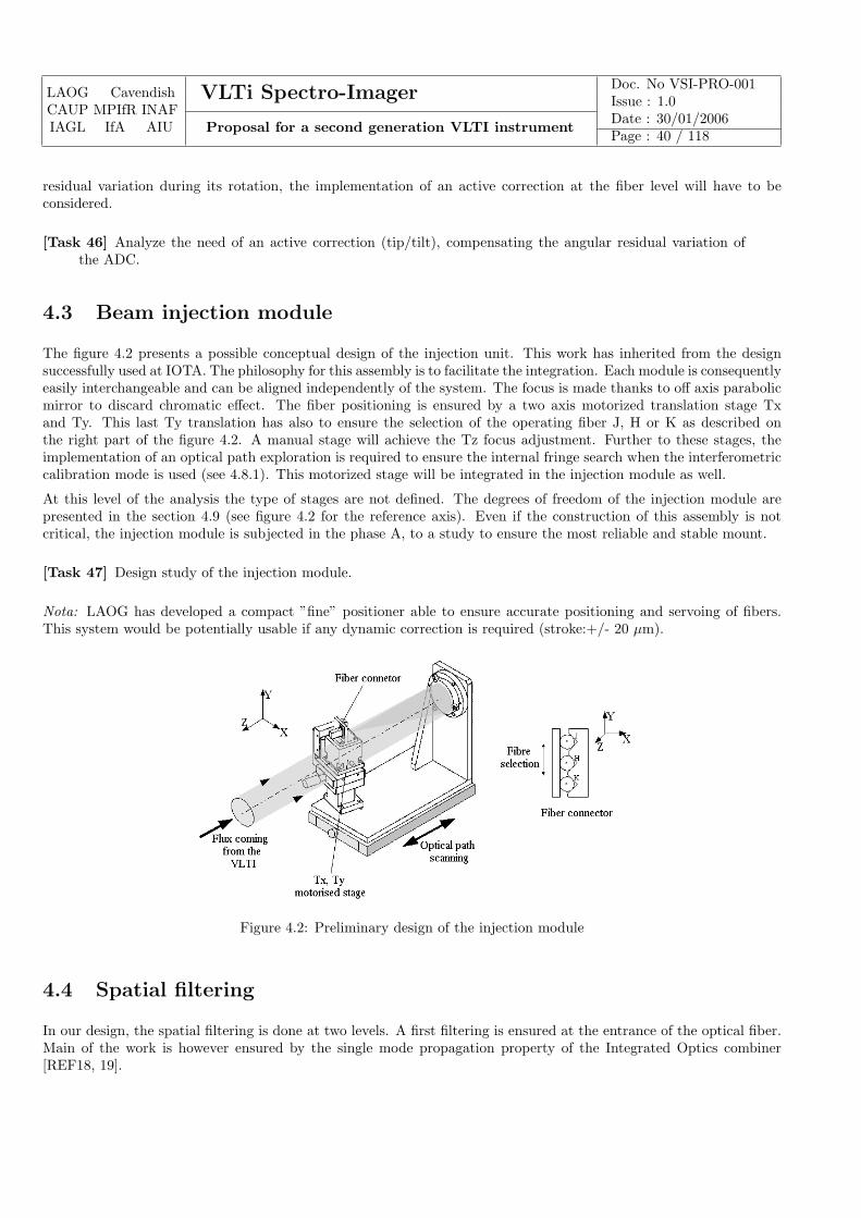
LAOG CavendishCAUP MPIfR INAFIAGL IfA AIU
VLTi Spectro-Imager Doc. No VSI-PRO-001Issue : 1.0
Proposal for a second generation VLTI instrumentDate : 30/01/2006Page : 40 / 118
residual variation during its rotation, the implementation of an active correction at the fiber level will have to beconsidered.
[Task 46] Analyze the need of an active correction (tip/tilt), compensating the angular residual variation ofthe ADC.
4.3 Beam injection module
The figure 4.2 presents a possible conceptual design of the injection unit. This work has inherited from the designsuccessfully used at IOTA. The philosophy for this assembly is to facilitate the integration. Each module is consequentlyeasily interchangeable and can be aligned independently of the system. The focus is made thanks to off axis parabolicmirror to discard chromatic effect. The fiber positioning is ensured by a two axis motorized translation stage Txand Ty. This last Ty translation has also to ensure the selection of the operating fiber J, H or K as described onthe right part of the figure 4.2. A manual stage will achieve the Tz focus adjustment. Further to these stages, theimplementation of an optical path exploration is required to ensure the internal fringe search when the interferometriccalibration mode is used (see 4.8.1). This motorized stage will be integrated in the injection module as well.
At this level of the analysis the type of stages are not defined. The degrees of freedom of the injection module arepresented in the section 4.9 (see figure 4.2 for the reference axis). Even if the construction of this assembly is notcritical, the injection module is subjected in the phase A, to a study to ensure the most reliable and stable mount.
[Task 47] Design study of the injection module.
Nota: LAOG has developed a compact ”fine” positioner able to ensure accurate positioning and servoing of fibers.This system would be potentially usable if any dynamic correction is required (stroke:+/- 20 µm).
Figure 4.2: Preliminary design of the injection module
4.4 Spatial filtering
In our design, the spatial filtering is done at two levels. A first filtering is ensured at the entrance of the optical fiber.Main of the work is however ensured by the single mode propagation property of the Integrated Optics combiner[REF18, 19].

LAOG CavendishCAUP MPIfR INAFIAGL IfA AIU
VLTi Spectro-Imager Doc. No VSI-PRO-001Issue : 1.0
Proposal for a second generation VLTI instrumentDate : 30/01/2006Page : 41 / 118
4.5 Integrated Optics science beam combiners
4.5.1 IO combiners
As it is proposed in the system analysis, the combination of 4 VLTI beams is our baseline while the combination of 6or 8 beams is proposed as an additional option (see section 4.11). We have considered IO technology as our solutionto combine the 4 to 6/8 VLTI beams. This choice is based on LAOG experience on this type of combination whichhas been successfully exploited at VLTI (2-way beam) and IOTA (2,3-way beam combiners). The main advantages ofthis technology are:
• possibility to integrate on single chip almost all combination schemes;
• it is easy to implement the modal filtering function associated to photometric calibration which has proved tobe a key element in the improvement to the visibility accuracy (xx reference);
• the very compact size of the combining chip allows a remarkable stability of phase properties and a smallcombining footprint;
• easy to install since only the alignment with the spectrograph has to be ensured;
Each beam combiner is made of an integrated optics chip connected to a fiber V-groove.
At the present state of the study, the capability to use only one chip to recombine both the J and H bands has not beendemonstrated. Our baseline is consequently to ensure the combination of the 4 VLTI beams with three components,one component per spectral band. In the global study of the combiner, we foresee to study however the use only oneIO component for both J and H bands.
The use of optical fibers coupled to the integrated optics chip induces several constraints:
• this introduces a differential birefringence and dispersion that will have to be characterized carefully;
• the fibers are cemented at one end to the IO combiner, and at the other end to the connector of the injectionmodule. The maintenance strategy of such a critical system has to be considered;
• alignment of fiber neutral axis together has to be ensured at the connector level;
• the fibers have to be chosen in order to match the numerical aperture defined by the off axis parabola for eachspectral band;
These points are included in the combiner study (see section 4.5.5).
4.5.2 Combining concept
Among all the beam combination concepts, our system study (REF14) has pointed out that a four way pairwise ABCDbeam combiner was the best compromise as far as signal to noise and biases are concerned.
Our industrial partner LETI has designed such a combination concept which can be seen in figure 4.3. The combinationchip has 4 inputs and 24 outputs (6 baselines x 4 A,B,C,D samples). The use of achromatic phase shifters allows tosample simultaneously four different phase states across the central fringe as it is described figure 4.4 (this is a spatialversion of the widely known ABCD concept [REF23]). No temporal modulation is then required for this concept.
4.5.3 Preliminary results
LETI has manufactured a prototype 4-way pairwise ABCD beam combiner similar to what will be proposed for thephase A. The beam combiner was optimized for the H band. We will perform a detailed study of the beam combinerproperties with the help of different tools that have been specifically developed (see section 4.14).
Figure 4.5 shows an actual image of the 24 interferometric outputs. As a first validation of the concept we havescanned the optical path of three out of the four beams which leads to spatially encode 6×4 interferograms (a subsetof 6 interferograms for each baseline is shown here in figure 4.6).

LAOG CavendishCAUP MPIfR INAFIAGL IfA AIU
VLTi Spectro-Imager Doc. No VSI-PRO-001Issue : 1.0
Proposal for a second generation VLTI instrumentDate : 30/01/2006Page : 42 / 118
Figure 4.3: Schematic design of a 4-way pairwise ABCD beam combiner.
Figure 4.4: Description of the ABCD concept
4.5.4 IO combiner mechanical support
The degrees of freedom identified for the beam combiner mechanical support are described figure 4.1. A two axismotorized stage Tx, Ty, is needed to ensure the centering of waveguide outputs on the detector pixels while a manualstage is foreseen to make the focus adjustment.
4.5.5 Phase A studies
During phase A studies we propose to check the compatibility of beam combiner properties with the science caserequirements. That includes:
[Task 48] Full characterization of a 4T ABCD H beam combiner (throughput, instrumental contrast, closurephase biases, chromatic behavior, polarization measurements)
[Task 49] Design study of the beam combiner sub-system for all bands (fibers, combiners, chromatic dispersionconstraint, maintenance)
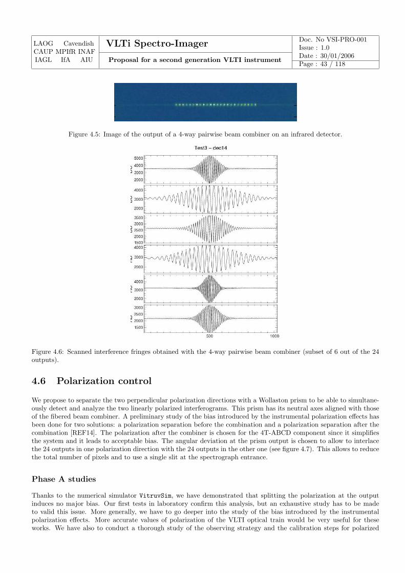
LAOG CavendishCAUP MPIfR INAFIAGL IfA AIU
VLTi Spectro-Imager Doc. No VSI-PRO-001Issue : 1.0
Proposal for a second generation VLTI instrumentDate : 30/01/2006Page : 43 / 118
Figure 4.5: Image of the output of a 4-way pairwise beam combiner on an infrared detector.
Figure 4.6: Scanned interference fringes obtained with the 4-way pairwise beam combiner (subset of 6 out of the 24outputs).
4.6 Polarization control
We propose to separate the two perpendicular polarization directions with a Wollaston prism to be able to simultane-ously detect and analyze the two linearly polarized interferograms. This prism has its neutral axes aligned with thoseof the fibered beam combiner. A preliminary study of the bias introduced by the instrumental polarization effects hasbeen done for two solutions: a polarization separation before the combination and a polarization separation after thecombination [REF14]. The polarization after the combiner is chosen for the 4T-ABCD component since it simplifiesthe system and it leads to acceptable bias. The angular deviation at the prism output is chosen to allow to interlacethe 24 outputs in one polarization direction with the 24 outputs in the other one (see figure 4.7). This allows to reducethe total number of pixels and to use a single slit at the spectrograph entrance.
Phase A studies
Thanks to the numerical simulator VitruvSim, we have demonstrated that splitting the polarization at the outputinduces no major bias. Our first tests in laboratory confirm this analysis, but an exhaustive study has to be madeto valid this issue. More generally, we have to go deeper into the study of the bias introduced by the instrumentalpolarization effects. More accurate values of polarization of the VLTI optical train would be very useful for theseworks. We have also to conduct a thorough study of the observing strategy and the calibration steps for polarized
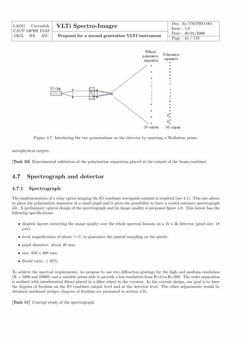
LAOG CavendishCAUP MPIfR INAFIAGL IfA AIU
VLTi Spectro-Imager Doc. No VSI-PRO-001Issue : 1.0
Proposal for a second generation VLTI instrumentDate : 30/01/2006Page : 44 / 118
Figure 4.7: Interlacing the two polarizations on the detector by inserting a Wollaston prism.
astrophysical targets.
[Task 50] Experimental validation of the polarization separation placed at the output of the beam combiner.
4.7 Spectrograph and detector
4.7.1 Spectrograph
The implementation of a relay optics imaging the IO combiner waveguide outputs is required (see 4.1). This one allowsto place the polarization separator in a small pupil and it gives the possibility to have a cooled entrance spectrographslit. A preliminary optical design of the spectrograph and its image quality is proposed figure 4.8. This layout has thefollowing specifications:
• dioptric layout correcting the image quality over the whole spectral domain on a 1k x 2k detector (pixel size: 18µm);
• focal magnification of about γ=7, to guarantee the spatial sampling on the pixels;
• pupil diameter: about 40 mm;
• size: 650 x 400 mm;
• Strehl ratio: ≥ 97%;
To achieve the spectral requirements, we propose to use two diffraction gratings for the high and medium resolution(R = 1000 and 10000) and a variable prism able to provide a low resolution from R=0 to R=200. The order separationis realized with interferential filters placed in a filter wheel in the cryostat. In the current design, our goal is to havethe degrees of freedom on the IO combiner output level and at the detector level. The other adjustments would beobtained machined wedges (degrees of freedom are presented in section 4.9).
[Task 51] Concept study of the spectrograph.
LAOG CavendishCAUP MPIfR INAFIAGL IfA AIU
VLTi Spectro-Imager Doc. No VSI-PRO-001Issue : 1.0
Proposal for a second generation VLTI instrumentDate : 30/01/2006Page : 45 / 118
4.7.2 Detector
The detector format chosen for the preliminary analysis is 1k x 2k with a pixel size of 18 microns, correspondingto an Engineering grade Hawaii-2RG with 2 running quadrant. We think that the implementation of the ESO NewGeneration Controller would be a major improvement.
According to the acquisition modes, several readout modes could be considered such as:
• fast double correlated
• slow double correlated
• low noise optimized multiple read
[Task 52] Search of the best suitable detector according the format and frame rate specifications.
4.7.3 Cryostat
The cooling of the spectrograph is preferred to minimize the background emission. No design is proposed for thecryostat at this point of the project but several constraints have to be taken into account:
• A LN2 tank is preferred for cooling process in order to minimize vibrations;
• Each sub-assembly (detector, calibration boxes, etc) has to be integrated independently of the system to simplifythe alignment/integration in the cryostat;
• The design has to be optimized to facilitate and limit the maintenance of the cryostat;
The final specifications of the cryostat will be accurately defined during the next phase.
4.8 Calibration and alignment tools
4.8.1 Calibration tools
Internal calibrations
This includes the spectral calibration and the detector and interferometric calibrations.
Spectral calibration: A spectral lamp can be inserted to spectrally calibrate the spectrum. It has to be chosen toprovide enough identified lines in each spectral band, for all the spectral modes. This calibration is mandatory foreach dispersive mode change.
Detector calibration: A broad band source is foreseen to provide flat field and thus allow to measure the detectorresponse. The accurate specifications of this detector calibration box should be defined in the phase A study. Ananalysis will be required to defined the position of this calibration source mainly if it has to be placed in the cryostat.
Interferometric calibration: An unresolved source allowing to check the contrast for each pair of telescopes can beinserted to estimate the instrument performances during assembly, integration, tests and maintenance. The designproposed at this point of this analysis is based on a Mach Zehnder interferometer which can be put at the place of thestellar beams coming from the VLTI (see figure 4.9). In this design the injection modules have been placed in orderto compensate the optical path difference between each channel. The final configuration will have to be confirmedhowever during next phase. The necessity to have this interferometric calibration permanently usable on the bench oroccasionally mounted has also to be defined in the phase A.
The accurate specifications, operating modes of these three calibration tools have to be studied during the phase Astudy.
LAOG CavendishCAUP MPIfR INAFIAGL IfA AIU
VLTi Spectro-Imager Doc. No VSI-PRO-001Issue : 1.0
Proposal for a second generation VLTI instrumentDate : 30/01/2006Page : 46 / 118
4.8.2 Alignment tools
Internal alignments
The beams coming from interferometric calibration system could be used to light up the four injection modules witha red laser source and to allow alignment of the instrument up to the spectrograph and the detector (sensitive inthe visible too). The use of this system has to be validated however during the next phase. The optimization of thecoupling with the fibers is made by maximizing the flux and the alignment procedure from the beam combiner to thedetector will be defined during this same phase.
Alignment with the VLTI
Our experience at IOTA shows that a capability allowing to align the VLTI beams with the injection fibers wouldallow to minimize the time spent to align the instrument with the telescopes. We consequently propose to installa movable LED enlightening the output of the integrated optics beam combiners. This allows to back illuminatethe beam injection modules and to gather on an imaging detector both the VLTI beams and the injection beams asdescribed figure 4.10.
In the phase A, the studies relative to these calibration/alignment tools, concern mainly the definition of the speci-fications. A preliminary design study of these tools will be performed however in parallel of the spectrograph designstudy.
4.9 Degrees of freedom
The degrees of freedom listed in at this stage of the project are detailed in table 4.1. At this point of the analysis thenumber of degrees of freedom and motorized functions listed are:
• Number of degrees of freedom: 41 (11 manual stages)
• Number of motorized functions: 30 + (TBC) functions
4.10 Software
4.10.1 Control command
Electronics
The electronics cabinets required for the controlled functions will conform to the ESO standard. If piezo-electricactuations are needed, the control system will have to be studied specifically.
Control software
As prescribed in [AD2], the control software supplied with instrument will conform to the general requirements andspecifications contained in [AD1] and the references contained therein. The control software will benefit of our valuableexperience acquired during AMBER instrument development.
During the phase A, we will study the impact of the integration specific sub-systems such beam shaper or fringetracker inside of the instrument.
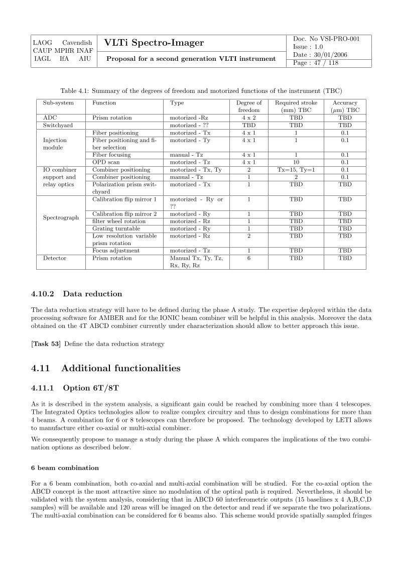
LAOG CavendishCAUP MPIfR INAFIAGL IfA AIU
VLTi Spectro-Imager Doc. No VSI-PRO-001Issue : 1.0
Proposal for a second generation VLTI instrumentDate : 30/01/2006Page : 47 / 118
Table 4.1: Summary of the degrees of freedom and motorized functions of the instrument (TBC)
Sub-system Function Type Degree of Required stroke Accuracyfreedom (mm) TBC (µm) TBC
ADC Prism rotation motorized -Rz 4 x 2 TBD TBD
Switchyard motorized - ?? TBD TBD TBD
Injectionmodule
Fiber positioning motorized - Tx 4 x 1 1 0.1Fiber positioning and fi-ber selection
motorized - Ty 4 x 1 1 0.1
Fiber focusing manual - Tz 4 x 1 1 0.1OPD scan motorized - Tz 4 x 1 10 0.1
IO combinersupport andrelay optics
Combiner positioning motorized - Tx, Ty 2 Tx=15, Ty=1 0.1Combiner positioning manual - Tz 1 2 0.1Polarization prism swit-chyard
motorized - Tx 1 TBD TBD
Spectrograph
Calibration flip mirror 1 motorized - Ry or??
1 TBD TBD
Calibration flip mirror 2 motorized - Ry 1 TBD TBDfilter wheel rotation motorized - Rz 1 TBD TBDGrating turntable motorized - Ry 1 TBD TBDLow resolution variableprism rotation
motorized - Rz 2 TBD TBD
Focus adjustment motorized - Tz 1 TBD TBD
Detector Prism rotation Manual Tx, Ty, Tz,Rx, Ry, Rz
6 TBD TBD
4.10.2 Data reduction
The data reduction strategy will have to be defined during the phase A study. The expertise deployed within the dataprocessing software for AMBER and for the IONIC beam combiner will be helpful in this analysis. Moreover the dataobtained on the 4T ABCD combiner currently under characterization should allow to better approach this issue.
[Task 53] Define the data reduction strategy
4.11 Additional functionalities
4.11.1 Option 6T/8T
As it is described in the system analysis, a significant gain could be reached by combining more than 4 telescopes.The Integrated Optics technologies allow to realize complex circuitry and thus to design combinations for more than4 beams. A combination for 6 or 8 telescopes can therefore be proposed. The technology developed by LETI allowsto manufacture either co-axial or multi-axial combiner.
We consequently propose to manage a study during the phase A which compares the implications of the two combi-nation options as described below.
6 beam combination
For a 6 beam combination, both co-axial and multi-axial combination will be studied. For the co-axial option theABCD concept is the most attractive since no modulation of the optical path is required. Nevertheless, it should bevalidated with the system analysis, considering that in ABCD 60 interferometric outputs (15 baselines x 4 A,B,C,Dsamples) will be available and 120 areas will be imaged on the detector and read if we separate the two polarizations.The multi-axial combination can be considered for 6 beams also. This scheme would provide spatially sampled fringes
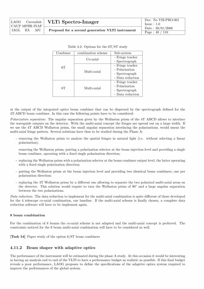
LAOG CavendishCAUP MPIfR INAFIAGL IfA AIU
VLTi Spectro-Imager Doc. No VSI-PRO-001Issue : 1.0
Proposal for a second generation VLTI instrumentDate : 30/01/2006Page : 48 / 118
Table 4.2: Options for the 6T/8T study
Combiner combination scheme Sub-system
6T
Co-axial - Fringe tracker- Spectrograph
Multi-axial
- Fringe tracker- Polarization- Spectrograph- Data reduction
8T Multi-axial
- Fringe tracker- Polarization- Spectrograph- Data reduction
at the output of the integrated optics beam combiner that can be dispersed by the spectrograph defined for the4T-ABCD beam combiner. In this case the following points have to be considered:
Polarization separation: The angular separation given by the Wollaston prism of the 4T ABCD allows to interlacethe waveguide outputs on the detector. With the multi-axial concept the fringes are spread out on a large width. Ifwe use the 4T ABCD Wollaston prism, the small angular separation interlacing the polarizations, would smear themulti-axial fringe pattern. Several solutions have thus to be studied during the Phase A:
- removing the Wollaston prism to analyze the spatial fringes in natural light (i.e. without selecting a linearpolarization);
removing the Wollaston prism, putting a polarization selector at the beam injection level and providing a singlebeam combiner, operating with a fixed single polarization direction;
-- replacing the Wollaston prism with a polarization selector at the beam combiner output level, the latter operatingwith a fixed single polarization direction;
- putting the Wollaston prism at the beam injection level and providing two identical beam combiners, one perpolarization direction;
- replacing the 4T Wollaston prism by a different one allowing to separate the two polarized multi-axial areas onthe detector. This solution would require to turn the Wollaston prism of 90◦ and a large angular separationbetween the two polarizations.
Data reduction: The data reduction to implement for the multi-axial combination is quite different of those developedfor the 4 telescope co-axial combination, our baseline. If the multi-axial scheme is finally chosen, a complete datareduction software will have to be implement again.
8 beam combination
For the combination of 8 beams the co-axial scheme is not adapted and the multi-axial concept is preferred. Theconstraints noticed for the 6 beam multi-axial combination will have to be considered as well.
[Task 54] Paper study of the option 6/8T beam combiners
4.11.2 Beam shaper with adaptive optics
The performance of the instrument will be estimated during the phase A study. At this occasion it would be interestingin having an analysis end to end of the VLTI to have a performance budget as realistic as possible. If this final budgetreveals a poor performance, LAOG proposes to define the specifications of the adaptive optics system required toimprove the performances of the global system.
LAOG CavendishCAUP MPIfR INAFIAGL IfA AIU
VLTi Spectro-Imager Doc. No VSI-PRO-001Issue : 1.0
Proposal for a second generation VLTI instrumentDate : 30/01/2006Page : 49 / 118
[Task 55] If required, make a concept study of an optional adaptive optics system
4.12 General means
This section gathers the items which have not been studied yet, but which are identified to be treated during thephase A study.
These issues include:
• Instrument implantation
• Optical bench height
• Bench size
• Bench enclosure
• Weight of the instrument
• Environment interactions (thermal dissipation, electro-magnetic constraints, Vibration and acoustic constraints)
• Safety constraints
Maintenance:
The preliminary analysis shows that several issues have to be considered with care:
Beam combiner fibers: In our design the fibers are cemented, at one end to the IO combiner and at the other end ina connector and each fiber has approximately the same length to discard chromatic dispersion effect (specification tobe defined). As a consequence, if a fiber is broken, we can’t shorten the fiber and then the assembly become unusable.We have thus chosen to limit the risk by adding a sleeve in the pigtail as described in the figure 4.1. We have tonotice however that if a fiber breaks, either the IO combiner sub-assembly or the injection connector will have to bereplaced. To limit the fiber breakage the study has to take into account the use a cable ensuring a good protection ofthe fiber. The spares parts will have to be considered for this issue.
Remote control stages: Remote stages and particularly stages which are placed in the cryostat can induce a criticalmaintenance. The design performed should therefore limit the number of motorized functions in the cryostat.
Calibration lamps: During the phase A study, the position and type of the calibration boxes will have to be definedin order to facilitate the maintenance operations.
4.13 Interfaces
4.13.1 VLTI interfaces
Optical: The design of the injection modules will be done taking into account the specifications given in [AD2]. Ananalysis end to end of the VLTI could be useful to make a realistic budget of the performances of the instrument.
Mechanical: The constraints defined in the [AD2] will be taken in account for the definition of the optical bench(height,size). The degree of freedom of the crane of the VLTI lab will have to be considered for the integration phase.
Supplying: Easy access to electrical power and cryogenic liquid will be required for the instrument. The vacuumneeds will be defined during the phase A study.
Data flow: Assuming the readout of complete 2k x 2k detector format, 4 quadrants with frame pixel of 1Mpx/sec,the maximum data flow is estimated at about 500Go/night and about 100Go/night in average.
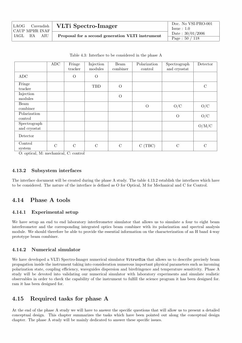
LAOG CavendishCAUP MPIfR INAFIAGL IfA AIU
VLTi Spectro-Imager Doc. No VSI-PRO-001Issue : 1.0
Proposal for a second generation VLTI instrumentDate : 30/01/2006Page : 50 / 118
Table 4.3: Interface to be considered in the phase A
ADC Fringe Injection Beam Polarization Spectrograph Detectortracker modules combiner control and cryostat
ADC O O
Fringetracker TBD O C
Injectionmodules O
Beamcombiner O O/C O/C
Polarizationcontrol O O/C
Spectrographand cryostat O/M/C
Detector
Controlsystem C C C C C (TBC) C C
O: optical, M: mechanical, C: control
4.13.2 Subsystem interfaces
The interface document will be created during the phase A study. The table 4.13.2 establish the interfaces which haveto be considered. The nature of the interface is defined as O for Optical, M for Mechanical and C for Control.
4.14 Phase A tools
4.14.1 Experimental setup
We have setup an end to end laboratory interferometer simulator that allows us to simulate a four to eight beaminterferometer and the corresponding integrated optics beam combiner with its polarization and spectral analysismodule. We should therefore be able to provide the essential information on the characterization of an H band 4-wayprototype beam combiner.
4.14.2 Numerical simulator
We have developed a VLTi Spectro-Imager numerical simulator VitruvSim that allows us to describe precisely beampropagation inside the instrument taking into consideration numerous important physical parameters such as incomingpolarization state, coupling efficiency, waveguides dispersion and birefringence and temperature sensitivity. Phase Astudy will be devoted into validating our numerical simulator with laboratory experiments and simulate realisticobservables in order to check the capability of the instrument to fulfill the science program it has been designed for.ram it has been designed for.
4.15 Required tasks for phase A
At the end of the phase A study we will have to answer the specific questions that will allow us to present a detailedconceptual design. This chapter summarizes the tasks which have been pointed out along the conceptual designchapter. The phase A study will be mainly dedicated to answer these specific issues.
LAOG CavendishCAUP MPIfR INAFIAGL IfA AIU
VLTi Spectro-Imager Doc. No VSI-PRO-001Issue : 1.0
Proposal for a second generation VLTI instrumentDate : 30/01/2006Page : 51 / 118
4.15.1 Atmospheric dispersion compensator
Task 46: Analyze the need of an active correction (tip/tilt), compensating the angular residual variation.
4.15.2 Injection module
Task 47: Design study of the injection module.
4.15.3 Beam combiner
Task 48: Full characterization of a 4T ABCD H beam combiner (throughput,instrumental contrast, closure phasebiases, chromatic behavior, polarization measurements)
Task 49: Design study of the beam combiner sub-system (fibers, combiners, chromatic dispersion constraint, main-tenance)
4.15.4 Polarization control
Task 50: Experimental validation of the polarization separation placed at the output of the beam combiner.
4.15.5 Spectrograph
Task 51: Concept study of the spectrograph.
4.15.6 Detector
Task 52: Search of the best suitable detector according the format and frame rate specifications.
4.15.7 Data reduction
Task 53: Define the data reduction strategy
4.15.8 Additional functionalities
Task 54: Paper study of the option 6/8T beam combiners
Task 55: If required, make a concept study of an optional adaptive optics system
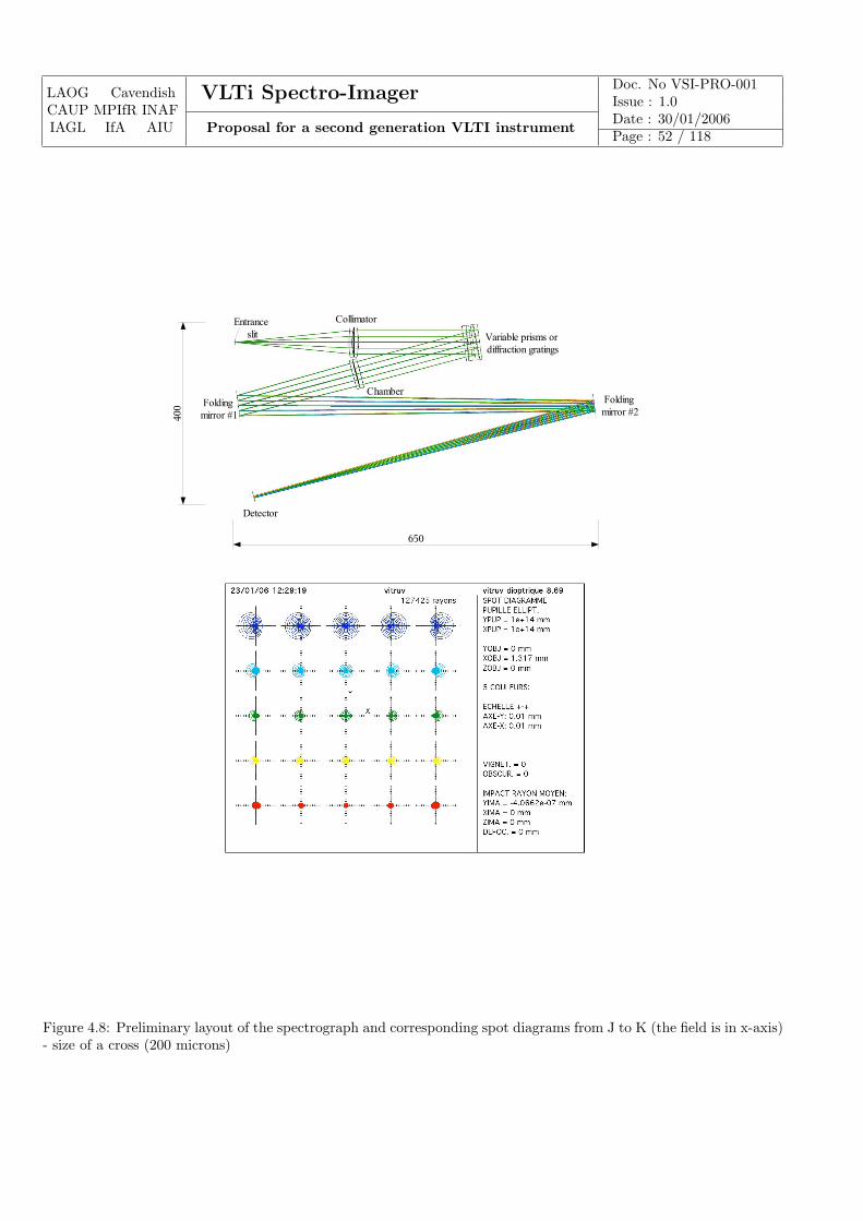
LAOG CavendishCAUP MPIfR INAFIAGL IfA AIU
VLTi Spectro-Imager Doc. No VSI-PRO-001Issue : 1.0
Proposal for a second generation VLTI instrumentDate : 30/01/2006Page : 52 / 118
Entrance slit Variable prisms or
diffraction gratings
Folding mirror #1
Folding mirror #2
Detector
Collimator
Chamber
400
650
Figure 4.8: Preliminary layout of the spectrograph and corresponding spot diagrams from J to K (the field is in x-axis)- size of a cross (200 microns)
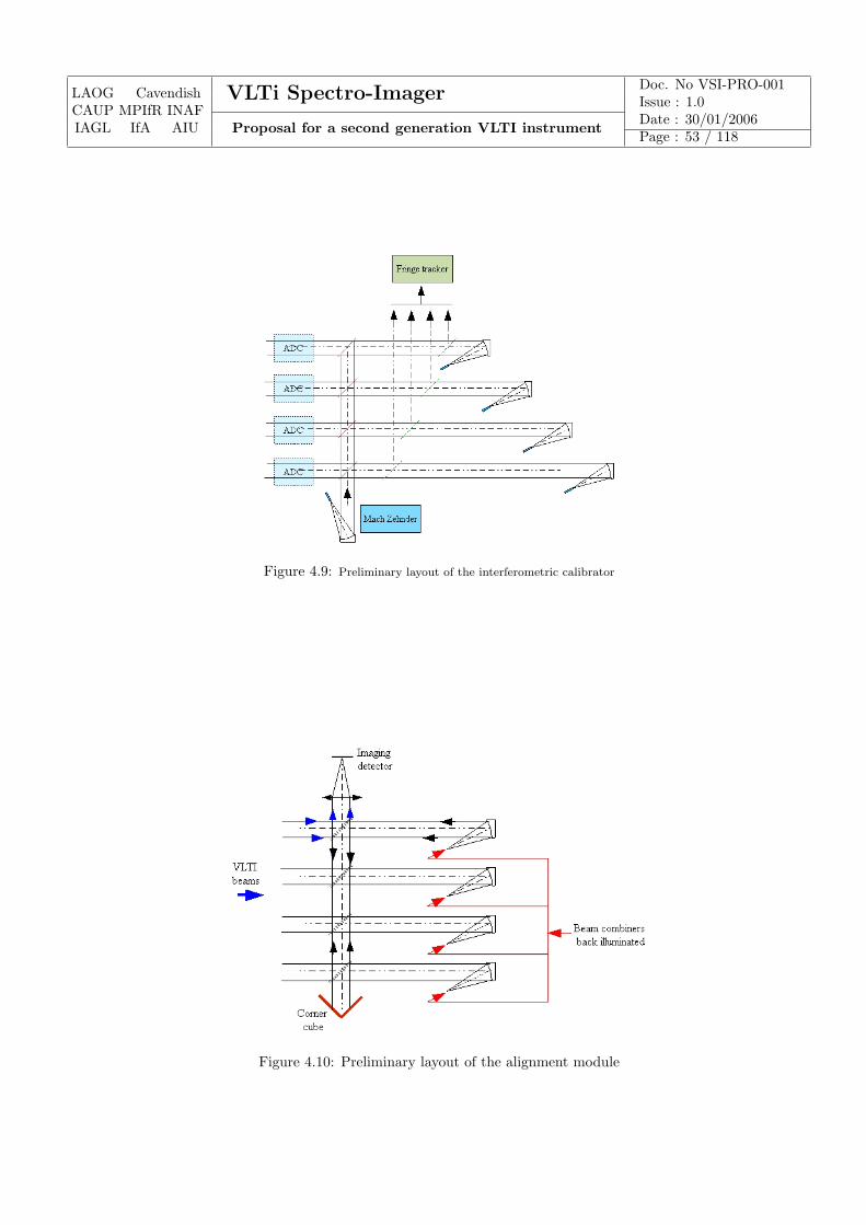
LAOG CavendishCAUP MPIfR INAFIAGL IfA AIU
VLTi Spectro-Imager Doc. No VSI-PRO-001Issue : 1.0
Proposal for a second generation VLTI instrumentDate : 30/01/2006Page : 53 / 118
Figure 4.9: Preliminary layout of the interferometric calibrator
Figure 4.10: Preliminary layout of the alignment module

LAOG CavendishCAUP MPIfR INAFIAGL IfA AIU
VLTi Spectro-Imager Doc. No VSI-PRO-001Issue : 1.0
Proposal for a second generation VLTI instrumentDate : 30/01/2006Page : 54 / 118
Chapter 5
Beam combiner conceptual design: BulkOptics solution
5.1 Overall description
The bulk-optics (BO) option is an alternative to the integrated-optics (IO) science combiner which offers a numberof potential advantages. Chief amongst these is the combination of high photon throughput (>96%) and high fringecontrast (>95%) which has been demonstrated in working prototypes. This high “interferometric throughput” isparticularly critical to science cases which require the observation of targets which are intrinsically faint, for exampleAGN or faint M-dwarfs.
The BO science combiner has the same basic functionality as the IO combiner. The main difference in implementationis the use of free-space optics rather than guided-wave optics for producing the interference patterns. A number ofbeam combination modes are possible within the BO concept, including image-plane and pupil-plane combination, asare a number of spatial filtering modes such as pinhole and fibre filtering. For simplicity we describe here mainly thebaseline option, which uses pupil-plane beam combination and fibre spatial filtering.
A schematic diagram of the overall instrument is shown in Figure 5.1. Light entering the instrument is split usingdichroics between the science beam combiner and the fringe tracker. The dichroics form part of a “beam switchyard”which feeds light into the main beam combiner. This is a 4-way pupil-plane design using beam splitters which produces4 outputs, each being the superposition of all 4 input beams, i.e. interference patterns corresponding to all 6 possiblebaselines are present in each output. The fringes are “fluffed out” i.e. each output beam is either all light or all darkdepending on the phases of the fringes. Path modulators serve to rapidly scan the phase of the input beams such thata temporally-modulated intensity is observed, with each of the 6 fringe patterns appearing at a separate frequency.The collimated outputs from the combiner are focused onto single-mode fibres, serving to spatially filter the fringesand also to inject light into the input “slit” of a cooled spectrograph. The spectrograph illuminates a detector whichis read out synchronously with the fringe modulation to produce a spectro-interferogram. This can be processed toyield fringe amplitude and phase information for all 6 baselines at a large number of wavelengths simultaneously.
This design is described further below in terms of a system analysis into a number of different functions:
• Atmospheric dispersion compensator modules;
• Alignment/calibration module;
• Beam switchyard/Fringe tracker;
• Science beam combiner;
• Fast path modulators
• Beam injection module;
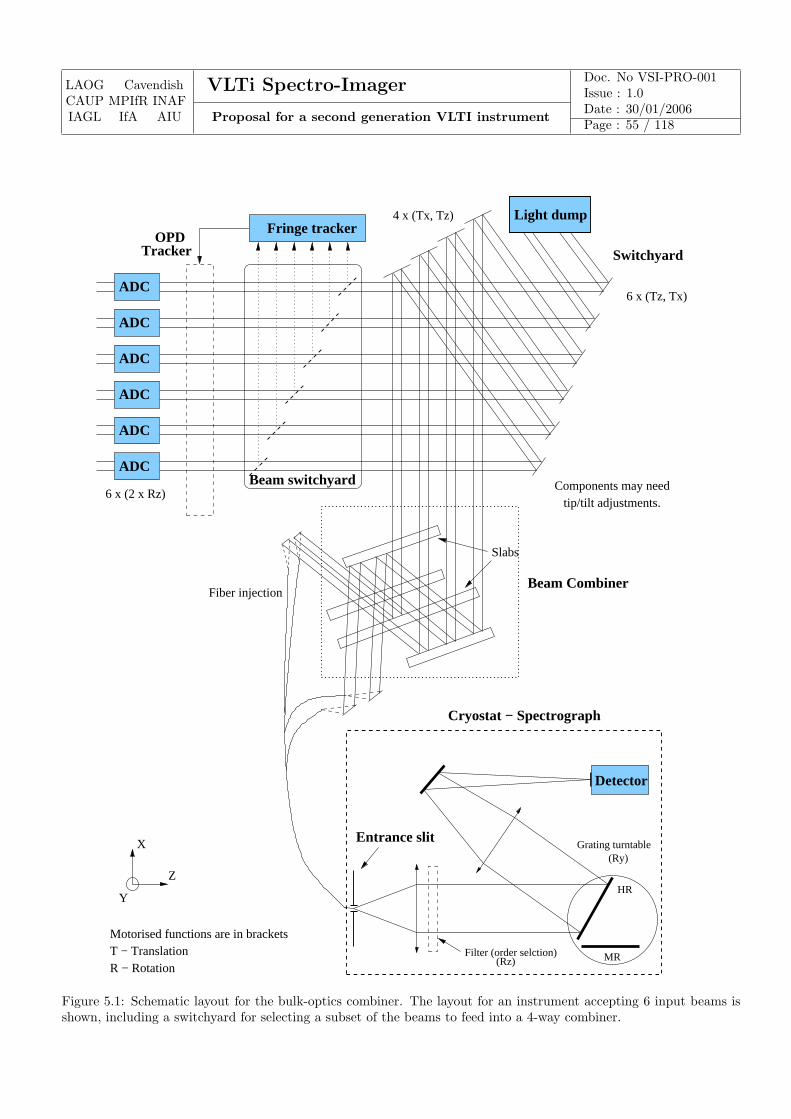
LAOG CavendishCAUP MPIfR INAFIAGL IfA AIU
VLTi Spectro-Imager Doc. No VSI-PRO-001Issue : 1.0
Proposal for a second generation VLTI instrumentDate : 30/01/2006Page : 55 / 118
Motorised functions are in bracketsT − TranslationR − Rotation
Y
X
Z
Components may needtip/tilt adjustments.
6 x (Tz, Tx)
Cryostat − Spectrograph
ADC
ADC
ADC
ADC
ADC
ADC
Entrance slit
Fringe trackerLight dump
Beam switchyard
OPDTracker
6 x (2 x Rz)
4 x (Tx, Tz)
Fiber injectionBeam Combiner
Slabs
HR
Detector
Grating turntable(Ry)
MR(Rz)Filter (order selction)
Switchyard
Figure 5.1: Schematic layout for the bulk-optics combiner. The layout for an instrument accepting 6 input beams isshown, including a switchyard for selecting a subset of the beams to feed into a 4-way combiner.
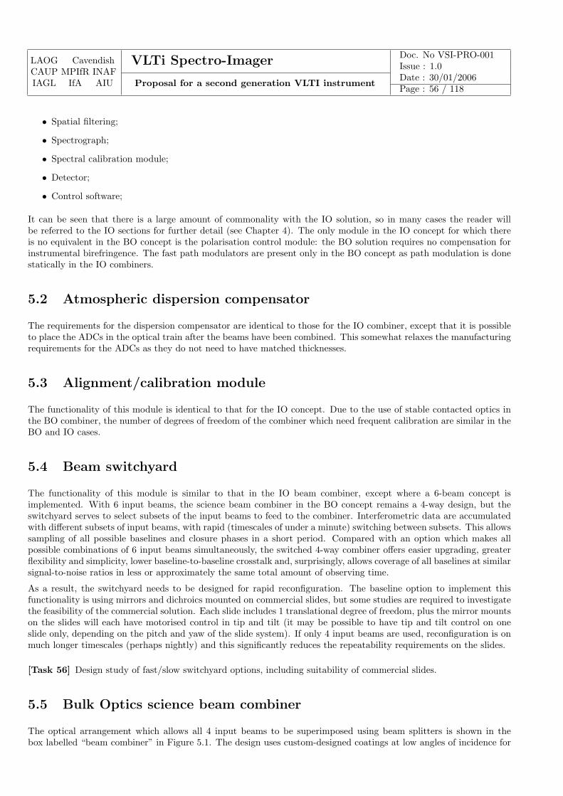
LAOG CavendishCAUP MPIfR INAFIAGL IfA AIU
VLTi Spectro-Imager Doc. No VSI-PRO-001Issue : 1.0
Proposal for a second generation VLTI instrumentDate : 30/01/2006Page : 56 / 118
• Spatial filtering;
• Spectrograph;
• Spectral calibration module;
• Detector;
• Control software;
It can be seen that there is a large amount of commonality with the IO solution, so in many cases the reader willbe referred to the IO sections for further detail (see Chapter 4). The only module in the IO concept for which thereis no equivalent in the BO concept is the polarisation control module: the BO solution requires no compensation forinstrumental birefringence. The fast path modulators are present only in the BO concept as path modulation is donestatically in the IO combiners.
5.2 Atmospheric dispersion compensator
The requirements for the dispersion compensator are identical to those for the IO combiner, except that it is possibleto place the ADCs in the optical train after the beams have been combined. This somewhat relaxes the manufacturingrequirements for the ADCs as they do not need to have matched thicknesses.
5.3 Alignment/calibration module
The functionality of this module is identical to that for the IO concept. Due to the use of stable contacted optics inthe BO combiner, the number of degrees of freedom of the combiner which need frequent calibration are similar in theBO and IO cases.
5.4 Beam switchyard
The functionality of this module is similar to that in the IO beam combiner, except where a 6-beam concept isimplemented. With 6 input beams, the science beam combiner in the BO concept remains a 4-way design, but theswitchyard serves to select subsets of the input beams to feed to the combiner. Interferometric data are accumulatedwith different subsets of input beams, with rapid (timescales of under a minute) switching between subsets. This allowssampling of all possible baselines and closure phases in a short period. Compared with an option which makes allpossible combinations of 6 input beams simultaneously, the switched 4-way combiner offers easier upgrading, greaterflexibility and simplicity, lower baseline-to-baseline crosstalk and, surprisingly, allows coverage of all baselines at similarsignal-to-noise ratios in less or approximately the same total amount of observing time.
As a result, the switchyard needs to be designed for rapid reconfiguration. The baseline option to implement thisfunctionality is using mirrors and dichroics mounted on commercial slides, but some studies are required to investigatethe feasibility of the commercial solution. Each slide includes 1 translational degree of freedom, plus the mirror mountson the slides will each have motorised control in tip and tilt (it may be possible to have tip and tilt control on oneslide only, depending on the pitch and yaw of the slide system). If only 4 input beams are used, reconfiguration is onmuch longer timescales (perhaps nightly) and this significantly reduces the repeatability requirements on the slides.
[Task 56] Design study of fast/slow switchyard options, including suitability of commercial slides.
5.5 Bulk Optics science beam combiner
The optical arrangement which allows all 4 input beams to be superimposed using beam splitters is shown in thebox labelled “beam combiner” in Figure 5.1. The design uses custom-designed coatings at low angles of incidence for
LAOG CavendishCAUP MPIfR INAFIAGL IfA AIU
VLTi Spectro-Imager Doc. No VSI-PRO-001Issue : 1.0
Proposal for a second generation VLTI instrumentDate : 30/01/2006Page : 57 / 118
high efficiency and low polarisation sensitivity, and components are connected using contacted-optics technology toachieve exceptional path length and alignment stability. The wide-band nature of the coatings means that only onecombiner is needed to cover the J, H and K bands. The design is based on a working prototype in Cambridge whichhas demonstrated the required high throughput and stability. The work in the phase-A study would mainly involvelooking at scaling issues for the larger VLTI beams.
[Task 57] Design study of options for manufacture of scaled-up contacted-optics beam combiner.
5.6 Path modulators
The optical path difference between beams is modulated at rates of several hundred Hertz using mirrors mountedon piezoelectric actuators. Laboratory tests have shown that the scanning of these mirrors can achieve the requiredaccuracy and repeatability by appropriately controlling the harmonics of the drive waveform. Studies thus far haveused feedback from direct measurements of the resulting modulation using a metrology laser, but injecting lasermetrology to all the modulators could be problematic within the space envelope. Alternative options for performingthe calibration of the drive waveform include use of capacitive or strain-gauge sensors.
[Task 58] Study of options for modular drive waveform calibration.
5.7 Spatial filtering/Beam injection module
The injection of light into fibres in the BO design occurs after beam combination, so the phase and birefringenceproperties of the fibres are of little concern. If suitable fibres (e.g. chalcogenide photonic crystal fibres) can beprocured, then only a single set of fibres may be needed to cover all wavebands. The beam injection technologydescribed for the IO combiner would be appropriate for application in the BO concept.
[Task 59] Investigate options for single mode fibres covering all wavebands simultaneously.
5.8 Detector and Spectrograph
The detector and spectrograph layout and requirements in the BO concept are similar to that for the IO concept. Onedifference is that the BO spectrograph has fewer outputs which are read out more often than the IO spectrograph,but the overall pixel rate is similar.
5.9 Software
The overall functionality and architecture of the control and data reduction software for the BO option is similar tothat for the IO design, yielding similar outputs at the end of the data reduction pipeline.
The number of degrees of freedom to be controlled are similar to that for the IO combiner, except the switchyard, whichadds 8/10 additional motorised translation stages (for 4/6 input beams respectively) and 16/20 motorised degrees offreedom of tip/tilt.
5.10 Other tasks
While there is a lot of commonality of modules with the IO concept, an additional task is to make sure that theconcepts for the modules within the IO system are fully compatible with the requirements of the BO concept.
[Task 60] Monitor common tasks for BO/IO concepts for commonality of specification.
LAOG CavendishCAUP MPIfR INAFIAGL IfA AIU
VLTi Spectro-Imager Doc. No VSI-PRO-001Issue : 1.0
Proposal for a second generation VLTI instrumentDate : 30/01/2006Page : 58 / 118
5.11 Interfaces
The external and internal interfaces for the BO concept are similar to that for the IO concept.
5.12 Required tasks for phase A
Below we summarise the required Phase-A studies as detailed in the previous sections.
5.12.1 Beam switchyard
Task 56: Design study of fast/slow switchyard options, including suitability of commercial slides.
5.12.2 Beam combiner
Task 57: Design study of options for manufacture of scaled-up contacted-optics beam combiner.
5.12.3 Path modulators
Task 58: Study of options for modulator drive waveform calibration.
5.12.4 Spatial filtering/Beam injection module
Task 59: Investigate options for single mode fibres covering all wavebands simultaneously.
5.12.5 Other tasks
Task 60: Monitor common tasks for BO/IO concepts for commonality of specification.
LAOG CavendishCAUP MPIfR INAFIAGL IfA AIU
VLTi Spectro-Imager Doc. No VSI-PRO-001Issue : 1.0
Proposal for a second generation VLTI instrumentDate : 30/01/2006Page : 59 / 118
Chapter 6
Internal fringe tracker conceptual design
6.1 Role of the fringe tracker
A fringe tracker performs a similar role within an interferometer as an adaptive optics (AO) system performs within asingle telescope. It measures wavefront errors due to the atmosphere and instrument (in the case of a fringe tracker,these OPD errors are the differences between telescopes of the amplitudes of their respective Zernike “piston” modes)and corrects these errors in real time. Like an AO system, a fringe tracker requires a bright reference object to sensethe wavefront errors, and also like an AO system there are strong fundamental limits to how faint this reference objectis allowed to be before the fringe tracker fails to operate. If the fringe tracker does not work, little or no science canbe done, and so the range of science targets accessible to the instrument is typically most strongly limited by theperformance of the fringe tracker, especially its magnitude limit. Because of this intimate relationship between fringetracker performance and the science performance of the system as a whole, the VLTi Spectro-Imager will incorporateits own fringe tracking subsystem. The combined system of fringe tracker and science beam combiner will be optimisedas a whole to meet the science requirements.
In order to fulfill the science goals of high-throughput acquisition of data, high-SNR high-spectral-resolution imaging,and imaging of complex faint objects, the fringe tracker will operate in a minimum of three distinct modes defined asfollows:
6.1.1 Fringe acquisition
This is a mode in which a finite region of OPD space is scanned in order to find the fringe coherence envelope in thepresence of atmospheric and instrumental delay uncertainties. This mode will typically use a either a continuous orstepped scan of the delay lines together a group-delay algorithm to efficiently detect the presence of fringes over aregion of delay space set by the coherence length of a single spectral channel.
6.1.2 Hardware phase tracking
This is a mode in which the delay errors are actively compensated at high speed so that the level of stability of thescience combiner fringes is sufficient to allow on-chip integration of the fringe signal over periods of many atmosphericcoherence times. Typically hardware phase tracking requires a high SNR fringe phase measurement to be made in ashort integration time in to allow the high-precision (typically of order λ/20) correction required. This means thata bright (mH < 10) reference object is required, but providing such a reference is available, then the long coherentintegration times afforded on the science combiner allow high-spectral-resolution measurements to be made relativelyrapidly.
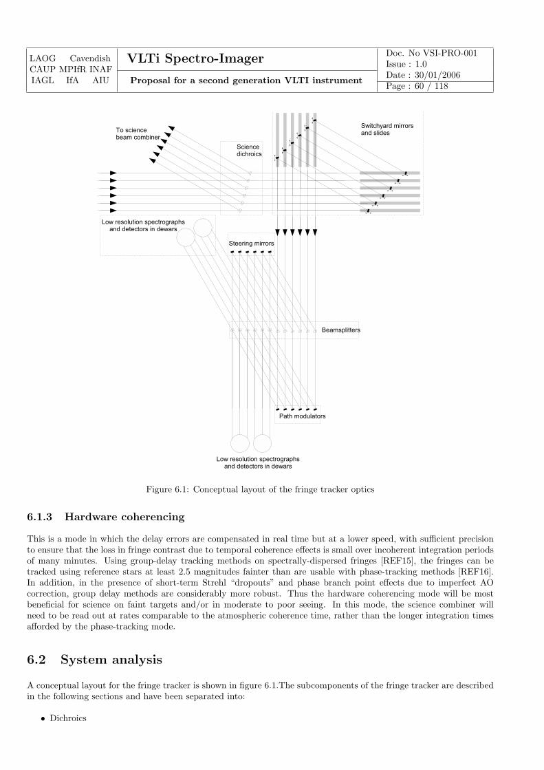
LAOG CavendishCAUP MPIfR INAFIAGL IfA AIU
VLTi Spectro-Imager Doc. No VSI-PRO-001Issue : 1.0
Proposal for a second generation VLTI instrumentDate : 30/01/2006Page : 60 / 118
Figure 6.1: Conceptual layout of the fringe tracker optics
6.1.3 Hardware coherencing
This is a mode in which the delay errors are compensated in real time but at a lower speed, with sufficient precisionto ensure that the loss in fringe contrast due to temporal coherence effects is small over incoherent integration periodsof many minutes. Using group-delay tracking methods on spectrally-dispersed fringes [REF15], the fringes can betracked using reference stars at least 2.5 magnitudes fainter than are usable with phase-tracking methods [REF16].In addition, in the presence of short-term Strehl “dropouts” and phase branch point effects due to imperfect AOcorrection, group delay methods are considerably more robust. Thus the hardware coherencing mode will be mostbeneficial for science on faint targets and/or in moderate to poor seeing. In this mode, the science combiner willneed to be read out at rates comparable to the atmospheric coherence time, rather than the longer integration timesafforded by the phase-tracking mode.
6.2 System analysis
A conceptual layout for the fringe tracker is shown in figure 6.1.The subcomponents of the fringe tracker are describedin the following sections and have been separated into:
• Dichroics
LAOG CavendishCAUP MPIfR INAFIAGL IfA AIU
VLTi Spectro-Imager Doc. No VSI-PRO-001Issue : 1.0
Proposal for a second generation VLTI instrumentDate : 30/01/2006Page : 61 / 118
• Beam switchyard;
• Fringe-tracking beam combiner;
• Fast path modulators
• Low-resolution spectrograph and detector;
• Control system;
• OPD corrector;
A number of system-level tasks need to be undertaken to validate the proposed fringe tracker concept.
A complete optical and mechanical design of the fringe-tracking combiner optics is needed to ensure that the combinercan be fitted within the space envelope at the VLTI.
A key parameter of the science case for the instrument as a whole will be the list of which potential science targets canbe observed in a high-spectral-resolution phase-tracking mode and which can be observed in a faint-object coherencingmode. Detailed calculations of the magnitude limits for both these modes will feed into the determination of thesepotential target lists.
The maximum coherent integration time, and hence SNR, for the science combiner when the fringe combiner is inphase-tracking mode will be strongly limited by drifts in the relative OPD as measured by the fringe tracker and asseen by the science beam combiner. Various methods of “tying together” the beam combiners using either mechanicalmeans or laser metrology will be evaluated to determine the practical limits to achieving long coherent integrationsand the most cost-effective means for achieving these.
[Task 61] Space envelope design study for fringe tracker
[Task 62] Prediction of fringe tracking magnitude limits
[Task 63] Design study of methods of mitigation of non-common-path OPD drifts
6.3 Dichroics
The fringe tracker uses light from the whole of a near-IR waveband, selectable between H and K, to derive the OPDerrors, while the science combiner will work in one of the remaining wavebands. The fringe-tracking light is separatedfrom the light for the science combiner using optimised dichroics. Two possible sets of dichroics are needed to allow allpossible sets of fringe tracking/science wavelength splits. The baseline is for these dichroics to be switched manually,but a motorised switching option would minimise the need for operators to enter the instrument area.
[Task 64] Cost/benefit analysis of motorised switching of dichroics.
6.4 Beam switchyard
Light not taken by the science combiner enters the fringe tracker beam switchyard, consisting of a pair of movable flatmirrors in sequence for each beam which performs the following three functions:
1. It allows beams from each of the delay lines to be fed into different inputs to the fringe tracking beam combiner.This allows the set of baselines to be used for fringe tracking to be optimally configured for the set of telescopesin use, for example to allow “baseline bootstrapping” on a set of nearest-neighbour telescopes.
2. It adapts the spacing of the beams coming from the delay lines to that required at the input of the fringe-trackingbeam combiner.
LAOG CavendishCAUP MPIfR INAFIAGL IfA AIU
VLTi Spectro-Imager Doc. No VSI-PRO-001Issue : 1.0
Proposal for a second generation VLTI instrumentDate : 30/01/2006Page : 62 / 118
3. It allows the relative pathlengths between the different beams entering the fringe tracking beam combiner tobe adjusted so that when the OPDs are equalised in the science combiner they are also equalised in the fringetracking combiner.
The switchyard is very similar in function to that in the science combiner, so phase A studies of the science switchyardwill be equally applicable to the fringe tracker switchyard.
6.5 Fringe-tracking combiner
The fringe tracking combiner is a pairwise pupil-plane combiner arranged as shown in the figure. The figure showsa 6-beam combiner but the arrangement can be straightforwardly adapted for different numbers of incoming beamsby adding or removing stages. In the 6-beam arrangement, only the 5 nearest-neighbour pairs of input beams arecombined, yielding 10 interference patterns, and the “outermost” pair of input beams are discarded. The fringes are“fluffed out” so that the output beams are either all dark or all light.
6.6 Fast pathlength modulators
The fringe phase is temporally modulated using mirrors mounted on piezoelectrically-actuated stages.
6.7 Low-resolution spectrograph and detector
The output beams of from the beam combiner constitute a single pixel of information: this enters a low-resolutionspectrograph which disperses the light into a low resolution spectrum incident on a near-infrared array detector. Theoptics are designed such that reading out approximately five pixels of the detector corresponds to reading 5 spectralsub-bands across a photometric band (i.e. R ∼ 20). These 5 pixels of spectral information are read out synchronouslywith the phase modulation waveform.
The detectors for the fringe tracking beam combiner are perhaps the most critical factor in achieving high performancefringe tracking, particularly for the faintest sources. An evaluation of existing and planned infrared focal-plane arrays,particularly with regard to minimising read noise, will be performed, resulting in a recommendation as to the bestarray technology for the fringe tracker and the most effective readout strategy to employ.
The most straightforward scheme for using detectors would be to have one spectrograph and detector for each ofthe 6-10 outputs of the fringe tracking beam combiner. Since only 5 pixels of each detector will be used, there isan opportunity to significantly reduce the system cost by multiplexing multiple beam combiner outputs onto a singledetector. The optimum trade between multiplexing advantage and losses in fringe tracking performance resulting fromchanges in throughput, crosstalk and detector read noise will be determined by designing in some detail a numberoptical arrangements for multiplexing and evaluating their effects on system performance.
[Task 65] Evaluation of detectors for the fringe tracker
[Task 66] Cost/benefit trade of multiplexing multiple beam combiner outputs onto a single detector
6.8 Control system
The software system for the fringe tracker controls all the basic functions of the fringe tracker. The subtasks withinthe control system are summarised in the subsections below.
LAOG CavendishCAUP MPIfR INAFIAGL IfA AIU
VLTi Spectro-Imager Doc. No VSI-PRO-001Issue : 1.0
Proposal for a second generation VLTI instrumentDate : 30/01/2006Page : 63 / 118
6.8.1 User interface
Control of the fringe tracker during observing will be part of an integrated interface to the entire instrument, butengineering-mode software will allow detailed access to system parameters.
6.8.2 Quasi-static control of motorised elements
The control system adjusts the motorised degrees of freedom of the fringe tracker on roughly a nightly basis foralignment purposes and also to change operating modes. The degrees of freedom to be controlled include:
• Adjustment of the beam switchyard (10 translational degrees of freedom and 20 tilt degrees of freedom for a 6Tsolution).
• Adjustment of internal alignment mirrors (12 rotational degrees of freedom).
• Changes of filter to allow for changes in fringe-tracking wavelength (6 filter slide changes). This may not benecessary depending on the design of the spectral dispersion system.
6.8.3 Real-time servo loops
The real-time component of the fringe tracker derives adjustments to the OPD from the pixel data stream arrivingfrom the detectors. In both the coherencing or phase-tracking modes the fringe amplitude and phase are derived foreach of the 5 spectral sub-bands at rates of up to several hundred Hz. Typically 4 fringe samples need to be takensynchronously with the OPD modulation in order to derive the fringe parameters, so that 20 pixels in total need tobe processed per coherent integration per baseline being tracked. For 5 baselines being tracked at a sample rate of500Hz, the data rate is 50ksamples/sec. This is not a demanding computational task, and so specialised computinghardware (e.g. DSP arrays) is not necessary — it should be possible to perform all the real-time computation on asingle Pentium-class processor running a hard real-time operating system.
6.8.4 Mode switching
Switching between the acquisition, coherencing and phase-tracking modes can either be done automatically based onreal-time evaluation of the fringe signal-to-noise ratio, or can be performed under external control. Switching betweenthese modes requires no hardware changes, only software algorithm and parameter changes within the fringe trackingcomputer, and so can be accomplished in fractions of a second.
6.8.5 Data archiving
The fringe tracking computer archives the sensed fringe signals and correction signals. This archived data can be usedfor diagnostics or for post-processing of the science data using software phase rotation algorithms.
6.9 OPD corrector
The fringe-tracking computer filters the derived OPD errors and sends the appropriate signals to the a two-stage OPDcorrection system consisting of:
1. A mirror mounted on a fast piezo-electric stage connected which takes out rapid pathlength fluctuations.
2. Error signals sent to the delay line signals to correct long-term large-amplitude OPD errors.
LAOG CavendishCAUP MPIfR INAFIAGL IfA AIU
VLTi Spectro-Imager Doc. No VSI-PRO-001Issue : 1.0
Proposal for a second generation VLTI instrumentDate : 30/01/2006Page : 64 / 118
6.10 Required studies for Phase-A
Much of the hardware and software required for the fringe tracker has already been demonstrated on the VLTI andother interferometers, and experience from the FINITO fringe tracker (especially that available from the members ofthe FINITO team who are members of the VLTi Spectro-Imager consortium) will provide good information as to theexternal constraints on the fringe tracker. However, a number of specific points need to be addressed in the Phase-Astudy in order to determine the optimum specification of the fringe tracker hardware and software to allow maximumscience throughput for the system as a whole. These tasks are summarised below.
6.10.1 System analysis
Task 59: Investigate options for monomode fibres covering all wavebands simultaneously.
Task 61: Space envelope design study for fringe tracker
Task 62: Prediction of fringe tracking magnitude limits
Task 63: Design study of methods of mitigation of non-common-path OPD drifts
6.10.2 Dichroics
Task 64: Cost/benefit analysis of motorised switching of dichroics.
6.10.3 Low-resolution spectrographs and detectors
Task 65: Evaluation of detectors for the fringe tracker
Task 66: Cost/benefit trade study of multiplexing multiple beam combiner outputs onto a single detector
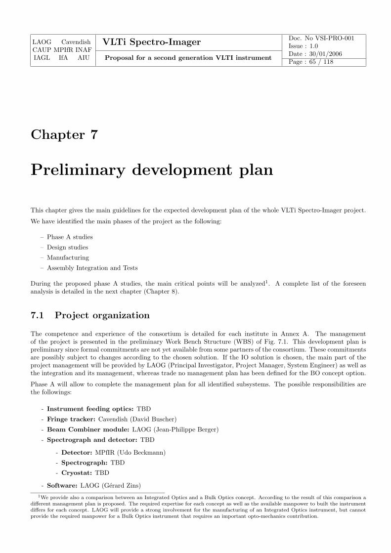
LAOG CavendishCAUP MPIfR INAFIAGL IfA AIU
VLTi Spectro-Imager Doc. No VSI-PRO-001Issue : 1.0
Proposal for a second generation VLTI instrumentDate : 30/01/2006Page : 65 / 118
Chapter 7
Preliminary development plan
This chapter gives the main guidelines for the expected development plan of the whole VLTi Spectro-Imager project.
We have identified the main phases of the project as the following:
– Phase A studies
– Design studies
– Manufacturing
– Assembly Integration and Tests
During the proposed phase A studies, the main critical points will be analyzed1. A complete list of the foreseenanalysis is detailed in the next chapter (Chapter 8).
7.1 Project organization
The competence and experience of the consortium is detailed for each institute in Annex A. The managementof the project is presented in the preliminary Work Bench Structure (WBS) of Fig. 7.1. This development plan ispreliminary since formal commitments are not yet available from some partners of the consortium. These commitmentsare possibly subject to changes according to the chosen solution. If the IO solution is chosen, the main part of theproject management will be provided by LAOG (Principal Investigator, Project Manager, System Engineer) as well asthe integration and its management, whereas trade no management plan has been defined for the BO concept option.
Phase A will allow to complete the management plan for all identified subsystems. The possible responsibilities arethe followings:
- Instrument feeding optics: TBD
- Fringe tracker: Cavendish (David Buscher)
- Beam Combiner module: LAOG (Jean-Philippe Berger)
- Spectrograph and detector: TBD
- Detector: MPfIR (Udo Beckmann)
- Spectrograph: TBD
- Cryostat: TBD
- Software: LAOG (Gerard Zins)1We provide also a comparison between an Integrated Optics and a Bulk Optics concept. According to the result of this comparison a
different management plan is proposed. The required expertise for each concept as well as the available manpower to built the instrumentdiffers for each concept. LAOG will provide a strong involvement for the manufacturing of an Integrated Optics instrument, but cannotprovide the required manpower for a Bulk Optics instrument that requires an important opto-mechanics contribution.

LAOG CavendishCAUP MPIfR INAFIAGL IfA AIU
VLTi Spectro-Imager Doc. No VSI-PRO-001Issue : 1.0
Proposal for a second generation VLTI instrumentDate : 30/01/2006Page : 66 / 118
Project Manager
Pierre Kern
LAOG
Co-PIs
D.Buscher, G. Weigelt,
P. Garcia, M. Gai, J. Surdej,
J. Hron, R. Neuhaüser
Science group
Chair : Paulo Garcia
CAUP
System Engineer
Laurent Jocou
LAOG
AIT
Karine Perraut
LAOG
Atmospheric Dispersion
Compensator
Beam Injection modules
Spatial Filtering
Optical Path Scanner
Instrument Feeding Optics
TBD
Switchyard
Combining Optics
Spectrograph &detector
Control Software
Fringe tracker
David Buscher
Cavendish
4T IO combiner
J, H & K
Fiber Optics Bundles
Relay Optics & support
Polarization Control
Component Selection
6/8T IO combiners
J, H &K
Beam Combiner
Jean Philippe Berger
LAOG
IR camera
Udo Beckmann
MPfIR
Spectrograph
TBD
Spectrometer & IR Detector
TBD
Control software
Gérard Zins
LAGO
Data reduction
Gilles Duvert
LAOG
Image reconstruction
Eric Thiébaut
JMMC
Software
Gérard Zins
LAOG
Alignments & calibration tools
TBD
VLTi Imager
PI : Fabien Malbet
LAOG
Figure 7.1: WBS of the VLTi Spectro-Imager for the IO solution. The green box corresponds to the optional deliverable,and the darker blue one to an external contribution.
- Alignment and calibration tools: TBD
For the bulk optics solution the management team has to be reconsidered as well as the responsibilities of the mainsubsystems.
The system activity will be conducted according to the system WBS presented in Fig. 7.2. The purpose of thisbreakdown is to achieve all the required budget and performance estimations described in Sect. 7.5, 7.3 and 7.2.
The system design will allow us to define the interfaces between the subsystems and with the VLTI. Maintenanceprocedures will be defined during this phase. Some prototyping activities can be foreseen for the most critical functions.
7.2 Manpower
7.2.1 Required manpower for VLTi Spectro-Imager
An evaluation of the required resources is given in Table 7.1. It has been obtained thanks to FTE affectation to eachsubsystem or activities of Fig. 7.2. These values will be analyzed more accurately during the phase A studies.

LAOG CavendishCAUP MPIfR INAFIAGL IfA AIU
VLTi Spectro-Imager Doc. No VSI-PRO-001Issue : 1.0
Proposal for a second generation VLTI instrumentDate : 30/01/2006Page : 67 / 118
Figure 7.2: System main activities
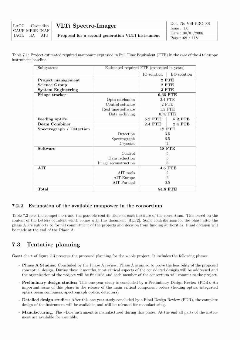
LAOG CavendishCAUP MPIfR INAFIAGL IfA AIU
VLTi Spectro-Imager Doc. No VSI-PRO-001Issue : 1.0
Proposal for a second generation VLTI instrumentDate : 30/01/2006Page : 68 / 118
Table 7.1: Project estimated required manpower expressed in Full Time Equivalent (FTE) in the case of the 4 telescopeinstrument baseline.
Subsystems Estimated required FTE (expressed in years)
IO solution BO solutionProject management 2 FTEScience Group 2 FTESystem Engineering 3 FTEFringe tracker 6.65 FTE
Opto-mechanics 2.4 FTEControl software 2 FTE
Real time software 1.5 FTEData archiving 0.75 FTE
Feeding optics 5.2 FTE 5.2 FTEBeam Combiner 2.4 FTE 2.4 FTESpectrograph / Detection 12 FTE
Detection 3.5Spectrograph 6.5
Cryostat 2Software 18 FTE
Control 5Data reduction 5
Image reconstruction 8AIT 4.5 FTE
AIT tools 2AIT Europe 2AIT Paranal 0.5
Total 54.8 FTE
7.2.2 Estimation of the available manpower in the consortium
Table 7.2 lists the competences and the possible contributions of each institute of the consortium. This based on thecontent of the Letters of Intent which comes with this document [REF2]. Some contributions for the phase after thephase A are subjects to formal commitment of the projects and decision from funding authorities. Final decision willbe made at the end of the Phase A.
7.3 Tentative planning
Gantt chart of figure 7.3 presents the proposed planning for the whole project. It includes the following phases:
- Phase A Studies: Concluded by the Phase A review. Phase A is aimed to prove the feasibility of the proposedconceptual design. During these 9 months, most critical aspects of the considered designs will be addressed andthe organization of the project will be finalized and each member of the consortium will commit to the project.
- Preliminary design studies: This one year study is concluded by a Preliminary Design Review (PDR). Animportant issue of this phase is the release of the main critical component orders (feeding optics, integratedoptics beam combiners, spectrograph optics, detectors)
- Detailed design studies: After this one year study concluded by a Final Design Review (FDR), the completedesign of the instrument will be available, and will be released for manufacturing.
- Manufacturing: The whole instrument is manufactured during this phase. At the end all parts of the instru-ment are available for assembly.

LAOG CavendishCAUP MPIfR INAFIAGL IfA AIU
VLTi Spectro-Imager Doc. No VSI-PRO-001Issue : 1.0
Proposal for a second generation VLTI instrumentDate : 30/01/2006Page : 69 / 118
Table 7.2: Possible consortium contributions for the project design and manufacturing, and related manpower ex-pressed in FTE (in years) over the 4 years of the project.
Institute Activities FTE(over 3-4 years)
LAOG(Grenoble)
Management
20Integrated OpticsSystem studiesScience Objectives
CAUP(Porto)
Image reconstruction
6∗Integrated OpticsScience Objectives
Cavendish(Cambridge)
Fringe tracker12∗System studies
Science Objectives
MPfIR(Bonn)
Nears infrared detectors systems
9
Detector electronicsOpto mechanical sub-systemsElectronics sub systemsSoftwareScience Objectives
INAF(Italy)
Optical and opto-mechanical
TBDcryogenics and detectorinstrument modeling: error budget and performance analysisSoftwareScience Objectives
IAGL(Liege)
Fiber optics
6∗System studiesSoftwareScience Objectives
IfA(Vienna)
Software 3∗Science Objectives
AIU(Jena)
Integrated Optics6∗Software
Science ObjectivesTotal ≥ 62
∗ subject to funding agencies agreement
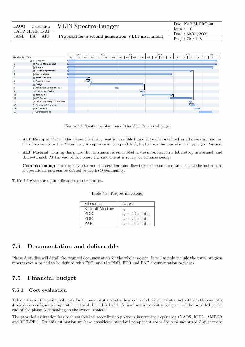
LAOG CavendishCAUP MPIfR INAFIAGL IfA AIU
VLTi Spectro-Imager Doc. No VSI-PRO-001Issue : 1.0
Proposal for a second generation VLTI instrumentDate : 30/01/2006Page : 70 / 118
VLTi Imager
1 Project Management
2 Science
3 System Engineering
4 Sub-systems
5 Phase A studies
6 Phase A review
7 Design
8 Preliminary Design review
9 Final Design Review
10 Realization
11 AIT Europe
12 Preliminary Acceptance Europe
13 Packing and Shipping
14 AIT Paranal
15 Commissionning
TitreNuméro de
plan
Q2 Q3 Q4 Q1 Q2 Q3 Q4 Q1 Q2 Q3 Q4 Q1 Q2 Q3 Q4 Q1 Q2 Q3 Q4 Q1 Q2 Q3
2006 2007 2008 2009 2010 2011
Figure 7.3: Tentative planning of the VLTi Spectro-Imager
- AIT Europe: During this phase the instrument is assembled, and fully characterized in all operating modes.This phase ends by the Preliminary Acceptance in Europe (PAE), that allows the consortium shipping to Paranal.
- AIT Paranal: During this phase the instrument is assembled in the interferometric laboratory in Paranal, andcharacterized. At the end of this phase the instrument is ready for commissioning.
- Commissioning: These on-sky tests and characterizations allow the consortium to establish that the instrumentis operational and can be offered to the ESO community.
Table 7.3 gives the main milestones of the project.
Table 7.3: Project milestones
Milestones DatesKick-off Meeting t0PDR t0 + 12 monthsFDR t0 + 24 monthsPAE t0 + 44 months
7.4 Documentation and deliverable
Phase A studies will detail the required documentation for the whole project. It will mainly include the usual progressreports over a period to be defined with ESO, and the PDR, FDR and PAE documentation packages.
7.5 Financial budget
7.5.1 Cost evaluation
Table 7.4 gives the estimated costs for the main instrument sub-systems and project related activities in the case of a4 telescope configuration operated in the J, H and K band. A more accurate cost estimation will be provided at theend of the phase A depending to the system choices.
The provided estimation has been established according to previous instrument experience (NAOS, IOTA, AMBERand VLT-PF ). For this estimation we have considered standard component costs down to motorized displacement
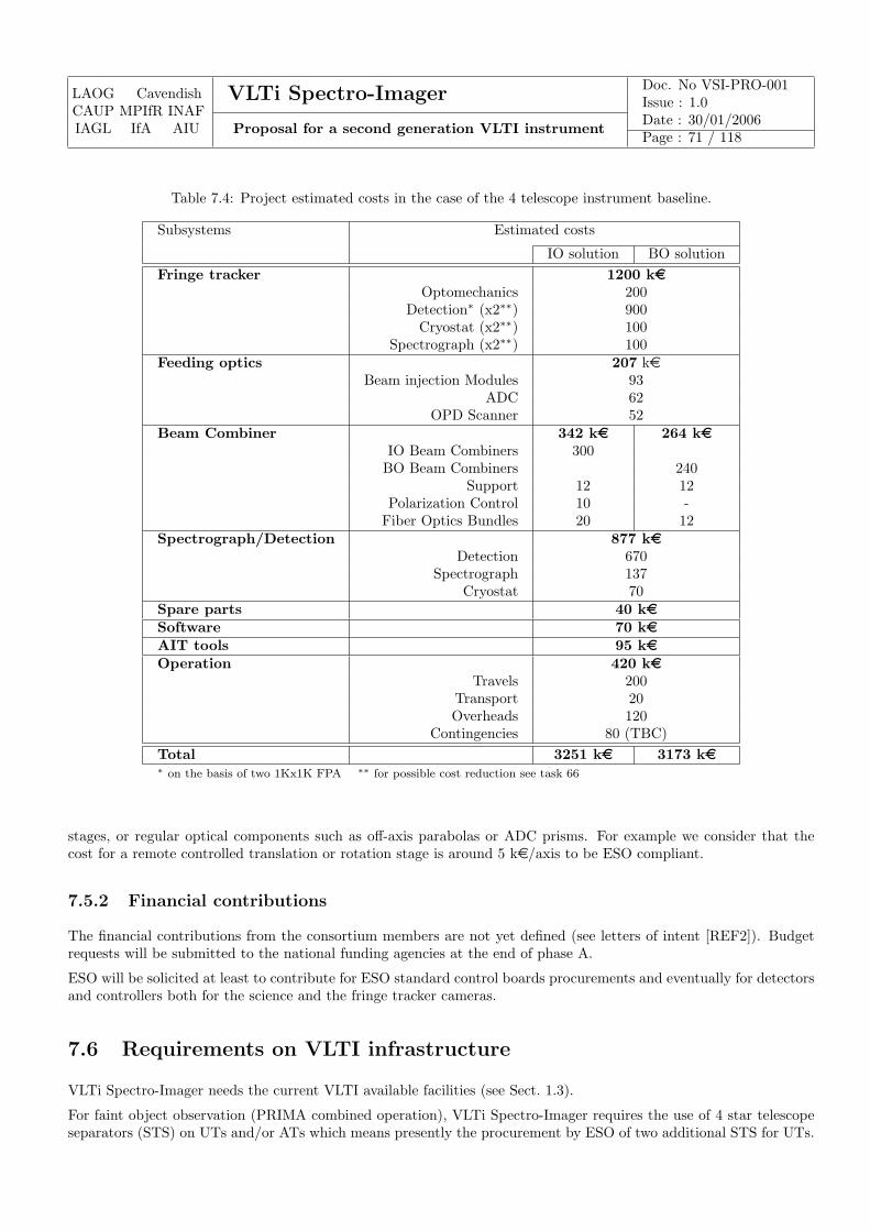
LAOG CavendishCAUP MPIfR INAFIAGL IfA AIU
VLTi Spectro-Imager Doc. No VSI-PRO-001Issue : 1.0
Proposal for a second generation VLTI instrumentDate : 30/01/2006Page : 71 / 118
Table 7.4: Project estimated costs in the case of the 4 telescope instrument baseline.
Subsystems Estimated costs
IO solution BO solutionFringe tracker 1200 ke
Optomechanics 200Detection∗ (x2∗∗) 900
Cryostat (x2∗∗) 100Spectrograph (x2∗∗) 100
Feeding optics 207 keBeam injection Modules 93
ADC 62OPD Scanner 52
Beam Combiner 342 ke 264 keIO Beam Combiners 300
BO Beam Combiners 240Support 12 12
Polarization Control 10 -Fiber Optics Bundles 20 12
Spectrograph/Detection 877 keDetection 670
Spectrograph 137Cryostat 70
Spare parts 40 keSoftware 70 keAIT tools 95 keOperation 420 ke
Travels 200Transport 20Overheads 120
Contingencies 80 (TBC)Total 3251 ke 3173 ke∗ on the basis of two 1Kx1K FPA ∗∗ for possible cost reduction see task 66
stages, or regular optical components such as off-axis parabolas or ADC prisms. For example we consider that thecost for a remote controlled translation or rotation stage is around 5 ke/axis to be ESO compliant.
7.5.2 Financial contributions
The financial contributions from the consortium members are not yet defined (see letters of intent [REF2]). Budgetrequests will be submitted to the national funding agencies at the end of phase A.
ESO will be solicited at least to contribute for ESO standard control boards procurements and eventually for detectorsand controllers both for the science and the fringe tracker cameras.
7.6 Requirements on VLTI infrastructure
VLTi Spectro-Imager needs the current VLTI available facilities (see Sect. 1.3).
For faint object observation (PRIMA combined operation), VLTi Spectro-Imager requires the use of 4 star telescopeseparators (STS) on UTs and/or ATs which means presently the procurement by ESO of two additional STS for UTs.
LAOG CavendishCAUP MPIfR INAFIAGL IfA AIU
VLTi Spectro-Imager Doc. No VSI-PRO-001Issue : 1.0
Proposal for a second generation VLTI instrumentDate : 30/01/2006Page : 72 / 118
If necessary, depending of phase A studies, we may require Adaptive Optics systems on all ATs2.
2LAOG associated with Floralis/AlpAO can eventually provide on ESO request a design and manufacturing of AO systems for ATs.
LAOG CavendishCAUP MPIfR INAFIAGL IfA AIU
VLTi Spectro-Imager Doc. No VSI-PRO-001Issue : 1.0
Proposal for a second generation VLTI instrumentDate : 30/01/2006Page : 73 / 118
Chapter 8
Phase-A management plan
8.1 Scope of the chapter
This chapter details the organization of the phase A study. This is based on the intentions given by the differentinstitutes of the consortium in their Letters of Intent [REF2] and the list of tasks defined in chapters 2 to 6.
8.2 Organization of the phase A study
The organization of the project will be split in three parts as indicated in Fig. 8.1:
– The science group is in charge of specifying the astrophysical high level requirements. It has a special andimportant role in VLTi Spectro-Imager since one has to define a strategy for the best use of the VLTI infras-tructure leading to consequences on the image quality. The group will be helped with external consultants,specialists in their astrophysical domains and by internal consultants. A special link is foreseen with the ImageReconstruction group.
– The system group is in charge of solving all the issues raised in chapters 3 to 6. It is made of the subsys-tem leaders and the identified persons who work at the system level (system engineer, interfaces engineer andintegration manager). The TBD leaders will be identified before or at the kick-off meeting depending on thecompetences of the available resources and the motivation of the participating consortium.
– The management is in charge of the project so that information circulates fluently between the groups andalso to organize the work of the consortium at higher level. The management will participate to the meetingsof each group as necessary. The management is also responsible to build the structure of the project for thefollowing phase. The management is the main contact point for ESO.
The science group will have two face-to-face meetings, at the beginning of its work and near the end. The rest of thetime, communication will be done through email or by audio-conference. We plan to have most of the science workdone by the middle of the phase A study so that inputs are given in advance to the system group.
The system group will have a telephone meeting of half a day every two weeks to follow the progress of the tasks anddiscuss main issues. We plan to have also two face-to-face meetings for general discussion, in particular to discussthe choice of the solution for the beam combiner. Many “easy” issues will be tackled at the beginning in order notto depend on the progress of the science group. At the end of the phase-A study, the different subsystem leaders willspecify the high level requirements of their subsystems.
We plan also have a meeting of the co-Is for the construction of the final management of the project. An importantquestion will have to be solved, namely the management which depends on the technical solution chosen (integratedoptics or bulk optics).
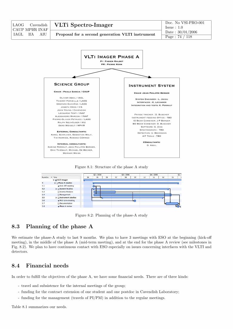
LAOG CavendishCAUP MPIfR INAFIAGL IfA AIU
VLTi Spectro-Imager Doc. No VSI-PRO-001Issue : 1.0
Proposal for a second generation VLTI instrumentDate : 30/01/2006Page : 74 / 118
Science Group
Chair : Paula Garcia / CAUP
Olivier Absil / IAGLThierry Forveille / LAOGGAspard Duchêne / LAOG
Joseph Hron / IfAJohn Young / CavendishLeonardo Testi / INAF
Alessandro Marconi / INAFPierre-Olivier Petrucci / LAOG
Ralph Neuhäuser / AIUGerd Weigelt / MPfIR
External Consultants:Karel Schrijver, Sebastian Wolf,
Tim Harries, Romano COrradi
Internal consultants:Karine Perraut, Jean Philippe Berger,
Eric Thiébaut, Michael De Becker, Werner Weiss
VLTi Imager Phase API : Fabien MalbetPM : Pierre Kern
Instrument System
Chair :Jean Philippe Berger
System Engineer : L. JocouInterfaces : E. Lecoarer
Integration and tests: K. Perraut
Fringe tracker : D. BuscherInstrument feeding Optics : TBD
IO Beam Combiner: J-P BergerBO Beam Combiner: D. Buscher
Software: G. ZinsSpectrograph : TBD
Detection: U. BeckmannAIT Tools : TBD
COnsultants:O. Absil
Figure 8.1: Structure of the phase A study
Figure 8.2: Planning of the phase-A study
8.3 Planning of the phase A
We estimate the phase-A study to last 9 months. We plan to have 3 meetings with ESO at the beginning (kick-offmeeting), in the middle of the phase A (mid-term meeting), and at the end for the phase A review (see milestones inFig. 8.2). We plan to have continuous contact with ESO especially on issues concerning interfaces with the VLTI anddetectors.
8.4 Financial needs
In order to fulfill the objectives of the phase A, we have some financial needs. There are of three kinds:
- travel and subsistence for the internal meetings of the group;
- funding for the contract extension of one student and one postdoc in Cavendish Laboratory;
- funding for the management (travels of PI/PM) in addition to the regular meetings.
Table 8.1 summarizes our needs.
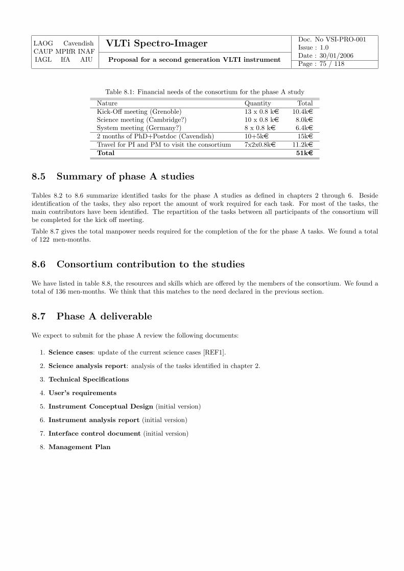
LAOG CavendishCAUP MPIfR INAFIAGL IfA AIU
VLTi Spectro-Imager Doc. No VSI-PRO-001Issue : 1.0
Proposal for a second generation VLTI instrumentDate : 30/01/2006Page : 75 / 118
Table 8.1: Financial needs of the consortium for the phase A study
Nature Quantity TotalKick-Off meeting (Grenoble) 13 x 0.8 ke 10.4keScience meeting (Cambridge?) 10 x 0.8 ke 8.0keSystem meeting (Germany?) 8 x 0.8 ke 6.4ke2 months of PhD+Postdoc (Cavendish) 10+5ke 15keTravel for PI and PM to visit the consortium 7x2x0.8ke 11.2keTotal 51ke
8.5 Summary of phase A studies
Tables 8.2 to 8.6 summarize identified tasks for the phase A studies as defined in chapters 2 through 6. Besideidentification of the tasks, they also report the amount of work required for each task. For most of the tasks, themain contributors have been identified. The repartition of the tasks between all participants of the consortium willbe completed for the kick off meeting.
Table 8.7 gives the total manpower needs required for the completion of the for the phase A tasks. We found a totalof 122 men-months.
8.6 Consortium contribution to the studies
We have listed in table 8.8, the resources and skills which are offered by the members of the consortium. We found atotal of 136 men-months. We think that this matches to the need declared in the previous section.
8.7 Phase A deliverable
We expect to submit for the phase A review the following documents:
1. Science cases: update of the current science cases [REF1].
2. Science analysis report: analysis of the tasks identified in chapter 2.
3. Technical Specifications
4. User’s requirements
5. Instrument Conceptual Design (initial version)
6. Instrument analysis report (initial version)
7. Interface control document (initial version)
8. Management Plan
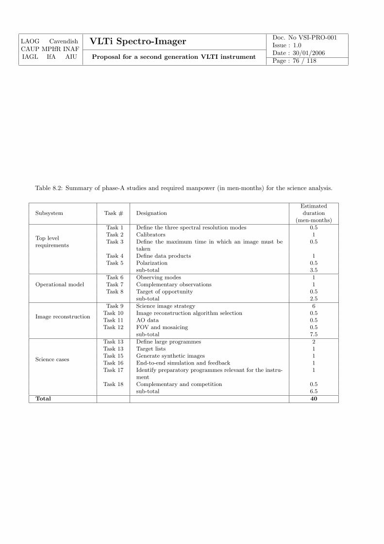
LAOG CavendishCAUP MPIfR INAFIAGL IfA AIU
VLTi Spectro-Imager Doc. No VSI-PRO-001Issue : 1.0
Proposal for a second generation VLTI instrumentDate : 30/01/2006Page : 76 / 118
Table 8.2: Summary of phase-A studies and required manpower (in men-months) for the science analysis.
EstimatedSubsystem Task # Designation duration
(men-months)
Top levelrequirements
Task 1 Define the three spectral resolution modes 0.5Task 2 Calibrators 1Task 3 Define the maximum time in which an image must be
taken0.5
Task 4 Define data products 1Task 5 Polarization 0.5
sub-total 3.5
Operational modelTask 6 Observing modes 1Task 7 Complementary observations 1Task 8 Target of opportunity 0.5
sub-total 2.5
Image reconstruction
Task 9 Science image strategy 6Task 10 Image reconstruction algorithm selection 0.5Task 11 AO data 0.5Task 12 FOV and mosaicing 0.5
sub-total 7.5
Science cases
Task 13 Define large programmes 2Task 13 Target lists 1Task 15 Generate synthetic images 1Task 16 End-to-end simulation and feedback 1Task 17 Identify preparatory programmes relevant for the instru-
ment1
Task 18 Complementary and competition 0.5sub-total 6.5
Total 40
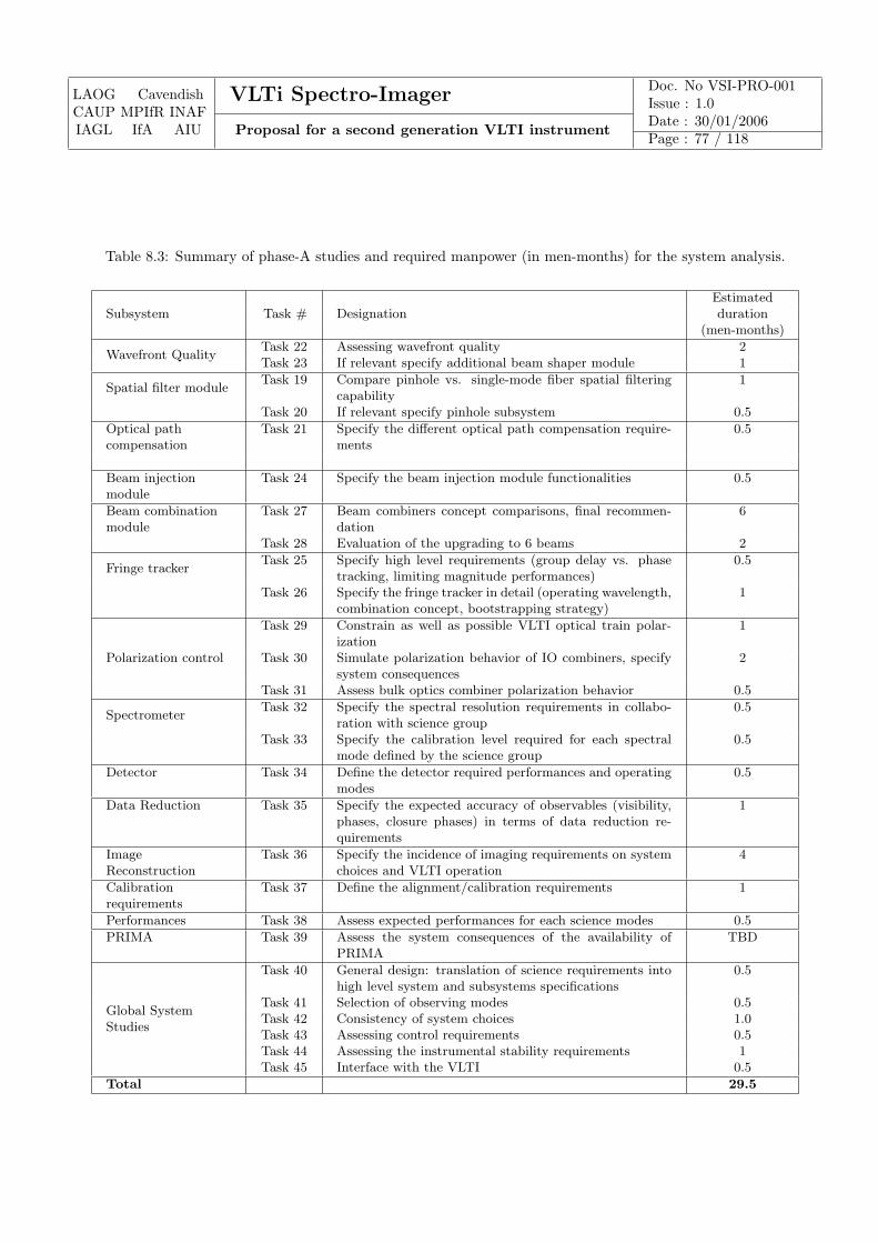
LAOG CavendishCAUP MPIfR INAFIAGL IfA AIU
VLTi Spectro-Imager Doc. No VSI-PRO-001Issue : 1.0
Proposal for a second generation VLTI instrumentDate : 30/01/2006Page : 77 / 118
Table 8.3: Summary of phase-A studies and required manpower (in men-months) for the system analysis.
EstimatedSubsystem Task # Designation duration
(men-months)
Wavefront QualityTask 22 Assessing wavefront quality 2Task 23 If relevant specify additional beam shaper module 1
Spatial filter moduleTask 19 Compare pinhole vs. single-mode fiber spatial filtering
capability1
Task 20 If relevant specify pinhole subsystem 0.5
Optical pathcompensation
Task 21 Specify the different optical path compensation require-ments
0.5
Beam injectionmodule
Task 24 Specify the beam injection module functionalities 0.5
Beam combinationmodule
Task 27 Beam combiners concept comparisons, final recommen-dation
6
Task 28 Evaluation of the upgrading to 6 beams 2
Fringe trackerTask 25 Specify high level requirements (group delay vs. phase
tracking, limiting magnitude performances)0.5
Task 26 Specify the fringe tracker in detail (operating wavelength,combination concept, bootstrapping strategy)
1
Polarization control
Task 29 Constrain as well as possible VLTI optical train polar-ization
1
Task 30 Simulate polarization behavior of IO combiners, specifysystem consequences
2
Task 31 Assess bulk optics combiner polarization behavior 0.5
SpectrometerTask 32 Specify the spectral resolution requirements in collabo-
ration with science group0.5
Task 33 Specify the calibration level required for each spectralmode defined by the science group
0.5
Detector Task 34 Define the detector required performances and operatingmodes
0.5
Data Reduction Task 35 Specify the expected accuracy of observables (visibility,phases, closure phases) in terms of data reduction re-quirements
1
ImageReconstruction
Task 36 Specify the incidence of imaging requirements on systemchoices and VLTI operation
4
Calibrationrequirements
Task 37 Define the alignment/calibration requirements 1
Performances Task 38 Assess expected performances for each science modes 0.5
PRIMA Task 39 Assess the system consequences of the availability ofPRIMA
TBD
Global SystemStudies
Task 40 General design: translation of science requirements intohigh level system and subsystems specifications
0.5
Task 41 Selection of observing modes 0.5Task 42 Consistency of system choices 1.0Task 43 Assessing control requirements 0.5Task 44 Assessing the instrumental stability requirements 1Task 45 Interface with the VLTI 0.5
Total 29.5
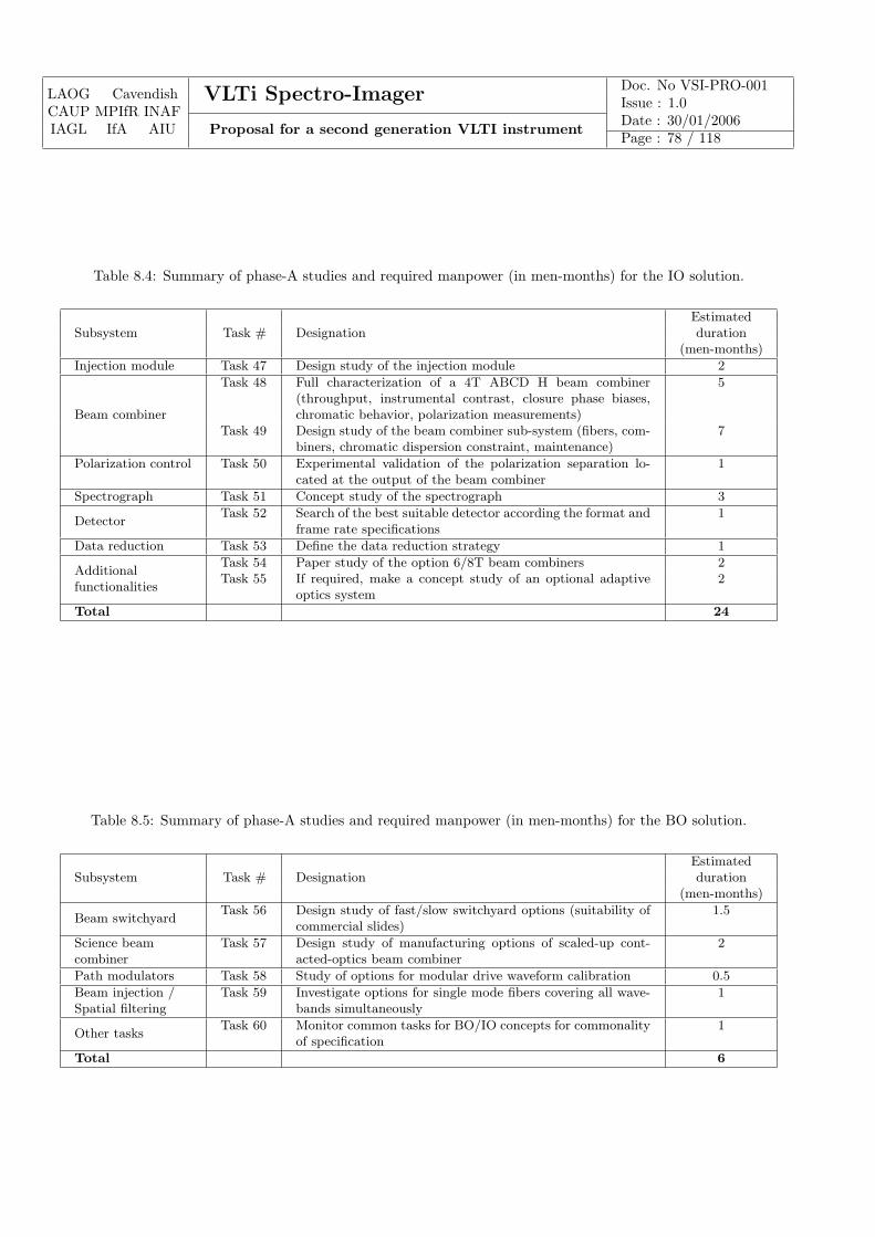
LAOG CavendishCAUP MPIfR INAFIAGL IfA AIU
VLTi Spectro-Imager Doc. No VSI-PRO-001Issue : 1.0
Proposal for a second generation VLTI instrumentDate : 30/01/2006Page : 78 / 118
Table 8.4: Summary of phase-A studies and required manpower (in men-months) for the IO solution.
EstimatedSubsystem Task # Designation duration
(men-months)
Injection module Task 47 Design study of the injection module 2
Beam combiner
Task 48 Full characterization of a 4T ABCD H beam combiner(throughput, instrumental contrast, closure phase biases,chromatic behavior, polarization measurements)
5
Task 49 Design study of the beam combiner sub-system (fibers, com-biners, chromatic dispersion constraint, maintenance)
7
Polarization control Task 50 Experimental validation of the polarization separation lo-cated at the output of the beam combiner
1
Spectrograph Task 51 Concept study of the spectrograph 3
DetectorTask 52 Search of the best suitable detector according the format and
frame rate specifications1
Data reduction Task 53 Define the data reduction strategy 1
Additionalfunctionalities
Task 54 Paper study of the option 6/8T beam combiners 2Task 55 If required, make a concept study of an optional adaptive
optics system2
Total 24
Table 8.5: Summary of phase-A studies and required manpower (in men-months) for the BO solution.
EstimatedSubsystem Task # Designation duration
(men-months)
Beam switchyardTask 56 Design study of fast/slow switchyard options (suitability of
commercial slides)1.5
Science beamcombiner
Task 57 Design study of manufacturing options of scaled-up cont-acted-optics beam combiner
2
Path modulators Task 58 Study of options for modular drive waveform calibration 0.5
Beam injection /Spatial filtering
Task 59 Investigate options for single mode fibers covering all wave-bands simultaneously
1
Other tasksTask 60 Monitor common tasks for BO/IO concepts for commonality
of specification1
Total 6
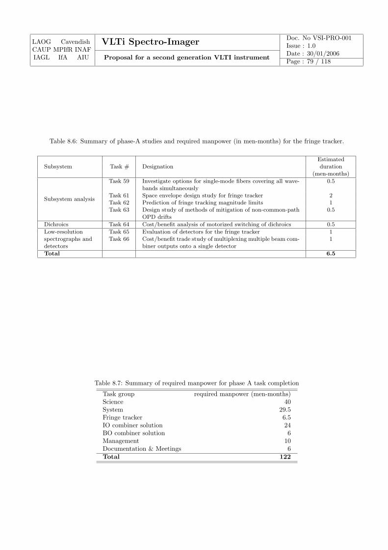
LAOG CavendishCAUP MPIfR INAFIAGL IfA AIU
VLTi Spectro-Imager Doc. No VSI-PRO-001Issue : 1.0
Proposal for a second generation VLTI instrumentDate : 30/01/2006Page : 79 / 118
Table 8.6: Summary of phase-A studies and required manpower (in men-months) for the fringe tracker.
EstimatedSubsystem Task # Designation duration
(men-months)
Subsystem analysis
Task 59 Investigate options for single-mode fibers covering all wave-bands simultaneously
0.5
Task 61 Space envelope design study for fringe tracker 2Task 62 Prediction of fringe tracking magnitude limits 1Task 63 Design study of methods of mitigation of non-common-path
OPD drifts0.5
Dichroics Task 64 Cost/benefit analysis of motorized switching of dichroics 0.5
Low-resolutionspectrographs anddetectors
Task 65 Evaluation of detectors for the fringe tracker 1Task 66 Cost/benefit trade study of multiplexing multiple beam com-
biner outputs onto a single detector1
Total 6.5
Table 8.7: Summary of required manpower for phase A task completion
Task group required manpower (men-months)Science 40System 29.5Fringe tracker 6.5IO combiner solution 24BO combiner solution 6Management 10Documentation & Meetings 6Total 122
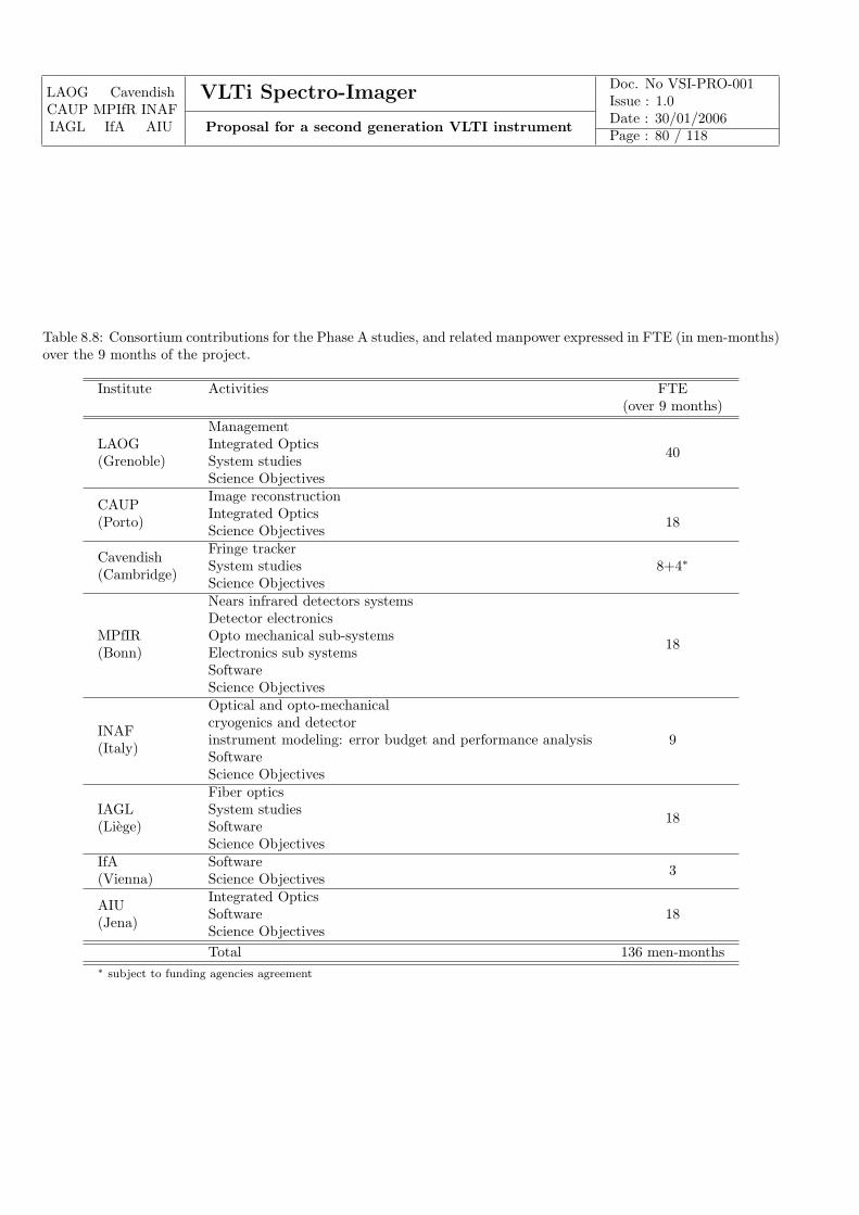
LAOG CavendishCAUP MPIfR INAFIAGL IfA AIU
VLTi Spectro-Imager Doc. No VSI-PRO-001Issue : 1.0
Proposal for a second generation VLTI instrumentDate : 30/01/2006Page : 80 / 118
Table 8.8: Consortium contributions for the Phase A studies, and related manpower expressed in FTE (in men-months)over the 9 months of the project.
Institute Activities FTE(over 9 months)
LAOG(Grenoble)
Management
40Integrated OpticsSystem studiesScience Objectives
CAUP(Porto)
Image reconstruction
18Integrated OpticsScience Objectives
Cavendish(Cambridge)
Fringe tracker8+4∗System studies
Science Objectives
MPfIR(Bonn)
Nears infrared detectors systems
18
Detector electronicsOpto mechanical sub-systemsElectronics sub systemsSoftwareScience Objectives
INAF(Italy)
Optical and opto-mechanical
9cryogenics and detectorinstrument modeling: error budget and performance analysisSoftwareScience Objectives
IAGL(Liege)
Fiber optics
18System studiesSoftwareScience Objectives
IfA(Vienna)
Software 3Science Objectives
AIU(Jena)
Integrated Optics18Software
Science ObjectivesTotal 136 men-months
∗ subject to funding agencies agreement
LAOG CavendishCAUP MPIfR INAFIAGL IfA AIU
VLTi Spectro-Imager Doc. No VSI-PRO-001Issue : 1.0
Proposal for a second generation VLTI instrumentDate : 30/01/2006Page : 81 / 118
Appendix A
Experience from the proposingconsortium
A.1 Laboratoire d’Astrophysique de Grenoble
LAOG has strong scientific and technical implications in high angular resolution techniques for astronomy and hasdeveloped over the past ten years its experience and expertise in several areas important in achieving the goals of theVLTi Spectro-Imager.
Teams interested in the VLTi Spectro-Imager
LAOG is composed of 4 main teams, 3 devoted to astrophysical research (FOST, SHERPAS and ASTROMOL) andone to instrumental research (GRIL), and a technical group. Three of these teams are focused on research which canbe tackled with the VLTi Spectro-Imager:
– FOST (= star and planet formation, brown dwarfs) team focuses on later stages of star formation, mainlythe physics of star-disk interactions, evolved disks and the conditions for planet formation (structural featureslike gaps and rings, dust grain evolution in disks, etc.; timescale ≈ 106 − 107 yrs), and also on the formationmechanisms of binaries and the Initial Mas Function (IMF). A specific activity within the team is the studyof brown dwarfs, both as astronomical objects by themselves, and as intermediate bodies between low-massstars and exoplanets. The search and characterization of exoplanets are themselves an increasing part of theFOST activities. The team contributes a lot to observations made with LAOG-built instruments and to theirinterpretation.Permanent staff : 13 + 7 shared with GRIL. PhDs in 2001-2005 completed : 5 + 1 with GRIL; underway: 9 +3 with GRIL + 1 with SHERPAS. Team leader : F. Menard (CNRS).
– SHERPAS (=sources of high energies and relativistic physics in accretion-ejection structures , in full) team isessentially involved in MHD theory calculations, with particular emphasis on the accretion-ejection phenomenonin astrophysics. Here it mainly applies models to star-disk interactions and disk-driven jets, where magnetic fields,instead of gravitation, play a dominant role. The team has an interest in high angular resolution observationsof AGN and micro-quasars in order to constrain their models.Permanent staff : 7. PhDs in 2001-2005 completed: 2; underway: 2 + 1 with FOST. Team leader : Pr. G.Pelletier (University J. Fourier).
– GRIL (= instrumental research group at LAOG) team concentrates on strategic issues in research & development(R&D) for future instruments and detectors. GRIL’s responsibility has been to contribute to the developmentof optical and near-IR instruments for large ground-based telescopes (ESO, CFHT) with the highest spatialresolution (for instance with the goal to resolve the inner parts of protoplanetary disks, i.e., within 1 AU at 450pc, say), by way of adaptive optics and interferometry, and/or the highest dynamic range (adaptive optics toimage exoplanets as closely as possible from their host star).
LAOG CavendishCAUP MPIfR INAFIAGL IfA AIU
VLTi Spectro-Imager Doc. No VSI-PRO-001Issue : 1.0
Proposal for a second generation VLTI instrumentDate : 30/01/2006Page : 82 / 118
Permanent staff : 9 (including 8 engineers) + 7 shared with FOST. PhDs in 2001-2005 completed: 3 + 1 withFOST; underway: 8 + 3 with FOST. Team leader : Dr. C. Perrier (Astronomer).
The key persons from LAOG involved in the VLTi Spectro-Imager are: J.-P. Berger, G. Duvert, L. Jocou, P. Kern,E. Le Coarer, F. Malbet, K. Perraut all of them part of GRIL. J.-P. Berger, G. Duvert and F. Malbet are also part ofFOST. G. Duchene, T. Forveille from FOST and P.O. Petrucci from SHERPAS are part of the science group.
Instrumental experience
Technically, LAOG has been involved in the development of two first generation VLT/VLTI instruments:
– NAOS, the Nasmyth Adaptive Optics System for the VLT, which was delivered to ESO in the fall of 2001 and isnow being installed on UT4. LAOG was responsible for the instrument opto-mechanical design and realization,the system interfaces, the visible wavefront sensor, the overall instrument control and the preliminary integration.NAOS was developed in collaboration with LESIA and ONERA.
– AMBER, a VLTI near-infrared instrument, which has been delivered to ESO in spring 2004. LAOG was re-sponsible for the system design, the final integration and testing, the high-level control software and the datareduction software. AMBER was developed in collaboration with OCA/LUAN in Nice, Max-Planck Institutefor Radioastronomy (Bonn) and Arcetri Observatory (Florence).
For this two projects, LAOG astronomers also played a key role in the definition of the scientific drivers and high levelrequirements of the instruments.
LAOG has been chosen by ESO to lead the development of the VLT Planet Finder, one the of the second generationinstrument of the VLT, under the leadership of Dr. J.-L. Beuzit. Compared to NAOS, the main emphasis is on avery high dynamic range to reach the scientific goal of direct detection of dozens of Jupiter-mass planets, possibly inmultiple systems (as a few are already known from the radial-velocity method). It is expected to be completed in2009-2010. The persons involved in the VLTi Spectro-Imager are mostly not involved in the VLT-PF project.
LAOG also took part to the development of the Wide-field Infrared Camera (WIRCAM) for the CFHT (Canada-France-Hawaii Telescope), in collaboration with LAE at Universite de Montreal and LESIA, among others. LAOGactivities on this project included the overall mechanical design, realization and testing (including the cryostat) andthe preliminary integration.
LAOG is currently leading Research and Development efforts on critical components for astronomical instruments,such as deformable micro-mirrors for adaptive optics (with up to 10000 actuators) and integrated optics combiners forinterferometry, in collaboration with other institutional and industrial partners. The IO work led to the manufacturingof 3 beam combiners, 2 of them being currently in operation:
• a 3T beam combiner which is the the science combiner of the IOTA interferometer. Two astrophysical papershave already been published in major journals and several others are in preparation [REF18, REF19].
• a 2T beam combiner which replaced the MONA fiber coupler of VINCI on the VLTI. This beam combiner wasused for example for the first fringes of the ATs (see press release).
LAOG hosts the service part and the direction of Jean-Marie Mariotti Center, the French Center for Infrared andOptical Interferometry. It provides support for the users of the astronomical interferometers currently in operationaround the world. JMMC plays a leading role in the Joint Research Activity 4 of the European InterferometryInitiative (EII). This project, centered on the VLTI, is one of the 6 JRAs of the European programme OPTICON.Twelve countries participate in this programme (Austria, Belgium, Czech Republic, France, Germany, Hungary, Israel,Italy, Nederlands, Poland, Portugal, United Kingdom), as well as ESA and ESO, for a total of more than twentylaboratories. The resources of the JRA4 are distributed evenly on two work packages Advanced instruments andOff-line data reduction software.
In 2006, the technical personnel at LAOG include a total of 17 engineers and technicians.
LAOG CavendishCAUP MPIfR INAFIAGL IfA AIU
VLTi Spectro-Imager Doc. No VSI-PRO-001Issue : 1.0
Proposal for a second generation VLTI instrumentDate : 30/01/2006Page : 83 / 118
Short biographies of the Principal Investigator and the Project Manager
Dr. Malbet graduated in 1992 on the astrophysical topic Circumstellar environments of young stars under the directionof Pr. Lena and Dr. Bertout. In 1993-1994, Research Associate at JPL in the group of Dr. Shao, he proposed thedark hole method in space-based stellar coronography and took part to the construction of the Palomar TestbedInterferometer (PTI) under the supervision of Dr. M. Colavita. Entered in CNRS in 1995, he worked on T Tauri diskmodeling showing the importance of infrared interferometry for such objects. In 1998, with Dr. R.G. Petrov, he put inplace a European consortium to build AMBER the near infrared instrument of the VLT Interferometer. He occupiedthe function of Project Scientist, and, after 2000, led the science group. He took part to the commissioning of theAMBER instrument, and, conducted the work leading to the first AMBER result, where for the first time evidence forspatially resolved wind was found together with the presence of a disk around the young star MWC 297. F. Malbetis part of the LAOG team working on the new technology promising for astronomical interferometry especially witha large number of telescopes. F. Malbet has been responsible for the interferometry activity in LAOG since 1998.
Dr. Kern graduated in 1990 with a thesis demonstrating for the first time that adaptive optics worked in astronomy(first observations at OHP in 1989). Hired by LAOG to take an active part to the VLTI development, and, P. Kerntook the leadership of the optomechanical part of the VLT project NAOS because of the delay of the VLTI. In thesame time Dr. Kern started an important research and technology development in the integrated optics technology.He organized the AstroFib’96 workshop where all specialists from this domain met for the first time. In 2002-2004, P.Kern has been deputy project manager of AMBER during its integration phase in LAOG. P. Kern is also at the originof the development of micro deformable mirrors which are now manufactured for several labs in Europe. P. Kern hasbeen the technical director of LAOG since 2003.
Internet webpages
More details can be found on the Internet at the following places:
• LAOG: http://www-laog.obs.ujf-grenoble.fr
• AMBER: http://amber.obs.ujf-grenoble.fr
• JMMC: http://www.mariotti.fr
A.2 Cavendish Laboratory, University of Cambridge
Background
Members of the Cambridge Optical Aperture Synthesis Telescope (COAST) team have been key players in the fieldof optical aperture synthesis since the early 1980’s. Then, under the leadership of Professor John Baldwin, they wereresponsible for the first measurements of optical and near-infrared closure phases, for delivering the first images fromoptical aperture synthesis and for the design and deployment of the world’s first optical separated element synthesistelescope, COAST.
Subsequently, their work has spanned the full range of activities associated with the delivery of a synthesis imag-ing capability for astronomers, including system design, design, prototyping and delivery of hardware and softwarecomponents of interferometers, as well as astronomical observations using COAST and other interferometric arrays.The group has also made significant contributions to the development of the OIFITS standard for interferometer dataexchange under the auspices of the IAU, and won the first IAU-organized “Imaging Beauty Contest” in 2004 withtheir BSMEM software package.
The group’s astrophysical interests have been mainly directed towards understanding the surface activity and massloss from cool evolved stars and confronting theories of stellar pulsation, in particular of Mira variables.
LAOG CavendishCAUP MPIfR INAFIAGL IfA AIU
VLTi Spectro-Imager Doc. No VSI-PRO-001Issue : 1.0
Proposal for a second generation VLTI instrumentDate : 30/01/2006Page : 84 / 118
Current activities
Most recently, the COAST group has been focusing mainly on two parallel technical efforts: (i) with US colleagues,as key participants of the Magdalena Ridge Observatory Interferometer (MROI) and (ii) with European colleaguesas participants of the European Interferometry Initiative (EII). The group’s role in the MROI is as provider of top-level technical and scientific oversight, as well as being responsible for the design and delivery of a number of criticalsubsystems, in particular the long-stroke vacuum delay lines and the beam combiners. Under the EII’s umbrella,the team have been participating in the technical activities associated with second-generation instrument design forthe VLTI, with fringe tracking, and with the testing and development of novel image reconstruction algorithms foroptical/IR interferometric data.
Team
The current COAST team comprises two full time tenured academic staff (Buscher and Haniff), three post-doctoralworkers (Young, Seneta and Baron), two engineers and, typically, around two graduate students. For this proposal weexpect that one of our graduate students and one of our post-docs will provide significant inputs of effort, togetherwith oversight, direction and top-level contributions from Buscher, Haniff and Young.
Further details of our group’s activity and research record can be found at our web site at:
http://www.mrao.cam.ac.uk/telescopes/coast/
Short biography of the Co-I
Dr. David Buscher has been closely involved in astronomical aperture synthesis for close to 20 years. He was akey contributor to the design of the Cambridge Optical Aperture Synthesis Telescope (COAST) and has workedat the MkIII interferometer on Mt Wilson, California and contributed to the design and construction of the NPOIinterferometer in Flagstaff, Arizona. From 1994-1999 he lead the team responsible for the design and commissioning ofthe University of Durham MARTINI and ELECTRA adaptive optics systems for the William Herschel Telescope andparticipated in the NAOMI common-user adaptive optics project. From 1999 he has worked on next-generation opticaland infrared synthesis telescopes at the Cavendish Laboratory. He has authored papers on imaging the surfaces ofsupergiant stars and stellar envelopes, aperture masking techniques, atmospheric seeing, image reconstruction, laser-guide-star adaptive optics, and the design and optimization of optical interferometers.
A.3 Infrared Interferometry Group at the Max-Planck Institute for Ra-dioastronomy
Group web page: http://www.mpifr-bonn.mpg.de/div/ir-interferometry
Research areas
Our Infrared Interferometry Group at the Max-Planck Institute for Radioastronomy conducts a wide range of re-search in the following fields: star formation, evolved stars, active galactic nuclei, radiative transfer modeling, anddevelopment of methods for high angular resolution imaging
Development of instrumentation for high angular resolution imaging
Our group developed the following instruments for high-resolution imaging at visible and near-infrared wavelengths:
• Speckle cameras for speckle imaging at visible wavelengths: based on optical photon-counting detectors andelectron-multiplying CCD cameras.
LAOG CavendishCAUP MPIfR INAFIAGL IfA AIU
VLTi Spectro-Imager Doc. No VSI-PRO-001Issue : 1.0
Proposal for a second generation VLTI instrumentDate : 30/01/2006Page : 85 / 118
• Speckle cameras for speckle imaging at near-infrared wavelengths: based on NICMOS, PICNIC, and HawaiiArray detectors.
• K-band beam combiner instrument for the GI2T interferometer.
• JHK-band beam combiner instrument for the IOTA interferometer (see movie on the web page of our group).
• Hawaii Array detector system and detector software for the AMBER instrument.
• Hawaii Array fringe tracker detector and science software for the LINC-NIRVANA interferometry instrument(Large Binocular Telescope).
The team
Head of the group: Gerd Weigelt - Director at the MPIfR (http://www.mpifr-bonn.mpg.de/staff/gweigelt);Staff members: 6 astronomers; Postdocs: 4 astronomers; students: 3 PhD students; number of engineers and techni-cians: 6.
Curriculum Vitae of the CoI Gerd Weigelt:
February 7, 1947 born in Erlangen, Germany1969 - 1975 Study of Physics, Erlangen-Nuremberg University1978 Ph.D. in Physics, Erlangen-Nuremberg University1978 - 1981 Postdoc at Erlangen-Nuremberg University1982 - 1989 Professor, Erlangen-Nuremberg University1989 - present Director at the Max Planck Institute for Radioastronomy in Bonn
A.4 Centro de Astrofısica da Universidade do Porto
CAUP is the largest astronomical centre in Portugal, with a staff of 14 permanent scientists, 4 post-docs and 16PhD students. It also attracts yearly 10 short term (1-2 weeks) visitors. The centre is one of the top Portugueseresearch units in Earth and Space Sciences - evaluated as excellent by National Science Foundation - FCT. Its mainareas of research are star formation, cosmology and asteroseismology. CAUP supports the training in astronomy viaAstronomy BSc, MSc and PhD programmes. CAUP shares a building with the town Planetarium actively participatingin outreach and spreading of scientific culture.
Instrumentation experience
CAUP has started in early 2004 a collaboration with INESC-Porto optoelectronics unit (located 500m from CAUP) inguided optics R&D for astronomical interferometry. This collaboration is being highly successful and rapid prototypingof recombiners for the J band using sol-gel technologies is underway.
Scientific domains related to VLTI
CAUP is actively involved in the scientific exploitation of the VLTI since 2001 in the fields of star formation andasteroseismology. Activities include: a) participation in the definition of the AMBER instrument guaranteed time; b)scientific exploitation of VINCI, MIDI and AMBER; c) participation in the radiative transfer and asteroseismologyworking groups of the OPTICON interferometry networking; d) participation in the OPTICON interferometry JRA;e) Coordination of the Marie Curie VLTI summer schools (2006-2008).
LAOG CavendishCAUP MPIfR INAFIAGL IfA AIU
VLTi Spectro-Imager Doc. No VSI-PRO-001Issue : 1.0
Proposal for a second generation VLTI instrumentDate : 30/01/2006Page : 86 / 118
Team description
Paulo J.V. Garcia Assistant professor star formation CAUPMargarida Cunha Post-doc asteroseismology CAUPSamira Rajabi PhD student radiative transfer CAUPInes Carvalho Assistant professor system studies FEUPAntonio Leite Associate professor integrated optics INESC-PortoJose Santos Associate professor guided optics INESC-PortoPaulo Marques Assistant professor integrated optics INESC-PortoPaulo Moreira Post-doc integrated optics CAUP/INESC-PortoAskari Ghasempour PhD student guided optics CAUP/INESC-Porto
Short bio of the co-I
Paulo J.V. Garcia scientific interests lie in the modelisation and high angular resolution observation of the circumstellarenvironments of pre-main-sequence stars. He completed his PhD on models and observations of jets from young starsunder the supervision of Renaud Foy in 1999. During the year 2000 was support astronomer and deputy instrumentspecialist of the ISIS and IDS spectrographs at the Isaac Newton Group of Telescopes, La Palma Observatory. Duringthe year 2001 was Post-doc at CAUP. From 2001 to 2005 was Assistant Professor on contract with 340h/yr teaching.Since 2005 is tenure track Assistant professor with 250h/yr teaching. Edited two proceedings and co-authored 16ISI articles. Has served in several national and international committees. Coordinator of several projects totaling∼ 1 Meuro.
Relevant publications
CAUP/INESC-Porto publications relevant to the theme:
Planar and UV written channel optical waveguides prepared with siloxane Polly(oxyethylene)-zirconia organic-inorganichybrids Molina C, Moreira PJ, et al., 2005, Journal of Materials Chemistry, 15, 3937Photosensitive materials for integrated optic applications, 2005, Marques PVS, Moreira PJ, Alexandre D, et al., Fiberand integrated optics, 24 (3-4): 149-169Observations of 51 Ophiuchi with MIDI at the VLTI, 2005, astro-ph/8052, Gil, C.; Malbet, F., et al.The Very Large Telescope Interferometer - Challenges for the Future, 2003, Eds. Garcia, P. J. V.; Glindemann, A.;Henning, Th.; Malbet, F. ISBN 1-4020-1518-6Interferometry and asteroseismology: The radius of tau Cet, 2003, A&A, 406, 15, Pijpers, F. P.; Teixeira, T. C.;Garcia, P. J.; Cunha, M. S.; Monteiro, M. J. P. F. G.; Christensen-Dalsgaard, J.
A.5 Istituto Nazionale di Astrofisica
The INAF team is composed by the Observatories of Arcetri (OAA), Rome (OAR), Turin (OATo) and Catania (OACt),supported by the Universities of Padova (UPD) and Bologna. Such Institutes are playing an important role in theconstruction and use of VLTI and LBT instrumentation. All institutes are interested to contribute to both scientificcase and instrument development.
Technological expertise
OAA is responsible for the cold spectrograph of AMBER (AMBER-SPG). OATo was responsible for the constructionof FINITO, the first instrument designed for fringe stabilization, which allows the other instruments to have exposureslonger than the atmospheric coherence time. OATo is part of the team (with Alenia Spazio) building the two FringeSensor Units (FSU) for PRIMA, the instrument for Phase Referenced Imaging and Microarcsecond Astrometry. OATohas been involved in characterization and testing of NIR and MIR detection systems, including optimization of Read-Out electronics for high-speed, low noise operations. OAR is responsible for the camera system on the Medium-High-Wavefront Sensor (MHWS) of the beam combiner LINC-NIRVANA on LBT. UPD has started a series of training
LAOG CavendishCAUP MPIfR INAFIAGL IfA AIU
VLTi Spectro-Imager Doc. No VSI-PRO-001Issue : 1.0
Proposal for a second generation VLTI instrumentDate : 30/01/2006Page : 87 / 118
activities dedicated to the formation of interferometric expertise. The Observatory of Catania (OACt) has a significantexperience on development, characterisation, maintenance and usage of astronomical instrumentation and detectionsystems at visible wavelengths, and wishes to achieve an active involvement in near IR interferometric instrumentation.
Data analysis expertise
Data reduction and analysis, from the calibration of the raw data to the extraction of the astrophysical parameters,are critical to the successful scientific utilisation of interferometric instruments. A large part of the team membershas developed specific expertise in handling data reduction tools of the present VLTI instruments (VINCI, MIDI,AMBER) and in developing procedures for the visibility computation from 2D physical models.
Scientific expertise
Scientific topics which we have already investigated with the present high resolution facilities, and that can be betteraddressed with the higher imaging performance of the instrument currently proposed, are:
• Sizes of asteroids: we are now involved in the first interferometric observations of minor bodies of the Solarsystem ever attempted. Interferometric observations allow us to get direct size estimates for these objects andto derive their physical parameters taking advantage of the known orbits.
• Young stellar objects: Properties of the close environment of young stars to address the dynamical interplaybetween the disk, the pre-main sequence star, and the emanated jet.
• Mira variables: determination of the photospheric diameter of Mira-type stars so far prevented by their largeasymmetries whose origin is still unknown.
• AGN: i) existence and size of the dusty tori at the core of the Unified Model for Active Galactic Nuclei; ii)geometry and kinematics of the Broad Line Region in AGN; iii) determination of the IR counterpart to the VLBImas radio observations in radio-loud AGN; iv) structure of galaxies at high redshift.
Additional information on the proposing Institutes can be derived from the Internet sites of INAF and the AstronomyDepartment of the Padova University:
• http://www.inaf.it
• http://dipastro.pd.astro.it
A.6 Institut d’Astrophysique et de Geophysique de Liege
Internet web pages:
– http://www.astro.ulg.ac.be/iagl.html
– http://www.astro.ulg.ac.be/Rech/AEOS
Personnel
IAGL comprises some 80 employees, among which approximately 15 senior scientists, 15 post-docs and 25 PhDstudents. Within IAGL, several astronomers from the AEOS group (Astrophysique Extragalactique et ObservationsSpatiales) ought to contribute to the VLTi Spectro-Imager. These are :
• Jean Surdej,professor & FNRS honorary research director: interest in high angular resolution imaging andextragalactic astrophysics
• Olivier Absil, PhD student: interferometry, Darwin, Genie, Pegase, extrasolar planets, exo-zodi, debris disks,massive stars
LAOG CavendishCAUP MPIfR INAFIAGL IfA AIU
VLTi Spectro-Imager Doc. No VSI-PRO-001Issue : 1.0
Proposal for a second generation VLTI instrumentDate : 30/01/2006Page : 88 / 118
• Denis Defrere, PhD student: interferometry, Darwin, young stellar disks
• Emilie Herwats, PhD student: interferometry, young stellar disks
• Dimitri Mawet, PhD student: coronagraphy, interferometry, Darwin, Achromatic Phase Shifters, AGN, extra-solar planets
• Pierre Riaud, post-doc, coronagraphy, interferometry, Achromatic Phase Shifters, adaptive optics, AGN, ex-trasolar planets, exo-zodi, circumstellar envelopes
Several members of the GAPHE group (Eric Gosset, FNRS Research Associate; Gregor Rauw, FNRS ResearchAssociate and Michael De Becker, post-doc) also wish to contribute to elaborate the scientific case of massive starsin the context of the phase-A studies of the VLTi Spectro-Imager.
Past instrumental realizations
• Construction of a pupil densifier with a sky experiment on the stars Castor and Altair (P. Riaud)
• Microlens replication with NOA and Silicon on the AOA master for the pupil densifier device (P. Riaud)
• Participation to brain-storming sessions for the interferometric optimization of a coronagraphic device for theTPF project (Team Boeing-SVS, P. Riaud)
• Optimization of a coronagraphic instrument for JWST/MIRI (LESIA-CEA partnership). Building of one Lyotmask (Al) and three monochromatic Four Quadrant Phase Masks (FQPM) in Germanium substrates for thethree wavelengths: 10.6 / 11.4 / 15.5 microns (P. Riaud & D. Mawet)
• Upgrade proposition and realization of a monochromatic FQPM coronagraph for the VLT/NACO instrumentin the Ks band. Commissioned and accessible to the scientific community since the P75 period (P. Riaud,D. Mawet)
• Manufacturing and testing of a half-wave FQPM coronagraph in the visible (P. Riaud, D. Mawet)
• Participation to high order adaptive optics test of achromatized FQPM coronagraph on the workbench BOA inONERA (P. Riaud)
• Partnership with LESIA and the CEA-LETI for the construction of 4QZOG and AGPM coronagraphs with api-phase shift achromatization provided by the Zero Order Grating (ZOG) technology (D. Mawet, P. Riaud,J. Surdej, J. Baudrand, S. Habraken, P. Baudoz, D. Rouan, + CSL)
• ESA contract concerning the APS (Achromatic Phase-Shifter) for the DARWIN project in the thermal infrared(6-18 microns). This device is also using the ZOG technology (D. Mawet, P. Riaud, J. Surdej, S. Habraken,D. Vandormael + CSL)
• Participation to the pre-phase A study of the GENIE nulling instrument with ESA/ESTEC (O. Absil)
• Participation to the phase A study of the GENIE nulling instrument in collaboration with Alcatel Alenia Space(O. Absil)
• Participation to the phase 0 of the Pegase space interferometer (O. Absil)
• Contribution to the preliminary design of the Darwin mission (O. Absil)
• Definition of the preliminary design of ALADDIN, the Antarctic nulling interferometer (O. Absil)
• On-going construction of the International 4m Liquid Mirror Telescope (J. Surdej)
A.7 Institut fur Astronomie, Universitat Wien
Web-page: http://www.univie.ac.at/astro
LAOG CavendishCAUP MPIfR INAFIAGL IfA AIU
VLTi Spectro-Imager Doc. No VSI-PRO-001Issue : 1.0
Proposal for a second generation VLTI instrumentDate : 30/01/2006Page : 89 / 118
Scientific interests
One of the main topics of astronomical research at IfA is Stellar Astrophysics (AGB-stars, asteroseismology, magneticstars). Thus there is a growing interest in interferometry at IfA and therefore the institute is also partner in theEuropean Interferometry Initiative and in the corresponding part of OPTICON. Participation in a proposal for a 2ndgeneration VLTI instrument is a logical next step not only for increasing the scientific exploitation of interferometricinstruments but also to gain more experience in interferometric instrumentation and data-processing.
Experience and staff involved
While the IfA has no direct experience in interferometric instrumentation, there is considerable experience in spaceand ground-based instruments with a strong emphasis in the development of control and data-processing software andin project management. This concerns the following projects:
• space: HERSCHEL/PACS, COROT
• ground: DENIS, TIMMI2
The following staff members are participating in Viennas contribution to the VLTi Spectro-Imager:
J. Hron: Co-I of DENIS, coordinator of Viennas involvement in TIMMI2, member of science board of the EuropeanInterferometry Initiative; working on atmospheres of late-type giants (model-atmospheres, IR-spectroscopy andIR-interferometry).
F. Kerschbaum: Co-I of Herschel/PACS and coordinator of Vienna contribution; research on winds of late typegiants (spectroscopy, mm-interferometry).
W.W. Weiss: Co-I of COROT, coordinator of Viennas involvment in COROT and MOST; research on asteroseis-mology and magnetic stars (optical photometry and spectroscopy).
A.8 Astrophysikalisches Institut und Universitats-Sternwarte
This description does not concern only AIU Jena, but also the Fraunhofer Institute for Applied Optics (IoF) in Jenadirected by for Prof. Andreas Tunnermann, who will fully participate in this Phase-A study.
Previous experience
At AIU Jena, the mid-infrared instruments TIMMI and TIMMI2 for the ESO 3.6m telescopes were built. Theinfrastructure with institute and faculty workshops are still available.
The Institute of Applied Physics (IAP) at University Jena lead by Prof. Andreas Tunnermann, has a longstandingtradition and competence in design, fabrication and application of active and passive photonic elements for both, opticand opto-electronic devices. A total staff of 30 scientists and engineers are working presently in education and R &D. The institute has a floorspace of 1200 square meters with installed clean rooms and optical laboratories includingmicrostructure technology (electron beam and photo lithography, reactive ion and reactive ion beam etching, diffusionand ion exchange ovens, coating facilities, scanning electron and atomic force microscopy) and optic / opto-electronictesting and measuring instrumentation.
The Fraunhofer Institute for Applied Optics (IoF) in Jena, also led by Prof. Andreas Tunnermann, willparticipate as well in the VLTI phase-A study. Research and development at Fraunhofer IOF focuses on optical systemstechnology with a view to continually improving the control of light from generation via guiding and manipulation upto its application. Integrated Optical devices are one of the main fields of IoF: Integrated electro-optical controlleddevices can be used for phase- and amplitude modulation in micro system technology. Optical waveguide structuresare fabricated in electro-optical crystals like lithium niobate (LiNbO3) or potassium titanyl phosphate (KTiOPO4) bymeans of proton or ion exchange. Using an electrode system a phase information can be impressed on the guided wave.

LAOG CavendishCAUP MPIfR INAFIAGL IfA AIU
VLTi Spectro-Imager Doc. No VSI-PRO-001Issue : 1.0
Proposal for a second generation VLTI instrumentDate : 30/01/2006Page : 90 / 118
Intensity modulators are constructed by insertion of a phase modulator in a Mach-Zehnder interferometer structure.The modulation voltages are between 3 and 10 Volts, depending on the polarization and the wavelength of the guidedlight. Typical modulation depths are about 500:1 up to frequencies in the Gigahertz range. The central operationwavelengths can amount between 450 nm to the near infrared. It is possible to guide and modulate optical powers upto 500 mW. Application fields are the fields of communication, sensor technology, polygraphic technology, and beamcombination of astrophysical sources. For the design of integrated-optical devices a broad variety of software tools andmethods is used. Eigenmode calculation is done by mode solvers based on finite difference and finite element schemes,mode matching, and transfer matrix algorithm, respectively. Field evolution is modeled by beam propagation methods,by mode propagation, and by the finite difference time domain method. Ad hoc programs, macros and interfaces areused to optimize designs, to relate design and measurement, to combine optical modeling with e.g. thermal analysis,and to facilitate hybrid designs combining integrated-optical and micro-optical components. According to specificrequirements of multimode applications ray-tracing methods are used as well.
Science interest
AIU scientists study the formation of stars, brown dwarfs, and planets, including circumstellar disks, both by ob-servations and theory. Most recently, we perform high-angular resolution, high sensitive AO observations (e.g. withVLT/NACO) to detect young sub-stellar companions around young nearby stars, in order to study the formation ofsuch companions empirically. We have contributed the detection of the first few brown dwarf companions to youngstars (TWA-5, HR 7329, GSC 8047) and also the direct imaging detection of the first (or at least one of the first few)planets, ever imaged directly, namely GQ Lupi b.
In addition, we are also working on theoretical models to understand planet formation, and to estimate the masses ofcompanions from observables, like luminosity and temperature (or color). Most conventional models do not take intoaccount the formation of the objects, so that they are not valid for young objects (below a few tens of Myrs), whileour models (Wuchterl et al.) do take into the formation, so that they arte also valid for young objects. The advantageof observing young stars is the fact that their companions are also young and, due to contraction and accretion, theyare self-luminous, i.e. much brighter than old planets.
List of scientists from Jena involved
Prof. Ralph Neuhauser (director AIU, observer of sub-stellar companions, imaging),Prof. Dr. Alexander Krivov (AIU, theory of circumstellar disks),Dr. Katharina Schreyer (AIU, radio interferometry, disks),Dr. Gunther Wuchterl (AIU, theory of formation, model tracks),Christopher Broeg (AIU, theory of formation, model tracks, finishing PhD in mid 2006, to stay at AIU as post-doc),Markus Mugrauer (AIU, observer of sub-stellar companions, astrometry, finishing PhD in mid 2006, to stay at AIUas post-doc),Walter Teuschel and/or NN (AIU, technician),Prof. Dr. Andreas Tunnermann (director IAP and IoF Jena) and his staff members and students, all working onintegrated optics:Dr. Jens Limpert, Dr. Jorg Fuchs, Dr. E.-B. Kley, Dipl.-Phys. Markus Augustin, Dipl.-Phys. Bodo Martin, Dipl.-Phys. Bernd Schelle, and Mrs. Abbe, technician.

LAOG CavendishCAUP MPIfR INAFIAGL IfA AIU
VLTi Spectro-Imager Doc. No VSI-PRO-001Issue : 1.0
Proposal for a second generation VLTI instrumentDate : 30/01/2006Page : 91 / 118
Appendix B
Bibliography
The bibliography presented here comes from all members of the consortium. It has been sorted by methodology andin reverse chronology.
B.1 Astrophysical drivers
Absil, O., den Hartog, R., Gondoin, P., Fabry, P., Wilhelm, R., Gitton, F. and Puech, F.: 2006. Performance study ofground-based infrared Bracewell interferometers – Application to the detection of exozodiacal dust disks with GENIE.A&A , in press.
Garcia, P., Berger, J. P., Corradi, R., Forveille, T., Harries, T., Henri, G., Malbet, F., Marconi, A., Perraut, K.,Petrucci, P. O., Schrijver, K., Testi, L., Thiebaut, E. and Wolf, S.: VITRUV - Science Cases. In The Powerof Optical/IR Interferometry: Recent Scientific Results and 2nd Generation VLTI Instrumentation”, Garching,(preprint astro-ph/0507580) (2005), in press.
Hatzes, A. P. and Wuchterl, G.: 2005. Astronomy: Giant planet seeks nursery place. Nature 436, 182.
Malbet, F., Berger, J. P., Garcia, P., Kern, P., Perraut, K., Benisty, M., Jocou, L., Herwats, E., Lebouquin, J. B.,Labeye, P., Le Coarer, E., Preis, O., Tatulli, E. and Thiebaut, E.: VITRUV - Imaging close environments of starsand galaxies with the VLTI at milli-arcsec resolution. In ”The Power of Optical/IR Interferometry: Recent ScientificResults and 2nd Generation VLTI Instrumentation”, Allemagne (2005) (2005).
Millour, F., Vannier, M., Petrov, R., Lopez, B. and Rantakiro, F.: 2005. Extrasolar Planets with AMBER/VLTI,What can we expect from current performances ? in IAU Syposium 200 , in press.
Nowotny, W., Lebzelter, T., Hron, J. and Hofner, S.: 2005. Atmospheric dynamics in carbon-rich Miras. A&A 437,285.
Pecnik, B. and Wuchterl, G.: 2005. Giant planet formation. A first classification of isothermal protoplanetary equilibria.A&A 440, 1183.
Smith, M. D. and Rosen, A.: 2005. Hydrodynamic simulations of molecular outflows driven by slow-precessing proto-stellar jets. MNRAS 357, 579.
Vannier, M., Petrov, R., Millour, F. and Lopez, B.: Prospects for Direct Observation of ”Pegasi” Planets with Color-Differential Interferometry. In Protostars and Planets V, Proceedings of the Conference held October 24-28, 2005,in Hilton Waikoloa Village, Hawai’i. LPI Contribution No. 1286., p.8626 (2005), 8626–+.
Wuchterl, G.: 2005a. Convective radiation fluid-dynamics: formation and early evolution at the substellar limit andbeyond. Astronomische Nachrichten 326, 633.
Wuchterl, G.: 2005b. Convective radiation fluid-dynamics: formation and early evolution of ultra low-mass objects.Astronomische Nachrichten 326, 905.
LAOG CavendishCAUP MPIfR INAFIAGL IfA AIU
VLTi Spectro-Imager Doc. No VSI-PRO-001Issue : 1.0
Proposal for a second generation VLTI instrumentDate : 30/01/2006Page : 92 / 118
Beckert, T. and Duschl, W. J.: 2004. The dynamical state of a thick cloudy torus around an AGN. A&A 426, 445.
Creech-Eakman, M. J., Buscher, D., Chang, M., Haniff, C., Howell, P., Jorgensen, A., Laubscher, B., Loos, G.,Romero, V., Sirota, M., Teare, S., Voelz, D. and Westpfahl, D.: The Magdalena Ridge Optical Interferometer andits Science Drivers. In AAS 203rd Meeting, 4–8 January 2004, Atlanta (AAS 203rd Meeting, 4–8 January 2004,Atlanta, 2004).
Gil, C. S., Thiebaut, E. M., Garcia, P. and Schoeller, M.: Observing jets in young stellar objects with AMBER/VLTI. InNew Frontiers in Stellar Interferometry, Proceedings of SPIE Volume 5491. Edited by Wesley A. Traub. Bellingham,WA: The International Society for Optical Engineering, 2004., p.1742 (2004), 1742–+.
Malbet, F., Berger, J.-P., Kern, P. Y., Rousselet-Perraut, K., Petrucci, P.-O., Menard, F., Chelli, A. E., Duvert, G.,Lebouquin, J.-B. J., Tatulli, E., Labeye, P. R., Schanen-Duport, I., Thiebaut, E. M., Garcia, P. and Carvalho,I.: VITRUV, a second-generation VLTI instrument for aperture synthesis imaging with eight telescopes. In NewFrontiers in Stellar Interferometry, Proceedings of SPIE Volume 5491. Edited by Wesley A. Traub. Bellingham,WA: The International Society for Optical Engineering, 2004., p.439 (2004a), 439–+.
Malbet, F., Driebe, T. M., Foy, R., Fraix-Burnet, D., Mathias, P., Marconi, A., Monin, J.-L., Petrov, R. G., Stee, P.,Testi, L. and Weigelt, G. P.: Science program of the AMBER consortium. In New Frontiers in Stellar Interferometry,Proceedings of SPIE Volume 5491. Edited by Wesley A. Traub. Bellingham, WA: The International Society forOptical Engineering, 2004., p.1722 (2004b), 1722–+.
Marconi, A., Risaliti, G., Gilli, R., Hunt, L. K., Maiolino, R. and Salvati, M.: 2004. Local supermassive black holes,relics of active galactic nuclei and the X-ray background. MNRAS 351, 169.
Ohnaka, K.: 2004a. Warm water vapor envelope in the supergiants α Ori and α Her and its effects on the apparentsize from the near-infrared to the mid-infrared. A&A 421, 1149.
Ohnaka, K.: 2004b. Warm water vapor envelope in Mira variables and its effects on the apparent size from thenear-infrared to the mid-infrared. A&A 424, 1011.
Rosen, A. and Smith, M. D.: 2004. Hydrodynamic simulations of molecular outflows driven by fast-precessing proto-stellar jets. MNRAS 347, 1097.
Rousselet-Perraut, K., Stehle, C., Lanz, T., Le Bouquin, J. B., Boudoyen, T., Kilbinger, M., Kochukhov, O. andJankov, S.: 2004. Stellar activity and magnetism studied by optical interferometry. A&A 422, 193.
Tatulli, E., Thiebaut, E. M., Malbet, F. and Duvert, G.: Imaging young stellar objects with AMBER on the VLTI. InNew Frontiers in Stellar Interferometry, Proceedings of SPIE Volume 5491. Edited by Wesley A. Traub. Bellingham,WA: The International Society for Optical Engineering, 2004., p.117 (2004), 117–+.
Vollmer, B., Beckert, T. and Duschl, W. J.: 2004. From the Circumnuclear Disk in the Galactic Center to thick,obscuring tori of AGNs. A&A 413, 949.
Absil, O., Kaltenegger, L., Eiroa, C., den Hartog, R., Gondoin, P., Wilhelm, R. and Fridlund, M.: Can GENIEcharacterize debris disks around nearby stars? In Toward Other Earths: Darwin/TPF and the Search for ExtrasolarTerrestrial Planets, volume SP-539 (ESA’s Publication Division, 2003), 323–328.
Bacciotti, F., Ray, T. P., Garcia, P. J., Eisloeffel, J., Woitas, J. and Coffey, D.: Exploring the Generation of StellarJets with HST and Vlti. In IAU Symposium (2003a), 283P–+.
Bacciotti, F., Testi, L., Marconi, A., Garcia, P. J. V., Ray, T. P., Eisloffel, J. and Dougados, C.: 2003b. Unveiling theLaunching Region of YSO Jets with AMBER. Ap&SS 286, 157.
Beckert, T.: 2003. Circular Polarization and Magnetic Fields in Jet Models. Ap&SS 288, 123.
Buscher, D. F.: Stellar surface imaging using closure phase. In G. Perrin and F. Malbet (Eds.), Observing with theVLTI, volume 6 of EAS Publications Series (3–8 February 2002, Les Houches, France, 2003), 227.
Chesneau, O., Wolf, S., Rousselet-Perraut, K., Mourard, D., Stehle, C. and Vakili, F.: Mass-loss of hot stars stud-ied with spectro-polarimetric interferometry (SPIN). In Polarimetry in Astronomy. Edited by Silvano Fineschi .Proceedings of the SPIE, Volume 4843, pp. 484-491 (2003). (2003), 484–491.
LAOG CavendishCAUP MPIfR INAFIAGL IfA AIU
VLTi Spectro-Imager Doc. No VSI-PRO-001Issue : 1.0
Proposal for a second generation VLTI instrumentDate : 30/01/2006Page : 93 / 118
Garcia, P., Glindemann, A., Henning, T. and Malbet, F. (Eds.): 2003. The Very Large Telescope Interferometer -Challenges for the Future (2003).
Gil, C. S. C., Garcia, P. J. V., Foy, R. and Thiebaut, E.: Reaching the jet engine with AMBER/VLTI. In EASPublications Series (2003), 261–+.
Haniff, C.: 2003. Imaging stars and their environments with the VLTI. Astrophysics and Space Science 286, 163.
Malbet, F.: 2003a. Probing the close environment of young stellar objects with interferometry. Ap&SS 286, 131.
Malbet, F.: Young stellar objects science with interferometry. In Interferometry for Optical Astronomy II. Edited byWesley A. Traub. Proceedings of the SPIE, Volume 4838, pp. 554-566 (2003). (2003b), 554–566.
Marconi, A., Axon, D. J., Capetti, A., Maciejewski, W., Atkinson, J., Batcheldor, D., Binney, J., Carollo, M., Dressel,L., Ford, H., Gerssen, J., Hughes, M. A., Macchetto, D., Merrifield, M. R., Scarlata, C., Sparks, W., Stiavelli, M.,Tsvetanov, Z. and van der Marel, R. P.: 2003. Is There Really a Black Hole at the Center of NGC 4041? Constraintsfrom Gas Kinematics. ApJ 586, 868.
Marconi, A. and Hunt, L. K.: 2003. The Relation between Black Hole Mass, Bulge Mass, and Near-Infrared Luminosity.ApJ 589, L21.
Monnier, J. D., Millan-Gabet, R., Akeson, R. L., Berger, J.-P., Billmeier, R. R., Calvet, N., D’Alessio, P., Hart-mann, L., Hillenbrand, L. A., Kuchner, M., Traub, W. A., Tuthill, P. G. and Keck Interferometer (NASA-JPL,K. O. M. S. C. T.: 2003. Young Stellar Objects with the Keck Interferometer. American Astronomical SocietyMeeting Abstracts 203, .
Pesenti, N., Dougados, C., Cabrit, S., O’Brien, D., Garcia, P. and Ferreira, J.: 2003. Near-IR [Fe II] emissiondiagnostics applied to cold disk winds in young stars. A&A 410, 155.
Thiebaut, E., Garcia, P. J. V. and Foy, R.: 2003. Imaging with Amber/VLTI: the case of microjets. Ap&SS 286, 171.
Vollmer, B. and Beckert, T.: 2003. Turbulent viscosity in clumpy accretion disks. II. Supernova driven turbulence inthe Galaxy. A&A 404, 21.
Wuchterl, G. and Tscharnuter, W. M.: 2003. From clouds to stars. Protostellar collapse and the evolution to thepre-main sequence I. Equations and evolution in the Hertzsprung-Russell diagram. A&A 398, 1081.
Young, J. S.: From visibilities to science with simple models. In G. Perrin and F. Malbet (Eds.), Observing with theVLTI, volume 6 of EAS Publications Series (3–8 February 2002, Les Houches, France, 2003), 181.
Beckert, T. and Duschl, W. J.: 2002. Where have all the black holes gone? A&A 387, 422.
Beckert, T. and Falcke, H.: 2002. Circular polarization of radio emission from relativistic jets. A&A 388, 1106.
Beckert, T., Krichbaum, T. P., Cimo, G., Fuhrmann, L., Kraus, A., Witzel, A. and Zensus, J. A.: 2002. The Size ofIDV Jet Cores. Publications of the Astronomical Society of Australia 19, 55.
Garcia, P. J. V., Foy, R. and Thiebaut, E.: Into the Twilight Zone [Claude Bertout, 1989]: Reaching the Jet Enginewith AMBER/VLTI. In The Origins of Stars and Planets: The VLT View. Proceedings of the ESO Workshop heldin Garching, Germany, 24-27 April 2001, p. 267. (2002), 267–+.
Heiter, U., Kupka, F., van’t Veer-Menneret, C., Barban, C., Weiss, W. W., Goupil, M.-J., Schmidt, W., Katz, D. andGarrido, R.: 2002. New grids of ATLAS9 atmospheres I: Influence of convection treatments on model structure andon observable quantities. A&A 392, 619.
Hron, J., Aringer, B., Gautschy-Loidl, R., Hofner, S. and Jørgensen, U. G.: Synthetic spectra for pulsating red giants:status, limitations and applications. In ASP Conf. Ser. 274: Observed HR Diagrams and Stellar Evolution (2002),110–+.
Ragland, S., Traub, W., Lacasse, M., Monnier, J., Millan-Gabet, R., Schloerb, P., Berger, J.-P., Pedretti, E. andCarleton, N.: 2002. Interferometric Investigations of Highly Evolved Stars. Bulletin of the American AstronomicalSociety 34, 1127.
LAOG CavendishCAUP MPIfR INAFIAGL IfA AIU
VLTi Spectro-Imager Doc. No VSI-PRO-001Issue : 1.0
Proposal for a second generation VLTI instrumentDate : 30/01/2006Page : 94 / 118
Vollmer, B. and Beckert, T.: 2002. Turbulent viscosity in clumpy accretion disks. Application to the Galaxy. A&A 382,872.
D’Onofrio, M.: 2001. 2D modelling of the light distribution of early-type galaxies in a volume-limited sample - I.Simulations with artificial data. MNRAS 326, 1508.
Maiolino, R., Salvati, M., Marconi, A. and Antonucci, R. R. J.: 2001. The Ly-edge paradox and the need for obscuredQSOs. A&A 375, 25.
Wuchterl, G.: A Dialogue on Dynamical Pre-Main Sequence Tracks. In IAU Symposium (2001), 492–+.
Wuchterl, G. and Klessen, R. S.: 2001. The First Million Years of the Sun: A Calculation of the Formation and EarlyEvolution of a Solar Mass Star. ApJ 560, L185.
Haniff, C. A.: High angular resolution studies of stellar atmospheres. In R. T. Schilizzi, S. N. Vogel, F. Paresceand M. S. Elvis (Eds.), Galaxies and their constituents at the highest angular resolution (IAU Symposium 205,15–18 August 2000, Manchester, 2000), 288–295.
Capetti, A., Axon, D. J., Macchetto, F. D., Marconi, A. and Winge, C.: 1999. The Origin of the Narrow-Line Regionof Markarian 3: an Overpressured Jet Cocoon. ApJ 516, 187.
B.2 Optical interferometry and related techniques
Buscher, D. F.: A high-level technical overview of prototype and first-generation optical arrays. In J. Surdej (Ed.),Technology roadmap for future interferometers (JENAM Meeting, 6–8 July 2005, Liege, 2006). In press.
Chazelas, B., Brachet, F., Borde, P., Mennesson, B., Ollivier, M., Absil, O., Labeque, A., Valette, C. and Leger,A.: 2006. Instrumental Stability Requirements for Exoplanet Detection with a Nulling Interferometer – VariabilityNoise is a Central Issue. Appl. Opt. , in press.
Rouan, D., Riaud, P., Boccaletti, A., Clenet, Y. and Labeyrie, A.: 2006. The Four-Quadrant Phase-Mask Coronagraph.I. Principle. PASP 112, 1479.
Basden, A. and Buscher, D.: 2005. Improvements for group delay fringe tracking. MNRAS 357, 656.
Gai, M., Bonino, D., Corcione, L., Gardiol, D., Lattanzi, M. G., Loreggia, D., Massone, G. and Menardi, S.: 2005a.Multiple beam fringe tracking at VLTI. ESO proceedings .
Gai, M., Bonino, D., Corcione, L., Gardiol, D., Lattanzi, M. G., Loreggia, D., Massone, G., Menardi, S. and Ribak,E.: 2005b. Cophasing and Fringe Tracking for future interferometers. JENAM Proceedings .
Garcia, P. J. V., Berger, J.-P., Corradi, R., Forveille, T., Harries, T., Henri, G., Malbet, F., Marconi, A., Perraut,K., Petrucci, P.-O., Schrijver, K., Testi, L., Thiebaut, E. and Wolf, S.: 2005. VITRUV - Science Cases. ArXivAstrophysics e-prints .
Hofmann, K.-H., Driebe, T., Heininger, M., Schertl, D. and Weigelt, G.: 2005. Reconstruction of aperture-synthesisimages from LBT LINC-NIRVANA data using the Richardson-Lucy and space-variant Building Block method.A&A 444, 983.
Kraus, S., Schloerb, F. P., Traub, W. A., Carleton, N. P., Lacasse, M., Pearlman, M., Monnier, J. D., Millan-Gabet,R., Berger, J.-P., Haguenauer, P., Perraut, K., Kern, P., Malbet, F. and Labeye, P.: 2005. Infrared Imaging ofCapella with the IOTA Closure Phase Interferometer. AJ 130, 246.
Labadie, L., Broquin, J. E., Kern, P., Labeye, P., Arezki, B., Schanen-Duport, I., Pradel, A., Vigreux-Bercovici, C.,Andre, B. and Saguet, P.: Results on the development of mid-infrared integrated optics for the Darwin Mission. InCryogenic Optical Systems and Instruments XI. Edited by Heaney, James B.; Burriesci, Lawrence G. Proceedingsof the SPIE, Volume 5905, pp. 80-90 (2005). (2005a), 80–90.

LAOG CavendishCAUP MPIfR INAFIAGL IfA AIU
VLTi Spectro-Imager Doc. No VSI-PRO-001Issue : 1.0
Proposal for a second generation VLTI instrumentDate : 30/01/2006Page : 95 / 118
Labadie, L., Labeye, P., Kern, P., Schanen, I., Arezki, B. and Broquin, J. E.: 2005b. Modal Filtering for NullingInterferometry-First Single-Mode Conductive Waveguides in the Mid-Infrared. ArXiv Astrophysics e-prints .
Labeye, P., Berger, J. P., Pouteau, P., No”l, P. and Kern, P.: Si-based integrated optics for stellar interferometryimaging. In Terahertz and Gigahertz Electronics and Photonics IV. Edited by Hwu, R. Jennifer; Linden, Kurt J.Proceedings of the SPIE, Volume 5728, pp. 1-12 (2005). (2005), 1–12.
Lawson, P. and Malbet, F.: Optical Long Baseline Interferometry News. In American Astronomical Society MeetingAbstracts, volume 207 (2005), –+.
Lawson, P. R., Cotton, W. D., Hummel, C. A., Monnier, J. D., Zhao, M., Young, J. S., Thorsteinsson, H., Meimon,S. C., Mugnier, L., Le Besnerais, G., Thiebaut, E. and Tuthill, P. G.: The 2004 optical/IR interferometry imagingbeauty contest. In AAS 205th Meeting, January 2005, San Diego (AAS 205th Meeting, January 2005, San Diego,2005).
Mawet, D., Lenaerts, C., Riaud, P., Surdej, J., Habraken, S. and Vandormael, D.: 2005a. Use of SubwavelengthGratings in TIR Incidence as Achromatic Phase Shifters. Opt. Express 13(22), 8686.
Mawet, D., Riaud, P., Absil, O. and Surdej, J.: 2005b. Annular Groove Phase Mask Coronagraph. ApJ 633, 1191.
Mawet, D., Riaud, P., Surdej, J. and Baudrand, J.: 2005c. Subwalength surface-relief gratings for stellar coronagraphy.Appl. Opt. 44(34), 7313.
Riaud, P., Mawet, D. and Absil, O.: 2005. Limitation of the pupil replication technique in the presence of instrumentaldefects. ApJ 628, L81.
Absil, O., Leger, A., Ollivier, M., Schneider, J., Rouan, D., Leyre, X., Mourard, D., Man, C. N., Rousset, G., Allard,F., Malbet, F., Udry, S. and Martin, E.: Pegase: a space interferometer for the spectro-photometry of Pegasides. InJ. Surdej, D. Caro and A. Detal (Eds.), The 37th Liege International Astrophysical Colloquium (2004), 184–190.
Barillot, M., Haguenauer, P., Weber, V., Kern, P., Schanen-Duport, I., Labeye, P., Pujol, L. and Sodnik, Z.: MAI2
nulling breadboard based on integrated optics: test results. In ESA SP-554: 5th International Conference on SpaceOptics (2004), 231–236.
Basden, A. G. and Haniff, C. A.: 2004. Low light level CCDs and visibility parameter estimation. MNRAS 347, 1187.
Beckmann, U., Behrend, J., Bohnhardt, H., Connot, C., Driebe, T. M., Heininger, M., Herbst, T. M., Hofmann, K.-H.,Nussbaum, E., Schertl, D., Solscheid, W., Straubmeier, C. and Weigelt, G. P.: The fringe and flexure tracking detectorof the LBT LINC-NIRVANA beam-combiner instrument. In New Frontiers in Stellar Interferometry, Proceedings ofSPIE Volume 5491. Edited by Wesley A. Traub. Bellingham, WA: The International Society for Optical Engineering,2004., p.1445 (2004), 1445–+.
Egner, S. E., Gaessler, W., Herbst, T. M., Ragazzoni, R., Stuik, R., Andersen, D. A., Arcidiacono, C., Baumeister,H., Beckmann, U., Behrend, J., Bertram, T., Bizenberger, P., Boehnhardt, H., Diolaiti, E., Driebe, T., Eckhardt,A., Farinato, J., Kuerster, M., Laun, W., Ligori, S., Naranjo, V., Nußbaum, E., Rix, H.-W., Rohloff, R.-R., Salinari,P., Soci, R., Straubmeier, C., Vernet-Viard, E., Weigelt, G. P., Weiss, R. and Xu, W.: LINC-NIRVANA: the singlearm MCAO experiment. In Advancements in Adaptive Optics. Edited by Domenico B. Calia, Brent L. Ellerbroek,and Roberto Ragazzoni. Proceedings of the SPIE, Volume 5490, pp. 924-933 (2004). (2004), 924–933.
Gaessler, W., Bertram, T., Briegel, F., Driebe, T. M., Heininger, M., Nussbaum, E., Storz, C., Wang, J., Zealouk,L., Herbst, T. M., Ragazzoni, R., Eckhardt, A. and Weigelt, G. P.: UML modeling of the LINC-NIRVANA controlsoftware. In Optical, Infrared, and Millimeter Space Telescopes. Edited by Mather, John C. Proceedings of the SPIE,Volume 5496, pp. 79-87 (2004). (2004a), 79–87.
Gaessler, W., Ragazzoni, R., Herbst, T. M., Andersen, D. R., Arcidiacono, C., Baumeister, H., Beckmann, U.,Behrend, J., Bertram, T., Bizenberger, P., Bohnhardt, H., Briegel, F., Diolaiti, E., Driebe, T. M., Eckhardt, A.,Egner, S. E., Farinato, J., Heininger, M., Kurster, M., Laun, W., Ligori, S., Naranjo, V., Nussbaum, E., Rix, H.-W.,Rohloff, R.-R., Salinari, P., Soci, R., Storz, C., Straubmeier, C., Vernet-Viard, E., Weigelt, G. P., Weiss, R. andXu, W.: LINC-NIRVANA: how to get a 23-m wavefront nearly flat. In Advancements in Adaptive Optics. Editedby Domenico B. Calia, Brent L. Ellerbroek, and Roberto Ragazzoni. Proceedings of the SPIE, Volume 5490, pp.527-534 (2004). (2004b), 527–534.

LAOG CavendishCAUP MPIfR INAFIAGL IfA AIU
VLTi Spectro-Imager Doc. No VSI-PRO-001Issue : 1.0
Proposal for a second generation VLTI instrumentDate : 30/01/2006Page : 96 / 118
Hron, J., Nowotny, W., Gautschy-Loidl, R., Hofner, S. and Galsterer, W.: Modeling pulsating red giants: intensityprofiles and visibilities. In New Frontiers in Stellar Interferometry, Proceedings of SPIE Volume 5491. Edited byWesley A. Traub. Bellingham, WA: The International Society for Optical Engineering, 2004., p.154 (2004), 154–+.
Jocou, L., Benisty, M., Berger, J.-P., Lecoarer, E. P., Haguenauer, P., Kern, P. Y., Rousselet-Perraut, K. and Malbet,F.: A laboratory interferometer simulator for integrated optics combiners qualification. In New Frontiers in StellarInterferometry, Proceedings of SPIE Volume 5491. Edited by Wesley A. Traub. Bellingham, WA: The InternationalSociety for Optical Engineering, 2004., p.1351 (2004), 1351–+.
Kraus, S. and Schloerb, F. P.: Infrared imaging of Capella with the IOTA interferometer. In New Frontiers in StellarInterferometry, Proceedings of SPIE Volume 5491. Edited by Wesley A. Traub. Bellingham, WA: The InternationalSociety for Optical Engineering, 2004., p.56 (2004), 56–+.
Labadie, L., Kern, P. Y., Schanen-Duport, I. and Broquin, J.-E.: Characterization methods of integrated optics formid-infrared interferometry. In New Frontiers in Stellar Interferometry, Proceedings of SPIE Volume 5491. Editedby Wesley A. Traub. Bellingham, WA: The International Society for Optical Engineering, 2004., p.1333 (2004),1333–+.
Labeye, P. R., Berger, J.-P., Salhi, M., Demolon, P., Rousselet-Perraut, K., Malbet, F. and Kern, P. Y.: Integratedoptics components in silica on silicon technology for stellar interferometry. In New Frontiers in Stellar Interferome-try, Proceedings of SPIE Volume 5491. Edited by Wesley A. Traub. Bellingham, WA: The International Society forOptical Engineering, 2004., p.667 (2004), 667–+.
Lawson, P. R., Cotton, W. D., Hummel, C. A., Monnier, J. D., Zhao, M., Young, J. S., Thorsteinsson, H., Meimon,S. C., Mugnier, L., Besnerais, G. L., Thiebaut, E. and Tuthill, P. G.: An interferometry imaging beauty contest. InW. Traub, J. D. Monnier and M. Scholler (Eds.), New Frontiers in Stellar Interferometry, volume 5491 of Proc.SPIE. 21–25 June 2004, Glasgow (SPIE Press, 2004), 886.
Lebouquin, J.-B. J., Berger, J.-P., Labeye, P. R., Tatulli, E., Malbet, F., Rousselet-Perraut, K. and Kern, P. Y.: Com-parison of integrated optics concepts for a near-infrared multi-telescope beam combiner. In New Frontiers in StellarInterferometry, Proceedings of SPIE Volume 5491. Edited by Wesley A. Traub. Bellingham, WA: The InternationalSociety for Optical Engineering, 2004., p.1362 (2004), 1362–+.
Malbet, F., Berger, J.-P., Kern, P. Y., Rousselet-Perraut, K., Petrucci, P.-O., Menard, F., Chelli, A. E., Duvert, G.,Lebouquin, J.-B. J., Tatulli, E., Labeye, P. R., Schanen-Duport, I., Thiebaut, E. M., Garcia, P. and Carvalho,I.: VITRUV, a second-generation VLTI instrument for aperture synthesis imaging with eight telescopes. In NewFrontiers in Stellar Interferometry, Proceedings of SPIE Volume 5491. Edited by Wesley A. Traub. Bellingham,WA: The International Society for Optical Engineering, 2004., p.439 (2004a), 439–+.
Malbet, F., Driebe, T. M., Foy, R., Fraix-Burnet, D., Mathias, P., Marconi, A., Monin, J.-L., Petrov, R. G., Stee, P.,Testi, L. and Weigelt, G. P.: Science program of the AMBER consortium. In New Frontiers in Stellar Interferometry,Proceedings of SPIE Volume 5491. Edited by Wesley A. Traub. Bellingham, WA: The International Society forOptical Engineering, 2004., p.1722 (2004b), 1722–+.
Monnier, J. D., Berger, J.-P., Millan-Gabet, R. and Ten Brummelaar, T. A.: The Michigan Infrared Combiner (MIRC):IR imaging with the CHARA Array. In New Frontiers in Stellar Interferometry, Proceedings of SPIE Volume5491. Edited by Wesley A. Traub. Bellingham, WA: The International Society for Optical Engineering, 2004.,p.1370 (2004a), 1370–+.
Monnier, J. D., Traub, W. A., Schloerb, F. P., Millan-Gabet, R., Berger, J.-P., Pedretti, E., Carleton, N. P., Kraus,S., Lacasse, M. G., Brewer, M., Ragland, S., Ahearn, A., Coldwell, C., Haguenauer, P., Kern, P., Labeye, P., Lagny,L., Malbet, F., Malin, D., Maymounkov, P., Morel, S., Papaliolios, C., Perraut, K., Pearlman, M., Porro, I. L.,Schanen, I., Souccar, K., Torres, G. and Wallace, G.: 2004b. First Results with the IOTA3 Imaging Interferometer:The Spectroscopic Binaries λ Virginis and WR 140. ApJ 602, L57.
Pedretti, E., Millan-Gabet, R., Monnier, J. D., Traub, W. A., Carleton, N. P., Berger, J.-P., Lacasse, M. G., Schloerb,F. P. and Brewer, M. K.: 2004a. The PICNIC Interferometry Camera at IOTA. PASP 116, 377.
LAOG CavendishCAUP MPIfR INAFIAGL IfA AIU
VLTi Spectro-Imager Doc. No VSI-PRO-001Issue : 1.0
Proposal for a second generation VLTI instrumentDate : 30/01/2006Page : 97 / 118
Pedretti, E., Thureau, N. D., Wilson, E., Traub, W. A., Monnier, J. D., Ragland, S., Carleton, N. P., Millan-Gabet,R., Schloerb, F. P., Brewer, M. K., Berger, J.-P. and Lacasse, M. G.: Fringe tracking at the IOTA interferometer. InNew Frontiers in Stellar Interferometry, Proceedings of SPIE Volume 5491. Edited by Wesley A. Traub. Bellingham,WA: The International Society for Optical Engineering, 2004., p.540 (2004b), 540–+.
Preis, O., Pichon, L., Delboulbe, A., Kern, P. Y., Magnard, Y. and Ventura, N.: Three-dimensional micropositioningdevice for optical fiber guided by a piezoelectric tube. In New Frontiers in Stellar Interferometry, Proceedings of SPIEVolume 5491. Edited by Wesley A. Traub. Bellingham, WA: The International Society for Optical Engineering,2004., p.1379 (2004), 1379–+.
Ragland, S., Traub, W. A., Berger, J.-P., Millan-Gabet, R., Monnier, J. D., Pedretti, E., Schloerb, F. P., Carleton,N. P., Haguenauer, P., Kern, P. Y., Labeye, P. R., Lacasse, M. G., Malbet, F. and Rousselet-Perraut, K.: Char-acterizing closure-phase measurements at IOTA. In New Frontiers in Stellar Interferometry, Proceedings of SPIEVolume 5491. Edited by Wesley A. Traub. Bellingham, WA: The International Society for Optical Engineering,2004., p.1390 (2004), 1390–+.
Seneta, E. B. and O’Donovan, B.: Atmospheric spatial and temporal seeing monitor using portable amateur astronomyequipment. In D. B. Calia, B. L. Ellerbroek and R. Ragazzoni (Eds.), Advancements in Adaptive Optics, volume5490 of Proc. SPIE. 21–25 June 2004, Glasgow (SPIE Press, 2004), 785.
Straubmeier, C., Bertram, T., Eckart, A., Wang, Y., Zealouk, L., Herbst, T. M., Andersen, D. R., Ragazzoni, R.and Weigelt, G. P.: The fringe and flexure tracking system for LINC-NIRVANA: basic design and principle ofoperation. In New Frontiers in Stellar Interferometry, Proceedings of SPIE Volume 5491. Edited by Wesley A.Traub. Bellingham, WA: The International Society for Optical Engineering, 2004., p.1486 (2004), 1486–+.
Thorsteinsson, H. and Buscher, D. F.: General fringe decomposition and statistical bias correction in optical interfer-ometry. In W. Traub, J. D. Monnier and M. Scholler (Eds.), New Frontiers in Stellar Interferometry, volume 5491of Proc. SPIE. 21–25 June 2004, Glasgow (SPIE Press, 2004), 1498.
Thorsteinsson, H., Buscher, D. F. and Young, J. S.: The bispectrum in model-independent imaging. In W. Traub,J. D. Monnier and M. Scholler (Eds.), New Frontiers in Stellar Interferometry, volume 5491 of Proc. SPIE. 21–25 June 2004, Glasgow (SPIE Press, 2004), 1547.
Traub, W. A., Berger, J.-P., Brewer, M. K., Carleton, N. P., Kern, P. Y., Kraus, S., Lacasse, M. G., McGonagle,W. H., Millan-Gabet, R., Monnier, J. D., Pedretti, E., Ragland, S., Reich, R. K., Schloerb, F. P., Schuller, P. A.,Souccar, K. and Wallace, G.: IOTA: recent technology and science. In New Frontiers in Stellar Interferometry,Proceedings of SPIE Volume 5491. Edited by Wesley A. Traub. Bellingham, WA: The International Society forOptical Engineering, 2004., p.482 (2004), 482–+.
Vannier, M., Petrov, R. G., Schoeller, M., Antonelli, P., Bresson, Y., Duvert, G., Gil, C. S., Glindemann, A., Lagarde,S., Lecoarer, E. P., Lopez, B., Morel, S., Malbet, F., Millour, F., Rousselet-Perraut, K., Rantakyro, F. T. andRobbe-Dubois, S.: Design and tests for the correction of atmospheric and instrumental effects on color-differentialphase with AMBER/VLTI. In New Frontiers in Stellar Interferometry, Proceedings of SPIE Volume 5491. Edited byWesley A. Traub. Bellingham, WA: The International Society for Optical Engineering, 2004., p.577 (2004), 577–+.
Weber, V., Barillot, M., Haguenauer, P., Kern, P. Y., Schanen-Duport, I., Labeye, P. R., Pujol, L. and Sodnik,Z.: Nulling interferometer based on an integrated optics combiner. In New Frontiers in Stellar Interferometry,Proceedings of SPIE Volume 5491. Edited by Wesley A. Traub. Bellingham, WA: The International Society forOptical Engineering, 2004., p.842 (2004), 842–+.
Arnold, L., Lagrange, A.-M., Mourard, D., Riaud, P., Ferrari, M., Gillet, S., Kern, P. Y., Koechlin, L., Labeyrie,A., Lardiere, O., Malbet, F., Perrin, G. S., Rousset, G. and Tallon, M.: High angular resolution in 2010-2020: acomparison between possible post-VLT/VLTI instruments. In Interferometry for Optical Astronomy II. Edited byWesley A. Traub. Proceedings of the SPIE, Volume 4838, pp. 134-143 (2003). (2003), 134–143.
Basden, A. G., Buscher, D. F., Haniff, C. A. and Mackay, C. D.: Low readout noise CCDs in optical interferometry.In Interferometry for Optical Astronomy II, volume 4838 of Proc. SPIE. 22–28 August 2002, Kona, Hawaii (SPIEPress, 2003), 786.
LAOG CavendishCAUP MPIfR INAFIAGL IfA AIU
VLTi Spectro-Imager Doc. No VSI-PRO-001Issue : 1.0
Proposal for a second generation VLTI instrumentDate : 30/01/2006Page : 98 / 118
Bharmal, N. A., Buscher, D. F., Haniff, C. A. and Read, J. I.: Novel wavefront sensor for interferometry. In Inter-ferometry for Optical Astronomy II, volume 4838 of Proc. SPIE. 22–28 August 2002, Kona, Hawaii (SPIE Press,2003), 721.
Buscher, D. F. and Haniff, C. A.: Interferometric fitness and the large optical array. In Interferometry for OpticalAstronomy II, volume 4838 of Proc. SPIE. 22–28 August 2002, Kona, Hawaii (SPIE Press, 2003), 119.
Chelli, A., Duvert, G., Bonneau, D., Perrin, G. S., Thiebaut, E. M., Mourard, D., Petrov, R. G., Cruzalebes, P., Lopez,B., Malbet, F., Daigne, G. and Ollivier, M.: Jean-Marie Mariotti Center for Interferometry. In Interferometry forOptical Astronomy II. Edited by Wesley A. Traub. Proceedings of the SPIE, Volume 4838, pp. 144-151 (2003). (2003),144–151.
Conway, P. B., Baker, I. P., Mansfield, A. G., Buscher, D. F., Haniff, C. A., Wilson, D. M. A. and Rogers, J.: Opti-mized unit telescopes for interferometric arrays. In Interferometry for Optical Astronomy II, volume 4838 of Proc.SPIE (22–28 August 2002, Kona, Hawaii, 2003), 748–758.
den Hartog, R., Absil, O., Kaltenegger, L., Gondoin, P., Wilhelm, R. and Fridlund, M.: Can GENIE characterizedebris disks around nearby stars? In Toward Other Earths: Darwin/TPF and the Search for Extrasolar TerrestrialPlanets, volume SP-539 (ESA’s Publication Division, 2003), 399–402.
Gai, M., Bonino, D., Corcione, L., Delage, L., Gardiol, D., Gennai, A., Lattanzi, M. G., Loreggia, D., Massone,G., Menardi, S. and Reynaud, F.: 2003. Fringe tracking for VLTI and LBT. Memorie della Societa AstronomicaItaliana 74, 130.
Haguenauer, P., Barillot, M., Kern, P. Y., Schanen-Duport, I., Collomb, V., Labeye, P., Poupinet, A., Weber, V.,Sodnik, Z. and Kervella, P.: Nulling interferometric breadboard using integrated optics beam combiners, preparationto the IRSI/DARWIN mission. In Interferometry for Optical Astronomy II. Edited by Wesley A. Traub. Proceedingsof the SPIE, Volume 4838, pp. 690-699 (2003). (2003a), 690–699.
Haguenauer, P., Schanen-Duport, I., Kern, P., Barillot, M., Laurent, E., Rousselet-Perraut, K., Berger, J.-P. andMalbet, F.: Integrated Optics and Astronomical Instrumentation. In ESA SP-522: GENIE - DARWIN Workshop -Hunting for Planets (2003b).
Haniff, C. and Buscher, D.: 2003. Optical interferometry. Physics World 16, 39.
Haniff, C. A.: An introduction to interferometry. In G. Perrin and F. Malbet (Eds.), Observing with the VLTI, volume 6of EAS Publications Series (3–8 February 2002, Les Houches, France, 2003a), 1.
Haniff, C. A.: Practical considerations in ground-based optical/infrared interferometry. In G. Perrin and F. Malbet(Eds.), Observing with the VLTI, volume 6 of EAS Publications Series (3–8 February 2002, Les Houches, France,2003b), 49.
Hron, J., Nowotny, W., Gautschy-Loidl, R. and Hofner, S.: 2003. Synthetic radii and visibilities for pulsating redgiants. Ap&SS 286, 213.
Lawson, P. R., Wilson, D. M. A. and Baldwin, J. E.: A desktop interferometer for optical synthesis imaging. InInterferometry for Optical Astronomy II, volume 4838 of Proc. SPIE. 22–28 August 2002, Kona, Hawaii (SPIEPress, 2003), 404.
Leproux, P., Weber, V., Schanen-Duport, I., Haguenauer, P., Doya, V., Reynaud, F., Benech, P., Broquin, J.-E. andKern, P. Y.: Numerical simulations on spatial filtering efficiency with optical fibers and integrated optics components.In Interferometry for Optical Astronomy II. Edited by Wesley A. Traub . Proceedings of the SPIE, Volume 4838,pp. 1324-1333 (2003). (2003), 1324–1333.
Marconi, A., Maiolino, R. and Petrov, R. G.: 2003. Extragalactic Astronomy with the VLTI: a new window on theUniverse. Ap&SS 286, 245.
Mege, P., Malbet, F. and Chelli, A.: Interferometry with single mode waveguide. In Interferometry for Optical Astron-omy II. Edited by Wesley A. Traub. Proceedings of the SPIE, Volume 4838, pp. 329-337 (2003). (2003), 329–337.
LAOG CavendishCAUP MPIfR INAFIAGL IfA AIU
VLTi Spectro-Imager Doc. No VSI-PRO-001Issue : 1.0
Proposal for a second generation VLTI instrumentDate : 30/01/2006Page : 99 / 118
Monnier, J. D., Berger, J.-P., Millan-Gabet, R., Traub, W. A., Carleton, N. P., Pedretti, E., Coldwell, C. M. andPapaliolios, C. D.: SMART precision interferometry at 794 nm. In Interferometry for Optical Astronomy II. Editedby Wesley A. Traub . Proceedings of the SPIE, Volume 4838, pp. 1127-1138 (2003). (2003), 1127–1138.
Mourard, D., Lardiere, O., Lopez, B., Malbet, F. and Stee, P.: 2003. Second generation instrumentation for the VLTI:The french VLTI connection. Ap&SS 286, 291.
O’Donovan, B., Young, J. S., Warner, P. J., Buscher, D. F., Wilson, D. M. A., Boysen, R. C., Seneta, E. B. and Keen,J. W.: Comparing atmospheric seeing values measured by a Differential Image Motion Monitor, Which Is Trans-portable and COAST. In Interferometry for Optical Astronomy II, volume 4838 of Proc. SPIE. 22–28 August 2002,Kona, Hawaii (SPIE Press, 2003), 794.
Pedretti, E., Millan-Gabet, R., Monnier, J. D., Morel, S., Traub, W. A., Carleton, N. P., Berger, J.-P., Schloerb,P., Brewer, M. K., Ragland, S. and Lacasse, M. G.: Reconfigurable electronics at the IOTA interferometer. InInterferometry for Optical Astronomy II. Edited by Wesley A. Traub . Proceedings of the SPIE, Volume 4838, pp.943-955 (2003). (2003), 943–955.
Rogers, J., Wilson, D. M. A., Haniff, C. A., Buscher, D. F., Baldwin, J. E. and Tubbs, R. N.: Possible designs foroptical interferometric array unit telescopes. In Interferometry for Optical Astronomy II, volume 4838 of Proc. SPIE.22–28 August 2002, Kona, Hawaii (SPIE Press, 2003), 1304.
Rooms, F., Morand, A., Schanen-Duport, I., Broquin, J.-E., Haguenauer, P., Berger, J.-P., Martin, M. and Beny-attou, T.: New concept for combining three telescopes with integrated optics: multi-mode interferences (MMI). InInterferometry for Optical Astronomy II. Edited by Wesley A. Traub . Proceedings of the SPIE, Volume 4838, pp.1359-1369 (2003). (2003), 1359–1369.
Traub, W. A., Ahearn, A., Carleton, N. P., Berger, J.-P., Brewer, M. K., Hofmann, K.-H., Kern, P. Y., Lacasse, M. G.,Malbet, F., Millan-Gabet, R., Monnier, J. D., Ohnaka, K., Pedretti, E., Ragland, S., Schloerb, F. P., Souccar, K.and Weigelt, G.: New Beam-Combination Techniques at IOTA. In Interferometry for Optical Astronomy II. Editedby Wesley A. Traub. Proceedings of the SPIE, Volume 4838, pp. 45-52 (2003). (2003), 45–52.
Basden, A. G., Haniff, C. A. and Mackay, C. D.: L3CCDs: fast photon counting for optical interferometry. In Proc.Scientific Detectors Workshop, ASSL Library Series. 16–23 June 2002, Hawaii (Kluwer, 2002).
Duvert, G., Berio, P. and Malbet, F.: ASPRO, a software to prepare observations with optical interferometers. InObservatory Operations to Optimize Scientific Return III. Edited by Quinn, Peter J. Proceedings of the SPIE,Volume 4844, pp. 295-299 (2002). (2002), 295–299.
Laurent, E., Rousselet-Perraut, K., Benech, P., Berger, J. P., Gluck, S., Haguenauer, P., Kern, P., Malbet, F. andSchanen-Duport, I.: 2002. Integrated optics for astronomical interferometry. V. Extension to the K band. A&A 390,1171.
Riaud, P., Boccaletti, A., Gillet, S., Schneider, J., Labeyrie, A., Arnold, L., Baudrand, J., Lardiere, O., Dejonghe,J. and Borkowski, V.: 2002. Coronagraphic search for exo-planets with a hypertelescope: I. In the Thermal IR.A&A 396, 345.
Baldwin, J. E. and Haniff, C. A.: 2001. The application of interferometry to optical astronomical imaging. Phil. Trans.A 360, 969.
Berger, J. P., Haguenauer, P., Kern, P., Perraut, K., Malbet, F., Schanen, I., Severi, M., Millan-Gabet, R. and Traub,W.: 2001. Integrated optics for astronomical interferometry. IV. First measurements of stars. A&A 376, L31.
Haniff, C. A. and Buscher, D. F.: Imaging interferometry — experience from COAST and implications for the VLTI.In J. Bergeron and G. Monnet (Eds.), Proc. ESO workshop on Scientific Drivers for ESO Future VLT/VLTIInstrumentation (Garching bei Munchen, Germany, 11–15 June 2001, 2001), 293.
Horton, A. J., Buscher, D. F. and Haniff, C. A.: 2001. Diffraction losses in ground-based optical interferometers.MNRAS 327, 217.
Keen, J., Buscher, D. and Warner, P.: 2001. Numerical simulations of pinhole and single-mode fibre spatial filters foroptical interferometers. MNRAS 326, 1381.
LAOG CavendishCAUP MPIfR INAFIAGL IfA AIU
VLTi Spectro-Imager Doc. No VSI-PRO-001Issue : 1.0
Proposal for a second generation VLTI instrumentDate : 30/01/2006Page : 100 / 118
Kern, P., Berger, J.-P., Haguenauer, P., Malbet, F. and Perraut, K.: 2001. Planar Integrated Optics and astronomicalinterferometry. Academie des Sciences Paris Comptes Rendus 2, 111.
Riaud, P., Boccaletti, A., Rouan, D., Lemarquis, F. and Labeyrie, A.: 2001. The Four-Quadrant Phase-Mask Coron-agraph. II. Simulation. PASP 113, 1145.
Berger, J.-P., Benech, P., Schanen-Duport, I., Maury, G., Malbet, F. and Reynaud, F.: Combining up to eight telescopebeams in a single chip. In Proc. SPIE Vol. 4006, p. 986-995, Interferometry in Optical Astronomy, Pierre J. Lena;Andreas Quirrenbach; Eds. (2000), 986–995.
Buscher, D. F., Rogers, J., Baldwin, J. E., Boysen, R. C., George, A. V., Haniff, C. A., Pearson, D., Rogers, J.,Warner, P. J., Wilson, D. M. A. and Young, J. S.: Technologies for a cost-effective astronomical imaging array. InInterferometry in Optical Astronomy, volume 4006 of Proc. SPIE. 27–29 March 2000, Munich (SPIE Press, 2000),1061.
Ollivier, M., Mariotti, J.-M., Sekulic, P., Michel, G., Leger, A. M., Bouchareine, P., Brunaud, J., Coude du Foresto,V., Mennesson, B. P., Borde, P. J., Amy-Klein, A., Vanlerberghe, A., Lagage, P.-O., Artzner, G. E. and Malbet,F.: Nulling interferometry for the DARWIN mission: experimental demonstration of the concept in the thermalinfrared with high levels of rejection. In Proc. SPIE Vol. 4006, p. 354-358, Interferometry in Optical Astronomy,Pierre J. Lena; Andreas Quirrenbach; Eds. (2000), 354–358.
Berger, J. P., Rousselet-Perraut, K., Kern, P., Malbet, F., Schanen-Duport, I., Reynaud, F., Haguenauer, P. andBenech, P.: 1999. Integrated optics for astronomical interferometry. II. First laboratory white-light interferograms.A&AS 139, 173.
Colavita, M. M., Wallace, J. K., Hines, B. E., Gursel, Y., Malbet, F., Palmer, D. L., Pan, X. P., Shao, M., Yu, J. W.,Boden, A. F., Dumont, P. J., Gubler, J., Koresko, C. D., Kulkarni, S. R., Lane, B. F., Mobley, D. W. and van Belle,G. T.: 1999. The Palomar Testbed Interferometer. ApJ 510, 505.
Haniff, C. A.: Practical considerations for imaging interferometry. In S. Unwin and R. Stachnik (Eds.), Optical and IRInterferometry from Ground and Space (NASA/JPL Conference, 24–27 May 1999, Dana Point, California, 1999),230–240.
Lawson, P. R., Scott, T. R. and Haniff, C. A.: 1999. Group-delay tracking and visibility fluctuations in long-baselineinterferometry. MNRAS 304, 218.
Malbet, F., Kern, P., Schanen-Duport, I., Berger, J.-P., Rousselet-Perraut, K. and Benech, P.: 1999. Integrated opticsfor astronomical interferometry. I. Concept and astronomical applications. A&AS 138, 135.
Ollivier, M., Leger, A., Sekulic, C. A. P., Brunaud, J., Artzner, G., Mariotti, J.-M., Michel, G., Coude Du Foresto, V.,Mennesson, B., Bouchareine, P., Lepine, T. and Malbet, F.: Nulling Interferometry for the DARWIN Mission - Lab-oratory Demonstration Experiment. In ASP Conf. Ser. 194: Working on the Fringe: Optical and IR Interferometryfrom Ground and Space (1999), 443–+.
Dejonghe, J., Arnold, L., Lardiere, O., Berger, J.-P., Cazale, C., Dutertre, S., Kohler, D. and Vernet, D.: Optical verylarge array (OVLA) prototype telescope: status report and perspective for large mosaic mirrors. In Proc. SPIE Vol.3352, p. 603-613, Advanced Technology Optical/IR Telescopes VI, Larry M. Stepp; Ed. (1998), 603–613.
Gai, M., Casertano, S., Carollo, D. and Lattanzi, M. G.: 1998. Location Estimators for Interferometric Fringes.PASP 110, 848.
Wallace, J. K., Boden, A. F., Colavita, M. M., Dumont, P. J., Gursel, Y., Hines, B. E., Koresko, C., Kulkarni,S. R., Lane, B., Malbet, F., Palmer, D., Pan, X., Shao, M., Vasisht, G., van Belle, G. T. and Yu, J. W.: PalomarTestbed Interferometer. In Proc. SPIE Vol. 3350, p. 864-871, Astronomical Interferometry, Robert D. Reasenberg;Ed. (1998), 864–871.
Kern, P. and Malbet, F.: Astrofib’96: Integrated optics for Astronomical interferometry (Integrated Optics for Astro-nomical Interferometry, 1997).
LAOG CavendishCAUP MPIfR INAFIAGL IfA AIU
VLTi Spectro-Imager Doc. No VSI-PRO-001Issue : 1.0
Proposal for a second generation VLTI instrumentDate : 30/01/2006Page : 101 / 118
B.3 Instrumental projects
Mawet, D., Riaud, P., Baudrand, J., Dupuis, O., Baudoz, P., Boccaletti, A. and Rouan, D.: 2006. The Four-QuadrantPhase-Mask Coronagraph: White light laboratory results with an achromatic device. A&A , in press.
Allsop, T., Floreani, F., Jedrzejewski, K. P., Romero, R., Marques, P. V. S., Webb, D. J. and Bennion, I.: Taperedfibre LPG device as a sensing element for refractive index. In Third International Conference on ExperimentalMechanics and Third Conference of the Asian Committee on Experimental Mechanics. Edited by Quan, Chenggen;Chau, Fook Siong; Asundi, Anand; Wong, Brian Stephen; Lim, Chwee Teck. Proceedings of the SPIE, Volume 5855,pp. 443-446 (2005). (2005), 443–446.
Barge, P., Baglin, A., Auvergne, M., Buey, J.-T., Catala, C., Michel, E., Weiss, W. W., Deleuil, M., Jorda, L.,Moutou, C. and COROT Team: CoRoT: a first space mission to find terrestrial planets. In SF2A-2005: Semainede l’Astrophysique Francaise (2005), 193–+.
Buscher, D. F., Baron, F., Coyne, J., Haniff, C. A. and Young, J. S.: BOBCAT - a photon-efficient multi-way combinerfor the VLTI. In F. Paresce, A. Richichi, A. Chelli and F. Delplancke (Eds.), Proc. ESO-EII workshop, The powerof optical/IR interferometry: recent scientific results and 2nd generation VLTI instrumentation (ESO, 2005). Inpress.
Coyne, J., Baron, F., Buscher, D. F., Haniff, C. A. and Young, J. S.: A photon-efficient imaging beam combinerfor VLTI. In UK National Astronomy Meeting, 4–8 April 2005, Birmingham (UK National Astronomy Meeting,4–8 April 2005, Birmingham, 2005).
Frazao, O., Melo, M., Marques, P. V. S. and Santos, J. L.: 2005a. Chirped Bragg grating fabricated in fused fibre taperfor strain temperature discrimination. Measurement Science and Technology 16, 984.
Frazao, O., Melo, M., Romero, R., Marques, P. V. S., Araujo, F. M., Ferreira, L. A. and Santos, J. L.: Short in-fibreBragg grating structure for simultaneous measurement of strain and temperature. In Third International Conferenceon Experimental Mechanics and Third Conference of the Asian Committee on Experimental Mechanics. Edited byQuan, Chenggen; Chau, Fook Siong; Asundi, Anand; Wong, Brian Stephen; Lim, Chwee Teck. Proceedings of theSPIE, Volume 5855, pp. 876-879 (2005). (2005b), 876–879.
Neill, R. J. and Young, J. S.: A new infra-red camera for COAST. In UK National Astronomy Meeting, 4–8 April 2005,Birmingham (UK National Astronomy Meeting, 4–8 April 2005, Birmingham, 2005).
Ollivier, M., Le Duigou, J. M., Mourard, D., Absil, O., Cassaing, F., Herwats, E., Escarrat, L., Allard, F., Cledassou,R., Coude Du Foresto, V., Delpech, M., Duchon, P., Guidotti, P. Y., Leger, A., Leyre, X., Malbet, F., Rouan, D.and Udry, S.: PEGASE... towards DARWIN. In SF2A-2005: Semaine de l’Astrophysique Francaise (2005), 197–+.
Pauls, T. A., Young, J. S., Cotton, W. D. and Monnier, J. D.: 2005. A data exchange standard for optical (visible/IR)interferometry. PASP In press.
Poglitsch, A., Waelkens, C., Geis, N., Cepa, J., Henning, T., van Hoof, C., Kerschbaum, F., Lemke, D., Renotte,E., Royer, P., Rodriguez, L. and Saraceno, P.: 2005. The Herschel Photodetector Array Camera and SpectrometerPACS. Astronomische Nachrichten 326, 583.
Rego, G., Carvalho, J. C. C., Marques, P. V. S., Fernandez Fernandez, A., Durr, F. and Limberger, H. G.: Stressprofiling of arc-induced long-period gratings written in pure-silica-core fibers. In Third International Conferenceon Experimental Mechanics and Third Conference of the Asian Committee on Experimental Mechanics. Edited byQuan, Chenggen; Chau, Fook Siong; Asundi, Anand; Wong, Brian Stephen; Lim, Chwee Teck. Proceedings of theSPIE, Volume 5855, pp. 884-887 (2005). (2005a), 884–887.
Rego, G. M., Falate, R., Kalinowski, H. J., Fabris, J. L., Marques, P. V., Salgado, H. M. and Santos, J. L.: Simulta-neous temperature and strain measurement based on arc-induced long-period fiber gratings. In Third InternationalConference on Experimental Mechanics and Third Conference of the Asian Committee on Experimental Mechanics.Edited by Quan, Chenggen; Chau, Fook Siong; Asundi, Anand; Wong, Brian Stephen; Lim, Chwee Teck. Proceedingsof the SPIE, Volume 5855, pp. 679-682 (2005). (2005b), 679–682.
LAOG CavendishCAUP MPIfR INAFIAGL IfA AIU
VLTi Spectro-Imager Doc. No VSI-PRO-001Issue : 1.0
Proposal for a second generation VLTI instrumentDate : 30/01/2006Page : 102 / 118
Romero, R., Frazao, O., Floreani, F., Zhang, L., Marques, P. V. S. and Salgado, H. M.: 2005. Chirped fibre Bragggrating based multiplexer and demultiplexer for DWDM applications. Optics and Lasers in Engineering 43, 987.
Weigelt, G., Beckert, T., Beckmann, U., Driebe, T., Foy, R., Fraix-Burnet, D., Hofmann, K. H., Kraus, S., Malbet, F.,Mathias, P., Marconi, A., Monin, J. L., Petrov, R., Schertl, D., Stee, P. and Testi, L.: Near-infrared Interferometrywith the AMBER Instrument of the VLTI. In Astronomische Nachrichten, volume 326 (2005), 572–572.
Young, J. S., Haniff, C. A. and Buscher, D. F.: UK science and technology participation in the Magdalena RidgeObservatory Interferometer. In UK National Astronomy Meeting, 4–8 April 2005, Birmingham (UK NationalAstronomy Meeting, 4–8 April 2005, Birmingham, 2005).
Basden, A. G., Haniff, C. A., Mackay, C. D., Bridgeland, M., Wilson, D. M. A., Young, J. S. and Buscher, D. F.: A newphoton counting spectrometer for the COAST. In W. Traub, J. D. Monnier and M. Scholler (Eds.), New Frontiersin Stellar Interferometry, volume 5491 of Proc. SPIE. 21–25 June 2004, Glasgow (SPIE Press, 2004), 677.
Boccaletti, A., Riaud, P., Baudoz, P., Baudrand, J., Rouan, D., Gratadour, D., Lacombe, F. and Lagrange, A.-M.: 2004. The Four-Quadrant Phase Mask Coronagraph. IV. First Light at the Very Large Telescope. PASP 116,1061.
Claudi, R. U., Costa, J., Feldt, M., Gratton, R., Amorim, A., Henning, T., Hippler, S., Neuhauser, R., Pernechele, C.,Turatto, M., Schmid, H. M., Walters, R. and Zinnecker, H.: CHEOPS: a second generation VLT instrument for thedirect detection of exo-planets. In ESA SP-538: Stellar Structure and Habitable Planet Finding (2004a), 301–304.
Claudi, R. U., Turatto, M., Gratton, R., Antichi, J., Buson, S., Pernechele, C., Desidera, S., Baruffolo, A., Lima, J.,Alcala, J., Cascone, E., Piotto, G., Ortolani, S., Schmid, H. M., Feldt, M., Neuhauser, R., Waters, R., Berton, A. andBagnara, P.: CHEOPS NIR IFS: exploring stars neighborhood spectroscopically. In Ground-based Instrumentationfor Astronomy. Edited by Alan F. M. Moorwood and Iye Masanori. Proceedings of the SPIE, Volume 5492, pp.1351-1361 (2004). (2004b), 1351–1361.
Creech-Eakman, M. J., Buscher, D. F., Haniff, C. A., Romero, V. D. and the MROI Design Team: The Magdalena RidgeObservatory Interferometer: A fully optimized aperture synthesis array for imaging. In W. Traub, J. D. Monnierand M. Scholler (Eds.), New Frontiers in Stellar Interferometry, volume 5491 of Proc. SPIE. 21–25 June 2004,Glasgow (SPIE Press, 2004), 405.
Dugue, M., Lopez, B., Przygodda, F., Graser, U., Gitton, P. B., Wolf, S., Mathias, P., Antonelli, P., Augereau, J. C.,Berruyer, N., Bresson, Y., Chesneau, O., Dutrey, A., Flament, S., Glazenborg-Kluttig, A. W., Glindemann, A.,Henning, T., Hofmann, K.-H., Lagarde, S., Hugues, Y., Leinert, C., Meisenheimer, K., Menut, J.-L., Rohloff, R.-R.,Roussel, A., Thiebaut, E. M. and Weigelt, G. P.: Recombining light of the VLTI at 10 microns by densifying theimages. In New Frontiers in Stellar Interferometry, Proceedings of SPIE Volume 5491. Edited by Wesley A. Traub.Bellingham, WA: The International Society for Optical Engineering, 2004., p.1536 (2004), 1536–+.
Feautrier, P., Dorn, R. J., Rousset, G., Cavadore, C., Charton, J., Cumani, C., Fusco, T., Hubin, N., Kern, P., Lizon,J. L., Magnard, Y., Puget, P., Rabaud, D., Rabou, P. and Stadler, E.: Performance and Results of the NAOS VisibleWavefront Sensor. In Scientific Detectors for Astronomy, The Beginning of a New Era (2004), 325–333.
Fusco, T., Ageorges, N., Rousset, G., Rabaud, D., Gendron, E., Mouillet, D., Lacombe, F., Zins, G., Charton, J.,Lidman, C. and Hubin, N. N.: NAOS performance characterization and turbulence parameters estimation usingclosed-loop data. In Advancements in Adaptive Optics. Edited by Domenico B. Calia, Brent L. Ellerbroek, andRoberto Ragazzoni. Proceedings of the SPIE, Volume 5490, pp. 118-129 (2004). (2004), 118–129.
Gai, M., Menardi, S., Cesare, S., Bauvir, B., Bonino, D., Corcione, L., Dimmler, M., Massone, G., Reynaud, F. andWallander, A.: The VLTI fringe sensors: FINITO and PRIMA FSU. In New Frontiers in Stellar Interferometry,Proceedings of SPIE Volume 5491. Edited by Wesley A. Traub. Bellingham, WA: The International Society forOptical Engineering, 2004., p.528 (2004), 528–+.
Gassler, W., Herbst, T. M., Ragazzoni, R., Andersen, D. R., Arcidiacono, C., Baumeister, H., Beckmann, U., Bertram,T., Bizenberger, P., Bohnhardt, H., Diolaiti, E., Eckart, A., Farinato, J., Ligori, S., Rix, H.-W., Rohloff, R.-R.,Salinari, P., Soci, R., Straubmeier, C., Vernet, E., Weigelt, G., Weiss, R. and Xu, W.: LINC-NIRVANA: firstattempt of an instrument for a 23-m-class telescope. In Emerging Optoelectronic Applications. Edited by Jabbour,Ghassan E.; Rantala, Juha T. Proceedings of the SPIE, Volume 5382, pp. 742-747 (2004). (2004), 742–747.
LAOG CavendishCAUP MPIfR INAFIAGL IfA AIU
VLTi Spectro-Imager Doc. No VSI-PRO-001Issue : 1.0
Proposal for a second generation VLTI instrumentDate : 30/01/2006Page : 103 / 118
Gendron, E., Coustenis, A., Drossart, P., Combes, M., Hirtzig, M., Lacombe, F., Rouan, D., Collin, C., Pau, S.,Lagrange, A.-M., Mouillet, D., Rabou, P., Fusco, T. and Zins, G.: 2004. VLT/NACO adaptive optics imaging ofTitan. A&A 417, L21.
Gisler, D., Schmid, H. M., Thalmann, C., Povel, H. P., Stenflo, J. O., Joos, F., Feldt, M., Lenzen, R., Tinbergen, J.,Gratton, R., Stuik, R., Stam, D. M., Brandner, W., Hippler, S., Turatto, M., Neuhauser, R., Dominik, C., Hatzes, A.,Henning, T., Lima, J., Quirrenbach, A., Waters, L. B. F. M., Wuchterl, G. and Zinnecker, H.: CHEOPS/ZIMPOL:a VLT instrument study for the polarimetric search of scattered light from extrasolar planets. In Ground-basedInstrumentation for Astronomy. Edited by Alan F. M. Moorwood and Iye Masanori. Proceedings of the SPIE,Volume 5492, pp. 463-474 (2004). (2004), 463–474.
Gratton, R., Feldt, M., Schmid, H. M., Brandner, W., Hippler, S., Neuhauser, R., Quirrenbach, A., Desidera, S.,Turatto, M. and Stam, D. M.: The science case of the CHEOPS planet finder for VLT. In Ground-based Instrumen-tation for Astronomy. Edited by Alan F. M. Moorwood and Iye Masanori. Proceedings of the SPIE, Volume 5492,pp. 1010-1021 (2004). (2004), 1010–1021.
Haniff, C. A., Baldwin, J. E., Basden, A. G., Bharmal, N. A., Boysen, R. C., Buscher, D. F., Keen, J., Mackay, C. D.,O’Donovan, B., Seneta, E. B., Thorsteinsson, H., Thureau, N., Tubbs, R. N., Warner, P. J., Wilson, D. M. A. andYoung, J. S.: COAST: recent technology and developments. In W. Traub, J. D. Monnier and M. Scholler (Eds.),New Frontiers in Stellar Interferometry, volume 5491 of Proc. SPIE. 21–25 June 2004, Glasgow (SPIE Press, 2004),511.
Herbst, T. M., Ragazzoni, R., Eckart, A. and Weigelt, G.: The LINC-NIRVANA interferometric imager for the LargeBinocular Telescope. In Ground-based Instrumentation for Astronomy. Edited by Alan F. M. Moorwood and IyeMasanori. Proceedings of the SPIE, Volume 5492, pp. 1045-1052 (2004). (2004), 1045–1052.
Kasper, M. E., Charton, J., Delabre, B., Donaldson, R., Fedrigo, E., Hess, G., Hubin, N. N., Lizon, J.-L., Nylund,M., Soenke, C. and Zins, G.: LGS implementation for NAOS. In Advancements in Adaptive Optics. Edited byDomenico B. Calia, Brent L. Ellerbroek, and Roberto Ragazzoni. Proceedings of the SPIE, Volume 5490, pp. 1071-1078 (2004). (2004), 1071–1078.
Klinglesmith, D. A., Alvarado, R., Creech-Eakman, M. J., O’Donovan, B., Seneta, E. B. and Young, J. S.: Astronomicalsite monitoring system for the Magdalena Ridge Observatory. In W. Traub, J. D. Monnier and M. Scholler (Eds.),New Frontiers in Stellar Interferometry, volume 5491 of Proc. SPIE. 21–25 June 2004, Glasgow (SPIE Press, 2004),1301.
leCoarer, E. P., Zins, G., Gluck, L., Duvert, G., Driebe, T., Ohnaka, K., Heininger, M., Connot, C., Behrend, J.,Dugue, M., Clausse, J. M. and Millour, F.: AMBER instrument control software. In Ground-based Instrumentationfor Astronomy. Edited by Alan F. M. Moorwood and Iye Masanori. Proceedings of the SPIE, Volume 5492, pp.1423-1430 (2004). (2004), 1423–1430.
Lopez, B., Przygodda, F., Wolf, S., Dugue, M., Graser, U., Gitton, P. B., Mathias, P., Antonelli, P., Augereau, J. C.,Berruyer, N., Bresson, Y., Chesneau, O., Dutrey, A., Flament, S., Glazenborg, A., Glindemann, A., Henning, T.,Hofmann, K.-H., Hugues, Y., Lagarde, S., Leinert, C., Meisenheimer, K., Menut, J.-L., Rohloff, R.-R., Roussel, A.,Thiebaut, E. M. and Weigelt, G. P.: APreS-MIDI, APerture Synthesis in the MID-infrared with the VLTI. In NewFrontiers in Stellar Interferometry, Proceedings of SPIE Volume 5491. Edited by Wesley A. Traub. Bellingham,WA: The International Society for Optical Engineering, 2004., p.433 (2004), 433–+.
Malbet, F., Driebe, T. M., Foy, R., Fraix-Burnet, D., Mathias, P., Marconi, A., Monin, J.-L., Petrov, R. G., Stee, P.,Testi, L. and Weigelt, G. P.: Science program of the AMBER consortium. In New Frontiers in Stellar Interferometry,Proceedings of SPIE Volume 5491. Edited by Wesley A. Traub. Bellingham, WA: The International Society forOptical Engineering, 2004., p.1722 (2004), 1722–+.
Millour, F., Tatulli, E., Chelli, A. E., Duvert, G., Zins, G., Acke, B. and Malbet, F.: Data reduction for the AMBERinstrument. In New Frontiers in Stellar Interferometry, Proceedings of SPIE Volume 5491. Edited by Wesley A.Traub. Bellingham, WA: The International Society for Optical Engineering, 2004., p.1222 (2004), 1222–+.
Moreira, P. J., Marques, P. V. S. and Leite, A. P.: Hybrid silica sol-gel symmetric buried channel waveguide onsilicon. In Photonic Crystal Materials and Nanostructures. Edited by De La Rue, Richard M.; Viktorovitch, Pierre;Sotomayor Torres, Clivia M.; Midrio, Michele. Proceedings of the SPIE, Volume 5451, pp. 40-47 (2004). (2004),40–47.
LAOG CavendishCAUP MPIfR INAFIAGL IfA AIU
VLTi Spectro-Imager Doc. No VSI-PRO-001Issue : 1.0
Proposal for a second generation VLTI instrumentDate : 30/01/2006Page : 104 / 118
Neill, R. J. and Young, J. S.: A new infrared camera for COAST. In J. W. Beletic and J. D. Garnett (Eds.), Opticaland Infrared Detectors for Astronomy, volume 5499 of Proc. SPIE. 21–22 June 2004, Glasgow (SPIE Press, 2004),423.
O’Donovan, B., Seneta, E. B., Bharmal, N. A., Young, J. S. and Klinglesmith, D. A.: DIMMWIT measurementsof the spatial and temporal scale of atmospheric turbulence at COAST and MROI. In W. Traub, J. D. Monnierand M. Scholler (Eds.), New Frontiers in Stellar Interferometry, volume 5491 of Proc. SPIE. 21–25 June 2004,Glasgow (SPIE Press, 2004), 1310.
Pauls, T. A., Young, J. S., Cotton, W. D. and Monnier, J. D.: A data exchange standard for optical (visible/IR)interferometry. In W. Traub, J. D. Monnier and M. Scholler (Eds.), New Frontiers in Stellar Interferometry,volume 5491 of Proc. SPIE. 21–25 June 2004, Glasgow (SPIE Press, 2004), 1231.
Rego, G. M., Marques, P. V. S., Salgado, H. M. and Santos, J. L.: Measurement of the temperature of an optical fibersubmitted to an electric arc discharge. In Saratov Fall Meeting 2003: Laser Physics and Photonics, Spectroscopy,and Molecular Modeling IV. Edited by Derbov, Vladimir L.; Melnikov, Leonid A.; Babkov, Lev M. Proceedings ofthe SPIE, Volume 5502, pp. 374-377 (2004). (2004), 374–377.
Robbe-Dubois, S., Petrov, R. G., Lagarde, S., Antonelli, P., Bresson, Y., Roussel, A., Mourard, D., Malbet, F.,Millour, F., Zins, G., Delboulbe, A., Duvert, G., Gluck, L., Kern, P. Y., Lecoarer, E. P., Rousselet-Perraut, K.,Tatulli, E., Beckmann, U., Heininger, M., Weigelt, G. P., Lisi, F., Stefanini, P., Accardo, M., Gil, C. S., Vannier, M.,Haddad, N., Housen, N., Kiekebusch, M., Mardones, P., Puech, F., Rantakyro, F. T., Richichi, A. and Schoeller,M.: The VLTI focal instrument Amber: results of the first phase of the alignment, integration, and verification inParanal. In New Frontiers in Stellar Interferometry, Proceedings of SPIE Volume 5491. Edited by Wesley A. Traub.Bellingham, WA: The International Society for Optical Engineering, 2004., p.1089 (2004), 1089–+.
Romero, R., Frazao, O., Marques, P. V. S. and Salgado, H. M.: 2004. Ring chirped fibre Bragg grating for dynamicdispersion compensation. Optics Communications 242, 417.
Rousselet-Perraut, K., Lecoarer, E. P., Gil, C. S., Kern, P. Y., Arezki, B., Delboulbe, A., Duvert, G., Gluck, L.,Magnard, Y., Malbet, F., Millour, F., Tatulli, E., Zins, G., Accardo, M., Antonelli, P., Beckmann, U., Behrend, J.,Bresson, Y., Busoni, S., Lagarde, S., Lisi, F., Petrov, R. G., Robbe-Dubois, S. and Roussel, A.: AMBER integrationand laboratory performances. In New Frontiers in Stellar Interferometry, Proceedings of SPIE Volume 5491. Editedby Wesley A. Traub. Bellingham, WA: The International Society for Optical Engineering, 2004., p.1398 (2004),1398–+.
Soppera, O., Moreira, P. J., Marques, P. V. S. and Leite, A. P.: Advanced hybrid sol-gel material processing for highertransparency at 1.5 µm. In Photonic Crystal Materials and Nanostructures. Edited by De La Rue, Richard M.;Viktorovitch, Pierre; Sotomayor Torres, Clivia M.; Midrio, Michele. Proceedings of the SPIE, Volume 5451, pp.173-181 (2004). (2004), 173–181.
Speziali, R., Liberi, D., Cortecchia, F., D’Alessio, F., Li Causi, G., Lorenzetti, D., Pedichini, F. and Vitali, F.: Prepa-ration and testing of a fiber MOS unit feeding a near-infrared spectrograph. In Ground-based Instrumentation forAstronomy. Edited by Alan F. M. Moorwood and Iye Masanori. Proceedings of the SPIE, Volume 5492, pp. 1520-1530 (2004). (2004), 1520–1530.
Traub, W. A., Berger, J.-P., Brewer, M. K., Carleton, N. P., Kern, P. Y., Kraus, S., Lacasse, M. G., McGonagle,W. H., Millan-Gabet, R., Monnier, J. D., Pedretti, E., Ragland, S., Reich, R. K., Schloerb, F. P., Schuller, P. A.,Souccar, K. and Wallace, G.: IOTA: recent technology and science. In New Frontiers in Stellar Interferometry,Proceedings of SPIE Volume 5491. Edited by Wesley A. Traub. Bellingham, WA: The International Society forOptical Engineering, 2004., p.482 (2004), 482–+.
Boccaletti, A., Riaud, P., Rouan, D. and Baudrand, J.: High-contrast coronagraphy with NGST in the mid-IR. In IRSpace Telescopes and Instruments, volume 4850 of ”Proc. SPIE” (2003), 556–563.
Dubreuil, D., Abergel, A., Baudrand, J., Bensammar, S., Cretolle, J., Dargent, P., Galdemard, P., Gay, J., Lacombe,F., Lagage, P., Martin, L., Prieto, E., Rabbia, Y., Reess, J., Riaud, P., Rouan, D., Salasca, S., Semeri, A. andWright, G.: Optical design for the 5-28µm NGST infrared imager MIRI. In IR Space Telescopes and Instruments,volume 4850 of ”Proc. SPIE” (2003), 564–573.
LAOG CavendishCAUP MPIfR INAFIAGL IfA AIU
VLTi Spectro-Imager Doc. No VSI-PRO-001Issue : 1.0
Proposal for a second generation VLTI instrumentDate : 30/01/2006Page : 105 / 118
Feautrier, P., Rousset, G., Dorn, R. J., Cavadore, C., Charton, J., Cumani, C., Fusco, T., Hubin, N. N., Kern, P. Y.,Lizon, J.-L., Magnard, Y., Puget, P., Rabaud, D., Rabou, P. and Stadler, E.: Performance and results of the NAOSvisible wavefront sensor. In Adaptive Optical System Technologies II. Edited by Wizinowich, Peter L.; Bonaccini,Domenico. Proceedings of the SPIE, Volume 4839, pp. 250-258 (2003). (2003), 250–258.
Feldt, M., Henning, T. F. E., Hippler, S., Weiß, R., Turatto, M., Neuhauser, R., Hatzes, A. P., Schmid, H. M., Waters,R., Puga, E. and Costa, J.: Can we really go for direct exo-planet detection from the ground? In High-ContrastImaging for Exo-Planet Detection. Edited by Alfred B. Schultz. Proceedings of the SPIE, Volume 4860, pp. 149-160(2003). (2003a), 149–160.
Feldt, M., Turatto, M., Schmid, H. M., Waters, R., Neuhauser, R. and Amorim, A.: A ”Planet Finder” instrument forthe ESO VLT. In ESA SP-539: Earths: DARWIN/TPF and the Search for Extrasolar Terrestrial Planets (2003b),99–107.
Gai, M., Corcione, L., Lattanzi, M. G., Bauvir, B., Bonino, D., Gardiol, D., Gennai, A., Loreggia, D., Massone, G.and Menardi, S.: 2003. FINITO: three-way fringe sensor for VLTI. Memorie della Societa Astronomica Italiana 74,472.
Gil, C., Perraut, K. and Preis, O.: 2003. Preparation of the AMBER integrations. Ap&SS 286, 69.
Haniff, C. A., Baldwin, J. E., Basden, A. G., Bharmal, N. A., Boysen, R. C., Buscher, D. F., George, A. V., Keen,J. W., Mackay, C. D., O’Donovan, B., Pearson, D., Rogers, J., Seneta, E. B., Thorsteinsson, H., Thureau, N., Tubbs,R. N., Warner, P. J., Wilson, D. M. A. and Young, J. S.: Progress at COAST 2000-2002. In Interferometry forOptical Astronomy II, volume 4838 of Proc. SPIE. 22–28 August 2002, Kona, Hawaii (SPIE Press, 2003), 19.
Kaufl, H.-U., Sterzik, M. F., Siebenmorgen, R., Weilenmann, U., Relke, H., Hron, J. and Sperl, M.: TIMMI2 ESO’sThermal Infrared Multimode Instrument: Technical Description and Some Scientific Results. In Instrument Designand Performance for Optical/Infrared Ground-based Telescopes. Edited by Iye, Masanori; Moorwood, Alan F. M.Proceedings of the SPIE, Volume 4841, pp. 117-128 (2003). (2003), 117–128.
Keen, J. W., Warner, P. J., Buscher, D. F., Wilson, D. M. A. and Young, J. S.: Results from a pinhole spatial filteringsystem at COAST. In Interferometry for Optical Astronomy II, volume 4838 of Proc. SPIE. 22–28 August 2002,Kona, Hawaii (SPIE Press, 2003), 266.
Kervella, P., Gitton, P. B., Segransan, D., di Folco, E., Kern, P. Y., Kiekebusch, M., Duc, T. P., Longinotti, A.,Coude du Foresto, V., Ballester, P., Sabet, C., Cotton, W. D., Schoeller, M. and Wilhelm, R.: VINCI, the VLTIcommissioning instrument: status after one year of operations at Paranal. In Interferometry for Optical AstronomyII. Edited by Wesley A. Traub . Proceedings of the SPIE, Volume 4838, pp. 858-869 (2003). (2003), 858–869.
Lacombe, F., Zins, G., Charton, J., Chauvin, G., Dumont, G., Feautrier, P., Fusco, T., Gendron, E., Hubin, N. N.,Kern, P. Y., Lagrange, A.-M., Mouillet, D., Puget, P., Rabaud, D., Rabou, P., Rousset, G. and Beuzit, J.-L.: NAOS:from an AO system to an astronomical instrument. In Adaptive Optical System Technologies II. Edited by Wiz-inowich, Peter L.; Bonaccini, Domenico. Proceedings of the SPIE, Volume 4839, pp. 150-154 (2003). (2003), 150–154.
Lagrange, A.-M., Chauvin, G., Fusco, T., Gendron, E., Rouan, D., Hartung, M., Lacombe, F., Mouillet, D., Rousset,G., Drossart, P., Lenzen, R., Moutou, C., Brandner, W., Hubin, N. N., Clenet, Y., Stolte, A., Schoedel, R., Zins,G. and Spyromilio, J.: First diffraction limited images at VLT with NAOS and CONICA. In Instrument Designand Performance for Optical/Infrared Ground-based Telescopes. Edited by Iye, Masanori; Moorwood, Alan F. M.Proceedings of the SPIE, Volume 4841, pp. 860-868 (2003). (2003), 860–868.
Lai, O., Ridgway, S. T., Berger, J.-P., Dougados, C., Coude du Foresto, V., Guyon, O., Lachaume, R., Magnier, E.,Malbet, F., Menard, F., Mourard, D., Perrin, G. S., Sol, H., Warren, S. and Woillez, J.: OHANA: representativescience objectives. In Interferometry for Optical Astronomy II. Edited by Wesley A. Traub . Proceedings of the SPIE,Volume 4838, pp. 1410-1423 (2003). (2003), 1410–1423.
Laubscher, B. E., Buscher, D. F., Chang, M. J., Cobb, M. L., Haniff, C. A., Horton, R. F., Jorgensen, A. M.,Klinglesmith, D., Loos, G. and Nemzek, R. J.: Magdalena Ridge Observatory Project Overview. In Large Telescopesand Virtual Observatory: Visions for the Future (25th meeting of the IAU, Joint Discussion 8, 17 July 2003, Sydney,Australia, 2003).
LAOG CavendishCAUP MPIfR INAFIAGL IfA AIU
VLTi Spectro-Imager Doc. No VSI-PRO-001Issue : 1.0
Proposal for a second generation VLTI instrumentDate : 30/01/2006Page : 106 / 118
Malbet, F., Bloecker, T., Foy, R., Fraix-Burnet, D., Mathias, P., Marconi, A., Monin, J.-L., Petrov, R. G., Stee, P.,Testi, L. and Weigelt, G.: Astrophysical potential of the AMBER/VLTI instrument. In Interferometry for OpticalAstronomy II. Edited by Wesley A. Traub . Proceedings of the SPIE, Volume 4838, pp. 917-923 (2003). (2003a),917–923.
Malbet, F., Petrov, R. G., Tallon-Bosc, I., Hofmann, K.-H., Mourard, D., Forveille, T., Cassaing, F., Reynaud,F., Tallon, M., Mege, P. and Rousselet-Perraut, K.: System analysis of the AMBER instrument on VLTI. InInterferometry for Optical Astronomy II. Edited by Wesley A. Traub . Proceedings of the SPIE, Volume 4838, pp.1163-1170 (2003). (2003b), 1163–1170.
Moreira, P. J., Marques, P. V. and Leite, A. M. P. P.: Sol-gel hybrid channel waveguide fabrication using UV excimerlaser patterning. In 19th Congress of the International Commission for Optics: Optics for the Quality of Life. Editedby Righini, Giancarlo C.; Consortini, Anna. Proceedings of the SPIE, Volume 4829, pp. 105-106 (2003). (2003),105–106.
Mouillet, D., Marteau, S., Zins, G., Conan, J.-M., Gendron, E., Rousset-Rouviere, L., Beuzit, J.-L., Lagrange, A.-M.,Moutou, C. and Rousset, G.: Preparation tool for optimal observations with NAOS-CONICA. In Adaptive OpticalSystem Technologies II. Edited by Wizinowich, Peter L.; Bonaccini, Domenico. Proceedings of the SPIE, Volume4839, pp. 107-113 (2003). (2003), 107–113.
Petrov, R. G., Malbet, F., Weigelt, G., Lisi, F., Puget, P., Antonelli, P., Beckmann, U., Lagarde, S., Lecoarer, E.,Robbe-Dubois, S., Duvert, G., Gennari, S., Chelli, A., Dugue, M., Rousselet-Perraut, K., Vannier, M. and Mourard,D.: Using the near infrared VLTI instrument AMBER. In Interferometry for Optical Astronomy II. Edited by WesleyA. Traub . Proceedings of the SPIE, Volume 4838, pp. 924-933 (2003). (2003), 924–933.
Rego, G., Fernandes, J. R. A., Santos, J. L., Salgado, H. M. and Marques, P. V. S.: 2003. New technique to mechanicallyinduce long-period fibre gratings. Optics Communications 220, 111.
Riaud, P., Baudrand, J., Boccaletti, A. and Rouan, D.: 2003. The Four-Quadrant Phase-MaskCoronagraph. III.Laboratory Performance. PASP 115, 712.
Romero, R., Frazao, O., Marques, P. V. S., Salgado, H. M. and Santos, J. L.: 2003. Fibre Bragg grating interrogationtechnique based on a chirped grating written in an erbium-doped fibre. Measurement Science and Technology 14,1993.
Rousset, G., Lacombe, F., Puget, P., Hubin, N. N., Gendron, E., Fusco, T., Arsenault, R., Charton, J., Feautrier, P.,Gigan, P., Kern, P. Y., Lagrange, A.-M., Madec, P.-Y., Mouillet, D., Rabaud, D., Rabou, P., Stadler, E. and Zins,G.: NAOS, the first AO system of the VLT: on-sky performance. In Adaptive Optical System Technologies II. Editedby Wizinowich, Peter L.; Bonaccini, Domenico. Proceedings of the SPIE, Volume 4839, pp. 140-149 (2003). (2003),140–149.
Thureau, N., Boysen, R. C., Buscher, D. F., Haniff, C. A., Pedretti, E., Warner, P. J. and Young, J. S.: Fringe envelopetracking at COAST. In Interferometry for Optical Astronomy II, volume 4838 of Proc. SPIE. 22–28 August 2002,Kona, Hawaii (SPIE Press, 2003), 956.
Brandner, W., Rousset, G., Lenzen, R., Hubin, N., Lacombe, F., Hofmann, R., Moorwood, A., Lagrange, A.-M.,Gendron, E., Hartung, M., Puget, P., Ageorges, N., Biereichel, P., Bouy, H., Charton, J., Dumont, G., Fusco, T.,Jung, Y., Lehnert, M., Lizon, J.-L., Monnet, G., Mouillet, D., Moutou, C., Rabaud, D., Rohrle, C., Skole, S.,Spyromilio, J., Storz, C., Tacconi-Garman, L. and Zins, G.: 2002. NAOS+CONICA at YEPUN: first VLT adaptiveoptics system sees first light. The Messenger 107, 1.
Steller, M. B., Heihsler, J., Ottacher, H. and Weiss, W. W.: From stars to habitable planets, the Austrian contributionto the COROT mission. In ESA SP-518: Exo-Astrobiology (2002), 561–562.
Bonanno, G., Belluso, M., Cali, A., Timpanaro, M. C., Uslenghi, M. C., Fiorini, M. and Modica, A.: Photon countingsystem based on intensified CMOS-APS: PC-IAPS. In Proc. SPIE Vol. 4498, p. 173-184, UV/EUV and VisibleSpace Instrumentation for Astronomy and Solar Physics, Oswald H. Siegmund; Silvano Fineschi; Mark A. Gummin;Eds. (2001), 173–184.
Gai, M., Carollo, D., Delbo, M., Lattanzi, M. G., Massone, G., Bertinetto, F., Mana, G. and Cesare, S.: 2001. Locationaccuracy limitations for CCD cameras. A&A 367, 362.
LAOG CavendishCAUP MPIfR INAFIAGL IfA AIU
VLTi Spectro-Imager Doc. No VSI-PRO-001Issue : 1.0
Proposal for a second generation VLTI instrumentDate : 30/01/2006Page : 107 / 118
Haniff, C. A.: The COAST interferometer: implications for the next steps in spatial interferometry. In Proc. of the36th Liege International Astrophysical Colloquium — From optical to millimetric interferometry: Scientific andtechnological challenges (Liege, Belgium, 2–5 July 2001, 2001), 17.
Mouillet, D., Lagrange, A., Beuzit, J.-L., Menard, F., Moutou, C., Fusco, T., Abe, L., Guillot, T., Soummer, R. andRiaud, P.: VLT-”Planet Finder”: Specifications for a ground-based high contrast imager. In Proc. SF2A ConferenceSeries in A&A (Paris, 2001).
Petrov, R. G., Malbet, F., Richichi, A., Hofmann, K.-H., Mourard, D. and The Amber Consortium: 2001. AMBER :a near infrared focal instrument for the VLTI. Academie des Sciences Paris Comptes Rendus 2, 67.
Riaud, P., Rouan, D. and Baudrand, J.: Coronagraphy with 4Q phase mask on the VLT. In Proc. SF2A ConferenceSeries in A&A (Lyon, 2001).
Rouan, D., Riaud, P. and Baudrand, J.: Coronagraphy with 4Q phase mask on the VLT. In J. Proc. Adaptive Opticsfor Extremely Large Telescopes (Venice, ESO, 2001a).
Rouan, D., Riaud, P., Baudrand, J. and Lacombe, F.: Coronagraphy with 4Q phase mask on the VLT. In Proc. TheOrigins of Stars and Planets - The VLT View (Garching, ESO, 2001b).
Bloecker, T., Hofmann, K.-H., Przygodda, F. and Weigelt, G.: Computer simulations of interferometric imaging withthe VLT Interferometer and the AMBER instrument. In Proc. SPIE Vol. 4006, p. 174-183, Interferometry in OpticalAstronomy, Pierre J. Lena; Andreas Quirrenbach; Eds. (2000), 174–183.
Duvert, G., Mouillet, D., Malbet, F., Berio, P., Forveille, T., Aristidi, E., Hofmann, K.-H. and Mege, P.: AMBERdata simulator. In Proc. SPIE Vol. 4006, p. 217-223, Interferometry in Optical Astronomy, Pierre J. Lena; AndreasQuirrenbach; Eds. (2000), 217–223.
George, A. V., Baldwin, J. E., Boysen, R. C., Haniff, C. A., Mackay, C. D., Pearson, D., Rogers, J., Warner, P. J.,Wilson, D. M. A. and Young, J. S.: Performance of new fringe-detecting avalanche photodiodes at COAST. InInterferometry in Optical Astronomy, volume 4006 of Proc. SPIE. 27–29 March 2000, Munich (SPIE Press, 2000),556.
Haniff, C. A., Baldwin, J. E., Boysen, R. C., George, A. V., Buscher, D. F., Mackay, C. D., Pearson, D., Rogers,J., Warner, P. J., Wilson, D. M. A. and Young, J. S.: COAST: the current status. In Interferometry in OpticalAstronomy, volume 4006 of Proc. SPIE. 27–29 March 2000, Munich (SPIE Press, 2000), 627.
Malbet, F., Chelli, A. and Petrov, R. G.: AMBER performances: signal-to-noise ratio analysis. In Proc. SPIE Vol.4006, p. 233-242, Interferometry in Optical Astronomy, Pierre J. Lena; Andreas Quirrenbach; Eds. (2000), 233–242.
Marteau, S., Gendron, E., Lacombe, F., Mouillet, D., Lagrange, A.-M., Rousset-Rouvieere, L., Rabaud, D., Conan,J.-M., Rousset, G., Zins, G. and Hubin, N.: A User-Friendly Way to Optimize Adaptive Optics: NAOS PreparationSoftware. In ASP Conf. Ser. 216: Astronomical Data Analysis Software and Systems IX (2000), 365–+.
Mege, P., Malbet, F. and Chelli, A.: Spatial filtering in AMBER. In Proc. SPIE Vol. 4006, p. 299-307, Interferometryin Optical Astronomy, Pierre J. Lena; Andreas Quirrenbach; Eds. (2000), 299–307.
Mouillet, D., Duvert, G., Forveille, T., Hofmann, K.-H., Malbet, F., Sacchettini, M. and Schertl, D.: AMBER datastructure, processing, and calibration. In Proc. SPIE Vol. 4006, p. 261-268, Interferometry in Optical Astronomy,Pierre J. Lena; Andreas Quirrenbach; Eds. (2000), 261–268.
Relke, H., Sperl, M., Hron, J., Kaeufl, H. U., Linz, H., Reimann, H.-G. and Wagner, R.: Advanced instrument controland data reduction software for TIMMI2: the new midinfrared camera for the ESO 3.6-m telescope. In Proc. SPIEVol. 4009, p. 440-448, Advanced Telescope and Instrumentation Control Software, Hilton Lewis; Ed. (2000), 440–448.
Richichi, A., Bloecker, T., Foy, R., Fraix-Burnet, D., Lopez, B., Malbet, F., Stee, P., von der Luehe, O. and Weigelt,G.: Science opportunities with AMBER, the near-IR VLTI instrument. In Proc. SPIE Vol. 4006, p. 80-91, Inter-ferometry in Optical Astronomy, Pierre J. Lena; Andreas Quirrenbach; Eds. (2000), 80–91.
LAOG CavendishCAUP MPIfR INAFIAGL IfA AIU
VLTi Spectro-Imager Doc. No VSI-PRO-001Issue : 1.0
Proposal for a second generation VLTI instrumentDate : 30/01/2006Page : 108 / 118
Robbe-Dubois, S., Antonelli, P., Beckmann, U., Bresson, Y., Gennari, S., Lagarde, S., Lisi, F., Malbet, F., Martinot-Lagarde, G., Rabbia, Y., Rebattu, S., Reynaud, F., Rousselet-Perraut, K. and Petrov, R. G.: AMBER: optical designand expected performance. In Proc. SPIE Vol. 4006, p. 224-232, Interferometry in Optical Astronomy, Pierre J.Lena; Andreas Quirrenbach; Eds. (2000), 224–232.
Rousselet-Perraut, K., Chesneau, O., Berio, P. and Vakili, F.: 2000. Spectro-polarimetric interferometry (SPIN) ofmagnetic stars. A&A 354, 595.
Zins, G., Lacombe, F., Knudstrup, J., Mouillet, D., Rabaud, D., Marteau, S., Rousset-Riviere, L., Rondeaux, O.,Charton, J., Lefort, B., Rousset, G. and Hubin, N. N.: NAOS computer-aided control: an optimized and astronomer-oriented way of controlling large adaptive optics systems. In Proc. SPIE Vol. 4009, p. 395-401, Advanced Telescopeand Instrumentation Control Software, Hilton Lewis; Ed. (2000), 395–401.
Mourard, D., Thureau, N., Antonelli, P., Berio, P., Blanc, J.-C., Blazit, A., Boit, J.-L., Bonneau, D., Chesneau, O.,Clausse, J. M., Corneloup, J. M., dalla, R., Dugue, M., Glentzlin, A., Hill, L., Labeyrie, A., Lemerrer, J., Menardi,S., Merlin, G., Moreaux, G., Petrov, R. G., Rebattu, S., Rousselet-Perraut, K., Stee, P., Tallon-Bosc, I., Trastour,J., Vakili, F., Verinaud, C., Voet, C. and Waultier, G.: GI2T/REGAIN interferometer. In Proc. SPIE Vol. 3350,p. 517-525, Astronomical Interferometry, Robert D. Reasenberg; Ed. (1998), 517–525.
B.4 Observations and Interpretation
Absil, O., di Folco, E., Merand, A., Coude du Foresto, V., Augereau, J.-C., Aufdenberg, J. A., Kervella, P., Ridgway,S. T., Berger, D. H., ten Brummelaar, T. A., Sturmann, J., Strumann, L., Turner, N. H. and McAlister, H. A.: 2006.Circumstellar material in the Vega inner system revealed by CHARA/FLUOR. A&A , in press.
Ohnaka, K., Driebe, T., Hofmann, K.-H., Leinert, C., Morel, S., Paresce, F., Preibisch, T., Richichi, A., Schertl, D.,Scholler, M., Waters, L. B. F. M., Weigelt, G. and Wittkowski, M.: 2006. High angular resolution N-band observationof the silicate carbon star IRAS08002-3803 with the VLTI/MIDI instrument . Dusty environment spatially resolved.A&A 445, 1015.
Antoniucci, S., Li Causi, G., Strafella, F., Elia, D., Nisini, B., Lorenzetti, D. and Paresce, F.: 2005a. Circumstellarstructures around Herbig AeBe stars: a direct interferometric insight . ESO Proceedings , in press.
Antoniucci, S., Paresce, F. and Wittkowski, M.: 2005b. VINCI-VLTI measurements of HR 4049: The physical size ofthe circumbinary envelope. A&A 429, L1.
Balega, I. I., Balega, Y. Y., Hofmann, K.-H., Pluzhnik, E. A., Schertl, D., Shkhagosheva, Z. U. and Weigelt, G.: 2005.Orbits of new Hipparcos binaries. I. A&A 433, 591.
Berger, J., Monnier, J., Pedretti, E., Millan-Gabet, R., Malbet, F., Perraut, K., Kern, P., Benisty, M., Haguenauer,P., Labeye, P., Traub, W., Carleton, N., Lacasse, M., Meimon, S., Brechet, C., Thiebaut, E. and Schloerb, P.: GWOrionis: A T-Tauri Multiple System Observed with AU-scale Resolution. In Protostars and Planets V, Proceedingsof the Conference held October 24-28, 2005, in Hilton Waikoloa Village, Hawai’i. LPI Contribution No. 1286.,p.8398 (2005), 8398–+.
Davis, J., Mendez, A., Seneta, E., Tango, W., Booth, A., O’Byrne, J., Thorvaldson, E., Ausseloos, M., Aerts, C.and Uytterhoeven, K.: 2005. Orbital parameters, masses and distance to beta centauri determined with the SydneyUniversity Stellar Interferometer and high resolution spectroscopy. MNRAS 356, 1362.
Delbo, M., Gai, M., Lattanzi, M. G., Loreggia, D., Saba, L. and Cellino, A.: 2005a. Observing Asteroids with theVLTI . Memorie della Societa Astronomica Italiana Supplement 6, 133.
Delbo, M., Gai, M., Lattanzi, M. G., Loreggia, D., Saba, L., Cellino, A., Gandolfi, D., Licchelli, D., Bianco, C., Cigna,M. and Wittkowski, M.: 2005b. MIDI observations of 1459 Magnya. Icarus accepted.
Domiciano de Souza, A., Driebe, T., Chesneau, O., Hofmann, K. H., Kraus, S., Miroshnichenko, A., Ohnaka, K.,Petrov, R., Preibisch, T., Stee, P., Weigelt, G., Lisi, F., Malbet, F. and Richichi, A.: 2005. VLTI/AMBERand VLTI/MIDI spectro-interferometric observations of the B[e] supergiant CPD-57 2874. A&A in press (astro-ph/0510735).

LAOG CavendishCAUP MPIfR INAFIAGL IfA AIU
VLTi Spectro-Imager Doc. No VSI-PRO-001Issue : 1.0
Proposal for a second generation VLTI instrumentDate : 30/01/2006Page : 109 / 118
Fedele, D., Wittkowski, M., Paresce, F., Scholz, M., Wood, P. R. and Ciroi, S.: 2005. The K-band intensity profile ofR Leonis probed by VLTI/VINCI. A&A 431, 1019.
Forveille, T., Beuzit, J. L., Delorme, P., Segransan, D., Delfosse, X., Chauvin, G., Fusco, T., Lagrange, A. M., Mayor,M., Montagnier, G., Mouillet, D., Perrier, C., Udry, S., Charton, J., Gigan, P., Conan, J. M., Kern, P. and Michet,G.: 2005. LP 349-25: A new tight M8V binary. A&A 435, L5.
Gil, C., Malbet, F., Schoeller, M., Chesneau, O. and Leinert, C.: Observations of 51 Ophiuchi with MIDI at the VLTI.In ”The Power of Optical / IR Interferometry: Recent Scientific Results and 2nd Generation VLTI Instrumentation”,Garching, April 4-8, 2005. Preprint astro-ph/0508052 (2005).
Gratadour, D., Rouan, D., Boccaletti, A., Riaud, P. and Clenet, Y.: 2005. Four quadrant phase mask K-band coron-agraphy of NGC 1068 with NAOS-CONICA at VLT. A&A 429, 433.
Guenther, E. W., Neuhauser, R., Wuchterl, G., Mugrauer, M., Bedalov, A. and Hauschildt, P. H.: 2005. The low-masscompanion of GQ Lup. Astronomische Nachrichten 326, 958.
Kraus, S., Schloerb, F., Traub, W., Carleton, N., Lacasse, M., Pearlman, M., Monnier, J., Millan-Gabet, R., Berger,J. P., Haguenauer, P., Perraut, K., Kern, P., Malbet, F. and Labeye, P.: 2005. Infrared Imaging of Capella with theIOTA Closure Phase Interferometer. AJ 130, 246.
Le Bouquin, J. B., Labeye, P., Malbet, F., Jocou, L., Zabihian, F., Rousselet-Perraut, K., Berger, J. P., Delboulbe, A.,Kern, P., Glindemann, A. and Schoeller, M.: 2005. Integrated optics for astronomical interferometry - VI. Couplingthe light of the VLTI in K band. ArXiv Astrophysics e-prints .
Lebzelter, T. and Wood, P. R.: 2005. Long period variables in 47 Tuc: direct evidence for lost mass. A&A 441, 1117.
Malbet, F., Benisty, M., De Wit, W., Kraus, S., Meilland, A., Millour, F., Tatulli, E., Berger, J. P., Chesneau,O., Hofmann, K. H., Isella, A., Natta, A., Petrov, R., Preibisch, T., Stee, P., Testi, L., Weigelt, G. and AMBERCollaboration, T.: 2005a. Disk and wind interaction in the young stellar object MWC 297 spatially resolved withVLTI/AMBER. A&A in press (astro-ph/0510350).
Malbet, F., Lachaume, R., Berger, J. P., Colavita, M., di Folco, E., Eisner, J., Lane, B., Millan-Gabet, R., Segransan,D. and Traub, W.: 2005b. New insights on the AU-scale circumstellar structure of FU Orionis. A&A 437, 627.
Millan-Gabet, R., Malbet, F., Akeson, R., Leinert, C., Monnier, J. and Waters, L.: Spatially Resolved Observationsof the Close Circumstellar Environment of Young Stars and Implications for Star, Disk and Planet Formation. InProceedings of the conference ”Protostars and Planets V”, eds. B. Reipurth et al., held in Waikoloa (Hawaii, USA),24-29 October 2005, volume in press (2005).
Monnier, J. D., Millan-Gabet, R., Berger, J.-P., Pedretti, E., Traub, W. and Schloerb, F. P.: 2005a. Few SkewedResults from IOTA Interferometer YSO Disk Survey. American Astronomical Society Meeting Abstracts 207, .
Monnier, J. D., Millan-Gabet, R., Billmeier, R., Akeson, R. L., Wallace, D., Berger, J.-P., Calvet, N., D’Alessio, P.,Danchi, W. C., Hartmann, L., Hillenbrand, L. A., Kuchner, M., Rajagopal, J., Traub, W. A., Tuthill, P. G., Boden,A., Booth, A., Colavita, M., Gathright, J., Hrynevych, M., Le Mignant, D., Ligon, R., Neyman, C., Swain, M.,Thompson, R., Vasisht, G., Wizinowich, P., Beichman, C., Beletic, J., Creech-Eakman, M., Koresko, C., Sargent, A.,Shao, M. and van Belle, G.: 2005b. The Near-Infrared Size-Luminosity Relations for Herbig Ae/Be Disks. ApJ 624,832.
Monnier, J. D., Pedretti, E., Millan-Gabet, R., Berger, J.-P., Traub, W., Ten Brummelaar, T., McAlister, H., Schloerb,P., Keck Interferometer Team, Iota Interferometer Team and Chara Interferometer Team: Zooming in on HerbigAe/Be Stars: Sizes and Shapes of the ”Hot Inner Wall” Through Near-Infrared Interferometry. In Protostarsand Planets V, Proceedings of the Conference held October 24-28, 2005, in Hilton Waikoloa Village, Hawai’i. LPIContribution No. 1286., p.8238 (2005c), 8238–+.
Mugrauer, M., Neuhaeuser, R., Guenther, E. and Mazeh, T.: 2005a. The multiplicity of exoplanet host stars. As-tronomische Nachrichten 326, 629.
Mugrauer, M. and Neuhauser, R.: 2005a. GQ Lup and its common proper motion companion. AstronomischeNachrichten 326, 701.

LAOG CavendishCAUP MPIfR INAFIAGL IfA AIU
VLTi Spectro-Imager Doc. No VSI-PRO-001Issue : 1.0
Proposal for a second generation VLTI instrumentDate : 30/01/2006Page : 110 / 118
Mugrauer, M. and Neuhauser, R.: 2005b. Gl86B: a white dwarf orbits an exoplanet host star. MNRAS 361, L15.
Mugrauer, M., Neuhauser, R., Seifahrt, A., Mazeh, T. and Guenther, E.: 2005b. Four new wide binaries amongexoplanet host stars. A&A 440, 1051.
Neuhaeuser, R., Guenther, E., Mugrauer, M., Wuchterl, G. and Hauschildt, P.: 2005. Direct imaging of planets aroundyoung stars, the case of GQ Lup b. Astronomische Nachrichten 326, 630.
Neuhauser, R., Guenther, E. W., Wuchterl, G., Mugrauer, M., Bedalov, A. and Hauschildt, P. H.: 2005. Evidence fora co-moving sub-stellar companion of GQ Lup. A&A 435, L13.
Ohnaka, K., Bergeat, J., Driebe, T., Graser, U., Hofmann, K. H., Kohler, R., Leinert, C., Lopez, B., Malbet, F.,Morel, S., Paresce, F., Perrin, G., Preibisch, T., Richichi, A., Schertl, D., Scholler, M., Sol, H., Weigelt, G. andWittkowski, M.: 2005. Mid-infrared interferometry of the Mira variable RR Sco with the VLTI MIDI instrument.A&A 429, 1057.
Pedretti, E., Monnier, J. D., Millan Gabet, R., Traub, W. A., Tuthill, P., Danchi, W., Berger, J., Schloerb, F. P.,Thureau, N. D., Carleton, N. P., Lacasse, M. G., Schuller, P. A., Ragland, S. and Brewer, M.: 2005. High angularresolution observations of the cool giant V Hya. American Astronomical Society Meeting Abstracts 207, .
Petrov, R., Millour, F., Chesneau, O., Weigelt, G., Bonneau, D., Stee, P., Kraus, S., Mourard, D., Meilland, A.,Malbet, F., Lisi, F., Kern, P., Beckmann, U., Lagarde, S., Gennari, S., Lecoarer, E., Driebe, T., Accardo, M.,Robbe-Dubois, S., Ohnaka, K., Busoni, S., Roussel, A., Zins, G., Behrend, J., Ferruzi, D., Bresson, Y., Duvert,G., Nussbaum, E., Marconi, A., Feautrier, P., Dugue, M., Chelli, A., Tatulli, E., Heininger, M., Delboulbe, A.,Bonhomme, S., Schertl, D., Testi, L., Mathias, P., Monin, J. L., Gluck, L., Hofmann, K., Salinari, P., Puget, P.,Clausse, J. M., Fraix-Burnet, D., Foy, R. and Isella, A.: First AMBER/VLTI observations of hot massive stars. InIn ”The Power of Optical/IR Interferometry: Recent Scientific Results and 2nd Generation VLTI Instrumentation,Allemagne (2005) in press”, astro-ph/0509208 (2005).
Riechers, D., Balega, Y., Driebe, T., Hofmann, K.-H., Men’shchikov, A. B., Shenavrin, V. I. and Weigelt, G.: 2005. Aquasi-time-dependent radiative transfer model of OH 104.9+2.4. A&A 436, 925.
Seifahrt, A., Guenther, E. and Neuhauser, R.: 2005a. The dM4.5e star G124-62 and its binary L dwarf companionDENIS-P J1441-0945. Common proper motion, distance, age, and masses. A&A 440, 967.
Seifahrt, A., Mugrauer, M., Wiese, M., Neuhauser, R. and Guenther, E. W.: 2005b. New brown dwarf companions todM(e) stars. Astronomische Nachrichten 326, 974.
Smith, K. W., Balega, Y. Y., Duschl, W. J., Hofmann, K.-H., Lachaume, R., Preibisch, T., Schertl, D. and Weigelt,G.: 2005. Close binary companions of the HAeBe stars LkHα 198, Elias 1, HK Ori and V380 Ori. A&A 431, 307.
Thureau, N. D., Traub, W., Millan-Gabet, R., Monnier, J. D., Pedretti, E., Berger, J.-P. and Schloerb, P.: 2005.IOTA interferometer observations of the B[e] star/X-ray transient object CI Cam. American Astronomical SocietyMeeting Abstracts 207, .
Whelan, E. T., Ray, T. P., Bacciotti, F., Natta, A., Testi, L. and Randich, S.: 2005. A resolved outflow of matter froma brown dwarf. Nature 435, 652.
Zhao, M., Monnier, J. D., Torres, G., Pedretti, E., Millan-Gabet, R., Berger, J.-P., Traub, W. A. and Schloerb,F. P.: 2005. Physical Orbit for Lam Vir and Testing of Stellar Evolution Models. American Astronomical SocietyMeeting Abstracts 207, .
Bacciotti, F.: 2004. Virtual Versus Real Jets: New Clues from the Hubble Space Telescope. Ap&SS 293, 37.
Balega, I., Balega, Y. Y., Maksimov, A. F., Pluzhnik, E. A., Schertl, D., Shkhagosheva, Z. U. and Weigelt, G.: 2004.Speckle interferometry of nearby multiple stars. II. A&A 422, 627.
Bruntt, H., Bikmaev, I. F., Catala, C., Solano, E., Gillon, M., Magain, P., Van’t Veer-Menneret, C., Stutz, C., Weiss,W. W., Ballereau, D., Bouret, J. C., Charpinet, S., Hua, T., Katz, D., Lignieres, F. and Lueftinger, T.: 2004.Abundance analysis of targets for the COROT/MONS asteroseismology missions. II. Abundance analysis of theCOROT main targets. A&A 425, 683.
LAOG CavendishCAUP MPIfR INAFIAGL IfA AIU
VLTi Spectro-Imager Doc. No VSI-PRO-001Issue : 1.0
Proposal for a second generation VLTI instrumentDate : 30/01/2006Page : 111 / 118
Gautschy-Loidl, R., Hofner, S., Jørgensen, U. G. and Hron, J.: 2004. Dynamic model atmospheres of AGB stars. IV.A comparison of synthetic carbon star spectra with observations. A&A 422, 289.
Habart, E., Testi, L., Natta, A. and Carbillet, M.: 2004. Diamonds in HD 97048: A Closer Look. ApJ 614, L129.
Hofmann, K.-H., Balega, Y. Y., Preibisch, T. and Weigelt, G.: 2004. Peering into the heart of a high-mass star formingregion: Bispectrum speckle interferometry of the ultracompact H II region K3-50 A. A&A 417, 981.
Jacob, A., Bedding, T., Robertson, J., Barton, J., Haniff, C. and Marson, R.: 2004. Multiwavelength visibility mea-surements of Miras: observations of R Dor and R Leo with MAPPIT. MNRAS 349, 303.
Jaffe, W., Meisenheimer, K., Rottgering, H. J. A., Leinert, C., Richichi, A., Chesneau, O., Fraix-Burnet, D.,Glazenborg-Kluttig, A., Granato, G.-L., Graser, U., Heijligers, B., Kohler, R., Malbet, F., Miley, G. K., Paresce,F., Pel, J.-W., Perrin, G., Przygodda, F., Schoeller, M., Sol, H., Waters, L. B. F. M., Weigelt, G., Woillez, J. andde Zeeuw, P. T.: 2004. The central dusty torus in the active nucleus of NGC 1068. Nature 429, 47.
LeBouquin, J. B., Rousselet-Perraut, K., Kern, P., Malbet, F., Haguenauer, P., Kervella, P., Schanen, I., Berger, J. P.,Delboulbe, A., Arezki, B. and Scholler, M.: 2004. First observations with an H-band integrated optics beam combinerat the VLTI. A&A 424, 719.
Leinert, C., van Boekel, R., Waters, L. B. F. M., Chesneau, O., Malbet, F., Kohler, R., Jaffe, W., Ratzka, T., Dutrey,A., Preibisch, T., Graser, U., Bakker, E., Chagnon, G., Cotton, W. D., Dominik, C., Dullemond, C. P., Glazenborg-Kluttig, A. W., Glindemann, A., Henning, T., Hofmann, K.-H., de Jong, J., Lenzen, R., Ligori, S., Lopez, B.,Meisner, J., Morel, S., Paresce, F., Pel, J.-W., Percheron, I., Perrin, G., Przygodda, F., Richichi, A., Scholler, M.,Schuller, P., Stecklum, B., van den Ancker, M. E., von der Luhe, O. and Weigelt, G.: 2004. Mid-infrared sizes ofcircumstellar disks around Herbig Ae/Be stars measured with MIDI on the VLTI. A&A 423, 537.
Monnier, J. D., Traub, W. A., Schloerb, F. P., Millan-Gabet, R., Berger, J.-P., Pedretti, E., Carleton, N. P., Kraus,S., Lacasse, M. G., Brewer, M., Ragland, S., Ahearn, A., Coldwell, C., Haguenauer, P., Kern, P., Labeye, P., Lagny,L., Malbet, F., Malin, D., Maymounkov, P., Morel, S., Papaliolios, C., Perraut, K., Pearlman, M., Porro, I. L.,Schanen, I., Souccar, K., Torres, G. and Wallace, G.: 2004. First Results with the IOTA3 Imaging Interferometer:The Spectroscopic Binaries λ Virginis and WR 140. ApJ 602, L57.
Mugrauer, M., Neuhauser, R., Guenther, E. W., Hatzes, A. P., Huelamo, N., Fernandez, M., Ammler, M., Retzlaff, J.,Konig, B., Charbonneau, D., Jayawardhana, R. and Brandner, W.: 2004a. HD 77407 and GJ 577: Two new youngstellar binaries. Detected with the Calar Alto Adaptive Optics system ALFA. A&A 417, 1031.
Mugrauer, M., Neuhauser, R., Mazeh, T., Alves, J. and Guenther, E.: 2004b. A low-mass stellar companion of theplanet host star HD 75289. A&A 425, 249.
Mugrauer, M., Neuhauser, R., Mazeh, T., Guenther, E. and Fernandez, M.: 2004c. Astrometric confirmation of a widelow-mass companion to the planet host star HD 89744. Astronomische Nachrichten 325, 718.
Natta, A., Testi, L., Muzerolle, J., Randich, S., Comeron, F. and Persi, P.: 2004. Accretion in brown dwarfs: Aninfrared view. A&A 424, 603.
Neuhauser, R. and Guenther, E. W.: 2004. Infrared spectroscopy of a brown dwarf companion candidate near the youngstar GSC 08047-00232 in Horologium. A&A 420, 647.
Riechers, D., Balega, Y., Driebe, T., Hofmann, K.-H., Men’shchikov, A. B. and Weigelt, G.: 2004a. High-resolutionnear-infrared speckle interferometry and radiative transfer modeling of the OH/IR star OH 104.9+2.4. A&A 424,165.
Riechers, D., Balega, Y. Y., Driebe, T. M., Hofmann, K.-H., Men’shchikov, A. B., Schertl, D. and Weigelt, G. P.: High-resolution near-infrared speckle interferometry and radiative transfer modeling of the OH/IR star OH 104.9+2.4. InNew Frontiers in Stellar Interferometry, Proceedings of SPIE Volume 5491. Edited by Wesley A. Traub. Bellingham,WA: The International Society for Optical Engineering, 2004., p.1714 (2004b), 1714–+.
Schoier, F. L., Olofsson, H., Wong, T., Lindqvist, M. and Kerschbaum, F.: 2004. Probing the inner wind of AGBstars: Interferometric observations of SiO millimetre line emission from the oxygen-rich stars R Dor and L2Pup.A&A 422, 651.
LAOG CavendishCAUP MPIfR INAFIAGL IfA AIU
VLTi Spectro-Imager Doc. No VSI-PRO-001Issue : 1.0
Proposal for a second generation VLTI instrumentDate : 30/01/2006Page : 112 / 118
Seifahrt, A., Neuhauser, R. and Mugrauer, M.: 2004. Astrometric proof of companionship for the L dwarf companioncandidate GJ1048B. A&A 421, 255.
Smith, K. W., Balega, Y. Y., Hofmann, K.-H., Preibisch, T., Schertl, D. and Weigelt, G.: 2004. Speckle interferometryof the HAeBe star V376 Cas. A&A 413, 217.
van Boekel, R., Min, M., Leinert, C., Waters, L. B. F. M., Richichi, A., Chesneau, O., Dominik, C., Jaffe, W., Dutrey,A., Graser, U., Henning, T., de Jong, J., Kohler, R., de Koter, A., Lopez, B., Malbet, F., Morel, S., Paresce, F.,Perrin, G., Preibisch, T., Przygodda, F., Scholler, M. and Wittkowski, M.: 2004. The building blocks of planetswithin the ‘terrestrial’ region of protoplanetary disks. Nature 432, 479.
Vinkovic, D., Blocker, T., Hofmann, K.-H., Elitzur, M. and Weigelt, G.: 2004. Bipolar outflow on the asymptotic giantbranch - the case of IRC+10011. MNRAS 352, 852.
Weigelt, G., Wittkowski, M., Balega, Y. Y., Beckert, T., Duschl, W. J., Hofmann, K.-H., Men’shchikov, A. B. andSchertl, D.: 2004. Diffraction-limited bispectrum speckle interferometry of the nuclear region of the Seyfert galaxyNGC 1068 in the H and K’ bands. A&A 425, 77.
Wittkowski, M., Kervella, P., Arsenault, R., Paresce, F., Beckert, T. and Weigelt, G.: 2004. VLTI/VINCI observationsof the nucleus of NGC 1068 using the adaptive optics system MACAO. A&A 418, L39.
Woodruff, H. C., Eberhardt, M., Driebe, T., Hofmann, K.-H., Ohnaka, K., Richichi, A., Schertl, D., Scholler, M.,Scholz, M., Weigelt, G., Wittkowski, M. and Wood, P. R.: 2004a. Interferometric observations of the Mira star oCeti with the VLTI/VINCI instrument in the near-infrared. A&A 421, 703.
Woodruff, H. C., Eberhardt, M., Driebe, T. M., Hofmann, K.-H., Ohnaka, K., Richichi, A., Schertl, D., Schoeller, M.,Scholz, M., Weigelt, G. P., Wittkowski, M. and Wood, P. R.: Interferometric observations of the Mira star o Cetiwith the VLTI/VINCI instrument in the near-infrared. In New Frontiers in Stellar Interferometry, Proceedings ofSPIE Volume 5491. Edited by Wesley A. Traub. Bellingham, WA: The International Society for Optical Engineering,2004., p.1707 (2004b), 1707–+.
Young, J. S., Pedretti, E., Basden, A. G., Bharmal, N. A., Boysen, R. C., Haniff, C. A., Monnier, J. D., O’Donovan,B., Seneta, E. B., Thorsteinsson, H. and Thureau, N. D.: Unveiling Alpha Orionis. In UK National AstronomyMeeting, 29 March–2 April 2004, Milton Keynes (UK National Astronomy Meeting, 29 March–2 April 2004, MiltonKeynes, 2004).
Bacciotti, F., Testi, L., Marconi, A., Garcia, P. J. V., Ray, T. P., Eisloffel, J. and Dougados, C.: 2003. Unveiling theLaunching Region of YSO Jets with AMBER. Ap&SS 286, 157.
Bloecker, T., Balega, Y., Hofmann, K.-H., Men’shchikov, A. B., Weigelt, G. and Winters, J.-M.: Bispectrum speckleinterferometry and future long-baseline interferometry of the carbon star IRC+10216. In Interferometry for OpticalAstronomy II. Edited by Wesley A. Traub . Proceedings of the SPIE, Volume 4838, pp. 1055-1060 (2003). (2003),1055–1060.
Hofmann, K.-H., Beckmann, U., Bloecker, T., Ohnaka, K., Schertl, D., Weigelt, G., Brewer, M. K., Schloerb, F.,Efimov, Y. N., Shenavrin, V., Yudin, B., Berger, J., Lacasse, M., Millan-Gabet, R., Monnier, J., Morel, S., Pedretti,E., Traub, W., Malanushenko, V., Mennesson, B. and Scholz, M.: 2003. Near-infrared IOTA interferometry of thesymbiotic star CH Cyg. Astronomische Nachrichten Supplement 324, 68.
Lachaume, R., Malbet, F. and Monin, J.-L.: 2003. The vertical structure of T Tauri accretion discs. III. Consistentinterpretation of spectra and visibilities with a two-layer model. A&A 400, 185.
Lueftinger, T., Kuschnig, R., Piskunov, N. E. and Weiss, W. W.: 2003. Doppler Imaging of the Ap star epsilon UrsaeMajoris: Ca, Cr, Fe, Mg, Mn, Ti, Sr. A&A 406, 1033.
Marconi, A. and Hunt, L. K.: 2003. The Relation between Black Hole Mass, Bulge Mass, and Near-Infrared Luminosity.ApJ 589, L21.
Marziani, P., Dultzin-Hacyan, D., D’Onofrio, M. and Sulentic, J. W.: 2003. Arp 194: Evidence of Tidal Stripping ofGas and Cross-Fueling. AJ 125, 1897.
LAOG CavendishCAUP MPIfR INAFIAGL IfA AIU
VLTi Spectro-Imager Doc. No VSI-PRO-001Issue : 1.0
Proposal for a second generation VLTI instrumentDate : 30/01/2006Page : 113 / 118
Mozurkewich, D., Armstrong, J., Hindsley, R., Quirrenbach, A., Hummel, C., Hutter, D., Johnston, K., Hajian, A.,Elias, N. M. I., Buscher, D. and Simon, R.: 2003. Angular diameters of stars from the Mark III Optical Interferometer.AJ 126, 2502.
Neuhauser, R., Guenther, E. W., Alves, J., Huelamo, N., Ott, T. and Eckart, A.: 2003. An infrared imaging search forlow-mass companions to members of the young nearby β Pic and Tucana/Horologium associations. AstronomischeNachrichten 324, 535.
Ohnaka, K., Beckmann, U., Berger, J.-P., Brewer, M. K., Hofmann, K.-H., Lacasse, M. G., Malanushenko, V., Millan-Gabet, R., Monnier, J. D., Pedretti, E., Schertl, D., Schloerb, F. P., Shenavrin, V., Traub, W. A., Weigelt, G. andYudin, B.: IOTA observation of the circumstellar envelope of R CrB. In Interferometry for Optical Astronomy II.Edited by Wesley A. Traub . Proceedings of the SPIE, Volume 4838, pp. 1068-1071 (2003). (2003a), 1068–1071.
Ohnaka, K., Beckmann, U., Berger, J.-P., Brewer, M. K., Hofmann, K.-H., Lacasse, M. G., Malanushenko, V., Millan-Gabet, R., Monnier, J. D., Pedretti, E., Schertl, D., Schloerb, F. P., Shenavrin, V. I., Traub, W. A., Weigelt, G.and Yudin, B. F.: 2003b. JHK’-band IOTA interferometry of the circumstellar environment of R CrB. A&A 408,553.
Ohnaka, K., Beckmann, U., Berger, J.-P., Brewer, M. K., Hofmann, K.-H., Lacasse, M. G., Millan-Gabet, R., Monnier,J. D., Pedretti, E., Schertl, D., Schloerb, F. P., Scholz, M., Traub, W. A. and Weigelt, G.: 2003c. JHK’-Band IOTAInterferometry of the Mira Star T Cep and the Circumstellar Environment of R CrB. Astronomische NachrichtenSupplement 324, 61.
Ohnaka, K., Beckmann, U., Hofmann, K.-H., Malanushenko, V., Schertl, D., Weigelt, G., Ahearn, A., Berger, J.-P., Lacasse, M., Millan-Gabet, R., Monnier, J., Traub, W., Brewer, M., Schloerb, P., Shenavrin, V. and Yudin,B.: 2003d. IOTA observation of the circumstellar envelope of R CrB. Astronomische Nachrichten Supplement 324,66.
Pijpers, F. P., Teixeira, T. C., Garcia, P. J., Cunha, M. S., Monteiro, M. J. P. F. G. and Christensen-Dalsgaard,J.: 2003. Interferometry and asteroseismology: The radius of tau Cet. A&A 406, L15.
Preibisch, T., Balega, Y., Schertl, D., Hofmann, K.-H. and Weigelt, G.: Bispectrum speckle interferometry and futurelong-baseline interferometry of the young bipolar outflow source S140 IRS1. In Interferometry for Optical AstronomyII. Edited by Wesley A. Traub . Proceedings of the SPIE, Volume 4838, pp. 1047-1054 (2003). (2003a), 1047–1054.
Preibisch, T., Balega, Y. Y., Schertl, D. and Weigelt, G.: 2003b. Bispectrum speckle interferometry of the massiveprotostellar outflow source AFGL 2591. A&A 412, 735.
Preibisch, T., Schertl, D. and Weigelt, G.: 2003c. High-resolution infrared imaging of young outflow-sources.Ap&SS 287, 179.
Schertl, D., Balega, Y. Y., Preibisch, T. and Weigelt, G.: 2003. Orbital motion of the massive multiple stars in theOrion Trapezium. A&A 402, 267.
Testi, L., Natta, A., Shepherd, D. S. and Wilner, D. J.: 2003. Large grains in the disk of CQ Tau. A&A 403, 323.
Tokovinin, A., Balega, Y. Y., Pluzhnik, E. A., Shatsky, N. I., Gorynya, N. A. and Weigelt, G.: 2003. Fundamentalparameters and origin of the very eccentric binary 41 Dra. A&A 409, 245.
Weigelt, G., Beckmann, U., Blocker, T., Hofmann, K.-H., Ohnaka, K., Schertl, D., Brewer, M. K., Schloerb, F.,Efimov, Y. N., Shenavrin, V., Yudin, B., Berger, J., Lacasse, M., Millan-Gabet, R., Monnier, J., Morel, S., Pedretti,E., Traub, W., Malanushenko, V., Mennesson, B. and Scholz, M.: 2003. Spectro-interferometry of the Mira Star TCep with the IOTA Interferometer and Comparison with Models. Astronomische Nachrichten Supplement 324, 71.
Wittkowski, M., Duschl, W., Hofmann, K.-H., Men’shchikov, A. B. and Weigelt, G.: Interferometric studies of nearbygalactic centers. In Interferometry for Optical Astronomy II. Edited by Wesley A. Traub . Proceedings of the SPIE,Volume 4838, pp. 1378-1388 (2003). (2003), 1378–1388.
Young, J. S., Baldwin, J. E., Basden, A. G., Bharmal, N. A., Buscher, D. F., George, A. V., Haniff, C. A., Keen,J. W., O’Donovan, B., Pearson, D., Thorsteinsson, H., Thureau, N., Tubbs, R. N. and Warner, P. J.: Astrophysicalresults from COAST. In Interferometry for Optical Astronomy II, volume 4838 of Proc. SPIE. 22–28 August 2002,Kona, Hawaii (SPIE Press, 2003), 369.
LAOG CavendishCAUP MPIfR INAFIAGL IfA AIU
VLTi Spectro-Imager Doc. No VSI-PRO-001Issue : 1.0
Proposal for a second generation VLTI instrumentDate : 30/01/2006Page : 114 / 118
Bacciotti, F., Ray, T. P., Mundt, R., Eisloeffel, J. and Solf, J.: 2002. Hubble Space Telescope/STIS Spectroscopy ofthe Optical Outflow from DG Tauri: Indications for Rotation in the Initial Jet Channel. ApJ 576, 222.
Balega, I. I., Balega, Y. Y., Hofmann, K.-H., Maksimov, A. F., Pluzhnik, E. A., Schertl, D., Shkhagosheva, Z. U. andWeigelt, G.: 2002. Speckle interferometry of nearby multiple stars. A&A 385, 87.
Fasano, G., Bettoni, D., D’Onofrio, M., Kjærgaard, P. and Moles, M.: 2002. The scaling relations of early-type galaxiesin clusters. I. Surface photometry in seven nearby clusters. A&A 387, 26.
Hofmann, K.-H., Balega, Y., Ikhsanov, N. R., Miroshnichenko, A. S. and Weigelt, G.: 2002. Bispectrum speckleinterferometry of the B[e] star MWC 349A. A&A 395, 891.
Konig, B., Fuhrmann, K., Neuhauser, R., Charbonneau, D. and Jayawardhana, R.: 2002. Direct detection of thecompanion of chi 1 Orionis. A&A 394, L43.
Lebzelter, T. and Hinkle, K. H.: 2002. Velocity variability of semiregular and irregular variables. A&A 393, 563.
Lorenzetti, D., Giannini, T., Nisini, B., Benedettini, M., Elia, D., Campeggio, L. and Strafella, F.: 2002. The completefar infrared spectroscopic survey of Herbig AeBe stars obtained by ISO-LWS. A&A 395, 637.
Men’shchikov, A. B., Hofmann, K.-H. and Weigelt, G.: 2002a. IRC +10 216 in action: Present episode of intensemass-loss reconstructed by two-dimensional radiative transfer modeling. A&A 392, 921.
Men’shchikov, A. B., Schertl, D., Tuthill, P. G., Weigelt, G. and Yungelson, L. R.: 2002b. Properties of the closebinary and circumbinary torus of the Red Rectangle. A&A 393, 867.
Neuhauser, R., Brandner, W., Alves, J., Joergens, V. and Comeron, F.: 2002a. HST, VLT, and NTT imaging searchfor wide companions to bona-fide and candidate brown dwarfs in the Cha I dark cloud. A&A 384, 999.
Neuhauser, R., Guenther, E., Mugrauer, M., Ott, T. and Eckart, A.: 2002b. Infrared imaging and spectroscopy ofcompanion candidates near the young stars HD 199143 and HD 358623 in Capricornius. A&A 395, 877.
Neuhauser, R., Guenther, E. W., Alves, J., Grosso, N., Leinert, C., Ratzka, T., Ott, T., Mugrauer, M., Comeron, F.,Brandner, A. and Eckart, W.: 2002c. Deep infrared imaging and spectroscopy of the nearby late M-dwarf DENIS-PJ104814-395606. Astronomische Nachrichten 323, 447.
Potter, D., Martın, E. L., Cushing, M. C., Baudoz, P., Brandner, W., Guyon, O. and Neuhauser, R.: 2002. Hokupa’a-Gemini Discovery of Two Ultracool Companions to the Young Star HD 130948. ApJ 567, L133.
Preibisch, T., Balega, Y. Y., Schertl, D. and Weigelt, G.: 2002. High-resolution study of the young stellar objects inMon R2 IRS 3. A&A 392, 945.
Ryabchikova, T., Piskunov, N., Kochukhov, O., Tsymbal, V., Mittermayer, P. and Weiss, W. W.: 2002. Abundancestratification and pulsation in the atmosphere of the roAp star boldmath gamma Equulei. A&A 384, 545.
Weigelt, G., Balega, Y. Y., Blocker, T., Hofmann, K.-H., Men’shchikov, A. B. and Winters, J. M.: 2002a. Bispectrumspeckle interferometry of IRC +10216: The dynamic evolution of the innermost circumstellar environment from1995 to 2001. A&A 392, 131.
Weigelt, G., Balega, Y. Y., Hofmann, K.-H. and Preibisch, T.: 2002b. Diffraction-limited bispectrum speckle interfer-ometry of the Herbig Be star R Mon. A&A 392, 937.
Weigelt, G., Balega, Y. Y., Preibisch, T., Schertl, D. and Smith, M. D.: 2002c. Bispectrum speckle interferometry ofthe massive protostellar object S140 IRS 1: Evidence for multiple outflows. A&A 381, 905.
Yudin, B. F., Fernie, J. D., Ikhsanov, N. R., Shenavrin, V. I. and Weigelt, G.: 2002. UBVJHKLM photometry andmodeling of R Coronae Borealis. A&A 394, 617.
Berger, J. P., Haguenauer, P., Kern, P., Perraut, K., Malbet, F., Schanen, I., Severi, M., Millan-Gabet, R. and Traub,W.: 2001. Integrated optics: first measurements of stars. Bulletin of the American Astronomical Society 33, 881.
LAOG CavendishCAUP MPIfR INAFIAGL IfA AIU
VLTi Spectro-Imager Doc. No VSI-PRO-001Issue : 1.0
Proposal for a second generation VLTI instrumentDate : 30/01/2006Page : 115 / 118
Blocker, T., Balega, Y., Hofmann, K.-H. and Weigelt, G.: 2001. Bispectrum speckle interferometry observationsand radiative transfer modelling of the red supergiant NML Cyg. Multiple dust-shell structures evidencing previoussuperwind phases. A&A 369, 142.
D’Onofrio, M.: 2001. 2D modelling of the light distribution of early-type galaxies in a volume-limited sample - II.Results for real galaxies. MNRAS 326, 1517.
Guenther, E. W., Neuhauser, R., Huelamo, N., Brandner, W. and Alves, J.: 2001. Infrared spectrum and proper motionof the brown dwarf companion of HR 7329 in Tucanae. A&A 365, 514.
Hofmann, K.-H., Balega, Y., Blocker, T. and Weigelt, G.: 2001a. A multi-wavelength study of the oxygen-rich AGBstar CIT 3: Bispectrum speckle interferometry and dust-shell modelling. A&A 379, 529.
Hofmann, K.-H., Balega, Y., Scholz, M. and Weigelt, G.: 2001b. Multi-wavelength bispectrum speckle interferometryof R Leo and comparison with Mira star models. A&A 376, 518.
Huelamo, N., Brandner, W., Brown, A. G. A., Neuhauser, R. and Zinnecker, H.: 2001. ADONIS observations of hardX-ray emitting late B-type stars in Lindroos systems. A&A 373, 657.
Kenworthy, M., Hofmann, K.-H., Close, L., Hinz, P., Mamajek, E., Schertl, D., Weigelt, G., Angel, R., Balega, Y. Y.,Hinz, J. and Rieke, G.: 2001. Gliese 569B: A Young Multiple Brown Dwarf System? ApJ 554, L67.
Kerschbaum, F. and Olofsson, H.: The Promise for AGB Stars: Physics and Chemistry of the Inner CircumstellarEnvelope, and the Mass Loss History. In ESA SP-460: The Promise of the Herschel Space Observatory (2001),245–+.
Men’shchikov, A. B., Balega, Y., Blocker, T., Osterbart, R. and Weigelt, G.: 2001. Structure and physical propertiesof the rapidly evolving dusty envelope of IRC +10 216 reconstructed by detailed two-dimensional radiative transfermodeling. A&A 368, 497.
Young, J. S.: Interferometric imaging of the symbiotic system CH Cygni. In UK National Astronomy Meeting, 2–6 April 2001, Cambridge (UK National Astronomy Meeting, 2–6 April 2001, Cambridge, 2001).
Young, J. S., Baldwin, J. E., Boysen, R. C., Buscher, D. F., George, A. V., Haniff, C. A., Keen, J. W., Pearson, D.,Tubbs, R. N., Warner, P. J. and Wilson, D. M. A.: Latest results from the COAST interferometer. In AAS 198thMeeting, June 2001, Pasadena (AAS 198th Meeting, June 2001, Pasadena, 2001).
Yudin, B., Balega, Y., Blocker, T., Hofmann, K.-H., Schertl, D. and Weigelt, G.: 2001. Speckle interferometry andradiative transfer modelling of the Wolf-Rayet star WR 118. A&A 379, 229.
Bergman, P., Kerschbaum, F. and Olofsson, H.: 2000. The circumstellar CO emission of RV Bootis. Evidence for aKeplerian disk? A&A 353, 257.
Hinkle, K. H., Aringer, B., Lebzelter, T., Martin, C. L. and Ridgway, S. T.: 2000. H2 in the 2 micron infrared spectraof long period variables. I. Observations. A&A 363, 1065.
Hofmann, K.-H., Balega, Y., Scholz, M. and Weigelt, G.: 2000. Multi-wavelength bispectrum speckle interferometry ofR Cas and comparison of the observations with Mira star models. A&A 353, 1016.
Jacob, A. P., Bedding, T. R., Robertson, J. G., Barton, R., Haniff, C. A., Marson, R. G. and Scholz, M.: Multi-wavelength visibility measurements of the red giant R Doradus. In Interferometry in Optical Astronomy, volume4006 of Proc. SPIE. 27–29 March 2000, Munich (SPIE Press, 2000a), 723–730.
Jacob, A. P., Bedding, T. R., Robertson, J. G., Barton, R., Haniff, C. A., Marson, R. G. and Scholz, M.: Observations ofthe red giant R Doradus with the MAPPIT interferometer. In R. T. Schilizzi, S. N. Vogel, F. Paresce and M. S. Elvis(Eds.), Galaxies and their constituents at the highest angular resolution (IAU Symposium 205, 15–18 August 2000,Manchester, 2000b), 298–299.
Jørgensen, U. G., Hron, J. and Loidl, R.: 2000. ISO-SWS spectra of the carbon stars TX Psc, V460 Cyg, and TT Cyg.A&A 356, 253.
LAOG CavendishCAUP MPIfR INAFIAGL IfA AIU
VLTi Spectro-Imager Doc. No VSI-PRO-001Issue : 1.0
Proposal for a second generation VLTI instrumentDate : 30/01/2006Page : 116 / 118
Neuhauser, R., Brandner, W., Eckart, A., Guenther, E., Alves, J., Ott, T., Huelamo, N. and Fernandez, M.: 2000a.On the possibility of ground-based direct imaging detection of extra-solar planets: the case of TWA-7. A&A 354, L9.
Neuhauser, R., Guenther, E. W., Petr, M. G., Brandner, W., Huelamo, N. and Alves, J.: 2000b. Spectrum and propermotion of a brown dwarf companion of the T Tauri star CoD-33o7795. A&A 360, L39.
Osterbart, R., Balega, Y. Y., Blocker, T., Men’shchikov, A. B. and Weigelt, G.: 2000. The dynamical evolution ofthe fragmented, bipolar dust shell around the carbon star IRC +10 216 . Rapid changes of a PPN-like structure?A&A 357, 169.
Schertl, D., Balega, Y., Hannemann, T., Hofmann, K.-H., Preibisch, T. and Weigelt, G.: 2000. Diffraction-limitedbispectrum speckle interferometry and speckle polarimetry of the young bipolar outflow source S140 IRS1. A&A 361,L29.
Tuthill, P. G., Monnier, J. D., Danchi, W. C., Wishnow, E. H. and Haniff, C. A.: 2000. Michelson interferometry withthe Keck I telescope. PASP 112, 555.
Young, J. S., Baldwin, J. E., Boysen, R. C., George, A. V., Haniff, C. A., Mackay, C. D., Pearson, D., Rogers, J.,Warner, P. J., Wilson, D. M. A. and Wilson, R. W.: Recent astronomical results from COAST. In Interferometryin Optical Astronomy, volume 4006 of Proc. SPIE. 27–29 March 2000, Munich (SPIE Press, 2000a), 472.
Young, J. S., Baldwin, J. E., Boysen, R. C., Haniff, C. A., Lawson, P. R., Mackay, C. D., Pearson, D., Rogers, J., St.-Jacques, D., Warner, P. J., Wilson, D. M. A. and Wilson, R. W.: 2000b. New views of Betelgeuse: multi-wavelengthsurface imaging and implications for models of hotspot generation. MNRAS 315, 635.
Young, J. S., Baldwin, J. E., Boysen, R. C., Haniff, C. A., Pearson, D., Rogers, J., St.-Jacques, D., Warner, P. J. andWilson, D. M. A.: 2000c. Cyclic variations in the angular diameter of χ Cygni. MNRAS 318, 381.
Millan-Gabet, R., Schloerb, F. P., Traub, W. A., Malbet, F., Berger, J. P. and Bregman, J. D.: 1999. Sub-AstronomicalUnit Structure of the Near-Infrared Emission from AB Aurigae. ApJ 513, L131.
Monnier, J. D., Tuthill, P. G., Lopez, B., Cruzalebes, P., Danchi, W. C. and Haniff, C. A.: 1999. The last gasps ofVY CMa: Aperture synthesis and adaptive optics imagery. ApJ 512, 351.
Tuthill, P. G., Haniff, C. A. and Baldwin, J. E.: 1999. Surface imaging of long-period variable stars. MNRAS 306,353.
Garcia, P. J. V. and Thiebaut, E.: 1998. Extended (15 X 6 AU) Hα Emission Around T Tau N. Ap&SS 261, 141.
Malbet, F., Berger, J.-P., Colavita, M. M., Koresko, C. D., Beichman, C., Boden, A. F., Kulkarni, S. R., Lane, B. F.,Mobley, D. W., Pan, X. P., Shao, M., van Belle, G. T. and Wallace, J. K.: 1998. FU Orionis Resolved by InfraredLong-Baseline Interferometry at a 2 AU Scale. ApJ 507, L149.
Rousselet-Perraut, K., Vakili, F., Mourard, D., Morand, F., Bonneau, D. and Stee, P.: 1997. An attempt to detectpolarization effects in the envelope of gamma Cassiopeiae with the GI2T interferometer. A&AS 123, 173.
B.5 Other technical papers
Augustin, M., Iliew, R., Etrich, C., Schelle, D., Fuchs, H.-J., Peschel, U., Nolte, S., Kley, E.-B., Lederer, F. andTunnermann, A.: 2005. Self-guiding of infrared and visible light in photonic crystal slabs. Applied Physics B: Lasersand Optics 81, 313.
Gerken, M., Boschert, R., Bornemann, R., Lemmer, U., Schelle, D., Augustin, M., Kley, E.-B. and Tunnermann,A.: Transmission measurements for the optical characterization of 2D-photonic crystals. In Detectors and AssociatedSignal Processing II. Edited by Chatard, Jean-Pierre; Dennis, Peter N. J. Proceedings of the SPIE, Volume 5965,pp. 143-149 (2005). (2005), 143–149.
LAOG CavendishCAUP MPIfR INAFIAGL IfA AIU
VLTi Spectro-Imager Doc. No VSI-PRO-001Issue : 1.0
Proposal for a second generation VLTI instrumentDate : 30/01/2006Page : 117 / 118
Kaempfe, T., Kley, E.-B. and Tuennermann, A.: Design and fabrication of refractive and diffractive micro opticalelements used in holographic recording setups. In Detectors and Associated Signal Processing II. Edited by Chatard,Jean-Pierre; Dennis, Peter N. J. Proceedings of the SPIE, Volume 5965, pp. 17-28 (2005). (2005), 17–28.
Kasebier, T., Hartung, H., Kley, E.-B. and Tunnermann, A.: Novel fabrication technique of continuous profiles formicrooptics and integrated optics. In Detectors and Associated Signal Processing II. Edited by Chatard, Jean-Pierre;Dennis, Peter N. J. Proceedings of the SPIE, Volume 5965, pp. 29-39 (2005). (2005), 29–39.
Nejadmalayeri, A. H., Herman, P. R., Burghoff, J., Will, M., Nolte, S. and Tunnermann, A.: 2005. Inscription ofoptical waveguides in crystalline silicon by mid-infrared femtosecond laser pulses. Optics Letters 30, 964.
Augustin, M., Fuchs, H.-J., Schelle, D., Kley, E.-B., Nolte, S., Tunnermann, A., Iliew, R., Etrich, C., Peschel, U. andLederer, F.: 2004a. High transmission and single-mode operation in low-index-contrast photonic crystal waveguidedevices. Applied Physics Letters 84, 663.
Augustin, M., Iliew, R., Fuchs, H.-J., Peschel, U., Kley, E.-B., Nolte, S., Lederer, F. L. and Tuennermann, A.: Highlyefficient waveguide bends in low in-plane index contrast photonic crystals. In Quantum Sensing and Nanopho-tonic Devices. Edited by Razeghi, Manijeh; Brown, Gail J. Proceedings of the SPIE, Volume 5360, pp. 156-164(2004). (2004b), 156–164.
Schrempel, F., Opfermann, T., Ruske, J.-P., Grusemann, U. and Wesch, W.: 2004. Properties of buried waveguidesproduced by He-irradiation in KTP and Rb:KTP. Nuclear Instruments and Methods in Physics Research B 218,209.
Tunnermann, A., Schreiber, T., Augustin, M. and et al.: 2004. Photonic Crystal Structures in Ultrafast Optics.Advances in Solid State Physics 44, 117.
Will, M., Burghoff, J., Limpert, J., Schreiber, T., Nolte, S. and Tuennermann, A.: High-speed fabrication of opticalwaveguides inside glasses using a high-repetition-rate fiber CPA system. In Free-Space Laser Communication Tech-nologies XVI. Edited by Mecherle, G. S.; Young, Cynthia Y.; Stryjewski, John S. Proceedings of the SPIE, Volume5339, pp. 168-174 (2004). (2004), 168–174.
Limpert, J., Schreiber, T., Liem, A., Nolte, S., Zellmer, H., Peschel, T., Guyenot, V. and Tunnermann, A.: 2003.Thermo-optical properties of air-clad photonic crystal fiber lasers in high power operation. Optics Express 11, 2982.
Nolte, S., Will, M., Burghoff, J. and Tuennermann, A.: 2003. Femtosecond waveguide writing: a new avenue tothree-dimensional integrated optics. Applied Physics A: Materials Science & Processing 77, 109.
Schreiber, T., Limpert, J., Zellmer, H., Tunnermann, A. and Hansen, K. P.: 2003. High average power supercontinuumgeneration in photonic crystal fibers. Optics Communications 228, 71.
Werner, E. A., Ruske, J.-P., Zeitner, B., Biehlig, W. and Tunnermann, A.: 2003. Integrated-optical amplitude modulatorfor high power applications. Optics Communications 221, 9.
Will, M., Burghoff, J., Nolte, S. and Tuennermann, A.: Femtosecond-laser-induced refractive index modificationsfor fabrication of three-dimensional integrated optical devices. In Laser Micromachining for Optoelectronic DeviceFabrication. Edited by Ostendorf, Andreas. Proceedings of the SPIE, Volume 4941, pp. 58-64 (2003). (2003), 58–64.
Grusemann, U., Zeitner, B., Rottschalk, M., Ruske, J.-P., Tunnermann, A. and Rasch, A.: 2002. Integrated-opticalwavelength sensor with self-compensation of thermally induced phase shifts by use of a LiNbO3 unbalanced Mach-Zehnder interferometer. Appl. Opt. 41, 6211.
Schrempel, F., Hoche, T., Ruske, J.-P., Grusemann, U. and Wesch, W.: 2002. Depth dependence of radiation damagein Li+-implanted KTiOPO4. Nuclear Instruments and Methods in Physics Research B 191, 202.
Will, M., Nolte, S. and Tuennermann, A.: Single- and multimode waveguides in glasses manufactured with femtosecondlaser pulses. In Proc. SPIE Vol. 4633, p. 99-106, Commercial and Biomedical Applications of Ultrafast and Free-Electron Lasers, Glenn S. Edwards; Joseph Neev; Andreas Ostendorf; John C. Sutherland; Eds. (2002), 99–106.
Peterseim, M., Brozek, O. S., Danzmann, K., Tunnermann, A. and Freitag, I.: Earthbound and Deep Space Operationof Laser Metrology. In Second Edoardo Amaldi Conference on Gravitational Wave Experiments (1998), 391–+.

LAOG CavendishCAUP MPIfR INAFIAGL IfA AIU
VLTi Spectro-Imager Doc. No VSI-PRO-001Issue : 1.0
Proposal for a second generation VLTI instrumentDate : 30/01/2006Page : 118 / 118
Rottschalk, M., Ruske, J.-P., Unterschutz, B., Rasch, A. and Grober, V.: 1997. Single mode integrated-optical wide-band channel waveguides and junction splitters in KTiOPO4 for visible light. Journal of Applied Physics 81, 2504.
Rottschalk, M., Ruske, J.-P. and Rasch, A.: 1995. Singlemode Channel Waveguides and Electrooptic Modulators inKTiOPO4 for the Short Visible Wavelength Region. Journal of Lightwave Technology 13, 2041.
Ruske, J.-P., Rottschalk, M. and Steinberg, S.: 1995. Light-induced refractive index changes in singlemode channelwaveguides in KTiOPO4. Optics Communications 120, 47.
Rottschalk, M., Bachmann, T., Steinberg, S. and Ruske, J.-P.: 1994a. Annealed proton-implanted channel waveguidesin LiNbO3 and their photorefractive properties. Optics Communications 106, 187.
Rottschalk, M., Ruske, J.-P., Hornig, K. and Rasch, A.: Fabrication and characterization of singlemode channelwaveguides and modulators in KTiOPO4 for the short visible wavelength region. In Proc. SPIE Vol. 2213, p.152-163, Nanofabrication Technologies and Device Integration, Wolfgang Karthe; Ed. (1994b), 152–163.
Copyright © 2022 FDOKUMEN