
Numerical Investigation of the Asymmetrical Vortex Combustor ...
Upload
independentCategory
view
4download
0
IEEE TRANSACTIONS ON INDUSTRIAL ELECTRONICS, VOL. 56, NO. 6, JUNE 2009 1937
A Proof of Concept Study of Predictive CurrentControl for VSI-Driven Asymmetrical Dual
Three-Phase AC MachinesFederico Barrero, Senior Member, IEEE, Manuel R. Arahal, Member, IEEE,
Raúl Gregor, Sergio Toral, Senior Member, IEEE, and Mario J. Durán
Abstract—Multiphase (more than three phases) drives possessinteresting advantages over conventional three-phase drives. Overthe last years, various topics related to the extension of the classicalcontrol schemes to these specifics drives have been covered indepth in literature, such as vector control of a six-phase inductionmachine with two sets of three-phase stator windings spatiallyshifted by 30 electrical degrees (also called asymmetrical dualthree-phase ac machine). In this paper, a model-based predictivecontrol (MBPC) for the current regulation of asymmetrical dualthree-phase ac machines is analyzed. MBPC overcomes the diffi-culties of multiphase current control, avoiding complex controllersand modulation techniques, but at the expense of an increasedcomputational cost. Simulation results are provided to examinethe potential of the control method. The influence of the numberof voltage vectors considered to evaluate the predictive model isstudied, and different cost functions are analyzed. The computa-tion time needed for the implementation of the control method isdiscussed to prove its real-time feasibility. Finally, experimentalresults are given to illustrate the capability of the control method.
Index Terms—Analysis, asymmetrical dual three-phase induc-tion machine, modeling, multiphase drives, predictive control.
I. INTRODUCTION
MULTIPHASE electrical drives have been recently pro-posed for applications where some specific advantages
(lower torque pulsations, less dc-link current harmonics, higheroverall system reliability, and better power distribution perphase) can be better exploited [1]–[8]. Among these multi-phase drives, symmetrical and asymmetrical dual three-phaseac machines have been used in specific applications since thelate 1920s [9]. The two-level voltage-source-inverter (VSI)-fed dual three-phase induction machine with two sets of three-phase stator windings spatially shifted by 30 electrical degreesand isolated neutral points is one of the most widely discussedtopologies [10]–[12].
Manuscript received April 15, 2008; revised November 17, 2008. Firstpublished January 9, 2009; current version published June 3, 2009. This workwas supported in part by the Spanish Ministry of Education and Science withinthe I+D+ I national project with Reference DPI2005/04438.
F. Barrero, R. Gregor, and S. Toral are with the Electronics EngineeringDepartment, University of Seville, 41092 Seville, Spain (e-mail: [email protected]).
M. R. Arahal is with the Department of Systems Engineering and AutomaticControl, University of Seville, 41092 Seville, Spain (e-mail: [email protected]).
M. J. Durán is with the Electrical Engineering Department, University ofMálaga, 29013 Málaga, Spain (e-mail: [email protected]).
Color versions of one or more of the figures in this paper are available onlineat http://ieeexplore.ieee.org.
Digital Object Identifier 10.1109/TIE.2008.2011604
Current control in VSI-fed dual three-phase induction motordrives is usually based on multidimensional extension of three-phase current controllers [13]–[15], coping with unbalancedcurrents, machine asymmetries, and large harmonic currents[12], [13]. The peculiarities of this system have drawn attentionfrom people in developing effective control strategies at theexpense of degrading the generalization of the three-phasecurrent control method.
The difficulties in the generalization of the control methodcan be overcome using a predictive control technique, which isa control theory that was developed at the end of the 1970s.It avoids the use of controllers and modulation techniques,providing a natural generalization of the three-phase control.Model-based predictive control (MBPC) is based on a modelof the real system, also called “predictive model,” used topredict its future evolution. This prediction is carried out foreach possible VSI switching vector to determine which oneminimizes a defined cost function. Although MBPC is a well-established control discipline, its applicability to fast processes,like electromechanical drives, is hindered due to the use ofintensive computations [16]–[18]. The increase in computingpower of microprocessors has recently made MBPC plausiblefor controlling conventional three-phase power converter andelectrical drives [19]–[32].
This paper considers, for the first time, the use of MBPCfor the current control of multiphase drives. The performanceof the proposed control technique in an asymmetrical dualthree-phase ac drive is studied for drive quasi-balanced oper-ation, comparing the control results with a standard pulsewidthmodulation (PWM) strategy. The viability of the proposedcontrol technique for dual three-phase induction motor drivesis experimentally confirmed by the real-time implementa-tion on a 32-b floating-point Texas Instrument digital signalprocessor (DSP).
II. MBPC TECHNIQUE IN THE ASYMMETRICAL DUAL
THREE-PHASE AC DRIVE
Current control in VSI drives is one of the most impor-tant and classical subjects in power electronics and has beenextensively studied during the last decades. Nonlinear meth-ods like hysteresis control and, more recently, linear methodslike proportional–integral controllers using PWM techniqueshave been frequently used. With the development of modern
0278-0046/$25.00 © 2009 IEEE
1938 IEEE TRANSACTIONS ON INDUSTRIAL ELECTRONICS, VOL. 56, NO. 6, JUNE 2009
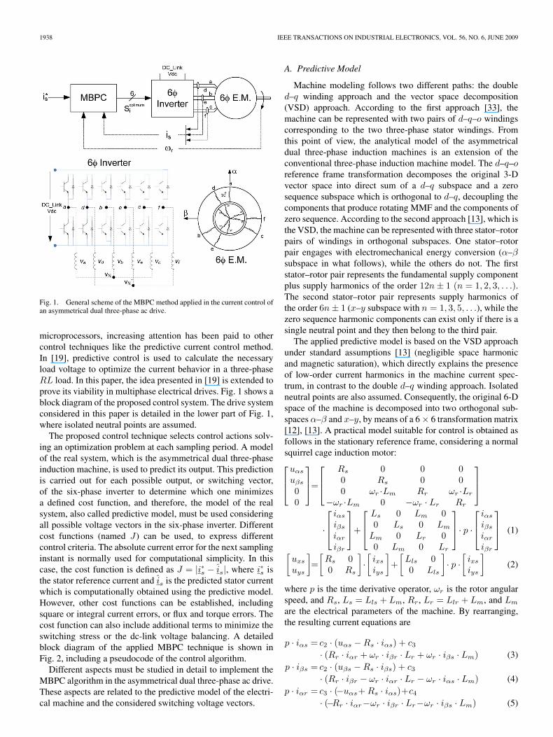
Fig. 1. General scheme of the MBPC method applied in the current control ofan asymmetrical dual three-phase ac drive.
microprocessors, increasing attention has been paid to othercontrol techniques like the predictive current control method.In [19], predictive control is used to calculate the necessaryload voltage to optimize the current behavior in a three-phaseRL load. In this paper, the idea presented in [19] is extended toprove its viability in multiphase electrical drives. Fig. 1 shows ablock diagram of the proposed control system. The drive systemconsidered in this paper is detailed in the lower part of Fig. 1,where isolated neutral points are assumed.
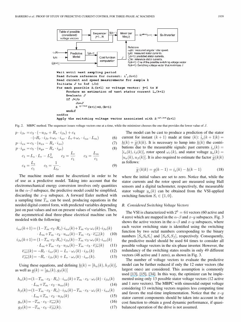
The proposed control technique selects control actions solv-ing an optimization problem at each sampling period. A modelof the real system, which is the asymmetrical dual three-phaseinduction machine, is used to predict its output. This predictionis carried out for each possible output, or switching vector,of the six-phase inverter to determine which one minimizesa defined cost function, and therefore, the model of the realsystem, also called predictive model, must be used consideringall possible voltage vectors in the six-phase inverter. Differentcost functions (named J) can be used, to express differentcontrol criteria. The absolute current error for the next samplinginstant is normally used for computational simplicity. In thiscase, the cost function is defined as J = |i∗s − is|, where i∗s isthe stator reference current and is is the predicted stator currentwhich is computationally obtained using the predictive model.However, other cost functions can be established, includingsquare or integral current errors, or flux and torque errors. Thecost function can also include additional terms to minimize theswitching stress or the dc-link voltage balancing. A detailedblock diagram of the applied MBPC technique is shown inFig. 2, including a pseudocode of the control algorithm.
Different aspects must be studied in detail to implement theMBPC algorithm in the asymmetrical dual three-phase ac drive.These aspects are related to the predictive model of the electri-cal machine and the considered switching voltage vectors.
A. Predictive Model
Machine modeling follows two different paths: the doubled–q winding approach and the vector space decomposition(VSD) approach. According to the first approach [33], themachine can be represented with two pairs of d–q–o windingscorresponding to the two three-phase stator windings. Fromthis point of view, the analytical model of the asymmetricaldual three-phase induction machines is an extension of theconventional three-phase induction machine model. The d–q–oreference frame transformation decomposes the original 3-Dvector space into direct sum of a d–q subspace and a zerosequence subspace which is orthogonal to d–q, decoupling thecomponents that produce rotating MMF and the components ofzero sequence. According to the second approach [13], which isthe VSD, the machine can be represented with three stator–rotorpairs of windings in orthogonal subspaces. One stator–rotorpair engages with electromechanical energy conversion (α–βsubspace in what follows), while the others do not. The firststator–rotor pair represents the fundamental supply componentplus supply harmonics of the order 12n ± 1 (n = 1, 2, 3, . . .).The second stator–rotor pair represents supply harmonics ofthe order 6n ± 1 (x–y subspace with n = 1, 3, 5, . . .), while thezero sequence harmonic components can exist only if there is asingle neutral point and they then belong to the third pair.
The applied predictive model is based on the VSD approachunder standard assumptions [13] (negligible space harmonicand magnetic saturation), which directly explains the presenceof low-order current harmonics in the machine current spec-trum, in contrast to the double d–q winding approach. Isolatedneutral points are also assumed. Consequently, the original 6-Dspace of the machine is decomposed into two orthogonal sub-spaces α–β and x–y, by means of a 6 × 6 transformation matrix[12], [13]. A practical model suitable for control is obtained asfollows in the stationary reference frame, considering a normalsquirrel cage induction motor:⎡⎢⎣
uαs
uβs
00
⎤⎥⎦=
⎡⎢⎣
Rs 0 0 00 Rs 0 00 ωr ·Lm Rr ωr ·Lr
−ωr ·Lm 0 −ωr · Lr Rr
⎤⎥⎦
·
⎡⎢⎣
iαs
iβs
iαr
iβr
⎤⎥⎦+
⎡⎢⎣
Ls 0 Lm 00 Ls 0 Lm
Lm 0 Lr 00 Lm 0 Lr
⎤⎥⎦· p ·
⎡⎢⎣
iαs
iβs
iαr
iβr
⎤⎥⎦ (1)
[uxs
uys
]=
[Rs 00 Rs
]·[
ixs
iys
]+
[Lls 00 Lls
]· p ·
[ixs
iys
](2)
where p is the time derivative operator, ωr is the rotor angularspeed, and Rs, Ls = Lls + Lm, Rr, Lr = Llr + Lm, and Lm
are the electrical parameters of the machine. By rearranging,the resulting current equations are
p · iαs = c2 · (uαs − Rs · iαs) + c3
· (Rr · iαr + ωr · iβr · Lr + ωr · iβs · Lm) (3)p · iβs = c2 · (uβs − Rs · iβs) + c3
· (Rr · iβr − ωr · iαr · Lr − ωr · iαs · Lm) (4)p · iαr = c3 · (−uαs+ Rs · iαs)+c4
· (−Rr · iαr−ωr · iβr · Lr−ωr · iβs · Lm) (5)
BARRERO et al.: PROOF OF STUDY OF PREDICTIVE CURRENT CONTROL FOR THREE-PHASE AC MACHINES 1939
Fig. 2. MBPC method. The sequencer issues voltage vectors one at a time, while the minimizer chooses the one that provides the lower value of J .
p · iβr = c3 · (−uβs + Rs · iβs) + c4
· (−Rr · iβr+ωr · iαr · Lr+ωr · iαs · Lm) (6)p · ixs = c5 · (uxs − Rs · ixs) (7)p · iys = c5 · (uys − Rs · iys) (8)
c1 = Ls · Lr − L2m c2 =
Lr
c1c3 =
Lm
c1
c4 =Ls
c1c5 =
1Lls
. (9)
The machine model must be discretized in order to beof use as a predictive model. Taking into account that theelectromechanical energy conversion involves only quantitiesin the α–β subspace, the predictive model could be simplified,discarding the x–y subspace. A forward Euler method witha sampling time Tm can be used, producing equations in theneeded digital control form, with predicted variables dependingjust on past values and not on present values of variables. Then,the asymmetrical dual three-phase electrical machine can bemodeled with the following:
iαs(k+1)= (1−Tm ·c2 ·Rs)·iαs(k)+Tm ·c3 ·ωr(k)·iβs(k)· Lm+Tm · c2 · uαs(k)−Tm · c3 · eαs(k) (10)
iβs(k+1)= (1−Tm ·c2 ·Rs)·iβs(k)−Tm ·c3 ·ωr(k)·iαs(k)· Lm+Tm · c2 · uβs(k)−Tm · c3 · eβs(k) (11)
eαs(k)= −Rr · iαr(k) − Lr · ωr(k) · iβr(k) (12)
eβs(k)= −Rr · iβr(k) + Lr · ωr(k) · iαr(k). (13)
Using these equations, and defining h(k) = [hα(k), hβ(k)],as well as g(k) = [gα(k), gβ(k)]
hα(k)=(1−Tm · c2 · Rs) · iαs(k)+Tm · c3 · ωr(k) · iβs(k)· Lm+Tm · c2 · uαs(k) (14)
hβ(k)=(1−Tm · c2 · Rs) · iβs(k)−Tm · c3 · ωr(k) · iαs(k)· Lm+Tm · c2 · uβs(k) (15)
gα(k)= −Tm · c3 · eαs(k) (16)
gβ(k)= −Tm · c3 · eβs(k). (17)
The model can be cast to produce a prediction of the statorcurrent for instant (k + 1) made at time (k): is(k + 1|k) =h(k) + �
g (k|k). It is necessary to lump into h(k) the contri-butions due to the measurable signals: past currents is(k) =[iα(k), iβ(k)], rotor speed ωr(k), and stator voltage us(k) =[uα(k), uβ(k)]. It is also required to estimate the factor �
g (k|k)as follows:
�g (k|k) = g(k − 1) = is(k) − h(k − 1) (18)
where the initial values are set to zero. Notice that, while thestator currents and the rotor speed are measured using Hallsensors and a digital tachometer, respectively, the measurablestator voltage us(k) can be obtained from the VSI-appliedswitching function Si ∈ {1, 0}.
B. Considered Switching Voltage Vectors
The VSI is characterized with 26 = 64 vectors (60 active and4 zero) which are mapped in the α–β and x–y subspaces. Fig. 3shows the active vectors in the α–β and x–y subspaces, whereeach vector switching state is identified using the switchingfunction by two octal numbers corresponding to the binarynumbers [SaSbSc] and [SdSeSf ], respectively. Consequently,the predictive model should be used 64 times to consider allpossible voltage vectors in the six-phase inverter. However, theredundancy of the switching states results in only 49 differentvectors (48 active and 1 zero), as shown in Fig. 3.
The number of voltage vectors to evaluate the predictivemodel can be further reduced if only the 12 outer vectors (thelargest ones) are considered. This assumption is commonlyused [13], [15], [34]. In this way, the optimizer can be imple-mented using only 13 possible stator voltage vectors (12 activeand 1 zero vectors). The MBPC with sinusoidal output voltageconsidering 13 switching vectors requires less computing timeand favors the real-time implementation. Notice that the x–ystator current components should be taken into account in thecost function to obtain a good dynamic performance, if quasi-balanced operation of the drive is not assumed.

1940 IEEE TRANSACTIONS ON INDUSTRIAL ELECTRONICS, VOL. 56, NO. 6, JUNE 2009
Fig. 3. Voltage vectors applied in the α–β and x–y subspaces using a six-phase VSI.
TABLE IELECTRICAL AND MECHANICAL PARAMETERS IN THE ASYMMETRICAL
DUAL THREE-PHASE INDUCTION MACHINE MODEL
III. MBPC PERFORMANCE AND VIABILITY
A Matlab/Simulink simulation environment has been de-signed for the VSI-fed asynchronous dual three-phase inductionmachine, and simulations have been done to prove the effective-ness of the proposed control method. A small (around 2 kW)asymmetrical dual three-phase induction machine model withsix poles has been used (Table I shows the electrical andmechanical parameters).
It is considered in all tests that the machine is running at320 r/min in steady-state operation when a step in the referencecurrent from 3 to 5.4 A and from 16 to 21 Hz is applied.The tests allow verifying both the steady state and transientperformance of different control methods. In all figures, theα–β and x–y stator current components are shown togetherwith the α-component current spectrum.
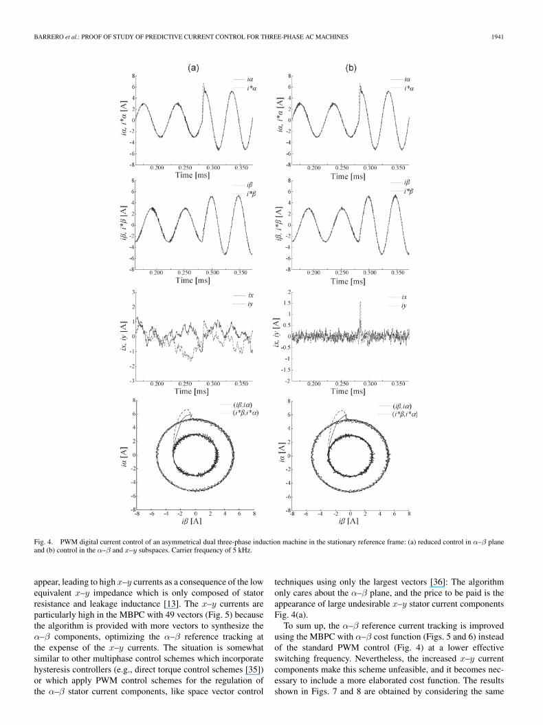
Fig. 4 shows the results obtained using a PWM control thathas been implemented using a carrier frequency of 5 kHz,which provides a switching frequency of 5 kHz (notice thatthe PWM control technique is continuous, and on/off switchingoccurs within every sampling period, for all inverter legs andall sectors). These results serve for comparison purposes. InFig. 4(a), sinusoidal output voltage is supposed so that x–ystator current components are not considered, and a drive quasi-balanced operation is assumed so that the current-control loopis reduced to the control of α–β stator current components [34].In Fig. 4(b), the current-control loop is extended to the controlof both α–β and x–y stator current components [12].
The results that show the performance of the proposed con-trol method are reported in Figs. 5–14. The MBPC technique isdiscontinuous since on/off switching is not guaranteed withinevery sampling period, for all inverter legs and all sectors.Therefore, an MBPC sampling frequency of 5 kHz will producea switching frequency lower than 5 kHz, and slightly worseresults are assumed compared with PWM control.
Computing time is a crucial factor for MBPC implemen-tation. The total number of control signal combinations tobe explored by the predictive model exponentially increasesin multiphase electrical machines with the number of phases.Consequently, the number of voltage vectors to be explored bythe predictive model needs careful consideration. The resultsare reported in Figs. 5–8. The MBPC scheme includes thecurrent components (α–β only, or α–β and x–y) in the costfunction.
Figs. 5 and 6 show the results obtained using theproposed MBPC with α–β components in the cost function(J = |i∗α(k + 1) − iα(k + 1)| + |i∗β(k + 1) − iβ(k + 1)|) andconsidering all 49 switching vectors or just the 12 outermostvectors plus a zero one for different sampling frequencies(1 and 5 kHz). It can be observed that the α–β reference currentis properly tracked both in steady state and transient operation,maintaining the dynamic behavior and the waveform qualityat 5 kHz compared to the PWM control results in Fig. 4. Theresults are degraded when the sampling frequency is decreasedto 1 kHz, this being a consequence of the increased switchingperiod more than an inadequate characteristic of the MBPC.It is noticeable that the α–β reference tracking of the MBPCusing 49 vectors is slightly better than that of the MBPC using13 vectors. The improvement is due to the 36 additional avail-able vectors which allow the finding of an optimized solution.Despite the improvement obtained for the α–β referencetracking, it is noticeable that the x–y current components aremuch higher in Figs. 5 and 6 than those of the PWM controlresults in Fig. 4. The increase of x–y current components is anundesirable characteristic because it leads to additional lossesin the machine, and it is due to the absence of x–y terms inthe definition of the cost function. Since only α–β referencecomponents are considered, collateral x–y voltage components
BARRERO et al.: PROOF OF STUDY OF PREDICTIVE CURRENT CONTROL FOR THREE-PHASE AC MACHINES 1941
Fig. 4. PWM digital current control of an asymmetrical dual three-phase induction machine in the stationary reference frame: (a) reduced control in α–β planeand (b) control in the α–β and x–y subspaces. Carrier frequency of 5 kHz.
appear, leading to high x–y currents as a consequence of the lowequivalent x–y impedance which is only composed of statorresistance and leakage inductance [13]. The x–y currents areparticularly high in the MBPC with 49 vectors (Fig. 5) becausethe algorithm is provided with more vectors to synthesize theα–β components, optimizing the α–β reference tracking atthe expense of the x–y currents. The situation is somewhatsimilar to other multiphase control schemes which incorporatehysteresis controllers (e.g., direct torque control schemes [35])or which apply PWM control schemes for the regulation ofthe α–β stator current components, like space vector control
techniques using only the largest vectors [36]: The algorithmonly cares about the α–β plane, and the price to be paid is theappearance of large undesirable x–y stator current componentsFig. 4(a).
To sum up, the α–β reference current tracking is improvedusing the MBPC with α–β cost function (Figs. 5 and 6) insteadof the standard PWM control (Fig. 4) at a lower effectiveswitching frequency. Nevertheless, the increased x–y currentcomponents make this scheme unfeasible, and it becomes nec-essary to include a more elaborated cost function. The resultsshown in Figs. 7 and 8 are obtained by considering the same

1942 IEEE TRANSACTIONS ON INDUSTRIAL ELECTRONICS, VOL. 56, NO. 6, JUNE 2009
Fig. 5. MBPC in the stationary α–β (using stator current α–β components in the function cost) reference frame using 49 switching voltage vectors and samplingfrequencies of (a) 1 and (b) 5 kHz.
MBPC scheme and tests but including the x–y components inthe cost function. In this case, J is defined as follows:
J =∣∣∣i∗α(k+1) − iα(k+1)
∣∣∣+∣∣∣i∗β(k+1) − iβ(k+1)
∣∣∣+
∣∣∣i∗x(k+1) − ix(k+1)∣∣∣+
∣∣∣i∗y(k+1) − iy(k+1)∣∣∣ . (19)
For this new cost function, 49 and 13 possible switchingvectors have been respectively considered, as well as differentswitching frequencies (1 and 5 kHz). It can be observed thatthe α–β stator current references are properly tracked, both insteady state and transient operations. The transient performancefor the α–β reference tracking at 5 kHz is slightly worse than
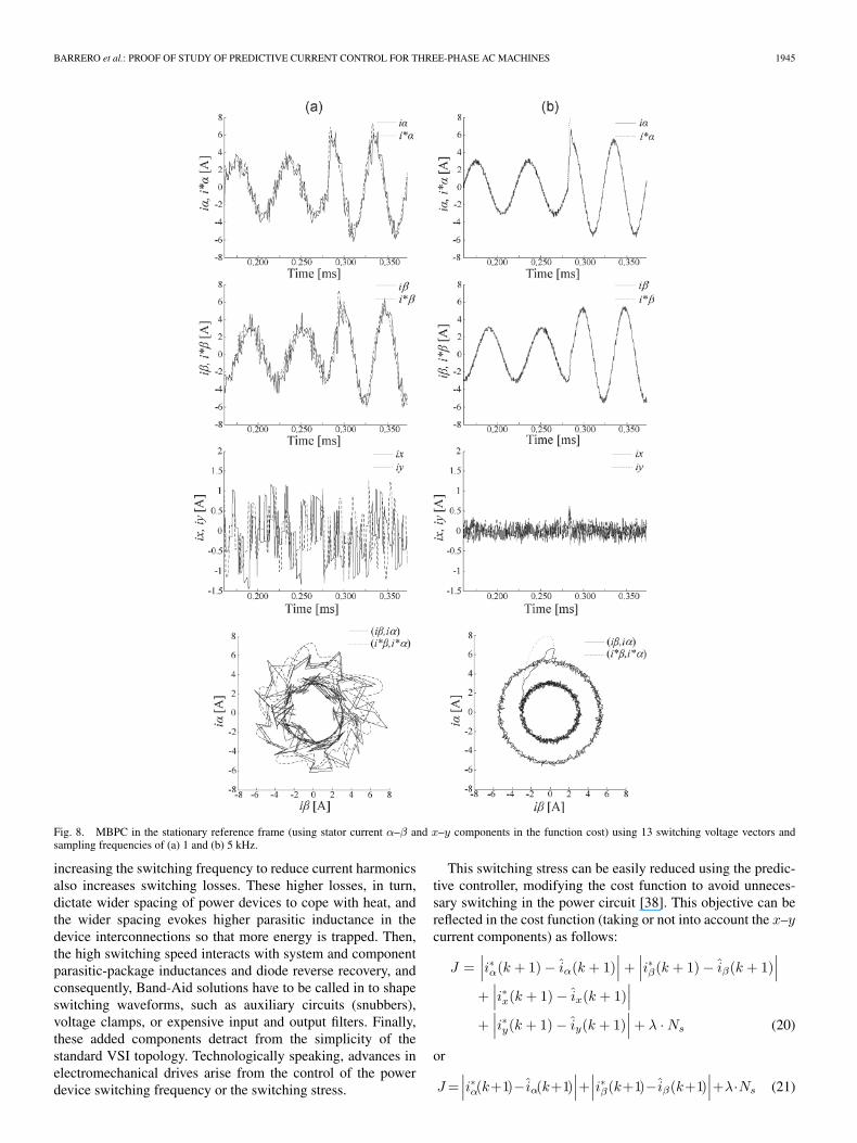
in Figs. 5 and 6 but better than those in Fig. 4, although allresults can be considered to provide similar quality. The steadystate performance for the α–β tracking is similar to the PWMcontrol and slightly worse than in Figs. 5 and 6. The reasonis that the new cost function considers α–β and x–y currentcomponents, finding a satisfactory solution for both planes.Nevertheless, it is relevant that the x–y components in Figs. 7and 8 show a significant decrement compared to the previouscases shown in Figs. 5 and 6. This is an interesting characteristicbecause the control maintains a good transient and steady stateperformance but assures minimum losses in the machine dueto circulating x–y currents. Furthermore, this relevant decreasein the x–y components (which leads to enhanced efficiency

BARRERO et al.: PROOF OF STUDY OF PREDICTIVE CURRENT CONTROL FOR THREE-PHASE AC MACHINES 1943
Fig. 6. MBPC in the stationary α–β (using stator current α–β components in the function cost) reference frame using 13 switching voltage vectors and samplingfrequencies of (a) 1 and (b) 5 kHz.
in the machine) is obtained without the need of sophisticatedmodulation schemes or additional controllers. The steady stateperformance for a switching frequency of 1 kHz is again pooras a direct consequence of the longer switching periods ratherthan an inadequate control method. Consequently, a minimumsampling frequency of about 5 kHz is required.
It is worth noting that the results in Fig. 8 (MBPC with13 vectors) are very similar to the results obtained in Fig. 7(MBPC with 49 vectors). This result confirms that the sub-group of 13 vectors provides a performance similar to thewhole set of 49 vectors, because the 26 discarded vectors are
not within the selected vectors for the optimal solution. TheMBPC with sinusoidal output voltage considering 13 switchingvectors requires less computing time and favors the real-timeimplementation. A real-time implementation analysis has beendone to prove the viability of the proposed control technique,when using an embedded system. The selection of the properactive vector is a time consuming task. To perform the analysis,a 32-b floating-point Texas Instruments DSP (TMS320C6711with a clock frequency of 150 MHz and 16 kB two-way setassociative instruction/data cache memory) has been used forimplementing the MBPC.

1944 IEEE TRANSACTIONS ON INDUSTRIAL ELECTRONICS, VOL. 56, NO. 6, JUNE 2009
Fig. 7. MBPC in the stationary reference frame (using stator current α–β and x–y components in the function cost) using 49 switching voltage vectors andsampling frequencies of (a) 1 and (b) 5 kHz.
Table II shows the real-time implementation results obtainedwith the profiling tools included in DSP/BIOS, which is a mi-crokernel provided for Texas Instruments DSPs. These resultsshow the execution time once the algorithm has been imple-mented and stored in the cache memory. The MBPC techniqueusing the predictive model 49 times to evaluate the functioncost is limited to a maximum sampling frequency of about1 kHz. Meanwhile, the MBPC technique using the predictivemodel 13 times to evaluate the function cost is limited to amaximum sampling frequency of about 6 kHz. Notice that thesemaximum sampling frequencies are within the conventionalvalues and that they can be increased using higher frequencyclock rates. Notice also that the obtained sampling frequency is
slightly affected by including the x–y components in the costfunction.
Although device switching frequency must be increasedbecause it is directly linked to the current waveform, whichis related with the sampling frequency using MBPC, severalconstraints are inherent in modern electrical drive technology.These constraints (motor insulation winding failure due tohigh voltage stress, premature failure of the bearings due tothe current flow during the switching transient, or the diffi-culties to suppress the broadband electromagnetic interferencegenerated) advise against the free increment of the switchingfrequency [37]. In fact, the power inverter design is a tradeoffamong thermal, mechanical, and electrical issues. For instance,
BARRERO et al.: PROOF OF STUDY OF PREDICTIVE CURRENT CONTROL FOR THREE-PHASE AC MACHINES 1945
Fig. 8. MBPC in the stationary reference frame (using stator current α–β and x–y components in the function cost) using 13 switching voltage vectors andsampling frequencies of (a) 1 and (b) 5 kHz.
increasing the switching frequency to reduce current harmonicsalso increases switching losses. These higher losses, in turn,dictate wider spacing of power devices to cope with heat, andthe wider spacing evokes higher parasitic inductance in thedevice interconnections so that more energy is trapped. Then,the high switching speed interacts with system and componentparasitic-package inductances and diode reverse recovery, andconsequently, Band-Aid solutions have to be called in to shapeswitching waveforms, such as auxiliary circuits (snubbers),voltage clamps, or expensive input and output filters. Finally,these added components detract from the simplicity of thestandard VSI topology. Technologically speaking, advances inelectromechanical drives arise from the control of the powerdevice switching frequency or the switching stress.
This switching stress can be easily reduced using the predic-tive controller, modifying the cost function to avoid unneces-sary switching in the power circuit [38]. This objective can bereflected in the cost function (taking or not into account the x–ycurrent components) as follows:
J =∣∣∣i∗α(k + 1) − iα(k + 1)
∣∣∣ +∣∣∣i∗β(k + 1) − iβ(k + 1)
∣∣∣+
∣∣∣i∗x(k + 1) − ix(k + 1)∣∣∣
+∣∣∣i∗y(k + 1) − iy(k + 1)
∣∣∣ + λ · Ns (20)
or
J =∣∣∣i∗α(k+1)− iα(k+1)
∣∣∣+∣∣∣i∗β(k+1)− iβ(k+1)
∣∣∣+λ·Ns (21)

1946 IEEE TRANSACTIONS ON INDUSTRIAL ELECTRONICS, VOL. 56, NO. 6, JUNE 2009
Fig. 9. MBPC in the stationary reference frame (using the switching stress and the stator current α–β and x–y components in the cost function) using13 switching voltage vectors, a sampling frequency of 5 kHz, and different values of the weighting factor λ: (a) λ = 0, and (b) λ = 0.1.
Fig. 10. Switching voltage supply using the MBPC in the stationary reference frame (using the switching stress and the stator current α–β and x–y componentsin the cost function) using 13 switching voltage vectors, a sampling frequency of 5 kHz, and different values of the weighting factor λ: (a) λ = 0, (b) λ = 0.1,(c) λ = 0.15, and (d) λ = 0.2.

BARRERO et al.: PROOF OF STUDY OF PREDICTIVE CURRENT CONTROL FOR THREE-PHASE AC MACHINES 1947
Fig. 11. MBPC in the stationary reference frame (using the switching stress and the stator current α–β components in the cost function) using 13 switchingvoltage vectors, a sampling frequency of 5 kHz, and different values of the weighting factor λ: (a) λ = 0, and (b) λ = 0.1.
Fig. 12. Switching voltage supply using the MBPC in the stationary reference frame (using the switching stress and the stator current α–β components inthe cost function) using 13 switching voltage vectors, a sampling frequency of 5kHz, and different values of the weighting factor λ: (a) λ = 0, (b) λ = 0.1,(c) λ = 0.15, and (d) λ = 0.2.

1948 IEEE TRANSACTIONS ON INDUSTRIAL ELECTRONICS, VOL. 56, NO. 6, JUNE 2009
Fig. 13. Scheme of the experimental setup.
Fig. 14. A picture of the system, including the power and control modules atthe left side and the dual three-phase induction machine at the right side.
TABLE IIDSP IMPLEMENTATION OF THE MBPC ALGORITHMS
where λ is a weighting factor which handles the relation be-tween terms dedicated to reference tracking and reduction ofswitching frequency, and Ns is the number of commutationsto get the switching state under evaluation. A large value ofλ implies greater priority to the new objective of reducing theswitching stress. More results have been obtained to prove theeffectiveness of the new cost functions. The results that showthe performance of the system are reported in Figs. 9–12. It isconsidered, as in the previous experiments, that the machine isrunning at 320 r/min in steady state operation when a step inthe reference current from 3 to 5.4 A and from 16 to 21 Hz isapplied. The tests allow verifying the steady state and transientperformance, and the switching stress defined as the numberof switching per second. The MBPC is applied with 13 voltagevectors, a sampling frequency of 5 kHz, and a cost function thatincludes a term related with the switching stress (λ · Ns).
Figs. 9 and 10 show the results obtained using the MBPCwith α–β and x–y current components in the cost function.Figs. 11 and 12 show the results obtained using the MBPC con-
TABLE IIIOBTAINED SWITCHING STRESS EXPLORING
MORE COMPLEX COST FUNCTIONS
TABLE IVDSP IMPLEMENTATION OF THE MBPC ALGORITHMS
TABLE VESTIMATED ELECTRICAL AND MECHANICAL PARAMETERS OF THE
REWOUND ASYMMETRICAL DUAL THREE-PHASE INDUCTION MACHINE
sidering only the α–β current components. Although differentswitching stress terms have been evaluated, only four cases areconsidered in depth (λ = 0, λ = 0.1, λ = 0.15, and λ = 0.2).For λ > 0.2, the degradation in the current reference trackingand in the harmonic distortion advises against its use in theswitching stress term. Moreover, if λ > 0.1, the control perfor-mance is degraded without producing benefits in the switchingstress. It is noticeable (Figs. 9 and 11) that the α–β (and x–y,if the x–y current components are included in the cost func-tion) reference tracking of the MBPC and the total harmonicdistortion [(THD), defined as the ratio of the sum of the powersof all harmonic components to the power of the fundamentalfrequency] slightly degrade with increasing λ, although theswitching frequency is also reduced (Figs. 10 and 12).
Table III quantifies the degradation in the reference trackingagainst the reduction of the switching stress. The first columnindicates the experiment. The other columns detail the effectiveswitching frequency, the root-mean-square error in the currenttracking for the α, β, x, and y components, and the THD. Avalue of λ = 0.1 is shown to be appropriate for the switchingstress term; increasing this value of λ degrades the controlperformance without producing benefits in the switching stress.
A real-time implementation analysis has been also doneusing the same DSP (TMS320C6711 with a clock frequency of150 MHz). The obtained sampling frequency is lightly affected

BARRERO et al.: PROOF OF STUDY OF PREDICTIVE CURRENT CONTROL FOR THREE-PHASE AC MACHINES 1949
Fig. 15. Digital current control in the stationary reference frame using the PWM technique. Experimental result with (a) α–β current controllers and (b) α–βand x–y current controllers. A step in the amplitude and frequency of the reference currents is applied.
by including the switching stress term in the cost function, asshown in Table IV. It can be deduced from the obtained resultsthat the new cost function can be applied using 13 voltagevectors and a sampling frequency of 4 kHz.
IV. EXPERIMENTAL RESULTS
An experimental test rig has been designed for implementingthe MBPC technique [39]. A diagram and a photo of thecomplete system are shown in Figs. 13 and 14, respectively. Thetest rig is based on a conventional 36-slot two-pair-pole 10-kWthree-phase induction machine whose stator has been rewoundto construct a 36-slot three-pair-pole dual three-phase inductionmachine. Two sets of stator three-phase windings spatiallyshifted by 30 electrical degrees have been included. Table Vshows its estimated electrical and mechanical parameters.
Two Semistack insulated-gate bipolar transistor modulesfrom Semikron Inc. (series SKS21F) have been used todrive the machine. Each module includes a precharge cir-cuit, handles up to 21 A, and allows a maximum switchingfrequency of 15 kHz. Speed is also measured using a two-channel 10 000-pulses-per-revolution Herrekor incremental en-coder (series GHM5_S6). An interface and a control board have
been designed to control the real system. The interface boardis used to adapt analog signals provided by current sensors(two LEM 55-P Hall-effect current sensors included in eachSemistack to measure two phase currents and four currentsensors for control purposes) and the dc-link voltage. Theencoder and power switch control signals are also optocoupledin this board, which includes a conventional protection circuitdesigned to maintain system integrity against fault conditions.The control board is based on the TMS320LF2812 TexasInstruments DSP and the MCK2812 system. This DSP pro-vides peripheral for real-time control of the power systems.For instance, it includes up to 12 PWM outputs that can beused to control two independent three-phase VSIs, includingprogrammable dead time control systems. A peripheral forprocessing signals coming from a quadrature encoder in orderto help the user to obtain the mechanical speed and a high-performance 16-channel (12 b each) analog-to-digital converterwith up to 12.5 MSPS of conversion rate are also provided.
The control code is written in C, performing current control(current-controlled V/f mode of operation) and using an opti-mized sampling frequency of 2.5 kHz. A series of experimentaltests are performed in order to examine the current-controlproperties.
1950 IEEE TRANSACTIONS ON INDUSTRIAL ELECTRONICS, VOL. 56, NO. 6, JUNE 2009
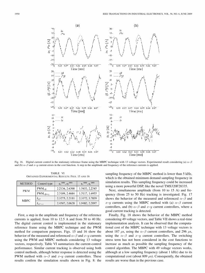
Fig. 16. Digital current control in the stationary reference frame using the MBPC technique with 13 voltage vectors. Experimental result considering (a) α–βand (b) α–β and x–y current errors in the cost function. A step in the amplitude and frequency of the reference currents is applied.
TABLE VIOBTAINED EXPERIMENTAL RESULTS: FIGS. 15 AND 16
First, a step in the amplitude and frequency of the referencecurrents is applied, from 10 to 12.5 A and from 50 to 40 Hz.The digital current control is implemented in the stationaryreference frame using the MBPC technique and the PWMmethod for comparison purposes. Figs. 15 and 16 show thebehavior of the measured and referenced α–β and x–y currentsusing the PWM and MBPC methods considering 13 voltagevectors, respectively. Table VI summarizes the current-controlperformance. Similar current tracking is observed using bothcontrol methods, although better response is detected using thePWM method with α–β and x–y current controllers. Theseresults confirm the simulation results shown in Fig. 8: the
sampling frequency of the MBPC method is lower than 5 kHz,which is the obtained minimum demand sampling frequency insimulation results. This sampling frequency could be increasedusing a more powerful DSP, like the novel TMS320F28335.
Next, simultaneous amplitude (from 10 to 15 A) and fre-quency (from 25 to 50 Hz) tracking is investigated. Fig. 17shows the behavior of the measured and referenced α–β andx–y currents using the MBPC method with (a) α–β currentcontrollers, and (b) α–β and x–y current controllers, where agood current tracking is detected.
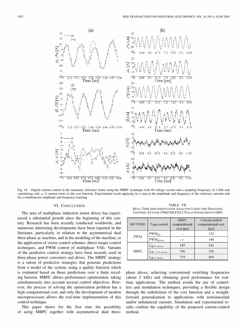
Finally, Fig. 18 shows the behavior of the MBPC methodconsidering 49 voltage vectors, and Table VII shows a real-timeimplementation analysis. It can be observed that the computa-tional cost of the MBPC technique with 13 voltage vectors isabout 187 μs, using the α–β current controllers, and 296 μs,using the α–β and x–y current controllers. The switchingstress term has not been considered in the cost functions toincrease as much as possible the sampling frequency of thecontrol algorithm. The MBPC with 49 voltage vectors works,although at a low sampling frequency (about 1 kHz) due to itscomputational cost (about 809 μs). Consequently, the obtainedresults are worse than in the previous case.

BARRERO et al.: PROOF OF STUDY OF PREDICTIVE CURRENT CONTROL FOR THREE-PHASE AC MACHINES 1951
Fig. 17. Digital current control in the stationary reference frame using the MBPC technique with 13 voltage vectors and applying simultaneous amplitude andfrequency tracking. Experimental result considering (a) α–β and (b) α–β and x–y current errors in the cost function. i∗α and i∗β represent the reference α–β
currents, while iα and iβ represent the measured α–β currents. ix and iy represent the measured x–y currents.
V. DISCUSSION OF RESULTS
The obtained results prove that the predictive control canbe a good alternative in comparison to conventional cascadecontrol. The general advantages of predictive control are abetter representation of nonlinear systems and the possibilityto use the foreknowledge of the drive system. The followingcan be deduced from the obtained results.
1) The MBPC technique proves to be a viable alternativeto the PWM control for multiphase drives, avoiding thetuning of the PI controllers and the design of specificmodulation techniques. Using 13 voltage vectors insteadof the 49 possible voltage vectors facilitates the real-timeimplementation of the MBPC, with a low degradation inthe control features.
2) The MBPC is a flexible approach that, opposite to PWM-based control methods, allows a straightforward general-ization to different cases or requirements. For instance,the method can be generalized to series-connected multi-motor drives or fault-tolerant drives maintaining the samepredictive model. However, a total of 49 different spacevectors must be considered. Consequently, the MBPC
implementation using the existing DSPs becomes morecomplex, and the switching frequency must be reduced.
3) The MBPC technique is again a flexible control approachbecause it can be implemented using elaborated costfunctions including not only α–β and x–y stator currentcomponents but also other terms to reduce, for instance,the switching stress.
4) The MBPC technique has been, for the first time, im-plemented in a multiphase induction machine, takingadvantage of the available DSP technology. Good resultshave been obtained. However, better results are expectedusing more powerful DSPs. The optimized samplingfrequency should be increased to improve the currenttracking, particularly in the x–y current components. Theobtained experimental results confirm that the MBPCoffers similar performance to PWM control techniquein the transient and steady states. Nevertheless, it mustbe highlighted that the PWM control generates a higherswitching frequency than the MBPC technique. Con-sequently, the dynamic performance of the current ismaintained with the MBPC while the efficiency is favoreddue to reduced switching losses.
1952 IEEE TRANSACTIONS ON INDUSTRIAL ELECTRONICS, VOL. 56, NO. 6, JUNE 2009
Fig. 18. Digital current control in the stationary reference frame using the MBPC technique with 49 voltage vectors and a sampling frequency of 1 kHz andconsidering only α–β current errors in the cost function. Experimental result applying (a) a step in the amplitude and frequency of the reference currents and(b) a simultaneous amplitude and frequency tracking.
VI. CONCLUSION
The area of multiphase induction motor drives has experi-enced a substantial growth since the beginning of this cen-tury. Research has been recently conducted worldwide, andnumerous interesting developments have been reported in theliterature, particularly in relation to the asymmetrical dualthree-phase ac machine, and in the modeling of the machine, orthe application of vector control schemes, direct torque controltechniques, and PWM control of multiphase VSIs. Variantsof the predictive control strategy have been recently used inthree-phase power converters and drives. The MBPC strategyis a subset of predictive strategies that generate predictionsfrom a model of the system, using a quality function whichis evaluated based on those predictions over a finite reced-ing horizon. MBPC allows performance optimization, takingsimultaneously into account several control objectives. How-ever, the process of solving the optimization problem has ahigh computational cost, and only the development of modernmicroprocessors allows the real-time implementation of thiscontrol technique.
This paper shows for the first time the possibilityof using MBPC together with asymmetrical dual three-
TABLE VIIREAL-TIME IMPLEMENTATION ANALYSIS USING THE DESIGNED
CONTROL SYSTEM (TMS320LF2812 TEXAS INSTRUMENTS DSP)
phase drives, achieving conventional switching frequencies(about 5 kHz) and obtaining good performance for real-time applications. The method avoids the use of control-lers and modulation techniques, providing a flexible designthrough the redefinition of the cost function and a straight-forward generalization to applications with nonsinusoidaland/or unbalanced currents. Simulation and experimental re-sults confirm the capability of the proposed current-controlmethod.

BARRERO et al.: PROOF OF STUDY OF PREDICTIVE CURRENT CONTROL FOR THREE-PHASE AC MACHINES 1953
REFERENCES
[1] E. Levi, R. Bojoi, F. Profumo, H. A. Toliyat, and S. Williamson, “Mul-tiphase induction motor drives—A technology status review,” IET Elect.Power Appl., vol. 1, no. 4, pp. 489–516, Jul. 2007.
[2] K. K. Mohapatra, M. R. Baiju, and K. Gopakumar, “Independent speedcontrol of two six-phase induction motors using a single six-phase in-verter,” EPE J., vol. 13, no. 3, pp. 49–62, Aug. 2004.
[3] K. K. Mohapatra, R. S. Kanchan, M. R. Baiju, P. N. Tekwani, andK. Gopakumar, “Independent field-oriented control of two split-phaseinduction motors from a single six-phase inverter,” IEEE Trans. Ind.Electron., vol. 52, no. 5, pp. 1372–1382, Oct. 2005.
[4] E. Levi, “Multiphase electric machines for variable-speed applications,”IEEE Trans. Ind. Electron., vol. 55, no. 5, pp. 1893–1909, May 2008.
[5] K. Marouani, L. Baghli, D. Hadiouche, A. Kheloui, and A. Rezzoug,“A new PWM strategy based on a 24-sector vector space decompositionfor a six-phase VSI-fed dual stator induction motor,” IEEE Trans. Ind.Electron., vol. 55, no. 5, pp. 1910–1920, May 2008.
[6] D. Casadei, D. Dujic, E. Levi, G. Serra, A. Tani, and L. Zarri, “Generalmodulation strategy for seven-phase inverters with independent control ofmultiple voltage space vectors,” IEEE Trans. Ind. Electron., vol. 55, no. 5,pp. 1921–1932, May 2008.
[7] O. Lopez, J. Alvarez, J. Doval-Gandoy, and F. D. Freijedo, “Multilevelmultiphase space vector PWM algorithm,” IEEE Trans. Ind. Electron.,vol. 55, no. 5, pp. 1933–1942, May 2008.
[8] D. Dujic, G. Grandi, M. Jones, and E. Levi, “A space vector PWM schemefor multifrequency output voltage generation with multiphase voltage-source inverters,” IEEE Trans. Ind. Electron., vol. 55, no. 5, pp. 1943–1955, May 2008.
[9] P. L. Alger, E. H. Freiburghouse, and D. D. Chase, “Double windings forturbine alternators,” AIEE Trans., vol. 49, pp. 226–244, Jan. 1930.
[10] K. Gopakumar, V. T. Ranganathan, and S. R. Bhat, “Split-phase inductionmotor operation from PWM voltage source inverter,” IEEE Trans. Ind.Appl., vol. 29, no. 5, pp. 927–933, Sep./Oct. 1993.
[11] K. Gopakumar, V. T. Ranganathan, and S. R. Bhat, “Vector control ofinduction motor with split phase stator windings,” EPE J., vol. 7, no. 1/2,pp. 61–66, 1997.
[12] R. Bojoi, E. Levi, F. Farina, A. Tenconi, and F. Profumo, “Dual three-phase induction motor drive with digital current control in the stationaryreference frame,” Proc. Inst. Elect. Eng.—Elect. Power Appl., vol. 153,no. 1, pp. 129–139, Jan. 2006.
[13] Y. Zhao and T. A. Lipo, “Space vector PWM control of dual three-phaseinduction machine using vector space decomposition,” IEEE Trans. Ind.Appl., vol. 31, no. 5, pp. 1100–1109, Sep./Oct. 1995.
[14] M. J. Durán, S. Toral, F. Barrero, and E. Levi, “Real-time implementationof multi-dimensional five-phase space vector pulse-width modulation,”Electron. Lett., vol. 43, no. 17, pp. 949–950, Aug. 2007.
[15] D. Hadiouche, L. Baghli, and A. Rezzoug, “Space-vector PWM tech-niques for dual three-phase AC machines: Analysis, performance eval-uation, and DSP implementation,” IEEE Trans. Ind. Appl., vol. 42, no. 4,pp. 1112–1122, Jul./Aug. 2006.
[16] R. Kennel, A. Linder, and M. Linke, “Generalized Predictive Control(GPC) ready for use in drive applications?” in Proc. 32nd Annu. IEEEPESC, Vancouver, BC, Canada, 2001, vol. 4, pp. 1839–1844.
[17] A. Linder and R. Kennel, “Model predictive control for electrical drives,”in Proc. 36th Annu. IEEE PESC, Recife, Brazil, 2005, pp. 1793–1799.
[18] P. Cortés, M. P. Kazmierkowski, R. M. Kennel, D. E. Quevedo, andJ. Rodríguez, “Predictive control in power electronics and drives,” IEEETrans. Ind. Electron., vol. 55, no. 12, pp. 4312–4324, Dec. 2008.
[19] J. Rodríguez, J. Pontt, C. Silva, P. Correa, P. Lezana, P. Cortés, andU. Ammann, “Predictive current control of a voltage source inverter,”IEEE Trans. Ind. Electron., vol. 54, no. 1, pp. 495–503, Feb. 2007.
[20] P. Correa, M. Pacas, and J. Rodriguez, “Predictive torque control forinverter-fed induction machines,” IEEE Trans. Ind. Electron., vol. 54,no. 2, pp. 1073–1079, Apr. 2007.
[21] R. Morales-Caporal and M. Pacas, “A predictive torque control for thesynchronous reluctance machine taking into account the magnetic crosssaturation,” IEEE Trans. Ind. Electron., vol. 54, no. 2, pp. 1161–1167,Apr. 2007.
[22] S. A. Larrinaga, M. A. R. Vidal, E. Oyarbide, and J. R. T. Apraiz, “Predic-tive control strategy for DC/AC converters based on direct power control,”IEEE Trans. Ind. Electron., vol. 54, no. 3, pp. 1261–1271, Jun. 2007.
[23] X. Lin-Shi, F. Morel, A. M. Llor, B. Allard, and J. M. Rétif, “Implemen-tation of hybrid control for motor drives,” IEEE Trans. Ind. Electron.,vol. 54, no. 4, pp. 1946–1952, Aug. 2007.
[24] M. Nemec, D. Nedeljkovic, and V. Ambrozic, “Predictive torque controlof induction machines using immediate flux control,” IEEE Trans. Ind.Electron., vol. 54, no. 4, pp. 2009–2017, Aug. 2007.
[25] R. Vargas, P. Cortes, U. Ammann, J. Rodriguez, and J. Pontt, “Predictivecontrol of a three-phase neutral-point-clamped inverter,” IEEE Trans. Ind.Electron., vol. 54, no. 5, pp. 2697–2705, Oct. 2007.
[26] F. Morel, J. M. Rétif, X. Lin-Shi, and C. Valentin, “Permanent magnetsynchronous machine hybrid torque control,” IEEE Trans. Ind. Electron.,vol. 55, no. 2, pp. 501–511, Feb. 2008.
[27] J. Weigold and M. Braun, “Predictive current control using identificationof current ripple,” IEEE Trans. Ind. Electron., vol. 55, no. 12, pp. 4346–4353, Dec. 2008.
[28] M. A. Pérez, P. Cortés, and J. Rodríguez, “Predictive control algorithmtechnique for multilevel asymmetric cascaded H-bridge inverters,” IEEETrans. Ind. Electron., vol. 55, no. 12, pp. 4354–4361, Dec. 2008.
[29] R. Vargas, J. Rodríguez, U. Ammann, and P. W. Wheeler, “Predictivecurrent control of an induction machine fed by a matrix converter withreactive power control,” IEEE Trans. Ind. Electron., vol. 55, no. 12,pp. 4362–4371, Dec. 2008.
[30] R. Vargas, U. Ammann, J. Rodriguez, and J. Pontt, “Predictive strategy tocontrol common-mode voltage in loads fed by matrix converters,” IEEETrans. Ind. Electron., vol. 55, no. 12, pp. 4372–4380, Dec. 2008.
[31] P. Antoniewicz and M. P. Kazmierkowski, “Virtual-flux-based predictivedirect power control of AC/DC converters with online inductance esti-mation,” IEEE Trans. Ind. Electron., vol. 55, no. 12, pp. 4381–4390,Dec. 2008.
[32] E. S. de Santana, E. Bim, and W. C. do Amaral, “A predictive algorithmfor controlling speed and rotor flux of induction motor,” IEEE Trans. Ind.Electron., vol. 55, no. 12, pp. 4398–4407, Dec. 2008.
[33] G. K. Singh, V. Pant, and Y. P. Singh, “Voltage source inverter drivenmulti-phase induction machine,” Comput. Elect. Eng., vol. 29, no. 8,pp. 813–834, Nov. 2003.
[34] R. Bojoi, A. Tenconi, G. Griva, and F. Profumo, “Vector control of adual-three-phase induction-motor drive using two current sensors,” IEEETrans. Ind. Appl., vol. 42, no. 5, pp. 1284–1292, Sep./Oct. 2006.
[35] G. S. Buja and M. P. Kazmierkowski, “Direct torque control of PWMinverter-fed AC motors—A survey,” IEEE Trans. Ind. Electron., vol. 51,no. 4, pp. 744–757, Aug. 2004.
[36] H. Xu, H. A. Toliyat, and L. J. Petersen, “Five-phase induction motordrives with DSP-based control system,” IEEE Trans. Power Electron.,vol. 17, no. 2, pp. 524–533, Jul. 2002.
[37] D. Divan, “Low-stress switching for efficiency,” IEEE Spectr., vol. 33,no. 12, pp. 33–39, Dec. 1996.
[38] P. Cortés, J. Rodríguez, R. Vargas, and U. Ammann, “Cost function-based predictive control for power converters,” in Proc. 32th Annu. IEEEIECON, Paris, France, 2006, pp. 2268–2273.
[39] R. Gregor, F. Barrero, S. Toral, and M. J. Durán, “Realization of anasynchronous six-phase induction motor drive test-rig,” in ICREPQ,Santander, España, 2008. [Online]. Available: http://www.icrepq.com/icrepq-08/230-gregor.pdf
Federico Barrero (M’04–SM’05) was born inSeville, Spain, in 1967. He received the M.Sc. andPh.D. degrees in electrical and electronic engineer-ing from the University of Seville, Seville, in 1992and 1998, respectively.
In 1992, he joined the Electronics EngineeringDepartment, University of Seville, where he is cur-rently an Associate Professor. His recent interestsinclude microprocessor and DSP device systems,control of electrical drives and power electron-ics, and information and communication technology
systems.
Manuel R. Arahal (M’06) was born in Seville,Spain, in 1966. He received the M.Sc. and Ph.D.degrees in electrical and electronic engineering fromthe University of Seville, Seville, in 1991 and 1996,respectively.
From 1995 to 1998, he was an Assistant Pro-fessor with the Department of Systems Engineeringand Automatic Control, University of Seville, wherehe is currently an Associate Professor. His currentresearch interests include industrial applications ofmodel predictive control, artificial intelligence, and
forecasting techniques.
1954 IEEE TRANSACTIONS ON INDUSTRIAL ELECTRONICS, VOL. 56, NO. 6, JUNE 2009
Raúl Gregor was born in Asunción, Paraguay, in1979. He received the M.Sc. degree in electronicengineering from the Universidad Católica NuestraSeñora de la Asunción, Asunción, Paraguay, in 2005.He is currently working toward the Ph.D. degree inelectrical and electronic engineering in the Electron-ics Engineering Department, University of Seville,Seville, Spain.
His current research interest includes control ofmultiphase electrical drives.
Sergio Toral (M’01–SM’06) was born in Rabat,Morocco, in 1972. He received the M.Sc. and Ph.D.degrees in electrical and electronic engineering fromthe University of Seville, Seville, Spain, in 1995 and1999, respectively.
He is currently an Associate Professor with theDepartment of Electronics Engineering, Universityof Seville. His main research interests include mi-croprocessor and DSP devices, electrical drives, andreal-time and distributed systems.
Mario J. Durán was born in Málaga, Spain, in 1975.He received the M.Sc. and Ph.D. degrees in electricalengineering from the University of Málaga, Málaga,Spain, in 1999 and 2003, respectively.
He is currently an Associate Professor with theElectrical Engineering Department, University ofMálaga. His research interests include modeling andcontrol of multiphase converters and machines.
Copyright © 2022 FDOKUMEN