Numerical Investigation of the Asymmetrical Vortex Combustor ...
19
Journal of Advanced Research in Fluid Mechanics and Thermal Sciences 74, Issue 1 (2020) 1-18 1 Journal of Advanced Research in Fluid Mechanics and Thermal Sciences Journal homepage: www.akademiabaru.com/arfmts.html ISBN: 2289-7879 Numerical Investigation of the Asymmetrical Vortex Combustor Running on Biogas Mohsin Mohd Sies 1,* , Mazlan Abdul Wahid 1 1 High Speed Reacting Flow (HiREF) Lab, School of Mechanical Engineering, Universiti Teknologi Malaysia, 81310 UTM Skudai, Johor, Malaysia ARTICLE INFO ABSTRACT Article history: Received 2 May 2020 Received in revised form 5 June 2020 Accepted 5 June 2020 Available online 6 June 2020 Biogas is an attractive renewable fuel to combat greenhouse gas (GHG) emissions. However, the low and variable quality of un-upgraded biogas present some challenges in terms of holding a stable flame and resulting emissions. Meanwhile, asymmetrical vortex combustor (AVC) has been shown to possess excellent flame stability even at very lean conditions. This work aims to study the suitability and potential of AVC to burn biogas by investigating its combustion characteristics and explaining its ultra- stable flame behavior. A numerical study was done where the flame stability was studied by looking at the flow field. Synthetic biogas of various compositions that reflect palm oil mill effluent (POME) biogas was used in this research. The combustion characteristics was studied for equivalence ratio ranging from very lean to very rich that explores the limit of the AVC. The results showed that this combustor is very capable of stably burning biogas of different compositions with correspondingly low emissions. This allows ready use of un-upgraded biogas which would have been cost prohibitive previously. The flame stability envelope is extended beyond that of pure methane with lean limit reaching down to 0.3 and the rich limit going beyond 2 compared to the published range of between 0.46 to 1.6. Flame stability was found to be due to two effects; the strong tangential vortex containing the flame region, and also the trapped vortex effect of the backward facing step which provides a secondary stable flame. Thus, it can be concluded that raw biogas can be utilized as fuel without costly upgrading by burning it in an AVC. Keywords: Asymmetrical Vortex Combustor; Biogas; Flammability Envelope; POME Copyright © 2020 PENERBIT AKADEMIA BARU - All rights reserved 1. Introduction Presently, concern about climate change and global warming is driving the world to reduce greenhouse gas emissions. In 2014, the Intergovernmental Panel on Climate Change (IPCC) reported that between the year 1880 to 2012 the global average temperature has climbed by 0.85 ◦C [1]. With * Corresponding author. E-mail address: [email protected] (Mohsin Mohd Sies) https://doi.org/10.37934/arfmts.74.1.118 Open Access
-
Upload
khangminh22 -
Category
Documents
-
view
1 -
download
0
Transcript of Numerical Investigation of the Asymmetrical Vortex Combustor ...

Journal of Advanced Research in Fluid Mechanics and Thermal Sciences 74, Issue 1 (2020) 1-18
1
Journal of Advanced Research in Fluid
Mechanics and Thermal Sciences
Journal homepage: www.akademiabaru.com/arfmts.html ISBN: 2289-7879
Numerical Investigation of the Asymmetrical Vortex Combustor Running on Biogas
Mohsin Mohd Sies1,*, Mazlan Abdul Wahid1
1 High Speed Reacting Flow (HiREF) Lab, School of Mechanical Engineering, Universiti Teknologi Malaysia, 81310 UTM Skudai, Johor, Malaysia
ARTICLE INFO ABSTRACT
Article history: Received 2 May 2020 Received in revised form 5 June 2020 Accepted 5 June 2020 Available online 6 June 2020
Biogas is an attractive renewable fuel to combat greenhouse gas (GHG) emissions. However, the low and variable quality of un-upgraded biogas present some challenges in terms of holding a stable flame and resulting emissions. Meanwhile, asymmetrical vortex combustor (AVC) has been shown to possess excellent flame stability even at very lean conditions. This work aims to study the suitability and potential of AVC to burn biogas by investigating its combustion characteristics and explaining its ultra-stable flame behavior. A numerical study was done where the flame stability was studied by looking at the flow field. Synthetic biogas of various compositions that reflect palm oil mill effluent (POME) biogas was used in this research. The combustion characteristics was studied for equivalence ratio ranging from very lean to very rich that explores the limit of the AVC. The results showed that this combustor is very capable of stably burning biogas of different compositions with correspondingly low emissions. This allows ready use of un-upgraded biogas which would have been cost prohibitive previously. The flame stability envelope is extended beyond that of pure methane with lean limit reaching down to 0.3 and the rich limit going beyond 2 compared to the published range of between 0.46 to 1.6. Flame stability was found to be due to two effects; the strong tangential vortex containing the flame region, and also the trapped vortex effect of the backward facing step which provides a secondary stable flame. Thus, it can be concluded that raw biogas can be utilized as fuel without costly upgrading by burning it in an AVC.
Keywords: Asymmetrical Vortex Combustor; Biogas; Flammability Envelope; POME Copyright © 2020 PENERBIT AKADEMIA BARU - All rights reserved
1. Introduction
Presently, concern about climate change and global warming is driving the world to reduce greenhouse gas emissions. In 2014, the Intergovernmental Panel on Climate Change (IPCC) reported that between the year 1880 to 2012 the global average temperature has climbed by 0.85 ◦C [1]. With
* Corresponding author. E-mail address: [email protected] (Mohsin Mohd Sies) https://doi.org/10.37934/arfmts.74.1.118
Open
Access
Journal of Advanced Research in Fluid Mechanics and Thermal Sciences
Volume 74, Issue 1 (2020) 1-18
2
heat and power being generally produced by combustion, fossil fuel contribution towards the global energy supply mix is expected to continue to be around eighty percent even by 2030 [2].
Transport makes up about twenty percent of energy use [3]. Despite the increasing use renewable fuels, oil continues to dominate the energy demand for transport [3]. For aviation, with its weight constraint and range requirement, there is no foreseeable technological breakthrough that would allow electricity to replace hydrocarbon as fuel. Even though the electric car fleet is expected to grow to about 300 million cars total globally by 2040 [4], the internal combustion engine vehicles are projected to continue to grow to about 1.5 billion vehicles at the same time [5]. This means that combustion will continue to play an important role in transport for many decades to come.
Thus, reducing CO2 emissions will continue to be important even with higher adoption of renewables. For this, biofuel sources are continually investigated as suitable candidates as drop-in replacement for fossil fuels. Biogas is a promising renewable fuel candidate. It is mainly composed of methane and carbon dioxide while containing trace amounts of hydrogen sulfide (H2S), carbon monoxide (CO), siloxanes, and moisture. In Malaysia, palm oil mill effluent (POME) is a major source of biogas [6, 42]. As shown in the Table 1, for biogas from POME, CH4 content can range from 50-75%, effectively putting the low range into the class of low-quality biogas.
Table 1 Biogas composition of POME [7, 8, 9] Component Formula POME biogas composition (vol %)
Methane CH4 50-75 Carbon dioxide CO2 25-45 Water H2O 2-7 Oxygen O2 <2 Nitrogen N2 <2 Hydrogen sulphide H2S <2 Ammonia NH3 <1 Hydrogen H2 <1
Biogas has a low calorific value (LCV) of around 30 MJ/kg (60% CH4) compared to about 50 MJ/kg
for pure methane [10]. The already low flame speed of methane-air mixture of about 43 cm/s is further reduced by the high content of CO2 in biogas. The ignition temperature of methane is about 645 ◦C and for biogas it is around 700 ◦C [12]. Due to these factors, the raw biogas has to either be upgraded (purified), or a more robust combustor design has to be used [11].
Asymmetrical vortex combustor (AVC) is a novel combustor design that has been shown to be able to hold a stable flame over a very wide range of equivalence ratios [38,13]. Very good mixing due to the vortex nature of the flow results in complete combustion with very low CO and NOx emissions [13]. A bluish color of a premixed flame was produced despite the non-premixed nature of the vortex flame as shown in Figure 1. These characteristics of an AVC presents a very attractive possible match for the low LCV and poor combustion characteristics of raw biogas, sidestepping the need for costly biogas upgrades.

Journal of Advanced Research in Fluid Mechanics and Thermal Sciences
Volume 74, Issue 1 (2020) 1-18
3
Fig. 1. Typical vortex flame in an AVC
The flame in an AVC can be described as a vortex flame where the flame is stabilized in the forced vortex itself. In the AVC, air enters tangentially while fuel enter from the bottom and off the central axis (i.e. fuel and air are not coaxial). The fuel inlet flow is designed to be intercepted and entrained by the forced vortex flow field of the tangential air stream. This results, first, in the formation of the reaction zone within the strong forced vortex field and not within the central recirculation zone dominated by axial flow, and the second is the extremely good mixing between fuel and air [13].
The AVC was first investigated by Gabler [38] who termed the flame the ‘whirl flame’. However, to distinguish this ‘whirl flame’ from ‘fire whirls’ [14, 15, 16, 17, 18], the term "vortex flame" is used here instead. Furthermore, the forced nature of the vortex in vortex combustors distinguished itself from the induced nature of vortex in fire whirls. Saqr [13] further studied the AVC using a modified design shown in Figure 2. As depicted in Figure 2(a), ’a’ is the asymmetric distance, ’b’ is the fuel shift distance, and ’d’ is the inner diameter of the combustor. This design effectively creates a backward facing step to the tangential air flow.
(a) (b) Fig. 2. The asymmetrical vortex combustor (a) perspective view and (b) top view. Figure adapted from Saqr [13]
Journal of Advanced Research in Fluid Mechanics and Thermal Sciences
Volume 74, Issue 1 (2020) 1-18
4
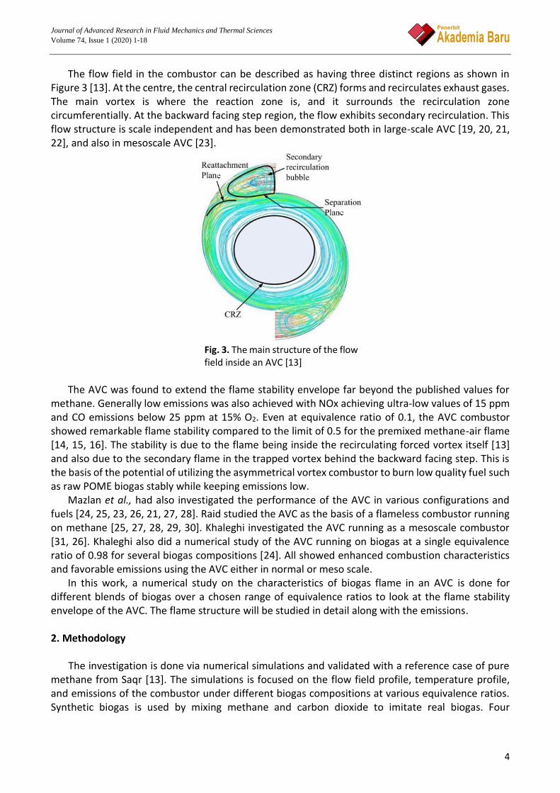
The flow field in the combustor can be described as having three distinct regions as shown in Figure 3 [13]. At the centre, the central recirculation zone (CRZ) forms and recirculates exhaust gases. The main vortex is where the reaction zone is, and it surrounds the recirculation zone circumferentially. At the backward facing step region, the flow exhibits secondary recirculation. This flow structure is scale independent and has been demonstrated both in large-scale AVC [19, 20, 21, 22], and also in mesoscale AVC [23].
Fig. 3. The main structure of the flow field inside an AVC [13]
The AVC was found to extend the flame stability envelope far beyond the published values for
methane. Generally low emissions was also achieved with NOx achieving ultra-low values of 15 ppm and CO emissions below 25 ppm at 15% O2. Even at equivalence ratio of 0.1, the AVC combustor showed remarkable flame stability compared to the limit of 0.5 for the premixed methane-air flame [14, 15, 16]. The stability is due to the flame being inside the recirculating forced vortex itself [13] and also due to the secondary flame in the trapped vortex behind the backward facing step. This is the basis of the potential of utilizing the asymmetrical vortex combustor to burn low quality fuel such as raw POME biogas stably while keeping emissions low.
Mazlan et al., had also investigated the performance of the AVC in various configurations and fuels [24, 25, 23, 26, 21, 27, 28]. Raid studied the AVC as the basis of a flameless combustor running on methane [25, 27, 28, 29, 30]. Khaleghi investigated the AVC running as a mesoscale combustor [31, 26]. Khaleghi also did a numerical study of the AVC running on biogas at a single equivalence ratio of 0.98 for several biogas compositions [24]. All showed enhanced combustion characteristics and favorable emissions using the AVC either in normal or meso scale.
In this work, a numerical study on the characteristics of biogas flame in an AVC is done for different blends of biogas over a chosen range of equivalence ratios to look at the flame stability envelope of the AVC. The flame structure will be studied in detail along with the emissions. 2. Methodology
The investigation is done via numerical simulations and validated with a reference case of pure methane from Saqr [13]. The simulations is focused on the flow field profile, temperature profile, and emissions of the combustor under different biogas compositions at various equivalence ratios. Synthetic biogas is used by mixing methane and carbon dioxide to imitate real biogas. Four

Journal of Advanced Research in Fluid Mechanics and Thermal Sciences
Volume 74, Issue 1 (2020) 1-18
5
compositions from pure methane to 50% methane as tabulated in Table 3 are studied following the range of published compositions for POME biogas [7, 8, 9]. The geometry is based on Figure 2 as described previously. 2.1 Equilibrium Calculations
Equilibrium calculations using the NASA CEA package [40] is done to investigate the adiabatic
flame temperature of different biogas compositions at different equivalence ratios. This will also show the limit of combustibility of the biogas compositions. This limit, in terms of the equivalence ratio and composition, will be the basis for the range of cases of the numerical CFD investigation. 2.2 Governing Equations
This research studies the flame characteristics of an asymmetrical vortex combustor running on
biogas. This part focuses on the computational solution for the steady chemically reacting vortex flows. The 3D conservation equations are given below for mass, momentum, and also energy [41]. The mass conservation is given as 𝜕𝜌
𝜕𝑡+
𝜕𝜌𝑢𝑖
𝜕𝑥𝑖= 0 (1)
ρ and ui are density and flow velocity in the i-direction respectively. Momentum equation is stated as 𝜕
𝜕𝑡𝜌𝑢𝑖 +
𝜕
𝜕𝑥𝑖𝜌𝑢𝑖𝑢𝑗 =
𝜕𝑝
𝜕𝑥𝑗+
𝜏𝑖𝑗
𝜕𝑥𝑖+ 𝜌 ∑ 𝑌𝑘𝑓𝑘,𝑗
𝑁𝑘=1 (2)
with the viscous tensor τi,j expressed as
𝜏𝑖𝑗 = −2
3𝜇
𝜕𝑢𝑘
𝜕𝑥𝑘𝛿𝑖𝑗 + 𝜇 (
𝜕𝑢𝑖
𝜕𝑥𝑗+
𝜕𝑢𝑗
𝜕𝑥𝑖) (3)
where p, Yk , and fk,j denotes the pressure, the mass fraction of species k, and the volume force that acts on species k in the j direction respectively, while µ and δi j represent the dynamic viscosity and the Kronecker symbol respectively. The energy equation is given as
𝜌𝐶𝑝
𝐷𝑇
𝐷𝑡= �̇�𝑇 +
𝜕
𝜕𝑥𝑖(𝜆
𝜕𝑇
𝜕𝑥𝑖) − (𝜌 ∑ 𝐶𝑝,𝑘𝑌𝑘𝑉𝑘𝑗
𝑁
𝑘=1
)𝜕𝑇
𝜕𝑥𝑖+ 𝜏𝑖𝑗
𝜕𝑢𝑖
𝜕𝑥𝑗+ 𝑄 + 𝜌 ∑ 𝑌𝑘𝑓𝑘,𝑗𝑉𝑘𝑗
𝑁
𝑘=1
(4)
where variables Cp, T, and λ represent the mass heat capacity, the temperature, the thermal conductivity of the mixture, while �̇�𝑇, Cp,k , and Q are the rate of heat release, the mass heat capacity of species k, and the heat source term. The species conservation can be stated as
𝜕𝜌𝑌𝑘
𝜕𝑡+
𝜕
𝜕𝑥(𝜌(𝑢𝑖 + 𝑉𝑘,𝑖)𝑌𝑘) = �̇�𝑘 (5)

Journal of Advanced Research in Fluid Mechanics and Thermal Sciences
Volume 74, Issue 1 (2020) 1-18
6
where Vk,i and �̇�𝑘 represent the diffusion velocity of species k in the direction i, and the reaction rate of species k respectively. Assuming all species stay in the gas phase, we can assume ideal gas behaviour for all species. 2.3 Numerical Scheme
The flow domain is discretized using a finite volume method via a second order upwind scheme,
and the governing equations are solved by a steady state pressure based solver. The SIMPLE algorithm [35] is employed to link the pressure field with the continuity equation in the discretized momentum equation. Solution is assumed to have converged when residuals get below 1×10⁻⁴. For the conservation equations of energy and species, convergence is assumed when the residuals are less than 1×10⁻⁶. ANSYS Fluent Version R19.0 [32] was used to solve the three-dimensional momentum, energy, species, mass and heat transfer equations using the finite volume method. 2.4 Operating Conditions
Steady flow cases will be investigated for various biogas compositions and mixture strengths. A
composition of 100% methane is used as the baseline and carbon dioxide is added at several percentages until 50% to simulate real POME biogas. The different composition cases and equivalence ratios are tabulated in Table 3. For each composition, the reacting flow will be solved for various equivalence ratios ranging from rich to lean to study the limits of combustion.
The lean limit of 0.1 is determined from equilibrium calculations. At this equivalence ratio, the mixture did not ignite for any composition of the biogas. The rich limit for pure methane is reported to be around 1.68 by Hamidi and Suardi in separate works [33, 34]. With addition of CO2 it would be even less. Based on this but considering the ability of the vortex combustor to hold a stable flame at extended limits, the rich limit for this numerical study is set to 2.0. 2.5 Meshing and Grid Independence
An unstructured tetrahedron mesh scheme is used to discretize the flow domain as illustrated in
Figure 4. A mesh independence test was done using a steady flow case with 100% methane as fuel at stoichiometric condition to find a suitable mesh size. Five sets of mesh were compared and the plots of central axis temperature along the axial location for the different meshes were shown in Figure 5. The final mesh with 649496 was thus chosen for subsequent simulation runs since the required computing time is still tolerable given the capacity of the computing hardware and platform.

Journal of Advanced Research in Fluid Mechanics and Thermal Sciences
Volume 74, Issue 1 (2020) 1-18
7
Fig. 4. Computational domain with tetrahedral unstructured meshing (third quarter bottom view of the combustor showing tangential air inlet and axial fuel inlets)
Fig. 5. Mesh independence test
2.6 Turbulence and Chemistry Models
Turbulence models, namely standard k-epsilon, RNG k-epsilon, and Realizable k-epsilon
turbulence models were compared with experimental measurement of the central axis temperature of the combustor done by Saqr [13]. From the results, it was found that the Realizable k-epsilon closely matched the experimental measurements compared with the other models as depicted in

Journal of Advanced Research in Fluid Mechanics and Thermal Sciences
Volume 74, Issue 1 (2020) 1-18
8
Figure 6, and it will used from here onwards. This is also expected because the realizable k-epsilon model is more suitable for high swirl flows which the AVC is as will be shown later in terms of the swirl number.
The combustion model is simulated with a methane-air two-step reaction scheme. Chemical reaction was considered volumetric and the Eddy-Dissipation Model (EDM) algorithm was used for turbulence-chemistry interactions. The EDM reaction model uses only the reaction flow parameters and ignores the chemical kinetics from Arrhenius equations [39]. Thermal NOx calculation uses the partial-equilibrium model to predict the O radical concentration required.
Surface-to-gas radiation heat transfer in the vortex combustor is modeled by the Discrete Ordinates (DO) model. Wall material is steel, with mixed heat transfer (h= 20 W/m2.K) on the outside surface to an ambient temperature of 300 K. The summary of the chosen models and the boundary conditions employed to solve the cases are tabulated in Table 2.
Fig. 6. Comparison of experimental and several turbulence models’ results of temperature profile along the centerline for pure CH4 combustion
Emissions are studied for CO2, CO and NOx. Thermal NOx occurs via the Zeldovich mechanism
[36] whereby sufficient heat at high temperature conditions leads to nitrogen oxidation. The NOx formation strongly depends on the maximum flame temperature as well as residence time due to the high activation energies of the O radical reactions [36]. Fuel NOx are typically formed from liquid or solid fuels but rarely occurs in gaseous fuel system [37] such as in the present study. At lean conditions (φ < 0.8) and low temperatures, NOx could be produced from the intermediate N2O mechanism [37]. Nevertheless, in real combustion processes only a minute amount of N2O are produced which later will be oxidised into nitrogen monoxide NO.
Table 2 FLUENT model settings and Boundary Conditions Turbulence model Realizable k ε
Reaction model Volumetric reaction, Species transport, EDM for tubulence-chemistry interaction, methane-air two-step
Radiation model Discrete ordinates (DO) Air inlet
Mass flow rate: various (depending on φ) Temperature: 300 K, Pressure: 100 kPa Composition: O2 21%, N2 79%.
Fuel inlet Mass flow rate: various (depending on φ) Temperature: 300 K, Pressure: 100 kPa Composition: CH4 (various) & CO2 (various), depending on composition case.

Journal of Advanced Research in Fluid Mechanics and Thermal Sciences
Volume 74, Issue 1 (2020) 1-18
9
Wall Material: steel Thermal condition: Mixed heat transfer, h= 20 W/m2.K Outside temperature: 300 K.
2.7 Inlet Conditions
The air inlet mass flow rate is chosen to ensure a stable vortex is produced in the combustor [13].
Inlet condition is taken to be 100 kPa pressure and 300 K temperature for all cases. Target equivalence ratios dictate the mass flow rate of methane for a given air mass flow rate. To determine the inlet fuel mixture mass flow rate, methane and CO2 are assumed to be ideal gases and the fuel mixture mass flow rate is then calculated using Dalton’s law for partial pressures. The resulting inlet mass flow rates of air and fuel mixtures for the cases investigated are tabulated in Table 3.
Table 3 Air and fuel inlet conditions for all cases Case 0 1 2 3
𝝌𝑪𝑯𝟒 1 0.7 0.6 0.5 𝝌𝑪𝑶𝟐 0 0.3 0.4 0.5 φ m˙ a (kg/s) m˙ f (kg/s) m˙ a (kg/s) m˙ f (kg/s) m˙ a (kg/s) m˙ f (kg/s) m˙ a (kg/s) m˙ f (kg/s) 0.1 0.005534 3.225x10⁻⁵ 0.005534 7.017 x10⁻⁵ 0.005534 9.124 x10⁻⁵ 0.005534 1.21 x10⁻⁴ 0.2 0.003689 3.225x10⁻⁵ 0.003689 7.017 x10⁻⁵ 0.003689 9.124 x10⁻⁵ 0.003689 1.21 x10⁻⁴ 0.4 0.002767 3.225x10⁻⁵ 0.002767 7.017 x10⁻⁵ 0.002767 9.124 x10⁻⁵ 0.002767 1.21 x10⁻⁴ 0.5 0.00123 3.225x10⁻⁵ 0.00123 7.017 x10⁻⁵ 0.00123 9.124 x10⁻⁵ 0.00123 1.21 x10⁻⁴ 0.6 0.000922 3.225x10⁻⁵ 0.000922 7.017 x10⁻⁵ 0.000922 9.124 x10⁻⁵ 0.000922 1.21 x10⁻⁴ 0.8 0.000692 3.225x10⁻⁵ 0.000692 7.017 x10⁻⁵ 0.000692 9.124 x10⁻⁵ 0.000692 1.21 x10⁻⁴ 1.0 0.000553 3.225x10⁻⁵ 0.000553 7.017 x10⁻⁵ 0.000553 9.124 x10⁻⁵ 0.000553 1.21 x10⁻⁴ 1.2 0.000461 3.225x10⁻⁵ 0.000461 7.017 x10⁻⁵ 0.000461 9.124 x10⁻⁵ 0.000461 1.21 x10⁻⁴ 1.5 0.000369 3.225x10⁻⁵ 0.000369 7.017 x10⁻⁵ 0.000369 9.124 x10⁻⁵ 0.000369 1.21 x10⁻⁴ 1.8 0.000307 3.225x10⁻⁵ 0.000307 7.017 x10⁻⁵ 0.000307 9.124 x10⁻⁵ 0.000307 1.21 x10⁻⁴ 2.0 0.000277 3.225x10⁻⁵ 0.000277 7.017 x10⁻⁵ 0.000277 9.124 x10⁻⁵ 0.000277 1.21 x10⁻⁴
Note: 𝜒𝐶𝐻4 and 𝜒𝐶𝑂2 denote the mole fraction of CH4 and CO2 respectively m˙ a and m˙ f denote the mass flow rate of air and fuel mixture respectively, in kg/s
2.7 Swirl Number
Swirl number is the parameter that shows the existence and strength of the swirling vortex in the
combustor. This is useful in evaluating the mixing process between the fuel and air. It is also especially useful in studying vortex decay along the axial length of the combustor and it also gives us an insight into the stability of the vortex flame. Swirl number is defined as the ratio of the axial flux of the angular momentum to the axial flux of the axial momentum of swirling flows. Neglecting the pressure term, the swirl number can be expressed as
(6)
where ρ is the density, r the radial coordinate, W the tangential velocity, U the axial velocity, and R is the combustor radius. In FLUENT, the integrals appearing in the numerator and denominator can be evaluated by defining a custom function and computing a surface integral of a selected plane, and hence the swirl number for the plane can be readily calculated separately. 3. Results and Discussion
Journal of Advanced Research in Fluid Mechanics and Thermal Sciences
Volume 74, Issue 1 (2020) 1-18
10
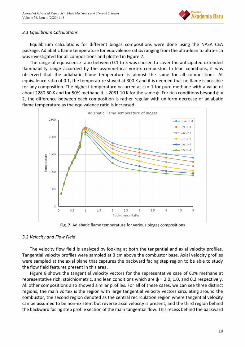
3.1 Equilibrium Calculations Equilibrium calculations for different biogas compositions were done using the NASA CEA
package. Adiabatic flame temperature for equivalence ratios ranging from the ultra-lean to ultra-rich was investigated for all compositions and plotted in Figure 7.
The range of equivalence ratio between 0.1 to 5 was chosen to cover the anticipated extended flammability range accorded by the asymmetrical vortex combustor. In lean conditions, it was observed that the adiabatic flame temperature is almost the same for all compositions. At equivalence ratio of 0.1, the temperature stayed at 300 K and it is deemed that no flame is possible for any composition. The highest temperature occurred at φ = 1 for pure methane with a value of about 2280.60 K and for 50% methane it is 2081.10 K for the same φ. For rich conditions beyond φ = 2, the difference between each composition is rather regular with uniform decrease of adiabatic flame temperature as the equivalence ratio is increased.
Fig. 7. Adiabatic flame temperature for various biogas compositions
3.2 Velocity and Flow Field
The velocity flow field is analyzed by looking at both the tangential and axial velocity profiles.
Tangential velocity profiles were sampled at 3 cm above the combustor base. Axial velocity profiles were sampled at the axial plane that captures the backward facing step region to be able to study the flow field features present in this area.
Figure 8 shows the tangential velocity vectors for the representative case of 60% methane at representative rich, stoichiometric, and lean conditions which are φ = 2.0, 1.0, and 0.2 respectively. All other compositions also showed similar profiles. For all of these cases, we can see three distinct regions; the main vortex is the region with large tangential velocity vectors circulating around the combustor, the second region denoted as the central recirculation region where tangential velocity can be assumed to be non-existent but reverse axial velocity is present, and the third region behind the backward facing step profile section of the main tangential flow. This recess behind the backward

Journal of Advanced Research in Fluid Mechanics and Thermal Sciences
Volume 74, Issue 1 (2020) 1-18
11
facing step, holds a secondary recirculation region where a trapped vortex forms. This region shall be called the trapped vortex region contrary to Saqr [13] who called it as the secondary recirculation zone. This trapped vortex region gives additional stability by holding a secondary flame (the trapped vortex flame). This trapped vortex flame which resides in the calm region of the flow acts as a pilot flame that keeps reigniting the main vortex when the main vortex flame becomes unstable due to flow or mixture conditions. This stability mechanism is similar to the one in trapped vortex combustors.
Fig. 8. Tangential velocity vectors at rich (φ =2), stoichiometric, and lean (φ = 0.2) conditions for 60% methane composition
Axial velocity vectors are shown in Figure 9 (in greyscale for better clarity) for the representative
case of 60% CH4 since all cases again showed similar behavior and characteristics. The main feature of the axial flow field is the upwards direction of the flow within the main vortex region at the periphery of the combustor. The flow reverses downwards in the middle of the combustor and completes the circulation at the bottom. The central recirculation zone boundary is where the axial velocity is zero. This boundary extends along the whole length of the combustor. The flow reversal also causes outside air to be entrained into the combustor via the exhaust.
Journal of Advanced Research in Fluid Mechanics and Thermal Sciences
Volume 74, Issue 1 (2020) 1-18
12
Fig. 9. Axial velocity vectors at rich (φ =2), stoichiometric, and lean (φ = 0.2) conditions for 60% methane
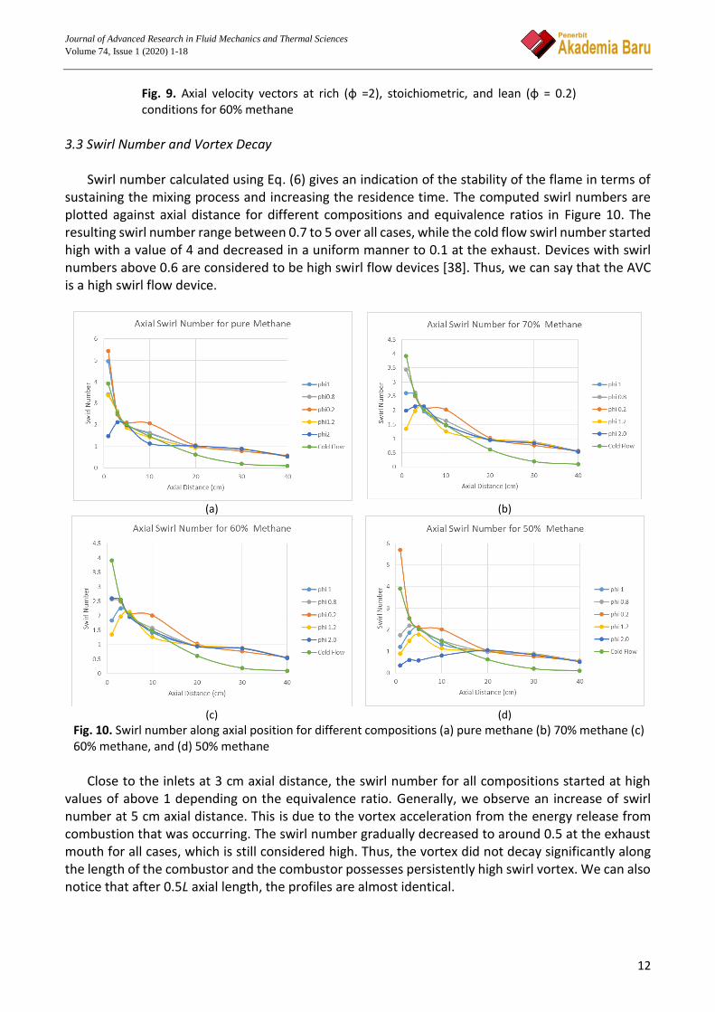
3.3 Swirl Number and Vortex Decay
Swirl number calculated using Eq. (6) gives an indication of the stability of the flame in terms of
sustaining the mixing process and increasing the residence time. The computed swirl numbers are plotted against axial distance for different compositions and equivalence ratios in Figure 10. The resulting swirl number range between 0.7 to 5 over all cases, while the cold flow swirl number started high with a value of 4 and decreased in a uniform manner to 0.1 at the exhaust. Devices with swirl numbers above 0.6 are considered to be high swirl flow devices [38]. Thus, we can say that the AVC is a high swirl flow device.
(a) (b)
(c) (d)
Fig. 10. Swirl number along axial position for different compositions (a) pure methane (b) 70% methane (c) 60% methane, and (d) 50% methane
Close to the inlets at 3 cm axial distance, the swirl number for all compositions started at high
values of above 1 depending on the equivalence ratio. Generally, we observe an increase of swirl number at 5 cm axial distance. This is due to the vortex acceleration from the energy release from combustion that was occurring. The swirl number gradually decreased to around 0.5 at the exhaust mouth for all cases, which is still considered high. Thus, the vortex did not decay significantly along the length of the combustor and the combustor possesses persistently high swirl vortex. We can also notice that after 0.5L axial length, the profiles are almost identical.

Journal of Advanced Research in Fluid Mechanics and Thermal Sciences
Volume 74, Issue 1 (2020) 1-18
13
3.4 Temperature and Flame Temperature profile of the central axis is plotted in Figure 11 for all compositions at
stoichiometric condition. Between 1/8L to 5/8L of the length of the combustor, temperature profiles of different biogas compositions did not differ much from each other. Peak temperature for all compositions can be estimated to be around 1800 K, which is below the adiabatic flame temperature for methane. Temperature contours are also qualitatively similar for different compositions over the range of equivalence ratios. Figure 12 shows the contour for the representative composition of 60% CH4. The results show that the AVC can burn the biogas even at equivalence ratio of 2.0, however no flame is able to be burned at equivalence ratio of 0.2 for all biogas compositions.
Fig. 11. Central axis temperature profile for different biogas compositions at stoichiometry
Fig. 12. Axial temperature profile comparison at different equivalence ratios for 60% methane
Journal of Advanced Research in Fluid Mechanics and Thermal Sciences
Volume 74, Issue 1 (2020) 1-18
14
The low peak combustor temperature is in contrast with the result reported by Gabler who identified a central core of hot gases with temperatures above the adiabatic flame temperature. This is because Gabler’s combustor employed a tangential exhaust port which resulted in a region of trapped hot gases in the combustor central core while the AVC here has an open exhaust which entrains atmospheric air into the combustor causing lower central core temperature as can be seen in the temperature contour profiles of all the cases shown in Figure 12.
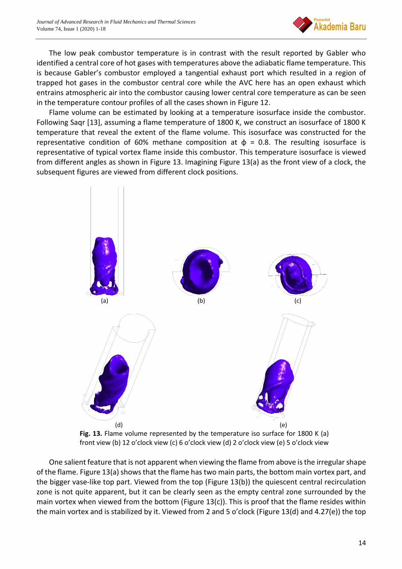
Flame volume can be estimated by looking at a temperature isosurface inside the combustor. Following Saqr [13], assuming a flame temperature of 1800 K, we construct an isosurface of 1800 K temperature that reveal the extent of the flame volume. This isosurface was constructed for the representative condition of 60% methane composition at φ = 0.8. The resulting isosurface is representative of typical vortex flame inside this combustor. This temperature isosurface is viewed from different angles as shown in Figure 13. Imagining Figure 13(a) as the front view of a clock, the subsequent figures are viewed from different clock positions.
(a) (b) (c)
(d) (e)
Fig. 13. Flame volume represented by the temperature iso surface for 1800 K (a) front view (b) 12 o’clock view (c) 6 o’clock view (d) 2 o’clock view (e) 5 o’clock view
One salient feature that is not apparent when viewing the flame from above is the irregular shape
of the flame. Figure 13(a) shows that the flame has two main parts, the bottom main vortex part, and the bigger vase-like top part. Viewed from the top (Figure 13(b)) the quiescent central recirculation zone is not quite apparent, but it can be clearly seen as the empty central zone surrounded by the main vortex when viewed from the bottom (Figure 13(c)). This is proof that the flame resides within the main vortex and is stabilized by it. Viewed from 2 and 5 o’clock (Figure 13(d) and 4.27(e)) the top
Journal of Advanced Research in Fluid Mechanics and Thermal Sciences
Volume 74, Issue 1 (2020) 1-18
15
vase-like structure also shows an irregular shape where we can see the vortex twisting upwards along with the flow.
3.5 Emissions
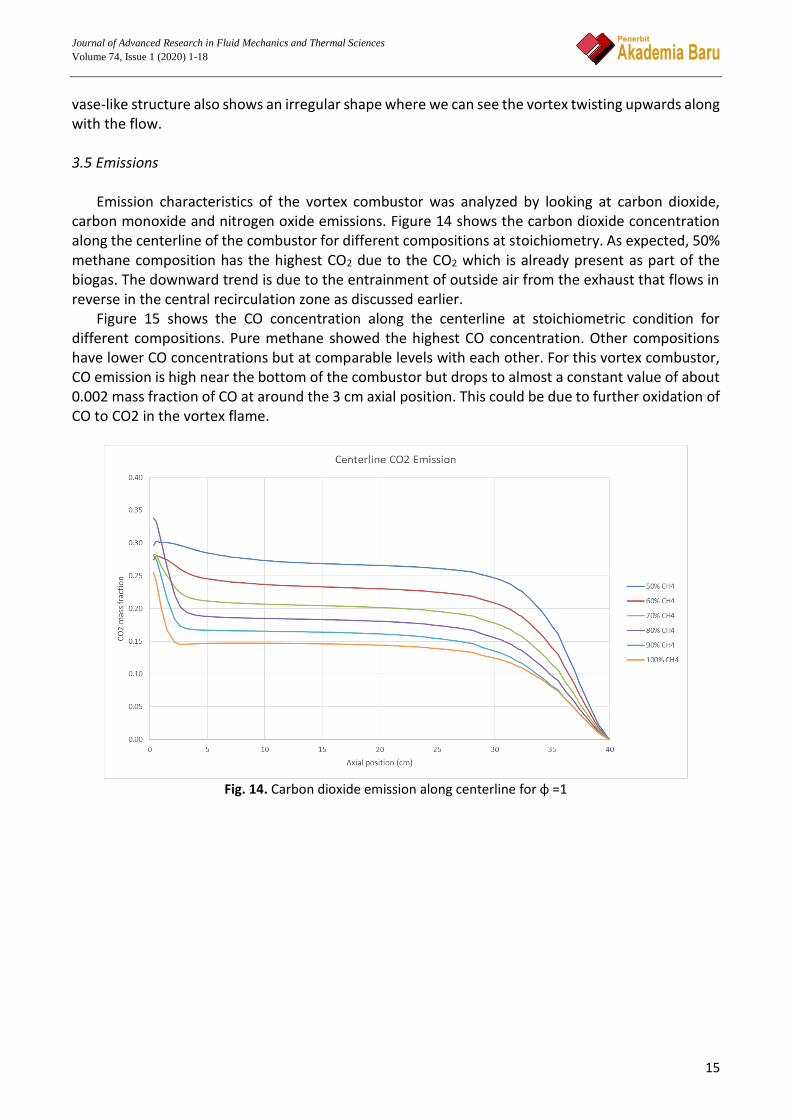
Emission characteristics of the vortex combustor was analyzed by looking at carbon dioxide,
carbon monoxide and nitrogen oxide emissions. Figure 14 shows the carbon dioxide concentration along the centerline of the combustor for different compositions at stoichiometry. As expected, 50% methane composition has the highest CO2 due to the CO2 which is already present as part of the biogas. The downward trend is due to the entrainment of outside air from the exhaust that flows in reverse in the central recirculation zone as discussed earlier.
Figure 15 shows the CO concentration along the centerline at stoichiometric condition for different compositions. Pure methane showed the highest CO concentration. Other compositions have lower CO concentrations but at comparable levels with each other. For this vortex combustor, CO emission is high near the bottom of the combustor but drops to almost a constant value of about 0.002 mass fraction of CO at around the 3 cm axial position. This could be due to further oxidation of CO to CO2 in the vortex flame.
Fig. 14. Carbon dioxide emission along centerline for φ =1

Journal of Advanced Research in Fluid Mechanics and Thermal Sciences
Volume 74, Issue 1 (2020) 1-18
16
Fig. 15. Carbon monoxide emission along centerline for φ =1
Figure 16 shows the NOx emission along the combustor centerline at stoichiometric condition for different biogas compositions. 90% and 80% methane compositions gave significantly higher values of NOx compared to other compositions including pure methane. For 60% and 50% methane compositions, NOx is virtually non-existent in all operating conditions due to low flame temperatures. The overall NOx emission is considered ultra-low since the highest concentration is of the order 3.45×10⁻⁵ mole fraction which translates to less than 1 ppm. NOx emission is considered ultra-low when it is below 25 ppm [38]. This is due to the low flame temperature present in the vortex combustor.
Fig. 16. NOx emission along centerline for φ = 1
4. Conclusions
Journal of Advanced Research in Fluid Mechanics and Thermal Sciences
Volume 74, Issue 1 (2020) 1-18
17
Experimental and numerical investigations that were just concluded showed a very favorable
combustion and flame characteristics of the asymmetrical vortex combustor in terms of flame stability and emission. Swirl number was calculated and found to be above 0.6 for all operating conditions, reaching up to 3 in some cases, which puts the AVC in the category of very high swirl. Emissions from this combustor are generally low, NOx emission can be classified as ultra-low, below 25 ppm for all cases studied. The AVC flame ultra-stability was found to be due to two factors; the stable main vortex holing the flame region, and the trapped vortex region giving additional stability during unstable conditions. The AVC was able to hold a stable flame for a large range of equivalence ratio and even for low quality biogas (50% methane). This is a testament to the great potential of the asymmetric combustor design as a flexible fuel combustor. References [1] Change, IPCC Climate. "Synthesis Report. Contribution of working groups I." II and III to the Fifth Assessment Report
of the Intergovernmental Panel on Climate Change 151, no. 10.1017 (2014). [2] BP, Energy Outlook. "edition (BP plc, London, 2018)." (2019). [3] Outlook, BP Energy. "BP Energy Outlook 2019 edition The Energy Outlook explores the forces shaping the global
energy transition out to 2040 and the key uncertainties surrounding that." BP Energy Outlook 2019 (2019). [4] Energy, I. E. A., and C. Change. "World Energy Outlook 2017." (2017). [5] Outlook, BP BP Energy. "BP: London." (2018). [6] Ohimain, Elijah Ige, and Sylvester Chibueze Izah. "A review of biogas production from palm oil mill effluents using
different configurations of bioreactors." Renewable and Sustainable Energy Reviews 70 (2017): 242-253. https://doi.org/10.1016/j.rser.2016.11.221
[7] Hagen, Martin, Erik Polman, J. Jensen, Asger Myken, Owe Joensson, and Anders Dahl. "Adding gas from biomass to the gas grid." Contract No: XVII/4.1030 99-412 (2001).
[8] Kusrini, Eny, Maya Lukita, Misri Gozan, Bambang Heru Susanto, Teguh Wikan Widodo, Dedy Alharis Nasution, Shella Wu, Arif Rahman, and Yusraini Dian Inayati Siregar. "Biogas from palm oil mill effluent: characterization and removal of CO2 using modified clinoptilolite zeolites in a fixed-bed column." International Journal of Technology 4 (2016): 625-634. https://doi.org/10.14716/ijtech.v7i4.2207
[9] Shahidul, M. I., M. L. Malcolm, and J. J. Eugene. "Methane Production Potential of POME: A Review on Waste-to-Energy [WTE] Model." Sci Int 30, no. 5 (2018): 717-728.
[10] Noyola, Adalberto, Juan Manuel Morgan-Sagastume, and Jorge E. Lopez-Hernandez. "Treatment of biogas produced in anaerobic reactors for domestic wastewater: odor control and energy/resource recovery." Reviews in Environmental Science and Bio/Technology 5, no. 1 (2006): 93-114. https://doi.org/10.1007/s11157-005-2754-6
[11] Persson, Margareta, Owe Jönsson, and Arthur Wellinger. "Biogas upgrading to vehicle fuel standards and grid injection." In IEA Bioenergy task, vol. 37, pp. 1-34. 2006.
[12] Baader, W., E. Dohne, and M. Brenndoerfer. "Biogas in theory and practice. Biogas in Theorie und Praxis. Behandlung organischer Reststoffe aus der Landwirtschaft durch Methangaerung." (1978).
[13] Saqr, Khalid Mohammed Mohiee Eldien Mansour. "Aerodynamics and Thermochemistry of Turbulent Confined Asymmetric Vortex Flames." PhD diss., Universiti Teknologi Malaysia, 2011.
[14] XIA, Yun-chun, and Qing-an WANG. "Study on the Vorticity of Fire Whirl Affected by a Magnetic Field (I)[J]." Journal of Combustion Science and Technology 3 (2005).
[15] Kuwana, Kazunori, Kozo Sekimoto, Kozo Saito, and Forman A. Williams. "Scaling fire whirls." Fire Safety Journal 43, no. 4 (2008): 252-257. https://doi.org/10.1016/j.firesaf.2007.10.006
[16] Chow, W. K., and S. S. Han. "Experimental investigation on onsetting internal fire whirls in a vertical shaft." Journal of fire sciences 27, no. 6 (2009): 529-543. https://doi.org/10.1177/0734904109342123
[17] Chuah, Keng Hoo, Kazunori Kuwana, and Kozo Saito. "Modeling a fire whirl generated over a 5-cm-diameter methanol pool fire." Combustion and Flame 156, no. 9 (2009): 1828-1833. https://doi.org/10.1016/j.combustflame.2009.06.010

Journal of Advanced Research in Fluid Mechanics and Thermal Sciences
Volume 74, Issue 1 (2020) 1-18
18
[18] Satoh, Kohyu, Naian Liu, Qiong Liu, and K. T. Yang. "Numerical and experimental study of fire whirl generated in 15× 15 square array fires placed in cross wind." In ASME 2008 International Mechanical Engineering Congress and Exposition, pp. 103-112. American Society of Mechanical Engineers Digital Collection, 2008. https://doi.org/10.1115/IMECE2008-66865
[19] Saqr, Khalid M., Hossam S. Aly, Mohsin M. Sies, and Mazlan A. Wahid. "Computational and experimental investigations of turbulent asymmetric vortex flames." International Communications in Heat and Mass Transfer 38, no. 3 (2011): 353-362. https://doi.org/10.1016/j.icheatmasstransfer.2010.12.001
[20] Khaleghi, Mostafa, S. E. Hosseini, M. A. Wahid, and H. A. Mohammed. "The Effects of Air Preheating and Fuel/Air Inlet Diameter on the Characteristics of Vortex Flame." Journal of Energy 2015 (2015). https://doi.org/10.1155/2015/397219
[21] Khaleghi, Mostafa, Seyed Ehsan Hosseini, and Mazlan Abdul Wahid. "Emission and combustion characteristics of hydrogen in vortex flame." Jurnal Teknologi 66, no. 2 (2014): 47-51. https://doi.org/10.11113/jt.v66.2483
[22] Saqr, Khalid M., Hassan I. Kassem, Hossam S. Aly, and Mazlan A. Wahid. "Computational study of decaying annular vortex flow using the Rε/k− ε turbulence model." Applied Mathematical Modelling 36, no. 10 (2012): 4652-4664. https://doi.org/10.1016/j.apm.2011.11.082
[23] Khaleghi, Mostafa, Mazlan A. Wahid, Mohsin M. Seis, and Aminuddin Saat. "Investigation of vortex reacting flows in asymmetric Meso scale combustor." In Applied Mechanics and Materials, vol. 388, pp. 246-250. Trans Tech Publications Ltd, 2013. https://doi.org/10.4028/www.scientific.net/AMM.388.246
[24] Khaleghi, Mostafa. "Experimental and Computational Thermal Analysis of Vortex Flame in Meso-scale Combustor." PhD diss., Universiti Teknologi Malaysia, 2015.
[25] Alwan, Raid A., M. Wahid, A. Abuelnuor, and Mohd Suardi. "Combustion in asymmetric vortex chambers." In International Conference on Energy and Thermal Sciences. 2014.
[26] Khaleghi, Mostafa, S. E. Hosseini, M. A. Wahid, and H. A. Mohammed. "The Effects of Air Preheating and Fuel/Air Inlet Diameter on the Characteristics of Vortex Flame." Journal of Energy 2015 (2015): 1-10. https://doi.org/10.1155/2015/397219
[27] Alwan, R. A.,Wahid, M. A., F, M. F. M., Abuelnuor, A. A. A. and Taie, A. A. "The effect of swirling vortex combustion on NOx emissions." In 6th International Conference on Fluid Mechanics and Heat & Mass Transfer, 2015: 62-66.
[28] Alwan, Raid A., M. Wahid, A. Abuelnuor, and Arkan Al Taie. "NOx Characteristics in Asymmetric Vortex Combustion." In th International Meeting on Advanced Thermofluids (IMAT 2014), Kuala lumpur-Malaysia. 2014.
[29] Alwan, Raid Abid, Mazlan Abdul Wahid, Mohd Fairus Mohd Yasin, Arkan Al-Taie, and Abuelnuor Abdeen Ali Abuelnuor. "Effects of Equivalence Ratio on Asymmetric Vortex Combustion in a Low NOx Burner." International Review of Mechanical Engineering (IREME) 9, no. 5 (2015): 476-483. https://doi.org/10.15866/ireme.v9i5.7157
[30] Al Wan, Raid Abid. "Thermal and Fluid Flow Analysis of Swirling Flameless Combustion." PhD diss., Universiti Teknologi Malaysia, 2016.
[31] Khaleghi, Mostafa, Mazlan A. Wahid, Mohsin M. Seis, and Aminuddin Saat. "Investigation of vortex reacting flows in asymmetric Meso scale combustor." In Applied Mechanics and Materials, vol. 388, pp. 246-250. Trans Tech Publications Ltd, 2013. https://doi.org/10.4028/www.scientific.net/AMM.388.246
[32] ANSYS, INC. "ANSYS Fluent MANUAL, no. 19.0." [33] Hamidi, Nurkholis. "Carbon dioxide effects on the flammability characteristics of biogas." In Applied Mechanics and
Materials, vol. 493, pp. 129-133. Trans Tech Publications Ltd, 2014. https://doi.org/10.4028/www.scientific.net/AMM.493.129
[34] Suhaimi, Mohd Suardi, Aminuddin Saat, and Mazlan Abdul Wahid. "FLAMMABILITY AND BURNING RATES OF LOW QUALITY BIOGAS AT ATMOSPHERIC CONDITION." Jurnal Teknologi 79, no. 7-3 (2017). https://doi.org/10.11113/jt.v79.11892
[35] Patankar, Suhas V., and D. Brian Spalding. "A calculation procedure for heat, mass and momentum transfer in three-dimensional parabolic flows." In Numerical prediction of flow, heat transfer, turbulence and combustion, pp. 54-73. Pergamon, 1983. https://doi.org/10.1016/B978-0-08-030937-8.50013-1
[36] Zeldovich, Y. A., D. Frank-Kamenetskii, and P. Sadovnikov. Oxidation of nitrogen in combustion. Publishing House of the Acad of Sciences of USSR, 1947.
[37] Malte, P. C., and D. T. Pratt. "Measurement of atomic oxygen and nitrogen oxides in jet-stirred combustion." In Symposium (international) on combustion, vol. 15, no. 1, pp. 1061-1070. Elsevier, 1975.

Journal of Advanced Research in Fluid Mechanics and Thermal Sciences
Volume 74, Issue 1 (2020) 1-18
19
https://doi.org/10.1016/S0082-0784(75)80371-7 [38] Gabler, H. C. I. "An experimental and numerical investigation of asymmetrically-fueled whirl flames." (1999): 1326-
1326. Ph.D diss., Princeton University, 1998. [39] Magnussen, Bjørn F., and Bjørn H. Hjertager. "On mathematical modeling of turbulent combustion with special
emphasis on soot formation and combustion." In Symposium (international) on Combustion, vol. 16, no. 1, pp. 719-729. Elsevier, 1977. https://doi.org/10.1016/S0082-0784(77)80366-4
[40] Gordon, Sanford, and Bonnie J. McBride. "Computer program for calculation of complex chemical equilibrium compositions and applications. Part 1: Analysis." (1994).
[41] Saqr, Khalid M., Hossam S. Aly, Mazlan A. Wahid, and Mohsin M. Sies. "Numerical Simulation of Confined Vortex Flow Using a Modified k--ϵ Turbulence Model." CFD letters 1, no. 2 (2009): 87-94.
[42] Alam, Md Zahangir, and Nurfarhana Abdul Hanid. "Development of Indigenous biofilm for enhanced biogas production from palm oil mill effluent." Journal of Advanced Research in Fluid Mechanics and Thermal Sciences 39, no. 1 (2017): 1-8.