vortex-lattice - utilization - NASA Technical Reports Server
423
NASA SP-405 VORTEX-LATTICE UTILIZATION (NRSA-5P-405) V3BTZX- LATTIZZ UTILIZF.TION N76-28163 (?iASA) 409 p HC 611.Ci0 CSCL 31A THRU rn N76-28186 Unclas H1/02 47615 .- A workshop held at LANGLEY RESEARCH CENTER Hampton, Virginia May 17-18, 1976 NATIONAL AERONAUTICS AND I SPAC
-
Upload
khangminh22 -
Category
Documents
-
view
0 -
download
0
Transcript of vortex-lattice - utilization - NASA Technical Reports Server

NASA SP-405
VORTEX-LATTICE
UTILIZATION
( N R S A - 5 P - 4 0 5 ) V 3 B T Z X - L A T T I Z Z U T I L I Z F . T I O N N76-28163 (?iASA) 4 0 9 p HC 611.Ci0 CSCL 31A THRU
rn N76-28186 U n c l a s
H1/02 47615 .-
A workshop held at
LANGLEY RESEARCH CENTER
Hampton, Virginia
May 17-18, 1976
NATIONAL AERONAUTICS AND
I SPAC
ERRATA
NASA SP-405
VORTEX-LATTICE UTILIZATION
Page 231: Figure 6 is in error. Replace figure 6 with the following corrected version.
Figure 6.- Span load and section suction distributions on a swept and skewed wing. h = 45O; A = 1; M = 0 .
VORTEX-LATTICE
UTILIZATION
A workshop held at Langley Research Center, Hampton, Virginia, on May 17-18, 1976
NASA SP-405
Prepared by Lungley Research Center
Srietrlifir and Terhnirnl lrlformdtion Ofice !9'h
u 5. b. NATIONAL AERONAUTICS AND SPACE ADMINISTRATION Washington, D.C.
CONTENTS
. . . . . . . . . . . . . . . . . . . . . . . . . . . . . . . . . . PREFACE iii o)tl/7- .
j . 1. HISTORICAL EVOLUTION OF VORTEX-LATTICE METHODS . . . . . . . . . . . . 1 - John DeYoung, Vought Corporation Hampton Technical Center
SESSION I - CONFIGURATION DESIGN AND ANALYSIS AND WALL EFFECTS Chairman: Percy J. Bobbitt, NASA Langley Research Center
A. WING-BODY COMBINATIONS
. . . . . . . . . 2. SUBSONIC FINITC ELEMENTS FOR WING-BODY COMBINATIONS 11 James L. Thomas, NASA Langley Research Center
3. EXTENDED APPLICATIONS OF THE VORTEX LATTICE METHOD . . . . . . . . . 2 7 Luis R. Miranda, Lockheed-California Company
B. NONPLANAR CONFIGURATIONS
4. WMERICAL METHOD TO CALCULATE THE INDUCED DRAG OR OPTIMUM LOADING FOR ARBITRARY NON-PLANAR AIRCRAFT . . . . . . . . . . . . . . . . . 49 James A. Blackwell, Jr., Lockheed-Georgia Company
5. OPTIMIZATION AND DESIGN OF THREE-DIMEKSIONAL AERODYNAMIC CONFIGURATIONS OF ARBITRARY SHAPE BY A VORTEX LATTICE METHOD . . . . . . . . . . . . . . . . . . . . . . . . . . . . . . 71 Wlnfried M. Feifel, The Boeing Company
6. MINIMUM TRIM D U G DESIGN FOR INTERFERING LIFTING SURFACES USING VORTEX-LATTICE METHODOLOGY . . . . . . . . . . . . . . . . . 8 9 John E. Lamar, NASA Langley Research Center
7. APPLICATIONS OF VORTEX-LATTICE THEORY TO PRELIMINARY AERObYNAMICDESIGN . . . . . . . . . . . . . . . . . . . . . . . . 113 John W. Paulson, Jr., NASA Langley Research Center
C. PROPULSION AERODYNAMICS
8. UTILIZATION OF THE AEDC THREE-DIMENSIONAL POTENTIAL FLOW COMPUTER PROGRAM . . . . . . . . . . . . . . . . . . . . . . . . . 127 Richard L. Palko, ARO, Inc.
D . WALL EFFECTS 9. REPORT ON THE STATUS OF A SLOTTED WIND-TUNNEL WALL
REPRESENTATION USING THE VORTEX-LATTICE TECHNIQUE . . . . . . . . . 145 Fred L. Heltsley, ARO, Inc.

SESSION I1 - HIGH LIFT Chairman: Edward C, Polhamus, NASA Langley Research Center
A. FLAPS
10. A QUADRILATERAL VORTEX METHOD APPLIED TO CONFIGURATIONS WITH HIGH CIRCULATION . . . . . . . . . . . . . . . . . . . . . . . . . 163 Brian Maskew, Analytical Methods, Inc.
B. WING-JET
11. UPPER-SURFACE-BLOWING JET-WING INTERACTION . . . . . . . . . . . . . 187 C. Edward Lan, The University of Kansas
12. CALCULATION OF THE LONGITUDINAL AERODYNAMIC CHARACTERISTICS OF WINGFLAP CONFIGURATIONS WITH EXTERNALLY BLOWN FLAPS . . . . . . . 199 Michael R. Meadenhall, Nielsen Engineering & Research, Inc.
C. VORTEX LIFT
13. SOME RECENT APPLICATIONS OF THE SUCTION ANALOGY TO ASYMMETRIC . . . . . . . . . . . . . . . . ~ O W S I T U A T I O N S . . . . . . . . . . . 219 James M. Luckring, NASA Langley Research Center
14. APPLICATION OF THE VORTEX-LATTICE TECHNIQUE TO THE ANALYSIS OF THIN WINGS WITH VORTEX SEPARATION AM) THICK MULTI-ELEMENT WINGS............................... 237 Charles W. Smith and Ishwar C. Bhateley, Fort Worth Division of General Dynamics
15. COMPARISON OF VORTEX LATTICE PREDICTED FORCES WITH WIND TUNNEL EXPERIMENTS FOR THE F-4E(CCV) AIRPLANE WITH A CLOSELY . . . . . . . . . . . . . . . . . . . . . . . . . . COUPLED CANARD 261 Lloyd W. Gross, McDonnell Aircraft Company
16. NEW CONVERGENCE CRITERIA FOR THE VORTEX-LATTICE MODELS OF THE . . . . . . . . . . . . . . . . . . . . . . LEADINGEDGE SEPARATION 285 Osama A. Kandil, Dean 7'. Mook, and A l i H. Nayfeh, Virginia Polytechnic Institute and State University
SESSION I11 - NEW PROCEDURES Chairman: Willia; B. Kemp, Jr. , NASA Langley Research Center
A. LATTICE ARRANGEMENT
17. ARRANGEMENT OF VORTEX LATTICES ON SUBSONIC WINGS . . . . . . . . . . 301 Fred R. DeJarnette, North Carolina State University

. . . . . . . . . . . . . 18. LATTICE ARRANGEMENTS FOR RAPID CONVERGENCE 325 Gary R. Hough, Vought Corporation Advanced Technology Center
19. OPTIMUM LATTICE ARRANGEMENT DEVELOPED FROM A RIGOROUS ANALYTICAL . . . . . . . . . . . . . . . . . . . . . . . . . . . . . BASIS.. 343 John DeYoung, Vought Corporation Hampton Technical Center
20. A SUBVORTEX TECHNIQUE FOR THE CLOSE APPROACH TO A DISCRETIZED VORTEXSHEET . . . . . . . . . . . . . . . . . . . . . . . . . . . 369 Brian Maskew, Analytical Methods, Inc.
B. OTHERS
21. SOME APPLICATldNS OF THE QUASI VORTEX-LATTICE METHOD IN STEADY . . . AND UNSTEADY AERODYNAMICS . . . . . . . . . . . . . . . . . 385 C. Edward Lan, The University of Kansas
22. UNSTEADY now OVER WINGS HAVING SHARP-EDGE SEPARATION . . . . . . . . 407 E. H. Atta, 0. A. Kandil, D. T. Mook, and A. H. Nayfeh, Virginia Polytechnic Institute and State University
SESSION IV - OPEN DISCUSSION RELATED TO FUTURE WORK Chairman: John C. Houbolt, NASA Langley Research Center
23. SUMMARY OF OPEN DISCUSSION ON FUTURE VORTEX-LATTICE UTILIZATION . . . 419 John C. Houbolt, NASA Langley Research Center
. . . . . . . . . . . . . . . . . . . . . . . 24. SAMPLEWINGSFORSTUDY 423 John E. Lamar, NASA Langley Research Center
vii
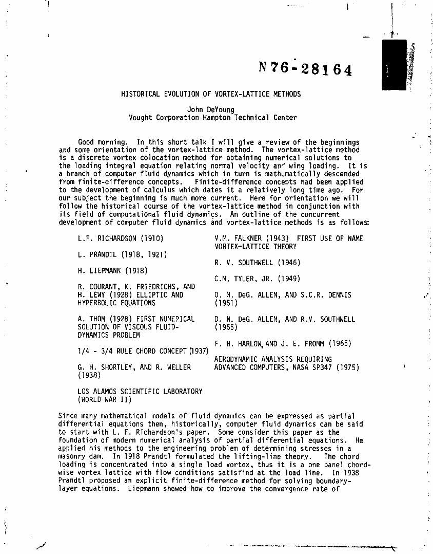
HISTORICAL EVOLUTION OF VORTEX-LATTICE METHODS
John DeYoung Vought Corporat ion Hampton Technical Center
Good morning. I n t h i s shor t t a l k I w i l l g i ve a review o f t he beginnings and some o r i e n t a t i o n o f the v o r t e x - l a t t i ce method. The vortex-1 a t t i c e method i s a d i s c r e t e vor tex co loca t ion method f o r ob ta in ing numerical so lu t ions t o t he loading i n t e g r a l equat ion r e l a t i n g normal v e l o c i t y an2 wing loading. I t i s . a branch o f computer f l u i d dynamics which i n t u r n i s m a t h ~ m a t i c a l l y descended from f i n i t e - d i f ference concepts. F i n i t e -d i f f e rence concepts had been appl i e d t o the development o f ca lcu lus which dates i t a r e l a t i v e l y long t ime ago. For our subject the beginning i s much more cur ren t . Here f o r o r i e n t a t i o n we w i l l f o l l o w the h i s t o r i c a l course o f the v o r t e x - l a t t i c e method i n conjunct ion w i t h i t s f i e l d o f computational f l u i d dynamics. An o u t l i n e o f the concurrent development o f computer f l u i d dynamics and v o r t e x - l a t t i c e methods i s as f o l lows:
L.F. RICHARDSON (1910) V.M. FALKNER (1943) FIRST USE OF NAME VORTEX-LATTI CE THEORY
L. PRANDTL (1918, 1921) R. V. SOUTHWELL (1946)
H. LIEPMANN (1918) C.M. TYLER, JR. (1949)
R. COURANT, K. FRIEDRICHS, AND H. LEWY (1928) ELLIPTIC AND D. N. DeG. ALLEN, AND S.C.R. DENNIS HYPERBOLIC EQUATIONS (1951)
A. THOM (1928) FIRST NUMEPICAL D. N. DeG. ALLEN, AND R.V. SOUTHWELL SOLUTION OF VISCOUS FLUID- (1 955) DYNAMICS PROBLEM
F. H. HARLOW, AND J. E. FROMFI (1965) 114 - 314 RULE CHORD CONCEPT (1 937)
AERODYNAMIC ANALYSIS REQUIRING G. H. SHORTLEY, AND R. WELLER ADVANCED COMPUTERS, NASA SP347 (1 975) (1 938)
LOS ALAMOS SCIENTIFIC LABORATORY (WORLD WAR I I )
Since many mathematical models o f f l u i d dynamics can be expressed as p a r t i a l d i f f e r e n t i a l equations then, h i s t o r i c a l l y , computer f l u i d dynamics can be sa id t o s t a r t w i t h L. F. Richardson's paper. Some consider t h i s paper as the foundat ion o f modern numerical ana lys is of p a r t i a l d i f f e r e n t i a l equations. He appl ied h i s methods t o the engineer ing problem o f determining stresses i n a masonry dam. I n 1918 Prandt l formulated t he 1 i f t i n g - l i n e theory. The chord loading i s concentrated i n t o a s i n g l e load vortex, thus i t i s a one panel chord- wise vor tex l a t t i c e w i t h f l ow cond i t ions s a t i s f i e d a t the load l i n e , I n 1938 Prandt l proposed an expl i c i t f i n i t e - d i fference method f o r so l v i ng boundary- l aye r equations. Liepmann showed how t o improve t he convergence r a t e o f
-- - a). r.lP-Y.r.--, 4-tr*- .,.--"..Us-
7
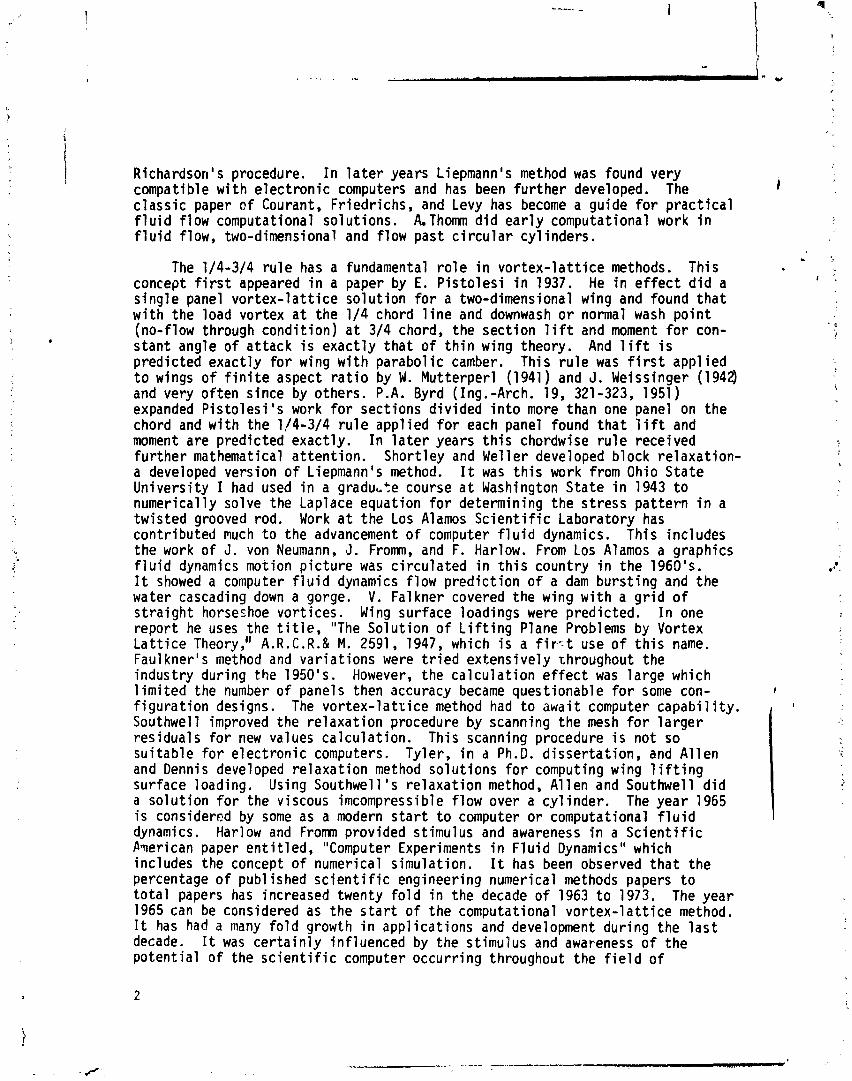
Richardson's procedure. I n l a t e r years Liepmann's method was found very i compatible w i th e lec t ron ic computers and has been f u r t h e r developed. The
c lass ic paper o f Courant, Fr iedrichs, and Levy has become a guide f o r p rac t i ca l f l u i d f low computational so lut ions. AThomn d i d e a r l y computational work i n f l u i d flow, two-dimensional and f low past c i r c u l a r c y l inders.
The 114-314 r u l e has a fundamental r o l e i n vo r tex - l a t t i ce methods. This concept f i r s t appeared i n a paper by E. P i s to les i i n 1937. He i n e f f e c t d i d a s ing le panel vo r tex - l a t t i ce so lu t ion f o r a two-dimensional wing and found t h a t w i t h the load vortex a t the 114 chord l i n e and downwash o r normal wash po in t (no-flow through condi t ion) a t 314 chord, the sect ion l i f t and moment f o r con- s tant angle o f at tack i s exact ly t ha t of t h i n wing theory. And l i f t i s predicted exact ly f o r wing w i t h parabol ic camber. This r u l e was f i r s t appl ied t o wings o f f i n i t e aspect r a t i o by W . Mutterperl (1941) and J. Weissinger (1942) and very o f ten since by others. P.A. Byrd (1ng.-Arch. 19, 321-323, 1951) expanded P is to les i 's work f o r sections d iv ided i n t o more than one panel on the chord and w i t h the 1/4-314 r u l e appl ied f o r each panel found t h a t l i f t and moment are predicted exact ly. I n l a t e r years t h i s chordwise r u l e received fu r the r mathematical a t ten t ion . Shortley and We1 1 e r developed block re1 axation- a developed version o f Liepmann's method. It was t h i s work from Ohio State Univers i ty I had used i n a gradu,,te course a t Washington State i n 1943 t o numerically solve the Laplace equation fo r determining the st ress pa t te rn i n a twisted grooved rod. Work a t the Los Alamos S c i e n t i f i c Laboratory has contr ibuted much t o the advancement o f computer f l u i d dynamics. This includes the work o f J. von Neumann, J. Fromrn, and F. Harlow. From Los Alamos a graphics f l u i d dynamics motion p i c tu re was c i r cu la ted i n t h i s country i n the 1960's. It showed a computer f l u i d dynamics f low pred ic t ion o f a dam burs t ing and the water cascading down a gorge. V. Fa1 kner covered the wing w i t h a g r i d o f s t ra igh t horseshoe vor t ices. Wing surface loadings were predicted. I n one repor t he uses the t i t l e , "The Solut ion o f L i f t i n g Plane Problems by Vortex L a t t i c e Theory," A.R.C.R.& M. 2591, 1947, which i s a f iv t use o f t h i s name. Faulkner's method and var ia t ions were t r i e d extensively throughout the industry during the 1950's. However, the ca l cu la t i on e f f e c t was la rge which 1 im i ted the number o f panels then accuracy became questionable f o r some con- f igura t ion designs. The vo r tex - l a t t i ce method had t o await computer capabi 1 i t y . Southwell improved the re laxa t ion procedure by scanning the mesh f o r l a rge r residuals f o r new values ca lcu la t ion . This scanning procedure i s not so su i tab le f o r e lec t ron ic computers. Tyler, i n a Ph.D. d isser ta t ion , and A l l en and Dennis developed re laxat ion method solut ions f o r computing wing 1 i f t i n g surface loading. Using Southwell ' s re laxa t ion method, A1 1 en and Southwell d i d a so lu t ion f o r the viscous imcompressible f low over a cy l inder . The year 1965 i s considered by some as a modern s t a r t t o computer o r computational f l u i d dynamics. Harlow and F rom provided stimulus and awareness i n a S c i e n t i f i c h e r i c a n paper en t i t l ed , "Computer Experiments i n F l u i d Dynamics" which includes the concept o f numerical simulation. I t has been observed t h a t the percentage o f pub1 ished s c i e n t i f i c engineering numerical methods papers t o t o t a l papers has increased twenty f o l d i n the decade o f 1963 t o 1973. The year 1965 can be considered as the s t a r t of the computational vo r tex - l a t t i ce method. I t has had a many f o l d growth i n appl icat ions and development during the l a s t decade. I t was c e r t a i n l y inf luenced by the stimulus and awareness o f the po tent ia l of the s c i e n t i f i c computer occurr ing throughout the f i e l d o f
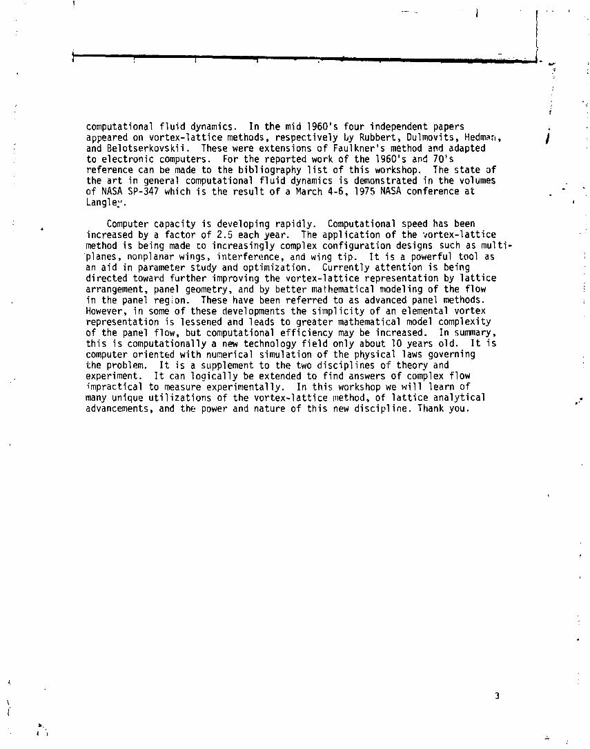
computational f l u i d dynamics. I n t h e mid 1960's f o u r independent papers appeared on v o r t e x - l a t t i c e methods, r espec t i ve l y by Rubbert, Dulmovi t s , Hedman, and Be lo tse rkovsk i i . These were extensions o f Faul kne r ' s method and adapted t o e l e c t r o n i c computers. For t h e repor ted work o f t he 1960's and 70's re ference can be made t o the b ib l iog raphy l i s t o f t h i s workshop. The s t a t e a f the a r t i n general computational f l u i d dynamics i s demonstrated i n t h e volumes o f NASA SP-347 which i s t h e r e s u l t o f a March 4-6, 1975 NASA conference a t Langl eil.
Computer capac i ty i s developing r a p i d l y . Computational speed has been increased by a f a c t o r o f 2.5 each year. The a p p l i c a t i o n o f t he *do r t ex - l a t t i ce method i s being made t o i nc reas ing l y complex con f i gu ra t i on designs such as mu1 ti- 'planes, nonplanar wings, in te r fe rence , and wing t i p . I t i s a powerful t o o l as an a i d i n parameter s tudy and op t im i za t i on . Cu r ren t l y a t t e n t i o n i s being d i r ec ted toward f u r t h e r improving t he v o r t e x - l a t t i c e represen ta t ion by l a t t i c e arrangement, panel geometry, and by b e t t e r ma thematical niodel i n g o f the f l o w i n t he panel reg ion. These have been r e f e r r e d t o as advanced panel methods. However, i n some o f these developments t he s i m p l i c i t y o f an elemental vo r tex representat ion i s lessened and 1 eads t o g rea te r mathematical model complexi ty o f the panel f low, bu t con~putat iona l e f f i c i e n c y may be increased. I n sumnary, t h i s i s computat iona l ly a new technology f i e l d on l y about 10 years o l d . It i s computer o r i en ted w i t h numerical s imu la t ion o f t h e phys ica l laws governing the problem. I t i s a supplement t o the two d i s c i p l i n e s o f theory and experiment. I t can l o g i c a l l y be extended t o f i n d answers o f complex f l ow imprac t i ca l t o measure exper imenta l ly . I n t h i s workshop we w i l l l e a r n o f many unique u t i l i z a t i o n s o f t he v o r t e x - l a t t i c e method, o f l a t t i c e a n a l y t i c a l advancements, and the power and na tu re o f t h i s new d i s c i p l i n e . Thank you.
BIBLIOGRAPHY
P i s t o l e s i , E. : Betrachtungen uber d i e gegensei t i g e Bee in f l ussung von Trag- f l ugel systemen (Considerat ions on t he Mutual I n t e r f e rence o f Aerofo i 1 Sys- tems). L.G.L. Rep., 1937, pp. 214-219.
Falkner, V . M.: The Ca lcu la t ion o f Aerodynamic Loading on Surfaces o f Any Shape. R. & M. No. 1910, B r i t i s h A.R.C., 1943.
. Fa1 kner, V. M. : The Accuracy of Ca lcu la t ions Based on Vortex L a t t i c e Theory.
Rep. No. 9621, B r i t i s h A.R.C., 1946.
Fa1 kner, V. M. : Ca lcu la t ions o f the Aerodynamic Loading o f a De l ta Wing. Rep. No. 9830, B r i t i s h A.R.C., 1946.
Falkner, V. M. : The E f f e c t o f Pointed T ips on Wing Loading Ca lcu la t ions . R. & M. No. 2483, B r i t i s h A.R.C., 1946.
Falkner, V. M.: A Note on the Present P o s i t i o n o f Ca lcu la t ions by Vortex La t - t i c e Theory. Rep. No. 9637, B r i t i s h A.R.C., 1946.
Fa1 kner, V. M. : The Use of Equiva lent Slopes i n Vortex L a t t i c e Theory. R. & M. No. 2293, B r i t i s h A.R.C., 1946.
Jones, W. P.: The Ca l cu la t i on o f Aerodynamic D e r i v a t i v e C o e f f i c i e n t s f o r Wings o f Any Plan Form i n Non-Uniform Motion. R. & M. No. 2470, B r i t i s h A.R.C., 1946.
Sch l i ch t ing , H.; and Thomas, H. H. B. M.: Note on t h e Ca l cu la t i on o f the L i f t D i s t r i b u t i o n of Swept Wings. Rep. No. Aero. 2236, G r i t i s h R.A.E., Dec. 1947.
Van Dorn, Nicholas H. ; and DeYoung, John: A Comparison o f Three Theore t i ca l Methods of Ca l cu l a t i ng Span Load D i s t r i b u t i o n on Swept Wings. NACA TN 1476, 1947. (Supersedes NACA RM A7C31. )
Berndt, Sune B. ; and Or1 i k-Ruckemann, Kazimierz: Comparison Between Theore t i ca l and Experimental L i f t D i s t r i b u t i o n s o f Plane Del ta Wings a t Low Speeds and Zero Yaw. KTH-Aero TN 10, Div. Aeronaut., Roy. I n s t . Techno1 . (Stockholm), 1 948.
Garner, I!. C. : Methods o f Approaching an Accurate Three-Dimensional Do ten t ia l So lu t i on f o r a Wing. R. & M. No. 2721, B r i t i s h A.R.C., 1948.
Jones, Ar thur L., and Sluder, Loma: An Appl i c a t i o n o f Fa1 kne r ' s Sur fxe -Load ing Method t o Pred ic t ions o f Hinge-Moment Parameters f o r Swept-Back Wings. NACA TN 1506, 1948.
Fa1 kner, V . M. : A Comparison of Two Methods of Ca l cu l a t i ng Wing Loading With Allowance fo r Compress ib i l i ty . R. & M. Nc. 2685, B r i t i s h A.R.C., 1949
Fa1 kner, V. i?. : The Scope and Accuracy o f Vortex L a t t i c e Theory. R. & M. No. 2740, B r i t i s h A.R.C., 1949.
darner, H. C . : The Eva lua t ion of Downwash a t Large Spanwise Distances From a Vortex L a t c i c e . R. 8 M. No. 2808, B r i t i s h A.Q.C., 1950.
Byrd, 7 . F. : Erganzung zu dem Aufsatz von N. Scholz, B e i t r a g e tragenden Flache. 1ng.-Arch., Bd. X I X , H e f t 6, 1951, pp. 32
Cdmpbell , George S. : A F i n i te -Step Method f o r t h e C , c u l a t i o n o f Unusual P lan Forms. NACA RM L5OLl3, 1951.
zu r Theor ie de r -323.
of Span Loadings
Falkner, V. M: C a l c u l a t i o n by L i f t i n g Plane Theory o f t h e R o l l i n g and Yawing Moments o f a Wing Due t o Rotary Mot ion i n Yaw. A i r c r a f t Eng., vo l . X X I I I , no. 264, Feb. 1951, pp. 44-50, 54.
Garner, H. C. : Swept-Wing Loading. A C r i t i c a l Comparison o f Four Subsonic Vortex Sheet Theories. C.P. No. 102, B r i t i s h A.R.C., Oct. 11, 1951.
Lehr ian, Dor i s E . : Aerodynamic C o e f f i c i e n t s f o r an O s c i l l a t i n g De l ta Wing. R. & F1. No. 2'141, B r i t i s h A.R.C., 1951.
Falkner, V. I.: The S o l u t i o n o f L i f t i n g - P l a n e Problems by V o r t e x - L a t t i c e Theory. R. & M. No. 2591, B r i t i s h A.R.C., 1953.
Lehr ian, Dor i s E. : C a l c u l a t i o n o f S t a b i l i t y D e r i v a t i v e s f o r O s c i l l a t i n g Wings. R. & M. No. 2922, B r i t i s h A.R.C., 1953.
Schneider, W i l l i a m C. : A Comparison o f t h e Spanwise Loading Ca lcu la ted by L a r - ious Methods With Experimental Loadings Obtained on a 450 Sweptback Wing o f Aspect R a t i o 8.02 a t a Reynolds Number of 4.0 x 10⁶. NACA Rep. 1208, 1954. (Supersedes NACA RM L51G30. )
M3rd, G. N. : L i n e a r i z e d Theory of Steady High-speed Flow. Cambridge Univ. Press, 1955.
Lehr ian, Dor i s E . : Ca lcu la ted D e r i v a t i v e s f o r Rectangular Wings O s c i l l a t i n g i n Compressible Subsonic Flow. R. & M. No. 3068, B r i t i s h A.R.C., 1956.
L e h r i m , Dor i s E. : Vo r tex -La t t i ce Treatment o f Rectangular Wings With O s c i l - l a t i n g Cont ro l Surfaces. R. & M. No. 3182, B r i t i s h A.R.C., 1957.
Carlson, Har ry W. ; and Midd le ton, Wi lbu r D.: A Numerical Method f o r the Design o f Camber Surfaces o f Supersonic Wings Wi th A r b i t r a r y Planforms. NASA I N D-2341, 1964.
Rubbert, Paul E . : Theore t i ca l C h a r a c t e r i s t i c s o f A r b i t r a r y Wings by a Non- P lanar Vortex L a t t i c e Method. Doc. No. D6-9244, Boeing Lo., Teb. 1964.
Ashley, Hol t; and Landahl , Marten: Aerodynamics o f Wings and Bodies. Addison- We5ley Pub. Co., Inc . , c. 1965.

Middleton, Wilbur D.; and Carlson, Harry W. : A Numerical Method f o r Calculat ing the Flat -Plate Pressure D is t r ibu t ions on Supersonic Wings o f A r b i t r a r y Planform. NASA TN 0-2570, 1965.
Blackwell, James A., J r . : Numerical Method for the Design o f Warped Surfaces f o r Subsonic Wings With A rb i t ra ry Planform. M. S. Thesis, Univ. o f V i rg in ia , 1966. (Avai lab le as NASA TM X-57857. )
Hedman, Sven G. : Vortex L a t t i c e Method f o r Calculat ion o f Quasi Steady State Loadings on Thin E las t i c Wings i n Subscnic Fiow. FFA Rep. 105, Aeronaut. Res. I ns t . o f Sweden, 1966.
Kfoury, Denis J. : A Routine Method fo r the Calculat ion o f Aerodynamic Loads on a Wing i n the V i c i n i t y of I n f i n i t e Vortices. Tech. Rep. 133-2 (Contract NOW 65-0139-d), Massachuzetts I ns t . Technol., May 1966.
Belotserkovski i . Sergei M i khai 1 ovich (Maurice Hol t, trans1 . ed. ) : The Theory o f Thin Wings i n Subsonic Flow. Plenum Press, 1967.
Jopp~ , R w e r t f. : A Method of Calculat ing Wind Tunnel Inta-ferenc,. Factors for Tunnel. o i Arb i t ra ry Cross Section. NASA CR-845, 1967.
Mirokhin, B. V . : Design V-Shaped F o i l s of Small Aspect Rdt io by the Method o f Horseshoe Vortices. News o f I n s t i t u t i o n s of Higher Learning - Aeronautical Engineering, FTD-TT-67-6235-0 (MT-64-288), U. S. A i r Force, Apr. 27, 1967, pp. 23-35. (Avai lable from DDC as AD 655 358. )
Albano, E.; and Rodden, W. P.: A Doublet L a t t i c e Method f o r Calculat ing L i f t D is t r ibu t ions on Osc i l l a t i ng Surfaces i n Subsonic Flows. A I A A Paper No. 68-73, Jan. 1968.
Bukhovtsev, B. 8.; and Stepanova, N. V. : The Non-Stationary Calculat ion o f Flow Past a Rectangular Wing o f Low Aspect Ratio. NASA TT F-11, 823, 1968.
Giesing, Joseph P. : L i f t i n g Surface Theory f o r Wing-Fuse1 age Combinations. Rep. DAC-67212, Vol. I, McDonnell Douglas, Aug. 1, 1968.
Landahl, Marten T.; and Stark, Val t e r J. E.: Numerical L i f t ing-Sur face Theory - Problems and Progress. A I A A J., vol . 6, no. \ 1, Nov. 1968, pp. 2049-2060.
Stahl, B.; ~a ' lmin, T. P.; Giesing, J. P.; and Rodden, W. P.: Aerodynamic Influence Coefficients f o r Osc i l l a t i ng Planar L i f t i n g Surfaces by the Doublet La t t i ce Method for Subsonic Flows Inc luding Quasi -Steady Fuse1 age Interference - Part I. Rep. No. DAC-67201, McDonnell h u g l a s Corp., 1968. (Avai l able from DDC as AD 903 874.)
Belotserkovskiy, S. M. : Calculat ion o f the Flow Around Wings o f A rb i t ra ry Plan- form i n a Wide Range o f Angles o f Attack. NASA TT F-12,291, 1969.
Blackwell, James A , , Jr . : A Fini te-Step Method for Calculat ion of Theoret ical Load D is t r ibu t ions f o r Arb i t ra ry L i f t ing-Sur face Arrangements a t Subsonic Speeds. NASA TN D-5335, 1969.

Houbol t, John C. : Some New Concepts i n Osc i l l a to ry L i f t i n g Surface Theory. 4FFDL-TR-69-2, U.S. A i r Force, June 1969. (Avai lab le from DDC as AD 857 522. )
James, R. M.: On the Remarkable Accuracy of the Vortex L a t t i c e D isc re t i za t i on i n Thin Wing Theory. Rep. No. DAC 67211, McDonnell Douglas, Feb. 1969.
~ i l m i n , T. P. ; Rodden, W. P. ; and Giesing, J. P. : Aerodynamic Inf luence Coef- f i c i en ts by the Doublet L a t t i c e Method f o r I n te r fe r i ng Nonplanar L i f t i n g Sur- faces O s c i l l a t i n g i n a Subsonic Flow - Part I. Rep. No. DAC-67977, McDonnell Douglas Corp., 1969.
Rodden, Wi l l iam P.; and Liu, David 7 . : Corre la t ion o f the Vortex L a t t i c e Method on Rotor/Wing Configurations. J. A i rc r . , vo l . 6, no. 4, July-Aug. 1969, p. 375.
Brebnei-, G. G.; and Wyatt, L. A.: The Ve loc i t ies Induced by D is t r i bu t i ons o f I n f i n i t e Kinked Source and the Vortex Lines Representing Wings With Sweep and Dihedral i n 1ncompress;ble Flow. R. & M. No. 3667, B r i t i s h A.R.C., 1970.
~ i l m i i n , T. P.; Giesing, J. P.; and Rodden, W. P.: Spanwise D i s t r i b u t i o n of Induced Drag i n Subsonic Flow by the Vortex L a t t i c e Method. 3. Ai rc r . , vol . 7, no. 6, Nov.-Dec. 1970, pp. 574-576.
Maskew, B. : Calculat ion o f the Three-Dimensional Potent ia l Flow Around L i f t i n g Non-Planar Wings and Wing-Bodies Using a Surface D i s t r i b u t i o n o f Quadri- l a t e r a l Vortex-Rings. TT 7009, Loughborough Univ. Technol., Sept. 1970.
Rodden, Wi l l iam P.; and Giesing, Joseph P.: Appl icat ion o f Osc i l l a to ry Aerody- namic Theory t o Estimation o f Dynamic S t a b i l i t y Derivat ives. J. Aircr. , vol . 7, no. 3, May-June 1970, pp. 272-275.
Giesing, J. P. ; Kilmin, T. P. ; and Rodden, W. P. : Subsonic Unsteady Aerody- namics fo r General Configurations. Par t I, Vol. I - D i rec t Appl icat ion of the Nonplanar Doublet-Latt ice Method. AFFDL-TR-71-5, P t . I, Vol . I, U.S. A i r Force, Nov. 1971.
Kilmin, T. P.; Rodden, W. P. ; and Giesing, 3. P. : Appl icat ion of the Doublet- L a t t i c e Method t o Nonplanar .Configurations i n Subsonic Flow. J . Aircr . , vol . 8, no. 6, June 1971, pp. 406-413.
Margason, Richard J.; and Lamar, John E. : Vortex-Latt ice FORTRAN Program f o r Estimating Subsonic Aerodynamic Character is t ics o f Complex P l anforms. NASA TN 0-6142, 1971.
Rodden, W. P. ; Giesing, J. P. ; and Kilmin, T. P. : New Developments and Appl i ca t ions o f the Subsonic Doublet-Latt ice Method f o r Nonplanar Configurations . Sycpos ium on Unsteady Aerodynamics f o r Aeroelas t i c Analyses of I n t e r f e r i n g Surfaces, Par t 11, AGARD CP No. 80, Apr. 1971, pp. 4-1-4-27.
Ash1 ey, Hol t; and Rodden, W i 11 iam P. : Wing-8ody Aerodynamic In te rac t ion . Annual Review o f F l u i d Mechanics, Vol. 4, M. Van Dyke, W. G. Vincenti, and J. V. Wehausen, eds., Annual Rev., Inc., 1972, pp. 431-472.
Giesing, J. P.; ~ i l k n , T. P. ; and Rodden, W. P. : Subsonic Steady and Osci l - l a t o r y Aerodynamics for Mu1 t i p l e I n t e r f e r i n g Wings and Bodies. J e Ai~rr- . vol. 9, no. 10, Oct. 1972, pp. 693-702.
Giesiny , J. P. : Subsonic Unsteady Aerodynamics f o r General Configurations. Par t 2, Vol. I - A p p l i c a t i m o f the Doublet-Latt ice Method and the Method o f Images t o L i f t i n g Surface Body Interference. AFFDL-TR-71-5, P t . 11, Vol. I, U.S. A i r Force, Apr. 1972. (Avai lab le from DDC as AD 893 825L.)
Giesing, J. P. ; Kilmin, T. P. ; and Rodden W. P. : Subsonic Unsteady Aerody- namics f o r General Configurations. A I A A Paper No. 72-26, Jan. 1972.
Gomez, Antul i o V. : TRW Vortex-Latt ice Method Subsonic Aerodynamic Analysis f o r Mu1 t i p 1 e-Li f t ing-Surfaces (N. Surface) TRW Program Number HA01 OB. 20029-HI 10-RO-00 (Contract NAS9-12330), TRW Syst., Sept. 1, 1972. (Avai lab le as NASA CR-128588. )
James, Richard M.: On the Remarkable Accuracy o f the Vortex L a t t i c e Method. Comput. Methods Appl. Mech. & Eng., vol. 1, no. 1, June 1972, pp. 59-79.
Rodden, W. P.; Giesing, J. P. ; and ~ i l m i n , T. P. : Refinement o f the Nonplanar Aspects of the Subsonic Doublet-Latt ice L i f t i n g Surface Method. J. Aircr., vol . 9, no. 1, Jan. 1972, pp. 69-73.
Sorre l ls , Russel 1 B. ; and M i l l e r , David S. : Numerical Method f o r Design o f Minimum-Drag Supersonic Wing Camber With Constraints on P i t c h i ~ g Moment and Surface Deformation. NASA TN D-7097, 1972.
Tul in ius, J. : Uni f ied Subsonic, Transonic, and Supersonic NAR Vortex La t t i ce . TFD-72-523, Los Angeles Div. , North American Rockwell, Apr. 27, 1972.
Clever, W. C.: A Vortex L a t t i c e Program f o r J e t Flapped A i r f o i l s . TFD-73-70, Los Angeles Div., North American Rockwell, Jan. 26, 1973.
Hedman, Sven G. : Computation o f Vortex Models f o r Wings a t High Angle of Attack i n Incompressible Flow. Tech. Note FFA AU-653, Aeronaut. Res. I ns t . o f Sweden, 1973.
Hough, Gary R.: Remarks on Vortex-Latt ice Methods. J. A i rcr . , vol . 10, no. 5, May 1973, pp. 314-317.
McCormick, Barnes W. : Final Report t o Close Out NASA Grant NGR-39-009-111 [ ~ o t o r B l ade-Vortex ~ n t e r a c t i o g . NASA CR-l3I)591, 1973.
Carlson, Harry W.; and M i l l e r , David S. : Numerical Methods for the Design and Analysis of Wings a t Supersonic Speeds. NASA TN D-7713, 1974.
Lan, C. Edward: An Ana l y t i ca l I n v e s t i g a t i o n o f Wing-Jet - In teract ion. CRINC-FRL 74-001 (NASA Grant NGR 17-002-107), Univ. o f Kansas, Apr. 1974. (Ava i l ab le as NASA CR-138140. )
Lan, C. Edward: A Quasi -Vor tex-Lat t ice Method i n Th in Wing Theory. J . Ai rc r . , vo l . 11, no. 9, Sept. 1974, pp. 518-527.
Mook, D. T.; and Maddox, S. A.: Extension o f a Vor tex -La t t i ce Method t o Inc lude t he E f f e c t s o f Leading-Edge Separation. J . A i r c r . , vo l . 11, no. 2, Feb. 1974, pp. 127-128.
Rodden, W i l l i a m P.; Giesing, Joseph P.; ~ i l m i n , Terez P; and Rowan, Jack C.: Comment on "A F i n i te-Element Method f o r Ca l cu l a t i ng Aerodynamic C o e f f i c i e n t s o f a Subsonic A i r p l a n e . ' J. A i r c r . , vo l . 11, no. 6, June 1974, pp. 366-368.
Aerodynamic Analyses Requi r ing Advanced Computers - Par ts I and 11. NASA SP-347, 1975.
Lamar, John E.; and Gloss, B l a i r B.: Subsonic Aerodynamic Cha rac te r i s t i c s o f I n t e r a c t i n g L i f t i n g Surfaces With Separated Flow Around Sharp Edges Pred ic ted by a Vor tex -La t t i ce Method. NASA TN D-7921, 1975.
Tu l i n i us , J.; Clever, W.; Niemann, A.; Dunn, K.; and Gai ther , B.: Theoret ica l P red i c t i on of A i rp lane S t a b i l i t y Der i va t i ves a t S u b c r i t i c a l Speeds. NASA CR-132681, 1975.
Lamar, John E.: A Vor tex -La t t i ce Method f o r the Mean Camber Shapes o f Trimmed Noncoplanar Flanforms With 'finimum Vortex Drag. NASA TN D-8090, 1976.
Rodden, W. P . : A Comparison o f Methods Used i n I n t e r f e r i n g L i f t i n g Surface Theory. AGARD Rep. No. 643, Feb. 1976.
Tu l i n i us , Jan R.; and Margason, Richard J. : A i r c r a f t Aerodynamic Design and Evaluat ion Methods. A I A A Paper No. 76-15, Jan. 1976.

SUBSONIC FINITE ELEMENTS FOR WING-BODY COMBINATIONS
James L. Thomas NASA Langley Research Center
SUMMARY
Capabilities, limitations, and applications of various theories for the prediction of wing-body aerodynamics are reviewed. The methods range from apploximate planar representations applicable in preliminary design to surface singularity approaches applicable in the later stages of detail design. The a~~aileble methods for three-dimensional configurations are limited as inviscid solutions with viscous eff3cts included on an empirical or strip basis.
IETTRODUCTION
Current research efforts directed toward the design of fuel-efficient air- craft dictate that adequate tools be available for the assessment of aerodynamic loads .tcross the expected speed envelope. Ashley and Rodden (ref. 1) have sum- marized the available methods for aerodynamic analyses of wings and bodies in steady and oscillatory motion at both subsonic and supersonic speeds. The ana- lytical methods applicable to generalized configurations vary over a range of sophistication, accuracy, artd computer times required hut are generally limited as inviscid solutions. Some inviscid-viscid coupling techniques in two dimen- sions have yielded good results (refs. 2 and 3), and their inclusion on a strip basis into three-dimensional inviscid solutions may serve as a near-term solu- tion. The inclusion of viscous effects for generalized configurations across the Mach number range remains a far-term solution requiring extensive computer resources and advances in turbulence modeling (ref. 4). Immediate design and verification methods are thus a combination of experimental and analytical trch- niques. The analytical methods largely remain inviscid solutions guided by the inclusion of viscous effects on a semiempirical or s~rip basis.
The purpose of this paper is to summerize the capabilities and limitations of the existing methods for the steady subsonic analysis of wing-body combina- tions. Solutions to the linearized perturbation potential equation (Laplace's equation), with Mach number effects included by the Prandtl-Glauert transforma- tion, are considered. Since the governing partial differential equation is linear, the solutions may be approximated by distributing a Finite number of elemental solutions over the body and solving for their relative strengths by imposing proper boundary conditions; for example, the flow field must satisfy the tangential requirement on the body surface and the Kutta condition at sub- sonic trailing edges. Such finite-element sol~tions have proven to be most useful and versatile at subsonic as well as supersonic speeds, The quality of the resulting solution is, however, a function of the type, distribution, and number of elemental solutions assumed. They require considerably less computer resources than the equivalent three-dimensional finite-difference solutions required at transonic speeds where the governing equations are nonlinear (ref. 5).
P K E ~ I N G

aspect ratio, b 2 / ~
wing span
lift coefficient
pressure coefficient
chord
section lift coefficient
body diameter
body length
Mach number
body radius
wing area
axis system
distances along X- and Z-axes
SYMBOLS
angle of attack
distance along semispan
sweep angle
taper ratio
Subscripts:
av average
max maximum
CO free stream
f fuselage
GENERAL SLENDER BODY P WING SOL
A large number of methods exist for the analysis of planar lifting surfaces which account approximately for the presence of bodies. Generally, the methods
12
treat the body separately in an initial analysis and then modify the analysis of the lifting surface such that the normal wash on the wing from the body is included and the flow is diverted around the body.
Slender body theory is used in the initial analysis of the body since its accuracy is consistent with the assumptions to be made in the wing-body inter- actions. Slender body theory assumes the total potential can be composed of a far-field potential dependent only on the area distribution and the Mach number and a near-field constant-density cross-flow potential solved subject to the three-dimensional boundary conditions of flow tangency at the surface (refs. 6 and 7). The equivalence rule extends the formulation to bodies of general cross
* section as indicated in figure 1. The flow around the actual body differs from that of the equivalent body of revolution by only a two-dimensional constant- density cross-flow potential that satisfies the flow tangency condition at the surf ace.
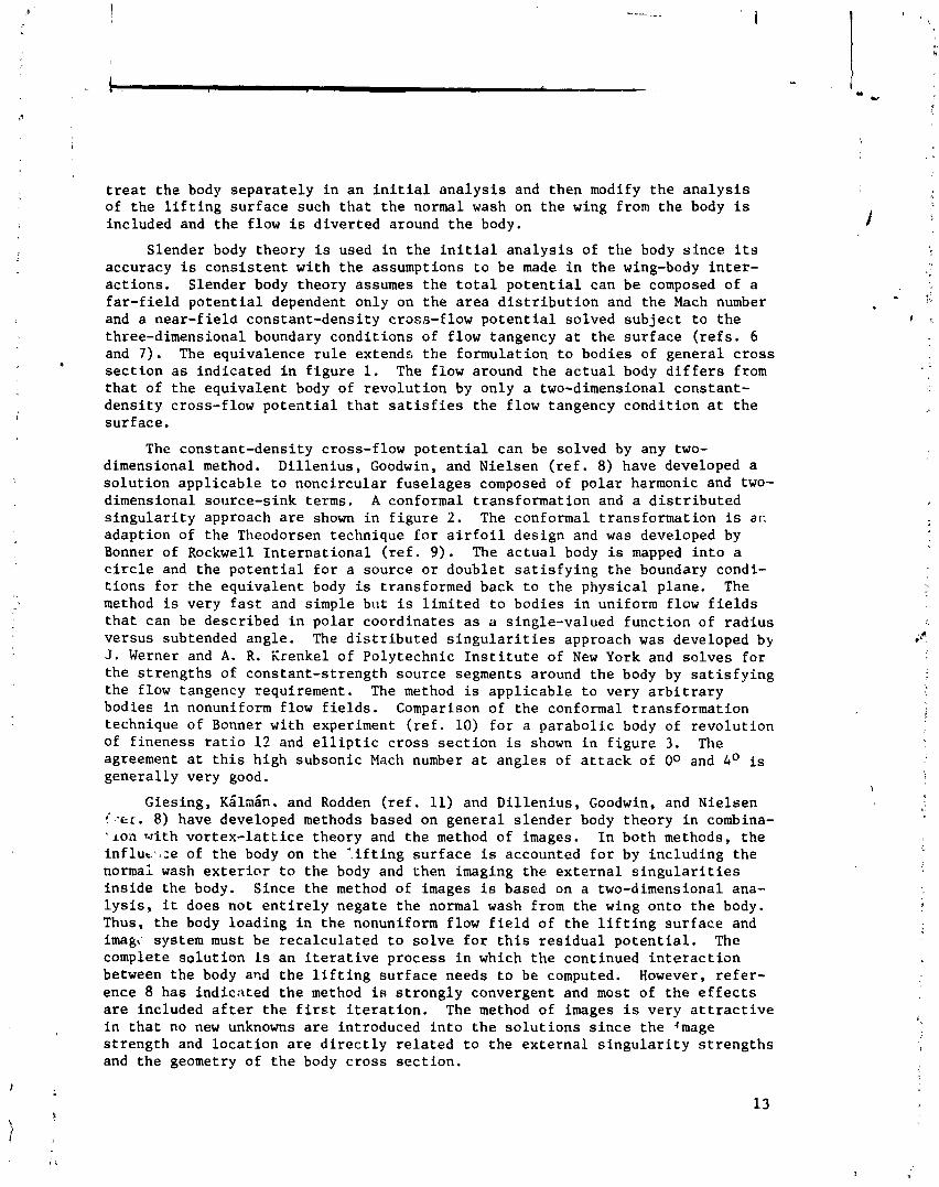
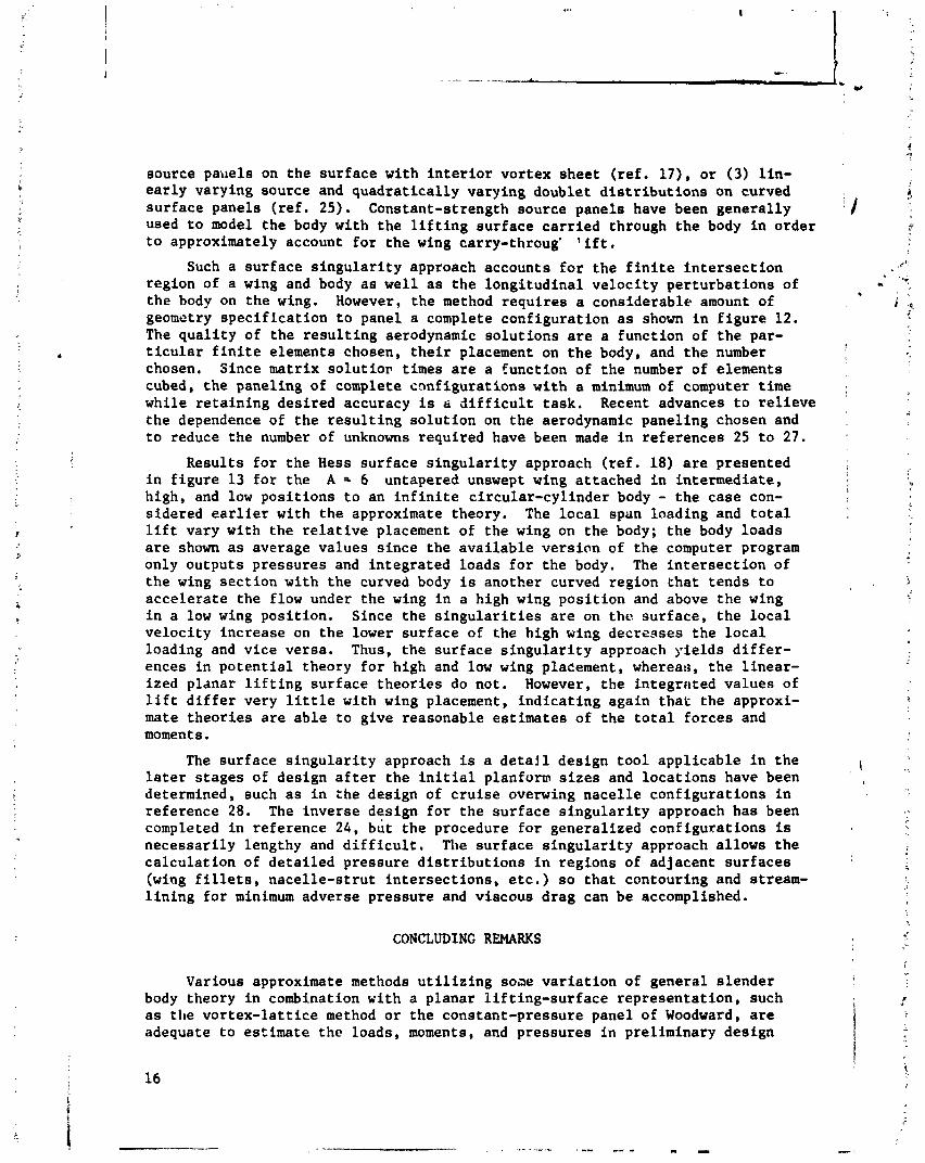
The constant-density cross-flow potential can be solved by any two- dimensional method. Dillenius, Goodwin, and Nielsen (ref. 8) have developed a solution applicable to noncircular fuselages composed of polar harmonic and two- dimensional source-sink terms. A conformal transformation and a distributed singularity approach are shown in figure 2. The conformal transformation is a c adaption of the Theodorsen technique for airfoil design and was developed by Bonner of Rockwell International (ref. 9). The actual body is mapped into a circle and the potential for a source or doublet satisfying the boundary condi- tions for the equivalent body is transformed back to the physical plane. The method is very fast and simple bat is limited to bodies in uniform flow fields that can be described in polar coordinates as a single-valued function of radius versus subtended angle. The distributed singularities approach was developed by J. Werner and A. R. Xrenkel of Polytechnic Institute of New York and solves for the strengths of constant-strength source segments around the body by satisfying the flow tangency requirement. The method is applicable to very arbitrary bodies in nonuniform flow fields. Comparison of the conformal transformation technique of Bonner with experiment (ref. 10) for a parabolic body of revolution of fineness ratio 12 and elliptic cross section is shown in figure 3. The agreement at this high subsonic Mach number at angles of attack of 00 and 4O is generally very good.
Giesing, ~Slahn. and Rodden (ref. 11) and Dillenius, Goodwin, and Nielsen ! ' . -er. 8) have developed methods based on general slender body theory in combina- 'Lon with vortex-latiice theory and the method of images. In both methods, the influt.ti:e of the body on the '.ifting surface is accounted for by including the normal wash exterior to the body and then imaging the external singularities inside the body. Since the method of images is based on a two-dimensional ana- lysis, it does not entirely negate the normal wash from the wing onto the body. Thus, the body loading in the nonuniform flow field of the lifting surface and ima&- system must be recalculated to solve for this residual potential. The complete solution is an iterative process in which the continued interaction between the body and the lifting surface needs to be computed. However, refer- ence 8 has indicated the method is strongly convergent and most of the effects are included after the first iteration. The method of images is very attractive in that no new unknowns are introduced into the solutions since the 'mag@ strength and location are directly related to the external singularity strengths and the geometry of the body cross section.
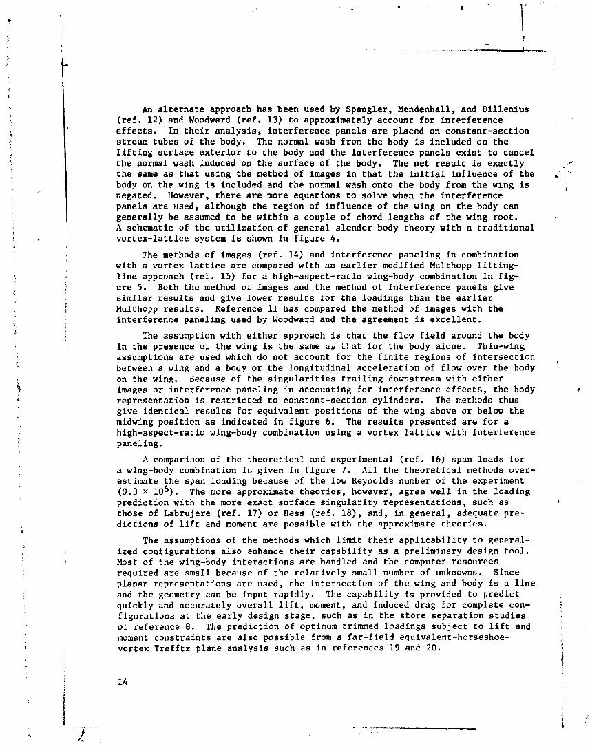
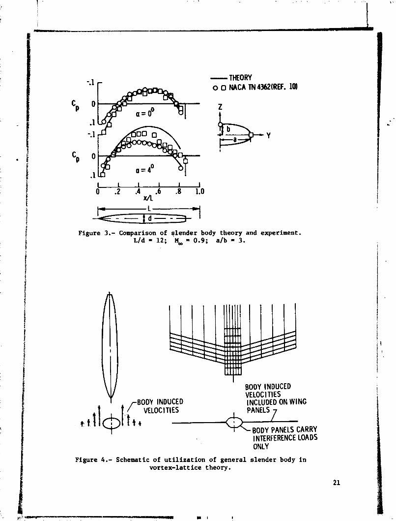
An alternate approach has been used by Spangler, Mendenhall, and Dillenius (ref. 12) and Woodward (ref. 13) to approximately account for interference effects. In their analysis, interference panels are placed on constant-section stream tubes of the body. The normal wash from the body is included on the lifting surface exterior to the body and the interference panels exist to cancel the normal wash induced on the surface of the body. The net result is exactly the same as that using the method of images in that the initial influence of the body on the wing is included and the normal wash onto the body from the wing is negated. However, there are more equations to solve when the interference panels are used, although the region of influence of the wing on the body can generally be assumed to be within a couple of chord lengths of the wing root. A schematic of the utilization of general slender body theory with a traditional vortex-lattice system is shown in figare 4.
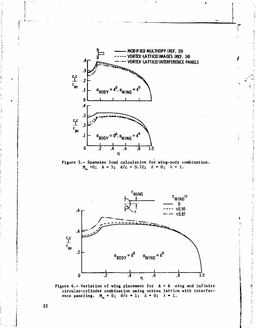
The methods of images (ref. 14) and interference paneling in combination with a vortex lattice are compared with an earlier modified Multhopp lifting- line approach (ref. 15) for a high-aspect-ratio wing-body combination in fig- ure 5. Both the method of images and the method of interference panels give similar results and give lower results for the loadings than the earlier Multhopp results. Reference 11 has compared the method of images with the interference paneling used by Woodward and the agreement is excellent.
The assumption with either approach is that the flow field around the body in the presence of the wing is the same as Lhat for the body alone. Thin-wing assumptions are used which do not account for the finite regions of intersection between a wing and a body or the longitudinal acceleration of flow over the body on the wing. Because of the singularities trailing downstream with either images or interference paneling in accounting for interference effects, the body representation is restricted to constant-section cylinders. The methods thus give identical results for equivalent positions of the wing above or below the midwing position as indicated in figure 6. The results presented are for a high-aspect-ratio wing-body combination using a vortex lattice with interference paneling.
A comparison of the theoretical and experimental (ref. 16) span loads for a wing-body combination is given in figure 7. All the theoretical methods over- estimate the span loading because of the low Reynolds number of the experiment (0.3 x lo6). The more approximate theories, however, agree well in the loading prediction with the more exact surface singularity representations, such as those of Labrujere (ref. 17) or Hess (ref. la), and, in general, adequate pre- dictions of lift and moment are possible with the approximate theories.
The assumptions of the methods which limit their applicability to general- ized configurations also enhance their capability as a preliminary design tool. Most of the wing-body interactions are handled and the computer resources required are small because of the relatively small number of unknowns. Since planar representations are used, the intersection of the wing and body is a line and the geometry can be input rapidly. The capability is provided to predict quickly and accurately overall lift, moment, and induced drag for complete con- figurations at the early design stage, such as in the store separation studies of reference 8. The prediction of optimum trimmed loadings subject to lift and moment constraints are also possible from a far-field equivalent-horseshoe- vortex Trefftz plane analysis such as in references 19 and 20.

QUADRILATERAL VORTEX AND SOURCE LATTICE SOLUTION
A method which computes the interfering flow fields of both wing and body simultaneously while still retaining the linearized boundary condition is that of Tulinius (ref. 21). The method distributes a series of constant-strength quadrilateral vortices over the surface of the body and in the region of the wing near the wing-body intersection region as shown in figure 8. Horseshoe vortices are used in regions of the wing away from the wing-body intersection region. A source lattice is distributed over the surface of the wing at the quarter-chord and three-quarter-chord of each panel, and the source strengths are defined as the local slopes of the thickness distribution independent of the wing lift. The influence of the quadrilateral vortex dies off rapidly at points away from the quadrilateral because of the canceling effects of adjccent sides. Hence, the panels can be extended over the fore and aft regions of the body. The analysis has Leen extended to predict thick wing and pylon-fuselage- fanpod-nacelle characteristics at subsonic speeds by placing the vortices along the mean camber line of the wing (ref. 22).
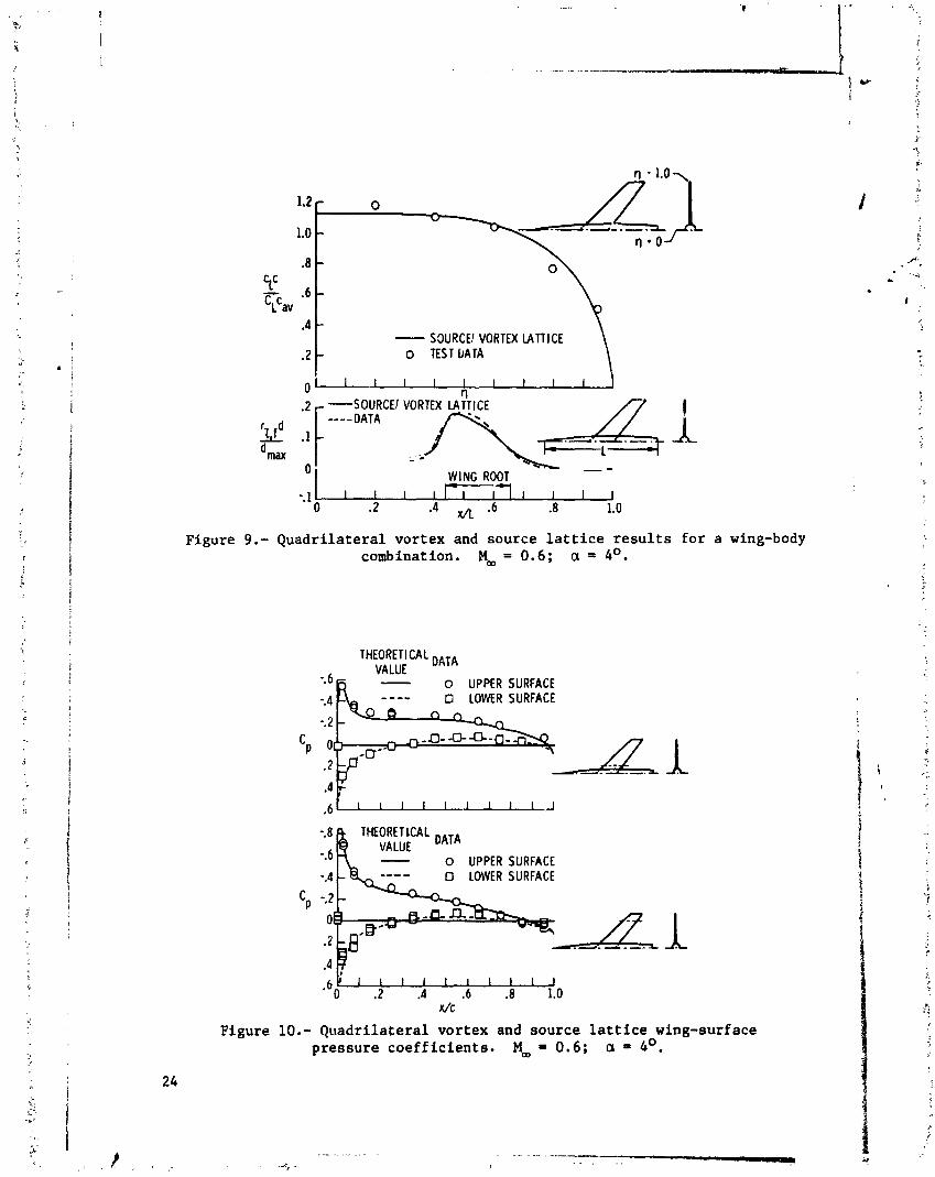
Results of the Tulinius wing-body program are compared with experiment in / figures 9, 10, and 11 for a swept wing-body combination at a Mach number of 0.60 i and an angle of attack of 4O. The unit span load c c/cLcaV and the longitudi-
1 nal distribution of fuselage lift c fd/dmax are predicted very well by the I 1 , !
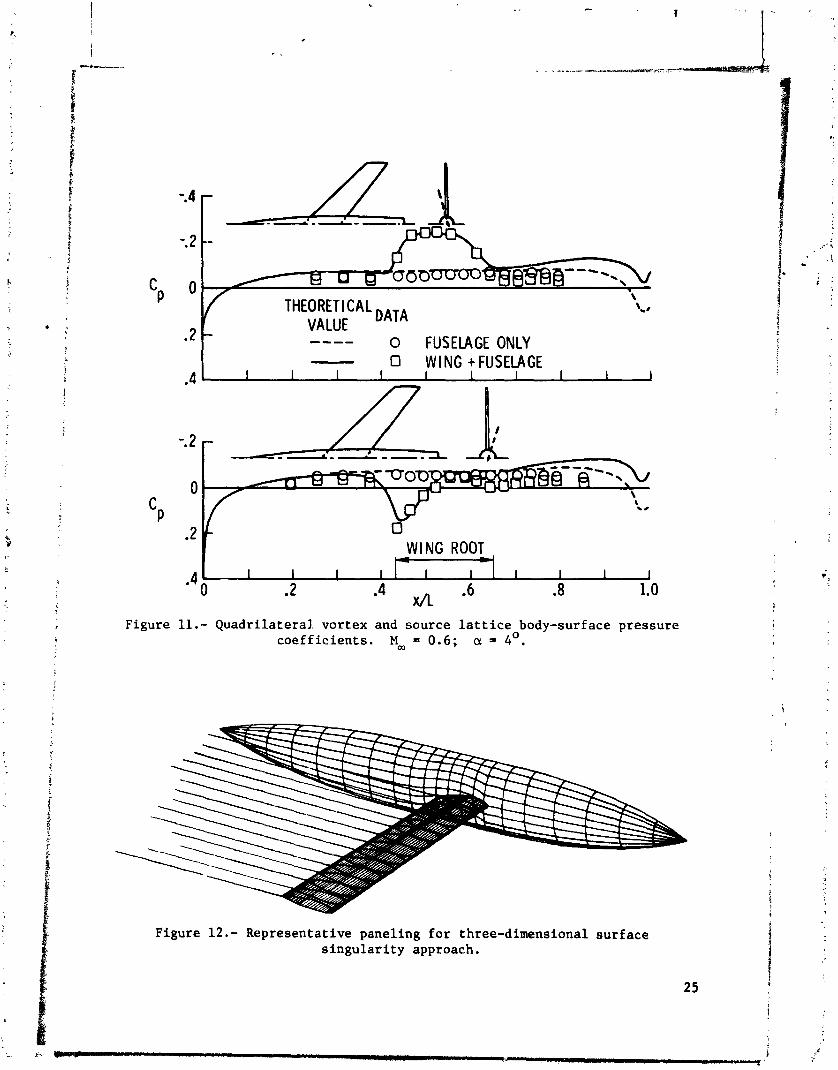
theory (fig. 9); the fuselage lift increases rapidly in the region of the wing root. The pressure coefficients on the wing at two spanwise stations in fig- ure 10 and the pressure coefficients on the body at longitudinal stations just above and below the wing in figure 11 are also predicted well. The body pres- Rures are influenced by the wing primarily in the wing root region, and the pressures over the aft end of the body are not predicted because of viscous and separation effects. The agreement with theory is expected since the wing is relatively thin and attached in the midwing position.
The method cannot account for the longitudinal acceleration of flow over 1 the body on the wing (speed bump effect) or equivalent high and low positions / of the wing because of the linearized planar boundary conditions. The pressure
coefficients and not just loadings are predicted so that streamlining and con- [ touring of adjacent surfaces at high subsonic Mach numbers can be accomplished. Regions of intersecting surfaces are lines so that geometry description is rela- tively easy. The number of equations to solve for the simultaneous quadrilateral and horseshoe vortex strength increases in comparison with the slender body and planar wing analyses but the quality of the aerodynamic solution is higher since the body and wing flow fields are solved simultaneously.
SURFACE SINGULARITY POTENTIAL FLOW
In order to account for the full potential interactions between the wing I and body, a surface singularity technique such as that in references 17, 18, 23,
24, or 25 must be used, In such a method, the eingularities are placed on the surface of the wing and body such that the tangency and Kutta conditions are satisfied. The type of finite-element modeling used for the lifting surfaces has been varied, including (1) constant-strength surface source panels with a constant-strength vortex sheet on the surface (ref. 18). (2) constant-strength
source pai~els on the surface with interior vortex sheet (ref. 17), or (3) lin- early varying source and quadratically varying doublet distributions on curved surface panels (ref. 25). Constant-strength source panels have been generally !
used to model the body with the lifting surface carried through the body in order to approximately account for the wing carry-throug' lift.
Such a surface singularity approach accounts for the finite intersection region of a wing and body as well as the longitudinal velocity perturbations of - the body on the wing. However, the method requires a considerable amount of geometry specification to panel a complete configuration as shown in figure 12. The quality of the resulting aerodynamic solutions are a function of the par- ticular finite elements chosen, their placement on the body, and the number chosen. Since matrix solutior times are a function of the number of elements cubed, the paneling of complete configurations with a minimum of computer time
! while retaining desired accuracy is a difficult task. Recent advances to relieve the dependence of the resulting solution on the aerodynamic paneling chosen and to reduce the number of unknowns required have been made in references 25 to 27.
Results for the Hess surface singularity approach (ref. 18) are presented in figure 13 for the A = 6 untapered unswept wing attached in intermediate, high, and low positions to an infinite circular-cylinder body - the case con- i
sidered earlier with the approximate theory. The local span loading and total lift vary with the relative placement of the wing on the body; the body loads are shown as average values since the available version of the computer program only outputs pressures and integrated loads for the body. The intersection of the wing section with the curved body is another curved region that tends to accelerate the flow under the wing in a high wing position and above the wing in a low wing position. Since the singularities are on tht? surface, the local velocity increase on the lower surface of the high wing decrcases the local loading and vice versa. Thus, the surface singularity approach yields differ- ences in potential theory for high and low wing placement, whereas, the linear- ized planar lifting surface theories do not. However, the integritted values of lift differ very little with wing placement, indicating again that the approxi- mate theories are able to give reasonable estimates of the total forces and moments .
The surface singularity approach is a detail design tool applicable in the , \
later stages of design after the initial planfom sizes and locations have been , determined, such as in :he design of cruise overwing nacelle configurations in reference 28. The inverse design for the surface singularity approach has been completed in reference 24, but the procedure for generalized configurations is necessarily lengthy and difficult. The surface singularity approach allows the calculation of detailed pressure distributions in regions of adjacent surfaces (wing fillets, nacelle-strut intersections, etc.) so that contouring and stream- lining for minimum adverse pressure and viscous drag can be accomplished.
CONCLUDING REMARKS
Various approximate methods utilizing sone variation of general slender body theory in combination with a planar lifting-surface representation, such as the vortex-lattice method or the constant-pressure panel of Woodward, are adequate to estimate the loads, moments, and pressures in preliminary design
! i I
16 1

applicatians. Such methods require limited computer resources and simple geometry input specifications and are well suited to inverse design p-ocedures since the number of unknowns are small and the planar boundary conditions arlz retained. The methods are most appl+cable to midwing cases with constant-amtion cylindrical bodies,
An extension of the voytex-lattice method to include a quadrilateral fortex representation of the body solves for the wing and body loads simultaneousl;~. No restrictions on body shape or wing shape in the intersection regions are u d s although the thin-wing representation is retained. Regions of intersecting sur- faces are curved lines and the geometry input remains relatively simple. With the method, pressures in regions of adjacent surfaces are predicted to allow contouring and streamlining, The method is also well suited to inverse design procedures for the wing in the presence of the body since the camber and thick- ness solutions are separate.
In order to accurately predict the correct potential flow pressures in areas of intersecting wings and bodies, a surface singularity approach is needed. The surface singularity approach removes all thin-wing and linearized-boundary- condition assumptions but more than doubles the number of unknowns to be solved and the geometry definition required. The detail pressure distributions in regions of intersecting surfaces are available so that adverse viscous effects can be minimized.
Viscous effects are not predicted in any of the methods. For the present, empirical or strip analyses must be used, such as in the prediction of viscous effects using an infinite yawed-wing analogy in two-dimensional strips along a swept wing. The usefulness of all the wing-body theories depend on how well the theoretical loadings or pressures can be related to the actual physical situa- tion. The nonlinear and viscous effects, such as vortex formation near the wing-body juncture or separated flow at higher angles of attack, remains untract- able computationally. The viscous calculation for generalized configurations across the Mach number range remains a far-term solution.

REFERENCES
1. Ashley, Holt; and Rodden, William P.: Wing-Body Aerodynamic Interaction. Annual Review of Fluid Mechanics, Vol. 4, M. Van Dyke, W, G. Vincenti, and J. V. Wehausen, eds., Annual Rev., Inc., 1972, pp. 431-472, .
2. Morgan, Harry L., Jr.: A Computer Program for the Analysis of Multieleaent Airfoils in Two-Dimensional Subsonic, Viscous Flow. Aerodynamic Analyses I
Requiring Advanced Computers, Part 11, NASA SP-347, 1975, pp. 713-7h7.
3. Garabedian, Paul R.: Computational Transonics. Aerodynamic Analyses Requiring Advanced Computers, Part 11, NASA SP-347, 1975, pp. 1269-1280.
4. Chapman, Dean R.; Mark, Hans; and Pirtle, Melvin W.: Computer vs. Wjnd Tunnels for Aerodynamic Flow Simulations. Astronaut. & Aeronaut., .:% . 13, no. 4, Apr. 1975, pp. 22-35.
5. Bailey, F. R.; and Ballhaus, W. F.: Comparisons of Computed and Expt. tal Pressures for Transonic Flows About Isolated Wings and Wing-Fuselage Configurations. Aerodynamic Analyses Requiring Advanced Computers, Part 11, NASA SP-347, 1975, pp. 1213-1231.
6. Adams, Mac C.; and Sears, W. R.: Slender Body Theory - Review and Extension. J. Aeronaut. Sci., vol. 20, no. 2, Feb. 1953, pp. 85-98.
7. Ashley, Holt; and Landahl, Marten: Aerodynamics of Wings and Bodies. Addison-Wesley Pub. Co., Inc., c.1965.
8. Dillenius, Marnix F. E.; Goodwin, Frederick K.; and Nielsen, Jack N.: Analytical Prediction of Store Separation Characteristics From Subsonic Aircraft. J. Aircr., vol. 12, no. 10, Oct. 1975, pp. 812-818.
9. Bonner, E.: Theoretical Prediction of Inviscid Three Dimensional Slender Body Flows. Report No. NA-74-687, Los Angeles Aircraft Div., Rockwel; International Corp., 1974.
10. McDevitt, John B; and Taylor, Robert A.: Force and Pressure Measurements at Transonic Speeds for Several Bodies Having Elliptical Cross Sections. NACA TN 4362, 1958.
11. Giesing, J. P. ; ~iilmin, T. P. ; and Rodden, W. P. : Subsonic Steady and Oscillatory Aerodynamics for Multiple Interfering Wings and Bodies. J. Aircr., vol. 9, no. 10, Oct. 1972, pp. 693-702.
12. Spangler, S. B.; Mendenhall, M. R.; and Dillenius, M. F. E.: Theoretical Investigation of Ducted Fan Interference for Transport-Type Aircraft. Analytic Methods in Aircraft Aerodynamics, NASA SP-228, 1970, pp. 703-719.
13. Woodward, Frank A.: Analysis and Design of Wing-Body Combinations at Sub- sonic and Supersonic Speeds. J. Aircr., vol. 5, no. 6, Nov.-Dec. 1968, pp. 528-534.
14. Giesing, Joseph P.: Lifting Surface Theory for Wing-Fuselage Combinations. Rep. PAC-67212, Vol. I, McDonnell Douglas, Aug. 1, 1.968.
15. Weber, J.; Kirby, D. A.; and Kettle, D. J.: An Exter~sion of Mult'lopp's Method of Calculating the Spanwise Loading of Wing-Fuselage Combinations. R. & M. No. 2872, British A.R.C., 1956.

16. ~Srner, H.: Unterouchungen zur Bestimmung der Druckverteilung a,.. ~lcgel- Rumpf-Kombinationen - Teil I: MeBergebnisse fcr Mitteldeckeranordnung aus dem 1,3 m-Windkanal. DFVLB-Ber. Nr. 0562, 1969.
Labrujere, Th. E.; Loeve, W.; and Slooff, J. W.: An Approximate Method for the Calculation of the Pressure Distribution on Wing-Body Combinations at Subcritical Speeds. Aerodynamic Interference, AGARD CP No. 71, Jan. 1971, pp. 11-1 - 11-15.
Hess, John L.: Calculation of Potential Flow About Arbitrary Three- Dimensional Lifting Bodies. Rep. No. MDC 55679-01 (Contract NOC019-71-C-0524), McDonnell Douglas rorp., Oct. 1972.
Paulson, John W.: Applications of Vortex-Lattice Theory to Preliminary Aerodynamic Design. Vortex-Lattice Utilization, NASA SP-405, 1976. (Paper no. 7 of this compilation.)
Tulinius, J. R.; and Nas.gason, Richard J.: Aircraft Aerodynamic Design and Evaluation Methods. AIAA Paper No. 76-15, Jan. 1976.
Tulinius, J.: Theoretical Prediction of Wing-Fuselage Aerodynamic Ch ac- teristics at Subsonic Speeds. Rep. No. NA-69-789, Los Angeles Div., North American Rockwell Corp., 1969.
Tulinius, J. R.: Theoretical Prediction of Thick Wing and Pylon-Fuselage- Fanpod-Nacelle Aerodynamic Characteristics at Subcritical Speeds - Part I: Theory and Results. NASA CR-137578, 1974.
Woodward, F. A.; Dvorak, F. A.; and Geller, E. W.: A Computer Program for Three-Dimensional Lifting Bodies in Subsonic Inviscid Flow. Rep. No. USAAMRDL-TR-74-18, U.S. Army, Apr. 1954. (Available from DDC as AD 782 202.)
Chen, Lee-Tzong, Suciu, Emil 0.; and Morino, Luigi: A Finite Element Method for Potential Aerodynamics Around Complex Co~~figurations. AIAA Paper No. 74-107, Jan.-Feb. 1974.
Ehlers, F. Edward; Johnson, Forrester T.; and Rubbert, Paul E.: Advanced Panel-Type Influence Coefficient Methods Applied to Subsonic and Super- sonic Flows. Aerodynamic Analyses Requiring Advanced Computers, Part 11, NASA SP-347, 1975, pp. 939-984.
Hess, John L.: The Use oc Higher-Order Surface Singularity Distributions to Obtain Improved Potential Flow Solutions for Two-Dimensional Lifting Air- foils. Comput. Methods Appl. Mech. & Eng., vol. 5, no. 1, Jan. 1975, pp. 11-35.
3ristow. D. R.: A New Surface Singularity Approach for Multi-Element Air- foil Analysis and Design. AIAA Paper ho. 76-20, Jan. 1976.
Mohn, L. W.: Comparison of Yind-Tunnel Test Results at Mm = 0.7 With Results Frcm the Boeing TEA-230 Subsonic Flow Method. NASA CR-2554, 1975.

FLOW FIELD AT ANY POINT DUE TO AN ARBITRARY BODY I S GIVEN BY 3 I
EQU I VALENCE RULE:
FLOW FIELD DUE = SOLUTION FOR t 2-0 - 2-0 TO ACTUAL BODY EQU I VALENT BODY SOLUTION SOLUTION
OF REVOLUTION FOR ACTUAL FOR BODY CROSS - EQUIVALENT SECTION A-A CROSS-
SECTION A-A
3-D BOUNDARY CONDITIONS ARE SATISFIED I N THESE 2-D SOlUTIONS
Figure 1.- General slender body theory.
CONFORMAL TRANSFORMATION DISTRIBUTED SINGUIARITIES
Figure 2.- Methods for solving two-dimensional cross-flow potential for arbitrary cross sections.
- THEORY 0 0 NACA TN 4MZ(REF. 10)
Figure 3.- Comparison of slender body theory and experiment. L/d = 12; M,,, = 0.9; a/b = 3.
INCLUDED ON WING
BODY PANELS CARRY l NTERFERENCE LOADS ONLY
Figure 4.- Schematic of u t i l i za t ion of general slender body i n vortex-lattice theory.
- MOD IF IED MULTHOPP (REF. 15.1 - - - -- VORTEX -lATTICU IMAGES (REF. 14) 'A ----__ - .-- "INTERFER"" PANELS
.3
.2
rl
Figure 5.- Spanwise load calculation for wing-body combination. MW =0; A = 5; d/c = 0.72; A = 0; A = 1.
Figure 6.- Variation of wing placement for A = 6 wing and infinite circular-cylinder combination using vortex lattice with interfer- ence paneling. Ma = 0; d/c = 1; A = 0; X = 1.
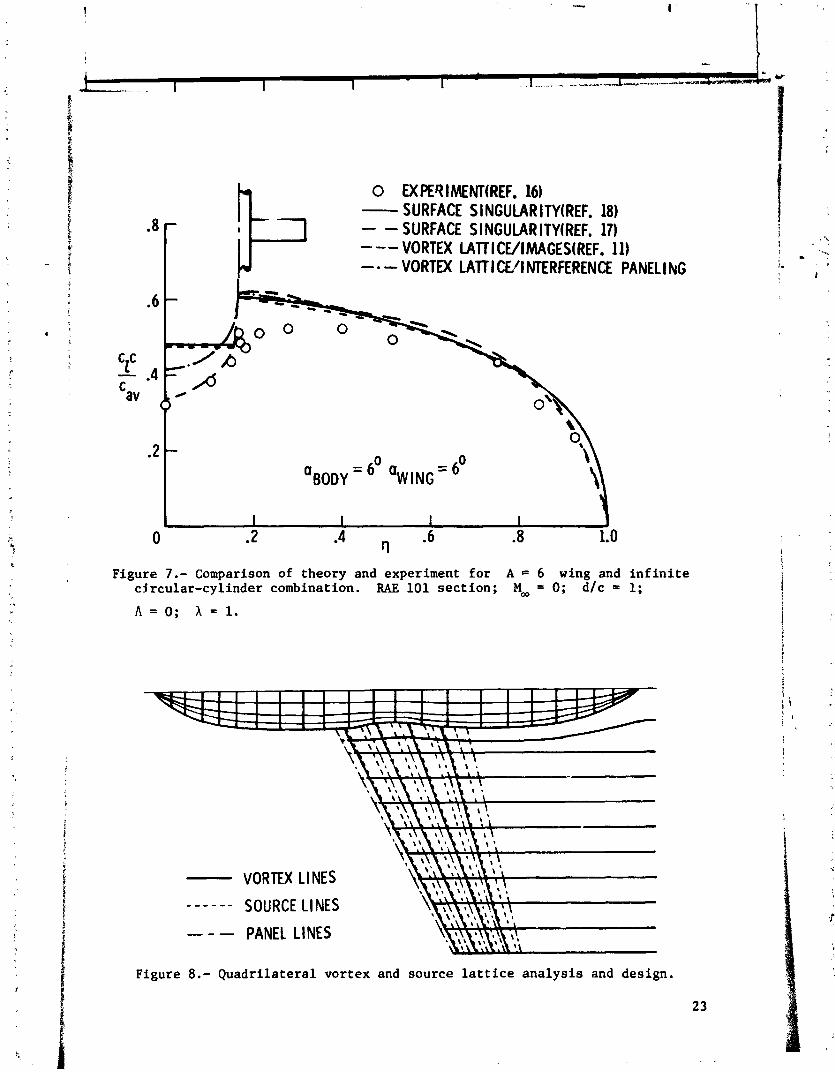
0 EX PER I MENUREF. 16) - SURFACE S I NCUlAR ITWREF. 18) - - SURFACE SINGULARITY(REF. 17) --- VORTEX LATT I C V I MACES(REF. 11) - - VORTEX LATTl CL/I NTERFERENCE PANEL1 NG
Figure 7.- Comparison of theory and experiment for A = 6 wing and infinite cjrcular-cylinder combination. RAE 101 section; Moo = 0; dlc = 1;
A = O ; X = l .
- VORTEX LINES
- - - - - - SOURCE LINES - - - PANEL LINES
Figure 8.- Quadrilateral vortex and source lattice analysis and design.
2 3
- S3URCEI VQRTEX LATTICE o TESTBATA
-;:IcE' vO;K-<& 1 WING ROOT
' - - I I I l r I I l l I I I
0 .2 .4 a .6 .8 1.0
Figure 9.- Quadrilateral vortex and source lattice results for a wing-body combination. M, = 0.6; a = 4O.
THEORETICAL DATA VALUE
- . b g - 0 UPPER SURFACE
-.4 LOWER SURFACE
-. 2
C~ 0 .2
.4
8 T H E M L C A L
-.6 - 0 UPPER SURFACE 0 LOWER SURFACE
I
Figure 10.- Quadrilateral vortex and source lattice wing-surface pressure coefficients. Mm = 0.6; a = 4'.
THEORETI CAL DATA VALUE . ---- 0 FUSELAGE ONLY
I - 0 W l NG + FUSELAGE
U
W I N G ROOT - Figure 11.- Quadrilateral. vortex and source lattice body-surface pressure
coefficients. Ma = 0.6; a = 4'.
Figure 12.- Representative paneling for three-dimensional surface singularity approach.

Figure 13.- Variation of wing placement for A = 6 wing and infinite circular-cylinder combination using Hess surface singularity approach (ref. 18). RAE 101 section (thickness - 0.09~) ; no = 0; d/c - 1; h = 0; X = 1.
MTEM)ED APPLICATIONS OF THE VORTM LATTICE MElHCID 7 1
L u i s R. Miranda Lockheed-California Company
.: - i s- %
1 .
The application of the vortex l a t t i c e method t o problem not ueually dealt with by t h i s technique is considered. It is shown t h a t if the dis- crete vortex l a t t i c e is considered as en approximation to surface-dia- tr ibuted vor t ic i ty , then the concept of the generalized principal pa r t I
of an in tegral yields a residual term to the vortex-induced velocity that renders the vortex l a t t i c e method v d i d fo r supersonic flow, Special schemes fo r simulating non-zero thickness l i f t i n g surfaces and fusiform bodies with vortex l a t t i c e elements a re presented. Thickness e f fec t s of wing-like components are simulated by a double vortex l a t t i c e layer, end fusiform bodies are represented by a vortex g r id arranged on a ser ies of concentrical cylindrical surfaces. Numerical consideratiom peculiaz t o the application of these techniques a re b r i e f l y discussed.
INTRODUCTION
The several versions or variations of the vortex l a t t i c e method t ha t a r e presently available have proven t o be very pract ica l and versa t i l e theoretical tools for the aerodynamic a ~ a l y s i s and design of planar and non- planar configurations. The success of the method is due i n great pa r t t o the re la t ive simplicity of the numerical techniques involved, and t o the high accuracy, within the limitations of the basic theory, of the resu l t s obtained. But most of the work on vortex l a t t i c e methods appears t o have concentrated on subsonic flow application. The appl icabi l i ty of the basic techniques of vortex l a t t i c e theory t o supersonic flow has been largely ignored. It is one of the objectives of t h i s paper t o show how the vortex l a t t i c e method can be eas i ly extended t o deal with problems a t supersonic Mach numbers wi th the same degree of success t ha t it enjoys in subsonic flow.
The other objective of t h i s paper is t o discuss a couple of schemes by which it is possible t o simulate thickness and volume e f fec t s by using
1 vortex l a t t i c e elements only. This represents an a l ternat ive , with somewhat reduced computational requirements, t o the methd of quadrilateral vortex rings (refs . 1 and 2). The simulation of thickness and volume e f fec t s mker possible the computation of the surface pressure dis t r ibut ion on wu-body configurations. The fac t t ha t t h i s can be done without having t o resor t t o additional types of s ingular i t ies , such as sources, r esu l t s in a simpler
i d ig i t a l computer code. ! c
:r J 1 f
i

mE BASIC EQUATIONS
Ward has shown, ( r e f . 3 ) , tha t the small-perturbation, l inearized flow of an inviscid compressible f lu id i s governed by the three first order vector equations :
V < T = T , V. 'i3 = Q, 'i3=\k.T ( 1 )
on the assumption tha t the vor t i c i ty r a n d the source in tens i ty Q are known .functions of the point whose position vector is R. The vector 7 is the perturbation velocity with orthogonal a r t e s i a n components u, v, and w, and 9 is a constant symmetrical tensor tha t for orthogonal cartesian coordinates
with the x-axis aligned with the freestream direct ion has the form
-
1 ( 2 )
0 01 1
2 where M, is the freestream Mach number. If 8 = l - M a , then the vector Ti has t h e components w = p2 u T + v J + w x. This vector was first introduced by Robinson ( r e f . 4 ) , who cal led it the "reduced current velocity". If - denotes the t o t a l velocity vector, i , e . , u = (u, + u) -i + v j + w x, and p the f lu id density, then it can be shown t h a t fo r i r ro ta t iona l and hornentropic flow -
P 5 = P, U, + Pa 23 + higher order t e r m ( 3 )
where - the subscript - indicates the value of the quantity a t upstream in f in i ty , e.g., = ud5 i. Therefore, t o a l inear approximation, the vector T i i s
d i rec t ly re la ted t o the perturbation mass flux a s follows:
The second equation of (1) ,. i.e., t he continuity condition, shows tha t for source-free flows (Q = 0) , w is a conserved quantity.
Ward has integrated the three f i r s t order vector equation^ d i rec t ly without having t o resor t t o an auxi l iary potent ia l function. He obtained two di f ferent solutions for 7 (E) , depending on whether 82 i s posi t ive ( sub- sonic flow), or negative (supersonic flow). These two solutions can be com- bined formally in to u single
K = 2 for ) 2
K = 1 for id RI - Real pa r t
expression i f the following convention is used:

f = F i n i t e part of i n t e g r a l a s define! and 6).
d by Hadamard ( r e f s . 5
The resu l t ing so lu t ion for - t he perturbat ion ve loc l ty 7 a t the point whose pos i t ion vector i s = xl i + y J + z 1, i s given by 1 1
This formula determines the value of 'iT within the region V bounded by the surface S. The vector fi: i s the u n i t outward (from the region V) normal t o t he surface S. Furthermore, it is understood t h a t f o r supersonic flow only those pa r t s of V azd S lying within the domain of dependence (Mach forecone) of t he point R a r e t o be included i n t he integrat ion. 1
For source-fYee (Q=o), i r r o t a t i o n a l (;SO) flow, equation ( 5 ) reduces t o
This is a r e l a t i o n between 7 inside S and the values of x,w and K 7 on S, b u t t h e s a two quan t i t i e s cannot be spec i f ied independently on S.
To determine the source-free, i r r o t a t i o n a l flow about an a r b i t r a r y bvdy B by mean8 of equation ( 6 ) , assume t h a t t he surface S coincides with the wetted surface of the body, with tiny t r a i l i n g wake t h a t it may have, and with a sphere of i n f i n i t e radius enclosing the body and the whole flow f i e l d about it, namely, S = SB + E$ + S .
m
This surface S divides t he apace i n t o two regions, Ve ex te rna l t o t h e body, and V i i n t e rna l t o it. Applying equation ( 6 ) t o both Ve and V i , s ince the in t eg ra l s over S, converge t o zerc , t he following expression is obtained:

where a - iii- -& is the un i t normal t o the body, or wake as the case may be, positive from the in te r io r t o the exterior of the body, A 5f qe - Ti, and A V = Ve - 31. Here the subscripts desdgmte the mlues of the quanti t ies on the corresponding a c e of S, The first eurface in tegral can be considered as representing the contribution of a source dis t r ibut ion of surface density a . A V, while the second surface in tegral gives the contribution of a vor t i - c i t y d is t r ibut ion of ourface density x A V.
If the boundary condition of zero mass f lux thraugh the surface SB + SW is applied t o both external and in ternal flows
then the condition f , A i7 = 0 exis ts over SB + %, ant3 the flow f i e l d is uniquely determined by
MTJDJSION TO SUPERSONIC FLOW
In order t o extend the application of the vortex l a t t i c e method t o supersonic flow, it is essent ia l t o consider the fbndamental element of the method, the vortex filament, a s a nur?r ica l approximation scheme t o the integral expreeal.cn (9) instead of a r e a l physical ent i ty . The velocity f i e l d generated by a vortex filament can be obtained by a straightforward limiting procees, the resu l t being

8 is a dimension norm1 to y, and d l is the dfstcrnce element along ye In the c lars ical vortex l a t t i c e method, applicable only t o subsonic flow, the vorti- c i t y distribution w e r the body and the wake, i.e., w a r the rurfkce SB + %, i r replaced by a suitable arrangement of vortex filaments whose velocity f ie lds are everywhere determined by equation (10). This procedure i s no longer appropriate for su erronic flow. For t h i s l a t t e r case, it is nccesrary t o go back t o equation (9 and t o derive an approxinnrtion to it. 'Phi8 is done in fhe following.
I I f the surface SB + &, which defines the body and its wake, is conridered
a8 being compared of a large number of discrete f l a t area elements r w e r which the surfhce vort ic i ty density can be assumed apgroximrtely constant, then equation ( 9 ) can be approxinnted by the following equation:
where N is the t o t a l number of discrete area elements 7 . When the poinl whoee position vector is R l is not part of 75, the integral orer t h i s die- crete area can be approximated by the mean value theorem a8 fcllows:
R-R1 f y j x a a = y J b J X d l ( 12) b
where CJ i s a l ine in r j p r a l l e l t o the a k a g * direction of 7 i n IJ, 47 is a distance norm1 t o CJ, and d l is the arc length element along C j . This means t?mt the velocity f ie ld induced by a discrete vortici ty pstch 75 can be appoximsted for point8 outride of 7 J by erne mean discrete vortex l i ne who-,; strength per unit length is y~ b. But i f the point xl is part of the divc:,ete area 7 , the integral in equation (11) has sm inherent r ingulsri ty of the Cauchy type due t o the isct that = a t some point within T . In order t o evaluate the integral expression for t h i s case, consider a point close t o & but located jut abwe T by a distance e. A s indicated in figure 1, the area of integration in 7 is divided into two regions, A - , and A,. Obviaurly, the integr8l over A,, ha8 no Cauchy-type singularity , Hadamrd'e fi ni te part concept being euff icient t o perform the indicated integration. Thus,
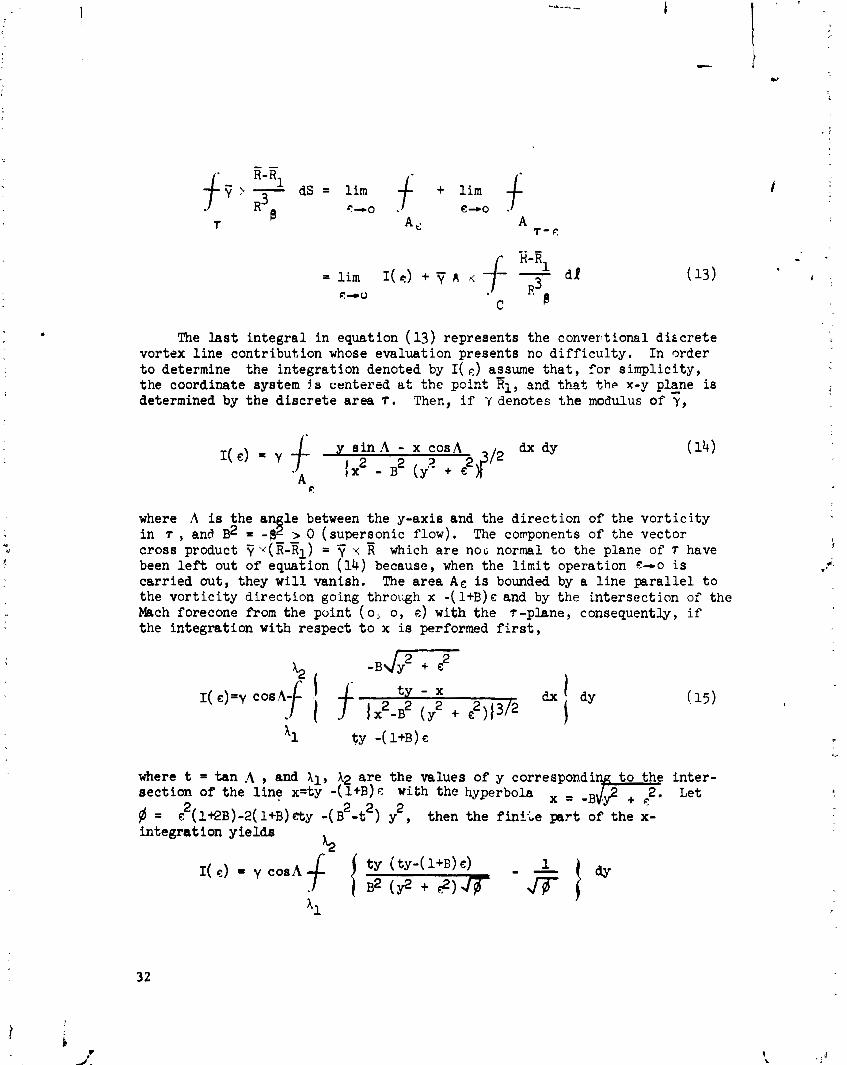
The l a s t i n t e g r a l i n equation ( 13) represents the converlt ional d ikcre te vortex l i n e contr ibut ion whose evaluation presents no d i f f i c u l t y . In order t o determine the in tegra t ion denoted by I( c ) assume t h a t , f o r s impl ic i ty , the coordinate system !s centered tit the p i n t Ei, snd thst t h e x-y plane i s determined by t h e d i s c r e t e a rea T . Ther,, i f Y denotes t h e modulus of y,
Y s i n A ; x :OS .A~$ /~ b a y
A {X2 - B (y'- + E
C:
where A is the an l e between the y-axis and the d i r ec t ion of the v o r t i c i t y i n r , and B2 = -89 I 0 (supersonic flow). The conponents of the vector cross product u(R-Rl) = x which a r e no(; normal t o the plane of 7 have been l e f t out of equation (14) because, when the l i m i t operation c-o is car r ied out , they w i l l vanish. The a rea A € i s bounded by a l i n e p a r a l l e l t o the v o r t i c i t y d i r ec t ion going through x - ( ~ + B ) c and by the in te rsec t ion of t h e Mach forecone from the point ( 0 ; o, e) with t h e ?-plane, consequently, i f t he in tegra t ion with respect t o x is performed f i r s t ,
where t = t a n A , and 11, 12 a r e t h e values of y correspondi t o the i n t e r - sec t ion of t he l i n e x=ty -(l+B) c with the hyperbola . , -B ,$ +
2 2 3 7 . Let
fl = 8(1+2~)-2(1+B)&y - (B -t ) y2, then the f in iLe s r t of t h e x- in tegra t ion y i e l d s
X2

Since c is a E r y small quantity, the variation of y in the interval (11, Q) is going t o be equally small, ma, therefore, the quantity within brackets i n the last integrand of equation (16) can be replaced by a mean value and taken outside of the integral sign. The same is not true of the term 1/& since it w i l l vary from oo for y = 11, go through f i n i t e values in the integration interval, and then again increase t o m for y = b. With t h i s in mind, and i f #.I y denotes a mean value of y, I( c) can be written a s
L
5 J2, i i.. , they a r e the roots of But 11, are the roots of ty-c = -B y
the polynmial denoted by 8. Thus
Introducing t h i s expression for ./-$-into (IT), and taking the limit E-0, the following value for I( c) is obtained:
The integral appearing i n equation ( 19) can be eas i ly evaluated by com- plex variable methods; i t s value i s found t o be

The c o n t r i h t i m of the inherent 8ingulrsity t o the tnlocity f ie ld induced by vorticity prtch 7, within?, denoted herein by #, irr therefore givun by
mi8 contrftnation i n perpendicular t o the pllne of 7, ud it bar am3y mica1 moaning when # > @, i.e., when the vortex liner . re mpt in iront of the h c h lineu. It is up~re88ion (21), taken in conjunction with ~ t i a (12), tbt makcs the vortex l a t t i ce method applicable t o s~perroaric now.
The method of quadrilateral vortex ring8 placed on the actual body sur- face (ref. 1 ) provides a way of computing the 8urface persure distribution of arbitrary bodies using discrete vortex line8 only. lOurmericaldifficultie8 m y occur when the above method is applied t o the analysis of a i r fo i l s w i t h 8 h - p t rai l ing edges due t o the close proximity of two vortex surfaces of nearly parallel direct ion. An alternative approach, requiring somewhat leu8 complter storage and easier t o handle numerically, consiets in using a double, or biplaasr, aheet of swept horseshoe vortices t o modela l i f t ing surface w i t h thickness, as shown schematically in figure 2. This constitutes an approxinnticm t o the true location of the s inguhr i t ies , similar in nature t o the classical lifting surface theory approximtion of a cambered sheet.
A l l . the swept horseshoe vortices, and their boundary condition control points, corresponding t o a given surface, upper or lower, a re located in a ssme plane. The upper and lower surface la t t ice planes are separated by a gap which represents the chordwise average of the a i r f o i l thickness d is t r i - bution. The results a re not too sensitive t o the magnitude of th is gap; any value between one h a l f t o the Pull maximum chordwise thickness of the a i r f o i l has been found t o be adequate, the preferred value being two thirds of the maximum thickness. Furthermore, the gap can vary in the direction normal t o the x-axis t o allow for spenwise thicknese taper. On the other hand, the chordwise distribution, or spscing, of the tramverse elements of the horse- shoe vortices have a significant influence on the accuracy o i t h e computed surfsce pressure die tribut ion. For greater accuracy, for a given chordwise number of horseshoe vortices, the transverse legs have t o be longitudinally
1 spaced according t o the 'cosine' distribution law
v *ere XJ - x represents the distance from the leading edge t o the midpoint of the swept yeg of the J th horseshoe vortex, c is the length of the local chord running through the midpoint8 of a given chordwise s t r ip , and rJ is the number of horseehoe vortices per s t r ip . The chordwine control point location
corresponding t o t h i s d is t r ibut ion of vortex elements is given by
The control points a re located along the centerl .na, or midpoint l i n e , of the chordwise s t r i p ( f ig . 3) . Ian has shown ( r e f . 7) t h a t the chordwise 'cosine' collocation of the l a t t i c e elements, defined by equations (22) and (23), grea t ly improve the accuracy of the computation of the ef fec ts due t o l i f t . H i s r e su l t s a re d i rec t ly extendable t o the computation of surface pressure distr ibutions of wings with thickness by the 'biplanar ' l a t t i c e scheme pre- sented herein.
The small perturbation boundary condition
is applied a t the control points. I n equation (24), fi = 11 + I$ + n1, and E' = knj + &, where 1, m, and n a r e the d i rec t ion cosines of the normal t o the ac tual a i r f o i l surface. Equation (24) implies tha t I l u 1 << I mv + nw I . The use of the smll perturbation boundary condition is consis ;ent with the present 'biplanar' approach t o the simulation of th ick wings.
MODELING OF mTSIF0R.M BODIES
The modeling of f'usiform bodies with horseshoe vort ices requires a special concentrical vortex l a t t i c e i f the simulation of the volume displace- ment ef fec ts , and the computation of the surface pressure d is t r ibut ion, a re t o be carried out. To define t h i s l a t t i c e , it is necessary t o consider f i r s t an auxil iary body, ident ica l i n cross-sectional shape and longitudinal area d is t r ibut ion t o the ac tual body, with a s t r a igh t barycentric l ine , i .e. , without camber. The cross-sectional shape of t h i s auxi l iary body i s then approximated by a polygm whose sides determine the transverse legs of the horseshoe vortices. The ver t ices of the polygon and the ax i s of the auxi l iary body (which by def in i t ion i s r ec t i l inea r (zero camber) and in ternal t o a l l possible cross sections of the body) define a s e t of r ad ia l planes in which the bound t r a i l i n g legs of the horseshoe vort ices l i e pa ra l l e l t o the ax i s ( f i g . 4). As the body cross section changes shape along its length, the corresponding polygon is allowed t o change accordingly, but with the constraint tha t the polygonal ver t ices must always l i e i n the same s e t of r ad ia l planes. The a x i a l spacing of the cross-sectional planes tha t determine the transverse vorl;ex elements, or polygonal r ings, follows the 'cosine ' law of equation (22). The boundary condition control points are located on the auxi l iary body sur- face, and in the bisector r ad ia l planes, with t h e i r longitudinal spacing given by equation (23).
The boundary condition t o be sa t i s f i ed a t these control points is the zero mass f lux equation
- 2 where a l l the components of the scalar product 7 . n = @ ! u + mv + nw a re t o be retained. Thus, equation (25) is a higher order condition than equation (24). The use of t h i s higher order boundary condition, within the framework of a linearized theory, is not mathematically consistent. There- fore, it can only be jus t i f ied by its resu l t s rather than by a s t r i c t mrthe- matical derivation. In the present treatment of msiform bodies, it has been found that the use of higher order, or 'exact' boundary conditions is a re- quis i te for the accurate determination of the surface pressure distr ibution.
The f a c t that the vector F, instead of T, appears in the l e f t hand member of equation (25) requires some elaboration. F i r s t , it should be pointed out - - - that for small perturbations F . n r v . n'. Furthermore, for incompressible flow ( @ = l ) , the vector i;j i s identical t o the perturbation velocity T. Con- sequently, the boundary condition equation (24) i s consistent with the con- t inu i ty equation, V. ? = 0, t o a f i r s t order f1,r compressible flow, and t o any higher order for incompressible flow, But when a higher order boundary con- d i t ion i s applied in compressible f low t o a l inearized solution, it should be remembered that t h i s solution s a t i s f i e s the conservation of 7, not of 7, i .e., V. w = 0. Thus, the higher order boundary condition should involve the
reduced current velocity, or perturbation mass f lux, vector T, as in equation (25), rather than the perturbation velocity vector 7.
The body camber, which was el.iminated in the definit ion of the auxil iary body, is taken into account i n the computation of the direction cosines l , m , and n, which a re implicit i n equation (25). Therefore, the e f fec t of camber is represented in the boundary condition but ignored i n the spa t i a l placement of the horseshoe elements. This scheme w i l l give a f a i r approximation t o cambered flisifom bodies provided that the amount of body camber i s not too large.
THE GENERALIZED VORTEX LATTICE METHOD
Description of Method
The three features discussed above, i.e., the inclusion of the vor t ic i ty- induced residual term w* for supersonic flow, the 'biplanar' scheme for rep- resenting thickness, and the use of a vortex grid of concentrical polygonal cylinders for the simulation of fusiform bodies, have been implemented i n a computational procedrrre herein known a s the Generalized Vortex Latt ice (GVL) method. The GVL method has been codified in a Fortran I V computer program ( VORIAX) , which has been widely u t i l i zed throughout the Lockhead-Calif ornia Company a s an e f f ic ien t aerodynamic design too l for advanced a i r c r a f t confi- gurations i n subsonic and supersonic flows.

5
The basic element of t he method is the swept horseshoe vortex with 'bound' and ' f r ee ' legs. I n t h e present version of the method, the f r e e l e g s may t ra i l t o downstream i n f i n i t y i n any a r b i t r a r y , but predetermined, d i rec- t ion. The l a t t i c e formed by the bound legs of t he horseshoe vo r t i ce s is l a i d out on the proper c y l i n d r i c a l surfaces, t he t r a i l i n g l egs being p a r a l l e l t o t he x-axis. Figure 5 i l l u s t r a t e s schematically t he representa t ion of a simple wing-body configuration within the context of t he present method. The streamwise arrangement of t he l a t t i c e follows t h e 'cosine' d i s t r i b u t i o n l a w (eq. (22)), whereas the spanwise, or cross-flow, spacing of the t r a i l i m l egs can be a r b i t r a r i l y specif ied. To each horseshoe vortex the re corresponds an . associated cont ro l po in t , placed midway between the bound t r a i l i n g i egs of t he horseshoe and longi tudina l ly spaced according t o equation (23) .
The veloc i ty f i e l d induced by t h e elementary horseshoe vortex is derived from equzfion (12), and it includes the contr ibut ion given by equation (21) when the ve loc i ty induced by a horseshoe a t i ts own cont ro l po in t is evaluated a t supersonic Mach numbers. This ve loc i ty f i e l d is used t o generate t he co- e f f i c i e n t s of a system of l i n e a r equations r e l a t i n g t h e unknown vortex s t rengths t o t he appropriate boundary condition a t t h e con t ro l points . This l i nea r system is solved by e i t h e r a Gauss-Seidel i t e r a t i v e procedure ( r e f . 8) , or by a vector orthogonalization technique ( r e f . 9 ) .
The pressure coe f f i c i en t s a r e computed i n terms of the per turba t ion veloci ty components. Force and moment c a e f f i c i e n t s a r e determined through a
i4 numerical in tegra t ion process. Due account is taken of t he leading edge suct ion through the appl ica t ion of Lan's procedure ( r e f . 7 ) , which the GVL method d i r e c t l y extends t o supersonic flow.
Nmer i c a l Considerations
A t supersonic Mach humbers, t h e ve loc i ty induced by a d i s c r e t e horseshoe vortex becomes very l a rge i n the very close proximity of the envelope of Mach cones generated by the t ransverse l e g of t he horseshoe. A t the c h a r a c t e r i s t i c envelcpe surface i t s e l f , the induced ve loc i ty co r r ec t ly vanishes, due t o t he f i n i t e p a r t concept. This s ingular behavior of t h e ve loc i ty f i e l d occurs only f o r f i e l d points of f the plane of t h e horseshoe, For t he planar case, the veloci ty f i e l d i s well behaved i n t he v i c i n i t y of the c h a r a c t e r i s t i c surface. A simple procedure t o t r e a t t h i s numerical s ingu la r i t y cons is t s of def ining the cha rac t e r i s t i c surfaces by the equation
where C i s a numerical constant whose value i s g rea t e r than, but c lose t o , 1. It has been found t h a t t h i s procedure y i e lds s a t i s f ac to ry r e s u l t s , and t h a t these r e s u l t s a r e qu i t e insens i t ive t o reasonable va r i a t i ons of the parameter C.
Another numerical problem, peculiar t o the supersonic horseshoe vortex, ex i s t s in the planar case ( f i e l d point in the plane of the horseshoe) when
/ the f i e l d point is close t o a transverse vortex leg swept exactly pa r a l l e l t o the Mach l ines (sonic vortex), while the vortex l ines immediately i n front of and behind t h i s sonic vortex a re subsonic and supersonic, respectively.
.. . , ..
This problem can be handled by replacing the boundar; condition equation fo r .. such sonic vortex with the averaging equation i
where y1* is the circulatior. strength of the c r i t i c a l horseshoe vortex, and
'1*-1 and y ~ + ~ are the respective circulat ion values fo r the fore-and-aft adjacent subsonfc and supersonic vortices.
The axialwash induced velocity component (u) i s needed for the computa- t ion of the surface pressure dis t r ibut ion, and for the formulation of the boundary condition for fusiform bodies. When the f i e l d point i s not too close t o the generating vor t i c i ty element, the axialwash is adequately des- cribed by the conventional d iscre te horseshoe vortex representation. But i f t h i s point is in the close v ic in i ty of the generating element, as may occur i n the biplanar and in the concentrical cylindrical l a t t i c e s of the present method, the er ror in the computation of the axialwash due t o the discret iza- t ion of the vor t i c i ty becomes unacceptable. T h i s problem is solved by resor- t ing t o a vortex-spli t t ing technique, s i m i l a r t o the one presented in refer- ence 10. Briefly, t h i s technique consists of computing the axialwash induced by the transverse leg of a horseshoe a s the summation of several transverse legs longitudinally redistr ibuted, according t o an in terdigi ta t ion scheme, over the region that contains the vor t ic i ty represented by the single d iscre te vortex. This is done only i f the point a t which the s j c i a l ~ s h value is re- quired l i e s within a given near f i e l d region surrounding the original d is- crete vortex.
COMPARISON WITH OTHER THEORIES AND EXPERIMENTAL RESULTS
Conical flow theory provides a body of 'exact' resul ta , within the con- text of linearized supersonic flow, for some simple three-dimensional confi- gurations, These exact r esu l t s can be used a s bench mark cases t o evaluate the accuracy of numerical techniques. This has been done rather extensively for the GVL method, and very good agreement between it and conical flow theory has been observed in the computed aerodynamic load dis t r ibut ion and a l l force and moment coefficients. Only some typical comparisons a r e presented in t h i s paper, figures 6 through 9.
Finally, the capabil i ty of computing surface pressure 8ist;ributions by the method of t h i s paper is i l lus t ra ted i n figures 10 and 11.
cmmm REMARKS
It h a been s h m that vortex l a t t i ce theory can be extended t o super- sonic flow i f due account is taken of the principal. part of the surface vorti- 1 ?- c i ty integral. Furthermore, special vortex l a t t i ce layouts, which allow the - I simulation of thickness and volume w i t h horseshoe vortices, have been presen- ted. A l l thin greatly enhances the value of vortex l a t t i ce theory as a com- i putationally efficient design and anslysir tool, a s exemplified by i t s exten- i sive use a t the Lockheed-California Company, discussion of which has been precluded by space limitations.
REFERENCES I I 1
1. Maskew, B.: Calculation of t he Three-Dimensional Po ten t i a l Flow Around Li f t ing Non-Planar Wings and Wing-Bodies Using a Surface Dis t r ibu t ion
..-+
of Quadr i l a t e r a l Vortex-Rings. Loughborough University of Technology . - .
TT 7009, 1970. I
2, Tul inius , J.; Clever, W . ; Niemann, A, ; Dunn, K.; and Gaither, B.: Theoreti- c a l Predict ion of Airplane S t a b i l i t y Derivatives a t Subc r i t i ca l Speeds. North American Rockwell NA-72-803, 1973. (Available a s NASA CR -132681. )
3 . Ward, G. N.: Linearized Theory of Steady High-Speed Flow. Cambridge Univers l t y Press, 1955.
4. Robinson, A. : On Source and Vortex Dis t r ibu t ions i n t h e Linearized Theory of Steady Supersonic Flow. Quart. J . Mech. Appl. Math. I , 1948.
5. Lomax, H , ; Heaslet, M. A.; and F u l l e r , F. B.: I n t eg ra l s and In t eg ra l Equations i n Linearized Wing Theory. NACA Report 1054, 1951.
6. Hadamard, J. : Lectures on Cauchy 's Problem i n Linear P a r t i a l Differ- e n t i a l Equations. Yale U n i v e ~ s i t y Press , 1923.
7. Lan, E. C. : A Quasi-Vortex-Lattice Method i n Thin Wing Theory. Journal of A i rc ra f t , Sept. 1974.
8, Bratkovich, A * ; and Marshall, F. J.: I t e r a t i v e Techniques f o r the Solution of Large Linear Systems i n Computational Aerodynamics. Journal of A i rc ra f t , Feb. 1975.
9. Purce l l , E. W.: The Vector Method of Solving Simultaneous Linear Equations. Journal of Mathematical Physics, Vol. 23, 1953.
10. Lan, E. C . ; and Campbell, J. F.: Theoret ical Aerodynamics of Upper- Surface-Blowing Jet-Wing In te rac t ion . NASA TN D-7936, Nov. 1975.
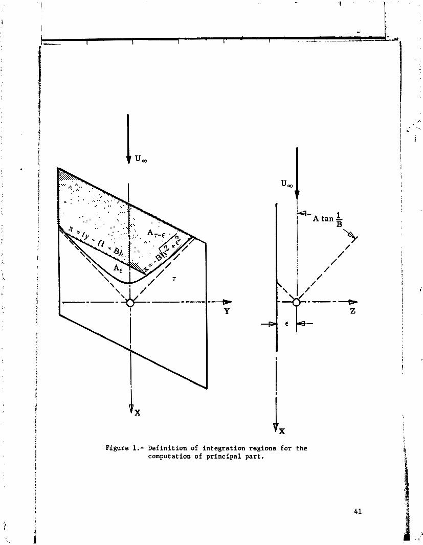
GI- 1 A tan -
B
Figure 1.- Definition of integration regions for the computation of principal part.

ACTUAL WING BOUNDARY CONDITION: t. = ;
THIN PANEL
XJ- X, CHORDWISE DISTRIBUTION OF VORTEX LINES: -
C - - 11 -cos(. $)I
2 xf- X, 1
CHORDWISE DlSTRlBUTlON OF B.C. CONTROL POINTS: C 2
Figure 2.- Modeling of t h i c k wing with horseshoe wrti,--s.
3.- Vortex
4' \ "COSINE"
lattice collocation.

. .
P
I <
Y I
TRANSVERSE
,! a ?
1 S ?
E SIMULATED BODY A HORSHOE VORTEX TRAILING LEGS I
x"- Xo AXIAL DISTRIBUTION OF VORTEXLINES: = I I - COS(n
L 2 L
i
AXIAL DISTRIBUTION OF B.C. CONTROL POINTS: I = - L 2
Figure 4.- Modeling of fusiform body with horseshoe vortices.
HORSESHOE FREE LEGS
HORSESHOE BOUND LEGS
Figure 5.- Generalized vortex lattice model of wing-body configuration.
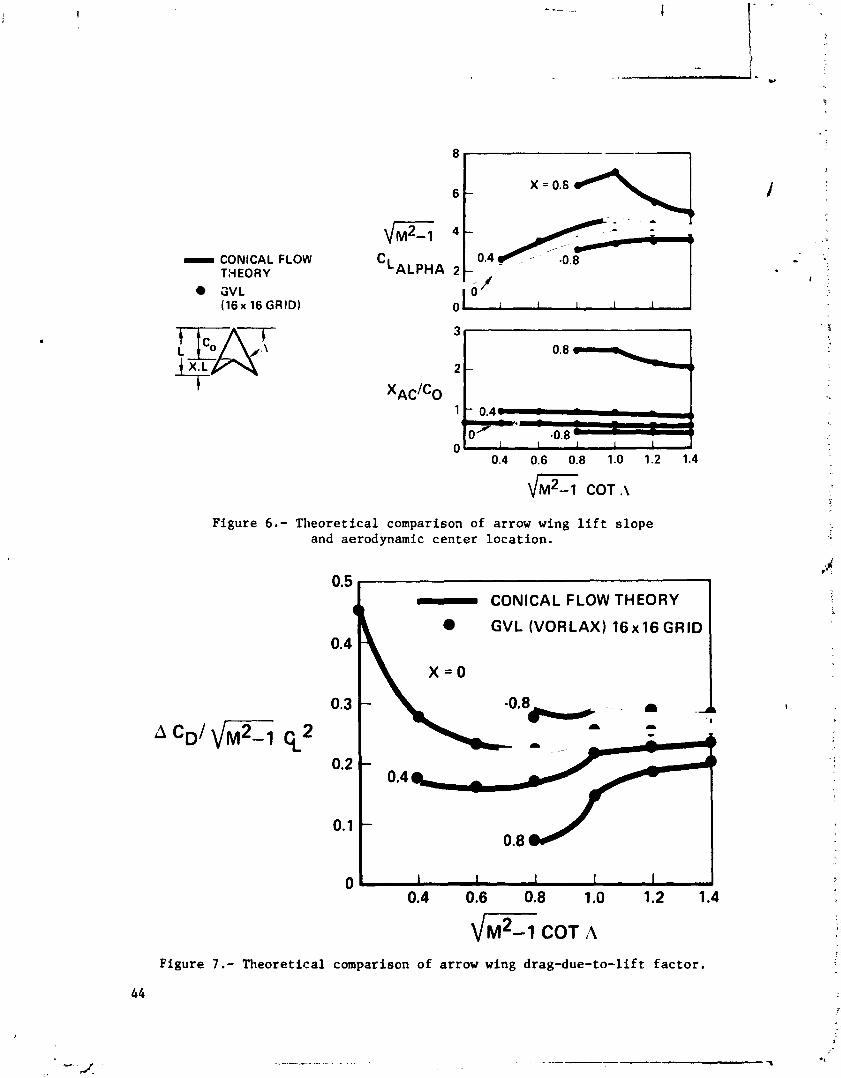
- CONICAL FLOW THEORY
GVL ( 1 6 x 16 GRID)
Figure 6.- Theoretical comparison of arrow wing lift slope and aerodynamic center location.
- CONICAL FLOW THEORY
L GVL (VORLAX) 16x16 GRID
M -1 COT A F Figure 7.- Theoretical comparison of arrow wing drag-due-to-lift factor.
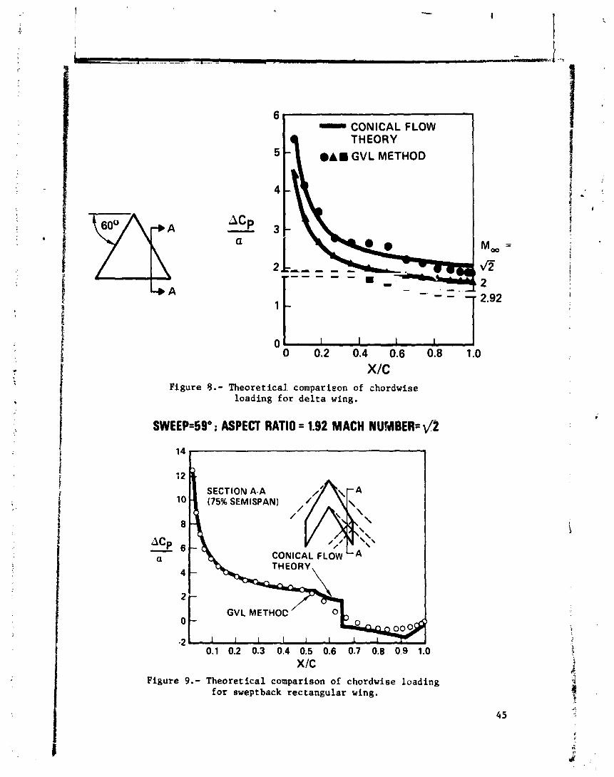
CONICAL FLOW I
Figure 8.- Theoretical. comparison of chordwise loading for de l ta wing.
SWEEP=5g0 ; ASPECT RATIO = 1.92 MACH NUMBER= v2
Figure 9.- Theoretical comparison of chordwise loading for sweptback rectangular wing.
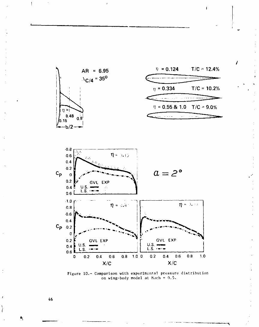
77 = 0.124 TIC - 12.4%
q = 0.334 TIC = 10.2%
t7 = 0.55 & 1.0 TIC = 9.0%
a = z o GVL EXP
U.S. - :. ; L.S. I - * - 1
GVL EXP GVL EXP U.S. - . U.S. - I 0.4 L.S. * - @ -
0.6 I
Figure 10.- Comparison with experimcntnl pressure distribution on wing-body model at N ~ c h = 0 . 5 .
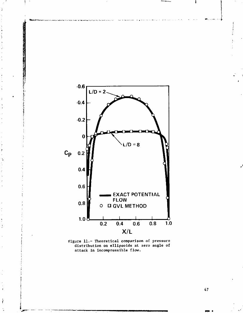
-0.4
-0.2
0
0.2
0.4
0.6 - EXACT POTENTIAL
0.8 0 GVLMETHOD
1 .o
Figure 11.- Theoretical comparison of pressure distribution on ellipsoids at zero angle of at tack in incompressible flow.

NUMERICAL METHOD TO CALCULATE THE INDUCED DRAG OR
OPTIMUM LOADING FOR ARBITRARY NON-PLANAR AIRCRAFT
James A. Blackwell, Jr. Lockheed-Georgia Company
SUMMARY
A simple unified numerical method applicable to non-planar subsonic air- craft has been developed for calculating either the induced drag for an arbi- trary loading or the optimum aircraft loading which results in minimum induced drag. The method utilizes a vortex lattice representation of the aircraft lifting surfaces coupled with the classic equations and theorems for computing and minimizing induced drag. Correlation of results from the numerical method with non-planar solutions obtained from other more complex theories indicates very good agreement. Comparison of the induced-drag computations using the numerical method with experimental data for planar and non-planar configura- tions was also very good.
pi INTRODUCTION
Over the past few years, increased attention has been focused on improving aircraft perfor~~ance. One method to improve performance is to lower the air- craft induced drag. This can be accomplished by more efficient design of con- ventional configurations sr by developing new and unique designs whose intent is to minimize induced drag. Typical of new configurations that have been developed for this purpose are the Lockheed boxplane and the Whitcomb winglet configuration.
The aircraft lifting surfaces for conventional aircraft as well as for new configurations are generally non-planar in design. To achieve a minimum in- duced d;ag, these non-planar surfaces must be designed to support the required optimum loads as specified by classical theory (refs. 1 and 2). Unfortunately, the use of classical theory to determine the design loads is quite cumbersome since rather complex conformal transformations must be utilized. Thus, a simple inexpensive method is required to determine what the "design to" loading of a no..-glanar configuration should be to miniinize the aircraft induced drag. Furthermore, for conditions where the aircraft is not operating at design con- ditions, an analysis method is required to quickly assess the magnitude of the aircraft off-design induced drag. Also, methods of this type are of particular importance in making configurational trade-offs.
The objective of this paper is to present a simple unified numerical method applicable to subsonic non-planar aircraft for the rapid calculation of:
49
PRIZEDING PAGE BLANK NCT FILED

1. the induced drag for an arbitrary aircraft loading or i
2 . the optimum aircraft loading which results in minimum induced drag.
The paper will include a discussion of the fundamental theoretical concepts on which the method is based, followed by the theoretical formulation of the nu- ,, 4 . . merical calculation procedure. Computations will be mhde using the method and * - . - i '-
will be compared to existing theoretical solutions and to experimental data. . This will be followed by an illustration of the utility of the method for 1 .
making configurational trade-offs by comparing the loading and induced drag results for various types of wing additions such as winglets or wing-tip extensions.
SYMBOLS
geometric influence function
aspect ratio, b2 IS
reference span
local chord of lifting surface
average chord (S/b)
soction load coefficient normal to load perimeter
lift coefficient
induced drag coefficient
bending-moment coefficient
induced drag (DiscDi qS)
efficiency factor
resultant force of lifting surface
length of wing addition
unit normal vector parallel to Z axis
length of load perimeter
lift force (L=CL qS)
Mach number
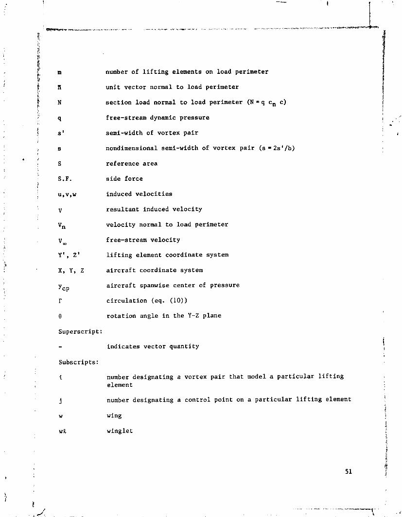
m number of perimeter
tl unit vector normal to load perimeter
N section load normal to load perimeter ( N = q cn c) I i
9 free-stream dynamic pressure ! . , . . . s ' semi-width of vortex pair , i
s nondimensional semi-width of vortex pair (s = 2s1/b)
S reference area
S.F. side force
UIVSW induced velocities
V resultant induced velocity
vn velocity normal to load perimeter
v, f ree-stream velocity
Y', Z ' lifting element coordinate system
x, y, z aircraft coordinate system
YCP aircraft spanwise center of pressure
r circulation (eq. (10))
8 rotation angle in the Y-Z plane
Superscript:
- indicates vector quantity
Subscripts:
i number designating a vortex pair that model a particular lifting element
j number designating a control point on a particular lifting element
w wing
w R winglet

BASIC THEORETICAL CONCEPTS
Fundamental to the development of the present model is the representation of the aircraft non-planar lifting surfaces by a system of rectangular horse- shoe vortices (ref. 3). The induced drag for a given loading or the optimum loading for minimum induced drag can be calculated for any arbitrary non-planar aircraft at subsonic speeds utilizing this vortex representation and the following basic law and theorems: Munk's Theorems I to 111, Biot-Savart Law, and the Kutta-Joukowski Theorem.
Munk's fizst theorem (ref. 1) can be stated as follows:
The t o t a l induced drag o f any multiplane system i s unaltered i f any of the Z i f t ing elements are moved i n the d i rec t ion o f motion provided tha t the a t t i t u d e o f the elements i s adjusted t o maintain the same d i s t r ibu t ion o f l i f ' among them.
This theorem is commonly referred to as Munk's stagger theorem. An illustra- tion of this theorem is shown in figure 1. Several practical applications can be deduced from this theorem. First, the chordwise distribution of pressure does not affect the theoretical induced drag of the aircraft if constant section lift is maintained. Second, wing sweep does not effect the theoretical induced drag as long as the spanwise distribution of lift is constant. A third application is that the load from a system of multi-surfaces (i.e. wing and horizontal tail) with the same projection in the Y-Z plane can be made equiva- lent to a single surface for the purpose of calculating induced drag.
In the following theoretical development, use will be made of Munk's first theorem to lump the chordwise distribution of vorticity into a single chordwise load and to translate all loads into the O,Y,Z plane (fig. 1).
Munk's second theorem (ref. 1) is illustrated in figure 2 and can be stated as:
I n calculating the t o t a l induced drag o f a l i f t i n g system, once a l l the forces have been concentrated i n t o the plane O,Y,Z, we may, instead o f using the actual values o f the ve loc i t y normal t o the l i f t i n g elements [Vn'n(x,y,zl I a t the or ig inal points o f appl icat ion o f the forces, use one-half the l imi t ing value o f the normal ve loc i t y [Vn(m,y ,z) I for the corresponding values a t points P ( 0 , y , 2).
This theorem allows the computations to be done in the Trefftz plane (down- stream infinity) rather than in the real plane. In the subsequent theoretical derivation, this fact will be utilized to make all the computations in the Trefftz plane, thereby greatly simplifying the calculations.
The third theorem given by Munk (ref. 1) is presented as follows:
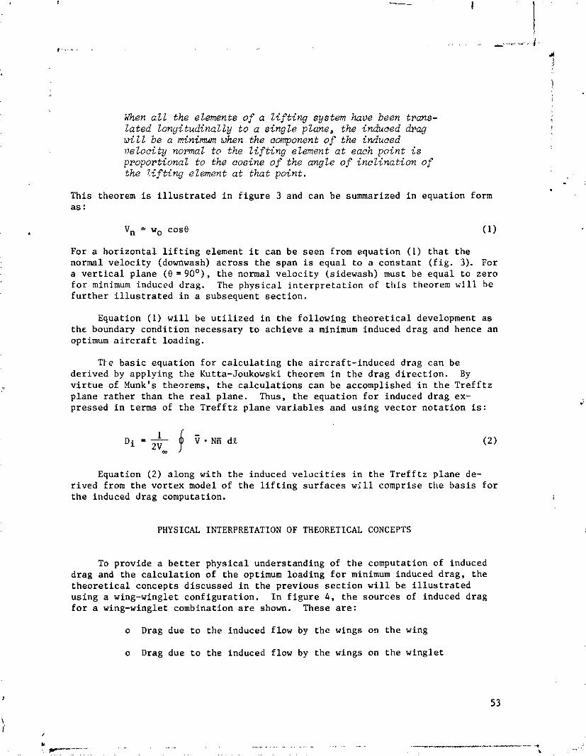
When a l l the elements o f a l i f t i n g system have been trans- lated longi tudinal ly t o a s ingle plane, the induced drag w i l l be a minimum when the component o f the induced ve loc i t y normal t o the l i f t i n g element a t each point i s proportional t o the cosine o f the angle o f i nc l ina t ion o f the l i f t i n g element a t t h a t point.
This theorem is i l l u s t r a t e d i n f i g u r e 3 and can be summarized i n equat ion form a s :
For a h o r i z o n t a l l i f t i n g element i t can be seen from equa t ion (1) t h a t t h e normal v e l o c i t y (downwash) a c r o s s t h e span is equa l t o a cons tan t ( f i g . 3). For a v e r t i c a l p lane (8 = g o 0 ) , t h e normal v e l o c i t y (sidewash) must be equa l t o ze ro f o r minimum induced drag. The phys ica l i n t e r p r e t a t i o n of t h i s theorem w i l l be f u r t h e r i l l u s t r a t e d i n a subsequent s e c t i o n .
Equation (1) w i l l be u t i l i z e d i n t h e fo l lowing t h e o r e t i c a l development a s t h e boundary cond i t ion necessary t o achieve a minimum induced d rag and hence an optimum a i r c r a f t loading.
T t e b a s i c equa t ion f o r c a l c u l a t i n g t h e a i rc ra f t - induced drag can be de r ived by applying t h e Kutta-Joukowski theorem i n t h e d rag d i r e c t i o n . By v i r t u e of Munk's theorems, t h e c a l c u l a t i o n s can be accomplished i n t h e T r e f f t z p lane r a t h e r than t h e r e a l p lane . Thus, t h e equa t ion f o r induced d rag ex- pressed i n terms of t h e T r e f f t z p lane v a r i a b l e s and us ing v e c t o r n o t a t i o n is:
Equation ( 2 ) a long wi th t h e induced v e l o c i t i e s i n t h e T r e f f t z p lane de- r i v e d from t h e v o r t e x model of t h e l i f t i n g s u r f a c e s w i l l comprise t h e b a s i s f o r t h e induced drag computation.
PHYSICAL INTERPRETATION OF THEORETICAL CONCEPTS
To provide a b e t t e r p h y s i c a l understanding of t h e computation of induced drag and t h e c a l c u l a t i o n of t h e optimum load ing f o r minimum induced d rag , t h e t h e o r e t i c a l concepts d i scussed i n t h e previous s e c t i o n w i l l be i l l u s t r a t e d us ing a wing-winglet conf igura t ion . I n f i g u r e 4 , t h e sources of induced drag f o r a wing-winglet combination a r e shown. These a r e :
o Drag due t o t h e induced flow by the wings on t h e wing
o Drag due t o the induced flow by the wings on t h e wing le t

o Drag due t o t h e induced flow by t h e wing le t s on t h e wing le t
o Drag due t o t h e induced f low by t h e w i n g l e t s on t h e wing
For s i m p l i c i t y , t h e e f f e c t s of symmetry a r e included i n t h e sources of induced drag shown and a r e no t d e l i n e a t e d s e p a r a t e l y .
I n f i g u r e 4 j a ) , t h e e f f e c t of t h e wing induced flow is shown. The wing under p o s i t i v e load produces a downwash on i t s e l f which r e s u l t s i n t h e wing - f o r c e v e c t o r , F, t i l t i n g rearward by an ang le a i . The wing f o r c e v e c t o r , F, is perpendicular t o t h e r e s u l t a n t , V , (Kutta-Joukowski theorem). The rearward r o t a t i o n of t h e f o r c e v e c t o r r e s u l t s i n a wing-induced drag. A sidewash is a l s o produced by t!e wing a t t h e wing le t l o c a t i o n . As can be s e e n i n f i g u r e 4 (b ) , t h e sidewash from t h e wing combined wi th t h e f ree-s t ream v e l o c i t y pro- duces a t ilt forward of t h e wing le t f o r c e r e s u l t i n g i n a t h r u s t component.
I n f i g u r e 4 ( c ) , t h e induced d rag r e s u l t i n g from t h e sidewash of t h e winr,- l e t on i t s e l f is presented. This r e s u l t s i n a rearward t i l t i n g of t h e wing'et f o r c e v e t t o r and an a t t e n d a n t induced drag. It should be noted t h a t t h e d'rec- t i o n of t h e wing le t f o r c e v e c t o r is c o n s i s t e n t wi th a p o s i t i v e (upload) oo t h e wing. The wing le t a l s o induces an upwash on t h e wing. I n f i g u r e 4 ( d ) , i t can be seen t h a t t h i s upwash r o t a t e s t h e wing f o r c e v e c t o r forward producing a t h r u s t f o r c e .
The r e s u l t s from f i g u r e 4 a r e summarized i n f i g u r e 5, where a l l t h e in- duced v e l o c i t i e s are combined. For minimum induced d rag , equa t ion (1) ind i - c a t e s t h a t t h e v e l o c i t y normal t o t h e wing le t n u s t be equa l t o ze ro (9 = 9 0 ° ) . This can be seen t o occur when t h e sidewash produced on t h e wing le t by t h e wing e x a c t l y cance l s t h e sidewash produced by t h e wing le t on i t s e l f . I n o t h e r words, t h e induced ang le of a t t a c k (ai) of t h e wing le t is zero. The induced drag of t h e wing is a l s o minimized by t h e presence of a wingle t s i n c e t h e wing- l e t causes a r educ t ion i n t h e n e t downwash a t t h e wing; and, hence, t h e induced ang le of a t t a c k is reduced.
DERIVATION OF NUMERICAL METHODS
Vortex Model
By v i r t u e of Munk's theorems, t h e c a l c u l a t i o n s f o r induced drag and t h e optimum l o a J i n g can be accomplished i n t h e T r e f f t z plane. This f a c t consider- a b l y s i m p l i f i e s t h e c a l c u l a t i o n problem s i n c e t h e method w i l l no t be a func t ion of t k l o n g i t u d i n a l coord ina te . The p r o j e c t i o n of t h e a i r c r a f t non-planar l i f t i n g s u r f a c e s ' . I t h e T r e f f t z p lane w i l l be r e f e r r e d t o as t h e load per imeter .
I n t h e r e a l p lane , t h e a i r c r a f t l i f t i n g s u r f a c e s w i l l be r epresen ted by a system of horseshoe v o r t i c e s . The equa t ions d e s c r i b i n g t h e induced v e l o c i t i e s i n t h e T r e f f t z p lane a t a c o n t r o l po in t P (o ,y i , z i ) ( f i g . 6) due t o a horseshoe

v o r t e x l o c a t e d i n t h e r e a l p lane at a p o i n t P ( x j , y j , z j ) a r e g iven below as de- j r i ved from t h e Biot-Savart Law ( r e f . 3 ) :
where
R~ = ( z ' ) ~ + (y ' -s '12 ( 6 )
R2 = ( 2 1 ) ~ + (y ' ( 7 )
yl = (yi - y j ) C O S ~ ~ + ( Z i - z j ) s i n e j (8)
Z ' = - ( y i - y j ) s i n 8 j + ( z i - z j ) C O S O ~ (9)
and t h e c i r c u l a t i o n by v i r t u e of t h e Kutta-Joukowski theorem is given a s
I' (cn ~ 1 - i A = v
m 2 (10)
Inspec t ion of equat ions ( 3 ) t o (5) i n d i c a t e s t h a t t h e r e is no c o n t r i b u t i o n from t h e horseshoe bound l e g i n t h e T r e f f t z p lane and t h e induced v e l o c i t i e s a r e not dependent on x. The r e s u l t i n g model then reduces t o d e s c r i b i n g t h e load per imeter i n the T r e f f t z p lane ( f i g . 6) by l i f t i n g elements t h a t are. r ep resen ted by a t r a i l i n g v o r t e x p a i r having a c i r c u l a t i o n of equal magnitude bu t of oppos i t e r o t a t i o n . For each l i f t i n g element t h e r e i s an a s s o c i a t e d c o n t r o l po in t loca ted midway between t h e p a i r of v o r t i c e s .
Induced Drag Ca lcu la t ion
The b a s i c equa t ion f o r c a l c u l a t i n g the induced d rag f o r an a r b i t r a r y non- p lanar l i f t i n g system was given i n equat ion ( 2 ) a s :
The i n t e g r a l is a c i r c u i t i n t e g r a l taken around t h e per imeter o f t h e pro- j e c t i o n of t h e l i f t i n g system i n t h e T r e f f t z plane. The v e c t o r is t h e r e s u l t a n t induced v e l o c i t y v e c t o r i n t h e T r e f f t z p lane from a l l v o r t i c e s on t h e load per imeter . The v e c t o r ii is a u n i t v e c t o r , normal t o the load per imeter .
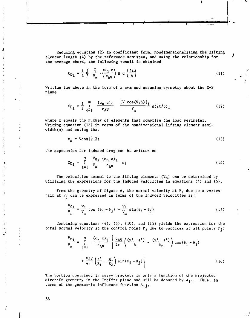
Reducing equation (2) to coefficient form, nondimensionalizing the lifting element length (R) by the reference semispan, and using the relationship for 1 the average chord, the following result is obtained
i
Writing the above in the form of a svm and assuming symmetry about the X-Z plane
where m equals ttp number of elements that comprise the load perimeter. Writing equztion (li) in terms of the nondimensional lifting element semi- width(s) dnd noting thai
vn = vcos (V ,ii)
the expression for induced drag can be written as
The velocities normal to the lifting elements (Vn) can be determined by utilizing the expressions for the induced velocities in equations (4) and (5).
From the geometry of figure 6, the normal velocity at Pi due to a vortex pair at Pj can be expressed in terms of the induced velocities as:
Vni wi - - - V i v - cos (ei-ej) - - V V ~in(€)~ - ej) (15) i
OD m m
Combining equations ( 4 ) , (5), (lo), and (15) yields the expression for the total normal velocity at the control point Pi due to vortices at all points Pj:
The portion contained in curvy brackets is only a function of the projected aircraft geometry in the Trefftz plane and will be denoted by Aij. Thus. in terms of the geometric influence function Aij,
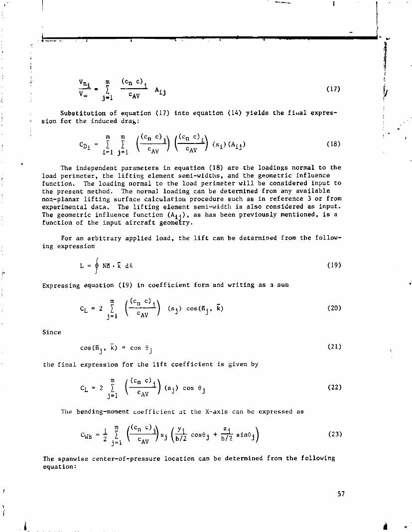
Substitution of sion for the induced
equation (17) into equation (14) yields the firla1 expres- drak :
6
The independent parameters in equation (18) are the loadings normal to the load perimeter, the lifting element semi-widths, and the geometric influence function. The loading normal to the load perimeter will be considered input to the present method. The normal loading can be determined from any available noa-planar lifting surface calculation procedure such as in reference 3 or from experimental data. The lifting element semi-width is also considered as input. The geometric influence function (Ai.), as has been previously mentioned, is a function of the input aircraft geome$ry.
For an arbitrary applied load, the lift can be determined from ing expression
L = j * i= i . i ; d!L
Expressing equation (19) in coefficient form and writing as 3 sum
Since
- cos(ii k) = cos 0
j ' j
the final expression for the lift coefficient is given by
The bending-moment coefficient at the X-axis can be expressed as
the follow-
(19)
The spanwise center-of-pressure location can be determined from the following equation :

The a i r c r a f t e f f i c i e n c y f a c t o r can b e c a l c u l a t e d from t h e fo l lowing s t andard e q u a t i m : .,q
Optimum Load Ca lcu la t ion
The express ion f o r t h e t o t a l v e l o c i t y normal t o a l i f t i n g element was given i n equat ion (17) a s :
According t o Munk's theorem 111, t h e load ing f o r minimum induced drag i s obta ined when t h e d i s t r i b u t i o n of normal v e l o c i t y s a t i s f i e s equa t ion (1 ) :
where wo i s a constant . Using equa t ion (1) a s a boundary cond i t ion and combin- i n g i t wi th equat ion ( 1 7 ) , t h e r e r e s u l t s :
where t h e loading i n equa t ion (26) is t h e optimum loading. Using square i
bracke t s t o i n d i c a t e mat r ix n o t a t i o n , equat ion (26) can be w r i t t e n a s :
Solving f o r t h e optimum load ing
i
The va lue of t h e a r b i t r a r y c o n s t a n t , wo, can be determined from equat ion (22) by s p e c i f y i a g t h e a i r c r a f t l i f t c o e f f i c i e n t .
I n summary, t o determine t h e loading f o r minimum induced d rag , only t h e l i f t c o e f f i c i e n t and a i r c r a f t geometry a r e r equ i red f o r inpu t . Once t h e
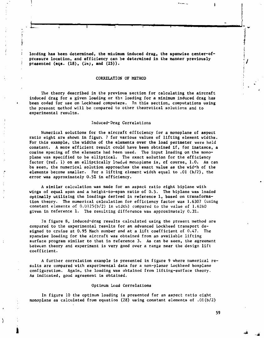
loading has been determined, t h e miuimum induced d rag , t h e spanwise center-of- p r e s s u r e l o c a t i o n , and e f f i c i e n c y can be determined i n t h e manner p rev ious ly presented (eqs. (18), (241, and (25)) .
CORRELATION OF METHOD
The theory descr ibed i n t h e previous s e c t i o n f o r c a l c u l a t i n g t h e a i r c r a f t induced drag f o r a g iven loading o r th.? loading f o r a minimum induced drag has been coded f o r use on Lockheed computers. I n t h i s s e c t i o n , computations us ing t h e p resen t method w i l l be compared t o o t n e r t h e o r e t i c a l s o l u t i o ! ~ ~ and t o exper imenta l r e s u l t s .
Induced-Drag C o r r e l a t i o n s
Numerical s o l u t i o n s f o r t h e a i r c r a f t e f f i c i e n c y f o r a monoplane of a s p e c t r a t i o e i g h t a r e shown i n f i g u r t 7 f o r va r ious va lues of l i f t i n g element widths. For t h i s example, t h e widths of t h e elements over t h e load per imeter were held constant . A more e f f i c i e n t r e s u l t could have been obta ined i f , f o r i n s t a n c e , a cos ine spacing of t h e elements had been used. The inpu t loading on t h e mono- p lane was s p e c i f i e d t o be e l l i p t i c a l . The exac t s o l u t i o n f o r t h e e f f i c i e n c y f a c t o r ( r e f . 1) on a n e l l i p t i c a l l y 10aiLd motiopiane is, of course , 1.0. A s can be seen, t h e numerical s o l u t i o n approaches t h e exac t va lue as t h e width of t h e elements become smal le r . For a l i f t i n g element width equa l t o .O1 (b/2.), t h e e r r o r was approximately 0.5% i n e f f i c i e n c y .
A s i m i l a r c a l c u l a t i o n was made f o r an a s p e c t r a t i o e i g h t b i p l a n e wi th wings of equa l span and a height-to-span r a t i o of 0.5 . The b i p l a n e was loaded opt imal ly u t i l i z i n g t h e loadings de r ived i n r e f e r e n c e 1, based on transforma- t i o n theory. The numerical c a l c u l a t i o n f o r e f f i c i e n c y f a c t o r was 1.6307 (us ing cons tan t elements of 0.0125(b/2) i n width) compared t o the va lue of 1.6260 given i n r e fe rence 1. The r e s u l t i n g d i f f e r e n c e was approximately 0.3%.
Jn f i g u r e 8 , induced-drag r e s u l t s c a l c u l a t e d us ing t h e p resen t method a r e compared t o t h e exper imenta l r e s u l t s f o r a n advanced Lockheed t r a n s p o r t de- s igned t o c r u i s e a t 0.95 Mach number and a t a l i f t c o e f f i c i e n t of 0.47. The spanwise load ing f o r t h e a i r c r a f t was obta ined from an a v a i l a b l e l i f t i n g s u r f a c e program s i m i l a r t o t h a t i n r e fe rence 3. A s can be seen , t h e agreement Letwcen theory and experiment is very good over a range near t h e des ign l i f t c o e f f i c i e n t .
A f u r t h e r c o r r e l a t i o n example is presented i n f i g u r e 9 where numerical re- s u l t s a r e compared wi th exper imenta l d a t a f o r a non-planar Lockheed boxplane conf igura t ion . Again, t h e load ing was obta ined from l i f t i n g - s u r f a c e theory . A s i n d i c a t e d , good agreement is obta ined.
Optimum Load C o r r e l a t i o n s
I n f i g u r e 10 the optimum loading i s presented f o r an a s p e c t r a t i o e i g h t monoplane a s c a l c u l a t e d from equat ion (28) us ing cons tan t elements of .Ol(b/2)
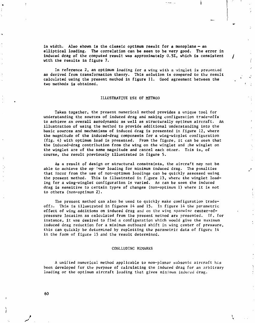
i n wid th . Also shown is t h e c l a s s i c optimum r e s u l t f o r a monoplane- a n e l l i p t i c a l l o a d i n g , The c o r r e l a t i o n c a n b e s e e n t o b e v e r y good. The e r r o r i n induced d r a g o f t h e computed r e s u l t was approx ima te ly 0.52, which is c o n s i s t e n t 1 w i t h t h e r e s u l t s i n f i g u r e 7.
I n r e f e r e n c e 2 , a n optimum l o a d i n g f o r a wing wi th a v i n g l e t i s prcaenLed as d e r i v e d from t r a n s f o r m a t i o n theo ry . T h i s s o l u t i o n is compared t o t h e r e s u l t c a l c u l a t e d u s i n g t h e p r e s e n t method i n f i g u r e 11. Good agreement between t h e - two methods is o b t a i n e d . I .
ILLUSTRATIVE USE OF METHOD
Taken t o g e t h e r , t h e p r e s e n t numer i ca l method p r o v i d e s a unique t o o l f o r unde r s t and ing t h e s o u r c e s o f induced d r a g and making c o n f i g u r a t i o n t r a d e - o f f s t o a c h i e v e e n o v e r a l l aerodynamic a s well a s s t r u c t u r a l l y optimum a i r c r a f t . An i l l u s t r a t i o n of u s i n g t h e method t o p rov ide a d d i t i o n a l unde r s t and ing i n t o t h e b a s i c s o u r c e s and mechanisms of induced d r a g is p r e s e n t e d i n f i g u r e 12, where t h e magnitude of t h e induced-drag components f o r a wing-wicglet c o n f i g u r a t i o n ( f i g . 4) w i t h optimum load is p r e s e n t e d . From t h e f i g u r e , i t cian b e s e e n t h a t t h e induced-drag c o n t r i b u t i o n from t h e wing on t h e w i n g l e t and :he w i n g l e t on t h e w i n g l e t a r e of t h e same magnitude and c a n c e l each o t h e r . T h i s is, of cou r se , t h e r e s u l t p r e v i o u s l y i l l u s t r a t e d i n f i g u r e 5.
A s a r e s u l t o f d e s i g n o r s t r u c t u r a l c o n s t r a i n t s , t h e a i r c r a f t may n o t b e a b l e t o a c h i e v e t h e op . ?mm l o a d i n g f o r minimum induced d rag . The p n n a l t i e s t h a t i n c u r from t h e u s e of non-optimum l o a d i n g s c a n b e q u i c k l y a s s e s s e d u s i n g t h e p r e s e n t method. T h i s is i l l u s t r a t e d i n f-:gure 13, where t h e w i n g l e t load- i n g f o r a wing-winglet c o n f i g u r a t i o n is v a r i e d . As can b e s e e n t h e induced d r a g is s e n s i t i v e t o c e r t a i n t ypes of changes (non-optimum 1) where i t is n o t t o o t h e r s (non-optimum 2 ) .
The p r e s e n t method can a l s o be used t o q u i c k l y make c o n f i g u r a t i o n t r a d e - o f f ~ . T h i s i s i l l u s t r a t e d i n f i g u r e s 14 and 15. I n f i g u r e 14 t h e pavame t r i c e f f e c t of wing a d d i t i o n s on induced d r a g and on t h o wir~g spanwise cen t e r -o f - p r e s s u r e l o c a t i o n as c a l c u l a t e d from t h e p r e s e n t method a r e p r e s e n t e d . I f , f o r i n s t a n c e , i t was d e s i r e d t o f i n d a c o n f i g u r a t i o n which would g i v e t h e maximum induced d r a g r e d u c t i o n f o r a minimum ou tboa rd s h i f t i n wing c e n t e r of p r e s s u r e , t h i s can q u i c k l y be determined by r e p l o t t i n g t h e p a r a m e t r i c d a t a of f i g u r e 14 i n t h e form of f i g u r e 15 and t h e r e s u l t de te rmined .
CONCLUDINC REMARKS
A u n i f i e d numer i ca l method a p p l i c a b l e t o non-planar subson ic a i r c r a f t hc s been developed f o r t h e purpose of c a l c u l a t i n g t h e induced d r a g f o r an a r b i t r a r y l oad ing o r t h e optimum a i r c r a f t l o a d i n g t h a t g i v e s minimum induced d r a g .
Use of the numerical method has indi-ate4 d that:
the method is simple and easy to use
induced drag and optimum loading results from the numerical method correlate very well with non-planar solutions obtained from more complex theories
numerical induced-drag predictions ace in good agreement with experimental data for planar and non-planar configurations
the numerical method provides both analysis and design capa- bility which allows the designer to make rapid configuration assessments and trade-offs for the purpose of achieving an overall aerodynamic as well as structurally optimum aircraft.
REFERENCES
Durand, W. F. (ed.): Aerodynamic Theory. Dover Publications, Inc., New York, 1963, Volume 11, Division E.
Lundry, J. L.: A Numerical Solution for the Minimum Induced Drag and the Corresponding Loading of Nonplanar Wings. NASA CR-1218, November 1968.
Blackwell, James A. Jr.: A Finite-Step Method for Calculation of Theo- retical Load Distributions for Arbitrary Lifting-Surface Arrangements at Subsonic Speeds. NAS TN D-5335, July 1969.
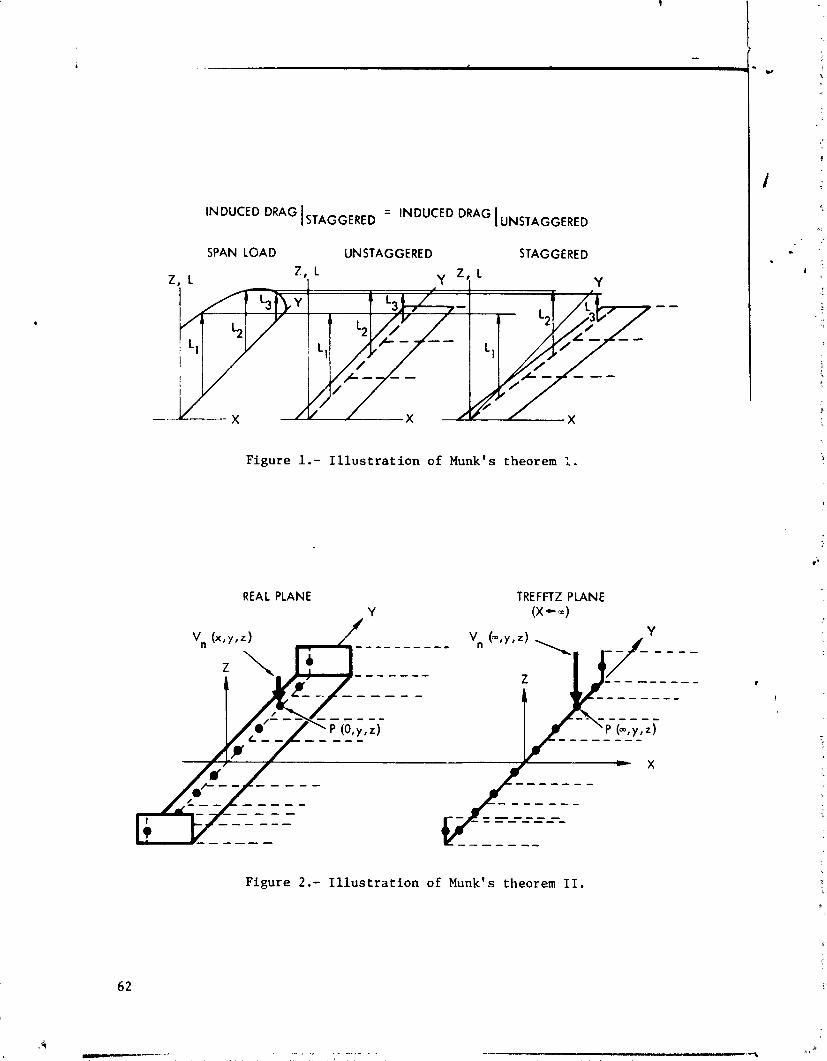
SPAN LOAD UNSTAGGERED STAGGERED I . , L
I Y z ~ L Y
Figure 1.- Illustration of Munk's theorem 1.
REAL PLANE Y
TREFnZ PLANE (X - ID)
Figure 2.- Illustration of Munk's theorem 11.
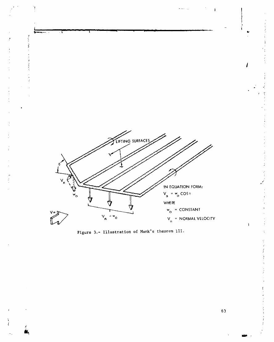
IN EQUATION FORM:
V" = wo COS? I I I I
WHERE
w o = CONSTANT
= W "n 0 V 11 = NORMAL VELOCITY
Figure 3.- Illustration of Munk's theorem 111.
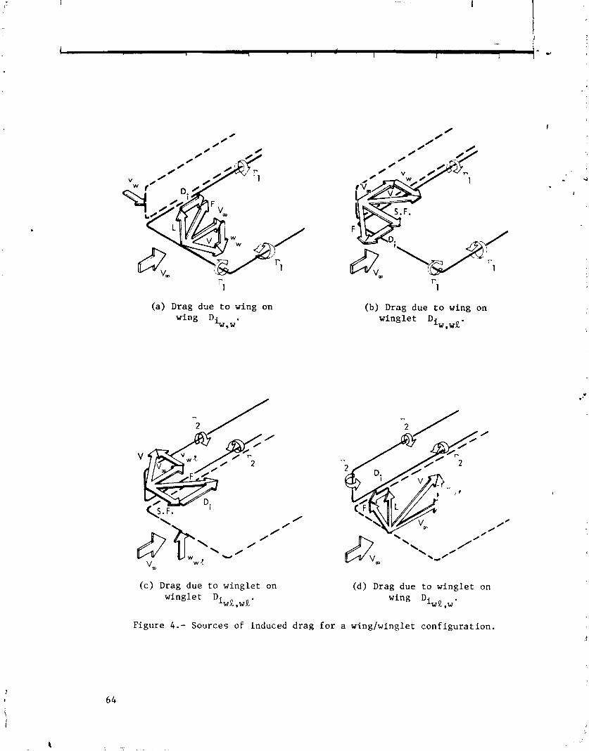
(a) Drag due t o wing on wing Di .
w9w
(b) Drag due t o wing on w i n g l e t D
iw,w%.
( c ) Drag due t o w i n g l e t on (d) Drag due t o w i n g l e t on wing le t D. wing D.
~ W R , W R ' IWR,W'
F igu re 4.- Sources of induced d r a g f o r a wingfwing le t c o n f i g u r a t i o n .

OPTIMUM SIDE LOAD FOR VERTICAL SURFACE /
= 'TOTAL ' w ' v W a
v TOTAL
= 0 OPTIMUM VERTICAL LOA HORIZONTAL SURFACE
+ w W~~~~~ = W w ~ , w,
W~~~~~ = CONSTANT
.D FOR
W
Figure 5.- Combined sources of induced drag for a winglwinglet configuration.
LIFTING ELEMENT
1
Figure 6.- Induced velocities in the Trefftz plane.

EXACT VALUE
!
I
.981 e 1 NUMERICAL VALUE
I .97, (PRESENT METHOD) I
.96
Figure 7 . - Variation of eff ic iency for optimally loaded monoplane.
0 EXPERIMENT
- PRESENT METHOD M = 0.5
c:
Figure 8.- Induced drag for Lockheed ATT-95 aircraf t .
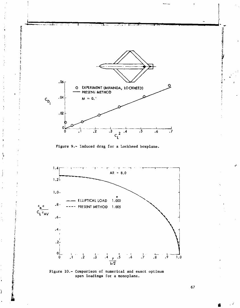
0 EXPERIMENT (MIRANDA, LOCKHEED) - PRESEN'i METHOD
M 2 0.'
Figure 9.- Induced drag for a Lockheed boxplane.
Figure
e - ELLIPTICAL LOAD 1.000 '\ ---- PRESENT METHOD 1.005
10.- Comparison of numerical and exact optimum span loadings for a monoplane.

WING
I I
. a b
- 6 -
- LUNDRY ---- PRESENT METHOD
Figure 11.- Comparison of theoretical optimum loadings for a winglwinglet configuration.
WING - WINGLET WING ALONE C = 1.0 L AR = 10.0 . ;
(1) CD. = + -0369 C = + .0318 I Di w, w
(2) c = - .0110 'i
W, w t
' WING . '.
Figure 12.- Illustration of induced drag calculations for a wLng/winglet configuration.

I
I I
t I
8 Ac Di i- WING
r RELATIVE TO MONOPLAKE e i SYM LOADING
- OPTIMUM -17.62% 1.2240 I ,+:
I i ., ,
- - - - - - NON-OPTIMUM 1 -15.59% 1.1945 : , - .p i. !
c c 0.8- - -- NON-OPTIMUM 2 -6.50% 1.0783 I ; n j
. i * '
0.4 - ,
0.2 - 1'
0 0.2 0.4 0.6 0.8 1.0 0 0.2
Figure 13.- Effect of changes in winglet loading on the ind. ~ e d drag of a winglwinglet configuration.
LIFT = CONSTANT MINIMUM DRAG LOADINGS
WING CENTER-OF-PRESSURE CHANGE, % SEMISPAN INDUCED DRAG CHANGES, %
Figure 14.- Basic theoretical effects due to wing additions.
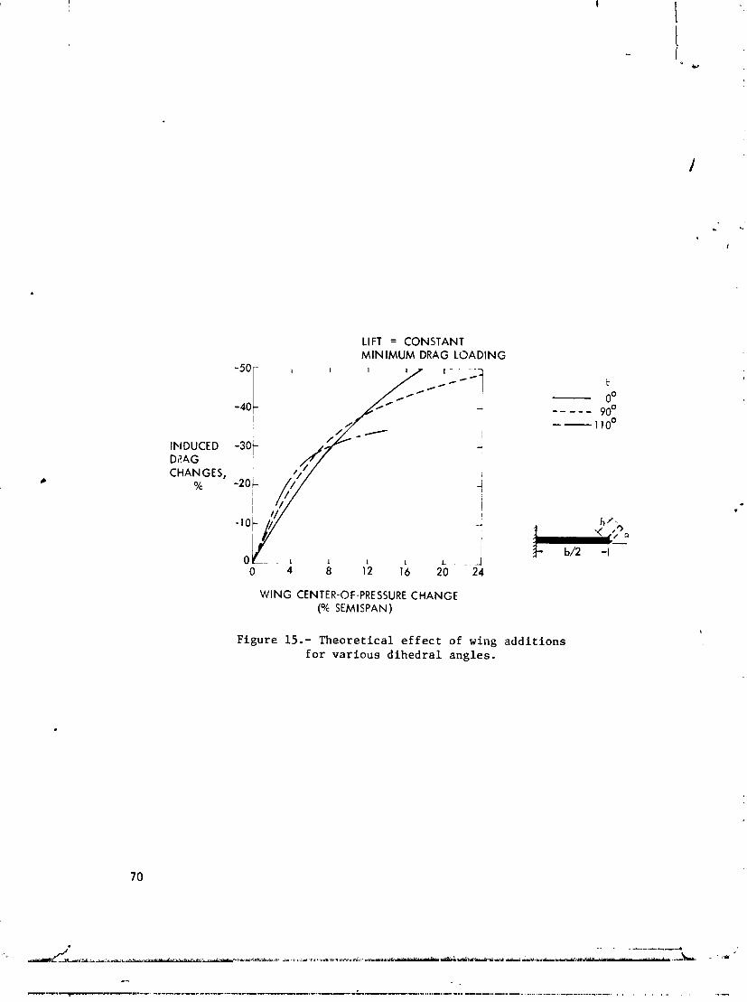
LIFT = CONSTANT MINIMUM DRAG LOADING
INDUCED -301 D1?4G CHANGES,
O/c
WING CENTER-OF-PRESSURE CHANGE (% SEMISPAN)
Figure 15.- Theoretical e f f e c t of wing addit ions for various dihedral angles .
1 Wr.v*cwz.- -***r*1.'9r-*, ,--.- . . , , W~IQIF . ~m~ftii3#+~1 fiww.rlr*s*~*~r?"~ -.%*f?W*:*.m v i. -
' ~ ? 6 : 2 8 1 6 8 OPTIMIZATION AND DESIGN OF THREE-DIMENSIONAL AERODYNAMIC
CONFIGURATIONS OF ARBITRARY SHAPE
BY A VORTEX LATTICE METHOD
Winfr ied M. F e i f e l The Boeing Company
SUMMARY
A new method based on v o r t e x l a t t i c e t h e o r y h a s been deve l - oped which can be a p p l i e d t o t h e cambined a n a l y s i s , induced d r a g o p t i m i z a t i o n , and aer9dynamic d e s i g n of t h ree -d imens iona l c o n f i g - u r a t i o n s of a r b i t r a r y shape. Geometric and aerodynamic con- s t r a i n t s can be imposed on b o t h t h e o p t i m i z a t i o n and t h e d e s i g n p roces s . The method is compared w i t h s e v e r a l known a n a l y t i c a l s o l u t i o n s and is a p p l i e d t o s e v e r a l d i f f e r e n t d e s i g n and op t imi - z a t i o n problems, i n c l u d i n g fo rma t ion f l i g h t and w i n g t i p f i n s f o r t h e Boeing KC-135 t a n k e r a i r p l a n e . Good agreement h a s been observed between t h e t h e o r e t i c a l p r e d i c t i o n s and t h e wind t u n n e l test r e s u l t s f o r t h e KC-135 m o d i f i c a t i o n .
INTRODUCTION
Fa lkne r ( r e f . 1) h a s used v o r t e x l a t t i c e ne tworks a s e a r l y a s i943 f o r t h e c a l c u l a t i o n of t h e aerodynamic f o r c e s on s u r f a c e s of a r b i t r a r y shape. With t h e a d v e n t of e l e c t r o n i c d i g i t a l computers , v o r t e x l a t t i c e methods were t h e First powerful t o o l s f o r t h r e e - d imens iona l p o t e n t i a l f l ow a n a l y s i s . I n t h e p a s t decade , v o r t e x l a t t i c e computer codes were deve loped independen t ly by s e v e r a l i n v e s t i g a t o r s , i n c l u d i n g Rubbert ( r e f . 2 ) and t h e a u t h o r of t h i s pape r ( r e f . 3 ) .
The v o r t e x l a t t i c e approach is s t i l l f avo red f o r many e n g i - n e e r i n g a p p l i c a t i o n s f o r s e v e r a l r e a s o n s , such a s t h e e a s e o f t h e problem d e s c r i p t i o n , t h e r e l a t i v e l y s m a l l compu ta t iona l e f f o r t r e q u i r e d and t h e " remarkable accu racy OL t h e s o l u t i o n " , a s no ted by James ( r e f . 4 ) . One s p e c i f i c advantage o f "he v o r t e x l a t t i c e i d e a l i z a t i o n o v e r t h e advanced p a n e l methods is t h a t t h e l e a d i n g edge s u c t i o n f o r c e is i n h e r e n t l y i nc luded i n t h e s o l u t i o n . T h i s a l l o w s t h e computa t ion of t h e c o n f i g u r a t i o n induced d r a g wi thou t r e s o r t i n g t o t h e T r e f f t z - p l a n e theorem.
V o r t e x l a t t i c e methods t e n d t o s l i g h t l y u n d e r p r e d i c t i n d u c e d d r a g , as o b s e r v e d by Rubber t ( r e f . 2 ) and Kalman ( r e f . 5 ) . How- e v e r , a s l o n g a s t h e p a n e l i n g scheme is k e p t u n i f o r m , t h e i n d u c e d d r a g computed by t h e v o r t e x l a t t i ce method v a r i e s i n a c o n s i s t e n t f a s h i o n from known e x a c t s o l u t i o n s . T h e r e f o r e , it a p p e a r s to b e j u s t i f i a b l e t o u t i l i z e t h e v o r t e x l a t t i c e n e a r - f i e l d i n d u c e d d r a g p r e d i c t i o n s f ~ r t h e o p t i m i z a t i o n o f t h e ae rodynamic l o a d d i s t r i - b u t i o n .
T h i s papez p r e s e n t s a u n i f i e d a p p r o a c h f o r t h e combined a n a l y s i s , o p t i m i z a t i o n , and d e s i g n o f t h r e e - d i m e n s i o n a l a e r o d y - namic c o n f i g u r a t i o n s based on t h e v o r t e x l a t t i c e t e c h n i q u e . The new method w i l l s a t i s f y ae rodynamic and g e o m e t r i c c o n s t r a i n t s w h i l e r e d e s i g n i n g t h e c o n t o u r o f t h e c o n f i g u r a t i o n t o y i e l d m i n i - mum i n d u c e d d r a g .
The new combined a n a l y s i s - o p t i m i z a t i o n - d e s i g n method t a k e s a d v a n t a g e o f t h e v o r t e x l a t t i c e n e a r - f i e l d i n d u c e d d r a g s o l u t i o n f o r t h e o p t i m i z a t i o n p r o c e s s . When l i n e a r i z e d boundary c o n d i - t i o n s w i t h r e s p e c t t o t h e f i r s t g u e s s o f t h e c o n f i g u r a t i o n geo- m e t r y a r e i n t r o d u c e d , t h e new method c a n p r e d i c t w i t h good a c c u r a c y t h e c h a n g e s i n t w i s t and camber r e q u i r e d t o a c h i e v e t h e l o a d d i s t r i b u t i o n f o r minimum i n d u c e d d::ag and a l s o s a t i s f y a d d i - t i o n a l d e s i g n c o n s t r a i n t s .
PROBLEM FORMULATION
A good example o f a complex d e s i g n problem i s t h e a d d i t i o n o f w i n g t i p f i n s t o a n e x i s t i n g a i r p l a n e . For a g i v e n wing f i n h e i g h t and p l a n f o r m , t h e t a s k i s t o d e t e r m i n e t h e f i n t w i s t a n d camber , and t h e a n g l e o f a t t a c k o f b o t h t h e f i n and t h e wing t h a t w i l l r e s u l t i n minimal induced d r a g f o r t h e a i r p l a n e a t a p r e - s c r i b e d l i f t c o e f f i c i e n t . To a ~ z a m p l i s h t h i s , a mixed a n a l y s i s / d e s i g n problem must be s o l v e d . The problem c a n be s t a t e d a s f o l l o w s : Determine t h e t w i s t a n d / o r camber S i s t r i b u t i o n r e q u i r e d t
f o r p o r t i o n s o r a l l o f a t h r e e - d i m e n s i o n a l sys tem o f wings w i t h a r b i t r a r y p l a q f o r m s w h i l e a number o f p r e s c r i b e d d e s i g n r e q u i r e - ments a r e s a t i s f i e d . The d e s i g n r e q u i r e m e n t s c o u l d be a n y mean- @
i n g f u l c o m b i n a t i o n o f t h e c c . ~ d i t i o n t h a t t h e i n d u c e d d r a g o f t h e sys tem ( o r o f p a r t o f t h e sys tem) be a minimum w h i l e a t t h e same time a number of c o n s t r a i n t c o n d i t i o n s a r e imposed. T y p i c a l con- s t r a i n t s would be, f o r example , t h a t a g i v e n amount o f l i f t be g e n e r a t e d a t a g i v e n p i t c h i n g o r r o l l i n g moment, o r t h a t t h e boundary c o n d i t i o n s be s a t i s f i e d o n p o r t i o n s o f t h e i n i t i a l con- f i g u r a t i o n .
Translated into the language of mathematics, the task des- cr!bed auove amounts to finding the extreinum of a function sub-
! ject to a set of imposed constraints. Such a problem can be solved by Lagrange's method of multipliers.
SOLUTION
The configuration to be analyzed or designed is subdivided irto a network of n panels spaced uniformly in spanwise and chordwise direction, as outlined in figure 1. Based m the theorem of Pistolesi (ref. 6) an unknown lifting vortex singular- ity y is located along the 1/4-chord line of each panel. Hel- moltz' law is satisfied by shedding a p:;ir of trailing vortices along the panel edger downstream to infinity. It is a basic assumption for this horseshoe vortex model that these trailing vortices are aligned with the loc~l flow direction; therefore, oaly the forces acting on the lifting vortex elements need to be computed. There are two points of special significance located on each panel: the lifting vortex midpoint a1.d a boundary point at 3/4-chord.
Boundary Conditions
In the configuration analysis moCe, the strength of the unknown singularities y is determin,cZ such that the flow tangency condition is satisfied at all boundary points. In the configura- tion design mode, the boundary condikions need not necessarily be satisfied on the initial geometry, but there the angle formed between the panel surface and the veloci-ty vector at the panel 3/1-chord poi-:t represents the unknown values Act, A P of the changes in panel orientation, which are necessary to yield the contour of the updated configuration.
The boundary condition for the panel j can be written in the generalized form n
where -
fji - boundary point influence coefficient indicating the
velocity induced by a unit strength singularity i parallel to the surface normal vector fl on panel j .
j
Aa.,AB = unknown pitch and yaw angles that may be required +.o j reorient the panel j in order to satisfy the flow tan-
gency at its boundary point.
a j , b j = p a n e l r e o r i e n t a t i o n i n s l u e n c e c o e f f i c i e n t s t h a t i n d i - c a t e t h e change i n gj -u, when t h e p a n e l j i s p i t c h e d o r yawed by h = A B = l O . 1
-b
UW = f r e e s t r eam v e l o c i t y v e c t o r .
The pane l r e o r i e n t a t i o n i n f l u e n c e c o e f f i c i e n t s are l i n e a r - . i z ed w i t h r e s p e c t t o t h e i n i t i a l p a n e l l o c a t i o n . T h e r e f o r e I
e qua t ion (1) can be cons ide red a c c u r a t e f o r o r i e n t a t i o n changes of approximate ly up t o Aaj=A@j=200. I f t h e boundary c o n d i t i o n has t o be s a t i s f i e d a t t h e o r i g i n a l p o s i t i o n of t h e p a n e l ( ana ly - sis mode) t h e n 4 a j and ASj a r e ze ro .
Computation of F o r c e s
The c o n d i t i o n s a t t h e 1/4-chord p o i n t ( v o r t e x m i d p o i n t ) + govern t h e f o r c e s a c t i n g on t h e p a n e l . The v e l o c i t y v e c t o r V j
a t t h e 1/4-chord p o i n t is o b t a i n e d a s t h e sum o f t h e f r e e stream v e l o c i t y v e c t o r GW and t h e v e l o c i t y induced acco rd ing t o B i o t - S a v e r t ' s law by a l l unknown v o r t e x s i n g u l a r i t i e s i n t h e f l ow f i e l d :
*' + where w j i d e n o t e s t h e v e l o c i t y induced a t t h e midpo in t o f p a n e l j by t h e u n i t s t r e n g t h horseshoe v o r t e x o f p a n e l i. The v e l w i t y a t t h e midpoint i s assumed t o r e p r t s e n t t h e ave rage v a l u e dve r t h e pariel and IS used t o de t e rmine t h e f o r c e i f . a c t i n g on t h e pdne l by app ly ing Kutta-Joukowsky's law f o r a g l u i d o f u n i t d e n s i t y :
where S j d e s c r i b e s t h e l e n g t h and o r i e n t a t i o n o f t h e l i f t i a g v o r t e x e lement .
The f o r c e vec tog S j compr i se s t h e p a n e l d r a g component D and t h e l i f t v e c t o r Lj,+which by d e f i n i t i o n i s o r i e n t e d normal t o t h e f r e e s t r eam v e c t o r u , ~ .
The induced d rag of a whole c o n f i g u r a t i o n w i t h n p a n e l s c a n be exprer ;ed a s a q u a d r a t i c f u n c t i o n of a l l . t h e p a n e l v o r t e x s t r e n g t h s y i n t h e t x m of t h e doub le sum:

The induced drag influence coefficients d i describe the drag force experienced by the panel j due to t d e panel i when their horseshoe vortices have unit strength. The drag influence coefficients contain only geometrical terms. In order to get a nontrivial minimum induced drag solution, at least one constraint must be introduced in addition to equation (4).
Constraint Conditions
There are a large number of different constraint conditions which can be imposed on the minimum induced drag problem. In the present method, any meaningful combination of the following con- straints may be specified:
1) Boundary conditions: For each boundary condition to be satis- fied, a new equation (1) is introduced.
2 ) Relationships between unknown singularities: The strength of certain horseshoe vortices or a relationship between groups of horseshoe vortices is introduced via a.il equation of the type:
where the constants (g) are weighting functions describing the particular constraint condition.
3) Relationships between the panel reorientation parameters: The movements of panels or of groups of panels are controlled by the following constraint equations that establish relationships between the unknowns Aa and/or A@:
4) Force or moment relationships between groups of panels: Forces and moments due to individual panels or groups of panels are pre- scribed by equations of the following type:
where the influence coefficient hi indicates the force or the moment of '-he panel i for yi=l.

The influence coefficients hi are, in principle, described by equation (3). Equation (2) shows that for the computation of hi, all vortex strengths y need to be known. Equation (7) there- fore is nonlinear. However, rather than solving the nonlinear problem directly, an iterative scheme is employed wher the first solution of the vorticity distribution is found for hi'O)=h~(da). Subsequent iterations use updated coefficients, hi (k) = hi (urn, . yl (k-1) , . . . Yn (k-l) ) which are based on the vortex distribution of
1
the previous solution. Tnis process converges very rapidly, and in many cases the first solution is already sufficiently accurate.
Drag Minimizttion Under Constraint Conditions
The induced drag function (4) and the constraints C given by the expressions (1) and (5) through (7) may be combined in a new quadratic function:
m
G (yl" yn,Aal- *Aan,AB1**ABn,Al--*Am)=D(yl**yn)+ C hi Ci ( 8 ) i=l
where Ai are the Lagrangian multipliers for m constraints imposed. A necessary requirement for the induced drag to be a minimum is that all the partial derivatives of equation (8) be zero. Differ- entiating the function G with respect to all its variables yl through A, yields a system of simultaneous linear equations for the unknowns y, Aa, AB, A. Solution of this system of equations completes the configuration analysis-optimization-design process, unless an iteration is required to update the influence coeffi- cients h of equation (7) or if the redesigned geometry deviates too much from the starting configuration.
VALIDATION OF THE TECHNIQUE
Tne vortex lattice analysis-optimization-design method has been programmed in FORTRAN IV on the CDC6600 computer. A series of data cases have been run to check the method against known analytical solutions.
Planar Wings
R. T. Jones (ref. 7) has given an analytical solution for the load distribution about wings of varying spans having the same prescribed lift and wing root bending moment. Some of his cases have been analysed by the present vortex lattice method using a single lifting line subdivided into 40 equal panels. The wingtip panel and its trail'i.;r vortex were inset by l/4-panel span as proposed by Rubbert (ref. 2). The agreement between the vortex
" lattice results and Jones' exact solution is excellent for both the " shape and the spanwise load distribution (see figure 2) and the in- $
' duced drag ratios shown In figure 3. 5
Nonplanar Configurations
Lundry (ref. 8) gives the induced drag factor, e, and the optimum spanwise circulation distribution obtained by a Trefftz- plane analysis of wings with a wingtip mounted end plate. Figure 4 shows the optimum circulation distribution on a wing with a 20% end plate compared to two vortex lattice results obtained with a single lifting lins but using a different number of spanwise panels. The agreement with the exact solution is excellent, except in the corner between-the wing and the tip fin. There the vortex lattice solution obtained with 25 panels per half-wing deviates slightly from the exact solution.
Some understanding of the source of the slight differences in span loading can be gained by comparing the downwash and side- wash computed at the midpoints of the lifting vortex elements with the known exact distribution. The Trefftz-plane analysis yields constant downwash along the span of the wing and zero sidewash along the span of the tip fin for the minimum induced drag load distribution. The present vortex lattice solution yields essentially the same results, but there are noticeable discrepancies in a small region of the wing-fin intersection, as shown in figure 5. This indicates that under certain conditions, the point selected for induced drag computation should not always be located exactly in the middle of each panel lifting vortex element. This error is, however, confir.ed to a relatively small portion of the configuration and some of the downwash deviations are of oscillatory nature and therefore self-cancelling. The in- duced drag efficiency factors indicated by the vortex lattice method and by the exact solution are thus practically identical for this particular configuration, as shown in figure 6.
APPLICATION OF THE PRESENT VORTEX LATTICE DESIGN METHOD
The present method has been applied to a variety of problems, such as the design of wingtip fins, the modification of wings of a hydrofoil boat, and the optimum positioning of the leading-edge devices of the YC-14 military transport, The following two examples demonstrate some of the capabilities of the combined analysis-optimization-design vortex lattice method.

Formation Flight
Formation flying techniques have been proposed repeatedly as a means of reducing airplane drag. To get an estimate of the possible savings in induced drag, a group of five airplanes flying at the same altitude in an arrow formation illustrated in figure 7 were analyzed. The ideal (elliptic) load distribution, which yields minimum drag for the whole formation, is well known from the Trefftz-plane analysis. This optimum solution is, however, not practical since none of the airplanes off the centerline would be balanced in roll. In adzition, a completely impractical wing twist distribution would be required to achieve such a load distribution. The induced drag savings indicated by this simple theory are, therefore, far too optimistic.
A more realistic picture is obtained by introducing the constraint that each airplane of the formation be trimmed in pitch and roll with respect to its own center of gravity. For thij analysis, the airplanes are assumed to have swept, constant chozd wings without wing twist. The left-hand and right-hand ailsrons of each airplane are interconnected such that they de- flect by equal but opposite angles. The horizontal tail is a simple flat plate. The unkn~wn geometry variables are the angular deflections af every surface in the formation; ie, wing and hori- zontal tail incidences and aileron deflection angles. A lift coefficient of CL = 0.5 is prescribed for the formation.
When only the lift for the whole airplane formation is pre- scribed, each of the airplanes carries a different amount of load, as seen in the top of figure 8. This distribution of the load between airplanes creates the minimum amount of induced drag for the whole formation flying at the conditions stated.
A more practical result is obtained when the constraint is introduced that each airplane in the formation flies at the same lift coefficient. Then the problem is fully defin~d, and only an analysis-design scheme has to be implemented. The load distribu- tion and the induced drag values for the airplanes operating under this condition are shown in the center of figure 8.
As a third variant of the formation flight problem, the in- duced drag of only the No. 2 and No. 4 airplane has been mini- mized by allowing a redistribution of the formation weight among t h ~ other airplanes. The results are shown at the bottom of figure 8. The lift of the No. 2 and No. 4 airplanes is close to zero for minimum induced drag; the small residual lift stems from the condition that the planes are trimmed. This solution is only of academic interest, but it demonstrates the capability of the present method to minimize the induced drag of subsets of a con- figuration.

The a n a l y s i s of t h i s f i v e - a i r p l a n e fo rma t ion u s i n g t h e vor- t e x l a t t i c e method i n d i c a t e s t h a t d r a g s a v i n g s can be s i g n i f i c a n t though much s m a l l e r t h a n p r e d i c t e d by t h e i d e a l i z i n g T r e f f t z - p l a n e assumpt ions . I n a d d i t i o n , it is seen t h a t t h e induced d r a g is unevenly d i s t r i b u t e d among t h e a i r p l a n e s i n t h e fo rma t ion . The re fo re , d i f f e r e n t fo rma t ion a r rangements should be used t o o b t a i n a more uniform d r a g l e v e l f o r a l l a i r p l a n e s involved .
Wingt ip F i n s f o r t h e KC-135 A i r p l a n e . The p r e s e n t v o r t e x l a t t i c e method h a s been used e x t e n s i v e l y
by I s h i m i t s u , e t a l . , ( r e f . 9 ) t o e v a l u a t e and d e s i g n t i p f i n s f o r t h e KC-135 t a n k e r a i r p l a n e ,
F i g u r e 9 shows a t y p i c a l v o r t e x l a t t i c e r e p r e s e n t a t i o n of t h e KC-135 wing w i t h t h e t i p f i n s . S i n c e t h e prime a r e a of i n t e r e s t of t h i s s t u d y was t h e r e g i o n n e a r t h e w i n g t i p , t h e body of t h e a i r p l a n e was n o t modeled i n p o t e n t i a l f low. The s m a l l loss i n accu racy was b e l i e v e d t o be outweighed by t h e s a v i n g s i n computer t i m e . A f t e r a series o f t r a d e s v a r y i n g t i p f i n h e i g h t and c a n t a n g l e , t h e f i n a l planform was s e l e c t e d f o r t h e t i p f i n . For t h i s g i v e n f i n planform, t h r f i n i n c i d e n c e a n g l e and t h e pro- f i l e camber shape were des igned t o y i e l d minimum induced d r a g , w h i l e a t t h e same t i m e t h e boundary c o n d i t i o n s were s a t i s f i e d on t h e remainder of t h e a i r p l a n e . A s a f i r s t g u e s s , t h e wing f i n was inp i i t a s a f l a t p l a t e . The chordwise v s r t i c i t y d i s t r i b u t i o n on t h e f i n was approximated by 1 0 l i f t i n g v o r t e x e l emen t s , w h i l e 6 p a n e l s were used i n t h e spanwise d i r e c t i o n . S i n c e t h e induced d r a g i s independent o f t h e shape of t h e chordwise load d i s t r i b u - t i o n (Munck's s t a g g e r t heo rem) , t h e induced d r a g min imiza t ion problem i s n o t f u l l y d e f i n e d u n l e s s a we igh t ing f u a c t i o n i s i n t r o - duced t h a t p r e s c r i b e s how t h e v o r t i c i t y i s d i s t r i b u t e d among t h e 1 0 chordwise l i f t i n g e lements . The v o r t e x l a t t i c e progrcm s o l v e s f o r t h e optimum t o t a l amount of l i f t c a r r i e d by e a c h chordwise column and f o r t h e o r i e n t a t i o n of t n e p a n e l s n e c e s s a r y t o produce t h e p r e s c r i b e d chordwise l o a d v a r i a t i o n . The a i r f o i l s e c t i o n camber l i n e i s o b t a i n e d by i n t e g r a t i n g t h e pane l s l o p e changes c a l c u l a t e d by t h e v o r t e x l a t t i c e program. Thin a i r f o i l t h e o r y h a s been used t o super impose a s u i t a b l e t h i c k n e s s d i s t r i b u t i o n and t h e f i n camber l i n e s . The r e s u l t s of t h i s p r o c e s s a r e shown i n f i g u r e 10.
The f ina l - t i p f i n c o n f i g u r a t i o n was t e s t e d i n a wind t u n n e l . F i g u r e 11 shows good agreement between t h e measured changes i n a a i r p l a n e d r a g and t h e p r e d i c t i o n s of t h e v o r t e x l a t t i c e a n a l y s i s . The expe r imen ta l and t h e o r e t i c a l l o a d s on t h e wing and t h e t i p f i n a r e compared i n f i g u r e 12. Cons ide r ing t h a t t h e incompress- i b l e v o r t e x l a t t i c e a n a l y s i s d i d n o t i n c l u d e t h e e f f e c t s of t h e body and wing thickness, t h e agreement w i t h t h e exper iment i s s u r ; x i s i n g l y good.
CONCLUSION
The vortex lattice method has been successfully applied to the design and ~ptimization of three-dimensional configurations. The nmlinear analysis-design-optimization problem in which both the geometry or portions thereof and the optimum load distribu- - .
h
tion are unknown can be solved in a straightforward manner. The I
validity of the method has been demonstrated by application to several problems, previously not directly amenable to theoretical analysis. The new method has no serious dra..dacks, but it must be applied with caution in regions of sudden geometric changes, such as intersecting wing surfaces, in which case additional work is required to determine the best paneling scheme and optimum location of the control points. Even though m o m advanced panel methods have been developed, the vortex lattice approach is stiil preferred in many applications for several reasons. The theory is simple and can be translated into fast numerical schemes. The vortex lattice approach, unlike many other methods, accounts for t.he leading edge suction force and therefore, yields an accurate near-field drag solution. These characterkstics make the vorLex lattice scheme a powerful tool in the hands of an ex- perienc, ~d aerodynamicist for the analysis, modification, and optimization of three-dimensional configurations.
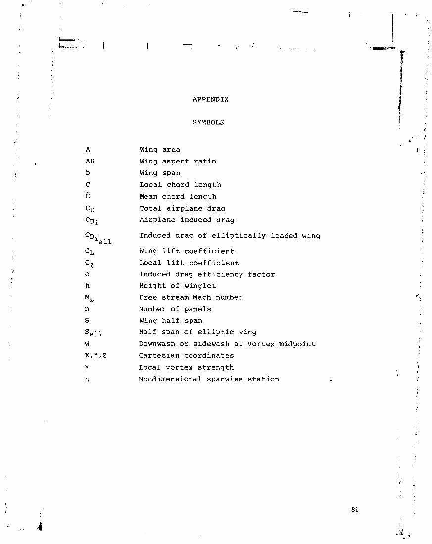
SYMBOLS
APPENDIX
'Di e l l
Wing a r e a
Wing a s p e c t r a t i o
Wing span
Loca l chord l e n g t h
Mean chord l e n g t h
T o t a l a i r p l a n e d r a g
A i r p l a n e induced d r a g
Induced d r a g o f e l l i p t i c a l l y loaded wing
Wing l i f t c o e f f i c i e n t
Local l i f t c o e f f i c i e n t
Induced d r a g e f f i c i e n c y f a c t o r
Height of w i n g l e t
F r e e s t r eam Mach number
Number o f p a n e l s
Wing h a l f span
Half span o f e l l i p t i c wing
Downwash o r s idewash a t v o r t e x midpo in t
C a r t e s i a n c o o r d i n a t e s
Local v o r t e x s t r e n g t h
Nondimensional spanwise s t a t i o n
REFERENCES
1. Falkner, V. M., "The Calculation of Aerodynamic Loading on Surfaces of Any Shape," R&M 1910, 1943, British Aero- nautical Research Council.
2. Rubbert, P. E., "Theoretical Characteristics of Arbitrary Wings by a Nonplanar Vortex Lattice Method," Rept. D6-9244, 1964, The Boeing Company, Seattle, Wash.
3. Feifel, W. M.. Fortran IV - Prograrnm zur Berechnung von V- Leitwerken," Mitteilung im Institut fur Aerodynamik und Gasdynamik der ~echnischen Universitat , ~tuttgart , Germany, 1966.
4. James, R. M., "On the Remarkable Accuracy of the Vortex- Lattice Discretization in Thin Wing Theory," Rept DAC- 67211, McDonnell Douqlas Corp, Long Beach, Calif., Feb. 1969.
5. Kalman, T. P., Giesing, J. P., Rodden, W. P., "Spanwise Dis- tribution of Induced Drag in Subsonic Flow by the Vortex Lattice Method," J. Aircraft, Vol. 7, No. 6, 1970.
6. Pistolesi, E., "Betrachtungen uber die gegenseitige Beeinfiussung von TragflGgelsystemen." Gesamrnelte Vortrage der Hauptversammlung 1937 der Lilienthal-Gesellschaft (19371, S. 214-219.
7. Jones, R. T., "The Spanwise Distribution of Lift for Minimum Induced Drag or Wings Having a Given Lift and a Given Bending Moment," NACA Technical Note 2249, Ames Aero- nautical Laboratory, Moffett Field, Calif., Dec. 1950.
I
8. Lundry, J. L., "A Numerical Solution for the Minimum Induced Drag, and the Corresponding Loading, of Nonplanar Wings," NASA CR-1218, issued by originator as Report DAC-66900, McDonnell Douglas Corp., Long Beach, Calif., 1968.
9. IsLimitsu, K. K., Van Devender, N., Dodson, R., ''Design and Analysis of Winglets for Mi>itary Aircraft," ~ i r Force Wright Aeronautical Laboratories, Wright-Patterson AFB, Ohio, Rpt No. RFFDL-TR-76-6, 1976.

VORTEX MI DPOI NT
LIFTING VORTEX ( @ + C )
BOUNDARY POINT
--- m- t TRAIL1 NG VORTl CES FOLLOW l NG STREAMLI RES
Figure 1.- S u r f a c e d i v i s i o n i n t o p a n e l s and l o c a t i o n of v o r t i c e s and c o n t r o l p o i n t s .
'F - EXACT SOLUTION AFTER R. T. JONES (REF. 7) PRESEIT VORTEX LATTICE METHOD
- - SPANWI SE STATION YISeII
Figure 2 . - Spanwise l o a d i n g cu rve f o r minimum induced d r a g of wings having a f i x e d t o t a l l i f t and a f i x e d r o o t bending monent .
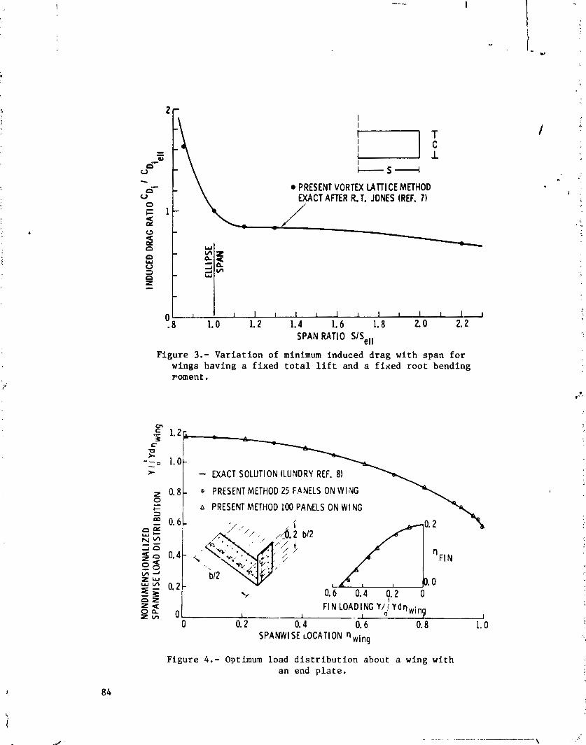
PRESENT VORTEX MlTl CE METHOD EXACT AFTER R. T. JONES (REF. 7)
n : z B 5 2 3 i Ul 0 W Z -
0 1 I t I I I I I I I I I I I L r .8 1.0 1.2 1.4 1.6 1.8 2.0 2.2
S P A N RATIO SISeII
Figure 3.- Variation of minimum induced drag with span f o r wings having a f ixed t o t a l l i f t and a f ixed root bending ~ o m e n t .
I::: - EXACT SOLUTION (LUNDRY REF. 8)
0 .81 @ PRESENT METHOD 25 FANELS O N W l NG 1 I A PRESENT METHOD 100 PAhELS O N W I N G '(k
F I N LOADING Y / i Y d q w i n 0
0 0.2 0.4 0.6 0.8 1.0 1
SPANWISE LOCATION n,ing
Figure 4 . - Optimum load d i s t r i b u t i o n about a wing with an end p l a t e .

Figure 5 . - Downwash and sidewash along the 114-chord l i n e of a wing and end plate for the minimum induced drag load distribution.
SPANWISE LOCATION 0 C 0,o 0.2 0.4 0.,6 V'ng 0.8 1.0
I I - '-0
5-0 .2 - @VORTEX LATTICE METHOD 25 PANELS O N W I N G z - VORTEX IATT I CE METHOD 100 PANELS O N W l NC U
S EXACT SOLUTION (LUNDRY REF. 8)
a 1.4- E!
- (LUNDRY REF. 8)
PRESENT VORTEX LATTICE METHOD A 25 SPANW I SE PANELS
50 SPANWISE PANELS
0 . 1 . 2 . 3
s
F I N HEIGHT 2hlb
W
- EXACT SOLUTION V, Z
NONDIMENSI ONAL 51 DEWASH VELOCITY AT THE F I N
Figure 6 . - Induced drag e f f ic iency factor of wings with an end plate .
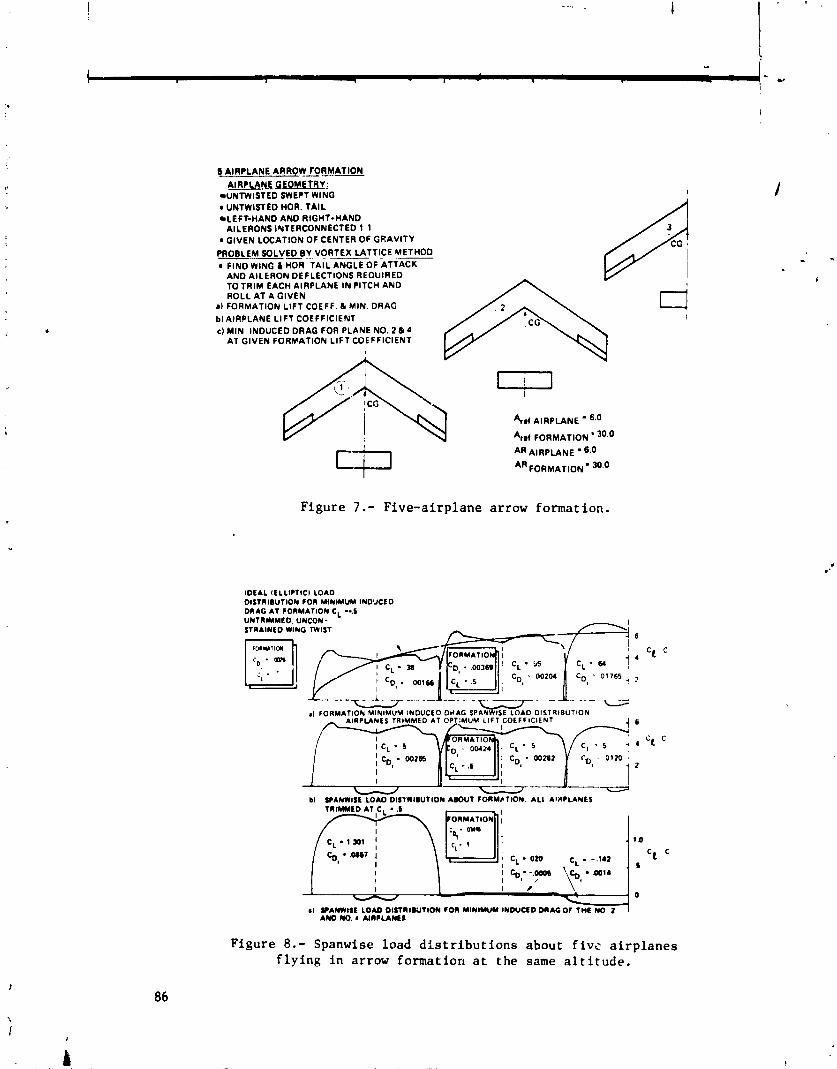
6 AIRPLANE ARROW FORMATION
AIRPLANE GEOMETRY: UNTWISTED SWEPT WING
0 UNTWISTED HOR. TAIL LEFT-HAND AND RIGHT-HAND AILERONS INTERCONNECT ED 1 1
0 GIVEN LOCATION OF CENTER OF GRAVITY
PROBLEM SOLVED0V VORTEX LATTICE METHOD, 0 FIND WING L HOR, TAIL ANGLE OF ATTACK
AND AILERON DEFLECT IONS REQUIRED TOTRIM EACH AIRPLANE I N PITCH AND ROLL AT A GIVEN
11 FORMATION LlFT COEFF. 6 MIN. DRAG blA1RPLANE LlFT COEFFICIENT CI MIN INDUCED DRAG FOR PLANE NO. 2 6 4
AT GIVEN FORHATION LlFT COEFFICIENT
4.1 AIRPLANE 6.0
FORMATION ' 30.0
AIRPLANE ' 6.0
AR FORMATION - 30'0
Figure 7.- Five-airplane ar row formation.
IDEAL lELLlCTlCl LOAD D I S T R I ~ U T I O N FOR MINIMUM IND'JCED DRAG AT FORMATION C. .5
- J bl PANWISE LOAD D I S T ~ I D U T I O N A m U T FORMbTlON. A L I AIRPLANES
TRIMMED AT CL - .I OnMATION I - kT-;
Figure 8.- Spanwise load d i s t r i b u t i o n s about f i v s a i rp lanes f l y i n g i n ar row format ion a t the same a l t i t u d e .

A 114 PANEL
/- / LIFJI NG VORTEX
VORTl CES \'. -
Figuz e 9. - Typical representat ion of wing and winglet by a multi-,horseshoe vortex l a t t i c e systen.
Figure 10.- Tip f i n a i r f o i l sect ions with camber l ine designed by vortex l a t t i c e optimizing method.
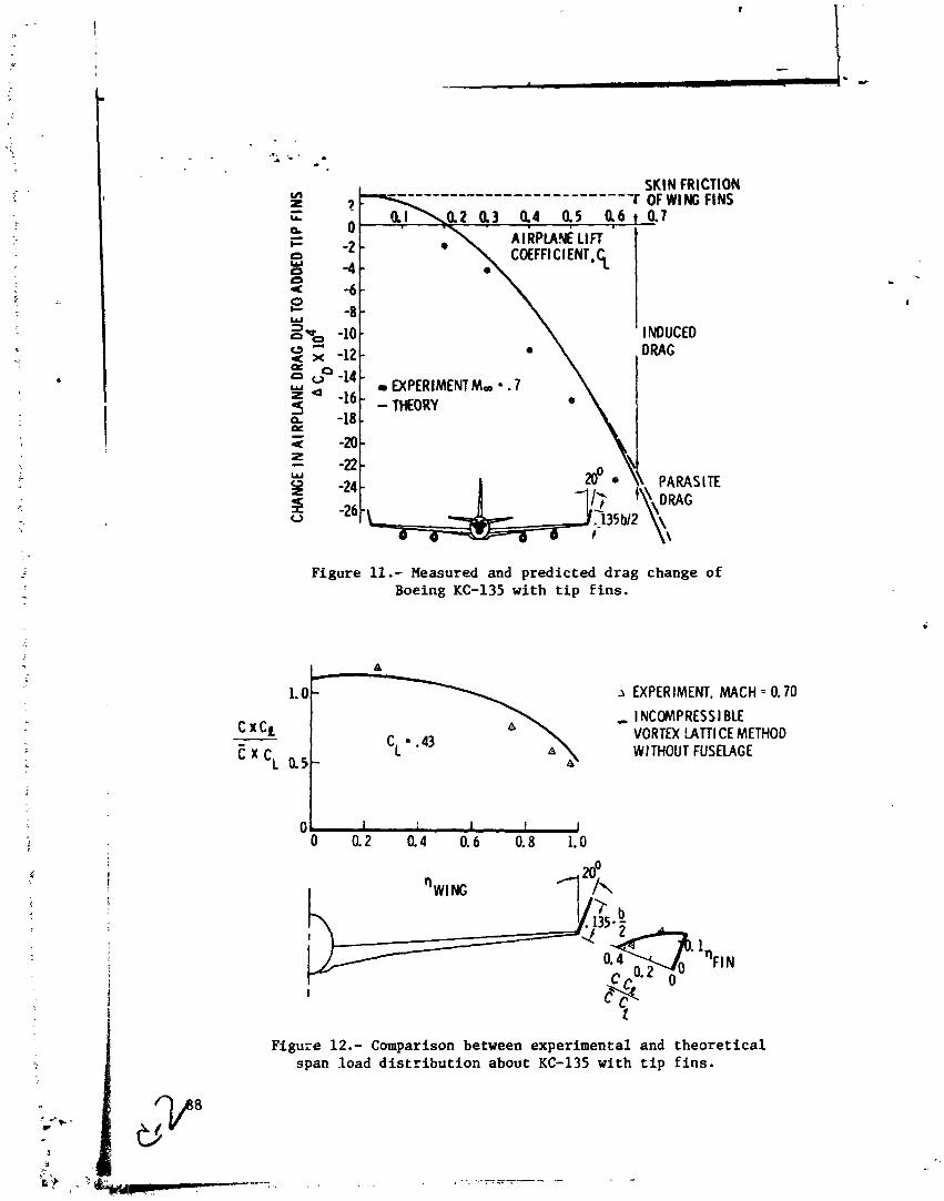
SKIN FRICTION
-8 - -10 - -12 -
EXPERIMENT M, = . 7
-18 \ i
Figure 11.- Measured and predicted drag change of Boeing KC-135 with tip fins.
Figure 12.- Comparison between experimental and theoretical span load distribution about KC-135 with tip fins.
1.0-
C xCL
t x c L 0.5-
a *
2 EXPERIMENT. MACH = 0.70
, I NCCMPRESSI BLE VORTEX !ATTI CE METHOD WITHOUT FUSELAGE

MINIMUM TRIM DRAG DESIGN FOR INTERFERING LIFTING
SURFACES USING VORTEX-LATTICE METHODOLOGY
John E. Lamar NASA Langley Research Center
SUMMARY
A new subsonic method has been developed by which t h e mean camber s u r f a c e can be determined f o r trimmed noncoplanar planforms wi th minimum vor tex drag. This method uses a vor tex l a t t i c e and overcomes previous d i f f i c u l t i e s w i t h chord loading s p e c i f i c a t i o n . Th is method uses a T r e f f t z p lane a n a l y s i s t o determine t h e optimum span loading f o r minimum drag , then s o l v e s f o r t h e mean camber s u r f a c e of t h e wing, which w i l l provide t h e required loading. P i t ch ing- moment o r root-bending-moment c o n s t r a i n t s can be employed as w e l l a t t h e des ign l i f t c o e f f i c i e n t .
S e n s i t i v i t y s t u d i e s of v o r t e x - l a t t i c e arrangement have been made wi th t h i s method and a r c presented. Comparisons wi th o t h e r t h e o r i e s show g e n e r a l l y good agreement. The v e r s a t i l i t y of t h e method is demonstrated by applying i t t o (1) i s o l a t e d wings, (2) wing-canard conf igura t ions , (3) a tandem wing, and ( 4 ) a wing-winglet con£ i g u r a t ion.
INTRODUCTION
Confisurat ion des ign f o r subsonic t r a n s p o r t s u s u a l l y begins wi th t h e wing, a f t e r whi2h t h e body and its e f f e c t s a r e taken i n t o account, and then t h e t a i l s a r e s i z e d and loca ted by taking i n t o account s t a b i l i t y and c o n t r o l requirements. With t h e advent of h ighly maneuverable a i r c r a f t having c l o s e l y coupled l i f t i n g sur faces , t h e r e has been a n increased i n t e r e s t i n changing t h e des ign o r d e r s o t h a t m u l t i p l e s u r f a c e s could be designed toge ther t o y i e l d a trimmed configura- t i o n wi th minimuin induced drag a t some s p e c i f i e d l i f t c o e f f i c i e n t . Such a com- bined design approach r e q u i r e s t h a t t h e mutual i n t e r f e r e n c e of t h e l i f t i n g sur - f aces be considered i n i t i a l l y .
S ing le planform design methods a r e a v a i l a b l e t o opt imize t h e mean camber s u r f a c e , b e t t e r c a l l e d t h e l o c a l e l e v a t i o n s u r f a c e , f o r wings f l y i n g a t sub-, son ic speeds ( f o r example, r e f . 1 ) and a t supersonic speeds ( f o r example, r e f s . 2 and 3) . The des ign method presented i n r e f e r e n c e 1 was developed from an e s t a b l i s h e d a n a l y s i s method (Multhopp t y p e ) , a l s o presented i n r e f e r e n c e 1, by using the same mathematical model, but t h e des ign method s o l v e s f o r t h e l o c a l mean s l o p e s r a t h e r than t h e l i f t i n g p ressures . I n t h e u s u a l implementa- t i o n of r e f e r e n c e 1, t h e des ign l i f t i n g p ressures a r e taken t o be l i n e a r chord- wise, but must be represented i n t h i s s o l u t i o n by a s i n e s e r i e s which o s c i l l a t e s about them. An example presented h e r e i n demonstrates t h a t corresponding o s c i l - l a t i o n s may appear i n p r e s s u r e d i s t r i b u t i o n s measured on wings which have been designed by t h e method of re fe rence 1. The method developed h e r e i n overcomes t h i s o s c i l l a t o r y l i f t i n g p ressure behavior by spec i fy ing l i n e a r chord load ings a t t h e o u t s e t .
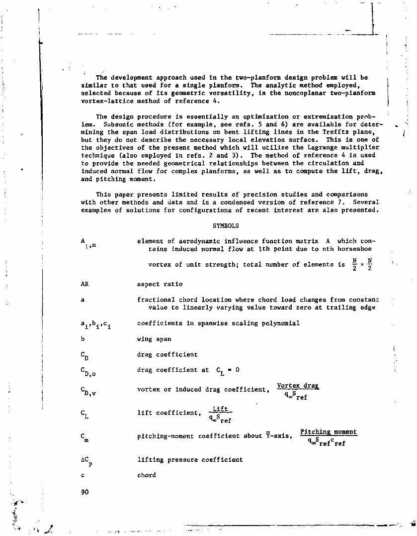
: . . ' he development approach used i n t he two-planform design problem w i l l be
similar t o t h a t used f o r a s i n g l e planform. The ana ly t i c method employed, selected because of i ts geometric v e r s a t i l i t y , is the noncoplanar two-planform
1 : vor tex- la t t ice method of reference 4.
The design procedure is e s s e n t i a l l y an optimization o r extremization prnb- *. lem. Subsonic methods ( fo r example, s e e r e f s . 5 and 6) a r e ava i lab le f o r deter- , :
mining the span load d i s t r i bu t ions on bent l i f t i n g l i n e s i n the Tre f f t z plane, / ,,
but they do not descr ibe the necessary l o c a l e leva t ion surface. This is one of the object ives of the present method which w i l l u t i l i z e t he Lagrange mul t ip l i e r technique (a l so employed i n r e f s . 2 and 3). The method of reference 4 is used t o provide the needed geometrical re la t ionships between the c i r cu l a t ion and induced normal flow f o r complex planforms, a s well a s t o compute t h e l i f t , drag, and pi tching moment.
This paper presents l imited r e s u l t s of precis ion s tud ie s and comparisons with other methods and da ta and is a condensed version of reference 7. Several examples of so lu t ions f o r configurations of recent i n t e r e s t a r e a l s o presented.
SYMBOLS
A element of aerodynamic inf luence funct ion matrix A which con- 1 s" t a i n s induced normal flow a t I t h point due t o n th horseshoe
N N vortex of un i t s t rength; t o t a l number of elements is - x - I : 2 2
AR aspect r a t i o
f r a c t i o n a l chord loca t ion where chord load changes from constanc ,
value t o l i n e a r l y varying value toward zero a t t r a i l i n g edge '
ai,b c i' i coe f f i c i en t s i n spanwise sca l ing polynomial
b wing span
C~ drag coe f f i c i en t
C drag coe f f i c i en t a t CL = 0 D,o
vortex o r induced drag coe f f i c i en t , Vortex d r a ~
qmSref
L i f t l i f t coe f f i c i en t , - qmSref
Pi tching moment pitching-moment coef f ic ien t about ?-axis,
qmSrefCref
l i f t i n g pressure coef f ic ien t
chord
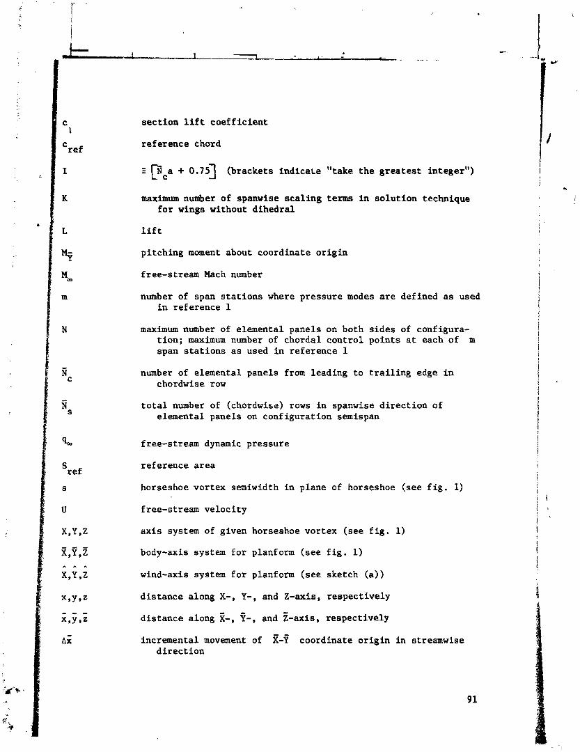
C 1
C re f
I
K
sec t ion l i f t coe f f i c i en t
reference chord
Z [vca + 0.75) (brackets i n d i c a ~ r "take the g rea t e s t integer")
maximum number of spanwise sca l ing terms i n so lu t ion technique f o r wings without d ihedra l
l i f t
pi tching moment about coordinate o r ig in
free-stream Mach number
number of span s t a t i o n s where pressure modes a r e defined a s used i n reference 1
maximum number of elemental panels on both s ides of configura- t i on ; maximum number of chordal cont ro l points a t each of m span s t a t i o n s a s used i n reference 1
number of elemental panels from leading t o t r a i l i n g edge i n chordwise row
t o t a l number of (chordwise) rows i n spanwise d i r ec t ion of elemental panels on configurat ion semispan
free-stream dynamic pressure
reference a rea
horseshoe vortex semiwidth i n plane of horseshoe (see f i g . 1)
a x i s system of given horseshoe vortex (see f i g . 1)
body-axis system f o r planform (see f i g . 1 )
wind-axis system f o r planform (see sketch ( a ) )
d i s tance along X-, Y-, and Z-axis, respect ively
d is tance along z-, P-, and Z-axis, respect ively
incremental movement of g-f coordinate o r ig in i n streamwise d i r ec t ion
free-stream ve loc i ty
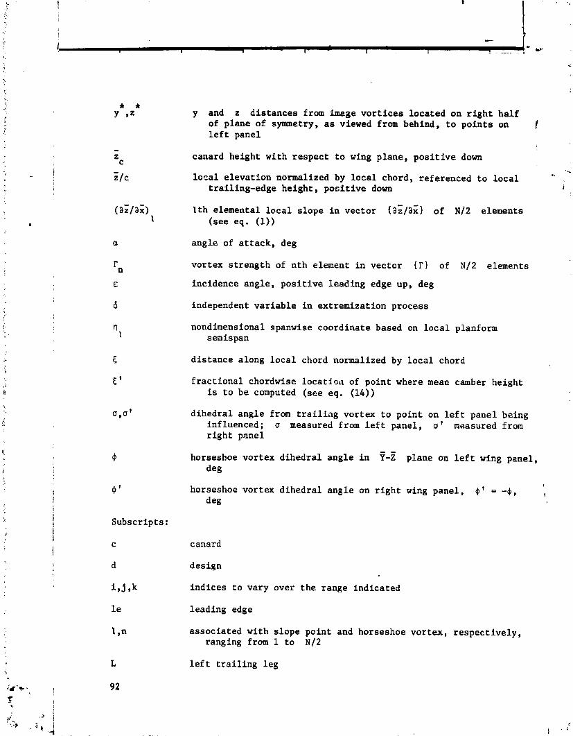
Subscr ip t s :
C
d
i , j 9k
1 e
t s n
y and z d i s t a n c e s from image v o r t i c e s loca ted on r i g h t h a l f of p lane of symmetry, as viewed from behind, t o p o i n t s on l e f t panel
canard height wi th r e s p e c t t o wing p lane , p o s i t i v e down
l o c a l e l e v a t i o n normalized by l o c a l chord, referenced t o l o c a l t r a i l ing-edge h e i g h t , p o s i t i v e down
l t h e lemental l o c a l s l o p e i n v e c t o r { a i / a x } of N/2 elements ( see eq. (1))
ang le of a t t a c k , deg
vor tex s t r e n g t h of n t h element i n vec to r 1 of N/2 elements
incidence ang le , p o s i t i v e l ead ing edge up, deg
independent v a r i a b l e i n ex t remiza t ion process
nondimensional spanwise coord ina te based on l o c a l planform semispan
d i s t a n c e along l o c a l chord normalized by l o c a l chord
f r a c t i o n a l chordwise l o c a t i c n of p o i n t where mean camber he igh t i s t o be computed ( see eq. (14))
d i h e d r a l ang le from t r a i l i a g vor tex t o p o i n t on l e f t panel being inf luenced; u measured from l e f t panel , a ' measured from r i g h t panel
horseshoe v o r t e x d i h e d r a l a n g l e i n Y-Z plane on l e f t wing panel, deg
I
horseshoe vor tex d i h e d r a l ang le on r i g h t wing pane l , 4 ' = - 4 , 1
deg
canard
des ign
i n d i c e s t o vary over t h e range ind ica ted
l ead ing edge
assoc ia ted wi th s l o p e po in t and horseshoe v o r t e x , r e s p e c t i v e l y , ranging from 1 t o N/2
l e f t t r a i l i n g l e g
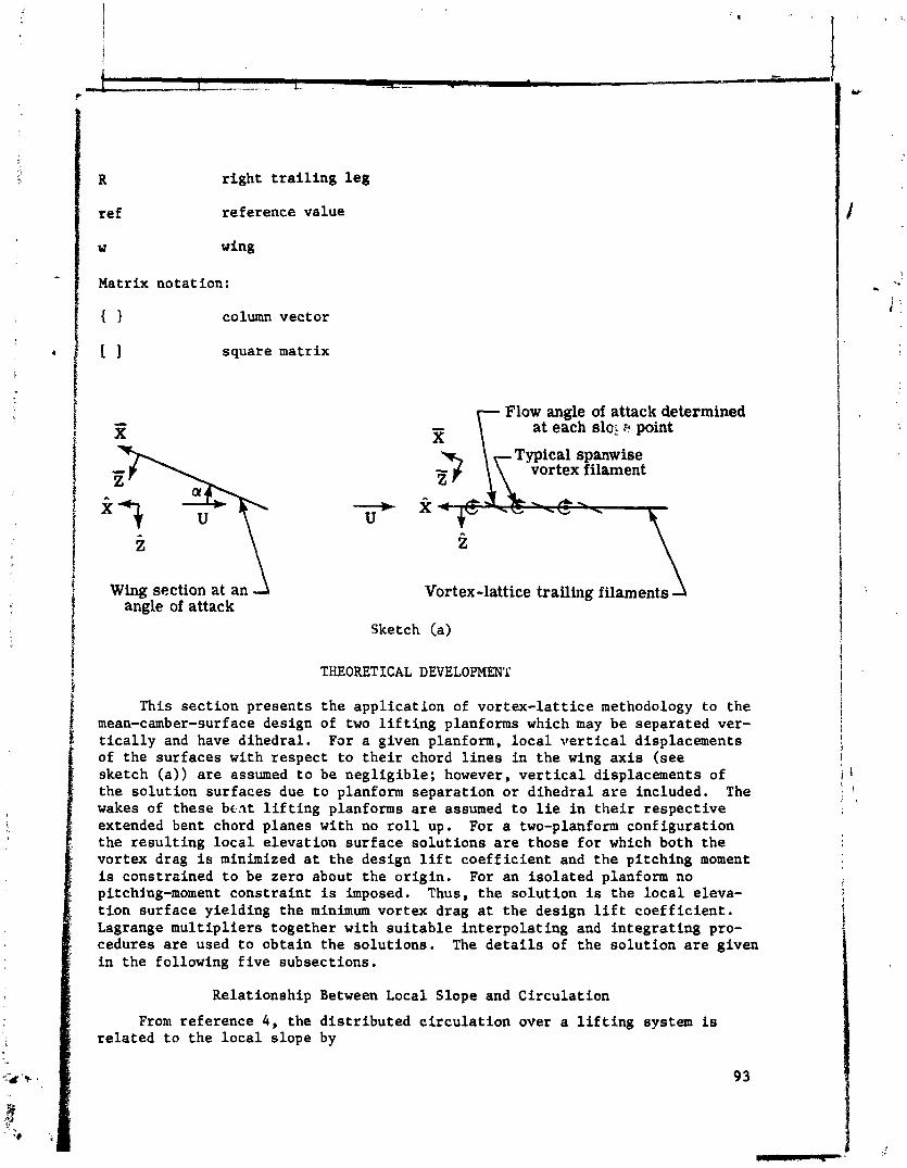
R r i g h t t r a i l i n g l e g
ref reference value
w wing
Matrix notat ion:
{ 1 column vector
[ 1 square matrix
Flow angle of attack determined - r at each sloi P point X
Typical spanwise vortex filament
Wing section at an -1\ angle of attack
Vortex-lattice trailing filaments 1 Sketch (a)
THEORETICAL DEVELOPMEN'L'
This s ec t i on presents t h e appl ica t ion of vo r t ex - l a t t i c e methodology t o t he mean-camber-surface design of two l i f t i n g planforms which may be separated ver- t i c a l l y and have dihedral . For a given planform, l oca l v e r t i c a l displacements of t he sur faces with respect t o t h e i r chord l i n e s i n t he wing a x i s (see sketch (a)) a r e assumed t o be negl ig ib le ; however, v e r t i c a l displacements of the so lu t ion surfaces due t o planform separat ion o r d ihedra l a r e included. The wakes of these be.?t l i f t i n g planforms a r e assumed t o l i e i n t h e i r respec t ive extended bent chord planes with no r o l l up. For a two-planform configurat ion the r e su l t i ng l o c a l e leva t ion sur face so lu t ions a r e those f o r which both t he vortex drag i s minimized a t t he design l i f t coe f f i c i en t and t h e pi tching moment is constrained t o be zero about t he o r ig in . For an i so l a t ed planform no pitching-moment cons t ra in t is imposed. Thus, t h e so lu t ion is the l o c a l eleva- t i on sur face yielding the minimum vortex drag a t t he design l i f t coe f f i c i en t . Lagrange mu l t i p l i e r s together with s u i t a b l e i n t e rpo la t i ng and in t eg ra t i ng pro- cedures a r e used t o obtain the so lu t ions . The d e t a i l s of t he so lu t ion a r e given i n t he following f i v e subsections.
Relationship Between Local Slope and Ci rcu la t ion
From reference 4 , the d i s t r i bu t ed c i r c u l a t i o n over a l i f t i n g system is r e l a t ed t o the l o c a l s lope by
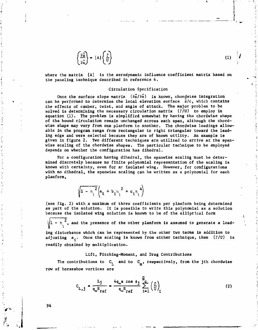
where the mat r ix [ A ] is t h e aerodynamic in f luence c o e f f i c i e n t mat r ix based on t h e paneling technique descr ibed i n re fe rence 4 .
C i r c u l a t i o n S p e c i f i c a t i o n
Once t h e s u r f a c e s l o p e mat r ix {ah lax ) is known, chordwise - i n t e g r a t i o n can be performed t o determine t h e l o c a l e l e v a t i o n s u r f a c e z /c , which con ta ins t h e e f f e c t s of camber, t w i s t , and ang le of a t t a c k . The major problem t o be solved is determining t h e necessary c i r c u l a t i o n mat r ix W u l t o employ i n equat ion (1). The problem is s i m p l i f i e d somewhat by having t h e chordwise shape of t h e bound c i r c u l a t i o n remain unchanged a c r o s s each span, al though the chord- wise shape may vary from one placform t o ano ther , The chordwise load ings allow- a b l e i n t h e program range from rec tangu la r t o r i g h t t r i a n g u l a r toward t h e lead- ing edge and were s e l e c t e d because they a r e of known u t i l i t y . An example is given i n f i g u r e 2 , Two d i f f e r e n t techniques a r e u t i l i z e d t o a r r i v e a t t h e span- wise s c a l i n g of t h e chordwise shapes , The p a r t i c u l a r technique t o be employed depends on whether t h e conf igura t ion has d ihedra l .
For a conf igura t ion having d i h e d r a l , t h e spanwise s c a l i n g must be d e t e r - mined d i s c r e t e l y because no f i n i t e polynomial r e p r e s e n t a t i o n of t h e s c a l i n g is known wi th c e r t a i n t y , even f o r a r i s o l a t e d wing. However, f o r conf i g u r a t i o n s wi th no d i h e d r a l , t h e spanwise s c a l i n g can be w r i t t e n a s a polynomial f o r each planform,
( see f i g . 2 j wi th a maximum of t h r e e c o e f f i c i e n t s per planfonn being determined a s p a r t of t h e s o l u t i o n . I t is p o s s i b l e t o w r i t e t h i s polynomial as a s o l u t i o n because t h e i s o l a t e d wing s o l u t i o n is known t o be of t h e e l l i p t i c a l form
L il - n I , and t h e presence of t h e o t h e r planform is assumed t o genera te a load-
ing d i s tu rbance which can be represented by t h e o t h e r two terms i n a d d i t i o n t o a d j u s t i n g ai. Once t h e s c a l i n g is known from e i t h e r technique, then { I ' l U ) i s
r e a d i l y obtained by m u l t i p l i c a t i o n .
L i f t , Pitching-Moment, and Drag Cont r ibu t ions
The c o n t r i b u t i o n s t o C and t o Cm, r e s p e c t i v e l y , from t h e j t h chordwise L
row of horseshoe v o r t i c e s a r e
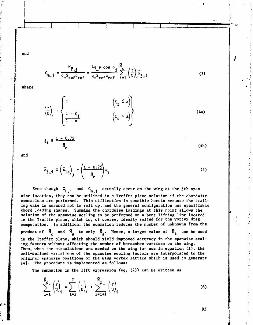
and
4q s cos 0 N %J * OD C = m ~ j qwSrefCrei q=Srefcref
where
and
Even though C L , j
and C actually occur on the wing at the jth span- m,j
wise location, they can be utilized in a Trefftz plane solution if the chordwise ~ummations are performed. This utilization is possible herein because the trail- ing wake is assumed not to roll up, and the general configuration has specifiable chord loading shapes. Summing the chordwise loadings at this point allows the solution of the spanwise scaling to be performed on a bent lifting line located in the Trefftz plane, which is, of course, ideally suited for the vortex drag computation. In addition, the summation reduces the number of unknowns from the
product of and is to only Is. Hence, a larger value of is can be used C
in the Trefftz plane, which should yield improved accuracy in the spanwise scal- ing factors without affecting the number of horseshoe vortices on the wing. Then, when the circulations are needed on the wing for use in equation (I), the well-defined varlatlnnn of the spanwise scaling factors are interpolated to the original spanwise positions of the wing vortex lattice which is used to generate [A]. The procedure is implemented as follows:
The summation in the lift expression (eq. (2)) can be written as

where I is the last i value which satisfies Ei 5 a; that is,
(7)
where the brackets indicate "take the greatest integer. " Hence,
Similarly, the summation in the pitch expression (eg. (3)) can be written as
Bc i-1
The contribution to the vortex drag coefficient at the ith chordwise row due to the jt l i chordwise row is obtained by using only half the trailing vortex induced normal wash from the Trefftz plane. The result is
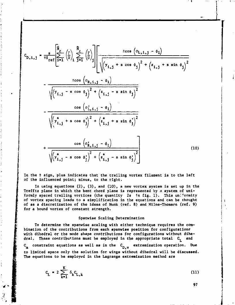
+ s cos (j)2 + ( z ~ , ~ + s sin P ~ ) 2
2 db;, \ , + . cos ; + , + s .in 0;)
\(& - s cos $1,' j + (z* i,j - s sin PfrJ j
In the 2 sign, plus indicates that the trailing vortex filament is to the left of the influenced point; minus, to the right.
In using equations (2), ( 3 ) , and (lo), a new vortex system is set up in the Trefftz plane in which the bent chord plane is represented by a system of uni- formly spaced trailing vortices (the quantity 2s in fig. 1). This unlcormity of vortex spacing leads to a simplification in the equations and can be chought of as a discretization of the ideas of Munk (ref. 8) and Milne-Thomsm (ref. 9) for a bound vortex of constant strength.
Spanwise Scaling Determination
To determine the spanwise scaling with either technique requires the com- bination of the contributions from each spanwise position for configuratione with dihedral or the mode shape contributions for configurations without dihe- dral. These contributions must be employed in the appropriate total C and L
cm constraint equations as well as in the C extremization operation. Due D,v
to limited space only the solution for wings without dihedral will be discussed. The equations to be employed in the Lagrange extremization method are

and
where K 5 6 and C L,k
and C are the CL and Cm contrlbution~ associ- a,k
ated with the kth term in the poly~omials
I (Note that k = 1, 2, and 3 are assigned to the first planform azd 4, 5, and 6 to the second.) These contributions are computed by first assuming a unit value
*
of scaling with each term in the polynomial, then multiplying each resulting spanwise scaling distribution by the CL,, and C terms of equations (2)
m,j and ( 3 ) . and finally suxmning spanwise ove; all the chordwise rows associated with zach set of k values (or planform). The vortex drag coefficient associ- ated with the ith and kth combination of spanwise scaling distributions CD,i,k is compared similarly. The cSk terms are equivalent to the unknown coefficients , in the polynomial and are the independent variables in the solution.
An application of the preceding process to a conventional wlng-tail config- uration is shown in figure 3. The resulting idealized loading set io of the type that would meet the constraints and extremization.
Determination of Local Elevation Curves
results for { r / ~ ) are interpolated to the original^ spanwise positione of the paneling which is ueed in equation (I) and in the following equation to find the local elevation curves. The equation for - the local elevatioi~ above the computa- tional plane at a particular point (St ,y) is

RESULTS AND DISCUSSION
General
It is r'ecessary to examine the sensitivity of the results of the present method to -4ortex-lattice arrangement. It is elso important to compare resalts obtainer! with this method with those available in the literature. Unfortunately, the rvailable solutions, whether exact or numerical, may not be for configura- t4.0ns which will exercise the constraint or extreminization capabilitieu of the ?resent method. In fact, the available exact solutians are for configurations which are either two-dimensional sections or iscla: i three-dimension61 wings with a nonelliptic span loading. The solutions ior such configurstions require program modifications to the span loading and involve no optimization.
Two-Dimensional Comparison
Various chordwise arrangemente and number of vortices were Investigated for several chordwise loading shapes, of which the a - 0.6 results are given in figure 4. Although difficult to see clearly from this figure, the agreement of the present method with analytic results (ref. 10) is good for both local slope and elevation. Examination of figure 4 leads to the following general conclu- sions concern'mg the chordwise arrangement: (1) Uniform spacing is preferred; (2) kc = 20 1s a good compromiue when considering both computrrtional requirr-
ments and completely converged results. An additional conclusion is that the present method yields incidence angles near the leading edge which are slightly higher than the analytical ones.
Number of Rows Along Semispan P S )
Various spanwlse arrangements and number of vortices were studied for o;,e planform and from these studies the following conclusions were drawn: (1) Uni- form spacing is preferred; (2) for at least 10 spmwiee rows per semispan, the local slopes and elevations were not too sensitive to increasing the number.
Three-Dimensional Camparisons
Two comparisons with available mean-camber-surface solutions will be made. The comparisons are for a high-aspect-ratio swepcback and tapered wing with a uniform area loading at CLmd = 1.0 and M, = 0.9!; and a lower aspect-ratio
trapezoidal wing with a I 1.0, spanwise elliptic loading at C 1 0.35, and L,d
M, = 0.40.
Figure 5 presents the predicted results from the present method for the sweptback wing and compares these results with those from references 1 and 11. A comparison of the three solutions indicates that they are all in generally - good agreement with the exception of the results at & = 0.05. The surprising
result is that the present method and the modified Multhopp method (ref. 1) agree as well as they do at this span station because of the known differences that exist between them near the plane of symmetry. xhe reason for the larger
disagreement between the present method and that of reference 11 :tear
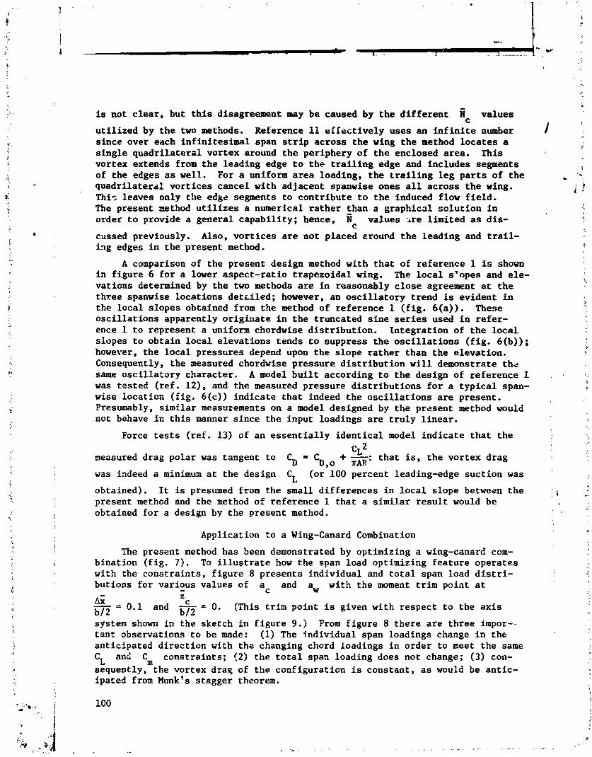
is not clear, but this disagreement may be caused by the different fi values C
utilized by the two methods. Reference 11 dfectively uses an infinite number since over each infinitesimal span strip across the wing the method locates a single quadrilateral vortex around the periphery of the enclosed area. This vortex extends from the leading edge to the trailing edge and includes segments of the edges as well. For a uniform area loading, the trailing leg parts of the quadrilateral vortices cancel with adjacent spanwise ones all across the wing. This leaves only the edge segments to contribute to the induced flow field. The present method utilizes a numerical rather than a graphical solution in order to provide a general capability; hence, 9 values ire limited as dis- cussed previously. Also, vortices are not placed rrourd the leading and trail- i ~ g edges in the present method.
A comparison of the present design method with that of reference 1 is shown in figure 6 for a lower aspect-ratio trapezoidal wing. The local s'opes and ele- vations determined by the two methods are in reasonably close agreement at the three spanwise locations dettiled; however, an oscillatory trend is evident in the local slopes obtained from the method of reference 1 (fig. 6(a)). These oscillations apparently originate in the truncated sine series used in refer- ence 1 to represent a uniform chordwise distribution. Integration of the local slopes to obtain local elevations tends to suppress the oscillations (fig. 6(b)); however, the local pressures depend upon the slope rather than the elevation. Consequently, the measured chordwise pressure distribution will demonstrate thd same oscillatory character. A model built according to the design of reference 1 was tested (ref. 12), and the measured pressure distributions for a typical span- wise location (fig. 6(c)) indicate that indeed the oscillations are present. Presumably, similar measurements on a model designed by the present method would not behave in this manner since the input loadings are truly linear.
Force tests (ref. 13) of an essentially identical model indicate that the
measured drag polar was tangent to C L ~ CD = C +-• D.o TAR'
that is, the vortex drag
was indeed a minimum at the design CL
(or 100 percent leading-edge suction was
obtained). It is presumed from the small differences in local slope between the present method and the method of reference 1 that a similar result would be obtained for a design by the present method.
Application to a Wing-Canard Combination
The present method has been demonstrated by optimizing a wing-canard com- bination (fig. 7). To illustrate how the span load optimizing feature operates with the constraints, figure 8 presents individual and total span load distri- butions for various values of a and aw with the moment trim point at - C
AI 2 - = C
b/2 0.1 and - =
b/2 0. (This trim point is given with respect to the axis
system shown in the sketch in figure 9.) From figure 8 there are three impor-- tant observations to be made: (1) The individual span loadings change in the anticipated direction with the changing chord loadings in order to meet the same CL and Cm constraints; (2) the total span loading does not change; (3) con- sequently, the vortex draq of the configuration is constant, as would be antic- ipated from Munk's stagger theorem.
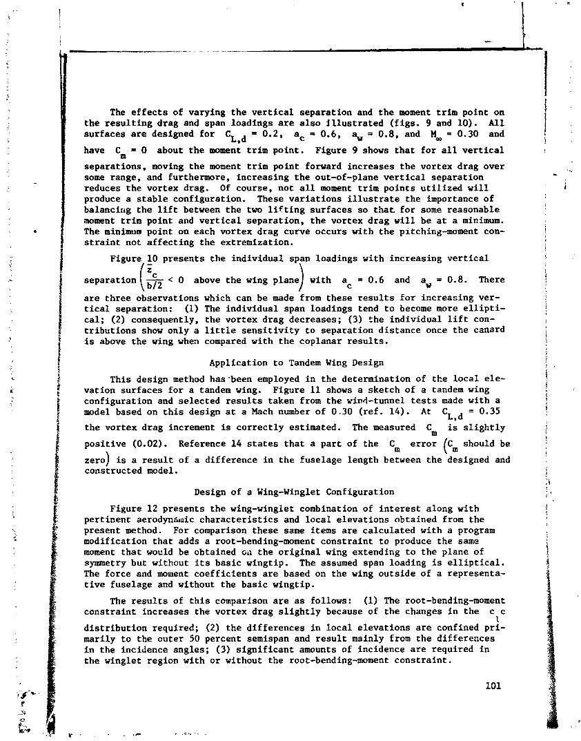
The effects of varying the vertical separation and the moment trim point on the resulting drag and span loadings are also illustrated (figs. 9 and 10). All surfaces are designed for CL,d - 0.2, ac = 0.6, aw = 0.8, and M _ = 0.30 and
have Cm = 0 about the m e n ; trim point. Figure 9 shows that for all vertical
separations, moving the moment trim point forward increases the vortex drag over some range, and furthermore, increasing the out-of-plane vertical separation reduces the vortex drag. Of course, not all moment trim points utilized will produce a stable configuration. These variations illustrate the importance of balancing the lift between the two lifting surfaces so that for some reasonable moment trim point and vertical separation, the vortex drag will be at a minimum. The minimum point on each vortex drag curve occurs with the pitching-moment con- straint not affecting the extremization.
Figure 10 presents the individual loadings with increasing vertical - z
separation (& < 0 above the wing ac = 0.6 and aw = 0.8. There
are three observations which can be made from these results for increasing ver- tical separation: (1) The individual span loadings tend to become more ellipti- cal; (2) consequently, the vortex drag decreases; (3) the individual lift con- tributions show only a little sensitivity to separation distance once the canard is above the wing when compared with the coplanar results.
Application to Tandem Wing Design
This design method has-been employed in the determination of the local ele- vation surfaces for a tandem wing. Figure 11 shows a sketch of a tandem wing configuration and selected results taken from the wind-tunnel tests made with a model based on this design at a Mach number of 0 -30 (ref. 14). At CL,d = 0.35
the vortex drag increment is correctly estimated. The measured Cm is slightly
positive (0.02). Reference 14 states that a part of the Cm error (cm should be zero) is a result of a difference in the fuselage length between the -designed and constructed model.
Design of a Wing-Winglet Configuration
Figure 12 presents the wing-winglet combination of interest along with pertinent: aerodynanic characteristics and local elevations obtained from the present method. For comparison these same items are calculated with a program modification that adds a root-bending-moment constraint to produce the same moment that wocld be obtained Gil the original wing extending to the plane of symmetry but without its basic wingtip. The assumed span loading is elliptical. The force and moment coefficients are based on the wing outside of a representa- tive fuselage and without the basic wingtip.
The results of this comparison are as follows: (1) The root-bending-moment constraint increases the vortex drag slightly because of the changes in the c c
1
distribution required; (2) the differences in local elevations are confined pri- marily to the outer 50 percent semispan and result mainly from the differences in the incidence angles; (3) significant amounts of incidence are required in the winglet region with or without the root-bending-moment constraint.

CONCLUDING REMARKS
A new subsonic method has been deveLped by which the mean camber (local elevation) surface can be determined for trimmed noncoplanar planforms with minimum vortex drag. This method employs a vortex lattice and svorcomes pre- vious difficulties with chord loading specification. This method designs con- - figurations to have their local midsurface elevations determined to yield the 1 span load for minimum vortex drag while simultaneously controlling the pitching- moment or root-bending-moment constraint at the design lift coefficient. This method can be used for planfoms which (1) are isolated, (2) are in pairs, (3) include a winglet, or (4) employ variable sweep, but only at a specified sweep position.
Results obtained with this method are comparable with those from other methods for appropriate planforms. The versatility of the present method has been demonstrated by application to (1) isolated wings, (2) wing-canard config- urations, (3) a tandem wing, and (4) a wing-winglet configuration.

REFERENCES
1. Lamar, John E.: A Modified Multhopp Approach for Predicting Lifting Pres- sures and Camber Shape for Composite Plenforms in Subsonic Flow. NASA TN D-4427, 1968.
2. Carlson, Harry W.; and Middleton, Wilbur D,: A Numerical Method for the Design of Camber Surfaces of Supersonic Wings With Arbitrary Planforms, NASA TN D-2341, 1964.
3. Sorrells, Russell B.; and Miller, David S.: Numerical Method for Design of Minimum-Drag Supersonic Wing Camber With Constraints on Pitching Moment and Surface Deformation. NASA TN D-7097, 1972.
4. Margason, Richard J.; and Lamar, John E.: Vortex-Lattice FORTRAN Program for Estimating Subsonic Aerodynamic Characteristics of Complex Planforms. NASA TN D-6142, 1971.
5. Lundry, J. L.: A Numerical Solution for the Minimum Induced Drag, and the Corresponding Loading, of Nonplanar Wings. NASA CR-1218, 1968.
6. Loth, John L.; and Boyle, Robert E.: Optimum Loading on Nonplanar Wings at Minimum Induced Drag. Aerosp. hag. TR-19 (Contract N00014-68-A-1512), West Virginia Univ., Aug. 1969. (Available from DDC as AD 704 502.)
7. Lamar, John E.: A Vortex-Lattice Method for the Mean Camber Shapes of Trimmed Noncoplanar Planforms With Minimum Vortex Drag. NASA TN Ii-8090, 1976.
8. Munk, Max M.: The Minimum Induced Drag of Aerofoils. NACA Rep. 121, 1921.
9. Milne-Thomson, L. M.: Theoretical Aerodynamics. Second ed. D. Van Nostrand Co., Inc., 1952.
10. Abbott, Ira H.; Von Doenhoff, Albert E.; and Stivers, Louis S., Jr.: Sum- mary of Airfoil Data. NACA Rep. 824, 1945. (Supersedes NACA WR L-560.)
11. Katzoff, S.; Faison, M. Frances; and DuBose, Hugh C.: Determination of Mean Camber Surfaces for Wings Having Uniform Chordwise Loading and Arbitrary Spanwise Loading in Subsonic Flow. NACA Rep. 1176, 1954. (Supersedes NACA TN 2908.)
12. Henderson, William P.: Pressure Distributions on a Cambered Wing-Body Con- figuration at Subsonic Mach Numbers. NASA TN D-7946, 1975.
13. Henderson, William P.; and Huffman, Jarrett K.: Effect of Wing Design on the Longitudinal Aerodynamic Characteristics of a Wing-Body Model at Sub- sonic Speeds. NASA TN D-7099, 1972.
14. Henderson, William P.; and Huffman, Jarrett K.: Aerodynamic Characteristics of a Tandem Wing Configuration at a Mach Number of 0.30. NASA TM X-72779, 1975.
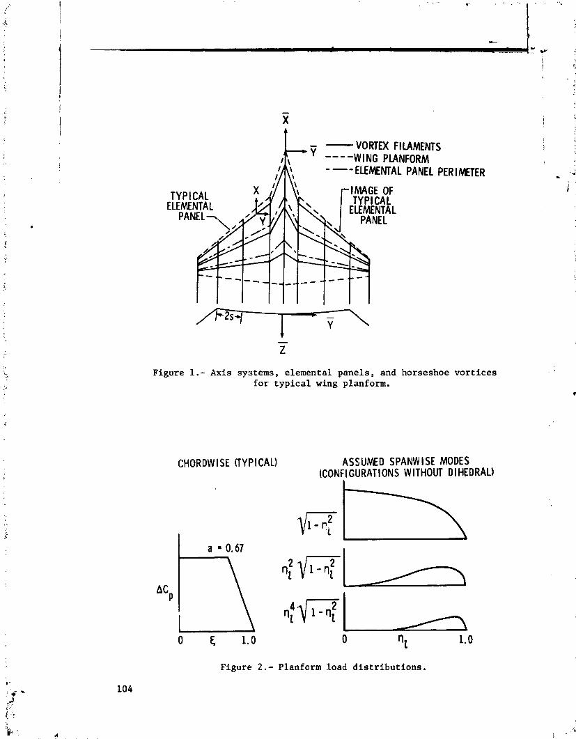
- X
- - VORTEX F l LAMENTS
--- ELEMEMAL PANEL PER I METER
Figure 1.- Axis systems, elemental panels, and horseshoe vortices for typical wing planform.
CHORDW l SE (TYPICAL) ASSUMED SPANW I SE MODES (CONFIGURATIONS WITHOUT D l HEDRAL)
Figure Planform load distributions.
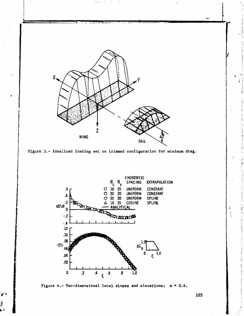
Figure 3. -
TAIL U\ Idealized loading set on trinuned configuration for minimum drag.
CHORDW l SE Nc Ns SPACING EXTRAPOLATION
0 10 25 UNIFORM CONSTANT 0 20 20 UNIFORM CONSTANT 0 20 20 UNIFORM SPLINE
.2 SINE SPLINE dZ/dx'
0
- .2
Figure 4.- Two-dimensional local slopes and elevations; a = 0 . 6 .
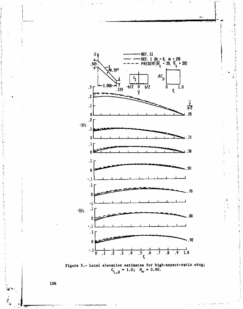
ti;
Figure 5.- Local elevation estimates for high-aspect-ratio wing;
%,d = 1.0; M, = 0.90.

(a) Local slopes.
METHOD OF REF. 1 N - 8 , m a 2 3
4 v2 0 ,866
.M + 0
RESENT-METHOD
Nc = 16, N, = 25
(b) Elevations.
o MPERIMEMREF. la - METHOD OF REF. 1 1 -- PRESENT METHOD
(c) Lifting pressure distributions; & = 0.259.
Figure 6.- Local slopes, elevations, and lifting pressure distributions;
c~,d = 0.35; = 0.40.
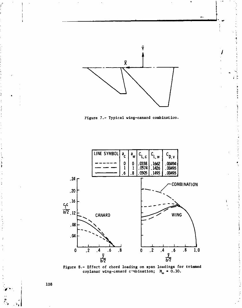
Figure 7 . - Typical wing-canard combination.
LINE SYMBOL ac aw c Llc c Ll 'D. v
.20
.16 Cr W , 12
- *- - /CoMB'NAT'oN 1.
\ -
- -\
CANARD
-
1 I 1 I I
0 .2 .4 .6 .8 0 . 2 .4 . 6 .8 1.0 4, bR B
Figure 8 . - Effect of chord loading on span loadings for trimmed coplanar wing-canard c- bina at ion; Moo = 0.30.
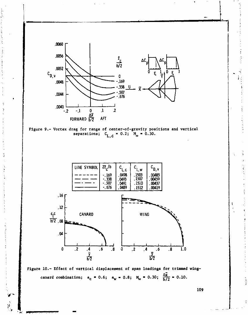
,0040 -.2 -.l 0 .1 .2
hx' FORWARD b/2 AFT
Figure 9.- Vortex drag for range of center-of-gravity positions and vertical separations; C = 0.2; M o o = 0.30.
L,d
LINE SYMBOL 2Zc/b CLc CL, 'D. v ------
--7
-. 169 .W98 .I503 . OW85 -- - - -. 338 .0493 .I507 .00459
-- -. 507 .W91 .I510 ,00437 -.676 . W 9 .1512 .00419
.12
CzC CANARD
Figure 10.- Effect of vertical displacement of span loadings for trimmed wing-
A;; canard combination; a, = 0.6; a,,, = 0.8; Y, = 0.30; -0.10.

0 EXPER I MENT (REF. ---- DATA F A I R I N G THEORY + CDSp
* DESIGN POINT
Figure :I.- Longitudinal aerodynamic characteristics of tandem wing; C = 0.35; MOD = 0.30. L,d
REPRODUCSBILITY OF THE ORIQWAL PAGE I8 POOR
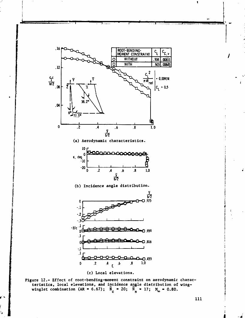
(a) Aerodynamic characteristics.
(b) Incidence angle distribution,
-. 1 .1
.433 0 .2 .4 .6 .8 1.0
€
(c) Local elevations.
Figure 12.- Effect of root-bending-morent constraint on aerodynamic charac- teristics, local elevations, and incidence arigle distribution of wing- winglet combination (AR = 6.67); 1 c = 20; Ns - 17; M, - 0.80.

APPLICATIONS OF :.'ORTEX-LATTICE THEORY TO
PRELIMINARY AERODYNAMIC DESIGN
John W . Paulson, Jr. NASA Langley Research Center
This paper presents some applications of the vortex-lattice theory to the preliminary aerodynamic design and analysis of subsonic aircraft. These methods include the Rockwell-Tulinius vortex-lattice theory for estimating aerodynamic characteristics, a Trefftz plane optimizatlon procedure for determining the span loads for minimum induced drag, and a modification of the Tref'tz plane prcce- dure to estimate the induced drag for soecified span loads. The ff ;t two methods are used to aerodynamically design aircraft planforms, twists, and cam- bers, and the latter method is used to estlmate the drag Lor components such as f lape and control surfaces.
Results from the theories for predicting lift and pitchjng moaent, drag duc to lift, and the drag of control surfaces are compared with experimental data. The data were obtained on a general aviation model with flaps and a close- coupled canard-wing model.
INTRODUCTION
In the preliminary stages of aircraft design, it is necessary that the designer have valid estimates of aircraft aerodynamics, particularly lift, drag, and pitching moments. Lift and pitching moment are required to size the plan- forms (wing, tail, and canard) and locate them with respect to a moment center, usually a desired aircraft center of gravity, for trimmed lift requirements and stability margins. Skin friction, form, and induced drags must be estiwted and minimized for best performance. Many theoretical methods involving various levels of complexity have been developed which estimate these characteristics to varying degrees of accuracy. The preliminary designer, however, wants methods that are fast, reasonably accurate, and easy to use so that changes in aircraft configuration can be easily assessed. Once the overall configuration geometry is defined, he may wish to use some of the more highly sophisticated methods to refine his estimates before beginning experimental verification of the design. This paper will address applications of easy-to-use methods appropriate at the preliminary design stage; these methods include the Rockwell-Tulinius vortcx- lattice theory for estimating aerodynamic characteristics, a Trefftz plane opti- mization procedure for determining the span loads for minimum induced drag, and a modification of the Trefftz plane procedure to estimate the induced drag for specified span loads.
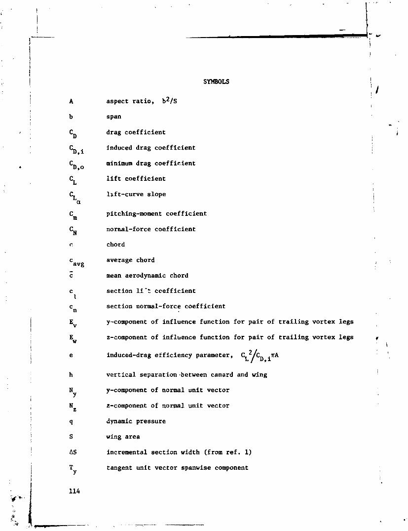
aspect ratio, b * / ~
span
drag coefficient
induced drag coefficient
minimum drag coefficient
lift coefficient
lift-curve slope
pitching-moment coefficient
nornal-force coefficient
chord
average chord
mean aerodynamic chord
section li'r coefficient
section normal-force coefficient
y-component of influence function for pair of trailing vortex legs
z-component of influence function for pair of trailing vortex legs v ' i
induced-drag efficiency parameter, . \
vertical separation-between canard and wing
y-component of normal unit vector
z-component of normal unit vector
dynamic pressure
wing area
incremental section width (from ref. 1)
tangent unit vector spanwise component
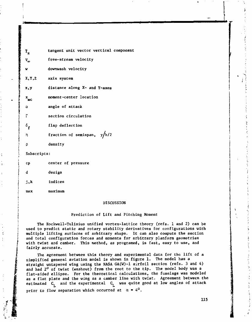
tangent unit vector vertical component
free-stream velocity
downwash velocity
axis system
distance along X- and Y-axes
moment-center location
angle of attack
section circulation
flap deflect ion
fraction of semispan, y/b/2
density
Subscripts :
C P center of pressure
d design
j ,k indices
max maximum
DISCUSSION
Prediction of Lift and Pitching Moment
The Rockweil-Tulinius unified vortex-lattice theory (refs. 1 and 2) can be used to predict static and rotary stability derivatives for configurations with multiple lifting surfaces of arbitrary shape. It can also compute the section and total configuration forces and moments for arbitrary planform geometries with twist and camber. This method, as programed, is fast, easy to use, and fairly accurate.
The agreement between this theory and experimental data for the lift of a simplified general aviation model is shown in figure 1. The model has a straight untapered wing using the NASA GA(W)-1 airfoil section (refs. 3 and 4 ) and had 2O of twist (washout) from the root to the tip. The model body was a flat-sided ellipse. For the theoretical calculations, the fuselage was modeled as a flat plate and the wing as a camber line with twist. Agreement between the estimated CL and the experimental CL was quite good at low angles of attack
prior to flow separation which occurred at a = 4'.
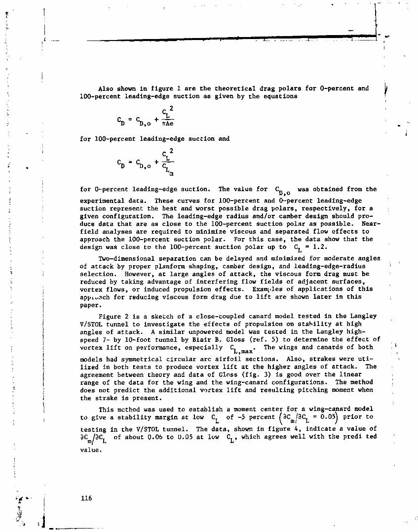
Also shown i n f i gu re 1 a r e t he t heo re t i ca l d rag po l a r s f o r 0-percent and 100-percent leading-edge suc t ion a s given by t h e equat ions
I f o r 100-percent leading-edge suc t ion and
f o r 0-percent leading-edge suct ion. The value f o r C was obtained from the D,o
experimental data. These curves f o r 100-percent and 0-percent leading-edge suc t ion represect the bes t and worst poss ib le drag pola rs , respec t ive ly , f o r a :,
given configuration. The leading-edge rad ius and/or camber design should pro- duce da ta t h a t a r e a s c lose t o t he 100-percent suc t ion pola r a s possible . Near- f i e l d analyses a r e required t o minimize viscous and separated flow e f f e c t s t o approach the 100-percent suct ion polar . For t h i s case, t h e da t a show tha t t he design was c lo se t o t he 100-percent suct ion pola r up t o CL = 1.2.
Two-dimensional separat ion can be delayed and minimized f o r moderate angles , 1
of a t t a c k by proper planform shaping, camber design, and leading-edge-radius se lec t ion . However, a t l a r g e angles of a t t ack , t he viscous form drag must be reduced by taking advantage of i n t e r f e r i n g flow f i e l d s of adjacent sur faces , vortex flows, o r induced propulsion e f f e c t s . Examl~les of appl ica t ions of t h i s a p p ~ ~ s c h f o r reducing viscous form drag due t o l i f t a r e shown l a t e r i n t h i s paper.
Figure 2 is a sketch of a close-coupled canard model t e s t ed i n t he Langley V/STOL tunnel t o i nves t i ga t e the e f f e c t s of propulsion on s t a h i l i t y a t high angles of a t tack . A s imi l a r unpowered model was t e s t ed i n t he Langley high- speed 7- by 10-foot tunnel by B la i r B. Gloss ( r e f . 5) t o determine the e f f e c t of vortex l i f t on performance, e spec i a l l y C The wings and canards of both 1 \ L ,maxw , I
models had symmetrical c i r c u l a r a r c a i r f o i l sec t ions . Also, s t r akes were u t i - ,
l i z ed i n both t e s t s t o produce vortex l i f t a t t he higher angles of a t t ack . The agreement between theory and da t a of Gloss ( f i g . 3) is good over t h e l i n e a r i
range of the da ta f o r the wing and the wing-canard configurat ions. The method does not p red ic t t h e addi t iona l vortex l i f t and r e s u l t i n g pi tching moment when the s t r ake is present.
This mcthod was used t o e s t a b l i s h a moment cen te r f o r a wing-canard model t o give a s t a b i l i t y margin a t low CL of -5 percent (acm/3cL = 0.05 p r i o r t o ) t e s t i n g i n t he V/STOL tunnel. The da ta , shown i n f i gu re 4 , i nd i ca t e a value of '
a C aCL of about 0.06 t o 0.05 a t low CL, which agrees wel l with t he predi t ed m l
value.

Prediction of Minimum Induced Drag
Once the pla:-iorms of a configuration have been sized and located to meet lift and stability requirements, it is necessary to compute rhe optimum span loads for minimum induced drag for the interfering planforms. The expression for the induced drag was developed by using an equivalent lifting-line Trefftz plane approach of reference 1 and is illustrated by the following sketch and equation:
I' CANARD
TRAILING VORTEX LEG
A A SECT I ON
TREFFTZ PLANE - 1
SECTION A-A I w
By utilizing the method of Lagrsngian multipliers with the induced-drag equation, the span loads for minimum C -
D,i may be calculated while constraining CL and
'm to desired values. This procedure was programed by Tulinius and Gloss, and
the results are given in reference 2. The input for this program consists of the basic planform geometry, as in the Rockwell-Tuiinius method, along with the desired (x/c) distribution. The (x/c) distribution is required to locate
CP c P the chordwise position of the net span load for constraining the pitching moment and is generally selected from a desired two-dimensional section loading.
The method was applied to the close-coupled wing-canard model of Gloss and the results with and without constraints on Cm are presected in figure 5 .
The variation of the induced-drag efficiency parameter e is a function of wing-canard span ratio bcanard/ b, wing-canard separation h/b , and wing-canard
lift ratio. The left side of figure 5 gives estimates of e when C is con- L
strained and C is unconstrained. It can be seen that the estimated valus.,.? m of e increase as h/b and beenard /b increase and are equal to or greater
than 1.0. The right side of figure 5 gives estimates of e when both CL and
16 are constrained to produce a trimmed configuration. It can be seen that the m extra constraint lowers the values of e; however, e can still be greater than l..O if an upload on the canard is required for trim. When a canard or emp?magp download is requirdd for trin, e is equal to or less than 1. In this figure, the location of the moment center was arbitrary and was chosen simply to gfve uploads and downloads on the canard.
A detailed study of the effect of moment-center on e was per- fcrlned for one configuration (hlb = 0.09, bcanard/b and is presented
in figure 6. It can be - seen that e is a maximum at a moment-center location of about 10 percent c due to the nearly elliptic span loads - present for this case. As the moment center is moved away from 10 percent c, the loads required on the wing and canard for trim become more nonelliptic and e decreases accordingly.
It should be noted that the wing and canard must be twisted and cambered to produce the span loads required to approach the minimum %,i . The data of Gloss (ref. 5) were obtained for both flat and cambered wings in the presence of a canard. The cambered wings were designed to lift coefficients of 9.35 and 0.70. These experimental data are compared with the theoretical minimum value
0 f 'D - 'D,O in figure 7. The uncambered wing alone does not approach the
c L ~ theoretical minimum at low CL because the sharp leading edge does not carry
any 1-eading-edge thrust. This wing departs drastically from the minimum at higher CL because of the flow separation from the sharp leading edge. The
downwash and vortex from the canard and strake retard the two-dimensional type of separation on the wing and the data show large improvements over the wing alone at higher CL. However, the flat wing-canard-strake combination still
does not approach the theoretical minimum because of the zero leading-edge thrust associated with the sharp leading edge. The cambered wings for the wing- canard configuration do approach the theoretical minimum at the design CL because the cambered airfoil carries thrust on the camber line and the leading edge is drooped into the local flow direction to reduce the leading-edge flow separation,
Prediction of Induced Drag Due to Control Deflections
In addition to using the theory to aerodynamically design a configuration to meet the primary mission requirements, it is also useful in examining the effects of deflecting control surfaces and high-lift devices on the induced drag. A modification was made by Paulson and Thomas to the induced drag mini-
mization program to calculate the induced drag for specified span loads. The input span loads may be obtained either theoretically or experimentally. An example of the variation in span load due to two different types of flaps is shown in figure 8. This analysis was done on the general aviation model shown in figure 1 without the fuselage. The span loads were calculated by using the Rockwell-Tulinius method for the plain wing and for the wing with either slotted flaps or Fowler flaps deflected. Figure 9 shows the experimental drag polars for the three configurations. At CL = 1.0, the calculated differences in
induced drag between the plain wing and the wing with slotted flaps or Fowler flaps were 0.0010 and 0.0126, respectively. (See table 1.) The corresponding differences in the experimental data were 0.0012 and 0.0165, respectively. The additional skin-friction drag for the deflected Fowler flap (ref. 6) was esti- mated to be 0.0024. When this is combined with the computed induced drag, a total theoretical increment in drag of 0.0150 is obtained for the Fowler flap. This agrees well with the experimentally measured increment of 0.0165.
CONCLUDING REMARKS
Three applications of theoretical methods for preliminary aerodynamic design have been discussed. These methods are used to estimate wing and empen- nage geometries and locations to meet performance and stability requirements, to estimate span loads for minimum trimmed induced drag, and to analyze the effects of control surface deflection on induced drag. The theories are, in general, easy to use, fast, and the agreement with experimental data shows that they give accurate results. These methods are being used to design complex multiple lifting-surface models for experfmental investigations in the Langley V/STOL tunnel.
REFERENCES
1. Tulinius, J.; Clever, W.; Niemann, A.; Dunn, K.; and Gaither, Prediction of Airplane Stability Derivatives at Subcritical CR-132681, 1975.
i/ B . : Theoretical Speeds. NASA
2. Tulinius, Jan R.; and Margason, Richard J.: Aircraft Aerodynamic Design and Evaluation Methods. AIAA Paper 76-15, Jan. 1976.
3. NcGhee, Robert J.; and Beasley, William D.: Low-Speed Aerodynamic Character- istics of a 17-Percent-Thick Airfoil Section Designed for General Aviation Applicarions. NASA TN D-7428, 1973.
4. Paulson, John W., Jr.: Wind-Tunnel Tests of a Conventional Flap and Aileron and a Fowler '?lap and Slot-Lip Aileron for an Advanced General Aviation Wing. SAE Paper 750501, Apr. 1975.
5. Gloss, Blair B.: Effect of Wing Planform and Canard Location and Geometry '
on the Longitudinal Aerodynamic Characteristics of a Close-Coupled Canard ,
Wing Model at Subsonic Speeds. NASA TN D-7910, 1975.
6. Peterson, John B., Jr.: A Comparison of Experimental and Theoretical Results 1 for the Compressible Turbulent-Boundary-Layer Skin Friction With Zerc Pres- sure Gradient. NASA TN D-1795, 1963.

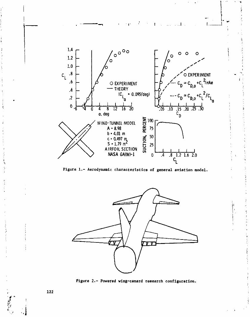
0 EX PER I MENT
0 0 0 0
0
# //
0 /
/' /'o EXPERIMENT / 2 - cD = c ~ , ~ +CL h A e
2 --- CD I C D,o +C L /C La
1 I I 1 1 .05 .10 .15 .20 2 5 .U]
Figure 2.- Powered wing-canard research configuration.
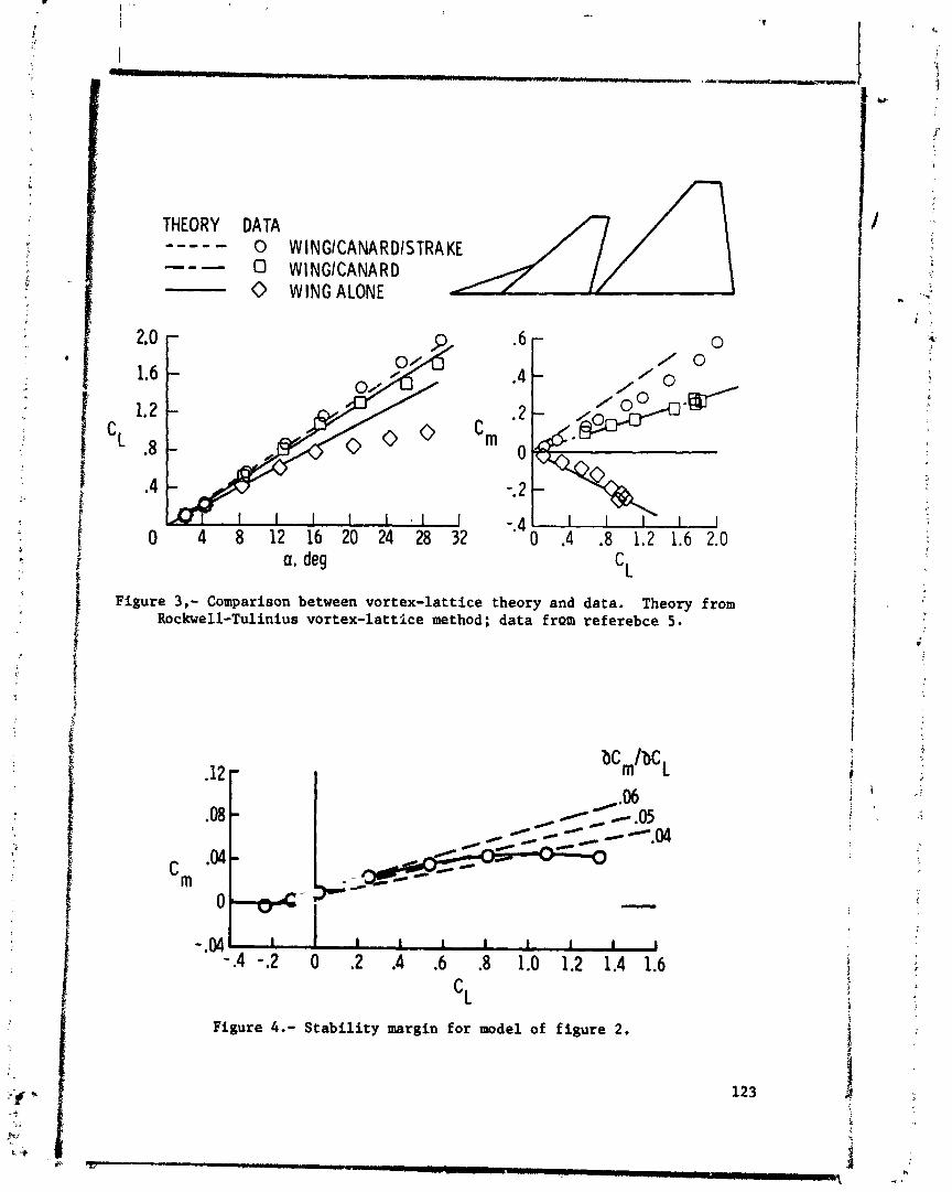
THEORY DATA ---- - 0 WINGICANARDISTRAKE --- 0 WlNGlCANARD 0 WINGALONE
a, deg
Figure 3,- Comparison between vortex-lattice theory and data. Theory from Rockwell-Tulinius vortex-lattice method; data f r ~ m ref erebce 5.
Figure 4.- Stability margin for model of figure 2.

A L e=--- "*WING C~
- POS CANARD L l FT
1.3- 1.2- --- NEG CANARD LIFT
1.2 - e
1.1 1.0
1.0 I I 1 .9 - 1 0 .05 .I0 .15 .20 0 .05 .lo .15 ,20
Figure 5.- Results from Trefftz plane vortex drag minimization theory. Equivalent lifting line approach.
- - - CANARD --- ELLIPTIC .2 xmc = 0.1r
0 .2 .4 .6 .8 1.0
Figure 6.- Interference effects on optimum span load shape of the wing and canard.
REPR0DUCBILIT"Y OF THE ORI06Tfi PAGE 18 POOR

0
CAMBERED WING/
CAMBERED WING/
.8 r
W I LCICANARD .4 - INGICANARDI
S TRA KE THEORETICAL M I N .
\ \ . \ \ \ \ \ \ , \ , \ \ \ \ \ \ \ , \ ~ ~ *
* I I I I I J s I I I I 'i 0 ,4 .8 1.2 1.6 2.0 2.4 0 .4 .8 1.2 1.6 2.0 2.4
Figure 7 . - Effects of canard, strake, and wing camber on drag due t o l i f t .
- PLAIN W I N G -- SLOTTED FLAP, 1, = lo0
Figure 8.- Calculated span loads for general aviation model a t CL = 1.0.

0 P L A I N W I N G C SLOTTED FLAP, bf = 10'
0 FOWLER FLAP, 4 = 10'
Figure 9.- Experimental drag polars for general aviation model.
POTENTIAL FLOW COMPUTER PROGRAM*
Richard L. Palko ARO, Inc.
A potential flow computer program has been in use at the Arnold Engineering De- velopment Center (AEDC) for several years. This program has been used primarily a s a tool for flow-field analysis in support of test activities in the transonic wind tunnels of the Propulsion Wind Tunnel Facility (PWT). Analyses have been made over a Mach
k nurnber range from 0 to 0.9 for a variety of configurations from aircraft to wind tun- $ nels, with excellent agreement between calculated flow fields and measured wind tunnel 2
%. data. Analytical and experimental data for seven different flow analysis problems a r e f- presented :n this paper.
Iz f f -. . 2. E INTRODUCTION e
The AEDC rhree-Dimensional Potential Flow Computer Program (PFP) in the existing form was developed primarily as a result of the need to make calculations of the flow field in the vicinity of aircraft fuselages (typically at locations where aircraft inlets might be located). This need arose because of the support the theoretical flow- i field calculations could lend to a research program carried out at AEDC to simulate the I
inlet flow fields in a wind-tunnel test of full/scale inlet/en.$ne systems (refs. 1 and 2). Much of the computing capability that the PFP presently has resulted from these flow- field calculations which have a s their primary variables the flow angularity (upwash and sidewash) over a y-z plane. After the initial solution of the velocity field for a given model attitude m d Mach number is obtained, the upwash and sidewash can be deter- mined for any given point or over any grid desired. A new solution is required for each model attitude o r Mach number. In addition to computing the upwash and sidewash, tne PFP also computes the local Mach number, Cp, and flow streamlines. A computer
I plotting program has been written to supplement the PFP, and computer plots can be
*The research reported herein was conducted by the Arnold Engineering Develop- ; ment Center, Air Force Systems Command. Research results were obtained by per- sonnel of ARO, Inc., Contract Operator at AEDC. Further reproduction i s authorized
$
I to satisfy needs of the U. S. Government. . Q a 127 :: i;
' * ;a ' i,

obtained for most of the above parameters. A streamline can be traced from any point in the stream either upstream o r downstream (or both). The capability to make a plot of the mathematical representation of the model geometry before running the complete program allows corrections to be made, if needed, with only a slight loss of computer time. A two-volume report (ref. 3) that details the program, modeling techniques, ap- plication, and verification has been published.
This paper briefly outlines the PFP application to seven flow analysis problems in support of the transonic wind tunnels in the PWT a t AEDC.
SYMBOLS
Values a r e given in both SI and U. S. Customary Units. The measurements and calculations were made in U. S. Customary Units.
angle of attack
lift coefficient
pressure cot:fficien t
free-stream Mach number
ratio of surface static pressure to free stream total pressure
coordinate along tunnel axis, posi tive downstream
horizontal coordinate, sign a s indicated
vertical coordinate, sign a s indicated
model angle of attack, deg, positive up
model angle of yaw, deg, sign a s indicated
upwash, deg, positive up
sidewash, deg, positive a s indicated
P F P APPLICATION AND UTILIZATION
The P F P at AEDC has been used primarily a s a cool for analysis of the flow in the far field. (Far field refers to a distance away from tht andysis model surface equal

to, o r greater than, the vortex spacing in the direction of flobr. ) The modeling tech- niques required for this type of analysis a re presented in v c u n e I1 of reference 3. However, work is underway to develop the modeling technique to allow accurate analysis of the surface pressure. Results of some of this continuing effort a re reported in reference 4. All the flow problems presented here a re of the far-field type.
Flow Field Between TWO Hollow Circular Cylinders
The analysis of these cylinders was part of a research program in which the objec- tive was to create flow fields by some auxiliary method to simulate the flow entering a full-scale inlet/engine at high mgles of attack and yaw. The device was to deflect (or induce) the flow upward a s it passed between the inclined cylinders. A mathematical model of the cylinders is shown in figure 1. The last circumferential ray on each cyl- inder had trailing vortices that were trailed at an angle equal to one-half the cylinder pitch angle. A comparison between the theoretical and experimental flow angularity data is shown in figure 2. The theoretical results a r e shown a s lines of constant flow angle (both upwash and sidewash), and the solid symbols show the relative location of experimental data with the magnitude of the measured angles indicated. The Mach num- ber a t which these data were taken was 0.9. It can be seen that the P F P overestimated the flow inclination angles by approximately lo.
Flow Field Around an Aircraft Fuselage
Primary purpose of this analysis was to verify the results obtained from the PFP. Experimental flow-field data used for comparison with theory were available from wind- tunnel measurements made during the Tailor Mate test series. The objective of the windtunnel test was to determine the flow field (upwash and sidewash) at a typical en- gine inlet fuselage loca tion. The ma thema tical model of the fuselage configuration is shown in figure 3. The comparison between the predictions from the PFP and the wind- tunnel data for a pitch angle of 25' and a free-stream Mach number of 0.9 a r e shown in figure 4. Here again, excellent agreement was obtained.
Flow Field Under a Fuselage-Wing Configuration
The purpose of this analysis was also for program verification; again experimental data obtained du~ing the Tailor Mate studies were used. The fuselage-wing configura- tion was analyzed to compute the flow field under the wing a t the wing-fuselage junction. The computer math model used in the analysis is shown in figure 5. A comparison be- tween the upwash and sidewash predictions and the experimental data for a Mach num- ber of 0.9 and an angle of attack of lo0 is shown in figure 6. Analytical and experi- mental data trends show excellent agreement, although the predicted d a k show some- what higher flow angularity gradients across the survey area than the measured data.
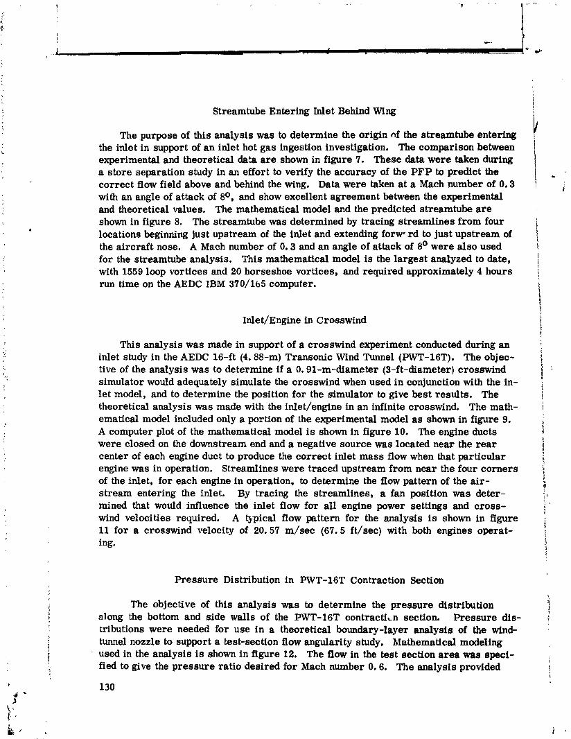
Streamtube Entering M e t Behind Wing
The purpose of this analysis was to determine the origin of the streamtube entering the inlet in support of an inlet hot gas ingestion investigation. The comparison between experimental and theoretical data a r e shown in figure 7. These data were taken during a store separation study in an effort to verify the accuracy of the PFP to predict the correct flow field above and behind the wing. Data were taken a t a Mach number of 0.3 with an angle of attack of 8O, and show excellent agreement between the experimental and theoretical values. The mathematical model and the predicted streamtube a r e shown in figure 8. The streamtube was determined by tracing streamlines from four locations beginning just upstream of the inlet and extending forw .rd to just upstream of the aircraft nose. A Mach number of 0.3 and an angle of attack of 8' were also used for the streamtube analysis. This mathematical model is the largest analyzed to date, with 1559 loop vortices and 20 horseshoe vortices, and required approximately 4 hours run time on the AEDC IBM 370/1b5 computer.
Inle t/Engine in Crosswind
This analysis was made in support of a crosswind experiment conducted during an inlet study in the AEDC 16-ft (4.88-m) Transonic Wind Tunnel (PWT-16T). The objec- tive of the analysis was to determine if a 0.91-m-diameter (3-ft-diameter) crosswind simulator would adequately simulate the crosswind when used in conjunction with the in- let model, and to determine the position for the simulator to give best results. The theoretical analysis was made with the inlet/engine in an infinite crosswind, The math- ema tical model included only a portion of the experimental model a s shown in figure 9. A computer plot of the mathematical model is shown in figure 10. The engine ducts were closed on the downstream end and a negative source was located near the rear center of each engine duct to produce the correct inlet mass flow when that particular engine was in operation. Streamlines were traced upstream from near the four corners of the inlet, for each engine in operation, to determine the flow pattern of the air- stream entering the inlet. By tracing the streamlines, a fan position was deter- mined that would influence the inlet flow for all engine power settings and cross- wind velocities required. A mica1 flow pattern for the analysis is shown in figure 11 for a crosswind velocity of 20.57 m/sec (67.5 ft/sec) with both engines operat- ing.
Pressure Distribution in PWT-16T Contraction Section
The objective of this analysis was to determine the pressure distribution \ i along the bottom and side walls of the PWT-16T contract i~n section. Pressure dis- Y tributions were needed for use in a theoretical boundary-layer analysis of the wind- tunnel nozzle to support a test-sec tion flow angularity study. Mathematical modeling used in the analysis ie shown in figure 12. The flow in the test section area was speci- fied to give the pressure ratio desired for Mach number 0.6. The analysis provided
1
1
130

streamline information at a distance of 0.305 m (1 ft) from the walls, and the calculated Cp was converted to p/po. Following the calculation of the theoretical pressure dis- tribution, the pressure distribution was experimentally measured in the contraction section. A comparison between the theoretical and experimental pressure distribution is shown in figure 13, with excellent agreement indicated.
Strut Effects Analysis
The objective of this analysis was to determine the strut effect corrections to mea- sured force and moment data for a slender winged vehicle with a mid-strut mount. The vehicle wing was located just forward of the strut, For this analysis the upwash angle was determined with the PFP for the body alone (fig. 14) and the body with strut (fig. 15). An ir,cremental upwash angle was then determined a t the wing location from these two sets of data. In this case the incremental values were negative because of the down flow around the strut. The incremental values along the wing location were averaged and the ACL correction calculated from the average angle-of-at tack change. A comparison of the calculated corrections and those measured with a subscale model are shown in fig- ure 16. Excellent agreement is shown in both the trend with Mach number and the ab- s o h te values.
CONCLUDING REMARKS
The AEDC Potential Flow Program is used primarily a s a tool for flow-field analysis in support of the test activities in the transonic wind tunnels of PWT. This paper has covered seven different problems that have utilized the PFP including both external and internal analysis, A11 but one of the examples have experimental data to verify the calculated flow fields, and all comparisons show excellent agreement. The PFP at AEDC has not been used as a tool to obtain absolute values, but rather a s a tool to predict and verify flow fields in sapport of the test activities. In addition to the problems presented, the PFP has been used to predict the flow angularity at the model resulting from sting and support systems, to predict the flow around various types of support systems, and many other general flow analysis pmblems directly connected with wind-tunnel testing.
1 REFERENCES
i i/ 1. Palko, R. L. : Full-scale Inlet/Engine Testing at High Maneuvering Angles at
Transonic Velocities. AIAA Paper No. 72-1026, Presented at the A M Seventh 1 Aerodynamic Testing Conference, Palo Alto, California, September 13-15, I .
, - 1972. , i
2. Palko, R. L. : A Method to Increase the Full-scale Inlet/~ngine System Testing Capability of the AEDC 16-F t Transonic Wind Tunnel. AEDC -TR-73-9
4 (AD 762912). June 1973.
3. Todd, Donald C. and Palko, Richard L. : The AEDC Three-Dimensional, Potential Flow Computer Program. Vol. I and 11. AEDC-TR 75-75, February 1976.
4. Heltsley, Fred L.: Report on the Status of a Slotted Wind-Tunnel Wall Representa- tion Using the Vortex-Lattice Technique. Vortex-Lattice Utilization, NASA SP-405, 1976. (Paper no. 9 of this compilation.)

600
SID
EV
IEW
3. 00
0
-3. 0
0 CY
LIND
ER N
O.
1 -
-
-
~.
-
-4.m
J-12
:00
' -4
.b '
* '
' '
I
0 60
0 12
.00
9.00-
X
TOP
VIEW
60
0
3. 00
.
N
0,
~cY
LIN
OE
R N
O.
1 -9
.00l
* -12
.00
400
0 60
0 12
.00
X
Figure 1.-
Mathematical model of
the
dual hollow circular cylinder
configuration.
MAC
H NU
MBE
R = a
9 E
M
PERI
MEN
TAL
DATA
THEO
RETI
CAL
UPW
ASH
THEO
RETI
CAL
SIDE
WAS
H
CYLI
NDER
DIA
MET
ER =
L 42
m (5
6 In
. 1 FU
LL S
CALE
CY
LIND
ERS
SPAC
ED 3
.91
m 1
154
in. 1
CEN
TER-
TO-
CENC
ER F
ULL S
CALE
(SCA
LED
FOR
PWT-
16Tl
Figure 2
.- Experimental and theoretical comparison
of upwash and sidewash angles for the dual hollow
circular cylinders at
a Mach number of 0.9.
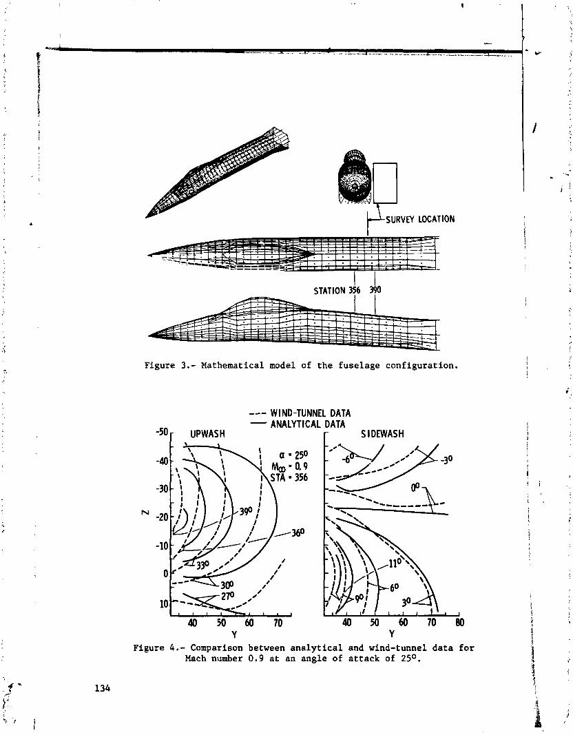
VM LOCATION
STATION 3% 3h
Figure 3.- Mathematical model of the fuselage configuration.
W I ND-TUNNEL DATA ANALYTICAL DATA
r s I DEWAS H
Y Y Figure 4.- Comparison between analytical and wind-tunnel data for
Mach number 0.9 at an angle of attack of 25O.

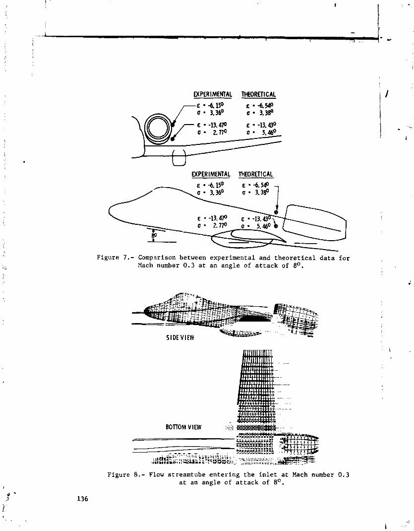
EXPERIMENTAL THEORETICAL
7 E -6.15' E * -6.540
EXPERIMENTAL THEORETICAL
Figure 7.- Compsrison between experimental and theoretical data for Mach number 0.3 at an angle of attack of 8O.
Figure 8.- Flow streamtube entering the inlet at Mach number 0.3 at an angle of attack of 8O.

--..----- -a CROSSWIND -
Figure 9.- Sketch of the section of the test model wirh the mathematical model.
duplicated
TOP VIEW
LEADING-EDGE NEGATIVE SOURCE
POSITIVE INBOARD) - NEGATIVE (OUTBOARD1
NEGATIVE SOURCE
NEGATIVE 1 POSITIVE (OUTBOARD) (INBOARD)
FRONT VIEW CROSSWIND- NEGATIVE
LEAD I NG-EDGE LIP SOURCE INLET RAMP/
Figure 10.- Basic mathematical model for the inletlengine crosswind analysis.
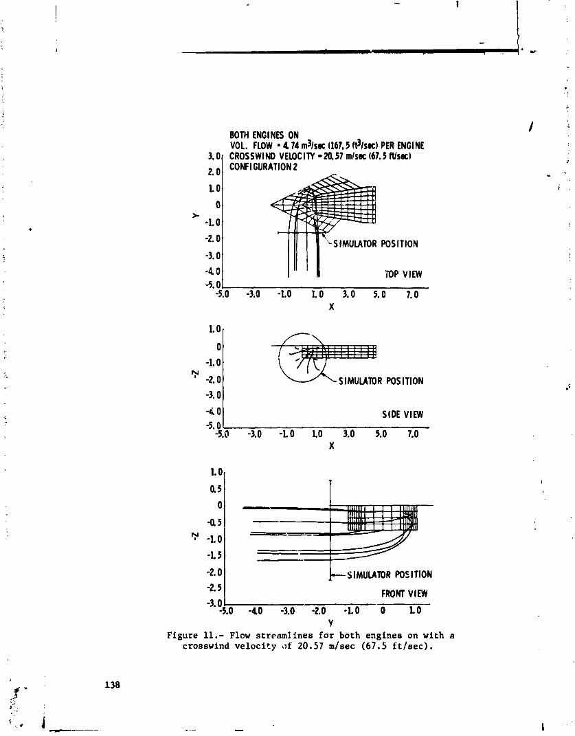
BOTH ENGINES ON VOL. FLOW . 4 74 m3lsec (167.5 ft31sa) PER ENGl NE CROSSWIND VELOCITY M 57 mlsa (67.5 ftlsa) CONFIGURATION 2
POSITION
TOP VIEW
-4 0 1 SIDE VIEW
0 ,
-LO
-2.0
::I SIMUUIOR POSITION
FRONT VIEW -3.0
-5.0 -40 -3.0 -2.0 -LO 0 LO Y
Figure 11. - Flow streamlines for both engines on with a crosswind v e l o c i t y a>f 20.57 m/sec (67.5 f t / s e c ) .
SIMUUTOR POSITION


SYM LOCATION - SOURCE - BOTTOM WALL
;'iP I CALCULATED FOR 0.38 m -- - S I DE WALL PFP (1 ft) OFF WALL 0 BOrrOM WALL EXPERIMENTAL DATA
BOITOM WALL EXPERIMENTAL DATA (2175) A SIDE WALL EXPERIMENTAL DATA (2175)
Figure 13.- Pressure distribution in PWT-16T for Mach number of 0.6.

35 * ARO OM91 THRU AP R 24, 1975
30' NOSTRUT b 4 . 7 A . 2
25 .,
Figsre 14. - Upwash about c y l i n d r i c a l model a t &, = 0 . 7 and a = 2'.
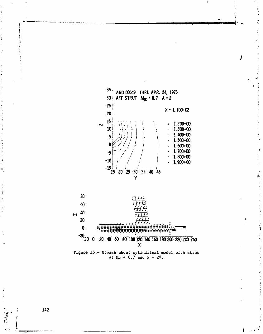
35 ' ARO 00649 THRU APR. 24, 1975 30; AFT STRUT M m x Q 7 A . 2
Figure 15.- Upwash about cyl indrical model with s trut a t Mm = 0.7 and a = 2 O .

REPORT ON THE STATUS OF A SLOTTED WIND-
TUNNEL WALL RE2RESENTATION USING THE VORTEX-
LATTICE TECHNIQUE*
Fred L. Heltsley ARO, Inc.
SUMMARY
A combined analytical/experimental program for development of an improved slotted wind-tunnel wall representation is de- scribed. The effort is presently being conducted at the Arnold Engineering Development Center (AEDC) and is scheduled for com- pletion in 1977. The vortex-lattice technique which is being used as the primary analytical tool for representing both the wind-tunnel and the lifting model is discussed. Comparisons of results obtained to date with available data are presented. Included also is a brief description of the experimental effort to be conducted in conjunction with the analytical development.
INTRODUCTION
The literature contains numerous examples of the application of vortex-lattice theory to the modeling of closed wall wind tunnels (refs. 1 through 3). Interference factors provided by the vortex lattice method correlate well with values computed using various analytical techniques. Considerably less work, however, has been directed toward the vortex-lattice simulation of tunnels with partially open walls, in particular those with slots (refs. 2 and 3). In addition, comparisons of the resulting interference factors with those generated by analytical methods are limited to cases involving extremely simplified wall config- urations and equally simple test vehicle geometries since analyt- ical solutions are not available for the more complex models. This paper describes a program presently underway at the AEDC which is intended to provide a more useful vortex-lattice venti- lated wind-tunnel model by accountinq for the viscous effects
h he work reported herein is sponsored by NASA/Ames Research Center and was conducted by the Arnold Engineering Development Center, Air Force Systems Command. Research results were obtained by personnel of ARO, Inc., Contract Operator at AEDC. Further reproduction is authorized to satisfy needs of the U.S. Government.
I
PRJZh3DING PAGE BLANK NCtT FILEIl3D
associated with flow through and/cr across the slots (ref. 4). Similar studies have been conducted to develop representations of several aerodynamic configurations (refs. 5 through 9). Many of the resulting models are capable of generating the effects of complex real flow phenomena such as separated wakes and jet exhausts although most of the simulations are strongly dependent upon empirical information. The intent of the present effort is to develop an improved mathematical wind-tunnel wall formulation by supplementing an in-depth analytical study with appropriate experimentation.
SYMBOLS
unit normal vector at the ith control point, negative away from the boundary on the inner surface
unit normal vector at the ith control point
tunnel cross-sectional area
reference tunnel area
influence of the jth singular point
ity on the ith control
lift coefficient
pressure coefficient
length of a vortex line
singularity density at the ith control point
number of singularities
wall
unit vector parallel to the boundary at the ith control point
wing area
free-stream velocity
+ v i velocity induced at the ith control point in the
vortex sheet
velocity induced at the ith control point on the inner surface of the vortex sheet
6 , -'** . ' vi velocity induced at the ith control point on the outer surface of the vortex sheet
-. , + : . "00
free-stream velocity
), Av velocity jump across the vortex sheet
$ W local downwash velocity
X nondimensionalized distance from model along center line
r
X/C nondimensionalized chord length i' 1
a angle of attack
j strength of the jth singularity
6 lift interference factor
6" normalized lift interference factor
X ratio of tunnel height to tunnel width
T ratio of wing span to tunnel span
ANALYTICAL STUDY
Vortex-Lattice Technique
a The analytical work has been directed toward representing both the wind-tunnel walls and the lifting model. The vortex-
%. lattice technique was chosen as the primary tool since the i.
method can be extended to simulate extremely complex aerodynamic geometries without changing the basic solution scheme. Reference 10 describes a digital program (PFP) which has been developed at
;i
the Arnold Engineering Development Center for potential flow i analysis using vortex-lattice theory. The computation procedure i
involves definition of the model geometry and boundary conditions, ' - calculation of the influence coefficient matrix, and solution of i the resulting set of linear equations for the st-rengths of the individual vortex filaments. Once the singularity strengths are known, velocities can be determined anywhere in the flow field, including the model surfaces. In addition, the program is capable 1 of computirg lift forces, pressure coefficients, and streamlines. Routines ars also available for generating three-view, isometric, and perspective plots of both the model input geometry and computed streamlines and velocity vectors.
Solid Surface Simulation
The PFP has been used extensively at the AEDC for aefo- dynamic analyses involving solid boundaries (refs. 5, 6, 8, and 10). These cases involved the classical form of the vortex lattice equation:
-+ A
Application of the solid-wall boundary condition, vi bi = 0, forces the components of velocity perpendicular to the surface to vanish and permits solution of the resulting N linear homogeneous equations.
The technique has been used to compute lift interference in a closed wall wind tunnel. A simple example is illustrated in figure 1. The resulting interference levels averaged along the span at each axial location are shown in figure 2. Included also in the plot are interference distributions for several other tunnel cross sections along with corresponding analytical results due to Kraft (ref. 12).
Slotted Wall Simulation
Exterdon of the method to represent tunnels with partially open walls is somewhat more difficult due to the added complexity of applying the constant-pressure boundary condition in the slots. This requires that the tangential component of velocity on the interior surface of the vortex sheet which represents the free jet boundary must vanish. It can be shown that the continuity in the tangential component of velocity across the

vortex sheet is equal to the local vortex density, i.e., K = dr/dk. Since equation (1) is expressed in terms of the velocity directly on the sheet, only half of the velocity jump must be accounted for. Modification of equation ( 1 ) yields
The nomenclature used in equations (1) and (2) is illustrated in figure 3.
A vortex-lattice model of a slotted wall tunnel is presented in figure 4 to demonstrate the application of both types of boundary conditions. The wall interference distribution computed for the configuration show in figure 5 . In addition, distribu- tions for a closed tunnel and a tunnel with open upper and lower walls and closed slde walls are shown. Theoretical data due to Kraft (ref. 12) and vortex-lattice results computed by Bhateley (ref. 2) for similar configurations are included for comparison. Two basic rules of thumb to be followed in the construction of a model such as the one in figure 4 should be noted here. These are (1) the edge of each slot should coincide with a vortex filament and (2) the vortex grid and the control points should be positioned by the same function. In the present case, the slot configuration has been conveniently selected so that a uniform spacing satisfies both rules. Situations in which the slots are narrow relative to the width of the solid wall panels are some- what more difficult to handle. Two primary alternatives exist. A uniform spacing which is at least as narrow as the slots can be used for both the slots and the solid wall panels. This may result, however, in a prohibitive number of singularities. An alternate solution is to select a nonuniform spacing. The use of a cosine function has been found to yield good tip definition when representing finite wings. A similar technique, illustrated in figure 6, has been used by the author. In addition to reducing the number of singularities required, the scheme provides excellent mutual slot/panel edge definition.
Lifting Model
The experimental model used during this study to provide lift interference measurements is shown in figure 7. The wing assembly consists of a 32.0 in. (81.28 cm) span x 9.0 in. (22.86 cm) chord NACA 63A006 airfoil with a minimum blockage circular centerbody. A similar half-scale assembly is mounted aft of and above the wing to provide tail surface measurements. A vortex-lattice representation of the lifting model is presented in figure 8. Since the PFP is capable of assuming symmetry, definition of only one-hal" of the model is required. Pressure coefficient
j
distributions over a two-dimensional version of the wing model i / are shown in figures 9 and 10 to illustrate the effects of grid spacing and angle of attack, respectively. In all cases, a
I precisely computed cosine (cosine) function was used to determine 1 I both the vortex and the control point locations. An attempt to i
interpolate between previously obtained "as built" coordinates . 1 L , ' proved to be unsuccessful due to the extreme sensitivity to the I , i . lack of measurement preci5ion. Finally, good results were achieved by generating slope continuous smoothing functions to define the !: surf ace.
I !
Details of the leading and trailing edues of the lattice i wing model are shown in figure 11. It should be noted that the trailing edge was not closed but was allowed to "leak" in both the two- and three-dimensional models since the tips of the three-dimensional wing wer4 closed with lattice plates.
A less detailed vortex-lattice representation of the lifting model is under development which will require a significantly smaller number of singularities. The new model will be utilized in order to reduce the computer time required during the develop- ment of the tunnel wall model. Later, the detailed vortex lattice lifting model will be recalled to provide the necessary precision : for correlation of analytical and experimental interference results.
EXPERIMENTAL PROGRAM
Wind-Tunnel Description '
The AEDC Low Speed Wind Tunnel (V/STOL) shown in figure 12 f will be used to provide experimental interference data. The tunnel has a test section 45.0 in. (114.3 cm) wide and 36.0 in. i
i I (91.44 cm) high and is capable of generating velocities from near , zero to 250 ft/sec (76.2 m/sec). The solid test section walls i '
can easily be replaced with selected slotted walls to provide ,
wall flow relief. Figure 13 is a schematic of the lifting model \ installed in the V/STOL tunnel. The installation shown permits I
1 an angle-of-attack variation from 6 ' to 16' about the pitch center. :
Interference Frtz Data
Only a limited amount of suitable interference free data are available for the lifting model since a majority of the previous I tests has been conducted at high Mach numbers. Plans are presently f underway to obtain the necessary additional interference free 1 data for the lower Mach numbers.
CONCLUDING REMARKS
The vortex-lattice technique has been succe~sfully used to represent solid surfaces for both the wind-tunnel walls and the lifting model. Correlation with available interference free experimental data and analytical results were excellent. In addition, the free jet boundary condition has been applied to simulate the flow in the tunnel wall slots. Good agreement was obtained with existing analytical predictions, Development of both vortex-lattice models is continuing.
Preparation for the experimental program is underway and testing will begin in the near future.

REFERENCES
1. Joppa, Robert G. "Wind Tunnel Interference Factors for High- Lift Wings in Closed Wind Tunnels." NASA CR-2191, February 1973.
2. Bhateley, I. C. "A Theoretical Optimization of the Test- Section Geometry for the Proposed Boeing Low-Speed Wind Tunnel." Boeing Report D6-15023, February 1967.
3. Wasserstrom, E., Borovik, Y., Hazandvsky, D., and Rom, J. "Calculation of Lift Interference Corrections Due to Wind-Tunnel Test-Section Boundaries by the Vortex- Lattice Method.'' T.A.E. Report No. 124, Technion-Israel Institute of Technology, Haifa, Israel, April 1971.
4. Keller, J. D. "Numerical Calculation of Boundary-Induced Interference in Slotted or Perforated Wind Tunnels Including Viscous Effects in Slots." NASA TN D-6871, August 1972.
5. Parker, R. L., Jr. and Meltsley, F. L. "Simulation of a High Disc Loading Free Propeller in a Cross Flow by the Vortex-Lattice Method." AEDC-TR-72-139, November 1972.
6. Heltsley, F. L. and Parker, R. L., Jr. "Application of the Vortex Lattice Method to Represent a Jet Exhausting from a Flat Plate Into a Crossflowing Stream." AEDC- TR-73-57, June 1373.
7. Rubbert, P. E., et al. "A General Method for Determining the Aerodynamic Characteristics of Fan-in-Wing Config- urations." Vol. 1 and 2, USAAVLABS TR-67-61A, December I
1967.
8. Palko, R. L. "Full-scale Inlet/Engine Testing at High Maneuvering Angles at Transonic Velocities." AIAA Paper No. 72-1026, September 1972.
9. Maskew, B. "Calculation of the Three-Dimensional Potential Flow Around Lifting Ncn-Planar Wings and Wing-Bodies Using a Surface Distribution of Quadrilateral Vortex- Rings." Loughborough University of Technology, Report TT 7009, September 1970.

10. Todd, D. C . and Palko, H. L. "The AEDC Three-Dimensional, P
Potential Flow Computer Program, Vol. I and 11," AEDC- TR-75-75.
11. Kraft, E. M. and Lo, C. F. "A General Solution for Lift Interference in Rectangular Ventilated Wind Tunels."
B AIAA Paper No. 73-209, January 1973. i! f r . I 12. Kraft, E. M. "Upwash Interference on a Symmetrical Wing in
e, 3
a Rectangular Wall Wind Tunnel: Part I - Development i of Theory." AEDC-TR-72-187, March 1973. ?

Figure 1.- Vortex-lattice representation of the NASA Ames flat oval tunnel.
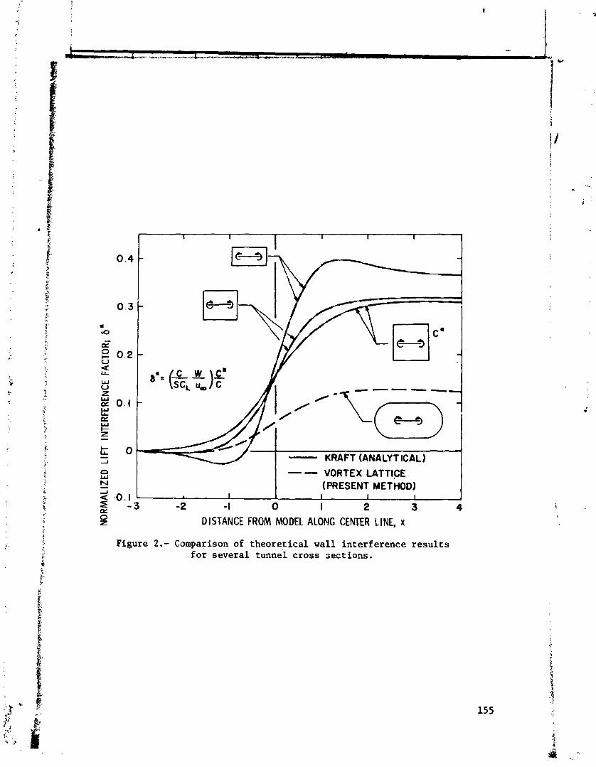
I - - VORTEX LATTICE (PRESENT METHOD) I g -0.1 1 I I I 1 I 1
P: - 3 -2 -I 0 I 2 3 4
2 DISTANCE FROM MODEL ALONG CENTER LINE, x
Figure 2.- Comparison of theoretical wall interference results for several tunnel cross sections.
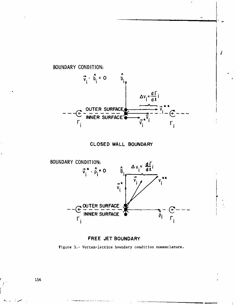
BOUNDARY CONDITION:
CLOSED WALL BOUNDARY
BOUNDARY CONDITION:
- -c OUTER SURFACE
INNER SURFACE r.
I
FREE JET BOUNDARY
Figure 3.- Vortex-lattice boundary condition nomenclature.

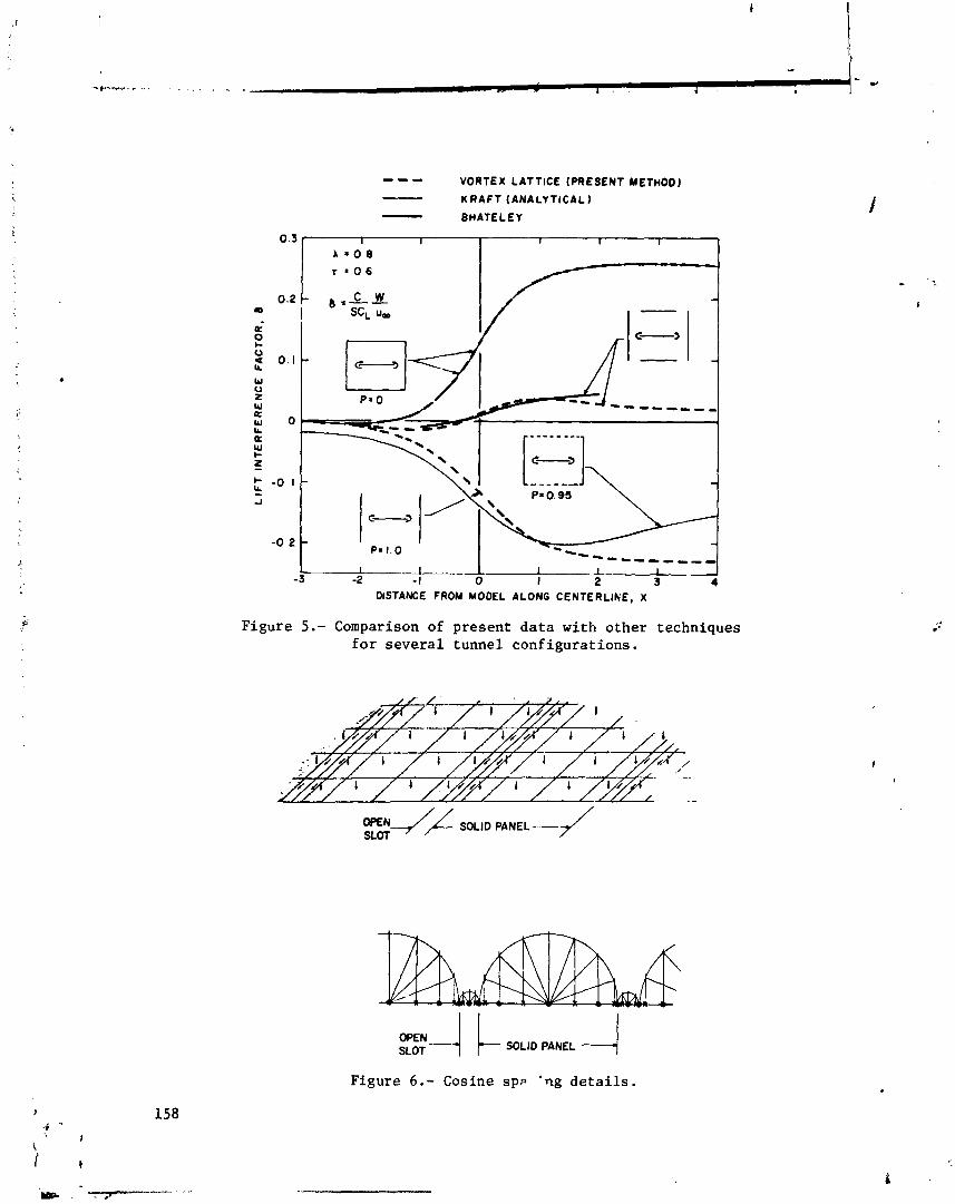
- - - VORTEX LATTICE (PRESENT METHOD) KRAFT (ANALYTICAL - BHATELEY
Figure 5 . - Comparison of present data with other techniques f o r several tunnel configurations.
mN-'-j SOLID PANEL 4 SLOT
Figure 6 . - Cosine s p ~ 'ng d e t a i l s .
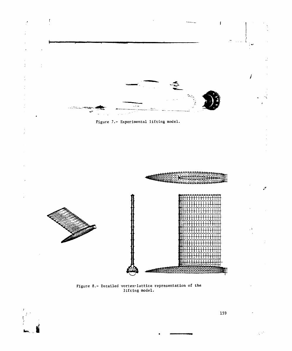
Figure 7 . - Experimental l i f t i n g model.
Figure 8 . - Detailed vortex-lattice representation of the l i f t i n g model.
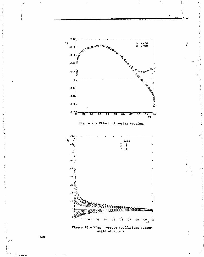
0.08 - \
0.12 -
O.I68 QI an 013 0.4 cia 0.6 0:7 0.; i9
I /c
Figure 9 . - Effect of vortex spacing.
Figure 10.- Wing pressure coef f ic ient versus angle of attack.
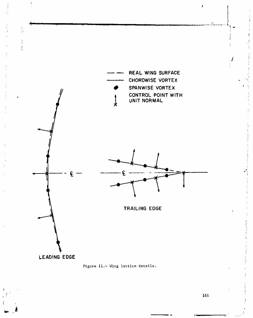
LEADING EDGE
Figure 11.- Wing l a t t i c e de ta i l s .
-- REAL WING SURFACE
CHORDWISE VORTEX
SPANWISE VORTEX CONTROL POINT WITH f UNIT NORMAL
\
TRAILING EDGE

A QUADRILATERAL VORTEX METHOD
APPLIED TO CONFIGURATIONS WITH H I G H CIRCULATION
Brian Maskew Analytical Methods, Inc.
SUMMARY
A quadri lateral vortex-lat t ice method is b r i e f ly described for calcula- t ing the potential flow aerodynamic charac ter is t ics of h igh- l i f t configurations. I t incorporates an i t e r a t i v e scheme fo r calculat ing the deformation of force- f r e s wakes, including wakes f r cn side edges. The method i s applicable t o mul- t i p l e l i f t i n g surfaces with part-span f laps deflected, and can include ground e f fec t and wind-t.mnel interference. Numerical r e su l t s , presented for a number of h igh- l i f t configurations, demonstrate rapid convergence of the i t e r a t i v e technique. The resu l t s are i n good agreement with available experimental data.
INTRODUCTION
The calculat ion of aerodynamic charac ter is t ics fo r three-dimensional configurations with high circulat ion, e.g., a wing with f l a p and ta i lp lane can be misleading unless the t r a i l i n g vortex wakes are represented correct ly. Iq
f ac t , i n i t i a l applications of a quadr i la tera l v o r t e l r l a t t i c e method with r i g i d non-planar wake ( refs . 1 and 2 ) showed tha t r e su l t s fo r a wing alone were sen- s i t i v e t o wake location a t even moderate l i f t coeff icients . The high circula- t ion case, therefore, i s non-linear, and requires a force-free wake represen- ta t ion .
The problem of calculat ing vortex sheet roll-up has recieved considerable a t tent ion i n the past , (see review by Rossow ( re f . 3 ) ) , but has been concerned mainly with the two-dimensional case. More recent work has included three-di- mensional factors . Butter and Hancock ( ref . 4 ) and a l so Hackett and Evans ( r e f . 5) included the influence of a bound vortex, and Belotserkovskii ( r e f . 6) incorporated a wake roll-up procedure with a vortex-lat t ice method. Mook and Maddox (ref . 7 ) developed a vortex-lat t ice method with leading-edge vortex rcll- up. The roll-up procedure incorporated i n the quadr i la tera l vcrtex method ( re f . 2 ) d i f f e r s s l igh t ly from the above methods, and i s described here before discussing the h igh- l i f t applications.
SYMBOLS
a incidence, i n degrees
S area
c chord
- c reference chord
A aspect r a t i o
11 spanwise pos i t ion normalised by wing semispan
C~ l i f t coef f ic ien t
c~ pi tching moment coe f f i c i en t (about the mid chord)
C~ induced drag coef f ic ien t
i
k induced drag fac tor , = ?TA C /CL 2
Di
Subscripts:
W wing
T t a i l p l ane o r wind tunnel
ca l c calculated
exP experimental
METHOD DESCRIPTION
The method, which incorporates an i t e r a t i v e procedure f o r wake shape, i s based on vor tex- la t t ice theory (e.g. , r e f . 8), but the l a t t i c e i s formed i n t o quadr i la te ra l vor t ices ( f i g . 1) instead of horse-shoe vor t ices . The quadri la- t e r a l form is equivalent t o a piecewise constant doublet d i c t r i bu t ion and each vortex "panel" is self-contained. This makes i t e a s i e r t o apply t o cambered slirfaces. Another advantage is t h a t only the quadr i l a t e r a l s adjacent t o t r a i l - ing edges (and t o s ide edges when edge separat ion is included) have t r a i l i n g vor t ices , and s o they a r e the only panels whose influence coe f f i c i en t s vary i n the i t e r a t i o n s i o r wake shape. The complete matrix of influence coe f f i c i en t s would be a f fec ted fo r the horse-shoe vortex model.

For the wake model, each t r a i l i n g vortex is divided i n t o s t r a i g h t seg- ments ( f ig . 1 1 , the number and length of which can be varied from vortex t o vortex t o a.llow more deta i led repreeentatiorr i n roll-up regions. The segmented pa r t of each vortex ends i n a semi-infinite vortex i n the free-stream direct ion. In the i t e r a t i v e wake procedure, each t r a i l i n g vortex segment is made approxi- mately force-free bv aligning it with the local mean veloci ty vector. The segment midpoint is the most appropriate posi t ion t o apply t h i s condition, yet most methods use the upstream end of the segment (following r e f . 6 ) . Th? pre- sent method calculates the mean velocity a t 55% of the segment 1e;lgth (extra- polated from the previous segment) a f t e r examining a roll-up calculat ion ( re f . 2 ) fo r a pa i r of equal s trength, segmented vort ices. Compared with the upstream end point, the 55% point gives f a s t e r convergence, and the r e s u l t s arc! l e s s sens i t ive t o segment length, ( f ig . 2 ) .
Small Rankine vortex cores a r e placed cn the vor t ices t o avoid large veloci t ies being calculated near the vort ices; nevertheless, when calculat ing the velocity vectors fo r the wake relaxation, the l o c a l vortex contribution is excluded. To obtain the f i r s t vortex strength solut ion, the t r a i l i n g vor t ices a re assumed semi-infinite i n the free-stream direct ion. A new vortex strength solut ion is obtained a f t e r each wake relaxation is completed.
RESULTS AND DISCUSSION
Wing-f lap-tai lplane
The wing-flap-tailplane configuration is a typica l problem facing the aerodynamicist when calculat ing the behavior of an a i r c r a f t during landing and take-of f . h e present method enables the f ree-air and the ground-ef f ec t re- gimes t o be evaluated. An i l l u s t r a t i v e calculat ion was performed fo r the par t span f l a p configuration shown i n figure 3 ( a ) . The geometric charac ter is t ics are presented i n table 1.
Figure 3(a) shows the calculated vortex t r a j e c t o r i e s i n f r ee a i r a f t e r the fourth i t e ra t ion . The vortex roll-up region from the f l a p edge passes close t o the ta i lp lane t i p (outboard and below) and has c l ea r ly influenced the ta i lp lane t i p vortex t ra jec tory (compare vortex (15) with vortex (10) from the wing t i p , especial ly i n the s ide view). The plan view shows wing inboard t r a i l - ing vort ices passing d i rec t ly below the centers o'f t a i lp lane quadr i la tera ls . I f these vort ices had been close t o the ta i lp lane surface, then the r e su l t s would have diverged. In Its present form the method is not applicable t o close approach problems unless the vortex trajec,ories a re constrained t o a l ign with the local surface l a t t i c e . However, the close approach problem has been inves- t iga ted , and a technique developed t o overcome i t ( refs . 9 and 10) but, so f a r , t h i s has not been incorporated i n the r a i n program.
The e f fec t of i t e r a t i o n on the t ra jec tory of vortex ( 7 ) from the f l a p edge region i s giver. separately i n figure 3 ( b ) . This vortex moved the most i n 3
1 the group; nevertheless, the figure shows l i t t l e change between t h e t h i rd and "i fourth i t e ra t ions . Sections through the calculated wakes i n f r ee a i r and i n 1
165 $
ground e f f e c t a r e shown i n f i g u r e 3 ( c ) . Compared wi th t h e f r e e - a i r p o s i t i o n s , t h e vortices move outwards i n ground e f f e c t , and a r e d e f l e c t e d upwards. Th is movement w i l l i n f luence t h e ground-effect cond i t ions a t t h e t a i l p l a n e .
Figure 4 shows t h e changes i n wing and t a i l p l a n e c a l c u l a t e d l i f t and 'n- duced drag wi th i t e r a t i o n i n f r e e - a i r condi t ions . The wing l i f t i s e s s e n t i a l l y converged by t h e second i t e r a t i o n and t h e induced drag f a c t o r , k , by t h e t h i r d . The t a i l p l a r ~ e l i f t and induced drag ( i n t h e presence o f t h e wing) a r e e s s e n t i - a l l y converged by t h e second i t e r a t i o n a f t e r a r e l a t i v e l y b i g jump from t h e streamwise-wake value .
Table I1 g ives t h e c a l c u l a t e d va lues of l i f t and induced drag f o r f r e e air and f o r ground-effect cond i t ions , and inc ludes va lues f o r wing and t a i l p l a n e alone. These r e s u l t s i q l y ( f o r t h e combined configurdiicxi) an average down- wash angle a t t h e t a i l p l a n e o f about 1 0 . F i n f r e e a i r and 1.7O i n ground e f - f e c t . The method, however, t a k e s i n t o account v a r i a t i o n s i n downwash - and sidewash - across t h e span and chord o f t h e t a i l p l a n e . The presence of t h e t a i l p l a n e causes smal l changes i n t h e wing c h a r a c t e r i s t i c s . In f r e e a i r t h e r e is a small decrease i n wing l i f t ( % 0 . 8 % ) and a small inc rease i n induced drag f a c t o r (from 1.100 t o 1 .108) , which r e s u l t from a smal l downwash induced by t h e negat ive c i r c u l a t i o n on t h e t a i l p l a n e . I n ground e f f e c t , however, t h e t a i l p h e - which now has p s i t i v e l i f t - causes a smal l i n c r e a s e i;' wing l i f t and a de- c rease i n its induced drag f a c t o r (from 0.613 t o 0.581). Although t h e t a i lp lane alone r e s u l t s show t h e expected inc rease i n l i f t wi th ground e f f e c t , the wing- f l a p alone r e s u l t shows a decrease . This apparent anomaly is i n accordance with r e s u l t s found e a r l i e r i n re fe rence 11; with inc reas ing camber and/or i n - cidence, t h e i n i t i a l inc rease i n wing l i f t i n ground e f f e c t decreases and even- t u a l l y goes negat ive . Th is f e a t u r e i s made more apparent i n t h e spanwise d i s - t r i b u t i o n .
The c s l c u l a t e d spanwise load d i s t r i b u t i o n , C c / l , and c e n t e r o f p ressure L
locus f o r t h e wing a r e shown i n f i g u r e s 5 ( a ) and 5 ( b ) fox both f r e e - a i r and ground-effect cond i t ions . In jround e f f e c t ( a t t h e same incidence a s i n f r e e - a i r ) the re is a r e l a t i v e % i n l i f t i n t h e f lapped reg ion - e v i d e n t l y over t h e f l a p i t s e l f because t h e cen te r o f p ressure moves forward t h e r e - while out- board t h e r e is a small inc rease i n l i f t and a rearward s h i f t i n c e n t e r o f pres- s u r e ( i . e . , t h e normally accepted in f luences of ground e f f e c t ) . The n e t r e s u l t , a s a l ready seen i n t a b l e 11, i s a decrease i n o v e r a l l l i f t . Evidently, camber has a s t r o n g in f luence . , I t h e grr>und i n t e r f e r e n c e e f f e c t which must be t aken i n t o account when p r e d i c t i n g aerodynamic c h a r a c t e r i s t i c s near t h e ground ( r e f . 11).
A s would be expected, t h e induced drag is concentra ted over the f l apped region i n f r e e a i r ( f i g . 5(c) 1 , and i n f a c t an induced t h r u s t is c a l c u l a t e d over t h e unflapped region - a p l a u s i b l e consequence o f concen t ra t ing t h e load over t h e inboard p a r t of a swept wing. I n ground e f f e c t , t h e expected reduc- t i o n i n induced drag occurs mainly inboard o f t h e f l a p edge region ( i . e . , i n t h e upwash reqion from the f l a p edge t r a i l i n g vor tex image).
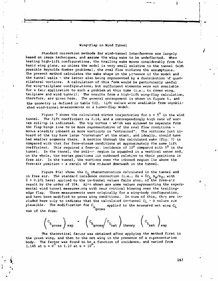
Wing-Flap i n Wind Tunnel
S t anda rd c o r r e c t i o n methods f o r wind-tunnel i n t e r f e r e n c e a r e l a r g e l y based on image t e c h n i q u e s , and assume t h e wing wake t o be u n d e f l e c t e d . When t e s t i n g h i g h - l i f t c o n f i g u r a t i o n s , t h e t r a i l i n g wake moves c o n s i d e r a b l y from t h e b a s i c wing p l a n e , s o u n l e s s t h e model i s ve ry s m a l l r e l a t i v e t o t h e t u n n e l ( w i t b p o s s i b l e Reynolds Number problems) , t h e r e a l f low v i o l a t e s t h e a s sumpt io r ;~ . The p r e s e n t method c a l c u l a t e s t h e wake shape i n t h e k r? sence of t h e model and t h e t u n n e l walls - t h e l a t t e r a l s o be ing r e p r e s e n t e d by a d i s t r i b u t i o n ?f quad- r i l a t e r a l v o r t i c e s . A c a l c u l a t i o n of t h i s form would b e p a r t i c u l a r l y u s e f u l . f o r w i n g - t a i l p l a n e c o n f i g u x a t i o n s , b u t s u i f l c i e n t e l emen t s were n o t a v a i l a b l e f o r a f a i r a p p l i c a t i o n t o such a problem a t t h i s t i m e ( i .e. , t o c o v e r wing, t a i l p l a n e and wind t u n n e l ) . The r e s u l t s from a h i g h - l i f t wing-f lap c a l c u l a t i o n , t h e r e f o r e , a r e g i v e n h e r e . The g e n e r a l arrangement i s shown i n f i g u r e 6 , and the geometry is d e f i n e d i n t a b l e 111. L i f t v a l u e s were a v a i l a b l e from unpubl i - shed wind-tunnel measurements on a blown-flap model.
F igu re 7 shows t h e c a l c u l a t e d v o r t e x t r a j e c t o r i e s f o r a = 5' i n t h e wird tunne l . The l i f t c o e f f i c i e n t is 2.14, and a co r re spond ing ly h i g h r a t e o f vor- t e x r o l l - u p i s i n d i c a t e d . The t i p v c r t e x - which was a l lowed t o s e p a r a t e from t h e f l a p h inge l i n e t o be more r e p r e s e n t a t i v e o f t h e real f low c o n d i t i o n s - moves s z e a d i l y inboa rd a s more v o r t i c i t y i s " e n t r a i n e d " . The v o r t i c e s j u s t in- board o f t h e t i p have l a r g e "cu rva tu re" a t t h e s t a r t , and i d e a l l y , shou ld have had smaller segments t h e r e . A s e c t i o n th rough t h e c a l c u l a t e d wake ( f i g . 7 ) is compared w i t h t h a t f o r f r ee - s t r eam c o n d i t i o n s a t approximate ly t h e same l i f t c o e f f i c i e n t . Th i s r e q u i r e d a f r e e - a i l i n c i d e n c e o f lo0 compared w i t h 5O i n t h e t u n n e l . I n t h e t u n n e l , t h e ro l l - t i - reg ion i s squashed i n a v e r t i c a l s e n s e and , on t h e whole, t h e v o r t e x p o s i t i o n s l i e ou tboa rd r e l a t i v e t o t h e i r p o s i t i o n s i n f r e e a i r . I n t h e tunnel. , t h e v o r t i c e s o v e r t h e i n b o a r d r e g i o n l i e above t h e f r e e - a i r p o s i t i o n - a r e s u l t o f t h e r d u c e d downwash i n t h e t u n n e l .
F i g u r e 8(a) shows t h e CL c h a r a c t e r i s t i c s c a l c u l a t e d i n t h e t u n n e l and i n f r e e a i r . The s t a n d a r d i n c i d e n c e c o r r e c t i o n ( i . e . , Acr = kL SW/ST, w i t h 6 = 0.101 h e r e ) a p p l i e d t o t h e i n - t u n n e l v a l u e s f a l l s short o f t h e f r e e - a . r # r e s u l t by t h e o r d e r o f 35%. A l r ? shown are some v a l u e s r e p r e s e n t i n g t h e exper i - t
menta l wind t u n n e l measure1~2nts w i t h n e t r c r i t i c a l blowing o v e r t h e t r a i l i n g - edge f l a p . These measurements were o r i g i n a l l y f o r a wing-body c o n f i g u r a t i o n , and have been modif ied t o g r o s s wing c o n d i t i o n s . I n view o f t h i s , tht>y a r e in- c luded h e r e 0 . 1 1 ~ t o i n d i c a t e t h a t t h e ca l cu laLed in - tunne l CL - cl v a l u e s a x e p l a u s i b l e . The m o d i f i c a t i o n f o r CL a p p l i e d t o t h e measured n e t wjng CL
was o f t h e form: g r o s s
The t h e o r e t i c a l f a c c o r was o b t a i n e d a f t e r a p p l y i n g t h e method f i r s t t o t h e g r o s s wing, and then t o t h e n e t wing i n t h e p r e s e n c e o f a r e p r e s e n t a t i v e body. The f a c t o r was found t o be a f m c t i o n o f i n c i d e n c e , and v a r i e d from 1.145 a t a = 0" t o 1.10 a t a = lo0.

The ca lcu la ted induced drag f a c t o r c h a r a c t e r i s t i c s a r e shown i n f i g u r e 8 ( b ) , and show a dependence on C i n both f r e e - a i r and in- lunnel cond i t ions - I t h e form of t h e dependence is nok. shown s i n c e only two p o i n t s ware c a l c u l a t e d f o r each condi t ion. The s tandard c o r r e c t i o n f o r drag (AC = CLxAcc) added t o
Di t h e ca lcu la ted in- tunnel induced drag gave k va lues which f e l l s h o r t of t h e f r e e - a i r ca lcu la t ions ; t h e d i f f e r e n c e i n t h e increment i n k -
var ied from i ~ % a t C = 1.98 t o 18% a t CL = 2.14. L
Small Aspect Rat io Wing
For an extreme t e s t case f o r t h e wake ro l l -up c a l c u l a t i ~ n , a s l e n d e r rec tangu la r wing of aspec t r a t i o 0.25 was considered a t 20° incidence. Cal- c u l a t i o n s were performed using an 8 x 6 vor tex a r r a y and two i t e r a t i o n s f o r two conf igurat ions:
( a ) f l a t p l a t e
(b) bent p l a t e (20° de f lec t i c r? about t h e mid chord)
Flow v i s u a l i z a t i o n s t u d i e s and wind-tunnel fo rce and moment measurements have been c a r r i e d o u t on these m n f i g u r a t i o n s by Wickens ( r e f . i2 1 . The r e a l flow f o r these cases is dominated by t h e t ip-edge v o r t i c i t y , and s u r f a c viscous e f f e c t s a r e r r ' a t l v e l y small; a comparison betb en t h e p o t e n t i a l flow ca lcu la - t i o r and ,?xperimcnt is the re fore p r a c t i c a b l e .
The s i d e view and p lan view of t h e c a l c u l a t e d vor tex t r a j e c t o r i e s from t h e f l a t arid bent p 1 a t . e ~ a r e p resen ted i n f i g u r e s 9 ( a ) and 9 ( b ) , r e s p e c t i v e l y . Included i n t h e s i d e views a r e t h e approximate p o s i t i o n s o f t h e v o r t e x cores from flow v i s u a l i z a t i o n ( r e f . 12) and t h e c a l c u l a t e d c e n t r o i d o f v o r t i c i t y locus. I n t h e f l a t p l a t e case , t h e s e l i n e s a r e i n e x c e l l e c t agreement, and i n f a c t a r e i n c l i n e d a t approximztely a / 2 t o t h e s u r f a c e - i . e . , t h e t h e o r e t i c a l angle f o r vanishingly smal l a s p e c t r a t i o . I n t h e b e n t p l a t e case , two vor tex cores appear i n t h e experiment, one from t h e leading-edge t i p and t h e o t h e r from the bend l i n e t i p - i . e . , from t h e two peak v o r t i c i t y reg ions . When c a l - c u l a t i n g t h e c e n t r o i d o f v o r t i c i t y locus f o r t h i s case , t h e edge v o r t i c e s were divided i n t o two groups, t h e leading-edge vortex s t a r t i n g t h e f i r s t group, and the hinge-line vor tex t h e second. me c a l c u l a t e d c e n t r o i d l o c i i n i t i a l l y have f a i r agreement with t h e observed vor tex cores , b u t l a t e r t end t o d iverge , ind i - c a t i n g . slower r a t e o f ro l l -up i n t h e c a l c u l a t i o n . Another i t e r a t i o n might have helped here , but che p o x i m i t y o f t h e end of t h e segment-represented reg ion ( t h e e x t e n t o f which was l i m i t e d by t h e number o f segments a v a i l a b l e i n t h e
program) must have inf luenced t h e shape near t h e downstream end.
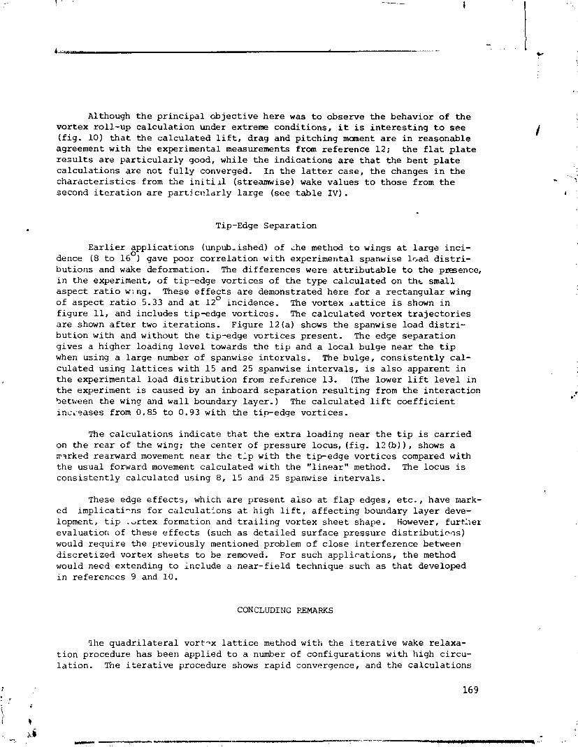
Although t h e p r i n c i p a l o b j e c t i v e h e r e w a s t o observe t h e behavior of the vor tex ro l l -up c a l c u l a t i o n under extreme condi t ions , it is i n t e r e s t i n g t o s e e ( f i g . 10) t h a t t h e c a l c u l a t e d l i f t , drag and p i t c h i n g manent a r e i n reasonable agreement wi th t h e experimental measurements from r e f e r e n c e 12; t h e f l a t p l a t e r e s u l t s a r e p a r t i c u l a r l y good, whi le t h e i n d i c a t i o n s a r e t h a t t h e b e n t p l a t e c a l c u l a t i o n s a r e no t f u l l y converged. I n t h e l a t t e r case , t h e changes i n t h e c h a r a c t e r i s t i c s from t h e i n i t i l l (streamwise) wake va lues t o those from t h e second i t e r a t i o n a r e p a r t l c~! ld r ly l a r g e ( see t a b l e IV) .
Tip-Edge Separat ion
E a r l i e r a p p l i c a t i o n s (unpub-ished) of che method t o wings a t l a r g e i n c i - 0
dence (8 t o 16 gave poor c o r r e l a t i o n wi th experimental spanwise h a d d i s t r i - bu t ions and wake deformation. The d i f f e r e n c e s were a t t r i b u t a b l e t o t h e presence, i n t h e experiment, o f t ip-edge v o r t i c e s of t h e type c a l c u l a t e d on t h t smal l a s p e c t r a t i o w;.ng. These e f f e c t s a r e demonstrated here f o r a r e c t a n g u l a r wing o f a s p e c t r a t i o 5.33 and a t 12O incidence. The vor tex l a t t i c e is shown i n f i g u r e 11, and includes t ip-edge v o r t i c e s . The c a l c u l a t e d vor tex t r a j e c t o r i e s a r e shown a f t e r two i t e r a t i o n s . Figure 1 2 ( a ) shows t h e spanwise load d i s t r i - bu t ion wi th and wi thout t h e t ip-edge v o r t i c e s p resen t . The edse s e p a r a t i o n g ives a h igher loading l e v e l towards t h e t i p and a l o c a l bulge near t h e t i p when using a l a r g e number o f spanwise i n t e r v a l s . The bulge , c o n s i s t e n t l y ca l - c u l a t e d us ing l a t t i c e s wi th 1 5 and 25 spanwise i n t e r v a l s , is a l s o apparent i n t h e experimental load d i s t r i b u t i o n from reference 13. (The lower l i f t l e v e l i n t h e experiment is caused by an inboard s e p a r a t i o n r e s u l t i n g from t h e i n t e r a c t i o n 5etveen t h e winq and wal l boundary l a y e r . ) The c a l c u l a t e d l i f t c o e f f i c i e n t i n c i 2 a s e s from 0.85 t o 0.93 wi th t h e t ip-edge v o r t i c e s .
The c a l c u l a t i o n s i n d i c a t e t h a t t h e e x t r a loading near t h e t i p is c a r r i e d on t h e r e a r of t h e wing; t h e c e n t e r of p ressure locus, ( f i g . 1 2 (b)) , shows a rrwked rearward movement near t h e t l p wi th t h e t ip-edge v o r t i c e s compared wi th t h e usual forward movement c a l c u l a t e d wi th t h e " l i n e a r " method. The locus is c o n s i s t e n t l y c a l c u l a t e d us ing 8, 15 and 25 spanwise i n t e r v a l s .
These edge e f f e c t s , which a r e p r e s e n t a l s o a t f l a p edges, e t c . , have mark- ed impl ica t i -ns f o r c a l c u l a t i o n s a t high l i f t , a f f e c t i n g boundary l a y e r deve- lopment, t i p . d r t e x formation and t r a i l i n g vor tex s h e e t shape. However, f u r t h e r eva lua t ion of t h e s e e f f e c t s (such a s d e t a i l e d s u r f a c e p ressure d i s t r i b u t i ~ a s ) would r e q u i r e t h e previously mentioned problem o f c l o s e i n t e r f e r e n c e between d i s c r e t i z e d vor tex s h e e t s t o be removed. For such a p p l i c a t i o n s , t h e method would need extending t o inc lude a n e a r - f i e l d technique such a s t h a t developed i n re fe rences 9 and 10.
CONCLUDING REMARKS
l h e q u a d r i l a t e r a l vor t -x l a t t i c e method wi th t h e i t e r a t i v e wake re laxa- t i o n procedure has been app l ied t o a number of conf igura t ions wi th high c i rcu- l a t i o n . The i t e r a t i v e procedure shows r a p i d convergence, and t h e c a l c u l a t i o n s
are i n good agreement wi th a v a i l a b l e experimental r e s u l t s . Tip-edge separa- t i o n effects have been shown t o be important a s p e c t s o f h i g h - l i f t c a l c u l a t i o n s . f More d e t a i l e d t h e o r e t i c a l e v a l u a t i o n o f t h e s e e f f e c t s , e.g., i n terms o f sur- f a c e p ressure d i s t r i b u t i o n s , would r e q u i r e ex tens ions o f t h e method t o incor- p o r a t e r e c e n t l y developed n e a r - f i e l d techniques. Such an ex tens ion would also allow a t h e r c l o s e i n t e r f e r e n c e e f f e c t s t o be s tud ied .
REFERENCES
1. Maskew, B.: Ca lcu la t ion of t h e Three-Dimensions1 P o t e n t i a l Flow Around L i f t i n g Non-Planar Wings and Wing-Bodies Using a Surface D i s t r i b u t i o n of Q u a d r i l a t e r a l Vortex Rings. TT7OO9, Loughborough Univ. o f Technology, England, Sept. 1970.
2. Maskew, B.: Numerical L i f t i n g Surface Methods f o r Ca lcu la t ing t h e P o t e n t i a l Flow about Wings and Wing-Bodies o f Arb i t ra ry Geometry. Ph.D. Thesis , Loughborough rlniv. o f Technology, England, O c t . 1972.
3. Rossow, V.J . : Survey o f Computational Methods f o r Lift-Generate2 Wakes. NASA SP-347, March 1975, pp. 897-923.
4. But te r , D. J. ; and Hancock, G. J. : A Numerical Method f o r Ca lcu la t ing t h e T r a i l i n g Vortex System Behind a Swept Wing a t Low Speed. The Aeronautical Journa l , Vol. 75, No. 728, Aug. 1971, pp. 564-568. .~
5. Hackett , J.E.; and Evans, M.R.: Vortex Wakes Behind High-Lift Wings. J. A i r c r a f t , Vol. 8, No. 5 , May 1971, pp. 334-340.
6. Belotserkovski i , S.M.: Ca lcu la t ion of t h e Flow Around Wings o f A r b i t r a r y Planform over a Wide Range o f Angles o f Attack. NASA TTF-12, 291, May, 1971.
7. Mook, D.T.; and Maddox, S.A.: Extension o f a Vortex L a t t i c e Method t o In- 1
clude t h e E f f e c t s o f Leading-Edge Separat ion. J. A i r c r a f t , Vol. 11, No.2, Feb. 1974, pp. 127-128.
8. Rubbert, P.E.: Theore t i ca l C h a r a c t e r i s t i c s o f Arb i t ra ry Wings by a Non- Plal a r Vortex L a t t i c e Method. D6-9244, The Boeing Co., 1964.
9. Maskew, B.: A Subvortex Technique f o r t h e Close Approach t o a Disc re t i zed Vortex Sheet. NASA 'rM X-62, 487, Sept . 1975.
lO.Maskew, B.: A Submerged S i n g u l a r i t y Method f o r Ca lcu la t ing P o t e n t i a l Flow V e l o c i t i e s a t Arb i t ra ry Near-Field Points . NASA TMx-73,115, March, 1976.
ll.Maskew, B: 3n t h e Inf luence o f Camber and Non-Planar Wake on t h e A i r f o i l C h a r a c t e r i s t i c s i n Ground E f f e c t . TT7112, Loughborough Univ. Of Techno- logy, England, Oct. 1971, (See a l s o ARC 33950, 1973, Aero. Res. Council , London) .

12. Wickens, R . H . : The Vortex Wake and Aerodynamic Load Dis tr ibut ion o f Slen- der Rectangular Wings. Canadian Aeronautics and Space Journal, June 1967, pp. 247-260.
13. Chigier, N . A . ; and Cors ig l ia , V . R . : T i p Vort ices - Veloci ty Dis tr ibut ions . NASA TM X-62,087, 1971.
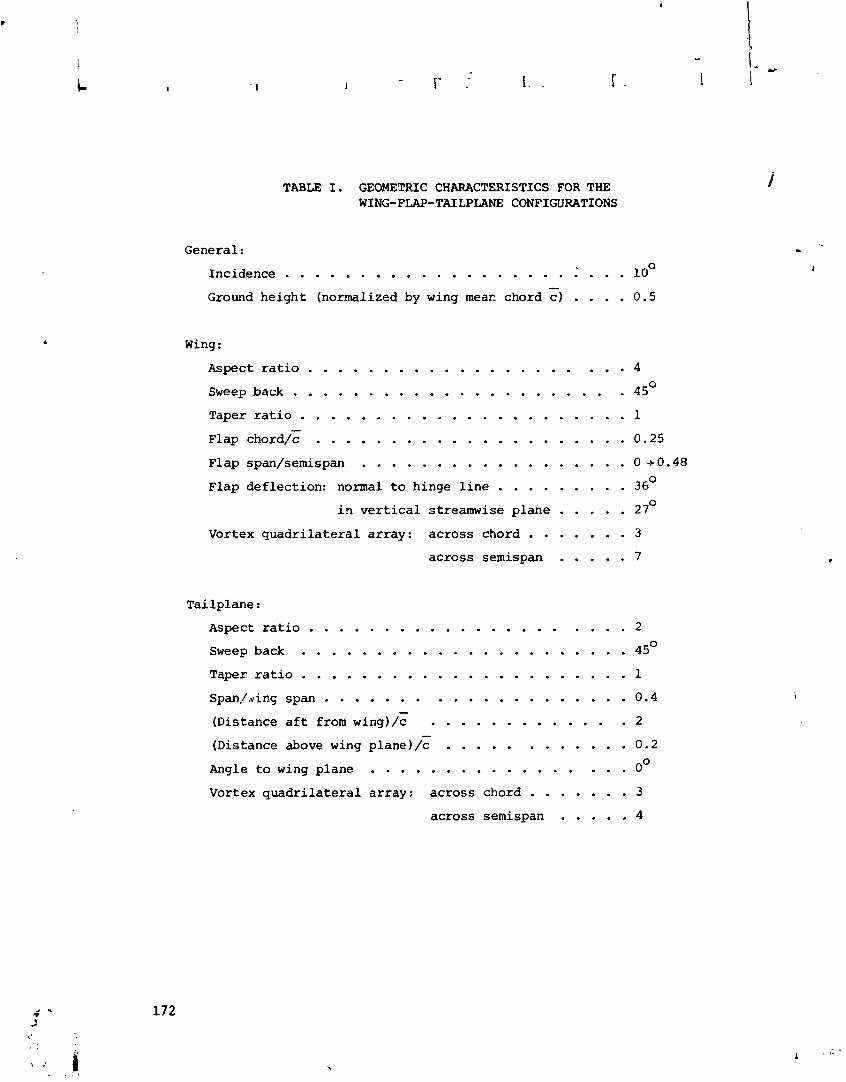
TABLE I. GEOMETRIC CHARACTERISTICS FOR THE WING-FLAP-TAILPLANE CONFIGURATIONS
General :
. . . . . . . . . . . . . . . . . . . . . . Incidence : lo0 Ground h e i g h t (normalized by wing mear chord c) . . . . 0.5
Wing:
Aspect ratio . . . . . . . . . . . . . . . . . . . . . 4
Sweep back . . . . . . . . . . . . . . . . . . . . . . 45O
Taper r a t i o . . . . . . . . . . . . . . . . . . . . . . 1
Flap chord/; . . . . . . . . . . . . . . . . . . . . . 0.25 Flap span/semispan . . . . . . . . . . . . . . . . . . O+0.48 Flap de f lec t ion : normal to hinge l i n e . . . . . . . . . 36O
. . . . . i n v e r t i c a l streamwise p l a n e 27O
Vortex q u a d r i l a t e r a l a r r a y : a c r o s s chord . . . . . . . 3
a c r o s s semispan . . . . . 7
Tai lp lane:
. . . . . . . . . . . . . . . . . . . . . A s p e c t r a t i o 2
Sweep back . . . . . . . . . . . . . . . . . . . . . . 45O Taper r a t i o . . . . . . . . . . . . . . . . . . . . . . 1
. . . . . . . . . . . . . . . . . . . . Span,/,.v i n s span 0.4
(Distance a f t from wing)/: . . . . . . . . . . . . . 2 (Distance above wing plane) /: . . . . . . . . . . . . 0.2
. . . . . . . . . . . . . . . . . Angle t o wing p lane o0 Vortex q u a d r i l a t e r a l a r ray : a c r o s s chord . . . . . . . 3
ac ross semispan . . . . . 4

TABLE 11. CALCULATED WING-FLAP-TAILPLANE LIFT AND INDUCED DRAG
CHARACTERISTICS I N FREE AIR AND IN GROUND EFFECT
(SECOND ITERATION)
Wing-Flap T a i l p l a n e (based on w i n g a r e a )
Conf i y u r a t i o n
Free - air
Ground-
E f f e c t
together
a l o n e
together
a l o n e

TABLE 111. BASIC CHARACTERISTICS FOR THE WIS-FLAP I N WIND4'UNNEL CONFIGURATION
Theoret ical Model
Wing : . . . . . . . . . . . . . . . . . . . . . . . . AspectRat io 2.9
Leading edge sweepback . . . . . . . . . . . . . . . . . . . 31°
Trailing-edge f l a p : Span/wingspan . . . . . . . . . . . . . . . . . . . . . 1.0 Chord/wingchord . . . . . . . . . . . . . . . . . . . . 0.31 Deflection (normal t o hinge l i n e ) . . . . . . . . . . . . 40° Hinge - l ine sweepback . . . . . . . . . . . . . . . . . . . 17O
Vortex quadr i l a t e r a l a r r ay (chordwise x spanwise) . . . . . . 3 x 10
Wind Tunnel: . . . . . . . . . . . . . . . . . . . Wing span/tunnel width 0.56
Wing ai-ea/tunnel c ross sec t ion a rea (sW/ST) . . . . . . . . . 0.256
Tunnel1length'/wing mean chord . . . . . . . . . . . . . . . 6
Vortex quadr i l a t e r a l a r ray (lengthwise x circumferential) . . 11 x l u
Reynolds Number (based on wing mean chord) 1.2 x 10 6 . . . . . . . . . . .
Gross Wing : Basic d e t a i l s a r e t h e same a s f o r t h e o r e t i c a l model, bu t i n addition:
Leading edge f lap : I
Fu l l n e t span i . . . . . . . . . . . . . . . . . . . . Chord/wing c h o r d . 0.15 Deflection. . . . . . . . . . . . . . . . . . . . . . . . 40' Hinge-line sweepback . . . . . . . . . . . . . . . . . 28O
Trailing-edge f l a p blowing momentum coe f f i c i en t 0 . . . . . . . . . . . . . . . . . ( c r i t i c a l value a t a = 8 ) 0.018
Body : + . . . . . . . . . . . . . . . . . . . . . . . . . . . . Width 0.18, . . . . . . . . . . . . . . . . . . . . . . . . . . . . Depth 0.36 * . . . . . . . . . . . . . . . . . . . . . . . . . . . Length 1.834,+ . . . . . . . . . . . . . . . Length of fo re and a f t f a i r i n g s 0.357, . . . . . . . . . . . Wing pos i t ion (above body center l i n e ) . 0.096 Section - rectangular witn rounded corners
+ * Note: normalised by gross wing semispan (each)
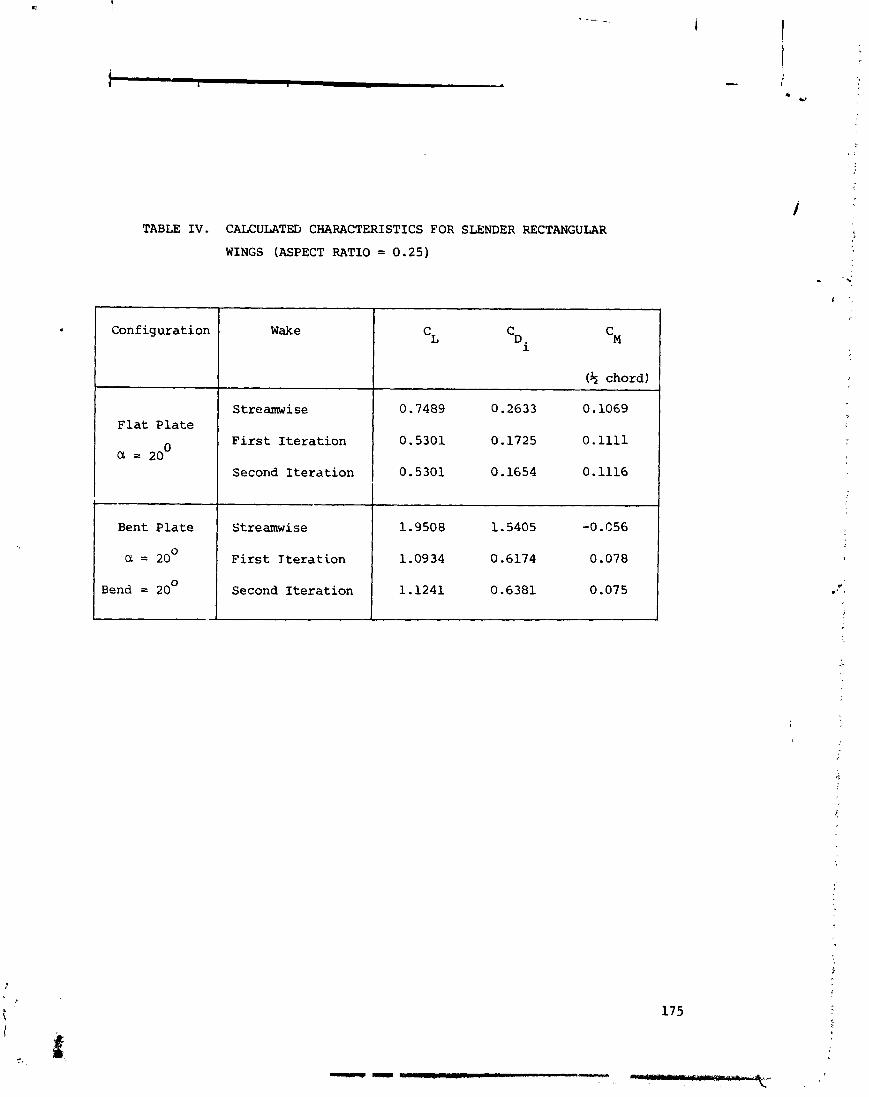
TABLE I V . CALCULATE11 CHARACTERISTICS FOR SLENDER RECTANGULAR
WINGS (ASPECT RATIO = 0.25)
Configurat ion Wake
F i r s t I t e r a t i o n
Second I t e r a t i o n
F l a t P l a t e
I a = zoo I F i r s t Tteration 1 1.0934 0.6174 0.078 I
Streamwise
Bent P l a t e Streamwise
0.7489 0.2633 0.1069
1.9508 1.5405 -0. C56
Bend = 20° Second I t e r a t i o n
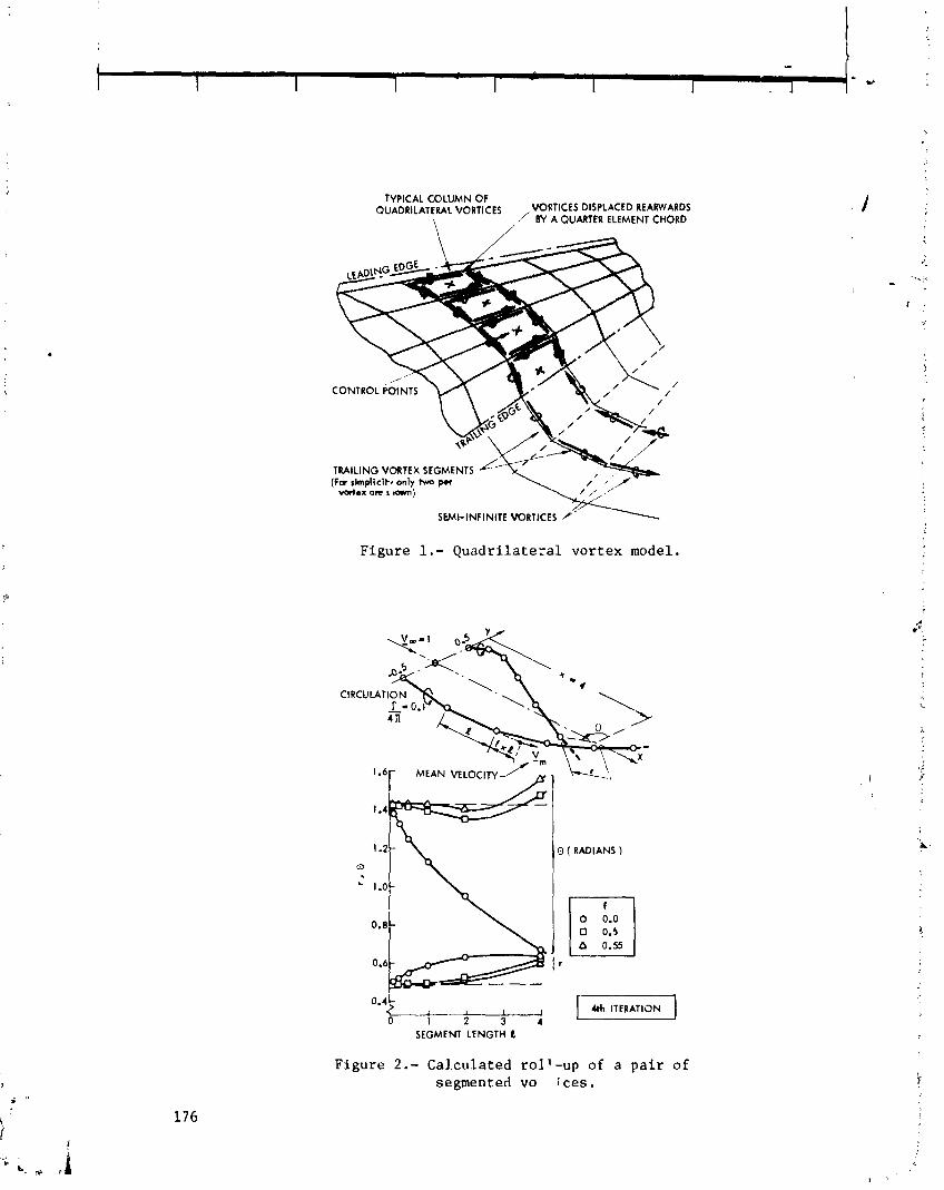
/
T R A I L I N G VORTEX SEGMENTS ( F a t impl ic i t r only two per
vortex o n i lam;
SEMI- INFINITE VORTICES
F i g u r e 1.- Q u a d r i l a t e r a l v o r t e x model.
C I R C U L A T I O N
O ( RADIANS )
0.4b ' , , , -1 0 1 2 3 4
SEGMENT L E N G T H L
F i g u r e 2.- Cal .culated r o l l - u p of a p a i r of segmented vo i-ces.

SIDE VlEW
I- @- - - ---- SIDE VIEW
(a) Conf igurat ion and genera l views a f t e r four i t e r a t i o n s .
EFFECT OF ITERATION ON VORTEX 7
5lDE VlEW
ITERATION NUMBERS
\
/
EFFECT OF ITERATION ON VORTEX 7 PLAt4 VIEW
(b) E f f e c t of i t e r a t i o n an vor tex (7) t r a j e c t o r y .
Figure 3 . - Calcula ted vor tex t r a j e c t o r i e s f o r a wing-flap- t a i l p l a d e con£ i g u r a t ion i n f r e e a i r .
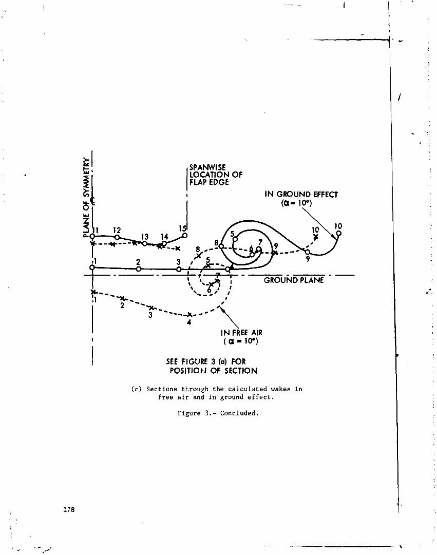
FLAP EDGE I IN GROUND EFFECT
I (a- lo0) \
4 \ IN FREE AIR ( a 10.)
SEE FIGURE 3 (a) FOR POSITIObJ OF SECTION
( c ) S e c t i o n s through t h e c a l c u l a t e d wakes i n f r e e a i r and i n ground e f f e c t .
F i g u r e 3 . - Concluded.

n on, W l N G LIFT COEFFICIENT
W l N G INDUCED DRAG FACTOR V
SEE FSGURE 3(a) FOR CONFIGURATION
TAILPLANE LlFf COEFFICIENT (BASED ON W I N G AREA)
TAILPLANE INDUCED DRAG COEFFICIENT ( BASED ON W l N G AREA )
FREE STREAMWISE 1 2 WAKE ITEUATION
Figure 4.- Effect of iteration on the calculated lift and induced drag of the wing-flap-tailpiece configuration in free air.

SEE FIGURE 3(a) FOR CONFIGURATION
1.0 - L= - t
0.5 -
(a) Spanwise loading.
--- - - STREAMWISE WAKE FRCt -0- ITERATIONS 1 TO 4
' - 0 - ITERATION 2, IN GROUND EFFECT
(b) Center of pressure locus.
Figure 5.- Calculated aerodynamic characteristics for the wing and inboard flap in the wing-flap-tailplene configuration in free air and in ground effect.

SEE FIGURE 3 (0) FOR CONFIGURATION
--- STREAMWISE WAKE 4 IT ERATICINS 1 T 0 4
I IN FREE A l l
-0- ITERATION 2, IN GROUND EFFECT
(c) Induced drag distribution.
Figure 5.- Concluded.

. . . . . \
WI-ININIT€ TRAILING VORlICEI FROM IUNWL
Figure 6 . - Wing f lap i n wind tunnel - general arrangement of the theoretical model.
EtO OF 'NNNR' ,,
FLAP HINGE LINE A h l
PLAN VIW *A
Figurt 7.- Calculated vortex trajectories i n wind tunnel.
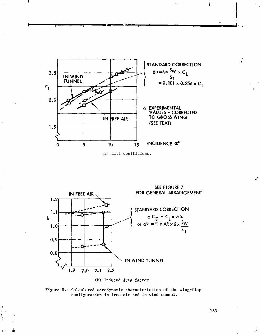
STANDARD CORRECT1 ON
1.5
EXPERIMENTAL VALUES - CORRECTED TO GROSS W I N G (SEE TEXT)
IN FREE AIR
0 5 10 15 INCIDENCE a0 (a) Lift coefficient.
I N FREE AIR , SEE FIGURE 7
FOR GENERAL ARRANGEMENT 1.2
\
*--- - - '- 1 .1 . - m z - *.-•
STANDARD CORRECTION
k a C D - C L x ~a ~ a k = T X A R ~ ~ ~ S W -
I
IN WIND TUNNEL
(b) Induced drag factor.
Figure 8.- Calculated aerodynamic characteristics of the wing-flap configuration in free air and in wind tunnel.
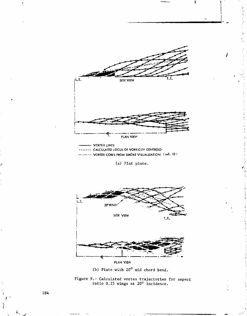
1L.E. SIDE VIEW T.E.
I I
- VORTEX LINES - - - - - - - CALCULATED LOCUS OF VORTlCllY CENTROID
-- VORTEX CORES FROM SMOKE VISUALIZATION ( ref. 12 )
(a ) F l a t p l a t e .
i ,.*-- e-.- ,- - - / .,.-. - - - - - - L. E.
20' BEND f = . -_
I
PLAN VlEW
(b) P l a t e w i t h 20' mid chord bend.
F i g u r e 9.- C a l c u l a t e d v o r t e x t r a j e c t o r i e s f o r a s p e c t r a t i o 0.25 wings a t 20' i nc idence .

FLAT U T E
&&SIC F I W W tfFEWC€ 12
4.4
,\a FLAT PUTf
-10 0 lo DUG CO€fFICI€HT.
Figure 10.- Calculated aerodynamic characteristics for the small aspect ratio wings compared with experimental measurenents.
Figure 11.- Calculated vortex trajectories for an aspect ratio 5.33 rectangular wing at 12O incidence after two iterations.
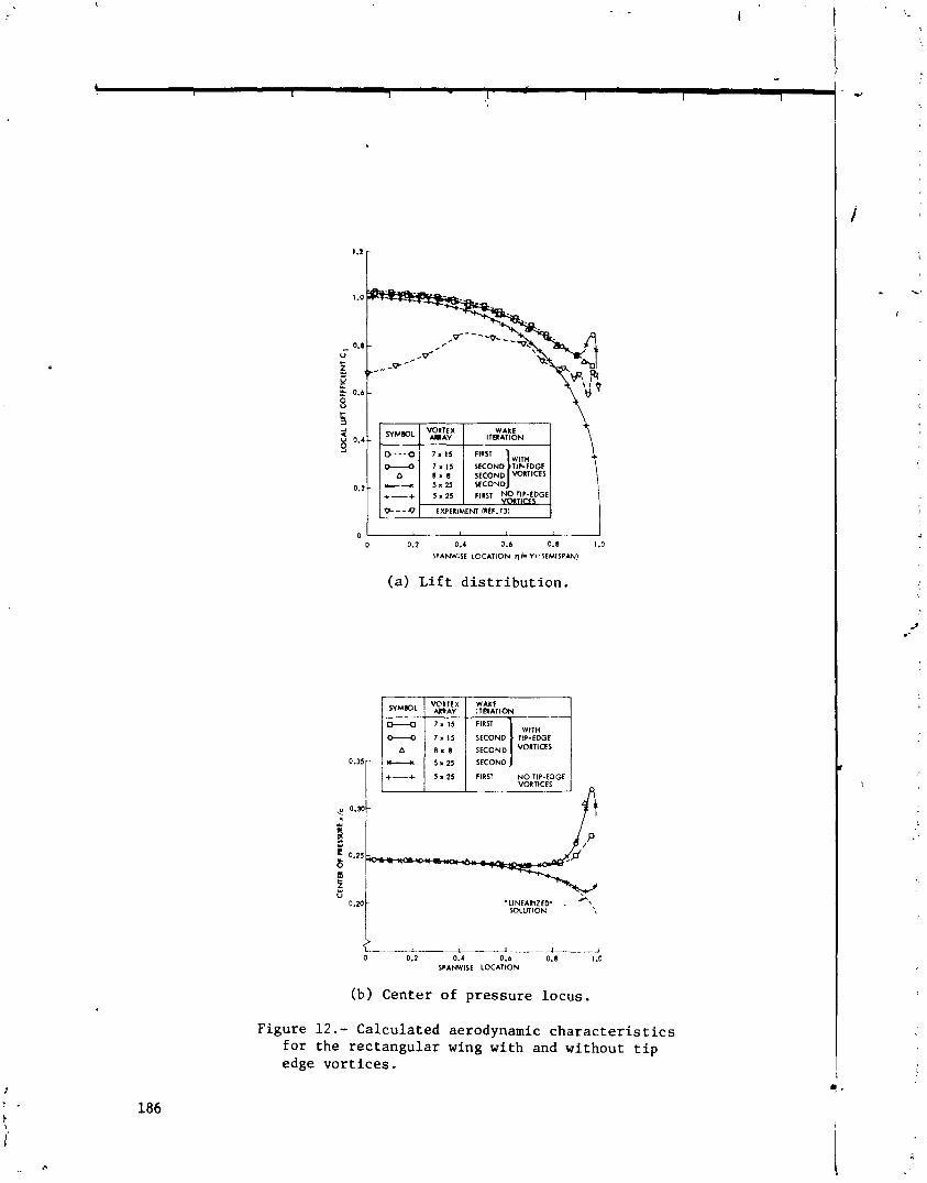
WAKE
\ SYMBOL I y2LtX 1 ITAATION
(a) Lift distribution.
VORTICES
LA- O.? 0.4 0.6 0.8 1 .O
SPAWISE LOCATION
(b) Center of pressure locus.
Figure 12.- Calculated aerodynamic characteristics for the rectangular wing with and without tip edge vortices.
- - - IBM S e l e c t r i c I1
N 7 6 0 2 8 1 1 4 P r e s t i g e E l i t e 72
C. Edward Lan The Univers i ty of Kansas
SUMMARY
A l i n e a r , i n v i s c i d , s u b s o n i c compressible f low theory is formulated f o r p r e d i c t i n g t h e aerodynamic c h a r a c t e r i s t i c s o f upper-surface-blowing configurat ,ons. The e f f e c t of t h e t h i c k j e t is represent2d by a two-vortex- s h e e t model i n o r d e r t o account f o r t h e Mach number nonuniformity. The wing loading w i t h t h e j e t i n t e r a c t i o n e f f e c t s i s computed by s a t i s f y i n g boundary cond i t ions on t h e wing and t h e j e t s u r f a c e s . The v o r t e x model i s discussed , in d e t a i l .
INTRODUCTION
I n upper-surface-blowing (62B) c o n f i g u r a t i o n s , t h e low-pressure-rat io j e t from high by-pass r a t i o tu rbofan engines blows d i r e c t l y on t h e wing upper s u r f a c e . A s the j e t i s r e l a t i v e l y t h i c k , being of t h e o r d e r of 10% of t h e l o c a l chord, t h e convent ional t h i n j e t f l a p theory has been found t o be inadequate t o p r e d i c t t h e h igh l i f t ( r e f . 1 ) . T h i s means t h a t a d d i t i o n a l l i f t may come from the i n t e r a c t i o n between t h e wing flow and t h e t h i c k j e t which h a s h igher dynamic p r e s s u r e than t h e f rees t ream. Of course , t h e j e t entrainment w i l l i n c r e a s e t h e l i f t a l s o , mainly through producing t h e Coanda ef f ecc .
I n t h i s paper , a t h e o r e t i c a l method w i l l be desc r ibed f o r p r e d i c t i n g t h e i n t e r a c t i o n e f f e c t s due t o nonuniformity i n Mach numbers and dynamic p r e s s u r e s i n t h e flow f i e l d . The i n v i s c i d , l i n e a r , subsonic compressible flow theory is assumed.
SYMBOLS
C~ t o t a l l i f t c o e f f i c i e n t ( c i r c u l a t i o n l i f t p l u s j e t r e a c t i o n l i f t )
* This work was suppor ted by NASA Langley Grant NSG 1139.
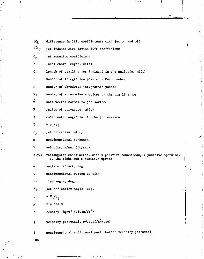
difference in lift coefficients with jet on and off
jet induced circulation lift coefficient
jet momentum coefficient
local chord length, m(ft)
length of trailing jet included in the analysis, m(ft)
number of integration points or Mach number
number of chrodwise integration points
number of streamwise vortices on the trailing jet
unit vector normal to jet surface
radius of curvature, m(ft)
coordinate tangential to the jet surface
= PO/ pj
jet thickness, m(ft)
nondimensional backwash
velocity, m/sec (ftlsec)
rectangular coordinates, with x positive downstream, y positive spanwise- to the right and z positive upward
angle of attack, deg.
nondimensional vortex density
flap angle, deg.
jet-deflection angle, deg.
= p COB n
density, kg/m3 (slugs/f t 3,
velocity potential, mk/sec(f t2/sec)
nondimensional additional perturbation velocity potential

Subscr ip t s :
c chordwise
j j e t f l o w
o o u t e r f l o w
s spanwise
w wing
. f rees t ream
METHOD OF ANALYSIS
Formulation of t h e Problem
The p e r t u r b a t i o n flow f i e l d s i n s i d e and o u t s i d e t h e j e t a r e assumed t o be governed by t h e Prandt i -Glauer t equa t ions w i t h Mj and %, r e s p e c t i v e l y . The s o l u t i o n s of these equa t ions must s a t i s f y t h e boundary cond i t ions t h a t t h e j e t s u r f a c e is a s t ream s u r f a c e and t h e s t a t i c p r e s s u r e must be con- t inuous a c r o s s i t , i n a d d i t i o n t o t h e u s u a l wing tangency cond i t ion . I n t h e l i n e a r theory, t h e s e cond i t ions can be w r i t t e n a s ( r e f . 1 )
- - -b -b a+, a + j -vW.n(l-p ') ( j e t s t ream s u r f a c e cond i t ion) (1)
( j e t s t a t i c p r e s s u r e c o n t i n u i t y ) (2 )
- 34, azc I - t a n a az
(wing tangency) ax
where
T = P o I P j
and To and Tj a r e r e l a t e d t o t h e dimensional v e l o c i t y p o t e n t i a l s oo an.i m j a s
S ince t h e above problem is l i n e a r , i t can be decomposed i n t o a wing-alone - case wi th p o t e n t i a l 9w and t h e i n t e r a c t i o n case wi th a d d i t i o n a l p o t e n t i a l $. Let - -
4o = owo (W + $0 (4,) ( 6 ) - - oj o w j M + $ j ( 4 ) (7 ) -
where ow, and qwj s a t i s f y t h e Prandt l -Glauer t equa t ions wi th r e s p e c t i v e
Mach numbers and the fo l lowing boundary c o n d i t i o n s
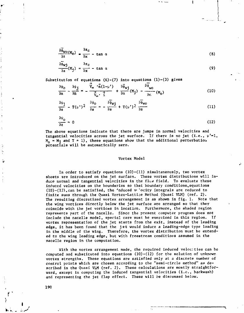
- a s w j azc
( M j ) az = ax - t a n a
S u b s t i t u t i o n of equa t ions (6) - (7 ) i n t o equa t ions (1)-(3) g i v e s
The above equat ions i n d i c a t e t h a t t h e r e a r e jumps i n normal v e l o c i t i e s and t a n g e n t i a l v e l o c i t i e s a c r o s s t h e j e t s u r f a c e . I f t h e r e Is no j e t ( i . e . , w 1 = 1 , M, = M j and T = l ) , t h e s e equa t ions show t h a t t h e a d d i t i o n a l p e r t u r b a t i o i ~ p o t e n t i a l s w i l l be au tomat ica l ly zero.
Vortex Model
I n o r d e r t o s a t i s f y equa t ions (10)-(11) s imul taneously , two v o r t e x s h e e t s a r e in t roduced on t h e j e t s u r f a c e . These vor tex d i s t r i b u t i o n s w5l l in- duce normal and t a n g e n t i a l v e l o c i t i e s i n t h e f l c s f i e l d . To e v a l u a t e t h e s e induced v e l o c i t i e s on t h e boundaries s o t h a t boundary cond i t ions ,equa t ions (10)-(121,can be s a t i s f i e d , t h e 'nduced vf ' o c i t y i n t e g r a l s a r e reduced t o f i n i t e sums through t h e Quasi Vortex-Latt ice Method (Quasi VLM) ( r e f . 2) . The r e s u l t i n g d i s c r e t i z e d v o r t e x arrangement is a s shown i n f i g . 1. Note t h a t t h e wing v o r t i c e s d i r e c t l y below t h e j e t s u r f a c e a r e ar ranged s o t h a t they co inc ide wi th t h e jet v o r t i c e s i n l o c a t i o n . Furthermore, t h e shaded region r e p r e s e n t s p a r t of t h e n a c e l l e . Sincc t h e p r e s e n t computer program does not inc lude t h e n a c e l l e model, s p e c i a l c a r e must be exerc i sed i n t h i s r eg ion . I f vor tex r e p r e s e n t a t i o n of t h e j e t s t a r t s from t h e e x i t , i n s t e a d of t h e l e a d i n g edge, i t has been found t h a t t h e j e t would induce a leading-edge type loading i n t h e middle of t h e wing. Therefore , t h e vor tex d i s t r i b u t i o n must be extend- ed t o t h e wing l ead ing edge, bu t w i t h f rees t ream c o n d i t i o ~ s assumed i n t h e n a c e l l e r eg ion i n t h e computation.
With t h e vor tex arrangement made, t h e requ i red induced v e l o c j t i e s can be computed sad s u b s t i t u t e d i n t o equa t ions (10)-(12) f o r t h e s o l u t i o n of unknow. vor tex s t r e n g t h s . These equa t ions a r e s a t i s f i e d only a t a d i s c r e t e number of c o n t r o l p o i n t s which a r e chosen according t o t h e "semi-c i rc le method" as de- s c r i b e d i n t h e Quasi VLM ( r e f . 2 ) . These c a l c u l a t i o n s a r e mostly s t r a i g h t f o r - ward, except i n computing t h e induced t a n g e n t i a l v e l o c i t l e s ( i . e . , backwash) and r e p r e s e n t i n g t h e j e t f l a p e f f e c t . These w i l l be d i scussed below.

Computation of Induced Tangen t i a l V e l o c i t i e s
The induced t a n g e n t i a l v e l o c i t i e s on t h e j e t s u r f a c e a r e needed t o s a t - i s f y equa t ion (11) . A t any c o n t r o l p o i n t , t h e induced t a n g e n t i a l v e l o c i t y dr t o t h e j e t v o r t e x d i s t r i b u t i o n i n i t s neighborhood is simply equa l t o t h e vor tex d e n s i t y at t h a t c o n t r o l p o i n t . S ince t h e vor tex d e n s i t y a t t h e c o n t r o l po in t does no t appear i n t h e formulat ion, it is necessary t o express i t i n terms of those a t t h e v o r t e x p o i n t s through i n t e r p o l a t i o n , such a s Lagrangian . i n t e r p o l a t i o n . However, t h e c o n t r i b u t i o n from those v o r t i c e s no t on t h e same
plane w i t h t h e c o n t r o l point can n o t be a c c u r a t e l y computed i n t h e u s u a l man- ne r a s i n computing tile induced normal v e l o c i t i e s . To i l l u s t r a t e , cons ide r t h e backwash express ion i n tile two-dimensional flow:
A s + 0, t h e i n t e g r a n d o f equat ion (13) w i l l have a second-order s i n g u l a r i t y . The usua l method is not a c c u r a t e i n t r e a t i n g such s i n g u l a r i t y . Therefore , equat ion (13) should b e r e w r i t t e n a s
u ( ~ , = ) = -% J1 &:wz dx* + dx'
2n 0 (x-x ) + z 0 ! x - x ' ) ~ T ~ -
and M = 2 P ~
f o r i n t e r d i g i t a t i o n between t h e c o n t r o l and i n t e g r a t i o n p o i n t s i n t h e l a s t summation and p is an a r b i t r a r y i n t e g e r g r e a t e r than 1.
I n t h e implementation of equa t ion (14a) i n t h e p r e s e n t computer program, i t is assumed t h a t M=8N i f N>6 and M=16N i f N < 6 . To compute t h e t a n g e n t i a l v e l o c i t y a t a , e t c o n t r o l p o i n t due t o wing v o r t i c e s , equa t ion (14a) i s ap- p l i e d t o t h r e e wing v o r t e x s t r i p s i n t h e immediate neighborhood of t h e c o n t r o l p o i n t . Th i s is i n d i c a t e d i n f i g . 2 . On t h e o t h e r hand, i f t h e c o n t r o l po in t i s on t h e j e t upper s u r f a c e , t h e e f f e c t due t o a l l v o r t i c e s on t h e j e t lower s u r f a c e i n t h e same streamwise s e c t i o n is computed wi th equa t ion (14a). S imi la r p r i n c i p l e is a p p l i c a b l e i f t h e c o n t r o l po in t i s on t h e lower s u r f a c e . This i s i l l u s t r a t e d i n f i g . 3. The accuracy of equa t ion (14a) has been i l l u s t r a t e d i n r e f . 3 .
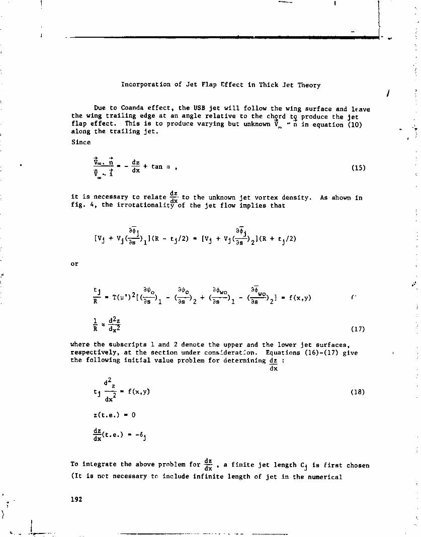
r'
Incorporat ion of J e t Flap E f f e c t i n Thick J e t Tneory
Due t o Coanda e f f e c t , t h e USB j e t w i l l fo l low t h e wing s u r f a c e and 1c.ave t h e wing t r a i l i n g edge a t an a n g l e r e l a t i v e t o t h e chgrd tq produce t h e j e t f l a p e f f e c t . This is t o produce varying but unknown Vm n i n equat ion (10) . . along t h e t r a i l i n g j e t . - ?: >
I -
Since
-+ -* Vw. n - = - - :E + t a n a , if 1
w
d z i t is necessary t o r e l a t e - - t o t h e unknown j e t v o r t e x dens i ty . A s shown i n dx f i g . 4 , t h e i r r o t a t i o n a l i t y of t h e j e t flow impl ies t h a t
where t h e s u b s c r i p t s 1 and 2 denote t h e upper and t h e lower j e t s u r f a c e s , r e s p e c t i v e l y , a t t h e s e c t i o n under constderat2on. Equations (16)-(17) g ive t h e following i n i t i a l va lue problem f o r determining :
dx
To i n t e g r a t e t h e above problem f o r dZ , a f i n i t e jet l eng th C j is First chosen dx
( I t i s n e t necessary t o inc lude i n f i n i t e length of j e t I n t h e numerical
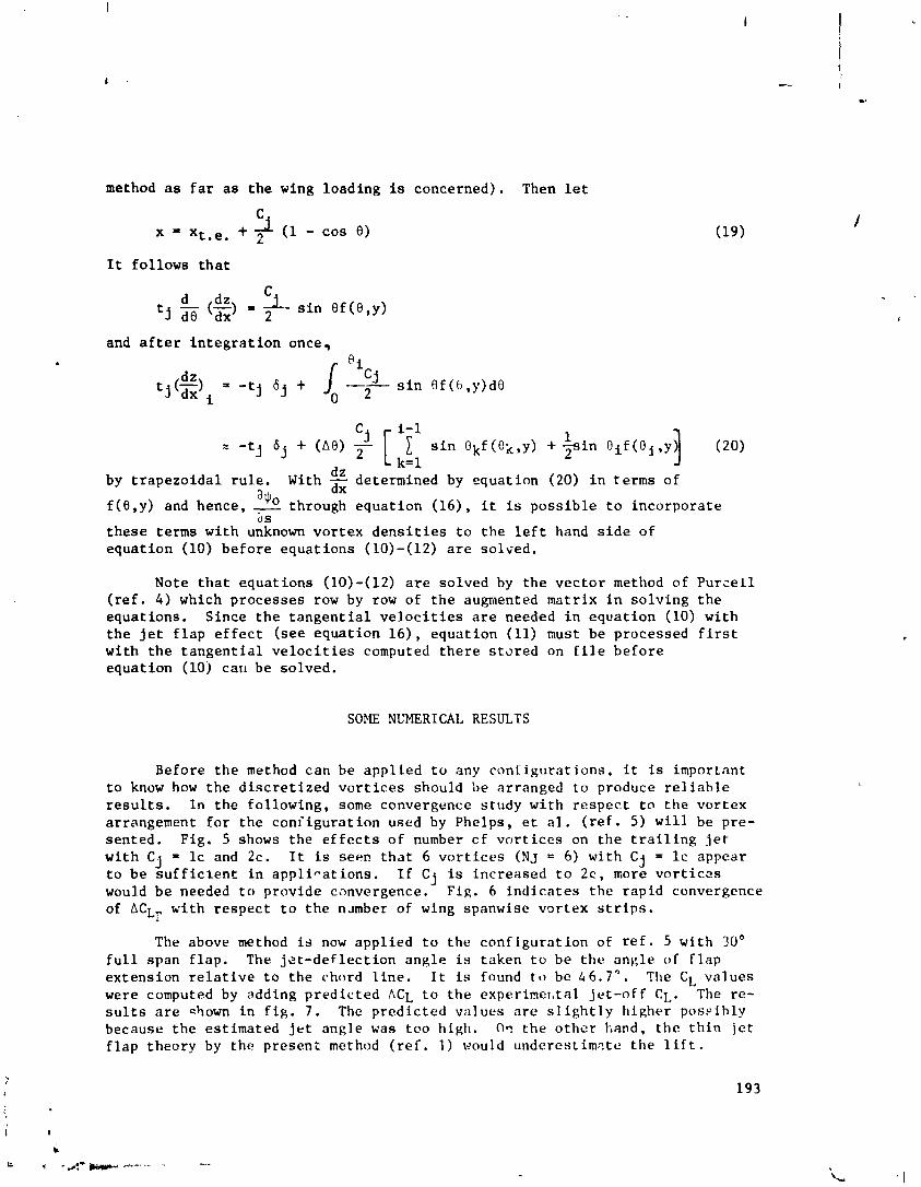
method a s f a r a s t h e wing loading is concerned). Then l e t
C + 2 ( 1 - cos 0) X ' xt .e ,
It fol lows t h a t
dz 1 s i n 0 f (e ,y ) - (-1 = * t j dB dx
and a f t e r i n t e g r a t i o n once, - e,
dz by t r a p e z o i d a l r u l e . With a$o f (8 ,y) and hence, - through
determined by equat ion (20) i n terms of
equa t ion (16) , i t is p o s s i b l e t o incorpora te 2s
-
t h e s e terms wi th unknown v o r t e x d e n s i t i e s t o t h e l e f t hand s i d e of equa t ion (10) b e f o r e equa t ions (10)-(12) a r e s o l ~ e d .
Note t h a t equat ions (10)-(12) a r e solved by t h e v e c t o r method of P u r z e l l ( r e f . 4 ) which processes row by row of t h e augmented mat r ix i n s o l v i n g t h e equat ions . Since t h e t a n g e n t i a l v e l o c i t i e s a r e needed i n equa t ion (10) wi th t h e j e t f l a p e f f e c t (see equa t ion l 6 ) , equa t ion (11) must be processed f i r s t wi th t h e t a n g e n t i a l v e l o c i t i e s computed t h e r e s t o r e d on f i l e b e f o r e equat ion (10j can be solved.
SOME NUMERICAL RESULTS
Before t h e method can be a p p l i e d t o any c o n f i g u r a t i o n s , i t is important t o know how t h e d i s c r e t i z e d v o r t i c e s should be ar ranged t o produce r e l i a b l e r e s u l t s . I n the fo l lowing, some convergence s tudy wi th r e s p e c t t o t h e vor tex arrangement f o r t h e c o n i i g u r a t i o n used by Phelps, e t a l . ( r e f . 5) w i l l be pre- sented. Fig . 5 shows the e f f e c t s of number c f v o r t i c e s on t h e t r a i l i n g j e t wi th C j = l c and 2c. I t is seep t h a t 6 v o r t i c e s (NJ = 6) wi th C j = l c appear t o be sufficient i n a p p l i - a t i o n s . I f Cj is increased t o 2c , more v o r t i c s s would be needed t o provide convergence. Fig. 6 i n d i c a t e s the rap id convergence of LCLr v i t h respec t t o t h e n ~ m b e r of wing spanwise vor tex s t r i p s .
The above method is now app l i ed t o the c o n f i g u r a t i o n of r e f . 5 wi th 30° f u l l span f l a p . The j e t - d e f l e c t i o n ang le is taken t o be t h e ang le of f l a p extension r e l a t i v e t o t h e chord l i n e . I t is found t o bc 4 6 . 7 " . The CL va lues were computed by adding p red ic ted ACL t o the experimer, tal j e t -o f f CL. The re- s u l t s a r e shown i n f i g . 7 . The p red ic ted va lues a r e s l i g h t l y h igher poss ibly because the es t imated j e t angle was too high. O n t h e o t h e r k,and, t h e t h i n je t f l a p theory by t h e p resen t method ( r e f . 1) would underes t imste t h e l i f t .
To illustrate the importance of improved tangential velocity evaluation (see equation 14a), the configuration of ref. 6 with 6f = 20° and 40° is used in fig. 8. It is seen that without the improved integration technique, the predicted lift would be too high.
CONCLUDING REMARKS
A vortex model for the USB jet-wing interaction has been described. The model consists of using two vortex sheets on the jet surface to account for Mach number nonuniformitv and differences in jet and freestream dynamic pressures. The rate of numerical convergence with respect to the number of vortices used appeared to be reasonably rapid. Comparison of the predicted results with some available data showed much better cgreemenl than the thin jet flap theory.
REFERENCES
1. Lan, C. Edward; and Campbell, James F.: Theoretical Aerodynamics o" Upper-Surface-Blowing Jet-Wing Interaction. NASA TN D-7936, 1975.
2. Lan, C. Edward: A Quasi Vortex-Lattice Method in Thin Wing Theory. Journal of Aircraft, Vol. 11, No. 9, Sept. 1974, pp. 518-527.
3. Lan, C. Edward: Some Applications of the Quasi Vortex-Lattice Method in Steady and Unsteady Aerodynamics. Vortex-Lattice Utj-lization, NASA SP-405, 1976. (Paper no. 21 of this compilation.)
4. Purcell, E. W.: The Vector Method of Solving Simultaneous Linear Equations. Journal of Math. and Phys., tol. 32, July-Oct. 1953, pp. 180-183.
5. Phelps, Arthur E.; Letko, William; and Henderson, Robert L.: Low-Speed Wing-Tunnel Investigation or a Semispan STOL Jet Transport Wing-Body with an Upper-Surface Blown Jet Flap. NASA TN D-7183, 1973.
6. Smith, Charles C., Jr.; Phelps, Arthur E., 111; and Copeland, W. Latham: Wind-Tunnel Investigation of a Large-Scale Semispan Model with an Unswept Wing and an Upper-Surface Blown Jet Flap. NASA TN D-7526, 1974.
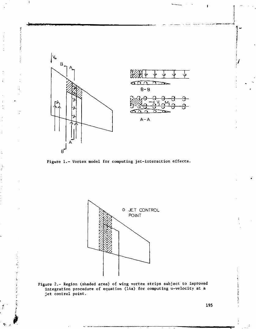
A-A
B~
Figure 1.- Vortex model for computing jet-interaction e f f e c t s .
0 JET CONTROL
'7'--" Figure 2 . - Region (shaded area) of wing vortex s t r i p s subject to improved
integration procedure of equation (14a) for computing u-velocity a t a j e t control point.
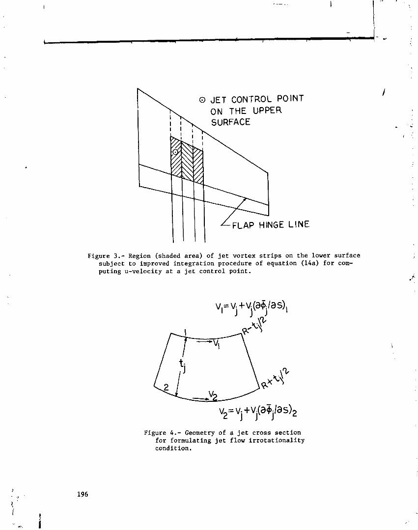
h JET CONTROL POINT
Figure 3.- Region (shaded area) of jet vortex strips on the lower surface subject to improved integration procedure of equation (14a) for com- puting u-velocity at a jet control point.
Figure 4.- Geometry of a jet cross section for formulating jet flow irrotationality condition.

Figure 5.- Effect of number of trailing jet vortices on predicted lift. C = 0.8 x 2.095; a = 5"; 6f = 30°; 6j
1-1 = 46.7O; Nc = 6; Ns = 9.
Figure 6.- Effect of number of wing vortex strips on predicted lift. c = 0.8 x 2.095; a = 5"; 6, = 30°; 6 - 46.7O;
j N~ = 6; C = lc.
lJ j
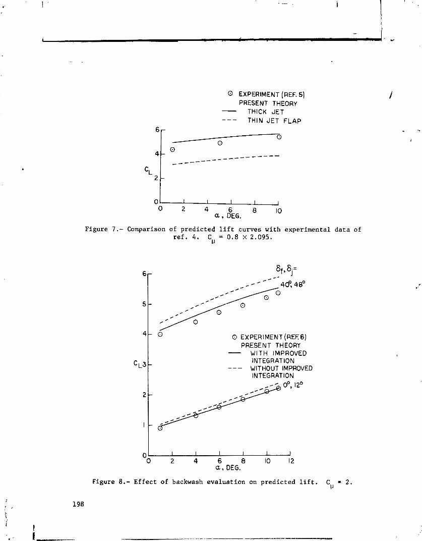
EXPERIMENT (REF. 5 ) PRESENT THEORY - THICK JET
- - - THIN JET FLAP
0 0
0 0 0 2 4 6 8 a DEG.
10
Figure 7.- Comparison of predicted lift curves with experimental data of ref. 4. C = 0.8 x2.095.
1-1
0 EXPERIMENT (REEG) PRESENT THEORY - WITH IMPROVED
INTEGRATION - -- WITHOUT IMPROVED
INTEGRATION
Figure 8.- Effect of backwash evaluation on predicted lift. C = 2. v
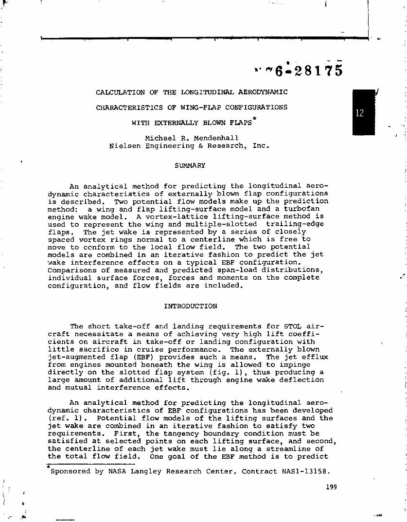
CALCULATION OF THE LONGITUDINAL AERODYNAMIC
CHARACTERISTICS OF WING-FLAP CONFIGURATIONS
Michael R. Mendenhall Nielsen Engineering & Research, Inc.
SUMMARY
An analytical method for predicting the longitudinal aero- dynamic characteristics of externally blown flap configurations is described. Two potential flow models make up the prediction method: a wing and flap lifting-surface model and a turbofan engine wake model. A vortex-lattice lifting-surface method is used to represent the wing and multiple-slotted trailing-edge flaps. The jet wake is represented by a series of closely spaced vortex rings normal to a centerline which is free to move to ccnform to the local flow field. The two potential models are combined in an iterative fashion to predict the jet -.gake interference effects on a typical EBF configuration. Comparisons of measured and predicted span-load distributions, individual surface forces, forces and moments on the complete configuration, and flow fields are included.
INTRODUCTION
The short take-off arid landing requirements for STOL air- craft necessitate a means of achieving very high lift coeffi- cients on aircraft in take-off or landing configuration with little sacrifice in cruise performance. The externally blown jet-augmented flap (EBF) provides such a means. The jet efflux from engines mounted beneath the wing is allowed to impinge directly on the slotted flap system (fig. l), thus producing a large amount of additional lift through engine wake deflection and mutual interference effects.
An analytical method for predicting the longitudinal aero- dynamic characteristics of EBF configurations has been developed ref. 1 ) Potential flow models of the lifting surfaces and the jet wake are combined in an iterative fashion to satisfy two requirements. First, the tangency boundary condition must be satisfied at selected points on each lifting surface, and second, the centerline of each jet wake must lie along a streamline of the total flow field. One goal of the EBF method is to predict * Sponsored by NASA Langley Research Center, Contract NAS1-13158.

t h e t o t a l loads and d i s t r i b u t i o n of loads on each component of t h e wing-flap conf igurat ion under t h e inf luence of mul t ip le j e t I wakes. A second goal is t h a t a minimum of empir ical information be required a s input t o t h e method.
This paper conta ins a d i scuss ion of t h e technica l approach t o t he pred ic t ion of EZBF aerodynamic c h a r a c t e r i s t i c s , a d iscuss ion - -;
of t he development of t h e p o t e n t i a l flow models, and some 1 .
comparisons with data .
SYMBOLS
sec t ion normal-force c o e f f i c i e n t
drag c o e f f i c i e n t , p o s i t i v e a f t
l i f t c o e f f i c i e n t
pitching-moment c o e f f i c i e n t , p o s i t i v e nose up
normal-force c o e f f i c i e n t
t h r u s t c o e f f i c i e n t of a s i n g l e j e t
t o t a l t h r u s t c o e f f i c i e n t f o r a conf igurat ion with mul t ip le j e t s
l o c a l rad ius of c i r c u l a r j e t , m ( f t . )
i n i t i a l rad ius of c i r c u l a r j e t , rn ( f t . )
a x i a l ve loc i ty , d s e c ( f t / sec)
free-stream ve loc i ty , Wsec ( f t / s ec )
i n i t i a l j e t wake ve loc i ty , Wsec ( f t / s ec )
j e t coordinate system wi th o r i g i n a t t h e cen te r of t h e j e t i n l e t
wing coordinate system with o r i g i n a t ,the wing r o o t chord leading edge
angle of a t t ack , degrees
j e t wake vor tex cy l inder s t rength , d s e c ( f t / s ec )
f l a p de f l ec t ion angle, degrees
convergence to le rance
j e t model vor tex r i n g spacing, m ( f t . )
dimensionless spanwise coordinate
d ihedra l angle , degrees
ANALY S IS
Wing-Flap Vortex-Lattice Model
The l i f t i n g sur faces of ex t e rna l ly blown f l a p conf igura t ions c d n s i s t of a wing and mul t ip le-s lot ted t ra i l ing-edge f l aps . The l i f t i n g - s u r f a c e model needed t o represen t t h e t y p i c a l EBF wing- f l a p conf igurat ion must be capable of handling ind iv idua l l i f t i n g sur faces and p red ic t i ng t h e spanwise and chordwise load d i s t r i b u - t i o n s on each surface . Mutual i n t e r f e r ence between sc r faces must 3e considered along with i n t e r f e r ence e f f e c t s induced by some ex te rna l source of d is turbance, fai example, t h e wake of a high bypass r a t i o t u r b o j e t engine. I t is a l s o e s s e n t i a l t h a t t h e l i f t i n g - s u r f a c e model be capable of p red i c t i ng t h e ve loc i ty f i e l d induced i n t l ~ e v i c i n i t y of t h e wing and f l aps . The above requirements a r e b e s t f u l f i l l e d through t h e use of a vortex- l a t t i c e model of t h e l i f t i n g surfaces .
The wi.7g and f l a p s a r e divided i n t o a rea elements, i n each of which i s placed a horseshoe vortex. Its bound l e g i s a l igned with t h e e lemmt qua r t e r chord and i t s t r a i l i n g l egs l i e along t h e s i d e s of t h e element a s i l l u s t r a t e d i n f i g u r e 2. The t r a i l i n g l egs a r e positioned i n the plane of t h e i r o r i g i n a t i n g element, and they a r e def lec ted s o t h a t they l i e i n t h e plane of each sur face downstream of t h e o r i g i n a t i n g surface . The t r a i l i n g l e g s extend t o i n f i n i t y i n t h e plane of t h e l a s t sur face contacted.
The boundary condi t ions , expressing t h e flow tangency t o t h e camber surface , a r e s a t i s f i e d a t a s e t of con t ro l po in t s located a t the midspan of t he three-quar ter chord l i n e of each a rea element. The wing con t ro l po in t s a r e a l l assumed t o l i e i n t h e plane containing t h e roo t chord and making an angle wi th t he Z = 0 plane. The con t ro l po in t s on each f l a p a r e assumed t o l i e i n t h e chord plane of t h e f l ap . The boundary condi t ion equations ( r e f . 1) s t a t e t h a t t h e t o t a l flow i s tangent t o t h e camber sur faces of t h e wing and f l a p s a t each con t ro l point . The t o t a l ve loc i ty a t each con t ro l po in t i s made up of t he f r e e stream, t h e ve loc i ty induced by t h e vo r t ex - l a t t i ce horseshoe vortex system, and add i t i ona l v e l o c i t i e s induced by an ex te rna l source of d is turbance. The s o l u t i o r of t he se equat ions provides t he unknown value of t h e c i r c u l a t i o n of each horseshoe vortex.

Once the circulation strengths are determined, the flow field surrounding the lifting surface can be computed as well as the surface load distributions. The force on each area element is
i calculated as the product of density, local velocity norma-- to the element of vorticity, and circulation strength. The total force on each area element is made up of two contributions: that acting on the bound leg of the horseshoe vortex and the force acting on the trailing legs contained within the area element. There is only one bound leg associated with each area element,
1
but numerous trailing legs may be present along each side of the area element, one for each area element upstream of the element being considered. All three components of force on each vortex leg are computed on each area element. These are resolved into normal and axial forces in each area element. The section char- acteristics of each lifting surface are computed from these elemental forces and finally the total individual surface forces are resolved into the gross aerodynamic characteristics relative to the aircraft axis system.
The vortex-lattice method is restricted to calculating longitudinal characteristics, and compressibility corrections are not included in the method. No small angle assumptions are used in the theoretical model.
Since the EBF model is to be used as a predictive technique, it is important that the vortex-lattice method be applicable to typical EBF configurations. The wing and flap configuration * parameters are listed as follows:
Wing
Leading-edge shape: May have up to 30 breaks in sweep.
Trailing-edge shape: Same as leading edge.
Taper: Determined from leading-edge and trailing-edge specification.
Tip chord: Parallel to root chord.
Dihedral: Constant over the semispan.
Mean camber surface: May have both twist and camber.
Thickness: Neglected.
Flaps
Number: Up to ten individual flap segments.
Location: Only trailing-edge flaps are considered; gaps between surfaces are permitted.
Leading-edge shape: Straight.
Trailing-edge shape: Straight.
Taper: Linear.
Root chord:
T i p chord:
Span: F u l l
Def lec t ion:
Mean camber
Thickness:
Must l i e i n a v e r t i c a l p lane p a r a l l e l t o t h e wing r o o t chord.
P a r a l l e l t o r o o t chord.
o r p a r t i a l span.
D i f f e r e n t f o r each f l a p .
su r face : Each f l a p may have b o t h camber and t w i s t .
Neglected.
The v o r t e x - l a t t i c e arrangement on each l i f t i n g s u r f a c e i s genera l enough t o provide good f l e x i b i l i t y i n d e s c r i b i n g t h e load ing d i s t r i b u t i o n . A maximum of t h i r t y (30) spanwise rows of v o r t i c e s may b e used, and each l i f t i n g - s u r f a c e component can have a maximum of t e n (10) chordwise v o r t i c e s . The a r e a elements on a l i f t i n g s u r f a c e have the same chord a t each spanwise s t a t i o n , b u t t h e element chords need n o t b e t h e same on adjacer? s u r f a c e s . Thus, t h e number of chordwise elements on each l i f t i n g s u r f a c e may b e chosen according t o t h e accuracy requ i red i n t h e p r e d i c t e d chordwise load ing d i s t r i b u t i o n . I n t h e spanwise d i r e c t i o n , t h e widths of t h e a r e a elements may b e v a r i e d t o f i t t h e loading s i t u a t i o n s ; t h a t is, i n r eg ions of l a r g e spanwise load ing g r a d i e n t s , t h e element widths may be reduced t o a l low c l o s e r spacing and more d e t a i l e d load p r e d i c t i o n s . Convergence of p r e d i c t e d r e s u l t s a s a f u n c t i o n of l a t t i c e arrangement on wings and f l a p s i s desc r ibed i n Appendix A of r e f e r e n c e 2. One r e s t r i c - t i o n on t h e spanwise l a t t i c e arrangement on t h e wing and f l a p s i s t h e requirement t h a t t h e l a t t i c e elements on t h e f l a p s be d i r e c t l y a l igned w i t h t h o s e on t h e wing. Th i s requirement is imposed be- cause of t h e d e f l e c t i o n of t h e vor tex t r a i l i n g l e g s and t h e neces- s i t y f o r a l l t r a i l i n g l e g s t~ l i e a long t h e edges of a r e a elements.
When a wing-f lap c o n f i g u r a t i o n h a s m u l t i p l e spanwise f l a p segments wi th d i f f e r e n t d e f l e c t i o n a n g l e s l i k e t h a t shown i n f i g u r e 2 , c e r t a i n d i f f i c u l t i e s a r i s e i n c a l c u l a t i n g t h e load ing d i s t r i b u t i o n s on t h e f l ap . segments , p a r t i c u l a r l y nea r t h e f l a p edges. The problem is caused by t h e d e f l e c t e d t r a i l i n g l e g s from t h e upstream a r e a elements on t h e wing. The i n d i v i d u a l c i r c u l a - t i o n s t r e n g t h s can b e l a r g e ; b u t when t h e s i d e edges o f t h e a r e a elements co inc ide , t h e t r a i l i n g vor tex l e g s tend t o cance l and t h e n e t s t r e n g t h of t h e t r a i l i n g v o r t i c i t y on t h i s s i d e edge is q u i t e small . When t h e s i d e edges do n o t co inc ide , a s i s t h e c a s e on a d j a c e n t f l a p s wi th d i f f e r e n t d e f l e c t i o n s , t h e n e t s t r e n g t h of t h e t r a i l i n g l e g s a long t h e s e edges can be la rge . Th i s h a s two e f f e c t s on t h e l o a d i n g c a l c u l a t i o n . F i r s t , t h e unbalanced t r a i l i n g l e g s t r e n g t h s can cause c n r e a l i s t i c c i r c u l a t i o n s t o be computed nea r t h e f l a p edges; and because of t h e mutual i n t e r - f e r e n c e between p a n e l s , t h i s can be f e l t on surrounding panels . Second, t h e s e c i r c u l a t i o n d i s t r i b u t i o n s on t h e f l a p s l e a d t o unusual f o r c e d i s t r i b u t i o n s . T h i s p a r t i c u l a r problem i s n o t
i 1 %
t
i
unique wi th t h i s au thor a s Rubbert p r e s e n t s an e x t e n s i v e i n v e s t i g a t i o n of t h e same t y p e of d i f f i c u l t y i n r e f e r e n c e 3.
S ince t h i s problem h a s a l a r g e e f f e c t on ly on t h e flay. loads on t h e a r e a elements nea r t h e edges of t h e f l a p s , and t h e t o t a l e f f e c t on t h e g r o s s l o a d i n g on t h e c o n f i g u r a t i o n is smal l , t h e fo l lowing approximate s o l u t i o n is app l i ed t o t h i s a r e a . The wing t r a i l i n g v o r t i c i t y a t t h e semispan s t a t i o n corresponding t o t h e f l a p s i d e edges is no t allowed t o a e f l e c t a long t h e f l a p s b u t i s a r b i t r a r i l y forced t o move a f t i n t h e p lane of t h e wing. I t is r e l a t i v e l y unimportant a s t o t h e exac t p o s i t i o n ass igned t o t h e wing t r a i l i n g l e g s so long a s they a r e combined; t h e r e f o r e , t h e cho ice was made to l e a v e t h e wing t r a i l i n g l e g s ( a t t h i s one semispan s t a t i o n only) undef lec ted . There is s t i l l an imbalance i n t h e t r a i l i n g l e g s a s s o c i a t e d wi th t h e f l a p edges, b u t it g z n e r a l l y h a s only a smal l e f f e c t on t h e r e s u l t i c g f l a p c i r c u l a - t i o n d i s t r i b u t i o n . I n a d d i t i o n t o t h e modi f i ca t ion t o t h e wing t r a i l i n g l e g p o s i t i o n s , t h e imbalance i n t h e t r a i l i n g vor tex ~ t r e n y t h on t h e f l a p edges produced some l a r g e f o r c e s on t h e f l a p edges. For t h i s reason, it was necessary t o n e g l e c t t h e normal-force component due t o t h e t r a i l i n g v o r t e x l e g a t t h e f r e e edge of each f l a p . These modi f i ca t ions smoothed t h e p r e d i c t e d load d i s t r i b u t i o n on t h e f l a p s w i t h n e g l i g i b l e e f f e c t on t h e t o t a l load ing on t h e conf igura t ion .
Vortex Ring J e t Model
A p o t e n t i a l f l o w model of a h igh-bypass- ra t io turb0fa.n engine wake is needed which w i l l p rovide a means f o r c a l c u l a t i n g t h e induced v e l o c i t y f i e l d b o t h i n s i d e and o u t s i d e t h e boundary of t h e j e t wake. The flow model should s i m u l a t e t h e ent ra inment e f f e c t e x h i b i t e d by jet wakes, t h e jet boundar ies should behave according t o observed spreading r a t e s f o r jets i n a coflowing stream, and t h e wake should b e p o s i t i o n e d under t h e i n f l u e n c e of a l i f t i n g s u r f a c e such t h a t it l i e s a long a s t r eaml ine . Such a p o t e n t i a l f low model of a jet wake w i t h c i r c u l a r c r o s s s e c t i o n i s presented i n r e f e r e n c e 2 , and t h e f low model i s extended t o e l l i p t i c c r o s s - s e c t i o n a l j e t s i n r e f e r e n c e 1.
The f low model c o n s i s t s of a d i s t r i b u t i o n of v o r t i c i t y p laced on t h e s u r f a c e of an expanding c y l i n d e r w i t h c i r c u l a r o r e l l i p t i - c a l c r o s s s e c t i o n . The s t r e n g t h of t h e v o r t i c i t y is determined by t h e jet t h r u s t c o e f f i c i e n t . The d i s t r i b u t i o n of v o r t i c i t y on t h e c y l i n d e r i s modeled by a series of vor tex r i n g s c o a x i a l w i t h t h e jet c e n t e r l i n e and having t h e same c r o s s - s e c t i o n a l shape a s t h e c y l i n d e r . Each r i n g r e p r e s e n t s a f i n i t e increment of l eng th of t h e c y l i n d e r , and t h e vor tex s t r e n g t h of each i n d i v i d u a l r i n g i s equal t o t h e n e t v o r t i c i t y on t h e incrementa l l e n g t h of c y l i n - d e r which it rep laces . The momentum i n s i d e t h e jet boundary remains c o n s t a n t ; and i f t h e expansion of t h e boundary i s spec i - f i e d c o r r e c t l y , t h e mass f l o w i n s i d e t h e boundary i s i n good

agreement with actual jets. Thus, the model represents the momentum, mass, and entrainment characteristics of a turbulent, coflowing jet. While the velocity profile within the jet is approximated by a uniform profile (fig. 3), the induced veloci- ties outside the jet boundary are accurate because they are related to the entrainment induced flow.
Measured velocity profiles in the wake of a JT15D-1 jet engine mounted beneath a wing are available in reference 4. The profiles were measured on both the wing side and the free side of the engine centerline at a point approximately two nozzle diame- ters downstream of the engine exit. These data are shown in fig- ure 4 for CT = 0.56. A circular vortex ring jet model was designed to expand at a rate that would produce the same mass flow at the measured profile station. The resulting pre :~.i.ted velocity profile is also shown in figure 4. The jet moc~-~ #,as approximately 5 percent less momentum than the real jet; tWre- fore, the vortex ring model can satisfactorily match boti. ltrcisis and momentum of an actual jet if the correct spreading rate is known. Any interference calculation taking place inside the jet boundaries will be reasonably accurate when averaged over the total wake area, but there may be certain inaccuracies locally due to differences in the shape of the velocity profile within the wake.
Use of the vortex ring jet model requires three items to determine completely the analytical description of the jet. The first item is the initial vortex ring strength which is related to the thrust and momentum in the jet. The remaining two items are the boundary of the jet and the position of the jet center- line. The jet centerline can either be located a priori, or it can be left free to move under the influences of the free-stream velocity, the wing and flap loading induced flow field, and the jet induced flow field. The objective in permitting the center- line to move freely is to be able to position it along the streamline of the wing-flap-jet flow which leaves the center of the exhaust. Iterations can be performed until convergence is attained between the jet centerline and the streamline position.
To complete the description of the jet wake, the boundary of the jet must be specified at all points along the jet. An analyt- ical method is available in reference 5 which gives the radius distributions for axisymmetric jets in a coflowing stream for various velocity ratios. Unfortunately, a similar series of curves is not available for noncircular cross-sectional jets. It is here that empirical evidence must be used to complete the specifications of the jet.
Little data exist on the cross-sectional shape of nonaxisym- metric jets in a coflowing stream. Jet wake extent and profiles measured aft of the last flap on a four-engine EBF configuration are presented in reference 6. These data illustrate that

i n i t i a l l y c i r c u l a r j e t s tend t o mix and ,=come e l l i p t i c a l i n c r o s s s e c t i o n a f t e r i n t e r a c t i o n wi th t h e f l a p s . The expansion c h a r a c t e r i s t i c s of t h e s e jets between t h e engine e x i t and t h e s t a t i o n a f t of tlia win); i s undetermined. Modeling of t h e j e t i n t h i s r eg ion r e q u i r e s s ims ly a good eng inee r ing e s t i m a t e u n t i l more d e t a i l e d measurements become a v a i l a b l e .
Iiiterference C a l c u l a t i o n
C a l c u l a t i o n of t h e aerodynamic l o a d i n g of a wing-f lap ccnf ig - u r a t i o n under t h e i , i f luence of t h e j e t wake oC a tu rbofan engine is done wi th t h e combination o f t h e two p o t e n t i a l f low models described above. The two flow models a r e combined by superpos i - t i o n ( f i g . 5 ) . The jet model induces a v e l o c i t y f i e l d on t h e winy and f l a p which produces an i n t e r f e r e n c e load ing on t h e lift in^ s u r f a c e s . The wing and f l a p loadins , induce a v e l o c i t y f i e l d i n t h e v i c i n i t y of t h e j e t and tend t o d e f l e c r t h e jet away from t h e s 2 s u r f a c e s , It is assumed t h a t t h e engine t h r u s t i s unaffec ted by t h e presence of t h e wing-flap. Btzause of t h e mutual i n t e r a c t i o n between t h e j e t and l i f t i n g s u r f a c e s , an i t e r a t i v e s o l u t i o n i s requ i red . The s o l u t i o n i s c a r r i e d o u t i n t h e fo l lowing manner.
Before any c a l c u l a t i o n s a r e made, t h e j e t c e n t e r l i n e i s pos i t ioned wi th r e s p e c t t o t h e wing and f l a p . The i n i t i a l loca- t i o n of t h e c e n t e r l i n e car. b e based on some a p r i o r i knowledge of t h e flow f i e l d beneath t h e wing and f l a p system, o r it can b e l o c a t e d i n a s t r i c t l y a r b i t r a r y fashion. For exm.ple, it i s q u i t e accep tab le t o choose t h e i n i t i a l jet c e n t a r l i n t t o be a s t r a i g h t l i n e a f t from t h e engine exhaust a s i l l u s t r z t e d i n f i g u r e 5.
The (expanding) jet boundary and c r o s s - s e c t i o n a l shape d i s t r i b u t i o n should be chosen according t o whatever procedure seems most a p p r o p r i a t e , and t h i s d i s t r i b u t i o n (which w i l l b e unchanged from t h i s p o i n t on) is placed on t h e c e n t e r l i n e t o d e f i n e an i n i t i a l jet wake. The jet- induced v e l o c i t y f i e l d i s computed ;t s e l e c t e d c o n t r o l p o i n t s on t h e l i f t i n g s u r f a c e s and t h e c i r c u l a t i o n d i s t r i b u t i o n on t h e wing and f l a p s i s obta ined such t h a t t h e tangency boundary cond i t ion is satisfied a t each c o n t r o l po in t .
A t t h i s p o i n t i n t h e s o l u t i o n , t h e boundary c o n d i t i o n on t h e wing and f l a p s u r f a c e s is s a t i s f i e d but t h e jet p o s i t i o n has no t been inf luenced by t h e presence of t h e wing and f l a p . The wing-flap i n f l u e n c e c o n s i s t s of modifying t h e j e t l o c a t i o n t o cause t h e j e t c e n t e r l i n e t o l i e along a s t r e a m l i n e of t h e combined jet-wing-flap flow. The i n i t i a l j e t c e n t e r l i n e is a d j u s t e d by c o ~ ~ p u t i n g t h e t o t a l flow f i e l d a t a number o f p o i n t s on t h e cen t -e r l ine and moving t h e c e n t e r l i n e t o a new p o s i t i o n such t h a t it l i e s along t h e computed flow d i r e c t i o n a t t h e s p e c i f i e d p o i n t s .

This completes t h e f i r s t i t e r a t i o n . I n t h i s s i t u a t i o n , t h e wing and f l a p loading is n o t compatible w i t h t h e jet f l o w f i e l d corresponding t o t h e new p o s i t i o n of t h e jet. Thus, a second
i i t e r a t i o n is needed.
The f l o w f i e l d corresponding t o t h e ad jus ted jet p o s i t i o n is computed, and a new wing-flap loading d i s t r i b u t i o n is obta ined. The jet c e n t e r l i n e is aga in moved t o l i e a long the new flow d i r e c t i o n s . This procedure is continued u n t i l either the c e n t e r - l i n e p o s i t i o n or t h e t o t a l wing and f l a p l o a d i n g converges t o w i t h i n a d e s i r e d to le rance . W i t h a converged s o l u t i o n , t h e t o t a l f low i s tangen t t o t h e wing and f l a p s u r f a c e s and t h e jet c e n t e r - l i n e l i e s along a s t r e a m l i n e o f t h e flow.
It i s iu r ing the i t e r a t i o n procedure and t h e subsequent motion o f t h e j e t c e n t e r l i n e t h a t ano the r b i t o f empiricism is used. The combination of the two p o t e n t i a l f low inodels r e s u l t s i n t h e d e f l e c t i o n of t h e j e t such that it p a s s e s beneath t h e wing and f l a p su r faces . A t y p i c a l converged s o l u t i o n w i l l show t h e maximum jet c e n t e r l i n e d e f l e c t i o n ang le t o be c l o s e t o t h e maximum f l a p angle. Measurements i n d i c a t e t h a t t h e t u r n i n g e f f i c i e n c y o f a t y p i c a l EBF c o n f i g u r a t i o n can drop a s low a s 0.75 a t h i g h f l a p angles. Consequently, a l i m i t on jet d e f l e c - t i o n ang le i s imposed d u r i n g t h e i t e r a t i o n p rocess t o more r e a l i s t i c a l l y model j e t d e f l e c t i o n f o r h igh f l a p d e f l e c t i o n angles.
RESULTS
The methods of a n a l y s i s desc r ibed i n t h e p rev ious s e c t i o n have b e e i ~ app l i ed t o a number of d i f f e r e n t EBF c o n f i g u r a t i o n s under v a r i o u s flow cond i t ions . Convergence c h a r a c t e r i s t i c s o f t h e i t e r a t i o n procedure a r e examined, and comparisons w i t h experimental data a r e presented .
Convergence C h a r a c t e r i s t i c s
For purposes of examining the convergence c h a r a c t e r i s t i c s of t h e p r e d i c t i o n method, t h e four-engine EBF c o n f i g u r a t i o n o f r e f e r e n c e s 4 and 7 w a s chosen. This l a r g e - s c a l e model h a s a 25O swept wing w i t h an a s p e c t r a t i o of 7.28 and a t a p e r r a t i o o f 0.4. The t r a i l i n g - e d g e f l a p system considered f o r t h e c a l c u l a t i o n s c o ~ ~ s i s t s of t h r e e fu l l - span, s l o t t e d f l a p s . Two JTlSD-1 tu rbofan engines a r e pylon mounted beneath each wing a t 7 = 0.25 and 0.42. T h e l a t t i c e arrangement f o r t h i s c o n f i g u r a t i o n i s shown i n f i g u r e 6. The i n i t i a l assumption f o r t h e jet c e n t e r l i n e i n .- a l l c a s e s is a s t r a i g h t l i n e c o i n c i d e n t w i t h t h e engine c e r ~ t e r l i n e . The convergence s t u d i e s a r e c a r r i e d o u t f o r t h e f l a p s i n a take- o f f p o s i t i o n ( d f = G0/200/409) and a c o n f i g u r a t j m ang le of a t t a c k of .l8.5O.
Convergence of t h e total wing-flap normal-force c o e f f i c i e n t is shown i n f i g u r e 7 f o r t h r u s t c o e f f i c i e n t s of 2.3 and 4.0. A t the end of the f o u r t h i t e r a t i o n , b o t h c a s e s have converged t o w i t h i n 7 percent . This convergence p a t t e r n h a s been observed on t h e same c o n f i g u r a t i o n a t o t h e r ang les o f a t t a c k and on o t h e r similar conf igura t ions .
The convergence o f the noxmal-force c o e f f i c i e n t on each component of t h e wing-flap c o n f i g u r a t i o n is shown i n f i g u r e 8. Each component t e n d s t o converge according t o i ts own p a t t e r n , b u t a l l components reach convergence a t about t h e same t i m e .
The convergence p a t t e r n of t h e spanwise d i s t r i b u t i o n of s e c t i o n normal f o r c e on a s i n g l e component, f l a p 2 , o f t h e conf ig- u r a t i o n is shown i n f i g u r e 9 through f o u r i t e r a t i o n s . The peak load ings a r e caused by d i r e c t jet i n t e r a c t i o n w i t h t h e f l a p . The span l o a d s on t h e o t h e r components have a s i m i l a r convergence p a t t e r n and t h e s e a r e presented and d i scussed i n r e f e r e n c e 1.
The convergence r e s u l t s j u s t desc r ibed a r e t y p i c a l of t h o s e observed on o t h e r EBF c o n f i g u r a t i o n s over a wide range of f low condi t ions . The method h a s never f a i l e d t o converge, b u t conver- gence is slower f o r h i g h f l a p angles . Genera l ly , c a l c u l a t i o n s have been i n i t i a t e d w i t h a s t r a i q h t jet c e n t e r l i u e because o f t h e s i m p l i c i t y i n p r e s c r i b i n g t h e inpu t ; however, t h e number of i t e r a t i o n s requ i red f o r convergence can b e reduced i f t h e i n i t i a l c e n t e r l i n e is l o c a t e d c l o s e r t o t h e f i n a l p o s i t i o n . On the b a s i s of c a s e s run, convergence i s more r a p i d i f t h e c e n t e r l i n e approaches i t s f i n a l p o s i t i o n from above r a t h e r t h a n below, because t h e c o r r e c t i n g v e l o c i t i e s caus ing t h e c e n t e r l i n e p o s i t i o n t o change a r e l a r g e r i f the c e n t e r l i n e s t a r t s t o o c l o s e t o t h e wing and f l a p s .
EBF Data Comparisons
The o v e r a l l EBF p r e d i c t i o n method w a s eva lua ted by comparing p r e d i c t e d r e s u l t s wi th d a t a on s e v e r a l EBF conf igura t ions . These comparisons a r e presented and d i scussed i n d e t a i l i n r e f e r e n c e 1, and r e s u l t s presented h e r e i n a r e t y p i c a l examples of t h o s e included i n t .hat r e fe rence .
The first c o n f i g u r a t i o n t o be considered i s t h e four-engine model of r e f e r e n c e s 4 and 7 wi th take-off f l a p s e t t i n g ( a f = 0°/ 2 0 ~ / 4 0 " ) . The j e t t u r n i n g e f f i c i e n c y was assumed t o be 85 pe r - c e n t which l i m i t e d t h e j e t downward d e f l e c t i o n ang le t o 34' f o r a l l c a l c u l a t i o n s . The p r e d i c t i o n s t o fo l low have a l l converged t o w i t h i n an 8-percent t o l e r a n c e . The convergence i s not t h e same a t a l l ang les of a t t a c k , t h u s in t roduc ing some u n c e r t a i n t y i n t h e s l o p e of t h e p r e d i c t e d curves.
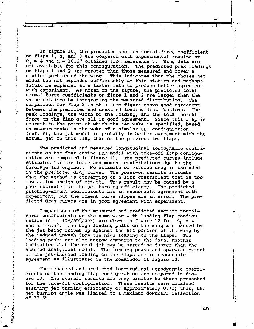
I n f i g u r e 10, t h e pred ic ted sec t ion normal-force c o e f f i c i e n t on f l a p s 1, 2, and 3 are compared with experimental r e s u l t s a t Cw = 4 and a = 18.5O obtained from reference 7. Wing da t a a r e
a I not ava i l ab l e f o r t h i s conf igurat ion. The predic ted peak loadings on f l a p s 1 and 2 a r e g r e a t e r than those measured and cover a smaller por t ion of t h e wing. This i nd i ca t e s t h a t t h e chosen jet model has not expanded s u f f i c i e n t l y a t th is s t a t i o n and perhaps should be expanded a t a f a s t e r r a t e t o produce b e t t e r agreement with experinlent, A s noted on t h e f i gu re , t h e predic ted t o t a l normal-force c o e f f i c i e n t s on f l a p s 1 and 2 a r e l a r g e r than t h e value obtained by i n t s g r a t i n g t h e measured d i s t r i b u t i o n , The comparison f o r f l a p 3 i n t h i s same f i g u r e shows good agreement between t h e predic ted and measured loading d i s t r i b u t i o n s . The peak loadings, t h e width of t h e loading, and t h e t o t a l normal fo rce on t h e f l a p a r e a l l i n good agreement, Since t h i s f l a p is neares t t o t h e ,mint a t which t h e j e t wake is spec i f ied , based on measurements i n t h e wake of a s imi l a r EBF configurat ion ( r e f . 6), t h e j e t model i s probably i n b e t t e r agreanent with t h e ac tua l jet on t h i s f l a p than on t h e previous two f l aps .
The predic ted and measured longi tud ina l aerodynamic coe f f i - c i e n t s on t h e four-engine EBF model with take-off f l a p configu- r a t i o n a r e compared i n f i g u r e 11. The pred ic ted curves include es t imates f o r t h e force and moment cont r ibu t ions due t o t h e fuselage and engines. No es t imate of viscous drag i s included i n t h e pred ic ted drag curve. The power-on r e s c l t s i n d i c a t e t h a t t h e method is converging on a l i f t coeffic. ient t h a t is t o o low aL low angles of a t t ack . This r e s u l t may be caused by a poor es t imate f o r t h e j e t t u rn ing e f f ic iency . The pred ic ted pitching-moment c o e f f i c i e n t s a r e i n reasonable agreement with experiment, bu t t h e moment curve s lopes a r e i n e r r o r , The pre- d i c t ed drag curves a r e i n good agreement wi th experiment.
Comparisons of t he measured and predic ted sec t ion normal- fo rce coefficient.^ on t h e same wing with landing f l a p configu- r a t i o n (6f = 15O/35O/55O) a r e shown i n f i g u r e 12 f o r Cy = 4 and a = 6.5O. The high loading peaks on t h e wing a r e caused by t h e j e t being dr iven up aga ins t t h e a f t po r t i on of t h e wing by t h e induced upwash from t h e high loading on t h e f l aps . The loading peaks a r e a l s o narrow compared t o t h e da ta , another i nd i ca t ion t h a t t h e r e a l jet may be spreading f a s t e r than t h e assumed a n a l y t i c a l model. The loading peaks and spanwise ex t en t of t he je t - i i idxed loading on t h e f l a p s a r e i n reasonable agreement a s i l l u s t r a t e d i n t h e remainder of f i g u r e 12.
The measured and predic ted longi tud ina l aerodynamic coe f f i - c i e n t s on t h e landing f l a p conf igurat ion a r e compared i n f i g - u re 13. The o v e r a l l r e s u l t s a r e very s i m i l a r t o those presented f o r t h e trrke-off conf igurat ion. These r e s u l t s were obtained assuming j e t t u rn ing e f f i c i ency of approximately 0.70; thus , t h e j e t tu rn ing angle was l imi ted t o a maximum downward de f l ec t ion of 38.5O.
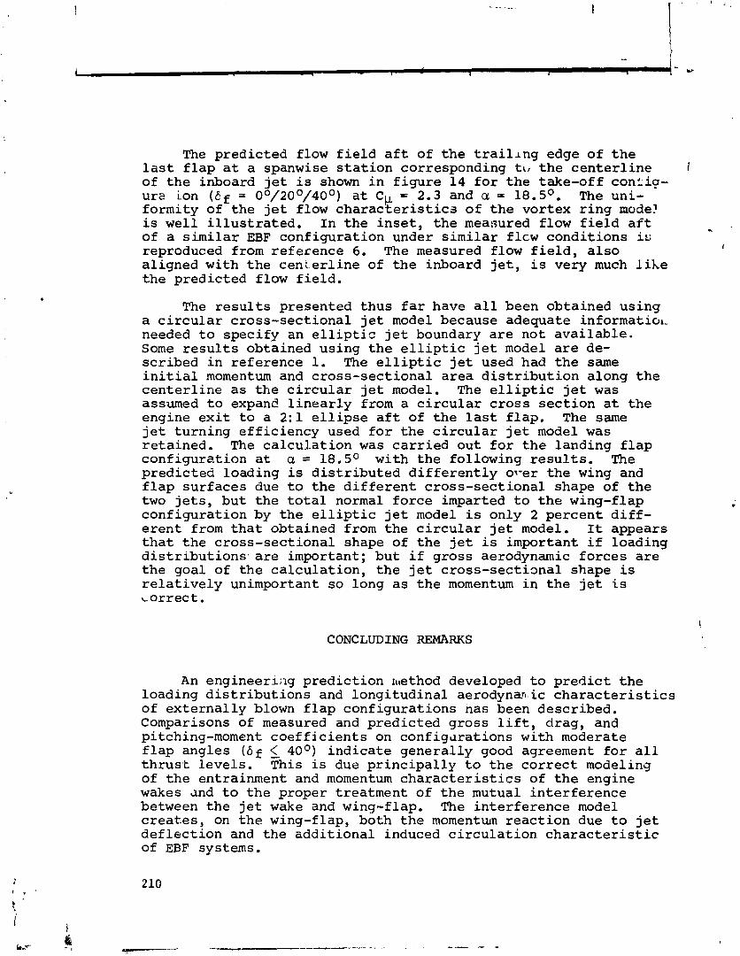
The predicted flow field aft of the trail~ng edge of the last flap at a spanwise station corresponding ttl the centerline r' of the inboard jet is shown in figure 14 for the take-off conCi9- urz ion (Ef = 0°/200/400) at Cp = 2.3 and a = l8.5O. The uni- formity of the jet flow characteristics of the vortex ring nude! is well illustrated. In the inset, the measured flow field aft of a similar EBF configuration under similar flcw conditions is
- reproduced from reference 6. The measured flow field, also I
aligned with the centerline of the inboard jet, is very much like the predicted flow field.
The results presented thus far have all been obtained using a circular cross-sectional jet model because adequate informatio~ needed to specify an elliptic jet boundary are not available. Some results obtained using the elliptic jet model are de- scribed in reference 1. The elliptic jet used had the same initial momentum and cross-sectional area distribution along the centerline as the circular jet model. The elliptic jet was assumed to expans linearly from a circular cross section at the engine exit to a 2:l ellipse aft of the last flap. The same jet turning efficiency used for the circular jet model was retained. The calculation was carried out for the landing flap configuration at a = 18.5O with the following results. The predicted loading is distributed differently 01-er the wing and flap surfaces due to the different cross-sectional shape of the two jets, but the total normal force imparted to the wing-flap configuration by the elliptic jet model is only 2 percent diff- erent from that obtained from the circular jet model. It appears that the cross-sectional shape of the jet is important if loading distributions.are important; but if gross aerodynamic forces are the goal of the calculation, the jet cross-sectimal shape is relatively unimportant so long as the momentum in the jet is correct.
C ONC LUD ING REMARKS
An engineerii~g prediction ~~tethod developed to predict the loading distributions and longitudinal aerodynan'ic characteristics of externally blown flap configurations has been described. Comparisons of measured and predicted gross lift, drag, and pitching-moment coefficients on configmations with moderate flap angles (bf 40°) indicate generally good agreement for all thrust levels. This is due principally to the correct modeling of the entrainment and momentum characteristics of the engine wakes and to the proper treatment of the mutual interference between the jet wake and wing-flap. The interference model creates, on the wing-flap, both the momentum reaction due to jet deflection and the additional induced circulation characteristic of EBF systems.
A s t h e f l a p angles increase beyond 40°, t h e predic ted r e s u l t s agree l e s s wel l with t h e data . The assumption t h a t t h e wing-flap induced in t e r f e r ence on t h e j e t a f f e c t s only i t s c e n t e r l i n e and not i t s boundary becomes less accurate as t h e j e t i s more highly deformed, and it i s poss ib l e t h a t t h i s i s responsible f o r t h e poorer agreement a t t h e higher f l a p angles.
Comparisons of measured and pred ic ted spanwise loading d i s t r i b u t i o n s on t h e ind iv idua l l i f t i n g su r f aces i nd i ca t e good q u a n t i t a t i v e ayres~nent i n some cases and poor agreement i n o thers . Generally, t h e c o r r e c t ~ ~ l l i t a t i v e behavior is predic ted i n ah ich l a r g e peak loadings crcci- i o c a l l y on t h e f l a p s due t o d i r e c t impingement of t h e j e t wakes, b u t t h e magnitude of t h e pea.l.3 is not cons i s t en t ly i n good agreement witk the data . The di:fezences a r e f e l t t o be due pr imar i ly t o t h e modeling of t h e v e l a c i t y p r o f i l e wi th in t h e wake and t h e boundary of t h e wake.
REFERENCES
1. Mendenhall, M. R., Spangler, S. B., ~ i e l s e n , J. N., and Goodwin, F. K.: Calcula t ion of t h e Longitudinal Aerodynamic
i C h a r a c t e r i s t i c s of Wing-Flap Configurations With External ly Blown Flaps. NEAR TR 97, Dec. 1975. NASA CR-2705, 1976.
i
d
2. ~ i l l e n i u s , M. F. E. , Mendenhall, M. R., and Spangler, S. B.: Calcula t ion of t h e ~ o n g i t u d i n a l Aerodynamic Cha rac t e r i s t i c s
! of STOL A i r c r a f t wi th Externally-Blown Jet-Augmented Flaps. NASA CR-2358, Feb. 1974.
3. Rubbert, P. E.: Theore t ica l C h a r a c t e r i s t i c s of Arb i t ra ry Wings by a Non-Planar Vortex L a t t i c e Method. Boeing Rept. D6-9244, Feb. 1964.
4. Aoyagi, K., Fa l a r sk i , M. D., and Koenig, D. G.: Wind-Tunnel Inves t iga t ion of a Large-Scale 25O Swept-Wing J e t Transport Model wi th an External Blowing Triple-Slot ted Flap. NASA TM X-62,197, NOV. 1973.
i
5. Abramovich, G. N.: The Theory of Turbulent J e t s . MIT Press, 1963.
6. Johnson, W. G . , Jr. and Kardas, G. E.: A Wind-Tunnel Inves t iga t ion of t h e Wake Near The T r a i l i n g Edge of a Deflected External ly Blown Flap. NASA TM X-3079, Oct. 1974.
7. Perry, B., I11 and Greene, G. C.: Wind-Tunnel Inves t iga t ion of Aerodynamic Loads on a Large-Scale External ly Blown Flap
* Model and Comparison with Theory. NASA TN D-7863, Mar. 1975.

Figure 1.- EBF configuration.
Figure 2.- Wing-flap vortex-lattice model.
Figure 3.- Circular vortex ring wake model and velocity profiles.

m ft. WING SIDE OF
a FREE'SIDE OF: -FAIRED CURVE
Figure 4 . - Measured and predicted ve loc i ty prof i les i n the wake of a JT15D-1 j e t engine.
,INITIAL JET BOUNDARY
WlNG \1- - - ---
c- ---- - 6 - - ---_ - - FLAP 17> FLAP 3
-1 FLAP 2 < ITERATION
Figure 5.- Convergence of inboard j e t centerline on a four-engine EBF configuration.

WING FLAP FLAP FLAP
Figure 6.- Vortex-lattice arrangement for EBF configuration.
ITERATION
Figure 7.- Convergence of the total wing-flap normal-force coefficient on a four-engine EBF configuration.

OF-5 ITERATION
Figure 8.- Convergence of normal-force coefficients on the wing and flaps of a four-engine EBF configuration.
Figure 9.- Convergence of predicted spanwise distribution of section normal-force coefficients on flap 2 of a four-engine EBF configuration.
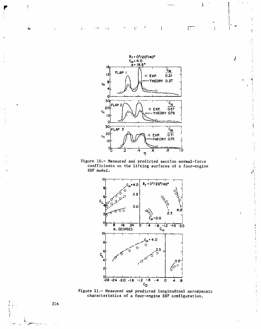
16 a'= 18.5'
12 FLAP I 0 EXP. 0.21
-THEORY 0.27 Cn
4
0
FLAP 2
c, --THEORY 0.79
30 I - r - - - --T FLAP 3 I CN
20 - - 0 EXP. 0.71
10 - -THEORY 0.75 -
OO .2 .4 .6 .8 1 .O -
rl
Figure 10.- Measured and predicted sect ion normal-force coef f ic ients on the l i f t i n g surfaces of a EBF model.
0 , DEGREES c m
f our-engine
3
Figure 11.- Measured and predicted longitudinal aerodynznic characterist ics of a four-engine EBF configuration.
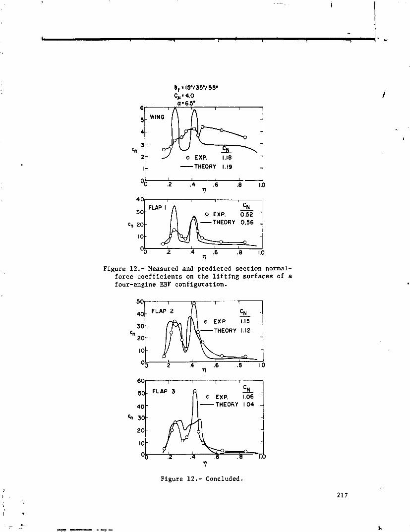
- THEORY 1.19
I \ f i T H E O R Y 0.56 1
Figure 12.- Measured and predicted section normal- force coefficients on the lifting surfaces of a f our-engine EBF configuration.
FLAP 2 ' \ o EXP. 1.15
-THEORY 1.12
I
I I
2 .4 .6 .8 1 .o I
- THEOKY 1.04
cn 3 2 0 1 10 -
Ob 2 4 6 8 I b
Figure 12.- Concluded.
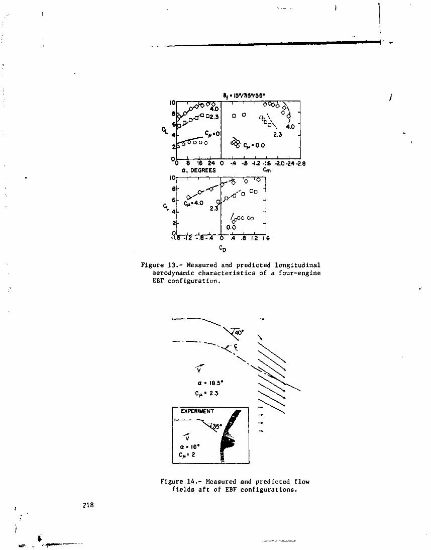
a, DEGREES h
Figure 13.- Measured and predicted longitudinal aerodynamic characteristics of a four-engine EBF configuraticn.
Figure 14.- Measured and predicted flow fields aft of EBF configurations.
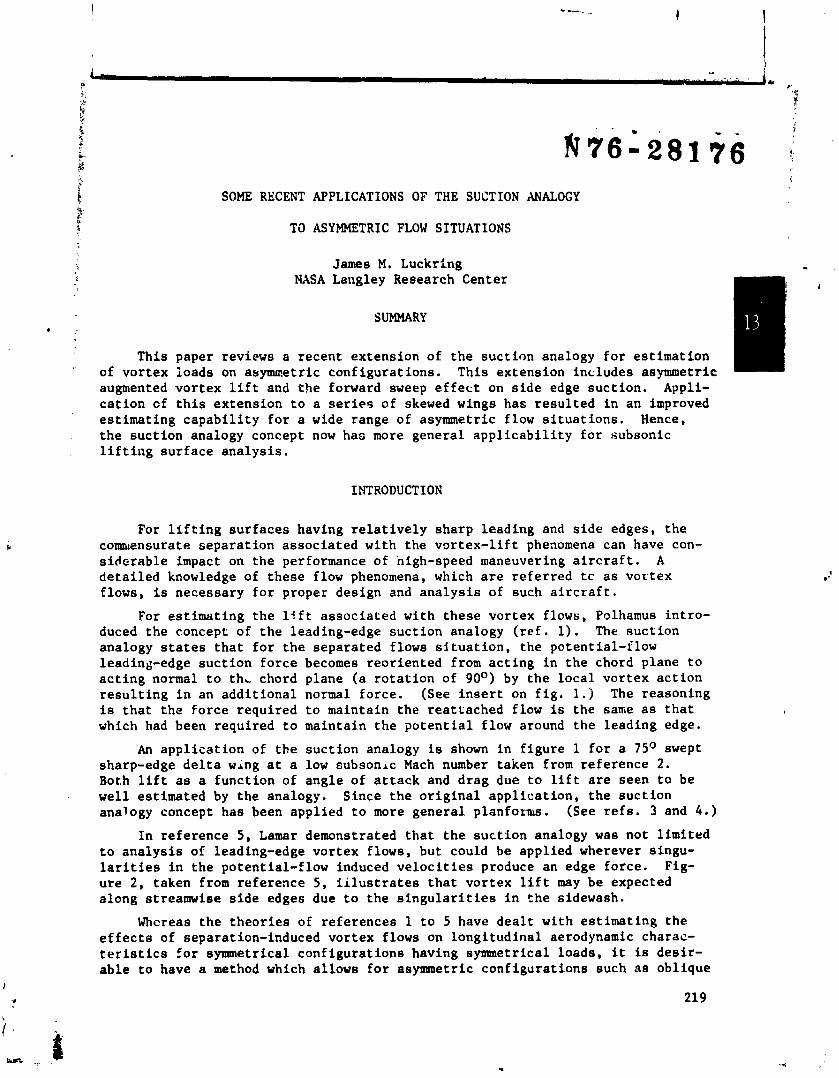
SOME RECENT APPLICATIONS OF THE SUCTION ANALOGY
TO ASYMMETRIC FLOW SITUATIONS
James M. Luckring NASA Langley ~esearch-center
SUMMARY
This paper reviews a recent extension of the suction analogy for estimation of vortex ioads on asynmetric configurations. This extension includes asymmetric augmented vortex lift and the forward sweep effect on side edge suction. Appli- cation cf this extension to a seriea of skewed wings has resulted in an improved estimating capability for a wide range of asymmetric flow situations. Hence, the suction analogy concept now has more general applicability for subsonic lifting surface analysis.
INTRODUCTION
For lifting surfaces having relatively sharp leading and side edges, the commensurate separation associated with the vortex-lift phenomena can have con- sirlcrable impact on the performance of high-speed maneuvering aircraft. A detailed knowledge of these flow phenomena, which are referred tc as vortex flows, is necessary for proper design and analysis of such aircraft.
For estimating the lift associated with these vortex flows, Polhamus intro- duced the concept of the leading-edge suction analogy (ref. 1). The suction analogy states that for the separated flows situation, the potential-flow leading-edge suction force becomes reoriented from acting in the chord plane to acting normal to thL chord plane (a rotation of 90°) by the local vortex action resulting in an additional normal force. (See insert an fig. 1.) The reasoning is that the force required to maintain the reattached flow is the same as that which had been required to maintain the potential flow around the leading edge.
An application of th,e suction analogy is shown in figure 1 for a 75" swept sharp-edge delta wing at a low oubsonrc Mach number taken from reference 2. Both lift as a function of angle of attack and drag due to lift are seen to be well estimated by the analogy. Since the original application, the suction analogy concept has been applied to more general planforrus. (See refs. 3 and 4.)
In reference 5, Lamar demonstrated that the suction analogy was not limited to analysis of leading-edge vortex flows, but could be applied wherever singu- larities in the potential-flow induced velocities produce an edge force. Fig- ure 2, taken from reference 5 , iilustrates that vortex lift may be expected along streamwise side edges due to the singularities in the sidewash.
Whcreas the theories of references 1 to 5 have dealt with estimating the effects of separation-induced vortex flows on longitudinal aerodynamic charac- teristics for symmetrical configurations having symmetrical loads, it is desir- able to have a method which allows for asymmetric configurations such as oblique
or skewed wings, for example, and asymmetric flight conditions such as those associated with sideslip or lateral control. i
Accordingly, the present investigation deals with a recent extension of the suction analogy concept to include asymmetric flow situations. To acco~plish this analysis, the computer program of references 6 and 7 has been generalized to account for asymmetry resulting in the asymmetric vortex-lattice (AVL) pro- gram. Although analysis with this program may be perfo-aed on many different types of asymmetric flow situations, as shown in figure 3, this paper will focus on the analysis of wings with geometric asymmetries and, in particular, on unta- pered skewed wings having separated vortex flows along leading and side edges. The effects of forward sweep on side-edge suction are introduced and the concept of augmented vortex lift as developed in reference 8 is applied to skewed wj.ngs.
Subsonic solutions can be obtained with the AVL program for configurations having matrix jizes up to 400 x 400. Operating in FORTRAN extended (FTN) version 4.4, the program requires 74000 storage and can solve a 200 singularity
8 configuration in less than 2 minutes on the Control Data Corporation (CDC) 6600 system running under NOS 1.0. Compared with its symmetric progenitor, the pro- gram requires 130008 more storage, but executes roughly 20 percent faster for
the same configuration.
SYMBOLS
aspect ratio
wing span
drag coefficient, Drag
%'ref
experimental value of drag coefficient at CL = 0
Lift lift coefficient, - QSref
CL increment associated with augmented vortex lift
rclling-moment coefficient about reference point, Rolling moment
%'refb
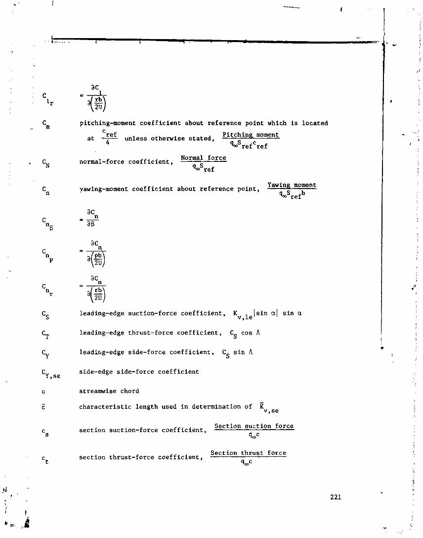
pitching-moment coefficient about reference point which is located C
at - ref unless otherwise stated, Pitching moment 4 GSrefCref
normal-force coefficient, Normal force
%'ref
yawing-moment coefficient about reference point,
leading-edge suction-force coe
Yawing moment
%'refb
f f icient , Kv,lelsin a1 sin a
leading-edge thrust-force coefficient, C cos A S
leadir,g-edge side-force coefficient, CS sin A
side-edge side-force coefficient
streamwise chord
characteristic length used in determination of T(v, se
Section suction force section suction-force coefficient, sooC
Section thrust force section thrust-force coefficient,
qmc
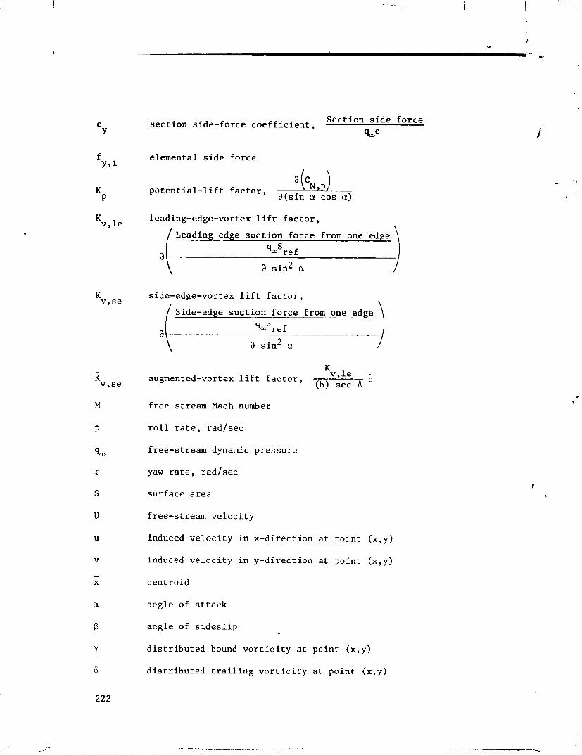
Section side force section side-force coefficient,
4oOc
elemental side force
potential-lift factor, a (cN,P) a(sin a cos a)
leading-edge-vortex lift factor,
/ Leading-edge suction force from one edge \
side-edge-vortex lift factor,
/ Side-edge suction force f rom one edge \
augmented-vortex lift factor, Kv,le -
(b) sec A
free-stream Mach number
roll rate, radlsec
free-stream dynamic pressure
yaw rate, radlsec
surface area
free-stream velocity
induced velocity in x-direction at point (x,y)
induced velocity in y-direction at point (x,y)
cent roid
sngle of attack
angle of sideslip
distributed bound vorticity at point (x,y)
distributed trailing vorticity at point (x,y)
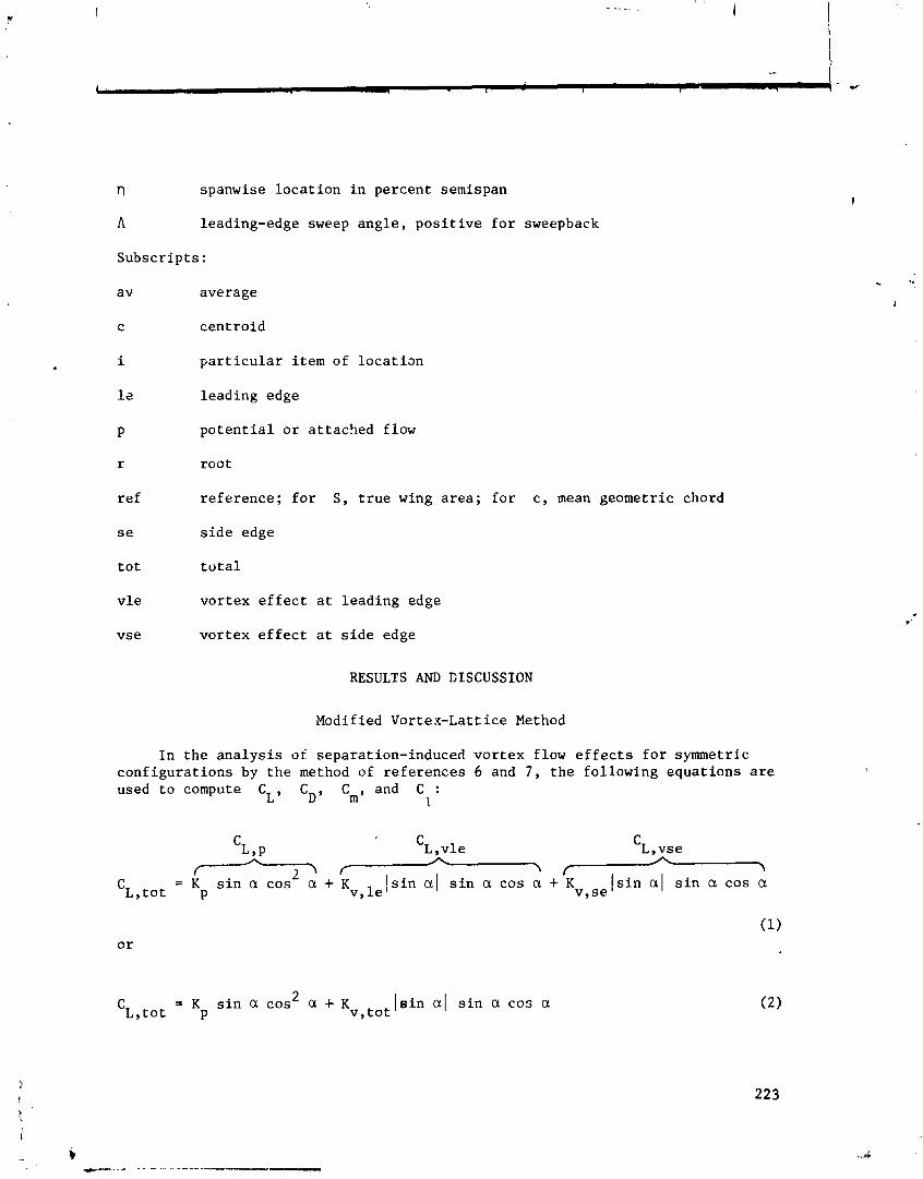
r) spanwise l o c a t i o n i n percent semispan
A leading-edge sweep a n g l e , p o s i t i v e f o r sweepback
Subsc r ip t s :
average
c e n t r o i d
p a r t i c u l a r i tem of l o c a t i m
lead ing edge
p o t e n t i a l o r a t t ached flow
r o o t
f r e f e r e n c e ; f o r S, t r u e wing a r e a ; f o r c , mean geometric chord
s i d e edge
t o t t o t a l
v l e vor tex e f f e c t a t l ead ing edge
vse v o r t e x e f f e c t a t s i d e edge
RESULTS AND CISCUSSION
Modified Vortex-Latt ice Method
I n t h e a n a l y s i s of separation-induced v o r t e x flow e f f e c t s f o r symmetric c o n f i g u r a t i o n s by t h e method of r e f e r e n c e s 6 and 7 , t h e fo l lowing equa t ions a r e used t o compute CL, CD, Cm, and C :
1
C ~ , p 'L ,vie 'L ,vse f \
= K s i n a c o s 2 > f
a + K v , l e [ s i n a ( s i n a cos a +TK [ s i n a1 s i n a cos a
C ~ , t o t p v , s e
2 = K s i n a cos a + K v , t o t C ~ , t o t p
I s i n a1 s i n a cos a ( 2 )

= C + C t a n a = C + K s i n 2 a c o s a + K C~ D,o L v, tot
sin3 a D,o P
= K sin a cos a h lsin a ( sin a Xc,le 'm, tot p c + Kv,le c ref ref
X c se
+ K Isin a1 sin a- v,se c ref
Y = K sin a cos a + sin a1 sin a 'c, le
C ~ J O t P b b
'C se + Kv,se lsin a1 sin a- b
- where the particular x terms represent the distance between the appropriate centroid and the reference point
'ref taken to be the quarter chord of the
mean geometric chord. The potential flow lift term K is computed from the P
symmetric vortex lattice and the vortex lift terms, Kv, le and K , are v,se
computed from the symmetric potential flow solution by using the suction analogy. The application of this technique is not limited, however, to symmetric condi- tions and should be applicable to asymmetric conditions providing the appropriate values of K and Kv can be obtained.
P
The asymmetric vortex-lattice computer program was developed from its sym- metric progenitors (refs. 6 and 7) to compute potential flow solutions about arbitrary thin asymmetric configurations. Once the asymmetric potential-flow solution (and, hence, K ~ ) is known, the suction analogy may be invoked to com-
pute corresponding asymmetric vortex lift terms, Kv,le and Kv,se. The anal-
ysis technique of equations (1) to (5) may now be employed by using the K P
and KV quantities as computed from the asymmetric potential flow.
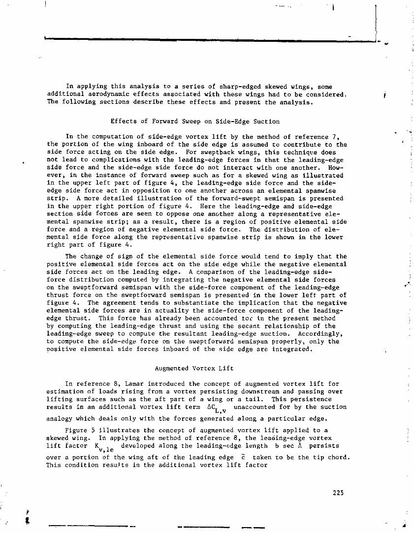
I n applying t h i s a n a l y s i s t o a s e r i e s of sharp-edged skewed wings, some a d d i t i o n a l aerodynamic e f f e c t s a s s o c i a t e d w i t h t h e s e wings had t o b e considered. The fol lowing s e c t i o n s d e s c r i b e t h e s e e f f e c t s and p r e s e n t t h e a n a l y s i s .
E f f e c t s of Forward Sweep on Side-Edge Suc t ion
I n t h e computation of side-edge v o r t e x l i f t by t h e method of r e f e r e n c e 7 , t h e p o r t i o n of t h e wing inboard of t h e s i d e edge is assumed t o c0ntribut .e t o t h e s i d e f o r c e a c t i n g on t h e s i d e edge. For sweptback wings, t h i s t echn iqce does no t l ead t o compl icat ions wi th t h e leading-edge f o r c e s i n t h a t t h e leading-edge s i d e f o r c e and t h e side-edge s i d e f o r c e do n o t i n t e r a c t w i t h one another . How- ever , i n t h e i n s t a n c e of forward sweep such a s f o r a skewed wing a s i l l u s t r a t e d i n t h e upper l e f t p a r t of f i g u r e 4 , t h e leading-edge s i d e f o r c e and t h e s ide - edge s i d e f o r c e a c t i n oppos i t ion t o one ano the r a c r o s s a n e lementa l spanwise s t r i p . A more d e t a i l e d i l l u s t r a t i o n of t h e forward-swept semispan is presented i n t h e upper r i g h t p o r t i o n of f i g u r e 4. Here t h e leading-edge and side-edge s e c t i o n s i d e f o r c e s a r e seen t o oppose one another a long a r e p r e s e n t a t i v e e l e - mental spanwise s t r i p ; a s a r e s u l t , t h e r e is a reg ion of p o s i t i v e e lementa l s i d e f o r c e and a reg ion of nega t ive e lementa l s i d e f o r c e . The d i s t r i b u t i o n of e l e - mental s i d e f o r c e a long t h e r e p r e s e n t a t i v e spanwise s t r i p is shown i n t h e lower r i g h t p a r t of f i g u r e 4.
The change of s i g n of t h e e lementa l s i d e f o r c e would tend t o imply t h a t t h e p o s i t i v e e lementa l s i d e f o r c e s a c t on t h e s i d e edge whi le t h e n e g a t i v e e lementa l s i d e f o r c e s a c t on t h e l ead ing edge. A comparison of t h e leading-edge s ide - f o r c e d i s t r i b u t i o n computed by i n t e g r a t i n g t h e n e g a t i v e e lementa l s i d e f o r c e s on t h e sweptforward semispan wi th t h e s ide - fo rce component of t h e leading-edge t h r u s t f o r c e on t h e sweptforward semispan is presented i n t h e lower l e f t p a r t of f i g u r e 4. The agreement t ends t o s u b s t a n t i a t e t h e i m p l i c a t i o n t h a t t h e nega t ive e lementa l s i d e f o r c e s a r e i n a c t u a l i t y t h e s ide - fo rce component of t h e leading- edge t h r u s t . Th i s f o r c e h a s a l r e a d y been accounted t o r i n t h e p r e s e n t method by computing t h e leading-edge t h r u s t and us ing t h e s e c a n t r e l a t i o n s h i p of t h e leading-edge sweep t o compute t h e r e s u l t a n t leading-edge s u c t i o n . Accordingly, t o compute t h e side-edge f o r c e on t h e sweptforward semispan p roper ly , only t h e p o s i t i v e e lementa l s i d e f o r c e s inboard of t h e s i d e edge a r e i n t e g r a t e d .
Augmented Vortex L i f t
I n r e f e r e n c e 8, Lamar in t roduced t h e concept of augmented vor tex l i f t f o r e s t i m a t i o n of loads r i s i n g from a v o r t e x p e r s i s t i n g downstream and pass ing over l i f t i n g s u r f a c e s such a s t h e a f t p a r t of a wing o r a t a i l . Th i s p e r s i s t e n c e r e s u l t s I n a n a d d i t i o n a l v o r t e x l i f t t e r n AC unaccounted f o r by t h e s u c t i o n
L,v analogy which d e a l s on ly wi th t h e f o r c e s genera ted a long a p a r t i c u l a r edge.
Figure 5 i l l u s t r a t e s t h e concept of augmented v o r t e x l i f t app l i ed t o a skewed wing. I n applying t h e method of r e f e r e n c e 8 , t h e leading-edge v o r t e x l i f t f a c t o r K developed a long t h e leading-edge l eng th b s e c A p e r s i s t s
v, l e *
over a p o r t i o n of t h e wing a f t of t h e l e a d i n g edge c taken t o be t h e t i p chord. This cond i t ion r e s u l t s i n t h e a d d i t i o n a l vor tex l i f t f a c t o r
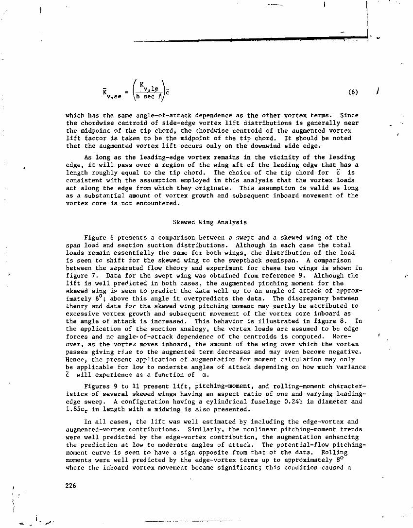
which has the same angle-of-attack dependence as the other vortex terms. Since the chordwise centroid of side-edge vortex lift distributions is generally near the midpoinc of the tip chord, the chordwise centroid of the augmented vortex lift factor is taken to be the midpoint of the tip chord. It should be noted that the augmented vortex lift occurs only on the downwind side edge.
As long as the leading-edge vortex remains in the vicinity of the leading edge, it will pass over a region of the wing aft of the leading edge that has a length roughly equal to the tip chord. The choice of the tip chord for is consistent with the assumption employed in this analysis that the vortex loads act along the edge from which they originate. This assumption is valid as long as a substantial amount of vortex growth and subsequent inboard movement of the vortex core is not encountered.
Skewed Wing Analysis
Figure 6 presents a comparison between a swept and a skewed wing of the span load and section suction distributions. Although in each case the total loads remain essentially the same for both wings, the distribution of the load is seen to shift for the skewed wing to the sweptback semispan. A comparison between the ssparated flow theory and experiment for these two wings is shown in figure 7. Data for the swept wing was obtained from reference 9. Although the lift is well predicted in both cases, the augmented pitching moment for the skewed wing is seen to predict the data well up to an angle of attack of approx- imately 6'; above this angle it overpredicts the data. The discrepancy between theory and data for the skewed wing pitching moment may partly be attributed to excessive vortex growth and subsequent movement of the vortex core inboard as the angle of attack is increased. This behavior is illustrated in figure 8. In the application of the suction analogy, the vortex loads are assumed to be edge forces and no angle-of-attack dependence of the centroids is computed. More- I
over, as the vortex moves inboard, the amount of the wing over which the vortex I
passes giving rjje to the augmented term decreases and may even become negative. Hence, the present application of augmentation for moment calculation may only be applicable for low to moderate angles of attack depending on how much variance m
c will experience as a function of a.
Figures 9 to 11 present lift, pitching-moment, and rolling-moment character- istics of several skewed wings having an aspect ratio of one and varying leading- edge sweep. A configuration having a cylindrical fuselage 0.24b in diameter and 1 . 8 5 ~ ~ in length with a midwing is also presented.
In all cases, the lift was well estimated by insl.uding the edge-vortex and augmented-vortex contributions. Similarly, the nonlinear pitching-moment trends were well predicted by the edge-vortex contribution, the augmentation enhancing the prediction at low to moderate angles of attack. The potential-flow pitching- moment curve is seen to have a sign opposite from that of the data. Rolling moments were well predicted by the edge-vortex terms up to approximately 8' where the inboard vortex movement became significant; this condition caused a

sign reversal in the data except for the wing-fuselage configuration. The pri- mary effect of the fuselage is to break the leading-edge vortex into two pieces, one emanating from the wing apex and bending downstream at the right-wing fuse- lage juncture and the other emanating from the left leading-edge fuselage junc- ture and bending downstream at the left wing tip. Regenerating the leading- edge vortex with the fuselage substantially decreases the extent of inboard movement of the vortex as exhibited by the agreement between theory and experi- ment for the pitching- and rolling-moment coefficients of figures 10 and 11.
Figures 12 to 14 present the lift, pitching-moment, and rolling-moment characteristics of several skewed wings of varying aspect ratio. As in the previous case, the lift was well predicted for the three wings. The experimental pitching moments are well predicted by including the augmented term but the experimental rolling moments still depart from the theory at approximately 6O. Hence, for these wings the chordwise distribution of the load is being well esti- mated whereas the spanwise distribution of the load can be estimated only as long as a substantial inboard movement of the vortex is not encountered.
CONCLUDING REMARKS
This paper has presented 3 recent extension of the suction analogy for the estimation of potential and vortex loads on asymmetric configurations. The analysis has been accomplished by the development and application of an asym- metric vortex-lattice computer program which may be used to compute the potential and vortex loads on asymmetric configurations. In applying this analysis to a series of sharp-edge skewed wings, the effects of forward sweep or, side-edge suction and of a skewed geometry on augmented,vortex lift have been accounted for. Total loads have been well predicted whereas pitching 2nd rolling moments have been well predicted only as long as the assumption that the vortex loads act along the edge from which the vortex has originated is not violated. Hence, the suction analogy concept may now be applied to a wider range of isolated planfnrms resulting in an improved estimating capability of separation-induced vortex flow.
REFERENCES
1. Polhamus, Edward C.: A Concept of the Vortex Lift of Sharp-Edge Delta Wings Based on a Leading-Edge-Suction Analogy. NASA TN D-3767, 1966.
2. Wentz, William H., Jr.; and Kohlman, David L.: Wind Tunnel Investigations of Vortex Breakdown on Slender Sharp-Edged Wings. Rep. FRL 68-013 (Grant NGR-17-002-043), Univ. of Kansas Center for Research, Inc., Nov. 27, 1969. (Available as NASA CR-98737.)
3. Polhamus, Edward C.: Charts for Predicting the Subsonic Vortex-Lift Charac- teristics of Arrow, Delta, and Diamond Wings. NASA TN D-6243, 1971.
4. Polhamus, Edward C.: Predictions of Vortex-Lift Characteristics by a Leading- Edge Suction Analogy. J. Aircraft, vol. 8, no. 4, Apr. 1971, pp. 193-199.
5. Lamar, John E.: Extension of Leading-Edge-Suction Analogy to Wings With Separated Flow Around the Side Edges at Subsonic Speeds. NASA TR R-428, 1974.
6. Margason, Richard J; and Lamar, John E.: Vortex-Lattice FORTRAN Program for Estimating Subsonic Aerodynamic Characteristics of Complex Planforms. NASA TN D-6142, 1971.
7. Lamar, John E.; aqd Gloss, Blair B.: Subsonic Aerodynamic Characteristics on Interacting Lifting Surfaces With Separated Flow Around Sharp Edges Pre- dicted by a Vortex-Lattice Method. NASA TN D-7921, 1975.
8. Lamar, John E.: Some Recent Applications of the Suction Analogy to Vortex- Lift Estimates. Aerodynamic Analyses Requiring Advanced Computers, Part 11, NASA SP-347, 1975, pp. 985-1011.
9. Gersten, K.: Calculation of Non-Linear Aerodynamic Stability Derivatives of Aeroplanes. AGARD Rep. 342, Apr. 1961.

0 EXP. (REF. 2)
tan a
F i g u ~ e 1 . - Original appl icat ion of leading-edge suct ion analogy.
NORMAL I \ FORCE I \
-EDGE THRUST^^ NORMALFORCE
!\ ! f
LEAD I NG -
;/s IDE-EDGE SUCTION FORCE
S I DE-EDGE SUCTION FQRCE
2 C = K sin a cos a + IKv, ,e + Kv, se) l s i n a I s i n a cos CI L P
Figure 2 . - Vortex- l i f t concept: suc t ion analogy appl i ca t ion t o leading edge and s i d e edge.
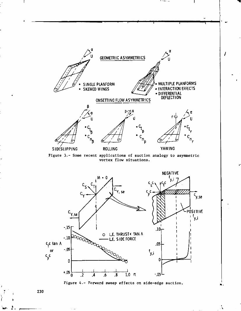
I " GEOMETRIC
SINGLE PLANFORM SKEWED WINGS
ASYMMETRICS /fi
MULTl PLE PLANFORMS INTERACTION EFFECTS DIFFERENTIAL
ONSETTI NG FLOW ASYMMETR I CS DEFLECTION
SIDESLIPPING ROLLING /
YAWING
Figure 3.- Some recent applications of suction analogy to asymmetric vortex flow situations.
C,c tan A
+.05 0 .2 .4 .6 .8 1 .Or l -.05 L
Figure 4.- Forward sweep effects on side-edge suction.
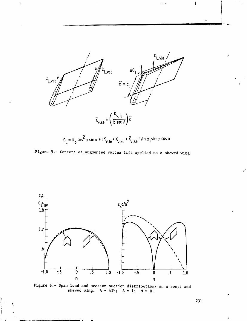
- = (k); Kv,se b sec A
2 - c L = K cos a s i n a +(Kv,l ,+Kv,se + Kv.se I l s in a 1 s i n a cos a
P
Figure 5 . - Concept of augmented vortex l i f t applied t o a skewed wing.
Figure 6 . - Span load and s e c t i o n suct ion d i s t r i b u t i o n s on a swept and skewed wing. A = 45O; A = 1; M = 0.
I
1 . 231 1
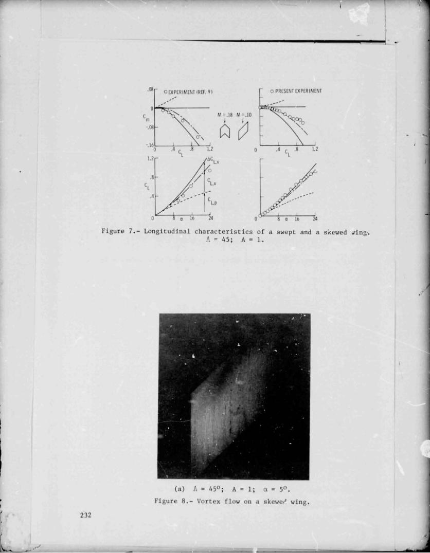
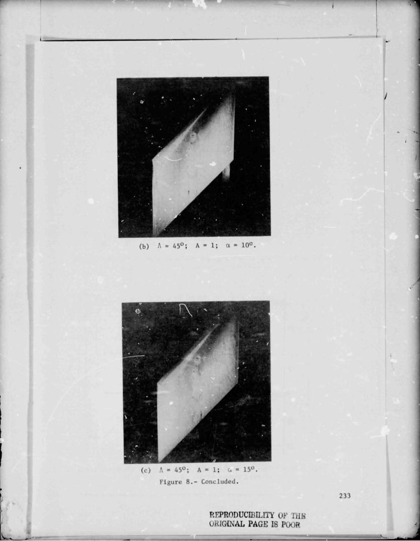

1.2 r r O PRESENT EXPERIMENT
Figure 9.- Effect of leading-edge sweep on l i f t characterist ics of several skewed wings. A = 1; M z 0.10.
0 A = 45 0
'rn -. 08
-. 16 0 PRESENT EXPERIMENT
b ern r r
Figure 10.- Effect of leading-edge sweep on pitch characterist ics of several skewed wings. A = 1; M : 0.10.
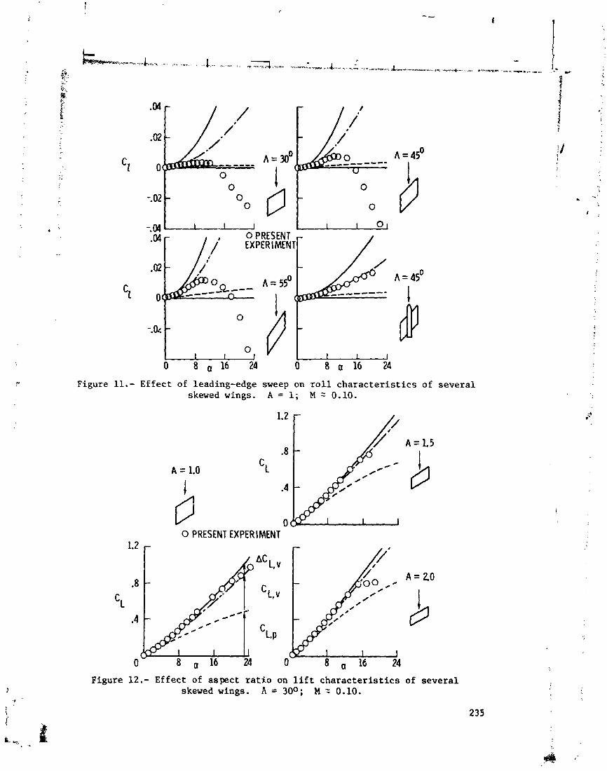
-. 04 I I 1 0 0 PRESENT 'F EXPERlf#N
.02 0 A = 55' A = 45O
-c-- ,Q--- 0 I I
Figure 11.- Effect of leading-edge sweep on r o l l characterist ics of several skewed wings. A = I; M z 0.10.
0 PRESENT EXPERIMENT
Figure 12.- Effect of aspect rat io on l i f t characterist ics of several - skewed wings. A = 30°; M ? 0.10.
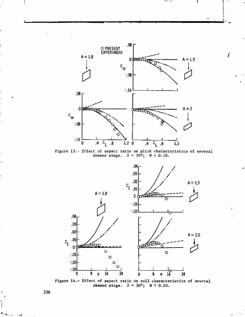
.oa 0 PRESENT EXPER IMENT
A = 1.0 0
Cm -. 08
Figure 13.- Effect of aspect ratio on pitch characteristics of several skewed wings. A = 30°; M = 0.10.
Figure 14.- Effect of aspect ratio on roll characteristics of several skewed wings. A = 30°; M : 0.10.

APPLICATION OF THE VORTEX-LATTICE TECHNIQUE TO THE ANALYSIS OF THIN WINGS WITH VORTEX SEPARATION AND THICK MULTI-ELEMENT WINGS
Charles FT. Smith and Ishwar C. Bhateley Fort Worth Division of General Dynamics
SUMMARY
Two techniques f o r extending the range of app l i cab i l i ty of the basic vor tex- la t t ice method a r e discussed. The f i r s t tech- nique improves the computation of aerodynamic forces on th in , low-aspect-ratio wings of a r b i t r a r y planforms a t subsonic Mach numbers by including the e f f e c t s of leading-edge and t i p vortex separation, cha rac te r i s t i c of t h i s type wing, through use of the well-known suction-analogy method of E. C. Polhamus. Comparisons with experimental data fo r a var ie ty of planforms a r e presented.
The second technique cons is t s of the use of the vortex- l a t t i c e method t o predic t pressure d i s t r ibu t ions over thick multi- element wings (wings with leading- and t rai l ing-edge devices). A method of laying out the l a t t i c e i s described which gives accurate pressures on the top and pa r t of the bottom surface of the wing. Limited comparisons between the r e s u l t predicted by t h i s method, the conventional l a t t i c e arrangement method, experi- mental data , and 2-D po ten t i a l flow analysis techniques a re presented.
INTRODUCTION
Vortex-lat t ice methods are known to give reasonable r e s u l t s f o r th in wings of moderate to high aspect r a t i o . However, use of these methods to predic t the aerodynamic forces on low-aspect- r a t i o wings has not been p r a c t i c a l due to the s ign i f i can t vortex l i f t generated by these wings. The analysis and predict ion of the nonl inear i t ies associated with the vortex l i f t has received con- s iderable a t t en t ion i n the l i t e r a t u r e f o r many years. Methods of solut ion based on complex mathematical models have generally f a i l e d . However, within the past several years, E. C. Polhamus of the NASA Langley Research Center has proposed and ve r i f i ed through comparison with experimental data an ana ly t i ca l method f o r sharp-leading-edge wings of zero taper r a t i o (reference 1 ) . The
method is based on a leading-edge suction analogy proposed by Polhamus in reference 2. Extension of the suction analogy to ; /
I
plane rectangular rings has been accomplished by J. E. Lamar in reference 3. A method for calculating the lift, drag, and pitching moment of cambered, sharp-edged wings of arbitrary plan- . ... form is presented here as a logical extension of the suction- i analogy concept. A vortex-lattice program is utilized to provide the potential-flow force coefficients required by the suction- analogy concept and to provide the foundation for development of a computer procedure which incorporates the methods developed.
The accurate calculation of pressure dis tributions near the leading edge of thick multi-element wings is of considerable interest to the aerodynamicist. Vortex-lattice methods using the conventional vortex-lattice arrangement of distributing the vor- ticity on the camber surface yield pressure coefficients which approach infinity at the leading edge due to the singularity at the leading edge. An alternate method of laying out the lattice is described which circumvents this difficulty and gives reason- able predictions for the pressures on the top surface and a part of the bottom surface of wings.
SYMBOLS
Values are given in both SI and U.S. Customary Units. The measurements and calculations were made in U.S. Customary Units.
AR aspect ratio
mean aerodynamic chord, cm (in. )
axial- force coefficient
drag-due-to-lift coefficient
total lift coefficient ( C L ~ + CL~)
zero-suction potential-flow lift coefficient
vortex-lift coefficient
total pitching-moment coefficient
zero-suction potential-flow pitching-moment coefficient for half-span wing
CN normal-force coefficient
potential-flow normal-force coefficient for half- span wing
pressure coefficient
potential-flow leading-edge suction coefficient for half-span wing
potential-flow leading-edge thrust coefficient for half-span wing
20 tential-flow side-force coefficient for half- span wing
potential-flow side-force-coefficient contribution from streamwise members of the vortex lattice for half-span wing
Ccc nozzle momentum coefficient
KP potential-f low normal-force slope
(Kp)m potential-flow constant used in pitching-moment calculation
Kv vortex- lif t constant
K~~~ leading-edge vortex-lift constant used in lift calculation
(Kv~~)m leading-edge vortex-lift constant used in pitching- moment calculations
K v ~ ~ ~ tip vortex- lif t constant used in lift calculations
( K v ~ ~ ~ ) m tip vortex- lif t constant used in pi tching-moment calculations
M Mach number
pitching-moment arm for tip vortex-lift contribu- tions, cm (in.)
pitching-moment arm for leading-edge vortex-lift contributions, cm (in.)

nondimensionalized chordwise locat ion 8 pitching-moment arm f o r leading-edge suct ion force, cm ( i n . )
' L
angle of a t tack , degrees i
planform taper r a t i o
leading-edge sweep angle, degrees
slope of the mean l i n e perpendicular t o the planform leading edge, degrees
THEORETICAL DEVELOPMENT FOR THIN WINGS
The Po lhamus Suc t ion h a logy
The General Dynamics vor tex - l a t t i ce method has been modi- f i e d t o incorporate the calculat ion of vortex separat ion e f fec t s . , '
The basis f o r t h i s modification t o the vor tex - l a t t i ce pro- cedure is the Polhamus leading-edge suct ion analogy, which is de ta i led i n reference 2. Brief ly , i t i s based on the postulate t h a t the normal force on the upper surface i s the same f o r attached vortex flow as the leading-edge suction force f o r attached potent ia l flow. The t o t a l l i f t of sharp-edged, pointed- t i p wings is given as :
CL = c ~ p + Cs cos a
is the potential-flow l i f t and CS i s the leading-edge suct ion orce. Polhamus wri tes the l i f t i n terms of K-factors, where K and Kv, which a re functions of planform and Mach number only. At is,
2 2 CL = Kp s i n a cos a + Kvv s i n a cos a LE
where Kp i s , by de f in i t ion , the normal-force slope given by potent ia l - f low theory,
rr a C N ~
"P a s i n a cos a

I i and Kv i s , by def in i t ion , LE
J. E . Lamar extended the Polhamus concept to rectangular wings of low aspect r a t i o i n work reported i n reference 3. The equation i s
CL ' c ~ p 4- cs COS a + Cy C J S Or
where Cy i s twice the potential-flow s i d e force f o r the half-wing. In terms of K-factors,
2 CL = Kp s i n a cos a + (KVLE + KvTIp ) s i n 2 a cos a
where, by de f in i t ion ,
CY
and Kp and Kv a re given i n equations (3) and (4) . LE
Ex tension to Arbitrary Fla t -Pla te Wings
The above equations have been extended (reference 4) to more complex planforms. For a trapezoidal planform, the f i n i t e t i p e f f e c t s a re taken i n t o account f o r defining the v o r t e x - l i f t con- t r ibu t ion as
CT + Cy - CT tan '4 cos a cos ,4 I The above formulation recognizes tha t pa r t of the t o t a l wing s ide force a c t s on the swept leading edge as pa r t of the leading-edge i suct ion vector (CT/COS A ) , and t h a t the remainder (Cy - CT tan A ) a c t s on the wing t i p , as shown i n f igure l ( a ) .
[ &
i

Generalization of the above r e s u l t to wings of a r b i t r a r y planform r e s u l t s i n the following equation f o r the l i f t :
I N . . - %
CTn + Cy -c C tan A cos a (8) cos A ' ;.
n=1
The notation i s i l l u s t r a t e d i n f igure l ( b ) . In terms of K-factors, >
the t o t a l l i f t is given by
where
2 CL = Kp s i n a cos a + (KvLE + KvTIp) s i n 2 a cos a (9)
and
The potential-flow in-plane force coeff ic ients , CT and Cy, a re those computed by any accurate l i f t ing-surface theory. In t h i s appl icat ion, they are obtained from a vor tex - l a t t i ce procedure. Compressibility e f f e c t s a r e included through use of the Goethert transformation.
The zero-leading-edge-suction drag due to l i f t fo r sharp- edged, uncambered wings is defined by
where CL i s the t o t a l l i f t coef f ic ient a s given by equation (9) .
Extension of the above formulations fo r the calculat ion of l i f t to the calculat ion of pitching moment logica l ly foll.ows. As i n the l i f t case, the pitching moment i s comprised of potent ial-

flow and vortex contributions. In general form, the r e su l t ing equation is
The notat ion i s i l l u s t r a t e d i n f igure l ( b ) . The potential-flow moment, Cmpy i s the moment r e su l t ing from the potential-flow normal forces on each member of the l a t t i c e .
The moment r e su l t ing from the vortex l i f t is comprised of a leading-edge and a t i p component. To determine the leading- edge contribution, the leading-edge vortex l i f t , a s determined by the suct ton analogy (C~,/cos An), i s assumed to a c t precisely a t the leading edge of each chordwise s t r i p , The moment is then the sum of the products of these forces and the moment arms (xn), defined as the dis tance from the midpoint of the leading edge of each chordwise s t r i p t o the reference locat ion. The leading-edge force includes a portion of the s ide force (CT* tan An). The remainder of the s ide force, which is equal t o the contribution of the streamwise members of the vortex l a t t i c e , i s noted as
fo r each spanwise s t r i p . The sum of t h i s remainder cons t i tu tes the t o t a l t i p vortex l i f t . Thus the tip-vortex- l i f t contribution to the moment i s the sum of the products of these forces and the moment arms ( x ~ ) , defined as the dis tance from the midpoint of the t i p of each spanwise s t r i p to the reference locat ion.
I n terms of K-factors,

d c ' ~ n (xn/C)
( K v ~ ~ ) m ds in2 a 15 cos A J
The t o t a l moment i s given by
] s i n 2 a (17) Cm - (Kp), s i n a cos a +
Extension to Cambered Wings
The bas is f o r determining the force and moment coe f f i c i en t s f o r thin, cambered planforms i s the hypothesis t h a t the t o t a l suction force a c t s perpendicular to the slope of the mean l i n e a t the leading edge. This i s a logica l extension to the suztion- analogy assumption t h a t the suct ion force a c t s i n the normal-
#
force d i rec t ion f o r f la t -p la t e planforms . Thus f o r cambered planforms, contributions t o both the normal force and the a x i a l force ( i n the s x t i o n d i rec t ion) a re rea l ized from the t o t a l i
suction force calculated by potential-flow theory.
The development tha t follows fu r the r assumes t h a t the leading-edge vortex is positioned above the wing surface a l l along the wing span. Thus, extreme camber cases where the leading-edge vortex can be shed below the wing surface a t low angle of a t t ack and may even r o l l around the leading edge t o the upper surface a t some spanwise locat ion a re not allowed.
The general equation fox l i f t a s resolved from the normal, CN, and a x i a l , CA, forces is
CL = CN cos a - CA s i n a (18)
REpRoDUCIcBILW OF THE ORIOZNfi PAGE E POOR
Consistent with the current nomenclature, the t o t a l l i f t f o r the cambered ~ l a n f o r m (neglecting f r i c t i o n drag) the.? becomes
+ C cTnsingn s i n a c1 1 The angle 0 is equal to the slope of the mean l i n e perpendicular to the planform leading edge a t the midpoint of the leading edge of each chordwise s t r i p . Note tha t CT is defined a s a posi t ive force i n the upstream di rec t ion ,
Similarly, the t o t a l drag due t o l i f t (neglecting f r i c t i o n drag) is given by
or , fo r the cambered planform,
The pitching moment i s determinedin ntuch the same manner a s tha t described previously f o r the uncambered planform. An addi- t iona l term is required to account f o r the moment contrfbution of the suction-force component i n the axial-force d i rec t ion . h e moment arm, zn, fo r t h i s force i s the v e r t i c a l dis tance from the

reference t o the midpoint of each chordwise segment. The re- su l t ing equation is
is the potential-flow moment resul t ing from the potentia -flow normal forces only. where
EVALUATION AND RESULTS FOR THIN WINGS
Verif icat ion of the aerodynamic coeff ic ient calculat ions f o r unca,: 5ered planforms has been accomplished through comparison $ with t e s t data fo r de l t a , arrow, diamond, double-delta, rectangular , and ogee wings. Cambered wing calculat ions have been compared with data f o r a moderately cambered de l t a planform.
Fla t-Pla t e Wings f
Data from reference 5 f o r d e l t a and clipped de l t a planforms t
of taper r a t i o 0.0 and 0 . 4 a re presented i n f igures 2 and 3. Results of the current method generally agree qui te well with the data. However, the t e s t data f o r the de l t a wing begin to depart t
s ign i f i can t ly from the predict ions when vortex breakdown reaches the wing t r a i l i n g edge. Reference 6 reports tha t vortex break- down occurs a t 14 degrees angle of a t t ack f o r the wing of f igure 2 . The de l t a wing ( f igure 2 ) exhib i t s l i t t l e e f f e c t of vortex l i f t on the pitching moment. Apparently the leading-edge vortex l i f t is approximately equally d i s t r ibu ted about the reference ax i s , which is a t the quarter-chord of the mean aerodynamic chord. On the clipped de l t a wing of f igure 3, the v o r t e x - l i f t contr ibut ion to the moment becomes much more pronounced. The potential-flow r e s u l t s , considered alone, ac tua l ly predict a moment i n the wrong direc t ion .
Comparisons between the theore t ica l r e s u l t s and data from reference 7 f o r an aspect-ratio-2.0 rectangular wing a r e presented i n f igure 4. Even though the predicted t o t a l l i f t agrees well with the data up to an angle of a t tack of 12 degrees, the data depart from the predicted moment a t 8 degrees. This i s a t t r ibu ted to the progression of the vortex across the planform a s angle of a t tack i s increased.
. Comparisons with reference 6 data f o r an 80-165-degree double- de l ta planform and an ogee planform a re presented i n f igures 5 and 6. Excellent agreement with the l i f t and drag predictions i s apparent t o the angle of a t tack f c r vortex breakdown. Good agreement with the pitching moment i s obtained a t the lower angles of a t tack , but the data break away from theory before the angle of a t tack fo r vortex breakdown is reached. This could be caused by a complex flow in terac t ion resu l t ing from the formation of multiple leading-edge vor t ices on t h i s type planform.
Figures 7 and 8 present t e s t - to- theory comparisons f o r two planforms (reference 3) which help inves t iga te the a b i l i t y of the method to evaluate the e f f e c t s of trail ing-edge sweep. The l i f t of the clipped arrow wing of f igure 7 i s predicted very well , however the l i f t of the clipped diamond wing of f igure 8 i s under-predicted. This i s a t t r ibu ted to the induced l i f t e f f e c t of the shed vo tex on the addi t ional surface area a f t of the t r a i l i n g edge of the diamond wing t i p .
Test data from a model which employs spanwise blowing on the wing upper surface (reference 8) is presented i n f igure 9 f o r a 30-degree dc l t a wing. Comparison with predict ions i l l u s t r a t e s the potent ia l of t h i s method a s a tool f o r estimating the bene- f i t s which can be rea l ized from vortex augmentation of t h i s type. The a b i l i t y of the spanwise blowing t o extend the leading-edge vortex l i f t to higher angles of a t t a c k i s most pronounced. Agree- ment with the predicted l i f t - cu rve slope i s apparent to angles of a t t ack much above the no-blowing vortex breakdown region. There is a blowing-induced camber e f f e c t which i s , of course, not predicted by the theory.
Cambered Wings
The cambered-wing equations havt been used t o predict the charac ter i s t ics of a moderately cambered (C = 0.15) d e l t a wing R i for which reference 5 presents t e s t data. The comparisons of
l i f t , drag, and moment shown i n f igure 10 indica te good agreement. i, The reference 5 data f o r the same wing with an uncambered sect ion : have been included i n f igure 10 t o i l l u s t r a t e the method's a b i l i t y t o predict the incremental camber e f f e c t accurately. It i s a l s o noteworthy tha t the incremental. vor tex- l i f t contr ibut ion due to - camber i s very small. Thus, a t l e a s t f o r small o r moderate amounts of camber, the po ten t i a l flow increment due to camber
1
gives a good approximation f o r the incremental e f f e c t s of camber.
VORTEX-LATTICE ARRANGEMENT FOR THICK WINGS
Vortex-lat t ice methods a re best su i ted f o r the analysis of th in wirgs with sharp leading edges which can be approximated by camber surfaces. The predicted r e s a l t s i n general f o r t h i s type of wing show good agreement with experimental data. How- ever, when the vor tex- la t t ice method i n d i r e c t l y applied to thick wings (including multi-element wings) the cdlculated r e s u l t s do not agree with experimental data.
A typica l conventional vor t ex - l a t t i ce layout f o r multi- element wings is s3own i n f igure 11. Each wing element is re- presented by a network of horseshoe vor t ices lying on the camber surface and t r a i l i n g behind the surface. A s can be seer from t h i s f igurz a bound vortex l i e s along the leading edge of each com- ponent of the multi-element system. This causes i n f i ~ i t e ve loc i t i e s t o be generated a t the leading edge which produce very large negative pressure coeff ic ients (unrea l i s t i c ) a t poin ts i n the iamediate v i c i n i t y of the leading edge. This phenomenon i s acceptable f o r t h i n sharp-leading-edge wings but f a i l s t o give acceptable predict ions f o r thick wings. For example, the loads calculated f o r the F-111 wing i n the h i g h - l i f t configuration a t angles of a t tack of 4 and 15 degrees a re compared with experimental data (reference 9) i n f igures 12(a) and 12(b), respect ively. Large discrepancies between experimental and theore t ica l loads a re evident near the leading edge of the wing and f laps .
A technique f o r laying out the l a t t i c e has been developed a t General Dynamics which g rea t ly improves the pressure d i s t r i - butions predicted by the vor tex- la t t ice method f o r thick m u l t i - element wings. A typica l example of t h i s l a t t i c e i s shown i n f igure 13. Each element of the multi-element wing i s represented by a network of horseshoe vor t ices lying on and t r a i l i n g behind a surface which i s composed of the top surface and p a r t of the
bottom surface, and wraps around the leading edge of the wing. The surface on the bottom is extended downstream of the a n t i c i - pated stagnation point . I f the surface i s extended to the t r a i l i n g edge the problem becomes s ingular and meaningless r e s u l t s a re obtained. No large differences i n predicted pressures have been noted fo r var ia t ions i n the extent of the vortex sheet on the lower surface.
A large-aspect-rat io , unswept, untapered wing having the same sect ion as the F-111 wing sect ion a t BL 289 was analyzed using t h i s wrapped l a t t i c e arrangement. The pressure d i s t r ibu t ions ca l - culated a t the center l ine of t h i s wing a re shown i n f igures 14(a) and 14(b) fo r angles of a t tack of 4 and 12 degrees, respectively. The chordwise d i s t r ibu t ion of the vortex l i n e s is a l s o shown i n these f igures . Since the pressures a t the center l ine of a large- aspect-rat io wing a r e compatible with two-dimensional flow r e s u l t s they a r e compared with two-dimensional experimental data (reference LO) and two-dimensional theore t ica l r e s u l t s (reference 11) i n these f igures . The predict ions show good agreement with both the experimental and theore t i ca l r e s u l t s . The two-dimensional theore t ica l pressure d i s t r ibu t ions shown were obtained with a much denser chordwise d i s t r i b u t i o n of points . A b e t t e r predict ion should be obtained with the vor tex - l a t t i ce method i f a denser chordwise portioning of the l a t t i c e i s employed.
CONCLUDING REMARKS
A method has been formulated f o r determining the l i f t , zero- leading-edge-suction drag due t o l i f t , and pi tching moment of th in , sharp-edged, low-aspect-ratio wings with camber. This method u t i l i z e s a vor tex- la t t ice procedure modified to include v o r t e x - l i f t induced e f f e c t s by including an extension of the Polhamus suction-analogy concept. Good agreement with experiment i s obtained for simple highly swept planforms below the angle of a t t ack a t which vortex breakdown reaches the t r a i l i n g edge of the wing and a t somewhat lower angles of a t tack f o r wings with more complex flow pat te rns , such as double-delta and ogee planforms.
The method shows promise as a tool fo r evaluation of the po ten t i a l of vortex augmentation systems.
To obtain more accurate predictions fo r :he more complex planforms, i t i s necessary t o include the e f f e c t s of the
- Y
t .
1 !
h
progression of the vor t ices away from the leading edge and t i p of the planform and t o include the vortex in terac t ions on plan- forms which emanate multiple leading-edge vor t i ces , 1
A method has a l s o been developed f o r laying out the vortex l a t t i c e f o r th ick multi-element wings which gives accurate pressure predict ions on the top and pa r t of the bottom surface - of the wing. Comparison with experimental data and other 1
theore t ica l methods subs tant ia tes the accuracy of the r e s u l t s .
REFERENCES
1. Poihamus, E. C. : Predictions of Vortex-Lift Charac ter i s t ics by a Leading-Edge Suction Analogy. Journal of Ai rc ra f t , volume 8, no. 4, April 1971, pp. 193-199.
2. Polhamus, E. C. : A Concept of the Vortex L i f t of Sharp-Edge Delta Wings Based on a Leading-Edge Suction Analogy. NASA TN D-3767, December 1966.
3. Lamar, J. E. : Extension of Leading-Edge-Suction Analogy t o Wings with Separated Flow Around the Side Edges a t Subsonic Speeds. NASA TR R-428, October 1974.
4. Bradley, R. G. ; Smith, C. W. ; and Bhateley, I. C. : Vortex- L i f t Prediction f o r Complex Wing Planforms . Journal of <
Aircraf t , volume 10, no. 6, June 1973, pp. 379-381.
5. Emerson, H. F.: Wind-Tunnel Investigat'on of the Effect of , ,
Clipping the Tips of Triangular Wings 0.' I f f e ren t Thickness, Camber, and Aspect Ratio - Transonic Bun, iqethod. NACA TN 3671, June 1956.
6. Wentz, W. H. , Jr. ; and Kohlman, D. L. : Wind Tunnel Inves t i - gations of Vortex Breakdown on Slender Sharp-Edged Wings. NASA CR-98737, November 1968.
7. Nelson, W. H. ; and McDevitt, J. B. : The Transonic Charac- t e r i s t i c s of 22 Rectangular, Symmetrical Wing Models of Varying Aspect Ratio and Thickness. NACA TN 3501, June 1955.
8. Bradley, R. G . ; Wray, W. 0.; Smith, C. W . : An Experimental Investigation of Leading-Edge Vortex Augmentation by Blowing. NASA CR-132415, 1 April 1974.
Goss, W. J .: Report of Fourth Ser ies Wind Tunnel Tests of 1 the 116-scale F-111 Semi-span lbde l . Grumman Aircraf t Report i
GW.TT 184 (310-4), October 1963.
Goodwin, L. C. : Wind Tbnnel Tests on a 2-D Model of a NACA - . . +
64A210 (bbdified) Section with Various Leading and Trai l ing Edge Devices, Using the Canadair 2-D Blowing Walls, i n the NAE 6x9-Ft Low-Speed Wind Tunnel, NAE Test 6x910140, D I R
I
Project All-Phase 11, volumes 1, 2, and 3. Canadair Report ERR-CL-RAA-228-010, Sept. 1969.
Bhateley, I. C. : Invest igat ion of Inviscid Incompressible i
Flow, Part I V : Potent ia l Flow Analysis about Arbitrary : Elultiple Two-Dimensional Bodies by the Method of Distributed Singular i t ies . General Dynamics Fort Worth Division Report ERR-FW-669, 31 March 1968.
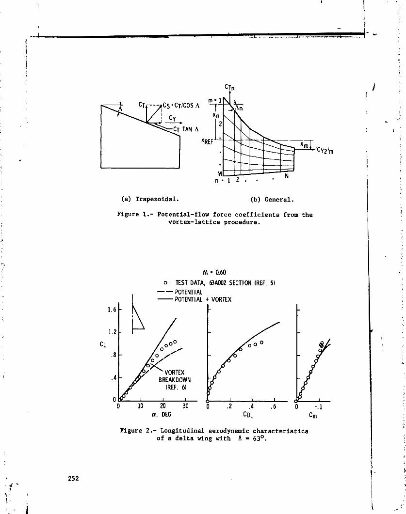
(a) Trapezoidal. (b) General.
Figure 1.- Potential-flow force coefficients from the vortex-lattice procedure.
o TEST DATA, 63A002 SECTION (REF. 5) -- I
POTENT l AL - POTENTIAL + VORTEX
a, DEG
Figure 2.- Longitudinal aerodynamic characteristics of a delta wing with A = 63O.
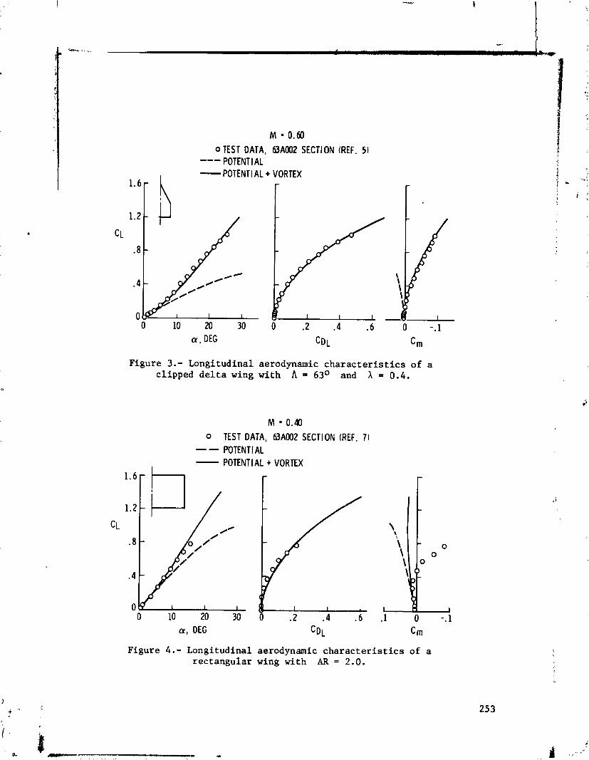
M = 0.60 OTEST DATA, 63A002 SECTION (REF. 5 ) --- POTENT l AL - POTENTI AL + VORTEX
0 10 M 30 0 . 2 .4 .6 0 -.l
Figure 3.- Longitudinal aerodynamic characterist ics of a clipped de l ta wing with A = 63O and h = 0.4.
Figure 4.- Longitudinal aerodynamic characterist ics of a rectangular wing with AR = 2 . 0 .
M 0.40 0 TEST DATA, 63A002 SECTIOFI (REF. 7 ) -- POTENT I AL -
I POTENTIAL + VORTEX

TEST DATA, FLAT PLATE (REF. 6 ) --- POTENTIAL - POTENTIAL + VORTEX
0 0
-c--
1 1 1 1
0 10 20 30 40 a, DEG
Figure 5.- Longitudinal aerodynamic characteristics of a -
double-delta wing A t h A = 800165O.
o TEST DATA, FLAT PLATE (REF. 6 ) ---- POTENT1 AL - POTENTIAL + VORTEX
a, DEG C~~
Figure 6.- Longitudinal aerodynamic characteristics of an ogee wing with AR = 1.7.
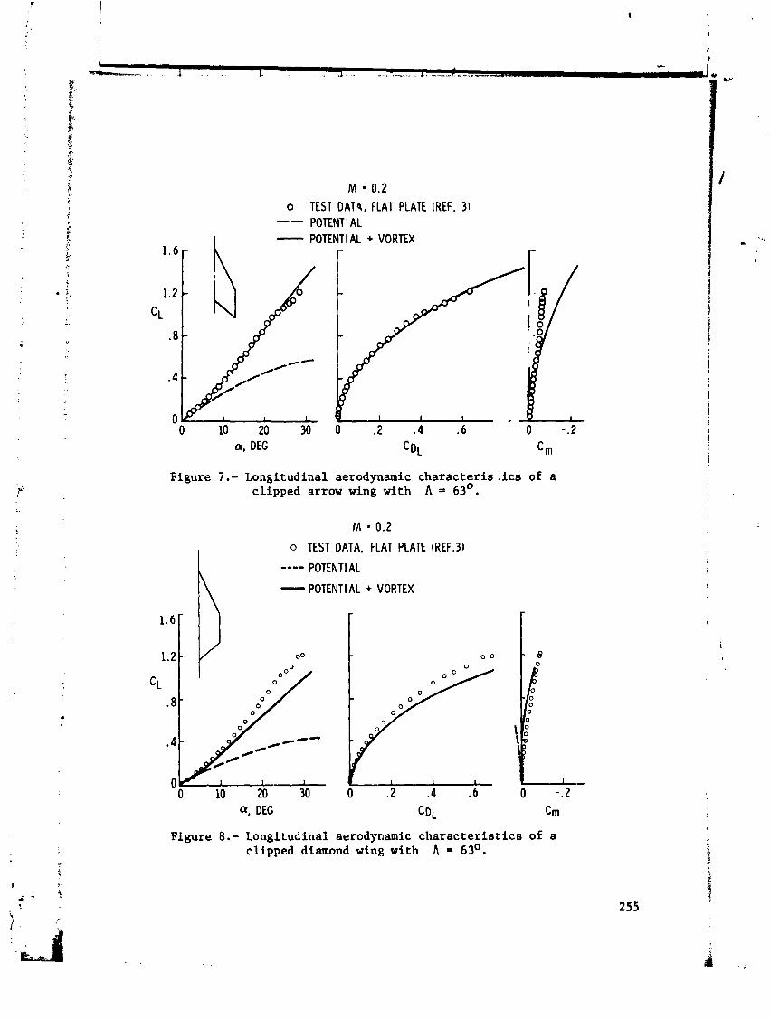
M = 0.2 TEST DAT4, FLAT PLATE (REF. 31 POTENTI AL POTENTIAL + VORTEX
a. DEG
Figure 7.- Longitudinal aerodynamic characteris-ics of a clipped arrow wing with = 63O.
M = 0.2
h o TEST DATA, FLAT PLATE (REF.31
---- POTENT1 AL
- POTENTI AL + VORTEX
Figure 8.- Longitudinal aerodynamic characteristics of a clipped diamond wing with A = 6 3 O .

a, DEG
Figure 9.- Longitudinal aerodynamic characteristics of a delta wing with A = 30° and spanwise blowing.
o TEST DATA, 63A004 SECTION (REF. 51 --- POTENTIAL + VORTEX o TEST DATA, 63A(1.5)04 SECTIbtd (REF. 5 ) - POTENTIAL + VORTEX
Figure 10.- Effect of camber on the longitudinal aerodynamic characteristics of a delta wing with A = 63O.

Figure 11.- Conventional vortex-lattice arrangement on a thick multi-element wing.
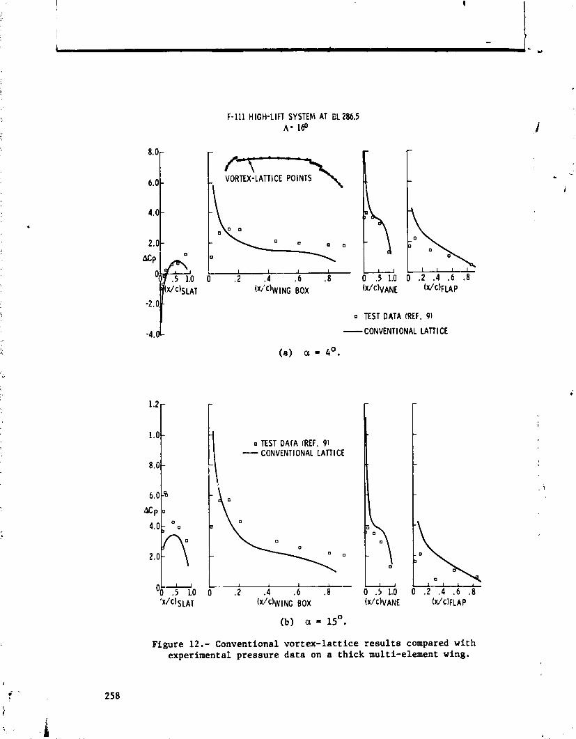
F-111 HIGH-LIFT SYSTEM AT BL 286.5 A - 160
(a) a = 4'.
o TEST DArA (REF. 91 - CONVENTIONAL LATTl CE
-
IY
-
0 TEST DATA (REF. 91
- CONVENTIONAL LATTl CE
Figure 12.- Conventional vortex-lattice results compared with experimental pressure data on a thick multi-element wing.

Figure 13.- Wrapped vortex-lattice arrangement on a thick multi-element wing.
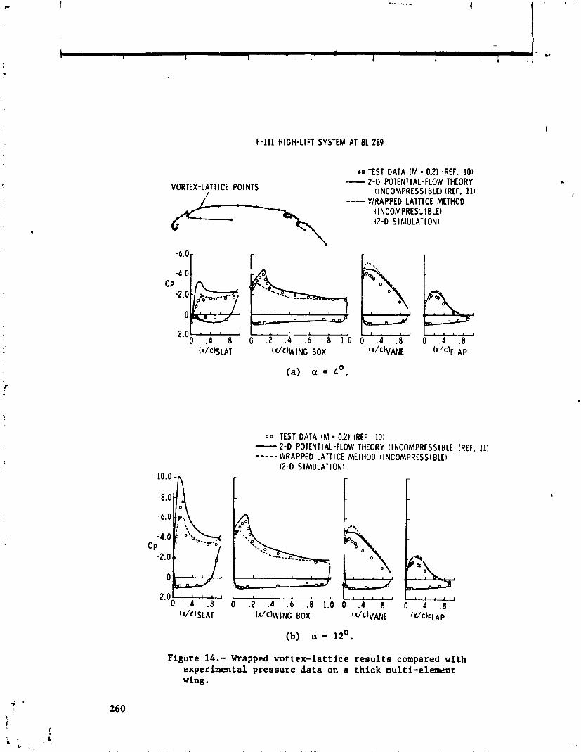
F-111 HIGH-LIFT SYSTEM AT 8 1 289
VORTEX-LATTI CE POINTS I
00 TEST DATA ( M = 0.2) (REF. 10) -- 2-0 POTENTI AL-FLOW THEORY (INCOMPRESSI BLEI (REF. 11) ---- WRAPPED LATTICE METHOD (INCOMPRES: I BLE) (2 -0 SIMULATIONI
(a) a = 4'.
0 0 iEST DATA ( M = 0.21 (REF. 101 - 2 - 0 POTENTIAL-FLOW THEORY (INCOMPRESS1 BLEI (REF. 111 ----- WRAPPED LATTl CE METHOD (INCOMPRESS I BLEI
(2-D SIMULATIONI
(b) a = 12'.
Figure 14.- Wrapped vortex-lattice results compared with experimental pressure data on a thick multi-element wing.
COMPARISON OF VORTEX LATTICE PREDICTED FORCES WITH
WIND TUNNEL EXPERIMENTS FOR THE F-4E(CCV) AIRPLANE
WITH A cLosnY COUPLED CANARD
Lloyd W. Gross
McDonnell A i r c r a f t Company
SUMMARY
The McDonnell nouglas F-4E (CCV) wind tunne l model wi th c i o s e l y coupled canard c o n t r o l s u r f a c e s was analyzed by means of a v e r s i o n of a Vortex L a t t i c e program t h a t included t h e e f f e c t s of non l inea r l ead ing edge o r s i d e edge vor- t e x l i f t on a s many a s four i n d i v i d u a l planforms. The r e s u l t s were compared wi th experimental d a t a from wind tunne l t e s t s of a 5-percent s c a l e model testea a t a Mach number M = 0.6. The comparison was f a c i l i t a t e d by drawing t h e respec t ive l i f t o r t h r u s t f o r c e v e c t o r s on t h e l i f t v s d r a g p o l a r diagram. It indicated t h a t non l inea r vor tex l i f t developed on t h e s i d e edges due t o t i p v o r t i c e s , but d id not appear t o develop on t h e l ead ing edges w i t h i n t h e range of ang les of a t t a c k t h a t were s tud ied . Ins tead , s u b s t a n t i a l l e a d i n g edge t h r u s t was developed on t h e l i f t i n g s u r f a c e s .
A conf igura t ion bui ldup i l l u s t r a t e d t h e mutual i n ~ e r f e r e n c e between t h e wing and c o n t r o l su r faces . The e f f e c t of adding a l i f t i n g s u r f a c e behind e x i s t i n g s u r f a c e s is t o i n c r e a s e t h e load ing on t h e forward s u r f a c e s . Simi- l a r l y , adding a forward s u r f a c e dec reases t h e load on t h e fo l lowing s u r f a c e s . On t h e conf igura t ion s t u d i e d , a d d i t i o n of t h e wing increased t h e loading on t h e canard, but t h e a d d i t i o n a l load on t h e canard dce t o add i rg t h e s t a b i l a t o r was small . The e f f e c t of t h e wing on t h e s t a b i l a t o r was t o reduce t h e s t a t i c s t a - b i l i t y c o n t r i b u t i o n of the s t a b i l a t o r . Then, when t h e canard was added, t h e s t a b i l a t o r su f fe red an a d d i t i o n a l l o s s of s t a t i c s t a b i l i t y c o n t r i b u t i o n , i n c o n t r a s t t o t h e e f f e c t on t h e canard of adding t h e s t a b i l a t o r .
T h i ~ s tudy v e r i f i e d ;he use fu lness of t h e ?or tex L a t t i c e program a s a p red ic t iv , t o o l . It pointed up t h e need f o r a ve r s ion capable of inc lud ing v e r t i c a l panels s o t h a t s i d e f o r c e s and yawing moments can be i n c l u d e < . 1 . 1 ~ 0 , t h e a b i l i t y t o add independent planforms outboard of e x i s t i n g planforms, wi th a proper carry-over of l i f t , would f a c i l i t a t e t h e s tudy of "all-movable" con- t r o l su r faces .
INTRODUCTION
The McDonnell A i r c r a f t Company has been us ing t h e Vortex L a t t i c e program developed by Ma~gason and Lamar of t h e NASA Langley Research Center (Reference 1 ) f o r t h e des ign and a n a l y s i s of a i r c r a f t c o n f i g u r a t i o n s having

single or multiple planforms with good results (unpublished studies similar to those of Reference 2). However, the available program was an early version of limited capability. The advent of versions having enhanced capability increases the potential for the use of the method as long as rules can be established to define the applicable ranges of the pertinent parameters. The version that currently has been made available by NASA (LRC Program No. A4737) includes the prediction of nonlinear leading edge and side edge vortex lift detailed in Reference 3 and has provision for as many as four planforms which can be arranged asymmetrically. This version of the Vortex Lattice program was developed by Jamec Luckring of the NASA Langley Research Center.
A method of ai plane cn-trol that is receiving new emphasis is the use of canards or control surfaces forward of the main lifting surface. This form of control has been made attractive by advances in active control technology that allow reduced or negative static stability. Also, it has been determined that the interference between the wing and canard is such that direct lift control and direct side force control can be achieved (Reference 4). These ideas have been explored by many agencies, among which &re a series of wind tunnel tests conducted as part of the USAF Flight Dynamics Laboratory Fighter Control Con- figured Vehicle (CCV) programs. Various horizontal and vertical canard plan- forms were tested on several models of the McDonnell Douglas YF-4E airplane (e.g., Reference 5 ) . The close-coupled, fully operable horizontal canards then were test-flown on an YF-4E under the MCAIR-sponsored Precision Aircraft Control Technology (PACT) program. These tests verified the use of canards for maneu- verability enhancement and additional degrees of freedom of the flight path.
The use of canards on the YF-4E (PACT) airplane generated i . 1 Lcerest in predicting all of their effects. The Vortex Lattice program ha '.om .jhown to be useful in the prediction of the wing-canard interference (RelL 2), but it had been limited by the restriction to two planforms. Once the - -ur-plan- form version of the program becanie available, a more complex configuration could be studied. In particular, it was of interest to determine how well the Vortex Lattice program predicted the multiple lifting surface interactions and to what extent the various elements generated nonlinear vortex lift. Direct side force control could not be studied since there was no provision for verti- cal paneling. For a study of the longitudinal forces and moments, the wind tunnel model of Reference 5 was analyzed in order to provide a comparison with the experimental data. In addition to the analysis of the specific configura- tions for which experimental data was available, a complete configuration buildup was made to give an indication of the interference that existed between the components of the configuration.
SYMBOLS
wing span
wing or control surface chord

wing o r cont ro l surface sec t ion l i f t coe f f i c i en t
t o t a l drag coe f f i c i en t
t o t a l drag coe f f i c i en t a t zero degrees angle of a t tack
t o t a l l i f t coe f f i c i en t
t o t a l l i f t coe f f i c i en t a t zero degrees angle oP a t t ack
t o t a l moment coef f ic ien t based on mean aerodynamic chord
t o t a l normal force coe f f i c i en t
t o t a l normal force coef f ic ien t due t o po ten t i a l flow normal force on deflected cont ro l surface
t o t a l normal force coe f f i c i en t due t o nonlinear leading edge th rus t of def lected cont ro l surface
t o t a l normal force coe f f i c i en t due t o nonlinear leading edge vortex l i f t of def lected cont ro l surface
t o t a l leading edge suct ion force coe f f i c i en t
t o t a l leading edge th rus t coe f f i c i en t
t o t a l leading edge th ra s t coe f f i c i en t due t o po ten t i a l flow normal force on deflected cont ro l surface
t o t a l leading edge th rus t coe f f i c i en t due t o leading edge thrus t of def lected control surface
t o t a l leading edge thrus t coe f f i c i en t due t o nonlinear vortex l i f t of deElected cont ro l surface
t o t a l vortex force coe f f i c i en t (Polhamus Ef fec t )
t o t a l s i d e force coef f ic ien t ro ta ted t o normal force d i r ec t ion (Polhamus Effect )
constant
kernel of po ten t i a l fiow normal force ( d e f h e d i n reference 3)
kernel of po ten t i a l flow narmal force f o r undeflected port ion of planform
kernel of po ten t i a l flow normal force f o r def lected cont ro l sur face
%,LE
%, SE
%I, LEb
MAC
Y
a
6
6 C
6 r
k e r n e l of non l inear l ead ing edge suc re fe rence 3)
lrce (def ined i n
k e r n e l of non l inear s i d e edge t h r u s t (def ined i n r e f e r e n c e 3)
k e r n e l s of non i inear f o r c e s f o r d e f l e c t e d c o n t r o l s u r f a c e
mean aerodynamic chord
d i s t a n c e from a i r c r a f t c e n t e r l i n e i n wingt ip d i r e c t i o n
angle of a t t a c k
c o n t r o l s u r f a c e d e f l e c t i o n
canard d e f l e c t i o n
c o n t r o l s u r f a c e d e f l e c t i o n inc lud ing r o t a t i o n f o r Polhamus E f f e c t
MODEL CONFIGURATION
The YF-4E (PACT) is equipped wi th a 1.86 m2 a u x i l i a r y c o n t r o l s u r f a c e and r e l a t e d f a i r i n g located j u s t a f t of and above t h e engine i n l e t on each s i d e (Figure 1 ) . The canard is an a c t i v e c o n t r o l s u r f a c e wi th t h e a s s o c i a t e d a c t u a t o r s and e l e c t r o n i c s . The wing includes l ead ing edge s l a t s on both inboard and outboard panels . The wind tunnel model, a g a i n s t which t h e a n a l y s i s was checked, is of 5-percent s c a l e and a l s c includes t h e leading edge s l a t s . The model was t e s t e d over a range of Mach numbers from M = 0.6 t o M = 1.98, al though the a n a l y s i s i s r e s t i c t e d t o a Mach number M = 0.6. The c o ~ f i g u r a t i o n s t h a t were t e s t e d inc lude t h e b a s i c a i r p l a n e , the b a s i c a i r p l a n e without s t ab i l ac t - , r and t h e b a s i c a i r p l a n e with h o r i z o n t a l canard. The model was
, i not t e s t e d wi th a l l of t h e conf igura t ions t h a t normally would make up a f u l l conf igura t ion buildup. I n p a r t i c u l a r , the conf igura t ion wi th canard and wing but wi th t h e s t a b i l a t o r removed was n o t t e s t e d . A1 so , the des ign o i t h i s model precluded the removql of t h e wings.
The planform conf igura t ions used t o represen t t h e a i r c r a f t model a r e shown a s Figure 2. The a f t fuselage and s t a b i l a t o r conf igura t ion was changed from t h a t of t h e model i n order t o keep t h e s t a b i l a t o r e f f e c t i v e , bu t no a t tempt was made t o determine whether t h i s conf igura t ion change was necessary t o match experiment. A l ist of t h e conf igura t ions t h a t were analyzed is given a s Table 1. The conf igura t ions f o r dhich experimental d a t a a r e a v a i l a b l e a l s o a r d noted.
RESULTS AND DISCUSSION
Control Surfaces Undeflected
The r e s u l t s of t he ana lys i s a r e compared with experiment i n Figures 3 and 4. These f i gu re s show t h e usual presentat ion of t h e l i f t coe f f i c i en t versus angle of a t t a c k and moment coe f f i c i en t versus l i f t coe f f i c i en t i n Figures 3(a) through 3(c) f o r t h e t h r ee configurat ions f o r which experimental d a t a a r e ava i l - able. The l i f t coe f f i c i en t versus drag coe f f i c i en t po la rs a r e compared with experiment f o r these configurat ions i n Figures 4(a) through 4(c) . The t h r e e curves shown i n each f i gu re represent the end po in t s of the force vec tors i d e n t i f i a b l e by p o t e n t i a l flow theory. The f i r s t curve is the sum of the l i f t and induced drag fo rces due t o i n t eg ra t i on of t h e incremental vor tex forces induced a t r i g h t angles t o t h e voxtex l a t t i c e ( p o t m t i a l flow normal forces) . The second is the combination of the p o t e n t i a l flow normal force and the non- l i n e a r t h r u s t fo rce induced i n t h e d i r ec t i on of t he vortex l a t t i c e ( leading edge suct ion o r t h rus t ) . The t h i r d is t h e combination of the p o t e n t i a l flow normal force and t h e nonlinear forces normal t o t he vortex l a t t i c e induced by the presence of v o r t i c i t y i n t he flow f i e l d near a sharp leading or s i d e edge (vortex force) . The magnitudes of the vor tex foi-ces a r e found by r o t a t i n g t he leading edge suc t ion force c r s i de edge force through n ine ty degrees (Polhamus Effect , Reference 6) .
Conclusions might be drawn from Figures 3 and 4 but it is d i f f i c u l t t o determine what percentage of leading edge t h r u s t o r vor tex l i f t has been a-hieved. This becomes more obvious i f the forces a r e drawn i n v e c t o r i a l form a s i~ Figures 5(a) through 5(c) . I n t h i s case t he s c a l e s a r e no t d i s t o r t e d a s they a r e i n Figure 4 so t h a t t he angular r e l a t i onsh ips can be appreciated. Since t he drag d i r e c t i o n is coincident with t he freestream d i r ec t i on , t he po t en t i a l flow normal force is incl ined t o t he l i f t force d i r ec t i on bythe angle of a t tack . This vector i s not drawn i n order t o reduce the number of l i n e s but i t l oca t e s t he o r ig in of t he subsequent vectors . The s i d e force vector i s d i rec ted normal t o the plane of t he paper but appears i n the d i r ec t i on of tha po t en t i a l flow normal force when ro ta ted by the presence of the t i p vortex. The leading edge suct ion force and t h e component of t h i s vector i n the t h r u s t d i r ec t i on a r e a t r i gh t angles t o the po t en t i a l flow normal force. The Polhamus Effec t i s i l l u s - t r a t ed by r o t a t i n g the leading edge suct ion force t o l i e i n the d i r ec t i on of t he normal force .
The three examples fo r which experimental comparisons a r e ava i l ab l e have had t h e i r force vec tors for the midrange of angles of a t t a c k combined a s Figure 6. It can be seen tha t there is a good agreement between experiment and ana lys i s when t h e leading edge t h r u s t e f f e c t is considered. Thus, a t these angles of a t t ack , t he re does not seem t o be any leading edge vortex l i f t .
I n order t o evaluate the p i tch ing moment pred ic t ions of t he vor tex l a t t i c e method, the longi tud ina l s t a t i c s t a b i l i t y was determined from Figures 3(a) through 3(c) and compared with experiment i n Table 11. Since t he longi tud ina l s t a t i c s t a - b i l i t y contr ibut ion of the vortex l i f t is zero a t a l i f t coe f f i c i en t of zero, i t s cont r ibu t ion was evaluated a t the intermediate l i f t coe f f i c i en t CL = 0.3.
The d i s t a n c e t o t h e cen t ro id of l i f t from t h e normal re fe rence c e n t e r , ex- pressed i n terms of t h e wing mean aerodynamic chord, a l s o is given i n Table 11. And s i n c e t h e c e n t r o i d a s c a l c u l a t e d inc ludes a p o r t i o n of t h e fuse lage l i f t , the d l s t a n c e from t h e model balance c e n t e r t o t h e quarter-chord of t h e mean aerodynamic chord f o r each l i f t i n g s u r f a c e is included. It can be seen t h a t i n a l l t h r e e cases t h e a n a l y t i c a l s t a t i c s t a b i l i t y is more negat ive than a r e t h e experimental values . S ince the case without t h e s t a b i l a t o r shows good agreement and t h e cases wi th t h e s t a b i l a t o r show poorer agreement, i t would appear t h a t t h e s t a b i l a t o r as modeled is t o o e f f e c t i v e . However, it was f e l t t h a t a d d i t i o n a l s t u d i e s t o determine how b e s t t o model t h e t a i l i n o r d e r t o more c l o s e l y match experiment were beyor : t h e scope of t h i s i n v e s t i g a t i o n .
E f f e c t of Control Surface Def lec t ion
While vor tex l i f t d i d n o t seem t o form on t h e wing o r c o n t r o l s u r f a c e s under s tandard f l i g h t cond i t ions , i t could form on t h i n c o n t r o l s u r f a c e s t h a t had been d e f l e c t e d through an apprec iab le angle . But i n o r d e r t o i s o l a t e t h e e f f e c t of t h e d e f l e c t e d c o n t r o l s u r f a c e , i t was necessary t o e v a l u a t e t h e fo rce ,. v e c t o r s i n d e t a i l . To do t h i s , a purely geometr ical s tudy was r e s o r t e d to. The f f r s t assumption was t h a t t h e leading edge sunc t ion f o r c e v e c t o r of t h e c o n t r o l s u r f a c e was i n t h e d i r e c t i o n of t h e t w i s t angle of t h e leadfng edge panel. Thus, the s i n g l e planform is made up of t h e untwis ted p a r t and t h e twis ted p a r t b (Figure 7) whose p r i n c i p l e f o r c e d i r e c t i o n s a r e separa ted by the ,
t w i s t angle . It was f u r t h e r assumed t h a t t h e t o t a l p o t e n t i a l f low f o r c e a s given by t h e program w a s determined by the i n t e g r a t i o n of t h e f o r c e produced by J, t h e horseshoe v o r t i c e s i n t h e d i r e c t i o n normal t o t h e v o r t e x l a t t i c e . Tn t h e same way, i t was assumed t h a t t h e t o t a l non l inear fo rce was determined by t h e i
i n t e g r a t i o n of these vor tex s i n g u l a r i t y f o r c e s i n t h e d i r e c t i o n o f t h e v o r t e x l a t t i c e . Then t h e fo rces of t h e indivj-dual panels can be w r i t t e n i n terms of t h e given fo rces of the t o t a l planform ( see Figure 7 f o r d e f i n i t i o n of t h e appropr ia te v e c t o r s ) .
Normal Forces :
K s i n a cosa + C L ~ = %a s i n a cosa + K s in(a+6) cos(a+b) cos6 P Pb
Leading Edge Suction:
2 SsLE s i n a+Kc = - Kpb s in(a+6) cos(a+b) s i n a + s i n 2 (a+b) cos6
where 6 is t h e t w i s t angle of t h e c o n t r o l s u r f a c e and K p, $,LE, and CL a r e 0
known from t h e Vortex L a t t i c e program s o l u t i o n .
A t an angle of a t t a c k a = 0"
2 CL, = Kpb s i n s cos 6
Kc = - 2 Kpb s i n 6 cos6 +
These are two equations for the four unknowns &, Kp,, Kpb, and Kv,LE~. To provide the other two equations, the solutions are matched at a = -6 so that
-K sin6 cos6 + CLo = Kpa sin6 cos6 P
%,LE sin26 + Kc = 0 - Then,
C~ I
- 2 a - 0 Kc - -$,LE sin 6 K ~ a + K
sin6 cos6 p
- %,LE - C~ 0
%,LE,, K ~ b C O S ~ K ~ b - 2 sin6 cos 6
and KV,SE~ = KV,SE since the integration of the side forces is unchanged hy the
fact that the control surface is rotated.
Resolving the forces on the control surface to the principal normal force and thrust force directions of the basic configuration:
Control Surface Potential Flow Force:
Control Surface Leading Edge Suction Force:
Control Surface Suction Force with Polhamus Effect n
where
6 = 6 + 5 to give the proper direction of rotation. r
The method of vectorial addition of the forces of the undeflected and deflected surfaces is illustrated in Figure 7. The lift vs drag polar for the complete configuration with the canard deflected 20" is shown in Figure 8. It can be seen that the vectorial representation gives a closer agreement with the experimental results than does the case where the force coefficient kernels Kp, KV,LE and KV,SE are all grouped together linearly, In thic case, the agreement would appear to be enhanced if the side edge normal forces were
discounted a s we l l .
L i f t i n g Surface Ef fec t iveness
One method of determining t h e i n t e r f e r e n c e between t h e components of a r '..
complete conf igura t ion would be an eva lua t ion of t h e p o t e n t i a l flow normal f o r c e c o e f f i c i e n t k e r n e l s Kp. Another, more g raph ic , method is t o look a t t h e I - span loading f o r t h e ind iv idua l components. I n t h i s case t h e span load ings a r e compared a t a cons tan t ang le of a t t a c k a = 16.45". This ang le of a t t a c k g ives an o v e r a l l l i f t c o e f f i c i e n t CL = 1.0 f o r t h e conf igura t ion inc lud ing both canard and s t a b i l a t o r . Figure 9 shows t h e t o t a l span loading f o r t h e t h r e e c?ses wi th i n t e r f e r i n g flows. The i n t e g r a t e d l i f t i s approximately t h e same f o r a l l t h r e e cases ; i n f a c t , t h e r e is less than a 3% d i f f e r e n c e between t h e h ighes t and t h e lowest t o t a l l i f t c o e f f i c i e n t .
The span loadings on t h e ind iv idua l components a r e given a s Figures 10(a ) through 1 0 ( c ) . The wing loadings a r e shown a s Figure 10(a ) and i t can be seen t h a t t h e presence of t h e canard decreases t h e t o t a l wing lift whereas t h e presence of t h e s t a b i l a t o r i n c r e a s e s i t . Hcwever, w i t h t h e canard i n p l a c e , t h e a d d i t i o n a l presence of t h e s t a b i l a t o r causes only a small i n c r e a s e of wing l i f t . The e f f e c t of t h e a d d i t i o n a l l i f t l n g s u r f a c e s on t h e canard i s s i m i l a r a s can be seen i n Figure 10(b) . The t o t a l l i f t on t h e canard a lone is increased by t h e presence of t h e wing and t h e a d d i t i o n a l presence o f t h e s t a b i l a t o r causes only a ve ry small a d d i t i o n a l l t f t .
r *' However, t h e s t a b i l a t o r is much more s e n s i t i v e t o the presence of addi-
t i o n a l l i f t i n g elements a s can be seen i n Figure 10(c ) . A s a s u r f a c e a c t i n g a lone, t h e s t a b i l a t o r can c a r r y a good load. The presence of t h e wing sub- s t a n t i a l l y decreases t h e l i f t - c u r v e s lope s o t h a t t h e load c a r r i e d at t h i s angle of a t t a c k is much l e s s than i t would be i f t h e s t a b i l a t o r were a c t i n g alone. The a d d i t i o n of t h e canard f u r t h e r decreases t h e s t a t i c s t a b i l i t y con- t r i b u t i o n of t h e s t a b i l a t o r . I n t h i s case t h e s t a b i l a t o r l i f t - c u r v e s l o p e i s only one-tenth of t h e l i f t c u i . 2 s lope of t h e s t a b i l a t o r a c t i n g a lone. Th is e f f e c t i s analogous r o t h e "cascading of l i f t " d iscussed i n Reference 7 wi th t
respec t t o multi-element a i r f o i l s . I n each case t h e a d d i t i o n of a l i f t i n g element causes t h e l i f t of forward elements t o be increased and t h a t of following elements t o be decreased.
CONCLUSIONS
The Vortex L a t t i c e program has been shown by comparison wi th wind tunne l t e s t s t o accura te ly c a l c u l a t e t h e normal f o r c e s of a i r c r a f t , even when mul t t - p l e elements wi th s t r o n g i n t e r a c t i o n s a r e p resen t . This is t r u e up t o ang les of a t t a c k where s t r o n g v i s c o * ~ s - i n v i s c i d i n t e r a c t i o n s become important. Ca lcu la t ion of t h e l ead ing sdge t h r u s t a l s o is good. These conclus ions hold even f o r t h e case of d e f l e c t e d c o n t r o l s u r f a c e s a s long a s t h e f o r c e v e c t o r s a r e proper ly d i r e c t e d . P red ic t ion of t h e l o n g i t u d i n a l p i t c h i n g mclnent was l e s s s a t i s f a c t o r y due t o t h e s t a b i l a t o r panel ing t h a t was chosen.

The 5% sca l e model of t he F-4E (CCV) a i r c r a f t apparently did not develop leading edge vortex l i f t up t o t he angles of a t t a c k where the viscous i n t e r - ac t ions predominate. Although t h e l i f t i n g sur face leading edges are round, t h e i r thickness t o chord r a t i o s a r e small enough t h a t leading edge boundary layer separat ion should occur. Unfortunately, the presence of the leading edge s l a t clouds t h e comparison s o t h a t general conclusions can not be drawn.
Two possible improvements have suggested themselves during t h i s study. The f i r s t i s the inc lus ion of v e r t i c a l panels so t ha t v e r t i c a l cont ro l sur- faces o r fuselage sur faces can be modeled. This would allow the study of phenomena such a s d i r e c t side-force c m t r o l due t o d i f f e r e n t i a l l y def lec ted canards. The second is provision f o r t he spanwise s tacking of planforms (e.g., a canard and forward fuselage) with a proper carry-over of l i f t . I n :his way, the e f f e c t of def lected con t ro l sur faces could be s tudied without having t o separate t he cont r ibu t ions of t he def lec ted and undeflected p a r t s a s was done i n t h i s study.
REFERENCES
1, Margason, R. J. and Lamar, J. E., "Vortex-Lattice Fortran Program for Estimating Suhsonic Aerodynamic Characteristics of Complex Planforms," NASA TN D-6142, February 1971.
2. Gloss, B. B., "Effect of Canard Location and Size on Canard-Wing Inter- ference and Aerodynamic Center Shift Related to Maneuvering Aircraft at Tranoonic Speeds," NASA TN D-7505, June 1974.
3. Lamar, J. E. and Gloss, B. B., "Subsonic Aerodynamic Characteristics of Interacting Lifting Surfaces with Separated Flow Around Sharp Edges Pre- dicted by a Vortex-Lattice Method," NASA TN D-?921, September 1975.
4. Stumpfl, S. C. and Whitmoyer, R. A., "Horizontal Canards for Two-Axis CCV Fighter Control," Presented to AGARD P mposium on "Impact of Active Control Technology in Airplane Design, " A G d D CPP-157, October 1974.
5. Voda, J. J., "Summary of Results of Series I1 and 111 High Speed Wind Tunnel Tests of a 5-percent Scale Model F-4E (CCV), AEDC &foot Transonic Wind Tunnel Test No. 242," McDonnell Douglas Report MDC A2129, December 1972.
6. Polhamus, E. C., "A Concept of the Vortex Lift of Sharp-Edged Delta Wings Based on a Leading-Edge-Suction Analogy," NASA TN D-3767, 1966.
7, Smith, A. M. O., "High-Lift Aeradynamics," 37th Wright Brothers Lecture, Journal of Aircraft, V. 12, No. 6, June 1975.
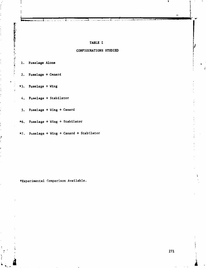
$
,$, 1. Fusalage Alone
I'
:" 2 . Fuselage + Canard
4 '
: *3. Fuselage + Wing * -
4 . Fuselage + Stabilator
TABLE I
CONFIGURATIONS STUDIED
5 . Fuselage + Wing + Canard
*6. Fuselage f Wing + Stabilator
*7 . Fuselage + Wing + Canard + Stabilator
*Experimental Comparison Available.

TABL
E II
LON
GIT
UD
INA
L PI
TC
HIN
G
MOM
ENT
PRE
DIC
TIO
N
dC
~
Sta
tic
Sta
bil
ity
. (-) d
C~
D
ista
nce
to
Nor
mal
F
orc
e C
entr
oid
fr
om M
omen
t C
ente
r -
I P
red
icte
d
Exp
erim
ent a
1
Lin
ear
(CL
=O
)
0.0
44
0
.03
2
1
Sta
bil
ato
r
Vo
rtex
(C
L=
O. 3
) C
anar
d W
ing
Fu
sela
ge
+ W
ing
Fu
sela
ge
+ W
ing
+ S
tab
ila
tor
Fu
sela
ge
+ W
ing
+ C
anar
d +
Sta
bil
ato
r
Dis
tmc
e t
o 1
14 M
AC
from
Hom
ect
Cen
ter
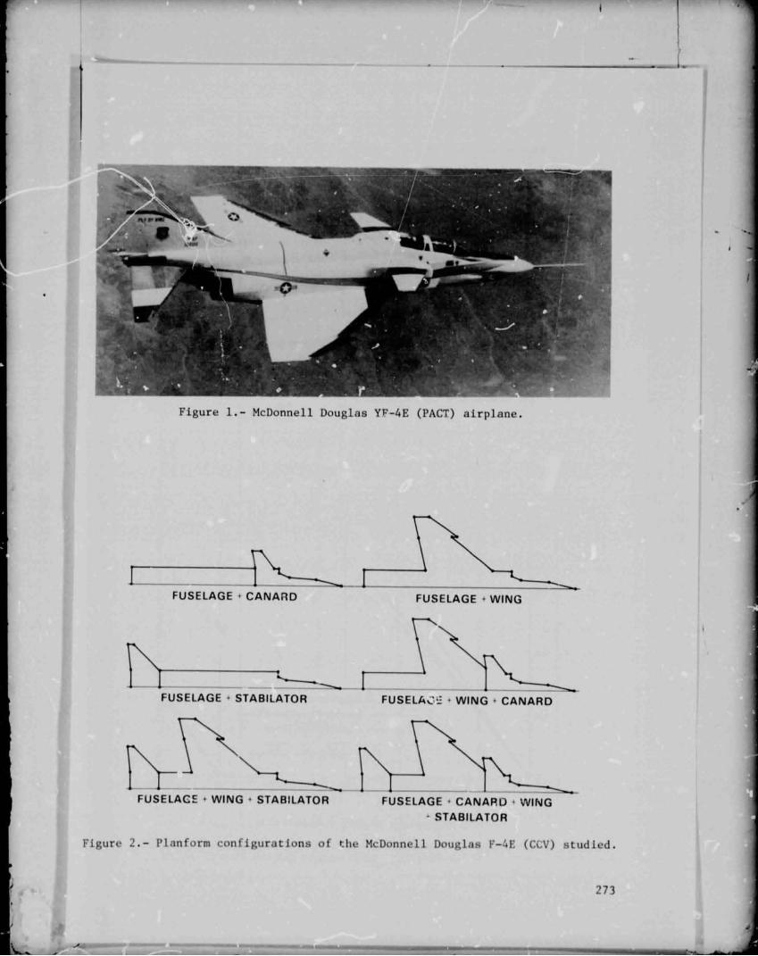
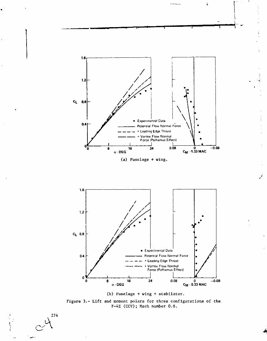
(a) Fuselage + wing.
- 0 8 16 24 0.08 0 -0.08
a - DEG CM - 0.33 MAC
(b) Fuselage + wing + stabilator. Figure 3.- Lift and moment polars for three configurztions of the
F-4E (CCV) ; Mach number 0.6.

a - DEG
Figure 3 . - Concluded.
0 CM - 0.33 MAC
(c) Fuselage + wing + canard + s tabi lator .
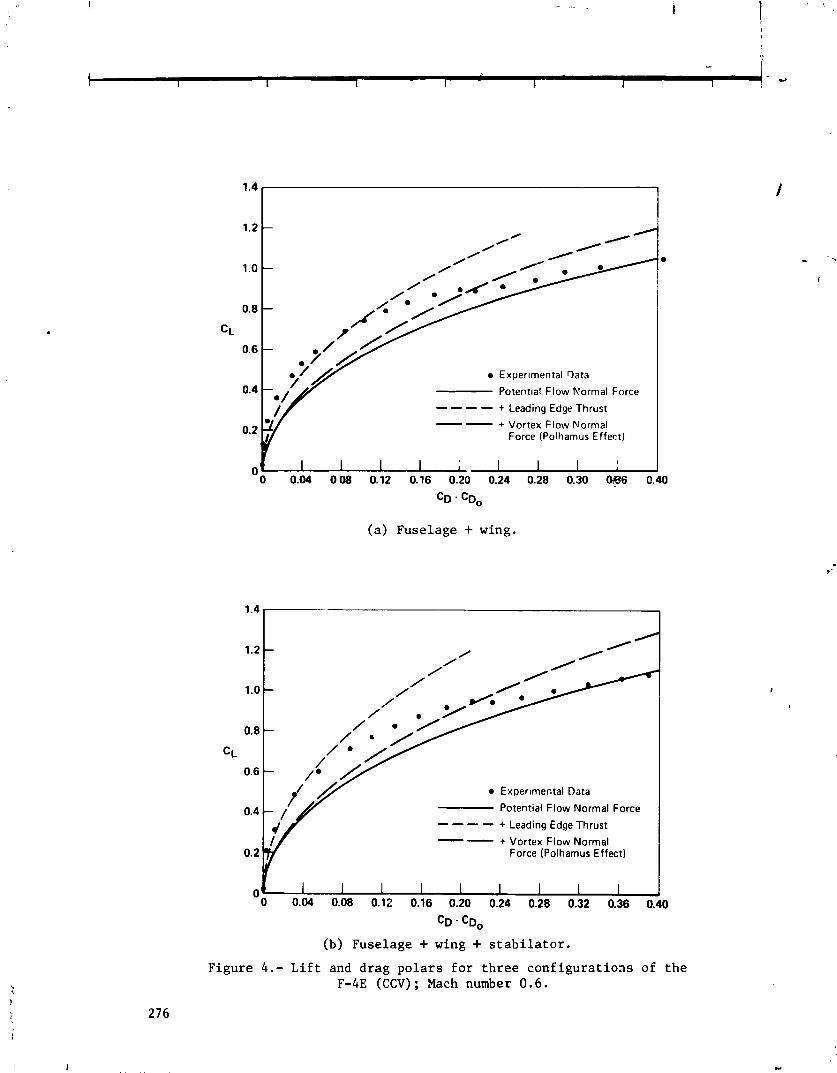
0 Exper~mental Qata
Potential Flow Normal Force ---- + Leading Edge Thrust
-- + Vortex Flow Normal Force (Polhamus Effect)
(a) Fuselage + wing.
1.2 -
1.0 -
0 Exper~mental Data
Potential Flow Normal Force ---- + Leading Edge Thrust -- + Vortex Flow Normal Force (Polhamus Effect)
1 I 1 I I I I I I 0 0.04 0.08 0.12 0.16 0.20 0.24 0.28 0.32 0.36 0,
CD - CD,
(b) Fuselage + wing + stabilator. Figure 4.- Lift and drag polars for three configurations of the
F-4E (CCV) ; Mach number 0.6.
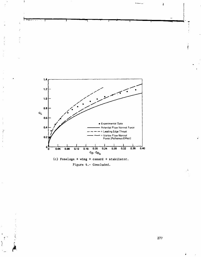
0.8
0.6
Experimental Data
Potential Flow Ncrmal Force
- - - - + Leading Edge Thrust
0.2 y -- + Vortex Flow Normal Force (Polhamus Effect)
( c ) Fuselage + wing + canard + s tabi la tor .
Figure 4 . - Concluded.
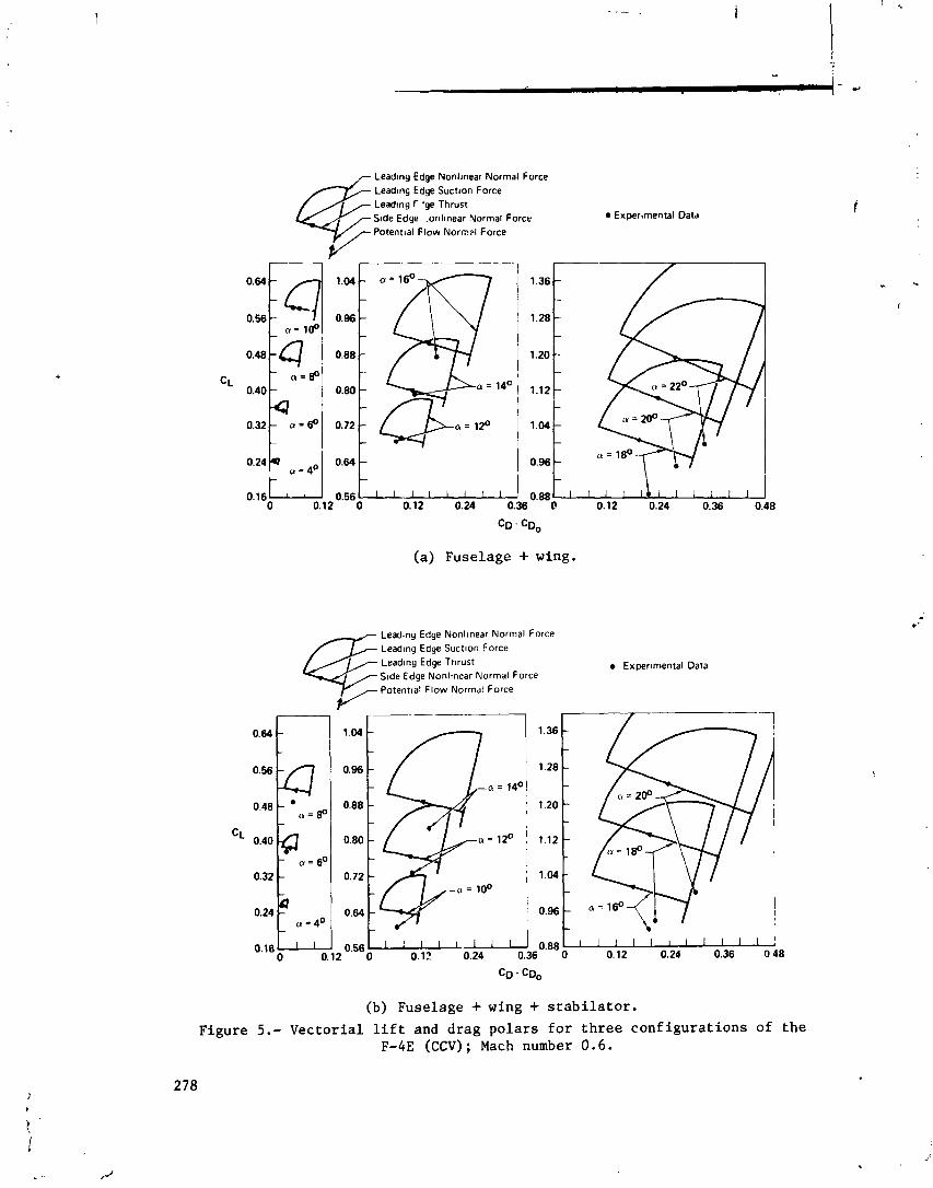
Leadmg Edge Nonlmear Normal Force Lead~nc, Edge Suctton Force Leadmg r 'ge Thrust S ~ d e Edge '.onl~near Normal Force b Expertmental Data
Potentla1 Flow Nornpl Force
(a) Fuselage + wing.
Leadtng Edge Nonltnear Normal Force Lead~ng Edge Suct~on Force Lead~ng Edge Tnrust Expertmental Data S ~ d e Edge Nonltnear Normal Force
/- Potenttal Flow Normal Force
(b) Fuselage + wing + s r a b i l a t o r .
F igure 5.- Vec to r i a l l i f t and d rag p o l a r s f o r t h r e e c o n f i g u r a t i o n s of t h e F-4E (CCV) ; Mach number 0.6.
278

Leading Edge Nonlmear Normal Force
/ & Leading Edge Suctton Force Lead~ng Edge Thrust
Experimental Data r S ~ d e Edge Norl~near Normal Force
Y Potentla1 Flow Normal Force P-
(c) Fuselage + wing + canard + s t a b i l a t o r .
Figure 5 . - Concluded.

Fuselage Fuselage Fuselage Fuselage
+ W1ng + + Wing + + W ~ n g +
t W ~ n g
Canard + Stab~lator Stab~lator Canard
Exper~mental Data
Figure 6.- Vectorial lift and drag polars at medium angles of attack for various configurations of the F-4E (CCV); Mach number 0.6.
GEOMETRY
VECTORS
v - Undeflected Surfaces (a)
v - Deflected Surfaces (b)
VECTORIAL ADDITION
Figure 7.- Vectorial addition of lifting and control surface forces.
280
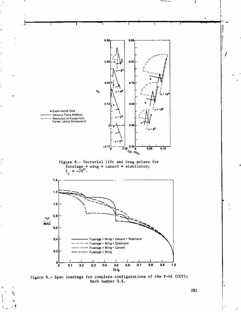
a Experimental Data - Vectorial Force Addit~on - - - Resolut~on of Forces from Vortex Lattice Components
Figure 8.- V e c t o r i a l l i f t and d rag p o l a r s f o r fuse lage + wing + canard + s t a b i l a t o r ; 6 = -20'.
C
0.4 1 Fuselage + Wmg + Canard + Stabilator ---- Fuselage + Wing + Stabilator -- Fuselage + Wing + Canard . 6 --- Fuselage + Wing
Figure 9.- Span loadings f o r complete c o n f i g u r a t i o n s of t h e F-4E (CCV); Mach number 0.6.

0.8 - CPC -- -
MAC 0.6 -
0.4 - Fuselage + Wing + Canard + Stabilator ---- Fuselage + Wing + Stabilator
-- - Fuselage + Wing + Canard - - - - Fuselage + Wing
(a) Wing + partial fuselage.
=!F - MAC
0.6
Fuselage + Wing + Canard + S?abdator - - - - Fuselage + Wing + Canard - - - Fuselage + Canard
(b) Canard + partial fuselage.
Figure 10.- Span loadings for individual elements of various configurations of the F-4E (CCV); Mach number 0 .6 .

Fuselage + Wmg + Canard + Stabilator ---- Fuselage + W ~ n g + Stabilator --- Fuselage + Stabilatcr
- MAC
( c ) S t a b i l a t o r + p a r t i a l f u s e l a g e .
F i g u r e 10.- Concluded.
NEW CONVERGENCE CRITERIA FOR THE VORTEX-LATTICE MODELS
OF THE LEUING-EDGE SEPARATION*
Osamo A. Kandil, Dean T. Mook, and Ali H. Nayfeh
Virginia Polytechnic Institute and State U-!versity
SUMMARY
The convergence criterion for the vortex-lattice technique which deals with
delta wings exhibiting significant leading-edge separation has two rr luirements.
First, the wake must converge to a force-free position for any given number of
discrete vortex elements. Second, the distributed loads must converge as the
number of elements increases. Replacing the vortex sheets representing the
wakes by a system of discrete vortex lines whose positions are determined as
part of the solution (first requirement), one finds that the total loads corn-
puted agree very well with experimental data. But t!le predicted pressure dis-
tributions have some irregularities which are the rvsult of discrete vortex
lines coming close to the lifting surface. Here it is shown that one can
eliminate these irregularities and predict presscre distributions which agree
fairly well with experlmental data (which show r~ome irregularities of their 1 - .. own) by replacing the system of discrete vortex lines with a single concentra-
ted core. This core has a circulation equal tc; the algebraic SUP of the cir.
cvlations around the discrete lines and is located at the centroid of these
lines. Moreover, the second requirement is replaced by the requirement that
the position and strength or' the core converge as the number of elements in-
creases. Because the calculation of the position and strength of the core is
much less involved than the calculation of the loads, this ap?roach has the ad-
ditional desirable feature of requiring less computational time.
INTRODUCTION
A characteristic feature of the flow over wings 52-.ring highly swept, sharp
leading edges is the forration of vortices above suction i;ides in the vicinity
of the leading edges. These vortices roll up in a conicai-like spiral with a
concentrated core. This vortex spiral grows in size and strength as it approaches - *This work was suyported by the NASA Langlev Research Center under Crant No. NSG 1262.
the trailing edge, Below the angle of stall (i.e., the angle at which vortex
bursting occurs), the effect of the leading-edge separation is to increase the
velocity on the suction side of the lifting surface by adding a strong cross-
flow component and hence to increase the aerodynamic loads. Experimental in- .. vestigations, such as those described in refs. 1-7, and numerical investigations, I
such as those described in refs. 8 and 9, confirm these conclusions. Detailed
descriptions of the flow field are alsr given in these references.
Though the experimental results show that the pressure distribution is some-
what influenced by the character (laminar or turbulentj of the boundary layer,
the lift and pitching-moment coefficients are independent of the Reynolds number.
Thus, one expects an inviscid modei of the flow to predict the total loads more
reliably than tne distributed loads. And such has turned out to be the case.
The early attempts to develop an inviscid model of these flows were based
on assumptions of conical flow and/or slender-body theory. These assumptions
are apparently discredited by the experiticntal obseivations; more discuosi2-.n is
given in references 8 and 9.
Subsequent attempts to develop inviscid models did not use these assumptions.
Rehbach (ref. 10) developed a vortex-lattice technique which progressively short-
ens the leading edge of a rectangular wing until a delta win2 is formed. Associ-
ated with this method are questions concerning the second convergence requirement
and the undesirable feature of long computation times; more discussion is given
in refs. 8 and 9. Weber et a1 (ref. 11) developed a technique which uses piece-
wise continuous, quadratic, doublet-sheet distributions. The second requirement
apparently was not considered, and no results showing the computed shapes of the
rolled-up wakes were given.
In a related effort, Suciu and Yorino (ref. 12) developed a technique for
modelling the region adjoining the trailing edge. However, numerical experiments,
as described in refs. 8 and 9, show that the wake adjoining the trailing edge has
very little influence 0.1 the aerodynamic loads.
In the present paper, the question of the convergence of the centroidal
line as the number of discrete elements increaees is considered; and this lime,
instead of the system of discrete vortex lines, is used to comprte the pressure.
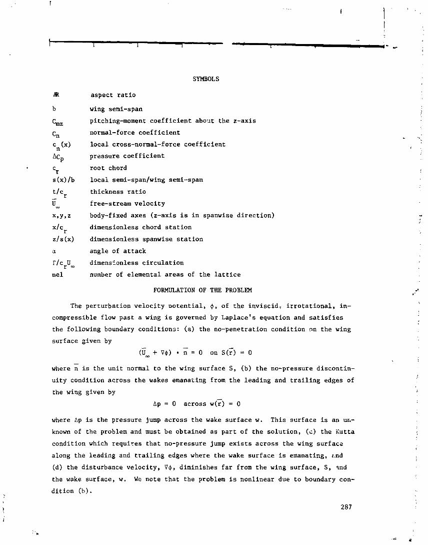
SYMBOLS
r/crUm
nel
aspect ratio
wing semi-span
pitching-moment coefficient about the z-axis
normal-force coefficient
local cross-normal-force coefficient
pressure coefficient
root chord
local semi-spanlwing semi-span
thickness ratio
free-stream velocity
body-fixed axes (z-axis is in spanwise direction)
dimensionless chord station
dimensionless spanwise station
angle of attack
dimensFonless circulation
number of elemental areas of the lattice
FORMULATION OF THE PROBLEM
The perturbation velocity ~otential, 41, of the inviscid* irrotational, in-
compressible flow past a wing is governed by Laplace's equation and satisfies
the following boundary conditions: (a) the no-penetration condition nn the wing
surface given by - - (urn + v+) n = 0 on s(;) = 0
where n is the unit normal to the wing surface S, (b) the no-pressure discontin- uity condition across the wakes emanating from the leading and trailing edges of
the wing given by
~p = o across w(c) = o
where Ap is the pressure jump across the wake surface w. This scrface is an UL-
known of the problem and must be obtained as part of the solution, ( c ) the Kutta
condition which requires that no-pressure jump exists across the wing surfacs
along the leading and trailing edges where the wake surface is emanating, and
(d) the disturbance velocity, V+, diminishes far from the wing surface, S, m d
the wake surface, w. We note that the problem is nonlinear due to boundary con-
dition ( h ) .
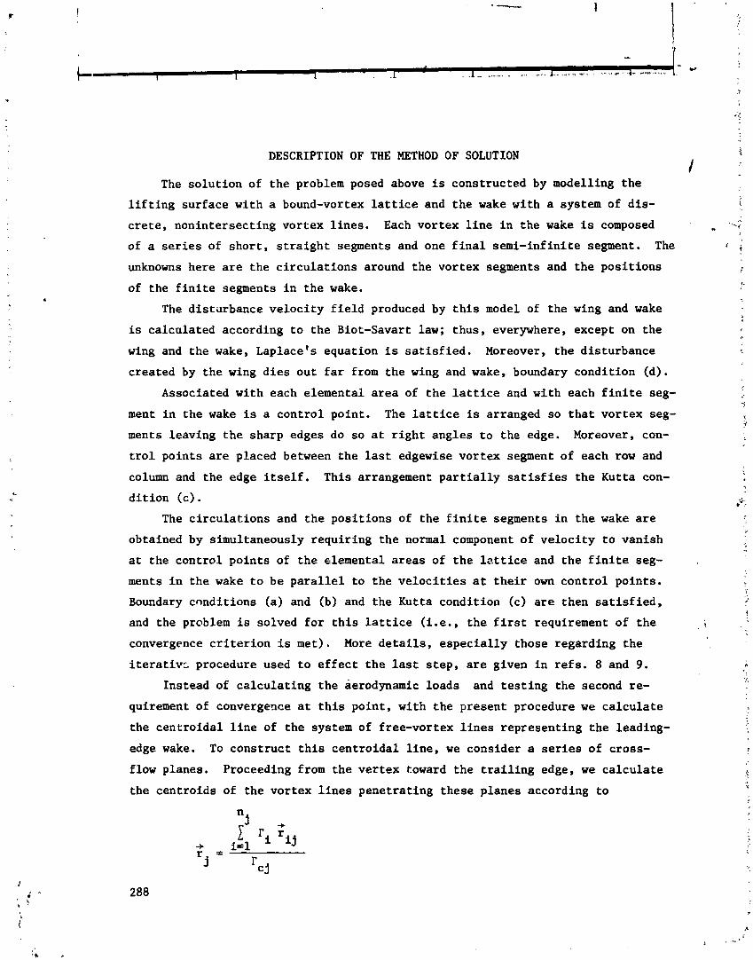
DESCRIPTION OF THE METHOD OF SOLUTION
The solution of the problem posed above is constructed by modelling the
lifting surface with a bound-vortex lattice and the wake with a system of dis-
crete, nonintersecting vortex lines. Each vortex line in the wake is composed
of a series of short, straight segments and one final semi-infinite segment. The
unknowns here are the circulations around the vortex segments and the positions
of the finite segments in the wake.
The distarbance velocity field produced by this model of the wing and wake
is calculated according to the Biot-Savart law; thus, everywhere, except on the
wing and the wake, Laplace's equation is satisfied. Moreover, the disturbance
created by the wing dies out far from the wing and wake, boundary condition (d).
Associated with each elemental area of the lattice and with each finite seg-
ment in the wake is a control point. The lattice is arranged so that vortex seg-
ments leaving the sharp edges do so at right angles to the edge. Moreover, con-
trol points are placed between the last edgewise vortex segment of each row and
column and the edge itself. This arrangement partially satisfies the Kutta con-
dition (c) . The circulations and the positions of the finite segments in the wake are
obtained by simultaneously requiring the normal component of velocity to vanish
at the control points of the elemental areas of the lattice
ments in the wake to be parallel to the velocities at their
Boundary conditions (a) and (b) and the Kutta condition (c)
and the problem is solved for this lattice (i.e., the first
and the finite seg-
own control points.
are then satisfied,
requirement of the
convergence criterion is met). More details, especially those regarding the
iterativc procedure used to effect the last step, are given in refs. 8 and 9.
Instead of calculating the aerodynamic loads and testing the second re-
quirement of convergence at this point, with the present procedure we calculate
the centroidal line of the system of free-vortex lines representing the leading-
edge wake. To construct this centroidal line, we consider a series of cross-
flow planes. Proceeding from the vertex toward the trailing edge, we calculate
the centroids of the vortex lines penetrating these planes according to

where r is taken t o be t h e c i r c u l a t i o n around t h e c e n t r o i d a l l i n e between t h e c j
jth and ( j + l ) th p laner and i t given by
-+ -+ r 3 is t h e p o s i t i o n of t h e c e n t r o i d i n t h e j th p lane , r i s t h e p o s i t i o n of t h e
i j i n t e r s e c t i o n of t h e ith v o r t e x l i n e wi th t h e j th p lane , r, i s t h e c i r c u l a t i o n
I
around t h e ith l i n e , and n is t h e number of l i n e s p e n e t r a t i n g t h e j th plane. j
More l i n e s p e n e t r a t e t h e p lanes near t h e t r a i l i n g edge than those near t h e ver-
tex; thus , .I' inc reases toward t h e t r a i l i n g edge. c j
Now, t h e number of elements is inc reased and new c e n t r o i d a l l i n e s a r e ca l -
cu la ted u n t i l t h e changes i n I' and f a l l w i t h i n p resc r ibed to le rances . A t c j j
t h i s p o i n t , t h e second requirement of t h e convergence c r i t e r i o n is m e t .
Only when both requirements a r e met, do we c a l c u l a t e t h e aerodynamic l o a d s
and p ressure d i s t r i b u t i o n . The d e t a i l s f o r c a l c u l a t i n g t h e loads a r e given i n
r e f . 8. The numerical r e s u l t s below show, f o r t h e examples being considered a t
l e a s t , t h a t t h e c e n t r o i d a l l i n e s converge t o a p o s i t i o n which i s very c l o s e t o
t h e exper imental ly determined p o s i t i o n of t h e c o r e , t h a t t h e t o t a l l o a d s agree
very w e l l wi th t h e experimental d a t a , and t h a t t h e p ressure d i s t r i b u t i o n s a g r e e
f a i r l y w e l l wi th t h e experimental da ta .
NUMERICAL EXAMPLES
Figures 1 and 2 show t h e a c t u a l c a l c u l a t e d p o s i t i o n s of t h e f ree -vor tex
l i n e s f o r two d e l t a wings. The plan view a l s o shows t h e bound-vortex l a t t i c e .
And t h e t h r e e dimensional view shows t h e f ree-vor tex l i n e s , t h e i r c e n t r o i d a l
l i n e , and t h e t r a c e of t h e s p i r a l v o r t e x s h e e t . A l l t h e fol lowing r e s u l t s a r e
assoc ia ted wi th t h e s e two wings.
Figures 3 and 4 show t h e convergence of t h e c i r c u l a t i o n s around t h e cen-
t r o i d a l l i n e . And f i g u r e s 5-8 show t h e convergence of t h e p o s i t i o n of t h e cen-
t r o i d a l l i n e and t h e c l o s e agreement between t h e p o s i t i o n of t h e c a l c u l a t e d l i n e
and t h e exper imental ly determined p o s i t i o n of t h e v o r t e x core .
Figures 9 and 1 0 show t h e convergence of t h e t o t a l loads c a l c u l a t e d by us ing
the system of d i s c r e t e l i n e s and by us ing t h e c e n t r o i d a l l i n e as a f u n c t i o n of
the number of e l e n e n t s ( n e l ) . These r e s u l t s a r e compared w i t h those obta ined by
t h e leading-edge-suction analogy ( r e f . 13) and w i t h experimental d a t a . We n o t e

that there is a considerable difference in the experim~ntally determined normal-
force coefficients in figure 10.
Figures 11 and 12 show comparisons of the predicted cross-load coefficients
and experimental data. And figures 13-16 show comparisons of the predicted
pressure distributions at several chordwise stations with those obtained by
another method (ref. 11) and with experimental data. We note that the shape and
size of the suction peak on the upper surface under the vortex differ from one
experiment to another, depending on how thick the wing is and on whether the
boundary layer is laminar or turbulent (refs. 5, 6, and 14).
CONCLUDING REMARKS
The second requirement of coniiergence is based on the centroidal line of
the free-vortex lines representing the wake. Using this requirement greatly
reduces the computational time. The position of the centroidal line compares
very well with that of the vortex core. The centroidai line can also be used to
calculate the total and distributed aerodynamic loads with gooa accuracy. This
results in more reduction in the computational time and smoothing of the peaks
produced by using many discrete lines.
Peckham, D. H., "Low-Speed Wind-Tunnel Tests on a Series of Uncambered
Slender Pointed Wings with Sharp Edges'!, R & M No. 3186, Brit. ARC, 1961.
Bergesen, A. J., and Porter, J. D., "An Investigation of the Flow Around
Slender Delta Wings with Leading-Edge Separation", Princeton University,
Department of Aeronautical Engineering, Report No. 510, May 1960.
Nangia, R. K., and Hancock, G. J., "Delta Wings with Longitudinal Camber
at Low speed", C.P. No. 1129, Brit. ARC, 1970.
Marsden, D. J., Simpson, R. W., and Rainbird, B. E., " ~ n Investigation into
the Flow over Delta Wings at Low Speeds with Leading-Edge Separation", The
College of Aeronautics, Cranfield, Report No. 114, February 1958.
Hummel, D., "Study of the Flow Around Sharp-Edged Slender Delta Wings with
Large Angles of ~ttack", NASA TT F-15,107, September 1973.
Hummel, D. and Rcdeker, G., "Experimental Determination of Bound Vortex
Lines and Flow in the Vicinity of the Trailing Edge of a Slender Delta
Wing", NASA TT F-15,012, August 1973.
Bartlett, G. E.: and Vidal, R. K., "Experimental Investigation of Influextse
of Edge Shape on the Aerodynamic Characteristics of Low-Aspect-Ratio Wings
rtt Low Speeds", Journal of Aeronautical Sciences, Vol. 22, No. 8, August
1.955, pp. 517-533.
Kandil, 0. A. , "Prediction of the Steady Aerodynamic Loads on Lifting Sur- faces having Sharp-Edge Separation", Ph.D. Dissertation, Engineering Science
arld Mechanics Department, Virginia Polytechnic Institute and State Univer-
sf ty, December 1974.
Kondil, 0. A., Mook, D. T., and Nayfeh, A. H., "Nonlinear Prediction of the
Aerody~amic Loads on Lifting Surfaces. AIAA Paper No. 74-503, June 1974.
Also :-n Journal of Aircraft, Vol. 13, No. 1, January 1976, pp. 22-28.
R.enbach, C., "Numerical Investigation of Vortex Sheets Issuing from Separa-
tion Line near the Leading Edge", NASA TT F-15, 530, 1974.
Weeter, J. A., Brune, G. W., Johnson, F. T., Lu, P., and Rubbert, P. E., "A
T,~ree-Dimt.,sional Solution of Flows Over Wings with Leading-Edge-Vortex
Separation", NASA SP-347, Part 11, 1975, pp. 1013-1032.

12. Suciu, E. O., and Morino, L., "A Nonlinear Finite-Element Analysis of Wings
in Steady Incompressible Flows with Wake Roll-Up", AIAA Paper No. 76-64, I January 1976.
13. Polhamus, E. C., "A Concept of the Vortex Lift of Sharp-Edge Delta Wings
Based on a Leading-Edge-Suction Analogy", NASA TN D-3767, December 1966. .. 14. Smith, J. H. B., "Improved Calculations of Leading-Edge Separation from I
Slender, Thin, Delta Wings", Proc. Roy. Soc. A. 306, 1968, pp. 67-90.

Figure 1 . - A typical solution of the wake shape for a de l ta wing with R = 1. 12x12 l a t t i c e .
Figure 2.- A typical solution of the wake shape for a de l ta wing with 1R = 1.46. 12x12 l a t t i c e .

Figure 3 . - Variation of c irculat ion along the vortex core of a delta wing with Ai = 1. a = 15O.
6 .4 5
CURVE NO UTTlCE 4 ?l
2
.3 1
.2
.I
n
Figure 4.- Variation of c irculat ion along the vortex core of a de l ta wing w i t t i 1R = 1.46. a = 14'.

v PECKHAM (REF. I )
0 BERESEN AND PORTER (REF. 2 1 .8 -PRESENT METHOD
CURVE NO. LATTICE
Figure 5.- Spanwise position of vortex-core path on a delta wing with At = 1. a = 15'.
- v PECKHAM (REF I 1 v
0 BERGESEN AND PORTER (REF. 2 1 -PRESENT METHOO 0 - CURVE NQ LA1 TlCE
I 2
- 3 4
-
Figure 6 . - Height of v~rtex-core path on a delta wing with 1R = 1. ci = 15'.
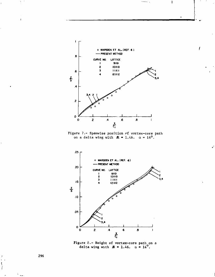
I 0 MARSEN ET AL. (REF. 4
I- - PRESENT METHOD .8
I CURVE NO. LATTICE I 9x9
Figure 7 . - Spanwise position cf vortex-core path on a de l ta wing with R = 1.66. a = 14'.
0 MARSOEN ET AL. (REF. 4 -PRESENT METHOD
CURVE I 2 3 4
NO. LATTICE 1
2 3,4
Figure ti.- Height of vortex-core path on o del ta wing wlth P = 1.46. a = 14'.
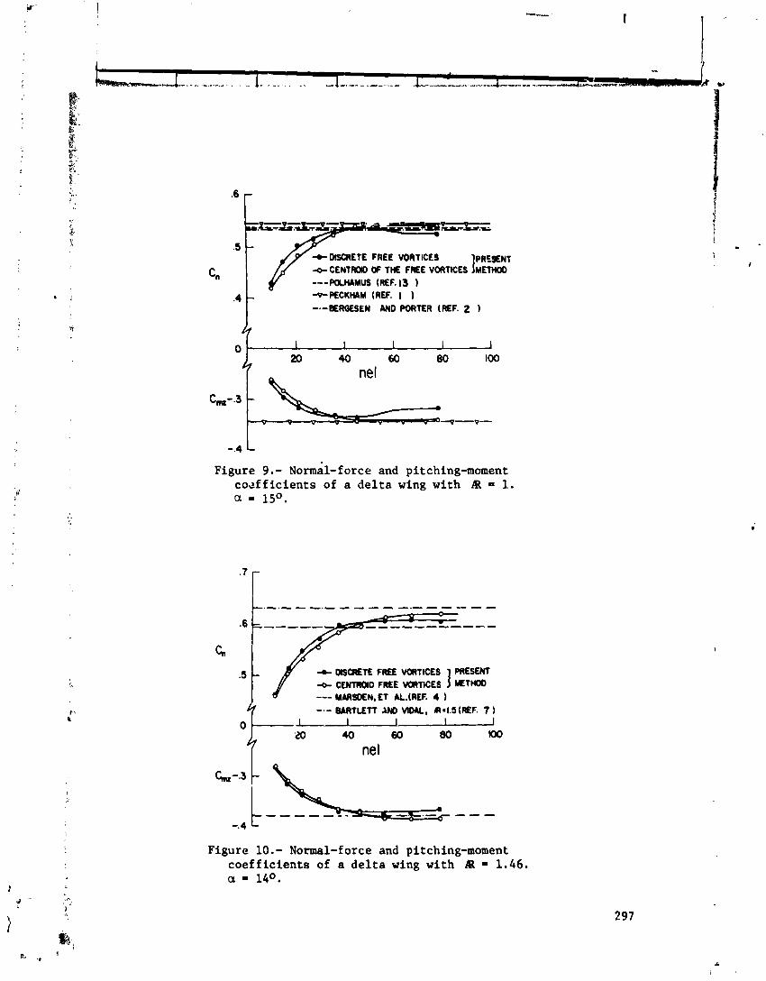
6 DISCRETE FREE VORTICES
C" +PECKHAM (REF. I I -.-BERMSEN AND PORTER (REF. 2 1
Figure 9. - ~ormal- force and pitching-moment co~fficients of a delta wing with At = 1. a = 15O.
'I-
+ MSCRETE FREE VORTICES PRESENT
--- MARSDEN, E l &.(REF. 4 )
I + CENTROID FREE MRTlCES mTH(XJ
-.- BARTLETT AN0 V I M , RsI.5 (REF. 7 1
Figure 10.- Normal-force and pitching-moment coefficients of a delta wing with IEL = 1.46. a = 14O.
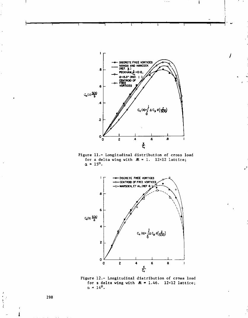
Figure 11.- Longitudinal for a de l ta wing with
distribution of cross load 1R = 1. 12x12 l a t t i c e ;
FREE VORTICES -CENTRaD OF FREE VCftTKXS -0- MARSDEN, € 1 AL.(REF 4
Figure 12.- Longitudinal distribution of cross load for s del ta wing with R = 1.46. 12x12 l a t t i c e ; ci = 14O.
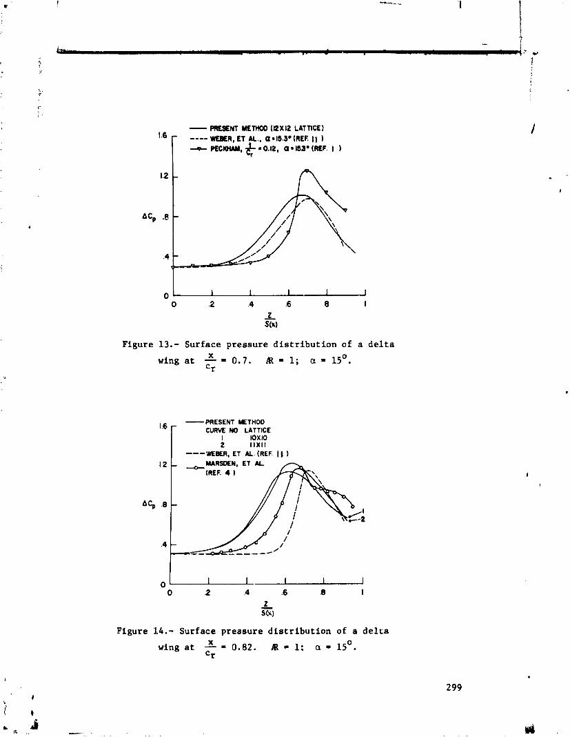
Figure 13.- Surface pressure distribution of a de l ta X wing a t - = 0 .7 . A I R 1; a = 15'. r
- PRESENT METHOD CURVE NO LATTICE
I mI0 2 11x11 --- WEER, E l M. (REF. 11
MARSDEN, E l AL.
Figure 14.- Surface pressure distribution of a delra X wing a t - = 0.82. R = 1: a = 15'. = r
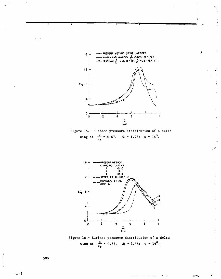
. - S A)
Figure 15.- Surface pressure distribution of a delta X wing at - = 0.67. 1R = 1.46; a = 14'. Cr
PRESENT METHOD C U M NO LATTICE
WEBER, E l AL. (REF.
3 2 I
Figure 16.- Surface pressure distrilution of a delta X wing at - = 0.83. I% = 1.46; a = 14'. Cr

ARRANGEMENT OF VORTM LATTICES
Fred R. DeJarnette North Carolina State University
SUMMARY
A new method is developed for solving the lifting-surface equation for thin wings. The solution requires the downwash equation to be in the form of Cauchy integrals which can be interpreted as a vortex lattice with the posi- tions of the vortices and control points dictated by the finite sum used to ap- proximate the integrals involved. Lan's continuous loading method is employed for the chordwise integral since it properly accounts for the leading-edge singularity, Cauchy singularity, and Kutta condition. Unlike Lan, the spanwise loading is also continuous and the Cauchy singularity in the spanwise integral is also properly accounted for by using the midpoint trapezoidal rule and the theory of Chebychev polynomials. This techd;- yields the exact classical so- lution to Prandtl's lifting-line equation. The solution to the lifting-surface equation for rectangular wings was found to compare well with other continuous loading methods, but with much smaller computational times, and it converges :aster than other vortex lattice methods.
INTRODUCTION
The vortex lattice method has proven to be a useful technique for calcula- ting the aerodynamic characteristics of complete configurations as well as wings. In the conventional vortex lattice method (VLM), the planform is di- vided into a number of elemental panels, and a horseshoe vortex is placed at the local quarter-chord of each panel. The boundary condition is satisfied at the local three-quarter chord of each elemental panel (called control points) by requiring the flow to be tangent to the surface there. The strengths of the horseshoe vortices are determined by solving the matrix equation formed from the tangent-flow boundary conditions. Then, the aerodynamic characteristics are calculated by summing the results from each elemental panel. A complete description of the conventional vortex lattice method is given by Margason and Lamar in reference 1.
Although reasonable results are obtained by the conventional VLM, Lan (ref. 2) listed the following deficiencies: 1) The method used to compute the in- duced drag implies that the leading-edge thrust is distributed over the chord
* This research is supported by the U. S. Army Research Office, Research Triangle Park, N. C., under Grant Number DAAG29-764-0045,
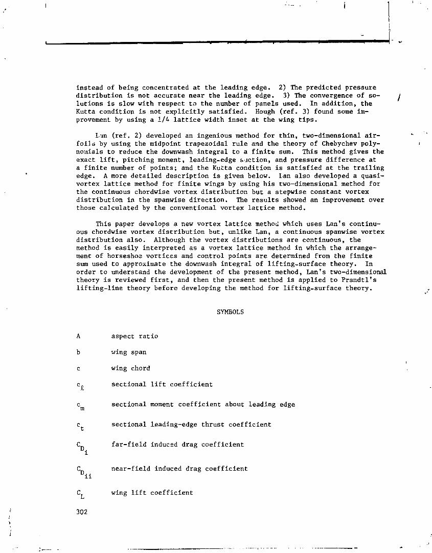
i n s t e a d of being concentra ted at t h e l ead ing edge. 2) The pred ic ted p r e s s u r e d i s t r i b u t i o n is no t a c c u r a t e n e a r t h e l ead ing edge. 3) The convergence of so- 1 l u t i o n s is slow wi th r e s p e c t t o t h e number of panels used. I n a d d i t i o n , t h e Kutta cond i t ion is no t e x p l i c i t l y s a t i s f i e d . Hough ( r e f . 3) found some i m - provemen!. by using a 1 / L l a t t i c e width i n s e t a t t h e wing t i p s .
L m ( r e f . 2 ) developed an ingenious method f o r t h i n , two-dimensional a i r - - f o i l s by us ing t h e midpoint t r a p e z o i d a l r u l e and t h e theory of Chebychev poly- I
no:nials t o reduce t h e downwash i n t e g r a l t o a f i n i t e sum. This method g ives t h e exact l i f t , p i t c h i n g moment, leading-edge s ~ x t i o n , and p r e s s u r e d i f f e r e n c e a t a f i n i t e number of p o i n t s ; and t h e Kutta cond i t ion i s s a t i s f i e d a t t h e t r a i l i n g edge. A more d e t a i l e d d e s c r i p t i o n is given below. Lan a l s o developed a quasi- vor tex l a t t i c e method f o r f i n i t e wings by us ing h i s two-dimensional method f o r t h e continuous chordwise v o r t e x d i s t r i b u t i o n but a s t epwise cons tan t vor tex d i s t r i b u t i o n i n t h e spanwise d i r e c t i o n . The r e s u l t s showed an improvement over those c a l c u l a t e d by t h e convent ional v o r t e x l a t t i c e method.
This paper develops a new v o r t e x l a t t i c e method which uses Lan's continu- ous chordwise v o r t e x d i s t r i b u t i o n b u t , u n l i k e Lan, a continuous spanwise vor tex d i s t r i b u t i o n a l s o . Although t h e v o r t e x d i s t r i b u t i o n s a r e continuous, t h e rcethod i s e a s i l y i n t e r p r e t e d a s a v o r t e x l a t t i c e method i n which t h e arrange- ment of horseshoe v o r t i c e s and c o n t r o l p o i n t s a r e determined from t h e f i n i t e sum used t o approxin~ate t h e downwash i n t e g r a l of l i f t i n g - s u r f a c e theory. I n o rder t o understand t h e development of t h e p resen t method, Lan's two-dimensional theory is reviewed f i r s t , and then t h e p resen t method is app l ied t o P r a n d t l ' s l i f t i n g - l i n e theory before developing t h e method f o r l i f t i n g - s u r f a c e theory.
a spec t r a t i o
wing span
wing chord
s e c t i o n a l l i f t c o e f f i c i e n t
s e c t i o n a l moment c o e f f i c i e n t about l ead ing edge
s e c t i o n a l leading-edge t h r u s t c o e f f i c i e n t
f a r - f i e l d induced drag c o e f f i c i e n t
near - f i e ld induced drag c o e f f i c i e n t
wing l i f t c o e f f i c i e n t
C~ a
CM
CM C1
Cs
C~
e
e n f
Ki j k!2
M
M-1
n
N
NLR
S
L r n
vm
W
X
X acs 'ac
Y
lift-curve slope, per radian except when ncted otherwi.ie
wi g pitching moment coefficient about leading edge
pitching-moment curve slope, per radiac
leading-edge suction parameter
wing leading-edge thrust coefficient
far-field spanwise efficiency
near-field efficiency factor,
parameter defined by eq. (26)
factor, cLL/c D ,
number of trailing vortices over whole wing span
number of spanwise control points over whole span
summational integer
number of chordwise vortices and control points
National. Aerospace Laboratory, Netherlands
wing planform area
vortex lattice method
freestream velocity
downwash velocity, referred to VW and positive upwards
chordwise coordinate measured from leading zdge in direction of VW
sectional and wing aerodynamic center locations, respectively
spanwise coordinate, positive to the right
vertical coordinate of mean camber line
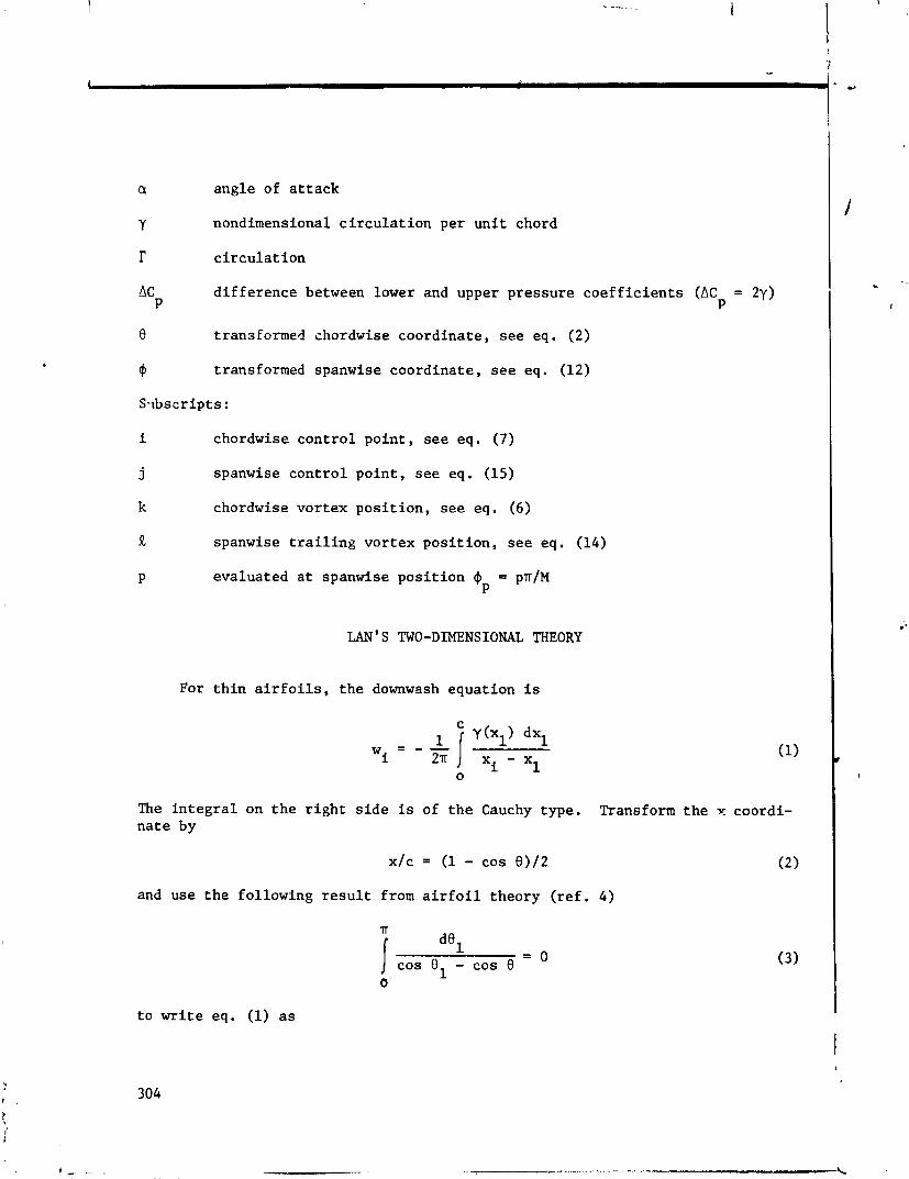
a angle of attack
Y nondimensional circulation per unit chord
l- circulation
AC difference between lower and upper pressure coefficients (AC = 2y) P P
0 transformed chordwise coordinate, see eq. (2)
@ transformed spanwise coordinate, see eq. (12)
Svbscripts :
i chordwise control point, see eq. (7)
j spanwise control point, see eq. (15)
k chordwise vortex position, see eq. (6)
R spanwise trailing vortex position, see eq. (14)
P evaluated at spanwise position 41 = pr/M P
LAN'S TWO-DIMENSIONAL THEORY
For thin airfoils, the downwash equation is
The integral on the right side is of the Cauchy type. Transform the Y coordi- nate by
x/c = (1 - cos 8 ) / 2 (2)
and use the following result from airfoil theory (ref. 4)
IT
dOl 1 cos el - cos 0 = 0 (3)
0
to write eq. (1) as

~ ( 0 ~ ) s i n dB1 [y(0,) s i n 5 - y(0) s i n O]dB1
i - L / 2n cos - cos 0 A] 2TT cos el - Cos €l ( 4 )
0 0
Lan ( r e f . 2 ) used t h e theory of Chebychev pol.ynomials t o show t h a t
N - N ~ f o r i = 0
1 f o r i f 0, N cos ek - cos 0 k=i i
when t h e v o r t e x p o s i t i o n s a r e
and t h e c o n t r o l p o i n t s a r e loca ted a t
Then t h e i n t e g r a l i n eq. (4) can be reduced t o a f i n i t e sum by us ing t h e mid- po in t t r a p e z o i d a l r u l e ( r e f . 5) and eq. (5) t o o b t a i n
N y s i n Ok - yi s i n 0 w '--- k i i 2TT * k=1 1 c o s e -case
k i
N y(0) s i n 0 , i = 0
N yk s i n 0 = - - I I 2 N k = l C O S Bk
, i f 0 , N (8)
N - 1 i m y(8) s i n 0 , i = N
However,
l i m y (0 ) s i n 0 = 4 CS 0-4
where C is t h e leading-edge s u c t i o n parameter and s i n c e t h e Kutta cond i t ion re- q u i r e s ?hat y (n) = 0,
l i m y ( 0 ) s i n 0 = 0 8-m
Unlike t h e conventional vor tex l a t t i c e method, t h e Cauchy s i n g u l a r i t y , leading-edge square-root s i n g u l a r i t y and t h e Kutta cond i t ion a r e p roper ly ac- counted f o r i n t h i s method. Equation (8) can be solved wi th i # 0 t o o b t a i n
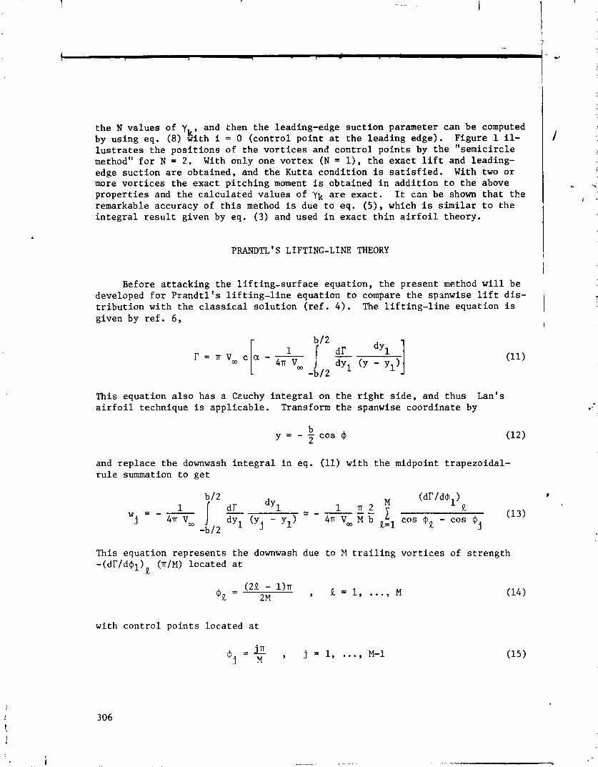
t h e N va lues of y and then t h e leading-edge s u c t i o n parameter can be computed k '
by using eq. (8) wi th i = 0 ( c o n t r o l p o i n t a t t h e l ead ing edge). Figure 1 il- l u s t r a t e s t h e p o s i t i o n s of t h e v o r t i c e s and c o n t r o l p o i n t s by t h e " semic i rc le method" f o r N = 2 . With only one v o r t e x (N = I ) , t h e exac t l i f t and leading- edge s u c t i o n a r e ob ta ined , and t h e Kutta cond i t ion is s a t i s f i e d . With two o r more v o r t i c e s t h e exact p i t c h i n g moment is obtained i n a d d i t i o n t o t h e above p r o p e r t i e s and t h e c a l c u l a t e d va lues of yk a r e exac t . It can be shown t h a t t h e remarkable accuracy of t h i s method i s due t o eq. ( 5 ) , which is s i m i l a r t o t h e i n t e g r a l r e s u l t given by eq. (3) and used i n exac t t h i n a i r f o i l theory.
PRkWTL ' S LIFTING-LINE THEORY
Before a t t a c k i n g t h e l i f t i n g - s u r f a c e equat ion, t h e p resen t method w i l l be developed f o r P r a n d t l f s l i f t i n g - l i n e equat ion t o compare t h e spsnwise l i f t d i s - t r i b u t i o n wi th t h e c l a s s i c a l s o l u t i o n ( r e f . 4 ) . The l i f t i n g - l i n e equat ion i s given by r e f . 6 ,
This equat ion a l s o has a Ceuchy i n t e g r a l on t h e r i g h t s i d e , and thus Lan's a i r f o i l technique is a p p l i c a b l e . Transform t h 2 spanwise coord ina te by
and r e p l a c e t h e downwash i n t e g r a l i n eq. (11) wi th t h e midpoint t r apezo ida l - r u l e summation t o g e t
This equat ion r e p r e s e n t s t h e downwash due t o M t r a i l i n g v o r t i c e s of s t r e n g t h -(dT/dml) II (TIM) loca ted a t
with c o n t r o l p o i n t s loca ted a t
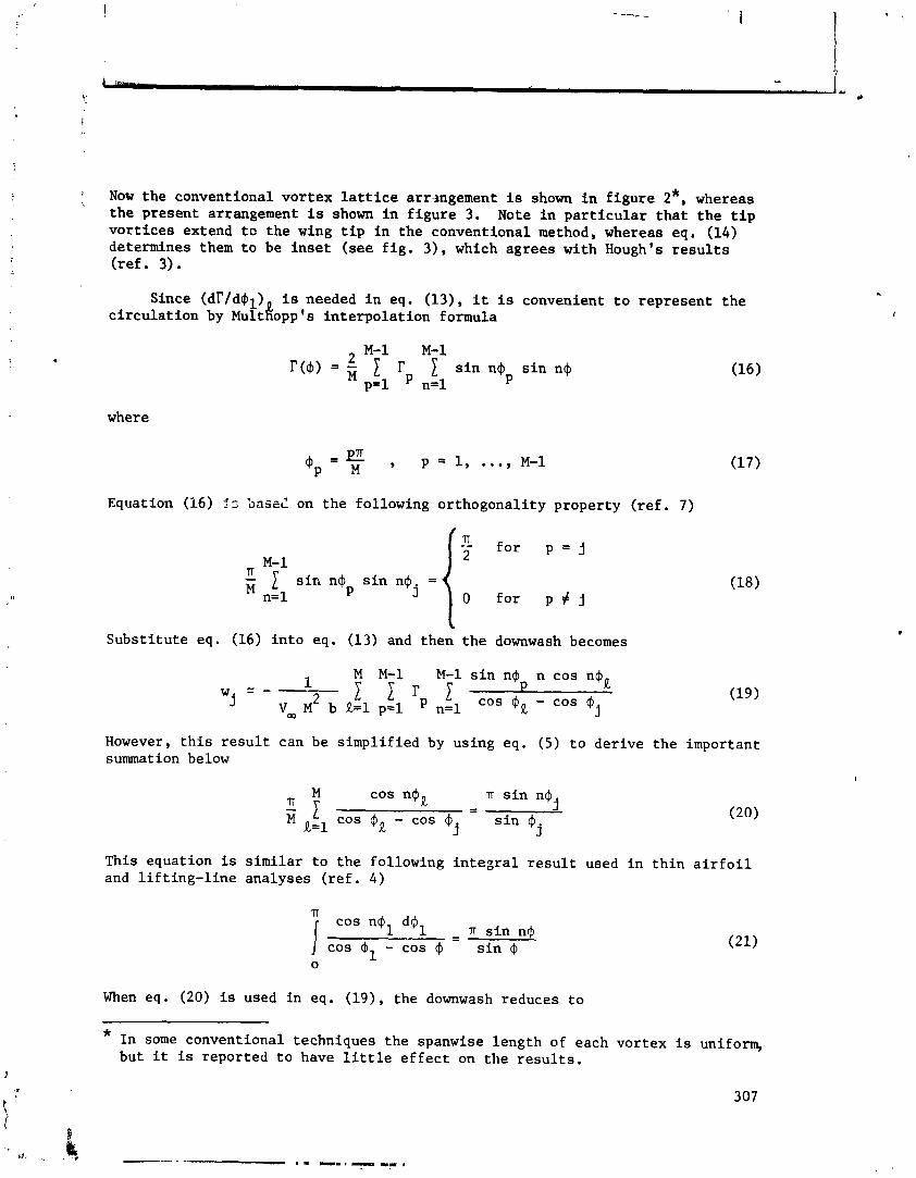
1 Now t h e convent ional v o r t e x l a t t i c e arrmgement is shown i n f i g u r e 2*, whereas t h e p resen t arrangement i s shown i n f i g u r e 3. Note i n p a r t i c u l a r t h a t t h e t i p v o r t i c e s extend t o t h e wing t i p i n t h e convent ional method, whereas eq. (14) determines them t o be i n s e t ( see f i g . 3 ) , which agrees wi th Hough's r e s u l t s ( r e f . 3) .
Since (dl'/dgl) i s needed i n eq. (13), it is convenient t o r e p r e s e n t t h e c i r c u l a t i o n by ~ultl!opp's i n t e r p o l a t i o n formula
where
Equation (16) f ; S a s d on t h e fol lowing o r thogona l i ty p roper ty ( r e f . 7)
S u b s t i t u t e eq. (16) i n t o eq. (13) and then t h e downwash becomes
1 M M-1 M - l s i n n $ n c o s n $
w " - R 2 I- cos rnP - cos 4 (19)
j v M b R-1 p = l n = l R j
However, t h i s r e s u l t can be s i m p l i f i e d by us ing eq. (5) t o d e r i v e t h e important summation below
M cos n'gR T s i n n, - - j LL I cos , - cos @ ~ = l R j s i n $
j
This equat ion i s s i m i l a r t o t h e fol lowing i n t e g r a l r e s u l t used i n t h i n a i r f o i l and l i f t i n g - l i n e ana lyses ( r e f . 4 )
71 cos n,
1 d'l n s i n n$ - \ cos - cos 4 s i n 4 0
When eq. (20) is used i n eq. (19) , t h e downwash reduces t o
* I n some conventional techniques t h e spanwise l eng th of each v o r t e x i s uniform, but it is repor ted t o have l i t t l e e f f e c t on t h e r e s u l t s .
307

F i n a l l y , s u b s t i t u t e eq. (22) f o r t h e downwash i n eq. (11) and apply t h e r e s u l t - i n g equat ion a t t h e spanwise l o c a t i o n s mj(j = 1, ..., M-1) t o o b t a i n a matr ix equat ion f o r t h e (M-1) va lues of r . Then, t h e l i f t , p i t c h i n g moment, and in- duced drag can be c a l c u l a t e d by re$ucing t h e spanwise i n t e g r a l s t o a f i n i t e sum through t h e midpoint t r a p e z o i d a l r u l e . However, t h e midpoint t r a p e z o i d a l r u l e g ives e x a c t l y t h e same r e s u l t f o r t h e spanwise i n t e g r a l s a s t h e i n t e g r a l i t s e l f when eq. (16) is used f o r r . To prove t h i s a s s e r t i o n , consider t h e spanwise i n t e g r a l f o r t h e l i f t . Using eq. ( l 6 ) , t h e exact i n t e g r a l r e s u l t i s
b/2
I IT M- 1 C v - = - L cob b T ~ Y = 1 r P s i n 3 P
p = l -b/2
whereas t h e midpoint t r a p e z o i d a l r u l e g i v e s
which is t h e same a s t h e exact i n t e g r a l r e s u l t above. I n ob ta in ing t h i s last r e s u l t , t h e fol lowing o r thogona l i ty proper ty was app l ied
The i n t e g r a l s f o r t h e induced drag a r e handled i n a s i m i l a r f ash ion .
The remarkable f e a t u r e of t h e p resen t method i s t h a t t h e r e s u l t s a r e iden- t i c a l t o t h e c l a s s i c a l s o l u t i o n of P r a n d t l ' s l i f t i n g - l i n e equat ion when a f i n i t e number c f terms i.s used i n t h e Four ie r s e r i e s f c r I' ( r e f . 4 ) . The suc- cess of t h e p resen t method is a t t r i b u t e d t o t h e l o c a t i o n of t h e spanwise vor- t i c e s and c o n t r o l p o i n t s , t h e summational r e s u l t of eq. (20) , and t h e accuracy of t h e midpoint t r a p e z o i d a l r u l e f o r t h e spanwise i n t e g r a l s .
Figure 4 i l l u s t r a t e s t h e convergence of t h i s method compared wi th t h e con- v e n t i o n a l VLM f o r C h of r e c t a n g u l a r and e l l i p t i c a l planforms wi th an aspec t r a t i o of 2n. P r a n d t l ' s l l f t i n g - l i n e theory r e q u i r e s t r a i l i n g v o r t i c e s and spanwise c o n t r o l p o i n t s , but no chordwise c o n t r o l p o i n t s a r e needed because t h e theory assumes t h e downwash is cons tan t i n t h e chordwise d i r e c t i o n . Therefore , I
t h e c o n t r o l p o i n t s a r e placed on , ~ l e "bound" vor tex f o r both methods. I n t h i s way, t h e accuracy of t h e spanwise v o r t e x arrangement can be t e s t e d without t h e in f luence of t h e l o c a t i o n of chordwise c o n t r o l p o i n t s . Figure 4 shows t h a t t h e

conventional VLM converges slowly and C L ~ does not appear to approach the cor- rect limit when the curve is extrapolated to an infinite number of trailing vortices, M*(l/M+O), On the other hand, the present method converges very quickly and approaches the correct limit. As in the classical solutions, only one horseshoe vortex (M=2) is needed to obtain the exact Cb for the elliptical planform in Prandtl's lifting-line theory. Figure 5 illustrates the effect of the nunber of trailing vortices on the spanwise efficiency factor used in the induced drag. Here again, the co~~ventional VLM converges slowly and does not appear to approach the correct limit, whereas the present method converges quickly and approaches the correct limit.
LIFTING -SURFACE THEORY
For simplicity, the present method is developed here for rectangular wings. The downwash equation from lifting-surface theory is usually given by one of the two following integrals (ref. 6)
Equation (23) contains the Mangler-type integral, and therefore, is not suitable for the present method. Equation (24), however, contains Cauchy-type integrals and is therefore in the form to apply a combination of Lan's two-dimensional method for the chordwise integration and the lifting-line method developed above for the spanwise integration. Note that the integrand of eq. (24) represents the downwash at (x,y) due to half of a horseshoe vortex as shown below.

With y = -b cos $12 and xbc = (1 - cos 8)/2, replace both integrals in eq. (24) with the midpoint trapezoidal-rule sum to get
where
2 J(cr s ok - cos oil2 + A (COS m, - cos mi) 2
Kifk, 5 1 + cos ek - COS 8 i The control points are located at
in 8, = , i = 1 . N (chordwise)
and
- - , j - 1 , m j M . . . , M-1 (spanwise) and the "joint" in the horseshoe vortices are located at
8 = k
(2k - , k = 1 . . . , N (chordwise) 2N
and
(21 - 1)n $, = 2M , R = 1, . . . , M (spanwise)
#
where Yp,k 'epresents the unknown circulations per unit chord at 8k and mp = ~TT/M. Substitute eq. (31) into eq. (25) to obtain the final f ~ r n of the downwash as
- TTC M N M-1 M-1 n sin n@ cos n$R Ki sin Ok C W = - 2 yp,k (cos @& - cos (32)
"j 2bM N R=l k=l p-1 n= 1 I I
310
The positions of the horseshoe vortices and the control points are illustrated in figure 6 by the "semicircle method" for two chordwise vortices (N=2) and four trailing vortices (M=4). As in eq. (16), represent the spanwise variation of yk(@), at the chordwise position ek, by Multhopp's interpolation formula,
M-1 M- 1 'Y,($> = M 1 Y ~ , ~ sin n$ sin n$
~'1 n=l P

The tangent-flow boundary condition f o r t h i n wings requi res t h a t
e
where zc(x,y) is the shape of the mean camber l i n e . The N(M-1) val.t~es of yp,k a r e ca lcu la ted by solving t h e matrix equation formed by applying r.q. (32) f o r i # 0 a t the chordwise and spanwise cont ro l po in ts given by eqs. (27) and (28). Then a f t e r yp,k is ca lcu la ted , the (M-1) leading-edge suc t ion parameters CSj can be computed by successively applying eq. (32) with i - 0 (cont ro l point a t the leading edge) a t t h e spanwise pos i t ions j = 1, ..., M-1. Regardless of t he number (N) of chordwise vo r t i ce s used, t he re is always a can t ro l point a t t he t r a i l i n g edge which s a t i s f i e s t h e Kutta condi t ion, and another con t ro l point a t t he leading edge which gives t h e leading-edge suc t ion parameter, i f desired.
The sec t iona l and wing aerodynamic c h a r a c t e r i s t i c s may now be ca lcu la ted by using the midpoint t rapezoida l r u l e t o reduce t h e i n t e g r a l s t o f i n i t e sums, a s shown below ( for rectangular wings)
51 N
(Cm)p = - y ( ) xl dxl = - -
2 P 1 1 Y ~ , ~ ( 1 - cos Ok) s i n Ok C
0 2N k = l
b/2 II
M-1 % = c m c 2 dy/Sc p=1 1 (cmlp s i n 4 p
-b/2
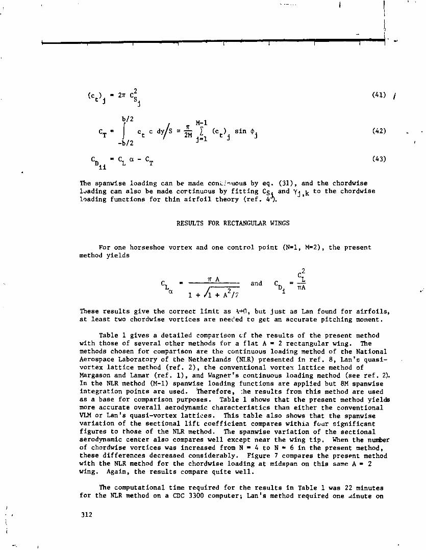
The spanwise loading can be made coniri~uous by eq. (31), and the chordwise Lading can also be made cortinuous by fitting CS and yj,k to the chordwise loading functions for thin airfoil theory (ref. 4 3 .
RESULTS FOR RECTANGULAR WINGS
For one horseshoe vortex and one control point (N=l, W2), the present method yields
These results give the correct limit as 4 0 , but just as Lan found for airfoils, at least two chordwise vortices are needed to get an accurate pitching moment.
Table 1 gives a detailed comparison cf the results of the present method with those of several other methods f o r a flat A a 2 rectangular wing. The methods chosen for cornpartson are the cantinuous loading method of the National Aerospace Laboratory of the Netherlands (mR) presented in ref. 8, Lan's quasi- vortex lattice method (ref. 2), the conventional vortex lattice method of Margason and Lamar (ref. l), and Wagner's continuous loading method (see ref. 2). In the NLR method (M-1) spanwise loading functions are applied but 8M spanwise integration points are used. 'rherefore, :he results from this method are used as a base for comparison purposes. Table 1 shows that the present method yields more accurate overall aerodynamic characteristics than either the conventional VLM or Lan's quasi-vortex lattices. This table also shows that the spanwise variation of the sectional lift coefficient compares withia four significant figures to those of the NLR method. The spanwise variation of the sectional aerodynamic center also compares well except near the wing tip. When the number of chordwise vortices was increased from N = 4 to N = 6 in the present method, these differences decreased considerably. Figure 7 compares the present method with the NLR method for the chordwise loading at midspan on this same A = 2 wing. Again, the results compare quite well.
The computational time required for the results in Table 1 was 22 minutes for the NLR method on a CDC 3300 computer; Lan's method required one dnute on

the Honeywell 635 computer; Wagner's method used about three ~inutes: and the present method required less than ten seconds on an IBM 376,'165. Therefore, the present method is as economical as the VL,M for the same number of vortices, but it is generally more economical when one considers that a smaller number of vortices can be used to achieve the same accuracy as the VLV.
L
The effect of the vortex lattice arrangement on the con-qergenca of the lift-curve slope is presentzd in figure 8 and compared with the conventional VLM for flat rectangular wings with A = 2, 4.5, and 7. This figurr illustrates again the slow convergence of t.he conventional VLM and the rapid convergence of
4 the present method. For all three wings, the present method gives good ac- curacy with only two chordwise vortices, but more spanwise vortic~s are needed for the A = 7 wing ( d l 2 " 10) than the A = 4.5 wing (~/2 = 5) or A = 2 wing (M/2 - 2). Results for the pitching moment, aerodynamic center location, and induced drag were found to converge even faster than the lift-curve slope, therefore they are not presented.
The Prandtl-Glauert rule can be easily applied to the present method to include subsonic compressibility effects.
APPLICATIONS TO OTHER CONFIGURAIIONS
Flaps and ailerons may be added tc the wing by using an approach somewhat similar to that of Lan (ref. 2). For the chordwise integration, the interval from the leading edge of the wing to the flap leading edge is transformed into [O,n] by the "semicircle method", and the interval from the flap lead~ng edge to the trailing edge is also mapped into [O,*rr] by another "semicircle". The same technique can also be applied in the spanwise direction.
Application of the present method to tapered and/or swept wings requires additional considerations. Care must be exercised so that the chordwise vortex and control points at one spanwise location match those at another spanwise position in order to evaluate the Cauchy jntegral properly. These configura- tions are presently being studied along with non-planar wings.
CONCLUDING REMARKS
A new method is developed for solving the lJfting-surface equation for thin, subsonic wings. The downwash equation is written as Cauchy-type inte- grals for the chordwise and spanwise directions. They can be interpreted as a 1atti:e of horseshoe vortices and the positions of the vortices and control points are determined by the finite sum used to approximate the integrals. Lan's two-dimensional method is used for the chordwise integral since it pro- perly accounts f or the leading-edge singularity, Cauchy singularity, and the Kutta condition. For the spanwise integral, Multhopp Is interpolation formula is used in conjunction with the midpoint trapezoidal rule and the theory of Chebychev polynomials. This method properly accounts for the Cauchy singularity

and yields the classical solution to Prandtl's lifting-line equation. The nu- merical method for evaluating the chordwide and spanwise integrals is much simpler and quicker than other continuous loading methods.
i
The chordwise and spanwise methods are combined '5 obtain a continuous loading solution to the lifting-surface equation. The algorithm for the rectan- gular wing gives results which compare well with other cc.ntinuous loading - methods, but with much smaller compctational times. In addition, it converges I
faster and is more accurate than other vortex lattice methods.
For rectangular wings, the vortex lattice arrangement dictated by the pre- sent method differs from the conventional VLM in that the chordwise positions of the vortices and control points do not follow the usual 114-314 rule. There is always a control point at the trailing edge, which allows the Kutta condition to be satisfied, and a control point at the leading edge which yields :he leading-edge suction parameter. The spanwise vortices determined by the present method are not uniformly spaced, and the tip vortices are inset from the actual wing tip. This vortex lattice arrangement gives better results than other VLM's for rectangular wings. Other wing planforms require additional considerations, and they are presently being investigated.
REFERENCES
1. Margason, R. J.; and Lamar, J. E.: Vortex-Lattice Fortran Program for Estimating Subsonic Aerodynamic Characteristics of Complex Planforms. NASA TN D-6142, 1971.
2. Lan, C. E.: A Quasi-Vortex Lattice Method in Thin Wing Theory. J. Air- craft, vol. 11, no. 9, Sept. 1974, pp. 518-527.
3. Hough, G. R.: Remarks on Vortex-Lattice Methods. J. Aircraft, vol. 10, no. 5, May 1973, pp. 314-317.
4. Kuethe, A. M.; and Schetzer, J. D.: Foundations of Aerodynamics. John Wiley & Sons, Inc., N. Y., second edition, 1959.
5. Luke, Y. L.: The Special Functions and Their Approximations. Vol. 11, Chap. XV, Academic Press, N. Y., 1969.
6. Ashley, Holt; and Landahl, M. T.: Aerodynamics of Wings and Bodies. Addison-Wesley Publishing Co., Inc., Mass., 1965.
7. Scheid, Francis: Theory and Problems of Numerical Analysis. Schaum's Outline Series, McGraw-Hill Book Co., N. Y., 1968.
8. Garner, H. C.; Hewitt, B. L.; and Labrujere, T. E.: Compariscn of Three Methods for the Evaluation of Subsonic Lifting Surface Theory. Reports and Memoranda 3597, Aeronautical Research Council, London, England, June 1968.
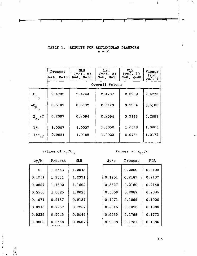
TABLE 1. RESULTS FOR RECTANGULAR PLANFORM
Present
1.2543
1.2331
1.1692
1.0625
0.9137
0.7257
0.5045
0.2588
Present
W4, M=16
Overal l Values
Values of cR/CL
NLR ( r e f . 8 )
N=4, M=16
Values of x / c a s
Lan VLM Wagner ( r e f . 2) ( r e f . 1 ) from
N=8, M=30 N=6, M=40 ref.
Present
0.2200
0.2187
0.2150
0.2087
0.1999
0.1896
0.1798
0.1731 -
NLR
0.2199
0.2187
0.2149
0.2085
0.1996
0.1886
0.1773
0.1685
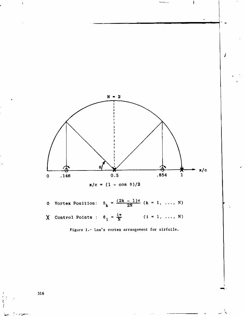
0 .I46 0.5 .854 1
x/c = (1 - cos 0) /2
- o Vortex Position: ek - (2k - 'In 2N (k = 1, . . . , N)
)( Control Points : B i = $ (i = 1, . . . , N)
Figure 1.- Lan's vortex arrangement for a i r f o i l s .

)( denotes control points
Figure 2.- Conventional arrangement of vortex lattice (illustrated for N = 1, M = 4).
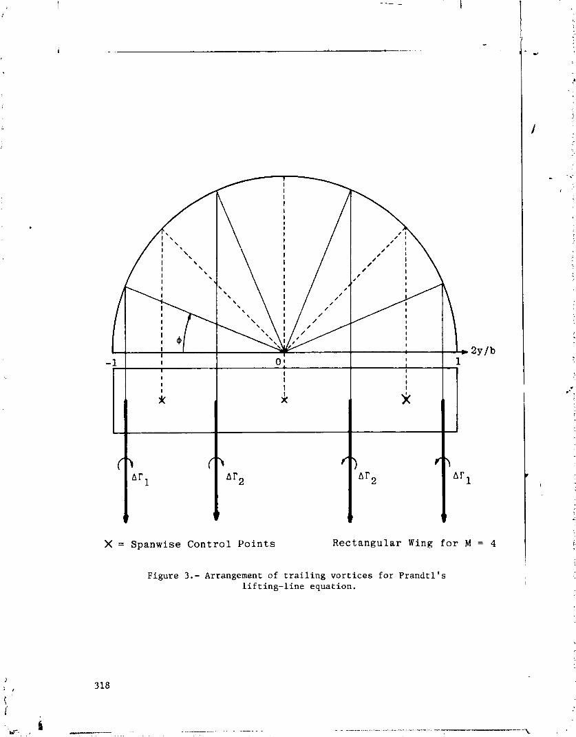

0 Conventional method, e l l i p t i c a l planform
A Conventional method, rectangular planform
0 Present method, rectangular planform
M Number of t r a i l i n g v o r t i c e s
I I
\ exact a n d p r e s e n t v a l u e f o r e l l i p t i c a l p l a n f o r m
Figure 4.- Effect of number of trailing vortices on CLa from
Prandtl's lifting-line theory, A = 2 ~ .

0 Convehtional method elliptical wing
A Conventional method rectangular wing
0 Present method rectangular wing
M Number of Trailing
L a c , and Vortices present values for elliptical wing
Figure 5.- Ef fec t of number of t r a i l i n g v o r t i c e s on induced drag from P r a n d t l ' s l i f t i n g - l i n e theory, A = 27r.
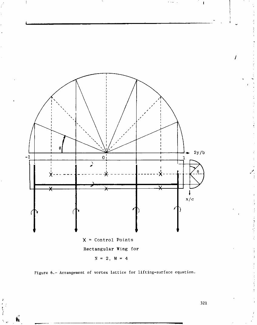
t
X = Cont ro l P o i n t s
Rectangular Wing f o r
N = 2 , M = 4
Figure 6.- Arrangement of vortex lattice for lifting-surface equation.
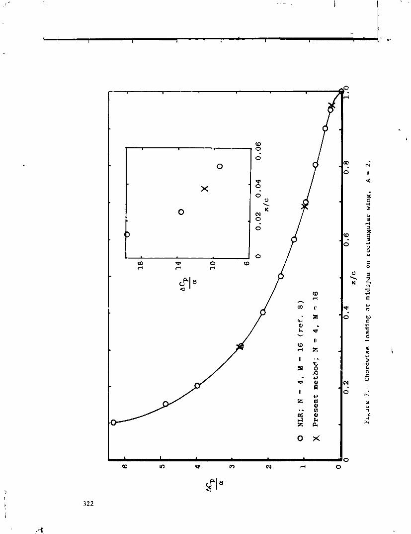
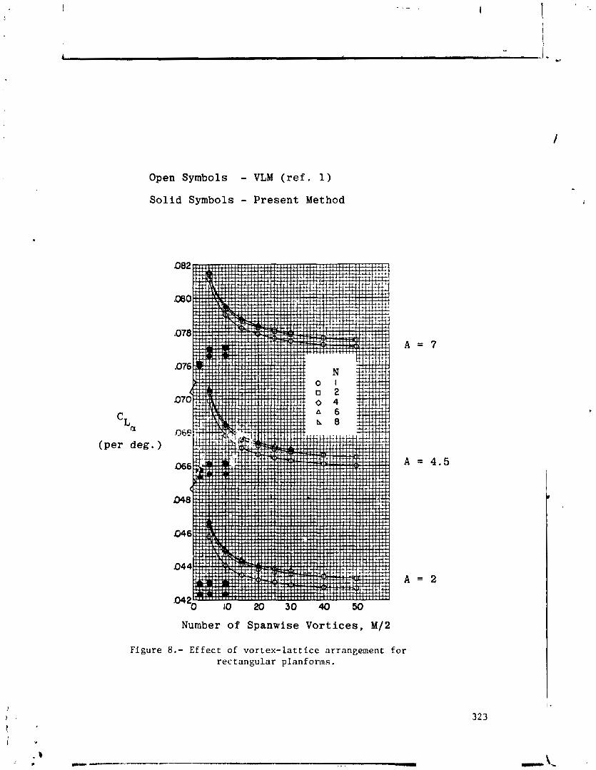
Open Symbols - VLM ( re f . 1 )
S o l i d Symbols - P r e s e n t Method
Figure 8.- Effect of vortex-lattice arrangement for rectangular planfonns.

LATTICE ARRANGEMENTS FOR R A P I D CONVERGENCE
Gary R. Hough Vought Ccrporat ion Advanced Technology Center
SUMMARY
A s appl i c a t
imple, systemat ic, opt imized v o r t e x - l a t t i c e approach i s developed f o r i on t o l i f t i n g - s u r f a c e problems. I t a f f o rds a s i g n i f i c a n t reduct ion i n
computational costs when compared t o cu r ren t methods. Extens i ve numerical experiments have been ca , r i ed ou t on a wide v a r i e t y o f con f igu ra t ions , inc lud- ing wings w i t h camber and s i n g l e o r m u l t i p l e f l a p s , as w e l l as h i g h - l i f t j e t - f l a p systems. Rapid convergence as the 'number o f spanwi se o r chordwise l a t t i c e s are increased i s assured, along w i t h accurate answers. The r e s u l t s from t h i s model should be useful not on ly i n p re l im ina ry a i r c r a f t design bu t also, f o r example, as i npu t f o r wake vor tex r o l l - u p s tud ies and t ranson ic flow ca lcu la- t ions.
l NTRODUCT l ON
The v o r t e x - l a t t i c e method (VLM) f o r the ana lys is o f l i f t i n g - s u r f a c e aero- dynamics has become a w ide ly used technique dur ing the past decade. Although o r i g i n a l l y developed by Falkner i n 1943 ( r e f . I ) , i t was no t u n t i l the i n t r o - duct ion of high-speed dig1 t a l computers i n the e a r l y 1960's t h a t the method was reconsidered and extended, p a r t i c u l a r l y by Rubbert ( re f . 2). Since then, many appl i cat ions o f the VLM have been made t o problems o f aerodynamic design and ana lys is w i t h considerable success.
The VLM represents a type o f f i n i te -e lement s o l u t i o n t o l i f t i n g - s u r f a c e theory problems. As opposed t o the a l t e r n a t e ke rne l - func t ion approach, i t I1seem(s) t o possess none o f the t r a d i t i o n a l values o the r than some approximat ion t o the ca lcu lus o f i n f i n i t e s i m a l s " ( r e f . 3). Nevertheless, a number o f compar- isons between the two methods have been favorab le ove ra l l .
C r i t i c i sms o f the VLM have cont inued though. These usua l l y contend e i t h e r t h a t the l a t t i c e s car1 be l a i d ou t i n a preconceived manner t o g i ve some des i red answer o r t h a t too many l a t t i c e s a re requi red f o r adequate convergence o f the computed loadings. The present study was undertaken t o der i ve sys temati c a l l y an opt imized v o r t e x - l a t t i ce layout which overcomes these ob jec t ions and can be adapted t o a wide v a r i e t y o f con f igu ra t ions .
I The phi losophy o f the approach i s o u t l i n e d b r i e F l y and then the numerical
r e s u l t s a re presented.
SYMBOLS
A! l lengths a re d imensionless w i t h respect t o the w ing r o o t chord.
aspect r a t i o
induced drag c o e f f i c i e n t
l i f t c o e f f i c i e n t
j e t momentam c o e f f i c i e n t
l o c a l wing chord
t i p l a t t i c e i n s e t d i s tance , f r a c t i o n o f l a t t i c e span
f 1 ap chord/w i ng chord
v o r t e x drag f a c t o r , nACD/CL 2
number o f chordwi se v o r t i ces
number o f spanwise v o r t i c e s on wing semispan
t o t a l number o f v o r t i c e s
r ight-handed Car tes ian coord inates
x -center o f pressure
w ing semi span
angle o f a t t a c k , degrees
f l a p d e f l e c t i o n angle, degrees
spanwise v a r i a b l e , y / y t
j e t d e f l e c t i o n angle, degrees
THE VORTEX-LATTICE APPROACH
The r e s u l t s presented here a re based on the commonly used l i n e a r i z e d anal- y s i s of t h i n l i f t i n g surfaces. The f l o w i s cons idered t o be steady, i n v i s c i d , and incompress ib le (a1 though t h i s l a t t e r as sump ti or^ can read i l y be re laxed by u s i n g the Gother t t rans fo rma t ion ) . Whi le t h i s s t r i c t l y l i m i t s the s tudy t o a t tached f l ows w i t h smal l d e f l e c t i o n s , the b a s i c model has proved i t s use fu l - ness i n many extended a p p l i c a t i o n s because o f i t s s i m p l i c i t y and the genera l agreement w i t h exper imental data.
The t y p i c a l mechanics o f t he l a t t i c e l ayou t , the mathematical d e t a i l s , and the computations o f the r e s u l t i n g loads w i l l n o t be discussed here , as they a r e assumed fami 1 i a r o r can be found i n o t h e r r e p o r t s (e. j . , r e f s . 2,4,5). Rather, the focus o f the a n a l y s i s w i l l be on d e r i v i n g the op t im ized l a t t i c e s t r u c t u r e which r e s u l t s i n an accurate, c o s t - e f f i c i e n t approach t o performance p r e d i c t i o n f o r a wide v a r i e t y o f c o n f i g u r a t i o n s , i n c l u d i n g wings w i t h f l a p s and j e t - f l a p sys terns.
Before proceeding w i t h the d e t a i l s o f the opt imized VLM, a word about the " a c ~ u r a c y ~ ~ (or lack o f i t ) o f these f i n i te-element approaches i s i n order. I t should be remembered t he t w i t h the assumptions employed, we a re i n e f f e c t so lv- ing a p a r t i c u l a r boundary-value problem, and a unique s o l u t i o n ex i s t s . Hence, a l l p roper l y formulated f in i te -e lement analyses (o r assumed load i rg - func t ion approaches) based on t h i s model should g i v e r e s u l t s which converge t o t h l s solu- t i o n as the number o f unknowns i s increased i n d e f i n i t e l y . There a re of course some d i f fe rences i n the ease o f a p p l i c a t i o n and computational e f f o r t Invo lved i n the var ious approaches, bu t what u l t i m a t e l y d is t ingu ishes t h e i r m e r i t s i s haw rap id l y the r e s u l t s converge t o the co r rec t answer. Th is should be exp lored numer ica l ly f o r a number o f configurations i n order t o g i ve the u l t ima te user some degree o f confidence i n the p a r t i c u l a r p r e d i c t i o n technique.
Since no exact so l u t i ons e x i s t (except f o r the c i r c u l a r wing), determina- t i o n o f jl8?t what i s the "cor rect " answer r es t s e n t i r e l y upon comparison between two o r more d i f f e r e n t t heo re t i ca l approaches t o the same problem. Thus, i n cnis sense, a favorab le comparison o f a n a l y t i c a l r e s u l t s w i t h p a r t i c u l a r exper imental data does no t guarantee t ha t the method i s "accurate". Rather, once some degree o f accuracy i s es tab1 i shed through numerl ca l experimentat i on and agreement wi t h o ther analyses, comparison w i t h experiment should be used t o v e r i f y the range of v a l i d i t y o f the l i n e a r i z e d thin-wing theory model. I n cases where agreement I s not good, i t ind ica tes t ha t a b e t t e r bas ic model i s requi red.
NUMER I CAL RESULTS
Rectangular Planforms
We f i r s t consider the case o t an uncambered rectangular wing a t angle o f a t tack a, which w i l l serve t o i l l u s t r a t e some o f the opt imized l a t t i c e features. A r ight-handed xyz-coordinate system i s chosen such t h a t x i s posi t i v e i n the f reestream d i r e c t i o n and the o r i g i n i s located a t the wing roo t leading edge. For convenience, the wing roo t chord i s normalized t o u n i t y , t h a t i s , a l i lengths a re dimensionless w i t h respect t o the roo t chord. Then t h i s wing geom e t r y i s completely descr ibed by y the y-coordinate o f t h e w i n g t i p (o r equ iva len t l y by the aspect r a t i o A;.
The cor,ventional l a t t i c e layout f o r t h i s case ( r e f . 5) i s t o use un i formly spaced chordwise and spanwise panels which cover the whole wing. While the computed loads converge, they do so somewhat s low ly w i t h respect t o the number o f spanwise vor t i ces . However, t h i s can be acce lerated by e m ~ l o y l n g equa l l y spaced l a t t i c e s which a re i nse t from the t i p by a f r a c t i o n d o f the l a t t i c e span (0gd<l). (See f i g . 1 .) Such an idea was f i r s t sugges(iad i n reference 7 and was subsequently shown ( re f . 6) t o a f f o r d a marked improvement i n spanwise convergence.
Th is i s demonstrated i n f i g u r e 2 where the perceqt e r r o r i n the l i f t - c u r v e slope per rad ian CLQ i s p l o t t e d as a f unc t i on o f the number o f v o r t i c e s on the semispan N f o r A = 2 and A = 7 . The basel ine data which a re ccns id r red t a be "exact" f o r these cases were taken from references 7 and 8, where ca re fu l calcu- l a t i o n s were c a r r i e d out based on the ke rne l - f unc t i on approach. I t i s seen thar the use of d = 1 /4 d ramat i ca l l y improves the convergence. I n f ac t , f o r one
percent accuracy i n C b , on ly 5 spanwise vo r t i ces need t o be used when d = 1/4 3
as opposed t o about 35 when d = 0. Since the computational e f f o r t increases as betwecn the square and cube o f the number o f unknowns, t h i s represents poss ib ly
t a two order o f magnitude cost savings.
A key c a l c u l a t i o n which f u r t h e r reveals the advantages o f spanwise l a t t i c e i n s e t t i n g i s t ha t o f the l i f t - i n d u c e d drag. This quan t i t y may be computed by - . e i t h e r a near o r a f a r f i e l d approach. The l a t t e r i s based on the work o f Munk, I - i n which a T re f f t z -p lane ana lys is i s used t o express the induced-drag c o e f f i c i e n t C D i n terms o f the Four ie r c o e f f i c i e n t s o f the spanwise l i f t d i s t r i b u t i o n . This has the advantage o f r e l a t i v e s i m p l i c i t y (assuming the l i f t d i s t r i b u t i o n i s accurate) but cannot be used t o f i n d the spanwise v a r i a t i o n o f CD. On the o ther hand, the near f i e l d approach i s more demanding o f computer time, bu t does y i e l d t h i s spanwise va r i a t i on . For the near f i e l d computation, xe have found i t best t o use the d i r e c t me;k.~d o f summing the forces i n the f reestream d i r e c t i o n on each bound vor tex element, neg lec t ing the in f luence o f a bound element on i tse l f . (See a lso ref. 9.)
I n f i g u r e 3, the vor tex drag f a c t o r K = ~ A C ~ / C ~ ~ by both the near and f a r f i e l d methods i s shown f o r the A = 2 wing as a f unc t i on o f N w i t h d = 0 and d = 1/4. The convergence as N i s increased i s d isp layed more c l e a r l y by p l o t t i n g K against 1/N. Again, the g rea t improve3ent i n us ing d = 1/4 i s ev ident , along w i t h the remarkable accuracy o f the near f i e l d ca lcu la t ion . Fur ther , f o r no i n s e t t i n g (d = 0) , we see t ha t t o requi r e very c lose agreement i n the near and f a r f i t l d drag5 i s doomed t o f a i l u r e unless an abnormally la rge number o f span- wise vo r t i ces are used. The tendency o f the VLM t o "pred ic t " low values o f K (see re f . 9) i s thus shown t o be a consequence o f no t using the optimum l a t t i c e inse t arrangement.
To i l l u s t r a t e the e f f e c t o f va ry ing the number o f chordwise v o r t i c e s M, the corresponding v a r i a t i o n o f K and the x-center o f pressure xc a re p l o t t e d i n f i g u r e 4. Note t ha t K i s independent o f M f o r M>2 (whether gr no t i n s e t t i n g i s used), wh i l e xcp i s near l y l i n e a r i n l / ~ 2 and t i p i n s e t t i n g does no t improve i t s convergence rate. For t h i s A = 2 wing, the est imated converged values are C L ~ = 2.474, xcp = 0.2594, and K = 1.001, which are i n excel l e n t agreement w i t h those obtained using the kerne l - func t ion approach ( r e f s . 7 and 8) o f C L ~ = 2.4744 and xCp = 0.20939.
These ca lcu la t ions have been made f o r an inse t d is tance o f one-quarter o f a l a t t i c e span. A number o f tes ts were made f o r o ther values o f d, and i t i s found t ha t d = 1/4 represents approximately the optimum value. As i s usual i n the VLM, the bound vo r t i ces are located a t the l oca l l a t t i c e quar te r chord, and the tangent ia l f l ow boundary cor d i t i o n s a t i s f i e d a t the l oca l three-quar ter chord midway between the t r a i 1 i ng v o r t i ces . These pos i t ions were sugges t ~ d by two-dimensional r esu l t s and have been used by Falkner and a l l who fol lowed. I t can be shown tha t they are mandatory f o r the three-dimensional case as we1 1 ( ref . 6 ) .
Several o ther comnents can be made regarding the o v e r a l l l a t t i c e arrange- ment. F i r s t , the use o f nonuniform chordwise spacings which bunch the l a t t i c e s near the leading and/or t r a i 1 ;ng edges where the v a r i a t i o n i n v o r t i c i t y i s l a r - gest has been invest igated. I t i s found f o r these uncambered wings t h a t the
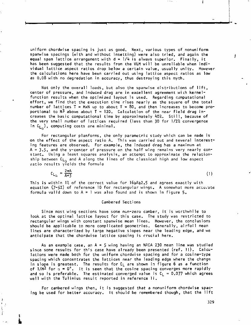
u n i f o r m chordwise spacing i s j u s t as good. Next, va r ious types o f nonuni form spanwise spacings ( w i t h and w i t h o u t i n s e t t i n g ) were a l s o t r i e d , and aga in the equal span l a t t i c e arrangement w i t h d = 1/4 i s always super io r . F i n a l l y , i t has been suggested t h a t t he r e s u l t s from t h e VLM w i l l be u n r e l i a b l e when i n d i - v i d u a l l a t t i c e aspect r a t i o s drop below a c e r t a i n value, u s u a l l y u n i t y . However the c a l c u l a t i o n s here have been c a r r i e d o u t us ing l a t t i c e aspect r a t i o s as low as 0.08 w i t h no degredat ion i n accuracy, thus d e s t r o y i n g t h i s myth.
Not o n l y t h e o v e r a l l loads, b u t a l s o the spanwise a i s t r i b u t i o n s o f l i f t , cen te r o f pressure, and induced drag a r e i n e x c e l l e n t agreement w ich k e r n e l - f unc t i on r e s u l t s when the op t im ized l a y o u t i s used. Regarding computat ional e f f o r t , we f i n d t h a t the execu t ion t ime r i s e s n e a r l y as the square o f t he t o t a l number o f l a t t i c e s T = MxN up t o about T = 80, and then increases t o become pro- p o r t i o n a l t o ~3 above about T = 123. C a l c u l a t i o n o f t he near f i e l d drag i n - creases the b a s i c computat i o n a l t ime by approx imate ly 40%. S t i 1 1, because o f the very smal l number o f l a t t i c e s requ i red ( l e s s than 30 f o r 1/2% convergence i n cLU), computing cos ts a r e minimal .
For r e c t a n g u l a r p lanforms, the o n l y pa ramet r i c s tudy which can be made i s on the e f f e c t o f t h e aspect r a t i o A. T h i s was c a r r i e d o u t and seve ra l i n t e r e s t - i n g fea tu res a r e observed. For example, t h e induced drag has a maximum a t A - 3.5, and the y -center o f p ressure on t h e h a l f wing remains ve ry n e a r l y con- s tant . Using a l e a s t squares a n a l y s i s , an a t tempt t o approximate the r e l a t i o n - s h i p between C L ~ and A a long the l i n e s o f t he c l a s s i c a l h i g h and low aspect r a t i o r e s u l t s y i e l d s t h e fo rmula
Th is i s w i t h i n 1% o f t h e c o r r e c t va lue f o r 16bA22.5 and agrees e x a c t l y w i t h equa t ion 0 - 5 2 ) o f re ference 10 f o r rec tangu la r wings. A somewhat more acru,.ate formula v a l i d down t o A = 1 was a l s o found and i s shown i n f i g u r e 5.
Cambered Sect ions
Since most w ing sec t i ons have sone non-zero camber, i t i s worthwhi l e t o look a t t he op t ima l l a t t i c e l a y o u t f o r t h i s case. The s tudy was r e s t r i c t e d t o rec tangu la r wings w i t h constant spanwise mean l i n e s . However, the conc lus ions shou ld be a p p l i c a b l e t o more compl ica ted geometries. Genera l ly , a i r f o i l mean l i n e s a r e c h a r a c t e r i z e d by l a r g e h e g a t i v e s lopes near the l ead ing edge, and we a n t i c i p a t e t h a t t he chordwise l a t t i c e spacing i s c r u c i a l here.
0 f and we 1
i ng
As an example case, an A = 5 wing hav ing an NACA 230 mean l i n e was s t u d i e d s i n c e some r e s u l t s f o r t h i s case have a l ready been presented ( r e f . 11). Calcu- l a t i o n s were made bo th f o r t he u n i f o r m chordwise spac ing and f o r a cos ine- type spacing which concent ra tes the l a t t i c e s near the l ead ing edge where the change i n s lope i s g rea tes t . The r e s u l t s f o r C L a r e shown i n f i g u r e 6 as a f u n c t i o n
1 / ~ 2 f o r a = 0'. I t i s seen t h a t t he cos ine spacing converges more r a p i d l y so i s p r e f e r a b l e . The es t ima ted converged va lue i s CL = 0.077 which agrees
1 w i t h the T u l i n i u s r e s u l t repo r ted i n re fe rence 1 1 .
For cambered wings then, i t i s suggested t h a t a nonun i fo rm chordwise spac- be used f o r b e t t e r accuracy. I t should be remembered though, t h a t t h e l i f t
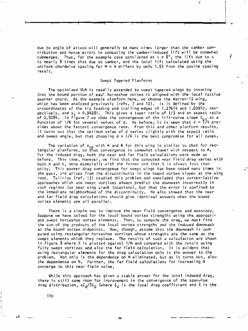
due t o angle o f a t t a c k w i 1 1 general l y be many t imes l a r g e r than the camber con- t r i b u t i o n and hence e r r o r s i n computing the camber-induced 1 i f t w i 1 1 be somewhat submerged. Thus, f o r the example case considered a t r = 8 O , the l i f t due t o a i s n e a r l y 8 t imes t h a t due t o camber, and the t o t a l 1 i f t c a l c u l a t e d us ing the un i fo rm chordwise spacing f o r M = 4 d i f f e r s by o n l y 1.5% f rom the cos ine spacing r e s u l t .
Swept Tapered P 1 anforms
The op t im ized VLM i s r e a d i l y extended t o swept tapered wings by i n s u r i n g t h a t the bound p o r t i o n o f eack horseshoe v o r t e x i s a l i g n e d w i t h the l o c a l l a t t i c e q u a r t e r chord. As the example p lanform here, we choose the Warren-12 wing, which has been analyzed p r e v i o u s l y ( r e f s . 7 and 12). I t i s def ined by the x -coord inates o f the t i p l ead ing and t r a i l i n g edges o f 1.27614 and 1.60947, res- p e c t i v e l y , and y t = 0.94281. T h i s g i ves a tape r r a t i o o f 1/3 and an aspect r a t i o o f 2.8284. I n f i g u r e 7 we show the convergence o f t he l i f t - c u r v e s lope CL, as a f u n c t i o n o f 1/N f o r seve ra l values o f d. As before , i t i s seen t h a t d = 1 / 4 p ro- v ides about the f a s t e s t convergence ra te . From t h i s and o t h e r p lan fo rm r e s u l t s , i t tu rns o u t t h a t the optimum va lue o f d v a r i e s s l i g h t l y w i t h the aspect r a t i o and sweep angle, b u t t h a t choosing d = 1/4 i s the b e s t compromise f o r a1 1 cases.
The v a r i a t i o n o f xc w i t h M and N f o r t h i s wing i s s imi l a r t o t h a t f o r rec- t angu la r p lanforms, so tRat convergence i s somewhat s lower w i i h respect t o M. For the induced drag, bo th the near and f a r f i e l d c a l c u l a t i o i s were made as before. Th is t ime, however, we f i n d t h a t the computed near f i e l d drag v a r i e s w i t h bo th M and M, more espec ia l l y w i t h the former and t h a t K i s always l e s s than u n i t y . Th i s poorer drag convergence f o r swept wings has been noted many t imes i n the past , and a r i s e s f rom the d i s c o n t i n u i t y i n the bound v o r t e x s lopes a t the wing roo t . Tu l i n i u s ( r e f . 13) s t u d i e d t h i s problem and concluded t h a t v o r t e x - l a t t i c e approaches which use swept v o r t i c e s always p r e d i c t the downwash i n c o r r e c t 1 y i n such regions ( o r near wing crank l o c a t i o n s ) , b u t t h a t t he e r r o r i s con f ined t o the immediate neighborhood o f t he d i s c o n t i n u i t y . He a l s o showed t h a t the near and f a r f i e l d drag c a l c u l a t i o n s shou ld g i v e i d e n t i c a l answers when the bound v o r t e x elements a re a l l para1 l e l .
There i s a s imple way t o improve the near f i e l d convergence and accuracy. Suppose we have so lved f o r the l o c a l bound v o r t e x s t r e n g t h s u s i n g the approp r i - a t e swept horseshoe v o r t e x elements. Then, tc, compute the drag, we must f i n d the sum o f the products o f the l o c a l v o r t e x s t reng ths and the induced downwash a t the bound v o r t e x midpo in ts . Now, though, assume t h a t the downwash i s com- puted u s i n g rec tangu la r horseshoe v o r t i c e s whose s t r e n g t h s a re the same as the swept elements which they replace. The r e s u l t s o f such a c a l c u l a t i o n a r e shown i n f i g u r e 8 where K i s p l o t t e d a g a i n s t 1 / M and compared w i t h the r e s u l t us ing f u l l y swept v o r t i c e s and a l s o t h e f a r f i e l d c a l c u l a t i o n . I t i s e v i d e n t t h a t us ing rec tangu la r elements f o r t he drag c a l c u l a t i o n o n l y i s t he answer t o the problem. Not o n l y i s t h e dependence on M e l i m i n a t e d , b u t as i t turns o u t , a l s o the dependence on N. Fu r the r , t h e f a r f i e l d c a l c u l a t i o n s f o r i n c r e a s i n g N converge t o t h i s near f i e l d value.
Whi le t h i s approach hzs g i ven a s t a b l e answer f o r the t o t a l induced drag, there i s s t i 1 1 some room f o r improvement i n the convergence o f the spa rd i se drag d i s t r i b u t i o n , cCd/ZCD (where Cd i s the l o c a l drag c o e f f i c i e n t and i s t h e
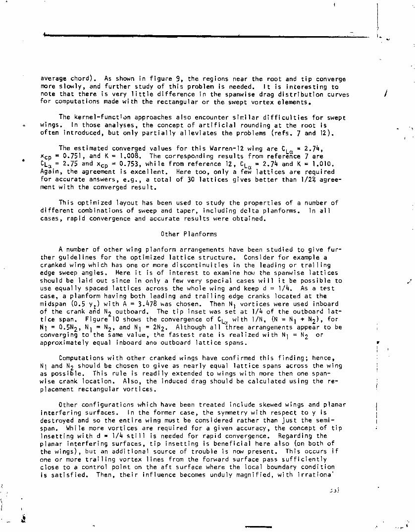
average chord). As shown i n f i g u r e 9, the regions near the r oo t and t i p converge more s lowly , and f u r t h e r study o f t h i s problem i s needed. I t i s i n t e r e s t i n g t o note t h a t there i s very l i t t l e d i f f e rence i n the spanwise drag d i s t r i b u t i o n curves I f o r computations made w i t h the rectangular o r the swept vo r tex elements.
The kerne l - func t ion approaches a l so encounter s i r i l a r d i f f i c u l t i e s f o r swept - wings. I n those analyses, the concept o f a r t i f i c i a l rounding a t the r oo t i s o f t e n introduced, bu t on ly p a r t i a l l y a l l e v i a t e s the problems ( r e f s . 7 and 12).
The est imated converged values f o r t h i s Warren-12 wing are CL, = 2.74, xcp = 0.751, and K = 1.008. The corresponding r e s u l t s from reference 7 are
CLcc = 2.75 and xcp = 0.753, w h i l e from reference 12, CL, = 2.74 and K = 1.010. Again, the agreement i s exce l len t . Here too, on ly a few l a t t i c e s are requi red f o r accurate answers, e.g., a t o t a l o f 30 l a t t i c e s gives b e t t e r than 1/2% agree- ment w i t h the converged resu l t .
Th is opt imized layout has been used t o study the p roper t ies o f a number o f d i f f e r e n t combinations o f sweep and taper, i n c l ud ing d e l t a planforms. I n a1 1 cases, r ap id convergence and accurate resu l t s were obtained.
Other Planforms
A number of o ther wing planform arrangements have been s tud ied t o g i ve f u r - the r gu ide l ines f o r the opt imized l a t t i c e s t r uc tu re . Consider f o r example a cranked wing which has one o r more d i s c o n t i n u i t i e s i n the lead ing o r t r a i l i n g edge sweep angles. Here i t i s o f i n t e r e s t t o examine h w the spanwise l a t t i c e s should be l a i d ou t s ince i n on ly a few very spec ia l cases w i l l i t be poss ib le t o use equal l y spaced l a t t i c e s across the whole wing and keep d = 1/4. As a t e s t case, a planform having both lead ing and t r a i l i n g edge cranks located a t the midspan (0.5 y t ) w i t h A = 3.478 was chosen. Then N 1 vo r t i ces were used inboard o f the crank and N2 outboard. The t i p , i n se t was se t a t 1 /4 o f the outboard l a t - t i c e span. F igure 10 shows the convergence o f CLo, w i t h 1/N, (N = N 1 + N2), f o r N1 = 0.5N2, N, = N2, and N 1 = 2N2. Although a l l three arrangerrents appear t o be converging t o the same value, the f a s t e s t r a t e i s r ea l i zed w i t h N 1 = N2 o r approximately equal inboard and outboard l a t t i c e spans. c
' \
Computations w i t h o the r cranked wings have confirmed t h i s f i n d i n g ; hence, N 1 and N2 should be chosen t o g i v e as near l y equal l a t t i c e spans across the wing as poss ib le . This r u l e i s readi l y extended t o wings w i t h more then one span- wise crank loca t ion . Also, the induced drag should be ca l cu l a ted us ing the re- placement rectangular vo r t i ces .
Other con f igu ra t i cns which have been t rea ted inc lude skewed wings and p lanar i n t e r f e r i n g surfaces. I n the former case, the symmetry w i t h respect t o y i s
1 1
destroyed and so the e n t i r e wing must be considered ra the r than j u s t the semi- I span. While more vo r t i ces are requi red f o r a g iven accuracy, the concept of t i p ;
i n s e t t i n g w i t h d = 1/4 s t i l l i s needed f o r r a p i d convergence. Regarding the p lanar i n t e r f e r i n g surfaces, t i p i n s e t t i n g i s b e n e f i c i a l here a l so (on both of the wings), bu t an add i t i ona l source o f t r oub le i s now present. Th is occurs i f one o r more t r a i l i n g vo r tex l i n e s from the forward sur face pass s u f f i c i e n t l y c lose t o a con t ro l p o i n t on the a f t sur face where the l oca l boundary cond i t i on i s s a t i s f i e d . Then, t h e i r i n f luence becomes unduly magnif ied, w i t h i r r a t i o n a '
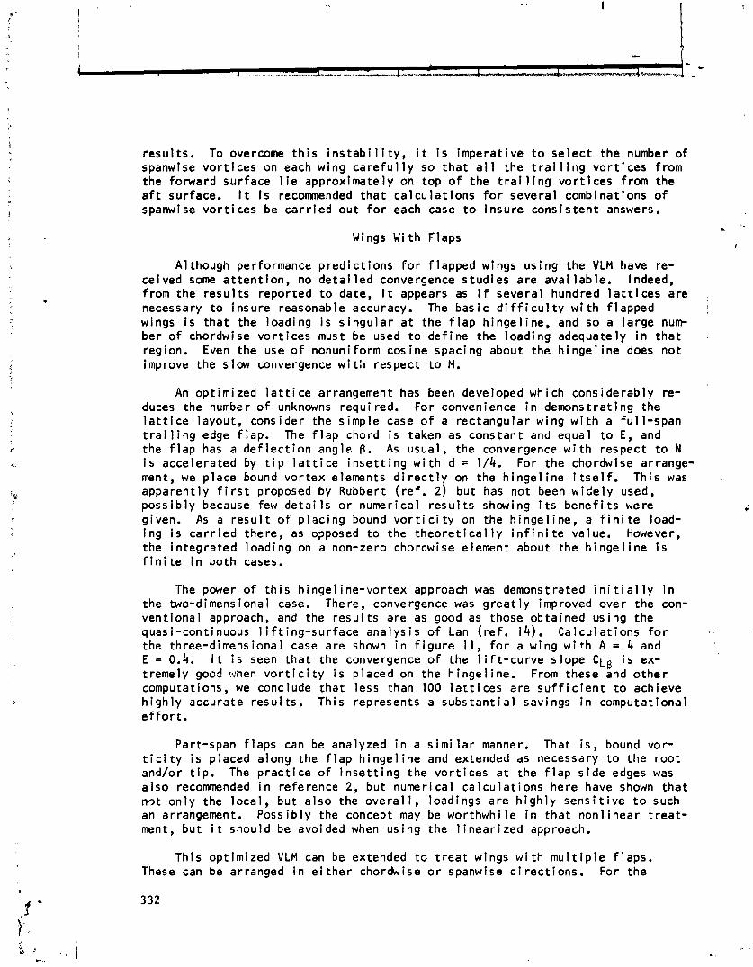
resu l t s . To overcome t h i s i n s t a b i l i t y , i t i s imperat ive t o se l ec t the number o f spanwlse vo r t i ces on each wing c a r e f u l l y so t h a t a l l the t r a i l i n g v o r t i c e s from the forward surface 1 i e approximately on top o f the t r a i 1 i ng v o r t i c e s from the a f t surface. It i s recommended t h a t ca l cu l a t i ons f o r severa l combinations o f spanwise vo r t i ces be ca r r i ed ou t f o r each case t o insure cons is ten t answers.
Wings With Flaps
A1 though performance p red i c t i ons f o r f lapped wings us ing the VLM have re- ceived some a t t en t i on , no d e t a i l e d convergence s tud ies a re ava i lab le . Indeed, from the resu l t s reported t o date, i t appears as i f several hundred l a t t i c e s are necessary t o insure reasonable accuracy. The bas ic d i f f i c u l t y w i t h f lapped wings i s t ha t the loading i s s i ngu la r a t the f l a p h inge l ine , and so a la rge num ber o f chordwise vor t i ces must be used t o de f ine the load ing adequately i n t h a t region. Even the use o f nonuniform cosine spacing about the h i n g e l i n e does no t improve the slow convergence w i t h respect t o M.
An opt imized l a t t i c e arrangement has been developed which considerably re- duces the number o f unknowns requi red. For convenience i n demonstrating the l a t t i c e layout, consider the s imple case o f a rectangular wing w i t h a f u l l - span t r a i l i n g edge f lap. The f l a p chord i s taken as constant and equal t o E, and the f l a p has a d e f l e c t i o n angle B. As usual, the convergence w i t h respect t o N i s accelerated by t i p l a t t i c e i n s e t t i n g w i t h d = 1/4. For the chordwise arrange- ment, we place bound vor tex elements d i r e c t l y on the h i nge l i ne i t s e l f . Th is was apparent ly f i r s t proposed by Rubbert ( r e f . 2) but has no t been w ide ly used, poss ib ly because few d e t a i l s o r numerical r e s u l t s showing i t s b e n e f i t s were given. As a r e s u l t o f p l ac i ng bound v o r t i c i t y on the h inge l ine , a f i n i t e load- ing i s c a r r i e d there, as opposed t o the t h e o r e t i c a l l y i n f i n i t e value. However, the in tegra ted loading on a non-zero chordwise element about the h i n g e l i n e i s f i n i t e i n both cases.
The power o f t h i s h inge l ine -vor tex approach was demonstrated i n i t i a l l y i n the two-dimens i ona 1 case. The re, convergence was g r e a t l y i mproved over the con- vent iona l approach, and the resu l t s are as good as those obtained us ing the quasi-continuous 1 i f t ing-surface analys is o f Lan (ref. 14). Ca lcu la t ions f o r I
the three-dimensional case are shown i n f i g u r e 1 1 , f o r a wing w i t h A = 4 and E = 0.4. I t i s seen t h a t the convergence o f the 1 i f t - c u r v e s lope C L g i s ex- tremely good when v o r t i c i t y i s placed on the h inge l ine. From these and o t h e r computations, we conclude t ha t less than 100 l a t t i c e s are s u f f i c i e n t t o achieve h i gh l y accurate resu l t s . Th is represents a subs tan t i a l savings I n computational e f f o r t .
Part-span f l aps can be analyzed i n a s i m i l a r manner. That i s , bound vor- t i c i t y i s placed along the f l a p h inge l ine and extended as necessary t o the r oo t and/or t i p . The p r a c t i c e o f i n s e t t i n g the vo r t i ces a t the f l a p s i d e edges was a l so recommended i n reference 2, but numerical ca l cu l a t i ons here have shown t h a t n9t on ly the loca l , but a l so the o v e r a l l , loadings a re h i g h l y s e n s i t i v e t o such an arrangement. Poss ib ly the concept may be worthwhi l e i n t ha t non l inear t r e a t - ment, bu t i t should be avoided when us ing the l i n e a r i z e d approach.
This opt imized VLM can be extended t o t r e a t wings w i t h m u l t i p l e f l aps . These can be arranged i n e i t h e r chordwise o r spanwise d i r ec t i ons . For the

m u l t i p l e chordwise f l a p case, i t i s necessary t o p lace bound vo r t ex segments on each o f the f l a p h inge l ines t o insure r ap id convergence. The performance o f
I i i
leading edge h i g h - l i f t devices can a l so be inves t iga ted us ing these layouts. I ! ! While the re i s a s c a r c i t y o f good numerical r e s u l t s f o r comparison purposes,
one kerne l - func t ion c a l c u l a t i o n should be mentioned. I n reference 15, Garner ! . .. analyzed a swept untapered wing o f aspect r a t i o 4 wi t h a 25% chord f l a p extend-
I ing from the 45% spanwise s t a t i o n ou t t o the t i p . Using the ke rne l - f unc t i on method, he p red ic ted a value o f C L ~ = 0.758 and CD = 0.179. With the opt imized VLM and 91 unknowns, C k B = 0.757 and C = 0.180. Here, 7 chordwise vo r t i ces (5 ahead o f the hinge1 I ne and 1 behind! and 13 spanwise v o r t i c e s (6 inboard and 7 on the f l a p ) were employed. Also, the spanwise 1 i f t d i s t r i b u t i o n compared ! very w e l l f o r t h i s case.
F ina l l y , t o show the v e r s a t i 1 i t y o f t h i s approach, the p red ic ted spanwise l i f t d i s t r i b u t i o n on a cranked tapered wins (approximating the Convair 990 plan- form) a t 12O angle o f a t t ack w i t h m u l t i p l e spanwise f l a p s i s p l o t t e d i n f i gu re I
12. Here the seven f l aps were de f lec ted through var ious angles as shown i n an attempt t o produce a near l y l i n e a r d ropo f f i n the load ing over the ou te r h a l f
I
o f the wing. Such loadings are o f i n t e r e s t i n wake vo r t ex r o l l - u p ca lcu la t ions . I
Je t -F lap Wings i
The opt imized VLM has a l so been app l ied t o p r e d i c t j e t - f l a p wing pe r f o r - !
mance. The j e t f l a p i s bas ica l l y an arrangement f o r i n t e g r a t i n g the p ropu ls ion system o f an a i r c r a f t w i t h i t s l i f t product ion by b lcwing a narrow j e t o f h igh- v e l o c i t y a i r from a s l o t a t the wing t r a i l i n g edge. Th is de f l ec ted j e t , besides i supply ing t h rus t , a l s o increases the 1 i f t through an addi t i o n a l induced c i rcu- t
l a t i o n as w e l l as by a reac t ion t o i t s v e r t i c a l momentum. The a d d i t i o n a l c i r cu - l a t i o n , o r supe rc i r cu l a t i on as i t i s sometimes ca l l ed , a r i ses from the asymmetry i induced i n the main stream by the presence o f the j e t and can amount t o a l a rge f r a c t i o n of the t o t a l l i f t on the wing under c e r t a i n condi t ions. I
W i th in the l i nea r i zed theory framework, the t r a i l i n g j e t sheet can be 1
represented by vor tex 1 a t t ices and the appropr ia te dynamic boundary condi t i o n , i
s a t i s f i e d a t corresponding con t ro l po in ts . We wi 11 consider on ly the so -ca l led I
"s ingu lar blowing" con f i gu ra t i on i n which the j e t leaves a t an angle -r w i t h respect t o the s lope o f the camberl ine a t the t r a i l i n g edge. The j e t s t ~ r l g t h i s described by the parameter C,,'(y), the j e t momentum c o e f f i c i e n t . The fc , low- ing r esu l t s are taken from reference 16 wherein a complete performance ana iys is was ca r r i ed out. Th is work was sponsored by NASA ARC under Contract NAS2-8115.
As i n the pure f lapped wing, the j e t - f l a p load ing e x h i b i t s a s i n g u l a r be- havior. Here, i t i s a t the t r a i l i n g edge where the s t reaml ine d e f l e c t i o n changes abrupt ly . Thus, i n analogy w i t h the p l a i n f l a p case, we t r y p l ac i ng bound v o r t i c i t y along the wing t r a i l i n g edge. Th is was again v e r i f i e d t o g i v e good convergence cha rac te r i s t i c s i n the 1 i m i t i ng two-dl mens i ona l problem. I n add i t ion , i t turns ou t t o be necessary t o use a nonuniform chordwise spacing which concentrates the l a t t i c e s near the t r a i l i n g edge. Th is does have the advantage t h a t the i n f i n i t e downstream ex ten t o f the j e t sheet can be mapped i n t o a f i n i t e region.
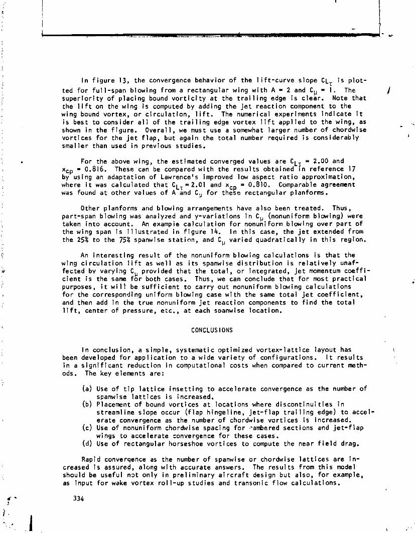
I n f i g u r e 13, the convergence behavior o f the l i f t - c u r v e slope C L ~ i s p l o t -
ted f o r f u l l - span blowing from a rectangular wing w i t h A = 2 and C,, = 1. The s u p e r i o r i t y o f p l ac i ng bound v o r t i c i t y a t the t r a i l i n g edge i s c lea r . Note t h a t the 1 i f t on the wing i s computed by adding the j e t r eac t i on component t o the wing bound vor tex, o r c i r c u l a t i o n , l i f t . The numerical experiments i n d i c a t e i t i s best t o consider a l l o f the t r a i l i n g edge vo r t ex l i f t app l ied t o the wing, as shown i n the f igu re . Overa l l , we must use a somewhat l a r g e r number o f chordwise vo r t i ces f o r the j e t f l ap , but again the t o t a l number requi red i s considerably smal ler than used i n previous studies.
For the above wing, the est imated converged values are C L T = 2.00 and xCp = 0.816. These can be compared w i t h the r e s u l t s obtained I n re ference 17 by using an adaptat ion o f Lawrence's improved low aspect r a t i o approximation, where i t was ca lcu la ted t ha t CL, = 2.01 and xcp = 0.810. Comparable agreement was found a t o t he r values o f A and C,, f o r these rectangular planforms.
Other planforms and blowing arrangements have a l s o been t reated. Thus, part-span b lowing was analyzed and y - va r i a t i ons i n C,, (nonuniform blowing) were taken i n t o account. An example c a l c u l 3 t i o n f o r nonuniform b lowing over p a r t of the wing span i s i 1 l u s t r a t e d i n f i g u r e 14. I n t h i s case, the j e t extended from the 25% t o the 75% spanwise s ta t i on , and C,, v a r i ed q u a d r a t i c a l l y i n t h i s region.
An i n t e r e s t i n g r esu l t o f the nocuniform blowing ca l cu l a t i ons i s t h a t the wing c i r c u l a t i o n l i f t as w e l l as i t s spanwise d i s t r i b u t i o n i s r e l a t i v e l y unaf- fec ted by va ry ing C,, provided t h a t the t o t a l , o r in tegrated, j e t momentum coeff i- c i e n t i s the same f o r both cases. Thus, we can conclude t h a t f o r most p r a c t i c a l purposes, i t w i l l be s u f f i c i e n t t o ca r r y ou t nonuniform blowing ca l cu l a t i ons f o r the corresponding un i form blowing case w i t h the same t o t a l j e t c o e f f i c i e n t , and then add i n the t r u e nonuniform j e t reac t ion components t o f i n d the t o t a l 1 i f t , center o f pressure, etc., a t each s ~ a n w i s e locat ion.
CONCLUS l ONS
I n conclusion, a simple, systemat ic opt imized v o r t e x - l a t t i c e layout has been developed f o r a p p l i c a t i o n t o a wide v a r i e t y o f con f igu ra t ions . I t r e s u l t s i n a s i g n i f i c a n t reduct ion i n computational costs when compared t o cu r ren t meth- ods. The key elements are:
(a) Use of t i p l a t t i c e i n s e t t i n g t o acce lerate convergence as the number o f spanwise l a t t i c e s i s increased.
(b) Placement o f bound vo r t i ces a t l oca t ions where d s t reaml ine slope occur ( f l a p h inge l ine , j e t - f l a p e ra te convergence as the number o f chordwise vor
(c) Use of nonuniform chordwise spacing f o r -ambered wings t o acce lerate convergence f o r these cases.
(d) Use o f rec tangular horseshoe v o r t i ces t o compute
i s con t i nu i t i e s i n t r a i 1 i ng edge) t o accel-
t i c e s i s increased. sect ions and j e t - f l ap
the near f i e l d drag.
Rapid converqence as the number o f spanwise o r chordwise l a t t i c e s are i n - creased i s assured, along w i t h accurate answers. The r e s u l t s from t h i s model should be use fu l nDt on ly i n p re l im ina ry a i r c r a f t design bu t also, f o r example, as input f o r wake vor tex r o l l - u p s tud ies and transorric f l ow ca lcu la t ions .

REFERENCES
1. Falkner, V. M.: The Ca lcu la t ion o f Aerodynamic Loading on Surfaces o f Any Shape. Great B r i t a i n , ARC RCM 1910, August 1943.
2. Rubbert, P. E.: Theore t i ca l Cha rac te r i s t i c s o f A r b i t r a r y Wings by a Non- p lanar Vortex L a t t i c e Method. Boeing Co. Report D6-9244, 1964.
3. Ashley, H.; and Rodden, W. P.: Wing-Body Aerodynamic I n t e rac t i on . Annual Review of F l u i d Mechanics, Vol. 4, 1972, pp. 431-472.
4. Giesing, J. P.; Kalman, T. P.; and Rodden, W. P.: Subsonic Steady and Osci 1 l a t $ r y Aerodynamics f o r Mu1 t i p l e I n t e r f e r i n g Wings and Bodies. J. A i r c r a f t , Vol. 9, No. 10, 1972, pp. 693-702.
5. Margason, R. J.; and Lamar, J. E.: Vor tex -La t t i ce For t ran Program f o r Est imat ing Subsonic Aerodynamic Cha rac te r i s t i c s o f Complex Planforms. NASA TN 0-6142, February 1971.
6. Hough, G. R.: Remarks on Vor tex -La t t i ce Methods. J. A i r c r a f t , Vol. 10, No. 5, 1973, pp. 314-317.
7. Medan, R. T.: Improvements t o the Kernel-Function Method o f Steady, Subsonic L i f t i n g Surface Theory. NASA TM X-62,327, March 1974.
8. Labrujere, Th. E.; and Zandbergen, P. J.: On the App! icat ion o f a New Version o f L i f t i ng Surface Theory t o Non-S lender and Kinked Wings. J. Engineering Mathematics, Vol. 7, No. 1, 1973, pp. 85-96.
9. Kalman, T. P.; Giesing, J. P.; and Rodden, W. P.: Spanwise D i s t r i b u t i o n o f Induced Drag i n Subsonic Flow by the Vortex L a t t i c e Method. J. A i r c r a f t , Vol. 7, No. 6, 1970, pp. 574-576.
10. Jones, R. T.; and Cohen, D.: High Speed Wing Theory. Pr inceton U n i v e r s i t y Press, 1360.
11. Wang, H. T.: Comprehensive Evaluat ion o f S i x Thin-Wing L i f t i ng -Su r f ace Computer Programs. NSRDC Report No. 4333, June 1974.
12. Garner, H. C.; Hewit t , B. L.; and Labrujere, Th. E.: Comparison o f Three Methods f o r the Evaluat ion o f Subsonic L i f t i ng -Su r f ace Theory. Great B r i t a i n , ARC R&M 3597, June 1968.
13. Tu l i n i us , J.: Theore t i ca l P r e d i c t i o n o f A i rp lane Stabi 1 i t y Der i va t i ves a t Subcri t i c a l Speeds. North American Rockwell Co. Report NA-72-803, 1972.
14. Lac, C. E.: A Quas i -Vor tex-Lat t ice Method i n Thin Wing Theory. J. A i r c r a f t , Vol. 1 1 , No. 9, 1974, pp. 518-527.
15. Garner, ". C.: The Vortex Drag o f a Swept Wing w i t h Part-Span Flaps. Great B r i t a i l l , ARC R&M 3695, September 1970.
16. Hough, G. R. : Aerodynamic Performance o f Jet-Flap Wings. NASA CR-137858, February 1976.
17. Erickson, J. C.; and Kaskel, A. L.: Theore t i ca l So lu t ions and Numerical Resul t s f o r Low-Aspect-Rat i o Rectangular Jet -F lap Contro l Surfaces. Therm Advanced Research Report TAR-TR 6603, December 1966.
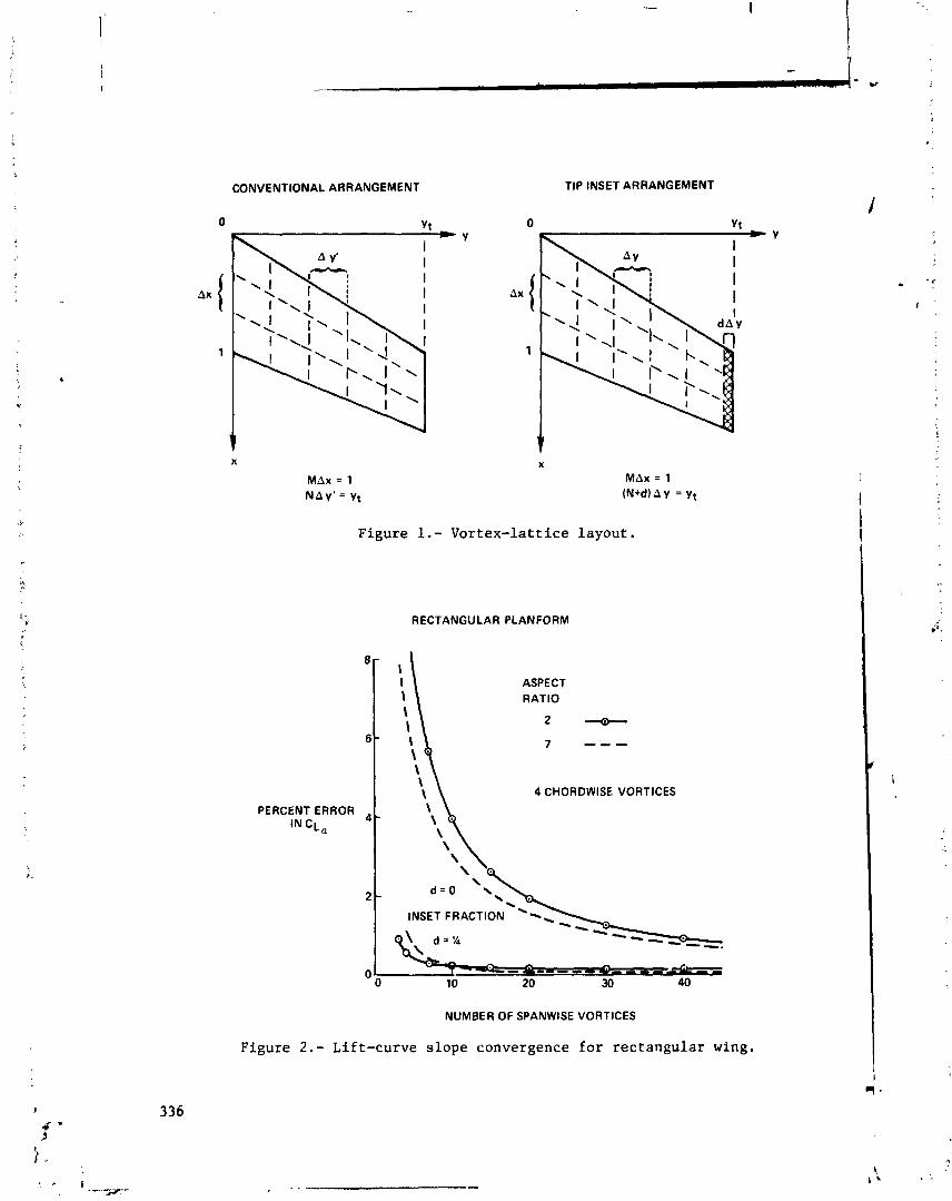
CONVENTIONAL ARRANGEMENT
0 Y t
TIP INSET ARRANGEMENT
0 Y t
Figure 1.- Vortex-lattice layout.
8 -
6 -
PERCENT ERROR IN C L ~
RECTANGULAR PLANFORM
ASPECT RATIO
2 - " . \ 7 ---
\
4 CHORDWISE VORTICES
NUMBER OF SPANWISE VORTICES
Figure 2.- Lift-curve slope convergence for rectangular wing.
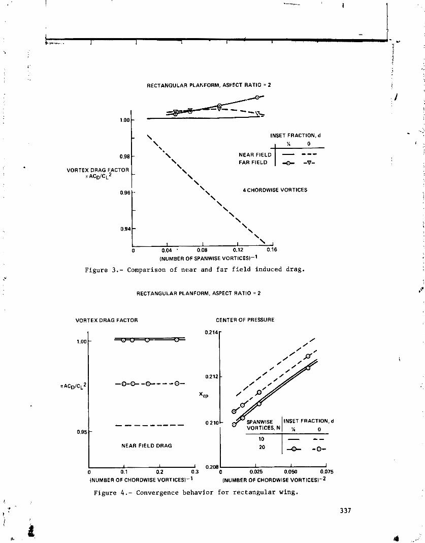
- -
1 I I 1 . b . . - U !a t 3 5 4 +' 9
. - RECTANGULAR PLAPiFORM, ASFFCT RATIO = 2 i
VORTEX DRAG FACTOR ~ A C ~ I C ~ ~ t
INSET FRACTION, d
FAR FIELD
4 CHORDWISE VORTICES
Figure 3 . - Comparison of nea r and f a r f i e l d induced drag.
RECTANGULAR PLANFORM, ASPECT RATIO = 2
VORTEX DRAG FACTOR CENTER OF PRESSURE
Figure 4.- Convergence behavior f o r r e c t a n g u l a r wing.

@LIFTING-LINE THEORY (PRANDTL) - HIGH ASPECT RATIO, ELLIPTIC PLANFORM
@LOW ASPECT RATIO THEORY (JONES)
@NUMERICAL LIFTINGSURFACE THEORY (HOUGH) - RECTANGULAR PLANFORM 2 n A
a. CL, = - (1% ACCURACY FOR 16 > A 2 2.5) A+3
2 n A b. CL, - ~ + 2 . 9 0 3 + 0 2 7 (314% ACCURACY FOR 16 2 A > 1)
A
Figure 5.- Lift-curve slope formulas.
RECTANGULAR PLANFORM. ASPECT RATIO = 5
NACA 230 MEAN LINE 10 SPANWISE VORTICES
SPACING
COSINE CHORDWISE
Figure 6.- Convergence for cambered wing.

LIFTCURVE SLOPE, CL a
WARREN.12 PLANFORM, ASPECT RATIO = 2 0 d. INSET
4 CHORDWISE VORTICES
t 2.70 0.04 0.08 0.1 2 0.16
(NUMBER OF SPANWISE VORTICES)-1
Figure 7 . - Lift-cr~rve slope convergence for tapered wing.
WARREN-12 PLANFORM. 10 SPANWISE VORTICES
FAR FIELD CALCULATION- 1.02 r \
- RECTANGULAR VORTICES
\ (FOR DRAG CALCULATION ONLY)
VORTEX DRAG FACTOR n A C ~ I C . ~ ~ I
Figure 8 . - Induced drag for tapered wing.
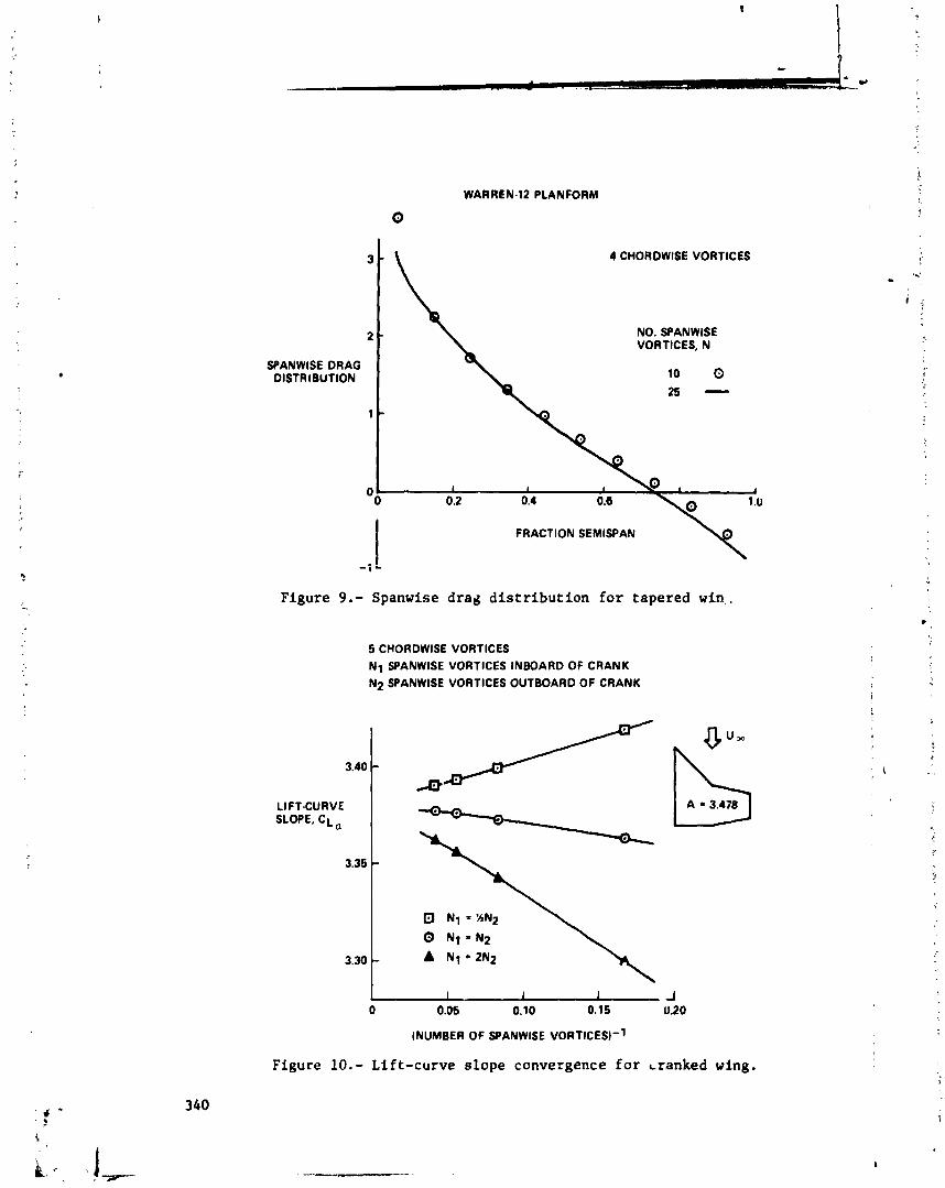
SPANWISE DRAG DlST RlBUT ION
WARREN-12 PLANFORM
4 CHORDWISE VORTICES
NO. SPANWISE VORTICES. N
Figure 9.- Spanwise drad distribution for tapered win,.
5 CHORDWISE VORTICES N 1 SPANWISE VORTICES INBOARD OF CRANK N2 SPANWISE VORTICES OUTBOARD OF CRANK
Figure 10.- Lift-curve slope convergence for cranked wing.
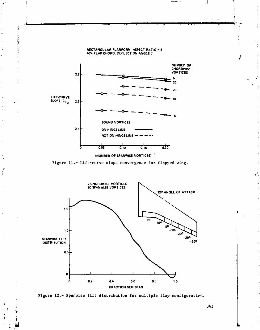
1 -- - *-' I
4 4 * - ... . * U
! !
1'
Z
5
$ . . 1 d
t4 RECTANGULAR PLANFORM, ASPECT RATIO 4 40% FLAP CHORD, DEFLECTION ,ANGLE 0
I
VORTICES
6 20
I BOUND VORTICES:
2B t ON HlNGELlNE
NOT ON HlNGELlNE - - - --
Figure 11.- Lift-curve slope convergence for flapped wing.
7 CHORDWISE VORTICES 20 SPANWISE ieORTICES \
I \ 120 ANGLE OF ATTACK
SPANWISE LIFT DISTRIBUTION
Figure 12.- Spanwise lift distribution for multiple flap configuration.
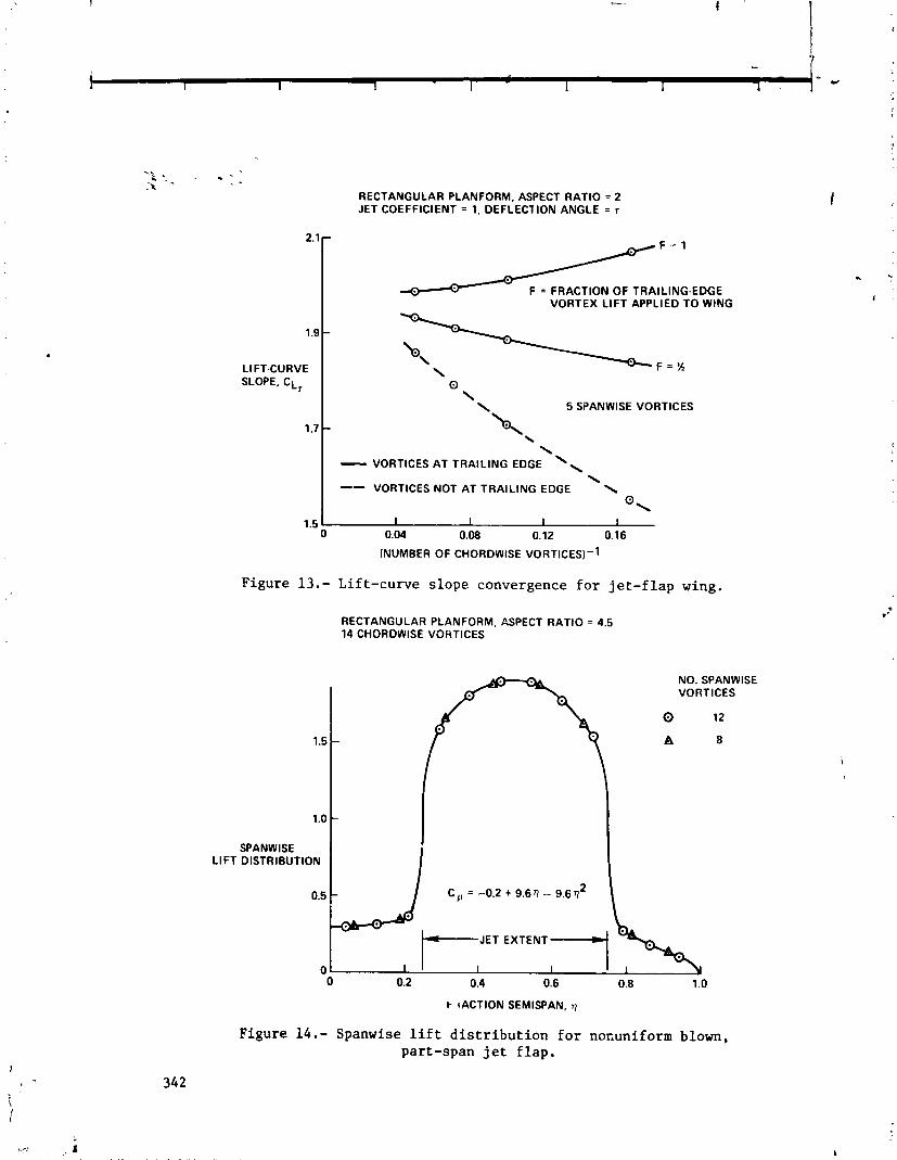
RECTANGULAR PLANFORM, ASPECT RATIO = 2 JET COEFFICIENT = 1. DEFLECTION ANGLE = I
F = l
F = FRACTION OF TRAILING.EDGE VORTEX LlFT APPLIED TO WING
\ \ 5 SPANWISE VORTICES
\
I - VORTICES AT TRAILING EDGE '\ \ I -- VORTICES NOT AT TRAILING EDGE \
@ \
Figure 13.- Lift-curve slope convergence for jet-flap wing.
RECTANGULAR PLANFORM, ASPECT RATIO = 4.5 14 CHORDWISE VORTICES
NO. SPANWISE VORTICES
0 12
A 8
SPANWISE LlFT DISTRIBUTION
0 0.2 0.4 0.6 0.8 1.0
k (ACTION SEMISPAN. r)
Figure 14.- Spanwise lift distribution for nofiuniform blown, part-span jet flap.

OPTIMUM LATTICE ARRANGEMENT DEVELOPED FROM
A RIGOROUS ANALYTICAL BASIS*
John DeYoung Vought Corporat ion Hampton Technical Center
The spanwise v o r t e x - l a t t i c e arrangement i s mathemat ica l ly es tab l i shed by l a t t i c e so l u t i ons o f the s lender wing which a re shown t o be analogous t o t he chordwise v o r t e x - l a t t i c e t h i n wing so lu t i on . So lu t ions f o r any N number of panels t o i n f i n i t y a re obtained. With the optimum l a t t i c e for any N va lue t h e s lender wing theory l i f t and induced drag and t h i n wing theory l i f t and moment a re p red ic ted exac t l y . For N*, s lender wing e l l i p t i c spanwise load ing and t h i n wing cotangent chordwi se load ing a re predicted, which proves there i s mathematical convergence o f t h e v o r t e x - l a t t i c e method t o t he exact answer. Based on t h i s A-to and an A- planform spanwise l a t t i c e arrangements, an A-vortex-1 a t t i ce spanwi se system i s developed f o r a r b i t r a r y aspect r a t i o . Th is A - l a t t i c e has the optimum c h a r a c t e r i s t i c o f p r e d i c t i n g 1 i f t accura te ly f o r any N value. .'
INTRODUCTION
Growth of computer f a c i l i t i e s has given the engineer a powerful t o o l f o r ob ta in ing so lu t i ons t o general i zed problems. Th is i s poss ib le because w i t h numerical o r f i n i t e -d i f f e rence methods the equat ions o f a problem can be simp1 i f i e d r e a d i l y t o computer language. V o r t e x - l a t t i c e methods have been developed ex tens ive ly f o r steady and unsteady pressure p r e d i c t i o n and f o r p lanar and nonplanar con f igu ra t ions . Examples o f some o f the work and i nves t i ga t i ons i n t he vor tex-1 a t t i c e method and aspects and app l i ca t i ons o f t h i s method a re repor ted i n references 1 through 20. A b r i e f d e s c r i p t i o n o f the t y p i c a l vo r tex l a t t i c e i s t h a t the surfaces a re d i v i ded i n t he spanwise and chordwise d i r e c t i o n s i n t o panels which cover the sur face w i t h a l a t t i c e . The sides o f the panels a re p a r a l l e l t o t he f reestream and the chordwise panel boundaries f o l l ow the sur face contour. The 114 chord l i n e o f each panel conta ins a bound o r load vor tex w h i l e the t r a i l i n g v o r t i c e s a re a t the s ides o f t he panel. The boundary cond i t i on o f no f l o w through the surfacc i s f u l - f i l l e d on every panel a t one p o i n t l oca ted a t the l a t e r a l cen te r o f the 314 chord l i n e of the panel. These panels a re d i s t r i b u t e d i n a un i form, and thus geomet r i ca l l y s implest mesh, r e f e r r e d t o as a planform l a t t i c e . However, i n
*Preparat ion of t h i s paper was supported p r i n c i p a l l y under NASA Langley Cont ract No. NAS1-13500.
1966 an a p p l i c a t i o n of the l a t t i c e method of reference 5 t o a swept wing showed t h a t the chord load ing i n the panel border ing t he wing lead ing edgc was too low, the spanwise load ing near the wing t i p was too h i gh f o r engineer ing accep tab i l i t y , and the ne t 1 i f t s l i g h t l y too large. Th is was w i t h 1C0 panels on the semispan, 10 chordwise t imes 10 spanwise. I n v e s t i g a t i o n of a i a t t i c e mathematical model was made a t t h a t t ime o f the chordwise panel d i s t r i b u t i o n - . .. .. ,.
and l a t e r repor ted i n reference 20. The r e s u l t s o f t h i s work showed t h a t the loading a t the lead ing edge panel needs a f a c t o r o f about 1 . I28 which improved I :
the loading value i n t h a t panel. However,the too h i gh wing t i p load ing and l i f t was no t explained. I n e a r l y 1972 a mathematical ly r igo rous spanwise vortex-1 a t t i ce ana lys i s was developed based on slender wing theory ( p a r t of r e f . 19). This was mathematical ly analogous t o the e a r l i e r chordwise s o l u t i o n bu t more compl icated. This spanwise l a t t i c e arrangement i s character ized by a 114 - 314 r u l e which locates the t r a i l i n g v o r t i c e s inboard 114 o f the planform panel span and the no f low through po in t s inboard 314 o f planform panel span from the planform panel outboard edges. This inboard s h i f t c f the l a t t i c e leads t o so lu t ions w i t h less loading near the wing t i p and l e s s 1 ift, which improves the loading i n the above example. This example supports the observat ion t h a t accuracy depends on the p o s i t i o n o f the panels i n the l a t t i c e as we l l as dens i t y of panels.
The ob jec t i ves o f the present study a re t o c o r r e l a t e and extend the work o f references 19 and 20, t o i nves t i ga te the e f f e c t o f three-dimensional planform on l a t t i c e arrangement, arrangement and method f o r th ree
and t o formulate a dimensional wings.
general i zed vortex-1 a t t i c e
SYMBOLS
A aspect r a t i o
*e swept panel aspect r a t i o [eq. (52) ]
b, c wing span, wing chord
CL, CLa l i f t c o e f f i c i e n t , l i f t - c u r v e slope
C D ~ induced drag c o e f f i c i e n t
Cjls CR sec t ion 1 i f t coe f f i c i en t , sec t ion 1 i f t - c u r v e slope
a
C m a ~ E sec t ion p i t c h i n g moment c o e f f i c i e n t due t o angle o: a t t ack
eNcnc parameter o f chordwise loading [eq. (38) ]
~ c n c chordwise loading f a c t o r [eq. (41 ) and t a b l e 51
G spanwise loading c o e f f i c i e n t o r dimensionless c i r c u l a t i o n [eq. ( I ) ]
' ~ n parameter o f spanwise incremental c i r c u l a t i o n [eq. (7)]
Subscr ipts:
spanwise load ing g rad ien t f a c t o r [eq. (19) and t a b l e 2)
spanwise load ing f a c t o r [eq. (22) and t a b l e 31
i n t e g e r number of panels on wing semispan, and wing chord r espec t i ve l y
i n t ege rs denot ing spanwise p o s i t i o n o f vor tex, and downwash p o i n t
i n t ege rs denot ing chordwise p o s i t i o n o f vortex, and downwash p o i n t
f r e e stream v e l o c i t y
angle o f a t t a c k
c i r c u l a t i o n , a l s o Gamma f u n c t i o n
l a t e r a l coord ina te per wing semispan
sweep angle a t 50% chord l i n e
l o n g i t u d i n a l coord inate per wing sec t i on chord
v vo r tex
w downwash p o i n t
L E lead ing edge
SLENDER WING OPTIMUM VORTEX LATTICE
Physical S i m i l a r i t y o f T r a i l i n g Vortex Sheet Flow w i t h Chordwise Thin Wing Theory Flow
The o b j e c t i v e o f t h i s ~ t u d j l i s t o do a r igo rous a n a l y t i c a l d e r i v a t i o n t o determine t he optimum spanwise d i s t r i b u t i o n o f panels analogous t o the ana l ys i s done i n re ference 20 f o r the optimum chordwise d i s t r i b u t i o n o f panels. Optimum here defines the l a t t i c e which bes t dup l i ca tes exact so lu t ions . A phys ica l s i m i l a r i t y does e x i s t between t h e v o r t i c i t y d i s t r i b u t i o n o f the chordwise load ing w i t h the t r a i l i n g vo r tex sheet from a f i n i t e span wing. Th is can be seen g r a p h i c a l l y i n f i g u r e 1 where t h i n a i r f o i l theory chord-load v o r t i c i t y i s compared w i t h the t r a i l i n g v o r t i c i t y which i s p red ic ted by s lender wing theory ( r e f s . 21 and 22). I t has of ten been noted t h a t t he mathematics o f t h i n wing and slender wing t heo r i es have a s t r i k i n g s i m i l a r i t y .
-om f i gu re 1, i t i s noted t h a t a s i m i l a r i t y o f v o r t i c i t y i s obtained when Lhe winq t i p a t TI = 1 co r re l a tes w i t h t he wing lead ing edge, and the

midspan p o i n t a t n = 0 cor re la tes w i t h t he wing t r a i l i n g edge. Since t h i s c o r r e l a t i o n makes the f l o w f i e l d s analogous, i t fo l lows t h a t the optimum spat?- wise panel d i s t r i b u t i o n i s analogous t o the optimum chordwise panel d i s t r i b u - t i o n given i n reference 20. Th is i s subject t o the cond i t i on t h a t the d i s t r i b u t i o n s t a r t a t t he wing t i p and proceed inboard. Applying t h i s cond i t i on and us ing these d i s t r i b u t i o n condi t ions, t he spanwise panel d i s t r i b u t i o n becomes t h a t shown i n f i gu re 2. The determinat ion o f an optimum
. chordwise panel d i s t r i b u t i o n i s made by two-dimensional i z i n g the problem t o 4
planar f low and thus the spanwise ex ten t of the panel i s i n f i n i t e . The optimum chordwise panel d i s t r i b u t i o n i s t h a t which y i e l d s t h i n wing so lu t i ons which most accura te ly dup l i ca te the r e s u l t s o f exact t h i n a i r f o i l theory. I n the present work, the determinat ion o f an optimum spanwise panel d i s t r i b u t i o n w i l l be made by two-dimensional iz ing the problem t o cross-sect ional f l ow and thus the chordwise ex ten t of the panel i s i n f i n i t e . The optimum A-+O spanwise panel d i s t r i b u t i o n i s t h a t which y i e l d s s o l u t i o n which most accura te ly dupl i ca tes the resu l t s o f s lender wing theory.
The ob jec t i ve o f t he present paper i s t o apply the a n a l y t i c a l methodology of re ference 20 t o determine the optimum spanwise panel d i s t r i b u t i o n . This d i s t r i b u t i o n should r e s u l t i n an exact p r e d i c t i o n o f t o t a l l i f t f o r any number of spanwise panels and prov ide spanwise loading f ac to r s . The chordwi se panel d i s t r i b u t i o n ana lys is i s co r re l a ted w i t h t h i n a i r f o i l theory f o r the determi na t i on of opt imal accuracy. I n an analogous procedure the spanwi se panel d i s t r i b u t i o n ana lys is here w i l l be co r re l a ted w i t h s lender wing theory f o r the determinat ion o f opt imal accuracy.
Formulation of Spanwise L a t t i c e Mat r i x and So lu t i on t o I n f i n i t y which S a t i s f y A l l Boundary Points
Slender wing theory eq.~at ions f o r add i t i ona l loading ( r e f . 22) a re
r ( d - where Ga(n) = - - - bVa 2ba
Also presented i n re ference 22 a re so lu t ions f o r f l a p , a i le rons , and a l l spanwise loadings, which can be used t o eva luate l a t t i c e accuracy when a problem invo lves these types o f loadings.
By Biot -Savar t law, the downwash a t nwm due t o an i n f i n i t e ex ten t vo r tex a t qvn i s (see f i g . 2)
w i t h v o r t i c e s located a t

boundary c o n d i t i o n po in t s a t
w i t h equat ions (3) and (4 ) t he downwash angle a t 21, i s
(5)
1 load ing (am=a), equat ion w i t h equdtions (3) , (4 ) , and (5 ) f o r add i t i ona ( 5 ) becones
n=l
where
Generalized I nve rs i on o f gNn Equ a t i
Equation ( 6 ) represents N unknowns, g~,, and N Equations. An i nve rs i on o f equat ion ( 6 ) means a l i n e a r simultaneous s o l u t i o n o f N equations. Solu t ions f o r N = 1, 2, . . . can be obtained r e a d i l y f o r small N and from the resu l t ed se r ies formed o f t he general s o l u t i o n can be determined by induc t ion . For N = 1, the s o l u t i o n i s
For N = 2, the l i n e a r simultaneous s o l u t i o n o f two equations i s
then,
These so lu t i ons a re done f o r h igher va Th is sequence i s presented i n t a b l e 1. t a b l e 1 shows the sequence f o l l ows the
lues o f N u n t Examination
general term
il a sequence i s formed. o f the 1 s t column i n o f

f o r n = 1:
I n the second column, r a t i o s of gN2/gNL g i v e s t h e sequence
N = 2 3 4 5 6
T h i s shows t h e general te rm as [and us ing gN1 from eq. (9) ]
f o r n = 2:
S i m i l a r l y , r a t i o s of gN3/gN2 g i v e the sequence
Th is shows t h e general term as [us ing gN2 from eq. ( l o ) ]
f o r n = 3:
52 3 ~ 3 ~ x 5 ~ ( ~ + 2 ) (N+1 ) (N) (N-1) (N-2) (2N-7)0dd! g ~ 3 = -
2'(2N-5) (2N+5) 2'(2N+5)0dd
These sequences of gN1, gN2, and gN3 show t h a t
- - 3 ~ 3 ' ~ 5 ~ ~ 7 ~ ( N + 3 ) (N+2) ( N t l ) (N) (N-1 ) (N-2) (N-3) (2N-9)odd! 3 '~2 ' (2Nt7 ) ,~~ ! (1 2)
Then i n enera l t h e recur rence i s [ f rom f i r s t e q u a l i t i e s of eqs. ( l o ) , ( l l ) , and (12)7
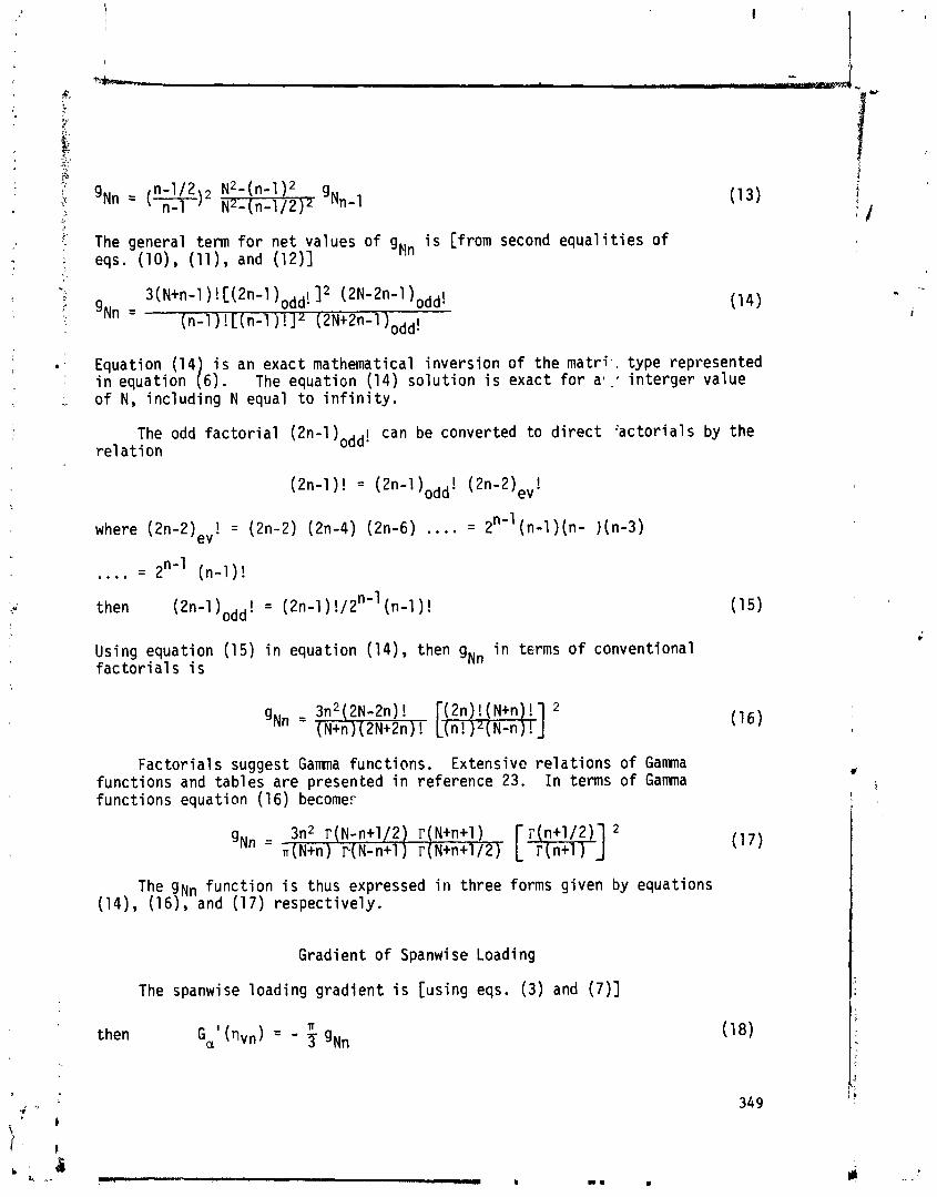
The general term f o r n e t values o f gNn i s [from second e q u a l i t i e s o f eqs. ( l o ) , ( l l ) , and (12)]
Equation (14 i s an exact mathematical i nve rs i on o f the m a t r i , , type represented i n e q u a t i o n /6) . The equat ion (14) s o l u t i o n i s exact f o r a l : i n te rger va lue o f N, i nc l ud ing N equal t o i n f i n i t y .
The odd f a c t o r i a l (2n-l)odd! can be converted t o d i r e c t ' ac to r i a l s by t he r e l a t i o n
where (2n-2)eV! = (2n-2) (2n-4) (2n-6) . . . . = 2"-' (n-1 ) (n- ) (n-3)
then (21-1-1 )odd! = (2n-1) !/2"' (n-1) !
Using equat ion (15) i n equation (14), then gNn i n tsrms o f conventional f a c t o r i a l s i s
F a c t o r i a l s suggest Gamma funct ions. Extensive r e l a t i o n s of Gamna func t ions and tab les a re presented i n re ference 23. I n terms of Gamma func t ions equation (16) become.
The gNn func t i on i s thus expressed i n three forms g iven by equations (14), (16), and (17) respec t i ve ly .
Gradient o f Spanwi se Loading
The spanwise load ing g rad ien t i s [using eqs. (3) and (7)]
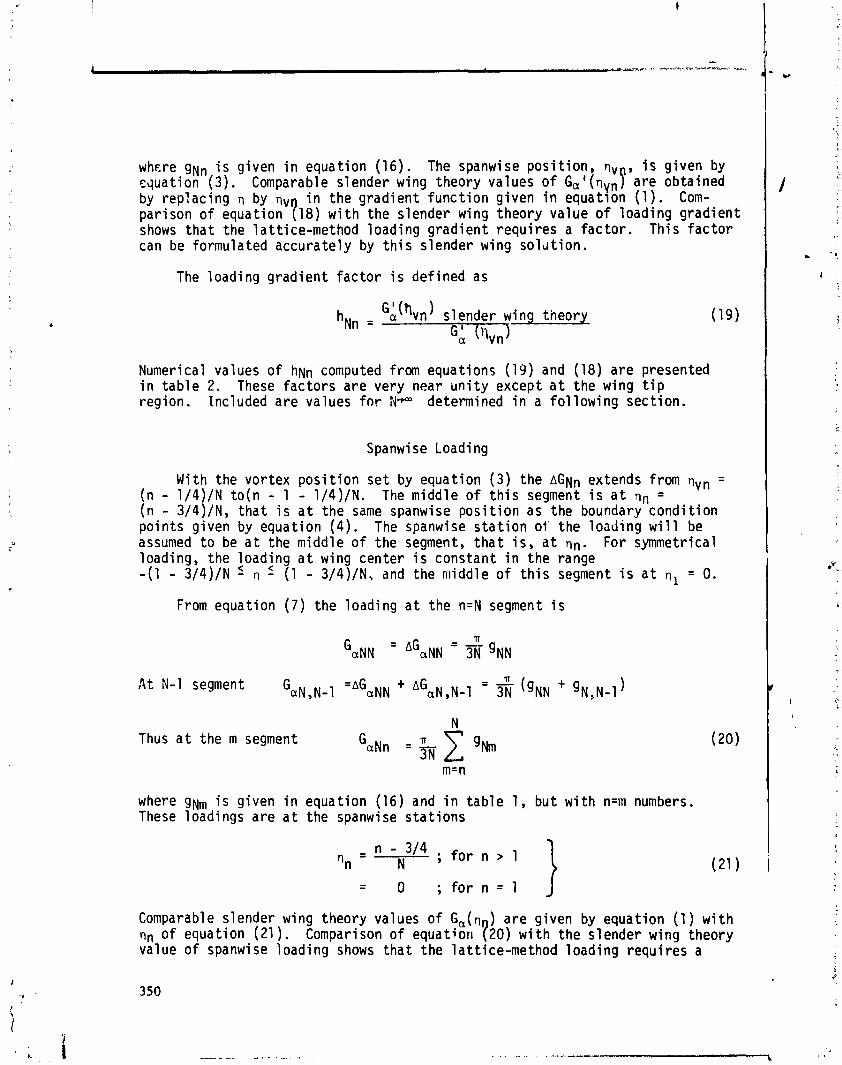
where g ~ , i s given i n equat ion (16) . The spanwise pos i t i on , vv , i s g iven by equat ion (3 ) . Comparable s lender wing theory values o f ~ ~ l ( n ~ ~ P a re obtained by rep lac ing by qv i n t he g rad ien t f u n c t i o n g iven i n equat ion ( 1 ) . Com- par ison of equat ion 118) w i t h the s lender wing theory va lue o f l oad ing g rad ien t shows t h a t the 1 at t ice-method load ing g rad ien t r equ i r es a f a c t o r . Th is f a c t o r can be formulated accura te ly by t h i s s lender wing s o l d t i o n .
The
Numeri ca 1
load ing g rad ien t f a c t o r i s de f ined as
h ~ n = GA(hvn) s lender wing theory
GA ('lvn)
values o f hNn computed from equations (19) and (18) a re presented i n t a b l e 2. These f a c t o r s a re very near u n i t y except a t the wing t i p reg ion. Included a re values f o r N- determined i n a f o l l o w i n g sect ion.
Spanwise Loading
With the vo r tex p o s i t i o n s e t by equat ion ( 3 ) t he AGNn extends from qVn = (n - 1/4)/N t o ( n - 1 - 1/4)/N. The midd le o f t h i s segment i s a t TI, = ( n - 3/4)/N, t h a t i s a t the same spanwise p o s i t i o n as the boundary c o n d i t i o n po in t s g iven by equat ion ( 4 ) . The spanwise s t a t i o n 01' the load ing w i l l be assumed t o be a t the midd le o f the segment, t h a t i s , a t on. For symmetrical loading, the load ing a t wing center i s constant i n t he range -(1 - 3/4)/N 5 n 5 (1 - 3/4)/N, and the midd le o f t h i s segment i s a t n , = 0.
From equat ion ( 7 ) t he load ing a t the n=N segment i s
At N-1 segment G a ~ , ~ - ~ - -"GNN + A G a ~ ,N-1 - - IT ( g ~ ~ + 'N,N-~ 1
Thus a t the m segment
where g~, i s g iven i n equat ion (16) and i n t a b l e 1, bu t w i t h n=m numbers. These loadings a re a t the spanwise s t a t i o n s
"n - - 3/4 ; fo r n > 1 - N 1
Comparable s lender wing theory values of Ga(q ) a re given by equat ion ( 1 ) w i t h on o f equat ion (21 ) . Comparison o f equat ion 120) w i t h the s lender wing theory value of spanwise load ing shows t h a t t he la t t i ce -method load ing requ i res a
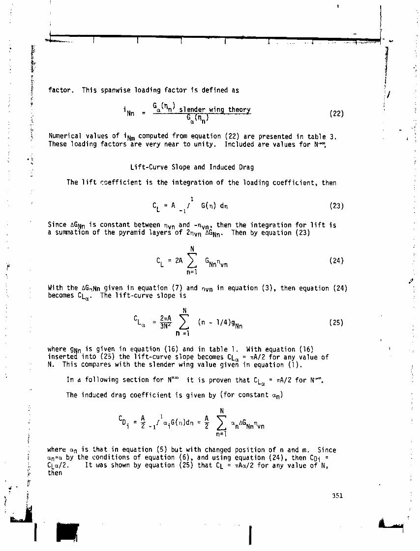
fac tor . This spanwise loading f a c t o r i s def ined as
i Nn = slender wing theory
Ga (en )
Numerical values of iN, computed from equation (22) are presented i n tab le 3. These loading fac tors are very near t o un i t y . Included are values f o r N*,
Li f t -Curve Slope and Induced Drag
The l i f t r s e f f i c i e n t i s the i n teg ra t i on of the loading coe f f i c i en t , then
Since AGN, i s constant between qvn and -nvn, then the i n teg ra t i on f o r l i f t i s a sumnation o f the pyramid layers of 2nvn AGNn. Then by equation (23)
With the AG,Nn given i n equation (7) and nvn i n equation ( 3 ) . then equation (24) becomes CL,. The 1 i f t - c u r v e slope i s
where g n i s given i n equation (16) and i n tab le 1. With equation (16) i nse r te ! i n t o (23 ) the l i f t - c u r v e slope becomes CL, = nA/2 f o r any value o f N. This compares w i t h the slender wing value given i n equation (1) .
I n a fo l low ing sect ion f o r NZm i t i s proven tha t CL, = nA/2 fo r NW.
The i n d x e d drag c o e f f i c i e n t i s given by ( fo r constant an)
where an i s t h a t i n equation (5) bu t w i th changed pos i t i on o f n and m. Since an=a by the condi t ions o f equation (6). and using equation (24). then C D i = C L C J ~ . I t was shown by equation (25) t ha t CL = nAa/2 fo r any value o f N, then
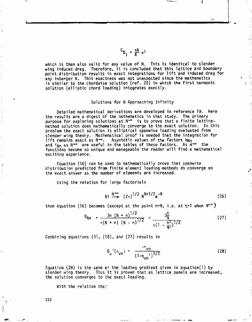
which i s then a lso v a l i d f o r any value o f N. Th is i s i d e n t i c a l t o s lender wing induced drag. Therefore, i t i s concluded t h a t t h i s l a t t i c e and boundary p o i n t d i s t r i b u t i o n r e s u l t s i n exact i n t eg ra t i ons f o r 1 i f t and induced drag f o r any i n t e r g e r N. This exactness was no t unexpected s ince the mathematics - I, i s s i m i l a r t o the chordwise s o l u t i o n ( r e f . 20) i n which the f i r s t harmonic I ; s o l u t i o n ( e l 1 i p t i c chord loading) i n teg ra tes exac t l y .
Solut ions f o r N Approaching I n f i n i t y
De ta i led mathematical de r i va t i ons a re developed i n re ference 19. Here the r e s u l t s a re a d i ges t o f the mathematics i n t h a t study. The pr imary purpose f o r exp lo r ing so lu t i ons a t N-"" i s t o prove t h a t a f i n i t e l a t t i c e - method so lu t i on does mathematical ly converge t o the exact so lu t i on . I n t h i s problem the exact s o l u t i o n i s e l l i p t i c a l spanwise loading evaluated from slender wing theory. Mathematical p roo f i s needed t h a t the i n t e g r a t i o n f o r l i f t remains exact as N-. Asymtotic values o f the factors hNn and i N n as K*" are usefu l i n the tab les o f these f ac to r s . As IV- the funct ions become so unique and manageable the reader w i l l f i n d a mathematical exc i t i ng exper i ence .
Equation (16) can be used t o mathematical ly prove t h a t spanwise d i s t r i b u t i o n pred ic ted from f i n i t e elemect loading methods do converge on the exact answer as the number o f elements a re increased.
Using the r e l a t i o n f o r l a rge f a c t o r i a l s
then equat ion (16) becomes (except a t the p o i n t n=N, i .e. a t q=1 when N=")
Combining equations ( 3 ) , (18), and (27) r e s u l t s i n
Equation (28) i s the same as the loading g rad ien t given i n equat ion(1) by slender wing theory. Thus i t i s proven t h a t as l a t t i c e panels a re increased, the s o l u t i o n converges t o the exact loading.
With the r e l a t i o n tha t

then equation ( 1 7 ) can be expressed i n the forms
N" N-n = f i n i t e (30)
g ~ , ~ - n = 3N1I2 r ( N - n + 1 1 2 n2 ' l2 r ( N - n + I )
Then f o r N" the spanwise loading gradient f a c t o r o f equation (19) becomes
N- N- n = f i n i t e N-n = f i n i t e (31
r(N-n + 1 ) h ~ n = n (N-n + 114)''~r(N-n + 112)
With the use o f the ser ies summation
the spanwise loadins fac to r
N="
i ~ , ~ - n
o f equation (22) f o r N-becomes
Numerical values of equations (31) and (33) are l i s t e d i n tables 2 and 3. Examination o f these equationr ind icates simple re la t ionsh ips . These re la t ionsh ips extend t o chordwise loading fac to rs developed i n a l a t e r sect ion and can be expressed i n one equation as fo l lows:
- f o r N = NC - - 112
h ~ n IN ,N-n+l f ~ c ,Nc-nc+l h ~ , ~ - n = - - -
1 - 1 1 6 n ) = [1-1/16(~-n+1)2] ' /~ - 11 - 1 / 1 6 ( ~ , - n ~ - l ) ~ ] 'I2
For the zero condi t i o n
= f - h ~ , (N-n)=0 = 1 .I28379 Nc9(n$)=0 - 7

For N-n = 1
For N = - the expression f o r C L ~ develops i n t o the f o l l o w i n g s ~ r i e s summation:
This f a c t o r o f A12 i s n, thus CL = nA/2. a
CHORDWISE VORTEX LATTICE
Formulat ion of Chot-dwi se L a t t i c e Ma t r i x and S o l u t i m t o I n f i n i t y
I n reference 2d the l a t t i c e i s d i s t r i b u t e d i n t o equal l eng th chord segments and the chcrd load ing vor tex i s loca ted ~t the 114 po in t s of each of the chord segment:; and boundary c o n d i t i o ? p o i n t a t the 3/4 p o i n t o f each o f the chord segments. Then the load vor tex chord s t a t i o n and the boundary cond i t i on chord s t a t i o n a re r espec t i ve l y a t
where 5 = x/c.
The load ing equations t o be solved a re g iven as,
where
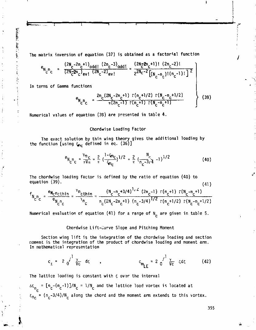
The mat r i x invers ion o f equation (37) i s obtained as a f a c t o r i a l func t ion I
I I n terms o f Gamna funct ions i -
-- ! Numerical values o f equation (39) are presented i n tab'e 4.
Chordwi se Loading Factor
The exact so lu t ion by t h i n wing theory g ives the add i t iona l loading by the func t ion [using kc defined i n eq. (36)]
The chordwise loading f a c t o r i s defined by the r a t i o o f equation (40) t o equation (39).
(41 . .
f eNcncthin - c t h i n - -n +3/4)11 (2nc-1 ) r ( n c t l ) r(Nc-nc+l ) Y n N n = - - (Nc c
C C e~ n C C
n c nc(2Nc-2nc+l ) (nc-314) 'I2 r (nc+l 12) r (Nc-nc+l/2)
Numerical evaluat ion o f equation (41) f o r a range o f Nc are given i n tab le 5.
Chordwi se L i ft-Curve Slope and P i tch ing Moment
Section wing l i f t i s the i n teg ra t i on o f the chordwise loading and sect ion r;iom~nt i s the i n teg ra t i on o f the product o f chordwise loading and moment am. I n mathemati cal representat ion
, T h e l a t t i c e l o a d i n g i s c o n s t a n t w i t h c o v ~ ? r t h e i n t e r v a l
; A C = ["-(nc-l)]/Nc = l / N c and the l a t t i c e load vortex i c located a t c
kc = (nc-3/4)/Nc along the chord and the moment arm extends t o t h i s vor tex.

Then w i t h equation (38) equation (42) becomes
The summation terms i n equation (43) are 1 i s t e d i n tab le 4 which when inser ted i n t o equation (43) show t h a t the l i f t and moment f o r a r b i t r a r y Nc i s the same as predicted by t h i n wing theory, t h a t i s
Proof t ha t cka i s Exact a t A1 1 Values of N
Inse r t i ng equation (39) i n t o (43) resu l t s i n
Now r(n+1/2) = (11-112) r(n-1/2); r(N-n-112) = r(N-n+1/2)/(N-n-112) ; and
r ( n + l ) = n r (n ) = n!, then
The Gamma functions and fac to r i a l s i n equation (46) show t r A t h i s product term i s a symmetric funct ion which i s factored by an a n t i s y m e t r i c term (brt)/lgm Then some o f the h igh nc terms cancel the low nc terms. By exi>anding the summation a new summation can be formed given by
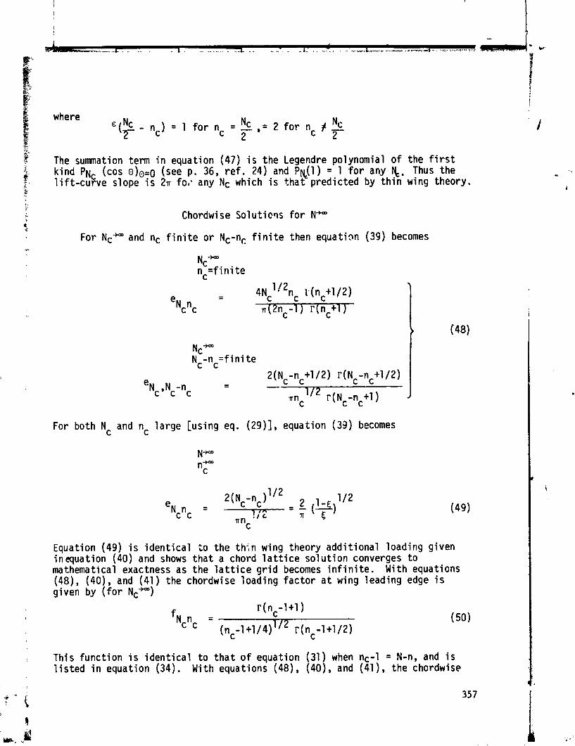
%?
The summation term i n equation (47) i s the Legendre polynomial o f the f i r s t
2. k ind P N ~ (COS O)O=O (see p. 36, r e f . 24) and Py(1) = 1 f o r any &. Thus the 2 - l i f t - c u r v e slope i s 2n fo,. any Nc which i s t h a t predic ted by t h i n wing theory. L
Chordwise S o l u t i o ~ s f o r N-
For Nc- and nc f i n i t e o r Nc-n, f i n i t e then equation (39) becomes
For both Nc and nc la rge [using eq. (29)], equation (33) becomes
Equation (49) i s i den t i ca l t o the th;n wing theory add i t iona l loading given inequation (40) and shows t h a t a chord l a t t i c e so lu t i on converges t o mathematical exactness as the l a t t i c e g r i d becomes i n f i n i t e . With equations (48), (4O), and (41) the chordwise loading f a c t o r a t wing leading edge i s given by ( f o r Nc-)
; This func t ion i s i d e n t i c a l t o t h a t o f equation (31 ) when nc-1 = N-n, and i s l i s t e d i n equation (34). With equations (48), (40), and (41 ), the chordwise

1 cad
This
i n g f a c t o r a t wing t r a i l
f unc t i on i s i d e n t i c a l i s l i s t e d i n equat ion (34).
ng edge i s g iven by ( f o r Nc+-)
o iN,N-,, of equat ion (33) when Nc-nc = N-n, and
A,-VORTEX LATTICE
Dependency o f Spanwise L a t t i c e on E f f e c t o f Aspect Ra t i o
As aspect r a t i o approaches zero the spanwi se optimum l a t t i c e arrangement i s t h a t def ined by equat ion ( 3 ) , t h a t i s a t r\vn = (n-1/4)/N. As aspect r a t i o approaches i n f i n i t y the spanwi se l a t t i c e arrangement i s the planform l a t t i c e which pos i t i ons the t r a i l i n g v o r t i c e s a t nvn = n/N, t h a t i s a t the outs ide edge of the l a t t i c e panel i nc l ud ing a vor tex a t the w ing t i p . This i s because a t A = a the spanwise load ing has the same d i s t r i b u t i o n as the wing chord along t he span. This h i gh loading near the wing t i p (when A = a) must be taken i n t o account by the l a t t i c e t r a i l i n g vo r t i ces . The o b j e c t i v e here i s t o develop an aspect r a t i o f u n c t i o n f a c t o r f o r the l a t e r a l panel pos i t i ons which asympto t i ca l l y approaches the c c r r e c t values a t A e 4 and a t A,-. The subscr ip t e denotes the e f f e c t i v e swept panel aspect r a t i o given by
The planform l a t t i c e (sVv = n/N) i s the l a t e r a l l a t t i c e arrangement t h a t has been i n general use i n most v o r t e x - l a t t i c e methods.
i An aspect r a t i o equal t o f o u r i s about an aerodynamic mean between
01Ae5w. Loading values based on the A e 4 l a t t i c e and on the Ae* l a t t i c e w i l l be computed f o r an Ae = 4 rectangular wing. Comparison w i t h t he load ing pred ic ted by an accurate ana lys is w i l l e s t a b l i s h the A -e f f ec t f u n c t i o n t h a t i s needed. By Biot -Savar t law the downwash due t o an unskewed horseshoe vor tex i s
Where 60 = cwm, - Cvnc9 and Gnnc i s the dimensionless vor tex str-ength o f the elemental horseshoe vor tex. For Nc = 1 so lu t ion , 50 r e m a i ~ s constant equal t o 1/4 f o r A = 4 . qAn i s the l a t e r a l middle o f the n pancl . Foi- the slender wing (Ae+O) l a t t i c e use
358

For the planform l a t t i c e use
- n - - m-112 - - "vn W 9 "wm N ' " ~ n = 0
The equation t o be solved f o r add i t iona l loading f o r an Nc = 1 solut ion, A = 4 rectangular wing i s
Wing l i f t - c u r v e slope i s determined from equation (24) and wing loading by equation (20) w i th which
where f o r the A 4 l a t t i c e i values are given i n tab le 3, wh i le f o r the planform l a t t i c e iNn are a l P u n i t y . Results o f the solut ions o f equation (56) w i t h the A e 4 l a t t i c e o f (54) and w i t h the planform l a t t i c e o f (55), f o r increasing N, are presented i n tables 6 and 7. An accurate loading pred ic t ion o f t h i s A = 4 rectangular wing i s made i n reference 19. From reference 19
Percent d i f fe rencer from the values of equation (58) are shown i n tables 6 and 7. For t h i s A = 4 wing the A 4 l a t t i c e has less than one-half the e r r o r o f the planform l a t t i c e .
Spanwi se Ae-Vortex L a t t i c e
Since f o r the A = 4 wing the A 4 l a t t i c e pred ic t ion i s too small and the planform (A*) l a t t i c e pred ic t ion too la rge then a fac to r can be developed between the two which forms the basis o f spanwise Ae- la t t i ce arrangement. This f a c t o r i s 21-, then f o r the A e - l a t t i c e
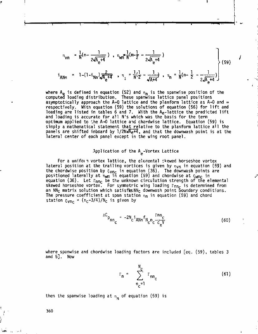
where A i s defined i n equat ion (52) and q,, i s the spanwise p o s i t i o n o f the compute$ loading d i s t r i b u t i o n . These spanwise l a t t i c e panel pos i t i ons asympto t i ca l l y approach the A+O l a t t i c e and the planform l a t t i c e as A 4 and - respec t i ve ly . With equat ion (59) the so lu t i ons o f equat ion (56) f o r l i f t and load ing a re l i s t e d i n tab les 6 and 7. With t he A e - l a t t i c e the p red ic ted l i f t and loading i s accurate f o r a l l N's which was the bas is f o r the term optimum appl ied t o the A 4 l a t t i c e awl chardwise l a t t i c e . Equation (59) i s s imply a mathematical statement t h a t r e l a t i v e t o the planform l a t t i c e a l l the panels are s h i f t e d inboard by 1/2N-, and t h a t t he downwash p o i n t i s a t the l a t e r a l center of each panel except i n the wing r o o t panel.
Appl i c a t i o n o f the Ae-Vortex L a t t i c e
For a u n i f o l i vor tex l a t t i c e , the elemental ckewed horseshoe vor tex l a t e r a l p o s i t i o n a t the t r a i l i n g v o r t i c e s i s g iven by qvn i n equat ion (59) and the chordwise p o s i t i o n by cvCc i n equation (36). The downwash po in t s are pos i t ioned l a t e r a l l y a t nr~m i n equation (59) and chordwise a t (mc i n equat ion (36). L e t rnnc be t k unknown c i r c u l a t i o n s t reng th of the elemental skewed horseshoe vortex. For symmetric wing load ing rnn i s determined from an NNc ma t r i x so lu t i on which satisfiesNNc downwash p o i n t 6oundary condi t ions. The pressure c o e f f i c i e n t a t span s t a t i o n nn i n equat ion (59) and chord s t a t i o n cvnc = (nc-3/44)Nc i s given by
where spanwise and chordwise load ing f ac to r s a re inc luded [eq. (59), tab les 3 and 51. Now
then the spanwise load ing a t qn of equat ion (59) i s

which inc ludes the spanwise load ing f a c t o r [eq. (59), t a b l e 31. The spanwise loading g rad ien t a t span s t a t i o n nvn i n equat ion (59) i s
where r n i s g iven i n equat ion (61) and where the spanwise load ing g rad ien t f a c t o r i s g iven by
hANn = 1-(1-h ) 2 Nn J , w i t h hNn i n t a b l e 2.
e
The l i f t c o e f f i c i e n t i s [rn from eq. (61) ]
The induced drag i s g iven by
where rn i s g iven i n equat ion (61). For spanwise loading d i s t r i b u t i o n a l ready known then equat ion (65) provides a c o n v e ~ i e n t method f o r p r e d i c t i n g induced drag. For t h i s case r )atnn i s known then rn i s determined from equation (62) f o r a p p l i c a t i o n i n ( 6 1 ) .
CONCLUDING REMARKS
The app l i ca t i on o f t he v o r t e x - l a t t i c e method t o the slender wing conf igu- r a t i o n has provided a r igo rous a n a l y t i c a l bas is f o r t he spanwi se p roper t ies o f the v o r t e x - l a t t i c e method. Mathematical s imi 1 a r i t i e s a re shown between the spanwise panel l a t t i c e s o l u t i o n and t he chordwise s o l u t i o n which con- verge t o t h i n winq theory resu l t s . As the number o f chordwise panels approaches i n f i n i t y , t h i n wing theory chordwise load ing i s p red ic ted exac t l y except i n the 1 i m i t po in ts exac t l y a t the lead ing edge and a t the t r a i l i n g edge. A t

these two points chordwise loading fac tors are mathematically evaluated which are useful i n f i n i t e panel solut ions. S imi la r ly , as the number o f spanwise panels becomes i n f i n i t e , slender wing theory spanwise loading i s predicted exact ly except a t the po in t o f the wing t i p . A t t h i s po in t a spanwise loading fac to r i s mathematically determined from a l i m i t so lut ion. The presentat ion i n t h i s paper i s based on a planform uniform d i s t r i b u t i o n o f panels chordwise and spanwise. I n a discussion i n 1972 M r . W . B. Kemp, Jr . o f NASA-Langley said he had found t h a t the chordwise v o r t e x - l a t t i c e so lu t i on gave an accurate in tegrated 1 i f t f o r an a r b i t r a r y planform panel d i s t r i b u t i o n along the chord. As pa r t o f the present work t h i s was invest igated and i t was shown t h a t using the 114 - 314 r u l e f o r l oca t i ng the vortex and downwash po in t i n the planform panel, the chordwise l i f t - c u r v e slope o f 2n and a lso the spanwise slender wing value of ~ A 1 2 are predic ted f o r any d i s t r i b u t i o n o f planform panels on the wing and for any t o t a l number o f panels. However, the loading d i s t r i b u t i o n factors are not as near un i ty . The aspect r a t i o e f f e c t on spanwise l a t t i c e arrangement has a weak chordwise counterpart f o r a chordwise l a t t i c e arrangement. An i n i t i a l study o f t h i s e f f e c t ind icates t h a t the chordwise l a t t i c e arrangement d i f f e r s when aspect r a t i o i s less than un i t y . I n conclusion, the A,-vortex-1 a t t i c e arrangement o f the previous sect ion provides a uniform uncomplicated, accurate system. It leads t o computations w i t h a high accuracy t o work r a t i o .
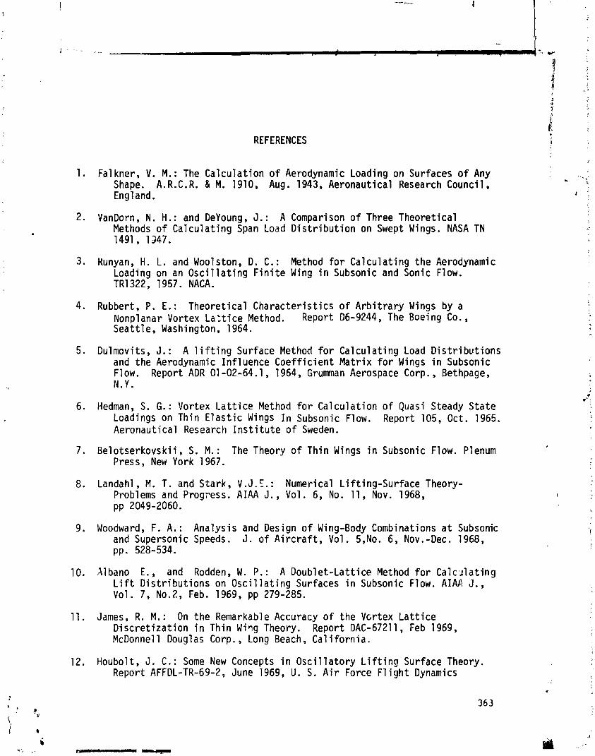
REFERENCES
1. Fa1 kner, V. M. : The Ca lcu la t ion o f Aerodynamic Loading on Surfaces o f Any Shape. A.R.C.R. & M. 1910, Aug. 1943, Aeronaut ical Research Council, England.
2. VanDorn, N. H.: and DeYoung, J. : A Comparison o f Three Theoret ica l Methods o f Ca lcu la t ing Span Load D i s t r i b u t i o n on Swept Wings. NASA TN 1491, 1347.
3 . Kunyan, H. L. and Woolston, D. C. : Method f o r Ca lcu la t ing t he Aerodynamic Loading on an O s c i l l a t i n g F i n i t e Wing i n Subsonic and Sonic Flow. TR1322, 1957. NACA.
4. Rubbert, P. E.: Theoret ica l Charac te r i s t i cs o f A r b i t r a r y Wings by a Nonplanar Vortex La:tice Method. Report D6-9244, The Boeing Co. , Seat t le , Washington, 1964.
5. Dulmovits, J. : A l i f t i n g Surface Method f o r Ca lcu la t ing Load D i s t r i b u t i o n s and the Aerodynamic In f luence C o e f f i c i e n t Ma t r i x f o r Wings i n Subsonic Flow. Report ADR 01 -02-64.1 , 1964, Grumnan Aerospace Corp. , Bethpage, N.Y.
6. Hedman, S. G . : Vortex L a t t i c e Method f o r Ca lcu la t ion o f Quasi Steady S ta te Loadings on Thin E l a s t i c Wings I n Subsonic Flow. Report 105, Oct. 1965. Aeronaut ical Research I n s t i t u t e o f Sweden.
7 . Belo tserkovsk i i , S. M. : The Theory o f Thin Wings i n Subsonic Flow. Plenum Press, New York 1967.
8. Landahl , M. T. and Stark, V.J. !. : Numerical L i f t i ng -Su r face Theory- Problems and Prog~ess . AIAA J., Vol . 6, No. 11, Nov. 1968, pp 2049-2060.
9. Woodward, F. A. : Analys is and Design o f Wing-Body Combinations a t Subsonic and Supersonic Speeds. J. o f A i r c r a f t , Vol . 5,No. 6, Nov.-Dec. 1968, pp. 528-534.
10, Albano E., and Rodden, W. P.: A Doub le t -La t t i ce Method f o r C a l c t ~ l a t i n g L i f t D i s t r i b u t i o n s on O s c i l l a t i n g Surfaces i n Subsonic Flow. AIM J., Vol. 7, No.2, Feb. 1963, pp 279-285.
11. James, R. M.: On the Remarkable Accuracy o f the Vcrtex L a t t i c e D i s c r e t i z a t i o n i n Thin W i ~ g Theory. Report DAC-67211, Feb 1969, McDonnel 1 Doug1 as Corp. , Long Beach, Cal i f o r n i a.
12. Houbolt, J. C . : Some New Concepts i n O s c i l l a t o r y L i f t i n g Surface Theory. Report AFFDL-TR-69-2, June 1969, U. S. A i r Force F l i g h t Dynamics
Laboratory, Wri ght-Patterson A i r Force Base, Ohio.
Margason, R. J . and Lamar, J . E. : Vortex-Lat t ice For t ran Program f o r Est imat ing Subsonic Aerodynamic Character is t ics o f Complex Planforms. NASA TN D-6142, Feb. 1971, 139 pp.
Kalman, T. P., Rodden, W. P., and Giesing, J . P. : App l ica t ion o f the Doublet-Latt ice Method t o Nonplanar Conf igurat ions i n Subsonic Flow. J. o f A i r c r a f t , Vol 8, No. 6, June 1971, pp 406-413.
Lamar, J . E. : Nonplanar Method f o r Pred ic t ing Incompressible Aerodynamic Coef f i c ien ts of Rectangular Wings w i t h Ci rcu lar-Arc Camber. Ph.D. Disser tat ion, Aerospace Engineering, V i r g i n i a Polytechnic I n s t i t u t e and State Univers i ty , December 1971, 91 pp.
Seath, D. D. and DeYoung, J . : Generation o f F in i te -D i f fe rence Mesh Geometry Conf igurat ions . Convair Report ERR-FW-1240, Dec. 1971 . General Dynamics, Fo r t Worth, Texas, 80 pp.
DeYoung, J. and Seath, D. D.: Examination o f Mcsh Geometry Generation Techniques. UTA Report No. AE 72-01, Dec 1971 , Un ive rs i t y o f Texas a t Ar l ington, Ar l ington, Texas, 18 pp.
Lan, C. t. : A Quasi-Vortex-Latt ice Method i n Thin Wing Theory. J. o f A i r c r a f t , Vol. 11, No. 9, Sept. 1974, pp 518-527.
Dejoung, J. : Wing Loading Theory Sa t i s f y i ng A1 1 Boundary Points. Ph.D. Disser tat ion, The Un ivers i ty of Texas a t Ar l ington, Ar l ington, Texas, Dec. 1975, 180 pp.
DeYoung J . : Convergence-Proof o f Discrete-Panel Wing Loading Theories. J. o f A i rcraTt, Vol . 8, No. 10, Oct. 1971, pp. 837-838.
Jones, R. T.: Propert ies o f Low-Aspect Rat io Po i r ted Wings a t Speeds Below and Above the Speed o f Sound. NACA Report 835, i 946.
DeYoung, J . : Spanwise Loading f o r Wings and Control Surfaces o f Low Aspect Ratio, NASA TN 2011, Jan. 1950, 36 pp.
Handbook o f Mathematical Functio;is w i t h Formulas, Graphs, and Mathematical Tables. Edited by Abramowitz, M. and Stegun, I.A., National Bureau o f Standards, Appl i e d Mathematics Series 55, U.S. Government P r i n t i n g Of f i ce , 1965, 1046 pp.
Mangul i s , V. : Handbook o f Series f o r Sc ien t i s t s and Engineers. Academic Press. New York and London, 1965, 134 pp.
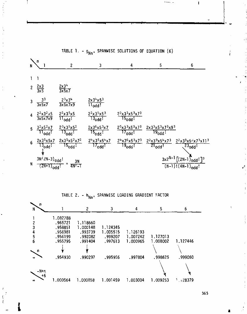
TABLE 1 . - gN, , SPANWISE SOLUTIONS OF EQUATION ( 6 )
TABLE 2. - hN,, SFANW I S E LOADING GRADIENT FACTOR

TABLE 3. - IN,, SPANWISE LOADING FACTOR
TABLE 4 . - e , CHORDWISE SOLUTIONS OF EQUATION ( 3 7 ) Ncnc
NC N
C
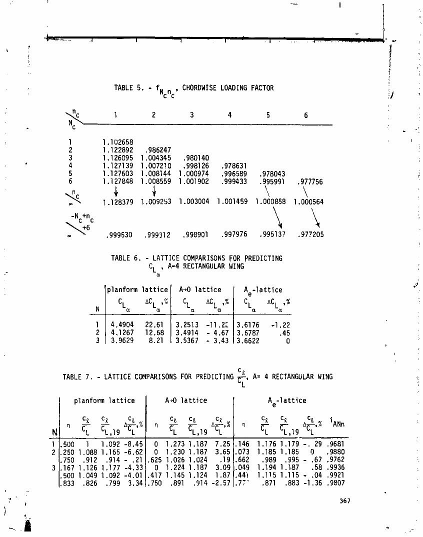
TABLE 5. - fN , CHORDWISE LOADING FACTOR C C
TABLE 6 . - L A T T I C E COMPARISONS FOR P R E D I C T I N G CL , A=4 RECTANGULAR WING
a
TABLE 7 . - L A T T I C E COMPARISONS FOR P R E D I C T I N G CP A= 4 RECTANGULAR WING 5'
planform l a t t i c e
c~ a A C ~ a ,C
4.4904 22.61 4.1267 12.68 3.9629 8.21
I planform l a t t i c e I A - 9 l a t t i c e I
' A 4 l a t t i c e
L bCL 9 %
a a
3.2523 - 1 1 . 2 3.4914 - 4.67 3.5367 - 3.43
A e - l a t t i c e
CL nCL 9 %
a a
3.6176 -1.22 3.6787 .45 3.6622 0
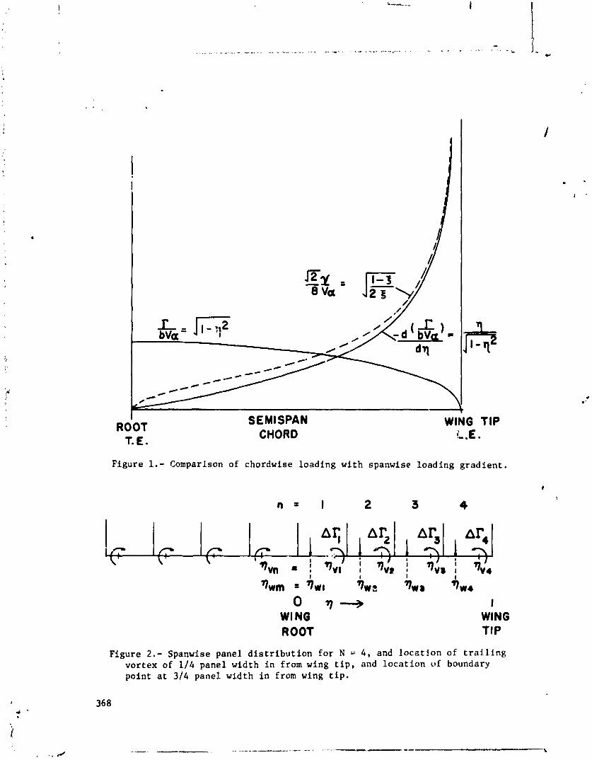
I ROOT
T. E.
SEMISPAN CHORD
WlNG TIP L.E.
Figure 1.- Comparison of chordwise loading with spanwise loading gradient .
7)wm = TWI 3 w t qwr 7 w 4
0 3- I WINO WING ROOT 1 IP
Figure 2 . - Spanwise panel d i s t r i b u t i o n for N = 4 , and locat ion of t ra i - l ing vortex of 114 panel width i n from wing t i p , and locat ion of boundary point a t 314 panel width i n from wing t i p .
A SUBVORTEX TECHNIQUE FOR THE
Brian Maskew Analytical Methods, In. .
SUMMARY
The close-approach problem associated with vor tex- la t t ice methods was ex- amined numerically with the objec t ive of ca lcu la t ing v e l o c i t i e s a t a r b i t r a r y points , not j u s t a t midpoints, between the vor t ices . The objec t ive was achiewd using a subvortex technique i n which a vortex s p l i t s i n t o an increasing number of subvortices a s it is approached. The technique, incorporated i n a two-dimerr s iona l po ten t i a l flaw method using "submerged" vo r t i ce s and sources, was evalu- a ted f o r a cambered Joukowski a i r f o i l . The method could be extended t o three dimensions, and should improve non-linear methods, which ca l cu la t e in te r fe rence e f f e c t s between mult iple wings and vortex wakes, and which include procedures f o r force-f r ee wakes.
INTRODUCTION
A fundamental problem associated with vor tex- la t t ice methods (e.g., r e f . 1) is t h a t appreciable e r r o r s can occur i n v e l o c i t i e s ca lcu la ted c lose t o the d is - c re t ized vortex shee ts because of t h e s ingu la r nature of the induced ve loc i ty expression. This problem has been circumvented i n t he p a s t by ca lcu la t ing "near-field" v e l o c i t i e s only a t spec i a l po in ts , e.g., midway between the vo r t i - ces, and by employing in te rpola t ion f o r intermediate pos i t ions . For calcula- t i ons involving mult iple vortex sheets, (e.g., r e f s . 2 and 31, t he near-f ie ld problem o f t en requires t h a t adjacent l a t t i c e s be made t o correspond across t h e gap between t h e sheets . Hawever, sucll a so lu t ion is no t p r a c t i c a l i n vortex- l a t t i c e methods which incorporate i t e r a t i v e procedures f o r force-free wakes, ( re fs . 3 through 11). Although these methods have proved very v e r s a t i l e i n general, close-approach s i t u a t i o n s involving mult iple d i sc re t i zed vortex shee ts requi re ca re fu l t.reatment, and, i dea l ly , t h e near-f ie ld problem should be re- moved.
The object ive of t h i s inves t iga t ion was t o develop a near - f ie ld modifica- t i on f o r the d i sc re t e vo r t i ce s which would allow v e l o c i t i e s t o be ca lcu la ted anywhere i n t he f:ow f i e l d , not j u s t a t t he spec i a l points . Such a capab i l i t y would pa r t i cu l a r iy bene f i t the ana lys is of h i g h - l i f t configurat ions and the ca l - cu la t ion of o ther c lose in te r fe rence e f f e c t s between wings and vortex shee ts
+ This work was performed while the author was a National Research Council Associate a t the NAS3 Ames Research Center.

(or vor t ices ) such a s occur i n configurat ions with lesding-edge or tip-edge vor t ices .
Although t h e presen t paper dea ls with the near-f ie ld problems i n two-di- mensional flow, t h e extension t o t h r ee dimensions ( p a r t i c u l a r l y f o r methods having a force-free wake) is a major considerat ion throughout. The development of the technique described here in is presented i n more d e t a i l i n references 12 and 13.
EXTENT OF THE NEAR-FIELD REGION
To evaluate t h e ex t en t of t he near-f ie ld region, t he ve loc i ty d i s t r i b u t i o n was examined f o r a f l a t , two-dimensional vortex shee t with a p r a b o l i c vo r t i - c i t y d i s t r i b u t i o n ( re f . 12) . This d i s t r i b u t i o n was d i s c r e t i zed using f o r t y
% vor t ices with equal spacing, A. Velocity d i s t r i b u t i o n s were ca lcu la ted over a region between two midpoints near t he qua r t e r pos i t i on on the segment { f ig . 1 ( a ) ) and compared w i t h t h e ana ly t i c values. Erro.7 contours a r e shown i n f ig- u re l ( b ) . The d i s c r e t i z a t i o n gives neg l ig ib l e e r r o r s f o r both components of ve loc i ty i n the region beyond l A fr9m t h e sheet . In e f f e c t , t he "holesn i n t h e
% representat ion a r e no t sensed u n t i l we e n t e r the 1 A region. Ins ide t h e 1 A re- gion the e r r o r s increase rap id ly except along spec i a l l i n e s o f approach t o t he sheet. For the normal ve loc i ty component, t he zero-error l i n e s follow approxi- mately the normals t o t h e shee t a t t he po in t s midway between the v o r t i c e s and a l s o a t t h e vor t ices . (Deviations from the normal l i n e s occur because of t h e gradient i n v o r t i c i t y across t h e region.) Both sets of pos i t ions on t h e sur- face ace used i n t h e non-linear vor tex- la t t i ce method, (e.g., r e f . 3 ) , i.e., t he midpoints a r e used a s cont ro l po in t s , a s i n t h e s tandard vo r t ex - l a t t i c e theory, and t h e vortex po in t s a r e used when applying the Kutta-Joukowski law f o r l o c a l forces and a l s o when performing the t ra i l ing-vor tex ro l l -up calcula- t ions. The zero-error l i n e s f o r the tangent ia l ve loc i ty component a r e l e s s w e l l known; these l i n e s e n t e r t h e near-f ie ld region above t h e qua r t e r and t h r e e qua r t e r pos i t ions between t h e vo r t i ce s , and approach t h e vortex loca t ions along approximately e l l i p t i c a l paths . A l l t h e zero-error pa ths a r e s i t u a t e d on ex- treme "precipicesn i n t he e r r o r contour map; small dev ia t ions from the paths r e s u l t i n l a rge e r r o r s and lead t o the near - f ie ld problems.
NEAR-FIEID MODELS
The previous sec t ion ind ica ted t h a t e r r o r s a r i s i n g from t h e d i s c r e t i z a t i o n of a vortex shee t become appreciable only within t he l a region. Clear ly , i f we wished t o ca l cu l a t e v e l o c i t i e s very c lose t o the d i s c r e t i zed vortex shee t , we r w l d simply decrease t h e size of A by increasing t h e number of vo r t i ce s ; however, f o r three-dimensional problems the computing time could then become prohibitive. An a l t e r n a t i v e so lu t ion is t o apply a near-f ie ld treatment t o the vort ices . This treatment would be appl ied only t o those vo r t i ce s t h a t a r e within a spec i f ied near-f i e l d rad ius (e. g. , 1 A ) from the po in t where t he veloci ty is being calculated. A number of near-f ie ld models were considered.

A core model o f f e r s t he s implest near-f ie ld treatment which removes t h e s ingular behavior of t h e ve loc i ty f i e l d . In such a model t h e ve loc i ty induced by the vorLex is factored l o c a l l y s o as t o remain bounded a t t h e vortex center . The Rankine vortex and Lamb's viscous vortex a r e w e l l known examples, bu t t he re a r e o the r poss ib le forms. Core models h a w been used i n t h e p a s t t o smooth the motions of vo r t i ce s used i n two-dimensional rol l -up ca lcu la t ions (e.g. refs. 14 and 15). Several core models were t e s t e d using the d i sc re t i zed paraboi ic vor- t i c i t y shee t , bu t none were found s a t i s f a c t o r y f o r both components of veloci ty . For example, they f a i l t o r e s t o r e t he tangent ia l component of ve loc i ty near t he vortex sheet . This can be seen i n f i gu re 2, which shows t h e e r r o r contours f o r a Rankine vortex model with a core diameter of A. Although t h e t angen t i a l velo- c i t y e r r o r s appear s l i g h t l y worse than f o r t h e unmodified vortex (compare f i g s . l ( b ) and 2 ) , t he normal component e r r o r s are improved, on the whole, wi th in t h e core. But t he e r r o r l e v e l s a r e still s ign i f i can t , and t h e zero-error l i n e s no longer approach the vortex points . Other near-f ie ld models w e r e , therefore , considered i n which t h e vortex i t s e l f is modified, its s t r eng th being e f f ec t - ive ly d i s t r i bu ted along a l i n e represent ing t h e l o c a l pos i t i on of the vortex sheet. This inves t iga t ion l e d t 3 t he subvortex technique.
SUBVORTEX TECHNIQUE
A technique was developed i n which t h e s t rength of a near-f ie ld vortex is d i s t r i bu ted by s p l i t t i n g it i n t o a number of small vo r t i ce s , i . e . , subvortices. 1
These a r e d i s t r i bu ted evenly along t h e vortex shee t joining t h e vortex to its two immediate neighbors. The joining sheet is not necessar i ly a s t r a i g h t l i n e ;
j t h e subvort ices can be placed on an in te rpola ted curve passing through t h e basic vor t ices , and t h i s allows a c lo se representat ion of curved vortex sheets . Half i n t e rva l s separa te t he bas i c vo r t i ce s from t h e neares t subvort ices ( f i g . 3 (a) 1 , and s o t h e bas i c vortex pos i t ions become midpoints i n t h e subvortex system. This f ea tu re improves t h e accuracy of t he ca lcu la ted ve loc i ty a t t h e bas i c vor- t i c e s (see "e r ro r contours") .
The subvort ices must have a combined s t r eng th equal t o t h a t of t he associ- a t . 4 bas i c vortex. I n t h e technique as used here, t h e i r s t r eng ths vary l inearly i w i t h d is tance from t h e bas ic vortex pos i t ion . When severa l neighboring bas i c , I
i .
v o r t i ce s a r e t r e a t e d i n t h i s way, t h e l o c a l e f f e c t approaches t h a t of a piece- wise l i n e a r v o r t i c i t y d i s t r i bu t ion . Clear ly, higher o rde r d i s t r i b u t i o n s could t
be used, bu t would involve more than one bas ic vortex i n t e r v a l on each s ide .
The number of subvortices used is such t h a t t he poin t where the ve loc i ty is being ca lcu la ted cannot "see t h e holes" i n the d i sc re t i zed vortex sheet , i .e . , the poin t is kept j u s t outs ide the new l o c a l l A region of the subvortex system. Figure 3(b) shows how t h i s works using the following expression f o r the number of subvort ices on one s i d e of t h e bas i c vortex:
NSV = integer-part-of (1 + A/H)
where H is the normal dis tance of t h e poin t from t h e segment. Use of t h i s ex- pression keeps the number of subvort ices t o a minimum and helps t o keep canpu-
371
t i ng costs dawn. When applied t o the volt-.ex-lattice methods, t h e midpoints be- tween the vort ices (i.e., the control points) should remain midpoints i n the subvortex system; NSV must then be even, i .e . , a s shown dotted i n f ig . 3(b) .
A maximum l i m i t , NSVw, is placed on the number of subvortices t o avoid a runaway condition when the height H approaches zero. This l i m i t controls the c loses t approach t h a t can be made t o the vortex s h m t before the new loca l 1 A region of the subvortices is entered. I t can therefore be used t o control the "accuracy" of the calculat ion i n a trade-off with computing time, i .e. , by increasing the l i m i t the e r ro r region would decrease i n s i z e , but the com- puting t i m e would increase, and vice-versa. To mini7:ize calculat ion e r ro r s inside the l h region of the subvortex system, each subvortex has been modified with a Rankine vortex core of diameter s l i g h t l y less than the subvortex spacing. This smears out the tangential veloci ty discontinuity associated with the vor- t ex sheet, but only over the new, diminished error-region. When representing f ree vortex sheets , t h i s smeared region could be re l a t ed t o the thickness of the viscous wake i n r e a l flow.
Although the veloci ty er rors become s ign i f i can t only within the 1 A region, the near-field radius, within which the subvortex technique is applied, had t o be increased t o !ib t o obtain the required accuracy (2 0.5% e r ro r ) . The reason f o r t h i s extension is tha t the induced vdlocity from the "distributed" model does not match t h a t from the bas ic vortex u n t i l some distance away ( re f . 12).
Error Contours
The technique was tes ted on the discret ized parabolic vor t i c i ty distr ibu- t ion considered ea r l i e r . The e r ro r contours ( f ig . 4 ) a re reduced t o a very small region adjacent t o the vortex sheet where the approach is c loser than +he subvortex spacing. The extent of t h i s e r r o r region depends on the maximum limit placed on the number of subvortices. In these calculat ions NSV was 10.
MAX
The nonnal component of veloci ty calculated a t the vortex locations has always been s l igh t ly l e s s accurate than t h a t calculated a t points midway be- tween the vort ices. (The vortex points are ef fec t ive ly midpoints i n a coarser d iscre t iza t ion . ) For the present d iscre t ized parabolic v o r t i c i t y d i s t r ibu t ion , the e r ro r a t the vort ices i n the region considered (see f ig . l ( a ) ) is 2.8% com- parsd with 0.03% a t the midpoints. With the subvortex technique applied, the e r ro r a t the vort ices decreases t o 0.2%; t h i s reduction is helped by the f a c t t h a t the basic vortex locations become midpoints i n the subvortex system.
SUBMERGED SINGULARITIES
The subvortex technique was incorporated i n a two-dimensional potent ia l flow method ( re f . 13) aimed a t calculat ing pressures a t a rb i t r a ry points on a i r f o i l surfaces. For t h i s purpose, the e r r o r region associated with the sub- vortex system was enclosed i n the contour by "submerging" the vort ices a small
distance below t h e sur face ( f ig . 5). The bas i c vo r t i ce s (before submerging) were positioned on the a i r f o i l surface using equal angle increments i n a cosine 1 equation appl ied t o dis tance along the contour. In t h i s spacing system, ha l f angles separate the i n i t i a l vortex pos i t ions from t h e cont ro l po in ts where the boundary condition of tangent ia l flow is specif ied. This i s an adaptat ion of Lan's work ( re f . 16 ) ; it keeps the s ingu la r i t y s t r eng th d i s t r i b u t i o n more uni- form when passing through " d i f f i c u l t " regions such a s leading and t r a i l i n g edges and f l a p hinge l i n e s . With t h i s po in t d i s t r i bu t ion , the f i r s t cont ro l point is located a t t he t r a i l i n g edge, and so the Kutta condition is appl ied by specifying the flow d i r ec t ion there , e.g., t!!e d i r ec t ion along the mean l i n e .
From t h e i r i ! l i t i a l surface pos i t ions , t he bas i c vor t ices a r e submerged along the loca l normals t o t he surface by a f r a c t i o n of A , i .e., SDFA . The sub merged depth f ac to r , SDF, is constant over t he whole contour except i n the trail ing-edge region where it automatically decreases along the s ing le shee t ( f i g . 5). The cont ro l po in ts remain on the a i r f o i l contour except i n t he region very c lose t o the t r a i l i n g edge; here, corresponding upper and lower cont ro l points a r e combined and moved t o t he mean lime. Hence, t h e model adjacent t o t h e t r a i l i n g edge resembles a camber l i n e model. Because of t h i s modelling, there a r e more cont ro l po in ts than unknown s i n g u l a r i t i e s , and so the equations a r e solved i n a least-squares sense.
The subvortices a r e placed on s t r a i g h t segments joining the b a s i c vo r t i ce s (see f i g . 6 ) . They a r e posi t ioned i n accordance with equal angle increments i n the same system a s the bas ic vo r t i ce s ( re f . 13) .
For t he three-dimensional case, quadr i l a t e r a l vo r t i ce s have been found convenient f o r modelling a r b i t r a r y geometry con£ igura t ions ( r e f s . 2,3 and 11) . The present study, therefore , is based on the two-dimensional form of t h a t model, viz . , opposing vortex p a i r s , ( f i g . 6 ) , which a r e equivalent t o a piece- wise uniform normal doublet d i s t r i b u t i o r . Such a model, forming a closed sur- face, requi res one doublet panel s t rength t o be spec i f ied , otherwise t h e system is indeterminate. Accordingly, t he upper panel adjacent t o t h e crossover ( f i g . 6) is spec i f ied t o have zero s t rength. The boundary condition oquation associ- a ted with the cont ro l point above the spe- i f ied panel is s t i l l included i n the system of equations. The r e su l t an t vortex s t rengths a r e :
where D a r e t he doublet panel s t rengths , i . e . , the s t rengths of t h e opposing k vortex pa i rs . (Note t h a t DN+l has been assumed zero.)
Preliminary ca lcu la t ions using vor t ices alone ( r e f . 13) showed problems near the leadina edge and near t h e crossover of t h e i n t e r i o r vortex "sheets". These problems were a t t r i b u t e d t o i l l -condi t ion ing of t he boundary equations, pa r t i cu l a r ly near the crossover, because the vo r t i ce s were t ry ing t o provide thickness e f f e c t s (as wel l a s l i f t i n g e f f e c t s ) from a small base. Source sing* l a r i t i e s , which a r e more su i t ab l e f o r providing thickness e f f e c t s , were there- fore included i n t h e model. The sources, coincident with the vo r t i ce s and
receiving the same "subvortex" treatment, have a simple s t r eng th d i s t r i b u t i o n which provides t he bas i c thickness form symmetrically about t h e mean l i n e ( r e f . 13) . The sources pa r t i cu l a r ly bene f i t the pressure ca lcu la t ions i n t he leading- and trail ing-edge regions.
RESULTS AND DISCUSSION
Figure 7 shows the pressure d i s t r i b u t i o n ca lcu la ted a t 120 sur face poin ts t h a t a r e not r e l a t ed t o the vortex/control po in t locat ions. The a i r f o i l is a cambered Joukowski represented by 46 vortex/sources w i t h a submerged depth of 0.1 and a near-f ie ld radius of 5 . Trapezoidal-rule in tegra t ion of t h e pres- sure d i s t r i b u t xi y ie lds the following l i f t , drag and moment coef f ic ien ts : CL
= 1.7040 (0.4% e r r o r ) ; CD = -0.0069 (an e r r o r of 0.4% of CL); and CM = -0.5377
(0.26% e r r o r ) . The calculated pressure values show good agreement with the exact d i s t r i bu t ion , bu t they show a minor tendency t o o s c i l l a t e near t h e lead- ing edge. The o s c i l l a t i o n s can be reduced ( r e f . 13) by increasing t h e dens i ty of t h e subvortex system, but che computing t i m e increases (53% increase i n time f o r a f ac to r of 2 on the number of subvortices) . 'Jse of a higher order i n t e r - po la t ion scheme f o r posi t ioning t h e subvort ices a l s o reduces the o s c i l l a t o r y tendency ( r e f . 13) . The o s c i l l a t i o n s can be eliminated by using a la rge number of bas i c s i n g u l a r i t i e s (e.g., 90). It is s i g n i f i c a n t t h a t t he small o s c i l l a - t i o n disappears when there is no suc t ion peak, e.g., f i gu re 8 shows the pres- sure d i s t r i b u t i o n f o r t h e same a i r f o i l a t zero incidence, t h e C e r r o r i n this
D case being 0.0002 o r 0.4% of CL. (This case had t h e higher-order geometry rou-
t i n e f o r posi t ioning the subvortices.) This implies t h a t a higher-orderdrength va r i a t i on f o r the subvort ices might be usefu l when using only a small number of bas i c s i n g u l a r i t i e s ; this would ensure t h a t peaks i n the pressure d i s t r i b u t i o n a re adequately represented. The higher-order rout ines would only be appl ied loca i ly i n t he problem areas.
Figure 9 shows the pressures ca lcu la ted a t t he same 120 a r b i t r a r y po in t s as before, bu t with only 19 bas i c s i n g u l a r i t i e s ; using s o few vortex unknowns would c l e a r l y b~ an advantage i n three dimensions. The d i s t r i b u t i o n i n f i gu re 9 corresponds with f igu re 12 i n reference 13, bu t t h e subvortex system f o r t he present case was doubled. The higher-order geometry rout ine f o r pos i t ion ing the subvortices was used, but the subvortex s t rength va r i a t i on was l i n e a r . The ca lcu la ted pressures a r e i n good agreement with the exac t so lu t ion except near t h e leading edge. A higher-order s t rength va r i a t i on f o r t he subvort ices , a s discussed above, should improve t h e ca lcu la t ions i n t he peak suc t ion region.
Submerged Depth
The submerged depth has a s ign i f i can t e f f e c t on the solut ion. Typical va r i a t i ons i n t he e r r o r s i n in tegra ted C C and CD with submerged depth
L' M fac tor , SDF, a r e presented i n f igure 10. The e r r o r s i n C and C decrease ra-
D M pidly as t h e dpeth decreases, bu t the computing time increases because the
R'EPRODUC~~ITY OF THE rlalGINAL PAGE I8 POOR
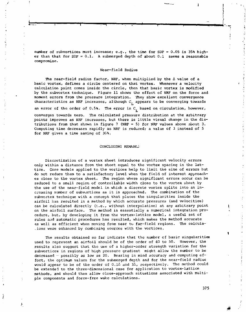
number of subvort ices must increase; e.g., t h e t i m e f o r SDF = 0.05 i s 35% high- er than t h a t f o r SDF = 0.1. A submerged depth o f about 0.1 seems a reasonable compromise.
Near-f i e l d Radius
The near-f ie ld radius f a c t o r , NRF, when mul t ip l ied by the b value of a b a s i c vortex, def ines a c i r c l e centered on t h a t vortex. Whenever a ve loc i ty ca lcu la t ion poin t comes in s ide t h e c i r c l e , then t h a t ba s i c vor tex is modified by t h e subvortex technique. Figure 11 shows the e f f e c t o f NRF on t h e force and moment e r r o r s from the pressure in tegra t ion . They show exce l l en t convergence c h a r a c t e r i s t i c s a s NRF increases , although CL appears t o be converging towards
an e r r o r of t h e order of 0.5%. The e r r o r i n C based on c i r c u l a t i o n , however, L
converges towards zero. The ca lcu la ted pressure d i s t r i b u t i o n a t t he a r b i t r a r y po in t s improves a s NRF increases , bu t t he re is l i t t l e v i sua l change i n t h e dis- t r i b u t i o n s from t h a t shown i n f i gu re 7 (NRF = 5) f o r NRF values above &out 3. Computing time decreases rapidly a s NRF is reddced; a value of 3 ins tead of 5 f o r NRF gives a time saving of 3C%.
CONCLUDING REMARKS
Discre t iza t ion of a vortex shee t introduces s i g n i f i c a n t ve loc i ty e r r o r s only within a d i s tance from the shee t equal t o the vortex spacing i n the l a t - t i c e . Core models appl ied t o t h e vo r t i ce s he lp t o l i m i t t h e s i z e of e r r o r s but do not reduce them t o a s a t i s f a c t o r y l eve l when the f i e l d of i n t e r e s t apyxoach- e s c lose t o t h e vortex sheet . The region where s i g n i f i c a n t e r r o r s occur can be reduced t o a small region of con t ro l l ab l e width c lose t o the vor tex shee t by t h e use of the near-f ie ld model i n which a d i s c r e t e vortex s p l i t s i n t o an in- creasing ninnber of subvdrt ices a s i t is approached. The combination of t h e subvortex technique with a concept t h a t places the s i n g u l a r i t i e s ins ide t he a i r f o i l has r e su l t ed i n a method by which accurate pressures (and v e l o c i t i e s ) can be ca lcu la ted d i r e c t l y ( i . e . , without i n t e rpo la t i on ) a t any a r b i t r a r y po in t on the a i r f o i l surface. The method is e s s e n t i a l l y a numerical i n t eg ra t i on pro- cedure, bu t , by developing it from the vo r t ex - l a t t i c e model, a useful s e t of r u l e s a,id automatic procedures has r e su l t ed , which makes t h e method accura te a s wel l a s e f f i c i e n t when moving from near t o f a r - f i e ld regions. The calcula- . ions were enhanced by combining sources with the vor t ices .
The r e s u l t s obtained s o f a r i nd i ca t e t h a t t h e number c f b a s i c s i n g u l a r i t i e s used t o represent an a i r f o i l should be of the order of 40 t o 50. However, t he r e s u l t s a l s o suggest t h a t t he use of a higher-order s t rength va r i a t i on f o r the subvort ices i n regions of high pressure gradient might allow t h e number t o be decreased .- possibly a s low a s 20. Bearing i n mind accuracy and computing e f - f o r t , the optimum values f o r the submerged depth and f o r t he near-f ie ld radius would appear t o be of the order of O . l A and 3A, respec t ive ly . The nethod could be extende3 t o the three-dimensional case fo r appl ica t ion t o vo r t ex - l a t t i c e methods, and should then allow close-approach s i t u a t i o n s associated with multi- p l e components and force- f ree wake ca lcu la t ions .
REFERENCES
1. Rubbert, P.E.: T h e o r e t i c a l C h a r a c t e r i s t i c s o f A r b i t r a r y Wings by a Non- P lanar Vortex L a t t i c e Method. D6-9244, The Boeing Co., 1964.
2. Maskew, B.: Ca lcu la t ion o f t h e Three-Dimensional P o t e n t i a l Flow Around L i f t i n g Non-Planar Wings and Wing-Bodies Using a Surface D i s t r i b u t i o n o f Q u a d r i l a t e r a l Vortex Rings. TT7009, Loughborough Univ. o f Technology, England, Sep t . 1970.
3. Maskew, B.: Numerical L i f t i n g Surface Methods f o r C a l c u l a t i n g t h e P o t e n t i a l Flow about Wings and Wing-Bodies o f A r b i t r a r y Geometry. Ph.D. Thes i s , Loughborough Univ. o f Technology, England, Oct.. 1972.
4. Be lo t se rkovsk i i , S.M.: Ca lcu la t ion o f t h e Flow Around Wings o f A r b i t r a r y Planform over a Wide Range o f Angles o f Attack. NASA TTF-12, 291, May 1971.
5. B u t t e r , D . J . ; and Hancock, G . J . : A Numerical Method f o r Ca lcu la t ing t h e T r a i l i n g Vortex System Behind a Swept Wing a t Low Speed. The Aeronaut ical Journal , Vol. 75, No. 728, Aug. 1971, pp. 564-568.
6. Hackett , J.E.; and Evans, M.R.: Vortex Wakes Behind High-Lift Wings. J. A i r c r a f t , Vol. 8 , No. 5, May 1971, pp. 334-340.
7. Labrujere, Th.E.: A Numerical Method f o r t h e Determination o f t h e Vortex Sheet Location Behind a Wing i n 1ncm.press ible Flow. TR 72091 U, Nat ional Aerospace Laboratory (NLR), Amsterdam, t h e Netherlands, J u l y 1972.
8. Lind, I . A . : A Non-Linear Vortex L a t t i c e Method Applicable t o Three-Dimen- s i o n a l Wing Systems with Rolled Up Vortex Wakes i n Low Subsonic Flow. FI43, The Royal I n s t i t u t e o f Tech., Stockholm, Sweden, 1973.
9. Rehbach, C.: Ca lcu la t ion o f Flows around Zero Thickness Wings wi th Evolu- t i v e Vortex Sheets . NASA TTF-15, 183, 1973.
10. Mook, D.T.; and Maddox, S.A.: Extension o f a Vortex L a t t i c e Method t o In- clude t h e E f f e c t s o f Leading-Edge Separat ion. J. A i r c r a f t , Vol. 11, No. 2, Feb. 1974, pp. 127-128.
11. Sumna, 2.M.: P o t e n t i a l Flow about Three-Dimensional St reamlined L i f t i n g Configurat ions , w i t h Appl icat ion t o Wings and Rotors. SUDAAR No. 485, S tanford Univers i ty , C a l i f o r n i a , Sept . 1974.
12. Maskew, B.: A Subvortex Technique f o r t h e Close Approach t o a D i s c r e t i z e d Vortex Sheet. NASA TM X-62, 487, Sept . 1975.
13. Maskew, B.: A Submerged S i n g u l a r i t y Method f o r C a l c u l a t i n g P o t e n t i a l Flow V ~ l o c i t i e s a t A r b i t r a r y Ncar-Field Po in t s . NASA TM X-73, 115, March 1976.
14. Chorin, A.J . ; and Bernard, P.S.: D i s c r e t i z a t i o n of a Vortex Sheet wi th an Example o f Roll-up. FM-72-5, College of Engineering, Univ. of C a l i f o r n i a , Berkeley, Ca l i f . , Nov. 1972.
15. Kuwahara, K.; and Takami, H.: Numerical Study of Two-Dimensional Vortex Motion by a Systen. of Po in t Vort ices . J. of t h e Phys ica l Soc., Japan, V o l . 34, No. 1, Jan. 1973, pp. 247-253.
16. Lan, C.E.: A Quasi-Vortex L a t t i c e ~ e t h o d i n Thin Wing Theory. J. Ai rc ra f t r 1 .
Vol. 11, No. 9 , Sept. 1974, pp. 518-527.

VORTICIlY DISTRIBUTION
I
OlSCRETE CONSIDERED VORTICES
(40' MID POINTS
.275 3 0 I kV%f!f~~d SPACING
(a) Locat ion of region considered.
TANGENTIAL
I COMPONENT 1 ERROR I N V, %
NORMAL COMPONENT 1 ERROR IN W, % a I
Y
(b) Velocity error contours for the basic discret izat ion.
Figure 1 . - Velocity error calculat ions.

TANGENTIAL COMPONENT
ERROR IN V, %
NORMAL COMPONENT
ERROR IN W, %
Figure 2.- Velocity error contours for a Rankine vortex core model. Core diameter = A.

BASIC VORTKES
SUWORTEX POSITIONS, S S V + { NW + 0.5 - 1 ) A/ NSV
(a) Arrangement of the subvortices for NSV = 4.
"BOUNDARY FOR THL NEW l A REGION OF THE SUBVORTEX SYSTEM
I FOR EVEN NSV IN A
'yORTEx- L m m A m l c m o N
1 /.,,,,,,-L,,,-----
EQ. 1
/ / / / / / I l'///'/'l/ 'r r r r - 1 -
1 2 3 4 (HEIGHT ABOVE VORTEX "SHEET") / 13
(b) Number of subvortices as a function of height above the segment.
Figure 3.- The subvortex technique.
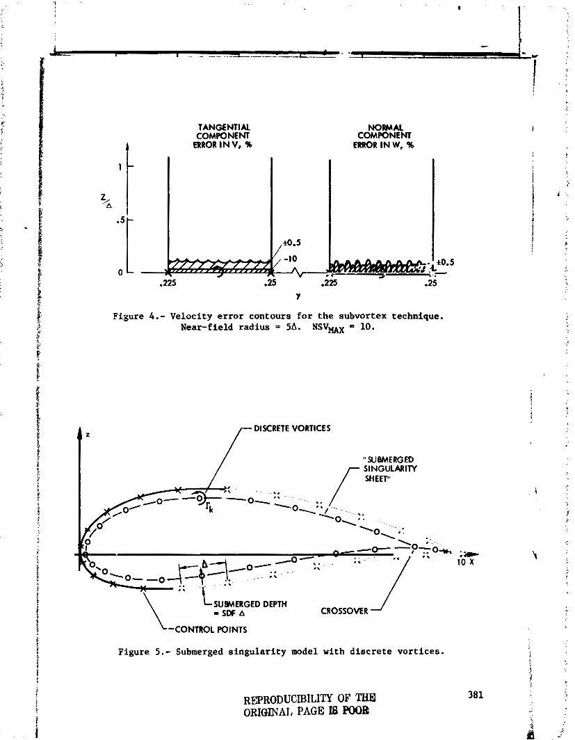
TANGENTIAL COMPONENT
ERROR I N V, %
NORMAL COMPONENT
ERROR IN W, %
Figure 4.- Velocity error contours for the subvortex technique. Near-field radius = 56. NSVmX = 10.
/ DISCRETE VORTICES
" SUBMERGED SINGULARITY /- SHEET"
L SUBMERGED DEPTH = SDF A CROSSOVER
'--CONTROL POINTS
Figure 5 . - Submerged singularity model with discrete vortices .
REPRODUCIBILITY OF THEI ORIMNAJ, PAGE I8 POOIP

MITM CONDINON AmlED AT W L I N G EDGE
piecewise constant doublet model.
W C VORTKtJ M E ? M E 0 ON Tt# 'WIMERGED Plm-
Figure 6. - Equivalent
o CALCULATED PRESSURES - E X K T DISRIWTION
o SINGULARITY POSITIONS X COMROL PClMS
Figure 7.- Pressures calculated a t arbitrary points on a Joukowski a i r£ o i l a t 10' incidence. Model : submerged vortices and sources (coincident) with subvortex tech- nique applied ( l inear interpolation for pos i t ion) ; 46 basic s ingular i t ies ; submerged depth = 0.1A; near- f i e l d radius = 56.

0 CALCUUTED R E S M S
- EXMT DlSTltlYmON
1.00; 0.2 I I I I 1 0.4 0.6 0.8
wc Figure 8.- Pressures calculated a t arbitrary points on
a Joukowski a i r f o i l a t zero incidence. Model: a s i n figure 7 but with higher-order interpolation for subvortex posit ions.
o CALCULATED PRESSURES - EXKT DISTRIWTION
-
o SINGOLARIN POSITIONS x CONTROL POINTS
Figure 9 . - Pressures calculated a t arbitrary points on a Joukowski a i r f o i l a t 10'. Model: a s i n figure 7 but with 19 basic s ingular i t ies .
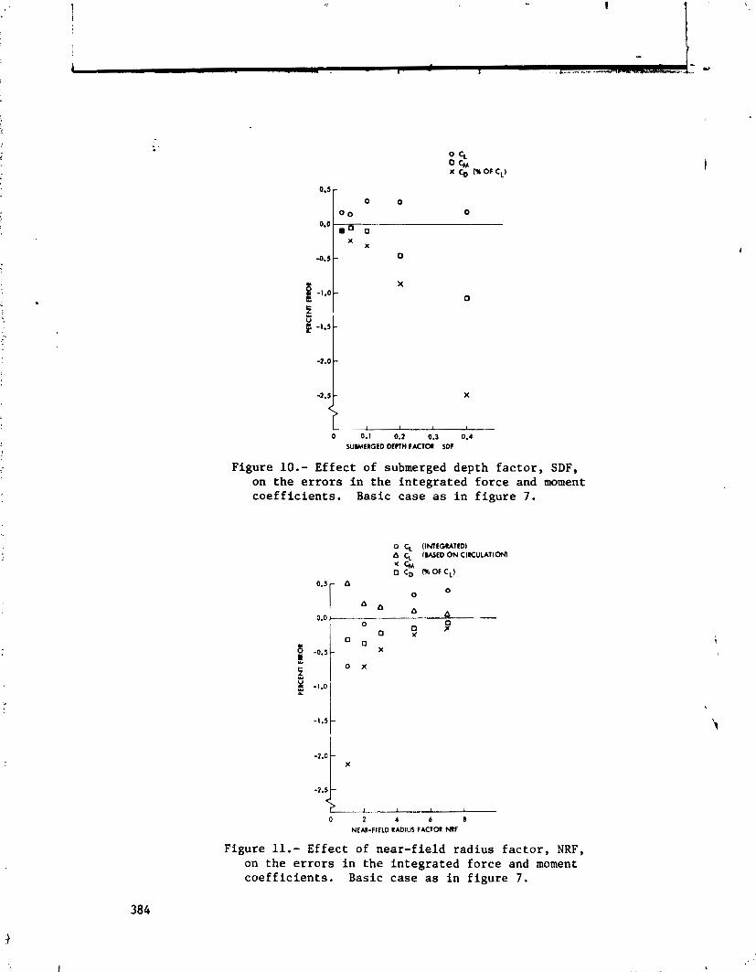
I I 1 1 - 0 0.1 0.2 0.3 0.4
XIMERGED MCTH FACTOR SW
Figure 10.- Effect of submerged depth factor, SDF, on the errors i n the integrated force and moment coe f f i c i en t s . Basic case a s i n figure 7 .
0 CL (INTEGRATED) O CL ( W E D O N ClRCULATlOM * CM 0 CD 06 O F C L )
0 O
0 2 4 6 8 NEM-f IELD RADIUS FACTOR N f
Figure 11.- Effect of near-field radius factor, NRF, on the errors in the integrated force and moment coef f ic ients . Basic case as i n figure 7 .

SOME APPLICATIONS OF THE QUASI VORTEX-LATTICE METHOD
IN STEADY AND UNSTEADY AERODYNAMICS
C. Edward Lan The University of Kansas
SUMMARY
i The quasi vortex-lattice method is reviewed and applied to the evalua-
$ Lion of backwash, with applications in ground effect analysis. It is also extended to unsteady aerodynamics, with particular interest in the calcula-
4 tion of unsteady leading-edge suction. Some applications in ornithopter f aerodynamics are given. 2
INTRODUCTION
i- The quasi vortex-lattice method (Quasi VLM) has been shown to produce good accuracy in lifting-surface problems not only for non-flapped but also flapped configurations (ref. 1). In these applications, the only induced velocity to be evaluated is the downwash. However, in some other applica-
$ tions such as ground effect analysis and wing-jet interaction (ref. 2 ) , it . is necessary to compute the u-induced velocity (i.e. backwash) in the
flow field away from the wing plane. It is the purpose of this paper to t assess the accuracy of such backwash computatioa. t Y
i One important feature of the Quasi VLM is the accurate prediction of the leading-edge suction without resorting to Kbtta-Joukowsky relation. It
: is this feature that makes it possible to extend the method to the predic- : tion of unsteady leading-edge suction in unsteady aerodynamics. This exten- 1 sion is also presented below.
SYMBOLS
aspect r a t i o
chord length, m(f t ) , taken as unity.
leading-edge s ingu la r i t y parameter, defined i n eq. (3c)
induced drag coe f f i c i en t
s ec t i ona l l i f t coe f f i c i en t
amplitude of s e c t i o n a l l i f t coe f f i c i en t i n unsteady flow
t o t a l l i f t coe f f i c i en t
l i f t curve s lope , per radian
p i tch ing moment coe f f i c i en t
p i tch ing moment curve s lope, per radian
pressure coe f f i c i en t d i f fe rence
time-averaged leading-edge t h r u s t coe f f i c i en t
nondimensional height measured from t h e wing plane, re fe r red t o the chord length. See f i g . 5. ! i
1 ' f lapping amplitude I ' S
j
f lapping amplitude a t t he wing t i p
reduced frequency, defined a s wc/ZV
number of i n t eg ra t i on poin ts , o r Mach number
number of chordwise vo r t i ce s
number of spanwise vor tex s t r i p s
leading-edge suc t ion , N(1b) , or wing a rea , m2(f t 2,

Subscript :
amplitude of unsteady leading-edge suction . b
nondimensional backwash, positive downstream
amplitude of unsteady backwash on the wing plane
freestream velocity, m/sec (ft/sec)
nondimensional downwash, positive downward
rectangular coordinates, with x positive downstream, y positive spanwise to the right and z positive upward
camber slope
angle of attack, deg.
amplitude of pitching oscilla
= f i 2
t ion
propulsive efficiency, percent
nondimensional spanwise coordinate
nondimensional vortex density
oscillation frequency, radlsec
density, kg/m3 (slugs/f t 3,
f reestream dynamic pressure, ~ / m 2 (lb/ f t2)
=p amplitude of flap angle
sectional lift coefficient in free air
f flap
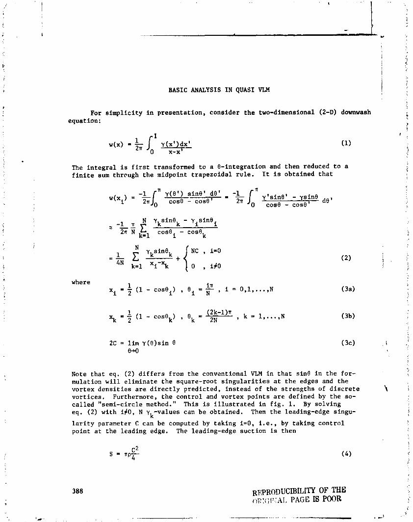
BASIC ANALYSIS IN QUASI VLM
For s i m p l i c i t y i n p r e s e n t a t i o n , cons ider t h e two-dimensional (2-D) downwash equation:
The i n t e g r a l i s f i r s t transformed t o a & i n t e g r a t i o n and then reduced t o a f i n i t e sum thrcugh t h e midpoint t r a p e z o i d a l r u l e . It is obta ined t h a t
'n y(8 ' ) s i n e ' de ' - - - * s i n - ysine
cost3 - cos0' 2n C O S ~ - C O S ~ '
de'
N yksinek - yisinei -1 a z -- C
2= cose - cose i k
where 1 x = - ( 1 - cos8 ) , B i = - i 2 i N in , i = 0,1 , . .., N
Note t h a t eq. (2) d i f f e r s from t h e convent ional VLM i n t h a t s in0 i n t h e for- mulation w i l l e l imina te t h e square-root s i n g u l a r i t i e s a t t h e edges and t h e vor tex d e n s i t i e s a r e d i r e c t l y p red ic ted , ins tead of t h e s t r e n g t h s of d i s c r e t e v o r t i c e s , Furthermore, t h e c o n t r o l and v o r t e x p o i n t s a r e def ined by t h e so- c a l l e d "semi-circle method." This is i l l u s t r a t e d i n f i g . l. By s o l v i n g eq. (2) wi th i f 0 , N y -values can be obta ined. Then t h e leading-edge singu-
k l a r i t y parameter C can be computed by t ak ing i = 0 , i . e . , by t ak ing c o n t r o l point a t t h e leading edge. The leading-edge s u c t i o n is then

In three-dimensional cases, the above concept is also applicable by treat- ing each chordwise vortex integral in a similar manner as in eq. (2). In this case, not only chordwise control and vortex locations are defined by the semi- circle method, but also the sparrwise vortex strips and control locations. See fig. 1. The detail is referred to in ref. 1. The rate of convergence of this method is indicated in figs. (2) and (3) for a 450-sweep wing of AR-2 and constant chord. It is seen that the method converges reasonably fast. ,
i .
BACKWASH EVALUATION AND GROUND EFFECT ANALYSIS
In ground effect analysis, it is known that the image vortex system may produce strong backwash to decrease the air velocity on the wing great enough to be significant. In fact, as a result the wing lift in ground effect may be less than the free air value. This unfavorable effect of backwash is par- ticularly important in powered-lift aerodynamics and for wings under high lift conditions (ref. 3). Therefore, any formulation of ground-effect problem without backwash computation is applicable only to small loading conditions as analyzed in ref. 4.
To see the accuracy of backwash computation by VLM and Quasi VLM, con- sider the 2-D expressions for the backwash and downwash:
If y(xt)= , the integration can be performed exactly. The results are shown in Appendix A. The downwash expression is included here for later comparison. In all computations shown below, equal-spacing elements are used for the VLM. For the Quasi VLM, again the 8-transformation is applied first before using the midpoint trapezoidal rule. Fig. 4 shows that the backwash along the chord evaluated by the VLM at both control and vortex points tend to be too high, in particular near the leading edge. On the other hand, the Quasi VLM gives quite accurate results everywhere at these not too small z- values. With these results in mind, both methods are now applied to the fol- lowing 2-D linear ground-effect equations:

The corresponding geometry is given i n f i g . 5. The second i n t e g r a l i n eq. (7 ) r e p r e s e n t s t h e normalwash due t o t h e image v o r t e x system. The "2ha" term is t h e backwash c o n t r i b u t i o n . The r e s u l t s of computation a r e shown i n f i g , 6. Two p o i n t s a r e of p a r t i c u l a r i n t e r e s t . F i r s t l y , t h e l i n e a r v o r t e x theory w i l l g ive b e t t e r r e s u l t s i f t h e mean s u r f a c e ( a s used i n t h e mean s u r f a c e approxi- mation of t h e l i n e a r a i r f o i l theory) i s taken through t h e 314 chord po in t . Secondly, both t h e Quasi VLM and VLM p r e d i c t approximately t h e same l i f t , de- s p i t e t h e f a c t t h a t t h e VLM g ives h igher backwash. This i s because t h e VLM a l s o produces h igher downwash a t a given z-value. Th i s is shown i n f i g . 7. This means t h a t t h e h igher upwash from t h e image vor tex system a s p r e d i c t e d by t h e VLM tends t o compensate t h e e f f e c t due t o t h e h igher p red ic ted back- wash. With f l a p d e f l e c t e d , t h e VLM p r e d i c t s lower l i f t t han t h e Quasi V L M does a s shown i n f i g . 8.
The a n a l y s i s wi th eqs . (7)-(8) becomes i n c r e a s i n g l y i n a c c u r a t e a t h 9 . 2 . A s an extreme example, l e t ~ 4 . 0 5 i n eq. ( 5 ) . With y= Jm , t h e r e s u l t s a r e shown i n f i g s . 9 and 10. It is seen t h a t t h e backwash is underpredic ted a t t h e c o n t r o l p o i n t s and overpredic ted a t t h e v o r t e x p o i n t s by both t h e VLM and t h e Quasi VLM. Depending on a , t h i s would r e s u l t i n small o r even nega- t i v e c i n eq. (8 ) . The backwash computation wi th small z h a s important ap- II p l i c a t ions i n wing-jet i n t e r a c t ion theory ( r e f . 2) . Therefore , i t is d e s i r a b l e t o f i n d a p r a c t i c a l way t o improve t h e accuracy of t h e computation. Even though i n c r e a s i n g t h e number of v o r t e x p o i n t s ( i . e . t h e number of i n t e g r a t i o n po in t s ) can i n c r e a s e t h e a c c u r a c y , i t is no t a p r a c t i c a l way because t h e number of unknowns t o be solved would g r e a t l y i n c r e a s e , i n p a r t i c u l a r , i n 3-D a p p l i - c a t i o n s . Since t h e inaccuracy is mainly due t o t h e second-order s i n g u l a r i t y i n eq. (5) a s 2 4 , a p r a c t i c a l method is desc r ibed i n r e f . 6 t o d e a l wi th t h i s by weakening t h e s l n g u l a r i t y . According t o t h i s method, eq. (5) i s eva lua ted a s follows:
N [Y (xk) -Y(x), ,.. C s i n e ,
+&;C *s inek 4n (10) 4rr N k = l (x-\I2+ z2
j=l (x-x ) 2 + 9 J
where x may be t h e c o n t r o l p o i n t s (eq. 3a) o r t h e v o r t e x l o c a t i o n s (eq. 3b) and
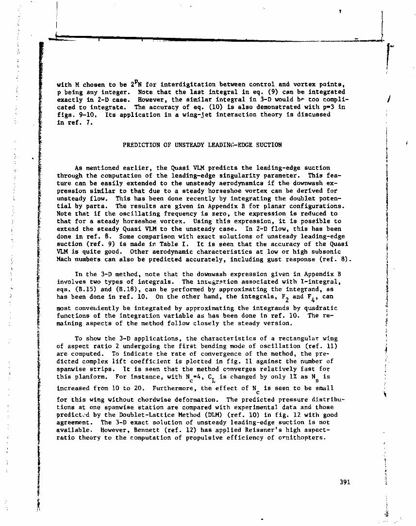
with M chosen t o be 2 ' ~ f o r i n t e r d i g i t a t i o n between cont ro l and vortex po in ts , p being any in teger . Note t h a t t he l a s t i n t e g r a l i n eq. (9) can be in tegra ted exact ly i n 2-D case. However, the s imi l a r i n t e g r a l i n 3-D would be too compli- cated t o in tegra te . The accuracy of eq. (10) is a l s o demonstrated with p-3 i n
/ f i g s . 9-10. Its appl ica t ion i n a wing-jet i n t e r ac t i on theory i s discussed a
i n r e f . 7.
PREDICTION OF UNSTEADY LEADINGEDGE SUCTION ' i t i 1
A s mentioned e a r l i e r , t h e Quasi VLM pred ic t s t he leading-edge suc t ion through the computation of t h e leading-edge s i n g u l a r i t y parameter. This fea- t u r e can be e a s i l y extended t o t he unsteady aerodynamics i f t he downwash ex- pression s imi l a r t o t h a t due t o a s teady horseshoe vortex can be derived f o r unsteady flow. This has been done recent ly by in t eg ra t i ng t h e doublet poten- t i a l by pa r t s . The r e s u l t s a r e given i n Appendix B fo r planar configurat ions. Note t h a t i f t he o s c i l l a t i n g frequency i s zero, t h e expression is reduced t o t h a t f o r a s teady horseshoe vortex. Using t h i s expression, it is poss ib le t o extend the steady Quasi VLM t o t he unsteady case. In 2-D flow, t h i s has been
1 done i n r e f . 8. Some comparison with exact so lu t ions of unsteady leading-edge i 9 suc t ion ( r e f . 9) is inade i n Table I. It is seen t h a t the accuracy of t he Quasi s VLM is q u i t e good. Other aerodynamic c h a r a c t e r i s t i c s a t low o r high subsonic 1 $ Mach numbers can a l s o be predicted accura te ly , including gust response ( r e f . 8 ) . J
I n t he 3-D method, note t ha t t h e downwash expression given i n Appendix B involves two types of i n t eg ra l s . The i n t e g r l t i o n associated with I - in tegra l , eqs. (B.15) and (B.18), can be performed by approximating the integrand, a s has been done i n r e f . 10. On the o ther hand, t he i n t eg ra l s , F and F4, can 2 most converiiently be in tegra ted by approximating the integrands by qgadrat ic functions of the i n t eg ra t i on va r i ab l e a s has been done i n r e f . 10. The re- maining aspec ts of the method follow c lose ly t he steady version.
To show the 3-D appl ica t ions , the c h a r a c t e r i s t i c s of a rectangular wing of aspect r a t i o 2 undergoing the f i r s t bending mode of o s c i l l a t i o n ( r e f . 11) a r e computed. To ind i ca t e the r a t e of convergence of the method, t h e pre- d ic ted complex l i f t coe f f i c i en t is p lo t ted i n f i g . 11 agains t the number of spanwise s t r i p s . It is seen t h a t the method cmverges r e l a t i v e l y f a s t f o r t h i s planform. For ins tance , with Nc=4, CL is changed by only 1% a s Ns i s
increased i ron 10 t o 20. Furthermore, the e f f e c t of N is seen t o be small C
f o r t h i s wing without chordwise deformation. The predicted pressure d i s t r i bu - t i ons a t one spanwise s t a t i o n a r e compared with experimental da ta and those predictzd by t h e Doublet-Lattice Method (DLM) ( r e f . 10) i n f i g . 12 with good agreement. The 3-D exact so lu t ion of unsteady leading-edge suc t ion is not ava i lab le . However, Bennett ( r e f . 12) has applied Reissner 's high aspect- r a t i o theory t o t h e computation of propulsive e f f ic iency of orn i thopters .

Here, the propulsive efficiency is defined as
All quantities in eq. (12) have been averaged over one cycle. The r ,.ults for two rectangular wings of aspect ratios of 6 and 12 performing line,:- apping - - - (h(n) = htn) are shown in fig. 13. It appears that the high aspect .: ,. !o
theory tends to predict higher thrust than the present method. The agreement of the predicted efficitncy by both methods is good for AR=12. But for AR=6, the high aspect-ratio theory predicts lower efficiency, presumably because it would predict much higher input power which depends on the wing loading.
CONCLUDING REMARKS
The quasi vortex-lattice method was shown to possess good convergence characteristics in steady wing theory. Its application to the computation of downwash and backwash away from the wtng plane in 2-D flow showed better accuracy than the conventional VLM with z not too small. When z is small, both methods become inaccurate in backwash computation. An improved methoJ for the Quasi VLM was presented. The Quasi VLM was also extended to the un- steady aerodynamics, with the calculation of unsteady leading-edge suction being of particular interest.
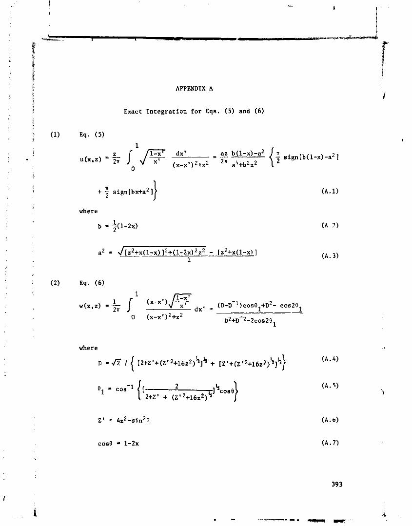
APPENDIX A
Exact Integration for Eqs. ( 5 ) and (6)
(A. 1)
(A ?)
(A. 3)
where
where
[2+~'+(~'~+16z~)~]' + [Z'+(Z'2+16z2)4]4)
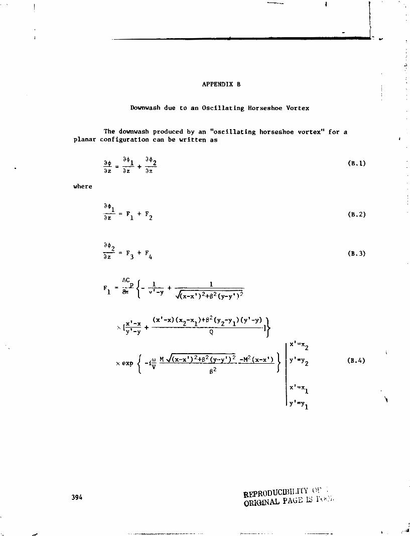
APPENDIX B
Downwash due to an Oscillating Horseshoe Vortex
The downwash produced by an "oscillating horseshoe vortex" for a planar configuration can be written as
where

XO X-X - T ( X -X ) 1 2 1
( B . 9 )
(B. 10)
(B. 11)
(B. 1 2 )
(B. 14)
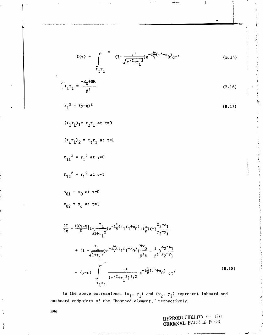
( B . 16)
(B. 17)
In the above e x p r e s s i o n s , (xl, y l ) and ( x 2 , y ) represent inboard and 2
outboard endpoints o f t h e "bounded e l ement ," r e s p e c t i v e l y .
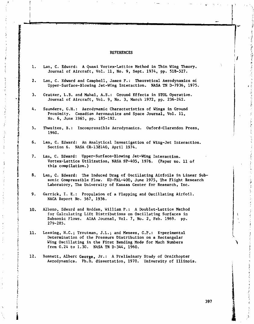
REFERENCES
Lan, C. Edward: A Quasi Vortex-Lattice Method in Thin Wing Theory. Journal of Aircraft, Vol. 11, No. 9, Sept. 1974, pp. 518-527.
Lan, C. Edward and Campbell, James F.: Theoretical Aerodynamics of Upper-Surface-Blowing Jet-Wing Interaction. NASA TN D-7936, 1975.
Gratzer, L.B. and Mahal, A.S.: Ground Effects in STOL Operation. Journal of Aircraft, Vol. 9, No. 3, March 1972, pp, 236-242.
Saunders, G.H.: Aerodynamic Characteristics of Wings in Ground Proximity. Canadian Aeronautics and Space Journal, Vol. 11, No. 6, June 1965, pp. 185-192.
Thwaites, B.: Incompressible Aerodynamics. Oxford-Clarendon Press, 1960.
Lan, C. Edward: An Analytical Investigation of Wing-Jet Interaction. Section 6. NASA CR-138140, April 1974.
Lan, C. Edward: Upper-Surface-Blowing Jet-Wing Interaction. Vortex-Lattice Utilization, NASA SP-405, 1976. (Paper no. 11 o f this compilation. )
Lan, C. Edward: The Induced Drag of Oscillating Airfoils in Linear Sub- sonic Compressible Flow. KU-FRL-400, June 1975, The Flight Research Laboratory, The University of Kansas Center for Research, Inc.
Garrick, I. E.: Propulsion of a Flapping and Oscillating Airfoil. NACA Report No. 567, 1936.
Albano, Edward and Rodden, William P.: A Doublet-Lattice Method for Calculating Lift Distributions on Oscillating Surfaces in Subsonic Flows. AIM Journal, Vol. 7, No. 2, Feb. 1969. pp. 279-285.
Lessing, H.C.; Troutman, J.L.; and Menees, G.P.: Experimental Determination of the Pressure Distribution on a Rectangular Wing Oscillating in the First Bending Mode for Mach Numbers from 0.24 to 1.30. NASA TN D-344, 1960.
Bennett, Albert George, Jr.: A Preliminary Study of Ornithopter Aerodynamics. Ph.D. dissertation, 1970. University of Illinois.
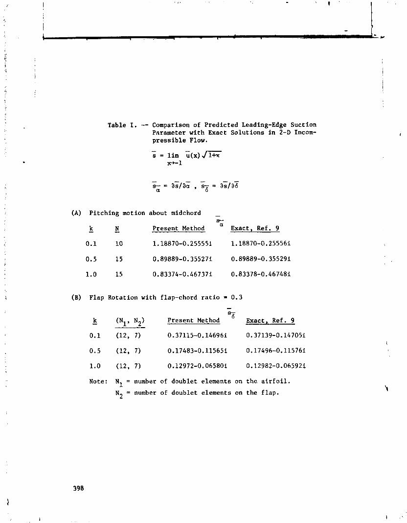
Table I, -- Comparison of Predicted Leading-Edge Suction Parameter with Exact Solutions in 2-D Incom- pressible Flow.
(A) Pitching motion about midchord - s-
k N a
- - Present Method Exact, Ref. 9
0.1 10 1.18870-0.25555i 1.18870-0.25556i
(B) Flap Rotation with flap-chord ratio = 0.3
k 0
- (N1 , N2) Present Method Exact, Ref. 9 -
Note: N1 = number of doublet elements on the airfoil.
N2 = number of doublet elements on the flap.
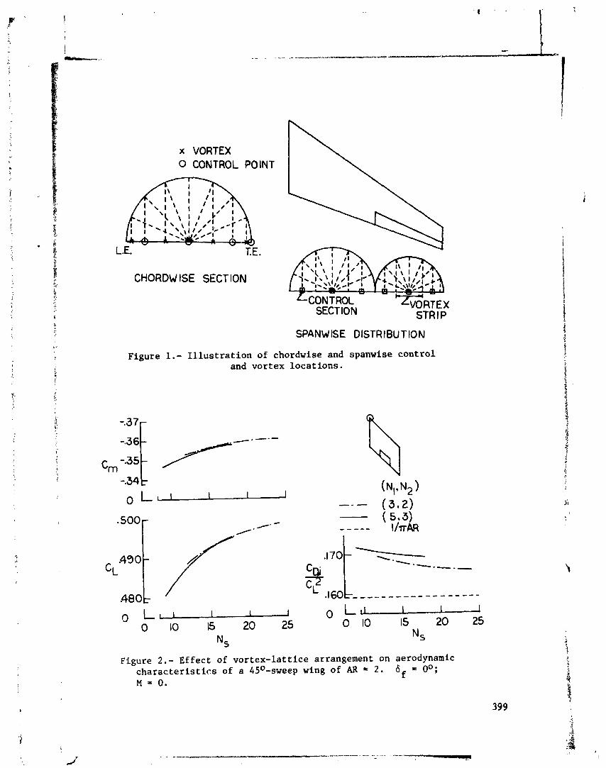
x VORTEX 0 CONTROL POINT
L.E. T.E.
CHORDW IS€ SECTION
SPANWISE DISTRIBUTION
Figure 1.- Illustration of chordwise and spanwise control and vortex locations.
-34 t I--
(N!. N2) 0 -. - - (312) . SO0
/- * - - --- (5.3) /- I /TAR
CL ----.-*-
.480
C) 0 L U 0 10 6 20 25 0 10 15 2 0 25
Ns *,
Figure 2.- Effect of vortex-lattice arrangement on aerodynamic characteristics of a 45O-sweep wing of AR - 2. 6f = OO; M = 0.

Figure 3.- Effect of vortex-lattice arrangement on aerodynamic char- acteristics of a 45O-sweep wing of AR = 2. 6f = lo0; a = lo0;
and M = 0.5.
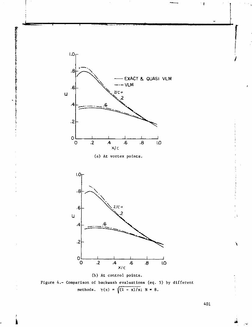
VLM
(a) A t vortex po ints .
(b) A t control po ints .
Figure 4 . - Comparison of backwash evaluat ions (eq. 5 ) by d i f f e r e n t
methods. y (x ) = i m ; N = 8.

4 s rsQ- IMAGE AIRFOIL Figure 5.- Geometry for the ground-effect equation.
[ I h, 'MEAN SURFACE AT
- EXACT ( REF. 5) QUASI VLM & VLM , MEAN
SURFACE AT - - --- 3 c/4 --- c I4
V
Figure 6.- Comparison of computed airfoi' lift in ground effect by different methods. cR = 2na; h measured from c/4.
w
I h,= h SIN a //////////////////////
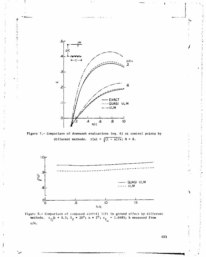
I / /'/ - EXACT I / . '/ ---QUASI VLM
Figure 7.- Comparison of downwash evaluations (eq. 6) at control points by
different methods. y(x) = i(l-xTI;; N = 8.
- QUASI VLM - - -- VLM
Figure 8.- Comparison of computed airfoil lift in gro'und effect by different methods. cf/c = 0.3; 6 f = 20°; a = 2'; c , = 1.6685; h measured from
. . CD
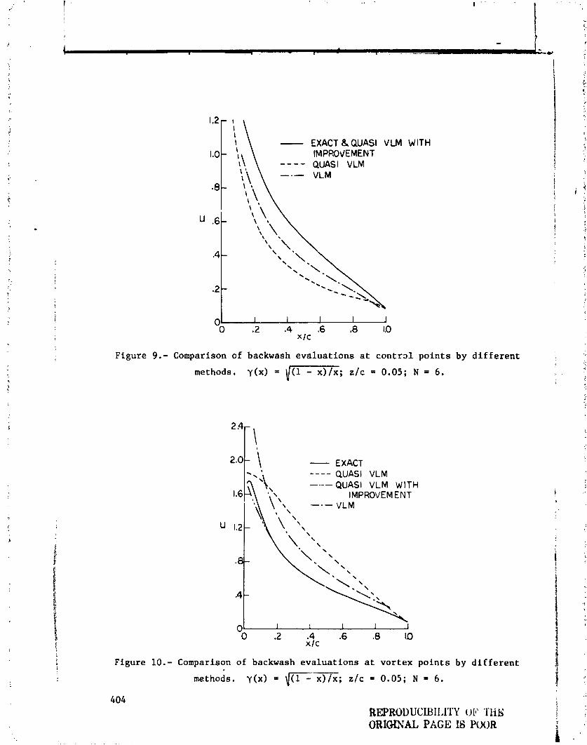
- EXACT & QUASI V LM IMPF!O\IEMENT ---- QUASI VLM
WlTH
Figure 9.- Comparison of backwash evaluations at c o n t r ~ l points by different
methods. y(r) = I-; rlc = 0.05; N = 6 .
- EXACT QUASI VLM QUASI VLM WlTH
IMPROVEMENT VLM
u 1.2 - \ \ \ \
8- \
A -
0 I
0 .2 .4 .6 .8 x l c
ID
Figure 10.- Comparison of backwash evaluations at vortex points by different
methods. y(x) = (-; r l c = 0.05; N = 6 .
REPRODUCUIIAITY OE' THS ORIGIXAL PAGE I6 POOR
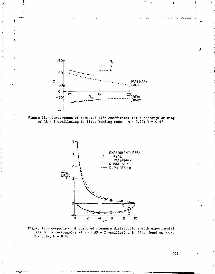
I J IS _ _ _ _ _ _ _ _ _ ---__
PART
Figure 11.- Convergence of computed lift coefficient for a rectangular wing of AR = 2 oscillating in first bending mode. M = 0 .24 ; k = 0.47.
EXPERIMENT ( REF. I I ) 0 REAL El IMAGINARY - QUASI VLM --- DL M ( REF. 10)
Figur e 12.- Comp .son of computed pressure distributions with experimental data for a rectangular wing of AR = 2 oscillzting in first bending mode. M = 0 .24 ; k = 0.47.

- PRESENT --- BENNETT ( REF. 12j
(a) Propulsive efficiency.
- FPESENT
AR = - - -BENNETT( REF. 12)
(b) Thrust.
Figure 13.- Theoretical propulsive efficiency and thrust for rectangular wings in linear flapping.
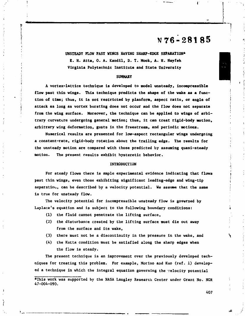
UNSTEADY PLOW PAST WINGS HAVING SHARP-EDGE SBPARATION*
E. 8. Atta, 0. A. Kandil, D. T. Hook, A. 8. Nayfeh
Virginia Polytechnic Institute and State University
A vortex-lattice technique is developed to model unsteady, incompressible
flow past thin wings. This technique predicts the shape of the wake aa a func-
tion of time; thus, it is not restricted by planform, aspect ratio, or angle of
attack as long as vortex bursting does not occur and the flow does not separate
from the wing surface. Moreover, the technique can be applied to wings of arbi-
trary curvattire undergoing general motion; thus, it can treat rigid-body motion,
arbitrary wing deformation, gusts in the freestream, and periodic motions.
Nunerical results are presented for low-aspect rectangular wings undergoing
a constant-rate, rigid-body rotation about the trailing edge. The results for
the unsteady motion are compared with those predicted by assuming quasi-steady
motion. The present results exhibit hysteretic behavior.
INTRODUCTION
d For stead./ flows there is ample experimental evidence indicating that flows
past thin wings, even those exhibiting significant leading-edge and wing-tip a!
separatioi~, can be described by a velocity potential. We assume that the same
is true for unsteady flow.
The velocity potential for incompressible unsteady flow is governed by
Laplace's equation and is subject to the following boundary conditions:
(1) the fluid cannot penetrate the lifting surface,
(2) the disturbance created by the lifting surface must die out away
from the surface and its wake,
(3) there must not be a discontinuity in the pressure in the wake, and
(4) the Kutta condition must be satisfied along the sharp edges when
the flow is steady.
The present technique is an improvement over the previously developed tech-
niques for treating this problem. For example, Morino and Kuo (ref. 1) develop-
ed a technique in which the integral equation governing the T:elocity potential
*This work was supported by the NASA Langley Research Center under Grant No. NGR 47-004-090.
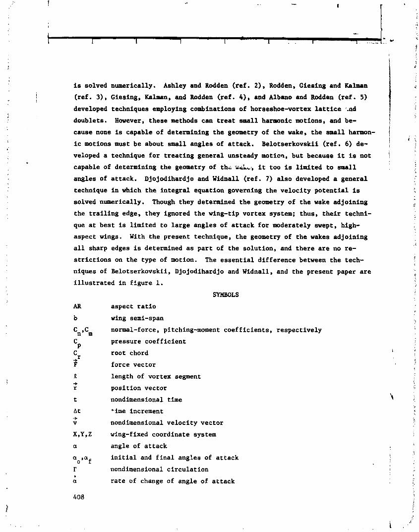
is solved numerically. Ashley and Rodden (ref. 2), Rodden, Gie~ing and blman I J
(ref. 3) , Giesing, Kalman, and Rodden (ref. 4), and Albano and Rodden (ref. 5) developed techniques employing combinations of horseshoe-vortex lattice -.ad
doublets. However, these methods can treat small harmonic motions, and be- ! cause none is capable of determining the geometry of the wake. the small harmon- 1
? i .r
ic motions must be about small angles of attack. Belotserkovskii (ref. 6) de-
veloped a technique for treating general unsteady motion, but because it is not
capable of determining the geometry of thi; ;siA,., it too is limited to small
angles of attack. Djojodihardjo and Widnall (ref. 7) also developed a general
technique in which the integral equation governing the velocity potential is , a
solved numerically. Though they determined the geometry of the wake adjoining
the trailing edge, they ignored the wing-tip vortex system; thus, their techni-
que at best is limited to large angles of attack for moderately swept, high-
aspect wings. With the present technique, the geometry of the wakes adjoining
all sharp edges is determined as part of the solution, and there are no re-
strictions on the type of motion. The essential difference between the tech-
niques of Belotserkovskii, Djojodihardjo and Widnall, and the present paper are
illustrated in figure 1.
SYMBOLS
aspect ratio
wing semi-span
normal-force, pitching-moment coefficients, respectively
pressure coefficient
root chord
force vector
length of vortex segment
position vector
nondimensional time
'ime increment
nondimensional velocity vector
wing-fixed coordinate system
angle of attack
initial and final angl.es of attack
nondimensional circulation
rate of change of angle of attack

THE PRESENT TECHNIQUE
For completeness, the vortex-lattice technique for steady flows is briefly
discussed. Then the modifications needed to model unsteady flows are described.
Steady Flows
The wing surface is represented by a lattice of discrete vortex lines, while
the wake is represented by a series of discrete nonintersecting vortex lines.
Each vortex segment of the lattice is straight (the elemental areas are not nec-
essarily planar), and each line in the wake is composed of a series of short
straight segments and one semi-infinite segment. Control points are associated
with each elemental area of the lattice and with each finite segment of the wake.
The desired velocity potential is the sum of the known freestream potential
and the potentials of all the discrete vortex lines. The velocities generated
by the latter are calculated in terns of the circulations around these qegments
according to the Biot-Savart law. These circulations are the primary unknowns.
To satisfy the no-penetration boundary condition, the normal component of
the velocity is forced to vanish at each control point of the lattice. The velo-
city field generated by the vortex segments is calculated according to the Biot-
Savart law; thus, the disturbance dies out far from the wing and its wake. The
finite segments in the wake are aligned with the velocity at their control points
in order to render the pressure continuous. Finally, no vortex segments on the
lattice are placed between the last row and column of control points and the
edge where the Kutta condition is imposed.
The problem is solved by the following iterative scheme:
(1) a direction is assigned to each segment in the wake,
(2) the circula2ions around each of the vortex segments are determined
by simultaneously satisfying the no-penetration condition and
spatial conservation of circulation,
(3) the segments in the wake are rendered force-free while the circula-
tions are held constant,
(4) steps (2) and (3) are repeated until the shape of the wake doesn't
change.
An example of a steady solution is shown in figure 2.
More Ge~ails and results are given by Kandil, Mook and Nayfeh (ref. 8) and
by Kandil (ref. 9).
409
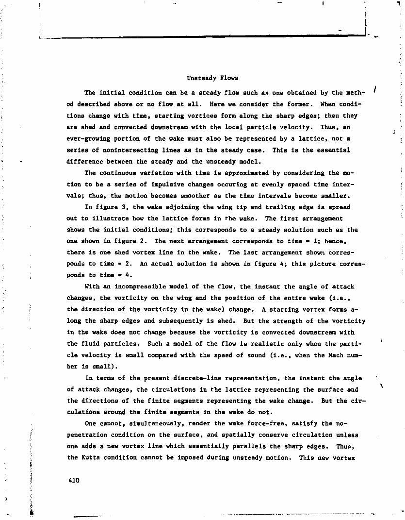
Unsteady Flows
The initial condition can be a steady flow such aft one obtained by the meth- / od described above or no flow at all. Here we consider the former. When condi-
tions change with time, starting vortices form along the sharp edges; then they
are shed and convected downstream with the local particle velocity. Thus, an
ever-growing portion of the wake must also be represented by a lattice, not a
series of nonintersecting lines as in the steady case. This is the essential
difference between the steady and the unsteady model.
The continuous variation with time is approximated by considering the mo-
tion to be a series of impulsive changes occuring at evenly spaced time inter-
vals; thus, the motion becomes smoother as the time intervals become smaller.
In figure 3, the wake adjoining the wing tip and trailing edge is spread
out to illustrate how the lattice forms in the wake. The first arrangement
shows the initial conditions; this corresponds to a steady solution such as the
one shown in figure 2. The next arrangement corresponds to time = 1; hence,
there is one shed vortex line in the wake. The last arrangement show1 corres-
ponds to time = 2. An actual solution is shown in figure 4; this picture corres-
ponds to time = 4.
With an incompressible model of the flow, the instant the angle of attack
changes, the vorticity on the wing and the position of the entire wake (i .e.,
the direction of the vorticity in the wake) change. A starting vortex forms a-
long the sharp edges and subsequently is shed. But the strength of the vorticity
in the wake does not change because the vorticity is convected downstream with i
the fluid particles. Such a model of the flow is realistic only when the parti-
cle velocity is small compared with the speed of sound (i.e., when the Mach num-
ber is small),
In terms of the present discrete-line representation, the instant the angle '
of attack changes, the circulations in the lattice representing the surface and I
the directions of the finite segments representing the wake change. But the cir-
culations around the finite segments in the wake do not.
One cannot, simultaneously, render the wake force-free, satisfy the no-
penetration condition on the surface, and spatially conserve circulation unless
one adds a new vortex line which essentially parallels the sharp edges. Thu~,
the Kutta condition cannot be imposed during unsteady motion. This new vortex

.- line represents the shed vorticity which is convected downstream causing a
lattice to form in the wake. One new vortex line is formed for each time inter-
: val. When the wing stops rotating, lines continue to be shed; however, the
strengths of these lines decrease and the steady-state results are approached
rapidly. This is illustrated in figures 5 - 7. The sequence of events leading
up to figures 5 - 7 is as follows: Initially the angle of attack was eleven
degrees and the flow was steady. Then the angle of attack was increased at the
rate of one degree per nondimensional time unit until the angle of attack reach-
; ed fifteen degrees. At this point the angle of attack stopped changing. The
general unsteady program was allowed to run for twelve time units. This allowed
the strength of the shed vortices to vanish, those of appreciable strength to be
convected far downstream, and the flow to achieve a steady state.
In all three cases, the lift and moment produced by the unsteady flow are
lower than those produced by a steady flow at the same angle of attack. The
steady-flow results are shown by the dotted lines.
At each time step, the solution is obtained in essentially the same way
that the steady problem is solved. But now there is the added complication of
convecting the shed vorticity downstream with the particle velocity. This is
accomplished by moving the ends of the segments of the shed line according to -b + + r(t + At) = r(t) + vAt
where 2 is the particle velocity and At is the time interval. The nondimensional loads are calculated according to
-f F = 2Rf x 2
where R is the nondimensional length of the segment on which the force 9 acts, -F I' is the circulation around this segment multiplied by a unit vector parallel
-+ to the segment and v is the velocity at the midpoint of the segment. The re-
sultant force is obtained by adding the forces on the bound segments. The 1 t i
pressures are calculated by averaging one-half the forces on the segments along i
the edges of an elemental area over the elemental area, exceptions being those
elements along the leading edge for which the entire force acting on the forward
segment is averaged.
Figure 8 shows the convergence as the number of elements is increased. Com-
paring figures 9 and 10 with figures 5 and 6 shows that the unsteady results
approach the steady results as the rate of changing the angle of attack decreases.
Figures 11 and 12, which show hysteretic behavior, compare the results for
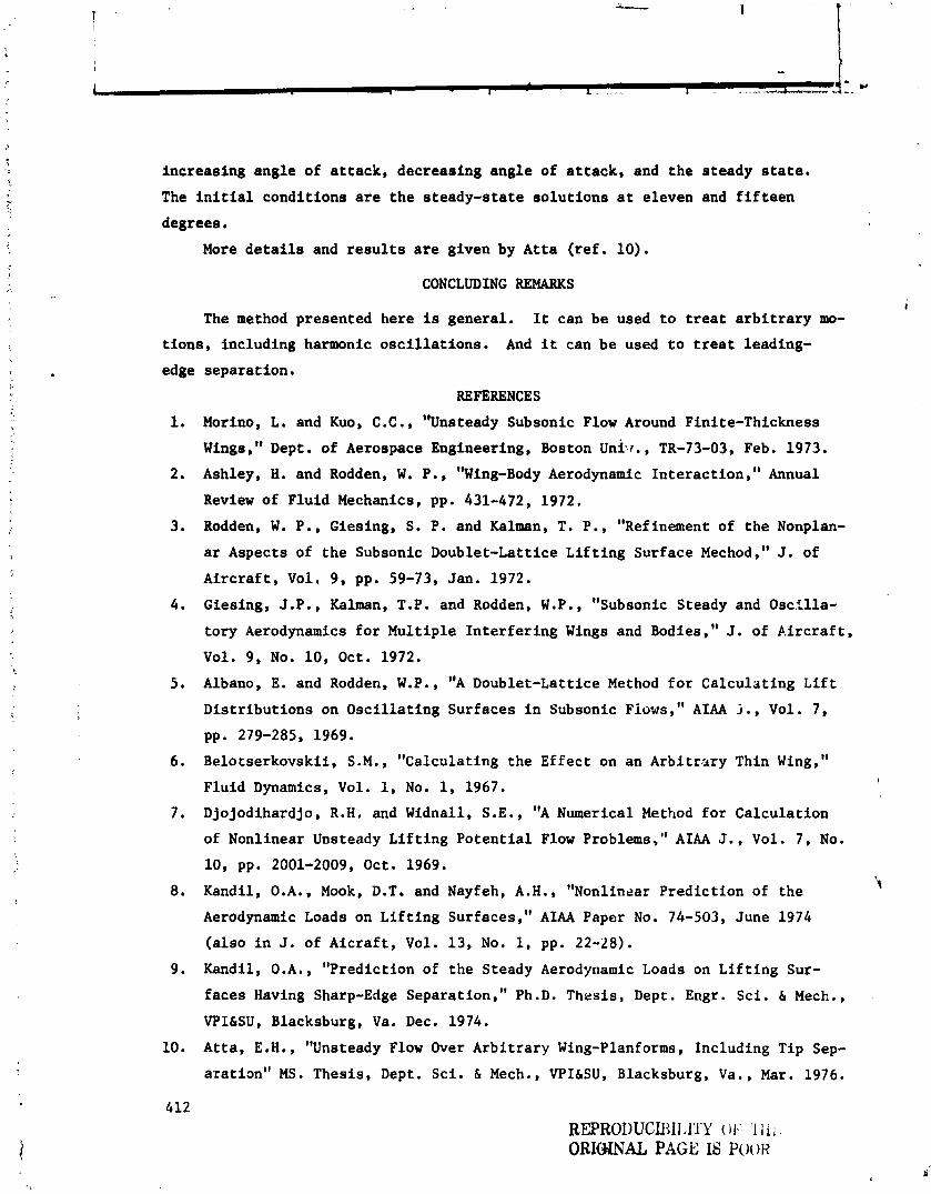
increasing angle of attack, decreasing angle of attack, and the steady state.
The initial conditions are the steady-state solutions at eleven and fifteen
degrees.
More details and results are given by Atta (ref. 10).
CONCLUDING REMARKS
The method presented here is general. It can be used to treat arbitrary mo-
tions, including harmonic oscillations. And it can be used to treat leading-
edge separation.
REFERENCES
Morino , L . and Kuo , C . C . , "Unsteady Subsonic Flow Around Fini te-Thickness Wings," Dept. of Aerospace Engineering, Boston unilr., TR-73-03, Feb. 1973.
Ashley, H. and Rodden, W. P., "Wing-Body Aerodynamic Interaction," Annual
Review of Fluid Mechanics, pp. 431-472, 1972.
Rodden, W. P., Giesing, S. P. and Kalman, T. P., "Refinement of the Nonplan-
ar Aspects of the Subsonic Doublet-Lattice Lifting Surface Mechod," J. of
Aircraft, Vol. 9, pp. 59-73, Jan. 1972.
Giesing, J.P., Kalman, T.P. and Rodden, W.P., "Subsonic Steady and Oscilla-
tory Aerodynamics for Multiple Interfering Wings and Bodies," J. of P-ircraf t , Vol. 9, No. 10, Oct. 1972.
Albano, E. and Rodden, W.P., "A Doublet-Lattice Method for Calculating Lift
Distributions on Oscillating Surfaces in Subsonic ~iows," A M j . , Vol. 7,
pp. 279-285, 1969.
Belotserkovskii, S.M., "Calculating the Effect on an Arbitrary Thin Wing,"
Fluid Dynamics, Vol. 1, No. 1, 1967.
Djojodihardjo, R.H. and Widnall, S.E., "A Numerical Method for Calculation
of Nonlinear Unsteady Lifting Potential Flow Problems,'' AIAA J., Vol. 7, No.
10, pp. 2001-2009, Oct. 1969.
Kandil, O.A., Mook, D.T. and Nayfeh, A.H., "Nonlinear Prediction of the
Aerodynamic Loads on Lifting Surfaces," AIAA Paper No. 74-503, June 1974
(also in J. of Aicraft, Vol. 13, No. 1, pp. 22-28).
Kandil, O.A., "Prediction of the Steady Aerodynamic Loads on Lifting Sur-
faces Having Sharp-Edge Separation," Ph.D. Thesis, Dept. Engr. Sci. 6 Mech..,
VPI&SU, Blacksburg, Va, Dec. 1974.
Atta, E.H., "Unsteady Flow Over Arbitrary Wing-Planforms, Including Tip Sep-
aratim" MS. Thesis, Dept. Sci. & Mech., VPI&SU, Blacksburg, Va., Mar. 1976.

D J Q I O D I W pfmvrm (1969)
Figure 1.- Comparison of different methods.
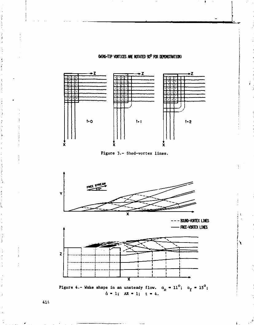
Figure 3.- Shed-vortex lines.
I-; z .------
Figure 4.- Wake shape in an unsteady flow. a. 11'; af = 15'; & 1; AR = 1; t 4.

Figure 5.- Variation of the normal-force coefficient. a o = l l O ; a f = l S O ; & = I ; A t = l .
Figure 6.- Variation of the pitching-moment coefficient.
a. = 11'; af = 15 ; & = 1; At = 1.
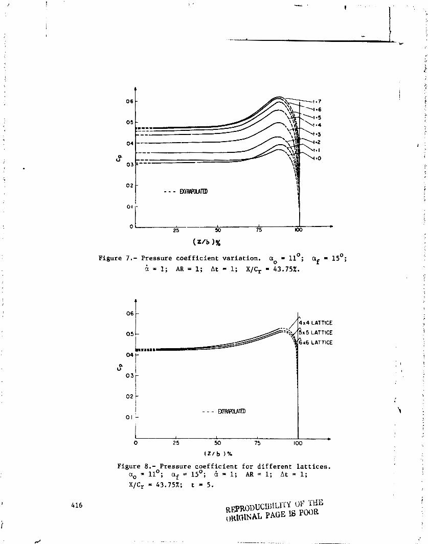
o h - L I I *
25 50 75 00
Figure 7.- Pressure coefficient variation. OLo = llO; af = 15O;
& = 1 AR = 1; At = 1; X/Cr = 43.75X.
Figure 8.- Pressure coefficient for different lattices.
@o = 11'; af = 15'; & 5 1; AR = 1; At 1;
X/Cr = 43.75%; t = 5.
R~R( ]~ )UCUHLSI .Y OF THE oIt1OtNAL PAGE I6 PWR
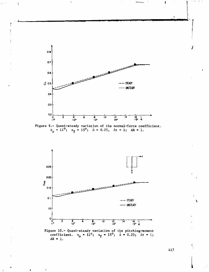
Figure 9.- Quasi-steady variation of the normal-force coefficient. a. = 11'; af = 15'; 6 = 0.25, At = 1; AR = 1.
Figure 10.- Quasi-steady variation of the pitching-moment coefficient. a, = llO; af = 15'; 6 = 0.25; At 1; AR = 1.
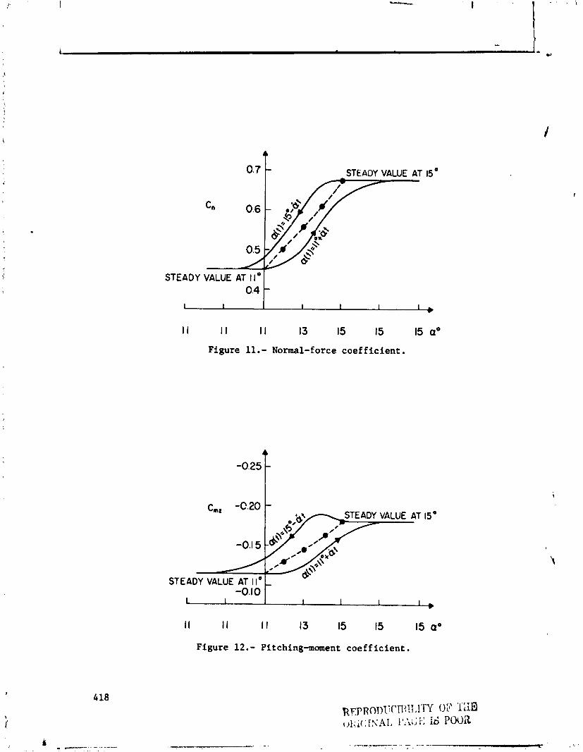
0.7 STEADY VALUE AT
STEADY VALUE AT 1 I* 0.4 1
I I I I I I 13 15 15 15 a0
Figure 11.- Normal-force coefficient.
STEADY VALUE AT I I * L u-
-0.1 0 I 1 I I 1 1 * I I I I I I 13 15 15 15 a*
Figure 12.- Pitchinglnoment coefficient.
SUMMARY OF OPEN DISCUSSION ON FUTU!Ul VORTEX-LATTICE UTILIZATION
John C. Houbolt NASA Langley Research Center
The response of the attendees during the open discussion on vortex-lattice utilization was excellent. The intent of this summary is not to evaluate the comments made but simply to indicate the topics discussed. Essentially, the discussion focused on the following general topics: grid layout, drag calcula- tions, bodies in combination, vortex lift, and separated flow effects.
In order to stimulate and initiate the discussion, a panel was set up on a spur-of-the-moment basis. Members were Jan Tulinius of NASA Langley Research Center, Joseph Giesing of McDonnell Aircraft Company, Winfried Feifel of The Boeing Company, and Brian Maskew 9f Analytical Methods, Inc. The sub- jects covered by each of these members are essentially as follows:
Tulinius, in effect, gave a very good impromptu paper. He covered two- dimensional and three-dimensional drag effects and discussed the equivalence of near- and far-field drag estimates. He mentioned supersonic vortex-lattice methods and pointrd out problems associated with Mach cone and sonic line singu- larities, with natural edge conditions, and with nonplanar effects. He also discussed the use of distributed singularities versus the use of lattice con- straint functions. Also covered was the topic of free vortices, whether of the leading-edge variety for arbitrary planforms or as associated with trailing-edge and tip wakes.
Giesing's remarks also constituted a very gund impromptu paper. He dis- cussed areas for numerical improvenent of the lattice method with topic coverage as follows:
Supersonic flow
Infinite velocity on Mach cones Smearing of loads - loads wandering out. of Mach cone Instability of solutions
Convecting singularities (jets, wakes, leading-edge vortices)
'1 Infinite velocity when vortex contacts control point
i Force or pressure calculation inconvenient on yawed elements Wake next to fuselage Low lift for jet flaps
Subsonic flow
Discontinuity in Ax causes disturbance in pressures Collocating points on body surfaces, while using axial singularities can cause instabilities
High frequency lattice method expensive and/or inaccurate Computing tjme and accuracy trade-off for wing-bodies
Areas where Giesing felt there was need for basic improvement in the lattice methods are as follows:
Transonic flow
Empirical corrections
Viscous corrections
Steady Unsteady
Oscillatory flow
Nonplanar flaps down, etc. Wing- jet j nteraction (compressible) Leading-edge vortex
Lateral-directional forces
Feifel emphasized the need for practical considerations and input sim- plicity. He discussed problems related to the treatment of cambered wings. He also felt more attention should be given to grid system layout, especially with respect to the simulation of bodies or other complex configurations. The treat- ment of high lift configurations, such as constant chord flaps on tapered wings, and the situation of wings with cutouts also represent problem areas.
Maskew's comments are summarized as follows. He referred to the use of constraint functions discussed by Tulinius as a possible alternative to the subvortex technique for keeping the number of unknowns down while effectively using a large number of vortices. Maskew mentioned that he had used constraint functions with a subvortex model, as reported in NASA TI: X-73115 (ref. 1). The number of unknowns was halved without spoiling the pressure calculations at the arbitrary points. With the small number of unknowns, i.e., 46, the savings in solution time was about the same as the time required to fiani;~ulate the metrix. For a larger number of unknowns, there should be a savings in computer time. On the question posed by Houbolt on separated flow modeling, Maskew felt the answer might be found in Giesing's comments, namely, that the multienerpy mod~ling developed by Shollenberger for jet flow interference might also be adapted for the low energy region associated with separated flows. Moskcw mentioned that certain problems arise in wake rollup calculations of compli- cated flap systems. For tne 747 flap system, with edge vortices on each flap, he found that the two opposing regions from the flap edges adjacent to the high-

is speed aileron pose a ploblem in that the calculations predict an orbiti .ng mot ion which does not appear in real flow. The two vortices in fact soon cancel each other, leaving a single wake vortex. This merging problem needs further inves-
i
f; tigation so that it can be modeled correctly. Another problem he discussed
2 deals with the near-field calculation of forces using the Kutta-Joukowski law B applied to vartex segments. He pointed out that in most cases the forces are f calculated only on the bound vortex segments, and with the assumption that the
chordwise segments are alined with the local mean velocity and therefore carry $,
no 104. In some configurations this assumption is not valid. He brought out : the example of a yawed wing which has been paneled for symmetrical flow and , S- raised the question, does the wing need repaneling before calculating the yawed
9 i condition. The problem alsc appears on wings with deflccted flaps. Large mean I spanwise flow components exist on the flaps, particularly near the tip, and if 5 :he forces on the chordwise segments ?re computed in this case, the Kutta f - trailing-edge condition appears violated. Maskew pointed out that this problem j
requires further attention and that perhaps the chordwise segments should always ?
b? alined with the mean flow direction.
In summary, the following items appear to be of chief concern in continuing and future development of the vortex-lattice methods:
1. Grid layout, especially with respect to the use of the 114-point, 314-point rule, or the approach which employs equal angular spacing within a semicircle
2. Drag calculation techniques
6. Treatment of lateral flow or of combined pitch and yaw displacement
REFERENCE
1. Maskew, B.: A Submerged Singularity Method for Calculating Potential Flow Velocities at Arbitrary Near-Field Points. NASA TM X-73115, 1976.
3. Bodies in combination
4. Separated flow effects including wake rollup
5. Supersonic flow applications
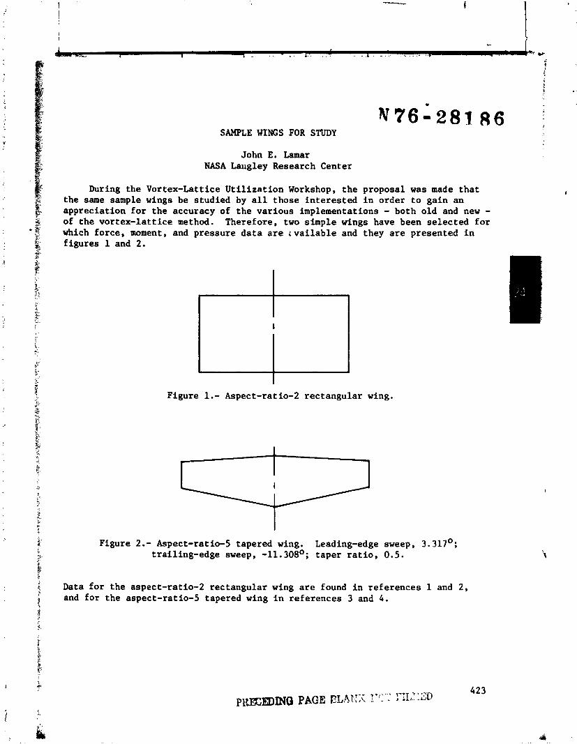
SAMPLE WINGS FOR STUDY
John E. Lamar NASA Langley Research Center
During the Vortex-Lattice U t i l i z a t i on Workshop, t he proposal was made t h a t the same sample wings be studied by a l l those i n t e r e s t ed i n order t o gain an appreciation f o r the accuracy of the var ious implementations - both old and new - of the vor tex- la t t i ce method. Therefore, two simple wings have been se lec ted f o r which force, moment, and pressure da t a a r e i v a i l a b l e and they a r e presented i n f igures 1 and 2.
Figure 1.- Aspect-ratio-2 rectangular wing.
Figure 2 .- Aspect-ratio-5 tapered wing. Leading-edge sweep, 3.317'; trail ing-edge sweep, -11.308O; taper r a t i o , 0.5.
Data fo r the aspect-ratio-2 rectangular wing a r e found i n references 1 and 2 , and fo r the aspect-ratio-5 tapered wing i n references 3 and 4.
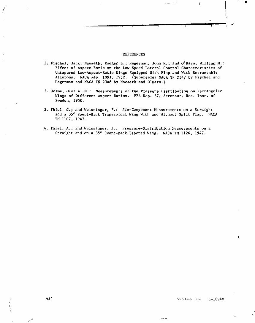
REFERENCES
1. Fischel, Jack; Naeseth, Rodger L.; Hagerman, John R.; and O'Hara, William M.: Effect of Aspect Ratio on the Low-Speed Lateral Control Characteristics of Untapered Low-Aspect-Ratio Wings Equipped With Flap and With Retractable Ailerons, NACA Rep. 1091, 1952. (Supersedes NACA TN 2347 by Fischel and Hagerman and NACA TN 2348 by Naeseth and O'Hara.)
2. Holme, Olof A. M.: Measurements of the Pressure Distribution on Rectangular Wings of Different Aspect Ratios. FFA Rep. 37, Aeronaut. Res. Inst. of Sweden, 1950.
3. Thiel, G.; and Weissinger, F.: Six-Component Measurements on a Straight and a 35O Swept-Back Trapezoidal Wing With and Without Split Flap. NACA TM 1107, 1947.
4. Thiel, A.; and Weissinger, J.: Pressure-Distribution Measurements on a Straight and on a 35O Swept-Back Tapered Wing. NACA TM 1126, 1947.