NEW TOPOLOGY FOR SINGLE-PHASE, THREE-LEVEL, SPWM VSI WITH LC FILTER
9
NEW TOPOLOGY FOR SINGLE-PHASE, THREE-LEVEL, SPWM VSI WITH LC FILTER Charles I. Odeh and Marcel U. Agu Department of Electrical Engineering, University of Nigeria, Nsukka. Abstract Multilevel inverters that provide more than two levels of voltage to achieve less distorted dc-ac conversion have attracted many contributors. This paper presents a new simplified topology for single-phase, sinusoidal pulse width mod- ulated (SPWM) three-level SPWM voltage source inverter (VSI) with LC filter. To keep the power circuit component count to a minimum, the proposed three- level topology simplifies the conventional three-level inverter configuration to that of a full-bridge, two-level inverter, with only one added auxiliary power switch. Operational principles, with switching functions are analyzed. The performance characteristics of the proposed inverter are predicted using simulation process in simplorer schematic environment. Assessment of the proposed inverter is done by comparing it with the conventional single-phase, two and three level SPWM inverter under the conditions of identical supply dc voltage, switching frequency and loading. Keywords: SPWM inverter, Frequency, single-phase, Harmonics 1. Introduction Simultaneous variation and control of the output voltage and frequency, reduction in the harmonic components in load currents are some of the basic characteristics of PWM in- verters. These inherent features have made them to be employed in many industrial ap- plications such as variable speed drives, un- interruptible power supplies and other power conversion systems. However, the reduction of the harmonic components in output currents is still the focus of major interests to mitigate the influence of electro-magnetic interference or noise and vibrations. In recent years, many multilevel inverters have been presented, [1] [5]. The approaches in these technical papers also have a lot of merits such as improved out- put waveforms, smaller filter size, low EMI and other advantages. Among them, various PWM techniques have been investigated and discussed with their respective characteristics. However, the gate/firing signals to control a particular inverter must be derived before the choice of the switching technique. In general, neutral point clamped PWM three-phase in- verter which uses four switching elements in each arm has three level voltage waveforms that result in considerable suppression of the harmonic components when compared with the conventional full-bridge, three-phase, two- Nigerian Journal of Technology Vol. 30, No. 1, March 2011.
-
Upload
independent -
Category
Documents
-
view
0 -
download
0
Transcript of NEW TOPOLOGY FOR SINGLE-PHASE, THREE-LEVEL, SPWM VSI WITH LC FILTER
NEW TOPOLOGY FOR SINGLE-PHASE,
THREE-LEVEL, SPWM VSI WITH LC FILTER
Charles I. Odeh and Marcel U. Agu
Department of Electrical Engineering, University of Nigeria, Nsukka.
Abstract
Multilevel inverters that provide more than two levels of voltage to achieveless distorted dc-ac conversion have attracted many contributors. This paperpresents a new simplified topology for single-phase, sinusoidal pulse width mod-ulated (SPWM) three-level SPWM voltage source inverter (VSI) with LC filter.To keep the power circuit component count to a minimum, the proposed three-level topology simplifies the conventional three-level inverter configuration to thatof a full-bridge, two-level inverter, with only one added auxiliary power switch.Operational principles, with switching functions are analyzed. The performancecharacteristics of the proposed inverter are predicted using simulation process insimplorer schematic environment. Assessment of the proposed inverter is doneby comparing it with the conventional single-phase, two and three level SPWMinverter under the conditions of identical supply dc voltage, switching frequencyand loading.
Keywords: SPWM inverter, Frequency, single-phase, Harmonics
1. Introduction
Simultaneous variation and control of theoutput voltage and frequency, reduction inthe harmonic components in load currents aresome of the basic characteristics of PWM in-verters. These inherent features have madethem to be employed in many industrial ap-plications such as variable speed drives, un-interruptible power supplies and other powerconversion systems. However, the reduction ofthe harmonic components in output currentsis still the focus of major interests to mitigatethe influence of electro-magnetic interferenceor noise and vibrations. In recent years, manymultilevel inverters have been presented, [1]
[5]. The approaches in these technical papersalso have a lot of merits such as improved out-put waveforms, smaller filter size, low EMIand other advantages. Among them, variousPWM techniques have been investigated anddiscussed with their respective characteristics.However, the gate/firing signals to control aparticular inverter must be derived before thechoice of the switching technique. In general,neutral point clamped PWM three-phase in-verter which uses four switching elements ineach arm has three level voltage waveformsthat result in considerable suppression of theharmonic components when compared withthe conventional full-bridge, three-phase, two-
Nigerian Journal of Technology Vol. 30, No. 1, March 2011.
92 C.I. ODEH and M.U. AGU
level PWM inverter. However, this is not thecase with single-phase PWM inverters. Inthese days, the popular single-phase invertersadopt the full-bridge type using approximatesinusoidal modulation technique. The outputvoltage in them has two values: zero and pos-itive supply dc voltage levels in the positivehalf cycle. Hence, the harmonic componentsof their output voltage are determined by thecarrier frequency. Moreover, the harmonic re-duction in them is limited to a certain degree.
As a solution, this paper presents a single-phase, three-level PWM inverter whose out-put voltage has three values: zero, half andfull supply dc voltage levels in the positive halfcycle. The proposed inverter can reduce theharmonic components compared with that ofthe conventional full-bridge, two-level PWMinverter under the condition of identical sup-ply dc voltage, switching frequency and load-ing. Operational principles and switchingfunctions are analysed. Simulation results arepresented to verify the validity of the proposedinverter.
2. Configuration and Operational Prin-ciples of the Proposed Inverter.
�
�
�
���������������������������������������������������������������������������������������������������������������
�
�
�
�
���
���
���
���
���
�������������������������������������������������������������
��
���
��
��
�� ��
��
��
�� ��
��
���
���
���
���
��
��
�
��
Figure 1: Power circuit of the proposed Single-Phase, Three-level PWM inverter.
The proposed single-phase, three-levelPWM inverter power circuit is shown in fig-ure 1. One switching element and four clamp-ing diodes are added in the conventional full-bridge inverter circuit and are connected tothe center-tap of the dc power supply. Propergating control of the auxiliary power switch
Table 1: Output voltage according to the switch ON-OFF conditions.ONswitches
Node avoltage(va)
Node bvoltage(vb)
Outputvoltage(vab = vo)
S1, S4 Vs 0 +VsS5, S4 Vs/2 0 +Vs/2S2, S4
(S1, S3)0 0 0
S2, S5 0 Vs/2 −Vs/2S2, S3 0 Vs −Vs
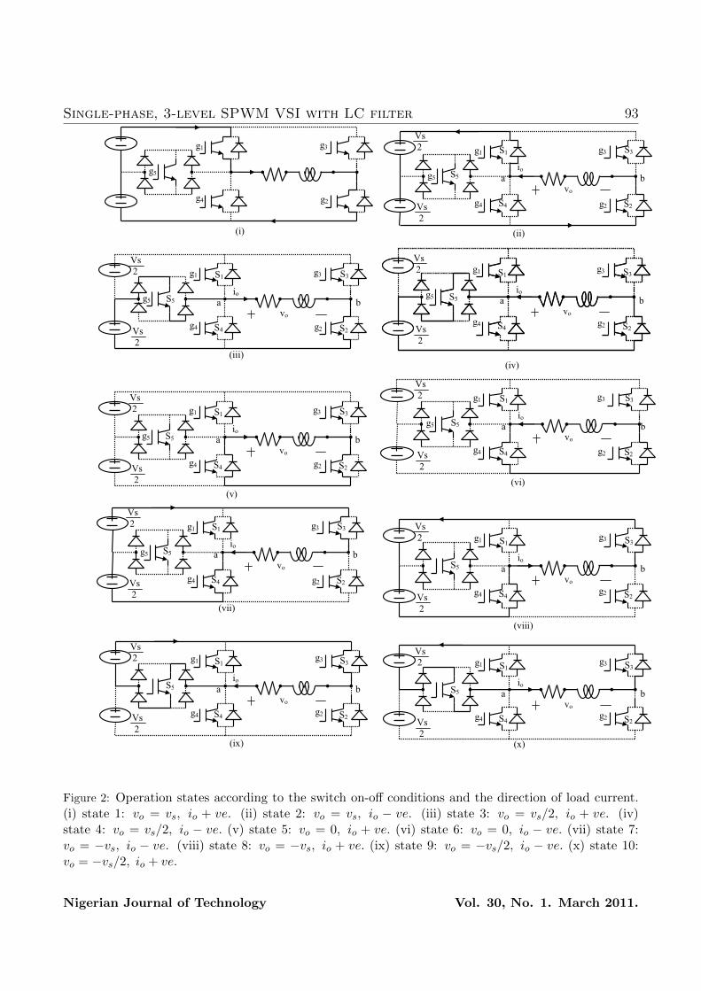
can generate half level of the dc supply volt-age. The operation of the proposed invertercan be divided into ten switching states as il-lustrated in Figure 2.
Operational states of the conventional two-level inverter are shown in figure 2(i), (ii), (v),(vi), (vii) and (viii) in sequence; and addi-tional states in the proposed inverter synthe-sizing half level of dc bus voltage are shown infigure 2(iii), (iv), (ix) and (x). The additionalswitch, s5 must be properly triggered consid-ering the direction of the load current, io. Theswitching patterns adopted in the proposedinverter are illustrated in Figure 3; and theoutput voltage levels according to the switchon-off conditions are shown in Table 1.
Basic principle of the proposed switchingstrategy is to generate triggering signals bycomparing the reference signal with two dis-posed carrier waves having the same frequencyand in phase, but different offset voltages. Ifthe required output voltage for a certain loadcan be produced using only the half of thedc bus voltage, only the lower carrier waveis compared with reference signal. Powerswitches S2, S3 and S5 are used to generatethe output voltage. In this case, the mod-ulation index is equal or less than 0.5 andthe behaviour of the proposed inverter is sim-ilar to that of conventional full-bridge, two-
Nigerian Journal of Technology Vol. 30, No. 1. March 2011.
Single-phase, 3-level SPWM VSI with LC filter 93
��
�
�
�
�
�
�
�
�������������������������������������������������������
�
�
�
��
��
�� ��
����
��
���
��
� �
���
����
��
�
��
�
�
�
�
�
�
�
�
�
�����������������������������������������
�
�
�
�
�
�
�
�����
���������������������������������������������������������������
��
���
��
�
����
��
��
�� �
��
���
���
���
���
��
�����
��
� �
���
����
��
�
�
�
�
�
�
�
�
�
���������������������������������������������������������
�
�
��
��
�� ��
����
��
��
�
��
��
�� ��
����
��
��
�
��
�
���
��
� �
���
���
���������������������������������������������������������������
��
���
��
�
����
��
��
�� �
��
���
���
���
���
��
��
��
�
�
�
�
�
�
�
�
�
�
�
�
�
��������������������������������������������������
� �����
�
���������������������������������������������������������������
��
���
��
�
����
��
��
�� �
��
���
���
���
���
��
��
��
�
��
��
�� ��
����
��
��
�
���
��
� �
���
���
��
�
�
�
�
��
�
�
�
�
�
� �
�
�
�
� ����
���
��
� �
���
���
���������������������������������������������������������������
��
���
��
�
����
��
��
�� �
��
���
���
���
���
��
��
��
�
�
�
����������������������������������������������������
�
�
�
�
�
�
�
�
�
��������������������������������������������������������
�
�
�
��
��
�� ��
����
��
�
��
���
��
� �
���
���
���������������������������������������������������������������
��
���
��
�
����
��
��
�� �
��
���
���
���
���
��
��
��
�
�
�
�
�
�
�
�
����������������������������������������������������
�
�
�
�
�
�
�
������
���
��
� �
���
���
���������������������������������������������������������������
��
���
��
�
����
��
��
�� �
��
���
���
���
���
��
��
�
��
�
�
�
�
�
�
�
�
�
�
����������������������������������������������������������
�
�
��
��
�� ��
����
��
�
��
��
��
�� ��
����
��
�
��
���
��
��
���
���������������������������������������������������������� ����
��
���
��
��
�����
��
��
�����
��
���
���
���
���
���
��
��
�
�
�
�
�
�
�
�
�
�
�
�
�
��������������������������������������������������������
�
�
�
��
��
�� ��
����
��
�
��
���
��
��
���
���������������������������������������������������������� ����
��
���
��
��
�����
��
��
�����
��
���
���
���
���
���
��
�
��
�
�
�
�
�
�
�
�
�
�
�
�
�������������������������������������������������������
�
���
��
��
���
���������������������������������������������������������� ����
��
���
��
��
�����
��
��
�����
��
���
���
���
���
���
��
�
��
Figure 2: Operation states according to the switch on-off conditions and the direction of load current.(i) state 1: vo = vs, io + ve. (ii) state 2: vo = vs, io − ve. (iii) state 3: vo = vs/2, io + ve. (iv)state 4: vo = vs/2, io − ve. (v) state 5: vo = 0, io + ve. (vi) state 6: vo = 0, io − ve. (vii) state 7:vo = −vs, io − ve. (viii) state 8: vo = −vs, io + ve. (ix) state 9: vo = −vs/2, io − ve. (x) state 10:vo = −vs/2, io + ve.
Nigerian Journal of Technology Vol. 30, No. 1. March 2011.
94 C.I. ODEH and M.U. AGU�
�
�
�
�
�
�
�
�
�
�
�
�
�
�
�
�
�
�
���� ����� ����� ���� ����� ����� ����
��
��
��� �
�����
��� �
���
���
���
���
���
������� � ��� �!� �"�
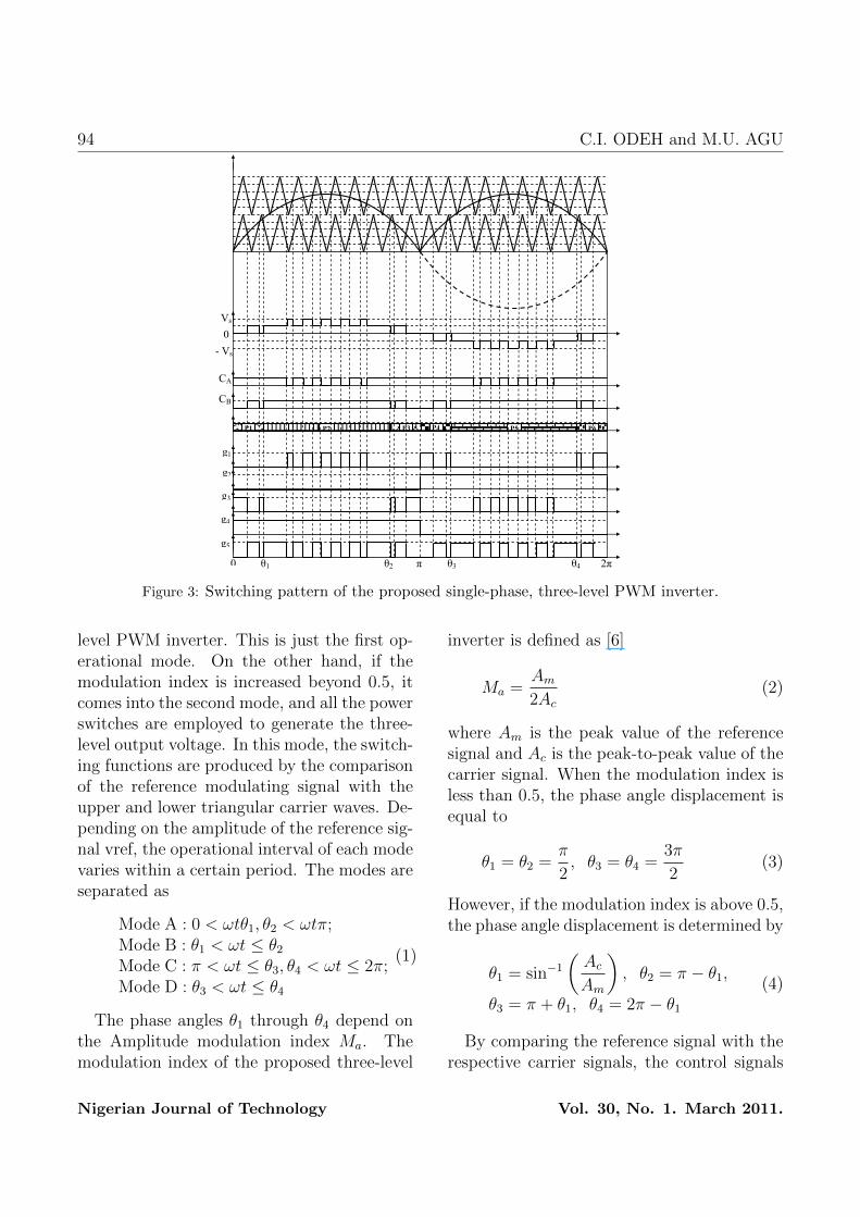
Figure 3: Switching pattern of the proposed single-phase, three-level PWM inverter.
level PWM inverter. This is just the first op-erational mode. On the other hand, if themodulation index is increased beyond 0.5, itcomes into the second mode, and all the powerswitches are employed to generate the three-level output voltage. In this mode, the switch-ing functions are produced by the comparisonof the reference modulating signal with theupper and lower triangular carrier waves. De-pending on the amplitude of the reference sig-nal vref, the operational interval of each modevaries within a certain period. The modes areseparated as
Mode A : 0 < ωtθ1, θ2 < ωtπ;Mode B : θ1 < ωt ≤ θ2Mode C : π < ωt ≤ θ3, θ4 < ωt ≤ 2π;Mode D : θ3 < ωt ≤ θ4
(1)
The phase angles θ1 through θ4 depend onthe Amplitude modulation index Ma. Themodulation index of the proposed three-level
inverter is defined as [6]
Ma =Am
2Ac
(2)
where Am is the peak value of the referencesignal and Ac is the peak-to-peak value of thecarrier signal. When the modulation index isless than 0.5, the phase angle displacement isequal to
θ1 = θ2 =π
2, θ3 = θ4 =
3π
2(3)
However, if the modulation index is above 0.5,the phase angle displacement is determined by
θ1 = sin−1(Ac
Am
), θ2 = π − θ1,
θ3 = π + θ1, θ4 = 2π − θ1(4)
By comparing the reference signal with therespective carrier signals, the control signals
Nigerian Journal of Technology Vol. 30, No. 1. March 2011.
Single-phase, 3-level SPWM VSI with LC filter 95
CA and CB are generated as shown in fig-ure 3. Consequently, the switching signals g1through g5 of the proposed inverter are de-rived from the use of basic logic gates on thesignals CA, CB and the phase angle displace-ments; equation (5) gives the respective logi-cal operations.
g1 = CAP2 + CBP4 + CBP6;g2 = P4 + P5 + P6;g3 = CBP2 + CBP3 + CAP5;g4 = P1 + P2 + P3;g5 = CBP1 + CACBP2 + CBP3
+CBP4 + CACBP5 + CBP6
(5)
From the two disposed carrier waves andoutput voltage in figure 3, the analysis ofthe harmonic components in the proposed in-verter can be performed. The output voltageproduced by the comparison of the referencesignal and the two carrier waves can be ex-pressed as
Vo(θ) = Ao+∞∑n=1
(An cosnθ+Bn sinnθ)(6)
If there are P pulses per a quarter period, andit is an odd number, the coefficients Bn andA0 would be zero. Thus, equation (6) simpli-fies to
Vo(θ) = Ao +∞∑
n=1,3,5,...
(An cosnθ) (7)
where m is a pulse number.
The Fourier series coefficients of the con-ventional single-phase, full-bridge, sinusoidalPWM inverter is given by
An =2Vsnπ
P∑m=1
{(−1)m sin(nαm)} (8)
3. Performance Estimation of the Pro-posed Inverter
Reduction in the harmonic components ofthe output voltage synthesized by an invertersystem is highly needed as it alleviates theoutput current ripples; as well as minimizesthe size of the output filter. Simulation studyis carried out on the proposed single-phase,three-level inverter to evaluate its character-istic performance. The simulation is done inthe SIMPLORER schematic environment.
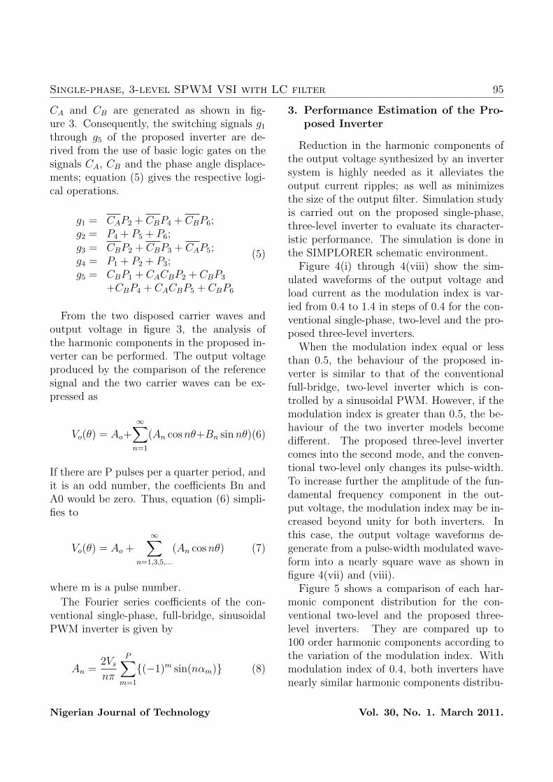
Figure 4(i) through 4(viii) show the sim-ulated waveforms of the output voltage andload current as the modulation index is var-ied from 0.4 to 1.4 in steps of 0.4 for the con-ventional single-phase, two-level and the pro-posed three-level inverters.
When the modulation index equal or lessthan 0.5, the behaviour of the proposed in-verter is similar to that of the conventionalfull-bridge, two-level inverter which is con-trolled by a sinusoidal PWM. However, if themodulation index is greater than 0.5, the be-haviour of the two inverter models becomedifferent. The proposed three-level invertercomes into the second mode, and the conven-tional two-level only changes its pulse-width.To increase further the amplitude of the fun-damental frequency component in the out-put voltage, the modulation index may be in-creased beyond unity for both inverters. Inthis case, the output voltage waveforms de-generate from a pulse-width modulated wave-form into a nearly square wave as shown infigure 4(vii) and (viii).
Figure 5 shows a comparison of each har-monic component distribution for the con-ventional two-level and the proposed three-level inverters. They are compared up to100 order harmonic components according tothe variation of the modulation index. Withmodulation index of 0.4, both inverters havenearly similar harmonic components distribu-
Nigerian Journal of Technology Vol. 30, No. 1. March 2011.
96 C.I. ODEH and M.U. AGU
�
���������������� ����������������������
����
�
���
���
���
���
� ��� �� �� �� �� �� � � �� �� �� �� �� �� �� �� �� �� � � �� �� �� �� �� �� � � �� �� �� �� �� �� �� �� �� �� ��
����� ���������� ���� �� ��� ����������� ����������������������
�����
�
�����
�����
����
����
� ������������ � ����������������������������������� � ���������������������
����� ���������� ���� �� ������� �������� ������������������
�
�
��
��
�
�
� ������������ � ����������������������������������� � ���������������������
�����������������������������������
�
�
����
�
���
���
���
���
� ��� �� �� �� �� �� � � �� �� �� �� �� �� �� �� �� �� � � �� �� �� �� �� �� � � �� �� �� �� �� �� �� �� �� �� �
����
�����
�
�����
�����
��
�
����
����
� ������������ � ����������������������������������� � ��������������������
��
��
�
��
��
��
�
�
�
�
� ������������ � ����������������������������������� � ��������������������
���
����
�
���
���
���
���
�
� ��� �� �� �� �� �� � � �� �� �� �� �� �� �� �� �� �� � � �� �� �� �� �� �� � � �� �� �� �� �� �� �� �� �� �� �
����
�����
�
�����
�����
����
����
� ������������ � ����������������������������������� � ��������������������
�
��
�
��
��
��
�
�
�
� ��� �� �� �� �� �� � � �� �� �� �� �� �� �� �� �� �� � � �� �� �� �� �� �� � � �� �� �� �� �� �� �� �� �� �� �
�
����������������� ���������������������
�
����
�
���
���
���
���
� ��� �� �� �� �� �� � � �� �� �� �� �� �� �� �� �� �� � � �� �� �� �� �� �� � � �� �� �� �� �� �� �� �� �� �� ��
������������ ���� �� ��� ����������� �����������������������
������
�
�����
��
�
����
� ��� �� �� �� �� �� � � �� �� �� �� �� �� �� �� �� �� � � �� �� �� �� �� �� � � �� �� �� �� �� �� �� �� �� �� ��
������������ ���� �� ������� �������� �������������������
��
�
��
��
��
�
�
�
� ��� �� �� �� �� �� � � �� �� �� �� �� �� �� �� �� �� � � �� �� �� �� �� �� � � �� �� �� �� �� �� �� �� �� �� ��
����������������������������������
�
� ��� �� �� �� �� �� � � �� �� �� �� �� �� �� �� �� �� � � �� �� �� �� �� �� � � �� �� �� �� �� �� �� �� �� �� �
����
�����
�
�����
�����
����
����
� ��� �� �� �� �� �� � � �� �� �� �� �� �� �� �� �� �� � � �� �� �� �� �� �� � � �� �� �� �� �� �� �� �� �� �� �
�
��
�
��
��
��
�
�
�
� ��� �� �� �� �� �� � � �� �� �� �� �� �� �� �� �� �� � � �� �� �� �� �� �� � � �� �� �� �� �� �� �� �� �� �� �
�
����������������� ���������������������
�
����
�
���
���
���
���
� ��� �� �� �� �� �� � � �� �� �� �� �� �� �� �� �� �� � � �� �� �� �� �� �� � � �� �� �� �� �� �� �� �� �� �� ��
����� ���������� ���� �� ��� ����������� ����������������������
�����
�
�����
�����
��
�
����
����
� ������������ � ����������������������������������� � ���������������������
����� ���������� ���� �� ������� �������� ��������������������
��
�
��
��
��
�
�
�
�
� ������������ � ����������������������������������� � ���������������������
�����������������������������������
�
���
����
�
���
���
���
���
�
� ��� �� �� �� �� �� � � �� �� �� �� �� �� �� �� �� �� � � �� �� �� �� �� �� � � �� �� �� �� �� �� �� �� �� �� �
����
�����
�
�����
�����
����
����
� ������������ � ����������������������������������� � ��������������������
�
��
�
��
��
��
�
�
�
� ��� �� �� �� �� �� � � �� �� �� �� �� �� �� �� �� �� � � �� �� �� �� �� �� � � �� �� �� �� �� �� �� �� �� �� �
�
����������������� ���������������������
�
����
�
���
���
���
���
� ��� �� �� �� �� �� � � �� �� �� �� �� �� �� �� �� �� � � �� �� �� �� �� �� � � �� �� �� �� �� �� �� �� �� �� ��
������������ ���� �� ��� ����������� ����������������������
�����
�
�����
�����
����
����
� ��� �� �� �� �� �� � � �� �� �� �� �� �� �� �� �� �� � � �� �� �� �� �� �� � � �� �� �� �� �� �� �� �� �� �� ��
������������ ���� �� ������� �������� �������������������
��
�
��
��
��
�
�
�
� ��� �� �� �� �� �� � � �� �� �� �� �� �� �� �� �� �� � � �� �� �� �� �� �� � � �� �� �� �� �� �� �� �� �� �� ��
����������������������������������
�
����������������� ���������������������
���
����
�
���
���
���
���
�
� ��� �� �� �� �� �� � � �� �� �� �� �� �� �� �� �� �� � � �� �� �� �� �� �� � � �� �� �� �� �� �� �� �� �� �� ��
����� ���������� ���� �� ��� ����������� ��������������������
�����
�
�����
�����
����
����
� ������������ � ����������������������������������� � ���������������������
����� ���������� ���� �� ������� �������� �����������������
��
�
��
��
��
�
�
�
� ��� �� �� �� �� �� � � �� �� �� �� �� �� �� �� �� �� � � �� �� �� �� �� �� � � �� �� �� �� �� �� �� �� �� �� ��
���������������������������������
�
���������������� ������������������������
����
�
���
���
���
���
�
� ��� �� �� �� �� �� � � �� �� �� �� �� �� �� �� �� �� � � �� �� �� �� �� �� � � �� �� �� �� �� �� �� �� �� �� ��
������������ ���� �� ��� ����������� ��������������������
�����
�
�����
�����
����
����
� ��� �� �� �� �� �� � � �� �� �� �� �� �� �� �� �� �� � � �� �� �� �� �� �� � � �� �� �� �� �� �� �� �� �� �� ��
������������ ���� �� ������� �������� �����������������
��
�
��
��
��
�
�
�
� ��� �� �� �� �� �� � � �� �� �� �� �� �� �� �� �� �� � � �� �� �� �� �� �� � � �� �� �� �� �� �� �� �� �� �� ��
����������������������������������
�
���
����
�
���
���
���
���
�
���
� ��� �� �� �� �� �� � � �� �� �� �� �� �� �� �� �� �� � � �� �� �� �� �� �� � � �� �� �� �� �� �� �� �� �� �� �
����
�����
�
�����
�����
����
����
� ��� �� �� �� �� �� � � �� �� �� �� �� �� �� �� �� �� � � �� �� �� �� �� �� � � �� �� �� �� �� �� �� �� �� �� �
��
���
�
���
�
���
��
��
� ��� �� �� �� �� �� � � �� �� �� �� �� �� �� �� �� �� � � �� �� �� �� �� �� � � �� �� �� �� �� �� �� �� �� �� �
�
���������������� ������������������������
����
�
���
���
���
���
�
���
� ��� �� �� �� �� �� � � �� �� �� �� �� �� �� �� �� �� � � �� �� �� �� �� �� � � �� �� �� �� �� �� �� �� �� �� ��
����� ���������� ���� �� ��� ����������� ������������������
�����
�
�����
�����
����
����
� ��� �� �� �� �� �� � � �� �� �� �� �� �� �� �� �� �� � � �� �� �� �� �� �� � � �� �� �� �� �� �� �� �� �� �� ��
����� ���������� ���� �� ������� �������� ��������������������
���
�
���
�
���
��
��
� ��� �� �� �� �� �� � � �� �� �� �� �� �� �� �� �� �� � � �� �� �� �� �� �� � � �� �� �� �� �� �� �� �� �� �� ��
�����������������������������������
�
�
����
�
���
���
���
���
� ��� �� �� �� �� �� � � �� �� �� �� �� �� �� �� �� �� � � �� �� �� �� �� �� � � �� �� �� �� �� �� �� �� �� �� �
�����
������
�
�����
��
�
����
� ��� �� �� �� �� �� � � �� �� �� �� �� �� �� �� �� �� � � �� �� �� �� �� �� � � �� �� �� �� �� �� �� �� �� �� �
�
��
�
��
��
��
�
�
�
� ��� �� �� �� �� �� � � �� �� �� �� �� �� �� �� �� �� � � �� �� �� �� �� �� � � �� �� �� �� �� �� �� �� �� �� �
� ��� �� �� �� �� �� � � �� �� �� �� �� �� �� �� �� �� � � �� �� �� �� �� �� � � �� �� �� �� �� �� �� �� �� �� �
����
�����
�
�����
�����
����
����
� ��� �� �� �� �� �� � � �� �� �� �� �� �� �� �� �� �� � � �� �� �� �� �� �� � � �� �� �� �� �� �� �� �� �� �� �
�
��
�
��
��
��
�
�
�
� ��� �� �� �� �� �� � � �� �� �� �� �� �� �� �� �� �� � � �� �� �� �� �� �� � � �� �� �� �� �� �� �� �� �� �� �
�
����������������� ���������������������
���
����
�
���
���
���
���
�
���
� ��� �� �� �� �� �� � � �� �� �� �� �� �� �� �� �� �� � � �� �� �� �� �� �� � � �� �� �� �� �� �� �� �� �� �� ��
������������ ���� �� ��� ����������� ����������������������
�����
�
�����
�����
����
����
� ��� �� �� �� �� �� � � �� �� �� �� �� �� �� �� �� �� � � �� �� �� �� �� �� � � �� �� �� �� �� �� �� �� �� �� ��
������������ ���� �� ������� �������� ��������������������
���
�
���
�
���
��
��
� ��� �� �� �� �� �� � � �� �� �� �� �� �� �� �� �� �� � � �� �� �� �� �� �� � � �� �� �� �� �� �� �� �� �� �� ��
������������������������������������
Figure 4: Simulated output voltage and load current with modulation index, Ma. (i) Conventional,Ma = 0.4. (ii) Proposed, Ma = 0.4. (iii) Conventional, Ma = 0.8. (iv) Proposed, Ma = 0.8. (v)Conventional, Ma = 1. (vi) Proposed, Ma = 1. (vii) Conventional, Ma = 1.4. (viii) Proposed, Ma =1.4.Nigerian Journal of Technology Vol. 30, No. 1. March 2011.

Single-phase, 3-level SPWM VSI with LC filter 97
�
���� ����
���� ����
Figure 5: Comparison of each harmonic component. (a) Ma = 0.4. (b) Ma = 0.8. (c) Ma = 1. (d) Ma= 1.4.
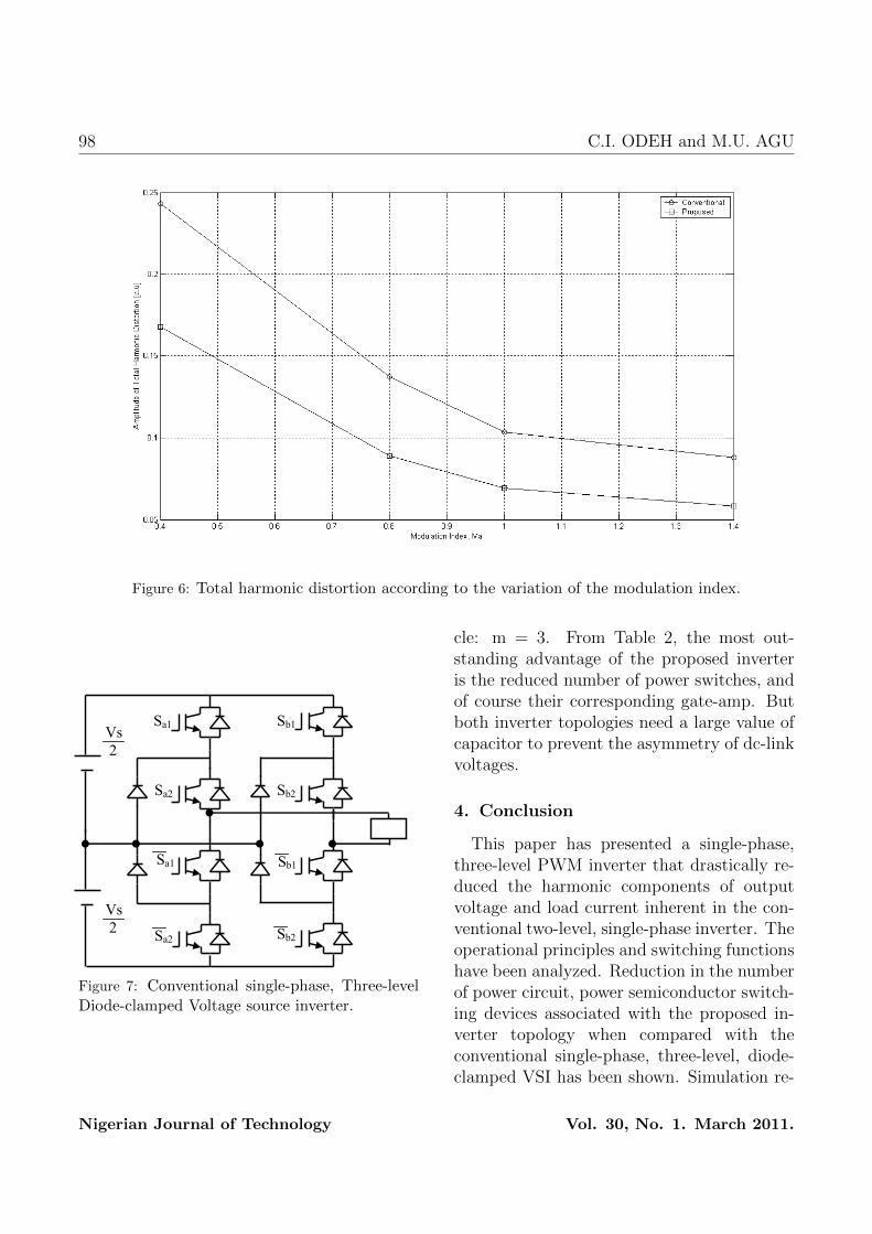
tion, differing in their quantities because oftheir different pulse widths and amplitude ofthe used input dc source. In the range Ma1.0, the harmonic components of the proposedinverter are smaller than those of the con-ventional two-level inverter. However, in theover-modulation region, the output voltagesof both inverters contain more harmonics inthe lower order. Beside, the harmonics withdominant amplitudes in the linear range Ma1.0 are recessive during over-modulation asshown in figure 5(d). It can also be inferredfrom the displayed spectra that the amplitudeof the fundamental frequency component doesnot vary linearly with the amplitude modula-tion ratio, Ma. Figure 6 shows a comparisonof the total harmonic distortion, THD of theoutput current for both inverters. From thisgraph, it is clear that the THD of the pro-posed inverter has lower values than those of
Table 2: A Comparison of the 3-level, diode-clampedand the proposed inverters.
Diode clamped ProposedMainswitches
2(m+ 1) 2m− 1
Maindiodes
3(m+ 1) 2(m+ 1)
Gate-Amp
2(m+ 1) 2m− 1
DC-link Bulk Capacitor Bulk Capacitor
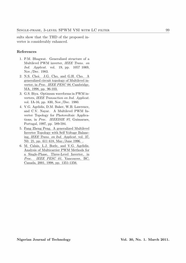
the conventional two-level inverter.Furthermore, the power circuit of the pro-
posed inverter is compared with that ofconventional single-phase, three-level, diode-clamped inverter shown in Figure 7.
The comparison between the diode-clampedand the proposed three-level, single-phase in-verters is listed in Table 2; where m is thenumber of output voltage levels per half cy-
Nigerian Journal of Technology Vol. 30, No. 1. March 2011.
98 C.I. ODEH and M.U. AGU
�
Figure 6: Total harmonic distortion according to the variation of the modulation index.
�
�
�������������������������������������������������������������������������������������
����������������������������������������������������������������������������������������������������
����������������������������������������������������������������������������������������������������
����������������������������������������������������������������������������������������������������
����������������������������������������������������������������������������������������������������
�
�
�
��
�
�
���
���
���
���
����
��
���
��
����
��
���
��
����
��
���
��
����
��
���
��
Figure 7: Conventional single-phase, Three-levelDiode-clamped Voltage source inverter.
cle: m = 3. From Table 2, the most out-standing advantage of the proposed inverteris the reduced number of power switches, andof course their corresponding gate-amp. Butboth inverter topologies need a large value ofcapacitor to prevent the asymmetry of dc-linkvoltages.
4. Conclusion
This paper has presented a single-phase,three-level PWM inverter that drastically re-duced the harmonic components of outputvoltage and load current inherent in the con-ventional two-level, single-phase inverter. Theoperational principles and switching functionshave been analyzed. Reduction in the numberof power circuit, power semiconductor switch-ing devices associated with the proposed in-verter topology when compared with theconventional single-phase, three-level, diode-clamped VSI has been shown. Simulation re-
Nigerian Journal of Technology Vol. 30, No. 1. March 2011.
Single-phase, 3-level SPWM VSI with LC filter 99
sults show that the THD of the proposed in-verter is considerably enhanced.
References
1. P.M. Bhagwat. Generalized structure of aMultilevel PWM inverter, IEEE Trans. onInd. Applicat. vol. 19, pp. 1057 1069,Nov./Dec. 1983.
2. N.S. Choi. J.G. Cho, and G.H. Cho. Ageneralized circuit topology of Multilevel in-verter, in Proc. IEEE PESC 98, Cambridge,MA, 1998, pp. 96-103.
3. G.S. Biya. Optimum waveforms in PWM in-verters, IEEE Transaction on Ind. Applicat.vol. IA-16, pp. 830, Nov./Dec. 1980.
4. V.G. Agelidis, D.M. Baker, W.B. Lawrence,and C.V. Nayar. A Multilevel PWM In-verter Topology for Photovoltaic Applica-tions, in Proc. IEEEISIE 97, Guimaraes,Portugal, 1997, pp. 589-594.
5. Fang Zheng Peng. A generalized MultilevelInverter Topology with Self Voltage Balanc-ing, IEEE Trans. on Ind. Applicat. vol. 37,N0. 21, pp. 611 618, May./June 1996. .
6. M. Calais, L.J. Borle, and V.G. Agelidis.Analysis of Multicarrier PWM Methods fora Single-Phase, Three-Level Inverter, inProc. IEEE PESC 01, Vancouver, BC,Canada, 2001, 1998, pp. 1351-1356.
Nigerian Journal of Technology Vol. 30, No. 1. March 2011.