VR-Forces Scenario Management Guide - MAK Technologies
470
Scenario Management Guide VR-Forces
-
Upload
khangminh22 -
Category
Documents
-
view
0 -
download
0
Transcript of VR-Forces Scenario Management Guide - MAK Technologies

Scenario Management Guide
VR-Forces


Scenario Management Guide
VR-Forces

Copyright © 2013 VT MÄKAll rights Reserved. Printed in the United States.
Under copyright laws, no part of this document may be copied or reproduced inany form without prior written consent of VT MÄK.
VR-Exchange™, VR-TheWorld™, and VR-Vantage™ are trademarks of VT MÄK. MÄK Technologies®, VR-Forces®, RTIspy®, B-HAVE®, and VR-Link® are regis-
tered trademarks of VT MÄK.
Terrain Profiles are based in part on the work of the Qwt project (http://qwt.source-forge.net).
All other trademarks are owned by their respective companies.
For third-party license information, please see “Third Party Licenses,” on page xxii.
VT MÄK150 Cambridge Park Drive, 3rd Floor
Cambridge, MA 02140 USA
Voice: 617-876-8085Fax: 617-876-9208
www.mak.com
Revision VRF-4.2-18-131022

Contents
PrefaceHow This Manual is Organized ................................................................ xv
VR-Forces Documentation............................................................... xviiMÄK Products ....................................................................................... xviiiHow to Contact Us ................................................................................... xxDocument Conventions ........................................................................... xxi
Mouse Button Naming Conventions................................................ xxiiThird Party Licenses ................................................................................ xxii
Boost License.................................................................................... xxiilibXML and libICONV .................................................................. xxiiiLua .................................................................................................. xxiiiFreefont OpenType Font Set........................................................... xxiiiThird-Party Licenses for VR-Vantage Applications.......................... xxiii
Chapter 1 Creating and Running Scenarios1.1. Creating a Scenario ........................................................................... 1-3
1.1.1. Specifying Multiple Simulation Model Sets ............................ 1-81.1.2. Merging Scenarios .................................................................. 1-91.1.3. Importing and Exporting MSDL ............................................ 1-9
1.2. Loading a Scenario .......................................................................... 1-111.2.1. Loading a Recently Loaded Scenario .................................... 1-121.2.2. Loading a Scenario from the Command Line ....................... 1-121.2.3. Load Balancing a Scenario .................................................... 1-131.2.4. Displaying Scenario Information .......................................... 1-151.2.5. Editing the Scenario Description .......................................... 1-171.2.6. Sample Scenarios .................................................................. 1-17
iiiVR-Forces Scenario Management Guide

Contents
1.3. Saving a Scenario ............................................................................. 1-181.3.1. Saving an Existing Scenario .................................................. 1-191.3.2. Saving a Scenario to a New Name ........................................ 1-191.3.3. Saving Checkpoints .............................................................. 1-201.3.4. Deleting Checkpoints ........................................................... 1-22
1.4. Starting a Simulation ....................................................................... 1-231.4.1. Starting or Resuming a Paused Scenario ............................... 1-231.4.2. Changing the Simulation Speed ........................................... 1-231.4.3. Pausing a Scenario ................................................................ 1-241.4.4. Rewinding a Scenario ........................................................... 1-241.4.5. Closing a Scenario ................................................................ 1-24
1.5. Running VR-Forces in Batch Mode ................................................ 1-241.5.1. The Batch File ...................................................................... 1-251.5.2. Creating a Batch File ............................................................ 1-251.5.3. Editing a Batch File .............................................................. 1-261.5.4. Running VR-Forces in Batch Mode ..................................... 1-281.5.5. Recording Batch Scenarios ................................................... 1-29
1.6. Recording VR-Forces Simulations with the MÄK Logger ............... 1-29
Chapter 2 Creating and Placing Objects2.1. Creating Objects ............................................................................... 2-32.2. Selecting the Object to Create ........................................................... 2-3
2.2.1. Selecting the Object to Create on the Create Menu ................ 2-42.2.2. Selecting the Object to Create on an Object Palette ............... 2-52.2.3. Pinning an Object Palette to the Window .............................. 2-72.2.4. Draw Mode ............................................................................ 2-8
2.3. Placing Objects ................................................................................. 2-92.3.1. Placing an Object Using Default Values (Click to Create) .... 2-102.3.2. Specifying an Object’s Properties Before You Create It
(Click to Locate) ................................................................. 2-112.4. Specifying an Object’s Altitude ....................................................... 2-12
2.4.1. Setting Altitude Dynamically ............................................... 2-132.4.2. Setting Altitude in the Create Object or Edit Object
Dialog Box .......................................................................... 2-132.4.3. Specifying the Altitude for All of the Vertices in a Route ...... 2-14
2.5. Specifying an Object’s Heading Dynamically .................................. 2-152.6. Locking the Mouse to the Object Being Created ............................. 2-152.7. Moving Objects .............................................................................. 2-16
2.7.1. Dragging an Object to a New Location ................................ 2-162.8. Copying and Pasting Objects .......................................................... 2-17
2.8.1. Copying Objects .................................................................. 2-182.8.2. Pasting Objects ..................................................................... 2-182.8.3. Pasting Specific Entity Characteristics .................................. 2-19
2.9. Creating Cultural Features .............................................................. 2-202.10. Creating Props .............................................................................. 2-21
iv VT MÄK

Contents
2.11. Adding an Object to the Favorites List .......................................... 2-21
Chapter 3 Creating and Managing Entities3.1. Creating Entities ............................................................................... 3-2
3.1.1. Default Placement of New Entities ......................................... 3-23.1.2. Placing Entities Inside Buildings ............................................. 3-33.1.3. Placing Entities on Other Entities .......................................... 3-33.1.4. Entity Resources ..................................................................... 3-33.1.5. Deleting Entities ..................................................................... 3-4
3.2. Editing Entities ................................................................................. 3-43.3. Embarking and Disembarking Entities .............................................. 3-5
3.3.1. Embarking and Disembarking Entities Instantly .................... 3-63.3.2. Disembarking Entities Using the Disembark Command ........ 3-8
3.4. Collision, Obstacle, and Feature Avoidance ....................................... 3-93.5. Entity Movement and Soil Type ..................................................... 3-103.6. Using a Joystick to Control Entities ................................................ 3-11
Chapter 4 Working with Aggregate Entities4.1. Introduction to Aggregates ................................................................ 4-2
4.1.1. How an Aggregate’s State is Shown ........................................ 4-24.1.2. Changing the Aggregation State at Runtime ........................... 4-34.1.3. Triggering Aggregate State Transitions ................................... 4-4
4.2. Creating Aggregates ........................................................................... 4-54.2.1. Creating an Aggregate by Combining Existing Entities .......... 4-54.2.2. Creating a Preconfigured Aggregate ........................................ 4-74.2.3. Configuring the Aggregate Creation State .............................. 4-8
4.3. Selecting an Aggregate ....................................................................... 4-84.4. Adding Entities to an Aggregate ........................................................ 4-94.5. Removing an Entity from an Aggregate ........................................... 4-104.6. Changing the Aggregation State of an Aggregate Entity ................... 4-11
4.6.1. Aggregating and Disaggregating Entities Manually ............... 4-114.6.2. Configuring Automatic Aggregation and Disaggregation ...... 4-114.6.3. Using Disaggregation Areas .................................................. 4-11
4.7. Writing Plans for Aggregates ........................................................... 4-124.8. Deleting an Aggregate ..................................................................... 4-12
Chapter 5 Overlays and Tactical Graphics5.1. Introduction ...................................................................................... 5-3
5.1.1. Naming Tactical Graphics ...................................................... 5-3
VR-Forces Scenario Management Guide v

Contents
5.2. Creating and Editing Overlays .......................................................... 5-35.2.1. Creating an Overlay ............................................................... 5-45.2.2. Selecting Overlays .................................................................. 5-45.2.3. Locking an Overlay ................................................................ 5-45.2.4. Changing an Overlay’s Name ................................................. 5-55.2.5. Deleting an Overlay ............................................................... 5-5
5.3. Creating Tactical Graphics ................................................................ 5-55.3.1. Creating Freehand Lines ......................................................... 5-65.3.2. Drawing Circles and Ellipses .................................................. 5-65.3.3. Drawing Boxes ....................................................................... 5-75.3.4. Adding Text to an Overlay ..................................................... 5-75.3.5. Assigning Tactical Graphics to an Overlay ............................. 5-85.3.6. Displaying a Terrain Profile When You Create a Line ............ 5-95.3.7. Publishing Tactical Graphics ................................................ 5-105.3.8. Creating Routes for Aircraft ................................................. 5-10
5.4. Deleting Tactical Graphics .............................................................. 5-115.5. Editing Tactical Graphics ................................................................ 5-11
5.5.1. Editing Vertices .................................................................... 5-125.5.2. Resizing Boxes and Text Objects .......................................... 5-145.5.3. Rotating an Ellipse ............................................................... 5-145.5.4. Changing the Direction of a Line ......................................... 5-155.5.5. Changing the Color of a Tactical Graphic ............................ 5-155.5.6. Changing Linear and Areal Style Properties .......................... 5-15
5.6. Saving and Loading Tactical Graphics and Overlays ....................... 5-165.6.1. Loading Tactical Graphics and Overlays .............................. 5-17
Chapter 6 Assigning Tasks6.1. Assigning Tasks to Entities ................................................................ 6-3
6.1.1. C++ Tasks and Scripted Tasks ................................................ 6-36.1.2. Concurrent Task Execution .................................................... 6-46.1.3. How do I Know which Entity can Execute a Task? ................ 6-56.1.4. Escaping the Task Assignment Process ................................... 6-56.1.5. Specifying Parameters for Tasks .............................................. 6-56.1.6. Viewing Task Status ............................................................... 6-76.1.7. Filtering the Object Selection Lists ......................................... 6-86.1.8. Skipping (Stopping) a Task .................................................... 6-8
6.2. Assigning Tasks to Aggregates ........................................................... 6-96.2.1. Convoy Tasks ......................................................................... 6-96.2.2. Independently Tasking Aggregate Members ......................... 6-10
6.3. Reactive Tasks ................................................................................. 6-106.3.1. Enabling Reactive Tasks ....................................................... 6-126.3.2. Disabling Reactive Tasks ...................................................... 6-126.3.3. Setting the Priority of a Reactive Task .................................. 6-136.3.4. Managing Reactive Tasks ..................................................... 6-146.3.5. Cancelling a Reactive Task ................................................... 6-15
vi VT MÄK
Contents
6.4. Using Behavior Sets to Manage Scripted Tasks ................................ 6-166.4.1. Creating Behavior Sets .......................................................... 6-176.4.2. Editing Behavior Sets ............................................................ 6-186.4.3. Assigning a Behavior Set to a Force ...................................... 6-18
6.5. Entity Movement On Roads and Off Roads .................................... 6-186.5.1. Road Driving Behavior ......................................................... 6-20
6.6. Fixed-Wing Entity Tasks and Behaviors .......................................... 6-216.6.1. Placement of Newly Created Fixed-Wing Entities ................ 6-216.6.2. Fly Task Behavior is Different from Move Task Behavior .... 6-216.6.3. Specifying and Maintaining Altitude for Fixed-Wing
Entities ................................................................................ 6-226.6.4. Fixed-Wing Entity Movement on the Ground and in the
Air ....................................................................................... 6-226.6.5. How Fixed-Wing Entities Take Off ..................................... 6-256.6.6. How Fixed-Wing Entities Land ............................................ 6-26
6.7. Rotary-Wing Entity Tasks and Behaviors ........................................ 6-276.7.1. Controlling Rotary-Wing Orientation .................................. 6-29
Chapter 7 Task Procedures7.1. Task Procedures ................................................................................ 7-47.2. Animated Movement ........................................................................ 7-47.3. Arm Mine at Depth .......................................................................... 7-57.4. Come to Stop .................................................................................... 7-57.5. Convoy Along ................................................................................... 7-67.6. Convoy To ........................................................................................ 7-77.7. Deploy Sonobuoy .............................................................................. 7-77.8. Deploy Sonobuoys Along Route ........................................................ 7-87.9. Disembark ......................................................................................... 7-97.10. Disembark All ................................................................................. 7-97.11. DI-Guy Animation ....................................................................... 7-107.12. Drop Naval Depth Charge ............................................................ 7-117.13. Drop Naval Depth Charge at Location ......................................... 7-117.14. Drop Naval Mine .......................................................................... 7-127.15. Drop Naval Mines Along Route .................................................... 7-137.16. Embark ......................................................................................... 7-147.17. Execute Close Air Support ............................................................. 7-167.18. Explode Charge at Depth .............................................................. 7-187.19. Fire at Target ................................................................................. 7-187.20. Fire Cruise Missile ......................................................................... 7-197.21. Fire for Effect Tasks ...................................................................... 7-20
7.21.1. Firing Naval Guns .............................................................. 7-217.22. Fixed-Wing Land .......................................................................... 7-217.23. Fixed Wing Takeoff ...................................................................... 7-227.24. Fly Altitude ................................................................................... 7-227.25. Fly Heading .................................................................................. 7-23
VR-Forces Scenario Management Guide vii

Contents
7.26. Fly Heading and Altitude .............................................................. 7-247.27. Follow Entity ................................................................................ 7-25
7.27.1. How Fixed-Wing Entities Follow Entities .......................... 7-257.28. Intercept and Destroy ................................................................... 7-267.29. Lase Target .................................................................................... 7-267.30. Launch Anti-Submarine Missile (Vertical) .................................... 7-277.31. Launch Counter Measures ............................................................ 7-277.32. Launch Smoke .............................................................................. 7-287.33. LaunchTorpedo ............................................................................ 7-28
7.33.1. Anti-ship (Fixed Depth) ..................................................... 7-297.33.2. Anti-Submarine .................................................................. 7-29
7.34. Lower Periscope ............................................................................ 7-307.35. Move Along Route ........................................................................ 7-307.36. Move Into Formation .................................................................... 7-317.37. Move To Altitude ......................................................................... 7-327.38. Move To Depth ............................................................................ 7-327.39. Move To Location (Direct) ........................................................... 7-33
7.39.1. Adding Multiple Move To Location (Direct) Tasks to a Plan .................................................................................. 7-34
7.40. Move To Location (On Roads) ..................................................... 7-347.41. Move to Location (Plan Path) ....................................................... 7-35
7.41.1. Move to Location (Plan Path) for Ground Vehicles ............ 7-357.41.2. Move to Location (Plan Path) for Ships .............................. 7-36
7.42. Move To Waypoint (Direct) ......................................................... 7-377.43. Move To Waypoint (On Roads) ................................................... 7-387.44. Move to Waypoint (Plan Path) ..................................................... 7-39
7.44.1. Move to Waypoint (Plan Path) for Ground Vehicles .......... 7-397.44.2. Move to Waypoint (Plan Path) for Ships ............................ 7-40
7.45. Orbit ............................................................................................. 7-417.46. Patrol Along Route ........................................................................ 7-417.47. Patrol Between .............................................................................. 7-427.48. Pattern Hold (Location) ................................................................ 7-427.49. Pattern Hold (Waypoint) .............................................................. 7-437.50. Place IED ...................................................................................... 7-437.51. Raise Periscope .............................................................................. 7-457.52. Release Bomb Tasks ...................................................................... 7-457.53. Rotary-Wing Land ........................................................................ 7-467.54. Sail Heading .................................................................................. 7-467.55. Send Radio Set .............................................................................. 7-477.56. Send Radio Task ........................................................................... 7-487.57. Send Text Message ........................................................................ 7-487.58. Sonar Dip ..................................................................................... 7-497.59. Sweep Naval Mines ....................................................................... 7-497.60. Turn To Heading ......................................................................... 7-507.61. User Task ...................................................................................... 7-50
viii VT MÄK

Contents
7.62. Wait Tasks .................................................................................... 7-517.62.1. Wait ................................................................................... 7-517.62.2. Wait Duration .................................................................... 7-517.62.3. Wait Elapsed ...................................................................... 7-51
Chapter 8 Setting Entity State8.1. Setting Entity State and Attributes .................................................... 8-38.2. Active Sonar Mode ............................................................................ 8-48.3. Aggregate State .................................................................................. 8-48.4. Altitude ............................................................................................. 8-58.5. Appearance ........................................................................................ 8-58.6. Armed ............................................................................................... 8-68.7. Capabilities ....................................................................................... 8-68.8. Collision Avoidance Types ................................................................ 8-78.9. Concealed ......................................................................................... 8-88.10. Counter Measures Auto Launch ...................................................... 8-88.11. Destroyed ........................................................................................ 8-88.12. Detonation Fuse Type ..................................................................... 8-98.13. DI-Guy Appearance ...................................................................... 8-108.14. Disembarked ................................................................................. 8-108.15. Embarked ...................................................................................... 8-118.16. Emitter .......................................................................................... 8-128.17. Force ............................................................................................. 8-138.18. Formation ..................................................................................... 8-148.19. Heading ........................................................................................ 8-15
8.19.1. Setting an Entity’s Heading Manually ................................ 8-158.20. IFF ................................................................................................ 8-168.21. Lase Autonomous .......................................................................... 8-178.22. Laser Code .................................................................................... 8-178.23. Location ........................................................................................ 8-188.24. Notify Level .................................................................................. 8-188.25. Ordered Speed .............................................................................. 8-198.26. Posture .......................................................................................... 8-208.27. Radar Mode .................................................................................. 8-218.28. Reorganize ..................................................................................... 8-218.29. Resources ...................................................................................... 8-228.30. Restore .......................................................................................... 8-228.31. Rules of Engagement ..................................................................... 8-23
8.31.1. How Fire-When-Fired-Upon Works .................................. 8-238.32. Sector of Responsibility ................................................................. 8-248.33. Sonar Depth .................................................................................. 8-258.34. Spot Reports .................................................................................. 8-268.35. Surrendered ................................................................................... 8-268.36. Synchronize Laser Code ................................................................ 8-278.37. Target ............................................................................................ 8-27
VR-Forces Scenario Management Guide ix

Contents
8.38. Tasked by Superior ....................................................................... 8-288.39. Weapon State ................................................................................ 8-28
Chapter 9 Writing Plans9.1. Introduction to Entity Plans and Global Plans .................................. 9-39.2. Conditional Statements ..................................................................... 9-5
9.2.1. Specifying Names or Patterns in Conditional Statements ....... 9-69.2.2. The If/else Statement ............................................................. 9-99.2.3. When Statements (Triggers) ................................................. 9-109.2.4. While Statements ................................................................. 9-119.2.5. Conditional Tests ................................................................. 9-12
9.3. Viewing Plans ................................................................................. 9-169.4. Writing Entity Plans ....................................................................... 9-17
9.4.1. Adding an Entity Task or Set Data Request to a Plan ........... 9-189.4.2. Adding a Conditional Statement to a Plan ........................... 9-199.4.3. Editing a Statement .............................................................. 9-229.4.4. Deleting Statements from a Plan .......................................... 9-229.4.5. Printing Plans ....................................................................... 9-229.4.6. Saving Changes to a Plan ...................................................... 9-23
9.5. Creating Global Plans ..................................................................... 9-239.6. Adding Global Commands to a Plan ............................................... 9-24
9.6.1. Adding a Global Task or Set to a Plan .................................. 9-259.6.2. Sending Console Messages ................................................... 9-269.6.3. Creating Objects from Within a Plan ................................... 9-279.6.4. Deleting Objects from Within a Plan ................................... 9-279.6.5. Issuing a Plan ....................................................................... 9-28
9.7. Writing Plans for Aggregates ........................................................... 9-299.8. Writing a Plan for Multiple Entities ................................................ 9-299.9. Writing Plans for Remote Entities ................................................... 9-299.10. Copying Plans and Plan Statements .............................................. 9-309.11. Restarting a Plan ........................................................................... 9-319.12. Abandoning a Plan ........................................................................ 9-329.13. Considerations for Creating Plans ................................................. 9-32
9.13.1. Name Changes Can Invalidate Plan Statements ................. 9-329.13.2. Considerations for Using Triggers ...................................... 9-339.13.3. Moving In Formation ........................................................ 9-349.13.4. Using the Tasked-By-Superior Request in a Plan ................ 9-349.13.5. Following Entities .............................................................. 9-349.13.6. Planning Tasks for Aircraft ................................................. 9-359.13.7. Using Non-VR-Forces Entities in Plans ............................. 9-35
x VT MÄK

Contents
Chapter 10 Target Detection and Combat Features10.1. Displaying Entities Based on Spot Reports .................................... 10-2
10.1.1. Enabling or Disabling Spot Reports .................................... 10-310.1.2. Configuring the Spot Reports Viewpoint ........................... 10-410.1.3. Configuring the Spot Reports Certainty Level .................... 10-710.1.4. Applying Spot Reports to Tactical Graphics ....................... 10-810.1.5. Displaying Labels for Spot Reports ..................................... 10-810.1.6. Using Spot Reports in Tasks ............................................... 10-8
10.2. Managing Force Hostility Relationships ........................................ 10-910.2.1. Changing a Force’s Hostility in a Plan .............................. 10-10
10.3. Detecting Targets ........................................................................ 10-1110.3.1. Target Detection and Spot Reports .................................. 10-1310.3.2. Lasing Targets .................................................................. 10-13
10.4. Using Sonar ................................................................................. 10-1510.4.1. Propulsion Noise and Sonar ............................................. 10-16
10.5. Launching Counter Measures (Chaff and Flare) .......................... 10-1710.6. Modeling Artillery Munitions ..................................................... 10-1910.7. Taking Damage from Munitions ................................................. 10-20
Chapter 11 Managing Indirect Fire and Missiles11.1. Introduction to Indirect Fire ......................................................... 11-2
11.1.1. Creating an Indirect Fire Event .......................................... 11-311.1.2. Editing Indirect Fire Events ................................................ 11-611.1.3. Deleting Indirect Fire Events .............................................. 11-611.1.4. Configuring Indirect Fire Event Default Values ................. 11-7
11.2. Ballistic Missiles ............................................................................ 11-811.2.1. Firing Ballistic Missiles ....................................................... 11-811.2.2. Editing Missile Target Events ........................................... 11-1011.2.3. Deleting Missile Target Events ......................................... 11-10
Chapter 12 Environment Conditions12.1. Introduction to Environment Conditions ..................................... 12-212.2. Setting the Time of Day ................................................................ 12-312.3. Specifying the Environment Conditions ........................................ 12-4
12.3.1. Adding an Environment Condition .................................... 12-512.3.2. Editing an Environment Condition .................................... 12-612.3.3. Deleting an Environment Condition .................................. 12-6
12.4. Setting Weather Conditions .......................................................... 12-712.4.1. Setting the Wind Speed and Direction ............................... 12-712.4.2. Setting Visibility (Fog) ....................................................... 12-812.4.3. Specifying Precipitation Type and Intensity ....................... 12-912.4.4. Specifying Cloud Cover ...................................................... 12-9
VR-Forces Scenario Management Guide xi

Contents
12.5. Configuring Marine Conditions .................................................. 12-1012.5.1. Enabling Marine Effects ................................................... 12-1112.5.2. Configuring Marine Conditions ....................................... 12-11
12.6. Setting the Thermocline .............................................................. 12-1312.7. Displaying Screen Splash Effects ................................................. 12-14
Chapter 13 Creating Scripted Tasks13.1. Introduction to Scripted Tasks ...................................................... 13-3
13.1.1. Script Meta Data ................................................................ 13-413.1.2. The Lua Scripting Language ............................................... 13-4
13.2. Creating a New Scripted Task ....................................................... 13-513.2.1. Specifying the Script ID ..................................................... 13-913.2.2. Specifying the Task Menu Icon .......................................... 13-913.2.3. Specifying Task Parameters .............................................. 13-1013.2.4. Specifying the Task Menu Location ................................. 13-1313.2.5. Specifying Action Categories ............................................ 13-1513.2.6. Configuring a Script’s Availability .................................... 13-1513.2.7. Specifying the Programming Language for a Scripted
Task .................................................................................. 13-1813.2.8. Creating Reactive Tasks ................................................... 13-19
13.3. Saving Scripted Tasks .................................................................. 13-2013.4. Editing a Scripted Task ............................................................... 13-2113.5. Filtering the List of Scripted Tasks .............................................. 13-2113.6. Organizing Scripted Tasks into Folders ....................................... 13-22
13.6.1. Adding a Folder ................................................................ 13-2213.6.2. Renaming a Folder ........................................................... 13-2213.6.3. Deleting a Folder .............................................................. 13-2213.6.4. Adding Scripted Tasks to a Folder .................................... 13-2213.6.5. Removing a Scripted Task from a Folder .......................... 13-22
13.7. Exporting and Importing Scripted Tasks ..................................... 13-2313.7.1. Importing a Scripted Task Package ................................... 13-24
13.8. Copying a Scripted Task ............................................................. 13-2513.9. Deleting a Scripted Task ............................................................. 13-2513.10. Creating a System Scripted Task ............................................... 13-26
13.10.1. Including System Scripted Tasks on the Task Menu ...... 13-2613.11. Specifying a Script Editor .......................................................... 13-2813.12. Editing Lua Files ....................................................................... 13-29
Chapter 14 Writing Scripts for Scripted Tasks14.1. The VR-Forces Lua Interface ........................................................ 14-2
14.1.1. Lua Classes ......................................................................... 14-214.1.2. Lua Modules ...................................................................... 14-3
xii VT MÄK

Contents
14.2. Script Loading and Execution ....................................................... 14-414.2.1. Script Entry Points ............................................................. 14-414.2.2. The Scripted Task Execution Sequence .............................. 14-614.2.3. Limitations for Checkpointing Scripted Tasks .................... 14-914.2.4. Editing Scripted Tasks While a Scenario is Running ........ 14-11
14.3. Tasks and Subtasks ...................................................................... 14-1114.3.1. Monitoring the Status of Tasks and Subtasks ................... 14-1314.3.2. Stopping Tasks ................................................................. 14-1314.3.3. Task Parameters ............................................................... 14-13
14.4. Geometry .................................................................................... 14-1514.4.1. Location3D ....................................................................... 14-1514.4.2. Vector3D ........................................................................... 14-1514.4.3. VectorOffset3D .................................................................. 14-1714.4.4. VectorGeoc3D .................................................................... 14-17
14.5. Reserved Words ........................................................................... 14-1814.6. Error Detection ........................................................................... 14-1914.7. A Basic Scripted Task .................................................................. 14-20
14.7.1. Create and Move to Waypoint Meta Data ........................ 14-2114.7.2. The Create and Move To Waypoint Lua Script ................ 14-23
14.8. A Simple Reactive Task ............................................................... 14-25
Appendix A Example ScenariosA.1. The Breaching Scenario ................................................................... A-2
A.1.1. Create the Scenario ............................................................... A-3A.1.2. Create the Minefield ............................................................. A-4A.1.3. Create the Opposing Forces .................................................. A-5A.1.4. Create the Tactical Graphics ................................................. A-7A.1.5. Create the Friendly Entities ................................................... A-8A.1.6. Write the Plans ................................................................... A-10A.1.7. Save the Scenario ................................................................ A-17A.1.8. Running the Scenario .......................................................... A-18
A.2. The Embarkexample Scenario ........................................................ A-19A.2.1. Create the Entities and Objects ........................................... A-20A.2.2. Write the Plans for the Entities ........................................... A-29
Appendix B Merging ScenariosB.1. The Scenario Merge Tool ................................................................ B-2B.2. Starting Scenario Merge ................................................................... B-3B.3. Creating a Scenario Merge Project ................................................... B-4
B.3.1. Adding Scenarios to a Project ................................................ B-4B.3.2. Removing Scenarios from a Project ....................................... B-5B.3.3. Specifying an Ignore List File ................................................ B-5B.3.4. Saving a Project ..................................................................... B-6B.3.5. Loading a Project .................................................................. B-6
B.4. Merging Scenarios ............................................................................ B-7
VR-Forces Scenario Management Guide xiii

Contents
B.5. Displaying Scenario Files ................................................................. B-7B.5.1. Editing Scenario Files ........................................................... B-8B.5.2. Closing Scenario Files ........................................................... B-8
B.6. Specifying the Output Notification Level ........................................ B-8B.7. Using the Scenario Merge Command-Line Interface ....................... B-9
Appendix C Systems and System UsageC.1. VR-Forces Systems .......................................................................... C-2
Index
xiv VT MÄK

Preface
This manual is written for persons who will use the VR-Forces application. The manual assumes that you are familiar with your operating system and that you know how to work in your computer’s graphical window environment.
Please see release documentation for information about changes and updates to VR-Forces since this manual went to press.
How This Manual is OrganizedThe chapters are organized as follows:
Chapter 1, Creating and Running Scenarios, explains how to create and run scenarios, how to create batch scenarios and how to checkpoint scenarios.
Chapter 2, Creating and Placing Objects, explains describes the common procedures for creating entities, tactical graphics, and props.
Chapter 3, Creating and Managing Entities, explainsthe fine points of creating entities. It also covers embarkation and collision avoidance.
Chapter 4, Working with Aggregate Entities, explains how to create and edit aggregate entities.
Chapter 5, Overlays and Tactical Graphics describes the creation and use of overlays, how to create tactical graphics other than points, lines, and areas, and how to edit tactical graphics.
Chapter 6, Assigning Tasks, provides general information about assigning tasks and creating behavior sets..
Chapter 7, Task Procedures, describes the tasks provided with VR-Forces.
Chapter 8, Setting Entity State, describes how to assign set data requests to entities.
Chapter 9, Writing Plans explains how to write plans for entities and how to write global plans.
xvVR-Forces Scenario Management Guide

Preface — How This Manual is Organized
Chapter 10, Target Detection and Combat Features, describes spot reports, laser targeting, entity hostility, and how entities take damage.
Chapter 11, Managing Indirect Fire and Missiles, explains how to configure and call in indirect fire.
Chapter 12, Environment Conditions, describes how to manipulate the time of day and weather conditions.
Chapter 13, Creating Scripted Tasks, introduces scripted tasks and explains how to create them. It does not cover how to write scripts for scripted tasks.
Chapter 14, Writing Scripts for Scripted Tasks, introduces the Lua script API for VR-Forces and explains how to write scripts for scripted tasks.
Appendix A, Example Scenarios walks you through the process of creating two of the sample scenarios provided with VR-Forces.
Appendix B, Merging Scenarios explains how to use the Scenario Merge tool to merge scenarios.
Appendix C, Systems and System Usage lists all the systems provided with VR-Forces and provides information about them, including which entities use them..
xvi VT MÄK

Preface — How This Manual is Organized
VR-Forces Documentation
VR-Forces documentation is provided as manuals in PDF format, online help, and HTML class documentation. The PDF files are in the ./doc directory. The VR-Forces documentation set is as follows:
VR-Forces Documentation Center is your central starting point for accessing the VR-Forces manual set. It has a documentation roadmap, tables of contents for all manuals, and a master index, including the TDB Tool, to help you find references to subjects that are covered in two or more manuals or locate the manual in which a particular topic is discussed. All table of contents entries and index entries are live links to the manuals.
VR-Forces Getting Started Guide is a quick introduction to VR-Forces. It covers the basics of installing VR-Forces, running a scenario, and creating a scenario. It focuses on helping new users avoid common mistakes.
VR-Forces Users Guide describes how to install VR-Forces and configure license management. It explains how to use the VR-Forces graphical user interface to view simulations and how to manage aspects of VR-Forces that are not directly related to creating and running scenarios.
VR-Forces Scenario Management Guide explains how to create and run scenarios.
VR-Forces Configuration Guide explains advanced features for configuring perfor-mance and how to edit VR-Forces configuration files. It includes documentation of the Entity Editor, OPD Editor, and Scenario Merge tools. It also explains how to compose terrains and configure 3D models.
VR-Forces Migration Guide collates API migration information for recent releases.
Online help. The VR-Forces front-end, the OPD Editor, the Entity Editor, and the TDB Tool have online help accessible from the Help menu.
VR-Forces Developers Guide and API documentation. Class documentation and developers guides in linked HTML pages.
VR-Forces Release Notes.
VR-Forces First Experience Guide. A brief introduction to the most basic features of VR-Forces. Provides less detail than VR-Forces Getting Started Guide.
VR-Forces Entity Model Catalog. A catalog of all of the entities configured in the Entity Editor with basic parameter details and a screen capture of the model.
VR-Forces Scenario Management Guide xvii

Preface — MÄK Products
MÄK ProductsVR-Forces is a member of the VT MÄK line of software products designed to stream-line the process of developing and using networked simulated environments. The VT MÄK product line includes the following:
VR-Link® Network Toolkit. VR-Link is an object-oriented library of C++ func-tions and definitions that implement the High Level Architecture (HLA) and the Distributed Interactive Simulation (DIS) protocol. VR-Link has built-in support for the RPR FOM and allows you to map to other FOMs. This library minimizes the time and effort required to build and maintain new HLA or DIS-compliant applications, and to integrate such compliance into existing applications.
VR-Link includes a set of sample debugging applications and their source code. The source code serves as an example of how to use the VR-Link Toolkit to write applications. The executables provide valuable debugging services such as gener-ating a predictable stream of HLA or DIS messages, and displaying the contents of messages transmitted on the network.
MÄK RTI. An RTI (Run-Time Infrastructure) is required to run applications using the High Level Architecture (HLA). The MÄK RTI is optimized for high perfor-mance. It has an API, RTIspy®, that allows you to extend the RTI using plug-in modules. It also has a graphical user interface (the RTI Assistant) that helps users with configuration tasks and managing federates and federations.
VR-Forces®. VR-Forces is a computer generated forces application and toolkit. It provides an application with a GUI, that gives you a 2D and 3D views of a simu-lated environment.
You can create and view local entities, aggregate them into hierarchical units, assign tasks, set state parameters, and create plans that have tasks, set statements, and conditional statements. VR-Forces also functions as a plan view display for viewing remote entities taking part in an exercise. Using the toolkit, you can extend the VR-Forces application or create your own application for use with another user interface.
VR-Vantage™. VR-Vantage is a line of products designed to meet your simulation visualization needs. It includes three end-user applications (VR-Vantage Stealth, VR-Vantage PVD, and VR-Vantage IG) and the VR-Vantage Toolkit.
– VR-Vantage Stealth displays a realistic, 3D view of your virtual world, a 2D plan view, and an exaggerated reality (XR) view. Together these views provide both situational awareness and the big picture of the simulated world. You can move your viewpoint to any location in the 3D world and can attach it to entities so that it moves as they do.
– VR-Vantage IG is a configurable desktop image generator (IG) for out the window (OTW) scenes and remote camera views. It has most of the features of the Stealth, but is optimized for its IG function.
– VR-Vantage PVD provides a 2D plan view display. It gives you the big picture of the simulated world.
xviii VT MÄK

Preface — MÄK Products
– The VR-Vantage Toolkit is a 3D visual application development toolkit. Use it to customize or extend MÄK’s VR-Vantage applications, or to integrate VR-Vantage capabilities into your custom applications. VR-Vantage is built on top of OpenSceneGraph (OSG). The toolkit includes the OSG version used to build VR-Vantage.
MÄK Data Logger. The Data Logger, also called the Logger, can record HLA and DIS exercises and play them back for after-action review. You can play a recorded file at speeds above or below normal and can quickly jump to areas of interest. The Logger has a GUI and a text interface. The Logger API allows you to extend the Logger using plug-in modules or embed the Logger into your own application. The Logger editing features let you merge, trim, and offset Logger recordings.
VR-Exchange™. VR-Exchange allows simulations that use incompatible commu-nications protocols to interoperate. For example, within the HLA world, using VR-Exchange, federations using the HLA RPR FOM 1.0 can interoperate with simula-tions using RPR FOM 2.0, or federations using different RTIs can interoperate. VR-Exchange supports HLA, TENA, and DIS translation.
VR-TheWorld™ Server. VR-TheWorld Server is a simple, yet powerful, web-based streaming terrain server, developed in conjunction with Pelican Mapping. Delivered with a global base map, you can also easily populate it with your own custom source data through a web-based interface. The server can be deployed on private, classified networks to provide streaming terrain data to a variety of simula-tion and visualization applications behind your firewall.
VR-inTerra. VR-inTerra is a C++ API for adding terrain agility to applications. It can load, page, or stream terrain from a wide variety of formats or sources into a single, consistent run-time representation, consisting of a collision graph and vector network.
VR-Forces Scenario Management Guide xix

Preface — How to Contact Us
How to Contact UsFor VR-Forces technical support, information about upgrades, and information about other MÄK products, you can contact us in the following ways:
Telephone
Internet
Post
When requesting support, please tell us the product you are using, the version, and the platform on which you are running.
Call or fax us at: Voice:Fax:
617-876-8085 (extension 3 for support)617-876-9208
Sales and upgrade information:Technical support:
VR-Vantage support:
[email protected]@[email protected]
MÄK web site home page: www.mak.com
License key requests: www.mak.com/support/get-licenses.html
Product version and platform information: www.mak.com/support/product-versions.html
For the free, unlicensed MÄK RTI: www.mak.com/resources/bonus-material/cat_view/16-bonus-materials/24-mak-high-performance-rti.html
MÄK Community Forum: www.mak.com/community-forum/1-forum.html
Send postal correspondence to: VT MÄK150 Cambridge Park Drive, 3rd FloorCambridge, MA, USA 02140
xx VT MÄK

Preface — Document Conventions
Document ConventionsThis manual uses the following typographic conventions:
Directory names are preceded with dot and slash characters that show their position with respect to the VR-Forces home directory. For example, the directory vrforces4.2/doc appears in the text as ./doc.
Monospaced Indicates commands or values you enter.
Monospaced Bold Indicates a key on the keyboard.
Monospaced Italic Indicates command variables that you replace with appropriate values.
Blue text A hypertext link to another location in this manual or another manual in the documentation set.
{ } Indicates required arguments.
[ ] Indicates optional arguments.
| Separates options in a command where only one option may be chosen at a time.
( | ) In command syntax, indicates equivalent alternatives for a command-line option, for example, (-h | --help).
/ Indicates a directory. Since MÄK products run on both Linux and Windows PC platforms, we use the / (slash) for generic discus-sions of pathnames. If you are running on a PC, substitute a \ (backslash) when you type pathnames.
Italic Indicates a file name, pathname, or a class name.
sans Serif Indicates a parameter or argument.
Indicates a one-step procedure.
Menu Option Indicates a menu choice. For example, an instruction to select the Save option from the File menu appears as:
Choose File Save.
Click the icon to run a tutorial video in the default browser.
Indicates supplemental or clarifying information.
!Indicates additional information that you must observe to ensure the success of a procedure or other task.
VR-Forces Scenario Management Guide xxi

Preface — Third Party Licenses
Mouse Button Naming Conventions
An instruction to click the mouse button, refers to clicking the primary mouse button, usually the left button for right-handed mice and the right button for left-handed mice. The context-sensitive menu, also called a popup menu or right-click menu, refers to the menu displayed when you click the secondary mouse button, usually the right button on right-handed mice and the left button on left-handed mice.
Third Party LicensesMÄK software products may use code from third parties. This section contains the license documentation required by these third parties.
Boost License
VR-Link, and all MÄK software that uses VR-Link uses some code that is distributed under the Boost License. All header files that contain Boost code are properly attrib-uted. The Boost web site is: www.boost.org.
Boost Software License - Version 1.0 - August 17th, 2003
Permission is hereby granted, free of charge, to any person or organization obtaining a copy of the software and accompanying documentation covered by this license (the “Software”) to use, reproduce, display, distribute, execute, and transmit the Software, and to prepare derivative works of the Software, and to permit third-parties to whom the Software is furnished to do so, all subject to the following:
The copyright notices in the Software and this entire statement, including the above license grant, this restriction and the following disclaimer, must be included in all copies of the Software, in whole or in part, and all derivative works of the Software, unless such copies or derivative works are solely in the form of machine-executable object code generated by a source language processor.
THE SOFTWARE IS PROVIDED “AS IS”, WITHOUT WARRANTY OF ANY KIND, EXPRESS OR IMPLIED, INCLUDING BUT NOT LIMITED TO THE WARRANTIES OF MERCHANTABILITY, FITNESS FOR A PARTICULAR PURPOSE, TITLE AND NON-INFRINGEMENT. IN NO EVENT SHALL THE COPYRIGHT HOLDERS OR ANYONE DISTRIBUTING THE SOFTWARE BE LIABLE FOR ANY DAMAGES OR OTHER LIABILITY, WHETHER IN CONTRACT, TORT OR OTHERWISE, ARISING FROM, OUT OF OR IN CONNECTION WITH THE SOFTWARE OR THE USE OR OTHER DEAL-INGS IN THE SOFTWARE.
xxii VT MÄK

Preface — Third Party Licenses
libXML and libICONV
VR-Link and all MÄK software that uses VR-Link, links in libXML and libICONV. On some platforms the compiled libraries and header files are distributed with MÄK Products. MÄK has made no modifications to these libraries. For more information about these libraries please see the following web sites:
The LGPL license is available at: http://www.gnu.org/licenses/lgpl.html
Information about IconV is at: http://www.gnu.org/software/libiconv/
Information about LibXML is at: http://xmlsoft.org/
Lua
VR-Forces uses the Lua programming language (www.lua.org). Its license is as follows:
Copyright © 1994–2012 Lua.org, PUC-Rio.
Permission is hereby granted, free of charge, to any person obtaining a copy of this soft-ware and associated documentation files (the "Software"), to deal in the Software without restriction, including without limitation the rights to use, copy, modify, merge, publish, distribute, sublicense, and/or sell copies of the Software, and to permit persons to whom the Software is furnished to do so, subject to the following conditions:
The above copyright notice and this permission notice shall be included in all copies or substantial portions of the Software.
THE SOFTWARE IS PROVIDED "AS IS", WITHOUT WARRANTY OF ANY KIND, EXPRESS OR IMPLIED, INCLUDING BUT NOT LIMITED TO THE WARRANTIES OF MERCHANTABILITY, FITNESS FOR A PARTICULAR PURPOSE AND NONINFRINGEMENT. IN NO EVENT SHALL THE AUTHORS OR COPYRIGHT HOLDERS BE LIABLE FOR ANY CLAIM, DAMAGES OR OTHER LIABILITY, WHETHER IN AN ACTION OF CONTRACT, TORT OR OTHERWISE, ARISING FROM, OUT OF OR IN CONNECTION WITH THE SOFTWARE OR THE USE OR OTHER DEAL-INGS IN THE SOFTWARE.
Freefont OpenType Font Set
VR-Vantage applications and VR-Forces use the Freefont OpenType font set from the Free Software Foundation. It is covered by the General Public License (GPL). For details, please see: http://www.gnu.org/licenses/gpl.html
Third-Party Licenses for VR-Vantage Applications
VR-Vantage applications use a variety of third-party libraries. Developers who want to use these libraries may be required to purchase developer’s licenses. Please see section 1.2 in VR-Forces Front-End Developers Guide for details.
VR-Forces Scenario Management Guide xxiii

Preface — Third Party Licenses
xxiv VT MÄK

VR-Forces Scenario Management Guide
1
Creating and Running Scenarios
This chapter explains how to create, load, run, and save scenarios.
Creating a Scenario ....................................................................................... 1-3Specifying Multiple Simulation Model Sets ............................................ 1-8Merging Scenarios .................................................................................. 1-9Importing and Exporting MSDL............................................................ 1-9
Loading a Scenario...................................................................................... 1-11Loading a Recently Loaded Scenario .................................................... 1-12Loading a Scenario from the Command Line ....................................... 1-12Load Balancing a Scenario.................................................................... 1-13Displaying Scenario Information.......................................................... 1-15Editing the Scenario Description.......................................................... 1-17Sample Scenarios .................................................................................. 1-17
Saving a Scenario ........................................................................................ 1-18Saving an Existing Scenario .................................................................. 1-19Saving a Scenario to a New Name ........................................................ 1-19Saving Checkpoints .............................................................................. 1-20Deleting Checkpoints........................................................................... 1-22
Starting a Simulation .................................................................................. 1-23Starting or Resuming a Paused Scenario ............................................... 1-23Changing the Simulation Speed ........................................................... 1-23Pausing a Scenario ................................................................................ 1-24Rewinding a Scenario ........................................................................... 1-24Closing a Scenario ................................................................................ 1-24
Running VR-Forces in Batch Mode ............................................................ 1-24The Batch File ...................................................................................... 1-25Creating a Batch File ............................................................................ 1-25
1-1

Creating and Running Scenarios
Editing a Batch File .............................................................................. 1-26Running VR-Forces in Batch Mode ..................................................... 1-28Recording Batch Scenarios ................................................................... 1-29
Recording VR-Forces Simulations with the MÄK Logger ........................... 1-29
1-2 VT MÄK

Creating and Running Scenarios — Creating a Scenario
1.1. Creating a ScenarioTo use VR-Forces to simulate entities, you must load a scenario or create a new one. When you first start VR-Forces, the Startup Screen asks you if you want to create or load a scenario (unless you have disabled this feature). Thereafter, to create a scenario, use the procedure in this section. (For details about the Startup Screen, please see Section 5.1.1, “Starting VR-Forces from the VR-Forces Launcher,” in VR-Forces Users Guide.)
To create a scenario:
1. Choose File New Scenario, or click the New Scenario button ( ) on the File toolbar. The Choose Simulation Terrain dialog box opens (Figure 1-1). By default, it opens in ./userData/terrains, the directory that contains the terrain files shipped with VR-Forces. (For a brief description of the databases supplied with VR-Forces, please see Section 18.8, “Terrain Databases Provided with VR-Forces,” in VR-Forces Users Guide. For details about terrain files, please see Section 3.11, “Terrain Data-bases,” in VR-Forces Users Guide.)
Figure 1-1. Select Simulation Database dialog box
2. In the file list, select a terrain database. (MTF is the preferred file type.) A database must be a flat earth, geocentric, UTM, or Lambert Conformal Conic database. By default, this terrain is used for both the front-end and back-end.
i If you are using multiple front-ends in the same session, when one of them creates a scenario, the terrains in all other front-ends are closed (unless the terrain is the same as that for the new scenario) and the terrain for the new scenario is loaded.
VR-Forces Scenario Management Guide 1-3

Creating and Running Scenarios — Creating a Scenario
3. Click Open. The New Scenario dialog box opens (Figure 1-2).
Figure 1-2. New Scenario dialog box
i If you choose an MTF file and an MTD file with the same name exists, the back-end loads the MTD file.
1-4 VT MÄK

Creating and Running Scenarios — Creating a Scenario
4. Optionally, set basic scenario parameters. Table 1-2 describes the basic parameters.
For more information about these parameters, please see Section 3.2.1, “Scenario Parameters,” in VR-Forces Configuration Guide.
5. Optionally, select the Advanced tab (Figure 1-3) and set advanced scenario parame-ters (overriding the default settings).
Table 1-1: Basic scenario parameters
Parameter Description
Scenario Name Specifies the name of the scenario. This is the name used to iden-tify the scenario when you join a session. If you do not specify a name, the scenario file name is used.
Simulation Terrain
Specifies the terrain to be used by the back-end. By default, this is the terrain you selected in the Choose Simulation Terrain dialog box. However, you can change it if you want to.
Scenario Description
The scenario description lets you provide a descripion of the scenario. This may be useful to remind you or other VR-Forces users of its purpose or special details. You can enter the descrip-tion as plain text or as HTML. If you use HTML, when the descrip-tion is displayed in the Scenario Information dialog box, it is displayed using the HTML formatting.
Attach Compo-nents to Remote Entities On
Specifies whether or not to attach components to remote entities, and if so, the back-ends on which to manage the components that are being attached to remote entities. Unlike other scenario parameters, you can change this value when you load a scenario. For details about configuring components for attachment to remote entities, please see Section 7.12, “Configuring VR-Forces Components on Remote Entities,” in VR-Forces Configuration Guide.
! This value is not saved in the scenario file. To attach components in future runs of the scenario, you must specify the appropriate setting each time you load the scenario.
VR-Forces Scenario Management Guide 1-5

Creating and Running Scenarios — Creating a Scenario
Figure 1-3. New Scenario dialog box, Advanced tab
Table 1-2 describes the parameters you can set.
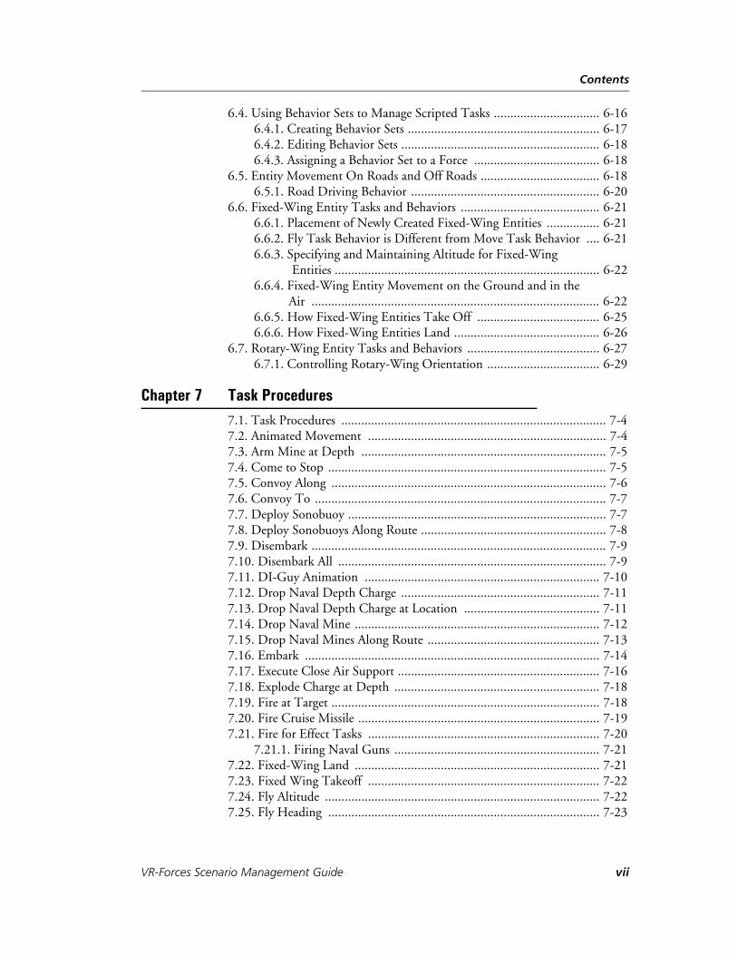
Table 1-2: Advanced scenario parameters
Parameter Description
Use the Simula-tion Terrain in the Display
If selected (the default), the scenario uses the same terrain for the front-end and back-end.
Use a Different Terrain for the Display
If selected, lets you specify the terrain to be used by the front-end.
Simulation Model Sets
Specify one or more simulation model sets. A scenario must specify at least one simulation model set. For more information, please see “Specifying Multiple Simulation Model Sets,” on page 1-8. Default: default.sms.
Component Attachment Table
If you plan to attach components to remote entities, specify the component attachment table that you want to use. For details about configuring components for attachment to remote entities, please see Section 7.12, “Configuring VR-Forces Components on Remote Entities,” in VR-Forces Configuration Guide.
Time Multiplier Specify a time multiplier for the scenario. For HLA time-managed federations, this parameter is ignored. Default: 1.0 (real-time).
Starting Time of Day
Specify the time of day at which the simulation should start. As time advances, the Time of Day toolbar will change coloration. In 3D, the sky coloration also changes as time advances.
1-6 VT MÄK
Creating and Running Scenarios — Creating a Scenario
For more information about these parameters, please see:
– Section 3.13.1, “Simulation Time,” in VR-Forces Users Guide.
– Section 3.13.3, “Exercise Clock Modes,” in VR-Forces Users Guide.
– Section 3.2.1, “Scenario Parameters,” in VR-Forces Configuration Guide.
6. Click OK. The scenario information is displayed and the terrain is displayed in the 2D view.
7. Add the entities and graphical objects that you need for your simulation. For infor-mation about adding entities and tactical graphics, please see Chapter 2, Creating and Placing Objects.
8. Save the scenario. For details about saving scenarios, please see “Saving a Scenario,” on page 1-18.
Random Number Seed
Specify a random number seed as an integer >= 0.
Frame Mode Select a frame mode from the list.
Frame Time Specifies the length of a frame, in seconds. This parameter is not enabled if Frame Mode is variable-frame.
Table 1-2: Advanced scenario parameters
Parameter Description
VR-Forces Scenario Management Guide 1-7

Creating and Running Scenarios — Creating a Scenario
1.1.1. Specifying Multiple Simulation Model Sets
You can specify more than one simulation model set for a scenario. One strategy for extending VR-Forces is to use the default SMS for the majority of objects and to create a separate SMS for customized entities. As you upgrade to newer versions of VR-Forces, you can more easily migrate your customized SMS to the new version because your changes have not been integrated into the default SMS.
To specify multiple simulation model sets for a scenario:
1. In the New Scenario dialog box, click the Browse button on the Simulation Model Set line. The Simulation Model Set Files dialog box opens. It lists the SMS files to be loaded for this scenario.
Figure 1-4. Simulation Model Set Files dialog box
2. In the The Simulation Model Set Files dialog box, click Add. A blank line is added to the window (Figure 1-5).
Figure 1-5. Add simulation model set
3. Click the Browse button next to the blank line. The Choose File dialog box opens.
4. Select a simulation model set and click Open. The SMS is added to the text box.
5. Click OK.
6. Complete the New Scenario dialog box.
1-8 VT MÄK

Creating and Running Scenarios — Creating a Scenario
1.1.2. Merging Scenarios
VR-Forces users often assign scenario development to multiple persons or teams. Then they merge the separately-developed scenarios into a master scenario. Merging scenarios by hand can be a difficult task due to the requirement to reconcile entity and object names, plans, and other scenario elements that could be duplicated, particularly if objects are named using the default conventions. VR-Forces includes an offline tool, Scenario Merge, for merging scenarios. For details, please see Appendix B, Merging Scenarios.
1.1.3. Importing and Exporting MSDL
Military Scenario Definition Language (MSDL) is a SISO standard for describing mili-tary scenarios using an XML format. It allows for interchange of scenario descriptions between simulation applications and systems that use different internal formats. You can import MSDL files into a VR-Forces scenario.
VR-Forces does not import all of the information that can be in an MSDL file. It imports and exports:
Entities and entity locations. Locations are always exported in geocentric coordi-nates.
Force relationships and hostility relationships.
Aggregate formations.
Tactical graphics.
To import MSDL:
1. Create or load a scenario.
2. Choose File Import Scenario Laydown. The Import Scenario File dialog box opens.
3. Select the MSDL file that you want to import.
4. Click Open.
VR-Forces Scenario Management Guide 1-9

Creating and Running Scenarios — Creating a Scenario
Exporting MSDL
To export a scenario to MSDL:
1. Create or load a scenario.
2. Choose File Export Scenario Laydown. The Export Scenario dialog box opens.
3. Type a name for the file.
4. Click Save. If VR-Forces is not sure how to export an entity type to MSDL, the Export MSDL Scenario dialog opens (Figure 1-6).
Figure 1-6. Export MSDL Scenario dialog box
5. For each entity type listed in the Export MSDL Scenario dialog box:
a. In the Symbol Identification column, click the value. A list of possible identifi-cation codes is displayed. (These codes are from the MSDL specification. You will need to familiarize yourself with the specification to fully understand them.)
b. Select the proper identification.
6. Click OK.
1-10 VT MÄK
Creating and Running Scenarios — Loading a Scenario
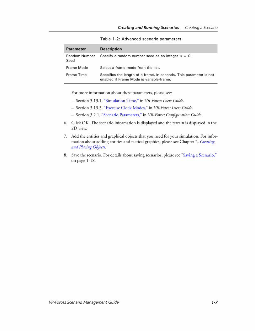
1.2. Loading a ScenarioAfter you have created and saved a scenario, you can load it and run it on any platform supported by the version of VR-Forces in which you created it. Most scenarios are forward compatible. Please see VR-Forces Release Notes for compatibility issues.
To load a scenario:
1. Choose File Load Scenario or click the Open Scenario button ( ) on the File toolbar. The Load Scenario dialog box opens (Figure 1-7).
Figure 1-7. Load Scenario dialog box
2. Select a scenario to load. Basic information about the scenario is displayed (Figure 1-8). Scenarios are files with the suffix .scn. Sample scenarios are located in the ./userData/scenarios directory. (Batch scenarios, described in “Running VR-Forces in Batch Mode,” on page 1-24, have the suffix .bsn.)
i If you are running multiple front-ends in the same session, when you load a scenario, any terrains that are open on other front-ends are closed and the terrain for the newly loaded scenario is opened.
When you load a scenario that uses multiple back-ends, if any of the required back-ends are not running, VR-Forces prompts you to remap the objects in the scenario. The Remap Missing Back-ends dialog box lists the unavailable back-ends and the available back-ends. You can specify which back-ends to map objects to or you can select “map all to” and map all objects to one back-end. For more information about remapping back-ends, please see Remapping Back-ends, under Section 3.2.5, “Working with Multiple Back-ends,” in VR-Forces Users Guide.
VR-Forces Scenario Management Guide 1-11

Creating and Running Scenarios — Loading a Scenario
Figure 1-8. Load Scenario dialog box
3. Optionally, specify whether or not to allow management of components on remote entities by selecting an option in the Attach Components to Remote Entities On list. For details about configuring components on remote entities, please see Section 7.12, “Configuring VR-Forces Components on Remote Entities,” in VR-Forces Configuration Guide.
4. Optionally select a load balancing option.
5. Click Open.
1.2.1. Loading a Recently Loaded Scenario
VR-Forces keeps a list of the scenarios you open. You can quickly open a scenario from the list.
To open a recently used scenario, choose File Recent Scenarios scenario_name.
1.2.2. Loading a Scenario from the Command Line
If you start VR-Forces from the command line, you can specify a scenario to load. You can specify the scenario in the back-end or front-end. The other executable will load it as soon as it starts up.
To load a scenario when you start the back-end, use the -L command-line option, for example:
vrfSimDIS -s 1 -a 3001 -L “../userData/scenarios/mySce-nario.scn”
To load a scenario when you start the front-end, use the --scenarioFile command-line option, for example:
vrfGui --scenarioFile “../userData/scenarios/mySce-nario.scn” --dis -s 1 -a 3000
1-12 VT MÄK

Creating and Running Scenarios — Loading a Scenario
1.2.3. Load Balancing a Scenario
After you create a scenario, you may decide that you want to spread simulation of objects across more back-ends than you used to create it. You would typically increase the number of back-ends to improve performance. The process of spreading the simula-tion work across multiple simulation engines is called load balancing. VR-Forces supports even distribution (done automatically by VR-Forces) and manual load balancing.
To load-balance a scenario:
1. Choose File Load Scenario. The Load Scenario dialog box opens.
2. In the Load Scenario dialog box, select an option from the Load Balancing list (Figure 1-9).
Figure 1-9. Load Balancing list
If you select Even Distribution, VR-Forces automatically distributes objects across the available back-ends. If you choose Manual load balancing, the Object Mapping dialog box opens (Figure 1-10).
! If you are using interest management to support large entity counts, do not enable load balancing. It will negate the assignment of entities to specific back-ends that is part of designing a scenario for interest management.
VR-Forces Scenario Management Guide 1-13

Creating and Running Scenarios — Loading a Scenario
Figure 1-10. Object Mapping dialog box
3. In the Object Mapping dialog box, expand the list for the back-end from which you want to distribute objects.
4. Redistribute objects by dragging them from a source back-end to a target back-end, or by cutting them from the source back-end and pasting them onto the target back-end. You can view the new distribution of objects by expanding the list for the target back-end.
5. Click OK. The scenario loads. If you open the information dialog box for an object, the title bar displays the back-end on which it is simulated.
6. To preserve the new object mappings, save the scenario. When you save the scenario, you are prompted to save the original mappings. Click No to save the new load balanced mappings.
1-14 VT MÄK

Creating and Running Scenarios — Loading a Scenario
1.2.4. Displaying Scenario Information
When you create a scenario, you specify a variety of parameters (or accept default values) and, optionally, specify a name and description for the scenario. If a scenario has a description, when you load the scenario, the Scenario Information dialog box opens automatically. (You can disable this behavior.)
You can display scenario information at any time while a scenario is loaded. You can edit the scenario description. Other values are read only. (You can edit them directly in the scenario file. For details, please see Section 3.2, “The Scenario File,” in VR-Forces Configuration Guide.)
To display scenario information:
1. Choose File Scenario Information. The Scenario Information dialog box opens (Figure 1-11).
Figure 1-11. Scenario Information dialog box
2. To view advanced parameters, select the Advanced tab.
VR-Forces Scenario Management Guide 1-15

Creating and Running Scenarios — Loading a Scenario
Enabling and Disabling Display of the Scenario Description
By default, the scenario description gets displayed when you open a scenario. You can turn it off in the Scenario Information window and you can enable and disable its display in the Application Settings dialog box.
To disable display of scenario information when a scenario is loaded, use one of the following methods:
When the Scenario Information window opens, select the Never Show Again check box.
On the Application Settings dialog box, Session Options page, clear the Show Scenario Information Dialog check box.
To enable the Scenario Information dialog box, on the Application Settings dialog box, Session Options page, select the Show Scenario Information Dialog check box.
1-16 VT MÄK

Creating and Running Scenarios — Loading a Scenario
1.2.5. Editing the Scenario Description
You can edit a scenario’s description in the Scenario Information dialog box.
To edit a scenario’s description:
1. Choose File Scenario Information. The Scenario Information dialog box opens (Figure 1-12).
Figure 1-12. Scenario Information (editable)
2. Click Edit. The description window changes to edit mode and the button text changes to View.
3. Edit the text.
4. To see how the text will be displayed, click View.
5. Click OK.
1.2.6. Sample Scenarios
VR-Forces includes several sample scenarios. Appendix A, Example Scenarios has the step-by-step process for creating the breaching scenario and the embarkexample scenario.
VR-Forces Scenario Management Guide 1-17

Creating and Running Scenarios — Saving a Scenario
1.3. Saving a ScenarioThe first time you save a scenario, VR-Forces saves the path of the terrain database and other scenario configuration data to a scenario file (extension .scn). (Paths are saved rela-tive to the ./bin directory.) This information usually does not change between runs of a scenario. Every time you save a scenario, VR-Forces saves the order of battle, the plans, and object mapping information to individual files that have the same name as the scenario, but with file extensions that identify the information in the file (.oob, .pln, .gpl, .xtr, .omp, and so on).
When you save a scenario, whether during the course of setting it up or during a simu-lation, all object state information gets saved. Essentially, every save is a checkpoint. Therefore, when you run a saved simulation, all entities will resume whatever they were doing when the scenario was saved.
If you save a scenario after it has started (whether it is paused or running), it is not saved to the original scenario file. It is saved to a checkpoint that is named using the conven-tion scenario_name_at_time_time.scn. This ensures that you cannot inadvertently over-write the original scenario file. To overwrite the original scenario, you must use Save Scenario As. For more information about checkpoints, please see “Saving Check-points,” on page 1-20.
To save a new scenario:
1. Choose File Save Scenario or click the Save button ( ) on the File toolbar. The Save Scenario dialog box opens.
2. Select the directory in which you want to save the scenario.
3. Give the scenario a name.
4. Click Save. All scenario files are saved with the new name.
! If you want to keep the initial state of a scenario (simulation time = 0 and no simulation has taken place), so that you can repeatedly run a simulation from the beginning, save the scenario when you have finished creating it, but before you run it. Then, do not save the scenario again under the same name (unless you specifically want to change the original state of the scenario).
If you load an alternate terrain in a front-end when it joins a session, the alternate terrain is not saved as part of the scenario.
i If entities are executing scripted tasks, some information regarding the tasks is not saved. For details, please see “Limitations for Checkpointing Scripted Tasks,” on page 14-9.
1-18 VT MÄK

Creating and Running Scenarios — Saving a Scenario
1.3.1. Saving an Existing Scenario
In most computer applications, when you save an existing file, the current version of the file simply overwrites the previously saved version. However, when VR-Forces saves a scenario, the save action depends on the status of the scenario. VR-Forces tracks the simulation time of the scenario. When you save a scenario:
If a version of the scenario exists with the current simulation time, VR-Forces displays a message indicating that a version of the scenario at that simulation time exists and asks if you want to overwrite it.
If there is no version with the current simulation time, VR-Forces creates a new checkpoint at the current simulation time, using the checkpoint naming conven-tion.
This behavior ensures that if you change a scenario after you have started a simulation, you will never inadvertently overwrite the original version or another checkpoint.
To save a previously saved scenario, choose File Save Scenario.
1.3.2. Saving a Scenario to a New Name
To save a scenario to a new name:
1. Choose File Save Scenario As. The Save Scenario dialog box opens.
2. Select the directory in which you want to save the scenario.
3. Give the scenario a name.
4. Click Save. The scenario is saved to the new name.
i If you save a remapped scenario, you are prompted to save the scenario with the original mappings or with the remappings.
VR-Forces Scenario Management Guide 1-19

Creating and Running Scenarios — Saving a Scenario
1.3.3. Saving Checkpoints
You may want to save snapshots of a simulation at various points in its life for after-action-review or to use as the starting point of a new exercise. You might also want to stop an exercise and resume it at some later point, with all entities remembering their tasks and state information. You can do this by saving a checkpoint.
You can save a checkpoint at any time by saving the scenario. Checkpoints are saved to the same directory. You can also configure VR-Forces to save checkpoints at regular intervals. If periodic checkpointing is enabled, the Status bar displays the time until the next checkpoint.
When you run a checkpointed scenario, entities resume the tasks that they were executing at the time the checkpoint was saved. If detonations were scheduled or if missiles were in flight, they resume their former state.
Saving an Individual Checkpoint
Whenever you save a scenario, it creates a checkpoint.
To save an individual checkpoint, choose File Save Scenario.
i If entities are executing scripted tasks, some information regarding the tasks is not saved. For details, please see “Limitations for Checkpointing Scripted Tasks,” on page 14-9.
1-20 VT MÄK

Creating and Running Scenarios — Saving a Scenario
Scheduling Periodic Checkpoints
You can configure VR-Forces to save checkpoints at regular intervals. You can specify that the intervals be calculated in real time or simulation time. Saving checkpoints in simulation time may be useful if you are running a scenario at a rate greater or lesser than real time.
To schedule checkpoints:
1. Choose File Schedule Periodic Checkpointing. The Periodic Checkpointing dialog box opens (Figure 1-13).
Figure 1-13. Periodic Checkpointing dialog box
2. Enter the time interval between checkpoints, in hours, minutes, and seconds.
3. Select the Enable Periodic Checkpointing check box.
4. To save checkpoints based on simulation time, check the Use Simulation Time check box. To use real time intervals, clear the check box.
5. Click OK.
Disabling Periodic Checkpointing
To disable periodic checkpointing:
1. Choose File Schedule Periodic Checkpointing. The Periodic Checkpointing dialog box opens.
2. Clear the Enable Periodic Checkpointing check box.
3. Click OK.
VR-Forces Scenario Management Guide 1-21

Creating and Running Scenarios — Saving a Scenario
1.3.4. Deleting Checkpoints
You can delete checkpoints manually in a file browser, like you can delete any other files on your computer. You can also easily delete them from the front-end.
To delete checkpoints:
1. Choose File Delete Scenario Checkpoints. The Delete Checkpoints dialog box opens (Figure 1-14).
Figure 1-14. Delete Checkpoints dialog box
2. Select the checkpoints that you want to delete.
3. Click OK.
1-22 VT MÄK

Creating and Running Scenarios — Starting a Simulation
1.4. Starting a SimulationIf you want to use VR-Forces to simply observe a remote simulation, you can start it, open a terrain database, and wait for it to pick up messages from the network. However, you will probably use VR-Forces to run simulations that have locally simulated entities.
1.4.1. Starting or Resuming a Paused Scenario
When you load a scenario, it opens in the paused state unless you start with the -L and -r back-end command line options.
To begin or resume execution of a paused scenario, choose Simulation Run Scenario, or click the Run button on the Simulation Control toolbar (Figure 1-15).
Figure 1-15. Simulation Control toolbar
1.4.2. Changing the Simulation Speed
You can vary the speed of a simulation so that it runs at speeds faster or slower than real-time.
If you are running VR-Forces with time management, the Simulation Time Scale toolbar has no effect on simulation speed.
To change the speed of a simulation, drag the indicator on the Simulation Time Scale toolbar (Figure 1-16), or type a value in the text box.
Figure 1-16. Simulation Time Scale toolbar
! Always save a new scenario before you run it for the first time. If you do not save it, you will not be able to return to the starting point. Rewinding a scenario that has not been saved deletes all unsaved objects.
! If you increase the speed at which a scenario runs, the frame rate is reduced and performance of models may degrade.
Rewind Run Pause
VR-Forces Scenario Management Guide 1-23

Creating and Running Scenarios — Running VR-Forces in Batch Mode
1.4.3. Pausing a Scenario
When you pause a simulation, local entities stop executing plans and tasks. Display of remote entity activity continues as it is received over the network.
To pause a simulation, choose Simulation Pause Scenario, or click the Pause button on the Simulation Control toolbar (Figure 1-15).
1.4.4. Rewinding a Scenario
If you are running a scenario or have completed a scenario and want to start it over again, you can rewind it. Rewinding a scenario returns it to its last saved state.
To rewind a scenario, choose Simulation Rewind Scenario, or click the Rewind button on the Simulation Control toolbar (Figure 1-15).
If you do not pause a scenario before you rewind it, it starts playing again immediately.
1.4.5. Closing a Scenario
To close a scenario, choose File Close Scenario, or click the Close Scenario button ( ) on the File toolbar.
1.5. Running VR-Forces in Batch ModeBatch mode allows you to run one or more scenarios multiple times, without direct action through the graphical user interface. A scenario run in batch mode runs with the parameters in the scenario file, except that you can override the random number seed.
Batch mode is “read only.” You cannot save a scenario, create entities or objects, pause the scenario, or otherwise change it, while a batch is running. However, you can view the Objects List Panel, Plan windows, and open informational dialog boxes. You can close a scenario that is running in batch mode and resume control of VR-Forces.
! If you are working on a new scenario and have not saved it, rewind deletes all your work and returns the scenario to its original, blank state.
i If you save checkpoints while a scenario is running, when you rewind, the scenario rewinds to the most recent checkpoint, not to the original scenario. To return to a version of the scenario other than the most recent checkpoint, you must load that version.
1-24 VT MÄK

Creating and Running Scenarios — Running VR-Forces in Batch Mode
1.5.1. The Batch File
A batch mode file contains the information that VR-Forces needs to run scenarios in batch mode. Batch mode offers the following options:
Run a particular scenario multiple times.
Run a series of different scenarios (batches), each of which can be run multiple times.
Run from the command line using one back-end. If a scenario was created using multiple back-ends, you cannot run it in batch mode using this method.
Run from the VR-Forces front-end using one or more back-ends.
Generate Logger Control messages to have the MÄK Logger record each simula-tion.
For each batch (one scenario run one or more times) within the batch file, you can:
Specify the length of time the simulation is to run (in real time or simulation time).
Specify the object parameter database to use.
Specify that the random number seed used be the value specified in the scenario file, a value specified in the batch file, or be computer generated.
A batch file has the file extension .bsn.
1.5.2. Creating a Batch File
To run VR-Forces in batch mode, you create a batch file (.bsn). VR-Forces supplies a sample batch file. Use it as a model for creating your own batch files.
To create a batch file:
1. Create scenarios as you would any scenario. (For details, please see “Creating a Scenario,” on page 1-3.)
2. In a text editor, open the sample batch file provided with VR-Forces.
3. Save the batch file under a new name, with the file extension .bsn.
4. Replace the sample values with your own, as described in “Editing a Batch File,” on page 1-26.
5. Save the new batch file.
VR-Forces Scenario Management Guide 1-25

Creating and Running Scenarios — Running VR-Forces in Batch Mode
1.5.3. Editing a Batch File
A batch file is written in MÄK Technologies Lisp format (MTL). (For information about the MTL format, please see Section 2.5, “MÄK Technologies Lisp (MTL) Files,” in VR-Forces Configuration Guide.) A batch file starts with parameters that affect the entire batch. Then it has a batch list, which contains one or more batches. Each batch specifies a scenario, the number of times it is to be run, and other parameters. Table 1-3 describes the parameters.
The following is an example of a batch file:
(scenario-batch (use-logger-control True)(logger-files-path "..\logger_tapes") ;; path is relative to Logger executable.(batch-list
(batch (number-of-runs 2)(random-number-seed 4)(scenario-filename "..\data\scenarios\breach\breaching.scn")(parameter-filename
"..\data\simulationModelSets\default\vrfSim.opd")(simulation-run-duration 0 : 0 : 0 : 30.000000) ;; simulation time
)(batch
(number-of-runs 3)(scenario-filename
"..\data\scenarios\apache\apache_groundDB.scn")(parameter-filename
"..\data\simulationModelSets\default\vrfSim.opd")(run-duration 0 : 0 : 0 : 20.000000) ;; real time
))
)
Table 1-3: Batch file parameters (Sheet 1 of 2)
Parameter Description
Scenario-batch parameters
use-logger-control Specifies whether or not to generate Logger Control messages. Options:
False – Do not generate messages. True – Generate messages to create Logger files for each
run of each batch.
logger-files-path If user-logger-control is True, specifies the directory in which to store Logger files. The path can be absolute or relative to the Logger executable.
1-26 VT MÄK

Creating and Running Scenarios — Running VR-Forces in Batch Mode
Batch-list parameters
number-of-runs Specifies how many times to run the scenario in this batch run entry.
random-number-seed This parameter is optional. If it is specified, it overrides the random number seed in the scenario file. It specifies a random number seed as follows:
-1 – use a value generated by the computer. Values are different for each run of this batch.
Any non-negative integer – use the number specified for each run of the batch.
scenario-filename Specifies the scenario to be run in this batch run entry. The scenario can be specified as an absolute path or a path rela-tive to the directory in which the executable is located.
parameter-filename This parameter is optional. If it is specified, it overrides the object parameter database specified by the scenario and specifies the object parameter database file to use.
simulation-run-duration Specifies the duration in simulation time that the simulation will run. It is mutually exclusive with run-duration. If both are specified, VR-Forces uses simulation-run-duration.
run-duration Specifies the duration in real time that the simulation will run. For example, if a scenario has a time scale set to 2 (twice real time), and a run-duration of 10 minutes, 20 minutes of simu-lation time will elapse before the batch stops running this scenario. It is mutually exclusive with simulation-run-duration.
Table 1-3: Batch file parameters (Sheet 2 of 2)
Parameter Description
! Specify hours, minutes, and days as integers, for example 15. Specify seconds as real numbers, for example, 15.0.
! Specify hours, minutes, and days as integers, for example 15. Specify seconds as real numbers, for example, 15.0.
VR-Forces Scenario Management Guide 1-27

Creating and Running Scenarios — Running VR-Forces in Batch Mode
1.5.4. Running VR-Forces in Batch Mode
To run VR-Forces in batch mode:
1. Start VR-Forces. If any of the scenarios you plan to run in batch mode require multiple back-ends, start the back-ends with the required site and application IDs.
2. If you are going to generate Logger control messages, start the MÄK Logger.
3. Choose File Load Batch File, or click the Load Batch File button ( ) on the File toolbar. The Load Batch File dialog box opens.
4. Select the batch file you want to run.
5. Click Open.
VR-Forces begins running the first scenario in the batch file. When VR-Forces finishes running the batch file, it closes the final scenario.
Running in Batch Mode from the Command Line
If your scenarios only need one back-end, you can run a batch file from the command line.
To run a batch from the command line, use the -B parameter, with the back-end in separate mode, for example:
vrfSimDIS -s 1 -a 3001 -B “../userData/scenarios/batchfile.bsn”
The scenario begins to run automatically.
i When VR-Forces runs a batch file, if it cannot load a scenario specified in the file, it skips the scenario and goes to the next batch entry in the file.
Automatic remapping is always enabled for batch mode.
1-28 VT MÄK

Creating and Running Scenarios — Recording VR-Forces Simulations with the MÄK Logger
1.5.5. Recording Batch Scenarios
You can generate Logger Control messages and save scenario output to a Logger file. You must start the Logger before you run the batch scenario.
If you generate Logger Control messages, each simulation is saved individually by the Logger, with a filename in the format:
<batch_scenario_name>_<scenario_run_number>_<random_number_seed>.lgr
You can specify the directory in which you want the Logger file to be saved.
The MÄK Logger does not record batch file runs if a previous recording exists. By default, the Logger does not allow you to overwrite existing files using the remote control API. So, once you record a batch run, you cannot record a subsequent run of the same batch. You can work around this problem by editing the lgrConfig.xml file to permit overwriting of Logger files. Make the following edits in the configuration file for each protocol for which you want to record batch runs:
Add the following lines to the <defaults> section:
<var name="processRemoteControl" type="bool" value="true"/><var name="recordRemoteControl" type="bool" value="true"/><var name="allowDeleteRemoteControl" type="bool" value="true"/>
Add the following lines to the <commands name="startup"> section:
<command domain="Simulation" protocol="DIS" command="SetRemoteControlSettings"><param name="process" var="processRemoteControl"></param><param name="record" var="recordRemoteControl"></param><param name="allowDelete" var="allowDeleteRemoteControl"></param>
</command>
Use the appropriate value for the protocol attribute.
1.6. Recording VR-Forces Simulations with the MÄK LoggerYou can use the MÄK Logger to record VR-Forces simulations and then play them back for review. If you want to view a Logger file in VR-Forces (as opposed to some other MÄK viewer, such as the VR-Vantage Stealth), note the following considerations:
When you view the Logger file, you must run VR-Forces with an application number that is different from the one you used when you recorded the simulation. If you use the same application number, VR-Forces may crash.
Do not load the original scenario in VR-Forces while you view the recording. Just load the terrain database that the simulation requires.
If you are using HLA 1516, do not record a simulation and then immediately play it back. Exit the applications and start a new federation. Trying to play back the file in the federation from which it was recorded can result in name reservation conflicts and applications may crash.
VR-Forces Scenario Management Guide 1-29

Creating and Running Scenarios — Recording VR-Forces Simulations with the MÄK Logger
1-30 VT MÄK

VR-Forces Scenario Management Guide
2
Creating and Placing Objects
This chapter describes generic procedures for creating and placing entities and tactical graphics. The later chapters assume that you are familiar with these procedures.
Creating Objects ........................................................................................... 2-3
Selecting the Object to Create....................................................................... 2-3Selecting the Object to Create on the Create Menu................................ 2-4Selecting the Object to Create on an Object Palette................................ 2-5Pinning an Object Palette to the Window .............................................. 2-7Draw Mode............................................................................................ 2-8
Placing Objects ............................................................................................. 2-9Placing an Object Using Default Values (Click to Create) .................... 2-10Specifying an Object’s Properties Before You Create It (Click to Locate) 2-11
Specifying an Object’s Altitude.................................................................... 2-12Setting Altitude Dynamically ............................................................... 2-13Setting Altitude in the Create Object or Edit Object Dialog Box.......... 2-13Specifying the Altitude for All of the Vertices in a Route ...................... 2-14
Specifying an Object’s Heading Dynamically .............................................. 2-15
Locking the Mouse to the Object Being Created......................................... 2-15
Moving Objects .......................................................................................... 2-16Dragging an Object to a New Location ................................................ 2-16
Copying and Pasting Objects ...................................................................... 2-17Copying Objects .................................................................................. 2-18Pasting Objects..................................................................................... 2-18Pasting Specific Entity Characteristics .................................................. 2-19
Creating Cultural Features .......................................................................... 2-20
Creating Props ............................................................................................ 2-21
2-1

Creating and Placing Objects
Adding an Object to the Favorites List ........................................................ 2-21
2-2 VT MÄK

Creating and Placing Objects — Creating Objects
2.1. Creating ObjectsVR-Forces lets you create entities, cultural features, tactical graphics, and props. You can create entities, cultural features, and tactical graphics from the Create menu or the Entity Palette. You create props from the Prop Palette. The procedure for creating an object is essentially the same regardless of the type of object:
1. Select the object that you want to create.
2. Specify the location and properties of the object.
However, there are several ways to select the object you want to create and several ways to specify an object’s location and properties. This chapter describes the different generic ways to create objects. Additional procedures specific to the object type are described in later chapters.
When you create an object, VR-Forces adds a tab to the right side of the window, below the object palettes. The tab is labeled Create object, where object is whatever object you selected to create. If you click that tab, it opens a dialog box that lets you specify the properties of the object you are creating. Table 2-1 lists the properties that you can set for each object type. You can also edit these same properties after you create an object.
2.2. Selecting the Object to CreateYou can select the object to create on the Create menu or on an object palette (Entity Palette, Tactical Graphics Palette, or Prop Palette). Once you have selected the object, placing the object is the same regardless of how you started the process. For details, please see “Placing Objects,” on page 2-9.
The Create menu does not contain the full list of objects configured in VR-Forces. It only lists the entities and tactical graphics that you have marked as “Favorites”. It gives you quick access to your most frequently used objects. For details, please see “Adding an Object to the Favorites List,” on page 2-21.
Table 2-1: Editable object properties
Entity Cultural Feature
Tactical Graphic
Prop
Force X X X
Heading X X
Label X X
Location X X X X
Name X X X
Overlay X (Edit only)
X (Edit only)
X
Style X
VR-Forces Scenario Management Guide 2-3

Creating and Placing Objects — Selecting the Object to Create
2.2.1. Selecting the Object to Create on the Create Menu
If you have marked an object as a Favorite, it is available on the Create menu.
To select the object to create on the Create menu:
1. If you are using multiple simulation engines, in the Selected Simulation Engine toolbar select the simulation engine on which you want to simulate the object.
2. To create an object or graphic, choose Create category object_type, where:
– category is a category of entity, such as Ground or Human, a category of cultural feature (Building or Cultural Feature), or a category of tactical graphic (Tactical Graphic or Control Object).
– object_type is a specific type within the category, such as M1A2 or T80.
The cursor changes to draw mode and a Create Object tab is added to the window. For details about draw mode, please see “Draw Mode,” on page 2-8.
3. Create the object, as described in “Placing Objects,” on page 2-9.
2-4 VT MÄK

Creating and Placing Objects — Selecting the Object to Create
2.2.2. Selecting the Object to Create on an Object Palette
VR-Forces has the following object palettes that let you quickly choose the object that you want ot create:
Entity Palette. Create entities, cultural features, and buildings.
Tactical Graphics Palette. Create tactical graphics, such as control objects, lines, circles, points, and text.
Prop Palette. Create props that can be saved as part of the terrain.
Figure 2-1 shows the location of the palettes.
Figure 2-1. Object creation palette tabs
To select the object to create on an object palette:
1. If you are using multiple simulation engines, in the Selected Simulation Engine toolbar select the simulation engine on which you want to simulate the object.
2. Click the tab for the palette you want to open. The palette is displayed (Figure 2-2).
VR-Forces Scenario Management Guide 2-5

Creating and Placing Objects — Selecting the Object to Create
Figure 2-2. Object palettes
By default, the palettes list all objects that can be created. You can filter the Entity Palette list by category, force, and country of use. You can filter the Tactical Graphics Palette by category and force. The Prop Palette organizes props by cate-gory in a tree list.
3. Optionally, in the Categories list, select the category for the object you want to create, such as ground or fixed-wing for entities, or control objects for tactical graphics.
4. Optionally, filter the Entity Palette by selecting a country in the Used By list.
5. In the Force list, select the force for which you want to create this entity. All entity types for a given platform are listed. There is no preconceived force for any of them.
i The Used By filter lists entities of the selected Category that are used by the specified country. VR-Forces does not provide an exhaustive list of countries or the platforms that they use. You can add additional countries and categorize entities in the Entity Editor. For details, please see Section 5.5.3, “Editing an Entity’s Used By Countries List,” in VR-Forces Configuration Guide.
2-6 VT MÄK

Creating and Placing Objects — Selecting the Object to Create
6. In the list of objects, click the object that you want to create. The cursor changes to draw mode and a Create Object tab is added to the window. For details about draw mode, please see “Draw Mode,” on page 2-8.
7. Create the object, as described in “Placing Objects,” on page 2-9.
2.2.3. Pinning an Object Palette to the Window
Ordinarily, after you select an object to create, the palette closes. However, you can pin the palette to keep it open so that you can select additional objects to create without needing to click the palette’s tab to reopen it. If you pin a palette, it becomes dockable and undockable and you can drag it off the window like the other panels. (For details about undocking panels, please see Section A.1, “Dockable Panels and Toolbars,” in VR-Forces Users Guide.)
To pin a palette so that it stays open after you select an object, click the pin button ( ) in the title bar (Figure 2-3).
Figure 2-3. Palette pin
VR-Forces Scenario Management Guide 2-7

Creating and Placing Objects — Selecting the Object to Create
2.2.4. Draw Mode
When you are creating an object, the cursor changes to draw mode. If you are creating an entity or a cultural feature in the 2D view, the cursor changes to a 2D icon that represents the chosen entity (Figure 2-4).
Figure 2-4. 2D entity creation and Create Object tab
In the 3D view, the cursor changes to the 3D model for the chosen entity (Figure 2-5). If you are zoomed out, 3D models may be hard to see.
Figure 2-5. 3D entity creation
If you are creating a tactical graphic, the cursor displays the waypoint symbol when you create a point and a vertex symbol when you create any type of line or area. Figure 2-6 illustrates draw mode cursors.
Top-down view as in Figure 2-1 Ground-level view
2-8 VT MÄK

Creating and Placing Objects — Placing Objects
Figure 2-6. Cursors in draw mode
If you are creating a prop, the cursor changes to show the model for the prop. In the 2D view, the model is a top down view and is proportional to the terrain, so it may be diffi-cult to see if you are zoomed out.
2.3. Placing ObjectsAfter you select the object that you want to create, the Create Object tab is added to the right side of the window below the Prop Palette.
There are two basic methods for placing entities, as follows:
Click to Create. Each mouse click creates an instance of the selected object. For multi-vertex tactical graphics, each click specifies a vertex. Click to Create is best for rapidly creating objects using the default values for the object’s properties.
The create object graphic is attached to the mouse cursor. Although you can use the Create Object dialog box to specify an object’s name or other properties, as you move the cursor into the dialog box, the creation location (as represented by the object graphic) moves with it, which can be disconcerting. You can set heading and altitude dynamically, so there is no need to use the Create Object dialog box for these properties.
Click to Locate. Mouse clicks specify the coordinates, but do not cause the entity to be created. The create object graphic is placed at the specified coordinates, but is not attached to the mouse cursor.
If you want to explicitly set the object’s location, and particularly if you want to set the altitude relative to sea level, you must use this method. This method may also be more comfortable for persons who want to take a deliberative approach to spec-ifying an object’s properties before creating it.
VR-Forces Scenario Management Guide 2-9

Creating and Placing Objects — Placing Objects
2.3.1. Placing an Object Using Default Values (Click to Create)
Although you can specify an object’s properties using the Click to Create method, it is best suited for quickly creating objects using default properties. Objects are placed on the default overlay.
To place an object with each mouse click:
1. Select the object that you want to create as described in “Selecting the Object to Create,” on page 2-3.
2. For entities and waypoints, click on the terrain for each object you want to place. You can create multiple single point objects without exiting create mode. For details about disabling this create mode, please see “Locking the Mouse to the Object Being Created,” on page 2-15.
For multi-vertex tactical graphics, click on the terrain to place each vertex. Right click to place the last vertex in a route or area. (Do not try to close areas by clicking on the starting point. Doing so only creates another vertex near the first one.)
To draw a circles, ellipses, boxes, or text, please see the sections in Chapter 5, Over-lays and Tactical Graphics.
3. Optionally, you can set the altitude of an object as you create it. For details, please see “Setting Altitude Dynamically,” on page 2-13.
4. Optionally, you can set the heading of an object as you create it. For details, please see “Specifying an Object’s Heading Dynamically,” on page 2-15.
5. Right-click to exit create mode.
! If new objects or vertices do not get displayed as you click, it is possible that Attach Object to Mouse is disabled. To restore Click to Create mode:
1. Click the Create Object tab. The Create Object dialog box opens.
2. Select the Attach Object to Mouse check box.
If tactical graphics are not displayed after you create them, check to see if the display of tactical graphics has been disabled. For details, please see Section 6.4, “Displaying Tactical Graphics,” in VR-Forces Users Guide.
i If you want to specify any of the object’s properties in the Create Object dialog box while using Click to Create, you can do so. However, be aware that as you move the cursor into the dialog box, the object graphic will move also. Once you specify the desired properties, click on the terrain to create an object with those properties. The properties will be applied to any additional objects you create until you change them or close the dialog box.
2-10 VT MÄK

Creating and Placing Objects — Placing Objects
2.3.2. Specifying an Object’s Properties Before You Create It (Click to Locate)
In the Click to Locate method, clicking on the terrain sets the coordinates of the object, but does not create it. You can specify all of the object’s properties in the Create Object dialog box before creating it. Table 2-1 lists the properties that you can set for the different types of objects.
To specify the properties of an object when you create it:
1. Select the object that you want to create as described in “Selecting the Object to Create,” on page 2-3. A Create Object tab is added to the window below the Prop Palette (Figure 2-4).
2. Click the Create Object tab. A Create Object dialog box that is appropriate for the object opens (Figure 2-9).
Figure 2-7. Create Object dialog boxes
3. Clear the Attach Object to Mouse check box. For details about this option, please see “Locking the Mouse to the Object Being Created,” on page 2-15.
i VR-Forces remembers how you use the Create Object dialog box on a per-object basis. For example, if you create a waypoint and open the Create Waypoint dialog box to specify its properties, the next time you create a waypoint, the Create Waypoint dialog box opens automatically. If the dialog box opens and you do not want it open for this object creation or for future creations of the current object type, click the Create Object tab. The dialog box will close and VR-Forces will still be in object creation mode. The next time you create this object type, the dialog box will not open automatically.
VR-Forces Scenario Management Guide 2-11

Creating and Placing Objects — Specifying an Object’s Altitude
4. To specify the object’s name, type a name in the Name box. For details about how entities are named, please see Section 3.5.1, “How Entities are Identified,” in VR-Forces Users Guide.
5. If you are creating an entity, specify a label (optional).
6. To specify the object’s heading, type or select a value, in degrees, in the Heading box.
7. To specify the overlay on which to place an object, select an overlay from the Overlay list.
8. To specify an entity or point object’s coordinates, click on the terrain or type coor-dinate values in the dialog box. To specify the altitude, follow the procedure in “Specifying an Object’s Altitude,” on page 2-12.
To specify the vertices of a route or area:
a. Click on the terrain to place the first vertex, or type the coordinates in the dialog box.
b. Click the Add button ( ) to add a vertex.
c. Click to locate the vertex or type the coordinates.
d. Continue adding vertices until you are finished specifying the route or area. You can insert vertices anyplace in the object by selecting an existing vertex and clicking the Add button.
To draw circles, ellipses, boxes, or text, please see Chapter 5, Overlays and Tactical Graphics.
9. Click Create. The object is created. You can continue to create additional objects of this type.
10. For tactical graphics, specify whether or not to publish the object.
11. To close the dialog box, click Close.
2.4. Specifying an Object’s AltitudeYou can specify an altitude for air platforms, sub-surface entities, the vertices of waypoints and routes, and props when you create them or edit their properties. (You can also set altitude for entities using the Location set data request, Fly Alitutde tasks, and the Move to Location task. You can set altitude dynamically or in the various dialog boxes for setting object properties or actions.)
2-12 VT MÄK

Creating and Placing Objects — Specifying an Object’s Altitude
2.4.1. Setting Altitude Dynamically
You can set altitude dynamically for entities that support an altitude, for waypoints, for individual vertices of a route, and for props that have not been saved into a terrain. When you set altitude dynamically, it is set relative to the terrain.
To set altitude dynamically:
If you are creating the object, press Alt and scroll the mouse wheel, or press Alt+left mouse button and drag the mouse.
If you are editing an entity or vertex:
a. Double-click the object to make it editable.
b. Press Alt and scroll the mouse wheel, or press Alt+left mouse button and drag the mouse.
c. Click to set the new altitude.
2.4.2. Setting Altitude in the Create Object or Edit Object Dialog Box
When you set altitude in a dialog box, you have the following options:
Above Sea Level. The distance above sea level. If the terrain is higher than the alti-tude entered, the entity will be below the surface of the ground.
Above Terrain. The distance above the terrain at this location.
If you are creating or editing a route, you can adjust the altitude of all of the vertices at the same time and in the same way. For details, please see “Specifying the Altitude for All of the Vertices in a Route,” on page 2-14.
To set altitude in a dialog box:
1. If you are creating or editing an object:
a. Click the Create Object (or Edit Object) tab. A dialog box opens.
b. Clear the Attach Object to Mouse check box. The Location group box becomes enabled. (Although the entity will change its location as you move the cursor into the dialog box, it snaps back to its original location as soon as you clear the check box.)
2. In the Altitude group box, select one of the options.
3. Type an altitude in the box.
VR-Forces Scenario Management Guide 2-13

Creating and Placing Objects — Specifying an Object’s Altitude
2.4.3. Specifying the Altitude for All of the Vertices in a Route
When you create a route or edit its vertices, you may want to change the altitude of all of its vertices in a similar way. VR-Forces lets you:
Adjust all vertices by the same amount.
Set all vertices to the same height above sea level.
Set all vertices to the same height above the terrain.
To change the altitude for all of the vertices in a route:
1. If you are creating a route, open the Create Route dialog box. If you are editing a route:
a. Select the route.
b. Choose Entities Edit. The Edit Route dialog box opens.
2. Click the Adjust Points button ( ). The Adjust All Points dialog box opens (Figure 2-8).
Figure 2-8. Adjust All Points dialog box
3. Select the adjustment action as follows:
– Adjust Altitude By. Changes the altitude of each vertex by the amount specified in the Altitude box.
– Set Altitude Above Sea Level. Sets the altitude of each vertex to the amount above sea level specified in the Altitude box. This could result in some vertices being below ground.
– Set Altitude Above Terrain. Sets the altitude of each vertex the amount above the terrain specified in the Altitude box.
4. Type the desired altitude adjustment value in the Altitude box.
5. Click OK.
2-14 VT MÄK

Creating and Placing Objects — Specifying an Object’s Heading Dynamically
2.5. Specifying an Object’s Heading DynamicallyWhen you create an entity, cultural feature, or prop, you can set its heading in the Create Object dialog box, or dynamically. Afterwards, you can edit an entity or cultural feature’s heading directly or use the Heading set data request. (For more information, please see “Heading,” on page 8-15.)
To set an object’s heading dynamically as part of the creation process, hold down the Shift key and the left mouse button, and drag the mouse.
2.6. Locking the Mouse to the Object Being CreatedBy default, when you create entities or waypoints, you can create multiple objects by continuously left-clicking without exiting create mode. This is a very convenient feature if you want to create objects using default naming conventions and do not need to specify specific location coordinates or overlay assignments during the creation process. (You can always edit an object’s properties after you create it.)
However, if you want to use the Create Object dialog box to specify location or other properties for each object as you create it, this feature can be inconvenient because as you move the mouse to the Create Object dialog box, the placement location changes with the mouse movement. Disabling this feature can give you greater control over the creation process, because clicking to set the location of the object or a vertex does not create it – it sets the coordinates, but lets you make further changes in the Create Object dialog box before you create the object.
If you disable an object’s attachment to the mouse when you are creating objects, you create them by clicking Create in the dialog box rather than clicking on the terrain.
To enable or disable the mouse’s attachment to the creation location, in the Create Object or Edit Object dialog box, select or clear the Attach Object to Mouse check box (Figure 2-9). When you select the check box, a Create button gets added to the dialog box. The setting gets carried over to future object creations.
i In the 2D view, as you change the heading for an entity you can see the heading indicator change heading. However cultural features do not have heading indicators, so if you want to set the heading dynamically, you may want to switch to 3D view so that you can see the model rotate.
VR-Forces Scenario Management Guide 2-15

Creating and Placing Objects — Moving Objects
Figure 2-9. Create Object dialog box
2.7. Moving ObjectsYou can move an object by dragging it, changing its location in the Edit Object dialog box, or for entities only, sending a Location request.
For information about setting the location of an entity, please see “Location,” on page 8-18.
2.7.1. Dragging an Object to a New Location
To drag an object from one point on the terrain to another:
1. Double-click the object, or select the object and choose Entities Move.
2. Move the mouse to change the location of the object.
3. Left-click the mouse.
i You can only move objects simulated by VR-Forces.
i You can drag multiple objects and they can be of different types.
To drag multiple objects, you must select the objects and chooseEntities Move.
2-16 VT MÄK

Creating and Placing Objects — Copying and Pasting Objects
Canceling a Drag-and-Drop Move
To cancel a move made by dragging an object, press Escape before you click the left mouse button.
2.8. Copying and Pasting ObjectsYou can copy objects and paste the copies elsewhere in a scenario or even in another scenario. The Paste Special option allows you to specify which entity characteristics you paste.
VR-Forces copies the following data about an object:
Environmental objects:
– Original name
– Label
– Force
– Color.
Entities:
– Original name
– Label
– Force
– Heading
– Appearance (lights, landing gear, and so on)
– Rules of engagement
– Plan.
Aggregate entities copy the same information as individual entities plus the list of subordinates.
VR-Forces does not copy:
The current task.
State information, except as noted previously.
Load balancing status. All objects get pasted into the currently selected back-end.
Embarkation structures. If, for example, you copy an aircraft carrier that has planes embarked, only the carrier is copied, not the embarked entities.
! The copy/paste process is resource intensive. It is primarily for use during scenario development. Use during a simulation could affect performance.
VR-Forces Scenario Management Guide 2-17

Creating and Placing Objects — Copying and Pasting Objects
2.8.1. Copying Objects
To copy objects:
1. Select the objects you want to copy.
2. Choose Entities Copy.
2.8.2. Pasting Objects
A simple paste pastes all of the attributes of an object that get copied. It pastes objects as follows:
Tactical graphics are placed on the currently selected overlay. If you copied objects that were on different overlays, that differentiation is not preserved.
Copied objects maintain the state at the time that they were copied. Therefore, if you paste objects some time after they were initially copied, the copies do not reflect any changes that may have taken place to the original entities. For example, if an entity was copied and then deleted, the copied version of the entity is still pasted.
Embarkation structures are not copied, only the parent entity.
To paste objects:
1. Choose Entities Paste. The objects in the paste buffer are displayed on screen. They float as you move the cursor to show you where they will be placed when you paste them.
2. Click on the terrain where you want the objects to be pasted. They are pasted in the relative positions in which they were copied. If an object has an altitude, it is pasted using the same altitude above the terrain as the original object.
3. Optionally, continue pasting additional copies if desired.
4. Right-click to exit paste mode.
! Pasting entity plans may have unexpected consequences, because their object references do not change when you copy them. For example, suppose the plan for Entity A refers to Waypoint 1. You copy Entity A and Waypoint 1 and paste them as Entity B and Waypoint 2. If you copy the plan, Entity B’s plan will still refer to Waypoint 1. If you expected it to refer to Waypoint 2, you will not see the behavior you expected. You can choose not to paste plans. For details, please see “Pasting Specific Entity Characteristics,” on page 2-19.
2-18 VT MÄK

Creating and Placing Objects — Copying and Pasting Objects
2.8.3. Pasting Specific Entity Characteristics
When you paste entities, you can specify which of the following entity characteristics you want to paste with the entity:
Plans.
Appearance.
Heading.
Rules of engagement.
Entity name. (If you are pasting an entity in its original scenario, you must paste with a new name. However if you are copying it to another scenario, you might want to keep the same name.)
Altitude. You can specify that the previous altitude be applied as above terrain or as above sea level.
To paste particular entity characteristics:
1. Choose Entities Paste Special. The Paste Special dialog box opens.
Figure 2-10. Paste Special dialog box
2. By default, all check boxes are selected. Clear the check boxes for the options you do not want to paste. If you are pasting entities into the scenario from which they were copied, you must paste with new names. Clearing that option will cause the paste to fail.
3. Choose the altitude option that you want to use.
4. Click OK. The objects in the paste buffer are displayed on screen. They float as you move the cursor to show you where they will be placed when you paste them.
5. Click on the terrain where you want the objects to be pasted. They are pasted in the relative positions in which they were copied.
6. Optionally, continue pasting additional copies if desired.
7. Right-click to exit paste mode.
VR-Forces Scenario Management Guide 2-19

Creating and Placing Objects — Creating Cultural Features
Pasting Altitude
When you paste objects, if the pasted object can have an altitude value, such as a fixed-wing entity, a waypoint, or the vertices of a route, the default behavior is to replicate the original altitude above the terrain. If you use the Paste Special operation, you can choose to apply the original altitude as being above sea level. Figure 2-11 illustrates these alternatives. A waypoint is placed on the terrain. It is 0 meters above the terrain. However, the terrain itself is 200m above sea level. If the waypoint is copied and pasted at point A and the altitude above the terrain is maintained, the point is placed at 0m above the terrain. If the point is pasted at point B and altitude above sea level is main-tained, it is placed 200m above sea level.
Figure 2-11. Pasting altitude
2.9. Creating Cultural FeaturesCultural features are objects that you can add to a scenario to simulate human artifacts such as buildings, bridges, and so on. They are in the Building and Cultural Feature categories on the Create menu and the Entity Palette. You add them to a scenario the same way you would add an entity. Cultural features are listed in the Objects List Panel. You can apply some set data requests to them, such as Location and Heading.
! Some of the choices on the cultural feature lists are the same as those available on the Prop Palette. However, cultural features are not the same things as props. Props are terrain objects and can be saved as part of a terrain. Cultural features are not part of the terrain, they are a type of entity and are saved in the order of battle file.
A B
200m
Original
Copy
2-20 VT MÄK
Creating and Placing Objects — Creating Props
2.10. Creating PropsProps are terrain objects that you can select independently of the terrain. Section 10.12.1, “Extracting Props from a Terrain Patch,” in VR-Forces Configuration Guide explains how to create them by extracting them from a terrain or a feature layer. However, you can also create them from the Props Palette, similarly to how you create entities. This is a valuable feature if your terrains do not have any features that you can extract as props. However note the following important details:
Props are not saved in a scenario. If you want to save a prop, you must save the terrain. You can save the terrain to a different name or overwrite the existing terrain. The next time you open the terrain, the prop will be part of it.
When you create a prop, the back-end does not know anything about it, because it is a terrain object. To have the back-end take the prop into account, you must save the terrain (as mentioned in the previous paragraph) and start a new scenario that uses the terrain.
You can also create cultural features that look exactly like the props that you can create. However cultural features are not the same things as props. Cultural features are treated like entities. They are listed with entities and tactical graphics and get saved as part of the scenario.
2.11. Adding an Object to the Favorites ListAs mentioned in “Selecting the Object to Create,” on page 2-3, the Create menu does not include all of the objects that you can create. It just lists the objects that you have designated as “Favorites”. When you specify that an entity or tactical graphic be a favorite, it is automatically added to the Create menu.
The favorites list is specific to a simulation model set. It is saved to ./data/simulation-ModelSets/<model_set>/gui/favorites.mst. You can copy the file to other instances of VR-Forces or future releases and your favorites list will be enabled.
To add or remove an object from the Favorites list:
1. Open the Entity Palette or Tactical Graphics Palette.
2. Select the category for the object you want to add to the Favorites list.
3. Click the star to the left of the object’s name.
i The list of props that you can create from the Prop Palette is based on the model definitions defined on the Model Definitions tab of the Visual Model Editors dialog box. Therefore, you can add new props to the Prop Palette by adding new model definitions. For details, please see Section 12.7, “Adding Object Models as Props,” in VR-Forces Configuration Guide.
VR-Forces Scenario Management Guide 2-21

Creating and Placing Objects — Adding an Object to the Favorites List
2-22 VT MÄK

VR-Forces Scenario Management Guide
3
Creating and Managing Entities
This chapter explains how to create and manipulate entities. For information about working with aggregate entities, please see Chapter 4, Working with Aggregate Entities. For information about managing entity information, please see Chapter 7, Viewing Entities and Entity Information, in VR-Forces Users Guide. For information about entity hostility relationships, target detection, and target acquisition, please see Chapter 10, Target Detection and Combat Features. For information about assigning tasks and set data requests to entities, please see Chapter 6, Assigning Tasks and Chapter 8, Setting Entity State.
Creating Entities ........................................................................................... 3-2Default Placement of New Entities......................................................... 3-2Placing Entities Inside Buildings............................................................. 3-3Placing Entities on Other Entities .......................................................... 3-3Entity Resources ..................................................................................... 3-3Deleting Entities .................................................................................... 3-4
Editing Entities ............................................................................................. 3-4
Embarking and Disembarking Entities.......................................................... 3-5Embarking and Disembarking Entities Instantly .................................... 3-6Disembarking Entities Using the Disembark Command ........................ 3-8
Collision, Obstacle, and Feature Avoidance................................................... 3-9
Entity Movement and Soil Type.................................................................. 3-10
Using a Joystick to Control Entities ............................................................ 3-11
3-1

Creating and Managing Entities
3.1. Creating EntitiesThe basic procedure for creating an entity is fairly simple:
1. On the Create menu or Entity Palette, select the entity that you want to create.
2. Click on the terrain to place the entity.
3. Optionally, specify the properties of the entity, such as name, altitude, and heading.
The generic procedures for choosing the entity to create, placing it on the terrain, and setting properties are described in Chapter 2, Creating and Placing Objects. This section provides additional details about entity creation and placement.
You can also create entities by copying existing entities. For details, please see “Copying and Pasting Objects,” on page 2-17.
You can create pre-configured aggregates the same way you create individual entities. You can also create aggregates by aggregating existing entities. To learn how to create an aggregate, please see “Creating Aggregates,” on page 4-5.
The force ID of the entity is set to the type specified in the simulation model set.
3.1.1. Default Placement of New Entities
By default, ground, lifeform, rotary-wing, and fixed-wing entities get placed on the ground. Surface and subsurface entities are created at sea level.
Ground-based entities are placed at the highest possible terrain intersection at the loca-tion. If a terrain supports buildings with multiple levels, the entity is placed at the highest level. Once the entity begins moving, if the next calculated location resides in-between two levels of terrain, and if the entity is configured to respect terrain intersec-tions when moving, and there is no terrain blocking its movement, the entity places itself at the closest elevation to the desired location.
! When you create entities, if spot reports are enabled and a particular force is hidden, if you create an entity of the hidden force, you will not be able to see it. It is recommended that you disable spot reports or set the viewpoint to show all forces when you are creating scenarios. For details about spot reports, please see “Displaying Entities Based on Spot Reports,” on page 10-2.
3-2 VT MÄK

Creating and Managing Entities — Creating Entities
3.1.2. Placing Entities Inside Buildings
One of the benefits of creating entities in a 3D observer mode is the ease of placing entities in the precise location and orientation that you want them to be in, particularly inside buildings. However, placing entities inside small enclosed spaces can be hindered by the location of walls relative to the observer. You can work around this problem by:
Adjusting the near clipping plane to remove the display of walls and floors until you see the location where you want to place entities. For details about changing the clipping plane, please see Section 9.4.1, “Setting the Clipping Planes,” in VR-Forces Configuration Guide.
Adjusting the transparency of a building so that you can see inside of it. For details about changing transparency, please see Section 10.12.5, “Setting the Opacity of Props,” in VR-Forces Configuration Guide.
3.1.3. Placing Entities on Other Entities
If you want to place an entity on or in another entity, such as an aircraft on an aircraft carrier or a dismounted infantry entity in a truck, then you must embark the entity. Creating an entity on top of another entity will not provide the results you want. For example, if you create a fixed-wing entity and manipulate its location and altitude so that it looks like it is on the deck of an aircraft carrier, as soon as you start the simula-tion, the jet will start flying at that altitude, because it is not attached to the carrier. It is just created at a particular location. For complete details about embarking entities, please see “Embarking and Disembarking Entities,” on page 3-5.
3.1.4. Entity Resources
When you create an entity, it has a full complement of resources, as defined in the object parameter database. You do not have to assign resources to an entity when you create it. However, if you want an entity to start a simulation with less than a full set of resources, you could use Resource set data requests to set its resources at some amount less than 100%.
i If you enable view constraints, it may restrict your ability to move the observer into buildings. You can disable view constraints by pressing x.
VR-Forces Scenario Management Guide 3-3

Creating and Managing Entities — Editing Entities
3.1.5. Deleting Entities
To delete an entity:
1. Select the entity you want to delete.
2. Choose Entities Delete or press the Delete key.
3.2. Editing EntitiesYou can edit the following entity properties:
Name
Location
Heading
Altitude
Overlay.
To edit an entity:
1. Select the entity.
2. Choose Entities Edit. The Edit Entity dialog box opens (Figure 3-1).
Figure 3-1. Edit Entity dialog box
3. Change the properties as desired.
4. Click OK.
i If you delete an aggregate entity, all its subordinates also get deleted.
If you delete an entity that has an intervisibility object pinned to it, the intervisibility object also gets deleted. For details, please see Section 14.10, “Deleting Intervisibility Objects,” in VR-Forces Users Guide.
3-4 VT MÄK

Creating and Managing Entities — Embarking and Disembarking Entities
3.3. Embarking and Disembarking EntitiesEmbarkation places entities into or onto other entities, for example, dismounted infantry in a truck, trucks on an LCAC, or aircraft on an aircraft carrier. While embarked, the entities travel with the entity on which they are embarked. Embarked entities are not visible in the 2D view. They are always visible in the 3D view.
You can attach control objects to entities so that embarked entities can use them to move about on the parent entity. For example, an aircraft could taxi towards a waypoint on the flight deck of an aircraft carrier.
The embarkation status of entities is displayed in the Embarkation View of the Objects List Panel (Figure 3-2).
i You can also change the location, altitude, and heading dynamically, through a variety of movement tasks, or with set data requests. For details, please see:
“Setting Altitude Dynamically,” on page 2-13.
“Specifying an Object’s Heading Dynamically,” on page 2-15.
“Moving Objects,” on page 2-16.
Chapter 7, Task Procedures.
Chapter 8, Setting Entity State.
! If you are using HLA and want to use the embarkation feature, you must use RPR FOM 2, draft 17. VR-Forces includes configurations in the Simulation Connections Configuration dialog box that start VR-Forces using the correct FED file and FOM Mapper for RPR FOM 1.0 and RPR FOM 2, draft 17.
i Attached objects are shown in the Embarkation View on the Objects List Panel.
VR-Forces Scenario Management Guide 3-5

Creating and Managing Entities — Embarking and Disembarking Entities
Figure 3-2. Echelon View and Embarkation View
You can embark and disembark entities instantly (described in this section), or you can have them simulate embarkation and disembarkation using the Embark and Disembark tasks, described in Chapter 7, Task Procedures.
When you embark an entity using the Embark task, the entity can embark only on enti-ties that are configured to accept that type of entity. For example, LCACs are config-ured to accept several types of ground vehicles. You cannot give a DI an Embark task to embark on an LCAC. However, when you use the immediate embark method to embark an entity, you can use preconfigured slots (spaces) for entities or specify an over-ride. When you specify an override you can embark an entity on any other entity at the coordinates you enter. However, it is your responsibility to know what the proper coor-dinates are.
3.3.1. Embarking and Disembarking Entities Instantly
You can embark and disembark entities instantly using commands on the Entities menu, using set data requests, or in the Embarkation View. Using set data requests lets you embed immediate embarkation in plans. This may be particularly useful in a global plan, in which you may want to quickly create and embark entities without paying attention to the realism of the action. For details about using set data requests for embarkation, please see “Embarked,” on page 8-11 and “Disembarked,” on page 8-10.
3-6 VT MÄK

Creating and Managing Entities — Embarking and Disembarking Entities
Embarking Entities Instantly Using the Embark On Command
The Embark On command lets you embark entities using preconfigured embarkation spaces or using specific coordinates. If the embarkation spaces on the parent entity are full, VR-Forces sends a message to the back-end console and the entity is not embarked. To embark entities instantly from a plan, use the Embarked set data request.
To embark an entity instantly using the Embark On command:
1. Select the entity that you want to embark.
2. Choose Entities Embark On. The Embark On dialog box opens.
Figure 3-3. Embark On dialog box
3. Optionally, filter the list of potential parent entities.
4. Select the parent entity.
5. To embark in a configured space, select the Reserve Slot option. To specify an embarkation point, select Override Position.
6. If you chose the Override Position option, specify the coordinates on the parent, in body coordinates, for the embarkation point.
7. Click OK.
VR-Forces Scenario Management Guide 3-7

Creating and Managing Entities — Embarking and Disembarking Entities
Embarking Entities in the Embarkation View
To embark an object in the Embarkation View:
1. On the Objects List Panel, select the Embarkation view.
2. Drag the entity you want to embark onto the parent entity. The Embarked dialog box opens.
3. Click OK to embark using the Reserve Slot option.
4. To specify an embarkation location, select Override Position and specify the loca-tion.
5. Click OK.
3.3.2. Disembarking Entities Using the Disembark Command
Like the Embark On command, the Disembark command is typically used as part of scenario development. To simulate disembarkation, you would use the Disembark task. To provide instant disembarkation in a plan, you would use the Disembarked set data request.
To disembark an entity instantly:
1. Select the entity that you want to disembark.
2. Choose Entities Disembark. If the entity was embarked using the default embar-kation point, it is disembarked next to the former parent entity. If the entity was embarked using a position override, it is disembarked in the same location as the former parent.
To disembark an entity in the Embarkation View:
1. Open the Embarkation View.
2. Drag the entity you want to disembark off of the parent entity to the force level.
Disembarking All Entities
When you disembark all entities from a parent, the placement of the entities depends on how they were embarked. If the entities were embarked with the Embark On command or the Embark task, they are disembarked to separate locations near the parent. If they were embarked with the Embarked set data request, they are all disem-barked in the same location in the center of the parent entity. Since this behavior is usually not desirable, you should understand how you embarked the entities before you use this command.
To disembark all entities from a parent entity:
1. Select the parent entity.
2. Choose Entities Disembark All.
3-8 VT MÄK

Creating and Managing Entities — Collision, Obstacle, and Feature Avoidance
3.4. Collision, Obstacle, and Feature AvoidanceBy default, entities avoid other entities, features, and obstacle control objects. If, while carrying out a task, a ground, lifeform, or rotary-wing entity detects that it is on course to collide with another entity, a feature, or an obstacle, it alters its route to avoid the collision. Then it returns to its task.
When an entity avoids an obstacle, it does not necessarily follow the outline of the obstacle, it avoids the obstacle's bounding volume, which is conceptually the smallest rectangle that bounds all of the points in the obstacle.
Ground entities avoid features, such as buildings and plants. By default, entities avoid other entities (some cultural features are created as entities), buildings, water, and vege-tation. (LCACs do not avoid vegetation by default.)
Collision avoidance has the following qualifications:
To specify that ground entities should not move through the terrain (for example, through a wall or through a hill), set the check-terrain-collisions parameter in the automotive actuator component (powertrain) to True. For performance reasons, it defaults to False, so that entities that do not care about terrain collisions do not perform the check.
If an entity is tasked to move to a point that is inside an obstruction, or very close to one, it might never reach the point, but it will continue to try to reach the point as long as the task is in effect. This behavior also applies to entities following routes that have vertices inside an obstruction.
If a terrain has geometric features as well as point vector features, the feature avoid-ance may not work because the points are placed on the terrain on “top” of the existing geometry, which means they are on top of the geometric feature.
Do not place entities inside obstacles. Their behavior will be unpredictable.
Although you can assign a force to an obstacle when you create it, it has no effect on entity behavior. Entities avoid all obstacles.
You can configure the objects that an entity will avoid by editing its entry in the object parameter database. For details about configuring obstacle avoidance, please see Section 7.10, “Configuring Obstruction Avoidance,” in VR-Forces Configuration Guide.
i The B-HAVE Module for VR-Forces, an extra-cost plug-in for VR-Forces provides improved collision avoidance using advanced AI techniques.
VR-Forces Scenario Management Guide 3-9

Creating and Managing Entities — Entity Movement and Soil Type
3.5. Entity Movement and Soil TypeIn VR-Forces, the movement of entities is affected by the surfaces on which they are moving. The speed of movement over a given surface (as a percentage of ordered speed) is configured in the soil-list block in an entity’s object parameter database entry.
Table 3-1 lists the soil types supported for terrain databases and how they map to the roughness types that can configured in the soil-list block for VR-Forces entities.
Table 3-1: Soil type/roughness type mappings
Soil type Roughness type
ocean deep-water
deepLake deep-water
shallowLake shallow-water
deepRiver deep-water
shallowRiver shallow-water
shallowPond shallow-water
shallowStream shallow-water
dryGround hard-packed
pavedRoad paved-road
gravelRoad gravel
dirtRoad gravel
asphalt hard-packed
USRailroad hard-packed
softSoil sand
swamp muck
mud muck
forest hard-packed
grass hard-packed
cultivatedFields hard-packed
orchards hard-packed
rock rocks
boulder rocks
sand sand
building hard-packed
tree hard-packed
3-10 VT MÄK

Creating and Managing Entities — Using a Joystick to Control Entities
3.6. Using a Joystick to Control EntitiesVR-Forces supports use of joysticks to control ground, fixed-wing, and rotary-wing entities. The default joystick parameters are specified in the file ./appData/settings/vrfSim/joyParam.dat. (For details, please see Section 7.9, “Configuring Joysticks,” in VR-Forces Configuration Guide.) You can override the default values for specific entities by editing parameters for the joystick controller in the system definition file for an entity’s movement system.
To enable or disable joystick use:
1. Select the entity for which you want to enable or disable joysticks.
2. Choose Entities Enable Joystick or Disable Joystick.
i The joystick must be connected to the computer on which the entity is being simulated.
You cannot enable or disable joystick support for all entities at once. You can only enable joysticks for individual entities.
VR-Forces Scenario Management Guide 3-11

Creating and Managing Entities — Using a Joystick to Control Entities
3-12 VT MÄK

VR-Forces Scenario Management Guide
4
Working with Aggregate Entities
This chapter explains how to create and manage aggregate entities.
Introduction to Aggregates............................................................................ 4-2How an Aggregate’s State is Shown......................................................... 4-2Changing the Aggregation State at Runtime........................................... 4-3Triggering Aggregate State Transitions .................................................... 4-4
Creating Aggregates ...................................................................................... 4-5Creating an Aggregate by Combining Existing Entities .......................... 4-5Creating a Preconfigured Aggregate ........................................................ 4-7Configuring the Aggregate Creation State............................................... 4-8
Selecting an Aggregate................................................................................... 4-8
Adding Entities to an Aggregate .................................................................... 4-9
Removing an Entity from an Aggregate....................................................... 4-10
Changing the Aggregation State of an Aggregate Entity .............................. 4-11Aggregating and Disaggregating Entities Manually ............................... 4-11Configuring Automatic Aggregation and Disaggregation...................... 4-11Using Disaggregation Areas .................................................................. 4-11
Writing Plans for Aggregates ....................................................................... 4-12
Deleting an Aggregate ................................................................................. 4-12
4-1
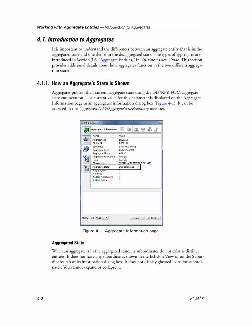
Working with Aggregate Entities — Introduction to Aggregates
4.1. Introduction to AggregatesIt is important to understand the differences between an aggregate entity that is in the aggregated state and one that is in the disaggregated state. The types of aggregates are introduced in Section 3.6, “Aggregate Entities,” in VR-Forces Users Guide. This section provides additional details about how aggregates function in the two different aggrega-tion states.
4.1.1. How an Aggregate’s State is Shown
Aggregates publish their current aggregate state using the DIS/RPR FOM aggregate state enumeration. The current value for this parameter is displayed on the Aggregate Information page in an aggregate’s information dialog box (Figure 4-1). It can be accessed in the aggregate’s DtVrfAggregateStateRepository member.
Figure 4-1. Aggregate Information page
Aggregated State
When an aggregate is in the aggregated state, its subordinates do not exist as distinct entities. It does not have any subordinates shown in the Echelon View or on the Subor-dinates tab of its information dialog box. It does not display ghosted icons for subordi-nates. You cannot expand or collapse it.
4-2 VT MÄK
Working with Aggregate Entities — Introduction to Aggregates
Disaggregated State
When an aggregate is in the disaggregated state, its subordinates are simulated as distinct entities. (However, it is possible to have a disaggregated aggregate with no subordinates.) Subordinates are displayed under the aggregate in the Echelon View and are listed on the Subordinates tab of its information dialog box. You can expand or collapse the aggregate view.
4.1.2. Changing the Aggregation State at Runtime
Aggregates can change their aggregation state at runtime. All state information main-tained by the aggregate (for example, the current task it is executing, plan state, current resource levels) is maintained across the transition between aggregated and disaggre-gated states. This section describes how aggregates handle transitions for the most important activities.
Movement
All movement tasks can be executed in either aggregated or disaggregated state. Aggre-gates can transition between states at any time, without interrupting movement tasks. For example, suppose an aggregate in the disaggregated state, is executing a move-to-location task. While it is executing the task, you issue a Aggregate State set data request, indicating it should switch to the aggregated state. The aggregate transitions into the aggregated state (subordinates are deleted, and the state associated with them is mapped and stored internally in the aggregate), and continues moving toward its destination. Similarly, making a transition in the opposite direction while executing a movement task, does not interrupt the execution of that task.
Aggregates preserve their formation across aggregate state transitions.
Combat
Only disaggregated aggregates can engage in combat. However, an aggregate remembers any loss of resources or subordinates while it is aggregated. If a subordinate is destroyed while the aggregate is disaggregated, it will not be created again if the aggregate aggre-gates and then disaggregates again.
VR-Forces Scenario Management Guide 4-3

Working with Aggregate Entities — Introduction to Aggregates
Resources
Resources are tracked and restored across state transitions. However, if a subordinate is destroyed while in the disaggregated state, then all of its resources are lost. They are not redistributed to other subordinates.
4.1.3. Triggering Aggregate State Transitions
Aggregate state transitions can be initiated manually or automatically, as follows:
Manually: You can send a Aggregate State set data request or use Aggregate and Disaggregate commands on the Entities menu. This immediately forces the aggre-gate to change state. As a set data request, state changes can be included in plans.
Automatically: On the Aggregate Display Settings page of the Display Settings dialog box you can configure automatic aggregation and disaggregation. In auto-matic mode, aggregates automatically aggregate or disaggregate according to the following rules:
– If the aggregate is within “disaggregation range” of a hostile entity or aggregate, the aggregate is in the disaggregated state. Disaggregation range is the range around an entity or aggregate in which you want to force any nearby aggregated entities to disaggregate so you can detect or engage them. This range is configu-rable for every type of entity and aggregate in the Entity Editor. (You must show advanced parameters to set this parameter.)
– If the aggregate’s formation footprint (projection of its bounding extent in a topographic plane) overlaps a disaggregation area, the aggregate is in the disag-gregated state. (A disaggregation area is a specific type of control object.)
– If neither of the above conditions is in effect, the aggregate is in the aggregated state.
i When you restore an aggregate that is in the aggregated state (using Restore), the original configuration of the aggregate is recreated. If you restore an aggregate that is in the disaggregated state, then only those subordinates still present in the simulation are restored. Any destroyed subordinates that were previously removed from the simulation as result of a disaggregate-->aggregate-->disaggregate transition are not restored. To fully recover all subordinates, restore the aggregate while in the aggregated state.
4-4 VT MÄK

Working with Aggregate Entities — Creating Aggregates
4.2. Creating AggregatesYou can create an aggregate by selecting existing entities (which can be individual enti-ties or aggregate entities) and combining them to form an aggregate entity, or by placing a preconfigured aggregate from the Entity Palette.
When you create an aggregate, it is created as a subordinate to the force level. You cannot create aggregates that are subordinates of an existing aggregate. Once you create an aggregate, you can subordinate it to another aggregate. (For details, please see “Adding Entities to an Aggregate,” on page 4-9).
By default, aggregates are created in a disaggregated state. However, you can change this behavior. For details, please see “Configuring the Aggregate Creation State,” on page 4-8.
4.2.1. Creating an Aggregate by Combining Existing Entities
When you create an aggregate by combining entities, you can specify the order of subordinates in the aggregate. This determines which subordinate is considered the aggregate leader and affects the assignment of echelon IDs. You cannot change the subordinate order after you create the aggregate.
To create an aggregate by combining existing entities:
1. Select the entities that you want to become part of an aggregate.
2. Choose Entities Aggregate As. The Aggregate As dialog box opens (Figure 4-3).
Figure 4-2. Aggregate As dialog box
i When you create an aggregate entity, the members of the aggregate get new echelon IDs to reflect the new entity hierarchy.
VR-Forces Scenario Management Guide 4-5

Working with Aggregate Entities — Creating Aggregates
3. Select an aggregate type from the list.
4. Optionally, customize the entity type enumeration for the aggregate, as follows:
a. Click More. The dialog box expands to show the entity type enumeration for the aggregate type selected.
Figure 4-3. Aggregate As dialog box
b. Edit the enumeration by typing values in the boxes in the left column, or selecting values from the lists in the right column.
5. Optionally, change the order of subordinates, as follows:
a. Select the subordinate whose order you want to change.
b. Click the up or down arrow to move it to a new position in the list of subordi-nates.
6. Click OK.
By default, the aggregate is created in a disaggregated, collapsed format. The icons for individual members are hidden. You can change the default aggregation state. For details, please see “Configuring the Aggregate Creation State,” on page 4-8.
i The Convoy aggregate can only be assigned convoy tasks. Its only purpose is to allow you to quickly aggregate miscellaneous ground vehicles into a convoy. You cannot aggregate or disaggregate a convoy aggregate.
i If an edit to the enumeration results in an entity type that does not match the aggregate type selected in the list, the list entry does not change. However, the aggregate will be created with the entity type specified by the custom enumeration.
4-6 VT MÄK

Working with Aggregate Entities — Creating Aggregates
4.2.2. Creating a Preconfigured Aggregate
VR-Forces includes preconfigured aggregates at several hierarchical levels. You can configure these entities and add additional aggregates in the Entity Editor. (For details, please see Section 5.7, “Editing Aggregate Composition and Formations,” in VR-Forces Configuration Guide.)
You can create preconfigured aggregates by selecting them on the Entity Palette and follow the standard procedures for creating entities. The abbreviations in the aggregate names have the following meanings:
ADA. Air defense artillery.
COLT. Combat observation lasing team.
CSS. Combat service support.
FA. Field artillery.
MI. Mechanized infantry.
i You can add additional preconfigured aggregates to the Entity Palette by creating them in the Entity Editor.
VR-Forces Scenario Management Guide 4-7

Working with Aggregate Entities — Selecting an Aggregate
4.2.3. Configuring the Aggregate Creation State
To configure the aggregation state used when aggregates are created:
1. Choose Settings Display. The Display Settings dialog box opens.
2. Select the Aggregate Display Settings page (Figure 4-4).
Figure 4-4. Aggregate Display Settings page
3. In the Initial Aggregate State group box, select the creation option that you want.
4. Click OK.
4.3. Selecting an Aggregate To select an aggregate, select its icon on the terrain, or select it in one of the views
on the Objects List Panel.
4-8 VT MÄK

Working with Aggregate Entities — Adding Entities to an Aggregate
4.4. Adding Entities to an Aggregate To add an entity to an aggregate, in the Echelon View, select the entity you want to
add and drag it onto the aggregate as illustrated in Figure 4-5. Notice that the name of the aggregate stays the same, but its echelon ID changes.
Figure 4-5. Adding an entity to an aggregate
i You can add entities to an aggregate only if it is in the disaggregated state.
VR-Forces Scenario Management Guide 4-9

Working with Aggregate Entities — Removing an Entity from an Aggregate
4.5. Removing an Entity from an Aggregate To remove an entity from an aggregate, in the Echelon View, drag the entity from
the aggregate to the force level in the window, as illustrated in Figure 4-6, or into another aggregate. Notice that the name of the aggregate stays the same, but its echelon ID changes.
Figure 4-6. Removing an entity from an aggregate
i You can remove entities from an aggregate only if it is in the disaggregated state.
4-10 VT MÄK

Working with Aggregate Entities — Changing the Aggregation State of an Aggregate Entity
4.6. Changing the Aggregation State of an Aggregate EntityYou can aggregate and disaggregate aggregates manually and automatically.
4.6.1. Aggregating and Disaggregating Entities Manually
To aggregate a disaggregated entity:
1. Select the aggregate.
2. Choose Entities Aggregate.
To disaggregate an aggregated entity:
1. Select the aggregate.
2. Choose Entities Disaggregate.
4.6.2. Configuring Automatic Aggregation and Disaggregation
When automatic aggregation and disaggregation is enabled, aggregated entities auto-matically disaggregate when they enter a disaggregation area or when they encounter opposing forces.
To configure automatic aggregation and disaggregation:
1. Choose Settings Display. The Display Settings dialog box opens.
2. Select the Aggregate Display Settings page (Figure 4-4).
3. In the Aggregate/Disaggregate group box, select Automatically or Manually.
4. Click OK.
4.6.3. Using Disaggregation Areas
When an aggregated entity that has automatic aggregation and disaggregation enabled enters a disaggregation area, it disaggregates. When it leaves the area, it aggregates again. A disaggregation area is a control object. You create one just like any other area, as described in Chapter 2, Creating and Placing Objects.
i The Convoy aggregate does not support aggregation and disaggregation.
i You can also change an aggregate’s state with the Aggregate State set data request (which also means that you can change state from within a plan).
VR-Forces Scenario Management Guide 4-11

Working with Aggregate Entities — Writing Plans for Aggregates
4.7. Writing Plans for Aggregates To write a plan for an aggregate, follow the procedures for writing a plan for an
entity in Chapter 9, Writing Plans.
4.8. Deleting an Aggregate
To delete an aggregate:
1. Select the aggregate.
2. Choose Entities Delete.
! If you delete an aggregate, all its member entities get deleted.
4-12 VT MÄK

VR-Forces Scenario Management Guide
5
Overlays and Tactical Graphics
This chapter explains how to create and edit overlays and tactical graphics.
Introduction ................................................................................................. 5-3Naming Tactical Graphics ...................................................................... 5-3
Creating and Editing Overlays ...................................................................... 5-3Creating an Overlay ............................................................................... 5-4Selecting Overlays .................................................................................. 5-4Locking an Overlay ................................................................................ 5-4Changing an Overlay’s Name ................................................................. 5-5Deleting an Overlay ............................................................................... 5-5
Creating Tactical Graphics ............................................................................ 5-5Creating Freehand Lines......................................................................... 5-6Drawing Circles and Ellipses .................................................................. 5-6Drawing Boxes ....................................................................................... 5-7Adding Text to an Overlay...................................................................... 5-7Assigning Tactical Graphics to an Overlay .............................................. 5-8Displaying a Terrain Profile When You Create a Line ............................. 5-9Publishing Tactical Graphics................................................................. 5-10Creating Routes for Aircraft ................................................................. 5-10
Deleting Tactical Graphics .......................................................................... 5-11
Editing Tactical Graphics ............................................................................ 5-11Editing Vertices .................................................................................... 5-12Resizing Boxes and Text Objects........................................................... 5-14Rotating an Ellipse ............................................................................... 5-14Changing the Direction of a Line ......................................................... 5-15Changing the Color of a Tactical Graphic ............................................ 5-15Changing Linear and Areal Style Properties .......................................... 5-15
5-1

Overlays and Tactical Graphics
Saving and Loading Tactical Graphics and Overlays.................................... 5-16Loading Tactical Graphics and Overlays ............................................... 5-17
5-2 VT MÄK

Overlays and Tactical Graphics — Introduction
5.1. IntroductionTactical graphics are graphical objects, such as lines, points, and areas, that you can draw on the terrain, or which are drawn by VR-Forces or remote applications. Control objects are a special kind of tactical graphic. Entities are aware of control objects and most lines and points and can interact with them. For example, an entity can follow a route, move to a point, or avoid an obstacle. VR-Forces can test to determine if an entity is in an area or to either side of a phase line.
All tactical graphics and entities are placed on overlays. By default, they are placed on the Default overlay. You can create additional overlays and assign objects to them.
For conceptual information about tactical graphics, please see Section 3.7, “Tactical Graphics,” in VR-Forces Users Guide.
5.1.1. Naming Tactical Graphics
The names you assign to graphics must be unique among all objects. Names are case sensitive, for example you can create three points called Waypoint Alpha, waypoint alpha, and Waypoint alpha, but you cannot create an area called Area 1 and a disaggre-gation area called Area 1. Object names can be up to 255 characters long.
5.2. Creating and Editing OverlaysOverlays allow you to add graphic objects to the VR-Forces window as if you were adding clear plastic overlays to a physical map and drawing on them. They provide a convenient way to organize and manage the tactical graphics in a simulation. You can add any number of overlays. You can rename them. You can enable or disable editing of the objects they contain.
When you create a tactical graphic, entity, or cultural feature, if you do not explicitly assign it to an overlay, it gets placed on the Default overlay. If the Default overlay does not exist, it gets created.
i Some character sets require multiple ASCII characters to represent a displayed character. If you use one of the these character sets, the maximum length of object names in visible characters may vary.
VR-Forces Scenario Management Guide 5-3

Overlays and Tactical Graphics — Creating and Editing Overlays
5.2.1. Creating an Overlay
To create an overlay:
1. On the Objects List Panel, select the Overlays tab (Figure 5-1).
Figure 5-1. Overlays tab
2. Click the Add button ( ). An overlay is added to the list with a default name.
3. Optionally, change the name as described in “Changing an Overlay’s Name,” on page 5-5.
5.2.2. Selecting Overlays
To select an overlay, click its name on the Overlays tab.
5.2.3. Locking an Overlay
When an overlay is locked, you cannot edit the objects on it. You can still add and delete objects.
To lock or unlock an overlay:
1. On the Objects List Panel, select the Overlays tab.
2. Select the overlay you want to lock or unlock.
3. Click the Lock/Unlock button ( ), or double-click the entry in the Locked column. It will toggle between Yes and No.
5-4 VT MÄK

Overlays and Tactical Graphics — Creating Tactical Graphics
5.2.4. Changing an Overlay’s Name
To change an overlay’s name:
1. On the Objects List Panel, select the Overlays tab.
2. Select the overlay that you want to rename and click the Rename button ( ), or double-click the overlay whose name you want to change. The name becomes edit-able.
3. Type a new name.
4. Press Enter.
5.2.5. Deleting an Overlay
To delete an overlay:
1. On the Objects List Panel, select the Overlays tab.
2. Select the overlay you want to delete.
3. Click the Delete button ( ).
5.3. Creating Tactical GraphicsThe generic procedures for creating tactical graphics are described in Chapter 2, Creating and Placing Objects. This section provides additional details about tactical graphic creation and placement.
! When you delete an overlay, all of the tactical graphics on it are also deleted.
VR-Forces Scenario Management Guide 5-5

Overlays and Tactical Graphics — Creating Tactical Graphics
5.3.1. Creating Freehand Lines
A freehand line is essenitally many short line segments. After you create a freehand line you can change the sampling rate used to determine how many segments it has. The fewer the segments, the less fluid the line is.
Unlike other lines, the individual vertices of a freehand line do not have vertex markers. You cannot select them individually on the map. However, you can edit them in the Edit Freehand Line dialog box.
The Freehand Line With Arrow automatically puts an arrow at the end of the line. However, you can also add an arrow to a freehand line that is created without one.
To create a freehand line:
1. Open the Tactical Graphics Palette.
2. Select the Shapes category.
3. Select Freehand line or Freehand Line with Arrow.
4. Click where you want the line to start, and while holding down the left mouse button, draw a line on the screen.
5. Release the mouse button. The Create Freehand dialog box opens.
6. Edit the properties as desired.
5.3.2. Drawing Circles and Ellipses
Entities do not interact with circle and ellipses. They are strictly for use as graphics.
To draw a circle:
1. Open the Tactical Graphics Palette.
2. Select the Shapes category.
3. Select Circle. The cursor changes to draw mode and shows a vertex icon.
4. Click to place the center of the circle. A center point is placed on the terrain and a circle is drawn. There is now a vertex icon on the circumference of the circle.
5. Drag the mouse to set the radius of the circle.
6. Click to complete the circle.
i If you reduce the sampling rate, resulting in fewer segments and a less fluid line, once you save the line you cannot automatically increase the number of segments to increase the fluidity of the line. You would have to add vertices by hand.
5-6 VT MÄK

Overlays and Tactical Graphics — Creating Tactical Graphics
To draw an ellipse:
1. Open the Tactical Graphics Palette.
2. Select the Shapes category.
3. Select Ellipse. The cursor changes to draw mode and shows a vertex icon.
4. Click to set the center of the ellipse. A center point is set and a small circle is displayed with a vertex indicator at the bottom of the circle.
5. Drag the mouse up or down and click to set the height of the ellipse. A vertex indi-cator is added to the left side of the circle.
6. Drag the mouse left and right and click to set the width of the ellipse.
5.3.3. Drawing Boxes
Boxes are constrained to be parallelograms. Entities do not interact with boxes. (In other words, they are not areas.)
To draw a box:
1. Open the Tactical Graphics Palette.
2. Select the Shapes category.
3. Select Box. A box is attached to the cursor
4. Click to place the box in the approximate location that you want.
5. Double-click any vertex. The vertex changes to show it is editable.
6. Drag the vertex to reshape the box.
5.3.4. Adding Text to an Overlay
You can add text to an overlay. The maximum width of the text object is fixed.
To add text to an overlay:
1. Open the Tactical Graphics Palette.
2. Select the Shapes category. (Text is also in the Logistics, Intel, and Symbols catego-ries.)
3. Select Text. The text “Text” is attached to the cursor.
4. Click to set the bottom center of the text. The Create Text dialog box opens.
5. Type the text you want in the Text box.
6. Edit any other properties as desired.
7. Click Create.
VR-Forces Scenario Management Guide 5-7
Overlays and Tactical Graphics — Creating Tactical Graphics
5.3.5. Assigning Tactical Graphics to an Overlay
By default, when you create a tactical graphic, it gets assigned to whichever overlay is selected on the Overlay tab. If no overlay exists, the Default overlay is created and the graphic is assigned to it. You can assign a tactical graphic to a different overlay when you create it or edit it. To assign a tactical graphic to an overlay when you create it, set this property as described in “Specifying an Object’s Properties Before You Create It (Click to Locate),” on page 2-11. To move a tactical graphic to a different overlay, follow the procedure in “Moving a Tactical Graphic to a Different Overlay,” on page 5-8.
Moving a Tactical Graphic to a Different Overlay
To move a tactical graphic to a different overlay:
1. Select the object you want to move.
2. Choose Entities Edit. The Edit Object dialog box opens.
3. If Attach Object to Mouse is selected, clear the check box.
4. In the Overlay list, select the overlay that you want the object to move to.
5. Click Update.
i You can also move a tactical graphic to a different overlay by dragging it to the new overlay on the Overlays tab of the Objects List panel.
5-8 VT MÄK

Overlays and Tactical Graphics — Creating Tactical Graphics
5.3.6. Displaying a Terrain Profile When You Create a Line
You can display a terrain profile window while you create a line. You can configure terrain profiles to automatically display a terrain profile when a line is created (Section 13.1.2, “Configuring Terrain Profiles,” in VR-Forces Users Guide), or you can display the window manually.
To open a terrain profile window while you are creating a line:
1. Select the object that you want to create as described in “Selecting the Object to Create,” on page 2-3. A Create Object tab is added to the window below the Prop Palette (Figure 2-4).
2. Click the Create Object tab. A Create Object dialog box that is appropriate for the object opens (Figure 5-2).
Figure 5-2. Terrain Profile button
3. Click to place the first vertex. The Terrain Profile button is activated.
4. Click Terrain Profile.
VR-Forces Scenario Management Guide 5-9

Overlays and Tactical Graphics — Creating Tactical Graphics
5.3.7. Publishing Tactical Graphics
By default, all tactical graphics are published. That is, they are sent out over the network and are visible to other participants in an exercise. You can choose to not publish a tactical graphic. In that case, it is visible only in the front-end on which it was created.
Published tactical graphics get saved to the order of battle file. Unpublished tactical graphics get saved to the overlays file that gets created as part of the scenario. You can also manually save tactical graphics to an overlay file separate from the one stored with the scenario.
To publish or unpublish a tactical graphic:
1. Select the graphic you want to edit.
2. Choose Entities Edit. The Edit Object dialog box opens.
3. To publish the object, select the Publish Object check box. To unpublish it, clear the check box.
5.3.8. Creating Routes for Aircraft
When you create a route for a fixed-wing entity, remember that as an aircraft flies between the vertices of a route, it starts at the altitude of the first vertex and immedi-ately rises or falls to the altitude of the next vertex as shown in the trajectory in (Figure 5-3). (It does not change altitude smoothly between the vertices.) If a terrain feature in-between the two vertices is higher than the trajectory followed by the aircraft, the aircraft will fly into the terrain, even though a line between the two vertices would not pass through the terrain. There is no terrain following built into the route following process for fixed-wing entities.
Figure 5-3. Fixed-wing trajectory between vertices
This caution applies to rotary-wing entities if there are abrupt changes in elevation in the terrain. Rotary-wing entities can follow the terrain, but they only look down, not ahead, so abrupt changes in terrain could cause a crash.
Route
Trajectory
Terrain profile
5-10 VT MÄK

Overlays and Tactical Graphics — Deleting Tactical Graphics
5.4. Deleting Tactical GraphicsTo delete a graphical object:
1. Select the object you want to delete.
2. Choose Entities Delete, or press the Delete key.
5.5. Editing Tactical GraphicsYou can edit a tactical graphic’s properties. The properties that you can edit vary depending on the type of graphic and can include some or all of the following:
Add, delete, and edit vertices (“Editing Vertices,” on page 5-12).
Change its name.
Change the altitude reference (“Setting Altitude in the Create Object or Edit Object Dialog Box,” on page 2-13), “Specifying the Altitude for All of the Vertices in a Route,” on page 2-14.
Change the direction of a line (“Changing the Direction of a Line,” on page 5-15).
Edit linear and areal styles:
– Change the pen style and width.
– Change the line style.
– Add or remove arrows.
– Change the fill of an area.
(“Changing Linear and Areal Style Properties,” on page 5-15.)
Move it to a different location (“Dragging an Object to a New Location,” on page 2-16).
Move it to a different overlay (“Moving a Tactical Graphic to a Different Overlay,” on page 5-8).
Change the color (“Changing the Color of a Tactical Graphic,” on page 5-15).
Resize boxes and text objects (“Resizing Boxes and Text Objects,” on page 5-14).
Rotate an ellipse (“Rotating an Ellipse,” on page 5-14).
i To edit a tactical graphic, its overlay must be unlocked.
VR-Forces Scenario Management Guide 5-11

Overlays and Tactical Graphics — Editing Tactical Graphics
5.5.1. Editing Vertices
You can edit the vertices of routes and areas. You can edit them dynamically or in the Edit Object dialog box.
Adding a Vertex
You can add vertices to a route or area directly on the terrain or in the Edit Object dialog box.
To add a vertex to an object dynamically:
1. Right-click the vertex next to which you want to add a new vertex. A menu is displayed.
2. Choose Add Point After or Add Point Before. A point is added midway between the selected vertex and the next or previous vertex, based on the command you chose.
3. Optionally, edit the new point as described in “Editing a Vertex,” on page 5-13.
To add a vertex in the Edit Object dialog box:
1. Select the object you want to edit.
2. Choose Entities Edit. The Edit Object dialog box opens (Figure 5-4).
Figure 5-4. Edit Route dialog box
3. If Attach Object to Mouse is selected, clear the check box.
4. In the list of vertices, select the vertex after which you want to add the new vertex.
5. Click the Add button ( ). A vertex is added midway between the selected vertex and the next vertex. If you selected the last vertex, a new vertex is added to the end of the route.
5-12 VT MÄK
Overlays and Tactical Graphics — Editing Tactical Graphics
6. Optionally, edit the new point as described in “Editing a Vertex,” on page 5-13.
7. Click Update.
Editing a Vertex
You can edit a vertex dynamically or in the Edit Object dialog box.
To edit a vertex dynamically:
1. Double-click the vertex.
2. Move the mouse to change the vertex’s location.
3. Use Alt+mouse wheel or Alt+left mouse button+drag to change the altitude.
4. Click to place the vertex.
To edit a vertex in the Edit Object dialog box:
1. Select the object you want to edit.
2. Choose Entities Edit. The Edit Object dialog box opens.
3. If Attach Object to Mouse is selected, clear the check box.
4. If you are editing a waypoint, click on the terrain to specify a new location or edit the coordinates and altitude in the Edit Waypoint dialog box.
If you are editing a phase line, route, or area, you can:
a. Double-click the coordinate value you want to change to make it editable.
b. Type a new value and press Enter or click someplace outside of the value.
Alternatively, you can click on the map to change the coordinates of the selected vertex. To set the altitude, you must edit the value by hand.
5. Click Update.
VR-Forces Scenario Management Guide 5-13

Overlays and Tactical Graphics — Editing Tactical Graphics
Deleting a Vertex
You can delete vertices directly or in the Edit Object dialog box.
To delete a vertex directly:
1. Right-click the vertex you want to delete. A menu is displayed.
2. Choose Delete Point. The point is deleted. (There is no confirmation prompt.)
To delete a vertex in the Edit Object dialog box:
1. Select the object you want to edit.
2. Choose Entities Edit. The Edit Object dialog box opens.
3. If Attach Object to Mouse is selected, clear the check box.
4. In the list of vertices, select the vertex you want to delete.
5. Click the Delete button ( ).
6. Click Update.
5.5.2. Resizing Boxes and Text Objects
You cannot edit the individual vertices of a box or a text object, you can only resize them.
To resize a box or text object, grab one of its vertices and drag it to create the new object size.
5.5.3. Rotating an Ellipse
In addition to changing the width and height of an ellipse, you can rotate it around its center point. You can undo and redo ellipse rotation.
To rotate an ellipse:
1. Select the ellipse.
2. Choose Entities Edit. The Edit object dialog box opens.
3. Select the Free Rotate check box.
4. Click OK.
5. Grab one of the points on the ellipse and drag it in a circular direction.
5-14 VT MÄK

Overlays and Tactical Graphics — Editing Tactical Graphics
5.5.4. Changing the Direction of a Line
All lines have a direction. The direction affects how an entity moves along it and the direction that arrows face, if present. If you draw a line and then decide you want to reverse its direction, you can do so.
To change the direction of a line:
1. Select the line.
2. Choose Entities Edit. The Edit object dialog box opens.
3. Click the Reverse Direction button ( ).
4. Click OK.
5.5.5. Changing the Color of a Tactical Graphic
You can change the color of a tactical graphic.
To change the color of an tactical graphic:
1. Select the graphic whose color you want to change.
2. Choose Entities Edit. The Edit object dialog box opens.
3. Click the Color button ( ). A color picker dialog box opens.
4. Click a color button or click the Custom Color button to choose a new color from the Color Picker.
5. Click OK.
5.5.6. Changing Linear and Areal Style Properties
Lines and areas have a variety of properties that can be set in the Edit Style dialog box. The procedure is essentially the same for all of these properties. The properties you might be able to change are as follows:
Line width. The width of the lines that make up a tactical graphic, either the actual line or the boundary of an area.
Pen style. How the line or outline is drawn – solid line, no line, or as dashed and dotted lines. This property does not apply to lines that use a texture, such as Line of Contact.
Fill style. The fill style for areal objects. Fill styles include degrees of solid fill and various types of line and grid fills.
Line style. The different types of special lines, such as Main Axis.
Arrow. You can add arrows to the end of a line or at the end of each segment of the line.
VR-Forces Scenario Management Guide 5-15

Overlays and Tactical Graphics — Saving and Loading Tactical Graphics and Overlays
To change a style property:
1. Select the graphic you want to edit.
2. Choose Entities Edit. The Edit object dialog box opens.
3. Click the Edit Style button ( ). The Edit Style dialog box opens (Figure 5-5).
Figure 5-5. Edit Style dialog box
4. Change the properties by selecting options from the appropriate list or typing new values.
5. Click OK.
5.6. Saving and Loading Tactical Graphics and OverlaysIf you publish a tactical graphic, it is automatically saved to the order of battle file (.oob). If you do not publish a tactical graphic, it is automatically saved to the overlay file (.ovl). There may be cases where you want to create a set of overlays for use in multiple scenarios. You can save them to an overlay file independently of the scenario, or even save the overlays and not save the scenario at all.
To save overlays and tactical graphics:
1. Choose File Save Overlay. The Save Overlay dialog box opens.
2. Type a name for the overlay file.
3. Click Save.
i When you save overlay objects, only unpublished tactical graphics get saved.
5-16 VT MÄK

Overlays and Tactical Graphics — Saving and Loading Tactical Graphics and Overlays
5.6.1. Loading Tactical Graphics and Overlays
You can load overlays that you have saved from a previous session.
To load overlays:
1. Choose File Load Overlay. The Load Overlay dialog box opens.
2. Select the overlay file you want to load.
3. Click Open.
! When you load overlay objects, you must use the same terrain database you created them on, or a terrain database that includes the area they were created in.
VR-Forces Scenario Management Guide 5-17

Overlays and Tactical Graphics — Saving and Loading Tactical Graphics and Overlays
5-18 VT MÄK
VR-Forces Scenario Management Guide
6
Assigning Tasks
This chapter provides general details about how to assign tasks to entities. For descrip-tions of specific tasks and how to assign them, please see Chapter 7, Task Procedures.
Assigning Tasks to Entities ............................................................................ 6-3C++ Tasks and Scripted Tasks................................................................. 6-3Concurrent Task Execution .................................................................... 6-4How do I Know which Entity can Execute a Task? ................................. 6-5Escaping the Task Assignment Process .................................................... 6-5Specifying Parameters for Tasks .............................................................. 6-5Viewing Task Status................................................................................ 6-7Filtering the Object Selection Lists ......................................................... 6-8Skipping (Stopping) a Task..................................................................... 6-8
Assigning Tasks to Aggregates ....................................................................... 6-9Convoy Tasks ......................................................................................... 6-9Independently Tasking Aggregate Members.......................................... 6-10
Reactive Tasks ............................................................................................. 6-10Enabling Reactive Tasks........................................................................ 6-12Disabling Reactive Tasks....................................................................... 6-12Setting the Priority of a Reactive Task................................................... 6-13Managing Reactive Tasks...................................................................... 6-14Cancelling a Reactive Task.................................................................... 6-15
Using Behavior Sets to Manage Scripted Tasks............................................ 6-16Creating Behavior Sets.......................................................................... 6-17Editing Behavior Sets ........................................................................... 6-18Assigning a Behavior Set to a Force....................................................... 6-18
Entity Movement On Roads and Off Roads ............................................... 6-18Road Driving Behavior......................................................................... 6-20
6-1

Assigning Tasks
Fixed-Wing Entity Tasks and Behaviors ...................................................... 6-21Placement of Newly Created Fixed-Wing Entities ................................ 6-21Fly Task Behavior is Different from Move Task Behavior ..................... 6-21Specifying and Maintaining Altitude for Fixed-Wing Entities .............. 6-22Fixed-Wing Entity Movement on the Ground and in the Air ............... 6-22How Fixed-Wing Entities Take Off ...................................................... 6-25How Fixed-Wing Entities Land............................................................ 6-26
Rotary-Wing Entity Tasks and Behaviors .................................................... 6-27Controlling Rotary-Wing Orientation.................................................. 6-29
6-2 VT MÄK

Assigning Tasks — Assigning Tasks to Entities
6.1. Assigning Tasks to EntitiesYou can assign tasks to an entity as part of its plan, as part of a global plan, and inde-pendently of any plan. For conceptual information about tasks, please see Section 3.8, “Tasks,” in VR-Forces Users Guide. For information about how to add a task to a plan, please see “Adding an Entity Task or Set Data Request to a Plan,” on page 9-18. For the procedures for assigning tasks, please see “Task Procedures,” on page 7-4.
You cannot assign tasks to non-VR-Forces entities. However, you can use a remote entity as a parameter in a task, for example, following a remote entity, or targeting a remote entity. For more information, please see “Using Non-VR-Forces Entities in Plans,” on page 9-35.
6.1.1. C++ Tasks and Scripted Tasks
The VR-Forces application includes a basic set of entity tasks for movement, weapons fire and other actions, that were developed using the VR-Forces Toolkit and the C++ API. System integrators often add additional tasks before delivering VR-Forces to their customers. These tasks are called C++ tasks to distinguish them from another type of task – the scripted task. Scripted tasks, written in the Lua programming language, use the lower-level C++ tasks and the VR-Forces Lua API to build higher-order tasks for entities.
To the VR-Forces end user, these tasks, all of which are listed on the Task menu, are indistinguishable. However, you can write new scripted tasks and edit existing tasks. Therefore, where necessary, when discussing a task, this manual will indicate which type of task it is discussing. For information about scripted tasks, please see Chapter 13, Creating Scripted Tasks.
VR-Forces also supports a special category of scripted tasks called reactive tasks. These tasks are not on the Task menu. They execute when a condition becomes true. For details, please see “Reactive Tasks,” on page 6-10.
VR-Forces Scenario Management Guide 6-3
Assigning Tasks — Assigning Tasks to Entities
6.1.2. Concurrent Task Execution
Some tasks can execute at the same time. Some are mutually exclusive. If you assign an entity a task that is mutually exclusive with its current task, the current task is aban-doned. If you assign a task that is not mutually exclusive with the current task, an entity executes the new task while continuing to execute the previous task.
Tasks are organized into the following groups:
Weapon
Movement
Radio
Depth control.
All tasks within a group are mutually exclusive among themselves. For example, all movement tasks are mutually exclusive. Entities that are moving can usually execute a task from one of the other groups at the same time. For example, entities can execute the various Send tasks while they are executing movement tasks. When you create a scripted task, you can specify which groups it conflicts with. For information about how to configure mutually exclusive tasks, please see Section 7.8, “Configuring Task Execution Rules,” in VR-Forces Configuration Guide. For information about scripted tasks, please see Chapter 13, Creating Scripted Tasks.
i When you assign a mutually exclusive independent task, VR-Forces displays a prompt that asks you to confirm interruption of the current task. You can disable this prompt if you always want a new task to interrupt the current task.
6-4 VT MÄK

Assigning Tasks — Assigning Tasks to Entities
6.1.3. How do I Know which Entity can Execute a Task?
Some VR-Forces tasks apply to almost all entities, such as Radio tasks and some move-ment tasks. Others are valid only for particular platforms or even particular entity types. Sometimes it is obvious which entity types can execute a task. For example, you would expect that Fixed-Wing Land only applies to fixed-wing entities. Similarly, Raise Peri-scope applies to submarines. However, for other tasks, it is not always evident which entity can execute a task.
Entities can execute tasks for which they have an appropriate controller. Since most task controllers are embodied in systems, this means that entities can execute the tasks supported by their various movement, weapons, sensors, and other systems. For example, to deploy naval mines, an entity needs a Naval Mine Deployment system.
To see which systems an entity has, and thereby infer which tasks it can execute, you can examine the entity’s systems in the Entity Editor. You can also refer to VRFEntity-Catalog.pdf, which lists the systems for each entity configured in the Entity Editor.
Appendix C, Systems and System Usage lists each system provided with VR-Forces, the types of entities it supports, and its description. It also lists each system and the entities that are configured to use it.
6.1.4. Escaping the Task Assignment Process
You can escape the task assignment process at any point before you complete it.
To escape the task assignment process, in the task dialog box, click Cancel.
6.1.5. Specifying Parameters for Tasks
VR-Forces lets you specify task parameters in dialog boxes or by selecting them on the terrain. Many tasks require you to select an object or entity.
If you select the appropriate object, the selection is reflected in the task dialog box.
If you prefer, you can specify all parameters in the task dialog box. Depending on the zoom level of the terrain and the number of entities and tactical graphics you have created, it may be easier to select an object from a list than to select it from a densely packed group of icons.
VR-Forces Scenario Management Guide 6-5

Assigning Tasks — Assigning Tasks to Entities
Selecting Objects in Multiple List Dialog Boxes
Some task dialog boxes, such as Patrol Between, require you to select multiple objects, each of which is selected from a different list.
You can select the objects in the list window or in the display window. At any given moment, one of the lists is the active list and a selection in the display window is reflected in that list. The active list is indicated by the button next to the Filter list (Figure 6-1).
Figure 6-1. Multiple list dialog box
The active list is determined as follows:
When you first open the dialog box, the first list window is automatically active. If you select an object in the display, it is selected in the first list window. Then the second list window automatically becomes active and the next object you select in the display is selected in the second list window. This sequence continues until all list windows have a selection. Then the last window stays as the active list.
Selecting an object in a list window makes it active.
Clicking the Filter button ( ) next to the Filter list makes that list window active. It will stay active until you click the button to inactivate it or click in another list window.
If all lists are inactive (by clicking the Filter button to put it into the unselected state), you can click objects in the display without affecting the selections in the list windows.
6-6 VT MÄK

Assigning Tasks — Assigning Tasks to Entities
6.1.6. Viewing Task Status
The Entity Information dialog box for an entity lists its current task on the Task Status page. It also lists the state of the reactive tasks that are enabled for the entity. If an entity is executing a task as part of its plan, you can also see which task it is executing by opening its Plan window (Figure 6-2).
Figure 6-2. Display of entity task status
VR-Forces Scenario Management Guide 6-7

Assigning Tasks — Assigning Tasks to Entities
6.1.7. Filtering the Object Selection Lists
If a task requires you to select objects, you can filter the object selection list to make it easier to find the particular objects you need to select (Figure 6-3). If you are selecting entities, for example in a Follow Entity task, you can display all entities, individual enti-ties only, or aggregate entities only. Within the latter two groups, you can display friendly or opposing entities. In a Move To task, you can filter for waypoints, friendly entities, or opposing entities.
Figure 6-3. Entity filter list
To filter an entity list, in a task or set data request dialog box, choose the filter type from the list.
6.1.8. Skipping (Stopping) a Task
You can instruct an entity to stop executing its current task. If the entity is executing a plan, it moves to the next task in its plan. If there are no further tasks, the entity waits for further orders.
To order an entity to skip a task, choose Entities Skip Task.
i Skip Task does not apply to members of an aggregate that are executing tasks assigned to them by the aggregate leader.
You can also stop tasks from the Task Status page of the Entity Informa-tion dialog box. For details, please see “Cancelling a Reactive Task,” on page 6-15.
6-8 VT MÄK

Assigning Tasks — Assigning Tasks to Aggregates
6.2. Assigning Tasks to Aggregates To assign a task to an aggregate, select the aggregate, then assign it a task as you
would any individual entity.
6.2.1. Convoy Tasks
VR-Forces has two tasks for moving in convoys – Convoy Along and Convoy To. These tasks can only be assigned to aggregate entities made up of ground vehicles. When an aggregate receives a convoy task, it organizes itself into a column based on the echelon IDs. Then it executes the task.
Once the task begins, the members of the aggregate try to maintain a consistent distance apart from each other. You can configure this distance by editing the Ground Convoy Movement system in the OPD Editor. The distance is specified by the separa-tion-distance parameter. You can also specify an amount by which the separation distance can vary using the separation-tolerance parameter.
i If VR-Forces can determine that a convoy task is not appropriate for a given aggregate, for example a rotary wing aggregate, the convoy tasks will not be available on the Task menu. However, in other cases, such as mixed aggregates or if you aggregate disparate entities as Ground Aggregate, it is up to you to know whether or not an aggregate consists only of ground vehicles or contains platforms that do not support convoy tasks.
VR-Forces Scenario Management Guide 6-9

Assigning Tasks — Reactive Tasks
6.2.2. Independently Tasking Aggregate Members
Members of a disaggregated aggregate can have individual plans or be assigned tasks independently of the aggregate. If a member of an aggregate unit is independently tasked, when it completes its task it automatically becomes tasked by its superior. You do not need to give it a Tasked by Superior set data request. You can override this behavior by setting an object’s tasked-by-superior-upon-task-complete parameter in the object parameter database to False.
If a Skip Task command is given to an independently tasked subordinate, it remains in the independently tasked state until it either completes a task or it is given a Set Tasked by Superior set data request.
When an entity becomes tasked by its superior, it does not execute the task that the aggregate is currently executing. It receives the next task that is sent out by the aggre-gate.
6.3. Reactive TasksReactive tasks are a special category of scripted tasks. Unlike other tasks (whether scripted or built-in), reactive tasks do not begin to execute as soon as they are assigned. They monitor events in a simulation and execute in response to conditions specified in the script. In this way they are similar to collision avoidance, which takes over entity movement in response to an imminent collision, or When statements in plans, which get triggered when a condition becomes true.
Because reactive tasks are scripted tasks, you are not restricted to the few conditions available in plans. You have the full VR-Forces Lua API available to script the condi-tions and the resulting behaviors. Like other scripted tasks, reactive tasks are either scenario-specific or system reactive tasks.
i When a disaggregated aggregate changes to the aggregated state, the individual subordinates cease to exist. Therefore, if a subordinate is executing an independent task, when the aggregate changes state, the task activity ends immediately.
6-10 VT MÄK

Assigning Tasks — Reactive Tasks
Reactive tasks have the following behaviors and characteristics:
Reactive tasks can be automatically enabled for a category of entity. They can also be individually enabled and disabled.
When a reactive task is activated, the current task is suspended. When the reactive task concludes, the entity resumes the previous task, if possible. There may be cases where the previous task is no longer valid. For example, if an entity was executing a Move to Waypoint (Use Roads) task and the result of the reactive task was that the entity is no longer near the road network, it will not be able to resume the Move to Waypoint (Use Roads) task.
Reactive tasks support task concurrency.
Reactive tasks can be interrupted by other reactive tasks. Precedence among reactive tasks is based on a task’s priority. If a reactive task is executing and a reactive task with a higher priority gets triggered, it suspends the current reactive task. When the higher priority task completes, the lower priority task resumes. When it completes, the original task resumes. Multiple nesting of tasks in this way is permitted. Reac-tive tasks with the same or lower priority do not interrupt the active task.
Reactive tasks can have parameters, just like any other task. If a reactive task is enabled and the parameters are not set, it may not work as expected. A well-written reactive task should have default values for parameters, but VR-Forces does not enforce this.
Users can change the priority of a reactive task while a scenario is running. This affects the next activation of the task.
If a reactive task is interrupted by an nonconcurrent independent task assignment, from the Task menu or a global plan, the reactive task and all suspended tasks are cancelled and the new task is executed. However, it is still possible that the new task could be interrupted by the same or a different reactive task.
Active reactive tasks can be cancelled by a VR-Forces user.
After a reactive task is complete, it enters the enabled state and can become trig-gered again.
The status of reactive tasks is displayed on the Task Status page of the Entity Infor-mation dialog box, along with the status of the current or suspended task.
The following sections describe how to manage reactive tasks in a scenario. For infor-mation about how to write and configure reactive tasks, please see Chapter 14, Writing Scripts for Scripted Tasks.
VR-Forces Scenario Management Guide 6-11

Assigning Tasks — Reactive Tasks
6.3.1. Enabling Reactive Tasks
Like other scripted tasks, when a reactive task is written, it is specified as being valid for one or more entity types. It can also be configured to be enabled by default. If a reactive task is not enabled by default, you can enable it for individual entities.
To enable a reactive task:
1. Select the entity for which you want to enable the task.
2. Choose Set Reactive Tasks Enable. The Enable Reactive Task dialog box opens (Figure 6-4). If there are no reactive tasks available, the dialog box states this. This condition occurs if all appropriate reactive tasks are already enabled or there are no reactive tasks for this entity type.
3. In the Reactive Tasks list, select the task you want to enable. If the task requires parameters, the dialog box redisplays and lists the parameters.
4. If necessary, specify the parameters.
5. Click OK.
6.3.2. Disabling Reactive Tasks
You can disable reactive tasks on a per-entity basis. When you disable a reactive task, any active tasks continue to execute. However, no new instances of the disabled task will be activated.
i This procedure applies to the currently selected entity. If you have multiple Entity Information windows open, selecting a reactive task on the Task Status page of an entity does not select the entity and does not make it the task affected by this procedure.
i You can also enable reactive tasks in the Reactive Task Status dialog box. For details, please see “Managing Reactive Tasks,” on page 6-14.
i This procedure applies to the currently selected entity. If you have multiple Entity Information windows open, selecting a reactive task on the Task Status page of an entity does not select the entity and does not make it the task affected by this procedure.
6-12 VT MÄK

Assigning Tasks — Reactive Tasks
To disable a reactive task for an entity:
1. Select the entity for which you want to disable a reactive task.
2. Choose Set Reactive Tasks Disable. The Disable Reactive Task dialog box opens. If there are no reactive tasks available, the dialog box states this. This condi-tion occurs if all appropriate reactive tasks are already disabled or there are no reac-tive tasks for this entity type.
3. In the Reactive Tasks list, select the task you want to disable.
4. Click OK.
6.3.3. Setting the Priority of a Reactive Task
When a reactive task is created, it is assigned a priority. The priority determines which reactive tasks it can override or be overridden by. Priorities are expressed as integers, with 1 being the highest priority. You can change the priority of a reactive task on a per-entity basis.
To change the priority of a reactive task:
1. Select the entity for which you want to change a reactive task’s priority.
2. Choose Set Reactive Tasks Priority. The Reactive Task Priority dialog box opens. If there are no reactive tasks available, the dialog box states this.
3. In the Reactive Tasks list, select the task whose priority you want to change.
4. Select a priority in the box. The lower the number, the higher its priority.
5. Click OK.
i You can also disable reactive tasks in the Reactive Task Status dialog box. For details, please see “Managing Reactive Tasks,” on page 6-14.
i This procedure applies to the currently selected entity. If you have multiple Entity Information windows open, selecting a reactive task on the Task Status page of an entity does not select the entity and does not make it the task affected by this procedure.
i You can also change priority in the Reactive Task Status dialog box. For details, please see “Managing Reactive Tasks,” on page 6-14.
VR-Forces Scenario Management Guide 6-13

Assigning Tasks — Reactive Tasks
6.3.4. Managing Reactive Tasks
You can enable, disable, and change priority for all the reactive tasks that apply to an entity from the Reactive Task Status dialog box.
To manage multiple reactive tasks for an entity:
1. Select the entity for which you want to manage reactive tasks.
2. Choose Set Reactive Tasks Manage or choose Entities Manage Reactive Tasks. The Manage Reactive Task dialog box opens (Figure 6-4). It lists each reac-tive task configured for this entity type, its status, and its priority. If a task requires parameters, you can set them.
Figure 6-4. Manage Reactive Task dialog box
3. For each task, to enable or disable, select an option from the list in the Enabled column.
4. For each task, change the priority by selecting an option in the box in the Priority column.
5. For each task that has parameters, click Parameters and set its parameters.
6. Click OK.
6-14 VT MÄK

Assigning Tasks — Reactive Tasks
6.3.5. Cancelling a Reactive Task
You can cancel a reactive task while it is executing. When you cancel a reactive task, the entity resumes the suspended task. However, if the condition that caused the reactive task to activate is still true, when you cancel a reactive task, it will usually immediately activate again.
To cancel a reactive task:
1. Select the entity whose task you want to cancel.
2. Choose Entities Information, or press i. The Entity Information dialog box opens.
3. Select the Task Status page. If a reactive task is active, it has a button in the Cancel column.
4. Right-click the active task and choose Cancel Reactive Task, or click the button in the Cancel column.
i You can also use this procedure to cancel (skip) a regular task.
VR-Forces Scenario Management Guide 6-15

Assigning Tasks — Using Behavior Sets to Manage Scripted Tasks
6.4. Using Behavior Sets to Manage Scripted TasksBehavior Sets let you organize scripted tasks so that a set of related tasks can be enabled or disabled at the force level.
If a scripted task is not assigned to a Behavior Set, its availability to an entity is deter-mined by the following settings:
The Valid for Entity Types list for the task.
For tasks specific to systems, configuration of that system on an entity.
For reactive tasks, the Enable/Disable setting in the Manage Reactive Tasks dialog box for the entity.
If a scripted task is assigned to a Behavior Set, then in addition to the requirements in the previous list, it is available to entities only if the Behavior Set is assigned to a force and only to entities of that force. (You can assign a Behavior Set to more than one force.)
As an example of how you might use Behavior Sets, suppose that dismounted infantry react differently to an attack depending on whether they are operating in rural terrain or in urban terrain. You have a set of scripted tasks that you have written for reacting to attack in each of these two situations. If you are not using Behavior Sets, then at a minimum, to manage which tasks would get used when the entitities are under attack, you would have to tell users not to use the innapropriate tasks. Or, you could enable and disable the correct set of tasks in the Scripted Tasks dialog box before the start of the scenario. Or, you would have to enable and disable the tasks on a per entity basis in the Manage Reactive Tasks dialog box. Shifting back and forth between simulations in different terrains might become a management problem.
Using Behavior Sets, you could create a Behavior Set for rural terrain operations and one for urban operations. You would assign the relevant scripted tasks to each Behavior Set. Then before you ran a scenario, you would assign the Behavior Set you want to use to the force. The tasks in the Behavior Set would be enabled and those in the unused Behavior Set would be disabled. There would be no further configuration required.
6-16 VT MÄK

Assigning Tasks — Using Behavior Sets to Manage Scripted Tasks
6.4.1. Creating Behavior Sets
To create a Behavior Set:
1. Choose Simulation Behavior Sets. The Edit Behavior Sets dialog box opens (Figure 6-5).
Figure 6-5. Edit Behavior Sets dialog box
2. Click the Add button ( ). The New Behavior Set Name dialog box opens.
3. Type a name for the Behavior Set.
4. Click OK.
5. In the Scripted Tasks list, select the scripted tasks that you want to assign to this Behavior Set. Click the left-facing arrow. The scripted tasks are added to the Behavior Set. If you select a folder, all tasks in the folder get added to the Behavior Set. (You can also assign tasks to Behavior Sets in the Edit Scripted Task dialog box. For details, please see “Creating a New Scripted Task,” on page 13-5.)
6. Optionally, assign the Behavior Set to a force.
VR-Forces Scenario Management Guide 6-17

Assigning Tasks — Entity Movement On Roads and Off Roads
6.4.2. Editing Behavior Sets
You can edit Behavior Sets, rename them, and delete them.
To edit Behavior Sets:
1. Choose Simulation Behavior Sets. The Edit Behavior Sets dialog box opens (Figure 6-5).
2. Expand the Behavior Set that you want to edit.
3. Add and remove scripted tasks by selecting them and clicking the appropriate arrow button.
To rename a Behavior Set, select it in the Behavior Sets list, click the Rename button ( ), and type a new name.
To delete a Behavior Set, select it in the Behavior Sets list and click the Delete button ( ).
6.4.3. Assigning a Behavior Set to a Force
You can only assign one Behavior Set to a force at any given time.
To assign a Behavior Set to a force:
1. Choose Simulation Behavior Sets. The Edit Behavior Sets dialog box opens (Figure 6-5).
2. In the Assign Behavior Set to Force window, click the list for the force to which you want to assign a Behavior Set.
3. Select the Behavior Set that you want to assign. If you do not want any Behavior Sets assigned, select the blank line in the list.
6.5. Entity Movement On Roads and Off RoadsSome terrains have vector road networks. Ground vehicle entities can use these networks to move precisely through the terrain. The tasks for moving on roads are distinct from the tasks for moving without respect to road networks. (For a description of how entities move when they use road driving, please see “Road Driving Behavior,” on page 6-20.) If you want entities to move both on and off roads, you need to under-stand how these tasks interact.
The road driving tasks are Move to Waypoint (On Roads) and Move To Location (On Roads). The generic movement tasks are Move to Location (Direct) and Move to Waypoint (Direct).
6-18 VT MÄK

Assigning Tasks — Entity Movement On Roads and Off Roads
When you give an entity a generic Move To (Direct) task, it moves directly towards its destination. It will avoid obstacles. It will not pay attention to the terrain except to the extent that it cannot move on certain soil types or terrains that are too steep.
When you give an entity a Move (On Roads) task, it must be within 10 meters of the edge of the road (this is configurable) or the task fails. It will move along the road network to the point nearest the destination and then will stop. If the destination is not on the road, the entity does not leave the road to move to it.
Given these behaviors, if you want an entity to move from an off-road location to another location, but use roads if it can, you will have to give it three tasks:
1. Move to Waypoint (Direct) or Move to Location (Direct), where the waypoint or location is on the road network.
2. Move to Waypoint (On Roads) or Move To Location (On Roads), where the waypoint or location is the final destination or some point on the road network where you want the entity to leave the network.
3. Move to Waypoint (Direct) or Move to Location (Direct), where the waypoint or location is the final off road destination.
VR-Forces has a pair of tasks that combine direct movement and road driving – Move to Waypoint (Plan Path) and Move To Location (Plan Path). If you give an entity one of these tasks, it moves directly to the nearest point on the nearest road, drives along the road to the nearest point to the destination, then drives directly to the destination.
Using one of these tasks saves you from assigning three tasks as in the sequence in the previous paragraphs. However, using a path planning task may not result in the most efficient plan. For example, consider the entity and waypoint in Figure 6-6. The quickest way to get to the waypoint is to drive directly to it across the terrain. Alterna-tively, it could drive to the road, drive a short distance, and then exit the road. Figure 6-7 shows the path (bold red) that VR-Forces plans when given the Move To Waypoint (Plan Path) task. As you can see, it uses the road network, but not in the most direct way.
! Road driving tasks are valid only for ground vehicles. If you give a road driving task (including Move To (On Roads), Treat Route as Road, and Use Roads in B-HAVE default plans) to any other type of entity, it will fail.
VR-Forces Scenario Management Guide 6-19

Assigning Tasks — Entity Movement On Roads and Off Roads
Figure 6-6. Entity and waypoint
Figure 6-7. Result of Move To Waypoint (Plan Path)
6.5.1. Road Driving Behavior
The Move (On Roads) tasks use road driving behaviors intended to provide realistic behavior of multiple cars on a road network. When an entity is given one of these tasks:
It clamps to the road and does not deviate from it.
It goes around corners accurately.
It ignores any obstacles that are near to the road and which would ordinarily trigger obstacle avoidance. The vehicle only responds to obstacles that block the road.
If a vehicle is blocking its progress and there is an adjacent lane in the road that is clear, the entity passes the blocking vehicle.
In the Move Along Route task, you can specify that VR-Forces treat the route as a road. The entity would then use the road driving system to follow the route.
6-20 VT MÄK

Assigning Tasks — Fixed-Wing Entity Tasks and Behaviors
6.6. Fixed-Wing Entity Tasks and BehaviorsThis section describes the behaviors of fixed-wing entities supplied with VR-Forces and the issues you should keep in mind when assigning tasks and set data requests.
6.6.1. Placement of Newly Created Fixed-Wing Entities
When you create a fixed-wing entity, it is placed on the ground. If you want a fixed-wing entity to start a scenario in the air, you must set its altitude at the beginning of the scenario. It will loiter at the specified altitude.
6.6.2. Fly Task Behavior is Different from Move Task Behavior
Fixed-wing entities can move in response to Fly tasks (Fly Altitude, Fly Heading, and so on) and Move tasks (Move to Waypoint (Direct), Move Along Route, and so on). There are important differences between how fixed-wing entities respond to the different classes of movement tasks. Fixed-wing entities can move on the ground (taxi), in which case they move like ground vehicles.
For Move and Patrol tasks, if a fixed-wing entity is in the air:
When a fixed-wing entity moves to a point or between the vertices in a route, it immediately ascends or descends to the altitude of the target point. This is illus-trated in “Fixed-Wing Movement Between Vertices,” on page 6-24.
When an entity arrives at a point or the end point of a route, it loiters.
Fly tasks are only for entities that are in the air. You cannot use them to cause an entity to take off or land. For Fly tasks:
Entities move to a new altitude at the specified heading, at the specified climb or descent rate.
When they reach the new altitude, they continue flying at their current heading.
Given these differences, if you want to change heading, altitude, or both for an entity that is in the air and not executing a Move or Patrol task, use a Fly task. These tasks are not designed to have an entity move to a particular location or along a route. To have an entity move to a particular location or along a route, use a Move or Patrol task. In most cases, Fly Altitude will be preferable to Move to Altitude.
VR-Forces Scenario Management Guide 6-21
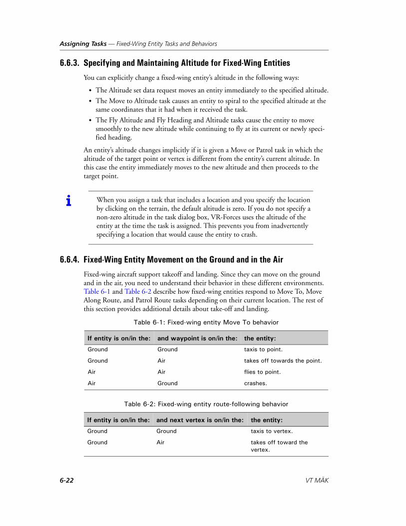
Assigning Tasks — Fixed-Wing Entity Tasks and Behaviors
6.6.3. Specifying and Maintaining Altitude for Fixed-Wing Entities
You can explicitly change a fixed-wing entity’s altitude in the following ways:
The Altitude set data request moves an entity immediately to the specified altitude.
The Move to Altitude task causes an entity to spiral to the specified altitude at the same coordinates that it had when it received the task.
The Fly Altitude and Fly Heading and Altitude tasks cause the entity to move smoothly to the new altitude while continuing to fly at its current or newly speci-fied heading.
An entity’s altitude changes implicitly if it is given a Move or Patrol task in which the altitude of the target point or vertex is different from the entity’s current altitude. In this case the entity immediately moves to the new altitude and then proceeds to the target point.
6.6.4. Fixed-Wing Entity Movement on the Ground and in the Air
Fixed-wing aircraft support takeoff and landing. Since they can move on the ground and in the air, you need to understand their behavior in these different environments. Table 6-1 and Table 6-2 describe how fixed-wing entities respond to Move To, Move Along Route, and Patrol Route tasks depending on their current location. The rest of this section provides additional details about take-off and landing.
i When you assign a task that includes a location and you specify the location by clicking on the terrain, the default altitude is zero. If you do not specify a non-zero altitude in the task dialog box, VR-Forces uses the altitude of the entity at the time the task is assigned. This prevents you from inadvertently specifying a location that would cause the entity to crash.
Table 6-1: Fixed-wing entity Move To behavior
If entity is on/in the: and waypoint is on/in the: the entity:
Ground Ground taxis to point.
Ground Air takes off towards the point.
Air Air flies to point.
Air Ground crashes.
Table 6-2: Fixed-wing entity route-following behavior
If entity is on/in the: and next vertex is on/in the: the entity:
Ground Ground taxis to vertex.
Ground Air takes off toward the vertex.
6-22 VT MÄK

Assigning Tasks — Fixed-Wing Entity Tasks and Behaviors
Fixed-wing entities do not support terrain-following. Therefore, when you task a fixed-wing entity to move to a point or follow a route, you must be certain that there are no points in the terrain that are higher than the altitude of the entity’s flight path, or the entity will crash. For example, if you assign a fixed-wing entity to follow a route whose vertices are set at 3000 meters above sea level, if the terrain rises above 3000 meters at some point in between two vertices of the route, the entity will crash into the terrain at that point (Figure 6-8). You can view the terrain profile of the route to check for inter-sections with the terrain. (For details, please see Section 13.1.1, “Displaying a Line’s Terrain Profile,” in VR-Forces Users Guide.)
Figure 6-8. Fixed-wing route following
Air Air flies to the vertex.
Air Ground tries to land at the vertex.
Table 6-2: Fixed-wing entity route-following behavior
If entity is on/in the: and next vertex is on/in the: the entity:
Route
Trajectory
VR-Forces Scenario Management Guide 6-23

Assigning Tasks — Fixed-Wing Entity Tasks and Behaviors
Fixed-Wing Movement Between Vertices
If two vertices in a route are not at the same altitude, a fixed-wing entity does not fly from the first vertex to the second in a smooth gradient. As soon as it passes the first vertex, it immediately descends to the altitude of the next vertex and then continues to fly towards it at that altitude. Therefore, it is possible that you could create a route that does not intersect the terrain, but an entity flying along that route could crash because a location in the terrain exceeds the altitude of a destination point, as illustrated in (Figure 6-9).
Figure 6-9. Fixed-wing trajectory between vertices
i If you want a plane to change altitude using a smooth gradient, use one of the Fly Altitude tasks. However, these tasks do not let you follow a route.
Intended
Terrain profile
Route
Flight path
6-24 VT MÄK

Assigning Tasks — Fixed-Wing Entity Tasks and Behaviors
6.6.5. How Fixed-Wing Entities Take Off
You can have fixed-wing aircraft take off using the Fixed Wing Takeoff task (for details, please see “Fixed Wing Takeoff,” on page 7-22) or by using innate behavior. This section describes take-off using innate behavior.
Fixed-wing entities take off by moving to a waypoint that is above ground level or by following a route that has a vertex above ground level.
When you task a fixed-wing entity to move to a waypoint that is above ground level, the entity orients itself directly towards that point and accelerates in the direction of the point. When it reaches its minimum lift speed, it takes off and rises to the altitude of the point it is moving to. You can control the distance required to take off by setting the max-thrust parameter.
When a fixed-wing entity takes off, it does not take into account the soil type or terrain, except that if the slope of the terrain along which the entity must move to take off is greater than the max-slope parameter, the entity halts.
Fixed-wing entities do not know anything about runways that may be part of a terrain database. When you create a waypoint towards which an entity will take off, or create a route along which an entity will take off, you are responsible for ensuring that the entity is properly oriented towards the runway.
If an entity takes off as part of route following, you can define a runway with two points on the ground. If an entity detects that the point in the route after the one it is moving towards is in the air, it uses the current point as the take-off direction, but takes off as soon as possible and flies to the point in the air. Figure 6-10 illustrates this behavior.
Figure 6-10. Defining a runway for take-off
Heading during take-off
Heading after take-off
Take-off point
Vertex determines take-off heading (Z= 0 m) Z=1000 m
VR-Forces Scenario Management Guide 6-25

Assigning Tasks — Fixed-Wing Entity Tasks and Behaviors
6.6.6. How Fixed-Wing Entities Land
You can have aircraft land using the Fixed Wing Land task (please see “Fixed-Wing Land,” on page 7-21), or as described in this section. The underlying behavior of the Fixed Wing Land task is the same as in this section. Using the Fixed Wing Land task automates the process of setting up the approach route.
A fixed-wing entity can land only in the context of following or patrolling a route. When a fixed-wing entity follows a route and determines that the next vertex in the route is on the ground, it decelerates as it reduces altitude towards that vertex. If it does not have enough distance from the previous vertex to decelerate sufficiently, it may crash. To ensure adequate deceleration, you may want to create a trigger that sets the entity’s speed when it approaches the runway.
To orient an entity for landing, you may have to create several vertices prior to the runway to get the entity properly lined up. Figure 6-10 shows two different routes ending at an airport (the routes have been edited to improve visibility). The first route has vertices that line up the entity with the runway. The second route curves in towards the runway, so the entity does not approach the runway in a straight line. Therefore, as it reaches the landing point, it is not lined up with the runway and it lands on the taxiway.
i Any time an entity is within 10 meters of the terrain and it is moving within 10 percent of its minimum lift speed, it will try to land.
6-26 VT MÄK

Assigning Tasks — Rotary-Wing Entity Tasks and Behaviors
Figure 6-11. Landing fixed-wing entities
6.7. Rotary-Wing Entity Tasks and BehaviorsThis section describes the behaviors of rotary-wing entities supplied with VR-Forces and the issues you should keep in mind when assigning tasks and set data requests.
Rotary-wing entities get created on the ground unless you specify an altitude at creation. (For details about specifying an altitude when you create an air platform, please see “Specifying an Object’s Altitude,” on page 2-12.)
If a rotary-wing entity is airborne and it is not assigned a task, it hovers at the specified location and altitude. When it completes a task, it hovers in the location where it completed the task.
Entity lands to left of runway
Entity lands on runway
VR-Forces Scenario Management Guide 6-27

Assigning Tasks — Rotary-Wing Entity Tasks and Behaviors
The terrain-check parameter determines how a rotary-wing entity interacts with the terrain. If terrain-check is False, a rotary-wing entity ignores the terrain. It could appear to fly below ground. However, when terrain-check is set to False, VR-Forces does not have to check ground points, so performance may improve.
When terrain-check is True, rotary-wing entities interact with the terrain. If a rotary-wing entity approaches a ground point at three meters per second or less, it lands. If it approaches the ground at a greater speed, it crashes.
Helicopters have a basic terrain avoidance algorithm that helps prevent crashing if they are sent to waypoints or follow routes that do not have an altitude. The terrain avoid-ance logic maintains a distance above the ground; it does not look ahead. So, a heli-copter could crash if the terrain rises suddenly (Figure 6-12). You can view the terrain profile of the route to check for intersections with the terrain. (For details, please see Section 13.1.1, “Displaying a Line’s Terrain Profile,” in VR-Forces Users Guide.)
Figure 6-12. Helicopter terrain avoidance
i When you assign a task that includes a location and you specify the location by clicking on the terrain, the default altitude is zero. If you do not specify a non-zero altitude in the task dialog box, VR-Forces uses the altitude of the entity at the time the task is assigned. This prevents you from inadvertently specifying a location that would cause the entity to crash.
6-28 VT MÄK

Assigning Tasks — Rotary-Wing Entity Tasks and Behaviors
6.7.1. Controlling Rotary-Wing Orientation
A rotary-wing entity can move laterally (sideways) without changing its orientation. In other words, it does not have to face in the direction it is moving. Rotary-wing entity movement controllers have two parameters that configure the speed at which a rotary-wing entity can move laterally. Rotary-wing entities rotate to try to align themselves with their velocity vector under the following circumstances:
If the current speed is greater than the speed specified by vel-to-align-actual. If the speed of the entity is not greater than vel-to-align-actual, but the desired speed
of the entity (the velocity it is attempting to achieve as a result of position or velocity commands) is greater than vel-to-align-desired.
If you do not want a rotary-wing entity to align itself with its direction of travel, set vel-to-align-actual and vel-to-align-desired to speeds that are greater than the speed at which you expect the entity to travel. You can set these parameters in the OPD Editor.
VR-Forces Scenario Management Guide 6-29

Assigning Tasks — Rotary-Wing Entity Tasks and Behaviors
6-30 VT MÄK

VR-Forces Scenario Management Guide
7
Task Procedures
This chapter describes the tasks supplied with VR-Forces.
Task Procedures ............................................................................................ 7-4
Animated Movement .................................................................................... 7-4
Arm Mine at Depth ...................................................................................... 7-5
Come to Stop................................................................................................ 7-5
Convoy Along............................................................................................... 7-6
Convoy To .................................................................................................... 7-7
Deploy Sonobuoy ......................................................................................... 7-7
Deploy Sonobuoys Along Route ................................................................... 7-8
Disembark .................................................................................................... 7-9
Disembark All............................................................................................... 7-9
DI-Guy Animation ..................................................................................... 7-10
Drop Naval Depth Charge.......................................................................... 7-11
Drop Naval Depth Charge at Location ....................................................... 7-11
Drop Naval Mine........................................................................................ 7-12
Drop Naval Mines Along Route.................................................................. 7-13
Embark ....................................................................................................... 7-14
Execute Close Air Support .......................................................................... 7-16
Explode Charge at Depth............................................................................ 7-18
Fire at Target............................................................................................... 7-18
Fire Cruise Missile ...................................................................................... 7-19
Fire for Effect Tasks..................................................................................... 7-20Firing Naval Guns ................................................................................ 7-21
7-1

Task Procedures
Fixed-Wing Land........................................................................................ 7-21
Fixed Wing Takeoff .................................................................................... 7-22
Fly Altitude................................................................................................. 7-22
Fly Heading ................................................................................................ 7-23
Fly Heading and Altitude............................................................................ 7-24
Follow Entity .............................................................................................. 7-25How Fixed-Wing Entities Follow Entities ............................................ 7-25
Intercept and Destroy ................................................................................. 7-26
Lase Target.................................................................................................. 7-26
Launch Anti-Submarine Missile (Vertical) .................................................. 7-27
Launch Counter Measures .......................................................................... 7-27
Launch Smoke ............................................................................................ 7-28
LaunchTorpedo .......................................................................................... 7-28Anti-ship (Fixed Depth) ....................................................................... 7-29Anti-Submarine.................................................................................... 7-29
Lower Periscope .......................................................................................... 7-30
Move Along Route...................................................................................... 7-30
Move Into Formation ................................................................................. 7-31
Move To Altitude........................................................................................ 7-32
Move To Depth .......................................................................................... 7-32
Move To Location (Direct) ......................................................................... 7-33Adding Multiple Move To Location (Direct) Tasks to a Plan................ 7-34
Move To Location (On Roads) ................................................................... 7-34
Move to Location (Plan Path) ..................................................................... 7-35Move to Location (Plan Path) for Ground Vehicles .............................. 7-35Move to Location (Plan Path) for Ships................................................ 7-36
Move To Waypoint (Direct)........................................................................ 7-37
Move To Waypoint (On Roads).................................................................. 7-38
Move to Waypoint (Plan Path).................................................................... 7-39Move to Waypoint (Plan Path) for Ground Vehicles ............................. 7-39Move to Waypoint (Plan Path) for Ships .............................................. 7-40
Sweep Naval Mines..................................................................................... 7-49
Orbit .......................................................................................................... 7-41
Patrol Along Route ..................................................................................... 7-41
Patrol Between............................................................................................ 7-42
Pattern Hold (Location).............................................................................. 7-42
7-2 VT MÄK

Task Procedures
Pattern Hold (Waypoint) ............................................................................ 7-43
Place IED ................................................................................................... 7-43
Raise Periscope............................................................................................ 7-45
Release Bomb Tasks .................................................................................... 7-45
Rotary-Wing Land...................................................................................... 7-46
Sail Heading ............................................................................................... 7-46
Send Radio Set............................................................................................ 7-47
Send Radio Task ......................................................................................... 7-48
Send Text Message ...................................................................................... 7-48
Sonar Dip ................................................................................................... 7-49
Turn To Heading ........................................................................................ 7-50
User Task .................................................................................................... 7-50
Wait Tasks................................................................................................... 7-51Wait ..................................................................................................... 7-51Wait Duration ...................................................................................... 7-51Wait Elapsed ........................................................................................ 7-51
VR-Forces Scenario Management Guide -3Draft - Subject to Change

Task Procedures — Task Procedures
7.1. Task ProceduresThis chapter describes the procedures for the tasks supplied with VR-Forces. If your installation uses the VR-Forces API to add additional tasks, consult with your software engineers for local procedural information. Please see “Fixed-Wing Entity Tasks and Behaviors,” on page 6-21 and “Rotary-Wing Entity Tasks and Behaviors,” on page 6-27, for additional information about assigning tasks to these entity types.
The instructions for creating tasks direct you to use options on the Task menu. However, all the options available on the main menu are also available on context-sensi-tive menus. A limited number of tasks are available on the Tasks Toolbar.
7.2. Animated MovementThe Animated Movement task lets you assign a scripted behavior to an entity. This task is a generalized version of firing ballistic missiles, which is described in “Ballistic Missiles,” on page 11-8. To use this task, you must first create a file that describes the movements that you want an entity to make. Animated movement files can be in comma-separated vlaues (CSV) format or 3DS ASCII Export (ASE) format. You configure animated movement tasks in the Entity Editor. For details, please see Section 5.9.2, “Configuring Animated Movement,” in VR-Forces Configuration Guide.
To assign an animated movement task:
1. Select the entity to task.
2. Choose Task Movement Animated Movement. The Animated Movement dialog box opens (Figure 7-1).
Figure 7-1. Animated Movement dialog box
3. Optionally, filter the animation list by selecting a category in the Category list.
4. Select an animation in the Animation list. You are responsible for knowing that the animation is appropriate to the entity you selected.
5. Optionally, specify a time scale. By changing the time scale you can make the animation run faster or slower than specified in the animation file.
7-4 VT MÄK

Task Procedures — Arm Mine at Depth
7.3. Arm Mine at DepthIf a naval mine has been deployed, Arm Mine at Depth lets you change the mine’s parameters.
Arm Mine at Depth is a system scripted task. It is disabled by default.
To arm a mine:
1. Select the mine.
2. Choose Task Arm Mine at Depth. The Arm Mine at Depth dialog box opens.
3. Specify the depth at which to arm the mine.
4. Specify the radius within which target entities will detonate the mine.
5. Optionally, specify a time when the mine will be armed, in days and hours:minutes:seconds.
6. In the Targets list, add the types of entities that can trigger the mine, as follows:
a. Click the Add button ( ). The Entity Type dialog box opens.
b. Build an entity type by selecting options from the lists for each enumeration component or type an enumeration.
c. Click OK.
7. To specify that only hostile entities will set off the mine, select Hostile Only. If this setting is cleared, any entity will set off the mine.
8. Click OK.
7.4. Come to StopThe Come to Stop task stops a surface entity using a normal stop, an emergency stop, or a slow drift.
To assign a Come to Stop task:
1. Select the entity.
2. Choose Task Movement Come to Stop. The Come to Stop dialog box opens.
3. Select an option for how to stop.
4. Click OK.
VR-Forces Scenario Management Guide 7-5

Task Procedures — Convoy Along
7.5. Convoy AlongThe Convoy Along task commands an aggregate to move along a route in a convoy. When the task starts, the lead entity moves far enough along the route for the rest of the aggregate to create a column that ends approximately at the beginning of the route. Then the aggregate begins moving along the route.
For more details about convoys, please see “Convoy Tasks,” on page 6-9.
To assign a Convoy Along task:
1. Select the aggregate that you want to send in a convoy.
2. Choose Task Movement Convoy Along. The Convoy Along dialog box opens.
3. Specify the route to convoy along.
4. Click OK.
i The Convoy Along task is valid only for ground-vehicle aggregates.
7-6 VT MÄK

Task Procedures — Convoy To
7.6. Convoy ToThe Convoy To task commands an aggregate to move to a waypoint in a convoy. If you specify use of roads, VR-Forces uses the information in the road network to plan the convoy’s movement. If you do not specify use of roads, the convoy moves directly across the terrain as an individual entity would move in a Move To task.
For more details about convoys, please see “Convoy Tasks,” on page 6-9.
To assign a Convoy To task:
1. Select the aggregate that you want to send in a convoy.
2. Choose Task Movement Convoy To. The Convoy To dialog box opens.
3. Specify the waypoint to convoy to.
4. Click OK.
7.7. Deploy SonobuoyThe Deploy Sonobuoy task lets an aircraft deploy a sonobuoy for taking sonar readings. A sonobuoy is deployed as an entity. This task is available to entities that have a Sonobuoy Deployer system configured. Deploy Sonobuoy is a system scripted task.
To deploy a sonobuoy:
1. Select the entity.
2. Choose Task Deploy Sonobuoy. The Deploy Sonobuoy dialog box opens.
3. Select the type of sonar to use – Active or Passive.
4. Specify the depth at which to deploy the sonobuoy.
5. Click OK.
i The Convoy To task is valid only for ground-vehicle aggregates.
! When you specify use of roads, VR-Forces looks for roads over a fairly wide area and if one is found, will try to use them even if this results in an indirect approach to the waypoint. If there are no roads close to the route you would expect the aggregate to take to reach the waypoint, do not select his option.
i RPR FOM 1.0 does not support active sonar. You will not be able to create sonobuoys if they have an active sonar system.
VR-Forces Scenario Management Guide 7-7

Task Procedures — Deploy Sonobuoys Along Route
7.8. Deploy Sonobuoys Along RouteThe Deploy Sonobuoys Along Route task lets an aircraft deploy sonobuoys for taking sonar readings. A sonobuoy is deployed as an entity. This task is available to entities that have a Sonobuoy Deployer system configured. Deploy Sonobuoys Along Route is a system scripted task.
To deploy sonobuoys along a route:
1. Select the entity.
2. Choose Task Deploy Sonobuoys Along Route. The Deploy Sonobuoys Along Route dialog box opens.
3. Select the route to use.
4. Specify the distance between each sonobuoy.
5. Select the type of sonar to use – Active or Passive.
6. Specify the depth at which to deploy the sonobuoys.
7. Click OK.
i RPR FOM 1.0 does not support active sonar. You will not be able to create sonobuoys if they have an active sonar system.
7-8 VT MÄK

Task Procedures — Disembark
7.9. DisembarkThe Disembark task causes an entity to move to the parent entity’s egress (exit) point and disembark. If the selected entity is an aggregate (disaggregated), the disembark task is given to all embarked subordinates. The task is considered complete when all subor-dinates are disembarked. To disembark entities immediately, that is, without using a task, please see “Embarking and Disembarking Entities,” on page 3-5.
To disembark an entity:
1. Select the entity you want to disembark.
2. Choose Task Embarkation Disembark, or click the Disembark button ( ) on the Tasks toolbar.
7.10. Disembark AllThe Disembark All task is given to a parent entity. It gives a Disembark task to all embarked entities except aggregates. When you issue a Disembark All task, VR-Forces tries to disembark the entities sequentially and have them move to sufficiently dispersed locations to avoid collision problems.
To disembark all entities from a parent entity:
1. Select the parent entity.
2. Choose Task Embarkation Disembark All.
i When an entity disembarks, it simply goes to the disembarkation location. If you plan to disembark several entities from the same parent by giving them disembark tasks, you are responsible for making sure that each entity moves from the disembarkation point before the next entity disembarks.
Aggregate entities in the aggregated state cannot embark or disembark. If a disaggregated entity is embarked, you cannot aggregate it either manually, or as a result of automated aggregation conditions.
VR-Forces Scenario Management Guide 7-9

Task Procedures — DI-Guy Animation
7.11. DI-Guy AnimationVR-Forces can specify the movements and appearance of DI-Guy models used in the Stealth observer mode and in 3D visualization programs such as VR-Vantage Stealth. The DI-Guy Animation task directs the 3D model to engage in a one-time or repeated series of motions. VR-Forces does not simulate the actions that the 3D model performs; it just adjusts the location and orientation of the VR-Forces entity to synchronize it with the 3D model’s animated behavior. To change a 3D model’s appearance, use the DI-Guy Appearance set data request. For details, please see “DI-Guy Appearance,” on page 8-10.
To specify a DI-Guy animation:
1. Select the lifeform entity whose behavior you want to animate.
2. Choose Task DI-Guy DI-Guy Animation. The DI-Guy Animation dialog box opens (Figure 7-2).
Figure 7-2. DI-Guy Task Animation dialog box
3. In the Animation list, select an animation. The names of animation options do not always clearly describe the animation. The Description is a friendlier description of what the animation is.
4. In the Animate group box, specify the duration of the animation.
5. Click OK.
i The DI-Guy Animation task applies only to lifeform entities.
i You can edit the animation description. Descriptions are in ./appData/settings/vrfSim/character_animations_table.mtl.
7-10 VT MÄK

Task Procedures — Drop Naval Depth Charge
7.12. Drop Naval Depth ChargeThe Drop Naval Depth Charge task drops a depth charge at the current location of the entity. To execute this task, an entity must have a Naval Depth Charge Deployment weapons system. Drop Naval Depth Charge is a system scripted task.
To drop a naval depth charge:
1. Select the entity.
2. Choose Task Engagement Drop Naval Depth Charge. The Drop Naval Depth Charge dialog box opens.
3. In the Naval Depth Charge list, select the type of depth charge to drop.
4. Specify the depth at which you want the depth charge to explode.
5. Click OK.
7.13. Drop Naval Depth Charge at LocationThe Drop Naval Depth Charge at Location task drops a depth charge at a specified location. To execute this task, an entity must have a Naval Depth Charge Deployment weapons system. Drop Naval Depth Charge at Location is a system scripted task.
To drop a naval depth charge at a location:
1. Select the entity.
2. Choose Task Engagement Drop Naval Depth Charge at Location. The Drop Naval Depth Charge At Location dialog box opens.
3. In the Naval Depth Charge list, select the type of depth charge to drop.
4. Specify the depth at which you want the depth charge to explode.
5. Specify the location where you want to drop the depth charge.
By default, this task uses the altitude of the entity at the time the task is assigned as the altitude for the drop location. (Use Current Altitude check box.) If you specify an altitude and the check box is selected, VR-Forces ignores the altitude you entered and uses the current entity altitude. If you want to specify the altitude, clear the check box and make sure that you specify the altitude in the Altitude group box. If you click on the terrain to specify the X, Y location, the altitude gets set to 0, so be sure to enter the altitude you want after clicking on the terrain.
6. Click OK.
i In this task, the location is the location of the entity when it drops the depth charge. Since the entity is flying, the location must include a reasonable altitude.
VR-Forces Scenario Management Guide 7-11

Task Procedures — Drop Naval Mine
7.14. Drop Naval MineThe Drop Naval Mine task allows entities with a Naval Mine Deployment system to drop naval (underwater) mines at their current location. Drop Naval Mine is a system scripted task.
To drop a naval mine:
1. Select the entity.
2. Choose Task Engagement Drop Naval Mine. The Drop Naval Mine dialog box opens.
3. In the Naval Mine list, select the type of mine to drop.
4. In the Mine Depth field, set the depth to drop the mine. Positive numbers are below sea level.
5. In the Arming Delay fields, set the time to elapse before the mine becomes armed. The first field is days. The second field is Hours:Minutes:Seconds.
6. In the Detonate Proximity field, set the distance from the mine within which a target entity will detonate the mine.
7. In the Trigger Entity Types list, add the types of entities that can trigger the mine, as follows:
a. Click the Add button ( ). The Entity Type dialog box opens.
b. Build an entity type by selecting options from the lists for each enumeration component or type an enumeration.
c. Click OK.
8. To specify that only hostile entities will set of the mine, select Hostile Only. If this setting is cleared, any entity will set off the mine.
9. Click OK.
7-12 VT MÄK
Task Procedures — Drop Naval Mines Along Route
7.15. Drop Naval Mines Along RouteThe Drop Naval Mines Along Route task allows entities with a Naval Mine Deploy-ment system to drop naval (underwater) mines while they travel along a route. Drop Naval Mines Along Route is a system scripted task.
To drop naval mines along a route:
1. Select the entity.
2. Choose Task Engagement Drop Naval Mine. The Drop Naval Mines Along Route dialog box opens.
3. Select the route to follow.
4. In the Mine Spacing field, specify the distance between each mine.
5. In the Naval Mine list, select the type of mine to drop.
6. In the Mine Depth field, set the depth to drop the mine. Positive numbers are below sea level.
7. In the Arming Delay fields, set the time to elapse before the mine becomes armed. The first field is days. The second field is Hours:Minutes:Seconds.
8. In the Detonate Proximity field, set the distance from the mine within which a target entity will detonate the mine.
9. In the Trigger Entity Types list, add the types of entities that can trigger the mine, as follows:
a. Click the Add button ( ). The Entity Type dialog box opens.
b. Build an entity type by selecting options from the lists for each enumeration component or type an enumeration.
c. Click OK.
10. To specify that only hostile entities will set of the mine, select Hostile Only. If this setting is cleared, any entity will set off the mine.
11. Click OK.
VR-Forces Scenario Management Guide 7-13

Task Procedures — Embark
7.16. EmbarkThe Embark task causes an entity to move to the ingress (entry) point of the parent entity and embark on it. If the embarking entity is an aggregate, each available taskable subordinate is given an embark task. When all subordinates have embarked, the aggre-gate task is considered complete.
The Embark task is valid only if the specified parent entity is configured to accept the entity that wants to embark on it. If you task an entity to embark on an entity that is not configured to receive it, for example, you task a DI to embark on an M1A2, the entity will not respond to the task. If you want to embark an entity on an entity that is not configured to receive it, you can use the immediate embarkation process. For details, please see “Embarking and Disembarking Entities,” on page 3-5.
Table 7-1 lists the entities that support embarkation and the number and type of embarked entities they can hold. High fidelity entities (HF column) have polygonal models of the entity and embarkation slots defined in such a way that the embarking entities can smoothly embark on the host entity when viewed in the 3D view or VR-Vantage.
i Aggregate entities in the aggregated state cannot embark or disembark.
Table 7-1: Embarkation support
Entity Can Carry HF
M2A2 Bradley IFV 6 DI
M113 Armored Utility Vehicle 11 DI
M-939A2 5-Ton Truck 14 DI x
MT-LB Multipurpose Armored Vehicle 11 DI
BTR-80 Armored Personnel Carrier 11 DI
BMP-2 AVF 7 DI
C-130 Hercules 92 DI or 3 ground vehicles
CH-46E Sea Knight 11 DI
CH-53E Super Stallion 55 DI
UH-60 Blackhawk 11 DI
OH-58 Kiowa 6 DI
Mi-2 Hoplite 11 DI
LCAC Landing Craft Air Cushion 12 HMMWVs or 4 trucks or 1 M1A2 or 1 generic ground vehicle
x
LSD-49 Harpers Ferry 2 LCACs and 2 helicopters x
7-14 VT MÄK

Task Procedures — Embark
The aircraft carrier can carry both fixed-wing and rotary-wing aircraft. After the deck positions are used, additional entities embarked are stored below deck, as in a low-fidelity model.
To embark an entity:
1. Select the entity.
2. Choose Task Embarkation Embark, or click the Embark button ( ) on the Tasks toolbar. The Embark On dialog box opens.
3. Select the parent entity (the entity to embark on) or type its name in the Name box.
4. Click OK.
Guided Missile Destroyer 2 helicopters
Aircraft Carrier 12 fighters or 9 fighters and 2 cargo planes. Three helicopters. 70 planes below deck.
x
! If you are using HLA and want to use the embarkation feature, you must use RPR FOM 2, draft 17. VR-Forces includes entries on the Simulation Connections Configuration dialog box that start VR-Forces using the correct FED file and FOM Mapper for RPR FOM 1.0, and RPR FOM 2, draft 17.
If the embarkation spaces on the parent entity are full, VR-Forces sends a message to the back-end console and the entity does not try to embark.
If you give multiple entities embark tasks for the same parent, you are responsible for spreading the tasks over time so that the entities do not all converge on the parent at the same time, which would result in problems due to collision avoidance.
i Unlike the Embark On dialog box that opens when you choose Entities Embark, the Embark On dialog box for the Embark task does not allow you to choose the embarkation point.
Table 7-1: Embarkation support
Entity Can Carry HF
VR-Forces Scenario Management Guide 7-15

Task Procedures — Execute Close Air Support
7.17. Execute Close Air SupportThe Execute Close Air Support task assigns a fixed-wing fighter or bomber a close air support (CAS) task based on a 9-Line Briefing. The entity being tasked must be in the air to execute this task. This is a system scripted task.
To execute close air support:
1. Select the entity you want to fire.
2. Choose Task Engagement Execute Close Air Support. The Execute Close Air Support dialog box opens (Figure 7-3).
3. In the Initial Point section, specify the location from which the aircraft should line up with the target by entering location values or clicking on the terrain.
4. In the Heading box, specify the approach heading. Optionally, specify an offset if you want the entity to favor a particular side of the line of approach.
5. In the Distance box, specify the distance from the initial point to the target. This information is not used by the task.
6. Select the target. Target selection satisfies lines 4, 5, and 6 of a 9-Line briefing, because it provides the location, altitude, and name of the target.
7. In the Mark Type box, specify how the target is marked. This information is not used by the task.
i A 9-Line Briefing is a format used by U.S. armed forces to call in CAS. The Execute Close Air Support dialog box explicitly or implicitly requests all of the information in a 9-Line Briefing. However, the scripted task does not use all of this information to simulate CAS. (The procedure notes which fields are not used.) The task has parameters for all 9 lines to provide simulation authenticity. Since this is a scripted task, you could modify it to use all of the parameters.
7-16 VT MÄK

Task Procedures — Execute Close Air Support
Figure 7-3. Execute Close Air Support dialog box
8. If you are using a laser designator to mark the target, enter the laser code. (If you specify a laser code, an entity in the simulation must be lasing the target for the CAS to work.)
9. In the Friendlies box, specify the distance and direction of friendly forces from the target. This information is not used by the task.
10. In the Egress Heading box, specify the heading by which the attacking entity should leave after parting the target. It will continue on this heading until it is given another task.
11. In the Ordnance list, select the type of bomb to drop.
12. Click OK.
VR-Forces Scenario Management Guide 7-17

Task Procedures — Explode Charge at Depth
7.18. Explode Charge at DepthThe Explode Charge at Depth task explodes a depth charge at the specified depth. You can use this task to explode a depth charge that has been deployed, but has not yet exploded.
Explode Charge at Depth is a system scripted task. It is disabled by default.
To explode a depth charge:
1. Select the depth charge.
2. Choose Task Explode Charge at Depth. The Explode Charge at Depth dialog box opens.
3. Specify the depth.
4. Click OK.
7.19. Fire at TargetThe Fire at Target task commands an entity to fire at a specific target. You can specify which weapon system to use and how many rounds to fire.
To order an entity to fire at a target:
1. Select the entity you want to fire.
2. Choose Task Engagement Fire at Target. The Fire at Target dialog box opens.
3. Select the target entity.
4. In the Weapon Selection group box, select an option as follows:
– To let VR-Forces choose the weapon, select Automatic.
– To choose the weapon yourself, select Manual and select a weapon from the list.
5. In the Maximum Rounds to Fire box, enter the number of rounds you want the entity to fire. (The entity will stop firing when the target is destroyed or when the maximum number of rounds has been fired, whichever comes first.)
7-18 VT MÄK

Task Procedures — Fire Cruise Missile
7.20. Fire Cruise MissileA cruise missile can fly directly to a target or follow a route.
To fire a cruise missile:
1. Select an entity that has cruise missile resources.
2. Choose Task Engagement Fire Cruise Missile. The Fire Cruise Missile dialog box opens (Figure 7-4).
Figure 7-4. Fire Cruise Missile dialog box
3. Select the target from the list or on the terrain, or type its name in the Name box. Targets can be entities or points.
4. Select a route for the missile to follow or select the No Route check box. If no route is selected, the missile flies directly to the target.
5. Specify the ordered speed for the missile.
6. Specify the detonation proximity for the warhead. It will detonate within this range of the selected target.
7. Click OK.
VR-Forces Scenario Management Guide 7-19

Task Procedures — Fire for Effect Tasks
7.21. Fire for Effect TasksYou can task artillery entities and surface vessels that have naval guns to fire for effect. The three options are:
Fire-for-Effect on Entity.
Fire-for-Effect on Location, where location is a point on the terrain.
Fire-for-Effect on Target, where a target is a waypoint.
If an entity has more than one weapon, you can select multiple weapons to fire. However, they will all fire on the same target. You cannot target them independently.
To assign a Fire-for-Effect task:
1. Select the entity to which you want to assign the task. (It must be an artillery entity.)
2. Choose Task Engagement Fire-for-Effect on Entity (or Location or Target). The appropriate dialog box opens.
3. Identify the target as follows:
– For FFE Entity, select the target entity in the list, select it on the terrain, or type its name in the Name box.
– For FFE Location, click a location on the terrain, or enter the coordinates.
– For FFE Target, select a point from the list, or select it on the terrain.4.
5. In the Select Weapons list, select the weapons that you want to fire.
6. Specify the number of rounds.
7. Optionally, specify the height above the terrain at which rounds should detonate.
8. Click OK.
i For FFE Entity and FFE Target, you can filter the target list.
i The Fire-for-Effect tasks are only meaningful when assigned to artillery entities or surface vessels that have naval guns.
When you choose Fire-for-Effect on Entity, VR-Forces notes the location of the entity and fires at that spot. If the targeted entity moves, the artillery does not change the location at which it is firing.
Artillery entities have maximum and minimum ranges. To see these ranges, enable range rings for the entity. (For details, please see Section 7.8, “Displaying Entity Range (Threat) Rings,” in VR-Forces Users Guide.) The back-end console window prints messages when you select targets that are outside of the entity’s range.
7-20 VT MÄK

Task Procedures — Fixed-Wing Land
7.21.1. Firing Naval Guns
Ordinarily, naval guns fire their munitions in a parabola, similar to artillery. However, they can also fire directly at a target if the following conditions are true:
The target’s range is greater than the weapon’s minimum range, but less than the first value in its range list.
The capable-of-direct-alignment parameter for the weapon system’s naval-gun-controller is set to True.
The firing entity has line-of-sight to the target.
7.22. Fixed-Wing Land“How Fixed-Wing Entities Take Off,” on page 6-25, describes how fixed-wing entities land and the steps to design a landing approach. The Fixed Wing Land task automates the process of landing a fixed-wing aircraft. However, you must still specify a route to serve as the runway. Fixed-Wing Land is a system scripted task.
When the task is invoked, VR-Forces defines an approach route for the plane to move along. The length of this route is either the plane’s altitude or the length needed to slow the plane down to landing speed, whichever is greater. The route is created and the plane moves along the route, coming to landing speed. At the end of the approach route, the plane is tasked to move along the runway.
To land a fixed-wing aircraft:
1. Select the entity.
2. Choose Task Movement Fixed Wing Land. The Fixed Wing Land dialog box opens.
3. In the Name box, type the name of the route you want it to land on, or select the route in the list or on the terrain.
4. Click OK.
! Although it is possible to land an entity on another entity, such as an aircraft carrier, if you want to embark an entity, you must use the Embark task, not a landing task.
VR-Forces Scenario Management Guide 7-21
Task Procedures — Fixed Wing Takeoff
7.23. Fixed Wing TakeoffYou can explicitly task a fixed-wing entity to take off. (For details about implicit take-off, please see “How Fixed-Wing Entities Take Off,” on page 6-25.) In a Fixed Wing Takeoff task, the entity moves along the specified route, reaches takeoff speed (30% of minimum lift), and then moves to a point defined by the controller some distance up and away from the end of the route. Fixed-Wing Takeoff is a system scripted task.
To assign a Fixed Wing Takeoff task:
1. Select the entity.
2. Choose Task Movement Fixed Wing Takeoff. The Fixed Wing Takeoff dialog box opens.
3. Select the route to take off on or type its name in the Name box.
4. Click OK.
7.24. Fly AltitudeThe Fly Altitude task commands a fixed-wing or rotary-wing entity to fly to the speci-fied altitude at a specified ascent or descent rate, using its current heading and ordered speed. When it reaches the altitude it continues to fly at that altitude at the current heading until it receives other commands. The entity will not exceed the limits for alti-tude or ascent/descent rate set in the OPD for the entity type.
You cannot use a Fly Altitude task to cause a fixed-wing entity to take off. A fixed-wing entity that is on the ground ignores this task.
If a rotary-wing entity is on the ground and is given this task, it rises to the specified altitude as it moves forward at its current heading. If a rotary-wing entity is in the air and is given this task with an altitude of zero, it descends to approximately 33 M and continues flying at that altitude at its current heading.
To assign a Fly Altitude task:
1. Select a fixed-wing or rotary-wing entity.
2. Choose Task Movement Fly Altitude. The Fly Altitude dialog box opens.
3. In the Altitude box, specify the altitude above sea level to fly to.
4. In the Climb/Descent Rate box, specify the rate.
5. Click OK.
7-22 VT MÄK

Task Procedures — Fly Heading
7.25. Fly HeadingThe Fly Heading task commands a fixed-wing or rotary-wing entity to turn to the spec-ified heading at the specified turn rate. It maintains its current altitude and speed. When it is finished turning to the new heading, it continues to fly at this heading until it receives other commands. The entity will not exceed the turn rate specified in the OPD.
A fixed-wing entity that is on the ground ignores this task.
If a rotary-wing entity is on the ground and is given this task, it rises to approximately 60 M and then drops down to approximately 33 M while simultaneously moving forward and turning to the specified heading. After turning to the new heading, it continues moving forward. Its altitude varies somewhat as it follows the terrain.
To assign a Fly Heading task:
1. Select a fixed-wing or rotary-wing entity.
2. Choose Task Movement Fly Heading. The Fly Heading dialog box opens.
3. In the Heading box, specify the heading to fly to.
4. In the Turn Rate box, specify the rate.
5. Click OK.
VR-Forces Scenario Management Guide 7-23

Task Procedures — Fly Heading and Altitude
7.26. Fly Heading and AltitudeThe Fly Heading and Altitude task commands a fixed-wing or rotary-wing entity to fly to a specified altitude, at a specified ascent or descent rate, while turning to a specified heading at a specified turn rate. If you do not specify a heading or altitude, the entity continues to use the current value for that parameter.
While executing this task, the entity maintains its current speed. When it completes the command, it continues to fly at the new altitude and heading until given other commands. The entity will not exceed the limits on altitude, turn rate, and ascent/descent rate set in the OPD.
You cannot use a Fly Heading and Altitude task to cause a fixed-wing entity to take off. A fixed-wing entity that is on the ground ignores this task.
If a rotary-wing entity is on the ground and is given this task, it takes off and moves forward while it rises to the specified altitude and turns to the specified heading. If a rotary-wing entity is in the air and is given this task with an altitude of zero, it moves forward and turns to the new heading while it descends to approximately 33 M and continues flying at that altitude on the new heading.
To assign a Fly Heading task:
1. Select a fixed-wing or rotary-wing entity.
2. Choose Task Movement Fly Heading and Altitude. The Fly Heading and Alti-tude dialog box opens.
3. In the Heading box, specify the heading to fly to.
4. In the Altitude box, specify the altitude above sea level to fly to.
5. In the Turn Rate box, specify the rate.
6. In the Climb/Descent Rate box, specify the rate.
7. Click OK.
7-24 VT MÄK

Task Procedures — Follow Entity
7.27. Follow EntityYou can order an entity to follow another entity. You can specify a distance and offset between the entities. If you tell two or more entities to follow the same entity, make sure that you do not give them the same offset (please see “Following Entities,” on page 9-34).
An entity continues to follow its target entity until:
The task is overridden.
The followed entity is destroyed.
If entity A is assigned to follow entity B, but it cannot find entity B, entity A continues to look for entity B until entity B becomes available, or until entity A is assigned another task.
The following entity tries to match the speed of the followed entity unless it has to hold back or catch up to accommodate changes in direction or terrain effects.
To order an entity to follow another entity:
1. Select the entity.
2. Choose Task Movement Follow Entity. The Follow Entity dialog box opens.
3. Optionally, filter the entity list.
4. In the Name box, type the name of the entity to follow, or select it from the list or on the terrain.
5. Optionally, type an offset in the Behind, Right, and Above text boxes. If you want an entity to follow in front, to the left, or below, put a minus sign (-) in front of the value.
6. Click OK.
7.27.1. How Fixed-Wing Entities Follow Entities
A fixed-wing entity can follow an entity that is on the ground, or might be on the ground, for example if it is following a fixed-wing entity that lands. To ensure that the follower does not crash, make sure that it is following above the followed entity and that the distance above is high enough to account for changes in the terrain.
VR-Forces Scenario Management Guide 7-25

Task Procedures — Intercept and Destroy
7.28. Intercept and DestroyThe Intercept and Destroy task tells an entity to move towards the target entity and engage it in any way that is appropriate.
To assign the Intercept and Destroy task:
1. Select the entity to which you want to assign the task.
2. Choose Task Engagement Intercept and Destroy. The Intercept and Destroy dialog box opens.
3. Select the entity that is to be the target of the assault.
4. Optionally, specify a standoff distance. The entity will not go closer to the target than this distance.
5. Click OK.
7.29. Lase TargetThe Lase Target task simulates aiming a laser beam at a target to guide a laser guided weapon. By default, entities with laser capability lase autonomously. Use this task if you want to lase a specific target. An entity can lase a target while it is executing a move-ment task.
To lase a target, an entity must have a Laser Designator system. By default, rotary-wing entities based on the generic attack helicopter platform and the DI Lasing entity can lase targets.
To lase a target:
1. Select the entity that will aim the laser.
2. Choose Task Engagement Lase Target. The Lase Target dialog box opens.
3. Select the entity that you want to lase.
4. Click OK.
i Intercept and Destroy turns off collision avoidance for the tasked entity. Its primary purpose is to allow entities such as car bombs and suicide bombers to approach a target entity and detonate its munition. If you give this task to an entity that does not have any offensive capability, such as a truck, it will ram the target. However, since VR-Forces does not model the effects of two entities colliding, there will be no damage to either entity and the tasked entity may end up circling the target. Therefore, you should be careful about which entities you assign this task to or the results may not be what you expect.
7-26 VT MÄK

Task Procedures — Launch Anti-Submarine Missile (Vertical)
7.30. Launch Anti-Submarine Missile (Vertical)The Launch Anti-Submarine Missile (Vertical) task lets a surface entity launch a missile that flies to the vicinity of the target and then drops a homing torpedo. To execute this task, an entity needs an Anti-Submarine Missile (Vertically Launched) weapon system. This is a system scripted task.
To launch an anti-submarine missile:
1. Select the surface entity.
2. Choose Task Engagement Launch Anti-Submarine Missile (Vertical). The Launch Anti-Submarine Missile (Vertical) dialog box opens.
3. Select the target entity.
4. Specify the location at which to drop the homing torpedo.
5. Click OK.
7.31. Launch Counter MeasuresFixed-wing and rotary-wing entities can launch counter measures, such as chaff and flares. Launch Counter Measures is not an exclusive task. It does not interrupt an entity’s current task. (For more information, please see “Launching Counter Measures (Chaff and Flare),” on page 10-17.)
To launch counter measures:
1. Select the entity that you want to launch counter measures.
2. Choose Task Engagement Launch Counter Measures. The Launch Counter Measures dialog box opens.
3. In the Counter Measure Types list, select the type of counter measures you want to launch.
4. In the Number To Fire box, specify the number of counter measures to launch.
5. In the Time Between Fires box, specify the amount of time, in seconds, between each counter measure launch.
6. Click OK.
VR-Forces Scenario Management Guide 7-27

Task Procedures — Launch Smoke
7.32. Launch SmokeThe Launch Smoke task causes an entity to create a smoke cloud. The cloud is created as an environmental object. It grows over time.
An entity can launch a smoke cloud towards a threat or in a specific direction. Smoke clouds affect sensors. They do not affect entity movement.
To launch a smoke cloud:
1. Select the entity that you want to launch smoke.
2. Choose Task Engagement Launch Smoke. The Launch Smoke dialog box opens.
3. Select At Nearest Threat or Toward Compass Heading.
4. If you selected Toward Compass Heading, specify a compass heading, in degrees.
5. Click OK.
7.33. LaunchTorpedoSubsurface entities can launch two types of anti-ship torpedoes. One moves at a fixed depth; one homes in on the center of the target. In both cases, the torpedo travels at an initial bearing for a fixed distance before it homes in on the target. The Launch Torpedo tasks are system scripted tasks.
i Tactical smoke is delivered by the M250 smoke grenade launcher. An entity must have this system to execute this task.
7-28 VT MÄK

Task Procedures — LaunchTorpedo
7.33.1. Anti-ship (Fixed Depth)
To launch a torpedo that moves at a fixed depth:
1. Select a subsurface entity.
2. Choose Task Engagment Launch Torpedo Anti-ship (Fixed Depth). The Anti-ship (Fixed Depth) dialog box opens.
3. Optionally, filter the entity list.
4. Select the target entity.
5. In the Homing Start Delay box, enter the amount of time that the torpedo should travel on its initial bearing.
6. In the Cruise Depth box, specify the depth the torpedo should travel at. It will remain at this depth.
7. In the Initial Bearing box, specify the bearing the torpedo should travel at until it begins homing in on the target.
8. In the Proximity Trigger Distance box, set the distance from a target at which the torpedo will detonate.
9. Click OK.
7.33.2. Anti-Submarine
The anti-submarine torpedo homes in on the center of the target.
To launch an anti-submarine torpedo:
1. Select a subsurface entity.
2. Choose Task Engagment Launch Torpedo Anti-submarine. The Anti-Submarine dialog box opens.
3. Optionally, filter the entity list.
4. Select the target entity.
5. In the Homing Start Delay box, enter the amount of time that the torpedo should travel on its initial bearing.
6. In the Initial Bearing box, specify the bearing the torpedo should travel at until it begins homing in on the target.
7. In the Proximity Trigger Distance box, set the distance from a target at which the torpedo will detonate.
8. Click OK.
VR-Forces Scenario Management Guide 7-29

Task Procedures — Lower Periscope
7.34. Lower PeriscopeThe Lower Periscope task lowers the periscope of a subsurface entity. The periscope is an articulated part that is visible in the Stealth view. Lower Periscope is a system scripted task.
To lower a submarine’s periscope:
1. Select the entity.
2. Choose Task Other Lower Periscope.
7.35. Move Along RouteBy default, an entity moves along a route from its nearest vertex to its end point.
To direct an entity to move along a route:
1. Select the entity.
2. Choose Task Movement Move Along Route, or click the Move Along Route button ( ) on the Tasks toolbar. The Move Along Route dialog box opens.
3. In the Name box, type the name of the route you want the entity to follow, or select a route in the list or on the terrain.
4. To have the entity move from the end of the route to the beginning, select Reverse Direction.
i If you edit a route while an entity is moving to the starting point of that route as part of a Move Along Route task, the entity will move to the nearest vertex, whether it is the starting point, or not.
If you want an entity to repeatedly move along the same route from begin-ning to end (for example, to follow a circular route), be sure to clear the Start at Closest Vertex check box. If you do not, after the first time the entity moves along the route, it will keep going to the end vertex, because that will be the closest vertex to where it is starting the new Move Along Route task.
When you task an air platform entity to follow a route, be sure to take into account the altitude of the route’s vertices and the terrain the entity has to pass over to complete the task. (For more information, please see “Fixed-Wing Movement Between Vertices,” on page 6-24 and “Rotary-Wing Entity Tasks and Behaviors,” on page 6-27.)
Aggregates do not generate subordinate routes until they reach the begin-ning of the route.
An aggregate starts moving along a route when the leading edge of its formation is at the first point of the route. It is considered finished when the leading edge reaches the last point of the route.
7-30 VT MÄK

Task Procedures — Move Into Formation
5. To have the entity use the road driving movement strategy, select the Treat Route as Road check box. The route is treated as a two-lane bidirectional road.
6. To have the entity start the route at the beginning, clear the Start at Closest Vertex check box.
7. Click OK.
7.36. Move Into FormationYou can order a disaggregated aggregate to move to a formation at a specified location. Moving to a formation is not the same as setting formation. Setting formation changes the formation instantly. Moving to a formation causes the members of the aggregate to simulate traveling through the terrain into the new formation.
For aggregated aggregates, Move Into Formation has the same effect as a Formation set data request.
To direct an aggregate to move to a formation:
1. Select the aggregate.
2. Choose Task Movement Move Into Formation. The Move Into Formation dialog box opens.
3. Select the desired formation from the list.
4. Specify the location at which the aggregate is to move into formation by entering coordinates, or by clicking on the terrain.
5. If you specify the location by clicking and the task is for an air platform that is in the air, change the altitude to a height that will prevent the entity from crashing.
6. Specify the heading the aggregate is to assume at the target location.
7. Click OK.
! If you select Treat Route as Road, the entity must be within 10 meters of the route or the task will fail. The task is treated just like a Move To Waypoint/Location (On Roads) task.
VR-Forces Scenario Management Guide 7-31

Task Procedures — Move To Altitude
7.37. Move To AltitudeYou can order an air or subsurface entity to move to an altitude. When you assign this task, the entity moves to the new altitude at the same coordinates. Fixed-wing aircraft spiral to the new coordinates. Rotary-wing and subsurface entities rise or fall. Moving to an altitude is not the same as setting altitude. Setting altitude moves an entity instan-taneously. It is also not the same thing as Fly Altitude. At the conclusion of Move to Altitude, an aircraft circles or hovers at the new altitude. At the conclusion of Fly Alti-tude, an aircraft continues moving at its current heading.
To send an entity to an altitude:
1. Select the entity.
2. Choose Task Movement Move to Altitude, or click the Move to Altitude button ( ) on the Tasks toolbar. The Move To Altitude dialog box opens.
3. Type the altitude that you want the entity to move to.
4. Click OK.
7.38. Move To DepthThe Move To Depth task lets you specify the depth for subsurface entities. When an entity moves to a depth, it continues any horizontal movement that was in effect prior to starting the task.
To assign a move to depth task:
1. Select the entity.
2. Choose Task Movement Move to Depth. The Move To Depth dialog box opens.
3. Select an option for the depth. If you choose a specific depth, type a depth in the Target Depth box.
4. Specify the ascent/descent rate.
5. Click OK.
i Fixed-wing entities that are on the ground cannot respond to a Move to Altitude task. If they are given this task, a message is printed to the object console and the task is ignored.
7-32 VT MÄK

Task Procedures — Move To Location (Direct)
7.39. Move To Location (Direct)You can order an entity to move to a location on the terrain. If you add Move to Loca-tion (Direct) tasks to a plan, you have more options than when you give an indepen-dent task.
Moving to a location is not the same as setting location. Setting location moves an entity instantaneously. Moving to a location causes an entity to simulate traveling through the terrain.
If you want an entity to use the road network to move to a location, use the Move To Location (On Roads) task. If you want to move both on and off road, use Move To Location (Plan Path). For details about road movement, please see “Entity Movement On Roads and Off Roads,” on page 6-18.
To direct an entity to move to a location as an independent task:
1. Select the entity.
2. Choose Task Movement Move to Location (Direct), or click the Move to Loca-tion (Direct) button ( ) on the Tasks toolbar. The Move to Location (Direct) dialog box opens.
Figure 7-5. Move to Location (Direct) dialog box for an independent task
3. Click on the terrain where you want the entity to move, or enter the coordinates of the location in the Move to Location (Direct) dialog box.
4. Optionally, set the altitude, as described in “Specifying an Object’s Altitude,” on page 2-12.
5. Click OK.
i If you specify the location by clicking and the task is for an air platform that is in the air, be sure to change the altitude to a height that will prevent the entity from crashing.
VR-Forces Scenario Management Guide 7-33

Task Procedures — Move To Location (On Roads)
7.39.1. Adding Multiple Move To Location (Direct) Tasks to a Plan
When you add a Move to Location (Direct) task to a plan, you can add multiple loca-tions without clicking OK and selecting the task again from the menu. Also, since in this method you cannot specify the altitude for each location, you can specify a height above the terrain for the altitude of the succeeding points.
To add multiple Move to Location (Direct) tasks to a plan:
1. In the Plan Editor for an entity, choose Task Movement Move to Location (Direct). The Move to Location (Direct) dialog box opens.
2. Select Each Click Generates A Task.
3. If you want to specify an altitude for the locations, specify an altitude, as described in “Specifying an Object’s Altitude,” on page 2-12.
4. Click a point on the terrain for each location that you want the entity to move to. A Move To Location (Direct) task is added to the plan for each location.
5. Click OK.
7.40. Move To Location (On Roads)The Move To Location (On Roads) task causes an entity to move along the road network to the nearest point on the road to the specified location. If the location is not on the road, the entity does not leave the road to move to the location.
The entity must be within 10 meters of the edge of the road at the start of the task or it will fail. (The distance is configurable in the allowable-distance parameter in the rail-path-movement controller in the entity’s movement system definition file.)
If you want an entity to move directly to a location without using the road network, use the Move To Location (Direct) task. If you want to move both on and off road, use Move To Location (Plan Path). For details about road movement, please see “Entity Movement On Roads and Off Roads,” on page 6-18.
To direct an entity to move to a location along roads:
1. Select the entity.
2. Choose Task Movement Move To Location (On Roads). The Move To Location (On Roads) dialog box opens.
3. Click on the terrain where you want the entity to move, or enter the coordinates of the location in the dialog box.
4. Click OK.
! Move To Location (On Roads) is valid only for ground vehicles. If you give it to any other type of entity, it fails.
7-34 VT MÄK

Task Procedures — Move to Location (Plan Path)
7.41. Move to Location (Plan Path)VR-Forces has two versions of the Move to Location (Plan Path) task. One is for ground vehicles; one is for surface and subsurface entities.
7.41.1. Move to Location (Plan Path) for Ground Vehicles
The Move to Location (Plan Path) task combines the Move to Location (Direct) and Move to Location (On Roads) tasks to let you send an entity to a location without the need to create multiple individual Move to Location (Direct) and Move to Location (On Roads) tasks. Move to Location (Plan Path) is a system scripted task.
When an entity receives this task, it determines if there is a road network near by. If there is, it moves directly to the nearest point on the road network. Then it moves along the roads using road driving behavior until it gets to the point on the road that is closest to the destination. Then the entity moves off the road directly to the destination.
For more information about road driving and how the path planning tasks work, please see “Entity Movement On Roads and Off Roads,” on page 6-18.
To move a ground vehicle to a location with path planning:
1. Select the entity.
2. Choose Task Movement Move To Location (Plan Path). The Move To Location (Plan Path) dialog box opens.
3. Click on the terrain where you want the entity to move, or enter the coordinates of the location in the dialog box.
4. Click OK.
VR-Forces Scenario Management Guide 7-35

Task Procedures — Move to Location (Plan Path)
7.41.2. Move to Location (Plan Path) for Ships
The Move to Location (Plan Path) task plots a route to the destinaion location based on the depth of water between the starting point and ending point. You specify the minimum depth required for the ship to maneuver. You can specify that the depth be based on the ship’s draft or you can enter a specific depth value. The ship’s draft is deter-mined based by calculating the distance its bounding box extends below its origin, as set in the Entity Editor.
If you give this task to a submarine, VR-Forces assumes that it is moving on the surface.
This task is a system scripted task.
To move a surface or subsurface vehicle to a location with path planning:
1. Select the entity.
2. Choose Task Movement Move To Location (Plan Path). The Move To Location (Plan Path) dialog box opens.
3. Click on the terrain where you want the entity to move, or enter the coordinates of the location in the dialog box.
4. Specify how you want VR-Forces to determine the minimum depth of water for the route.
5. If you want to see the path displayed, select Display Route.
6. Click OK.
i The formula for calculating the draft is:
draft = height/2 - offset (Up)
where height and offset are set in the Size group box in the Entity Editor.
7-36 VT MÄK

Task Procedures — Move To Waypoint (Direct)
7.42. Move To Waypoint (Direct)You can order an entity to move to a point or another entity. Moving to an object is not the same as setting location. Setting location moves an entity instantaneously. Moving to an object simulates an entity traveling through the terrain.
If you want an entity to use the road network to move to a waypoint, use the Move To Waypoint (On Roads) task. If you want to move both on and off road, use Move To Waypoint (Plan Path). For details about road movement, please see “Entity Movement On Roads and Off Roads,” on page 6-18.
To send an entity to an object:
1. Select the entity.
2. Choose Task Movement Move to Waypoint (Direct), or click the Move to Waypoint (Direct) button ( ) on the Tasks toolbar. The Move To Waypoint (Direct) dialog box opens.
3. Optionally, filter the object selection list.
4. In the Name box, type the name of the object to move to, or select the object in the list or on the terrain.
5. Click OK.
i When you task an air platform entity to move to an object, be sure to take into account the altitude setting for the object and the terrain the entity has to pass over to complete the task.
VR-Forces Scenario Management Guide 7-37
Task Procedures — Move To Waypoint (On Roads)
7.43. Move To Waypoint (On Roads)The Move To Waypoint (On Roads) task causes an entity to move along the road network to the nearest point on the road to the specified waypoint. If the waypoint is not on the road, the entity does not leave the road to move to it.
The entity must be within 10 meters of the edge of the road at the start of the task or it will fail. (The distance is configurable in the allowable-distance parameter in the rail-path-movement controller in the entity’s movement system definition file.)
If you want an entity to move directly to a waypoint without using the road network, use the Move To Waypoint (Direct) task. If you want to move both on and off road, use Move To Waypoint (Plan Path). For details about road movement, please see “Entity Movement On Roads and Off Roads,” on page 6-18.
To direct an entity to move along roads to a waypoint:
1. Select the entity.
2. Choose Task Movement Move To Waypoint (On Roads). The Move To Waypoint (On Roads) dialog box opens.
3. Select the waypoint.
4. Click OK.
! Move To Waypoint (On Roads) is valid only for ground vehicles. If you give it to any other type of entity, it will fail.
7-38 VT MÄK

Task Procedures — Move to Waypoint (Plan Path)
7.44. Move to Waypoint (Plan Path)Move to Waypoint (Plan Path) has two versions, one for ground vehicles and one for surface and subsurface entities.
7.44.1. Move to Waypoint (Plan Path) for Ground Vehicles
The Move to Waypoint (Plan Path) task combines the Move to Waypoint (Direct) and Move to Waypoint (On Roads) behaviors to let you send an entity to a waypoint without the need to create multiple individual Move to Waypoint (Direct) and Move to Waypoint (On Roads) tasks. Move to Waypoint (Plan Path) is a system scripted task.
When an entity receives this task, it determines if there is a road network near by. If there is, it moves directly to the nearest point on the road network. Then it moves along the roads using road driving behavior until it gets to the point on the road that is closest to the destination. Then the entity moves off the road directly to the destination.
For more information about road driving and how the path planning tasks work, please see “Entity Movement On Roads and Off Roads,” on page 6-18.
To direct an entity to move to a waypoint with path planning:
1. Select the entity.
2. Choose Task Movement Move To Waypoint (Plan Path). The Move To Waypoint (Plan Path) dialog box opens.
3. Select the waypoint.
4. Click OK.
VR-Forces Scenario Management Guide 7-39

Task Procedures — Move to Waypoint (Plan Path)
7.44.2. Move to Waypoint (Plan Path) for Ships
The Move to Waypoint (Plan Path) task plots a route to the waypoint based on the depth of water between the starting point and ending point. You specify the minimum depth required for the ship to maneuver. You can specify that the depth be based on the ship’s draft or you can enter a specific depth value. The ship’s draft is determined based by calculating the distance its bounding box extends below its origin, as set in the Entity Editor.
If you give this task to a submarine, VR-Forces assumes that it is moving on the surface.
This task is a system scripted task.
To move a surface or subsurface vehicle to a waypoint with path planning:
1. Select the entity.
2. Choose Task Movement Move To Waypoint (Plan Path). The Move To Waypoint (Plan Path) dialog box opens.
3. Select the waypoint to move to.
4. Specify how you want VR-Forces to determine the minimum depth of water for the route.
5. If you want to see the path displayed, select Display Route.
6. Click OK.
i The formula for calculating the draft is:
draft = height/2 - offset (Up)
where height and offset are set in the Size group box in the Entity Editor.
7-40 VT MÄK

Task Procedures — Orbit
7.45. OrbitThe Orbit task allows a fixed-wing aircraft to circle around a point without needing to create a route for it to follow.
To specify an orbit task:
1. Select the entity that you want to orbit.
2. Choose Task Movement Orbit. The Orbit dialog box opens.
3. Specify the coordinates of a point on the terrain around which the entity should orbit. You can click on the terrain to specify the points.
4. Specify the altitude at which to fly.
5. Specify the radius of the circle.
6. Select or clear the Clockwise option to specify the direction of travel.
7. Click OK.
7.46. Patrol Along RouteWhen an entity patrols along a route, it moves to the nearest vertex of the route, to the end point, back to the beginning of the route, and then continues going back and forth along the route until given another command.
To order an entity to patrol along a route:
1. Select the entity.
2. Choose Task Movement Patrol Along Route, or click the Patrol Along Route button ( ) on the Tasks toolbar. The Patrol Along Route dialog box opens.
3. In the Name box, type the name of the route to patrol along, or select the route in the list or on the terrain.
4. Click OK.
i When you task an air platform entity to follow a route, be sure to take into account the altitude of the vertices and the terrain the entity has to pass over to complete the task.
VR-Forces Scenario Management Guide 7-41

Task Procedures — Patrol Between
7.47. Patrol BetweenAn entity can patrol between two point objects, entity objects, or both. When an entity patrols between two objects, it goes to the starting object, then moves back and forth between the two objects.
To order an entity to patrol between two objects:
1. Select the entity.
2. Choose Task Movement Patrol Between, or click the Patrol Between Points button ( ) on the Tasks toolbar. The Patrol Between dialog box opens.
3. In the Name box for Point 1, type the name of the first object to patrol between, or select an object in the list or on the terrain.
4. In the Name box for Point 2, type the name of the second object to patrol between, or select an object in the list or on the terrain.
5. Click OK.
7.48. Pattern Hold (Location)The Pattern Hold (Location) task assigns a fixed-wing or rotary-wing entity to execute a standard hold pattern at the specified location. This is a system scripted task.
To assign a pattern hold (location) task:
1. Select a fixed-wing or rotary-wing entity.
2. Choose Task Movement Pattern Hold (Location). The Pattern Hold (Location) dialog box opens.
3. Enter the location or select it on the terrain.
4. Specify the heading, speed, and altitude for the hold pattern.
5. Specify the turn direction for the hold pattern.
6. Click OK.
i When you task an air platform entity to patrol between objects, be sure to take into account the altitude of the objects and the terrain the entity has to pass over to complete the task.
7-42 VT MÄK

Task Procedures — Pattern Hold (Waypoint)
7.49. Pattern Hold (Waypoint)The Pattern Hold (Waypoint) task assigns a fixed-wing or rotary-wing entity to execute a standard hold pattern at the specified waypoint. This is a system scripted task.
To assign a pattern hold (waypoint) task:
1. Select a fixed-wing or rotary-wing entity.
2. Choose Task Movement Pattern Hold (Waypoint). The Pattern Hold (Waypoint) dialog box opens.
3. Select the waypoint.
4. Specify the heading, speed, and altitude for the hold pattern.
5. Specify the turn direction for the hold pattern.
6. Click OK.
7.50. Place IEDThe Place IED task lets a human entity place an improvised explosive device (IED) at a particular location and move to a post-placement location. This task also sets the parameters for how the IED will be armed. Place IED is a system scripted task.
To assign a place IED task to a human entity:
1. Select the entity.
2. Choose Task Engagement Place IED. The Place IED dialog box opens (Figure 7-6).
VR-Forces Scenario Management Guide 7-43

Task Procedures — Place IED
Figure 7-6. Place IED dialog box
3. Enter the location where the IED should be placed, or click on the terrain to specify the location.
4. Select a fuse type from the Fuse Type list.
5. For a timed delay fuse, specify the time to delay in the Time Delay box.
6. For a proximity fuse, specify the distance from the IED within which another entity will trigger the IED.
7. Enter the location where the entity should move to after it places the IED, or click on the terrain to specify the location.
8. In the Arming Location list select Arm at Placement Location to arm the IED as soon as it is placed, or Arm at Post Placement Location to arm it when the entity reaches the post-placement location.
9. Click OK.
7-44 VT MÄK

Task Procedures — Raise Periscope
7.51. Raise PeriscopeThe Raise Periscope task raises the periscope of a subsurface entity. The periscope is an articulated part that is visible in the Stealth observer mode. Raise Periscope is a system scripted task.
To raise a submarine’s periscope:
1. Select the entity.
2. Choose Task Other Raise Periscope.
7.52. Release Bomb TasksFixed-wing entities can release bombs targeted to a laser spot, a location, or an entity. The Release Bomb on Laser Spot task requires that another entity lase the target. You must synchronize the laser code for the bomber with the laser code for the lasing entity. Use of lasers is described in:
“Lasing Targets,” on page 10-13.
“Lase Target,” on page 7-26.
“Laser Code,” on page 8-17.
“Synchronize Laser Code,” on page 8-27.
To assign a release bomb task:
1. Select the entity that will release the bomb.
2. Choose Task Engagement task, where task is Release Bomb on Laser Spot, Release Bomb on Location, or Release Bomb on Target. The appropriate dialog box opens.
3. In the Bomb Types list, select the type of bomb you want to drop.
4. In the Detonation Proximity box, enter the distance from the target at which the bomb should detonate.
5. For Release Bomb on Location, specify the location.
For Release Bomb on Target, select the target.
6. Click OK.
VR-Forces Scenario Management Guide 7-45

Task Procedures — Rotary-Wing Land
7.53. Rotary-Wing LandThe Rotary Wing Land task automates the process of landing a rotary-wing aircraft. Rotary-wing aircraft can land on points.
To land a rotary-wing aircraft:
1. Select the entity.
2. Choose Task Movement Rotary Wing Land. The Rotary Wing Land dialog box opens.
3. In the Name box, type the name of the waypoint on which you want the entity to land, or select the waypoint in the list or on the terrain.
4. Click OK.
7.54. Sail HeadingThe Sail Heading task causes a surface entity to sail towards the specified heading. After turning to the heading, the entity moves at its ordered speed indefinitely.
To assign a sail heading task:
1. Select the entity.
2. Choose Task Movement Sail Heading. The Sail Heading dialog box opens.
3. Specify a heading in the indicated units (radians or degrees).
4. Specify the diameter of the turn.
5. Specify the direction of the turn, as follows:
– Toward Heading. Chooses the most direct turn.
– Port. Turns to port until it reaches the heading.
– Starboard. Turns to starboard until it reaches the heading.
6. Click OK.
! Although it is possible to land an entity on another entity, such as an aircraft carrier, if you want to embark an entity, you must use the Embark task, not a landing task.
7-46 VT MÄK
Task Procedures — Send Radio Set
7.55. Send Radio SetThe Send Radio Set task lets you send a set data request to an entity using a VR-Forces radio message. The receiving entity executes the set data request as if you had issued it directly to the entity from the Set menu or a set data request in a plan.
To send a set data request radio message:
1. Select the entity that will send the message.
2. Choose Task Radio Send Radio Set category set_data_request, where cate-gory is one of the categories of set data requests and set_data_request is one of the set data requests for that category. A dialog box for the set data request opens.
3. In the Name text box, type the name of the entity that will receive the set data request message, or select the entity in the list or on the terrain.
4. If the selected set data request requires input, complete the dialog box as described in Chapter 8, Setting Entity State.
5. To send the message to all entities configured to receive messages from this entity’s radio, select the Broadcast check box. (For details about configuring the radio model, please see Section 2.4, “Configuring Communication Models,” in VR-Forces Configuration Guide.)
6. Click OK.
VR-Forces Scenario Management Guide 7-47

Task Procedures — Send Radio Task
7.56. Send Radio TaskThe Send Radio Task task lets you send a task to an entity using a VR-Forces radio message. The receiving entity executes the task as an independent task.
To send a task radio message:
1. Select the entity that will send the message.
2. Choose Task Radio Send Radio Task category task, where category is one of the categories of tasks and task is one of the tasks in that category. A dialog box for the task opens.
3. In the Name text box, type the name of the entity that will receive the task message, or select the entity in the list or on the terrain.
4. If the selected task requires input, complete the dialog box as described in “Speci-fying Parameters for Tasks,” on page 6-5.
5. To send the message to all entities configured to receive messages from this entity’s radio, select the Broadcast check box. (For details about configuring the radio model, please see Section 2.4, “Configuring Communication Models,” in VR-Forces Configuration Guide.)
6. Click OK.
7.57. Send Text MessageThe Send Text Message task lets you send a text message to an entity using a VR-Forces simulated radio message. The receiving entity must be on the same network as the sending entity. Usually this means the same aggregate or same force. The receiving entity can test for receipt of the message in a conditional statement in its plan. (For details, please see “The Receive Text Message Condition,” on page 9-13.)
To send a text message:
1. Select the entity that will send the message.
2. Choose Task Radio Send Text Message. The Send Text dialog box opens.
3. In the Name text box, type the name of the entity that will receive the text message, or select the entity in the list or on the terrain.
4. In the Message Text box, type the message.
5. To send the message to all entities configured to receive messages from this entity’s radio, select the Broadcast check box. (For details about configuring the radio model, please see Section 2.4, “Configuring Communication Models,” in VR-Forces Configuration Guide.)
6. Click OK.
7-48 VT MÄK

Task Procedures — Sonar Dip
7.58. Sonar DipRotary-wing entities that have sonar can dip the sonar into water at a specified depth. Dipped sonar is not visualized in the Stealth view. The sonar is just simulated at the specified depth. Entities cannot dip sonar if they are moving faster than a set speed. Sonar Dip is a system scripted task.
To dip sonar:
1. Select the entity.
2. Choose Task Sonar Dip. The Sonar Dip dialog box opens.
3. Specify the location at which to dip the sonar.
4. Specify how long the sonar should stay dipped.
5. Select the type of sonar to dip – Active or Passive.
6. Specify the depth for the sonar.
7. Click OK.
7.59. Sweep Naval MinesThe Sweep Naval Mines task causes an entity to look for and disable naval mines along a route. It looks within a specified distance from the route. The error rate specifies a percentage of the time that the entity will detect a mine, but not disable it. The Sweep Naval Mines task is available to surface entities that have a Naval Mine Sweep system. Sweep Naval Mines is a system scripted task.
To assign the Sweep Naval Mines task:
1. Select the entity.
2. Choose Task Movement Sweep Naval Mines. The Sweep Naval Mines dialog box opens.
3. Select the route to follow.
4. Specify the sensing range. The default is 300 meters.
5. Optionally, specify an error rate as a percentage of the mines found that are not disabled.
6. Click OK.
i RPR FOM 1.0 does not support active sonar.
VR-Forces Scenario Management Guide 7-49

Task Procedures — Turn To Heading
7.60. Turn To HeadingThe Turn to Heading task provides a realistic way for ground vehicles to turn to a new heading. Rather than turning instantly, as happens with the Heading request, a vehicle pivots or makes a K-turn to the new heading. The turning behavior for an entity is controlled by its can-pivot parameter in the object parameter database.
To order an entity to turn to a heading:
1. Select the entity.
2. Choose Task Movement Turn to Heading. The Turn to Heading dialog box opens.
3. Type a heading.
4. Click OK.
7.61. User TaskUser tasks are tasks that have been added to VR-Forces using the VR-Forces toolkit. To assign a user task, you must know the name of the task and the required values for up to four parameters.
To assign a user task:
1. Select the entity that you want to execute the task.
2. Choose Task Other User Task. The User Task dialog box opens.
3. Type the name of the task.
4. Type any required parameters.
i The User Task command is not available on the Task menu unless a developer adds a controller that accepts a user task.
7-50 VT MÄK

Task Procedures — Wait Tasks
7.62. Wait TasksYou can order an entity to wait indefinitely, for a specified period of time, or until a specified elapsed simulation time.
7.62.1. Wait
To order an entity to wait indefinitely:
1. Select the entity.
2. Choose Task Wait Wait.
7.62.2. Wait Duration
To order an entity to wait a specific amount of time:
1. Select the entity.
2. Choose Task Wait Wait Duration. The Wait Duration dialog box opens.
3. Specify the duration of the wait in hours, minutes, and seconds.
4. Click OK.
7.62.3. Wait Elapsed
To order an entity to wait until a specific elapsed simulation time:
1. Select the entity.
2. Choose Task Wait Wait Elapsed. The Wait Elapsed dialog box opens.
3. Specify the elapsed time from the start of the simulation, in hours, minutes, and seconds.
4. Click OK.
For information about simulation time and simulated exercise time, please see Section 3.13.1, “Simulation Time,” in VR-Forces Users Guide.
i The Wait task is not equivalent to an immediate stop task. If an entity is moving and you give it a Wait task, it might not stop immediately, particularly if a controller such as the collision avoidance controller is controlling its movement.
i If you put an indefinite wait in a plan, the entity does not progress through its plan until it receives another command.
VR-Forces Scenario Management Guide 7-51

Task Procedures — Wait Tasks
7-52 VT MÄK

VR-Forces Scenario Management Guide
8
Setting Entity State
This chapter explains how to set entity state, such as speed, force, and target.
Setting Entity State and Attributes ................................................................ 8-3
Active Sonar Mode........................................................................................ 8-4
Aggregate State.............................................................................................. 8-4
Altitude......................................................................................................... 8-5
Appearance ................................................................................................... 8-5
Armed........................................................................................................... 8-6
Capabilities ................................................................................................... 8-6
Collision Avoidance Types ............................................................................ 8-7
Concealed ..................................................................................................... 8-8
Counter Measures Auto Launch.................................................................... 8-8
Destroyed ..................................................................................................... 8-8
Detonation Fuse Type................................................................................... 8-9
DI-Guy Appearance.................................................................................... 8-10
Disembarked............................................................................................... 8-10
Embarked ................................................................................................... 8-11
Emitter ....................................................................................................... 8-12
Force........................................................................................................... 8-13
Formation................................................................................................... 8-14
Heading ...................................................................................................... 8-15Setting an Entity’s Heading Manually................................................... 8-15
IFF.............................................................................................................. 8-16
Lase Autonomous ....................................................................................... 8-17
8-1

Setting Entity State
Laser Code.................................................................................................. 8-17
Location ..................................................................................................... 8-18
Notify Level ................................................................................................ 8-18
Ordered Speed ............................................................................................ 8-19
Posture........................................................................................................ 8-20
Radar Mode................................................................................................ 8-21
Reorganize .................................................................................................. 8-21
Resources .................................................................................................... 8-22
Restore........................................................................................................ 8-22
Rules of Engagement .................................................................................. 8-23How Fire-When-Fired-Upon Works..................................................... 8-23
Sonar Depth ............................................................................................... 8-25
Sector of Responsibility............................................................................... 8-24
Spot Reports ............................................................................................... 8-26
Surrendered ................................................................................................ 8-26
Synchronize Laser Code.............................................................................. 8-27
Target ......................................................................................................... 8-27
Tasked by Superior...................................................................................... 8-28
Weapon State.............................................................................................. 8-28
8-2 VT MÄK

Setting Entity State — Setting Entity State and Attributes
8.1. Setting Entity State and AttributesYou can set the following entity state values for VR-Forces entities. The Set menu is context sensitive. It only shows the options that apply to the selected entity.
i The graphical user interface does not necessarily know about the state of an entity. When you open a dialog box for a Set command, any data in the dialog box represents either default values or the most recently used value, except for the Altitude, Location, and Heading dialog boxes, which show the current values for the selected entity.
You can filter entity selection lists. For details, please see “Filtering the Object Selection Lists,” on page 6-8.
Active Sonar Mode
Aggregate State
Altitude
Appearance
Armed
Capabilities
Collision avoidance types
Concealed
Counter Measures Auto Launch
Destroyed
Detonation Fuse Type
DI-Guy Appearance
Disembarked
Embarked
Emitter
Force
Formation
Heading
IFF
Lase Autonomous
Laser Code
Location
Notify Level
Ordered Speed
Posture
Radar Mode
Reorganize
Resources
Restore
Rules of Engagement
Sector of Responsibility
Sonar Depth
Spot Reports
Surrendered
Synchronize Laser Code
Target
Tasked by Superior
Weapon State.
VR-Forces Scenario Management Guide 8-3
Setting Entity State — Active Sonar Mode
8.2. Active Sonar ModeIf an entity has an active sonar system, you can set the sonar mode.
To set the active sonar mode:
1. Select the entity.
2. Choose Set Sensors Active Sonar Mode. The Active Sonar Mode dialog box opens.
3. In the System ID list, select the sonar system that you are setting. The entities provided with VR-Forces just have one active sonar system.
4. In the Mode list, select a sonar mode or select Off to disable active sonar.
5. Click OK.
8.3. Aggregate StateThe Aggregate State request lets you change an aggregate from the aggregated state to the disaggregated state and vice versa.
To set an aggregate’s aggregation state:
1. Select the aggregate.
2. Choose Set Aggregate Aggregate State. The Aggregate State dialog box opens.
3. Select the desired state from the list.
4. Click OK.
i RPR FOM 1.0 does not support active sonar.
8-4 VT MÄK

Setting Entity State — Altitude
8.4. AltitudeThe Altitude request changes the altitude of entities immediately. If you want a fixed-wing or rotary-wing entity to move to an altitude, use the Move to Altitude or Fly Alti-tude task. You can set the altitude manually or place an entity at a specific level in a multi-level terrain features, such as a building.
To set an entity’s altitude:
1. Select the entity.
2. Choose Set Position Altitude, or click the Altitude button ( ) on the Sets toolbar. The Altitude dialog box opens. It displays the entity’s current altitude.
3. Type the new altitude.
4. Click OK.
8.5. AppearanceYou can set appearance attributes for entities. The appearance attributes that are avail-able for an entity are determined by its entry in ./appData/settings/vrfGui/appear-ance.mtl. The default list of appearance attributes is based on the DIS standard.
The Lifeform State field of the Appearance dialog box sets the posture for an entity. If VR-Forces does not support a selected posture, it simulates the entity using the closest similar posture. If a posture involves walking or running, VR-Forces chooses the posture to use based on the entity’s speed. For more information about setting posture, please see “Posture,” on page 8-20.
To set appearance values:
1. Select the entity.
2. Choose Set Appearance Appearance. The Appearance dialog box opens. The settings displayed are the current settings for the entity.
3. Change appearance settings as desired.
4. Click OK.
VR-Forces Scenario Management Guide 8-5

Setting Entity State — Armed
8.6. ArmedIEDs, car bombs, and suicide bombers must be armed to detonate. They are all armed by default. You can disarm them and re-arm them.
To arm or disarm an explosive device:
1. Select the IED.
2. Choose Set Engagement Armed. The Armed dialog box opens.
3. Select an option from the list.
4. Click OK.
8.7. CapabilitiesYou can set capabilities for entities. The capabilities that are available for an entity are determined by its entry in ./appData/settings/vrfGui/capabilities.mtl. The default list of capabilities is based on the DIS standard.
To set entity capabilities:
1. Select the entity.
2. Choose Set Disposition Capabilities. The Capabilities dialog box opens. It displays the current settings for the entity.
3. Change the settings you want to change.
4. Click OK.
i IEDs, car bombs, and suicide bombers have radios. Therefore, you can arm and disarm them using the Send Radio Set task.
8-6 VT MÄK

Setting Entity State — Collision Avoidance Types
8.8. Collision Avoidance TypesSometimes entities exhibit undesired collision avoidance behavior because they try to avoid objects that are close to their line of travel, but not necessarily blocking it. You can enable and disable avoidance of entities, buildings, and trees on a per-entity basis. This option overrides the collision avoidance settings in the object parameter database entry for the entity.
To change collision avoidance for specific object types:
1. Select the entity.
2. Choose Set Action Collision Avoidance Types. The Collision Avoidance Types dialog box opens.
3. Select the check boxes for object types to avoid and clear the check boxes for the object types that the entity should not try to avoid.
4. Click OK.
i Collision avoidance settings are saved in an entity’s process state repository. However, there is no indication in the GUI what these settings are. There-fore, we recommend that you not change collision avoidance settings through the GUI indiscriminately because you may lose track of which entities are avoiding which types of objects. To permanently set collision avoidance for an entity, edit its components in the object parameter data-base.
When the Collision Avoidance Types dialog box opens, it does not reflect the settings for the selected entities. It only provides a default setting. Make sure that you review all the settings in the dialog box to be sure you do not inadvertently enable or disable a setting that you do not want to change.
The Collision Avoidance Types set data request lets you specify collision avoidance only for broad categories of objects. You can set collision avoid-ance more specifically in the object parameter database.
VR-Forces Scenario Management Guide 8-7

Setting Entity State — Concealed
8.9. ConcealedThe Concealed request sets an entity’s concealment attribute to True or False. This only affects the DIS or RPR FOM data sent over the network. It does not affect the simula-tion.
To set the concealment attribute for an entity:
1. Select the entity.
2. Choose Set Disposition Concealed. The Concealed dialog box opens.
3. Select an option from the list.
4. Click OK.
8.10. Counter Measures Auto LaunchThe Counter Measures Auto Launch set data request lets you enable and disable auto-matic launching of counter measures. If you disable automatic counter measures, you can still launch them manually using the Launch Counter Measures task.
To enable or disable automatic launch of counter measures:
1. Select the entity.
2. Choose Set Engagement Counter Measures Auto Launch. The Auto Launch dialog box opens.
3. Select an option from the list.
4. Click OK.
8.11. DestroyedYou can set an entity’s state to be destroyed. This can be helpful when you want an entity to be destroyed without having to first simulate its destruction by another entity.
To set an entity’s state to destroyed:
1. Select the entity.
2. Choose Set Appearance Destroyed. The entity is immediately destroyed.
8-8 VT MÄK

Setting Entity State — Detonation Fuse Type
8.12. Detonation Fuse TypeThe Detonation Fuse Type set data request lets you configure detonation of improvised explosive devices (IEDs), suicide bombers, and car bombs. You can set them to deto-nate immediately, at a certain time delay, or based on the proximity of a target entity. If you specify proximity detonation, you can set the radius of the proximate area. If you specify time, you must set the time in seconds until detonation. Detonation Fuse Type implicitly arms the device. (For details about arming devices, please see “Armed,” on page 8-6.)
To configure detonation of an IED or car bomb:
1. Select the IED that you want to configure.
2. Choose Set Engagement Detonation Fuse Type. The Detonation Fuse Type dialog box opens.
3. In the Fuse Type list, select the fuse type (Timed, Immediate, or Proximity).
4. If you selected a Timed fuse, in the Time box, specify the elapsed time, in seconds, at which the IED should detonate.
If you selected a Proximity fuse, in the Proximity box, specify the radius of the area in which an entity will trigger the detonation.
5. Click OK.
i IEDs, car bombs, and suicide bombers have radios. Therefore, you can detonate them using the Send Radio Set task.
VR-Forces Scenario Management Guide 8-9

Setting Entity State — DI-Guy Appearance
8.13. DI-Guy AppearanceThe DI-Guy Appearance set data request determines the clothing and physical charac-teristics of a lifeform when it is displayed in a 3D simulation that uses DI-Guy charac-ters.
To set an entity’s DI-Guy appearance:
1. Select the entity.
2. Choose Set Appearance DI-Guy Appearance, or click the DI-Guy Appearance button ( ) on the Sets toolbar. The DI-Guy Appearance dialog box opens.
3. Select an appearance from the list.
4. Optionally, in the 3D view only, select the Apply Selected Appearance Immediately check box. This displays the selected entity with the new appearance so that you can see what the appearance looks like before you apply the change.
5. Click OK.
8.14. DisembarkedThe Disembarked set data request immediately disembarks an entity (as opposed to simulating disembarkation, as done by the Disembark task). It is the equivalent of the Entities Disembark command. However, Disembarked allows you to include imme-diate disembarkation in a plan.
To set an entity to be disembarked:
1. Select the entity. (If you are using the 2D icon model set embarked entities are not displayed, so you have to select it in the Objects List Panel.)
2. Choose Set Embarkation Disembarked.
i The DI-Guy Appearance set data request applies only to lifeform entities.
8-10 VT MÄK

Setting Entity State — Embarked
8.15. EmbarkedThe Embarked set data request immediately embarks an entity (as opposed to simu-lating embarkation, as done by the Embark task). It is the equivalent of the Entities Embark On command. However, Embarked allows you to include immediate embarka-tion in a plan.
To set an entity to be embarked:
1. Select the entity to be embarked.
2. Choose Set Embarkation Embarked. The Embarked dialog box opens.
3. Select the entity to embark on.
4. Optionally, specify a embarkation offset. The default, 0,0,0, puts the entity at the center of the parent entity.
5. Click OK.
! If you are using HLA and want to use the embarkation feature, you must use RPR FOM 2, draft 17.
VR-Forces Scenario Management Guide 8-11

Setting Entity State — Emitter
8.16. EmitterThe radar sensor has an emitter component that models basic electromagnetic emis-sions. An entity can have multiple emitter components. Each emitter component can have a list of modes and each mode can have multiple beams.
Emission properties (azimuth, elevation, effective radiated power, and so on) for each beam are specified in the emitter component descriptor in the object parameter data-base. Emission properties are published by the emitter component.
An emitter component can publish itself as a standard beam type or a tracking beam type. The type is determined by the setting for the targeting-capable parameter in the object parameter database. It applies to all beams emitted by the specific component. If targeting-capable is False, the beam is a standard beam. If targeting-capable is True, it is a tracking beam.
If an emitter component has targeting-capable set to True, it registers for set-target messages. If you set a target for the entity on which the emitter is mounted, it publishes the target entity as its tracking target for all of the components beams.
Each emitter has an ID that is assigned automatically, starting with 0. Unless you change the system definition files, all default fixed-wing aircraft have one emitter with ID 0.
To turn on electromagnetic emissions:
1. Select the entity.
2. Choose Set Sensors Emitter. The Emitter dialog box opens (Figure 8-1).
i Setting a target does not cause the beam to actually track the target. The beam’s behavior is determined by the parameters in its description in the object parameter database.
The emitter will continue to publish the targeted entity as its tracking target until you set another target, regardless of the status of that entity in the exercise. There is no way to set the target to “none”.
Please see Section 7.5, “Configuring Emitters,” in VR-Forces Configuration Guide, for an explanation of how to configure individual and multiple emitters in the object parameter database.
Please see the online help for the OPD Editor for a description of emitter parameters.
8-12 VT MÄK

Setting Entity State — Force
Figure 8-1. Emitter dialog box
3. Type the emitter ID. If the entity only has one emitter, its ID is 0. If it has more than one emitter, IDs get incremented by 1 for each additional emitter. There is no way to identify the emitter ID for a particular emitter, so you will have to use a trial-and-error approach to identify the correct emitter ID to use.
4. In the Emitter list, select On.
8.17. ForceYou can change an entity’s force during runtime. This might be useful in a simulation in which neutral forces begin assisting one force or another, or in which opposing forces capture friendly force weaponry and begin using it.
When you change an entity’s force, its:
Echelon ID changes to reflect the new force.
Icon changes to the appropriate force color and type.
Force ID changes.
Its entity enumeration does not change. So, for example, if you change the force of an M1A2, which has the country code 225 (United States), it still has the same country code, even though it might now be functioning as part of a force that is opposing United States forces.
To set the force of an entity:
1. Choose Set Disposition Force. The Force dialog box opens.
2. Select a force from the list.
3. Click OK.
VR-Forces Scenario Management Guide 8-13

Setting Entity State — Formation
8.18. FormationVR-Forces supports the following formations:
Column (default)
Line
Wedge
Vee
User-defined formations.
Formations are defined in formation files in the directory ./data/simulationModel-Sets/<model_set>/vrfSim/formation. Formation files have the extension .frm. In addition to the named formations provided by MÄK, VR-Forces supports user-defined forma-tions. If you create a new formation in the Entity Editor, it automatically gets added to the formation list for the aggregate types that support it.
When you set the formation for a disaggregated aggregate, the entities that make up the aggregate snap to formation immediately. If you want entities to simulate moving into formation, rather than snapping to formation, use the Move Into Formation task.
If you set the formation for an aggregated aggregate, the aggregate remembers the formation and uses it the next time it disaggregates.
To set an aggregate’s formation:
1. Select the aggregate whose formation you want to set.
2. Choose Set Aggregate Formation. The Formation dialog box opens.
3. In the Formation list, select the formation that you want the aggregate to use.
4. Click OK.
For information about configuring formations and about how to create user-defined formations, please see Section 7.4, “Configuring Formations,” in VR-Forces Configuration Guide.
i The vee and wedge formations provided with VR-Forces place the aggregate leader at the end of one of the arms of the formation. If an aggregate has fewer than seven or eight members, it will not be symmetrical.
8-14 VT MÄK

Setting Entity State — Heading
8.19. HeadingThe Heading request instantly sets an entity’s heading. If you want an entity to move to a new heading by pivoting or executing a K-turn, use the Turn To Heading task.
To set an entity’s heading:
1. Select the entity.
2. Choose Set Position Heading, or click the Heading button ( ) on the Sets toolbar. The Heading dialog box opens. It displays the entity’s current heading.
3. In the Heading text box, type a heading, in degrees.
4. Click OK.
8.19.1. Setting an Entity’s Heading Manually
You can set an entity’s heading by directly manipulating the entity.
To set an entity’s heading manually:
1. Double-click the entity.
2. Shift+left mouse button+drag the mouse to change the heading. In the 3D view, you can see the entity rotate to the new heading. In the 2D view, the heading indi-cator rotates.
3. Release the Shift key.
4. Release the mouse button. If you have enabled rotation of icons to the heading, the entity icon rotates. For information about rotating icons to a heading, please see Section 7.2.2, “Rotating 2D Icons to an Entity’s Heading,” in VR-Forces Users Guide.
VR-Forces Scenario Management Guide 8-15

Setting Entity State — IFF
8.20. IFFFriendly fixed-wing entities can model a NATO Identification Friend from Foe (IFF) transponder.
To set the IFF transponder for a fixed-wing entity that is configured with an IFF controller:
1. Select the entity.
2. Choose Set Sensors IFF. The IFF dialog box opens (Figure 8-2).
Figure 8-2. IFF dialog box
3. Complete the IFF dialog box.
i Mode 5 and mode C are equivalent.
The dialog box does not force you to enter valid codes. It truncates invalid entries to the correct length (but not necessarily valid data).
When you open the dialog box, it reflects the current IFF settings for the entity, if any.
You can view an entity’s IFF settings on the IFF tab of its Information dialog box.
8-16 VT MÄK

Setting Entity State — Lase Autonomous
8.21. Lase AutonomousBy default, entities with laser capability lase targets autonomously as part of the built-in target acquisition and firing process. You can specifically enable and disable autono-mous lasing.
To enable or disable autonomous lasing:
1. Select the entity.
2. Choose Set Laser Designator Lase Autonomous. The Lase Autonomous dialog box opens.
3. Select an option from the list (Off or On).
4. Click OK.
8.22. Laser CodeThe Laser Code set data request sets the code for laser beams sent by an entity and the code that the entity’s missiles seek when they fire. By default, VR-Forces calculates a laser code for each laser-capable entity when it is created. You can change the laser code to a code of your choice. For information about the consequences of setting laser codes, please see “Lasing Targets,” on page 10-13.
To specify an entity’s laser code:
1. Select the entity.
2. Choose Set Laser Designator Laser Code. The Laser Code dialog box opens.
3. Type a number between 111 and 8888, using only the digits 1-8.
4. Click OK.
i The Lase Autonomous dialog box does not show the current lasing state of the entity.
VR-Forces Scenario Management Guide 8-17

Setting Entity State — Location
8.23. LocationTo move an entity instantly from one place to another, you can set its location or you can drag it to a new location. For information about dragging entities, please see “Drag-ging an Object to a New Location,” on page 2-16. For ground entities, specifying an altitude lets you place an entity at different levels (floors) in building features.
To set the location for an entity:
1. Select the entity.
2. Choose Set Position Location. The Location dialog box opens. It displays the entity’s current location. The cursor changes to input mode.
3. Click on the terrain where you want to move the entity, or enter the coordinates of the location in the Location dialog box.
4. Optionally, set the altitude, as described in “Specifying an Object’s Altitude,” on page 2-12.
5. Click OK.
8.24. Notify LevelYou can set the notification level for entity console messages without opening the Entity Information dialog box.
To set the notification level:
1. Choose Set Other Notify Level. The Notify Level dialog box opens.
2. Select a notification level in the list.
3. Click OK.
8-18 VT MÄK

Setting Entity State — Ordered Speed
8.25. Ordered SpeedWhen you set an entity’s speed, you are setting its ordered speed, the speed at which you want it to move. It may not move at that actual speed due to soil type, slope, and so on. If you set the speed while an entity is moving, it accelerates or decelerates from the current speed to the new ordered speed.
To set the ordered speed of an entity:
1. Select the entity.
2. Choose Set Action Ordered Speed. The Ordered Speed dialog box opens.
3. In the Ordered Speed text box, set the speed.
4. Click OK.
i Regardless of the speed that you enter, an entity’s speed cannot exceed the value set by the max-speed parameter in the object parameter database.
The Speed request sets the ordered speed of a fixed-wing entity in its current context – air or ground. The entity will not exceed the maximum speed for that context. However, if the maximum allowable ground speed is greater than the lift speed of the entity, and you assign an ordered speed greater than the lift speed, when the entity reaches that speed, it will take off.
VR-Forces Scenario Management Guide 8-19
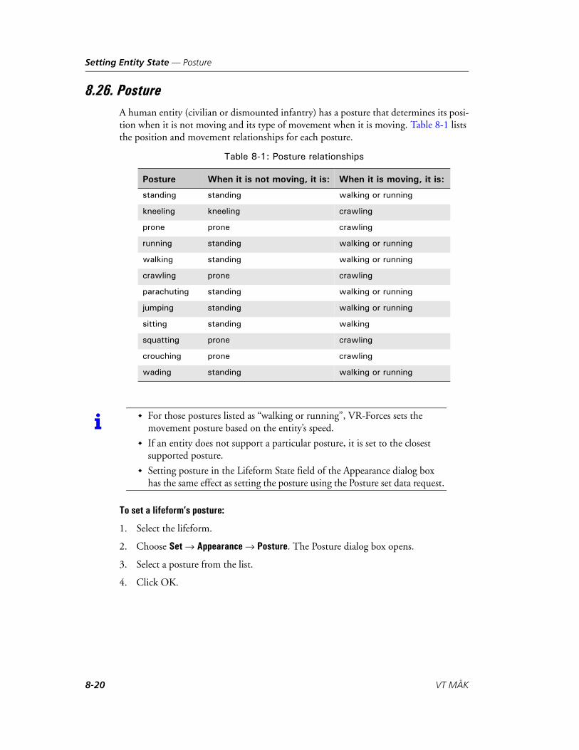
Setting Entity State — Posture
8.26. PostureA human entity (civilian or dismounted infantry) has a posture that determines its posi-tion when it is not moving and its type of movement when it is moving. Table 8-1 lists the position and movement relationships for each posture.
To set a lifeform’s posture:
1. Select the lifeform.
2. Choose Set Appearance Posture. The Posture dialog box opens.
3. Select a posture from the list.
4. Click OK.
Table 8-1: Posture relationships
Posture When it is not moving, it is: When it is moving, it is:
standing standing walking or running
kneeling kneeling crawling
prone prone crawling
running standing walking or running
walking standing walking or running
crawling prone crawling
parachuting standing walking or running
jumping standing walking or running
sitting standing walking
squatting prone crawling
crouching prone crawling
wading standing walking or running
i For those postures listed as “walking or running”, VR-Forces sets the movement posture based on the entity’s speed.
If an entity does not support a particular posture, it is set to the closest supported posture.
Setting posture in the Lifeform State field of the Appearance dialog box has the same effect as setting the posture using the Posture set data request.
8-20 VT MÄK

Setting Entity State — Radar Mode
8.27. Radar ModeThe Radar Mode set data request lets you change the type of beam that an entity emitter publishes. By default, each fixed-wing aircraft has one emitter that has two beam types, search and track. For more information about emitter beams, please see “Emitter,” on page 8-12 and Section 7.5, “Configuring Emitters,” in VR-Forces Configuration Guide.
Figure 8-3 illustrates the difference in appearance between the beams for the two radar modes, in the 2D view. (The beams are not displayed unless you set emitters to be on.)
Figure 8-3. Radar mode beams
To set an entity’s radar mode:
1. Select the entity whose radar mode you want to set.
2. Choose Set Sensors Radar Mode. The Radar Mode dialog box opens.
3. If the entity has more than one emitter, select the emitter ID you want to set in the Emitter ID list.
4. Select the mode in the Mode list.
8.28. ReorganizeIf automatic reorganization is not enabled, you can reorganize an aggregate by issuing the Reorganize set data request.
To reorganize an aggregate:
1. Select the aggregate that you want to reorganize.
2. Choose Set Aggregate Reorganize.
The change takes place immediately. For more information about reorganization, please see Reorganizing Aggregates, under Section 3.6.1, “How Aggregates Are Organized,” in VR-Forces Users Guide.
Search Track
VR-Forces Scenario Management Guide 8-21

Setting Entity State — Resources
8.29. ResourcesYou can specify the value to assign to a resource. The resources provided with VR-Forces that you can set are fuel and ammunition. The object parameter database lists the ammunition types available for each type of entity.
To specify a resource value:
1. Select the entity.
2. Choose Set Disposition Resources. The Resources dialog box opens.
3. Select a resource from the Resource list.
4. Specify a value for the resource. The dialog box displays the maximum amount of the resource allowed, as configured in the object parameter database.
5. Click OK.
8.30. RestoreRestoring an entity returns its resources to the values specified in the object parameter database. If the entity is destroyed, it returns it to life.
To restore an entity:
1. Select the entity.
2. Choose Set Disposition Restore.
The change takes place immediately.
i When you restore an aggregate that is in the aggregated state (using Restore), the original configuration of the aggregate is recreated. If you restore an aggregate that is in the disaggregated state, then only those subordinates still present in the simulation are restored. Any destroyed subordinates that were previously removed from the simulation as result of a disaggregate-->aggregate-->disaggregate transition are not restored. To fully recover all subordinates, restore the aggregate while in the aggregated state.
8-22 VT MÄK
Setting Entity State — Rules of Engagement
8.31. Rules of EngagementRules of engagement specify the conditions under which an entity will fire at the enemy.
To specify the rules of engagement for an entity:
1. Select the entity.
2. Choose Set Engagement Rules of Engagement, or click the Rules of Engage-ment button ( ) on the Sets toolbar. The Rules of Engagement dialog box opens.
3. In the Rules of Engagement list, select the rule you want to apply.
4. Click OK.
8.31.1. How Fire-When-Fired-Upon Works
An entity considers itself under fire if either of the following is true:
An “Entity Impact” detonation interaction that targeted this entity has recently (within underFireTime seconds (default 120)) been received.
Any detonation has happened within underFireDistance (default 1000 meters) of this entity.
There is no attempt to return fire specifically at the attacking entity. If an entity thinks that it is under fire, it will fire at any enemies that it can target.
i The rules of engagement for a fixed-wing entity are in effect whether it is on the ground or in the air. If you do not want fixed-wing entities to fire missiles while they are on the ground, you must change the rules of engagement.
i The underFireTime and underFireDistance parameters are part of the under-fire-determination-sensor component in an entity’s platform (OPE) file.
VR-Forces Scenario Management Guide 8-23

Setting Entity State — Sector of Responsibility
8.32. Sector of ResponsibilityAn entity's sector of responsibility is used with detection tables to determine the priority of targets. Normally, the priority of targets that are outside an entity's sector of responsibility is lower than the priority of targets in its sector of responsibility. For information about the target detection tables, please see Section 7.2, “Detection Tables,” in VR-Forces Configuration Guide.
You must specify a sector center and a sector size. Sector center is the center of the area you wish to designate, and sector size is the size of the area, both in degrees. Degrees are measured as 0 to the front (based on the heading), increasing clockwise. If the Turret Scan Controller is mounted on an entity with an articulating turret, then the turret scans the sector of responsibility specified. Sector center is the midpoint of the area. Figure 8-4 illustrates these parameters. The sector size is approximately 140 degrees, a bit less than half the circle. The sector center is at 0 degrees.
Figure 8-4. Sector of responsibility parameters
To set an entity’s sector of responsibility:
1. Select the entity.
2. Choose Set Engagement Sector of Responsibility. The Sector of Responsibility dialog box opens.
3. In the Size text box, set the size of the area to be scanned, in degrees.
4. In the Center text box, set the center of the scan area, in degrees.
5. Click OK.
i The default sector of responsibility is 90 degrees, centered at zero degrees.
area center
sector size
entity
8-24 VT MÄK

Setting Entity State — Sonar Depth
8.33. Sonar DepthThe Sonar Depth set data request lets you set the depth at which an entity’s sonar oper-ates. This allows you to simulate a helicopter dipping a sonar sensor into the water or a vessel dipping a sensor to a lower depth. Since sonar only works when the sensor is in the water, setting the sonar depth is the only way for helicopter-born sonar to work.
The sonar stays at this depth regardless of the altitude or depth of the entity. If you set the depth to be the depth of the entity with the Use Entity Depth option, it has the effect of retracting the sonar. If you simply set the sonar to the depth of the entity and the entity changes depth, the sonar will stay at the assigned depth.
To set sonar depth:
1. Select the entity.
2. Choose Set Sensors Sonar Depth. The Sonar Depth dialog box opens.
3. Specify the depth.
4. Optionally, select Use Entity Depth to set a dipped sonar to the depth of the entity.
5. Click OK.
VR-Forces Scenario Management Guide 8-25
Setting Entity State — Spot Reports
8.34. Spot ReportsYou can set spot reports on or off for all entities (global setting) from the Spot Reports page of the Application Settings dialog box. You can also set them for individual enti-ties. When you set spot reports on, it means that the entity sends them. Visualization of spot reports is enabled or disabled for the GUI as a whole on the Spot Reports page. For more information about spot reports, including setting them globally, please see “Displaying Entities Based on Spot Reports,” on page 10-2.
To set spot reports on or off for an entity:
1. Select the entity.
2. Choose Set Sensors Spot Reports. The Spot Reports dialog box opens. If you are turning spot reports off, skip to step 5.
3. Select Broadcast to send spot reports to all entities. Select Send to Specific Entities to send to specific entities.
4. If you selected Send to Specific Entities, the entity list is enabled. Select the entities to which you want this entity to send sport reports.
5. Select an option from the Spot Reports Enabled list. If you choose On or Off, the setting persists regardless of the global spot report setting. If you want the entity to use the global spot report setting, choose Use Global Setting.
6. Click OK.
8.35. SurrenderedThe Surrendered set data request only applies to lifeforms. When a lifeform is in the surrendered state, it does not fire at other entities and other entities do not fire at it.
To set an entity to be surrendered:
1. Select the entity.
2. Choose Set Disposition Surrendered. The Surrendered dialog box opens.
3. Select an option from the list.
4. Click OK.
i You cannot set an aggregate entity to send spot reports; you can only set spot reports for individual entities. However, you can select multiple individual entities and set spot reports for all of them at the same time.
8-26 VT MÄK
Setting Entity State — Synchronize Laser Code
8.36. Synchronize Laser CodeThe Synchronize Laser Code set data request lets an entity with laser-guided weapons easily synchronize its laser code with the laser code of the lasing entity. The alternative to this command would be to use Laser Code to set the code for the lasing entity and the firing entity.
To synchronize laser codes:
1. Select the entity that has a laser-guide weapon.
2. Choose Set Laser Designator Synchronize Laser Code. The Synchronize Laser Code dialog box opens.
3. Select the lasing entity that you want this entity to synchronize with.
4. Click OK. The laser code for the selected entity is changed to match that of the lasing entity.
8.37. TargetYou can command an entity to specifically target another entity. For this set data request to be effective, the target must be visible to the targeting entity. When you set a target, you override the priorities set by the target selection controller. If the specified target is in the list of candidate targets, it gets the highest priority as a target. However, if the specified target is not visible as a target to the targeting entity, the entity fires at the other available targets. It does not keep looking for the specified target. (You could achieve this behavior by putting a Target statement inside a While statement.)
To set an entity’s target:
1. Select the entity.
2. Choose Set Engagement Target. The Target dialog box opens.
3. Optionally, filter the entity selection list.
4. In the Target list, or on the terrain, select the entity to target.
5. Click OK.
VR-Forces Scenario Management Guide 8-27

Setting Entity State — Tasked by Superior
8.38. Tasked by SuperiorYou can order an entity that is part of an aggregate, and which is executing its own plan or is conducting an independent task, to stop executing those tasks and take commands from its aggregate. When you order an entity to be tasked by its superior, it stops conducting independent tasks and waits for the next order from the aggregate. (It does not execute the aggregate’s current task, if any.) For more information about being tasked by superior, please see “Independently Tasking Aggregate Members,” on page 6-10.
To order an entity to be tasked by its superior:
1. Select the entity.
2. Choose Set Other Tasked by Superior.
The change takes place immediately.
8.39. Weapon StateYou can set the weapon state for dismounted infantry entities. The options are stowed, deployed, and in-fire-position.
To set the weapon state:
1. Select the entity.
2. Choose Set Disposition Weapon State. The Weapon State dialog box opens.
3. Choose a weapon state from the list.
4. Click OK.
i If an entity has an appearance for a weapon state, it uses it in the 3D view. However, some weapon states are not supported for some entities.
8-28 VT MÄK

VR-Forces Scenario Management Guide
9
Writing Plans
This chapter explains how to combine tasks, set data requests, global commands, and conditions into plans.
Introduction to Entity Plans and Global Plans .............................................. 9-3
Conditional Statements................................................................................. 9-5Specifying Names or Patterns in Conditional Statements........................ 9-6The If/else Statement.............................................................................. 9-9When Statements (Triggers) ................................................................. 9-10While Statements ................................................................................. 9-11Conditional Tests ................................................................................. 9-12
Viewing Plans ............................................................................................. 9-16
Writing Entity Plans ................................................................................... 9-17Adding an Entity Task or Set Data Request to a Plan ........................... 9-18Adding a Conditional Statement to a Plan............................................ 9-19Editing a Statement .............................................................................. 9-22Deleting Statements from a Plan .......................................................... 9-22Printing Plans....................................................................................... 9-22Saving Changes to a Plan...................................................................... 9-23
Creating Global Plans ................................................................................. 9-23
Adding Global Commands to a Plan........................................................... 9-24Adding a Global Task or Set to a Plan .................................................. 9-25Sending Console Messages.................................................................... 9-26Creating Objects from Within a Plan ................................................... 9-27Deleting Objects from Within a Plan ................................................... 9-27Issuing a Plan ....................................................................................... 9-28
Writing Plans for Aggregates ....................................................................... 9-29
9-1

Writing Plans
Writing a Plan for Multiple Entities ............................................................ 9-29
Writing Plans for Remote Entities............................................................... 9-29
Copying Plans and Plan Statements ............................................................ 9-30
Restarting a Plan......................................................................................... 9-31
Abandoning a Plan ..................................................................................... 9-32
Considerations for Creating Plans............................................................... 9-32Name Changes Can Invalidate Plan Statements ................................... 9-32Considerations for Using Triggers ........................................................ 9-33Moving In Formation........................................................................... 9-34Using the Tasked-By-Superior Request in a Plan .................................. 9-34Following Entities ................................................................................ 9-34Planning Tasks for Aircraft ................................................................... 9-35Using Non-VR-Forces Entities in Plans................................................ 9-35
9-2 VT MÄK

Writing Plans — Introduction to Entity Plans and Global Plans
9.1. Introduction to Entity Plans and Global PlansA plan contains one or more statements that get executed by VR-Forces without human intervention. You build these statements in dialog boxes. VR-Forces writes the state-ment to the plan, so you do not have to worry about syntax errors in your statements when you first create them. However, you must understand the meaning of individual commands and parameters and the implications of how you order them, to make sure that a plan does what you want it to do.
VR-Forces supports two types of plans – entity plans and global plans. They have the following characteristics:
Entity plans apply to a specific entity. They contain tasks and set data requests that are specific to the entity and which get executed sequentially. The sequence of task execution can be interrupted by receipt of a task from an external actor (a global plan command or independent task). The task sequence can also be interrupted if a trigger (a form of conditional statement) or a reactive task is activated.
Global plans are independent of any entity. The statements in a global plan affect the scenario as a whole (create and delete object commands) or a specific entity (task and set commands). Tasks sent to an entity from a global plan have the same effect on the entity as independent tasks assigned by a human player. They inter-rupt any task that the entity is engaged in and terminate its plan. Furthermore, if a global plan has a series of tasks for the same entity, they get sent in order without regard to completion of the previous task (as if you issued a series of commands from the Task menu, one immediately after another). In such a case, only the last command sent is likely to be completed.
For an example of how to write a “good” global plan, please see Global Plans, in Chapter 6, Writing Plans, in VR-Forces Getting Started Guide.
In Figure 9-1, note that the entity plan window (on the right) is tied to a particular entity (shown in the title bar). It has the same menus as the global plan, plus additional Task and Set menus. The commands on the Task and Set menus in the entity plan apply implicitly to the entity for which you are writing the plan.
! Entity plans can include global commands (which are described later in this section). However, you must be careful not to target global commands, tasks, or sets to an entity in its own plan when you really want entity-specific tasks or sets. Entity tasks are executed sequentially. Sending an entity a global command, even from within its own plan, terminates its plan.
VR-Forces Scenario Management Guide 9-3

Writing Plans — Introduction to Entity Plans and Global Plans
Figure 9-1. Global plan and entity plan
The commands menu, which is common to both types of plans, contains global commands. These commands allow you to:
Create and delete objects.
Assign tasks and set data requests to entities.
Send console messages.
Change hostility.
Issue plans to entities.
Abandon and restart plans.
Change time of day and weather settings.
Global commands must explicitly state the entity to which they apply.
9-4 VT MÄK

Writing Plans — Conditional Statements
9.2. Conditional StatementsMany of the statements used in plans set a parameter or direct an entity to perform a specific task unconditionally. However, the plan language also includes the conditional statements, If, When, and While. A conditional statement specifies a condition and a block of plan statements.
An If statement is evaluated once, when the plan arrives at the statement. If the condition is true at that point, VR-Forces executes the statements in the If block.
A When statement is also called a trigger. It specifies a condition that is evaluated periodically by VR-Forces. If the condition becomes true, VR-Forces executes the statements in the trigger block. A trigger statement lets you plan for a condition without knowing in advance when the condition will occur.
A While statement executes a block of statements repeatedly while the condition remains true. VR-Forces evaluates the condition when the plan first arrives at the While statement. If the condition is true, it executes the statements in the block. When it completes the statements, it evaluates the condition again. If it is still true, VR-Forces executes the statements again. It continues to do so as long as the While condition is true.
The conditions supported by VR-Forces are:
Is an entity in a given area? (Entity In Area)
Is an entity to the left of a phase line? (Entity Left of Line)
Is an entity destroyed? (Entity Destroyed)
Is an entity under fire? (Entity Under Fire)
Has an entity located a target? (Entity Has Target)
Has an entity’s embarkation state changed? (Entity Embarked)
Is an entity above or below a specified altitude? (Entity Altitude)
Has an entity detected another entity? (Entity Detected)
Has an entity received a radio message? (Receive Text Message)
Has a lifeform surrendered? (Lifeform Surrendered)
Does a lifeform have a particular DI-Guy animation? (Entity Di-Guy Animation Check)
Does a lifeform have a particular DI-Guy appearance? (Entity Di-Guy Appearance Check)
Is a random probability true? (Random)
Is an entity resource at a certain level? (Resource)
Is the simulation time greater than or less than a specific elapsed time? (Sim Time)
Conditional statements can include the boolean operators True and False, and the logical operators AND, OR, and NOT.
VR-Forces Scenario Management Guide 9-5

Writing Plans — Conditional Statements
9.2.1. Specifying Names or Patterns in Conditional Statements
When you add a conditional statement to a plan, you must specify the entity or entities for which the condition will be tested. You can specify:
A specific named entity, for example, When entity M1A2 1 is in Area 1.
That the condition applies to “Self ”, for example, When “I” am in Area 1. Speci-fying a condition for one’s self makes it easy to copy and paste plans or plan state-ments to the plans of other entities without doing any editing.
An entity enumeration, for example, any entity with enumeration 1:1:225:1:1:3:0 (any M1A2).
The inverse of the selection, for example, any entity but myself, or any entity except an M1A2.
That for aggregates, the entire aggregate must satisfy the condition (the default), or that any subordinate member of an aggregate satisfies the condition. For example, the default behavior when Entity Is Destroyed is applied to an aggregate is that all members of the aggregate must be destroyed for the condition to be true. The alter-native is that the condition is true if any member of the aggregate is destroyed.
The Name and Pattern specifications are mutually exclusive. You cannot specify a name and a pattern. The tab in the Condition dialog box that is visible when you click OK is the specification that gets applied.
Specifying a Name in a Conditional Statement
To specify a named entity in a condition statement:
1. In a conditional statement dialog box, select the Name tab (Figure 9-2).
Figure 9-2. Name tab in condition dialog box
9-6 VT MÄK

Writing Plans — Conditional Statements
2. Do one of the following:
– To specify the entity whose plan this is as the entity in the condition, select the Use SELF check box.
– To specify an entity by name, select the entity in the list or type its name in the Name text box.
3. If you select an aggregate entity in the list, the Any Subordinate of Selected Aggre-gate check box is enabled. If you want the condition to be satisfied when any entity in the aggregate meets the condition, select the check box.
4. To specify the inverse of the name, that is, any entity except the selected one, select the Invert Selection check box.
5. Click OK.
VR-Forces Scenario Management Guide 9-7

Writing Plans — Conditional Statements
Specifying an Entity Pattern in a Conditional Statement
The enumerations used in the lists on the Pattern tab are loaded from the file ./appData/settings/vrfGui/condition-entity-types.csv. They represent a subset of the enumerations typically used for entities in simulations. However, you can enter any numeric value you want in the enumeration value boxes.
If you expect that you will consistently need to specify enumeration values that are not part of condition-entity-types.csv, such as a particular country code, you can edit it to add the patterns you need.
To specify an entity pattern in a condition statement:
1. In a conditional statement dialog box, select the Pattern tab (Figure 9-3).
Figure 9-3. Pattern tab in condition dialog box
2. Optionally, specify a force to test for.
3. For each element of the enumeration, select an option from the list, or type an enumeration in the text box.
4. If the enumeration you enter is for an aggregate entity, the Any Subordinate Of Selected Aggregate check box is enabled. If you want the condition to be satisfied when any entity in the aggregate meets the condition, select the check box.
5. To specify the inverse of the name, that is, any entity except the selected one, select the Invert Pattern check box.
6. Click OK.
9-8 VT MÄK

Writing Plans — Conditional Statements
9.2.2. The If/else Statement
An If/else statement tests a condition. It only tests the condition once.
An If/else statement consists of:
The word If.
A condition to be evaluated.
A block of statements.
An else statement.
Optionally, statements for the else condition.
If the condition is true at the moment the If statement is evaluated, control passes to the first statement of the If block. If the condition is false, control passes to the first statement in the else block, if you have one, or to the first statement after the complete If/else block if you do not have an else block. You can nest If/else statements within If/else statements. The syntax is as follows:
If (condition) thenzero_one_or_more_statements
elsezero_one_or_more_statements
endif
When VR-Forces reaches the end of the block of If or else statements, control passes to the first statement after the If/else statement.
The Add Conditional Expression dialog box ensures that you have the correct syntax. It does not ensure that your If/else block makes logical sense.
i Do not use an If statement to test for receipt of a message or some other circumstance that does not represent an entity’s state. VR-Forces does not keep a record of events and such a test will almost always evaluate to false. Use a When statement to test for conditions that do not evaluate entity state.
VR-Forces Scenario Management Guide 9-9
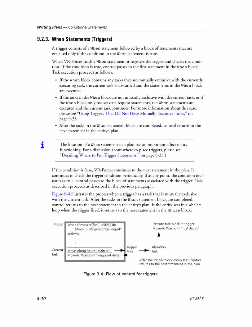
Writing Plans — Conditional Statements
9.2.3. When Statements (Triggers)
A trigger consists of a When statement followed by a block of statements that are executed only if the condition in the When statement is true.
When VR-Forces reads a When statement, it registers the trigger and checks the condi-tion. If the condition is true, control passes to the first statement in the When block. Task execution proceeds as follows:
If the When block contains any tasks that are mutually exclusive with the currently executing task, the current task is discarded and the statements in the When block are executed.
If the tasks in the When block are not mutually exclusive with the current task, or if the When block only has set data request statements, the When statements are executed and the current task continues. For more information about this case, please see “Using Triggers That Do Not Have Mutually Exclusive Tasks,” on page 9-33.
After the tasks in the When statement block are completed, control returns to the next statement in the entity’s plan.
If the condition is false, VR-Forces continues to the next statement in the plan. It continues to check the trigger condition periodically. If at any point, the condition eval-uates as true, control passes to the block of statements associated with the trigger. Task execution proceeds as described in the previous paragraph.
Figure 9-4 illustrates the process when a trigger has a task that is mutually exclusive with the current task. After the tasks in the When statement block are completed, control returns to the next statement in the entity’s plan. If the entity was in a While loop when the trigger fired, it returns to the next statement in the While block.
Figure 9-4. Flow of control for triggers
i The location of a When statement in a plan has an important affect on its functioning. For a discussion about where to place triggers, please see “Deciding Where to Put Trigger Statements,” on page 9-33.)
When (Resource(fuel) <50%) doMove-To Waypoint:"fuel depot"
endwhen...
Move-Along Route:"main st."Move-To Waypoint:"waypoint delta"
Currenttask
Execute task block in trigger:Move-To Waypoint:"fuel depot"
Triggerfires
Trigger
After the trigger block completes, controlreturns to the next statement in the plan.
Abandontask
9-10 VT MÄK

Writing Plans — Conditional Statements
After a trigger fires, it is removed from the list of registered triggers. If you want to continue to test for the same condition, you need to execute another When statement for that condition.
Unregistering Triggers
You cannot unregister triggers while a scenario is running. If you do not want a trigger to be executed, you have the following options:
Before you start the scenario, remove the trigger from the plan.
During a simulation, abandon the plan.
During the simulation, remove the trigger from the plan and save the plan. The new plan will erase the old one. However, the plan will begin executing at the first statement, which may not be the behavior you want.
9.2.4. While Statements
A While statement consists of:
The word While.
A condition to be evaluated.
A block of statements.
If the condition is true at the moment the While statement is reached, control passes to the first statement of the While block. If the condition is false, control passes to the first statement after the complete While block. You can nest While statements within If, When, and While statements.
When VR-Forces reaches the end of the While block, it evaluates the condition again. If the condition is still true, VR-Forces executes the statements again. If it is false, control passes to the first statement after the While block.
i VR-Forces re-evaluates a While condition only after it has executed all of the statements in the block. If the condition becomes false while VR-Forces is executing statements in the block, VR-Forces continues to execute all statements because it does not re-evaluate the condition until it completes the While block.
If you put a continuous task such as Wait or a Patrol Between in a While block, it is possible that the condition will never be re-evaluated, because the tasks in the block will never be completed.
VR-Forces Scenario Management Guide 9-11

Writing Plans — Conditional Statements
9.2.5. Conditional Tests
This section describes each of the conditions that VR-Forces can test. When you set up conditions, keep in mind the following:
If there is no entity with the specified name, the result is always false.
If the specified entity is destroyed, the condition might never be satisfied. Your plan should take this possibility into account.
The Entity Has Target Condition
Entity Has Target returns true if the entity specified in the condition identifies a target. For example, consider the entities in Figure 9-5. The condition in M1A2 1’s plan is true when BMP 1 has a target, not when M1A2 1 targets BMP 1.
Figure 9-5. Entity Has Target condition
The Entity In Area Condition
Entity In Area returns true if the entity (or member of an aggregate) reports that it is in the named area. You can use the NOT boolean operator, to test whether an entity is outside the area.
The Entity Left of Line Condition
Entity Left of Line returns true if the entity (or member of an aggregate) reports that it is to the left of the specified phase line.
An entity is considered to be to the left of a phase line if it is on the left side of an infi-nite extension of the phase line as viewed from a point on the line facing in the direc-tion of the line. For a description of phase line direction, please see Section 3.7.2, “Phase Lines,” in VR-Forces Users Guide.
i If an entity’s rules of engagement prevent it from firing, this condition does not return true when the entity identifies a target.
M1A2 1 BMP 1Plan for M1A2 1If(Entity-Has-Target:”BMP 1”)do something
endwhen
9-12 VT MÄK

Writing Plans — Conditional Statements
The Entity Destroyed Condition
Entity Destroyed returns true if the specified entity or aggregate is destroyed.
The Entity Embarked Condition
Entity Embarked returns true if the named entity is embarked.
The Detect Entity Condition
The Detect Entity condition tests to see if an entity has been detected at a particular identification level. The identification levels are Detected, Classified, Identified, Full Knowledge. Identification levels are determined by the detection probability configura-tion files, based on the distance between the detecting entity and the target and for how long the entity has been detected. For details about the detection probability files, please see Section 7.2, “Detection Tables,” in VR-Forces Configuration Guide.
The Entity Under Fire Condition
Entity Under Fire returns true if the entity (or member of an aggregate) is under fire.
The Altitude Condition
Altitude returns true if the entity (or member of an aggregate) is at a higher or lower altitude than the one specified.
The Receive Text Message Condition
The Receive Text Message condition tests to see if an entity has received a text message (sent by the Send Text Message task) that contains the text specified in the Receive Text Message dialog box.
The Entity Di-Guy Animation Check Condition
The Entity Di-Guy Animation Check condition tests the current DI-Guy animation for a lifeform. This condition may be useful if you are scripting a series of animations. For example, if a particular entity is using a threatening or hostile animation, you might want to have other entities respond a certain way.
i The definition of destruction for an aggregate is implementation specific. The aggregates supplied by MÄK for VR-Forces report that they are destroyed if every member of the aggregate is destroyed. An aggregated aggregate is destroyed if the aggregateIf you have implemented aggregates locally using the VR-Forces Toolkit, they could have a different definition of destroyed.
VR-Forces Scenario Management Guide 9-13

Writing Plans — Conditional Statements
The Entity Di-Guy Appearance Condition
The Entity Di-Guy Appearance Check condition tests the current DI-Guy appearance for a lifeform. This condition may be useful if you are scripting a lifeform’s interaction with another lifeform based on ethnicity or how they are dressed.
The Lifeform Surrendered Condition
The Lifeform Surrendered condition tests to see if a lifeform entity has surrendered (using the Surrendered set data request).
The Sim Time Condition
The Sim Time condition returns true if the elapsed simulation time is greater than (Sim Time >) or less than (Sim Time <) the time specified in the statement. Sim Time is the elapsed simulation time in days, hours, minutes, and seconds.
The Resource Condition
The Resource condition tests the amount of a specified resource using comparison operators.
9-14 VT MÄK

Writing Plans — Conditional Statements
The Random Condition
You can use the Random condition to randomly decide an entity's behavior at run time.
Percentage – A floating point probability percentage value between 0% (zero) and 100%. Random returns true if a random number between zero and 100 is less than or equal to the specified value.
If you use the Random condition, consider the following issues:
Random is not very useful in triggers, since triggers may evaluate their condition expressions as often as once per tick. This means that a trigger expression of “Random Probability:50%” is likely to fire within the first couple of times it is eval-uated. Therefore, we recommend that you not create triggers that are based on a random condition.
If you use a random condition in a cascading sequence of If/else statements, and you want to ensure the correct probability distribution, be careful how you specify the percentage value. For example, randomly selecting one of three paths with equal probability would be done like this:If (Random Probability:33.33%) then
Move-Along Route:"1"Else
If (Random Probability:50%) thenMove-Along Route:"2"
ElseMove-Along Route:"3"
EndifEndif
As with all other random numbers used in VR-Forces, if the scenario initializes a random number seed value (for details. please see “Scenario Parameters,” on page 3-4 in VR-Forces Configuration Guide), then the results of the Random condi-tion can be made repeatable. (For details about repeatability, please see Section 3.13.3, “Exercise Clock Modes,” in VR-Forces Users Guide.)
Boolean and Logical Operators
You can use the following boolean and logical operators in conditional expressions:
True.
False.
AND (expression, expression) – evaluates as true if both conditional expressions are true.
OR (expression, expression) – evaluates as true if either of the expressions are true.
NOT (expression) - evaluates as true if the conditional expression is false.
You can nest and combine conditional expressions.
VR-Forces Scenario Management Guide 9-15

Writing Plans — Viewing Plans
9.3. Viewing PlansYou can view an entity’s plan and observe its progress through the plan. You can view the plans for as many entities at a time as you want. In addition to viewing plan status in the Plan window, you can view the current task on the State page of the Entity Infor-mation dialog box.
To view an entity’s plan:
1. Select the entity whose plan you want to view.
2. Choose Entities Plan, or press p. The Plan window opens.
The task that an entity is executing is highlighted in the Plan window. When the entity completes its plan, a message is displayed in the status area at the bottom of the Plan window.
9-16 VT MÄK

Writing Plans — Writing Entity Plans
9.4. Writing Entity PlansThis section explains how to write entity plans. For conceptual information about plans, please see Section 3.9, “Plans,” in VR-Forces Users Guide, and the previous sections in this chapter.
When you write a plan, keep the following considerations in mind:
If you edit a plan during a simulation, when you apply the changes, the entity whose plan has been changed begins executing it from the beginning. This might mean its activities are no longer synchronized with those of the other entities, unless the updated plan only includes statements that you want to execute starting at the current point of the simulation. Therefore, we recommend that you edit plans when you first load a scenario, before you start running the simulation.
If you have two or more Plan windows open at the same time, and you open a dialog box, such as Move To, but do not complete the command, you cannot open that same dialog box from another Plan window until you complete the one that is open.
To edit an entity’s plan:
1. Select an entity.
2. Choose Entities Plan, or press p. The Plan window opens. The entity’s plan is displayed.
Figure 9-6. Plan window
3. Add new statements, edit statements, or delete statements as described in the following sections.
VR-Forces Scenario Management Guide 9-17

Writing Plans — Writing Entity Plans
9.4.1. Adding an Entity Task or Set Data Request to a Plan
When you add statements to an entity plan, you add them after the currently selected statement. (For details about adding tasks to a global plan, please see“Adding Global Commands to a Plan,” on page 9-24.)
To add a task to a plan:
1. Open the Plan window for an entity.
2. In the Plan window, select the statement immediately above where you want to insert a new statement. If the plan does not have any statements yet, the plan root – “Entity_name” is already selected.
3. Choose Task category Task, where category is one of the categories on the Task menu and Task is a task listed for the selected category. A dialog box appropriate to the task opens. The procedures for filling out each type of task dialog box are described in Chapter 6, Assigning Tasks.
4. Complete the required parameter information.
5. Click OK in the task dialog box to add the statement. You can click Cancel at any time to exit a task dialog box.
To add a set data request to a plan, follow the same procedure as for adding a task, except choose Set category Set Data Request.
The procedures for filling out Set statement dialog boxes are in Chapter 8, Setting Entity State.
i Some task and set statements, such as Wait, or Reorganize, do not require you to specify any values. They are added immediately to the plan without any intermediate dialog boxes.
9-18 VT MÄK

Writing Plans — Writing Entity Plans
9.4.2. Adding a Conditional Statement to a Plan
To add a conditional statement to a plan:
1. Open the Plan window for an entity.
2. In the Plan window, select the statement immediately above where you want to insert a new statement. If the plan does not have any statements yet, the plan root – Entity_name is already selected.
3. Choose Conditions condition. The conditional expression dialog box opens.
4. Complete the conditional expression dialog box as described in “Building State-ments in the Conditional Expression Dialog Box,” on page 9-20.
5. Click OK. A conditional statement block is added to the plan, with the syntax (the condition plus an “end” statement) that defines the bounds of the block of tasks that are executed if the condition is true. You need to add the task statements that you want to have executed. To add the task statements, follow the procedure in “Adding an Entity Task or Set Data Request to a Plan,” on page 9-18.
! Once you make a selection from a list, you cannot change it. If you make an error building a conditional expression, you will have to Cancel out of the dialog box and start over again.
VR-Forces Scenario Management Guide 9-19

Writing Plans — Writing Entity Plans
Building Statements in the Conditional Expression Dialog Box
The conditional expression dialog box is a dynamic dialog box that lets you build a conditional statement. It contains lists that have the permissible options for each step of a condition. As you select options, the dialog box redisplays, adding additional fields. You can build conditional statements using comparison operators, logical operators, and tests of entity status.
Using Prefix Notation to Establish Grouping and Precedence
To specify grouping, the Conditional Expression dialog box uses prefix notation, in which the operator comes first, followed by the operands. For example, a condition that you might verbalize as, “If entity 1 is in area A and entity 2 is in area B,” is expressed in prefix notation as:
AND(entity 1 in area A, entity 2 in area B)
(For simplicity, this example does not use complete VR-Forces statement syntax.)
If you are not familiar with prefix notation, you might want to write out your condi-tional expressions before you begin entering them in the Conditional Expression dialog box.
Figure 9-7 illustrates how the Conditional Expression dialog box might redraw as you successively add the components of a condition statement. It creates the following conditional expression:
If(AND(Entity-In-Area Entity:"M1A2 2" Area:"base camp", resource(fuel)<25%))then
elseendif
i The conditional expression dialog box resizes as you add conditions.
9-20 VT MÄK

Writing Plans — Writing Entity Plans
Figure 9-7. Example of building a conditional statement
2. Select Entity In Area fromthe list.
4. Select Resourcefrom the list.
1. Select And from thelist.
3. Select parameter valuesin the dialog box.
5. Enter parametervalues in the dialog box.
6. Click OK.
FinishedconditionAdd tasks to becompleted based
on evaluation of the condition.
VR-Forces Scenario Management Guide 9-21

Writing Plans — Writing Entity Plans
9.4.3. Editing a Statement
You can edit simple statements in the Plan window. If you want to change a complex conditional statement, you must delete it and re-enter it.
To edit a plan statement:
1. Double-click the statement or select the statement and click Edit. An edit dialog box for the particular statement type opens.
2. Enter the changes you want to make.
3. Click OK in the edit dialog box.
4. Click OK or Apply in the Plan window.
9.4.4. Deleting Statements from a Plan
You can delete statements from a plan individually, or all at once.You can delete the individual statements in the statement block of a conditional statement. If you delete the conditional statement itself, all substatements are also deleted.
To delete a statement from a plan:
1. Select the statement you want to delete.
2. Click Delete or press Delete.
Deleting All Statements From a Plan
To delete all statements in a plan:
1. Select the top line in the plan.
2. Click Delete or press Delete.
9.4.5. Printing Plans
You can print plans. The printout lists the name of the scenario, the entity’s name, and the plan statements.
To print a plan:
1. Open a global plan or the Plan window for the entity whose plan you want to print.
2. Click Print. A standard print dialog box for your operating system opens.
3. Complete the dialog box as you normally would.
9-22 VT MÄK
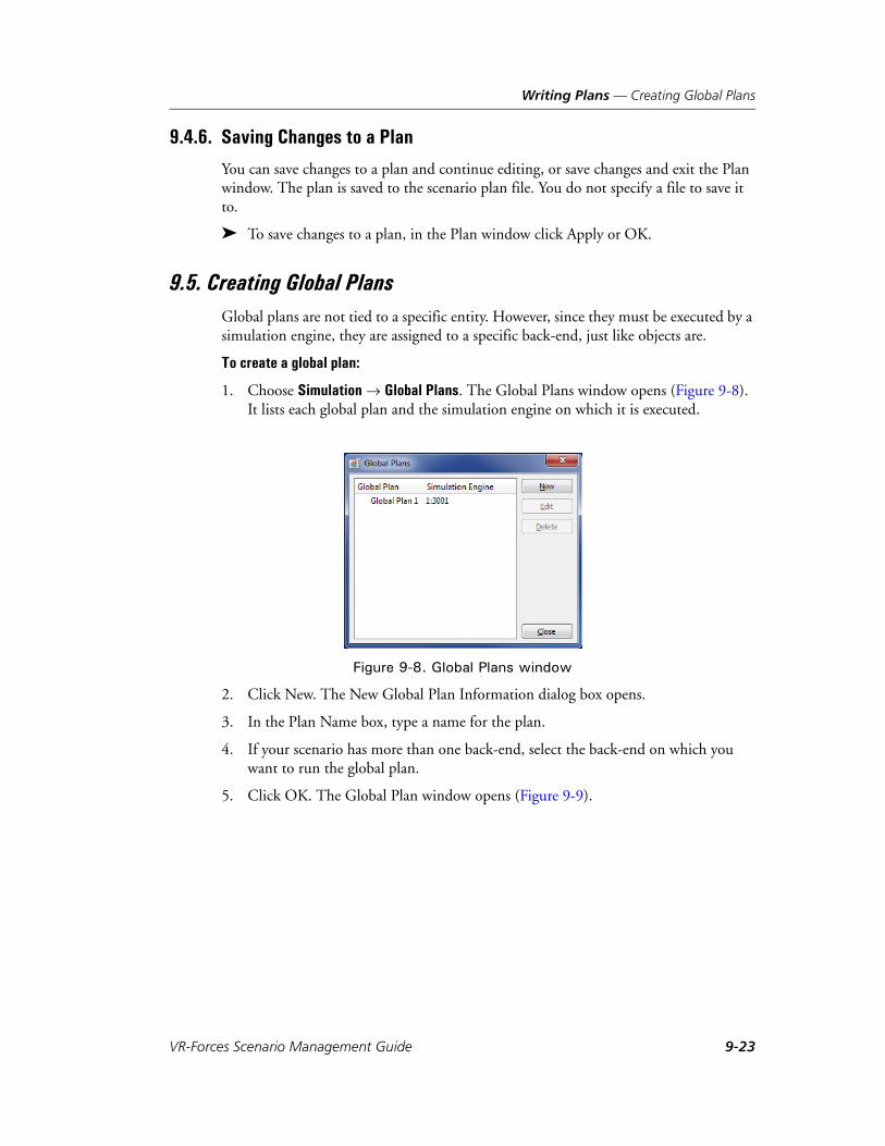
Writing Plans — Creating Global Plans
9.4.6. Saving Changes to a Plan
You can save changes to a plan and continue editing, or save changes and exit the Plan window. The plan is saved to the scenario plan file. You do not specify a file to save it to.
To save changes to a plan, in the Plan window click Apply or OK.
9.5. Creating Global PlansGlobal plans are not tied to a specific entity. However, since they must be executed by a simulation engine, they are assigned to a specific back-end, just like objects are.
To create a global plan:
1. Choose Simulation Global Plans. The Global Plans window opens (Figure 9-8). It lists each global plan and the simulation engine on which it is executed.
Figure 9-8. Global Plans window
2. Click New. The New Global Plan Information dialog box opens.
3. In the Plan Name box, type a name for the plan.
4. If your scenario has more than one back-end, select the back-end on which you want to run the global plan.
5. Click OK. The Global Plan window opens (Figure 9-9).
VR-Forces Scenario Management Guide 9-23

Writing Plans — Adding Global Commands to a Plan
Figure 9-9. Edit Global Plan window
6. Add commands as described in “Adding Global Commands to a Plan,” on page 9-24.
9.6. Adding Global Commands to a PlanThe global command submenus mimic the Task and Set menus on the VR-Forces menu bar and the options on the Entity Palette and Tactical Graphics Palette. There are also several global commands that are only available on the commands menu. Except as noted in this section, the procedures for adding global commands and conditional statements to a global plan are the same as the procedures for adding them to entity plans.
9-24 VT MÄK

Writing Plans — Adding Global Commands to a Plan
9.6.1. Adding a Global Task or Set to a Plan
The commands on the Task and Set menus in an entity plan apply implicitly to the entity for whom you are writing a plan. Global commands must be assigned explicitly to a target entity. Therefore, even though the list of tasks and sets on the commands menu look the same as those in an entity plan or the main VR-Forces menu bar, the dialog boxes they use are different.
Figure 9-10 shows the Follow Entity dialog box displayed if you choose Commands Task Movement Follow Entity in a global plan, and the Follow Entity dialog box displayed if you choose Task Movement Follow Entity in an entity plan. The right pane in the global command requires the same information as the local command. The difference is that in the global command dialog box you must specify the entity to which the command will apply. You can specify an existing entity or you can specify the name of an entity that does not yet exist, but which you expect to be created during the lifetime of the scenario, perhaps as the result of a Create command in a global plan.
Other than the requirement to specify the target entity, adding a global task or set command to a plan uses the same procedure as adding any task or set to an entity plan.
Figure 9-10. Global command task dialog box and entity plan task dialog box
Global plan Entity plan
VR-Forces Scenario Management Guide 9-25

Writing Plans — Adding Global Commands to a Plan
To assign a global command:
1. In a Plan window or Global Plan window, choose one of the commands on the commands menu or a submenu. The appropriate dialog box opens for the command.
2. If the dialog box requires you to specify the entity that will execute the command (in other words, if there is an Apply Command To panel in the dialog box), select an entity from the list or type its name in the Name box. The entity does not have to exist in the scenario at the time you add the command, but you should be sure that it will be created before the command is run.
3. In the command-specific panel of the dialog box, complete the command parame-ters. Please see Chapter 6, Assigning Tasks and Chapter 8, Setting Entity State for the details of assigning specific tasks and sets.
9.6.2. Sending Console Messages
You can send messages to be displayed in the console on an object’s information dialog box and to the back-end console. Messages sent by global plans go to the back-end console. Messages sent from an entity’s plan go to the console in its Entity Information dialog box.
If the notification level for a console message is lower than the notification level config-ured for the back-end or the target entity, the message is not displayed. For example, if an entity’s notification level is set to Info, it receives Error, Warn, and Info messages, but not messages set to Verbose or Debug.
To send a console message from a plan:
1. In an Entity Plan or Global Plan window, choose Commands Console Message. The Console Message dialog box opens.
2. Select the notify level from the list.
3. Type the message you want to send.
4. Click OK.
i Remember that a global task command affects an entity like an independent task. It interrupts the current task and causes the entity to abandon its plan. If you are adding a global task command to an entity plan, be sure that you are assigning it to some other entity and not the entity for whom you are writing the plan. (Unless you want the entity to abandon its plan.)
9-26 VT MÄK

Writing Plans — Adding Global Commands to a Plan
9.6.3. Creating Objects from Within a Plan
You can create any of the objects on the Entity Palette from within a plan.
To create an object from a plan:
1. In an Entity Plan or Global Plan window, choose Commands Create object, where object is an object listed on one of the submenus.
2. Create the desired object as you would if you were creating it directly from the main Entity Palette. When you are finished creating the object, a create command is added to the plan and the object itself disappears. (The object disappears because you are not actually creating the object right now, you are just creating the command that will create it later when the plan executes.)
9.6.4. Deleting Objects from Within a Plan
You can delete any object in a scenario from a plan.
To delete an object from a plan:
1. In the Entity Plan or Global Plan window, choose Commands Delete Object. The Delete Object dialog box opens.
2. Type the name of the object you want to delete or select the object in the list or on the terrain.
3. Click OK.
Deleting One’s Self from the Scenario
The Delete Object global command lets you delete any specified object. If you just want to delete the entity whose plan you are editing, you can use the Delete Self command. Like the Use Self option in some conditions, Delete Self provides a non-entity-specific command that is useful for plans that you want to assign to multiple entities.
To assign the Delete Self command, choose Commands Delete Self.
VR-Forces Scenario Management Guide 9-27

Writing Plans — Adding Global Commands to a Plan
9.6.5. Issuing a Plan
The Issue Plan global command lets you assign a plan to an entity. When you issue a plan, the new plan replaces whatever plan or task the entity is executing. Although you can issue a plan to any entity, this command is particularly useful for when you create an entity after a scenario has started.
When you create a scenario, you cannot create an entity plan for an entity that does not exist. Therefore, if you create an entity after the scenario starts (using the Create global command), it is difficult to send it a sequence of tasks because global commands are not executed in sequence (as discussed in “Introduction to Entity Plans and Global Plans,” on page 9-3 and Chapter 6, Writing Plans, in VR-Forces Getting Started Guide). The Issue Plan command solves this problem.
Issue Plan is a concurrent task. Including it in an entity plan does not affect the current task that the entity is executing or the sequencing of tasks in its plan.
To issue a plan to an entity:
1. In a global plan or an entity plan, choose Commands Issue Plan. The Issue Plan dialog box opens (Figure 9-11).
Figure 9-11. Issue Plan dialog box
2. In the Apply command To: group box, select the entity to which you want to assign this plan or type the name of the entity in the Name text box. If this is an entity that does not yet exist (because you plan to create it from a plan after the scenario starts), you must type the name and you are responsible for ensuring that the name you type matches the name of the entity that will be created.
3. Use the right side of the dialog box to write an entity plan. It has the exact same set of menus and commands as the Entity Plan dialog box. Follow the procedures described elsewhere in this chapter to write the plan.
4. Click OK.
9-28 VT MÄK

Writing Plans — Writing Plans for Aggregates
9.7. Writing Plans for AggregatesTo write a plan for an aggregate:
1. Select the aggregate.
2. Follow the procedures for writing a plan for an individual entity.
9.8. Writing a Plan for Multiple EntitiesYou can write a plan and assign it to multiple entities at the same time. If any of the entities already has a plan, it is overwritten by the new plan. After you assign a plan using this procedure, you can individually edit the plans for any entity and the changes do not affect the other entities.
To write a plan for multiple entities:
1. Select the entities to which you want to assign the same plan.
2. Choose Entities Plan. The Plan window opens.
3. Add statements to the plan as you would if you were writing a plan for an indi-vidual entity.
4. Click OK. The plan is assigned to the selected entities.
9.9. Writing Plans for Remote EntitiesIf you attach components to remote entities, you can write plans for those entities. To assign plans, the entities must exist in the exercise, must have attached components, and must be present in the exercise when VR-Forces saves the scenario. The plans must be appropriate for the attached components. Movements tasks are not appropriate, because VR-Forces cannot control the location of a remote entity. Appropriate plan statements might be to enable spot reporting, or to send a radio message. For details about how to attach components to remote entities, please see Section 7.12, “Config-uring VR-Forces Components on Remote Entities,” in VR-Forces Configuration Guide.
i Please see “Independently Tasking Aggregate Members,” on page 6-10 for notes about how entities that are members of aggregates respond to individual plans and independent tasks.
i If you select several entities and they all have the exact same plan, the plan window displays that plan. If any of the entities have different plans, you are given the option to continue or cancel. If you continue, VR-Forces displays an empty Plan window and the new plan replaces the whatever plans the entities previously had.
VR-Forces Scenario Management Guide 9-29

Writing Plans — Copying Plans and Plan Statements
9.10. Copying Plans and Plan StatementsYou can copy plans and individual plan statements and paste them into another entity’s plan.
To copy plan statements:
1. Open the Plan window for the plan that you want to copy.
2. To copy the entire plan, select the top line in the plan (Entity_name). To copy a statement, select the statement. If you select a conditional statement, the entire statement block is selected.
3. Click Copy. If you selected the top line, it reads Copy Plan. If you select a state-ment, it reads Copy Block.
4. Open the Plan window for the entity you want to copy the plan to.
5. Select the line just above where you want to insert the copied plan.
6. Click Paste.
7. Continue editing the plan as described in the previous sections.
8. Save the plan.
9-30 VT MÄK

Writing Plans — Restarting a Plan
9.11. Restarting a PlanThere may be occasions when you want to restart an entity’s plan without restarting a scenario. You can restart a plan interactively or by placing a Restart Plan command in a plan.
When you restart a plan, VR-Forces processes the statements in the plan, starting from the first statement. However, the entity executes tasks starting from its current location, not the location it had at the start of the scenario (unless it has not moved since the start of the scenario).
To restart a plan interactively:
1. Select the entity whose plan you want to restart.
2. Choose Entities Restart Plan.
To restart a plan from within a plan:
1. Open an entity’s plan or a global plan.
2. Choose Commands Restart Plan. The Restart Plan dialog box opens.
3. Select the entity whose plan you want to restart.
4. Click OK.
5. Save the plan.
To restart a plan from the Plan window:
1. Open an entity’s plan.
2. Click Restart.
VR-Forces Scenario Management Guide 9-31

Writing Plans — Abandoning a Plan
9.12. Abandoning a PlanYou can order an entity to stop executing its plan. When you abandon a plan, the following things happen:
The entity stops whatever task it is working on, even if it is an independent task.
The plan is marked as complete.
All registered triggers are deleted.
The statement indicator skips to the end of the plan.
The entity enters a wait state.
You can abandon a plan interactively or by sending an Abandon Plan command in an entity or global plan.
To abandon a plan interactively:
1. Select the entity whose plan you want to abandon.
2. Choose Entities Abandon Plan.
To abandon a plan from within a plan:
1. Open an entity’s plan or a global plan.
2. Choose Commands Abandon Plan. The Abandon Plan dialog box opens.
3. Select the entity whose plan you want to abandon.
4. Click OK.
5. Save the plan.
To abandon a plan from the Plan window:
1. Open an entity’s plan.
2. Click Abandon.
9.13. Considerations for Creating PlansThis section has tips for constructing plans including how to avoid problems that are hard to debug and how statements affect each other, with implications for how to orga-nize the statements in a plan.
9.13.1. Name Changes Can Invalidate Plan Statements
Plan statements can reference named objects, such as tactical graphics and entities. For example, a Follow Entity task specifies the name of the entity to follow. If someone changes the name of an entity or tactical graphic after you create a plan, VR-Forces will not be able to find the object referenced in the plan statement. If this happens in a task statement, the plan skips the task and moves to the next task. If a renamed object is in a conditional statement, the condition may never become true.
9-32 VT MÄK

Writing Plans — Considerations for Creating Plans
9.13.2. Considerations for Using Triggers
Triggers are a versatile part of plans and you should have a good understanding of their intricacies before you use them.
Deciding Where to Put Trigger Statements
VR-Forces does not evaluate a trigger condition until it executes a When statement and registers the trigger. If you want to ensure that a When statement always gets read by VR-Forces, put it at the beginning of a plan before any non-trigger statements. If you put a trigger later in a plan, it is possible that it will never be registered. This could occur if a plan is abandoned. Of course, you might decide that you do not want a trigger to be registered unless a set of preceding tasks have been completed. In that case, placing it later in the plan may be exactly what you want to do.
You can also place a trigger inside a conditional block so that it gets registered only if a particular condition is true at a particular time.
For example, if you always want entity 1 to respond to entry of hostile forces into an area, put a trigger at the beginning of the plan. If you want entity 1 to respond to a hostile entity in an area only after the simulation has progressed for 15 minutes, nest the trigger inside another trigger that fires when Sim Time > 15 minutes.
Using Triggers That Do Not Have Mutually Exclusive Tasks
A trigger does not have to have any task statements in its statement block. It could just have Set statements. Or, it could have sets and concurrent tasks. If a trigger block just has Set statements, it does not interrupt the task that the entity is executing when the trigger gets executed. The Set statements get executed while the entity is performing its task. This has the same effect as if you manually set the entity’s state while it was performing a task.
Using a trigger that just has Set statements can be useful if you want to change an entity’s state under certain conditions, but do not know in advance when those condi-tions might exist.
VR-Forces Scenario Management Guide 9-33
Writing Plans — Considerations for Creating Plans
Reregistering Triggers
A trigger can only fire once. It does not stay in effect for a reoccurrence of the triggering event. Under limited circumstances it is possible to work around this limitation. If an entity’s plan only contains When statements, you could put a Restart Plan command at the end of each When block. In this way, after a trigger fires, it executes the commands in the trigger block and then it restarts the plan. This reregisters all of the When state-ments in the plan.
If a plan has commands outside of a trigger, then restarting the plan would also cause the entity to execute those commands, which might not be desirable. You might be able to work around this issue by putting these commands in a When block related to the simulation time.
As an alternative to using triggers, you can write reactive tasks, which work similarly to triggers or you can write a regular scripted task that is designed to repeatedly test a condition.
9.13.3. Moving In Formation
If you want an aggregate to move in a certain formation, add a Formation statement to the plan before the task that requires the aggregate to move. The default formation is a column.
9.13.4. Using the Tasked-By-Superior Request in a Plan
If you put the Tasked-By-Superior request in the body of a plan, it has no real effect. This is because, as soon as it is set, the plan goes to the next task and overrides the supe-rior. The only way that the Tasked-By-Superior command gets implemented as part of a plan is if it is the last statement in a plan or the last statement in a trigger that happens to get executed after all the statements in an entity’s plan have been executed.
9.13.5. Following Entities
If you tell two or more entities to follow another entity, do not give them the same offset values. If the followed entity stops, one follower will arrive at the specified offset position and stop, while the others will circle the location because they cannot all occupy the same space.
9-34 VT MÄK

Writing Plans — Considerations for Creating Plans
9.13.6. Planning Tasks for Aircraft
When you plan tasks for aircraft, the most important thing to remember is to pay atten-tion to the terrain. Fixed-wing aircraft do not have terrain following capabilities. Rotary-wing aircraft have some terrain-following capacity, but it has some limitations. So if you assign aircraft an altitude that is lower than the terrain at some point along a route or the path they must follow to reach a waypoint, they will crash into the terrain. View the terrain profile for a route to see if it intersects the terrain.
You should also bear in mind that the turning radius and speed of fixed-wing aircraft affect how closely they can follow a route.
9.13.7. Using Non-VR-Forces Entities in Plans
You can use a non-VR-Forces entity as a parameter in a plan, for example, following a remote entity, or testing to see if a remote entity is in an area.
To identify non-VR-Forces entities, VR-Forces uses their marking text. If a non-VR-Forces entity does not have marking text, VR-Forces uses its entity identifier as its name.
VR-Forces does not recognize remote aggregates as aggregates, so it cannot check their children. Remote aggregates are ignored by the simulation engine.
i Referring to remote entities by their marking text may have unpredictable results if there is more than one remote entity with the same marking text.
If you include a non-VR-Forces entity in a plan you must ensure that the remote simulator uses the same name for the entity in future runs.
VR-Forces Scenario Management Guide 9-35

Writing Plans — Considerations for Creating Plans
9-36 VT MÄK

VR-Forces Scenario Management Guide
10
Target Detection and Combat Features
The chapter describes VR-Forces features related to target detection and acquisition – spot reports, hostility relationships, lasing, and munition damage.
Displaying Entities Based on Spot Reports.................................................. 10-2Enabling or Disabling Spot Reports...................................................... 10-3Configuring the Spot Reports Viewpoint ............................................. 10-4Applying Spot Reports to Tactical Graphics.......................................... 10-8Displaying Labels for Spot Reports....................................................... 10-8Using Spot Reports in Tasks ................................................................. 10-8
Managing Force Hostility Relationships...................................................... 10-9Changing a Force’s Hostility in a Plan ................................................ 10-10
Detecting Targets ...................................................................................... 10-11Target Detection and Spot Reports..................................................... 10-13Lasing Targets..................................................................................... 10-13
Using Sonar .............................................................................................. 10-15Propulsion Noise and Sonar ............................................................... 10-16
Launching Counter Measures (Chaff and Flare)........................................ 10-17
Modeling Artillery Munitions ................................................................... 10-19
Taking Damage from Munitions ............................................................... 10-20
10-1

Target Detection and Combat Features — Displaying Entities Based on Spot Reports
10.1. Displaying Entities Based on Spot ReportsA spot report is a report by an entity to members of its force that it has detected a member of another force.
By default, VR-Forces displays entities based on complete ground truth. That is, it shows all entities in their exact location. However in real-world combat and training situations, participants rarely know where all other entities are, including those in their own force. This is called the fog-of-war. VR-Forces can simulate a semblance of the fog-of-war by displaying entities based on spot reports, rather than ground truth.
When you display entities based on spot reports, you do not see all members of forces other than your own. You only see spot reports for other-force entities that have been detected by members of your force. Spot reports are represented by icons that are similar to entity icons, but they do not move as entity icons do. Furthermore, since spot reports lose value over time as entities move to different locations, VR-Forces maintains a certainty level for the location of other forces. If a detected entity is not detected again for a period of time, its certainty decreases and its icon becomes increasingly trans-parent to show that it is less certain that the entity is at the reported location.
You can view a video that demonstrates entity classification and spot reports at ./doc/vrforces_tutorialvideos.htm.
i Generating spot reports can reduce the performance of the simulation engine.
When spot reports are enabled, VR-Forces does not display icons for dead entities.
When you rewind a scenario, the global spot report setting persists. Spot report settings for individual entities revert to the settings saved with the scenario.
10-2 VT MÄK

Target Detection and Combat Features — Displaying Entities Based on Spot Reports
10.1.1. Enabling or Disabling Spot Reports
You can enable or disable spot reports globally or per entity. To set spot reports for an entity, use the Spot Reports set data request, as described in “Spot Reports,” on page 8-26.
Enabling or Disabling Spot Reports Globally
When you enable or disable spot reports globally, the setting is applied to all entities that have not explicitly set spot reports on or off with the Spot Reports set data request. The setting persists, which allows you to set an entity to use the global spot report setting.
To enable or disable spot reports for all entities:
1. Choose Settings Application. The Application Settings dialog box opens.
2. Select the Spot Report Options page.
3. Select the Enable/Disable Spot Reports tab (Figure 10-1).
Figure 10-1. Spot Report Options page, Enable/Disable Spot Reports tab
4. Click Turn on Spot Reports or Turn Off Spot Reports. The change takes effect immediately.
VR-Forces Scenario Management Guide 10-3

Target Detection and Combat Features — Displaying Entities Based on Spot Reports
10.1.2. Configuring the Spot Reports Viewpoint
The spot report viewpoint determines which entities and objects are shown using ground truth and which are shown using only spot reports. You can select preconfig-ured viewpoints or create custom viewpoints.
Selecting a Preconfigured Spot Report Viewpoint
VR-Forces provides viewpoints for the friendly, opposing, and neutral forces. In each of these viewpoints, VR-Forces displays ground truth for the viewpoint force and spot reports for the other forces. For example, if you select the Friendly force viewpoint, all entities in Force 1 are displayed showing ground truth. All other entities are displayed only if they have been detected by a friendly entity that is configured to send spot reports.
When you select a preconfigured viewpoint, the check boxes in the windows in the Map View group box are automatically set to match the selected viewpoint.
To configure spot reports:
1. Choose Settings Application. The Application Settings dialog box opens.
2. Select the Spot Report Options page.
3. Select the Viewpoint tab (Figure 10-2).
! If you create an entity for a force that is not visible based on the viewpoint setting, after you create the entity, it will disappear. Therefore, it is recom-mended that you show ground truth for all forces when you are creating entities and tactical graphics.
When you rewind a scenario, the viewpoint configuration stays the same as in the previous run of the scenario. The global spot report setting stays the same. Entity-specific spot report settings revert to the settings saved with the scenario.
10-4 VT MÄK
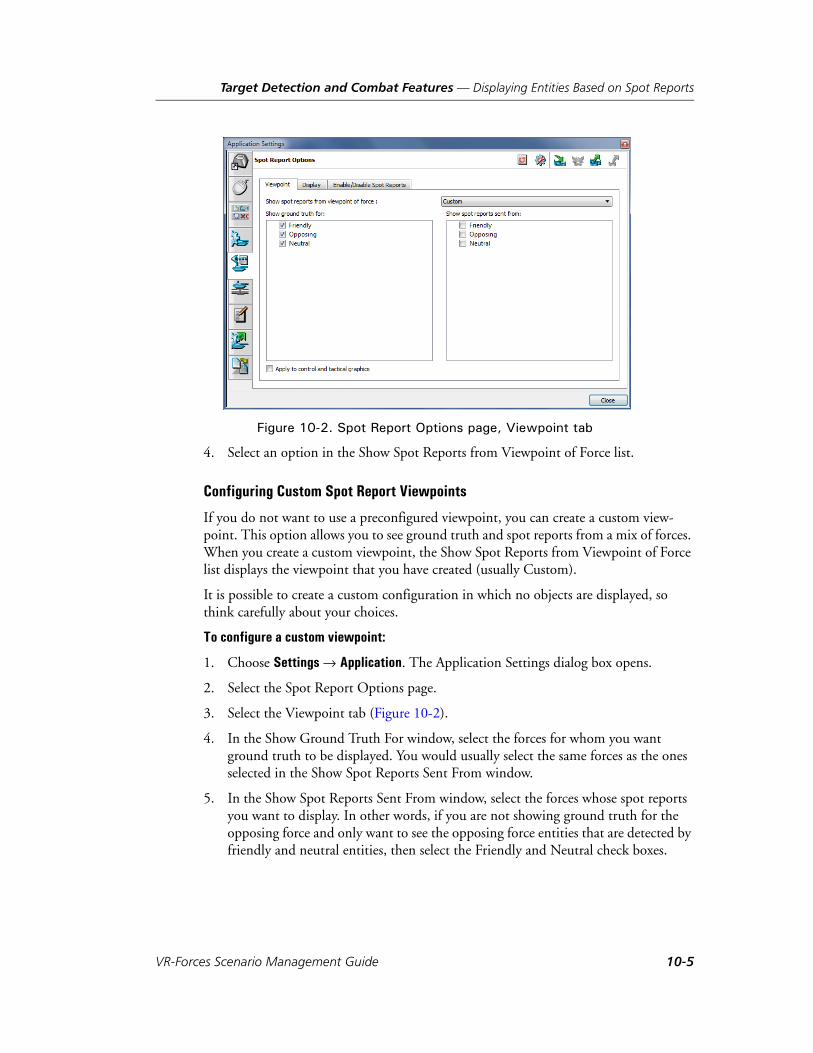
Target Detection and Combat Features — Displaying Entities Based on Spot Reports
Figure 10-2. Spot Report Options page, Viewpoint tab
4. Select an option in the Show Spot Reports from Viewpoint of Force list.
Configuring Custom Spot Report Viewpoints
If you do not want to use a preconfigured viewpoint, you can create a custom view-point. This option allows you to see ground truth and spot reports from a mix of forces. When you create a custom viewpoint, the Show Spot Reports from Viewpoint of Force list displays the viewpoint that you have created (usually Custom).
It is possible to create a custom configuration in which no objects are displayed, so think carefully about your choices.
To configure a custom viewpoint:
1. Choose Settings Application. The Application Settings dialog box opens.
2. Select the Spot Report Options page.
3. Select the Viewpoint tab (Figure 10-2).
4. In the Show Ground Truth For window, select the forces for whom you want ground truth to be displayed. You would usually select the same forces as the ones selected in the Show Spot Reports Sent From window.
5. In the Show Spot Reports Sent From window, select the forces whose spot reports you want to display. In other words, if you are not showing ground truth for the opposing force and only want to see the opposing force entities that are detected by friendly and neutral entities, then select the Friendly and Neutral check boxes.
VR-Forces Scenario Management Guide 10-5

Target Detection and Combat Features — Displaying Entities Based on Spot Reports
Configuring Same-Side Fog-of-War
There may be cases when you want to simulate same-side fog-of-war. That is, members of a force do not know where other members of their force are unless detected by an entity and reported using a spot report.
To simulate same-side fog-of-war, you must edit the spot-report-generator.sysdef file. You might want to create a customized file that you can assign only to the entities that you want to simulate same-side fog-of-war. (You can use the Entity Editor to change the spot report systems that entities use.) In the system definition file change the send-spot-reports-on-own-force parameter to True, as follows:
You can edit the system definition file by hand or in the OPD Editor. For details about the OPD Editor and the Entity Editor, please see VR-Forces Configuration Guide.
(spot-report-generator-system (controllers
(spot-report-generator (component-descriptor-type
"spot-report-generator-controller-descriptor")...(object-types-to-spot-report
(object-type 1 (1 -1 -1 -1 -1 -1 -1))(object-type 1 (3 -1 -1 -1 -1 -1 -1))(object-type 1 (5 -1 -1 -1 -1 -1 -1))
)(send-spot-reports True)
(send-spot-reports-on-own-force True)(send-spot-reports-on-hostile-forces True)(send-spot-reports-on-neutral-forces True)
))...
)
10-6 VT MÄK

Target Detection and Combat Features — Displaying Entities Based on Spot Reports
10.1.3. Configuring the Spot Reports Certainty Level
It is assumed that as time passes the validity, or certainty, of a spot report declines. To simulate this decline in certainty, VR-Forces can display the icons that represent spot reports at increasing levels of transparency. You can configure the amount of time that VR-Forces displays icons for each certainty level.
To configure the amount of time, in seconds, that an icon is displayed at each certainty level:
1. Choose Settings Application. The Application Settings dialog box opens.
2. Select the Spot Report Options page.
3. Select the Display tab (Figure 10-3).
4. Double-click the value in the Time at Level column that you want to change. The value changes to edit mode.
5. Type a new value.
6. Click outside the list.
Figure 10-3. Spot Reports dialog box, Display tab
VR-Forces Scenario Management Guide 10-7

Target Detection and Combat Features — Displaying Entities Based on Spot Reports
10.1.4. Applying Spot Reports to Tactical Graphics
You can display tactical graphics based on spot reports rather than ground truth. The same criteria are applied to their display as are applied to the display of entities. For information about how to assign objects to a force, please see “Creating Tactical Graphics,” on page 5-5.
To apply spot reports to tactical graphics:
1. Choose Settings Application. The Application Settings dialog box opens.
2. Select the Spot Report Options page.
3. Select the Viewpoint tab (Figure 10-2).
4. Select the Apply to Control and Overlay Objects check box.
10.1.5. Displaying Labels for Spot Reports
You can display labels for spot reports with information similar to that for entity icons.
To display spot report labels:
1. Choose Settings Application. The Application Settings dialog box opens.
2. Select the Spot Report Options page.
3. Select the Display tab (Figure 10-3).
4. In the Spot Report Labels group box, select the labels that you want to display.
10.1.6. Using Spot Reports in Tasks
Spot reports are listed in the Objects List Panel and other entity lists. Although the spot report icon in the display window may not show information about a spot report if it has not been identified, the entry in the list includes the object name. You can filter the list to only show spot reports.
You can select a spot report as a parameter in tasks that require you to select an entity. If you use a spot report in a task, VR-Forces carries out the task based on the ground truth of the reported entity, not the location of the spot report. For example, if you specify a spot report in the Follow Entity task, and the target entity moves after the spot report was received, the following entity will follow the actual location of the reported entity, not its location when the spot report was made.
i You can also enable labels for spot reports on the Display Settings dialog box, Symbol Decoration Settings page.
10-8 VT MÄK

Target Detection and Combat Features — Managing Force Hostility Relationships
10.2. Managing Force Hostility RelationshipsVR-Forces categorizes entities as members of a force, such as friendly, opposing, or neutral. By default, friendly forces and opposing forces are hostile to each other. Neither is hostile towards neutral forces. You can change force hostility relationships dynamically. This may be particularly useful if you are simulating an environment in which civilian populations become hostile to a particular force, or in which armed mili-tias, for example, switch allegiances to other forces.
You can add new forces in the Entity Editor. For details, please see Section 5.16, “Managing the Forces List,” in VR-Forces Configuration Guide. You can change a force’s hostility in a global or entity plan. For details, please see “Changing a Force’s Hostility in a Plan,” on page 10-10.
You can change the default hostility relationships by editing the forceHostilty.mtl file for the simulation model set you are using (for example, ./data/simulationModel-Sets/default/forceHostilty.mtl).
When you change force hostility at runtime, the changes are saved as part of the scenario. The hostility loaded with a scenario overrides the hostility loaded by the simu-lation model set's hostility file.
To change the force hostility matrix:
1. Choose Simulation Hostility Matrix. The Hostility Matrix opens (Figure 10-4). Each row in the matrix lists the hostility relationships between that row’s force and all of the other forces (represented by color-coded columns).
Figure 10-4. Hostility Matrix
i Hostility relationships are not reciprocal. For example if you set neutral force entities to be hostile to friendly force entities, that does not mean that friendly force entities are hostile to neutral force entities.
VR-Forces Scenario Management Guide 10-9

Target Detection and Combat Features — Managing Force Hostility Relationships
2. For each row in the matrix, select the check boxes in the columns for the forces that you want this force to be hostile towards. Clear the check boxes for forces that you do not want it to be hostile towards.
3. Click OK.
10.2.1. Changing a Force’s Hostility in a Plan
To change a force’s hostility in a global or local plan:
1. Open a global plan or an entity’s plan.
2. Choose Commands Change Hostility. The Change Hostility dialog box opens (Figure 10-5).
Figure 10-5. Change Hostility dialog box
3. In the Force to Change list, select the force whose hostility you want to change.
4. In the To Force list, select the force towards which you want to change hostility.
5. Select the new force relationship (New Stance), either Friendly or Hostile.
6. Click OK. The command is added to the plan.
10-10 VT MÄK

Target Detection and Combat Features — Detecting Targets
10.3. Detecting TargetsEntities can have one or more sensors, for example, visual, sonar, or radar, for detecting and identifying other entities. When an entity detects another entity, it assigns it a combat identification (CID) level. If it continues to maintain contact with the entity, it upgrades the CID level as follows:
CID Level 0 – not detected.
CID Level 1 – Detected: the entity is detected, but only its platform is known, for example, ground.
CID Level 2 – Classified: the entity’s category is known, for example, tank.
CID Level 3– Identified: the entity’s category and subcategory are known, for example M1A2.
CID Level 4 – Full Knowledge: all visible information about the entity is known.
CID levels are assigned based on the distance to the detected entity and the length of time that the entity has been in contact. You can configure these values in the detection tables (./data/simulationModelSets/default/vrfSim/detection/*.csv). For details about these configuration files, please see Section 7.2, “Detection Tables,” in VR-Forces Configuration Guide.
By default, entities do not fire at a detected hostile entity until it achieves the Identified level. You can configure this behavior by changing the detection-level-to-set-hostility parameter in the entity’s sensor system. For details about editing entity parameters, please see VR-Forces Configuration Guide.
Figure 10-6 shows a series of screen captures of an entity as its CID level is advanced from Detected through Identified. In this scenario, spot reports are enabled. Therefore, when an entity is detected, it is displayed with a yellow icon, rather than the normal color for the force. It is not given the correct force color until the detected entity is CID level Identified.
You can view videos that demonstrates entity classification and spot reports at ./doc/vrforces_tutorialvideos.htm, or click the camera icons in previous paragraphs.
VR-Forces Scenario Management Guide 10-11

Target Detection and Combat Features — Detecting Targets
Figure 10-6. Entity classification and display when spot reports are enabled
Detected
Identified
Classified
10-12 VT MÄK

Target Detection and Combat Features — Detecting Targets
10.3.1. Target Detection and Spot Reports
Entity detection and classification can be enhanced by enabling spot reports. Detected entities are assigned CID levels based on length of contact and distance from the detecting entity. In some cases, such as a fixed-wing aircraft flying quickly over a battle-field, or an entity that is at the extreme of its range from a target, contact might not be sufficient to advance to the Identified CID level. In such cases, even though the entity is technically capable of firing on the target, it might not do so because the CID level is not high enough.
If spot reports are enabled, the classification of entities in the spot reports that an entity receives is combined with the directly sensed information. Therefore, if an entity classi-fies a target at a low CID level, but it receives a spot report that classifies the target at a high CID level, it can fire on the target based on the CID level in the spot report. For example, as noted in the previous paragraph, a fixed-wing aircraft is unlikely to main-tain contact with a ground-based entity long enough to elevate its CID level to Identi-fied. However, if a member of its force on the ground identifies the target and sends out a spot report indicating CID level 3 or 4, when the fixed-wing aircraft receives the spot report, it can add the target to its target list.
10.3.2. Lasing Targets
Some entities, such as DI Lasing, have laser-targeting capability. Others, such as attack helicopters, have laser targeting capability and carry laser-guided missiles. Laser-guided missiles do not use the standard VR-Forces targeting mechanisms. They only fire on targets that are identified by laser beams that have the same laser code as the laser-guided missile launcher. The laser beam could be generated by a laser designator on the same entity (autonomous lasing), or could be generated by another entity.
Laser codes are numbers in the range of 111-8888, using only the digits 1-8. By default, VR-Forces calculates a unique laser code for each entity when it is created. When you assign a laser code to an entity, any laser beams sent by that entity use the assigned laser code and the missiles carried by that entity (if applicable) use the same code. Therefore, for example, the default behavior for attack helicopters would be to fire their laser-targeted missiles only at targets that they have lased.
i A laser-guided missile launcher must be able to see a laser spot and an appropriate target before it fires. If the missile loses the laser spot before it hits the target, it tracks to the last known laser spot.
VR-Forces Scenario Management Guide 10-13

Target Detection and Combat Features — Detecting Targets
Autonomous Lasing
By default, entities that have laser-guided missiles are configured for autonomous lasing. This means that they can lase targets and fire at them without outside interven-tion (for example, using the Lase Target task). Entities with autonomous lasing enabled identify and fire at targets independently, just like entities that use conventional muni-tions.
Synchronizing Laser Codes
There are cases in which you will want more than one entity to use the same laser code. For example, you might want one entity to lase targets (the designator), and another one to fire on them (the shooter). In this case you would assign both entities the same laser code. The designator would be given the hold-fire rule of engagement or not have any missile resources. The shooter would be configured to not lase targets (Lase Auton-omous would be set to Off ). It would just fire on the targets identified by the desig-nator’s laser.
You can synchronize the laser codes of the lasing entity and the firing entity by setting them for each entity with the Laser Code set data request, or you can let VR-Forces synchronize the codes with the Synchronize Laser Code set data request. For details, please see “Laser Code,” on page 8-17 and “Synchronize Laser Code,” on page 8-27.
10-14 VT MÄK

Target Detection and Combat Features — Using Sonar
10.4. Using SonarVR-Forces simulates active and passive sonar. Entities can be configured with three types of sonar sensor systems: Active Sonar, Passive Sonar, and Sonar. The Sonar system includes both active and passive sonar. Both types of sonar use the VR-Forces sensor signature mechanism. The signatures are different, reflecting the different chances of detecting entities using the two types of sonar.
Passive sonar has the following characteristics:
Sonar can be dipped at a depth other than that of the entity.
If an entity is moving faster than a specified speed, passive sonar does not work.
Sonar takes into account thermocline data. Thermoclines are layers of water that have different temperatures and, therefore, different density. Sound transmission varies as it passes through the thermocline. In VR-Forces sonar effectiveness is reduced as it passes through thermocline boundaries. For more information, please see “Setting the Thermocline,” on page 12-13.
Passive sonar ignores line-of-sight. It does not take into account underwater terrain or the presence of islands.
If an entity is publishing propulsion noise, it can affect its detectability by passive sonar.
Active sonar has the following characteristics:
Active sonar should acquire targets more quickly than passive sonar.
If an entity has an active sonar system enabled, it is more easily detected by passive sonar systems.
Entities with an active sonar that is enabled publish Underwater Acoustics PDUs.
Entities can have multiple active sonar modes, similar to radar modes, using emitter beams. For details about configuring emitters, please see Section 7.5, “Configuring Emitters,” in VR-Forces Configuration Guide.
Active sonar detects targets within the range of its emitter beams, but without regard to the direction of the beams.
Active sonar ignores propulsion noise and the presence of active sonar on the target.
Sonar only works in water. Therefore rotary-wing entities with sonar systems must set their depth in order to sense anything.
! RPR FOM 1.0 does not support active sonar. If you try to create an entity that has an active sonar system, the entity will not be created and a warning will be sent to the console. If you try to load a scenario that has such an entity, it will not be created.
VR-Forces Scenario Management Guide 10-15

Target Detection and Combat Features — Using Sonar
10.4.1. Propulsion Noise and Sonar
If an entity is generating propulsion noise, it is easier to detect using passive sonar. VR-Forces publishes propulsion noise for surface and subsurface entities. If the power plant for an entity is turned off, it does not publish propulsion noise. To turn propulsion noise on or off, change the power plant appearance (for details, please see “Appearance,” on page 8-5) or set the power-plant-active parameter in the propulsion-noise-generator component of the entity’s movement system in the OPD Editor.
VR-Forces publishes three propulsion noise values:
Current Shaft RPM, calculated as current speed * speed-to-rpm-factor.
Ordered Shaft RPM, calculated as ordered speed * speed-to-rpm-factor.
Shaft RPM Rate of Change, calculated as current acceleration * acceleration-to-rpm-factor.
The values for current speed, ordered speed, and current acceleration are the current values for the entity. The values for speed-to-rpm-factor and acceleration-to-rpm-factor are taken from the speed-to-rpm-factor and acceleration-to-rpm-factor parameters in the propulsion-noise-generator component of the entity’s movement system.
When a target is being detected by passive sonar, if it is publishing propulsion noise, its calculated RPM is compared to a nominal RPM (default 100) to generate a sensor signature modifier. For example, if an entity is publishing an RPM of 80, its signature is scaled by 0.8. If its RPM is 150, the signature is scaled by 1.5.
! RPR FOM 1.0 does not support propulsion noise. If you try to create an entity that has propulsion noise enabled, the entity will not be created and a warning will be sent to the console. If you try to load a scenario that has such an entity, it will not be created.
10-16 VT MÄK

Target Detection and Combat Features — Launching Counter Measures (Chaff and Flare)
10.5. Launching Counter Measures (Chaff and Flare)Fixed-wing and rotary-wing entities can launch counter measures (chaff and flare) when they are targeted by air-to-air and ground-to-air missiles. By default, entities launch counter measures automatically based on settings in the countermeasures.sysdef file. When an aircraft detects a hostile missile within a specified range, it determines the type of missile and looks up the type of counter measures to use in the USCounterMea-suresTable.asl or CISCounterMeasuresTable.asl table.
Figure 10-7 shows a friendly force fighter launching counter measures against an aphid missile.
Figure 10-7. Counter measures (flare)
You can disable automatic counter-measures with the Counter Measures Auto Launch set data request. You can also launch counter-measures with the Launch Counter Measures task. The Launch Counter Measures task is not an exclusive task, so it does not interfere with the entity’s current task. For details about the task and set data request, please see “Launch Counter Measures,” on page 7-27 and “Counter Measures Auto Launch,” on page 8-8.
2D 3D
VR-Forces Scenario Management Guide 10-17
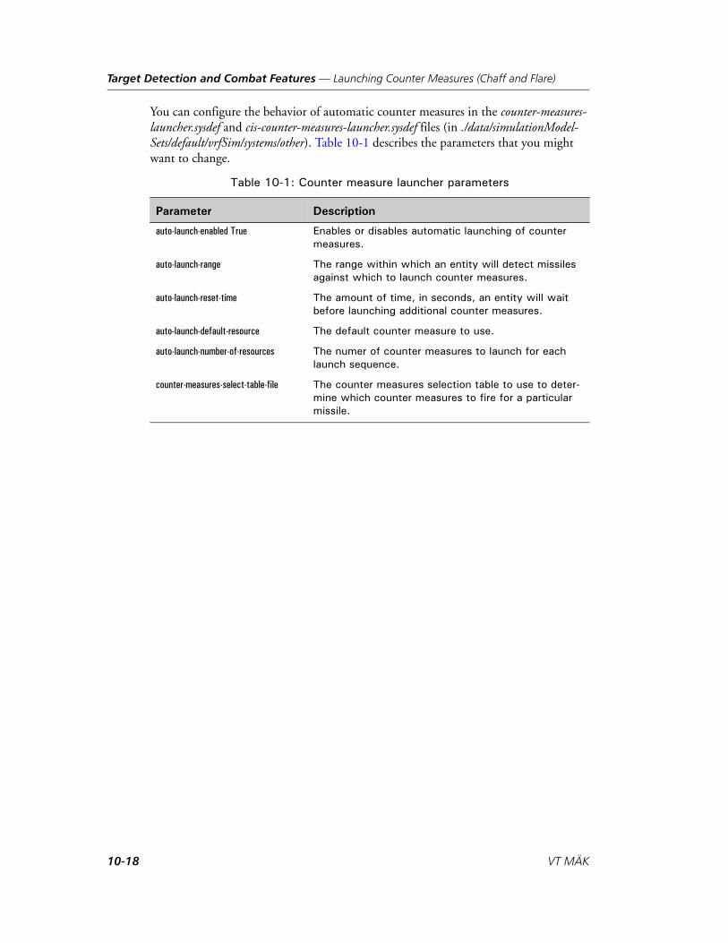
Target Detection and Combat Features — Launching Counter Measures (Chaff and Flare)
You can configure the behavior of automatic counter measures in the counter-measures-launcher.sysdef and cis-counter-measures-launcher.sysdef files (in ./data/simulationModel-Sets/default/vrfSim/systems/other). Table 10-1 describes the parameters that you might want to change.
Table 10-1: Counter measure launcher parameters
Parameter Description
auto-launch-enabled True Enables or disables automatic launching of counter measures.
auto-launch-range The range within which an entity will detect missiles against which to launch counter measures.
auto-launch-reset-time The amount of time, in seconds, an entity will wait before launching additional counter measures.
auto-launch-default-resource The default counter measure to use.
auto-launch-number-of-resources The numer of counter measures to launch for each launch sequence.
counter-measures-select-table-file The counter measures selection table to use to deter-mine which counter measures to fire for a particular missile.
10-18 VT MÄK

Target Detection and Combat Features — Modeling Artillery Munitions
10.6. Modeling Artillery MunitionsVR-Forces models artillery in two ways – direct fire and indirect fire. Artillery entities, such as howitzers use a direct fire model. The artillery entity is modeled and the muni-tions it fires are modeled. Indirect fire simply models artillery barrages within an area. For details about indirect fire, please see Chapter 11, Managing Indirect Fire and Missiles.
By default, when an artillery entity fires, VR-Forces models the munition. Munitions are not affected by wind speed or friction. VR-Forces can also model artillery without modeling the munition. In this case, it just publishes a fire event and detonation event. Modeling munitions requires more computer resources than not doing so. Therefore, in large simulations you may want to disable modeling of munitions.
To disable modeling munitions, in the indirect-fire-actuator, set the simulate-munition parameter to false. For example, in the OPD Editor:
1. Select the Systems List tab.
2. Select the M284 155mm Cannon.
3. Select the Components tab.
4. Expand the Actuators list.
5. Select M284-cannon.
6. Change the value for the simulate-munition parameter.
VR-Forces Scenario Management Guide 10-19
Target Detection and Combat Features — Taking Damage from Munitions
10.7. Taking Damage from MunitionsEntities can be damaged by munitions fired by other entities. They can be damaged by direct fire – a munition that hits the entity or within a configurable distance of the entity, and by indirect fire – a munition that explodes within a configurable distance of the entity. An entity can also suffer collateral damage. This can occur if an entity is hit by direct fire of sufficient power to damage nearby entities.
The types of munitions to which an entity is vulnerable are determined by its damage system. Each damage system has a damage actuator, which specifies damage files. These damage files specify how entities are damaged by direct and indirect fire from specific munitions. VR-Forces Configuration Guide describes damage systems and damage files. The important point to remember as a VR-Forces user is that an entity will not be harmed by a munition unless it has a damage system that knows about that munition. And, if you introduce a new munition type, it will not harm any entities unless their damage systems have a damage file for the new munition.
i The default radar signature for ground vehicles is 500 meters. This is too short a distance for most fixed-wing aircraft to detect and fire on a ground vehicle. To make ground vehicles vulnerable to aircraft, increase the radar signature to a distance that is appropriate for the aircraft in your simulation.
10-20 VT MÄK

VR-Forces Scenario Management Guide
11
Managing Indirect Fire and Missiles
This chapter explains how to create and edit indirect fire events and ballistic missiles.
Introduction to Indirect Fire ....................................................................... 11-2Creating an Indirect Fire Event............................................................. 11-3Editing Indirect Fire Events .................................................................. 11-6Deleting Indirect Fire Events ................................................................ 11-6Configuring Indirect Fire Event Default Values .................................... 11-7
Ballistic Missiles .......................................................................................... 11-8Firing Ballistic Missiles ......................................................................... 11-8Editing Missile Target Events ............................................................. 11-10Deleting Missile Target Events............................................................ 11-10
11-1

Managing Indirect Fire and Missiles — Introduction to Indirect Fire
11.1. Introduction to Indirect FireThe indirect fire feature allows you to create, configure, and schedule indirect fire events. Indirect fire events are not associated with a particular entity. VR-Forces does not model the launcher or trajectory of the munitions. Indirect fire results in one or more salvos of one or more rounds in or near a designated area of the terrain. Entities do not take damage from indirect fire unless they are configured to do so. Figure 11-1 illustrates indirect fire fire within an indirect fire area.
Figure 11-1. Indirect fire event
Indirect fire types are configured in ./data/simulationModelSets/default/indirectFire-Types.mtl.
11-2 VT MÄK

Managing Indirect Fire and Missiles — Introduction to Indirect Fire
11.1.1. Creating an Indirect Fire Event
When you create an indirect fire event, you specify an area in which the event is to take place, the parameters of the event, and a starting time. The area in which an indirect fire event takes place is a tactical graphic and is listed on the Environmental tab of the Objects List Panel.
By default, indirect fire areas are placed on the Indirect Fire layer (which is created for the first indirect fire object). You can put other objects on this layer. You can put indi-rect fire objects on other layers by selecting a layer in the Create Indirect Fire dialog box or by dragging them on the Overlay tab of the Objects List Panel.
To create an indirect fire event:
1. Choose Simulation Munition Targets. The Munition Target Settings dialog box opens (Figure 11-2).
Figure 11-2. Munition Target Settings dialog box, Indirect Fire page
2. Select the Indirect Fire page.
3. Click New. The cursor changes to create mode and a tab for the Create Indirect Fire dialog box is added to the window.
4. Draw an ellipse on the map to specify the area of the fire event:
a. Click to set the center of the ellipse. A center point is set and a small circle is displayed with a vertex indicator at the bottom of the circle.
b. Drag the mouse up or down and click to set the height of the ellipse. A vertex indicator is added to the left side of the circle.
c. Drag the mouse left and right and click to set the width of the ellipse (Figure 11-3).
Optionally, you can specify the properties of the ellipse in the Create Indirect Fire dialog box.
VR-Forces Scenario Management Guide 11-3

Managing Indirect Fire and Missiles — Introduction to Indirect Fire
Figure 11-3. Indirect fire event area
5. Click the tab to display the Create Indirect Fire dialog box (Figure 11-4).
Figure 11-4. Create Indirect Fire dialog box
6. Type a name for the event in the Name text box, or accept the default name (Indi-rect Fire n).
7. Optionally, specify a layer for the event. (If there are no tactical graphics in the scenario, there might not be any layers to select. A layer will be created when you click Create to create this indirect fire event.)
11-4 VT MÄK

Managing Indirect Fire and Missiles — Introduction to Indirect Fire
8. Configure the parameters of the fire event, as follows:
– Select the detonation start time. The options are Immediate or At Simulation Time. If you select At Simulation Time, enter the simulation time at which you want the munition to start firing.
– In the Number of Salvos box, enter the number of salvos you want to fire.
– In the Rounds Per Salvo box, enter the number of rounds you want to fire for each salvo.
– In the Scatter Time box, enter the length of time for each salvo. The rounds in each salvo will be detonated at random times within this time period.
– If you specified more than one salvo, in the Time Between Salvos box enter the amount of time you want to pass between each salvo.
– Optionally, specify an altitude above the terrain that the rounds should detonate at.
– Select the munition type in the Munition Type list.
9. Click Create. The Indirect Fire event is added to the list (Figure 11-5). The area is added as an object on the Indirect Fire layer on the Overlays tab of the Objects List Panel.
Figure 11-5. Indirect Fire page with indirect fire event
VR-Forces Scenario Management Guide 11-5

Managing Indirect Fire and Missiles — Introduction to Indirect Fire
11.1.2. Editing Indirect Fire Events
You can edit the properties of an indirect fire event. You can also directly manipulate the area that specifies the event.
To edit an indirect fire event:
1. Choose Simulation Munition Targets. The Munition Target Settings dialog box opens.
2. Select the Indirect Fire page (Figure 11-5).
3. Select the indirect fire event that you want to edit.
4. Click Edit. The Edit Indirect Fire dialog box opens.
5. Change the properties that you want to change.
6. Click OK.
11.1.3. Deleting Indirect Fire Events
To delete an indirect fire event:
1. Choose Simulation Munition Targets. The Munition Target Settings dialog box opens (Figure 11-2).
2. Select the Indirect Fire page (Figure 11-5).
3. Select the indirect fire event that you want to delete.
4. Click Delete.
5. Click Close.
11-6 VT MÄK

Managing Indirect Fire and Missiles — Introduction to Indirect Fire
11.1.4. Configuring Indirect Fire Event Default Values
You can configure a set of default values that get applied to the Create Indirect Fire dialog box.
To configure default values for indirect fire events:
1. Choose Settings Display. The Display Settings dialog box opens.
2. Select the Indirect Fire Settings page (Figure 11-6).
Figure 11-6. Indirect Fire Settings page
3. Set the parameters to the desired default values.
4. Click Close.
VR-Forces Scenario Management Guide 11-7

Managing Indirect Fire and Missiles — Ballistic Missiles
11.2. Ballistic MissilesVR-Forces supports firing of ballistic missiles, including multistage missiles. The trajec-tory of a missile is determined by a series of coordinates in a comma-separated values (CSV) file. VR-Forces includes some sample CSV files. VR-Forces users are responsible for creating their own files if they want missiles to fly with different characteristics.
You fire a ballistic missile by specifying a target and choosing a missile type. The charac-teristics of the missile type are specified in the Entity Editor. A missile launches at the same altitude as the target point at a distance determined by the CSV file. Therefore, if a target point is placed at or near the ground, it is possible that due to variations in the terrain, the launch location could be underground. Once the missile launches, it follows the trajectory contained in the CSV that it is configured with. It detonates when it reaches the target point. For details about configuring missiles, please see Section 5.9.1, “Configuring Ballistic Missile Movement,” in VR-Forces Configuration Guide.
11.2.1. Firing Ballistic Missiles
To fire a ballistic missile:
1. Choose Simulation Munition Targets. The Munition Target Settings dialog box opens (Figure 11-2).
2. Select the Missile Target page (Figure 11-7).
Figure 11-7. Munition Target Settings dialog box, Missile Target page
3. Click New. The cursor changes to a cross-hair.
4. Click the location where you want the missile to hit. The Create Missile Target dialog box opens (Figure 11-8).
11-8 VT MÄK

Managing Indirect Fire and Missiles — Ballistic Missiles
Figure 11-8. Create Missile Target dialog box
5. Optionally, specify the parameters for the target. In particular, set the following parameters:
– Name. The name of the target point.
– Launch Time. The simulation time at which the missile will be launched.
– Incoming Heading. The heading, relative to the target, from which the missile will be launched.
– Missile Type. An option from the list.
6. Click Create. The missile event is listed in the Missile Target window.
VR-Forces Scenario Management Guide 11-9

Managing Indirect Fire and Missiles — Ballistic Missiles
11.2.2. Editing Missile Target Events
You can edit the properties of a missile target event. You can also directly manipulate the target point.
To edit a missile target event:
1. Choose Simulation Munition Targets. The Munition Target Settings dialog box opens (Figure 11-2).
2. Select the Missile Target page (Figure 11-7).
3. Select the missile fire event that you want to edit.
4. Click Edit. The Edit Missile Target dialog box opens.
5. Change the properties that you want to change.
6. Click Update.
11.2.3. Deleting Missile Target Events
To delete a missile target event:
1. Choose Simulation Munition Targets. The Munition Target Settings dialog box opens (Figure 11-2).
2. Select the Missile Target page (Figure 11-7).
3. Select the missile fire event that you want to delete.
4. Click Delete.
5. Click Close.
i You can also simply delete the target point from the terrain.
11-10 VT MÄK

VR-Forces Scenario Management Guide
12
Environment Conditions
This chapter explains how to set the time of day and weather conditions.
Introduction to Environment Conditions ................................................... 12-2
Setting the Time of Day.............................................................................. 12-3
Specifying the Environment Conditions ..................................................... 12-4Adding an Environment Condition...................................................... 12-5Editing an Environment Condition...................................................... 12-6Deleting an Environment Condition.................................................... 12-6
Setting Weather Conditions ........................................................................ 12-7Setting the Wind Speed and Direction ................................................. 12-7Setting Visibility (Fog) ......................................................................... 12-8Specifying Precipitation Type and Intensity .......................................... 12-9Specifying Cloud Cover........................................................................ 12-9
Configuring Marine Conditions ............................................................... 12-10Enabling Marine Effects ..................................................................... 12-11Configuring Marine Conditions......................................................... 12-11
Setting the Thermocline............................................................................ 12-13
Displaying Screen Splash Effects ............................................................... 12-14
12-1

Environment Conditions — Introduction to Environment Conditions
12.1. Introduction to Environment ConditionsYou can set the time of day, weather, and marine conditions from the front-end and in plans. The time of day and weather conditions are back-end settings, not merely front-end display effects. They affect entity sensors and line-of-sight. For example, if visibility is set to 4 kilometers, an entity will not see an entity that is 5 km away. If the time of day changes from daytime to nighttime, lighting conditions in the 3D view change accordingly.
The time of day advances as simulation time advances. However, they are not directly tied to each other. For example, if at the start of a simulation (simulation time 0:00:00:00), you set the time of day to 10:00 AM, after eight hours of simulation time passes, the time of day will be 6:00 PM. However, you could just as easily set the initial time of day to some other time or change it at will during the course of the simulation. These changes would not affect the elapsed simulation time in any way. They would just change the starting point for the advance of the time of day.
Time of Day and Global Weather are options on the commands menu in global plans and entity plans.
12-2 VT MÄK

Environment Conditions — Setting the Time of Day
12.2. Setting the Time of DayAs time advances, the time displayed on the Environment Settings toolbar changes. The time of day setting is independent of simulation time.
To set the time of day:
1. Choose Simulation Environment Settings, or click the Time of Day button ( ) on the Environment Settings toolbar. The Environment Settings dialog box opens.
2. Select the Time of Day page (Figure 12-1).
Figure 12-1. Time of Day page
3. Set the time of day by typing or selecting a value in the Current Time box.
VR-Forces Scenario Management Guide 12-3

Environment Conditions — Specifying the Environment Conditions
12.3. Specifying the Environment ConditionsVR-Forces has a set of preconfigured environment conditions. Each environment condition has settings for:
Weather:
– Wind speed and direction.
– Cloud cover.
– Visibility.
– Precipitation type and intensity.
– Fog height and color.
Marine:
– Sea swell.
– Sea state.
– Surface transparency.
– Underwater visibility.
– Choppiness.
– Surge depth.
Conditions range from clear to stormy and let you quickly set the weather without needing to adjust all the various weather parameters. However, if you want to, you can change any of the individual weather parameters. Changing a weather or marine setting does not affect the saved settings unless you specifically overwrite them.
You can save and import environment settings. When you save a scene, environment settings are saved as part of the scene. Environment settings support the standard VR-Forces settings behaviors, as described in “Managing VR-Vantage Settings,” on page 3-20.
You can add your own environment conditions. You can also set an environment condi-tion as the default condition to use when VR-Forces starts up. If you do not set a default condition, VR-Forces saves the settings that were in effect when you last closed it.
To specify a weather condition:
1. Choose Simulation Environment Conditions. The Environment Conditions dialog box opens.
2. Select the Weather page (Figure 12-2).
12-4 VT MÄK

Environment Conditions — Specifying the Environment Conditions
Figure 12-2. Weather page
3. In the Apply Environment Condition list, select the condition you want.
12.3.1. Adding an Environment Condition
If you add an environment condition, it gets added to the Apply Environment Condi-tion list.
To add an environment condition:
1. Choose Simulation Environment Conditions. The Environment Conditions dialog box opens.
2. Select the Weather page (Figure 12-2).
3. Click the Add button ( ). The Name an Environment Condition dialog box opens.
4. Type a name for the new condition.
5. Click OK.
VR-Forces Scenario Management Guide 12-5
Environment Conditions — Specifying the Environment Conditions
12.3.2. Editing an Environment Condition
You can change the settings for an environment condition. Editing a condition essen-tially means overwriting a condition with the current set of weather and marine condi-tions.
To edit an environment condition:
1. Choose Simulation Environment Conditions. The Environment Conditions dialog box opens.
2. Select the Weather page (Figure 12-2).
3. Optionally, in the Apply Environment Condition list, select a condition you want to use as your starting point.
4. Change whatever conditions you want.
5. Click the Edit button ( ). The Select an Environment Condition dialog box opens.
6. In the Select Name list, select the condition you want to overwrite.
7. Click OK.
12.3.3. Deleting an Environment Condition
If you delete one of the built-in environment conditions, you can restore it from the factory settings.
To delete an environment condition:
1. Choose Simulation Environment Conditions. The Environment Conditions dialog box opens.
2. Select the Weather page (Figure 12-2).
3. Click the Delete button ( ). The Select an Environment Condition dialog box opens.
4. In the Select Name list, select the condition you want to delete.
5. Click OK.
12-6 VT MÄK
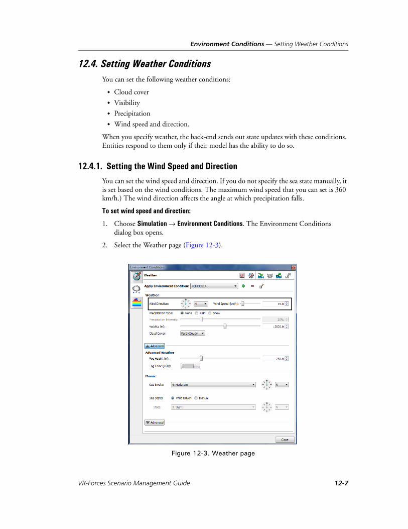
Environment Conditions — Setting Weather Conditions
12.4. Setting Weather ConditionsYou can set the following weather conditions:
Cloud cover
Visibility
Precipitation
Wind speed and direction.
When you specify weather, the back-end sends out state updates with these conditions. Entities respond to them only if their model has the ability to do so.
12.4.1. Setting the Wind Speed and Direction
You can set the wind speed and direction. If you do not specify the sea state manually, it is set based on the wind conditions. The maximum wind speed that you can set is 360 km/h.) The wind direction affects the angle at which precipitation falls.
To set wind speed and direction:
1. Choose Simulation Environment Conditions. The Environment Conditions dialog box opens.
2. Select the Weather page (Figure 12-3).
Figure 12-3. Weather page
VR-Forces Scenario Management Guide 12-7

Environment Conditions — Setting Weather Conditions
3. Drag the Wind Direction indicator to the desired compass point or select an option from the list.
4. Drag the Wind Speed slider or enter a value in the box.
12.4.2. Setting Visibility (Fog)
The visibility setting determines the denseness of the fog effect, which determines how far you can see.
To set visibility:
1. Choose Simulation Environment Conditions. The Environment Conditions dialog box opens.
2. Select the Weather page (Figure 12-3).
3. Adjust the Visibility slider or enter a value in the box.
Configuring Fog
You can set the fog height and color. The fog height affects how much sky the observer can see when looking up from ground level. For example, if you set the fog height to 50m and look up, you will see some amount of sky above you, and to the sides it will be very gray. If you then set it to 10m and look up, you will see mostly blue sky above you, but still quite a bit of gray to the sides.
To configure fog:
1. Choose Simulation Environment Conditions. The Environment Conditions dialog box opens.
2. Select the Weather page (Figure 12-3).
3. In the Weather section of the page, click Advanced. The dialog box expands to show options for fog.
4. To set the fog height, adjust the slider or enter a value in the box.
5. To set the fog color:
a. Click the color swatch. A color picker dialog box opens.
b. Select the color you want to apply to the fog. It is applied immediately, so you can easily see the effect of the new color and change it if you want to.
c. Click OK.
i Fog settings are not modeled in the back-end. Therefore, they are not available when you set weather conditions in a plan.
12-8 VT MÄK

Environment Conditions — Setting Weather Conditions
12.4.3. Specifying Precipitation Type and Intensity
VR-Forces supports display of rain and snow. You can configure the intensity of precip-itation.
To specify the precipitation type and intensity:
1. Choose Simulation Environment Conditions. The Environment Conditions dialog box opens.
2. Select the Weather page (Figure 12-3).
3. Select a Precipitation Type. If you select rain or snow, the Precipitation Intensity setting becomes editable.
4. Adjust the Precipitation Intensity slider or enter a value in the box. The range is 0% through 100%.
12.4.4. Specifying Cloud Cover
VR-Forces simulated varying amounts and types of cloud cover, from clear, to cloudy, to thunderstorm. When you choose an environment condition, it includes an appro-priate degree of cloud cover. You can also change the cloud cover at any time.
To specify the cloud cover:
1. Choose Simulation Environment Conditions. The Environment Conditions dialog box opens.
2. Select the Weather page (Figure 12-3).
3. Select an option from the Cloud Cover list.
VR-Forces Scenario Management Guide 12-9

Environment Conditions — Configuring Marine Conditions
12.5. Configuring Marine ConditionsVR-Forces supports a variety of dynamic ocean effects (Figure 12-4), including:
Douglas Sea State. This includes wind waves (wind sea), swell character, and the directions of each. VR-Forces allows each to be separately configured.
Wave chop.
Surface transparency. The ability to see through the water from above sea level.
Underwater visibility. The ability to see underwater.
Swell.
Surge depth.
Figure 12-4. Fishing boat
i Enabling dynamic ocean effects can affect performance.
12-10 VT MÄK
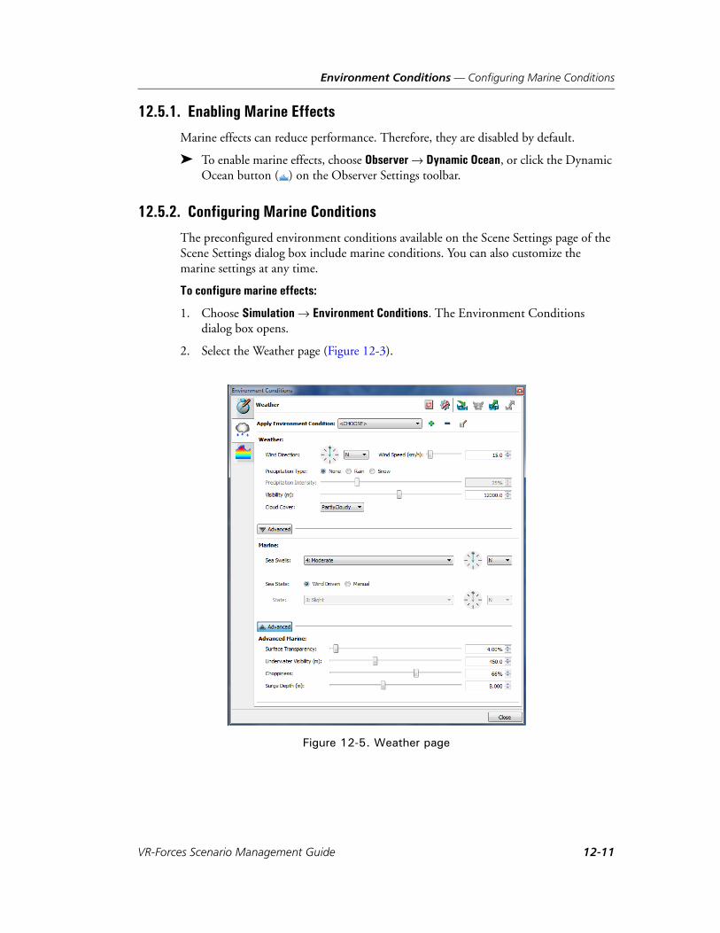
Environment Conditions — Configuring Marine Conditions
12.5.1. Enabling Marine Effects
Marine effects can reduce performance. Therefore, they are disabled by default.
To enable marine effects, choose Observer Dynamic Ocean, or click the Dynamic Ocean button ( ) on the Observer Settings toolbar.
12.5.2. Configuring Marine Conditions
The preconfigured environment conditions available on the Scene Settings page of the Scene Settings dialog box include marine conditions. You can also customize the marine settings at any time.
To configure marine effects:
1. Choose Simulation Environment Conditions. The Environment Conditions dialog box opens.
2. Select the Weather page (Figure 12-3).
Figure 12-5. Weather page
VR-Forces Scenario Management Guide 12-11

Environment Conditions — Configuring Marine Conditions
3. Change settings as desired. The settings are described in Table 12-1.
Table 12-1: Advanced marine settings
Parameter Description
Sea Swells The amount of rise and fall of waves independent of wind. Choose from 10 fixed swell states. You can also set the compass direction from which swells originate.
Sea (wind) state Determined by the wind direction and speed or set manu-ally. If manual, one of the swell states for the Douglass sea state scale. You can also set the compass direction from which sea state originates.
Advanced Parameters
Surface Transparency The depth at which VR-Forces begins to apply transpar-ency to the water surface if the terrain has bathymetry or underwater polygons. This setting helps reduce Z-fighting along the shoreline. It does not mean that you can see some distance into the water when the observer is over deep water. The maximum value represents transparency to 500 meters.
Underwater visibility The distance you can see underwater if the observer is underwater
Choppiness The percentage of turbulence on the water.
Surge depth When bathymetry data is present, this is the depth of the water at which full storm effects take place. As the water gets shallower, it gets calmer.
12-12 VT MÄK

Environment Conditions — Setting the Thermocline
12.6. Setting the ThermoclineThermoclines are layers of water that have different temperatures and, therefore, different density. Sound transmission varies as it passes through the thermocline. In VR-Forces sonar effectiveness is reduced as it passes through thermocline boundaries. By default, VR-Forces does not set any thermoclines. You can specify the depth of up to five thermoclines.
To specify a thermocline:
1. Choose Simulation Environment Conditions. The Environment Conditions dialog box opens.
2. Select the Thermoclines page (Figure 12-6).
Figure 12-6. Thermoclines page
3. For each thermocline that you want to specify, type or select a value in the depth box and the permeability box.
VR-Forces Scenario Management Guide 12-13

Environment Conditions — Displaying Screen Splash Effects
12.7. Displaying Screen Splash EffectsWhen it is raining, VR-Forces can simulate raindrops hitting the oberver’s camera lens. If the observer is close to the surface of the ocean (as if a periscope were being raised or lowered), VR-Forces can simulate the effect of waves and water droplets splashing on the observer’s camera (Figure 12-7).
Figure 12-7. Rain effect
To enable or disable screen splash effects:
1. Choose Settings Display. The Display Settings dialog box opens.
2. Select the Render Settings page (Figure 12-8).
12-14 VT MÄK

Environment Conditions — Displaying Screen Splash Effects
Figure 12-8. Render Settings page
3. Select or clear the Rain Effect, Wave Effect, or Ocean Spray effect check boxes.
VR-Forces Scenario Management Guide 12-15

Environment Conditions — Displaying Screen Splash Effects
12-16 VT MÄK

VR-Forces Scenario Management Guide
13
Creating Scripted Tasks
VR-Forces lets you create new tasks by writing scripts. You do not need to know C++ or have a developers license to write these scripts.
Introduction to Scripted Tasks .................................................................... 13-3Script Meta Data .................................................................................. 13-4The Lua Scripting Language................................................................. 13-4
Creating a New Scripted Task ..................................................................... 13-5Specifying the Script ID ....................................................................... 13-9Specifying the Task Menu Icon............................................................. 13-9Specifying Task Parameters ................................................................. 13-10Specifying the Task Menu Location.................................................... 13-13Specifying Action Categories .............................................................. 13-15Configuring a Script’s Availability....................................................... 13-15Specifying the Programming Language for a Scripted Task ................. 13-18Creating Reactive Tasks ...................................................................... 13-19
Saving Scripted Tasks ................................................................................ 13-20
Editing a Scripted Task ............................................................................. 13-21
Filtering the List of Scripted Tasks ............................................................ 13-21
Organizing Scripted Tasks into Folders ..................................................... 13-22Adding a Folder.................................................................................. 13-22Renaming a Folder ............................................................................. 13-22Deleting a Folder................................................................................ 13-22Adding Scripted Tasks to a Folder ...................................................... 13-22Removing a Scripted Task from a Folder ............................................ 13-22
Exporting and Importing Scripted Tasks ................................................... 13-23Importing a Scripted Task Package ..................................................... 13-24
13-1

Creating Scripted Tasks
Copying a Scripted Task ........................................................................... 13-25
Deleting a Scripted Task ........................................................................... 13-25
Creating a System Scripted Task ............................................................... 13-26Including System Scripted Tasks on the Task Menu ........................... 13-26
Specifying a Script Editor ......................................................................... 13-28
Editing Lua Files....................................................................................... 13-29
13-2 VT MÄK

Creating Scripted Tasks — Introduction to Scripted Tasks
13.1. Introduction to Scripted TasksThe scripted task feature in VR-Forces allows you to create new tasks for entities without using the VR-Forces Toolkit and C++ API. Scripted tasks use the Lua program-ming language. The actions that entities can carry out are still limited to the basic C++ tasks provided by VR-Forces. However, since Lua is a full-featured scripting language, it is far more powerful than the plan language used to create entity plans and you can be much more creative in how you use the basic tasks. In addition to functions for tasks and sets, Lua scripts can make many types of calls to the simulation engine to get entity status or other simulation data. Scripts can also set some simulation data.
Scripted tasks get added to the Task menu and are treated just like the tasks that are built into VR-Forces. Scripted tasks are classified as system scripts or as scenario scripts. System scripted tasks are saved as part of the SMS and available to all scenarios that use that SMS. Scenario scripted tasks are available only in the scenario for which the script was created. However, you can save a scenario script as a system script if you want to and, just as with other data used by VR-Forces, there are ways of copying scripted tasks from one VR-Forces installation to another.
When you create a scripted task, you can specify input parameters. When you assign the task to an entity, either from the Task menu or in a plan, VR-Forces builds a dialog box for the task that includes all of the parameters specified for the script.
Although creation of scripts requires that you have some programming skills, you do not need to know C++, use a compiler, or use the VR-Forces APIs to write these scripts.
i Reactive tasks are a special category of scripted tasks. Once enabled they monitor a simulation and get activated when the conditions set in the script become true. Reactive tasks are not added to the Task menu. In most respects the process for creating and writing reactive tasks is the same as creating and writing all scripted tasks. Assume that all details about scripted tasks apply to reactive tasks unless noted otherwise. For conceptual details about reactive tasks, please see “Reactive Tasks,” on page 6-10.
VR-Forces Scenario Management Guide 13-3

Creating Scripted Tasks — Introduction to Scripted Tasks
From a Lua script you can:
Create and delete simulation objects (entities, waypoints, and so on).
Set weather and environment state.
Get entity state, such as:
– Aggregation
– Location
– Embarkation
– Type
– Force
– Damage state
– Velocity.
Monitor and set entity resources.
Get entity sensor contacts.
Task other entities.
Subtask self.
Send Set Data Request messages.
Test terrain:
– Get terrain height.
– Check line of sight.
– Find feature data.
VR-Forces includes a text editor (SciTE) to use as the default script editor. You can configure VR-Forces to use a different editor if you want to. For details, please see “Specifying a Script Editor,” on page 13-28.
13.1.1. Script Meta Data
A script has two major components, the script code, and the script meta data. The meta data provides all of the information that VR-Forces needs to store the script, add it to the Task menu, and generate the task dialog box.
13.1.2. The Lua Scripting Language
Lua is a lightweight scripting language used by VR-Forces to implement the scripted tasks feature. VR-Forces includes a set of Lua functions that map the built-in tasks and set data requests as well as the ability to obtain entity state information. You use these functions as the starting point for building new tasks. For details about the Lua language, please see the Lua website (www.Lua.org).
13-4 VT MÄK

Creating Scripted Tasks — Creating a New Scripted Task
13.2. Creating a New Scripted TaskTo create a new scripted task, you specify the meta data for the script and write the script code. A scripted task’s meta data specifies the script’s name, where it will be placed on the Task menu, and its parameters, if any. Specifying meta data may be an iterative process, particularly the parameters, which may change as you write the code for the script. However, the minimum first step in creating a scripted task is to specify a name for the script and add it to the list of scripted tasks. Once you do this, you can edit the meta data and the code as needed until you have completed the scripted task to your satisfaction.
All new scripted tasks are created as scenario tasks. If you want to create a new system scripted task, you save the scenario scripted task as a system scripted task. For details, please see “Creating a System Scripted Task,” on page 13-26.
To create a new scripted task:
1. Choose Simulation Scripted Tasks. The Scripted Tasks dialog box opens (Figure 13-1).
Figure 13-1. Scripted Tasks dialog box
2. If you have a folder hierarchy and want to create the script in a particular folder, select the folder. (For more information, please see “Organizing Scripted Tasks into Folders,” on page 13-22.)
3. Choose Script New Scripted Task. The New Scripted Task dialog box opens (Figure 13-2).
VR-Forces Scenario Management Guide 13-5
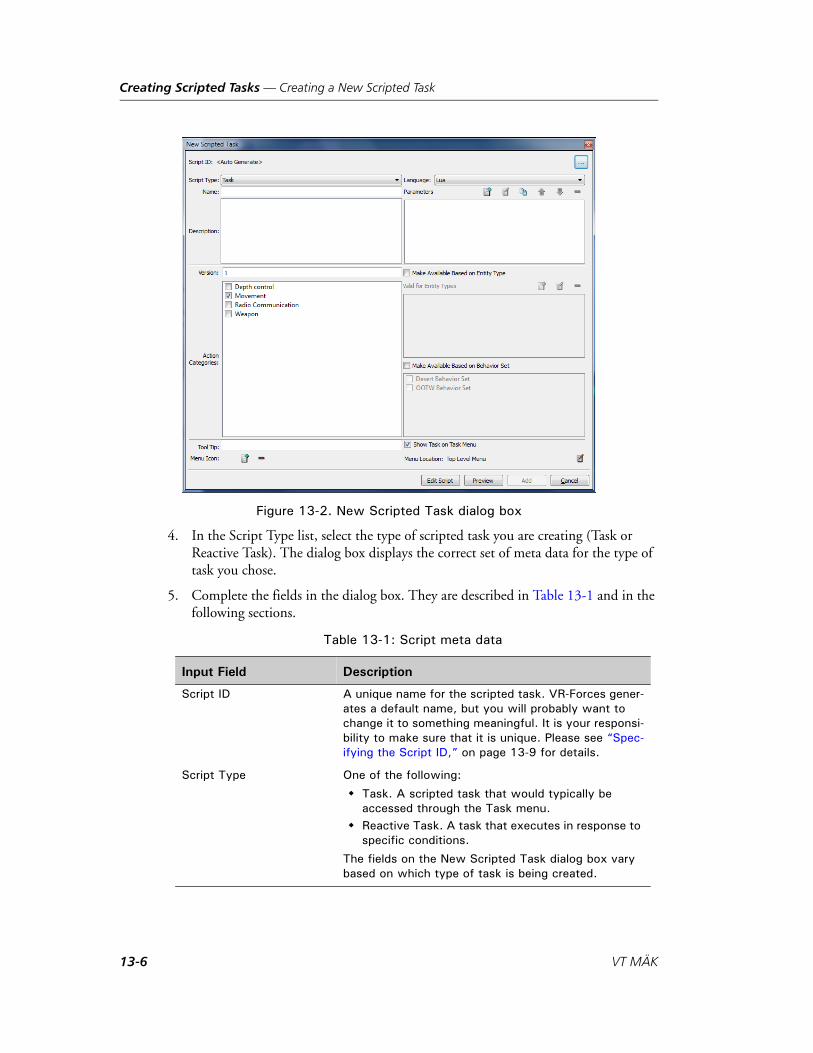
Creating Scripted Tasks — Creating a New Scripted Task
Figure 13-2. New Scripted Task dialog box
4. In the Script Type list, select the type of scripted task you are creating (Task or Reactive Task). The dialog box displays the correct set of meta data for the type of task you chose.
5. Complete the fields in the dialog box. They are described in Table 13-1 and in the following sections.
Table 13-1: Script meta data
Input Field Description
Script ID A unique name for the scripted task. VR-Forces gener-ates a default name, but you will probably want to change it to something meaningful. It is your responsi-bility to make sure that it is unique. Please see “Spec-ifying the Script ID,” on page 13-9 for details.
Script Type One of the following:
Task. A scripted task that would typically be accessed through the Task menu.
Reactive Task. A task that executes in response to specific conditions.
The fields on the New Scripted Task dialog box vary based on which type of task is being created.
13-6 VT MÄK

Creating Scripted Tasks — Creating a New Scripted Task
Language Specify Lua if you are writing a Lua script for this task. Specify C++ if you have written a new task controller and want to use the scripted task interface to create the GUI portion of the task. For more infor-mation, please see “Specifying the Programming Language for a Scripted Task,” on page 13-18.
Name The text that will be added to the Task menu for this script.
Description The description of what the task does that is displayed on the task’s dialog box. (Optional)
Tool Tip Text for a tooltip when the task is selected on the Task menu. (Optional) (Does not apply to reactive tasks.)
Menu Icon The icon to display next to the task name on the Task menu. Please see “Specifying the Task Menu Icon,” on page 13-9 for details. (Optional) (Does not apply to reactive tasks.)
Version Script version. Available as a parameter to a Lua script. For use by script writers who want to have different versions of a script.
Action Categories Specifies the categories of tasks that this scripted task will interrupt. (In other words, action categories manage task concurrency. For details about concur-rent tasks, please see “Concurrent Task Execution,” on page 6-4.)
Behavior Sets Select each Behavior Set that you want this script to be part of. You can also assign scripts to Behavior Sets in the Edit Behavior Sets dialog box. For details about Behavior Sets, please see “Using Behavior Sets to Manage Scripted Tasks,” on page 6-16.
Parameters The input parameters that the task requires. Please see “Specifying Task Parameters,” on page 13-10 for details. (Optional)
Show Scripted Task on Task Menu
Select to show the scripted task on the Task menu. Clear to hide the task. (You might want to write a scripted task that will be used by other scripted tasks, but which you do not want a user to assign directly to an entity.) (Does not apply to reactive tasks.)
Menu Location The location on the Task menu where this scripted task will be listed. Please see “Specifying the Task Menu Location,” on page 13-13 for details. (Does not apply to reactive tasks.)
Table 13-1: Script meta data
Input Field Description
VR-Forces Scenario Management Guide 13-7

Creating Scripted Tasks — Creating a New Scripted Task
6. Optionally, click Preview to see the dialog box that the scripted task will create.
7. Optionally, click Edit Script to begin writing the code for this scripted task.
8. Click Add. The script is added to the list in the Scripted Tasks window.
Valid for Entity Types The entity types that can use this task. This entry affects the context sensitivity of the Task menu. Please see “Specifying the Valid Entity Types for a Task,” on page 13-16 for details.
Enabled by Default Reactive tasks only. If selected, the reactive task is automatically enabled for all supported entity types.
Default Priority Reactive tasks only. The priority for this task. For information about the effect of reactive task priority, please see “Reactive Tasks,” on page 6-10.
View Like Priorities Reactive tasks only. Displays a list of the reactive tasks that are valid for this task’s entity types and action categories. This helps you decide what priority you want to give to the reactive task you are creating or editing.
Table 13-1: Script meta data
Input Field Description
13-8 VT MÄK

Creating Scripted Tasks — Creating a New Scripted Task
13.2.1. Specifying the Script ID
Each script must have a unique ID. VR-Forces generates a default ID, but it does not contain meaningful text. Therefore, you may want to change the ID.
To specify the script ID:
1. In the New Scripted Task (or Edit Scripted Task) dialog box, click the button to the right of the Script ID. The New Script ID dialog box opens.
2. Type the ID you want to use.
3. Click OK.
13.2.2. Specifying the Task Menu Icon
If you want to put an icon on the Task menu next to the menu text, you can specify one. (Does not apply to reactive tasks.)
To specify a Task menu icon:
1. Click the Add button ( ) next to the Menu Icon label. The Select Menu Icon dialog box opens.
2. Browse the directory structure and select the icon that you want to use.
3. Click Open.
To remove the Task Menu icon for a script, click the Remove button ( ) next to the Menu Icon label.
! The script ID is used internally by VR-Forces to manage how a scripted task is executed. If a scripted task is used in a plan, it is referenced by its script ID. If you change the ID, you must ensure that it is unique. You cannot edit the ID of a system scripted task.
VR-Forces Scenario Management Guide 13-9

Creating Scripted Tasks — Creating a New Scripted Task
13.2.3. Specifying Task Parameters
Scripted tasks can take input parameters. When you specify parameters for a scripted task, VR-Forces automatically builds a dialog box that lets the user enter the parameter values. The parameter types that you can specify for a scripted task are as follows:
Aggregate Formation. Provides a list of formations for aggregate entities.
Altitude MSL. Altitude above mean sea level.
Bomb Resource. Creates a list of bomb resources.
Boolean. Creates a check box.
Choice (List). Specifies choices presented in a drop-down list.
Choice (Option Button). Specifies choices presented as a option (radio) buttons.
DI-Guy Animation. Lets you select a DI-Guy animation.
DI-Guy Appearance. Lets you select a DI-Guy appearance.
Distance. Specifies a distance.
Emitter. Entity emitter ID.
Entity Type. Entity type enumeration.
Force.
Heading. Heading, in degrees.
Integer. A whole number.
Location (with altitude). Vector description of a location, in geocentric, including altitude.
Location (without altitude). Vector description of a location, in geocentric, altitude not included.
Munition Resource. Creates a list of munitions.
Offset Location. Specifies an offset to the side, behind, and above, as in the Follow Entity task.
Real. A floating point decimal number.
Resource. Creates a list of available resources.
Separator. Lets you put a separator in the generated dialog box. This is just for formatting purposes
Simulation Object (Single). Lets you select one simulation object in a list window.
Simulation Object (Multiple). Lets you select multiple simulation objects in a list window.
Speed. Any kind of rate, such as speed, climb rate, and so on.
String. An alphanumeric string.
Time. Time in days:hours:minutes:seconds.
Turn Rate. Turn rate in radians/second.
13-10 VT MÄK

Creating Scripted Tasks — Creating a New Scripted Task
If a scripted task does not have any input parameters, it executes as soon as it is assigned to an entity, like the Wait command does.
To specify a parameter for a script:
1. Click the Add button ( ) above the Parameters list. The Add Parameter dialog box opens (Figure 13-3).
Figure 13-3. Add Parameter dialog box
2. Select the type of parameter from the Type list. If appropriate, the dialog box redis-plays to request the details required for the variable type you selected.
3. Fill out the fields as follows:
All of the parameters have the following fields:
– Parameter Name. The name to be used by the Lua script for this parameter. For example, if you give a parameter the name taskDestination, in the Lua code for the scripted task, the parameter will be accessed as taskParameters.taskDestination.
– Label. This is the text used on the dialog box that is generated for the task. If you leave this field blank, the parameter name is used.
– Tool Tip. Optional text for a tool tip.
– Indent Level. The number of pixels to indent the parameter on the task dialog box. This allows you to apply some formatting to the dialog box.
– Visible check box. Specifies that the parameter be included on the scripted task dialog box. (You might want a parameter to be available in the code, but not have it set by a user when the scripted task is assigned.)
Many parameters let you specify a default value or state.
Some parameters let you specify a range for the acceptable values:
– Range Bottom. The lowest acceptable value for this parameter.
– Range Top. The highest acceptable value for this parameter.
VR-Forces Scenario Management Guide 13-11

Creating Scripted Tasks — Creating a New Scripted Task
The Boolean parameter type lets you create a check box. You can specify that the default be checked or unchecked.
For details about adding choices to a Choice parameter, please see “Specifying Choices for the Choice Parameters,” on page 13-12. For details about adding cate-gories to a filtered list, please see “Specifying Categories for a Simulation Object,” on page 13-12.
Specifying Choices for the Choice Parameters
The Choice parameters require a list of choices, which get added to the dialog box as option buttons or as a list. You can add choices, edit them, and delete them.
To add a choice:
1. Click the Add Parameter button ( ) on the Choice Box Values line. The New Choice dialog box opens.
2. Type the text for the choice.
3. Click OK.
4. Repeat this procedure for each choice that you want to have available. (The last choice added becomes the default choice.)
Specifying Categories for a Simulation Object
The Simulation Object parameter lets you build a list of categories on which to filter the display of entity types in a dialog box.
To add a category to the simulation object list:
1. Click the Add Parameter button ( ) on the Filters line. The Choose Filter dialog box opens.
2. Select a filter from the Filters list.
3. Click OK.
4. Repeat the procedure to add as many filters as you want.
13-12 VT MÄK

Creating Scripted Tasks — Creating a New Scripted Task
Editing the Category List for a Simulation Object Parameter
You can edit the list of filter categories for a Simulation Object parameter. The edit operation is essentially a replacement of the current category with a new one. You can achieve the same effect by deleting the current category and adding a new one.
To edit the list of filter categories in a Simulation Object parameter:
1. Select the parameter you want to edit in the Parameters list on the New Scripted Task dialog box.
2. Click the Edit button ( ). The Script Variable dialog box opens.
3. In the Filters list, select the filter that you want to edit.
4. Click the Edit button ( ). The Choose Filter dialog box opens.
5. Select the filter category that you want to use.
6. Click OK. The original category is removed and the new one is added.
To delete a category from a Simulation Object parameter:
1. Select the parameter you want to edit in the Parameters list on the New Scripted Task dialog box.
2. Click the Edit button ( ). The Script Variable dialog box opens.
3. In the Filters list, select the filter that you want to delete.
4. Click the Delete button ( ). The category is removed from the list.
13.2.4. Specifying the Task Menu Location
Scripted tasks get added to the Task menu, unless you specify that they not be shown (by clearing the Show Task on Task Menu check box). The default location is the top level of the menu. However, you will probably want to organize your tasks using the submenus provided by VR-Forces or in newly created submenus. The New Scripted Task dialog box displays the menu under which the scripted task is placed. It does not show the full path from the top level menu.
i Reactive tasks do not get placed on the Task menu and do not have this option on the the New Scripted Task dialog box.
VR-Forces Scenario Management Guide 13-13

Creating Scripted Tasks — Creating a New Scripted Task
To specify a Task menu location for a scripted task:
1. Click the Edit button ( ). The Select Location on Task Menu dialog box opens (Figure 13-1).
Figure 13-4. Select Location on Task Menu dialog box
2. To add the scripted task to an existing submenu:
a. Expand the submenu on which you want to put the task.
b. Select the task that you want the new task to be next to.
c. To put the new task above the selected menu item, select the Add Item Before Selected option. To put the new task below the selected menu item, select the Add Item After Selected option.
d. Click OK.
3. To create a new submenu for the scripted task:
a. Select the submenu next to where you want to add the new submenu.
b. To add the new menu before the selected submenu, click Add Menu Before. To add the new menu after the selected submenu, click Add Menu After. The New Menu Name dialog box opens.
c. Type a name for the new submenu.
d. Click OK.
e. Add the scripted task to the new submenu using the procedure in step 2.
13-14 VT MÄK

Creating Scripted Tasks — Creating a New Scripted Task
13.2.5. Specifying Action Categories
Some VR-Forces tasks can run at the same time as other tasks, while some are mutually exclusive. This is called task concurrency. (For details about concurrent tasks, please see “Concurrent Task Execution,” on page 6-4.) The tasks provided with VR-Forces are organized in groups to help manage concurrency. In the New Scripted Task dialog box, these groups are represented as action categories.
When you create or edit a scripted task you can specify which groups of tasks the new task can run concurrently with and which it will interrupt. By default, the Movement category is selected, which means that if you do not change the setting, the new task will interrupt movement tasks.
To specify which tasks a scripted task will interrupt, in the Action Categories list, select the categories to interrupt. For example, if the new task involves movement, you probably want it to interrupt other movement tasks, so you would select the Movement category check box. If it is a new type of message task, you probably want to let it run concurrently with movement tasks, so you would clear the Move-ment category check box.
13.2.6. Configuring a Script’s Availability
Scripted tasks can be available to an entity based on the following criteria:
The task implements a system. (For example, the Naval Mine Sweep task is avail-able to entities with a Naval Mine Sweep system. This state is not shown in the Edit Scripted Task dialog box.)
The task is available for certain entity types.
The task is part of a Behavior Set.
Availability by entity type and by Behavior Set is configured in the New Scripted Task and Edit Scripted Task dialog boxes. Table 13-2 shows the interaction of these settings.
Table 13-2: Scripted task availability
Available by Entity Type
Available by Behavior Set
Availability
The script is available only to those entity types listed.
The script is available to all entities, but only if one of the selected Behavior Sets is applied to the entity’s force.
The script is available to the specified entity types, but only if one of the selected Behavior Sets is applied to the entity’s force.
VR-Forces Scenario Management Guide 13-15

Creating Scripted Tasks — Creating a New Scripted Task
Specifying the Valid Entity Types for a Task
You can restrict a scripted task to specific entity types. If you do this, the task will not appear on the Task menu when you select an entity for which it is not valid. Just as with built-in VR-Forces tasks, there are cases, such as for global plans, where VR-Forces cannot determine the entity context and the task will be available on the Task menu even though it is not appropriate to the entity that you are tasking. In those cases it is up to you to know that a task is valid.
To specify the valid entity types for a scripted task:
1. Select the Make Available Based on Entity Type check box.
2. Click the Add button ( ) on the Valid for Entity Types line. The Entity Type dialog box opens (Figure 13-5). You can build an entity type enumeration by selecting options from the enumeration field lists or you can type in the enumera-tion directly.
Figure 13-5. Entity Type dialog box
3. For each field of the entity type (Kind, Domain, Country, and so on), select an option from the list.
The options are drawn from the DIS Enumerations document. As you select an option, the enumeration at the bottom of the dialog box changes to reflect your choice. You do not have to make a selection for each field. VR-Forces uses wild carding to match entities against the final enumeration.
4. If appropriate, add additional enumerations for each entity type that is valid for the scripted task.
13-16 VT MÄK

Creating Scripted Tasks — Creating a New Scripted Task
Specifying Availability by Behavior Set
You can restrict a scripted task to specific Behavior Sets. If you do this, the task will not appear on the Task menu when you select an entity whose force does not have the Behavior Set assigned to it.
To specify that a scripted task is available by Behavior Set:
1. Select the Make Available Based on Behavior Set check box.
2. Select each Behavior Set for which you want this scripted task to be available.
i You must create the Behavior Sets before you can assign scripts to them. All available Behavior Sets are automatically listed in the dialog box window.
VR-Forces Scenario Management Guide 13-17

Creating Scripted Tasks — Creating a New Scripted Task
13.2.7. Specifying the Programming Language for a Scripted Task
The Language list in the New Scripted Task dialog box has two options, Lua and C++. In most cases you will choose Lua and write a script to implement the scripted task. However, since the scripted task interface automatically generates task dialog boxes and updates the Task menu, it can be a convenient way to add the GUI component for new tasks that developers have written in C++ with the VR-Forces Toolkit. Developers who take this approach do not have to rebuild the VR-Forces front-end or write a plug-in to add their new task to the menu and code a task dialog box.
If a developer adds a new C++ task controller using this approach, it looks for the script ID of the scripted task. The Move (On Roads) tasks use the scripted task interface to create their dialog boxes. The addTask example in the VR-Forces Toolkit demonstrates this method of adding tasks. For more information, please see VR-Forces Developers Guide.
You can display C++ tasks in the Scripted Tasks dialog box by selecting the Show C++ Tasks check box (Figure 13-6).
Figure 13-6. C++ tasks
13-18 VT MÄK

Creating Scripted Tasks — Creating a New Scripted Task
13.2.8. Creating Reactive Tasks
The process for creating a reactive task is largely the same as for creating other scripted tasks. This procedure focuses on the differences.
To create a reactive task:
1. Choose Simulation Scripted Tasks. The Scripted Tasks dialog box opens (Figure 13-1).
2. If you have a folder hierarchy and want to create the script in a particular folder, select the folder. (For more information, please see “Organizing Scripted Tasks into Folders,” on page 13-22.)
3. Choose Script New Scripted Task. The New Scripted Task dialog box opens (Figure 13-2).
4. In Script Type list, select Reactive Task. The New Scripted Task dialog box redis-plays to show the meta data fields for a reactive task (Figure 13-7).
Figure 13-7. New Scripted Task dialog box, reactive task
5. Complete the fields in the dialog box. Fields that are common to all scripted tasks are described in Table 13-1.
6. To make this reactive task enabled by default, select the Enabled By Default check box.
VR-Forces Scenario Management Guide 13-19

Creating Scripted Tasks — Saving Scripted Tasks
7. In the Default Priority box, type the priority for this task. The lower the number, the higher the priority. To help you set the priority, you can view a list of all reactive tasks that are valid for the entity types of this task so that you can consider their relative importance and set an appropriate priority.
8. Optionally, click Compare Priorities to see a list of reactive tasks and their priori-ties.
9. Click Add.
13.3. Saving Scripted TasksWhen you create or edit a scripted task, its listing in the Scripted Tasks window is in italics, prefaced by an asterisk. When you save the scenario, or promote a scripted task to a system script, the scripted task gets saved and the italics and asterisk get removed.
It is likely that you will test scripted tasks by running a scenario and you will want to edit the scripted task as you find problems. If you create or edit a scripted task while a scenario is running and you decide to rewind the scenario without saving it (which would be normal behavior for rewinding a scenario), you are prompted to preserve the changes to the scripted task after the scenario rewinds. The scripted task is still not saved and you will, therefore, receive the standard “scenario modified” prompt when you start the scenario again. You do not have to save the scenario if the only thing that changed is the scripted task. You can continue to run the scenario and rewind while you are working on the scripted task. Eventually you will have to save the scenario if you want to save your changes to the scripted task.
13-20 VT MÄK

Creating Scripted Tasks — Editing a Scripted Task
13.4. Editing a Scripted TaskYou can edit scripted tasks.
To edit the meta data for a scenario script:
1. Choose Simulation Scripted Tasks. The Scripted Tasks window opens (Figure 13-1).
2. Select the scripted task that you want to edit.
3. Choose Script Scripted Task, or double-click the script name. The Edit Scripted Task dialog box opens. (If you are editing a system scripted task, you are prompted to confirm that you want to edit it.)
4. Edit the meta data as desired.
5. Click Update.
13.5. Filtering the List of Scripted TasksYou can filter the tasks listed in the Scripted Tasks dialog box by selecting options from the lists below the menu bar, as follows:
Script Access: Show system scripts, scenario scripts, or all scripts.
Script Type: Show scripted tasks, reactive tasks, or all scripted tasks.
Entity Type: Show scripts that apply to the selected entity type.
Show C++ Tasks: Toggles the display of tasks that are written in C++, but whose GUIs are created using the scripted task mechanism.
! If you edit a system scripted task, the changes will affect all scenarios that use the scripted task. You are responsible for ensuring that any changes have the intended results for all scenarios that are affected.
i In the Script ID column the icon indicates the type of scripted task, Task ( ) or Reactive Task ( ).
i This filter is based on the Valid for Entity Types list for each scripted task. Some scripted tasks do not have any entity types listed. These tasks, such as Drop Naval Depth Charge, become available to entities based on the systems that they have configured. Therefore, this list may be somewhat misleading in terms of the overall applicability of scripted tasks to the different platforms.
VR-Forces Scenario Management Guide 13-21

Creating Scripted Tasks — Organizing Scripted Tasks into Folders
13.6. Organizing Scripted Tasks into FoldersYou can create folders and organize scripted tasks by folder.
13.6.1. Adding a Folder
To add a folder:
1. Choose Simulation Scripted Tasks. The Scripted Tasks window opens (Figure 13-1).
2. Choose Folders Add Folder. The Folder Name dialog box opens.
3. Type a name for the folder.
4. Click OK.
13.6.2. Renaming a Folder
To rename a folder:
1. Choose Simulation Scripted Tasks. The Scripted Tasks window opens (Figure 13-1).
2. Select the folder that you want to rename.
3. Choose Folders Rename Folder. The Folder Name dialog box opens.
4. Type a new name for the folder.
5. Click OK.
13.6.3. Deleting a Folder
You cannot delete a folder that has scripts in it.
To delete a folder:
1. Choose Simulation Scripted Tasks. The Scripted Tasks window opens (Figure 13-1).
2. Select the folder that you want to delete.
3. Choose Folders Delete Folder.
13.6.4. Adding Scripted Tasks to a Folder
To add a scripted task to a folder, drag it onto the folder.
13.6.5. Removing a Scripted Task from a Folder
To remove a scripted task from a folder, drag away from the folder.
13-22 VT MÄK

Creating Scripted Tasks — Exporting and Importing Scripted Tasks
13.7. Exporting and Importing Scripted TasksScenario scripts are saved in a scenario’s SPT file, not as individual scripts. If you want to make a scenario script available to other scenarios, but you do not want to save it as a system script, you can export the script from the scenario in which you created it and import it into any other scenario. You can export multiple scripts to one file as a script “package”.
If scripted tasks are organized in folders, when you save them the folder structure is also saved.
To export scripted tasks:
1. Choose Simulation Scripted Tasks. The Scripted Tasks window opens (Figure 13-1).
2. Select the scripts that you want to export. (The window supports typical methods for selecting multiple entries in a list.)
3. Choose Script Export Script Package. The Choose Script File dialog box opens. By default it opens in ./userData/taskScripts.
4. Type a name for the scripts file.
5. Click Save. The scripts gets saved to a file with the extension .spt. The file contains the meta data and the script code.
i You cannot add or remove scripted tasks from a script package. To change the contents you would have to create a new package.
VR-Forces Scenario Management Guide 13-23

Creating Scripted Tasks — Exporting and Importing Scripted Tasks
13.7.1. Importing a Scripted Task Package
If you import a script package that has multiple scripted tasks, you can choose which scripted tasks to import. Scripts get imported with the folder hierarchy that they were saved in.
To import scenario scripted tasks:
1. Choose Simulation Scripted Tasks. The Scripted Tasks window opens (Figure 13-1).
2. Choose Script Import Script Package or click Import Scripts. The Choose Script File dialog box opens.
3. Select the script file that you want to import.
4. Click Open. The Import dialog box opens (Figure 13-8). It lists the scripted tasks saved in the script file.
Figure 13-8. Import dialog box
5. Select the scripted tasks that you want to import.
6. Click Import.
13-24 VT MÄK

Creating Scripted Tasks — Copying a Scripted Task
13.8. Copying a Scripted TaskIf you want to create a new script that is similar to an existing one, you can copy an existing script and then edit it for its new purpose.
To copy a scenario scripted task:
1. Choose Simulation Scripted Tasks. The Scripted Tasks window opens (Figure 13-1).
2. Select the scripted task that you want to copy.
3. Choose Script Duplicate. The New Scripted Task dialog box opens. If you copied a scenario scripted task, the duplicate script is assigned a new script ID. If you copied a system script, the script ID is not changed. You will have to change the script ID manually.
4. Edit the script.
5. Click Duplicate. The script is added to the list.
13.9. Deleting a Scripted TaskIf you delete a scripted task that is assigned to an entity in the scenario, the task assign-ment, whether as an independent task or as part of a plan, will fail. If the scripted task is used as a subtask in another scripted task, that scripted task will fail. VR-Forces does not warn you if either of these cases exist. It is your responsibility to consider the effects of deleting a scripted task.
To delete a scripted task:
1. Choose Simulation Scripted Tasks. The Scripted Tasks window opens (Figure 13-1).
2. Select the scripted task that you want to delete.
3. Choose Script Delete Scripted Task.
i If you do not change the script ID for a copied system scripted task, the system scripted task gets removed from the list of scripted tasks for this scenario and the new scripted task is added as a scenario scripted task. This lets you experiment with changes to a system scripted task without actually changing it. The original system scripted task will still be available to other scenarios.
VR-Forces Scenario Management Guide 13-25

Creating Scripted Tasks — Creating a System Scripted Task
13.10. Creating a System Scripted TaskTo create a system scripted task, you create a scenario scripted task and then save it as a system scripted task. System scripted tasks are saved in ./data/simulationMod-elSet/<model_set>/scripts. A system scripted task has two files. The meta data is saved in a file ending with the extension .xml. The code is saved in a file with the extension .lua.
To save a scenario scripted task as a system scripted task:
1. Choose Simulation Scripted Tasks. The Scripted Tasks window opens (Figure 13-1).
2. Select the scripted task that you want to save as a system scripted task.
3. Choose Script Promote to System Scripted Task. You are prompted to confirm the change.
4. Click Yes.
13.10.1. Including System Scripted Tasks on the Task Menu
The system scripted tasks included with VR-Forces are all listed on the Task menu, except the scripted tasks in the Examples folder. However, you can specify that partic-ular scripted tasks not be listed. You might want to do this to reduce clutter on the Task menu. Or you might want to limit the tasks available to players in a particular deploy-ment of VR-Forces.
A system scripted task’s inclusion on the Task menu is controlled by the following settings:
The Show Scripted Task on Task Menu check box on the New Scripted Task and Edited Scripted Task dialog boxes.
The check box next to the scripted tasks entry on the Scripted Tasks dialog box (Figure 13-9).
Its membership in a behavior set. The effect of behavior sets on task availability is additive to the configuration discussed in this section. For details about using behavior sets, please see “Using Behavior Sets to Manage Scripted Tasks,” on page 6-16.
13-26 VT MÄK

Creating Scripted Tasks — Creating a System Scripted Task
Figure 13-9. Show scripted task on Task menu check box
Table 13-3 shows when a scripted task is listed on the Task menu based on the configu-ration check boxes selected.
To specify the availability of a system scripted task on the Task menu:
1. Choose Simulation Scripted Tasks. The Scripted Tasks window opens (Figure 13-1).
2. In the list of system scripted tasks, select the scripted task whose availability you want to change. Use Table 13-3 to determine which check box configuration you need for your desired Task menu status.
3. Choose Script Scripted Task. The System Script Editing prompt opens. (If you have disabled this prompt, the Edit Scripted Task dialog box opens. Skip to step 5.)
4. In the System Script Editing prompt, click Yes. The Edit Scripted Task dialog box opens.
5. Select or clear the Show Scripted Task on Task Menu check box.
6. Click Update.
Table 13-3: System scripted task inclusion on Task menu
Show Scripted Task on Task Menu check box
System scripted task list check box
Task included on Task menu
Yes
No
Yes, for this scenario.
No
VR-Forces Scenario Management Guide 13-27

Creating Scripted Tasks — Specifying a Script Editor
7. In the list of scripted tasks, select the check box next to the system scripted task you are editing to make it available. Clear the check box to make it unavailable.
13.11. Specifying a Script EditorVR-Forces installs SciTE as the default script editor for scripted tasks. However, you can use any text editor that you want.
To specify the editor to use for scripts:
1. Choose Settings Application. The Application Settings dialog box opens.
2. Select the Scripted Task Options page (Figure 13-10).
Figure 13-10. Scripted Task Option page
3. Click the Browse button ( ) next to the Script Editor box. The Choose Script Editor dialog box opens.
4. Select the application that you want to use as the editor.
5. Click Open.
13-28 VT MÄK

Creating Scripted Tasks — Editing Lua Files
13.12. Editing Lua FilesTo edit the scripts for scenario scripted tasks you need to work through the Scripted task GUI because the scripts are embedded in the scenario scripts file rather than being saved as individual Lua files. System scripts are saved as Lua files, but even in this case it is better to edit them in the context of the entire scripted task rather than by editing the Lua file. However, VR-Forces includes some libraries of Lua functions that are indepen-dent of any of the scripted tasks. They are available to be included in your scripted tasks. If you want to edit the functions in these libraries or add to them, you need to edit the individual Lua files. The function libraries are in ./userData/scripts. You can open them in any editor, or access them through the Scripted Tasks dialog box.
To edit a Lua file from the Scripted Task dialog box:
1. Choose Simulation Scripted Tasks. The Scripted Tasks window opens (Figure 13-1).
2. Choose Script Edit External Script. A file chooser dialog box opens.
3. Select the script that you want to edit. The file opens in a text editor.
4. Edit the file.
5. Save the file.
VR-Forces Scenario Management Guide 13-29

Creating Scripted Tasks — Editing Lua Files
13-30 VT MÄK
VR-Forces Scenario Management Guide
14
Writing Scripts for Scripted Tasks
This chapter explains how to write Lua scripts for scripted tasks.
The VR-Forces Lua Interface ...................................................................... 14-2Lua Classes ........................................................................................... 14-2Lua Modules ........................................................................................ 14-3
Script Loading and Execution ..................................................................... 14-4Script Entry Points ............................................................................... 14-4The Scripted Task Execution Sequence................................................. 14-6Limitations for Checkpointing Scripted Tasks ...................................... 14-9Editing Scripted Tasks While a Scenario is Running........................... 14-11
Tasks and Subtasks .................................................................................... 14-11Monitoring the Status of Tasks and Subtasks ...................................... 14-13Stopping Tasks ................................................................................... 14-13Task Parameters .................................................................................. 14-13
Geometry.................................................................................................. 14-15Location3D........................................................................................ 14-15Vector3D............................................................................................ 14-15VectorOffset3D .................................................................................. 14-17VectorGeoc3D ................................................................................... 14-17
Reserved Words ........................................................................................ 14-18
Error Detection......................................................................................... 14-19
A Basic Scripted Task ................................................................................ 14-20Create and Move to Waypoint Meta Data .......................................... 14-21The Create and Move To Waypoint Lua Script................................... 14-23
A Simple Reactive Task ............................................................................. 14-25
14-1
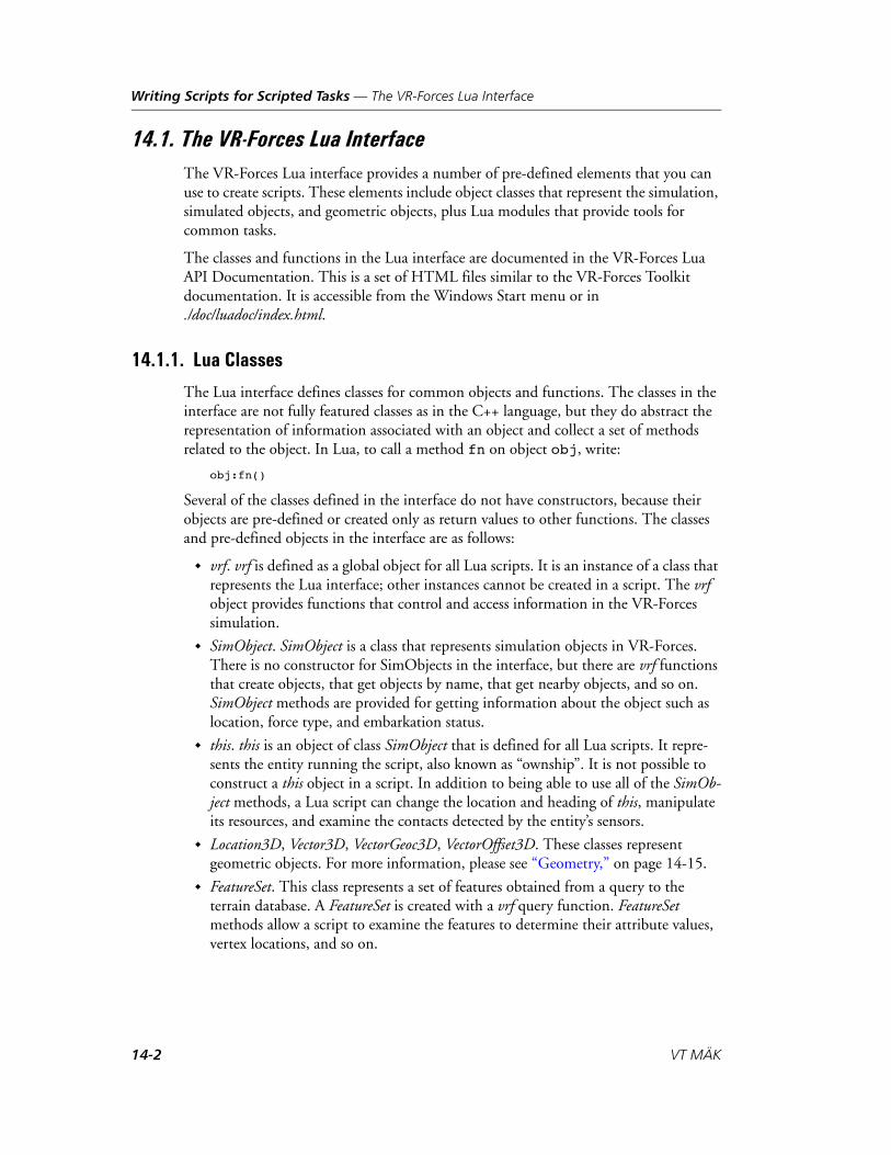
Writing Scripts for Scripted Tasks — The VR-Forces Lua Interface
14.1. The VR-Forces Lua InterfaceThe VR-Forces Lua interface provides a number of pre-defined elements that you can use to create scripts. These elements include object classes that represent the simulation, simulated objects, and geometric objects, plus Lua modules that provide tools for common tasks.
The classes and functions in the Lua interface are documented in the VR-Forces Lua API Documentation. This is a set of HTML files similar to the VR-Forces Toolkit documentation. It is accessible from the Windows Start menu or in ./doc/luadoc/index.html.
14.1.1. Lua Classes
The Lua interface defines classes for common objects and functions. The classes in the interface are not fully featured classes as in the C++ language, but they do abstract the representation of information associated with an object and collect a set of methods related to the object. In Lua, to call a method fn on object obj, write:
obj:fn()
Several of the classes defined in the interface do not have constructors, because their objects are pre-defined or created only as return values to other functions. The classes and pre-defined objects in the interface are as follows:
vrf. vrf is defined as a global object for all Lua scripts. It is an instance of a class that represents the Lua interface; other instances cannot be created in a script. The vrf object provides functions that control and access information in the VR-Forces simulation.
SimObject. SimObject is a class that represents simulation objects in VR-Forces. There is no constructor for SimObjects in the interface, but there are vrf functions that create objects, that get objects by name, that get nearby objects, and so on. SimObject methods are provided for getting information about the object such as location, force type, and embarkation status.
this. this is an object of class SimObject that is defined for all Lua scripts. It repre-sents the entity running the script, also known as “ownship”. It is not possible to construct a this object in a script. In addition to being able to use all of the SimOb-ject methods, a Lua script can change the location and heading of this, manipulate its resources, and examine the contacts detected by the entity’s sensors.
Location3D, Vector3D, VectorGeoc3D, VectorOffset3D. These classes represent geometric objects. For more information, please see “Geometry,” on page 14-15.
FeatureSet. This class represents a set of features obtained from a query to the terrain database. A FeatureSet is created with a vrf query function. FeatureSet methods allow a script to examine the features to determine their attribute values, vertex locations, and so on.
14-2 VT MÄK

Writing Scripts for Scripted Tasks — The VR-Forces Lua Interface
14.1.2. Lua Modules
The Lua interface includes Lua modules for use in Lua scripts. A module stuff can be accessed in a Lua script by writing
require "stuff"
The modules available in the interface are as follows:
vrfutil. Technically, vrfutil is not a Lua module. (It is not defined with a module function.) It is just a set of global utility functions. The Lua script template that opens when a new script is created contains:require "vrfutil"
so that these functions are available to the script by default.
fsm. The fsm module defines a class that implements finite state machine logic. There is one function in this module, new(), which creates an fsm object.
exectool. The exectool module is a package of functions that supports the use of a single Lua function to describe the control flow of a scripted task. To use this tool, the task logic is described in a function we call a scriptFunction. This function is written as if it will execute up to a subtask invocation, and then wait until that subtask is completed before continuing.
The .lua module files are located in ./userData/scripts. You can add user-created modules to this directory and then import them into scripts with a require statement.
i In Lua, variables assigned to objects actually just hold a reference to an object, so that if one variable is assigned to another they will both hold a reference to the same object. In the following example, firstObj and secondObj refer to the same object.
firstObj = getObjectByName("APC 1")secondObj = firstObj
In most cases this is what a Lua programmer wants. However, for the geometric objects, a Lua programmer may sometimes want to make a copy of an object. A simple assignment does not make a copy in Lua, so the geometric objects have makeCopy() methods to provide copies.
VR-Forces Scenario Management Guide 14-3

Writing Scripts for Scripted Tasks — Script Loading and Execution
14.2. Script Loading and ExecutionThis section describes script entry point functions and the execution sequence for scripted tasks. It also describes how VR-Forces checkpoints scripted tasks and executes them when a checkpointed scenario is run.
14.2.1. Script Entry Points
The Lua API includes functions that we call “entry points” to a scripted task. When you create a new script, they are included in the default script template. Unlike the Lua functions that you might write as part of a script, you do not have to call entry point functions from within the script. They are called by the simulation engine. (However, if an entry point function is not defined in a script, it does not get called.)
init(). Use init() to set up the initial state of your scripted task’s environment. The init() function is the first function called when a scripted task is executed. It is called when a task is assigned to an entity, even if the scenario is paused. It is never called again for the life of the scripted task.
tick(). The tick() function is the heart of every scripted task. It is called at every tick of the simulation engine once the entity has completed its initialization. Most of a scripted task's logic should be written into the tick() function as it is the only entry point function consistently called in the script.
suspend(). The suspend() function gets executed when a reactive task is triggered for an entity and the reactive task cannot run concurrently with the current task. The typical behavior, as embodied in the scripted task template, is to stop all tasks and subtasks.
resume(). The resume() function gets executed when a reactive task completes. The typical behavior is to reinitialize the suspended task.
i As you can see from their descriptions, the suspend() and resume() functions do not exactly suspend and resume tasks as those terms are commonly understood. In most cases (this is task dependent), VR-Forces does not preserve the state of an entity’s tasks when they are suspended, it stops the tasks. Nor does it resume the previous task from the point at which it was suspended, it restarts the task from the current state of the entity. However, VR-Forces always saves the lua state of scripted tasks, so when a scripted task resumes, its variables may need to be reset in init() or checkInit().
14-4 VT MÄK

Writing Scripts for Scripted Tasks — Script Loading and Execution
saveState(). If a script is running, the saveState() function is called just before a scenario is about to be saved. VR-Forces automatically saves the state of script execution. (For details, please see “Limitations for Checkpointing Scripted Tasks,” on page 14-9.) This function lets you do any additional processing to save the state of your scripted task. Most scripts do not use this function.
loadState(). If a script was running when a scenario was saved, the loadState() func-tion is called just after a scenario is loaded or rewound. VR-Forces automatically restores the state of a scripted task that was running when a scenario was saved. This function lets you do any additional processing required to restore the state of the script. If your script uses the saveState() function, you probably want to include complementary processing in loadState(). Most scripts do not use this function.
shutdown(). The shutdown() function is called when the task is ending for any reason. You will not typically need to write any code in this function, however it is available if there is a case in which you want to do anything before the task ends.
receiveTextMessage(). The receiveTextMessage() function is called when the entity executing this task receives a text message. The function provides some data to determine what the text message is and which entity the text message came from.
The following script entry points are only used in reactive tasks:
check(). The check() function defines the condition under which the reactive task gets triggered. It keeps checking the condition until it becomes true, at which point it starts the reactive task.
checkInit(). The checkInit() function initializes the reactive task when it is enabled. It sets the initial conditions for the check() function. checkInit() runs when a reac-tive task is first enabled and runs again after the reactive task completes so that it can begin checking the condition again.
i If your loadState() function assumes the presence of other entities, you must take into account that other entities might not have loaded yet when the function is called.
VR-Forces Scenario Management Guide 14-5
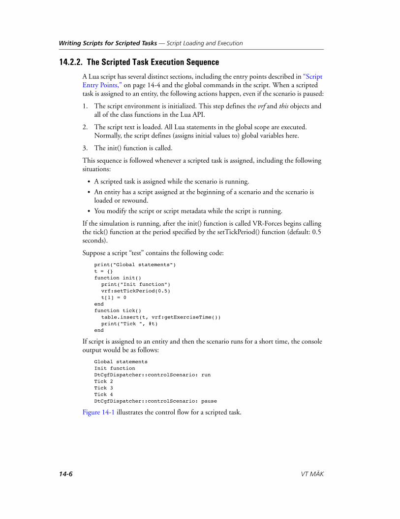
Writing Scripts for Scripted Tasks — Script Loading and Execution
14.2.2. The Scripted Task Execution Sequence
A Lua script has several distinct sections, including the entry points described in “Script Entry Points,” on page 14-4 and the global commands in the script. When a scripted task is assigned to an entity, the following actions happen, even if the scenario is paused:
1. The script environment is initialized. This step defines the vrf and this objects and all of the class functions in the Lua API.
2. The script text is loaded. All Lua statements in the global scope are executed. Normally, the script defines (assigns initial values to) global variables here.
3. The init() function is called.
This sequence is followed whenever a scripted task is assigned, including the following situations:
A scripted task is assigned while the scenario is running.
An entity has a script assigned at the beginning of a scenario and the scenario is loaded or rewound.
You modify the script or script metadata while the script is running.
If the simulation is running, after the init() function is called VR-Forces begins calling the tick() function at the period specified by the setTickPeriod() function (default: 0.5 seconds).
Suppose a script “test” contains the following code:
print("Global statements")t = {}function init()
print("Init function")vrf:setTickPeriod(0.5)t[1] = 0
endfunction tick()
table.insert(t, vrf:getExerciseTime())print("Tick ", #t)
end
If script is assigned to an entity and then the scenario runs for a short time, the console output would be as follows:
Global statementsInit functionDtCgfDispatcher::controlScenario: runTick 2Tick 3Tick 4DtCgfDispatcher::controlScenario: pause
Figure 14-1 illustrates the control flow for a scripted task.
14-6 VT MÄK

Writing Scripts for Scripted Tasks — Script Loading and Execution
Figure 14-1. Scripted task control flow
Assign task
Global scope
init()
tick()
Is taskcomplete? No
Yes
shutdown()
VR-Forces Scenario Management Guide 14-7

Writing Scripts for Scripted Tasks — Script Loading and Execution
The Script Execution Sequence for Reactive Tasks
Figure 14-2 illustrates the script execution sequence for reactive tasks. It is distinguished from that for scripted tasks by the addition of the checking process.
Figure 14-2. Reactive task control flow
Enable task
Global scope
init()
tick()
Is taskcomplete? No
Yes
checkInit()
check()
Is checktrue? No
Yes
Run task
14-8 VT MÄK

Writing Scripts for Scripted Tasks — Script Loading and Execution
The Script Execution Sequence for Saved Scenarios
When a scenario is saved (checkpointed), VR-Forces first runs saveState() and then saves the Lua state in the scenario file. (Checkpointing a scripted task has some limita-tions. For details, please see “Limitations for Checkpointing Scripted Tasks,” on page 14-9. For general details about checkpointing, please see “Saving a Scenario,” on page 1-18.) When a saved scenario is loaded, the following steps are taken to restore the scripted task:
1. The script environment is initialized. This step defines the vrf and this objects and all of the class functions in the Lua API.
2. The script text is loaded. All Lua statements in the global scope are executed. Global variables defined and initialized in this part of the script are re-initialized.
3. VR-Forces restores the values of global variables to the saved values. These values replace the initial values just assigned in step 2.
4. The loadState() function is called.
Assume that the “test” scripted task described in the previous section is saved at the point shown in the sample code (t = 4). When the scenario is run from the checkpoint, the console output will be as follows:
DtCgfDispatcher::controlScenario: runTick 5Tick 6
DtCgfDispatcher::controlScenario: pause
14.2.3. Limitations for Checkpointing Scripted Tasks
When VR-Forces saves (or checkpoints) a scenario, it saves the following aspects of the Lua state in the checkpoint:
The values of global variables that contain strings, numbers, and objects (of the classes listed in “Lua Classes,” on page 14-2).
Tables, but only table values that contain strings, numbers, objects, and tables. Tables cannot contain values that refer to the same table, either directly or indi-rectly through another table.
The following aspects of the Lua state do not get saved in a checkpoint:
Variables containing functions or threads.
Variables declared in the global scope with the keyword local preceding the declaration.
Table entries that do not use numbers or strings as keys.
i The init() function is not run when a scenario is reloaded.
VR-Forces Scenario Management Guide 14-9

Writing Scripts for Scripted Tasks — Script Loading and Execution
Lua scripts that contain elements that do not get saved can still be restored after a checkpoint if the global statements in the script reset the elements. For example, a vari-able containing a function will not be saved in the scenario file, but if this variable is initialized in the global Lua statements, it will be reset when those statements are loaded. However, if the value of this variable was changed during script execution (in the init() or tick() functions), then its value will not be restored correctly.
Tables that reference themselves in the table do not get saved properly.
To demonstrate how scripted tasks get saved, assume the following script:
print("Global statements")a = 0t = {foo = 0, bar = 1}f = function () print("hello") endfunction init()
print("Init function")vrf:setTickPeriod(0.5)a = 100 -- change at.foo= 10 -- change t.foot.bar = nil -- remove t.barf = function () print("world") end -- change f
endfunction tick()
print ("Tick. a = ",a, "t.foo = ", t.foo, "t.bar = ", t.bar)f()print()
end
The output the first time the scripted task runs is as follows:
Global statementsInit functionDtCgfDispatcher::controlScenario: runTick. a = 100 t.foo = 10 t.bar = nilworld
When the scenario is saved and then reloaded, and the simulation is run again, the following is printed:
DtCgfDispatcher::controlScenario: runTick. a = 100 t.foo = 10 t.bar = 1hello
A comparison of the outputs reveals that variable a and table entry t.foo were restored to the correct values. However, table entry t.bar and function f were re-initialized in the global statements, but were not restored to the values they had when the scenario was saved.
14-10 VT MÄK

Writing Scripts for Scripted Tasks — Tasks and Subtasks
14.2.4. Editing Scripted Tasks While a Scenario is Running
You can add, remove, and edit scripted tasks during scenario creation or while a scenario is running. If a scripted task is not being used by any entities, editing or deleting it has no effect on the scenario. If you change a scripted task that is being executed by an entity, when you save the change the scripted task may be stopped, restarted, or continue to execute depending on what has changed.
Table 14-1 lists the effect on scripted tasks and scripted tasks running as subtasks if you edit the code or meta data:
If you changed the entity types that can use the scripted task, then it will be added to or removed from the Task menu for the appropriate entity types. (This change takes place immediately.)
14.3. Tasks and SubtasksThe primary way that a scripted task carries out actions is through starting subtasks for the entity running it or sending tasks to other entities. All C++ tasks and other scripted tasks are available for sending as subtasks or tasks.
If a scripted task needs to give a task to the entity that is running it, it does so as a subtask. (The entity’s current task is the scripted task itself, so any action that it needs to take is a subtask to the scripted task.) Subtasks are started using the vrf:startSubtask() function.
If a scripted task needs to give a task to an entity other than the one running it, it uses the vrf:sendTask() function.
A startSubtask() or sendTask() function specifies the task name and task parameters, if any. The name must be the name of one of the C++ tasks, as listed in the Task page of the Lua API Documentation, or the script ID of another scripted task.
Table 14-1: Side effects of editing scripted tasks
Change to scripted task Result
Change code or any meta data except the script ID. Entity type is still supported.
The task restarts. Changes to the Action Cate-gory take effect when scenario restarts.
Entity types supported changes. The task stops for entities that no longer support it.
Script ID changes. The task continues to execute. Any other script that uses this scripted task (as a subtask) will fail until its code is updated to use the new script ID.
VR-Forces Scenario Management Guide 14-11

Writing Scripts for Scripted Tasks — Tasks and Subtasks
The task parameters are passed as a Lua table, with parameter names as the indices and the parameter values as the values. The valid parameters for C++ tasks are also listed in the Task page. For scripted tasks, the parameter names are the parameter names defined for that task. You can view them by opening a scripted task in the Edit Scripted Task dialog box. Any parameters that are not specified when starting the task use their default values.
The following example subtask gives a Move To Waypoint task to the entity running the scripted task:
vrf:startSubtask("move-to", {destination = "Waypoint 1"})
The following example task sends a Patrol Between Waypoints task to the entity named “someEntity”:
vrf:sendTask(someEntity, "patrol-two-points", {first_control_point="Waypoint 1", second_control_point="Waypoint 2"})
If a task is started with an invalid name or invalid parameters, a runtime error will occur in the script.
Whenever a task or subtask is started, a task ID integer is returned. This task ID is used to monitor or stop the task.
i If a task does not have any parameters, startSubtask() must represent the parameters as {}. For example:
vrf:startSubtask("wait", {})
i If a task is started on an entity that cannot execute it, the task will enter the Complete (failed) state shortly after the start call is made. This may not happen until a subsequent tick of the scripted task.
14-12 VT MÄK
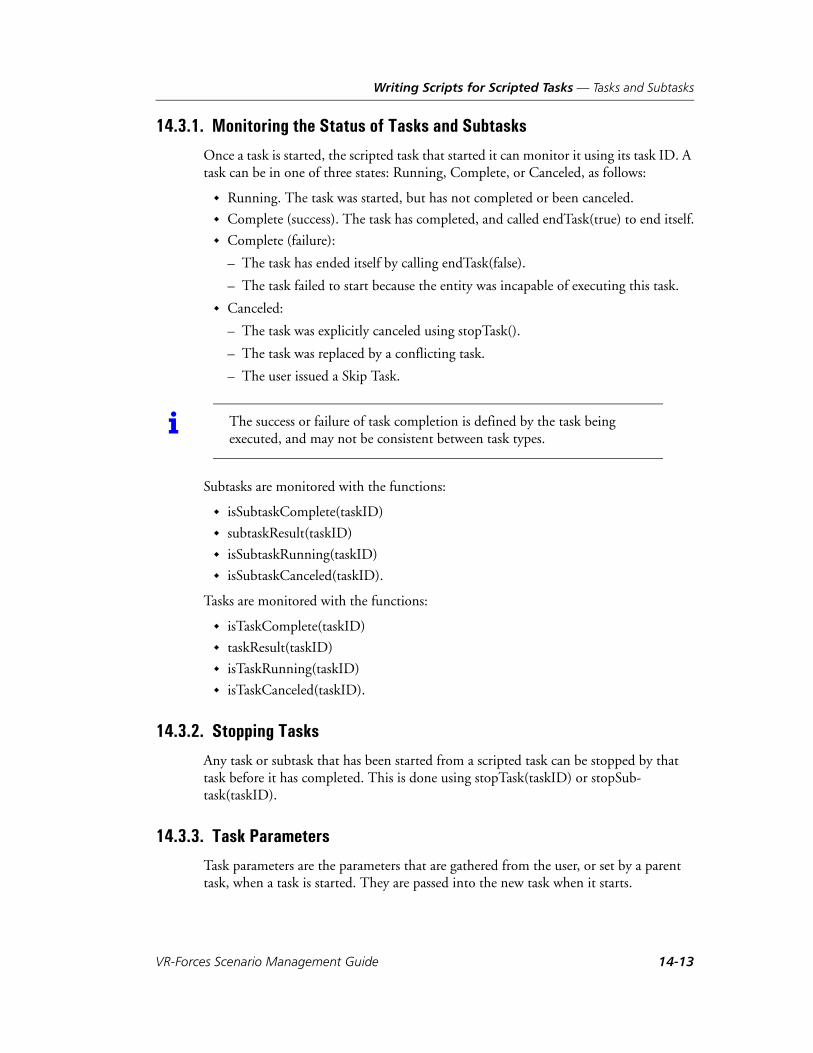
Writing Scripts for Scripted Tasks — Tasks and Subtasks
14.3.1. Monitoring the Status of Tasks and Subtasks
Once a task is started, the scripted task that started it can monitor it using its task ID. A task can be in one of three states: Running, Complete, or Canceled, as follows:
Running. The task was started, but has not completed or been canceled.
Complete (success). The task has completed, and called endTask(true) to end itself.
Complete (failure):
– The task has ended itself by calling endTask(false).
– The task failed to start because the entity was incapable of executing this task.
Canceled:
– The task was explicitly canceled using stopTask().
– The task was replaced by a conflicting task.
– The user issued a Skip Task.
Subtasks are monitored with the functions:
isSubtaskComplete(taskID)
subtaskResult(taskID)
isSubtaskRunning(taskID)
isSubtaskCanceled(taskID).
Tasks are monitored with the functions:
isTaskComplete(taskID)
taskResult(taskID)
isTaskRunning(taskID)
isTaskCanceled(taskID).
14.3.2. Stopping Tasks
Any task or subtask that has been started from a scripted task can be stopped by that task before it has completed. This is done using stopTask(taskID) or stopSub-task(taskID).
14.3.3. Task Parameters
Task parameters are the parameters that are gathered from the user, or set by a parent task, when a task is started. They are passed into the new task when it starts.
i The success or failure of task completion is defined by the task being executed, and may not be consistent between task types.
VR-Forces Scenario Management Guide 14-13

Writing Scripts for Scripted Tasks — Tasks and Subtasks
For scripted tasks, the task parameters are available in a Lua table named taskParameters available in the global scope. The table contains items named using the parameter names specified in the parameters section of the Scripted Task dialog box when the task was created. The types of these parameters depend on the parameter types selected by the user in this dialog box. Table 14-2 lists the parameter types you can specify when you create a scripted task and the corresponding Lua types in the taskParameters table.
Table 14-2: Task parameters and Lua types
Parameter Type Lua Type
Aggregate Formation String
Altitude MSL Number (meters)
Bomb Resource String (resource name)
Boolean Boolean
Choice (List) Number (Index of the option chosen)
Choice (Option Button) Number (Index of option chosen)
DI-Guy Animation String
DI-Guy Appearance String
Distance Number (meters)
Emitter Number (Index of the emitter system)
Entity Type String (DIS type enumeration, colon separated)
Force String
Heading Number (radians)
Integer Number
Location (with altitude) Location3D
Location (without altitude) Location3D
Munition Resource String (resource name)
Offset Location VectorOffset3D
Real Number
Resource String (resource name)
Simulation Object (Single) SimObject
Simulation Objects (Multiple) Table of SimObjects
Speed Number (meters / second)
String String
Time Number (seconds)
Turn Rate Number (radians / second)
14-14 VT MÄK

Writing Scripts for Scripted Tasks — Geometry
14.4. GeometryThe Lua interface includes classes representing geometric objects. The classes represent locations and vectors in three dimensional space. Different classes are defined for vectors in different contexts so that functions that manipulate them know what their context is and can convert between contexts automatically. Therefore, a script does not have to, for example, create rotation matrices to perform coordinate transformations between vectors that are in an entity-body context and vectors that are in a world context.
14.4.1. Location3D
A Location3D represents a point in three-dimensional (3D) space. Scripts can access the three components of the location as latitude, longitude, and altitude. There is no other access to components in any other coordinate system. Methods are available to construct a Location3D, to create a vector from the difference between two locations, and to generate a new point by adding a vector to a location.
14.4.2. Vector3D
A Vector3D is a direction in a north-east-down coordinate system. Scripts can access these three components of a Vector3D, or access bearing-inclination-range (Figure 14-4). This is the type of vector that scripts will use most often to find directions between locations, to create new locations relative to other locations, and so on.
Figure 14-3. Vector3D: North-East-Down, or Bearing-Inclination-Range
When viewed from the perspective of a 3D Cartesian coordinate system that is fixed to the earth, there is no single north-east-down coordinate system. This is because “north” and “east” directions vary depending on where the observer is located on the earth. The Vector3D is therefore similar to a vector in topographic coordinates. At higher latitudes, “north” for two different entities may not be the same direction (for example, two planes near the north pole, but at different longitudes, that are both flying “north,” are not on parallel courses).
Down
North
East
Rang
e North
Bearing
Inclination
VR-Forces Scenario Management Guide 14-15
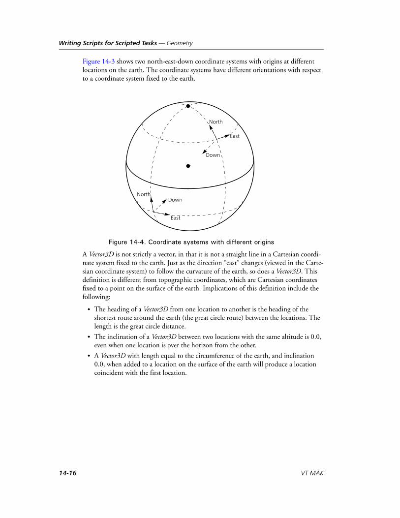
Writing Scripts for Scripted Tasks — Geometry
Figure 14-3 shows two north-east-down coordinate systems with origins at different locations on the earth. The coordinate systems have different orientations with respect to a coordinate system fixed to the earth.
Figure 14-4. Coordinate systems with different origins
A Vector3D is not strictly a vector, in that it is not a straight line in a Cartesian coordi-nate system fixed to the earth. Just as the direction “east” changes (viewed in the Carte-sian coordinate system) to follow the curvature of the earth, so does a Vector3D. This definition is different from topographic coordinates, which are Cartesian coordinates fixed to a point on the surface of the earth. Implications of this definition include the following:
The heading of a Vector3D from one location to another is the heading of the shortest route around the earth (the great circle route) between the locations. The length is the great circle distance.
The inclination of a Vector3D between two locations with the same altitude is 0.0, even when one location is over the horizon from the other.
A Vector3D with length equal to the circumference of the earth, and inclination 0.0, when added to a location on the surface of the earth will produce a location coincident with the first location.
Down
East
North
Down
East
North
14-16 VT MÄK

Writing Scripts for Scripted Tasks — Geometry
14.4.3. VectorOffset3D
A VectorOffset3D is a set of three values that define an offset from some reference direc-tion defined by a Vector3D. The three values represent right-forward-up, where:
forward is in the same direction as the reference.
right is to the right in a horizontal plane. Horizontal means the plane defined by an inclination of zero; this definition implies that the “roll” component of the refer-ence direction is assumed to be zero.
up is perpendicular to forward and right, that is, right X forward.
A VectorOffset3D is appropriate to use, for example, to define the offsets of unit forma-tion positions from a central location. Actual formation positions could be generated by transforming the offsets to Vector3Ds using the direction vector of the unit, and then adding the Vector3Ds to the unit location.
14.4.4. VectorGeoc3D
A VectorGeoc3D is a vector in a Cartesian coordinate system fixed to the earth (geocen-tric coordinates). The actual coordinate meanings and values are not accessible to the script, because they are considered to be abstract. A VectorGeoc3D can be generated only by taking the difference of two locations, or by transforming a Vector3D at a particular location.
A VectorGeoc3D between two locations is the line-of-sight vector between the locations. Therefore:
A VectorGeoc3D between two points on opposite sides of the earth, at the same alti-tude, will go through the earth. (A Vector3D, by contrast, will go around the earth parallel to the surface.)
The angle between two VectorGeoc3D vectors corresponding to north for two enti-ties near the north pole will be the difference in their longitudes. (The angle between their Vector3Ds for north, by contrast, will be zero.)
The Lua interface does not have any simulation functions that require VectorGeoc3Ds. However, they may be manipulated to compute angles and so forth.
VR-Forces Scenario Management Guide 14-17

Writing Scripts for Scripted Tasks — Reserved Words
14.5. Reserved WordsTable 14-3 lists reserved words (in addition to those reserved by Lua), which should not be used except for their intended purpose.
Table 14-3: Reserved words
Name Module Function
vrf vrf Module singleton
this SimObject Ownship name
ScriptVrfObject SimObject Class name
Location3D Location3D Class name
Vector3D Vector3D Class name
VectorGeoc3D VectorGeoc3D Class name
VectorOffset3D VectorOffset3D Class name
ScriptFeatureSet FeatureSet Class name
vrfprint vrfutil Global function
printDebug vrfutil Global function
printVerbose vrfutil Global function
printInfo vrfutil Global function
printWarn vrfutil Global function
printError vrfutil Global function
EntityType vrfutil Global table of functions
bhaveLoaded vrfutil Global function
new fsm Function name
14-18 VT MÄK

Writing Scripts for Scripted Tasks — Error Detection
14.6. Error DetectionThe VR-Forces Lua implementation can detect syntax errors and runtime errors.
When you save the script for a scripted task, it is checked for syntax errors. If an error is found, it is reported in an error message. In Figure 14-5, the if statement in line 7 is missing the then keyword.
Figure 14-5. Lua syntax error
When you run a scripted task, the back-end can detect errors due to incorrect use of user functions and the Lua API functions, such as calling an object that does not exist, or trying to access feature data before it is paged in. When a runtime error is detected, the back-end generates an error message. When the back-end generates an error, the script that caused the error is displayed in bold, red type in the Scripted Tasks dialog box (Figure 14-6). Therefore, you may want to keep the dialog box open while you are testing new or edited scripts.
i Detection of a syntax error does not prevent the script from being saved. If you do not fix the error and try to use the scripted task, the back-end will generate an error.
VR-Forces Scenario Management Guide 14-19

Writing Scripts for Scripted Tasks — A Basic Scripted Task
Figure 14-6. Lua error message
To view an error message:
1. In the Scripted Tasks dialog box, select the script that has generated an error.
2. Choose Script View Script Error. An error message is displayed.
14.7. A Basic Scripted TaskVR-Forces includes many scripted tasks, all of which can serve as examples of how to write one. The Create and Move to Waypoint scripted task is intended is a basic example that shows you how to:
Set up meta data.
Include the VRF Utilities module.
Initialize a subtask ID.
Use the init() function.
Create a waypoint using input from the task’s dialog box.
Send a set data request to an entity, using input from the task’s dialog box.
Use the tick() function.
Send a subtask and get the subtask ID.
Check for completion of the task.
Stop the task.
The Lua code is comprehensively commented. This section supplements the comments.
i Script errors are also sent to the console in the Entity Information dialog box.
14-20 VT MÄK

Writing Scripts for Scripted Tasks — A Basic Scripted Task
14.7.1. Create and Move to Waypoint Meta Data
Figure 14-7 shows the meta data for the Create and Move to Waypoint scripted task.
Figure 14-7. Create and Move to Waypoint scripted task
To view the meta data:
1. Choose Simulation Scripted Tasks. The Scripted Tasks dialog box opens.
2. Expand the Examples folder (Figure 14-8).
VR-Forces Scenario Management Guide 14-21

Writing Scripts for Scripted Tasks — A Basic Scripted Task
Figure 14-8. Scripted Tasks dialog box
3. Select Create and Move to Waypoint.
4. Choose Script Scripted Task. The Edit Scripted Task dialog box opens (Figure 14-7).
Note how the Name column of the Create and Move To Waypoint entry in the Scripted Tasks dialog box matches the Menu Text in the Edit Scripted Task dialog box. The Script ID and Description fields are also drawn from the scripted tasks meta data.
Now let’s look at the parameters. This scripted task has two parameters, waypointLoca-tion and orderedSpeed. To see the definition of a parameter, select it and click the Edit button ( ). Figure 14-9 shows the dialog boxes that specify the parameters.
Figure 14-9. Parameter definitions
14-22 VT MÄK

Writing Scripts for Scripted Tasks — A Basic Scripted Task
Figure 14-10 shows the dialog box that is displayed when you assign an entity this task. Note that the description of the task on the dialog box matches the description in the meta data. The parameter labels in the dialog box match the labels specified for the two parameters. The labels are not the same thing as the parameter name. The parameter name is the name used in the Lua script for this scripted task.
Figure 14-10. Create and Move to Waypoint dialog box
When this scripted task is assigned to an entity, the user will specify the waypoint and the ordered speed. Then the scripted task will be executed. Now we will look at the Lua script to see what happens.
14.7.2. The Create and Move To Waypoint Lua Script
The entire Lua script for this scripted task (without comments) is as follows:
require "vrfutil"moveToWaypointSubtaskId = -1function init()
vrf:setTickPeriod(0.5)
waypoint = vrf:createWaypoint({location=taskParameters.waypointLocation, force=this:getForceType()})
vrf:sendSetData(this, "set-speed",
{speed=taskParameters.orderedSpeed})endfunction tick()
if moveToWaypointSubtaskId == -1 then moveToWaypointSubtaskId = vrf:startSubtask("move-to",
{control_point=waypoint:getName()})endif vrf:isSubtaskComplete(moveToWaypointSubtaskId) then
vrf:endTask(true)end
endfunction shutdown()
vrf:deleteObject(waypoint)end
VR-Forces Scenario Management Guide 14-23

Writing Scripts for Scripted Tasks — A Basic Scripted Task
The comments in the script describe the control flow. The essence is that using the input from the task dialog box, the waypoint gets created and the speed gets set in init(). The first time the task is ticked, it sends the Move to Waypoint subtask. There-after, each time the task is ticked, it checks to see if the subtask is complete. When the subtask is complete, the task is ended and the waypoint is removed.
The functions in this script are all in the vrf class, which is described in “Lua Classes,” on page 14-2. The createWaypoint() function takes its location from the waypointLo-cation parameter that was defined in the scripted task meta data and whose value was provided in the Create and Move To Waypoint dialog box when the task was assigned. Similarly, the ordered speed is set with the sendSetData() function and the value is taken from the orderedSpeed parameter for the task. The script gets the parameter values with the taskParameters.parameter syntax.
This script uses three of the entry point functions – init(), tick(), and shutdown(). If you were to checkpoint the scenario while the script was executing, the standard save actions would take place, but no script-specific actions would be taken, because there is no saveState() function in the script. Similarly, no special action would be taken when the scenario was loaded again because loadState() is not used.
For details about the parameters and return values of the functions, please see the VR-Forces Lua API documentation. Similarly, the tasks and set data requests that you can assign with the startSubtask() and sendSetData() functions are described on the Task and Set pages of the Lua API documentation. You should review the lists of functions to see what you can do in a scripted task.
14-24 VT MÄK

Writing Scripts for Scripted Tasks — A Simple Reactive Task
14.8. A Simple Reactive TaskThe difference between a scripted task and a reactive task is the use of the check() and checkInit() functions in the reactive task. The check() function tests a condition at whatever tick rate you specify. If the condition returns true, the task runs.
The simple reactive task in this section monitors the speed of an entity. When it exceeds 15 meters per second, the entity is destroyed. The script works as follows:
1. The checkInit() function sets the tick rate to 1.0 second.
2. In check(), VR-Forces gets the speed of the entity and prints it to the console.
3. It tests to see if the speed is greater than 15 meters per second. If the condition is met, the function returns true.
4. If the function returns true, the script executes init() and begins to tick().
5. In the tick() function, the entity is destroyed and the task is complete. Note that in the executeSetData() function, set-destroy does not have parameters, but the command must include empty braces.
function checkInit()vrf:setTickPeriod(1.0)
end
function check()currentSpeed = this:getSpeed()print("speed is:", currentSpeed)if currentSpeed > 15 then
return trueend
return falseend
function init()vrf:setTickPeriod(0.5)
end
function tick()vrf:executeSetData("set-destroy", {})vrf:endTask(true)
end
VR-Forces Scenario Management Guide 14-25

Writing Scripts for Scripted Tasks — A Simple Reactive Task
14-26 VT MÄK

VR-Forces Scenario Management Guide
A
Example Scenarios
VR-Forces includes several sample scenarios. This appendix explains how to create the breaching scenario and the embarkexample scenario. It assumes some basic knowledge of VR-Forces concepts and the VR-Forces interface, such as how to select objects, how to pan and zoom the terrain, and so on. If you have not yet reviewed the sample tutorial in VR-Forces Getting Started Guide, you may want to try that tutorial before trying these example scenarios.
The Breaching Scenario ................................................................................ A-2Create the Scenario................................................................................. A-3Create the Minefield............................................................................... A-4Create the Opposing Forces.................................................................... A-5Create the Tactical Graphics ................................................................... A-7Create the Friendly Entities .................................................................... A-8Write the Plans ..................................................................................... A-10Save the Scenario.................................................................................. A-17Running the Scenario ........................................................................... A-18
The Embarkexample Scenario..................................................................... A-19Create the Entities and Objects ............................................................ A-20Write the Plans for the Entities ............................................................. A-29
A-1

Example Scenarios — The Breaching Scenario
A.1. The Breaching ScenarioThis scenario simulates a breaching exercise. In this exercise, four hostile vehicles are arrayed behind a minefield. Three platoons of four tanks each suppress the hostile vehi-cles, allowing two engineering vehicles to clear the minefield.
Figure A-1 illustrates the order of battle and tactical graphics in the scenario.
Figure A-1. Breaching scenario order of battle
The scenario demonstrates the following features of VR-Forces:
Creating entities.
Creating tactical graphics (waypoints, routes, areas).
Creating a pre-defined aggregate and creating an aggregate from individual entities.
Creating plans, using:
– Move To.
– Follow Entity.
– Follow Route.
– Conditions.
Minefield
Blue waypoint
Red waypoint
Breach route
White Plt
Blue Plt
Red Plt
Engineering units
A-2 VT MÄK
Example Scenarios — The Breaching Scenario
The scenario plays out as follows for the Blue force units:
White Platoon stays in position and fires on hostile forces.
Red Platoon advances to waypoint red and provides cover for the engineers.
Blue Platoon advances to waypoint blue and provides cover for the engineers.
When the hostile forces are destroyed, the engineering entities advance on the minefield to clear it.
You can view videos that demonstrate this tutorial at ./doc/vrforces_tutorialvideos.htm.
A.1.1. Create the Scenario
To create the scenario:
1. Start VR-Forces. The VR-Forces window opens.
2. Choose File New Scenario. The Select Simulation Database dialog box opens.
3. Select a terrain database. We used the SanLuisObispo.mtf database.
4. Click Open. The New Scenario dialog box opens.
5. Type a name in the Scenario Name box, such as myBreachingScenario. Accept all of the default values for the scenario parameters.
6. Click OK. The San Luis Obispo database is displayed. This database covers a portion of California, U.S.A.
Save the Scenario
Save the scenario periodically as you work on it.
To save the scenario:
1. Choose File Save Scenario. The Save Scenario dialog box opens. By default, the name you gave to the scenario when you created it is automatically entered.
2. Click the New Folder button. A new folder is added to the window.
3. Type a name for the new folder, such as myBreaching.
4. Select the folder.
5. Accept the default name or type a name of your choice.
6. Click OK.
i The scenario has entities that represent engineering entities, but VR-Forces does not actually have models for engineering entities.
VR-Forces Scenario Management Guide A-3

Example Scenarios — The Breaching Scenario
A.1.2. Create the Minefield
We will create the minefield first, since it becomes a good reference around which to create the entities and other objects.
To create the minefield:
1. Zoom in on a relatively flat portion of the terrain. This is to minimize the impact of hilly terrain and intervisibility issues on how the simulation runs. For this scenario, we used an area just to the northeast of the center of the terrain (Figure A-2).
Figure A-2. San Luis Obispo terrain
2. Click the Tactical Graphics tab on the right side of the window. The Tactical Graphics Palette opens.
3. In the Categories list, select Engineering.
4. In the list of tactical graphics, select Minefield. The Create Minefield tab gets added to the window and the cursor changes to a vertex marker.
5. Click the Create Minefield tab. The Create Minefield dialog box opens (Figure A-3).
6. In the Name box, type Minefield.
A-4 VT MÄK

Example Scenarios — The Breaching Scenario
7. Draw an oblong area to define a minefield (Figure A-3). Click to define the first three vertices. Right-click to define the last vertex.
Figure A-3. Create the minefield
A.1.3. Create the Opposing Forces
Now that we have the minefield as a reference point, we can create the hostile entities.
To create the opposing forces:
1. Click the Entity Palette (on the right margin of the window).
2. In the Category list, select Ground.
3. In the Force list, select Opposing.
4. In the list of entities, select T-80 Main Battle Tank.
5. Click on the map north of the minefield four times, as indicated in Figure A-1, to place the T-80s.
6. Right-click to exit create mode.
VR-Forces Scenario Management Guide A-5

Example Scenarios — The Breaching Scenario
Aggregate the Opposing Forces
We will want to test for when all of the opposing forces are destroyed. This will be easier to do if they are in an aggregate.
To aggregate the opposing forces:
1. Select the four T-80 tanks.
2. Choose Entities Aggregates As. The Aggregate As dialog box opens (Figure A-4).
Figure A-4. Aggregate As dialog box
3. In the list, select Ground Aggregate.
4. Click OK. The tanks are aggregated into a platoon.
5. In the Echelon View tab on the Object tab, expand the aggregate (Figure A-5).
Figure A-5. Echelon View
A-6 VT MÄK

Example Scenarios — The Breaching Scenario
A.1.4. Create the Tactical Graphics
We need to create two waypoints and a route for the Blue Force.
Create the Waypoints
To create the waypoints:
1. Click the Tactical Graphics Palette (on the right margin of the window).
2. In the Category list, select Control Objects.
3. In the list of control objects, select Waypoint. The Create Waypoint tab is added to the window.
4. Click the Create Waypoint tab. The Create Waypoint dialog box opens.
5. Type a name for the waypoint, such as Red.
6. Using Figure A-1 as a guide, click on the map where you want to place the waypoint for Red platoon.
7. In the Create Waypoint dialog box, type a name for the second waypoint, such as Blue.
8. Click on the terrain where you want to place the waypoint.
9. Right-click to exit draw mode.
Create the Route
The route will guide the engineers as they swing past the Red Platoon and move to the minefield. The route is shown as Breach route in Figure A-1.
To create the route:
1. Click the Tactical Graphics Palette.
2. In the list of control objects, select Route. The Create Route tab is added to the window.
3. Click the Create Route tab. The Create Route dialog box opens.
4. Type a name for the route, such as “Breach route”.
5. Click on a point just east of waypoint Red.
6. Move the mouse cursor to the edge of the minefield.
7. Right-click to place the end point in the route.
8. Save the scenario.
At this point, the scenario should look something like Figure A-6.
VR-Forces Scenario Management Guide A-7

Example Scenarios — The Breaching Scenario
Figure A-6. Breaching scenario progress
A.1.5. Create the Friendly Entities
Using Figure A-1 as a guide to location, create the friendly entities. We will create one platoon from individual entities, and the other two using pre-configured platoons.
To create the friendly entities:
1. Click the Entity Palette.
2. In the Categories list, select Aggregate.
3. In the Force list, select Friendly.
4. In the list of entities displayed, select Armor Plt(US).
5. Click on the map to place the red platoon and blue platoon as shown in Figure A-1. Right-click to exit create mode. The aggregates are created with default names (ARPlt 2 and ARPlt 3). They are disaggregated and expanded, so you can see the individual entities.
6. Select one of the platoons. To select a platoon, you must select the platoon icon, not one of its subordinates. The easiest place to do that is on the Echelon View tab of the Object Lists panel (Figure A-7).
A-8 VT MÄK

Example Scenarios — The Breaching Scenario
Figure A-7. Echelon View tab
7. Choose Entities Edit. The Edit Armor Plt (US) dialog box opens.
8. In the name text box, replace the default name with Red Plt or Blue Plt, depending on which platoon you selected.
9. Click Update.
10. Rename the other platoon that you created.
11. Click the Entity Palette.
12. In the Categories list, select Ground.
13. In the list of entities, click M1A2 Tank. The cursor changes to draw mode.
14. Click on the map where White Platoon should be. An entity icon is displayed.
15. Click three more times to create the rest of the tanks in White Platoon. Right-click to exit create mode. (We will create the aggregate from these entities in the next section.)
16. Open the Entity Palette.
17. In the Ground/Friendly category, select M58 MICLIC.
18. Click twice on the map to the South of Red Plt to create two MICLIC entities.
19. Right-click to exit create mode.
20. Save the scenario.
VR-Forces Scenario Management Guide A-9

Example Scenarios — The Breaching Scenario
Create White Platoon
To create the white platoon:
1. Select the four members of White Platoon.
2. Choose Entities Aggregates As. The Aggregate As dialog box opens.
3. Select Ground Aggregate from the list.
4. Click OK.
5. Select the new platoon.
6. Choose Entities Edit. The Edit Scene Object dialog box opens.
7. Change the name to White Plt.
8. Save the scenario.
A.1.6. Write the Plans
The plans tell the entities how to carry out their roles in the scenario. The White platoon just stays in place. We do not give it a plan. It will just respond to any opposing force entities that it detects.
Write the Plan for Blue Platoon
Blue Platoon will move to a waypoint. As it moves it responds to any opposing force entities that it detects. The plan is quite simple to write.
To write the plan for Blue Platoon:
1. Select Blue Platoon.
2. Choose Entities Plan. The Plan window opens (Figure A-8).
A-10 VT MÄK

Example Scenarios — The Breaching Scenario
Figure A-8. Blue Platoon plan
3. In the Plan window, choose Task Movement Move To Waypoint (Direct). The Move To Waypoint (Direct) dialog box opens (Figure A-9).
Figure A-9. Move To Waypoint (Direct) dialog box
4. In the Move To Waypoint (Direct) dialog box, or on the map, select the Blue waypoint.
5. Click OK. The task is added to the plan. The plan is now complete (Figure A-10).
VR-Forces Scenario Management Guide A-11

Example Scenarios — The Breaching Scenario
Figure A-10. Blue plan - complete
6. In the Plan window, click OK.
Write the Plan for Red Platoon
The Red Platoon moves to the Red waypoint. It has another job to do. When all the opposing forces are destroyed, it sends a message on the radio network. The MICLICs are listening for the message. They will not try to clear the minefield until they receive it.
To write the plan for red platoon:
1. Select Red Platoon.
2. Press p. The Plan window opens.
3. In the Plan window, choose Task Movement Move To Waypoint (Direct). The Move To Waypoint (Direct) dialog box opens (Figure A-9).
4. In the Move To Waypoint (Direct) dialog box, or on the map, select the Red waypoint.
5. Click OK. The task is added to the plan (Figure A-11).
Figure A-11. Plan for Red Platoon - move to waypoint
6. Select the top line in the plan.
7. In the Plan window, choose Conditions When. The When Expression dialog box opens (Figure A-12).
A-12 VT MÄK

Example Scenarios — The Breaching Scenario
Figure A-12. When Expression dialog box
8. In the list, select Entity Destroyed. The Entity Destroyed dialog box opens.
9. In the list of entities, select ArPlt 1 (Figure A-13).
Figure A-13. Entity Destroyed dialog box
10. Click OK. The expression is added to the When Expression dialog box (Figure A-14).
Figure A-14. Completed When Expression dialog box
VR-Forces Scenario Management Guide A-13
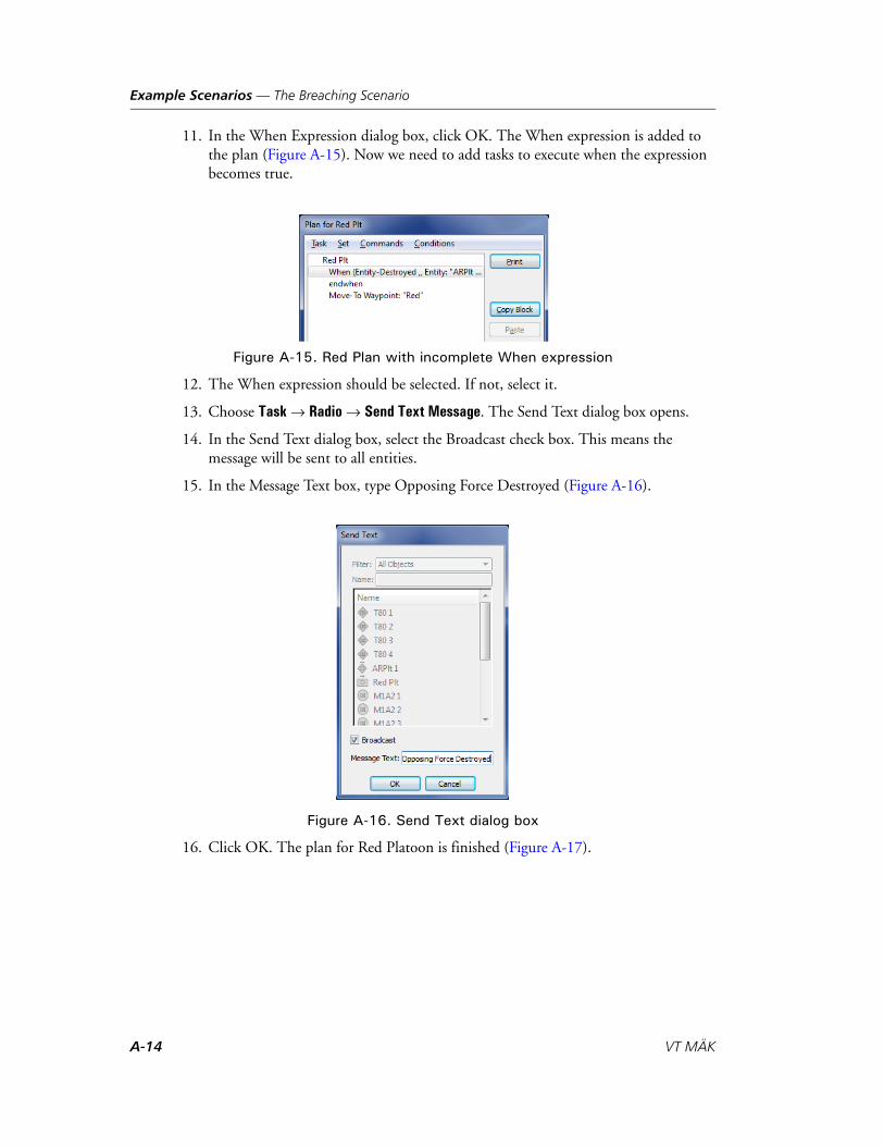
Example Scenarios — The Breaching Scenario
11. In the When Expression dialog box, click OK. The When expression is added to the plan (Figure A-15). Now we need to add tasks to execute when the expression becomes true.
Figure A-15. Red Plan with incomplete When expression
12. The When expression should be selected. If not, select it.
13. Choose Task Radio Send Text Message. The Send Text dialog box opens.
14. In the Send Text dialog box, select the Broadcast check box. This means the message will be sent to all entities.
15. In the Message Text box, type Opposing Force Destroyed (Figure A-16).
Figure A-16. Send Text dialog box
16. Click OK. The plan for Red Platoon is finished (Figure A-17).
A-14 VT MÄK

Example Scenarios — The Breaching Scenario
Figure A-17. Completed plan for Red Platoon
17. Click OK.
18. Save the scenario.
Write the Plans for the Engineering Units
When the the MICLICs are notified that the opposing force has been destroyed, they move along a route to the edge of the minefield. Then they clear it.
The MICLICs provided with VR-Forces do not actually have the ability to simulate clearing a minefield. We are going to provide some visual interest by using global commands to remove the original minefield and replace it with two minefields with a space between them.
We will start with the plan for SmWhel 1:
1. Select SmWhel 1.
2. Press p. The Plan window opens.
3. In the Plan window, choose Conditions When. The When Expression dialog box opens.
4. In the list, select Receive Text Message. The Receive Text Message dialog box opens.
5. Type the message that we are waiting for (Opposing Force Destroyed) (Figure A-18).
Figure A-18. Receive Text Message dialog box
6. Click OK.
VR-Forces Scenario Management Guide A-15

Example Scenarios — The Breaching Scenario
7. In the When Expression dialog box, click OK. The empty expression is added to the plan window (Figure A-19). Now we need to tell the entity what to do when it gets this message (move along the route, then redraw the minefield).
Figure A-19. Plan for SmWhel 1
8. In the Plan window, choose Task Movement Move Along Route. The Move Along Route dialog box opens.
9. Select Breach route, then click OK. The task is added to the plan.
As we said earlier, VR-Forces does not actually model minefields or the types of entities that could clear one. To provide the visual illusion of clearing a corridor through the minefield, after the MICLICs arrive at the end of the route, we will delete the minefield and create two new minefields that occupy most of the space of the original one, but leaves a corridor for entities to travel through.
10. Choose Commands Delete. The Delete dialog box opens.
11. In the list, select Minefield.
12. Click OK.
13. Choose Commands Create Tactical Graphics Engineering Minefield. The Create Minefield dialog box opens.
14. Type Minefield-left in the Name box.
15. Draw an area over most of the minefield to the left of where the breach route inter-sects the minefield.
16. Click OK. You will not see this new area, because it does not exist in the simulation yet. It will not exist until the command gets executed.
17. Repeat steps 13 through 16, but this time draw the minefield to the right of the route. Call it Minefield-right. The plan should now be similar to Figure A-20.
A-16 VT MÄK

Example Scenarios — The Breaching Scenario
Figure A-20. Plan for SmWhel 1 after When expression complete
18. Click OK. The plan is now complete.
19. Save the scenario.
Write the Plan for SmWhel2 2
The plan for SmWhel 2 is a bit simpler than that of SmWhel 1. It follows SmWhel 1, offset to the right, so that it arrives at the minefield next to the other entity. Try creating the plan yourself. It should look like (Figure A-21).
Figure A-21. Plan for SmWhel 2
A.1.7. Save the Scenario
Be sure to save the scenario before you run the simulation. If you want to save it in its starting state, do not save it after you run the simulation.
VR-Forces Scenario Management Guide A-17

Example Scenarios — The Breaching Scenario
A.1.8. Running the Scenario
Once you have created the scenario and saved it, click the Run button and watch the simulation run. Open the plan windows for the MICLICs and observe the progression of tasks through the plan.
If hostile entities do not get destroyed, it may be that the blue entities cannot see them. If they cannot see them, they cannot shoot each other. Use the intervisibility feature to test line-of-sight. Move the entities around, or find a flatter section of the terrain until you get the results you want.
You can run the breaching scenario included with VR-Forces and see how it compares to the one that you created.
Figure A-22 shows the breaching scenario after the MICLICs have completed their plans. All of the aggregates are expanded so that you can see the individual entities.
Figure A-22. Breaching scenario after minefield cleared
A-18 VT MÄK
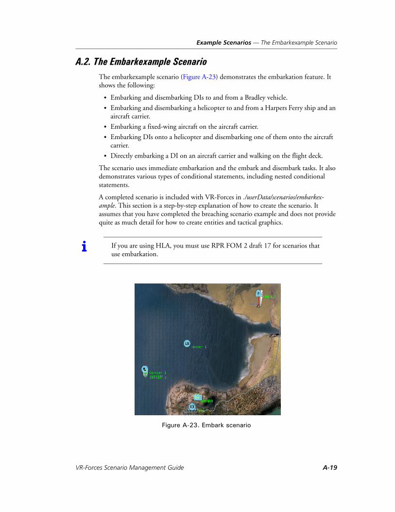
Example Scenarios — The Embarkexample Scenario
A.2. The Embarkexample ScenarioThe embarkexample scenario (Figure A-23) demonstrates the embarkation feature. It shows the following:
Embarking and disembarking DIs to and from a Bradley vehicle.
Embarking and disembarking a helicopter to and from a Harpers Ferry ship and an aircraft carrier.
Embarking a fixed-wing aircraft on the aircraft carrier.
Embarking DIs onto a helicopter and disembarking one of them onto the aircraft carrier.
Directly embarking a DI on an aircraft carrier and walking on the flight deck.
The scenario uses immediate embarkation and the embark and disembark tasks. It also demonstrates various types of conditional statements, including nested conditional statements.
A completed scenario is included with VR-Forces in ./userData/scenarios/embarkex-ample. This section is a step-by-step explanation of how to create the scenario. It assumes that you have completed the breaching scenario example and does not provide quite as much detail for how to create entities and tactical graphics.
Figure A-23. Embark scenario
i If you are using HLA, you must use RPR FOM 2 draft 17 for scenarios that use embarkation.
VR-Forces Scenario Management Guide A-19

Example Scenarios — The Embarkexample Scenario
A.2.1. Create the Entities and Objects
The scenario has the following entities:
A fixed-wing aircraft on the airport runway.
A helicopter embarked on an LSD-49 Harpers Ferry ship.
A dismounted infantry entity (DI) embarked on an aircraft carrier.
A DI standing behind a Bradley vehicle in the town.
A DI standing in the courtyard of the palace.
The scenario has the following tactical graphics:
A route for the fixed-wing plane to follow to take off.
A waypoint in front of the palace for the Bradley vehicle to drive to.
A waypoint in front of the palace for the helicopter to land at.
A waypoint on the carrier deck for the DI to walk to.
Create the Surface Entities
To create the surface entities:
1. Start VR-Forces.
2. Choose File New Scenario. The Choose Simulation Terrain dialog box opens.
3. Select Makland.mtf.
4. Click Open. The New Scenario dialog box opens.
5. Click OK. The Makland database is displayed.
6. Navigate to the Makland peninsula, the bay and the airport.
7. On the Entity Palette, select the Surface category and the Friendly force.
8. In the entity list, select CVN-75 Harry S. Truman
9. Click in Makland Bay midway to the left of the peninsula.
10. Right click to exit create entity mode.
11. Place a LSD- 49 Harpers Ferry Class Ship in the middle of Makland Bay (Figure A-24).
A-20 VT MÄK

Example Scenarios — The Embarkexample Scenario
Figure A-24. Surface entities
12. Save the scenario.
Create the Aircraft
To create the aircraft:
1. Zoom in on the airport, located northeast of the bay.
2. On the Entity Palette, select the Fixed Wing category.
3. Select force Friendly.
4. Select an F/A 18 Hornet entity.
5. Click the northern end of the north/south runway.
6. Right-click to exit create entity mode.
7. Select the entity.
8. Choose Set Position Heading. The Heading dialog box opens.
9. Type 180 and click OK.
10. Zoom out to see a larger area of the map.
11. On the Entity Palette, select the Rotary Wing category.
12. Select a CH46E Sea Knight entity.
13. Click anyplace on the map.
14. Right-click to exit create mode.
15. Select the helicopter.
VR-Forces Scenario Management Guide A-21

Example Scenarios — The Embarkexample Scenario
16. Choose Entities Embark On. The Embark On dialog box opens.
17. In the list window, select the LSD 49 (Harper 1).
18. Click OK. The helicopter is immediately embarked on the LSD 49. If you select the Embarkation View on the Objects List Panel, you can see that the helicopter is listed as being embarked on the LSD 49 (Figure A-25).
Figure A-25. Helicopter embarked on LSD 49 Harpers Ferry
19. Save the scenario.
A-22 VT MÄK

Example Scenarios — The Embarkexample Scenario
Create the Bradley Vehicle
To create the Bradley Vehicle:
1. Zoom in on the town on the peninsula.
2. On the Entity Palette, change the category to Ground.
3. Select force Friendly.
4. Select an M2A2 Bradley IFV entity.
5. Place the Bradley vehicle where the road to the palace intersects a north/south street, as shown in Figure A-26.
Figure A-26. Bradley vehicle
6. Save the scenario.
VR-Forces Scenario Management Guide A-23

Example Scenarios — The Embarkexample Scenario
Create Dismounted Infantry
The scenario has two dismounted infantry that ride in the helicopter, and one that is embarked on the aircraft carrier. Embarking the DI on the carrier requires a bit of discussion.
There are two ways to embark an entity – immediate embarkation and the embarkation task. If you want to use the Embark task, the receiving entity must be configured to accept the embarking entity. We will use the Embark task a little later in this example.
We want to embark one of the DI entities on the aircraft carrier. However, aircraft carriers are not configured to accept DI entities, so we cannot use an Embark task to do this. However, we can use the immediate embark feature to embark an entity on any other entity. To do this, we must specify the coordinates at which to place the entity. In this example, we want to place a DI on the carrier deck and make it look good in the 3D view. Through experimentation, we know that using the model supplied with VR-Forces, the altitude offset to place an entity on the carrier deck is 21 meters. We also offset the location to move the entity to the side of the deck.
1. On the Entity Palette, change the category to Human.
2. Select a Dismounted-Infantry entity.
3. Select force Friendly.
4. Place one DI directly behind (south of ) the Bradley vehicle.
5. Place one DI in the courtyard area of the palace at the top of the hill in Makland (Figure A-27).
Figure A-27. DI at palace
6. Place a third DI anyplace in town. This is just a temporary location. In a moment you will embark this entity on the aircraft carrier.
A-24 VT MÄK

Example Scenarios — The Embarkexample Scenario
7. Double-click the DI in the palace to make its position editable. Hold down the Shift key and drag the mouse to change the heading indicator to 270 degrees (Figure A-28).
Figure A-28. DI at palace after setting heading
8. Select the DI that you placed temporarily in town.
9. Choose Entities Embark On. The Embark On dialog box opens.
10. In the entity list, select the carrier.
11. Select the Override Position option.
12. In the Position Override group box, set the X value to 15 and the altitude value to 21. This places the DI at the deck level of the carrier (Figure A-29).
Figure A-29. Embark On dialog box
13. Click OK. The DI is embarked on the carrier.
14. Save the scenario.
VR-Forces Scenario Management Guide A-25

Example Scenarios — The Embarkexample Scenario
Create the Tactical Graphics
We need a few tactical graphics to specify the movement tasks for the entities.
Create a Runway at the Airport
At the airport, create a route from North to South along the runway. Call it Runway (Figure A-30).
Figure A-30. Runway
Create Waypoints at the Palace
To create the waypoints at the palace:
1. Zoom in on the palace at the top of the hill near the town.
2. Place a waypoint on the edge of the road just before the palace entryway. Call it “palace”.
3. Place a waypoint on the ground in front of the palace between the trees. Call is “helipad” (Figure A-31).
A-26 VT MÄK

Example Scenarios — The Embarkexample Scenario
Figure A-31. DI and waypoints at palace
Attach a Waypoint to the Carrier
We want to attach a waypoint to the carrier. However, in the 2D view, there is no way to figure out where to place the waypoint because the carrier is shown as a 2D icon. So, we will switch to the 3D view.
To attach a waypoint to the carrier:
1. Move the observer so that you are looking at the 2D icon for the aircraft carrier.
2. Check the Attachment button ( ) on the Attach Object toolbar to make sure that you are not attached to an entity. If it is depressed, click it to unattach the observer.
3. In the Observer list on the Observer toolbar, select Stealth. The view changes to 3D. However we are still looking down on the terrain, so we have a nice top-down view of the aircraft carrier (Figure A-32).
Figure A-32. Aerial view of carrier in 3D
VR-Forces Scenario Management Guide A-27

Example Scenarios — The Embarkexample Scenario
4. Zoom in on the aircraft carrier.
5. Choose Create Waypoint.
6. Expand the Create Waypoint dialog box.
7. Clear the Attach Object to Mouse check box.
8. Type a name for the waypoint, such as Carrier.
9. For the Altitude option, select Above Sea Level.
10. Type a value of 21 (to put the waypoint on the carrier deck).
11. Select the Attach Object to Mouse check box.
12. Click on the deck of the carrier toward the lower right (Figure A-33).
Figure A-33. Waypoint on carrier
13. Right-click.
Now we will attach the waypoint to the aircraft carrier. When you attach a tactical graphic to an entity, it moves with the entity. Even though the aircraft carrier is not moving in this scenario, this extra step will teach you about this procedure.
14. Select the waypoint.
15. Choose Entities Attach Object To. The Attach Object To dialog box opens.
16. Select Carrier 1.
17. Save the scenario.
A-28 VT MÄK

Example Scenarios — The Embarkexample Scenario
A.2.2. Write the Plans for the Entities
We need to write plans for the entities to do the following:
The jet will take off from the airport and embark on the carrier (land and taxi to a parking place).
The helicopter will disembark from the LSD-49 and fly to the palace, where it will land. Two DIs will embark on it. Then it will take off and embark on the carrier, disembark, and embark back on the LSD-49.
The DI in town will embark on the Bradley and ride with it to the palace. It will then disembark from the Bradley and embark on the helicopter.
The DI in the palace courtyard will embark on the helicopter.
The DI on the carrier will walk to the waypoint.
Write the Fixed-Wing Aircraft’s Plan
To write the fixed-wing aircraft’s plan:
1. Select the fixed-wing entity.
2. Choose Entities Plan. The Plan window opens.
3. In the Plan window, choose Task Movement Fixed Wing Takeoff. The Fixed Wing Takeoff dialog box opens.
4. In the Fixed Wing Takeoff dialog box, select Runway from the list of routes.
5. Click OK. The task is added to the plan.
6. Choose Task Embarkation Embark. The Embark On dialog box opens.
7. In the Embark On dialog box, select Carrier 1 from the list and click OK (Figure A-34).
Figure A-34. Fixed-wing entity plan
8. In the Plan window, click OK. The plan for the fixed-wing entity is finished.
VR-Forces Scenario Management Guide A-29

Example Scenarios — The Embarkexample Scenario
Write the Helicopter’s Plan
To write the helicopter’s plan:
1. If you are in the 2D view, on the Objects List Panel, Entity List view, select the helicopter entity. (Since the helicopter is embarked, it is not visible on the map, so you cannot select it there.) If you are in the 3D view, you can select the copter in the Objects List Panel or by clicking the model.
2. Choose Entities Plan. The Plan window opens.
3. Choose Task Disembark.
4. Choose Task Move To Altitude. The helicopter is going to fly to the palace, which is on top of a hill with steep cliffs. Sometimes the terrain following feature of the helicopter cannot handle steep cliffs well, causing the helicopter to crash, so we want to get it up to a good altitude to avoid crashing.
5. Set the altitude to 200 meters and click OK.
6. Choose Task Rotary Wing Land. The Rotary Wing Landing dialog box opens.
7. In the list of waypoints, select helipad and click OK.
When the helicopter lands, it sends a message to the DIs to tell them that it is OK to embark.
8. Choose Task Send Text Message. The Send Text dialog box opens.
9. Select DI 1. This will direct the message just to this entity.
10. In the Message Text box, type Load up.
11. Click OK. When the helicopter lands, it will tell DI 1 to load up, so that it knows it is time to embark on the helicopter.
After the helicopter lands at the palace, it needs to wait until the two DI have embarked before it takes off. So we use a When statement with an Entity Embarked condition. The helicopter doesn’t need to watch for this entity to be embarked until it lands at the palace, so we can put the When statement in the middle of the plan rather than at the beginning as we might with other conditions.
12. Choose Conditions When. The When Expression dialog box opens.
13. Select Entity Embarked. The Entity Embarked dialog box opens.
14. On the Name tab, in the top list, select DI 2. This is the entity whose embarkation status we want the helicopter to montor.
15. In the bottom list, select UtilRW1. This is the name of the helicopter. We want to test the condition that DI 2 is embarked on UtilRW 1.
16. In the Entity Embarked dialog box, click OK. Then, click OK in the When Expression dialog box. The condition is added to the plan. Now we need to specify what the helicopter should do when the condition is true.
A-30 VT MÄK

Example Scenarios — The Embarkexample Scenario
17. The line in the plan window that starts “When (Entity-Embarked” should already be selected. If it is not, select it now.
18. In the Plan window, choose Task Embark.
19. Specify that the helicopter embark on Carrier 1.
20. In the Plan window, choose Task Wait Duration.
21. Specify a duration of 1 minute. This is how long the helicopter will wait on the carrier deck after it embarks.
22. In the Plan window, choose Task Disembark. This disembarks the helicopter from the carrier.
23. In the Plan window, choose Task Embark.
24. Specify that the helicopter is to embark on the LSD-49 Harpers Ferry.
25. The plan is complete (Figure A-35), so click OK.
Figure A-35. Rotary-wing entity plan
Write the Plan for the DI on the Carrier
By now you should have a pretty good feel for the mechanics of adding tasks to a plan, so we will just tell you which tasks to add to the plans for the DI entities. To view the plans for the entities, load the supplied example scenario and open the Plan window for the entity you are interested in.
Give the DI on the carrier a task to Move to Waypoint “carrier”.
VR-Forces Scenario Management Guide A-31
Example Scenarios — The Embarkexample Scenario
Write the Plan for the DI in Town
To write the plan for the DI in the town:
1. Task this entity to embark on the Bradley vehicle.
The DI will have to disembark from the Bradley to embark on the helicopter. We will do this by having the helicopter send a message to the DI when it lands. That will trigger the disembarkation task.
2. Select the top line in the plan window. (The line that says entity_name.) We want this condition to be at the top of the plan so it gets registered immediately because we do not know when it will come true.
3. Choose Conditions When.
4. In the When Expression dialog box, select Receive Text Message.
5. In the Receive Text Message dialog box, type the message text “load up”.
6. Click OK to back out of the dialog boxes.
7. In the When block, add a Disembark task.
8. Send a text message to DI2 that says “Let’s go”.
9. Set the speed to 10.0 km/h. This is fast enough so that the DI will run to the heli-copter instead of walking.
10. Add a task to embark on the UtilRW1.
11. Add another When condition. Select the Entity Embarked condition and specify the helicopter embarked on the carrier.
12. In the When block, add a Wait Duration, 30 seconds task. This task means that when the helicopter embarks on the carrier, the DI entity waits 30 seconds.
13. Add a Disembark task. This disembarks the DI from the helicopter. Since the heli-copter is embarked on the carrier, the DI is automatically embarked on the carrier.
14. Add a Move To task and specify Waypoint “carrier”. After the DI disembarks from the helicopter, it walks across the deck to the waypoint.
15. Save the plan.
A-32 VT MÄK

Example Scenarios — The Embarkexample Scenario
Write the Plan for the DI in the Courtyard
The DI in the courtyard (DI 2) waits until DI 1 sends a “Let’s go” message, then it embarks on the helicopter.
To write the plan for the DI in the courtyard:
1. Open the Plan window for DI 2.
2. Add a When condition that tests for receipt of the “Let’s go” message from DI1.
3. In the When block, set the speed to 10.0 km/h and add an Embark task for DI 2 to embark on the helicopter.
4. Save the plan.
Write the Bradley Vehicle’s Plan
We want the Bradley to wait until DI 1 embarks on it, then drive to the palace.
To write the plan for the Bradley vehicle:
1. Add a When statement that tests for DI 1 being embarked on the Bradley.
2. Within the When block, add a Move To Waypoint (On Roads) task for the Bradley to move to waypoint “palace”.
3. Save the plan.
VR-Forces Scenario Management Guide A-33

Example Scenarios — The Embarkexample Scenario
A-34 VT MÄK
VR-Forces Scenario Management Guide
B
Merging Scenarios
This chapter explains how to merge scenarios with the Scenario Merge tool.
The Scenario Merge Tool .............................................................................. B-2
Starting Scenario Merge ................................................................................ B-3
Creating a Scenario Merge Project................................................................. B-4Adding Scenarios to a Project ................................................................. B-4Removing Scenarios from a Project......................................................... B-5Specifying an Ignore List File.................................................................. B-5Saving a Project ...................................................................................... B-6Loading a Project.................................................................................... B-6
Merging Scenarios......................................................................................... B-7
Displaying Scenario Files .............................................................................. B-7Editing Scenario Files ............................................................................. B-8Closing Scenario Files............................................................................. B-8
Specifying the Output Notification Level...................................................... B-8
Using the Scenario Merge Command-Line Interface..................................... B-9
B-1

Merging Scenarios — The Scenario Merge Tool
B.1. The Scenario Merge ToolVR-Forces users often assign scenario development to multiple persons or teams. Then they merge the separately-developed scenarios into a master scenario. Merging scenarios by hand can be a difficult task due to the requirement to reconcile entity and object names, plans, and other scenario elements that could be duplicated, particularly if objects are named using the default conventions.
The Scenario Merge tool allows you to combine two or more VR-Forces scenarios into a single scenario. Scenario Merge detects and resolves conflicts so that the simulated objects can co-exist in a single scenario, without losing their unique identity. Likewise, references to conflicting names are resolved, so that the plans from both scenarios work properly.
Scenario Merge has a graphical user interface and a command-line interface. It is an off-line tool for combining existing scenarios.
Scenario Merge has an API that lets you merge scenarios programmatically. For details, please see the DtScenarioMergeDirector class (scenarioMergeDirector.h) in the class docu-mentation.
i Scenario Merge does not merge scripted tasks, selection groups, or observer views.
To merge scripted tasks, export the tasks for each scenario and import them into the merged scenario. For details, please see “Exporting and Importing Scripted Tasks,” on page 13-23.
To merge observer views, export the observer views from the original scenarios and import them into the merged scenario. For details, please see Section 11.10, “Saving and Recalling Views,” in VR-Forces Users Guide.
There is no way to save and merge in selection groups. However, you could use the selection groups file from the original base scenario.
B-2 VT MÄK

Merging Scenarios — Starting Scenario Merge
B.2. Starting Scenario MergeThe graphical user interface is the primary way to use the Scenario Merge tool.
To start Scenario Merge in Windows, on the Start menu, choose Programs MAK Technologies VR-Forces 4.2 Tools Scenario Merge.
Figure B-1. Scenario Merge window at startup
To start the Scenario Merge from the command line, enter the following:
./bin/scenarioMerge [projectFile]
If you start Scenario Merge from the command line and specify projectFile, Scenario Merge loads the project file. Otherwise, it opens a new project. command-line syntax is described in “Using the Scenario Merge Command-Line Interface,” on page B-9.
VR-Forces Scenario Management Guide B-3

Merging Scenarios — Creating a Scenario Merge Project
B.3. Creating a Scenario Merge ProjectBefore you can merge scenarios, you must create a Scenario Merge project. A project identifies the scenarios to merge, where to write the merged scenario, and optionally, a list of attributes to ignore during the merge process.
When you start Scenario Merge, it automatically creates a new, empty project. However, you can also start a new project manually.
To open a new project, choose File New Project.
B.3.1. Adding Scenarios to a Project
You can add as many scenarios as you want to a project. However, the first scenario you add is the key scenario. It determines the parameters of the final scenario, including, terrain database, object parameter database, exercise start time, and so on. If any of the scenarios that you merge into the first scenario have different scenario parameters, they are ignored and a diagnostic message is recorded in the project log file.
If you add scenarios from different terrains, Scenario Merge uses only geocentric coor-dinates for entity position data. This is accomplished using the Ignore List File, which is explained in “Specifying an Ignore List File,” on page B-5.
To add a scenario to a project, use one of the following methods:
Choose Project Add Scenario, and select a scenario to add.
Drag a scenario file (.scn) from Windows Explorer to the Scenario Merge Project tree view.
Drag a scenario folder from Windows Explorer to the Scenario Merge Project tree view. If you drag a folder, Scenario Merge adds all scenario files in the folder to the project.
i All of the scenarios in a project should be created with the same version of VR-Forces. If you have a scenario that you created with a previous version of VR-Forces and you want to merge it with a newer scenario, open it in the latest version of VR-Forces and save it.
! Before you add a scenario created in VR-Forces 3.10.x or earlier to a project, open it in the current version of VR-Forces and save it.
B-4 VT MÄK

Merging Scenarios — Creating a Scenario Merge Project
B.3.2. Removing Scenarios from a Project
To remove a scenario from a project:
1. In the Project window, select the scenario that you want to remove.
2. Choose Project Remove Scenario.
B.3.3. Specifying an Ignore List File
Sometimes it is useful to suppress values when writing to the final scenario. For example, Scenario Merge suppresses any reference to a local coordinate system in the Order of Battle file (.oob) file. You can specify values to ignore in an ignore list file. The ignore list file is a comma-delimited text file, for example:
local-kinematics-state,IGNORElocal-vertices,IGNORE
The first value is the string to search for during a merge operation. The second value is a text string that will replace the key in the merged scenario.
If a substitution is specified in the ignore list, it is applied to the following files in the scenario:
Order of Battle (.oob)
Plan (.pln)
Global Plan (.gpl)
Object Map (.omp).
To create an ignore list file, you must use a text editor. Scenario Merge just lets you specify which file to use. You must include the following lines from the default ignore list:
local-kinematics-state,IGNORElocal-vertices,IGNORE
These entries are needed when merging scenarios that use different terrains.
To specify the Ignore List file:
1. Choose Project Specify Ignore List. The Specify Ignore File dialog box opens.
2. Type a filename or click Browse and select the Ignore List file.
3. Click OK.
VR-Forces Scenario Management Guide B-5

Merging Scenarios — Creating a Scenario Merge Project
B.3.4. Saving a Project
When you save a project, Scenario Merge creates a project file. You can load the project at a later date to merge the scenario again or change which scenarios you want to merge. You can also use a project file to merge files from the command-line. For details about running from the command-line, please see “Using the Scenario Merge Command-Line Interface,” on page B-9.
To save a project:
1. Choose File Save Project. The Scenario Merge dialog box opens.
2. Select a directory and type a name for the project.
3. Click Save. The project gets saved with the extension .smp.
The Scenario Merge Project File
A merge project is a comma-delimited text file that lists the scenarios to merge, the desired location for the final result, and merge options. The following is an example of a Scenario Merge project file:
OUT,..\data\scenarios\demoMergeIGN,..\config\scenarioMergeIgnoreList.csvSCN,..\data\scenarios\scenarioOne\scenarioOne.scnSCN,..\data\scenarios\scenarioTwo\scenarioTwo.scnSCN,..\data\scenarios\scenarioThree\scenarioThree.scnSCN,..\data\scenarios\scenarioFlour\scenarioFlour.scn
Each line starts with one of the following keywords:
OUT specifies the location for the output scenario files.
IGN specifies an Ignore List file. For details, please see “Specifying an Ignore List File,” on page B-5.
SCN specifies the path of a scenario to merge in.
B.3.5. Loading a Project
If you have saved a project, you can load it, edit it as necessary, and regenerate the merged scenario.
To load a project:
1. Choose File Load Project. An Open dialog box opens.
2. Select the Scenario Merge project file that you want to load.
3. Click Open.
i Paths are relative to the location of scenarioMerge.exe.
B-6 VT MÄK

Merging Scenarios — Merging Scenarios
B.4. Merging Scenarios To merge the scenarios in a project, choose Project Merge. The scenarios are
merged and informational messages are displayed in the console.
B.5. Displaying Scenario FilesYou can display the text of one or more of the scenario files in a project.
To display a scenario file, in the Project window, double click the file. It is displayed to the right of the Project window.
Figure B-2. Scenario file display
VR-Forces Scenario Management Guide B-7

Merging Scenarios — Specifying the Output Notification Level
B.5.1. Editing Scenario Files
If you display a scenario file, you can edit it. Any edits you make are saved back to the original scenario. You cannot edit the scenario file that gets created when you merge scenarios.
To edit a scenario file:
1. In the scenario file display window, make any edits desired.
2. Choose File Save Scenario or Save All.
B.5.2. Closing Scenario Files
To close a scenario file that is displayed by Scenario Merge, use one of the following methods:
Choose Window Close. If multiple files are open, this closes the most recently opened one.
Choose Window Close All. Choose File Close Scenario.
B.6. Specifying the Output Notification LevelYou can specify the notification level used for sending messages to the output console. The notification levels correspond to the notification levels used throughout MÄK products and described in Chapter 2, VR-Forces Configuration Files.
To set the notification level, choose Options Set Notify Level level, where level is one of the following:
Fatal
Warning
Info
Verbose
Debug.
! Editing scenario files is risky to scenarios and is advisable only for experienced VR-Forces users. Be sure you fully understand the contents of the file.
B-8 VT MÄK

Merging Scenarios — Using the Scenario Merge Command-Line Interface
B.7. Using the Scenario Merge Command-Line InterfaceTo run the Scenario Merge tool from the command line, use the following syntax:
scenarioMerge -c projectFile
where:
-c specifies that Scenario Merge should run in command-line mode.
projectFile specifies a Scenario Merge project file to load. For details about creating project files, please see “Adding Scenarios to a Project,” on page B-4.
VR-Forces Scenario Management Guide B-9

Merging Scenarios — Using the Scenario Merge Command-Line Interface
B-10 VT MÄK

VR-Forces Scenario Management Guide
C
Systems and System Usage
The tables in this appendix provide information about the systems provided with VR-Forces and list the entities that use them.
VR-Forces Systems....................................................................................... C-2
C-1

Systems and System Usage — VR-Forces Systems
C.1. VR-Forces SystemsTable C-1 lists all of the systems provided with VR-Forces and provides information about them. Table C-2 lists each system and the entity types that use it.
Table C-1: System descriptions
System Category Entity Types Description
120mm Gun weapon ground Turreted 120mm gun, typical of tanks such as the M1A2. Fires M829A1-AP and M830-HEAT rounds. Targets ground vehicles.
125mm Gun weapon ground Turreted 125mm gun, typical of tanks such as the T-80. Fires both BM-9-AP and BM-14m-HEAT rounds. Targets ground vehicles.
ADA Quad 14.5mm Machine Gun
weapon ground ADA Quad Machine Gun , multi-barreled machine gun used for ADA. Found on ZPU-4. 14.5mm rounds. Targets Air entities.
25mm Gun weapon ground Turreted 25mm gun. Fires M791-AP 25mm rounds. Targets ground vehicles.
30mm Gun weapon ground Turreted 30mm gun. Fires AT-30mm rounds. Targets ground vehicles.
Active RADAR Sensor
sensor all Allows an entity to detect other objects through RADAR. Also publishes emitter beams that represent the emissions from the sensor.
Active SONAR Sensor
sensor all Allows an entity to detect other objects through SONAR.
Air Aggre-gate
movement aggregate Basic movement capabilities for any air-based aggregate, fixed wing or rotary wing.
Air Cushion movement ground Air cushion movement; allows entity to cross both land and water.
Airborne Targeting RADAR
sensor fixed-wing, rotary-wing
RADAR used by aircraft to detect targets. Publishes an emitter beam.
Anti-Subma-rine Missile (Vertically Launched)
weapon surface Missile launched from deck of ship, flies out to submarine target and drops a homing torpedo.
Building Default Damage
damage cultural-feature
Default damage system for a building.
C-2 VT MÄK

Systems and System Usage — VR-Forces Systems
CIS Air Defense Missile Package
weapon fixed-wing Missile launcher with loadout for CIS air defense entity. Fires Aphid AA-8 missiles against air targets and Kedge AS-14 missiles against ground targets.
CIS Attack Helicopter Missile Package
weapon rotary-wing Missile launcher with loadout for CIS attack helicopter. Fires Archer AA-11 missiles against air targets and Spiral AT-6 missiles against ground targets.
CIS Attack/Strike Missile Package
weapon fixed-wing Missile launcher with loadout for CIS attack/strike entity. Fires Aphid AA-8 missiles against air targets and Kerry AS-7 missiles against ground targets.
CIS Counter Measures Launcher
other all Allows an entity to launch counter measures for self defense. Configured with CIS flares and chaff.
CIS Fighter Bomber Bomb Bay
weapon fixed-wing, rotary-wing
Releases bombs in response to Release Bomb on Target, Location and Laser Spot tasks. Configured to launch bombs manufactured in the Commonwealth of Independent States.
CIS Heavy Bomber Bomb Bay
weapon fixed-wing, rotary-wing
Releases bombs in response to Release Bomb on Target, Location and Laser Spot tasks. Configured to launch bombs manufactured in the Commonwealth of Independent States.
Counter Measures Launcher
other all Allows an entity to launch counter measures for self defense.
Cruise Missile
movement fixed-wing Cruise missile flight dynamics. Fast and maneuverable, but with limited tasking capabilities.
DI Laser Designator
other all A laser designator, which can aim a laser at targets. For use with a laser guided missile delivery system. This laser designator can be explicity tasked to designate particular targets, or set to autonomous lasing mode. In autono-mous lasing mode, the laser will auto-matically designate hostile ground vehicles.
Exocet Cruise Missile Launcher (Forward Launched)
weapon fixed-wing Launcher for Exocet anti-ship cruise missiles. Launches missiles forward of the entity, appopriate for aircraft.
Table C-1: System descriptions
System Category Entity Types Description
VR-Forces Scenario Management Guide C-3

Systems and System Usage — VR-Forces Systems
Exocet Cruise Missile Launcher (Vertically Launched)
weapon surface, ground
Launcher for Exocet anti-ship cruise missiles. Launches missiles at an upward angle, appropriate for ships.
Explosive Device
weapon all Explosive device system. Allows 3 types of detonations -- instant, time-delayed, and proximity.
Fall From Sky Dynamics
movement all Movement dynamics for based on gravity and drag of object.
Maverick Missile Launcher
weapon fixed-wing Fixed Maverick Missile Launcher. Fires Air-To-Ground missiles at ground targets. Fixed to the entity (no turret) and always fires forward.
Sidewinder Missile Launcher
weapon fixed-wing, rotary-wing
Fixed Maverick Missile Launcher. Fires Air-To-Air missiles at air targets. Fixed to the entity (no turret) and always fires forward.
Fixed Wing Default Armor
damage fixed-wing Basic armor for a fixed-wing aircraft.
Fixed-wing Disaggre-gated Move-ment
disaggre-gated
aggregate Basic movement capabilities for any fixed-wing-based disaggregated unit.
Fighter Jet movement fixed-wing Fighter jet, such as the A-10.
Heavy Plane movement fixed-wing Heavy plane flight dynamics, such as a cargo plane.
High Manu-verability Fighter
movement fixed-wing Highly maneuverable fighter jet, such as the F-16.
Frictionless Gravity Dynamics
movement all Movement dynamics solely based on gravity.
Ground Aggregated Movement
aggre-gated
aggregate Basic movement capabilities for any ground-based aggregated unit, both vehicle and DI.
Ground Convoy Movement
disaggre-gated
aggregate Basic movement capabilities for any ground-based convoy unit.
Table C-1: System descriptions
System Category Entity Types Description
C-4 VT MÄK

Systems and System Usage — VR-Forces Systems
Ground Disaggre-gated Move-ment
disaggre-gated
aggregate Basic movement capabilities for any ground-based disaggregated unit, both vehicle and DI.
Heavy Armor damage ground Heavy armored ground vehicle, such as a tank.
Light Armor damage model.
damage ground Component that computes damage for lightly armored ground vehicles. Maps munition types to damage tables.
Tracks movement ground Movement model for ground entities with tracks.
Tracks/Amphibious
movement ground Amphibious tracked vehicles that can move over land and water.
No Armor damage ground, vrf object
Unarmored ground vehicle, such as a civilian vehicle.
Wheels (off road)
movement ground Wheeled vehicle designed for off road use, such as a HMMWV. Can switch into road following mode.
Wheels (road)
movement ground Wheeled vehicle designed for on-road use, such as a civilian car.
AK-47 weapon human Handheld AK-47 rifle. Targets human entities.
AT4 weapon human Handheld AT4 Anti-Tank weapon. Targets ground vehicles and helicopters.
M16 rifle weapon human Handheld M16 rifle. Targets human enti-ties.
M240B Machine Gun
weapon human Hand carried M240B 7.62mm Machine Gun. Targets lifeforms.
M249 SAW weapon human M249 Squad Automatic Weapon, 5.56mm fully automatic rifle. Targets lifeforms.
M60 Machine Gun
weapon human Hand carried M60 7.62mm Machine Gun. Targets lifeforms.
RPG Launcher
weapon human Handheld RPG Launcher. Targets ground vehicles and helicopters.
High Manu-verability Fighter
movement fixed-wing Highly maneuverable fighter jet, such as the F-16.
Table C-1: System descriptions
System Category Entity Types Description
VR-Forces Scenario Management Guide C-5

Systems and System Usage — VR-Forces Systems
Homing Torpedo Capability (Forward Launched)
weapon subsurface, , , surface, , , rotary-wing, , , fixed-wing
Homing torpedo capability. Launched from forward tubes.
Human Disaggre-gated Move-ment
disaggre-gated
aggregate Basic movement capabilities for any human disaggregated unit, both vehicle and DI.
Suicide Vest weapon human Explosive device system that is worn by a lifeform.
Human Default
movement human Default movement dynamics for human entities. Manages movement and posture.
IFF Tran-sponder
other all Sends IFF data, when turned on. IFF is off by default.
IR Sensor sensor all Allows an entity to detect other objects through Infrared.
Laser Desig-nator
other all A laser designator, which can aim a laser at targets. For use with a laser guided missile delivery system. This laser designator can be explicity tasked to designate particular targets, or set to autonomous lasing mode. In autono-mous lasing mode, the laser will auto-matically designate hostile ground vehicles.
Laser Guided Hellfire Missile Launcher
weapon fixed-wing, rotary-wing
Launches Hellfire missiles at targets that are lased with the laser code matching the one set in the launcher. Can only fire on targets designated with a laser.
Laser Guided Missile Dynamics
movement missile Movement dynamics for a laser guided missile. A missile using this type will require a laser on its target.
Default Armor
damage human Basic damage model for lifeform enti-ties.
Limit Entity Existence
other all Used to control the life span of the object this system is attached to. Once it's life span is up the object is removed from the simulation.
M2HB Machine Gun
weapon ground Turreted M2 .50 Caliber Machine Gun, typical of the secondary gun on tanks such as the M1A2. M2 12.7mm rounds. Targets lifeforms.
Table C-1: System descriptions
System Category Entity Types Description
C-6 VT MÄK

Systems and System Usage — VR-Forces Systems
M230 Chain Gun
weapon ground, rotary-wing
M230 chain gun, mounted on the AH-64 Apache. Fires High Explosive Dual Purpose rounds that can penetrate 2 inches of armor, and that fragment to kill soft targets.
M240 Machine Gun
weapon ground, rotary-wing
Vehicle mounted M240 7.62mm Machine Gun. Typical secondary gun on tanks such as the M1A2. Targets life-forms and unarmored vehicles.
M250 smoke grenade launcher
other all Allows an entity to launch thermal obscuring white phospherous (WP) smoke.
M252 81mm mortar
weapon human
M270 MLRS Launcher
weapon ground Turreted indirect fire weapon. Fires M26 rockets on command. Targets must be at least 2km away.
M284 155mm Cannon
weapon ground Turreted indirect fire weapon. Fires 155mm M107 rounds on command. Targets must be at least 2km away.
M60 Machine Gun
weapon ground, rotary-wing
M60 7.62mm Machine Gun, typical vehicle machine gun. Replaced by M240. Targets lifeforms and unarmored vehicles.
MAD Sensor sensor all Allows an entity to detect Subsurface entities using Magnetic Anomoly Detec-tion.
Missile Default Armor
damage missile, fixed-wing, scripted-movement
Basic armor for a missile.
Guided Missile Dynamics
movement missile Movement dynamics for a basic guided missile.
Missile Warhead
weapon fixed-wing, subsurface, surface
Missile warhead. It explodes as soon as it hits another entity, the ground, or the surface of the water.
MK 45 Naval Gun
weapon surface Turreted indirect fire weapon. Fires 127mm rounds on command.
Naval Depth Charge Deployment
weapon fixed-wing Depth charge release system for naval depth charges.
Table C-1: System descriptions
System Category Entity Types Description
VR-Forces Scenario Management Guide C-7

Systems and System Usage — VR-Forces Systems
Naval Mine Deployment
weapon fixed-wing, subsurface, surface
Mine release system for naval (under-water) mines.
Naval Mine Dynamics
movement all Movement dynamics based on gravity and drag of object. Will also allow the object to stop at a certain altitude.
Naval Mine Explosive Device
weapon bomb Naval Mine device system. Allows 3 types of detonations -- instant, time-delayed, and proximity.
Naval Mine Sweep
other surface Execute task to sweep and disable naval mines.
Passive RADAR Sensor
sensor all Allows an entity to detect other objects through RADAR. No emitters are published for this sensor.
Passive SONAR Sensor
sensor all Allows an entity to detect other objects through SONAR.
Patriot Missile Launcher
weapon ground Turreted Patriot Missile Launcher. Targets air vehicles.
Periscope other subsurface System that will allow modeling of a periscope.
Rotary Wing Attack
movement rotary-wing Attack Helicopter, such as the A-64.
Rotary Wing Default Armor
damage rotary-wing Basic armor for a rotary wing aircraft.
Rotary-wing Disaggre-gated Move-ment
disaggre-gated
aggregate Basic movement capabilities for any rotary-wing-based disaggregated unit.
Cargo movement rotary-wing General Cargo helicopter, such as the CH-53 Super Stallion.
Dipping SONAR Sensor
sensor rotary-wing Allows an entity to detect other objects through SONAR.
Utility movement rotary-wing General utility helicopter, such as the UH-60 Blackhawk.
VTUAV movement rotary-wing General Vertical Takeoff Unmanned Arial Vehicle such as the Dragon Warrior
Table C-1: System descriptions
System Category Entity Types Description
C-8 VT MÄK

Systems and System Usage — VR-Forces Systems
SA-9 SAM Missile Launcher
weapon ground Turreted surface-to-air missile launcher which fires SA-9 missiles. Targets air vehicles.
Scripted Movement
scripted-movement
scripted-movement
System that will allow for scripted movements.
Small boat movement surface Movement dynamics for small boats.
Bomb Dynamics
movement bomb Movement dynamics for a guided smart bomb.
SONAR Sensor
sensor all Allows an entity to detect other objects through SONAR.
Sonobuoy Deployer
other all System that allows an entity to deploy sonobuoys.
Space Shuttle
movement fixed-wing Based on the heavy plane flight dynamics.
Spot Report Generator
other all Allows the entity to send spot reports through its radio when its sensors detect other entities in the scenario.
Spot Report Receiver
other all Allows an entity to receive spot reports from other entities over the radio, and add these contacts to its list of known entities. By default, spot reports expire after 5 minutes.
Stinger Missile Launcher
weapon ground Turreted Stinger Missile Launcher. Targets air vehicles beteween 1km and 8km away, and fires guided stinger missiles at them.
Subsurface Entity Default
damage subsurface Basic damage model for subsurface enti-ties.
Subsurface movement subsurface Movement dynamics for a subsurface vessel.
Surface Entity Default
damage surface Basic damage model for a surface vessel
Surface Disaggre-gated Move-ment
disaggre-gated
aggregate Basic movement capabilities for any surface-entity-based disaggregated unit.
Large Ship movement surface Movement dynamics for a large ship.
Surface Multiple Hit Damage
damage surface Hit point based surface damage model
Table C-1: System descriptions
System Category Entity Types Description
VR-Forces Scenario Management Guide C-9

Systems and System Usage — VR-Forces Systems
Torpedo Warhead
weapon subsurface, , , surface
Torpedo warhead. It explodes as soon as it hits another entity, the ground, but not the surface of the water. Can also explode proximal to entity.
TOW Missile Launcher
weapon ground Turreted TOW Missile Launcher. Targets ground vehicles.
US Fighter Bomber Bomb Bay
weapon fixed-wing, rotary-wing
Releases bombs in response to Release Bomb on Target, Location and Laser Spot tasks. Configured to launch bombs manufactured in the United States of America.
US Heavy Bomber Bomb Bay
weapon fixed-wing, rotary-wing
Releases bombs in response to Release Bomb on Target, Location and Laser Spot tasks. Configured to launch bombs manufactured in the United States of America.
Vertical SAM Missile Launcher
weapon ground, surface
surface-to-air missile launcher which fires SM-2 missiles. Targets cruise missiles.
Visual Sensor
sensor all Allows an entity to detect other objects through visible light.
Table C-2: System usage
System Entities that Use System
120mm Gun AMX-30 MBT, AMX-56 Leclerc MBT, Arjun MBT (No 3D), C1 Ariete MBT (No 3D), FV4030/4 Challenger MBT (No 3D), FV4034 Challenger 2 MBT (No 3D), K1A1 MBT (No 3D), Leopard 2 Tank, M1A2 Abrams MBT, Merkava III MBT (No 3D), Merkava IV MBT (No 3D), PT-91 Twardy MBT (No 3D), Type 10 MBT (No 3D), Type 90 Kyu-maru MBT (No 3D)
125mm Gun MBT 2000 (No 3D), T-69 MBT, T-72 MBT, T-80 MBT, T-84 MBT (No 3D), T90A MBT (No 3D), Type 99 MBT (No 3D)
ADA Quad 14.5mm Machine Gun
ZPU-4 AA Gun, ZSU-23-4 Shilka
25mm Gun AAVC7A1 Landing Vehicle, FV101 Scorpion CVR, M2A2 Bradley IFV, M3A2 Bradley CFV, MBT 2000 (No 3D), T-69 MBT, T-72 MBT, T-80 MBT, T-84 MBT (No 3D), T90A MBT (No 3D), Type 99 MBT (No 3D), XM7 FIST-Bradley
30mm Gun BMP-2 AFV, FV 510 Warrior (No 3D), FV107 Scimitar (No 3D)
Table C-1: System descriptions
System Category Entity Types Description
C-10 VT MÄK

Systems and System Usage — VR-Forces Systems
Active RADAR Sensor
Aircraft Carrier, Arleigh Burke-class Destroyer, Bay-class DLS (No 3D), Sentinel R1 (No 3D), Dabur-class Patrol Boat (No 3D), Durand de la Penne-class Destroyer (No 3D), Echo-class Survey Ship (No 3D), Guided Missile Destroyer, Guided Missile Frigate, Halifax-class Frigate (No 3D), Hauk-class Fast Attack (No 3D), Henry J Kaiser-class Oiler (No 3D), Horizon-class Destroyer (No 3D), Hunt-class Minehunter (No 3D), Iroquois-class Destroyer (No 3D), Island-class Patrol Vessel (No 3D), Kingston-class Patrol vessel (No 3D), L 14 Albion (No 3D), LPH01 Ocean (No 3D), Harpers Ferry-class LSD, MIM-104 Patriot Launcher, Osprey-class Mine CMS (No 3D), Nimitz-class Carrier, River-class Patrol Vessel (No 3D), Saar 4-class Missile Boat (No 3D), Saar 4.5-class Missile Boat (No 3D), Saar 5-class Corvette (No 3D), Sandown-class Minehunter (No 3D), Skjold-class Patrol (No 3D), Sovremenny-class Destroyer, Super Dvora Mark II (No 3D), Tiger-class Fast Attack Craft (No 3D), Type 42 Destroyer (No 3D), Type 45 Destroyer (No 3D), Type 22 Frigate (No 3D), Type 23 Frigate (No 3D), Udaloy-class Destroyer (No 3D)
Active SONAR Sensor
Sonobuoy (Passive)
Air Aggregate
Air Cushion , LCAC
Airborne Targeting RADAR
A-10 Thunderbolt, A-4 Skyhawk (No 3D), AV-8B Harrier II, B-2 Spirit, BAE CT-155 Hawk (No 3D), C-130 Hercules, C-17 Globe-master III (No 3D), C-5 Galaxy (No 3D), Cypher VTUAV, Dragon Warrior VTUAV, E-3 Sentry, EA-6B Prowler, Eurofighter Typhoon, F-117A Nighthawk, F-15 Eagle, F-16A Fighting Falcon, F-22 Raptor (No 3D), F-35 Lightning II, F/A-18 Hornet, Hermes 450 (No 3D), Maveric UAS (No 3D), MiG-27 Flogger, MiG-29 Fulcrum, Mirage 2000, Mirage F1, MQ-9 Reaper UAV, P-3 Orion, MQ-1 Predator, RQ-11 Raven UAV, RQ-4 Global Hawk UAV (No 3D), RQ-7 Shadow UAV (No 3D), ScanEagle UAV (No 3D), SU-25 Frogfoot, SU-27 Flanker, Su-37 Flanker, Tornado ADV
Anti-Submarine Missile (Vertically Launched)
Arleigh Burke-class Destroyer, Type 23 Frigate (No 3D)
Building Default Damage
POL Storage Tank, Tower Radio
CIS Air Defense Missile Package
, MiG-29 Fulcrum, SU-27 Flanker
CIS Attack Heli-copter Missile Package
, KA-50 Hokum, Mi-24 Hind, Mi-28 Havoc
CIS Attack/Strike Missile Package
, MiG-27 Flogger, SU-25 Frogfoot, Su-37 Flanker
Table C-2: System usage
System Entities that Use System
VR-Forces Scenario Management Guide C-11

Systems and System Usage — VR-Forces Systems
CIS Counter Measures Launcher
, KA-50 Hokum, Mi-24 Hind, Mi-28 Havoc, MiG-27 Flogger, MiG-29 Fulcrum, SU-25 Frogfoot, SU-27 Flanker, Su-37 Flanker
CIS Fighter Bomber Bomb Bay
, MiG-27 Flogger, MiG-29 Fulcrum, SU-25 Frogfoot, SU-27 Flanker, Su-37 Flanker
CIS Heavy Bomber Bomb Bay
Counter Measures Launcher
A-10 Thunderbolt, A-4 Skyhawk (No 3D), AH-1W SuperCobra, AH-64A Apache, AH-6 Little Bird (No 3D), AS-365 Dauphin (No 3D), AS-565 Panther (No 3D), AV-8B Harrier II, BAE CT-155 Hawk (No 3D), Bell 412 (No 3D), Bell 206 JetRanger (No 3D), Bell 406 (No 3D), C-130 Hercules, C-17 Globemaster III (No 3D), C-5 Galaxy (No 3D), CH-148 Cyclone (No 3D), CH-46E Sea Knight, CH-47 Chinook (No 3D), CH-53E Super Stallion, EA-6B Prowler, EC145 (No 3D), EH101 Merlin (No 3D), Eurofighter Typhoon, F-15 Eagle, F-16A Fighting Falcon, F-22 Raptor (No 3D), F-35 Lightning II, F/A-18 Hornet, HH-65 Dolphin (No 3D), KA-50 Hokum, MD 500 (No 3D), MH-47 Chinook (No 3D), MH-60L Black Hawk DAP (No 3D), MH-60 Black Hawk, MH-6 Little Bird (No 3D), Mi-24 Hind, Mi-28 Havoc, Mi-2 Hoplite, MiG-27 Flogger, MiG-29 Fulcrum, Mirage 2000, Mirage F1, OH-58 Kiowa, P-3 Orion, RAH-66 Comanche, SA 330 Puma (No 3D), SH-3 Sea King (No 3D), SH-60 Seahawk, SU-25 Frogfoot, SU-27 Flanker, Su-37 Flanker, Tornado ADV, UH-1N Twin Huey (No 3D), UH-60 Blackhawk, UH-72 Lakota (No 3D), V-22 Osprey (No 3D), Westland Lynx (No 3D), WS-61 Sea King (No 3D)
Cruise Missile Exocet Cruise Missile, RUR-5 ASROC (No 3D)
DI Laser Desig-nator
DI Lasing (CIS), DI Lasing (US)
Exocet Cruise Missile Launcher (Forward Launched)
, MiG-27 Flogger, Mirage 2000, SU-25 Frogfoot, Su-37 Flanker
Exocet Cruise Missile Launcher (Vertically Launched)
Arleigh Burke-class Destroyer, Durand de la Penne-class Destroyer (No 3D), Guided Missile Destroyer, Halifax-class Frigate (No 3D), Hauk-class Fast Attack (No 3D), Horizon-class Destroyer (No 3D), Iroquois-class Destroyer (No 3D), KD-III-class Destroyer (No 3D), Saar 4-class Missile Boat (No 3D), Saar 4.5-class Missile Boat (No 3D), Saar 5-class Corvette (No 3D), Skjold-class Patrol (No 3D), Sovremenny-class Destroyer, Tiger-class Fast Attack Craft (No 3D), Type 42 Destroyer (No 3D), Type 22 Frigate (No 3D), Udaloy-class Destroyer (No 3D)
Explosive Device Car Bomb, Duffle Bag, Naval Mine, Quickstrike Mk 65, Roadside IED, Sea Lance ASW, Suicide Bomber
Table C-2: System usage
System Entities that Use System
C-12 VT MÄK

Systems and System Usage — VR-Forces Systems
Fall From Sky Dynamics
CIS Chaff, CIS Flare, , US Chaff, US Flare
Maverick Missile Launcher
A-10 Thunderbolt, A-4 Skyhawk (No 3D), AV-8B Harrier II, EA-6B Prowler, Eurofighter Typhoon, F-117A Nighthawk, F-15 Eagle, F-16A Fighting Falcon, F-22 Raptor (No 3D), F-35 Lightning II, F/A-18 Hornet, Mirage F1, P-3 Orion, MQ-1 Predator, Tornado ADV
Sidewinder Missile Launcher
A-10 Thunderbolt, A-4 Skyhawk (No 3D), AV-8B Harrier II, BAE CT-155 Hawk (No 3D), Eurofighter Typhoon, F-117A Nighthawk, F-15 Eagle, F-16A Fighting Falcon, F-22 Raptor (No 3D), F-35 Lightning II, F/A-18 Hornet, Mirage F1, Tornado ADV
Fixed Wing Default Armor
A-10 Thunderbolt, A-4 Skyhawk (No 3D), Airbus 310, Airbus 320, Airbus 380 (No 3D), AT-802 (No 3D), AV-8B Harrier II, B-2 Spirit, Beechcraft 36 Bonanza (No 3D), Beechcraft C-12 Super King (No 3D), Beechcraft T-6 (No 3D), BN-2 Islander (No 3D), Boeing 707, Boeing 737 British Midland, Boeing 747-400, Boeing 757 (No 3D), Boeing 767 (No 3D), Boeing 777 (No 3D), Boeing 787 (No 3D), Bombardier CL-600 (No 3D), Bombardier DHC-8 (No 3D), Sentinel R1 (No 3D), Bombardier CRJ100 Conrad Air, Bombardier CRJ200 Air France, C-130 Hercules, C-17 Globe-master III (No 3D), C-5 Galaxy (No 3D), Dornier DO 228-200 LGW, E-3 Sentry, EA-6B Prowler, Eurofighter Typhoon, F-117A Nighthawk, F-15 Eagle, F-16A Fighting Falcon, F-22 Raptor (No 3D), F-35 Lightning II, F/A-18 Hornet, Gulfstream G550 (No 3D), Hermes 450 (No 3D), IAI 1124 Sea Scan (No 3D), Lockheed L-1011 (No 3D), Maveric UAS (No 3D), MiG-27 Flogger, MiG-29 Fulcrum, Mirage 2000, Mirage F1, MQ-9 Reaper UAV, P-3 Orion, MQ-1 Predator, RQ-11 Raven UAV, RQ-4 Global Hawk UAV (No 3D), RQ-7 Shadow UAV (No 3D), ScanEagle UAV (No 3D), Space Shuttle, SU-25 Frogfoot, SU-27 Flanker, Su-37 Flanker, Tornado ADV
Fixed-wing Disag-gregated Move-ment
Fighter Jet A-10 Thunderbolt, AV-8B Harrier II, B-2 Spirit, F-117A Night-hawk, MiG-27 Flogger, SU-25 Frogfoot, Su-37 Flanker
Heavy Plane Airbus 310, Airbus 320, Airbus 380 (No 3D), AT-802 (No 3D), Beechcraft 36 Bonanza (No 3D), Beechcraft C-12 Super King (No 3D), Beechcraft T-6 (No 3D), BN-2 Islander (No 3D), Boeing 707, Boeing 737 British Midland, Boeing 747-400, Boeing 757 (No 3D), Boeing 767 (No 3D), Boeing 777 (No 3D), Boeing 787 (No 3D), Bombardier CL-600 (No 3D), Bombardier DHC-8 (No 3D), Sentinel R1 (No 3D), Bombardier CRJ100 Conrad Air, Bombar-dier CRJ200 Air France, C-130 Hercules, C-17 Globemaster III (No 3D), C-5 Galaxy (No 3D), Dornier DO 228-200 LGW, E-3 Sentry, EA-6B Prowler, Gulfstream G550 (No 3D), IAI 1124 Sea Scan (No 3D), Lockheed L-1011 (No 3D), P-3 Orion
Table C-2: System usage
System Entities that Use System
VR-Forces Scenario Management Guide C-13

Systems and System Usage — VR-Forces Systems
High Manuver-ability Fighter
Frictionless Gravity Dynamics
M107 155mm, M374A2 81mm
Ground Aggre-gated Movement
ADA Plt (CIS), ADA Plt (US), Armor Co (CIS), Armor Co (US), Armor Co HQ (CIS), Armor Co HQ (US), Armor Plt (CIS), Armor Plt (US), COLT Team (CIS), COLT Team (US), CSS Plt (CIS), CSS Plt (US), DI Plt (CIS), DI Squad (CIS), DI Squad (US), FA Battery (US), Ground Aggregate, MI Plt (CIS), MI Plt with IFV (US), USMC FT, USMC SQD, US Army LtInf FT, US Army LtInf SQD, US Army Mech FT A (Javelin), US Army Mech FT B, US Army Mech SQD
Ground Convoy Movement
Convoy
Ground Disaggre-gated Movement
ADA Plt (CIS), ADA Plt (US), Armor Co (CIS), Armor Co (US), Armor Co HQ (CIS), Armor Co HQ (US), Armor Plt (CIS), Armor Plt (US), CSS Plt (CIS), CSS Plt (US), DI Squad (US), FA Battery (US), Ground Aggregate, MI Plt (CIS), MI Plt with IFV (US)
Heavy Armor AMX-30 MBT, AMX-56 Leclerc MBT, Arjun MBT (No 3D), Badger AEV (No 3D), Beaver AVLB (No 3D), Buffalo MRAP III (No 3D), Buffel ARV (No 3D), C1 Ariete MBT (No 3D), FV4030/4 Chal-lenger MBT (No 3D), FV4034 Challenger 2 MBT (No 3D), K1A1 MBT (No 3D), Leopard 2 Tank, M1A2 Abrams MBT, MBT 2000 (No 3D), Merkava III MBT (No 3D), Merkava IV MBT (No 3D), MRAP-ATV (No 3D), MRAP-CAT II Cougar (No 3D), MRAP-CAT I MaxxPro (No 3D), PT-91 Twardy MBT (No 3D), T-69 MBT, T-72 MBT, T-80 MBT, T-84 MBT (No 3D), T90A MBT (No 3D), Taurus ARV (No 3D), Type 10 MBT (No 3D), Type 90 Kyu-maru MBT (No 3D), Type 99 MBT (No 3D), VM 90 LSVW (No 3D)
Light Armor damage model.
Aardvark JSFU (No 3D), AAVC7A1 Landing Vehicle, Achzarit APC (No 3D), AS-90 Artillery (No 3D), Bison APC (No 3D), BMP-2 AFV, BTR-80 APC, CAESAR SP Howitzer, Cougar FSV (No 3D), Coyote APC (No 3D), FV 510 Warrior (No 3D), FV101 Scor-pion CVR, FV107 Scimitar (No 3D), FV432 APC (No 3D), Grizzly APC (No 3D), Husky ARV (No 3D), L-118 Howitzer (No 3D), LAV III APC (No 3D), LG1 Howitzer (No 3D), M-71 Howitzer (No 3D), M109 Howitzer, M1126 Stryker ICV, M113 APC, M252 Mortar (No 3D), M2A2 Bradley IFV, M3A2 Bradley CFV, M577A2 Command Post, M777 Howitzer (No 3D), M88 Medium Recovery Vehicle, M993 MLRS, M9 ACE, Mamba APC (No 3D), MT-LB APC, Namer APC (No 3D), Puma CEV (No 3D), Rapier SAM (No 3D), SA-15 Gauntlet SAM, SA-19 Grison, SA-6 Gainful SAM, SA-9 Gaskin SAM System, VAB APC, VBL ATV, XM7 FIST-Bradley, ZPU-4 AA Gun, ZSU-23-4 Shilka
Table C-2: System usage
System Entities that Use System
C-14 VT MÄK

Systems and System Usage — VR-Forces Systems
Tracks Aardvark JSFU (No 3D), Achzarit APC (No 3D), AMX-30 MBT, AMX-56 Leclerc MBT, Arjun MBT (No 3D), AS-90 Artillery (No 3D), Badger AEV (No 3D), Beaver AVLB (No 3D), Bison APC (No 3D), BMP-2 AFV, BTR-80 APC, Buffel ARV (No 3D), C1 Ariete MBT (No 3D), Cougar FSV (No 3D), Coyote APC (No 3D), FV 510 Warrior (No 3D), FV101 Scorpion CVR, FV107 Scimitar (No 3D), FV4030/4 Challenger MBT (No 3D), FV4034 Challenger 2 MBT (No 3D), FV432 APC (No 3D), Grizzly APC (No 3D), Husky ARV (No 3D), K1A1 MBT (No 3D), LAV III APC (No 3D), Leopard 2 Tank, LG1 Howitzer (No 3D), M-71 Howitzer (No 3D), M109 Howitzer, M1A2 Abrams MBT, M252 Mortar (No 3D), M2A2 Bradley IFV, M3A2 Bradley CFV, M577A2 Command Post, M777 Howitzer (No 3D), M88 Medium Recovery Vehicle, M993 MLRS, M9 ACE, Mamba APC (No 3D), MBT 2000 (No 3D), Merkava III MBT (No 3D), Merkava IV MBT (No 3D), MT-LB APC, Namer APC (No 3D), PT-91 Twardy MBT (No 3D), Puma CEV (No 3D), Rapier SAM (No 3D), SA-15 Gauntlet SAM, SA-19 Grison, SA-6 Gainful SAM, T-69 MBT, T-72 MBT, T-80 MBT, T-84 MBT (No 3D), T90A MBT (No 3D), Taurus ARV (No 3D), Type 10 MBT (No 3D), Type 90 Kyu-maru MBT (No 3D), Type 99 MBT (No 3D), VAB APC, VBL ATV, XM7 FIST-Bradley, ZSU-23-4 Shilka
Tracks/Amphib-ious
AAVC7A1 Landing Vehicle
No Armor Actros AHSVS (No 3D), Ambulance, BV206 SUSV (No 3D), Car Bomb, Civilian vehicle, Cow, Defense Satellite, Duffle Bag, Female On Bike, Fire Engine, Fuel Tanker Trailer, G-Wagen (No 3D), GAZ-69 Utility Vehicle, Goat, HMMWV Utility Vehicle, HMMWV with Avenger, HMMWV with M2, HMMWV with Shelter, HMMWV with TOW launcher, Horse, Horse with Rider, Iveco LMV (No 3D), Jackal MWMIK (No 3D), Jet Ski, Land Rover Wolf (No 3D), LCAC, M-Gator ATV (No 3D), M35 Truck, M58 MICLIC, M939A2 5-Ton Truck, M977 HEMTT Cargo Truck, M978 HEMTT Fuel Truck, Male On Bike, MILCOTTS Silverado (No 3D), MIM-104 Patriot Launcher, Mule, Navistar 7000 (No 3D), Police Car, Rigid-Hulled Inflatable Boat, Rigid-Hulled Inflat-able Boat - Civilian, Roadside IED, Sailboat, Sheep, Speedboat, Technical Truck, Tractor Trailer Cab, Tractor Trailer with Cab, Water Buffalo, ZIL-135 8x8 Truck
Table C-2: System usage
System Entities that Use System
VR-Forces Scenario Management Guide C-15

Systems and System Usage — VR-Forces Systems
Wheels (off road) Actros AHSVS (No 3D), Buffalo MRAP III (No 3D), CAESAR SP Howitzer, Cow, Female On Bike, Fire Engine, GAZ-69 Utility Vehicle, Goat, HMMWV Utility Vehicle, HMMWV with Avenger, HMMWV with M2, HMMWV with Shelter, HMMWV with TOW launcher, Horse, Horse with Rider, Iveco LMV (No 3D), Jackal MWMIK (No 3D), Land Rover Wolf (No 3D), M1126 Stryker ICV, M113 APC, M35 Truck, M58 MICLIC, M939A2 5-Ton Truck, M977 HEMTT Cargo Truck, M978 HEMTT Fuel Truck, Male On Bike, MIM-104 Patriot Launcher, MRAP-ATV (No 3D), MRAP-CAT II Cougar (No 3D), MRAP-CAT I MaxxPro (No 3D), Mule, Navistar 7000 (No 3D), SA-9 Gaskin SAM System, Sheep, Tech-nical Truck, VM 90 LSVW (No 3D), Water Buffalo, ZIL-135 8x8 Truck
Wheels (road) Ambulance, BV206 SUSV (No 3D), Car Bomb, Civilian vehicle, Fuel Tanker Trailer, G-Wagen (No 3D), M-Gator ATV (No 3D), MILCOTTS Silverado (No 3D), Police Car, Tractor Trailer Cab, Tractor Trailer with Cab
AK-47 DI AK-47, DI Lasing (CIS), Mideast Combatant, Taliban
AT4 Chilean AT4, US Army AT4
M16 rifle Chilean IMI Galil, Chilean M16-M203, Chilean M16, Chilean M4, DI Lasing (US), DI SMAW And Rifle, Police Officer, Sergeant M16, Suspect, USMC M16-M203, USMC M16, USMC M4, US Army M16-M203, US Army M16, US Army M4, US Army M9
M240B Machine Gun
Chilean M240, USMC M240, US Army M240
M249 SAW Chilean M249, USMC M249, US Army M249
M60 Machine Gun
Chilean M60, US Army M60
RPG Launcher DI RPG, , Mideast Combatant with RPG, US Army Javelin
High Manuver-ability Fighter
Maveric UAS (No 3D), RQ-11 Raven UAV, RQ-7 Shadow UAV (No 3D), ScanEagle UAV (No 3D)
Homing Torpedo Capability (Forward Launched)
Arleigh Burke-class Destroyer, Astute-class Submarine (No 3D), Dolphin-class Submarine (No 3D), Durand de la Penne-class Destroyer (No 3D), Guided Missile Destroyer, Halifax-class Frigate (No 3D), Hauk-class Fast Attack (No 3D), Iroquois-class Destroyer (No 3D), KD-III-class Destroyer (No 3D), Kingston-class Patrol vessel (No 3D), Los Angeles-Class Submarine, Ohio-class Submarine, Romeo-class Submarine, RUR-5 ASROC (No 3D), Scorpene-class Submarine (No 3D), SH-60 Seahawk, Song-class Submarine, Sovremenny-class Destroyer, Trafalgar-class Subma-rine (No 3D), Type 209 Submarine (No 3D), Type 42 Destroyer (No 3D), Type 45 Destroyer (No 3D), Type 23 Frigate (No 3D), Udaloy-class Destroyer (No 3D), Ula-class Submarine (No 3D), Vanguard-class Submarine (No 3D), Victoria-class (No 3D), Walrus-class submarine (No 3D)
Table C-2: System usage
System Entities that Use System
C-16 VT MÄK

Systems and System Usage — VR-Forces Systems
Human Disaggre-gated Movement
COLT Team (CIS), COLT Team (US), DI Plt (CIS), DI Squad (CIS), USMC FT, USMC SQD, US Army LtInf FT, US Army LtInf SQD, US Army Mech FT A (Javelin), US Army Mech FT B, US Army Mech SQD
Suicide Vest Suicide Bomber
Human Default Cameraman, Chicken, Child, Child (Crowd Behavior), Chilean AT4, Chilean IMI Galil, Chilean M16-M203, Chilean M16, Chilean M240, Chilean M249, Chilean M4, Chilean M60, Civilian (Chem/Bio Behavior), Civilian Female, Civilian Male, DI AK-47, DI Lasing (CIS), DI Lasing (US), DI RPG, DI SMAW And Rifle, Factory Worker, Female Civilian (Crowd Behavior), Female Dancer, Fireman (Extinguisher), Fireman (Hose), Flight Deck Crew, Flight Deck Crewman, Flight Deck Crew (Chock And Chains), Flight Deck Crew (Grounding Cable), Flight Deck Crew (Pallet Handler), Flight Deck Worker, Male Civilian (Crowd Behavior), Man in Wheelchair, Mideast Combatant, Mideast Combatant with RPG, Mideast Female, Mideast Female (Crowd Behavior), Mideast Male, Mideast Male (Crowd Behavior), Mother, Police Officer, Sergeant M16, Suicide Bomber, Suspect, Taliban, US Army Medic, US EOD, USMC M16-M203, USMC M16, USMC M240, USMC M249, USMC M4, US Army AT4, US Army Javelin, US Army M16-M203, US Army M16, US Army M240, US Army M249, US Army M4, US Army M60, US Army M9, Western Teen
Table C-2: System usage
System Entities that Use System
VR-Forces Scenario Management Guide C-17

Systems and System Usage — VR-Forces Systems
IFF Transponder A-10 Thunderbolt, A-4 Skyhawk (No 3D), AH-1W SuperCobra, AH-64A Apache, AH-6 Little Bird (No 3D), Airbus 310, Airbus 320, Airbus 380 (No 3D), AS-365 Dauphin (No 3D), AS-565 Panther (No 3D), Astute-class Submarine (No 3D), AT-802 (No 3D), AV-8B Harrier II, B-2 Spirit, BAE CT-155 Hawk (No 3D), Bay-class DLS (No 3D), Beechcraft 36 Bonanza (No 3D), Beech-craft C-12 Super King (No 3D), Beechcraft T-6 (No 3D), Bell 412 (No 3D), Bell 206 JetRanger (No 3D), Bell 406 (No 3D), BN-2 Islander (No 3D), Boeing 707, Boeing 737 British Midland, Boeing 747-400, Boeing 757 (No 3D), Boeing 767 (No 3D), Boeing 777 (No 3D), Boeing 787 (No 3D), Bombardier CL-600 (No 3D), Bombardier DHC-8 (No 3D), Sentinel R1 (No 3D), Bombardier CRJ100 Conrad Air, Bombardier CRJ200 Air France, C-130 Hercules, C-17 Globemaster III (No 3D), C-5 Galaxy (No 3D), Canadair CT-114 (No 3D), CH-148 Cyclone (No 3D), CH-149 Cormorant, CH-46E Sea Knight, CH-47 Chinook (No 3D), CH-53E Super Stallion, Cypher VTUAV, Dabur-class Patrol Boat (No 3D), Dornier DO 228-200 LGW, Dragon Warrior VTUAV, Durand de la Penne-class Destroyer (No 3D), E-3 Sentry, EA-6B Prowler, EC145 (No 3D), Echo-class Survey Ship (No 3D), EH101 Merlin (No 3D), Eurofighter Typhoon, F-117A Nighthawk, F-15 Eagle, F-16A Fighting Falcon, F-22 Raptor (No 3D), F-35 Lightning II, F/A-18 Hornet, Gulfstream G550 (No 3D), Halifax-class Frigate (No 3D), Hauk-class Fast Attack (No 3D), HH-65 Dolphin (No 3D), Horizon-class Destroyer (No 3D), Hunt-class Minehunter (No 3D), IAI 1124 Sea Scan (No 3D), Iroquois-class Destroyer (No 3D), Island-class Patrol Vessel (No 3D), KA-50 Hokum, KD-III-class Destroyer (No 3D), L 14 Albion (No 3D), Lockheed L-1011 (No 3D), LPH01 Ocean (No 3D), MD 500 (No 3D), MH-47 Chinook (No 3D), MH-60L Black Hawk DAP (No 3D), MH-60 Black Hawk, MH-6 Little Bird (No 3D), Mi-24 Hind, Mi-28 Havoc, Mi-2 Hoplite, MiG-27 Flogger, MiG-29 Fulcrum, Mirage 2000, Mirage F1, Nimitz-class Carrier, OH-58 Kiowa, P-3 Orion, RAH-66 Comanche, River-class Patrol Vessel (No 3D), SA 330 Puma (No 3D), Saar 4-class Missile Boat (No 3D), Saar 4.5-class Missile Boat (No 3D), Saar 5-class Corvette (No 3D), SH-3 Sea King (No 3D), SH-60 Seahawk, Sovremenny-class Destroyer, Space Shuttle, SU-25 Frogfoot, SU-27 Flanker, Su-37 Flanker, Tornado ADV, Type 42 Destroyer (No 3D), Type 45 Destroyer (No 3D), Type 22 Frigate (No 3D), Type 23 Frigate (No 3D), Udaloy-class Destroyer (No 3D), UH-1N Twin Huey (No 3D), UH-60 Black-hawk, UH-72 Lakota (No 3D), V-22 Osprey (No 3D), Westland Lynx (No 3D), WS-61 Sea King (No 3D)
Table C-2: System usage
System Entities that Use System
C-18 VT MÄK

Systems and System Usage — VR-Forces Systems
IFF Transponder (continued)
A-10 Thunderbolt, A-4 Skyhawk (No 3D), AH-1W SuperCobra, AH-64A Apache, AH-6 Little Bird (No 3D), Airbus 310, Airbus 320, Airbus 380 (No 3D), AS-365 Dauphin (No 3D), AS-565 Panther (No 3D), Astute-class Submarine (No 3D), AT-802 (No 3D), AV-8B Harrier II, B-2 Spirit, BAE CT-155 Hawk (No 3D), Bay-class DLS (No 3D), Beechcraft 36 Bonanza (No 3D), Beech-craft C-12 Super King (No 3D), Beechcraft T-6 (No 3D), Bell 412 (No 3D), Bell 206 JetRanger (No 3D), Bell 406 (No 3D), BN-2 Islander (No 3D), Boeing 707, Boeing 737 British Midland, Boeing 747-400, Boeing 757 (No 3D), Boeing 767 (No 3D), Boeing 777 (No 3D), Boeing 787 (No 3D), Bombardier CL-600 (No 3D), Bombardier DHC-8 (No 3D), Sentinel R1 (No 3D), Bombardier CRJ100 Conrad Air, Bombardier CRJ200 Air France, C-130 Hercules, C-17 Globemaster III (No 3D), C-5 Galaxy (No 3D), Canadair CT-114 (No 3D), CH-148 Cyclone (No 3D), CH-149 Cormorant, CH-46E Sea Knight, CH-47 Chinook (No 3D), CH-53E Super Stallion, Cypher VTUAV, Dabur-class Patrol Boat (No 3D), Dornier DO 228-200 LGW, Dragon Warrior VTUAV, Durand de la Penne-class Destroyer (No 3D), E-3 Sentry, EA-6B Prowler, EC145 (No 3D), Echo-class Survey Ship (No 3D), EH101 Merlin (No 3D), Eurofighter Typhoon, F-117A Nighthawk, F-15 Eagle, F-16A Fighting Falcon, F-22 Raptor (No 3D), F-35 Lightning II, F/A-18 Hornet, Gulfstream G550 (No 3D), Halifax-class Frigate (No 3D), Hauk-class Fast Attack (No 3D), HH-65 Dolphin (No 3D), Horizon-class Destroyer (No 3D), Hunt-class Minehunter (No 3D), IAI 1124 Sea Scan (No 3D), Iroquois-class Destroyer (No 3D), Island-class Patrol Vessel (No 3D), KA-50 Hokum, KD-III-class Destroyer (No 3D), L 14 Albion (No 3D), Lockheed L-1011 (No 3D), LPH01 Ocean (No 3D), MD 500 (No 3D), MH-47 Chinook (No 3D), MH-60L Black Hawk DAP (No 3D), MH-60 Black Hawk, MH-6 Little Bird (No 3D), Mi-24 Hind, Mi-28 Havoc, Mi-2 Hoplite, MiG-27 Flogger, MiG-29 Fulcrum, Mirage 2000, Mirage F1, Nimitz-class Carrier, OH-58 Kiowa, P-3 Orion, RAH-66 Comanche, River-class Patrol Vessel (No 3D), SA 330 Puma (No 3D), Saar 4-class Missile Boat (No 3D), Saar 4.5-class Missile Boat (No 3D), Saar 5-class Corvette (No 3D), SH-3 Sea King (No 3D), SH-60 Seahawk, Sovremenny-class Destroyer, Space Shuttle, SU-25 Frogfoot, SU-27 Flanker, Su-37 Flanker, Tornado ADV, Type 42 Destroyer (No 3D), Type 45 Destroyer (No 3D), Type 22 Frigate (No 3D), Type 23 Frigate (No 3D), Udaloy-class Destroyer (No 3D), UH-1N Twin Huey (No 3D), UH-60 Black-hawk, UH-72 Lakota (No 3D), V-22 Osprey (No 3D), Westland Lynx (No 3D), WS-61 Sea King (No 3D)
Table C-2: System usage
System Entities that Use System
VR-Forces Scenario Management Guide C-19

Systems and System Usage — VR-Forces Systems
IR Sensor AH-1W SuperCobra, AH-64A Apache, AH-6 Little Bird (No 3D), Arleigh Burke-class Destroyer, AS-365 Dauphin (No 3D), AS-565 Panther (No 3D), Bell 412 (No 3D), Bell 206 JetRanger (No 3D), Bell 406 (No 3D), CH-148 Cyclone (No 3D), CH-149 Cormorant, CH-46E Sea Knight, CH-47 Chinook (No 3D), CH-53E Super Stal-lion, Dabur-class Patrol Boat (No 3D), EC145 (No 3D), Echo-class Survey Ship (No 3D), EH101 Merlin (No 3D), Hermes 450 (No 3D), HH-65 Dolphin (No 3D), HMMWV with Avenger, Island-class Patrol Vessel (No 3D), KA-50 Hokum, Maveric UAS (No 3D), MD 500 (No 3D), MH-47 Chinook (No 3D), MH-60L Black Hawk DAP (No 3D), MH-60 Black Hawk, MH-6 Little Bird (No 3D), Mi-24 Hind, Mi-28 Havoc, Mi-2 Hoplite, MQ-9 Reaper UAV, OH-58 Kiowa, MQ-1 Predator, RAH-66 Comanche, River-class Patrol Vessel (No 3D), RQ-11 Raven UAV, RQ-4 Global Hawk UAV (No 3D), RQ-7 Shadow UAV (No 3D), SA 330 Puma (No 3D), Sandown-class Minehunter (No 3D), ScanEagle UAV (No 3D), SH-3 Sea King (No 3D), SH-60 Seahawk, Type 42 Destroyer (No 3D), UH-1N Twin Huey (No 3D), UH-60 Blackhawk, UH-72 Lakota (No 3D), V-22 Osprey (No 3D), Westland Lynx (No 3D), WS-61 Sea King (No 3D)
Laser Designator DI Lasing (CIS), DI Lasing (US)
Laser Guided Hell-fire Missile Launcher
AH-1W SuperCobra, AH-64A Apache, AH-6 Little Bird (No 3D), MH-60L Black Hawk DAP (No 3D), MH-60 Black Hawk, MQ-9 Reaper UAV, RAH-66 Comanche
Laser Guided Missile Dynamics
Laser Guided Hellfire Missile
Default Armor Cameraman, Chicken, Child, Child (Crowd Behavior), Child (Injured), Chilean AT4, Chilean IMI Galil, Chilean M16-M203, Chilean M16, Chilean M240, Chilean M249, Chilean M4, Chilean M60, Civilian (Chem/Bio Behavior), Civilian Female, Civilian Male, DI AK-47, DI Lasing (CIS), DI Lasing (US), DI RPG, DI SMAW And Rifle, Factory Worker, Female Civilian (Crowd Behavior), Female Dancer, Fireman (Extinguisher), Fireman (Hose), Flight Deck Crew, Flight Deck Crewman, Flight Deck Crew (Chock And Chains), Flight Deck Crew (Grounding Cable), Flight Deck Crew (Pallet Handler), Flight Deck Worker, Male Civilian (Crowd Behavior), Man in Wheelchair, Mideast Combatant, Mideast Combatant with RPG, Mideast Female, Mideast Female (Crowd Behavior), Mideast Male, Mideast Male (Crowd Behavior), Mother, Police Officer, Sergeant M16, Suicide Bomber, Suspect, Taliban, US Army Medic, US EOD, USMC M16-M203, USMC M16, USMC M240, USMC M249, USMC M4, US Army AT4, US Army Javelin, US Army M16-M203, US Army M16, US Army M240, US Army M249, US Army M4, US Army M60, US Army M9, Western Teen
Limit Entity Exis-tence
CIS Chaff, CIS Flare, , Mk-46 MOD 5 Torpedo (No 3D), Mk-48 ADCAP Torpedo, RUR-5 ASROC (No 3D), US Chaff, US Flare
Table C-2: System usage
System Entities that Use System
C-20 VT MÄK

Systems and System Usage — VR-Forces Systems
M2HB Machine Gun
Achzarit APC (No 3D), Badger AEV (No 3D), BTR-80 APC, Buffel ARV (No 3D), HMMWV with M2, Leopard 2 Tank, M1126 Stryker ICV, M113 APC, MT-LB APC, Namer APC (No 3D), Rigid-Hulled Inflatable Boat, Taurus ARV (No 3D), Technical Truck, Type 10 MBT (No 3D), Type 90 Kyu-maru MBT (No 3D), VAB APC
M230 Chain Gun AH-1W SuperCobra, AH-64A Apache, AH-6 Little Bird (No 3D), MH-60L Black Hawk DAP (No 3D), RAH-66 Comanche, Westland Lynx (No 3D)
M240 Machine Gun
Arjun MBT (No 3D), Bison APC (No 3D), C1 Ariete MBT (No 3D), Cougar FSV (No 3D), Coyote APC (No 3D), FV4034 Challenger 2 MBT (No 3D), FV432 APC (No 3D), Grizzly APC (No 3D), HH-65 Dolphin (No 3D), Husky ARV (No 3D), Iveco LMV (No 3D), Jackal MWMIK (No 3D), LAV III APC (No 3D), M1A2 Abrams MBT, Mamba APC (No 3D), MBT 2000 (No 3D), MH-47 Chinook (No 3D), MRAP-ATV (No 3D), MRAP-CAT II Cougar (No 3D), MRAP-CAT I MaxxPro (No 3D), PT-91 Twardy MBT (No 3D), T-84 MBT (No 3D), T90A MBT (No 3D), Type 99 MBT (No 3D), USMC M240, V-22 Osprey (No 3D), VM 90 LSVW (No 3D)
M250 smoke grenade launcher
Achzarit APC (No 3D), Arjun MBT (No 3D), Badger AEV (No 3D), Buffel ARV (No 3D), M1A2 Abrams MBT, Merkava III MBT (No 3D), Merkava IV MBT (No 3D), Namer APC (No 3D), Puma CEV (No 3D), Taurus ARV (No 3D), Type 10 MBT (No 3D)
M252 81mm mortar
M252 Mortar (No 3D)
M270 MLRS Launcher
M993 MLRS
M284 155mm Cannon
AS-90 Artillery (No 3D), CAESAR SP Howitzer, L-118 Howitzer (No 3D), LG1 Howitzer (No 3D), M-71 Howitzer (No 3D), M109 Howitzer, M777 Howitzer (No 3D)
M60 Machine Gun
CH-148 Cyclone (No 3D), CH-47 Chinook (No 3D), MH-60 Black Hawk, SH-3 Sea King (No 3D)
MAD Sensor CH-46E Sea Knight
Missile Default Armor
AA-11 Archer Missile, AA-8 Aphid Missile, AGM-65 Maverick Missile, AIM-9 Sidewinder Missile, AS-12 Kegler Missile, AS-14 Kedge Missile, AS-7 Kerry Missile, AT-6 Spiral Missile, BGM-71 TOW Missile, Exocet Cruise Missile, FIM-92 Stinger Missile, Hell-fire Missile, Laser Guided Hellfire Missile, M39 Missile, MIM004 Patriot Missile, RUR-5 ASROC (No 3D), SA-9 Missile, Scud-B Missile, SM-2 Standard Missile, SS-24 Scalpel Missile, SS-24 Scalpel Stage
Table C-2: System usage
System Entities that Use System
VR-Forces Scenario Management Guide C-21

Systems and System Usage — VR-Forces Systems
Guided Missile Dynamics
AA-11 Archer Missile, AA-8 Aphid Missile, AGM-65 Maverick Missile, AIM-9 Sidewinder Missile, AS-12 Kegler Missile, AS-14 Kedge Missile, AS-7 Kerry Missile, AT-6 Spiral Missile, BGM-71 TOW Missile, Exocet Cruise Missile, FIM-92 Stinger Missile, Hell-fire Missile, Laser Guided Hellfire Missile, MIM004 Patriot Missile, RUR-5 ASROC (No 3D), SA-9 Missile, SM-2 Standard Missile
Missile Warhead Exocet Cruise Missile, M107 155mm, M374A2 81mm, SM-2 Standard Missile
MK 45 Naval Gun Arleigh Burke-class Destroyer, Bay-class DLS (No 3D), Dabur-class Patrol Boat (No 3D), Durand de la Penne-class Destroyer (No 3D), Echo-class Survey Ship (No 3D), Guided Missile Destroyer, Halifax-class Frigate (No 3D), Hauk-class Fast Attack (No 3D), Hunt-class Minehunter (No 3D), Iroquois-class Destroyer (No 3D), Island-class Patrol Vessel (No 3D), KD-III-class Destroyer (No 3D), Kingston-class Patrol vessel (No 3D), L 14 Albion (No 3D), LPH01 Ocean (No 3D), Oskoy-class Minehunter (No 3D), River-class Patrol Vessel (No 3D), Saar 4-class Missile Boat (No 3D), Saar 4.5-class Missile Boat (No 3D), Skjold-class Patrol (No 3D), Sovremenny-class Destroyer, Super Dvora Mark II (No 3D), Tiger-class Fast Attack Craft (No 3D), Type 42 Destroyer (No 3D), Type 45 Destroyer (No 3D), Type 22 Frigate (No 3D), Type 23 Frigate (No 3D), Udaloy-class Destroyer (No 3D)
Naval Depth Charge Deploy-ment
B-2 Spirit, P-3 Orion
Naval Mine Deployment
B-2 Spirit, Durand de la Penne-class Destroyer (No 3D), Halifax-class Frigate (No 3D), Horizon-class Destroyer (No 3D), Hunt-class Minehunter (No 3D), Osprey-class Mine CMS (No 3D), P-3 Orion, Sandown-class Minehunter (No 3D), Skjold-class Patrol (No 3D), Sovremenny-class Destroyer, Tiger-class Fast Attack Craft (No 3D), Type 42 Destroyer (No 3D), Type 45 Destroyer (No 3D), Type 22 Frigate (No 3D), Type 23 Frigate (No 3D)
Naval Mine Dynamics
Naval Mine, Quickstrike Mk 65, Sea Lance ASW
Naval Mine Explo-sive Device
Naval Mine, Quickstrike Mk 65, Sea Lance ASW
Naval Mine Sweep
Alta-class Minehunter (No 3D), Hunt-class Minehunter (No 3D), Kingston-class Patrol vessel (No 3D), Osprey-class Mine CMS (No 3D), Oskoy-class Minehunter (No 3D), Sandown-class Mine-hunter (No 3D), Tiger-class Fast Attack Craft (No 3D)
Table C-2: System usage
System Entities that Use System
C-22 VT MÄK

Systems and System Usage — VR-Forces Systems
Passive RADAR Sensor
Arleigh Burke-class Destroyer, Dabur-class Patrol Boat (No 3D), Echo-class Survey Ship (No 3D), Hunt-class Minehunter (No 3D), Iroquois-class Destroyer (No 3D), Island-class Patrol Vessel (No 3D), KD-III-class Destroyer (No 3D), Rapier SAM (No 3D), River-class Patrol Vessel (No 3D), SA-15 Gauntlet SAM, SA-19 Grison, SA-6 Gainful SAM, SA-9 Gaskin SAM System, Sandown-class Minehunter (No 3D), Scorpene-class Submarine (No 3D), Type 209 Submarine (No 3D), Type 23 Frigate (No 3D), Vanguard-class Submarine (No 3D), Victoria-class (No 3D)
Passive SONAR Sensor
Sonobuoy (Passive)
Patriot Missile Launcher
MIM-104 Patriot Launcher
Periscope Astute-class Submarine (No 3D), Dolphin-class Submarine (No 3D), Los Angeles-Class Submarine, Ohio-class Submarine, Romeo-class Submarine, Scorpene-class Submarine (No 3D), Song-class Submarine, Trafalgar-class Submarine (No 3D), Type 209 Submarine (No 3D), Ula-class Submarine (No 3D), Vanguard-class Submarine (No 3D), Victoria-class (No 3D), Walrus-class submarine (No 3D)
Rotary Wing Attack
AH-1W SuperCobra, AH-64A Apache, AS-365 Dauphin (No 3D), AS-565 Panther (No 3D), HH-65 Dolphin (No 3D), KA-50 Hokum, Mi-24 Hind, Mi-28 Havoc, RAH-66 Comanche
Rotary Wing Default Armor
AH-1W SuperCobra, AH-64A Apache, AH-6 Little Bird (No 3D), AS-365 Dauphin (No 3D), AS-565 Panther (No 3D), Bell 412 (No 3D), Bell 206 JetRanger (No 3D), Bell 406 (No 3D), CH-148 Cyclone (No 3D), CH-149 Cormorant, CH-46E Sea Knight, CH-47 Chinook (No 3D), CH-53E Super Stallion, Cypher VTUAV, Dragon Warrior VTUAV, EC145 (No 3D), EH101 Merlin (No 3D), HH-65 Dolphin (No 3D), KA-50 Hokum, MD 500 (No 3D), MH-47 Chinook (No 3D), MH-60L Black Hawk DAP (No 3D), MH-60 Black Hawk, MH-6 Little Bird (No 3D), Mi-24 Hind, Mi-28 Havoc, Mi-2 Hoplite, OH-58 Kiowa, RAH-66 Comanche, SA 330 Puma (No 3D), SH-3 Sea King (No 3D), SH-60 Seahawk, UH-1N Twin Huey (No 3D), UH-60 Blackhawk, UH-72 Lakota (No 3D), V-22 Osprey (No 3D), Westland Lynx (No 3D), WS-61 Sea King (No 3D)
Rotary-wing Disaggregated Movement
Cargo CH-148 Cyclone (No 3D), CH-47 Chinook (No 3D), CH-53E Super Stallion, EH101 Merlin (No 3D), MH-47 Chinook (No 3D), SA 330 Puma (No 3D), SH-3 Sea King (No 3D), V-22 Osprey (No 3D), Westland Lynx (No 3D), WS-61 Sea King (No 3D)
Dipping SONAR Sensor
CH-46E Sea Knight, SH-3 Sea King (No 3D)
Table C-2: System usage
System Entities that Use System
VR-Forces Scenario Management Guide C-23

Systems and System Usage — VR-Forces Systems
Utility AH-6 Little Bird (No 3D), Bell 412 (No 3D), Bell 206 JetRanger (No 3D), Bell 406 (No 3D), CH-149 Cormorant, CH-46E Sea Knight, EC145 (No 3D), MD 500 (No 3D), MH-60L Black Hawk DAP (No 3D), MH-60 Black Hawk, MH-6 Little Bird (No 3D), Mi-2 Hoplite, OH-58 Kiowa, SH-60 Seahawk, UH-1N Twin Huey (No 3D), UH-60 Blackhawk, UH-72 Lakota (No 3D)
VTUAV Cypher VTUAV, Dragon Warrior VTUAV
SA-9 SAM Missile Launcher
Rapier SAM (No 3D), SA-15 Gauntlet SAM, SA-19 Grison, SA-6 Gainful SAM, SA-9 Gaskin SAM System
Scripted Move-ment
M39 Missile, Scud-B Missile, SS-24 Scalpel Missile, SS-24 Scalpel Stage
Small boat Dabur-class Patrol Boat (No 3D), Echo-class Survey Ship (No 3D), Hauk-class Fast Attack (No 3D), Island-class Patrol Vessel (No 3D), Jet Ski, Rigid-Hulled Inflatable Boat, Rigid-Hulled Inflatable Boat - Civilian, River-class Patrol Vessel (No 3D), Saar 4-class Missile Boat (No 3D), Saar 4.5-class Missile Boat (No 3D), Saar 5-class Corvette (No 3D), Sailboat, Skjold-class Patrol (No 3D), Speedboat, Super Dvora Mark II (No 3D), Tiger-class Fast Attack Craft (No 3D)
Bomb Dynamics CBU-105 SFW, GBU-31A JDAM, KAB-500N Bomb
SONAR Sensor Aircraft Carrier, AN/BLQ-11 UUV (No 3D), Arleigh Burke-class Destroyer, Astute-class Submarine (No 3D), Bay-class DLS (No 3D), CH-46E Sea Knight, Dolphin-class Submarine (No 3D), Durand de la Penne-class Destroyer (No 3D), Guided Missile Destroyer, Guided Missile Frigate, Halifax-class Frigate (No 3D), Horizon-class Destroyer (No 3D), Hunt-class Minehunter (No 3D), Iroquois-class Destroyer (No 3D), KD-III-class Destroyer (No 3D), Kingston-class Patrol vessel (No 3D), L 14 Albion (No 3D), Los Angeles-Class Submarine, LPH01 Ocean (No 3D), Harpers Ferry-class LSD, Osprey-class Mine CMS (No 3D), Mk-46 MOD 5 Torpedo (No 3D), Mk-48 ADCAP Torpedo, Nimitz-class Carrier, Ohio-class Submarine, REMUS UUV (No 3D), Romeo-class Submarine, Saar 5-class Corvette (No 3D), Sandown-class Mine-hunter (No 3D), Scorpene-class Submarine (No 3D), SH-3 Sea King (No 3D), SH-60 Seahawk, Skjold-class Patrol (No 3D), Song-class Submarine, Sonobuoy (Passive), Sovremenny-class Destroyer, Trafalgar-class Submarine (No 3D), Type 209 Subma-rine (No 3D), Type 42 Destroyer (No 3D), Type 45 Destroyer (No 3D), Type 22 Frigate (No 3D), Type 23 Frigate (No 3D), Udaloy-class Destroyer (No 3D), Ula-class Submarine (No 3D), Victoria-class (No 3D)
Table C-2: System usage
System Entities that Use System
C-24 VT MÄK

Systems and System Usage — VR-Forces Systems
Sonobuoy Deployer
Bay-class DLS (No 3D), Dabur-class Patrol Boat (No 3D), Echo-class Survey Ship (No 3D), Halifax-class Frigate (No 3D), Horizon-class Destroyer (No 3D), Iroquois-class Destroyer (No 3D), Island-class Patrol Vessel (No 3D), L 14 Albion (No 3D), LPH01 Ocean (No 3D), P-3 Orion, River-class Patrol Vessel (No 3D), Tiger-class Fast Attack Craft (No 3D), Type 45 Destroyer (No 3D), Type 22 Frigate (No 3D)
Space Shuttle Space Shuttle
Spot Report Generator
A-10 Thunderbolt, A-4 Skyhawk (No 3D), Aardvark JSFU (No 3D), AAVC7A1 Landing Vehicle, Achzarit APC (No 3D), Actros AHSVS (No 3D), AH-1W SuperCobra, AH-64A Apache, AH-6 Little Bird (No 3D), Aircraft Carrier, AMX-30 MBT, AMX-56 Leclerc MBT, AN/BLQ-11 UUV (No 3D), Arjun MBT (No 3D), Arleigh Burke-class Destroyer, AS-365 Dauphin (No 3D), AS-565 Panther (No 3D), AS-90 Artillery (No 3D), AV-8B Harrier II, B-2 Spirit, Badger AEV (No 3D), BAE CT-155 Hawk (No 3D), Bay-class DLS (No 3D), Beaver AVLB (No 3D), Bell 412 (No 3D), Bell 206 JetRanger (No 3D), Bell 406 (No 3D), Bison APC (No 3D), BMP-2 AFV, BN-2 Islander (No 3D), BTR-80 APC, Buffalo MRAP III (No 3D), Buffel ARV (No 3D), C-130 Hercules, C-17 Globe-master III (No 3D), C-5 Galaxy (No 3D), C1 Ariete MBT (No 3D), CAESAR SP Howitzer, Canadair CT-114 (No 3D), CH-148 Cyclone (No 3D), CH-149 Cormorant, CH-46E Sea Knight, CH-47 Chinook (No 3D), CH-53E Super Stallion, Chilean AT4, Chilean IMI Galil, Chilean M16-M203, Chilean M16, Chilean M240, Chilean M249, Chilean M4, Chilean M60, Cougar FSV (No 3D), Coyote APC (No 3D), Cypher VTUAV, Dabur-class Patrol Boat (No 3D), Defense Satellite, DI AK-47, DI Lasing (CIS), DI Lasing (US), DI RPG, DI SMAW And Rifle, Dolphin-class Submarine (No 3D), Dragon Warrior VTUAV, E-3 Sentry, EA-6B Prowler, EC145 (No 3D), Echo-class Survey Ship (No 3D), EH101 Merlin (No 3D), Eurofighter Typhoon, F-117A Nighthawk, F-15 Eagle, F-16A Fighting Falcon, F-22 Raptor (No 3D), F-35 Lightning II, FV 510 Warrior (No 3D), FV101 Scorpion CVR, FV107 Scimitar (No 3D), FV4030/4 Challenger MBT (No 3D), FV4034 Challenger 2 MBT (No 3D), FV432 APC (No 3D), F/A-18 Hornet, GAZ-69 Utility Vehicle, Grizzly APC (No 3D), Guided Missile Destroyer, Guided Missile Frigate, Halifax-class Frigate (No 3D), Hauk-class Fast Attack (No 3D), Hermes 450 (No 3D), HH-65 Dolphin (No 3D), HMMWV Utility Vehicle, HMMWV with Avenger, HMMWV with M2, HMMWV with Shelter, HMMWV with TOW launcher, Husky ARV (No 3D), Iroquois-class Destroyer (No 3D), Island-class Patrol Vessel (No 3D), Iveco LMV (No 3D), Jackal MWMIK (No 3D), K1A1 MBT (No 3D), KA-50 Hokum, KD-III-class Destroyer (No 3D), Kingston-class Patrol vessel (No 3D), L 14 Albion (No 3D), L-118 Howitzer (No 3D), Land Rover Wolf (No 3D), LAV III APC (No 3D), LCAC, Leopard 2 Tank
Table C-2: System usage
System Entities that Use System
VR-Forces Scenario Management Guide C-25

Systems and System Usage — VR-Forces Systems
Spot Report Generator
LG1 Howitzer (No 3D), Lockheed L-1011 (No 3D), Los Angeles-Class Submarine, LPH01 Ocean (No 3D), Harpers Ferry-class LSD, M-71 Howitzer (No 3D), M109 Howitzer, M1126 Stryker ICV, M113 APC, M1A2 Abrams MBT, M2A2 Bradley IFV, M35 Truck, M3A2 Bradley CFV, M577A2 Command Post, M58 MICLIC, M777 Howitzer (No 3D), M88 Medium Recovery Vehicle, M939A2 5-Ton Truck, M977 HEMTT Cargo Truck, M978 HEMTT Fuel Truck, M993 MLRS, M9 ACE, Mamba APC (No 3D), Maveric UAS (No 3D), MBT 2000 (No 3D), MD 500 (No 3D), Merkava III MBT (No 3D), Merkava IV MBT (No 3D), MH-47 Chinook (No 3D), MH-60L Black Hawk DAP (No 3D), MH-60 Black Hawk, MH-6 Little Bird (No 3D), Mi-24 Hind, Mi-28 Havoc, Mi-2 Hoplite, Mideast Combatant, Mideast Combatant with RPG, MiG-27 Flogger, MiG-29 Fulcrum, MIM-104 Patriot Launcher, Mirage 2000, Mirage F1, MQ-9 Reaper UAV, MRAP-ATV (No 3D), MRAP-CAT II Cougar (No 3D), MRAP-CAT I MaxxPro (No 3D), MT-LB APC, Namer APC (No 3D), Navistar 7000 (No 3D), Nimitz-class Carrier, OH-58 Kiowa, Ohio-class Submarine, Oskoy-class Minehunter (No 3D), P-3 Orion, Police Officer, MQ-1 Pred-ator, PT-91 Twardy MBT (No 3D), Puma CEV (No 3D), RAH-66 Comanche, Rapier SAM (No 3D), REMUS UUV (No 3D), Rigid-Hulled Inflatable Boat, River-class Patrol Vessel (No 3D), Romeo-class Submarine, RQ-11 Raven UAV, RQ-4 Global Hawk UAV (No 3D), RQ-7 Shadow UAV (No 3D), SA 330 Puma (No 3D), SA-15 Gauntlet SAM, SA-19 Grison, SA-6 Gainful SAM, SA-9 Gaskin SAM System, Saar 4-class Missile Boat (No 3D), Saar 4.5-class Missile Boat (No 3D), Saar 5-class Corvette (No 3D), ScanEagle UAV (No 3D), Scorpene-class Submarine (No 3D), Sergeant M16, SH-3 Sea King (No 3D), SH-60 Seahawk, Skjold-class Patrol (No 3D), Song-class Submarine, Sonobuoy (Passive), Sovremenny-class Destroyer, Space Shuttle, SU-25 Frogfoot, SU-27 Flanker, Su-37 Flanker, Super Dvora Mark II (No 3D), Suspect, T-69 MBT, T-72 MBT, T-80 MBT, T-84 MBT (No 3D), T90A MBT (No 3D), Taurus ARV (No 3D), Technical Truck, Tiger-class Fast Attack Craft (No 3D), Tornado ADV, Trafalgar-class Submarine (No 3D), Type 209 Submarine (No 3D), Type 42 Destroyer (No 3D), Type 45 Destroyer (No 3D), Type 10 MBT (No 3D), Type 22 Frigate (No 3D), Type 23 Frigate (No 3D), Type 90 Kyu-maru MBT (No 3D), Type 99 MBT (No 3D), Udaloy-class Destroyer (No 3D), UH-1N Twin Huey (No 3D), UH-60 Blackhawk, UH-72 Lakota (No 3D), Ula-class Submarine (No 3D), US Army Medic, US EOD, USMC M16-M203, USMC M16, USMC M240, USMC M249, USMC M4, US Army AT4, US Army Javelin
Spot Report Generator (continued)
US Army M16-M203, US Army M16, US Army M240, US Army M249, US Army M4, US Army M60, US Army M9, V-22 Osprey (No 3D), VAB APC, Vanguard-class Submarine (No 3D), VBL ATV, Victoria-class (No 3D), VM 90 LSVW (No 3D), Walrus-class submarine (No 3D), Westland Lynx (No 3D), WS-61 Sea King (No 3D), XM7 FIST-Bradley, ZIL-135 8x8 Truck, ZPU-4 AA Gun, ZSU-23-4 Shilka
Table C-2: System usage
System Entities that Use System
C-26 VT MÄK

Systems and System Usage — VR-Forces Systems
Spot Report Receiver
A-10 Thunderbolt, A-4 Skyhawk (No 3D), Aardvark JSFU (No 3D), AAVC7A1 Landing Vehicle, Achzarit APC (No 3D), Actros AHSVS (No 3D), AH-1W SuperCobra, AH-64A Apache, AH-6 Little Bird (No 3D), Aircraft Carrier, AMX-30 MBT, AMX-56 Leclerc MBT, AN/BLQ-11 UUV (No 3D), Arjun MBT (No 3D), Arleigh Burke-class Destroyer, AS-365 Dauphin (No 3D), AS-565 Panther (No 3D), AS-90 Artillery (No 3D), AV-8B Harrier II, B-2 Spirit, Badger AEV (No 3D), BAE CT-155 Hawk (No 3D), Bay-class DLS (No 3D), Beaver AVLB (No 3D), Bell 412 (No 3D), Bell 206 JetRanger (No 3D), Bell 406 (No 3D), Bison APC (No 3D), BMP-2 AFV, BN-2 Islander (No 3D), BTR-80 APC, Buffalo MRAP III (No 3D), Buffel ARV (No 3D), C-130 Hercules, C-17 Globe-master III (No 3D), C-5 Galaxy (No 3D), C1 Ariete MBT (No 3D), CAESAR SP Howitzer, Canadair CT-114 (No 3D), CH-148 Cyclone (No 3D), CH-149 Cormorant, CH-46E Sea Knight, CH-47 Chinook (No 3D), CH-53E Super Stallion, Chilean AT4, Chilean IMI Galil, Chilean M16-M203, Chilean M16, Chilean M240, Chilean M249, Chilean M4, Chilean M60, Cougar FSV (No 3D), Coyote APC (No 3D), Dabur-class Patrol Boat (No 3D), Defense Satellite, DI AK-47, DI Lasing (CIS), DI Lasing (US), DI RPG, DI SMAW And Rifle, Dolphin-class Submarine (No 3D), E-3 Sentry, EA-6B Prowler, EC145 (No 3D), Echo-class Survey Ship (No 3D), EH101 Merlin (No 3D), Eurofighter Typhoon, F-117A Nighthawk, F-15 Eagle, F-16A Fighting Falcon, F-22 Raptor (No 3D), F-35 Lightning II, FV 510 Warrior (No 3D), FV101 Scorpion CVR, FV107 Scimitar (No 3D), FV4030/4 Challenger MBT (No 3D), FV4034 Challenger 2 MBT (No 3D), FV432 APC (No 3D), F/A-18 Hornet, GAZ-69 Utility Vehicle, Grizzly APC (No 3D), Guided Missile Destroyer, Guided Missile Frigate, Halifax-class Frigate (No 3D), Hauk-class Fast Attack (No 3D), Hermes 450 (No 3D), HH-65 Dolphin (No 3D), HMMWV Utility Vehicle, HMMWV with Avenger, HMMWV with M2, HMMWV with Shelter, HMMWV with TOW launcher, Husky ARV (No 3D), Iroquois-class Destroyer (No 3D), Island-class Patrol Vessel (No 3D), Iveco LMV (No 3D), Jackal MWMIK (No 3D), K1A1 MBT (No 3D), KA-50 Hokum, KD-III-class Destroyer (No 3D), Kingston-class Patrol vessel (No 3D), L 14 Albion (No 3D), L-118 Howitzer (No 3D), Land Rover Wolf (No 3D), LAV III APC (No 3D), LCAC, Leopard 2 Tank, LG1 Howitzer (No 3D), Lockheed L-1011 (No 3D), Los Angeles-Class Submarine
Table C-2: System usage
System Entities that Use System
VR-Forces Scenario Management Guide C-27

Systems and System Usage — VR-Forces Systems
Spot Report Receiver
LPH01 Ocean (No 3D), Harpers Ferry-class LSD, M-71 Howitzer (No 3D), M109 Howitzer, M1126 Stryker ICV, M113 APC, M1A2 Abrams MBT, M2A2 Bradley IFV, M35 Truck, M3A2 Bradley CFV, M577A2 Command Post, M58 MICLIC, M777 Howitzer (No 3D), M88 Medium Recovery Vehicle, M939A2 5-Ton Truck, M977 HEMTT Cargo Truck, M978 HEMTT Fuel Truck, M993 MLRS, M9 ACE, Mamba APC (No 3D), Maveric UAS (No 3D), MBT 2000 (No 3D), MD 500 (No 3D), Merkava III MBT (No 3D), Merkava IV MBT (No 3D), MH-47 Chinook (No 3D), MH-60L Black Hawk DAP (No 3D), MH-60 Black Hawk, MH-6 Little Bird (No 3D), Mi-24 Hind, Mi-28 Havoc, Mi-2 Hoplite, Mideast Combatant, Mideast Combatant with RPG, MiG-27 Flogger, MiG-29 Fulcrum, MIM-104 Patriot Launcher, Mirage 2000, Mirage F1, MQ-9 Reaper UAV, MRAP-ATV (No 3D), MRAP-CAT II Cougar (No 3D), MRAP-CAT I MaxxPro (No 3D), MT-LB APC, Namer APC (No 3D), Navistar 7000 (No 3D), Nimitz-class Carrier, OH-58 Kiowa, Ohio-class Submarine, Oskoy-class Minehunter (No 3D), P-3 Orion, Police Officer, MQ-1 Predator, PT-91 Twardy MBT (No 3D), Puma CEV (No 3D), RAH-66 Comanche, Rapier SAM (No 3D), REMUS UUV (No 3D), Rigid-Hulled Inflatable Boat, River-class Patrol Vessel (No 3D), Romeo-class Submarine, RQ-11 Raven UAV, RQ-4 Global Hawk UAV (No 3D), RQ-7 Shadow UAV (No 3D), SA 330 Puma (No 3D), SA-15 Gauntlet SAM, SA-19 Grison, SA-6 Gainful SAM, SA-9 Gaskin SAM System, ScanEagle UAV (No 3D), Scorpene-class Subma-rine (No 3D), Sergeant M16, SH-3 Sea King (No 3D), SH-60 Seahawk, Skjold-class Patrol (No 3D), Song-class Submarine, Sovremenny-class Destroyer, Space Shuttle, SU-25 Frogfoot, SU-27 Flanker, Su-37 Flanker, Super Dvora Mark II (No 3D), Suspect, T-69 MBT, T-72 MBT, T-80 MBT, T-84 MBT (No 3D), T90A MBT (No 3D), Taurus ARV (No 3D), Technical Truck, Tiger-class Fast Attack Craft (No 3D), Tornado ADV, Trafalgar-class Submarine (No 3D), Type 209 Submarine (No 3D), Type 42 Destroyer (No 3D), Type 45 Destroyer (No 3D), Type 10 MBT (No 3D), Type 22 Frigate (No 3D), Type 23 Frigate (No 3D), Type 90 Kyu-maru MBT (No 3D), Type 99 MBT (No 3D), Udaloy-class Destroyer (No 3D), UH-1N Twin Huey (No 3D), UH-60 Blackhawk, UH-72 Lakota (No 3D), Ula-class Submarine (No 3D), US Army Medic, US EOD, USMC M16-M203, USMC M16, USMC M240, USMC M249, USMC M4, US Army AT4, US Army Javelin, US Army M16-M203, US Army M16, US Army M240, US Army M249, US Army M4, US Army M60, US Army M9, V-22 Osprey (No 3D)
Spot Report Receiver (continued)
VAB APC, Vanguard-class Submarine (No 3D), VBL ATV, Victoria-class (No 3D), VM 90 LSVW (No 3D), Walrus-class submarine (No 3D), Westland Lynx (No 3D), WS-61 Sea King (No 3D), XM7 FIST-Bradley, ZIL-135 8x8 Truck, ZPU-4 AA Gun, ZSU-23-4 Shilka
Stinger Missile Launcher
HMMWV with Avenger
Table C-2: System usage
System Entities that Use System
C-28 VT MÄK

Systems and System Usage — VR-Forces Systems
Subsurface Entity Default
AN/BLQ-11 UUV (No 3D), Astute-class Submarine (No 3D), Dolphin-class Submarine (No 3D), Los Angeles-Class Submarine, Mk-46 MOD 5 Torpedo (No 3D), Mk-48 ADCAP Torpedo, Ohio-class Submarine, REMUS UUV (No 3D), Romeo-class Submarine, Scorpene-class Submarine (No 3D), Song-class Submarine, Trafalgar-class Submarine (No 3D), Type 209 Submarine (No 3D), Ula-class Submarine (No 3D), Vanguard-class Submarine (No 3D), Victoria-class (No 3D), Walrus-class submarine (No 3D)
Subsurface AN/BLQ-11 UUV (No 3D), Astute-class Submarine (No 3D), Dolphin-class Submarine (No 3D), Los Angeles-Class Submarine, Mk-46 MOD 5 Torpedo (No 3D), Mk-48 ADCAP Torpedo, Ohio-class Submarine, REMUS UUV (No 3D), Romeo-class Submarine, Scorpene-class Submarine (No 3D), Song-class Submarine, Trafalgar-class Submarine (No 3D), Type 209 Submarine (No 3D), Ula-class Submarine (No 3D), Vanguard-class Submarine (No 3D), Victoria-class (No 3D), Walrus-class submarine (No 3D)
Surface Entity Default
Aircraft Carrier, Alta-class Minehunter (No 3D), AN/BLQ-11 UUV (No 3D), Arleigh Burke-class Destroyer, Astute-class Submarine (No 3D), Bay-class DLS (No 3D), Container Ship, Container Ship Loaded, Cruise Ship (No 3D), Dabur-class Patrol Boat (No 3D), Dolphin-class Submarine (No 3D), Durand de la Penne-class Destroyer (No 3D), Echo-class Survey Ship (No 3D), Fishing Boat, Guided Missile Destroyer, Halifax-class Frigate (No 3D), Hauk-class Fast Attack (No 3D), Henry J Kaiser-class Oiler (No 3D), Horizon-class Destroyer (No 3D), Hunt-class Minehunter (No 3D), Iroquois-class Destroyer (No 3D), Island-class Patrol Vessel (No 3D), L-class Frigate (No 3D), Jet Ski, M-class Frigate (No 3D), KD-III-class Destroyer (No 3D), Kingston-class Patrol vessel (No 3D), L 14 Albion (No 3D), Los Angeles-Class Submarine, LPH01 Ocean (No 3D), Harpers Ferry-class LSD, Osprey-class Mine CMS (No 3D), Mk-46 MOD 5 Torpedo (No 3D), Mk-48 ADCAP Torpedo, Nimitz-class Carrier, Ohio-class Submarine, Oskoy-class Minehunter (No 3D), Queen Elizabeth-class Carrier (No 3D), REMUS UUV (No 3D), Rigid-Hulled Inflatable Boat, Rigid-Hulled Inflatable Boat - Civilian, River-class Patrol Vessel (No 3D), Romeo-class Submarine, Saar 4-class Missile Boat (No 3D), Saar 4.5-class Missile Boat (No 3D), Saar 5-class Corvette (No 3D), Sailboat, Sandown-class Minehunter (No 3D), Scorpene-class Submarine (No 3D), Skjold-class Patrol (No 3D), Song-class Submarine, Sovremenny-class Destroyer, Speedboat, Super Dvora Mark II (No 3D), Super Tanker (No 3D), Trafalgar-class Submarine (No 3D), Type 209 Submarine (No 3D), Type 42 Destroyer (No 3D), Type 45 Destroyer (No 3D), Type 22 Frigate (No 3D), Type 23 Frigate (No 3D), Udaloy-class Destroyer (No 3D), Ula-class Submarine (No 3D), Vanguard-class Submarine (No 3D), Victoria-class (No 3D), Walrus-class submarine (No 3D)
Surface Disaggre-gated Movement
Table C-2: System usage
System Entities that Use System
VR-Forces Scenario Management Guide C-29

Systems and System Usage — VR-Forces Systems
Large Ship Aircraft Carrier, Alta-class Minehunter (No 3D), Arleigh Burke-class Destroyer, Bay-class DLS (No 3D), Container Ship, Container Ship Loaded, Cruise Ship (No 3D), Durand de la Penne-class Destroyer (No 3D), Fishing Boat, Fridtjof Nansen-class (No 3D), Guided Missile Destroyer, Guided Missile Frigate, Halifax-class Frigate (No 3D), Henry J Kaiser-class Oiler (No 3D), Horizon-class Destroyer (No 3D), Hunt-class Minehunter (No 3D), Invincible-class Carrier (No 3D), Iroquois-class Destroyer (No 3D), L-class Frigate (No 3D), M-class Frigate (No 3D), KD-III-class Destroyer (No 3D), Kingston-class Patrol vessel (No 3D), L 14 Albion (No 3D), LPH01 Ocean (No 3D), Harpers Ferry-class LSD, Osprey-class Mine CMS (No 3D), Nimitz-class Carrier, Oskoy-class Minehunter (No 3D), Queen Elizabeth-class Carrier (No 3D), Sandown-class Minehunter (No 3D), Sovremenny-class Destroyer, Super Tanker (No 3D), Type 42 Destroyer (No 3D), Type 45 Destroyer (No 3D), Type 22 Frigate (No 3D), Type 23 Frigate (No 3D), Udaloy-class Destroyer (No 3D)
Surface Multiple Hit Damage
Guided Missile Frigate
Torpedo Warhead Mk-46 MOD 5 Torpedo (No 3D), Mk-48 ADCAP Torpedo
TOW Missile Launcher
HMMWV with TOW launcher, MRAP-ATV (No 3D), MRAP-CAT II Cougar (No 3D), MRAP-CAT I MaxxPro (No 3D), VM 90 LSVW (No 3D)
US Fighter Bomber Bomb Bay
A-10 Thunderbolt, A-4 Skyhawk (No 3D), AV-8B Harrier II, Euro-fighter Typhoon, F-117A Nighthawk, F-15 Eagle, F-16A Fighting Falcon, F-22 Raptor (No 3D), F-35 Lightning II, F/A-18 Hornet, Mirage 2000, Mirage F1, Tornado ADV
US Heavy Bomber Bomb Bay
B-2 Spirit, P-3 Orion
Vertical SAM Missile Launcher
Arleigh Burke-class Destroyer, Durand de la Penne-class Destroyer (No 3D), Guided Missile Destroyer, Halifax-class Frigate (No 3D), Hauk-class Fast Attack (No 3D), Horizon-class Destroyer (No 3D), Iroquois-class Destroyer (No 3D), KD-III-class Destroyer (No 3D), Saar 4-class Missile Boat (No 3D), Saar 4.5-class Missile Boat (No 3D), Saar 5-class Corvette (No 3D), Skjold-class Patrol (No 3D), Sovremenny-class Destroyer, Tiger-class Fast Attack Craft (No 3D), Type 42 Destroyer (No 3D), Type 45 Destroyer (No 3D), Type 22 Frigate (No 3D), Type 23 Frigate (No 3D), Udaloy-class Destroyer (No 3D)
Table C-2: System usage
System Entities that Use System
C-30 VT MÄK

Systems and System Usage — VR-Forces Systems
Visual Sensor Aardvark JSFU (No 3D), AAVC7A1 Landing Vehicle, Achzarit APC (No 3D), Actros AHSVS (No 3D), AMX-30 MBT, AMX-56 Leclerc MBT, Arjun MBT (No 3D), AS-90 Artillery (No 3D), Badger AEV (No 3D), Beaver AVLB (No 3D), Bison APC (No 3D), BMP-2 AFV, BTR-80 APC, Buffalo MRAP III (No 3D), Buffel ARV (No 3D), C1 Ariete MBT (No 3D), CAESAR SP Howitzer, Car Bomb, CH-46E Sea Knight, Chilean AT4, Chilean IMI Galil, Chilean M16-M203, Chilean M16, Chilean M240, Chilean M249, Chilean M4, Chilean M60, Cougar FSV (No 3D), Coyote APC (No 3D), DI AK-47, DI Lasing (CIS), DI Lasing (US), DI RPG, DI SMAW And Rifle, Durand de la Penne-class Destroyer (No 3D), Fishing Boat, FV 510 Warrior (No 3D), FV101 Scorpion CVR, FV107 Scimitar (No 3D), FV4030/4 Challenger MBT (No 3D), FV4034 Challenger 2 MBT (No 3D), FV432 APC (No 3D), GAZ-69 Utility Vehicle, Grizzly APC (No 3D), HMMWV Utility Vehicle, HMMWV with M2, HMMWV with Shelter, HMMWV with TOW launcher, Husky ARV (No 3D), Iveco LMV (No 3D), Jackal MWMIK (No 3D), Jet Ski, K1A1 MBT (No 3D), Land Rover Wolf (No 3D), LAV III APC (No 3D), LCAC, Leopard 2 Tank, M109 Howitzer, M1126 Stryker ICV, M113 APC, M1A2 Abrams MBT, M2A2 Bradley IFV, M35 Truck, M3A2 Bradley CFV, M577A2 Command Post, M58 MICLIC, M88 Medium Recovery Vehicle, M939A2 5-Ton Truck, M977 HEMTT Cargo Truck, M978 HEMTT Fuel Truck, M993 MLRS, M9 ACE, Mamba APC (No 3D), Maveric UAS (No 3D), MBT 2000 (No 3D), Merkava III MBT (No 3D), Merkava IV MBT (No 3D), Mideast Combatant, Mideast Combatant with RPG, MRAP-ATV (No 3D), MRAP-CAT II Cougar (No 3D), MRAP-CAT I MaxxPro (No 3D), MT-LB APC, Namer APC (No 3D), Navistar 7000 (No 3D), Police Officer, PT-91 Twardy MBT (No 3D), Puma CEV (No 3D), Rigid-Hulled Inflatable Boat, Rigid-Hulled Inflatable Boat - Civilian, Roadside IED, RQ-11 Raven UAV, RQ-7 Shadow UAV (No 3D), Sailboat, ScanEagle UAV (No 3D), Sergeant M16, Suicide Bomber, Super Dvora Mark II (No 3D), Suspect, T-69 MBT, T-72 MBT, T-80 MBT, T-84 MBT (No 3D), T90A MBT (No 3D), Taliban, Taurus ARV (No 3D), Technical Truck, Type 10 MBT (No 3D), Type 90 Kyu-maru MBT (No 3D), Type 99 MBT (No 3D), US Army Medic, US EOD, USMC M16-M203, USMC M16, USMC M240, USMC M249, USMC M4, US Army AT4, US Army Javelin, US Army M16-M203, US Army M16
Visual Sensor (continued)
US Army M240, US Army M249, US Army M4, US Army M60, US Army M9, VAB APC, VBL ATV, VM 90 LSVW (No 3D), XM7 FIST-Bradley, ZIL-135 8x8 Truck, ZPU-4 AA Gun, ZSU-23-4 Shilka
Table C-2: System usage
System Entities that Use System
VR-Forces Scenario Management Guide C-31

Systems and System Usage — VR-Forces Systems
C-32 VT MÄK

Index
Numerics2D, icon 2-83Dmodel 2-8DI-Guy 7-10
3D Cartesian, coordinate system 14-153DS, ASE 7-49-Line briefing 7-16
AAbandon Plan command 9-32abandoning, plan 9-32acceleartion-to-rpm-factor parameter 10-16action category 13-7, 13-15active sonar 10-15Active Sonar Mode, set data request 8-4actuator, damage 10-20Add Conditional Expression dialog box 9-9adding
conditional expression to plan 9-19entity to aggregate 4-9environment condition 12-5global commands to plan 9-25object, to Favorites list 2-21scenarios to Scenario Merge project B-4text object 5-7vertex 5-12
aggregateadding entity to 4-9aggregated state 4-2assigning tasks 6-9changing state manually 4-11
VR-Forces Scenario Management Guide
aggregate (continued)convoy 7-6, 7-7
behavior 6-9creating 4-5
preconfigured 4-7deleting 4-12disaggregated state 4-3disaggregation area 4-11embark task 7-14formation 8-14introduction 4-2moving to formation 7-31preconfigured 4-7removing entity from 4-10reorganizing 8-21restoring 4-4, 8-22selecting 4-8setting formation in plan 9-34state
affect on combat 4-3affect on resource tracking 4-4changing at runtime 4-3initiating change 4-4setting 8-4showing in GUI 4-2
state at creation 4-8state change, affect on movement task 4-3subordinate, in condition 9-6writing plan for 4-12, 9-29
Aggregate Display Settings page 4-4, 4-8, 4-11Aggregate State set data request 8-4aggregated state 4-2aggregation
automatic 4-11manual 4-11
i-1

Index
aggregation (continued)state 4-8
aircraftSee also Fixed-Wing entity and Rotary-Wing
entitysetting speed 8-19
allowable-distance parameter 7-34, 7-38Altitude
condition 9-13dialog box 8-5set data request 6-22
altitude 14-15fixed-wing entity 6-21flying to 7-22, 7-24object, changing 3-4, 5-12ordering entity to 7-32pasted object 2-20route, setting 2-14setting 2-12, 2-14, 8-5
fixed-wing entity 6-22in dialog box 2-13manually 2-13
testing entity for 9-13vertex, changing 5-13
Altitude set data request 6-22, 8-5ammo select table, counter measure 10-17ammunition, specifying amount 8-22Animated Movement, task 7-4Animated Movement dialog box 7-4animation
DI-Guy 7-10entity 7-4testing DI-Guy 9-13
Anti-ship (Fixed Depth), task 7-29anti-submarine, missile 7-27Any, as condition parameter 9-6Any Subordinate of Selected Aggregate check box
9-7API, Scenario Merge B-2Appearance, dialog box 8-5appearance
pasting 2-19power plant 10-15setting 8-5testing DI-Guy 9-14
Appearance set data request 8-5application number 1-29Application Settings dialog box 1-16
Scripted Task Options page 13-28Session Options page 1-16
i-2
Application Settings dialog box (continued)Spot Report Options page 10-3, 10-4, 10-5, 10-
7, 10-8Spot Reports page 8-26
areadisaggregation 4-11fill style 5-15
Arm Mine at Depth, task 7-5Armed dialog box 8-6Armed set data request 8-6arming
IED 8-6mine, naval 7-5
arrowadding to line 5-15freehand line 5-6
artillery, Fire-for-Effect task 7-20ASE 7-4assigning, plan to multiple entities 9-29Attach Components to Remote Entities On,
parameter 1-5Attach Object to Mouse check box 2-15attribute, setting entity 8-5automatic
aggregation 4-4aggregation and disaggregation 4-11counter measures 10-17laser 8-17reorganization 8-21running of scenarios 1-25
autonomous lasing 10-14avoidance, collision 8-7avoiding, collisions, obstacles, and features 3-9
B-B command-line option 1-28back-end
balancing load 1-13remapping, in batch mode 1-28
balancing, object load 1-13ballistic
missile 11-8firing 11-8target event 11-10
batch file 1-25editing 1-26
batch mode 1-24, 1-25remapping 1-28starting from command line 1-28
VT MÄK

Index
beam 8-21emitter 8-12, 10-15standard and tracking 8-12
behavior, scripted 7-4Behavior Set 13-7
assigning to force 6-18creating 6-17scripted task availability 13-15, 13-17
bombdropping 7-45laser guided 7-45
boolean, operator 9-15bounding volume 3-9box
drawing 5-7resizing 5-14
bridge 2-20building 2-20
avoiding 3-9conditional statement 9-20creating entity in 3-3setting avoidance 8-7
CC++
scripted task 13-18task 13-3, 14-11
cancelling, reactive task 6-15can-pivot parameter 7-50Capabilities, dialog box 8-6Capabilities set data request 8-6capability, setting 8-6car bomb, detonating 8-9carrier, placing entity on 3-3Cartesian, coordinate system 14-15, 14-17CAS 7-16category, action 13-7, 13-15certainty level for spot reports 10-7chaff 7-27
launching 10-17Change Hostility dialog box 10-10changing
aggregate state 4-4runtime 4-3
altitude, vertex 5-13color, tactical graphics 5-15control object 5-11force hostility 10-9line, direction 5-15
VR-Forces Scenario Management Guide
changing (continued)name, tactical graphic 3-4overlay name 5-5width of line 5-15
check() function 14-5checkInit() function 14-5checkpoint 1-18, 1-20
deleting 1-22disabling periodic 1-21periodic, scheduling 1-21status 1-20
Choose Simulation Terrain dialog box 1-3chop, wave 12-10choppiness, ocean 12-12CID level 10-11
for firing at target 10-13icon, color 10-11
circling, point 7-41class
DtScenarioMergeDirector B-2DtVrfAggregateStateRepository 4-2FeatureSet 14-2Location3D 14-15Lua 14-2SimObject 14-2Vector3D 14-15VectorGeoc3D 14-17VectorOffset3D 14-17vrf 14-2
Classified CID level 10-11Click to Create 2-9, 2-10Click to Locate 2-9, 2-11climb rate 7-24clipping plane, adjusting when creating entities 3-3close air support 7-16closing
Create Object dialog box 2-11scenario file in Scenario Merge B-8simulation 1-24
cloudcover 12-4, 12-7, 12-9smoke 7-28
codelaser 8-17
assigning 10-13collateral damage 10-20collision avoidance 3-9
specifying for entity 8-7Collision Avoidance Types, dialog box 8-7Collision Avoidance Types set data request 8-7
i-3

Index
colorfog 12-4, 12-8partially identified entities 10-11tactical graphics, changing 5-15
combat, aggregate 4-3combat identification level 10-11Come to Stop, task 7-5command
Abandon Plan 9-32Disembark 3-8Embark On 3-7global, adding to plan 9-25Issue Plan 9-28Restart Plan 9-31
command lineloading scenario from 1-12running Scenario Merge from B-9
comma-separated values file 11-8company, pre-configured 4-7comparison operator 9-14component
attaching to remote entities 1-5emitter 8-12
Component Attachment Table, parameter 1-6Concealed, dialog box 8-8Concealed set data request 8-8concealment, setting 8-8concurrent task 6-4, 13-15condition
considerations for using 9-12Detect Entity 9-13Entity Altitude 9-13Entity Destroyed 9-13Entity Di-Guy Animation Check 9-13Entity Di-Guy Appearance Check 9-14Entity Embarked 9-13Entity Has Target 9-12Entity In Area 9-12Entity Left of Line 9-12Entity Under Fire 9-13Lifeform Surrendered 9-14name 9-6name condition, pattern 9-6pattern 9-8
editing csv file 9-8Random 9-15Receive Text Message 9-13Resource 9-14Sim Time 9-14While 9-11
i-4
conditional expression, dialog box 9-19, 9-20conditional statement 9-5
adding to plan 9-19building 9-20filtering entity list 6-8prefix notation 9-20trigger 9-10
condition-entity-types.csvfile 9-8configuration file, condition-entity-types.csv 9-8configuring
condition pattern enumerations 9-8counter measures 10-17Create Object dialog box 2-11detection tables 10-11hostility 10-9IED 8-9rotary-wing lateral movement 6-29
consolemessages, sending 9-26setting notification level 8-18
control objectcopying 2-17, 2-18creating 2-3editing 5-11introduction 5-3pasting 2-17spot report 10-8
controller, rail-path-movement 7-34, 7-38convoy 7-6, 7-7
behavior 6-9Convoy Along task 6-9, 7-6Convoy To task 6-9, 7-7coordinate system
3D Cartesian 14-15Cartesian 14-15, 14-17
copyingobjects 2-17, 2-18performance and 2-17plan statements 9-30scripted task 13-25
counter measure 7-27ammo select table 10-17launching 10-17
Counter Measures Auto Launch, set data request 10-17
Counter Measures Auto Launch set data request 8-8
crawling 8-20Create global command 9-27Create Indirect Artillery dialog box 11-3
VT MÄK

Index
Create menu 2-3selecting object 2-4
Create Objectdialog box 2-3, 2-11
Attach Mouse to Object 2-15configuring 2-11
tab 2-9Create Route dialog box 2-14creating 2-8
aggregate 4-5aggregation state 4-8entity 4-5
batch file 1-25Behavior Set 6-17control object 2-3cultural feature 2-20entity 2-8, 3-2, 5-5
adjusting clipping plane 3-3in buildings 3-3
fixed-wing entity 6-21freehand line 5-6global plan 9-23indirect artillery event 11-3new scenario 1-3object 2-3, 2-4, 2-5, 2-9, 2-10
in plan 9-27mouse with 2-15setting properties 2-11
objects 2-4overlay 5-4plans 9-17prop 2-8, 2-21reactive task 13-19Scenario Merge project B-4scripted task 13-5tactical graphics 2-8text object 5-7
crouching 8-20cruise missile, firing 7-19CSV 7-4CSV file 11-8cultural feature 2-20
creating 2-3, 2-4, 2-5, 2-9, 2-10heading, setting 2-15
cursor 2-8
Ddamage
actuator 10-20
VR-Forces Scenario Management Guide
damage (continued)collateral 10-20file 10-20system 10-20
dashed line 5-15decay rate for spot reports 10-7default
name 2-10Set commands 8-3
defensive measure 7-28Delete Checkpoints dialog box 1-22Delete Object global command 9-27Delete Self global command 9-27deleting
aggregate 4-12checkpoints 1-22entity 3-4
in plan 9-27environment condition 12-6object in plan 9-27overlay 5-5
object 5-11plan statement 9-22scripted task 13-25trigger 9-11vertex 5-14
Deploy Sonobuoy, task 7-7Deploy Sonobuoys Along Route, task 7-8deploying, sonobuoy 7-7, 7-8depth
moving to 7-32sonar 8-25
depth charge 7-11, 7-18descent rate 7-24designator, laser beam 10-13destroyed, setting entity to 8-8Destroyed set data request 8-8Detect Entity condition 9-13Detected CID level 10-11detecting, targets 10-11detection table 10-11detonating, IED and car bomb 8-9Detonation Fuse Type dialog box 8-9Detonation Fuse Type set data request 8-9dialog box
Add Conditional Expression 9-9Altitude 8-5Animated Movement 7-4Appearance 8-5
i-5

Index
dialog box (continued)Application Settings 1-16
Scripted Task Options page 13-28Session Options page 1-16Spot Report Options page 10-3, 10-4, 10-5,
10-7, 10-8Spot Reports page 8-26
Armed 8-6capabilities 8-6Change Hostility 10-10Choose Simulation Terrain 1-3Collision Avoidance Types 8-7Concealed 8-8conditional statement 9-6, 9-20Create Indirect Artillery 11-3Create Object 2-3
configuring 2-11Create Route 2-14Delete Checkpoints 1-22Detonation Fuse Type 8-9DI-Guy Appearance 8-10Display Settings
Aggregate Display Settings page 4-4, 4-8, 4-11
Indirect Fire Settings page 11-7Render Settings page 12-14
Edit Behavior Sets 6-17, 6-18Embark On 7-15Embarked 8-11Emitter 8-12Environment Settings 12-3Execute Close Air Support 7-16Fire Cruise Missile 7-19Fixed Wing Land 7-21Fixed Wing Takeoff 7-22Follow Entity 7-25Force 8-13Formation 8-14Heading 8-15IFF 8-16Lase Autonomous 8-17Laser Code 8-17Load Batch File 1-28Load Overlays 5-17Location 8-18Manage Reactive Task 6-14Move Along Route 7-30Move Into Formation 7-31Move To Altitude 7-32Move To Depth 7-32
i-6
dialog box (continued)Move To Location (Direct) 7-33Move To Waypoint (Direct) 7-37Munition Target Settings 11-3, 11-6, 11-8, 11-
10Notify Level 8-18Ordered Speed 8-19Patrol Along Route 7-41Patrol Between 7-42Pattern Hold (Location) 7-42Pattern Hold (Waypoint) 7-43Periodic Checkpointing 1-21Place IED 7-43Posture 8-20Radar Mode 8-21Resources 8-22Rotary Wing Land 7-46Rules of Engagement 8-23Sail Heading 7-46Save Scenario 1-18Scenario Information 1-17Sector of Responsibility 8-24Spot Reports 8-26Surrendered 8-26Synchronize Laser Code 8-27Target 8-27Turn to Heading 7-50User Task 7-50Wait Duration 7-51Wait Elapsed 7-51Weapon State 8-28
DI-Guyanimation, testing for 9-13appearance, testing for 9-14integration with VR-Forces 7-10
DI-Guy Animation task 7-10DI-Guy Appearance dialog box 8-10DI-Guy Appearance set data request 8-10dipping, sonar 7-49direction
line, changing 5-15Lua 14-15wind 12-7
disablingediting of overlay 5-4joystick use 3-11periodic checkpointing 1-21reactive task 6-12spot report 10-3spot report for entity 8-26
VT MÄK

Index
disabling (continued)view constraint 3-3
disaggregated state, aggregate 4-3disaggregation
area 4-11automatic 4-11manual 4-11
Disembark, command 3-8disembark 3-8
in echelon view 3-8disembark all 3-8Disembark All task 7-9Disembark task 7-9Disembarked set data request 3-8, 8-10disembarked status, testing for 9-13disembarking
entities 3-5entity 8-10, 8-11instantly 3-8
Display Settings dialog boxAggregate Display Settings page 4-4, 4-8, 4-11Indirect Fire Settings page 11-7Render Settings page 12-14
Display Terrain, parameter 1-6displaying
scenario file in Scenario Merge B-7scenario information 1-15terrain profile, creating line 5-9
dotted line 5-15Douglas, sea state 12-10Douglas sea state 12-12drag-and-drop, cancelling 2-17dragging
cancelling move 2-17object to new location 2-16objects 8-18
drawing, box 5-7driving, on and off roads 6-18Drop Naval Depth Charge, task 7-11Drop Naval Depth Charge at Location, task 7-11Drop Naval Mine, task 7-12Drop Naval Mines Along Route, task 7-13dropping, mine 7-12, 7-13dropping bomb 7-45DtScenarioMergeDirector class B-2DtVrfAggregateStateRepository class 4-2dynamic ocean 12-10
enabling and disabling 12-11
VR-Forces Scenario Management Guide
EEchelon View 4-9, 4-10
aggregated aggregate 4-2disaggregated aggregate 4-3disembarking 3-8
Edit Behavior Sets dialog box 6-17, 6-18editing
batch file 1-26control object 5-11ellipse 5-14environment condition 12-6fill style 5-15force hostility 10-9indirect artillery event 11-6line 5-15Lua scripts 13-29object
location, heading, altitude 3-4scene, location, heading, altitude 5-12
overlay and overlay object 5-4plan 9-17
statements 9-22plans 9-17scenario description 1-17scenario file, in Scenario Merge B-8scripted task 13-21tactical graphics 5-11vertex 5-13
effect, ocean 12-10electromagnetic emissions 8-12ellipse
rotating 5-14undoing and redoing rotation 5-14
Embark Oncommand 3-7dialog box 3-7, 7-15
Embark task 3-6, 7-14embarkation, condition 9-13Embarkation View 3-5, 3-6, 3-8
embarking objects in 3-8Embarked dialog box 8-11Embarked set data request 3-7, 8-11embarking
entities 3-3, 3-5in Embarkation View 3-8instantly 3-7
Emitter, dialog box 8-12emitter 8-21
beam 8-12, 10-15
i-7

Index
emitter (continued)component 8-12ID 8-13setting 8-12
Emitter set data request 8-12Enable/Disable Spot Reports tab 10-3enabling
editing of overlay 5-4joystick use 3-11marine effects 12-11reactive task 6-12spot report 10-3
entity 8-26ending, scenario 1-24endTask() function 14-13engagement rules 8-23entity
adding to, aggregate 4-9adding to Prop Palette 2-21aggregate 4-5altitude, testing 9-13animation 7-4assigning plan to multiple 9-29avoiding obstacles, features, and collisions 3-9console, setting notification level 8-18console message, sending 9-26controlling with joystick 3-11copying 2-17, 2-18creating 2-3, 2-4, 2-5, 2-8, 2-10, 3-2, 5-5creating in plan 9-27damaging 10-20deleting 3-4
in plan 9-27deleting in plan 9-27destroyed 8-8disembarking 3-5, 8-10, 8-11
all 3-8dragging 2-16
to new location 8-18embarkation, testing 9-13embarking 3-3, 3-5enumeration
in condition 9-6in plan 9-8
filtering list of 6-8firing at target 10-11fixed-wing 6-21
route following 6-24following
entity 7-25
i-8
entity (continued)following
route 7-30ground, road driving 6-18heading 8-15
setting 2-15hiding 10-2hostility 10-9icon
color, CID level 10-11list, spot report 10-8moving 2-16
on roads 7-34, 7-38moving to
altitude 7-32location 7-33object or entity 7-37
name, pasting 2-19pasting 2-17
control object 2-18, 2-19patrolling between 7-42patrolling route 7-41placing 2-9
new 3-2on entity 3-3
plan 12-2issuing to 9-28viewing 9-16
properties, specifying at creation 2-11remote
in task 6-3plans 9-29
removing, from aggregate 4-10resource, at creation 3-3restoring health and stores 8-22routes for aircraft 5-10setting
appearance 8-5collision avoidance types 8-7location 8-18state and parameters 8-3target 8-27
specifying resource 8-22spot report, enabling or disabling 8-26state 8-3target detection 10-11target in global command 9-25tasking by superior 8-28waiting 7-51writing plan 9-17
VT MÄK
Index
Entity Altitude condition 9-13Entity Destroyed condition 9-13Entity Di-Guy Animation Check condition 9-13Entity Di-Guy Appearance Check condition 9-14Entity Embarked condition 9-13Entity Has Target condition 9-12Entity In Area condition 9-12Entity Left of Line condition 9-12Entity Palette 2-3, 2-5entity plan 9-3entity type
scripted task availability 13-15scripted task validity 13-16
Entity Under Fire condition 9-13entry point, scripted task 14-4enumeration
for condition patterns 9-8in condition 9-6
environment condition 12-4adding 12-5deleting 12-6editing 12-6
environment conditionsmarine, setting 12-11
Environment Settings dialog box 12-3escaping
plan 9-32task assignment 6-5
exectool, module 14-3Execute Close Air Support dialog box 7-16Execute Close Air Support task 7-16exercise, starting 1-23exiting
plan 9-32scenario 1-24
Explode Charge at Depth, task 7-18explosive device, arming 8-6exporting, scripted task 13-23external script, editing 13-29
Ffavorite 2-4
adding or removing from list 2-21favorites.mst 2-21feature, avoiding 3-9FeatureSet class 14-2file, batch 1-25fill style 5-15
VR-Forces Scenario Management Guide
filteringentity list 6-8scripted task list 13-21
fireindirect 11-2target 7-18
Fire at Target, task 7-18Fire Cruise Missile dialog box 7-19Fire Cruise Missile task 7-19Fire-for-Effect task 7-20fire-when-fired-upon 8-23firing
at target 7-18ballistic missile 11-8cruise missile 7-19target at 10-11
spot report 10-13Fixed Wing Land dialog box 7-21Fixed Wing Land task 6-26, 7-21Fixed Wing Takeoff dialog box 7-22Fixed Wing Takeoff task 6-25, 7-22fixed-wing
altitude 7-24holding pattern 7-42, 7-43
fixed-wing enity, dropping bombs 7-45fixed-wing entity
altitude 7-22circling a point 7-41counter measures 7-27creating 6-21creating routes for 5-10follow entity behavior 7-25heading 7-23, 7-24landing 6-26, 7-21route following 6-24routes for 5-10setting altitude 6-22setting IFF transponder 8-16setting speed 8-19takeoff 6-25takeoff and landing 6-22taking off 7-22terrain following 6-23writing plans for 9-35
flare 7-27launching 10-17
Fly Altitude task 7-22Fly Heading and Altitude task 7-24Fly Heading task 7-23
i-9

Index
flyingaltitude to 7-22, 7-24heading to 7-23, 7-24
fog 12-4denseness of 12-8height and color 12-8
fog-of-war 10-2same side 10-6
folderadding scripted task to 13-22removing scripted task from 13-22scripted task 13-22
adding 13-22deleting 13-22renaming 13-22
follow entity, fixed-wing entity behavior 7-25Follow Entity dialog box 7-25Follow Entity task 7-25
in plan 9-34follow route task 7-30following
entities 7-25route 7-30
forceBehavior Set, assigning to 6-18default ID 3-2hostility
changing in plan 10-10matrix 10-9
setting at runtime 8-13Force dialog box 8-13Force set data request 8-13forceHostilty.mtl 10-9Formation, dialog box 8-14formation
moving to 7-31setting 8-14
in plan 9-34supported 8-14
Formation set data request 8-14in plan 9-34
Frame Mode, parameter 1-7Frame Time, parameter 1-7freehand line 5-6
sampling rate 5-6front-end, selecting database 1-3fsm, module 14-3fuel 8-6
specifying amount 8-22Full Knowledge CID level 10-11
i-10
functioncheck() 14-5checkInit() 14-5endTask() 14-13init() 14-4loadState() 14-5makeCopy() 14-3receiveTextMessage() 14-5resume() 14-4saveState() 14-5sendTask() 14-11shutdown() 14-5startSubtask() 14-11stopSubtask() 14-13stopTask() 14-13subtaskCanceled() 14-13subtaskComplete() 14-13subtaskResult() 14-13subtaskRunning() 14-13suspend() 14-4taskCanceled() 14-13taskComplete() 14-13taskResult() 14-13taskRunning() 14-13tick() 14-4
Ggeocentric
coordinate system, vector 14-17geometric, objects 14-15global command
adding to plan 9-25Create 9-27Delete Object 9-27Delete Self 9-27Issue Plan 9-28
global plan 9-3, 12-2creating 9-23
graphical objectchanging, line width 5-15deleting 5-11naming 5-3spot report 10-8
ground truth 10-2, 10-4ground vehicle, road driving 6-18
Hheader file, scenarioMergeDirector.h B-2
VT MÄK

Index
Heading, dialog box 8-15heading
flying to 7-23, 7-24object, changing 3-4, 5-12pasting 2-19setting 2-3, 8-15
manually 2-15, 8-15turning to 7-50
heading indicator 2-15Heading set data request 8-15health, restoring entity 8-22height, fog 12-8helicopter, terrain avoidance 6-28hiding, entities 10-2HLA
1516troubleshooting 1-29
holding patternfixed-wing 7-42, 7-43rotary-wing 7-42, 7-43
hostilitychanging, plan in 10-10matrix, force 10-9
Iicon
2D 2-8Task menu 13-9yellow 10-11
IDemitter 8-21script 13-6, 13-9, 14-11task 14-12, 14-13
Identification Friend from Foe 8-16IED
arming 8-6detonating 8-9placing 7-43
If statement 9-5, 9-9adding to plan 9-19building 9-20
IFF 8-16IFF dialog box 8-16IFF set data request 8-16ignore list B-5importing
MSDL 1-9scripted task 13-23, 13-24
improvised explosive device, placing 7-43
VR-Forces Scenario Management Guide
independent task 6-3indirect artillery
creating 11-3editing 11-6
Indirect Fire, page 11-3, 11-6indirect fire 11-2Indirect Fire Settings page 11-7information
scenario, displaying 1-15init() function 14-4Initial Aggregate State 4-8intensity, rain and snow 12-9Intercept and Destroy, task 7-26interface, Lua 14-2invert pattern 9-6Invert Selection check box 9-7inverting condition parameter 9-6Issue Plan, command 9-28
Jjoystick 3-11jumping 8-20
Kkneeling 8-20
L-L command-line option 1-12label, spot report 10-8landing
fixed-wing entity 6-22, 6-26, 7-21rotary-wing entity 7-46
language, scripted task 13-18Lase Autonomous dialog box 8-17Lase Autonomous set data request 8-17, 10-14Lase Target task 7-26, 10-14laser
autonomous 8-17bomb 7-45code 8-17
range 10-13using 10-13
targeting 7-26laser code, synchronizing between entities 8-27,
10-14Laser Code dialog box 8-17
i-11

Index
Laser Code set data request 8-17, 10-13, 10-14lasing, autonomous 10-14latitude 14-15Launch Anti-Submarine Missile (Vertical), task 7-
27Launch Counter Measures, task 10-17Launch Smoke task 7-28launching
counter measures 10-17torpedo 7-28
lifeform 9-14setting
posture 8-20weapon state 8-28
Lifeform Surrendered condition 9-14line
arrow, editing 5-15changing width 5-15creating, displaying terrain profile 5-9direction, changing 5-15dotted and dashed 5-15editing 5-15freehand 5-6style 5-15
list, spot report 10-8load balancing 1-13Load Batch File dialog box 1-28Load Overlays dialog box 5-17Load Scenario dialog box 1-11, 1-13loading
entities on entities 3-5scenario 1-11
at startup 1-12recently used 1-12
Scenario Merge project B-6tactical graphics 5-16
loadState() function 14-5Location, dialog box 8-18location
fixed-wing at creation 6-21moving to 7-33new entity 3-2object, changing 3-4, 5-12ordering entity to 7-33setting 2-3, 8-18
by dragging 2-16Location set data request 8-18Location3D class 14-15locking, overlay 5-4Logger, recording to 1-29
i-12
Logger Control message 1-29logical, operator 9-15longitude 14-15Lower Periscope, task 7-30Lua 13-3, 13-4
classes 14-2direction vector 14-15interface 14-2locations and vectors 14-15method 14-2module 14-3object 14-2
location of 14-15parameter 14-14
as table 14-12require 14-3table 14-12tasks and subtasks 14-11utility functions 14-3vector
geocentric 14-17offset 14-17
Lua API Documentation 14-2, 14-11
MmakeCopy() function 14-3Manage Reactive Task dialog box 6-14manual
aggregation 4-4aggregation and disaggregation 4-11
marineconditions, setting 12-11
marine effects, enabling and disabling 12-11marking, remote entity 9-35max-slope parameter 6-25max-speed parameter 8-19max-thrust parameter 6-25menu, Task 13-3merging, scenarios B-2, B-7message
notification for Scenario Merge B-8object console, sending 9-26radio 7-47, 7-48sending, text 7-48
metadata, script 13-4method, Lua 14-2Military Scenario Definition Language, importing
1-9
VT MÄK

Index
minedropping 7-12, 7-13naval, arming 7-5sweeping for 7-49
minimum lift speed 6-25missile
anti-submarine 7-27ballistic 11-8
firing 11-8target event 11-10
cruise 7-19Missile Target, page 11-8, 11-10missile target event 11-10mode
batch 1-25C and 5 in IFF 8-16
model3D 2-8
DI-Guy 7-10modifying, control object 5-11module
exectool 14-3fsm, finite state machine 14-3location of 14-3Lua 14-3
mouse, locking to object 2-15Move Along Route dialog box 7-30Move Along Route task 7-30Move Into Formation dialog box 7-31Move Into Formation task 7-31Move To Altitude dialog box 7-32Move To Altitude task 7-32Move To Depth dialog box 7-32Move To Depth task 7-32Move To Location (Direct) dialog box 7-33Move To Location (On Roads) task 6-18, 7-34Move To Location (Plan Path) task 6-19, 7-35Move To Location task 6-19, 7-33Move to Location task, in plan 7-34Move To Waypoint (Direct) dialog box 7-37Move To Waypoint (Direct) task 7-37Move To Waypoint (On Roads) task 6-18, 7-38Move To Waypoint (Plan Path) task 6-19, 7-39Move To Waypoint task 6-19movement
DI-Guy 7-10lifeform 8-20path planning 6-19scripted 7-4
VR-Forces Scenario Management Guide
movement (continued)task, affect of aggregation and disaggregation 4-
3moving
along a route 7-30in formation 9-34objects 2-16, 8-18
between overlays 5-8to altitude 7-32to location 7-33to points or entities 7-37vertex 5-13
MSDL, importing 1-9munition, damaging entity 10-20Munition Target Settings dialog box 11-3, 11-6,
11-8, 11-10mutually exclusive task 6-4, 9-10
Nname
changing, tactical graphic 3-4changing overlay 5-5default 2-10in condition 9-6object, in plan 9-32setting 2-3
naming, tactical graphics 5-3Naval Depth Charge Deployment, system 7-11Naval Mine Deployment, system 7-12, 7-13network, vector 6-18noise
propulsion, RPM 10-16non-VR-Forces, entity 9-35NOT operator 9-12notation, prefix 9-20notification level
Scenario Merge B-8setting 8-18
Notify Level, set data request 8-18Notify Level dialog box 8-18
Oobject
adding, to Prop Palette 2-21altitude, changing 3-4, 5-12changing
line width 5-15name 3-4
i-13

Index
object (continued)copying 2-17, 2-18creating 2-3, 2-4, 2-5, 2-8, 2-9, 2-10
in plan 9-27creation, mouse locking 2-15cultural feature 2-20deleting, from plan 9-27disembarking 8-10, 8-11dragging 2-16
to new location 8-18editing 5-11embarking in Embarkation View 3-8fill style 5-15geometric 14-15heading, changing 3-4, 5-12hiding 10-2location, changing 3-4, 5-12locking mouse to 2-15Lua 14-2moving 2-16moving to 7-37palette 2-3pasting 2-17, 2-18, 2-19
altitude 2-20placing 2-9properties
setting 2-3specifying 2-11
selecting, for creation 2-3vertex
adding 5-12deleting 5-14editing 5-13
objects 2-8, 2-9Objects List Panel 3-5, 3-8, 4-8
Embarkation View 3-5observer
rain and wave effects 12-14visibility 12-4
obstacleavoidance 3-9fill style 5-15
oceanchoppiness 12-12dynamic, enabling and disabling 12-11effect 12-10swell 12-12
off road driving 6-18opening, Create Object dialog box 2-11
i-14
operatorboolean 9-15comparison 9-14logical 9-15
orbit, task 7-41order of battle, file 5-16Ordered Speed, dialog box 8-19ordered speed, setting 8-19Ordered Speed set data request 8-19
fixed-wing for 8-19overlay
changing name 5-5creating 5-4deleting 5-5editing, enabling and disabling 5-4file 5-10, 5-16introduction to 5-3locking and unlocking 5-4moving objects between 5-8setting 2-3text, adding 5-7
overlay objectcopying 2-17, 2-18deleting 5-11disaggregation area 4-11moving, to different overlay 5-8naming 5-3pasting 2-17, 2-18, 2-19spot report 10-8
Override Position 3-7overriding
default scenario parameters 1-5plan 9-32
Ppackage, scripted task 13-23page
Indirect Fire 11-3, 11-6Missile Target 11-8, 11-10
paletteentity 2-3object creation 2-3prop 2-3
parachuting 8-20parameter
acceleartion-to-rpm-factor 10-16allowable-distance 7-34, 7-38Attach Components to Remote Entities On 1-5can-pivot 7-50
VT MÄK

Index
parameter (continued)Component Attachment Table 1-6Display Terrain 1-6Frame Mode 1-7Frame Time 1-7Lua, table 14-12max-slope 6-25max-speed 8-19max-thrust 6-25power-plant-active 10-16Radio Button Choice 13-12Random Number Seed 1-7scenario, setting 1-5Scenario Name 1-5scripted task 13-10send-spot-reports-on-own-force 10-6separation-distance 6-9separation-tolerance 6-9setting entity 8-3Simulation Model Sets 1-6Simulation Object 13-12, 13-13Simulation Terrain 1-5soil-list 3-10specifying for task 6-5speed-to-rpm-factor 10-16targeting-capable 8-12task, Lua 14-14terrain-check 6-28Time Multiplier 1-6underFireDistance 8-23underFireTime 8-23using remote entities as 9-35vel-to-align-actual 6-29vel-to-align-desired 6-29
parent, disembarking from 3-8passive sonar 10-15paste
special, altitude 2-20Paste Special 2-19pasting
appearance 2-19objects 2-17, 2-18, 2-19performance and 2-17plans 2-18
path, planning 6-19, 7-35, 7-39Patrol Along Route dialog box 7-41Patrol Along Route task 7-41Patrol Between dialog box 7-42Patrol Between task 7-42
VR-Forces Scenario Management Guide
patrollingbetween objects 7-42route 7-41
patternediting condition 9-8in condition 9-6, 9-8
Pattern Hold (Location) dialog box 7-42Pattern Hold (Location) task 7-42Pattern Hold (Waypoint) dialog box 7-43Pattern Hold (Waypoint) task 7-43Pattern tab 9-8pausing, simulation 1-24PDU, Underwater Acoustics 10-15pen style 5-15performance
affected by copy and paste 2-17load balancing 1-13
periodic checkpointingdisabling 1-21scheduling 1-21
Periodic Checkpointing dialog box 1-21periscope
lowering 7-30raising 7-45
phase line, Entity Left of Line 9-12Place IED dialog box 7-43Place IED task 7-43placing 2-9
entities 2-9IED 7-43new entity 3-2props 2-9tactical graphics 2-9
planabandoning 9-32
from a plan 9-32adding
condition 9-19statement 9-18task 9-18
aggregate, for 4-12, 9-29aircraft 9-35altitude condition 9-13assigning to multiple entities 9-29conditional statement 9-5considerations for creating 9-17console message, sending 9-26copying 9-30creating object 9-27
i-15

Index
plan (continued)deleting
entity 9-27object 9-27statement 9-22
deleting statement 9-22editing 9-17
statement in 9-22effect of name changes 9-32entity 9-3, 12-2Follow Entity task 9-34force hostility 10-10global 9-3, 12-2
target entity 9-25writing 9-23
global command, adding 9-25inverting condition parameter 9-6issuing 9-28Move to Location task 7-34name in condition 9-6pasting 2-18, 2-19pattern in condition 9-8printing 9-22remote entity 9-29, 9-35restarting 9-31saving 9-23simulation time condition 9-14Tasked by Superior 9-34trigger 9-10viewing 9-16When statement 9-10While condition 9-11writing 9-17
Plan window 9-16, 9-17, 9-18, 9-19, 9-22, 9-23, 9-30
planning, path 6-19, 7-35, 7-39plant, avoiding 3-9platoon, preconfigured 4-7point
moving to 7-37patrolling between 7-42reversing 5-15
Posture, dialog box 8-20posture, setting 8-20Posture set data request 8-20power-plant-active parameter 10-16precipitation 12-4, 12-7
intensity 12-9type 12-9
preconfigured aggregate 4-7
i-16
prefix notation 9-20printing, plan 9-22prisoner-of-war 8-26project
adding scenarios to B-4creating Scenario Merge B-4file B-6
Scenario Merge B-3loading Scenario Merge B-6removing scenarios from B-5saving Scenario Merge B-6specifying ignore list for B-5
prone 8-20prop 2-9
adding, to Prop Palette 2-21creating 2-3, 2-4, 2-5, 2-8, 2-10, 2-21heading, setting 2-15placing 2-9saving 2-21
Prop Palette 2-3, 2-5, 2-9adding objects to 2-21
propertyobject, setting 2-3
propulsion noise 10-15, 10-16proximity fuse 8-9publishing, tactical graphics 5-10
Qquitting
plan 9-32retask procedure 6-5
Rradar 8-21
sensor 8-12radar mode
search 8-21track 8-21
Radar Mode dialog box 8-21Radar Mode set data request 8-21radio 8-6, 8-9
messageset data request 7-47task 7-48
Radio Button Choice, parameter 13-12rail-path-movement, controller 7-34, 7-38rain 12-4
intensity 12-9
VT MÄK

Index
rain (continued)splash effect 12-14
rain and snow 12-7Raise Periscope, task 7-45Random condition 9-15Random Number Seed, parameter 1-7range, laser codes 10-13rate, turn 7-23reactive task 6-10, 14-5, 14-25
cancelling 6-15creating 13-19disabling 6-12enabling 6-12
real time, checkpointing in 1-21Receive Text Message condition 9-13receiveTextMessage() function 14-5recently used scenario 1-12recording, to Logger 1-29recovery 8-6redo, ellipse rotation 5-14register, trigger 9-11Release Bomb on Laser Spot, task 7-45Release Bomb on Location, task 7-45Release Bomb on Target, task 7-45remapping, batch mode 1-28remote
entity 6-3attaching components to 1-5markings 9-35plan 9-29use in plans 9-35
removingentity from aggregate 4-10object from Favorites list 2-21scenarios from Scenario Merge project B-5
renamingoverlay 5-5scenario 1-19
Render Settings page 12-14Reorganize set data request 8-21reorganizing, aggregate 8-21repair 8-6require statement, Lua 14-3reregistering, trigger 9-34Reserve Space 3-7resizing, boxes and text overlay objects 5-14resource
specifying 8-22status at creation 3-3tracking aggregate 4-4
VR-Forces Scenario Management Guide
Resource condition 9-14Resources, dialog box 8-22Resources set data request 8-22Restart Plan command 9-31restarting, plan 9-31Restore set data request 8-22restoring
aggregate 4-4, 8-22entity health and stores 8-22
resume() function 14-4resuming, simulation 1-23resupply 8-6Reverse Direction 7-30reversing, line direction 5-15rewinding
scenario 1-24scripted task 13-20
roaddriving on 6-20moving on 7-34, 7-38network 6-18using route as 7-30
Rotary Wing Land dialog box 7-46Rotary Wing Land task 7-46rotary-wing, holding pattern 7-42, 7-43rotary-wing entity
altitude 7-22, 7-24creating, routes for 5-10heading 7-23, 7-24landing 7-46lateral movement, configuring 6-29routes for 5-10terrain avoidance 6-28writing plans for 9-35
rotating, ellipse 5-14roughness type, mapped to soil type 3-10round 11-2route
altitude, setting 2-14evaluating for aircraft 5-10following 7-30
fixed-wing 6-24for aircraft 5-10patrolling 7-41using as road 7-30
Rules of Engagement, dialog box 8-23rules of engagement
pasting 2-19setting 8-23
Rules of Engagement set data request 8-23
i-17

Index
running 8-20batch scenario 1-26, 1-27, 1-28simulation 1-23
runway 6-25
SSail Heading dialog box 7-46Sail Heading task 7-46salvo 11-2sample, scenario 1-17sampling rate, freehand line 5-6Save Scenario dialog box 1-18saveState() function 14-5saving
plan 9-23prop 2-21scenario 1-18
existing 1-19under new name 1-19
Scenario Merge project B-6scripted tasks 13-20tactical graphics 5-16
scenarioadding to Scenario Merge project B-4batch 1-25checkpointing 1-20closing 1-24
in Scenario Merge B-8component attachment table 1-6creating new 1-3description, editing 1-17displaying scenario file in Scenario Merge B-7editing B-8frame mode 1-7frame time 1-7information, displaying 1-15loading 1-11
recently used 1-12merging B-2, B-7MSDL, importing 1-9name 1-5parameter, setting 1-5random number seed 1-7removing from Scenario Merge project B-5resuming 1-23rewinding 1-24
scripted task 13-20running 1-23sample 1-17
i-18
scenario (continued)saving 1-18
existing 1-19under new name 1-19
simulation model set 1-6starting 1-23terrain
display 1-6simulation 1-5
time multiplier 1-6Scenario Information dialog box 1-17Scenario Merge B-2
API B-2closing scenario file B-8command line syntax B-9console output B-8creating project B-4displaying scenario file B-7editing scenario file B-8ignore list B-5loading project B-6project file B-3, B-6saving project B-6
Scenario Name, parameter 1-5scenario script 13-3scenarioMergeDirector.h header file B-2scheduling, periodic checkpoint 1-21SciTE 13-4script
ID 13-6, 13-9, 14-11location, object 14-15metadata 13-4system and scenario 13-3
scripted, behavior 7-4scripted task 13-3
adding to folder 13-22availability, by entity type or Behavior Set 13-15copying 13-25creating 13-5deleting 13-25editing 13-21entity type supported 13-16entry point 14-4execution flow 14-6exporting and importing 13-23filtering list 13-21folder
adding 13-22deleting 13-22renaming 13-22
VT MÄK

Index
scripted task (continued)importing 13-24language 13-18making available by Behavior Set 13-17organizing 13-22package 13-23parameter types 13-10previewing dialog box 13-8reactive 14-5reactive task 6-10, 14-25removing from folder 13-22rewinding 13-20saving 13-20script, editing 13-29script storage location 13-23system
creating 13-26making available on Task menu 13-26storage location 13-26
Task menu location 13-13text editor, specifying 13-28
Scripted Task Options page 13-28sea
choppiness 12-4state 12-4, 12-12swell 12-4
sea state, Douglas 12-10sea swell 12-12search, radar mode 8-21Sector of Responsibility, dialog box 8-24sector of responsibility, setting 8-24Sector of Responsibility set data request 8-24Selected Simulation Engine toolbar 2-4, 2-5selecting
aggregate 4-8database for front-end 1-3object, to create 2-3
self, as condition parameter 9-6Send Radio Set task 7-47Send Radio Task task 7-48Send Text Message task 7-48sending
console message 9-26set data request via radio message 7-47task via radio message 7-48text message 7-48
send-spot-reports-on-own-force parameter 10-6sendTask() function 14-11sensor 10-11
radar 8-12
VR-Forces Scenario Management Guide
sensor (continued)signature 10-15
separation-distance parameter 6-9separation-tolerance parameter 6-9Session Options page 1-16Set command, default 8-3set data request
Active Sonar Mode 8-4Aggregate State 8-4Altitude 6-22, 8-5Appearance 8-5Armed 8-6Capabilities 8-6Collision Avoidance Types 8-7Concealed 8-8Counter Measures Auto Launch 8-8, 10-17Destroyed 8-8Detonation Fuse Type 8-9DI-Guy Appearance 8-10Disembarked 3-8, 8-10Embarked 3-7, 8-11Emitter 8-12Force 8-13Formation 8-14
in plan 9-34Heading 8-15IFF 8-16Lase Autonomous 8-17, 10-14Laser Code 8-17, 10-13, 10-14Location 8-18Notify Level 8-18Ordered Speed 8-19Posture 8-20Radar mode 8-21Reorganize 8-21Resources 8-22Restore 8-22Rules of Engagement 8-23Sector of Responsibility 8-24sending by radio 7-47Sonar Depth 8-25Spot Reports 8-26Surrendered 8-26surrendered 8-26Synchronize Laser Code 8-27, 10-14Target 8-27Tasked by Superior 6-10, 8-28Weapon State 8-28
setting
i-19

Index
setting (continued)altitude 2-12, 8-5
dialog box 2-13fixed-wing entity 6-22manually 2-13route 2-14
appearance 8-5autonomous lasing 8-17capabilities 8-6collision avoidance types 8-7concealment 8-8emitter 8-12entity 8-3
parameters 8-3to be destroyed 8-8
formation 8-14heading 2-3, 8-15
manually 2-15, 8-15IFF 8-16laser code 8-17location 2-3, 8-18name 2-3notification level 8-18ordered speed 8-19overlay 2-3posture 8-20precipitation
intensity 12-9type 12-9
properties, object 2-3rules of engagement 8-23sector of responsibility 8-24simulation speed with time management 1-23target 8-27visibility 12-8weapon state 8-28weather 12-7
shooter, laser 10-13Show Ground Truth For 10-5Show Spot Reports from Viewpoint of Force 10-5Show Spot Reports Sent By 10-5shutdown() function 14-5signature, sensor 10-15Sim Time condition 9-14SimObject class 14-2simulation
closing 1-24pausing 1-24resuming 1-23rewinding 1-24
i-20
simulation (continued)running 1-23
automatically 1-25speed, with time management 1-23starting 1-23time
checkpointing in 1-21evaluating in plan 9-14
Simulation Control toolbar 1-23, 1-24simulation engine, specifying 2-4, 2-5simulation model set, hostility file 10-9Simulation Model Sets, parameter 1-6Simulation Object, parameter 13-12, 13-13Simulation Terrain, parameter 1-5Simulation Time Scale, toolbar 1-23sitting 8-20Skip Task, task 6-10skipping task 6-8smoke, creating 7-28snow 12-4
intensity 12-9soil type, mapped to roughness type 3-10soil-list parameter 3-10solid line 5-15sonar
active, mode 8-4active and passive 10-15depth 8-25dipping 7-49sonobuoy 7-7, 7-8thermocline 10-15, 12-13
Sonar Depth, set data request 8-25Sonar Dip, task 7-49sonobuoy, deploying 7-7, 7-8specifying
resource 8-22target entity in global command 9-25
speedsetting 8-19wind 12-7
speed-to-rpm-factor parameter 10-16splash effect 12-14spot report 10-2
custom viewpoint 10-5decay rate 10-7enabling and disabling 10-3enabling or disabling, for entity 8-26label 10-8role in target detection 10-13tactical graphics, for 10-8
VT MÄK

Index
spot report (continued)using in task 10-8viewpoint 10-4
Spot Report Options page 10-3, 10-4, 10-5, 10-7, 10-8
Spot Reports dialog box 8-26Spot Reports page 8-26Spot Reports set data request 8-26squatting 8-20standard beam 8-12standing 8-20starting
Scenario Merge tool B-3simulation 1-23
startSubtask() function 14-11state, sea 12-12statement
adding to plan 9-18conditional 9-19deleting 9-22editing in plan 9-22
statussubtask 14-13task 14-13
Status bar 1-20stopping
subtask 14-13task 6-8, 14-13
stopSubtask() function 14-13stopTask() function 14-13stores, restoring entity 8-22style
fill 5-15line 5-15pen 5-15
submarinelowering periscope 7-30moving to depth 7-32raising periscope 7-45
subordinateaggregate, aggregated state 4-2disaggregated state 4-3in condition 9-6
Subordinates tab, aggregate 4-2subsurface, moving to depth 7-32subsurface entity, RPM 10-16subtask
Lua 14-11state
canceled 14-13
VR-Forces Scenario Management Guide
subtask (continued)state
complete 14-13running 14-13
status 14-13stopping 14-13
subtaskCanceled() function 14-13subtaskComplete() function 14-13subtaskResult() function 14-13subtaskRunning() function 14-13superior, tasking entity 8-28surface, transparency 12-12surface entity, RPM 10-16surface transparency 12-10surface type, mapped to roughness type 3-10surge depth 12-4, 12-10, 12-12surrender
lifeform, testing 9-14surrendered 9-14
set data request 8-26Surrendered dialog box 8-26Surrendered set data request 8-26suspend() function 14-4swell 12-4, 12-10
sea 12-12Synchronize Laser Code dialog box 8-27Synchronize Laser Code set data request 8-27, 10-
14synchronizing, laser codes 8-27system
damage 10-20Naval Depth Charge Deployment 7-11Naval Mine Deployment 7-12, 7-13script 13-3
system scripted taskcreating 13-26making available on Task menu 13-26
Ttab, Create Object 2-9table
detection 10-11Lua 14-12taskParameters 14-14
tactical graphicbox, drawing 5-7changing name 3-4color, changing 5-15creating 2-3, 2-4, 2-5, 2-8, 2-10
i-21

Index
tactical graphic (continued)editing 5-11loading 5-16moving, to different overlay 5-8placing 2-9property, setting at creation 2-11publishing 5-10saving 5-16vertex
adding 5-12deleting 5-14
Tactical Graphics Palette 2-3takeoff, fixed-wing entity 6-22, 6-25taking off 7-22Target, dialog box 8-27target
detection 10-11spot reports 10-13
firing at 7-18, 10-11identifying with laser beam 10-13setting 8-27specifying using laser 7-26
Target set data request 8-27targeting-capable parameter 8-12task 6-3
adding to plan 9-18Animated Movement 7-4Anti-ship (Fixed Depth) 7-29Arm Mine at Depth 7-5assigning to aggregate 6-9by superior 8-28C++ 13-3, 14-11Come to Stop 7-5concurrent 6-4, 13-7, 13-15Convoy Along 6-9, 7-6Convoy To 6-9, 7-7Deploy Sonobuoy 7-7Deploy Sonobuoys Along Route 7-8DI-Guy Animation 7-10Disembark 7-9Disembark All 7-9Drop Naval Depth Charge 7-11Drop Naval Depth Charge at Location 7-11Drop Naval Mine 7-12Drop Naval Mines Along Route 7-13Embark 3-6, 7-14escaping retask procedure 6-5Execute Close Air Support 7-16Explode Charge at Depth 7-18filtering entity list 6-8
i-22
task (continued)Fire at Target 7-18Fire Cruise Missile 7-19Fire-for-Effect 7-20Fixed Wing Land 6-26, 7-21Fixed Wing Takeoff 6-25, 7-22Fly Altitude 7-22Fly Heading 7-23Fly Heading and Altitude 7-24Follow Entity 7-25ID 14-12, 14-13Intercept and Destroy 7-26Lase Target 7-26, 10-14Launch Anti-Submarine Missile (Vertical) 7-27Launch Counter Measures 10-17Launch Smoke 7-28Lower Periscope 7-30Lua 14-11
parameter 14-14Move Along Route 7-30Move Into Formation 7-31Move To Altitude 7-32Move To Depth 7-32Move To Location 6-19, 7-33Move to Location, for plan 7-34Move To Location (On Roads) 6-18, 7-34Move To Location (Plan Path) 6-19, 7-35Move To Waypoint 6-19Move To Waypoint (Direct) 7-37Move To Waypoint (On Roads) 6-18, 7-38Move To Waypoint (Plan Path) 6-19, 7-39movement, affect of aggregation state change 4-
3mutually exclusive 6-4, 9-10orbit 7-41parameters 6-5Patrol Along Route 7-41Patrol Between 7-42Pattern Hold (Location) 7-42Pattern Hold (Waypoint) 7-43Place IED 7-43Raise Periscope 7-45reactive 6-10, 14-5, 14-25Release Bomb on Laser Spot 7-45Release Bomb on Location 7-45Release Bomb on Target 7-45retask 6-3Rotary Wing Land 7-46Sail Heading 7-46
VT MÄK

Index
task (continued)scripted 13-3
available by Behavior Set 13-17execution flow 14-6filtering list 13-21
Send Radio Set 7-47Send Radio Task 7-48Send Text Message 7-48Skip Task 6-10skipping 6-8Sonar Dip 7-49spot report, using in 10-8state
canceled 14-13complete 14-13running 14-13
status 14-13stopping 6-8, 14-13Turn to Heading 7-50user 7-50viewing current 9-16Wait 7-51Wait Duration 7-51Wait Elapsed 7-51who can execute 6-5
Task menu 13-3icon 13-9location for scripted task 13-13system scripted task, hiding 13-26
taskCanceled() function 14-13taskComplete() function 14-13Tasked by Superior
set data request 6-10using in plans 9-34
Tasked by Superior set data request 8-28tasking, by superior 8-28taskParameters, table 14-14taskResult() function 14-13taskRunning() function 14-13terrain
avoidance 6-28following 5-10placement of new entities 3-2
terrain profiledisplaying, line creation 5-9
terrain-check parameter 6-28terrain-following, fixed-wing entity 6-23testing, amount of resources 9-14text
creating 5-7
VR-Forces Scenario Management Guide
text (continued)object, resizing 5-14sending 7-48
text editor 13-4scripted task, specifying 13-28
thermocline, sonar 10-15, 12-13this, Lua object 14-2tick() function 14-4time, evaluating in plan 9-14time management, setting simulation speed 1-23Time Multiplier, parameter 1-6Time of Day page 12-3timed fuse 8-9toolbar
Entity Palette 2-5Objects 3-5, 3-8, 4-8Simulation Control 1-23, 1-24Simulation Time Scale 1-23
torpedoanti-submarine 7-27launching 7-28
track, radar mode 8-21tracking beam 8-12transparency, surface 12-4, 12-10, 12-12transponder, IFF 8-16tree, setting avoidance 8-7trigger 9-10
adding to plan 9-19deciding order in plan 9-33reactive task 6-10registration 9-11reregistering 9-34taskless 9-33unregister 9-11
turn rate 7-23rate, climb, turn, and descent 7-24
Turn to Heading dialog box 7-50Turn to Heading task 7-50
UunderFireDistance parameter 8-23underFireTime parameter 8-23underwater, visibility 12-12Underwater Acoustics PDU 10-15underwater visibility 12-10undo, ellipse rotation 5-14unloading, entities from entities 3-5unlocking, overlay 5-4unpublishing, tactical graphics 5-10
i-23

Index
unregistering, trigger 9-11user, task 7-50User Task dialog box 7-50UTM, database 1-3
Vvector
geocentric 14-17Lua 14-15, 14-17network 6-18
Vector3D class 14-15VectorGeoc3D class 14-17VectorOffset3D class 14-17vel-to-align-actual parameter 6-29vel-to-align-desired parameter 6-29vertex
adding 5-12deleting 5-14editing 5-13
view constraint, disabling 3-3viewing
current task 9-16Logger files 1-29plan 9-16
viewpointspot report 10-4
custom 10-5visibility 12-7, 12-8
observer 12-4underwater 12-4, 12-10, 12-12
vrf class 14-2VR-Forces window 1-7vrfutil, functions 14-3
Wwading 8-20Wait Duration dialog box 7-51Wait Duration task 7-51Wait Elapsed dialog box 7-51Wait Elapsed task 7-51Wait task 7-51walking 8-20water, splash 12-14wave, choppiness 12-10wave effect 12-14waypoint
moving to 7-34, 7-38ordering entity to 7-37
i-24
waypoint (continued)patrolling between 7-42
weapondeployed 8-28in fire position 8-28laser guided 7-26state, setting 8-28stowed 8-28
Weapon State, dialog box 8-28Weapon State set data request 8-28weather 12-4
setting 12-7When statement 9-5, 9-10
adding to plan 9-19building 9-20
While statement 9-5, 9-11width, changing for line 5-15wind
direction 12-4offset 11-2speed 12-4speed and direction 12-7
writingentity plan 9-17global plan 9-23plan
for aggregate 4-12for multiple entities 9-29
plans, remote entities 9-29
X-Y-Zyellow icon 10-11
VT MÄK


Link - Simulate - Visualize
VRF-4.2-18-131022
150 CAMBRIDGE PARK DRIVE, 3RD FLOOR CAMBRIDGE, MA 02140 617.876.8085 www.mak.com