A Framework for Utilizing Group Support Systems in Scenario Process
Upload
independentCategory
view
4download
0
� ������� ���� ���� ������
����� ��� �� �� �� ��� ���������� ��� �� �� �� ��� ������ ����� �� �� ���� ����� �� �� ������ ���� ����� ����� ���� ����� ������ ��������� �� � ������� �� � ����
���������� ���� ������ ���� ��� �� ��� � ��� ���� ��� � ��� ���� ������� ����� ������ ������� � �� ������ �� ��� ��� �� ��� ������ ���� ������������� � � � ���� � �� �������� � �� ��� ��� �� �� ��� ��� �� ��� ������ ����� ������ � � ������� �� ��� ��� �� ��� �����
Scenario is a description technique that has beenattracting a lot of attention from practitioners andfrom researchers. Several disciplines have been usingscenarios for some time now, but recently the informa-tion system community has dedicated special attention tothe possibilities that this description technique providesto enhance understandability of task-related descriptionsand communicability among stakeholders. This paperaims its attention at a particular scenario constructionprocess, but while doing so it tackles important problemsregarding scenario management, in particular scenarioorganisation. Our scenarios are described in astructured way, using a simple conceptual modeltogether with a form-oriented language. We have beenusing this representation for some time now, and ourresults are based on several case studies conducted withreal-world problems.
Keywords: Organisational context; Requirements elici-tation; Scenario management; Scenario modelling;Stakeholders
�� ����� ����
The necessity of ensuring good understanding betweenrequirements engineers and clients/users has motivatedthe research and development of methods that allowbetter results in the collaboration among all participantsin the requirements definition process. Requirementsengineers should understand, model and analyse theapplication domain where the software will run and the
clients/users must validate whether or not the engineers’vision is correct. Our research uses the idea of scenarioas a medium to achieve this goal.
The word scenario, defined as ‘the plot of a motionpicture’ in the Merrian–Webster Dictionary, has beenused for a long time in several areas of differentdisciplines (military strategy, decision making, market-ing, economy). The information system area startedusing scenarios in the human–computer interface andrecently in software engineering. Jarke, Bui and Carroll[50] provide an overview of scenario research in abroader view, both from an information system point ofview as well as from a management (decision theory)view. They point out that the effectiveness of the use ofscenarios in several disciplines is fundamentally due totheir capability of stimulating thinking. Scenarioprovides a situated task vision together with an effectiveway of communication among the actors involved in thesubject of study.
For us, scenarios describe situations that happen in theUniverse of Discourse (UofD).1 Carroll [5], taking intoaccount usage aspects, believes that scenarios allow us toknow the problem, to unify criteria, to gain clients/userscompromise, to organise the involved details and to trainnew participants. The use of scenarios, as a way ofunderstanding the domain in which the software willperform, has been recommended by several authors [6–9] and those proposals became very important forextending the use of scenarios in real practice. However,a detailed analysis of the recommendations from the
���������� ��� ����� �������� ���� ��������������� ��� �� ����� Requirements
Engineering
Correspondence and offprint requests to: Julio Cesar Sampaio doPrado Leite, Pontifıcia Universidade Catolica do Rio de Janeiro –PUC-Rio, Rua Marques de Sao Vicente 255, 22451-041 Gavea-RJ,Rio de Janeiro, Brazil. Email: [email protected]
1‘The overall context in which software will be developed andoperated. The UofD includes all the sources of information and all thepeople related to the software. It is the reality trimmed by the set ofobjectives established by those demanding a software solution.’ [1, 2].We use the term Universe of Discourse with the same meaning givenby Michael Jackson [3] to Application Domain. Loucopoulos [4] alsouses both terms as synonyms.

literature shows some degree of dispersion and contra-diction in the use of scenarios. Recent work of theCREWS project confirms this observation [10,11].
This lack of precision of when and how scenariosshould be used has spread to the engineers who are usingthese techniques in the field. Thus, most developers seescenario creation more as a craft than as an engineeringtask. Recent studies concerning the use of scenarios inindustrial projects [11] have clearly proved this fact andpointed out the necessity of more detailed definitions onscenario construction to increase their use in realsituations. This is in complete agreement with Rollandet al. [12] and Sutcliffe [13], who think that there is littleunderstanding about the usage and production ofscenarios.
The variety of interpretations, syntax and constructionmechanisms for scenarios goes as far as showing upbasic contradictions. For instance, with respect to thescenario construction process there is no agreementwhether scenarios should be built in a top-down or in abottom-up fashion. We believe that part of the problemof such diversity in the scenario literature is due to thefact that the scenarios building process should be neithertop-down nor bottom-up.
The present work proposes a strategy for the creationand use of scenarios2 as a grounding representation forthe requirements engineering process. The strategy isbuilt on the assumption that scenarios must rely onnatural language as a means of communication amongstakeholders, in particular among clients/users andrequirements engineers. The strategy also relies on theidea of scenario evolution [14], starting from whatRolland et al. classified as organisational context [10],which aims at the ‘broad picture of how the work getsdone’ [10, p. 30], and what Jarke et al. [50] calledenvironmental scenarios. Our scenarios are neitherspecifications nor requirements, they are auxiliarydescriptions for the process of requirements definition.They provide a knowledge source where requirementsmay be found and specifications may be based upon.
This paper details a scenario construction process.This process addresses two important problems relatedto scenario management [50]: organisation and quality.The organisation problem arises as we start to deal witha large number of scenarios. The quality problem refersto the reliability of the descriptions presented asscenarios. Regarding the first problem, we provide aninnovative middle-out strategy that systematises theconstruction process using typed relationships andoperational heuristics. Regarding quality, we providepolicies and procedures for detecting defects and errors
in scenarios. It is important to stress that our proposal isbased on a cumulative experience on the use ofscenarios. For the last four years, we have analysedmore than 20 software projects that used scenarios in therequirements process. In total we have analysed morethan 400 different scenarios.
We understand that describing the process, giving dataon its use and comparing it with other work contributesto increase the knowledge about scenario management.We have organised the paper into six sections. Section 2provides a survey of existing scenario constructionprocesses. In section 3 we present our strategy, givingemphasis to its reliance on natural language. Detail onhow scenarios are put together is given in section 4.Section 5 reports on our experience in producingscenarios. In conclusion we state that our results areimportant to scenario management by comparing ourwork with previous work, as well as pointing to futureresearch.
�� ��������� ��������� �� ����������� ����
There are several styles3 in which scenarios are built.such as textual narrative, storyboards, video mock-upsand written prototypes [5,7,8,9,15]. This section stressesthe distinction between top-down and bottom-upstrategies by quoting some of the construction heuristicsproposed by the literature. We believe that this review isimportant since our proposal, a middle-out strategy, isperceived by us to be a major contribution. This belief isbased on our own experience of previously using top-down and bottom-up strategies. In the followingparagraphs we present different quotations from theliterature.
Even if it is not clearly stated, Booch [16] seems toadhere to a top-down approach since: ‘The mostcomplex application can be characterized in terms of afew dozen primary scenarios. Primary scenarios modelthe central problem. A Primary scenario represents somefundamental system function. Secondary Scenariosrepresent some variation on the theme of a primaryscenario. The entire desired behavior of a softwaresystem can be captured through a web of scenarios,much the same way as a storyboard does in making amovie.’
Booch’s primary scenarios are seen as relevantscenarios by Firesmith [17]; they are linked togetherby a scenario lifecycle diagram: ‘A scenario lifecyclediagram is used to document the valid interactions
2‘The process dimension of scenarios is seldom considered in theliterature’ [10, p. 36].
3The form view in the CREWS framework [10]. In this paper weconsider ‘use cases’ as one of the several styles of scenarios.
� ������� ���� ���� ������ �!

among the top level scenarios of a system or assembly.’And ‘Because scenarios are functional abstractions, thereis often a strong tendency to functionally decomposethem.’
Sutcliffe’s [18] proposal may also be seen as a top-down approach taking into account the heuristics:‘1. Initial requirements capture and domain familiariza-tion. A grounding scenario is developed based on thepreliminary domain analysis, 2. Specification anddevelopment of the concept demonstrator (early proto-type). Design Rationale diagrams are used to explaindesign options at the key points, 3. RequirementsAnalysis – validation session to critique the conceptdemonstrator.’
The scenario formalisation process using regulargrammars in a tree of scenarios described by Hsia etal. [19] is also an example of a top-down approach.
On the other hand, Dano et al. [20] are closer to abottom-up approach in their proposal ‘to collect anddescribe use cases based on a tabular notation’ and then‘to create Petri Nets for each use case in order to bringthe necessary formalism to the analyst’ and finally ‘to setup formal inter use cases links to obtain a globaldescription of the application.’
Robertson [21] identifies the need for linkingscenarios: ‘Since a single scenario gives partialinformation, scenario-based analysis involves the ob-servation of a set of scenarios.’ And ‘The systematicquestion-asking technique helps to create a bridgebetween the specific scenario events and the generalsituations that enable, cause, or explain the events.’
Potts et al.’s Inquiry Cycle Model [15] may also beincluded in the bottom-up approach: ‘Scenarios arerepresented at two levels of detail: 1. Episodes or phasesthat are sequences of fine-grained actions, 2. Families ofScenarios using Jacobson’s uses relationship.’
It is also useful to watch the construction of use cases,where top-down approaches may be found, such as inWirfs-Brock’s heuristics [22]: ‘1. Determine the soft-ware system (boundaries, scope, identify actors, identifysystem interfaces, develop first-cut subsystem partition-ing), 2. Stereotype the actors (active or passive, roles),3. Determine system use-cases (decompose system intodiscrete chunks meaningful to both businesspeople anddevelopers), 4. Construct conversations (sequence ofinteractions between actors and the system for each use-case).’
Also, Oberg et al.’s [23] proposal corresponds to atop-down approach, since they wrote: ‘1. Problemanalysis’, ‘2. Understanding stakeholder needs’, thatinvolves ‘Find actors and use cases’ and ‘Outline theuse-case model’, ‘3. Defining the system’, that involvesthe tasks: ‘Refine the use-case model’ and ‘Describe usecases’, ‘4. Managing the scope of the project’, that
involves: ‘Prioritize use cases’ and ‘Model a use-caseview of the system architecture’, ‘5. Refining the systemdefinition’ that involves: ‘Detail use cases’, and finally‘6. Managing changing requirements.’
Schneider and Winters’ [24] proposal consists of fourmain primary phases following a top-down approach:‘1. Inception phase: identify actors and high-level usecases are developed to help scope out the project;2. Elaboration phase: more detailed use cases aredeveloped, they are used to create the plan for nextphase. Product of this phase: detailed primary scenariosand secondary scenarios; 3. Construction phase: usecases are used as a starting point for design and fordeveloping test plans; 4. Transition phase: use cases canbe used to develop user guides and training.’
An intermediate approach closer to top-down is thatone of Constantine [25], where the process forgenerating uses cases involves the following: ‘Identifycandidate use cases based on user role model andbrainstorming: generate a list of use cases; Sketch usecase map based on initial understanding (relationshipsamong use cases); Develop use case narratives instructured form; Reduce concrete use cases to essentialform; Switch between narratives and map when needed.’
On the other hand, Jacobson [26,27] follows a strictbottom-up approach: ‘We first describe the basic usecases and then describe how to enhance them to allowmore advanced use cases, some of which may depend onthe basic ones. Abstract use cases should evolve fromconcrete use cases, not the other way round. Extendsassociation let us capture the functional requirements ofa complex system, in the same way we learn about anynew subject: First we understand the basic functions,then we introduce complexity.’
Gough et al. [28] follow an approach closer to the oneproposed in this article regarding their heuristics:‘1. Creation of natural language documents: projectscope documents, customer needs documents, serviceneeds documents, competitor analysis and marketanalysis. Get functional specifications of an existingsystem, 2. To Identify the main actors in the system,3. To derive the Scenario headings, 4. To completeScenario Description.’
In their conclusions Gough et al. [28] clearlyestablish: ‘The need to provide a high level view ofscenarios interaction as a means of addressing thecomplexity of a large number of scenarios.’
Weidenhaupt et al. [11] have found four types ofscenario processes in practice: ‘(i) Top-down decom-position’, ‘(ii) From black-box to white-box scenarios’,‘(iii) From informal to formal scenario definition’ and‘(iv) Incremental scenario development.’
There are several lines written about top-down orbottom-up, but we would like to point out Jackson’s
"� ��� �� �� ����� �� ���

view [3] on the matter: ‘The first (difficulty) is that Top-Down enforces the riskiest possible ordering ofdecisions. The largest decision is the subdivision of thewhole problem: it is the largest in scale and the largest inits consequences. Yet this decision is taken first, whennothing is yet known and everything remain to bediscovered.’ ‘The second difficulty is that the real worldhardly ever has a hierarchical structure. Instead there aremany parallel and overlapping structures.’
With these excerpts from the literature we have shownthat there is no agreement regarding how to buildscenarios. Of course, if the functionality of the system iswell known, the top-down approach could be used, whileif there is not enough knowledge we need to extract itfrom the bottom up. In our process, where scenarios arefirst deployed to understand the UofD, we start from abottom-up manner and later organise the scenarios usingthe middle-out strategy.
We would like to point out that our contributionshould be viewed as a scenario engineering approach.Although we do not claim to have the final word onscenario construction, we firmly believe that the detaileddescription of our process contributes to the field andestablishes grounds for further improvements.
�� � ��� ��� ���� ��������� �������
In this section we will focus on representation schemasthat deal with scenarios. First, we give a generaloverview of our approach, which uses a controlledvocabulary based on the lexicon of the application. Thefollowing sections, 3.2 and 3.3, detail the representationswe use for scenarios and for the lexicon.
���� � �� ��!
Although we know that the requirements engineersshould elicit, model and analyse requirements, we alsoknow that these tasks are very much tangled, forming acomplex web of relationships. Our work [2] does tacklethese three tasks, but here we will be more concernedwith the modelling aspect, in particular with an emphasison the organisation aspect of modelling.
A scenario is a partial description of the applicationbehaviour that occurs at a given moment in a specificgeographical context – a situation [9]. Several authorshave studied this technique [5,7–9,15]. Although eachscenario describes a particular situation, none of them isentirely independent of the rest of the scenarios. Eachscenario keeps a semantic relationship with otherscenarios [16].
Scenarios accomplish different goals depending on thephase where they are used during the softwaredevelopment process. In the RE process, the scenariogoals are:
� to capture the requirements;� to provide a means of communication among
stakeholders;� to provide an anchor for traceability.
Scenarios are not created from the minds of therequirements engineers; their definition should beanchored on real situations. Our work anchors scenarioson the organisational context [10]. But how do we elicitsuch situations and model them accordingly? How do weavoid using a modelling scheme that does not fit theelicitation process? As such, we have the challenge ofhaving to choose a modelling strategy that fits theprocess of eliciting and representing situations.
Using natural language for describing situations helpsthe validation with the client/user and complies with thegoal of improving stakeholders’ communication. The useof the Language Extended Lexicon (LEL) and scenariosfor requirements elicitation and their utilisation through-out the entire software development process [2] allowsfor validation with the client/user. The main purpose ofthe lexicon is to capture the application vocabulary andits semantics, postponing the comprehension of theapplication functionality [29]. Scenarios are used tounderstand the application and its functionality: eachscenario describes a specific situation of the application,centring the attention on its behaviour.
The rationale of the proposed approach was presentedin Leite et al. [2] and the details of the first case study,based on the Argentine Passports Issue System,4 werereported in Hadad et al. [30]. On the basis of theseresults, we conducted several other case studies,including the one used as an example in this article,which is a variation of the widely known MeetingScheduler problem [31, 32].5 This case was studied onlyfor the RE process and consisted in modelling themeeting scheduler for the authorities of the Universidadde Belgrano, Buenos Aires.
Our scenario model has a decomposition organisa-tion, but this does not imply that we use a top-downapproach to build the scenarios. We do not use abottom-up approach either. A truly bottom-up processwould begin by discovering episodes, then building
4The past strategy consisted on building the LEL from the UofD.Afterwards, scenarios were constructed based on the UofD and usingthe vocabulary defined in the LEL. The lexicon and scenarios werethen validated against the UofD and the scenarios were used to verifythe lexicon.5The problem proposed by van Lamsweerde is used for validatingmethods/techniques in RE.
� ������� ���� ���� ������ "�

sub-scenarios and finally integrating them in scenarios.A top-down process would begin building either one orfew scenarios of the whole system, refining them laterto obtain a succession of scenario sets with increasinglevels of detail.
We based the construction of scenarios on thevocabulary of the Universe of Discourse (UofD). Thisvocabulary reflects the peculiar and most usedwords or phrases in the UofD and should be presentin the LEL. The LEL is a representation of thesymbols in the application language, and it is anchoredon a very simple idea: understand the language of theproblem, without worrying about understanding theproblem.
Several authors [23,25] suggest the use of a glossarycontaining the vocabulary of the application. Ourproposal is to build not just a glossary but a lexiconthat involves the denotation and the connotation of everysymbol discovered as a word or phrase relevant to theapplication domain. The purpose of constructing thislexicon is not only to enable a good communication andagreement between the clients/users and the engineeringteam but also to bootstrap the scenario constructionprocess and to help their description facilitating thevalidation process. The use of the symbols of the lexiconin the scenarios makes it possible for these symbols to bea natural hyperlink between these two representationstructures, a fundamental characteristic of our require-ments baseline concept [2].
In real practice, of 15 projects analysed by theCREWS project [11] just one project, and to a lesserextent three others, had employed glossaries. This oneproject presented the practice of linking terms in theglossary to scenarios by means of a hypertext navigation.In our understanding this is an indication of the necessitythat requirements engineers have to anchor their under-standing on the application vocabulary.
A fundamental characteristic of our work [2] is thatwe anchor the natural language representation ofscenarios on a previous lexicon of the applicationlanguage. This characteristic is original and tackles theimportant problem of reducing ambiguity in naturallanguage-based descriptions. As the scenario uses theLEL symbols, they became a hypertext, the lexiconsymbols being the hyperlinks between these tworepresentations.
In the following sections we detail the representationschemas used to describe the lexicon (LEL) and theUofD situations (scenarios). Again we stress that bothrepresentations are not intended to replace the require-ments specification – their goal is to help the productionof specifications.
���� ���� ��� "#������ ��#��� $�"�%
The LEL [33] is a meta-model designed to help theelicitation and representation of the language used in theapplication. This model is centred on the idea that aclosed description of language terms improves thecomprehension of the UofD. It is a natural languagerepresentation that aims to capture the vocabulary of anapplication.
The lexicon main goal is to register signs (words orphrases) which are peculiar to the application domain.Each entry in the lexicon is identified by a name ornames (case of synonyms) and has two descriptions (asopposed to the usual dictionary, which provides onlyone). The first, called Notion, is the usual one and itsgoal is to describe the denotation (defines ‘what thesymbol is’) of the word or phrase. The second, calledBehavioural Response, is intended to describe theconnotation (describes ‘how the symbols acts in thesystem’) of the word or phrase, that is, it provides extrainformation about the context at hand. Entries areclassified into four types according to its general use inthe Universe of Discourse. The types are: Subject,Object, Verb and State.
Figure 1 presents the Language Extended LexiconModel, while Fig. 2 shows an example of a symbol basedon the Meeting Scheduler case.
While describing the symbols, two principles [29]have to be followed: the principle of circularity6 thatintends to maximise the use of symbols in thedescription of other symbols, and the principle of
���� �� #$� �������� �%�� � ��%�&�� '� ��(
6This rule is also called ‘principle of closure’.
"� ��� �� �� ����� �� ���
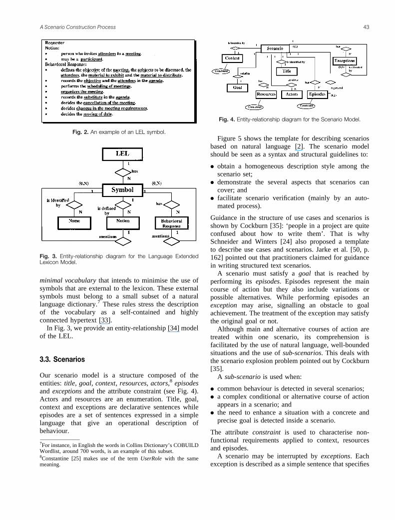
minimal vocabulary that intends to minimise the use ofsymbols that are external to the lexicon. These externalsymbols must belong to a small subset of a naturallanguage dictionary.7 These rules stress the descriptionof the vocabulary as a self-contained and highlyconnected hypertext [33].
In Fig. 3, we provide an entity-relationship [34] modelof the LEL.
���� ��������
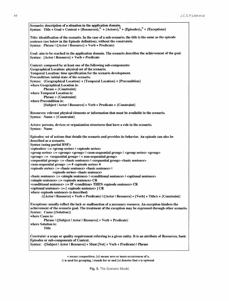
Our scenario model is a structure composed of theentities: title, goal, context, resources, actors,8 episodesand exceptions and the attribute constraint (see Fig. 4).Actors and resources are an enumeration. Title, goal,context and exceptions are declarative sentences whileepisodes are a set of sentences expressed in a simplelanguage that give an operational description ofbehaviour.
Figure 5 shows the template for describing scenariosbased on natural language [2]. The scenario modelshould be seen as a syntax and structural guidelines to:
� obtain a homogeneous description style among thescenario set;
� demonstrate the several aspects that scenarios cancover; and
� facilitate scenario verification (mainly by an auto-mated process).
Guidance in the structure of use cases and scenarios isshown by Cockburn [35]: ‘people in a project are quiteconfused about how to write them’. That is whySchneider and Winters [24] also proposed a templateto describe use cases and scenarios. Jarke et al. [50, p.162] pointed out that practitioners claimed for guidancein writing structured text scenarios.
A scenario must satisfy a goal that is reached byperforming its episodes. Episodes represent the maincourse of action but they also include variations orpossible alternatives. While performing episodes anexception may arise, signalling an obstacle to goalachievement. The treatment of the exception may satisfythe original goal or not.
Although main and alternative courses of action aretreated within one scenario, its comprehension isfacilitated by the use of natural language, well-boundedsituations and the use of sub-scenarios. This deals withthe scenario explosion problem pointed out by Cockburn[35].
A sub-scenario is used when:
� common behaviour is detected in several scenarios;� a complex conditional or alternative course of action
appears in a scenario; and� the need to enhance a situation with a concrete and
precise goal is detected inside a scenario.
The attribute constraint is used to characterise non-functional requirements applied to context, resourcesand episodes.
A scenario may be interrupted by exceptions. Eachexception is described as a simple sentence that specifies
���� �� )� �%����� �* �� ��� +�,��(
���� �� ���+��������$�� ������ *�� $� �������� �%�� � ��%�&�� '� ��(
���� �� ���+��������$�� ������ *�� $� �&������ '� ��(
7For instance, in English the words in Collins Dictionary’s COBUILDWordlist, around 700 words, is an example of this subset.8Constantine [25] makes use of the term UserRole with the samemeaning.
� ������� ���� ���� ������ "�
���� � #$� �&������ '� ��(
"" ��� �� �� ����� �� ���
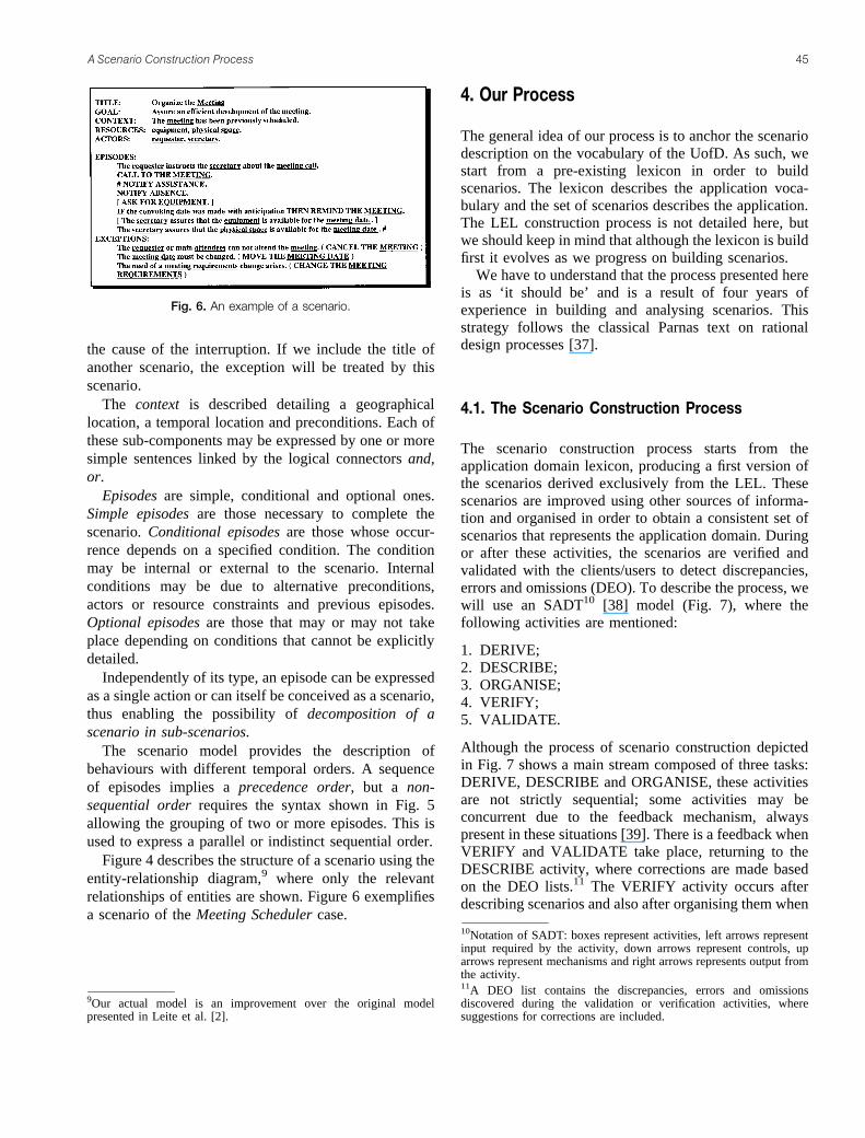
the cause of the interruption. If we include the title ofanother scenario, the exception will be treated by thisscenario.
The context is described detailing a geographicallocation, a temporal location and preconditions. Each ofthese sub-components may be expressed by one or moresimple sentences linked by the logical connectors and,or.
Episodes are simple, conditional and optional ones.Simple episodes are those necessary to complete thescenario. Conditional episodes are those whose occur-rence depends on a specified condition. The conditionmay be internal or external to the scenario. Internalconditions may be due to alternative preconditions,actors or resource constraints and previous episodes.Optional episodes are those that may or may not takeplace depending on conditions that cannot be explicitlydetailed.
Independently of its type, an episode can be expressedas a single action or can itself be conceived as a scenario,thus enabling the possibility of decomposition of ascenario in sub-scenarios.
The scenario model provides the description ofbehaviours with different temporal orders. A sequenceof episodes implies a precedence order, but a non-sequential order requires the syntax shown in Fig. 5allowing the grouping of two or more episodes. This isused to express a parallel or indistinct sequential order.
Figure 4 describes the structure of a scenario using theentity-relationship diagram,9 where only the relevantrelationships of entities are shown. Figure 6 exemplifiesa scenario of the Meeting Scheduler case.
&� � � ������
The general idea of our process is to anchor the scenariodescription on the vocabulary of the UofD. As such, westart from a pre-existing lexicon in order to buildscenarios. The lexicon describes the application voca-bulary and the set of scenarios describes the application.The LEL construction process is not detailed here, butwe should keep in mind that although the lexicon is buildfirst it evolves as we progress on building scenarios.
We have to understand that the process presented hereis as ‘it should be’ and is a result of four years ofexperience in building and analysing scenarios. Thisstrategy follows the classical Parnas text on rationaldesign processes [37].
&��� '�� ������� ���� ���� ������
The scenario construction process starts from theapplication domain lexicon, producing a first version ofthe scenarios derived exclusively from the LEL. Thesescenarios are improved using other sources of informa-tion and organised in order to obtain a consistent set ofscenarios that represents the application domain. Duringor after these activities, the scenarios are verified andvalidated with the clients/users to detect discrepancies,errors and omissions (DEO). To describe the process, wewill use an SADT10 [38] model (Fig. 7), where thefollowing activities are mentioned:
1. DERIVE;2. DESCRIBE;3. ORGANISE;4. VERIFY;5. VALIDATE.
Although the process of scenario construction depictedin Fig. 7 shows a main stream composed of three tasks:DERIVE, DESCRIBE and ORGANISE, these activitiesare not strictly sequential; some activities may beconcurrent due to the feedback mechanism, alwayspresent in these situations [39]. There is a feedback whenVERIFY and VALIDATE take place, returning to theDESCRIBE activity, where corrections are made basedon the DEO lists.11 The VERIFY activity occurs afterdescribing scenarios and also after organising them when
���� � )� �%����� �* � &������(
9Our actual model is an improvement over the original modelpresented in Leite et al. [2].
10Notation of SADT: boxes represent activities, left arrows representinput required by the activity, down arrows represent controls, uparrows represent mechanisms and right arrows represents output fromthe activity.11A DEO list contains the discrepancies, errors and omissionsdiscovered during the validation or verification activities, wheresuggestions for corrections are included.
� ������� ���� ���� ������ "�

new scenarios appear or the integration scenarios aregenerated. Scenarios are validated with the clients/usersafter verification.
This process might also produce three DEO lists thatwill act as a feedback for the LEL construction processin order to maintain consistency between the vocabularyof the scenarios and the LEL itself.
&��� ���������� � ��� ���� ����� �� ������� ���� ������
Below we detail the activities in the SADT model of Fig.7, and for the activities DERIVE and ORGANISE, wedetail even further by presenting a SADT model for thedecomposition of each one of these activities.
(1) DERIVEThis activity aims at generating the derived candidatescenarios from the information of the LEL using thescenario model and applying the derivation heuristics.The derivation process consists of three steps: identify-ing the actors of the UofD, identifying candidatescenarios and creating them using the lexicon. Figure 8shows the SADT model that decomposes the DERIVEactivity.
(1.1) IDENTIFY ACTORSSymbols representing actors of the UofD are identifiedwithin the LEL. They should belong to the subjecttype.12 Actors are classified into main actors andsecondary actors. Main actors are those who executeactions directly in the application domain, while thesecondary actors are those who receive and/or giveinformation, but do not share responsibility in the action.
(1.2) IDENTIFY SCENARIOSThe behavioural responses of symbols chosen as main orsecondary actors are extracted from the LEL. Eachbehavioural response represents a possible scenario, andtherefore it is incorporated to the candidate scenario list.The scenario title is composed of the action (verb)included in the behavioural response but expressed ininfinitive tense plus a predicate also taken from thebehavioural response.When different actors execute the same action, it is verylikely that two or more scenarios of the list may share thetitle; in this case all of them but one should be removed.
���� �� �)-# �* $� &������ ,��� ��� ���&�(
12LEL symbols are classified into four types: Subject, Object, Verband State [29].
"� ��� �� �� ����� �� ���

(1.3) CREATEThe intention here is to build the scenario with as muchinformation extracted from the LEL as possible,applying the creation heuristics; the product of thisstep is the derived candidate scenarios.The content of each behavioural response that leads toevery candidate scenario is analysed in order to findlexicon symbols belonging to the Verb type, from nowon called a Verb symbol.
� If a Verb symbol is found within the behavioralresponse:The goal is defined based on the title, and the notionof the Verb symbol.The actors and resources of the scenario areidentified from the information contained in theVerb symbol and should also be LEL symbols of theSubject type and the Object type respectively.The episodes are derived from each behaviouralresponse of the Verb symbol.
� If the behavioural response does not include a Verbsymbol:Lexicon symbols within the behavioural response areidentified and considered as a possible source ofinformation.The goal is defined on the basis of the scenario title.
Possible actors and resources are selected from theabove symbols by reading their full definition. Actorsare derived from Subject type symbols and resourcesare derived from Object type symbols.No episodes are derived from the LEL: they are leftfor the next step.
In both cases, the geographical and temporal location ofthe context may be extracted from the behaviouralresponse of the LEL symbol that originated the scenario(Subject symbol). Relevant information that should beregistered in the context preconditions may be availablenot only in that behavioural response, but in otherbehavioural responses of the same symbol.
Figure 9 exemplifies the DERIVE activity using theMeeting Scheduler case and Fig. 10 shows the finalversion of this scenario. The underlined words or phrasesare symbols of the Meeting Scheduler lexicon. We willuse numbers in Fig. 9 to explain the DERIVE activity:1 – from the LEL entries we generate a list of actors;2 – selecting an actor we have the corresponding LELentry; 3 – from the behavioural response of this LELentry we produce a list of candidate scenarios;4 – selecting a candidate scenario we find the LELVerb symbol corresponding to the scenario title; 5 – weuse the notion of LEL Verb symbol to define the goal,actor and resources; 6 – the behavioural response of the
���� �� �)-# �* $� -��.�� �&�/�+(
� ������� ���� ���� ������ "0

���� � 1���$�& �%����� *�� ���/��� � &������(
"� ��� �� �� ����� �� ���

LEL Verb symbol will provide the basis to describe theepisodes; and 7 – from the behavioural response of theLEL originated in 3 (Subject type) we derive the contextinformation.
(2) DESCRIBEThis activity aims at improving the candidate scenariosby adding information from the UofD using the scenariomodel, the lexicon symbols in the descriptions andapplying the description heuristics. The result is a set offully described scenarios.
After the previous step, an incomplete set of candidatescenarios is obtained. They require to be extended in twosenses: new scenarios might be added and the scenariocontent should be improved. Thus, if available, theinformation gathered during the LEL constructionprocess, but not included in the lexicon, is used hereas well. When needed, the requirements engineers returnto the sources in order to collect more information.
This activity should be planned and usually relies onstructured interviews, observations and document read-ing. First, information gathering aims at confirming andimproving normal courses of events. Afterwards,alternative and exception cases should be detected.Some causes of exception are elicited from the sourcesof information while others may be deducted byquestioning the occurrence of episodes or the unavail-ability or malfunction of resources. When discoveringcauses of exception, the requirements engineers shouldinquire how the exception is treated in the UofD; thisimplies a new situation that might need to be describedthrough a separate scenario. Constraints may also bedetected, some elicited from the UofD and others byexamining the episodes. After finishing the scenario set
description, episodes should be carefully reviewed toconfirm sequential or non-sequential ordering and todetect optional episodes.
Observing Fig. 7, we can see that there is a feedbackfrom the verification and validation processes, hererepresented by the DEO lists (lists of Discrepancies,Errors and Omissions). These lists may motivate changesin the scenario description. It is also the case that, in theDESCRIBE activity, we may generate a DEO list for theLEL.
Below, we list some general heuristics regarding thisactivity. Since some scenarios might already be partiallydescribed at this point, these guidelines should be used toreview initial descriptions.
� Short sentences are preferred.� The sentences should be written maximising the use of
the lexicon symbols.� The use of more than one verb per sentence should be
avoided.� Actors and Resources should be preferentially lexicon
symbols.� The goal must be precise and concrete.� At least one of the sub-components of the context
must be filled.� The component Resources should list those involved
in the episodes or implicitly referred to the episodeverb, excluding trivial resources.
� The component Resources should not include thoseneeded in sub-scenarios.
� The component Actors should list those involved inthe episodes.
� The component Actors should not include thoseneeded in sub-scenarios.
� The verb of each episode should be precise andconcrete, specifying the final action and avoidingambiguity and vagueness.
� Every episode must be enacted within the geographi-cal and temporal location described by the scenarioContext.
� The present tense should be preferred in describingepisodes.
� Avoid using ‘should’, ‘can’, ‘may’, ‘must’ inepisodes.
(3) ORGANISEThis activity is the most complex and more systematisedone in our scenario construction process. Its root is theidea of integration scenarios, ‘artificial’ descriptionswith the sole purpose of making the set of scenariosmore understandable and manageable. Integrationscenarios give a global vision of the application.
When facing large applications, the number ofscenarios could be unmanageable and the requirementsengineer becomes sunk in details, losing the global
���� ��� 2���� /����� �* � &������(
� ������� ���� ���� ������ "!

vision of the application. In order to face this problem,we propose the construction of integration scenarios,which give an overview of the relationship amongseveral situations, since each integration scenarioepisode corresponds to a scenario. Therefore, the mainpurpose of integration scenarios is to link dispersescenarios providing a global vision of the application,while preserving the natural language format encouragedin our approach.
Thus, scenarios are organised by reorganisation andintegration, beginning with the fully described scenarios.Although ORGANISE is located as third box at Fig. 7,the activities VERIFY and VALIDATE must occurbefore we start the organisation of fully describedscenarios. In other words, organising scenarios is a taskthat is done only when there is a good confidence inhaving a well-defined scenario set, ideally when theDEO lists are empty.
In this activity we may need to go back to the UofD,using the LEL and the scenario model and applying theorganisation heuristics. Nonetheless, the fully describedscenarios may still have some important weakness, suchas:
� lack of homogeneity;� minor semantic problems; and� lack of global perspective.
We understand that these problems may be minimised bythe heuristics that we detail for the ORGANISE activity.
Figure 11 shows the SADT model that decomposesthe ORGANISE activity. The heuristics used in thisactivity reflect our experience on building scenarios. Wealso have produced taxonomies of operations andrelationships that are used by these heuristics.
(3.1) REORGANISEScenarios may have different degrees of detail oroverlapping information, especially when built by morethan one requirements engineer. This situation gets morecomplex as we have more scenarios and a larger team.Basically reorganising scenarios consists in puttingtogether two or more scenarios in one or breaking ascenario in two or more. Putting together is done when aunique scenario becomes artificially divided during theDERIVE or DESCRIBE activities. On the other hand,we break a scenario when it contains more than onesituation. We describe these operations as pairs indifferent dimensions. The criteria to decide whichoperation to use in each dimension are given byheuristics. The three main dimensions in which scenarioreorganisation can be applied are:
� sub-scenario;� situations with variations;� temporal context.
During the DERIVE and DESCRIBE activities focus isnot on the sub-scenario; thus at this moment derived sub-scenarios require special attention to confirm that theyare needed and any hidden sub-scenarios should befound to clarify the scenario set.
���� ��� �)-# �* $� 3�1)4.�� �&�/�+(
�� ��� �� �� ����� �� ���

In the UofD there may be situations very similar toeach other. How they were elicited for the scenario setdepends on several factors, such as the number ofrequirements engineers involved, the order in which thebehavioural responses of LEL Subjects were considered,and the viewpoints taken in consideration.
The duration of a scenario is also a difficult matter toestablish. In some cases two scenarios are so related thatone is produced immediately after the other; thus theymay be better described as just one scenario. On theother hand, a scenario with a long life span (temporalcontext ) containing episodes that are not very tightsemantically may lead to the creation of two or moredifferent scenarios.
Below we define, for each dimension in whichscenario reorganisation can be applied, the operationsthat should be used for each dimension.
There are two operations in the sub-scenario dimen-sion:
� Flatten� Factor
There are two operations in the variation dimension:
� Consolidate� Divide
There are two operations in the temporal contextdimension:
� Fusion� Split
In order to establish the necessity of composition/decomposition operations, some scenario properties andrelationships among them should be previously identi-fied. When a scenario presents special properties mainlyin its episodes, decomposition may be applied. On theother hand, composition may be used when discoveringspecific relationships among scenarios: strong overlap,precedence order or hierarchy relation.
It should be noticed that either the composition ordecomposition operation involves the risk of semanticdegradation. Decomposition creates two or morescenarios where there was previously just one. Thisprocedure must not create ‘artificial’ situations; in otherwords, decomposition must be applied only when theresulting scenarios better describe the UofD. On thecontrary, composition replaces two or more scenarios byone.
Operations are suggested as guidelines to improvescenario comprehension and management. Therefore,reorganisation should not be seen as a mandatory activitybut as good practice.
Below, operations with their corresponding propertiesor scenario relationships are described:
� Flatten:13 May be applied when detecting non-relevant sub-scenarios with few occurrences in otherscenarios. Flatten incorporates the episodes of the sub-scenario inside each scenario that mentions it. Thesub-scenario should present the same granularity ofevery flattened scenario. The original sub-scenario isdeleted when all occurrences are flattened. Thisoperation allows to reduce the number of non-relevantscenarios and, thus, to ease their management. Theresulting scenario set decreases the hierarchy depth inall flattening points. This operation can also be seen asthe inline feature of code generation in some programlanguages.
� Factor: May be applied when a set of very relevantepisodes or a set of episodes with different level ofdetail in relation to the rest is detected; in either casethe set deserves special treatment. Also, whendiscovering the occurrence of the same set of episodesin two or more scenarios having common behavioursthis operation may be used. Factor creates a sub-scenario factoring episodes from one or morescenarios. The group of episodes is replaced by thetitle of the sub-scenario holding them. Factor makesscenarios easier to understand and more reusable.
� Consolidate: May be applied to overlapping scenar-ios. Two or more scenarios strongly overlap if theirgoals and contexts are similar and they have severalcoincidences in episodes. The original scenarios mustpresent the same ‘core of action’ [14]. Consolidatecopies the common episodes of the original scenariosto the new one and creates new conditional episodesusing the non-shared episodes, the condition being thecorresponding part of the original scenario precondi-tion. Occasionally new symbols may be added to theLEL. Original scenarios are deleted. In consequence,this operation allows reducing redundancy in thescenario set.
� Divide: May be applied when the presence of severalconditional episodes, driven by the same condition, isdetected. Divide produces two new scenarios, movingthe trigger condition to both preconditions. Non-trigger condition-based episodes are put in bothscenarios. On the other hand, trigger condition-basedepisodes are moved to their corresponding scenariowith the removed condition. The original scenario isdeleted. This operation helps to avoid clutteredscenarios, thus reducing complexity.
� Fusion: May be applied to scenarios that present acontiguous precedence order, compounded goals andcoupled contexts. No temporal gap may exist among
13In [14], another scenario operation, called Encapsulate, was definedand used; actually flatten and fusion are a specialisation ofEncapsulate.
� ������� ���� ���� ������ ��
these scenarios. A temporal gap occurs when there is along time interval between two scenarios. Fusioncopies the episodes of every original scenario to thenew scenario in the corresponding order. The originalscenarios are deleted, giving an opportunity to reducethe number of scenarios and, thus, to ease theirmanagement.
� Split: May be applied to a scenario if there is atemporal gap between episodes or when detecting avery extended temporal context. An extended tempor-al context may be detected straightforwardly by thecontext itself or by the sequence of the episodes. Also,discovering more than one geographical location in ascenario could be used as a guide for considering thenecessity of a split operation. Therefore, the scenariois representing more than one situation, contradictingthe scenario definition. The decomposition of thescenario should produce scenarios with a well-bounded temporal context. Split copies all theepisodes that precede a temporal gap to a newscenario and those following the temporal gap toanother new scenario. The original scenario is thendeleted. Preconditions of the second and followingnew scenarios may reflect the contiguous precedenceorder established. Thus, split allows to reducecomplexity and to better understand situations.
Figure 12 shows the factor operation applied to twoscenarios with several common episodes that have aspecific goal; a new scenario holding those episodes iscreated and the original scenarios are rewritten,replacing the common episodes by the new scenariotitle. Figure 13 exemplifies the consolidate operationapplied to two overlapped scenarios, producing a singlescenario holding common episodes while non-commonepisodes are incorporated into a conditional statement.
When applying composition operations, the goal of theresulting scenario should be extended to embrace thewhole situation, especially during fusion; in case ofconsolidate the goal is extended by generalisation. On thecontrary, when applying decomposition, the goal of thenew scenario may be less global than the original one.
Since consolidate and divide are opposite operations,after a consolidation the resulting scenario may beconsidered for a division returning to the original stateand vice versa. Criteria to decide to go back or forth arerequired. Consolidate should be applied if few condi-tional episodes appear in the resulting scenario andshould be avoided otherwise. On the other hand, divideshould be chosen only if several trigger-condition-basedepisodes are affected by the operation.
Fusion and split are opposite operations too; thus bothrequire criteria to decide the best direction to go. Thekeyword here is the temporal gap, either with respect to
scenarios or to episodes. A delay between two episodesmay be considered as a temporal gap only if it cannot beembraced by the scenario temporal context. In otherwords, a specific episode could be preceded by atemporal gap in one scenario but not in another one. Itthen becomes clear when to split or fusion scenarios.The sub-scenario dimension operations also requirecriteria to avoid looping from one state to the opposite.Therefore, flatten should be applied when flattenedepisodes in the resulting scenario have the same level ofdetail as the rest of the episodes and when the originalsub-scenario does not represent a situation by itself,which could be confirmed by a lack of meaning of itsgoal. On the contrary, factor should be used only if ameaningful goal can be found for the new sub-scenarioas a consequence of having discovered a specific andactual situation inside a larger scenario.
(3.2) DEFINESeveral authors have proposed scenario relationships,such as Jacobson’s uses association and extendassociations [27], Booch’s semantic connections [16],Dano’s temporal links [20] and others. Those relation-ships were identified and found valuable for otherpurposes. Since the target of the relationships that weare going to define here is the construction of integrationscenarios, a new set of relations is necessary. As such theDEFINE activity identifies different relationships amongscenarios in order to be able to integrate them.
Below we detail each type of relationship we haveidentified in our work with scenario integration.
� Hierarchical relationship is the one establishedbetween scenarios and sub-scenarios. This relation-ship comes naturally while describing the scenarios orreorganising them. The behaviour of a scenario isdescribed through a set of episodes, which could besimple actions or sub-scenarios; the latter case occurswhen the action is more complex or is common toseveral scenarios. A scenario may contain more thanone sub-scenario or none. A sub-scenario could beincluded in one or more scenarios and can itselfcontain sub-scenarios, allowing many levels of depthin the hierarchy. Thus, we can define a hierarchy as aset composed of a scenario and its sub-scenarios.
� Overlap relationship is that one established amongscenarios with common portions. This relationship isobserved mainly when several common episodes arepresent among different scenarios; thus commonactors and probably common resources appear.
� Order relationship is the one established between twohierarchies when one precedes the other. A hierarchymay come before other hierarchies setting up a partialtemporal ordering with them. Thus, a hierarchy mayhave zero or more predecessors and zero or more
�� ��� �� �� ����� �� ���

���� ��� )� �%����� �* *�&��(
� ������� ���� ���� ������ ��

successors. A sequence is established when ahierarchy is immediately preceded by another one.Since the second may be also preceded by a third one,a large number of hierarchies may be involved in asequence beginning with at least one leader hierarchy.It should be noticed that a sequence could have morethan one leader hierarchy and also more than onetrailer hierarchy.
� Exception relationship is the one established betweena scenario and those scenarios that treat exceptions.When a scenario has an exception, its cause isdescribed and if a treatment of the exception isspecified a scenario for treating the exception ismentioned. A scenario may be related to one or more
exception scenarios. An exception scenario may treatexceptions occurring in different scenarios.
If two scenarios are linked by an exception relationshipthey will be put together in one integration scenario as asequence, where the normal scenario comes first,followed by a conditional episode holding the exceptioncondition and the solving exception scenario.
The overlap relationship is not currently used in thescenario integration activity since it is essentially basedon hierarchy and order relationship. However, thepossibility of integration by generalisation has beendetected. The scope, advantages and inconveniences ofintegration by generalisation are still being studied.
���� ��� )� �%����� �* &����� ��(
�" ��� �� �� ����� �� ���
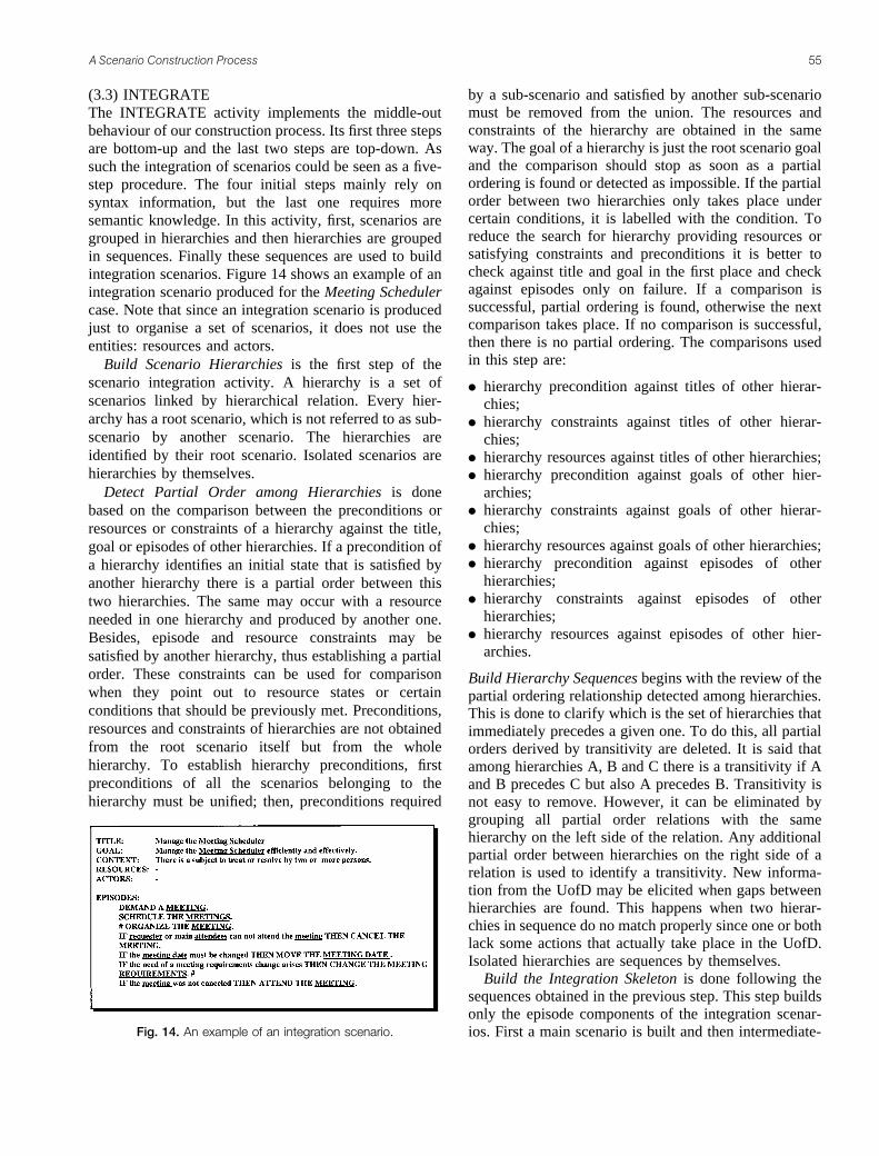
(3.3) INTEGRATEThe INTEGRATE activity implements the middle-outbehaviour of our construction process. Its first three stepsare bottom-up and the last two steps are top-down. Assuch the integration of scenarios could be seen as a five-step procedure. The four initial steps mainly rely onsyntax information, but the last one requires moresemantic knowledge. In this activity, first, scenarios aregrouped in hierarchies and then hierarchies are groupedin sequences. Finally these sequences are used to buildintegration scenarios. Figure 14 shows an example of anintegration scenario produced for the Meeting Schedulercase. Note that since an integration scenario is producedjust to organise a set of scenarios, it does not use theentities: resources and actors.
Build Scenario Hierarchies is the first step of thescenario integration activity. A hierarchy is a set ofscenarios linked by hierarchical relation. Every hier-archy has a root scenario, which is not referred to as sub-scenario by another scenario. The hierarchies areidentified by their root scenario. Isolated scenarios arehierarchies by themselves.
Detect Partial Order among Hierarchies is donebased on the comparison between the preconditions orresources or constraints of a hierarchy against the title,goal or episodes of other hierarchies. If a precondition ofa hierarchy identifies an initial state that is satisfied byanother hierarchy there is a partial order between thistwo hierarchies. The same may occur with a resourceneeded in one hierarchy and produced by another one.Besides, episode and resource constraints may besatisfied by another hierarchy, thus establishing a partialorder. These constraints can be used for comparisonwhen they point out to resource states or certainconditions that should be previously met. Preconditions,resources and constraints of hierarchies are not obtainedfrom the root scenario itself but from the wholehierarchy. To establish hierarchy preconditions, firstpreconditions of all the scenarios belonging to thehierarchy must be unified; then, preconditions required
by a sub-scenario and satisfied by another sub-scenariomust be removed from the union. The resources andconstraints of the hierarchy are obtained in the sameway. The goal of a hierarchy is just the root scenario goaland the comparison should stop as soon as a partialordering is found or detected as impossible. If the partialorder between two hierarchies only takes place undercertain conditions, it is labelled with the condition. Toreduce the search for hierarchy providing resources orsatisfying constraints and preconditions it is better tocheck against title and goal in the first place and checkagainst episodes only on failure. If a comparison issuccessful, partial ordering is found, otherwise the nextcomparison takes place. If no comparison is successful,then there is no partial ordering. The comparisons usedin this step are:
� hierarchy precondition against titles of other hierar-chies;
� hierarchy constraints against titles of other hierar-chies;
� hierarchy resources against titles of other hierarchies;� hierarchy precondition against goals of other hier-
archies;� hierarchy constraints against goals of other hierar-
chies;� hierarchy resources against goals of other hierarchies;� hierarchy precondition against episodes of other
hierarchies;� hierarchy constraints against episodes of other
hierarchies;� hierarchy resources against episodes of other hier-
archies.
Build Hierarchy Sequences begins with the review of thepartial ordering relationship detected among hierarchies.This is done to clarify which is the set of hierarchies thatimmediately precedes a given one. To do this, all partialorders derived by transitivity are deleted. It is said thatamong hierarchies A, B and C there is a transitivity if Aand B precedes C but also A precedes B. Transitivity isnot easy to remove. However, it can be eliminated bygrouping all partial order relations with the samehierarchy on the left side of the relation. Any additionalpartial order between hierarchies on the right side of arelation is used to identify a transitivity. New informa-tion from the UofD may be elicited when gaps betweenhierarchies are found. This happens when two hierar-chies in sequence do no match properly since one or bothlack some actions that actually take place in the UofD.Isolated hierarchies are sequences by themselves.
Build the Integration Skeleton is done following thesequences obtained in the previous step. This step buildsonly the episode components of the integration scenar-ios. First a main scenario is built and then intermediate-���� ��� )� �%����� �* �� ��������� &������(
� ������� ���� ���� ������ ��

level integration scenarios may be obtained. Allsequences are put in the main integration scenariomarked with the non-sequential indicator (#). If asequence is composed of more than one scenario, astub for an intermediate-level scenario is created and anominal title is used in both the main integrationscenario and the stub. This is applied to every existingstub creating new stubs when non-sequences ofsubsequences show up.
Compose Title, Goal and Context for the IntegrationScenarios is the step where new semantic informationneeds to be added. This is done by watching thescenarios involved in the integration scenario. This stepacts as a sort of final verification, since the title and thegoal should be written preserving cohesion; in otherwords, no conjunctions should be allowed. Descriptionsshould be written based on the LEL.
(4) VERIFYThe VERIFY activity is performed at least twice duringthe scenario-building process, the first one over the fullydescribed scenario set and the second after theORGANISE activity. This is done following a checklistwith verification heuristics. As a consequence of thisactivity, two DEO lists are produced: one used atDESCRIBE and the other used during the LELconstruction process. The verification is divided intointra-scenarios, inter-scenarios and against the LEL.The intra-scenario verification includes:
� Verify syntax:– Check the completeness of every component.– Check the existence of more than one Episode per
scenario.– Check the syntax of each component as established
in the scenario model.
� Verify relationship among components:– Check that every Actor participates in at least one
episode.– Check that every Actor mentioned in episodes is
included in the Actor component.– Check that every Resource is used in at least one
Episode.– Check that every Resource mentioned in Episodes
is included in the Resources component.
� Verify semantics:– Check coherence between the Title and the Goal.– Ensure that the set of Episodes satisfies the Goal
and is within the context.– Ensure that actions present in the preconditions are
already performed.– Ensure that Episodes contain only actions to be
performed.– Ensure the same level of detail inside a scenario.
The inter-scenarios verification includes:
� Verify sub-scenarios existence:– Check that every Episode identified as a sub-
scenario exists within the set of scenarios.– Check that the set of Episodes of every sub-
scenario is not already included in anotherscenario.
– Check that every exception is treated by a scenario.
� Verify context:– Check that every precondition is either an
uncontrollable fact or is satisfied by anotherscenario.
– Check coherence between sub-scenario precondi-tions and scenario preconditions.
– Check that geographical and temporal locations ofsub-scenarios are equal or more restricted thanthose of scenarios.
� Verify equivalence in scenario set:– Check that Goal coincidence only takes place in
different situations.– Check that Episode coincidence only takes place in
different situations.– Check that Context coincidence only takes place in
different situations.
The against LEL verification includes:
– Check that every lexicon symbol is identified.– Check the correct use of lexicon symbols.– Check that Actors are preferentially Subject
symbols.– Check that Resources are preferentially Object
symbols.– Check that the behavioural responses of Subject
symbols are covered by scenarios.
Using the verification DEO lists, the scenarios and theLEL are modified. If major corrections were needed, anew verification could be required. When the Describe–Verify cycle is over, the ORGANISE activity shouldprovide a larger set of scenarios, which in turn areverified, starting a possible Describe–Organise–Verifycycle. This activity is actually done by means of aninspection process [40].
Its is important to stress that our verification process isdriven by syntax checks, by cross-referencing the LELand the scenarios and by a checklist. Some of theheuristics of this checklist were given above. Thechecklist registers what was learned in terms ofverification during our experience with scenarios.
(5) VALIDATEScenarios are validated with the clients/users usually byperforming structured interviews or meetings. During
�� ��� �� �� ����� �� ���
validation, the doubt component must be consideredwith special attention for those scenarios still presentingit.
It is important to stress that, although using astructured description, our scenarios are written innatural language, employing their client/user’s ownvocabulary and describing a specific well-boundedsituation.
The validation task allows the detection of DEO inscenarios. Errors are mainly detected by reading eachscenario to the client/user; some omissions may alsoappear during that reading but others by questioning thelack of information or details in scenarios. Discrepanciesmay appear during interviews but they mainly ariseafterwards, when analysing the collected information.
Note that the primary goal of validation is to confirmthe elicited information and to detect DEO; however, aside effect of this process is the elicitation of newinformation. The validation of a set of scenarios, after averification process, should confirm that the Universe ofDiscourse situations, occurrences, have been reported inaccordance with the perception of the UofD actors(clients/users) in charge of reading and discussing thescenarios.
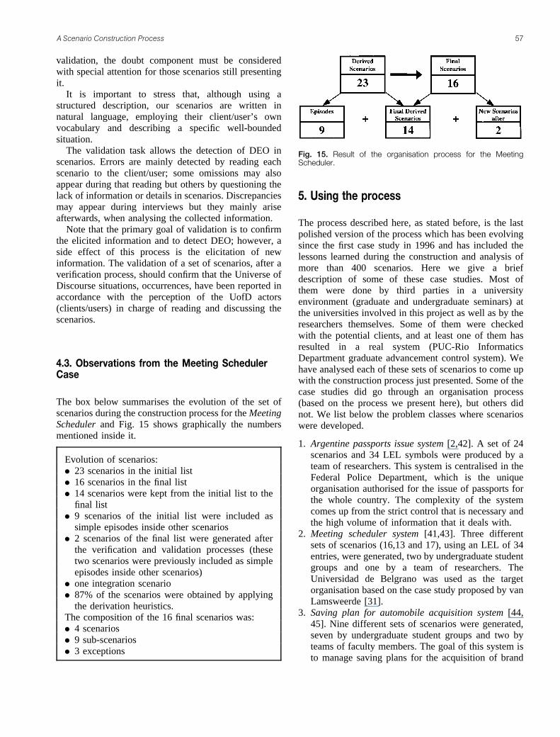
&��� �(��� ����� ��) ��� *������ ����� ������
The box below summarises the evolution of the set ofscenarios during the construction process for the MeetingScheduler and Fig. 15 shows graphically the numbersmentioned inside it.
Evolution of scenarios:� 23 scenarios in the initial list� 16 scenarios in the final list� 14 scenarios were kept from the initial list to the
final list� 9 scenarios of the initial list were included as
simple episodes inside other scenarios� 2 scenarios of the final list were generated after
the verification and validation processes (thesetwo scenarios were previously included as simpleepisodes inside other scenarios)
� one integration scenario� 87% of the scenarios were obtained by applying
the derivation heuristics.The composition of the 16 final scenarios was:� 4 scenarios� 9 sub-scenarios� 3 exceptions
+� ,���� ��� ������
The process described here, as stated before, is the lastpolished version of the process which has been evolvingsince the first case study in 1996 and has included thelessons learned during the construction and analysis ofmore than 400 scenarios. Here we give a briefdescription of some of these case studies. Most ofthem were done by third parties in a universityenvironment (graduate and undergraduate seminars) atthe universities involved in this project as well as by theresearchers themselves. Some of them were checkedwith the potential clients, and at least one of them hasresulted in a real system (PUC-Rio InformaticsDepartment graduate advancement control system). Wehave analysed each of these sets of scenarios to come upwith the construction process just presented. Some of thecase studies did go through an organisation process(based on the process we present here), but others didnot. We list below the problem classes where scenarioswere developed.
1. Argentine passports issue system [2,42]. A set of 24scenarios and 34 LEL symbols were produced by ateam of researchers. This system is centralised in theFederal Police Department, which is the uniqueorganisation authorised for the issue of passports forthe whole country. The complexity of the systemcomes up from the strict control that is necessary andthe high volume of information that it deals with.
2. Meeting scheduler system [41,43]. Three differentsets of scenarios (16,13 and 17), using an LEL of 34entries, were generated, two by undergraduate studentgroups and one by a team of researchers. TheUniversidad de Belgrano was used as the targetorganisation based on the case study proposed by vanLamsweerde [31].
3. Saving plan for automobile acquisition system [44,45]. Nine different sets of scenarios were generated,seven by undergraduate student groups and two byteams of faculty members. The goal of this system isto manage saving plans for the acquisition of brand
���� �� ���� �* $� ���������� ���&� *�� $� '������&$� ����(
� ������� ���� ���� ������ �0

new vehicles. A group of physical or legal persons isconstituted and participates monthly in an adjudica-tion process organised by a general manager in orderto deliver a vehicle. An average of 18 scenarios foreach group were produced, ranging from 8 to 22scenarios. The LEL varied from 16 entries to 68entries.
4. Graduate advancement system [14]. Five differentsets of scenarios were generated by graduate studentgroups. From one of these five sets, a real system wasmodelled and developed for the Informatics Depart-ment of PUC-Rio and it manages all operationsregarding the control of graduated students (http://www.inf.puc-rio.br/~dilbert).
5. Library system. Four different sets of scenarios weregenerated by groups of senior undergraduate students.The system consists basically of recording books andusers and checking the loan of books.
6. Text editor system. Eight different sets of scenariosdeveloped by senior undergraduate students.
7. The lexicon and scenarios for the lexicon and thescenario construction processes [46]. A set of 64scenarios and 78 LEL entries were produced by anundergraduate student group and two researchers.This lexicon describes all the important items in theconstruction of the lexicon and scenarios, followingour approach. The set of scenarios describes thesituations that occur during the construction of thelexicon and the scenarios. Both the lexicon andscenarios were analysed by the authors of the presentpaper. The lexicon and scenarios are available at(http://usuarios.arnet.com.ar/ogarcia).
Some of the above sets were developed intuitively fromscratch, beginning with the UofD and following the ideaof finding situations, while others were constructed usingan approach similar to the one previously described. Inthe case studies performed without following ourprocess, scenario producers noticed the necessity ofhaving an overview of the problem, materialised in oneor more ‘general scenarios’ [41] or another model thatwould help to get a first idea of the application domain.This idea is similar to Booch’s primary scenarios [16]and to Sutcliffe’s grounding scenarios [18]; that is, thegeneral scenario makes it possible to have an abstractview of the set of scenarios.
On the other hand, when the scenario set wasdeveloped following the heuristics described in theprevious section, there was no need for a generaloverview at the beginning of the process, since we werenot using a top-down approach. Our process answers thequestion of how to organise scenarios, when we havemany of them. As such, we believe that the processreported here has a clear-cut distinction between creating
the scenarios for the several situations and thenorganising them as a model, in the software engineeringsense.
-� ��� ����
Scenarios have been attracting much attention from theRE community. A significant number of articles havebeen dealing with the subject and there is a continuouseffort to improve processes and scenario representations.We consider our work a contribution mainly to the areaof scenario management [50].
From other work [8, 47] we became convinced of theimportance that scenarios have for describing thebehaviour of objects and the advantage of tracing thisbehaviour through the software system interface. FromCarroll [5] we achieved a better comprehension of thecognitive aspects of scenario-based development andalso a confirmation that scenarios must begin in theUniverse of Discourse and not only in the softwaresystem interface. This idea was also reaffirmed byZorman [9], who well defines scenarios as situations; inaddition, we utilise her study of scenario representation.Potts [15] showed us the relevance of relating scenarioswith goals and thus proved important our previousknowledge of the meta model oriented to goals proposedby Dardenne et al. [48]. In particular, we differ fromPotts [15] because we use a scenario hierarchy instead ofa goal hierarchy and our construction of hierarchies usesa bottom-up strategy against Potts’s decomposition ofgoals.
Dano et al. [20] consider that Use Cases and scenariosare interchangeable because they capture specific waysof using the system functionality, while for us scenarioscapture situations of the application domain. Besides,[20] proposes the utilisation of formalisms as analternative to natural language. Our approach consistsof using natural language with rules for eliciting andthen modelling scenarios. We agree with Rolland [12]that the use of natural language in scenarios implies aneasy-to-understand model though it may be attachedwith ambiguities and inconsistencies. These drawbackscan be reduced by employing a well-defined UofDvocabulary such as our LEL [29], complemented with averification process such as presented here. With respectto Sutcliffe [18], we share entirely the convenience ofintegrating methods for the requirements production.Nonetheless, the idea of developing a prototype that actsas ‘concept demonstrator’, as proposed by that author,only helps to establish the requirements concerning theman–machine interface and that are specific to theartefact in construction, leaving out other aspects of theapplication domain.
�� ��� �� �� ����� �� ���

The operations presented in the ORGANISE activity(section 4) were inspired by Breitman’s work [14],which discovered, from analysis of sets of scenarios, thatscenario authors have used certain types of operations inproducing the scenarios. The difference is that ouroperations were designed to achieve the goal ofproducing an organised set of scenarios.
During the learning process that we went through, itbecame clear to us that we have deployed two differentways of organising scenarios: one that we called generalscenarios and the other which we called integrationscenarios. General scenarios are the root scenarios thatwe use when following a top-down strategy. Table 1synthesises the characteristics of using general scenariosversus integration scenarios, learned through ourexperience in the case studies already mentioned.
In a top-down approach the general scenarios aredescribed at the beginning of the scenario constructionprocess, from poor and general application domainknowledge. Conversely, the integration scenarios in amiddle-out approach are described as the last step of theprocess, after acquiring large and detailed domainknowledge.
General scenarios need continuous maintenance alongthe construction process in order to achieve consistencywith the rest of the scenarios, otherwise they will losetheir utility and should be put aside. As the integrationscenarios are built at the end of the process, they arenaturally consistent with the rest of the scenarios.
General scenarios give an approximate image of theapplication domain at the beginning of the process andwith a great maintenance effort they could provide aview similar to the integration scenarios. This effort isdirectly related to the possibility of verifying theconsistency among scenarios. The integration scenariosepisodes show the relationships among scenarios, whilethe general scenarios show activities that may or may notbe scenarios.
In practice [11], general scenarios are used to dividetasks, not yet well known, among the team of engineers.This is neither possible nor desirable with our approach.
As pointed out by Jackson (see section 2), a top-downapproach is useful to organise a problem when it ispreviously known but not before.
Based on our experience with scenarios we haveconcluded that there is an advantage of using integrationscenarios instead of a top-down organisation. We havestated that our ‘middle-out’ strategy produces a set ofscenarios that, although, representing different UofDsituations, are organised following software engineeringmodelling principles We consider that our contributionto scenario research is to unveil some of the aspects ofthe scenario construction process. Although our work isbiased by our own representation model (Fig. 5), webelieve that the aspect of composition/decomposition isof general interest to scenario construction. We see thetheme of composition/decomposition related to theabstraction facet (Contents View) of the CREWSframework [10], but there they only make a distinctionbetween instance and type scenario. It is important tonotice that our use of scenarios is of the typed scenarioas per the cited framework; that is, we treat actors andevents by their collective name and not by particularinstances.
It is important once more to stress that in our viewscenarios describe situations in the macrosystem and notonly a sequence of interactions between a user and asystem. Prior work on scenario integration [49] used auser-interaction point of view and focused on thebehavioural aspect of scenarios. Glinz used Statechartsas a means to model scenarios, exploring not only thecapability of decomposition of Statecharts but also theconcurrence aspects, thus making possible not only theintegration of several scenarios in one, but also theanalysis of the scenarios for consistency problems.Contrary to Glinz [49], our approach to scenariointegration deals with the behavioural aspect of scenarios(episodes), but with other context information as well,such as actors, resources, goals and preconditions. Onthe other hand, our proposal is strongly based onheuristics that, as of now, does not have automatedsupport.
Desharnais et al. [51] describe a state-orientedrelational approach to scenario and applies it tosequential scenarios. Scenarios here are atomic descrip-tions, in a Z style, of the interaction between the systemand the environment represented by a triple (T, Re, Rs),where T is a space and Re and Rs are disjoint relationson T. The approach assumes that the scenarios fulfilcertain consistency descriptions. From the atomicscenarios, a functional specification is derived. Thisapproach seems promising, once you get to the level ofthese atomic descriptions, which in our understandingare of a level even lower than our episodes.
����� �� 5�������/� �,�� *�� &������ &����&���
5$���&����& 1������ &������ .�������� &������
)�����&$ #��� �6� '� �����5����&��� ) $� ,�������� 5��� � $� �� ��7����� ��� 8� 4�5�����&+ �**�� 9��$ ���+ ��62��� �����&���� �����/��6
)����%���� :��%����
.����&������ /��6 :��� 5����)���6 ���,��� �/���� 8� 4�)���6 &�����&+ 3��+ �* ��7�� 8�
� ������� ���� ���� ������ �!

One of the first articles dealing with scenarioorganisation came from the object-oriented community[35]. In this article Cockburn presents the problems of‘scenario explosion’ and proposes a hierarchy of goals asa way of solving it. Regnell [52] also deals with theproblem in a goal-oriented way; his proposal organisesthe use cases in a top-down fashion (environment level,structure level, event level), but he also points out that tobetter understand a user case there should be a synthesisphase were use cases are integrated in abstract usagescenarios.
The CREWS–L’Ecritoire [53, 54] approach uses acombination of goals and scenarios not only to elicit butalso to organise scenarios. From goal elicitation, by case-based discovery, a template-driven strategy with freeprose leads to scenarios. Once scenarios are availablethey are organised in a hierarchical way, also based ongoal modelling (AND/OR relationships). They alsoprovide some heuristics for quality management [54].Comparing this with our work, we may say that wedirectly use situations, in a bottom-up fashion, tounderstand the problem and when organising thescenarios we may integrate them with our integrationmechanisms that encapsulate the notions of AND/ORrelationships.
Sutcliffe et al. [55] present a method for scenario-based RE. Its basic representation is similar to ours, withthe difference that we have scenario sub-scenarioshierarchies (n levels of structuring) and they have justone level of structuring; that is, each use-case can have mscenarios. They also present a method as a DFD diagram[55, p. 1074, Fig. 1], where four steps are presented:elicit use case, analyse generic problems, generatescenarios and validate scenarios. We have shown herea much more detailed process, focusing on elicitation ofscenarios from the connotation of the applicationvocabulary.
We would like to stress that our results are based onreal experience with the use of scenarios. We firmlybelieve that the presentation of our strategy for buildingscenarios is important to researchers as well as forpractitioners, since the information we provided helpsthe general understanding of how scenarios are producedand how they might get organised. We will continuestudying the abstraction facet of scenarios and, inparticular, we are looking at the other axis of abstractionmechanisms, namely specialisation/generalisation, inorder to explore how this type of organisation couldsupport scenario reusability.
Acknowledgments. We would like to thank the reviewers for theirtime and careful reading of our first submission. We hope that byaddressing their comments the paper is more readable. We would like
to thank Karin Koogan Breitman for her comments. Financial supportfor this work was partially provided by Universidad de Belgrano,Conicet, Faperj and CNPq.
References1. Leite JCSP, Freeman PA. Requirements validation through
viewpoint resolution. IEEE Trans Software Eng 1991;17(12):1253–1269
2. Leite JCSP, Rossi G, Balaguer F, Maiorana V, Kaplan G, HadadG, Oliveros A. Enhancing a requirements baseline with scenarios.Requirements Eng 1997;l2(4):184–198
3. Jackson M. Software requirements and specifications: a lexicon ofpractice, principles and prejudices. Addison-Wesley, Reading,MA/ACM Press, New York, 1995
4. Loucopoulos P, Karakostas V. System requirements engineering.McGraw-Hill, London, 1995
5. Carroll J. Introduction: the scenario perspective on systemdevelopment. In: Carroll J (ed). Scenario-based design: envision-ing work and technology in system development. Wiley, NewYork, 1995, pp 1–18
6. Potts C. Using schematic scenarios to understand user needs. In:Proceedings of DIS’95 – Symposium on designing interactivesystems: processes, practices and techniques. ACM Press/University of Michigan, 1995, pp 247–256
7. Booch G. Object oriented design with applications. BenjaminCummings, Redwood City, CA, 1991
8. Jacobson, I, Christerson, M, Jonsson, P, Overgaard, G. Object-oriented software engineering: a use case driven approach.Addison-Wesley, Reading, MA/ACM Press, New York, 1992
9. Zorman L. Requirements envisaging by utilizing scenarios(Rebus). PhD dissertation, University of Southern California,1995
10. Rolland C, Ben Achour C, Cauvet C, Ralyte J, Sutcliffe A,Maiden M, Jarke M, Haumer P, Pohl K, Dubois E, Heymans P. Aproposal for a scenario classification framework. RequirementsEng 1998;3(1):23–47
11. Weidenhaupt K, Pohl K, Jarke M, Haumer P. Scenarios in systemdevelopment: current practice. IEEE Software 1998;34–45
12. Rolland C, Ben Achour C. Guiding the construction of textual usecase specifications. Data Knowl Eng 1998;25:125–160
13. Sutcliffe A. Workshop: exploring scenarios in requirementsengineering. In: Proceedings of the third IEEE internationalsymposium on requirements engineering. IEEE Computer SocietyPress, Los Alamitos, CA, 1997, pp 180–182
14. Breitman KK, Leite JCSP. A framework for scenario evolution.In: Proceedings of the IEEE international conference onrequirements engineering. IEEE Computer Society Press, LosAlamitos, CA, 1998, pp 214–221
15. Potts C, Takahashi K, Anton AI. Inquiry-based requirementsanalysis. IEEE Software 1994;11(2):21–32
16. Booch G. Scenarios. Rep Object Analysis Design 1994; 1(3):3–617. Firesmith DG. Modeling the dynamic behavior of systems,
mechanisms, and classes with scenarios. Rep Object AnalysisDesign 1994;1(2):32–36
18. Sutcliffe A. A technique combination approach to requirementsengineering. In: Proceedings of the third IEEE internationalsymposium on requirements engineering. IEEE Computer SocietyPress, Los Alamitos, CA, 1997, pp 65–74
19. Hsia P, Samuel J, Gao J, Kung D, Toyosima I, Chen C. Formalapproach to scenario analysis. IEEE Software 1994;7(2):33–41
20. Dano B, Briand H, Barbier F. An approach based on the conceptof use case to produce dynamic object-oriented specification. In:RE’95: Proceedings of the third IEEE international symposiumon requirements engineering. IEEE Computer Society Press, LosAlamitos, CA, 1997, pp 54–64
21. Robertson SP. Generating object-oriented design representationsvia scenario queries. In: Carroll J (ed). Scenario-based design:envisioning work and technology in system development. Wiley,New York, 1995, pp 279–306
�� ��� �� �� ����� �� ���

22. Wirfs-Brock R. Designing objects and their interactions: a brieflook at responsibility-driven design. In: Carroll J (ed). Scenario-based design: envisioning work and technology in systemdevelopment. Wiley,, New York, 1995, pp 337–359
23. Oberg R, Probasco L, Ericsson M. Applying requirementsmanagement with use cases. Rational Software Corporation, 1998
24. Schneider G, Winters J. Applying use cases: a practical guide.Addison-Wesley, Reading, MA, 1998
25. Constantine L. Joint essential modeling, user requirementsmodeling for usability. In: International conference on require-ments engineering (Tutorial Notes). Constantine & Lockwood,Colorado Springs, CO, 1998
26. Jacobson I. Basic use-case modeling. Rep Object Analysis Design1994;1(2):15–19
27. Jacobson I. Basic use-case modeling (continued). Rep ObjectAnalysis Design 1994;1(3):7–9
28. Gough PA, Fodemski FT, Higgins SA, Ray SJ. Scenarios: anindustrial case study and hypermedia enhancements. In: RE’95:Proceedings of the international symposium on requirementsengineering. IEEE Computer Society Press, Los Alamitos, CA,1995, pp 10–17
29. Leite JCSP, Franco APM. O Uso de Hipertexto na Elicitacao deLinguagens da Aplicacao. In: Anais de IV Simposio Brasilero deEngenharia de Software. SBC, Brazil, 1990, pp 134–149
30. Hadad G, Kaplan G, Oliveros A, Leite JCSP. Integracion deEscenarios con el Lexico Extendido del Lenguaje en la elicitacionde requerimientos: Aplicacion a un caso real. Rev Inform TeoricaAplicada (RITA), Brazil 2000;6(1):77–104
31. van Lamsweerde A, Darimont R, Massonet Ph. The meetingscheduler system: preliminary definition. Internal report, Uni-versite Catholique de Louvain, 1993
32. Leite JCSP. Eliciting requirements using a natural language basedapproach: the case of the meeting scheduler. In: Monografias emCiencia da Computacao, Departamento de Informatica, PUC-Rio,1993
33. Leite JCSP, Franco APM. A strategy for conceptual modelacquisition. In: IEEE international symposium on requirementsengineering. IEEE Computer Society Press, Los Alamitos, CA,1993, pp 243–246
34. Chen P. The entity-relationship model: towards a unified view ofdata. ACM Trans Database Syst 1976;1(1):9–36
35. Cockburn A. Structuring use cases with goals. Technicalreport, Humans and Technology, Salt Lake City, UT (http://members.aol.com/acockburn/papers/usecases.htm), 1995
36. Breitman KK, Leite JCSP. Processo de Software baseado enCenarios. In: Proceedings of WER’99, Workshop en Requer-imientos, Buenos Aires, Argentine, 1999, pp 95–105
37. Parnas DL, Clements PC. A rational design process: how and whyto fake it. IEEE Trans Software Eng 1986;SE-12(2):251–257
38. Ross D, Schoman A. Structured analysis for requirementsdefinition. IEEE Trans Software Eng (special issue on require-ments analysis) 1977;3(1):6–15
39. Goguen JA, Linde Ch. Techniques for requirements elicitation.In: Proceedings of the international symposium on requirementsengineering. IEEE Computer Society Press, Los Alamitos, CA,1992, pp 152–164
40. Doorn J, Kaplan G, Hadad G, Leite JCSP. Inspeccion deEscenarios. In: Proceedings of WER’98, Workshop en Engenhar-ia do Requisitos, Maringa, Brazil, 1998, pp 57–69
41. Hadad G, Kaplan G, Oliveros A, Leite JCSP. Construccion deEscenarios a partir del Lexico Extendido del Lenguaje, BuenosAires, Argentine, 1997, pp 65–77
42. Leite JCSP, Oliveros A, Rossi G, Balaguer F, Hadad G, KaplanG, Maiorana V. Lexico extendido del lenguaje y escenarios delsistema nacional para la obtencion de pasaportes. Technicalreport 7, Departamento de Investigacion, Universidad deBelgrano, Buenos Aires, 1996
43. Hadad G, Kaplan G, Oliveros A, Leite JCSP. Lexico Extendidodel Lenguaje y Escenarios del Meeting Scheduler. Technicalreport 13, Departamento de Investigacion, Universidad deBelgrano, Buenos Aires, 1998
44. Rivero L, Doorn J, Del Fresno M, Mauco V, Ridao M, LeonardiC. Una Estrategia de Analisis Orientada a Objetos basada enEscenarios: Aplicacion en un Caso Real. In: Proceedings ofWER’98: Workshop en Engenharia do Requisitos, Maringa,Brazil, 1998, pp 79–90
45. Mauco V, Ridao M, del Fresno M, Rivero L, Doorn J. Ingenierıade Requisitos, Proyecto: Sistema de Planes de Ahorro. Technicalreport, ISISTAN, UNCPBA, Tandil, Argentine, 1997
46. Garcıa O, Gentile CG. Diseno de una herramienta paracontruccion de LEL y Escenarios. Graduation dissertation,Universidad Nacional del Centro de la Provincia de BuenosAires, Argentine, 1999
47. Rubin KS, Goldberg J. Object behavior analysis. Commun ACM1992; 35(9):48–62
48. Dardenne A, van Lamsweerde A, Fickas S. Goal directedrequirements acquisition. Sci Comput Prog 1993;20:3–50
49. Glinz M. An integrated formal model of scenarios based onstatecharts. In: Proceedings of the 5th ESEC, Lecture Notes onComputer Science 989. Springer, Berlin, 1995, pp 254–271
50. Jarke M, Bui TX, Carroll JM. Scenario management: aninterdisciplinary approach. Requirements Eng 1998;3(4):155–173
51. Desharnais J, Frappier M, Khedri R, Mili A. Integration ofsequential scenarios. IEEE Trans Software Eng 1998;24(9):695–708
52. Regnell B. Hierarchical use case modeling for requirementsengineering. Department of Communication Systems, LundInstitute of Technology, Lund University, Sweden, 1996
53. Rolland C, Souveyet C, Ben Achour C. Guiding goal modelingusing scenarios. IEEE Trans Software Eng 1998;24(12):1055–1071
54. Ben Achour C, Rolland C, Souveyet C. A proposal for improvingthe quality of scenario collections. In: Proceedings of the 4thinternational workshop on RE: foundations of software quality,REFSQ’98. Presses University of Namur (http://sunsite.informa-tik.rwth-aachen.de/CREWS), 1998, pp 29–42
55. Sutcliffe AG, Maiden NAM, Minocha S, Manuel D. Supportingscenario-based requirements engineering. IEEE Trans SoftwareEng 1998;24(12):1072–1088
� ������� ���� ���� ������ ��
Copyright © 2022 FDOKUMEN