EN-Cloud VR Solution Practice Report 01 - Huawei
52
Huawei iLab · Ultimate Experience Solution Practice Report
-
Upload
khangminh22 -
Category
Documents
-
view
1 -
download
0
Transcript of EN-Cloud VR Solution Practice Report 01 - Huawei

Huawei iLab · Ult imate Experience
Solution Practice Report

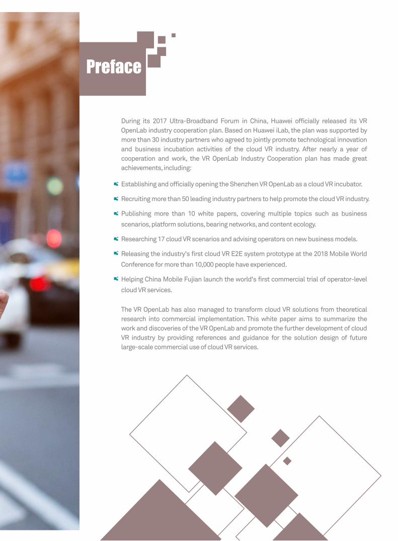
During its 2017 Ultra-Broadband Forum in China, Huawei officially released its VR OpenLab industry cooperation plan. Based on Huawei iLab, the plan was supported by more than 30 industry partners who agreed to jointly promote technological innovation and business incubation activities of the cloud VR industry. After nearly a year of cooperation and work, the VR OpenLab Industry Cooperation plan has made great achievements, including:
The VR OpenLab has also managed to transform cloud VR solutions from theoretical research into commercial implementation. This white paper aims to summarize the work and discoveries of the VR OpenLab and promote the further development of cloud VR industry by providing references and guidance for the solution design of future large-scale commercial use of cloud VR services.
Establishing and officially opening the Shenzhen VR OpenLab as a cloud VR incubator.
Recruiting more than 50 leading industry partners to help promote the cloud VR industry.
Publishing more than 10 white papers, covering multiple topics such as business
scenarios, platform solutions, bearing networks, and content ecology.
Researching 17 cloud VR scenarios and advising operators on new business models.
Releasing the industry's first cloud VR E2E system prototype at the 2018 Mobile World
Conference for more than 10,000 people have experienced.
Helping China Mobile Fujian launch the world's first commercial trial of operator-level
cloud VR services.
Preface
Contents
Preface
1 Overview
2 Cloud VR Scenarios and Content
2.1 Cloud VR Scenarios
2.2 Cloud VR Content Sources
2.2.1 Cloud VR IMAX
2.2.2 Cloud VR Live Broadcast
2.2.3 Cloud VR 360° Video
2.2.4 CloudVR Gaming
2.2.5 Cloud VR Education
2.3 Cloud VR Content Releasing
2.4 Suggestions on Cloud VR Service Indicators
2.4.1 Cloud VR Video Indicators
2.4.2 Cloud VR Gaming Indicators
3 Cloud VR Platforms and Terminals
3.1 Cloud VR Platform Deployment
3.2 Cloud VR Terminal Selection
3.3 Cloud VR Transmission Protocol Selection
3.4 Cloud VR Server Resources and Location Planning
3.4.1 Video Server Resources and Location Planning
3.4.2 Gaming Server Resources and Location Planning
4 Cloud VR Network Planning and Deployment
4.1 Network Indicator Requirements of Cloud VR
4.1.1 Network Indicator Requirements of VR Videos
00
01
02
02
03
03
04
04
05
05
06
07
07
09
11
11
12
13
14
14
16
17
17
17

19
22
23
23
26
28
28
31
33
33
34
35
35
36
37
39
40
40
41
42
43
44
45
4.1.2 Network Indicator Requirements of VR Gaming Services
4.2 Target Network Architecture of Cloud VR
4.3 Solution Based on the Wi-Fi Home Network
4.3.1 Key Challenges for Home Networks
4.3.2 Home Network Solution
4.4 Expansion and Upgrade Based on the 4K Bearer Network
4.4.1 Access Network Planning and Deployment
4.4.2 Metro Network Capacity Expansion and Upgrade
4.5 Cloud VR Bearer Solution
4.5.1 Basic Bearer Solution
4.5.2 Projection Bearer Solution
4.6 QoS Planning and deployment
4.6.1 Priority Allocation
4.6.2 Priority Marking
4.6.3 User CAR/Shaping for Rate Limiting
4.7 Cloud VR Network Requirements
5 Cloud VR Installation and Troubleshooting
5.1 Service Provisioning Process
5.2 Installation Process
5.3 Troubleshooting
6 Summary and Prospects
7 Version Mapping
A Acronyms and Abbreviations
Cloud VR Solution Practice Report
| 01 |
Overview
| 01 |
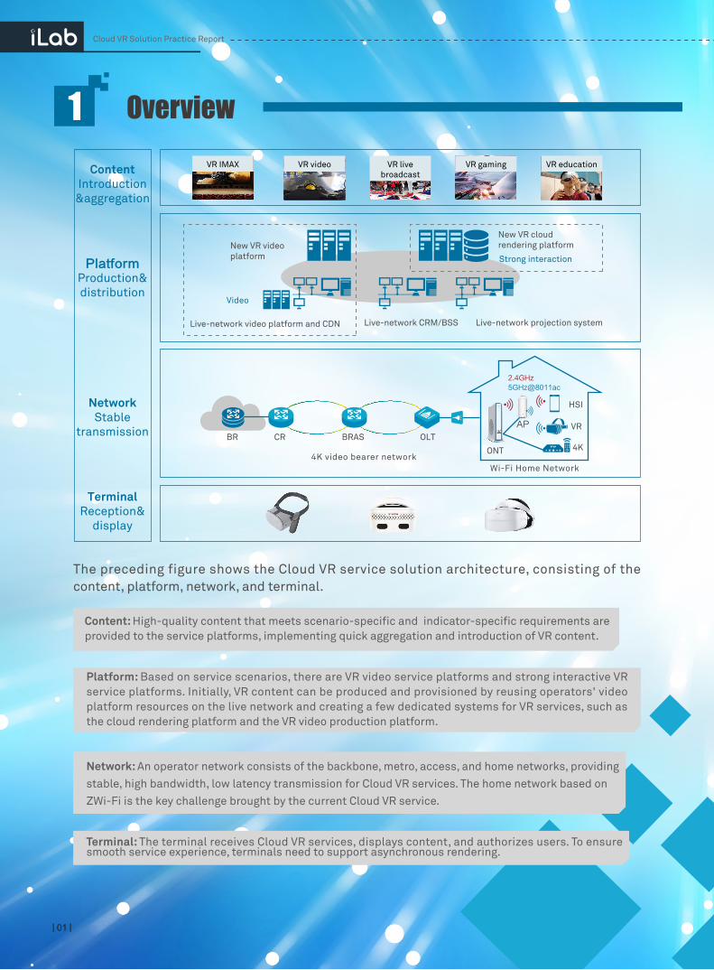
The preceding figure shows the Cloud VR service solution architecture, consisting of the content, platform, network, and terminal.
Content: High-quality content that meets scenario-specific and indicator-specific requirements are provided to the service platforms, implementing quick aggregation and introduction of VR content.
Platform: Based on service scenarios, there are VR video service platforms and strong interactive VR service platforms. Initially, VR content can be produced and provisioned by reusing operators' video platform resources on the live network and creating a few dedicated systems for VR services, such as the cloud rendering platform and the VR video production platform.
Network: An operator network consists of the backbone, metro, access, and home networks, providing stable, high bandwidth, low latency transmission for Cloud VR services. The home network based on ZWi-Fi is the key challenge brought by the current Cloud VR service.
Terminal: The terminal receives Cloud VR services, displays content, and authorizes users. To ensure smooth service experience, terminals need to support asynchronous rendering.
VR IMAX VR video VR livebroadcast
VR gaming VR educationContentIntroduction
&aggregation
PlatformProduction&distribution
NetworkStable
transmission
TerminalReception&
display
BR CR BRAS OLT
ONT
AP
4K
VR
HSI
2.4GHz5GHz@8011ac
Wi-Fi Home Network4K video bearer network
Live-network video platform and CDN Live-network CRM/BSS Live-network projection system
New VR cloudrendering platformNew VR video
platform
Video
Strong interaction

Cloud VR Solution Practice Report
| 02 |
VR IMAX, VR live broadcast, VR 360° video, VR gaming, and VR education scenarios were developed early. They feature extensive and attractive content, easy application, and low learning cost, cultivating a large user base. In addition, E2E technologies such as collection, production, distribution, and playback have matured, and the overall industry chain is complete, making these Cloud VR service scenarios the first online batch for operators.
In early 2018, the China Academy of Information and Communications Technology (CAICT), Huawei iLab, and Huawei Business Consulting Dept jointly released the Cloud VR Scenario White Paper. The paper identifies dozens of Cloud VR scenarios with the highest commercial potential and likelihood of being implemented, clarifies the Cloud VR scenario development roadmap (recently cloudified, short-term cloudified, and long-term cloudified), and gives suggestions on operator service development in each phase.
2.1 Cloud VR Scenarios
Cloud VR Scenarios and Content
Recently cloudified Mid-term cloudified Long- term cloudified
Aw
aren
ess
of V
R b
y ta
rget
use
rs
User
Current phase, with cloudification supported
1 to 3 years Over 3 years
Cloud VR360° video
Cloud VReducation
Cloud VR karaoke
(education, healthcare, tourism, shopping, real estate, etc.)
Cloud VRIMAX
Cloud VR live broadcast
Cloud VRgaming
Cloud VReSports arena
Cloud VRmarketing
Cloud VRfitness
Cloud VRmusic
Cloud social VR
Further development and extension of videos (2C)2B expansion, aggregating
industry applications
VR+ vertical industries
Cloudification process
Industry maturity
Content variety
User base
Terminal variety
User experience
Opportunity
☆☆☆
☆☆☆
☆☆☆
☆☆☆
☆☆☆
☆☆☆
☆☆☆
☆☆☆
☆☆☆
☆☆
☆☆☆
☆☆☆
☆☆
☆☆☆
☆☆☆
☆☆☆
☆☆☆
☆☆☆
☆☆☆
☆☆
☆☆☆
☆☆☆
☆☆☆
☆☆
☆☆☆
☆☆☆
☆☆☆
☆☆☆
☆☆☆
☆☆
☆☆
☆☆☆
☆☆☆
☆☆
☆☆☆
VR IMAXVR Live
BroadcastVR 360°
Video VR Gaming VR Education
| 03 |
2.2 Cloud VR Content Sources
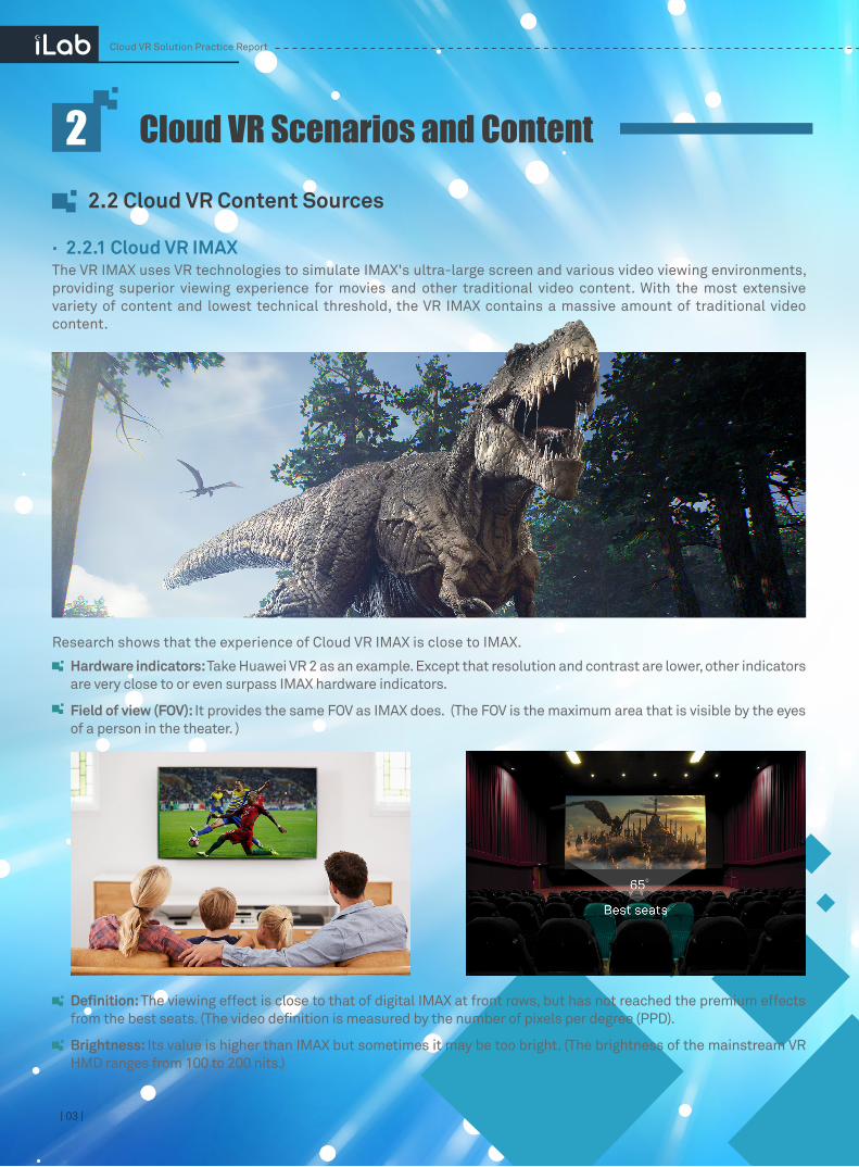
The VR IMAX uses VR technologies to simulate IMAX's ultra-large screen and various video viewing environments, providing superior viewing experience for movies and other traditional video content. With the most extensive variety of content and lowest technical threshold, the VR IMAX contains a massive amount of traditional video content.
Research shows that the experience of Cloud VR IMAX is close to IMAX.
Hardware indicators: Take Huawei VR 2 as an example. Except that resolution and contrast are lower, other indicators are very close to or even surpass IMAX hardware indicators.
Field of view (FOV): It provides the same FOV as IMAX does. (The FOV is the maximum area that is visible by the eyes of a person in the theater. )
· 2.2.1 Cloud VR IMAX
Cloud VR Scenarios and Content
Cloud VR Solution Practice Report
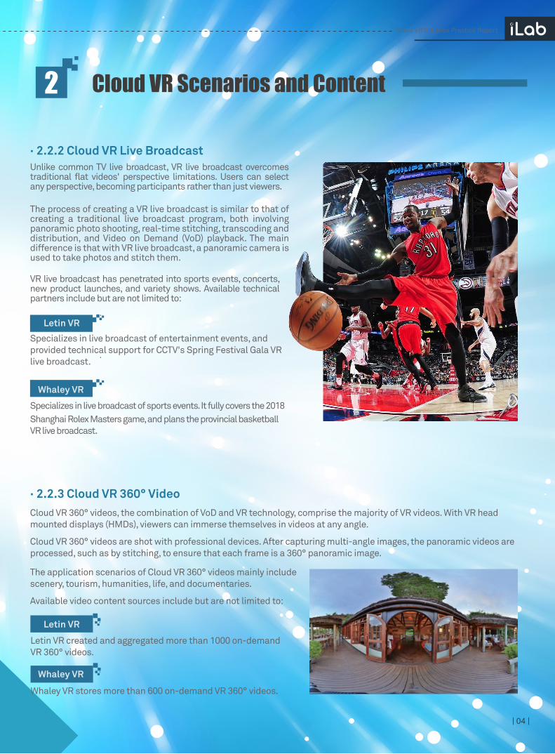
Definition: The viewing effect is close to that of digital IMAX at front rows, but has not reached the premium effects from the best seats. (The video definition is measured by the number of pixels per degree (PPD).
Brightness: Its value is higher than IMAX but sometimes it may be too bright. (The brightness of the mainstream VR HMD ranges from 100 to 200 nits.)
| 04 |
Unlike common TV live broadcast, VR live broadcast overcomes traditional flat videos' perspective limitations. Users can select any perspective, becoming participants rather than just viewers.
The process of creating a VR live broadcast is similar to that of creating a traditional live broadcast program, both involving panoramic photo shooting, real-time stitching, transcoding and distribution, and Video on Demand (VoD) playback. The main difference is that with VR live broadcast, a panoramic camera is used to take photos and stitch them.
VR live broadcast has penetrated into sports events, concerts, new product launches, and variety shows. Available technical partners include but are not limited to:
· 2.2.2 Cloud VR Live Broadcast
Whaley VR
Letin VR
Cloud VR 360° videos, the combination of VoD and VR technology, comprise the majority of VR videos. With VR head mounted displays (HMDs), viewers can immerse themselves in videos at any angle.
Cloud VR 360° videos are shot with professional devices. After capturing multi-angle images, the panoramic videos are processed, such as by stitching, to ensure that each frame is a 360° panoramic image.
The application scenarios of Cloud VR 360° videos mainly include scenery, tourism, humanities, life, and documentaries.
Available video content sources include but are not limited to:
· 2.2.3 Cloud VR 360° Video
Whaley VR stores more than 600 on-demand VR 360° videos.
Letin VR created and aggregated more than 1000 on-demand VR 360° videos.
Cloud VR Scenarios and Content
Cloud VR Solution Practice Report
Specializes in live broadcast of entertainment events, and provided technical support for CCTV's Spring Festival Gala VR live broadcast.
Specializes in live broadcast of sports events. It fully covers the 2018 Shanghai Rolex Masters game, and plans the provincial basketball VR live broadcast.
Whaley VR
Letin VR
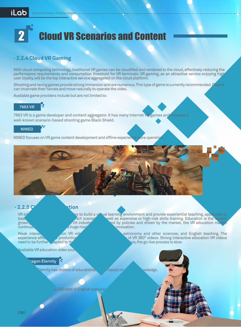
VR education uses VR technologies to build a virtual learning environment and provide experiential teaching, applicable to basic education in rare and abstract scenarios as well as expensive or high-risk skills training. Education is the fastest growing and application in the VR industry. Encouraged by policies and driven by the market, the VR education market continues to grow and offers a huge market for education innovation.
Weak interactive education VR videos are mainly used in astronomy and other sciences, and English teaching. The experience effects and production process are similar to those of VR 360° videos. Strong interactive education VR videos need to be further adapted to the cloud rendering platform. Therefore, the go-live process is slow.
· 2.2.5 Cloud VR Education
Available VR education video sources include but not limited to:
Letin VR has more than 200 sets of English scenario-based VR teaching content.
NetDragon Elernity has dozens of educational series based on cultural knowledge.
Letin VR
NetDragon Elernity
| 05 |
With cloud computing technology, traditional VR games can be cloudified and rendered to the cloud, effectively reducing the performance requirements and consumption threshold for VR terminals. VR gaming, as an attractive service enjoying high user loyalty, will be the top interactive service aggregated on the cloud platform.
Shooting and racing games provide strong immersion and are numerous. This type of game is currently recommended. Players can incarnate their heroes and move naturally to operate the video.
Available game providers include but are not limited to:
· 2.2.4 Cloud VR Gaming
7663 VR is a game developer and content aggregator. It has many Internet VR games and releases a well-known scenario-based shooting game Black Shield.
NINED focuses on VR game content development and offline experience store operation.
Cloud VR Solution Practice Report
Cloud VR Scenarios and Content
7663 VR
NINED
| 06 |
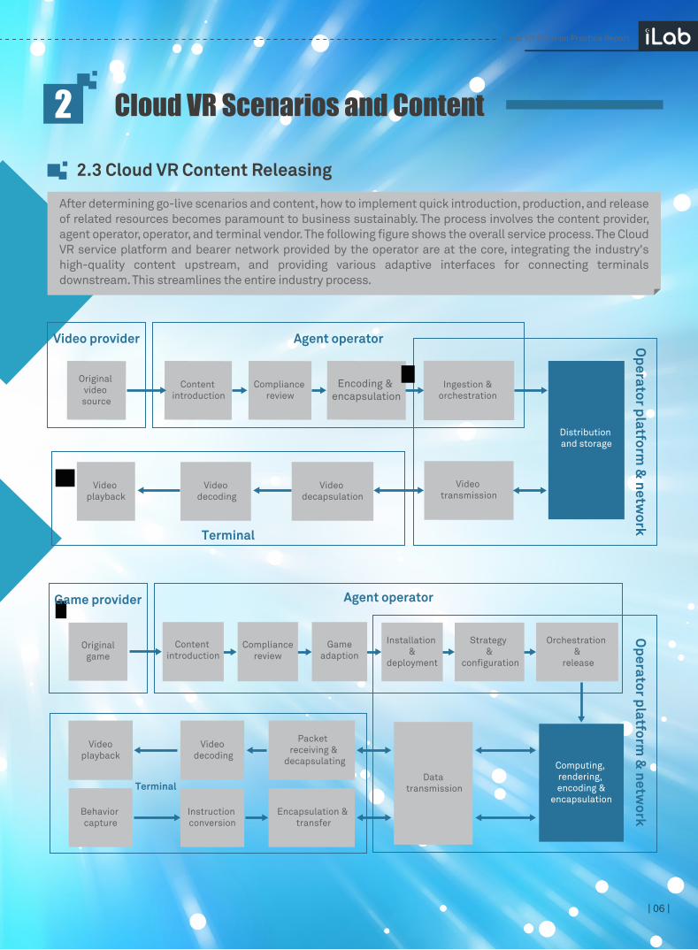
After determining go-live scenarios and content, how to implement quick introduction, production, and release of related resources becomes paramount to business sustainably. The process involves the content provider, agent operator, operator, and terminal vendor. The following figure shows the overall service process. The Cloud VR service platform and bearer network provided by the operator are at the core, integrating the industry's high-quality content upstream, and providing various adaptive interfaces for connecting terminals downstream. This streamlines the entire industry process.
2.3 Cloud VR Content Releasing
Cloud VR Solution Practice Report
Cloud VR Scenarios and Content
Terminal
Video provider
Original video source
Content introduction
Compliance review
Encoding & encapsulation
Ingestion & orchestration
Agent operator
Video transmission
Video decapsulation
Video decoding
Video playback
Distribution and storage
Videoplayback
Video decoding
Packet receiving &
decapsulating
Originalgame
Agent operatorGame provider
Behavior capture
Instruction conversion
Encapsulation & transfer
Data transmissionTerminal
Compliancereview
Content introduction
Orchestration &
release
Strategy &
configuration
Installation &
deployment
Gameadaption
Computing, rendering, encoding &
encapsulation
Operator platform
& netw
orkO
perator platform &
network

| 05 |
To ensure user experience quality after the Cloud VR service goes live and to guide the healthy development of the industry through related indicators, a large amount of user feedback through channels such as exhibitions has been collected. Additionally, some experience tests and verification through are also performed in labs.
Based on this, typical service indicators and mid- and short-term experience goals of Cloud VR video and VR game services are summarized and output. However, initially, due to restrictions such as the current content source, platform, and terminal performance, not all indicators and goals can be met. Continuous optimization and improvement are required.
2.4 Suggestions on Cloud VR Service Indicators
| 07 |
Like traditional videos, users focus on image quality, initial buffering duration, and frame freezing of VR videos. The details are shown in the following table.
·2.4.1 Cloud VR Video Indicators
Content view: 360 ° panoramic content is the major form of VR video content. The full-view transmission solution transmits 360 ° content, whereas FOV transmission solution transmits only the content within the user's perspective. In full-view transmission, the platform pushes the entire 360 ° surrounding images to the terminal, and the terminal traces changes of the user's perspective, decodes the video, and performs image projection. The full-view solution is simple to use and has no special processing requirements. The existing video platform resources of operators can be reused. The processing performance of the terminal side has no obvious bottleneck, making it suitable for the initial phase of the Cloud VR video service.
Color depth: Currently, the color depth of most VR videos is 8 bits. Theoretically, 256 colors (including black and white) are supported. The lab test results show that even if the resolution were 8K, limited by the pixel per degree, increasing color depth would not significantly improve image quality. Therefore, the 8-bit requirement is the short-term target.
Frame rate: The research results show that the frame rate boundary is about 24 FPS for unaided eyes to clearly identify whether a video is smooth. At 30 FPS, the video is considered smooth. Currently, mainstream VR content can meet this requirement.
Video resolution: With 8K panoramic resolution, image quality (calculated based on the pixels per degree) is the same as that under 480P TV. This quality meets the requirements of most users. Currently, restricted by content sources, mainstream VR videos are mainly 4K, with 8K content still uncommon. The image quality viewed by users is equivalent to that of a 240P TV. Actively promoting 8K VR industry development and introducing 8K video content is a top priority for operators.
Cloud VR Solution Practice Report
Cloud VR Scenarios and Content
Service IndicatorService Scenario Indicator Type Target Value Current Value Remarks
Weak interactive
VR service (video)
Content view (full view)
Resolution (full view)
Color depth (bit)
Frame rate
Encoding
Bit rate
Content quality
360°
8K
8bit
30fps
AVS2/H.265
90Mbps
360°
4K
8bit
30fps
H.264
40Mbps
360° panoramic videos are dominant. In the initial phase,most users use the full-view transmission mode.
In the initial stage, 4K content is mainly used. The low resolutionis the major factor that adversely affects the definition.
When the pixel per degree is too low, increasing the color depthis not significant for improving the image quality.
When the video frame rate reaches 30 fps, users can watch the video smoothly with unaided eyes.
4K content is encoded in H.264 format. After 8K content isencoded,the content can be upgraded to AVS2/H.265.
The 4K VR panoramic video can improve the definition by improving the bit rate in a certain range.
See 4K video experience standards.
See 4K video experience standards.
<1s
0
<1s
0
Interaction experience
Viewing experience
Initial buffering duration
Freezing ratio

| 08 |
Encoding: Before transmission, video data must be effectively compressed by the encoder to reduce network resource consumption. Currently, MPEG-2, H.263, H.264, H.265, and AVS2 are commonly used. Because 4K content is dominant, H.264 is usually used for encoding. For enriched 8K content, the AVS2/H.265 encoding mode is recommended to improve the compression rate and reduce network forwarding pressure without degrading image quality.
Bitrate: In princiAple, each video has a minimum bitrate when the resolution is determined. The higher the bitrate is, the clearer the image is. However, beyond a critical point, the effect of image quality improvement is no longer significant. According to a survey of a large number of users and the subjective experience test in the lab, the critical point of most 4K VR video bitrates is about 40 Mbit/s. However, for 8K content, the estimated bitrate will be no lower than 90 Mbit/s.
Initial buffering duration: It refers to the wait period from the time when a user clicks a video to the time when the video begins playing. The longer the initial buffering duration, the poorer the user experience. Based on the experience in playing operator's 4K videos on-demand, the initial buffering duration of VR videos should less than 1s. However, initially, this is not mandatory.
Freezing ratio: During video playing, if the total amount of data downloaded by a terminal cannot meet video playback requirements, frame freezing occurs. Frame freezing directly interrupts users' immersive experience and adversely affects user experience. Therefore, ensuring no freezes is recommended.
Cloud VR Solution Practice Report
Cloud VR Scenarios and Content
Content view: Unlike the Cloud VR video service, which is 360 ° panoramic content and uses the full-view transmission solution initially, the Cloud VR gaming uses the FOV transmission solution to reduce cloud and terminal performance requirements. The cloud only renders and transmits images in the view of users. To maximize terminal performance and minimize consumption of cloud rendering resources, the cloud rendering platform needs to adapt to terminal specifications. Most VR terminals specify in their design specifications that the FOV on the cloud should be set within between 90° and 110°, and gradually be increased to about 120°.
Game resolution: The cloud rendering platform pushes the video to the terminal for decoding and display through video streaming. Image quality is solely controlled and determined by the cloud rendering server. However, related parameters need to be adjusted and adapted based on the terminal specifications. Currently, mainstream VR terminals have high screen resolution (ranging from 2.5K to 3K or higher) to support 4K to 6K panoramic videos. A small number of 4K screens even support more than 8K panoramic videos. As an example, consider the mainstream Chinese cloud game platform Cyber Cloud. For the sake of performance, 2K resolution is generally used for rendering. The terminal viewing effect is similar to that of 4K panoramic video. To make full use of terminal performance, the rendering resolution needs to be improved by optimizing platform performance.
| 05 || 09 |
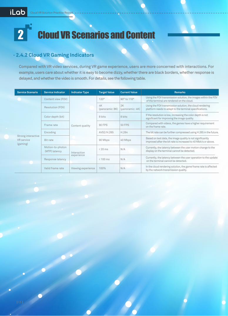
· 2.4.2 Cloud VR Gaming Indicators
Compared with VR video services, during VR game experience, users are more concerned with interactions. For example, users care about whether it is easy to become dizzy, whether there are black borders, whether response is delayed, and whether the video is smooth. For details, see the following table.
Cloud VR Scenarios and Content
Cloud VR Solution Practice Report
Service IndicatorService Scenario Indicator Type Target Value Current Value Remarks
Using the FOV transmission solution, the images within the FOV of the terminal are rendered on the cloud.120° 90° to 110°
4K (panoramic: 8K)
8 bits
90 FPS
AVS2/H.265
90 Mbps 40 Mbps
H.264
50 FPS
8 bits
2K(panoramic: 4K)
Using the FOV transmission solution, the cloud rendering platform needs to adapt to the terminal specifications.
If the resolution is low, increasing the color depth is not significant for improving the image quality.
Compared with videos, the games have a higher requirement on the frame rate.
The bit rate can be further compressed using H.265 in the future.
Based on test data, the image quality is not significantly improved after the bit rate is increased to 40 Mbit/s or above.
Currently, the latency between the user motion change to the display on the terminal cannot be detected.
Currently, the latency between the user operation to the update on the terminal cannot be detected.
In the cloud rendering solution, the game frame rate is affected by the network transmission quality.
N/A
N/A
N/A
< 20 ms
< 100 ms
100%
Strong interactiveVR service (gaming)
Content view (FOV)
Resolution (FOV)
Color depth (bit)
Frame rate
Encoding
Bit rate
Content quality
Interaction experience
Viewing experience
Motion-to-photon (MTP) latency
Response latency
Valid frame rate

Game frame rate: The video images captured in real scenarios include change information of the scenes, whereas the game images are generated by rendering on a video card without any motion tracking information of the image objects. Therefore, to obtain the same smoothness, games require a much higher frame rate than that of videos. Theoretically, the higher the frame rate, the smoother the images. Currently, the maximum frame rate supported by terminals is about 90 FPS. However, limited by the cloud processing specifications. It is difficult to achieve this goal in the short term. For example, on Cyber Cloud, the actual frame rate 50 FPS is acceptable.
Valid frame rate: The cloud rendering solution transfers the local computing and rendering functions of VR games to the cloud. The terminal only needs to decode and display VR games like common videos. This reduces terminal performance and usage costs. In addition, higher requirements are imposed on the transmission quality of the network. If network transmission quality deteriorates, frame data cannot arrive in time, and the terminal cannot decode the frame properly, resulting in image discontinuity or jitter. In principle, the network needs to be optimized to avoid this situation.
Game bitrate: According to the lab test results, on the cloud game platform Cyber Cloud, when the game frame rate is controlled at 50 FPS and the game bitrate is set to about 40 Mbit/s, the game experience requirements of most users can be met. Increasing the bitrate does not significantly improve image quality.
Response latency: When a user rotates the HMD, pulls the trigger, or swipes the handle in the virtual world, the user needs to see the visual response immediately. A high latency results in an obvious lag. Industry research shows that like most common games, for most people, when the response latency is under 100 ms, the user perceives instant response.
Motion-to-photon (MTP) latency: MTP latency refers to the time difference between the user's motion change and the terminal display of the corresponding image. When the MTP latency is excessively large, it may cause dizziness. Maintaining MTP latency less than 20 ms significantly mitigates motion sickness. For the traditional cloud rendering solution, it is difficult to meet such a high latency requirement quickly. Currently, the asynchronous timewarp/spacewarp (ATW/ASW) technologies on the terminal side are mainly used to minimize latency. Based on a change in the user's motion and location information, predictive adjustment and local rendering can be performed on the current frame to generate a transition frame, reducing dizziness. However, such technologies can only use current images as inputs; they cannot generate new content. Therefore, when the head rotates too fast or at a large angle, the part of the view outside the original image is displayed as a black border. This problem can be resolved by performing ultra wide-angle content rendering on the cloud. Considering the cloud latency and head's rotation speed, it is recommended that the angle value be greater than 6 degrees in each direction.
| 10 |
Cloud VR Scenarios and Content
Cloud VR Solution Practice Report

3.1 Cloud VR Platform Deployment
It has been proved that during Cloud VR service platform setup, operators can reuse the content distribution system and content delivery network (CDN) resources of the live video platform to achieve fast and low-cost deployment. Only some dedicated systems need to be developed and adapted, such as the VR video platform, VR cloud rendering platform, and VR projection system.
Cloud VR Platforms and Terminals3
VR video platform:
The media and broadcast information and content specifications of VR videos differ from those of traditional videos. As a result, the live-network system cannot be directly used. The VR video platform manages, orchestrates, produces the content, and sends and receives traffic for original VR videos. After the platform is connected to the operator's Hybrid Video Solution (HVS) through standard interfaces, the produced content can be distributed and injected to the CDN on the live network. This allows subscribers to watch the VoD programs.
VR cloud rendering platform:Implementation of the cloud rendering platform differs greatly from that of the traditional video platform. The cloud rendering platform transfers local computing and rendering tasks of strong interactive services such as VR gaming to the cloud, and can run independent application instances for each user. The platform obtains user instructions and performs related calculation and rendering. Then, it pushes images to the terminal through video
VR projection system:
Based on messages exchanged between the cloud Extensible Messaging and Presence Protocol (XMPP) message channel, VR HMD, and STB's multi-window module, VR content can be displayed on both the VR HMD and the home TV screen. You can share your VR world with your family or friends.
| 11 |
Cloud VR Solution Practice Report
STBTerminal
PlatformHVS
Multi-window moduleAll-in-one
VoD modulemodule
Gaming module
Interconnect
CDN
Live broadcast module
Application background
Inject
Log in VoD flow
Simultaneous playback
Rendering flow
Rendering projection flow
Projection flow
Dispatch
XMPP
Terminal matching
VR video platformVR cloud rendering
platformVR projection
system
VR live broadcast production system
VR VoD production system
Management/Scheduling system
Rendering/Application system
Live broadcast orchestration
Gaming orchestration
VoD orchestration
Authentication module
Launcher (UI level-1 menu)
Multi-window module
VR video player VR game player
Live broadcast flow
3.2 Cloud VR Terminal Selection
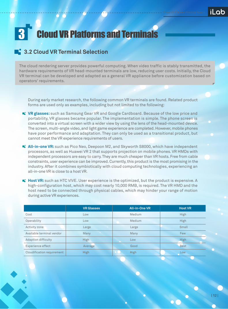
The cloud rendering server provides powerful computing. When video traffic is stably transmitted, the hardware requirements of VR head-mounted terminals are low, reducing user costs. Initially, the Cloud VR terminal can be developed and adapted as a general VR appliance before customization based on operators' requirements.
Cloud VR Platforms and Terminals3
| 12 |
During early market research, the following common VR terminals are found. Related product forms are used only as examples, including but not limited to the following:
VR glasses: such as Samsung Gear VR and Google Cardboard. Because of the low price and portability, VR glasses became popular. The implementation is simple. The phone screen is converted into a virtual screen with a wider view by using the lens of the head-mounted device. The screen, multi-angle video, and light game experience are completed. However, mobile phones have poor performance and adaptation. They can only be used as a transitional product, but cannot meet the VR experience requirements of users.
All-in-one VR: such as Pico Neo, Deepoon M2, and Skyworth S8000, which have independent processors, as well as Huawei VR 2 that supports projection on mobile phones. VR HMDs with independent processors are easy to carry. They are much cheaper than VR hosts. Free from cable constraints, user experience can be improved. Currently, this product is the most promising in the industry. After it combines symbiotically with cloud computing technologies, experiencing an all-in-one VR is close to a host VR.
Host VR: such as HTC VIVE. User experience is the optimized, but the product is expensive. A high-configuration host, which may cost nearly 10,000 RMB, is required. The VR HMD and the host need to be connected through physical cables, which may hinder your range of motion during active VR experiences.
Cloud VR Solution Practice Report
Cost Low Medium High
Operability Low Medium High
Activity zone Large Large Small
Available terminal vendor Many Many Few
Adaption difficulty High Low High
Experience effect Average Good Best
Cloudification requirement High High Low
VR Glasses All-in-One VR Host VR

| 05 || 13 |
VR VoD service: Initially, the Cloud VR VoD services are generally distributed and stored by reusing the operators' self-operating video platform. Over HTTP, HLS has low requirements on the server's performance and is currently used by most over-the-top (OTT) video platforms on the live network.
VR live broadcast service: Initially, because there are few subscribers and live broadcast channels, the VR live broadcast services use the same media streaming mode as the VoD services. In the future, as VR live broadcast services develop, RTP multicast transmission and UDP bearer can reduce operators' network bandwidth consumption.
VR game service: Currently, as Cloud VR game services run on the cloud game platform provided by Cyber Cloud, TCP is used for streaming video at the bottom layer. Considering the sensitivity of game services to interaction latency, UDP, which has lower processing latency, may be used in the future. Transmission process reliability is ensured by the network. In addition, it is recommended that the platform developer's proprietary media streaming protocol be replaced with the standard RTP protocol to ensure the openness of the platform.
In the Cloud VR solution, regardless of video and game services, video streaming data is mainly transmitted between platforms and terminals. Currently, the most commonly used media streaming protocols are HTTP Live Streaming (HLS) and Real-Time Streaming Protocol/Real-Time Transport Protocol (RTSP/RTP).
After comprehensive consideration, the all-in-one VR should be used as the commercial terminal of the Cloud VR service. The following figure shows the technical specifications of mainstream all-in-one VR products.
3.3 Cloud VR Transmission Protocol Selection
Cloud VR Solution Practice Report
Module Parameter Specification
Screen
Screen type
Resolution
Refreshing rate
Optics
Lens
FOV
Friendliness with theshort eye-sighted
LocatingHMD
Handle
Wireless
Processor CPU
Wi-Fi
StorageMemory
Flash memory
Quick-response LCD or OLED
2560*1440 or above for both eyes
70 Hz or above
Fresnel lens
90° or above
Focal length adjustment or compatibility with glasses
6 DoF
Dual handles, 6 DoF
2.4G/5G dual-frequency Wi-Fi, 2x2 MIMO
Qualcomm Snapdragon 820, Samsung Exynos7420 or above
2G or above
16G or above
Cloud VR Platforms and Terminals3

| 14 |
Server performance and location affect user experience, making proper planning essential before deployment. In addition, requirements vary by service type. There are two examples.
First, VR video services occupy CDN resources on the live network, whereas VR game services consume video card resources. The second is that when the full-view transmission solution is used, compared with existing 4K video services, VR video services have no special requirements on CDN deployment position. However, VR game services are sensitive to latency, and must be deployed near the application rendering server.
· 3.4.1 Video Server Resources and Location Planning
VR VoD production system: It consists of the media and broadcast management server, video production server, and storage server to manage and produce original VoD sources. During production, no interaction with users is involved. Therefore, the servers can be deployed in the provincial central equipment room, facilitating unified management for operators. The specific requirements are as follows:
The media, broadcast information, and content specifications of VR videos differ from those of traditional videos. To facilitate management and production, a dedicated Cloud VR video platform is required. The VR video platform developed by Letin VR is used as an example. Depending on the service type, a VR video platform is classified as a VR VoD production system or VR broadcast production system.
3.4 Cloud VR Server Resources and Location Planning
Cloud VR Solution Practice Report
Project Name Model Specifications and Description Quantity Remarks
Media and broadcast management server
VMUsed to manage media resources and edit video content information.
Video transcodingserver
VM
Segmentation server VM
VoD storage server VM
2
2
2
2
VoD System Configuration List - Resource Requirements
Processor: 12-core, 2.3GHz Intel Xeon Gold 5118Memory: 32 GBHard disk: 600 GBNetwork adapter: Gigabit network adapterOperating system: Linux, CentOS7.4 x86 64bitit
Processor: 8-core, 1.8GHz Intel Xeon Silver 4108Memory: 32 GBHard disk: 600 GBNetwork adapter: Gigabit network adapterOperating system: Windows 2008R2 datacenter x86 64bit
Processor: 12-core, 2.3GHz Intel Xeon Gold 5118Memory: 32 GBHard disk: 600 GBNetwork adapter: Gigabit network adapterOperating system: Linux, CentOS7.4 x86 64bit
Processor: 12-core, 2.3GHz Intel Xeon Gold 5118Memory: 32 GBHard disk: 10TBNetwork adapter: Gigabit network adapterOperating system: Linux, CentOS7.4 x86 64bitit
Used for VR video transcoding and pre-processing of video uploading.
Used for VR video slicing and injection. One server is in hot standby mode. Four hours of 4K video evaluation are processed every day based on the output specifications.
Used for video material storage, slice storage, media asset storage, release storage, and transcoding storage
Cloud VR Platforms and Terminals3

VR live broadcast production system: It consists of the data server, service management server, video production server, and stream forwarding server. It is responsible for stream receiving, transcoding, orchestration, and streaming of live broadcast content in real-time. During the process, no interaction with users is involved. Therefore, the servers can also be deployed in the provincial central equipment room. The following table describes the server resource information when two live broadcast channels are planned.
The content produced by the platform needs to be distributed through the CDN. The CDN capacity and deployment location should be evaluated based on the number of content sources and the number of concurrent users. Initially, compared with the millions of subscribers on traditional video platforms on the live network, the new proportion is low in terms of the number of content sources and of subscribers. In this case, the idle CDN resources of the operators can be reused. However, with the development of services and the increase of VR users, it is recommended that in future projects, service provisioning be performed after the CDN concurrency requirement is evaluated.
| 05 || 15 |
Cloud VR Solution Practice Report
Project Name Model Specifications and Description Quantity Remarks
VM
VM
VM
Physical machine
VM
2
2
2
2
2
Live Broadcast System Configuration List - Resource Requirements
Data server
Servicemanagement server
Stream forwarding server
Real-time transcoding server
CDN source server
Service logic server:Processor: 8-core, 2.5GHz Intel Xeon E5-2682 v4Memory: 32 GBHard disk: 600 GBNetwork adapter: Gigabit network adapterOperating system: Ubuntu Server 16.04.4 LTS
List API server:Processor: 8-core, 2.5GHz Intel Xeon E5-2682 v4Memory: 32 GBHard disk: 600 GBNetwork adapter: Gigabit network adapterOperating system: Ubuntu Server 16.04.4 LTS
Video stream forwarding server:Processor: 8-core, 2.5GHz Intel Xeon E5-2682 v4Memory: 32 GBHard disk: 600 GBNetwork adapter: Gigabit network adapterOperating system: Ubuntu Server 16.04.4 LTS
Video encoding server:Processor: 16-core, 2.5GHz Intel Xeon E5-2682 v4Memory: 64 GBGPU: Nvidia Tesla P4Hard disk: 600 GBNetwork adapter: Gigabit network adapterOperating system: Ubuntu Server 16.04.4 LTS
CDN source server:Processor: 8-core, 2.5GHz Intel Xeon E5-2682 v4Memory: 32 GBHard disk: 4 TBNetwork adapter: Gigabit network adapterOperating system: Ubuntu Server 16.04.4 LTS
Deploys the database. One active and one
standby. It is recommended that data be
deployed in different places because of
data importance. This can prevent data l
oss caused by power failures.
CMS management system and service server
It is used for stream receiving and
forwarding. Two concurrent live
broadcast channels are supported.
Each output has one specification.
Real-time encoding and slicing
Two concurrent live TV channels are
supported. Each output supports
one specification.
Live broadcast orchestration information
and application scenario material
source site
Cloud VR Platforms and Terminals3

· 3.4.2 Gaming Server Resources and Location Planning
Considering Cyber Cloud as an example, it uses a distributed system architecture, including a central management system, sub-headend management system, and application server. For an application scale of 1000 users, the required server resource information is as follows:
| 16 |
Central management system: It monitors data storage and platforms, does not directly interact with end users, and can be deployed at a high-level network position, such as in a provincial central equipment room.
Sub-headend management system: It manages user access sessions and allocates application server resources. Generally, it is deployed in the same position with application servers. To reduce the impact of cloud game traffic on the backbone network and increase the user retention rate, and because cloud game services are sensitive to latency, the sub-headend management system and application server be centralized and deployed in the same municipal equipment room close to users.
VR application server: It is responsible for the running of specific game programs, rendering calculation, and pushing video streams, consuming video card resources. The Nvidia M60 graphics card is used as an example. A single graphics card supports concurrent rendering computing of a maximum of eight users. With the concurrency rate of 5%, at least seven graphics cards are required to meet the application scale of 1000 users. If each server can be configured with two graphics cards, then at least four servers are required.
Cloud VR Solution Practice Report
Project Name Model Specifications and Description Remarks
VM
VM
Physical
machine
Quantity
1
1
4
Cloud Game Platform Server Resources
Central
management
server
Sub-headend
management
server
VR application
server
Management server:CPU: Quad-core, 2.1 GHzMemory: 8 GBHard disk: 500 GBNetwork adapter: Gigabit network adapterOperating system: Windows Server 2008 Standard SP1 R2 64bit
Management server:CPU: 8-core, 2.1 GHzMemory: 16 GBHard disk: 1 TBNetwork adapter: Gigabit network adapterOperating system: Linux, CentOS7.4 x86 64bit
VR application server:CPU: 22-core, 2.60 GHzMemory: 60 GBHard disk: 600 GBGraphics card: M60 video card *2Network adapter: 10GE network adapterVirtual system: FusionSphere 6.1Operating system: Windows 7x64 SP1 professional
Data storage and platform supervision
User access session management and application server resource allocation
In actual applications, multiple virtual systems are deployed to share the graphics card resources of physical machines.
Cloud VR Platforms and Terminals3

| 17 |
4.1 Network Indicator Requirements of Cloud VR
The key objective of Cloud VR service network planning and deployment is to ensure the watching experience of VR videos and the interactive experience of VR gaming services. Network throughput and transmission latency are key determinants of this experience.
Cloud VR services typically require high bandwidth, ultra-low latency, and ultra-low packet loss rate. In addition, Cloud VR weak-interaction services and strong-interaction services have different implementation principles, deployment locations, and transmission paths. Therefore, you are advised to plan these services separately.
Cloud VR video services are weak-interaction services. During initial deployment of Cloud VR video services, the full-view transmission solution is used. When the services share CDN resources with traditional 4K OTT video services, the same streaming media transmission protocol (HLS/TCP) is used. The difference is that 4K VR video services require a higher bitrate and larger network throughput.
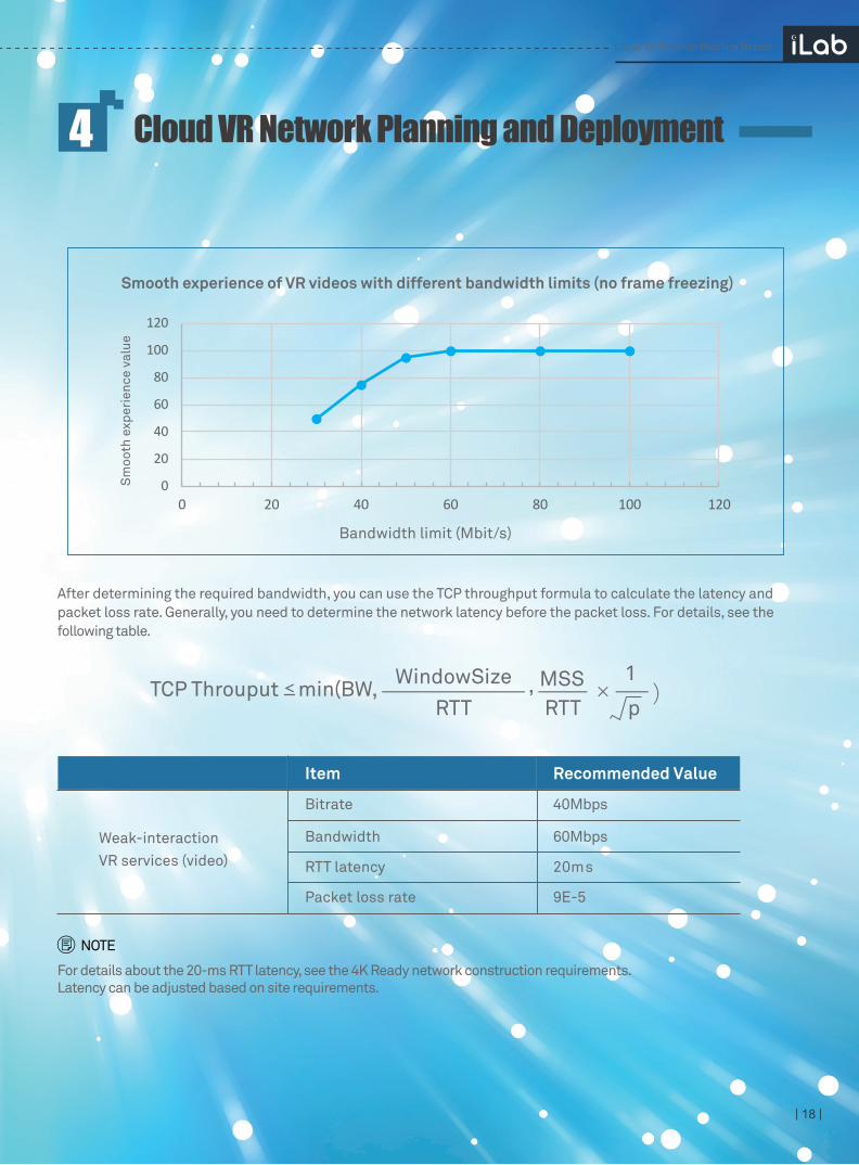
Lab tests of Cloud VR video show that for videos with an average bitrate of 40 Mbit/s, the bandwidth limit of 60 Mbit/s on the network side typically ensures smooth video, without frame freezing.
· 4.1.1 Network Indicator Requirements of VR Videos
Cloud VR Solution Practice Report
Cloud VR Network Planning and Deployment4
Resolution, color depth, frame rate, coding,
angle of view, bitrate
Bandwidth Latency Packet loss
Content quality Watching experience Interactive experience
Authenticity Pleasure Interaction
Frame freezing ratio of videos,effective frame rate
of gaming pictures
Initial buffer duration of videos,gaming operation
response latency
| 18 |
After determining the required bandwidth, you can use the TCP throughput formula to calculate the latency and packet loss rate. Generally, you need to determine the network latency before the packet loss. For details, see the following table.
, ×1
p)
WindowSizeRTT RTT
MSSTCP Throuput min(BW,
Cloud VR Solution Practice Report
Cloud VR Network Planning and Deployment4
For details about the 20-ms RTT latency, see the 4K Ready network construction requirements. Latency can be adjusted based on site requirements.
NOTE
0
20
40
60
80
100
120
0 20 40 60 80 100 120
Smooth experience of VR videos with different bandwidth limits (no frame freezing)
Sm
ooth
exp
erie
nce
valu
e
Bandwidth limit (Mbit/s)
Item Recommended Value
40Mbps
60Mbps
20ms
Weak-interaction VR services (video)
Bitrate
Bandwidth
RTT latency
Packet loss rate 9E-5
Cloud VR Solution Practice Report
| 19 |
In a strong-interaction service scenario, the transport network is a pipe that connects the cloud rendering platform and VR terminals. It transmits operation instructions and location information to the uplink and pushes video streams to the downlink. Therefore, the transmission network faces bandwidth, latency, and packet loss challenges.
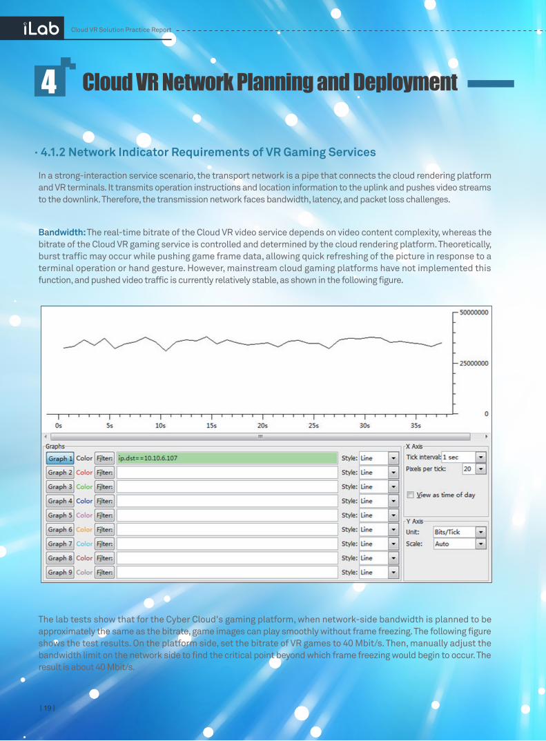
Bandwidth: The real-time bitrate of the Cloud VR video service depends on video content complexity, whereas the bitrate of the Cloud VR gaming service is controlled and determined by the cloud rendering platform. Theoretically, burst traffic may occur while pushing game frame data, allowing quick refreshing of the picture in response to a terminal operation or hand gesture. However, mainstream cloud gaming platforms have not implemented this function, and pushed video traffic is currently relatively stable, as shown in the following figure.
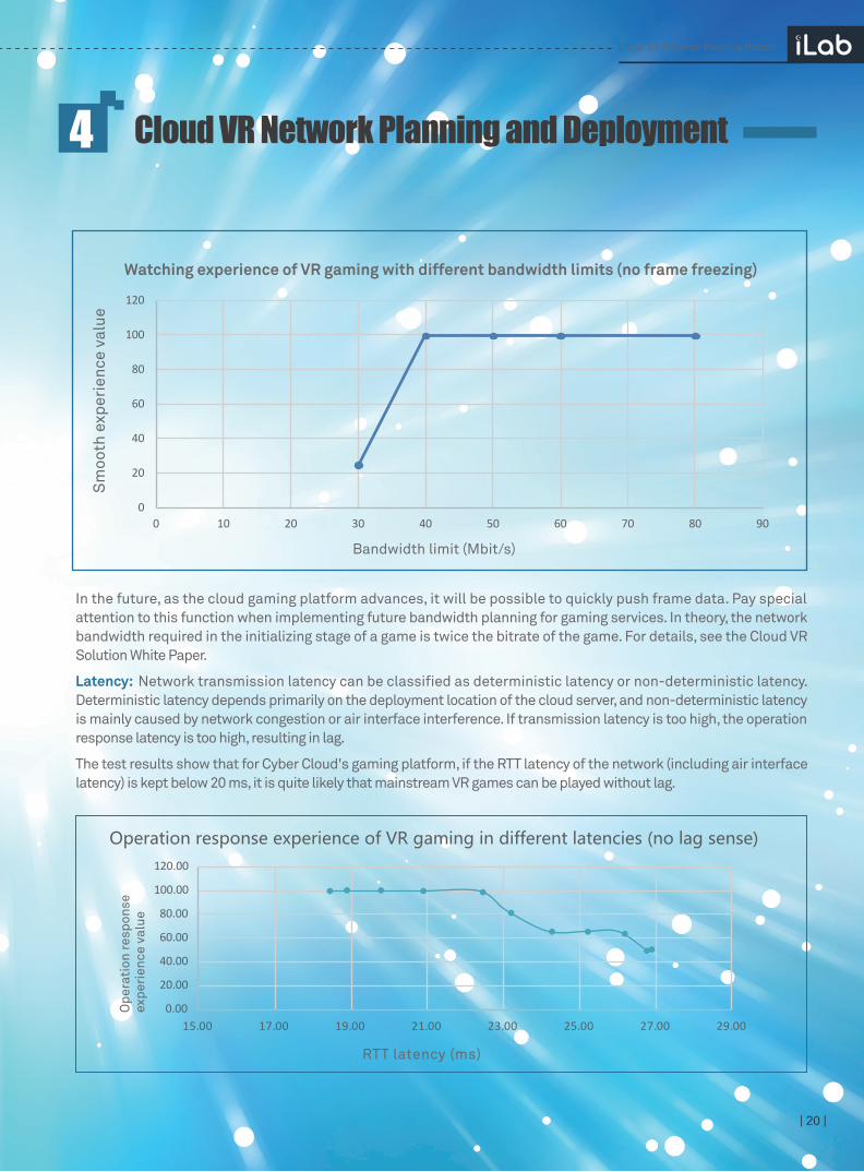
The lab tests show that for the Cyber Cloud's gaming platform, when network-side bandwidth is planned to be approximately the same as the bitrate, game images can play smoothly without frame freezing. The following figure shows the test results. On the platform side, set the bitrate of VR games to 40 Mbit/s. Then, manually adjust the bandwidth limit on the network side to find the critical point beyond which frame freezing would begin to occur. The result is about 40 Mbit/s.
· 4.1.2 Network Indicator Requirements of VR Gaming Services
Cloud VR Network Planning and Deployment4
Cloud VR Solution Practice Report
| 20 |
In the future, as the cloud gaming platform advances, it will be possible to quickly push frame data. Pay special attention to this function when implementing future bandwidth planning for gaming services. In theory, the network bandwidth required in the initializing stage of a game is twice the bitrate of the game. For details, see the Cloud VR Solution White Paper.
Latency: Network transmission latency can be classified as deterministic latency or non-deterministic latency. Deterministic latency depends primarily on the deployment location of the cloud server, and non-deterministic latency is mainly caused by network congestion or air interface interference. If transmission latency is too high, the operation response latency is too high, resulting in lag.
The test results show that for Cyber Cloud's gaming platform, if the RTT latency of the network (including air interface latency) is kept below 20 ms, it is quite likely that mainstream VR games can be played without lag.
Cloud VR Network Planning and Deployment4
0
20
40
60
80
100
120
0 10 20 30 40 50 60 70 80 90
Bandwidth limit (Mbit/s)
Watching experience of VR gaming with different bandwidth limits (no frame freezing)
Sm
ooth
exp
erie
nce
valu
e
0.00
20.00
40.00
60.00
80.00
100.00
120.00
15.00 17.00 19.00 21.00 23.00 25.00 27.00 29.00
Operation response experience of VR gaming in different latencies (no lag sense)
Ope
rati
on re
spon
se
expe
rien
ce v
alue
RTT latency (ms)
| 21 |
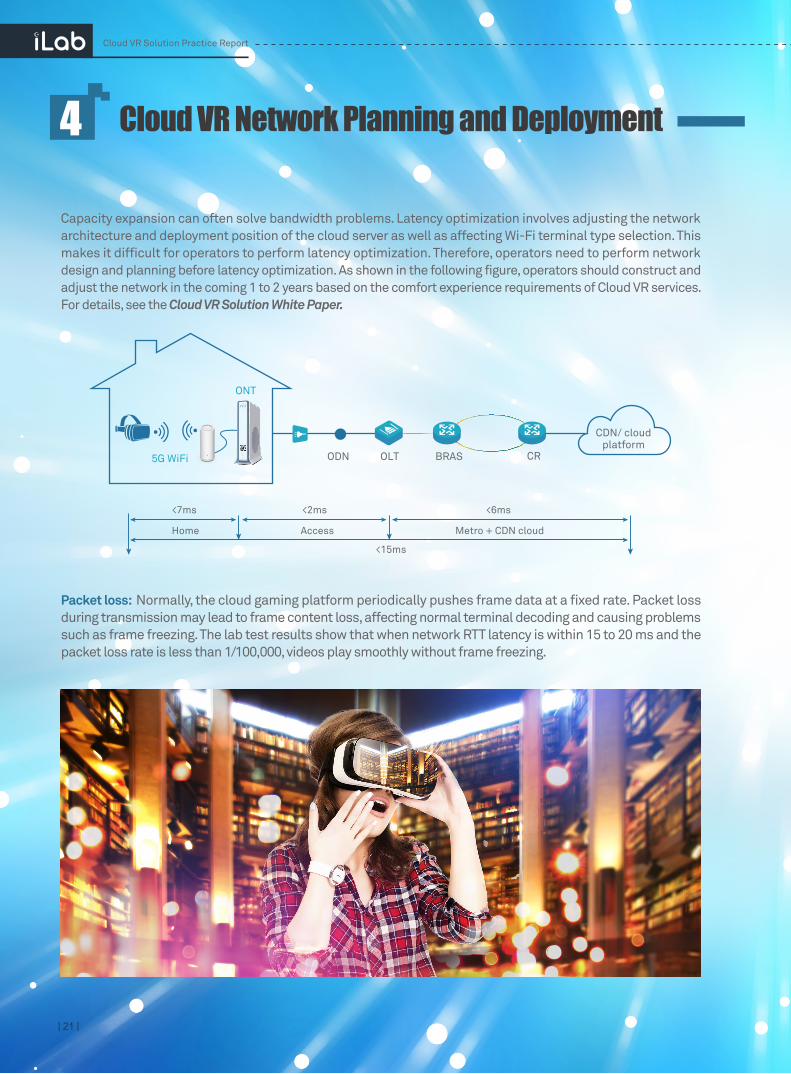
Capacity expansion can often solve bandwidth problems. Latency optimization involves adjusting the network architecture and deployment position of the cloud server as well as affecting Wi-Fi terminal type selection. This makes it difficult for operators to perform latency optimization. Therefore, operators need to perform network design and planning before latency optimization. As shown in the following figure, operators should construct and adjust the network in the coming 1 to 2 years based on the comfort experience requirements of Cloud VR services. For details, see the Cloud VR Solution White Paper.
Packet loss: Normally, the cloud gaming platform periodically pushes frame data at a fixed rate. Packet loss during transmission may lead to frame content loss, affecting normal terminal decoding and causing problems such as frame freezing. The lab test results show that when network RTT latency is within 15 to 20 ms and the packet loss rate is less than 1/100,000, videos play smoothly without frame freezing.
Cloud VR Network Planning and Deployment4
Cloud VR Solution Practice Report
CDN/ cloudplatform
ODN
ONT
5G WiFi OLT BRAS CR
<7ms
<15ms
Metro + CDN cloud AccessHome
<2ms <6ms
| 22 |
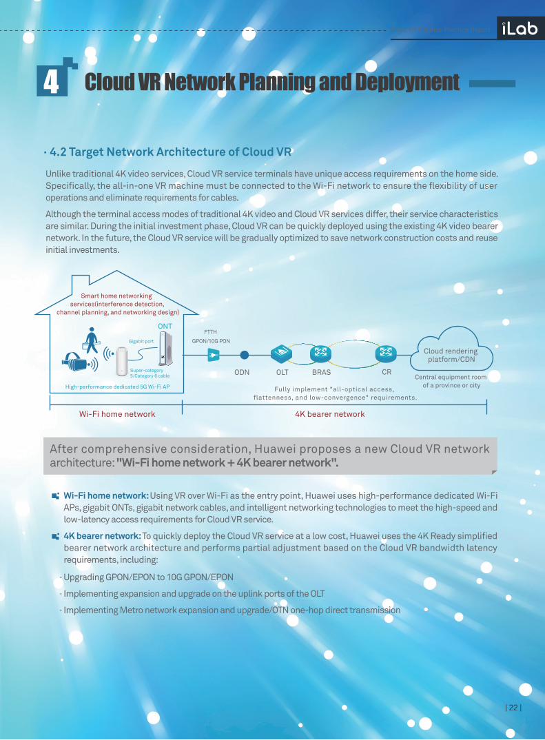
Unlike traditional 4K video services, Cloud VR service terminals have unique access requirements on the home side. Specifically, the all-in-one VR machine must be connected to the Wi-Fi network to ensure the flexibility of user operations and eliminate requirements for cables.
Although the terminal access modes of traditional 4K video and Cloud VR services differ, their service characteristics are similar. During the initial investment phase, Cloud VR can be quickly deployed using the existing 4K video bearer network. In the future, the Cloud VR service will be gradually optimized to save network construction costs and reuse initial investments.
· 4.2 Target Network Architecture of Cloud VR
After comprehensive consideration, Huawei proposes a new Cloud VR network architecture: "Wi-Fi home network + 4K bearer network".
Wi-Fi home network: Using VR over Wi-Fi as the entry point, Huawei uses high-performance dedicated Wi-Fi APs, gigabit ONTs, gigabit network cables, and intelligent networking technologies to meet the high-speed and low-latency access requirements for Cloud VR service.
4K bearer network: To quickly deploy the Cloud VR service at a low cost, Huawei uses the 4K Ready simplified bearer network architecture and performs partial adjustment based on the Cloud VR bandwidth latency requirements, including:
· Upgrading GPON/EPON to 10G GPON/EPON
· Implementing expansion and upgrade on the uplink ports of the OLT
· Implementing Metro network expansion and upgrade/OTN one-hop direct transmission
Cloud VR Network Planning and Deployment4
Cloud VR Solution Practice Report
Cloud rendering platform/CDN
Central equipment room of a province or city
ODN
FTTH
GPON/10G PON
ONT
High-performance dedicated 5G Wi-Fi AP
Gigabit port
Super-category 5/Category 6 cable OLT BRAS CR
Smart home networking services(interference detection,
channel planning, and networking design)
Wi-Fi home network 4K bearer network
Fully implement "all-optical access, flattenness, and low-convergence" requirements.

4.3 Solution Based on the Wi-Fi Home Network
· 4.3.1 Key Challenges for Home Networks
The live-network survey and lab tests show that Cloud VR services face many challenges on the home network side.
Maximally reuses live network resources: The legacy IP network, optical network, and FTTH access network can be upgraded on demand to carry Cloud VR services.
Simplifies deployment significantly: Legacy Internet access channels can be used to implement Cloud VR bearer without needing to configure a new VLAN, IP address, or authentication account.
Creates new home product/service sales opportunities: Cloud VR's high experience assurance demands create opportunities for operators to sell new home gateways and smart home networking services.
This architecture has the following advantages:
| 23 |
1. Cloud VR services can be carried by 5G Wi-Fi, but independent working channels need
to be planned properly.
The 2.4 GHz frequency band has few channels, which overlap. Only three independent channels can be allocated based on 20 MHz bandwidth, making the total bandwidth less than 80 MHz. This makes it difficult for the 2.4 GHz band to carry Cloud VR services. In contrast, the 5 GHz frequency band can provide more bandwidth and more channels, more flexibly, making it suitable for Cloud VR services. The following figure shows the four types of 5G Wi-Fi bandwidth (20 MHz, 40 MHz, 80 MHz, and 160 MHz). Testing and verification revealed that when using 80 MHz bandwidth, a transmission rate higher than 100 Mbit/s can be ensured even under certain interference conditions. Therefore, the 80 MHz bandwidth is suitable for Cloud VR services. In mainland China, there are only three frequency bands available for selecting 80 MHz bandwidth. Because of this limited quantity, it is vital to properly plan home networks.
20M
40M
80M
160M
36 40 44 48 52 56 60 64
5170MHz
5330MHz
149 153 157 161 165
5735MHz
5835MHz
Cloud VR Network Planning and Deployment4
Cloud VR Solution Practice Report
The survey results of some sites also confirm the preceding analysis. The following figure
shows the Wi-Fi signal strength distribution in a typical home. It has the following
features:
| 24 |
2.Different 5G Wi-Fi devices have different performance. Operators need to identify
high-performance 5G Wi-Fi devices.
Currently, many devices support 5G Wi-Fi, but they differ in price and performance. At the iLab lab, several common 5G Wi-Fi products were evaluated.
(1) During the test, interference scenarios were simulated using the following variables: traffic volume, signal strength, working channel, and number of interference sources.
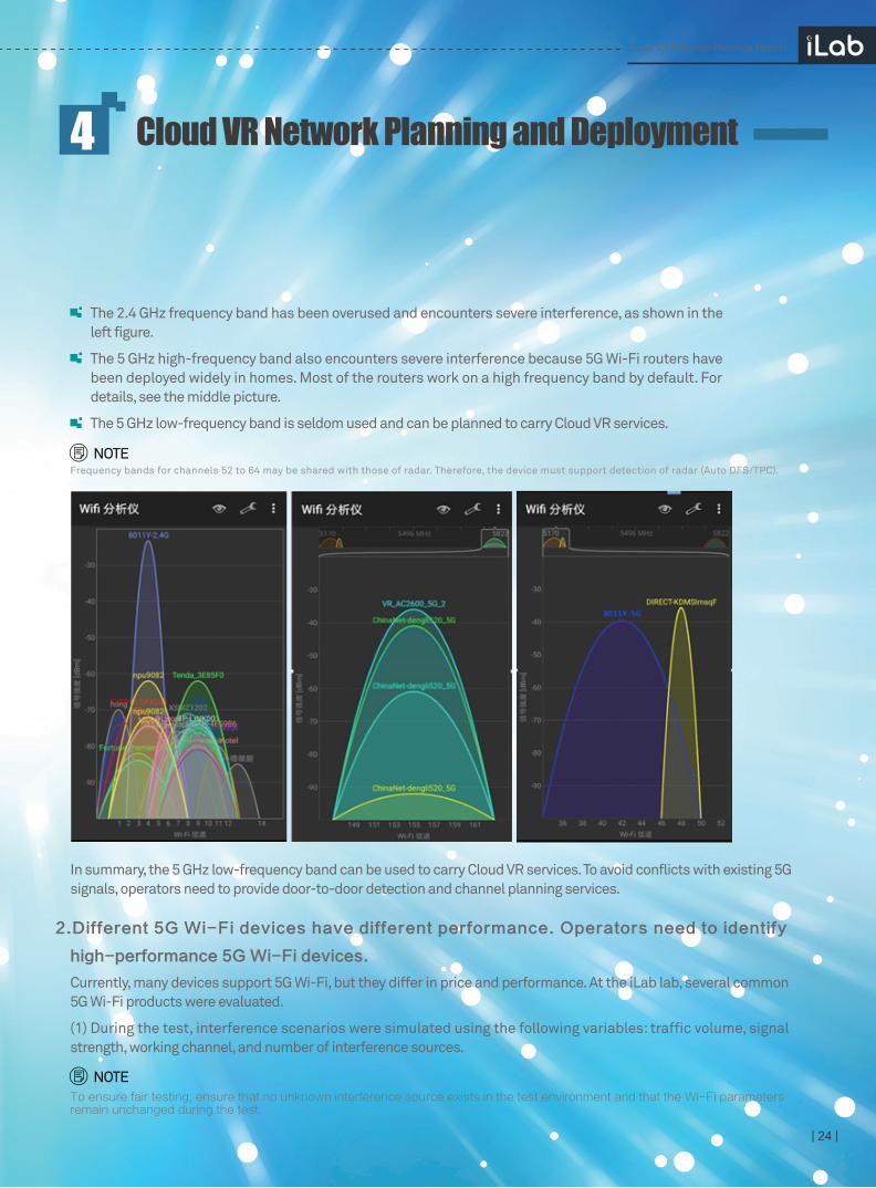
The 2.4 GHz frequency band has been overused and encounters severe interference, as shown in the left figure.
The 5 GHz high-frequency band also encounters severe interference because 5G Wi-Fi routers have been deployed widely in homes. Most of the routers work on a high frequency band by default. For details, see the middle picture.
The 5 GHz low-frequency band is seldom used and can be planned to carry Cloud VR services.
In summary, the 5 GHz low-frequency band can be used to carry Cloud VR services. To avoid conflicts with existing 5G signals, operators need to provide door-to-door detection and channel planning services.
Frequency bands for channels 52 to 64 may be shared with those of radar. Therefore, the device must support detection of radar (Auto DFS/TPC).
To ensure fair testing, ensure that no unknown interference source exists in the test environment and that the Wi-Fi parameters remain unchanged during the test.
Cloud VR Network Planning and Deployment4
NOTE
NOTE
Cloud VR Solution Practice Report
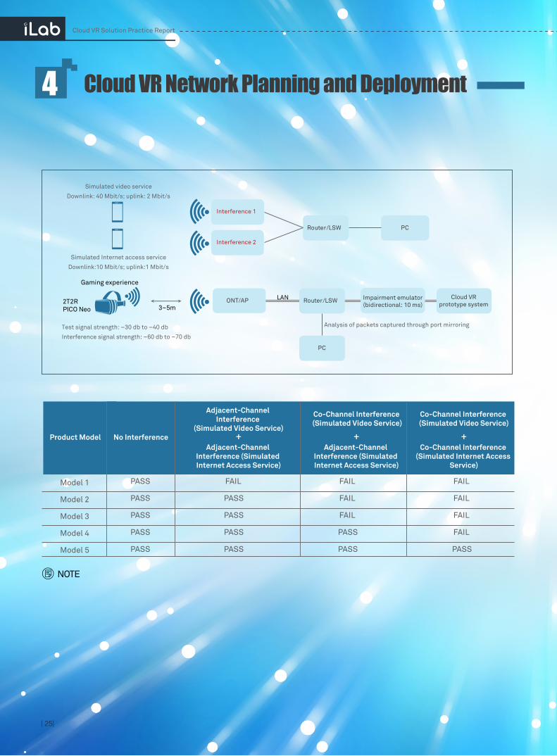
(2) The test object is the Cloud VR gaming service. The test focuses on changes in user experience and air interface latency in different interference scenarios. Air interface latency can be obtained by analyzing RTT in service packets that are captured through port mirroring. It is recommended that the air interface latency be less than 7 ms.
Two channels of interference signals are produced, simulating neighboring Wi-Fi signals. One channel carries video traffic, and the other carries Internet access traffic. By planning and adjusting the working channel, adjacent-channel interference and co-channel interference can also be simulated.
The test results show that different products adapt to the interference environment differently. Because the 5 GHz spectrum in mainland China has only three available 80 MHz frequency bands, adjacent-channel interference is inevitable. When 5G Wi-Fi is deployed on a large scale in the future, co-channel interference is also inevitable. Operators need to select Wi-Fi devices that ensure a smooth Cloud VR service experience in typical interference-prone scenarios projected from the coming 1 to 2 years.
The following table lists the test results.
| 25|
Cloud VR Solution Practice Report
Cloud VR Network Planning and Deployment4
NOTE
2T2RPICO Neo
LAN
PC
Analysis of packets captured through port mirroring
3~5m
Router/LSW PC
ONT/AP Router/LSW
Simulated video service
Downlink: 40 Mbit/s; uplink: 2 Mbit/s
Simulated Internet access service
Downlink:10 Mbit/s; uplink:1 Mbit/s
Test signal strength: –30 db to –40 db
Interference signal strength: –60 db to –70 db
Gaming experience
Interference 2
Interference 1
Cloud VRprototype system
Impairment emulator(bidirectional: 10 ms)
Product Model No Interference
Adjacent-Channel Interference
(Simulated Video Service)
Co-Channel Interference (Simulated Video Service)
Adjacent-Channel Interference (Simulated Internet Access Service)
Co-Channel Interference (Simulated Video Service)
+ + +Adjacent-Channel
Interference (Simulated Internet Access Service)
Co-Channel Interference (Simulated Internet Access
Service)
Model 1
Model 2
Model 3
Model 4
Model 5
PASS
PASS
PASS
PASS
PASS
FAIL
PASS
PASS
PASS
PASS
FAIL
FAIL
FAIL
PASS
PASS
FAIL
FAIL
FAIL
FAIL
PASS

· 4.3.2 Home Network Solution
3. Reusing the ONT on the live network to provide stable Wi-Fi signals is difficult, re-
quiring use of independent APs to carry Cloud VR services.
In addition to the Wi-Fi environment, ONT deployment location and network cable resources must
be considered in home networking. There are two typical home networking architectures:
The ONT is inside a weak-current box and only one network cable is connected to the VR experience area. This networking is common in new buildings. Because the weak-current box is far from the experience area and Wi-Fi signal penetration is poor, ONT Wi-Fi cannot be upgraded to provide Cloud VR service access. In this case, an external high-performance Wi-Fi AP can access without changing the original networking or service access mode.
The ONT is placed on a desk. In theory, you can upgrade ONT Wi-Fi to provide Cloud VR service access. However, because the ONT replacement process is complex, it is recommended that an external high-performance Wi-Fi AP be used.
The independent high-performance 5G Wi-Fi AP can adapt to various deployment scenarios and reuse the ONT/HGW devices on the live network to prevent Cloud VR services from affecting existing services on the live network.
The AP will be used for a long time. Once the AP is deployed, avoid repeated upgrades. Therefore, you need to select an AP that not only meets the current Cloud VR service requirements, but also supports smooth evolution towards the Cloud VR service that can provide a comfort experience level in the future. Therefore, it is recommended that the AP to be selected meet the following requirements:
To address these challenges, operators need to provide solutions such as high-performance products and professional services.
1.Add an independent high-performance 5G Wi-Fi AP to carry Cloud VR services (the AP supports
smooth evolution towards the comfort experience phase).
| 26 |
Cloud VR Solution Practice Report
Cloud VR Network Planning and Deployment4
FTTH GPON/10G PON
ONT
High-performance dedicated 5G Wi-Fi AP
Gigabit port
Super-category 5/Category 6 cable
Smart home networking services(interference detection,
channel planning, and networking design)
5GHz

Cloud VR Network Planning and Deployment4In the case of 2-4 channels of typical interference, the AP must provide a stable air interface transmission latency of less than 10 ms and a stable air interface transmission rate of more than 80 Mbit/s. In the future, the AP can evolve to support a stable latency of 7 ms and the air interference transmission rate of 260 Mbit/s.
The AP must support setting radar frequency bands to ensure that sufficient 5 GHz frequency band resources are available.
The AP must support the 4x4 MIMO technology. Currently, 2x2 MIMO is mainly used, but it is expected to be upgraded to 4x4 MIMO in the future. The AP must support smooth upgrade to 4x4 MIMO in the future.
The AP must provide sufficient GE ports to support flexible networking modes and reduce line reconstruction requirements.
Before provisioning the Cloud VR service, the live network provides Internet access (100 Mbit/s bandwidth) and IPTV (50 Mbit/s bandwidth). These two services use different ONT ports. 100 Mbit/s LAN port access and category 5 cables can meet access requirements.
A provisioned Cloud VR service requires about 100 Mbit/s bandwidth. If image projection is enabled, it requires about 200 Mbit/s bandwidth. Therefore, regardless of whether the Cloud VR service is carried on the Internet or IPTV plane, 100 Mbit/s LAN port access and category 5 cables cannot meet its access requirements. The 100 Mbit/s LAN port access needs to be upgraded to gigabit-level LAN port access, and category 5 cables need to be upgraded to super-category 5 or category 6 cables.
The survey shows that most live-network ONTs in China support gigabit-level LAN port access, making large-scale ONT replacement unnecessary. However, there are a lot of live-network category 5 cables that need to be replaced by super-category 5 or category 6 cables.
2. Perform an upgrade to use gigabit ONT and gigabit network cables.
Different homes have different house architecture, interference environments, and service provisioning. Therefore, operators need to provide smart home networking services for them in the following aspects:
Implement interference detection and channel planning to provide a clean and independent Wi-Fi working frequency band for Cloud VR services.
Select a proper networking mode to deploy dedicated APs. During deployment, consider their coexistence with HSI and IPTV services.
3.Provide smart home networking services.
| 27 |
Cloud VR Solution Practice Report
FTTH GPON
FTTH 10G PON
ONT
STB
high-performance dedicated AP for Cloud VR
Router for Internet access
HSI terminal
2.4G/5G WI-FI
5G Wi-Fi(planning of an
independent channel)
All-in-one VRmachine
Gigabit portSuper-category
5/Category 6 cable

Cloud VR Network Planning and Deployment4To avoid service conflicts after considering factors such as terminal location and network access requirements, Huawei provides the following sugges-tions for integrated home networking:
Cloud VR service: VR terminals have high requirements on home Wi-Fi environment and network throughput. They require high-performance APs specified by operators. To reduce cabling requirements and avoid changing the access modes of other services, you can connect the AP to the original home router. If the router does not support gigabit-level access, you can deploy the AP between the original router and ONT.
HSI service: Mobile terminals are the primary HSI service users. The 2.4 GHz frequency band ensures signal coverage, and is supplemented by the 5 GHz band to guarantee bandwidth in key areas. However, these frequency bands must be separated from the frequency band dedicated for the Cloud VR service.
IPTV service: The position of the TV set is generally fixed. Because the TV set has high network requirements, it must be connected in wired mode. If a dedicated video bearer plane is deployed on the network side, this plane should be used for IPTV service access. This delivers a good video service experience without competing for Internet access bandwidth.
| 28 |
· 4.4.1 Access Network Planning and DeploymentThe access network aggregates end users for the bearer network and is the closest to users. To support large-scale number allocation, operators should directly upgrade to 10G PON. Based on the 10G PON port, use a split ratio of 1:64. This allows 156 Mbit/s bandwidth to be obtained by a single user, even in the full-concurrence scenario. This meets Cloud VR service provisioning requirements.
However, 10G PON has not been deployed on a large scale, and upgrading GPON to 10G PON on the live network is slow. Operators hope to allocate a small number of VR users on the existing GPON network and gradually migrate GPON to 10G PON as they develop services. To avoid bandwidth overload, operators need to evaluate the number of GPON users that can be provisioned as follows:
4.4 Expansion and Upgrade Based on the 4K Bearer Network
Cloud VR Solution Practice Report
Original gigabit router Original 100M routerAP APONT
Weak-current box
ONT
Weak-current boxExternal connectionsolution
Internal connection solution
Number of VR users that can be provisioned =
(GPON port bandwidth) x (Expansion threshold) –(Average rate of broadband users) x (Split ratio) x (Actual installation rate)
Average rate of VR users

The average rate of broadband users is evaluated based on IPTV and HSI service development and the number of concurrent users. The following table shows current estimates and future predictions of these variables.
The average rate of VR users is related to the content bitrate, content ratio, and concurrence. The following table shows current evaluation results and their future predictions.
| 29 |
Based on the network construction specifications of the operator, for example, GPON expansion threshold of 45%, split ratio of 1:64, and broadband service installation rate of 60%, the number of VR users that can be provisioned for GPON ports in the next three years is calculated, as listed in the following table.
Cloud VR Network Planning and Deployment4
Cloud VR Solution Practice Report
Category 2018 2019 2020User forecast Video penetration rate 100% 100% 100%
VoD
SD VoD percentage 30% 20% 0%
HD VoD percentage 40% 30% 40%
30% 50% 60%
Average video bitrate 10.1 13.0 15.2
Concurrence rate
Average VoD rate of video users 10.1 13.0 15.2
Average VoD rate of home broadband users 10.1 13.0 15.2
Internet access service
Online percentage of Internet access users
Average rate of online users 4.8 7.0 11.0
100% 100% 100%
100% 100% 100%
Average rate of broadband users
Average rate of broadband users (Mbit/s)
4.8 7.0 11.0
Total 14.9 20.0 26.2
OTT 4K VoD percentage
Category 2018 2019 2020
VR
50% 45% 40%
0% 5% 10%
50% 45% 40%
0% 5% 10%
60.0 70.0 80.0
50% 60% 70%
30.0 42.0 56.0
Percentage of 8K VR videos (weak interaction; 90 Mbit/s)
Percentage of 4K VR videos (weak interaction; 40 Mbit/s)
Percentage of 4K VR games (strong interaction; 40 Mbit/s)
Percentage of 8K VR games (strong interaction; 90 Mbit/s)
Average bitrate of VR users
Concurrence rate of VR users
Average rate of VR users (Mbit/s)
Year Expansion Threshold
Split RatioActual
Installation Rate
GPON Port Bandwidth
(Mbit/s)
Average Rate of Bandwidth Users
(Mbit/s)
Average Rate of VR Users
(Mbit/s)
2018 2300 45% 14.9 64 60% 32 14
2019 2300 45% 20 64 60% 36 7
2020 2300 45% 26.2 64 60% 40 0
Number of VR Users That Can Be Provisioned
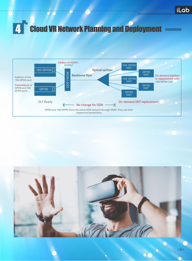
Take GPON as an example. During the evolution to 10G GPON, the following two solutions are available:
Solution 1: Through the external multiplexer, the wavelengths of the 10G GPON port and the GPON port are multiplexed and then transmitted through the same backbone fiber. The original GPON ONT can still be used, and can be added or replaced by a 10G GPON ONT on demand. Because deploying a multiplexer introduces extra attenuation, you are advised to reserve an optical budget of 2 to 3 dBm for the newly deployed GPON. If your optical budget is insufficient, upgrade the optical module.
Solution 2: The Combo board solution is used, integrating the 10G GPON and GPON capabilities in a board, and a multiplexer is built in an optical module. The PON port on the live network is cut over to the combo unicast PON port. The original GPON ONT can still be used, or it can be replaced on demand by the 10G GPON ONT.
This table shows that GPON ports face significant limitations in terms of large-scale allocation of Cloud VR users. The number of Cloud VR users needs to be controlled. However, in some areas with high penetration rates, GPON needs to be upgraded immediately to 10G GPON to cope with the development of Cloud VR services.
| 30 |
Cloud VR Network Planning and Deployment4
Cloud VR Solution Practice Report
No change for ODN
Addition of WDM1r (overlay)
10G GPON
GPON
OLT Ready
Optical splitter
Backbone fiberAddition of the 10G GPON card
Coexistence of GPON and 10G GPON ports
On-demand additionor replacement with 10G GPON ONT
GPON and 10G GPON share the same ODN network through WDM. They use their respective bandwidths.
10G GPONONT
10G GPONONT
GPONONT
GPONONT
GPONONT
On-demand ONT replacement
OD
F+
WD
M

· 4.4.2 Metro Network Capacity Expansion and UpgradeInitially, Cloud VR services can be quickly provisioned and deployed over an operator's existing 4K video bearer channels by fully implementing "all-optical access, flatness, and low-convergence" video network construction.
Investigations and commercial trials in multiple regions have found the following problems in operator networks:Some OLTs still use the switch aggregation networking. This results in a high convergence ratio and complex homing.
Some BRASs and OLTs are still connected with GE links, which cannot meet traffic growth requirements.
Some CRs and BRASs are still connected with 10GE links, which cannot meet traffic growth requirements.
As shown in the following table, VR user penetration rates can be assumed to be about 5% initially and about 5% higher each subsequent year. Average VR user rates are calculated based on the VR content bitrate and ratio and concurrence.
They can deploy WDM devices to metro edges or OLT sites, provide interconnection pipes with ultra-large bandwidth, low latency, and zero packet loss to implement flattened networks.
Overall Cloud VR service bandwidth requirements must be determined by operators in advance to facilitate on-demand capacity expansion. To evaluate bandwidth requirements, see the 4K Ready network bandwidth planning method for further details. VR user penetration rates and the average VR user rates will also be needed to perform this evaluation.
Network reconstruction involves a large number of fiber construction and device capacity expansion requirements. Operators must perform design and planning in advance:
| 31 |
Cloud VR Network Planning and Deployment4
Cloud VR Solution Practice Report
Intemet/CDN
ODN
ONT
AP
OLT BRAS CR
Home network Access network Metro network
All-optical access, flattenness, and low convergence

Finally, based on operator network construction specifications and the average rate of broadband users, downstream port bandwidth on the BRAS and CR over the next three years can be calculated, as listed in the following table.
| 32 |
Cloud VR Network Planning and Deployment4
Based on the preceding table, assume that an operator requires a BRAS downstream link be expanded by 60% and the related OLT have 1500 broadband users or less connected. With the development of VR services in 2018, multi-GE binding cannot support high enough bandwidth between the BRAS and the OLT. Capacity needs to be expanded to 2 x 10GE or more. Further, assume that the operator requires a CR downstream link be expanded by 65% and the related BRAS have 30,000 broadband users or less connected. Taking the con-vergence ratio into consideration, multi-10GE binding will support high enough bandwidth between the CR and the BRAS in 2019. A capacity of 100GE or more is required.
Cloud VR Solution Practice Report
2018 2019 2020User
predictionVR user penetration rate 5% 10% 15%
Video user penetration rate 70% 75% 80%
VoD
SD VoD percentage 30% 20% 10%
HD VoD percentage 50% 50% 40%
OTT 4K VoD percentage 20% 30% 50%
Average bitrate of VoD users 8.9 10.6 13.5
VoD concurrence percentage 20% 30% 40%
Average VoD rate of video users 1.8 3.2 5.4
Average VoD rate of broadband users 1.2 2.4 4.3
Percentage of 4K VR videos (weak interaction; 40 Mbit/s) 50% 45% 40%
Percentage of 8K VR videos (weak interaction; 90 Mbit/s) 0% 5% 10%
Percentage of 4K VR games (strong interaction; 40 Mbit/s) 50% 45% 40%
Percentage of 8K VR games (strong interaction; 90 Mbit/s) 0% 5% 10%
Average bitrate of VR users 40.0 45.0 50.0
Concurrence rate for VR users 10% 15% 20%
Average rate of VR users
Average VR rate of home broadband users
4.0 6.8 10.0
0.2 0.7 1.5
Internet access service
Total
Online percentage of Internet access users
Average rate of online users
Average Internet access rate of broadband users
Average rate of broadband users (Mbit/s)
65% 70% 70%
4.8 7.0 10.0
3.1
4.6 8.0 12.8
4.9 7.0
Average VRrate evaluation
19.911.4 32
30000
1500
70.2 122.5 197.2
2018(Gbps) 2020(Gbps)2019(Gbps)
2018(Gbps) 2020(Gbps)2019(Gbps)
Number of OLT Users
Number of BRAS Users

4.5 Cloud VR Bearer Solution
· 4.5.1 Basic Bearer Solution
Cloud VR is regarded as the future of operator-operated video services. Before a Cloud VR service network bearer solution can be designed, the network bearer status of an operator's existing video services needs to be fully understood.
Previous investigation shows that most video network bearer solutions in China are designed as per the preceding figure.
Access side: HSI access service and IPTV service channels are generally carried by independent VLAN planes.
Metro side: Services are carried together based on native IP or L3VPN.
| 33 |
Cloud VR Network Planning and Deployment4
Cloud VR Solution Practice Report
VLAN1
VLAN2单播VLAN2’
组播VLAN
VLAN1’Native IP
Native IP
IP Multicast
WAN1: PPPoE
WAN2: 桥接 LAN
SSID(2.4G) LAN
机顶盒IPOE
DH
CP
ONT
VLAN1
VLAN2Unicast VLAN2'
Multicast VLAN
Native IP
Native IP
IP Multicast
WAN1: PPPoE
WAN2:bridging LAN
SSID(2.4G) LAN
STBIPOE
DH
CP
OLTBRAS
Native IP/L3VPN
手机,PCDHCPDHCP
Mobile phonepc
VLAN1’
Internet / IPTV
BRASCR OLT
Service platform
Backbone
ONT
LAN
2.4GHz
5GHz
AP
Solution 1 Carrying VR services on the Internet access plane
Solution 2 Carrying VR
services on the IPTV plane
Solution 3Carrying VR services on a new plane
Unicast VLAN2'
Multicast VLAN
VLAN1’
IPTV
InternetVR
WAN1: PPPoE
WAN2: bridging LAN
SSID(2.4G) LAN
SSID(5G)
Mobile phone, PC
STB
DHCP
IPTV
HSI VR terminal
VR
Unicast VLAN2'
Multicast VLAN
VLAN1’
VRIPTV
Internet WAN1: PPPoE
WAN2: bridging
SSID(2.4G) LAN
LAN
SSID (5G)
IPTVUnicast VLAN2'
Multicast VLAN
VLAN1’
IPTV
Internet WAN1: PPPoE
WAN2: bridging
SSID(2.4G) LAN
LAN
Mobile phone, PC
STBIPOE
SSID(5G) VR terminalDHCP/IPOE
HSI
VRWAN3
VLAN1
VLAN2
VLAN1
VLAN2
VLAN1
VLAN2
VLAN3VLAN3’VR
IPTV
HSI
VR
Mobile phone,PC
STB
VR terminal
Native IP
Native IP/L3VPN
IP Multicast
Native IP
Native IP/L3VPN
IP Multicast
Native IP
IP Multicast
Native IP/L3VPN
Native IP/L3VPN
DHCP
IPOE
DHCP
DHCP
IPOE
IPOE
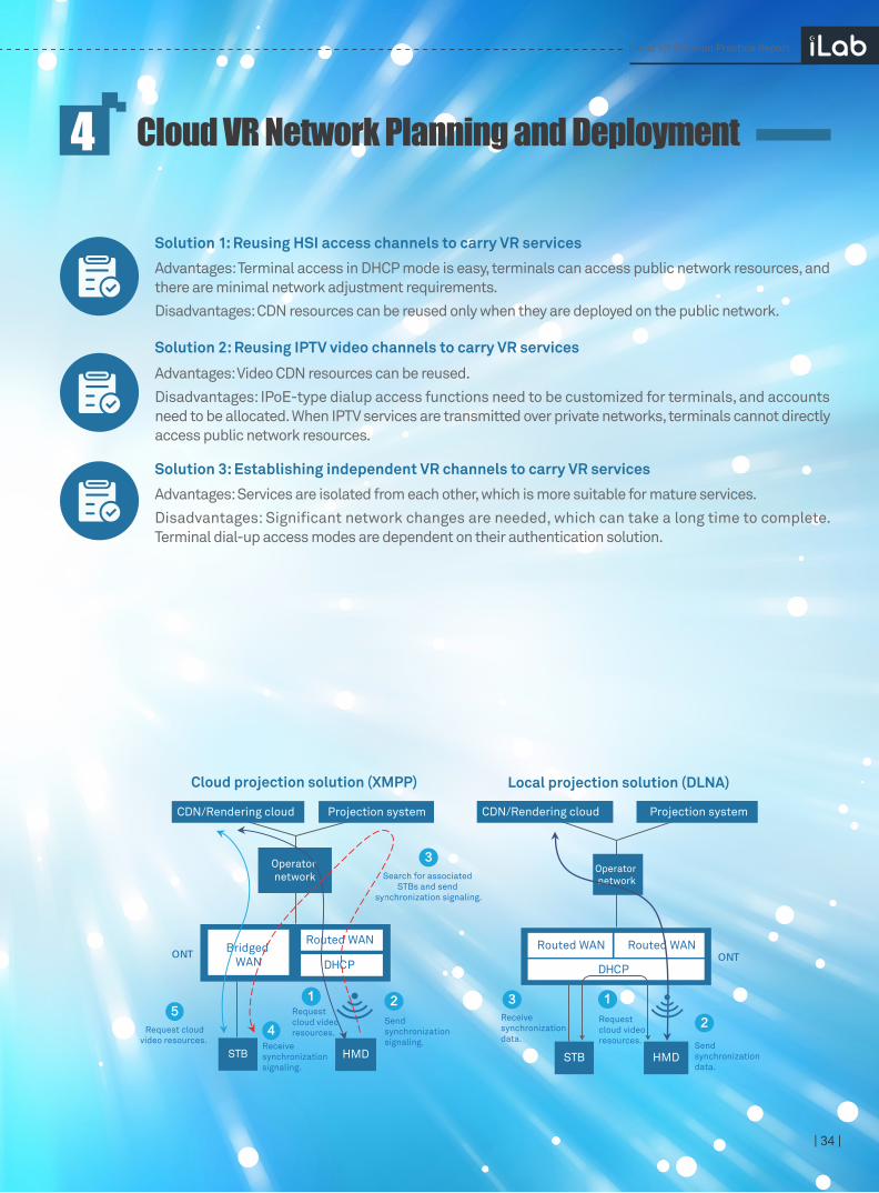
· 4.5.2 Projection Bearer Solution
Based on the advantages and disadvantages listed above, Huawei generally recommends Solution 1. This solution requires the least E2E changes and provides the fastest service provisioning speed. It can also achieve various Cloud VR services during initial rollout.
Through the collaboration of multi-window modules between the terminal, cloud, and STB, VR content can be displayed on home TV screens, allowing VR experiences to be shared within families. To achieve this, there are two projection solutions, as shown in the following figure.
Ultimately, three bearer channel solutions are available for operators for VR services:
| 34 |
Cloud VR Network Planning and Deployment4
Solution 1: Reusing HSI access channels to carry VR services
Advantages: Terminal access in DHCP mode is easy, terminals can access public network resources, and there are minimal network adjustment requirements.
Disadvantages: CDN resources can be reused only when they are deployed on the public network.
Advantages: Video CDN resources can be reused.
Disadvantages: IPoE-type dialup access functions need to be customized for terminals, and accounts need to be allocated. When IPTV services are transmitted over private networks, terminals cannot directly access public network resources.
Solution 2: Reusing IPTV video channels to carry VR services
Advantages: Services are isolated from each other, which is more suitable for mature services.
Disadvantages: Significant network changes are needed, which can take a long time to complete. Terminal dial-up access modes are dependent on their authentication solution.
Solution 3: Establishing independent VR channels to carry VR services
Cloud VR Solution Practice Report
STB HMD
Receive synchronization data.
3
Send synchronization data.
2Request cloud video resources.
1
Local projection solution (DLNA)
Operator network
DHCP
Routed WANRouted WANONT
Projection systemCDN/Rendering cloud
STB HMD
Operator network
2
3
51
Cloud projection solution (XMPP)
4
DHCP
Routed WAN Bridged
WANONT
CDN/Rendering cloud Projection system
Search for associated STBs and send
synchronization signaling.
Send synchronization signaling.
Request cloud video resources.
Receive synchronization signaling.
Request cloudvideo resources.
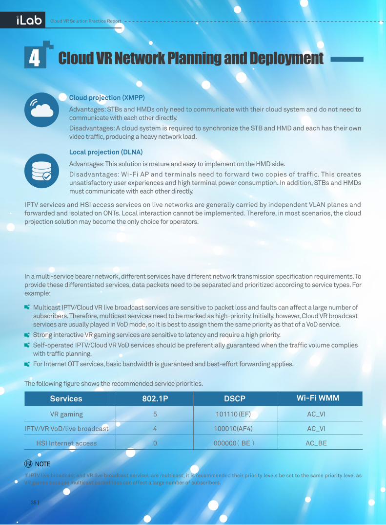
4.6 QoS Planning and deployment
·4.6.1 Priority Allocation
| 35 |
Cloud VR Network Planning and Deployment4
Advantages: STBs and HMDs only need to communicate with their cloud system and do not need to communicate with each other directly.
Disadvantages: A cloud system is required to synchronize the STB and HMD and each has their own video traffic, producing a heavy network load.
Cloud projection (XMPP)
Advantages: This solution is mature and easy to implement on the HMD side.
Disadvantages: Wi-Fi AP and terminals need to forward two copies of traffic. This creates unsatisfactory user experiences and high terminal power consumption. In addition, STBs and HMDs must communicate with each other directly.
IPTV services and HSI access services on live networks are generally carried by independent VLAN planes and forwarded and isolated on ONTs. Local interaction cannot be implemented. Therefore, in most scenarios, the cloud projection solution may become the only choice for operators.
In a multi-service bearer network, different services have different network transmission specification requirements. To provide these differentiated services, data packets need to be separated and prioritized according to service types. For example:
If IPTV live broadcast and VR live broadcast services are multicast, it is recommended their priority levels be set to the same priority level as VR games because multicast packet loss can affect a large number of subscribers.
Multicast IPTV/Cloud VR live broadcast services are sensitive to packet loss and faults can affect a large number of subscribers. Therefore, multicast services need to be marked as high-priority. Initially, however, Cloud VR broadcast services are usually played in VoD mode, so it is best to assign them the same priority as that of a VoD service.
Strong interactive VR gaming services are sensitive to latency and require a high priority.
Self-operated IPTV/Cloud VR VoD services should be preferentially guaranteed when the traffic volume complies with traffic planning.
For Internet OTT services, basic bandwidth is guaranteed and best-effort forwarding applies.
Local projection (DLNA)
The following figure shows the recommended service priorities.
NOTE
Cloud VR Solution Practice Report
Services 802.1P DSCP
VR gaming 5 101110 (EF) AC_VI
IPTV/VR VoD/live broadcast 4 100010(AF4) AC_VI
HSI Internet access 0 000000 (BE) AC_BE
Wi-Fi WMM
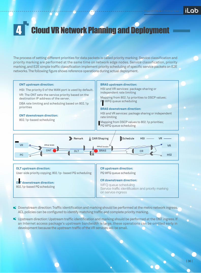
· 4.6.2 Priority Marking
| 36 |
Cloud VR Network Planning and Deployment4
The process of setting different priorities for data packets is called priority marking. Service classification and priority marking are performed at the same time on network edge nodes. Service classification, priority marking, and E2E simple traffic classification implement priority scheduling of specific service packets on E2E networks. The following figure shows reference operations during actual deployment.
Downstream direction: Traffic identification and marking should be performed at the metro network ingress. ACL policies can be configured to identify matching traffic and complete priority marking.
Upstream direction: Upstream traffic identification and marking should be performed at the ONT ingress. If an Internet access package's upstream bandwidth is large, these operations can be omitted early in development because the upstream traffic of the VR services will be small.
ONT upstream direction: BRAS upstream direction:
BRAS downstream direction:
HSI: The priority 0 of the WAN port is used by default.
VR: The ONT sets the service priority based on the destination IP address of the server.
DBA rate limiting and scheduling based on 802.1p priorities
ONT downstream direction:802.1p-based scheduling
HSI and VR services: package sharing or independent rate limiting
Mapping from 802.1p priorities to DSCP values; PQ WFQ queue scheduling
HSI and VR services: package sharing or independent rate limiting
Mapping from DSCP values to 802.1p priorities; PQ WFQ queue scheduling
CR upstream direction:
CR downstream direction:
OLT upstream direction:User-side priority copying; 802.1p- based PQ scheduling
OLT downstream direction:802.1p-based PQ scheduling
PQ WFQ queue scheduling
WFQ queue schedulingService traffic identification and priority marking on service ingress
Remark CAR/Shaping Schedule
BRASOLTONT
VR VR
HSIPC
VRHSI
PPPoE WANPPPoE Session
CR
Cloud VR Solution Practice Report

· 4.6.3 User CAR/Shaping for Rate Limiting
When an Internet access channel is reused to carry Cloud VR services, Cloud VR service traffic and Internet access service traffic share the same rate limit package. These services will preempt each other's bandwidth if no additional measures are taken. To prevent this, there are two common solutions: hierarchical quality of service (HQoS) and destination address accounting (DAA). The following figure shows the technical principles behind HQoS and DAA.
All user Cloud VR and Internet access service traffic of a user shares the same rate limit package. Services in the package are scheduled based on their priority to ensure Cloud VR traffic is preferentially forwarded and any remaining bandwidth is used by Internet access traffic. After HQoS is configured on a router, the router has a buffer temporarily store which service flow queues that require hierarchical scheduling. This is called shaping mode. Generally, shaping mode requires E2E simple traffic classification, and specific device hardware requirements, such as matching boards.
Cloud VR traffic is not part of a users' Internet access package. An ACL policy can be configured on the BRAS to identify Cloud VR service traffic based on specific server addresses and domain users. Once identified the policy can perform independent CAR limiting and accounting. Services do not preempt each other's bandwidth. The DAA solution requires a large number of ACLs and specific hardware.
HQOS
| 37 |
Cloud VR Network Planning and Deployment4
solution
DAA solution:
Cloud VR Solution Practice Report
DAA: Outband Acceleration, Exclusive Bandwidth
HQoS: Inband Rate Limiting, Bandwidth Competition
VR Video AF4 WFQ
HSI BE WFQ
VR Game EF PQ VRGame EF
UserPPPoE Session
daa-car200Mbps
daa-car 200Mbps
user-car100Mbps
UserPPPoE Session
UserPPPoE Sessionuser-
queue Shaping 200Mbps
VR Video AF4
HSI BE
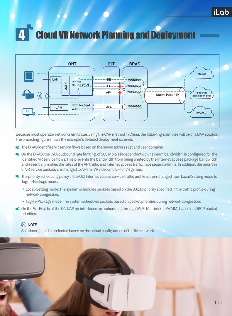
Because most operator networks limit rates using the CAR method in China, the following examples will be of a DAA solution. The preceding figure shows the example's detailed deployment scheme.
Solutions should be selected based on the actual configuration of the live network.
The BRAS identifies VR service flows based on the server address list and user domains.
On the BRAS, the DAA outbound rate limiting, of 200 Mbit/s independent downstream bandwidth, is configured for the identified VR service flows. This prevents the bandwidth from being limited by the Internet access package bandwidth and essentially makes the rates of the VR traffic and Internet access traffic have separate limits. In addition, the priorities of VR service packets are changed to AF4 for VR video and EF for VR games.
The priority scheduling policy in the OLT Internet access service traffic profile is then changed from Local-Setting mode to Tag-In-Package mode.
On the Wi-Fi side of the ONT/AP, air interfaces are scheduled through Wi-Fi Multimedia (WMM) based on DSCP packet priorities.
| 38 |
Cloud VR Network Planning and Deployment4
NOTE
Local-Setting mode: The system schedules packets based on the 802.1p priority specified in the traffic profile during network congestion.
Tag-In-Package mode: The system schedules packets based on packet priorities during network congestion.
Cloud VR Solution Practice Report
LAN
ONT OLT BRAS
Rendering application pool
Internet
IPTV CDN
PPPoE routed WAN
IPoE bridgedWAN
DH
CP
LAN
Native Public IP
100MbpsAF4
BE
EF
AF4
100Mbps
200Mbps
200Mbps
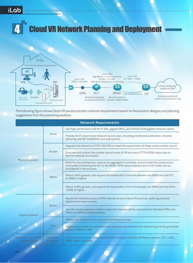
4.7 Cloud VR Network Requirements
| 39 |
The following figure shows Cloud VR service solution network requirements based on the solution designs and planning suggestions from the preceding sections.
Cloud VR Network Planning and Deployment4
Cloud VR Solution Practice Report
Cloud renderingplatform/CDN
Central equipment room of a province or city
ODN
FTTH
ONTSTB
OLT BRAS CR
Load < 45%GPON->10G GPON
Smart home networking services
5G WIFI
High-performance AP
CAT5E/CAT6 cable
Gigabit port
All-in-one VR machine
E2E QoS deployment
Service isolation solution (DAA/HQoS)
Scheduling based on packet priorities
Load < 65%N x 10GE -> 100GE
Load < 60%Aggregation -> Direct connection
N x GE -> 2 x 10GEWDM device deployment to CO nodes
Physical network
Home
Use high-performance 5G Wi-Fi APs, gigabit ONTs, and CAT5E/CAT6 gigabit network cables.
Provide Wi-Fi smart home networking services, including interference detection, channel planning, and AP installation and deployment.
Access
Upgrade the network to FTTH 10G PON to meet the requirement of large-scale number launch.
Evaluate and control the number launch scale of VR services if FTTH GPON resources on the live network are reused.
Metro
Simplify the architecture, remove the aggregation switches, and promote the construction of directly connecting the OLT to the BRAS. WDM device deployment to CO nodes can be considered in the process.
Match traffic growth, and expand the bandwidth of the link between the BRAS and the OLT to 20GE or higher.
Match traffic growth, and expand the bandwidth of the link between the BRAS and the CR to 100GE or higher.
Logical network
Bearer
Reuse the Internet access or IPTV channel to carry Cloud VR services, reducing network deployment requirements.
Use the cloud projection mode to meet the interoperability requirements between STBs and HMDs on different bearer planes.
Qos
Deploy port QoS to ensure service scheduling priorities.
Deploy service QoS to implement user-level service isolation and scheduling priority guarantee based on HQoS or DAA.
Network construction specifications
Expansion threshold
Expansion thresholds of the downlink link inherited from the 4K Ready network: OLT < 45%, BRAS < 60%, CR < 65%
Network Requirements
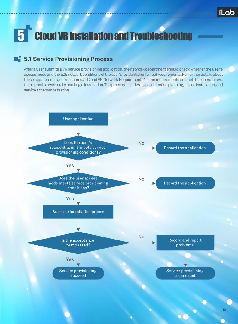
| 40 |
Cloud VR Installation and Troubleshooting55.1 Service Provisioning ProcessAfter a user submits a VR service provisioning application, the network department should check whether the user's access mode and the E2E network conditions of the user's residential unit meet requirements. For further details about these requirements, see section 4.7 "Cloud VR Network Requirements." If the requirements are met, the operator will then submit a work order and begin installation. The process includes signal detection planning, device installation, and service acceptance testing.
Cloud VR Solution Practice Report
User application
Does the user’s residential unit meets service
provisioning conditions?
Does the user access mode meets service provisioning
conditions?
Is the acceptance test passed?
Start the installation proces
Record and report problems.
Yes
No
Yes
No
Yes
No
Record the application.
Record the application.
Service provisioning is canceled.
Service provisioning succeed
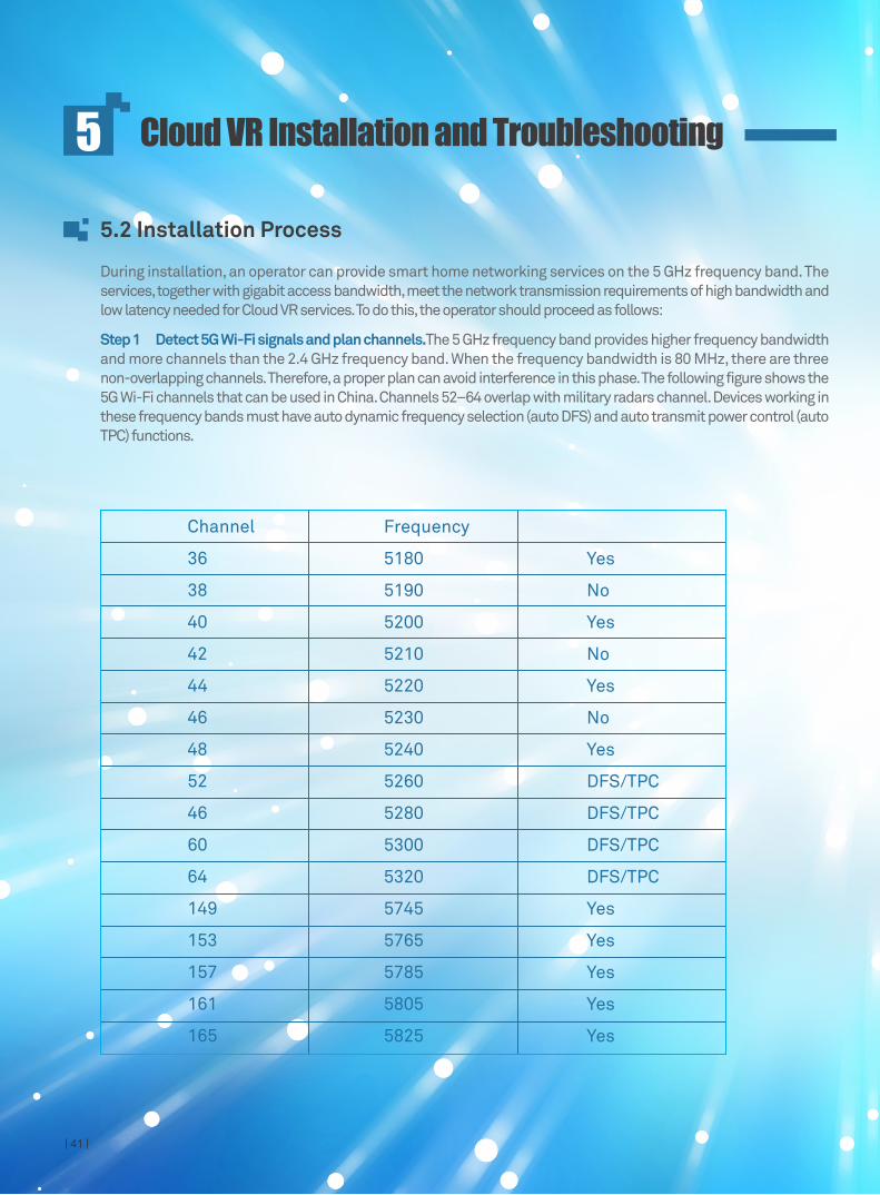
Cloud VR Solution Practice Report
| 41 |
5.2 Installation Process
During installation, an operator can provide smart home networking services on the 5 GHz frequency band. The services, together with gigabit access bandwidth, meet the network transmission requirements of high bandwidth and low latency needed for Cloud VR services. To do this, the operator should proceed as follows:
Step 1 Detect 5G Wi-Fi signals and plan channels.The 5 GHz frequency band provides higher frequency bandwidth and more channels than the 2.4 GHz frequency band. When the frequency bandwidth is 80 MHz, there are three non-overlapping channels. Therefore, a proper plan can avoid interference in this phase. The following figure shows the 5G Wi-Fi channels that can be used in China. Channels 52–64 overlap with military radars channel. Devices working in these frequency bands must have auto dynamic frequency selection (auto DFS) and auto transmit power control (auto TPC) functions.
Channel
36
38
40
42
44
46
48
52
46
60
64
149
153
157
161
165
Frequency
5180
5190
5200
5210
5220
5230
5240
5260
5280
5300
5320
5745
5765
5785
5805
5825
Yes
No
Yes
No
Yes
No
Yes
DFS/TPC
DFS/TPC
DFS/TPC
DFS/TPC
Yes
Yes
Yes
Yes
Yes
Cloud VR Installation and Troubleshooting5

Cloud VR Solution Practice Report
| 42 |
5.3 Troubleshooting
Step 2 Install and configure a high-performance 5G Wi-Fi device. Install the high-performance 5G Wi-Fi device specified by the operator and adjust its channel based on the channel planning result. To ensure sufficient transmission bandwidth, check that a CAT5E or CAT6 network cable has been correctly mounted to the ONT's gigabit LAN port during installation. Given the high requirements of VR services and current mainstream 5G Wi-Fi device capabilities, it is recommended that the user experience requirements of the living room are prioritized. Signal wall-penetration efficacy cannot be guaranteed.
Step 3 Complete network environment and user experience acceptance testing. Live-network investigations and lab test results show that users can currently achieve good VR service experiences so long as the E2E network environment meets specific throughput and latency requirements. Therefore, it is recommended the operator use the following criteria to perform acceptance testing after installation is complete to determine whether VR services can be successfully provisioned.
Initially, due to the lack of a mature E2E service experience O&M system, operators usually dispatch engineers to troubleshoot problems at users' houses when they complain about bad experience. After determining that the problem was not caused by terminals and platforms, the engineers can perform simple but effective demarcation and locating operations based on the Cloud VR service network indicator requirements to determine whether the problem was caused by the network. Home networks and bearer channels can both be potential problems sources. The procedure for such operations is as follows:
Step 1 Perform an FTP/HTTP download from the specified server over both a wireless and a wired connection. This tests their speed to determine whether the fault is caused by low network throughput and by either the home wireless network or bearer network.
Step 2 Perform a TCP ping latency test over both a wireless and a wired connection. Comparing to the results can determine whether the fault is caused by large network latency and by either the home wireless network or bearer network.
Step 3 Use the Wi-Fi analysis tool to check the channel distribution of surrounding interference sources to determine whether the fault was caused by wireless environment deterioration and whether channels need to be planned again.
Cloud VR Installation and Troubleshooting5
Item Acceptance Criteria Acceptance Method Remarks
Optical modem at the user's home
Wi-Fi AP
Upstream: GPON/10G PON; downstream: gigabit LAN port On-site check
On-site check WA8011Y is recommended.High-performance dedicated 5G Wi-Fi AP
Average >170 Mbit/s
Average <15 ms
Co-channel interference is avoided by proper planning as much as possible.
There is no video freeze or delay within 3 to 5 minutes during the service experience test.
Wi-Fi signal
DAA bandwidth
TCP ping latency
User experience
On-site check
Speed test by means of download
TCP ping test
Feedback collection from users
Test for the cloud rendering server
Download from the specified server and acceptance based on 85% of the configured DAA bandwidth
Signal detection and optimization

| 43 |
Summary and Prospects6To achieve large-scale commercial use of cloud VR services, operators can take the following measures:
Strengthen the content ecosystem: To release on the unified content aggregation platform and inventory video distribution network, streamline the entire VR industry chain, integrate high-quality content, adapt to various terminals, and streamline the entire service process from content introduction.
Transform the service platform: Reuse video platform resources on live networks to quickly and cost-effectively deploy cloud VR services. Only a few systems need to be developed and adapted to provision cloud VR services, such as a video production system and cloud rendering platform.
Develop service terminals: Cloud rendering platforms replace the need for local rendering hosts, reducing terminal performance requirements and user use costs, ultimately accelerating the popularity of VR terminals. Initially, cloud VR terminals will be mainly developed from general VR appliances and can be customized to operator requirements later.
By supporting cloud VR services, Huawei has helped operators innovate technical solutions at the system architecture level, which in turn, enables innovation in future services and business models. Huawei will work with operators to build E2E networks and to provide optimal video service experiences as part of their basic services. Huawei will also help operators build cloud-based and converged video platforms, share video capabilities, and build a mature ecosystem. Huawei will continue its commitment to working with operators in facilitating the development of the VR industry, and ultimately to meet the people's demand for a better life.
1. Upgrade FTTH GPON/EPON to FTTH 10G PON to meet large-scale cloud VR number allocation requirements;
2. Promote reconstructing BRASs with direct connections to OLTs to simplify network architecture. In the process, WDM sinks can be used to meet optical fiber interconnection requirements;
3. Expand upstream OLT links to 20GE or higher, and expand upstream BRAS links to 100GE or higher to meet the increased cloud VR network traffic requirements.
4. Reduce network deployment requirements during cloud VR provision by reusing Internet or video channels.
5. Configure E2E simple traffic classification and QoS deployment on BRASs to ensure the bandwidth and prioritization of E2E cloud VR services.
Wi-Fi home network: Wi-Fi access is a key requirement for cloud VR terminals. Meeting transmission bandwidth and latency requirements for cloud VR services in 1 to 2 years is a significant challenge. Based on Huawei's lab tests and project experience, operator solutions must include high-performance dedicated 5G Wi-Fi APs, gigabit ONTs, gigabit network cables, and smart home networking services to cope with this challenge.
4K bearing network: Cloud VR and traditional videos have similar service features, so cloud VR services can be quickly deployed by reusing existing video bearing networks. The key is to ensure that 4K Ready network construction requirements of "all-optical access, flattenness, and low-convergence" are implemented successfully, and that service bandwidth and latency are optimized and managed well. Specific recommendations are as follows:
Upgrade bearing networks: Upgrade and reconstruct overall target network architecture based on the "Wi-Fi home network + 4K bearing network" concept to meet the cloud VR user experience requirements.
Cloud VR Solution Practice Report

| 44 |
Version Mapping7
The above version mapping solution can be implemented based on the following Huawei iLab platform-network device pairings:
Cloud VR Solution Practice Report
Network Version Remarks
Cloud coreHVS HVS V600R001C31
CDN CDN V100R005C20
XMPP ONIP Netrix V300R002C91
Metro
CR NE5000E V8R6C00SPC600+SPH028
BRAS ME60 V600R007C00SPC600+SPC105
OTN
OSN 9800 V100R002C10SPC300+SPH350
OSN 6800 V100R009C10SPC500+SPH560
OSN 1800V100R006C20SPC500+SPH520
MA5600T V800R013C10+SPC219
Home
Access
ONT
Wi-Fi AP
MA5800 V100R017C10+SPH213
Gigabit LAN port optical modem
High-performance 5G Wi-Fi device
HS8545M V3R017C10S115
WA8011Y V300R019C00SPC050
OLT
BR CR BRAS OLT
ONT
AP
4K
VR
HSI
2.4GHz5GHz@8011ac
Home network4K video bearer network
Live-network video platform and CDNLive-network CRM/BSS
XMPPprojection system
New VR cloudrendering platform
New VR videoplatform
Video
Strong interaction

| 45 |
Cloud VR Solution Practice Report
Acronyms and AbbreviationsA
Motion to Photons Latency
Multiple Input Multiple Output
Multi User Multiple Input Multiple Output
Optical Network Terminal
Orthogonal Frequency Division Multiplexing
Optical Line Terminal
Operating Expense
Optical Transport Network
Over The Top
Passive Optical Network
Pixels Per Degree
Platonic Solid Projection
Quadrature Amplitude Modulation
Quality of Experience
Retransmission
Round Trip Time
Standard Definition
Set Top Box
Single User Multiple Input Multiple Output
Transmission Opportunity
Virtual Reality
Virtual Environment
Wi-Fi Multimedia
MTP
MIMO
MU-MIMO
ONT
OFDM
OLT
OPEX
OTN
OTT
PON
PPD
PSP
QAM
QoE
RET
RTT
SD
STB
SU-MIMO
TXOP
VR
VE
WMM
Full NameAcronym and Abbreviation

| 46 |
Cloud VR Solution Practice Report
Acronyms and AbbreviationsA
AIFSN
AP
ATW
BRAS
BNG
CAPEX
CDN
CO
CR
CSMA/CA
DASH
DoF
EDCA
ERP
FOV
FTTB
FTTC
FTTH
HLS
KPI
KQI
MOD
Arbitration Inter Frame Spacing Number
Access Point
Asynchronous Timewarp
Broadband Remote Access Server
Broadband Network Gateway
Capital Expenditure
Content Distribution Network
Central Office
Core Router
Carrier Sense Multiple Access with Collision Avoidance
Dynamic Adaptive Streaming over HTTP
Degrees of Freedom
Enhanced Distributed Channel Access
Equirectangular Projection
Field of View
Fiber To The Building
Fiber To The Curb
Fiber To The Home
HTTP Live Streaming
Key Performance Index
Key Quality Index
Multicast On Demand
Full NameAcronym and Abbreviation
HUAWEI TECHNOLOGIES CO., LTD. Bantian, Longgang District
Shenzhen518129, P. R. China
Tel:+86-755-28780808
2017