Quantum Dynamics through Conical Intersections: Combining Effective Modes and Quadratic Couplings
Upload
independentCategory
view
2download
0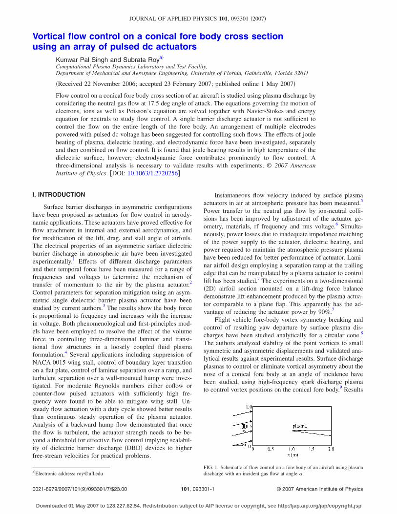
Vortical flow control on a conical fore body cross sectionusing an array of pulsed dc actuators
Kunwar Pal Singh and Subrata Roya�
Computational Plasma Dynamics Laboratory and Test Facility,Department of Mechanical and Aerospace Engineering, University of Florida, Gainesville, Florida 32611
�Received 22 November 2006; accepted 23 February 2007; published online 1 May 2007�
Flow control on a conical fore body cross section of an aircraft is studied using plasma discharge byconsidering the neutral gas flow at 17.5 deg angle of attack. The equations governing the motion ofelectrons, ions as well as Poisson’s equation are solved together with Navier-Stokes and energyequation for neutrals to study flow control. A single barrier discharge actuator is not sufficient tocontrol the flow on the entire length of the fore body. An arrangement of multiple electrodespowered with pulsed dc voltage has been suggested for controlling such flows. The effects of jouleheating of plasma, dielectric heating, and electrodynamic force have been investigated, separatelyand then combined on flow control. It is found that joule heating results in high temperature of thedielectric surface, however; electrodynamic force contributes prominently to flow control. Athree-dimensional analysis is necessary to validate results with experiments. © 2007 AmericanInstitute of Physics. �DOI: 10.1063/1.2720256�
I. INTRODUCTION
Surface barrier discharges in asymmetric configurationshave been proposed as actuators for flow control in aerody-namic applications. These actuators have proved effective forflow attachment in internal and external aerodynamics, andfor modification of the lift, drag, and stall angle of airfoils.The electrical properties of an asymmetric surface dielectricbarrier discharge in atmospheric air have been investigatedexperimentally.1 Effects of different discharge parametersand their temporal force have been measured for a range offrequencies and voltages to determine the mechanism oftransfer of momentum to the air by the plasma actuator.2
Control parameters for separation mitigation using an asym-metric single dielectric barrier plasma actuator have beenstudied by current authors.3 The results show the body forceis proportional to frequency and increases with the increasein voltage. Both phenomenological and first-principles mod-els have been employed to resolve the effect of the volumeforce in controlling three-dimensional laminar and transi-tional flow structures in a loosely coupled fluid plasmaformulation.4 Several applications including suppression ofNACA 0015 wing stall, control of boundary layer transitionon a flat plate, control of laminar separation over a ramp, andturbulent separation over a wall-mounted hump were inves-tigated. For moderate Reynolds numbers either coflow orcounter-flow pulsed actuators with sufficiently high fre-quency were found to be able to mitigate wing stall. Un-steady flow actuation with a duty cycle showed better resultsthan continuous steady operation of the plasma actuator.Analysis of a backward hump flow demonstrated that oncethe flow is turbulent, the actuator strength needs to be be-yond a threshold for effective flow control implying scalabil-ity of dielectric barrier discharge �DBD� devices to higherfree-stream velocities for practical problems.
Instantaneous flow velocity induced by surface plasmaactuators in air at atmospheric pressure has been measured.5
Power transfer to the neutral gas flow by ion-neutral colli-sions has been improved by adjustment of the actuator ge-ometry, materials, rf frequency and rms voltage.6 Simulta-neously, power losses due to inadequate impedance matchingof the power supply to the actuator, dielectric heating, andpower required to maintain the atmospheric pressure plasmahave been reduced for better performance of actuator. Lami-nar airfoil design employing a separation ramp at the trailingedge that can be manipulated by a plasma actuator to controllift has been studied.7 The experiments on a two-dimensional�2D� airfoil section mounted on a lift-drag force balancedemonstrate lift enhancement produced by the plasma actua-tor comparable to a plane flap. This apparently has the ad-vantage of reducing the actuator power by 90%.7
Flight vehicle fore-body vortex symmetry breaking andcontrol of resulting yaw departure by surface plasma dis-charges have been studied analytically for a circular cone.8
The authors analyzed stability of the point vortices to smallsymmetric and asymmetric displacements and validated ana-lytical results against experimental results. Surface dischargeplasmas to control or eliminate vortical asymmetry about thenose of a conical fore body at an angle of incidence havebeen studied, using high-frequency spark discharge plasmato control vortex positions on the conical fore body.9 Results
a�Electronic address: [email protected]. 1. Schematic of flow control on a fore body of an aircraft using plasmadischarge with an incident gas flow at angle �.
JOURNAL OF APPLIED PHYSICS 101, 093301 �2007�
0021-8979/2007/101�9�/093301/7/$23.00 © 2007 American Institute of Physics101, 093301-1
Downloaded 01 May 2007 to 128.227.82.54. Redistribution subject to AIP license or copyright, see http://jap.aip.org/jap/copyright.jsp
of wind tunnel experiments show that plasma discharges dis-tributed in the model nose region near flow separation linesmay be used for successful control or elimination of vortexasymmetry.
In this article, we study flow control on the fore body ofan aircraft using plasma discharge by considering the neutralgas flow at an angle of attack. The physics of a surfacebarrier discharge operated with a neutral gas has been inves-tigated by many researchers.10 A sinusoidal or pulsed excita-tion signal has been applied and the temporal and spatialprofiles of excited species and its interaction with neutralshave been determined.
Here, a single DBD actuator and an arrangement ofpulsed dc voltage plasma discharge have been investigated tocontrol the flow. The effects of joule heating of plasma, di-electric heating, and electrodynamic force have been inves-tigated separately and then combined on flow control. Geom-etry description is given in Sec. II, governing equations inSec. III, initial and boundary conditions are given in Sec. IV,results and discussion in Sec. V, and conclusion are drawn inSec. VI.
II. GEOMETRY DESCRIPTION
Schematic of flow control on the fore body of an aircraftusing plasma discharge with an incident gas flow angle � isshown in Fig. 1. The width of the domain is 2 m and theheight is 1 m. The gas is incident at an angle �=15° �17.5°with the centerline of the fore body� with 10 m/s velocity.The angle at the nose of the fore body is 5°. We have studied
two electrode configurations for this fore-body geometry, onewith dielectric barrier discharge plasma actuator and anotherwith seven pairs of electrodes powered with pulsed dc volt-age. The thickness of electrodes is assumed infinitesimallysmall for both cases. Following is the description of the con-figuration with dielectric barrier discharge plasma actuator.The dielectric is located between x=1.2 m and x=1.21 mwith dielectric thickness equal to 1.0 mm. The rf electrode isexposed and is located at x=1.203 m to x=1.204 m at y=0.301 m. Grounded electrode is x=1.206 m to x=1.207 mat y=0.3 m. The electrodes for pulsed dc configuration arelocated at y=0.3 m, and from x=1.05 to 1.172 m. Length ofeach electrode is 2 mm and the distance between electrodesis 8 mm. There are seven pairs of electrodes. Each pair ispowered by a pulsed dc potential specified below.
III. GOVERNING EQUATIONS
The drift-diffusion form of continuity and Poisson’sequations for the electrons and ions are solved together withthe following fluid momentum and continuity equations:
�n�
�t+ ��n�v�� = neS
with n�v� = − sgn�e�n��� � � − D� � n�
for �=e, i , �1a�
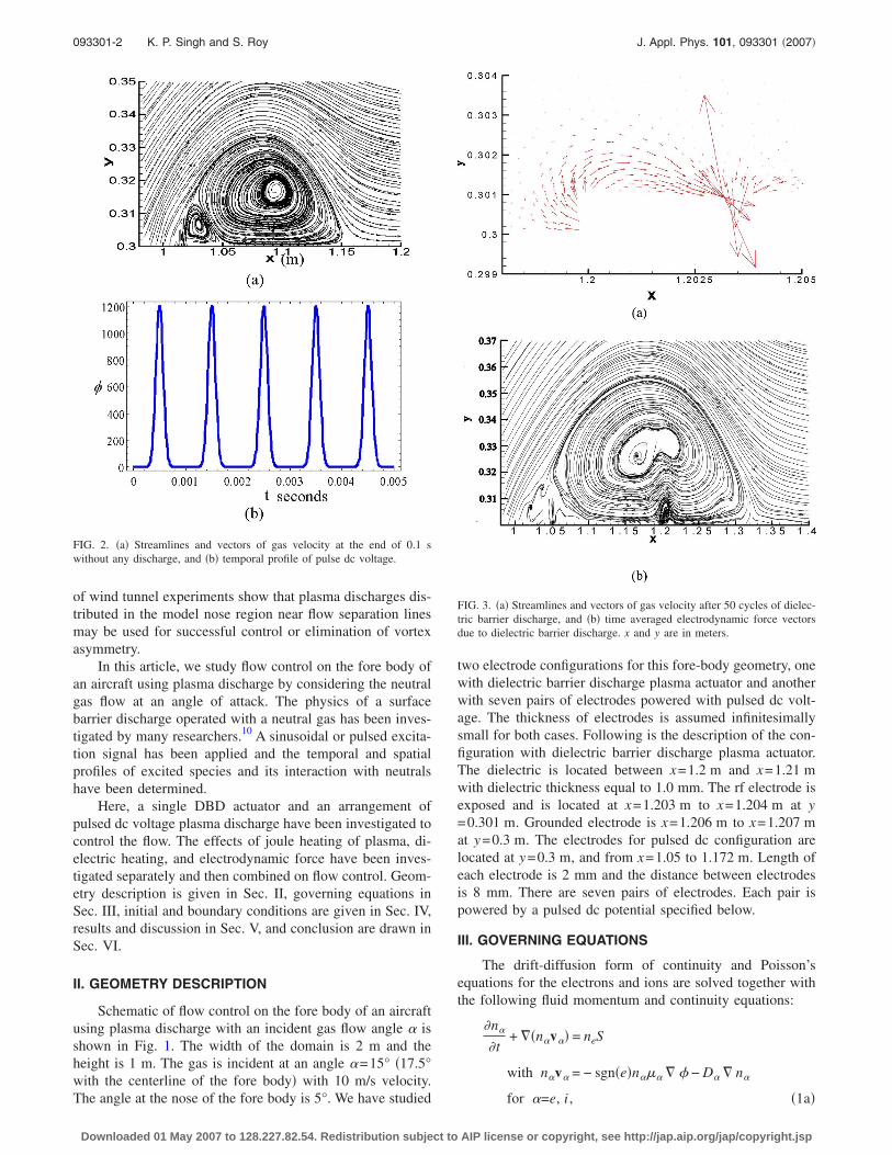
FIG. 2. �a� Streamlines and vectors of gas velocity at the end of 0.1 swithout any discharge, and �b� temporal profile of pulse dc voltage.
FIG. 3. �a� Streamlines and vectors of gas velocity after 50 cycles of dielec-tric barrier discharge, and �b� time averaged electrodynamic force vectorsdue to dielectric barrier discharge. x and y are in meters.
093301-2 K. P. Singh and S. Roy J. Appl. Phys. 101, 093301 �2007�
Downloaded 01 May 2007 to 128.227.82.54. Redistribution subject to AIP license or copyright, see http://jap.aip.org/jap/copyright.jsp
��2� = e�ne − ni� , �1b�
��u
�t− ��� � u� + ��u . ��u + �p = e�ne − ni� � � , �2a�
��
�t+ ���u� = 0, �2b�
�Cp�T
�t+ ��k � T + �CpTu� = J · E +
1
2
�
�t��0�rE�E , �3�
where ne, ni, �, ve, vi, and u are densities and velocities ofelectrons, ions, and the working gas, respectively. � is thegas viscosity, S is the Townsend ionization rate, pressurep=�RT /M, M �mole/gm� is the molar mass of helium, T isthe temperature �300 K�, and R is the universal gas constant�erg/�mole K��. J is total �electron and ion� current densityand E is the electric field. The bulk density of the helium istaken to be 1.79�10−4 g /cm3, and the viscosity is assumedto be 1.9 poise. First and second terms of Eq. �3� on theright-hand side represent joule and dielectric heating, respec-tively.
IV. INITIAL CONDITIONS AND BOUNDARYCONDITIONS
Initial electron and ion densities are 109 m3. Initial volt-age is zero, initial u and v velocities are 9.65 and 2.58 m/s,respectively. Initial air density is 1.2 Kg/m3 and initial gastemperature is 300 K.
Boundary conditions for Poisson’s equation are set asfollows: potential �=�0sin�50 000�t� for the DBD case,with �0=500 V and �=�0sin20�1000�t�. For pulsed dc volt-age case �0=1200 V. The potential is applied to the firstelectrode of the pair for pulsed dc case. Other electrodes ofeach pair are grounded. Electric insulation condition �normalcomponent of electric field equal to zero� is assumed at outerboundaries of the domain and at the surface of the fore body.
The following are boundary conditions related to elec-trons and ions continuity equations: The currents flow nor-mal only to the electrodes, since these are equipotential sur-faces. Homogeneous Neumann conditions are applied to theouter edges of the domain and electric insulation is assumedat the surface of the fore body and dielectric. The currentsflow normal as well as parallel to the dielectric surface.
The boundary conditions for Navier-Stokes equationsare as follows: The no-slip condition �u=0 and v=0� is as-sumed for the gas neutrals at the surface of fore-body, dielec-tric surface �for dielectric barrier discharge case� and at elec-trodes. The velocity at the left boundary of the upper domainis set equal to the initial condition �u=9.65 m/s andv=2.58 m/s�. Neutral boundary conditions are applied to theouter edges of the domain.
The self-consistent formulation is solved using aGalerkin variational formulation based finite-element methodto obtain electron and ion density, electric potential, neutralvelocity, density, and gas temperature.
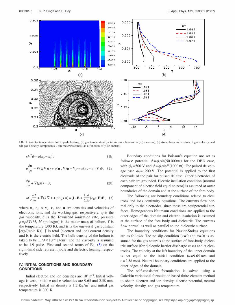
FIG. 4. �a� Gas temperature due to joule heating, �b� gas temperature �in kelvin� as a function of y �in meters�, �c� streamlines and vectors of gas velocity, and�d� gas velocity components u �in meters/seconds� as a function of y �in meters�.
093301-3 K. P. Singh and S. Roy J. Appl. Phys. 101, 093301 �2007�
Downloaded 01 May 2007 to 128.227.82.54. Redistribution subject to AIP license or copyright, see http://jap.aip.org/jap/copyright.jsp
V. RESULTS AND DISCUSSION
We describe our fluid dynamic simulation results in thefollowing paragraphs. Figure 2�a� shows streamlines andvectors of gas velocity at the end of 0.1 s without any plasmadischarge, obtained by solving Navier-Stokes equations. Wecan see a recirculation bubble near the nose of the fore body.These kinds of separation bubbles are harmful to the perfor-mance of the aircraft. A rf voltage �for DBD� or a pulsed dcvoltage is switched on after 0.1 s to see the effect. Figure2�b� shows the profile of pulsed dc voltage as a function oftime. Figure 3 displays results for dielectric barrier dischargeafter 25 cycles of plasma discharge activity, and Figs. 4–7show results for pulsed dc plasma discharge after 10 cyclesof plasma discharge activity.
Figure 3 shows the effect of dielectric barrier dischargeplasma actuator on flow control on the fore body of an air-craft. We do not solve temperature Eq. �3� for the resultsshown in this figure. After 0.1 s rf voltage �=�0 sin�2�f�;with �0=500 V and f =25 kHz, is switched on to see theeffect. Figure 3�a� shows vectors of time averaged electrody-namic force e�ni−ne�E. It can be seen from the figure thatforce is directed in forward direction which may help inelimination of recirculation. Figure 3�b� shows streamlinesand vectors of gas velocity after 25 cycles of rf dischargeactivity. We can see that recirculation is affected by a dielec-
tric barrier discharge plasma actuator, however, flow is notattached to the surface all over the surface of the fore body.This is because a single dielectric barrier plasma actuator isnot sufficient to cover the entire length of recirculation andrecirculation is not eliminated fully. Multiple dielectric bar-rier discharge plasma actuators on the surface of the forebody may control vortex dynamics of the flow. We suggestmultiple pairs of electrodes powered with pulsed dc potentialas an alternative to multiple DBD plasma actuators in thispaper.
We have included joule heating effect in Navier-Stokesequations for the results of Fig. 4. We have added Eq. �3� tothe set of equations described under governing equations andhave only considered the joule heating term. The force termin the Navier-Stokes equation is set to zero as we want toknow effect of joule heating of plasma alone on the flowcontrol. Figure 4�a� shows distribution of temperature. Maxi-mum temperature is near the dielectric surface or electrodesbecause total current is highest here due to high-electricfield. The temperature rises up to nearly 1400 K, whichmeans there is a significant rise in temperature above normaltemperature of 300 K due to joule heating. Figure 4�b� showsgas temperature �in kelvin� as a function of y for differentvalues of x. Figure 4�c� shows streamlines and vectors of gasvelocity after ten cycles of plasma discharge activity by a
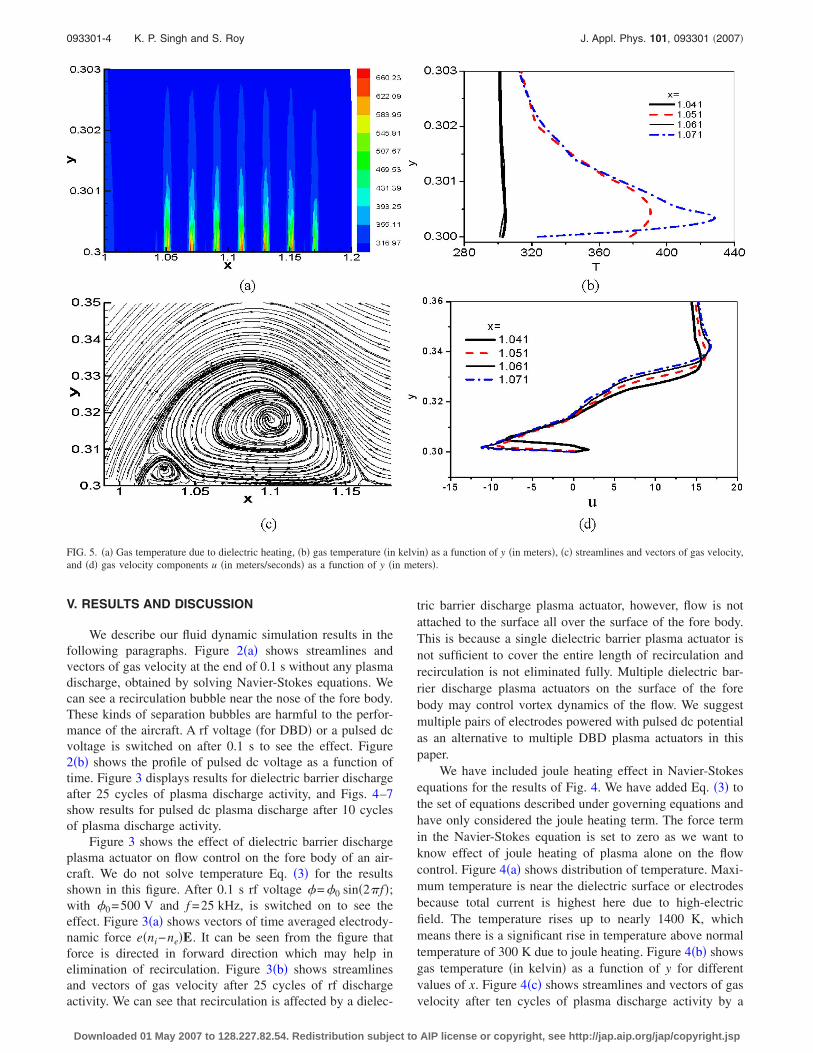
FIG. 5. �a� Gas temperature due to dielectric heating, �b� gas temperature �in kelvin� as a function of y �in meters�, �c� streamlines and vectors of gas velocity,and �d� gas velocity components u �in meters/seconds� as a function of y �in meters�.
093301-4 K. P. Singh and S. Roy J. Appl. Phys. 101, 093301 �2007�
Downloaded 01 May 2007 to 128.227.82.54. Redistribution subject to AIP license or copyright, see http://jap.aip.org/jap/copyright.jsp
pulsed dc voltage. If we compare Figs. 2�a� and 4�c� we cansee that there is negligible change in flow pattern after tencycles of plasma discharge activity. Recirculation is affectedvery little by joule heating of a pulsed dc voltage and flow isnot attached to the surface. Figure 4�d� shows gas velocitycomponents u �in meters/second� as a function of y�in meters� for different values of x as a result of joule heat-ing effect.
We have included dielectric heating effect in Navier-Stokes equations for the results of Fig. 5 by taking into ac-count dielectric heating only in Eq. �3�. The force term in theNavier-Stokes equation is set to zero, so as to investigate thedielectric heating effect alone on flow control. Displacementcurrent through the dielectric results in high temperatures onthe dielectric surface. Figure 5�a� shows temperature distri-bution in the domain. The temperature rises up to nearly 675K, which is higher than the normal temperature of 300 K.The rise in temperature of the gas is confined very close todielectric surface only. Figure 5�b� shows gas temperature �inkelvin� as a function of y. Figure 5�c� shows streamlines andvectors of gas velocity after ten cycles of plasma dischargeactivity by a pulsed dc voltage. If we compare Figs. 2�a� and5�c�, we can see that there is only a small change in the flowpattern due to dielectric heating after ten cycles of plasmadischarge activity. It means that the role played by dielectricheating due to pulsed dc voltage in not a major considerationin flow control. Figure 5�d� shows gas velocity components u�in meters/second� as a function of y �in meters� as a result ofdielectric heating.
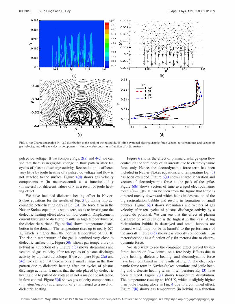
Figure 6 shows the effect of plasma discharge upon flowcontrol on the fore body of an aircraft due to electrodynamicforce only. Hence, the electrodynamic force term has beenincluded in Navier-Stokes equations and temperature Eq. �3�has been excluded. Figure 6�a� shows charge separation andvectors of electrodynamic force at the peak of the spike.Figure 6�b� shows vectors of time averaged electrodynamicforce e�ni−ne�E. It can be seen from the figure that force isdirected mostly downward which helps in destruction of thebig recirculation bubble and results in formation of smallbubbles. Figure 6�c� shows streamlines and vectors of gasvelocity after ten cycles of plasma discharge activity by apulsed dc potential. We can see that the effect of plasmadischarge on recirculation is the highest in this case. A bigrecirculation bubble is destroyed and small bubbles areformed which may not be as harmful to the performance ofthe aircraft. Figure 6�d� shows gas velocity components u �inmeters/second� as a function of y �in meters� due to electro-dynamic force.
We also want to see the combined effect played by dif-ferent factors on flow control on a fore body. Effects due tojoule heating, dielectric heating, and electrodynamic forcehave been combined in the results of Fig. 7. The electrody-namic force term in Navier-Stokes equations and joule heat-ing and dielectric heating terms in temperature Eq. �3� havebeen retained. Figure 7�a� shows temperature distribution.The temperature rises up to 1605 K, which is slightly higherthan joule heating alone in Fig. 4 due to a combined effect.Figure 7�b� shows gas temperature �in kelvin� as a function
FIG. 6. �a� Charge separation �ni−ne� distribution at the peak of the pulsed dc, �b� time averaged electrodynamic force vectors, �c� streamlines and vectors ofgas velocity, and �d� gas velocity components u �in meters/seconds� as a function of y �in meters�.
093301-5 K. P. Singh and S. Roy J. Appl. Phys. 101, 093301 �2007�
Downloaded 01 May 2007 to 128.227.82.54. Redistribution subject to AIP license or copyright, see http://jap.aip.org/jap/copyright.jsp
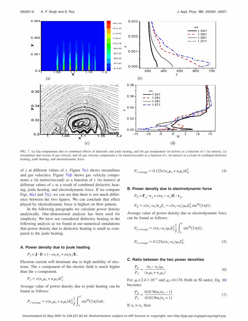
of y at different values of x. Figure 7�c� shows streamlinesand gas velocities. Figure 7�d� shows gas velocity compo-nents u �in meters/second� as a function of y �in meters� atdifferent values of x as a result of combined dielectric heat-ing, joule heating, and electrodynamic force. If we compareFigs. 6�c� and 7�c�, we can see that there is not much differ-ence between the two figures. We can conclude that effectplayed by electrodynamic force is highest on flow pattern.
In the following paragraphs we calculate power densityanalytically. One-dimensional analysis has been used forsimplicity. We have not considered dielectric heating in thefollowing analysis as we found in our numerical simulationsthat power density due to dielectric heating is small as com-pared to the joule heating.
A. Power density due to joule heating
PJ = J · E = �− eneve + enivi�E .
Electron current will dominate due to high mobility of elec-trons. The x component of the electric field is much higherthan the y-component.
PJ � e�ne�e + ni�i�Ex2.
Average value of power density due to joule heating can befound as follows:
PJ average � e�ne�e + ni�i�E02 1
T�
0
T
sin40�2�ft�dt ,
PJ average � 0.125e�ne�e + ni�i�E02. �4�
B. Power density due to electrodynamic force
PE = Fq · vq = e�ni − ne�E · vq,
PE � e�ni−ne�vqEx � e�ni−ne��iE02 sin40�2�ft� .
Average value of power density due to electrodynamic forcecan be found as follows:
PE average � e�ni−ne��iE02 1
T�
0
T
sin40�2�ft� ,
PE average � 0.125e�ni−ne��iE02. �5�
C. Ratio between the two power densities
PE
PJ�
�ni − ne��i
�ni�i + ne�e�. �6�
For �i=2.4�10−3 and �e=0.176 �both in SI units�, Eq. �6�becomes
PE
PJ�
0.0136�ni/ne − 1��0.0136ni/ne + 1�
. �7�
If ni�ne then
FIG. 7. �a� Gas temperature due to combined effects of dielectric and joule heating, and �b� gas temperature �in kelvin� as a function of y �in meters�, �c�streamlines and vectors of gas velocity, and �d� gas velocity components u �in meters/seconds� as a function of y �in meters� as a result of combined dielectricheating, joule heating, and electrodynamic force.
093301-6 K. P. Singh and S. Roy J. Appl. Phys. 101, 093301 �2007�
Downloaded 01 May 2007 to 128.227.82.54. Redistribution subject to AIP license or copyright, see http://jap.aip.org/jap/copyright.jsp
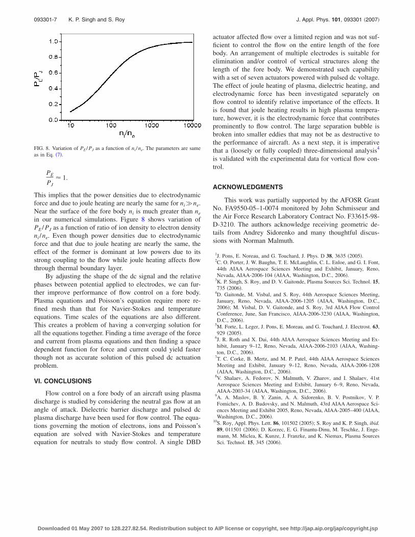
PE
PJ� 1.
This implies that the power densities due to electrodynamicforce and due to joule heating are nearly the same for ni�ne.Near the surface of the fore body ni is much greater than ne
in our numerical simulations. Figure 8 shows variation ofPE / PJ as a function of ratio of ion density to electron densityni /ne. Even though power densities due to electrodynamicforce and that due to joule heating are nearly the same, theeffect of the former is dominant at low powers due to itsstrong coupling to the flow while joule heating affects flowthrough thermal boundary layer.
By adjusting the shape of the dc signal and the relativephases between potential applied to electrodes, we can fur-ther improve performance of flow control on a fore body.Plasma equations and Poisson’s equation require more re-fined mesh than that for Navier-Stokes and temperatureequations. Time scales of the equations are also different.This creates a problem of having a converging solution forall the equations together. Finding a time average of the forceand current from plasma equations and then finding a spacedependent function for force and current could yield fasterthough not as accurate solution of this pulsed dc actuationproblem.
VI. CONCLUSIONS
Flow control on a fore body of an aircraft using plasmadischarge is studied by considering the neutral gas flow at anangle of attack. Dielectric barrier discharge and pulsed dcplasma discharge have been used for flow control. The equa-tions governing the motion of electrons, ions and Poisson’sequation are solved with Navier-Stokes and temperatureequation for neutrals to study flow control. A single DBD
actuator affected flow over a limited region and was not suf-ficient to control the flow on the entire length of the forebody. An arrangement of multiple electrodes is suitable forelimination and/or control of vertical structures along thelength of the fore body. We demonstrated such capabilitywith a set of seven actuators powered with pulsed dc voltage.The effect of joule heating of plasma, dielectric heating, andelectrodynamic force has been investigated separately onflow control to identify relative importance of the effects. Itis found that joule heating results in high plasma tempera-ture, however, it is the electrodynamic force that contributesprominently to flow control. The large separation bubble isbroken into smaller eddies that may not be as destructive tothe performance of aircraft. As a next step, it is imperativethat a �loosely or fully coupled� three-dimensional analysis4
is validated with the experimental data for vortical flow con-trol.
ACKNOWLEDGMENTS
This work was partially supported by the AFOSR GrantNo. FA9550-05–1-0074 monitored by John Schmisseur andthe Air Force Research Laboratory Contract No. F33615-98-D-3210. The authors acknowledge receiving geometric de-tails from Andrey Sidorenko and many thoughtful discus-sions with Norman Malmuth.
1J. Pons, E. Noreau, and G. Touchard, J. Phys. D 38, 3635 �2005�.2C. O. Porter, J. W. Baughn, T. E. McLaughlin, C. L. Enloe, and G. I. Font,44th AIAA Aerospace Sciences Meeting and Exhibit, January, Reno,Nevada, AIAA-2006-104 �AIAA, Washington, D.C., 2006�.
3K. P. Singh, S. Roy, and D. V. Gaitonde, Plasma Sources Sci. Technol. 15,735 �2006�.
4D. Gaitonde, M. Visbal, and S. Roy, 44th Aerospace Sciences Meeting,January, Reno, Nevada, AIAA-2006-1205 �AIAA, Washington, D.C.,2006�; M. Visbal, D. V. Gaitonde, and S. Roy, 3rd AIAA Flow ControlConference, June, San Francisco, AIAA-2006-3230 �AIAA, Washington,D.C., 2006�.
5M. Forte, L. Leger, J. Pons, E. Moreau, and G. Touchard, J. Electrost. 63,929 �2005�.
6J. R. Roth and X. Dai, 44th AIAA Aerospace Sciences Meeting and Ex-hibit, January 9–12, Reno, Nevada, AIAA-2006-2103 �AIAA, Washing-ton, D.C., 2006�.
7T. C. Corke, B. Mertz, and M. P. Patel, 44th AIAA Aerospace SciencesMeeting and Exhibit, January 9–12, Reno, Nevada, AIAA-2006-1208�AIAA, Washington, D.C., 2006�.
8V. Shalaev, A. Fedorov, N. Malmuth, V. Zharov, and I. Shalaev, 41stAerospace Sciences Meeting and Exhibit, January 6–9, Reno, Nevada,AIAA-2003-34 �AIAA, Washington, D.C., 2006�.
9A. A. Maslov, B. Y. Zanin, A. A. Sidorenko, B. V. Postnikov, V. P.Fomichev, A. D. Budovsky, and N. Malmuth, 43rd AIAA Aerospace Sci-ences Meeting and Exhibit 2005, Reno, Nevada, AIAA-2005–400 �AIAA,Washington, D.C., 2006�.
10S. Roy, Appl. Phys. Lett. 86, 101502 �2005�; S. Roy and K. P. Singh, ibid.89, 011501 �2006�; D. Korzec, E. G. Finantu-Dinu, M. Teschke, J. Enge-mann, M. Miclea, K. Kunze, J. Franzke, and K. Niemax, Plasma SourcesSci. Technol. 15, 345 �2006�.
FIG. 8. Variation of PE / PJ as a function of ni /ne. The parameters are sameas in Eq. �7�.
093301-7 K. P. Singh and S. Roy J. Appl. Phys. 101, 093301 �2007�
Downloaded 01 May 2007 to 128.227.82.54. Redistribution subject to AIP license or copyright, see http://jap.aip.org/jap/copyright.jsp
Copyright © 2022 FDOKUMEN