Comparing Feature Point Tracking with Dense Flow Tracking for Facial Expression Recognition
Visual Servoing/Tracking Using Central Catadioptric Images
11
Visual Servoing/Tracking Using Central Catadioptric Images Jo˜ ao P. Barreto 1 , Fr´ ed´ erick Martin 2 , and Radu Horaud 2 1 Institute of Systems and Robotics DEEC - University of Coimbra 3030 Coimbra, Portugal ⋆⋆⋆ 2 INRIARhˆone-Alpes 655 Avenue de l’Europe 38330 Montbonnot St. Martin, France Abstract. Visual control of robot motion may benefit from enhanced camera field of view. With traditional cameras the available fields of view are only enough to view a region around the observed object (for eye-in-hand systems) or around the end-effector (for independent-eye systems). Central catadioptric systems have larger fields of view thus allowing the entire robot AND the surrounding objects to be imaged with a unique camera. Therefore, the whole robot’s articulated mechanism can be observed and its joints can be tracked and controlled simultenously. This results in a new visual robot control concept where tracking and control are embed- ded together. Key to the understanding of both servoing and tracking is the central catadioptric Jacobian matrix linking the robot’s joint velocities to image observa- tions. In spite of a more complex projection matrix associated with catadioptric sensors, we study the catadioptric Jacobian matrix and we show that it does not introduce any additional singularity with respect to the traditional pinhole camera model. Experiments showing a rigid body being tracked with a catadioptric camera are described. 1 Introduction Machine vision provides noncontact measurements of the world, extending the robot ability to operate in circumstances and environments which can not be accurately controlled. The approach of controlling motion using visual information is referred in the literature as visual servoing. Visual control of motion has been the object of intensive research in the last years. Several applications have been described for pose estimation [3], robot navigation [13] and positioning tasks of robotic manipulators [1,2]. Visual servoing applications can benefit from sensors providing large fields of view. The advantages of omnidirectional imaging in egomotion recovery from video were first discussed in [5]. Ambiguities and confusion between translation and rotation may arise whenever the translation direction lies outside the camera field of view. Panoramic sensors overcome this problem ⋆⋆⋆ The work was partially supported by Foundation Calouste de Gulbenkian
-
Upload
independent -
Category
Documents
-
view
1 -
download
0
Transcript of Visual Servoing/Tracking Using Central Catadioptric Images
Visual Servoing/Tracking Using Central
Catadioptric Images
Joao P. Barreto1, Frederick Martin2, and Radu Horaud2
1 Institute of Systems and RoboticsDEEC - University of Coimbra3030 Coimbra, Portugal ⋆ ⋆ ⋆
2 INRIA Rhone-Alpes655 Avenue de l’Europe38330 Montbonnot St. Martin, France
Abstract. Visual control of robot motion may benefit from enhanced camera fieldof view. With traditional cameras the available fields of view are only enough toview a region around the observed object (for eye-in-hand systems) or around theend-effector (for independent-eye systems). Central catadioptric systems have largerfields of view thus allowing the entire robot AND the surrounding objects to beimaged with a unique camera. Therefore, the whole robot’s articulated mechanismcan be observed and its joints can be tracked and controlled simultenously. Thisresults in a new visual robot control concept where tracking and control are embed-ded together. Key to the understanding of both servoing and tracking is the centralcatadioptric Jacobian matrix linking the robot’s joint velocities to image observa-tions. In spite of a more complex projection matrix associated with catadioptricsensors, we study the catadioptric Jacobian matrix and we show that it does notintroduce any additional singularity with respect to the traditional pinhole cameramodel. Experiments showing a rigid body being tracked with a catadioptric cameraare described.
1 Introduction
Machine vision provides noncontact measurements of the world, extendingthe robot ability to operate in circumstances and environments which cannot be accurately controlled. The approach of controlling motion using visualinformation is referred in the literature as visual servoing. Visual control ofmotion has been the object of intensive research in the last years. Severalapplications have been described for pose estimation [3], robot navigation[13] and positioning tasks of robotic manipulators [1,2].
Visual servoing applications can benefit from sensors providing large fieldsof view. The advantages of omnidirectional imaging in egomotion recoveryfrom video were first discussed in [5]. Ambiguities and confusion betweentranslation and rotation may arise whenever the translation direction liesoutside the camera field of view. Panoramic sensors overcome this problem
⋆ ⋆ ⋆ The work was partially supported by Foundation Calouste de Gulbenkian
2 Barreto, Martin, and Horaud
making the uncertainty of egomotion estimation independent of the direc-tion of motion. More recently Aloimonos et al. proposed a spherical eye builtwith six cameras specifically designed for egomotion recovery [10]. Enhancedfields of view can also be advantageous for positioning tasks of robotic ma-nipulators. The approaches to this problem are traditionally classified in twogroups: position based and image based visual servoing [4]. In the formerthe control input is defined in the 3D task space. The pose of the target isestimated from image features based on the knowledge of a geometric modelof the object and the camera calibration [1]. With only one camera there areambiguities and singularities in pose estimation and the target can get outof the field of view during the tracking. In [3] a multiple camera approach isused to cope with these difficulties. Panoramic imaging can also overcome therefered problems avoiding multiple view geometry and calibration of severalcameras.
One effective way to enhance the field of view of a camera is to use mirrors.The general approach of combining mirrors with conventional imaging sys-tems is referred to as catadioptric image formation. In [6], Baker and Nayarderive the entire class of catadioptric systems with an unique viewpoint. Cen-tral catadioptric systems can be highly advantageous for many applicationsbecause they combine two important features: a single projection center anda wide field of view. Applications of these sensors in visual servoing, mainlyfor robot navigation purposes, appear in the literature [10,13]. However aglobal theory for visual control of motion using central catadioptric imageshas never been proposed.
This work introduces the Jacobian matrix J for a generic central cata-dioptric system. Matrix J is derived from the central catadioptric mappingfunction presented in [8]. According to this unifying theory, central cata-dioptric imaging can be modeled by a generic function fi, with the type ofsensor and shape of the mirror described by a parameter ξ. For the particularcase of a conventional perspective camera the parameter ξ is null. Thus, byassuming ξ = 0, the general Jacobian matrix Jg becomes the well knowninteraction matrix Jp introduced the first time in [2]. Moreover it is shownthat the derived Jacobian matrix can be decomposed in the product of twomatrices Jc and Jp (Jg = Jc.Jp). Jc is a 2×2 matrix that is always invertiblewhich proves that the general catadioptric Jacobian Jg has exactly the samesingularities as the standard perspective Jacobian Jp [11,12].
Experiments on iterative pose estimation from points in the catadioptricimage are performed. The singularities of Jg and the stability and conver-gence of image based visual servoing from catadioptric images are discussed.Point-to-contour tracking [3] on omnidireccional images is used to estimatethe rigid displacement of objects. The application of the derived frameworkto control the position of a robotic arm is also discussed.

Visual Tracking Using Catadioptric Images 3
2 Modelling Central Catadioptric Image Formation
Z cam
X cam��
Ycam
����������������������������
����������������
����������������
����������������
����������������
������������������������������������������
����������������
��������������������������
Ocam
Xi
Yix i
X =(X,Y,Z)t
��
��
Ob
��
��
����
��
����������������������������������������������������
������������������
��������������������������������������
����������������������������������
��������������������������������������������������������
������������������������������������������������������������
��������������������������������������������������������������
��������������������
����������������������
��������
����
4p
Z
YO
d
catadioptric image
Y
Z
X
X
b
b
b
X=R.X +Tb
Fig. 1. Central catadioptric projection of a rigid body
A catadioptric realization of omnidirectional vision combines reflectivesurfaces and lenses. In [5], Baker et al. derive the entire class of catadiop-tric systems verifying the fixed viewpoint constraint. The fixed viewpointconstraint is a requirement ensuring that the visual sensor only measuresthe intensity of light passing through a single point in 3D space. An uniqueprojection center is a necessary condition for the generation of geometricallycorrect perspective images [5], and for the existance of epipolar geometryinherent to the moving sensor and independent of the scene structure [7]. Acentral catadioptric system can be built by combining a parabolic mirror withan orthographic camera or an hyperbolic, elliptical or planar mirror with aperspective camera.
Mirror Surface ξ ψ
Parabolic√X2 + Y 2 + Z2 = 2p− Z 1 1 + 2p
Hyperbolic(Z−
d
2)2
( 1
2(√
d2+4p2−2p))2
− X2+Y 2
p(√
d2+4p2−2p)
= 1 d√d2+4p2
d+2p√d2+4p2
Elliptical(Z−
d
2)2
( 1
2(√
d2+4p2+2p))2+ X2+Y 2
p(√
d2+4p2+2p)= 1 d√
d2+4p2
d−2p√d2+4p2
Planar Z = d
20 1
Table 1. Column 1: Reflective surfaces for the different cases of central panoramicimaging. Column 2 and 3: Parameters ξ and ψ of the general central catadioptricmodel
4 Barreto, Martin, and Horaud
Fig.1 is a scheme of the catadioptric system combining an hyperbolic re-flective surface with a perspective camera. Consider the coordinate systemsℜ and ℜcam associated respectively with the mirror and the perspective cam-era. The hyperbola axis is coincident with the Z-axis of ℜ, and its foci arecoincident with O and Ocam (the origins of ℜ and ℜcam). The latus rectumof the hyperbolic surface is 4p and the distance between the foci is d. Lightrays incident with O (the inner focal point) are reflected into rays incidentwith Ocam (the outer focal point). If the projection center of the perspec-tive camera is coincident with Ocam the the captured light rays go originallythrough the inner focus of the hyperbolic surface. The effective viewpointof the grabbed image is O and is unique. Elliptical catadioptric images areobtained combining an elliptical mirror with a perspective camera in a simi-lar way. In the parabolic situation a parabolic mirror is placed such that itsaxis is the Z-axis, and its unique finite real focus is coincident with O. Lightrays incident with O are reflected into rays parallel with the Z-axis whichare captured by an orthographic camera with image plane perpendicular tothe Z-axis. The effective viewpoint is in O and is unique. A catadioptric sys-tem made up of a perspective camera steering a planar mirror also verifiesthe fixed viewpoint constraint. The effective projection center is behind themirror in the perpendicular line passing through camera center. Its distanceto the camera center is twice the distance between the planar mirror and thecamera. Tab. 1 shows the equations of the different reflective surfaces.
OcYc
X c
OX
Y
Z c
YiX i
x c
xi =(x , y )i it
X =(X,Y,Z)t
−2ξ
��������
������
������
��������
����
���
���
�����������
�����������
������������������������
Z
image plane
proj. ray
Q
ξ
ψ proj. ray x
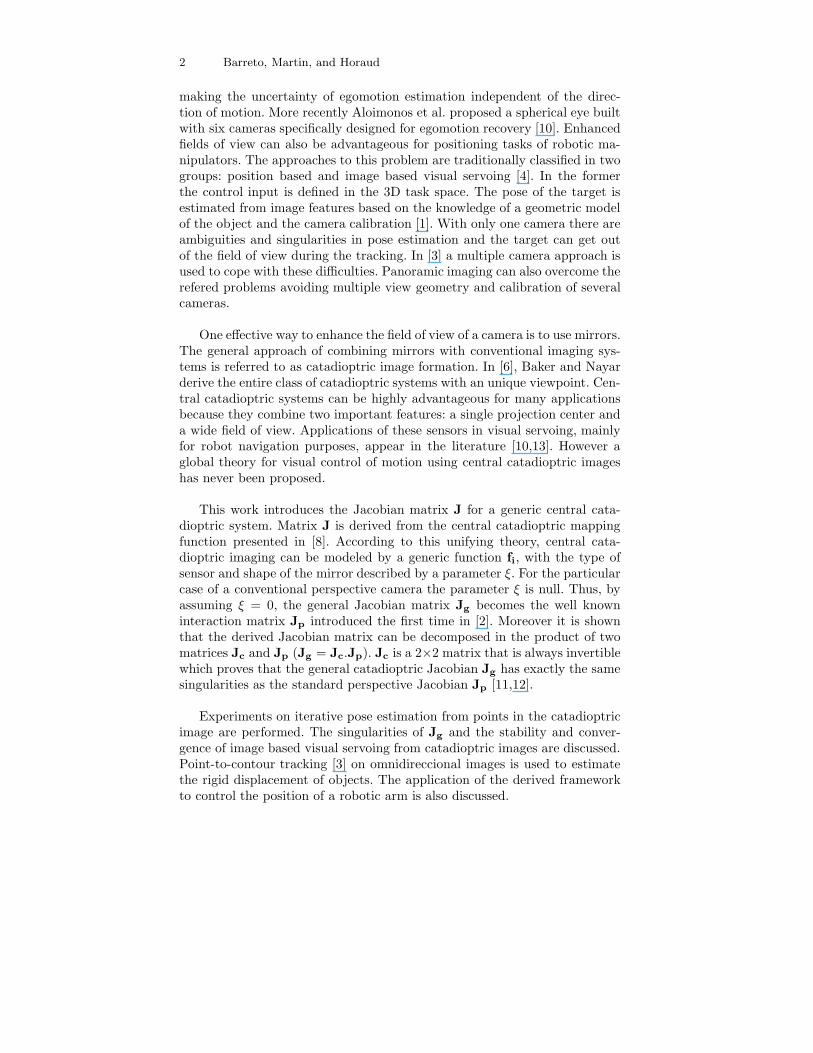
Fig. 2. Modelling central catadioptric image formation
In [8] Geyer and Daniilidis introduce an unifying theory for central cata-dioptric systems. Assume that a point with 3D coordinates X = (X,Y, Z)t isprojected in xi = (xi, yi)
t in the catadioptric image plane (Fig. 1). It can beshown that central panoramic projection is isomorphic to a projective map-
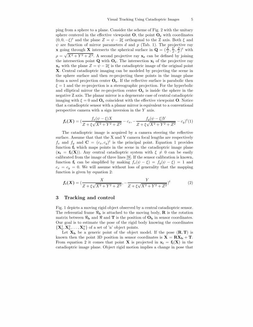
Visual Tracking Using Catadioptric Images 5
ping from a sphere to a plane. Consider the scheme of Fig. 2 with the unitarysphere centered in the effective viewpoint O, the point Oc with coordinates(0, 0,−ξ)t and the plane Z = ψ − 2ξ orthogonal to the Z axis. Both ξ andψ are function of mirror parameters d and p (Tab. 1). The projective rayx going through X intersects the spherical surface in Q = (X
ρ, Y
ρ, Z
ρ)t with
ρ =√X2 + Y 2 + Z2. A second projective ray xc can be defined by joining
the intersection point Q with Oc. The intersection xi of the projective rayxc with the plane Z = ψ − 2ξ is the catadioptric image of the original pointX. Central catadioptric imaging can be modeled by projecting the scene inthe sphere surface and then re-projecting these points in the image planefrom a novel projection center Oc. If the reflective surface is parabolic thenξ = 1 and the re-projection is a stereographic projection. For the hyperbolicand elliptical mirror the re-projection center Oc is inside the sphere in thenegative Z axis. The planar mirror is a degenerate case of central catadioptricimaging with ξ = 0 and Oc coincident with the effective viewpoint O. Noticethat a catadioptric sensor with a planar mirror is equivalent to a conventionalperspective camera with a sign inversion in the Y axis.
fi(X) = (fx(ψ − ξ)X
Z + ξ√X2 + Y 2 + Z2
− cx,−fy(ψ − ξ)Y
Z + ξ√X2 + Y 2 + Z2
− cy)t(1)
The catadioptric image is acquired by a camera steering the reflectivesurface. Assume that that the X and Y camera focal lengths are respectivelyfx and fy and C = (cx, cy)t is the principal point. Equation 1 providesfunction fi which maps points in the scene in the catadioptric image plane(xi = fi(X)). Any central catadioptric system with ξ 6= 0 can be easilycalibrated from the image of three lines [9]. If the sensor calibration is known,function fi can be simplified by making fx(ψ − ξ) = fy(ψ − ξ) = 1 andcx = cy = 0. We will assume without loss of generality that the mappingfunction is given by equation 2:
fi(X) = (X
Z + ξ√X2 + Y 2 + Z2
,− Y
Z + ξ√X2 + Y 2 + Z2
)t (2)
3 Tracking and control
Fig. 1 depicts a moving rigid object observed by a central catadioptric sensor.The referential frame ℜb is attached to the moving body, R is the rotationmatrix between ℜb and ℜ and T is the position of Ob in sensor coordinates.Our goal is to estimate the pose of the rigid body knowing the coordinates{X1
b ,X2b , . . . ,X
nb } of a set of ’n’ object points.
Let Xb be a generic point of the object model. If the pose (R,T) isknown then the point 3D position in sensor coordinates is X = RXb + T.From equation 2 it comes that point X is projected in xi = fi(X) in thecatadioptric image plane. Object rigid motion implies a change in pose that

6 Barreto, Martin, and Horaud
zz−1 I
I
−L
JU(k) Y(k)+ +
++
δ (k)
E(k+1) E(k)
Fig. 3. Iterative pose estimation is a regulation control problem. I is the 2n × 2nidentity matrix. The dashed line corresponds to the feedback loop.
can be described by a kinematic screw δ = (ω,v)t. Consider the 3×6 matrixJm = [X|I] where X is the skew-symetric matrix of X and I is the 3 × 3identity matrix. The 3D velocity of point X due to object rigid motion isX = Jmδ. Moreover if Ji is the Jacobian matrix of function fi (equation 2)and Jg = JiJm then the corresponding velocity in the catadioptric imageplane is xi = Jgδ.
E =
x1i − x1
i
x2i − x2
i...
xni − xn
i
≈
J1g
J2g
...Jn
g
δ = Jδ (3)
Let s = {x1i , x
2i , . . . , x
ni } be the set of model points projected in the image
accordingly to a certain pose estimation (R, T), and s = {x1i ,x
2i , . . . ,x
ni } the
real positions of those points. Vector E is defined as E = s − s and dependson the pose estimation error described by the kinematic screw δ. From theabove discussion it comes that (xj
i−xji) ≈ Jj
gδ with j = 1, 2, . . . , n and Jjg the
Jacobian matrix Jg evaluated on the jth model point. Equation 3 establishes
the relationship between the measured image error E and the error δ onthe pose estimation of the rigid body. J is a 2n × 6 matrix comprised bythe Jacobian matrix Jg evaluated in the ’n’ points of the object model. Theobjective is to update the pose estimation such that the image of the modelbecomes coincident with the object image and the measured error vector Econverges to zero.
{E(k + 1) = IE(k) + Jδ(k) + JU(k)Y (k) = E(k)
(4)
The problem stated in the previous paragraph can be formulated as a reg-ulation control problem. Consider the system whose block diagram is depictedin Fig. 3. The state vector is the error E(k) measured in the catadioptric im-age, the system input matrix is J (equation 3), and the system output isY(k) which must be zero. Accordingly to the system state-space equation 4

Visual Tracking Using Catadioptric Images 7
the pose change δ acts as a perturbation disturbing the output Y(k). Thepurpose is to find a state feedback controller L such that if U(k) = −LE(k)then the disturbance is rejected and the system state converges to zero.
L = (JtJ)−1Jt (5)
{E(k + 1) = (I − J(JtJ)−1Jt)E(k) + Jδ(k)Y (k) = E(k)
(6)
The least squares solution of equation 3 is δ(k) = (JtJ)−1JtE(k). δ(k)is an estimate of the pose error associated with the measured image errorE(k). System regulation can be achieved by making U(k) = δ(k) (equation5). Equation 6 provides the state space model of the final closed loop system.System stability and transient response depend on the eigenvalues of thematrix (I − J(JtJ)−1Jt). However it is important to remind that the statetransition matrix is a function of rigid body position which changes alongtime. Moreover the controller of equation 5 is only realizable when (JtJ) isnon singular. Whenever matrix (JtJ) is not invertible we are in presence ofa singularity.
4 The Jacobian Matrix for General CentralCatadioptric Projection
To design the controller of equation 5 we need to obtain matrix J dependingon the Jacobian matrix Jg which is evaluated on the ’n’ points of the objectmodel (equation 3).
Ji =1
ρ(Z + ξρ)2
[ρZ + ξ(Y 2 + Z2) −ξXY −X(ρ+ ξZ)
ξXY −(ρZ + ξ(X2 + Z2)) Y (ρ+ ξZ)
]
(7)
Consider the central catadioptric mapping function fi which maps 3Dpoint coordinates X in image coordinates xi. The corresponding Jacobianmatrix Ji is derived by diferentiating the function of equation 2. The achievedresult is presented on equation 7 where ρ =
√X2 + Y 2 + Z2.
Jg =
[
xiyi(1+x2
i)Υ−y2
iξ
Υ+ξyi
(1+y2
i)Υ−x2
iξ
Υ+ξxiyi −xi
1+x2
i(1−ξ(Υ+ξ))+y2
i
ρ(Υ+ξ)
−xiyiξρ
xiyiξρ
−xiΥρ
1+x2
i+y2
i(1−ξ(Υ+ξ))
ρ(Υ+ξ) − yiΥρ
](8)
Assume Ji provided by equation 7 and Jm = [X|I] with X the skew sy-metric matrix associated with point coordinates X. It was already shown thatthe Jacobian matrix Jg can be computed as Jg = JiJm. Equation 8 presents

8 Barreto, Martin, and Horaud
the general central catadioptric Jacobian matrix as a function of image posi-tion xi, point depth ρ and sensor ξ parameter ( Υ =
√
1 + (x2i + y2
i )(1 − ξ2)).Notice that if ξ = 0 then matrix Jg becomes the well known Jacobian matrixJp introduced in [2] for conventional perspective cameras.
Ji =
[Z(ρZ+ξ(Y 2+Z2))
ρ(Z+ξρ)2ξXY Z
ρ(Z+ξρ)2
ξXY Zρ(Z+ξρ)2
Z(ρZ+ξ(X2+Z2))ρ(Z+ξρ)2
]
︸ ︷︷ ︸
Jc
[1Z
0 − XZ2
0 − 1Z
YZ2
]
(9)
The Jacobian Ji of the mapping function fi can be decomposed in thematrix product of equation 9. Jc is the 2 × 2 matrix depending on pointcoordinates X and on the mirror parameter ξ. If ξ = 0 then Jc is the identitymatrix. The second matrix has dimension 2×3 and it is the Jacobian matrixof the perspective mapping function fi = (X/Z,−Y/Z)t obtained making ξequal to zero in equation 2. Thus the general catadioptric matrix Jg can bewritten as Jg = JcJp with Jp the 2× 6 Jacobian for the perspective camerasituation. Moreover for Z > 0 the square matrix Jc is positive definite witheigenvalues {Z/(Z + ρξ); (Z2(ρ+ ξZ))/(ρ(Z + ξρ)2)}.
J =
J1c 0 . . . 00 J2
c . . . 0...
.... . .
...0 0 . . . Jn
c
︸ ︷︷ ︸
C
J1p
J2p
...Jn
p
︸ ︷︷ ︸
P
(10)
The controller of equation 5 is realizable if and only if J is a full rankmatrix. J has dimension 2n× 6 where ’n’ is the number of considered modelpoints. Clearly the full rank constraint can not be verified with less than threepoints. Equation 10 is derived from equation 3 knowing that Jj
g = JjcJ
jp.
Matrix J is the product of a 2n× 2n square matrix C with a matrix P withdimension 2n× 6. It was shown that Jj
c is positive definite for j = 1, 2, . . . , nand matrix C is always full rank. This poofs that J is rank deficient onlywhen P is also rank deficient. The general central catadioptric situation doesnot present more singularities than the perspective case. These singularitieswere studied in [12,3].
5 Tracking experiments and Conclusions
Based on the tracking method described above we implemented an objecttracker. Since with catadioptric cameras straight lines map onto the imageplane as quadrics, we devised a contour-to-point tracker along the lines de-scribed in [3]. The figures below show a rectangular object moving towardsthe camera and in a direction perpendicular to the camera. The advantage of

Visual Tracking Using Catadioptric Images 9
Fig. 4. A tracking sequence. The object translates along axis of camera
this method is that only points along contours are to be found in the imagethus avoiding the tedious and unreliable process of fitting a quadric to a setof points.
The model based tracking of a rigid object can be exploited in manyways for visual servoing applications. The proposed approach is being usedin robot navigation and cooperation [13]. The experimental setup consists intwo mobile plataforms both equipped with central catadioptric cameras. Avisual landmark, similar to the one depicted in the figures, is positioned inthe room ceil. One robot is the leader with independent motion and the otheris the slave. The objective is to control slave motion such that the relativeposition between the two plataforms is kept constant. To achieve this goalboth robots use the omnidirectional vision to estimate their pose from themodel based tracking of the landamark. A method to control the positionof a robotic arm using a static catadioptric system is also being develoed.Typically, in visual servoing using a conventional perspective camera, theavailable field of view is only enough to image the region around the end-effector. The pose of the end-effector is estimated by visual feedback, andmotion control is achieved using the manipulator jacobian known “‘a priori”.
10 Barreto, Martin, and Horaud
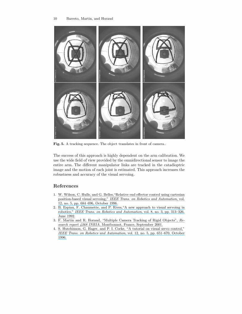
Fig. 5. A tracking sequence. The object translates in front of camera..
The success of this approach is highly dependent on the arm calibration. Weuse the wide field of view provided by the omnidirectional sensor to image theentire arm. The different manipulator links are tracked in the catadioptricimage and the motion of each joint is estimated. This approach increases therobustness and accuracy of the visual servoing.
References
1. W. Wilson, C. Hulls, and G. Belles,“Relative end effector control using cartesianposition-based visual servoing,” IEEE Trans. on Robotics and Automation, vol.12, no. 5, pp. 684–696, October 1996.
2. B. Espiau, F. Chaumette, and P. Rives,“A new approach to visual servoing inrobotics,” IEEE Trans. on Robotics and Automation, vol. 8, no. 3, pp. 313–326,June 1992.
3. F. Martin and R. Horaud, “Multiple Camera Tracking of Rigid Objects”, Re-
search report 4268 INRIA, Montbonnot, France, September 2001.4. S. Hutchinson, G. Hager, and P. I. Corke, “A tutorial on visual servo control,”
IEEE Trans. on Robotics and Automation, vol. 12, no. 5, pp. 651–670, October1996.

Visual Tracking Using Catadioptric Images 11
5. J. Gluckman and S. Nayar, “ Egomotion and Omnidirectional Cameras,”ICCV98 - Proc. IEEE International Conference on Computer Vision, pp. 999-1005, Bombay 1998.
6. S. Baker and S. Nayar, “A Theory of Catadioptric Image Formation,” ICCV98
- Proc. IEEE International Conference on Computer Vision, pp. 35-42, Bombay1998.
7. T. Svoboda, T. Pajdla and V. Hlavac, “Motion Estimation Using CentralPanoramic Cameras,” Proc. IEEE Conference on Intelligent Vehicles, Stugart
Germany 1998.
8. C. Geyer and K. Daniilidis, “A Unifying Theory for Central Panoramic Systemsand Pratical Implications,” ECCV2000-Proc. European Conference on Computer
Vision, pp. 445-461, Dublin 2000.9. Joao P. Barreto and H. Araujo,“Geometric Properties of Central catadioptric
Line Images,” in Proc. of the European Conference on Computer Vision, Copen-hag, Denmark, May 2002.
10. P. Baker, C. Fermuller, Y. Aloimonos and R. Pless,“A Spherical Eye FromMultiple Cameras (Makes Better Models of the World),” in Proc. of the IEEE
Int. Conf. on Computer Vision and Pattern Recognition, Kauai, Haway, USA,December 2001.
11. Francois Chaumette, “Potential Problems of Stability and Convergence in Im-age Based and Position Based Visual Servoing”, The Confluence of Vision and
Control, Lecture Notes in Control and Information Systems, Vol. 237, pp 66-78,Springer-Verlag, 1998.
12. H. Michel and P. Rives, “Singularities in the determination of the situation ofa robot effector from the perspective view of 3 points”, Research report 1850
INRIA, Sophia-Antipolis, France, February 1993.13. A. Paulino and H. Araujo, “Multiple Robots in Geometric Formation: Con-
trol Structure and Sensing”, in Int. Symposyum on Intelligent Robotic Systems,Reading, UK, 2000.