
Focused Site Investigation Report/Remediation Objectives ...
Upload
khangminh22Category
view
1download
0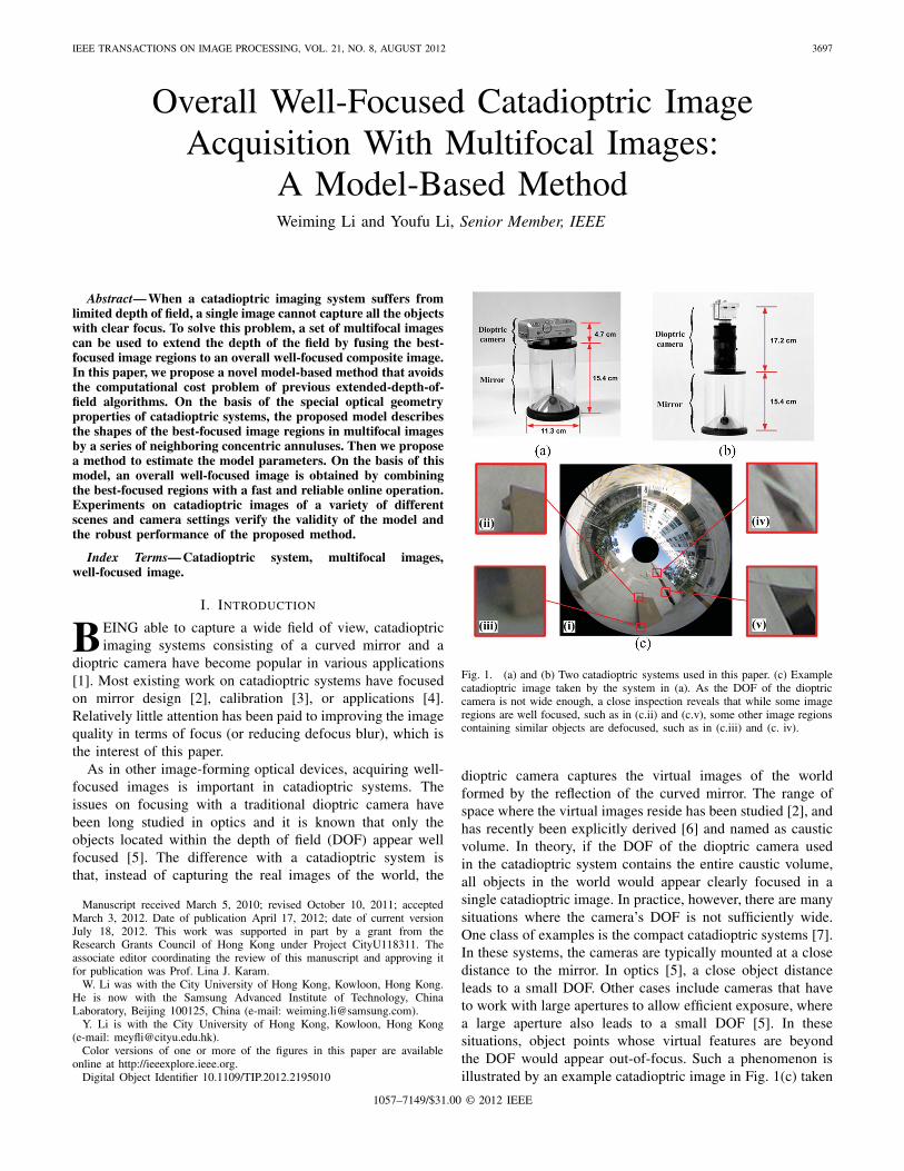
IEEE TRANSACTIONS ON IMAGE PROCESSING, VOL. 21, NO. 8, AUGUST 2012 3697
Overall Well-Focused Catadioptric ImageAcquisition With Multifocal Images:
A Model-Based MethodWeiming Li and Youfu Li, Senior Member, IEEE
Abstract— When a catadioptric imaging system suffers fromlimited depth of field, a single image cannot capture all the objectswith clear focus. To solve this problem, a set of multifocal imagescan be used to extend the depth of the field by fusing the best-focused image regions to an overall well-focused composite image.In this paper, we propose a novel model-based method that avoidsthe computational cost problem of previous extended-depth-of-field algorithms. On the basis of the special optical geometryproperties of catadioptric systems, the proposed model describesthe shapes of the best-focused image regions in multifocal imagesby a series of neighboring concentric annuluses. Then we proposea method to estimate the model parameters. On the basis of thismodel, an overall well-focused image is obtained by combiningthe best-focused regions with a fast and reliable online operation.Experiments on catadioptric images of a variety of differentscenes and camera settings verify the validity of the model andthe robust performance of the proposed method.
Index Terms— Catadioptric system, multifocal images,well-focused image.
I. INTRODUCTION
BEING able to capture a wide field of view, catadioptricimaging systems consisting of a curved mirror and a
dioptric camera have become popular in various applications[1]. Most existing work on catadioptric systems have focusedon mirror design [2], calibration [3], or applications [4].Relatively little attention has been paid to improving the imagequality in terms of focus (or reducing defocus blur), which isthe interest of this paper.
As in other image-forming optical devices, acquiring well-focused images is important in catadioptric systems. Theissues on focusing with a traditional dioptric camera havebeen long studied in optics and it is known that only theobjects located within the depth of field (DOF) appear wellfocused [5]. The difference with a catadioptric system isthat, instead of capturing the real images of the world, the
Manuscript received March 5, 2010; revised October 10, 2011; acceptedMarch 3, 2012. Date of publication April 17, 2012; date of current versionJuly 18, 2012. This work was supported in part by a grant from theResearch Grants Council of Hong Kong under Project CityU118311. Theassociate editor coordinating the review of this manuscript and approving itfor publication was Prof. Lina J. Karam.
W. Li was with the City University of Hong Kong, Kowloon, Hong Kong.He is now with the Samsung Advanced Institute of Technology, ChinaLaboratory, Beijing 100125, China (e-mail: [email protected]).
Y. Li is with the City University of Hong Kong, Kowloon, Hong Kong(e-mail: [email protected]).
Color versions of one or more of the figures in this paper are availableonline at http://ieeexplore.ieee.org.
Digital Object Identifier 10.1109/TIP.2012.2195010
Fig. 1. (a) and (b) Two catadioptric systems used in this paper. (c) Examplecatadioptric image taken by the system in (a). As the DOF of the dioptriccamera is not wide enough, a close inspection reveals that while some imageregions are well focused, such as in (c.ii) and (c.v), some other image regionscontaining similar objects are defocused, such as in (c.iii) and (c. iv).
dioptric camera captures the virtual images of the worldformed by the reflection of the curved mirror. The range ofspace where the virtual images reside has been studied [2], andhas recently been explicitly derived [6] and named as causticvolume. In theory, if the DOF of the dioptric camera usedin the catadioptric system contains the entire caustic volume,all objects in the world would appear clearly focused in asingle catadioptric image. In practice, however, there are manysituations where the camera’s DOF is not sufficiently wide.One class of examples is the compact catadioptric systems [7].In these systems, the cameras are typically mounted at a closedistance to the mirror. In optics [5], a close object distanceleads to a small DOF. Other cases include cameras that haveto work with large apertures to allow efficient exposure, wherea large aperture also leads to a small DOF [5]. In thesesituations, object points whose virtual features are beyondthe DOF would appear out-of-focus. Such a phenomenon isillustrated by an example catadioptric image in Fig. 1(c) taken
1057–7149/$31.00 © 2012 IEEE
3698 IEEE TRANSACTIONS ON IMAGE PROCESSING, VOL. 21, NO. 8, AUGUST 2012
by a system shown in Fig. 1(a). It can be seen that while someimage regions are well focused, some other image regionsare not focused as well. This leads to difficulties in bothsubsequent computer processing procedures and human visualinspections. In particular, this hinders applications where well-focus property is desired over the entire view such as wide areainspections and large-scale 3-D measurements.
Since a single image acquisition with small DOF is not ableto capture an overall well-focused image, a possible alternativeis to take a stack of images with different focal settingsand combine the well-focused pixels in each image throughimage fusion. These methods are often referred to as extended-depth-of-field (EDF) algorithms and have been investigated fordioptric cameras in bright-field microscopy and close distancephotography [8]–[19]. Given a stack of multifocal images I ={Ii (x, y)}, the task of an EDF algorithm is to determine thebest-focused image index i for every pixel (x, y) in the imagedomain. For this, a focus measurement is needed to evaluatethe degree of focus at each pixel. Then, the best-focused pixelsare selected and combined into a composite image. Dependingon how the focus measurement is formed, the existing EDFmethods can be roughly categorized into pixel-based methods,region-based methods, and multi-resolution-based methods.Pixel-based methods represent early EDF approaches [8], [9].Despite some success in certain areas, their performances areshown to be limited [10], since the defocus effect is essentiallydefined on image region. Regions-based methods take animage region around each pixel into account and calculatethe focus measurements that reflect high-frequency signalcomponent in the region, such as local variance (or contrast)[11]–[13], high-order statistics [14], and edge filter outputs[15]. As they are easy to implement, these methods are stillused in some software nowadays. To date, multi-resolution-based methods are among the most successful EDF methods.These methods first transform all the images using multi-resolution analysis methods such as steerable pyramids [16]or wavelet [10], [17], and then perform image fusion in thetransformed space. Such methods automatically process imagefeatures at multiscales and avoid the artifacts induced by usingfixed-size image windows. For most existing EDF methods,the constraint of local spatial continuity is applied to optimizethe result in various forms such as low-pass filtering [11],consistency check [10], [17], or region merging [14]. Someother recent works also employ image segmentation techniques[12], [13], [18] or employ parametric image formation models[19] for further improvements.
All the EDF algorithms outlined above are applied withdioptric cameras. In dioptric cameras, the shape of a well-focused image region is dependent on the unknown 3-D scenestructure and may appear at any unpredictable image location.Therefore, the focus measurement needs to be evaluated onevery pixel in all the images and the optimization procedureneeds to be performed over the entire image. This leads toa prohibitive computational load and memory consumption.In practical applications, catadioptric systems (especially thecompact ones) are often required to perform fast with limitedcomputational resources. In such situations, these EDF meth-ods encounter limitations due to their computational cost.
In general, this paper also takes an image processingapproach using multifocal images. However, unlike the previ-ous EDF algorithms, we explore the special optical geometryproperties of catadioptric systems and propose a novel model-based method that can avoid the computational cost problem.To the best of the authors’ knowledge, this is the first attemptto employ such properties in combining multifocal catadioptricimages, which makes the work different in the following ways.
1) On the basis of the spatial distribution property ofvirtual features in catadioptric systems, we proposethat the shapes of the best-focused regions in a set ofM multifocal catadioptric images can be modeled byM neighboring concentric annuluses, all of which arecentered at the image center: This model is essentiallydifferent from that of the traditional dioptric cameras.Remember that for images acquired by dioptric cameras,the shapes of well-focused regions are dependent onthe specific 3-D structure of the scene and cannot bepredicted using such primitive geometric shapes. On thebasis of this model, determination of the best-focusedimage regions in catadioptric systems is simplified toestimating the model parameters (the radii of the set ofannuluses). In this paper, a set of partly well-focused(PWF) images are automatically identified. Then wepropose a method to estimate the model parameters byevaluating the degree of focus for a set of image circles.
2) The parameters of the proposed model are independentof the 3-D scene structure: This feature allows the samemodel parameters to be used across different scenes.Based on this model, our method is implemented in twostages: an offline model construction stage and an onlineimage operation stage. The model construction stage isfirst performed and the obtained model parameters arestored. Then in the image operation stage, the knownmodel parameters are directly used to extract the best-focused image regions and combine them into an overallwell-focused image. Since no additional computationis involved in the image operation stage, the onlineoperation is very fast in practical applications. In con-trast, all previous EDF methods need to perform all thecomputation steps online for each new scene.
Our method does not need the mirror shape or the systemparameters to be known. The focal distance settings for theset of multifocal images are not involved in the computationeither, which makes this algorithm highly automatic. Exper-iments on catadioptric images of a variety of scenes verifythe validity of the proposed model. Experimental comparisonswith previous EDF methods using a variety of DOF settingsshow consistent results. Yet our method is much faster incomputation. These results suggest an efficient way to obtainthe overall well-focused catadioptric images and they willinspire potential works in designing high-quality compactcatadioptric image sensors.
The remainder of this paper is organized as follows.Section II discusses how to model the well-focused imageregions in catadioptric systems and how to combine them toacquire an overall well-focused image. Section III describes amethod for extracting the set of PWF images and a method for
LI AND LI: CATADIOPTRIC IMAGE ACQUISITION WITH MULTIFOCAL IMAGES 3699
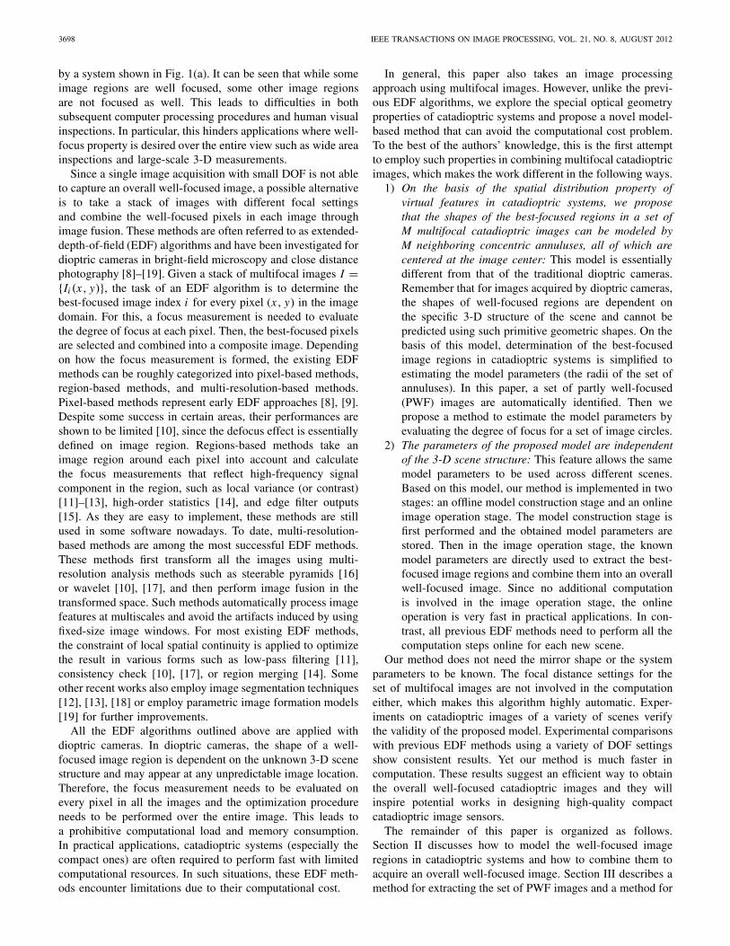
Fig. 2. Image formation process of well-focused image regions ina catadioptric system. (a) Shape of a well-focused image region ina single catadioptric image. (b) Shapes of the best-focused image regionsin multifocal catadioptric images.
estimating the model parameters. Experiments on catadioptricimages are presented in Section IV. Section V gives someconcluding remarks.
II. MODELS OF WELL-FOCUSED IMAGE REGIONS IN
CATADIOPTRIC SYSTEMS
The basic principle of our method is to combine the well-focused image regions in the set of multifocal images intoan overall well-focused composite image. For this purpose,a key issue is to determine the shapes, sizes, and locationsof the well-focused image regions. By exploring the opticalgeometry properties in catadioptric image formation, we findthat the shapes of well-focused image regions in catadioptricsystems can be modeled by well-defined geometry shapes. Inthe following, we first propose a model that describes the shapeof a well-focused image region in a single catadioptric image.Then we extend this model to describe the best-focused imageregions in multifocal images. On the basis of the proposedmodel, we describe a method to combine these best-focusedimage regions into an overall well-focused image. Finally, abrief discussion on the non-coaxial installation issue is given.
A. Shape of a Well-Focused Image Region in a SingleCatadioptric Image
The image formation process of a typical catadioptric sys-tem consisting of a curved mirror and a dioptric camera isillustrated in Fig. 2(a). Assume a Euclidean world coordinateX−Y−Z , where the Z -axis is parallel with the optical axisof the catadioptric system. As the system is rotationallysymmetric with the optical axis, the analysis can be conductedin a 2-D profile as shown in Fig. 2. The upper part of Fig. 2(a)(separated by a horizontal dash line) shows the 2-D profileof the system on the X −Z plane. The dioptric camera looksupward at the mirror surface. The lower part of Fig. 2(a) showsanother view of the image plane of the dioptric camera on theX −Y plane. An object point P in the world is first reflectedby the mirror surface to form a virtual feature P ′. Then thedioptric camera captures this virtual feature to form an imagepoint p. Other terms and annotations in Fig. 2(a) are explainedlater in this section.
It is known that only the object within the DOF of a dioptriccamera can be well focused. In a catadioptric system, the well-focused object points are the ones whose virtual features arelocated within the DOF. Following this, the shapes of the well-focused regions are dependent on the locations of the virtualfeatures and the range of DOF. Recently, Swaminathan [6]explicitly derives the locations of virtual features formed bythe conic curved mirrors and finds that the virtual features ofall object points are located within a finite space, named ascaustic volume. As presented in the work [6], caustic volume isthe space between the mirror surface and a virtual surface. Thevirtual surface is referred to as the caustic volume boundary(CVB), as shown in Fig. 2(a).
In this paper, we further find that the spatial density dis-tribution of virtual features within the caustic volume is notuniform, and the great majority of the virtual features arelocated on the CVB. On the basis of the math formulationof image formation [6], we explicitly compute the locationsof virtual features in a variety of quadric mirror–based centralcatadioptric systems, whose mirror eccentricities range from0.8 to 1.2, heights from the mirror apex to the camera lensrange from 5.0 to 115.0 mm, and the diameters of the mirrorsurface range from 5.0 to 135.0 mm. This set of parameters istypical for catadioptric sensor products, such as those producedby ACCOWLE Co. Ltd [20]. According to our computation,as an object point moves farther away from the system,its corresponding virtual feature would rapidly approach theCVB. For the tested set of system parameters, it is foundthat when an object point is more than 1 m away from thesystem, it will have its virtual feature located within a narrowneighborhood of the CVB, whose width is 5% of the distancefrom CVB to the mirror surface. In real applications withcatadioptric systems, as the points of interests are located ata distance, the great majority of the virtual features can beconsidered to be located on the CVB.
Therefore, in a catadioptric system, the well-focused virtualfeatures are located on the intersection of the CVB and theDOF of the dioptric camera. Denote the CVB as V ⊂ R
3 andthe DOF of an image Ii as D(Ii ) ⊂ R
3. Let the focal distanceof image Ii be f (Ii ). In optics [5], we know D(Ii ) can bemodeled as a space between the two parallel planes that areperpendicular to the optical axis, where D(Ii ) is representedas a gray region in Fig. 2(a). When the DOF is wide enoughto contain the entire CVB, Ii would appear to be overall wellfocused as long as f (Ii ) is properly set, so that V ⊂ D(Ii ).
However, as mentioned in Section I, there are still manycases where D(Ii ) is not wide enough. In these cases, only thepart of CVB that is within D(Ii ) is well focused. As the systemis rotationally symmetric, the set of pixels corresponding to themirror surface is a circular image region centered at the imagecenter. We denote this circular image region as the imagedomain s(Ii ). Within the image domain, the projection of thespace D(Ii ) ∩ V onto s(Ii ) is an annulus as shown in thelower part of Fig. 2(a). Therefore, this paper uses this annulusto model the shape of a well-focused image region in Ii anddenotes it as A(Ii ). The annulus A(Ii ) can be defined as theimage region between the two concentric circles with radii ri−1and ri , so that A(Ii ) = {p|ri−1 ≤ r(p) ≤ ri , p ∈ Ii }, where
3700 IEEE TRANSACTIONS ON IMAGE PROCESSING, VOL. 21, NO. 8, AUGUST 2012
r(p) represents the distance from an image pixel p ∈ Ii to theimage center.
Let F(p; Ii ) be a function that indicates the degree of focusof a pixel p ∈ Ii . For dioptric cameras, it is known byoptics [5] that the image feature of an object point becomesmore defocused as the point moves away from the focalplane along the optical axis. Though an explicit form for thisvariation of focus measurement can be accurately deduced byoptical geometry, in practice it is often modeled by a Gaussianfunction peaked at the focal plane [21], [22]. Our work alsofollows such an approximation. In catadioptric systems, as theimages are formed through mirror reflection, the variation offocus along the optical axis is mapped onto the radius of theimage plane through the mirror. Since the mirror surface issmooth and the DOF considered in this paper is small, thismapping can be locally approximated by a linear mapping.Following this, we still adopt a Gaussian function to modelthe variation of focus measurement along the image radius andgive the form of F(p; Ii ) as follows:
F(p; Ii ) = 1
σi√
2πexp
(− (r(p) − μi )
2
2σ 2i
). (1)
As the variation is only along the radius, we rewrite (1) as
F(r; Ii ) = 1
σi√
2πexp
(− (r − μi )
2
2σ 2i
)(2)
where r is the distance from the pixel p to the image center.Note that since CVB and DOF are determined only by theoptical configuration of the system, A(Ii ) is independent ofthe 3-D scene structures. This feature is essentially differentfrom that in a dioptric system. In a dioptric system, the shapesof the well-focused image regions are closely related to theobject depths, which is the theoretical basis for the class ofshape/depth from focus/defocus methods [21], [22].
It can be seen that when the focal distance f (Ii ) increases,D(Ii ) moves from the front to the back of the CVB, dur-ing which A(Ii ) moves from the image central part to theperipheral part. However, as long as D(Ii ) cannot contain theentire CVB, the image regions beyond A(Ii ) would still appeardefocused. In order to obtain an overall well-focused imagewith narrow DOF images, we next study the shapes of thebest-focused image regions in multiple-focal images.
B. Shapes of the Best-Focused Image Regions in MultifocalCatadioptric Images
Let I = {Ii } be a set of N multifocal catadioptric images,which are taken at the same view point for the same scene, yetwith different focal distance settings { f (Ii )}, where f (I1) <f (I2) < · · · < f (IN ). Here, we assume that the dioptriccamera is equipped with the image-space (rear) telecentricfeature [23], which guarantees that the scene content in eachimage is exactly the same though the image focal distancesare different. Note that this assumption is not a must to useour method. When the camera does not satisfy the image-spacetelecentric feature, the multifocal images can be aligned to thesame coordinate by a standard image registration procedure asa preprocessing step.
In order to make all objects clearly recorded in at least oneof the images, the following two conditions are required whiletaking the set of multifocal images I .
Condition 1: Any two images whose focal distance settingsare adjacent should have overlapping DOFs so that
D(Ip)⋂
D(Iq ) �= ∅ for ∀Ip, Iq ∈ I, q = p + 1.
Condition 2: The union DOF of the images should containthe entire CVB so that V ⊂ ⋃N
i=1 D(Ii ).Condition 1 can be satisfied by making the focal distance
step sufficiently small. Condition 2 can be met by lettingD(I1) locate before V and D(IN ) locate behind V . This canbe examined by visually checking whether both I1 and IN
are overall out-of-focus images. Note that the above imageacquisition procedure does not require the system parametersto be known. The focal distances of the images do not needto be accurately set either.
As the goal is to obtain an overall well-focused image, theimages of interests are a subset of K PWF images I ′ = {I ′
k} ⊂I that satisfy D(I ′
k) ∩ V �= ∅, where D(I ′k) denotes the DOF
of I ′k . Also assume that f (I ′
1) < f (I ′2) < · · · < f (I ′
K ).According to condition 1 and condition 2, it can be seen thatV ⊂ ⋃K
k=1 D(I ′k). Remember that the image domain s(I ′) is a
circular image region centered at the image center. Therefore,any part in s(I ′) would be clearly recorded in at least one ofthe images in I ′. Notice that, as CVB is a limited space [6],K can be expected to be a limited number.
The number of images in the PWF image set is determinedby the value of the focal distance step. In general, a larger focaldistance step would lead to a smaller number of multifocalimages, which is efficient to capture. However, when the focaldistance step is too large, there would be gaps between theDOFs. To avoid this, the focal distance step should be setsmall enough so that neighboring multifocal images share theoverlapping DOFs as required in condition 1. As long ascondition 1 and condition 2 are satisfied, a decrease of thefocal distance step (with a larger number of images in thePWF image set) would not further improve the final imagequality.
It is known from optics [5] that the degree of focus withinD(I
′k) decreases monotonically as an object point moves
away from f (I ′k). Therefore, each D(I ′
k) contains a subspaceD(I ′
k) ⊂ D(I ′k), where a point is best focused in I ′
k amongall the K images in I ′. The set of {D(I ′
k)} satisfy:1) D(I ′
p)⋂
D(I ′q) = ∅ for ∀I ′
p, I ′q ∈ I ′ and 2) V ⊂⋃K
k=1 D(I ′k). Therefore, the projection of D(I ′
k) ∩ V formsthe best-focused image region in image I ′
k . As the system isrotationally symmetric, this region is an annulus, which wedenote by Ak . Consider the K images in I ′, the best-focusedimage regions thus can be modeled by a set of K neighboringconcentric annuluses A = {Ak}, where
⋃Kk=1 Ak = s(I ′) and
A p ∩ Aq = ∅, for ∀A p �= Aq , A p, Aq ∈ A. The annulusesA = {Ak} are shown in Fig. 2(b).
Each annulus Ak can be described by the two concentriccircles enclosing it, whose radii are rk−1 and rk . Therefore,the model A = {Ak} can be parameterized as a set of (K + 1)radii {r0, r1, r2, . . . , rK }, where r0 < r1 < r2 < · · · < rK .
LI AND LI: CATADIOPTRIC IMAGE ACQUISITION WITH MULTIFOCAL IMAGES 3701
Here, r0 is the radius of the circular area in the image centralpart where the scene is occluded by the camera itself, whichis plotted as the black circle in Fig. 2(b). rK is the radiusof the circular view boundary of the mirror surface in theimage. As r0 and rK are determined by the system setup, thereare (K − 1) variable parameters, which are denoted as R ={r1, r2, . . . , rK−1}. As introduced in Section II-A, the degreeof focus in image I ′
k can be described by the Gaussian functionF(r; I ′
k). Therefore, it can be seen that rk is the solution tothe equation F(r; I ′
k) = F(r; I ′k+1).
In this paper, we propose a practical approach in Section IIIto compute the model parameters R, which only requireobserving a set of multifocal images and image processingcomputations.
C. Combining Multifocal Images Into a Single OverallWell-Focused Image
Given a set of multifocal images I ′ and the model parameterR, an overall well-focused image I can be simply obtained bycombining the best-focused regions of I ′
k , so that I (Ak) =I ′k(Ak). In practice, this can be simply implemented by a
cropping and replacing operation, which does not requireadditional image processing computations and thus is veryfast. Note that as R is only determined by the system setupand focal distance settings of I ′
k , the same R is applica-ble for images of arbitrary scenes despite of their different3-D structures, which is quite different from the situations ina conventional dioptric camera. We verify this property byexperiments on catadioptric images in various environmentsin Section IV-B and with various camera DOF settings inSection IV-C.
D. Non-Coaxial Installation Issue
In the above discussions, we have assumed that the cameraand the mirror are installed to be coaxial. Note that there arealso situations when the installation is not coaxial. Further-more, there are some systems where the mirror is intentionallyinstalled with an angle to the camera such as the work [24].When the camera’s axis has a significant angle of deviationfrom the mirror’s axis, the image formation process of thevirtual features reflected in the mirror is not rotationallysymmetric any more. The process of virtual feature formationmust be reconsidered. Following this, the shape of a best-focused image region in a PWF image may not be an annulus.Then the proposed annulus combination method cannot beapplied. To analyze the situations when the mirror axis and thecamera axis are not aligned, the analysis needs to include therotational motion parameters in modeling the virtual featureformation process. The shapes of the best-focused regionswould be dependent on the mirror shape and the motionparameters.
III. PROPOSED METHOD
The proposed method acquires an overall well-focusedimage by combining the best-focused regions into multifocalcatadioptric images using the parametric model introduced in
Acquisition of multi-focal images
Identification of PWF images
Model estimation
Acquisition of PWF images
Combination of the best focused image regions
Camera parameters
Model parameters
Output: an overall well focused catadioptric image.
ModelConstruction
ImageOperation
Off-line On-line
{ }iI I=
' { ' }kI I= , { ( ' )}kK f I
{ }kR r=
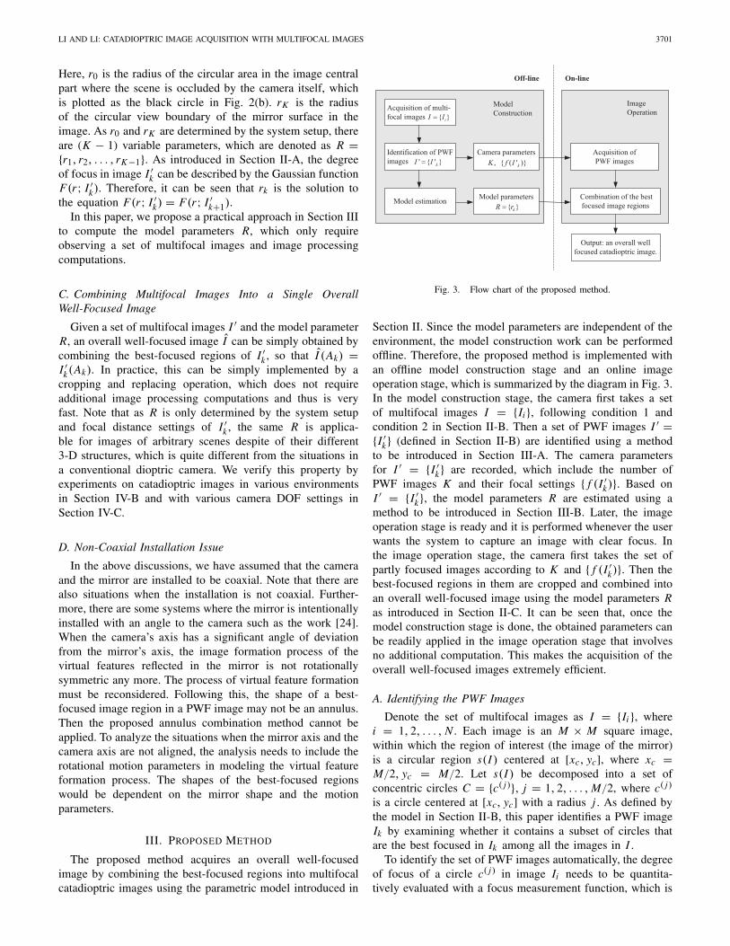
Fig. 3. Flow chart of the proposed method.
Section II. Since the model parameters are independent of theenvironment, the model construction work can be performedoffline. Therefore, the proposed method is implemented withan offline model construction stage and an online imageoperation stage, which is summarized by the diagram in Fig. 3.In the model construction stage, the camera first takes a setof multifocal images I = {Ii }, following condition 1 andcondition 2 in Section II-B. Then a set of PWF images I ′ ={I ′
k} (defined in Section II-B) are identified using a methodto be introduced in Section III-A. The camera parametersfor I ′ = {I ′
k} are recorded, which include the number ofPWF images K and their focal settings { f (I ′
k)}. Based onI ′ = {I ′
k}, the model parameters R are estimated using amethod to be introduced in Section III-B. Later, the imageoperation stage is ready and it is performed whenever the userwants the system to capture an image with clear focus. Inthe image operation stage, the camera first takes the set ofpartly focused images according to K and { f (I ′
k)}. Then thebest-focused regions in them are cropped and combined intoan overall well-focused image using the model parameters Ras introduced in Section II-C. It can be seen that, once themodel construction stage is done, the obtained parameters canbe readily applied in the image operation stage that involvesno additional computation. This makes the acquisition of theoverall well-focused images extremely efficient.
A. Identifying the PWF Images
Denote the set of multifocal images as I = {Ii }, wherei = 1, 2, . . . , N . Each image is an M × M square image,within which the region of interest (the image of the mirror)is a circular region s(I ) centered at [xc, yc], where xc =M/2, yc = M/2. Let s(I ) be decomposed into a set ofconcentric circles C = {c( j )}, j = 1, 2, . . . , M/2, where c( j )
is a circle centered at [xc, yc] with a radius j . As defined bythe model in Section II-B, this paper identifies a PWF imageIk by examining whether it contains a subset of circles thatare the best focused in Ik among all the images in I .
To identify the set of PWF images automatically, the degreeof focus of a circle c( j ) in image Ii needs to be quantita-tively evaluated with a focus measurement function, which is
3702 IEEE TRANSACTIONS ON IMAGE PROCESSING, VOL. 21, NO. 8, AUGUST 2012
1r 2r Kr1Kr −0r
1
2
K
… ...
… ...…...
j
( )z j
Fig. 4. Index function of the image where an image circle with radius j isthe best focused. The discontinuous points correspond to the radii that definethe annuluses in the proposed model.
denoted by F(c( j ); Ii ). In this paper, we use the sum of localgradient magnitude to measure the degree of focus, which isgiven as follows:
F(
c( j ); Ii
)=
M∑x=1
M∑y=1
R(
x, y; c( j ))
· Gi (x, y) (3)
where R(x, y; c( j )) is a mask image that is defined as follows:
R(x, y; c( j ))
={
1, if ( j −�r) ≤ √(x − xc)2 + (y − yc)2 ≤ ( j + �r)
0, otherwise.(4)
Here �r is the width of a neighborhood around the circle.Gi (x, y) is the gradient magnitude image of image Ii .
On the basis of the above definitions, a circle c( j ) isconsidered to be the best focused in Ik , if F(c( j ); Ik) =maxN
i=1 F(c( j ); Ii ). Hence, a set of circles that are the bestfocused in Ik can be identified as Ck = {c(w)} ⊂ C . Denotethe number of the best-focused circles (BFCs) in Ik as N(Ck),then Ik is selected as a partly focused image if N(Ck ) > 0.
B. Model Parameter Estimation
Denote the set of PWF images as I ′ = {I ′k}, where k =
1, 2, . . . , K . Following the model in Section II-B, the best-focused image regions are K concentric annulus regions A ={Ak}, where k = 1, 2, . . . , K . As introduced in Section II-B,the set of annuluses are defined by the (K − 1) radii R ={r1, r2, . . . , rK−1}.
Using a similar method as in Section III-A, let the imagedomain s(I ) be decomposed into a set of concentric circlesC = {c( j )}. Following (3), the image in which a circle c( j ) isthe best focused can be determined. Denote the index of theimage, where a circle c( j ) is the best focused as z( j). Thenz( j) takes values from K integers {1, 2, . . .,K}. Followingthe model in Section II-B, the radii of the circles that arethe best focused in the same image must fall in the samecontinuous interval. Then z( j) can be considered as a functionthat represents the index of the image, where a circle withradius j is the best focused among the set of multifocalimages. This index function z( j) is illustrated in Fig. 4, wherethe circle radius range [r0 rK ] is partitioned into K intervals.It can be seen that the partition points of these intervals are
1 2 3 4 5 6 7 8 9 10
50
100
150
200
250
300
0
Image index number
Num
ber o
f BFC
Fig. 5. Number of the BFCs in each input image.
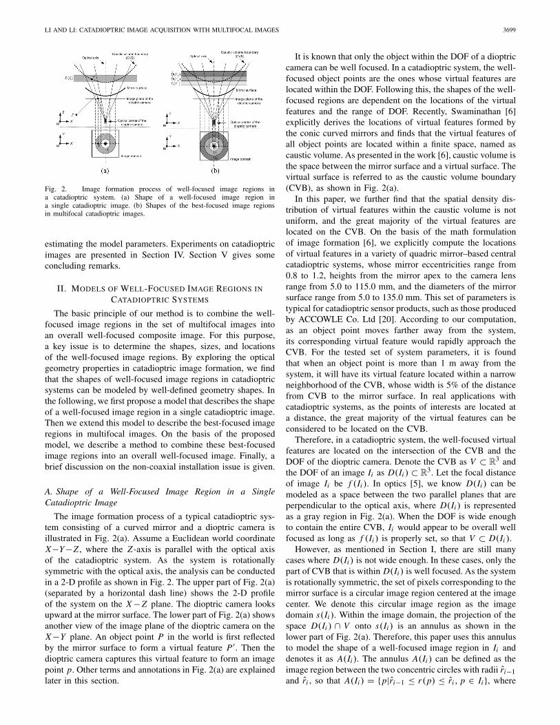
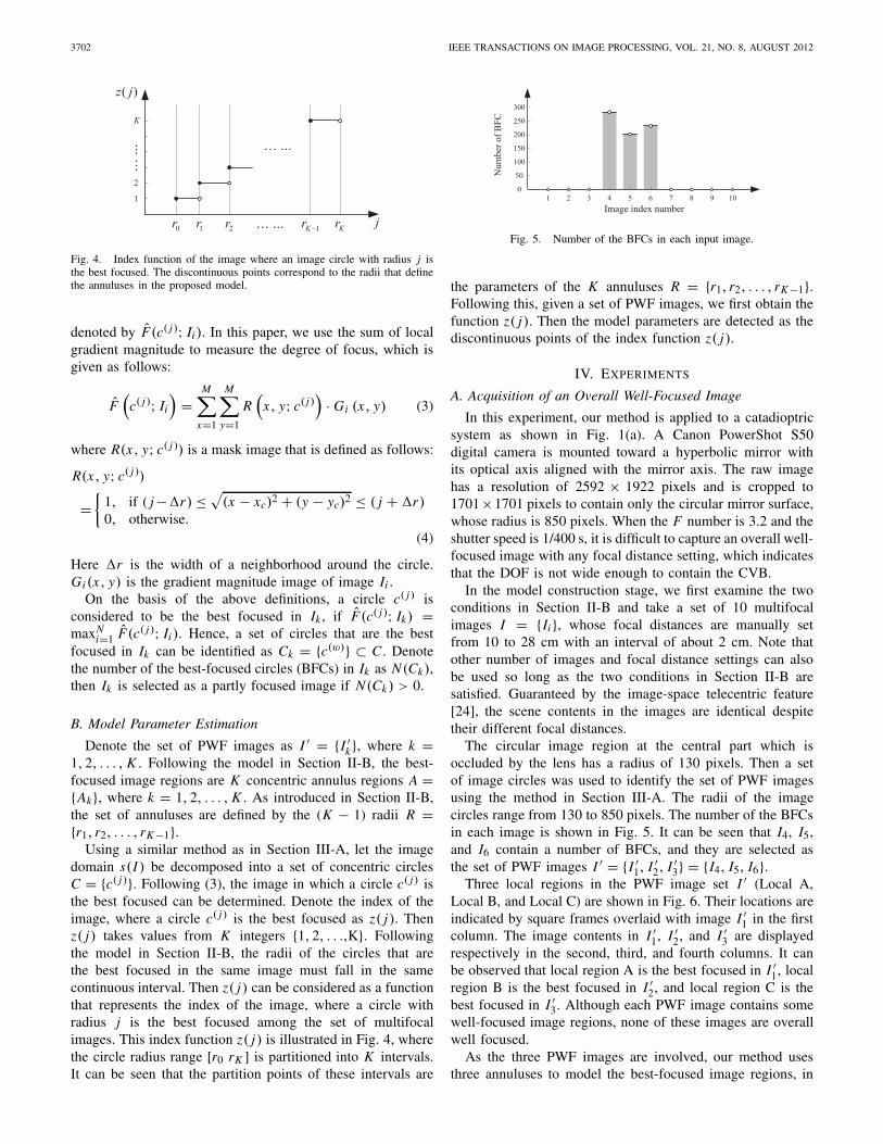
the parameters of the K annuluses R = {r1, r2, . . . , rK−1}.Following this, given a set of PWF images, we first obtain thefunction z( j). Then the model parameters are detected as thediscontinuous points of the index function z( j).
IV. EXPERIMENTS
A. Acquisition of an Overall Well-Focused Image
In this experiment, our method is applied to a catadioptricsystem as shown in Fig. 1(a). A Canon PowerShot S50digital camera is mounted toward a hyperbolic mirror withits optical axis aligned with the mirror axis. The raw imagehas a resolution of 2592 × 1922 pixels and is cropped to1701×1701 pixels to contain only the circular mirror surface,whose radius is 850 pixels. When the F number is 3.2 and theshutter speed is 1/400 s, it is difficult to capture an overall well-focused image with any focal distance setting, which indicatesthat the DOF is not wide enough to contain the CVB.
In the model construction stage, we first examine the twoconditions in Section II-B and take a set of 10 multifocalimages I = {Ii }, whose focal distances are manually setfrom 10 to 28 cm with an interval of about 2 cm. Note thatother number of images and focal distance settings can alsobe used so long as the two conditions in Section II-B aresatisfied. Guaranteed by the image-space telecentric feature[24], the scene contents in the images are identical despitetheir different focal distances.
The circular image region at the central part which isoccluded by the lens has a radius of 130 pixels. Then a setof image circles was used to identify the set of PWF imagesusing the method in Section III-A. The radii of the imagecircles range from 130 to 850 pixels. The number of the BFCsin each image is shown in Fig. 5. It can be seen that I4, I5,and I6 contain a number of BFCs, and they are selected asthe set of PWF images I ′ = {I ′
1, I ′2, I ′
3} = {I4, I5, I6}.Three local regions in the PWF image set I ′ (Local A,
Local B, and Local C) are shown in Fig. 6. Their locations areindicated by square frames overlaid with image I ′
1 in the firstcolumn. The image contents in I ′
1, I ′2, and I ′
3 are displayedrespectively in the second, third, and fourth columns. It canbe observed that local region A is the best focused in I ′
1, localregion B is the best focused in I ′
2, and local region C is thebest focused in I ′
3. Although each PWF image contains somewell-focused image regions, none of these images are overallwell focused.
As the three PWF images are involved, our method usesthree annuluses to model the best-focused image regions, in
LI AND LI: CATADIOPTRIC IMAGE ACQUISITION WITH MULTIFOCAL IMAGES 3703
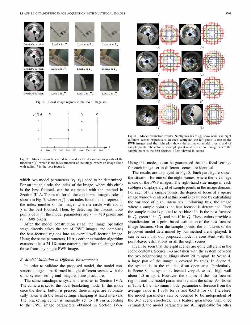
Fig. 6. Local image regions in the PWF image set.
1r 2r0r
1
3
j
( )z j
2
100 200 300 400 500 600 700 800 9000
3r
Fig. 7. Model parameters are determined as the discontinuous points of thefunction z( j), which is the index function of the image, where an image circlewith radius j is the best focused.
which two model parameters {r1, r2} need to be determined.For an image circle, the index of the image, where this circleis the best focused, can be estimated with the method inSection III-A. The result for all the considered image circles isshown in Fig. 7, where z( j) is an index function that representsthe index number of the image, where a circle with radiusj is the best focused. Then, by detecting the discontinuouspoints of z( j), the model parameters are r1 = 410 pixels andr2 = 609 pixels.
After the model construction stage, the image operationstage directly takes the set of PWF images and combinesthe best-focused regions into an overall well-focused image.Using the same parameters, Harris corner extraction algorithmextracts at least 24.1% more corner points from this image thanthose from any single PWF image.
B. Model Validation in Different Environments
In order to validate the proposed model, the model con-struction stage is performed in eight different scenes with thesame system setting and image capture procedure.
The same catadioptric system is used as in Section IV-A.The camera is set to the focal-bracketing mode. In this modeonce the shutter button is pressed, three images are automati-cally taken with the focal settings changing at fixed intervals.The bracketing center is manually set to 18 cm accordingto the PWF image parameters obtained in Section IV-A.
(a) (b)
(c) (d)
(e) (f)
(g) (h)
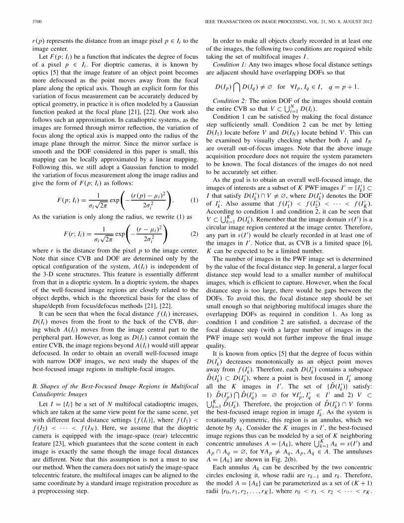
Fig. 8. Model estimation results. Subfigures (a) to (g) show results in eightdifferent scenes respectively. In each subfigure, the left photo is one of thePWF images and the right plot shows the estimated model over a grid ofsample points. The color of a sample point relates to a PWF image where thesample point is the best focused. (Best viewed in color.)
Using this mode, it can be guaranteed that the focal settingsfor each image set in different scenes are identical.
The results are displayed in Fig. 8. Each part figure showsthe situation for one of the eight scenes, where the left imageis one of the PWF images. The right-hand side image in eachsubfigure displays a grid of sample points in the image domain.For each of the sample points, the degree of focus of a squareimage window centered at this point is evaluated by calculatingthe variance of pixel intensities. Following this, the imagewhere a sample point is the best focused is determined. Thenthe sample point is plotted to be blue if it is the best focusedin I ′
1, green if in I ′2, and red if in I ′
3. These colors provide avisualization for a point-based estimation of the best-focusedimage features. Over the sample points, the annuluses of theproposed model determined by our method are displayed. Itcan be seen that our proposed model is consistent with thepoint-based estimations in all the eight scenes.
It can be seen that the eight scenes are quite different in thescene contents. Scenes 1–3 are taken with the system betweenthe two neighboring buildings about 20 m apart. In Scene 4,a large part of the image is covered by trees. In Scene 5,the system is in the middle of an open area. Particularly,in Scene 8, the system is located very close to a high wallabout 1.5 m apart. However, the shapes of the best-focusedregions and the model parameters remain the same. As shownin Table I, the maximum model parameter difference from theaverage value is 1.33% for r1 and 0.63% for r2. Therefore,the model parameters can be deemed to be independent ofthe 3-D scene structures. This feature guarantees that, onceestimated, the model parameters are still applicable for other
3704 IEEE TRANSACTIONS ON IMAGE PROCESSING, VOL. 21, NO. 8, AUGUST 2012
TABLE I
MODEL PARAMETER ESTIMATIONS OBTAINED UNDER
DIFFERENT SCENES
r1 r2
Scene 1 410 609
Scene 2 404 607
Scene 3 409 604
Scene 4 401 605
Scene 5 402 607
Scene 6 408 604
Scene 7 401 601
Scene 8 402 605
Average 404.6 605.3
Max. deviation 5.4 (1.33%) 3.8 (0.63%)
scenes as long as the imaging parameters do not change.Many modern cameras are able to store the imaging para-meters on-chip, which facilitates the use of this method.Therefore, an overall well-focused image can be acquired bycropping and combining the annular regions without additionalcomputation, which makes the procedure extremely efficient.
C. Model Validation With Different DOF Settings
To further validate the proposed model, we apply ourmethod to different sets of multifocal images acquired withdifferent DOF settings and compare the results with a clas-sic EDF method. Here a different dioptric camera is used,which consists of a Prosilica 1394 color CCD camera and aFUJINON zoom lens that allow its optical parameters to bemanually set in a more flexible manner than that in the Canoncamera.
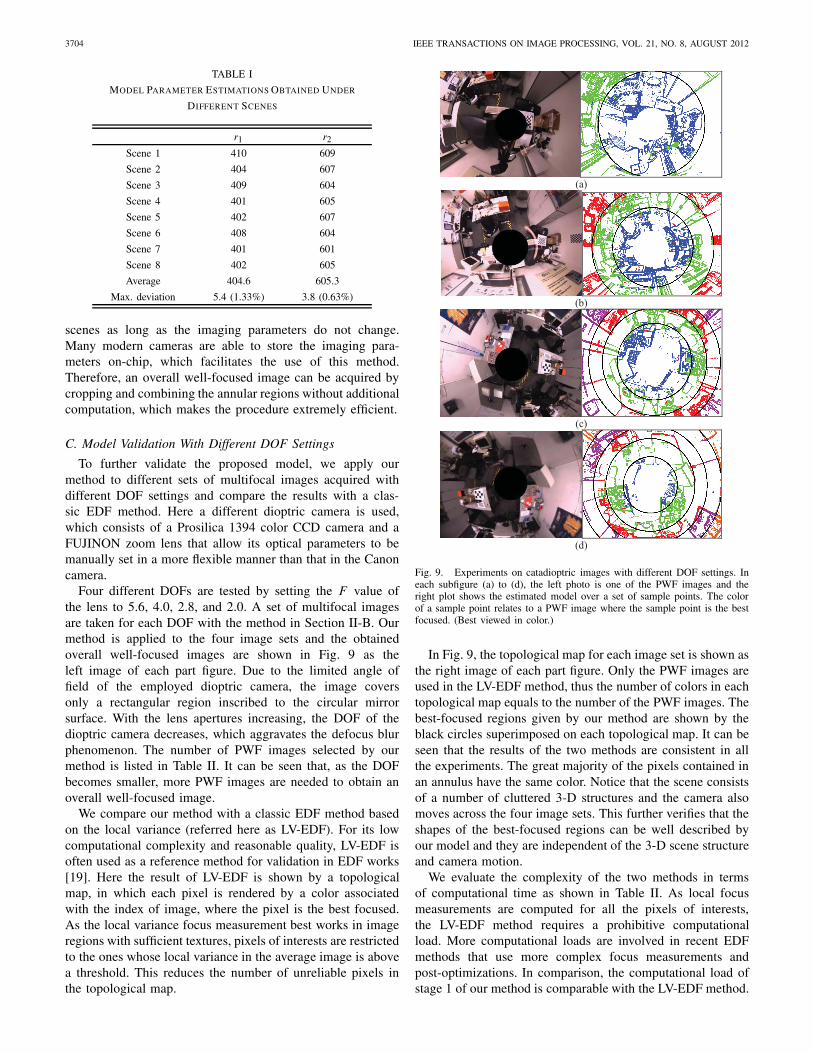
Four different DOFs are tested by setting the F value ofthe lens to 5.6, 4.0, 2.8, and 2.0. A set of multifocal imagesare taken for each DOF with the method in Section II-B. Ourmethod is applied to the four image sets and the obtainedoverall well-focused images are shown in Fig. 9 as theleft image of each part figure. Due to the limited angle offield of the employed dioptric camera, the image coversonly a rectangular region inscribed to the circular mirrorsurface. With the lens apertures increasing, the DOF of thedioptric camera decreases, which aggravates the defocus blurphenomenon. The number of PWF images selected by ourmethod is listed in Table II. It can be seen that, as the DOFbecomes smaller, more PWF images are needed to obtain anoverall well-focused image.
We compare our method with a classic EDF method basedon the local variance (referred here as LV-EDF). For its lowcomputational complexity and reasonable quality, LV-EDF isoften used as a reference method for validation in EDF works[19]. Here the result of LV-EDF is shown by a topologicalmap, in which each pixel is rendered by a color associatedwith the index of image, where the pixel is the best focused.As the local variance focus measurement best works in imageregions with sufficient textures, pixels of interests are restrictedto the ones whose local variance in the average image is abovea threshold. This reduces the number of unreliable pixels inthe topological map.
(a)
(b)
(c)
(d)
Fig. 9. Experiments on catadioptric images with different DOF settings. Ineach subfigure (a) to (d), the left photo is one of the PWF images and theright plot shows the estimated model over a set of sample points. The colorof a sample point relates to a PWF image where the sample point is the bestfocused. (Best viewed in color.)
In Fig. 9, the topological map for each image set is shown asthe right image of each part figure. Only the PWF images areused in the LV-EDF method, thus the number of colors in eachtopological map equals to the number of the PWF images. Thebest-focused regions given by our method are shown by theblack circles superimposed on each topological map. It can beseen that the results of the two methods are consistent in allthe experiments. The great majority of the pixels contained inan annulus have the same color. Notice that the scene consistsof a number of cluttered 3-D structures and the camera alsomoves across the four image sets. This further verifies that theshapes of the best-focused regions can be well described byour model and they are independent of the 3-D scene structureand camera motion.
We evaluate the complexity of the two methods in termsof computational time as shown in Table II. As local focusmeasurements are computed for all the pixels of interests,the LV-EDF method requires a prohibitive computationalload. More computational loads are involved in recent EDFmethods that use more complex focus measurements andpost-optimizations. In comparison, the computational load ofstage 1 of our method is comparable with the LV-EDF method.
LI AND LI: CATADIOPTRIC IMAGE ACQUISITION WITH MULTIFOCAL IMAGES 3705
TABLE II
EXPERIMENTAL RESULTS OF LV-EDF AND OUR METHOD WITH
DIFFERENT DOF SETTINGS
Aperturesize (F)
Number ofPWF
images
Computationtime of
LV-EDF (s)
Computation timeof our method
Stage 1 Stage 2
5.6 2 44.3 37.1 s 0.21 s
4.0 3 56.1 43.1 s 0.33 s
2.8 4 72.2 65.4 s 0.37 s
2.0 5 83.9 74.8 s 0.49 s
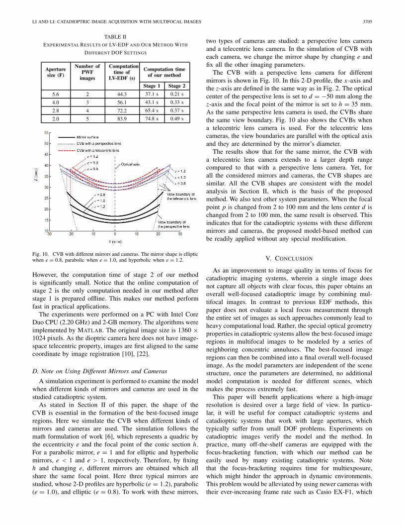
Fig. 10. CVB with different mirrors and cameras. The mirror shape is ellipticwhen e = 0.8, parabolic when e = 1.0, and hyperbolic when e = 1.2.
However, the computation time of stage 2 of our methodis significantly small. Notice that the online computation ofstage 2 is the only computation needed in our method afterstage 1 is prepared offline. This makes our method performfast in practical applications.
The experiments were performed on a PC with Intel CoreDuo CPU (2.20 GHz) and 2-GB memory. The algorithms wereimplemented by MATLAB. The original image size is 1360 ×1024 pixels. As the dioptric camera here does not have image-space telecentric property, images are first aligned to the samecoordinate by image registration [10], [22].
D. Note on Using Different Mirrors and Cameras
A simulation experiment is performed to examine the modelwhen different kinds of mirrors and cameras are used in thestudied catadioptric system.
As stated in Section II of this paper, the shape of theCVB is essential in the formation of the best-focused imageregions. Here we simulate the CVB when different kinds ofmirrors and cameras are used. The simulation follows themath formulation of work [6], which represents a quadric bythe eccentricity e and the focal point of the conic section h.For a parabolic mirror, e = 1 and for elliptic and hyperbolicmirrors, e < 1 and e > 1, respectively. Therefore, by fixingh and changing e, different mirrors are obtained which allshare the same focal point. Here three typical mirrors arestudied, whose 2-D profiles are hyperbolic (e = 1.2), parabolic(e = 1.0), and elliptic (e = 0.8). To work with these mirrors,
two types of cameras are studied: a perspective lens cameraand a telecentric lens camera. In the simulation of CVB witheach camera, we change the mirror shape by changing e andfix all the other imaging parameters.
The CVB with a perspective lens camera for differentmirrors is shown in Fig. 10. In this 2-D profile, the x-axis andthe z-axis are defined in the same way as in Fig. 2. The opticalcenter of the perspective lens is set to d = −50 mm along thez-axis and the focal point of the mirror is set to h = 35 mm.As the same perspective lens camera is used, the CVBs sharethe same view boundary. Fig. 10 also shows the CVBs whena telecentric lens camera is used. For the telecentric lenscameras, the view boundaries are parallel with the optical axisand they are determined by the mirror’s diameter.
The results show that for the same mirror, the CVB witha telecentric lens camera extends to a larger depth rangecompared to that with a perspective lens camera. Yet, forall the considered mirrors and cameras, the CVB shapes aresimilar. All the CVB shapes are consistent with the modelanalysis in Section II, which is the basis of the proposedmethod. We also test other system parameters. When the focalpoint p is changed from 2 to 100 mm and the lens center d ischanged from 2 to 100 mm, the same result is observed. Thisindicates that for the catadioptric systems with these differentmirrors and cameras, the proposed model-based method canbe readily applied without any special modification.
V. CONCLUSION
As an improvement to image quality in terms of focus forcatadioptric imaging systems, wherein a single image doesnot capture all objects with clear focus, this paper obtains anoverall well-focused catadioptric image by combining mul-tifocal images. In contrast to previous EDF methods, thispaper does not evaluate a local focus measurement throughthe entire set of images as such approaches commonly lead toheavy computational load. Rather, the special optical geometryproperties in catadioptric systems allow the best-focused imageregions in multifocal images to be modeled by a series ofneighboring concentric annuluses. The best-focused imageregions can then be combined into a final overall well-focusedimage. As the model parameters are independent of the scenestructure, once the parameters are determined, no additionalmodel computation is needed for different scenes, whichmakes the process extremely fast.
This paper will benefit applications where a high-imageresolution is desired over a large field of view. In particu-lar, it will be useful for compact catadioptric systems andcatadioptric systems that work with large apertures, whichtypically suffer from small DOF problems. Experiments oncatadioptric images verify the model and the method. Inpractice, many off-the-shelf cameras are equipped with thefocus-bracketing function, with which our method can beeasily used by many existing catadioptric systems. Notethat the focus-bracketing requires time for multiexposure,which might hinder the approach in dynamic environments.This problem would be alleviated by using newer cameras withtheir ever-increasing frame rate such as Casio EX-F1, which
3706 IEEE TRANSACTIONS ON IMAGE PROCESSING, VOL. 21, NO. 8, AUGUST 2012
can capture 60 f/s at 6 MP. The multifocal image acquisitioncan also achieve improved efficiency by using the techniquesin this paper [13].
REFERENCES
[1] I. Bogdanova, X. Bresson, J. P. Thiran, and P. Vandergheynst, “Scalespace analysis and active contours for omnidirectional images,” IEEETrans. Image Process., vol. 16, no. 7, pp. 1888–1901, Jul. 2007.
[2] S. Baker and S. K. Nayar, “A theory of single-viewpoint catadioptricimage formation,” Int. J. Comput. Vis., vol. 35, no. 2, pp. 1–22, 1999.
[3] X. Ying and Z. Hu, “Catadioptric camera calibration using geometricinvariants,” IEEE Trans. Pattern Anal. Mach. Intell., vol. 26, no. 10, pp.1260–1271, Oct. 2004.
[4] I. Tosic and P. Frossard, “Geometry-based distributed scene representa-tion with omnidirectional vision sensors,” IEEE Trans. Image Process.,vol. 17, no. 7, pp. 1033–1046, Jul. 2008.
[5] E. Hecht, Optics, 4th ed. Reading, MA: Addison-Wesley, 2002.[6] R. Swaminathan, “Focus in catadioptric imaging systems,” in Proc. IEEE
11th Int. Conf. Comput. Vis., Oct. 2007, pp. 1–7.[7] H. Ishiguro, “Development of low cost compact omni-directional vision
sensors and their applications,” in Panoramic Vision: Sensors, Theory,and Applications, R. Benosman and S. B. Kang, Eds. Heidelberg,Germany: Springer-Verlag, 2001, pp. 2–38.
[8] R. J. Pieper and A. Korpel, “Image processing for extended depth offield,” Appl. Opt., vol. 22, no. 10, pp. 1449–1453, 1983.
[9] D. G. Tieman, R. K. Murphey, J. T. Schmidt, and S. B. Tieman, “Acomputer-assisted video technique for preparing high resolution picturesand stereograms from thick specimens,” J. Neurosci. Methods, vol. 17,no. 4, pp. 231–245, 1986.
[10] A. G. Valdecasas, D. Marshall, J. M. Becerra, and J. J. Terrero, “On theextended depth of focus algorithms for bright field microscopy,” Micron,vol. 32, no. 6, pp. 559–569, 2001.
[11] K. Itoh, A. Hayashi, and Y. Ichioka, “Digitized optical microscopy withextended depth of field,” Appl. Opt., vol. 28, no. 16, pp. 3487–3493,1989.
[12] A. Agarwala, M. Dontcheva, M. Agrawala, S. Drucker, A. Colburn, B.Curless, D. Salesin, and M. Cohen, “Interactive digital photomontage,”in Proc. ACM SIGGRAPH, vol. 23. 2004, pp. 294–302.
[13] S. W. Hasinoff and K. N. Kutulakos, “Light-efficient photography,” IEEETrans. Pattern Anal. Mach. Intell., vol. 33, no. 11, pp. 2203–2214, Nov.2011.
[14] C. Kim, “Segmenting a low-depth-of-field image using morphologicalfilters and region merging,” IEEE Trans. Image Process., vol. 14, no.10, pp. 1503–1511, Oct. 2005.
[15] M. Antunes, M. Trachtenberg, G. Thomas, and T. Shoa, All-in-FocusImaging Using a Series of Images on Different Focal Planes (LectureNotes on Computer Science), vol. 3656. New York: Springer-Verlag,2005, pp. 174–181.
[16] Z. Liu, K. Tsukada, K. Hanasaki, Y. K. Ho, and Y. P. Dai, “Image fusionby using steerable pyramid,” Pattern Recognit. Lett., vol. 22, no. 9, pp.929–939, 2001.
[17] B. Forster, D. Van De Ville, J. Berent, D. Sage, and M. Unser, “Complexwavelets for extended depth-of-field: A new method for the fusion ofmultichannel microscopy images,” Microsc. Res. Tech., vol. 65, nos. 1–2,pp. 33–42, 2004.
[18] S. Li and B. Yang, “Multifocus image fusion using region segmentationand spatial frequency,” J. Image Vis. Comput., vol. 26, no. 7, pp. 971–979, 2008.
[19] F. Aguet, D. V. Ville, and M. Unser, “Model-based 2.5-D deconvolutionfor extended depth of field in bright field microscopy,” IEEE Trans.Image Process., vol. 17, no. 7, pp. 1144–1153, Jul. 2008.
[20] Production List. Accowle Company, Ltd., Tokyo, Japan [Online]. Avail-able: http: http://www.accowle.com/english/products.html
[21] S. K. Nayar and Y. Nakagawa, “Shape from focus,” IEEE Trans. PatternAnal. Mach. Intell., vol. 16, no. 8, pp. 824–831, Aug. 1994.
[22] P. Favaro and S. Soatto, “A geometric approach to shape from defocus,”IEEE Trans. Pattern Anal. Mach. Intell., vol. 27, no. 3, pp. 406–417,Mar. 2005.
[23] D. Malacara and Z. Malacara, Handbook of Optical Design, 2nd ed.New York: Marcel Dekker, 2004.
[24] D. Lanman, D. Crispell, M. Wachs, and G. Taubin, “Spherical catadiop-tric arrays: Construction, multi-view geometry, and calibration,” in Proc.Int. Symp. 3D Data Process., Vis., Trans., Jun. 2006, pp. 1–8.
Weiming Li received the Ph.D. degree in patternrecognition and intelligent systems from the Insti-tute of Automation, Chinese Academy of Sciences,Beijing, China, in 2008.
He was with the Department of ManufacturingEngineering and Engineering Management, CityUniversity of Hong Kong, Kowloon, Hong Kong,from 2008 to 2011. He is currently a Researcher withthe China Laboratory, Samsung Advanced Instituteof Technology, Beijing. His current research interestsinclude computer vision, computational imaging,
and multimedia technology.
Youfu Li (SM’01) received the Ph.D. degree inrobotics from Oxford University, Oxford, U.K., in1993.
He was a Post-Doctoral Researcher with theDepartment of Computer Science, University ofWales, Aberystwyth, U.K., from 1993 to 1995. Hejoined the City University of Hong Kong, Kowloon,Hong Kong, in 1995. His current research interestsinclude robot vision, visual tracking, robot sens-ing and sensor-based controls, mechatronics, andautomation.
Dr. Li has served as an Associate Editor of the IEEE TRANSACTIONS ONAUTOMATION SCIENCE AND ENGINEERING and the IEEE ROBOTICS AND
AUTOMATION MAGAZINE.
Copyright © 2022 FDOKUMEN