Focused RF hyperthermia using magnetic fluids
7
Focused RF hyperthermia using magnetic fluids T. Onur Tasci Department of Bioengineering, University of Utah, Salt Lake City, Utah 84112 Ibrahim Vargel Department of Plastic and Reconstructive Surgery, Kirikkale University, 71100, Kirikkale, Turkey Anil Arat Department of Radiology, Baylor College of Medicine, Houston, Texas 77030 Elif Guzel Department of Histology and Embryology, Cerrahpasa School of Medicine, 34098, Istanbul University, Istanbul, Turkey Petek Korkusuz Department of Histology and Embryology, Hacettepe University Faculty of Medicine, 06100, Sihhiye, Ankara, Turkey Ergin Atalar a Department of Electrical and Electronic Engineering, Bilkent University, 06800, Ankara, Turkey Received 28 June 2008; revised 2 March 2009; accepted for publication 5 March 2009; published 27 April 2009 Heat therapies such as hyperthermia and thermoablation are very promising approaches in the treatment of cancer. Compared with available hyperthermia modalities, magnetic fluid hyperthermia MFH yields better results in uniform heating of the deeply situated tumors. In this approach, fluid consisting of superparamagnetic particles magnetic fluid is delivered to the tumor. An alternating ac magnetic field is then used to heat the particles and the corresponding tumor, thereby ablating it. However, one of the most serious shortcomings of this technique is the unwanted heating of the healthy tissues. This results from the magnetic fluid diffusion from the tumor to the surrounding tissues or from incorrect localization of the fluids in the target tumor area. In this study, the authors demonstrated that by depositing appropriate static dc magnetic field gradients on the alternating ac magnetic fields, focused heating of the magnetic particles can be achieved. A focused hyper- thermia system was implemented by using two types of coils: dc and ac coils. The ac coil generated the alternating magnetic field responsible for the heating of the magnetic particles; the dc coil was used to superimpose a static magnetic field gradient on the alternating magnetic field. In this way, focused heating of the particles was obtained in the regions where the static field was dominated by the alternating magnetic field. In vitro experiments showed that as the magnitude of the dc solenoid currents was increased from 0 to 1.8 A, the specific absorption rate SAR of the superparamagnetic particles 2 cm apart from the ac solenoid center decreased by a factor of 4.5, while the SAR of the particles at the center was unchanged. This demonstrates that the hyperthermia system is capable of precisely focusing the heat at the center. Additionally, with this approach, shifting of the heat focus can be achieved by applying different amounts of currents to individual dc solenoids. In vivo experiments were performed with adult rats, where magnetic fluids were injected percutaneously into the tails with homogeneous fluid distribution inside the tails. Histological examination showed that, as we increased the dc solenoid current from 0.5 to 1.8 A, the total burned volume decreased from 1.6 to 0.2 cm 3 verifying the focusing capability of the system. The authors believe that the studies conducted in this work show that MFH can be a much more effective method with better heat localization and focusing abilities. © 2009 American Association of Physicists in Medicine. DOI: 10.1118/1.3106343 Key words: hyperthermia, thermal ablation, magnetic fluids, magnetic fields, focused hyperthermia, tumor therapy I. INTRODUCTION Currently, various types of heat treatment modalities are available for the treatment of cancer such as microwave, ul- trasound, focused ultrasound, radio frequency RF capaci- tance hyperthermia, RF probe hyperthermia, and magnetic fluid hyperthermia MFH. Each treatment technique has cer- tain limitations. 1–4 For instance, microwave hyperthermia has a poor depth of penetration, which makes it unsuitable for treatment of deep-seated tumors. Compared with micro- wave, ultrasound has better penetration depth and focusing abilities, but particular drawbacks of ultrasound include high energy absorption of the bone and liquid-containing organs and excessive reflection from the cavities filled with air. In 1906 1906 Med. Phys. 36 „5…, May 2009 0094-2405/2009/36„5…/1906/7/$25.00 © 2009 Am. Assoc. Phys. Med.
-
Upload
independent -
Category
Documents
-
view
0 -
download
0
Transcript of Focused RF hyperthermia using magnetic fluids
Focused RF hyperthermia using magnetic fluidsT. Onur TasciDepartment of Bioengineering, University of Utah, Salt Lake City, Utah 84112
Ibrahim VargelDepartment of Plastic and Reconstructive Surgery, Kirikkale University, 71100, Kirikkale, Turkey
Anil AratDepartment of Radiology, Baylor College of Medicine, Houston, Texas 77030
Elif GuzelDepartment of Histology and Embryology, Cerrahpasa School of Medicine, 34098, Istanbul University,Istanbul, Turkey
Petek KorkusuzDepartment of Histology and Embryology, Hacettepe University Faculty of Medicine, 06100, Sihhiye,Ankara, Turkey
Ergin Atalara�
Department of Electrical and Electronic Engineering, Bilkent University, 06800, Ankara, Turkey
�Received 28 June 2008; revised 2 March 2009; accepted for publication 5 March 2009;published 27 April 2009�
Heat therapies such as hyperthermia and thermoablation are very promising approaches in thetreatment of cancer. Compared with available hyperthermia modalities, magnetic fluid hyperthermia�MFH� yields better results in uniform heating of the deeply situated tumors. In this approach, fluidconsisting of superparamagnetic particles �magnetic fluid� is delivered to the tumor. An alternating�ac� magnetic field is then used to heat the particles and the corresponding tumor, thereby ablatingit. However, one of the most serious shortcomings of this technique is the unwanted heating of thehealthy tissues. This results from the magnetic fluid diffusion from the tumor to the surroundingtissues or from incorrect localization of the fluids in the target tumor area. In this study, the authorsdemonstrated that by depositing appropriate static �dc� magnetic field gradients on the alternating�ac� magnetic fields, focused heating of the magnetic particles can be achieved. A focused hyper-thermia system was implemented by using two types of coils: dc and ac coils. The ac coil generatedthe alternating magnetic field responsible for the heating of the magnetic particles; the dc coil wasused to superimpose a static magnetic field gradient on the alternating magnetic field. In this way,focused heating of the particles was obtained in the regions where the static field was dominated bythe alternating magnetic field. In vitro experiments showed that as the magnitude of the dc solenoidcurrents was increased from 0 to 1.8 A, the specific absorption rate �SAR� of the superparamagneticparticles 2 cm apart from the ac solenoid center decreased by a factor of 4.5, while the SAR of theparticles at the center was unchanged. This demonstrates that the hyperthermia system is capable ofprecisely focusing the heat at the center. Additionally, with this approach, shifting of the heat focuscan be achieved by applying different amounts of currents to individual dc solenoids. In vivoexperiments were performed with adult rats, where magnetic fluids were injected percutaneouslyinto the tails �with homogeneous fluid distribution inside the tails�. Histological examinationshowed that, as we increased the dc solenoid current from 0.5 to 1.8 A, the total burned volumedecreased from 1.6 to 0.2 cm3 verifying the focusing capability of the system. The authors believethat the studies conducted in this work show that MFH can be a much more effective methodwith better heat localization and focusing abilities. © 2009 American Association of Physicists inMedicine. �DOI: 10.1118/1.3106343�
Key words: hyperthermia, thermal ablation, magnetic fluids, magnetic fields, focused
hyperthermia, tumor therapyI. INTRODUCTION
Currently, various types of heat treatment modalities areavailable for the treatment of cancer such as microwave, ul-trasound, focused ultrasound, radio frequency �RF� capaci-tance hyperthermia, RF probe hyperthermia, and magnetic
fluid hyperthermia �MFH�. Each treatment technique has cer-1906 Med. Phys. 36 „5…, May 2009 0094-2405/2009/36„5…/
tain limitations.1–4 For instance, microwave hyperthermiahas a poor depth of penetration, which makes it unsuitablefor treatment of deep-seated tumors. Compared with micro-wave, ultrasound has better penetration depth and focusingabilities, but particular drawbacks of ultrasound include highenergy absorption of the bone and liquid-containing organs
and excessive reflection from the cavities filled with air. In19061906/7/$25.00 © 2009 Am. Assoc. Phys. Med.
1907 Tasci et al.: Focused RF hyperthermia using magnetic fluids 1907
RF capacitance hyperthermia, the major limiting factor is theinability of the electric field to focus on the tumor, so that allthe tissues that the electric field penetrated are heated. RFprobe hyperthermia has the disadvantage of poor accessibil-ity to the deep-seated tumors, with a limited accuracy oflocalization. Finally, this technique is not suitable for thetreatment of large tumors.
Compared with the aforementioned methods, MFH is bet-ter in uniform heating of the deeply situated tumors withrelatively good targeting.1,4 Generally, in this technique,magnetic fluids are dispersed into the target tissue and,through the application of an external ac magnetic field,heating of the fluids is achieved.5 Some of the limitations ofmagnetic fluid hyperthermia are the difficulty of temperaturemonitoring and quantification of the magnetic fluid distribu-tion inside the tissue. However, the most important short-coming of this technique is the unwanted heating of thehealthy tissues resulting from the diffusion of fluids into thecollateral tissues. Some methods to selectively tag the tumorswith magnetic particles have been proposed,6 but particlepenetration to the surrounding healthy tissues still has notbeen significantly prevented. Since dispersion of the mag-netic particles to normal tissues is currently unavoidable, amethod to directly focus the heat on the tumors should begenerated. In this study, we proposed and designed a systemthat focuses the heat into very small regions so that focusedheating of magnetic particles, and therefore tumors, can beachieved by limiting the damage to the collateral healthytissue. An analogous system has been demonstrated for thetomographic imaging of the magnetic particles by Gleich andWeizenecker.7
II. THEORY AND METHODS
It is well known that, under alternating magnetic fields,superparamagnetic �single domain� nanoparticles are heatedas a result of the rotation of the particle itself �Brownianrelaxation�8 and the rotation of the magnetic moment insidethe particle �Néel relaxation�.9 If a static magnetic field withequal or larger amplitude is superimposed on the alternatingfield, the single domain particles and their magnetic mo-ments will align with the static field. In this way, Néel andBrownian relaxations will be blocked and the heating of theparticles will be diminished. This effect has been shown inprevious studies5,10 in which a static magnetic field, perpen-dicular to the ac field, was applied to magnetic fluids �col-loidal dispersions of superparamagnetic iron oxide particles�and it was observed that heating was significantly reducedwhen the amplitude of the static field approached that of thealternating field. These studies demonstrate that static mag-netic fields can be used to modulate the heating effect of acmagnetic fields on the magnetic domains.
In traditional MFH systems, magnetic particles that havebeen dispersed into the tissue are heated by application of acmagnetic fields. In this process, unselective heating of theparticles occurs because all the particles exposed to the al-ternating field are heated equally. By depositing appropriate
dc magnetic field gradients on the ac magnetic fields, one canMedical Physics, Vol. 36, No. 5, May 2009
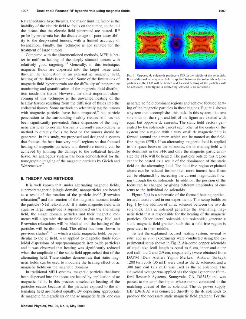
generate ac field dominant regions and achieve focused heat-ing of the magnetic particles in these regions. Figure 1 showsa system that accomplishes this task. In this system, the twosolenoids on the right and left of the figure are excited withequal but opposite dc currents. The static field vectors gen-erated by the solenoids cancel each other at the center of thesystem and a region with a very small dc magnetic field isformed around the center, which can be named as the field-free region �FFR�. If an alternating magnetic field is appliedto the space between the solenoids, the alternating field willbe dominant in the FFR and only the magnetic particles in-side the FFR will be heated. The particles outside this regioncannot be heated as a result of the dominance of the staticfield on the alternating field. The field-free region explainedabove can be reduced further �i.e., more intense heat focuscan be obtained� by increasing the current magnitudes flow-ing through the dc solenoids. In addition, the position of thefocus can be changed by giving different amplitudes of cur-rents to the individual dc solenoids.
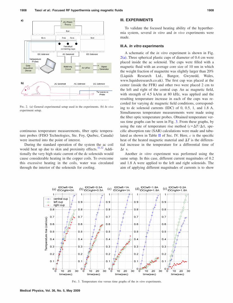
Figure 2�a� is a schematic of the focused heating applica-tor architecture used in our experiments. This setup builds onFig. 1 by the addition of an ac solenoid between the two dcsolenoids. This ac solenoid generates the alternating mag-netic field that is responsible for the heating of the magneticparticles. Other lateral solenoids �dc solenoids� generate astatic magnetic field gradient such that a field-free region isgenerated in their middle.
To test the explained focused heating system, several invitro and in vivo experiments were conducted using the ex-perimental setup shown in Fig. 2. Air-cored copper solenoidsof equal size �coil length is equal to 6 cm, inner and outercoil radii are 2 and 2.9 cm, respectively� were obtained fromDAYM �Ders Aletleri Yapim Merkezi, Ankara, Turkey�.1200 turn coils �35 mH� were used as the dc solenoids and a300 turn coil �2.7 mH� was used as the ac solenoid. Thesinusoidal voltage was applied via the signal generator �Stan-ford Research Systems, Sunnyvale, CA, DS345� and waspassed to the amplifier input, whose output connected to thematching circuit of the ac solenoid. The dc power supply�HP E3616 A� was connected directly to the dc solenoids to
FIG. 1. Opposed dc solenoids produce a FFR in the middle of the solenoids.If an additional ac magnetic field is applied between the solenoids only theparticles in the FFR will be heated and focused heating of the particles willbe achieved. �This figure is created by VIZIMAG 3.14 software.�
produce the necessary static magnetic field gradient. For the
1908 Tasci et al.: Focused RF hyperthermia using magnetic fluids 1908
continuous temperature measurements, fiber optic tempera-ture probes �FISO Technologies, Ste. Foy, Quebec, Canada�were inserted into the point of interest.
During the standard operation of the system the ac coilwould heat up due to skin and proximity effects.11,12 Addi-tionally the very high static current of the dc solenoids wouldcause considerable heating in the copper coils. To overcomethis excessive heating in the coils, water was circulatedthrough the interior of the solenoids for cooling.
FIG. 2. �a� General experimental setup used in the experiments. �b� In vivoexperiment setup.
FIG. 3. Temperature rise versus time g
Medical Physics, Vol. 36, No. 5, May 2009
III. EXPERIMENTS
To validate the focused heating ability of the hyperther-mia system, several in vitro and in vivo experiments weremade.
III.A. In vitro experiments
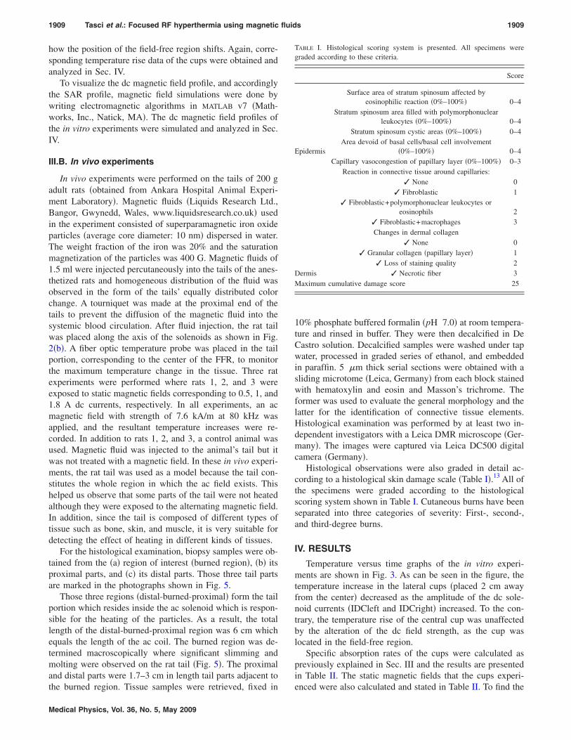
A schematic of the in vitro experiment is shown in Fig.2�a�. Three spherical plastic cups of diameter of 0.4 cm wereplaced inside the ac solenoid. The cups were filled with amagnetic fluid with an average core size of 10 nm in whichthe weight fraction of magnetite was slightly larger than 20%�Liquids Research Ltd., Bangor, Gwynedd, Wales,www.liquidsresearch.co.uk�. The first cup was placed at thecenter �inside the FFR� and other two were placed 2 cm tothe left and right of the central cup. An ac magnetic field,with strength of 4.5 kA/m at 80 kHz, was applied and theresulting temperature increase in each of the cups was re-corded for varying dc magnetic field conditions, correspond-ing to dc solenoid currents �IDC� of 0, 0.5, 1, and 1.8 A.Simultaneous temperature measurements were made usingthe fiber optic temperature probes. Obtained temperature ver-sus time graphs can be seen in Fig. 3. From these graphs, byusing the rate of temperature rise method �c��T /�t�, spe-cific absorption rate �SAR� calculations were made and tabu-lated as shown in Table II of Sec. IV. Here, c is the specificheat of the heated magnetic material and �T is the differen-tial increase in the temperature for a differential time of�t s.
Another in vitro experiment was performed using thesame setup. In this case, different current magnitudes of 0.2and 1.8 A were applied to the left and right solenoids. Theaim of applying different magnitudes of currents is to show
raphs of the in vitro experiments.
1909 Tasci et al.: Focused RF hyperthermia using magnetic fluids 1909
how the position of the field-free region shifts. Again, corre-sponding temperature rise data of the cups were obtained andanalyzed in Sec. IV.
To visualize the dc magnetic field profile, and accordinglythe SAR profile, magnetic field simulations were done bywriting electromagnetic algorithms in MATLAB v7 �Math-works, Inc., Natick, MA�. The dc magnetic field profiles ofthe in vitro experiments were simulated and analyzed in Sec.IV.
III.B. In vivo experiments
In vivo experiments were performed on the tails of 200 gadult rats �obtained from Ankara Hospital Animal Experi-ment Laboratory�. Magnetic fluids �Liquids Research Ltd.,Bangor, Gwynedd, Wales, www.liquidsresearch.co.uk� usedin the experiment consisted of superparamagnetic iron oxideparticles �average core diameter: 10 nm� dispersed in water.The weight fraction of the iron was 20% and the saturationmagnetization of the particles was 400 G. Magnetic fluids of1.5 ml were injected percutaneously into the tails of the anes-thetized rats and homogeneous distribution of the fluid wasobserved in the form of the tails’ equally distributed colorchange. A tourniquet was made at the proximal end of thetails to prevent the diffusion of the magnetic fluid into thesystemic blood circulation. After fluid injection, the rat tailwas placed along the axis of the solenoids as shown in Fig.2�b�. A fiber optic temperature probe was placed in the tailportion, corresponding to the center of the FFR, to monitorthe maximum temperature change in the tissue. Three ratexperiments were performed where rats 1, 2, and 3 wereexposed to static magnetic fields corresponding to 0.5, 1, and1.8 A dc currents, respectively. In all experiments, an acmagnetic field with strength of 7.6 kA/m at 80 kHz wasapplied, and the resultant temperature increases were re-corded. In addition to rats 1, 2, and 3, a control animal wasused. Magnetic fluid was injected to the animal’s tail but itwas not treated with a magnetic field. In these in vivo experi-ments, the rat tail was used as a model because the tail con-stitutes the whole region in which the ac field exists. Thishelped us observe that some parts of the tail were not heatedalthough they were exposed to the alternating magnetic field.In addition, since the tail is composed of different types oftissue such as bone, skin, and muscle, it is very suitable fordetecting the effect of heating in different kinds of tissues.
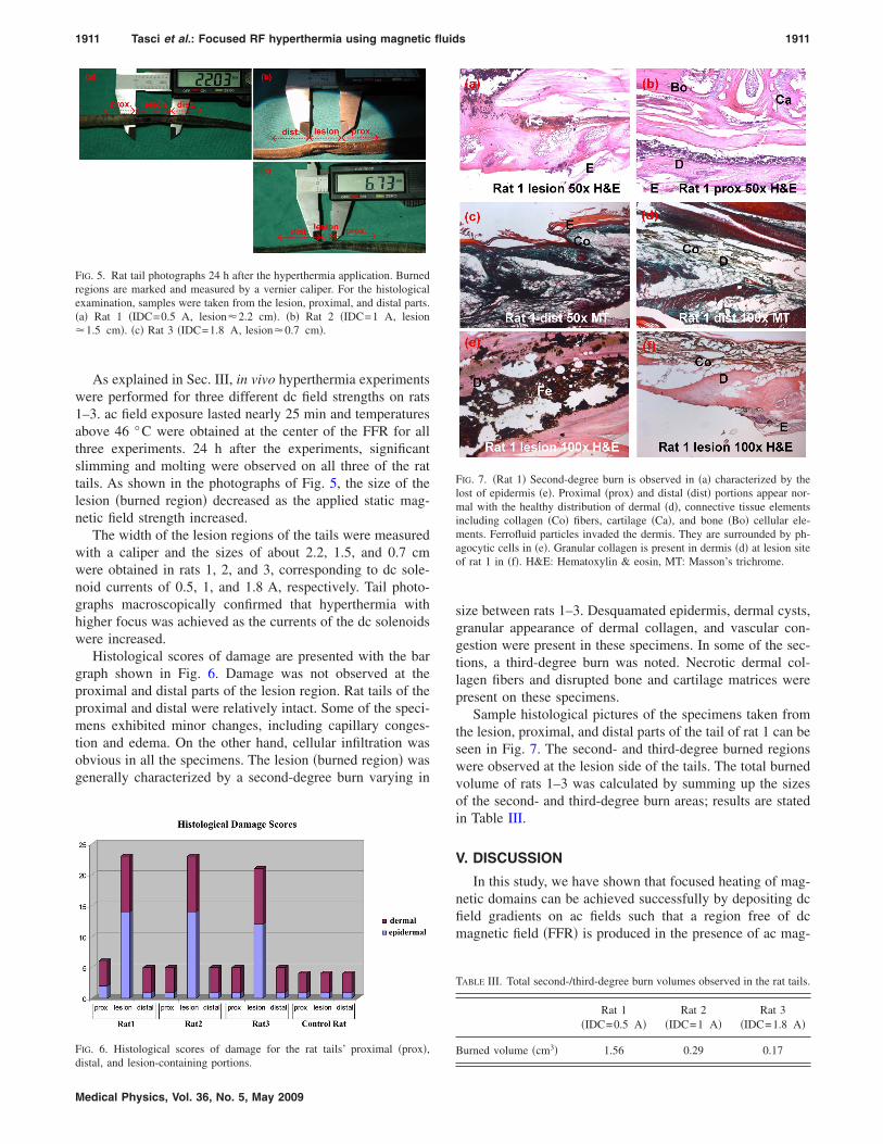
For the histological examination, biopsy samples were ob-tained from the �a� region of interest �burned region�, �b� itsproximal parts, and �c� its distal parts. Those three tail partsare marked in the photographs shown in Fig. 5.
Those three regions �distal-burned-proximal� form the tailportion which resides inside the ac solenoid which is respon-sible for the heating of the particles. As a result, the totallength of the distal-burned-proximal region was 6 cm whichequals the length of the ac coil. The burned region was de-termined macroscopically where significant slimming andmolting were observed on the rat tail �Fig. 5�. The proximaland distal parts were 1.7–3 cm in length tail parts adjacent to
the burned region. Tissue samples were retrieved, fixed inMedical Physics, Vol. 36, No. 5, May 2009
10% phosphate buffered formalin �pH 7.0� at room tempera-ture and rinsed in buffer. They were then decalcified in DeCastro solution. Decalcified samples were washed under tapwater, processed in graded series of ethanol, and embeddedin paraffin. 5 �m thick serial sections were obtained with asliding microtome �Leica, Germany� from each block stainedwith hematoxylin and eosin and Masson’s trichrome. Theformer was used to evaluate the general morphology and thelatter for the identification of connective tissue elements.Histological examination was performed by at least two in-dependent investigators with a Leica DMR microscope �Ger-many�. The images were captured via Leica DC500 digitalcamera �Germany�.
Histological observations were also graded in detail ac-cording to a histological skin damage scale �Table I�.13 All ofthe specimens were graded according to the histologicalscoring system shown in Table I. Cutaneous burns have beenseparated into three categories of severity: First-, second-,and third-degree burns.
IV. RESULTS
Temperature versus time graphs of the in vitro experi-ments are shown in Fig. 3. As can be seen in the figure, thetemperature increase in the lateral cups �placed 2 cm awayfrom the center� decreased as the amplitude of the dc sole-noid currents �IDCleft and IDCright� increased. To the con-trary, the temperature rise of the central cup was unaffectedby the alteration of the dc field strength, as the cup waslocated in the field-free region.
Specific absorption rates of the cups were calculated aspreviously explained in Sec. III and the results are presentedin Table II. The static magnetic fields that the cups experi-
TABLE I. Histological scoring system is presented. All specimens weregraded according to these criteria.
Score
Epidermis
Surface area of stratum spinosum affected byeosinophilic reaction �0%–100%� 0–4
Stratum spinosum area filled with polymorphonuclearleukocytes �0%–100%� 0–4
Stratum spinosum cystic areas �0%–100%� 0–4Area devoid of basal cells/basal cell involvement
�0%–100%� 0–4
Dermis
Capillary vasocongestion of papillary layer �0%–100%� 0–3Reaction in connective tissue around capillaries:
3 None 03 Fibroblastic 1
3 Fibroblastic+polymorphonuclear leukocytes oreosinophils 2
3 Fibroblastic+macrophages 3Changes in dermal collagen
3 None 03 Granular collagen �papillary layer� 1
3 Loss of staining quality 23 Necrotic fiber 3
Maximum cumulative damage score 25
enced were also calculated and stated in Table II. To find the
1910 Tasci et al.: Focused RF hyperthermia using magnetic fluids 1910
magnetic field generated by the solenoids, we first calculatedthe magnetic field produced by a single current loop and thensuperimposed this solution for the current loops of the sole-noids.
As we can see from Table II, while the current of the dcsolenoids increased from 0 to 1.8 A, the SAR of the lateralcups decreased from 120 to 30 W/kg and the SAR of thecentral cup did not change, remaining at roughly 160 W/kg.
Another in vitro experiment was done to observe the shift-ing of the FFR through the application of different magni-tudes of currents �IDC� to the dc solenoids. In this case, 0.2A was applied to the solenoid on the left-hand side and 1.8 Awas applied to the solenoid on the right-hand side. The cor-responding temperature curve is shown in Fig. 3�e�. Lookingat this figure, one can observe that maximum heating wasseen in the left cup, demonstrating that the field-free regionshifted to the left.
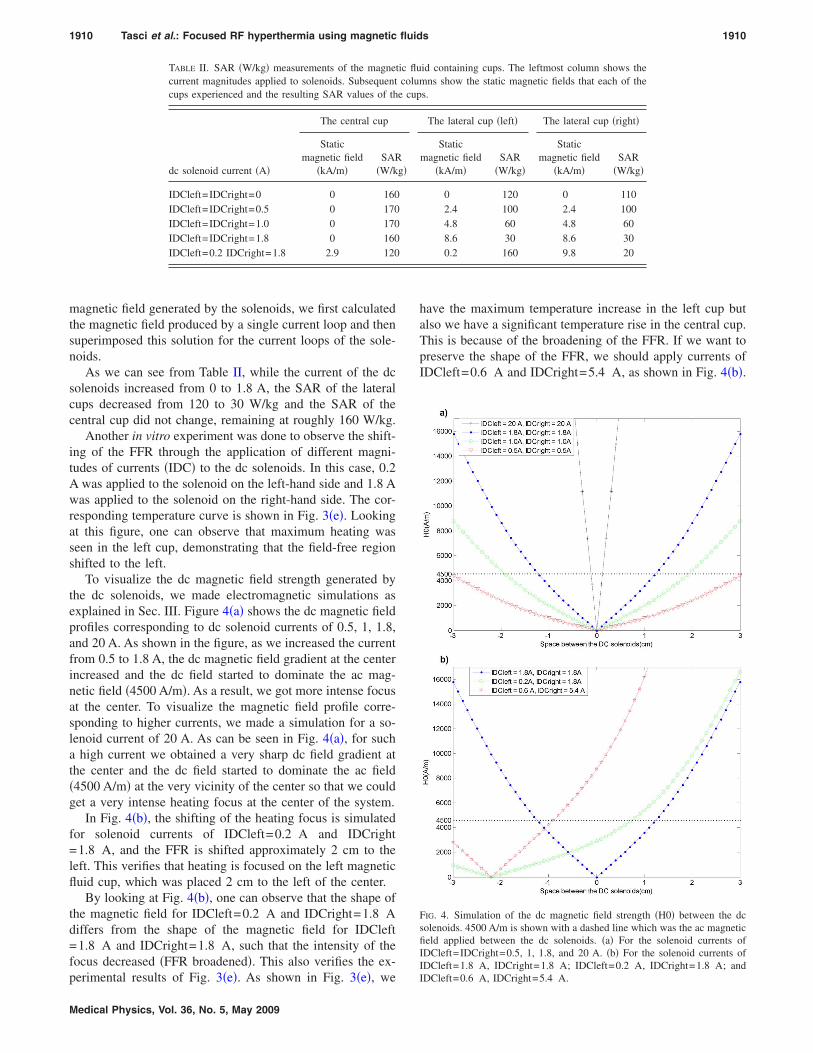
To visualize the dc magnetic field strength generated bythe dc solenoids, we made electromagnetic simulations asexplained in Sec. III. Figure 4�a� shows the dc magnetic fieldprofiles corresponding to dc solenoid currents of 0.5, 1, 1.8,and 20 A. As shown in the figure, as we increased the currentfrom 0.5 to 1.8 A, the dc magnetic field gradient at the centerincreased and the dc field started to dominate the ac mag-netic field �4500 A/m�. As a result, we got more intense focusat the center. To visualize the magnetic field profile corre-sponding to higher currents, we made a simulation for a so-lenoid current of 20 A. As can be seen in Fig. 4�a�, for sucha high current we obtained a very sharp dc field gradient atthe center and the dc field started to dominate the ac field�4500 A/m� at the very vicinity of the center so that we couldget a very intense heating focus at the center of the system.
In Fig. 4�b�, the shifting of the heating focus is simulatedfor solenoid currents of IDCleft=0.2 A and IDCright=1.8 A, and the FFR is shifted approximately 2 cm to theleft. This verifies that heating is focused on the left magneticfluid cup, which was placed 2 cm to the left of the center.
By looking at Fig. 4�b�, one can observe that the shape ofthe magnetic field for IDCleft=0.2 A and IDCright=1.8 Adiffers from the shape of the magnetic field for IDCleft=1.8 A and IDCright=1.8 A, such that the intensity of thefocus decreased �FFR broadened�. This also verifies the ex-
TABLE II. SAR �W/kg� measurements of the magnetcurrent magnitudes applied to solenoids. Subsequentcups experienced and the resulting SAR values of th
dc solenoid current �A�
The central cup
Staticmagnetic field
�kA/m�SAR
�W/k
IDCleft=IDCright=0 0 160IDCleft=IDCright=0.5 0 170IDCleft=IDCright=1.0 0 170IDCleft=IDCright=1.8 0 160IDCleft=0.2 IDCright=1.8 2.9 120
perimental results of Fig. 3�e�. As shown in Fig. 3�e�, we
Medical Physics, Vol. 36, No. 5, May 2009
have the maximum temperature increase in the left cup butalso we have a significant temperature rise in the central cup.This is because of the broadening of the FFR. If we want topreserve the shape of the FFR, we should apply currents ofIDCleft=0.6 A and IDCright=5.4 A, as shown in Fig. 4�b�.
id containing cups. The leftmost column shows themns show the static magnetic fields that each of thes.
The lateral cup �left� The lateral cup �right�
Staticmagnetic field
�kA/m�SAR
�W/kg�
Staticmagnetic field
�kA/m�SAR
�W/kg�
0 120 0 1102.4 100 2.4 1004.8 60 4.8 608.6 30 8.6 300.2 160 9.8 20
FIG. 4. Simulation of the dc magnetic field strength �H0� between the dcsolenoids. 4500 A/m is shown with a dashed line which was the ac magneticfield applied between the dc solenoids. �a� For the solenoid currents ofIDCleft=IDCright=0.5, 1, 1.8, and 20 A. �b� For the solenoid currents ofIDCleft=1.8 A, IDCright=1.8 A; IDCleft=0.2 A, IDCright=1.8 A; and
ic flucolu
e cup
g�
IDCleft=0.6 A, IDCright=5.4 A.
1911 Tasci et al.: Focused RF hyperthermia using magnetic fluids 1911
As explained in Sec. III, in vivo hyperthermia experimentswere performed for three different dc field strengths on rats1–3. ac field exposure lasted nearly 25 min and temperaturesabove 46 °C were obtained at the center of the FFR for allthree experiments. 24 h after the experiments, significantslimming and molting were observed on all three of the rattails. As shown in the photographs of Fig. 5, the size of thelesion �burned region� decreased as the applied static mag-netic field strength increased.
The width of the lesion regions of the tails were measuredwith a caliper and the sizes of about 2.2, 1.5, and 0.7 cmwere obtained in rats 1, 2, and 3, corresponding to dc sole-noid currents of 0.5, 1, and 1.8 A, respectively. Tail photo-graphs macroscopically confirmed that hyperthermia withhigher focus was achieved as the currents of the dc solenoidswere increased.
Histological scores of damage are presented with the bargraph shown in Fig. 6. Damage was not observed at theproximal and distal parts of the lesion region. Rat tails of theproximal and distal were relatively intact. Some of the speci-mens exhibited minor changes, including capillary conges-tion and edema. On the other hand, cellular infiltration wasobvious in all the specimens. The lesion �burned region� wasgenerally characterized by a second-degree burn varying in
FIG. 5. Rat tail photographs 24 h after the hyperthermia application. Burnedregions are marked and measured by a vernier caliper. For the histologicalexamination, samples were taken from the lesion, proximal, and distal parts.�a� Rat 1 �IDC=0.5 A, lesion�2.2 cm�. �b� Rat 2 �IDC=1 A, lesion�1.5 cm�. �c� Rat 3 �IDC=1.8 A, lesion�0.7 cm�.
FIG. 6. Histological scores of damage for the rat tails’ proximal �prox�,
distal, and lesion-containing portions.Medical Physics, Vol. 36, No. 5, May 2009
size between rats 1–3. Desquamated epidermis, dermal cysts,granular appearance of dermal collagen, and vascular con-gestion were present in these specimens. In some of the sec-tions, a third-degree burn was noted. Necrotic dermal col-lagen fibers and disrupted bone and cartilage matrices werepresent on these specimens.
Sample histological pictures of the specimens taken fromthe lesion, proximal, and distal parts of the tail of rat 1 can beseen in Fig. 7. The second- and third-degree burned regionswere observed at the lesion side of the tails. The total burnedvolume of rats 1–3 was calculated by summing up the sizesof the second- and third-degree burn areas; results are statedin Table III.
V. DISCUSSION
In this study, we have shown that focused heating of mag-netic domains can be achieved successfully by depositing dcfield gradients on ac fields such that a region free of dcmagnetic field �FFR� is produced in the presence of ac mag-
FIG. 7. �Rat 1� Second-degree burn is observed in �a� characterized by thelost of epidermis �e�. Proximal �prox� and distal �dist� portions appear nor-mal with the healthy distribution of dermal �d�, connective tissue elementsincluding collagen �Co� fibers, cartilage �Ca�, and bone �Bo� cellular ele-ments. Ferrofluid particles invaded the dermis. They are surrounded by ph-agocytic cells in �e�. Granular collagen is present in dermis �d� at lesion siteof rat 1 in �f�. H&E: Hematoxylin & eosin, MT: Masson’s trichrome.
TABLE III. Total second-/third-degree burn volumes observed in the rat tails.
Rat 1�IDC=0.5 A�
Rat 2�IDC=1 A�
Rat 3�IDC=1.8 A�
Burned volume �cm3� 1.56 0.29 0.17
1912 Tasci et al.: Focused RF hyperthermia using magnetic fluids 1912
netic field. As demonstrated in the temperature versus timegraphs of Fig. 3 and SAR measurements of Table II, theintensity of the heating focus can be easily improved byincreasing the dc magnetic field gradient, i.e., by applyinghigher magnitudes of currents to the dc solenoids.
As shown in the magnetic field simulations �Fig. 4�a��, ifwe want to focus the heat at the center of the solenoids, bothsolenoids should be excited with the same dc currents. If wewant to change the position of the focus �FFR�, we shouldapply different amounts of currents to the solenoids but, topreserve the intensity of the focus, these currents should beselected carefully by making magnetic field simulations asshown in Fig. 4�b�.
Heat focusing ability of the hyperthermia system wasverified in vivo via rat experiments. As summarized in TableIII, we obtained a significant decrease in the total burnedvolume as we increased the magnitude of the static magneticfield.
The system implemented in this study can shift the focusin only one dimension �along the axis of the solenoids�. 3Dmovement of the focus could be achieved by using more dccoils which could shift the FFR along the x, y, and z axes.For this purpose, 3D gradient coil systems similar in shape tothe gradient coils of magnetic resonance imaging �MRI�scanners may be used. Typical MRI gradient coils producedc field gradients in all three dimensions. Through furtheroptimization of this gradient coil system, 3D scanning of theheat focus could be obtained. Using such 3D location-shifting approach, tumors with different geometries can betreated by moving the FFR over the tumor. Even with thepresented hyperthermia system �composed of two dc sole-noids�, tumors with various shapes might still be treated. Toachieve this, since the FFR region always stays at the center,the patient would have to be moved by very accurate roboticdevices according to the shape of the tumor.
Copper heating is one of the serious problems that shouldbe considered during the design of the magnetic field appli-cators. In our system copper heating was seen in both dc andac field applicators and heating was resolved by using watercooling. Water cooling setups are successful in preventingthe copper heating of ac field applicators with magnetic fieldamplitudes lower than 20 kA/m.14 Water cooling may not besufficient for dc field applicators if highly intense focus isneeded �i.e., very large magnitudes of dc current flow is nec-essary�. To address this problem, superconductive wirescould be utilized in the construction of the dc field applica-tors.
VI. CONCLUSION
A novel hyperthermia system, capable of focused heatingof tumors, is presented and verified through experiments.
Through the use of this newly developed heat treatment sys-Medical Physics, Vol. 36, No. 5, May 2009
tem, magnetic fluid hyperthermia can be a more effectiveheat treatment method, with a much decreased risk of heat-ing healthy collateral tissues. Future works can include thecombination of the hyperthermia system with a suitable im-aging method and the construction of the dc solenoids withsuperconductive wires to overcome the excessive copperheating. In addition, systems capable of 3D shifting of theheating focus can also be implemented. Furthermore, pri-mary concern should be given to the optimization of themagnetic fluids, which will lead to the heating of tumorswith very small amounts of fluid injections and very shorttreatment durations.
ACKNOWLEDGMENTS
This work has been supported by a grant from the Na-tional Institutes of Health �Grant No. R01-RR-15396� andEuropean Commission, FP6 Marie Curie International Rein-tegration Grant.
a�Author to whom correspondence should be addressed. Electronic mail:[email protected]
1P. Moroz, S. K. Jones, and B. N. Gray, “Magnetically mediated hyper-thermia: Current status and future directions,” Int. J. Hyperthermia 18,267–284 �2002�.
2P. Moroz, S. K. Jones, and B. N. Gray, “Status of hyperthermia in thetreatment of advanced liver cancer,” J. Surg. Oncol. 77, 259–269 �2001�.
3M. Shinkai, “Functional magnetic particles for medical application,” J.Biosci. Bioeng. 94, 606–613 �2002�.
4M. Johannsen, A. Jordan, R. Scholz, M. Koch, M. Lein, S. Deger, J.Roigas, K. Jung, and S. Loening, “Evaluation of magnetic fluid hyper-thermia in a standard rat model of prostate cancer,” J. Endourol. 18,495–500 �2004�.
5A. Jordan, P. Wust, H. Fahling, W. John, A. Hinz, and R. Felix, “Inductiveheating of ferrimagnetic particles and magnetic fluids: Physical evaluationof their potential for hyperthermia,” Int. J. Hyperthermia 9, 51–68 �1993�.
6F. Matsuoka, M. Shinkai, H. Honda, T. Kubo, T. Sugita, and T. Koba-yashi, “Hyperthermia using magnetite cationic liposomes for hamster os-teosarcoma,” BioMagnetic Research and Technology 2004, 2:3.
7B. Gleich and J. Weizenecker, “Tomographic imaging using the nonlinearresponse of magnetic particles,” Nat. Biotechnol. 435, 1214–1217 �2005�.
8W. F. Brown, Jr., “Thermal fluctuations of a single-domain particle,”Phys. Rev. 130, 1677–1686 �1963�.
9L. Neel, “Theorie du trainage magnetique des ferromagnetiques en grainsfins avec applications aux terres cuites,” Ann. Geophys. 5, 99–136�1949�.
10M. Babincova, D. Leszczynska, P. Sourivong, P. Cicmanec, and P. Babi-nec, “Superparamagnetic gel as a novel material for electromagneticallyinduced hyperthermia,” J. Magn. Magn. Mater. 225, 109–112 �2001�.
11B. B. Austin, “The effective resistance of inductance coils at radio fre-quency,” The Wireless Engineer, Vol. 11, pp. 12–16, Jan. 1934, summaryof work by S. Butterworth.
12P. N. Murgatroyd, “Calculation of proximity losses in multistranded con-ductor bunches,” Proc. IEEE 36, 115–120 �1989�.
13P. F. Meyer, P. D. Gadsby, D. Van Sickle, W. E. Schoenlein, K. S. Foster,and G. P. Graber, “Impedance-gradient electrode reduces skin irritationinduced by transthoracic defibrillation,” Med. Biol. Eng. Comput. 43,225–229 �2005�.
14S. Mornet, S. Vasseur, F. Grasset, and E. Duguet, “Magnetic nanoparticledesign for medical diagnosis and therapy,” J. Mater. Chem. 14, 2161–
2175 �2004�.