Vision and GPS-based autonomous vehicle navigation using templates and artificial neural networks
6
Vision and GPS-based Autonomous Vehicle Navigation Using Templates and Artificial Neural Networks Jefferson R. Souza, Gustavo Pessin, Gustavo B. Eboli, Caio C. T. Mendes, Fernando S. Osório and Denis F. Wolf Mobile Robotics Laboratory, University of São Paulo (USP) Av. Trabalhador São-Carlense, 400 - P.O. Box 668 - 13.560-970 - São Carlos, Brazil {jrsouza, pessin, caiom, fosorio, denis}@icmc.usp.br [email protected] ABSTRACT This paper presents a vehicle control system capable of learn- ing to navigate autonomously. Our approach is based on im- age processing, road and navigable area identification, tem- plate matching classification for navigation control, and tra- jectory selection based on GPS way-points. The vehicle fol- lows a trajectory defined by GPS points avoiding obstacles using a single monocular camera. The images obtained from the camera are classified into navigable and non-navigable regions of the environment using neural networks that con- trol the steering and velocity of the vehicle. Several experi- mental tests have been carried out under different environ- mental conditions to evaluate the proposed techniques. Categories and Subject Descriptors I.2.9 [Artificial Intelligence]: Robotics—Autonomous Ve- hicles. General Terms Algorithms, Performance, Design, Experimentation. Keywords Robotic Vehicles Navigation, Compass, GPS, Trapezoidal Algorithm, Neural Networks and Urban Environments. 1. INTRODUCTION Human driving errors are a major cause of car accidents on roads. These errors are caused by a series of in-car distrac- tions, such as using mobile phones, eating while driving, or listening to loud music. Other human errors include drunk driving, speeding, and fatigue. People often get injured or even die due to road traffic collisions (RTC). Also, bad road and weather conditions Permission to make digital or hard copies of all or part of this work for personal or classroom use is granted without fee provided that copies are not made or distributed for profit or commercial advantage and that copies bear this notice and the full citation on the first page. To copy otherwise, to republish, to post on servers or to redistribute to lists, requires prior specific permission and/or a fee. SAC’12 March 25-29, 2012, Riva del Garda, Italy. Copyright 2011 ACM 978-1-4503-0857-1/12/03 ...$10.00. Figure 1: CaRINA test platform. increase the risk of RTC. Autonomous vehicles could pro- vide safer conditions in roads, as they can use sensors and actuators to detect and avoid dangerous situations. They could also improve the efficiency in freight transportation and traffic flow in large cities and provide transportation to physically handicapped or visually impaired people. Research in mobile robotics have reached significant pro- gress and improved the experimental results over the last years. Some of them have focused on autonomous naviga- tion, which is a fundamental task in the area [9]. Lately, several works have improved navigation in urban environ- ments. Competitions, like DARPA Grand [6] and Urban [7] Challenges and ELROB [1] have been pushing the state of the art in autonomous vehicle control. The relevant results obtained in such competitions com- bine information from a large number of complex sensors. Some approaches use five (or more) laser range finders, video cameras, radar, differential GPS, and inertial measurement units [3], [10]. Although there are several interesting appli- cations for such a technology, its cost is very high, hampering commercial applications. This paper proposes a GPS-oriented and vision-based au- tonomous navigation approach for urban environments. The system uses a single monocular camera to acquire data from the environment, a compass (orientation) and a GPS (lo- calization) to obtain the necessary information for the the vehicle to reach destination through a safe path. It also de- tects the navigable regions (roads) and estimates the most appropriate maneuver. Different Artificial Neural Networks (ANNs) topologies are evaluated in order to keep the vehicle in a safe path, and finally control the vehicle ˇ Ss steering and acceleration. Figure 1 presents our Intelligent Robotic Car for Autonomous Navigation (CaRINA). 280
-
Upload
independent -
Category
Documents
-
view
0 -
download
0
Transcript of Vision and GPS-based autonomous vehicle navigation using templates and artificial neural networks
Vision and GPS-based Autonomous Vehicle NavigationUsing Templates and Artificial Neural Networks
Jefferson R. Souza, Gustavo Pessin, Gustavo B. Eboli, Caio C. T. Mendes,Fernando S. Osório and Denis F. Wolf
Mobile Robotics Laboratory, University of São Paulo (USP)Av. Trabalhador São-Carlense, 400 - P.O. Box 668 - 13.560-970 - São Carlos, Brazil
{jrsouza, pessin, caiom, fosorio, denis}@[email protected]
ABSTRACTThis paper presents a vehicle control system capable of learn-ing to navigate autonomously. Our approach is based on im-age processing, road and navigable area identification, tem-plate matching classification for navigation control, and tra-jectory selection based on GPS way-points. The vehicle fol-lows a trajectory defined by GPS points avoiding obstaclesusing a single monocular camera. The images obtained fromthe camera are classified into navigable and non-navigableregions of the environment using neural networks that con-trol the steering and velocity of the vehicle. Several experi-mental tests have been carried out under different environ-mental conditions to evaluate the proposed techniques.
Categories and Subject DescriptorsI.2.9 [Artificial Intelligence]: Robotics—Autonomous Ve-hicles.
General TermsAlgorithms, Performance, Design, Experimentation.
KeywordsRobotic Vehicles Navigation, Compass, GPS, TrapezoidalAlgorithm, Neural Networks and Urban Environments.
1. INTRODUCTIONHuman driving errors are a major cause of car accidents on
roads. These errors are caused by a series of in-car distrac-tions, such as using mobile phones, eating while driving, orlistening to loud music. Other human errors include drunkdriving, speeding, and fatigue.
People often get injured or even die due to road trafficcollisions (RTC). Also, bad road and weather conditions
Permission to make digital or hard copies of all or part of this work forpersonal or classroom use is granted without fee provided that copies arenot made or distributed for profit or commercial advantage and that copiesbear this notice and the full citation on the first page. To copy otherwise, torepublish, to post on servers or to redistribute to lists, requires prior specificpermission and/or a fee.SAC’12 March 25-29, 2012, Riva del Garda, Italy.Copyright 2011 ACM 978-1-4503-0857-1/12/03 ...$10.00.
Figure 1: CaRINA test platform.
increase the risk of RTC. Autonomous vehicles could pro-vide safer conditions in roads, as they can use sensors andactuators to detect and avoid dangerous situations. Theycould also improve the efficiency in freight transportationand traffic flow in large cities and provide transportation tophysically handicapped or visually impaired people.
Research in mobile robotics have reached significant pro-gress and improved the experimental results over the lastyears. Some of them have focused on autonomous naviga-tion, which is a fundamental task in the area [9]. Lately,several works have improved navigation in urban environ-ments. Competitions, like DARPA Grand [6] and Urban [7]Challenges and ELROB [1] have been pushing the state ofthe art in autonomous vehicle control.
The relevant results obtained in such competitions com-bine information from a large number of complex sensors.Some approaches use five (or more) laser range finders, videocameras, radar, differential GPS, and inertial measurementunits [3], [10]. Although there are several interesting appli-cations for such a technology, its cost is very high, hamperingcommercial applications.
This paper proposes a GPS-oriented and vision-based au-tonomous navigation approach for urban environments. Thesystem uses a single monocular camera to acquire data fromthe environment, a compass (orientation) and a GPS (lo-calization) to obtain the necessary information for the thevehicle to reach destination through a safe path. It also de-tects the navigable regions (roads) and estimates the mostappropriate maneuver. Different Artificial Neural Networks(ANNs) topologies are evaluated in order to keep the vehiclein a safe path, and finally control the vehicleSs steering andacceleration. Figure 1 presents our Intelligent Robotic Carfor Autonomous Navigation (CaRINA).
280
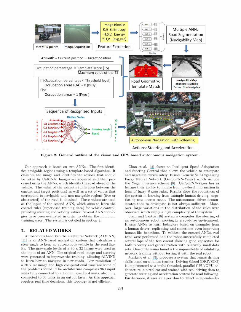
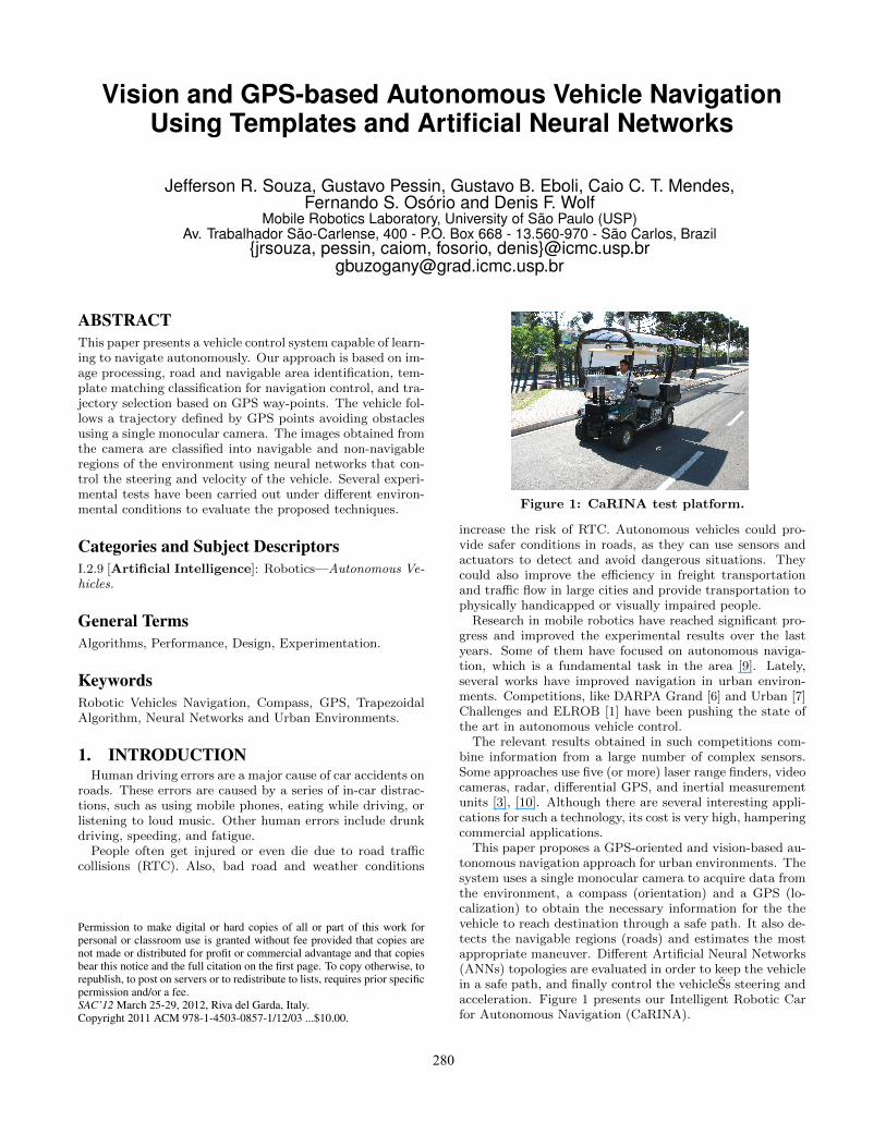
Figure 2: General outline of the vision and GPS based autonomous navigation system.
Our approach is based on two ANNs. The first identi-fies navigable regions using a template-based algorithm. Itclassifies the image and identifies the actions that shouldbe taken by CaRINA. Images are acquired and then pro-cessed using the ANNs, which identify the road ahead of thevehicle. The value of the azimuth (difference between thecurrent and target positions) as well as a set of values thatcorrespond to navigable and non-navigable regions (free orobstructed) of the road is obtained. These values are usedas the input of the second ANN, which aims to learn thecontrol rules (supervised training data) for vehicle control,providing steering and velocity values. Several ANN topolo-gies have been evaluated in order to obtain the minimumtraining error. The system is detailed in section 3.
2. RELATED WORKSAutonomous Land Vehicle in a Neural Network (ALVINN)
[11] is an ANN-based navigation system that calculates asteer angle to keep an autonomous vehicle in the road lim-its. The gray-scale levels of a 30 x 32 image were used asthe input of an ANN. The original road image and steeringwere generated to improve the training, allowing ALVINNto learn how to navigate in new roads. Low resolution ofa 30 x 32 image and high computational time are some ofthe problems found. The architecture comprises 960 inputunits fully connected to a hidden layer by 4 units, also fullyconnected to 30 units in an output layer. As this approachrequires real time decisions, this topology is not efficient.
Chan et al. [2] shows an Intelligent Speed Adaptationand Steering Control that allows the vehicle to anticipateand negotiate curves safely. It uses Generic Self-OrganizingFuzzy Neural Network (GenSoFNN-Yager) which includethe Yager inference scheme [8]. GenSoFNN-Yager has asfeature their ability to induce from low-level information inform of fuzzy if-then rules. Results show the robustness ofthe system in learning from example human driving, nego-tiating new unseen roads. The autonomous driver demon-strates that to anticipate is not always sufficient. More-over, large variations in the distribution of the rules wereobserved, which imply a high complexity of the system.
Stein and Santos [18] system’s computes the steering ofan autonomous robot, moving in a road-like environment.It uses ANNs to learn behaviors based on examples froma human driver, replicating and sometimes even improvinghuman-like behaviors. To validate the created ANNs, realtests were performed and the robot successfully completedseveral laps of the test circuit showing good capacities forboth recovery and generalization with relatively small datasets. One of the issues found is the impossibility of validatingnetwork training without testing it with the real robot.
Markelic et al. [5], proposes a system that learns drivingskills based on a human teacher. Driving School (DRIVSCO)is implemented as a multi-threaded, parallel CPU/GPU ar-chitecture in a real car and trained with real driving data togenerate steering and acceleration control for road following.Furthermore, it uses an algorithm to detect independently-
281
(a) (b) (c) (d)
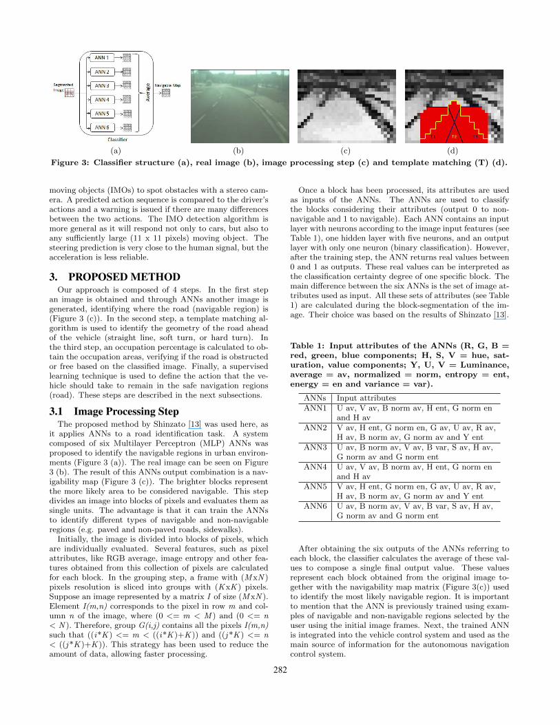
Figure 3: Classifier structure (a), real image (b), image processing step (c) and template matching (T) (d).
moving objects (IMOs) to spot obstacles with a stereo cam-era. A predicted action sequence is compared to the driver’sactions and a warning is issued if there are many differencesbetween the two actions. The IMO detection algorithm ismore general as it will respond not only to cars, but also toany sufficiently large (11 x 11 pixels) moving object. Thesteering prediction is very close to the human signal, but theacceleration is less reliable.
3. PROPOSED METHODOur approach is composed of 4 steps. In the first step
an image is obtained and through ANNs another image isgenerated, identifying where the road (navigable region) is(Figure 3 (c)). In the second step, a template matching al-gorithm is used to identify the geometry of the road aheadof the vehicle (straight line, soft turn, or hard turn). Inthe third step, an occupation percentage is calculated to ob-tain the occupation areas, verifying if the road is obstructedor free based on the classified image. Finally, a supervisedlearning technique is used to define the action that the ve-hicle should take to remain in the safe navigation regions(road). These steps are described in the next subsections.
3.1 Image Processing StepThe proposed method by Shinzato [13] was used here, as
it applies ANNs to a road identification task. A systemcomposed of six Multilayer Perceptron (MLP) ANNs wasproposed to identify the navigable regions in urban environ-ments (Figure 3 (a)). The real image can be seen on Figure3 (b). The result of this ANNs output combination is a nav-igability map (Figure 3 (c)). The brighter blocks representthe more likely area to be considered navigable. This stepdivides an image into blocks of pixels and evaluates them assingle units. The advantage is that it can train the ANNsto identify different types of navigable and non-navigableregions (e.g. paved and non-paved roads, sidewalks).
Initially, the image is divided into blocks of pixels, whichare individually evaluated. Several features, such as pixelattributes, like RGB average, image entropy and other fea-tures obtained from this collection of pixels are calculatedfor each block. In the grouping step, a frame with (MxN )pixels resolution is sliced into groups with (KxK ) pixels.Suppose an image represented by a matrix I of size (MxN ).Element I(m,n) corresponds to the pixel in row m and col-umn n of the image, where (0 <= m < M ) and (0 <= n< N ). Therefore, group G(i,j) contains all the pixels I(m,n)such that ((i*K ) <= m < ((i*K )+K )) and ((j*K ) <= n< ((j*K )+K )). This strategy has been used to reduce theamount of data, allowing faster processing.
Once a block has been processed, its attributes are usedas inputs of the ANNs. The ANNs are used to classifythe blocks considering their attributes (output 0 to non-navigable and 1 to navigable). Each ANN contains an inputlayer with neurons according to the image input features (seeTable 1), one hidden layer with five neurons, and an outputlayer with only one neuron (binary classification). However,after the training step, the ANN returns real values between0 and 1 as outputs. These real values can be interpreted asthe classification certainty degree of one specific block. Themain difference between the six ANNs is the set of image at-tributes used as input. All these sets of attributes (see Table1) are calculated during the block-segmentation of the im-age. Their choice was based on the results of Shinzato [13].
Table 1: Input attributes of the ANNs (R, G, B =red, green, blue components; H, S, V = hue, sat-uration, value components; Y, U, V = Luminance,average = av, normalized = norm, entropy = ent,energy = en and variance = var).
ANNs Input attributesANN1 U av, V av, B norm av, H ent, G norm en
and H avANN2 V av, H ent, G norm en, G av, U av, R av,
H av, B norm av, G norm av and Y entANN3 U av, B norm av, V av, B var, S av, H av,
G norm av and G norm entANN4 U av, V av, B norm av, H ent, G norm en
and H avANN5 V av, H ent, G norm en, G av, U av, R av,
H av, B norm av, G norm av and Y entANN6 U av, B norm av, V av, B var, S av, H av,
G norm av and G norm ent
After obtaining the six outputs of the ANNs referring toeach block, the classifier calculates the average of these val-ues to compose a single final output value. These valuesrepresent each block obtained from the original image to-gether with the navigability map matrix (Figure 3(c)) usedto identify the most likely navigable region. It is importantto mention that the ANN is previously trained using exam-ples of navigable and non-navigable regions selected by theuser using the initial image frames. Next, the trained ANNis integrated into the vehicle control system and used as themain source of information for the autonomous navigationcontrol system.
282
3.2 Template Matching StepAfter obtaining the ANN classification, different road tem-
plates are placed over the image in order to identify the roadgeometry. One of them identifies a straight road ahead, twoidentify soft turns, and two identify hard turns. Each tem-plate is composed of a mask of 1s and 0s, as proposed in[17]. The value of each mask is multiplied by the correspon-dent value into the navigability matrix. The total score foreach template is the sum of products. A good performancewas obtained in the navigation defined by the urban pathavoiding obstacles using the best template [16].
In this step, templates are selected for use in the next stepof the system. The template that obtains the higher scoreis selected as the best match to the road geometry.
3.3 Occupation PercentageIn this step, the templates of the previous step are used to
calculate the occupation percentage of the road regions (nav-igable and non-navigable). This calculation is performed bydividing the template score by its maximum value. This iscarried out for each template, so several values normalizedbetween [0, 1] are obtained.
After obtaining these values based on the occupation ar-eas resulting from the classified images (navigable and non-navigable - image processing step), we verify if the occupa-tion percentage obtained is lower than a threshold level. Itis then assigned as either obstructed (value 0) or free (value1) for the occupation areas, which are part of the systeminput for the next step.
3.4 Learning Based NavigationWe have already developed works analyzing different lev-
els of memory of the templates based on examples obtainedfrom human drivers using neural networks [15]. The re-sults of these neural networks have also been compared withdifferent supervised learning techniques for the same pur-pose [14]. This work is based in the integration of GPSand compass, furthermore the occupation percentage on theautonomous navigation system.
In this step, the basic network structure used is a feedfor-ward MLP. The activation functions of the hidden neuronsare logistic sigmoid and hyperbolic tangent, and the ANNlearning method is the resilient backpropagation (RPROP).The inputs are represented by azimuth (difference betweenthe current and target positions of the vehicle) and thefive values obtained by the occupation percentage step (ob-structed or free occupation areas). The outputs of the pro-posed method are the steer angle and speed (Figure 4).
Figure 4: Structure of the second ANN used to gen-erate steering and acceleration commands.
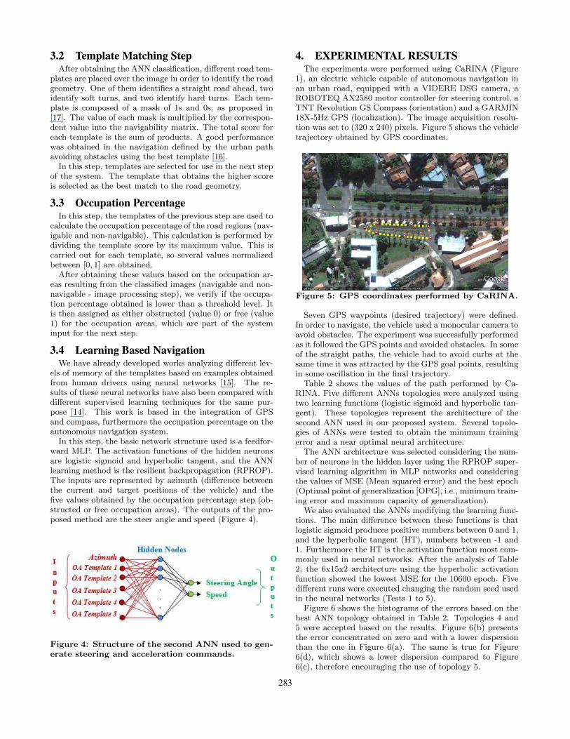
4. EXPERIMENTAL RESULTSThe experiments were performed using CaRINA (Figure
1), an electric vehicle capable of autonomous navigation inan urban road, equipped with a VIDERE DSG camera, aROBOTEQ AX2580 motor controller for steering control, aTNT Revolution GS Compass (orientation) and a GARMIN18X-5Hz GPS (localization). The image acquisition resolu-tion was set to (320 x 240) pixels. Figure 5 shows the vehicletrajectory obtained by GPS coordinates.
Figure 5: GPS coordinates performed by CaRINA.
Seven GPS waypoints (desired trajectory) were defined.In order to navigate, the vehicle used a monocular camera toavoid obstacles. The experiment was successfully performedas it followed the GPS points and avoided obstacles. In someof the straight paths, the vehicle had to avoid curbs at thesame time it was attracted by the GPS goal points, resultingin some oscillation in the final trajectory.
Table 2 shows the values of the path performed by Ca-RINA. Five different ANNs topologies were analyzed usingtwo learning functions (logistic sigmoid and hyperbolic tan-gent). These topologies represent the architecture of thesecond ANN used in our proposed system. Several topolo-gies of ANNs were tested to obtain the minimum trainingerror and a near optimal neural architecture.
The ANN architecture was selected considering the num-ber of neurons in the hidden layer using the RPROP super-vised learning algorithm in MLP networks and consideringthe values of MSE (Mean squared error) and the best epoch(Optimal point of generalization [OPG], i.e., minimum train-ing error and maximum capacity of generalization).
We also evaluated the ANNs modifying the learning func-tions. The main difference between these functions is thatlogistic sigmoid produces positive numbers between 0 and 1,and the hyperbolic tangent (HT), numbers between -1 and1. Furthermore the HT is the activation function most com-monly used in neural networks. After the analysis of Table2, the 6x15x2 architecture using the hyperbolic activationfunction showed the lowest MSE for the 10600 epoch. Fivedifferent runs were executed changing the random seed usedin the neural networks (Tests 1 to 5).
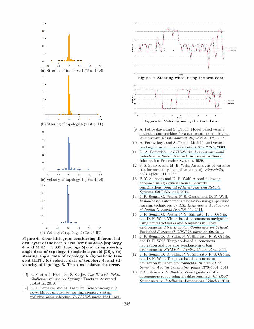
Figure 6 shows the histograms of the errors based on thebest ANN topology obtained in Table 2. Topologies 4 and5 were accepted based on the results. Figure 6(b) presentsthe error concentrated on zero and with a lower dispersionthan the one in Figure 6(a). The same is true for Figure6(d), which shows a lower dispersion compared to Figure6(c), therefore encouraging the use of topology 5.
283

Table 2: Results of the ANNs for each topology.Learning Functions
Logistic Sigmoid Hyperbolic TangentANN Topology Test 1 Test 2 Test 3 Test 4 Test 5 Test 1 Test 2 Test 3 Test 4 Test 5
6x3x2 OGP 600 3000 1400 700 1000 1400 2300 1000 2000 2600Topology 1 MSE (10−3) 5.266 3.922 3.747 5.407 4.856 4.119 3.418 3.737 3.393 3.310
6x6x2 OGP 7600 1200 8300 1700 5600 2200 700 1900 9700 26400Topology 2 MSE (10−3) 2.490 3.257 3.250 3.670 3.414 3.271 3.413 2.148 5.404 3.217
6x9x2 OGP 800 600 500 900 2300 1100 1100 800 800 400Topology 3 MSE (10−3) 3.774 5.013 4.584 5.050 3.190 3.162 3.318 3.650 2.352 4.292
6x12x2 OGP 91800 15200 1000 23600 1400 400 1400 800 300 7400Topology 4 MSE (10−3) 2.836 3.797 3.746 2.048 5.645 4.040 3.899 2.959 3.595 3.895
6x15x2 OGP 400 600 1300 400 700 2600 76100 10600 2500 1000Topology 5 MSE (10−3) 4.226 4.597 4.000 5.319 3.188 3.232 1.999 1.881 3.510 2.989
The statistical difference of the results was evaluated usingShapiro method [12]. We observed that the null hypothesis,i.e., normal adequacy, had not been satisfied (Table 3) usingthe best ANN topology (6x15x2) for the test data.
Table 3: Results of the Shapiro-Wilk Test.Shapiro-Wilk Normality Test
p-valueSteering Velocity
Topology 1 0.2468 3.84e-09Topology 2 5.43e-14 1.97e-15Topology 3 6.81e-14 2.68e-15Topology 4 6.69e-13 8.60e-15Topology 5 2.20e-16 1.59e-15
Value in boldface - Accepted as normalOther values - Not accepted as normal
The Man-Whitney method [4] was used to check the differ-ences between the topologies (see Table 4). For the velocity,the method does not reject the null hypothesis (equality)(the p-values are higher than 0.05) and for the steering, thenull hypothesis (equality) is rejected only between topologies(T) 1 and 5 (the p-values are lower than 0.05). According tothis statistical method and using a confidence level of 95%,there is no evidence of statistical differences between thebest results, except for T1 and T5 concerning the steering.
Table 4: Results of the Man/Whitney Test.Man/Whitney Test
p-valueT1 T2 T3 T4
Steering T5 0.031 0.115 0.397 0.114Velocity T5 0.464 0.403 0.715 0.585
Figures 7 and 8 illustrate the steering angle and velocity ofCaRINA using the 6x15x2 architecture (Test 3 HT), showingthe values based on the control rules (supervised trainingdata) and the results obtained by the learning of the ANN.Small oscillations are present in the data learned by theANN, since the original control rules maintained the steeringwheel and velocity constant, resulting in the linearity of data(the only problem for the ANN was to learn a rigid curve andhigh velocity, but this fact did not interfere in the results).
CaRINA was able to navigate autonomously in an urbanroad safely; it did not get too close to the sidewalk (non-navigable areas) and tracked the GPS points (way-point)provided to the system.
5. CONCLUSION AND FUTURE WORKSAutonomous vehicle navigation is a fundamental task in
mobile robotics. This paper has showed a GPS orientedvision-based autonomous navigation system that can be trai-ned to identify the road and navigable regions using ANNs,template matching classification, occupation percentage andlearning based navigation. Our approach was evaluated us-ing CaRINA in urban road. CaRINA was able to navigateautonomously in this environment, successfully following thedesired trajectory. Our quantitative analysis also obtainedsatisfactory results for the different ANNs topologies.
As future work, we plan to evaluate other classificationmethods and decision making algorithms. We also are plan-ning to integrate camera and LIDAR in order to deal withbumps and depressions in the road.
6. ACKNOWLEDGMENTSThe authors acknowledge the support granted by CNPq
and FAPESP to the INCT-SEC (National Institute of Sci-ence and Technology - Critical Embedded Systems - Brazil),and FAPESP doctoral grant (process 2009/11614-4).
7. REFERENCES[1] European land-robot (elrob), 2011.
http://www.elrob.org/, Access on 26 Aug.
[2] M. Chan, D. Partouche, and M. Pasquier. Anintelligent driving system for automaticallyanticipating and negotiating road curves. Int. Conf. onIntelligent Robots and Systems, pages 117–122, 2007.
[3] H. Dahlkamp, A. Kaehler, D. Stavens, S. Thrun, andG. Bradski. Self-supervised monocular road detectionin desert terrain. In G. Sukhatme, S. Schaal,W. Burgard, and D. Fox, editors, In RSS, 2006.
[4] M. P. Fay and M. A. Proschan.Wilcoxon-mann-whitney or t-test? on assumptions forhypothesis tests and multiple interpretations ofdecision rules. Statistics Surveys, 4:1–39, 2010.
[5] I. Markelic, A. Kjaer-Nielsen, K. Pauwels, L. B. W.Jensen, N. Chumerin, A. Vidugiriene,M. Tamosiunaite, A. Rotter, M. V. Hulle, N. Kruger,and F. Worgotter. The driving school system:Learning automated basic driving skills from a teacherin a real car. Trans. on Intell. Transp. Systems, 2011.
[6] B. Martin, I. Karl, and S. Sanjiv. The 2005 DARPAGrand Challenge, volume 36. Springer Tracts inAdvanced Robotics, 2007.
284
(a) Steering of topology 4 (Test 4 LS)
(b) Steering of topology 5 (Test 3 HT)
(c) Velocity of topology 4 (Test 4 LS)
(d) Velocity of topology 5 (Test 3 HT)
Figure 6: Error histogram considering different hid-den layers of the best ANNs (MSE = 2.048 [topology4] and MSE = 1.881 [topology 5]) (a) using steeringangle data of topology 4 (logistic sigmoid [LS]), (b)steering angle data of topology 5 (hyperbolic tan-gent [HT]), (c) velocity data of topology 4, and (d)velocity of topology 5. The x axis shows the error.
[7] B. Martin, I. Karl, and S. Sanjiv. The DARPA UrbanChallenge, volume 56. Springer Tracts in AdvancedRobotics, 2010.
[8] R. J. Oentaryo and M. Pasquier. Gensofnn-yager: Anovel hippocampus-like learning memory systemrealizing yager inference. In IJCNN, pages 1684–1691.
Figure 7: Steering wheel using the test data.
Figure 8: Velocity using the test data.
[9] A. Petrovskaya and S. Thrun. Model based vehicledetection and tracking for autonomous urban driving.Autonomous Robots Journal, 26(2-3):123–139, 2009.
[10] A. Petrovskaya and S. Thrun. Model based vehicletracking in urban environments. IEEE ICRA, 2009.
[11] D. A. Pomerleau. ALVINN: An Autonomous LandVehicle In a Neural Network. Advances In NeuralInformation Processing Systems, 1989.
[12] S. S. Shapiro and M. B. Wilk. An analysis of variancetest for normality (complete samples). Biometrika,52(3–4):591–611, 1965.
[13] P. Y. Shinzato and D. F. Wolf. A road followingapproach using artificial neural networkscombinations. Journal of Intelligent and RoboticSystems, 62(3):527–546, 2010.
[14] J. R. Souza, G. Pessin, F. S. Osorio, and D. F. Wolf.Vision-based autonomous navigation using supervisedlearning techniques. In 12th Engineering Applicationsof Neural Networks (EANN’11), 2011.
[15] J. R. Souza, G. Pessin, P. Y. Shinzato, F. S. Osorio,and D. F. Wolf. Vision-based autonomous navigationusing neural networks and templates in urbanenvironments. First Brazilian Conference on CriticalEmbedded Systems (I CBSEC), pages 55–60, 2011.
[16] J. R. Souza, D. O. Sales, P. Y. Shinzato, F. S. Osorio,and D. F. Wolf. Template-based autonomousnavigation and obstacle avoidance in urbanenvironments. SIGAPP - Applied Comp. Rev., 2011.
[17] J. R. Souza, D. O. Sales, P. Y. Shinzato, F. S. Osorio,and D. F. Wolf. Template-based autonomousnavigation in urban environments. In 26th ACMSymp. on Applied Computing, pages 1376–1381, 2011.
[18] P. S. Stein and V. Santos. Visual guidance of anautonomous robot using machine learning. 7th IFACSymposium on Intelligent Autonomous Vehicles, 2010.
285