Navigation Systems for Ablation
19
Navigation Systems for Ablation B. J. Wood 1 , J. Kruecker 2 , N Abi-Jaoudeh 1 , J. Locklin 1 , E. Levy 1 , S. Xu 2 , L. Solbiati 3 , A. Kapoor 1 , H. Amalou 1 , and A. Venkatesan 1 1 National Institutes of Health, Radiology and Imaging Sciences 2 Philips Research 3 General Hospital of Busto Arsizio, Department of Diagnostic Imaging Abstract Navigation systems, devices and intra-procedural software are changing the way we practice interventional oncology. Prior to the development of precision navigation tools integrated with imaging systems, thermal ablation of hard-to-image lesions was highly dependent upon operator experience, spatial skills, and estimation of positron emission tomography-avid or arterial-phase targets. Numerous navigation systems for ablation bring the opportunity for standardization and accuracy that extends our ability to use imaging feedback during procedures. Existing systems and techniques are reviewed, and specific clinical applications for ablation are discussed to better define how these novel technologies address specific clinical needs, and fit into clinical practice. Introduction Image-guidance and minimally invasive approaches have revolutionized the management of cancer. However, diagnosis and therapy remain distinctly separate from each other in both time and space. For thermal ablation of cancer, this gap between diagnosis and therapy can be narrowed by the application of novel guidance technologies during the ablation procedure. “Medical GPS” (or multi-modality fusion-guided interventions) is enabled by electromagnetic tracking (EM tracking), and lets the physician navigate within a volume of imaging data (1–4). In this way, the precise spatial imaging information may be used when it is needed the most, during the ablation procedure. Ablations may be facilitated by real-time updated information regarding the localization of needle, ultrasound plane, and neoplastic target tissue margin during a composite ablation. In this fashion, arterial enhancing hepatomas or positron emission tomography (PET)-hot tumors may be precisely localized and targeted during a multimodality ablation with “smart” needles and “smart” ultrasound that integrates arterial phase computed tomography (CT), magnetic resonance imaging (MRI), or PET data (5)Kruecker J, Xu S, Venkatesan A, et al.: Clinical Utility of Real-Time Fusion Guidance for Biopsy and Ablation. J Vasc Interv Radiol (in press)). A treatment plan can be implemented and adjusted during the procedure by using these accessory tools that augment standard imaging. (6–11). During the same ablation session, tissue at risk for under-treatment can be identified, localized, targeted, and ablated, instead of waiting months for the residual tumor to grow in order to be identified, at which point it might prove Parts of this paper were discussed and modified from the 2010 Tracking Workshop titled “Navigation Tools & Video Games in IR & Interventional Oncology”. Publisher's Disclaimer: This is a PDF file of an unedited manuscript that has been accepted for publication. As a service to our customers we are providing this early version of the manuscript. The manuscript will undergo copyediting, typesetting, and review of the resulting proof before it is published in its final citable form. Please note that during the production process errors may be discovered which could affect the content, and all legal disclaimers that apply to the journal pertain. NIH Public Access Author Manuscript J Vasc Interv Radiol. Author manuscript; available in PMC 2011 August 1. Published in final edited form as: J Vasc Interv Radiol. 2010 August ; 21(8 Suppl): S257–S263. doi:10.1016/j.jvir.2010.05.003. NIH-PA Author Manuscript NIH-PA Author Manuscript NIH-PA Author Manuscript
-
Upload
independent -
Category
Documents
-
view
7 -
download
0
Transcript of Navigation Systems for Ablation

Navigation Systems for Ablation
B. J. Wood1, J. Kruecker2, N Abi-Jaoudeh1, J. Locklin1, E. Levy1, S. Xu2, L. Solbiati3, A.Kapoor1, H. Amalou1, and A. Venkatesan11 National Institutes of Health, Radiology and Imaging Sciences2 Philips Research3 General Hospital of Busto Arsizio, Department of Diagnostic Imaging
AbstractNavigation systems, devices and intra-procedural software are changing the way we practiceinterventional oncology. Prior to the development of precision navigation tools integrated withimaging systems, thermal ablation of hard-to-image lesions was highly dependent upon operatorexperience, spatial skills, and estimation of positron emission tomography-avid or arterial-phasetargets. Numerous navigation systems for ablation bring the opportunity for standardization andaccuracy that extends our ability to use imaging feedback during procedures. Existing systems andtechniques are reviewed, and specific clinical applications for ablation are discussed to betterdefine how these novel technologies address specific clinical needs, and fit into clinical practice.
IntroductionImage-guidance and minimally invasive approaches have revolutionized the management ofcancer. However, diagnosis and therapy remain distinctly separate from each other in bothtime and space. For thermal ablation of cancer, this gap between diagnosis and therapy canbe narrowed by the application of novel guidance technologies during the ablationprocedure. “Medical GPS” (or multi-modality fusion-guided interventions) is enabled byelectromagnetic tracking (EM tracking), and lets the physician navigate within a volume ofimaging data (1–4). In this way, the precise spatial imaging information may be used when itis needed the most, during the ablation procedure. Ablations may be facilitated by real-timeupdated information regarding the localization of needle, ultrasound plane, and neoplastictarget tissue margin during a composite ablation. In this fashion, arterial enhancinghepatomas or positron emission tomography (PET)-hot tumors may be precisely localizedand targeted during a multimodality ablation with “smart” needles and “smart” ultrasoundthat integrates arterial phase computed tomography (CT), magnetic resonance imaging(MRI), or PET data (5)Kruecker J, Xu S, Venkatesan A, et al.: Clinical Utility of Real-TimeFusion Guidance for Biopsy and Ablation. J Vasc Interv Radiol (in press)). A treatment plancan be implemented and adjusted during the procedure by using these accessory tools thataugment standard imaging. (6–11). During the same ablation session, tissue at risk forunder-treatment can be identified, localized, targeted, and ablated, instead of waiting monthsfor the residual tumor to grow in order to be identified, at which point it might prove
Parts of this paper were discussed and modified from the 2010 Tracking Workshop titled “Navigation Tools & Video Games in IR &Interventional Oncology”.Publisher's Disclaimer: This is a PDF file of an unedited manuscript that has been accepted for publication. As a service to ourcustomers we are providing this early version of the manuscript. The manuscript will undergo copyediting, typesetting, and review ofthe resulting proof before it is published in its final citable form. Please note that during the production process errors may bediscovered which could affect the content, and all legal disclaimers that apply to the journal pertain.
NIH Public AccessAuthor ManuscriptJ Vasc Interv Radiol. Author manuscript; available in PMC 2011 August 1.
Published in final edited form as:J Vasc Interv Radiol. 2010 August ; 21(8 Suppl): S257–S263. doi:10.1016/j.jvir.2010.05.003.
NIH
-PA Author Manuscript
NIH
-PA Author Manuscript
NIH
-PA Author Manuscript

geometrically unfavorable for local therapy. Optimization of imaging-based navigationtechnologies will be key to establishing the IR suite as the home for the operating room ofthe future, and the best location to deliver minimally-invasive, image-guided local andregional oncologic therapies. The opportunity is upon us to truly bring all the imaginginformation to the patient during ablation.
BackgroundThe skills of interventional radiologists have recently been enhanced by navigationtechnologies with interfaces similar to video games. Image-based navigation technologycloses the natural gap between radiological diagnosis and therapy. Interventional oncologyand interventional radiology (IR) outcomes are highly dependent on the accuracy of needles,catheters and devices; navigation tools can help guide these devices with precision..Guidance technology for IR procedures is constantly evolving. Interventional radiologistsrely upon sophisticated manual skills (and on occasion, almost educated guesswork) tomanipulate devices towards sometimes nebulous targets. Navigation technology canenhance conventional IR techniques by allowing pre-acquired images to be used duringprocedures, with real-time referencing of “smart” devices, enabled by tracking of needles,guidewires, and ultrasound transducers, to guide the physician’s hand. Rapid imageprocessing technologies enable real time display of multi-planar, fused images, with thepotential to improve lesion targeting. Complex spatial relations that used to be done by theimagination is now done by the computer and available for viewing during an ablation.
Navigation tools include needle-based, catheter-based, and imaging-based technologies. Thedevelopment of electromagnetic (EM) tracking of needle tips and ultrasound transducers tofacilitate multimodality image-guided tumor ablation may alter the paradigm for what isconsidered standard of care ablation. It is now possible to chisel a composite ablation pieceby piece, guided by real time feedback relative to PET, MRI, or arterial phase CT data.Knowing exact locations of tumors and enabling accurate delivery of needle-based therapiesshould translate into improved outcomes for therapies that rely upon accuracy, such asthermal ablation (whether RF ablation, laser, cryoablation, or microwave). Multi-modalityfusion guidance combines the strength of each modality. For example, the spatial resolutionof CT can be combined with the temporal resolution and real time feedback of ultrasound(US) (CT is the eye, US is the hand). Metabolic and functional details can be co-registeredto anatomic and morphologic data, resulting in a system which provides multi-modalityfusion guidance. Sculpting a composite ablation can be facilitated by the knowledge ofwhere the needle (and treatment zone) has been, and where the needle still needs to go.Identification of tumor tissue at risk for under-treatment is enabled by the spatial knowledgeprovided by tracking. Interventional oncology and IR outcomes are highly dependent on theaccuracy of needle, catheter and device position and location. Navigation systems help guidethese tools to where they need to be, based upon real time spatial feedback, in relation toimaging data.
Image Fusion-Guided ProceduresImage co-registration is the joining of two imaging datasets (rigid where only translationand rotation are performed or elastic where some localized stretching is performed for imagecorrespondence)(12), whereas image fusion is the co-display of those datasets. Fusion maybe accompanied by an image overlay display, or by real-time updating of 2 or more imagedata sets (or modalities) based upon location of a device such as a needle or an ultrasoundtransducer. Fusion display techniques became widespread for diagnostic applications withPET-CT, but image fusion in interventional radiology had remained only a theoretical tooluntil recently. Fusion allows interactive multimodality targeting by placing sensor coils on
Wood et al. Page 2
J Vasc Interv Radiol. Author manuscript; available in PMC 2011 August 1.
NIH
-PA Author Manuscript
NIH
-PA Author Manuscript
NIH
-PA Author Manuscript
or inside biopsy and ablation needles, ultrasound transducers, guidewires, stent-grafts,catheters, scalpels, steerable endoscopes, and on the patient’s skin. In the case of tumorablation, the sensors are often located in a guiding needle or cannula, as well as in or fixedto the ultrasound transducer itself. This enables the ultrasound transducer to act as a standardultrasound, as well as an “MPR plane selection device”, displaying the matching imagingplane of a previously-obtained image data set (different modality - or same modality asduring intervention, but different phase).
Medical GPS Technology: Optical versus Electromagnetic (EM) TrackingOptical tracking uses passive reflectors or active light emitters on devices within view of acamera, instead of sensor coils within differential magnetic fields, as for EM tracking. Thesensor coils or reflectors are like the GPS device or car and the EM field generator orinfrared camera is like the “satellite”. The presence of a coil in rapidly changing magneticfields elicits a weak electrical current (Faraday’s law of electromagnetic induction).Processing this current in the presence of the EM field generator can define a location withina Cartesian coordinate system (XYZ space). The benefit of EM (over optical) is that thedevice can reside out of sight and within the patient’s body, without erosion of signal. Thisrequirement for optical tracking is termed “line-of-sight”, and necessitates a clear and directpathway for a photon or infra-red beam from camera to device (without intervening staff orbody parts). EM enabled devices can thus reside deep within the body and still report theirlocation. However, EM tracking suffers in that the working space is somewhat limited (~40× 40 to 70 × 70 cm2), and there may be metallic artifacts from large metal objects such astables, x-ray sources or detectors, although metal interactions have become lesser and lesserlimitations in recent years due to evolution of tracking technology. The EM field generatoris typically a flat plate under the patient or a brick-like device mounted near the patient andit must reside near the working space of the patient for most EM applications. Table 1defines key terms for tracking/navigation (Table 1).
EM Tracking Hardware and SoftwareTwo major vendors manufacture the EM tracking equipment for the vendors (NorthernDigital Inc, Waterloo, CA & Ascension Technologies, VT). Multiple vendors have EMtracking solutions for percutaneous procedures with varying degrees of complexity (TraxtalInc., Philips Healthcare, Toronto, CA/Siemens Healthcare, Erlangen, Germany/GeneralElectric, Milwaukee, WI/Veran Medical, St. Louis, MO/Esaote, Biosound, Indianapolis, IN/Civco, Kalona, Iowa/Hitachi Medical, Twinsburg, Ohio/Sentinelle Medical, Toronto,Canada/, State, Ultrasonix, Richmond, BC, Canada). Systems developed for surgicalprocedures can also be customized for percutaneous ablation (Medtronic and GE).
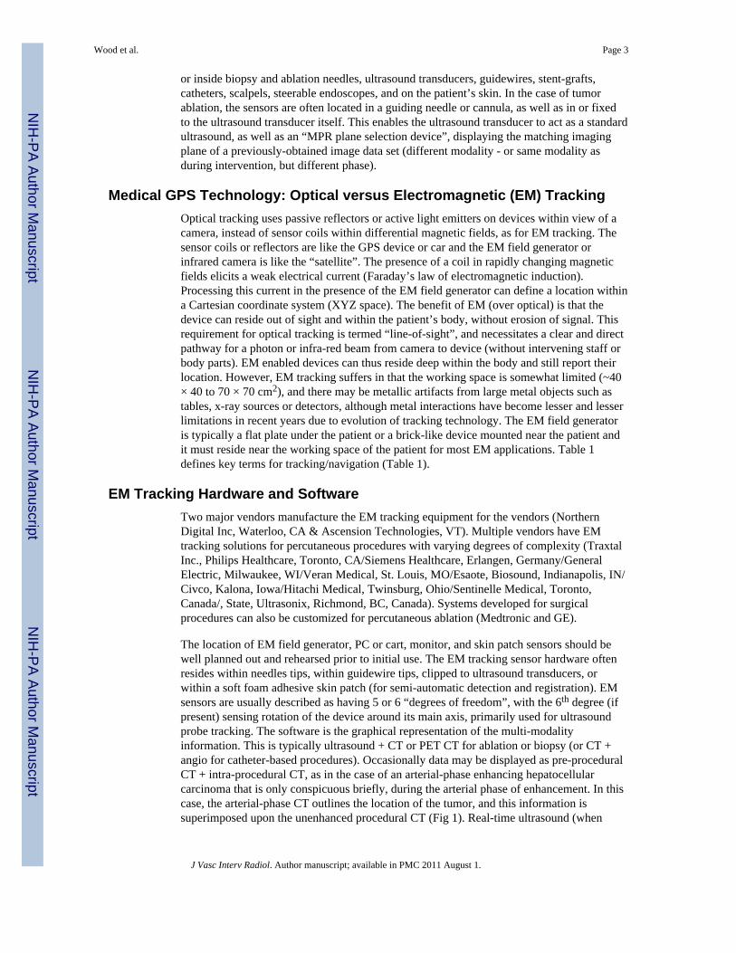
The location of EM field generator, PC or cart, monitor, and skin patch sensors should bewell planned out and rehearsed prior to initial use. The EM tracking sensor hardware oftenresides within needles tips, within guidewire tips, clipped to ultrasound transducers, orwithin a soft foam adhesive skin patch (for semi-automatic detection and registration). EMsensors are usually described as having 5 or 6 “degrees of freedom”, with the 6th degree (ifpresent) sensing rotation of the device around its main axis, primarily used for ultrasoundprobe tracking. The software is the graphical representation of the multi-modalityinformation. This is typically ultrasound + CT or PET CT for ablation or biopsy (or CT +angio for catheter-based procedures). Occasionally data may be displayed as pre-proceduralCT + intra-procedural CT, as in the case of an arterial-phase enhancing hepatocellularcarcinoma that is only conspicuous briefly, during the arterial phase of enhancement. In thiscase, the arterial-phase CT outlines the location of the tumor, and this information issuperimposed upon the unenhanced procedural CT (Fig 1). Real-time ultrasound (when
Wood et al. Page 3
J Vasc Interv Radiol. Author manuscript; available in PMC 2011 August 1.
NIH
-PA Author Manuscript
NIH
-PA Author Manuscript
NIH
-PA Author Manuscript

tracked) can also select the plane of the enhanced CT for display (multiplanar reconstructionalong the needle path).
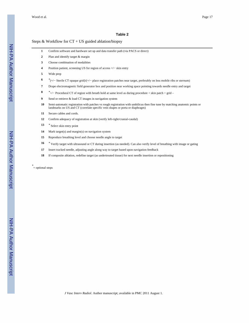
Steps and WorkflowThe sequence of steps and events will be dictated by which modality shows the tumormargin the best as well as operator preferences and patterns of CT and US use for biopsyand ablation. Table 2 shows one of the more common workflows for CT and US guidance(Table 2 “Steps and workflow”). The steps may differ if one is registering with automaticskin patches, or if one is using manual registration with anatomic points (landmark) or scanplane matching (umbilicus or nipples). The umbilicus or nipple level provides roughalignment and the matched anatomic points provide fine-tuning. Specific point matching inthe liver often involves the porta hepatis, or identifiable shapes from vessel branchingpoints. Automated registration methods may further simplify the process. The role forverification CT or US is also procedure-dependent. Generally speaking, the navigation toolsare usually for augmentation, and often supplement, instead of replace, standard imagingguidance techniques. If using a “dynamic reference sensor” or patch, one can move the fieldgenerator box and the patient without altering the registration. If not using this special sensoron the skin, then one must maintain patient and field generator immobile during procedure,and reposition CT table to same working spot (and record Z-axis table number). Staff shouldbe alerted to avoid dislodging the field generator and to exercise caution with regard tosterility.
For PET or MR-guidance, select appropriate MR sequence or attenuation-corrected PET.For PET guidance, manually register prior CT (from prior PET/CT) to intra-proceduralplanning CT using anatomic points (bones and landmarks), then blend in PET data and fadedisplay between PET (or MR), US, and CT as needed (Fig. 4). Keep in mind position andbreathing differences, since PET is usually acquired in shallow breathing. There is a widevariety of practice patterns that can accommodate tracking (Table 3).
Rotational angiography-based toolsCone beam CT is the creation of a 23 or 46 cm field of view “CT-like” image from anangiography machine after rotation of the C-arm around the patient. Dyna-CT (SiemensMedical Solutions, Erlangen Germany), Innova-CT (GE Healthcare, Waukesha, Wisconsin,USA) and Xper-CT (Philips Healthcare, Eindhoven, Netherlands) are three suchcommercially available systems. This method then enables cone beam CT guidance, wheretargets and needle pathways are planned using this CT-like volumetric information (“X-perguide”, Philips Healthcare, Eindhoven, Netherlands)/“I-guide and I-Guide Cappa”, SiemensMedical Solutions, Erlangen, Germany/“Innova CT” General Electric, Milwaukee, WI).Dynamic 3D roadmapping can provide reference to prior image volumes such as CTA orrotational angiography/CT. The next generation of interventional radiology (IR) suites alsointegrate methods for 3D navigation either with tracking systems referencing multiplemodalities or by enabling spatial information with what was once only a 2D modality (X-rayor ultrasound).. Although the systems each have different software and display formats, theconcept remains the same: providing 3D imaging capabilities and information in the IRsuite, in hopes of improving or facilitating needle, catheter, wire, or device placement.
For cone beam CT guidance, conventional orthogonal 2D fluoroscopy images are referencedto the rotational angiography or cone beam CT framework to provide guidance for needlebased procedures such as ablation, biopsy or vertebroplasty. A skin entry and target define apathway chosen on the CT-like image from the cone beam CT. Then the needleadvancement is monitored incrementally, either in the view 90 degrees orthogonal to theneedle or axial to the needle (down the needle shaft or “bird’s eye” view). Each orthogonal
Wood et al. Page 4
J Vasc Interv Radiol. Author manuscript; available in PMC 2011 August 1.
NIH
-PA Author Manuscript
NIH
-PA Author Manuscript
NIH
-PA Author Manuscript
viewpoint has the selected pathway superimposed upon the fluoroscopic image, so needleadjustments can be made by comparing actual needle to superimposed planned pathway.
Mechanical laser pointers and needle stabilization devicesVarious commercial devices exist for needle stabilization and angle selection includingdisposable bubble levelers with protractor-like needle guides (In-Rad), disposable adhesivearcs that stabilize the needle (Neo-Rad, Oslo, Norway and Radi) and automated laserpointers that integrate with the CT table (Neo-Rad, Oslo, Norway) or integrate directly withthe CT software (NIH, Bethesda, MD & Philips Healthcare, Cleveland, OH). Many of thesesolutions are low cost devices to facilitate needle placement accuracy, which can be acritical determinant of outcome following ablation. Needle stabilization can also beimportant when heavy ablation devices are subjected to gravity, flopping down during a CTin a lateral approach.
Clinical Outcomes/Patient ImpactThe accuracy, clinical utility, and impact upon patient outcomes is becoming better definedfor EM tracking and multi-modality image fusion for guidance of biopsy and thermalablation procedures. Many procedures are enabled by the technology, where targets wouldnot have been defined without the ability to use arterial phase CT or PET or MR informationduring the procedure. Specifically, for biopsy and ablation, tracking can improve accuracy interms of angle selection towards a predetermined point target (Kruecker J, Xu S, VenkatesanA, et al.: Clinical Utility of Real-Time Fusion Guidance for Biopsy and Ablation. J VascInterv Radiolo (in press)), and there may be advantages in terms of delivering a prescribedtreatment plan or adding together multiple individual ablations in order to fully envelope atumor with a composite ablation (multiple overlapping ablation volumes).
Clinical use of EM tracking for biopsy and ablationIt may be important to keep in mind that some systems will track the needle tip while otherswill track the shaft or hub. Tracking the needle tip could theoretically better account for tipdeflection or bending, organ deformation, or organ motion.
The ultrasound can be tracked, with or without a tracked needle. If the ultrasound is usedalone without a tracked needle, then one must look for needle images on ultrasound in orderto reference the actual needle to the target location or prior imaging modality. Tracking theultrasound and needle are most useful for the co-display of other modalities. There are abroad variety of potential clinical indications for using tracking during biopsy and ablation(Table 4).
Future DirectionsNavigation techniques have initially been applied to facilitate needle placement towards apre-defined target. Future work will refine integrated ablation treatment plans, in a fashionsimilar to radiation therapy dose maps. (Figures 2–3 ) Such standardization should decreasethe variability of practice patterns, and enable even less experienced operators to deliverprecise ablations. The registration process will become fully automated with integratedelastic warping, tissue deformation, breathing and motion compensation. The navigationsystems will become increasingly integrated with the imaging systems themselves(embedded in the ultrasound transducer, console, and angiography tables). This will in turnlead to broader ease of use and streamlined workflow. EM tracking treatment plans willidentify tissue at risk for under treatment and incorporate imaging such as ultrasoundcontrast, elastography, MR spectroscopy, and diffusion maps. PET-guided ablation will
Wood et al. Page 5
J Vasc Interv Radiol. Author manuscript; available in PMC 2011 August 1.
NIH
-PA Author Manuscript
NIH
-PA Author Manuscript
NIH
-PA Author Manuscript

become a standard tool for defining treatment margins, and the EM-tracked biopsy willbecome a tool for drug discovery and personalized medicine, selecting and verifyingmolecular-targeted therapies. Trainees in interventional radiology will learn needleplacement skills on EM tracking simulators, instead of patients.
ConclusionThe use of navigation technology and multi-modality image fusion represents a novel andimportant means by which to optimize image-guided interventions. Although speculative,improved imaging and navigation tools could potentially reduce procedure time, radiationdose, and complications while enhancing standardization. IR as a discipline is continuouslyfinding new ways to use our foundation in imaging to improve what we do. Navigation toolsat the fingertips of the physician have the potential to improve delivery of minimally-invasive image-guided local and regional cancer therapies.
Reference List1. Banovac F, Cheng P, Campos-Nanez E, et al. Radiofrequency ablation of lung tumors in swine
assisted by a navigation device with preprocedural volumetric planning. J Vasc Interv Radiol2010;21:122–129. [PubMed: 19939704]
2. Wood BJ, Locklin JK, Viswanathan A, et al. Technologies for guidance of radiofrequency ablationin the multimodality interventional suite of the future. J Vasc Interv Radio 2007;18:9–24.
3. Wood BJ, Zhang H, Durrani A, et al. Navigation with electromagnetic tracking for interventionalradiology procedures: a feasibility study. J Vasc Interv Radiol 2005;16:493–505. [PubMed:15802449]
4. Yaniv Z, Wilson E, Lindisch D, Cleary K. Electromagnetic tracking in the clinical environment.Med Phys 2009;36:876–892. [PubMed: 19378748]
5. Krucker J, Xu S, Glossop N, et al. Electromagnetic tracking for thermal ablation and biopsyguidance: clinical evaluation of spatial accuracy. J Vasc Interv Radiol 2007;18:1141–1150.[PubMed: 17804777]
6. Baegert C, Villard C, Schreck P, Soler L, Gangi A. Trajectory optimization for the planning ofpercutaneous radiofrequency ablation of hepatic tumors. Comput Aided Surg 2007;12:82–90.[PubMed: 17487658]
7. Banovac F, Abeledo H, Campos-Nanez E, et al. An image-guided system for optimized volumetrictreatment planning and execution for radiofrequency ablation of liver tumors. Int J CARS2007;2(Suppl 1):S146–S151.
8. Chen CR, Miga MI, Galloway RL. Optimizing Needle Placement in Treatment Planning ofRadiofrequency Ablation. Proceedings SPIE 6141: Progress in Biomedical Optics and Imaging2006:6141.
9. Trovato K, Dalal S, Kruecker J, Venkatesan A, Wood BJ. Automated RFA planning for completecoverage of large tumors. Proc SPIE 2009:7261.
10. Villard, C.; Soler, L.; Papier, N., et al. RF-Sim: a Treatment Planning Tool for RadiogrequencyAblation of Hepatic Tumors. Seventh International Conference on Information Visualization;2003. p. 561-566.
11. Villard C, Soler L, Gangi A. Radiofrequency ablation of hepatic tumors: simulation, planning, andcontribution of virtual reality and haptics. Comput Methods Biomech Biomed Engin 2005;8:215–227. [PubMed: 16298844]
12. Crum WR, Hartkens T, Hill DL. Non-rigid image registration: theory and practice. Br J Radiol2004;77(Spec No 2):S140–S153. [PubMed: 15677356]
Wood et al. Page 6
J Vasc Interv Radiol. Author manuscript; available in PMC 2011 August 1.
NIH
-PA Author Manuscript
NIH
-PA Author Manuscript
NIH
-PA Author Manuscript
Wood et al. Page 7
J Vasc Interv Radiol. Author manuscript; available in PMC 2011 August 1.
NIH
-PA Author Manuscript
NIH
-PA Author Manuscript
NIH
-PA Author Manuscript

Wood et al. Page 8
J Vasc Interv Radiol. Author manuscript; available in PMC 2011 August 1.
NIH
-PA Author Manuscript
NIH
-PA Author Manuscript
NIH
-PA Author Manuscript

Wood et al. Page 9
J Vasc Interv Radiol. Author manuscript; available in PMC 2011 August 1.
NIH
-PA Author Manuscript
NIH
-PA Author Manuscript
NIH
-PA Author Manuscript

Figure 1.Arterial phase CT (a) showing prior non-enhancing RFA treatments and solitary enhancinghepatocellular carcinoma (arrow). Targeting interface for placement of virtual needle (blueline, b, c, d); Virtual needle in target corresponds with actual needle on CT scan (e)
Wood et al. Page 10
J Vasc Interv Radiol. Author manuscript; available in PMC 2011 August 1.
NIH
-PA Author Manuscript
NIH
-PA Author Manuscript
NIH
-PA Author Manuscript

Wood et al. Page 11
J Vasc Interv Radiol. Author manuscript; available in PMC 2011 August 1.
NIH
-PA Author Manuscript
NIH
-PA Author Manuscript
NIH
-PA Author Manuscript

Wood et al. Page 12
J Vasc Interv Radiol. Author manuscript; available in PMC 2011 August 1.
NIH
-PA Author Manuscript
NIH
-PA Author Manuscript
NIH
-PA Author Manuscript

Figure 2.Enhanced CT scan before (a) and after (b) RFA with navigation shows complete treatmentof enhancing tumor. Treatment planning sequence (c–f) with sequential overlapping of
Wood et al. Page 13
J Vasc Interv Radiol. Author manuscript; available in PMC 2011 August 1.
NIH
-PA Author Manuscript
NIH
-PA Author Manuscript
NIH
-PA Author Manuscript

planned treatment volumes (green) superimposed on estimated tumor location (red) whichwas manually segmented at the beginning of the procedure. The treatment volume coversthe tumor plus a margin of normal tissue (f).
Wood et al. Page 14
J Vasc Interv Radiol. Author manuscript; available in PMC 2011 August 1.
NIH
-PA Author Manuscript
NIH
-PA Author Manuscript
NIH
-PA Author Manuscript
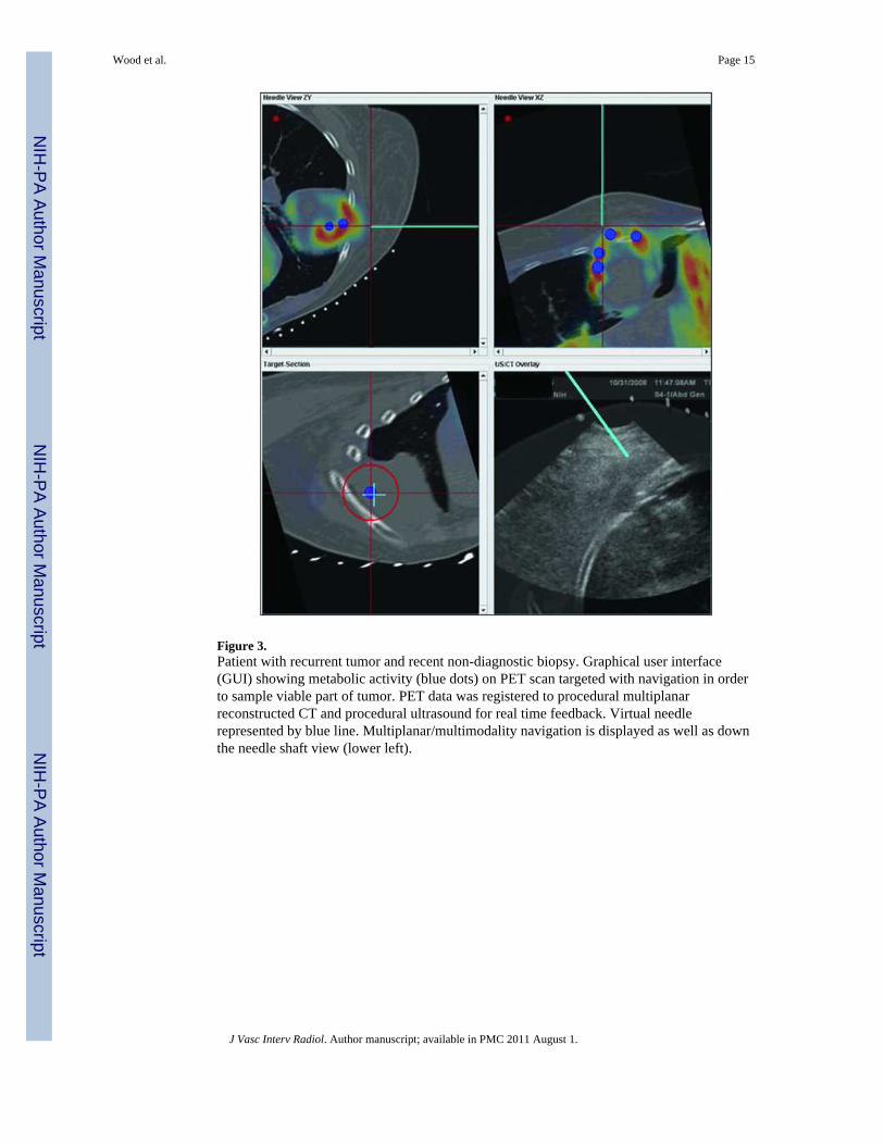
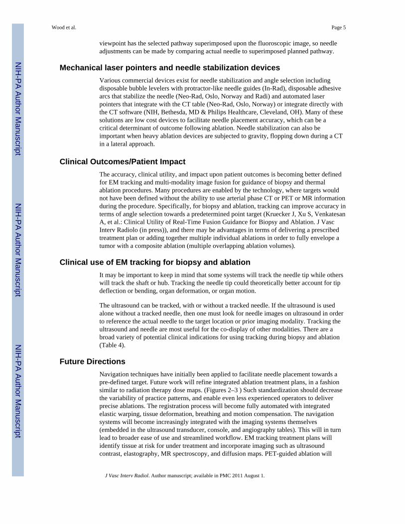
Figure 3.Patient with recurrent tumor and recent non-diagnostic biopsy. Graphical user interface(GUI) showing metabolic activity (blue dots) on PET scan targeted with navigation in orderto sample viable part of tumor. PET data was registered to procedural multiplanarreconstructed CT and procedural ultrasound for real time feedback. Virtual needlerepresented by blue line. Multiplanar/multimodality navigation is displayed as well as downthe needle shaft view (lower left).
Wood et al. Page 15
J Vasc Interv Radiol. Author manuscript; available in PMC 2011 August 1.
NIH
-PA Author Manuscript
NIH
-PA Author Manuscript
NIH
-PA Author Manuscript

NIH
-PA Author Manuscript
NIH
-PA Author Manuscript
NIH
-PA Author Manuscript
Wood et al. Page 16
Table 1
Glossary
Medical GPS Localization of a device or image in relation to prior pre-procedural imaging.The electromagnetic field generator is the “satellite” and the needle tip is the “car”
Multimodality Fusion Display of multiple modalities; useful during procedures
Electromagnetic Tracking Mechanism, based on electromagnetic field generator, to locate a needle (or ultrasound plane) within a3D volume of imaging data (like CT, MR, or PET), or to locate a 2D ultrasound plane within a 3Dvolume
“Target to Registration Error” orTRE
Difference between the real and virtual needle positions. How exact is the needle position displayed?
(Fiducial) Registration error” orFRE (or root mean square/RMS)
How well the images or points match upHow good is the registration?Necessary, but not a guarantee for accuracy (ideally under 2mm)
Placement Error How close is needle placed to point target?
Dynamic Reference Patch or sensor placed on patient that corrects for patient or generator motion, or breathing. Withoutthis, patient must remain in exact position.
Registration Matching co-localized images to images, or image space to “magnetic space”“Registration error” (root mean square or RMS)“Rigid registration” matches uses fixed images vs “deformable registration” (elastic, warping) matcheswith flexible images, accounting for organ shift or deformation between different images or differenttimes.
J Vasc Interv Radiol. Author manuscript; available in PMC 2011 August 1.
NIH
-PA Author Manuscript
NIH
-PA Author Manuscript
NIH
-PA Author Manuscript
Wood et al. Page 17
Table 2
Steps & Workflow for CT + US guided ablation/biopsy
1 Confirm software and hardware set up and data transfer path (via PACS or direct)
2 Plan and identify target & margin
3 Choose combination of modalities
4 Position patient, screening US for region of access +/− skin entry
5 Wide prep
6 *(+/− Sterile CT opaque grid)/(+/− place registration patches near target, preferably on less mobile ribs or sternum)
7 Drape electromagnetic field generator box and position near working space pointing towards needle entry and target
8 *+/− Procedural CT of region with breath hold at same level as during procedure + skin patch + grid –
9 Send or retrieve & load CT images in navigation system
10 Semi-automatic registration with patches vs rough registration with umbilicus then fine tune by matching anatomic points orlandmarks on US and CT (correlate specific vein shapes or porta or diaphragm)
11 Secure cables and cords.
12 Confirm adequacy of registration at skin (verify left-right/cranial-caudal)
13 * Select skin entry point
14 Mark target(s) and margin(s) on navigation system
15 Reproduce breathing level and choose needle angle to target
16 * Verify target with ultrasound or CT during insertion (as needed). Can also verify level of breathing with image or gating
17 Insert tracked needle, adjusting angle along way to target based upon navigation feedback
18 If composite ablation, redefine target (as undertreated tissue) for next needle insertion or repositioning
*= optional steps
J Vasc Interv Radiol. Author manuscript; available in PMC 2011 August 1.

NIH
-PA Author Manuscript
NIH
-PA Author Manuscript
NIH
-PA Author Manuscript
Wood et al. Page 18
Table 3
Methods for tracking during ablation
1 Needle tracking: track ablation needle itself internally (“tip tracking”), on shaft, or on hub
2 Ultrasound tracking: sensor attached to or embedded in transducer
3 Ablation needle can be placed tandem to tracked guider needle or coaxially after removing a tracked stylette or tracked outercannula, placed before the actual ablation needle
4 Registration is manual or semi-automated: matching skin points, imaging landmarks, umbilicus, nipples, or test simple imageoverlay
J Vasc Interv Radiol. Author manuscript; available in PMC 2011 August 1.

NIH
-PA Author Manuscript
NIH
-PA Author Manuscript
NIH
-PA Author Manuscript
Wood et al. Page 19
Table 4
When to use tracking during ablation or biopsy:
1 Lesions seen only on arterial phase.
2 Lesion margins seen best on MRI sequence.
3 Lesions best identified with PET/CT.
4 Localizing specific part of tumor for biopsy (only part of tumor hot on PET)
5 Lesions not seen at all on ultrasound
6 Composite ablations requiring multiple needle insertions, complex geometries or difficult treatment plan.
7 Localization of tumor tissue at risk for under-heating near the end of a treatment.
8 Identification of safest pathway, given complex angle of insertion
9 Dome lesions
10 Lesions under ribs
11 During “gas out” from tissue cooking
J Vasc Interv Radiol. Author manuscript; available in PMC 2011 August 1.