VIA Technologies Inc. Confidential ND A R equired
49
VIA Technologies Inc. Confidential NDA Required IDE RAID Host Controller User Manual Preliminary Revision 0.2 November 11, 2002 VIA TECHNOLOGIES, INC.
-
Upload
khangminh22 -
Category
Documents
-
view
1 -
download
0
Transcript of VIA Technologies Inc. Confidential ND A R equired

VIA T
echnologies I
nc.
Confidentia
l
NDA Require
d
IDE RAID Host Controller User Manual
Preliminary Revision 0.2 November 11, 2002
VIA TECHNOLOGIES, INC.

VIA T
echnologies I
nc.
Confidentia
l
NDA Require
d
Copyright Notice: Copyright © 2002 VIA Technologies Incorporated. All Rights Reserved. No part of this document may be reproduced, transmitted, transcribed, stored in a retrieval system, or translated into any language, in any form or by any means, electronic, mechanical, magnetic, optical, chemical, manual or otherwise without the prior written permission of VIA Technologies Incorporated. The material in this document is for information only and is subject to change without notice. VIA Technologies Incorporated reserves the right to make changes in the product design without reservation and without notice to its users
VT6410 is a product of VIA Technologies.
Disclaimer Notice: No license is granted, implied or otherwise, under any patent or patent rights of VIA Technologies. VIA Technologies makes no warranties, implied or otherwise, in regard to this document and to the products described in this document. The information provided by this document is believed to be accurate and reliable to the publication date of this document. However, VIA Technologies assume no responsibility for any errors in this document. Furthermore, VIA Technologies assume no responsibility for the use or misuse of the information in this document and for any patent infringements that may arise from the use of this document. The information and product specifications within this document are subject to change at any time, without notice and without obligation to notify any person of such change.
Offices: USA Office: Taipei Office: 940 Mission Court 8th Floor, No. 533 Fremont, CA 94539 Chung-Cheng Road, Hsin-Tien USA Taipei, Taiwan ROC Tel: (510) 683-3300 Tel: (886-2) 2218-5452 Fax: (510) 683-3301 or (510) 687-4654 Fax: (886-2) 2218-5453 Home Page: http://www.viatech.com Home Page: http://www.via.com.tw

VT6410 User Manual � IDE RAID Controller
Preliminary Revision 0.2, November 11, 2002 i Revision History
Technologies, Inc.We Connect
VIA T
echnologies I
nc.
Confidentia
l
NDA Require
d
Revision History
Document Release Date Revision Initials 0.1 11/4/02 Initial internal release JC 0.2 11/11/02 Added VIA cover page, revision history, header and footer
Corrected typos and grammatical errors AT

VT6410 User Manual � IDE RAID Controller
Preliminary Revision 0.2, November 11, 2002 i Table of Contents
Technologies, Inc.We Connect
VIA T
echnologies I
nc.
Confidentia
l
NDA Require
d
Table of Contents Revision History................................................................................................................................................. i Table of Contents............................................................................................................................................... i Introduction ....................................................................................................................................................... 1
RAID Basics................................................................................................................................................... 1 RAID 0 (Striping) ........................................................................................................................................................................ 1 RAID 1 (Mirroring) ..................................................................................................................................................................... 1 RAID 0+1 (Striping/Mirroring) ................................................................................................................................................... 2 JBOD (Spanning)......................................................................................................................................................................... 3
Key Features .................................................................................................................................................. 3 Installing The Hard Drives ............................................................................................................................... 4 BIOS Configuration Utility ............................................................................................................................... 5
Enter BIOS Configuration Utility ............................................................................................................... 5 Create Disk Array ......................................................................................................................................... 6 Delete Disk Array.......................................................................................................................................... 9 Create and Delete Spare Hard Drive ........................................................................................................ 10 Select Boot Array ........................................................................................................................................ 11 View Serial Number of Hard Drive........................................................................................................... 12 View Array Status ....................................................................................................................................... 12 Duplicate Critical RAID 1/0+1 Array ....................................................................................................... 13 Rebuild Broken RAID 0/0+1 array ........................................................................................................... 14
Driver and RAID Software Installation.......................................................................................................... 16 Microsoft Windows driver Installation..................................................................................................... 16 Verify Installation ....................................................................................................................................... 18
RAID Software................................................................................................................................................. 19 Installation ................................................................................................................................................... 19 Getting Start ................................................................................................................................................ 20 View Online Help ........................................................................................................................................ 22 View Controller and Device Status............................................................................................................ 23 Create Disk Array ....................................................................................................................................... 24 Delete Disk Array........................................................................................................................................ 27 Add and Remove Spare Disk Drive........................................................................................................... 29
Add Spare Disk Drive ................................................................................................................................................................ 29 Remove Spare Disk Drive.......................................................................................................................................................... 31
Check All Disks ........................................................................................................................................... 32 View Event Log ........................................................................................................................................... 33 Verify Mirror Disk...................................................................................................................................... 35 Synchronize Mirror Disk............................................................................................................................ 37 Disk Error Detection................................................................................................................................... 39 Duplicate Critical RAID 1/0+1 Array ....................................................................................................... 39 Rebuild Broken RAID 0/0+1 array ........................................................................................................... 41 Icon View...................................................................................................................................................... 45

VT6410 User Manual � IDE RAID Controller
Preliminary Revision 0.2, November 11, 2002 1 Introduction
Technologies, Inc.We Connect
VIA T
echnologies I
nc.
Confidentia
l
NDA Require
d
INTRODUCTION
This section gives a brief introduction on the RAID-related background knowledge and a brief introduction on the VIA IDE RAID Host Controller. For users wishing to install their VIA IDE RAID driver and RAID software, please proceed to the Driver and RAID Software Installation section.
RAID Basics RAID (Redundant Array of Independent Disks) is a method of combining two or more hard disk drives into one logical unit. The advantage of an Array is to provide better performance or data fault tolerance. Fault tolerance is achieved through data redundant operation, where if one drives fails, a mirrored copy of the data can be found on another drive. This can prevent data loss if the operating system fails or hangs. The individual disk drives in an array are called �members�. The configuration information of each member is recorded in the �reserved sector� that identifies the drive as a member. All disk members in a formed disk array are recognized as a single physical drive to the operating system.
Hard disk drives can be combined together through a few different methods. The different methods are referred to as different RAID levels. Different RAID levels represent different performance levels, security levels and implementation costs. The RAID levels which the VIA VT6410 IDE RAID Host Controller supports are RAID 0, 1, 0+1, and JBOD. The table below briefly introduced these RAID levels.
RAID Level No. of Drives Capacity Benefits RAID 0 (Striping) 2 to 4 Number drives * Smallest size Highest performance without
data protection RAID 1 (Mirroring) 2 Smallest size Data protection
RAID 0+1 (Striping/Mirroring)
4 2 * Smallest size Highest performance with data protection
JBOD (Spanning) 2 to 4 Sum of All drives No data protection and performance improving, but disk capacity fully used.
RAID 0 (Striping) RAID 0 reads and writes sectors of data interleaved between multiple drives. If any disk member fails, it affects the entire array. The disk array data capacity is equal to the number of drive members times the capacity of the smallest member. The striping block size can be set from 4KB to 64KB. RAID 0 does not support fault tolerance.
RAID 1 (Mirroring) RAID 1 writes duplicate data onto a pair of drives and reads both sets of data in parallel. If one of the mirrored drives suffers a mechanical failure or does not respond, the remaining drive will continue to function. Due to redundancy, the drive capacity of the array is the capacity of the smallest drive. Under a RAID 1 setup, an extra drive called the �spare drive� can be attached. Such a drive will be activated to replace a failed drive that is part of a mirrored array. Due to the fault tolerance, if any RAID 1 drive fails, data access will not be affected as long as there are other working drives in the array.
VT6410 User Manual � IDE RAID Controller
Preliminary Revision 0.2, November 11, 2002 2 Introduction
Technologies, Inc.We Connect
VIA T
echnologies I
nc.
Confidentia
l
NDA Require
d
RAID 0+1 (Striping/Mirroring) RAID 0+1 is a combination of RAID 0 and RAID 1 array types. A minimum of four drives needs to be installed. With a four-drive array, there must be two pairs of RAID 0 drives. Each pair mirrors the data on the other pair of striping drives. The data capacity is two times the smallest drive.
In a four-drive array, a single drive failure will cause the whole array to become, in essence, a RAID Level 0 array. However, this does not impact the data access. Another unique feature of RAID 0+1 is dual fault tolerance. In some cases, two drives can fail simultaneously and still maintain the integrity of the data. The data can still be accessed and worked like a RAID 0 array.
Assume the drives are configured as follows (M = Master, S = Slave, A/B indicates which striping pair the drive belongs to, number indicates which part of stripe data):
IDE 1 IDE 2
M Drive A1 Drive A2
S Drive B1 Drive B2
In a RAID 0+1 array, the data integrity will remain if any 1, 2 combination survives. The following table indicates the possible combination of dual drive failure and the respective results of each case.
Failed Drives Array Status Note A1, A2 Working B1, B2 retains array integrity B1, B2 Working A1, A2 retains array integrity A1, B2 Working B1, A2 retains array integrity B1, A2 Working A1, B2 retains array integrity A1, B1 Failure A2, B2 contains only half of array data A2, B2 Failure A1, B1 contains only half of array data

VT6410 User Manual � IDE RAID Controller
Preliminary Revision 0.2, November 11, 2002 3 Introduction
Technologies, Inc.We Connect
VIA T
echnologies I
nc.
Confidentia
l
NDA Require
d
JBOD (Spanning) A spanning disk array is equal to the sum of the all drives in the array. Spanning stores data on to a drive until it is full then proceeds to store files onto the next drive in the array. When any disk member fails, the failure affects the entire array. JBOD is not really a RAID and does not support fault tolerance.
Key Features The VIA IDE RAID solution uses the VT6410 chip (a two-channel ATA 133 solution) as a RAID controller. The RAID software is a Windows-based software utility. Its graphical user interface provides an easy way to configure and manage disk drives or disk arrays connected to the VT6410 controller. Listed below are the main features and benefits of VIA IDE RAID: 1. Supports ATA 133 high performance hard disk drive. 2. Supports hard disk drive larger than 137 GB (48-bits LBA). 3. Dual independent ATA channels and maximum connection of four hard disk drives allowed. 4. Supports Ultra DMA mode 6/5/4/3/2/1/0, DMA mode 2/1/0, and PIO mode 4/3/2/1/0. 5. Supports PCI Plug and Play. PCI interrupt sharing and coexists with mainboard IDE controller. 6. Supports IDE bus master operation. 7. Supports RAID 0, 1, 0+1, and JBOD. 8. 4 KB to 64 KB striping block size support. 9. Bootable disk or disk array support. 10. Windows-based RAID configure and management software tool. (Compatible with BIOS) 11. Real-time monitoring of device status and error alarm with popup message box and beeping. 12. Supports hot-swap failed disk drive in RAID 1 and 0+1 array. 13. Mirroring automatic background rebuilds support. 14. ATA SMART function support. 15. Microsoft Windows 98, Me, NT4.0, 2000, XP operating systems support. 16. Event log for easy troubleshooting. 17. On-line help for easy operation for RAID software.

VT6410 User Manual � IDE RAID Controller
Preliminary Revision 0.2, November 11, 2002 4 Installing The Hard Drives
Technologies, Inc.We Connect
VIA T
echnologies I
nc.
Confidentia
l
NDA Require
d
INSTALLING THE HARD DRIVES
Hard disk drives must be Ultra ATA/133, Ultra ATA/100, Ultra ATA/66, Ultra ATA/33, or ATA-3 compatible to operate with the VT6410 IDE RAID controller. For optimal performance, it is recommended to install all identical drives of the same model and capacity. 1. Striping (RAID 0) and JBOD require at least two drives and has a limit of four drives. Mirroring (RAID 1) requires two
drives. Striping and mirroring (RAID 0 +1) requires four drives. Set the jumpers of each hard drive to �Master� (�Device 0�) or �Slave� (�Device 1�) according to the following table.
Number of Drives IDE Channel 1 IDE Channel 2
1 Master ------ 2 Master Master 3 Master & Slave Master 4 Master & Slave Master & Slave
2. Connect the IDE cables and the power cables to the hard drives. When connecting hard drives, pay attention to its Master �
Slave jumper setting. If two hard drives are connected to one IDE cable, then one drive must be set as master while the other as slave.
3. Attach the IDE cables into the connectors on the VT6410 IDE RAID controller.

VT6410 User Manual � IDE RAID Controller
Preliminary Revision 0.2, November 11, 2002 5 BIOS Configuration Utility
Technologies, Inc.We Connect
VIA T
echnologies I
nc.
Confidentia
l
NDA Require
d
BIOS CONFIGURATION UTILITY
Enter BIOS Configuration Utility When the system powers on, the following information will appear on screen. Press the �Tab� key to enter BIOS configuration utility.
The main interface of BIOS configuration utility is as below:

VT6410 User Manual � IDE RAID Controller
Preliminary Revision 0.2, November 11, 2002 6 BIOS Configuration Utility
Technologies, Inc.We Connect
VIA T
echnologies I
nc.
Confidentia
l
NDA Require
d
Create Disk Array 1. Use the arrow keys to navigate the menu. Select Create Array and press <Enter> to call out the list of creation steps.
VT6410 User Manual � IDE RAID Controller
Preliminary Revision 0.2, November 11, 2002 7 BIOS Configuration Utility
Technologies, Inc.We Connect
VIA T
echnologies I
nc.
Confidentia
l
NDA Require
d
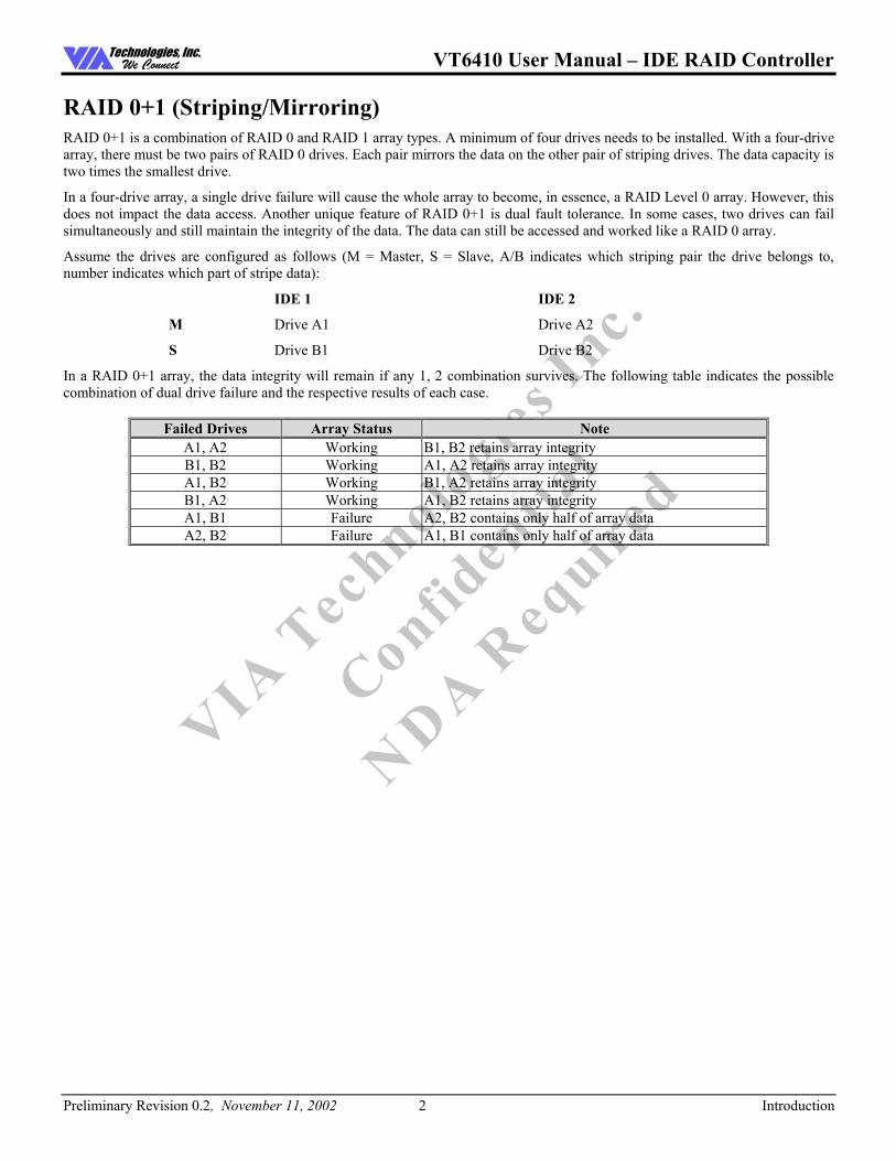
2. Select Array Mode and press <Enter>. A list of array modes will appear. Highlight the target array mode that you want to
create, and press <Enter> to confirm the selection. If RAID 1 or RAID 0/1 is selected, an option list will popup and enable the users to select Create only or Create and duplicate. Create only will allow BIOS to only create an array. The data on the mirroring drive may be different from the source drive. Create and duplicate allows BIOS to copy the data from the source to the mirroring drive.
3. After array mode is selected, there are two methods to create a disk array. One method is �Auto Setup� and the other one is
�Select Disk Drives�. Auto Setup allows BIOS to select the disk drives and create arrays automatically but it does not duplicate the mirroring drives even if the user selected Create and duplicate for RAID 1 or 0+1. It is recommended all disk drives are new ones when wanting to create an array. Select Disk Drives lets the user select the array drives by their requirements. When using Select Disk Drives, the channel column will be activated. Highlight the drives that you want to use and press <Enter> to select them. After all drives have been selected, press <Esc> to go back to the creation steps menu.

VT6410 User Manual � IDE RAID Controller
Preliminary Revision 0.2, November 11, 2002 8 BIOS Configuration Utility
Technologies, Inc.We Connect
VIA T
echnologies I
nc.
Confidentia
l
NDA Require
d
4. If RAID 0 or RAID 0+1 was selected in step 2, the block size of the array can also be selected. Use the arrow key to highlight
Block Size and press <Enter>. Then select a block size from the popup menu. The block size can be 4KB to 64KB.
5. Use the arrow key to highlight Start Create Process and press <Enter>. A confirmation message will appear. Press Y to
finish the creation, or press N to cancel the creation. 6. Important note: All existing content in the hard drive will be destroyed during array creation.

VT6410 User Manual � IDE RAID Controller
Preliminary Revision 0.2, November 11, 2002 9 BIOS Configuration Utility
Technologies, Inc.We Connect
VIA T
echnologies I
nc.
Confidentia
l
NDA Require
d
Delete Disk Array A RAID can be deleted after it has been created. To delete a RAID, use the following steps:
1. Select Delete Array and press <Enter>. The channel column will be activated. 2. Select the member of an array that is to be deleted and press <Enter>. A warning message will display. Press Y to delete or
press N to cancel.
Deleting a disk array will destroy all the data on the disk array except RAID 1 arrays. When a RAID is deleted, the data on these two hard disk drives will be reserved and become two normal disk drives.

VT6410 User Manual � IDE RAID Controller
Preliminary Revision 0.2, November 11, 2002 10 BIOS Configuration Utility
Technologies, Inc.We Connect
VIA T
echnologies I
nc.
Confidentia
l
NDA Require
d
Create and Delete Spare Hard Drive If a RAID 1 array is created and there are drives that do not belong to other arrays, the one that has a capacity which is equal to or greater than the array capacity cab be selected as a spare drive for the RAID 1 array. Select Create/Delete Spare and press <Enter> and he channel column will be activated. Select the drive that you want to use as a spare drive and press <Enter>. The selected drive will be marked as Spare. The spare drive cannot be accessed in an OS.
To delete a spare drive, highlight Create/Delete Spare and press <Enter>. The spare drive will be highlighted. Press <Enter> to delete the spare drive.

VT6410 User Manual � IDE RAID Controller
Preliminary Revision 0.2, November 11, 2002 11 BIOS Configuration Utility
Technologies, Inc.We Connect
VIA T
echnologies I
nc.
Confidentia
l
NDA Require
d
Select Boot Array User can select a disk array as boot device if user wants to boot operating system from an array. Boot disk array cannot be selected if the operating system does not boot from the disk array. Highlight the Select Boot Array item, then press <Enter> and the channel column will be activated. Then highlight the target disk array and press <Enter>. If user selects a disk array that has a boot mark and press <Enter>, its boot setting will be canceled.
VT6410 User Manual � IDE RAID Controller
Preliminary Revision 0.2, November 11, 2002 12 BIOS Configuration Utility
Technologies, Inc.We Connect
VIA T
echnologies I
nc.
Confidentia
l
NDA Require
d
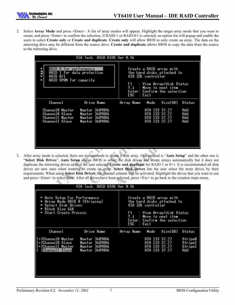
View Serial Number of Hard Drive Highlight Serial Number View and press <Enter>. Use arrow key to select a drive, the selected drive�s serial number can be viewed in the last column. The serial number is assigned by the disk drive manufacturer.
View Array Status Press the F1 key to show the array status on the screen. If there are no disk arrays then nothing will be displayed on the screen.

VT6410 User Manual � IDE RAID Controller
Preliminary Revision 0.2, November 11, 2002 13 BIOS Configuration Utility
Technologies, Inc.We Connect
VIA T
echnologies I
nc.
Confidentia
l
NDA Require
d
Duplicate Critical RAID 1/0+1 Array When booting up the system, BIOS will detect if the RAID 1 or RAID 0+1 array has any inconsistencies between user data and backup data. If BIOS detects any inconsistencies, then the status of the disk array will be marked as critical and BIOS will prompt the user to duplicate the RAID 1 or 0+1 to make the backup data consistent with the user data.
Continue to boot will enable duplicating the array after booting into OS.

VT6410 User Manual � IDE RAID Controller
Preliminary Revision 0.2, November 11, 2002 14 BIOS Configuration Utility
Technologies, Inc.We Connect
VIA T
echnologies I
nc.
Confidentia
l
NDA Require
d
Rebuild Broken RAID 0/0+1 array When booting up the system, BIOS will detect if any member disk drives of RAID has failed or is absent. If BIOS detects any disk drive failures or missing disk drives, the status of the array will be marked as broken.
If BIOS detects a broken RAID 1 array but there is a spare hard drive available for rebuilding the broken array, the spare hard drive will automatically become the mirroring drive. BIOS will show a main interface just like a duplicated RAID 1 main interface. Continue to boot will enable duplicating the array after booting into operating system.
If BIOS detects a broken RAID 1 or 0+1 array but there is no spare hard drive available for rebuilding the array, BIOS will provide several operations to solve such problem.
1. Power off and check the failed drive
This item turns off the computer and replaces the failed hard drive with a good one. If your computer does not support APM, you must turn off your computer manually. After replacing the hard drive, boot into BIOS and select Choose replacement drive and rebuild to rebuild the broken array.

VT6410 User Manual � IDE RAID Controller
Preliminary Revision 0.2, November 11, 2002 15 BIOS Configuration Utility
Technologies, Inc.We Connect
VIA T
echnologies I
nc.
Confidentia
l
NDA Require
d
2. Destroy the Mirroring Relationship
This item cancels the data mirroring relationship of the broken array. For broken RAID 1 arrays, the data on the surviving disk will remain after the destroy operation. For broken RAID 0+1 arrays, all data on the array will be lost after destroy operation. However, Destroy the Mirroring Relationship is not recommend because the data on the remaining disk will be lost when you use the hard drive to create another RAID 1 array.
3. Choose replacement drive and rebuild This item enables the user to select an already-connected hard drive to rebuild the broken array. After choosing a hard drive, the channel column will be activated.
Highlight the target hard drive and press <Enter>, a warning message will appear. Press Y to use that hard drive to rebuild, or press N to cancel. Please note that rebuilding the array will destroy all the data on the replacement hard drive.
4. Continue to boot
This item skips the problem and allows the system to continue booting into OS.

VT6410 User Manual � IDE RAID Controller
Preliminary Revision 0.2, November 11, 2002 16 Driver and RAID Software Installation
Technologies, Inc.We Connect
VIA T
echnologies I
nc.
Confidentia
l
NDA Require
d
DRIVER AND RAID SOFTWARE INSTALLATION
Microsoft Windows driver Installation 1. After Windows has finished booting up, the system will automatically find the newly installed adapter and prompt the
Found New Hardware Wizard window. Click Cancel to skip it.
2. Insert the RAID driver and software installation CD or diskettes. Browse the CD or diskettes and double click on setup.exe to begin the driver and software installation.

VT6410 User Manual � IDE RAID Controller
Preliminary Revision 0.2, November 11, 2002 17 Driver and RAID Software Installation
Technologies, Inc.We Connect
VIA T
echnologies I
nc.
Confidentia
l
NDA Require
d
3. Confirm the follow-up dialogue windows to finish the installation.
4. When the installation is completed, click Finish to restart the system.
VT6410 User Manual � IDE RAID Controller
Preliminary Revision 0.2, November 11, 2002 18 Driver and RAID Software Installation
Technologies, Inc.We Connect
VIA T
echnologies I
nc.
Confidentia
l
NDA Require
d
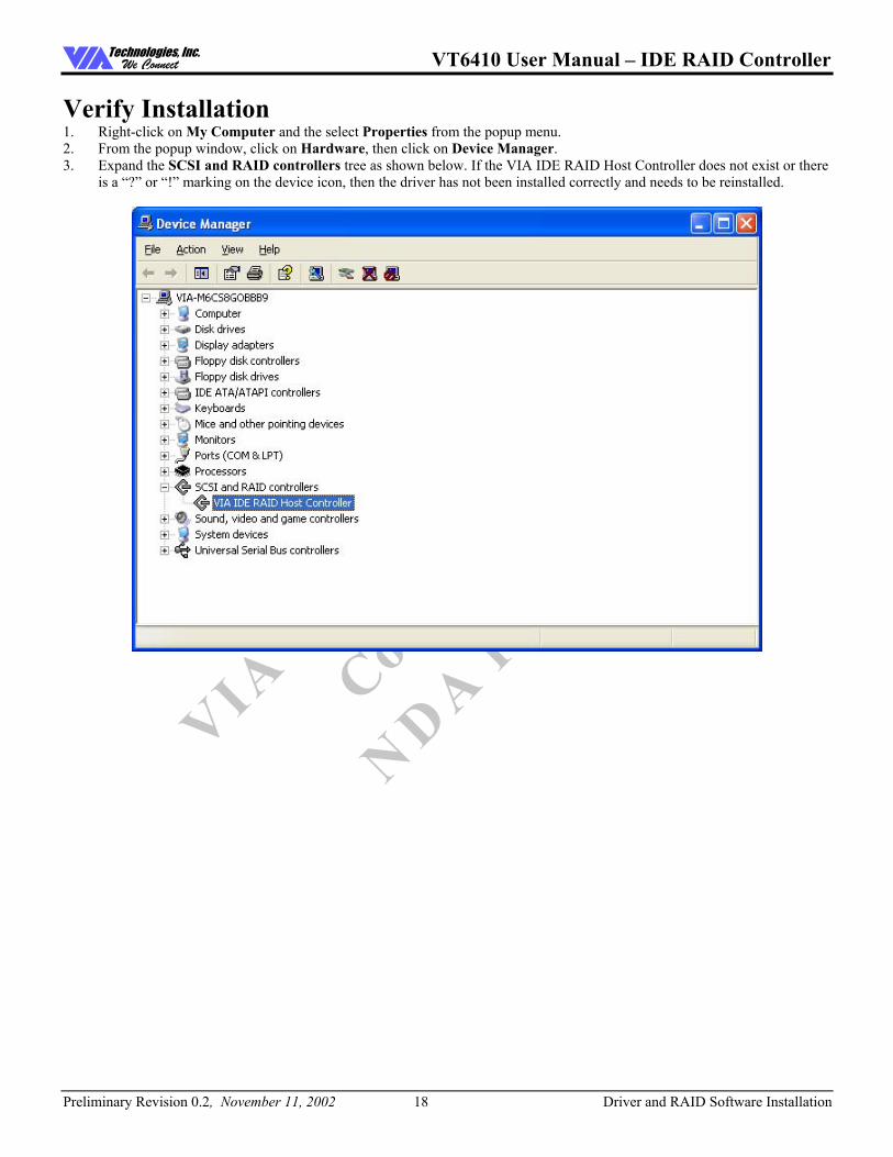
Verify Installation 1. Right-click on My Computer and the select Properties from the popup menu. 2. From the popup window, click on Hardware, then click on Device Manager. 3. Expand the SCSI and RAID controllers tree as shown below. If the VIA IDE RAID Host Controller does not exist or there
is a �?� or �!� marking on the device icon, then the driver has not been installed correctly and needs to be reinstalled.

VT6410 User Manual � IDE RAID Controller
Preliminary Revision 0.2, November 11, 2002 19 RAID Software
Technologies, Inc.We Connect
VIA T
echnologies I
nc.
Confidentia
l
NDA Require
d
RAID SOFTWARE
Installation The RAID software is installed simultaneously with driver installation.

VT6410 User Manual � IDE RAID Controller
Preliminary Revision 0.2, November 11, 2002 20 RAID Software
Technologies, Inc.We Connect
VIA T
echnologies I
nc.
Confidentia
l
NDA Require
d
Getting Start
After installing the GUI software, it will be automatically started every time Windows is started. An icon will appear in the system tray of the tool bar to indicate that GUI software is currently running.
Double click on the system tray icon to launch the main interface of the utility.

VT6410 User Manual � IDE RAID Controller
Preliminary Revision 0.2, November 11, 2002 21 RAID Software
Technologies, Inc.We Connect
VIA T
echnologies I
nc.
Confidentia
l
NDA Require
d
The main interface is divided into two windows and the toolbar above contain the main functions. Click on these toolbar buttons to execute specific functions. The left windowpane displays the controller and disk drives and the right windowpane displays the details of the controller or disk drives.
View by Controller Create Mirror Array (RAID 1)
Create Span Array (JBOD) Create Stripe Array (RAID 0)
Create RAID 0+1 Remove Array
Add/Remove Spare disk Check All Disks
View Event log Help Topics
View by Devices
VT6410 User Manual � IDE RAID Controller
Preliminary Revision 0.2, November 11, 2002 22 RAID Software
Technologies, Inc.We Connect
VIA T
echnologies I
nc.
Confidentia
l
NDA Require
d
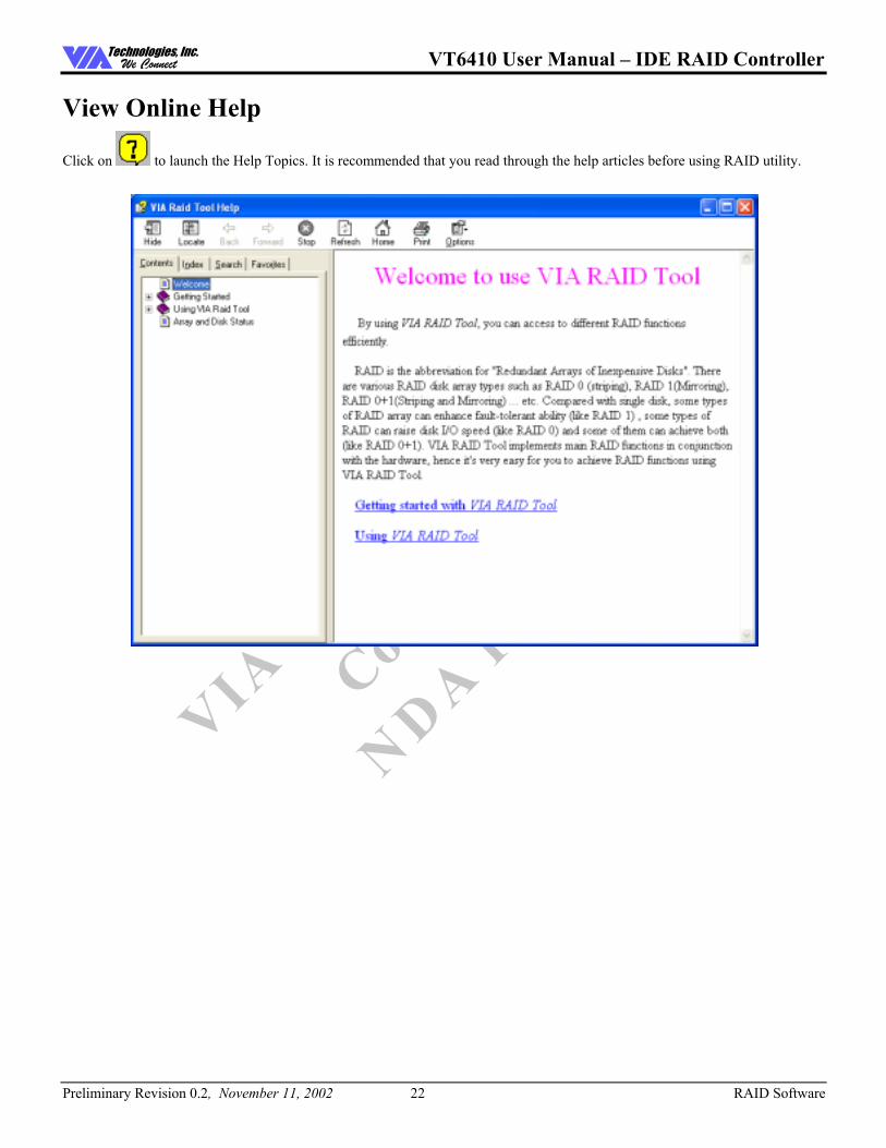
View Online Help
Click on to launch the Help Topics. It is recommended that you read through the help articles before using RAID utility.

VT6410 User Manual � IDE RAID Controller
Preliminary Revision 0.2, November 11, 2002 23 RAID Software
Technologies, Inc.We Connect
VIA T
echnologies I
nc.
Confidentia
l
NDA Require
d
View Controller and Device Status
Click on or button to determine the viewing type of left windowpane. There are two viewing types: By controllers and by device. Click on the object in the left windowpane to display the status of the object in the right windowpane.
VT6410 User Manual � IDE RAID Controller
Preliminary Revision 0.2, November 11, 2002 24 RAID Software
Technologies, Inc.We Connect
VIA T
echnologies I
nc.
Confidentia
l
NDA Require
d
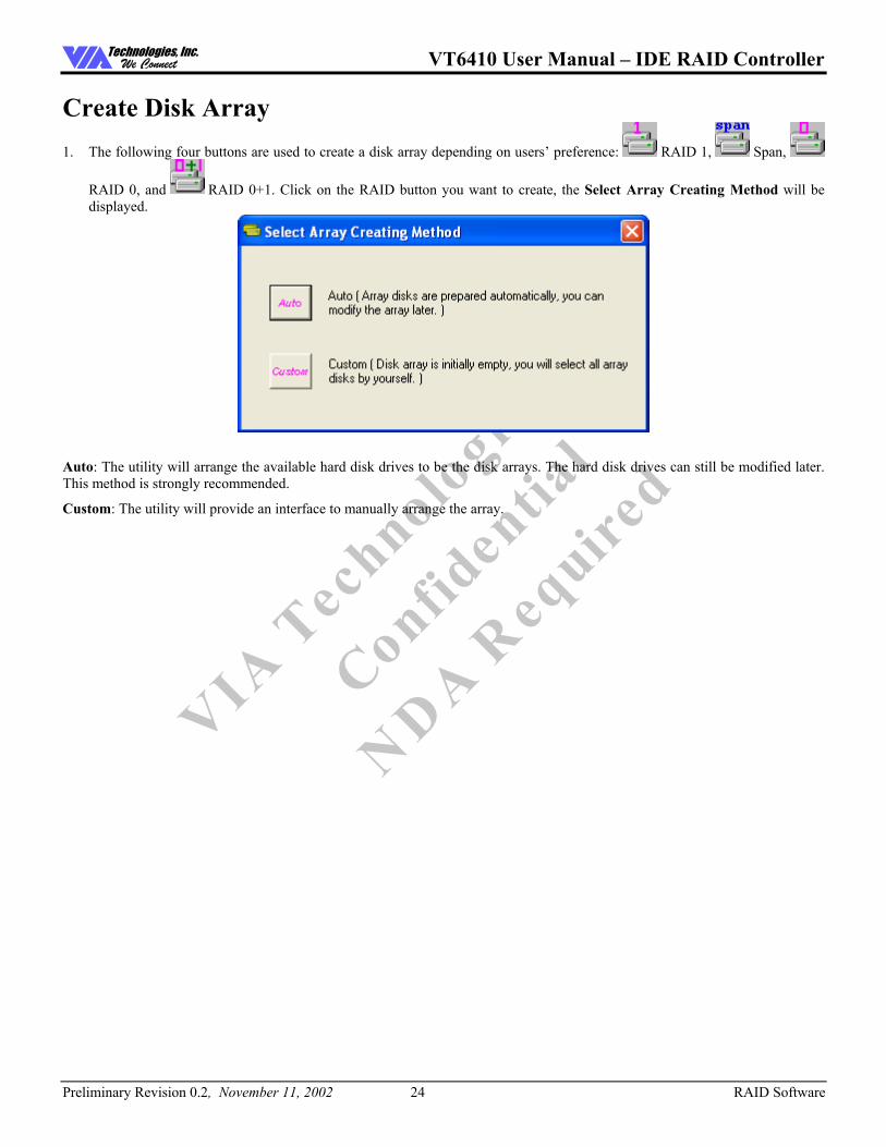
Create Disk Array 1. The following four buttons are used to create a disk array depending on users� preference: RAID 1, Span,
RAID 0, and RAID 0+1. Click on the RAID button you want to create, the Select Array Creating Method will be displayed.
Auto: The utility will arrange the available hard disk drives to be the disk arrays. The hard disk drives can still be modified later. This method is strongly recommended.
Custom: The utility will provide an interface to manually arrange the array.

VT6410 User Manual � IDE RAID Controller
Preliminary Revision 0.2, November 11, 2002 25 RAID Software
Technologies, Inc.We Connect
VIA T
echnologies I
nc.
Confidentia
l
NDA Require
d
2. Click on �Auto� to launch the creating array window. If you select Custom, the available disks window lists the available
disk drives that can be used to create the array. Select a disk drive and click on the right arrow button to add the specified disk drive to the array. Disk drives can be removed from the array by selecting an array disk and clicking on the left arrow button to remove the drive from the array.
Click on �Create� to continue or �Cancel� to exit. Click on �Help� to launch the Help Topics window.
VT6410 User Manual � IDE RAID Controller
Preliminary Revision 0.2, November 11, 2002 26 RAID Software
Technologies, Inc.We Connect
VIA T
echnologies I
nc.
Confidentia
l
NDA Require
d
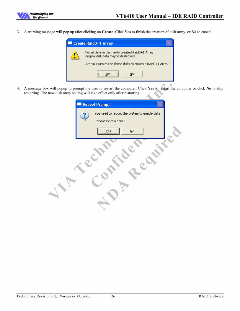
3. A warning message will pop up after clicking on Create. Click Yes to finish the creation of disk array, or No to cancel.
4. A message box will popup to prompt the user to restart the computer. Click Yes to restart the computer or click No to skip
restarting. The new disk array setting will take effect only after restarting.

VT6410 User Manual � IDE RAID Controller
Preliminary Revision 0.2, November 11, 2002 27 RAID Software
Technologies, Inc.We Connect
VIA T
echnologies I
nc.
Confidentia
l
NDA Require
d
Delete Disk Array 1. Select the disk array that you want to delete from the left windowpane. Click on Remove Array . A warning message
will popup.
2. Click Yes to delete the specified disk array or click No to cancel.

VT6410 User Manual � IDE RAID Controller
Preliminary Revision 0.2, November 11, 2002 28 RAID Software
Technologies, Inc.We Connect
VIA T
echnologies I
nc.
Confidentia
l
NDA Require
d
3. A message box will popup to prompt the user to restart the computer. Click Yes to restart the computer or click No to skip
restarting. The new setting will take effect only after restarting.
Warning: Deleting a disk array will destroy all the data on the disk array except RAID 1 arrays. When a RAID array is deleted, the data on these two hard disk drives will still remain and become two normal disk drives.

VT6410 User Manual � IDE RAID Controller
Preliminary Revision 0.2, November 11, 2002 29 RAID Software
Technologies, Inc.We Connect
VIA T
echnologies I
nc.
Confidentia
l
NDA Require
d
Add and Remove Spare Disk Drive
Add Spare Disk Drive A spare disk drive can be added when a RAID 1 array is created. The capacity of the spare disk drive must be greater than or equal to the capacity of the RAID 1 array. If there is no spare disk drive in a RAID 1 array, user can add a spare disk drive after RAID 1
array is created by clicking on .
1. Select the RAID 1 array in the left windowpane and click on . Then the available disk drives will be listed in a popup window.
2. Select a disk drive and click on OK to add a spare disk drive to RAID 1.
3. A warning message will popup. Click Yes to finish adding the spare disk, or No to cancel.

VT6410 User Manual � IDE RAID Controller
Preliminary Revision 0.2, November 11, 2002 30 RAID Software
Technologies, Inc.We Connect
VIA T
echnologies I
nc.
Confidentia
l
NDA Require
d
4. A message box will popup to prompt the user to restart the computer. Click Yes to restart the computer or click No to skip
restarting. The new setting will take effect only after restarting.
Note: The spare disk drive in the RAID 1 array can be accessed by the operating system.

VT6410 User Manual � IDE RAID Controller
Preliminary Revision 0.2, November 11, 2002 31 RAID Software
Technologies, Inc.We Connect
VIA T
echnologies I
nc.
Confidentia
l
NDA Require
d
Remove Spare Disk Drive Spare disk drives can be removed from a specified RAID 1 and changed into normal hard disk drives.
1. Select the RAID 1 array that you want to remove spare disk drive in the left windowpane and click on . A warning message will popup.
2. Click Yes to finish removing spare disk, or No to cancel. 3. A message box will popup to prompt the user to restart the computer. Click Yes to restart the computer or click No to skip
restarting. The new setting will take effect only after restarting

VT6410 User Manual � IDE RAID Controller
Preliminary Revision 0.2, November 11, 2002 32 RAID Software
Technologies, Inc.We Connect
VIA T
echnologies I
nc.
Confidentia
l
NDA Require
d
Check All Disks You can check whether the disk drives are working normally at any time by clicking on . After the disk check is completed, a dialog window will pop up to show the status of each disk. See picture below.
Your hard disk drive must be compatible with the ATA/ATAPI-5 specification and support SMART commands or the disk checking will fail.

VT6410 User Manual � IDE RAID Controller
Preliminary Revision 0.2, November 11, 2002 33 RAID Software
Technologies, Inc.We Connect
VIA T
echnologies I
nc.
Confidentia
l
NDA Require
d
View Event Log The RAID software records important events into a log file, such as disk array creation, disk array removal, disk failure, synchronization�etc.
1. Click on to display the event log. There are three types of log items: Information , Warning , and Error .
VT6410 User Manual � IDE RAID Controller
Preliminary Revision 0.2, November 11, 2002 34 RAID Software
Technologies, Inc.We Connect
VIA T
echnologies I
nc.
Confidentia
l
NDA Require
d
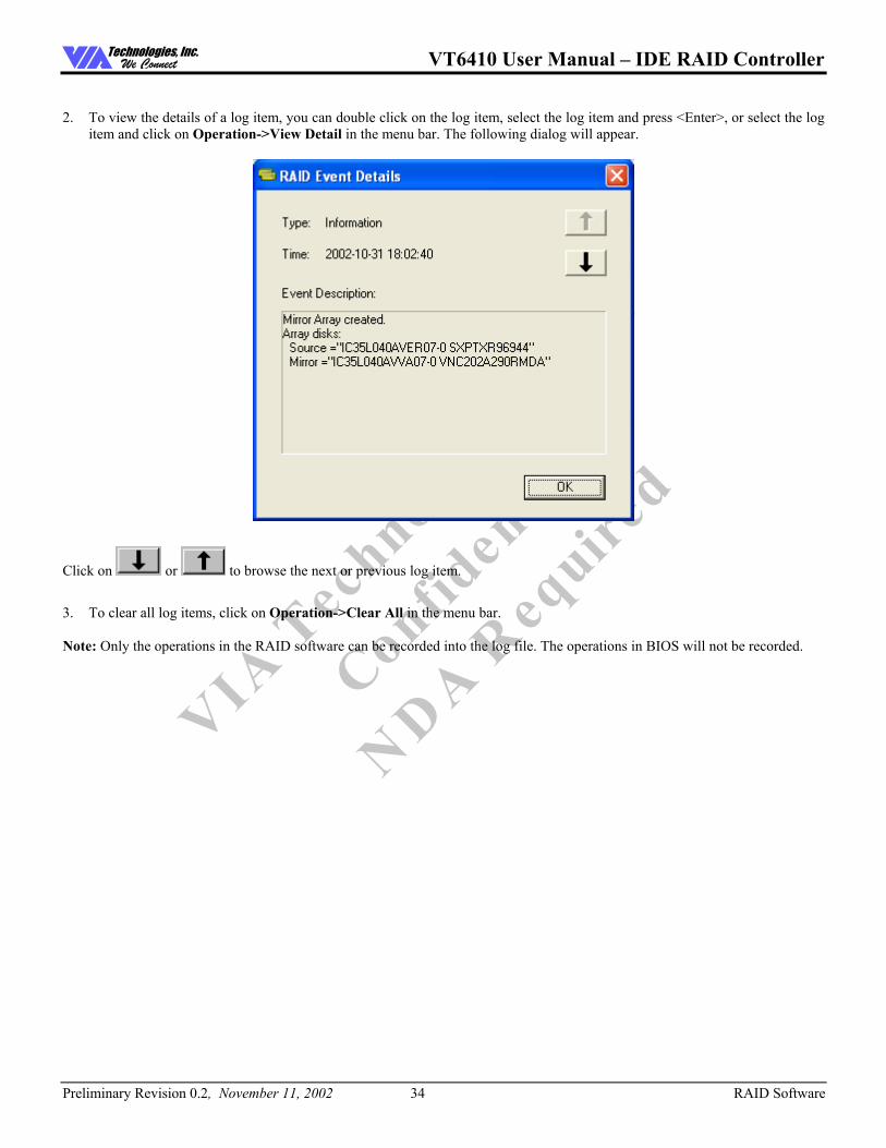
2. To view the details of a log item, you can double click on the log item, select the log item and press <Enter>, or select the log
item and click on Operation->View Detail in the menu bar. The following dialog will appear.
Click on or to browse the next or previous log item.
3. To clear all log items, click on Operation->Clear All in the menu bar. Note: Only the operations in the RAID software can be recorded into the log file. The operations in BIOS will not be recorded.

VT6410 User Manual � IDE RAID Controller
Preliminary Revision 0.2, November 11, 2002 35 RAID Software
Technologies, Inc.We Connect
VIA T
echnologies I
nc.
Confidentia
l
NDA Require
d
Verify Mirror Disk The data on the mirror disk must be the same with its corresponding source disk to provide fault tolerance for RAID 1 or RAID 0+1.
1. Select a RAID 1 or RAID 0+1 array. Right-click the selected RAID, then a shortcut menu will be shown. Click on Verify
Mirror to verify whether the source and mirror are identical.

VT6410 User Manual � IDE RAID Controller
Preliminary Revision 0.2, November 11, 2002 36 RAID Software
Technologies, Inc.We Connect
VIA T
echnologies I
nc.
Confidentia
l
NDA Require
d
2. After executing the �verify mirror� command, a dialog box will show the verifying process. You can pause or cancel this
process at any time. It may take a long time to verify the source and mirror disk if the capacity of the RAID is large.
3. When the mirror disk is not identical with the corresponding source disk, the mirror disk will be marked with a �need-sync�
flag. The icon used to indicate this status is . A �need-sync� mirror disk should be synchronized as soon as possible.

VT6410 User Manual � IDE RAID Controller
Preliminary Revision 0.2, November 11, 2002 37 RAID Software
Technologies, Inc.We Connect
VIA T
echnologies I
nc.
Confidentia
l
NDA Require
d
Synchronize Mirror Disk RAID 1 or RAID 0+1 arrays must be synchronized when the data on the mirror disk is not identical with its corresponding source disk. Sometimes the data on the mirror disk may be newer than the data on the source disk. For example, the source disk is absent and the mirror disk runs in the tolerance mode. So the exact meaning of �Synchronize Mirror� is to make a pair of source and
mirror disks have identical data. The RAID software always marks the mirror disk with a �need-sync� icon although the mirror disk may have the correct data.
1. Select a RAID 1 or RAID 0+1 array. Right-click the selected RAID, then a shortcut menu will be shown. Click on
Synchronize Mirror to synchronize the source and mirror disks.

VT6410 User Manual � IDE RAID Controller
Preliminary Revision 0.2, November 11, 2002 38 RAID Software
Technologies, Inc.We Connect
VIA T
echnologies I
nc.
Confidentia
l
NDA Require
d
2. After synchronization has started, a dialog box will show the process. You can pause or cancel this process at any time.
A message will pop up when the synchronization is finished.

VT6410 User Manual � IDE RAID Controller
Preliminary Revision 0.2, November 11, 2002 39 RAID Software
Technologies, Inc.We Connect
VIA T
echnologies I
nc.
Confidentia
l
NDA Require
d
Disk Error Detection The RAID software will pop up an error message if a disk drive fails or is missing.
Duplicate Critical RAID 1/0+1 Array When booting up the system, the RAID utility will detect if there are any inconsistencies between the source and mirror disk drives of the RAID 1 or RAID 0+1 arrays. If the software detects that a RAID 1 or 0+1 array has any inconsistencies, then the status of the disk array will be marked as critical and the software will prompt the user to duplicate the RAID 1 or 0+1 to make the mirror disk consistent with the corresponding source disk.

VT6410 User Manual � IDE RAID Controller
Preliminary Revision 0.2, November 11, 2002 40 RAID Software
Technologies, Inc.We Connect
VIA T
echnologies I
nc.
Confidentia
l
NDA Require
d
You can click Yes to synchronize now or click No to synchronize later.
After synchronization has started, a dialog box will show the process. You can pause or cancel this process at any time. If you cancel the synchronization process, the RAID will be on the �need-sync� condition. You should synchronize again to guarantee that the data between source and mirror disk drives is identical.
A message will pop up when the synchronization is finished.

VT6410 User Manual � IDE RAID Controller
Preliminary Revision 0.2, November 11, 2002 41 RAID Software
Technologies, Inc.We Connect
VIA T
echnologies I
nc.
Confidentia
l
NDA Require
d
Rebuild Broken RAID 0/0+1 array After booting up the system, the RAID utility will detect if any member disk drives of the RAID 0 or 0+1 array has failed or is absent. If the RAID utility detects any disk drive failures or missing disk drives, the status of the array will be marked as broken.
If the RAID software detects a RAID 1 array being broken, and there is a spare hard drive that could be used to rebuild the broken array, the spare hard drive will automatically become the mirroring drive. Software will remind the user to synchronize this RAID like the duplicating RAID 1.
If the RAID software detects a RAID 1 or 0+1 array being broken but there is no spare hard drive, the RAID software will indicate a series of steps to repair such problem.
1. Pop up a dialog box to indicate that the RAID is broken. Click Yes to repair the array.

VT6410 User Manual � IDE RAID Controller
Preliminary Revision 0.2, November 11, 2002 42 RAID Software
Technologies, Inc.We Connect
VIA T
echnologies I
nc.
Confidentia
l
NDA Require
d
2. Another dialog box will pop up. If the source or mirror disk drive is only unplugged, click Cancel to stop rebuilding. Shut
down system. Plug in the absent disk drive and then reboot system. If the original disk drive is broken, plug in a new disk drive and then reboot system. Click Next to proceed to the next step.
3. Select a disk drive from Available Disks and click on to replace the broken drive and then click Next.

VT6410 User Manual � IDE RAID Controller
Preliminary Revision 0.2, November 11, 2002 43 RAID Software
Technologies, Inc.We Connect
VIA T
echnologies I
nc.
Confidentia
l
NDA Require
d
4. A warning message will pop up. If you want to rebuild the RAID using the disk driver that you selected in the previous step, click Next.
Warning: All of the data on the selected disk drive will be lost.
VT6410 User Manual � IDE RAID Controller
Preliminary Revision 0.2, November 11, 2002 44 RAID Software
Technologies, Inc.We Connect
VIA T
echnologies I
nc.
Confidentia
l
NDA Require
d
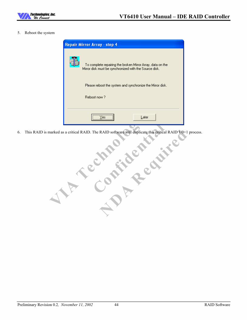
5. Reboot the system
6. This RAID is marked as a critical RAID. The RAID software will duplicate this critical RAID 1/0+1 process.
VT6410 User Manual � IDE RAID Controller
Preliminary Revision 0.2, November 11, 2002 45 RAID Software
Technologies, Inc.We Connect
VIA T
echnologies I
nc.
Confidentia
l
NDA Require
d
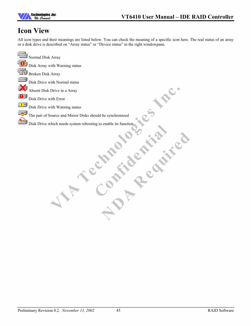
Icon View All icon types and their meanings are listed below. You can check the meaning of a specific icon here. The real status of an array or a disk drive is described on �Array status� or �Device status� in the right windowpane.
Normal Disk Array
Disk Array with Warning status
Broken Disk Array
Disk Drive with Normal status
Absent Disk Drive in a Array
Disk Drive with Error
Disk Drive with Warning status
The pair of Source and Mirror Disks should be synchronized
Disk Drive which needs system rebooting to enable its function.