Version Description Document - JTLS-GO
286
JTLS Version Description Document April 2007 JOINT THEATER LEVEL SIMULATION (JTLS 3.2.0.0) U.S. Joint Forces Command Joint Warfighting Center 116 Lake View Parkway Suffolk, VA 23435-2697 JTLS Document 17
-
Upload
khangminh22 -
Category
Documents
-
view
8 -
download
0
Transcript of Version Description Document - JTLS-GO
JTLS Document 17
JTLS
Version Description Document
April 2007
JOINT THEATER LEVEL SIMULATION(JTLS 3.2.0.0)
U.S. Joint Forces CommandJoint Warfighting Center116 Lake View ParkwaySuffolk, VA 23435-2697

April 2007 JTLS Document 17
ABSTRACT
This JTLS Version Description Document (VDD) describes Version 3.2.0.0 of the configuredsoftware suite identified as the Joint Theater Level Simulation (JTLS). JTLS 3.2.0.0 is a Majorrelease.
As a Major release, JTLS 3.2.0.0 includes a modified and enhanced Standard Database, as well asextensive model functionality changes implemented as Enhancement Change Proposals (ECPs).These ECPs are described in Chapter 2. Chapter 3 of this document describes the code modificationsthat represent corrections to Software Trouble Reports (STRs). The remaining outstanding STRs aredescribed in Chapter 4.
This publication is updated and revised for each version release of the JTLS model. User corrections,additions, or constructive recommendations for improvement must include justification and bereferenced to specific sections, pages, and paragraphs. Submissions must be written in Model ChangeRequest (MCR) format and forwarded to:
JTLS Configuration Management AgentJFCOM/JWFC116 Lake View ParkwaySuffolk, VA 23435-2697
Copyright 2007, ROLANDS & ASSOCIATES Corporation
JTLS 3.2.0.0 iii Version Description Document

JTLS Document 17 April 2007
[Blank Page]
Version Description Document iv JTLS 3.2.0.0
April 2007 JTLS Document 17
TABLE OF CONTENTS
1.0 INTRODUCTION 1.1 SCOPE .......................................................................................................................... 1-1 1.2 INVENTORY OF MATERIALS ................................................................................. 1-1
1.2.1 Obsolete/Outdated Documents ............................................................................ 1-1 1.2.2 Unchanged Documents ........................................................................................ 1-1 1.2.3 Updated Documents ............................................................................................. 1-1 1.2.4 New Documents ................................................................................................... 1-2 1.2.5 Released Software ................................................................................................ 1-2 1.2.6 Released Databases .............................................................................................. 1-3
1.3 INTERFACE COMPATIBILITY ................................................................................ 1-3 1.3.1 Support Software ................................................................................................. 1-3 1.3.2 HLA Compliance ................................................................................................. 1-5 1.3.3 JTLS Operational Interface (JOI) ........................................................................ 1-6
1.4 INSTALLATION CONSIDERATIONS ...................................................................... 1-6 1.5 DATABASE MODIFICATIONS ................................................................................. 1-6
1.5.1 Graphic Symbols Update ..................................................................................... 1-6 1.5.2 Database Upgrade ................................................................................................ 1-7 1.5.3 Data Elements ...................................................................................................... 1-8 1.5.4 Standard Database Changes ............................................................................... 1-22
1.6 INSTALLATION NOTES .......................................................................................... 1-23 1.6.1 Installation Instructions ...................................................................................... 1-23 1.6.2 Oracle Compatibility and Installation ................................................................ 1-23
2.0 ENHANCEMENT CHANGE PROPOSALS 2.1 JTLS-0004 DISPLAY RANGE RINGS ....................................................................... 2-1
2.1.1 Summary of Model Change Request ................................................................... 2-1 2.1.2 Design Summary .................................................................................................. 2-1 2.1.3 Data Changes ....................................................................................................... 2-4 2.1.4 Order Changes ..................................................................................................... 2-4 2.1.5 JODA Changes ..................................................................................................... 2-4
2.2 JTLS-0008 REAL TIME INTERCEPT REPORT ....................................................... 2-4 2.2.1 Summary of Model Change Request ................................................................... 2-4 2.2.2 Design Summary .................................................................................................. 2-4 2.2.3 Data Changes ....................................................................................................... 2-8 2.2.4 Order Changes ..................................................................................................... 2-8 2.2.5 JODA Changes ..................................................................................................... 2-8
2.3 JTLS-0018 NAVAL FUEL USAGE ............................................................................ 2-8 2.3.1 Summary of Model Change Request ................................................................... 2-8 2.3.2 Design Summary .................................................................................................. 2-8 2.3.3 Data Changes ....................................................................................................... 2-8
JTLS 3.2.0.0 v Version Description Document
JTLS Document 17 April 2007
2.3.4 Order Changes ..................................................................................................... 2-8 2.3.5 JODA Changes ..................................................................................................... 2-8
2.4 JTLS-0056 IMPROVE AIRCRAFT DIVERT LOGIC ................................................ 2-9 2.4.1 Summary of Model Change Request ................................................................... 2-9 2.4.2 Design Summary .................................................................................................. 2-9 2.4.3 Data Changes ..................................................................................................... 2-10 2.4.4 Order Changes ................................................................................................... 2-10 2.4.5 JODA Changes ................................................................................................... 2-10
2.5 JTLS-0074 REFUEL BASE LOGIC IMPROVEMENT ............................................ 2-11 2.5.1 Summary of Model Change Request ................................................................. 2-11 2.5.2 Design Summary ................................................................................................ 2-11 2.5.3 Data Changes ..................................................................................................... 2-11 2.5.4 Order Changes ................................................................................................... 2-11 2.5.5 JODA Changes ................................................................................................... 2-11
2.6 JTLS-0075 PASSIVE SONARS DO NOT DETECT SURFACE SHIPS ................. 2-11 2.6.1 Summary of Model Change Request ................................................................. 2-11 2.6.2 Design Summary ................................................................................................ 2-13 2.6.3 Data Changes ..................................................................................................... 2-17 2.6.4 Order Changes ................................................................................................... 2-17 2.6.5 JODA Changes ................................................................................................... 2-17
2.7 JTLS-0083 CONTROLLER ADJUSTS AIR MISSION SPEED .............................. 2-17 2.7.1 Summary of Model Change Request ................................................................. 2-17 2.7.2 Design Summary ................................................................................................ 2-18 2.7.3 Data Changes ..................................................................................................... 2-18 2.7.4 Order Changes ................................................................................................... 2-19 2.7.5 JODA Changes ................................................................................................... 2-19
2.8 JTLS-0084 CHANGE TERRAIN AND BARRIER VALUES .................................. 2-19 2.8.1 Summary of Model Change Request ................................................................. 2-19 2.8.2 Design Summary ................................................................................................ 2-19 2.8.3 Data Changes ..................................................................................................... 2-21 2.8.4 Order Changes ................................................................................................... 2-21 2.8.5 JODA Changes ................................................................................................... 2-22
2.9 JTLS-0091 NEW CONVOY SYMBOLS .................................................................. 2-22 2.9.1 Summary of Model Change Request ................................................................. 2-22 2.9.2 Design Summary ................................................................................................ 2-22 2.9.3 Data Changes ..................................................................................................... 2-23 2.9.4 Order Changes ................................................................................................... 2-24 2.9.5 JODA Changes ................................................................................................... 2-24
2.10 JTLS-0118 CHANGE ALERT BASE ...................................................................... 2-24 2.10.1 Summary of Model Change Request ............................................................... 2-24 2.10.2 Design Summary .............................................................................................. 2-24 2.10.3 Data Changes ................................................................................................... 2-29 2.10.4 Order Changes ................................................................................................. 2-29
Version Description Document vi JTLS 3.2.0.0
April 2007 JTLS Document 17
2.10.5 JODA Changes ................................................................................................. 2-29 2.11 JTLS-0181 TORPEDOES FOLLOW SHIPS ........................................................... 2-30
2.11.1 Summary of Model Change Request ............................................................... 2-30 2.11.2 Design Summary .............................................................................................. 2-30 2.11.3 Data Changes ................................................................................................... 2-31 2.11.4 Order Changes ................................................................................................. 2-31 2.11.5 JODA Changes ................................................................................................. 2-32
2.12 JTLS-0224 BUILD RAILROADS, PIPELINES, AND IADS ................................. 2-32 2.12.1 Summary of Model Change Request ............................................................... 2-32 2.12.2 Design Summary .............................................................................................. 2-32 2.12.3 Data Changes ................................................................................................... 2-32 2.12.4 Order Changes ................................................................................................. 2-32 2.12.5 JODA Changes ................................................................................................. 2-32
2.13 JTLS-0264 SLP-SC SPECIFIC NAME UNIQUENESS ......................................... 2-32 2.13.1 Summary of Model Change Request ............................................................... 2-32 2.13.2 Design Summary .............................................................................................. 2-33 2.13.3 Data Changes ................................................................................................... 2-35 2.13.4 Order Changes ................................................................................................. 2-35 2.13.5 JODA Changes ................................................................................................. 2-35
2.14 JTLS-0300 MAGIC MOVE TO OFFBOARD LOCATION FORMATION ........... 2-36 2.14.1 Summary of Model Change Request ............................................................... 2-36 2.14.2 Design Summary .............................................................................................. 2-36 2.14.3 Data Changes ................................................................................................... 2-37 2.14.4 Order Changes ................................................................................................. 2-38 2.14.5 JODA Changes ................................................................................................. 2-38
2.15 JTLS-0326 JUMP MAP ............................................................................................ 2-38 2.15.1 Summary of Model Change Request ............................................................... 2-38 2.15.2 Design Summary .............................................................................................. 2-38 2.15.3 Data Changes ................................................................................................... 2-42 2.15.4 Order Changes ................................................................................................. 2-42 2.15.5 JODA Changes ................................................................................................. 2-42
2.16 JTLS-0340 JTLS MESSAGE FORWARDING ....................................................... 2-42 2.16.1 Summary of Model Change Request ............................................................... 2-42 2.16.2 Design Summary .............................................................................................. 2-43 2.16.3 Data Changes ................................................................................................... 2-46 2.16.4 Order Changes ................................................................................................. 2-46 2.16.5 JODA Changes ................................................................................................. 2-47
2.17 JTLS-0347 UNITS IN COMBAT FLAG ................................................................. 2-47 2.17.1 Summary of Model Change Request ............................................................... 2-47 2.17.2 Design Summary .............................................................................................. 2-47 2.17.3 Data Changes ................................................................................................... 2-47 2.17.4 Order Changes ................................................................................................. 2-47 2.17.5 JODA Changes ................................................................................................. 2-47
JTLS 3.2.0.0 vii Version Description Document
JTLS Document 17 April 2007
2.18 JTLS-0349 COMMAND HIERARCHY DISPLAY MANAGEMENT .................. 2-47 2.18.1 Summary of Model Change Request ............................................................... 2-47 2.18.2 Design Summary .............................................................................................. 2-48 2.18.3 Data Changes ................................................................................................... 2-50 2.18.4 Order Changes ................................................................................................. 2-50 2.18.5 JODA Changes ................................................................................................. 2-50
2.19 JTLS-0370 XCHAT PAGING FLAGS .................................................................... 2-50 2.19.1 Summary of Model Change Request ............................................................... 2-50 2.19.2 Design Summary .............................................................................................. 2-51 2.19.3 Data Changes ................................................................................................... 2-53 2.19.4 Order Changes ................................................................................................. 2-53 2.19.5 JODA Changes ................................................................................................. 2-53
2.20 JTLS-0377 EXERCISE SUBMISSION TOOL ........................................................ 2-53 2.20.1 Summary of Model Change Request ............................................................... 2-53 2.20.2 Design Summary .............................................................................................. 2-53 2.20.3 Data Changes ................................................................................................... 2-56 2.20.4 Order Changes ................................................................................................. 2-56 2.20.5 JODA Changes ................................................................................................. 2-56
2.21 JTLS-0378 GRAPHICAL DATABASE PROGRAM .............................................. 2-57 2.21.1 Summary of Model Change Request ............................................................... 2-57 2.21.2 Design Summary .............................................................................................. 2-57 2.21.3 Data Changes ................................................................................................... 2-58 2.21.4 Order Changes ................................................................................................. 2-58 2.21.5 JODA Changes ................................................................................................. 2-58
2.22 JTLS-0385 SONAR AVAILABILITY FUNCTION OF SPEED ............................ 2-58 2.22.1 Summary of Model Change Request ............................................................... 2-58 2.22.2 Design Summary .............................................................................................. 2-58 2.22.3 Data Changes ................................................................................................... 2-59 2.22.4 Order Changes ................................................................................................. 2-59 2.22.5 JODA Changes ................................................................................................. 2-59
2.23 JTLS-0399 FLIGHT PLAN WHILE HEADING FOR FUEL ................................. 2-59 2.23.1 Summary of Model Change Request ............................................................... 2-59 2.23.2 Design Summary .............................................................................................. 2-60 2.23.3 Data Changes ................................................................................................... 2-68 2.23.4 Order Changes ................................................................................................. 2-68 2.23.5 JODA Changes ................................................................................................. 2-68
2.24 JTLS-0401 ATO-T ACCESS TO MISSION AND TARGET TYPES .................... 2-68 2.24.1 Summary of Model Change Request ............................................................... 2-68 2.24.2 Design Summary .............................................................................................. 2-68 2.24.3 Data Changes ................................................................................................... 2-72 2.24.4 Order Changes ................................................................................................. 2-72 2.24.5 JODA Changes ................................................................................................. 2-72
2.25 JTLS-0410 CAP INTERCEPT BREAK-OFF FEEDBACK .................................... 2-72
Version Description Document viii JTLS 3.2.0.0
April 2007 JTLS Document 17
2.25.1 Summary of Model Change Request ............................................................... 2-72 2.25.2 Design Summary .............................................................................................. 2-72 2.25.3 Data Changes ................................................................................................... 2-74 2.25.4 Order Changes ................................................................................................. 2-74 2.25.5 JODA Changes ................................................................................................. 2-75
2.26 JTLS-0430 AUTO PAIR VERSUS HELO/UAV .................................................... 2-75 2.26.1 Summary of Model Change Request ............................................................... 2-75 2.26.2 Design Summary .............................................................................................. 2-75 2.26.3 Data Changes ................................................................................................... 2-81 2.26.4 Order Changes ................................................................................................. 2-81 2.26.5 JODA Changes ................................................................................................. 2-81
2.27 JTLS-0501 AAR IMPROVEMENTS ....................................................................... 2-81 2.27.1 Summary of Model Change Request ............................................................... 2-81 2.27.2 Design Summary .............................................................................................. 2-83 2.27.3 Data Changes ................................................................................................... 2-93 2.27.4 Order Changes ................................................................................................. 2-94 2.27.5 JODA Changes ................................................................................................. 2-94
2.28 JTLS-0520 TACSIM IMMEDIATE WRECKAGE PLACEMENT ........................ 2-94 2.28.1 Summary of Model Change Request ............................................................... 2-94 2.28.2 Design Summary .............................................................................................. 2-94 2.28.3 Data Changes ................................................................................................... 2-94 2.28.4 Order Changes ................................................................................................. 2-94
2.29 JTLS-0526 MOVEMENT OF UNITS WITHIN A HEX ......................................... 2-95 2.29.1 Summary of Model Change Request ............................................................... 2-95 2.29.2 Design Summary .............................................................................................. 2-95 2.29.3 Data Changes ................................................................................................... 2-95 2.29.4 Order Changes ................................................................................................. 2-95 2.29.5 JODA Changes ................................................................................................. 2-96
2.30 JTLS-0531 IMPROVE ATO-T WING LEVEL TASKING .................................... 2-96 2.30.1 Summary of Model Change Request ............................................................... 2-96 2.30.2 Design Summary .............................................................................................. 2-96 2.30.3 Data Changes ................................................................................................... 2-97 2.30.4 Order Changes ................................................................................................. 2-97 2.30.5 JODA Changes ................................................................................................. 2-97
2.31 JTLS-0549 ORBIT DIRECTION ............................................................................. 2-97 2.31.1 Summary of Model Change Request ............................................................... 2-97 2.31.2 Design Summary .............................................................................................. 2-97 2.31.3 Data Changes ................................................................................................... 2-98 2.31.4 Order Changes ................................................................................................. 2-98 2.31.5 JODA Changes ................................................................................................. 2-98
2.32 JTLS-0572 OFF-MAP SSM FIRE ........................................................................... 2-98 2.32.1 Summary of Model Change Request ............................................................... 2-98 2.32.2 Design Summary .............................................................................................. 2-98
JTLS 3.2.0.0 ix Version Description Document
JTLS Document 17 April 2007
2.32.3 Data Changes ................................................................................................. 2-100 2.32.4 Order Changes ............................................................................................... 2-100 2.32.5 JODA Changes ............................................................................................... 2-101
2.33 JTLS-2005-1431 ATO-T ORBIT POINTS ............................................................ 2-101 2.33.1 Summary of Model Change Request ............................................................. 2-101 2.33.2 Design Summary ............................................................................................ 2-101 2.33.3 Data Changes ................................................................................................. 2-102 2.33.4 Order Changes ............................................................................................... 2-102 2.33.5 JODA Changes ............................................................................................... 2-102
2.34 JTLS-2005-1483 FILLUP REFUEL CHIT ............................................................ 2-103 2.34.1 Summary of Model Change Request ............................................................. 2-103 2.34.2 Design Summary ............................................................................................ 2-103 2.34.3 Data Changes ................................................................................................. 2-107 2.34.4 Order Changes ............................................................................................... 2-107 2.34.5 JODA Changes ............................................................................................... 2-107
2.35 JTLS-2005-1558 PRISIM WORKSHEET ............................................................. 2-107 2.35.1 Summary of Model Change Request ............................................................. 2-107 2.35.2 Design Summary ............................................................................................ 2-108 2.35.3 Data Changes ................................................................................................. 2-110 2.35.4 Order Changes ............................................................................................... 2-110 2.35.5 JODA Changes ............................................................................................... 2-111
2.36 JTLS-2006-1660 INTEGERIZED LANCHESTRIAN COMBAT ........................ 2-111 2.36.1 Summary of Model Change Request ............................................................. 2-111 2.36.2 Design Summary ............................................................................................ 2-112 2.36.3 Data Changes ................................................................................................. 2-125 2.36.4 Order Changes ............................................................................................... 2-126 2.36.5 JODA Changes ............................................................................................... 2-126
2.37 JTLS-2006-1736 FOM REPRESENTATION OF FUEL FOR AIR MISSIONS .. 2-126 2.37.1 Summary of Model Change Request ............................................................. 2-126 2.37.2 Design Summary ............................................................................................ 2-127 2.37.3 Data Changes ................................................................................................. 2-128 2.37.4 Order Changes ............................................................................................... 2-128 2.37.5 JODA Changes ............................................................................................... 2-128
2.38 JTLS-2006-1752 IMPROVE FUEL USAGE FLEXIBILITY ............................... 2-128 2.38.1 Summary of Model Change Request ............................................................. 2-128 2.38.2 Design Summary ............................................................................................ 2-128 2.38.3 Data Changes ................................................................................................. 2-131 2.38.4 Order Changes ............................................................................................... 2-138 2.38.5 JODA Changes ............................................................................................... 2-138
2.39 JTLS-2006-1827 NEW COMMAND CONTROL MODEL .................................. 2-139 2.39.1 Summary of Model Change Request ............................................................. 2-139 2.39.2 Design Summary ............................................................................................ 2-139 2.39.3 Data Changes ................................................................................................. 2-152
Version Description Document x JTLS 3.2.0.0
April 2007 JTLS Document 17
2.39.4 Order Changes ............................................................................................... 2-154 2.39.5 JODA Changes ............................................................................................... 2-154
2.40 JTLS-2006-1837 REMOVE USMTF 1998 CODE FROM ATO-T ....................... 2-155 2.40.1 Summary of Model Change Request ............................................................. 2-155 2.40.2 Design Summary ............................................................................................ 2-155 2.40.3 Data Changes ................................................................................................. 2-155 2.40.4 Order Changes ............................................................................................... 2-155 2.40.5 JODA Changes ............................................................................................... 2-155
2.41 JTLS-2006-1846 OPM TARGETABLE WEAPONS COMBAT SYSTEMS LINK 2-155 2.41.1 Summary of Model Change Request ............................................................. 2-155 2.41.2 Design Summary ............................................................................................ 2-156 2.41.3 Data Changes ................................................................................................. 2-158 2.41.4 Order Changes ............................................................................................... 2-158 2.41.5 JODA Changes ............................................................................................... 2-158
2.42 JTLS-2006-1865 TUP SPECIAL CAPABILITIES ................................................ 2-158 2.42.1 Summary of Model Change Request ............................................................. 2-158 2.42.2 Design Summary ............................................................................................ 2-158 2.42.3 Data Changes ................................................................................................. 2-159 2.42.4 Order Changes ............................................................................................... 2-159 2.42.5 JODA Changes ............................................................................................... 2-159
2.43 JTLS-2006-1900 IMPROVE MAP ENTRY OF UNITS AND TARGETS ........... 2-160 2.43.1 Summary of Model Change Request ............................................................. 2-160 2.43.2 Design Summary ............................................................................................ 2-160 2.43.3 Data Changes ................................................................................................. 2-161 2.43.4 Order Changes ............................................................................................... 2-161 2.43.5 JODA Changes ............................................................................................... 2-161
2.44 JTLS-2006-1901 SPACES WITHIN UNIT LONG NAMES ................................ 2-161 2.44.1 Summary of Model Change Request ............................................................. 2-161 2.44.2 Design Summary ............................................................................................ 2-161 2.44.3 Data Changes ................................................................................................. 2-162 2.44.4 Order Changes ............................................................................................... 2-162 2.44.5 JODA Changes ............................................................................................... 2-162
2.45 JTLS-1006-1902 STANDARDIZE CONTEXT-SENSITIVE ORDER MENUS . 2-163 2.45.1 Summary of Model Change Request ............................................................. 2-163 2.45.2 Design Summary ............................................................................................ 2-163 2.45.3 Data Changes ................................................................................................. 2-170 2.45.4 Order Changes ............................................................................................... 2-170 2.45.5 JODA Changes ............................................................................................... 2-170
2.46 JTLS-2006-1904 TRANSPARENT HEX TERRAIN OVERLAY ........................ 2-170 2.46.1 Summary of Model Change Request ............................................................. 2-170 2.46.2 Design Summary ............................................................................................ 2-170 2.46.3 Data Changes ................................................................................................. 2-173 2.46.4 Order Changes ............................................................................................... 2-173
JTLS 3.2.0.0 xi Version Description Document
JTLS Document 17 April 2007
2.46.5 JODA Changes ............................................................................................... 2-173 2.47 JTLS-2007-1973 JTLS FEED TO COMMON OPERATIONAL PICTURE (COP) 2-173
2.47.1 Summary of Model Change Request ............................................................. 2-173 2.47.2 Design Summary ............................................................................................ 2-173 2.47.3 Data Changes ................................................................................................. 2-174 2.47.4 Order Changes ............................................................................................... 2-174 2.47.5 JODA Changes ............................................................................................... 2-174
3.0 SOFTWARE TROUBLE REPORTS 3.1 INTRODUCTION ........................................................................................................ 3-1 3.2 ERRORS CORRECTED FOR THIS RELEASE ......................................................... 3-1
3.2.1 JTLS-1386 Accept Ownership And Use For New Runway ................................ 3-1 3.2.2 JTLS-2007-1993 Zero Used As Invalid Detection Time ..................................... 3-1
4.0 REMAINING ERRORS 4.1 INTRODUCTION ........................................................................................................ 4-1 4.2 REMAINING ERRORS ............................................................................................... 4-1
4.2.1 JTLS-0639 Error Determining When Engineering Task Completed .................. 4-1 4.2.2 JTLS-0695 Shadow Distance Of Zero Overriding Protection Radius ................. 4-1 4.2.3 JTLS-0696 Missions Ignoring Assigned Altitude on Egress ............................... 4-1 4.2.4 JTLS-0697 Missions On The Ground With Invalid Destination ......................... 4-2 4.2.5 JTLS-0698 Cannot Re-Activate Destroyed Targets ............................................ 4-2 4.2.6 JTLS-0699 Targets That Require An Owner Are Disassociated ......................... 4-2 4.2.7 JTLS-0700 GIAC Not Displaying Current Runway Length ............................... 4-2 4.2.8 JTLS-0701 Air Movement Report Does Not Consider Hold Points ................... 4-2 4.2.9 JTLS-0702 Mission Waiting For Delayed Mission ............................................. 4-2 4.2.10 JTLS-0703 Periodic Report Other Side Airbases Lists No Activity ................. 4-2 4.2.11 JTLS-0704 Immediate Cancel Of Air Mission in Delay Status ........................ 4-3 4.2.12 JTLS-0705 Missions Launching With Fewer Aircraft Than Available ............. 4-3 4.2.13 JTLS-0843 Error 427 ......................................................................................... 4-3 4.2.14 JTLS-0846 Naval Unit Distance Calculation .................................................... 4-3 4.2.15 JTLS-0865 Incorrect External Program Order .................................................. 4-4 4.2.16 JTLS-0869 Continue Engage Determination ..................................................... 4-4 4.2.17 JTLS-0870 Number of Air-to-Air Combat Kills Allowed ................................ 4-4 4.2.18 JTLS-0871 AC Mission Weapon Drop Determination ..................................... 4-4 4.2.19 JTLS-0906 Change ADA pE To Per-Element pE ............................................. 4-4 4.2.20 JTLS-0907 Scud-Like SSM Representation ...................................................... 4-5 4.2.21 JTLS-0908 Naval IADS Link Representation ................................................... 4-5 4.2.22 JTLS-0909 Display Moderate And Severe Attrition Level ............................... 4-5 4.2.23 JTLS-0910 HRU Patrol Intel Reports ................................................................ 4-5 4.2.24 JTLS-0911 Fire Artillery Wait Time Between Missions ................................... 4-6 4.2.25 JTLS-0929 Ship Changes Sides ......................................................................... 4-6 4.2.26 JTLS-0934 HRU Overwatch .............................................................................. 4-6
Version Description Document xii JTLS 3.2.0.0
April 2007 JTLS Document 17
4.2.27 JTLS-0942 Air Transport Cannot Combine Wet And Dry Supplies ................. 4-6 4.2.28 JTLS-0948 Lanchester Double Kills ................................................................. 4-7 4.2.29 JTLS-0949 Destroyed Target SITREP Strength Incorrect ................................ 4-7 4.2.30 JTLS-0950 JTLS Radius Of Effects .................................................................. 4-7 4.2.31 JTLS-0952 Air Report ....................................................................................... 4-7 4.2.32 JTLS-0953 All Sides Informed About Supply Dump Error .............................. 4-7 4.2.33 JTLS-0954 Multiple Supply Storage Targets .................................................... 4-7 4.2.34 JTLS-0955 Air Lift Drop Report Message ........................................................ 4-8 4.2.35 JTLS-0956 MPP Messages For Canceled Missions In Error ............................ 4-8 4.2.36 JTLS-0957 Can’t Take Control Of Unowned Runways .................................... 4-8 4.2.37 JTLS-0958 Withdrawing Units Cannot Destroy Supply Targets ...................... 4-8 4.2.38 JTLS-0959 Logistics Report Problem ............................................................... 4-8 4.2.39 JTLS-0960 Can’t Magic Move Airbase To Existing Airbase Location ............ 4-8 4.2.40 JTLS-0961 Group Ground Move Delayed To Lead Unit .................................. 4-9 4.2.41 JTLS-0962 Pass Unit Intelligence Does Not Include Update Information ........ 4-9 4.2.42 JTLS-0963 IMT Supply Category Line Disappears When Value Is Zero ......... 4-9 4.2.43 JTLS-0964 Reporting Bridge Damage .............................................................. 4-9 4.2.44 JTLS-0965 Error In Time Report For SET SP CONVOY DELAYS ............. 4-10 4.2.45 JTLS-0966 Incorrect Mission Report Locations .............................................. 4-10 4.2.46 JTLS-0967 Fire Mission Not Deleted From GENIS ....................................... 4-10 4.2.47 JTLS-0968 Inconsistency Between Regular Run And Pusher ........................ 4-10 4.2.48 JTLS-0969 Changing Mission On Alert .......................................................... 4-10 4.2.49 JTLS-0970 Availability Of Aircraft ................................................................. 4-11 4.2.50 JTLS-0971 Ship Continuous Tracking Not Working ...................................... 4-11 4.2.51 JTLS-0972 Air Mission Find In Middle Of Ocean .......................................... 4-11 4.2.52 JTLS-0973 Periodic Report Air Supplies And Fuel Not Correct .................... 4-11 4.2.53 JTLS-0974 Submarine Detection By Ground Sensors .................................... 4-11 4.2.54 JTLS-0975 GDS Target Update Error ............................................................. 4-11 4.2.55 JTLS-0976 Manual Pairing And Protection Radius ........................................ 4-11 4.2.56 JTLS-0977 Slightly Inaccurate Runway Length Sometimes Used .................. 4-12 4.2.57 JTLS-0978 Air Missions Don't Completely Comply With Egress .................. 4-12 4.2.58 JTLS-0979 Halted Helo Squadrons Show Mission As MOVING .................. 4-12 4.2.59 JTLS-0980 SVP Warning 22 ........................................................................... 4-12 4.2.60 JTLS-0981 Formation With No Posture .......................................................... 4-12 4.2.61 JTLS-0982 GIAC Shows HRU Mission Moving After Move Complete ........ 4-13 4.2.62 JTLS-0983 IMT/GIAC Show Insert/Extract Mission Flying .......................... 4-13 4.2.63 JTLS-0984 IMT Doesn’t Add Unit Names ..................................................... 4-13 4.2.64 JTLS-0985 PSYOP Results Multiplier ............................................................ 4-13 4.2.65 JTLS-0987 Set Periodic Report Times ............................................................ 4-13 4.2.66 JTLS-0988 Can’t Repair Naval Catapults ....................................................... 4-14 4.2.67 JTLS-0989 Controller Damaged Aircraft Not In Periodic Reports ................. 4-14 4.2.68 JTLS-0993 Weapons Report on Mission Report ............................................. 4-14 4.2.69 JTLS-0994 HRU Creation Target Requirements Assessed Incorrectly .......... 4-14
JTLS 3.2.0.0 xiii Version Description Document
JTLS Document 17 April 2007
4.2.70 JTLS-0999 Cancel Naval Mission Fails When A Unit Is Specified ................ 4-14 4.2.71 JTLS-1010 Controller Cannot MM NEUTRAL Unit Onto Formation ........... 4-14 4.2.72 JTLS-1017 Airlift Mission Problem ................................................................ 4-15 4.2.73 JTLS-1260 EMCON Order Problem Subordinates of Embarked Units .......... 4-15 4.2.74 JTLS-1328 SAM/AAA Initial Issue ................................................................ 4-15 4.2.75 JTLS-1341 Assign Multi Attack Order ............................................................ 4-15 4.2.76 JTLS-1351 Air Missions Refuel And Fly At Zero Altitude ............................ 4-16 4.2.77 JTLS-1364 ROE Setting Unstable ................................................................... 4-16 4.2.78 JTLS-1368 Orbiting OAS Assign Target ........................................................ 4-16 4.2.79 JTLS-1375 Orbit Location In Ingress Route ................................................... 4-16 4.2.80 JTLS-1376 Fuel Chits ...................................................................................... 4-16 4.2.81 JTLS-1377 Attack Posture Heading Home ...................................................... 4-16 4.2.82 JTLS-1378 Mission Refuel Chit Retrieval Button Does Not Work ................ 4-17 4.2.83 JTLS-1379 Improve Mission Splitting Capability ........................................... 4-17 4.2.84 JTLS-1380 Intercept Stopped for Refuel Chit Time ........................................ 4-17 4.2.85 JTLS-1381 Mission Stops Moving After Break-off Intercept ......................... 4-17 4.2.86 JTLS-1382 TBMCS ATO ID Problems .......................................................... 4-17 4.2.87 JTLS-1383 Alert Missions Display On COP ................................................... 4-17 4.2.88 JTLS-1384 Area, Target, And Unit Report Documentation ............................ 4-17 4.2.89 JTLS-1387 TBMCS Not Updating ATO Change Missions ............................ 4-18 4.2.90 JTLS-1390 Orbiting OAS ................................................................................ 4-18 4.2.91 JTLS-2005-1455 Changing Support Unit Via Naval Move Incorrect ............ 4-18 4.2.92 JTLS-2005-1456 Improper Formation Arrive Time Message ........................ 4-18 4.2.93 JTLS-2005-1457 Target Auto Assign Errors In Orbiting OAS ...................... 4-18 4.2.94 JTLS-2005-1458 CAS Damage Errors From Orbiting OAS .......................... 4-18 4.2.95 JTLS-2005-1459 Delay Order Not Executed Properly ................................... 4-19 4.2.96 JTLS-2005-1460 Ship Heading Inconsistency ............................................... 4-19 4.2.97 JTLS-2005-1463 Units in Combat While Embarked ...................................... 4-19 4.2.98 JTLS-2005-1464 Location Fields Allow Invalid Location Formats ............... 4-19 4.2.99 JTLS-2005-1466 Incoming Messages Not In Correct Order ........................... 4-19 4.2.100 JTLS-2005-1468 Perceived Aircraft Vectors Point In Wrong Direction ..... 4-19 4.2.101 JTLS-2005-1469 Shooting Side Has No Perception Of Shot Missile .......... 4-20 4.2.102 JTLS-2005-1471 Utilities Should Alter Group When Row Is Edited .......... 4-20 4.2.103 JTLS-2005-1475 Improper Depiction Of Unit Transported By Convoy ...... 4-20 4.2.104 JTLS-2005-1476 Aircraft Orders Allowed After JCATS Has Control ........ 4-20 4.2.105 JTLS-2005-1478 Order Lines Change Position on Map .............................. 4-20 4.2.106 JTLS-2005-1598 Strip Alert Missions Unusable In Quick Manual Pair ...... 4-21
APPENDIX A. ABBREVIATIONS AND ACRONYMS ....................................................... A-1
APPENDIX B. COMBAT SYSTEM CATEGORY DEFINITIONS........................................B-1
APPENDIX C . VERSION 3.2 STANDARD DATABASE CHANGES..................................C-1
Version Description Document xiv JTLS 3.2.0.0
April 2007 JTLS Document 17
C.1 GENERAL MODIFICATIONS ...................................................................................C-1 C.2 NEW SDBOIF SCENARIO .........................................................................................C-2 C.3 COMBAT SYSTEM UPGRADES ..............................................................................C-2 C.4 SUPPORTING EXISTING COMBAT SYSTEMS .....................................................C-7 C.5 REMAINING ENHANCEMENTS .............................................................................C-8
JTLS 3.2.0.0 xv Version Description Document

JTLS Document 17 April 2007
Version Description Document xvi JTLS 3.2.0.0
April 2007 JTLS Document 17
1.0 INTRODUCTION
1.1 SCOPE
This JTLS Version Description Document (VDD) describes Version 3.2.0.0 of the configuredsoftware suite identified as the Joint Theater Level Simulation (JTLS). JTLS 3.2.0.0 represents thefollow-on capability to the JTLS 3.1 series of releases.
JTLS 3.2.0.0 is a complete Major release that includes the Web Hosted Interface Program (WHIP), aswell as an updated Standard Database, named sdboif, that includes a new and more realistic scenariobased on Operation Iraqi Freedom. Database modifications that were accomplished to upgrade theprevious JTLS Standard Database to this current version are summarized in this chapter. Detaileddescriptions of Enhancement Change Proposals (ECPs) implemented for this release are provided inChapter 2. The code maintenance modifications that represent corrections to Software TroubleReports (STRs) are described in Chapter 3 of this document. The remaining outstanding STRs aredescribed in Chapter 4.
The JTLS 3.2.0.0 release executes on the SUN/SPARC Solaris and the Red Hat Linux operatingsystems.
1.2 INVENTORY OF MATERIALS
This section lists documents and software relevant to JTLS. JTLS documents can be obtained bycontacting the Configuration Management Agent (CMA) at the address listed in the Abstract onPage iii of this document. DoD Military Standards can be obtained through the appropriate militarychannels.
1.2.1 Obsolete/Outdated Documents
No documents have been removed from the JTLS documentation suite for this release.
1.2.2 Unchanged Documents
Due to the extensive changes made as part of JTLS 3.2.0.0, all JTLS documents have been revised asa part of this release.
1.2.3 Updated Documents
The documents listed in this section have been updated for JTLS 3.2.0.0 to reflect functionalenhancements or requirements to the JTLS system.
a. JTLS Analyst’s Guide (JTLS Document 01, Version 3.2.0.0)b. JTLS ATOG User’s Guide (JTLS Document 02, Version 3.2.0.0)c. JTLS ATOT User’s Guide (JTLS Document 03, Version 3.2.0.0)
JTLS 3.2.0.0 1-1 Version Description Document
JTLS Document 17 April 2007
d. JTLS Controller’s Guide (JTLS Document 04, Version 3.2.0.0)e. JTLS Data Requirements Manual (JTLS Document 05, Version 3.2.0.0)f. JTLS DDS User’s Guide (JTLS Document 06, Version 3.2.0.0)g. JTLS Director’s Guide (JTLS Document 07, Version 3.2.0.0)a. JTLS Executive Overview (JTLS Document 08, Version 3.2.0.0)a. JTLS Installation Manual (JTLS Document 09, Version 3.2.0.0)b. JTLS WHIP Training Manual (JTLS Document 10, Version 3.2.0.0)c. JTLS Player’s Guide (JTLS Document 12, Version 3.2.0.0)d. JTLS PPS User’s Guide (JTLS Document 13, Version 3.2.0.0)e. JTLS Standard Database Description (JTLS Document 14, Version 3.2.0.0)f. JTLS Software Maintenance Manual (JTLS Document 15, Version 3.2.0.0)g. JTLS Technical Coordinator’s Guide (JTLS Document 16, Version 3.2.0.0)h. JTLS Version Description Document (JTLS Document 17, Version 3.2.0.0)i. JTLS Entity Level Server User’s Guide (JTLS Document 19, Version 3.2.0.0)
1.2.4 New Documents
JTLS 3.2.0.0 includes the Entity Level Server, a new program designed to independently model themovement of entities represented by aggregate JTLS units. The JTLS ELS User’s Manual (JTLSDocument 19, Version 3.2.0.0), which describes the functional requirements and user proceduresimplemented for the JTLS Entity Level Server, is provided with this release.
1.2.5 Released Software
The JTLS Version 3.2.0.0 may be delivered either on a CD, or as a set of compressed tar files to bedownloaded. Either method includes the complete suite of software executable code and commandprocedures. The following software components are included in this release:
a. Combat Events Program (CEP)b. Information Management Tool (IMT)c. Message Processor Program (MPP)d. Scenario Initialization Program (SIP)e. Interface Configuration Program (ICP)f. Interface Configuration Program Login (IPCLogin)g. Order Preprocessor Program (OPP)h. Reformat Spreadsheet Program (RSP)i. Database Development System (DDS)j. Terrain Modification Utility (TMU)k. Lanchester Development Tool (LDT)l. ATO Generator Program (ATOG)m. ATO Translator Program (ATOT)n. ATO Retrieval Program (ATORET)o. Convert Location Program (XCONVERT)p. Count Critical Order Program (CCO)
Version Description Document 1-2 JTLS 3.2.0.0
April 2007 JTLS Document 17
q. Graphical Database Program (GDP)r. HLA Interface Program (HIP)s. After Action Review Client (AARC)t. Scenario Data Client (SDC)u. Order Entry Client (OEC)v. Order Verification Tool (OVT)w. JTLS Object Distribution Authority (JODA)x. Web-Hosted Interface Program (WHIP) and its component programs:
1. Apache Server (APACHE)2. JTLS XML Serial Repository (JXSR)3. Order Management Authority (OMA)4. Synchronized Authentication and Preferences Service (SYNAPSE)5. Web Services Manager (WSM)6. XML Message Service (XMS)
y. Entity Level Server (ELS)z. Template Building Tool (TBT)aa. JTLS Operational Interface (JOI)
Instructions for installing JTLS 3.2.0.0 are provided in the JTLS Installation Manual. It is notnecessary to install any previous version of JTLS prior to installing JTLS 3.2.0.0. No other upgradebeyond installation of the compressed tar files (or CD) is required. The software that is provided is acomplete release that includes all files and code required to execute JTLS.
1.2.6 Released Databases
This release includes two sample unclassified databases.
The scenario developed as Standard Database Operation Iraqi Freedom and named sdboif is alarge-scale, seven-sided scenario database reflecting the approximate starting positions of unitsinvolved in the March 2003 invasion of Iraq. This example scenario was developed using unclassifieddata sources and as a result is not completely accurate. Discrepancies with actual units and theirlocations are not detrimental to the intended purpose of this database, which is to provide arecognizable and realistic scenario that demonstrates the simulation capabilities and supports JTLStraining.
The scenario blank32 is the sdboif database with all force structure data removed. It can be used as thefoundation to build your own database.
1.3 INTERFACE COMPATIBILITY
1.3.1 Support Software
JTLS 3.2.0.0 requires the following versions of support software, including operating systems,compilers, scripting utilities, database tools, transfer protocols, and display managers.
JTLS 3.2.0.0 1-3 Version Description Document
JTLS Document 17 April 2007
a. Operating system for the model (one of the following):1. Solaris 8 for use on Sun/SPARC Workstations2. Solaris 9 for use on Sun/SPARC Workstations3. Red Hat Linux Enterprise Edition Version 3.0 (ES)4. Red Hat Linux Enterprise Edition Version 4.0 (ES), 32-bit or 64-bit architecture.
b. Operating system for workstations (one of the following):1. Solaris 8 for use on Sun/SPARC Workstations2. Solaris 9 for use on Sun/SPARC Workstations3. Red Hat Linux Enterprise Edition Version 3.0 (WS)4. Red Hat Linux Enterprise Edition Version 4.0 (WS), 32-bit or 64-bit architecture.5. Windows 20006. Windows XP
c. Operating system for Support Software, such as HIP, SIP, etc:1. Solaris 8 for use on Sun/SPARC Workstations (excepting all HLA programs)2. Solaris 9 for use on Sun/SPARC Workstations3. Red Hat Linux Enterprise Edition Version 3.0 (ES)4. Red Hat Linux Enterprise Edition Version 4.0 (ES)
d. Java Version 1.5 or later is required for all platforms.e. JTLS database tools require the use of an Oracle database server and the Oracle Form/
Reports Developer 6i client/server runtime (with patchset 18 or later). Refer to Section1.6.2, Oracle Compatibility and Installation of this chapter for additional installationdetails.
f. Windows software, X11R5 server, Motif 1.2 Library, Motif Window Manager: Theseitems are included as part of Solaris 8 or 9 and Linux ES 3.0 or 4.0.
g. Adobe Acrobat Reader Version 4.0.5 or later, is required to read the delivered JTLSdocumentation. The JTLS 3.2.0.0 tar file (or CD) includes the freeware version of AcrobatReader.
h. TCP/IP is required for inter-process communication between the JODA data server and alluser interface programs. The version of TCP/IP included with Solaris 8 or 9, and Red HatLinux ES/WS 3.0 or 4.0 is sufficient.
i. The Perl script language is used by the JTLS system and game setup scripts. The versionof Perl included with Solaris 8 or 9, or Red Hat Linux ES/WS 3.0 or 4.0 is sufficient. ThePerl program is typically located in the /usr/bin directory. If Perl is installed in a anotherlocation, a link should be created from the /usr/bin directory to this program.
Although Solaris 8 and Solaris 9 are fully supported to operate JTLSworkstations, the Java-based Web-Hosted Interface Program (WHIP) isnoticeably more efficient on Linux-based or Windows-based operating systemmachines.
Version Description Document 1-4 JTLS 3.2.0.0
April 2007 JTLS Document 17
j. KDE Desktop support has been added to JTLS Version 3.2.0.0. Support of the GNOMEdesktop is continuing, and use of the KDE environment is optional. Details regarding theinstallation and use of KDE are provided in Section 4.4.3.2 of the JTLS InstallationManual.
k. SIMSCRIPT II.5 (SIMSCRIPT to C) translator/compiler: SIMSCRIPT is required forrecompiling JTLS code. It is not necessary to have a SIMSCRIPT compiler to executeJTLS, because all JTLS software executables are statically linked with the SIMSCRIPTlibraries. The compiler is needed only if you are a U.S. Government organization that canobtain source code and plan to re-compile JTLS SIMSCRIPT code. To obtain aSIMSCRIPT compiler, contact CACI Inc. The following SIMSCRIPT II.5 versions arerecommended for each platform:
1. 32-bit SUN Solaris: version 3.0.32. 32-bit Red Hat Linux: version 3.43. 64-bit Red Hat Linux: version 3.5
l. ANSI C Compiler: It is not necessary to use a C compiler to execute JTLS. This compileris needed only if you are a U.S. Government organization that can obtain source code andplan to re-compile any JTLS software program. If you need a C compiler, the followingversions will suffice:
1. SUN Solaris: ANSI C 5.2 or later2. Linux: C Compiler as delivered with Red Hat Linux ES 3.0 or 4.0
m. C++ Compiler: It is not necessary to use a C++ compiler to execute JTLS. This compileris needed only if you are a U.S. Government organization that can obtain source code andintend to re-compile any of the JTLS HLA software programs. If you need a C++compiler, these versions are sufficient:
1. SUN Solaris: ANSI C++ 5.2 or later2. Linux: C++ Compiler delivered with Red Hat Linux ES 3.0 or 4.0
1.3.2 HLA Compliance
The JTLS 3.2.0.0 release is fully High Level Architecture (HLA) compliant, and includes all theprograms required to run JTLS in an HLA mode on any operating system listed in Item c of Section1.3.1, Support Software.
The HLA RTI (Run Time Infrastructure) executive program (rtiexec) recommended for use with thisrelease is RTI-NG-Pro-v4.0. However, this program is not included in the JTLS 3.2.0.0 delivery.Users may obtain a full installation package of this RTI software from the vendor, Raytheon VirtualTechnology Corporation, by contacting their Web site at http://www.virtc.com. For information aboutexecuting the HLA RTI Executive and other HLA-related software, refer to the appropriate HLAdocumentation and user guides.
JTLS 3.2.0.0 1-5 Version Description Document
JTLS Document 17 April 2007
1.3.3 JTLS Operational Interface (JOI)
JTLS exercises conducted by the United States Government have required data feeds to real-worldControl, Communications, Computers, and Intelligence (C4I) systems. The JOI is designed toprovide a configuration-managed capability to covey current JTLS force status information to thesesystems. This capability allows all JTLS Units and Air Missions to be passed via OTH-Gold messageformat to the US Global Command Control System (GCCS) or to any other system that accepts OTH-Gold messages by means of a TCP/IP socket connection.
The JOI is a JTLS Object Distribution Authority (JODA) client that has the capability to easily startand stop the feed of these OTH-Gold messages according to the status of the JTLS game and is ableto alter the naming data passed to the real-world systems. Consequently, any database object namingerrors can be corrected independently of the model to allow the exercise audience to view correctnames while monitoring the real-world system that is populated by the JOI. The JOI has a completecheckpointing capability and can be restarted from any of its checkpoint files without losinginformation.
Chapter 15 of the JTLS Technical Coordinator’s Guide describes procedures for using the JOI andhow the program obtains information required to properly fill the OTH-Gold messages. Informationabout operating the Global Command and Control System (GCCS) is not included. The content andformat specifications of each message file that the JOI accesses are described in Chapter 34 of theJTLS Software Maintenance Manual.
1.4 INSTALLATION CONSIDERATIONS
The procedures for installing JTLS 3.2.0.0 depend on the hardware configuration provided at theinstallation site. All installation considerations are addressed in the JTLS Installation Manual.
1.5 DATABASE MODIFICATIONS
This release includes a completely new demonstration database, named sdboif, that providesenhanced, realistic support of real-world operations. Additionally, significant database changes wereimplemented in conjunction with the upgrade from JTLS Version 3.1.0.0 to Version 3.2.0.0. Thefollowing sections provide a detailed description of these changes.
Version Description Document 1-6 JTLS 3.2.0.0
April 2007 JTLS Document 17
1.5.1 Graphic Symbols Update
1.5.2 Database Upgrade
The generic JTLS database upgrade feature of the Database Development System (DDS), known asthe JTLS Database Modify process, is accessed by a sequence of three JTLS Menu options: 1.Prepare or Alter a Scenario Database > 1. Access the Database Development System Menu > 2.Access an Existing Database. This upgrade feature must be used to upgrade the JTLS StandardDatabase from Version 3.1 to Version 3.2.0.0
Updating the graphic symbol definitions for your JTLS scenario is required before the database isupgraded to Version 3.2. To upgrade the symbol file for a scenario, use this procedure to run theJSyms application and resave the symbols:
1. Run JSyms for the scenario by typing this command: jsyms <scenario_name>.
2. Before JSyms starts, this dialog message appears: "Your symbol files need to beupgraded. Select File Save to upgrade." At this point, you will not need to make anymodifications to the symbol file. JSyms will perform the upgrade when the symbols aresaved. You can bypass the upgrade process by exiting JSyms without saving.
3. Select File > Save and exit JSyms.
Note:JTLS 3.2 graphic symbols have an Organization Type field that is not present in Version 3.1.After this required upgrade process is complete, each symbol will be assigned a defaultOrganization Type of UNK.
Oracle Database Server version 9.2.0.8 or later must be used to execute theDatabase Modify process while upgrading the JTLS Standard Database fromany previous version to Version 3.2.0.0. The modification process will fail ifperformed using earlier Oracle DB versions.
JTLS 3.2.0.0 1-7 Version Description Document
JTLS Document 17 April 2007
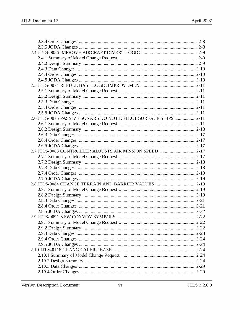
When the user selects and accesses a database that does not conform to the Standard Database 3.2format, a Warning dialog box (Figure 1.1) queries the JTLS user to begin the upgrade process.
Figure 1.1 Starting the Database Upgrade
Selecting the Yes option executes a separate process, entitled Modifying Your JTLS Database, thatdetermines the existing format of the selected database, begins the upgrade, and displays its progress
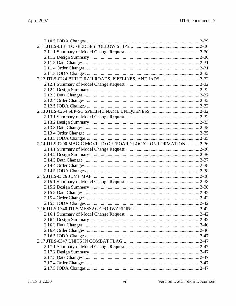
The database upgrade is successfully completed when the message shown in Figure 1.2 is displayed.The terminal window should then be closed.
Figure 1.2 Database Upgrade Completed
The JTLS Database Modify process for the JTLS 3.1 series of releases includes an interactive featurethat requires user input while the upgrade process executes. This interactive upgrade process must beused to modify your scenario database from JTLS version 3.0 or earlier to JTLS Version 3.2.0.0.Ensure that you review the corresponding database modification section of Chapter 1 of the JTLSVersion Description Document for JTLS versions 3.1.0.0, 3.1.1.0, or 3.1.2.0, which describes theinteractive modification process for the upgrade from Version 3.0 to 3.1. This process requiresspecific user input, which is described and illustrated in detail.
Version Description Document 1-8 JTLS 3.2.0.0
April 2007 JTLS Document 17
After your database has been modified from Version 3.0 or earlier to Version 3.2.0.0 and downloadedto ASCII files, a successive scenario load is required to properly create the check constraints in thedatabase to include the new illegal character set ( space, ", #, &, @, /, {, }, <, >, ’ ). Unit names,Target names, or other object names that contain any of these characters will be automaticallyremoved from your database. These symbols are incompatible with the JTLS 3.2.0.0 WHIP.
1.5.3 Data Elements
Currently implemented ECPs have required the addition, deletion, or modification of several dataelements. The description and use of the affected variables are presented in Chapter 2 andsummarized below in Table 1. Detailed descriptions are provided in Appendix B of the JTLS DataRequirements Manual.
Table 1.Summary of Standard Database OIF Data Elements
VARIABLE NAME CHANGE DESCRIPTION
These parameters support the separate graphical representation of Truck, Barge, and Rail convoyson the WHIP display.
SLP TRUCK CONVOYSYMBOL
Modified Formerly SLP CONVOY SYMBOL.This SustainmentLogistics Prototype entity attribute holds the name ofthe Graphic Symbol used to display a Truck Convoydispatched from a Support unit belonging to a Factionthat uses this SLP.
SLP BARGE CONVOYSYMBOL
Added This Sustainment Logistics Prototype entity attributeholds the name of the Graphic Symbol used to displaya Barge Convoy dispatched from a Support unitbelonging to a Faction that uses this SLP. This newattribute will be filled with the symbol held by theobsolete SLP CONVOY SYMBOL databaseparameter
SLP RAIL CONVOYSYMBOL
Added This Sustainment Logistics Prototype entity attributeholds the name of the Graphic Symbol used to displaya Rail Convoy dispatched from a Support unitbelonging to a Faction that uses this SLP.This newattribute will be filled with the symbol held by theobsolete SLP CONVOY SYMBOL databaseparameter
This data parameter represents the limitations of Towed Array sensors employed by Naval units.
JTLS 3.2.0.0 1-9 Version Description Document
JTLS Document 17 April 2007
ST MAXIMUM SPEEDALLOWED
Added This Sensor Type entity attribute holds the maximumspeed at which the ship carrying a sensor of Type I canbe moving and still be able to use the sensor to detectother assets.
The meaning of this Aircraft Class attribute has been changed as a result of implementing areason code for an Air Mission’s intercept termination.
AC CONTINUE ENGAGEMULT
Modified This attribute of the Aircraft Class permanent entity isused to determine whether an attacking aircraftcontinues an air-to-air engagement after the first shot isfired. The data held for this variable should bereviewed in any database that is upgraded to a JTLS3.2 format.
This parameter supports the capability of the Interceptor Assignment logic to prevent a CombatAir Patrol mission from automatically intercepting a specified aircraft target type.
ACP ATC AUTOINTERCEPT ALLOWED
Added This variable holds an indicator that signifies whetherthe CAP missions from a Faction that uses ACP I canbe automatically sent to intercept a mission that hasaircraft that use ATC J. This data element requires anew Oracle table, a new initialization data file, and anew Database Development System (DDS) AirControl Prototype (ACP) child form.
These parameters support modification of the JTLS Lanchester attrition capability to reduce itsdependence upon the hexagonal terrain model.
CSP CS FRACTION FAILON ISSUE
Deleted All references apply to CSP CS PROB NONCOMBAT FAILURE.
CSP CS FRACTIONREPAIRED PER PERIOD
Deleted All references apply to CSP CS MEAN TIMEBETWEEN REPAIRS.
CSP CS FRACTIONRECOVERABLE
Deleted All references apply to CSP CS PROB SYSTEMRECOVERED
CSP FRACTIONREMAINSRECOVERABLE.
Deleted All references apply to CSP PROB REMAINSRECOVERED.
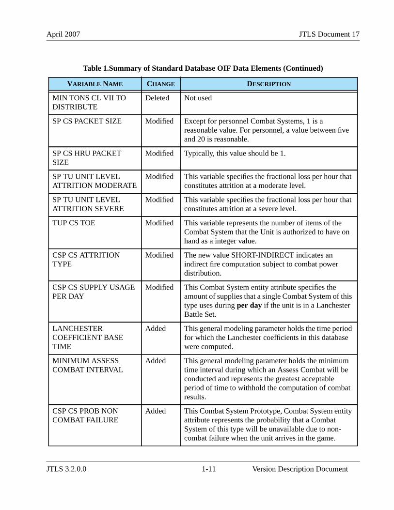
Table 1.Summary of Standard Database OIF Data Elements (Continued)
VARIABLE NAME CHANGE DESCRIPTION
Version Description Document 1-10 JTLS 3.2.0.0
April 2007 JTLS Document 17
MIN TONS CL VII TODISTRIBUTE
Deleted Not used
SP CS PACKET SIZE Modified Except for personnel Combat Systems, 1 is areasonable value. For personnel, a value between fiveand 20 is reasonable.
SP CS HRU PACKETSIZE
Modified Typically, this value should be 1.
SP TU UNIT LEVELATTRITION MODERATE
Modified This variable specifies the fractional loss per hour thatconstitutes attrition at a moderate level.
SP TU UNIT LEVELATTRITION SEVERE
Modified This variable specifies the fractional loss per hour thatconstitutes attrition at a severe level.
TUP CS TOE Modified This variable represents the number of items of theCombat System that the Unit is authorized to have onhand as a integer value.
CSP CS ATTRITIONTYPE
Modified The new value SHORT-INDIRECT indicates anindirect fire computation subject to combat powerdistribution.
CSP CS SUPPLY USAGEPER DAY
Modified This Combat System entity attribute specifies theamount of supplies that a single Combat System of thistype uses during per day if the unit is in a LanchesterBattle Set.
LANCHESTERCOEFFICIENT BASETIME
Added This general modeling parameter holds the time periodfor which the Lanchester coefficients in this databasewere computed.
MINIMUM ASSESSCOMBAT INTERVAL
Added This general modeling parameter holds the minimumtime interval during which an Assess Combat will beconducted and represents the greatest acceptableperiod of time to withhold the computation of combatresults.
CSP CS PROB NONCOMBAT FAILURE
Added This Combat System Prototype, Combat System entityattribute represents the probability that a CombatSystem of this type will be unavailable due to non-combat failure when the unit arrives in the game.
Table 1.Summary of Standard Database OIF Data Elements (Continued)
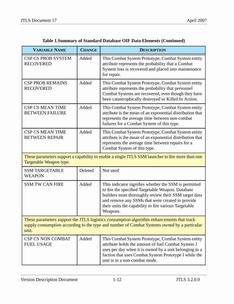
VARIABLE NAME CHANGE DESCRIPTION
JTLS 3.2.0.0 1-11 Version Description Document
JTLS Document 17 April 2007
CSP CS PROB SYSTEMRECOVERED
Added This Combat System Prototype, Combat System entityattribute represents the probability that a CombatSystem loss is recovered and placed into maintenancefor repair.
CSP PROB REMAINSRECOVERED
Added This Combat System Prototype, Combat System entityattribute represents the probability that personnelCombat Systems are recovered, even though they havebeen catastrophically destroyed or Killed In Action.
CSP CS MEAN TIMEBETWEEN FAILURE
Added This Combat System Prototype, Combat System entityattribute is the mean of an exponential distribution thatrepresents the average time between non-combatfailures for a Combat System of this type.
CSP CS MEAN TIMEBETWEEN REPAIR
Added This Combat System Prototype, Combat System entityattribute is the mean of an exponential distribution thatrepresents the average time between repairs for aCombat System of this type.
These parameters support a capability to enable a single JTLS SSM launcher to fire more than oneTargetable Weapon type.
SSM TARGETABLEWEAPON
Deleted Not used
SSM TW CAN FIRE Added This indicator signifies whether the SSM is permittedto fire the specified Targetable Weapon. Databasebuilders must thoroughly review their SSM target dataand remove any SSMs that were created to providetheir units the capability to fire various TargetableWeapons.
These parameters support the JTLS logistics consumption algorithm enhancements that tracksupply consumption according to the type and number of Combat Systems owned by a particularunit.
CSP CS NON COMBATFUEL USAGE
Added This Combat System Prototype, Combat System entityattribute holds the amount of fuel Combat System Juses per day when it is owned by a unit belonging to afaction that uses Combat System Prototype I while theunit is in a non-combat mode.
Table 1.Summary of Standard Database OIF Data Elements (Continued)
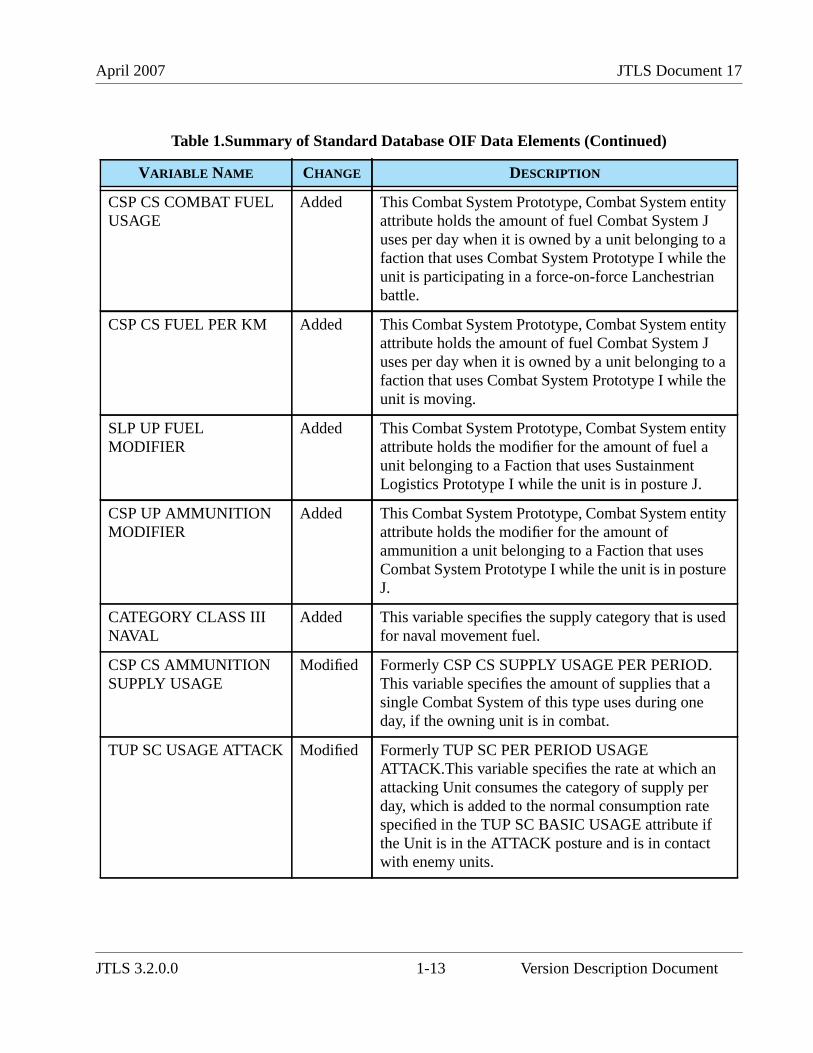
VARIABLE NAME CHANGE DESCRIPTION
Version Description Document 1-12 JTLS 3.2.0.0
April 2007 JTLS Document 17
CSP CS COMBAT FUELUSAGE
Added This Combat System Prototype, Combat System entityattribute holds the amount of fuel Combat System Juses per day when it is owned by a unit belonging to afaction that uses Combat System Prototype I while theunit is participating in a force-on-force Lanchestrianbattle.
CSP CS FUEL PER KM Added This Combat System Prototype, Combat System entityattribute holds the amount of fuel Combat System Juses per day when it is owned by a unit belonging to afaction that uses Combat System Prototype I while theunit is moving.
SLP UP FUELMODIFIER
Added This Combat System Prototype, Combat System entityattribute holds the modifier for the amount of fuel aunit belonging to a Faction that uses SustainmentLogistics Prototype I while the unit is in posture J.
CSP UP AMMUNITIONMODIFIER
Added This Combat System Prototype, Combat System entityattribute holds the modifier for the amount ofammunition a unit belonging to a Faction that usesCombat System Prototype I while the unit is in postureJ.
CATEGORY CLASS IIINAVAL
Added This variable specifies the supply category that is usedfor naval movement fuel.
CSP CS AMMUNITIONSUPPLY USAGE
Modified Formerly CSP CS SUPPLY USAGE PER PERIOD.This variable specifies the amount of supplies that asingle Combat System of this type uses during oneday, if the owning unit is in combat.
TUP SC USAGE ATTACK Modified Formerly TUP SC PER PERIOD USAGEATTACK.This variable specifies the rate at which anattacking Unit consumes the category of supply perday, which is added to the normal consumption ratespecified in the TUP SC BASIC USAGE attribute ifthe Unit is in the ATTACK posture and is in contactwith enemy units.
Table 1.Summary of Standard Database OIF Data Elements (Continued)
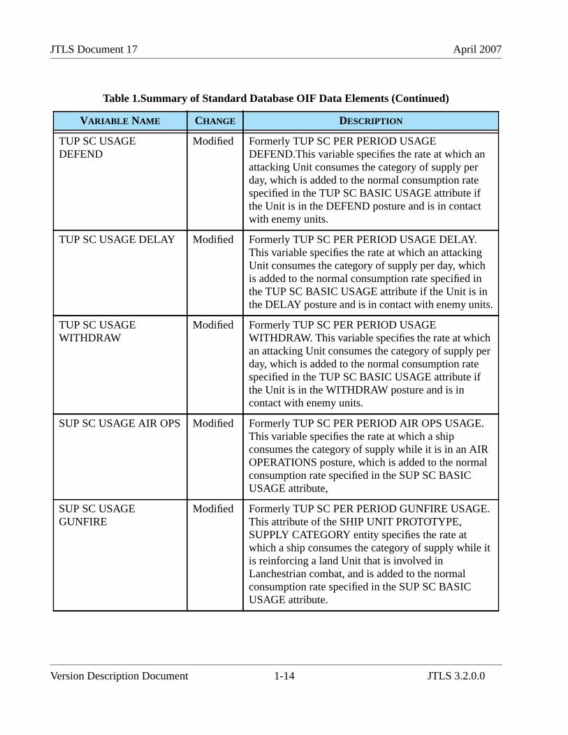
VARIABLE NAME CHANGE DESCRIPTION
JTLS 3.2.0.0 1-13 Version Description Document
JTLS Document 17 April 2007
TUP SC USAGEDEFEND
Modified Formerly TUP SC PER PERIOD USAGEDEFEND.This variable specifies the rate at which anattacking Unit consumes the category of supply perday, which is added to the normal consumption ratespecified in the TUP SC BASIC USAGE attribute ifthe Unit is in the DEFEND posture and is in contactwith enemy units.
TUP SC USAGE DELAY Modified Formerly TUP SC PER PERIOD USAGE DELAY.This variable specifies the rate at which an attackingUnit consumes the category of supply per day, whichis added to the normal consumption rate specified inthe TUP SC BASIC USAGE attribute if the Unit is inthe DELAY posture and is in contact with enemy units.
TUP SC USAGEWITHDRAW
Modified Formerly TUP SC PER PERIOD USAGEWITHDRAW. This variable specifies the rate at whichan attacking Unit consumes the category of supply perday, which is added to the normal consumption ratespecified in the TUP SC BASIC USAGE attribute ifthe Unit is in the WITHDRAW posture and is incontact with enemy units.
SUP SC USAGE AIR OPS Modified Formerly TUP SC PER PERIOD AIR OPS USAGE.This variable specifies the rate at which a shipconsumes the category of supply while it is in an AIROPERATIONS posture, which is added to the normalconsumption rate specified in the SUP SC BASICUSAGE attribute,
SUP SC USAGEGUNFIRE
Modified Formerly TUP SC PER PERIOD GUNFIRE USAGE.This attribute of the SHIP UNIT PROTOTYPE,SUPPLY CATEGORY entity specifies the rate atwhich a ship consumes the category of supply while itis reinforcing a land Unit that is involved inLanchestrian combat, and is added to the normalconsumption rate specified in the SUP SC BASICUSAGE attribute.
Table 1.Summary of Standard Database OIF Data Elements (Continued)
VARIABLE NAME CHANGE DESCRIPTION
Version Description Document 1-14 JTLS 3.2.0.0
April 2007 JTLS Document 17
SUP SC PER KM USAGE Modified This SHIP UNIT PROTOTYPE entity attribute andspecifies the amount of the Supply Category requiredto move the unit one kilometer.
These parameters support the C3 representation as a unit capability rather than a Combat System.
CP TIME DELAY PER100 KM
Deleted Communications are no longer a function of thedistance between units, and are based solely on thecommunication capability of the two units that attemptcontact.
CP JAMMING DELAYTIME MAX
Deleted All references apply to CQR JAMMING DELAYTIME MEAN.
CP JAMMING DELAYTIME MEAN
Deleted All references apply to CQR JAMMING DELAYTIME MEAN.
CP PROBBACKGROUNDMESSAGE DELAY
Deleted All references apply to CP CQR PROB MESSAGEDELAY.
CP COMM JAM ADAENGAGEEFFECTIVENESS
Deleted All references apply to CP CQR COMM JAM ADAENGAGE MULT.
CP COMM JAMCOMBATEFFECTIVENESS
Deleted All references apply to CP CQR COMM JAMCOMBAT MULT.
CP COMM JAM COMMSITE EFFECTIVENESS
Deleted All references apply to CP CQR COMM JAMCOMM SITE MULT
CP COMM JAMINDIRECT FIRE DELAYFACTOR
Deleted All references apply to CP CQR COMM JAM FIREDELAY MULT.
CP COMM JAM MOVEDELAY FACTOR
Deleted All references apply to CP CQR COMM JAM MOVEDELAY MULT.
CP COMM JAMINTERNAL TIMEDELAY FACTOR
Deleted All references apply to CP CQR COMM JAMINTERNAL MULT.
Table 1.Summary of Standard Database OIF Data Elements (Continued)
VARIABLE NAME CHANGE DESCRIPTION
JTLS 3.2.0.0 1-15 Version Description Document
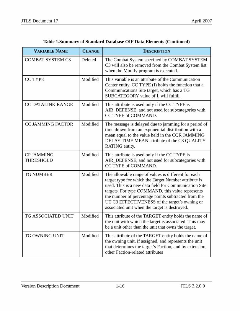
JTLS Document 17 April 2007
COMBAT SYSTEM C3 Deleted The Combat System specified by COMBAT SYSTEMC3 will also be removed from the Combat System listwhen the Modify program is executed.
CC TYPE Modified This variable is an attribute of the CommunicationCenter entity. CC TYPE (I) holds the function that aCommunications Site target, which has a TGSUBCATEGORY value of I, will fulfill.
CC DATALINK RANGE Modified This attribute is used only if the CC TYPE isAIR_DEFENSE, and not used for subcategories withCC TYPE of COMMAND.
CC JAMMING FACTOR Modified The message is delayed due to jamming for a period oftime drawn from an exponential distribution with amean equal to the value held in the CQR JAMMINGDELAY TIME MEAN attribute of the C3 QUALITYRATING entity.
CP JAMMINGTHRESHOLD
Modified This attribute is used only if the CC TYPE isAIR_DEFENSE, and not used for subcategories withCC TYPE of COMMAND.
TG NUMBER Modified The allowable range of values is different for eachtarget type for which the Target Number attribute isused. This is a new data field for Communication Sitetargets. For type COMMAND, this value representsthe number of percentage points subtracted from theUT C3 EFFECTIVENESS of the target’s owning orassociated unit when the target is destroyed.
TG ASSOCIATED UNIT Modified This attribute of the TARGET entity holds the name ofthe unit with which the target is associated. This maybe a unit other than the unit that owns the target.
TG OWNING UNIT Modified This attribute of the TARGET entity holds the name ofthe owning unit, if assigned, and represents the unitthat determines the target’s Faction, and by extension,other Faction-related attributes
Table 1.Summary of Standard Database OIF Data Elements (Continued)
VARIABLE NAME CHANGE DESCRIPTION
Version Description Document 1-16 JTLS 3.2.0.0
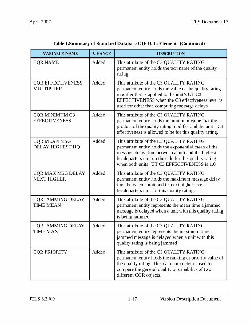
April 2007 JTLS Document 17
CQR NAME Added This attribute of the C3 QUALITY RATINGpermanent entity holds the text name of the qualityrating.
CQR EFFECTIVENESSMULTIPLIER
Added This attribute of the C3 QUALITY RATINGpermanent entity holds the value of the quality ratingmodifier that is applied to the unit’s UT C3EFFECTIVENESS when the C3 effectiveness level isused for other than computing message delays
CQR MINIMUM C3EFFECTIVENESS
Added This attribute of the C3 QUALITY RATINGpermanent entity holds the minimum value that theproduct of the quality rating modifier and the unit’s C3effectiveness is allowed to be for this quality rating.
CQR MEAN MSGDELAY HIGHEST HQ
Added This attribute of the C3 QUALITY RATINGpermanent entity holds the exponential mean of themessage delay time between a unit and the highestheadquarters unit on the side for this quality ratingwhen both units’ UT C3 EFFECTIVENESS is 1.0.
CQR MAX MSG DELAYNEXT HIGHER
Added This attribute of the C3 QUALITY RATINGpermanent entity holds the maximum message delaytime between a unit and its next higher levelheadquarters unit for this quality rating.
CQR JAMMING DELAYTIME MEAN
Added This attribute of the C3 QUALITY RATINGpermanent entity represents the mean time a jammedmessage is delayed when a unit with this quality ratingis being jammed.
CQR JAMMING DELAYTIME MAX
Added This attribute of the C3 QUALITY RATINGpermanent entity represents the maximum time ajammed message is delayed when a unit with thisquality rating is being jammed
CQR PRIORITY Added This attribute of the C3 QUALITY RATINGpermanent entity holds the ranking or priority value ofthe quality rating. This data parameter is used tocompare the general quality or capability of twodifferent CQR objects.
Table 1.Summary of Standard Database OIF Data Elements (Continued)
VARIABLE NAME CHANGE DESCRIPTION
JTLS 3.2.0.0 1-17 Version Description Document
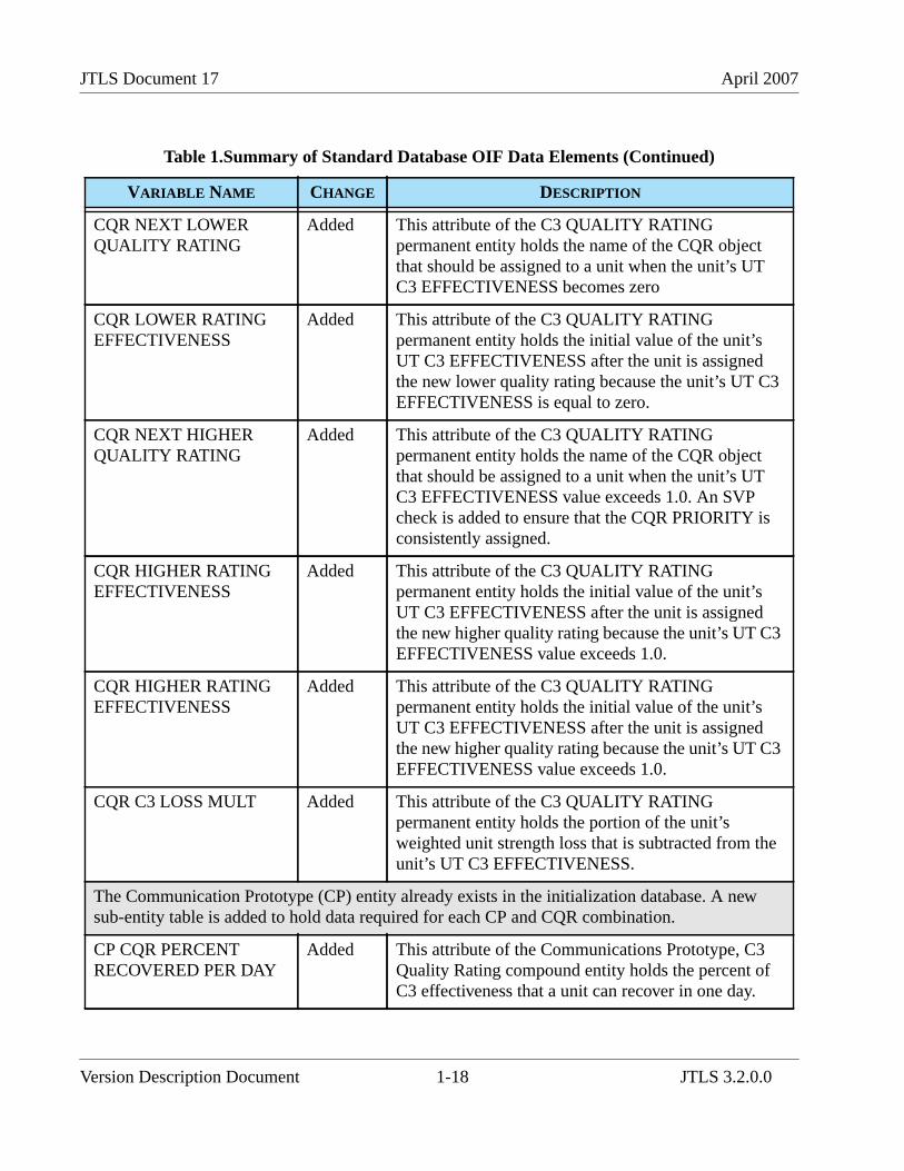
JTLS Document 17 April 2007
CQR NEXT LOWERQUALITY RATING
Added This attribute of the C3 QUALITY RATINGpermanent entity holds the name of the CQR objectthat should be assigned to a unit when the unit’s UTC3 EFFECTIVENESS becomes zero
CQR LOWER RATINGEFFECTIVENESS
Added This attribute of the C3 QUALITY RATINGpermanent entity holds the initial value of the unit’sUT C3 EFFECTIVENESS after the unit is assignedthe new lower quality rating because the unit’s UT C3EFFECTIVENESS is equal to zero.
CQR NEXT HIGHERQUALITY RATING
Added This attribute of the C3 QUALITY RATINGpermanent entity holds the name of the CQR objectthat should be assigned to a unit when the unit’s UTC3 EFFECTIVENESS value exceeds 1.0. An SVPcheck is added to ensure that the CQR PRIORITY isconsistently assigned.
CQR HIGHER RATINGEFFECTIVENESS
Added This attribute of the C3 QUALITY RATINGpermanent entity holds the initial value of the unit’sUT C3 EFFECTIVENESS after the unit is assignedthe new higher quality rating because the unit’s UT C3EFFECTIVENESS value exceeds 1.0.
CQR HIGHER RATINGEFFECTIVENESS
Added This attribute of the C3 QUALITY RATINGpermanent entity holds the initial value of the unit’sUT C3 EFFECTIVENESS after the unit is assignedthe new higher quality rating because the unit’s UT C3EFFECTIVENESS value exceeds 1.0.
CQR C3 LOSS MULT Added This attribute of the C3 QUALITY RATINGpermanent entity holds the portion of the unit’sweighted unit strength loss that is subtracted from theunit’s UT C3 EFFECTIVENESS.
The Communication Prototype (CP) entity already exists in the initialization database. A newsub-entity table is added to hold data required for each CP and CQR combination.
CP CQR PERCENTRECOVERED PER DAY
Added This attribute of the Communications Prototype, C3Quality Rating compound entity holds the percent ofC3 effectiveness that a unit can recover in one day.
Table 1.Summary of Standard Database OIF Data Elements (Continued)
VARIABLE NAME CHANGE DESCRIPTION
Version Description Document 1-18 JTLS 3.2.0.0
April 2007 JTLS Document 17
CP CQR PROBMESSAGE DELAY
Added This attribute of the Communications Prototype, C3Quality Rating compound entity represents theprobability that a message sent by a unit is delayed.
CP CQR COMM JAMADA ENGAGE MULT
Modified This variable is an attribute of the CommunicationsPrototype, C3 Quality Rating compound entity. Thequality rating referenced is the CQR of the unit that isbeing jammed and attempting to engage.
CP CQR COMM JAMCOMBAT MULT
Modified This variable is an attribute of the CommunicationsPrototype, C3 Quality Rating compound entity. Thereferenced quality rating is the CQR of the attritingunit.
CP CQR COMM JAMCOMM SITE MULT
Modified This variable is an attribute of the CommunicationsPrototype, C3 Quality Rating compound entity. Thisfactor is a measure of the Faction’s susceptibility tocommunications jamming when the owning unit of theCOMM SITE has the referenced quality rating.
CP CQR COMM JAMFIRE DELAY MULT
Modified This variable is an attribute of the CommunicationsPrototype, C3 Quality Rating compound entity. Thecommunications prototype referenced is the CP of theunit firing the mission. The referenced quality rating isthe CQR of the unit that is being jammed and is firingthe mission
CP CQR COMM JAMINTERNAL MULT
Modified This variable is an attribute of the CommunicationsPrototype, C3 Quality Rating compound entity. Thereferenced communications prototype is the CP of theunit conducting the task. The referenced quality ratingis the CQR of the unit conducting the task.
CP CQR COMM JAMMOVE DELAY MULT
Modified This variable is an attribute of the CommunicationsPrototype, C3 Quality Rating compound entity. Thecommunications prototype referenced is the CP of theunit conducting the move. The quality ratingreferenced is the CQR of the unit conducting themove.
Table 1.Summary of Standard Database OIF Data Elements (Continued)
VARIABLE NAME CHANGE DESCRIPTION
JTLS 3.2.0.0 1-19 Version Description Document
JTLS Document 17 April 2007
UT C3 EFFECTIVENESS Added This variable is an attribute of the Unit entity, andholds the current effectiveness level of a unit’sCommand and Control capability.
UT C3 QUALITYRATING
Added This variable is an attribute of the Unit entity, andholds the name of the C3 QUALITY RATING that thisunit is assigned when it arrives in the game.
UT HIGHEST C3QUALITY RATING
Added This variable is an attribute of the Unit entity, andholds the name of the highest possible C3 QUALITYRATING to which this unit may be set during thegame.
HUP C3 QUALITYRATING
Added This variable is an attribute of the High ResolutionUnit Prototype entity, and holds the name of the HRUC3 QUALITY RATING that should be assigned to anHRU that uses this HUP when the HRU is initiallycreated.
HUP STARTING C3EFFECTIVENESS
Added This variable is an attribute of the High ResolutionUnit Prototype entity, and holds the initial C3effectiveness level of an HRU that uses this HUP.
This parameter replaces a graphic symbol as the identifier of a TUP’s special capability.
TUP CAPABILITIESTYPE
Added This attribute of the Tactical Unit Prototype permanententity holds the name value of the TUP’s specialcapability.
These parameters were added or modified to support JOI improvements related to TADIL-J.
ACP AIR INFORMATIONPROTOCOL
Modified This variable is an attribute of the AIR CONTROLPROTOTYPE permanent entity and specifies theprotocol for sharing real-time air detectioninformation.
AC LINK16 CAPABLE Added This Aircraft Class permanent entity attribute indicateswhether the aircraft class is linked to the side’sCommon Operational Picture (COP).
SUP SHIP CLASS NAME Added This variable is an attribute of the Ship Unit Prototypepermanent entity that holds the name the SUP’s ShipClass, and is specifically required to properly link toreal-world C4I systems, such as the Global Commandand Control System (GCCS).
Table 1.Summary of Standard Database OIF Data Elements (Continued)
VARIABLE NAME CHANGE DESCRIPTION
Version Description Document 1-20 JTLS 3.2.0.0
April 2007 JTLS Document 17
TG COUNTRY CODE Added This attribute of the Target entity is a two-character textname variable used to identify the country in which atarget is located, and is meaningful for unowned targetsonly.
TG LINK16 BLOCKSTART
Added This variable is an attribute of the Target entity, andspecifies the starting octal track number that the target isallowed to assign. Relationships: This attribute is onlyassociated with Sensor_Site targets and is only used byAir Search Sensor targets. Furthermore, the attribute isonly access by JTLS algorithms if the target is owned bya Faction that uses an ACP indicating that the Link16track reporting algorithm should be used.
TG LINK16 BLOCK END Added This variable is an attribute of the Target entity, andspecifies the ending octal track number that the target isallowed to assign. This attribute is only associated withSensor_Site targets and is only used by Air SearchSensor targets. Furthermore, the attribute is accessed byJTLS algorithms only if the target is owned by a Factionthat uses an ACP indicating that the Link16 trackreporting algorithm should be used.
UT COUNTRY CODE Added This attribute of the Unit entity is a two-character textname variable used to identify a unit s countryaffiliation.
UT HULL NUMBER Added This variable is a text attribute of a Unit entity, andholds the hull number that should be reported to real-world C4I systems or the Common Operational Picture(COP). This attribute is only used by units that have aUT TYPE set to NAVAL.
UT LINK16 BLOCKSTART
Added This variable is an attribute of the Unit entity, andspecifies the starting octal track number that air missions flying from the unit are allowed to assign. Thisattribute is only accessed by Squadron units that ownaircraft for which the AC LINK16 CAPABLE attributeis set to YES. Furthermore, the attribute is only accessedby JTLS algorithms if the unit is owned by a Factionthat uses an ACP indicating that the Link16 trackreporting algorithm should be used.
Table 1.Summary of Standard Database OIF Data Elements (Continued)
VARIABLE NAME CHANGE DESCRIPTION
JTLS 3.2.0.0 1-21 Version Description Document
JTLS Document 17 April 2007
1.5.4 Standard Database Changes
The new JTLS 3.2 Standard Database based on Operation Iraqui Freedom (sdboif) includes extensivedata item modifications implemented since the Standard Database (SDB) version 3.1 (sdbv31)release. If you have used sdbv31 as a basis for your existing scenarios, evaluating the modificationsincluded in sdboif is advised. A total of 99 Combat Systems, which are described in APPENDIX B.of this document, are represented in sdboif. Reviewing your existing SDB-derived databases andupgrading them to the new data standard is strongly recommended. The detailed procedures requiredto upgrade sdbv30 or sdbv31 to sdboif are provided in APPENDIX C.
UT LINK16 BLOCK END Added This variable is an attribute of the Unit entity, andspecifies the starting octal track number that air missions flying from the unit are allowed to assign. Thisattribute is only accessed by Squadron units that ownaircraft for which the AC LINK16 CAPABLE attributeis set to YES. Furthermore, the attribute is only accessedby JTLS algorithms if the unit is owned by a Factionthat uses an ACP indicating that the Link16 trackreporting algorithm should be used.
UT PIFF CODE Added This variable is an attribute of a Unit entity andrepresents the octal code output of a ship’s PassiveIdentification of Friend or Foe (PIFF) apparatus. Thisattribute applies only to units that have a UT TYPE ofNAVAL.
This unused parameter is removed from the database.
MAX FIRE MISSIONDURATION
Deleted Not Used
The set of restricted characters for all text variable values is redefined.
General Modified The characters #, &, $, @, /, {, }, <, >, ’, and embeddedspaces are prohibited.
UT LONG NAME Modified The characters #, &, $, @, /, {, }, <, >, and ’ areprohibited. Embedded spaces are allowed.
SUP SHIP CLASS NAME Modified The characters #, &, $, @, /, {, }, <, >, ’, and - areprohibited. Embedded spaces are allowed.
Table 1.Summary of Standard Database OIF Data Elements (Continued)
VARIABLE NAME CHANGE DESCRIPTION
Version Description Document 1-22 JTLS 3.2.0.0
April 2007 JTLS Document 17
1.6 INSTALLATION NOTES
1.6.1 Installation Instructions
The JTLS Installation Manual (included in the documents compressed tar file that is part of this JTLSrelease) provides detailed instructions for installing a new version of JTLS.
1.6.2 Oracle Compatibility and Installation
This release of JTLS requires a complete installation of Oracle Forms/Reports Developer 6i client/server runtime.
Developer 6i is the final version of the client/server development and deployment of Oracle Forms,Reports, and Graphics. Oracle Corporation will provide only limited support for this Developerversion until January 2008, and Oracle10g will become the final certified database server compatiblewith Developer 6i. Beginning with the release of JTLS 3.1.0.0, Oracle 10g iAS EE (InternetApplication Server Enterprise Edition) has been implemented to deploy JTLS database applications,such as DDS Forms. The compatible database server version is Oracle 10gR2 Standard Edition Oneor newer. Database server requirements that are updated prior to a future JTLS release will bedescribed in the appropriate JTLS Version Description Document.
Utilizing the framework of iAS EE, which includes Forms Services, Reports Services, Portal, SingleSign-On, Java, and other components, will enable the delivery of JTLS-specific data from a centrallocation. This also allows the development of more scalable JTLS database applications, such as theSDR and AAR.
Currently, the following combinations of Forms 6i runtime and the Oracle Server are approved for usewith JTLS:
a. Oracle Database Server 9.2.0.8 or later (10gR2 Standard Edition One is recommended)b. Forms 6i client/server runtime (with patchset 18 or later) for Solaris and/or Linuxc. iAS EE 10.1.2.0.2 full stack (optional)
Refer to Chapter 6 of the JTLS Installation Manual for additional details regarding the Oracle Forms/Reports Developer 6i client/server custom runtime installation.
JTLS 3.2.0.0 1-23 Version Description Document

JTLS Document 17 April 2007
Version Description Document 1-24 JTLS 3.2.0.0
April 2007 JTLS Document 17
2.0 ENHANCEMENT CHANGE PROPOSALS
JTLS 3.2.0.0 is a Major JTLS release that includes the implemented Enhancement Change Proposals(ECPs) described in this chapter.
2.1 JTLS-0004 Display Range Rings
2.1.1 Summary of Model Change Request
This design addresses a requirement to graphically display range data for units, targets, and AirMissions on the Web Hosted Interface Program (WHIP) Map Component.
2.1.2 Design Summary
JTLS object types for which Range Rings have been added to the WHIP are described in Table 2.
TABLE 2. Range Ring Object Types
OBJECT TYPE CANDIDATE DATA EXPLANATION
Squadron Aircraft Range Radius The flight radius of the standard fuel load for aircraft flying from thisSquadron while the mission flies at its cruise speed and at the most fuel-efficient altitude. If the aircraft has a database-specified default load, the fuelfrom that default load is also considered in the range computation. The flightradius is determined by computing the range of the aircraft under thespecified conditions and dividing by 2.0.
Support Min or Max DistanceFor Truck Convoys
The database values for the minimum or maximum range to which theSupport unit sends convoy trucks.
FARPGroundNaval
Direct Weapon Range The range of the longest manned Direct Fire Combat System that the unitowns. As the unit loses systems or crews to operate those systems, this rangeis adjusted. Supplies are considered for this computation. If the unit has nosupplies available for this Combat System to fire, the range is listed as zero.
Indirect Weapon Range The range of the longest-range weapon that can be fired from the unit’smanned Indirect Fire Combat Systems, considering the unit’s caliber andavailable supplies. As the unit loses systems or crews, or consumes suppliesto operate those systems, this range is adjusted.Due to the implementation of the ECP JTLS-2006-1660 IntegerizedLanchestrian Combat, a third Combat System type is added to the model.This new LONG-INDIRECT system type is also used to compute this range.Thus, this range represents the longest manned Combat System that has atype of INDIRCT or LONG-INDIRECT.
Mandatory TransferDistance
The distance at which mandatory transfers of supplies can occur. This rangeis adjusted only if the Controller changes this database parameter.
JTLS 3.2.0.0 2-1 Version Description Document
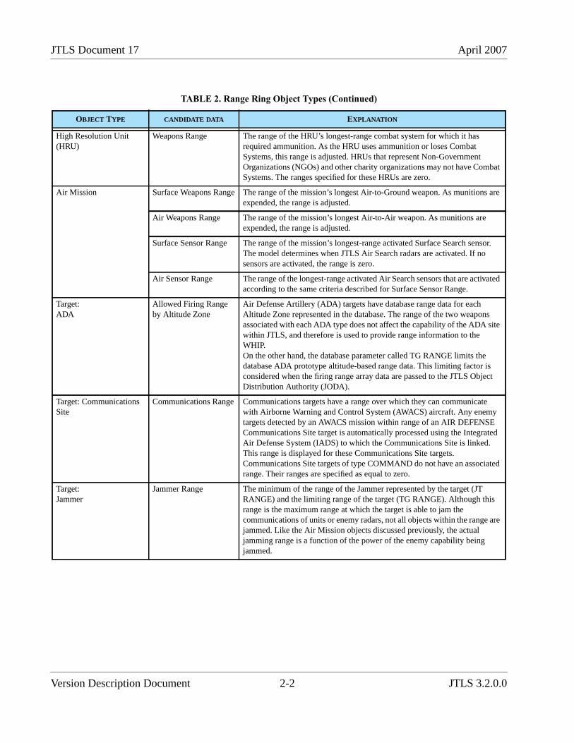
JTLS Document 17 April 2007
High Resolution Unit(HRU)
Weapons Range The range of the HRU’s longest-range combat system for which it hasrequired ammunition. As the HRU uses ammunition or loses CombatSystems, this range is adjusted. HRUs that represent Non-GovernmentOrganizations (NGOs) and other charity organizations may not have CombatSystems. The ranges specified for these HRUs are zero.
Air Mission Surface Weapons Range The range of the mission’s longest Air-to-Ground weapon. As munitions areexpended, the range is adjusted.
Air Weapons Range The range of the mission’s longest Air-to-Air weapon. As munitions areexpended, the range is adjusted.
Surface Sensor Range The range of the mission’s longest-range activated Surface Search sensor.The model determines when JTLS Air Search radars are activated. If nosensors are activated, the range is zero.
Air Sensor Range The range of the longest-range activated Air Search sensors that are activatedaccording to the same criteria described for Surface Sensor Range.
Target:ADA
Allowed Firing Rangeby Altitude Zone
Air Defense Artillery (ADA) targets have database range data for eachAltitude Zone represented in the database. The range of the two weaponsassociated with each ADA type does not affect the capability of the ADA sitewithin JTLS, and therefore is used to provide range information to theWHIP.On the other hand, the database parameter called TG RANGE limits thedatabase ADA prototype altitude-based range data. This limiting factor isconsidered when the firing range array data are passed to the JTLS ObjectDistribution Authority (JODA).
Target: CommunicationsSite
Communications Range Communications targets have a range over which they can communicatewith Airborne Warning and Control System (AWACS) aircraft. Any enemytargets detected by an AWACS mission within range of an AIR DEFENSECommunications Site target is automatically processed using the IntegratedAir Defense System (IADS) to which the Communications Site is linked.This range is displayed for these Communications Site targets.Communications Site targets of type COMMAND do not have an associatedrange. Their ranges are specified as equal to zero.
Target:Jammer
Jammer Range The minimum of the range of the Jammer represented by the target (JTRANGE) and the limiting range of the target (TG RANGE). Although thisrange is the maximum range at which the target is able to jam thecommunications of units or enemy radars, not all objects within the range arejammed. Like the Air Mission objects discussed previously, the actualjamming range is a function of the power of the enemy capability beingjammed.
TABLE 2. Range Ring Object Types (Continued)
OBJECT TYPE CANDIDATE DATA EXPLANATION
Version Description Document 2-2 JTLS 3.2.0.0
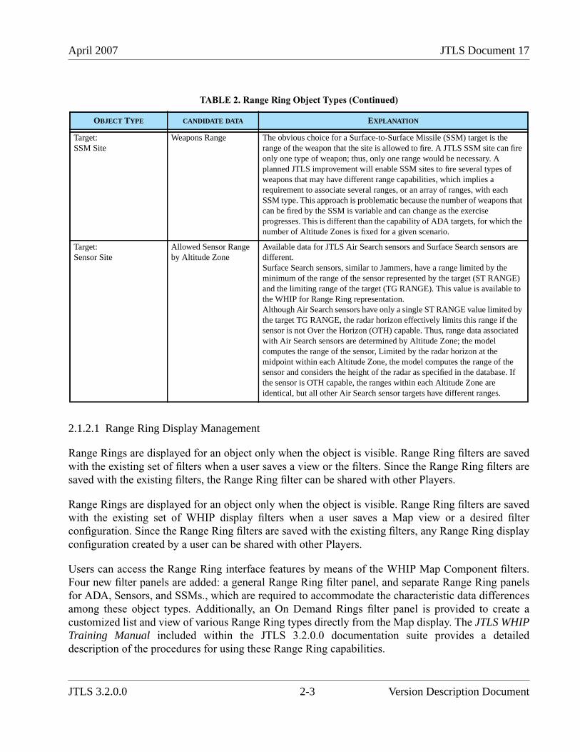
April 2007 JTLS Document 17
2.1.2.1 Range Ring Display Management
Range Rings are displayed for an object only when the object is visible. Range Ring filters are savedwith the existing set of filters when a user saves a view or the filters. Since the Range Ring filters aresaved with the existing filters, the Range Ring filter can be shared with other Players.
Range Rings are displayed for an object only when the object is visible. Range Ring filters are savedwith the existing set of WHIP display filters when a user saves a Map view or a desired filterconfiguration. Since the Range Ring filters are saved with the existing filters, any Range Ring displayconfiguration created by a user can be shared with other Players.
Users can access the Range Ring interface features by means of the WHIP Map Component filters.Four new filter panels are added: a general Range Ring filter panel, and separate Range Ring panelsfor ADA, Sensors, and SSMs., which are required to accommodate the characteristic data differencesamong these object types. Additionally, an On Demand Rings filter panel is provided to create acustomized list and view of various Range Ring types directly from the Map display. The JTLS WHIPTraining Manual included within the JTLS 3.2.0.0 documentation suite provides a detaileddescription of the procedures for using these Range Ring capabilities.
Target:SSM Site
Weapons Range The obvious choice for a Surface-to-Surface Missile (SSM) target is therange of the weapon that the site is allowed to fire. A JTLS SSM site can fireonly one type of weapon; thus, only one range would be necessary. Aplanned JTLS improvement will enable SSM sites to fire several types ofweapons that may have different range capabilities, which implies arequirement to associate several ranges, or an array of ranges, with eachSSM type. This approach is problematic because the number of weapons thatcan be fired by the SSM is variable and can change as the exerciseprogresses. This is different than the capability of ADA targets, for which thenumber of Altitude Zones is fixed for a given scenario.
Target:Sensor Site
Allowed Sensor Rangeby Altitude Zone
Available data for JTLS Air Search sensors and Surface Search sensors aredifferent.Surface Search sensors, similar to Jammers, have a range limited by theminimum of the range of the sensor represented by the target (ST RANGE)and the limiting range of the target (TG RANGE). This value is available tothe WHIP for Range Ring representation.Although Air Search sensors have only a single ST RANGE value limited bythe target TG RANGE, the radar horizon effectively limits this range if thesensor is not Over the Horizon (OTH) capable. Thus, range data associatedwith Air Search sensors are determined by Altitude Zone; the modelcomputes the range of the sensor, Limited by the radar horizon at themidpoint within each Altitude Zone, the model computes the range of thesensor and considers the height of the radar as specified in the database. Ifthe sensor is OTH capable, the ranges within each Altitude Zone areidentical, but all other Air Search sensor targets have different ranges.
TABLE 2. Range Ring Object Types (Continued)
OBJECT TYPE CANDIDATE DATA EXPLANATION
JTLS 3.2.0.0 2-3 Version Description Document
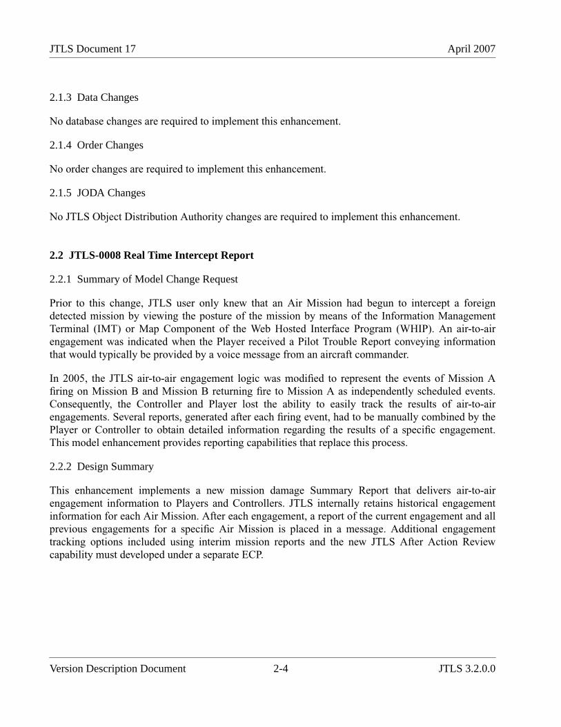
JTLS Document 17 April 2007
2.1.3 Data Changes
No database changes are required to implement this enhancement.
2.1.4 Order Changes
No order changes are required to implement this enhancement.
2.1.5 JODA Changes
No JTLS Object Distribution Authority changes are required to implement this enhancement.
2.2 JTLS-0008 Real Time Intercept Report
2.2.1 Summary of Model Change Request
Prior to this change, JTLS user only knew that an Air Mission had begun to intercept a foreigndetected mission by viewing the posture of the mission by means of the Information ManagementTerminal (IMT) or Map Component of the Web Hosted Interface Program (WHIP). An air-to-airengagement was indicated when the Player received a Pilot Trouble Report conveying informationthat would typically be provided by a voice message from an aircraft commander.
In 2005, the JTLS air-to-air engagement logic was modified to represent the events of Mission Afiring on Mission B and Mission B returning fire to Mission A as independently scheduled events.Consequently, the Controller and Player lost the ability to easily track the results of air-to-airengagements. Several reports, generated after each firing event, had to be manually combined by thePlayer or Controller to obtain detailed information regarding the results of a specific engagement.This model enhancement provides reporting capabilities that replace this process.
2.2.2 Design Summary
This enhancement implements a new mission damage Summary Report that delivers air-to-airengagement information to Players and Controllers. JTLS internally retains historical engagementinformation for each Air Mission. After each engagement, a report of the current engagement and allprevious engagements for a specific Air Mission is placed in a message. Additional engagementtracking options included using interim mission reports and the new JTLS After Action Reviewcapability must developed under a separate ECP.
Version Description Document 2-4 JTLS 3.2.0.0
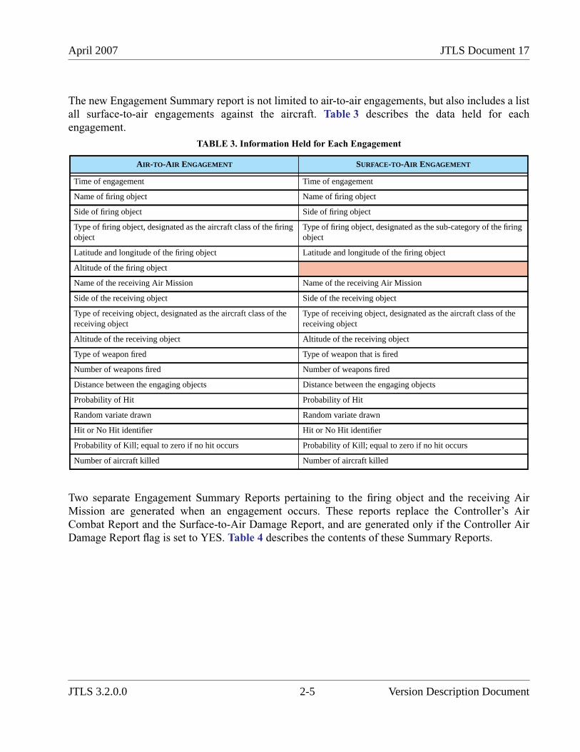
April 2007 JTLS Document 17
The new Engagement Summary report is not limited to air-to-air engagements, but also includes a listall surface-to-air engagements against the aircraft. Table 3 describes the data held for eachengagement.
Two separate Engagement Summary Reports pertaining to the firing object and the receiving AirMission are generated when an engagement occurs. These reports replace the Controller’s AirCombat Report and the Surface-to-Air Damage Report, and are generated only if the Controller AirDamage Report flag is set to YES. Table 4 describes the contents of these Summary Reports.
TABLE 3. Information Held for Each Engagement
AIR-TO-AIR ENGAGEMENT SURFACE-TO-AIR ENGAGEMENT
Time of engagement Time of engagement
Name of firing object Name of firing object
Side of firing object Side of firing object
Type of firing object, designated as the aircraft class of the firingobject
Type of firing object, designated as the sub-category of the firingobject
Latitude and longitude of the firing object Latitude and longitude of the firing object
Altitude of the firing object
Name of the receiving Air Mission Name of the receiving Air Mission
Side of the receiving object Side of the receiving object
Type of receiving object, designated as the aircraft class of thereceiving object
Type of receiving object, designated as the aircraft class of thereceiving object
Altitude of the receiving object Altitude of the receiving object
Type of weapon fired Type of weapon that is fired
Number of weapons fired Number of weapons fired
Distance between the engaging objects Distance between the engaging objects
Probability of Hit Probability of Hit
Random variate drawn Random variate drawn
Hit or No Hit identifier Hit or No Hit identifier
Probability of Kill; equal to zero if no hit occurs Probability of Kill; equal to zero if no hit occurs
Number of aircraft killed Number of aircraft killed
JTLS 3.2.0.0 2-5 Version Description Document
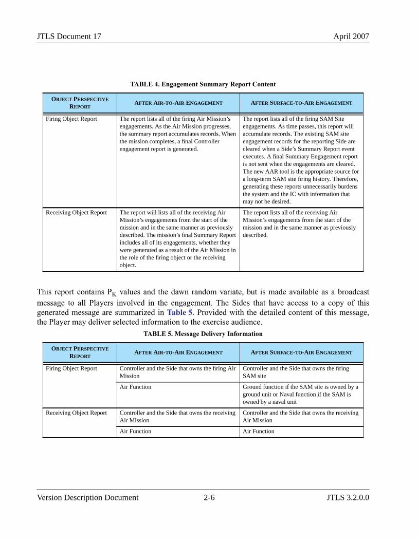
JTLS Document 17 April 2007
This report contains PK values and the dawn random variate, but is made available as a broadcast
message to all Players involved in the engagement. The Sides that have access to a copy of thisgenerated message are summarized in Table 5. Provided with the detailed content of this message,the Player may deliver selected information to the exercise audience.
TABLE 4. Engagement Summary Report Content
OBJECT PERSPECTIVE
REPORTAFTER AIR-TO-AIR ENGAGEMENT AFTER SURFACE-TO-AIR ENGAGEMENT
Firing Object Report The report lists all of the firing Air Mission’sengagements. As the Air Mission progresses,the summary report accumulates records. Whenthe mission completes, a final Controllerengagement report is generated.
The report lists all of the firing SAM Siteengagements. As time passes, this report willaccumulate records. The existing SAM siteengagement records for the reporting Side arecleared when a Side’s Summary Report eventexecutes. A final Summary Engagement reportis not sent when the engagements are cleared.The new AAR tool is the appropriate source fora long-term SAM site firing history. Therefore,generating these reports unnecessarily burdensthe system and the IC with information thatmay not be desired.
Receiving Object Report The report will lists all of the receiving AirMission’s engagements from the start of themission and in the same manner as previouslydescribed. The mission’s final Summary Reportincludes all of its engagements, whether theywere generated as a result of the Air Mission inthe role of the firing object or the receivingobject.
The report lists all of the receiving AirMission’s engagements from the start of themission and in the same manner as previouslydescribed.
TABLE 5. Message Delivery Information
OBJECT PERSPECTIVE
REPORTAFTER AIR-TO-AIR ENGAGEMENT AFTER SURFACE-TO-AIR ENGAGEMENT
Firing Object Report Controller and the Side that owns the firing AirMission
Controller and the Side that owns the firingSAM site
Air Function Ground function if the SAM site is owned by aground unit or Naval function if the SAM isowned by a naval unit
Receiving Object Report Controller and the Side that owns the receivingAir Mission
Controller and the Side that owns the receivingAir Mission
Air Function Air Function
Version Description Document 2-6 JTLS 3.2.0.0
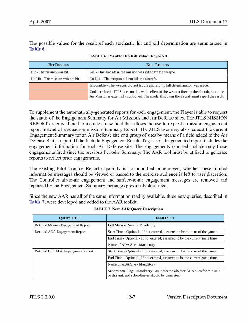
April 2007 JTLS Document 17
The possible values for the result of each stochastic hit and kill determination are summarized inTable 6.
To supplement the automatically-generated reports for each engagement, the Player is able to requestthe status of the Engagement Summary for Air Missions and Air Defense sites. The JTLS MISSIONREPORT order is altered to include a new field that allows the use to request a mission engagementreport instead of a squadron mission Summary Report. The JTLS user may also request the currentEngagement Summary for an Air Defense site or a group of sites by means of a field added to the AirDefense Status report. If the Include Engagement Results flag is set, the generated report includes theengagement information for each Air Defense site. The engagements reported include only thoseengagements fired since the previous Periodic Summary. The AAR tool must be utilized to generatereports to reflect prior engagements.
The existing Pilot Trouble Report capability is not modified or removed; whether these limitedinformation messages should be viewed or passed to the exercise audience is left to user discretion.The Controller air-to-air engagement and surface-to-air engagement messages are removed andreplaced by the Engagement Summary messages previously described.
Since the new AAR has all of the same information readily available, three new queries, described inTable 7, were developed and added to the AAR toolkit.
TABLE 6. Possible Hit/Kill Values Reported
HIT RESULTS KILL RESULTS
Hit - The mission was hit. Kill - One aircraft in the mission was killed by the weapon.
No Hit - The mission was not hit No Kill - The weapon did not kill the aircraft.
Impossible - The weapon did not hit the aircraft; no kill determination was made.
Undetermined - JTLS does not know the effect of the weapon fired on the aircraft, since theAir Mission is externally controlled. The model that owns the aircraft must report the results.
TABLE 7. New AAR Query Description
QUERY TITLE USER INPUT
Detailed Mission Engagement Report Full Mission Name - Mandatory
Detailed ADA Engagement Report Start Time - Optional - If not entered, assumed to be the start of the game.
End Time - Optional - If not entered, assumed to be the current game time.
Name of ADA Site - Mandatory
Detailed Unit ADA Engagement Report Start Time - Optional - If not entered, assumed to be the start of the game.
End Time - Optional - If not entered, assumed to be the current game time.
Name of ADA Site - Mandatory
Subordinate Flag - Mandatory - an indicator whether ADA sites for this unitor this unit and subordinates should be generated.
JTLS 3.2.0.0 2-7 Version Description Document
JTLS Document 17 April 2007
2.2.3 Data Changes
No data changes are required to implement this enhancement.
2.2.4 Order Changes
The Mission Report order is modified to allow the Controller or Player to specify the name of an AirMission for which an Engagement Summary message is desired.
The Air Defense Status order is modified to allow the Controller or Player to specify whether thestatus report will include Air Defense engagement information.
2.2.5 JODA Changes
No JTLS Object Distribution Authority changes are required to implement this enhancement.
2.3 JTLS-0018 Naval Fuel Usage
2.3.1 Summary of Model Change Request
The design for this model enhancement is included in the more comprehensive fuel design alsoimplemented as part of JTLS 3.2.0.0. This ECP, JTLS-2006-1752 Improve Fuel Usage Flexibility,includes the improvements implemented for Ground unit as well as Naval unit fuel consumption.
2.3.2 Design Summary
The logic used for this enhancement is included in JTLS-2006-1752 Improve Fuel UsageFlexibility.
2.3.3 Data Changes
The data changes required to implement this capability are included in JTLS-2006-1752 ImproveFuel Usage Flexibility.
2.3.4 Order Changes
The required order changes are included in JTLS-2006-1752 Improve Fuel Usage Flexibility.
2.3.5 JODA Changes
The required JTLS Object Distribution Authority changes are included in JTLS-2006-1752 ImproveFuel Usage Flexibility.
Version Description Document 2-8 JTLS 3.2.0.0

April 2007 JTLS Document 17
2.4 JTLS-0056 Improve Aircraft Divert Logic
2.4.1 Summary of Model Change Request
Previously, a JTLS Air Mission returning to its home Airbase attempted to find a logical alternativelanding location if the home base runway had been damaged to the extent that the mission could notland. The model’s runway selection logic considered the following assets in priority order:
1. The user-specified alternate Airbase
2. An Airbase that has a usable runway and available parking spaces for which mission hasenough fuel to reach
3. An unoccupied runway that is long enough to support the mission’s aircraft and for whichthe mission has enough fuel to reach
The model neither attempted to locate an alternative landing site nearest the mission’s assigned homebase, nor considered whether the alternative location supported similar aircraft, nor whether it hadavailable aviation fuel or weapons. This model enhancement has established a more robust automaticdivert location selection logic.
2.4.2 Design Summary
When a mission returns to its home base and cannot land, the new divert logic is executed. The firstcondition of this logic establishes whether an alternative location is minimally acceptable. Thefollowing rules were previously applied to this determination, and have not been changed due toimplementing this design:
• The mission must be able to reach the location, considering its current fuel load.
• If the alternative is a Naval unit, the Air Mission must be naval-qualified.
• If the Air Mission requires a runway, the runway at the alternative location must be longenough for the mission to land.
• The alternative location must have enough available parking spaces to accommodate the AirMission. This check is implemented primarily to prevent all returning aircraft fromselecting the same alternative landing location when a major base is closed.
The model logic first considers the user-assigned alternative base. If this location is feasible, themodel selects the location and the Air Mission is immediately diverted. If this alternative is notfeasible or the user has not assigned an alternative base, the new automatic selection logic is executed.
This new logic does not automatically select the first identified feasible location, but requires themodel to consider all feasible locations. The logic is based on a point system for which a numericalvalue is assigned to each feasible location according to its suitability for the mission. The alternativelocation that is assigned the greatest point value is selected. In the case of a point value tie betweentwo locations, the nearest alternative location is selected.
JTLS 3.2.0.0 2-9 Version Description Document
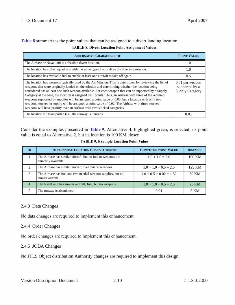
JTLS Document 17 April 2007
Table 8 summarizes the point values that can be assigned to a divert landing location.
Consider the examples presented in Table 9. Alternative 4, highlighted green, is selected; its pointvalue is equal to Alternative 2, but its location is 100 KM closer.
2.4.3 Data Changes
No data changes are required to implement this enhancement.
2.4.4 Order Changes
No order changes are required to implement this enhancement.
2.4.5 JODA Changes
No JTLS Object distribution Authority changes are required to implement this design.
TABLE 8. Divert Location Point Assignment Values
ALTERNATIVE CHARACTERISTIC POINT VALUE
The Airbase or Naval unit is a feasible divert location. 1.0
The location has other squadrons with the same type of aircraft as the diverting mission. 1.0
The location has available fuel to enable at least one aircraft to take off again. 0.5
The location has weapons typically used by the Air Mission. This is determined by reviewing the list ofweapons that were originally loaded on the mission and determining whether the location beingconsidered has at least one such weapon available. For each weapon that can be supported by a SupplyCategory at the base, the location is assigned 0.01 points. Thus, an Airbase with three of the requiredweapons supported by supplies will be assigned a point value of 0.03, but a location with only twoweapons stocked in supply will be assigned a point value of 0.02. The Airbase with three stockedweapons will have priority over an Airbase with two stocked categories.
0.01 per weaponsupported by a
Supply Category
The location is Unsupported (i.e., the runway is unused). 0.01
TABLE 9. Example Location Point Value
ID ALTERNATIVE LOCATION CHARACTERISTICS COMPUTED POINT VALUE DISTANCE
1 The Airbase has similar aircraft, but no fuel or weapons arecurrently available.
1.0 + 1.0 = 2.0 100 KM
2 The Airbase has similar aircraft, fuel, but no weapons. 1.0 + 1.0 + 0.5 = 2.5 125 KM
3 The Airbase has fuel and two needed weapon supplies, but nosimilar aircraft.
1.0 + 0.5 + 0.02 = 1.52 50 KM
4 The Naval unit has similar aircraft, fuel, but no weapons. 1.0 + 1.0 + 0.5 = 2.5 25 KM
5 The runway is abandoned. 0.01 5 KM
Version Description Document 2-10 JTLS 3.2.0.0
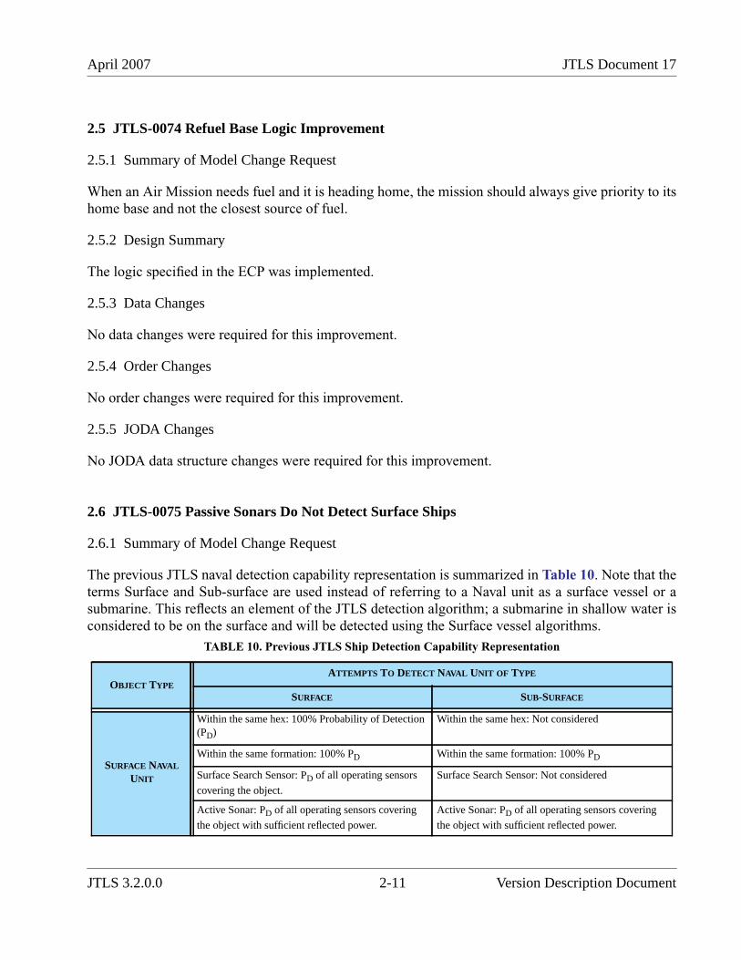
April 2007 JTLS Document 17
2.5 JTLS-0074 Refuel Base Logic Improvement
2.5.1 Summary of Model Change Request
When an Air Mission needs fuel and it is heading home, the mission should always give priority to itshome base and not the closest source of fuel.
2.5.2 Design Summary
The logic specified in the ECP was implemented.
2.5.3 Data Changes
No data changes were required for this improvement.
2.5.4 Order Changes
No order changes were required for this improvement.
2.5.5 JODA Changes
No JODA data structure changes were required for this improvement.
2.6 JTLS-0075 Passive Sonars Do Not Detect Surface Ships
2.6.1 Summary of Model Change Request
The previous JTLS naval detection capability representation is summarized in Table 10. Note that theterms Surface and Sub-surface are used instead of referring to a Naval unit as a surface vessel or asubmarine. This reflects an element of the JTLS detection algorithm; a submarine in shallow water isconsidered to be on the surface and will be detected using the Surface vessel algorithms.
TABLE 10. Previous JTLS Ship Detection Capability Representation
OBJECT TYPEATTEMPTS TO DETECT NAVAL UNIT OF TYPE
SURFACE SUB-SURFACE
SURFACE NAVAL
UNIT
Within the same hex: 100% Probability of Detection(PD)
Within the same hex: Not considered
Within the same formation: 100% PD Within the same formation: 100% PD
Surface Search Sensor: PD of all operating sensors
covering the object.
Surface Search Sensor: Not considered
Active Sonar: PD of all operating sensors covering
the object with sufficient reflected power.
Active Sonar: PD of all operating sensors covering
the object with sufficient reflected power.
JTLS 3.2.0.0 2-11 Version Description Document
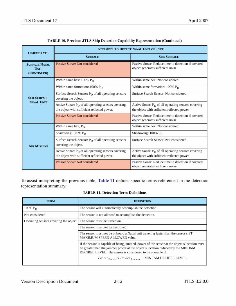
JTLS Document 17 April 2007
To assist interpreting the previous table, Table 11 defines specific terms referenced in the detectionrepresentation summary.
SURFACE NAVAL
UNIT
(CONTINUED)
Passive Sonar: Not considered Passive Sonar: Reduce time to detection if coveredobject generates sufficient noise
SUB-SURFACE
NAVAL UNIT
Within same hex: 100% PD Within same hex: Not considered
Within same formation: 100% PD Within same formation: 100% PD
Surface Search Sensor: PD of all operating sensors
covering the object.
Surface Search Sensor: Not considered
Active Sonar: PD of all operating sensors covering
the object with sufficient reflected power.
Active Sonar: PD of all operating sensors covering
the object with sufficient reflected power.
Passive Sonar: Not considered Passive Sonar: Reduce time to detection if coveredobject generates sufficient noise
AIR MISSION
Within same hex, PD Within same hex: Not considered
Shadowing: 100% PD Shadowing: 100% PD
Surface Search Sensor: PD of all operating sensors
covering the object.
Surface Search Sensor: Not considered
Active Sonar: PD of all operating sensors covering
the object with sufficient reflected power.
Active Sonar: PD of all operating sensors covering
the object with sufficient reflected power.
Passive Sonar: Not considered Passive Sonar: Reduce time to detection if coveredobject generates sufficient noise
TABLE 11. Detection Term Definitions
TERM DEFINITION
100% PD The sensor will automatically accomplish the detection.
Not considered The sensor is not allowed to accomplish the detection.
Operating sensors covering the object The sensor must be turned on.
The sensor must not be destroyed.
The sensor must not be onboard a Naval unit traveling faster than the sensor’s STMAXIMUM SPEED ALLOWED value.
If the sensor is capable of being jammed, power of the sensor at the object’s location mustbe greater than the jammer power at the object’s location reduced by the MIN JAMDECIBEL LEVEL. The sensor is considered to be operable if:
TABLE 10. Previous JTLS Ship Detection Capability Representation (Continued)
OBJECT TYPEATTEMPTS TO DETECT NAVAL UNIT OF TYPE
SURFACE SUB-SURFACE
PowerSensor PowerJammer MIN JAM DECIBEL LEVEL–>
Version Description Document 2-12 JTLS 3.2.0.0
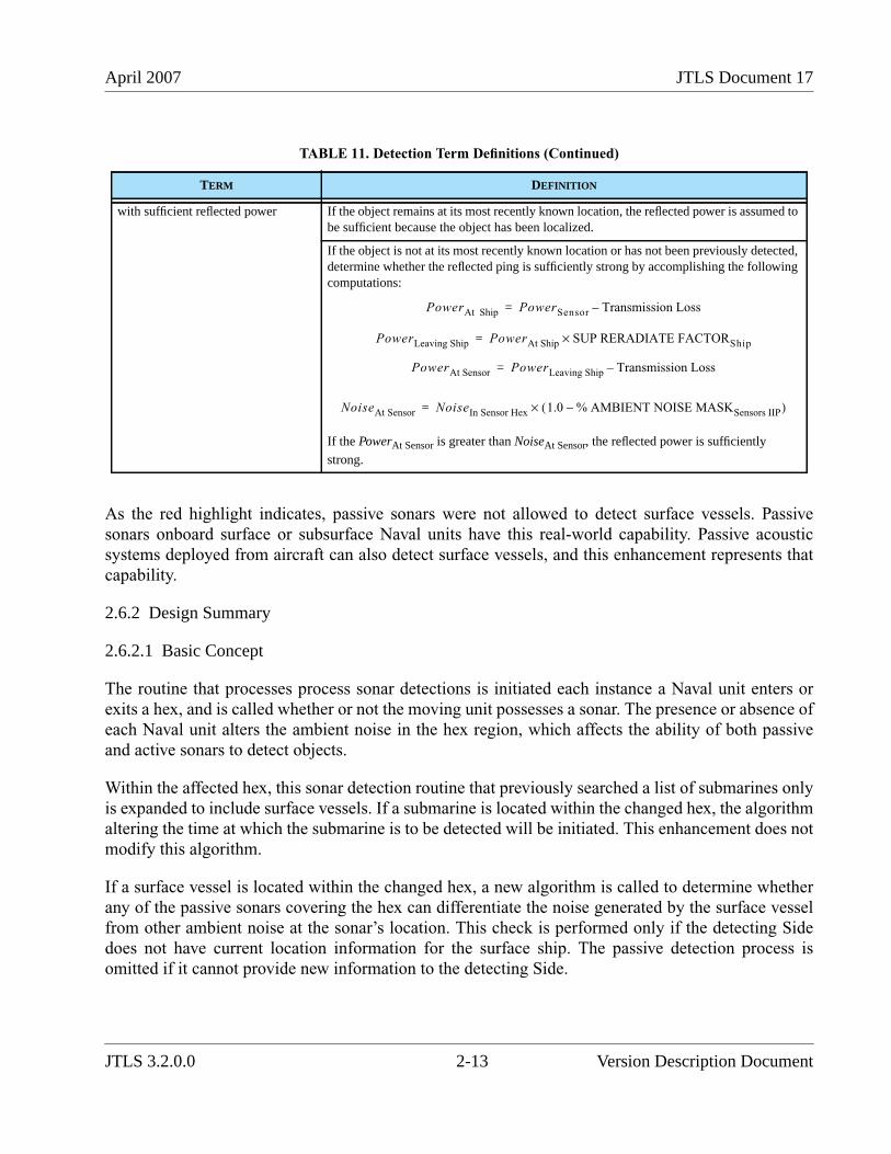
April 2007 JTLS Document 17
As the red highlight indicates, passive sonars were not allowed to detect surface vessels. Passivesonars onboard surface or subsurface Naval units have this real-world capability. Passive acousticsystems deployed from aircraft can also detect surface vessels, and this enhancement represents thatcapability.
2.6.2 Design Summary
2.6.2.1 Basic Concept
The routine that processes process sonar detections is initiated each instance a Naval unit enters orexits a hex, and is called whether or not the moving unit possesses a sonar. The presence or absence ofeach Naval unit alters the ambient noise in the hex region, which affects the ability of both passiveand active sonars to detect objects.
Within the affected hex, this sonar detection routine that previously searched a list of submarines onlyis expanded to include surface vessels. If a submarine is located within the changed hex, the algorithmaltering the time at which the submarine is to be detected will be initiated. This enhancement does notmodify this algorithm.
If a surface vessel is located within the changed hex, a new algorithm is called to determine whetherany of the passive sonars covering the hex can differentiate the noise generated by the surface vesselfrom other ambient noise at the sonar’s location. This check is performed only if the detecting Sidedoes not have current location information for the surface ship. The passive detection process isomitted if it cannot provide new information to the detecting Side.
with sufficient reflected power If the object remains at its most recently known location, the reflected power is assumed tobe sufficient because the object has been localized.
If the object is not at its most recently known location or has not been previously detected,determine whether the reflected ping is sufficiently strong by accomplishing the followingcomputations:
If the PowerAt Sensor is greater than NoiseAt Sensor, the reflected power is sufficiently
strong.
TABLE 11. Detection Term Definitions (Continued)
TERM DEFINITION
PowerAt Ship PowerSensor Transmission Loss–=
PowerLeaving Ship PowerAt Ship SUP RERADIATE FACTORShip×=
PowerAt Sensor PowerLeaving Ship Transmission Loss–=
NoiseAt Sensor NoiseIn Sensor Hex 1.0 % AMBIENT NOISE MASKSensors IIP–( )×=
JTLS 3.2.0.0 2-13 Version Description Document
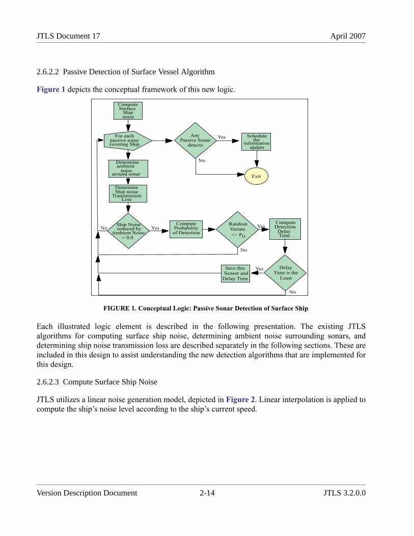
JTLS Document 17 April 2007
2.6.2.2 Passive Detection of Surface Vessel Algorithm
Figure 1 depicts the conceptual framework of this new logic.
FIGURE 1. Conceptual Logic: Passive Sonar Detection of Surface Ship
Each illustrated logic element is described in the following presentation. The existing JTLSalgorithms for computing surface ship noise, determining ambient noise surrounding sonars, anddetermining ship noise transmission loss are described separately in the following sections. These areincluded in this design to assist understanding the new detection algorithms that are implemented forthis design.
2.6.2.3 Compute Surface Ship Noise
JTLS utilizes a linear noise generation model, depicted in Figure 2. Linear interpolation is applied tocompute the ship’s noise level according to the ship’s current speed.
ComputeSurface
noise
For eachpassive sonarcovering Ship
Determineambient
noisearound sonar
DetermineShip noise
TransmissionLoss
Ship Noise
Ambient Noise> 0.0
ComputeProbability
of Detection
RandomVariate
<= PD
ComputeDetection
DelayTime
DelayTime is the
Least
Save thisSensor and
Delay Time
Passive Sonardetects
Schedulethe
informationupdate
Exit
No Yes Yes
No
Yes
No
Yes
No
Ship
reduced by
Any
Version Description Document 2-14 JTLS 3.2.0.0
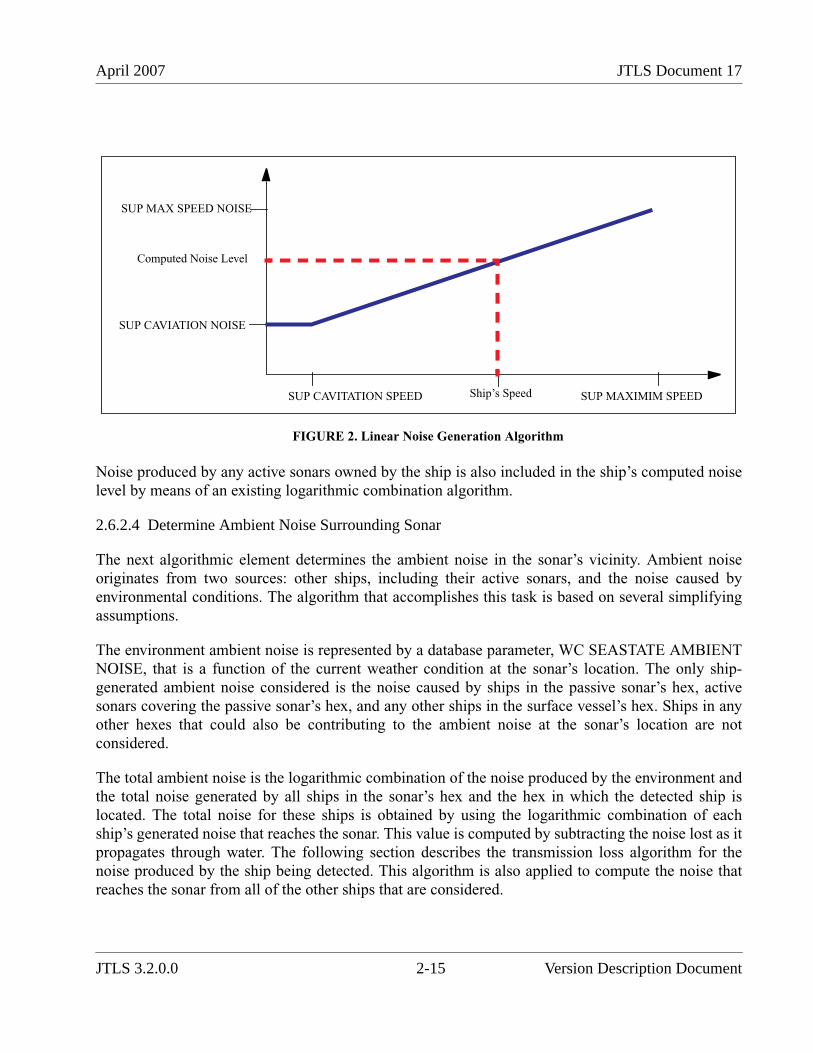
April 2007 JTLS Document 17
FIGURE 2. Linear Noise Generation Algorithm
Noise produced by any active sonars owned by the ship is also included in the ship’s computed noiselevel by means of an existing logarithmic combination algorithm.
2.6.2.4 Determine Ambient Noise Surrounding Sonar
The next algorithmic element determines the ambient noise in the sonar’s vicinity. Ambient noiseoriginates from two sources: other ships, including their active sonars, and the noise caused byenvironmental conditions. The algorithm that accomplishes this task is based on several simplifyingassumptions.
The environment ambient noise is represented by a database parameter, WC SEASTATE AMBIENTNOISE, that is a function of the current weather condition at the sonar’s location. The only ship-generated ambient noise considered is the noise caused by ships in the passive sonar’s hex, activesonars covering the passive sonar’s hex, and any other ships in the surface vessel’s hex. Ships in anyother hexes that could also be contributing to the ambient noise at the sonar’s location are notconsidered.
The total ambient noise is the logarithmic combination of the noise produced by the environment andthe total noise generated by all ships in the sonar’s hex and the hex in which the detected ship islocated. The total noise for these ships is obtained by using the logarithmic combination of eachship’s generated noise that reaches the sonar. This value is computed by subtracting the noise lost as itpropagates through water. The following section describes the transmission loss algorithm for thenoise produced by the ship being detected. This algorithm is also applied to compute the noise thatreaches the sonar from all of the other ships that are considered.
SUP CAVITATION SPEED SUP MAXIMIM SPEED
SUP CAVIATION NOISE
SUP MAX SPEED NOISE
Ship’s Speed
Computed Noise Level
JTLS 3.2.0.0 2-15 Version Description Document
JTLS Document 17 April 2007
2.6.2.5 Determine Ship Noise Transmission Loss
The next logical element determines the amount of noise reaching the location of the passive sonarthat is generated by the ship the algorithm is attempting to detect. This noise level is different for eachpassive sonar that covers the location of the ship being detected, since the transmission loss islogarithmically correlated to the noise propagation distance D in water, measured in meters. This losscan be represented as a spherical loss (a loss parameter of 20.0), which is applied to distances lessthan 1.0 meters, or a cylindrical loss (a loss parameter of 10.0), which is applied to distances greaterthan or equal to 1.0 meters and less than or equal to 1.0 kilometers.
The cylindrical model includes additional transmission loss attributed to Terrain Attenuation, whichrepresents the sound dissipation characteristics of the hexes through which the sounds must travel.The terrain type of each hex through which the noise must pass is accessed, including the existingdatabase parameter TT SOUND ATTENUATION LOSS. A partial hex distance computation modelrepresents the distance the sound travels through each hex. This model consist of a series of segmentsfrom the midpoint of the hex barrier across which the noise "enters" the hex to the midpoint of thebarrier from which the noise "exits" the hex. However, the sum of these distances does not exactlyrepresent the linear distance between the source ship and the sonar.
2.6.2.6 Compute Probability of Detection
At this point, the algorithm is prepared to determine whether the passive sensor can detect the surfacevessel. If the noise generated by the detected ship does not exceed the ambient noise, a detection doesnot occur. The sonar senses the presence of noise, but cannot distinguish the type of noise to completea detection. Conversely, if the ambient noise is less than or equal to the ship-generated sound thatreaches the sonar, a detection is possible but not certain. The model still requires that the passivesonar passes the probability of detection, PD. The ST EFFECTIVENESS is accessed and modified by
the sonar’s ST NIGHT FACTOR and ST WC FACTOR. The model does not consider the sonar’s STJAM FACTOR. Finally, the PD is adjusted for the Ship Unit Prototype (SUP) of the detected surface
vessel and the terrain type of the hex within which the vessel is located (TT SHIP DETECTIONMODIFIER). A random variate is drawn and compared to the computed PD to determine whether a
detection occurs. If a detection is not possible, the algorithm proceeds to the next passive sensor thatmay be able to detect the surface vessel.
2.6.2.7 Compute Detection Delay Time
If the random draw indicates that a detection has occurred, the next step determines the time thedetection will be received by the detecting Side. The time delay for reporting the detection has twocomponents, the initial report time of the sensor (ST INITIAL REPORT TIME) and the delay for theunit that owns the passive sensor that made the detection to report the detection to its next higherheadquarters. The method used to compute the unit delay component has also been changed withinJTLS 3.2.0.0 to implement the ECP JTLS-2006-1827 New Command Control Model. and isdescribed in the corresponding section.
Version Description Document 2-16 JTLS 3.2.0.0
April 2007 JTLS Document 17
As shown in Figure 1, the algorithm then loops to determine the next passive sonar from the detectingSide that can detect the surface vessel. The passive sonar that has the least report delay time isselected to report the presence of the surface vessel.
2.6.3 Data Changes
No data changes are required to implement this enhancement. The following sensor data parametersare accessed and used for those sensors that are assigned an ST USE value of PASSIVE SONAR:
• ST EFFECTIVENESS
• ST NIGHT FACTOR
• ST WC WEATHER FACTOR
• ST INITIAL REPORT TIME
A database developer should review these data elements for all represented passive sonars to ensurethat they represent appropriate values. As a result of this model enhancement, these values will beaccessed when the passive sonar attempts to detect surface vessels.
2.6.4 Order Changes
No order changes are required to implement this enhancement.
2.6.5 JODA Changes
No JTLS Object Distribution Authority (JODA) changes are required to implement this enhancement.
2.7 JTLS-0083 Controller Adjusts Air Mission Speed
2.7.1 Summary of Model Change Request
The capability to change an individual JTLS Air Mission's speed was previously limited to the rangeof valid air speeds that the aircraft type could fly. The Player who manages the mission can use theChange Air Mission Parameter order to set the mission's speed to a value between or including theaircraft type's stall speed and maximum flight speed.
During exercises, a requirement may arise to expedite an Air Mission to compensate for a Player'sorder entry error, or a planning or execution problem within the Air Tasking Order (ATO). The abilityto increase or decrease an Air Mission's speed to values less than the stall speed or greater than themaximum speed would provide Players the flexibility to correct undesirable situations to ensure thattraining objectives are satisfied. Furthermore, this capability is useful during software and databasetests.
JTLS 3.2.0.0 2-17 Version Description Document

JTLS Document 17 April 2007
2.7.2 Design Summary
This model enhancement establishes a new Controller and trusted Air Player capability to change theair speed of an individual Air Mission beyond the limitations of the aircraft type in the mission. Thiscapability was added to the existing Magic Replenish Air Mission order currently used to refuel andre-arm active missions, and required changes to several JTLS components: the Magic Replenish AirMission order panel (renamed to Magic Air Ops), the Web-Hosted Interface Program (WHIP) menusand messages, and the underlying Combat Events Program (CEP) routines.
2.7.2.1 Messages
A new line was added to the existing Air Order Received/Complied message that is sent to the WHIPMessage Browser to inform the Controller about the mission's new air speed after it is changed bymeans of the Magic Air Ops order.
Since at least one of the fields in the Magic Air Ops order must be filled or selected, the Speed fieldwas added to the existing list of fields in the Air Order Received/Cannot Comply message. Themessage is sent to notify the Controller who fails to enter or select at least one field in the order panel.This message is a merely a precaution, because the order panel also forces the Player to enter or selectat least one field.
2.7.2.2 CEP Changes
The underlying CEP routine that processes the Magic Replenish Air Mission order was modified toaccommodate the New Aircraft Speed field in the panel and reflect the new Magic Air Ops ordername.
If a value is entered in the New Aircraft Speed field, the CEP routine sets the mission's current speedto the desired value and updates the WHIP displays. The mission's ordered speed is also set to thedesired value to allow the mission to resume the desired speed without further Controller interventionafter landing for fuel or an airlift stop. Beyond the limits imposed by the order panel, no restrictionsare placed on the speed set for the mission. In this way, a very high air speed approximates a magicmove of the Air Mission, although fuel is still consumed over the distance traveled.
If the mission's speed exceeds the aircraft type's cruise speed, fuel consumption is limited to thecruise consumption rate to avoid excessive fuel usage. If the mission's speed is set to a value less thanthe aircraft type's stall speed, fuel consumption is calculated according to the stall consumption rate.
2.7.3 Data Changes
No data changes are required to implement this enhancement.
Version Description Document 2-18 JTLS 3.2.0.0
April 2007 JTLS Document 17
2.7.4 Order Changes
The existing Magic Replenish Air Mission order panel, available to both the Controller and thetrusted Air Player WHIPs, is renamed Magic Air Ops to reflect the expanded functionality of theorder. The corresponding WHIP menu options are renamed to reflect the new order name. A NewAircraft speed optional field is added to the order panel. The New Aircraft Speed is limited to a rangeof 1.0 to 999999.0 Km/Day, Km/Hr, or Knots.
2.7.5 JODA Changes
No JTLS Object Distribution Authority changes are required to implement this enhancement.
2.8 JTLS-0084 Change Terrain and Barrier Values
2.8.1 Summary of Model Change Request
The JTLS Controller has the capability to modify a number of environment parameters in order tosatisfy the training or analysis goals of the simulation audience. This ECP provided for augmentingthis capability to allow the Controller to change the terrain within a hex, the elevation of the hex, thewater depth within a hex, and/or the barriers between hexes on the game board. For example,changing the depth of water in hexes at a location might be done to increase the accessibility toshipping. Some residual effects of such a change would include changes the hex’s depth zonecharacteristics, including a changed water movement time multiplier for the specified new depth.
2.8.2 Design Summary
This enhancement implements the model changes necessary to allow the JTLS game Controller tomodify certain terrain characteristics of a hex, such as water depth, as well as a a capability to modifybarriers between hexes.
2.8.2.1 Terrain Changes
The water depth for all small island, open water, or dual-capable hexes is initially defined in thescenario database prior to starting the game. Thereafter, all ships having a water depth restriction areprevented from entering any hex that does not meet or exceed the depth restriction for the ship, asdefined by the ship unit protoype. This hex restriction provides a useful technique for the gameController to use to control access of certain ship types to the area of interest. For example, there is nocurrent method in JTLS to model shipping avoidance of mined waters. The CEP is just as likely toinclude a mined water hex of sufficient depth in the automatically generated route for a moving shipas any other hex that has sufficient depth. This design implements a new Controller order named AlterTerrain, from which terrain changes can be made after the game has started (Figure 3).
JTLS 3.2.0.0 2-19 Version Description Document
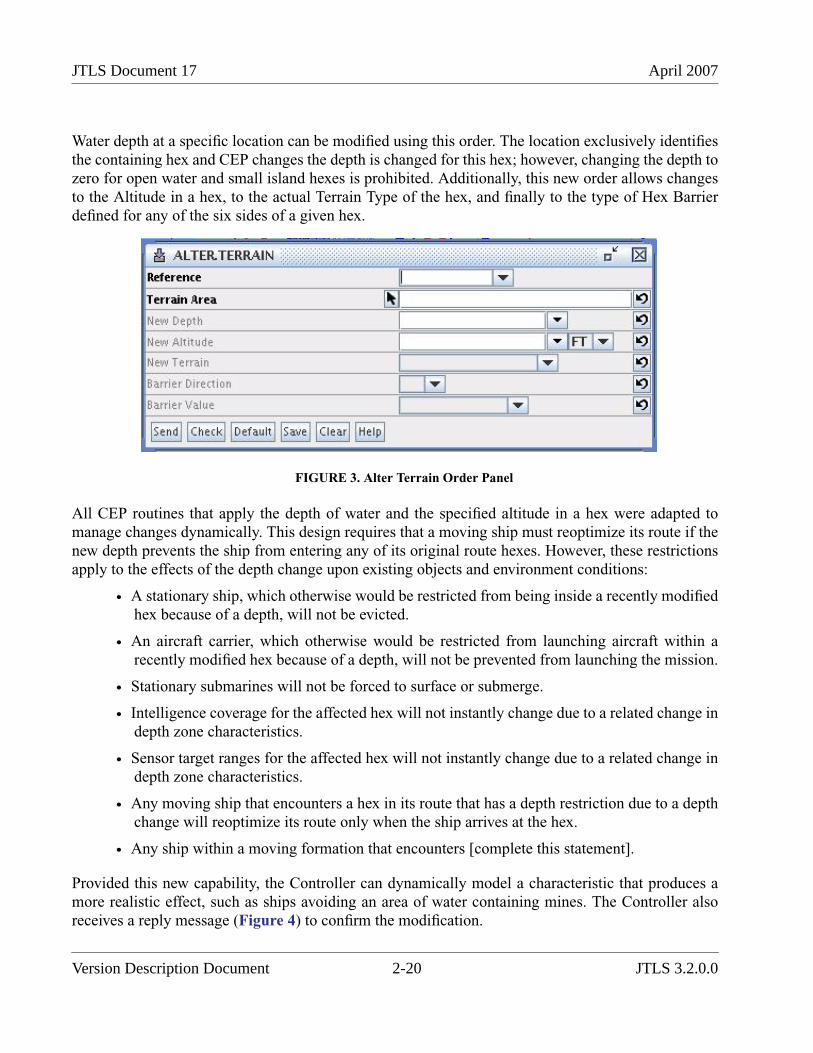
JTLS Document 17 April 2007
Water depth at a specific location can be modified using this order. The location exclusively identifiesthe containing hex and CEP changes the depth is changed for this hex; however, changing the depth tozero for open water and small island hexes is prohibited. Additionally, this new order allows changesto the Altitude in a hex, to the actual Terrain Type of the hex, and finally to the type of Hex Barrierdefined for any of the six sides of a given hex.
FIGURE 3. Alter Terrain Order Panel
All CEP routines that apply the depth of water and the specified altitude in a hex were adapted tomanage changes dynamically. This design requires that a moving ship must reoptimize its route if thenew depth prevents the ship from entering any of its original route hexes. However, these restrictionsapply to the effects of the depth change upon existing objects and environment conditions:
• A stationary ship, which otherwise would be restricted from being inside a recently modifiedhex because of a depth, will not be evicted.
• An aircraft carrier, which otherwise would be restricted from launching aircraft within arecently modified hex because of a depth, will not be prevented from launching the mission.
• Stationary submarines will not be forced to surface or submerge.
• Intelligence coverage for the affected hex will not instantly change due to a related change indepth zone characteristics.
• Sensor target ranges for the affected hex will not instantly change due to a related change indepth zone characteristics.
• Any moving ship that encounters a hex in its route that has a depth restriction due to a depthchange will reoptimize its route only when the ship arrives at the hex.
• Any ship within a moving formation that encounters [complete this statement].
Provided this new capability, the Controller can dynamically model a characteristic that produces amore realistic effect, such as ships avoiding an area of water containing mines. The Controller alsoreceives a reply message (Figure 4) to confirm the modification.
Version Description Document 2-20 JTLS 3.2.0.0
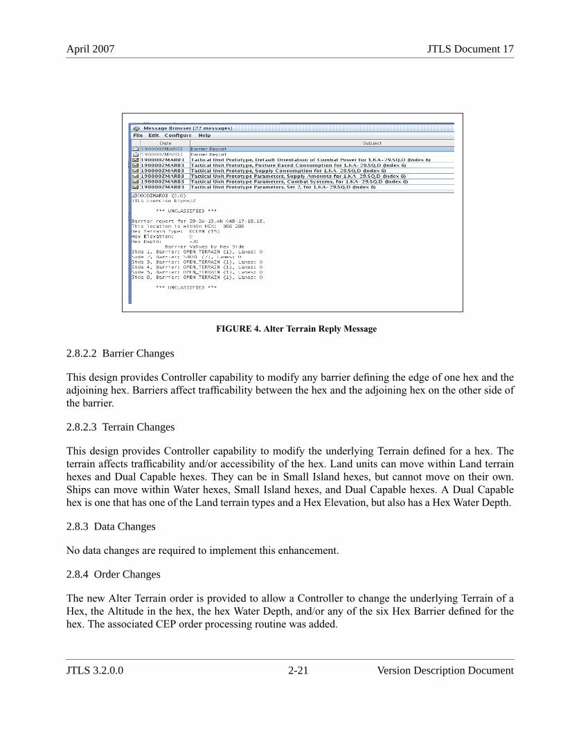
April 2007 JTLS Document 17
FIGURE 4. Alter Terrain Reply Message
2.8.2.2 Barrier Changes
This design provides Controller capability to modify any barrier defining the edge of one hex and theadjoining hex. Barriers affect trafficability between the hex and the adjoining hex on the other side ofthe barrier.
2.8.2.3 Terrain Changes
This design provides Controller capability to modify the underlying Terrain defined for a hex. Theterrain affects trafficability and/or accessibility of the hex. Land units can move within Land terrainhexes and Dual Capable hexes. They can be in Small Island hexes, but cannot move on their own.Ships can move within Water hexes, Small Island hexes, and Dual Capable hexes. A Dual Capablehex is one that has one of the Land terrain types and a Hex Elevation, but also has a Hex Water Depth.
2.8.3 Data Changes
No data changes are required to implement this enhancement.
2.8.4 Order Changes
The new Alter Terrain order is provided to allow a Controller to change the underlying Terrain of aHex, the Altitude in the hex, the hex Water Depth, and/or any of the six Hex Barrier defined for thehex. The associated CEP order processing routine was added.
JTLS 3.2.0.0 2-21 Version Description Document
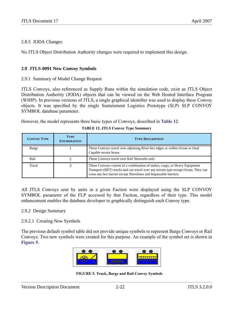
JTLS Document 17 April 2007
2.8.5 JODA Changes
No JTLS Object Distribution Authority changes were required to implement this design.
2.9 JTLS-0091 New Convoy Symbols
2.9.1 Summary of Model Change Request
JTLS Convoys, also referenced as Supply Runs within the simulation code, exist as JTLS ObjectDistribution Authority (JODA) objects that can be viewed on the Web Hosted Interface Program(WHIP). In previous versions of JTLS, a single graphical identifier was used to display these Convoyobjects. It was specified by the single Sustainment Logistics Prototype (SLP) SLP CONVOYSYMBOL database parameter.
However, the model represents three basic types of Convoys, described in Table 12.
All JTLS Convoys sent by units in a given Faction were displayed using the SLP CONVOYSYMBOL parameter of the FLP accessed by that Faction, regardless of their type. This modelenhancement enables the database developer to graphically distinguish each Convoy type.
2.9.2 Design Summary
2.9.2.1 Creating New Symbols
The previous default symbol table did not provide unique symbols to represent Barge Convoys or RailConvoys. Two new symbols were created for this purpose. An example of the symbol set is shown inFigure 5.
FIGURE 5. Truck, Barge and Rail Convoy Symbols
TABLE 12. JTLS Convoy Type Summary
CONVOY TYPETYPE
ENUMERATIONTYPE DESCRIPTION
Barge 1 These Convoys travel over adjoining River hex edges or within Ocean or DualCapable terrain hexes.
Rail 2 These Convoys travel over Rail Networks only.
Truck 3 These Convoys consist of a combination of tanker, cargo, or Heavy EquipmentTransport (HET) trucks and can travel over any terrain type except Ocean. They cancross any hex barrier except Shorelines and Impassable barriers.
Version Description Document 2-22 JTLS 3.2.0.0
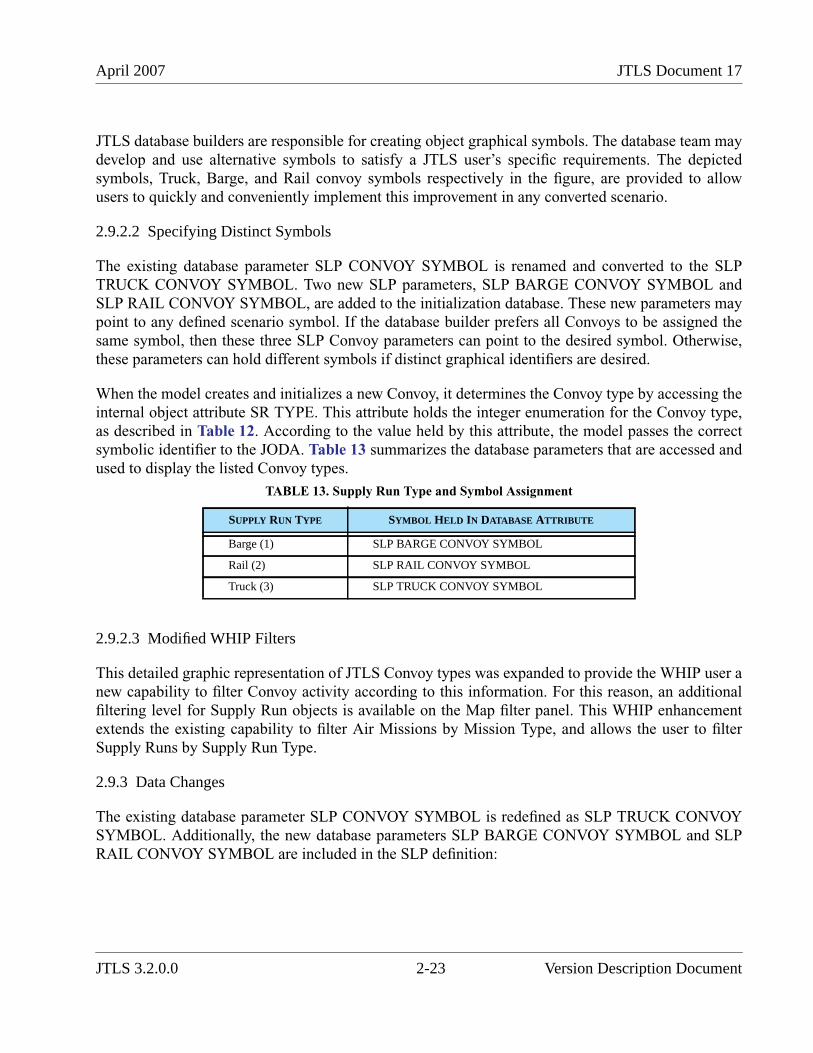
April 2007 JTLS Document 17
JTLS database builders are responsible for creating object graphical symbols. The database team maydevelop and use alternative symbols to satisfy a JTLS user’s specific requirements. The depictedsymbols, Truck, Barge, and Rail convoy symbols respectively in the figure, are provided to allowusers to quickly and conveniently implement this improvement in any converted scenario.
2.9.2.2 Specifying Distinct Symbols
The existing database parameter SLP CONVOY SYMBOL is renamed and converted to the SLPTRUCK CONVOY SYMBOL. Two new SLP parameters, SLP BARGE CONVOY SYMBOL andSLP RAIL CONVOY SYMBOL, are added to the initialization database. These new parameters maypoint to any defined scenario symbol. If the database builder prefers all Convoys to be assigned thesame symbol, then these three SLP Convoy parameters can point to the desired symbol. Otherwise,these parameters can hold different symbols if distinct graphical identifiers are desired.
When the model creates and initializes a new Convoy, it determines the Convoy type by accessing theinternal object attribute SR TYPE. This attribute holds the integer enumeration for the Convoy type,as described in Table 12. According to the value held by this attribute, the model passes the correctsymbolic identifier to the JODA. Table 13 summarizes the database parameters that are accessed andused to display the listed Convoy types.
2.9.2.3 Modified WHIP Filters
This detailed graphic representation of JTLS Convoy types was expanded to provide the WHIP user anew capability to filter Convoy activity according to this information. For this reason, an additionalfiltering level for Supply Run objects is available on the Map filter panel. This WHIP enhancementextends the existing capability to filter Air Missions by Mission Type, and allows the user to filterSupply Runs by Supply Run Type.
2.9.3 Data Changes
The existing database parameter SLP CONVOY SYMBOL is redefined as SLP TRUCK CONVOYSYMBOL. Additionally, the new database parameters SLP BARGE CONVOY SYMBOL and SLPRAIL CONVOY SYMBOL are included in the SLP definition:
TABLE 13. Supply Run Type and Symbol Assignment
SUPPLY RUN TYPE SYMBOL HELD IN DATABASE ATTRIBUTE
Barge (1) SLP BARGE CONVOY SYMBOL
Rail (2) SLP RAIL CONVOY SYMBOL
Truck (3) SLP TRUCK CONVOY SYMBOL
JTLS 3.2.0.0 2-23 Version Description Document
JTLS Document 17 April 2007
2.9.4 Order Changes
The Sustainment Logistics Prototype entity Set and Show orders are modified. If the Controllerchanges the symbol assigned to any Convoy symbol database parameter, the model examines allSupport units in the scenario that currently use the altered SLP and updates the symbol for any activeConvoy.
2.9.5 JODA Changes
To enhance the Map Filter panel and allow the interface user to filter Convoy activity according toSupply Run Type, the JODA must access the corresponding Supply Run Type data. A new CommonKnowledge attribute named Type is added to the JODA Supply Run object. This integer variable is anenumeration, as described in Table 12. The JODA passes Supply Run Type information to theInformation Management Tool (IMT) to be reported on the Supply Run display.
2.10 JTLS-0118 Change Alert Base
2.10.1 Summary of Model Change Request
JTLS provides the capability to alter an existing mission’s current tasking based on the exercisesaudience’s current operational requirement. For example, the JTLS player has the ability to order aspecific:
• CAP mission to alter its orbit location,
• Air-Ground Attack mission to alter its primary target, or
• Airlift mission to add or delete a planned stop within its flight plan.
An Air Mission’s assigned alert base previously could not be changed after being assigned for aspecific Air Mission. The Player could cancel the existing mission and resubmit a new mission withthe newly desired alert location. This enhancement improves the current operations capability ofJTLS to allow the Player capability to alter a specific mission’s alert base at any time during themission profile.
2.10.2 Design Summary
JTLS Air mission types that can be placed on alert include: Airborne Warning and Control System(AWACS), Air Refuel, Reconnaissance, Armed Reconnaissance, Electronic Combat (EC), WildWeasel, Combat Air Patrol (CAP), Mine Warfare, Offensive Air Support (OAS), and Patrol. Each ofthese missions can be ordered on alert at its home base or at a Forward Operating Location (FOL).Figure 6 depicts the flight profile of a mission placed on alert at an FOL. A mission on alert at itshome base is not required to fly from its home base to the FOL; therefore, Step 1 and Step 4 would beomitted.
Version Description Document 2-24 JTLS 3.2.0.0
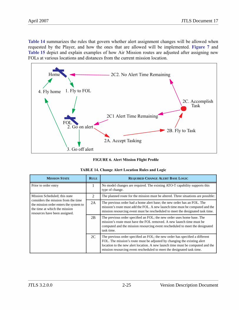
April 2007 JTLS Document 17
Table 14 summarizes the rules that govern whether alert assignment changes will be allowed whenrequested by the Player, and how the ones that are allowed will be implemented. Figure 7 andTable 15 depict and explain examples of how Air Mission routes are adjusted after assigning newFOLs at various locations and distances from the current mission location.
FIGURE 6. Alert Mission Flight Profile
TABLE 14. Change Alert Location Rules and Logic
MISSION STATE RULE REQUIRED CHANGE ALERT BASE LOGIC
Prior to order entry 1 No model changes are required. The existing ATO-T capability supports thistype of change.
Mission Scheduled; this stateconsiders the mission from the timethe mission order enters the system tothe time at which the missionresources have been assigned.
2 The planned route for the mission must be altered. Three situations are possible:
2A The previous order had a home alert base; the new order has an FOL. Themission’s route must add the FOL. A new launch time must be computed and themission resourcing event must be rescheduled to meet the designated task time.
2B The previous order specified an FOL; the new order uses home base. Themission’s route must have the FOL removed. A new launch time must becomputed and the mission resourcing event rescheduled to meet the designatedtask time.
2C The previous order specified an FOL; the new order has specified a differentFOL. The mission’s route must be adjusted by changing the existing alertlocation to the new alert location. A new launch time must be computed and themission resourcing event rescheduled to meet the designated task time.
Home
FOL
1. Fly to FOL
2. Go on alert
3. Go off alert
4. Fly home
2A. Accept Tasking
2B. Fly to Task
2C1 Alert Time Remaining
2C2. No Alert Time Remaining
2C. Accomplish Task
JTLS 3.2.0.0 2-25 Version Description Document
JTLS Document 17 April 2007
Mission Prelaunch; this stateconsiders the mission from the timethe mission has been assignedresources until the mission eithergoes on alert at its home base or takesoff to fly to its designated FOL.
3 The planned route for the mission must be altered. Four situations are possible:
3A The previous order had a home alert base; the new order has an FOL. Themission’s route needs to have the FOL added. A new launch time must becomputed and the mission launch event rescheduled to meet the designated tasktime.
3B The previous order specified an FOL; the new order uses home base. Themission’s route remove the FOL. A new launch time must be computed and themission launch event rescheduled to meet the designated task time.
3C The previous order specified an FOL; the new order has specified a differentFOL. The mission’s route must be adjusted by changing the existing alertlocation to the new alert location. A new launch time must be computed and themission launch event rescheduled to meet the designated task time.
The mission is airborne and its nextimportant route point is its AlertBase. This state considers the missionthat is either heading toward its FOLafter its initial launch. It also appliesto an Air Mission that has finished itsfirst assigned task and is headingback to its alert base, whether thatbase is the mission’s home base or aspecified FOL.
4 Two situations are possible for this mission state:
4A The mission is headed toward an intermediate transit or turn point. In this case,the location for the alert base must be altered within the mission’s route.
4B The mission has already optimized a path to the old alert location. In this case,the mission’s optimized path must be removed from its planned route, thelocation for the alert base must be altered within the mission’s route, and anoptimal path to the new alert base must be computed.
The mission is airborne and its nextimportant route point is its HomeBase. This state considers the missionthat is heading home for a variety ofreasons, including aircraft loss orcompleting the mission’s originalalert time.
5 Three situations are possible for this mission state:
5A If the mission has fewer than the Air Control Prototype ACP SEND HOMEPERCENT aircraft, the order is rejected.
5B If the mission has enough aircraft to continue and the new alert location is themission’s home base, the mission’s route is adjusted. A new alter location hex isadded to the end of the mission’s currently planned route, just prior to themission’s home hex.
5C If the mission has enough aircraft to continue and the new alert location is notthe mission’s home base, the mission’s route must also be adjusted. This is moredifficult than the previous situation because it is not easy to determine the mostlogical placement of the alert location in the mission’s route. Primarily, themodel determines which planned route point is nearest the newly specified alertbase. The alert base is placed immediately following the determined point.Figure 7 shows all of the possible situations for determine the proper placementof the alert base.Circles represent the mission’s current route. The green circles represent non-mandatory route points created as a result of the JTLS optimal route algorithm.The red circles represent mandatory route points. Four FOL locations arepossible. The algorithm loops through the mission’s planned route, seeking theposition in the route at which the next route point is further away than the lastroute point from the newly entered FOL.Table 15 describes these rules for theexamples shown in Figure 7.
TABLE 14. Change Alert Location Rules and Logic (Continued)
MISSION STATE RULE REQUIRED CHANGE ALERT BASE LOGIC
Version Description Document 2-26 JTLS 3.2.0.0
April 2007 JTLS Document 17
The mission is airborne and its nextmajor location is not its Alert locationand it is not home. This means thatthe mission is heading towards itsairborne task location.
6 Two situations are possible for this mission state:
6A The mission does not have an existing alert location in its route. This occurs ifthe mission is not ordered to go on alert. For this case, the model rejects theorder.
6B The mission has an existing alert location in its route. This alert location ischanged to the newly entered alert location.
Mission is currently on alert. 7 The new alert location is placed at the top of the mission’s route. The mission isremoved from alert, takes off immediately, optimizes a path to the new location,and proceeds toward the new location.
The mission is currently on theground, either refueling or rearming.
8 Two situations are possible for this mission state:
8A The mission is scheduled to go on alert as soon as the refueling or rearming taskis complete. The Air Mission’s data structure is changed to indicate that itshould not go on alert after the procedure is complete. Instead, the mission is setto take off as soon as the refuel/rearm procedure is complete. The new alertlocation is placed at the top of the mission’s route. After the refuel/rearm processis complete, the mission takes off, optimizes a path to the new alert base, andproceeds to the new FOL.
8B The mission is not scheduled to go on alert as soon as the refueling/rearmingtask is complete. For this situation, the model applies the same logic for acurrently airborne mission. The logic depends on whether the next major routepoint is a task location (Rule 6), an alert location (Rule 4), or home (Rule 5).
The mission is currently airborne andis heading toward fuel tanker fuel,heading toward base fuel, or isintercepting.
9 Two situations are possible for this mission state:
9A The mission does not have an existing alert location in its route. This occurs ifthe mission is not ordered to go on alert. For this case, the model rejects theorder.
9B The mission has an existing alert location in its route. This alert location ischanged to the newly entered alert location.
TABLE 14. Change Alert Location Rules and Logic (Continued)
MISSION STATE RULE REQUIRED CHANGE ALERT BASE LOGIC
JTLS 3.2.0.0 2-27 Version Description Document
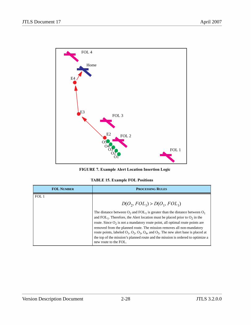
JTLS Document 17 April 2007
FIGURE 7. Example Alert Location Insertion Logic
TABLE 15. Example FOL Positions
FOL NUMBER PROCESSING RULES
FOL 1
The distance between O2 and FOL1 is greater than the distance between O1
and FOL1. Therefore, the Alert location must be placed prior to O2 in the
route. Since O2 is not a mandatory route point, all optimal route points are
removed from the planned route. The mission removes all non-mandatoryroute points, labeled O1, O2, O3, O4, and O5. The new alert base is placed at
the top of the mission’s planned route and the mission is ordered to optimize anew route to the FOL.
Home
FOL 4
FOL 3
FOL 2
FOL 1
O1O2
O3O4
O5
E2
E3
E4
D O2 FOL1,( ) D O1 FOL1,( )>
Version Description Document 2-28 JTLS 3.2.0.0
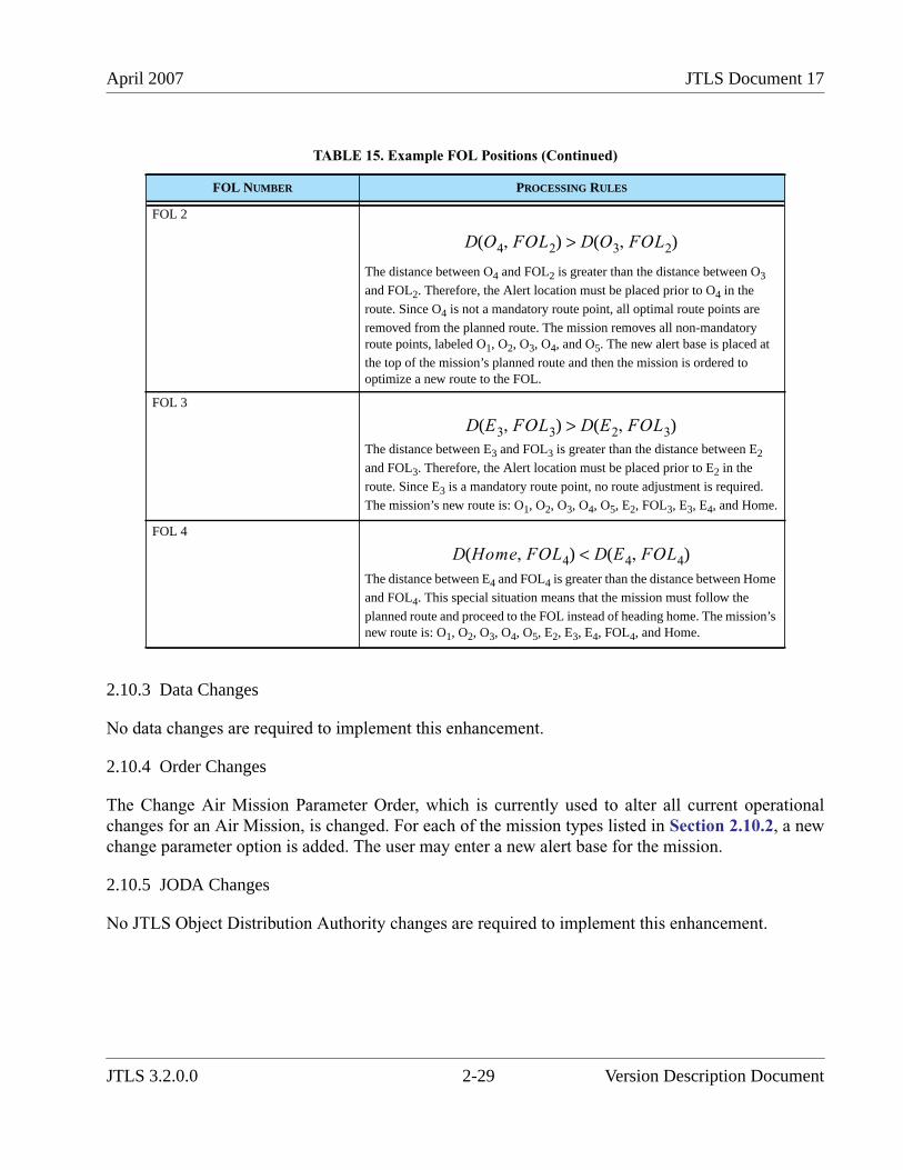
April 2007 JTLS Document 17
2.10.3 Data Changes
No data changes are required to implement this enhancement.
2.10.4 Order Changes
The Change Air Mission Parameter Order, which is currently used to alter all current operationalchanges for an Air Mission, is changed. For each of the mission types listed in Section 2.10.2, a newchange parameter option is added. The user may enter a new alert base for the mission.
2.10.5 JODA Changes
No JTLS Object Distribution Authority changes are required to implement this enhancement.
FOL 2
The distance between O4 and FOL2 is greater than the distance between O3
and FOL2. Therefore, the Alert location must be placed prior to O4 in the
route. Since O4 is not a mandatory route point, all optimal route points are
removed from the planned route. The mission removes all non-mandatoryroute points, labeled O1, O2, O3, O4, and O5. The new alert base is placed at
the top of the mission’s planned route and then the mission is ordered tooptimize a new route to the FOL.
FOL 3
The distance between E3 and FOL3 is greater than the distance between E2
and FOL3. Therefore, the Alert location must be placed prior to E2 in the
route. Since E3 is a mandatory route point, no route adjustment is required.
The mission’s new route is: O1, O2, O3, O4, O5, E2, FOL3, E3, E4, and Home.
FOL 4
The distance between E4 and FOL4 is greater than the distance between Home
and FOL4. This special situation means that the mission must follow the
planned route and proceed to the FOL instead of heading home. The mission’snew route is: O1, O2, O3, O4, O5, E2, E3, E4, FOL4, and Home.
TABLE 15. Example FOL Positions (Continued)
FOL NUMBER PROCESSING RULES
D O4 FOL2,( ) D O3 FOL2,( )>
D E3 FOL3,( ) D E2 FOL3,( )>
D Home FOL4,( ) D E4 FOL4,( )<
JTLS 3.2.0.0 2-29 Version Description Document
JTLS Document 17 April 2007
2.11 JTLS-0181 Torpedoes Follow Ships
2.11.1 Summary of Model Change Request
In previous versions, JTLS torpedoes did not update the locations of their targeted Naval Units duringtheir "flyout" after being fired. They were launched toward the perceived location of a targeted navalvessel specified by the Player. The ship’s coordinates were retained as an impact destination by theweapon and were not alterable after launch. If the targeted ship moved a sufficient distance afterlaunch, the torpedo could arrive at the impact destination after the ship has left the vicinity, resultingin a miss. The model’s representation of a real-world, sophisticated weapon needed to reflect acapability to track and intercept the ship as it moves.
This model enhancement improves the behavior of JTLS torpedoes that are launched to attackmoving Naval units. This design effectively enables real-time updating of the impact location that isretained by the fired weapon as the ship moves, and allows a torpedo to adjust its course during flightto intercept the ship in its new location.
2.11.2 Design Summary
This design involves changes in the Combat Events Program (CEP) routine that “flies” the weaponalong a course toward its specified Naval target. This software event routine individually movestargetable weapons that are represented for modeling purposes as Cruise Missile objects. Thus, theCEP represents torpedoes as slowly moving, submerged Cruise Missiles. The new capability to adjustcourse applies to all Cruise Missile representations, as well as torpedoes, which are referenced in thisdesign as missiles.
2.11.2.1 Previous Implementation
The Player initiates a Fire Missile order for the surface-to-surface missile site—onboard the ship orsubmarine in this case—and specifies a named Naval unit to attack. When the order is sent to the CEPand the target is verified to be located within range of the missile, a Fire Mission is created thatcontains the perceived location of the specified Naval unit (i.e., the impact location) and otherinformation from the order. After launch, the Cruise Missile (torpedo) proceeds toward the impactlocation. As simulation time advances, the MOVE ALONG ROUTE CRUISE MISSILE event isrepeatedly scheduled to update the missile’s position as it moves from hex to hex, according to itsspeed. During flight, the missile is subject to detection and being shot down if the appropriatecountermeasures are available and employed. Once the missile reaches the impact location asoriginally stored in the Fire Mission, the ASSESS WEAPONS DAMAGE routine calculates anydamage to the targeted ship. If no ship is present at the impact location, no damage occurs. However,a precision-guided weapon may attack other ships in the vicinity or continue its flight until it is out-of-range.
Version Description Document 2-30 JTLS 3.2.0.0

April 2007 JTLS Document 17
2.11.2.2 Logic Changes
The following logic additions to the MOVE ALONG ROUTE CRUISE MISSILE event wererequired to allow a Cruise Missile to follow a moving Naval unit.
New code was added to examine each Fire Mission as it is processed to determine whether thetargetable weapon is precision-guided and the specified target is a Naval unit. If both conditions aretrue, the Fire Mission’s impact location is reset to match the current (actual, not perceived) location ofthe targeted Naval unit. Whether the ship has actually changed location after the missile launched isimmaterial. The ship’s previous location is not known in this context and therefore cannot bedetermined if the ship has actually moved. Next, the missile’s maximum time of flight (endurance) iscalculated and considers its speed and the time elapsed since the missile’s launch. If this elapsed timeexceeds the missile’s endurance, the missile is destroyed and the Fire Mission is terminated.Otherwise, the missile is permitted to continue its flight. Existing logic calculates the new bearing tothe impact location, which now considers the updated ship location, and then determines where themissile should move next. In this manner, each time the missile plans a hex move, it is subject to aposition update event, and a new course is applied according to the actual location of the targetedship, allowing pursuit until the missile’s range as represented by its endurance is exceeded. When theimpact location is reached, the ASSESS WEAPON DAMAGE event uses the Fire Mission’s updatedimpact location to determine whether damage occurs.
Now, the targeted ship’s perceived location at the time the Player tries to fire an SSM or Torpedocould be radically different from the targeted ship’s actual game location. It might have been quite awhile since its last detection by the firing side. Therefore, to prevent Players from using missilefirings as "search tools", the model will not allow an SSM firing at a ship or submarine unless thetargeted vessel is actually at the perceived location at the time of firing.
A Great Circle distance calculation between the missile’s launch latitude/longitude coordinates andits current location coordinates is insufficient to determine whether the missile’s range has beenexceeded. The missile may perform several course adjustments while pursuing a rapidly movingnaval vessel within the Great Circle distance and continue beyond its true range. Furthermore,determining the actual distance traversed is not possible because the Fire Mission does not retain themissile’s previous location information. Instead, each position update within the MOVE ALONGROUTE CRUISE MISSILE event employs look-ahead logic to determine the next location to movethe missile. The missile’s previous location is irrelevant. For these two reasons, the endurancecalculation is used as a surrogate for the actual distance traveled.
2.11.3 Data Changes
No data changes are required to implement this enhancement.
2.11.4 Order Changes
No order changes are required to implement this enhancement.
JTLS 3.2.0.0 2-31 Version Description Document
JTLS Document 17 April 2007
2.11.5 JODA Changes
No JTLS Object Distribution Authority changes are required to implement this enhancement.
2.12 JTLS-0224 Build Railroads, Pipelines, and IADs
2.12.1 Summary of Model Change Request
This ECP addresses a requirement to provide the JTLS user capability to build railroads and pipelinesusing the Graphical Database Program (GDP).
The features of this model enhancement is are included in the more comprehensive design, entitledJTLS-0378 Graphical Database Program, also implemented as part of JTLS 3.2.0.0.
2.12.2 Design Summary
The logic used to implement this capability is included in JTLS-0378 Graphical DatabaseProgram.
2.12.3 Data Changes
No data changes are required to implement this enhancement.
2.12.4 Order Changes
No data changes are required to implement this enhancement.
2.12.5 JODA Changes
The JTLS Object Distribution Authority changes required to implement this capability are included inJTLS-0378 Graphical Database Program.
2.13 JTLS-0264 SLP-SC Specific Name Uniqueness
2.13.1 Summary of Model Change Request
Previously, a problem existed when a new JTLS Supply Category was created by cascade duplicatinga similar supply category. The duplication of SLP Supply Category Names caused confusion whenthe supply category was referenced by its SLP-specific supply category name in Logistic reports,Periodic reports, IMT supply screens, the OPM and other data reporting tools. Within a specific SLP,the SLP-specific supply category name must be unique.
Version Description Document 2-32 JTLS 3.2.0.0
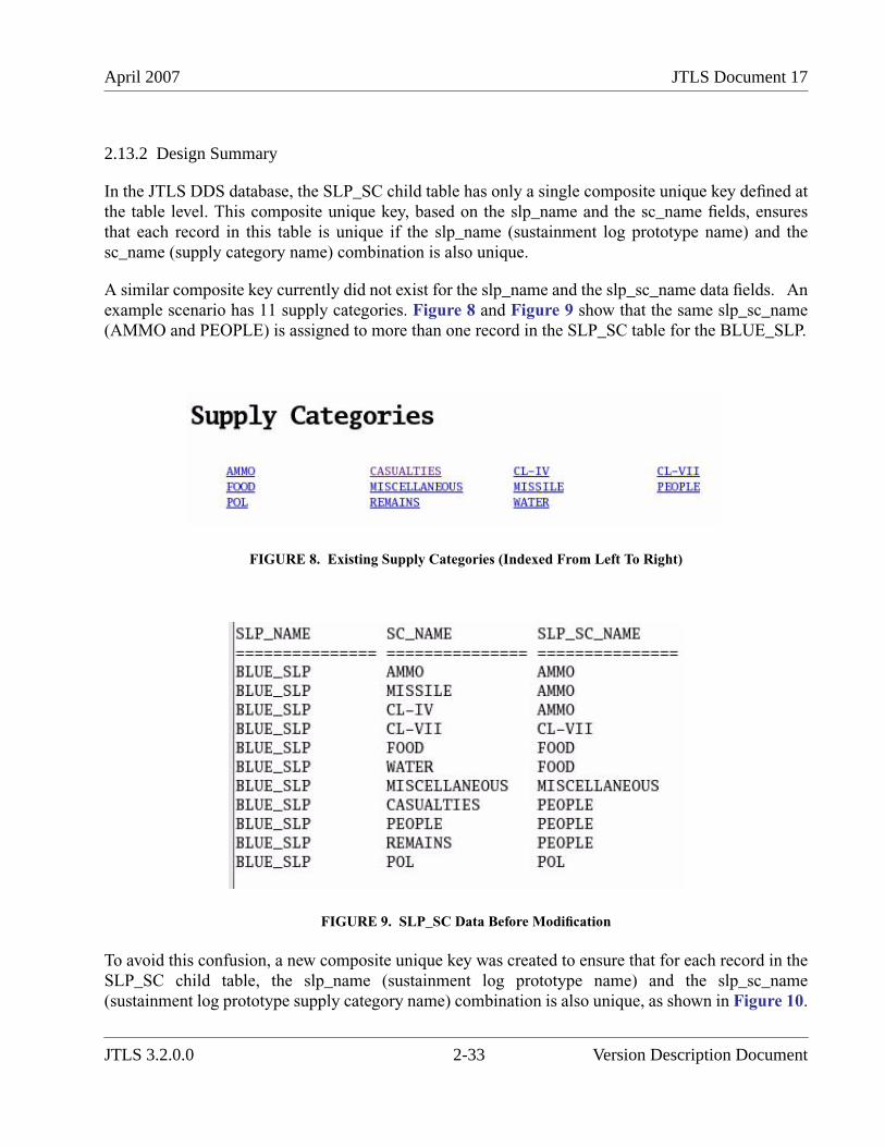
April 2007 JTLS Document 17
2.13.2 Design Summary
In the JTLS DDS database, the SLP_SC child table has only a single composite unique key defined atthe table level. This composite unique key, based on the slp_name and the sc_name fields, ensuresthat each record in this table is unique if the slp_name (sustainment log prototype name) and thesc_name (supply category name) combination is also unique.
A similar composite key currently did not exist for the slp_name and the slp_sc_name data fields. Anexample scenario has 11 supply categories. Figure 8 and Figure 9 show that the same slp_sc_name(AMMO and PEOPLE) is assigned to more than one record in the SLP_SC table for the BLUE_SLP.
FIGURE 8. Existing Supply Categories (Indexed From Left To Right)
FIGURE 9. SLP_SC Data Before Modification
To avoid this confusion, a new composite unique key was created to ensure that for each record in theSLP_SC child table, the slp_name (sustainment log prototype name) and the slp_sc_name(sustainment log prototype supply category name) combination is also unique, as shown in Figure 10.
JTLS 3.2.0.0 2-33 Version Description Document
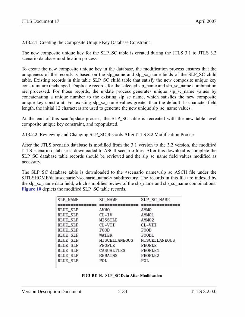
JTLS Document 17 April 2007
2.13.2.1 Creating the Composite Unique Key Database Constraint
The new composite unique key for the SLP_SC table is created during the JTLS 3.1 to JTLS 3.2scenario database modification process.
To create the new composite unique key in the database, the modification process ensures that theuniqueness of the records is based on the slp_name and slp_sc_name fields of the SLP_SC childtable. Existing records in this table SLP_SC child table that satisfy the new composite unique keyconstraint are unchanged. Duplicate records for the selected slp_name and slp_sc_name combinationare processed. For those records, the update process generates unique slp_sc_name values byconcatenating a unique number to the existing slp_sc_name, which satisfies the new compositeunique key constraint. For existing slp_sc_name values greater than the default 15-character fieldlength, the initial 12 characters are used to generate the new unique slp_sc_name values.
At the end of this scan/update process, the SLP_SC table is recreated with the new table levelcomposite unique key constraint, and repopulated.
2.13.2.2 Reviewing and Changing SLP_SC Records After JTLS 3.2 Modification Process
After the JTLS scenario database is modified from the 3.1 version to the 3.2 version, the modifiedJTLS scenario database is downloaded to ASCII scenario files. After this download is complete theSLP_SC database table records should be reviewed and the slp_sc_name field values modified asnecessary.
The SLP_SC database table is downloaded to the <scenario_name>.slp_sc ASCII file under the$JTLSHOME/data/scenario/<scenario_name>/ subdirectory. The records in this file are indexed bythe slp_sc_name data field, which simplifies review of the slp_name and slp_sc_name combinations.Figure 10 depicts the modified SLP_SC table records.
FIGURE 10. SLP_SC Data After Modification
Version Description Document 2-34 JTLS 3.2.0.0
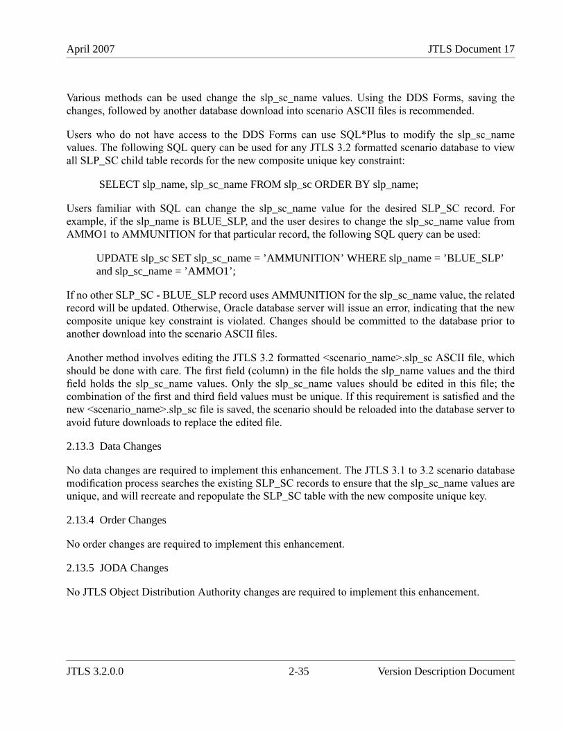
April 2007 JTLS Document 17
Various methods can be used change the slp_sc_name values. Using the DDS Forms, saving thechanges, followed by another database download into scenario ASCII files is recommended.
Users who do not have access to the DDS Forms can use SQL*Plus to modify the slp_sc_namevalues. The following SQL query can be used for any JTLS 3.2 formatted scenario database to viewall SLP_SC child table records for the new composite unique key constraint:
SELECT slp_name, slp_sc_name FROM slp_sc ORDER BY slp_name;
Users familiar with SQL can change the slp_sc_name value for the desired SLP_SC record. Forexample, if the slp_name is BLUE_SLP, and the user desires to change the slp_sc_name value fromAMMO1 to AMMUNITION for that particular record, the following SQL query can be used:
UPDATE slp_sc SET slp_sc_name = ’AMMUNITION’ WHERE slp_name = ’BLUE_SLP’and slp_sc_name = ’AMMO1’;
If no other SLP_SC - BLUE_SLP record uses AMMUNITION for the slp_sc_name value, the relatedrecord will be updated. Otherwise, Oracle database server will issue an error, indicating that the newcomposite unique key constraint is violated. Changes should be committed to the database prior toanother download into the scenario ASCII files.
Another method involves editing the JTLS 3.2 formatted <scenario_name>.slp_sc ASCII file, whichshould be done with care. The first field (column) in the file holds the slp_name values and the thirdfield holds the slp_sc_name values. Only the slp_sc_name values should be edited in this file; thecombination of the first and third field values must be unique. If this requirement is satisfied and thenew <scenario_name>.slp_sc file is saved, the scenario should be reloaded into the database server toavoid future downloads to replace the edited file.
2.13.3 Data Changes
No data changes are required to implement this enhancement. The JTLS 3.1 to 3.2 scenario databasemodification process searches the existing SLP_SC records to ensure that the slp_sc_name values areunique, and will recreate and repopulate the SLP_SC table with the new composite unique key.
2.13.4 Order Changes
No order changes are required to implement this enhancement.
2.13.5 JODA Changes
No JTLS Object Distribution Authority changes are required to implement this enhancement.
JTLS 3.2.0.0 2-35 Version Description Document
JTLS Document 17 April 2007
2.14 JTLS-0300 Magic Move To Offboard Location Formation
2.14.1 Summary of Model Change Request
The JTLS Magic Move capability allows the Controller three methods to instantaneously relocate aunit. A Controller can specify a set of latitude/longitude coordinates, specify a Formation of ships onwhich the land unit is to embark, or, in the case of a high-resolution unit (HRU), specify a unit towhich the HRU is to link up. However, a Ground unit could not be magically embarked on aFormation not in the theater of operations. Also, the Controller needed to specify latitude/longitudecoordinates as well as an Airbase (or Ship) name in order to move a Squadron to a new base, insteadof simply entering the new base’s name.
These improvements provide the JTLS Controller additional options to re-deploy forces moreefficiently. The Controller can:
• Permit a Ground unit to be embarked on an off-map Formation of ship(s).
• Enable a Squadron to be relocated to a specified home base, on the map or off the map.
2.14.2 Design Summary
This enhancement involves changes to the Magic Move (MM) order panel and the associated routineswithin the Combat Events Program (CEP).
2.14.2.1 Logic Changes
The MM processing code is modified to permit a Ground unit to be Magic Moved to a Formation thatis out-of-theater (off the game board). Specifically, new logic is added to the routine that completesthe Magic Move processing. When a Magic Move order to an off-map Formation is identified, someof the processing code required for on-map Magic Moves is bypassed. For example, there are nohexes are defined off the map; all code that associates the unit with a hex at its new location isbypassed. Such an attempted association would cause an invalid set owner pointer game crash.
2.14.2.2 New Order Constraints
A Squadron Home Base entry is added to the MM order panel. This field allows the Controller toexactly specify the name of a new home base (and, by extension, the location) for the Squadron. Newpanel constraints are implemented to:
• Reject a home base that belongs to a different Force Side than the Squadron to be MagicMoved.
• Reject a home base if the unit to be moved is not a Squadron.
• Reject a home base if it is not an Airbase, Naval unit (ship), or Forward Air Refueling Point(FARP).
Version Description Document 2-36 JTLS 3.2.0.0
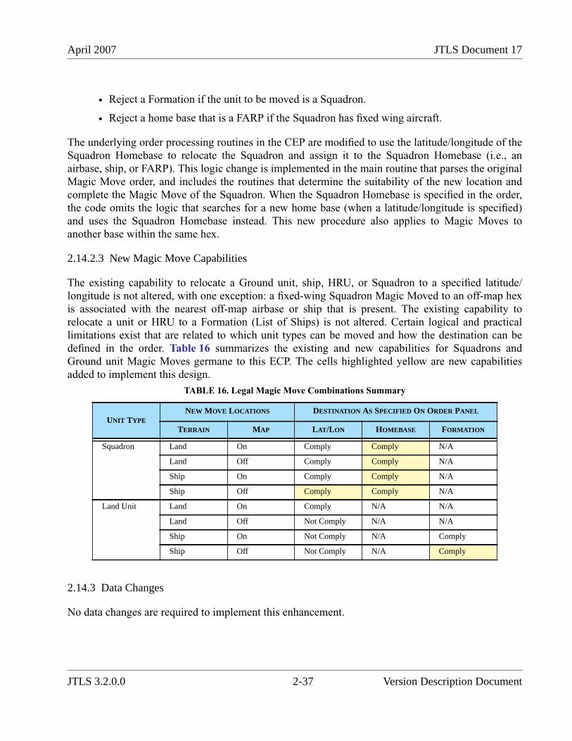
April 2007 JTLS Document 17
• Reject a Formation if the unit to be moved is a Squadron.
• Reject a home base that is a FARP if the Squadron has fixed wing aircraft.
The underlying order processing routines in the CEP are modified to use the latitude/longitude of theSquadron Homebase to relocate the Squadron and assign it to the Squadron Homebase (i.e., anairbase, ship, or FARP). This logic change is implemented in the main routine that parses the originalMagic Move order, and includes the routines that determine the suitability of the new location andcomplete the Magic Move of the Squadron. When the Squadron Homebase is specified in the order,the code omits the logic that searches for a new home base (when a latitude/longitude is specified)and uses the Squadron Homebase instead. This new procedure also applies to Magic Moves toanother base within the same hex.
2.14.2.3 New Magic Move Capabilities
The existing capability to relocate a Ground unit, ship, HRU, or Squadron to a specified latitude/longitude is not altered, with one exception: a fixed-wing Squadron Magic Moved to an off-map hexis associated with the nearest off-map airbase or ship that is present. The existing capability torelocate a unit or HRU to a Formation (List of Ships) is not altered. Certain logical and practicallimitations exist that are related to which unit types can be moved and how the destination can bedefined in the order. Table 16 summarizes the existing and new capabilities for Squadrons andGround unit Magic Moves germane to this ECP. The cells highlighted yellow are new capabilitiesadded to implement this design.
2.14.3 Data Changes
No data changes are required to implement this enhancement.
TABLE 16. Legal Magic Move Combinations Summary
UNIT TYPENEW MOVE LOCATIONS DESTINATION AS SPECIFIED ON ORDER PANEL
TERRAIN MAP LAT/LON HOMEBASE FORMATION
Squadron Land On Comply Comply N/A
Land Off Comply Comply N/A
Ship On Comply Comply N/A
Ship Off Comply Comply N/A
Land Unit Land On Comply N/A N/A
Land Off Not Comply N/A N/A
Ship On Not Comply N/A Comply
Ship Off Not Comply N/A Comply
JTLS 3.2.0.0 2-37 Version Description Document
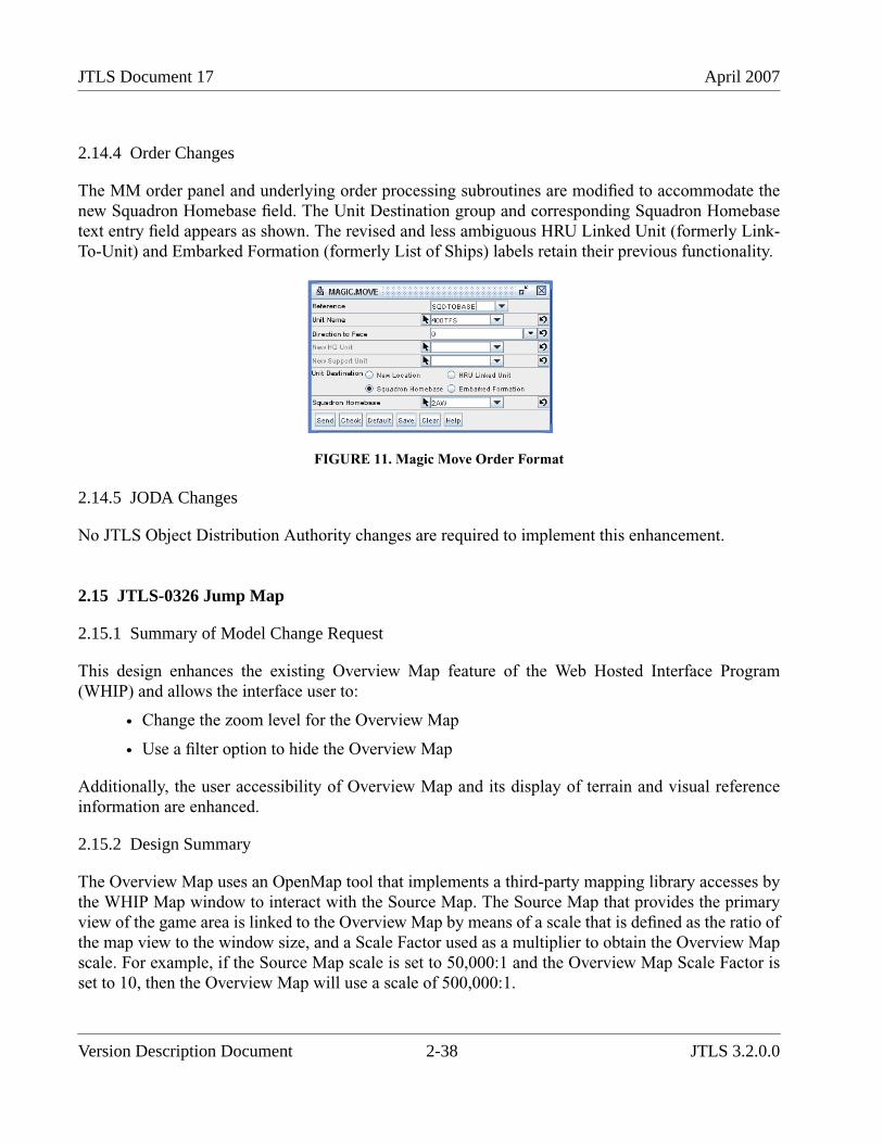
JTLS Document 17 April 2007
2.14.4 Order Changes
The MM order panel and underlying order processing subroutines are modified to accommodate thenew Squadron Homebase field. The Unit Destination group and corresponding Squadron Homebasetext entry field appears as shown. The revised and less ambiguous HRU Linked Unit (formerly Link-To-Unit) and Embarked Formation (formerly List of Ships) labels retain their previous functionality.
FIGURE 11. Magic Move Order Format
2.14.5 JODA Changes
No JTLS Object Distribution Authority changes are required to implement this enhancement.
2.15 JTLS-0326 Jump Map
2.15.1 Summary of Model Change Request
This design enhances the existing Overview Map feature of the Web Hosted Interface Program(WHIP) and allows the interface user to:
• Change the zoom level for the Overview Map
• Use a filter option to hide the Overview Map
Additionally, the user accessibility of Overview Map and its display of terrain and visual referenceinformation are enhanced.
2.15.2 Design Summary
The Overview Map uses an OpenMap tool that implements a third-party mapping library accesses bythe WHIP Map window to interact with the Source Map. The Source Map that provides the primaryview of the game area is linked to the Overview Map by means of a scale that is defined as the ratio ofthe map view to the window size, and a Scale Factor used as a multiplier to obtain the Overview Mapscale. For example, if the Source Map scale is set to 50,000:1 and the Overview Map Scale Factor isset to 10, then the Overview Map will use a scale of 500,000:1.
Version Description Document 2-38 JTLS 3.2.0.0
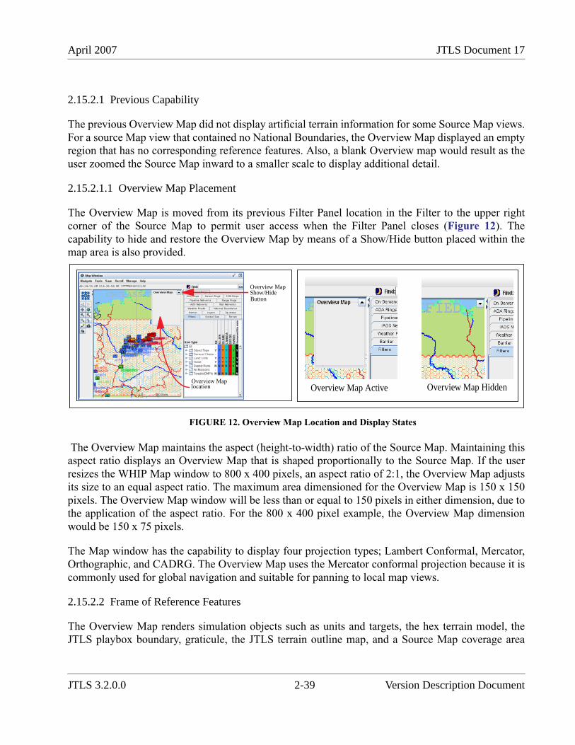
April 2007 JTLS Document 17
2.15.2.1 Previous Capability
The previous Overview Map did not display artificial terrain information for some Source Map views.For a source Map view that contained no National Boundaries, the Overview Map displayed an emptyregion that has no corresponding reference features. Also, a blank Overview map would result as theuser zoomed the Source Map inward to a smaller scale to display additional detail.
2.15.2.1.1 Overview Map Placement
The Overview Map is moved from its previous Filter Panel location in the Filter to the upper rightcorner of the Source Map to permit user access when the Filter Panel closes (Figure 12). Thecapability to hide and restore the Overview Map by means of a Show/Hide button placed within themap area is also provided.
FIGURE 12. Overview Map Location and Display States
The Overview Map maintains the aspect (height-to-width) ratio of the Source Map. Maintaining thisaspect ratio displays an Overview Map that is shaped proportionally to the Source Map. If the userresizes the WHIP Map window to 800 x 400 pixels, an aspect ratio of 2:1, the Overview Map adjustsits size to an equal aspect ratio. The maximum area dimensioned for the Overview Map is 150 x 150pixels. The Overview Map window will be less than or equal to 150 pixels in either dimension, due tothe application of the aspect ratio. For the 800 x 400 pixel example, the Overview Map dimensionwould be 150 x 75 pixels.
The Map window has the capability to display four projection types; Lambert Conformal, Mercator,Orthographic, and CADRG. The Overview Map uses the Mercator conformal projection because it iscommonly used for global navigation and suitable for panning to local map views.
2.15.2.2 Frame of Reference Features
The Overview Map renders simulation objects such as units and targets, the hex terrain model, theJTLS playbox boundary, graticule, the JTLS terrain outline map, and a Source Map coverage area
Show/HideButton
Overview Map
Overview Maplocation Overview Map Active Overview Map Hidden
JTLS 3.2.0.0 2-39 Version Description Document
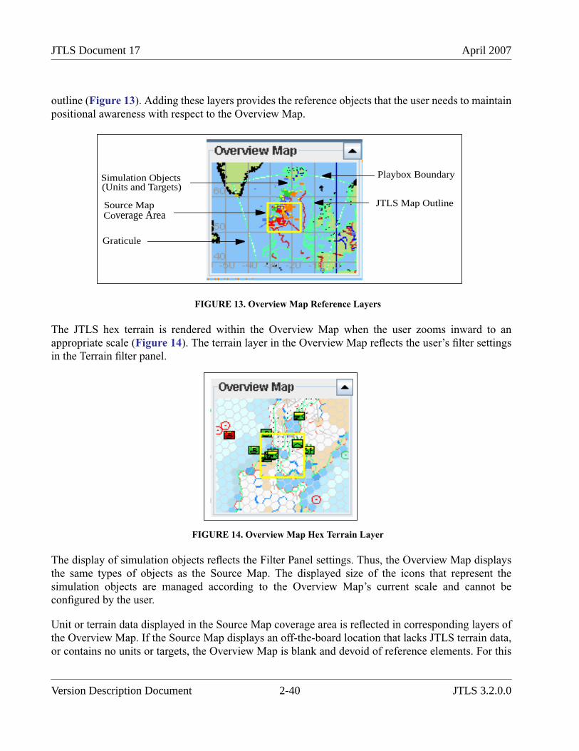
JTLS Document 17 April 2007
outline (Figure 13). Adding these layers provides the reference objects that the user needs to maintainpositional awareness with respect to the Overview Map.
FIGURE 13. Overview Map Reference Layers
The JTLS hex terrain is rendered within the Overview Map when the user zooms inward to anappropriate scale (Figure 14). The terrain layer in the Overview Map reflects the user’s filter settingsin the Terrain filter panel.
FIGURE 14. Overview Map Hex Terrain Layer
The display of simulation objects reflects the Filter Panel settings. Thus, the Overview Map displaysthe same types of objects as the Source Map. The displayed size of the icons that represent thesimulation objects are managed according to the Overview Map’s current scale and cannot beconfigured by the user.
Unit or terrain data displayed in the Source Map coverage area is reflected in corresponding layers ofthe Overview Map. If the Source Map displays an off-the-board location that lacks JTLS terrain data,or contains no units or targets, the Overview Map is blank and devoid of reference elements. For this
Playbox Boundary
JTLS Map Outline
Simulation Objects(Units and Targets)
Graticule
Source MapCoverage Area
Version Description Document 2-40 JTLS 3.2.0.0
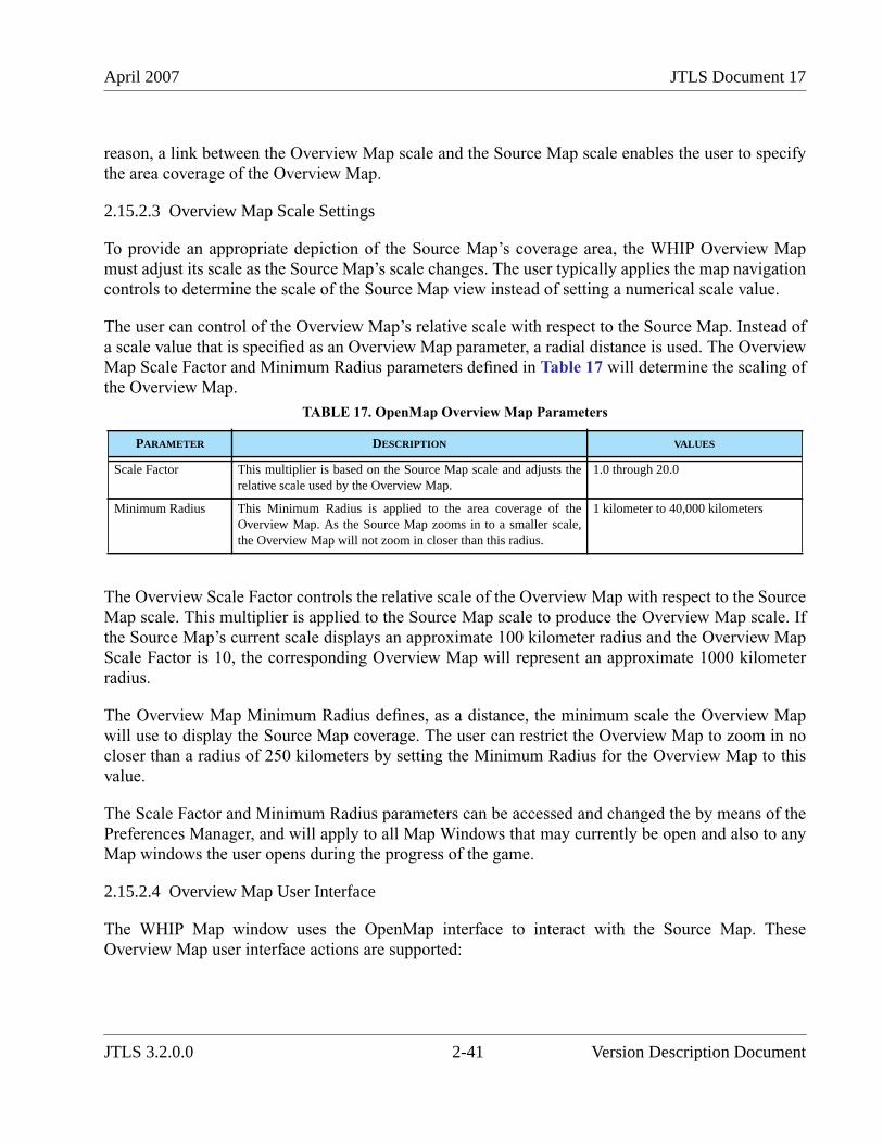
April 2007 JTLS Document 17
reason, a link between the Overview Map scale and the Source Map scale enables the user to specifythe area coverage of the Overview Map.
2.15.2.3 Overview Map Scale Settings
To provide an appropriate depiction of the Source Map’s coverage area, the WHIP Overview Mapmust adjust its scale as the Source Map’s scale changes. The user typically applies the map navigationcontrols to determine the scale of the Source Map view instead of setting a numerical scale value.
The user can control of the Overview Map’s relative scale with respect to the Source Map. Instead ofa scale value that is specified as an Overview Map parameter, a radial distance is used. The OverviewMap Scale Factor and Minimum Radius parameters defined in Table 17 will determine the scaling ofthe Overview Map.
The Overview Scale Factor controls the relative scale of the Overview Map with respect to the SourceMap scale. This multiplier is applied to the Source Map scale to produce the Overview Map scale. Ifthe Source Map’s current scale displays an approximate 100 kilometer radius and the Overview MapScale Factor is 10, the corresponding Overview Map will represent an approximate 1000 kilometerradius.
The Overview Map Minimum Radius defines, as a distance, the minimum scale the Overview Mapwill use to display the Source Map coverage. The user can restrict the Overview Map to zoom in nocloser than a radius of 250 kilometers by setting the Minimum Radius for the Overview Map to thisvalue.
The Scale Factor and Minimum Radius parameters can be accessed and changed the by means of thePreferences Manager, and will apply to all Map Windows that may currently be open and also to anyMap windows the user opens during the progress of the game.
2.15.2.4 Overview Map User Interface
The WHIP Map window uses the OpenMap interface to interact with the Source Map. TheseOverview Map user interface actions are supported:
TABLE 17. OpenMap Overview Map Parameters
PARAMETER DESCRIPTION VALUES
Scale Factor This multiplier is based on the Source Map scale and adjusts therelative scale used by the Overview Map.
1.0 through 20.0
Minimum Radius This Minimum Radius is applied to the area coverage of theOverview Map. As the Source Map zooms in to a smaller scale,the Overview Map will not zoom in closer than this radius.
1 kilometer to 40,000 kilometers
JTLS 3.2.0.0 2-41 Version Description Document
JTLS Document 17 April 2007
• Center Map. The center of the Source Map can be changed by performing a mouse click onthe Overview Map at the desired location. The Overview Map and the Source Map changeto reflect the new location.
• Zoom In/Out. The scale of the Source Map by can be changed by performing a mouse dragaction to define a rectangle that represents a larger or smaller coverage area. The SourceMap change to reflect the new scale.
The Source Map’s coverage is depicted on the Overview Map as a yellow polygon. Due to differencesamong the projection types, the Source Map’s coverage area may appear as a vertically orientedrectangle or a slightly distorted rectangle, due to the various plane representations of the sphericalterrain surface.
The scale Factor, Radius, and Font Size of the Overview Map can be changed by the WHIP user.Options to do this are under the WHIP top menu bar "Tools" selection, "Preferences" option.
2.15.3 Data Changes
No data changes are required to implement this enhancement.
2.15.4 Order Changes
No order changes are required to implement this enhancement.
2.15.5 JODA Changes
No JTLS Object Distribution Authority changes are required to implement this enhancement.
2.16 JTLS-0340 JTLS Message Forwarding
2.16.1 Summary of Model Change Request
Previous JTLS versions that did not support the Web-enabled capability allowed a Message ProcessorProgram (MPP) user to direct messages received by the MPP to be automatically forwarded to aspecific e-mail address. This capability was used to automatically deliver selected certain messagetypes to real-world Command, Control, Communication, Computer, and Intelligence (C4I) systems.
The MPP capability to forward received messages to a configured C4I e-mail account was lost withthe implementation of the Web-hosted simulation, primarily because the WHIP-based MessageProcessor Program does not actually receive messages. Instead, this component requests theExtensible Markup Language Message Service (XMS) data representation for only the messages thatsatisfy its current retrieval constraints. As a user modifies these constraints, the XMS serves and re-serves the messages for each request.
Version Description Document 2-42 JTLS 3.2.0.0
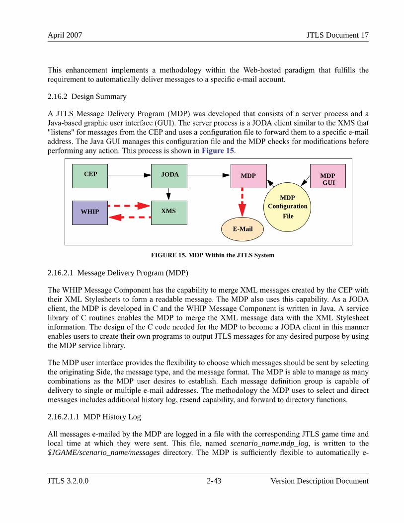
April 2007 JTLS Document 17
This enhancement implements a methodology within the Web-hosted paradigm that fulfills therequirement to automatically deliver messages to a specific e-mail account.
2.16.2 Design Summary
A JTLS Message Delivery Program (MDP) was developed that consists of a server process and aJava-based graphic user interface (GUI). The server process is a JODA client similar to the XMS that"listens" for messages from the CEP and uses a configuration file to forward them to a specific e-mailaddress. The Java GUI manages this configuration file and the MDP checks for modifications beforeperforming any action. This process is shown in Figure 15.
FIGURE 15. MDP Within the JTLS System
2.16.2.1 Message Delivery Program (MDP)
The WHIP Message Component has the capability to merge XML messages created by the CEP withtheir XML Stylesheets to form a readable message. The MDP also uses this capability. As a JODAclient, the MDP is developed in C and the WHIP Message Component is written in Java. A servicelibrary of C routines enables the MDP to merge the XML message data with the XML Stylesheetinformation. The design of the C code needed for the MDP to become a JODA client in this mannerenables users to create their own programs to output JTLS messages for any desired purpose by usingthe MDP service library.
The MDP user interface provides the flexibility to choose which messages should be sent by selectingthe originating Side, the message type, and the message format. The MDP is able to manage as manycombinations as the MDP user desires to establish. Each message definition group is capable ofdelivery to single or multiple e-mail addresses. The methodology the MDP uses to select and directmessages includes additional history log, resend capability, and forward to directory functions.
2.16.2.1.1 MDP History Log
All messages e-mailed by the MDP are logged in a file with the corresponding JTLS game time andlocal time at which they were sent. This file, named scenario_name.mdp_log, is written to the$JGAME/scenario_name/messages directory. The MDP is sufficiently flexible to automatically e-
CEP JODA MDP
MDPConfiguration
File
MDPGUI
XMSWHIP
JTLS 3.2.0.0 2-43 Version Description Document
JTLS Document 17 April 2007
mail any combination of messages to several e-mail locations simultaneously. Therefore, the user canrely on a single instance of the MDP. For this reason, the file naming convention does not requireincluding a specific MDP client name.
Besides listing which messages have been e-mailed, the MDP history log file includes other eventinformation, such as checkpoints, restarts, lost JODA communication, and delivery errors. Lost JODAcommunication is especially important because the JODA does not save JTLS messages. The CEPwrites the XML version of a message to a data file, then passes a message notification to the JODA.As JODA clients, the XMS and the MDP register to receive these notifications. If the MDP crashesfor any reason, it may not recognize some of these notifications and their associated messages. TheMDP history log will assist Technical Control to manage this situation.
The .mdf_log file is cleared each instance a scenario is started from Checkpoint 0000. Like the samescheme used for the JTLS Critical Input file, a single log file is recommended to assist locatingmanaging message handling errors, instead of a log file for each checkpoint.
2.16.2.1.2 MDP Resend Capability
The MDP includes re-send message capability that is managed by the MDP interface user. Thiscapability may be used for several reasons. For example, if e-mail service fails and messages are lost,the MDP can be deployed to re-consider and re-send a group of messages.
The MDP uses the interface to create a scenario_name.mdg_resend file within same directory as the.mdp_log file. This file contains the JTLS unique scenario message identification codes for themessages that must be resent. The MDP continuously polls and reads this file, and handles itsmessage contents in the same manner as it responds to the message existence notifications from theJODA. Thus, if the connection to the JODA is lost, the MDP can examine and evaluate any messagesassociated with missed notifications.
After reading the contents of this file, the MDP moves and rename the file to a reserved mdpsubdirectory that is located under the $JGAME/scenario_name/messages directory. The text of thenew file name is the current system time during which the MDP processes the file, appended to the.mdg_resend extension. The GUI user is able to create a new MDP resend file as needed. The MDPcontinues to poll for this file, and the resend process is repeated when the MDP locates the file.
2.16.2.1.3 Forward To Directory
The MDP has the capability to forward messages to a directory on the file system. This feature isuseful for debugging and redundancy if the MDP machine fails to send e-mail or if messages must bedelivered by other means besides e-mail. Some C4I systems are able to poll a directory to search formessage files. The forwarding feature allows the MDP to also fulfill this capability. The interface userwill have the ability to specify which messages should be saved to a file system directory as well as anunlimited number of save directories.
Version Description Document 2-44 JTLS 3.2.0.0
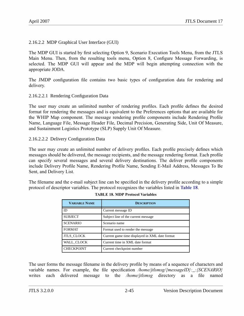
April 2007 JTLS Document 17
2.16.2.2 MDP Graphical User Interface (GUI)
The MDP GUI is started by first selecting Option 9, Scenario Execution Tools Menu, from the JTLSMain Menu. Then, from the resulting tools menu, Option 8, Configure Message Forwarding, isselected. The MDP GUI will appear and the MDP will begin attempting connection with theappropriate JODA.
The JMDP configuration file contains two basic types of configuration data for rendering anddelivery.
2.16.2.2.1 Rendering Configuration Data
The user may create an unlimited number of rendering profiles. Each profile defines the desiredformat for rendering the messages and is equivalent to the Preferences options that are available forthe WHIP Map component. The message rendering profile components include Rendering ProfileName, Language File, Message Header File, Decimal Precision, Generating Side, Unit Of Measure,and Sustainment Logistics Prototype (SLP) Supply Unit Of Measure.
2.16.2.2.2 Delivery Configuration Data
The user may create an unlimited number of delivery profiles. Each profile precisely defines whichmessages should be delivered, the message recipients, and the message rendering format. Each profilecan specify several messages and several delivery destinations. The deliver profile componentsinclude Delivery Profile Name, Rendering Profile Name, Sending E-Mail Address, Messages To BeSent, and Delivery List.
The filename and the e-mail subject line can be specified in the delivery profile according to a simpleprotocol of descriptor variables. The protocol recognizes the variables listed in Table 18.
The user forms the message filename in the delivery profile by means of a sequence of characters andvariable names. For example, the file specification /home/jtlsmsg/{messageID}:_:{SCENARIO}writes each delivered message to the /home/jtlsmsg directory as a file named
TABLE 18. MDP Protocol Variables
VARIABLE NAME DESCRIPTION
ID Current message ID
SUBJECT Subject line of the current message
SCENARIO Scenario name
FORMAT Format used to render the message
JTLS_CLOCK Current game time displayed in XML date format
WALL_CLOCK Current time in XML date format
CHECKPOINT Current checkpoint number
JTLS 3.2.0.0 2-45 Version Description Document
JTLS Document 17 April 2007
MessageID_ScenarioName. A message 000000235.xml from the scenario Webtest32 that satisfies thedelivery profile constraints will be written as a file named 235_webtest32. If the delivery profilespecifies the filename to be /home/jtlsmsg/{ID}:.:{JTLS_CLOCK}, the combined path and filenamewill be /home/jtlsmsg/235.301600JAN07.
The e-mail subject line provides the same functionality. Within the delivery profile, the user indicatesthe destination e-mail address and the subject description for the e-mail message. If the subject isspecified as {SUBJECT}, the message source is the subject of the e-mail. For example, the message000000235.xml is a Type 4105 (Cannot Comply) message from Unit 1BD. The subject of the e-mailis written as: Log Order received, 1BD, Cannot Comply. The format of this subject is derived directlyfrom the language file selected within the rendering profile. If the user specifies the e-mail subject as{SUBJECT}:at:{JTLS_CLOCK}, The format of the e-mail subject line is: Log Order received, 1BD,Cannot Comply at 01600JAN07.
2.16.2.2.3 MDP Event Log
The MDP logs events that occur while the program executes. This log can be viewed from the GUI.The MDP user can monitor the progress of the delivery instructions on a real-time basis. From thisEvent Log interface, the user can easily create the resend file.
2.16.2.3 JTLS Message Rendering Library
The MDP includes a reusable libjtlsmsg C library for rendering JTLS messages according to criteriaspecified in the rendering profiles panel, which will be used to configure this library. The libraryprovides a means to configure the rendering of messages and a handler that will parse XML code to arendering profile structure. Due the implementation of this feature, users can develop customizedprograms and interfaces to render JTLS messages.
2.16.3 Data Changes
No data changes are required to implement this enhancement.
To allow rendering library access, the Game Start Day, Start Month, and Start Year data parametersembedded in the JTLS general global data file are relocated. This file begins with the GameClassification and the database version number, then lists the Game Start Month, Start Day, and StartYear. While updating a database from any previous version, the database conversion process writesthese existing data to the required new position in the data file.
2.16.4 Order Changes
No order changes are required to implement this enhancement. Due to this design, the JTLSDuplicate Message order is obsolete. However, this capability is retained in the model because it isthoroughly tested and does not consume significant resources.
Version Description Document 2-46 JTLS 3.2.0.0
April 2007 JTLS Document 17
2.16.5 JODA Changes
No JTLS Object Distribution Authority changes are required to implement this enhancement.
2.17 JTLS-0347 Units In Combat Flag
2.17.1 Summary of Model Change Request
This enhancement supports a requirement to visually indicate the combat status of each unit in thegame on the WHIP Command Hierarchy component.
2.17.2 Design Summary
The combat status of a unit is a Boolean value; the unit is either in combat or not in combat. A redcolored background highlight for the name field of each unit on the Command tree is implemented asa flag that indicates a unit is in combat. This display option was chosen as the least confusing andmost easily identifiable visual indicator.
2.17.3 Data Changes
No data changes are required to implement this enhancement.
2.17.4 Order Changes
No order changes are required to implement this enhancement.
2.17.5 JODA Changes
No JTLS Object Distribution Authority changes are required to implement this enhancement.
2.18 JTLS-0349 Command Hierarchy Display Management
2.18.1 Summary of Model Change Request
This ECP defines a requirement to allow the user to hide or display portions of the WHIP CommandHierarchy. This feature enhances the functionality of this interface tool to permit the user to displayonly those units that are of interest in the Command Hierarchy window. This changes applies only tothe Command Hierarchy window, not to the Logistics Hierarchy window.
JTLS 3.2.0.0 2-47 Version Description Document
JTLS Document 17 April 2007
2.18.2 Design Summary
Managing the Command Hierarchy display structure is accomplished by providing the user withoptions to selectively display or hide units within the Command Hierarchy window. Unit symbols tobe displayed or hidden are simultaneously visible during the unit selection process.
The Command Hierarchy window support two modes of operation, a Display Mode and a PruneMode. The Display Mode presents the command structure with the hidden units removed. The PruneMode displays each unit symbol in the structure with an adjacent checkbox that indicates the displaystatus of the unit.
The content of this checkbox indicates three states:
• A check symbol indicates that a unit will be displayed.
• An empty check box indicates that the unit will be hidden and not displayed.
• A partial checked state indicates that the unit has subordinate units in both the displayed andhidden states. The checkbox contains a hyphen character (-) to indicate this display status.
In the Prune mode, the user may toggle the state of a unit between hidden or displayed states byperforming a left click on a selected unit symbol of interest. The display state of this unit and allsubordinates is changed according to these rules:
• The state of a displayed unit and each subordinate is changed to hidden.
• The state of a hidden unit and each subordinate is changed to displayed.
• The state of a partial unit and each subordinate is changed to displayed.
Version Description Document 2-48 JTLS 3.2.0.0

April 2007 JTLS Document 17
Figure 16 depicts the Command Hierarchy window displayed in the Prune Mode.
FIGURE 16. Prune Mode Example
A menu bar is added to the Command Hierarchy to provide access to the new user interface featuresdescribed in Table 19. This menu bar is accessed by clicking on the "Configure" selection.
TABLE 19. New Command Hierarchy User Interface Features
FEATURE ACTIVATION DESCRIPTION
Display Mode Configure > Display Modemenu item
Display the Command Hierarchy withselected units visible and unselectedunits hidden.
Prune Mode Configure > Prune Modemenu item
Display all units with check boxes toallow the user to select which unitsshould be displayed.
Reset Tree Configure > Reset Treemenu item
Reset the Command Hierarchy to itsinitial state with all units visible.
Expand All Configure > Expand Allmenu item
Expand all unit nodes in the CommandHierarchy.
Collapse All Configure > Collapse Allmenu item
Collapse all unit nodes in theCommand Hierarchy.
JTLS 3.2.0.0 2-49 Version Description Document
JTLS Document 17 April 2007
2.18.3 Data Changes
No data changes are required to implement this enhancement.
2.18.4 Order Changes
No order changes are required to implement this enhancement.
2.18.5 JODA Changes
No JTLS Object Distribution Authority changes are required to implement this enhancement.
2.19 JTLS-0370 XChat Paging Flags
2.19.1 Summary of Model Change Request
This design addresses a requirement to provide a paging flag capability for the WHIP that allowsTechnical Control to post messages to a group of WHIPs.
Save Configure > Savemenu item
Save the current Command Hierarchyconfiguration. This feature functions ina manner similar to the map SaveLocation/Filters/View features.
Recall Configure > Recallmenu item
Recall a previously saved CommandHierarchy configuration. This featurefunctions in a manner similar to themap Recall Location/Filters/Viewfeatures.
Manage Configure > Managemenu item
Provide the user the capability tomanage existing Command Hierarchyconfigurations. This feature functionsin a manner similar to the map ManageLocation/Filters/View features. Theuser can delete, share, and copyexisting Command Hierarchyconfigurations.
TABLE 19. New Command Hierarchy User Interface Features (Continued)
FEATURE ACTIVATION DESCRIPTION
Version Description Document 2-50 JTLS 3.2.0.0
April 2007 JTLS Document 17
The legacy GIAC user interface included an external XChat application provided with previous JTLSreleases that permitted communication among workstations. This application was used as the primarycommunication tool among experienced JTLS users, but presented difficulties for users moreaccustomed to graphically-oriented operating systems. The WHIP prototype developed for the AgileResponse 2003 exercise (AR03) provided an interim Government-required chat capability to supportcommunications sessions among users. The implemented open-source Babylon Chat feature was notintended to be a permanent configuration-managed solution.
The current requirement is only for developing a tool to push messages from Technical Control to theWHIP. The requirement for a more robust chat feature has been deferred to allow administrativeissues to be resolved.
2.19.2 Design Summary
This enhancement replaces the Babylon Chat server and client implementation with a proprietarymessage push capability. Integrating the Babylon capabilities with the WHIP and its servercomponent presented a maintenance issue and would have prevented future enhancement. Due tosecurity issues, the message notification capability is implemented within the WHIP.
These essential elements of the Chat feature requirement have been identified:
• Capability to send a notification message to all WHIPs
• Capability to send a notification message to all WHIPs on a Side
• Capability to send a notification message to a selected subset of WHIPs
• Capability to select the background color of the notification message
This solution functions independently of any Web Services or the CEP, which allows sendingmessages even if the model or any services are not executing. However, the Web Server must beexecuting and the WHIP must connect to the server. The WHIP uses standard protocols to maintainthis connection without requiring a proprietary Apache module.
A Java-based messaging application called the WHIP Notification Tool (WNT) has been created. Itallows Technical Control to create, update, and save messages and send them to the WHIPs.
The WNT provides a simple editing facility that produces and saves notification messages.Notifications created using a text editor and saved in a configuration directory can be sent later.Technical Control may create or select saved notifications, and send them to all WHIPs, WHIPs on aspecific Side, or individual WHIPs.
The notification is copied to a notification directory ($JGAME/{scenario}/config/wnt) for access fromthe WHIP via the Apache Server. Each WHIP has an assigned file that contains the notificationmessage, and retrieves this message via the server. The WHIP periodically checks this file for new
JTLS 3.2.0.0 2-51 Version Description Document
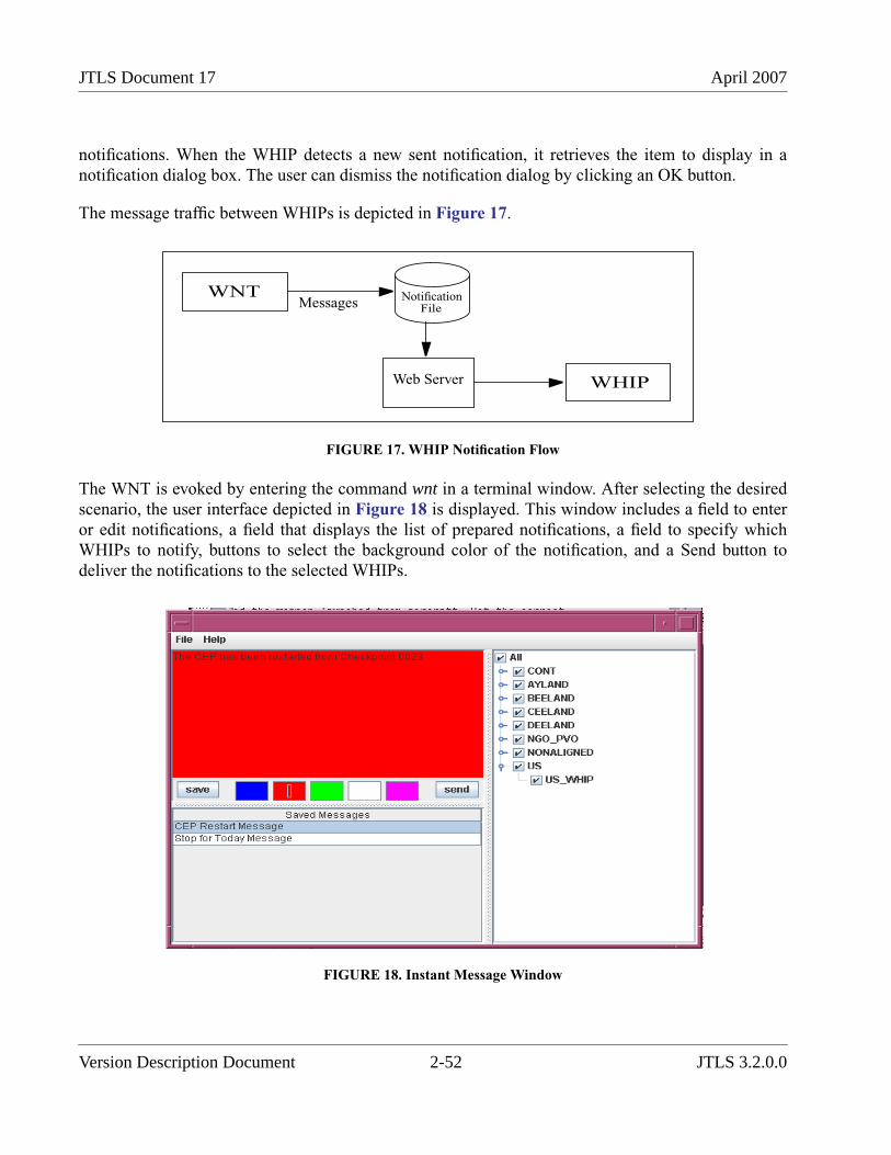
JTLS Document 17 April 2007
notifications. When the WHIP detects a new sent notification, it retrieves the item to display in anotification dialog box. The user can dismiss the notification dialog by clicking an OK button.
The message traffic between WHIPs is depicted in Figure 17.
FIGURE 17. WHIP Notification Flow
The WNT is evoked by entering the command wnt in a terminal window. After selecting the desiredscenario, the user interface depicted in Figure 18 is displayed. This window includes a field to enteror edit notifications, a field that displays the list of prepared notifications, a field to specify whichWHIPs to notify, buttons to select the background color of the notification, and a Send button todeliver the notifications to the selected WHIPs.
FIGURE 18. Instant Message Window
WHIP
WNT
Web Server
Messages NotificationFile
Version Description Document 2-52 JTLS 3.2.0.0
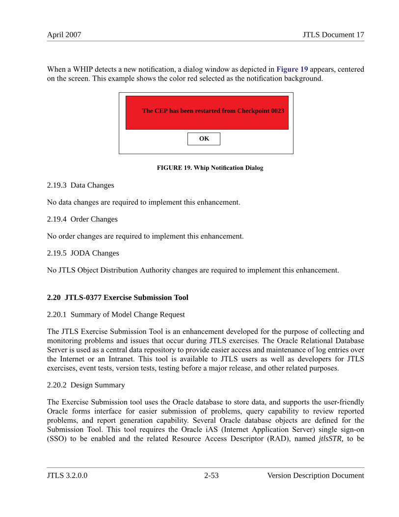
April 2007 JTLS Document 17
When a WHIP detects a new notification, a dialog window as depicted in Figure 19 appears, centeredon the screen. This example shows the color red selected as the notification background.
FIGURE 19. Whip Notification Dialog
2.19.3 Data Changes
No data changes are required to implement this enhancement.
2.19.4 Order Changes
No order changes are required to implement this enhancement.
2.19.5 JODA Changes
No JTLS Object Distribution Authority changes are required to implement this enhancement.
2.20 JTLS-0377 Exercise Submission Tool
2.20.1 Summary of Model Change Request
The JTLS Exercise Submission Tool is an enhancement developed for the purpose of collecting andmonitoring problems and issues that occur during JTLS exercises. The Oracle Relational DatabaseServer is used as a central data repository to provide easier access and maintenance of log entries overthe Internet or an Intranet. This tool is available to JTLS users as well as developers for JTLSexercises, event tests, version tests, testing before a major release, and other related purposes.
2.20.2 Design Summary
The Exercise Submission tool uses the Oracle database to store data, and supports the user-friendlyOracle forms interface for easier submission of problems, query capability to review reportedproblems, and report generation capability. Several Oracle database objects are defined for theSubmission Tool. This tool requires the Oracle iAS (Internet Application Server) single sign-on(SSO) to be enabled and the related Resource Access Descriptor (RAD), named jtlsSTR, to be
OK
The CEP has been restarted from Checkpoint 0023
JTLS 3.2.0.0 2-53 Version Description Document
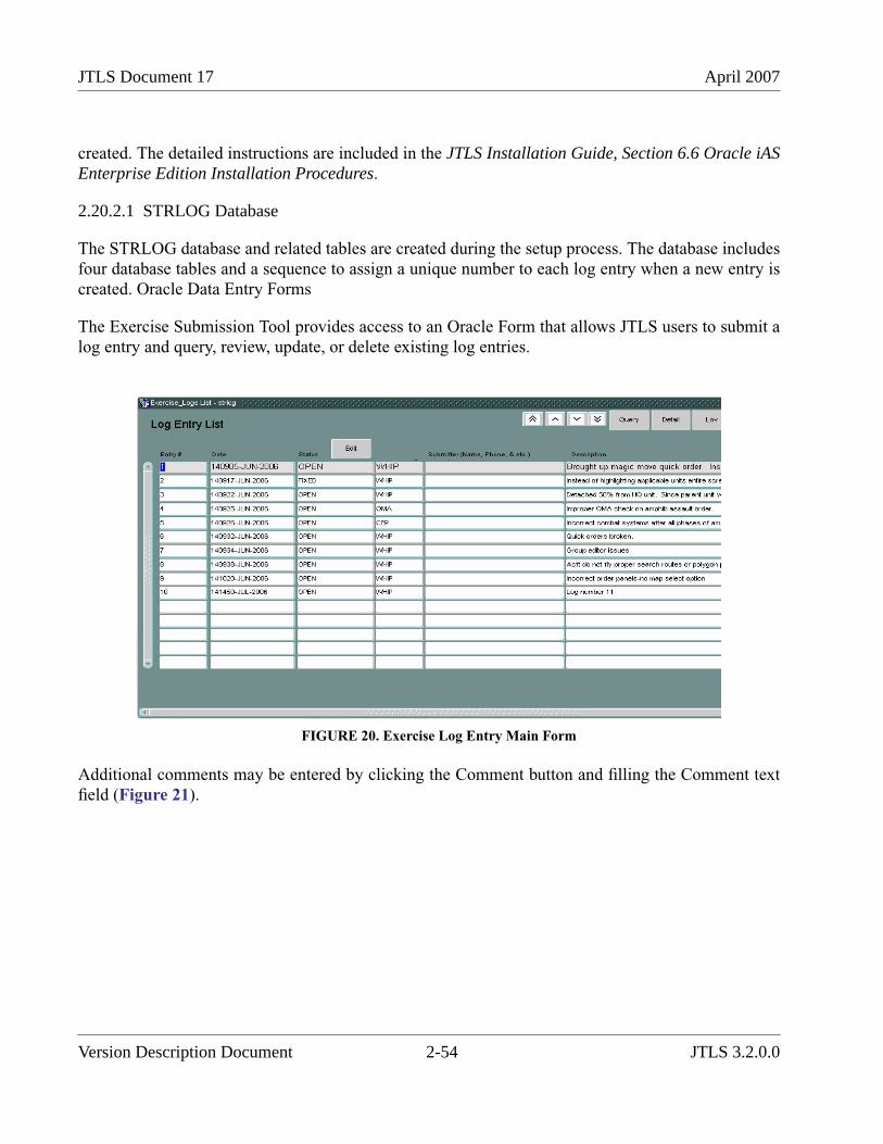
JTLS Document 17 April 2007
created. The detailed instructions are included in the JTLS Installation Guide, Section 6.6 Oracle iASEnterprise Edition Installation Procedures.
2.20.2.1 STRLOG Database
The STRLOG database and related tables are created during the setup process. The database includesfour database tables and a sequence to assign a unique number to each log entry when a new entry iscreated. Oracle Data Entry Forms
The Exercise Submission Tool provides access to an Oracle Form that allows JTLS users to submit alog entry and query, review, update, or delete existing log entries.
FIGURE 20. Exercise Log Entry Main Form
Additional comments may be entered by clicking the Comment button and filling the Comment textfield (Figure 21).
Version Description Document 2-54 JTLS 3.2.0.0
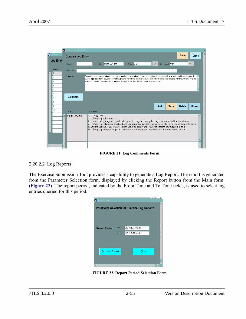
April 2007 JTLS Document 17
FIGURE 21. Log Comments Form
2.20.2.2 Log Reports
The Exercise Submission Tool provides a capability to generate a Log Report. The report is generatedfrom the Parameter Selection form, displayed by clicking the Report button from the Main form.(Figure 22). The report period, indicated by the From Time and To Time fields, is used to select logentries queried for this period.
FIGURE 22. Report Period Selection Form
JTLS 3.2.0.0 2-55 Version Description Document
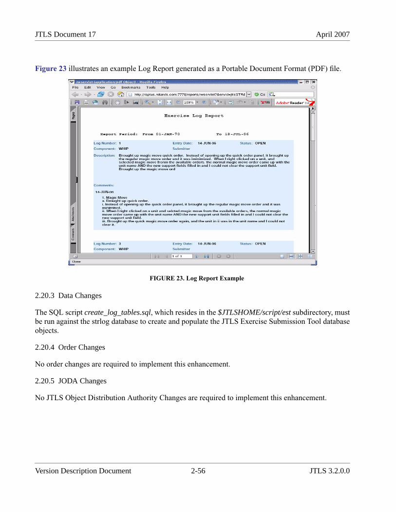
JTLS Document 17 April 2007
Figure 23 illustrates an example Log Report generated as a Portable Document Format (PDF) file.
FIGURE 23. Log Report Example
2.20.3 Data Changes
The SQL script create_log_tables.sql, which resides in the $JTLSHOME/script/est subdirectory, mustbe run against the strlog database to create and populate the JTLS Exercise Submission Tool databaseobjects.
2.20.4 Order Changes
No order changes are required to implement this enhancement.
2.20.5 JODA Changes
No JTLS Object Distribution Authority Changes are required to implement this enhancement.
Version Description Document 2-56 JTLS 3.2.0.0
April 2007 JTLS Document 17
2.21 JTLS-0378 Graphical Database Program
2.21.1 Summary of Model Change Request
This enhancement addresses the requirement to develop a new Graphical Database Program (GDP).that incorporates components developed for the Web Hosted Interface Program (WHIP). The GDPdelivered for the JTLS 3.1 version series implemented the original JTLS graphical user interface fordisplay and manipulation of a JTLS scenario database. This enhancement liberates JTLS model fromfurther dependence upon this obsolete interface and also includes the improvements proposed for theJTLS 3.2.0.0 ECP entitled JTLS-0224 Build Railroads, Pipelines, and IADs.
2.21.2 Design Summary
The JTLS 3.1 series GDP is a C program that implements a small Motif X-Windows interface andconnects to the Oracle scenario database and makes changes directly to the database tables. PRO-C isused to accomplish this database manipulation. This GDP uses the original JTLS graphical userinterface to display selected data from the database and to input user actions.
The JTLS 3.2 GDP is a Java program and leverages the WHIP the Map and Command Hierarchycomponents. These components support the graphical presentation and manipulation of scenario data,as well as a consistent graphical user interface between the WHIP and the GDP. This enhancement isintended to reduce the learning curve for a novice GDP user who has experience using the WHIP.Access to the Oracle database is provided by a new database-access package that supports genericdefinition of data from the database table to allow these data to be loaded to a GDP repository.Multiple users can manipulate the scenario data and reflect their changes from all executing GDPsconnected to a database.
These basic capabilities of the JTLS 3.1 GDP are implemented:
• Object Move
• Group Move
• Object Disperse
• National Boundary
• Operations Area
• IADS Network
• Unit Hierarchy
These new capabilities are included:
• Graphically build Railroad Networks
• Graphically build Pipeline Networks
JTLS 3.2.0.0 2-57 Version Description Document
JTLS Document 17 April 2007
The JTLS 3.2 GDP provides users with database editing capabilities that are consistent with moderngraphical user interfaces and behave in a manner similar to the familiar features of the Windowsplatform. Detailed procedures for using the enhanced GDP are provided in Chapter 6 of the JTLSDDS User’s Guide.
2.21.3 Data Changes
No data changes are required to implement this enhancement.
2.21.4 Order Changes
No order changes are required to implement this enhancement.
2.21.5 JODA Changes
No JTLS Object Distribution Authority changes are required to implement this enhancement.
2.22 JTLS-0385 Sonar Availability Function Of Speed
2.22.1 Summary of Model Change Request
All JTLS passive sonars were previously usable while turned on. The representation of Towed Arrays,which must maintain a straight course and are employed only at low speeds, and Variable DepthSonars (VDSs), which are employed only at low speeds or a virtual standstill, was unrealistic. Theinability of certain passive sonars to operate when a ship exceeds a specific speed needed to beproperly modeled within JTLS.
2.22.2 Design Summary
This enhancement primarily addresses the situation that a sonar cannot realistically receive detectionsif the speed of the ship exceeds a design limit speed for the sonar type. This design is limited to howspeed affects ship-mounted passive sonars. It does not consider the inability of ships to maneuverwhen sensors such as Towed Arrays are deployed. Additionally, this design does not address therequirement for VDS-equipped patrol helicopters to hover while obtaining detection information.Finally, note that the speed limitation is only applied to Passive sonars. Ship based Active sonars arenot ship speed limited by the model.
2.22.2.1 New Sensor Data Parameter
An individual sensor attribute, ST MAXIMUM SPEED ALLOWED, is added to represent a limitingspeed for sonar detections. A sensor becomes ineffective when moving faster than this speed. Thisdata parameter represents the limitations of Towed Array sensors (as well as hull mounted sonars)employed by naval units. ST MAXIMUM SPEED ALLOWED is the maximum speed at which the
Version Description Document 2-58 JTLS 3.2.0.0

April 2007 JTLS Document 17
ship carrying a sensor of this type can be moving and still be able to use the sensor to detectsubmarines. If the ship is traveling faster than this speed, the sensor of this type cannot accomplishdetections.
2.22.2.2 Modified Sensor Detection Algorithm
A sensor that is turned on and not damaged automatically begins detecting when the ship’s speeddecreases to the limiting value. The sensor is managed when it attempts to accomplish a detection.For each attempt, the model determines whether the sensor is turned on, is currently active, andwhether the owning naval unit’s speed of travel is sufficiently slow. In other words, the Player is notrequired to turn a Passive sonar back on, by Player Order, if it had been rendered useless for a timebecause the ship had gone too fast.
Minor modifications of the sensor detection algorithm were accomplished to implement this method.Each instance a check occurs that the sensor is turned on and has a positive percent capability, a thirdcheck is accomplished. If the Passive Sonar sensor is owned by a naval unit and the speed of the navalunit is greater than the new ST MAXIMUM SPEED ALLOWED data parameter, the sensor isomitted, considered not turned on.
2.22.3 Data Changes
The ST MAXIMUM SPEED ALLOWED parameter is added to the database as a Sensor Type entityattribute.
2.22.4 Order Changes
The Controller parameter Set and Show orders are modified as necessary. No other order changes arerequired to implement this enhancement.
2.22.5 JODA Changes
No JTLS Object Distribution Authority changes are required to implement this enhancement.
2.23 JTLS-0399 Flight Plan While Heading For Fuel
2.23.1 Summary of Model Change Request
The JTLS Air Design Review Board requested the capability to divert an Air Mission heading for fuelto resume its original flight plan, despite the mission’s perceived need for refueling.
The previously implemented capability to magically replenish an Air Mission with fuel whileairborne was designed to be invoked by a Trusted JTLS Player only as necessary to meet exerciseobjectives. This designated Player was tasked to ensure that this capability was not abused and to
JTLS 3.2.0.0 2-59 Version Description Document
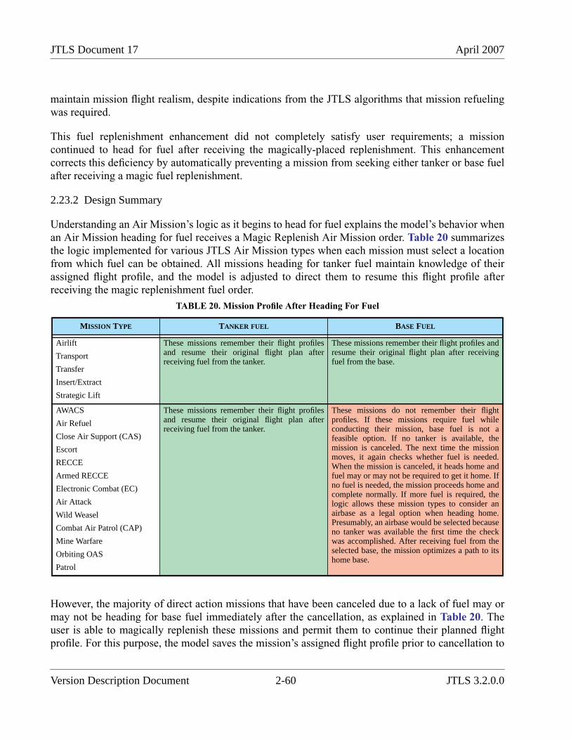
JTLS Document 17 April 2007
maintain mission flight realism, despite indications from the JTLS algorithms that mission refuelingwas required.
This fuel replenishment enhancement did not completely satisfy user requirements; a missioncontinued to head for fuel after receiving the magically-placed replenishment. This enhancementcorrects this deficiency by automatically preventing a mission from seeking either tanker or base fuelafter receiving a magic fuel replenishment.
2.23.2 Design Summary
Understanding an Air Mission’s logic as it begins to head for fuel explains the model’s behavior whenan Air Mission heading for fuel receives a Magic Replenish Air Mission order. Table 20 summarizesthe logic implemented for various JTLS Air Mission types when each mission must select a locationfrom which fuel can be obtained. All missions heading for tanker fuel maintain knowledge of theirassigned flight profile, and the model is adjusted to direct them to resume this flight profile afterreceiving the magic replenishment fuel order.
However, the majority of direct action missions that have been canceled due to a lack of fuel may ormay not be heading for base fuel immediately after the cancellation, as explained in Table 20. Theuser is able to magically replenish these missions and permit them to continue their planned flightprofile. For this purpose, the model saves the mission’s assigned flight profile prior to cancellation to
TABLE 20. Mission Profile After Heading For Fuel
MISSION TYPE TANKER FUEL BASE FUEL
Airlift
Transport
Transfer
Insert/Extract
Strategic Lift
These missions remember their flight profilesand resume their original flight plan afterreceiving fuel from the tanker.
These missions remember their flight profiles andresume their original flight plan after receivingfuel from the base.
AWACS
Air Refuel
Close Air Support (CAS)
Escort
RECCE
Armed RECCE
Electronic Combat (EC)
Air Attack
Wild Weasel
Combat Air Patrol (CAP)
Mine Warfare
Orbiting OAS
Patrol
These missions remember their flight profilesand resume their original flight plan afterreceiving fuel from the tanker.
These missions do not remember their flightprofiles. If these missions require fuel whileconducting their mission, base fuel is not afeasible option. If no tanker is available, themission is canceled. The next time the missionmoves, it again checks whether fuel is needed.When the mission is canceled, it heads home andfuel may or may not be required to get it home. Ifno fuel is needed, the mission proceeds home andcomplete normally. If more fuel is required, thelogic allows these mission types to consider anairbase as a legal option when heading home.Presumably, an airbase would be selected becauseno tanker was available the first time the checkwas accomplished. After receiving fuel from theselected base, the mission optimizes a path to itshome base.
Version Description Document 2-60 JTLS 3.2.0.0
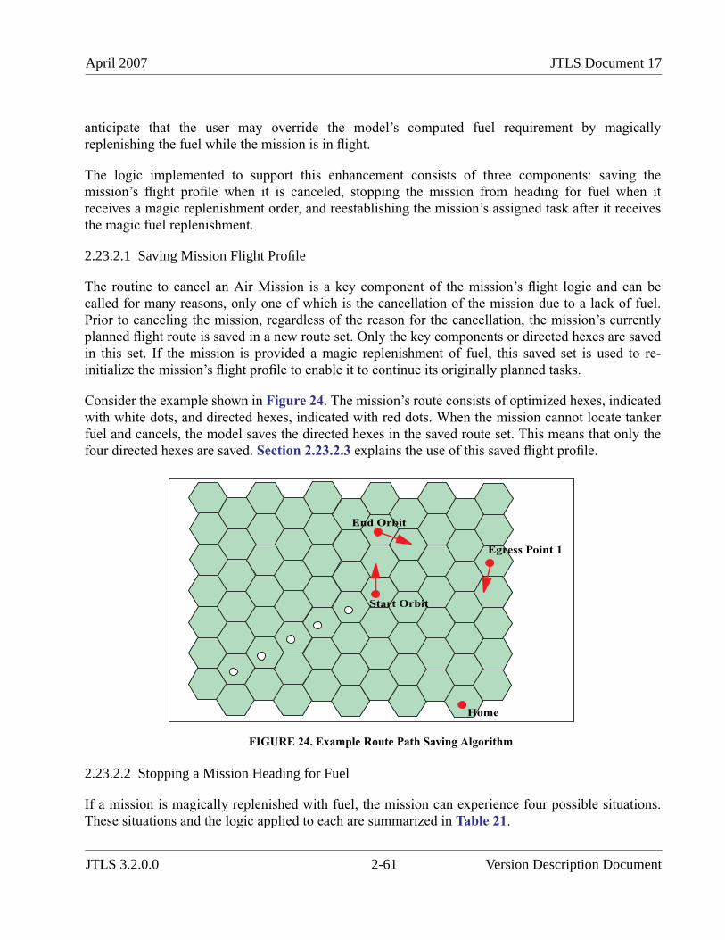
April 2007 JTLS Document 17
anticipate that the user may override the model’s computed fuel requirement by magicallyreplenishing the fuel while the mission is in flight.
The logic implemented to support this enhancement consists of three components: saving themission’s flight profile when it is canceled, stopping the mission from heading for fuel when itreceives a magic replenishment order, and reestablishing the mission’s assigned task after it receivesthe magic fuel replenishment.
2.23.2.1 Saving Mission Flight Profile
The routine to cancel an Air Mission is a key component of the mission’s flight logic and can becalled for many reasons, only one of which is the cancellation of the mission due to a lack of fuel.Prior to canceling the mission, regardless of the reason for the cancellation, the mission’s currentlyplanned flight route is saved in a new route set. Only the key components or directed hexes are savedin this set. If the mission is provided a magic replenishment of fuel, this saved set is used to re-initialize the mission’s flight profile to enable it to continue its originally planned tasks.
Consider the example shown in Figure 24. The mission’s route consists of optimized hexes, indicatedwith white dots, and directed hexes, indicated with red dots. When the mission cannot locate tankerfuel and cancels, the model saves the directed hexes in the saved route set. This means that only thefour directed hexes are saved. Section 2.23.2.3 explains the use of this saved flight profile.
FIGURE 24. Example Route Path Saving Algorithm
2.23.2.2 Stopping a Mission Heading for Fuel
If a mission is magically replenished with fuel, the mission can experience four possible situations.These situations and the logic applied to each are summarized in Table 21.
Home
Start Orbit
End Orbit
Egress Point 1
JTLS 3.2.0.0 2-61 Version Description Document
JTLS Document 17 April 2007
TABLE 21. Logic After Receipt of Magic Fuel Replenishment Order
SITUATION LOGIC IMPLEMENTED
Mission Heading for Tanker Fuel The mission posture is changed to Flying.
Under all circumstances, a mission in a Tank Fuel posture has a single “intercepting”hex at the top of its assigned route. This is the next hex the mission enters as it flies anintercepting route to its assigned tanker. This single hex is accessed and its type ischanged to optimizing. The next time the mission moves, it enters the hex and optimizesa path to the next point in its flight profile. Figure 25 shows the flight profile for themission shown in Figure 24 if it receives the magic fuel replenishment order whilelocated in the hex indicated with the blue dot. The hex indicated with the magenta dot isthe mission’s tanker intercepting hex. When the mission enters this hex, it optimizes aroute to the mission’s next directed hex, which is its planned orbit location.
The final step removes the mission’s Refuel Chit for the fuel it was scheduled to obtainfrom the tanker. Two types of Refuel Chits can be held by the mission. The orderedRefuel Chit holds the fuel the mission was specifically ordered by the Player to obtain.The model-generated Refuel Chit is automatically created by the model when themission decides to head for the tanker. A mission may have more than one Refuel Chit.It could have several ordered Refuel chits, but if the mission is heading for fuel becausethe model determined that it needed fuel, the mission should have only onemodel-generated refuel chit.
This design assumes that the user intends one and only one Refuel Chit to be canceledas a result of the magic fuel replenishment order. This chit is either a model-generatedrefuel chit if the mission independently determined to search for fuel, or a Player orderRefuel Chit with the earliest possible refuel time if the mission headed for fuel whileimplementing the user’s original orders. The selected Refuel Chit is removed from boththe mission and the tanker. The Refuel Chit is discarded and the tanker’s available fuelto provide other missions is updated. All of this status information is reported to the useron the Information Management Terminal (IMT).
All other Refuel Chits remain part of the mission. At the appropriate time, as identifiedon the order Refuel Chit, the mission heads for fuel and meets any remaining orderedrefuel times.
Mission Heading for Base Fuel The mission posture is changed to Flying.
Similarly, a mission in a Base Fuel posture has a single “intercepting” hex at the top ofits assigned route. This hex is used because the mission may be heading toward a ship torefuel, which like a tanker, has the ability to move while missions are approaching. Thissingle hex is accessed and its type is changed to optimizing. The next time the missionmoves, it computes an optimal path to its next route point. The mission then completesthe remainder of its assigned route.
Version Description Document 2-62 JTLS 3.2.0.0
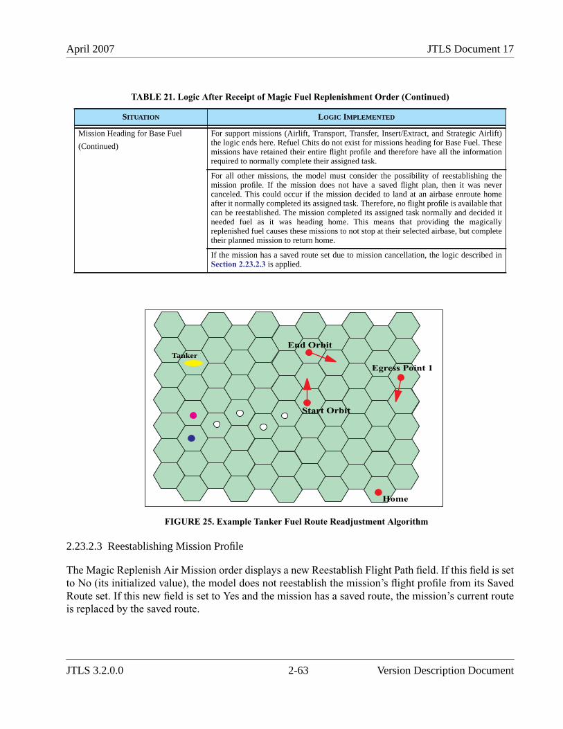
April 2007 JTLS Document 17
FIGURE 25. Example Tanker Fuel Route Readjustment Algorithm
2.23.2.3 Reestablishing Mission Profile
The Magic Replenish Air Mission order displays a new Reestablish Flight Path field. If this field is setto No (its initialized value), the model does not reestablish the mission’s flight profile from its SavedRoute set. If this new field is set to Yes and the mission has a saved route, the mission’s current routeis replaced by the saved route.
Mission Heading for Base Fuel
(Continued)
For support missions (Airlift, Transport, Transfer, Insert/Extract, and Strategic Airlift)the logic ends here. Refuel Chits do not exist for missions heading for Base Fuel. Thesemissions have retained their entire flight profile and therefore have all the informationrequired to normally complete their assigned task.
For all other missions, the model must consider the possibility of reestablishing themission profile. If the mission does not have a saved flight plan, then it was nevercanceled. This could occur if the mission decided to land at an airbase enroute homeafter it normally completed its assigned task. Therefore, no flight profile is available thatcan be reestablished. The mission completed its assigned task normally and decided itneeded fuel as it was heading home. This means that providing the magicallyreplenished fuel causes these missions to not stop at their selected airbase, but completetheir planned mission to return home.
If the mission has a saved route set due to mission cancellation, the logic described inSection 2.23.2.3 is applied.
TABLE 21. Logic After Receipt of Magic Fuel Replenishment Order (Continued)
SITUATION LOGIC IMPLEMENTED
Home
Start Orbit
End Orbit
Egress Point 1
Tanker
JTLS 3.2.0.0 2-63 Version Description Document
JTLS Document 17 April 2007
Recall that the model saves the current route of a cancelled mission and replace it with the new routeto its home base. When the Magic Replenish Air Mission order is processed, the procedure toreestablish the flight profile is simple. The mission’s current route is cleared and the saved route isused instead. This causes the mission to continue the route planned prior to the cancellation. A fewexamples explain the implications of this change.
The situation presented in Table 22 illustrates an Attack Air Mission that needs fuel and cannot locatea tanker.
TABLE 22. reestablish Flight Profile Example 1
# EVENT MISSION’S CURRENT ROUTE MISSION’S SAVED ROUTE
1 Mission moves while heading to its first targetand decides that it needs fuel. The mission iscurrently in Hex 120 120.
Hex 120 121 - Optimized
Hex 120 122 - Optimized
Hex 120 123 - Optimized
Hex 120 124 - Ingress Point 1
Hex 130 135 - Ingress Point 2
Hex 140 150 - Target 1
Hex 145 151 - Target 2
Hex 120 100 - Home
2 Assume that the mission cannot find a tanker.The mission decides to cancel. The missionroute is saved, the current route is cleared, anoptimizing hex is added to the mission’s route.
Hex 120 120 - Compute Route
Hex 120 100 - Home
Hex 120 124 - Ingress Point 1
Hex 130 135 - Ingress Point 2
Hex 140 150 - Target 1
Hex 145 151 - Target 2
Hex 120 100 - Home
3 The mission decides it still needs fuel andassumes a posture of Base Fuel, adds anintercepting hex to its route, and begins to headtoward the base.
Hex 119 119 - Intercepting
Hex 120 100 - Home
Hex 120 124 - Ingress Point 1
Hex 130 135 - Ingress Point 2
Hex 140 150 - Target 1
Hex 145 151 - Target 2
Hex 120 100 - Home
4 The mission has moved several hexes towardthe base from which it can obtain fuel. The userenters an order to magically replenish themission and indicates that the mission shouldreestablish its flight profile. The mission’s routewhen the order is received is shown.
Hex 119 123 - Intercepting
Hex 120 100 - Home
Hex 120 124 - Ingress Point 1
Hex 130 135 - Ingress Point 2
Hex 140 150 - Target 1
Hex 145 151 - Target 2
Hex 120 100 - Home
5 The mission posture is set to Flying, its route iscleared, and the saved route is moved to themission’s current route. Note the addition of acompute route hex. The next time the missionmoves, it computes an optimal path to IngressPoint 1.
Hex 119 122 - Compute Route
Hex 120 124 - Ingress Point 1
Hex 130 135 - Ingress Point 2
Hex 140 150 - Target 1
Hex 145 151 - Target 2
Hex 120 100 - Home
Version Description Document 2-64 JTLS 3.2.0.0
April 2007 JTLS Document 17
Next, assume that the same mission is flown, but after the mission is canceled (Table 22, Event 2) themission’s posture is Heading Home. Table 23 describes the mission at this point
This improvement does not apply only to the cancellation of a mission due to fuel depletion. Assumethat the user enters a Cancel Air Mission order to the same Attack mission. Table 24 describes thelogic for this mission.
TABLE 23. Reestablish Flight Profile Example 2
# EVENT MISSION’S CURRENT ROUTE MISSION’S SAVED ROUTE
3 The mission moves and has computed anoptimal path home.
Hex 120 119 - Optimized
Hex 120 118 - Optimized
Hex 120 117 - Optimized
Hex 120 116 - Optimized
Hex 120 115 - Optimized
Hex 120 114 - Optimized
Hex 120 113 - Optimized
Hex 120 112 - Optimized
Hex 120 111 - Optimized
Hex 120 110 - Home
Hex 120 124 - Ingress Point 1
Hex 130 135 - Ingress Point 2
Hex 140 150 - Target 1
Hex 145 151 - Target 2
Hex 120 100 - Home
4 The mission has moved several hexes towardhome. The user enters an order to magicallyreplenish the mission and indicates that themission should reestablish its flight profile. Themission’s route when the order is received isshown.
Hex 120 114 - Optimized
Hex 120 113 - Optimized
Hex 120 112 - Optimized
Hex 120 111 - Optimized
Hex 120 110 - Home
Hex 120 124 - Ingress Point 1
Hex 130 135 - Ingress Point 2
Hex 140 150 - Target 1
Hex 145 151 - Target 2
Hex 120 100 - Home
5 The mission posture is set to Flying, its route iscleared, and the saved route is moved to themissions current route. Note the addition of acompute route hex. The next time the missionmoves, it computes an optimal path to IngressPoint 1.
Hex 120 114 - Compute Route
Hex 120 124 - Ingress Point 1
Hex 130 135 - Ingress Point 2
Hex 140 150 - Target 1
Hex 145 151 - Target 2
Hex 120 100 - Home
TABLE 24. Reestablish Flight Profile Example 3
# EVENT MISSION’S CURRENT ROUTE MISSION’S SAVED ROUTE
1 Mission moves while heading to its first targetand decides that it needs fuel. The mission iscurrently in Hex 120 120.
Hex 120 121 - Optimized
Hex 120 122 - Optimized
Hex 120 123 - Optimized
Hex 120 124 - Ingress Point 1
Hex 130 135 - Ingress Point 2
Hex 140 150 - Target 1
Hex 145 151 - Target 2
Hex 120 100 - Home
JTLS 3.2.0.0 2-65 Version Description Document
JTLS Document 17 April 2007
Next, consider the situation for which a user submits a Cancel Air Mission order to a mission that hasalready been automatically canceled while attempting to find fuel. Consider again the first examplefor which an Attack mission is automatically canceled because it could not locate a tanker to obtainfuel. The situation is described in Table 25.
2 Assume that the user has entered a Cancel AirMission order. The mission’s route is saved,then cleared.
Hex 120 120 - Compute Route
Hex 120 100 - Home
Hex 120 124 - Ingress Point 1
Hex 130 135 - Ingress Point 2
Hex 140 150 - Target 1
Hex 145 151 - Target 2
Hex 120 100 - Home
3 Assume that the mission has moved a few hexestoward home and the user decides that themission should not be canceled. The usersubmits a Magic Replenish Air Mission orderand provides the mission with the fuel itinadvertently wasted by the Cancel Air Missionorder. The order is entered to indicate that themission’s previous profile should bereestablished. Prior to processing the order, Themission’s route prior to processing the order isshown.
Hex 120 116 - Optimized
Hex 120 115 - Optimized
Hex 120 114 - Optimized
Hex 120 113 - Optimized
Hex 120 112 - Optimized
Hex 120 111 - Optimized
Hex 120 110 - Home
Hex 120 124 - Ingress Point 1
Hex 130 135 - Ingress Point 2
Hex 140 150 - Target 1
Hex 145 151 - Target 2
Hex 120 100 - Home
4 After processing the order, the mission hasmoved the saved route to its current route andadded an air optimizing hex. The next time themission moves, it computes an optimal route tothe first Ingress Point and continues with itsoriginally planned flight profile.
Hex 120 116 - Compute Route
Hex 120 124 - Ingress Point 1
Hex 130 135 - Ingress Point 2
Hex 140 150 - Target 1
Hex 145 151 - Target 2
Hex 120 100 - Home
TABLE 25. Reestablish Flight Profile Example 4
# EVENT MISSION’S CURRENT ROUTE MISSION’S SAVED ROUTE
1 Mission moves while heading to its first targetand decides that it needs fuel. The mission iscurrently in Hex 120 120.
Hex 120 121 - Optimized
Hex 120 122 - Optimized
Hex 120 123 - Optimized
Hex 120 124 - Ingress Point 1
Hex 130 135 - Ingress Point 2
Hex 140 150 - Target 1
Hex 145 151 - Target 2
Hex 120 100 - Home
TABLE 24. Reestablish Flight Profile Example 3 (Continued)
# EVENT MISSION’S CURRENT ROUTE MISSION’S SAVED ROUTE
Version Description Document 2-66 JTLS 3.2.0.0
April 2007 JTLS Document 17
The Reestablish Mission Profile capability imposes a limitation. Airlift unit missions are neverautomatically canceled because this action permanently separates a unit into two parts, the forwarddetachment and the remaining rear detachment. If an airlift mission is canceled while carrying aportion of a unit, the unit portion is delivered and the mission heads home. If no other missions areparticipating in the airlift procedure for the unit, the airlift operation is halted and the unit ispermanently separated. This design does not allow an Airlift mission’s flight profile to bereestablished if the unit being lifted has completed its lift or has been permanently separated. Theprofile is be reestablished only while the airlift remains active.
2 Assume that the mission cannot find a tanker.The mission decides to cancel. The missionroute is saved, the current route is cleared, anoptimizing hex is added to the mission’s route.
Hex 120 120 - Compute Route
Hex 120 100 - Home
Hex 120 124 - Ingress Point 1
Hex 130 135 - Ingress Point 2
Hex 140 150 - Target 1
Hex 145 151 - Target 2
Hex 120 100 - Home
3 The mission has moved several hexes towardhome. The user enters a Cancel Air Missionorder. Since the mission is already headinghome, the order is not processed and themission structure is not altered.
Hex 120 114 - Optimized
Hex 120 113 - Optimized
Hex 120 112 - Optimized
Hex 120 111 - Optimized
Hex 120 110 - Home
Hex 120 124 - Ingress Point 1
Hex 130 135 - Ingress Point 2
Hex 140 150 - Target 1
Hex 145 151 - Target 2
Hex 120 100 - Home
4 The mission has moved along its route onemore hex when the user decides that themission should reestablish its flight profile. Theuser should submit a Magic Replenish AirMission order with the Reestablish flag set toYes. Assume that the user inadvertently sendsthe order with a flag set to No. The mission ismagically replenished and continues aspreviously planned.
Hex 120 113 - Optimized
Hex 120 112 - Optimized
Hex 120 111 - Optimized
Hex 120 110 - Home
Hex 120 124 - Ingress Point 1
Hex 130 135 - Ingress Point 2
Hex 140 150 - Target 1
Hex 145 151 - Target 2
Hex 120 100 - Home
5 The mission has moved along its route onemore hex when the user realizes the mistake.The order is submitted again with theReestablish flag set to Yes. Before the order isprocessed, the mission’s route is as indicated.
Hex 120 112 - Optimized
Hex 120 111 - Optimized
Hex 120 110 - Home
Hex 120 124 - Ingress Point 1
Hex 130 135 - Ingress Point 2
Hex 140 150 - Target 1
Hex 145 151 - Target 2
Hex 120 100 - Home
6 After processing the order, the mission’s savedroute has been moved to its current route andthe mission is assigned an optimizing hex.
Hex 120 112 - Optimized
Hex 120 124 - Ingress Point 1
Hex 130 135 - Ingress Point 2
Hex 140 150 - Target 1
Hex 145 151 - Target 2
Hex 120 100 - Home
TABLE 25. Reestablish Flight Profile Example 4 (Continued)
# EVENT MISSION’S CURRENT ROUTE MISSION’S SAVED ROUTE
JTLS 3.2.0.0 2-67 Version Description Document
JTLS Document 17 April 2007
2.23.3 Data Changes
No data changes are required to implement this enhancement.
2.23.4 Order Changes
A mandatory Reestablish Flight Path field is added to the Magic Replenish Air Mission order. If thisfield is set to No (its initialized value), the model does not reestablish the mission’s flight profile fromits Saved Route set. If this new field is set to Yes and the mission has a saved route, the mission’scurrent route is replaced by the saved route.
2.23.5 JODA Changes
No JTLS Object Distribution Authority changes are required to implement this enhancement.
2.24 JTLS-0401 ATO-T Access To Mission And Target Types
2.24.1 Summary of Model Change Request
JTLS must match TBMCS Air Mission types to effectively interface with TBMCS. Missing ormisnamed JTLS mission types do not comply with Joint or TBMCS mission types. These mismatchescreate ignored missions and mission errors. For example, ignored missions that have assignedrefueling chits lose their refueling assignments. This requires significant manpower and extensivecoordination to discover and correct.
2.24.2 Design Summary
To manage JTLS Mission type and Target type assignments, the Air Tasking Order (ATO) processreads the constants.ato data from the $JGAME/game/data directory. This file contains two sections.The first section holds the mapping of the ATO target assignments to JTLS target types. The secondsection contains the mapping of ATO mission types to JTLS mission type assignments.
When the Air Tasking Order Translator (ATO-T) executes, the initialization process opens this file,reads the information into memory, and closes the file. Until the ATO-T is stopped, all informationread in is static data. Before this upgrade, if any of the matching information for target or missiontype was incorrect, the operator was required to exit the translator, manually modify the constants.atofile, and restart the translator to effect the changes.
This enhancement eliminates the necessity for the ATO-T operator to stop the translator to change theMission Type or Target Type assignments. Now, as the ATO-T reads the constants.ato files, it also
Version Description Document 2-68 JTLS 3.2.0.0
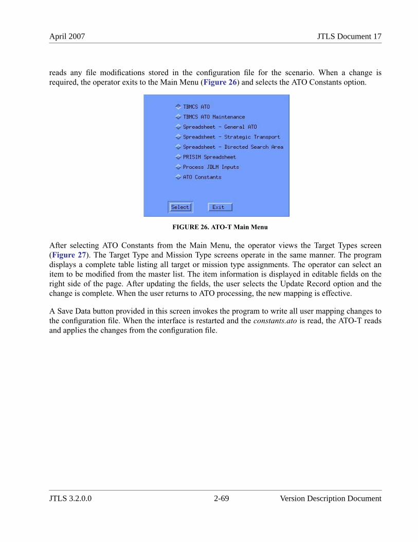
April 2007 JTLS Document 17
reads any file modifications stored in the configuration file for the scenario. When a change isrequired, the operator exits to the Main Menu (Figure 26) and selects the ATO Constants option.
FIGURE 26. ATO-T Main Menu
After selecting ATO Constants from the Main Menu, the operator views the Target Types screen(Figure 27). The Target Type and Mission Type screens operate in the same manner. The programdisplays a complete table listing all target or mission type assignments. The operator can select anitem to be modified from the master list. The item information is displayed in editable fields on theright side of the page. After updating the fields, the user selects the Update Record option and thechange is complete. When the user returns to ATO processing, the new mapping is effective.
A Save Data button provided in this screen invokes the program to write all user mapping changes tothe configuration file. When the interface is restarted and the constants.ato is read, the ATO-T readsand applies the changes from the configuration file.
JTLS 3.2.0.0 2-69 Version Description Document
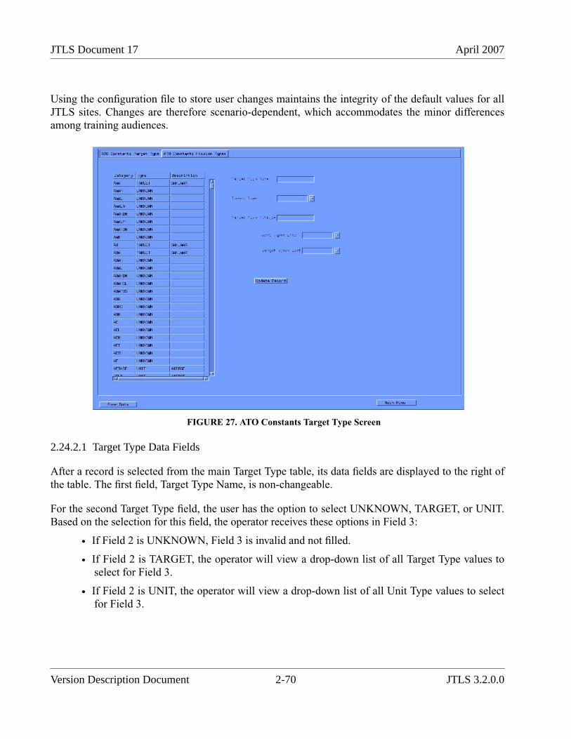
JTLS Document 17 April 2007
Using the configuration file to store user changes maintains the integrity of the default values for allJTLS sites. Changes are therefore scenario-dependent, which accommodates the minor differencesamong training audiences.
FIGURE 27. ATO Constants Target Type Screen
2.24.2.1 Target Type Data Fields
After a record is selected from the main Target Type table, its data fields are displayed to the right ofthe table. The first field, Target Type Name, is non-changeable.
For the second Target Type field, the user has the option to select UNKNOWN, TARGET, or UNIT.Based on the selection for this field, the operator receives these options in Field 3:
• If Field 2 is UNKNOWN, Field 3 is invalid and not filled.
• If Field 2 is TARGET, the operator will view a drop-down list of all Target Type values toselect for Field 3.
• If Field 2 is UNIT, the operator will view a drop-down list of all Unit Type values to selectfor Field 3.
Version Description Document 2-70 JTLS 3.2.0.0
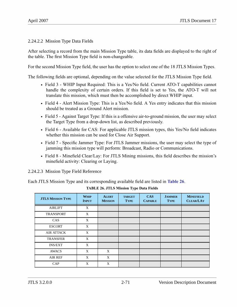
April 2007 JTLS Document 17
2.24.2.2 Mission Type Data Fields
After selecting a record from the main Mission Type table, its data fields are displayed to the right ofthe table. The first Mission Type field is non-changeable.
For the second Mission Type field, the user has the option to select one of the 18 JTLS Mission Types.
The following fields are optional, depending on the value selected for the JTLS Mission Type field.
• Field 3 - WHIP Input Required: This is a Yes/No field. Current ATO-T capabilities cannothandle the complexity of certain orders. If this field is set to Yes, the ATO-T will nottranslate this mission, which must then be accomplished by direct WHIP input.
• Field 4 - Alert Mission Type: This is a Yes/No field. A Yes entry indicates that this missionshould be treated as a Ground Alert mission.
• Field 5 - Against Target Type: If this is a offensive air-to-ground mission, the user may selectthe Target Type from a drop-down list, as described previously.
• Field 6 - Available for CAS: For applicable JTLS mission types, this Yes/No field indicateswhether this mission can be used for Close Air Support.
• Field 7 - Specific Jammer Type: For JTLS Jammer missions, the user may select the type ofjamming this mission type will perform: Broadcast, Radio or Communications.
• Field 8 - Minefield Clear/Lay: For JTLS Mining missions, this field describes the mission’sminefield activity: Clearing or Laying.
2.24.2.3 Mission Type Field Reference
Each JTLS Mission Type and its corresponding available field are listed in Table 26.
TABLE 26. JTLS Mission Type Data Fields
JTLS MISSION TYPEWHIP
INPUT
ALERT
MISSION
TARGET
TYPE
CASCAPABLE
JAMMER
TYPE
MINEFIELD
CLEAR/LAY
AIRLIFT X
TRANSPORT X
CAS X
ESCORT X
AIR ATTACK X
TRANSFER X
INS/EXT X
AWACS X X
AIR REF X X
CAP X X
JTLS 3.2.0.0 2-71 Version Description Document
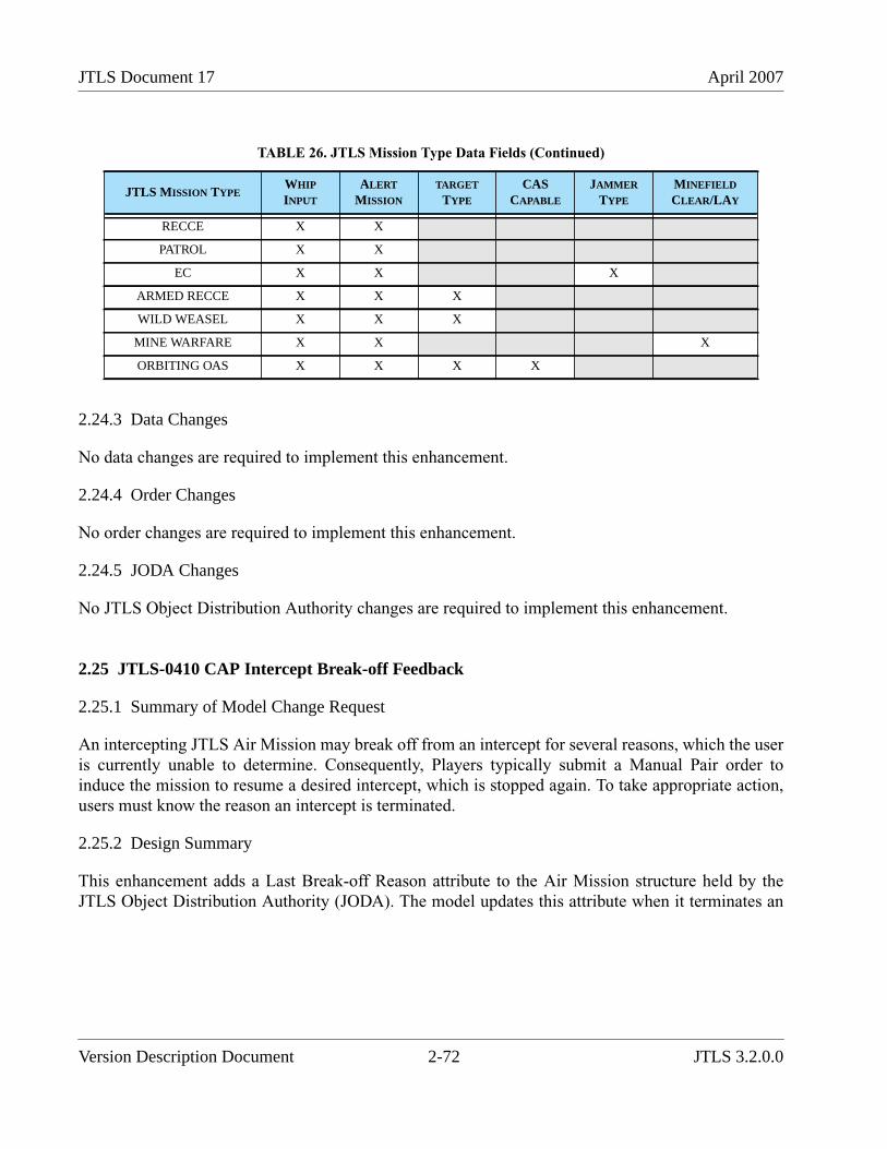
JTLS Document 17 April 2007
2.24.3 Data Changes
No data changes are required to implement this enhancement.
2.24.4 Order Changes
No order changes are required to implement this enhancement.
2.24.5 JODA Changes
No JTLS Object Distribution Authority changes are required to implement this enhancement.
2.25 JTLS-0410 CAP Intercept Break-off Feedback
2.25.1 Summary of Model Change Request
An intercepting JTLS Air Mission may break off from an intercept for several reasons, which the useris currently unable to determine. Consequently, Players typically submit a Manual Pair order toinduce the mission to resume a desired intercept, which is stopped again. To take appropriate action,users must know the reason an intercept is terminated.
2.25.2 Design Summary
This enhancement adds a Last Break-off Reason attribute to the Air Mission structure held by theJTLS Object Distribution Authority (JODA). The model updates this attribute when it terminates an
RECCE X X
PATROL X X
EC X X X
ARMED RECCE X X X
WILD WEASEL X X X
MINE WARFARE X X X
ORBITING OAS X X X X
TABLE 26. JTLS Mission Type Data Fields (Continued)
JTLS MISSION TYPEWHIP
INPUT
ALERT
MISSION
TARGET
TYPE
CASCAPABLE
JAMMER
TYPE
MINEFIELD
CLEAR/LAY
Version Description Document 2-72 JTLS 3.2.0.0
April 2007 JTLS Document 17
intercept. This attribute value is available to the user on the Information Management Terminal(IMT). Table 27 summarizes the reason codes generated by the model.
The logic for continuing an engagement is re-implemented for this enhancement, as indicated inTable 27. Consequently, the meaning of the existing data parameter AC CONTINUE ENGAGEMULT is changed. The decision to break off an intercept is based on the expected outcome of theensuing engagement.
First, the distance between the interceptor and the intercepted mission is computed. An average hexdistance is subtracted from this distance to estimate the expected distance between the two missionswhen the next engagement will occur.
After computing this distance, the model determines which weapon the interceptor will likely fire.This is accomplished by considering only those available air-to-air weapons that can be fired acrossthe expected distance between the two missions. From these legal distance weapons, the modelselects the weapon that has the greatest Probability of Kill (PK), considering the type of aircraft being
intercepted and the weather in the intercepted mission’s current hex.
A similar computation is accomplished from the intercepted mission’s perspective. However, themodel considers all air-to-air weapons that were loaded on the interested mission, instead of only theavailable air-to-air weapons. This logic simulates the concept that the pilot of the intercepting mission
TABLE 27. Break-off Reason Codes
BREAK-OFF CODE MEANING
Mission Killed The intercept mission has been killed, but may or may not have been killed by the interceptor. Theengagement reports implemented for the ECP JTLS-0008 Real Time Intercept Report provide thisinformation.
Mission Landed The intercepted mission has landed and can no longer be intercepted.
Fuel The intercepting mission ended the intercept due to a shortage of fuel.
Weapons The intercepting mission ended the intercept because its air-to-air weapons were expended.
Aircraft Loss The intercepting mission was automatically sent home because it has lost too many aircraft.
ROE The intercepting mission automatically ended the intercept because the ROE rules for break-off weresatisfied
Mission Uninteresting The intercepted mission was no longer of interest to the intercepting mission. This typically occursdue to a change in the IFF recognition of the intercepted Air Mission.
Unequal Odds The intercepting mission automatically ended the intercept because it determined that the odds ofcontinuing the engagement were not in its best interest. This capability was temporarily removed toimplement new intercept logic to define Air Mission fire and return fire as independent events. Thisprevious capability will be restored for this design.
Ordered The Player has submitted an order to break off the intercept.
Interceptor Killed The intercepting mission was killed. Although the Air Mission structure is removed from the JODA,the new attribute is updated to indicate to all JODA clients the reason for the break-off event. Astructure delete message is passed to JODA immediately after this attribute is updated.
JTLS 3.2.0.0 2-73 Version Description Document
JTLS Document 17 April 2007
knows the typical weapon load of an enemy mission, but not the actual load of the interceptedmission.
After the Probabilities of Kill for the interceptor (PKI) and intercepted mission (PKM) are determined,
this ratio is computed:
This value is compared to the data parameter AC CONTINUE ENGAGE MULT. If the ratio ofcomparison is greater than or equal to this data parameter, the intercept continues.
Consider the example described in Table 28.
2.25.3 Data Changes
No initialization database changes are required to implement this enhancement. A new staticvocabulary item is created to support this new functionality. However, these new data are deliveredwith JTLS and are available to all JTLS scenarios.
The meaning of the existing data parameter AC CONTINUE ENGAGE MULT has been changed.The user should review the data held for this variable in any database that is upgraded to a JTLS 3.2format. The revised data element description is provided in the JTLS Data Requirements Manual.
2.25.4 Order Changes
No order structure changes are required to implement this enhancement. However the Help field forthe AC CONTINUE ENGAGE MULT updated on the appropriate SET order to reflect the newmeaning of this data parameter.
TABLE 28. Continue Intercept Logic Example
ACCONTINUE
ENGAGE
MULT
PKI PKM RATIO RESULT
0.5 0.30 0.45 0.67 The interceptor is "brave" and continues the intercept,despite the likelihood of an unsuccessful attack.
0.5 0.2 0.45 0.44 The interceptor is "prudent" and breaks off the intercept, butmay re-engage according to the availability of otherinterceptors and other intercept rules.
2.0 0.8 0.45 1.78 The interceptor is "cautious" and breaks off the engagement,despite the likelihood of a successful attack.
PKI
PKM-----------
Version Description Document 2-74 JTLS 3.2.0.0
April 2007 JTLS Document 17
2.25.5 JODA Changes
The new Air_Mission object attribute Last_Breakoff_Reason is added to the Air_Mission objectstructure represented in the JODA.
2.26 JTLS-0430 Auto Pair Versus Helo/UAV
2.26.1 Summary of Model Change Request
JTLS applies a detailed set of rules to determine whether an Air Mission should intercept another.These rules comprise the Interceptor Assignment logic, which all Combat Air Patrol (CAP) missionsand Escort missions use to automatically determine their pairing against a detected mission.
This enhancement improves the Interceptor Assignment to allows JTLS users to prevent a CAP fromautomatically intercepting a specified aircraft target type, such as a helicopter or UAV mission.
2.26.2 Design Summary
The existing Interceptor Assignment logic comprises three intercept strategies that can be used toautomatically assign an Air Mission to intercept another mission.
• Protected Circle: A CAP mission directed to use this strategy is assigned a Protection Circleby the user. The mission is also assigned a Shadow Distance for each Force Side in thegame by means of the Rules of Engagement (ROE) order. By default, the CAP mission usesthe ROE assigned to its home squadron. The user may specifically change the ROE-basedShadow Distance for each mission.
• Protected Operations Area (OPAREA): For a CAP mission directed to use this strategy, theOPAREA has data that indicate whether the detected mission should be intercepted. Thedecision is based on the CAP’s perception of the Side that owns the detected mission, thealtitude zone in which the detected mission is flying, and the historical flight record for thedetected mission, which considers whether the mission has ever violated the altituderestrictions for the OPAREA.
• Protected Mission List: A CAP mission directed to use this strategy has a specific list ofmissions that it is designated to protect. If any mission begins to intercept a mission on theCAP’s protection list, the CAP mission will automatically be assigned to intercept thedetected intercepting mission. Escort missions always apply this strategy
This enhancement does not change the logic currently used by the Protected Mission List strategy forInterceptor Assignment. If an enemy asset is intercepting a mission in the CAP mission or Escortmission protected mission list, the type of enemy asset (helicopter or fixed-wing) should not beconsidered to determine whether the asset should be intercepted.
JTLS 3.2.0.0 2-75 Version Description Document
JTLS Document 17 April 2007
The remaining strategies, Protected Circle and Protected OPAREA, implement an additional check todetermine whether an automatic intercept should be executed. This new check considers the detectedmission’s aircraft type. If the detected mission does not satisfy the new aircraft type restrictions, theCAP mission is assigned to intercept the mission automatically. This new aircraft type check isaccomplished in three levels of restriction.
2.26.2.1 Default Aircraft Type Restrictions
A new data parameter is added to the JTLS initialization database to hold the default list of allowableInterceptor Assignment combinations. This new data element, ACP ATC AUTO INTERCEPTALLOWED, holds an indicator whether the Air Control Prototype (ACP) intends its CAP and Escortmissions to automatically intercept aircraft that belong to the Aircraft Target Class (ATC). The modelassumes that this value is YES. If the database developer desires to set any of these values to NO, arecord must be added to the new ACP ATC child table that can be accessed from the ACP detaileddata form via the DDS.
For example, assume that the database has ACP_1, ACP_2, and ACP_3, and defines six AircraftTarget Classes: BOMBER, FIGHTER, CARGO, HELO, UAV, and MISSILE. The model holds thenew data table shown as Table 29.
As illustrated, a CAP mission belonging to a Faction that uses ACP_1 is allowed to be automaticallysent to intercept an enemy Air Mission that uses aircraft belonging to an Aircraft Target Class ofBOMBER, FIGHTER, or CARGO. It is not allowed to automatically intercept an enemy Air Missionwith aircraft belonging to an Aircraft Target Class of HELO, UAV, or, MISSILE.
The model assumes that the entire array holds values of YES. Thus, the database developer can addonly the NO records to the initialization database, and may add the YES records to the database, if theexplicit assignment within the DDS is considered worthwhile. The ACP’s default data is not Side-dependent because several Factions on various Sides can access and use the same ACP.
2.26.2.2 Unit Level Aircraft Type Restrictions
This next level of decision logic is designed to allow the user to establish type aircraft rules that areSide-dependent. This decision layer is not part of the initialization database. The user establishes
TABLE 29. ACP ATC AUTO INTERCEPT ALLOWED Data Table Example
AIR CONTROL PROTOTYPE (ACP)AIRCRAFT TARGET CLASSES (ATC)
BOMBER FIGHTER CARGO HELO UAV MISSILE
ACP_1 YES YES YES NO NO NO
ACP_2 YES YES YES YES NO NO
ACP_3 YES YES NO NO NO NO
Version Description Document 2-76 JTLS 3.2.0.0
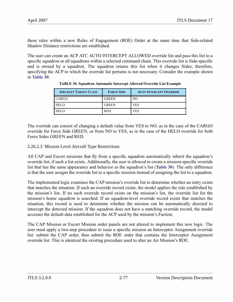
April 2007 JTLS Document 17
these rules within a new Rules of Engagement (ROE) Order at the same time that Side-relatedShadow Distance restrictions are established.
The user can create an ACP ATC AUTO INTERCEPT ALLOWED override list and pass this list to aspecific squadron or all squadrons within a selected command chain. This override list is Side-specificand is owned by a squadron. The squadron retains this list when it changes Sides; therefore,specifying the ACP to which the override list pertains is not necessary. Consider the example shownin Table 30.
The override can consist of changing a default value from YES to NO, as in the case of the CARGOoverride for Force Side GREEN, or from NO to YES, as in the case of the HELO override for bothForce Sides GREEN and RED.
2.26.2.3 Mission Level Aircraft Type Restrictions
All CAP and Escort missions that fly from a specific squadron automatically inherit the squadron’soverride list, if such a list exists. Additionally, the user is allowed to create a mission-specific overridelist that has the same appearance and behavior as the squadron’s list (Table 30). The only differenceis that the user assigns the override list to a specific mission instead of assigning the list to a squadron.
The implemented logic examines the CAP mission’s override list to determine whether an entry existsthat matches the situation. If such an override record exists, the model applies the rule established bythe mission’s list. If no such override record exists on the mission’s list, the override list for themission’s home squadron is searched. If an squadron-level override record exists that matches thesituation, this record is used to determine whether the mission can be automatically directed tointercept the detected mission. If the squadron does not have a matching override record, the modelaccesses the default data established for the ACP used by the mission’s Faction.
The CAP Mission or Escort Mission order panels are not altered to implement this new logic. Theuser must apply a two-step procedure to issue a specific mission an Interceptor Assignment overridelist: submit the CAP order, then submit the ROE order that contains the Interceptor Assignmentoverride list. This is identical the existing procedure used to alter an Air Mission’s ROE.
TABLE 30. Squadron Automatic Intercept Allowed Override List Example
AIRCRAFT TARGET CLASS FORCE SIDE AUTO INTERCEPT OVERRIDE
CARGO GREEN NO
HELO GREEN YES
HELO RED YES
JTLS 3.2.0.0 2-77 Version Description Document
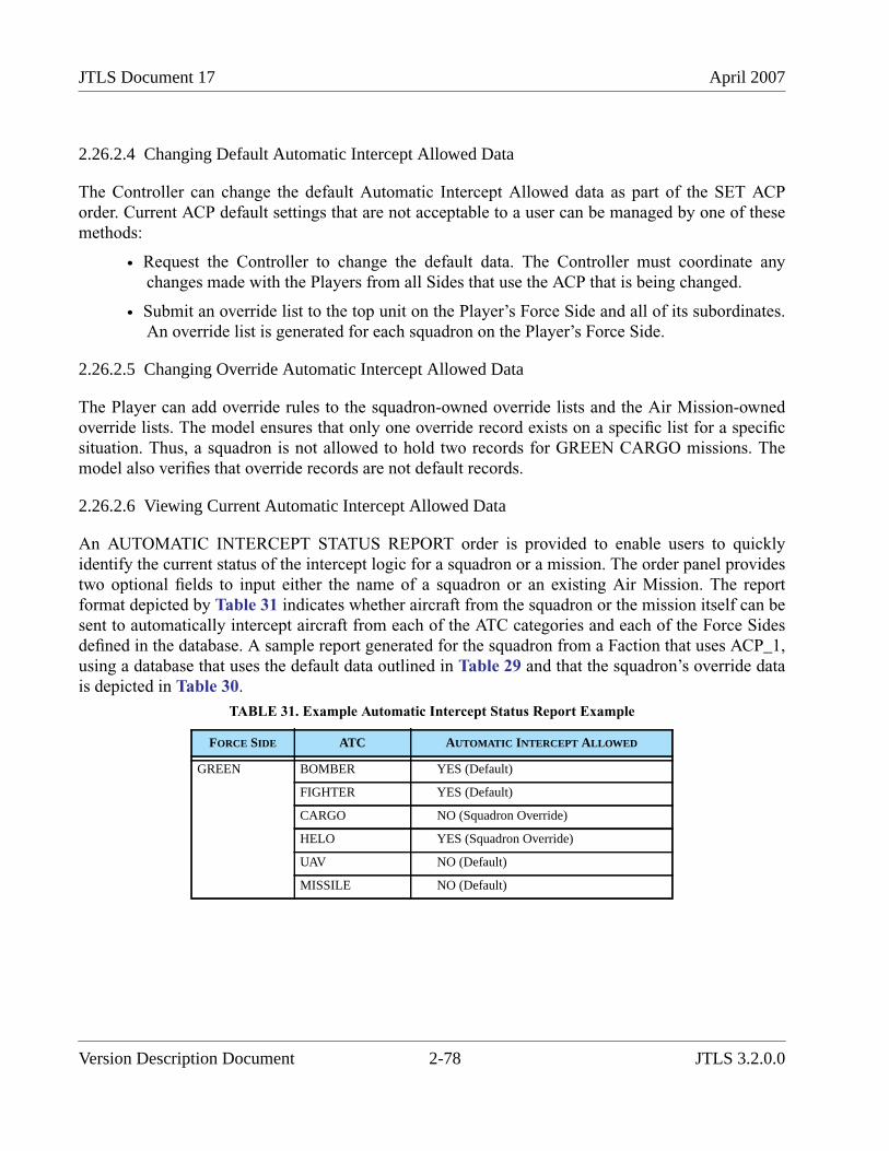
JTLS Document 17 April 2007
2.26.2.4 Changing Default Automatic Intercept Allowed Data
The Controller can change the default Automatic Intercept Allowed data as part of the SET ACPorder. Current ACP default settings that are not acceptable to a user can be managed by one of thesemethods:
• Request the Controller to change the default data. The Controller must coordinate anychanges made with the Players from all Sides that use the ACP that is being changed.
• Submit an override list to the top unit on the Player’s Force Side and all of its subordinates.An override list is generated for each squadron on the Player’s Force Side.
2.26.2.5 Changing Override Automatic Intercept Allowed Data
The Player can add override rules to the squadron-owned override lists and the Air Mission-ownedoverride lists. The model ensures that only one override record exists on a specific list for a specificsituation. Thus, a squadron is not allowed to hold two records for GREEN CARGO missions. Themodel also verifies that override records are not default records.
2.26.2.6 Viewing Current Automatic Intercept Allowed Data
An AUTOMATIC INTERCEPT STATUS REPORT order is provided to enable users to quicklyidentify the current status of the intercept logic for a squadron or a mission. The order panel providestwo optional fields to input either the name of a squadron or an existing Air Mission. The reportformat depicted by Table 31 indicates whether aircraft from the squadron or the mission itself can besent to automatically intercept aircraft from each of the ATC categories and each of the Force Sidesdefined in the database. A sample report generated for the squadron from a Faction that uses ACP_1,using a database that uses the default data outlined in Table 29 and that the squadron’s override datais depicted in Table 30.
TABLE 31. Example Automatic Intercept Status Report Example
FORCE SIDE ATC AUTOMATIC INTERCEPT ALLOWED
GREEN BOMBER YES (Default)
FIGHTER YES (Default)
CARGO NO (Squadron Override)
HELO YES (Squadron Override)
UAV NO (Default)
MISSILE NO (Default)
Version Description Document 2-78 JTLS 3.2.0.0
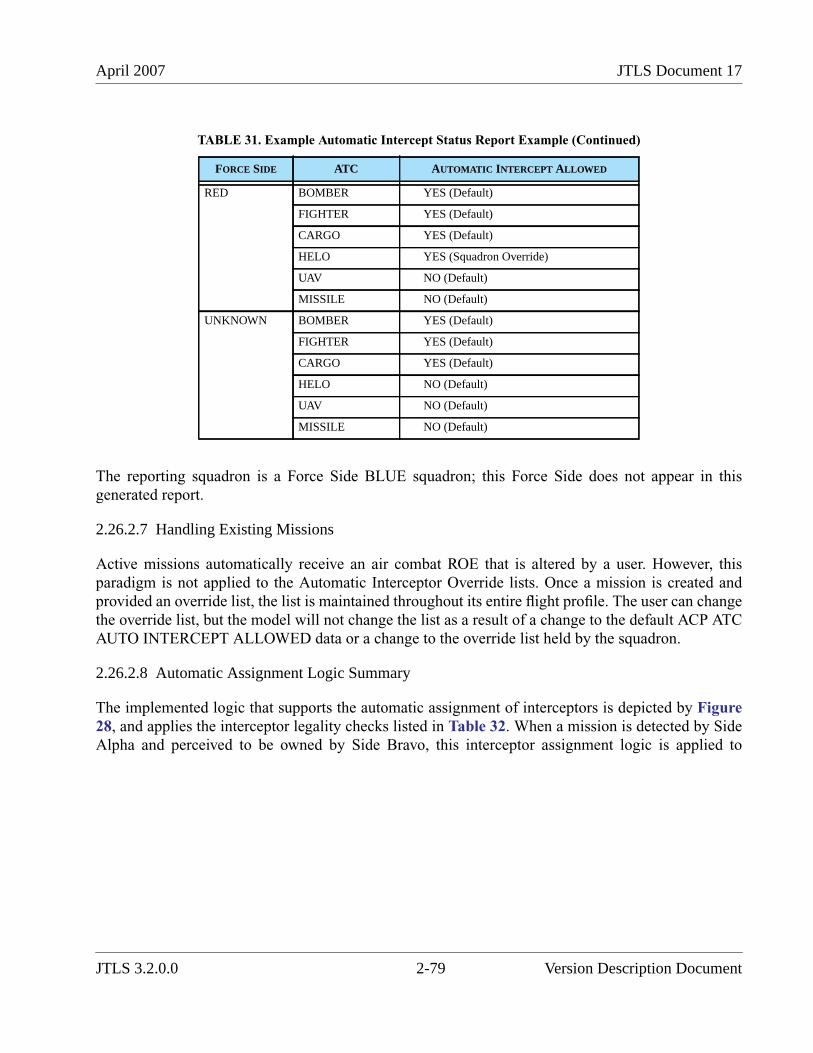
April 2007 JTLS Document 17
The reporting squadron is a Force Side BLUE squadron; this Force Side does not appear in thisgenerated report.
2.26.2.7 Handling Existing Missions
Active missions automatically receive an air combat ROE that is altered by a user. However, thisparadigm is not applied to the Automatic Interceptor Override lists. Once a mission is created andprovided an override list, the list is maintained throughout its entire flight profile. The user can changethe override list, but the model will not change the list as a result of a change to the default ACP ATCAUTO INTERCEPT ALLOWED data or a change to the override list held by the squadron.
2.26.2.8 Automatic Assignment Logic Summary
The implemented logic that supports the automatic assignment of interceptors is depicted by Figure28, and applies the interceptor legality checks listed in Table 32. When a mission is detected by SideAlpha and perceived to be owned by Side Bravo, this interceptor assignment logic is applied to
RED BOMBER YES (Default)
FIGHTER YES (Default)
CARGO YES (Default)
HELO YES (Squadron Override)
UAV NO (Default)
MISSILE NO (Default)
UNKNOWN BOMBER YES (Default)
FIGHTER YES (Default)
CARGO YES (Default)
HELO NO (Default)
UAV NO (Default)
MISSILE NO (Default)
TABLE 31. Example Automatic Intercept Status Report Example (Continued)
FORCE SIDE ATC AUTOMATIC INTERCEPT ALLOWED
JTLS 3.2.0.0 2-79 Version Description Document
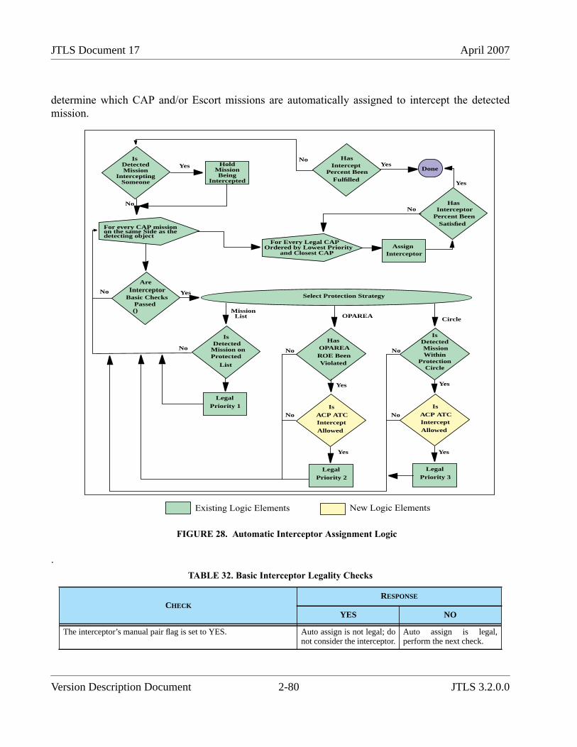
JTLS Document 17 April 2007
determine which CAP and/or Escort missions are automatically assigned to intercept the detectedmission.
FIGURE 28. Automatic Interceptor Assignment Logic
.
TABLE 32. Basic Interceptor Legality Checks
CHECKRESPONSE
YES NO
The interceptor’s manual pair flag is set to YES. Auto assign is not legal; donot consider the interceptor.
Auto assign is legal,perform the next check.
For every CAP missionon the same Side as thedetecting object
HasIntercept
Percent BeenFulfilled
YesDone
IsDetectedMission
InterceptingSomeone
HoldMissionBeing
Intercepted
Yes
No
No Yes
For Every Legal CAPOrdered by Lowest Priority
and Closest CAPAssign
Interceptor
HasInterceptor
Percent BeenSatisfied
Yes
No
Select Protection Strategy
No
CircleOPAREA
MissionList
AreInterceptor
Basic ChecksPassed()
IsDetected
Mission onProtected
List
No
LegalPriority 1
HasOPAREAROE BeenViolated
IsACP ATCInterceptAllowed
LegalPriority 2
IsDetected
WithinProtection
IsACP ATCInterceptAllowed
LegalPriority 3
Circle
MissionNo
No
Yes
Yes
No
Yes
No
Yes
Existing Logic Elements New Logic Elements
Version Description Document 2-80 JTLS 3.2.0.0
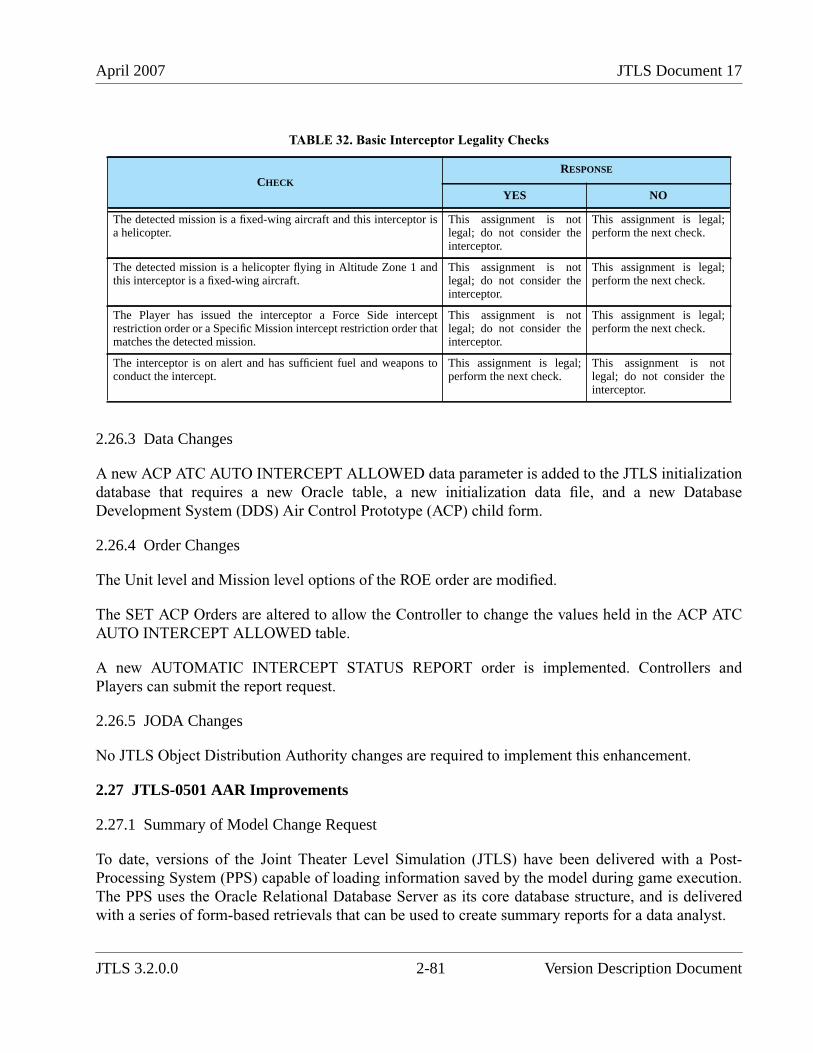
April 2007 JTLS Document 17
2.26.3 Data Changes
A new ACP ATC AUTO INTERCEPT ALLOWED data parameter is added to the JTLS initializationdatabase that requires a new Oracle table, a new initialization data file, and a new DatabaseDevelopment System (DDS) Air Control Prototype (ACP) child form.
2.26.4 Order Changes
The Unit level and Mission level options of the ROE order are modified.
The SET ACP Orders are altered to allow the Controller to change the values held in the ACP ATCAUTO INTERCEPT ALLOWED table.
A new AUTOMATIC INTERCEPT STATUS REPORT order is implemented. Controllers andPlayers can submit the report request.
2.26.5 JODA Changes
No JTLS Object Distribution Authority changes are required to implement this enhancement.
2.27 JTLS-0501 AAR Improvements
2.27.1 Summary of Model Change Request
To date, versions of the Joint Theater Level Simulation (JTLS) have been delivered with a Post-Processing System (PPS) capable of loading information saved by the model during game execution.The PPS uses the Oracle Relational Database Server as its core database structure, and is deliveredwith a series of form-based retrievals that can be used to create summary reports for a data analyst.
The detected mission is a fixed-wing aircraft and this interceptor isa helicopter.
This assignment is notlegal; do not consider theinterceptor.
This assignment is legal;perform the next check.
The detected mission is a helicopter flying in Altitude Zone 1 andthis interceptor is a fixed-wing aircraft.
This assignment is notlegal; do not consider theinterceptor.
This assignment is legal;perform the next check.
The Player has issued the interceptor a Force Side interceptrestriction order or a Specific Mission intercept restriction order thatmatches the detected mission.
This assignment is notlegal; do not consider theinterceptor.
This assignment is legal;perform the next check.
The interceptor is on alert and has sufficient fuel and weapons toconduct the intercept.
This assignment is legal;perform the next check.
This assignment is notlegal; do not consider theinterceptor.
TABLE 32. Basic Interceptor Legality Checks
CHECKRESPONSE
YES NO
JTLS 3.2.0.0 2-81 Version Description Document
JTLS Document 17 April 2007
The PPS delivered with the previous release was the result a series of attempts to create an AfterAction Review (AAR) capability for JTLS. This system solved several problems experienced duringprevious efforts by several other contractors. Specifically, it corrected the following deficiencies ofother developed AAR tools:
• Ability to handle several simulation runs. A JTLS simulation run is defined as a contiguoustimeline from the beginning of the scenario to the present time within the scenario. During aJTLS exercise, the simulation is frequently reset to a previous game time to replay portionsof the scenario. This situation can occur either by exercise design or because of exerciseerror conditions. The PPS considered the concepts of runs and had the ability to maintaindatabase integrity across runs.
• Ability to reduce the information held within the database as the exercise progresses. As anexercise progresses, more data is saved. This leads to an increase in the amount of timerequired to search, collect, and create reports supporting a users query. In an attempt toreduce this time, the JTLS PPS had the ability to delete some of the data held within thesystem, but the data was not lost. A user could reload the information at any point in time asneeded to support a specific query.
• Ability to correct information. It is not unusual for the model to compute a result that isdisputed by the response cell or the exercise audience. This situation can be caused by amodel problem, a database problem, a user order input error, or because the legal result willdegrade the planned exercise objectives. The JTLS PPS had the capability to correct ornullify data held within the database so that all future retrievals and reports accuratelyrepresented desired outcomes instead of actual outcomes. For example, when SeniorControl nullifies an air-to-air kill by returning the aircraft to its home squadron, the SeniorControl cell should also use the PPS Tool to nullify the kill within the database. The datawas not removed from the database; instead, it was marked with the reason why it shouldnot be considered in future retrievals.
The current PPS has been used infrequently by JTLS users. Although no specific reasons have beenidentified, we can presume the following model deficiencies:
• The data was not available on a real-time basis. The data was made available only after acheckpoint was taken. This did not allow users the type of access required.
• The collected data concentrated only on the air war and more data needed to be available.
• The PPS did not receive the necessary exposure. Therefore, the refinements needed to makeany tool useful have never been suggested or implemented.
This Enhancement Change Proposal (ECP) provided for expanding the current PPS capability,particularly, but not solely, to address these deficiencies while retaining the existing capabilities.
This VDD section provides an overview of the AAR Tool delivered with this release. For a morecomprehensive analysis of the capabilities of this tool, including detailed descriptions of the Oracle
Version Description Document 2-82 JTLS 3.2.0.0
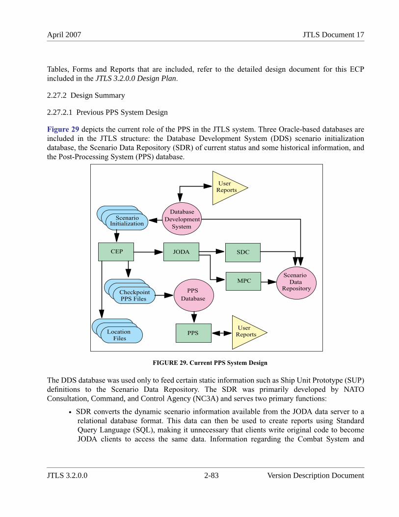
April 2007 JTLS Document 17
Tables, Forms and Reports that are included, refer to the detailed design document for this ECPincluded in the JTLS 3.2.0.0 Design Plan.
2.27.2 Design Summary
2.27.2.1 Previous PPS System Design
Figure 29 depicts the current role of the PPS in the JTLS system. Three Oracle-based databases areincluded in the JTLS structure: the Database Development System (DDS) scenario initializationdatabase, the Scenario Data Repository (SDR) of current status and some historical information, andthe Post-Processing System (PPS) database.
FIGURE 29. Current PPS System Design
The DDS database was used only to feed certain static information such as Ship Unit Prototype (SUP)definitions to the Scenario Data Repository. The SDR was primarily developed by NATOConsultation, Command, and Control Agency (NC3A) and serves two primary functions:
• SDR converts the dynamic scenario information available from the JODA data server to arelational database format. This data can then be used to create reports using StandardQuery Language (SQL), making it unnecessary that clients write original code to becomeJODA clients to access the same data. Information regarding the Combat System and
CEP JODA
CheckpointPPS Files
SDC
MPCScenario
DataRepositoryPPS
Database
PPSUser
Reports
Database
Development
System
ScenarioInitialization
UserReports
Location Files
JTLS 3.2.0.0 2-83 Version Description Document
JTLS Document 17 April 2007
Logistics levels of the various JTLS units used to format Logistics Reports and SituationReports is especially important.
• SDR provides specific historical information, particularly for Air Missions, by parsing theJTLS-generated mission reports (MISREPs) and placing this information into the SDR inrelational database format.
The previously delivered PPS database is solely a historical database that primarily holds air eventdata, such as aircraft kills.
These two AAR databases, compared in Table 33, each have unique advantages (green highlight) anddisadvantages (red highlight).
TABLE 33. Comparison of the SDR and PPS Databases
CHARACTERISTIC SDR PPS
Historical datacollection method
The SDR obtains historical information by parsinguser messages that contain this information. Themaintenance process for this code is intensivebecause message generation is closely tied to the datacollection process.
The PPS obtains information via formatteddata output directly from the model. If newinformation is desired in the PPS, only thePPS-formatted data must be changed.Existing message formats can remainunchanged. Similarly, if new information isrequested in a message, effects on the datacollection code can be ignored.
Data collectionefficiency
The SDR’s characteristic parsing of messageinformation ignores the inefficient nature of codemaintenance. Historical event information is outputonly once.
Historical information is output twice: onceinto the MISREP messages and once into thePPS data files loaded into the PPS.
Real-time datacollection
The dynamic information contains real-time data.After the data update is passed to the JODA, theJODA passes the information to the Scenario DataClient (SDC) to be entered into the SDR database.For historical information, the SDR is approximatelyreal-time. It must wait for the model to deliver thedelayed MISREP before its data can be parsed andentered into the database.
The historical data is not available in real-time, but only after a checkpoint, which istypically completed every two hours duringmajor exercises.
Data reliability Data is lost if the SDC breaks its connection to theJODA for any reason. The lost data cannot berecovered.
The CEP writes the historical informationdirectly to the PPS. Data loss is avoidedbecause the data is directly output to a file andnot handled by several other sequentiallylinked programs.
Collected data recovery Data is saved only to the Oracle database. Nocapability exists to delete information to makeretrievals faster. Deleted data cannot be recovered.
All data is saved in data files to be easilyreloaded at any time.
Version Description Document 2-84 JTLS 3.2.0.0
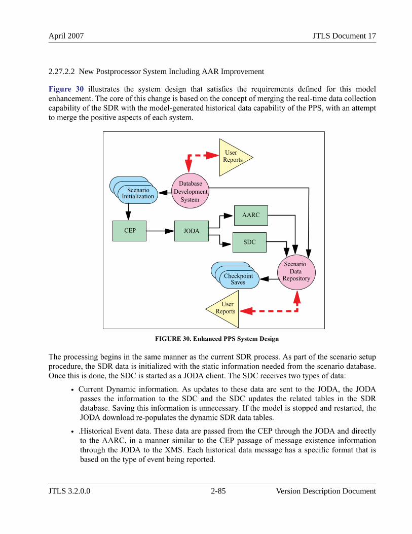
April 2007 JTLS Document 17
2.27.2.2 New Postprocessor System Including AAR Improvement
Figure 30 illustrates the system design that satisfies the requirements defined for this modelenhancement. The core of this change is based on the concept of merging the real-time data collectioncapability of the SDR with the model-generated historical data capability of the PPS, with an attemptto merge the positive aspects of each system.
FIGURE 30. Enhanced PPS System Design
The processing begins in the same manner as the current SDR process. As part of the scenario setupprocedure, the SDR data is initialized with the static information needed from the scenario database.Once this is done, the SDC is started as a JODA client. The SDC receives two types of data:
• Current Dynamic information. As updates to these data are sent to the JODA, the JODApasses the information to the SDC and the SDC updates the related tables in the SDRdatabase. Saving this information is unnecessary. If the model is stopped and restarted, theJODA download re-populates the dynamic SDR data tables.
• .Historical Event data. These data are passed from the CEP through the JODA and directlyto the AARC, in a manner similar to the CEP passage of message existence informationthrough the JODA to the XMS. Each historical data message has a specific format that isbased on the type of event being reported.
CEP JODA
SDC
ScenarioData
Repository
Database
Development
System
ScenarioInitialization
UserReports
UserReports
CheckpointSaves
AARC
JTLS 3.2.0.0 2-85 Version Description Document
JTLS Document 17 April 2007
While comparing Figure 29 and Figure 30, please note several items that require detailedexplanation:
• The MPC has been eliminated. Data obtained from parsing the messages become part of thehistorical event data passed from the CEP through the JODA to the AARC. This simplifieddesign will be easier to maintain.
• The design schematic depicts the interaction between the user and the Oracle database as adashed line. The user interface developed and delivered as part of this ECP use the OracleWeb-based access capability. This does not prevent other users from using standard SQL toaccess the Oracle relational database.
• The SDC is also responsible for maintaining a copy of periodic dynamic history informationsuch as object locations. At the beginning of each checkpoint procedure, the CEP currentlysaves the location of every active aggregate unit. The desire is to continue to save thisperiodic dynamic data for post-game analysis. The type of data saved under this concept isdiscussed in detail within Section 2.27.2.3. The principle is that the SDC will beresponsible for starting the procedure to save this period information and these data are tobe saved in data files as well as in relational data tables that can be accessed by users.
• The SDC is also responsible for having the SDR perform a database-level checkpointprocedure. This will allow the SDR to be reloaded quickly as part of the checkpoint restartprocedure, and the data held in the SDR will match the data at the time the checkpoint wastaken.
2.27.2.3 Database Tables
The Government’s Statement of Work for this ECP clearly specified the type of historical data that isnecessary for the AAR. Historical data are gathered for the object types listed in Table 34, with eachobject type having an entity table, which list all objects of that type, and an event table, whichprovides the historical information concerning the object.
TABLE 34. Historical Data Objects
OBJECT TYPE COMMENTS
Air Mission Air Mission records are already created as part of the existing PPS. Air mission namesmay be re-used and so do not constitute a unique identifier.
Air Mission Package Air Mission Package names may be re-used and so do not constitute a unique identifier.
Faction The primary purpose of this object type will be as a reference table when units or targetschange side.
Naval Formation Formations are never destroyed within the CEP. However, when a formation is dissolvedand then re-used a new JEDI index will be assigned by the CEP.
Order Order objects will act as both reference information and as historical information. As anexample of the former a minefield target created due to an explicit artillery mission wouldreference the Fire Artillery order within its Target historical event table.
Tactical Ground Formation
Version Description Document 2-86 JTLS 3.2.0.0
April 2007 JTLS Document 17
Each of these object types has an associated Relational Database table; Table 35 is an illustrativeexample. Some of these object types, such as Air Missions, allow the re-use of their name, so that thename does not provide a unique key. Therefore, each entry in the object tables also has a Unique Id,assigned by the CEP, that serves as a unique identifier.
Along with their item tables, each of the objects listed in Table 34 will also have an Associated Eventtable. The event tables allow a historical record of the activities and changes for each object. Eachevent has an associated text and value. For example, an Air Mission assigned weapons generatesnumerous LOAD_WEAPON events, one for each type of weapon that is loaded. The associated textis the weapon name and the value will contain the count. Table 36 illustrates the contents of the AirMission object’s event table
Target Target records are already created as part of the existing PPS.
Unit Includes both ARU and HRU units. Unit records are already created as part of the existingPPS.
TABLE 35. AAR Air Mission Table
COLUMN NAME COLUMN DESCRIPTION
Time Time the mission was created in the game. This is not the time the mission was told to accomplishits task.
Name Name of the mission. This name may be re-used and is not guaranteed to be unique.
Unique_Id The JEDI index assigned by the CEP to the Air Mission.
Home_Squadron_Id Unique Id of the mission’s squadron. This is the squadron from which the mission originallylaunches. If an Air Mission does adjust its Home Squadron this column will not be updated; insteadthe update will be recorded in the Air Mission Event table.
Order_Id The Receiver Number of the order that resulted in the creation of the Air Mission. It might be anexplicit order such as a CAP order with a mission name specified or a more generic (in air terms)order such as an Amphibious Assault using Helo assets which may result in multiple Air Missionsbeing created.
TOT Ordered time on target, or the time at which the mission was ordered to be at its operationallocation. Changes to the TOT will be recorded in the Air Mission Event table.
Type_Mission Type of the original mission; for example, CAP, AWACS, REFUEL, etc. Changes to the type ofmission would be recorded in the Air Mission Event table.
Aircraft_Type Type of aircraft to be usedFor example, it will eventually be possible to request the following information: How manymissions were flown during the entire exercise using aircraft that have a range of over 5000 KM,i.e. long range strategic lift aircraft?
Alert_Flag Indicator whether the mission was ordered to fly a mission or go on alert. This is information fromthe initial mission order. The player may change the mission instructions, but that will not result ina change to this column. Instead any changes to the Alert Flag will be recorded in the Air MissionEvent table.
TABLE 34. Historical Data Objects (Continued)
OBJECT TYPE COMMENTS
JTLS 3.2.0.0 2-87 Version Description Document
JTLS Document 17 April 2007
Note that some compound events, such as loading fuel and weapons, will require multiple records inthe Event History table to adequately and completely describe them.
As stated, each of the object types listed in Table 34 has an associated Event History table. Thegeneral location information is listed in each of the tables along with associated text and value fields.The exceptions to the location information are the Order Event table and the Faction Event table, forwhich location information is meaningless. Some activities may be recorded in more than one EventHistory table. As an example, when a naval unit joins a formation it will be recorded in both the UnitEvent table and the Naval Formation Event table. This redundancy is designed to support dataretrieval and investigation.
The combination of the Order table and the Order Event table (Table 37) enable Technical Control toinvestigate problems and track externally submitted orders. External interfaces will be able to usethese tables to track orders that they have submitted through the OEC to determine whether the orderhas been successful or rejected. Initial implementation for these tables will focus on the Air Missionorders, Fire Artillery, Fire Missile, Attack, CAS Request, engineering task orders, and naval minelaying and clearing orders. These orders reflect the totality of orders and their related messages thatwere tracked and parsed by previous versions of the MPC.
Requested_AC Number of aircraft requested on the mission order
TABLE 36. AAR Air Mission Event Table
COLUMN NAME COLUMN DESCRIPTION
Time Time the event occurred
Object_Id The Air Mission’s JEDI index.
Event Enumerated identifier of the event type.
Text Text value of an associated event object. Sometimes this will be a valid text string, at other times itwill hold integer values as text.
Value Real value associated with the event
Latitude Mission decimal latitude when the event takes place
Longitude Mission decimal longitude when the event takes place
Altitude Mission altitude in feet when the event takes place
TABLE 37. AAR Order Event Table
COLUMN NAME COLUMN DESCRIPTION
Time Time the event occurred
Object_Id The order’s JEDI index. Not all orders will be sent to the JODA, however all orders will be assigned aunique JEDI index by the CEP.
TABLE 35. AAR Air Mission Table (Continued)
COLUMN NAME COLUMN DESCRIPTION
Version Description Document 2-88 JTLS 3.2.0.0
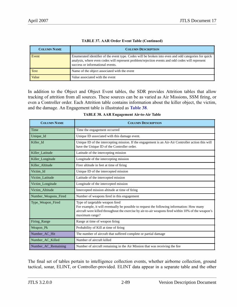
April 2007 JTLS Document 17
In addition to the Object and Object Event tables, the SDR provides Attrition tables that allowtracking of attrition from all sources. These sources can be as varied as Air Missions, SSM firing, oreven a Controller order. Each Attrition table contains information about the killer object, the victim,and the damage. An Engagement table is illustrated as Table 38.
The final set of tables pertain to intelligence collection events, whether airborne collection, groundtactical, sonar, ELINT, or Controller-provided. ELINT data appear in a separate table and the other
Event Enumerated identifier of the event type. Codes will be broken into even and odd categories for quickanalysis, where even codes will represent problem/rejection events and odd codes will representsuccess or informational events.
Text Name of the object associated with the event
Value Value associated with the event
TABLE 38. AAR Engagement Air-to-Air Table
COLUMN NAME COLUMN DESCRIPTION
Time Time the engagement occurred
Unique_Id Unique ID associated with this damage event.
Killer_Id Unique ID of the intercepting mission. If the engagement is an Air-Air Controller action this willhave the Unique ID of the Controller order.
Killer_Latitude Latitude of the intercepting mission
Killer_Longitude Longitude of the intercepting mission
Killer_Altitude Firer altitude in feet at time of firing
Victim_Id Unique ID of the intercepted mission
Victim_Latitude Latitude of the intercepted mission
Victim_Longitude Longitude of the intercepted mission
Victim_Altitude Intercepted mission altitude at time of firing
Number_Weapons_Fired Number of weapons fired in this engagement
Type_Weapon_Fired Type of targetable weapon firedFor example, it will eventually be possible to request the following information: How manyaircraft were killed throughout the exercise by air-to-air weapons fired within 10% of the weapon’smaximum range?
Firing_Range Range at time of weapon firing
Weapon_Pk Probability of Kill at time of firing
Number_AC_Hit The number of aircraft that suffered complete or partial damage
Number_AC_Killed Number of aircraft killed
Number_AC_Remaining Number of aircraft remaining in the Air Mission that was receiving the fire
TABLE 37. AAR Order Event Table (Continued)
COLUMN NAME COLUMN DESCRIPTION
JTLS 3.2.0.0 2-89 Version Description Document
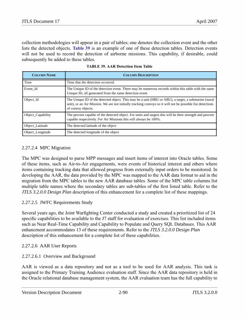
JTLS Document 17 April 2007
collection methodologies will appear in a pair of tables; one denotes the collection event and the otherlists the detected objects. Table 39 is an example of one of these detection tables. Detection eventswill not be used to record the detection of airborne missions. This capability, if desirable, couldsubsequently be added to these tables.
2.27.2.4 MPC Migration
The MPC was designed to parse MPP messages and insert items of interest into Oracle tables. Someof these items, such as Air-to-Air engagements, were events of historical interest and others whereitems containing tracking data that allowed progress from externally input orders to be monitored. Indeveloping the AAR, the data provided by the MPC was mapped to the AAR data format to aid in themigration from the MPC tables to the new AAR database tables. Some of the MPC table columns listmultiple table names where the secondary tables are sub-tables of the first listed table. Refer to theJTLS 3.2.0.0 Design Plan description of this enhancement for a complete list of these mappings.
2.27.2.5 JWFC Requirements Study
Several years ago, the Joint Warfighting Center conducted a study and created a prioritized list of 24specific capabilities to be available to the J7 staff for evaluation of exercises. This list included itemssuch as Near Real-Time Capability and Capability to Populate and Query SQL Databases. This AARenhancment accommodates 13 of these requirements. Refer to the JTLS 3.2.0.0 Design Plandescription of this enhancement for a complete list of these capabilities.
2.27.2.6 AAR User Reports
2.27.2.6.1 Overview and Background
AAR is viewed as a data repository and not as a tool to be used for AAR analysis. This task isassigned to the Primary Training Audience evaluation staff. Since the AAR data repository is held inthe Oracle relational database management system, the AAR evaluation team has the full capability to
TABLE 39. AAR Detection Item Table
COLUMN NAME COLUMN DESCRIPTION
Time Time that the detection occurred.
Event_Id The Unique ID of the detection event. There may be numerous records within this table with the sameUnique ID, all generated from the same detection event.
Object_Id The Unique ID of the detected object. This may be a unit (HRU or ARU), a target, a submarine (navalunit), or an Air Mission. We are not initially tracking convoys so it will not be possible list detectionsof convoy objects.
Object_Capability The percent capable of the detected object. For units and targets this will be their strength and percentcapable respectively. For Air Missions this will always be 100%.
Object_Latitude The detected latitude of the object
Object_Longitude The detected longitude of the object
Version Description Document 2-90 JTLS 3.2.0.0
April 2007 JTLS Document 17
query, summarize, and graphically depict a summary of the information collected during the conductof the JTLS game. It is impossible to pre-determine all evaluation team requirements; however, somebasic requirements exist any evaluation team would want fulfilled.
The JTLS AAR User Report Tool is being designed to provide the AAR evaluation team with a set ofstandard query, summary, and graphical report capabilities that will typical queries that would beuseful to the evaluation team. JTLS 3.2.0.0 provides the initial capability.
The generation of an AAR report is a two-step process; the retrieval of the desired information isfollowed by the definition of the summary and display of the retrieved data. The efficiency that isachieved justifies this separation. The new AAR data repository has the capability of holding a vastquantity of data. The speed with which the data can be saved and placed in the Oracle database mustbe considered against the speed with which the data can be retrieved. A goal of the AAR project is torefine the Oracle database structure to prevent creation and storage of the AAR data from interferingwith the game execution and to provide a reasonable retrieval rate for needed information.
By considering retrieval and reporting as separate functions, the user can retrieve the required dataand then consider various methods to report and summarize the data without requiring a re-retrievalof the data for each summary. For example, assume the user is interested in Side Blue aircraft kills onthe second day of combat. The first step would be to retrieve this information and once retrieved theAAR staff could consider summarizing this data by killing side, killing weapon, killing altitude zoneor other criterion. Each summary could be produced without re-retrieving the data. Thus if theoriginal data took 3 minutes to retrieve, the three example reports could be produced immediatelyafter the 3 minute retrieval was complete, versus requiring a 3 minute retrieval for each of the threeexample reports.
2.27.2.6.2 Retrieval Capability
Our goal for this initial capability is to provide a retrieval and reporting capability that is equivalent tothe previous Post Processor System, which emphasized air-related data. The future capability will beexpanded to include the ground war, the naval surface and sub-surface war, the available logisticsdata, and the intelligence collection capability represented within JTLS.
Three types of data will be made available for retrieval by the AAR User Report tool:
1. Specific Air Mission Details
This is the simplest retrieval. the user will be presented with a list of all of the Air Missionsthat existed since the start of the exercise. The user will highlight the desired mission byclicking on the mission record. This click will then display some basic mission informationconcerning the selected mission such as creation time and the number of events that existfor the mission. Based on this basic information, the user can then click on the Retrievebutton. All event information will be retrieved and placed in a separate temporary table.Once the retrieval is complete, the user can then move to the Report Summary phase, asdescribed in Section 2.27.2.6.3.
JTLS 3.2.0.0 2-91 Version Description Document
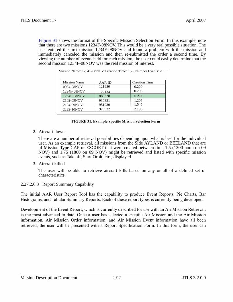
JTLS Document 17 April 2007
Figure 31 shows the format of the Specific Mission Selection Form. In this example, notethat there are two missions 1234F-08NOV. This would be a very real possible situation. Theuser entered the first mission 1234F-08NOV and found a problem with the mission andimmediately canceled the mission and then re-submitted the order a second time. Byviewing the number of events held for each mission, the user could easily determine that thesecond mission 1234F-08NOV was the real mission of interest.
FIGURE 31. Example Specific Mission Selection Form
2. Aircraft flown
There are a number of retrieval possibilities depending upon what is best for the individualuser. As an example retrieval, all missions from the Side AYLAND or BEELAND that areof Mission Type CAP or ESCORT that were created between time 1.5 (1200 noon on 09NOV) and 1.75 (1800 on 09 NOV) might be retrieved and listed with specific missionevents, such as Takeoff, Start Orbit, etc., displayed.
3. Aircraft killed
The user will be able to retrieve aircraft kills based on any or all of a defined set ofcharacteristics.
2.27.2.6.3 Report Summary Capability
The initial AAR User Report Tool has the capability to produce Event Reports, Pie Charts, BarHistograms, and Tabular Summary Reports. Each of these report types is currently being developed.
Development of the Event Report, which is currently described for use with an Air Mission Retrieval,is the most advanced to date. Once a user has selected a specific Air Mission and the Air Missioninformation, Air Mission Order information, and Air Mission Event information have all beenretrieved, the user will be presented with a Report Specification Form. In this form, the user can
Mission Name: 1234F-08NOV Creation Time: 1.25 Number Events: 23
Mission Name AAR ID Creation Time0034-08NOV1234F-08NOV1234F-08NOV2102-09NOV2104-09NOV2222-10NOV
121950
122134880328930331951030970922
0.2000.203
0.2111.2051.5452.195
Version Description Document 2-92 JTLS 3.2.0.0
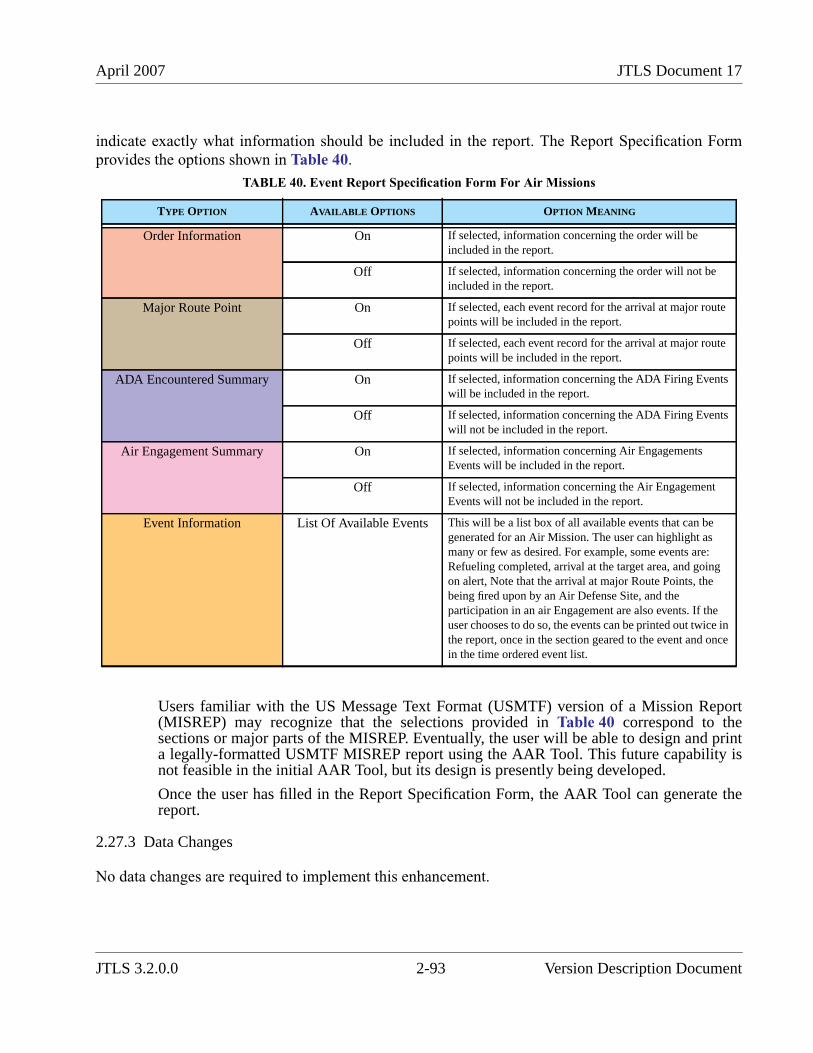
April 2007 JTLS Document 17
indicate exactly what information should be included in the report. The Report Specification Formprovides the options shown in Table 40.
Users familiar with the US Message Text Format (USMTF) version of a Mission Report(MISREP) may recognize that the selections provided in Table 40 correspond to thesections or major parts of the MISREP. Eventually, the user will be able to design and printa legally-formatted USMTF MISREP report using the AAR Tool. This future capability isnot feasible in the initial AAR Tool, but its design is presently being developed.
Once the user has filled in the Report Specification Form, the AAR Tool can generate thereport.
2.27.3 Data Changes
No data changes are required to implement this enhancement.
TABLE 40. Event Report Specification Form For Air Missions
TYPE OPTION AVAILABLE OPTIONS OPTION MEANING
Order Information On If selected, information concerning the order will beincluded in the report.
Off If selected, information concerning the order will not beincluded in the report.
Major Route Point On If selected, each event record for the arrival at major routepoints will be included in the report.
Off If selected, each event record for the arrival at major routepoints will be included in the report.
ADA Encountered Summary On If selected, information concerning the ADA Firing Eventswill be included in the report.
Off If selected, information concerning the ADA Firing Eventswill not be included in the report.
Air Engagement Summary On If selected, information concerning Air EngagementsEvents will be included in the report.
Off If selected, information concerning the Air EngagementEvents will not be included in the report.
Event Information List Of Available Events This will be a list box of all available events that can begenerated for an Air Mission. The user can highlight asmany or few as desired. For example, some events are:Refueling completed, arrival at the target area, and goingon alert, Note that the arrival at major Route Points, thebeing fired upon by an Air Defense Site, and theparticipation in an air Engagement are also events. If theuser chooses to do so, the events can be printed out twice inthe report, once in the section geared to the event and oncein the time ordered event list.
JTLS 3.2.0.0 2-93 Version Description Document
JTLS Document 17 April 2007
2.27.4 Order Changes
No order changes are required to implement this enhancement.
2.27.5 JODA Changes
The AAR data are passed from the JODA to the After Action Review Client (AARC) interface. Thesedata are held in reserved AAR objects that are defined within the JODA data structure. The AARCregisters for the receipt of these objects, which are transitory in nature. This scheme is similar to themethod used to inform the XML Message Server (XMS) regarding the existence of a message.
2.28 JTLS-0520 TACSIM Immediate Wreckage Placement
2.28.1 Summary of Model Change Request
This ECP requested that entities killed during force-on-force Lanchestrian combat be placed on thegame board as JTLS Catastrophic Killed entities in a timely manner.
2.28.2 Design Summary
In previous versions of JTLS, it was possible to kill partial combat as a result of the Lanchestriancomputation. As a result of integerizing the Lanchester algorithm and reducing the time interval atwhich damage occurs from a typical 1 hour to 15 minutes, the TACSIM requirements have beensatisfied.
At the end of each assessment period, the model now determines the number of Combat Systems thathave been killed. Each killed system is determined to be either repairable or non-repairable. If thesystem is not repairable, it is abandoned and a JTLS Catastrophic Kill entity is create. This entity ispublished in the JODA and via the HLA feed and is thus available to TACSIM immediately followingthe combat calculation in the model.
2.28.3 Data Changes
No data changes are required to implement this enhancement.
2.28.4 Order Changes
No order changes are required to implement this enhancement.
2.28.4.1 JODA Changes
No JODA changes are required to implement this enhancement.
Version Description Document 2-94 JTLS 3.2.0.0
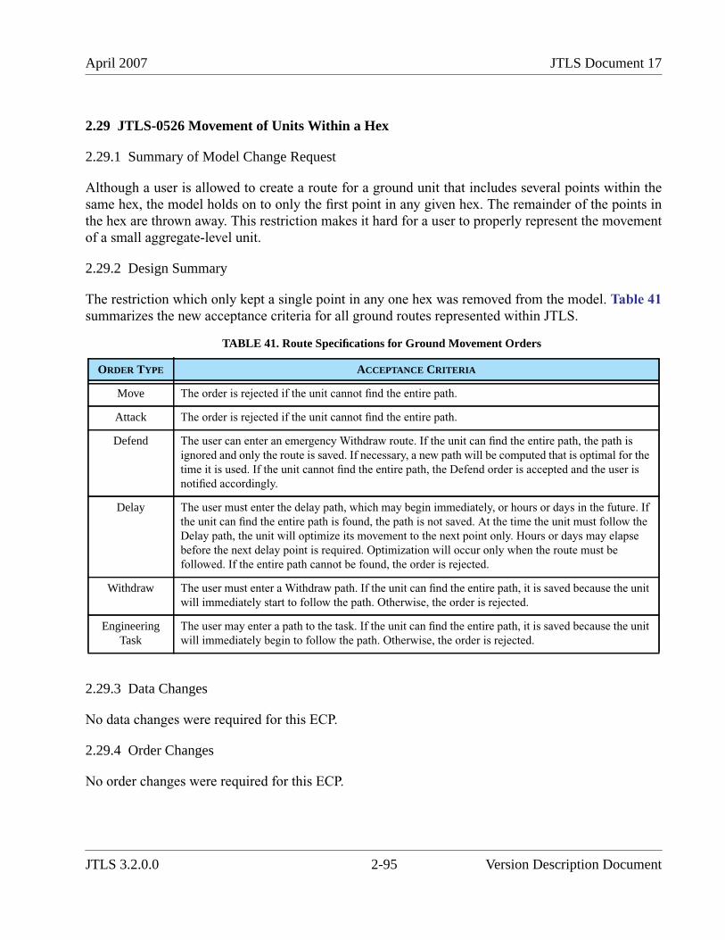
April 2007 JTLS Document 17
2.29 JTLS-0526 Movement of Units Within a Hex
2.29.1 Summary of Model Change Request
Although a user is allowed to create a route for a ground unit that includes several points within thesame hex, the model holds on to only the first point in any given hex. The remainder of the points inthe hex are thrown away. This restriction makes it hard for a user to properly represent the movementof a small aggregate-level unit.
2.29.2 Design Summary
The restriction which only kept a single point in any one hex was removed from the model. Table 41summarizes the new acceptance criteria for all ground routes represented within JTLS.
2.29.3 Data Changes
No data changes were required for this ECP.
2.29.4 Order Changes
No order changes were required for this ECP.
TABLE 41. Route Specifications for Ground Movement Orders
ORDER TYPE ACCEPTANCE CRITERIA
Move The order is rejected if the unit cannot find the entire path.
Attack The order is rejected if the unit cannot find the entire path.
Defend The user can enter an emergency Withdraw route. If the unit can find the entire path, the path is
ignored and only the route is saved. If necessary, a new path will be computed that is optimal for the
time it is used. If the unit cannot find the entire path, the Defend order is accepted and the user is
notified accordingly.
Delay The user must enter the delay path, which may begin immediately, or hours or days in the future. If
the unit can find the entire path is found, the path is not saved. At the time the unit must follow the
Delay path, the unit will optimize its movement to the next point only. Hours or days may elapse
before the next delay point is required. Optimization will occur only when the route must be
followed. If the entire path cannot be found, the order is rejected.
Withdraw The user must enter a Withdraw path. If the unit can find the entire path, it is saved because the unit
will immediately start to follow the path. Otherwise, the order is rejected.
EngineeringTask
The user may enter a path to the task. If the unit can find the entire path, it is saved because the unit
will immediately begin to follow the path. Otherwise, the order is rejected.
JTLS 3.2.0.0 2-95 Version Description Document
JTLS Document 17 April 2007
2.29.5 JODA Changes
No JODA changes were required for this ECP.
2.30 JTLS-0531 Improve ATO-T Wing Level Tasking
2.30.1 Summary of Model Change Request
Processing a JTLS Air Tasking Order (ATO) involves matching ATO air squadrons to an appropriateJTLS squadron unit. The previous matching process to assign aircraft did not properly represent real-world Wing Level air squadron tasking. This enhancement improves the representation of Wing Leveltasking as well as the one-to-many associations that occur within the Air Tasking Order during theATO translation process.
2.30.2 Design Summary
Previous ATO processing used a highly simplified method for tasking squadrons when more than oneJTLS unit was assigned to represent a single ATO unit. All JTLS units assigned as tasked units for theATO squadron were placed in a first-in, first-out list. As each mission was processed, the unit at thetop of the stack was tasked and then moved to the bottom of the stack.
Under the enhanced Wing Level tasking method, separate squadrons consisting of the same aircrafttype are typically assigned to fulfill the same mission roles under a single Wing Commander. Thesesquadrons may or may not be collocated, and therefore may be subject to the Wing Level taskingmethod. The Wing Commander is responsible for equally distributing the missions among the eligiblesquadrons.
When the ATO tasks one of these squadrons, part of the tasking information includes the departurelocation for the squadron to be tasked. This enables the ATO builders to task the squadron that islocated nearest to the mission location. Implementing this feature of this enhancement involves asimple logic improvement to use the information provided by the ATO builders in the departurelocation field to determine which squadron is to be tasked.
Since multiple units can still be tasked from the same location, the previous first-in, first-out logicprocess for selecting a squadron is improved.
For each mission tasking that is received, the ATO-T first processes the list of available squadrons andattempts to select a squadron from the desired departure location. Since more than one squadron maybe situated at the location, the selected unit is moved to the end of the stack after being tasked. If nounit is found at the desired location, the first unit in the stack is tasked, then moved to the end of thelist. The absence of a suitable unit at the desired departure location causes a warning message to begenerated and displayed in the Error and Warning list.
Version Description Document 2-96 JTLS 3.2.0.0
April 2007 JTLS Document 17
Tasking squadrons as first-in, first-out has been proven to be not completely reliable. Instances ofover-tasking individual squadrons have occurred using this method. If more than one unit exists at thetasking location, an additional process is applied. Each squadron will have a 24-hour tasking clock.As each mission is processed, a 24-hour clock array is updated to track the total number of aircraftscheduled to be flying during each of the hourly blocks. For each instance a squadron is tasked for anew mission, each hourly interval of the 24-hour clock is checked to determine whether the totalnumber of aircraft scheduled to fly during that hour exceeds the number of aircraft available from thesquadron. If this occurs, the program does not schedule the mission, and instead places it in a holdqueue. After all missions for all units have been processed through the first cycle, the programreprocesses the missions in the hold queue. The program now considers all units in the task unit setfor that squadron, and attempts to reassign the mission to a squadron that will not cause overtasking.If no squadrons with aircraft are available, the first listed squadron is selected and an appropriatewarning is displayed within the Error and Warning list. The ATO-T operator is responsible to informthe Air Cell regarding possible overtaskings identified during processing.
2.30.3 Data Changes
No data changes are required to implement this enhancement.
2.30.4 Order Changes
No order changes are required to implement this enhancement.
2.30.5 JODA Changes
No JTLS Object Distribution Authority changes are required to implement this enhancement.
2.31 JTLS-0549 Orbit Direction
2.31.1 Summary of Model Change Request
If an Air Mission is given a single orbit point within JTLS, the mission goes to the orbit point andappears to the Common Operational Picture (COP) to be stationary since its location never changes.
2.31.2 Design Summary
Within the model, a single-point orbiting mission is not stationary. It continues to move, update itsfuel, and conduct all of the other movement functions, such as determining whether it has been hit byenemy air defense. The location of the mission is not altered, but it has a speed and heading. Tosupport realistic COP representation, a single-point orbiting mission will appear to be orbiting itsdesignated orbit point. Each time the mission moves, it moves close to a different hex edge. The AirMission’s new latitude and longitude are output to the JODA and this information can then be passed
JTLS 3.2.0.0 2-97 Version Description Document
JTLS Document 17 April 2007
on to a real-world COP using whatever interface method has been developed by the user’sorganization.
2.31.3 Data Changes
No data changes were required to implement this ECP.
2.31.4 Order Changes
No order changes were required to implement this ECP.
2.31.5 JODA Changes
No JODA changes were required to implement this ECP.
2.32 JTLS-0572 Off-Map SSM Fire
2.32.1 Summary of Model Change Request
The previous JTLS Fire Missile order did not allow Surface-to-Surface Missiles (SSMs) to launchfrom off-map locations. Allowing off-map SSM targets to launch against on-map locations or targets.provides JTLS Players the flexibility to represent long-range missile attacks from locations beyondthe focused area of operations.
Off-map status is not synonymous with out-of-theater status. Out-of-theater status describes objectsthat have not yet arrived in the game via the Time Phased Force Deployment (TPFDD) process.Off-map objects have arrived, but are located outside of the playbox. In other words, they are outsidethe region of defined hexagons.
2.32.2 Design Summary
This enhancement implements changes in the Fire Missile order and the underlying routines thatprocess this order in the JTLS Combat Events Program (CEP). Furthermore, the routines that modelthe flight paths of SSMs are modified to accommodate missiles that originate off-map.
2.32.2.1 Existing Fire Missile Logic Retained
The existing internal logic for processing a Fire Missile order allows the player to initiate an SSMattack against a named Target, named Unit, specific geographic coordinates, or at a location definedby a distance and bearing from the launch location. Before the order is executed, a set of feasibilitychecks are made to ensure that the order is reasonable.
If the Fire Missile order passes the initial feasibility checks, the CEP routines begin processing theorder in detail. Information is extracted from the order and the latitude/longitude of the impact
Version Description Document 2-98 JTLS 3.2.0.0
April 2007 JTLS Document 17
location is calculated. If an SSM weapon type is not specified in the order, the CEP attempts toidentify a suitable targetable weapon for the launcher type, considering range to impact, impact hexterrain, effectiveness against the intended target, and supplies on hand. If a suitable targetable weaponcannot be identified, the order is rejected. Further feasibility checks consider Time Over Target(TOT), orbit times (if any), launch time, and distance to impact criteria. If any of these criteria cannotbe met, the order is rejected.
Before the actual launch event is scheduled, the location of the impact point is checked to verify thatit is on the map and that the terrain in the impact hex is compatible with the SSM targetable weapontype. If not, the Fire Missile order is rejected.
At this point, the missile fly-out (now a Fire Mission) begins. If the SSM does not have a boost phase,the weapon is represented as a cruise missile in the CEP. The SSM is explicitly flown from the launchlocation to the impact location hex-by-hex and is detectable. An SSM that has a boost phase is treatedas a ballistic missile and is not explicitly flown by the model. Instead, an impact time computed andthe assessment of damage at the target location is scheduled at that time. During the boost phase, theballistic missile is susceptible to attack and damage or destruction.
For the ballistic missile, a flight path from launch to impact hex is calculated to ensure that theweapon is capable of traversing the terrain along the route. If the weapon is incompatible with theterrain type, it is destroyed immediately.
For the cruise missile representation, the next hex location update is scheduled to begin the missile’sflight toward its target. From this point onward, the missile’s location is periodically updated, basedon its speed. Each instance the missile’s hex location is updated, the terrain is checked to determinewhether the missile is destroyed due to terrain incompatibility. For example, some weapons areincapable of flying over land hexes and are destroyed if the next hex in the route is not an ocean hex.
Although this existing logic did not allow SSMs to launch or fly off-map, other non-SSM objects suchas aircraft, ships, and ship formations are permitted to move while located in areas that are off themap. Note that off-map areas do not have terrain definitions; therefore, terrain limitations for objectmovement do not apply. Furthermore, off-map objects cannot be targeted for attack.
2.32.2.2 Expanded SSM Fire Capabilities
Implemented logic changes now allow an SSM to be launched from off the map and proceed to itsimpact location on the map.
The Fire Missile order is modified to permit an SSM target to launch when located off the map board.An previous initial feasibility check that verified whether the firing unit was on the map was removedfrom the order template to allow the CEP to accept the Fire Missile order for further processing.
Similarly, the off-map unit check in the Change Launcher Status order is removed to allow set-up ortear-down of SSM target launchers that are off the map. The OUT OF THEATER status (instead of
JTLS 3.2.0.0 2-99 Version Description Document
JTLS Document 17 April 2007
NOT PREPARED) is no longer assigned to off-map targets simply because they are located off themap. This allows Change Launcher Status to recognize the SSM target. The logic that checks fordetections of the launcher (the SSM Report routine) is bypassed because foreign sensors are allowedto cover on-map areas only—no hexes are defined off the map to hold an indicator that a sensor isprojecting into that location.
New logic is added to accommodate a firing unit (and by extension, the SSM target launcher) that isoff-map after the launch (Fire) event is scheduled. A check for on/off map status is added to the StartMissile Fly Out routine to appropriately handle the new off-map situation. If the SSM target isoff-map, an Off Board Movement event will be scheduled. While off-map, the missile will not besubject to detection or attack because no hexes are defined. The SSM Report routine is bypassed. Ifthe SSM target is on-map, the Move Along Route Cruise Missile event is scheduled and the missile isvulnerable to attack.
Within the Off Board Movement event, new logic is added to accommodate an SSM targetableweapon. The Fire Mission object type, which represents an SSM modeled as a cruise missile, is addedto the Off Board Movement event as a special case. New code calculates the mission’s next locationand schedules the next Off Board Movement event. The routine Get Current Location includes newcode that calculates the current location of an object, because a Fire Mission does not have anassociated route or current hex. The Off Board Movement continues to be scheduled while themission’s next location is off-map. However, if the next location update places the mission on themap, the Move Along Route Cruise Missile event is scheduled from that location forward.
Since off-map areas do not have terrain definitions, any terrain-limiting attributes of the SSMtargetable weapon are ignored during off-map flight within the Off Board Movement event. After theSSM enters the map, terrain limitations are applied in the Move Along Route Cruise Missile event.The pre-launch feasibility checks in the Start Missile Fly Out routine that verify that the impact hexand projected flight path contain acceptable terrain are retained.
Finally, the game save process was modified to accommodate introducing the Fire Mission object inthe Fire event. This ensures that the new object is included in the Fire event written to checkpoint fileand is successfully read during the restore process.
2.32.3 Data Changes
No data changes are required to implement this enhancement.
2.32.4 Order Changes
The unit check constraint that causes an order rejection when the Firing Unit is located off-map isremoved from the Fire Missile order.
Version Description Document 2-100 JTLS 3.2.0.0
April 2007 JTLS Document 17
2.32.5 JODA Changes
No JTLS Object Distribution Authority changes are required to implement this enhancement.
2.33 JTLS-2005-1431 ATO-T Orbit Points
2.33.1 Summary of Model Change Request
The Air Tasking Order Translator (ATO-T) performs a basic translation of an ATO. This modelenhancement creates and schedules JTLS orders that regulate the movement of the Air Missionamong different orbit points.
2.33.2 Design Summary
The ATO-T receives and processes the current day ATO and ACO for input to the JTLS model. Thisprocessing assigns the initial mission locations based on the ACO information. The assignment of themission locations uses only the first location information record. The text of the ATO may containmultiple location changes for a specific mission at different times. Under the previous processingsystem, these changes were the responsibility of the Air Operator. This model enhancementautomates the process of submitting these change orders to schedule the movement of orbiting AirMissions from one location to the next location at the time specified in the ATO.
This enhancement does not process all JTLS Air Missions types, and is limited by the softwareenvironment of the supported exercise, as well as a requirement to use an off-map ProC environment.
JTLS defines 18 different Air Mission types. Some of these require special processing, due to limitedor missing information in the ATO, or the complexity of the order. Only the following mission typeswill be considered for the new automated Change Orbit processing:
• Air Refuel
• Armed RECCE
• AWACS
• Combat Air Patrol
• Electronic Combat
• Mine Warfare
• Orbiting OAS
• Patrol
• RECCE
• Wild Weasel
JTLS 3.2.0.0 2-101 Version Description Document
JTLS Document 17 April 2007
The JTLS Change Air Mission Parameter order is used in JTLS to submit the Air Mission locationchanges. This order does not contain a order submission time field, which means that all orders areeffective immediately when the CEP receives them. For this reason the Order Entry Client (OEC),which is written for a off-map ProC environment, is used to control the submission time of the ordersto the CEP. This process involves the ATO-T, and creates and stores the Change Air MissionParameter order as a set of off-map tables. The required submission time field is stored in the OEC,which monitors the current game time and submits orders from the off-map tables to the CEP onschedule. Therefore, a off-map ProC environment and the OEC are required to process the second andsubsequent AMSLOC records from a ATO.
Processing and submission of the primary mission order is unchanged; the orbit information isobtained from the first Air Mission Location (AMSNLOC) record. The new logic requires saving andprocessing the second and subsequent AMSNLOC records. After each primary mission order iscreated, the program processes each of the subsequent AMSNLOC records by creating a Change AirMission Parameter order. Each Change Air Mission Parameter order, including the order submissiontime, is written to an off-map table; the OCE submits the order to the CEP. As a minimum, the ordermust contain the time of submission and new location information. As needed, the order can alsomodify the mission off-station time to reflect the new times specified in the AMSNLOC records.
The order submission time must be specified as the off-station time of the current location.
• Example 1: Two AMSNLOC records. Record 1 covers the period 0600-0900 at locationALPHA and Record 2 covers the period 1000-1300 at location BRAVO. This mission willleave at 0900 for its new location BRAVO and arrive early.
• Example 2: Two AMSNLOC records. Record 1 covers the period 0600-0900 at locationCHARLIE and Record 2 covers the period 0900-1200 at location DELTA. This mission willleave at 0900 for its new location DELTA and will arrive late, but ASAP.
Orbit location information is processed and submitted as described in the ACO or on the AMSNLOCrecord using the current ATO-T rules. While processing each AMSNLOC record, the ATO-T submitswith each change the required modification to the mission off-station time that satisfies missionrequirements.
2.33.3 Data Changes
No data changes are required to implement this enhancement.
2.33.4 Order Changes
No order changes are required to implement this enhancement.
2.33.5 JODA Changes
No JTLS Object Distribution Authority changes are required to implement this enhancement.
Version Description Document 2-102 JTLS 3.2.0.0
April 2007 JTLS Document 17
2.34 JTLS-2005-1483 Fillup Refuel Chit
2.34.1 Summary of Model Change Request
A JTLS Air Mission determines its need for fuel according to its current location and its next plannedrefuel location. If the mission cannot reach its next planned refuel location, considering its currentfuel load, altitude, and speed, the mission automatically searches for a fuel source. If the aircraft canbe refueled while airborne, the mission gives priority to locating an airborne tanker from which toobtain fuel and continue its planned mission. Previously, JTLS refueling logic applied the principlethat the Air Mission should load only as much fuel as required to complete its assigned task andreserve fuel for other aircraft in the area that may have similar needs.
Further model development to provide additional mission flexibility for Air Players has madeaccurate computation of fuel requirements more difficult. For example, an Orbiting Offensive AirSupport (OAS) mission sent as an intercept can complete that task and return to its orbit location forassignment to attack a target. In such situations, current JTLS Air Missions were frequently low onfuel, due to the conservative fuel assignment algorithm.
The previous fuel requirement computation is removed from an Air Mission’s refueling logic. Insteadof minimizing the refueling load to conserve fuel at the source, the mission loads fuel to its maximumcapacity when it determines that refueling is necessary.
2.34.2 Design Summary
Two basic fuel allocation principles support this model enhancement:
• Accurate Tanker Reserved Fuel Requirement. A JTLS Air Mission holds a Refuel Chitobject when it heads to a tanker to refuel. This Refuel Chit indicates the amount of fuel thatshould be taken from the tanker. The tanker providing the fuel holds an identical RefuelChit, which enables the tanker compute its non-reserved fuel as a sum of the fuel allocatedby its Refuel Chits and subtracting that sum from its current onboard fuel supply. Accuratecomputation of the available non-reserved fuel is critical.
If the tanker determines a greater non-reserved fuel supply than actually exists, other AirMissions anticipate using this non-reserved fuel, but will not receive their full requirementwhen they arrive at the tanker. Such missions will experience a non-recoverable fuelproblem. If no other tankers are present in the area, the mission may not have sufficient fuelto recover from the shortfall and crash. If an Air Mission overestimates its refuelrequirement and reserves excess fuel, other missions may cancel their operations due totheir inability to obtain fuel.
• Accurate Mission Minimum and Allowable Fuel Requirement. Considering the new logicthat missions will refuel to capacity, the difference between the mission’s requirement andits capacity may be significant when the mission determines which tanker should providefuel and may affect the mission’s decision when to head home.
JTLS 3.2.0.0 2-103 Version Description Document
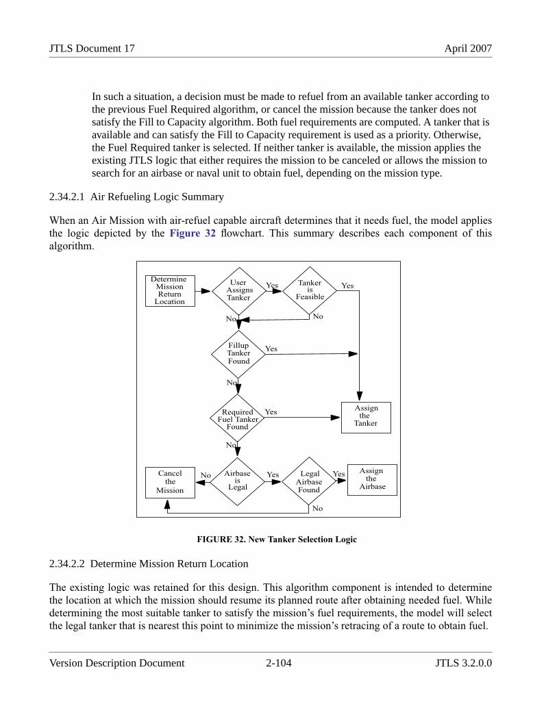
JTLS Document 17 April 2007
In such a situation, a decision must be made to refuel from an available tanker according tothe previous Fuel Required algorithm, or cancel the mission because the tanker does notsatisfy the Fill to Capacity algorithm. Both fuel requirements are computed. A tanker that isavailable and can satisfy the Fill to Capacity requirement is used as a priority. Otherwise,the Fuel Required tanker is selected. If neither tanker is available, the mission applies theexisting JTLS logic that either requires the mission to be canceled or allows the mission tosearch for an airbase or naval unit to obtain fuel, depending on the mission type.
2.34.2.1 Air Refueling Logic Summary
When an Air Mission with air-refuel capable aircraft determines that it needs fuel, the model appliesthe logic depicted by the Figure 32 flowchart. This summary describes each component of thisalgorithm.
FIGURE 32. New Tanker Selection Logic
2.34.2.2 Determine Mission Return Location
The existing logic was retained for this design. This algorithm component is intended to determinethe location at which the mission should resume its planned route after obtaining needed fuel. Whiledetermining the most suitable tanker to satisfy the mission’s fuel requirements, the model will selectthe legal tanker that is nearest this point to minimize the mission’s retracing of a route to obtain fuel.
Assignthe
Tanker
UserAssignsTanker
Tanker
Feasible
DetermineMissionReturn
Location
FillupTankerFound
RequiredFuel Tanker
Airbase
Legal
Found
LegalAirbaseFound
Assignthe
Airbase
Cancelthe
Mission
Yes
No
No
No
Yes
No
Yes
Yes
No Yes
No
Yesis
is
Version Description Document 2-104 JTLS 3.2.0.0

April 2007 JTLS Document 17
2.34.2.3 Determining Feasibility of a User-Assigned Tanker
The existing logic is retained. First, the model applies several criteria to determine which assignedtanker is feasible.
The mission from which fuel will be obtained has reached its assigned orbit location. The refuelingmission must already obtain fuel enroute to its next task location. A tanker that leads the missioncloser to its return point assists the mission to complete its planned route, and is therefore consideredfeasible. The refueling mission has sufficient fuel to meet the tanker at its most fuel efficient altitudeand speed. The tanker must carry the user-ordered fuel available for the mission.
After compiling a list of feasible assigned tankers, the model chooses a tanker nearest the mission’sreturn location. As Figure 32 depicts, the model does not consider further options if a user-assignedtanker is found and the mission is directed to head toward the selected tanker.
2.34.2.4 Determine Best Fillup Tanker
If no user-assigned feasible tanker is found, the tanker selection process applies similar rules to locatea feasible tanker from which sufficient fuel can be obtained to refuel the mission to capacity. Onlytankers currently at their orbit location and prepared to provide fuel are considered. All other tankersare not considered, regardless of their current or pending status. Thus, a tanker a few miles distantfrom its orbit location will not considered by this algorithm. This restriction is a legacy of the JTLStanker selection algorithm and altering this basic selection assumption is beyond the scope of thisdesign.
To determine the fuel quantity that will be required from the tanker, the model must accuratelycompute the amount of fuel needed when the mission arrives. This is done by computing the amountof fuel needed to fly the mission to the tanker at the mission’s most fuel-efficient speed and altitude.The tanker must carry the fuel required to supply the mission to its capacity and computes the amountof fuel that it has available. If the fuel available is greater than or equal to the fuel requirementcomputed in the previous step, the tanker is considered feasible. Otherwise, the tanker is notconsidered feasible.
After compiling a list of feasible assigned tankers, the model chooses a tanker nearest the mission’sreturn location. As Figure 32 depicts, the model does not consider further options if a user-assignedtanker is found and the mission is directed to head toward the selected tanker.
2.34.2.5 Determine Best Required Fuel Tanker
If no fill-up tanker is found, the model applies the existing logic to find a feasible tanker. Althoughusers contend that the current logic underestimates the amount of fuel that a mission may need, thealgorithm has been useful for several years. Not considering a tanker because it cannot provide a fullload of fuel to a mission when the mission may be accomplished with less fuel seems unreasonable.For this reason, the existing logic is retained in the model as a final fueling option.
JTLS 3.2.0.0 2-105 Version Description Document
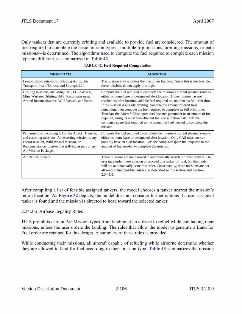
JTLS Document 17 April 2007
Only tankers that are currently orbiting and available to provide fuel are considered. The amount offuel required to complete the basic mission types—multiple trip missions, orbiting missions, or pathmissions—is determined. The algorithms used to compute the fuel required to complete each missiontype are different, as summarized in Table 42.
After compiling a list of feasible assigned tankers, the model chooses a tanker nearest the mission’sreturn location. As Figure 32 depicts, the model does not consider further options if a user-assignedtanker is found and the mission is directed to head toward the selected tanker.
2.34.2.6 Airbase Legality Rules
JTLS prohibits certain Air Mission types from landing at an airbase to refuel while conducting theirmissions, unless the user orders the landing. The rules that allow the model to generate a Land forFuel order are retained for this design. A summary of these rules is provided.
While conducting their missions, all aircraft capable of refueling while airborne determine whetherthey are allowed to land for fuel according to their mission type. Table 43 summarizes the mission
TABLE 42. Fuel Required Computation
MISSION TYPE ALGORITHM
Long-distance missions, including Airlift, AirTransport, Insert/Extract, and Strategic Lift
The mission always orders the maximum fuel load. Since this is not feasible,these missions do not apply this logic.
Orbiting missions, including CAP, EC, AWACS,Mine Warfare, Orbiting OAS, Reconnaissance,Armed Reconnaissance, Wild Weasel, and Patrol.
Compute the fuel required to complete the mission’s current planned route toeither its home base or designated alert location. If the mission has notreached its orbit location, add the fuel required to complete its full orbit time.If the mission is already orbiting, compute the amount of orbit timeremaining, then compute the fuel required to complete its full orbit time.Translate the Aircraft Class spare fuel distance parameter to an amount of fuelrequired, using its most fuel-efficient fuel consumption data. Add thecomputed spare fuel required to the amount of fuel needed to complete themission.
Path missions, including CAS, Air Attack, Transfer,and escorting missions. An escorting mission is anyEscort mission, Wild Weasel mission, orReconnaissance mission that is flying as part of anAir Mission Package.
Compute the fuel required to complete the mission’s current planned route toeither its home base or designated alert location. Only CAS missions canpossibly have an alert location. Add the computed spare fuel required to theamount of fuel needed to complete the mission.
Air Refuel Tankers These missions are not allowed to automatically search for other tankers. Theuser may order these mission to proceed to a tanker for fuel, but the modelwill not automatically issue this order. Consequently, these missions are notallowed to find feasible tankers, as described in this section and Section2.34.2.4.
Version Description Document 2-106 JTLS 3.2.0.0
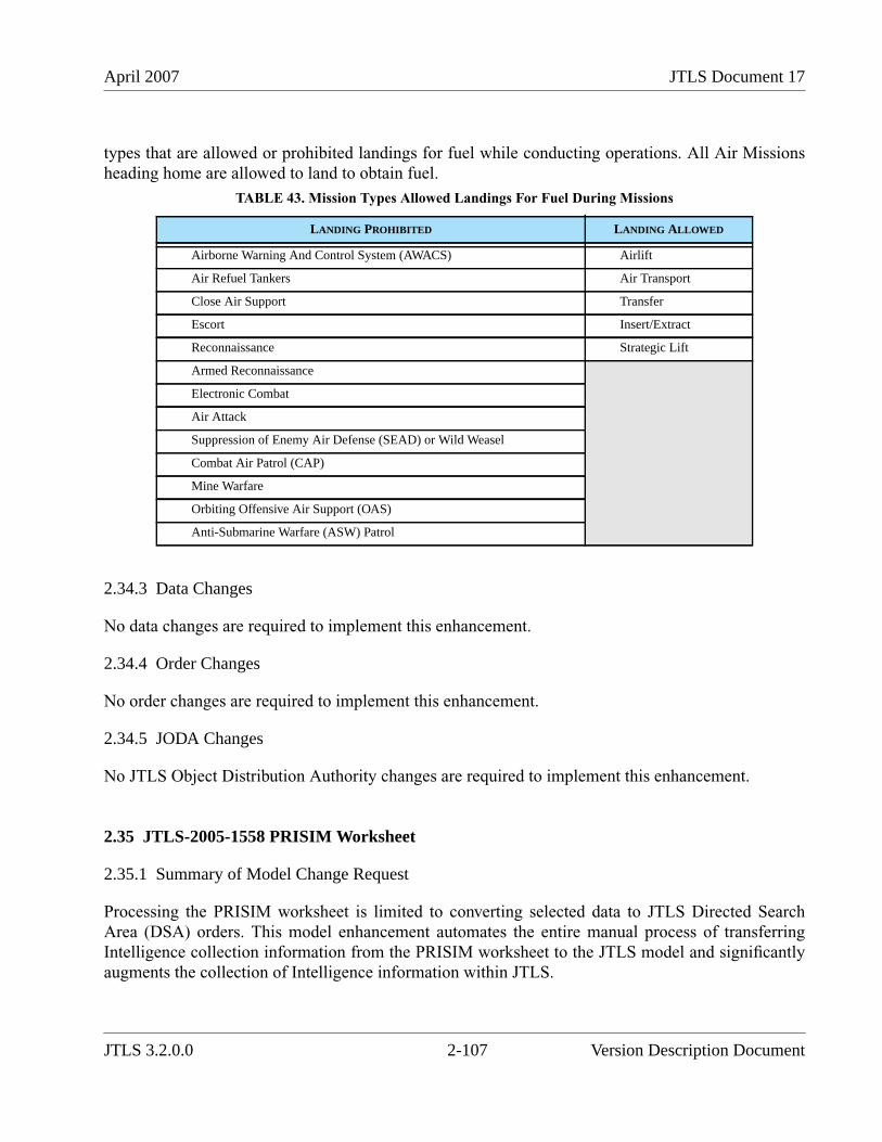
April 2007 JTLS Document 17
types that are allowed or prohibited landings for fuel while conducting operations. All Air Missionsheading home are allowed to land to obtain fuel.
2.34.3 Data Changes
No data changes are required to implement this enhancement.
2.34.4 Order Changes
No order changes are required to implement this enhancement.
2.34.5 JODA Changes
No JTLS Object Distribution Authority changes are required to implement this enhancement.
2.35 JTLS-2005-1558 PRISIM Worksheet
2.35.1 Summary of Model Change Request
Processing the PRISIM worksheet is limited to converting selected data to JTLS Directed SearchArea (DSA) orders. This model enhancement automates the entire manual process of transferringIntelligence collection information from the PRISIM worksheet to the JTLS model and significantlyaugments the collection of Intelligence information within JTLS.
TABLE 43. Mission Types Allowed Landings For Fuel During Missions
LANDING PROHIBITED LANDING ALLOWED
Airborne Warning And Control System (AWACS) Airlift
Air Refuel Tankers Air Transport
Close Air Support Transfer
Escort Insert/Extract
Reconnaissance Strategic Lift
Armed Reconnaissance
Electronic Combat
Air Attack
Suppression of Enemy Air Defense (SEAD) or Wild Weasel
Combat Air Patrol (CAP)
Mine Warfare
Orbiting Offensive Air Support (OAS)
Anti-Submarine Warfare (ASW) Patrol
JTLS 3.2.0.0 2-107 Version Description Document
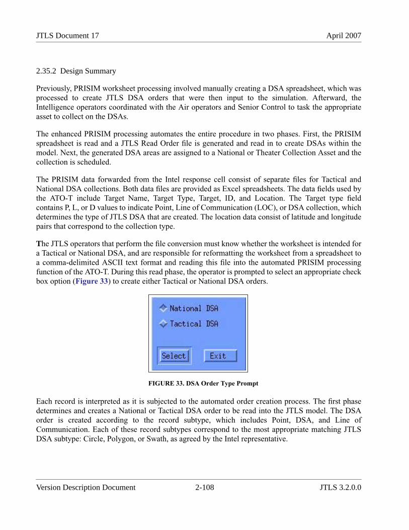
JTLS Document 17 April 2007
2.35.2 Design Summary
Previously, PRISIM worksheet processing involved manually creating a DSA spreadsheet, which wasprocessed to create JTLS DSA orders that were then input to the simulation. Afterward, theIntelligence operators coordinated with the Air operators and Senior Control to task the appropriateasset to collect on the DSAs.
The enhanced PRISIM processing automates the entire procedure in two phases. First, the PRISIMspreadsheet is read and a JTLS Read Order file is generated and read in to create DSAs within themodel. Next, the generated DSA areas are assigned to a National or Theater Collection Asset and thecollection is scheduled.
The PRISIM data forwarded from the Intel response cell consist of separate files for Tactical andNational DSA collections. Both data files are provided as Excel spreadsheets. The data fields used bythe ATO-T include Target Name, Target Type, Target, ID, and Location. The Target type fieldcontains P, L, or D values to indicate Point, Line of Communication (LOC), or DSA collection, whichdetermines the type of JTLS DSA that are created. The location data consist of latitude and longitudepairs that correspond to the collection type.
The JTLS operators that perform the file conversion must know whether the worksheet is intended fora Tactical or National DSA, and are responsible for reformatting the worksheet from a spreadsheet toa comma-delimited ASCII text format and reading this file into the automated PRISIM processingfunction of the ATO-T. During this read phase, the operator is prompted to select an appropriate checkbox option (Figure 33) to create either Tactical or National DSA orders.
FIGURE 33. DSA Order Type Prompt
Each record is interpreted as it is subjected to the automated order creation process. The first phasedetermines and creates a National or Tactical DSA order to be read into the JTLS model. The DSAorder is created according to the record subtype, which includes Point, DSA, and Line ofCommunication. Each of these record subtypes correspond to the most appropriate matching JTLSDSA subtype: Circle, Polygon, or Swath, as agreed by the Intel representative.
Version Description Document 2-108 JTLS 3.2.0.0
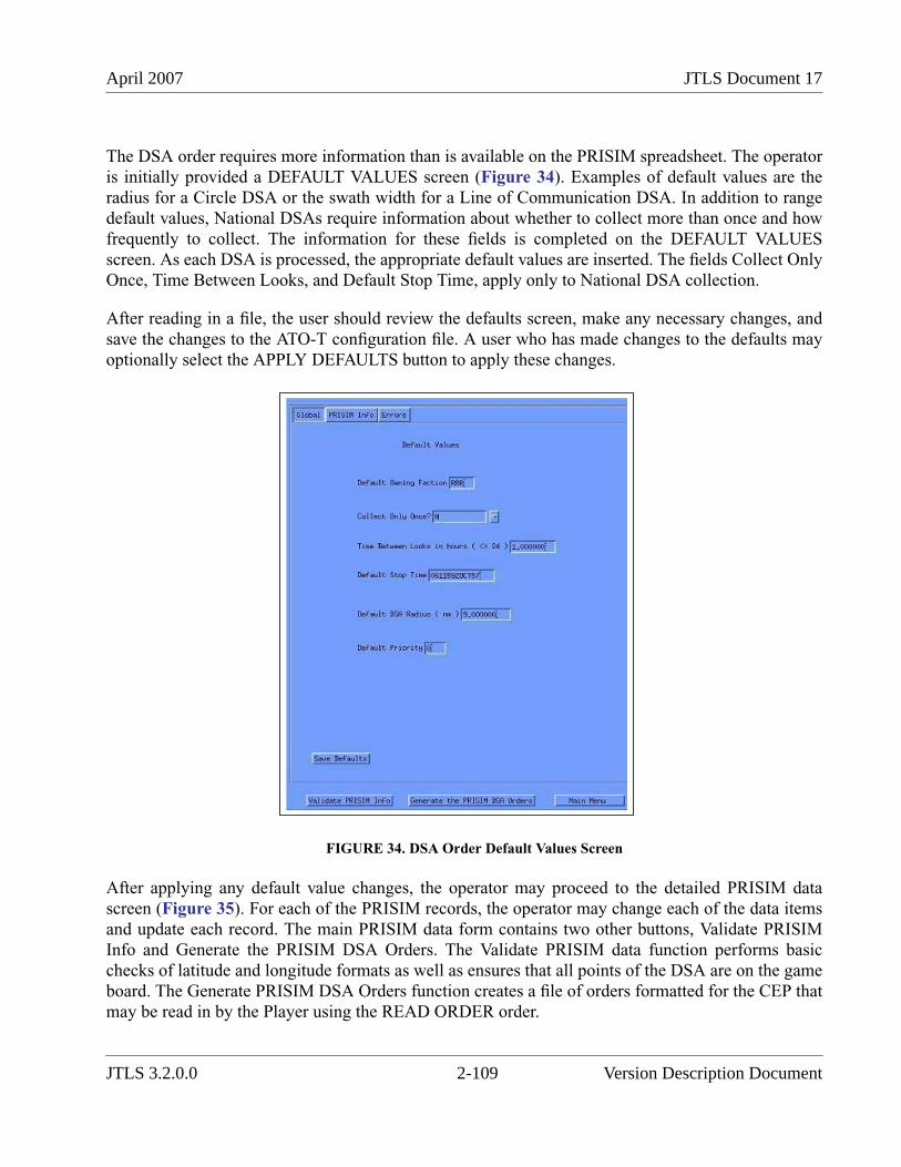
April 2007 JTLS Document 17
The DSA order requires more information than is available on the PRISIM spreadsheet. The operatoris initially provided a DEFAULT VALUES screen (Figure 34). Examples of default values are theradius for a Circle DSA or the swath width for a Line of Communication DSA. In addition to rangedefault values, National DSAs require information about whether to collect more than once and howfrequently to collect. The information for these fields is completed on the DEFAULT VALUESscreen. As each DSA is processed, the appropriate default values are inserted. The fields Collect OnlyOnce, Time Between Looks, and Default Stop Time, apply only to National DSA collection.
After reading in a file, the user should review the defaults screen, make any necessary changes, andsave the changes to the ATO-T configuration file. A user who has made changes to the defaults mayoptionally select the APPLY DEFAULTS button to apply these changes.
FIGURE 34. DSA Order Default Values Screen
After applying any default value changes, the operator may proceed to the detailed PRISIM datascreen (Figure 35). For each of the PRISIM records, the operator may change each of the data itemsand update each record. The main PRISIM data form contains two other buttons, Validate PRISIMInfo and Generate the PRISIM DSA Orders. The Validate PRISIM data function performs basicchecks of latitude and longitude formats as well as ensures that all points of the DSA are on the gameboard. The Generate PRISIM DSA Orders function creates a file of orders formatted for the CEP thatmay be read in by the Player using the READ ORDER order.
JTLS 3.2.0.0 2-109 Version Description Document
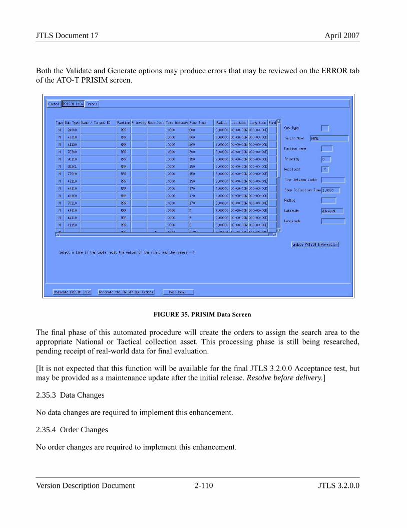
JTLS Document 17 April 2007
Both the Validate and Generate options may produce errors that may be reviewed on the ERROR tabof the ATO-T PRISIM screen.
FIGURE 35. PRISIM Data Screen
The final phase of this automated procedure will create the orders to assign the search area to theappropriate National or Tactical collection asset. This processing phase is still being researched,pending receipt of real-world data for final evaluation.
[It is not expected that this function will be available for the final JTLS 3.2.0.0 Acceptance test, butmay be provided as a maintenance update after the initial release. Resolve before delivery.]
2.35.3 Data Changes
No data changes are required to implement this enhancement.
2.35.4 Order Changes
No order changes are required to implement this enhancement.
Version Description Document 2-110 JTLS 3.2.0.0
April 2007 JTLS Document 17
2.35.5 JODA Changes
No JTLS Object Distribution Authority changes are required to implement this enhancement.
2.36 JTLS-2006-1660 Integerized Lanchestrian Combat
2.36.1 Summary of Model Change Request
The determination of force-on-force combat results, known in JTLS as Lanchestrian attrition, is asignificant capability of JTLS that is closely linked to its current hexagon-based terrainrepresentation. Force-on-force combat within JTLS uses an approximation (known as differenceequations) to Lanchester’s Direct Fire and Indirect Fire partial differential equations. TheUS Government has established the long-term goal of altering this Lanchestrian attrition capabilitywithin JTLS to reduce the dependence of the Joint Theater Level Simulation (JTLS) upon thehexagon-based terrain modeling assumptions and to support a high-resolution rectangular terrainmodel.
This enhancement has evolved as an interim development effort to address the following Lanchestrianattrition issues identified in the original terrain modification design:
• Lanchester combat results were previously computed periodically according to apredetermined time interval based on the database parameter ASSESS COMBAT TIME,which was conventionally set to a value of one hour. Modifying this value was not feasibledue to the abundance of other data parameters that were dependent upon ASSESSCOMBAT TIME. Removing the link between this database parameter and all otherdependent parameters, including the coefficients for the Lanchester difference equations,was required.
• When Lanchestrian attrition was computed, this damage assessment was simultaneouslycompleted for all units in the game during the Assess Combat event. In a large scenario,computing the Assess Combat event can require several minutes. This extendedcomputation period with no time advance causes problems for other federates of the JointMulti-Resolution Model (JMRM) federation. Dividing the assessment procedure intosmaller elements was required to prevent the model from entering an extended computationstate and halting the advancement of time for other JMRM federates.
• Lanchester combat attrition results caused fractional Combat System losses within units.Although the concept of fractional losses is appropriate within the Lanchester differentialequation paradigm and the JTLS aggregate unit representation, problems are introducedwhen JTLS links to entity-level models and virtual simulators.
JTLS 3.2.0.0 2-111 Version Description Document
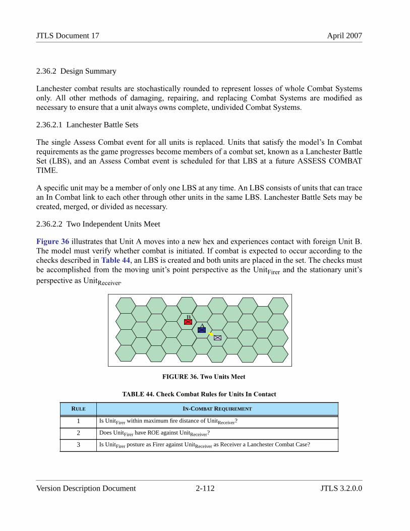
JTLS Document 17 April 2007
2.36.2 Design Summary
Lanchester combat results are stochastically rounded to represent losses of whole Combat Systemsonly. All other methods of damaging, repairing, and replacing Combat Systems are modified asnecessary to ensure that a unit always owns complete, undivided Combat Systems.
2.36.2.1 Lanchester Battle Sets
The single Assess Combat event for all units is replaced. Units that satisfy the model’s In Combatrequirements as the game progresses become members of a combat set, known as a Lanchester BattleSet (LBS), and an Assess Combat event is scheduled for that LBS at a future ASSESS COMBATTIME.
A specific unit may be a member of only one LBS at any time. An LBS consists of units that can tracean In Combat link to each other through other units in the same LBS. Lanchester Battle Sets may becreated, merged, or divided as necessary.
2.36.2.2 Two Independent Units Meet
Figure 36 illustrates that Unit A moves into a new hex and experiences contact with foreign Unit B.The model must verify whether combat is initiated. If combat is expected to occur according to thechecks described in Table 44, an LBS is created and both units are placed in the set. The checks mustbe accomplished from the moving unit’s point perspective as the UnitFirer and the stationary unit’s
perspective as UnitReceiver.
FIGURE 36. Two Units Meet
TABLE 44. Check Combat Rules for Units In Contact
RULE IN-COMBAT REQUIREMENT
1 Is UnitFirer within maximum fire distance of UnitReceiver?
2 Does UnitFirer have ROE against UnitReceiver?
3 Is UnitFirer posture as Firer against UnitReceiver as Receiver a Lanchester Combat Case?
A
B
Version Description Document 2-112 JTLS 3.2.0.0
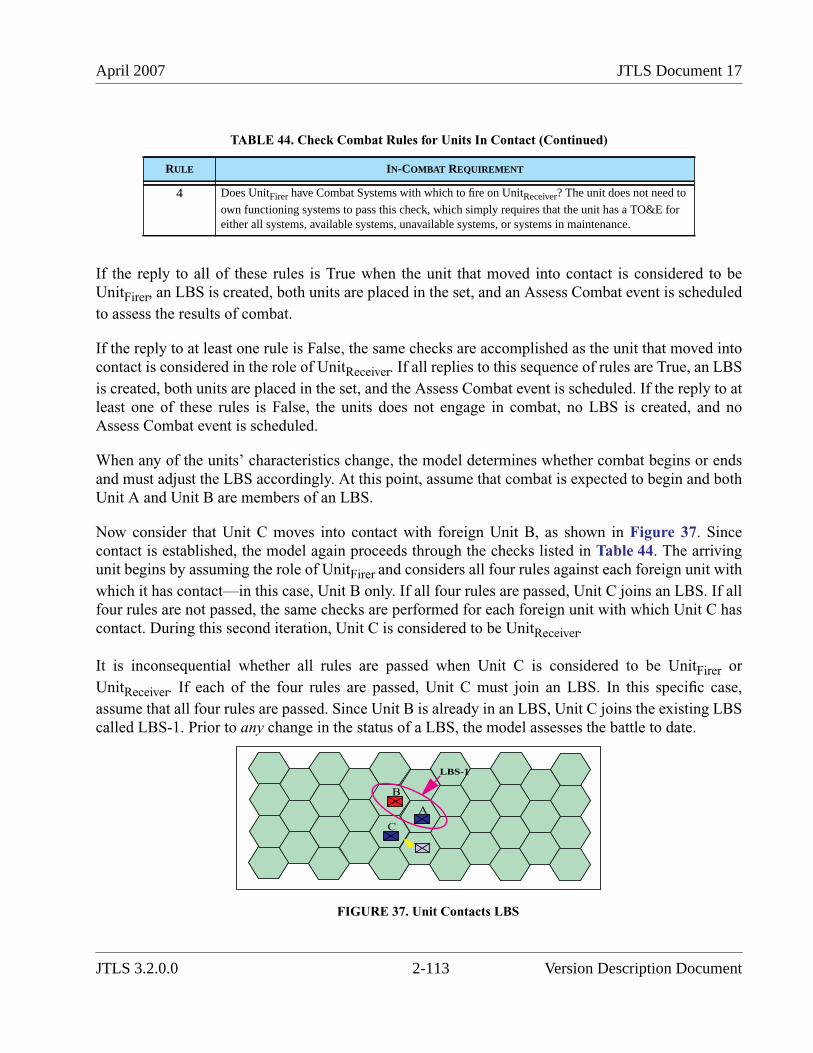
April 2007 JTLS Document 17
If the reply to all of these rules is True when the unit that moved into contact is considered to beUnitFirer, an LBS is created, both units are placed in the set, and an Assess Combat event is scheduled
to assess the results of combat.
If the reply to at least one rule is False, the same checks are accomplished as the unit that moved intocontact is considered in the role of UnitReceiver. If all replies to this sequence of rules are True, an LBS
is created, both units are placed in the set, and the Assess Combat event is scheduled. If the reply to atleast one of these rules is False, the units does not engage in combat, no LBS is created, and noAssess Combat event is scheduled.
When any of the units’ characteristics change, the model determines whether combat begins or endsand must adjust the LBS accordingly. At this point, assume that combat is expected to begin and bothUnit A and Unit B are members of an LBS.
Now consider that Unit C moves into contact with foreign Unit B, as shown in Figure 37. Sincecontact is established, the model again proceeds through the checks listed in Table 44. The arrivingunit begins by assuming the role of UnitFirer and considers all four rules against each foreign unit with
which it has contact—in this case, Unit B only. If all four rules are passed, Unit C joins an LBS. If allfour rules are not passed, the same checks are performed for each foreign unit with which Unit C hascontact. During this second iteration, Unit C is considered to be UnitReceiver.
It is inconsequential whether all rules are passed when Unit C is considered to be UnitFirer or
UnitReceiver. If each of the four rules are passed, Unit C must join an LBS. In this specific case,
assume that all four rules are passed. Since Unit B is already in an LBS, Unit C joins the existing LBScalled LBS-1. Prior to any change in the status of a LBS, the model assesses the battle to date.
FIGURE 37. Unit Contacts LBS
4 Does UnitFirer have Combat Systems with which to fire on UnitReceiver? The unit does not need to
own functioning systems to pass this check, which simply requires that the unit has a TO&E foreither all systems, available systems, unavailable systems, or systems in maintenance.
TABLE 44. Check Combat Rules for Units In Contact (Continued)
RULE IN-COMBAT REQUIREMENT
A
B
LBS-1
C
JTLS 3.2.0.0 2-113 Version Description Document
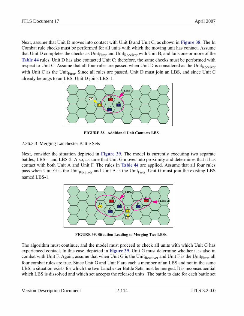
JTLS Document 17 April 2007
Next, assume that Unit D moves into contact with Unit B and Unit C, as shown in Figure 38. The InCombat rule checks must be performed for all units with which the moving unit has contact. Assumethat Unit D completes the checks as UnitFirer and UnitReceiver with Unit B, and fails one or more of the
Table 44 rules. Unit D has also contacted Unit C; therefore, the same checks must be performed withrespect to Unit C. Assume that all four rules are passed when Unit D is considered as the UnitReceiver
with Unit C as the UnitFirer. Since all rules are passed, Unit D must join an LBS, and since Unit C
already belongs to an LBS, Unit D joins LBS-1.
FIGURE 38. Additional Unit Contacts LBS
2.36.2.3 Merging Lanchester Battle Sets
Next, consider the situation depicted in Figure 39. The model is currently executing two separatebattles, LBS-1 and LBS-2. Also, assume that Unit G moves into proximity and determines that it hascontact with both Unit A and Unit F. The rules in Table 44 are applied. Assume that all four rulespass when Unit G is the UnitReceiver and Unit A is the UnitFirer. Unit G must join the existing LBS
named LBS-1.
FIGURE 39. Situation Leading to Merging Two LBSs.
The algorithm must continue, and the model must proceed to check all units with which Unit G hasexperienced contact. In this case, depicted in Figure 39, Unit G must determine whether it is also incombat with Unit F. Again, assume that when Unit G is the UnitReceiver and Unit F is the UnitFirer, all
four combat rules are true. Since Unit G and Unit F are each a member of an LBS and not in the sameLBS, a situation exists for which the two Lanchester Battle Sets must be merged. It is inconsequentialwhich LBS is dissolved and which set accepts the released units. The battle to date for each battle set
A
B
LBS-1
C
D
A
B
LBS-1
C
D F
ELBS-2
G
Version Description Document 2-114 JTLS 3.2.0.0
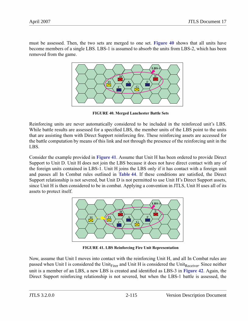
April 2007 JTLS Document 17
must be assessed. Then, the two sets are merged to one set. Figure 40 shows that all units havebecome members of a single LBS. LBS-1 is assumed to absorb the units from LBS-2, which has beenremoved from the game.
FIGURE 40. Merged Lanchester Battle Sets
Reinforcing units are never automatically considered to be included in the reinforced unit’s LBS.While battle results are assessed for a specified LBS, the member units of the LBS point to the unitsthat are assisting them with Direct Support reinforcing fire. These reinforcing assets are accessed forthe battle computation by means of this link and not through the presence of the reinforcing unit in theLBS.
Consider the example provided in Figure 41. Assume that Unit H has been ordered to provide DirectSupport to Unit D. Unit H does not join the LBS because it does not have direct contact with any ofthe foreign units contained in LBS-1. Unit H joins the LBS only if it has contact with a foreign unitand passes all In Combat rules outlined in Table 44. If these conditions are satisfied, the DirectSupport relationship is not severed, but Unit D is not permitted to use Unit H’s Direct Support assets,since Unit H is then considered to be in combat. Applying a convention in JTLS, Unit H uses all of itsassets to protect itself.
FIGURE 41. LBS Reinforcing Fire Unit Representation
Now, assume that Unit I moves into contact with the reinforcing Unit H, and all In Combat rules arepassed when Unit I is considered the UnitFirer and Unit H is considered the UnitReceiver. Since neither
unit is a member of an LBS, a new LBS is created and identified as LBS-3 in Figure 42. Again, theDirect Support reinforcing relationship is not severed, but when the LBS-1 battle is assessed, the
A
B
LBS-1
C
D F
E
G
A
B
LBS-1
C
D F
E
G
H
JTLS 3.2.0.0 2-115 Version Description Document
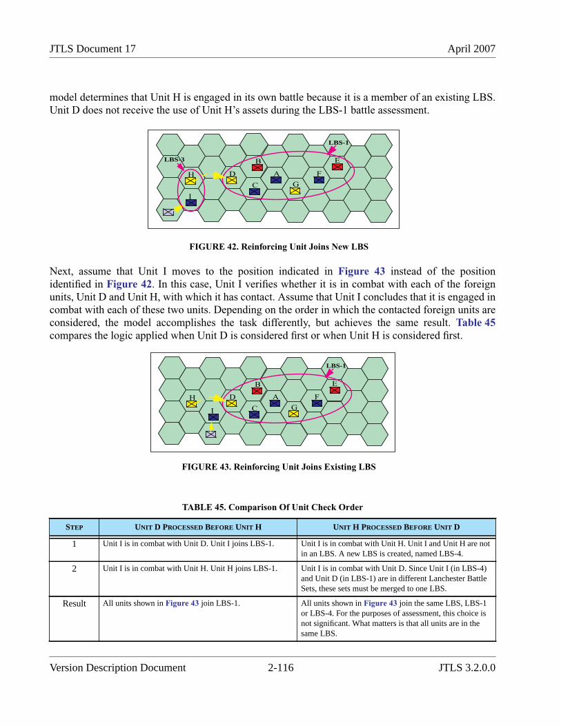
JTLS Document 17 April 2007
model determines that Unit H is engaged in its own battle because it is a member of an existing LBS.Unit D does not receive the use of Unit H’s assets during the LBS-1 battle assessment.
FIGURE 42. Reinforcing Unit Joins New LBS
Next, assume that Unit I moves to the position indicated in Figure 43 instead of the positionidentified in Figure 42. In this case, Unit I verifies whether it is in combat with each of the foreignunits, Unit D and Unit H, with which it has contact. Assume that Unit I concludes that it is engaged incombat with each of these two units. Depending on the order in which the contacted foreign units areconsidered, the model accomplishes the task differently, but achieves the same result. Table 45compares the logic applied when Unit D is considered first or when Unit H is considered first.
FIGURE 43. Reinforcing Unit Joins Existing LBS
TABLE 45. Comparison Of Unit Check Order
STEP UNIT D PROCESSED BEFORE UNIT H UNIT H PROCESSED BEFORE UNIT D
1 Unit I is in combat with Unit D. Unit I joins LBS-1. Unit I is in combat with Unit H. Unit I and Unit H are notin an LBS. A new LBS is created, named LBS-4.
2 Unit I is in combat with Unit H. Unit H joins LBS-1. Unit I is in combat with Unit D. Since Unit I (in LBS-4)and Unit D (in LBS-1) are in different Lanchester BattleSets, these sets must be merged to one LBS.
Result All units shown in Figure 43 join LBS-1. All units shown in Figure 43 join the same LBS, LBS-1or LBS-4. For the purposes of assessment, this choice isnot significant. What matters is that all units are in thesame LBS.
A
B
LBS-1
C
D F
E
G
H
I
LBS-3
A
B
LBS-1
C
D F
E
G
H
I
Version Description Document 2-116 JTLS 3.2.0.0
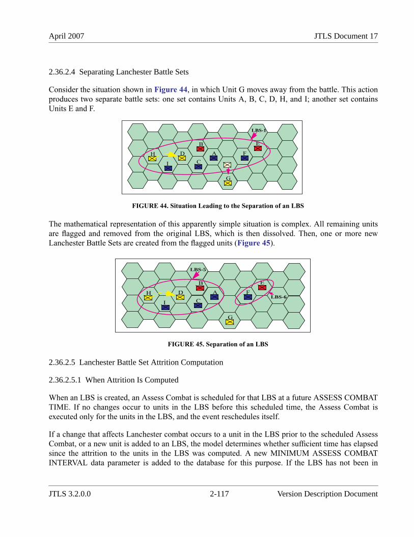
April 2007 JTLS Document 17
2.36.2.4 Separating Lanchester Battle Sets
Consider the situation shown in Figure 44, in which Unit G moves away from the battle. This actionproduces two separate battle sets: one set contains Units A, B, C, D, H, and I; another set containsUnits E and F.
FIGURE 44. Situation Leading to the Separation of an LBS
The mathematical representation of this apparently simple situation is complex. All remaining unitsare flagged and removed from the original LBS, which is then dissolved. Then, one or more newLanchester Battle Sets are created from the flagged units (Figure 45).
FIGURE 45. Separation of an LBS
2.36.2.5 Lanchester Battle Set Attrition Computation
2.36.2.5.1 When Attrition Is Computed
When an LBS is created, an Assess Combat is scheduled for that LBS at a future ASSESS COMBATTIME. If no changes occur to units in the LBS before this scheduled time, the Assess Combat isexecuted only for the units in the LBS, and the event reschedules itself.
If a change that affects Lanchester combat occurs to a unit in the LBS prior to the scheduled AssessCombat, or a new unit is added to an LBS, the model determines whether sufficient time has elapsedsince the attrition to the units in the LBS was computed. A new MINIMUM ASSESS COMBATINTERVAL data parameter is added to the database for this purpose. If the LBS has not been in
A
B
LBS-1
C
D F
E
G
H
I
A
B
LBS-5
C
D F
E
G
H
ILBS-6
JTLS 3.2.0.0 2-117 Version Description Document
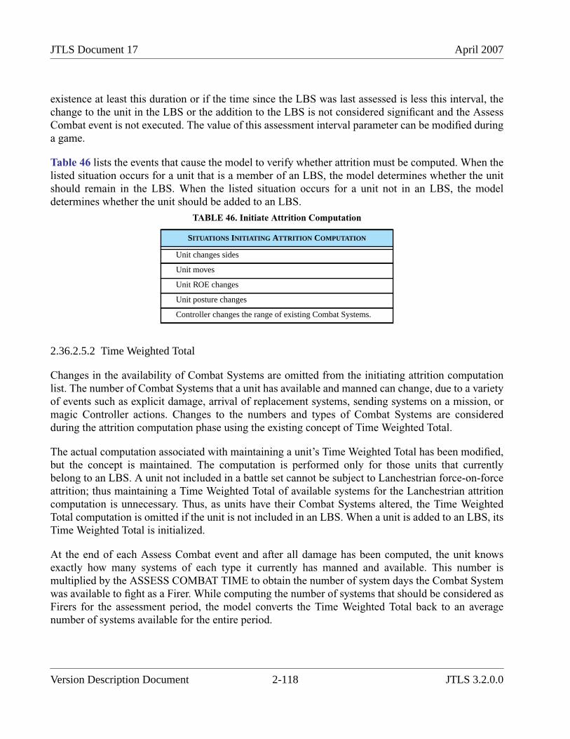
JTLS Document 17 April 2007
existence at least this duration or if the time since the LBS was last assessed is less this interval, thechange to the unit in the LBS or the addition to the LBS is not considered significant and the AssessCombat event is not executed. The value of this assessment interval parameter can be modified duringa game.
Table 46 lists the events that cause the model to verify whether attrition must be computed. When thelisted situation occurs for a unit that is a member of an LBS, the model determines whether the unitshould remain in the LBS. When the listed situation occurs for a unit not in an LBS, the modeldetermines whether the unit should be added to an LBS.
2.36.2.5.2 Time Weighted Total
Changes in the availability of Combat Systems are omitted from the initiating attrition computationlist. The number of Combat Systems that a unit has available and manned can change, due to a varietyof events such as explicit damage, arrival of replacement systems, sending systems on a mission, ormagic Controller actions. Changes to the numbers and types of Combat Systems are consideredduring the attrition computation phase using the existing concept of Time Weighted Total.
The actual computation associated with maintaining a unit’s Time Weighted Total has been modified,but the concept is maintained. The computation is performed only for those units that currentlybelong to an LBS. A unit not included in a battle set cannot be subject to Lanchestrian force-on-forceattrition; thus maintaining a Time Weighted Total of available systems for the Lanchestrian attritioncomputation is unnecessary. Thus, as units have their Combat Systems altered, the Time WeightedTotal computation is omitted if the unit is not included in an LBS. When a unit is added to an LBS, itsTime Weighted Total is initialized.
At the end of each Assess Combat event and after all damage has been computed, the unit knowsexactly how many systems of each type it currently has manned and available. This number ismultiplied by the ASSESS COMBAT TIME to obtain the number of system days the Combat Systemwas available to fight as a Firer. While computing the number of systems that should be considered asFirers for the assessment period, the model converts the Time Weighted Total back to an averagenumber of systems available for the entire period.
TABLE 46. Initiate Attrition Computation
SITUATIONS INITIATING ATTRITION COMPUTATION
Unit changes sides
Unit moves
Unit ROE changes
Unit posture changes
Controller changes the range of existing Combat Systems.
Version Description Document 2-118 JTLS 3.2.0.0
April 2007 JTLS Document 17
2.36.2.5.3 How Attrition Is Computed
The Lanchester Direct Fire attrition coefficients have a unit of measure equal to the number of victimsystems killed per killer Combat System per ASSESS COMBAT TIME. Similarly, the Indirect Fireattrition coefficients are based on the ASSESS COMBAT TIME. This has always realisticallyprevented users from using any value except one hour for the ASSESS COMBAT TIME, since anyother duration would require them to produce completely new sets of Lanchester coefficients.Considering this problem, and the problem that assessment periods are no longer constants becausethey can occur whenever the situation of a battle changes, an alteration of the method used to computethe force-on-force attrition is implemented.
A new LANCHESTER COEFFICIENT BASE TIME database parameter is the time duration forwhich the Lanchester coefficients are created in the database. While computing attrition, the modelmultiplies each Lanchester attrition coefficient by the fraction of the base time period for which theassessment is conducted.
Implementing this method is an approximation that does not reflect exactly the same damage. If theLanchester coefficients were built based on a one-hour time period, the damage assessed would not beidentical for two 30-minute assessment periods, in which the coefficients are multiplied by0.5 (30 minutes / 60 minutes), as compared to a single 60 minute assessment period in which thecoefficients are multiplied by 1.0 (60 minutes / 60 minutes). Due to the approximation of theLanchester differential equations as discrete difference equations, this inaccuracy is acceptable.
During the database conversion process to Version 3.2, the new LANCHESTER COEFFICIENTBASE TIME parameter is set to the database’s ASSESS COMBAT TIME.
Besides the adjustment of the attrition coefficients based on the percentage of the LANCHESTERCOEFFICIENT BASE TIME for which the assessment is being accomplished, the force-on-forceattrition computation methodology is otherwise unchanged. There are several changes after thesystem attrition has been computed, but the computation for determining which systems and thenumber of systems that are killed is not changed for this implementation.
2.36.2.6 Attrition Levels
A unit’s attrition for the previous ASSESS COMBAT TIME is compared to the data parameters SPTU UNIT LEVEL ATTRITION MODERATE and SP TU UNIT LEVEL ATTRITION SEVERE.Since the assessment period is no longer a constant, the model links this process to the Hourly UnitProcessing event instead of the end of Assess Combat.
During the Hourly Unit Processing event, the model records the unit’s current weighted strength. Atthe completion of each assessment calculation, the model determines whether the moderate or severeattrition level has been breached, based on the losses since the previous Hourly Unit Processing event.If the loss is greater than SP TU UNIT LEVEL ATTRITION SEVERE, the unit is stopped. If the loss
JTLS 3.2.0.0 2-119 Version Description Document

JTLS Document 17 April 2007
is between the SP TU UNIT LEVEL ATTRITION MODERATE and the SP TU UNIT LEVELATTRITION SEVERE, the unit is penalized in performance, as was previously customary.
This attrition level comparison is also performed during the Hourly Unit Processing event, in case theunit has received damage from causes other than force-on-force attrition. Stopped units are alsorestarted during the Hourly Unit Processing event if the excessive attrition level has not beenbreached again. This means that stopped units remain stopped for at least one hour.
2.36.2.7 Explicit Fire Missions
Previously, Explicit Fire missions were divided immediately prior to the Assess Combat event so thatappropriate damage from the fire mission could be applied and the Time Weighted Totals for thefiring systems could be adjusted before the Assess Combat is executed. This design does not allowcertain prediction as to when a specific LBS may be assessed; therefore, the Time Weighted Totals ofthe firing systems cannot be adjusted to prepare for the assessment procedure.
Fire missions are divided into volleys; each volley is fired and assessed individually. A volleyassumes that all of the unit’s manned and functioning Combat Systems capable of firing the desiredprojectile participate in the Explicit Fire mission. Thus, if five systems are available to fire, then fiveprojectiles are fired at a specified time and assessed.
The complex computation developed for Explicit Fire involves the ability to accurately track thesystems that are unavailable for the force-on-force Lanchestrian attrition computation because theywere used to support an Explicit Fire mission. This is done by expanding the logic supporting theTime Weighted Average computation described previously. The basis for this computation is thenecessity for each unit in the game to have access to its pending Fire Missions (as was previouslydone using the UT PENDING FIRE MISSION SET), as well as access to its active Fire Missions,which is accomplished by creating a UT ACTIVE FIRE MISSION SET.
2.36.2.8 Hourly Computations
These computations are transferred from the Assess Combat event to the Hourly Unit Processingevent, because the Assess Combat period is no longer a constant:
• Filling pipelines
• MHE serial processing
• Updating psychological operations effects and resetting jammed time
• \BDA Reports
CAS continues to be scheduled during the Assess Combat event.
Catastrophic kills are placed on the game board when they occur. This occurs whenever a system iskilled by any Explicit Fire event: artillery, air strike, Surface-to-Surface Missile (SSM) impact, or
Version Description Document 2-120 JTLS 3.2.0.0
April 2007 JTLS Document 17
minefield explosion. Catastrophic kills are also placed on the game board immediately when theyoccur in Assess Combat. The increased frequency of Assess Combat events is advantageous, and theplacement of these catastrophic kills appears to be more responsive to external models.
2.36.2.9 Combat Power Distribution
The existing methodology to distribute a unit’s Combat Systems in response to the location of enemyunits is modified to properly reallocate longer-range systems as needed. Previously, a JTLS CombatSystem (CS) capable of killing was listed as either a DIRECT or INDIRECT fire system. INDIRECTfire systems are typically longer-range systems, but are still distributed to the unit’s six hexagon sidesusing the same algorithm as DIRECT fire systems. Some INDIRECT systems have a limited rangefor which this paradigm is most appropriate. However, the longer-range systems must be allocatedagainst units facing their allocated side, but if no units are facing the hexagon side, these systemsmust be allowed to fire where they are needed.
A new CSP CS ATTRITION TYPE designator, LONG-INDIRECT, is added to allow the CombatSystem to be used against forces facing any hexagon side, provided that these systems are notrequired to fight enemy units on the side to which they have been allocated as part of the CombatSystem distribution algorithm. The allocation computation allows fractional Combat Systems that areacceptable for the Assess Combat calculation. However, the kills are intergeized after they have beencomputed.
Previously, a unit in the Attack posture and located at its attack destination would not reorient itscombat power in response to nearby enemy units that were not also attacking the unit. To resolve thisproblem, these new options are added to the Attack Order:
• Attack Unit by Name and Defend. The attacking unit remains in the Attack posture until thenamed unit is Wiped Out or leaves the LBS. As soon as this occurs, the attacking unitassumes the Defend posture, in which the formerly attacking unit is able to properlyreorient its Combat Systems to respond to other units in the area.
• Attack Unit by Name and Clear Hex. The attacking unit remains in the Attack posture untilthe named unit is Wiped Out or leaves the LBS. The attacking unit then attacks by name thenext nearest unit in the LBS. The attacking unit continues attacking until it leaves the LBS,because it no longer satisfies the participant rules established in Table 44.
• Attack Location and Defend. The attacking unit enters the Defend posture as soon as itarrives at the specified location, whether or not it joins an LBS.
• Attack Location and Clear Hex. The attacking unit attacks to the specified location. If theunit enters an LBS, the attacking unit then attacks by name the nearest enemy unit in theLBS. The attacking unit continues to attack until it leaves the LBS, because it no longersatisfies the participant rules established in Table 44.
JTLS 3.2.0.0 2-121 Version Description Document
JTLS Document 17 April 2007
2.36.2.10 Whole Combat System Representation
The integer-based representation that replaces the fractional Combat System kill results discussedpreviously adapts the fractional computation model.
2.36.2.11 Killing Using Lanchestrian Attrition Results
Since the Lanchester attrition computation remains unchanged, its force-on-force results reflectfractional Combat system kills. The translation of this fractional model to represent integerized wholesystem kills is accomplished by means of a stochastic rounding algorithm.
As a example, assume that the Lanchestrian attrition computation results in killing 0.3 Howitzers. Themodel interprets this result as a 30% chance that one Howitzer was killed due to the attrition thatoccurred during the assessment period. A random variate is drawn from a Uniform (0.0, 1.0)distribution. If this variate is less than or equal to 0.3, the Howitzer is considered killed. If the variateis greater than 0.3, the Howitzer is not killed and this Combat System is considered to be fullyfunctional.
During the Lanchestrian attrition computation, the model maintains a Killer Victim Table, whichholds the number of Victim Combat Systems that were killed by each Killer Combat System. Thistable holds the fractional kills as computed using the Lanchestrian methodology to support itsprimary use as a debugging tool. The Killer Victim Table should not be provided to the trainingaudience because it conflicts with the casualty reporting received from the model.
2.36.2.12 Killing Using Explicit Combat Results
In addition to Lanchestrian attrition, Combat Systems can be damaged within JTLS by other means,which include artillery fire, air-delivered munitions, Surface-to-Surface Missiles (SSMs), andminefields. These damage algorithms function in a similar manner. Once a kill has been determined,either by means of an Area Effects algorithm or a Probability of Kill algorithm, the model uses theCombat System packet size data to determine the number of systems that should be killed. In themajority of cases, the Combat System packet size is set to 1.0, but for personnel Combat Systems,values such as 5.0 are typical.
The Combat System packet size data, held in the database parameters SP CS PACKET SIZE and SPCS HRU PACKET SIZE and previously defined as real variables, allow the database developer toindicate fractional Combat Systems killed as the result of explicit combat results. This existing packetsize data type is changed to integer. The Modify program rounds existing database values andreplaces any resulting zero value with a value of 1. The appropriate Controller SET screens aremodified to limit entries for this database parameter to integer values.
Version Description Document 2-122 JTLS 3.2.0.0
April 2007 JTLS Document 17
2.36.2.13 Repairable and Catastrophic Kills Algorithm
Previously, the data parameter CSP CS FRACTION RECOVERABLE was used to place a fraction ofthe killed systems in maintenance and the remaining fraction of these killed systems were consideredto be catastrophic kills lost to the unit for the remainder of the game. Since an integer representationfor a unit’s Combat Systems must be maintained, this method has been replaced.
The attribute CSP CS FRACTION RECOVERABLE is changed to CSP CS PROB SYSTEMRECOVERED. After the algorithm determines the number of whole Combat Systems killed, themodel determines which of the killed systems are repairable and which systems are considered ascatastrophic kills by drawing a variate from a Uniform (0.0, 1.0) distribution for each killed system. Ifthis random variate is less than or equal to CSP CS PROB SYSTEM RECOVERED, the system isplaced in maintenance and the crew is moved from the crew unavailable count to the crew availablecount. If the variate is greater than CSP CS PROB SYSTEM RECOVERED, the system is identifiedas a catastrophic kill and the Catastrophic Kill object, commonly known as a “burning hulk”, isplaced on the game board. For these catastrophically killed systems, the existing stochastic method,which determines whether the crew is also killed, is modified.
Although not required for this capability, aircraft Combat Systems damaged while in the Squadronunit and not while assigned to a mission are no longer placed in the Maintenance column of theSquadron unit’s Combat System array. The aircraft Combat System is subjected to the CSP CS PROBSYSTEM RECOVERED algorithm. Once the model has determined that the aircraft Combat Systemcan be repaired, the aircraft is not processed by the conventional Combat System repair algorithm.Instead, the Aircraft Class data and the existing aircraft maintenance algorithm are applied. Thus,aircraft damaged as part of the unit are treated in the same manner as battle-damaged flying aircraftreturning from a mission. Additionally, the user is able to view data pertaining to aircraft releasedfrom maintenance.
2.36.2.14 Evacuation Policy Changes
A new algorithm determines which hospital-bound personnel should be evacuated as CASUALTIES,based on the theater evacuation policy held by the Faction attribute FC WIA MAX TREAT UNITTIME. For each recovered personnel Combat System loss, a random draw determines a repair timeusing CSP CS MEAN TIME BETWEEN REPAIR. Personnel Combat Systems with a random drawgreater than the FC WIA MAX TREAT UNIT TIME are treated as CASUALTIES.
2.36.2.15 Non-Battle Casualties
The manner in which Non-Battle Casualties are determined is also modified.
Each Combat System owned by the unit is checked to determine whether it has failed on arrival. Thenew data parameter CSP CS PROB NON COMBAT FAILURE replaces CSP CS FRACTION FAILON ISSUE only when a unit arrives in theater, is resurrected, or the Controller resets the unit to 100%
JTLS 3.2.0.0 2-123 Version Description Document
JTLS Document 17 April 2007
capability, and is used to determine whether each Combat System owned by the unit has failed onarrival. If true, a maintenance procedure is initiated for the failed systems.
Since the model can no longer repair fractional Combat Systems, an exponential whole-system repairtime model is applied. When a system is added to maintenance, a random repair time CSP CS MEANTIME BETWEEN REPAIR is drawn for each system. This new parameter replaces CSP CSFRACTION REPAIRED PER PERIOD. Each instance a repair event is executed and a whole systemis moved from maintenance to the available system count, a new repair event is scheduled. For eachremaining Combat System of the repaired type, a new random maintenance time is generated. Theminimum maintenance time is saved and the repair event is scheduled to occur at that minimum time.This algorithm reflects the characteristic of exponentially distributed events: the time interval betweenevents is also exponentially distributed with the same mean.
This means that each unit has one and only one repair event for each of its Combat System types thatare in maintenance. These data are displayed on the Combat System status screen of the InformationManagement Tool (IMT) to assist the user to determine when the next system is due out ofmaintenance.
Once the initial systems have been placed in maintenance using the new CSP CS PROB NONCOMBAT FAILURE data parameter, processing the remaining non-combat failures continues. Afterthe initial failures have been computed, an exponential distributed random variate with the mean CSPCS MEAN TIME BETWEEN FAILURE is drawn for each system that is currently manned andoperational. Unmanned systems are counted for the initial failure, but are not counted for thecontinued non-combat failure algorithm. The minimum of these random variates represents the nextnon-combat failure for this Combat System within the unit.
2.36.2.16 Reissuing Combat Systems
Units that have available supplies to replace lost Combat Systems reissue whole Combat Systemsinstead of fractional Combat Systems, due to a modified algorithm. All supplies available for issue areissued as Combat Systems; no supplies are saved toward the later issue of a heavier Combat System.
The data parameter MIN TONS CL VII TO DISTRIBUTE previously used to ensure that smallfractional Combat Systems were not unrealistically issued is removed from the database. Since themodel issues only whole Combat Systems, the concept of a minimum weight for a supply issue is notapplicable.
2.36.2.17 Changes To Controller Actions
Several methods are available to the Controller to alter the current status of a unit. The Controller cansubmit a Damage Combat System order or submit a direct access change order for the unit’s availableor in-maintenance Combat Systems. Each of these capabilities are altered to ensure that theController is not allowed to create fractional Combat Systems and that all of the new repair events andnon-combat damage events are properly adjusted.
Version Description Document 2-124 JTLS 3.2.0.0
April 2007 JTLS Document 17
2.36.2.18 Representation of Communications Capability
To achieve the goal to use whole numbers with respect to units’ Combat Systems arrays, C3I isremoved as a Combat System because its expected value ranges between 0 and 1. The ECP JTLS-2006-1827 New Command Control Model implements this requirement.
2.36.3 Data Changes
These new parameters are added to the database:
• LANCHESTER COEFFICIENT BASE TIME
• MINIMUM ASSESS COMBAT INTERVAL
• CSP CS PROB NON COMBAT FAILURE
• CSP CS PROB SYSTEM RECOVERED
• CSP PROB REMAINS RECOVERED
• CSP CS MEAN TIME BETWEEN FAILURE
• CSP CS MEAN TIME BETWEEN REPAIR
The following parameters are removed from the database and their data are referenced by the newparameters as indicated:
• CSP CS FRACTION FAIL ON ISSUE. All references currently apply to CSP CS PROBNON COMBAT FAILURE.
• CSP CS FRACTION REPAIRED PER PERIOD. All references currently apply to CSP CSMEAN TIME BETWEEN REPAIR.
• CSP CS FRACTION RECOVERABLE. All references currently apply to CSP CS PROBSYSTEM RECOVERED.
• CSP FRACTION REMAINS RECOVERABLE. All references currently apply to CSPPROB REMAINS RECOVERED.
• MIN TONS CL VII TO DISTRIBUTE
The definitions of these data parameters are modified and their JTLS Data Requirements Manualdocumentation is revised:
• SP CS PACKET SIZE
• SP CS HRU PACKET SIZE
• SP TU UNIT LEVEL ATTRITION MODERATE
• SP TU UNIT LEVEL ATTRITION SEVERE
• TUP CS TOE
JTLS 3.2.0.0 2-125 Version Description Document
JTLS Document 17 April 2007
• CSP CS ATTRITION TYPE
• CSP CS SUPPLY USAGE PER DAY
2.36.4 Order Changes
These new data fields are added to the Attack order panel:
• Attack Unit by Name and Defend
• Attack Unit by Name and Clear Hex
• Attack Location and Defend
• Attack Location and Clear Hex
The Controller Set and Show orders are modified to include the new database parameters and deletethe obsolete parameters.
Orders that enable the Controller to damage or alter a unit’s Combat Systems are modified to allowthe entry of integer values only.
2.36.5 JODA Changes
Next Repair Time data for each unit’s Combat Systems are held by the JTLS Object DistributionAuthority.
2.37 JTLS-2006-1736 FOM Representation of Fuel for Air Missions
2.37.1 Summary of Model Change Request
External JTLS programs require knowledge of the quantity of fuel held by a JTLS Air Mission. Thismeasurement is provided to the JODA from the CEP in two forms: a total number of gallons and apercent. These values are interpreted in two ways. If the mission is an Air Refueler, the client programmust consider the total number of gallons as representing the amount of fuel committed and availablefor distribution to refuelees. The percent value, also for Air Refuelers, is considered the amount offuel uncommitted to any refuelee. If the mission is not a Refueler, these values are interpreted asexpected: the gallon value is the amount of fuel each mission aircraft currently carries, and thepercent value is a fraction of the mission’s total capacity. Handling the fuel values differently for AirRefueler missions allows better insight of fuel management for Air Mission modeling.
Contrary to this convention, the JTLS High Level Architecture Interface Program (JHIP) providestwo fuel attributes for each Air Mission: Fuel_Available as a percent representing a decimal ratio ofavailable to total capacity and Fuel_Capacity represented as decimal gallons. The Fuel_Availableattribute is defined in the FOM as the percentage of the total fuel capacity of each aircraft in the
Version Description Document 2-126 JTLS 3.2.0.0
April 2007 JTLS Document 17
mission. This definition is retained, although a data type change from Float to Unsigned Short isnecessary because the CEP limits the resolution of this value to that of an Unsigned Short data type.
The Fuel_Capacity attribute has limited usefulness among the JMRM federates and requires anunnecessary calculation after each update because its data are not provided in the raw format by theJODA.
Assuming that the total fuel capacity is held consistently among all models in the JMRM federationand for all aircraft classes, updating the fuel capacity more than once is unnecessary, since this valuetypically remains constant. Providing the gallon quantity currently held by the mission within eachupdate is more useful for the purpose of monitoring available fuel. This value will almost always bechanging.
2.37.2 Design Summary
This enhancement includes JMRM FOM changes that provide federates a more useful pair of fuelattributes for Air Missions. All federates subscribing to these fuel attributes also must be able todifferentiate Air Refueler missions from the other mission types, i.e., subscribe to the Missionattribute.
Fuel calculations within the CEP are performed using the number of gallons of fuel an Air Missioncurrently has on board. For example, after the mission completes a segment of its flight of a specifieddistance, the fuel held by the mission is reduced by the amount of fuel the mission consumes ingallons per kilometer for the number of kilometers in the segment. Therefore, the amount of fuelonboard an Air Mission at any time during the game is the primary fuel attribute, and all fuel updatesto or from the CEP are based on this metric. The percent of fuel capacity available for a mission is aconvenient value for users, but should not be used to translate fuel quantities between models.Regardless of which model owns an Air Mission, the mission’s endurance should be representedconsistently. Separate models should represent approximately the same amount of fuel remainingafter owning and flying the Air Mission over the same segment of airspace. Any other result wouldappear to be unrealistic, as viewed from the reflecting model.
Ownership of an Air Mission currently requires the owning model to acquire all attributes of the AirMission. Maintaining ownership of an attribute necessarily requires appropriate update of theseattributes. Thus, any model that owns an Air Mission must update the Fuel_Available percentconcurrently with the Fuel_Remaining attribute, even though the values may be of no computationaluse internally for the controlling model.
As mentioned previously, the interpretation of fuel available to a JTLS Air Mission is dependent onthe mission’s type. For Tanker missions, the fuel remaining and the fuel available refer to the reserveof dispensable fuel, not the fuel available to the mission itself. The primary function of a Tanker is todeliver fuel to scheduled and unscheduled refuelees. When this is no longer practical, the Tankermission’s own fuel requirement for returning home is insignificant. Therefore, monitoring the Tankermission’s own fuel is less important, and the two available fuel attributes are of greater use for
JTLS 3.2.0.0 2-127 Version Description Document
JTLS Document 17 April 2007
tracking dispensable fuel. Federates capable of acquiring ownership of a Tanker Air Mission in theJMRM federation must manage a tanker’s fuel load in the same manner.
2.37.3 Data Changes
No data changes are required to implement this enhancement.
2.37.4 Order Changes
No order changes are required to implement this enhancement.
2.37.5 JODA Changes
The required JTLS Object Distribution Authority changes are described in Table 47.
2.38 JTLS-2006-1752 Improve Fuel Usage Flexibility
2.38.1 Summary of Model Change Request
The Joint Logistics Planning Enhancement (JLOG / PE) program is designed to investigateimprovements to the logistics information and management processes that allow a Joint ForceCommander to mitigate the risks associated with planning, executing, and managing the sustainmentof in-theater forces. JLOG / PE has selected the Joint Theater Level Simulation (JTLS) model as atool to support the evaluation of various new and improved logistics concepts.
To accomplish this task, JLOG / PE indicated that the JTLS logistics consumption algorithm requiredenhancement to track supply consumption according to the type and number of Combat Systemsowned by a particular unit. This enhancement fulfills that request.
2.38.2 Design Summary
2.38.2.1 Review of Existing Algorithm
The JTLS Standard Database, which is the basis for all Joint Warfighting Center (JWFC) exercises,supports 178 Supply Categories. Other databases have many more. Each of these Supply Categoriesis specified, as part of the initialization data, to use one of the three legal consumption methods:
TABLE 47. Summary of Required JODA Changes
CHANGE OBJECT ATTRIBUTE DATA TYPE
Delete Air_Mission Fuel_Capacity float: gallons
Delete Air_Mission Fuel_Available float: percent
Add Air_Mission Fuel_Remaining unsigned long: gallons
Add Air_Mission Fuel_Available unsigned short: percent
Version Description Document 2-128 JTLS 3.2.0.0
April 2007 JTLS Document 17
• Per Day
• Per Person Per Day
• As Used
JTLS Ground and Naval units own, use, and consume supplies according to five distinct consumptionmodes: As Used, Background, Unit Movement, Posture, and Combat.
2.38.2.2 As Used Supply Usage
The supplies are used for a specific purpose or objective, such as when the unit explicitly firesartillery or sends an aircraft on a mission. As supplies are used or committed for use, the modelimmediately subtracts the supplies from the consuming unit’s On Hand supply list.
2.38.2.3 Background Consumption Supply Usage
Every unit has its own Adjust Supply event. The database indicates the time the unit should executethis event for the first instance and the periodic interval the event should be repeated. For example, aunit can be directed to execute the Adjust Supply event at 0400 and every six hours thereafter. Thisunit computes its background consumption at 0400, 1000, 1600, and 2200 each day. The computedsupply consumption is subtracted from the unit’s On Hand supply list. As the term implies,background consumption is continuous, regardless of the unit’s activities or location in the game.
Each TUP and SUP holds data indicating the amounts and types of supplies expected to be expendedas part of background consumption. This data parameter represents either the amount of supplies thatshould be consumed Per Day or the amount that should be consumed Per Person Per Day.
The Supply Category Name and SC Type Consumption columns of data are held on the SupplyCategory (SC) structure. All units in the game must consume a given Supply Category using the samealgorithm. If a Supply Category is labeled as an As Used category, no background consumption iscomputed for that Supply Category.
2.38.2.4 Unit Movement Supply Consumption
Naval units do not currently consume supplies as a result of movement On the other hand, suppliesare consumed for each kilometer (KM) a Ground unit moves. This quantity is a database parameterassociated with each TUP.
For example, additional Food might not consumed as the unit moves, but Fuel, Water, andRepair_Parts might be assessed additional usage. Again, any supply category that is designated as AsUsed, such as Ammunition, is not considered in the movement consumption for algorithm.
This example is an illustration only. Within JTLS, additional supplies consumed during unitmovement are considered data. If the database builder intends additional Food to be consumed during
JTLS 3.2.0.0 2-129 Version Description Document
JTLS Document 17 April 2007
movement, a simple alteration of the TUP consumption parameter per KM for the Food SupplyCategory is required. Assigning a value of zero to this data parameter stops the additionalconsumption of the supply when the unit moves.
2.38.2.5 Posture-Based Supply Consumption
During each Combat Assess period, JTLS Ground units consume additional supplies according totheir Posture. This consumption mode is designed to represent the additional supply usage the unitwould incur while experiencing various represented combat situations. Computations of this posture-based consumption apply the same methodology demonstrated for the background and movementconsumption.
Naval units also experience posture-based consumption, but these units cannot assume the Attack,Defend, Delay, and Withdraw posture sequence. Instead, two data parameters are used for thispurpose, representing the extra supplies consumed in the Air Operations posture, or while activelyproviding reinforcement naval gunfire support. Similar to Ground unit computations, this posture-based consumption is calculated and assessed against the Naval unit each Combat Assess period.
2.38.2.6 Combat Supply Consumption
During every assessment period a unit is engaged in combat, and regardless of its posture, the unitalso consumes a single Supply Category for each Combat System capable to fight. Supplies expendedunder combat consumption are designed to represent the ammunition that the Combat System uses.Data required to compute this ammunition usage are not entered for each TUP, but are entered foreach Combat System Prototype (CSP), since this data structure is designed to define the CombatSystem capabilities for each Faction represented in a JTLS scenario.
The computation is similar to all of the previous consumption calculations. During the JTLS combatassessment period, the model determines whether a unit is actively involved in a battle. If true, thecombat consumption for the unit’s Combat Systems that are participating in combat activity iscomputed and assessed against the unit. The first step is to determine the number of Combat Systemsof each type that are currently fighting, which requires two checks:
• In the case of a system that requires a crew to fight, the existence of the Combat System isnot sufficient. A full crew must exist for the system to inflict damage on the enemy and beassessed with ammunition usage.
• The Combat System must be considered a "shooter" system and be oriented in a direction toconfront enemy forces. According to the unit’s combat power distribution and the directionof the oncoming enemy forces, not all systems participate in a battle.
The combat supply assessment is computed prior to the combat results computation, since a CombatSystem without ammunition is assumed to have no killing capability.
Version Description Document 2-130 JTLS 3.2.0.0
April 2007 JTLS Document 17
2.38.2.7 Analysis of Previous Algorithm Deficiencies
As this modeling logic represents, ammunition usage is a function of the number of Combat Systemsfighting, but the Combat System ammunition usage is not a function of the unit’s combat posture.Therefore, a unit in combat in the Attack posture uses the same amount of ammunition as a unit that isin combat in a Defend posture. This problem is corrected as a part of this design.
In our sample database, fuel was represented as a Per Day logistics supply category. Consequently, asthe unit is reduced in size, either as a result of attrition or Player task reorganization, the unit’s fuelusage does not change. There is no technical reason why Fuel is designated as a Per Day logisticssupply in our example. As a Per Person Per Day Supply Category, as is typically specified for JWFCdatabases, the unit’s fuel usage would also be adjusted as the unit loses personnel, either throughattrition or task reorganization. As the unit loses strength, its supply usage should decrease. Theassumption that personnel count is directly correlated to other Combat System counts justifies thisdecision. For example, a unit that has only 75% of its personnel remaining, would on the average havethe same percentage of all of its other Combat Systems available, and therefore would reduce its fuelsupply usage by 25%. JLOG / PE does not consider this assumption sufficiently accurate for theirapplication of JTLS as a supply analysis tool. Modeling a more explicit representation of CombatSystem fuel usage within the JTLS consumption algorithm is preferred.
Finally, an existing ECP, JTLS-0018 Naval Fuel Usage, specifically requests that Naval Units, usefuel as they move in a manner similar to the manner in which Ground units use fuel. Because of theclose relationship between this ECP and this design, both enhancements are implementedsimultaneously to address the JLOG / PE fuel usage and maritime fuel issues.
2.38.2.8 Summary of the Implementation
Implementing this improvement involved adding several new data parameters and retaining allcurrent data in the JTLS database. Database builders can elect to use any or all available consumptionparameters. Zero values for either the new or existing data parameters would result in that type ofconsumption not being represented in the JTLS scenario.
Basically, much of the data is now specified by the Prototype (CSP, SLP, TUP, or SUP), and CombatSystem (or Supply Category) combination. For example, CSP CS NON COMBAT FUEL USAGErepresents the amount of fuel that a unit in a Factions that uses the CSP would consume for eachManned CS each day the unit is in a non-combat mode. Similarly, SUP SC PER KM USAGErepresents the amount of the specific SC that a ship of the SUP class uses for every kilometer ofmovement. This parameter existed, but was not used in the past. It is used as part of this change.
2.38.3 Data Changes
The new and modified data parameters that support this enhancement are listed and summarized inSection 1.5.3 of this document and detailed definitions are provided in the JTLS Data RequirementsManual. Note that some parameters indicate "Per Day" instead of "Per Period".
JTLS 3.2.0.0 2-131 Version Description Document
JTLS Document 17 April 2007
The supply consumption calculation will become more complex as a result of implementing this ECP.The detailed example intended to clarify the computational implications of this design is presented inthe JTLS 3.2.0.0 Design Plan description of this enhancement.
One result of this change is that the supply calculation will occur more frequently. This computationoverhead will be offset by a more centralized supply consumption algorithm that will reduce theoverall size of the model. If a significant reduction in the maximum attainable game speed is observedafter implementation, an option for further enhancement would be to hold onto several recent supplycomputation times and revert to background consumption only being accomplished at the SupplyAdjust events.
Other events affecting a unit’s status will trigger the supply consumption computation:
• Loss of a Combat System from either air-to-ground fire, SSM impact, artillery fire, orcontroller action
• Increase in Combat Systems from Controller action
• Attachment of two aggregate units or an HRU rejoining its parent aggregate unit
• Detachment of an aggregate unit or an HRU.
The model will not compute fuel, combat, or movement supply consumption under the followingcircumstances. A unit conducting these operations will continue to consume using the backgroundconsumption algorithm:
• Magic Moving from one location to another
• Transport by Airlift
• Embarked on a moving Naval formation
• Transport by Convoy. The model assumes that all unit assets are carried by the convoy assetsThis capability does not consider Convoy fuel usage.
2.38.3.1 Naval Unit Fuel Consumption
The enhancements required by JTLS-0018 Naval Fuel Usage are incorporated within this design.The existing data parameter SUP SC PER KM USAGE has been implemented in the same manner asthe TUP SC PER KM USAGE. Naval units, as is currently done, will be assessed Backgroundconsumption, using the new fuel consumption data. Naval units will not access or use the new CSPCS FUEL PER KM data. These data are reserved only for the movement of ground units.
Prior to moving a naval unit, the model will check whether the ship has the needed fuel to accomplishthe move. This check will only be done if the SUP SC PER KM USAGE data element forCATEGORY CLASS III NAVAL is greater than zero. If the data element indicates that fuel should beused as the ship moves, the model will determine how much fuel is needed to accomplish the nextschedule move. There are three possible answers to the check:
Version Description Document 2-132 JTLS 3.2.0.0
April 2007 JTLS Document 17
1. If the ship has absolutely no CATEGORY CLASS III NAVAL supplies available, the unitmoves is not scheduled. The naval unit will not lose its mission, but it will be stopped and amessage supplied to the user concerning its status. When the unit receives fuel, itsmovement and task will be continued.
2. If the ship has some fuel, but not enough to accomplish the next planned move (full hex),the model will calculate how far the unit can move and will schedule the move to move theallowable distance. When the unit finishes the partial move, the fuel will be used whichpresumably will set the ship’s CATEGORY CLASS III NAVAL on hand value to zero.When attempting to schedule the next move, the ship will follow Rule 1 stated above. Notethat it is possible that the ship received fuel from some source prior to executing thescheduled move. In this case, the ship will have a positive value for CATEGORY CLASSIII NAVAL fuel available and when it schedules its next move and full move will bepossible.
3. The third possibility is that the unit has enough fuel to accomplish the full move and a fullmove will be scheduled for the unit.
Finally, it is possible that a unit loses fuel while in the middle of a move. for example, it could beattacked and the resulting hull hit could cause the unit to lose fuel. If this happens, the model makesno attempt to stop an existing scheduled move for the unit. When the move is executed, the model willrealize that there is not enough fuel to accomplish the move. The current move is allowed andfinalized, but the unit will stop moving at that time. This enhancement does not link the speed of amoving Naval unit and its fuel usage.
If these units also provide reinforcing fire for Lanchestrian combat, their Combat consumption will beassessed separately.
2.38.3.2 Automatic Supply Calculation Tool
In addition to the numerous data parameter changes, this change required modifications to JTLSAutomatic Supply Calculation (ASC) tool. To allow database builders to compute accurate supplylevels, the computation method used by the ASC must reflect all other JTLS supply computations.The user community has expressed ambivalence regarding the current ASC capability. Some databasedevelopers believe that its computation algorithm produces unrealistically high ammunition supplyrequirement that severely restrict the model’s ability to move units within the theater by means ofnaval or airlift assets. Although enhancing the ASC to fulfill all possible requirements is beyond thescope of this ECP, certain minor improvements will be implemented.
An overview of the ASC functionality illustrates the need for these improvements. Complete detailsregarding the operation of the ASC and its logic can be found in the Database Development System(DDS) Users Guide.
Currently proposed ASC improvements can be organized to address two purposes:
• Correct JTLS 3.1.0.0 errors. The design concept of hard-coded symbols is not supported inJTLS 3.1.0.0. The ASC used hard-coded symbols to identify certain unit capabilities. For
JTLS 3.2.0.0 2-133 Version Description Document
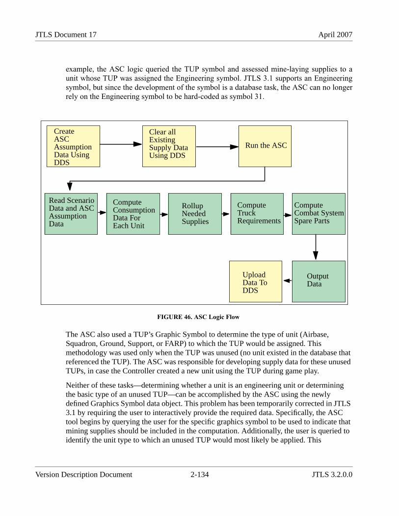
JTLS Document 17 April 2007
example, the ASC logic queried the TUP symbol and assessed mine-laying supplies to aunit whose TUP was assigned the Engineering symbol. JTLS 3.1 supports an Engineeringsymbol, but since the development of the symbol is a database task, the ASC can no longerrely on the Engineering symbol to be hard-coded as symbol 31.
FIGURE 46. ASC Logic Flow
The ASC also used a TUP’s Graphic Symbol to determine the type of unit (Airbase,Squadron, Ground, Support, or FARP) to which the TUP would be assigned. Thismethodology was used only when the TUP was unused (no unit existed in the database thatreferenced the TUP). The ASC was responsible for developing supply data for these unusedTUPs, in case the Controller created a new unit using the TUP during game play.
Neither of these tasks—determining whether a unit is an engineering unit or determiningthe basic type of an unused TUP—can be accomplished by the ASC using the newlydefined Graphics Symbol data object. This problem has been temporarily corrected in JTLS3.1 by requiring the user to interactively provide the required data. Specifically, the ASCtool begins by querying the user for the specific graphics symbol to be used to indicate thatmining supplies should be included in the computation. Additionally, the user is queried toidentify the unit type to which an unused TUP would most likely be applied. This
CreateASCAssumptionData UsingDDS
Clear allExistingSupply DataUsing DDS
Run the ASC
Read ScenarioData and ASCAssumptionData
ComputeConsumptionData ForEach Unit
RollupNeededSupplies
ComputeTruckRequirements
ComputeCombat SystemSpare Parts
OutputData
UploadData ToDDS
Version Description Document 2-134 JTLS 3.2.0.0
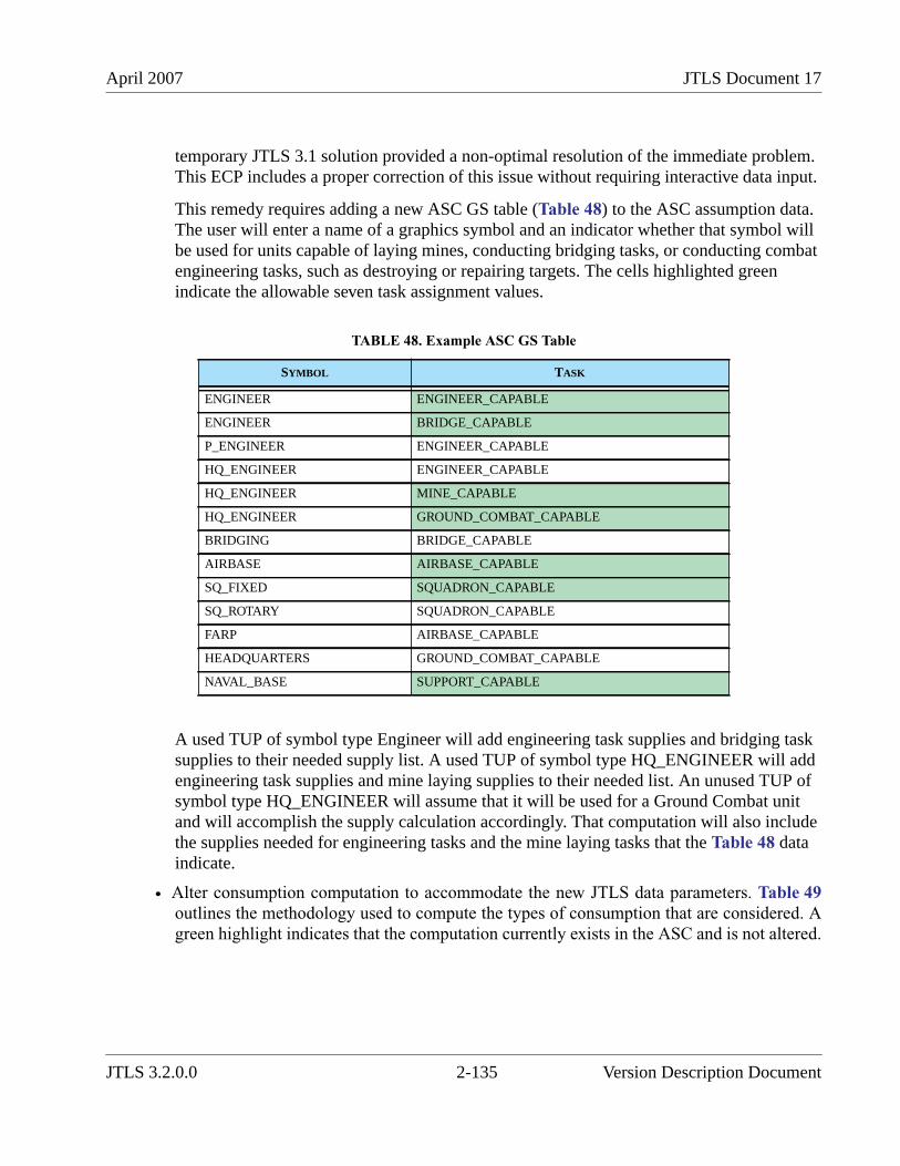
April 2007 JTLS Document 17
temporary JTLS 3.1 solution provided a non-optimal resolution of the immediate problem.This ECP includes a proper correction of this issue without requiring interactive data input.
This remedy requires adding a new ASC GS table (Table 48) to the ASC assumption data.The user will enter a name of a graphics symbol and an indicator whether that symbol willbe used for units capable of laying mines, conducting bridging tasks, or conducting combatengineering tasks, such as destroying or repairing targets. The cells highlighted greenindicate the allowable seven task assignment values.
A used TUP of symbol type Engineer will add engineering task supplies and bridging tasksupplies to their needed supply list. A used TUP of symbol type HQ_ENGINEER will addengineering task supplies and mine laying supplies to their needed list. An unused TUP ofsymbol type HQ_ENGINEER will assume that it will be used for a Ground Combat unitand will accomplish the supply calculation accordingly. That computation will also includethe supplies needed for engineering tasks and the mine laying tasks that the Table 48 dataindicate.
• Alter consumption computation to accommodate the new JTLS data parameters. Table 49outlines the methodology used to compute the types of consumption that are considered. Agreen highlight indicates that the computation currently exists in the ASC and is not altered.
TABLE 48. Example ASC GS Table
SYMBOL TASK
ENGINEER ENGINEER_CAPABLE
ENGINEER BRIDGE_CAPABLE
P_ENGINEER ENGINEER_CAPABLE
HQ_ENGINEER ENGINEER_CAPABLE
HQ_ENGINEER MINE_CAPABLE
HQ_ENGINEER GROUND_COMBAT_CAPABLE
BRIDGING BRIDGE_CAPABLE
AIRBASE AIRBASE_CAPABLE
SQ_FIXED SQUADRON_CAPABLE
SQ_ROTARY SQUADRON_CAPABLE
FARP AIRBASE_CAPABLE
HEADQUARTERS GROUND_COMBAT_CAPABLE
NAVAL_BASE SUPPORT_CAPABLE
JTLS 3.2.0.0 2-135 Version Description Document
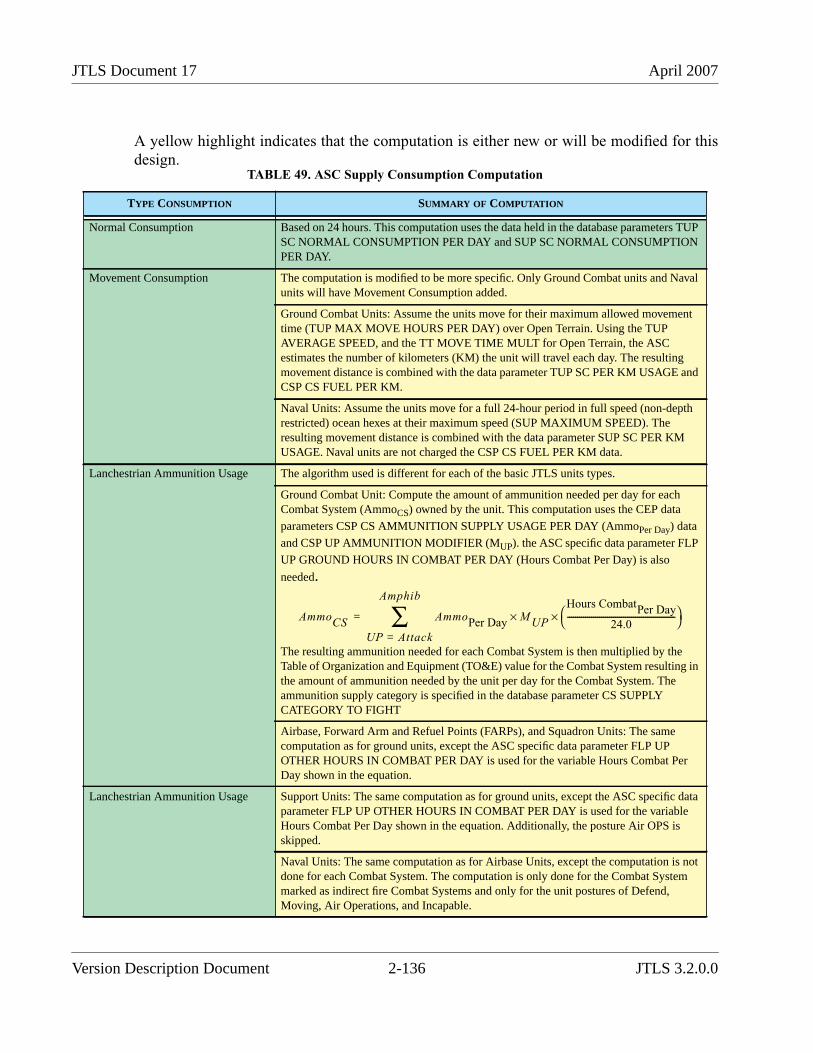
JTLS Document 17 April 2007
A yellow highlight indicates that the computation is either new or will be modified for thisdesign.
TABLE 49. ASC Supply Consumption Computation
TYPE CONSUMPTION SUMMARY OF COMPUTATION
Normal Consumption Based on 24 hours. This computation uses the data held in the database parameters TUPSC NORMAL CONSUMPTION PER DAY and SUP SC NORMAL CONSUMPTIONPER DAY.
Movement Consumption The computation is modified to be more specific. Only Ground Combat units and Navalunits will have Movement Consumption added.
Ground Combat Units: Assume the units move for their maximum allowed movementtime (TUP MAX MOVE HOURS PER DAY) over Open Terrain. Using the TUPAVERAGE SPEED, and the TT MOVE TIME MULT for Open Terrain, the ASCestimates the number of kilometers (KM) the unit will travel each day. The resultingmovement distance is combined with the data parameter TUP SC PER KM USAGE andCSP CS FUEL PER KM.
Naval Units: Assume the units move for a full 24-hour period in full speed (non-depthrestricted) ocean hexes at their maximum speed (SUP MAXIMUM SPEED). Theresulting movement distance is combined with the data parameter SUP SC PER KMUSAGE. Naval units are not charged the CSP CS FUEL PER KM data.
Lanchestrian Ammunition Usage The algorithm used is different for each of the basic JTLS units types.
Ground Combat Unit: Compute the amount of ammunition needed per day for eachCombat System (AmmoCS) owned by the unit. This computation uses the CEP data
parameters CSP CS AMMUNITION SUPPLY USAGE PER DAY (AmmoPer Day) data
and CSP UP AMMUNITION MODIFIER (MUP). the ASC specific data parameter FLP
UP GROUND HOURS IN COMBAT PER DAY (Hours Combat Per Day) is also
needed.
The resulting ammunition needed for each Combat System is then multiplied by theTable of Organization and Equipment (TO&E) value for the Combat System resulting inthe amount of ammunition needed by the unit per day for the Combat System. Theammunition supply category is specified in the database parameter CS SUPPLYCATEGORY TO FIGHT
Airbase, Forward Arm and Refuel Points (FARPs), and Squadron Units: The samecomputation as for ground units, except the ASC specific data parameter FLP UPOTHER HOURS IN COMBAT PER DAY is used for the variable Hours Combat PerDay shown in the equation.
Lanchestrian Ammunition Usage Support Units: The same computation as for ground units, except the ASC specific dataparameter FLP UP OTHER HOURS IN COMBAT PER DAY is used for the variableHours Combat Per Day shown in the equation. Additionally, the posture Air OPS isskipped.
Naval Units: The same computation as for Airbase Units, except the computation is notdone for each Combat System. The computation is only done for the Combat Systemmarked as indirect fire Combat Systems and only for the unit postures of Defend,Moving, Air Operations, and Incapable.
AmmoCS AmmoPer Day
M UP×Hours Combat
Per Day
24.0------------------------------------------------------⎝ ⎠
⎛ ⎞×
UP Attack=
Amphib
∑=
Version Description Document 2-136 JTLS 3.2.0.0
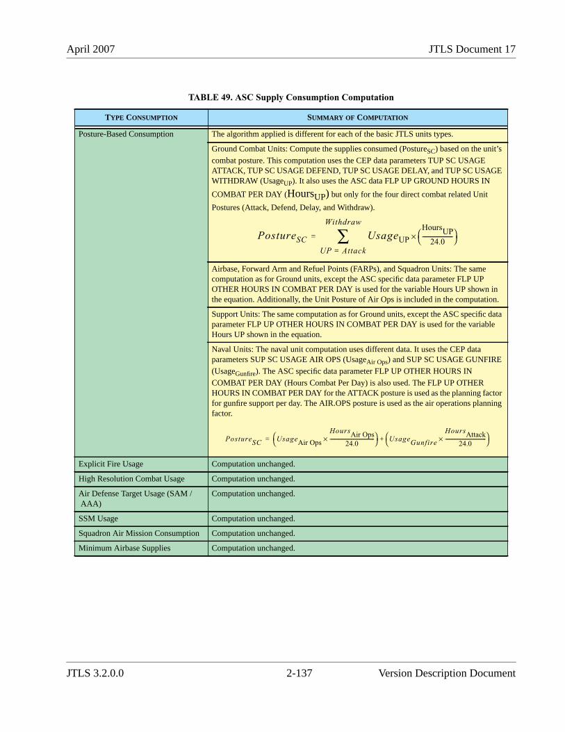
April 2007 JTLS Document 17
Posture-Based Consumption The algorithm applied is different for each of the basic JTLS units types.
Ground Combat Units: Compute the supplies consumed (PostureSC) based on the unit’s
combat posture. This computation uses the CEP data parameters TUP SC USAGEATTACK, TUP SC USAGE DEFEND, TUP SC USAGE DELAY, and TUP SC USAGEWITHDRAW (UsageUP). It also uses the ASC data FLP UP GROUND HOURS IN
COMBAT PER DAY (HoursUP) but only for the four direct combat related Unit
Postures (Attack, Defend, Delay, and Withdraw).
Airbase, Forward Arm and Refuel Points (FARPs), and Squadron Units: The samecomputation as for Ground units, except the ASC specific data parameter FLP UPOTHER HOURS IN COMBAT PER DAY is used for the variable Hours UP shown inthe equation. Additionally, the Unit Posture of Air Ops is included in the computation.
Support Units: The same computation as for Ground units, except the ASC specific dataparameter FLP UP OTHER HOURS IN COMBAT PER DAY is used for the variableHours UP shown in the equation.
Naval Units: The naval unit computation uses different data. It uses the CEP dataparameters SUP SC USAGE AIR OPS (UsageAir Ops) and SUP SC USAGE GUNFIRE
(UsageGunfire). The ASC specific data parameter FLP UP OTHER HOURS IN
COMBAT PER DAY (Hours Combat Per Day) is also used. The FLP UP OTHERHOURS IN COMBAT PER DAY for the ATTACK posture is used as the planning factorfor gunfire support per day. The AIR.OPS posture is used as the air operations planningfactor.
Explicit Fire Usage Computation unchanged.
High Resolution Combat Usage Computation unchanged.
Air Defense Target Usage (SAM /AAA)
Computation unchanged.
SSM Usage Computation unchanged.
Squadron Air Mission Consumption Computation unchanged.
Minimum Airbase Supplies Computation unchanged.
TABLE 49. ASC Supply Consumption Computation
TYPE CONSUMPTION SUMMARY OF COMPUTATION
PostureSC UsageUP
HoursUP
24.0----------------------⎝ ⎠
⎛ ⎞×
UP Attack=
Withdraw
∑=
PostureSC UsageAir Ops
HoursAir Ops
24.0------------------------------------×⎝ ⎠
⎛ ⎞ UsageGunfire
HoursAttack
24.0---------------------------------×⎝ ⎠
⎛ ⎞+=
JTLS 3.2.0.0 2-137 Version Description Document
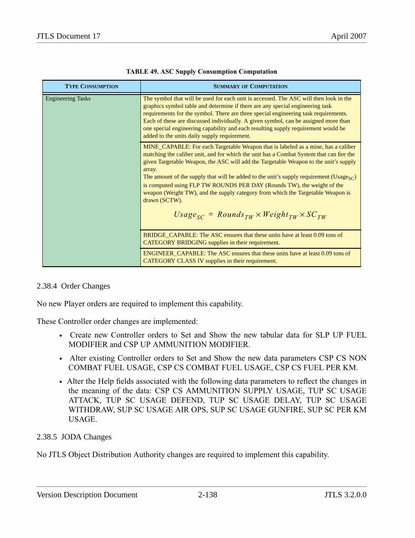
JTLS Document 17 April 2007
2.38.4 Order Changes
No new Player orders are required to implement this capability.
These Controller order changes are implemented:
• Create new Controller orders to Set and Show the new tabular data for SLP UP FUELMODIFIER and CSP UP AMMUNITION MODIFIER.
• Alter existing Controller orders to Set and Show the new data parameters CSP CS NONCOMBAT FUEL USAGE, CSP CS COMBAT FUEL USAGE, CSP CS FUEL PER KM.
• Alter the Help fields associated with the following data parameters to reflect the changes inthe meaning of the data: CSP CS AMMUNITION SUPPLY USAGE, TUP SC USAGEATTACK, TUP SC USAGE DEFEND, TUP SC USAGE DELAY, TUP SC USAGEWITHDRAW, SUP SC USAGE AIR OPS, SUP SC USAGE GUNFIRE, SUP SC PER KMUSAGE.
2.38.5 JODA Changes
No JTLS Object Distribution Authority changes are required to implement this capability.
Engineering Tasks The symbol that will be used for each unit is accessed. The ASC will then look in thegraphics symbol table and determine if there are any special engineering taskrequirements for the symbol. There are three special engineering task requirements.Each of these are discussed individually. A given symbol, can be assigned more thanone special engineering capability and each resulting supply requirement would beadded to the units daily supply requirement.
MINE_CAPABLE: For each Targetable Weapon that is labeled as a mine, has a calibermatching the caliber unit, and for which the unit has a Combat System that can fire thegiven Targetable Weapon, the ASC will add the Targetable Weapon to the unit’s supplyarray.The amount of the supply that will be added to the unit’s supply requirement (UsageSC)
is computed using FLP TW ROUNDS PER DAY (Rounds TW), the weight of theweapon (Weight TW), and the supply category from which the Targetable Weapon isdrawn (SCTW).
BRIDGE_CAPABLE: The ASC ensures that these units have at least 0.09 tons ofCATEGORY BRIDGING supplies in their requirement.
ENGINEER_CAPABLE: The ASC ensures that these units have at least 0.09 tons ofCATEGORY CLASS IV supplies in their requirement.
TABLE 49. ASC Supply Consumption Computation
TYPE CONSUMPTION SUMMARY OF COMPUTATION
UsageSC RoundsTW WeightTW× SCTW×=
Version Description Document 2-138 JTLS 3.2.0.0
April 2007 JTLS Document 17
2.39 JTLS-2006-1827 New Command Control Model
2.39.1 Summary of Model Change Request
Previous JTLS versions represented the Command, Control, and Communications (C3) capability ofa unit as a reserved Combat System named COMBAT SYSTEM C3 and was assigned the genericname C3I Combat System within the JTLS Standard Database. The number of C3I systems owned bya unit was used as a modifier to message delay and combat power reorientation.
The C3 capability is a combination of equipment, personnel, and procedures, and is a unit capabilityrather than a Combat System. Typically, Combat Systems represent separate objects, such aspersonnel or items of equipment. The definition of a complex capability as such an object causedproblems with the C3 representation. This enhancement redefines the C3 representation as a unitcapability rather than a Combat System.
2.39.2 Design Summary
All references to C3I are changed to C3, since the intelligence aspects are represented by other partsof the simulation. The variable COMBAT SYSTEM C3 is removed from the database and the CombatSystem to which it points is also be removed as part of the database conversion process. Additionally,the existing data item CP TIME DELAY PER 100 KM is removed. Several new data parameters areadded to more logically model the C3 capability of a unit and the message delay times encounteredwhen the unit receives or sends communications.
Each unit is assigned a UT C3 EFFECTIVENESS value between 0 and 1. This unit data parameterreplaces the number of available C3I Combat Systems as the modifier for message delay times andTUP PERCENT ALLOWED TO REORIENT, and is not a perceived data item. The value of a unit’sUT C3 EFFECTIVENESS can either increase or decrease as a result of game actions.
Each Aggregate Resolution Unit (ARU) is assigned a UT C3 QUALITY RATING, which points to anew permanent entity database object named C3 QUALITY RATING (CQR). To maintainconsistency with all JTLS object classes, this object has a short identifier CQR to simplify referencingthe C3 QUALITY RATING object data. A unit’s assigned CQR can change as a result of gameactions.
The attributes or data specified for each created CQR object are summarized in Table 50. Thedatabase conversion process automatically creates a single CQR object. Thus, after an existingdatabase is converted, contains a single CQR object with the indicated data. Database developers can
JTLS 3.2.0.0 2-139 Version Description Document
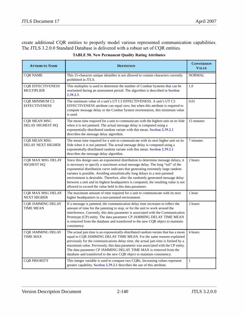
JTLS Document 17 April 2007
create additional CQR entities to properly model various represented communication capabilities.The JTLS 3.2.0.0 Standard Database is delivered with a robust set of CQR entities.
TABLE 50. New Permanent Quality Rating Attributes
ATTRIBUTE NAME DEFINITIONCONVERSION
VALUE
CQR NAME This 15-character unique identifier is not allowed to contain characters currentlyprohibited in JTLS.
NORMAL
CQR EFFECTIVENESSMULTIPLIER
This multiplier is used to determine the number of Combat Systems that can bereoriented during an assessment period. The algorithm is described in Section2.39.2.3.
1.0
CQR MINIMUM C3EFFECTIVENESS
The minimum value of a unit’s UT C3 EFFECTIVENESS. A unit’s UT C3EFFECTIVENESS attribute can equal zero, but when this attribute is required tocompute message delay or the Combat System reorientation, this minimum valueis used.
0.01
CQR MEAN MSGDELAY HIGHEST HQ
The mean time required for a unit to communicate with the highest unit on its Sidewhen it is not jammed. The actual message delay is computed using aexponentially-distributed random variate with this mean. Section 2.39.2.1describes the message delay algorithm.
15 minutes
CQR MEAN MSGDELAY NEXT HIGHER
The mean time required for a unit to communicate with its next higher unit on itsSide when it is not jammed. The actual message delay is computed using aexponentially-distributed random variate with this mean. Section 2.39.2.1describes the message delay algorithm.
7 minutes
CQR MAX MSG DELAYHIGHEST HQ
Since this design uses an exponential distribution to determine message delays, itis necessary to specify a maximum actual message delay. The long “tail” of theexponential distribution curve indicates that generating extremely large randomvariates is possible. Avoiding unrealistically long delays in a non-jammedenvironment is desirable. Therefore, after the randomly-generated message delaybetween a unit and its highest headquarters is computed, the resulting value is notallowed to exceed the value held in this data parameter.
2 hours
CQR MAX MSG DELAYNEXT HIGHER
The maximum amount of time required for a unit to communicate with its nexthigher headquarters in a non-jammed environment.
1 hour
CQR JAMMING DELAYTIME MEAN
If a message is jammed, the communication delay time increases to reflect theamount of time for the jamming to stop, or for the unit to work around theinterference. Currently, this data parameter is associated with the CommunicationPrototype (CP) entity. The data parameter CP JAMMING DELAY TIME MEANis removed from the database and transferred to the new CQR object to maintainconsistency.
2 hours
CQR JAMMING DELAYTIME MAX
The actual jam time is an exponentially-distributed random variate that has a meanequal to CQR JAMMING DELAY TIME MEAN. For the same reasons explainedpreviously for the communications delay time, the actual jam time is limited by amaximum value. Previously, this data parameter was associated with the CP entity.The data parameter CP JAMMING DELAY TIME MAX is removed from thedatabase and transferred to the new CQR object to maintain consistency.
4 hours
CQR PRIORITY This integer variable is used to compare two CQRs. Increasing values representgreater capability. Section 2.39.2.1 describes the use of this attribute.
1
Version Description Document 2-140 JTLS 3.2.0.0
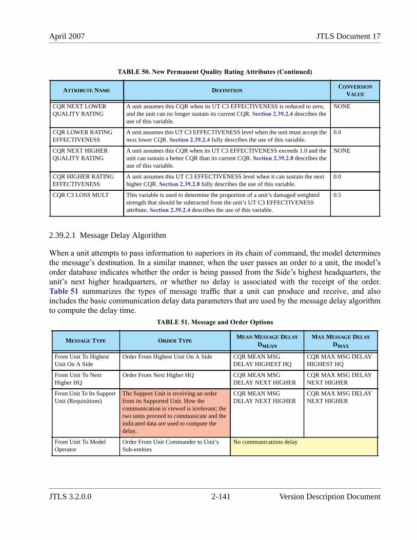
April 2007 JTLS Document 17
2.39.2.1 Message Delay Algorithm
When a unit attempts to pass information to superiors in its chain of command, the model determinesthe message’s destination. In a similar manner, when the user passes an order to a unit, the model’sorder database indicates whether the order is being passed from the Side’s highest headquarters, theunit’s next higher headquarters, or whether no delay is associated with the receipt of the order.Table 51 summarizes the types of message traffic that a unit can produce and receive, and alsoincludes the basic communication delay data parameters that are used by the message delay algorithmto compute the delay time.
CQR NEXT LOWERQUALITY RATING
A unit assumes this CQR when its UT C3 EFFECTIVENESS is reduced to zero,and the unit can no longer sustain its current CQR. Section 2.39.2.4 describes theuse of this variable.
NONE
CQR LOWER RATINGEFFECTIVENESS
A unit assumes this UT C3 EFFECTIVENESS level when the unit must accept thenext lower CQR. Section 2.39.2.4 fully describes the use of this variable.
0.0
CQR NEXT HIGHERQUALITY RATING
A unit assumes this CQR when its UT C3 EFFECTIVENESS exceeds 1.0 and theunit can sustain a better CQR than its current CQR. Section 2.39.2.8 describes theuse of this variable.
NONE
CQR HIGHER RATINGEFFECTIVENESS
A unit assumes this UT C3 EFFECTIVENESS level when it can sustain the nexthigher CQR. Section 2.39.2.8 fully describes the use of this variable.
0.0
CQR C3 LOSS MULT This variable is used to determine the proportion of a unit’s damaged weightedstrength that should be subtracted from the unit’s UT C3 EFFECTIVENESSattribute. Section 2.39.2.4 describes the use of this variable.
0.5
TABLE 51. Message and Order Options
MESSAGE TYPE ORDER TYPEMEAN MESSAGE DELAY
DMEAN
MAX MESSAGE DELAY
DMAX
From Unit To HighestUnit On A Side
Order From Highest Unit On A Side CQR MEAN MSGDELAY HIGHEST HQ
CQR MAX MSG DELAYHIGHEST HQ
From Unit To NextHigher HQ
Order From Next Higher HQ CQR MEAN MSGDELAY NEXT HIGHER
CQR MAX MSG DELAYNEXT HIGHER
From Unit To Its SupportUnit (Requisitions)
The Support Unit is receiving an orderfrom its Supported Unit. How thecommunication is viewed is irrelevant; thetwo units proceed to communicate and theindicated data are used to compute thedelay.
CQR MEAN MSGDELAY NEXT HIGHER
CQR MAX MSG DELAYNEXT HIGHER
From Unit To ModelOperator
Order From Unit Commander to Unit’sSub-entities
No communications delay
TABLE 50. New Permanent Quality Rating Attributes (Continued)
ATTRIBUTE NAME DEFINITIONCONVERSION
VALUE
JTLS 3.2.0.0 2-141 Version Description Document
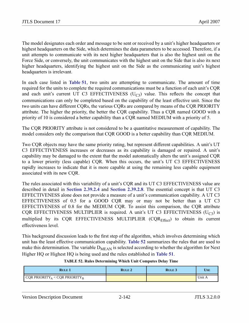
JTLS Document 17 April 2007
The model designates each order and message to be sent or received by a unit’s higher headquarters orhighest headquarters on the Side, which determines the data parameters to be accessed. Therefore, if aunit attempts to communicate with its next higher headquarters that is also the highest unit on theForce Side, or conversely, the unit communicates with the highest unit on the Side that is also its nexthigher headquarters, identifying the highest unit on the Side as the communicating unit’s highestheadquarters is irrelevant.
In each case listed in Table 51, two units are attempting to communicate. The amount of timerequired for the units to complete the required communications must be a function of each unit’s CQRand each unit’s current UT C3 EFFECTIVENESS (UC3) value. This reflects the concept that
communications can only be completed based on the capability of the least effective unit. Since thetwo units can have different CQRs, the various CQRs are compared by means of the CQR PRIORITYattribute. The higher the priority, the better the CQR capability. Thus a CQR named GOOD with apriority of 10 is considered a better capability than a CQR named MEDIUM with a priority of 5.
The CQR PRIORITY attribute is not considered to be a quantitative measurement of capability. Themodel considers only the comparison that CQR GOOD is a better capability than CQR MEDIUM.
Two CQR objects may have the same priority rating, but represent different capabilities. A unit’s UTC3 EFFECTIVENESS increases or decreases as its capability is damaged or repaired. A unit’scapability may be damaged to the extent that the model automatically alters the unit’s assigned CQRto a lower priority (less capable) CQR. When this occurs, the unit’s UT C3 EFFECTIVENESSrapidly increases to indicate that it is more capable at using the remaining less capable equipmentassociated with its new CQR.
The rules associated with this variability of a unit’s CQR and its UT C3 EFFECTIVENESS value aredescribed in detail in Section 2.39.2.4 and Section 2.39.2.8. The essential concept is that UT C3EFFECTIVENESS alone does not provide a measure of a unit’s communication capability. A UT C3EFFECTIVENESS of 0.5 for a GOOD CQR may or may not be better than a UT C3EFFECTIVENESS of 0.8 for the MEDIUM CQR. To assist this comparison, the CQR attributeCQR EFFECTIVENESS MULTIPLIER is required. A unit’s UT C3 EFFECTIVENESS (UC3) is
multiplied by its CQR EFFECTIVENESS MULTIPLIER (CQREffect) to obtain its current
effectiveness level.
This background discussion leads to the first step of the algorithm, which involves determining whichunit has the least effective communication capability. Table 52 summarizes the rules that are used tomake this determination. The variable DMEAN is selected according to whether the algorithm for Next
Higher HQ or Highest HQ is being used and the rules established in Table 51.
TABLE 52. Rules Determining Which Unit Computes Delay Time
RULE 1 RULE 2 RULE 3 USE
CQR PRIORITYA < CQR PRIORITYB Unit A
Version Description Document 2-142 JTLS 3.2.0.0
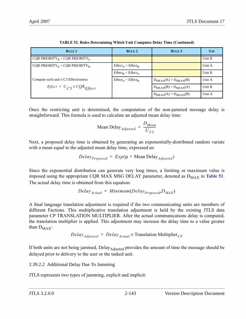
April 2007 JTLS Document 17
Once the restricting unit is determined, the computation of the non-jammed message delay isstraightforward. This formula is used to calculate an adjusted mean delay time:
Next, a proposed delay time is obtained by generating an exponentially-distributed random variatewith a mean equal to the adjusted mean delay time, expressed as:
Since the exponential distribution can generate very long times, a limiting or maximum value isimposed using the appropriate CQR MAX MSG DELAY parameter, denoted as DMAX in Table 51.
The actual delay time is obtained from this equation:
A final language translation adjustment is required if the two communicating units are members ofdifferent Factions. This multiplicative translation adjustment is held by the existing JTLS dataparameter CP TRANSLATION MULTIPLIER. After the actual communications delay is computed,the translation multiplier is applied. This adjustment may increase the delay time to a value greaterthan DMAX:
If both units are not being jammed, DelayAdjusted provides the amount of time the message should be
delayed prior to delivery to the user or the tasked unit.
2.39.2.2 Additional Delay Due To Jamming
JTLS represents two types of jamming, explicit and implicit:
CQR PRIORITYB < CQR PRIORITYA Unit B
CQR PRIORITYA = CQR PRIORITYB
Compute each unit’s C3 Effectiveness
EffectA < EffectB Unit A
EffectB < EffectA Unit B
EffectA = EffectB DMEAN(A) > DMEAN(B) Unit A
DMEAN(B) > DMEAN(A) Unit B
DMEAN(A) = DMEAN(B) Unit A
TABLE 52. Rules Determining Which Unit Computes Delay Time (Continued)
RULE 1 RULE 2 RULE 3 USE
Effect U C3CQREffect×=
Mean DelayAdjusted
DMean
U C3
---------------=
DelayProposed Exp μ Mean DelayAdjusted=( )=
DelayActual Minimum DelayProposed DMAX( , )=
DelayAdjusted DelayActual Translation MultiplierCP×=
JTLS 3.2.0.0 2-143 Version Description Document
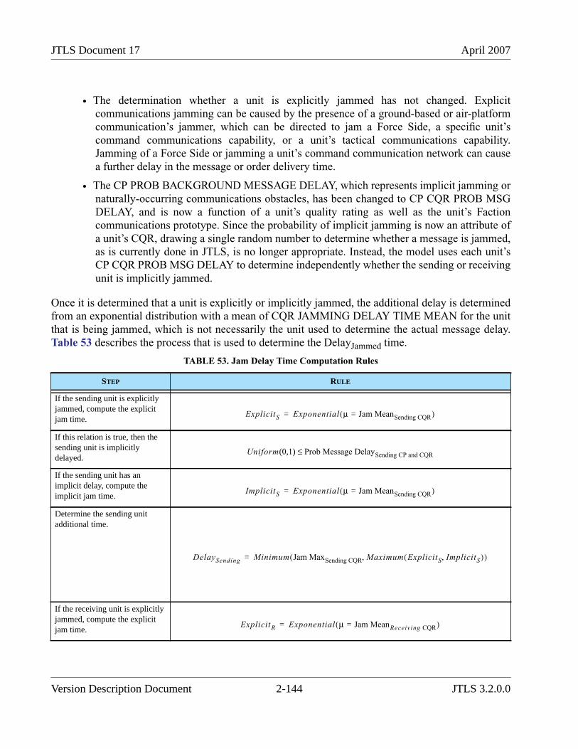
JTLS Document 17 April 2007
• The determination whether a unit is explicitly jammed has not changed. Explicitcommunications jamming can be caused by the presence of a ground-based or air-platformcommunication’s jammer, which can be directed to jam a Force Side, a specific unit’scommand communications capability, or a unit’s tactical communications capability.Jamming of a Force Side or jamming a unit’s command communication network can causea further delay in the message or order delivery time.
• The CP PROB BACKGROUND MESSAGE DELAY, which represents implicit jamming ornaturally-occurring communications obstacles, has been changed to CP CQR PROB MSGDELAY, and is now a function of a unit’s quality rating as well as the unit’s Factioncommunications prototype. Since the probability of implicit jamming is now an attribute ofa unit’s CQR, drawing a single random number to determine whether a message is jammed,as is currently done in JTLS, is no longer appropriate. Instead, the model uses each unit’sCP CQR PROB MSG DELAY to determine independently whether the sending or receivingunit is implicitly jammed.
Once it is determined that a unit is explicitly or implicitly jammed, the additional delay is determinedfrom an exponential distribution with a mean of CQR JAMMING DELAY TIME MEAN for the unitthat is being jammed, which is not necessarily the unit used to determine the actual message delay.Table 53 describes the process that is used to determine the DelayJammed time.
TABLE 53. Jam Delay Time Computation Rules
STEP RULE
If the sending unit is explicitlyjammed, compute the explicitjam time.
If this relation is true, then thesending unit is implicitlydelayed.
If the sending unit has animplicit delay, compute theimplicit jam time.
Determine the sending unitadditional time.
If the receiving unit is explicitlyjammed, compute the explicitjam time.
ExplicitS Exponential μ Jam MeanSending CQR=( )=
Uniform 0 1( , ) Prob Message DelaySending CP and CQR≤
ImplicitS Exponential μ Jam MeanSending CQR=( )=
DelaySending Minimum Jam MaxSending CQR Maximum ExplicitS ImplicitS,( ),( )=
ExplicitR Exponential μ Jam MeanReceiving CQR=( )=
Version Description Document 2-144 JTLS 3.2.0.0
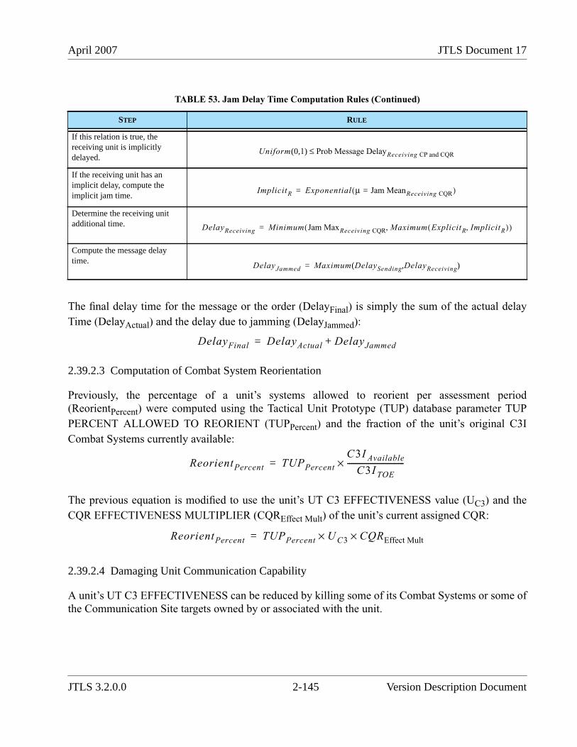
April 2007 JTLS Document 17
The final delay time for the message or the order (DelayFinal) is simply the sum of the actual delay
Time (DelayActual) and the delay due to jamming (DelayJammed):
2.39.2.3 Computation of Combat System Reorientation
Previously, the percentage of a unit’s systems allowed to reorient per assessment period(ReorientPercent) were computed using the Tactical Unit Prototype (TUP) database parameter TUP
PERCENT ALLOWED TO REORIENT (TUPPercent) and the fraction of the unit’s original C3I
Combat Systems currently available:
The previous equation is modified to use the unit’s UT C3 EFFECTIVENESS value (UC3) and the
CQR EFFECTIVENESS MULTIPLIER (CQREffect Mult) of the unit’s current assigned CQR:
2.39.2.4 Damaging Unit Communication Capability
A unit’s UT C3 EFFECTIVENESS can be reduced by killing some of its Combat Systems or some ofthe Communication Site targets owned by or associated with the unit.
If this relation is true, thereceiving unit is implicitlydelayed.
If the receiving unit has animplicit delay, compute theimplicit jam time.
Determine the receiving unitadditional time.
Compute the message delaytime.
TABLE 53. Jam Delay Time Computation Rules (Continued)
STEP RULE
Uniform 0 1( , ) Prob Message DelayReceiving CP and CQR≤
ImplicitR Exponential μ Jam MeanReceiving CQR=( )=
DelayReceiving Minimum Jam MaxReceiving CQR Maximum ExplicitR ImplicitR,( ),( )=
DelayJammed Maximum DelaySending DelayReceiving( , )=
DelayFinal DelayActual DelayJammed+=
ReorientPercent TUPPercent
C3I Available
C3I TOE------------------------------×=
ReorientPercent TUPPercent U C3× CQREffect Mult×=
JTLS 3.2.0.0 2-145 Version Description Document
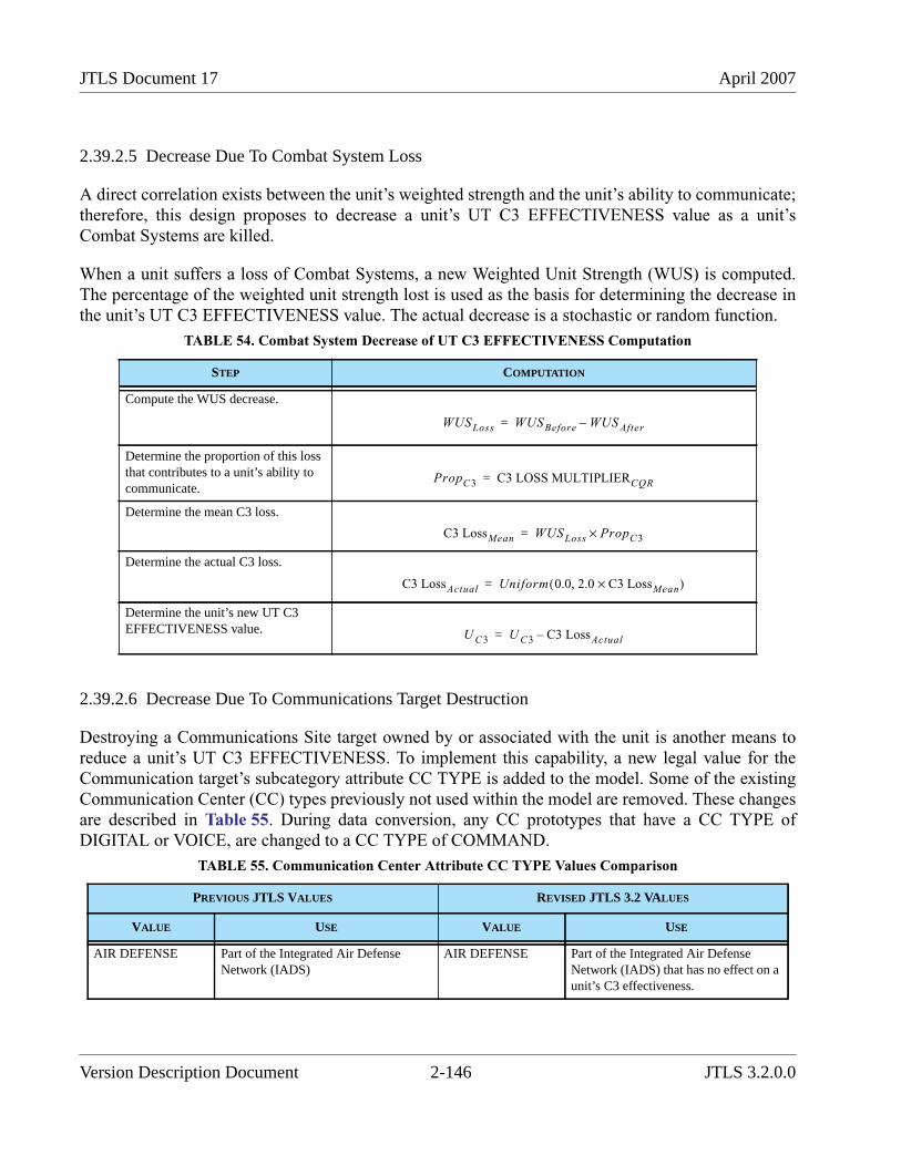
JTLS Document 17 April 2007
2.39.2.5 Decrease Due To Combat System Loss
A direct correlation exists between the unit’s weighted strength and the unit’s ability to communicate;therefore, this design proposes to decrease a unit’s UT C3 EFFECTIVENESS value as a unit’sCombat Systems are killed.
When a unit suffers a loss of Combat Systems, a new Weighted Unit Strength (WUS) is computed.The percentage of the weighted unit strength lost is used as the basis for determining the decrease inthe unit’s UT C3 EFFECTIVENESS value. The actual decrease is a stochastic or random function.
2.39.2.6 Decrease Due To Communications Target Destruction
Destroying a Communications Site target owned by or associated with the unit is another means toreduce a unit’s UT C3 EFFECTIVENESS. To implement this capability, a new legal value for theCommunication target’s subcategory attribute CC TYPE is added to the model. Some of the existingCommunication Center (CC) types previously not used within the model are removed. These changesare described in Table 55. During data conversion, any CC prototypes that have a CC TYPE ofDIGITAL or VOICE, are changed to a CC TYPE of COMMAND.
TABLE 54. Combat System Decrease of UT C3 EFFECTIVENESS Computation
STEP COMPUTATION
Compute the WUS decrease.
Determine the proportion of this lossthat contributes to a unit’s ability tocommunicate.
Determine the mean C3 loss.
Determine the actual C3 loss.
Determine the unit’s new UT C3EFFECTIVENESS value.
TABLE 55. Communication Center Attribute CC TYPE Values Comparison
PREVIOUS JTLS VALUES REVISED JTLS 3.2 VALUES
VALUE USE VALUE USE
AIR DEFENSE Part of the Integrated Air DefenseNetwork (IADS)
AIR DEFENSE Part of the Integrated Air DefenseNetwork (IADS) that has no effect on aunit’s C3 effectiveness.
WUSLoss WUSBefore WUS After–=
PropC3 C3 LOSS MULTIPLIERCQR=
C3 LossMean WUSLoss PropC3×=
C3 LossActual Uniform 0.0 2.0 C3 LossMean×,( )=
U C3 U C3 C3 LossActual–=
Version Description Document 2-146 JTLS 3.2.0.0
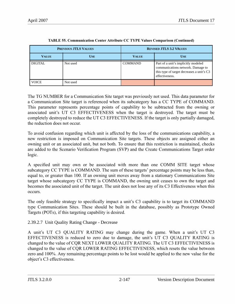
April 2007 JTLS Document 17
The TG NUMBER for a Communication Site target was previously not used. This data parameter fora Communication Site target is referenced when its subcategory has a CC TYPE of COMMAND.This parameter represents percentage points of capability to be subtracted from the owning orassociated unit’s UT C3 EFFECTIVENESS when the target is destroyed. The target must becompletely destroyed to reduce the UT C3 EFFECTIVENESS. If the target is only partially damaged,the reduction does not occur.
To avoid confusion regarding which unit is affected by the loss of the communications capability, anew restriction is imposed on Communication Site targets. These objects are assigned either anowning unit or an associated unit, but not both. To ensure that this restriction is maintained, checksare added to the Scenario Verification Program (SVP) and the Create Communications Target orderlogic.
A specified unit may own or be associated with more than one COMM SITE target whosesubcategory CC TYPE is COMMAND. The sum of these targets’ percentage points may be less than,equal to, or greater than 100. If an owning unit moves away from a stationary Communications Sitetarget whose subcategory CC TYPE is COMMAND, the owning unit ceases to own the target andbecomes the associated unit of the target. The unit does not lose any of its C3 Effectiveness when thisoccurs.
The only feasible strategy to specifically impact a unit’s C3 capability is to target its COMMANDtype Communication Sites. These should be built in the database, possibly as Prototype OwnedTargets (POTs), if this targeting capability is desired.
2.39.2.7 Unit Quality Rating Change - Decrease
A unit’s UT C3 QUALITY RATING may change during the game. When a unit’s UT C3EFFECTIVENESS is reduced to zero due to damage, the unit’s UT C3 QUALITY RATING ischanged to the value of CQR NEXT LOWER QUALITY RATING. The UT C3 EFFECTIVENESS ischanged to the value of CQR LOWER RATING EFFECTIVENESS, which resets the value betweenzero and 100%. Any remaining percentage points to be lost would be applied to the new value for theobject’s C3 effectiveness.
DIGITAL Not used COMMAND Part of a unit’s implicitly modeledcommunications network. Damage tothis type of target decreases a unit’s C3effectiveness.
VOICE Not used
TABLE 55. Communication Center Attribute CC TYPE Values Comparison (Continued)
PREVIOUS JTLS VALUES REVISED JTLS 3.2 VALUES
VALUE USE VALUE USE
JTLS 3.2.0.0 2-147 Version Description Document
JTLS Document 17 April 2007
2.39.2.8 Repairing Unit Communication Capability
A unit’s UT C3 EFFECTIVENESS can be increased by repairing the implicitly modeledcommunication capability or by repairing a damaged Communication Site target.
2.39.2.8.1 Repairing Implicit Communication Capability
As discussed previously, a unit’s UT C3 EFFECTIVENESS is reduced as the unit’s weighted strengthis reduced. This weighted strength can be reduced only when a Combat System is killed or damaged.However, the UT C3 EFFECTIVENESS value does not simply represent hardware, but alsorepresents the confusion or efficiency that influences the unit’s ability to communicate effectively.The reduction of UT C3 EFFECTIVENESS immediately following the loss of Combat Systemsattempts to model this situation during which unit commanders may experience difficultycommunicating with their superiors. However, this “confusion” factor should not always bemaintained in the unit until the damaged systems are repaired.
For these reasons, the repair of UT C3 EFFECTIVENESS is not linked to the repair of damagedsystems or the delivery of replacement systems. Instead, the repair function is linked to the unit’sFaction-based Communications Prototype (CP) and the unit’s Communications Quality Rating(CQR). Units recover C3 effectiveness during the Hourly Unit Processing event. The rate of recoveryis held in a new database array named CP CQR PERCENT RECOVERED PER DAY.
As this variable name indicates, the data are held as a Per Day value. During the Hourly UnitProcessing event, the database value is divided by 24, since it is being applied hourly. The value of CPCQR PERCENT RECOVERED PER DAY can exceed 1.0; in this case, the unit could recover 100percentage points in less than one day.
The effect of a unit’s recovery to a UT C3 EFFECTIVENESS of 1.0 or greater is discussed in thefollowing section.
2.39.2.9 Repairing Communication Site Targets
Repairing a COMM SITE target owned by or associated with a unit is another means to increase aunit’s UT C3 EFFECTIVENESS. The COMM SITE target subcategory must have a CC TYPE ofCOMMAND. As discussed in the context of damage to these targets, the TG NUMBER is thenumber of percentage points added to the owning or associated unit’s UT C3 EFFECTIVENESS afterthe damaged target is repaired.
2.39.2.10 Unit Quality Rating Change - Increase
A unit’s CQR can decrease when the UT C3 EFFECTIVENESS value is reduced to zero, but the unitalso has the ability to increase its CQR. If this increase would result in a UT C3 EFFECTIVENESSgreater than 1.0, the unit’s UT C3 QUALITY RATING may be changed to the quality rating in CQRNEXT HIGHER QUALITY RATING.
Version Description Document 2-148 JTLS 3.2.0.0
April 2007 JTLS Document 17
When a unit’s UT C3 EFFECTIVENESS is greater than or equal to 1.0, the unit’s CQR is changed tothe CQR NEXT HIGHER QUALITY RATING and assumes a UT C3 EFFECTIVENESS equal tothe attribute CQR HIGHER RATING EFFECTIVENESS. Two restrictions apply to this increase:
• A unit can never assume a CQR that has a CQR PRIORITY higher than the priority assignedto the unit’s attribute UT HIGHEST C3 QUALITY RATING.
• The additional restricting rule applies to the status of the unit’s owned or associatedCommunication Site targets. This rule does not allow a unit’s UT C3 EFFECTIVENESS toexceed 1.0 minus its damaged Communication Site targets when the unit has a CQR with aCQR PRIORITY equal to the CQR PRIORITY of its UT HIGHEST C3 QUALITYRATING.
2.39.2.11 Unit Detach and Attach Modeling Considerations
These rules apply when a unit detaches from an existing JTLS unit, or two units attach:
• A detached unit receives the same UT C3 EFFECTIVENESS value, UT C3 QUALITYRATING, and UT HIGHEST C3 QUALITY RATING assigned to its parent unit.
• A unit that accepts the attachment of another unit for purposes of Reconstitution retains itsown UT C3 QUALITY RATING and UT HIGHEST C3 QUALITY RATING, but its UTC3 EFFECTIVENESS is increased by the difference between its pre-attachment weightedunit strength (WBefore) and its post-attachment weighted unit strength (WAfter) multiplied by
the CQR C3 LOSS MULT (PropC3) of the unit’s current quality rating. Let UA represent the
unit that is attaching to unit UR, which represents the unit receiving the attachment.
The UT C3 EFFECTIVENESS may increase to a value greater than 1.0. In this case, theunit would obey the increase rules described previously, and be assigned the CQR NEXTHIGHER QUALITY RATING, if available and permitted by the corresponding restrictionrules. Any Communication Site targets transferred as a result of the attachment areconsidered in the restriction computation:
• A unit that accepts the attachment of another unit for Task Organization purposes maintainsits own UT C3 EFFECTIVENESS value, UT C3 QUALITY RATING, and UT HIGHESTC3 QUALITY RATING. The accepting unit’s UT C3 EFFECTIVENESS attribute obtains
CQRAfter U R( ) CQRBefore U R( )=
EffectAfter U R( ) EffectBefore U R( ) PropC3W After W Before–( )×[ ] TG Number U AComm Tgts( )∑+ +=
EffectAfter U A( ) Minimum EffectAfter U A( ) 1.0 TG Number
Comm
T etsarg
Damaged
∑–,
⎝ ⎠⎜ ⎟⎜ ⎟⎜ ⎟⎛ ⎞
=
JTLS 3.2.0.0 2-149 Version Description Document
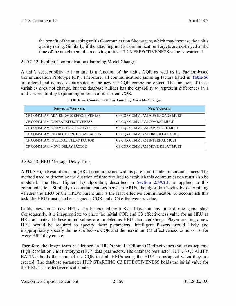
JTLS Document 17 April 2007
the benefit of the attaching unit’s Communication Site targets, which may increase the unit’squality rating. Similarly, if the attaching unit’s Communication Targets are destroyed at thetime of the attachment, the receiving unit’s UT C3 EFFECTIVENESS value is restricted.
2.39.2.12 Explicit Communications Jamming Model Changes
A unit’s susceptibility to jamming is a function of the unit’s CQR as well as its Faction-basedCommunication Prototype (CP). Therefore, all communications jamming factors listed in Table 56are altered and defined as attributes of the new CP CQR compound object. The function of thesevariables does not change, but the database builder has the capability to represent differences in aunit’s susceptibility to jamming in terms of its current CQR.
2.39.2.13 HRU Message Delay Time
A JTLS High Resolution Unit (HRU) communicates with its parent unit under all circumstances. Themethod used to determine the duration of time required to establish this communication must also bemodeled. The Next Higher HQ algorithm, described in Section 2.39.2.1, is applied to thiscommunication. Similarly to communications between ARUs, the algorithm begins by determiningwhether the HRU or the HRU’s parent unit is the least effective communicator. To accomplish thistask, the HRU must also be assigned a CQR and a C3 effectiveness value.
Unlike new units, new HRUs can be created by a Side Player at any time during game play.Consequently, it is inappropriate to place the initial CQR and C3 effectiveness value for an HRU asHRU attributes. If these initial values are modeled as HRU characteristics, a Player creating a newHRU would be required to specify these parameters. Intelligent Players would likely andinappropriately specify the most effective CQR and the maximum C3 effectiveness value as 1.0 forevery HRU they create.
Therefore, the design team has defined an HRU’s initial CQR and C3 effectiveness value as separateHigh Resolution Unit Prototype (HUP) data parameters. The database parameter HUP C3 QUALITYRATING holds the name of the CQR that all HRUs using the HUP are assigned when they arecreated. The database parameter HUP STARTING C3 EFFECTIVENESS holds the initial value forthe HRU’s C3 effectiveness attribute.
TABLE 56. Communications Jamming Variable Changes
PREVIOUS VARIABLE NEW VARIABLE
CP COMM JAM ADA ENGAGE EFFECTIVENESS CP CQR COMM JAM ADA ENGAGE MULT
CP COMM JAM COMBAT EFFECTIVENESS CP CQR COMM JAM COMBAT MULT
CP COMM JAM COMM SITE EFFECTIVENESS CP CQR COMM JAM COMM SITE MULT
CP COMM JAM INDIRECT FIRE DELAY FACTOR CP CQR COMM JAM FIRE DELAY MULT
CP COMM JAM INTERNAL DELAY FACTOR CP CQR COMM JAM INTERNAL MULT
CP COMM JAM MOVE DELAY FACTOR CP CQR COMM JAM MOVE DELAY MULT
Version Description Document 2-150 JTLS 3.2.0.0
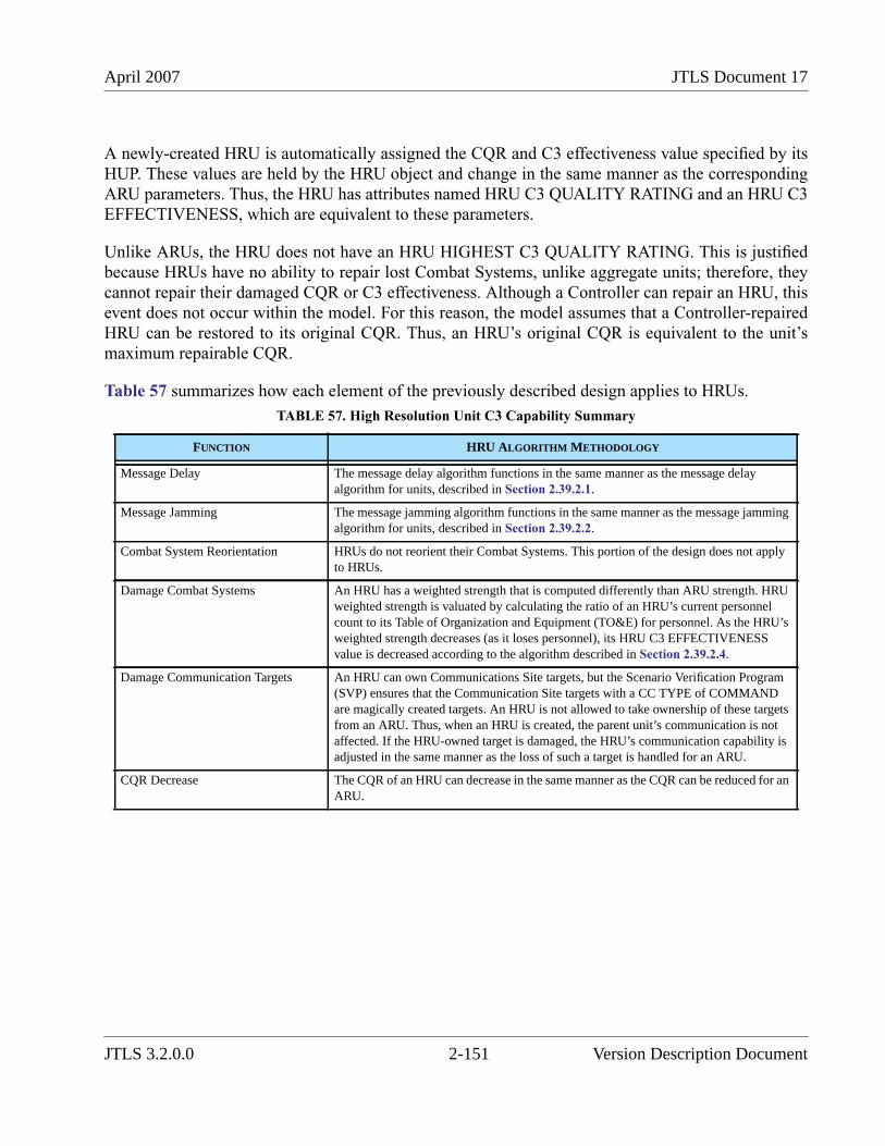
April 2007 JTLS Document 17
A newly-created HRU is automatically assigned the CQR and C3 effectiveness value specified by itsHUP. These values are held by the HRU object and change in the same manner as the correspondingARU parameters. Thus, the HRU has attributes named HRU C3 QUALITY RATING and an HRU C3EFFECTIVENESS, which are equivalent to these parameters.
Unlike ARUs, the HRU does not have an HRU HIGHEST C3 QUALITY RATING. This is justifiedbecause HRUs have no ability to repair lost Combat Systems, unlike aggregate units; therefore, theycannot repair their damaged CQR or C3 effectiveness. Although a Controller can repair an HRU, thisevent does not occur within the model. For this reason, the model assumes that a Controller-repairedHRU can be restored to its original CQR. Thus, an HRU’s original CQR is equivalent to the unit’smaximum repairable CQR.
Table 57 summarizes how each element of the previously described design applies to HRUs.
TABLE 57. High Resolution Unit C3 Capability Summary
FUNCTION HRU ALGORITHM METHODOLOGY
Message Delay The message delay algorithm functions in the same manner as the message delayalgorithm for units, described in Section 2.39.2.1.
Message Jamming The message jamming algorithm functions in the same manner as the message jammingalgorithm for units, described in Section 2.39.2.2.
Combat System Reorientation HRUs do not reorient their Combat Systems. This portion of the design does not applyto HRUs.
Damage Combat Systems An HRU has a weighted strength that is computed differently than ARU strength. HRUweighted strength is valuated by calculating the ratio of an HRU’s current personnelcount to its Table of Organization and Equipment (TO&E) for personnel. As the HRU’sweighted strength decreases (as it loses personnel), its HRU C3 EFFECTIVENESSvalue is decreased according to the algorithm described in Section 2.39.2.4.
Damage Communication Targets An HRU can own Communications Site targets, but the Scenario Verification Program(SVP) ensures that the Communication Site targets with a CC TYPE of COMMANDare magically created targets. An HRU is not allowed to take ownership of these targetsfrom an ARU. Thus, when an HRU is created, the parent unit’s communication is notaffected. If the HRU-owned target is damaged, the HRU’s communication capability isadjusted in the same manner as the loss of such a target is handled for an ARU.
CQR Decrease The CQR of an HRU can decrease in the same manner as the CQR can be reduced for anARU.
JTLS 3.2.0.0 2-151 Version Description Document
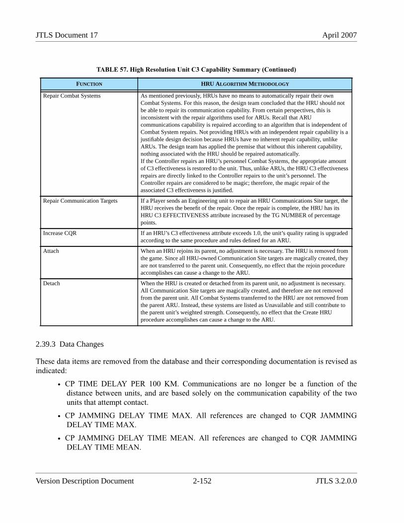
JTLS Document 17 April 2007
2.39.3 Data Changes
These data items are removed from the database and their corresponding documentation is revised asindicated:
• CP TIME DELAY PER 100 KM. Communications are no longer be a function of thedistance between units, and are based solely on the communication capability of the twounits that attempt contact.
• CP JAMMING DELAY TIME MAX. All references are changed to CQR JAMMINGDELAY TIME MAX.
• CP JAMMING DELAY TIME MEAN. All references are changed to CQR JAMMINGDELAY TIME MEAN.
Repair Combat Systems As mentioned previously, HRUs have no means to automatically repair their ownCombat Systems. For this reason, the design team concluded that the HRU should notbe able to repair its communication capability. From certain perspectives, this isinconsistent with the repair algorithms used for ARUs. Recall that ARUcommunications capability is repaired according to an algorithm that is independent ofCombat System repairs. Not providing HRUs with an independent repair capability is ajustifiable design decision because HRUs have no inherent repair capability, unlikeARUs. The design team has applied the premise that without this inherent capability,nothing associated with the HRU should be repaired automatically.If the Controller repairs an HRU’s personnel Combat Systems, the appropriate amountof C3 effectiveness is restored to the unit. Thus, unlike ARUs, the HRU C3 effectivenessrepairs are directly linked to the Controller repairs to the unit’s personnel. TheController repairs are considered to be magic; therefore, the magic repair of theassociated C3 effectiveness is justified.
Repair Communication Targets If a Player sends an Engineering unit to repair an HRU Communications Site target, theHRU receives the benefit of the repair. Once the repair is complete, the HRU has itsHRU C3 EFFECTIVENESS attribute increased by the TG NUMBER of percentagepoints.
Increase CQR If an HRU’s C3 effectiveness attribute exceeds 1.0, the unit’s quality rating is upgradedaccording to the same procedure and rules defined for an ARU.
Attach When an HRU rejoins its parent, no adjustment is necessary. The HRU is removed fromthe game. Since all HRU-owned Communication Site targets are magically created, theyare not transferred to the parent unit. Consequently, no effect that the rejoin procedureaccomplishes can cause a change to the ARU.
Detach When the HRU is created or detached from its parent unit, no adjustment is necessary.All Communication Site targets are magically created, and therefore are not removedfrom the parent unit. All Combat Systems transferred to the HRU are not removed fromthe parent ARU. Instead, these systems are listed as Unavailable and still contribute tothe parent unit’s weighted strength. Consequently, no effect that the Create HRUprocedure accomplishes can cause a change to the ARU.
TABLE 57. High Resolution Unit C3 Capability Summary (Continued)
FUNCTION HRU ALGORITHM METHODOLOGY
Version Description Document 2-152 JTLS 3.2.0.0
April 2007 JTLS Document 17
• CP PROB BACKGROUND MESSAGE DELAY. All references are changed to CP CQRPROB MESSAGE DELAY.
• CP COMM JAM ADA ENGAGE EFFECTIVENESS. All references are changed to CPCQR COMM JAM ADA ENGAGE MULT.
• CP COMM JAM COMBAT EFFECTIVENESS. All references are changed to CP CQRCOMM JAM COMBAT MULT.
• CP COMM JAM COMM SITE EFFECTIVENESS. All references are changed to CP CQRCOMM JAM COMM SITE MULT.
• CP COMM JAM INDIRECT FIRE DELAY FACTOR. All references are changed to CPCQR COMM JAM FIRE DELAY MULT.
• CP COMM JAM MOVE DELAY FACTOR. All references are changed to CP CQR COMMJAM MOVE DELAY MULT.
• CP COMM JAM INTERNAL TIME DELAY FACTOR. All references are changed to CPCQR COMM JAM INTERNAL MULT.
• COMBAT SYSTEM C3. The Combat System specified by COMBAT SYSTEM C3 isremoved from the Combat System list when the Modify program is executed.
The definitions of these existing data items are revised as described in the JTLS Data RequirementsManual.
• CC TYPE
• CC DATALINK RANGE
• CC JAMMING FACTOR
• CP JAMMING THRESHOLD
• TG NUMBER
• TG ASSOCIATED UNIT
• TG OWNING UNIT
The new C3 QUALITY RATING object requires the attributes described in Table 50.
The Communication Prototype (CP) entity exists in the initialization database. A new sub-entity tableis added to hold these data elements required for each CP and CQR combination:
• CP CQR PERCENT RECOVERED PER DAY
• CP CQR PROB MESSAGE DELAY
• CP CQR COMM JAM ADA ENGAGE MULT
• CP CQR COMM JAM COMBAT MULT
JTLS 3.2.0.0 2-153 Version Description Document
JTLS Document 17 April 2007
• CP CQR COMM JAM COMM SITE MULT
• CP CQR COMM JAM FIRE DELAY MULT
• CP CQR COMM JAM INTERNAL MULT
• CP CQR COMM JAM MOVE DELAY MULT
These data items are added to unit definition in the initialization database:
• UT C3 EFFECTIVENESS
• UT C3 QUALITY RATING
• UT HIGHEST C3 QUALITY RATING
• HUP C3 QUALITY RATING
• HUP STARTING C3 EFFECTIVENESS
2.39.4 Order Changes
The SET and SHOW orders are modified to accommodate the data changes.
The Create Unit order is modified to allow the Controller to specify the three new unit parameters: UTC3 QUALITY RATING, UT HIGHEST C3 QUALITY RATING, and UT C3 EFFECTIVENESS.
The Reactivate Unit order is modified to allow the Controller to specify the new UT C3 QUALITYRATING and UT C3 EFFECTIVENESS parameters. A reactivated unit retains its current UTHIGHEST C3 QUALITY RATING, unless the new UT C3 QUALITY RATING is greater than theUT HIGHEST C3 QUALITY RATING. In that case, the new CQR becomes the new UT HIGHESTC3 QUALITY RATING.
2.39.5 JODA Changes
These data are made available to client programs through both the JTLS Object Data Authority(JODA) feed and the High Level Architecture (HLA) feed:
• UT C3 EFFECTIVENESS
• UT COMMAND QUALITY RATING
• UT COMBINED EFFECTIVENESS
• HRU C3 EFFECTIVENESS
• HRU COMMAND QUALITY RATING
Version Description Document 2-154 JTLS 3.2.0.0
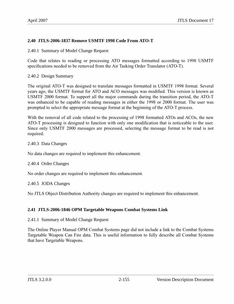
April 2007 JTLS Document 17
2.40 JTLS-2006-1837 Remove USMTF 1998 Code From ATO-T
2.40.1 Summary of Model Change Request
Code that relates to reading or processing ATO messages formatted according to 1998 USMTFspecifications needed to be removed from the Air Tasking Order Translator (ATO-T).
2.40.2 Design Summary
The original ATO-T was designed to translate messages formatted in USMTF 1998 format. Severalyears ago, the USMTF format for ATO and ACO messages was modified. This version is known asUSMTF 2000 format. To support all the major commands during the transition period, the ATO-Twas enhanced to be capable of reading messages in either the 1998 or 2000 format. The user wasprompted to select the appropriate message format at the beginning of the ATO-T process.
With the removal of all code related to the processing of 1998 formatted ATOs and ACOs, the newATO-T processing is designed to function with only one modification that is noticeable to the user.Since only USMTF 2000 messages are processed, selecting the message format to be read is notrequired.
2.40.3 Data Changes
No data changes are required to implement this enhancement.
2.40.4 Order Changes
No order changes are required to implement this enhancement.
2.40.5 JODA Changes
No JTLS Object Distribution Authority changes are required to implement this enhancement.
2.41 JTLS-2006-1846 OPM Targetable Weapons Combat Systems Link
2.41.1 Summary of Model Change Request
The Online Player Manual OPM Combat Systems page did not include a link to the Combat SystemsTargetable Weapon Can Fire data. This is useful information to fully describe all Combat Systemsthat have Targetable Weapons.
JTLS 3.2.0.0 2-155 Version Description Document
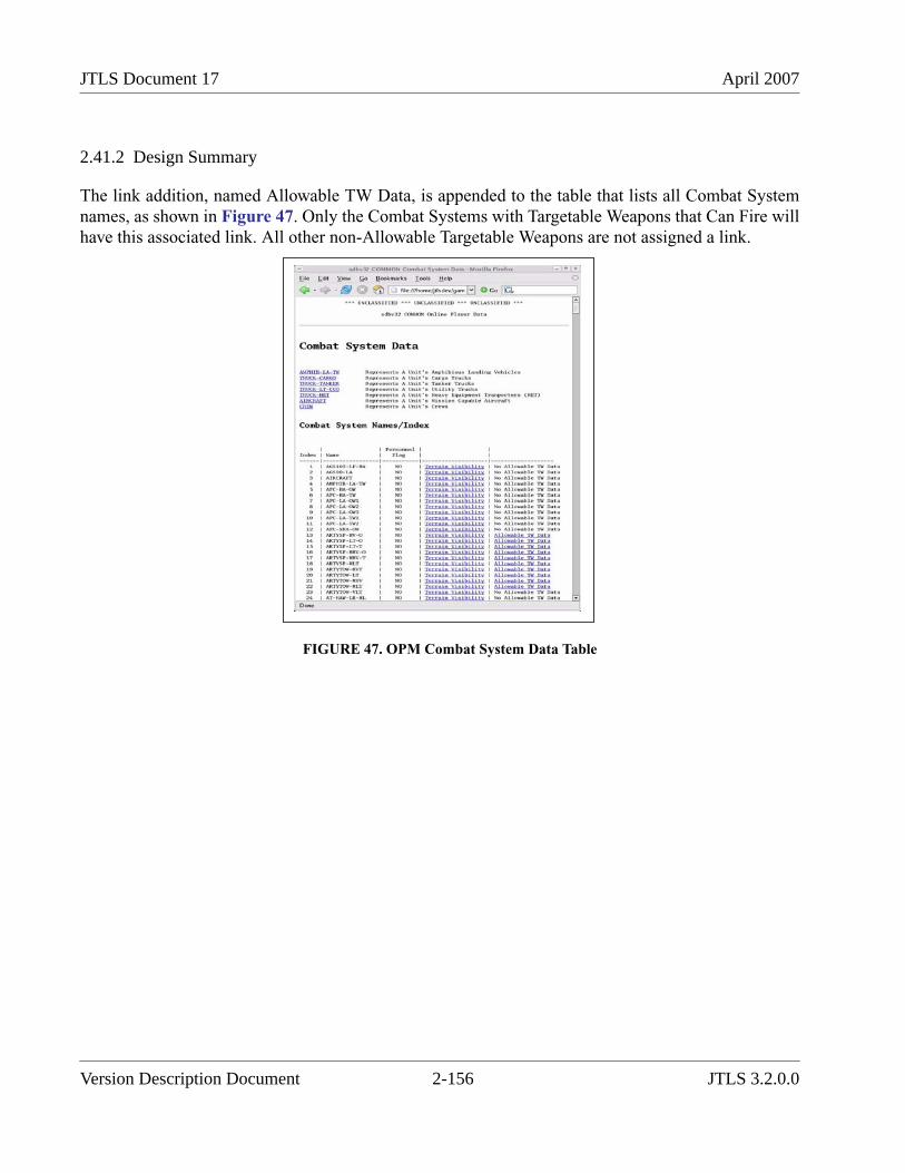
JTLS Document 17 April 2007
2.41.2 Design Summary
The link addition, named Allowable TW Data, is appended to the table that lists all Combat Systemnames, as shown in Figure 47. Only the Combat Systems with Targetable Weapons that Can Fire willhave this associated link. All other non-Allowable Targetable Weapons are not assigned a link.
FIGURE 47. OPM Combat System Data Table
Version Description Document 2-156 JTLS 3.2.0.0
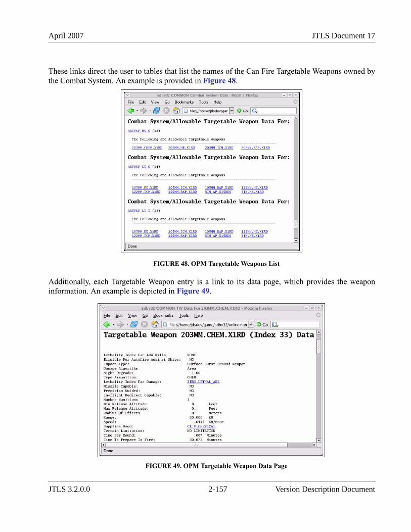
April 2007 JTLS Document 17
These links direct the user to tables that list the names of the Can Fire Targetable Weapons owned bythe Combat System. An example is provided in Figure 48.
FIGURE 48. OPM Targetable Weapons List
Additionally, each Targetable Weapon entry is a link to its data page, which provides the weaponinformation. An example is depicted in Figure 49.
FIGURE 49. OPM Targetable Weapon Data Page
JTLS 3.2.0.0 2-157 Version Description Document
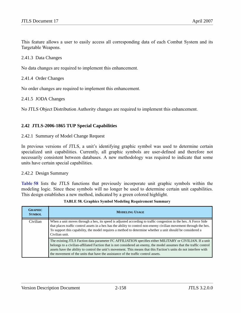
JTLS Document 17 April 2007
This feature allows a user to easily access all corresponding data of each Combat System and itsTargetable Weapons.
2.41.3 Data Changes
No data changes are required to implement this enhancement.
2.41.4 Order Changes
No order changes are required to implement this enhancement.
2.41.5 JODA Changes
No JTLS Object Distribution Authority changes are required to implement this enhancement.
2.42 JTLS-2006-1865 TUP Special Capabilities
2.42.1 Summary of Model Change Request
In previous versions of JTLS, a unit’s identifying graphic symbol was used to determine certainspecialized unit capabilities. Currently, all graphic symbols are user-defined and therefore notnecessarily consistent between databases. A new methodology was required to indicate that someunits have certain special capabilities.
2.42.2 Design Summary
Table 58 lists the JTLS functions that previously incorporate unit graphic symbols within themodeling logic. Since these symbols will no longer be used to determine certain unit capabilities.This design establishes a new method, indicated by a green colored highlight.
TABLE 58. Graphics Symbol Modeling Requirement Summary
GRAPHIC
SYMBOLMODELING USAGE
Civilian When a unit moves through a hex, its speed is adjusted according to traffic congestion in the hex. A Force Sidethat places traffic control assets in a hex has the ability to control non-enemy civilian movement through the hex.To support this capability, the model requires a method to determine whether a unit should be considered aCivilian unit.
The existing JTLS Faction data parameter FC AFFILIATION specifies either MILITARY or CIVILIAN. If a unitbelongs to a civilian-affiliated Faction that is not considered an enemy, the model assumes that the traffic controlassets have the ability to control the unit’s movement. This means that this Faction’s units do not interfere withthe movement of the units that have the assistance of the traffic control assets.
Version Description Document 2-158 JTLS 3.2.0.0
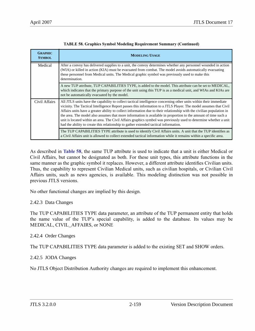
April 2007 JTLS Document 17
As described in Table 58, the same TUP attribute is used to indicate that a unit is either Medical orCivil Affairs, but cannot be designated as both. For these unit types, this attribute functions in thesame manner as the graphic symbol it replaces. However, a different attribute identifies Civilian units.Thus, the capability to represent Civilian Medical units, such as civilian hospitals, or Civilian CivilAffairs units, such as news agencies, is available. This modeling distinction was not possible inprevious JTLS versions.
No other functional changes are implied by this design.
2.42.3 Data Changes
The TUP CAPABILITIES TYPE data parameter, an attribute of the TUP permanent entity that holdsthe name value of the TUP’s special capability, is added to the database. Its values may beMEDICAL, CIVIL_AFFAIRS, or NONE
2.42.4 Order Changes
The TUP CAPABILITIES TYPE data parameter is added to the existing SET and SHOW orders.
2.42.5 JODA Changes
No JTLS Object Distribution Authority changes are required to implement this enhancement.
Medical After a convoy has delivered supplies to a unit, the convoy determines whether any personnel wounded in action(WIA) or killed in action (KIA) must be evacuated from combat. The model avoids automatically evacuatingthese personnel from Medical units. The Medical graphic symbol was previously used to make thisdetermination.
A new TUP attribute, TUP CAPABILITIES TYPE, is added to the model. This attribute can be set to MEDICAL,which indicates that the primary purpose of the unit using this TUP is as a medical unit, and WIAs and KIAs arenot be automatically evacuated by the model.
Civil Affairs All JTLS units have the capability to collect tactical intelligence concerning other units within their immediatevicinity. The Tactical Intelligence Report passes this information to a JTLS Player. The model assumes that CivilAffairs units have a greater ability to collect information due to their relationship with the civilian population inthe area. The model also assumes that more information is available in proportion to the amount of time such aunit is located within an area. The Civil Affairs graphics symbol was previously used to determine whether a unithad the ability to create this relationship to gather extended tactical information.
The TUP CAPABILITIES TYPE attribute is used to identify Civil Affairs units. A unit that the TUP identifies asa Civil Affairs unit is allowed to collect extended tactical information while it remains within a specific area.
TABLE 58. Graphics Symbol Modeling Requirement Summary (Continued)
GRAPHIC
SYMBOLMODELING USAGE
JTLS 3.2.0.0 2-159 Version Description Document
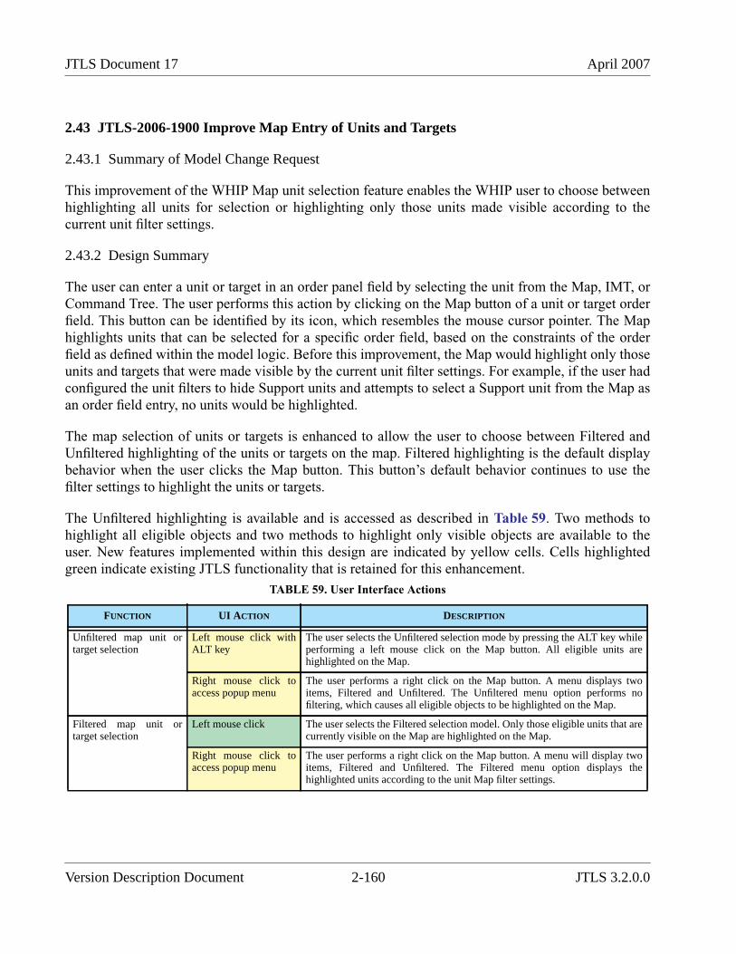
JTLS Document 17 April 2007
2.43 JTLS-2006-1900 Improve Map Entry of Units and Targets
2.43.1 Summary of Model Change Request
This improvement of the WHIP Map unit selection feature enables the WHIP user to choose betweenhighlighting all units for selection or highlighting only those units made visible according to thecurrent unit filter settings.
2.43.2 Design Summary
The user can enter a unit or target in an order panel field by selecting the unit from the Map, IMT, orCommand Tree. The user performs this action by clicking on the Map button of a unit or target orderfield. This button can be identified by its icon, which resembles the mouse cursor pointer. The Maphighlights units that can be selected for a specific order field, based on the constraints of the orderfield as defined within the model logic. Before this improvement, the Map would highlight only thoseunits and targets that were made visible by the current unit filter settings. For example, if the user hadconfigured the unit filters to hide Support units and attempts to select a Support unit from the Map asan order field entry, no units would be highlighted.
The map selection of units or targets is enhanced to allow the user to choose between Filtered andUnfiltered highlighting of the units or targets on the map. Filtered highlighting is the default displaybehavior when the user clicks the Map button. This button’s default behavior continues to use thefilter settings to highlight the units or targets.
The Unfiltered highlighting is available and is accessed as described in Table 59. Two methods tohighlight all eligible objects and two methods to highlight only visible objects are available to theuser. New features implemented within this design are indicated by yellow cells. Cells highlightedgreen indicate existing JTLS functionality that is retained for this enhancement.
TABLE 59. User Interface Actions
FUNCTION UI ACTION DESCRIPTION
Unfiltered map unit ortarget selection
Left mouse click withALT key
The user selects the Unfiltered selection mode by pressing the ALT key whileperforming a left mouse click on the Map button. All eligible units arehighlighted on the Map.
Right mouse click toaccess popup menu
The user performs a right click on the Map button. A menu displays twoitems, Filtered and Unfiltered. The Unfiltered menu option performs nofiltering, which causes all eligible objects to be highlighted on the Map.
Filtered map unit ortarget selection
Left mouse click The user selects the Filtered selection model. Only those eligible units that arecurrently visible on the Map are highlighted on the Map.
Right mouse click toaccess popup menu
The user performs a right click on the Map button. A menu will display twoitems, Filtered and Unfiltered. The Filtered menu option displays thehighlighted units according to the unit Map filter settings.
Version Description Document 2-160 JTLS 3.2.0.0
April 2007 JTLS Document 17
2.43.3 Data Changes
No data changes are required to implement this enhancement.
2.43.4 Order Changes
No order changes are required to implement this enhancement.
2.43.5 JODA Changes
No JTLS Object Distribution Authority changes are required to implement this enhancement.
2.44 JTLS-2006-1901 Spaces Within Unit Long Names
2.44.1 Summary of Model Change Request
The UT LONG NAME is a text string Unit attribute that holds a maximum of 40 characters,previously excluding the prohibited characters #, ", & and /. Space characters were not allowed in thisunit name. The format of the UT LONG NAME attributes must accept spaces characters.
2.44.2 Design Summary
A unit’s long name (UT LONG NAME) is included in some messages, displayed in the Online PlayerManuals, and used by certain external programs. This name is either created by the Database Builderusing the DDS, automatically created under certain circumstances such as unit Detaches or SquadronDetachments, or can be created by a Controller as part of an order, such as Create New Unit. Unlikethe UT SHORT NAME, the long name is intended to reflect the actual name of a real-world unit thatis represented in the game. Therefore, the name text string needs to contain spaces to be consistentwith representations of the unit name by other real-word systems and databases.
These JTLS program elements are modified to support this enhancement:
• UT LONG NAME format
• SIP read and write code
• CEP read, checkpoint write, and functional code
• the Create Unit order
• some message types
The UT LONG NAME will remain a text string with a length limit of 40 characters, including itsspaces. Several CEP routines were modified to allow this string be held as a text variable withimbedded spaces. The DDS was modified to allow the entry of spaces during database build process.
JTLS 3.2.0.0 2-161 Version Description Document
JTLS Document 17 April 2007
The SIP is also modified to read long names containing spaces, and to ensure that this data item isproperly held as the SIP performs its various functions. No OPM printing code changes wererequired; the existing code supports printing long names that include spaces. No changes to the SIPVerify or Reports code were required. Finally, no changes to SIP writes of data files designed for useby external programs were required.
The CEP uses the new name format to read long names, hold the names in memory, and to write thenames to checkpoint files. Also, the CEP correctly reads those names within the data stream of theCreate Unit order. Finally, when a new unit is automatically created, as occurs when a SquadronDetachment is built, the new long name is constructed correctly.
The Create Unit Order order requires that the Controller enter a new Long Name before the unit iscreated. The order panel allows spaces in this name and the CEP must correctly read the resulting textentry as a value that may contain spaces.
Some messages, generated automatically or in response to Player queries, include the Long Name ofan appropriate unit. For these, the CEP sends correctly formatted message data that indicates to theMessage Browser where to begin and stop reading an individual text item that may contain spaces.Examples of such messages include: Mission Reports, reports from successful Create Unit orders,and one of the Periodic Summary reports.
2.44.3 Data Changes
The definition of the UT LONG NAME data parameter is modified. Several prohibited characterswere added to the existing Range limitations of this data item. The prohibited list currently consists ofthe following items: #, ", &, $, @, ’, {, }, <, and > .
2.44.4 Order Changes
The Unit Long Name field of the Create Unit order allows entry of a name that includes spaces. TheHelp text for that field will reflects this change, and also states that spaces should be single blankspaces and not be positioned at the beginning or end of the name. The model allows the use ofmultiple spaces in unit long names. However, since the long name is intended to represent the real-world unit name, the Help text states that the use of sequential multiple spaces is not recommended.
2.44.5 JODA Changes
No JTLS Object Distribution Authority changes are required to implement this enhancement.
Version Description Document 2-162 JTLS 3.2.0.0
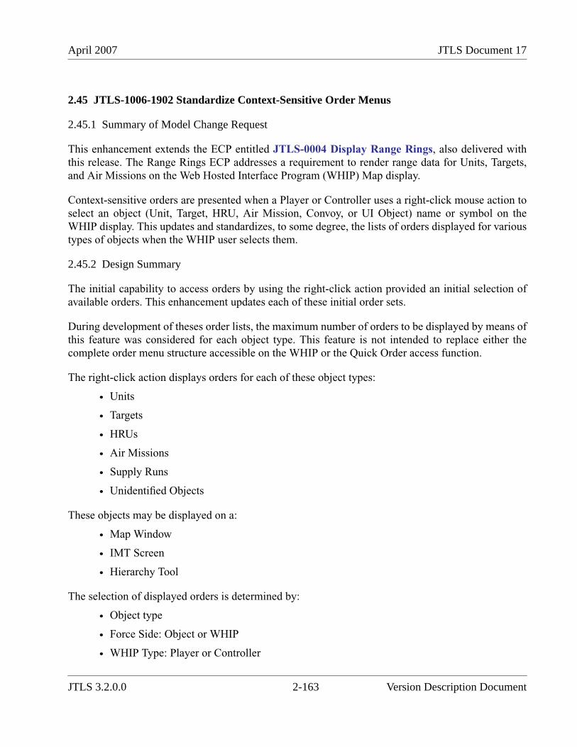
April 2007 JTLS Document 17
2.45 JTLS-1006-1902 Standardize Context-Sensitive Order Menus
2.45.1 Summary of Model Change Request
This enhancement extends the ECP entitled JTLS-0004 Display Range Rings, also delivered withthis release. The Range Rings ECP addresses a requirement to render range data for Units, Targets,and Air Missions on the Web Hosted Interface Program (WHIP) Map display.
Context-sensitive orders are presented when a Player or Controller uses a right-click mouse action toselect an object (Unit, Target, HRU, Air Mission, Convoy, or UI Object) name or symbol on theWHIP display. This updates and standardizes, to some degree, the lists of orders displayed for varioustypes of objects when the WHIP user selects them.
2.45.2 Design Summary
The initial capability to access orders by using the right-click action provided an initial selection ofavailable orders. This enhancement updates each of these initial order sets.
During development of theses order lists, the maximum number of orders to be displayed by means ofthis feature was considered for each object type. This feature is not intended to replace either thecomplete order menu structure accessible on the WHIP or the Quick Order access function.
The right-click action displays orders for each of these object types:
• Units
• Targets
• HRUs
• Air Missions
• Supply Runs
• Unidentified Objects
These objects may be displayed on a:
• Map Window
• IMT Screen
• Hierarchy Tool
The selection of displayed orders is determined by:
• Object type
• Force Side: Object or WHIP
• WHIP Type: Player or Controller
JTLS 3.2.0.0 2-163 Version Description Document
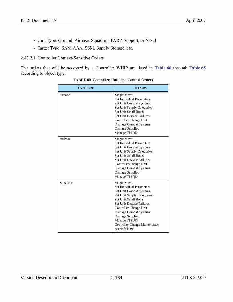
JTLS Document 17 April 2007
• Unit Type: Ground, Airbase, Squadron, FARP, Support, or Naval
• Target Type: SAM.AAA, SSM, Supply Storage, etc.
2.45.2.1 Controller Context-Sensitive Orders
The orders that will be accessed by a Controller WHIP are listed in Table 60 through Table 65according to object type.
TABLE 60. Controller, Unit, and Context Orders
UNIT TYPE ORDERS
Ground Magic MoveSet Individual ParametersSet Unit Combat SystemsSet Unit Supply CategoriesSet Unit Small BoatsSet Unit Disease/FailuresController Change UnitDamage Combat SystemsDamage SuppliesManage TPFDD
Airbase Magic MoveSet Individual ParametersSet Unit Combat SystemsSet Unit Supply CategoriesSet Unit Small BoatsSet Unit Disease/FailuresController Change UnitDamage Combat SystemsDamage SuppliesManage TPFDD
Squadron Magic MoveSet Individual ParametersSet Unit Combat SystemsSet Unit Supply CategoriesSet Unit Small BoatsSet Unit Disease/FailuresController Change UnitDamage Combat SystemsDamage SuppliesManage TPFDDController Change MaintenanceAircraft Time
Version Description Document 2-164 JTLS 3.2.0.0
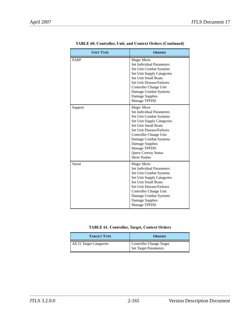
April 2007 JTLS Document 17
FARP Magic MoveSet Individual ParametersSet Unit Combat SystemsSet Unit Supply CategoriesSet Unit Small BoatsSet Unit Disease/FailuresController Change UnitDamage Combat SystemsDamage SuppliesManage TPFDD
Support Magic MoveSet Individual ParametersSet Unit Combat SystemsSet Unit Supply CategoriesSet Unit Small BoatsSet Unit Disease/FailuresController Change UnitDamage Combat SystemsDamage SuppliesManage TPFDDQuery Convoy StatusShow Pushes
Naval Magic MoveSet Individual ParametersSet Unit Combat SystemsSet Unit Supply CategoriesSet Unit Small BoatsSet Unit Disease/FailuresController Change UnitDamage Combat SystemsDamage SuppliesManage TPFDD
TABLE 61. Controller, Target, Context Orders
TARGET TYPE ORDERS
All 21 Target Categories Controller Change TargetSet Target Parameters
TABLE 60. Controller, Unit, and Context Orders (Continued)
UNIT TYPE ORDERS
JTLS 3.2.0.0 2-165 Version Description Document
JTLS Document 17 April 2007
2.45.2.2 Player Context-Sensitive Orders
The orders that will be accessed by a Player WHIP are listed in Table 66 through Table 71 accordingto object type.
TABLE 62. Controller, HRU, Context Orders
HRU TYPE ORDERS
All, performing any mission Magic MoveSet High Resolution Unit Parameters
TABLE 63. Controller, Air Mission, Context Orders
MISSION TYPE ORDERS
All Air Mission Types Damage Air TrackMagic Replenish
TABLE 64. Controller, Supply Run, Context Orders
CONVOY POSTURE ORDERS
Any Posture Cancel Convoy
TABLE 65. Controller, Unidentified Objects, Context Orders
UI TYPE ORDERS
Unidentified Unit Controller FusionRemove Unidentified Object
Unidentified Target Controller FusionRemove Unidentified Object
Version Description Document 2-166 JTLS 3.2.0.0

April 2007 JTLS Document 17
TABLE 66. Player, Unit, Context Orders
UNIT TYPE ORDERS
Ground WithdrawFire ArtilleryClear MinefieldRules of EngagementCreate HRUAttachDetachMandatory TransferSituation ReportMoveAttackDefendCAS RequestSOF AlertBridge Operations
Airbase Fire ArtilleryRules of EngagementAttachDetachCAS RequestSOF AlertTenant ActivityEviction NoticeLogistics ReportSituation Report
Squadron Orbiting OASCombat Air Patrol RECCEAir RefuelAirlift/AirdropInsert/ExtractArmed RECCESOF AlertSituation ReportMission ReportAir Unit Report
FARP Fire ArtilleryClear MinefieldRules of EngagementCreate HRUAttachDetachCAS RequestSOF AlertLogistics ReportSituation Report
JTLS 3.2.0.0 2-167 Version Description Document
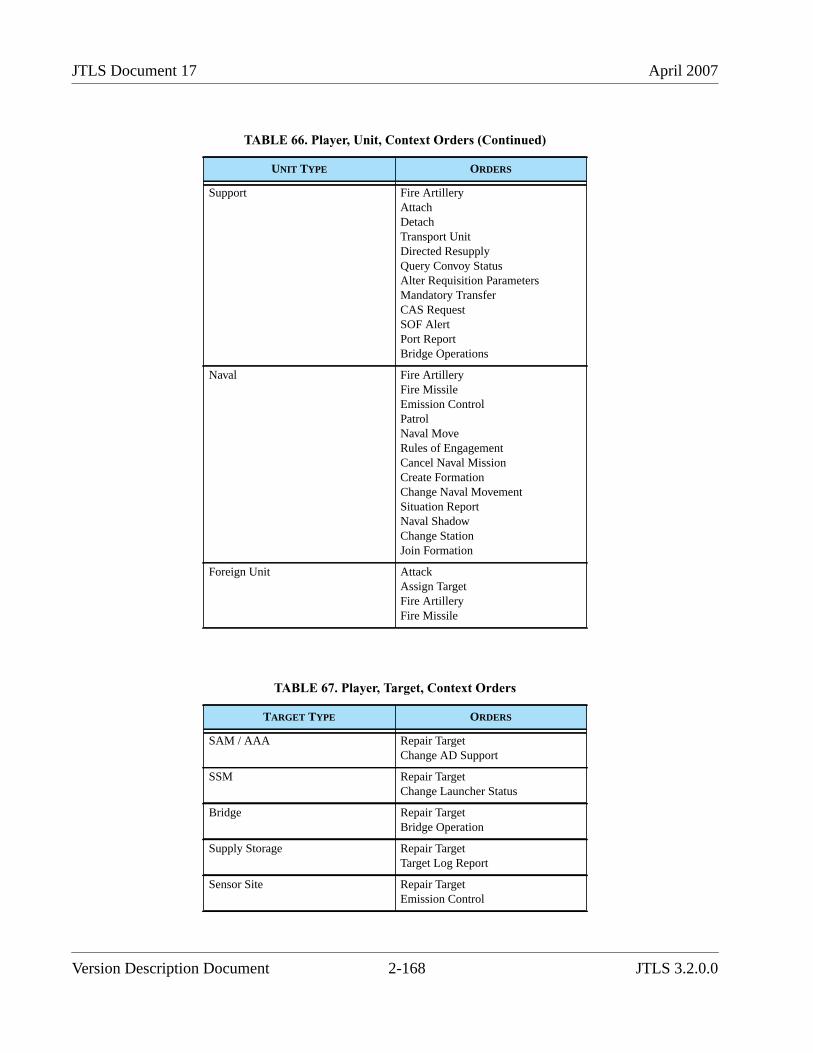
JTLS Document 17 April 2007
Support Fire ArtilleryAttachDetachTransport UnitDirected ResupplyQuery Convoy StatusAlter Requisition ParametersMandatory TransferCAS RequestSOF AlertPort ReportBridge Operations
Naval Fire ArtilleryFire MissileEmission ControlPatrolNaval MoveRules of EngagementCancel Naval MissionCreate FormationChange Naval MovementSituation ReportNaval ShadowChange StationJoin Formation
Foreign Unit AttackAssign TargetFire ArtilleryFire Missile
TABLE 67. Player, Target, Context Orders
TARGET TYPE ORDERS
SAM / AAA Repair TargetChange AD Support
SSM Repair TargetChange Launcher Status
Bridge Repair TargetBridge Operation
Supply Storage Repair TargetTarget Log Report
Sensor Site Repair TargetEmission Control
TABLE 66. Player, Unit, Context Orders (Continued)
UNIT TYPE ORDERS
Version Description Document 2-168 JTLS 3.2.0.0
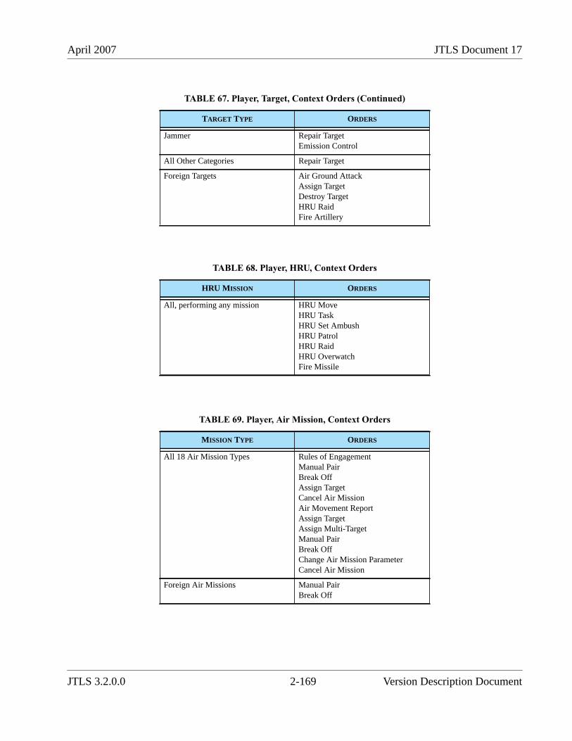
April 2007 JTLS Document 17
Jammer Repair TargetEmission Control
All Other Categories Repair Target
Foreign Targets Air Ground AttackAssign TargetDestroy TargetHRU RaidFire Artillery
TABLE 68. Player, HRU, Context Orders
HRU MISSION ORDERS
All, performing any mission HRU MoveHRU TaskHRU Set AmbushHRU PatrolHRU RaidHRU OverwatchFire Missile
TABLE 69. Player, Air Mission, Context Orders
MISSION TYPE ORDERS
All 18 Air Mission Types Rules of EngagementManual PairBreak OffAssign TargetCancel Air MissionAir Movement ReportAssign TargetAssign Multi-TargetManual PairBreak OffChange Air Mission ParameterCancel Air Mission
Foreign Air Missions Manual PairBreak Off
TABLE 67. Player, Target, Context Orders (Continued)
TARGET TYPE ORDERS
JTLS 3.2.0.0 2-169 Version Description Document
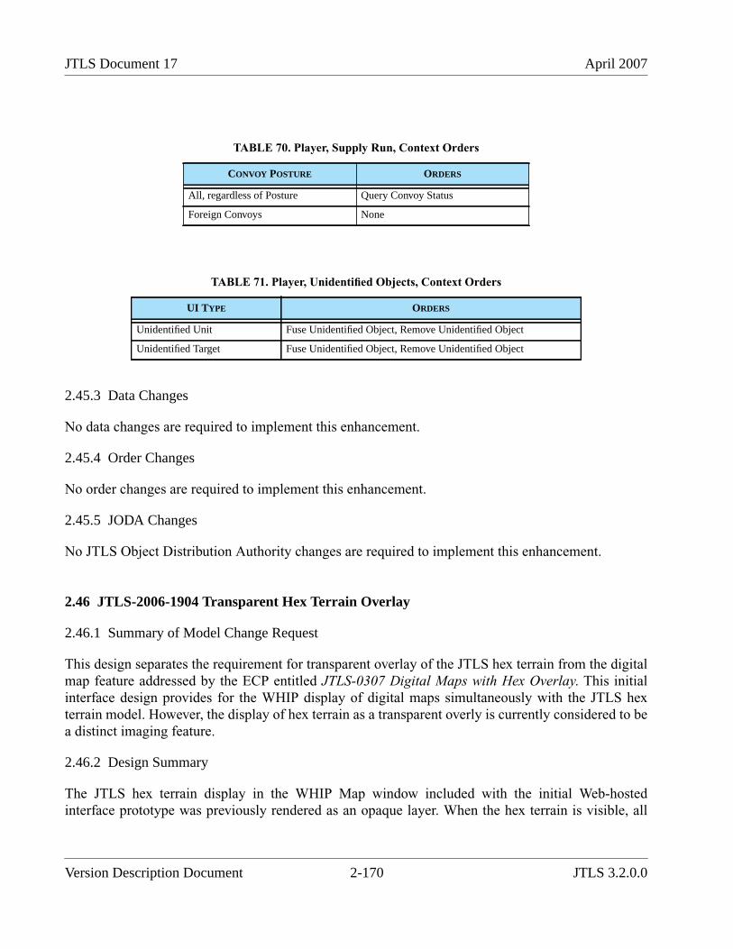
JTLS Document 17 April 2007
2.45.3 Data Changes
No data changes are required to implement this enhancement.
2.45.4 Order Changes
No order changes are required to implement this enhancement.
2.45.5 JODA Changes
No JTLS Object Distribution Authority changes are required to implement this enhancement.
2.46 JTLS-2006-1904 Transparent Hex Terrain Overlay
2.46.1 Summary of Model Change Request
This design separates the requirement for transparent overlay of the JTLS hex terrain from the digitalmap feature addressed by the ECP entitled JTLS-0307 Digital Maps with Hex Overlay. This initialinterface design provides for the WHIP display of digital maps simultaneously with the JTLS hexterrain model. However, the display of hex terrain as a transparent overly is currently considered to bea distinct imaging feature.
2.46.2 Design Summary
The JTLS hex terrain display in the WHIP Map window included with the initial Web-hostedinterface prototype was previously rendered as an opaque layer. When the hex terrain is visible, all
TABLE 70. Player, Supply Run, Context Orders
CONVOY POSTURE ORDERS
All, regardless of Posture Query Convoy Status
Foreign Convoys None
TABLE 71. Player, Unidentified Objects, Context Orders
UI TYPE ORDERS
Unidentified Unit Fuse Unidentified Object, Remove Unidentified Object
Unidentified Target Fuse Unidentified Object, Remove Unidentified Object
Version Description Document 2-170 JTLS 3.2.0.0
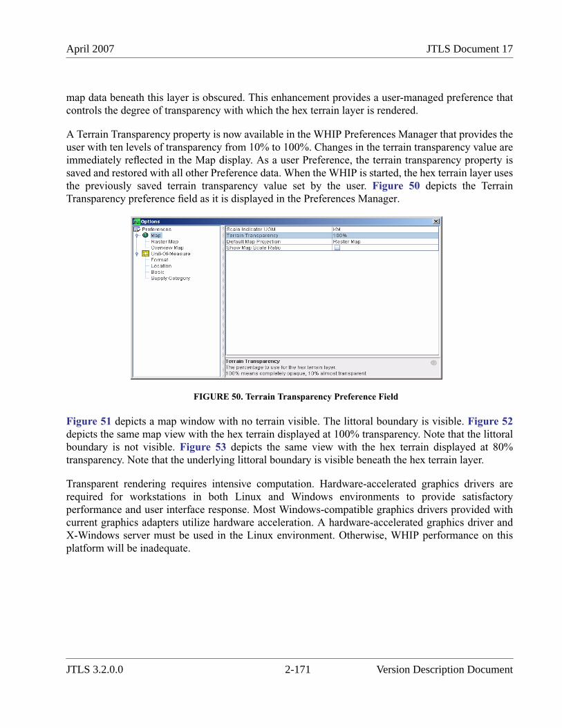
April 2007 JTLS Document 17
map data beneath this layer is obscured. This enhancement provides a user-managed preference thatcontrols the degree of transparency with which the hex terrain layer is rendered.
A Terrain Transparency property is now available in the WHIP Preferences Manager that provides theuser with ten levels of transparency from 10% to 100%. Changes in the terrain transparency value areimmediately reflected in the Map display. As a user Preference, the terrain transparency property issaved and restored with all other Preference data. When the WHIP is started, the hex terrain layer usesthe previously saved terrain transparency value set by the user. Figure 50 depicts the TerrainTransparency preference field as it is displayed in the Preferences Manager.
FIGURE 50. Terrain Transparency Preference Field
Figure 51 depicts a map window with no terrain visible. The littoral boundary is visible. Figure 52depicts the same map view with the hex terrain displayed at 100% transparency. Note that the littoralboundary is not visible. Figure 53 depicts the same view with the hex terrain displayed at 80%transparency. Note that the underlying littoral boundary is visible beneath the hex terrain layer.
Transparent rendering requires intensive computation. Hardware-accelerated graphics drivers arerequired for workstations in both Linux and Windows environments to provide satisfactoryperformance and user interface response. Most Windows-compatible graphics drivers provided withcurrent graphics adapters utilize hardware acceleration. A hardware-accelerated graphics driver andX-Windows server must be used in the Linux environment. Otherwise, WHIP performance on thisplatform will be inadequate.
JTLS 3.2.0.0 2-171 Version Description Document
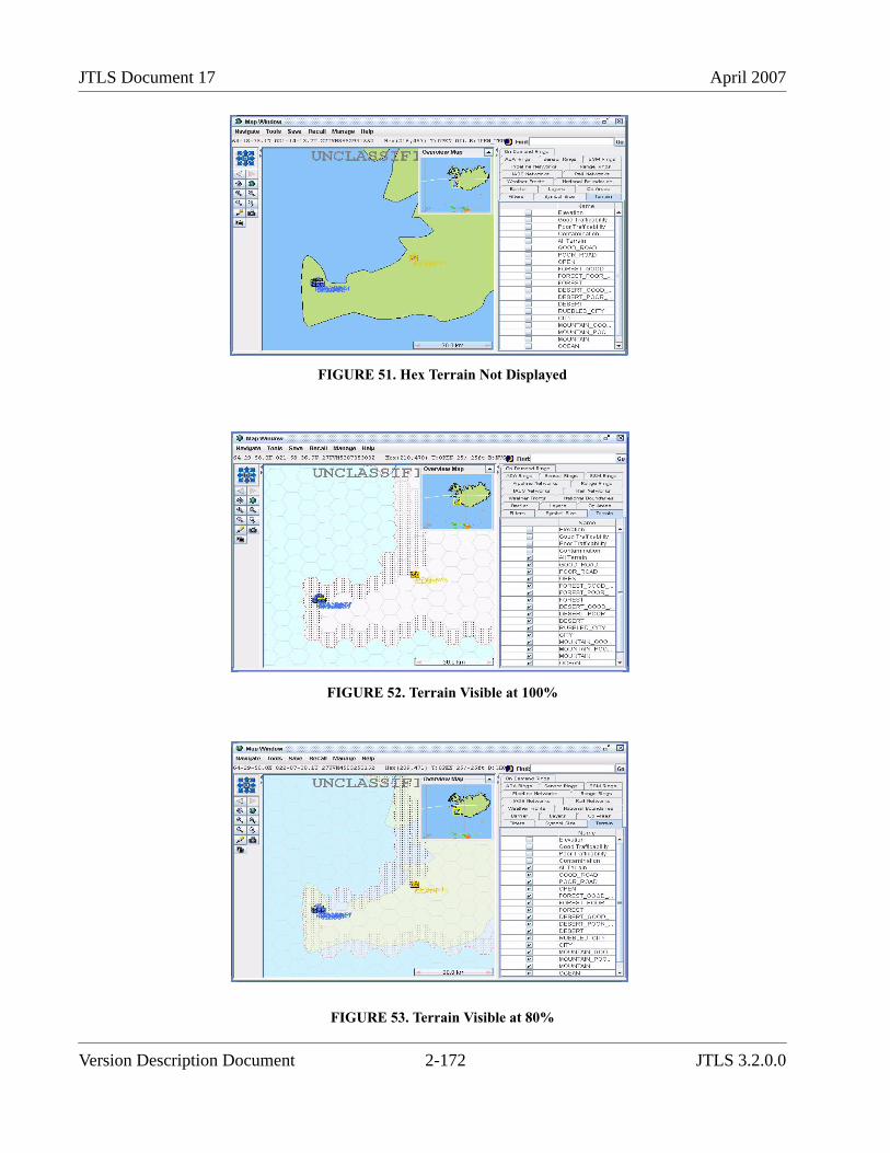
JTLS Document 17 April 2007
FIGURE 51. Hex Terrain Not Displayed
FIGURE 52. Terrain Visible at 100%
FIGURE 53. Terrain Visible at 80%
Version Description Document 2-172 JTLS 3.2.0.0
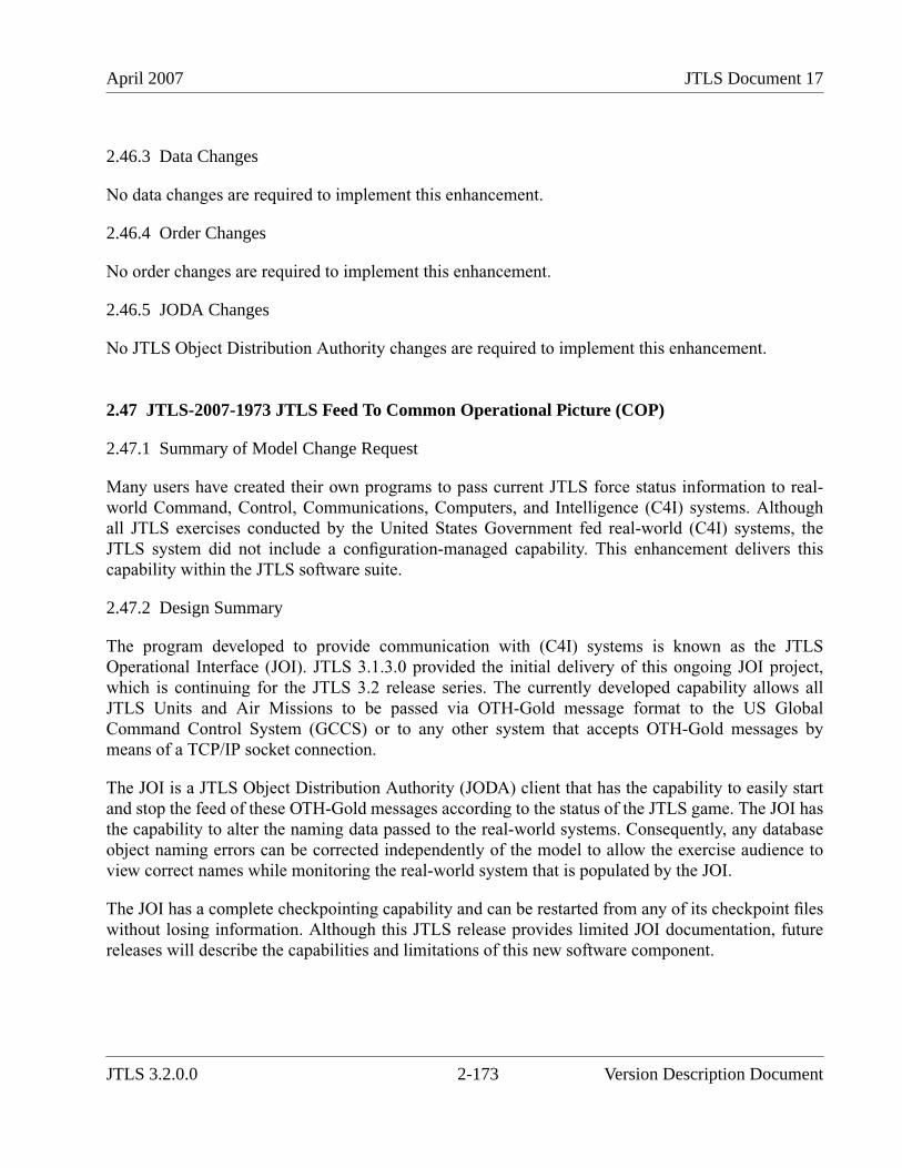
April 2007 JTLS Document 17
2.46.3 Data Changes
No data changes are required to implement this enhancement.
2.46.4 Order Changes
No order changes are required to implement this enhancement.
2.46.5 JODA Changes
No JTLS Object Distribution Authority changes are required to implement this enhancement.
2.47 JTLS-2007-1973 JTLS Feed To Common Operational Picture (COP)
2.47.1 Summary of Model Change Request
Many users have created their own programs to pass current JTLS force status information to real-world Command, Control, Communications, Computers, and Intelligence (C4I) systems. Althoughall JTLS exercises conducted by the United States Government fed real-world (C4I) systems, theJTLS system did not include a configuration-managed capability. This enhancement delivers thiscapability within the JTLS software suite.
2.47.2 Design Summary
The program developed to provide communication with (C4I) systems is known as the JTLSOperational Interface (JOI). JTLS 3.1.3.0 provided the initial delivery of this ongoing JOI project,which is continuing for the JTLS 3.2 release series. The currently developed capability allows allJTLS Units and Air Missions to be passed via OTH-Gold message format to the US GlobalCommand Control System (GCCS) or to any other system that accepts OTH-Gold messages bymeans of a TCP/IP socket connection.
The JOI is a JTLS Object Distribution Authority (JODA) client that has the capability to easily startand stop the feed of these OTH-Gold messages according to the status of the JTLS game. The JOI hasthe capability to alter the naming data passed to the real-world systems. Consequently, any databaseobject naming errors can be corrected independently of the model to allow the exercise audience toview correct names while monitoring the real-world system that is populated by the JOI.
The JOI has a complete checkpointing capability and can be restarted from any of its checkpoint fileswithout losing information. Although this JTLS release provides limited JOI documentation, futurereleases will describe the capabilities and limitations of this new software component.
JTLS 3.2.0.0 2-173 Version Description Document
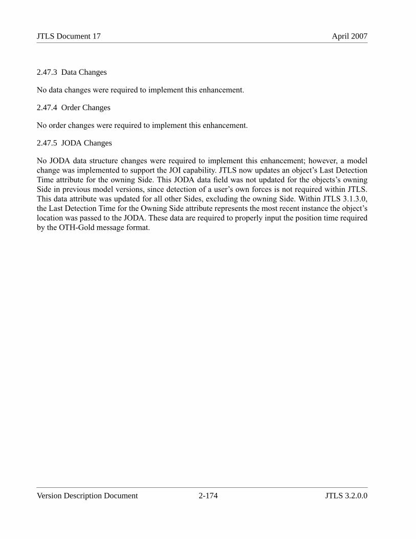
JTLS Document 17 April 2007
2.47.3 Data Changes
No data changes were required to implement this enhancement.
2.47.4 Order Changes
No order changes were required to implement this enhancement.
2.47.5 JODA Changes
No JODA data structure changes were required to implement this enhancement; however, a modelchange was implemented to support the JOI capability. JTLS now updates an object’s Last DetectionTime attribute for the owning Side. This JODA data field was not updated for the objects’s owningSide in previous model versions, since detection of a user’s own forces is not required within JTLS.This data attribute was updated for all other Sides, excluding the owning Side. Within JTLS 3.1.3.0,the Last Detection Time for the Owning Side attribute represents the most recent instance the object’slocation was passed to the JODA. These data are required to properly input the position time requiredby the OTH-Gold message format.
Version Description Document 2-174 JTLS 3.2.0.0
April 2007 JTLS Document 17
3.0 SOFTWARE TROUBLE REPORTS
3.1 INTRODUCTION
This chapter describes the software error corrections implemented for this release.
3.2 ERRORS CORRECTED FOR THIS RELEASE
Software Trouble Reports (STRs) describe code errors that were discovered and corrected for thisrelease. Code corrections completed for the JTLS 3.1 series of releases have been tested with themodel enhancements delivered with JTLS 3.2.0.0 and are included. STRs that are still outstanding arelisted and described in Chapter 4. The errors described herein were corrected as part of JTLS 3.2.0.0and have not been corrected in any previous versions.
3.2.1 JTLS-1386 Accept Ownership And Use For New Runway
If you create a new runway during the game, the runway cannot be assigned to an airbase and usedby the airbase. The Controller must Magic Move the airbase in and out of the hex to accomplish thetask
Solution: When creating the new runway, the user must specify that the runway is to be owned by aspecific airbase. When this is done, the new runway is given to the specified airbase and is availablefor its use. Once the airbase owns the runway, the user may have the airbase give permission to otherunits to use the new runway.
3.2.2 JTLS-2007-1993 Zero Used As Invalid Detection Time
In the JODA protocol, -1.0 detection time was customarily sent to indicate no detection. This valuewas intended to distinguish between no detection and a time zero detection. Since the delivery of theJTLS 3.0 series, the CEP code was modified to use a variable named RL.NEGATIVE.ONE, to replacehard-coding this value. This variable was never initialized, and thus held a value of 0.0. Therefore,distinguishing between a time zero detection and no detection based solely on the detection time wasnot possible.
Solution: The variable was switched to a define to mean and assigned a value of -1.0. This changemay affect JODA clients that receive and process detection times of Units, HRUs, Targets, and CruiseMissiles.
JTLS 3.2.0.0 3-1 Version Description Document

JTLS Document 17 April 2007
Version Description Document 3-2 JTLS 3.2.0.0
April 2007 JTLS Document 17
4.0 REMAINING ERRORS
4.1 INTRODUCTION
Every effort has been made to correct known errors in the model. All reproducible errors that resultedin a CEP catastrophic software failure (Crash) have been corrected. Other corrections were prioritizedand completed according to their resource cost-to-benefit relationship.
Correction of the remaining STRs, however, must be postponed to a later version due to time andresource constraints. These problems may be corrected prior to the next release of JTLS. If animmediate need arises for a code correction to any of these outstanding STRs (i.e., for an exerciseplanned to occur before the next release), contact the JTLS Configuration Management Agent. (Referto the Abstract of this document for the current address.)
4.2 REMAINING ERRORS
The errors described in this section should be noted specifically because they affect the basicfunctionality of JTLS. Information is provided regarding the extent of the error, as well as suggestionsto avoid or minimize the effects of the problem.
4.2.1 JTLS-0639 Error Determining When Engineering Task Completed
When a Unit starts a directed Engineering Task, the time to complete the task is based on the Unitbeing at 100%. The time to complete a task is adjusted for the Unit’s COMBINEDEFFECTIVENESS. Stronger units complete tasks faster than do weaker units. The task completionevent is then scheduled at the computed time. At this scheduled completion time, the code checkswhether enough time has actually elapsed to complete the task. If the Unit was at more than 100%COMBINED EFFECTIVENESS when the task started (meaning the task completed earlier than ifthe Unit were at 100%), it appears to the model that not enough time has passed and the task is notcredited as complete.
4.2.2 JTLS-0695 Shadow Distance Of Zero Overriding Protection Radius
In the routine SEND INTERCEPTOR, the model is determining which interceptor to send. If this is aprotection radius CAP mission, it gets the minimum of PROTECTION RADIUS and SHADOWDISTANCE. If this is zero, then the logic says there is really an infinite protection radius. This seemsodd. If someone forgets to set SHADOW DISTANCE, then protection radius is ignored. As aminimum, this needs to be either documented or changed so that a zero SHADOW DISTANCEmeans ignore shadow, not make protection radius infinite.
4.2.3 JTLS-0696 Missions Ignoring Assigned Altitude on Egress
Why aren’t missions observing their assigned altitudes on a egress path? Somewhere the posture of
JTLS 3.2.0.0 4-1 Version Description Document
JTLS Document 17 April 2007
the mission was changed to HEADING HOME when it is on its egress route. This causes the missionto automatically set its altitude to avoid air defense.
4.2.4 JTLS-0697 Missions On The Ground With Invalid Destination
Missions on strip alert report a next destination latitude/longitude on the IMT. The destinationcoordinates should be cleared for missions on strip alert.
4.2.5 JTLS-0698 Cannot Re-Activate Destroyed Targets
Some facility targets are 0% capable and not displayed on the GIAC. They need to be reactivated forthe ATO. Activation cannot be done with Controller Change Target because their GDS active flag isset to zero.
4.2.6 JTLS-0699 Targets That Require An Owner Are Disassociated
Targets owned by an HRU that die in combat are disassociated from the HRU and from theirassociated unit. When a checkpoint is taken, both fields are written as NONE. On restart, this causes acrash for ADA targets.
4.2.7 JTLS-0700 GIAC Not Displaying Current Runway Length
A runway has 21% strength, but the GIAC displays the maximum length and current length as equalto the maximum length. In the GENIS, the percent capable is reduced, but the range and currentlength values are the same. The model does not appear to update the current length to the GDS whenit changes.
4.2.8 JTLS-0701 Air Movement Report Does Not Consider Hold Points
When an air movement report is requested, it does not take into consideration scheduled delays in thedelivery instructions. As a result, it indicates an earlier departure time at each point, and an earliercompletion time for the mission.
4.2.9 JTLS-0702 Mission Waiting For Delayed Mission
An air mission package had an attack mission that went into weapons delay. The user told anotherattack mission to join the package, but did not cancel the old mission. The new mission launched,dropped its weapons, and then turned into an Escort and waited for the old Attack mission that wasstill in Weapons Delay. The logic needs to be improved.
4.2.10 JTLS-0703 Periodic Report Other Side Airbases Lists No Activity
The Periodic Report Other Side Airbase Summary lists all the airbases but for each one says there areno squadrons operating there. On the GIAC, you can click on the enemy airbase and see squadronsthere. Click on the squadron and it says that the home base is the expected home base. Discrepancy is
Version Description Document 4-2 JTLS 3.2.0.0
April 2007 JTLS Document 17
that the periodic report in BUILD FOREIGN BASE SQUADRON REPORT looks for squadrons atthe airbase, and perceived combat system aircraft for that squadron. If no aircraft have beenperceived, then it does not count as an operational squadron. There is no check whether the squadronsare actually perceived to be associated with the airbase; truth is used instead. This provides freeintelligence. The discrepancy is that GIAC reports the home base but it does not show on the periodicreport.
4.2.11 JTLS-0704 Immediate Cancel Of Air Mission in Delay Status
During a recent exercise, the air cell sent an Air Transport Order in which the aircraft was directed toremain on the ground at its home base until a certain time. This was a error, and the controllercancelled the mission. The mission did not cancel immediately, but waited until the “holding posture”time was complete and then cancelled. The Controllers stated that the mission should have cancelledimmediately.
4.2.12 JTLS-0705 Missions Launching With Fewer Aircraft Than Available
A mission that cannot get its resources goes into the UT AWAITING LAUNCH SET CAN YOULAUNCH looks only at missions in this set. If CAN YOU LAUNCH assigns enough aircraft to meetthe acceptable launch fraction, the mission is removed from the UT AWAITING LAUNCH SET anda launch event is scheduled. Thus, once a mission gets the aircraft to launch, it will not fill up to itsfull complement even if aircraft become available.
4.2.13 JTLS-0843 Error 427
When a ship and formation was in a dual capable hex, this error message appeared in the verify:“Error 427: Formation, <name>, has been placed at hex location ###,###. This location is notspecified as water.” No error was recorded for the ship, which was located in a dual capable hex. Anerror message should not be generated if the ship and formation are in a water, dual capable, or smallisland hex.
4.2.14 JTLS-0846 Naval Unit Distance Calculation
A Player ordered naval Unit A to arrive at a point due west 100 nautical miles away at a time 12 hourslater with a speed of 10 knots. Naval Unit B was ordered at the same speed and direction to a arrive24 hours later at a destination 200 nautical miles away. Unit A arrived 1.5 hours late and Unit Barrived 3.0 hours late. The orders were repeated for both units to arrive at points 100 and 200 nauticalmiles due north. The units arrived within 15 minutes of their expected arrival time. Although a speedof 10 knots was ordered, the speed displayed for each unit in the SITREP window was 9.7 knots. Themodel appears to not calculate the additional distance required when a unit follows an irregular pathfrom hex center to center. The problem does not appear when a unit follows a direct path from hex
JTLS 3.2.0.0 4-3 Version Description Document
JTLS Document 17 April 2007
center to center in any direction.
4.2.15 JTLS-0865 Incorrect External Program Order
If a non-GIAC program sends an incorrect order to the CEP, the CEP attempts to detect the error andgenerate a Player message reporting it. The model crashed generating this message while executingan order generated by the JTLS HLA Interface Program (JHIP).
The CEP code was modified to be stable under this specific circumstance. This does not guaranteethat another erroneous order sent to the model will not cause a different problem in another portion ofthe code. Processing an order through the Order Verification Tool before submitting it to the model isthe only procedure which assures that such errors and crashes will not occur.
The JHIP condition which initially caused the problem was not a code error, but a mismatch betweenthe JHIP version in use and the version of the External Update order used by the CEP. The orderversion was updated to match the JHIP version. This problem is not considered an STR because itwas discovered in a delivered non-official interim release of JTLS.
4.2.16 JTLS-0869 Continue Engage Determination
The A CONTINUE ENGAGE parameter is not used in JTLS 3.0. Due to the complete change of theair-to-air algorithm in this version, the determination of when and how an air mission decides tocontinue the engagement needed to be redone.This was not completed prior to the release of v3.0. It isthe desire and intent of the design team to restore this capability to the model.
4.2.17 JTLS-0870 Number of Air-to-Air Combat Kills Allowed
The code allows the weapons from a firing aircraft to kill only one enemy aircraft. A specific aircraftshould be able to target and kill multiple enemy aircraft up to its weapon control capability. This iscalculated as the number of weapons fired by the aircraft divided by the maximum number ofweapons allowed per enemy.
4.2.18 JTLS-0871 AC Mission Weapon Drop Determination
Currently, an air mission drops all of its air-to-ground weapons when an aircraft is killed in air-to-aircombat if the AC Weapon Drop Flag is YES. This flag value should also allow a mission to dropsnon-precision guided weapons when it is fired upon in air-to-air combat.
4.2.19 JTLS-0906 Change ADA pE To Per-Element pE
An Air Defense Class has a Probability of Engagement (pE) against each of the Aircraft TargetClasses. If detection by a sensor on an IADS network is prompting the engagement, then the pE isassumed to be 1. The following applies only to non-IADS detection and engagement attempts. Eachtime an air mission enters a hex within the SAM-AAA target altitude-range criteria, the SAM-AAAtarget attempts to detect the air mission with its fire control sensor. If the detection is successful then
Version Description Document 4-4 JTLS 3.2.0.0
April 2007 JTLS Document 17
the SAM-AAA target makes a pE attempt. It doesn’t matter how many elements are in the target, onlyone detection attempt and one pE attempt are made per hex. But each element, by definition, has anindependent fire control ability.
Each fire control sensor in the multi-element target should conduct a detection attempt. For eachsuccessful attempt, a separate pE attempt should be made. Assuming there is some form of commandand control within the elements of a specific SAM-AAA target, the actual firing can still be limited toone element.
4.2.20 JTLS-0907 Scud-Like SSM Representation
It is difficult to represent the effects of long-range ballistic missiles. Different missile types havevarious levels of accuracy in the CEP. However, in JTLS the missile will always hit its aimpoint. Toreflect the inaccuracy of these missiles, it is typical to assign them an unrealistically large TW Radiusof Effects. This usually results in very low damage effects from these weapons.
A new measure of the missile’s accuracy could be added to the CEP as a new database value, and usedto randomly determine the impact point of the weapon in a region surrounding the aimpoint. Thus, theactual weapon impact effects could be properly represented within the model.
4.2.21 JTLS-0908 Naval IADS Link Representation
The IADS network for ship units is computed during the exercise as needed, based on the currentlocation of ships which have Comm Sites. In some cases this can be CPU-intensive. Currently, allship-owned Comm Sites can serve as hubs, i.e., these sites can send and receive all information. Inreality, only a few ships serve as hubs or air defense control centers for the Task Force. The otherships’ Comm Sites are used only to pass detection information to the hubs, and receive detectioninformation and fire guidance.
A new Comm Site data parameter should be added to designate that a Comm Site subcategory is ahub. A ship with a Comm Site target that is not hub-capable can link only to a ship with a Comm Sitetarget that is hub-capable. A ship with a hub-capable Comm Site target can link to any other ship withany Comm Site target, within current side and distance restrictions.
4.2.22 JTLS-0909 Display Moderate And Severe Attrition Level
There is no capability to query whether a unit is suffering Moderate or Severe Attrition Level effects.This capability should be added to the Unit Situation Report.
4.2.23 JTLS-0910 HRU Patrol Intel Reports
Typically, many HRUs are conducting intelligence gathering patrols simultaneously during anexercise. Too frequently, they are collecting on “ANY UNIT”. These messages are all broadcastmessages, controlled by the Intelligence selection of the Broadcast Options menu. A workstationoperator has no capability to limit received intelligence reports to only those of interest. The HRU
JTLS 3.2.0.0 4-5 Version Description Document
JTLS Document 17 April 2007
Patrol Intelligence message should be modified from a Broadcast message to a Sending Workstationmessage.
4.2.24 JTLS-0911 Fire Artillery Wait Time Between Missions
Artillery can be fired continuously within the simulation. Ammo constraints can be played throughsupply category quantities, but frequently aren’t because logistics is not a training objective. Artillerycannot realistically fire continuously without a cool-down period and maintenance time. The crewalso needs to eat and rest at some point. The overuse of artillery during exercises has been an issue forseveral years.
Enforcing a minimum time between fire missions is a recommended capability. This could beaccomplished with a fixed database value, a database percent of the previous fire mission time, or aFLP value. As a fixed value, 10 minutes would mean no new fire mission could start until at least 10minutes after the completion of the previous fire mission. As a percentage, 25% would mean waiting2.5 minutes if the previous fire mission time was 10 minutes, or waiting 15 minutes if the previous firemission time was one hour. Fire missions that are broken up because of the combat assess or the maxfire mission time should not be subject to the wait time between the split parts of the mission. PriorityCounter-battery missions should not be subject to the wait time because they are priority missions andvery time-dependent. Just as the number of hours a day that a unit can move is limited, a similar limitcould be put on the number of hours a day that a unit can fire.
4.2.25 JTLS-0929 Ship Changes Sides
A Thailand ship changed sides when a Mandatory Transfer order was given to a US ship. The ship(FFG-456) was ordered to join an AOE-2.f formation. The Mandatory Transfer order to AOE-2 togive FFG-456 50,000 gal of Cl.III Navy was rejected for the reason that FFG-456 appeared to havechanged sides.
4.2.26 JTLS-0934 HRU Overwatch
An HRU was created and assigned overwatch of a flying squadron. The model refused the overwatchand reported “Unit is already in land combat, and not eligible for new overwatchers.” The flyingsquadron had been attacked by terrorist HRU, which was no longer present in the area, as shown onboth U.S. and Controller views. Unit was at 84% strength. IMT showed flying squadron as being incombat. When HRU broke off, flying unit should have come out of “In Combat” posture. The HRUshould have accepted overwatch responsibilities.
4.2.27 JTLS-0942 Air Transport Cannot Combine Wet And Dry Supplies
When both wet and dry supply categories are included in the same Transport Instructions List for anAir Transport mission, they will not be transported at the same time. The first supply categoryshipment type will be loaded, but the second will not. If both are included in the same Supply List, thewet category is preferred. The aircraft go through the motions as if loading and delivering the denied
Version Description Document 4-6 JTLS 3.2.0.0
April 2007 JTLS Document 17
category, including MISREP confirmation. No pickup or delivery is made, although an empty storagearea may be created. There is no documentation to support this situation, and the user is not notifiedof the problem.
4.2.28 JTLS-0948 Lanchester Double Kills
When two opposing units’ centers are within DECISIVELY ENGAGED DISTANCE of each other,100% of the combat systems are eligible to kill each other. The combat power distribution of the unitsis used to determine which combat systems are eligible to kill units in the same or adjacent hexes thatare not co-located. This can lead to some combat systems being allocated to kill twice in a singleAssess Combat period.
4.2.29 JTLS-0949 Destroyed Target SITREP Strength Incorrect
When a target is destroyed, such as a bridge or pumper station, the GIAC SITREP still has thestrength of the target as 100. GENIS also displays strength as 100. Apparently, the percent capable isbeing updated in GENIS from JTLS, but not the strength which is used to fill the GIAC SITREP. Thisis a problem in both 1.85B and the 2.0 versions
4.2.30 JTLS-0950 JTLS Radius Of Effects
The radius of effects for air missions is not being calculated correctly. The analyst guide states thatthe radius of effects is determined by the TW.RADIUS.OF.EFFECTS of the area weapons employedand the delivery altitude of the air mission. At the max altitude for the aircraft type, the covered areais the total area for all area weapons fired. Testing has shown that the max radius of effects occurswhen the aircraft’s mission altitude is anywhere between one half the max aircraft altitude and maxaircraft altitude. In the routine, Determine Covered Radius, the area overlap calculation statementshows the max altitude multiplied by 0.5. As such, the radius of effects is not calculated correctly.
4.2.31 JTLS-0952 Air Report
JTLS 1.85 provided the ability to obtain the report for one squadron or all squadrons. JTLS 2.0 onlyprovides capability to get one unit at a time.
4.2.32 JTLS-0953 All Sides Informed About Supply Dump Error
Created a supply dump using the Cache Order. Looking at the GDS shows that all sides are informedabout the dump; they show up on all sides IMT. Only the controller and the side that created the dumpshould be initially informed about the dump.
4.2.33 JTLS-0954 Multiple Supply Storage Targets
A supply storage target should not be allowed to be created in the same hex as another one on the
JTLS 3.2.0.0 4-7 Version Description Document
JTLS Document 17 April 2007
same side. A user was able to create several open storage supply targets right on top of each other.
4.2.34 JTLS-0955 Air Lift Drop Report Message
The subject line of the message received when a player requests an air lift drop report for a missionthat has completed the lift or drop, or is not conducting a lift or drop, reads “Air Order Received,<mission name>, Cannot Comply”. It should be titled, “Air Lift/Drop Report Cannot Comply”.
4.2.35 JTLS-0956 MPP Messages For Canceled Missions In Error
If an airbase is magic moved with several squadrons on active missions that need to be canceled orwith squadrons in the middle of a self lift, the subsequent message generated for the situation hasseveral errors. The changes required are too risky during the exercise. The problem will not cause acrash, but will cause the MPP to incorrectly display the message contents.
4.2.36 JTLS-0957 Can’t Take Control Of Unowned Runways
It is impossible for anyone to take control of an unowned runway in the hex it is already in. To do thisthe controller must enter the order, but the order is not on the controller’s menu. We have tested thison a sample menu, it doesn’t crash but the runway’s owner is not set.
4.2.37 JTLS-0958 Withdrawing Units Cannot Destroy Supply Targets
There appears to be an error in the interface between the CEP routines DESTROY CACHES ONLEAVING and IS TARGET SAFE. The first calls for supply targets that are another side or BLACK,but the second always says BLACK targets are safe. This means that a unit withdrawing will neverdestroy BLACK SUPPLY TARGETS, even if they could do so. The code needs to be updated, acomplicated fix.
4.2.38 JTLS-0959 Logistics Report Problem
The Logistics Report will report amounts as single decimal points (e.g., “.”). This is caused by formatD(8,0), and an amount smaller than 1 ton. To correct this situation, all of the Logrep files need to bechecked to determine if it is feasible to change the D(N,0) format specifications to at least D(N,1).
4.2.39 JTLS-0960 Can’t Magic Move Airbase To Existing Airbase Location
One cannot Magic Move an airbase into a hex wherein there is a runway that is on the same side asthe airbase, and is part of the initialization database. The airbase will not automatically assumecontrol of the runway. If the runway is one that was created by Controller action, the airbase willassume control of it. If this error is causing problems for upcoming exercises, the Configuration
Version Description Document 4-8 JTLS 3.2.0.0
April 2007 JTLS Document 17
Manager should be contacted for a code fix to solve this problem
4.2.40 JTLS-0961 Group Ground Move Delayed To Lead Unit
There is a problem when a group ground move is sent. The directive is delayed to the lead unit. Whenthe lead unit learns about the move, it immediately tells the units in the follow-on group. This couldlead to directives being received out of order. Assume the user sends a directive at 0100 and the CEPdetermines the lead unit should receive the message at 0200. The lead unit cannot receive any otherdirectives until after 0200. The CEP ensures that directive receipt is in the same order as the user sentthe directives. This is not true for the follow-on units. If the user sent an order at 0115 directly to oneof the follow-on units, the follow-on unit could receive the 0115 directive prior to the order sent at0100. If this error is causing problems for upcoming exercises, the Configuration Manager should becontacted for a code fix to solve this problem.
4.2.41 JTLS-0962 Pass Unit Intelligence Does Not Include Update Information
Pass Unit Intelligence does not follow any of the Update Information logic, so we are not goingthrough routines such as Alter Launch New Information procedure. This can cause Air Missions tohead toward old perceived information locations if they rely totally on the information obtainedthrough Pass Unit and Pass Target Intelligence capability. If your scenario involves a side whichdepends solely on this intelligence collection methodology and the side will be sending attackmissions, the Configuration Management Agent should be contacted immediately to obtain a properfix to this problem prior to your exercise.
4.2.42 JTLS-0963 IMT Supply Category Line Disappears When Value Is Zero
Recommend that a Unit’s IMT On-Hand Supplies (OHS) specific category line remain when suppliesare gone and no Due-Ins are established.
When a unit runs out of a supply category and no Due-Ins are scheduled, the unit’s IMT On-Handsupply line for that specific category disappears from the menu. This makes it very difficult for aplayer who is controlling 40 or more unit icons and being overwhelmed at times with MPP messagesto keep track of exactly what supply categories need his attention or thwarts his attempts to trouble-shoot a supply problem. The constant presence of the supply category line, even if empty, will savethe Player wasted time either making early printed copies of all his unit OHS for later comparison orreferring unnecessarily to the OPM TUP/SUP to determine what empty supply categories his unitshave that require resupply. Certain supplies (i.e. fuel/targetable weapons) are critical andunnecessarily impede game execution, if not maintained at required levels for play in an automatedlogistics scenario.
4.2.43 JTLS-0964 Reporting Bridge Damage
When an aircraft conducts an air-to-ground mission against a highway bridge, damage reporting isnot consistent. When the aircraft returns and the mission report says the bridge is at 0% capability, the
JTLS 3.2.0.0 4-9 Version Description Document
JTLS Document 17 April 2007
IMT and SITREP still report the bridge capability as 100%. When another aircraft is sent against thebridge, it flies over and doesn’t drop any munition because, according to the mission report, the targetisn’t there (it’s destroyed). When this aircraft returns, the IMT and SITREP still report the bridge at100%. Much later, although not consistently, the bridge status changes in the IMT and SITREP to 0%.If the bridge is destroyed, the IMT and SITREP should reflect the information provided in theMission Report. The problem reported is being investigated. If this is causing a problem for anupcoming exercise, the Configuration Manager should be contacted to implement a fix to the problemas soon as possible.
4.2.44 JTLS-0965 Error In Time Report For SET SP CONVOY DELAYS
When a time value of 2 hours 0 minutes is entered into any field of the SET SP CONVOY DELAYSwindow and then sent to the CEP, the MPP returns a message that shows a time of 1 hour 0 minutesinstead. This is a known round-off error. A solution is being investigated.
4.2.45 JTLS-0966 Incorrect Mission Report Locations
Some mission report locations appear to be incorrect. The ADA engagement location is an example.The problem is being investigated.
4.2.46 JTLS-0967 Fire Mission Not Deleted From GENIS
It appears that, in some circumstances, an Artillery Fire Mission that has been reported to the IMT isdeleted from the CEP without the GENIS being informed. This happened in the case of a unit thatwas moving when it was supposed to fire the mission. The Fire Mission still showed on the IMTseveral hours later.
4.2.47 JTLS-0968 Inconsistency Between Regular Run And Pusher
There is a major inconsistency between a regular run and a run created using pusher. When an orderwith ASAP is sent, the READ KEYWORD routine sets the data parameter to TIME.V. When pusherreads in the order, TIME.V is much earlier than it was when the order arrived in the first place. Fororbiting missions and alert missions, this alters when they will go off alert by a great deal. This mustbe fixed and made consistent. It appears that both TIME.V and order receipt time must be saved to theci1 file to accomplish this task.
4.2.48 JTLS-0969 Changing Mission On Alert
When a ship moves, it changes the attributes of missions that are on alert. It also needs to change alerthex for those missions that are not currently on alert, but still have their alert hex pointing to the ship’s
Version Description Document 4-10 JTLS 3.2.0.0
April 2007 JTLS Document 17
location.
4.2.49 JTLS-0970 Availability Of Aircraft
When a unit loses a fraction of an aircraft to Area Fire or Lanchester combat, the whole aircraftbecomes unavailable for air missions. However, the report of Available Aircraft on the IMT isexpressed in whole numbers. This may result in a unit incorrectly showing a damaged aircraft asavailable.
4.2.50 JTLS-0971 Ship Continuous Tracking Not Working
The new unidentified object design indicates that ships which are continuously tracked will not haveunidentified objects created. A continuously tracked Naval unit and all of its targets are creatingunidentified objects. They should not be doing this.
4.2.51 JTLS-0972 Air Mission Find In Middle Of Ocean
A user does a find on a pre-launched air mission that is home based on a moving Naval unit. The Xmarking the location of the pre-launch mission is where the Naval ship was when the order enteredthe system. As the ship is moving, the new location of the pre-launch mission is not being sent toGENIS and thus GIAC.
4.2.52 JTLS-0973 Periodic Report Air Supplies And Fuel Not Correct
The arrays which hold air supply usage are not being maintained correctly given the new MISSIONRESOURCE ALLOCATION event.
4.2.53 JTLS-0974 Submarine Detection By Ground Sensors
A moving submarine does not get full credit for coverage time by sonars on board other ships orsubmarines. It gets full coverage time for airborne sensors but not ground based sensors.
4.2.54 JTLS-0975 GDS Target Update Error
When the CEP accomplishes a GDS Target Update, the GENIS ends up knowing about the re-initialized target, but the GIAC does not.
4.2.55 JTLS-0976 Manual Pairing And Protection Radius
The JTLS 2.1 Analyst’s Guide, Section 8.4.8.2, second paragraph discusses the rules for manualpairing of CAP missions. The paragraph states that the manual pair order will only check todetermine if the new interceptor has enough fuel and appropriate weapons before sending it.
In the model however, a manual paired mission will do the following if the intercepted mission is outof the protection radius of the interceptor. The interceptor will move one hex towards the intercepted
JTLS 3.2.0.0 4-11 Version Description Document
JTLS Document 17 April 2007
mission, and then return to its orbit location.
4.2.56 JTLS-0977 Slightly Inaccurate Runway Length Sometimes Used
When AIRCRAFT.CLASS data are read, the takeoff and landing lengths are read in integer format.These are then assigned to the double real attributes of AIRCRAFT.CLASS. However, sometimes thedouble attributes become values slightly larger than the actual version of the integer in the database.
4.2.57 JTLS-0978 Air Missions Don't Completely Comply With Egress
Each assigned point on an air route has an associated altitude. The mission should climb (or descend)to that altitude upon reaching the point and attempt to maintain that altitude until another altitude isassigned. Air missions that have egress routes should fly from the last egress route point to home baseat the altitude assigned for the last egress route point. They are not doing so. Instead, they fly from thelast egress route point home at their Most Efficient altitude.
4.2.58 JTLS-0979 Halted Helo Squadrons Show Mission As MOVING
A helicopter squadron can be ordered to conduct a ground move to a new location. A helicoptersquadron that is moving will accept orders to launch aircraft. However, when it begins air operations,it stops. After the completion of air operations, the squadron does NOT resume its ordered movement.Its posture reverts to DEFEND, but its “Mission” remains “MOVING”. Since the squadron does notresume its move, its “Mission” should also revert to “DEFEND”.
4.2.59 JTLS-0980 SVP Warning 22
SVP Warning 22 reports aircraft loads whose extra fuel exceeds the aircraft’s wet carry capacity. Ibelieve the check should be changed to see if the extra fuel (carried in pods/tanks) when added to theother weapons exceeds either the aircraft’s dry carry capacity or total dry/wet carry capacity. Granted,there are other supply loads that might carry wet supplies, but in the case of extra fuel, I don’t believeit should be considered wet weight.
4.2.60 JTLS-0981 Formation With No Posture
The model crashed when a formation reached a Destination Two hex and the formation no longer hada posture. Therefore it did not know what to do. A Destination Two hex indicates that the Formationshould conduct its assigned Amphibious Operation, drop off its Sealifted supplies or clear mines froma minefield. The posture of the formation is used to tell the formation which of these three tasksshould be accomplished.
When the formation reached its Destination Two hex, the posture of the formation was zero;
Version Description Document 4-12 JTLS 3.2.0.0
April 2007 JTLS Document 17
therefore, the formation did not know which of the three tasks should be accomplished.
4.2.61 JTLS-0982 GIAC Shows HRU Mission Moving After Move Complete
The GIAC Message Box Unit SITREP for an HRU continues to show a Mission of MOVING whenmovement is complete. Unit Posture changes to DEFEND. ARU SITREPs are displayed with both aMission and Posture of DEFEND.
4.2.62 JTLS-0983 IMT/GIAC Show Insert/Extract Mission Flying
IMT and GIAC show Insert/Extract Mission flying at zero feet from Insert/Extract to next TransitPoint. Also between some Transit points. Radar detection reports correct altitude.
4.2.63 JTLS-0984 IMT Doesn’t Add Unit Names
IMT - Intelligence - Foreign Units will display the current list of identified Foreign Units and willupdate information about them while the Foreign Unit Information window remains open. However,if a new Foreign Unit is identified, that unit does not get added to the list in the open window. A newForeign Unit Information Window must be selected to obtain the current list of identified units.
4.2.64 JTLS-0985 PSYOP Results Multiplier
The PSYOP Results Multiplier was referred to as the PSYOP Effects Multiplier four times in the DataRequirements Manual (DRM) and three times in the Analyst’s Guide. Although listed in the DRM,the PSYOP Results Multiplier could not be accessed in the DDS. It appeared to default to 1.0 in thegame for all units. Controller - Set Individual Unit Parameters permitted entries from 0.00 to 1.00, butall entries below 0.50 were converted to 0.50. The DRM showed aUT.PSYOP.RESULTS.MULTIPLIER range from 0.001 to 999999.99.
4.2.65 JTLS-0987 Set Periodic Report Times
The Controller has the ability to change both the frequency of Periodic Reports and the number ofPeriodic Reports between Summary Reports. However, there exists no ability to specify when thenext Periodic Report should be, or which of the next reports should be a Summary Report. As anexample, if the Controller wishes the blue side to receive Periodic Reports every 8 hours starting at0600, and wants the Summary Report to be produced at 1400, then they must set the time betweenperiodic reports to 6 hours, and reset it to 8 hours after the 0600 report. Additionally, the number ofPeriodic Reports between Summary Reports must be set to 2, and then reset to 3 after the 1400
JTLS 3.2.0.0 4-13 Version Description Document

JTLS Document 17 April 2007
reports. An easier method should exist to accomplish such a task.
4.2.66 JTLS-0988 Can’t Repair Naval Catapults
Naval Units cannot repair their catapults because they do not know they have a repair capability.
4.2.67 JTLS-0989 Controller Damaged Aircraft Not In Periodic Reports
When a Controller kills an Aircraft, the model does not tally, therefore the current periodic reportdoes not report the kill. The categories of kills do not logically cover the Controller killed aircraft.The Post Processor Reports do include the Controller killed aircraft. This improvement can be madein at least two ways. First the current Aircraft Kill Periodic and Summary Reports can be expanded toinclude a category for Controller killed aircraft. A second solution is to remove the Periodic andSummary Aircraft Kill Periodic and Summary reports, and get the data from the Post Processor.
4.2.68 JTLS-0993 Weapons Report on Mission Report
When a Player uses the Change Air Mission Parameter order to modify a mission’s weapon load priorto takeoff and the order is implemented, the Mission Report does not always reflect the change. In atleast one case, when the final Mission Report was received, the only weapon listed was the newweapon that was added. The report also incorrectly showed that zero of those weapons were returnedwhen none were actually fired. The mission fired several weapons from the original load, but none ofthose weapons were listed in the final report, even though they were fired.
4.2.69 JTLS-0994 HRU Creation Target Requirements Assessed Incorrectly
If an HRU that is to be created and extract targets from its parent unit cannot find a target that is 100%capable, it will refuse creation, even if the parent has a 12-element target that is 97% capable and theHRU needs only one element.
4.2.70 JTLS-0999 Cancel Naval Mission Fails When A Unit Is Specified
The Cancel Naval Mission order allows either a unit or a formation to be entered. However, ifanything other than a formation is entered, the order is rejected on the grounds that the formation doesnot exist.
4.2.71 JTLS-1010 Controller Cannot MM NEUTRAL Unit Onto Formation
The Controller cannot Magic Move a unit onto a Formation unless both FS FS RELATIONSHIPs areFriendly. A player can pick up a unit via AMPHIBIOUS PICKUP as long as the relationships are noworse than Neutral. The Controller should have the same capability. However, all implications must
Version Description Document 4-14 JTLS 3.2.0.0
April 2007 JTLS Document 17
be considered before implementing this solution.
4.2.72 JTLS-1017 Airlift Mission Problem
An airlift mission was created to pick up a NEO icon. The mission did not have the lift capacity to liftthe entire icon, so a second mission was created to pick up the same icon. The second mission wentinto unit delay when it arrived at the pickup location. The first mission picked up then dropped off thefirst load, then returned for the second load. The second mission should not have gone into unit delaystatus.
4.2.73 JTLS-1260 EMCON Order Problem Subordinates of Embarked Units
If the primary Unit specified on an EMCON order is embarked on a ship, the CEP rejects the order,even if the order is supposed to apply to subordinates as well. A possible solution is to take the UNITCHECKS off the order itself, and put them in the code that turns the emitter on and off. The only timethat the order should be denied is for a unit that has been wiped out, and it has no subordinates, and isnot in anyone’s UT SUBORD SET. If this is done a possible problem is having the IMT show thesensor/jammer turned on while the unit is still not arrived, or is embarked on a formation. Thereappears to be no problem inside the CEP, but the IMT bit is the reason that it has not been fixed. Theplayers have a work-around—Magic Move the unit ashore, send the order, and then MM back ontothe formation.
4.2.74 JTLS-1328 SAM/AAA Initial Issue
Currently, when a SAM/AAA target comes into the game, either at game start, TPFDD arrival aftergame start, or target create; the owning unit or associated unit sends the initial issue of ammo to thetarget site by an implicit resupply action. This implicit resupply convoy requires time to dispatch,time to travel, and time to receive. In Standard Database this means it is 2.5 to 3.5 hours after a SAM/AAA target arrives in the game before it has any ammo and is able to engage an air object; even if it’sin the same hex as the owning unit. There is no reason for this restriction. A SAM/AAA target shouldbe given its initial issue of ammo instantaneously upon arrival in the game. The owning or associatedunit should still have its supply levels decremented based on the supplies that it passes to the SAM/AAA target.
4.2.75 JTLS-1341 Assign Multi Attack Order
An OAS mission was assigned a set of targets using Assign Multi Attack order. After the order wassent, that set of targets was deleted and a new set was assigned. The mission proceeded to the areawhere the old targets were located, then headed toward the new targets. and not drop on either set oftargets. The mission should have headed toward new target area immediately after targets were
JTLS 3.2.0.0 4-15 Version Description Document
JTLS Document 17 April 2007
assigned.
4.2.76 JTLS-1351 Air Missions Refuel And Fly At Zero Altitude
When specifying ingress and egress routes for an air mission, it is possible to specify refuel points andtransit points. A transit point requires an altitude. A refuel point does not have an associated altitude.However, both types of points are filed with the air mission with their associated altitudes, which iszero for the refuel point. After a mission reaches a refuel point, it will adopt the altitude of the point,zero feet, for its next leg.
When a refuel point is filed in the air mission’s route set, the Player should assign it the same altitudeas the previous Player-designated route point. This is only useful if such a point exists. This is apartial solution only, and this STR should not be considered closed.
4.2.77 JTLS-1364 ROE Setting Unstable
During exercise TF05, nine Navy P3C squadrons were set to an ROE of HOLD FIRE. The first ninemissions returned and reported launching all of their Harpoon missiles. The Player observed that theROE appeared to reset itself to FIRE. The opposite change occurred when the Player set the ROE toFIRE, and used the IMT to confirm the setting. Thus, several attacks were required to cause theaircraft to launch a Harpoon or torpedo.
4.2.78 JTLS-1368 Orbiting OAS Assign Target
During exercise TF05, an Orbiting OAS mission was assigned to strike a SAM target. The Sideperception was bad, and the SAM target was not in the hex indicated by the Blue side perception.Receiving an Assign Target order, the mission went to the hex and searched for the target. It remainedin the hex until almost out of fuel, then went to a tanker. After refueling, the mission returned to thehex to search for the target again. This continued until the mission off-station time. The missionshould have determined that the target was not in the hex and returned to its home squadron.
4.2.79 JTLS-1375 Orbit Location In Ingress Route
If an air mission is tasked by the ATOT and flies toward an orbit point, the mission cannot be divertedto a new location until the aircraft reaches its ATOT-assigned orbit point. Assigning a new orbitlocation should be possible at any time and the mission should immediately comply.
4.2.80 JTLS-1376 Fuel Chits
During exercise TF05, fuel chit data fields for individual receiver or supplier air missions were notpopulated. The fuel conversion factor is incorrect, and should be 6.5 pounds per gallon.
4.2.81 JTLS-1377 Attack Posture Heading Home
In several instances during exercise TF05, an air mission displayed an Attack posture while the
Version Description Document 4-16 JTLS 3.2.0.0
April 2007 JTLS Document 17
aircraft headed home. The aircraft received an Assign Target order, and either did not find the targetand held its munitions, or released them and headed back to the base. The attack mission could not bere-flight planned, and should have displayed a Heading Home posture.
4.2.82 JTLS-1378 Mission Refuel Chit Retrieval Button Does Not Work
Refuel chits do not appear when the Refuel Chit retrieval button on the IMT screen is used. However,they appear when the user requests a retrieval of all refuel chits.
4.2.83 JTLS-1379 Improve Mission Splitting Capability
When the ATO-T splits missions automatically, the program changes the missions’ Mode 2 and Mode3 squawk, call sign number, and mission number. It is preferable to concatenate an alphabeticidentifier to the original mission number. Also, we must develop a method to inform TBMCS thatonly a portion of the mission has returned to the base.
4.2.84 JTLS-1380 Intercept Stopped for Refuel Chit Time
An intercepting mission will break off its intercept to refuel from a tanker on time according to itsrefuel plan.
4.2.85 JTLS-1381 Mission Stops Moving After Break-off Intercept
An air mission stops moving after receiving a Break-off Intercept order. When a mission in this modereceives a change Orbit Location order, the missions bar points in the wrong direction.
4.2.86 JTLS-1382 TBMCS ATO ID Problems
These problems arise from assigning an air mission a specific ATO ID. ATO time round-off resultscause many missions designated to start immediately at the beginning of an ATO period to beassigned to the wrong ATO period. Additionally, the ATO periods were not continuous within themodel. For example, when an ATO period was designated to end at 1.333 days, the following periodwas started at 1.334 days. Any missions designated a mission time of 1.3335 days were not includedin an ATO period.
4.2.87 JTLS-1383 Alert Missions Display On COP
Alert missions displayed on the GIAC causes them to display on the COP, which is inappropriate. Themissions were placed on the GIAC display to solve another problem, but the implemented solutioncaused these unacceptable consequences.
4.2.88 JTLS-1384 Area, Target, And Unit Report Documentation
Some users have indicated that the documentation of Area Report, Unit Report, and Target Report
JTLS 3.2.0.0 4-17 Version Description Document
JTLS Document 17 April 2007
similarities and differences are incomplete or inaccurate. A review of this documentation is needed.
4.2.89 JTLS-1387 TBMCS Not Updating ATO Change Missions
If a mission exists in an ATO Change, the TBMCS Adaptor does not update the proper TBMCSrecord.
4.2.90 JTLS-1390 Orbiting OAS
During a recent training class, an Orbiting OAS was sent to an orbit point. En route to the orbit point,the mission was assigned a target to strike. Instead of proceeding directly to the target, the missionwent to the orbit first, then to the target. When an mission receives an Assign Target or Assign Multi-Target order, it should immediately head toward the target.
4.2.91 JTLS-2005-1455 Changing Support Unit Via Naval Move Incorrect
A naval unit was ordered to move, and then ordered to change it’s support unit to another boat. Theorders were accepted and the boat moved, but the designated support unit did not change. If the samemove and change-support orders were used, then it worked properly when the boat was ordered to usea ground unit as its new support unit.
4.2.92 JTLS-2005-1456 Improper Formation Arrive Time Message
A naval formation was ordered to follow a route to a location, and to arrive at a future time. Thefollowing message was received in reply: “Formation NAV.FORM has been ordered to move. It willstart this move at Time format {15.926929} is wrong it does not contain with ‘T’ separator in order tocomply with the specified arrival time.” The message should properly report the time that theformation will depart in order to arrive at the specified time. Some message output errors werecorrected in the CEP, and the WHIP message now gives the proper time, but the title of the messagestates that the formation cannot comply.
4.2.93 JTLS-2005-1457 Target Auto Assign Errors In Orbiting OAS
An Orbiting OAS mission was created with Auto Assigned allowed and search target category asSSM. An SSM was magic moved to the area of the orbit. Perception of the SSM was given to themission’s side using the controller Target Report order. The mission saw the target and immediatelyattacked it. When the OAS mission returned, the Mission Report said it was assigned to attack targetUI011816U but the target could not be found. It appears that mission was previously holding thetarget as unidentified and it was not found after it was assigned a specific target number.
4.2.94 JTLS-2005-1458 CAS Damage Errors From Orbiting OAS
In this example, Ayland and Ceeland units were in combat. Ceeland attacked an Ayland Engineerunit. An order was sent for an Orbiting OAS mission with CAS allowed. This mission was ordered to
Version Description Document 4-18 JTLS 3.2.0.0
April 2007 JTLS Document 17
support the engineer unit that was under attack. The mission immediately attacked, but it onlydamaged the Ayland unit and not the Ceeland unit. In the ACP prototype, the fratricide was set to 10percent. The fratricide was changed to 1 percent and re-tested. In this instance, it produced the sameresults, but another iteration of this test resulted in damage to Ceeland, but not to Ayland.
4.2.95 JTLS-2005-1459 Delay Order Not Executed Properly
A unit was given a delay order time of several days in the future and 70% strength. The unit delayedat contact with an attacking unit. Unit was still at 96% strength.
4.2.96 JTLS-2005-1460 Ship Heading Inconsistency
The IMT reports an incorrect ship Heading. The SITREP heading always indicates a value of 000.The Map heading is never correct; it is usually 180 degrees off.
4.2.97 JTLS-2005-1463 Units in Combat While Embarked
A ground unit was embarked on a naval formation via the database build. The IMT and CommandHierarchy lists this unit as “in combat”. The naval formation was moved away from any enemyground units, but the status still indicates “in combat”. There are two issues: units embarked on navalformations cannot be “in combat”, and the “in combat” status is never cleared when the unit is movedaway from any enemy units. The “in combat” status can be forcibly changed by magic moving theunit into a legitimate “in combat” position, and then magic moving it back aboard the boat.
4.2.98 JTLS-2005-1464 Location Fields Allow Invalid Location Formats
When sending or checking an order, the location fields allow invalid location formats. The user willclick Send or Check and nothing will happen. The Lat/Lon class throws an error when parsing. Thiscan be fixed by not allowing invalid formats or marking the order field as having an error.
4.2.99 JTLS-2005-1466 Incoming Messages Not In Correct Order
Messages do not always appear on the message browser in the correct order. Example: a mission oftwo aircraft were engaged and killed by SAMs. The messages appears as follows: Aircraft fromAREC-010007 Lost (ID: 359) Mission Report AREC-010007 - Completed (ID: 369) MissionCommander Trouble Report - Mission AREC-010007 (ID: 363) Aircraft from AREC-010007 Lost(ID: 359) Mission Commander Trouble Report - Mission AREC-010007 (ID: 363) The MissionReport should appear last in the sequence. In the same manner, a fire missile order responded with a“complied” message prior to the order acknowledgement. A secondary sort on the messageidentification number is required to resolve this issue.
4.2.100 JTLS-2005-1468 Perceived Aircraft Vectors Point In Wrong Direction
The speed leaders on perceived aircraft do not point in the direction they are heading. This is true for
JTLS 3.2.0.0 4-19 Version Description Document
JTLS Document 17 April 2007
all sides. The controller WHIP shows all sides correctly.
4.2.101 JTLS-2005-1469 Shooting Side Has No Perception Of Shot Missile
An SSM was fired by red at a blue boat, but it was never seen by the red (shooting) side. The blue sidedid have perception of it. All sides, based on sensor capability, should see SSMs.
4.2.102 JTLS-2005-1471 Utilities Should Alter Group When Row Is Edited
When a row is selected, it is made available for editing in the utility fields. While the data ispopulated, the group configuration is not changed to match the row. For example, a row in an air routemay be a route or refuel point. The group configuration may be changed by hand, so this has beenassigned a lower priority.
4.2.103 JTLS-2005-1475 Improper Depiction Of Unit Transported By Convoy
When a convoy reaches the location of a unit that it is going to ship to another location, the strength ofthe unit that is going to be lifted goes to zero. The SITREP window shows the lifted unit with astrength of 0%, a speed of 0 KPH and a destination of 00-00-00n 00-00-00e with a mission andposture of defend. The strength of a unit should not change, the destination of the unit should be thedrop-off location of the convoy. It is suggested that an additional posture should be added to informIC that the unit is being moved via air, rail, barge, or truck.
4.2.104 JTLS-2005-1476 Aircraft Orders Allowed After JCATS Has Control
Control of an orbiting RECCE mission was transferred to JCATS. It was accepted by and was underthe control of JCATS. The quick change orbit order was used to give the same mission a differentorbit point after JCATS assumed control of it. JTLS accepted the order and the MPP delivered amessage stating that the mission would optimize a route to the new location. The mission flew to itsoriginal orbit point and ignored the orbit point change. Also, missions transferred to JCATS stillappeared in various pull-down lists. Authority should be removed from the controlling JTLS stationonce transferred and the IC should receive the same response as he does when he tries to give an orderto a unit or mission he does not have authority over. When transferred back to JTLS, the sendingJTLS station should be the one who gains authority over it.
4.2.105 JTLS-2005-1478 Order Lines Change Position on Map
When a route is built, the order lines will change position after the Player has added a new point.When a new point is added, the route erases itself and redraws all the points to where they should be,and then moves all the points again. This occurred on a Windows box, and has not been reproduced
Version Description Document 4-20 JTLS 3.2.0.0
April 2007 JTLS Document 17
under Netbeans.
4.2.106 JTLS-2005-1598 Strip Alert Missions Unusable In Quick Manual Pair
Request GIAC display of air tracks on the ground. This would allow the quick Manual Pair order tobe used for strip alert missions, and include all launchable alert aircraft. Currently, a mission has aflag called the Active flag. This flag is set by the combat model and indicates to the GIAC whether themission should be displayed on graphics or not. This flag is also used to inform the COP interfaceprograms whether the mission is flying and should be displayed on the COP or not. Alert missionsshould not be displayed on the COP. This means that the single Active flag cannot be used. TheActive flag should tell the COP whether the mission is flying or not. In addition, the user interfaceshould be allowed to indicate whether Active missions and/or Alert missions should be displayed.This should be independent of the COP feed.
JTLS 3.2.0.0 4-21 Version Description Document

JTLS Document 17 April 2007
Version Description Document 4-22 JTLS 3.2.0.0
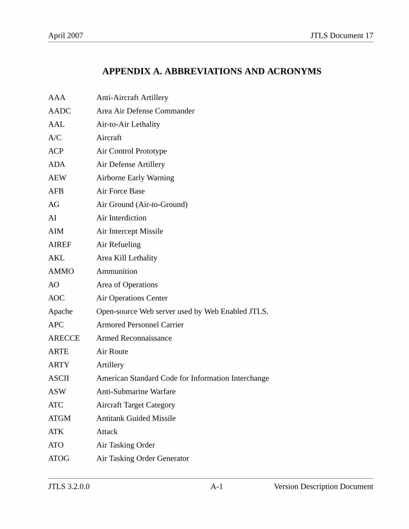
April 2007 JTLS Document 17
APPENDIX A. ABBREVIATIONS AND ACRONYMS
AAA Anti-Aircraft Artillery
AADC Area Air Defense Commander
AAL Air-to-Air Lethality
A/C Aircraft
ACP Air Control Prototype
ADA Air Defense Artillery
AEW Airborne Early Warning
AFB Air Force Base
AG Air Ground (Air-to-Ground)
AI Air Interdiction
AIM Air Intercept Missile
AIREF Air Refueling
AKL Area Kill Lethality
AMMO Ammunition
AO Area of Operations
AOC Air Operations Center
Apache Open-source Web server used by Web Enabled JTLS.
APC Armored Personnel Carrier
ARECCE Armed Reconnaissance
ARTE Air Route
ARTY Artillery
ASCII American Standard Code for Information Interchange
ASW Anti-Submarine Warfare
ATC Aircraft Target Category
ATGM Antitank Guided Missile
ATK Attack
ATO Air Tasking Order
ATOG Air Tasking Order Generator
JTLS 3.2.0.0 A-1 Version Description Document
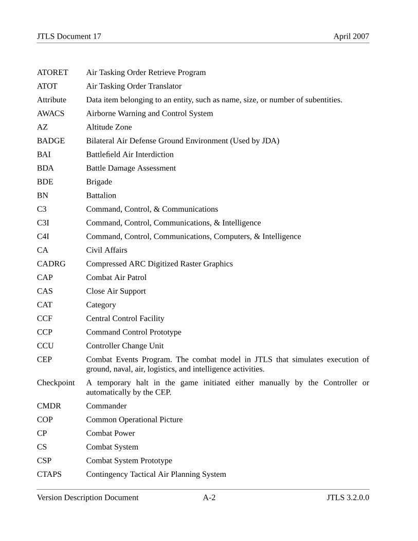
JTLS Document 17 April 2007
ATORET Air Tasking Order Retrieve Program
ATOT Air Tasking Order Translator
Attribute Data item belonging to an entity, such as name, size, or number of subentities.
AWACS Airborne Warning and Control System
AZ Altitude Zone
BADGE Bilateral Air Defense Ground Environment (Used by JDA)
BAI Battlefield Air Interdiction
BDA Battle Damage Assessment
BDE Brigade
BN Battalion
C3 Command, Control, & Communications
C3I Command, Control, Communications, & Intelligence
C4I Command, Control, Communications, Computers, & Intelligence
CA Civil Affairs
CADRG Compressed ARC Digitized Raster Graphics
CAP Combat Air Patrol
CAS Close Air Support
CAT Category
CCF Central Control Facility
CCP Command Control Prototype
CCU Controller Change Unit
CEP Combat Events Program. The combat model in JTLS that simulates execution ofground, naval, air, logistics, and intelligence activities.
Checkpoint A temporary halt in the game initiated either manually by the Controller orautomatically by the CEP.
CMDR Commander
COP Common Operational Picture
CP Combat Power
CS Combat System
CSP Combat System Prototype
CTAPS Contingency Tactical Air Planning System
Version Description Document A-2 JTLS 3.2.0.0
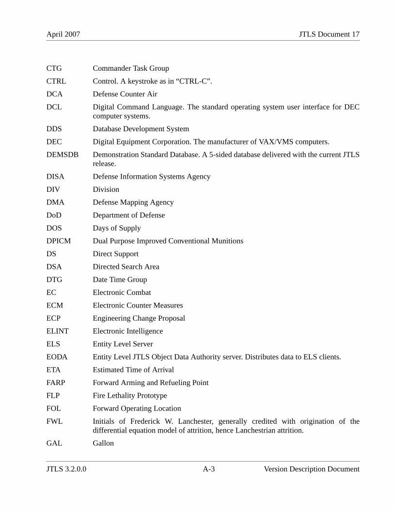
April 2007 JTLS Document 17
CTG Commander Task Group
CTRL Control. A keystroke as in “CTRL-C”.
DCA Defense Counter Air
DCL Digital Command Language. The standard operating system user interface for DECcomputer systems.
DDS Database Development System
DEC Digital Equipment Corporation. The manufacturer of VAX/VMS computers.
DEMSDB Demonstration Standard Database. A 5-sided database delivered with the current JTLSrelease.
DISA Defense Information Systems Agency
DIV Division
DMA Defense Mapping Agency
DoD Department of Defense
DOS Days of Supply
DPICM Dual Purpose Improved Conventional Munitions
DS Direct Support
DSA Directed Search Area
DTG Date Time Group
EC Electronic Combat
ECM Electronic Counter Measures
ECP Engineering Change Proposal
ELINT Electronic Intelligence
ELS Entity Level Server
EODA Entity Level JTLS Object Data Authority server. Distributes data to ELS clients.
ETA Estimated Time of Arrival
FARP Forward Arming and Refueling Point
FLP Fire Lethality Prototype
FOL Forward Operating Location
FWL Initials of Frederick W. Lanchester, generally credited with origination of thedifferential equation model of attrition, hence Lanchestrian attrition.
GAL Gallon
JTLS 3.2.0.0 A-3 Version Description Document
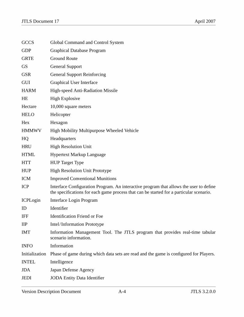
JTLS Document 17 April 2007
GCCS Global Command and Control System
GDP Graphical Database Program
GRTE Ground Route
GS General Support
GSR General Support Reinforcing
GUI Graphical User Interface
HARM High-speed Anti-Radiation Missile
HE High Explosive
Hectare 10,000 square meters
HELO Helicopter
Hex Hexagon
HMMWV High Mobility Multipurpose Wheeled Vehicle
HQ Headquarters
HRU High Resolution Unit
HTML Hypertext Markup Language
HTT HUP Target Type
HUP High Resolution Unit Prototype
ICM Improved Conventional Munitions
ICP Interface Configuration Program. An interactive program that allows the user to definethe specifications for each game process that can be started for a particular scenario.
ICPLogin Interface Login Program
ID Identifier
IFF Identification Friend or Foe
IIP Intel/Information Prototype
IMT Information Management Tool. The JTLS program that provides real-time tabularscenario information.
INFO Information
Initialization Phase of game during which data sets are read and the game is configured for Players.
INTEL Intelligence
JDA Japan Defense Agency
JEDI JODA Entity Data Identifier
Version Description Document A-4 JTLS 3.2.0.0
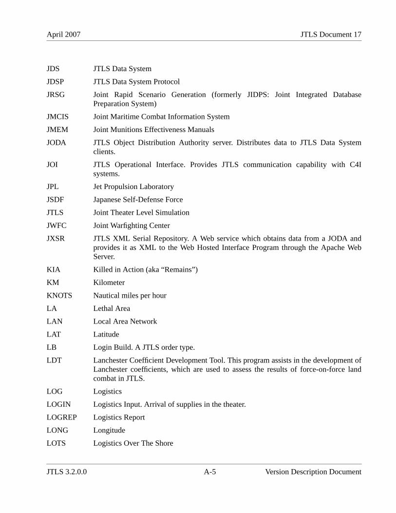
April 2007 JTLS Document 17
JDS JTLS Data System
JDSP JTLS Data System Protocol
JRSG Joint Rapid Scenario Generation (formerly JIDPS: Joint Integrated DatabasePreparation System)
JMCIS Joint Maritime Combat Information System
JMEM Joint Munitions Effectiveness Manuals
JODA JTLS Object Distribution Authority server. Distributes data to JTLS Data Systemclients.
JOI JTLS Operational Interface. Provides JTLS communication capability with C4Isystems.
JPL Jet Propulsion Laboratory
JSDF Japanese Self-Defense Force
JTLS Joint Theater Level Simulation
JWFC Joint Warfighting Center
JXSR JTLS XML Serial Repository. A Web service which obtains data from a JODA andprovides it as XML to the Web Hosted Interface Program through the Apache WebServer.
KIA Killed in Action (aka “Remains”)
KM Kilometer
KNOTS Nautical miles per hour
LA Lethal Area
LAN Local Area Network
LAT Latitude
LB Login Build. A JTLS order type.
LDT Lanchester Coefficient Development Tool. This program assists in the development ofLanchester coefficients, which are used to assess the results of force-on-force landcombat in JTLS.
LOG Logistics
LOGIN Logistics Input. Arrival of supplies in the theater.
LOGREP Logistics Report
LONG Longitude
LOTS Logistics Over The Shore
JTLS 3.2.0.0 A-5 Version Description Document
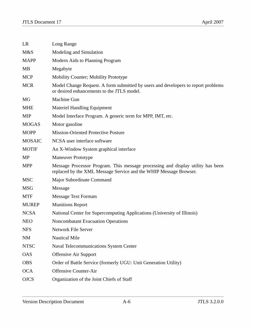
JTLS Document 17 April 2007
LR Long Range
M&S Modeling and Simulation
MAPP Modern Aids to Planning Program
MB Megabyte
MCP Mobility Counter; Mobility Prototype
MCR Model Change Request. A form submitted by users and developers to report problemsor desired enhancements to the JTLS model.
MG Machine Gun
MHE Materiel Handling Equipment
MIP Model Interface Program. A generic term for MPP, IMT, etc.
MOGAS Motor gasoline
MOPP Mission-Oriented Protective Posture
MOSAIC NCSA user interface software
MOTIF An X-Window System graphical interface
MP Maneuver Prototype
MPP Message Processor Program. This message processing and display utility has beenreplaced by the XML Message Service and the WHIP Message Browser.
MSC Major Subordinate Command
MSG Message
MTF Message Text Formats
MUREP Munitions Report
NCSA National Center for Supercomputing Applications (University of Illinois)
NEO Noncombatant Evacuation Operations
NFS Network File Server
NM Nautical Mile
NTSC Naval Telecommunications System Center
OAS Offensive Air Support
OBS Order of Battle Service (formerly UGU: Unit Generation Utility)
OCA Offensive Counter-Air
OJCS Organization of the Joint Chiefs of Staff
Version Description Document A-6 JTLS 3.2.0.0
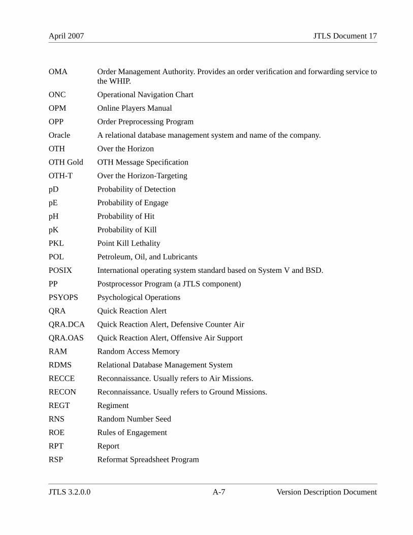
April 2007 JTLS Document 17
OMA Order Management Authority. Provides an order verification and forwarding service tothe WHIP.
ONC Operational Navigation Chart
OPM Online Players Manual
OPP Order Preprocessing Program
Oracle A relational database management system and name of the company.
OTH Over the Horizon
OTH Gold OTH Message Specification
OTH-T Over the Horizon-Targeting
pD Probability of Detection
pE Probability of Engage
pH Probability of Hit
pK Probability of Kill
PKL Point Kill Lethality
POL Petroleum, Oil, and Lubricants
POSIX International operating system standard based on System V and BSD.
PP Postprocessor Program (a JTLS component)
PSYOPS Psychological Operations
QRA Quick Reaction Alert
QRA.DCA Quick Reaction Alert, Defensive Counter Air
QRA.OAS Quick Reaction Alert, Offensive Air Support
RAM Random Access Memory
RDMS Relational Database Management System
RECCE Reconnaissance. Usually refers to Air Missions.
RECON Reconnaissance. Usually refers to Ground Missions.
REGT Regiment
RNS Random Number Seed
ROE Rules of Engagement
RPT Report
RSP Reformat Spreadsheet Program
JTLS 3.2.0.0 A-7 Version Description Document
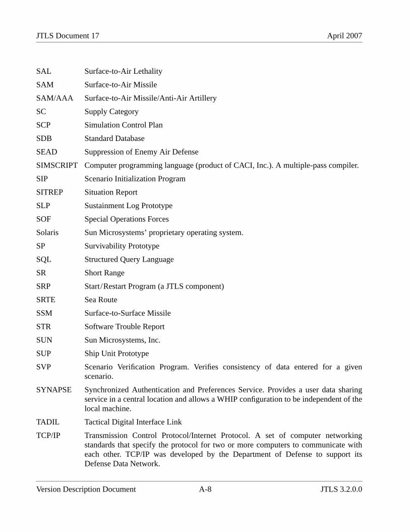
JTLS Document 17 April 2007
SAL Surface-to-Air Lethality
SAM Surface-to-Air Missile
SAM/AAA Surface-to-Air Missile/Anti-Air Artillery
SC Supply Category
SCP Simulation Control Plan
SDB Standard Database
SEAD Suppression of Enemy Air Defense
SIMSCRIPT Computer programming language (product of CACI, Inc.). A multiple-pass compiler.
SIP Scenario Initialization Program
SITREP Situation Report
SLP Sustainment Log Prototype
SOF Special Operations Forces
Solaris Sun Microsystems’ proprietary operating system.
SP Survivability Prototype
SQL Structured Query Language
SR Short Range
SRP Start/Restart Program (a JTLS component)
SRTE Sea Route
SSM Surface-to-Surface Missile
STR Software Trouble Report
SUN Sun Microsystems, Inc.
SUP Ship Unit Prototype
SVP Scenario Verification Program. Verifies consistency of data entered for a givenscenario.
SYNAPSE Synchronized Authentication and Preferences Service. Provides a user data sharingservice in a central location and allows a WHIP configuration to be independent of thelocal machine.
TADIL Tactical Digital Interface Link
TCP/IP Transmission Control Protocol/Internet Protocol. A set of computer networkingstandards that specify the protocol for two or more computers to communicate witheach other. TCP/IP was developed by the Department of Defense to support itsDefense Data Network.
Version Description Document A-8 JTLS 3.2.0.0
April 2007 JTLS Document 17
TEL Transporter Erector Launcher
TG Prefix for Target entity attributes.
TGT Target
TMU Terrain Modification Utility. A utility program used to modify JTLS hex-based terrainfiles.
TOE Table of Organization and Equipment
TOT Time on Target
TOW Tube-launched Optically-tracked Wire-guided missile
TPFDD Time-Phased Force Deployment Data
TGS Terrain Generation Service (formerly TPS:Terrain Preparation System)
TTG Target Type Group
TTL Target Types List
TUP Tactical Unit Prototype
TW Targetable Weapon
UBL Unit Basic Load
UIM/X GUI Builder Tool
UNIX A computer operating system.
UNK Unknown
UOM Unit of Measure
USA United States Army
USAF United States Air Force
USCG United States Coast Guard
USMC United States Marine Corps
USMTF U.S. Message Text Format
USN United States Navy
UT Prefix for Unit Attributes
UTM Universal Transverse Mercator
VAX A family of minicomputers developed by Digital Equipment Corporation.
VIFRED Visual Forms Editor
VMS Virtual Memory System
JTLS 3.2.0.0 A-9 Version Description Document
JTLS Document 17 April 2007
VTOL Vertical Takeoff and Landing aircraft
WAN Wide Area Network
WDRAW Withdraw
WEJ Web Enabled JTLS. Composed of several Web services which interface with theWHIP through an HTTP Web server.
WHIP Web Hosted Interface Program. An integrated Web interface to JTLS.
WIA Wounded in Action
WPC Warrior Preparation Center
WPN Weapon
WT Weight
WW Wild Weasel
XMS XML Message Service. Provides a JTLS message indexing service.
Version Description Document A-10 JTLS 3.2.0.0

April 2007 JTLS Document 17
APPENDIX B. COMBAT SYSTEM CATEGORY DEFINITIONS
This Appendix provides definitions of the 99 Combat System categories used in the StandardDatabase. Note that the C3I combat system has been removed due to the changes in Version 3.2.
INFANTRY
(INFANTRY)
Cause attrition via direct fire Lanchester equations and point lethality high resolution combatalgorithms. Armed with pistols, rifles, submachine guns, 5.56mm squad automatic weapons, riflegrenade launchers, single round grenade launchers, LAWs, hand grenades, bayonets, hasty mines.Effective ranges 400m to 800m. These are soldiers primarily trained to fight dismounted or with asignificant secondary mission of fighting as infantry. Includes dismount teams in mechanized infantryunits. A significant portion (70%) of combat engineer units and a smaller portion (50%) of militarypolice units should probably be counted as infantry. Artillery units might have a lesser portion (25%)counted as infantry. This is a personnel combat system.
ELITE INFANTRY
(ELITE-INF)
Cause attrition via direct fire Lanchester equations and point lethality high resolution combatalgorithms. Armed with pistols, rifles, submachine guns, 5.56mm squad automatic weapons, riflegrenade launchers, LAWs, single round grenade launchers, hand grenades, bayonets, and hasty mines.Have more automatic weapons, grenade launchers and LAWs than INFANTRY. Effective ranges outto 400m to 800m. ELITE-INFANTRY are about 150 to 200% as effective in Lanchester combat asINFANTRY. These are well trained, highly motivated soldiers primarily trained to fight dismounted.These soldiers are primarily found in specialized units: SF, Ranger, Airborne, Commando, etc. This isa personnel combat system.
INFANTRY/ENGINEER SPECIAL WEAPONS
(INFENG-SPWPN)
Cause attrition via direct fire Lanchester equations and point lethality high resolution combatalgorithms. Armed with a personal weapon such as pistols, rifles, submachine guns, hand grenades,and bayonets; but their primary lethality comes from the special weapon they operate. These weaponsare primarily anti-fortification weapons although they may be used in the anti-armor role. Theseinclude SMAW, Wasp, Bunkerfaust, T67 and other flamethrowers, various short range recoillessrifles, 90mm M67 or TYPE 51; 82mm B10, M60A or M79; 89mm M69; 120mm M43; 107mm B11;128mm M71, and satchel charges. Effective ranges out to 500m. These are soldiers primarily trainedto fight using a special weapon. A portion (20%) of combat engineer units should probably be
JTLS 3.2.0.0 B-1 Version Description Document
JTLS Document 17 April 2007
counted as INFENG-SPWPN. HUPs which had explosives combat systems should replace anexplosives combat system and a personnel combat system for one INFENG-SPWPN combat system.This is a personnel combat system.
OTHER TROOPS
(OTHER-TROOPS)
Cause attrition via direct fire Lanchester equations and point lethality high resolution combatalgorithms. Armed with weapons similar to infantry, but not armed as extensively. OTHER-TROOPSare about 25 to 33% as effective in Lanchester combat as INFANTRY. These are soldiers whoseprimary role is other than fighting dismounted. Includes headquarters and support troops in infantryunits. Generally all troops in units other than infantry, engineer or military police; however you maygive any unit some percent of its troops as INFANTRY, based on your evaluation of the unit's ability(training) to engage in ground combat. This is a personnel combat system.
SNIPER
(SNIPER)
Cause attrition via direct fire Lanchester equations and point lethality high resolution combatalgorithms. Armed with sniper rifles of various caliber, up to 12.7mm. Effective ranges out to 1500m.More effective in Lanchester combat than INFANTRY against most soft and lightly armored combatsystems. More survivable than INFANTRY. These are soldiers specifically trained and armed assnipers. This is a personnel combat system.
CREW
(CREW)
Cause attrition via direct fire Lanchester equations and point lethality high resolution combatalgorithms when not manning another combat system. Armed with weapons similar to infantry, butnot armed as extensively. These are soldiers whose primary role is operating another combat system:vehicle drivers, gunners, loaders and commanders; gun crews and operators of any other crewedcombat system. It is the specified Crew combat system. This means you must have enough combatsystem CREW to man all the combat systems that require crews. The Combat System Prototype(CSP) data identifies which combat systems require crews and how many of the Crew combat systemare required.
CREW-SERVED WEAPONS
(CREW-WEAPON)
Cause attrition via direct fire Lanchester equations and point lethality high resolution combatalgorithms. Machineguns of caliber 7.62mm or larger and automatic grenade launchers. Effectiveranges 600m to 1500m. Examples: 7.62mm M60/E3/E4, M240B/G, FN MAG, RPD, PK/PKS/PKM,
Version Description Document B-2 JTLS 3.2.0.0

April 2007 JTLS Document 17
RPK, RP46, Pecheneg, SG43/SGM/Type 57, Type 67/672C/74/80/81, WQ112, AAT F1, HK21/11,MG42/59, MG1/2/3, MG4, MGM1, M52, Model 62, Model 68, L4A4/L7A2, SS77, T74 and M53/M72/M77/M84; 12.7mm DShK-38/Type 54/59, NSV/NSW, Type 77/85, QJZ89, M2HB, 50MG,GAU19A; 14.5mm Type 75-1, KPV, Pirat; 30mm AGS17, AGS30; 35mm W87, QLZ87; 40mmMK19, GMG, and Striker. This is not a crewed combat system. Do not include weapons that aremounted on combat vehicles modeled separately as combat systems (i.e. coaxial or turret mountedmachineguns).
MEDIUM ANTI-TANK WEAPON - LONG RANGE
(AT-MAW-LR)
Cause attrition via direct fire Lanchester equations and point lethality high resolution combatalgorithms. Antitank rocket/missile launcher with max effective anti-tank ranges greater than 800mbut less than 1500m. Armor penetration generally greater than 400mm but less than 800mm. Thesesystems are used primarily in the anti-tank role. Examples: Dragon, Dragon 2, AT-7 (Saxhorn), AT-13, Shipon 2, Folgore 80mm, and Type 87 Chu-MAT. This is a crewed combat system. May be firedfrom vehicles, but usually employed from a ground mount.
MEDIUM ANTI-TANK WEAPON - SHORT RANGE - MEDIUM LETHALITY
(AT-MAW-SR-ML)
Cause attrition via direct fire Lanchester equations and point lethality high resolution combatalgorithms. Antitank rocket/missile launcher with max effective anti-tank ranges greater than 500mbut less than 800m. Armor penetration greater than 400mm but less than 800mm. These systems areused primarily in the anti-tank role. Examples: Dragon 2T, LAW 80, M2/M3 Carl Gustav, andRPG29. This is not a crewed combat system. May be fired from vehicles, but usually employed froma ground mount or shoulder launched.
MEDIUM ANTI-TANK WEAPON - SHORT RANGE - HIGH LETHALITY
(AT-MAW-SR-HL)
Cause attrition via direct fire Lanchester equations and point lethality high resolution combatalgorithms. Antitank rocket/missile launcher with max effective anti-tank ranges greater than 500mbut less than 800m. Armor penetration greater than or equal to 800mm. These systems are usedprimarily in the anti-tank role. Examples: Eryx, Alcotan 100, Bumble Bee and Shipon 1. This is not acrewed combat system. May be fired from vehicles, but usually employed from a ground mount orshoulder launched.
MEDIUM ANTI-TANK WEAPON - SHORT RANGE - TOP ATTACK
(AT-MAW-SR-TA)
JTLS 3.2.0.0 B-3 Version Description Document
JTLS Document 17 April 2007
Cause attrition via direct fire Lanchester equations and point lethality high resolution combatalgorithms. Antitank rocket/missile launcher with max effective anti-tank ranges greater than 500mbut less than 800m. Top attack capability allows it to defeat most armor. These systems are usedprimarily in the anti-tank role. Examples: Predator (SRAW) and MBT LAW. This is not a crewedcombat system. May be fired from vehicles, but usually employed from a ground mount or shoulderlaunched.
HEAVY ANTI-TANK WEAPON - SHORT RANGE - MEDIUM LETHALITY
(AT-HAW-SR-ML)
Cause attrition via direct fire Lanchester equations and point lethality high resolution combatalgorithms. Antitank gun or rocket/missile launcher with max effective anti-tank range of 2000m to3000m. Armor penetration greater than 400mm but less than 700mm. Examples: Milan,SuperDragon, RAAD, AT-3(Sagger) (Malyutka) (Malyutka-M), AT-4(Spigot) (Fagot) and MAF. Thisis a crewed combat system. Crew should be modeled as combat system CREW. Do not includeweapons that are mounted on combat vehicles modeled separately as combat systems (i.e. M2Bradley, BRDM-2 Sagger). Do include non-armored vehicle mounted weapons (i.e. unarmoredHMMWV/jeep mounted tow). The vehicle of the non-armored vehicle mounted weapons should bemodeled separately as a combat system: UTIL-VEH-NA or EQUIP-OTH-SP as appropriate.
HEAVY ANTI-TANK WEAPON - SHORT RANGE - HIGH LETHALITY
(AT-HAW-SR-HL)
Cause attrition via direct fire Lanchester equations and point lethality high resolution combatalgorithms. Antitank gun or rocket/missile launcher with max effective anti-tank range of 2000m to3000m. Armor penetration greater than or equal to 700mm. Examples: Milan 2, Milan 2T/3, Flame,AT-3(Sagger) (Malyutka2) (Malyutka2M), Red Arrow 8A/C, Baktar Shikan and Gill. This is acrewed combat system. Crew should be modeled as combat system CREW. Do not include weaponsthat are mounted on combat vehicles modeled separately as combat systems (i.e. M2 Bradley,BRDM-2 Sagger). Do include non-armored vehicle mounted weapons (i.e. unarmored HMMWV/jeep mounted tow). The vehicle of the non-armored vehicle mounted weapons should be modeledseparately as a combat system: UTIL-VEH-NA or EQUIP-OTH-SP as appropriate.
HEAVY ANTI-TANK WEAPON - SHORT RANGE - TOP ATTACK
(AT-HAW-SR-TA)
Cause attrition via direct fire Lanchester equations and point lethality high resolution combatalgorithms. Antitank gun or rocket/missile launcher with max effective anti-tank range of 2000m to3000m. Top attack capability allows it to defeat most armor. Examples: Javelin, TRIGAN, RBS 56BILL 1/BILL 2 and MACAM. This is a crewed combat system. Crew should be modeled as combatsystem CREW. Do not include weapons that are mounted on combat vehicles modeled separately ascombat systems (i.e. M2 Bradley, BRDM-2 Sagger). Do include non-armored vehicle mounted
Version Description Document B-4 JTLS 3.2.0.0
April 2007 JTLS Document 17
weapons (i.e. unarmored HMMWV/jeep mounted tow). The vehicle of the non-armored vehiclemounted weapons should be modeled separately as a combat system: UTIL-VEH-NA or EQUIP-OTH-SP as appropriate.
HEAVY ANTI-TANK WEAPON - LONG RANGE - HIGH LETHALITY
(AT-HAW-LR-HL)
Cause attrition via direct fire Lanchester equations and point lethality high resolution combatalgorithms. Antitank gun or rocket/missile launcher with max effective anti-tank range of 3500m orgreater. Armor penetration greater than or equal to 600mm. Examples: TOW, ITOW, TOW2A, AT-5(Spandrel) (Konkurs) (Konkurs-M), Red Arrow 8E, Toophan 1 and 2, Spike-MR, MAPATS andType 79 Jyu-MAT (KAM-9). This is a crewed combat system. Crew should be modeled as combatsystem CREW. Do not include weapons that are mounted on combat vehicles modeled separately ascombat systems (i.e. M2 Bradley, BRDM-2 Sagger). Do include non-armored vehicle mountedweapons (i.e. unarmored HMMWV/jeep mounted tow). The vehicle of the non-armored vehiclemounted weapons should be modeled separately as a combat system: UTIL-VEH-NA or EQUIP-OTH-SP as appropriate.
HEAVY ANTI-TANK WEAPON - LONG RANGE - TOP ATTACK
(AT-HAW-LR-TA)
Cause attrition via direct fire Lanchester equations and point lethality high resolution combatalgorithms. Antitank gun or rocket/missile launcher with max effective anti-tank range of 3500m orgreater. Top attack capability allows it to defeat most armor. Although not a top attack weapon, theAT-14 is best modeled as this combat system because of its extremely high penetration ability.Examples: TOW2B and AT-14. This is a crewed combat system. Crew should be modeled as combatsystem CREW. Do not include weapons that are mounted on combat vehicles modeled separately ascombat systems (i.e. M2 Bradley, BRDM-2 Sagger). Do include non-armored vehicle mountedweapons (i.e. unarmored HMMWV/jeep mounted tow). The vehicle of the non-armored vehiclemounted weapons should be modeled separately as a combat system: UTIL-VEH-NA or EQUIP-OTH-SP as appropriate.
ANTI-TANK GUN 73 TO 106MM - NOT MISSILE CAPABLE
(ATG73-106NMC)
Cause attrition via direct fire Lanchester equations and point lethality high resolution combatalgorithms. Multi-purpose weapon used primarily in anti-tank role, but also in anti-bunker or anti-personnel role. Max effective anti-tank range greater than or equal to 700m. Examples: 73mm SPG-9,100mm T12/MT12/Type 73 (CHI)/M87 (YUG), 90mm PV-1110 and 106mm M40/T126/T173. Thisis a crewed combat system. Crew should be modeled as combat system CREW. May be ground or
JTLS 3.2.0.0 B-5 Version Description Document
JTLS Document 17 April 2007
non-armored vehicle mounted. Armored vehicle mounted recoilless rifles are better modeled as anarmored gun system or a tank. If non-armored vehicle mounted, the vehicle should be modeledseparately as a combat system: UTIL-VEH-NA or EQUIP-OTH-SP as appropriate.
ANTI-TANK GUN 100 TO 125MM - MISSILE CAPABLE
(ATG100-125MC)
Cause attrition via direct fire Lanchester equations and point lethality high resolution combatalgorithms. Used primarily in the anti-tank role. Capable of firing an anti-tank guided missile fromthe gun tube. Max effective anti-tank range greater than or equal to 4000m. Examples: 100mm T12/MT12 and 125mm 2A45M (Sprut-B). This is a crewed combat system. Crew should be modeled ascombat system CREW. This is a ground mounted weapon; vehicle mounted variants are modeled aseither tanks or armored gun systems.
MORTAR DISMOUNTED 50MM TO 60MM
(MTRDISM50-60)
Cause attrition via indirect fire Lanchester equations and point lethality high resolution combatalgorithms. The standard database discourages explicit fire of light mortars, although the data is thereto support the area lethality explicit fire algorithms. Includes 60mm and smaller mortars. Examples:50mm M-8; 51mm L10A1, TN8111, E1; 52mm IMI 52 Cdo; 60mm commando: C6, M60D, Antos,Elis, Vammas, MO60C, FMK-1/2, HM12/13, C03, Model 87, M4/M4MK1, LM60K, M4L3, XT81,M70; 60mm standard: M2 (USA), M19, M1 (SAF), M6 (SAF), KM181, LM-60D, Soltam C576/C08/C06, M-57, M-90, M-94, HM14, Al-Jaleel, FMK-3, M6-111/M6-211 (AUS), Model L/LL-M86,Model 87, M224, M84, M/965, Vammas, TDA Proximity, NR 493, M60, MO 60L/LP, T75, Type M-83A, Type 63-1, Type WX90 and Type WW90L/M. This is not a crewed combat system. This is aground mounted weapon. Ground mount systems may be transported in vehicles. If transported byvehicle the vehicle should be modeled as a separate combat system as appropriate: UTIL-VEH-LA,UTIL-VEH-NA or EQUIP-OTH-SP.
MORTAR DISMOUNTED 81MM TO 82MM
(MTRDISM81-82)
Cause attrition via indirect fire Lanchester equations and point lethality high resolution combatalgorithms. The standard database discourages explicit fire of light mortars, although the data is thereto support the area lethality explicit fire algorithms. Includes 81mm mortars and 82mm mortars.Examples: 81mm M29A1, M252, M29 (SWE), NR475A1, M8-111/211/522, 1MT81, E1/E1Imp,KM187, M81, Model 1972, Vammas STD/LR, FMK-2, AWPC, Type W87, Type W91, HP SB/LBModel LN/LL, Model LN-M86/LL-M86, M-68, M3 (SAF), MO81LC/LL/LP/LLR, E44, HM15,L16A2, MO81-61L, Soltam B433/B449/B455/B502, Otobreda 81, M1, T75, UT-1/NT-1, ZTS; 82mmM-36, M-37, M-41, 2B9, 2B14, M-69A/B (YUG), 1MT82, Model M69 (EGY), Model 77, Model 94,Al-Jaleel, M93, M96 LM/LRLM (CRO), Type 67, Type W84 and Type W99. This is a crewed combat
Version Description Document B-6 JTLS 3.2.0.0
April 2007 JTLS Document 17
system. Crew should be modeled as combat system CREW. This is a ground mounted weapon. Iftransported by vehicle the vehicle should be modeled as a separate combat system as appropriate:UTIL-VEH-LA, UTIL-VEH-NA or EQUIP-OTH-SP.
MORTAR SELF PROPELLED LIGHT - LIGHT ARMOR - OPEN WEAPON
(MTRSPLT-LAO)
Cause attrition via indirect fire Lanchester equations and point lethality high resolution combatalgorithms. The standard database discourages explicit fire of light mortars, although the data is thereto support the area lethality explicit fire algorithms. Includes 81mm and 82mm mortars, generallymounted in lightly armored vehicles. Protected from small arms fire and shell splinters. May bedismounted, but generally fired from the vehicle mounting. The weapon is usually protected duringmovement but exposed while firing. Many vehicle types have been used to mount various mortars.Examples: 81mm M125 and LAV-M. This is a crewed combat system. Crew should be modeled ascombat system CREW. Vehicle mounted machineguns should not be modeled separately; they areincluded in the lethality values of the MTRSPLT-LAO.
MORTAR DISMOUNTED HEAVY
(MTRDISMHVY)
Cause attrition via indirect fire Lanchester equations, point lethality high resolution combatalgorithms, and area lethality explicit fire algorithms. Includes mortars larger than 82mm. Examples:98mm M98, Model 1997; 100mm Type 71; 107mm M30, M38, M107; 120mm M-43, 2B11, NonaSVK-M, Type W86, XT86, Model L, Model M86SB/LB, M12-1111/2222/3222, M41D, Model 82,Model 87, M120, MO120AM50, UBM52, M74, M75, FMK-2, Al-Jaleel, Vammas STD/LR, SoltamK5/K6/A7A2/M-65/M66, Model UK2, HM16, E56, AWPC M132, MO 120 LT/RT, E1/E1Imp,HY12, Type 55; 160mm M1943, M160, M58, M66; and 240mm M240. This is a crewed combatsystem. Crew should be modeled as combat system CREW. This is a ground mounted weapon.Almost always transported or towed by vehicle. Prime movers should be modeled separately as acombat system: UTIL-VEH-LA, UTIL-VEH-NA or EQUIP-OTH-SP as appropriate.
MORTAR SELF PROPELLED HEAVY - LIGHT ARMOR - OPEN WEAPON
(MTRSPHVY-LAO)
Cause attrition via indirect fire Lanchester equations, point lethality high resolution combatalgorithms, and area lethality explicit fire algorithms. Includes mortars larger than 82mm, generallymounted in lightly armored vehicles. Protected from small arms fire and shell splinters. May bedismounted, but generally fired from the vehicle mounting. The weapon is usually protected duringmovement but exposed while firing. Many vehicle types have been used to mount various mortars.Turreted 120mm mortars are modeled as combat system MTRSP120-LAT. Examples: 107mm M106;
JTLS 3.2.0.0 B-7 Version Description Document
JTLS Document 17 April 2007
120mm M12-2330, M121 (USA); and 240mm 2S4. This is a crewed combat system. Crew should bemodeled as combat system CREW. Vehicle mounted machineguns should not be modeled separately;they are included in the lethality values of the MTRSPHVY-LAO.
MORTAR SELF PROPELLED 120MM - LIGHT ARMOR - TURRETED WEAPON
(MTRSP120-LAT)
Cause attrition via indirect fire Lanchester equations, point lethality high resolution combatalgorithms, and area lethality explicit fire algorithms. Includes turreted 120mm mortars, generallymounted in lightly armored vehicles. Protected from small arms fire and shell splinters. Examples:120mm 2S9, 2S23, 2S31, AMS, AMOS, WIESEL2, PRAM-S and WZ551. This is a crewed combatsystem. Crew should be modeled as combat system CREW. Vehicle mounted machineguns should notbe modeled separately; they are included in the lethality values of the MTRSP120-LAT.
ARTILLERY TOWED - VERY LIGHT
(ARTYTOW-VLT)
Cause attrition via direct fire Lanchester equations and point lethality high resolution combatalgorithms. Towed howitzers/guns of caliber up to and including 95mm. These guns are primarilyused in the anti-tank role. Max effective anti-tank range greater than or equal to 1000m. Examples:75mm M116; 76mm M1966 (RUS), M48 (YUG), M1943/ZIS-3/Type 54; 76.2mm Model 1984(ROM); 85mm D44/M52 (CZ)/Type 56 (CHI) and D48. This is a crewed combat system. Crewshould be modeled as combat system CREW. Prime movers should be modeled separately as acombat system: UTIL-VEH-LA, UTIL-VEH-NA or EQUIP-OTH-SP as appropriate.
ARTILLERY TOWED - LIGHT
(ARTYTOW-LT)
Cause attrition via indirect fire Lanchester equations and area lethality explicit fire algorithms. Do notcause attrition via high resolution combat. Towed howitzers/guns of caliber greater than 95mm butless than 125mm. Examples: 98mm Model 93; 100mm M1944, M53 (CZ), M1977 (ROM); 105mmLight Gun, LFG, KH178, M56, M101, M102, M119, M425; 120mm 2B16 (RUS); 122mm D-30, D-74, M1938/M-30 and Type 54-1 (CHI). This is a crewed combat system. Crew should be modeled ascombat system CREW. Prime movers should be modeled separately as a combat system: UTIL-VEH-LA, UTIL-VEH-NA or EQUIP-OTH-SP as appropriate.
ARTILLERY SELF-PROPELLED - LIGHT - TURRETED WEAPON
(ARTYSP-LT-T)
Cause attrition via indirect fire Lanchester equations, point lethality high resolution combatalgorithms and area lethality explicit fire algorithms. Self propelled howitzers/guns of caliber lessthan or equal to 125mm with the gun in an enclosed turret. 120mm combined howitzer/mortars are
Version Description Document B-8 JTLS 3.2.0.0

April 2007 JTLS Document 17
modeled as combat system MTRSP120-LAT. Protected from small arms fire and shell splinters.Examples: 105mm M7, M52, M108, FV433, AMX MK51,Type 74;122mm 2S1, Model 89, SP122,Thunder-1, Type 89 and 122-T55. This is a crewed combat system. Crew should be modeled ascombat system CREW. Vehicle mounted machineguns should not be modeled separately; they areincluded in the lethality values of the ARTYSP-LT-T
ARTILLERY SELF-PROPELLED - LIGHT - OPEN WEAPON
(ARTYSP-LT-O)
Cause attrition via indirect fire Lanchester equations, point lethality high resolution combatalgorithms and area lethality explicit fire algorithms. Self propelled howitzers/guns of caliber lessthan or equal to 125mm with the gun in an open turret or un-turreted. Protected from small arms fireand shell splinters when not in action. Examples: 75mm DN5 Bufalo (MEX); 100mm M1944-T34;122mm D30-T34, D30-T55, Type 54-1, Type 70-1, Type 85, M1981, M1985, M1991 and M1997.This is a crewed combat system. Crew should be modeled as combat system CREW. Vehicle mountedmachineguns should not be modeled separately; they are included in the lethality values of theARTYSP-LT-O.
ARTILLERY TOWED - MEDIUM LIGHT
(ARTYTOW-MLT)
Cause attrition via indirect fire Lanchester equations and area lethality explicit fire algorithms. Do notcause attrition via high resolution combat. Towed howitzers/guns of caliber greater than 125mm butless than 145mm. Examples: 130mm M46, M59-1M (EGY), M1982 (ROM) and Type 59-1 (CHI).This is a crewed combat system. Crew should be modeled as combat system CREW. Prime moversshould be modeled separately as a combat system: UTIL-VEH-LA, UTIL-VEH-NA or EQUIP-OTH-SP as appropriate.
ARTILLERY SELF-PROPELLED - MEDIUM LIGHT
(ARTYSP-MLT)
Cause attrition via indirect fire Lanchester equations, point lethality high resolution combatalgorithms, and area lethality explicit fire algorithms. All self propelled howitzers/guns of calibergreater than 125mm but less than 145mm regardless of turret. Protected from small arms fire and shellsplinters. Examples: 130mm Catapult, Type 83 (CHI), M1975, M1991 and M1992. This is a crewedcombat system. Crew should be modeled as combat system CREW. Vehicle mounted machinegunsshould not be modeled separately; they are included in the lethality values of the ARTYSP-MLT.
ARTILLERY TOWED- MEDIUM HEAVY
(ARTYTOW-MHV)
JTLS 3.2.0.0 B-9 Version Description Document
JTLS Document 17 April 2007
Cause attrition via indirect fire Lanchester equations and area lethality explicit fire algorithms. Do notcause attrition via high resolution combat. Towed howitzers/guns of caliber greater than 145mm butless than 170mm. Examples: 152mm D1/Type 54, D20/Type 66, 2A65(M1987), 2A36(M1976),2A61, M1937/M1938, Model 1985 (ROM), M1981 (ROM), Type 83/Type 86 (CHI), M84; 155mmM114/T65, Model 50, M59, M65, M198, FH-70, FH-77A/B, FH-88, FH-2000, GM45, GC45,GHN45, EH52, HM41, KH179, WAC21(WA021), G5, M777, M83, TIG 2000, M68/M71, M46S,M46/84 (YUG), TR-F1, Model 845 and M139. This is a crewed combat system. Crew should bemodeled as combat system CREW. Prime movers should be modeled separately as a combat system:UTIL-VEH-LA, UTIL-VEH-NA or EQUIP-OTH-SP as appropriate.
ARTILLERY SELF-PROPELLED - MEDIUM HEAVY- TURRETED WEAPON
(ARTYSP-MHV-T)
Cause attrition via indirect fire Lanchester equations, point lethality high resolution combatalgorithms, and area lethality explicit fire algorithms. Self propelled howitzers/guns of caliber greaterthan 145mm but less than 170mm with the gun in an enclosed turret. Protected from small arms fireand shell splinters. Examples: 152mm 2S3, 2S19, Dana, Type 83; 155mm M109, M52T, GCT, AS90,FH-77, G6, PzH 2000, K9 Thunder, Palmaria, Bandkanon 1A, L33, Doher, Zuzana, Thunder-2,PLZ45, Type 75, Type 99 and VCA 155. This is a crewed combat system. Crew should be modeled ascombat system CREW. Vehicle mounted machineguns should not be modeled separately; they areincluded in the lethality values of the ARTYSP-MHV-T.
ARTILLERY SELF-PROPELLED - MEDIUM HEAVY - OPEN WEAPON
(ARTYSP-MHV-O)
Cause attrition via indirect fire Lanchester equations, point lethality high resolution combatalgorithms, and area lethality explicit fire algorithms. Self propelled howitzers/guns of caliber greaterthan 145mm but less than 170mm with the gun in an open turret or un-turreted. Protected from smallarms fire and shell splinters when not in action. Examples: 152mm 2S5, M1974, M1977, M1991;155mm MK F3, CAESAR, 155/52 APU SBT, M44T, 155 GH 52 APU, XT69 and XT69A1. This is acrewed combat system. Crew should be modeled as combat system CREW. Vehicle mountedmachineguns should not be modeled separately; they are included in the lethality values of theARTYSP-MHV-O.
ARTILLERY TOWED - HEAVY
(ARTYTOW-HVY)
Cause attrition via indirect fire Lanchester equations and area lethality explicit fire algorithms. Do notcause attrition via high resolution combat. Towed howitzers/guns of caliber 170mm and greater.Examples: 180mm S23 and 203mm M115. This is a crewed combat system. Crew should be modeledas combat system CREW. Prime movers should be modeled separately as a combat system: UTIL-VEH-LA, UTIL-VEH-NA or EQUIP-OTH-SP as appropriate.
Version Description Document B-10 JTLS 3.2.0.0
April 2007 JTLS Document 17
ARTILLERY SELF-PROPELLED - HEAVY - OPEN WEAPON
(ARTYSP-HV-O)
Cause attrition via indirect fire Lanchester equations, point lethality high resolution combatalgorithms, and area lethality explicit fire algorithms. Self propelled howitzers/guns of caliber 170mmand greater with the gun in an open turret or un-turreted. Protected from small arms fire and shellsplinters when not in action. Examples: 170mm M1978 Koksan; 175mm M107, Romach; 203mmM110, 2S7 and NORINCO 203 SP. This is a crewed combat system. Crew should be modeled ascombat system CREW. Vehicle mounted machineguns should be modeled separately; they are notincluded in the lethality values of the ARTYSP-HV-O.
MULTIPLE ROCKET LAUNCHER - SHORT RANGE - TOWED
(MRL-SR-TOWED)
Cause attrition via indirect fire Lanchester equations and area lethality explicit fire algorithms. Do notcause attrition via high resolution combat. Max range of 15 km or less. Examples: 60mm M91; 70mmM93A3, NDL40, RA7040; 107mm Type 63, FADGR1, RO107; 126mm Kung Feng 3; 128mm M63and M91A3. This is a crewed combat system. Crew should be modeled as combat system CREW.Prime movers should be modeled separately as a combat system: UTIL-VEH-LA, UTIL-VEH-NA orEQUIP-OTH-SP as appropriate.
MULTIPLE ROCKET LAUNCHER - SHORT RANGE - VEHICLE
(MRL-SR-VEH)
Cause attrition via indirect fire Lanchester equations and area lethality explicit fire algorithms. Do notcause attrition via high resolution combat. Max ranges of 15 km or less. Contains a mix of lightlyarmored and unarmored vehicles. Examples: 60mm LOV M93A1; 70mm LAU97; 107mm M1992,M1992/2,Type 81, FADGR1; 117mm Kung Feng 6; 126mm Kung Feng 4; 128mm LOV RAK24,M85; 130mm Type 75 (JPN), Type82/Type 85(CHI); and 220mm TOS-1. This is a crewed combatsystem. Crew should be modeled as combat system CREW. Vehicle mounted machineguns should notbe modeled separately; they are included in the lethality values of the MRL-SR-VEH.
MULTIPLE ROCKET LAUNCHER - MEDIUM RANGE - VEHICLE
(MRL-MR-VEH)
Cause attrition via indirect fire Lanchester equations, point lethality high resolution combatalgorithms, and area lethality explicit fire algorithms. Minimum range less than 15 km and maximumrange greater than 15km. Only a part of the full lethality of these systems is applied to Lanchestercombat. Contains a mix of lightly armored and unarmored vehicles. Examples: 110mm LARS;117mm RT2000 Thunder; 122mm BM11, Dr Khan, RM70, BM21 GRAD/GRAD1/GRAD-V,BM22(9P140), Type 81/83/89/90 (CHI), RL21, SR114, M96 Typhoon, HM20, ZIL Sakr, M1977/M1985 (NKO), Firos30, T122, Valkiri MK2, APR40; 127mm SS30 Astros2, Valkiri MK1; 128mm
JTLS 3.2.0.0 B-11 Version Description Document
JTLS Document 17 April 2007
Teruel, M77 Oganj; 130mm Kooryong; and 180mm Type 71. This is a crewed combat system. Crewshould be modeled as combat system CREW. Vehicle mounted machineguns should be modeledseparately; they are not included in the lethality values of the MRL-MR-VEH.
MULTIPLE ROCKET LAUNCHER - LONG RANGE - VEHICLE
(MRL-LR-VEH)
Non-attritor, do not cause attrition via indirect fire Lanchester equations, since the minimum range ofthese systems is greater than the minimum range for Lanchester combat. Cause attrition via arealethality explicit fire algorithms. Minimum range greater than 15 km. Contains a mix of lightlyarmored and unarmored vehicles. Examples: 160mm LAROM; 214mm Pinacha, 227mm M270MLRS; 230mm Oghab; 240mm FADJR3, M1985/M1989, M1991; 262mm M87 Orkan; 273mmWM80, Type 83; 300mm 9A52/A100 Smerch; 320mm WS1; and 333mm FADJR5. This is a crewedcombat system. Crew should be modeled as combat system CREW. Vehicle mounted machinegunsshould be modeled separately; they are not included in the lethality values of the MRL-LR-VEH.
TANK 120MM - ADVANCED FIRE CONTROL - HIGH SURVIVABILITY
(TANK120-AFHS)
Cause attrition via direct fire Lanchester equations and point lethality high resolution combatalgorithms. Tanks with main guns of caliber 120mm or 125mm, advanced fire control systems, andthe highest level of survivability. Examples: M1A1/A2, T-90 (RUS), Challenger II, Type 90 (JPN),Leclerc, and Leopard2A5/2A6. Vehicle crew should be modeled as combat system CREW. Coaxial,bow and turret mounted machineguns should not be modeled separately; they are included in thelethality values of the TANK120-AFHS.
TANK 120MM - ADVANCED FIRE CONTROL - ENHANCED SURVIVABILITY
(TANK120-AFES)
Cause attrition via direct fire Lanchester equations and point lethality high resolution combatalgorithms. Tanks with main guns of caliber 120mm or 125mm, advanced fire control systems, and anenhanced level of survivability. Examples: T-80U, T-64U, Challenger I, Leopard II, Merkava Mk3,Ariete, T-84/T84U (UKR), and K1A1. Vehicle crew should be modeled as combat system CREW.Coaxial, bow and turret mounted machineguns should not be modeled separately; they are included inthe lethality values of the TANK120-AFES.
TANK 120MM - LIMITED FIRE CONTROL - ENHANCED SURVIVABILITY
(TANK120-LFES)
Cause attrition via direct fire Lanchester equations and point lethality high resolution combatalgorithms. Tanks with main guns of caliber 120mm or 125mm, limited fire control systems, and anenhanced level of survivability. Examples: 125mm T72B/T72S, T72BM, T72M1V, T64BV, T80BV,
Version Description Document B-12 JTLS 3.2.0.0

April 2007 JTLS Document 17
Type 90-2/Khalid (CHI) and Type 98 (CHI). Vehicle crew should be modeled as combat systemCREW. Coaxial, bow and turret mounted machineguns should not be modeled separately; they areincluded in the lethality values of the TANK120-LFES.
TANK 120MM - LIMITED FIRE CONTROL - MEDIUM SURVIVABILITY
(TANK120-LFMS)
Cause attrition via direct fire Lanchester equations and point lethality high resolution combatalgorithms. Tanks with main guns of caliber 120mm or 125mm, limited fire control systems, and amedium level of survivability. Examples: 120mm Chieftain MK5, Type 89 SPATG (CHI); 125mmType 85-2M (CHI), T72A, T72M1, M84, T64B, T80B, Al Zarrar (PAK), Zulfiqar (IRN) and 2S25SPATG. Vehicle crew should be modeled as combat system CREW. Coaxial, bow and turret mountedmachineguns should not be modeled separately; they are included in the lethality values of theTANK120-LFMS.
TANK 105MM - ADVANCED FIRE CONTROL - ENHANCED SURVIVABILITY
(TANK105-AFES)
Cause attrition via direct fire Lanchester equations and point lethality high resolution combatalgorithms. Tanks with main guns of caliber 105mm or 115mm, advanced fire control systems, and anenhanced level of survivability. Examples: 105mm Merkava MK1/MK2 and Magach7. Vehicle crewshould be modeled as combat system CREW. Coaxial, bow and turret mounted machineguns shouldnot be modeled separately; they are included in the lethality values of the TANK105-AFES.
TANK 105MM - ADVANCED FIRE CONTROL - MEDIUM SURVIVABILITY
(TANK105-AFMS)
Cause attrition via direct fire Lanchester equations and point lethality high resolution combatalgorithms. Tanks with main guns of caliber 105mm or 115mm, advanced fire control systems, and amedium level of survivability. Examples: 105mm M60A3TTS and Leopard 1A5. Vehicle crew shouldbe modeled as combat system CREW. Coaxial, bow and turret mounted machineguns should not bemodeled separately; they are included in the lethality values of the TANK105-AFMS.
TANK 105MM - ADVANCED FIRE CONTROL - LOW SURVIVABILITY
(TANK105-AFLS)
Cause attrition via direct fire Lanchester equations and point lethality high resolution combatalgorithms. Tanks with main guns of caliber 105mm or 115mm, advanced fire control systems, and alow level of survivability. Examples: 105mm AMX30B2, SK105[AFC] and Stingray2. Vehicle crewshould be modeled as combat system CREW. Coaxial, bow and turret mounted machineguns shouldnot be modeled separately; they are included in the lethality values of the TANK105-AFLS.
JTLS 3.2.0.0 B-13 Version Description Document

JTLS Document 17 April 2007
TANK 105MM - LIMITED FIRE CONTROL - ENHANCED SURVIVABILITY
(TANK105-LFES)
Cause attrition via direct fire Lanchester equations and point lethality high resolution combatalgorithms Tanks with main guns of caliber 105mm or 115mm, limited fire control systems, and anenhanced level of survivability. Examples: 105mm M55S1 (YUG); and 115mm T-62MV (RUS).Vehicle crew should be modeled as combat system CREW. Coaxial, bow and turret mountedmachineguns should not be modeled separately; they are included in the lethality values of theTANK105-LFES.
TANK 105MM - LIMITED FIRE CONTROL - MEDIUM SURVIVABILITY
(TANK105-LFMS)
Cause attrition via direct fire Lanchester equations and point lethality high resolution combatalgorithms. Tanks with main guns of caliber 105mm or 115mm, limited fire control systems, and amedium level of survivability. Examples: M60A3, M48H (TAI), T-55AMV (RUS), AMX30EM2,Leopard 1A3/1A4, K1, Safir74 (IRN); and 115mm T-62M (RUS). Vehicle crew should be modeled ascombat system CREW. Coaxial, bow and turret mounted machineguns should not be modeledseparately; they are included in the lethality values of the TANK105-LFMS.
TANK 105MM - LIMITED FIRE CONTROL - LOW SURVIVABILITY
(TANK105-LFLS)
Cause attrition via direct fire Lanchester equations and point lethality high resolution combatalgorithms. Tanks with main guns of caliber 105mm or 115mm, limited fire control systems, and alow level of survivability. Examples: 105mm M48A5[LFC], T-72Z (IRN), Type 74 (JPN), OF-40MK2, Type 59-2[LFC] (CHI), Type 79 (CHI), Type 80 (CHI), Type 85 (CHI), Type 63A/Type 99(CHI), and Stingray. Vehicle crew should be modeled as combat system CREW. Coaxial, bow andturret mounted machineguns should not be modeled separately; they are included in the lethalityvalues of the TANK105-LFLS.
TANK 105MM - NO FIRE CONTROL - MEDIUM SURVIVABILITY
(TANK105-NFMS)
Cause attrition via direct fire Lanchester equations and point lethality high resolution combatalgorithms. Tanks with main guns of caliber 105mm or 115mm, no fire control systems, and amedium level of survivability. Examples: 105mm M60A1 and Leopard 1A1A1. Vehicle crew shouldbe modeled as combat system CREW. Coaxial, bow and turret mounted machineguns should not bemodeled separately; they are included in the lethality values of the TANK105-NFMS.
TANK 105MM - NO FIRE CONTROL - LOW SURVIVABILITY
(TANK105-NFLS)
Version Description Document B-14 JTLS 3.2.0.0
April 2007 JTLS Document 17
Cause attrition via direct fire Lanchester equations and point lethality high resolution combatalgorithms. Tanks with main guns of caliber 105mm or 115mm, no fire control systems, and a lowlevel of survivability. Examples: 105mm, AMX13, AMX30/AMX30S/AMX30ER, M48A5[NFC],SK105[NFC], Type 59-2[NFC] (CHI), Oliphant, Tariq, Vickers MK1; and 115mm T62. Vehicle crewshould be modeled as combat system CREW. Coaxial, bow and turret mounted machineguns shouldnot be modeled separately; they are included in the lethality values of the TANK105-NFLS.
TANK 85MM TO 100MM - LIMITED FIRE CONTROL - LOW SURVIVABILITY
(TANK100-LFLS)
Cause attrition via direct fire Lanchester equations and point lethality high resolution combatalgorithms. Tanks with main guns of caliber 85mm to 100mm, limited fire control systems, and a lowlevel of survivability. Example: 90mm M48A3; 100mm T-55AM (RUS) and Type 69-2 (CHI).Vehicle crew should be modeled as combat system CREW. Coaxial, bow and turret mountedmachineguns should not be modeled separately; they are included in the lethality values of theTANK100-LFLS.
TANK 85MM TO 100MM - NO FIRE CONTROL - LOW SURVIVABILITY
(TANK100-NFLS)
Cause attrition via direct fire Lanchester equations and point lethality high resolution combatalgorithms. Tanks with main guns of caliber 85mm to 100mm, no fire control systems, and a low levelof survivability. Example: 85mm T34-85, Type 63 (CHI), Type 62 (CHI), and M1985(PT85) (NK),90mm AMX13, M47, M48A1/A2, M24, M36, Scorpion90 and Tosan; 100mm TR-85, TR580, T54,T55, Type 59, and Type 69. Vehicle crew should be modeled as combat system CREW. Coaxial, bowand turret mounted machineguns should not be modeled separately; they are included in the lethalityvalues of the TANK100-NFLS.
TANK 76MM - NO FIRE CONTROL - LOW SURVIVABILITY
(TANK76-NFLS)
Cause attrition via direct fire Lanchester equations and point lethality high resolution combatalgorithms. All vehicles with main guns of caliber 75 or 76mm, whether wheeled or tracked. Mosthave no fire control system and low survivability. Example: 75mm AMX13; 76mm Rooikat,Scorpion, Saladin, Cougar, M41, Type 74, PT76, and M18TD. Vehicle crew should be modeled ascombat system CREW. Coaxial, bow and turret mounted machineguns should not be modeledseparately; they are included in the lethality values of the TANK76-NFLS.
ARMORED GUN SYSTEM 105MM - LIGHT ARMOR
(AGS105-LF-HA)
JTLS 3.2.0.0 B-15 Version Description Document
JTLS Document 17 April 2007
Cause attrition via direct fire Lanchester equations and point lethality high resolution combatalgorithms. Generally wheeled armored vehicles mounting 105mm tank guns, most with limited firecontrol systems. Protected across their frontal arc from heavy machineguns. Examples: NORINCO105mm and 120mm TD, AMX10RC, Centauro B1, R400, Rooikat 105mm, VEXTRA, PiranhaTML105, 105mm LPT AG and LAV-III MGS. Vehicle crew should be modeled as combat systemCREW. Coaxial, bow and turret mounted machineguns should not be modeled separately; they areincluded in the lethality values of the AGS105-LF-HA.
ARMORED GUN SYSTEM 90MM - LIGHT ARMOR
(AGS90-LA)
Cause attrition via direct fire Lanchester equations and point lethality high resolution combatalgorithms. Generally wheeled armored vehicles mounting 90mm tank guns, most with no fire controlsystems. Protected from small arms fire and shell splinters. Examples: AML90, ERC90, VBC90,EE9, Eland90, BMR-VEC 90, Simba CM90, Ratel FSV90, Piranha 90mm, LAV-150 90mm, Pandur90mm, Dragoon LFV-90, Scorpion 90, LAV-AG and Pizarro 90. Vehicle crew should be modeled ascombat system CREW. Coaxial, bow and turret mounted machineguns should not be modeledseparately; they are included in the lethality values of the AGS90-LA.
ANTI-TANK GUIDED MISSILE SYSTEM SELF-PROPELLED - LONG RANGE - TOP ATTACK- LIGHT ARMOR - TURRETED WEAPON
(ATGMSP-LT-LT)
Cause attrition via direct fire Lanchester equations and point lethality high resolution combatalgorithms. Tracked or wheeled armored vehicle mounting an ATGM but no gun and dedicated to theanti-tank role. Max effective anti-tank range of 3500m or greater. Some vehicles may havemachineguns. Vehicles are generally lightly armored although some are more heavily armored. Topattack capability allows it to defeat most armor. Gunner protected while firing. Although not a topattack weapon, the AT-14 is best modeled as this combat system because of its extremely highpenetration ability. Examples: VAB HOT[Mephisto], LAV-III TOW and BMP3-TD AT14. Vehiclecrew should be modeled as combat system CREW. ATGM and machinegun should not be modeledseparately; they are included in the lethality values of the ATGMSP-LT-LT.
ANTI-TANK GUIDED MISSILE SYSTEM SELF-PROPELLED - LONG RANGE - HIGHLETHALITY - LIGHT ARMOR - TURRETED WEAPON
(ATGMSP-LH-LT)
Cause attrition via direct fire Lanchester equations and point lethality high resolution combatalgorithms. Tracked or wheeled armored vehicle mounting an ATGM but no gun and dedicated to theanti-tank role. Max effective anti-tank range of 3500m or greater. Some vehicles may havemachineguns. Vehicles are generally lightly armored although some are more heavily armored.Armor penetration greater than or equal to 800mm. Gunner protected while firing. Examples: M901
Version Description Document B-16 JTLS 3.2.0.0
April 2007 JTLS Document 17
TOW, M113 TOW[KE], AIFV TOW, BRDM-2 AT5B, AMX-10 HOT, VAB HOT[UTM800], StrikerSwingfire, Jaguar1 HOT, Wiesel TOW/HOT, VCC TOW, Pandur TOW/HOT, VCAC HOT, VCR/THHOT[UTM800], Piranha TOW[KE], V-150 TOW, BMP3-TD AT15, and WZ551 Red Arrow 8.Vehicle crew should be modeled as combat system CREW. ATGM and machinegun should not bemodeled separately; they are included in the lethality values of the ATGMSP-LH-LT.
ANTI-TANK GUIDED MISSILE SYSTEM SELF-PROPELLED - LONG RANGE - HIGHLETHALITY - LIGHT ARMOR - OPEN WEAPON
(ATGMSP-LH-LO)
Cause attrition via direct fire Lanchester equations and point lethality high resolution combatalgorithms. Tracked or wheeled armored vehicle mounting an ATGM but no gun and dedicated to theanti-tank role. Max effective anti-tank range of 3500m or greater. Some vehicles may havemachineguns. Vehicles are generally lightly armored although some are more heavily armored.Armor penetration greater than or equal to 800mm. Gunner not protected while firing. Examples:M113 TOW, Jaguar2 TOW, VBL TOW/HOT, Bravia V-700 TOW/HOT, Pvrbv 551 TOW, BMR600TOW and MTLB-TD AT9. Vehicle crew should be modeled as combat system CREW. ATGM andmachinegun should not be modeled separately; they are included in the lethality values of theATGMSP-LH-LO.
ANTI-TANK GUIDED MISSILE SYSTEM SELF-PROPELLED - LONG RANGE - MEDIUMLETHALITY - LIGHT ARMOR - TURRETED WEAPON
(ATGMSP-LM-LT)
Cause attrition via direct fire Lanchester equations and point lethality high resolution combatalgorithms. Tracked or wheeled armored vehicle mounting an ATGM but no gun and dedicated to theanti-tank role. Max effective anti-tank range of 3500m or greater. Some vehicles may havemachineguns. Vehicles are generally lightly armored although some are more heavily armored.Armor penetration less than 800mm. Gunner protected while firing. Examples: BRDM-2 AT4/AT5mix, Ratel ZT-3 Swift, Type 92B Red Arrow 9 and MTLB-TD AT6. Vehicle crew should be modeledas combat system CREW. ATGM and machinegun should not be modeled separately; they areincluded in the lethality values of the ATGMSP-LM-LT.
ANTI-TANK GUIDED MISSILE SYSTEM SELF-PROPELLED - SHORT RANGE - HIGHLETHALITY - LIGHT ARMOR - TURRETED WEAPON
(ATGMSP-SH-LT)
Cause attrition via direct fire Lanchester equations and point lethality high resolution combatalgorithms. Tracked or wheeled armored vehicle mounting an ATGM but no gun and dedicated to theanti-tank role. Max effective anti-tank range 2000m to 3000m. Some vehicles may havemachineguns. Vehicles are generally lightly armored although some are more heavily armored.Armor penetration greater than or equal to 800mm. Gunner protected while firing. Examples:
JTLS 3.2.0.0 B-17 Version Description Document
JTLS Document 17 April 2007
BRDM-2 AT4, BRDM-2 AT3(Malyutka2), BOV AT3(Malyutka2), VAB Milan2, VBL Milan2,Spartan Milan2 and BMR-600 Milan2. Vehicle crew should be modeled as combat system CREW.ATGM and machinegun should not be modeled separately; they are included in the lethality values ofthe ATGMSP-SH-LT.
INFANTRY FIGHTING VEHICLE WITH ATGM - LONG RANGE - HIGH LETHALITY -EXTRA HEAVY ARMOR - TURRETED CANNON AND GUN
(IFV-ATLHXACG)
Cause attrition via direct fire Lanchester equations and point lethality high resolution combatalgorithms. Armored vehicle mounting a 100mm gun, a 30mm cannon, heavy anti-tank missilesystem and coaxial/turret machineguns. Frontal protection up to 20 to 23mm. Max effective anti-tankrange greater than 3500m. Armor penetration greater than 700mm. Example: BMP-3. Vehicle crewshould be modeled as combat system CREW. Dismount team should be modeled as combat systemINFANTRY. Gun, cannon, ATGM, and machineguns should not be modeled separately; they areincluded in the lethality values of the IFV-ATLHXACG.
INFANTRY FIGHTING VEHICLE WITH ATGM - LONG RANGE - HIGH LETHALITY -EXTRA HEAVY ARMOR - TURRETED CANNON
(IFV-ATLHXATC)
Cause attrition via direct fire Lanchester equations and point lethality high resolution combatalgorithms. Armored vehicle mounting a 20mm to 40mm cannon or 73mm gun, heavy anti-tankmissile system and coaxial/turret machineguns. Frontal protection up to 20 to 23mm. Max anti-tankrange greater than 3500m. Armor penetration greater than 700mm. Examples: M2/M3 and CentauroVBC. Vehicle crew should be modeled as combat system CREW. Dismount team should be modeledas combat system INFANTRY. Cannon, ATGM, and machineguns should not be modeled separately;they are included in the lethality values of the IFV-ATLHXATC.
INFANTRY FIGHTING VEHICLE WITH ATGM - LONG RANGE - HIGH LETHALITY -HEAVY ARMOR - TURRETED CANNON
(IFV-ATLHHATC)
Cause attrition via direct fire Lanchester equations and point lethality high resolution combatalgorithms. Armored vehicle mounting a 20mm to 40mm cannon or 73mm gun, heavy anti-tankmissile system and coaxial/turret machineguns. Frontal protection from heavy machineguns. Maxanti-tank range greater than 3500m. Armor penetration greater than 700mm. Examples: BMP1M,BMP1 AT5, BTR90, Desert Warrior, AF40-8-1[25mm] and VCC80. Vehicle crew should be modeledas combat system CREW. Dismount team should be modeled as combat system INFANTRY. Cannon,ATGM, and machineguns should not be modeled separately; they are included in the lethality valuesof the IFV-ATLHHATC.
Version Description Document B-18 JTLS 3.2.0.0

April 2007 JTLS Document 17
INFANTRY FIGHTING VEHICLE WITH ATGM - LONG RANGE - HIGH LETHALITY - LIGHTARMOR - TURRETED CANNON
(IFV-ATLHLATC)
Cause attrition via direct fire Lanchester equations and point lethality high resolution combatalgorithms. Armored vehicle mounting a 20mm to 40mm cannon or 73mm gun, heavy anti-tankmissile system and coaxial/turret machineguns. Frontal protection from small arms and shellsplinters. Max anti-tank range greater than 3500m. Armor penetration greater than 700mm.Examples: BMP2 AT5, BMD2 AT5, BMD3 AT5, BMP30, Fahd30, Sarath and Type 89 (JPN).Vehicle crew should be modeled as combat system CREW. Dismount team should be modeled ascombat system INFANTRY. Cannon, ATGM, and machineguns should not be modeled separately;they are included in the lethality values of the IFV-ATLHLATC.
INFANTRY FIGHTING VEHICLE WITH ATGM - SHORT RANGE - HIGH LETHALITY -EXTRA HEAVY ARMOR - TURRETED CANNON
(IFV-ATSHXATC)
Cause attrition via direct fire Lanchester equations and point lethality high resolution combatalgorithms. Armored vehicle mounting a 20mm to 40mm cannon or 73mm gun, heavy anti-tankmissile system and coaxial/turret machineguns. Frontal protection up to 20 to 23mm. Max anti-tankrange 2000m to 3000m. Armor penetration greater than 700mm. Examples: M80/M80A, and MarderMilan2. Vehicle crew should be modeled as combat system CREW. Dismount team should bemodeled as combat system INFANTRY. Cannon, ATGM, and machineguns should not be modeledseparately; they are included in the lethality values of the IFV-ATSHXATC.
INFANTRY FIGHTING VEHICLE WITH ATGM - SHORT RANGE - HIGH LETHALITY -HEAVY ARMOR - TURRETED CANNON
(IFV-ATSHHATC)
Cause attrition via direct fire Lanchester equations and point lethality high resolution combatalgorithms. Armored vehicle mounting a 20mm to 40mm cannon or 73mm gun, heavy anti-tankmissile system and coaxial/turret machineguns. Frontal protection from heavy machineguns. Maxanti-tank range 2000m to 3000m. Armor penetration greater than 700mm. Examples: BMP1AT3(Malyutka2), WZ501 AT3(Malyutka2), MLI-84 AT3(Malyutka2), MLVM[IFV]AT3(Malyutka2), Warrior Milan2, and BMP23. Vehicle crew should be modeled as combat systemCREW. Dismount team should be modeled as combat system INFANTRY. Cannon, ATGM, andmachineguns should not be modeled separately; they are included in the lethality values of the IFV-ATSHHATC.
INFANTRY FIGHTING VEHICLE WITH ATGM - SHORT RANGE - MEDIUM LETHALITY -HEAVY ARMOR - TURRETED CANNON
(IFV-ATSMHATC)
JTLS 3.2.0.0 B-19 Version Description Document

JTLS Document 17 April 2007
Cause attrition via direct fire Lanchester equations and point lethality high resolution combatalgorithms. Armored vehicle mounting a 20mm to 40mm cannon or 73mm gun, heavy anti-tankmissile system and coaxial/turret machineguns. Frontal protection from heavy machineguns. Maxanti-tank range 2000m to 3000m. Armor penetration less than 700mm. Examples: BMP1AT3(Malyutka) and BMP1 AT4. Vehicle crew should be modeled as combat system CREW.Dismount team should be modeled as combat system INFANTRY. Cannon, ATGM, and machinegunsshould not be modeled separately; they are included in the lethality values of the IFV-ATSMHATC.
INFANTRY FIGHTING VEHICLE WITH ATGM - SHORT RANGE - MEDIUM LETHALITY -LIGHT ARMOR - TURRETED CANNON
(IFV-ATSMLATC)
Cause attrition via direct fire Lanchester equations and point lethality high resolution combatalgorithms. Armored vehicle mounting a 20mm to 40mm cannon or 73mm gun, heavy anti-tankmissile system and coaxial/turret machineguns. Frontal protection from small arms and shellsplinters. Max anti-tank range 2000m to 3000m. Armor penetration less than 700mm. Examples:WZ501 AT3(Malyutka), BMP2 AT4, WZ551[IFV] AT3(Malyutka), Type85[IFV] AT3(Malyutka),BMD1 AT3(Malyutka) BMD1P AT4, BMD2 AT4 and BMD3 AT4. Vehicle crew should be modeledas combat system CREW. Dismount team should be modeled as combat system INFANTRY. Cannon,ATGM, and machineguns should not be modeled separately; they are included in the lethality valuesof the IFV-ATSMLATC.
INFANTRY FIGHTING VEHICLE - EXTRA HEAVY ARMOR
(IFV-XHA-TC)
Cause attrition via direct fire Lanchester equations and point lethality high resolution combatalgorithms. Armored vehicle mounting a 20 to 40mm cannon or 73mm gun, and machineguns; butgenerally not mounting an integrated anti-tank missile system. Max effective anti-armor range 1500mto 2000m. Frontal protection up to 20mm to 23mm. Examples: Marder, Luchs, Kentaurus,Pizarro[EA], VCTP, BRM-3K, AB14 Temsah (JOR), CV9030 and CV9040. Vehicle crew should bemodeled as combat system CREW. Dismount team should be modeled as combat systemINFANTRY. Cannon and machineguns should not be modeled separately; they are included in thelethality values of the IFV-XHA.
INFANTRY FIGHTING VEHICLE - HEAVY ARMOR
(IFV-HA-TC)
Cause attrition via direct fire Lanchester equations and point lethality high resolution combatalgorithms. Armored vehicle mounting a 20 to 40mm cannon or 73mm gun, and machineguns; butgenerally not mounting an integrated anti-tank missile system. Max effective anti-armor range 1500mto 2000m. Frontal protection from heavy machineguns. Examples: Warrior, AMX10P, Pizarro/ASCOD, Pandur[25mm], Ratel20 IFV, Simba[25mm], Bionix, VBCI, VEC-2[25mm], BTR80A,
Version Description Document B-20 JTLS 3.2.0.0
April 2007 JTLS Document 17
BTR94, Pbv501 and Pbv302[20mm]. Vehicle crew should be modeled as combat system CREW.Dismount team should be modeled as combat system INFANTRY. Cannon and machineguns shouldnot be modeled separately; they are included in the lethality values of the IFV-HA.
INFANTRY FIGHTING VEHICLE - LIGHT ARMOR
(IFV-LA-TC)
Cause attrition via direct fire Lanchester equations and point lethality high resolution combatalgorithms. Armored vehicle mounting a 20 to 40mm cannon or 73mm gun, and machineguns; butgenerally not mounting an integrated anti-tank missile system. Max effective anti-armor range 1500mto 2000m. Frontal protection from small arms and shell splinters. Examples: Sabre, Scimitar, Fox,Wiesel 20, AIFV[25mm], Fiat 6616, ASCOD, Cougar, AMX VCI[20], VAB-VCI, VEC[20/25mm],XA-185 LAV, XA203S, LAV-150[25mm], LAV-25, AV81[25mm], Cobra23-2, Dragoon[30mm],DN5 Toro, Type 87 (JPN), RN94[25mm], Nurol AIFV[20/30mm], Type 90[20/25/30mm] (CHI),Type 89-2[25mm] (CHI), WZ 551 (CHI). Vehicle crew should be modeled as combat system CREW.Dismount team should be modeled as combat system INFANTRY. Cannon and machineguns shouldnot be modeled separately; they are included in the lethality values of the IFV-LA.
ARMORED PERSONNEL CARRIER - EXTRA HEAVY ARMOR - OPEN WEAPON
(APC-XHA-OW)
Cause attrition via direct fire Lanchester equations and point lethality high resolution combatalgorithms. Armed with a machinegun on a pintle mount. Armor protection up to 20mm to 23mm.May be used either as infantry transport or reconnaissance vehicle. If used as command vehicle,ammo resupply vehicle, or prime mover, then model as combat system UTIL-VEH-LA. Examples:BMR-2, Leonidas, TABC79, Achzarit, and heavy armor class APCs that have enhanced armorprotection added. Vehicle crew should be modeled as combat system CREW. If an infantry dismountteam is carried, then the team should be modeled as combat system INFANTRY. Machineguns thatstay with the vehicle when the infantry team dismounts should not be modeled separately; they areincluded in the lethality values of the APC-XHA-OW.
ARMORED PERSONNEL CARRIER - HEAVY ARMOR - OPEN WEAPON
(APC-HA-OW)
Cause attrition via direct fire Lanchester equations and point lethality high resolution combatalgorithms. Armed with a machinegun on a pintle mount. Armor protection against heavymachineguns. May be used either as infantry transport or reconnaissance vehicle. If used as commandvehicle, ammo resupply vehicle, or prime mover, then model as combat system UTIL-VEH-LA.Examples: Fuchs, Transportpanzer 1[EA], KIFV, Boragh, VCC1[EA], VCC2, AF40-8-1, Classical(ISR) and light armor class APCs that have enhanced armor protection added. Vehicle crew should bemodeled as combat system CREW. If an infantry dismount team, is carried then the team should be
JTLS 3.2.0.0 B-21 Version Description Document
JTLS Document 17 April 2007
modeled as combat system INFANTRY. Machineguns that stay with the vehicle when the infantryteam dismounts should not be modeled separately; they are included in the lethality values of theAPC-HA-OW.
ARMORED PERSONNEL CARRIER - HEAVY ARMOR - TURRETED WEAPON
(APC-HA-TW)
Cause attrition via direct fire Lanchester equations and point lethality high resolution combatalgorithms. Armed with a machinegun in a turret or on a stable mount. Armor protection againstsmall arms and shell splinters. May be used either as infantry transport or reconnaissance vehicle. Ifused as command vehicle, ammo resupply vehicle, or prime mover, then model as combat systemUTIL-VEH-LA. Examples: BMR-600, BTR80, B33 (ROM), AF40-8-1, MRAV/GTK, XA186 andlight armor class APCs that have enhanced armor protection added. Vehicle crew should be modeledas combat system CREW. If an infantry dismount team is carried, then the team should be modeled ascombat system INFANTRY. Machineguns that stay with the vehicle when the infantry teamdismounts should not be modeled separately; they are included in the lethality values of the APC-HA-TW.
ARMORED PERSONNEL CARRIER - LIGHT ARMOR - OPEN WEAPON - ONE
(APC-LA-OW1)
Cause attrition via direct fire Lanchester equations and point lethality high resolution combatalgorithms. Most are armed with a machinegun on a pintle mount, but some are unarmed. Armorprotection against small arms and shell splinters. May be used either as infantry transport orreconnaissance vehicle. If used as command vehicle, ammo resupply vehicle, or prime mover, thenmodel as combat system UTIL-VEH-LA. Examples: M113, M8, M20, MT-LB, BRDM1, BTR152,BTR40, BTR50, BTR60P/PA, OT62A, OT64A/B, OT65(FUG), LAV, BLR (SPN), Panhard M3,Panhard P4, Ferret MK1, Shorland S-55, FV432, Saxon, Sultan, BvS10, BV206S, AIFV/CM21,Transportpanzer1, Type 73 (JPN), Type SU 60 (JPN), Type 82 (JPN), Dragoon, UR416, Type 90(CHI), Type 89/Type YW534 (CHI), Type 77/WZ211 (CHI), Type 63/YW531 (CHI), Type 85/YW531H (CHI), WZ551 (CHI), WZ523 (CHI), WZ503 (CHI), VTT323/M1973 (NKO), Walid,VCC1, EE3, EE11, Pbv401, Bushmaster, S600, Bison, Panhard Buffalo, Pandur, Cashuat, XA180/XA185, XA-230, TPK420 BL, TM-170, Armadillo, Gypsy, LOV OP, AMX VCI [w/o turret], VCC/TT, VAB VTT, VBL, VXB-170, Fahd [w/o turret], BDX, Piranha w/o turret, Condor, Dingo, Fiat6614 (ITA), Puma4x4, Puma6x6, MAV-5, M35 (JOR), Terrier LAU, BOV-M, BOV-VP, Casspir MK3,Kobra, Mamba MK2, RG31 Charger, RG32 Scout, Roland, Otokar, Cobra, Akrep, Alvis 4, Tactica,Hussar, LAV 150/150S, Ranger, Ram, RBY MK1, DN3 Sedena, DN4 Caballo, ABI, Aligator, Scarab,M60P and M1114/M1116 armored HMMWVs. Vehicle crew should be modeled as combat systemCREW. If an infantry dismount team, is carried, then the team should be modeled as combat systemINFANTRY. Machineguns that stay with the vehicle when the infantry team dismounts should not bemodeled separately; they are included in the lethality values of the APC-LA-OW1.
Version Description Document B-22 JTLS 3.2.0.0
April 2007 JTLS Document 17
ARMORED PERSONNEL CARRIER - LIGHT ARMOR - OPEN WEAPON - TWO
(APC-LA-OW2)
This combat system is basically the same as APC-LA-OW1. Since there are so many actual APCsystems that fall in this combat system class, three combat systems are assigned to this class. Thisallows you to differentiate between real world systems based on combat system prototype - combatsystem (CSP-CS) characteristics: weight, range, mobility, armament; whatever is important for yourscenario.
ARMORED PERSONNEL CARRIER - LIGHT ARMOR - OPEN WEAPON - THREE
(APC-LA-OW3)
This combat system is basically the same as APC-LA-OW1. Since there are so many actual APCsystems that fall in this combat system class, three combat systems are assigned to this class. Thisallows you to differentiate between real world systems based on combat system prototype - combatsystem (CSP-CS) characteristics: weight, range, mobility, armament; whatever is important for yourscenario.
ARMORED PERSONNEL CARRIER - LIGHT ARMOR - TURRETED WEAPON - ONE
(APC-LA-TW1)
Cause attrition via direct fire Lanchester equations and point lethality high resolution combatalgorithms. Armed with a machinegun in a turret or on a stable mount, which gives it better lethalitythan an open weapon APC. Armor protection against small arms and shell splinters. May be usedeither as infantry transport or reconnaissance vehicle. If used as command vehicle, ammo resupplyvehicle, or prime mover, then model as combat system UTIL-VEH-LA. Examples: BRDM2,BTR60PB, BTR70, PRP-4, OT62B/C, OT64C, OT65A, AMX VCI, VXB170 [w/MG turret],AML60, Fennek, Fahd [w/MG turret], Iranian 4x4 APC, Mohafiz (PAK), WZ 551B [w/MG turret](CHI), WZ531/WZ523 [w/MG turret] (CHI), PSZH IV, MLVM, Grizzly (CAN), Ferret MK2, FV103Spartan, FV432 [w/PEAK turret], Saracen, Shorland S52, Hornet, Cadillac Gage Scout, Bravia MK1,Bravia Commando MKIII, AAPC (TUR), TAB-71, TAB-77, Type 96 (JPN), HWK11, Simba, AV81,Dragoon LFV-40mm, DN4 Caballo [w/MG turret], Condor [w/MG turret], LAV150S [w/MG turret],Cobra [w/MG turret], LAV-III [w/MG turret], Pirahna [w/MG turret], Pandur [w/MG turret], Roland[w/MG turret], RN94 [w/MG turret], Tactica [w/MG turret], Hussar [w/MG turret], ASV-150,Eland60, Eagle, SPY, and Snezka. Vehicle crew should be modeled as combat system CREW. If aninfantry dismount team is carried, then the team should be modeled as combat system INFANTRY.Machineguns that stay with the vehicle when the infantry team dismounts should not be modeledseparately; they are included in the lethality values of the APC-LA-TW1.
ARMORED PERSONNEL CARRIER - LIGHT ARMOR - TURRETED WEAPON - TWO
(APC-LA-TW2)
JTLS 3.2.0.0 B-23 Version Description Document
JTLS Document 17 April 2007
This combat system is basically the same as APC-LA-TW1. Since there are so many actual APCsystems that fall in this combat system class, two combat systems are assigned to this class. Thisallows you to differentiate between real world systems based on combat system prototype - combatsystem (CSP-CS) characteristics: weight, range, mobility, armament; whatever is important for yourscenario.
AMPHIBIOUS VEHICLE - LIGHT ARMOR - TURRETED WEAPON (AMPHIB-LA-TW)
Cause attrition via direct fire Lanchester equations and point lethality high resolution combatalgorithms. Very similar to APC, but if listed here the carry capacity of operational items of thiscombat system will be added to the carry capacity of the first wave in an amphibious assaultconducted by a unit having these combat system. Frequently mounting a turreted machinegun orautomatic grenade launcher, which gives it better lethality than an open weapon APC. Armorprotection against small arms and shell splinters. Examples: AAV7A1, LVTP5, LVTP7 and Arisgator,Vehicle crew should be modeled as combat system CREW. Dismount team should be modeled asINFANTRY. Machineguns should not be modeled separately; they are included in the lethality valuesof the AMPHIB-LA-TW.
TRUCK CARGO
(TRUCK-CARGO)
Cause attrition via direct fire Lanchester equations and point lethality high resolution combatalgorithms. Generally mounting only a machinegun on a pintle. The lethality values are based on 60%of cargo trucks having a machinegun. Generally based on a five ton cargo truck, but whichTransportation Class asset is mapped to TRUCK-CARGO is determined by data in the SLP. Thus aten ton truck might be modeled as two of combat system TRUCK-CARGO. This is not a crewedcombat system. JTLS DEPOT type units use this combat system to send dry supplies via explicitconvoys. DEPOT type units may also use this combat system to assist other non-NAVAL type units inconducting a unit move by truck. JTLS GROUND, FARP, SQUADRON, and AIRBASE type units donot create explicit convoys, but may use cargo trucks to assist themselves in a unit move by truck.NAVAL type units (ships) will never use combat system TRUCK-CARGO. Trucks with dedicated fulltime loads, such as maintenance vans or kitchen vans, should be modeled as EQUIP-OTH-SP ratherthan TRUCK-CARGO.
TRUCK TANKER
(TRUCK-TANKER)
Cause attrition via direct fire Lanchester equations and point lethality high resolution combatalgorithms. Generally mounting only a machinegun on a pintle. The lethality values are based on 40%of tanker trucks having a machinegun. Generally based on a 5000 gallon tanker, but whichTransportation Class asset is mapped to TRUCK-TANKER is determined by data in the SLP. Thus a10,000 gallon tanker might be modeled as two of combat system TRUCK-TANKER. This is not acrewed combat system. JTLS DEPOT type units use this combat system to send wet supplies via
Version Description Document B-24 JTLS 3.2.0.0
April 2007 JTLS Document 17
explicit convoys. JTLS GROUND, FARP, SQUADRON, and AIRBASE type units do not createexplicit convoys, but may use tanker trucks to assist themselves in a unit move by truck. NAVAL typeunits (ships) will never use combat system TRUCK-TANKER.
TRUCK LIGHT CARGO
(TRUCK-LT-CGO)
Cause attrition via direct fire Lanchester equations and point lethality high resolution combatalgorithms. Generally mounting a machinegun or an automatic grenade launcher. The lethality valuesare based on 40% of light cargo trucks having a crew served weapon. Generally based on a 2.5 tontruck, but which Transportation Class asset is mapped to TRUCK-LT-CGO is determined by data inthe SLP. This is not a crewed combat system. JTLS DEPOT type units use this combat system to senddry supplies via explicit convoys. DEPOT type units may also use this combat system to assist othernon-NAVAL type units in conducting a unit move by truck. JTLS GROUND, FARP, SQUADRON,and AIRBASE type units do not create explicit convoys, but may use TRUCK-LT-CGO to assistthemselves in a unit move by truck. NAVAL type units (ships) will never use combat system TRUCK-LT-CGO. All SLPs currently use the transportation class data that specify TRUCK-LT-CGO as ageneral cargo carrier. A specific ambulance transportation variant that can only carry personnel andcasualties has been added to SDB and the SLP utility transportation class variant can be changed tothis.
TRUCK - HEAVY EQUIPMENT TRANSPORTER
(TRUCK-HET)
Non-attritor, cause no losses in Lanchester combat or high resolution combat. Survivability values ofthis combat system are based on a large truck type vehicle. This is not a crewed combat system. Thiscombat system will not be used for explicit resupply convoys. JTLS DEPOT type units use thiscombat system to assist other non-NAVAL type units in conducting a unit move by truck. JTLSGROUND, FARP, SQUADRON, and AIRBASE type units may use heavy equipment transporters toassist themselves in a unit move by truck. NAVAL type units (ships) will never use combat systemTRUCK-HET. The absence or presence of heavy equipment transporters has no impact in the gameon the loss (breakdown) rates of systems being transported.
UTILITY VEHICLE - LIGHT ARMOR
(UTIL-VEH-LA)
Cause attrition via direct fire Lanchester equations and point lethality high resolution combatalgorithms. Generally mounting a machinegun or an automatic grenade launcher. The lethality valuesare based on 50% of light armor utility vehicles having a crew served weapon. This is a crewedcombat system. These are vehicles that would be classified as APCs if their primary role was infantrytransport or reconnaissance. This combat system consists of APCs primarily performing other roles:
JTLS 3.2.0.0 B-25 Version Description Document

JTLS Document 17 April 2007
command vehicles, fire direction center, maintenance, ammo resupply, ambulances, prime movers,etc. The utility vehicle combat system is no longer used for explicit convoys; either for movingsupplies or for moving a unit. Example: M577
UTILITY VEHICLE - NO ARMOR
(UTIL-VEH-NA)
Cause attrition via direct fire Lanchester equations and point lethality high resolution combatalgorithms. Generally mounting a machinegun or an automatic grenade launcher. The lethality valuesare based on 25% of non-armored utility vehicles having a crew served weapon. This is a crewedcombat system. The utility vehicle combat system is no longer used for explicit convoys; either formoving supplies or for moving a unit. Example: Jeep, HMMWV, Land Rover, GAZ-69, unarmoredambulances.
AIRCRAFT
(AIRCRAFT)
Non-attritor, cause no losses in Lanchester combat or high resolution combat. Used to represent thenumber of fixed wing aircraft in fixed wing squadrons, the number of rotary wing aircraft in rotarywing squadrons, or the number of UAV's in UAV squadrons. This is not a crewed combat system. Hasno impact in any unit other than a JTLS SQUADRON type unit. Causes air to air and/or air to groundattrition through the air algorithms within the model.
EQUIPMENT - CHEMICAL
(EQUIP-CHEM)
Cause attrition via direct fire Lanchester equations. Do not cause attrition via high resolution combat.Some systems mount a machinegun on a pintle mount. The lethality values are based on 15% ofchemical related equipment having a machinegun. Survivability values of this combat system arebased on 80% truck type vehicles and 20% trailers. The absence or presence of chemical relatedequipment combat systems has no impact on the limited chemical play within the game. Examples:various decontamination vehicles. Crew should be modeled as combat system CREW. This combatsystem is primarily intended to enhance intelligence play.
EQUIPMENT - OTHER - SELF-PROPELLED
(EQUIP-OTH-SP)
Causes attrition via direct fire Lanchester equations and via point lethality high resolution combatalgorithms. Generally mounting a machinegun on a pintle mount. The lethality values are based on25% of other equipment having a machinegun. Survivability values of this combat system are basedon 50% truck type vehicles and 50% lightly armored vehicles. This is a crewed combat system. Crewshould be modeled as combat system CREW. Used to represent any piece of equipment that you may
Version Description Document B-26 JTLS 3.2.0.0
April 2007 JTLS Document 17
want to track that doesn't match another combat system. Any truck that is not a general cargo carriercould be modeled as EQUIP-OTH-SP. Examples: kitchen trucks, recovery vehicles. This combatsystem is no longer used to represent explosives in the SOF_CSP or OTHER_SF_CSP. The combatsystem INFENG-SPWPN is now used to represent someone using hand placed explosive charges, C4,satchel charges, demolition devices, etc.
EQUIPMENT - OTHER - TOWED
(EQUIP-OTH-TO)
Non-attritor, causes no losses in Lanchester combat or high resolution combat. Survivability values ofthis combat system are based on unarmored trailers or vans. This is a not a crewed combat system.Used to represent any piece of towed or carried equipment that you may want to track that doesn'tmatch another combat system. Any trailer, with or without equipment mounted in it. This combatsystem will not be used for explicit convoys. If you want to use the carry capacity of cargo trailers inthe model they will have to be modeled as TRUCK-CARGO, TRUCK-LT-CGO, or TRUCK-TANKER. Examples: kitchen trailers, trailers with maintenance or parts vans, water or fuel trailers,trailers with signal or FDC vans, generators, radar equipment (if not modeled as a sensor target), etc.This combat system is no longer used to represent explosives in the SOF_CSP or OTHER_SF_CSP.The combat system INFENG-SPWPN is now used to represent someone using hand placed explosivecharges, C4, satchel charges, demolition devices, etc.
EQUIPMENT - ENGINEER1
(EQUIP-ENG1)
Cause attrition via direct fire Lanchester equations and point lethality high resolution combatalgorithms. Some systems mount a machinegun on a pintle mount. The lethality values are based on30% of engineer equipment having a machinegun. Survivability values of this combat system arebased on 55% truck type vehicles and 45% armored vehicles. Engineer squad vehicles should becounted as APC's unless they are significantly different. Dump trucks may be counted as cargo trucks,utility vehicles or as engineer equipment. Vehicle crew should be modeled as combat system CREW.The absence or presence of engineer equipment combat systems currently has no impact in the gameon a unit's ability to conduct the limited engineering functions within the game. This will change infuture versions of the model. Examples: bulldozers, plows, tractors, digging machines, mine layingequipment, mine clearing equipment, cranes, and combat engineer vehicles. Some mine laying andmine clearing equipment may be better represented by the SSM target types MCLC.TRAILER (MineClearing Line Charge), VOLCANO(APC), and VOLCANO(TRUCK).
EQUIPMENT - ENGINEER2
(EQUIP-ENG2)
JTLS 3.2.0.0 B-27 Version Description Document

JTLS Document 17 April 2007
This combat system is basically the same as EQUIP-ENG1. Since there are many different types ofengineer systems, three combat systems are assigned to this class. This allows you to differentiatebetween real world systems based on combat system prototype - combat system (CSP-CS)characteristics: weight, range, mobility, armament and digging rate(future); whatever is important foryour scenario.
EQUIPMENT - ENGINEER3
(EQUIP-ENG3)
This combat system is basically the same as EQUIP-ENG1. Since there are many different types ofengineer systems, three combat systems are assigned to this class. This allows you to differentiatebetween real world systems based on combat system prototype - combat system (CSP-CS)characteristics: weight, range, mobility, armament and digging rate(future); whatever is important foryour scenario. In future versions when digging rate becomes a CSP-CS characteristic, this combatsystem could be used to represent dozer blades mounted on other combat systems. In this case theCSP data should show that this combat system is a non-attritor and is not a crewed combat system.
ELDERLY CIVILIANS
(ELDERLY-CIVILNS)
Non-attritor, cause no losses in Lanchester combat or high resolution combat. Also suffer no losses inLanchester combat. Are subject to area lethality and point lethality algorithms. This represents non-combatant men and women 65 years old or older. This is a personnel combat system.
CIVILIAN MEN - 15 YEARS AND UP
(MEN.15.UP)
Non-attritor, cause no losses in Lanchester combat or high resolution combat. Also suffer no losses inLanchester combat. Are subject to area lethality and point lethality algorithms. This represents non-combatant men between 15 and 64 years old. This is a personnel combat system.
CIVILIAN WOMEN - 15 YEARS AND UP
(WOMEN.15.UP)
Non-attritor, cause no losses in Lanchester combat or high resolution combat. Also suffer no losses inLanchester combat. Are subject to area lethality and point lethality algorithms. This represents non-combatant women between 15 and 64 years old. This is a personnel combat system.
CIVILIAN YOUTH - 6 TO 14 YEARS OLD
(YOUTH_6-14YO)
Version Description Document B-28 JTLS 3.2.0.0
April 2007 JTLS Document 17
Non-attritor, cause no losses in Lanchester combat or high resolution combat. Also suffer no losses inLanchester combat. Are subject to area lethality and point lethality algorithms. This represents non-combatant boys and girls between 6 and 14 years old. This is a personnel combat system.
CIVILIAN INFANTS 0 TO 5 YEARS OLD
(INFANTS_0-5YO)
Non-attritor, cause no losses in Lanchester combat or high resolution combat. Also suffer no losses inLanchester combat. Are subject to area lethality and point lethality algorithms. This represents non-combatant boys and girls between birth and 5 years old. This is a personnel combat system.
JTLS 3.2.0.0 B-29 Version Description Document

JTLS Document 17 April 2007
Version Description Document B-30 JTLS 3.2.0.0
April 2007 JTLS Document 17
APPENDIX C. VERSION 3.2 STANDARD DATABASE CHANGES
The JTLS 3.2.0.0 Standard Database (SDB) includes extensive data item modifications implementedsince the Version 3.1 release. Items that have been changed, added, deleted, or renamed are describedin this Appendix.
C.1 GENERAL MODIFICATIONS
An inclusive listing of changes is not possible, due to the extensive revision of the database.Significant modifications include the following:
1. Most of the TUPs are new based on TO&E data researched for the specific units in the scenario.
2. Combat System Prototypes were built specifically for the forces in the scenario.
3. Air Control Prototypes were built specifically for the forces in the scenario.
4. A new Pumping Station subcategory, named PIPELINE_INT_PT, was added.
5. A new Sensor Site subcategory, named AN-MPQ64, was added.
6. Several new Aircraft Classes were added:
•AERO.COMMNDR690•AEW.SEA.KING•AH1.GAZELLE•C140.JETSTAR•F33C.BONANZA•MFI-17.MUSHSHAK•MH6.LITTLE.BIRD•MQ1A.PREDATOR•PHOENIX.UAV•PR9.CANBERRA•RQ7A.SHADOW•TB200.TOBAGO•TB21.TRINIDAD
7. The High Explosive Targetable Weapons fired by naval guns were changed from a single roundto a burst, due to the implementation of volley fire. New Area Kill Lethality sets were added forthese weapons. Calibers were adjusted for the new weapons.
JTLS 3.2.0.0 C-1 Version Description Document
JTLS Document 17 April 2007
C.2 NEW sdboif SCENARIO
The release version of SDB includes a new scenario, sdboif, which stands for Standard DataBaseOperation Iraqi Freedom. This is a scenario based on the Coalition invasion of Iraq in March 2003.While this scenario contains most of the combat units available at the start of the war, it is notcomplete. This scenario will continue to have units and targets added to it over time. The target setonly includes some of the targets in Iraq. A pipeline network and a rail network were built, but onlywithin Iraq. Our goal was not 100% accuracy with this scenario, as only unclassified sources wereused. Our goal was to present a workable scenario that was recognizable to people when used as ademonstration of the model’s capabilities or when conducting training on the simulation.
This database is completely different than the ATLANTIS SDB.
C.3 COMBAT SYSTEM UPGRADES
This section provides instructions for upgrading from 43 to 99 Combat Systems if you haven’talready done so.
1. Delete unused TUPs, unless:
• you plan to use them eventually.
• they will be used with Detach Unit By TUP.
2. SQL Airbase, Squadron, and Naval TUPs to remove Combat Systems with zero TOE.
• Do not do this for Ground, Depot, or FARP units. Other units may be attached thatown additional Combat Systems. These are required to support the CS Score value.
3. Take care of Combat Systems that are no longer specifically included in the 99 CS.
• Any TUP that has BRIDGING-EQP Combat Systems should have them moved to theOTHER-EQUIP Combat System.
• Any TUP that has SPE1-SPT-EQP Combat Systems should have them moved to theOTHER-EQUIP Combat System.
• Delete these Combat Systems:
BRIDGING-EQP, LAW, SPE1-SPT-EQP, C3I
Version Description Document C-2 JTLS 3.2.0.0
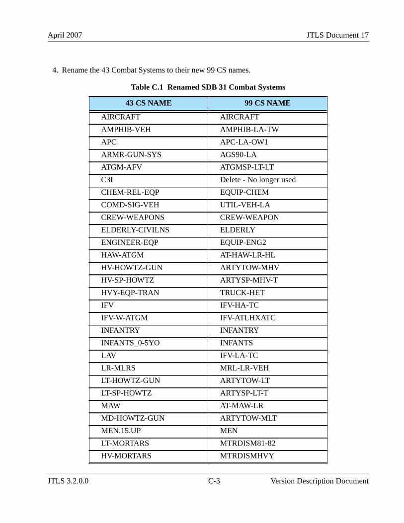
April 2007 JTLS Document 17
4. Rename the 43 Combat Systems to their new 99 CS names.
Table C.1 Renamed SDB 31 Combat Systems
43 CS NAME 99 CS NAME
AIRCRAFT AIRCRAFT
AMPHIB-VEH AMPHIB-LA-TW
APC APC-LA-OW1
ARMR-GUN-SYS AGS90-LA
ATGM-AFV ATGMSP-LT-LT
C3I Delete - No longer used
CHEM-REL-EQP EQUIP-CHEM
COMD-SIG-VEH UTIL-VEH-LA
CREW-WEAPONS CREW-WEAPON
ELDERLY-CIVILNS ELDERLY
ENGINEER-EQP EQUIP-ENG2
HAW-ATGM AT-HAW-LR-HL
HV-HOWTZ-GUN ARTYTOW-MHV
HV-SP-HOWTZ ARTYSP-MHV-T
HVY-EQP-TRAN TRUCK-HET
IFV IFV-HA-TC
IFV-W-ATGM IFV-ATLHXATC
INFANTRY INFANTRY
INFANTS_0-5YO INFANTS
LAV IFV-LA-TC
LR-MLRS MRL-LR-VEH
LT-HOWTZ-GUN ARTYTOW-LT
LT-SP-HOWTZ ARTYSP-LT-T
MAW AT-MAW-LR
MD-HOWTZ-GUN ARTYTOW-MLT
MEN.15.UP MEN
LT-MORTARS MTRDISM81-82
HV-MORTARS MTRDISMHVY
JTLS 3.2.0.0 C-3 Version Description Document
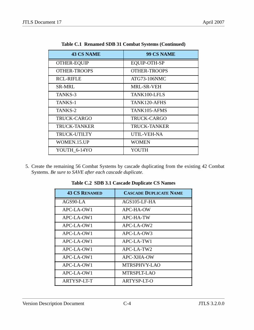
JTLS Document 17 April 2007
5. Create the remaining 56 Combat Systems by cascade duplicating from the existing 42 CombatSystems. Be sure to SAVE after each cascade duplicate.
OTHER-EQUIP EQUIP-OTH-SP
OTHER-TROOPS OTHER-TROOPS
RCL-RIFLE ATG73-106NMC
SR-MRL MRL-SR-VEH
TANKS-3 TANK100-LFLS
TANKS-1 TANK120-AFHS
TANKS-2 TANK105-AFMS
TRUCK-CARGO TRUCK-CARGO
TRUCK-TANKER TRUCK-TANKER
TRUCK-UTILTY UTIL-VEH-NA
WOMEN.15.UP WOMEN
YOUTH_6-14YO YOUTH
Table C.2 SDB 3.1 Cascade Duplicate CS Names
43 CS RENAMED CASCADE DUPLICATE NAME
AGS90-LA AGS105-LF-HA
APC-LA-OW1 APC-HA-OW
APC-LA-OW1 APC-HA-TW
APC-LA-OW1 APC-LA-OW2
APC-LA-OW1 APC-LA-OW3
APC-LA-OW1 APC-LA-TW1
APC-LA-OW1 APC-LA-TW2
APC-LA-OW1 APC-XHA-OW
APC-LA-OW1 MTRSPHVY-LAO
APC-LA-OW1 MTRSPLT-LAO
ARTYSP-LT-T ARTYSP-LT-O
Table C.1 Renamed SDB 31 Combat Systems (Continued)
43 CS NAME 99 CS NAME
Version Description Document C-4 JTLS 3.2.0.0
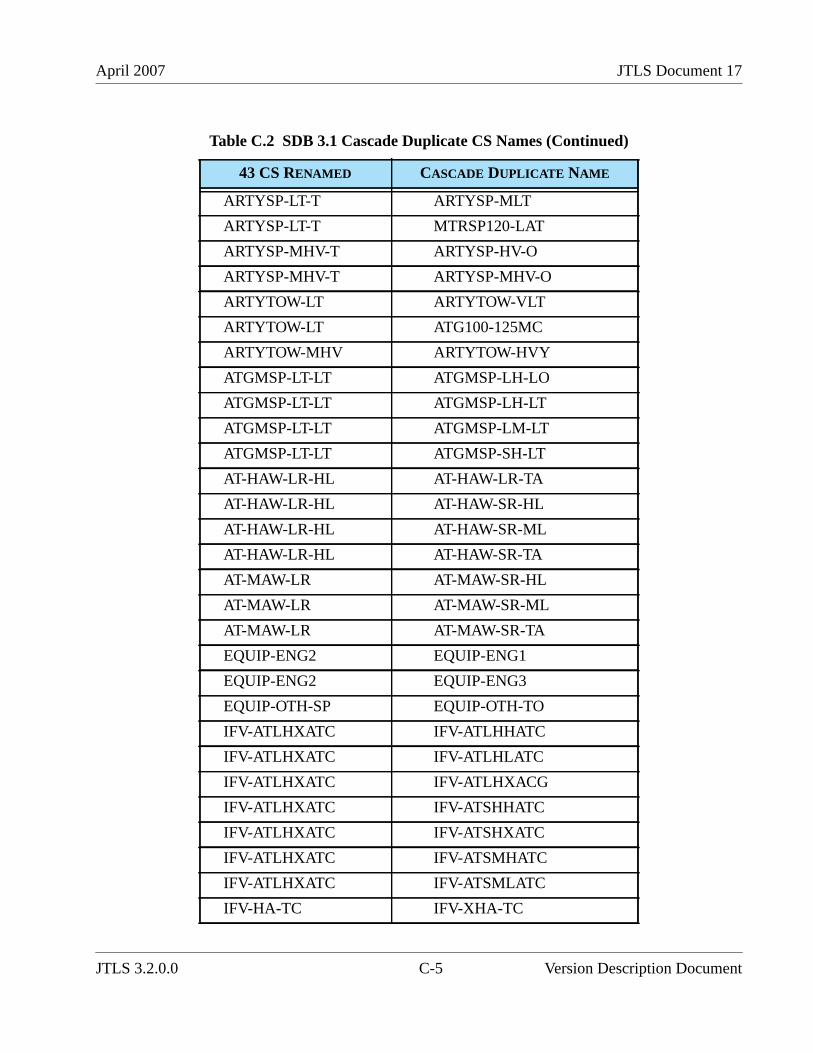
April 2007 JTLS Document 17
ARTYSP-LT-T ARTYSP-MLT
ARTYSP-LT-T MTRSP120-LAT
ARTYSP-MHV-T ARTYSP-HV-O
ARTYSP-MHV-T ARTYSP-MHV-O
ARTYTOW-LT ARTYTOW-VLT
ARTYTOW-LT ATG100-125MC
ARTYTOW-MHV ARTYTOW-HVY
ATGMSP-LT-LT ATGMSP-LH-LO
ATGMSP-LT-LT ATGMSP-LH-LT
ATGMSP-LT-LT ATGMSP-LM-LT
ATGMSP-LT-LT ATGMSP-SH-LT
AT-HAW-LR-HL AT-HAW-LR-TA
AT-HAW-LR-HL AT-HAW-SR-HL
AT-HAW-LR-HL AT-HAW-SR-ML
AT-HAW-LR-HL AT-HAW-SR-TA
AT-MAW-LR AT-MAW-SR-HL
AT-MAW-LR AT-MAW-SR-ML
AT-MAW-LR AT-MAW-SR-TA
EQUIP-ENG2 EQUIP-ENG1
EQUIP-ENG2 EQUIP-ENG3
EQUIP-OTH-SP EQUIP-OTH-TO
IFV-ATLHXATC IFV-ATLHHATC
IFV-ATLHXATC IFV-ATLHLATC
IFV-ATLHXATC IFV-ATLHXACG
IFV-ATLHXATC IFV-ATSHHATC
IFV-ATLHXATC IFV-ATSHXATC
IFV-ATLHXATC IFV-ATSMHATC
IFV-ATLHXATC IFV-ATSMLATC
IFV-HA-TC IFV-XHA-TC
Table C.2 SDB 3.1 Cascade Duplicate CS Names (Continued)
43 CS RENAMED CASCADE DUPLICATE NAME
JTLS 3.2.0.0 C-5 Version Description Document
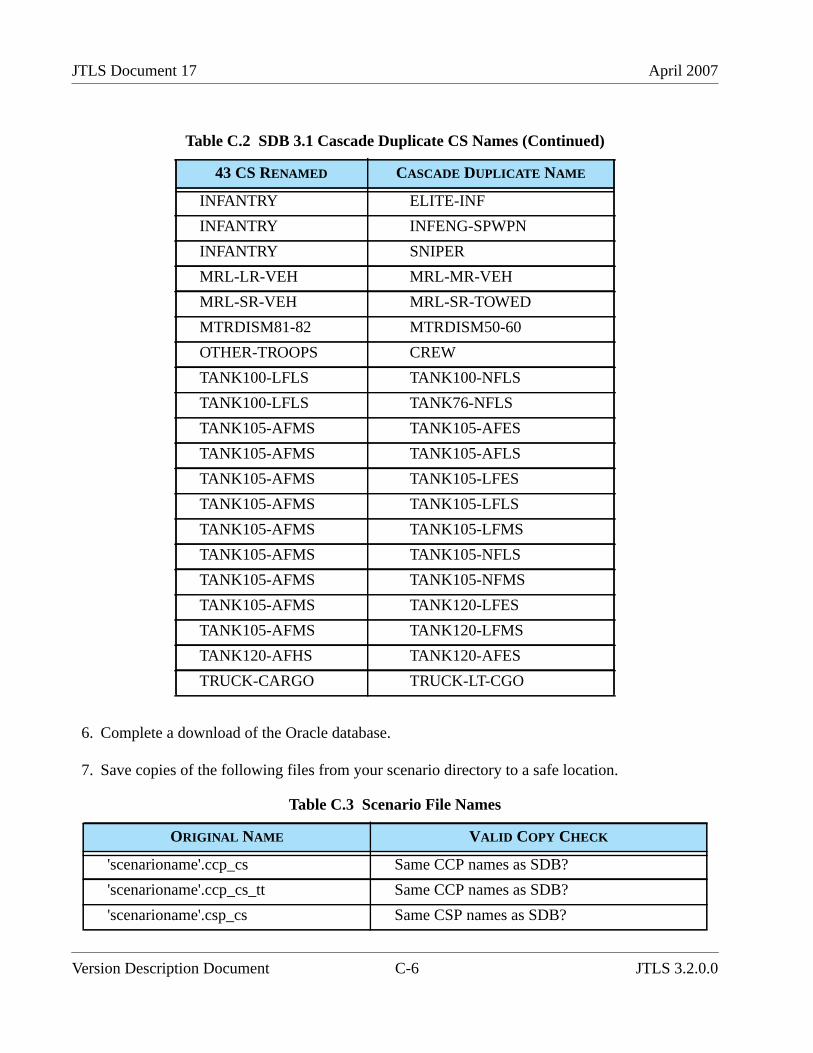
JTLS Document 17 April 2007
6. Complete a download of the Oracle database.
7. Save copies of the following files from your scenario directory to a safe location.
INFANTRY ELITE-INF
INFANTRY INFENG-SPWPN
INFANTRY SNIPER
MRL-LR-VEH MRL-MR-VEH
MRL-SR-VEH MRL-SR-TOWED
MTRDISM81-82 MTRDISM50-60
OTHER-TROOPS CREW
TANK100-LFLS TANK100-NFLS
TANK100-LFLS TANK76-NFLS
TANK105-AFMS TANK105-AFES
TANK105-AFMS TANK105-AFLS
TANK105-AFMS TANK105-LFES
TANK105-AFMS TANK105-LFLS
TANK105-AFMS TANK105-LFMS
TANK105-AFMS TANK105-NFLS
TANK105-AFMS TANK105-NFMS
TANK105-AFMS TANK120-LFES
TANK105-AFMS TANK120-LFMS
TANK120-AFHS TANK120-AFES
TRUCK-CARGO TRUCK-LT-CGO
Table C.3 Scenario File Names
ORIGINAL NAME VALID COPY CHECK
'scenarioname'.ccp_cs Same CCP names as SDB?
'scenarioname'.ccp_cs_tt Same CCP names as SDB?
'scenarioname'.csp_cs Same CSP names as SDB?
Table C.2 SDB 3.1 Cascade Duplicate CS Names (Continued)
43 CS RENAMED CASCADE DUPLICATE NAME
Version Description Document C-6 JTLS 3.2.0.0
April 2007 JTLS Document 17
8. Copy the files in the list above from SDB to your scenario with your scenario name.
9. If your answer is NO to the question in the Valid Copy Check column, edit the SDB file tomatch your scenario.
10.Add data for additional CSPs needed for your scenario.
11.Make changes to each TUP’s authorized Combat Systems to match the new 99 CS.
12.Make changes to each TUP’s Supply Categories based on the Combat System changes.
13.Make adjustments to personnel Combat Systems to reflect crew requirements.
14.Copy the new_tup_cs_score.tbl file from the SDB alterdata directory to your alterdata directory.
15.From the DDS Alter Database menu, select TUP and reset TUP CS Score. Select Load andModify TUP CS Score.
C.4 SUPPORTING EXISTING COMBAT SYSTEMS
This section provides instructions for users who choose to retain their existing set of CombatSystems.
'scenarioname'.csp_cs_mft Same CSP and Land Minefield names as SDB?
'scenarioname'.cs_tt
'scenarioname'.cs_tw Same Targetable Weapons as SDB?
'scenarioname'.eph
'scenarioname'.flp_cs Same FLP names as SDB?
'scenarioname'.flp_csp_cs Same FLP and CSP names as SDB?
'scenarioname'.fwl
'scenarioname'.fwl_cs
'scenarioname'.sp_cs Same SP names as SDB?
'scenarioname'.spec_cs
'scenarioname'.up_up
Table C.3 Scenario File Names (Continued)
ORIGINAL NAME VALID COPY CHECK
JTLS 3.2.0.0 C-7 Version Description Document
JTLS Document 17 April 2007
1. Lanchester coefficient data are still reduced. Since they are no longer indexed by FLP and SP,you must use the FLP and SP FWL modifiers to account for those differences. Typically, theOpposing Force FLP and SP resulted in the Opposing Force causing less attrition to other forceswhile taking more attrition from other forces. Using the same FLP and SP FWL modifier valueslisted in Section C.1. is recommended.
2. The CSP-CS data now include a Killer FWL Modifier and a Victim FWL Modifier. You mayprefer to change these MODIFIERS for less-capable systems in some CSPs. Note that a VictimFWL Modifier greater than 1.0 means that the associated Combat System will suffer morelosses.
C.5 REMAINING ENHANCEMENTS
This section describes data that have not been added or updated for this release.
SUP Combat Systems have not been changed to the new 99 Combat Systems. Minimal changes weremade to the NAVY_CSP that allow existing SUPs to function. SUP changes that include a newNAVY_CSP will be provided for a future JTLS release.
The ECP JTLS-2005-1480 Lifeboat Representation has not been fully implemented or tested for thisrelease. Therefore, no SUP has been assigned a Lifeboat HUP. If you choose to use this functionality,you must assign a Lifeboat HUP to the SUP of interest and change the SUP Lifeboat Mean Time ToDeploy, which is currently set to the default time of 1.0 minutes. Lifeboat HUPs have been addded;Lifeboat HUP names are identified by the inital characters LB.
SSM target subcategories now have an array of targetable weapons they can fire. New SSMsubcategories have been built for use by ships, but the SUPs have not been updated to use the newsubcategories. The current SUPs have the old SSM subcategories, which are still functional. Sincethere is no caliber for SSM targets, new supply categories for ship launched torpedoes and missileswill need to be added to control targetable weapon selection. We hope to do a major update of allSUPs in 2007 but that will depend on the priorities assigned by the government.
Version Description Document C-8 JTLS 3.2.0.0