Laser Ablated and RF Sputtered BaTiO3 Thin Films for Use in Superconducting RF MEM Switches
Upload
independentCategory
view
1download
0
Surface and Coatings Technology 116–119 (1999) 742–750www.elsevier.nl/locate/surfcoat
Variation of carbon concentration, ion energy, and ion currentdensity of magnetron-sputtered boron carbonitride films
S. Ulrich a,*, A. Kratzsch a, H. Leiste a, M. Stuber a, P. Schloßmacher a, H. Holleck a,J. Binder b, D. Schild c, S. Westermeyer d, P. Becker d, H. Oechsner d
a Forschungszentrum Karlsruhe, Institut fur Materialforschung I, Erwin-Schrodinger-Str., D-67663 Kaiserslautern, Germanyb Forschungszentrum Karlsruhe, Institut fur Materialforschung III, Erwin-Schrodinger-Str., D-67663 Kaiserslautern, Germany
c Institut fur Nukleare Entsorgungstechnik, Postfach 3640, D-76021 Karlsruhe, Germanyd IFOS, Erwin-Schrodinger-Str., D-67663 Kaiserslautern, Germany
Abstract
Diamond, cubic boron nitride and also ternary materials consisting of boron, carbon and nitrogen exhibit an extraordinarycombination of extreme mechanical and physical properties due to their bonding characteristics and crystal structure. This resultsin a high application potential in protective and functional layers. Taking into account the special properties of these phases, thecompositions inside the BMCMN concentration triangle are of particular interest, as novel superhard phases are expected tooccur. In this work, boron carbonitride films of variable compositions were produced by means of reactive radio frequency (r.f.)magnetron sputtering in combination with ion bombardment. Examination up to now has revealed carbon concentrations between16 and 27 at.% and a boron/nitrogen ratio varying between 1.08 and 1.26. For a carbon concentration of 12 at.%, the ion energywas varied between 125 and 300 eV at a constant ratio of ions to film-forming particles, Wion/WBCN. Peak analyses of thedifferentiated Auger spectra gave no indication of any generation of BMC bonds. The contents of the h-BN phase and c-BNphase as well as the threshold conditions and optimum conditions for c-BN formation were investigated for 8 energy variationsat 18 values of Wion/WBCN between 0.1 and 0.5. IR spectroscopy showed that the maximum fraction of sp3-hybrid BN bondsreached approximately 61% at an ion energy of 200 eV and an ion current density of 0.5 mA cm−2. The film properties can bestrongly influenced by the flux ratio of ions to film-forming particles, Wion/WBCN, and by the ion energy. Generally, the effect onthe film properties by increasing the flux ratio Wion/WBCN or by decreasing the ion energy is often the same. This statement isdiscussed theoretically. © 1999 Published by Elsevier Science S.A. All rights reserved.
Keywords: Boron carbonitride films; BMCMN
1. Introduction This paper is devoted to the interesting area of ternaryBCN materials.
The BMCMN ternary system contains the superhardmaterials, DLC and c-BN. Production of these materialsby PVD processes requires intense ion bombardment.
2. ExperimentalThe subplantation effect [1–3], on the one hand, causesmaterial densification and, consequently, transition from
The films are deposited by r.f. magnetron sputteringthe predominately sp2 to sp3 hybridized bonding states(13.56 MHz) of BC
xNy
targets of different compositionsand, on the other hand, produces residual stresses. Oneproduced in-house. The substrate material used wasmajor difference is the polar bonding fraction in BNsilicon. All films were deposited in a reactive gas atmo-films, which supports the formation of a nanocrystallinesphere containing 30 vol.% of argon and 70 vol.% ofcubic phase. The absence of this polar bonding fractionnitrogen at a total working gas pressure of p=0.35 Pain carbon films results in an amorphous phase formation.and a target–substrate distance of dTS=33 mm.Moreover, the substrate temperature, Ts, of 250°C andthe r.f. target power, Pr.f., of 400 W were kept constant.* Corresponding author.
E-mail address: [email protected] (S. Ulrich) The targets were made of a powder mixture of
0257-8972/99/$ – see front matter © 1999 Published by Elsevier Science S.A. All rights reserved.PII: S0257-8972 ( 99 ) 00353-9

743S. Ulrich et al. / Surface and Coatings Technology 116–119 (1999) 742–750
Fig. 1. List of relative dependences of process parameters on film compositions.
hexagonal boron nitride and carbon. These powderswere subjected to coaxial hot compaction in a graphitematrix under nitrogen at 1750°C and bonded to a targetcarrier. The target composition (BCN- and4BN · 3C-target) is mentioned in Section 3. Film depos-ition took place on silicon substrates with a (100)orientation, arranged on a circle 3 cm in front of thetarget at a substrate temperature of about 250°C in anargon/nitrogen atmosphere at a total pressure of 0.35 Pa.The energy of the argon and nitrogen ions was variedsystematically in the range of 25 eV (plasma potential )to 300 eV by applying a r.f. substrate bias. The composi-tion of the films was determined by means of AES and Fig. 2. IR transmission spectra of BCN films with 12 at.% of carbon
for various flux ratios, Wion/WBCN (Ts=250°C; Eion=225 eV;XPS. The film structure was investigated by IR spectro-Pr.f.=400 W; p=0.35 Pa (Ar/N2: 30/70 vol.%); dTS=33 mm; r=scopy, XPS, TEM and ellipsometric measurements. XPS32 mm).spectra were acquired using monochromated AlKa
X-rays. The binding energy scale of the spectrometer
was calibrated at the lines of Au 4f7/2 (83.98 eV ),Table 1 Ag 3d5/2 (368.26 eV ) and Cu 2p3/2 (932.67 eV ). TheConcentration of elements in a BCN film as determined by AES and binding energies of the photoelectron lines of the sampleXPS, in each case, after surface cleaning by an Ar ion beam (1 keV ):
are charge-referenced to the C 1s line at 284.8 eV.[Ts=250°C; Eion=225 eV, Pr.f.=400 W; p=0.35 Pa (Ar/N2:30/70 vol.%); dTS=33 mm; r=32 mm]
Element Element concentration Element concentration 3. Results and discussion(at.%) from AES (at.%) from XPSmeasurements measurements
The composition of the BCN films was examined byB 45.4 44.1 AES and XPS as a function of the substrate temperatureC 13.3 8.5 (Tsub) the ion energy (Eion) the nitrogen fraction in theN 39.3 43.1 working gas, and the flux ratio of ions to film-formingO 2.0 4.3
particles. The composition appears to depend on the

744 S. Ulrich et al. / Surface and Coatings Technology 116–119 (1999) 742–750
Fig. 3. High-resolution XPS spectra of two BCN films with the associated deconvolution (Gauß–Lorenz curves) for the B 1s, C 1s, N 1s, and O 1selement lines deposited at various flux ratios, Wion/WBCN=0.14 and Wion/WBCN=0.43 (Ts=250°C; Eion=225 eV; Pr.f.=400 W; p=0.35 Pa (Ar/N2:30/70 vol.%); dTS=33 mm; r=32 mm).

745S. Ulrich et al. / Surface and Coatings Technology 116–119 (1999) 742–750
gen atoms. The results obtained with the two targetsused (BCN target, 4BN · 3C target) are taken intoaccount.
Substrate temperatures above 200°C result in a slightdecrease in carbon fraction during film deposition(Fig. 1). With increasing substrate temperature, the B/Nratio is seen to increase slightly. One reason could bethe decomposition with depleted nitrogen. Anotherargument is attributed to the formation of volatilecompounds of carbon and nitrogen at elevated temper-atures. The production of such CMN bonds is alsosupported by the observation that experiments with asegmented BN/4BN · 3C target in a pure argon atmo-sphere resulted in carbon poisoning of the BN half ofthe target, which was expressed as a discoloration ofthe BN half of the target from snow-white to ivory.This was not observed when nitrogen was present in theFig. 4. Atomic concentrations of the line fractions resulting from curveworking gas. An increase in ion energy also provoked adeconvolution of two BCN films with Wion/WBCN=0.14 anddecrease in the carbon fraction in the films from energiesWion/WBCN=0.43 (Ts=250°C; Eion=225 eV; Pr.f.=400 W; p=0.35 Pa
(Ar/N2: 30/70 vol.%); dTS=33 mm; r=32 mm), plotted over the mean of 275 eV onward (Fig. 1). However, the B/N ratiovalues of the bonding energies and the associated bonding partners. remained almost constant. This is attributed to a prefe-
rential removal of carbon. An explanation is found byusing XPS to examine the types of bonding encounteredand their frequency. Thus, BMN bonds dominate, fol-lowed by BMNMC and CMC bonds. However, thereare no BMC bonds. If a carbon atom hits the solidsurface of the growing film, CMC and CMN bondsmay form. The latter type of bond is volatile if nonitrogen is bonded and, consequently, can easily besputtered with increasing ion energy. However, boronencounters good conditions for a reaction on the solidsurface because of the surplus of nitrogen provided bythe working gas atmosphere. Nitrogen is incorporatedin the film only to the extent in which boron and carbonare available as reaction partners. Otherwise, N2 is likelyto form, which is inert and also volatile. Increasingfractions of nitrogen in the working gas cause a decreasein the carbon fraction in the films. The B/N ratiodecreases considerably in the beginning, approaching alimit. The reason can be seen in an increased incorpora-tion of nitrogen in the film as the supply of nitrogenincreases. The ratio of fluxes does not influence thecomposition of the film, i.e. the number of bombardingions per particle deposited does not affect selectiveprocesses in film deposition within the range of parame-ters examined.
A qualitative study of BCN films will be discussedFig. 5. HRTEM image of a BCN film with the direction of transmission below. These films were deposited with a BCN targetnormal to the surface of the film (Ts=250°C; Eion=200 eV; with a composition of B:C:N=1:0.75:1 in anWion/WBCN=0.43; Pr.f.=400 W; p=0.35 Pa (Ar/N2: 30/70 vol.%); argon/nitrogen atmosphere (Ar:N2=30:70 vol.%).dTS=33 mm; r=32 mm). Table 1 shows the concentration of elements in a
BCN film as determined by AES and XPS, the filmnitrogen fraction in the working gas, the substrate having been deposited at an ion energy of 225 eV and atemperature, and the ion energy of the bombarding flux ratio, Wion/WBCN , of 0.43. The results are in goodions, but not on the flux ratio. Fig. 1 shows the qualita- agreement. If it is also taken into account that bombard-tive relations among the depostition parameters and the ment by Ar ions produces nitrogen depletion and boron
enrichment in the surface as a result of preferentialcarbon fraction, and the ratio between boron and nitro-

746 S. Ulrich et al. / Surface and Coatings Technology 116–119 (1999) 742–750
(a) (b)
Fig. 6. Bright-field (a) and dark-field (b) images of a BCN film with the direction of transmission normal to the surface of the film(Ts=250°C; Eion=200 eV; Wion/WBCN=0.43; Pr.f.=400 W; p=0.35 Pa (Ar/N2: 30/70 vol.%); dTS=33 mm; r=32 mm).
sputtering, even slight differences between the two ana- decreases. The absorption band cannot be attributedclearly. It may correspond to the TO mode of cubiclytical techniques can be understood properly. After
having analyzed the composition, let us now look at the boron nitride, but it could also be attributed to boroncarbide. For a flux ratio of 0.14, an absorption atbonding situation and the phases of these BCN films.
Fig. 2 shows the IR transmission spectra of BCN 2180 cm−1 can be found in the transmission spectrum,which corresponds to a CON triple bond.films containing approximately 12 at.% of carbon depos-
ited at an ion energy of 225 eV and different flux ratios, The deconvoluted XPS spectra of two BCN filmsdiffering in the flux ratio, Wion/WBCN, involved in theWion/WBCN. For easier comparison, the spectra are stag-
gered vertically. process of film production, are shown in Fig. 3. As isindicated by the spectra and their deconvolution, bothAll transmission spectra exhibit both BMN streching
oscillations at approximately 1400 cm−1 and BMNMB films have very similar types of bonding. Boron (B 1s)exhibits a high affinity to nitrogen (190.7 eV ). However,bending oscillations at approx 780 cm−1 due to
sp2-bonded BN, which are typical of h-BN and/or r-BN carbidic bonding fractions are absent, as would beexpected to exist for B4C at 188.4 eV [10]. Consequently,[7]. From a flux ratio of Wion/WBCN=0.23, an absorption
band can be seen forming at 1100 cm−1, which becomes the IR absorption at 1100 cm−1 measured in the sectionabove can be attributed unequivocally to the TO modemore pronounced as Wion/WBCN increases, reaching a
peak at 0.32, and decreasing again at still higher values. of c-BN. Also absent are bonds of the BMB type, whosevalues for B 1s should be in the range of 187.3 eV [10]A peak shift towards higher wave numbers is seen,
which becomes less pronounced as the flux ratio to 188.1 eV [11]. Carbon (C 1s) is mainly bound by
Fig. 7. Bonding characteristics and phases in phase separation in BCN films.

747S. Ulrich et al. / Surface and Coatings Technology 116–119 (1999) 742–750
single CMC bonds (284.8 eV ). The N 1s element line is ing occurring revealed that these depend on the parame-indicative of a large share of NMB bonds (398.24 eV ). ters of film deposition. The dominating parameters,Moreover, NMC bonds were found at 399.31 and besides substrate temperature, are the ion energy and397.07 eV. The latter correspond to a triple bond. The the flux ratio. Whenever a certain level of ion energyoxygen line can mainly be attributed bonds of the BMO and flux ratio was exceeded, BNMsp3 bonds were seenand CMOMN (532.50 eV ) and OMH and OMC forms, to be produced. As this was the TO mode of c-BN, it isrespectively (531.16 eV ). indicative of the existence of sp3-hybridized BN crystal-
With the elemental compositions determined from lites (c-BN) [5]. These were confirmed by HRTEMthe associated survey spectra, the corresponding atomic images. Below this characteristic, only BNMsp2 bondsconcentrations were calculated for the B 1s, C 1s, N1s, were detected, which were attributed to a hexagonaland O 1s line fractions. The result is shown in Fig. 4. phase by XRD and TEM examination. No BMC bondsThis figure clearly shows that both films have mainly were found either for sp2-hybridized or forBMN bonds, followed by CMC bonds and NMC and sp3-hybridized BN bonding regions by means of XPS.BMNMC bonds, respectively. In addition, relatively The dominant types are BMN, BMNMC, and CMCsmall fractions of CMN, CMO, and BMO bonds exist. bonds. Part of the latter can be attributed to surface
Fig. 5 is the high-resolution TEM image of a 50– contamination by graphite, which is typical of the sur-100 nm thick BCN film with the direction of transmis- faces of solids. For the case of BNMsp3 bonds occurring,sion normal to the film surface (deposition parameters: phase separation must be expected to exist betweenTs=250°C; Eion=200 eV; Wion/WBCN=0.43; Pr.f.=400 W; nanocrystalline cubic BMN bonding regions and amor-p=0.35 Pa (Ar/N2: 30/70 vol.%); dTS=33 mm; r= phous CMC bonding regions with NMC bonds at the32 mm; film composition 12 at.% carbon and B/N#1.1). phase boundaries, which is a general statement for theThree regions can be distinguished in the high-resolution parameters studied in this work. Under the assumptionimage. There are (002) net planes of h-BCN (interplanar of a carbon content of 12 at.% in the films, and a c-BNdistance: 0.341 nm), some of which are highly defective. crystallite size between 4 and 20 nm, the boundary layerIn between, there are net planes whose distance was between two c-BN crystallites can be estimated to bedetermined to be 0.206 nm. They can be attributed to below 0.33 nm, according to Schier [6 ]. It is not possible,the (111) net planes of cubic boron nitride. A third therefore, that crystallites are completely surrounded byregion has no net planes. It must be assumed that this a nanocrystalline amorphous CMC phase. Fig. 7means the existence of crystallites with adverse orienta- illustrates the bonding characteristics at the interfacetion, or of an amorphous phase. It should be noted between two c-BN crystallites.that, as a consequence of the imaging technique, no
The conditions under which the c-BN phase is pro-information can be given about the distribution ofduced will be examined below. Fig. 8 shows the resultscrystallites as a function of the film thickness.of a parameter study of the occurrence of BN bondBright-field and dark-field images of the film weretypes in BCN films (12 at.% carbon an B/N #1.1) as amade to study the shape and size of crystallites. Thefunction of ion energy and the flux ratio, Wion/WBCN.results are shown in Fig. 6(a) and (b). The bright-fieldThe open circles indicate regions in which the BN bondsimage [Fig. 6(a)] shows uniformly distributed grainyexist in an sp2 configuration. Solid circles denote regionsregions of different levels of brightness. The reason isin which at least 3% of the BN bonds arethe different diffraction of the electron beam by indivi-sp3-configured. The rhombus indicates the maximumdual crystallites, which is very pronounced in the dark-
field case. Bright, fiber-like regions can be seen betweenthe crystallites. These are grain boundaries. Their bright-ness is indicative of poor diffraction of the electronbeam and, hence, of amorphous regions and regions oflower density, respectively. The dark-field image[Fig. 6(b)] was obtained from the diffraction rings ofthe (111) net plane of c-BN, and the (100) net plane ofh-BCN [4]. Consequently, bright regions representplaces where these net planes are aligned normal to thesurface of the film. The crystallite size in the planeparallel to the surface of the film accordingly can beestimated at 4–20 nm. No distinction between the twophases was possible because of the similar interplanardistances, d [d(100)h-BCN=0.2135 nm; d(111)c-BN= Fig. 8. Types of BN bonds in BCN films as a function of the ion0.2087 nm]. energy, Eion, and the flux ratio, Wion/WBCN, and the maximum frac-
The findings can be summarized as follows. IR tion of BNMsp3 bonds (Ts=250°C; Pr.f.=400 W; p=0.35 Pa(Ar/N2: 30/70 vol.%); dTS=33 mm; r=32 mm).spectroscopy studies of the types and fractions of bond-

748 S. Ulrich et al. / Surface and Coatings Technology 116–119 (1999) 742–750
Fig. 9. Fraction of BNMsp3 bonds in BCN films deposited at ion energies of 150 eV (a), 175 eV (b), 200 eV (c), 225 eV (d), 250 eV (e), and 300 eV(f ) as a function of the flux ratio [Ts=250°C; Pr.f.=400 W; p=0.35 Pa (Ar/N2: 30/70 vol.%)].
Fig. 11. Comparison of deposited BN phases in BN and BCN films asFig. 10. Fraction of BNMsp3 bonds in BCN films as a function of the a function of the ion energy and the ratio of ions to boron atoms, F
(according to data from Refs. [7] and [9]). The black symbols indicateenergy input, k, of the cladding ions into the growing film[Ts=250°C; p=0.35 Pa (Ar/N2:30/70 vol.%)]. a minimum c-BN fraction of 3%.
749S. Ulrich et al. / Surface and Coatings Technology 116–119 (1999) 742–750
BNMsp3 to BNMsp2 bond fraction for the respectiveion energy.
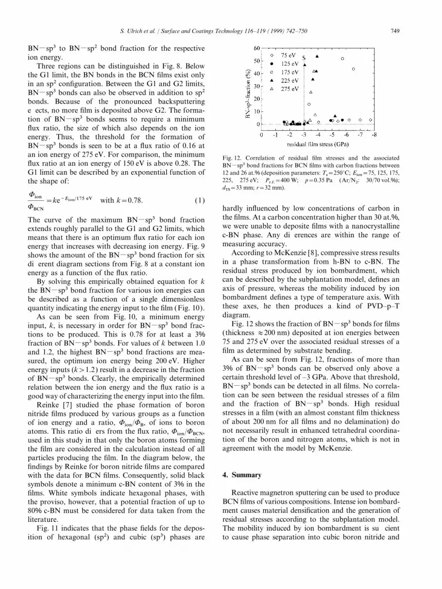
Three regions can be distinguished in Fig. 8. Belowthe G1 limit, the BN bonds in the BCN films exist onlyin an sp2 configuration. Between the G1 and G2 limits,BNMsp3 bonds can also be observed in addition to sp2bonds. Because of the pronounced backsputteringeffects, no more film is deposited above G2. The forma-tion of BNMsp3 bonds seems to require a minimumflux ratio, the size of which also depends on the ionenergy. Thus, the threshold for the formation ofBNMsp3 bonds is seen to be at a flux ratio of 0.16 atan ion energy of 275 eV. For comparison, the minimum Fig. 12. Correlation of residual film stresses and the associatedflux ratio at an ion energy of 150 eV is above 0.28. The BNMsp3 bond fractions for BCN films with carbon fractions betweenG1 limit can be described by an exponential function of 12 and 26 at.% (deposition parameters: Ts=250°C; Eion=75, 125, 175,
225, 275 eV; Pr.f.=400 W; p=0.35 Pa (Ar/N2: 30/70 vol.%);the shape of:dTS=33 mm; r=32 mm).
WionWBCN
=ke−Eion/175 eV with k=0.78. (1)
hardly influenced by low concentrations of carbon inthe films. At a carbon concentration higher than 30 at.%,The curve of the maximum BNMsp3 bond fractionwe were unable to deposite films with a nanocrystallineextends roughly parallel to the G1 and G2 limits, whichc-BN phase. Any differences are within the range ofmeans that there is an optimum flux ratio for each ionmeasuring accuracy.energy that increases with decreasing ion energy. Fig. 9
According to McKenzie [8], compressive stress resultsshows the amount of the BNMsp3 bond fraction for sixin a phase transformation from h-BN to c-BN. Thedifferent diagram sections from Fig. 8 at a constant ionresidual stress produced by ion bombardment, whichenergy as a function of the flux ratio.can be described by the subplantation model, defines anBy solving this empirically obtained equation for kaxis of pressure, whereas the mobility induced by ionthe BNMsp3 bond fraction for various ion energies canbombardment defines a type of temperature axis. Withbe described as a function of a single dimensionlessthese axes, he then produces a kind of PVD–p–Tquantity indicating the energy input to the film (Fig. 10).diagram.As can be seen from Fig. 10, a minimum energy
Fig. 12 shows the fraction of BNMsp3 bonds for filmsinput, k, is necessary in order for BNMsp3 bond frac-(thickness #200 nm) deposited at ion energies betweentions to be produced. This is 0.78 for at least a 3%75 and 275 eV over the associated residual stresses of afraction of BNMsp3 bonds. For values of k between 1.0film as determined by substrate bending.and 1.2, the highest BNMsp3 bond fractions are mea-
As can be seen from Fig. 12, fractions of more thansured, the optimum ion energy being 200 eV. Higher3% of BNMsp3 bonds can be observed only above aenergy inputs (k>1.2) result in a decrease in the fractioncertain threshold level of –3 GPa. Above that threshold,of BNMsp3 bonds. Clearly, the empirically determinedBNMsp3 bonds can be detected in all films. No correla-relation between the ion energy and the flux ratio is ation can be seen between the residual stresses of a filmgood way of characterizing the energy input into the film.and the fraction of BNMsp3 bonds. High residualReinke [7] studied the phase formation of boronstresses in a film (with an almost constant film thicknessnitride films produced by various groups as a functionof about 200 nm for all films and no delamination) doof ion energy and a ratio, Wion/WB, of ions to boronnot necessarily result in enhanced tetrahedral coordina-atoms. This ratio differs from the flux ratio, Wion/WBCN,tion of the boron and nitrogen atoms, which is not inused in this study in that only the boron atoms formingagreement with the model by McKenzie.the film are considered in the calculation instead of all
particles producing the film. In the diagram below, thefindings by Reinke for boron nitride films are compared
4. Summarywith the data for BCN films. Consequently, solid blacksymbols denote a minimum c-BN content of 3% in the
Reactive magnetron sputtering can be used to producefilms. White symbols indicate hexagonal phases, withBCN films of various compositions. Intense ion bombard-the proviso, however, that a potential fraction of up toment causes material densification and the generation of80% c-BN must be considered for data taken from theresidual stresses according to the subplantation model.literature.The mobility induced by ion bombardment is sufficientFig. 11 indicates that the phase fields for the depos-
ition of hexagonal (sp2) and cubic (sp3) phases are to cause phase separation into cubic boron nitride and

750 S. Ulrich et al. / Surface and Coatings Technology 116–119 (1999) 742–750
[3] C.A. Davis, Thin Solid Films 226 (1993) 30.carbon, as proven by a combination of various analytical[4] A. Badzian, Mater. Res. Bull. 16 (1981) 1385.techniques. For an energy range between 125 and 300 eV,[5] W. Dworschak, Thesis, Universitat Kaiserslautern, Kaiserslaut-
and a flux ratio of ions to film forming particles of ern, 1996.0.1:0.5, the transitions from hexagonal to cubic structures, [6 ] V. Schier, H.-J. Michael, J. Halbritter, Fresenius J. Anal. Chem.
364 (1993) 227.the region of maximum compaction, and the backsputter-[7] S. Reinke, Thesis, Universitat Gesamthochschule Kassel,ing limits have been described analytically.
Kassel, 1996.[8] D.R. McKenzie, W.D. McFall, W.G. Sainty, C.A. Davis, R.E.
Collins, Diamond Relat. Mater. 2 (1995) 970.[9] S. Ulrich, J. Scherer, J. Schwan, I. Barzen, M. Scheib, H. Ehrh-References
ardt, Appl. Phys. Lett. 68 (1996) 909.[10] H. Kunzl, P. Gantenbein, R. Steiner, P. Oelhafen, Fres. J. Anal.
[1] J. Robertson, Diamond Relat. Mater. 3 (1994) 361. Chem. 346 (1993) 41.[2] Y. Lifshitz, S.R. Kasi, J.W. Rabalais, W. Eckstein, Phys. Rev. B [11] D.N. Hendrickson, J.M. Hollander, W.L. Jolly, Inorg. Chem. 9
(1970) 612.4 (1990) 10 468.
Copyright © 2022 FDOKUMEN