Valves in sandwich plate design Nominal size 6 - HYDAC
24
DESCRIPTION Valves in sandwich plate design Nominal size 6 HYDAC valves in sandwich plate design in nominal size 6 enable modular design of the hydraulic control via stacked valve assembly. We offer them as pressure reducing and pressure relief valves for pressure control and as needle or flow valves with bypass check valve for flow control. Furthermore, the sandwich plates are available as check valve for direction control, pilot-to-open and non-pilot- to-open, and as pressure compensator to realise the flow control function. Mounting elements are dependent on the modular design of your hydraulic control and are thus not included in delivery. EN 5.249.27. 3/08.21 1 • Available with pressure, flow, check and pressure compensator function Modular design of the hydraulic control • Interface to ISO 4401-03-02-0-05 (Cetop 4.2-4-03-350) FEATURES TECHNICAL DATA ¹ General specifications MTTF d According to EN ISO 13849-1:2015 chart C1 & C2 Ambient temperature [°C] -20 to +60 Installation no orientation restrictions Casing: steel (ZW-RV10 only) Name plate: aluminium Surface coating Valve housing: phosphate-plated Hydraulic specifications Operating pressure [bar] 350 Operating fluid Hydraulic oil to DIN 51524 part 1, 2 and 3 Temp. range of operating fluid [°C] -20 to +80 Viscosity [mm²/s] 10 to 400 Permitted contamination level of operating fluid class 20/18/15 to ISO 4406 Sealing material NBR, FKM (standard) ¹ see “Conditions and Instructions for Valves” in brochure 53.000 Nominal size 6 up to 75 l/min up to 350 bar
-
Upload
khangminh22 -
Category
Documents
-
view
3 -
download
0
Transcript of Valves in sandwich plate design Nominal size 6 - HYDAC

DESCRIPTION
Valves in sandwich plate designNominal size 6
HYDAC valves in sandwich plate design in nominal size 6 enable modular design of the hydraulic control via stacked valve assembly.We offer them as pressure reducing and pressure relief valves for pressure control and as needle or flow valves with bypass check valve for flow control.
Furthermore, the sandwich plates are available as check valve for direction control, pilot-to-open and non-pilot-to-open, and as pressure compensator to realise the flow control function.
Mounting elements are dependent on the modular design of your hydraulic control and are thus not included in delivery.
EN
5.24
9.27
. 3/
08.2
1
1
• Available with pressure, flow, check and pressure compensator functionModular design of the hydraulic control
• Interface to ISO 4401-03-02-0-05 (Cetop 4.2-4-03-350)
FEATURES
TECHNICAL DATA ¹General specificationsMTTFd According to EN ISO 13849-1:2015
chart C1 & C2 Ambient temperature [°C] -20 to +60Installation no orientation restrictions
Casing: steel (ZW-RV10 only)Name plate: aluminium
Surface coating Valve housing: phosphate-platedHydraulic specificationsOperating pressure [bar] 350 Operating fluid Hydraulic oil to DIN 51524 part 1, 2
and 3 Temp. range of operating fluid [°C] -20 to +80
Viscosity [mm²/s] 10 to 400Permitted contamination levelof operating fluid
class 20/18/15 to ISO 4406
Sealing material NBR, FKM (standard)¹ see “Conditions and Instructions for Valves” in brochure 53.000
Nominal size 6up to 75 l/minup to 350 bar

Directional valve
Pressure reducing valves page 4
Pressure relief valves page 7
Needle valves page 13
Pressure compensators page 10
ZW-DM06…PT
ZW-DM06…PB
ZW-DM06…PA
ZW-DM06…AB
ZW-DM06…AT
ZW-DM06…BT
ZW-DM06…ABT
ZW-DM06…PT
ZW-DW06…PAB…V
ZW-DW06…PAB
ZW-DW06…PTAB…V
ZW-DW06…PTAB
ZW-SDR06…AA
ZW-SDR06…AB
ZW-SDR06…AAB
ZW-SDR06…ZAB
EN
5.2
49.2
7. 3
/08.
21
2
CONTENTS
~ ~ ~ ~
A BTP

Flow control valves page 16
Check valves pilot-to-open page 19
Check valves page 22
ZW-2SR06…AA
ZW-2SR06…AB
ZW-2SR06…AAB
ZW-RP06…AA
ZW-RP06…AAB
ZW-RP06…AB
ZW-RV06…A
ZW-RV06…B
ZW-RV06…P
ZW-RV06…T
ZW-RV06…AB
ZW-RV06…PT
Accessories page 24
EN
5.2
49.2
7. 3
/08.
21
3
Directional valve
CONTENTS
~ ~ ~ ~
A BTP

MODEL CODE
ZW-DM 06 - 01 - PA 035 V - N
TypePressure reducing valve in sandwich plate design, direct-acting
Nominal size6
Series01 = specified by manufacturer
Spool symbolPA = pressure control in port APB = pressure control in port BPT = pressure control in port T
Pressure ranges035 = 3 to 35 bar070 = 10 to 70 bar140 = 30 to 140 bar280 = 60 to 280 bar
Adjustment typesV = adjustable using toolK = adjustment knob (optional)
Sealing materialN = NBR V = FKM (standard)
PRESSURE REDUCING VALVE IN SANDWICH PLATE DESIGNZW – DM06
EN
5.2
49.2
7. 3
/08.
21
4
SUPPLEMENTARY TECHNICAL DATAGeneral specificationsWeight [kg] 1.4Hydraulic specificationsTank pressure [bar] Port T: pmax = 10Flow rate max. [l/min] 50 in controlled port
75 in free portLeakage [l/min] ≤ 0.08

SECTION VIEW
SPOOL TYPES / SYMBOLS
FUNCTIONThe direct-acting pressure reducing valve in sandwich plate design in nominal size 6 is used to reduce the inlet pressure at P2 to a smaller outlet pressure P1. The pressure tapping for the reduced pressure is designed differently depending on the symbol:- reduced pressure in line A PA- reduced pressure in line B PB- reduced pressure in line P PT
The outlet pressure P1 can be tapped at measuring port (M).
HintIn designs PA and PB, the pressure losses of the subsequent components must be considered when selecting the inlet pressure.
PT PB PA
P1
P2
EN
5.2
49.2
7. 3
/08.
21
5

DIMENSIONS
PERFORMANCEmeasured at v = 36 mm²/s and Toil = 50°C
Control Pressure drop
Interface to ISO 4401-03-02-0-05 (Cetop 4.2-4-03-350)
280
1407035
Pre
ssur
e p
[bar
]
P → T P2→ P1
Flow rate Q [l/min]
Manometer port1/4“ BSP
Fixing screw size 17Turning clockwise increases the pressure.
EN
5.2
49.2
7. 3
/08.
21
6
Δp
[bar
]
Flow rate Q [l/min]
P2→ P1
A2→ A1B2→ B1T2→ T1
Optional with adjustment type K (adjustment knob)(Press and turn simultaneously during actuation)

MODEL CODE
ZW-DB 06 - 01 - AB 70 V - N
TypePressure relief valve in sandwich plate design, pilot-operated
Nominal size6
Series01 = specified by manufacturer
Spool symbolAB = pressure relief in port B, meter-out in port AAT = pressure relief in port A, meter-out in port TBT = pressure relief in port B, meter-out in port TPT = pressure relief in port P, meter-out in port TABT = pressure relief in port A and B, meter-out in port T
Pressure ranges070 = up to 70 bar140 = up to 140 bar210 = up to 210 bar350 = up to 350 bar
Adjustment typesV = adjustable using tool
Sealing materialN = NBR V = FKM (standard)
PRESSURE RELIEF VALVE IN SANDWICH PLATE DESIGNZW – DB06
EN
5.2
49.2
7. 3
/08.
21
7
SUPPLEMENTARY TECHNICAL DATAGeneral specificationsWeight [kg] 1.4
2.1 (symbol ABT only)Hydraulic specificationsFlow rate max. [l/min] 75

SECTION VIEWExample PT
SPOOL TYPES / SYMBOLS
FUNCTIONThe pressure relief valve is a pilot-operated spool valve in sandwich plate design in nominal size 6, which limits the pressure in the system. If the pressure at port P exceeds the pressure setting, the pilot stage opens, so a small flow flows to the tank via pilotstage. Because of the resulting pressure difference, the main piston moves towards the return spring and allows flow from port P to T.
AB AT BT
ABT PT
T1P1
P2 T2
EN
5.2
49.2
7. 3
/08.
21
8

DIMENSIONS
PERFORMANCEmeasured at v = 36 mm²/s and Toil = 50°C
Control Pressure drop
Interface to ISO 4401-03-02-0-05
1) Controlled port, symbol PT, AT, BT2) Controlled port, symbol AB, ABT3) Free port
p [b
ar]
Flow rate Q [l/min]
p [b
ar]
Flow rate Q [l/min]
Symbol AT
Symbol AB, ABT
Symbol PT, BT
350
210
70
140
EN
5.2
49.2
7. 3
/08.
21
9

MODEL CODE
ZW-DW 06 - 01 - PAB 33 V - N
TypePressure compensator in sandwich plate design
Nominal size6
Series01 = specified by manufacturer
Spool symbolPAB = 2-way pressure compensatorPTAB = 3-way pressure compensator
Setting ranges4 = 4 bar8 = 8 bar
33 = 7 to 33 bar
Adjustment typesNot specified = non-adjustableV = adjustable using tool (only with setting range 33 bar)
Sealing materialN = NBR V = FKM (standard)
PRESSURE COMPENSATOR IN SANDWICH PLATE DESIGNZW – DW06
EN
5.2
49.2
7. 3
/08.
21
10
SUPPLEMENTARY TECHNICAL DATAGeneral specificationsWeight [kg] 1.5Hydraulic specificationsFlow rate max. [l/min] 40

SECTION VIEWExample PAB
SPOOL TYPES / SYMBOLS
FUNCTIONThe pressure compensator in sandwich plate design in nominal size 6 keeps the pressure loss constant between inlet port P and – depending on the remote control of the integrated shuttle valve – the inlet to either consumer port A or B. In combination with a needle valve or proportional directional valve results in a constant flow to the consumer at port A or B. The control pressure of the pressure compensator can be specified between 7 and 33 bar via an internal hexagon adjustment screw. Non-adjustable pressure compensators are available with a control pressure of 4 or 8 bar.
The valve is available as a 2- or 3-way pressure compensator.For the 3-way pressure compensator, an excess flow flows to tank port T.
Application example for a meter-in flow control at cylinder port A or B with a proportional directional valve:
PAB…V (adjustable) PAB PTAB…V (adjustable) PTAB
A1
A2 P2 B2
P1 B1
P1
B2P2
B1T1 A1
T2 A2
EN
5.2
49.2
7. 3
/08.
21
11
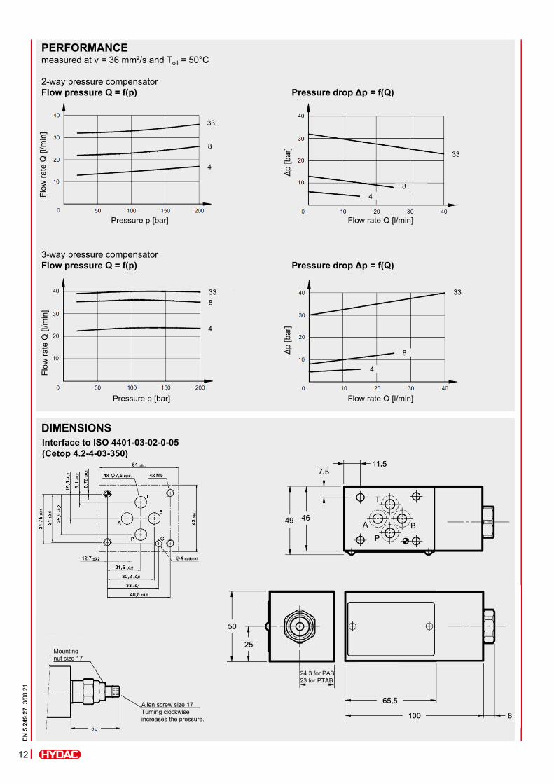
DIMENSIONS
PERFORMANCEmeasured at v = 36 mm²/s and Toil = 50°C
2-way pressure compensatorFlow pressure Q = f(p) Pressure drop Δp = f(Q)
Interface to ISO 4401-03-02-0-05 (Cetop 4.2-4-03-350)
3-way pressure compensatorFlow pressure Q = f(p) Pressure drop Δp = f(Q)
Pressure p [bar]
Flo
w r
ate
Q [
l/min
]
33
8
4
Δp
[bar
]
Flow rate Q [l/min]
33
8
4
Pressure p [bar]
Flo
w r
ate
Q [
l/min
]
33
8
4
33
8
4
Δp
[bar
]
Flow rate Q [l/min]
24.3 for PAB23 for PTAB
Mountingnut size 17
Allen screw size 17Turning clockwise increases the pressure.
EN
5.2
49.2
7. 3
/08.
21
12

MODEL CODE
ZW-SDR 06 - 01 - AAB – N
TypeNeedle valve in sandwich plate design
Nominal size6
Series01 = specified by manufacturer
Spool symbolAA = meter-out in port AAB = meter-out in port BAAB = meter-out in port A and BZAB = meter-in in port A and B
Sealing materialN = NBR V = FKM (standard)
NEEDLE VALVE IN SANDWICH PLATE DESIGNZW – SDR06
EN
5.2
49.2
7. 3
/08.
21
13
SUPPLEMENTARY TECHNICAL DATAGeneral specificationsWeight [kg] 1.3 Hydraulic specificationsCracking pressurecheck valve
[bar] 0.5
Flow rate max. [l/min] 50 in controlled port75 in free port

SECTION VIEWExample AAB
SPOOL TYPES / SYMBOLS
FUNCTIONThe needle valve in sandwich plate design in nominal size 6 is used to control a flow in flow direction. In the reverse direction there is free flow through the valve if the cracking pressure is exceeded. The valve opens when the inlet pressure at the check valve is higher than the outlet pressure including the pressure spring force. The throttling of the flow rate depends on the version: flow from consumer to directional valve in port A → AA flow from consumer to directional valve in port B → AB flow from consumer to directional valve in port A and B → AAB flow from directional valve to consumer in port A and B → ZAB
AA AB AAB ZAB
A1
A2
B1
B2
EN
5.2
49.2
7. 3
/08.
21
14

DIMENSIONS
PERFORMANCEmeasured at v = 36 mm²/s and Toil = 50°C
Control Pressure drop
Interface to ISO 4401-03-02-0-05 (Cetop 4.2-4-03-350)
Flo
w r
ate
Q [
l/min
]
Number of rotations
Fixing screw size 13Turning clockwise increases the flow rate.
Δp
[bar
]
Flow rate Q [l/min]
A1 → A2B1 → B2
P1 → P2T1 → T2
A1 → A2 (symbol AA)B1 → B2 (symbol AB)
EN
5.2
49.2
7. 3
/08.
21
15

MODEL CODE
ZW-2SR 06 - 01 - AA - 01 - N
TypeFlow control valve in sandwich plate design
Nominal size6
Series01 = specified by manufacturer
Spool symbolAA = meter-out in port AAB = meter-out in port BAAB = meter-out in port A and B
Adjustment ranges, flow rate01 = 1 l/min04 = 4 l/min10 = 10 l/min16 = 16 l/min22 = 22 l/min30 = 30 l/min
Sealing materialN = NBR V = FKM (standard)
FLOW CONTROL VALVEIN SANDWICH PLATE DESIGNZW – 2SR06
EN
5.2
49.2
7. 3
/08.
21
16
SUPPLEMENTARY TECHNICAL DATAGeneral specificationsWeight [kg] 3
4.1 (symbol AAB only) Hydraulic specificationsOperating pressure [bar] 250Cracking pressurecheck valve
[bar] 0.5
Flow rate max. [l/min] Controlled port: 1; 4; 10; 16; 22; 30Free port: 65(40 free flow in opposite direction)

SECTION VIEW
SPOOL TYPES / SYMBOLS
FUNCTIONThe flow control valve in sandwich plate design in nominal size 6 is used to control a flow in flow direction. The flow rate is kept constant independent of the pressure loss at the consumer. In the reverse direction there is free flow through the valve if the cracking pressure is exceeded. The valve opens when the inlet pressure at the checkvalve is higher than the outlet pressure including the pressure spring force. The control of the flow rate depends on the version: flow from consumer to directional valve in port A → AA flow from consumer to directional valve in port B → AB flow from consumer to directional valve in port A and B → AAB
AA AB AAB
A1
A2
B1
B2
EN
5.2
49.2
7. 3
/08.
21
17

DIMENSIONS
PERFORMANCEmeasured at v = 36 mm²/s and Toil = 50°C
Control Pressure drop
Interface to ISO 4401-03-02-0-05 (Cetop 4.2-4-03-350)
AA AB
Subplate
1) Free port2) Check valve
Rotary knob (3 rotations)Turning anti-clockwise increases the flow rate
AAB
Control stage of the rotary knob Fixing
screw
Flo
w r
ate
Q [
l/min
]
Number of rotations
30
22
16
10
41
Δp
[bar
]
Flow rate Q [l/min]
EN
5.2
49.2
7. 3
/08.
21
18

MODEL CODE
ZW-RP 06 - 01 - AA - N
TypeCheck valve, pilot-to-open in sandwich plate design
Nominal size6
Series01 = specified by manufacturer
Spool symbolAA = meter-out in port AAB = meter-out in port BAAB = meter-out in port A and B
Sealing materialN = NBR V = FKM (standard)
CHECK VALVE, PILOT-TO-OPENIN SANDWICH PLATE DESIGNZW – RP06
EN
5.2
49.2
7. 3
/08.
21
19
SUPPLEMENTARY TECHNICAL DATAGeneral specificationsWeight [kg] 1.3 Hydraulic specificationsCracking pressurecheck valve
[bar] 3
Flow rate max. [l/min] 50 in controlled port75 in free port
Pilot ratio 3.4 : 1

SECTION VIEW
SPOOL TYPES / SYMBOLS
FUNCTIONThe check valve, pilot-to-open in sandwich plate design in sandwich plate design in nominal size 6 is a direct-acting, spring-loaded poppet valve. It releases flow from the directional valve to the consumer and blocks flow from the consumer to the directional valve.Thereby the valve poppet is pressed into the seat and blocks the flow. If sufficiently high control pressure is built up in the relevant control port, the valve is unlocked and flow flows from the consumer to the directional valve. The required control pressure is based on the pressure difference between the ports to be unblocked.
HintA pressure in the port of the directional valve influences the required control pressure.
AA AB AAB
A1 B1
B2A2
EN
5.2
49.2
7. 3
/08.
21
20

DIMENSIONS
PERFORMANCEmeasured at v = 36 mm²/s and Toil = 50°C
Pressure drop
Interface to ISO 4401-03-02-0-05 (Cetop 4.2-4-03-350)
A1 → A2B1 → B2
P2 → P1T2 → T1A2 → A1 (symbol AB)B2 → B1 (symbol AA)
Δp
[bar
]
Flow rate Q [l/min]
A2 → A1B2 → B1
EN
5.2
49.2
7. 3
/08.
21
21

MODEL CODE
ZW-RV 06 - 01 - A 0,5 - N
TypeCheck valve in sandwich plate design
Nominal size6
Series01 = specified by manufacturer
Spool symbolA = check valve in port AB = check valve in port BP = check valve in port PT = check valve in port TAB = check valve in port ABPT = check valve in port PT
Cracking pressure0.5 = 0.5 barOther cracking pressures on request
Sealing materialN = NBR V = FKM (standard)
CHECK VALVE IN SANDWICH PLATE DESIGNZW – RV06
EN
5.2
49.2
7. 3
/08.
21
22
SUPPLEMENTARY TECHNICAL DATAGeneral specificationsWeight [kg] 1 Hydraulic specificationsCracking pressurecheck valve
[bar] 0.535
Flow rate max. [l/min] 50 in controlled port75 in free port

SECTION VIEW
SPOOL TYPES / SYMBOLS
FUNCTIONThe check valve in sandwich plate design in nominal size 6 is a direct-acting, spring-loaded poppet valve. The valve releases a flow in one direction after exceeding the spring force and blocks the flow in the opposite direction.Thereby the valve poppet is pressed into the seat and blocks the flow. Flow blocked in port A from consumer to directional valve A Flow blocked in port B from consumer to directional valve B Meter-out blocked to pressure supply P Preload of meter-out to tank T Flow blocked in port A and B from consumer to directional valve AB Meter-out blocked to pressure supply and preload of meter-out to tank PT
HintSpring-side pressures at the check element are added to its cracking pressure.
A B P
T AB PT
P1T1
P2T2
EN
5.2
49.2
7. 3
/08.
21
23

DIMENSIONS
PERFORMANCEmeasured at v = 36 mm²/s and Toil = 50°C
Pressure drop
Interface to ISO 4401-03-02-0-05 (Cetop 4.2-4-03-350)
Δp
[bar
]
Flow rate Q [l/min]
1) Controlled port (includes valve element)2) Free port
HintThe cracking pressure of the valve is added to the values of the performance curve 1).
Designation9.25 x 1.78 80 Sh NBR 34924329.25 x 1.78 80 Sh FKM 3120269
Part no.
Seal kits (4-part set)
ACCESSORIES
NoteThe information in this brochure relates to the operating conditions and applications described. For applications not described, please contact the relevant technical department.Subject to technical modifications.
HYDAC Fluidtechnik GmbHJustus-von-Liebig-Str.66280 Sulzbach/Saar, GermanyTel: 0 68 97 /509-01Fax: 0 68 97 /509-598E-mail: [email protected]
N 5
.249
.27.
3/0
8.21
24