MOBİL MEKÂNLARIN İÇ MEKÂN ORGANİZASYONU VE ÖRNEKLERLE MOBİL OFİS TASARIMLARININ ANALİZİ
Upload
khangminh22Category
view
0download
0
FluidAqua Mobil
FAM 25/45/60/75/95
Operating and maintenance instructions, part 1/2 English (translation of original instructions)
Keep for future reference. Document No.: 4170100a
Imprint
FAM 25/45/60/75/95, Part 1/2 en-US Page 2 / 112
BEWA FAM25-95 4170100a en-us 2018-07-10.docx 2018-07-10
Imprint
Publisher and responsible for the content: HYDAC FILTER SYSTEMS GMBH Postfach 1251 66273 Sulzbach / Saarland Germany Phone: +49 6897 509 01 Fax: +49 6897 509 9046 E-mail: [email protected] Homepage: www.hydac.com Court of Registration: Saarbrücken, HRB 17216 Executive directors: Mathias Dieter,
Dipl.Kfm. Wolfgang Haering
Documentation Representative
Mr. Günter Harge c/o HYDAC International GmbH, Industriegebiet, 66280 Sulzbach / Saar Phone: +49 6897 509 1511 Fax: +49 6897 509 1394 E-mail: [email protected]
© HYDAC FILTER SYSTEMS GMBH
All rights reserved. No part of this work may be reproduced in any form (print, photocopy or by other means) or processed, duplicated or distributed using electronic systems without the written consent of the publisher. These documents have been created and inspected with the greatest care. However, errors cannot be ruled out completely. All details are subject to technical modifications. Technical specifications are subject to change without notice.
Content
FAM 25/45/60/75/95, Part 1/2 en-US Page 3 / 112
BEWA FAM25-95 4170100a en-us 2018-07-10.docx 2018-07-10
Content
Imprint ............................................................................................................ 2
Documentation Representative ................................................................... 2
Content .......................................................................................................... 3
Preface ........................................................................................................... 6
Technical Support ........................................................................................ 6 Product modification .................................................................................... 6 Warranty ...................................................................................................... 6 Using the documentation ............................................................................. 7
General safety information .......................................................................... 8
Hazard symbols ........................................................................................... 8 Signal words and their meaning in the general safety information and instructions ........................................................................................... 9 Structure of the general safety information and instructions ...................... 10 Observe regulatory information ................................................................. 10 Proper/Designated Use ............................................................................. 11 Improper Use or Use Deviating from Intended Use ................................... 13 Qualifications of personnel / target group .................................................. 14 Wear suitable clothing ............................................................................... 16 Electrical Hazards ...................................................................................... 17 Modifications to the FluidAqua Mobil ......................................................... 17 Stoppage in an emergency (EMERGENCY STOP) ................................... 18
Unpacking the unit ...................................................................................... 18
Transporting the unit .................................................................................. 18
Transporting the FAM - mobile FAM (FAM-xx-2-…) .................................. 19 Transporting with the fork lift truck .......................................................... 19 Transporting with the crane .................................................................... 20 Transporting by train / truck .................................................................... 20
Decoding the model code label ................................................................. 21
Checking the scope of delivery ................................................................. 23
Description of unit ...................................................................................... 23
FAM version – stationary (FAM-xx-1-…) ................................................... 24 FAM version – mobile (FAM-xx-2-…) ........................................................ 24 System Components FAM 25-45 ............................................................... 25 System Components FAM 60-95 ............................................................... 27
Unit dimensions .......................................................................................... 29
FAM 25-45 – stationary (FAM-xx-1-…) ...................................................... 29 FAM 25-45 – mobile (FAM-xx-2-…) ........................................................... 30 FAM 60-95 with OFU – stationary (FAM-xx-1-x-x-26-…) ........................... 31

Content
FAM 25/45/60/75/95, Part 1/2 en-US Page 4 / 112
BEWA FAM25-95 4170100a en-us 2018-07-10.docx 2018-07-10
FAM 60-95 with OFU – mobile (FAM-xx-x-x-x-26-…) ................................ 32 FAM 60-95 with MRF – stationary (FAM-xx-1-x-x-40-…) ........................... 33 FAM 60-95 with MRF – mobile (FAM-xx-2-x-x-40-…)................................ 34
Hydraulic circuit .......................................................................................... 35
Technical specifications ............................................................................ 37
Function description .................................................................................. 38
Power unit with water ring vacuum pump .................................................. 39 Power unit of the rotary vane vacuum pump ............................................. 39 Cleaning in Bypass Flow ........................................................................... 40 Purifying and transferring by pumping ....................................................... 40
Unit setup and connection ......................................................................... 41
Setting up the unit ...................................................................................... 41 Connection overview ................................................................................. 41 Notes on pipes and hoses ......................................................................... 43
Connecting the inlet (IN) ......................................................................... 45 Connecting the outlet (OUT)................................................................... 45
Selecting a fluid filter element .................................................................... 46 Preparing vacuum pump for operation ...................................................... 47
Preparing water ring vacuum pump (FAM-xx-x-x-x-xx-W/WA-x …) .......................................................................................................... 47 Preparing rotary vane vacuum pump (FAM-xx-x-x-x-xx-R-x …) ............. 49
Filling up the rotary vane vacuum pump at the FAM 25 ...................... 50 Filling up the rotary vane vacuum pump at the FAM 45-95 ................. 50
Electrical connection of the unit ................................................................. 51 Rotating field .......................................................................................... 52
Operating elements on the FAM ................................................................ 53
Switching on / switching off / commissioning and error messages ...... 53
Performing maintenance ............................................................................ 54
Function testing of the fault indicator lamp ................................................ 58 Change the air filter ................................................................................... 58 Testing the AquaSensor ............................................................................ 58 Suction line filter – Cleaning/changing the filter element ........................... 59 Maintaining the water ring vacuum pump (FAM-xx-x-x-xx-W/WA-…) .............................................................................................................. 61
Checking/Cleaning the level switch ........................................................ 61 Switching Status - Level Sensor Water Ring Vacuum Pump/PLC .......... 61 Replacing the Water Filter ...................................................................... 61 Cleaning the Cooling Fins ...................................................................... 63 Flushing/Cleaning the vacuum pump ..................................................... 63 Cleaning the condensation cooler of the vacuum pump ......................... 67
Water filter combination (FAM-xx-x-x-xx-WA-...) maintenance .................. 69

Content
FAM 25/45/60/75/95, Part 1/2 en-US Page 5 / 112
BEWA FAM25-95 4170100a en-us 2018-07-10.docx 2018-07-10
Back-Flush Water Filter Combination ..................................................... 69 Checking / setting the downstream pressure ......................................... 70
Servicing the rotary vane vacuum pump (FAM-25-x-x-xx-R-…) ................ 71 Replacing oil and oil filter (FAM 25) ........................................................ 72 Replacing the air de-oiling element (FAM 25) ........................................ 73
Rotary vane vacuum pump (FAM 45/60/75/95-xx-x-x-xx-R-…) ................. 74 Changing vacuum pump oil and oil filter (FAM 45-95) ............................ 75 Replacing the air de-oiling element of the vacuum pump (FAM 45-95) ..................................................................................................... 76
Replacing the filter element on the fluid filter ............................................. 77 Filter housing 2600 (FAM-xx-x-x-x-26-…) – Changing filter element .................................................................................................. 77 OLF-5 Toploader (FAM-xx-x-x-x-10-…) – Replacing the filter element .................................................................................................. 80 MRF filter housing (FAM-xx-x-x-x-40-…) – Changing the filter elements ................................................................................................. 84
Checking the vacuum column level sensor ................................................ 86 Testing the float switch in the oil pan ......................................................... 89 Oil mist separator maintenance ................................................................. 90
Replacing the filter element on the oil mist separator ............................. 91
Replacement Parts and Accessories List ................................................. 92
FAM25 - Consumables for 2-year operation .............................................. 94 FAM45 - Consumables for 2-year operation .............................................. 95 FAM60 / 75 / 95 - Consumables for 2-year operation ................................ 96
Storing the unit / taking it out of operation .............................................. 97
Unit disposal ............................................................................................... 97
Technical Data............................................................................................. 98
Appendix ................................................................................................... 101
Customer Service / Service ..................................................................... 101 Model Code ............................................................................................. 102 Explanation of terms and abbreviations ................................................... 103 Index ........................................................................................................ 106

Preface
FAM 25/45/60/75/95, Part 1/2 en-US Page 6 / 112
BEWA FAM25-95 4170100a en-us 2018-07-10.docx 2018-07-10
Preface
These operating instructions were made to the best of our knowledge. Nevertheless and despite the greatest care, it cannot be excluded that mistakes could have crept in. Therefore please understand that, in the absence of any provisions to the contrary hereinafter, our warranty and liability – for any legal reasons whatsoever – are excluded in respect of the information in these operating instructions. In particular, we shall not be liable for lost profit or other financial loss. This exclusion of liability does not apply in cases of intent and gross negligence. Moreover, it does not apply to defects which have been deceitfully concealed or whose absence has been guaranteed, nor in cases of culpable harm to life, physical injury and damage to health. If we negligently breach any material contractual obligation, our liability shall be limited to foreseeable damage. Claims due to Product Liability shall remain unaffected.
Technical Support Contact our technical sales department if you have any questions on our product. When contacting us, please always include the model code, serial no. and part no. of the product: Fax: +49 6897 509 9046 E-mail: [email protected]
Product modification We would like to point out that changes to the product (e.g. purchasing options, etc.) may result in the information in the operating instructions no longer being completely accurate or sufficient. After modification or repair work that affects the safety of the product has been carried out on components, the product may not be returned to operation until it has been checked and released by a HYDAC technician. Please notify us immediately of any modifications made to the product whether by you or a third party.
Warranty For the warranty provided by us, please refer to the terms of delivery of HYDAC FILTER SYSTEMS GMBH. You will find these under www.hydac.com -> General terms and conditions.

Preface
FAM 25/45/60/75/95, Part 1/2 en-US Page 7 / 112
BEWA FAM25-95 4170100a en-us 2018-07-10.docx 2018-07-10
Using the documentation
Note that the method described for locating specific information does not release you from your responsibility of carefully reading all these instructions prior to starting the unit up for the first time and at regular intervals in the future.
What do I want to know? I determine which topic I am looking for. WHERE can I find the information I’m looking for? The documentation has a table of contents at the beginning. There, I select the chapter I'm looking for and the corresponding page number.
deHYDAC Filtertechnik GmbHBeWa 123456a de
Seite x
Produkt / Kapitel
200x-xx-xx
The documentation number with its index enables you to order another copy of the operating and maintenance instructions. The index is incremented every time the manual is revised or changed.
Chapter description
Page number Edition date
Document language
Documentation no. with index/
file name

General safety information
FAM 25/45/60/75/95, Part 1/2 en-US Page 8 / 112
BEWA FAM25-95 4170100a en-us 2018-07-10.docx 2018-07-10
General safety information
The unit was built according to the statutory provisions valid at the time of delivery and satisfies current safety requirements. Any residual hazards are indicated by general safety information and instructions and are described in the operating instructions. Observe all safety and warning instructions attached to the unit. They must always be complete and legible. Do not operate the unit unless all the safety devices are present. Secure the hazardous areas which may arise between the unit and other equipment. Maintain the unit inspection intervals prescribed by law. Document the results in an inspection certificate and keep it until the next inspection.
Hazard symbols These symbols are listed for all general safety information and instructions in these operating instructions which indicate particular dangers to persons, property or the environment. Observe these instructions and act with particular caution in such cases. Pass all safety information and instructions on to other users.
General hazard
Danger due to electrical voltage / current
Exposed electrical components Danger of electrical shock
Danger due to operating pressure
General safety information
FAM 25/45/60/75/95, Part 1/2 en-US Page 9 / 112
BEWA FAM25-95 4170100a en-us 2018-07-10.docx 2018-07-10
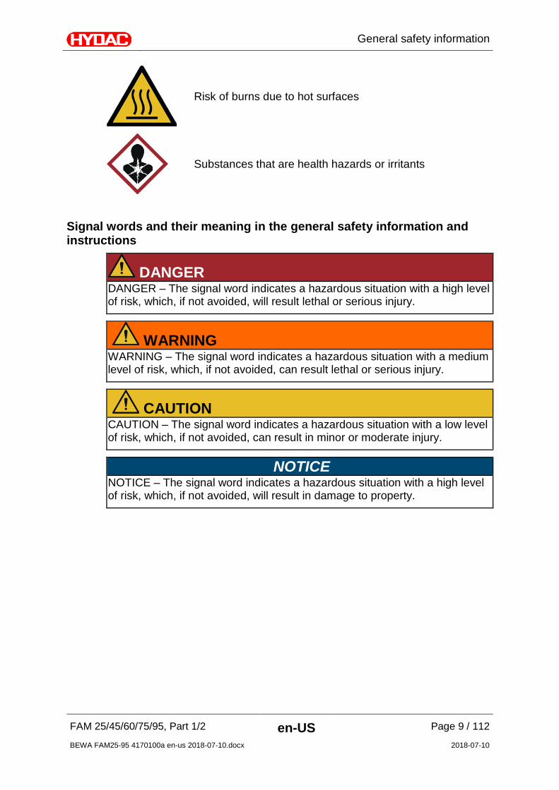
Risk of burns due to hot surfaces
Substances that are health hazards or irritants
Signal words and their meaning in the general safety information and instructions
DANGER DANGER – The signal word indicates a hazardous situation with a high level of risk, which, if not avoided, will result lethal or serious injury.
WARNING WARNING – The signal word indicates a hazardous situation with a medium level of risk, which, if not avoided, can result lethal or serious injury.
CAUTION CAUTION – The signal word indicates a hazardous situation with a low level of risk, which, if not avoided, can result in minor or moderate injury.
NOTICE NOTICE – The signal word indicates a hazardous situation with a high level of risk, which, if not avoided, will result in damage to property.

General safety information
FAM 25/45/60/75/95, Part 1/2 en-US Page 10 / 112
BEWA FAM25-95 4170100a en-us 2018-07-10.docx 2018-07-10
Structure of the general safety information and instructions All warning instructions in this manual are highlighted with pictograms and signal words. The pictogram and the signal word indicate the severity of the danger. Warning instructions listed before an activity are laid out as follows:
HAZARD SYMBOL
SIGNAL WORD
Type and source of danger
Consequence of the danger
Measures to avert danger
Observe regulatory information Observe the following regulatory information and directives:
• Legal and local regulations for accident prevention
• Legal and local regulations for environmental protection
• Country-specific regulations, organization-specific regulations
General safety information
FAM 25/45/60/75/95, Part 1/2 en-US Page 11 / 112
BEWA FAM25-95 4170100a en-us 2018-07-10.docx 2018-07-10
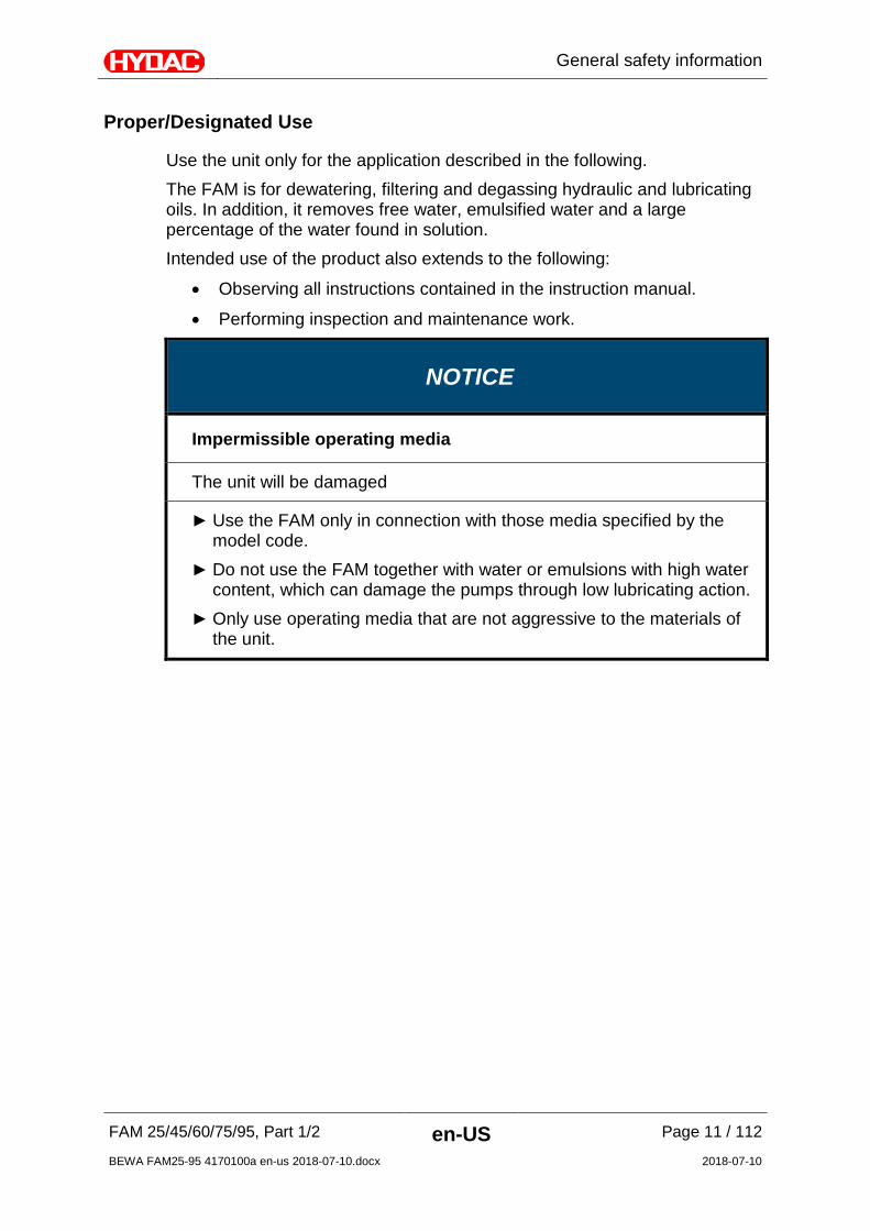
Proper/Designated Use
Use the unit only for the application described in the following. The FAM is for dewatering, filtering and degassing hydraulic and lubricating oils. In addition, it removes free water, emulsified water and a large percentage of the water found in solution. Intended use of the product also extends to the following:
• Observing all instructions contained in the instruction manual.
• Performing inspection and maintenance work.
NOTICE
Impermissible operating media
The unit will be damaged
Use the FAM only in connection with those media specified by the model code.
Do not use the FAM together with water or emulsions with high water content, which can damage the pumps through low lubricating action.
Only use operating media that are not aggressive to the materials of the unit.
General safety information
FAM 25/45/60/75/95, Part 1/2 en-US Page 12 / 112
BEWA FAM25-95 4170100a en-us 2018-07-10.docx 2018-07-10
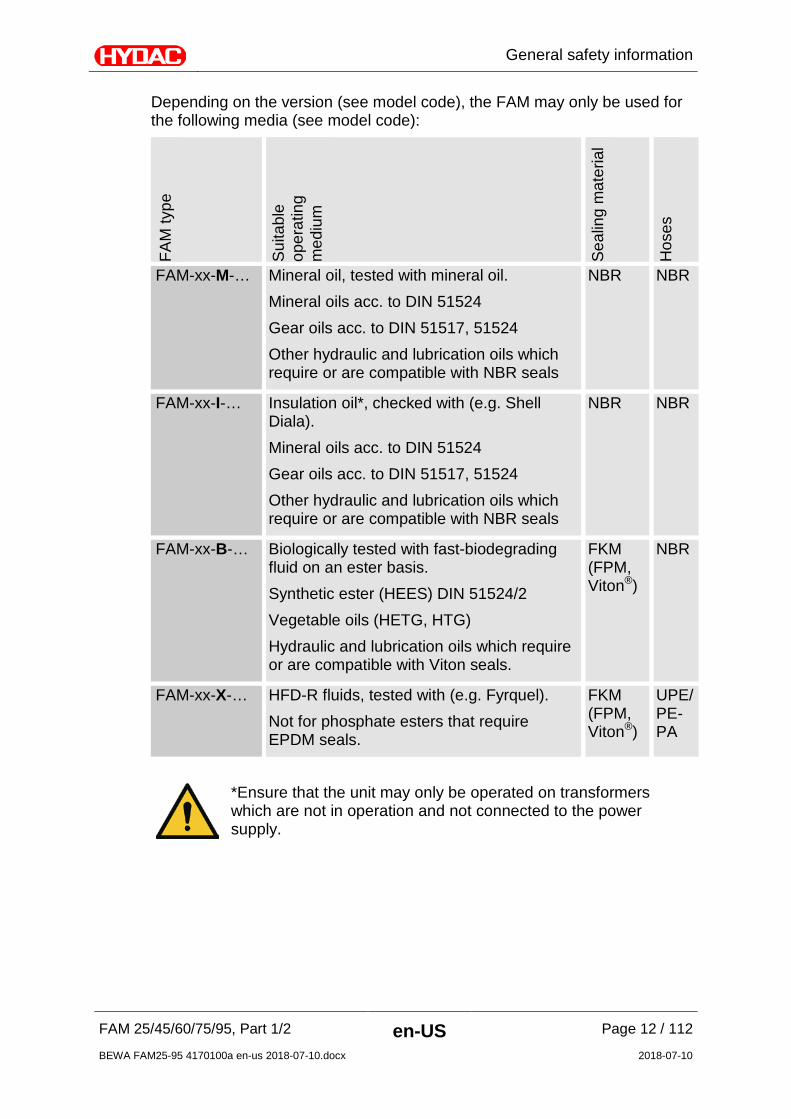
Depending on the version (see model code), the FAM may only be used for the following media (see model code):
FAM
type
Sui
tabl
e op
erat
ing
med
ium
Sea
ling
mat
eria
l
Hos
es
FAM-xx-M-… Mineral oil, tested with mineral oil. Mineral oils acc. to DIN 51524 Gear oils acc. to DIN 51517, 51524 Other hydraulic and lubrication oils which require or are compatible with NBR seals
NBR NBR
FAM-xx-I-… Insulation oil*, checked with (e.g. Shell Diala). Mineral oils acc. to DIN 51524 Gear oils acc. to DIN 51517, 51524 Other hydraulic and lubrication oils which require or are compatible with NBR seals
NBR NBR
FAM-xx-B-… Biologically tested with fast-biodegrading fluid on an ester basis. Synthetic ester (HEES) DIN 51524/2 Vegetable oils (HETG, HTG) Hydraulic and lubrication oils which require or are compatible with Viton seals.
FKM (FPM, Viton®)
NBR
FAM-xx-X-… HFD-R fluids, tested with (e.g. Fyrquel). Not for phosphate esters that require EPDM seals.
FKM (FPM, Viton®)
UPE/PE-PA
*Ensure that the unit may only be operated on transformers which are not in operation and not connected to the power supply.
General safety information
FAM 25/45/60/75/95, Part 1/2 en-US Page 13 / 112
BEWA FAM25-95 4170100a en-us 2018-07-10.docx 2018-07-10
Improper Use or Use Deviating from Intended Use
DANGER
Danger due to unanticipated use of the unit
Bodily injury and damage to property will result when operated improperly.
Never operate the unit in potentially explosive atmospheres.
The unit is only to be used with permissible media.
Do not use the FAM together with water or emulsions with high water content.
Any use extending beyond this or deviating therefrom shall not be considered intended use. HYDAC Filter Systems GmbH will assume no liability for any damage resulting from such use. This risk is borne solely by the owner. Improper use may result in hazards and/or will damage the unit. Examples of improper use:
• Operation in potentially explosive atmospheres.
• Operation with a non-approved medium.
• Operation under non-approved operational conditions.
• Operation when the safety devices are defective.
• Modifications to the power unit made by the user or purchaser.
• Inadequate monitoring of parts that are subject to wear and tear.
• Improperly performed repair work.

General safety information
FAM 25/45/60/75/95, Part 1/2 en-US Page 14 / 112
BEWA FAM25-95 4170100a en-us 2018-07-10.docx 2018-07-10
Qualifications of personnel / target group
Persons who work on the power unit must be aware of the associated hazards when using the power unit. Auxiliary and specialist personnel must have read and understood the operating instructions, in particular the safety information and instructions, and applicable regulations before beginning work. The operating instructions and applicable regulations are to kept so they are accessible for operating and specialist personnel. These operating instructions are intended for: Auxiliary personnel: such persons have been instructed in power unit operation and are aware of potential hazards due to improper use. Specialist personnel: such persons with corresponding specialist training and several years' work experience. They are able to assess and perform the work assigned to them, they are also able to recognize potential dangers.

General safety information
FAM 25/45/60/75/95, Part 1/2 en-US Page 15 / 112
BEWA FAM25-95 4170100a en-us 2018-07-10.docx 2018-07-10
Activity Person Knowledge
Transport / storage Forwarding agent Specialist personnel
Proof of knowledge of cargo securing instructions Safe handling/operation of hoisting and lifting equipment
Hydraulic / electrical installation, first commissioning, Maintenance Troubleshooting repair, Decommissioning Disassembly
Specialist personnel
Safe handling/use of tools Fitting and connection of hydraulic lines and connections Fitting and connection of electrical lines, electrical machinery, sockets, etc. Checking the phase sequence Product-specific knowledge
Operation Operations control
Specialist personnel
Product-specific knowledge Knowledge about how to handle operating media. Knowledge about contamination due to solids and water
Disposal Specialist personnel
Proper and environmentally-friendly disposal of materials and substances Decontamination of contaminants Knowledge about reuse

General safety information
FAM 25/45/60/75/95, Part 1/2 en-US Page 16 / 112
BEWA FAM25-95 4170100a en-us 2018-07-10.docx 2018-07-10
Wear suitable clothing Loosely worn clothing increases the danger of getting caught or wound up in rotating parts and the danger of getting snagged on projecting parts. You can be severely injured or killed.
-
Wear close-fitting clothing. Do not wear any rings, chains or any other jewelry.
-
Wear gloves.
-
Wear work safety shoes.
General safety information
FAM 25/45/60/75/95, Part 1/2 en-US Page 17 / 112
BEWA FAM25-95 4170100a en-us 2018-07-10.docx 2018-07-10
Electrical Hazards
DANGER
Electric shock
Bodily injury leading to death
Any work involving electrical equipment may only be done by a properly trained, certified electrician.
DANGER
Exposed electrical components in the switch cabinet
Danger of fatal injury due to electric shock
Any work involving the electrical system may only be done by a properly trained, certified electrician.
Check the FAM electrical equipment on a monthly basis. Immediately replace loose connections, damaged cables and hoses with original spare parts. These tasks may be performed only by a technician with corresponding knowledge and skills.
Modifications to the FluidAqua Mobil Do not make any modifications (design modifications, extensions) to the FluidAqua Mobil without the prior consent of the manufacturer. All design modifications require written permission from HYDAC FILTER SYSTEMS GMBH Immediately replace any machine components which are not in perfect condition. Use only original spare parts (OEM).
Unpacking the unit
FAM 25/45/60/75/95, Part 1/2 en-US Page 18 / 112
BEWA FAM25-95 4170100a en-us 2018-07-10.docx 2018-07-10
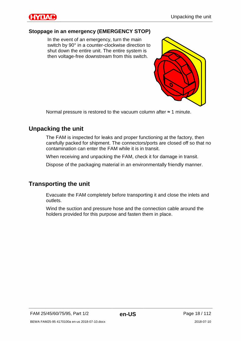
Stoppage in an emergency (EMERGENCY STOP) In the event of an emergency, turn the main switch by 90° in a counter-clockwise direction to shut down the entire unit. The entire system is then voltage-free downstream from this switch.
Normal pressure is restored to the vacuum column after ≈ 1 minute.
Unpacking the unit The FAM is inspected for leaks and proper functioning at the factory, then carefully packed for shipment. The connectors/ports are closed off so that no contamination can enter the FAM while it is in transit. When receiving and unpacking the FAM, check it for damage in transit. Dispose of the packaging material in an environmentally friendly manner.
Transporting the unit
Evacuate the FAM completely before transporting it and close the inlets and outlets. Wind the suction and pressure hose and the connection cable around the holders provided for this purpose and fasten them in place.
Transporting the unit
FAM 25/45/60/75/95, Part 1/2 en-US Page 19 / 112
BEWA FAM25-95 4170100a en-us 2018-07-10.docx 2018-07-10
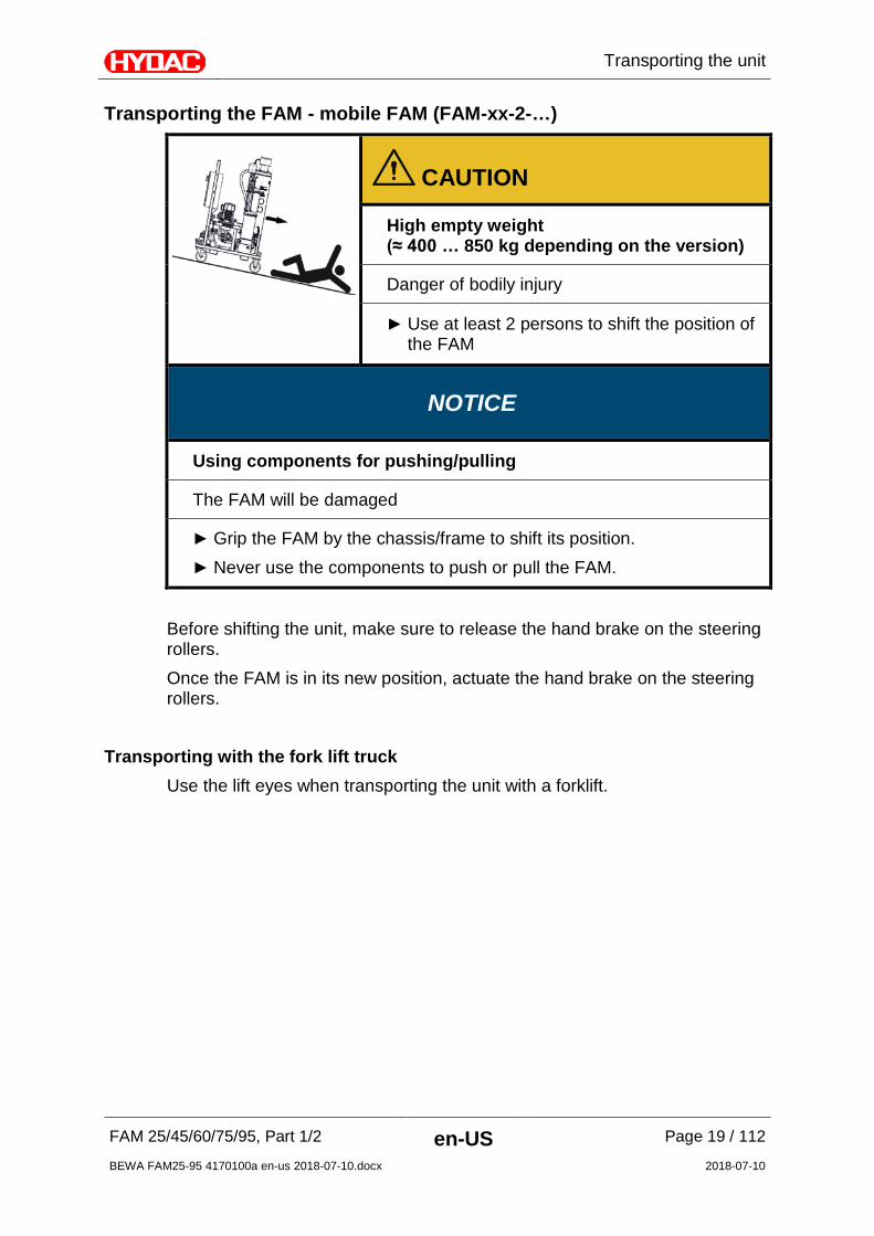
Transporting the FAM - mobile FAM (FAM-xx-2-…)
CAUTION
High empty weight (≈ 400 … 850 kg depending on the version)
Danger of bodily injury
Use at least 2 persons to shift the position of the FAM
NOTICE
Using components for pushing/pulling
The FAM will be damaged
Grip the FAM by the chassis/frame to shift its position. Never use the components to push or pull the FAM.
Before shifting the unit, make sure to release the hand brake on the steering rollers. Once the FAM is in its new position, actuate the hand brake on the steering rollers.
Transporting with the fork lift truck Use the lift eyes when transporting the unit with a forklift.

Transporting the unit
FAM 25/45/60/75/95, Part 1/2 en-US Page 20 / 112
BEWA FAM25-95 4170100a en-us 2018-07-10.docx 2018-07-10
Transporting with the crane
NOTICE
Unsuitable lifting accessories
The FAM will be damaged / Components will be damaged / destroyed
Use only suitable lifting accessories to raise or lash the FAM. Take care to ensure that the lifting accessories do not cause any
pressures to be brought to bear against the components on the FAM.
Use the crane eyes located on the FAM frame when using a crane to transport the FAM. Use suitable lifting accessories.
FAM 25 FAM 45-95
Transporting by train / truck For transport by rail or truck, supports must be placed under the mobile FAM so that the rollers are subjected to no load pressure. Secure the FAM with suitable means.

Decoding the model code label
FAM 25/45/60/75/95, Part 1/2 en-US Page 21 / 112
BEWA FAM25-95 4170100a en-us 2018-07-10.docx 2018-07-10
Decoding the model code label Details for identifying the filtration unit can be found on the name plates on the unit and the components.
Decoding the model code label
FAM 25/45/60/75/95, Part 1/2 en-US Page 22 / 112
BEWA FAM25-95 4170100a en-us 2018-07-10.docx 2018-07-10
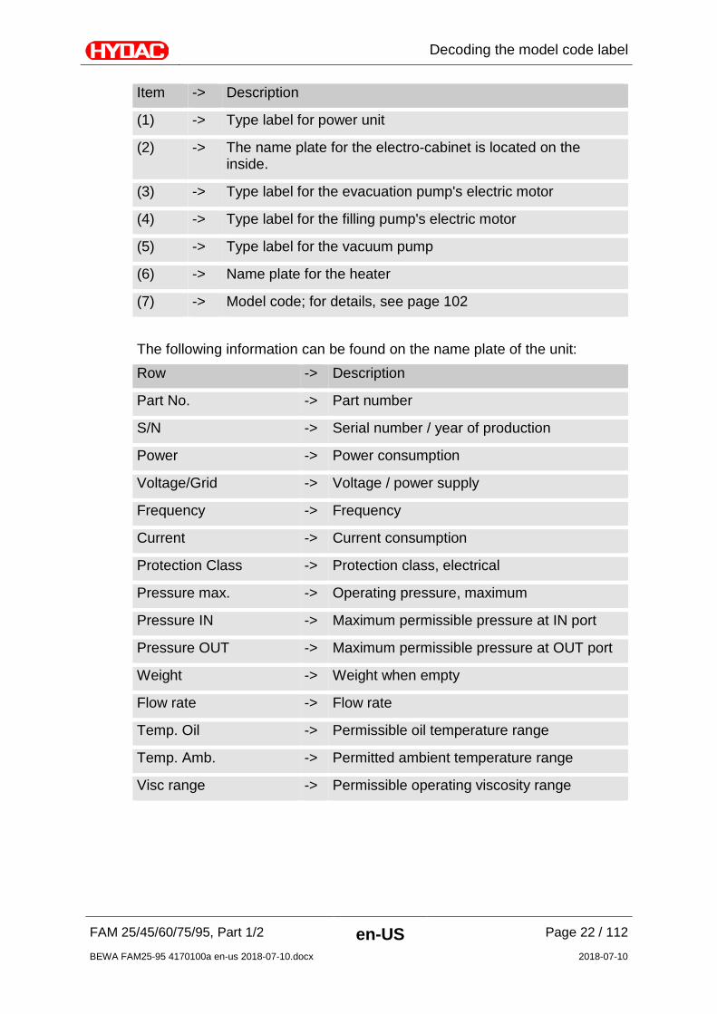
Item -> Description
(1) -> Type label for power unit
(2) -> The name plate for the electro-cabinet is located on the inside.
(3) -> Type label for the evacuation pump's electric motor
(4) -> Type label for the filling pump's electric motor
(5) -> Type label for the vacuum pump
(6) -> Name plate for the heater
(7) -> Model code; for details, see page 102 The following information can be found on the name plate of the unit: Row -> Description
Part No. -> Part number
S/N -> Serial number / year of production
Power -> Power consumption
Voltage/Grid -> Voltage / power supply
Frequency -> Frequency
Current -> Current consumption
Protection Class -> Protection class, electrical
Pressure max. -> Operating pressure, maximum
Pressure IN -> Maximum permissible pressure at IN port
Pressure OUT -> Maximum permissible pressure at OUT port
Weight -> Weight when empty
Flow rate -> Flow rate
Temp. Oil -> Permissible oil temperature range
Temp. Amb. -> Permitted ambient temperature range
Visc range -> Permissible operating viscosity range
Checking the scope of delivery
FAM 25/45/60/75/95, Part 1/2 en-US Page 23 / 112
BEWA FAM25-95 4170100a en-us 2018-07-10.docx 2018-07-10
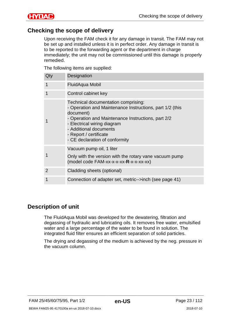
Checking the scope of delivery Upon receiving the FAM check it for any damage in transit. The FAM may not be set up and installed unless it is in perfect order. Any damage in transit is to be reported to the forwarding agent or the department in charge immediately; the unit may not be commissioned until this damage is properly remedied. The following items are supplied: Qty Designation
1 FluidAqua Mobil
1 Control cabinet key
1
Technical documentation comprising: - Operation and Maintenance Instructions, part 1/2 (this document) - Operation and Maintenance Instructions, part 2/2 - Electrical wiring diagram - Additional documents - Report / certificate - CE declaration of conformity
1 Vacuum pump oil, 1 liter Only with the version with the rotary vane vacuum pump (model code FAM-xx-x-x-xx-R-x-x-xx-xx)
2 Cladding sheets (optional)
1 Connection of adapter set, metric-->inch (see page 41)
Description of unit
The FluidAqua Mobil was developed for the dewatering, filtration and degassing of hydraulic and lubricating oils. It removes free water, emulsified water and a large percentage of the water to be found in solution. The integrated fluid filter ensures an efficient separation of solid particles. The drying and degassing of the medium is achieved by the neg. pressure in the vacuum column.

Description of unit
FAM 25/45/60/75/95, Part 1/2 en-US Page 24 / 112
BEWA FAM25-95 4170100a en-us 2018-07-10.docx 2018-07-10
FAM version – stationary (FAM-xx-1-…)
FAM version – mobile (FAM-xx-2-…)
Compared to the stationary version of the unit, the mobile version features: - 2 casters, 2 fixed casters
- Suction hose, L= 5 m
- Return hose , L= 5 m
- Connection cable 10m with CEE plug
- Hose retainer

Description of unit
FAM 25/45/60/75/95, Part 1/2 en-US Page 25 / 112
BEWA FAM25-95 4170100a en-us 2018-07-10.docx 2018-07-10
System Components FAM 25-45

Description of unit
FAM 25/45/60/75/95, Part 1/2 en-US Page 26 / 112
BEWA FAM25-95 4170100a en-us 2018-07-10.docx 2018-07-10
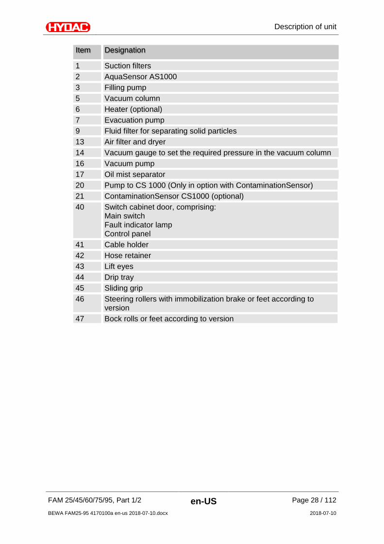
Item Designation
1 Suction filters 2 AquaSensor AS1000 3 Filling pump 5 Vacuum column 6 Heater (optional) 7 Evacuation pump 9 Fluid filter for separating solid particles 13 Air filter and dryer 14 Vacuum gauge to set the required pressure in the vacuum column 16 Vacuum pump 17 Oil mist separator 20 Pump to CS1000 (Only in option with ContaminationSensor) 21 ContaminationSensor CS1000 (optional) 40 Switch cabinet door, comprising:
Main switch Fault indicator lamp Control panel
41 Cable holder 42 Hose retainer 43 Lift eyes 44 Drip tray 45 Sliding grip 46 Steering rollers with immobilization brake or feet according to
version 47 Bock rolls or feet according to version

Description of unit
FAM 25/45/60/75/95, Part 1/2 en-US Page 27 / 112
BEWA FAM25-95 4170100a en-us 2018-07-10.docx 2018-07-10
System Components FAM 60-95
Description of unit
FAM 25/45/60/75/95, Part 1/2 en-US Page 28 / 112
BEWA FAM25-95 4170100a en-us 2018-07-10.docx 2018-07-10
Item Designation
1 Suction filters 2 AquaSensor AS1000 3 Filling pump 5 Vacuum column 6 Heater (optional) 7 Evacuation pump 9 Fluid filter for separating solid particles 13 Air filter and dryer 14 Vacuum gauge to set the required pressure in the vacuum column 16 Vacuum pump 17 Oil mist separator 20 Pump to CS 1000 (Only in option with ContaminationSensor) 21 ContaminationSensor CS1000 (optional) 40 Switch cabinet door, comprising:
Main switch Fault indicator lamp Control panel
41 Cable holder 42 Hose retainer 43 Lift eyes 44 Drip tray 45 Sliding grip 46 Steering rollers with immobilization brake or feet according to
version 47 Bock rolls or feet according to version
Unit dimensions
FAM 25/45/60/75/95, Part 1/2 en-US Page 29 / 112
BEWA FAM25-95 4170100a en-us 2018-07-10.docx 2018-07-10
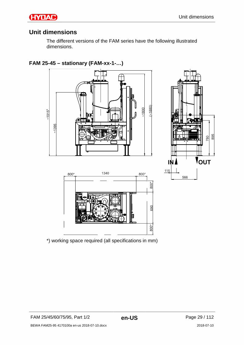
Unit dimensions The different versions of the FAM series have the following illustrated dimensions.
FAM 25-45 – stationary (FAM-xx-1-…)
*) working space required (all specifications in mm)

Unit dimensions
FAM 25/45/60/75/95, Part 1/2 en-US Page 30 / 112
BEWA FAM25-95 4170100a en-us 2018-07-10.docx 2018-07-10
FAM 25-45 – mobile (FAM-xx-2-…)
*) working space required (all specifications in mm)
Unit dimensions
FAM 25/45/60/75/95, Part 1/2 en-US Page 31 / 112
BEWA FAM25-95 4170100a en-us 2018-07-10.docx 2018-07-10
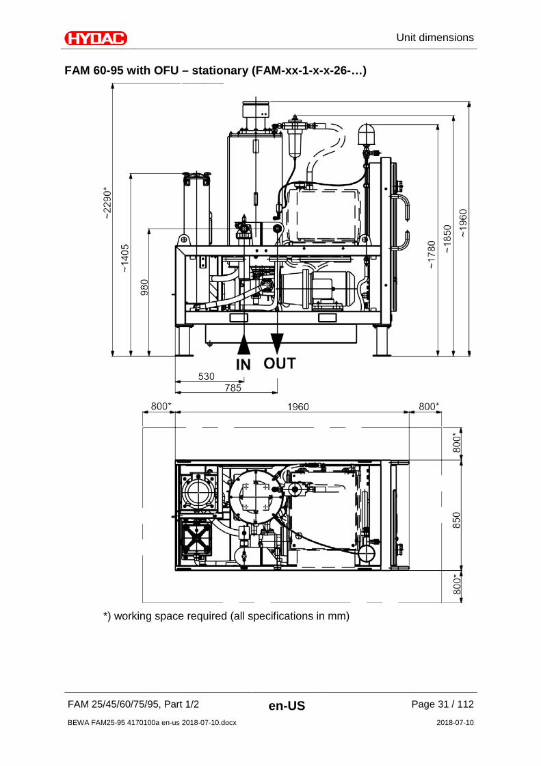
FAM 60-95 with OFU – stationary (FAM-xx-1-x-x-26-…)
*) working space required (all specifications in mm)
Unit dimensions
FAM 25/45/60/75/95, Part 1/2 en-US Page 32 / 112
BEWA FAM25-95 4170100a en-us 2018-07-10.docx 2018-07-10
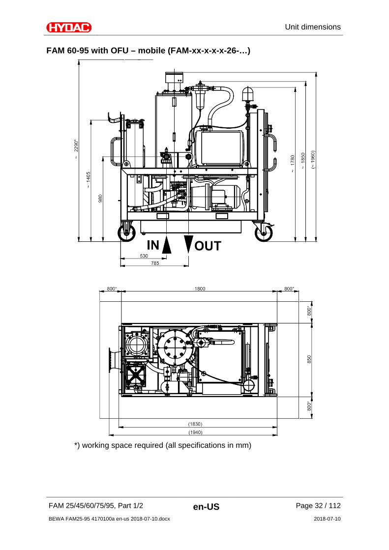
FAM 60-95 with OFU – mobile (FAM-xx-x-x-x-26-…)
*) working space required (all specifications in mm)

Unit dimensions
FAM 25/45/60/75/95, Part 1/2 en-US Page 33 / 112
BEWA FAM25-95 4170100a en-us 2018-07-10.docx 2018-07-10
FAM 60-95 with MRF – stationary (FAM-xx-1-x-x-40-…)
*) working space required (all specifications in mm)

Unit dimensions
FAM 25/45/60/75/95, Part 1/2 en-US Page 34 / 112
BEWA FAM25-95 4170100a en-us 2018-07-10.docx 2018-07-10
FAM 60-95 with MRF – mobile (FAM-xx-2-x-x-40-…)
*) working space required (all specifications in mm)
Hydraulic circuit
FAM 25/45/60/75/95, Part 1/2 en-US Page 35 / 112
BEWA FAM25-95 4170100a en-us 2018-07-10.docx 2018-07-10
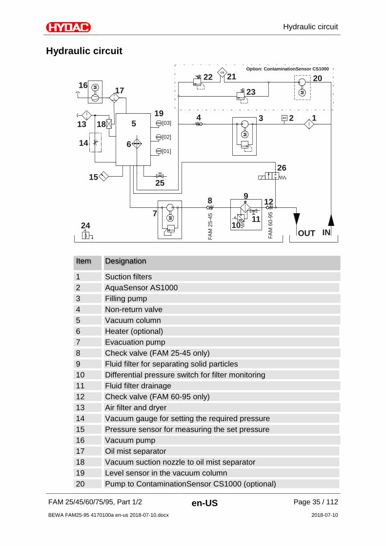
Hydraulic circuit
16 17
13 18
6
15
14
24
5
25
78
4 1
20
26
22 21
23
23
129
1011
[03]
[02]
[01]
19
INOUT
FAM
25-
45
FAM
60-
95
Option: ContaminationSensor CS1000
M
M
M
M
CS
AS
Item Designation
1 Suction filters 2 AquaSensor AS1000 3 Filling pump 4 Non-return valve 5 Vacuum column 6 Heater (optional) 7 Evacuation pump 8 Check valve (FAM 25-45 only) 9 Fluid filter for separating solid particles 10 Differential pressure switch for filter monitoring 11 Fluid filter drainage 12 Check valve (FAM 60-95 only) 13 Air filter and dryer 14 Vacuum gauge for setting the required pressure 15 Pressure sensor for measuring the set pressure 16 Vacuum pump 17 Oil mist separator 18 Vacuum suction nozzle to oil mist separator 19 Level sensor in the vacuum column 20 Pump to ContaminationSensor CS1000 (optional)
Hydraulic circuit
FAM 25/45/60/75/95, Part 1/2 en-US Page 36 / 112
BEWA FAM25-95 4170100a en-us 2018-07-10.docx 2018-07-10
21 ContaminationSensor CS1000 (optional) 22 Pressure relief valve CS1000 (optional) 23 Pressure relief valve CS1000 (optional) 24 Oil pan leakage indicator 25 Vacuum column drainage 26 Return valve

Technical specifications
FAM 25/45/60/75/95, Part 1/2 en-US Page 37 / 112
BEWA FAM25-95 4170100a en-us 2018-07-10.docx 2018-07-10
Technical specifications The FAM is able to dewater authorized fluids down to a water content of less than 100 ppm and transformer oils down to less than 10 ppm. As an approximate guideline, the dimensioning of the FluidAqua Mobil can be defined in accordance with the tank volume. Tank volume in liters Filter Size
< 2000 FAM5
1,000 – 7,000 FAM10/15
7,000 – 15,000 FAM25
15,000 – 25,000 FAM 45 / FAM 45 E
25,000 – 35,000 FAM60
35,000 – 45,000 FAM 75 7 FAM 75 E
> 45,000 FAM95 Generally speaking, however, it must be taken into account that the design depends on the application, the fluid and the ambient temperature, the fluid amount and the water input into the system. These exercise a great influence over the dewatering performance. It is for that reason that the specifications can serve only as a starting point. The dewatering performance is dependent upon: Dewatering
performance
Water content
Fluid temperature
Detergent additives
Volumetric flow of the FAM

Function description
FAM 25/45/60/75/95, Part 1/2 en-US Page 38 / 112
BEWA FAM25-95 4170100a en-us 2018-07-10.docx 2018-07-10
Function description
16 17
13 18
6
15
14
24
5
25
78
4 1
20
26
22 21
23
23
129
1011
[03]
[02]
[01]
19
INOUT
FAM
25-
45
FAM
60-
95
Option: ContaminationSensor CS1000
M
M
M
M
CS
AS
Connect up the power unit in bypass flow with the tank that is to be cleaned. After the unit is switched on, the filling pump (3) begins to convey the fluid from the tank through the suction filter (1) into the vacuum column (5) . The vacuum pump (16) sets up the negative pressure in the vacuum column (5) required for dewatering and degassing. The negative pressure is regulated using the negative pressure setting (14), measured continuously using the negative pressure sensor (15) and displayed on the SIMATIC control panel in the control cabinet. The fluid percolates downwards in the vacuum column over a special tower packing and collects in the lower area. After the Max [02] level is reached, the evacuation pump (7) switches on and now conveys the fluid continuously to the outlet through the fine filter (9). As a result of the greater volume flow of the evacuation pump, the filling level in the vacuum column drops down to the Min level [01]. Once this is reached, the return valve (2/2-way solenoid valve) (26) opens and a partial volume flow is returned into the vacuum column. After the Max [02] level is reached, the return valve (2/2-way solenoid valve) (26) closes again. Air is drawn in through the air filter (13) as a result of the negative pressure in the vacuum column (5). In the counter flow, this air absorbs the moisture of the fluid and is then drawn off by the vacuum pump (16) through an oil mist separator (17). Using the AquaSensors(2) installed, the saturation level of the fluid drawn in is measured continuously and displayed on the operating panel. The saturation level indicates what percent of maximum possible water is dissolved in the oil. A value of 0% would indicate water-free oil and 100%

Function description
FAM 25/45/60/75/95, Part 1/2 en-US Page 39 / 112
BEWA FAM25-95 4170100a en-us 2018-07-10.docx 2018-07-10
would mean oil that is completely saturated with water. It is possible to use the saturation level to control the power unit. All the functions on the control panel can be selected except for the negative pressure setting. The electrical control monitors the functioning of the unit. Malfunction and error messages are displayed in plain text in the correspondingly available national language. All E-STOP messages will lead to a direct switch-off of the unit. After the FAM is shut down using the control panel, the filling pump and the rotary vane of the vacuum pump, and the supply pump in the existing CS, are switched off. Exception: If the heater is switched on, a cooling phase of 60 seconds is included, during which the heater is switched off first. Afterwards, all of the pumps will be switched off, except for the evacuation pump. The evacuation pump runs until the Min [01] filling level in the vacuum column is reached. The run-down phase status is shown in the display. The unit is switched off when the Min [01] filling level in the vacuum column is reached.
Power unit with water ring vacuum pump The air is cooled and partially dried with a special cooling system within the water ring vacuum pump. The resulting condensed water is fed to the operating water using the water-operated vacuum pump. If more water is harvested than is consumed by the vacuum pump (evaporates), then the excess water is drained through the overflow valve into the condensate canister. If less water is harvested than is consumed by the vacuum pump, it then the missing amounts of water are automatically topped up either manually or via the automatic water connection. The water level is monitored by the integrated float switch of the water ring vacuum pump.
Power unit of the rotary vane vacuum pump The water that is absorbed is expelled as water vapor from the rotary vane vacuum pump.

Function description
FAM 25/45/60/75/95, Part 1/2 en-US Page 40 / 112
BEWA FAM25-95 4170100a en-us 2018-07-10.docx 2018-07-10
Cleaning in Bypass Flow The FAM is connected with suction and pressure lines to the tank and cleans the medium to be found in it in constant bypass flow.
Purifying and transferring by pumping The FAM is connected to the contaminated oil tank with the suction hose and pumps the fluid into the tank for the purified oil while cleaning it at the same time.
(A) = Waste oil tank
(B) = Pure oil tank The fill level of the clean-oil tank is to be monitored constantly during this process to prevent overfilling. You achieve permanently better levels of purity by operating the system continuously in bypass flow.
Unit setup and connection
FAM 25/45/60/75/95, Part 1/2 en-US Page 41 / 112
BEWA FAM25-95 4170100a en-us 2018-07-10.docx 2018-07-10
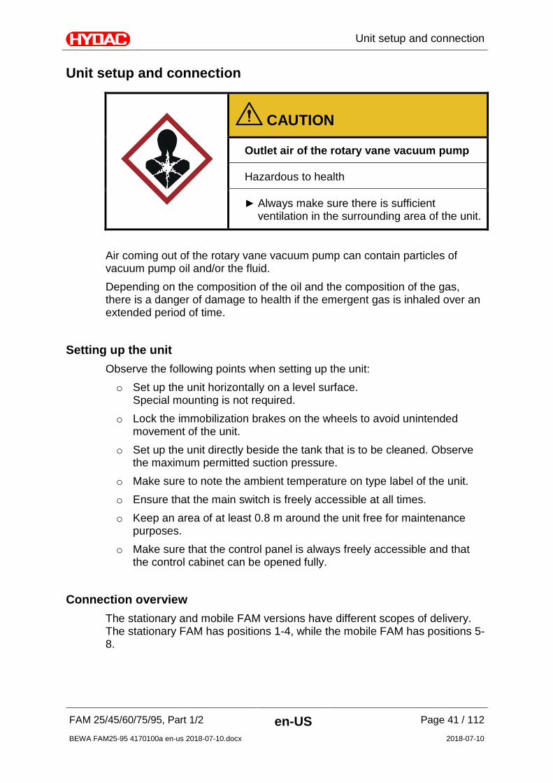
Unit setup and connection
CAUTION
Outlet air of the rotary vane vacuum pump
Hazardous to health
Always make sure there is sufficient ventilation in the surrounding area of the unit.
Air coming out of the rotary vane vacuum pump can contain particles of vacuum pump oil and/or the fluid. Depending on the composition of the oil and the composition of the gas, there is a danger of damage to health if the emergent gas is inhaled over an extended period of time.
Setting up the unit Observe the following points when setting up the unit: o Set up the unit horizontally on a level surface.
Special mounting is not required. o Lock the immobilization brakes on the wheels to avoid unintended
movement of the unit. o Set up the unit directly beside the tank that is to be cleaned. Observe
the maximum permitted suction pressure. o Make sure to note the ambient temperature on type label of the unit. o Ensure that the main switch is freely accessible at all times. o Keep an area of at least 0.8 m around the unit free for maintenance
purposes. o Make sure that the control panel is always freely accessible and that
the control cabinet can be opened fully.
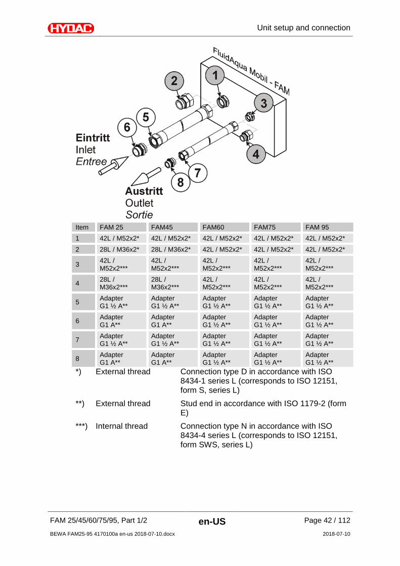
Connection overview The stationary and mobile FAM versions have different scopes of delivery. The stationary FAM has positions 1-4, while the mobile FAM has positions 5-8.
Unit setup and connection
FAM 25/45/60/75/95, Part 1/2 en-US Page 42 / 112
BEWA FAM25-95 4170100a en-us 2018-07-10.docx 2018-07-10
Item FAM 25 FAM45 FAM60 FAM75 FAM 95 1 42L / M52x2* 42L / M52x2* 42L / M52x2* 42L / M52x2* 42L / M52x2* 2 28L / M36x2* 28L / M36x2* 42L / M52x2* 42L / M52x2* 42L / M52x2*
3 42L / M52x2***
42L / M52x2***
42L / M52x2***
42L / M52x2***
42L / M52x2***
4 28L / M36x2***
28L / M36x2***
42L / M52x2***
42L / M52x2***
42L / M52x2***
5 Adapter G1 ½ A**
Adapter G1 ½ A**
Adapter G1 ½ A**
Adapter G1 ½ A**
Adapter G1 ½ A**
6 Adapter G1 A**
Adapter G1 A**
Adapter G1 ½ A**
Adapter G1 ½ A**
Adapter G1 ½ A**
7 Adapter G1 ½ A**
Adapter G1 ½ A**
Adapter G1 ½ A**
Adapter G1 ½ A**
Adapter G1 ½ A**
8 Adapter G1 A**
Adapter G1 A**
Adapter G1 ½ A**
Adapter G1 ½ A**
Adapter G1 ½ A**
*) External thread Connection type D in accordance with ISO 8434-1 series L (corresponds to ISO 12151, form S, series L)
**) External thread Stud end in accordance with ISO 1179-2 (form E)
***) Internal thread Connection type N in accordance with ISO 8434-4 series L (corresponds to ISO 12151, form SWS, series L)

Unit setup and connection
FAM 25/45/60/75/95, Part 1/2 en-US Page 43 / 112
BEWA FAM25-95 4170100a en-us 2018-07-10.docx 2018-07-10
Notes on pipes and hoses
NOTICE
Non-permitted pressure at the inlet IN / outlet OUT
Risk of malfunctions
Determine the pressure to be anticipated at the inlet/outlet with the prescribed values.
Make sure that the cross-section of the connected hoses/piping is at least as large as the cross-section of the inlet/outlet port sizes. In order to keep the pressure loss as low as possible, use as few threaded connections as possible. Connect all connectors to the FAM without initial stress. The pressure at the inlet Pe / outlet Pa depends on the height differential between the FAM fluid surface in the tank port (aspiration height ∆P(height)) and the line losses (∆P(line)). If the FAM is above the fluid surface in the tank, determine the pressure as follows:
Pe = -∆P(Height) -∆P(Line)
Pa = -∆P(height) +∆P(line) If the FAM is below the fluid surface in the tank, determine the pressure as follows:
Pe = +∆P(Height) -∆P(Line)
Pa = +∆P(height) +∆P(line) Caution: Pe perm/Pa perm refers to the inlet/outlet FAM without hose. The respective values for Pe perm/Pa perm can be found in the technical data on page 98.
Determine the pressure loss ∆P(height) as follows: ∆P(height)[bar] = h/10. Here, h refers to the distance between the suction port on the FAM and the fluid surface in the tank.
Unit setup and connection
FAM 25/45/60/75/95, Part 1/2 en-US Page 44 / 112
BEWA FAM25-95 4170100a en-us 2018-07-10.docx 2018-07-10
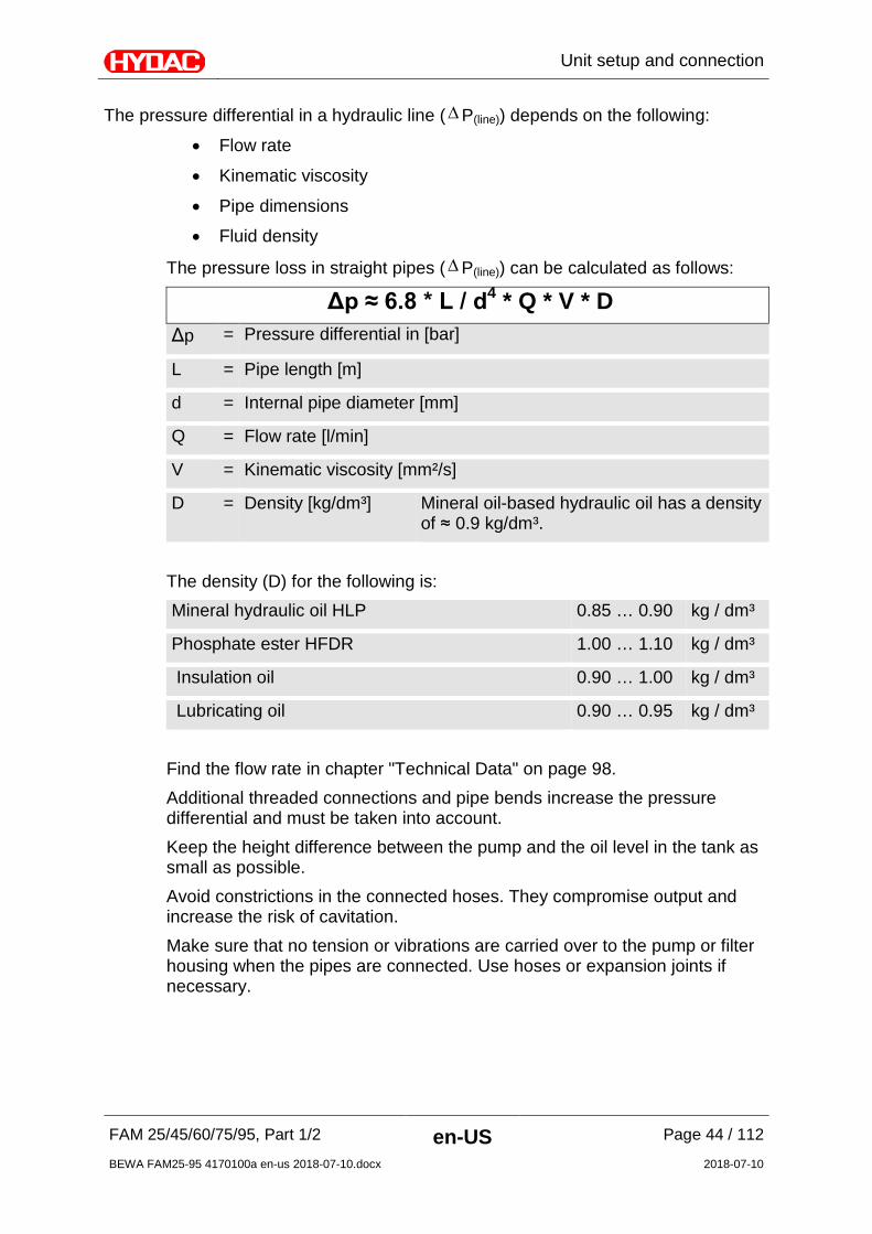
The pressure differential in a hydraulic line (∆P(line)) depends on the following:
• Flow rate
• Kinematic viscosity
• Pipe dimensions
• Fluid density
The pressure loss in straight pipes (∆P(line)) can be calculated as follows:
Δp ≈ 6.8 * L / d4 * Q * V * D Δp = Pressure differential in [bar]
L = Pipe length [m]
d = Internal pipe diameter [mm]
Q = Flow rate [l/min]
V = Kinematic viscosity [mm²/s]
D = Density [kg/dm³] Mineral oil-based hydraulic oil has a density of ≈ 0.9 kg/dm³.
The density (D) for the following is: Mineral hydraulic oil HLP 0.85 … 0.90 kg / dm³
Phosphate ester HFDR 1.00 … 1.10 kg / dm³
Insulation oil 0.90 … 1.00 kg / dm³
Lubricating oil 0.90 … 0.95 kg / dm³ Find the flow rate in chapter "Technical Data" on page 98. Additional threaded connections and pipe bends increase the pressure differential and must be taken into account. Keep the height difference between the pump and the oil level in the tank as small as possible. Avoid constrictions in the connected hoses. They compromise output and increase the risk of cavitation. Make sure that no tension or vibrations are carried over to the pump or filter housing when the pipes are connected. Use hoses or expansion joints if necessary.
Unit setup and connection
FAM 25/45/60/75/95, Part 1/2 en-US Page 45 / 112
BEWA FAM25-95 4170100a en-us 2018-07-10.docx 2018-07-10
Connecting the inlet (IN) The maximum permitted pressure Pe perm at the inlet to the FAM can be found in the technical data. Use a negative pressure-resistant, flexible hose or a pipe for the suction-side connection. Make sure that the cross-section of the connected hoses/piping is at least as large as the cross-section of the inlet/outlet port sizes. For the cross-section of the connection line, use at least DN50 on FAM 75 and 95. The shape of the tank connection should be set up in such a way that it will always be lower than the level of the oil in the tank.
NOTICE
Contamination too high
The FAM will be damaged
Do not prime directly at the bottom of the tank. Do not prime in the sump. Never prime without a built-in suction screen.
The greatest contamination is found on the bottom of the tank. All impurities and other particles are deposited on the bottom of the tank. All impurities and other particles are deposited on the bottom of the tank.
Connecting the outlet (OUT)
The maximum permitted pressure at the outlet Pa perm can be found in the technical data.
NOTICE
Connection OUT closed off
The FAM switches over to error mode
Check to be sure that all of the locking fixtures at the inlet/outlet are in "open" position each time before start-up.
To prevent air from entering the medium, make sure that the pressure hose with lance is always below the oil level in operation.

Unit setup and connection
FAM 25/45/60/75/95, Part 1/2 en-US Page 46 / 112
BEWA FAM25-95 4170100a en-us 2018-07-10.docx 2018-07-10
Selecting a fluid filter element To ensure a fault-free operation, a suitable filtration grade must be used. Refer to chapter "Technical Data" on page 98 for the suitable filtration grade. The filtration grade is determined by the filter design, the operating viscosity and the fluid to be cleaned.
Unit setup and connection
FAM 25/45/60/75/95, Part 1/2 en-US Page 47 / 112
BEWA FAM25-95 4170100a en-us 2018-07-10.docx 2018-07-10
Preparing vacuum pump for operation Different vacuum pumps are installed depending on the FAM version and they are described as follows:
- Water ring vacuum pump FAM-xx-x-x-x-xx-W/WA-x …
-> Details from page 47
- Rotary vane vacuum pump FAM-xx-x-x-x-xx-R-x …
-> Details from page 49
Preparing water ring vacuum pump (FAM-xx-x-x-x-xx-W/WA-x …)
NOTICE
Operation without water
The water ring vacuum pump will be destroyed
The water ring vacuum pump requires water as its operating medium. Check the water level before star-up, topping up the water if
necessary. Fill the water ring vacuum pump up with clean tap water. Do not use any deionized water If there is a danger of freezing, add commercially available automotive
antifreeze to the water in the vacuum pump.
If no vacuum forms after switching on the FAM, the intake connection [N1.0] should be filled with an additional 2-3 liters of water. To do this, release the transparent suction hose from the support and fill in the water. Re-attach the hose afterwards. During operation, the water filling level is monitored automatically by means of a level switch built into the vacuum pump. A corresponding message will be outputted on the display when the filling level reaches the MIN switch point.

Unit setup and connection
FAM 25/45/60/75/95, Part 1/2 en-US Page 48 / 112
BEWA FAM25-95 4170100a en-us 2018-07-10.docx 2018-07-10
Adding water manually: Add clean tap water through the opening [N3.4] until the water level has reached the lower edge of the opening. Seal the opening again afterwards. Automatic water feed (optional): If the FAM is equipped with an automatic water supply for the water ring vacuum pump, connect the water supply hose according to national and generally applicable regulations. Use a pipe separator if installing on a drinking water line. The port is constructed with 1" interior thread at the filter combination.
The water connection must meet the following conditions: Water temperature: 30°C maximum
Operating pressure: 1.5 … 16 bar
With this version, the vacuum pump is filled automatically after the FAM is switched on. Check the downstream pressure after the back-flushing filter in accordance with the instructions on page 70.
Unit setup and connection
FAM 25/45/60/75/95, Part 1/2 en-US Page 49 / 112
BEWA FAM25-95 4170100a en-us 2018-07-10.docx 2018-07-10
Preparing rotary vane vacuum pump (FAM-xx-x-x-x-xx-R-x …) As a basic rule, the rotary vane vacuum pump is not filled with oil at the time of delivery of the FAM. A sufficient amount of vacuum pump oil for the initial filling is included in the scope of delivery.
NOTICE
Operation without vacuum pump oil
The rotary vane vacuum pump will be destroyed
The rotary vane vacuum pump requires oil as its operating medium. Check the oil level before start-up, refilling with vacuum pump oil if
necessary.
The maximum filling amount for vacuum pump oil is: FAM 25 ≈ 0.3 liter
FAM 45-95 ≈ 1.0 liter The oil level is monitored automatically by the integrated float switch while the FAM is in operation. A message will appear on the control panel when the MIN MAX filling level has been reached. For refilling, use the vacuum pump oil listed in chapter "Replacement Parts and Accessories List". This oil has bee comprehensively tested and approved for utilization.
Unit setup and connection
FAM 25/45/60/75/95, Part 1/2 en-US Page 50 / 112
BEWA FAM25-95 4170100a en-us 2018-07-10.docx 2018-07-10
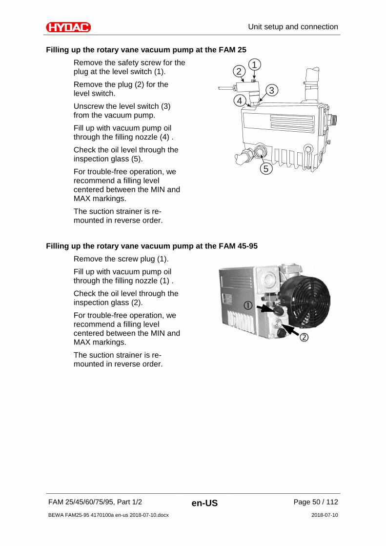
Filling up the rotary vane vacuum pump at the FAM 25 Remove the safety screw for the plug at the level switch (1). Remove the plug (2) for the level switch. Unscrew the level switch (3) from the vacuum pump. Fill up with vacuum pump oil through the filling nozzle (4) . Check the oil level through the inspection glass (5). For trouble-free operation, we recommend a filling level centered between the MIN and MAX markings. The suction strainer is re-mounted in reverse order.
12
34
5
Filling up the rotary vane vacuum pump at the FAM 45-95
Remove the screw plug (1). Fill up with vacuum pump oil through the filling nozzle (1) . Check the oil level through the inspection glass (2). For trouble-free operation, we recommend a filling level centered between the MIN and MAX markings. The suction strainer is re-mounted in reverse order.

Unit setup and connection
FAM 25/45/60/75/95, Part 1/2 en-US Page 51 / 112
BEWA FAM25-95 4170100a en-us 2018-07-10.docx 2018-07-10
Electrical connection of the unit
DANGER
Exposed electrical components in the switch cabinet
Danger of fatal injury due to electric shock
Any work involving the electrical system may only be done by a properly trained, certified electrician.
The electrical connection of units without connection plugs to the power supply module may be performed only by a technician with corresponding knowledge and skills. Make sure that the voltage and frequency specifications on the FAM type label correspond to the existing mains voltage. If a plug is present on the FAM or if a plug is mounted, then the FAM is to be operated from a correspondingly fused socket.
The electrical data on the type label of the unit is binding, and not that on the type label of the switch cabinet.

Unit setup and connection
FAM 25/45/60/75/95, Part 1/2 en-US Page 52 / 112
BEWA FAM25-95 4170100a en-us 2018-07-10.docx 2018-07-10
Rotating field Make sure there is a clockwise rotating field. If this is not the case, then the phases can be rotated in the 16A/32 A connection plug with the aid of the phase changing switch in the plug. For the 63A version and units without plug (60 Hz version), the two phases must be switched on the terminal block X0 (e.g. L1 and L2).
A phase sequence relay checks the correct phase sequence after switch-on. In the event of an incorrect phase sequence, error message no. 29 is shown on the control panel. Additional details can be viewed in part 2/2 of the Operating and maintenance instructions.

Operating elements on the FAM
FAM 25/45/60/75/95, Part 1/2 en-US Page 53 / 112
BEWA FAM25-95 4170100a en-us 2018-07-10.docx 2018-07-10
Operating elements on the FAM The following operating elements are to be found on the FAM:
Item Description
A Main switch with E-STOP function
B Alarm signal lamp (yellow)
C Operate the control panel and error messages / troubleshooting see Operation and maintenance instructions, part 2/2
D Needle valve to set the pressure in the vacuum column
Switching on / switching off / commissioning and error messages
Details on switching on/off, commissioning and error messages/troubleshooting can be found in the Operation and Maintenance Instructions, part 2/2.
Performing maintenance
FAM 25/45/60/75/95, Part 1/2 en-US Page 54 / 112
BEWA FAM25-95 4170100a en-us 2018-07-10.docx 2018-07-10
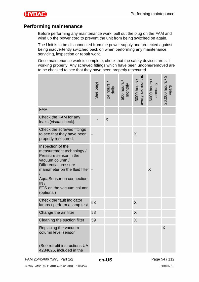
Performing maintenance Before performing any maintenance work, pull out the plug on the FAM and wind up the power cord to prevent the unit from being switched on again. The Unit is to be disconnected from the power supply and protected against being inadvertently switched back on when performing any maintenance, servicing, inspection or repair work. Once maintenance work is complete, check that the safety devices are still working properly. Any screwed fittings which have been undone/removed are to be checked to see that they have been properly resecured.
See
pag
e
24 h
ours
/ da
ily
500
hour
s /
mon
thly
3000
hou
rs /
ever
y si
x m
onth
s
6000
hou
rs /
annu
ally
26,0
00 h
ours
/ 3
year
s
FAM
Check the FAM for any leaks (visual check). - X
Check the screwed fittings to see that they have been properly resecured.
- X
Inspection of the measurement technology / Pressure sensor in the vacuum column / Differential pressure manometer on the fluid filter / AquaSensor on connection IN / ETS on the vacuum column (optional)
- X
Check the fault indicator lamps / perform a lamp test 58 X
Change the air filter 58 X
Cleaning the suction filter 59 X
Replacing the vacuum column level sensor (See retrofit instructions UA 4284625, included in the
X

Performing maintenance
FAM 25/45/60/75/95, Part 1/2 en-US Page 55 / 112
BEWA FAM25-95 4170100a en-us 2018-07-10.docx 2018-07-10
See
pag
e
24 h
ours
/ da
ily
500
hour
s /
mon
thly
3000
hou
rs /
ever
y si
x m
onth
s
6000
hou
rs /
annu
ally
26,0
00 h
ours
/ 3
year
s
scope of delivery of the spare part)
Water ring vacuum pump
Check and Clean the Level Switch 61 X
Replace water 61 X
Replace water filter vacuum pump 61 X
Cleaning the cooling fins on the water cooler 63 X
Flushing and completely cleaning the vacuum pump 63 X
Cleaning the condensation cooler 67 X
Back-flush water filter combination (only for version with automatic water intake)
69 X
Rotary vane vacuum pump
Checking the oil level 71 X
Replace oil, oil filter and air de-oiling element 75 X
Check and clean the ventilator hood - X
Emptying / filling pump
Check and clean the ventilator hood - X
Fluid filter
Performing maintenance
FAM 25/45/60/75/95, Part 1/2 en-US Page 56 / 112
BEWA FAM25-95 4170100a en-us 2018-07-10.docx 2018-07-10
See
pag
e
24 h
ours
/ da
ily
500
hour
s /
mon
thly
3000
hou
rs /
ever
y si
x m
onth
s
6000
hou
rs /
annu
ally
26,0
00 h
ours
/ 3
year
s
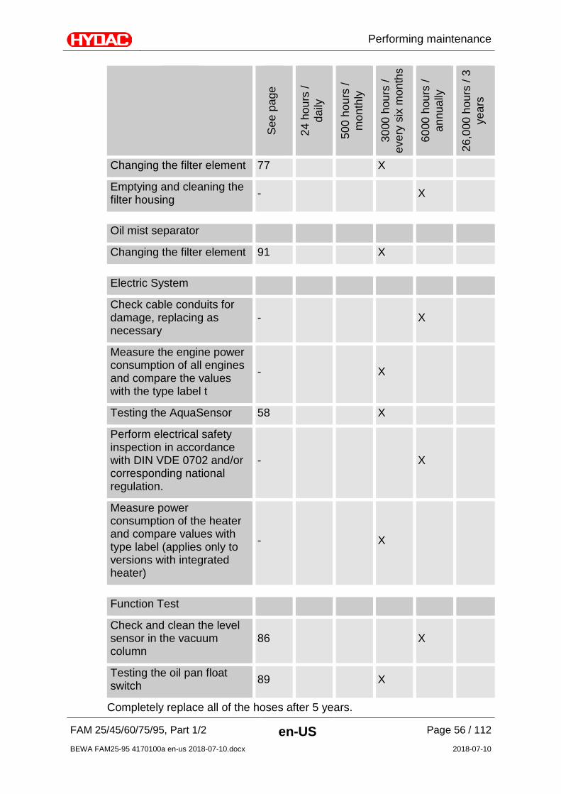
Changing the filter element 77 X
Emptying and cleaning the filter housing - X
Oil mist separator
Changing the filter element 91 X
Electric System
Check cable conduits for damage, replacing as necessary
- X
Measure the engine power consumption of all engines and compare the values with the type label t
- X
Testing the AquaSensor 58 X
Perform electrical safety inspection in accordance with DIN VDE 0702 and/or corresponding national regulation.
- X
Measure power consumption of the heater and compare values with type label (applies only to versions with integrated heater)
- X
Function Test
Check and clean the level sensor in the vacuum column
86 X
Testing the oil pan float switch 89 X
Completely replace all of the hoses after 5 years.
Performing maintenance
FAM 25/45/60/75/95, Part 1/2 en-US Page 57 / 112
BEWA FAM25-95 4170100a en-us 2018-07-10.docx 2018-07-10
The pictures and illustrations in the descriptions are examples. They do not represent all of the different product variants.

Performing maintenance
FAM 25/45/60/75/95, Part 1/2 en-US Page 58 / 112
BEWA FAM25-95 4170100a en-us 2018-07-10.docx 2018-07-10
Function testing of the fault indicator lamp To perform the function test of the fault indicator lamp, follow these steps: 1. Switch the unit on using the main switch (A).
2. An automatic lamp test is conducted after the unit has been switched on. The fault indicator lamp (B) lights up briefly during this test.
3. The function test of the fault indicator lamp has been completed.
Change the air filter Replace the air filter (1) every six months. If you are operating the unit in a very dusty/damp environment, the replacement interval is accordingly shorter. 1. Manually unscrew the air filter (1).
2. Dispose of the air filter in an environmentally friendly manner.
3. Manually screw on the new air filter (1) and tighten this manually until secure.
4. The air filter replacement has been completed.
Testing the AquaSensor Check the AquaSensor annually with the calibration and adjustment set (HYDAC p/no. 3122629). Replace the AquaSensor if it exhibits great deviations. The part no. can be found in the spare parts list.
Performing maintenance
FAM 25/45/60/75/95, Part 1/2 en-US Page 59 / 112
BEWA FAM25-95 4170100a en-us 2018-07-10.docx 2018-07-10
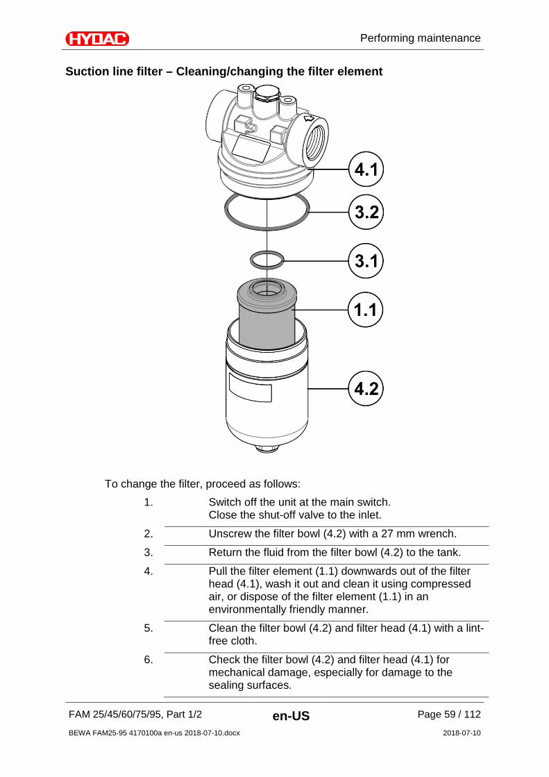
Suction line filter – Cleaning/changing the filter element
To change the filter, proceed as follows:
1. Switch off the unit at the main switch. Close the shut-off valve to the inlet.
2. Unscrew the filter bowl (4.2) with a 27 mm wrench.
3. Return the fluid from the filter bowl (4.2) to the tank.
4. Pull the filter element (1.1) downwards out of the filter head (4.1), wash it out and clean it using compressed air, or dispose of the filter element (1.1) in an environmentally friendly manner.
5. Clean the filter bowl (4.2) and filter head (4.1) with a lint-free cloth.
6. Check the filter bowl (4.2) and filter head (4.1) for mechanical damage, especially for damage to the sealing surfaces.

Performing maintenance
FAM 25/45/60/75/95, Part 1/2 en-US Page 60 / 112
BEWA FAM25-95 4170100a en-us 2018-07-10.docx 2018-07-10
7. Check the O-ring (3.2) for damage. Replace it if necessary.
8. Moisten the sealing surfaces on the filter bowl (4.2) and filter head (4.1) thread, and on the O-rings with fluid.
9. Insert the filter element (1.1) upwards from the bottom into the element mount in the filter head (4.1).
10. Screw the filter bowl (4.2) into the filter head (4.1) up to the stop and then loosen this by a quarter-turn.
11. The filter element change is now complete. Check the suction line filter during operation for any untight spots.

Performing maintenance
FAM 25/45/60/75/95, Part 1/2 en-US Page 61 / 112
BEWA FAM25-95 4170100a en-us 2018-07-10.docx 2018-07-10
Maintaining the water ring vacuum pump (FAM-xx-x-x-xx-W/WA-…) Checking/Cleaning the level switch
To check or clean the level switch, please proceed as follows: 1. Remove the cover plate (1) of the vacuum
pump.
2. Unscrew the four fastening screws of the level switch.
3. Remove the level switch (2) out of the vacuum pump from the top.
4. Check the level switch (2) for dirt and damage.
5. Check the function of the float switch(es) on the basis of the PLC inlet. See the illustration "Switching status" below in this connection. Please note that to inspect the switching status, the power unit needs to be switched on.
6. Perform the assembly in reversed order of sequence.
7. Testing/Cleaning the level switch is complete.
Switching Status - Level Sensor Water Ring Vacuum Pump/PLC
Leve
l sen
sor
I1.0 I1.1 I1.2 I1.0 I1.1 I1.2 I1.0 I1.1 I1.2
PLC
OFF OFF ON ON OFF ON ON ON OFF
Replacing the Water Filter
Performing maintenance
FAM 25/45/60/75/95, Part 1/2 en-US Page 62 / 112
BEWA FAM25-95 4170100a en-us 2018-07-10.docx 2018-07-10
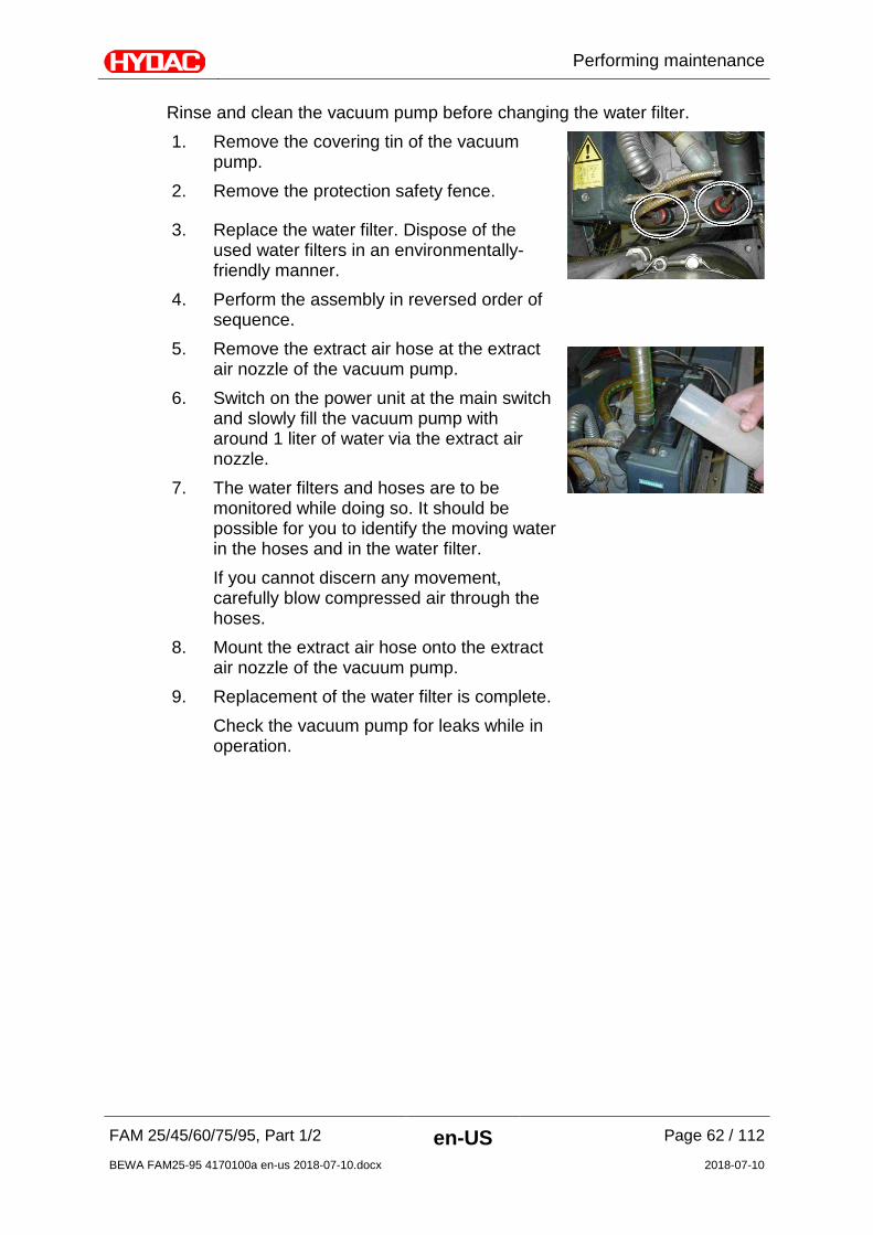
Rinse and clean the vacuum pump before changing the water filter. 1. Remove the covering tin of the vacuum
pump.
2. Remove the protection safety fence.
3. Replace the water filter. Dispose of the used water filters in an environmentally-friendly manner.
4. Perform the assembly in reversed order of sequence.
5. Remove the extract air hose at the extract air nozzle of the vacuum pump.
6. Switch on the power unit at the main switch and slowly fill the vacuum pump with around 1 liter of water via the extract air nozzle.
7. The water filters and hoses are to be monitored while doing so. It should be possible for you to identify the moving water in the hoses and in the water filter. If you cannot discern any movement, carefully blow compressed air through the hoses.
8. Mount the extract air hose onto the extract air nozzle of the vacuum pump.
9. Replacement of the water filter is complete. Check the vacuum pump for leaks while in operation.

Performing maintenance
FAM 25/45/60/75/95, Part 1/2 en-US Page 63 / 112
BEWA FAM25-95 4170100a en-us 2018-07-10.docx 2018-07-10
Cleaning the Cooling Fins To clean the cooling fins of the vacuum pump, proceed as follows: 1. Remove the covering tin.
2. Remove the protection safety fence. 3. Use compressed air to clean the cooling
fins of the water cooler. 4. Perform the assembly in reversed order of
sequence. 5. Cleaning the cooling fins is complete.
Flushing/Cleaning the vacuum pump
To perform these tasks, you will need the following tools and equipment:
• Compressed air
• VacuCleaner 1.75 liter
• Measuring beaker ≥ 2 liter
• Funnel
• 35 liters of hot water 60-65°C
• Philips screwdriver, PH#2 • Philips screwdriver, PH#3 • Flat-bladed screwdriver 0.6x4.5x100 • Face spanner 3-11-60
To flush or clean the vacuum pump, proceeds as follows:
1. Empty the vacuum pump through the evacuation line.

Performing maintenance
FAM 25/45/60/75/95, Part 1/2 en-US Page 64 / 112
BEWA FAM25-95 4170100a en-us 2018-07-10.docx 2018-07-10
2. Remove the five attachment screws on the side cover plate of the water cooler. Remove the cover plate of the water cooler.
3. Open the strap of the feed line hose [1].
Pull the feed line hose off the support.
4. Open the strap of the return line and pull the return line off the support/T-piece.
5. Carefully blow compressed air into the return
line (see direction of the arrow).
Fluid sprays out of the feed line hose. Blow out the cooler thoroughly with compressed air. The suction strainer is re-mounted in reverse order.

Performing maintenance
FAM 25/45/60/75/95, Part 1/2 en-US Page 65 / 112
BEWA FAM25-95 4170100a en-us 2018-07-10.docx 2018-07-10
6. Remove the cover plate (1), the level switch (2) and bung plug (3) from the filling opening. Fill the pump with hot water (60-65°C) through the filling opening or the opening for the level switch until the water emerges from the filling opening. Close the filling opening with the bung plug. Fill the VacuCleaner ≈ 1.75 liter through the level sensor opening. Install the level sensor. Start the vacuum pump in manual mode. Adjust the vacuum in the vacuum column to ≈ 250 mbar (absolute) using the throttle valve.
7. After around 5 minutes, drain 2 liters of the VacuCleaner into the measuring beaker.
8. Fill the collected VacuCleaner carefully into
the outlet connection of the vacuum pump.
9. Fasten the suction line.
Operate the vacuum pump for around 45 minutes in manual mode.
10. Empty the vacuum pump through the
evacuation line.

Performing maintenance
FAM 25/45/60/75/95, Part 1/2 en-US Page 66 / 112
BEWA FAM25-95 4170100a en-us 2018-07-10.docx 2018-07-10
11. Remove the bung plugs from the level switch opening and the filling opening.
12. Rinse the vacuum pump with tap water
through the level switch opening and the filling opening. Take care to ensure that the drain ball valve is open for this purpose. Close the drain ball valve. Fill the vacuum pump until water leaks out of the filling opening.
13. Screw in the bung plugs.
14. Mount the level switch.
16. Mount the cover plate.
15. Flushing/Cleaning the vacuum pump is complete. Check the vacuum pump for leaks while in operation.
Performing maintenance
FAM 25/45/60/75/95, Part 1/2 en-US Page 67 / 112
BEWA FAM25-95 4170100a en-us 2018-07-10.docx 2018-07-10
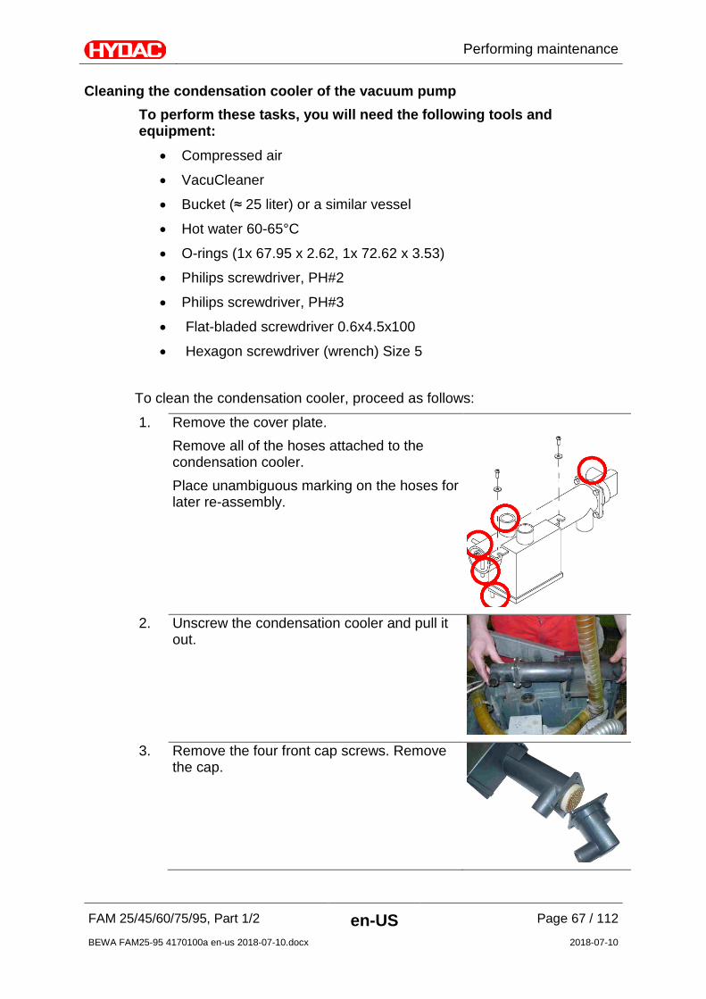
Cleaning the condensation cooler of the vacuum pump To perform these tasks, you will need the following tools and equipment:
• Compressed air
• VacuCleaner
• Bucket (≈ 25 liter) or a similar vessel
• Hot water 60-65°C
• O-rings (1x 67.95 x 2.62, 1x 72.62 x 3.53)
• Philips screwdriver, PH#2 • Philips screwdriver, PH#3 • Flat-bladed screwdriver 0.6x4.5x100 • Hexagon screwdriver (wrench) Size 5
To clean the condensation cooler, proceed as follows:
1. Remove the cover plate. Remove all of the hoses attached to the condensation cooler. Place unambiguous marking on the hoses for later re-assembly.
2. Unscrew the condensation cooler and pull it
out.
3. Remove the four front cap screws. Remove
the cap.
Performing maintenance
FAM 25/45/60/75/95, Part 1/2 en-US Page 68 / 112
BEWA FAM25-95 4170100a en-us 2018-07-10.docx 2018-07-10
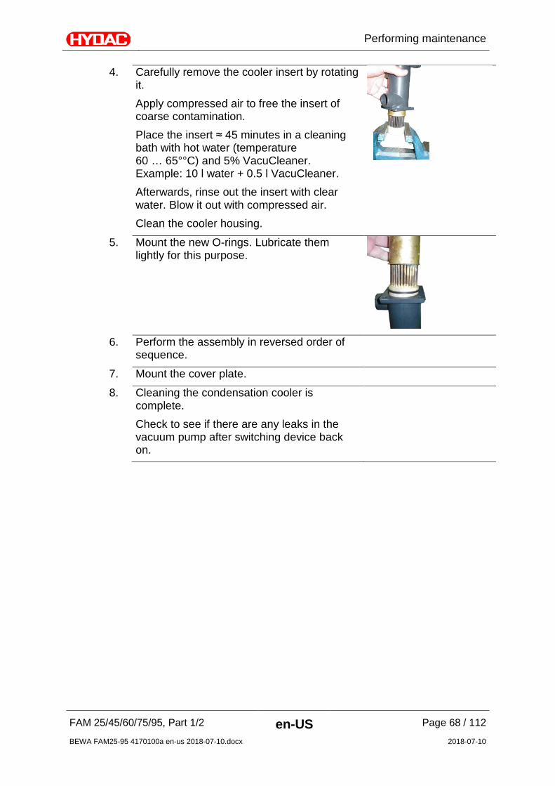
4. Carefully remove the cooler insert by rotating it. Apply compressed air to free the insert of coarse contamination. Place the insert ≈ 45 minutes in a cleaning bath with hot water (temperature 60 … 65°°C) and 5% VacuCleaner. Example: 10 l water + 0.5 l VacuCleaner. Afterwards, rinse out the insert with clear water. Blow it out with compressed air. Clean the cooler housing.
5. Mount the new O-rings. Lubricate them lightly for this purpose.
6. Perform the assembly in reversed order of
sequence.
7. Mount the cover plate.
8. Cleaning the condensation cooler is complete. Check to see if there are any leaks in the vacuum pump after switching device back on.

Performing maintenance
FAM 25/45/60/75/95, Part 1/2 en-US Page 69 / 112
BEWA FAM25-95 4170100a en-us 2018-07-10.docx 2018-07-10
Water filter combination (FAM-xx-x-x-xx-WA-...) maintenance Perform maintenance on the optional water filter combination at regular intervals as described in the following.
Back-Flush Water Filter Combination To back-flush the water filter combination, proceed as follows: You will require:
• Collecting vessel (25 liter)
• Tap water with water pressure of ≥ 1.5 bar.
1. Place a collecting vessel (≈ 25 liter) under the water-filter combination.
2. Open the ball valve by turning the back-flush button until it stops.
3. Take care to ensure that the marking bars are in vertical position. The back-flush system is activated. It is possible to remove filtered water during the back-flushing sequence.
4. Close the ball valve after ≈ 15 seconds. A longer back-flushing period may be required with filters that are heavily clogged.
5. Back-flushing the water filter combination is complete. Set the next date for manual back-flushing with the aid of the memory ring. Check the water filter combination for leaks while in operation.

Performing maintenance
FAM 25/45/60/75/95, Part 1/2 en-US Page 70 / 112
BEWA FAM25-95 4170100a en-us 2018-07-10.docx 2018-07-10
Checking / setting the downstream pressure Downstream pressure is the term used for the pressure after the water filter combination. Reduce the pressure to prevent strong turbulence in the vacuum pump tank when the operating pressure is high. The downstream pressure at the filter combination is set ex-works to 5 bar. To adjust the downstream pressure, proceed as follows:
1. Close the locking feature [1].
2. Relieve the pressure in the pipe between the shut-off devices [1] and [2]. For example using water spigots.
3. Loosen the flat-blade screw [4]. Do not screw out completely!
4. Depressurize the nominal value spring by turning the adjustment grip to the left (-).
5. Close the locking feature [2].
6. Slowly open the shut-off device [1].
7. Set the nominal value of 5 bar (downstream pressure) by rotating the adjustment grip. Turning the the right (+) increases the nominal value, turning to the left (-) decreases the nominal value. (Read the value on the manometer) If the downstream pressure is set to a lower value, then the output side must be relieved of pressure in order for the desired downstream pressure to adjust.
8. Tighten the flat-blade screw firmly [4].
9. Slowly open the shut-off device [2].
10. Testing the downstream pressure is complete.
Performing maintenance
FAM 25/45/60/75/95, Part 1/2 en-US Page 71 / 112
BEWA FAM25-95 4170100a en-us 2018-07-10.docx 2018-07-10
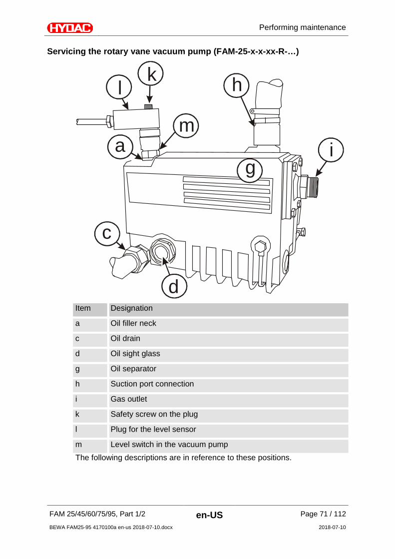
Servicing the rotary vane vacuum pump (FAM-25-x-x-xx-R-…)
l
ma i
g
h
d
c
k
Item Designation
a Oil filler neck
c Oil drain
d Oil sight glass
g Oil separator
h Suction port connection
i Gas outlet
k Safety screw on the plug
l Plug for the level sensor
m Level switch in the vacuum pump The following descriptions are in reference to these positions.
Performing maintenance
FAM 25/45/60/75/95, Part 1/2 en-US Page 72 / 112
BEWA FAM25-95 4170100a en-us 2018-07-10.docx 2018-07-10
Replacing oil and oil filter (FAM 25) The first oil change must take place after 100 operating hours. This increases the interval to approx. 3000 hours or every six months. The vacuum pump must be at operating state temperature when the oil is changed: Put the FAM into operation for 10 minutes. Switch off the FAM at the main switch. Wait until the pressure in the vacuum column has reached the atmospheric pressure (≈ 1000 mbar absolute). To perform these tasks, you will need the following tools and equipment:
• Vacuum pump oil (for part no., see spare parts list)
• Maintenance set, comprising oil filter, air deoiling element, ventilation cover seal (for part-no., see replacement parts list)
• Fork wrenches SW 27 / SW 32 To change the oil, proceed as follows:
1. Put a suitable container in place to catch the used oil.
2. Open the oil drain (c) and allow the old oil to drain into the container. Dispose of the used oil properly.
3. Close the screw plug when the flow of oil diminishes. Let the pump run again briefly for a few seconds,
4. Open the plug screw once again and drain off the remaining oil.
5. Screw in the plug screw and tighten it firmly.
6. Remove the oil filter and dispose of it properly.
7. Install the new oil filter.
8. Fill in fresh vacuum pump oil through the oil filling screw plug (a). Ensure that the level is in the middle between the MIN and MAX (d) markings. For details, refer to the section "Preparing vacuum pump for operation" on page 47..
Performing maintenance
FAM 25/45/60/75/95, Part 1/2 en-US Page 73 / 112
BEWA FAM25-95 4170100a en-us 2018-07-10.docx 2018-07-10
Replacing the air de-oiling element (FAM 25) Oil mist or increased electricity consumption by the drive engine (response of the engine protection switch) are signs of a soiled air de-oiling element. To replace the air de-oiling element, proceed as follows: 1. Remove the ventilation cover (i) from the oil separator (g) 2. Undo the screw in the middle of the filter spring, but do not remove this. 3. Press the filter spring down and rotate it out of the depression. 4. Remove the filter spring from the oil separator(g). 5. Pull the air de-oiling element out of the oil separator (g). 6. Make sure that the new air deoiling element is provided with a new O-
ring. 7. Install the air de-oiling element in such a way that the opening is
situated correctly in the holder in the oil separator (g). 8. Ensure that the tip of the screws in the center of the filter spring
protrudes ≈ 2 – 5 thread turns out of the filter spring. 9. Install the filter spring in such a way that the ends are secured against
slipping by lugs in the receptacles in the oil separator (g) and the tip of the screw engages in the depression of the air de-oiling element.
10. Tighten the screw in the filter spring until the head of the screw impacts against the spring steel sheet.
11. Make sure that the seal under the ventilation cover (i) is clean and undamaged. Replace the seal if necessary.
12. Fasten the ventilation cover (i) with seal and hexagon-head screws to the oil separator (g).
The air de-oiling element becomes saturated with oil during operation. A slight lowering of the oil filling level after the air de-oiling element has been replaced is therefore quite normal.

Performing maintenance
FAM 25/45/60/75/95, Part 1/2 en-US Page 74 / 112
BEWA FAM25-95 4170100a en-us 2018-07-10.docx 2018-07-10
Rotary vane vacuum pump (FAM 45/60/75/95-xx-x-x-xx-R-…)
Item Designation
1 Oil separator
2 Inlet flange
3 Oil sight glass
4 Screw plug
5 Oil filling screw plug
6 Exhaust valve
7 Rotor vane
8 Rotor
9 Air de-oiling element
10 Exhaust cover
11 Oil filter
12 Demister
13 Oil sump
14 Service cover
15 Leaf spring The following descriptions are in reference to these positions.

Performing maintenance
FAM 25/45/60/75/95, Part 1/2 en-US Page 75 / 112
BEWA FAM25-95 4170100a en-us 2018-07-10.docx 2018-07-10
Changing vacuum pump oil and oil filter (FAM 45-95) The first oil change must take place after 100 operating hours. This increases the interval to approx. 3000 hours or every six months. The vacuum pump must be at operating state temperature when the oil is changed. Switch on the unit and let it run for at least 10 minutes, then switch it off at the main switch. Wait until the pressure in the vacuum column has fallen to atmospheric pressure (≈ 1000 mbar absolute). To perform these tasks, you will need the following tools, equipment and material:
• Vacuum pump oil (for part no., see spare parts list)
• Used oil container
• Maintenance set, comprising oil filter, air deoiling element, ventilation cover seal (for part-no., see spare parts list)
• 27 mm / 32 mm wrench To change the oil, proceed as follows:
1. Have a suitable drip tray on hand to catch the used oil.
2. Open the screw plug (4) and allow the used vacuum pump oil to drain into the container. Dispose of the used oil in an environmentally friendly manner.
3. Close the screw plug when the flow of oil diminishes. Let the pump run again briefly for a few seconds,
4. Open the plug screw once again and drain off the remaining oil.
5. Screw in the plug screw and tighten it firmly.
6. Remove the oil filter (11) and dispose of it in an environmentally friendly manner.
7. Install the new oil filter (11).
8. Fill in fresh vacuum pump oil through the oil filling screw plug (5). Ensure that the level is in the middle between the MIN and MAX (3) markings. For details, refer to the section "Preparing vacuum pump for operation" on page 47..
9. The change of the vacuum pump oil and the oil filter is complete.

Performing maintenance
FAM 25/45/60/75/95, Part 1/2 en-US Page 76 / 112
BEWA FAM25-95 4170100a en-us 2018-07-10.docx 2018-07-10
Replacing the air de-oiling element of the vacuum pump (FAM 45-95) Oil mist or increased electricity consumption by the drive engine (response of the engine protection switch) are signs of a soiled air de-oiling element. To replace the air de-oiling element, proceed as follows: 1. Remove the 4 attachment screws of the ventilation cover (10). 2. Loosen the safety screw of the leaf spring (15) 3. Remove the leaf spring (15). 4. Remove the air de-oiling element (9) and replace it with a new element. 5. Replace the ventilation cover seal (10). 6. The suction strainer is re-mounted in reverse order.
The air de-oiling element becomes saturated with oil during operation. A slight lowering of the oil filling level after the air de-oiling element has been replaced is therefore quite normal.

Performing maintenance
FAM 25/45/60/75/95, Part 1/2 en-US Page 77 / 112
BEWA FAM25-95 4170100a en-us 2018-07-10.docx 2018-07-10
Replacing the filter element on the fluid filter
WARNING
Hydraulic system is under pressure
Danger of bodily injury
The hydraulic system must be depressurized before performing any work on the hydraulic system.
Switch off the FAM before replacing the filter element.
The FAM is equipped with various fluid filters depending on the version. You will find the different versions with the corresponding procedures described below: Fluid filter version Model Code For details, see
page
- 2600 filter housing FAM-xx-x-x-x-26-… 77
- OLF-5 Toploader FAM-xx-x-x-x-10-… 80
- MRF Filter Housing FAM-xx-x-x-x-40-… 84
Filter housing 2600 (FAM-xx-x-x-x-26-…) – Changing filter element 1. Switch off the unit at the main
switch.
2. Depressurize the filter housing. Remove the air bleed screw (1) in the filter cover for this purpose. The residual oil is drained into a suitable container through an evacuation ball valve (2).
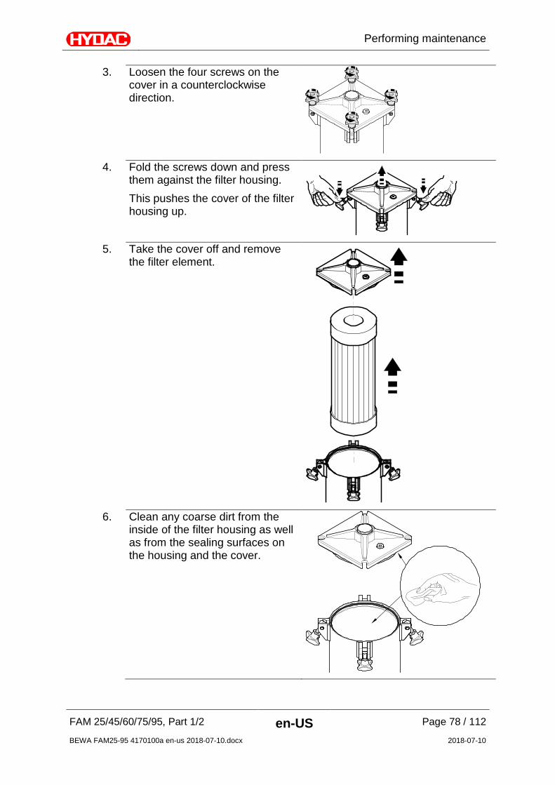
Performing maintenance
FAM 25/45/60/75/95, Part 1/2 en-US Page 78 / 112
BEWA FAM25-95 4170100a en-us 2018-07-10.docx 2018-07-10
3. Loosen the four screws on the cover in a counterclockwise direction.
4. Fold the screws down and press
them against the filter housing. This pushes the cover of the filter housing up.
5. Take the cover off and remove
the filter element.
6. Clean any coarse dirt from the
inside of the filter housing as well as from the sealing surfaces on the housing and the cover.

Performing maintenance
FAM 25/45/60/75/95, Part 1/2 en-US Page 79 / 112
BEWA FAM25-95 4170100a en-us 2018-07-10.docx 2018-07-10
6. For easier installation of
the filter element, wet the O-ring on the filter element with the operating medium.
7. Press the new filter element down
into the filter mount by turning it slightly.
Do not use striking tools for this.
8. Check the O-ring on the cover for
damage and replace it if necessary. Lightly wet the O-ring on the cover with medium.
9. Put the cover on.
Observe correct placement of the O-ring on the cover while doing so. It must not be damaged.

Performing maintenance
FAM 25/45/60/75/95, Part 1/2 en-US Page 80 / 112
BEWA FAM25-95 4170100a en-us 2018-07-10.docx 2018-07-10
10. Fold the 4 screws upward and, working cross-wise and clockwise, screw them in with uniform tightness.
11. Close the drain valve.
12. Switch on the FAM at the main
switch.
13. Remove the bleed screw (1) in the filter lid. Once the filter housing is completely filled, screw in the air bleed screw clockwise by hand and tighten it firmly with an Allen wrench.
14. Check the FAM for any leaks.
15. The filter element change on the
fluid filter is now complete.
OLF-5 Toploader (FAM-xx-x-x-x-10-…) – Replacing the filter element
Change the filter element as soon as the visual differential pressure gauge is red. The bayonet mount on the filter element makes changing the filter element easier. Rotate the filter element 90° clockwise or counterclockwise to separate it from the element receptacle.
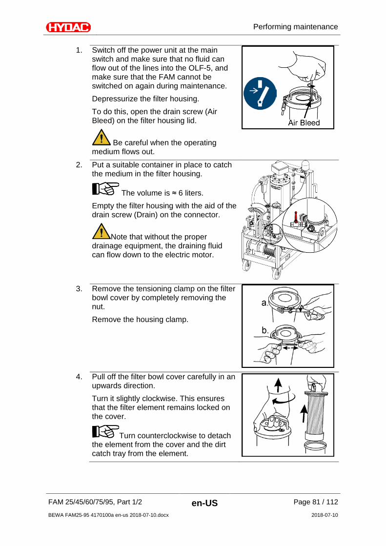
Performing maintenance
FAM 25/45/60/75/95, Part 1/2 en-US Page 81 / 112
BEWA FAM25-95 4170100a en-us 2018-07-10.docx 2018-07-10
1. Switch off the power unit at the main switch and make sure that no fluid can flow out of the lines into the OLF-5, and make sure that the FAM cannot be switched on again during maintenance. Depressurize the filter housing. To do this, open the drain screw (Air Bleed) on the filter housing lid.
Be careful when the operating medium flows out.
2. Put a suitable container in place to catch the medium in the filter housing.
The volume is ≈ 6 liters. Empty the filter housing with the aid of the drain screw (Drain) on the connector.
Note that without the proper drainage equipment, the draining fluid can flow down to the electric motor.
3. Remove the tensioning clamp on the filter
bowl cover by completely removing the nut. Remove the housing clamp.
4. Pull off the filter bowl cover carefully in an
upwards direction. Turn it slightly clockwise. This ensures that the filter element remains locked on the cover.
Turn counterclockwise to detach the element from the cover and the dirt catch tray from the element.

Performing maintenance
FAM 25/45/60/75/95, Part 1/2 en-US Page 82 / 112
BEWA FAM25-95 4170100a en-us 2018-07-10.docx 2018-07-10
5. Remove the dirt catch tray.
6. Remove the filter element from the filter
bowl cover. Dispose of the old filter element according to local regulations and guidelines.
7. Clean the removed parts and examine
them for any possible damage. Check the O-ring on the filter bowl cover for damage. Replace it if necessary. Moisten the O-rings on the filter bowl cover and on the new filter element with operating fluid. Never use grease or other media.
8. Now place the filter bowl cover on the new filter element and lock it in the bayonet mount.
9. Attach the dirt catch tray to the lower end
of the filter element and lock it in place by turning it 90° counterclockwise.
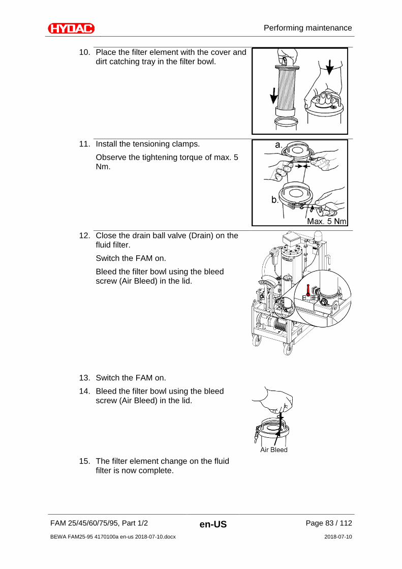
Performing maintenance
FAM 25/45/60/75/95, Part 1/2 en-US Page 83 / 112
BEWA FAM25-95 4170100a en-us 2018-07-10.docx 2018-07-10
10. Place the filter element with the cover and dirt catching tray in the filter bowl.
11. Install the tensioning clamps.
Observe the tightening torque of max. 5 Nm.
12. Close the drain ball valve (Drain) on the
fluid filter. Switch the FAM on. Bleed the filter bowl using the bleed screw (Air Bleed) in the lid.
13. Switch the FAM on. 14. Bleed the filter bowl using the bleed
screw (Air Bleed) in the lid.
15. The filter element change on the fluid
filter is now complete.

Performing maintenance
FAM 25/45/60/75/95, Part 1/2 en-US Page 84 / 112
BEWA FAM25-95 4170100a en-us 2018-07-10.docx 2018-07-10
MRF filter housing (FAM-xx-x-x-x-40-…) – Changing the filter elements 1. Switch off the unit at the main switch.
2. Close all shut-off valves at the inlet and outlet.
3. Depressurize the filter housing. Unscrew the air bleed screw (x) completely using a 10 mm Allen wrench.
4. Open the drain valve on the contamination
side. Collect the oil that emerges. Close the drain valve as soon as no more medium emerges.
5. Undo the tension clamps between the cover
and the topmost intermediate piece with the aid of a SW 13 mm open-end wrench.
6. Remove the cover and place it on a clean
surface.
7. Undo all of the star grips [A] and remove the filter element holding plate [B].
8. Remove all filter elements and dispose of
them in an environmentally friendly way.
9. Clean the inside of the filter housing.
10. Moisten the O-ring on the filter element lightly with operating medium.
11. Insert the new filter elements into the
element mount by rotating them slightly

Performing maintenance
FAM 25/45/60/75/95, Part 1/2 en-US Page 85 / 112
BEWA FAM25-95 4170100a en-us 2018-07-10.docx 2018-07-10
while applying pressure to the filter element Do not use excessive force or a hammer, etc.
12. Insert the filter element holding plate [B]. Fasten on the external filter elements. The middle filter elements do not require any further fastening. Screw on all of the star grips [A] gently by hand.
13. Clean the sealing surface on the housing.
Check the O-ring on the cover for damage and replace it if necessary. Moisten the O-ring with the operating medium.
14. Clean the sealing surface on the cover. Place the cover on the filter housing and center it.
15. Screw in the tensioning clamp tightly using a size 13 wrench and tighten it evenly at ≥ 8 Nm and ≤ 20 Nm. Screw on the lock nut and tighten it.
16. Fill the filter housing. Vent the filter housing using the tank air-vent plugs in the cover until oil emerges. Do not unscrew the ventilation plug completely — it has ventilation slots.
17. The filter element change on the fluid filter
is now complete.
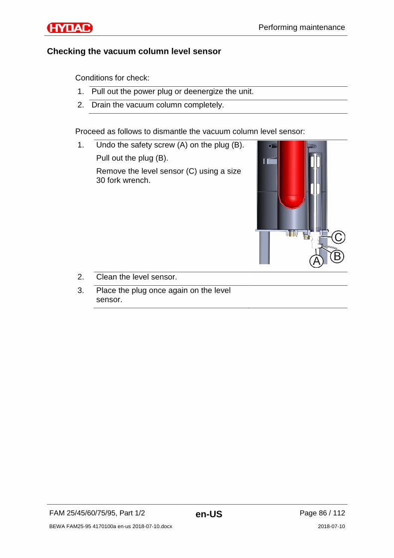
Performing maintenance
FAM 25/45/60/75/95, Part 1/2 en-US Page 86 / 112
BEWA FAM25-95 4170100a en-us 2018-07-10.docx 2018-07-10
Checking the vacuum column level sensor Conditions for check:
1. Pull out the power plug or deenergize the unit.
2. Drain the vacuum column completely.
Proceed as follows to dismantle the vacuum column level sensor:
1. Undo the safety screw (A) on the plug (B). Pull out the plug (B). Remove the level sensor (C) using a size 30 fork wrench.
2. Clean the level sensor.
3. Place the plug once again on the level sensor.
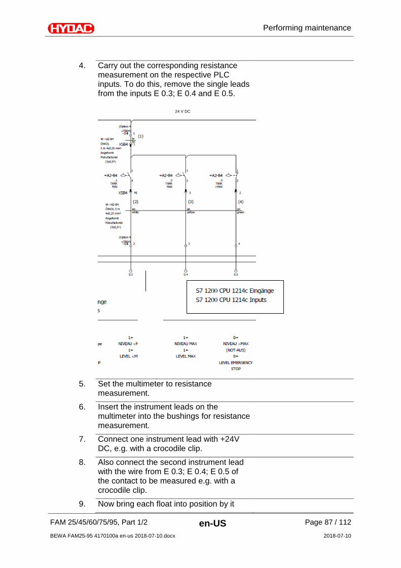
Performing maintenance
FAM 25/45/60/75/95, Part 1/2 en-US Page 87 / 112
BEWA FAM25-95 4170100a en-us 2018-07-10.docx 2018-07-10
4. Carry out the corresponding resistance measurement on the respective PLC inputs. To do this, remove the single leads from the inputs E 0.3; E 0.4 and E 0.5.
5. Set the multimeter to resistance measurement.
6. Insert the instrument leads on the multimeter into the bushings for resistance measurement.
7. Connect one instrument lead with +24V DC, e.g. with a crocodile clip.
8. Also connect the second instrument lead with the wire from E 0.3; E 0.4; E 0.5 of the contact to be measured e.g. with a crocodile clip.
9. Now bring each float into position by it
24 V DC

Performing maintenance
FAM 25/45/60/75/95, Part 1/2 en-US Page 88 / 112
BEWA FAM25-95 4170100a en-us 2018-07-10.docx 2018-07-10
closing the contact.
10. The contact is OK if the unit for measurement displays a resistance of ≤ 1.2 Ω after a measuring time of around 5 seconds. If there are larger resistance values, the contact is already damaged and no longer switches reliably, which leads to sporadic failures.
11. Perform the assembly in reversed order of sequence.

Performing maintenance
FAM 25/45/60/75/95, Part 1/2 en-US Page 89 / 112
BEWA FAM25-95 4170100a en-us 2018-07-10.docx 2018-07-10
Testing the float switch in the oil pan Proceed as follows to test the float switch in the oil pan:
1. Use your fingers to raise the float switch in the oil pan.
2. The unit must switch off and the fault
message "Pan overfilled" must appear in display of the control panel.
3. Release the float switch and acknowledge the fault message by pressing the F3 key.
4. The unit continues to operate -> You have tested the function of the float switch positively.
5. If the unit does not switch off after the lifting of the float switch and no fault message appears, contact the HYDAC Service.
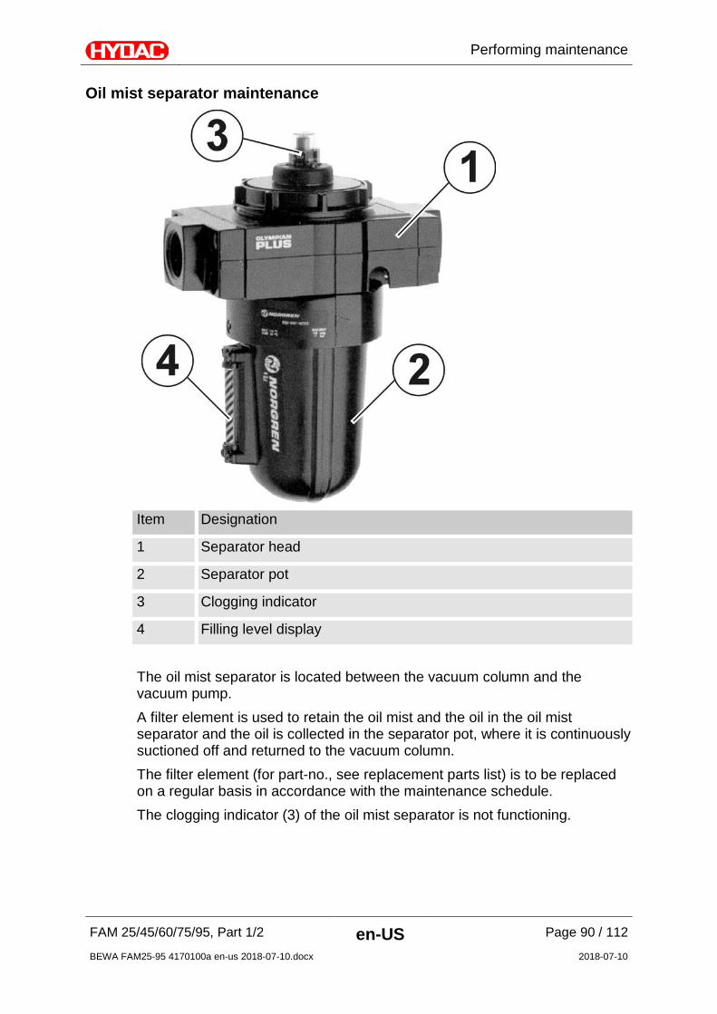
Performing maintenance
FAM 25/45/60/75/95, Part 1/2 en-US Page 90 / 112
BEWA FAM25-95 4170100a en-us 2018-07-10.docx 2018-07-10
Oil mist separator maintenance
Item Designation
1 Separator head
2 Separator pot
3 Clogging indicator
4 Filling level display The oil mist separator is located between the vacuum column and the vacuum pump. A filter element is used to retain the oil mist and the oil in the oil mist separator and the oil is collected in the separator pot, where it is continuously suctioned off and returned to the vacuum column. The filter element (for part-no., see replacement parts list) is to be replaced on a regular basis in accordance with the maintenance schedule. The clogging indicator (3) of the oil mist separator is not functioning.
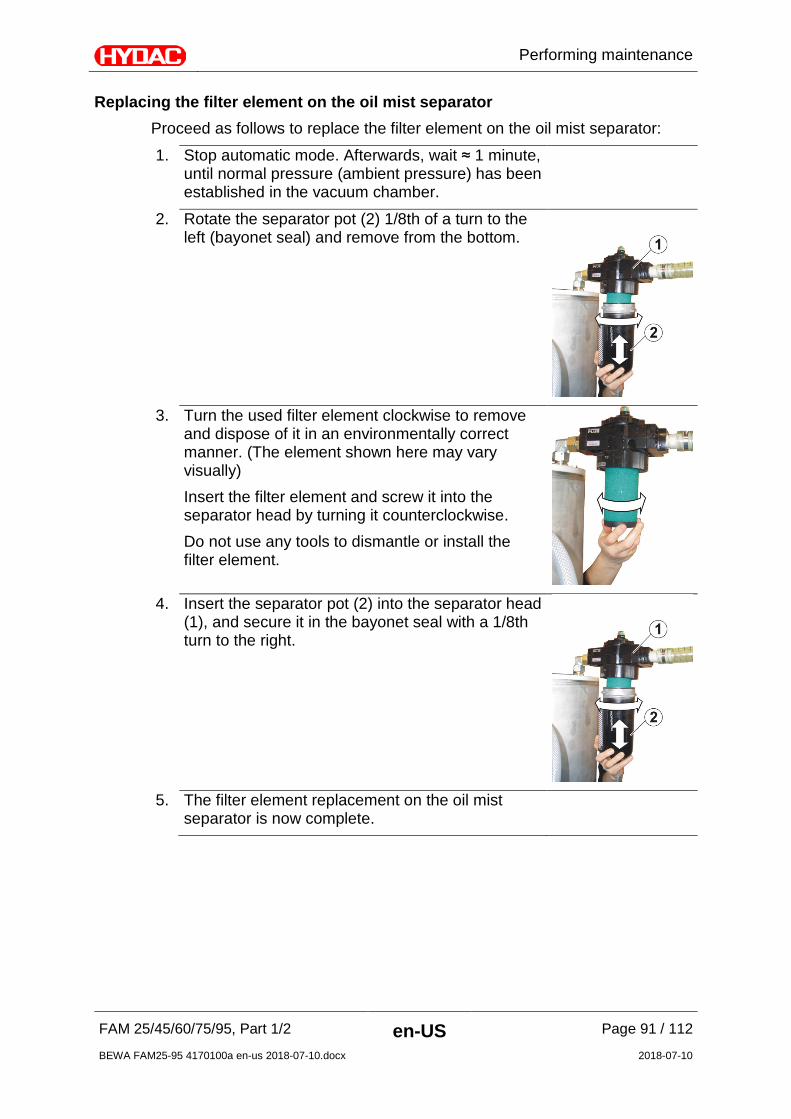
Performing maintenance
FAM 25/45/60/75/95, Part 1/2 en-US Page 91 / 112
BEWA FAM25-95 4170100a en-us 2018-07-10.docx 2018-07-10
Replacing the filter element on the oil mist separator Proceed as follows to replace the filter element on the oil mist separator:
1. Stop automatic mode. Afterwards, wait ≈ 1 minute, until normal pressure (ambient pressure) has been established in the vacuum chamber.
2. Rotate the separator pot (2) 1/8th of a turn to the left (bayonet seal) and remove from the bottom.
3. Turn the used filter element clockwise to remove
and dispose of it in an environmentally correct manner. (The element shown here may vary visually) Insert the filter element and screw it into the separator head by turning it counterclockwise. Do not use any tools to dismantle or install the filter element.
4. Insert the separator pot (2) into the separator head
(1), and secure it in the bayonet seal with a 1/8th turn to the right.
5. The filter element replacement on the oil mist
separator is now complete.
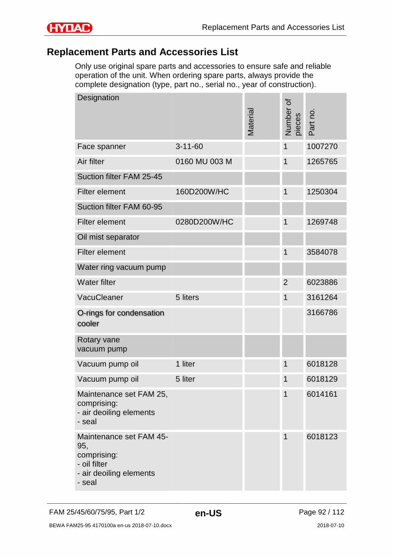
Replacement Parts and Accessories List
FAM 25/45/60/75/95, Part 1/2 en-US Page 92 / 112
BEWA FAM25-95 4170100a en-us 2018-07-10.docx 2018-07-10
Replacement Parts and Accessories List Only use original spare parts and accessories to ensure safe and reliable operation of the unit. When ordering spare parts, always provide the complete designation (type, part no., serial no., year of construction). Designation
Mat
eria
l
Num
ber o
f pi
eces
Par
t no.
Face spanner 3-11-60 1 1007270
Air filter 0160 MU 003 M 1 1265765
Suction filter FAM 25-45
Filter element 160D200W/HC 1 1250304
Suction filter FAM 60-95
Filter element 0280D200W/HC 1 1269748
Oil mist separator
Filter element 1 3584078
Water ring vacuum pump
Water filter 2 6023886
VacuCleaner 5 liters 1 3161264
O-rings for condensation cooler
3166786
Rotary vane vacuum pump
Vacuum pump oil 1 liter 1 6018128
Vacuum pump oil 5 liter 1 6018129
Maintenance set FAM 25, comprising: - air deoiling elements - seal
1 6014161
Maintenance set FAM 45-95, comprising: - oil filter - air deoiling elements - seal
1 6018123
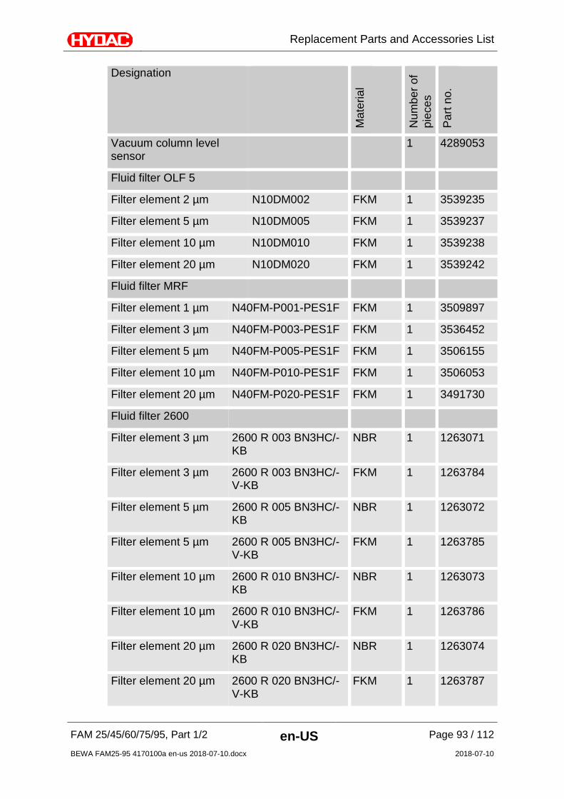
Replacement Parts and Accessories List
FAM 25/45/60/75/95, Part 1/2 en-US Page 93 / 112
BEWA FAM25-95 4170100a en-us 2018-07-10.docx 2018-07-10
Designation
Mat
eria
l
Num
ber o
f pi
eces
Par
t no.
Vacuum column level sensor
1 4289053
Fluid filter OLF 5
Filter element 2 µm N10DM002 FKM 1 3539235
Filter element 5 µm N10DM005 FKM 1 3539237
Filter element 10 µm N10DM010 FKM 1 3539238
Filter element 20 µm N10DM020 FKM 1 3539242
Fluid filter MRF
Filter element 1 µm N40FM-P001-PES1F FKM 1 3509897
Filter element 3 µm N40FM-P003-PES1F FKM 1 3536452
Filter element 5 µm N40FM-P005-PES1F FKM 1 3506155
Filter element 10 µm N40FM-P010-PES1F FKM 1 3506053
Filter element 20 µm N40FM-P020-PES1F FKM 1 3491730
Fluid filter 2600
Filter element 3 µm 2600 R 003 BN3HC/-KB
NBR 1 1263071
Filter element 3 µm 2600 R 003 BN3HC/-V-KB
FKM 1 1263784
Filter element 5 µm 2600 R 005 BN3HC/-KB
NBR 1 1263072
Filter element 5 µm 2600 R 005 BN3HC/-V-KB
FKM 1 1263785
Filter element 10 µm 2600 R 010 BN3HC/-KB
NBR 1 1263073
Filter element 10 µm 2600 R 010 BN3HC/-V-KB
FKM 1 1263786
Filter element 20 µm 2600 R 020 BN3HC/-KB
NBR 1 1263074
Filter element 20 µm 2600 R 020 BN3HC/-V-KB
FKM 1 1263787

Replacement Parts and Accessories List
FAM 25/45/60/75/95, Part 1/2 en-US Page 94 / 112
BEWA FAM25-95 4170100a en-us 2018-07-10.docx 2018-07-10
FAM25 - Consumables for 2-year operation For two years of operation under normal conditions, we recommend the following spare parts:
Rotary vane vacuum pump
Maintenance set comprising: - air deoiling elements - seal
4x 6014161
Vacuum pump oil, 5 liter 1x 6018129
Water ring vacuum pump
Water filter 4x 6023886
Vacuum pump cleaner, 5 liter 2x 3161264
Seal kit, consisting of: O-rings for the condensation cooler
2x 3166766
Filling pump
Seal kit 1x *
Evacuation pump
Seal kit 1x *
Breather filters
Filter element 4x 1265765
Suction filters
Filter element, NBR ** 1250304
Filter element, FKM ** 1265447
Oil mist separator
Filter element 4 3584078
Fluid filter OLF 10
Filter element, 2 µm (FKM) 4x 3539235
Filter element, 5 µm (FKM) 4x 3539237
Filter element, 10 µm (FKM) 4x 3539238
Filter element, 20 µm (FKM) 4x 3539242
*) Upon request **) Depending on the use of the unit

Replacement Parts and Accessories List
FAM 25/45/60/75/95, Part 1/2 en-US Page 95 / 112
BEWA FAM25-95 4170100a en-us 2018-07-10.docx 2018-07-10
FAM45 - Consumables for 2-year operation For two years of operation under normal conditions, we recommend the following spare parts:
Rotary vane vacuum pump
Maintenance set, comprising: - air deoiling elements - seal - oil filter
4x 6018223
Vacuum pump oil, 5 liter 2x 6018129
Water ring vacuum pump
Water filter 4x 6023886
Vacuum pump cleaner, 5 liter 2x 3161264
Seal kit, consisting of: O-rings for the condensation cooler
2x 3166766
Filling pump
Seal kit 1x *
Evacuation pump
Seal kit 1x *
Breather filters
Filter element 4x 1265765
Suction filters
Filter element, NBR ** 1250304
Filter element, FKM ** 1265447
Oil mist separator
Filter element 4 3584078
Fluid filter OLF 10
Filter element, 2 µm (FKM) 4x 3539235
Filter element, 5 µm (FKM) 4x 3539237
Filter element, 10 µm (FKM) 4x 3539238
Filter element, 20 µm (FKM) 4x 3539242
*) Upon request **) Depending on the use of the unit
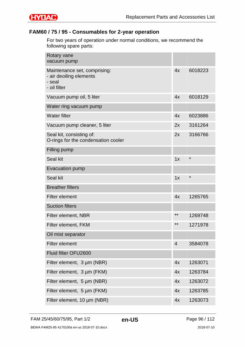
Replacement Parts and Accessories List
FAM 25/45/60/75/95, Part 1/2 en-US Page 96 / 112
BEWA FAM25-95 4170100a en-us 2018-07-10.docx 2018-07-10
FAM60 / 75 / 95 - Consumables for 2-year operation For two years of operation under normal conditions, we recommend the following spare parts:
Rotary vane vacuum pump
Maintenance set, comprising: - air deoiling elements - seal - oil filter
4x 6018223
Vacuum pump oil, 5 liter 4x 6018129
Water ring vacuum pump
Water filter 4x 6023886
Vacuum pump cleaner, 5 liter 2x 3161264
Seal kit, consisting of: O-rings for the condensation cooler
2x 3166766
Filling pump
Seal kit 1x *
Evacuation pump
Seal kit 1x *
Breather filters
Filter element 4x 1265765
Suction filters
Filter element, NBR ** 1269748
Filter element, FKM ** 1271978
Oil mist separator
Filter element 4 3584078
Fluid filter OFU2600
Filter element, 3 µm (NBR) 4x 1263071
Filter element, 3 µm (FKM) 4x 1263784
Filter element, 5 µm (NBR) 4x 1263072
Filter element, 5 µm (FKM) 4x 1263785
Filter element, 10 µm (NBR) 4x 1263073

Storing the unit / taking it out of operation
FAM 25/45/60/75/95, Part 1/2 en-US Page 97 / 112
BEWA FAM25-95 4170100a en-us 2018-07-10.docx 2018-07-10
Filter element, 10 µm (FKM) 4x 1263786
Filter element, 20 µm (NBR) 4x 1263074
Filter element, 20 µm (FKM) 4x 1263787
Fluid filter MRF 3/11/40
Filter element, 1 µm (FKM) 44x 3509897
Filter element, 3 µm (FKM) 44x 3536452
Filter element, 5 µm (FKM) 44x 3506155
Filter element, 10 µm (FKM) 44x 3506053
Filter element, 20 µm (FKM) 44x 3491730
*) Upon request **) Depending on the use of the unit
Storing the unit / taking it out of operation
Drain the unit completely, including all of its components, before putting it into storage. Pull out the power plug, and securely fasten the hoses and power cord to the FAM. Store the FAM in a clean, dry (condensation-free) space. In the case of storage periods greater than 1 year, please contact HYDAC FILTER SYSTEMS GMBH.
Unit disposal
Dispose of the packaging material in an environmentally friendly manner. After dismantling the unit and separating the various materials, dispose of the unit in an environmentally friendly manner.

Technical Data
FAM 25/45/60/75/95, Part 1/2 en-US Page 98 / 112
BEWA FAM25-95 4170100a en-us 2018-07-10.docx 2018-07-10
Technical Data FAM25 FAM45 FAM60 FAM75 FAM 95
Volume flow rate at the inlet (IN) @ 50 Hz
≈ 25 l/min ≈ 45 l/min ≈ 60 l/min ≈ 75 l/min ≈ 95 l/min
Volume flow rate at the inlet (IN) @ 50 Hz ≈ 30 l/min ≈ 54 l/min ≈ 72 l/min ≈ 90 l/min ≈ 114
l/min
Volume flow rate at the outlet (OUT) @ 50 Hz ≈ 35 l/min ≈ 55 l/min ≈ 70 l/min ≈ 85 l/min ≈ 105
l/min
Volume flow rate at the outlet (OUT) @ 60 Hz ≈ 42 l/min ≈ 66 l/min ≈ 84 l/min ≈ 102
l/min ≈ 126 l/min
Sealing material See model code on page 102
Fluid filter (Type Filter Size) OLF-10 OFU or MRF3/11/40
Clogging indicator VM 2 C.0 VM 2 C.0 VM 2 C.0 VM 2 C.0 VM 2 C.0
Pump type, vacuum pump Rotary vane vacuum pump
Rotary vane vacuum pump or water ring vacuum pump
Pump type, others Gear pump
Operating pressure 0 … 6 bar
Permissible pressure at the suction port (without suction hose) Pe zul.
-0.2 … 1 bar
Permitted pressure at the outlet (without pressure hose) Pa perm.
0 … 3.5 bar
Operation viscosity range 15 … 350 mm²/s (without an integrated heater) 15 … 550 mm²/s (with an integrated heater)
Permitted fluid temperature range
10 … 80°C
Permissible ambient temperature range
10 … 40°C
Permitted storage temperature range
10 … 50°C
Permissible relative humidity maximum 90%, non-condensing
Electrical power consumption in kW
without heater 3.5kW/16
A 4.5kW/16
A 5.9kW/32
A 7.5kW/32
A 7.5kW/32
A with heater 10.5kW/3
2A 13.5kW/3
2A 19.5kW/6
3A 25.5kW/6
3A 25.5kW/6
3A
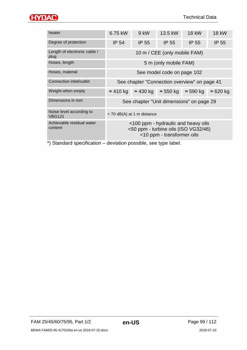
Technical Data
FAM 25/45/60/75/95, Part 1/2 en-US Page 99 / 112
BEWA FAM25-95 4170100a en-us 2018-07-10.docx 2018-07-10
heater 6.75 kW 9 kW 13.5 kW 18 kW 18 kW
Degree of protection IP 54 IP 55 IP 55 IP 55 IP 55
Length of electronic cable / plug
10 m / CEE (only mobile FAM)
Hoses, length 5 m (only mobile FAM)
Hoses, material See model code on page 102
Connection inlet/outlet See chapter "Connection overview" on page 41
Weight when empty ≈ 410 kg ≈ 430 kg ≈ 550 kg ≈ 590 kg ≈ 620 kg
Dimensions in mm
See chapter "Unit dimensions" on page 29
Noise level according to VBG121 < 70 dB(A) at 1 m distance
Achievable residual water content
<100 ppm - hydraulic and heavy oils <50 ppm - turbine oils (ISO VG32/46)
<10 ppm - transformer oils *) Standard specification – deviation possible, see type label.

Technical Data
FAM 25/45/60/75/95, Part 1/2 en-US Page 100 / 112
BEWA FAM25-95 4170100a en-us 2018-07-10.docx 2018-07-10
Fluid filter grade [µm] depending on the operating viscosity
Viscosity range FAM-25 Viscosity range FAM-45
OLF-10 OLF-10
… 200 mm²/s ≥ 2 µm … 120 mm²/s ≥ 2 µm
… 360 mm²/s ≥ 5 µm … 220 mm²/s ≥ 5 µm
… 480 mm²/s ≥ 10 µm … 300 mm²/s ≥ 10 µm
… 550 mm²/s ≥ 20 µm … 470 mm²/s ≥ 20 µm
Viscosity range FAM-60/75/95 Viscosity range FAM-
60/75/95
OFU MRF
… 500 mm²/s ≥ 3 µm … 280 mm²/s ≥ 1 µm
… 550 mm²/s ≥ 5 µm … 400 mm²/s ≥ 3 µm
… 550 mm²/s ≥ 10 µm … 550 mm²/s ≥ 5 µm
… 550 mm²/s ≥ 20 µm … 550 mm²/s ≥ 10 µm
Appendix
FAM 25/45/60/75/95, Part 1/2 en-US Page 101 / 112
BEWA FAM25-95 4170100a en-us 2018-07-10.docx 2018-07-10
Appendix
Customer Service / Service For product information or technical support or if you have comments or suggestions concerning this manual, please contact: HYDAC FILTER SYSTEMS GMBH Phone: +49 6897 509 1174 Fax: +49 6897 509 9046 E-mail: [email protected] Regular inspection and maintenance work is indispensable for ensuring trouble-free operation and long service life for your FluidAqua Mobil. Our HYDAC Servicenter offers you these tasks within agreed-upon time frames and at fixed prices. HYDAC SERVICE GMBH Friedrichsthaler Str. 15A, Werk 13 66540 Neunkirchen-Heinitz Germany Phone: +49 681 509 9518 Fax: +49 681 509 2324 E-mail: [email protected]
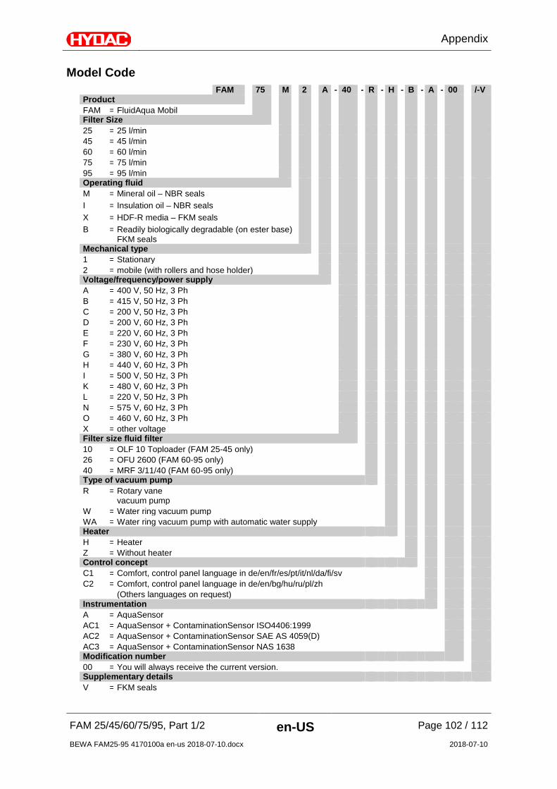
Appendix
FAM 25/45/60/75/95, Part 1/2 en-US Page 102 / 112
BEWA FAM25-95 4170100a en-us 2018-07-10.docx 2018-07-10
Model Code FAM 75 M 2 A - 40 - R - H - B - A - 00 /-V Product FAM = FluidAqua Mobil Filter Size 25 = 25 l/min 45 = 45 l/min 60 = 60 l/min 75 = 75 l/min 95 = 95 l/min Operating fluid M = Mineral oil – NBR seals I = Insulation oil – NBR seals X = HDF-R media – FKM seals B = Readily biologically degradable (on ester base)
FKM seals
Mechanical type 1 = Stationary 2 = mobile (with rollers and hose holder) Voltage/frequency/power supply A = 400 V, 50 Hz, 3 Ph B = 415 V, 50 Hz, 3 Ph C = 200 V, 50 Hz, 3 Ph D = 200 V, 60 Hz, 3 Ph E = 220 V, 60 Hz, 3 Ph F = 230 V, 60 Hz, 3 Ph G = 380 V, 60 Hz, 3 Ph H = 440 V, 60 Hz, 3 Ph I = 500 V, 50 Hz, 3 Ph K = 480 V, 60 Hz, 3 Ph L = 220 V, 50 Hz, 3 Ph N = 575 V, 60 Hz, 3 Ph O = 460 V, 60 Hz, 3 Ph X = other voltage Filter size fluid filter 10 = OLF 10 Toploader (FAM 25-45 only) 26 = OFU 2600 (FAM 60-95 only) 40 = MRF 3/11/40 (FAM 60-95 only) Type of vacuum pump R = Rotary vane
vacuum pump
W = Water ring vacuum pump WA = Water ring vacuum pump with automatic water supply Heater H = Heater Z = Without heater Control concept C1 = Comfort, control panel language in de/en/fr/es/pt/it/nl/da/fi/sv C2 = Comfort, control panel language in de/en/bg/hu/ru/pl/zh (Others languages on request) Instrumentation A = AquaSensor AC1 = AquaSensor + ContaminationSensor ISO4406:1999 AC2 = AquaSensor + ContaminationSensor SAE AS 4059(D) AC3 = AquaSensor + ContaminationSensor NAS 1638 Modification number 00 = You will always receive the current version. Supplementary details V = FKM seals

Appendix
FAM 25/45/60/75/95, Part 1/2 en-US Page 103 / 112
BEWA FAM25-95 4170100a en-us 2018-07-10.docx 2018-07-10
Explanation of terms and abbreviations An explanation of terms and abbreviations follows below:
%Sat. % Water saturation, degree of saturation
% saturation % Water saturation, degree of saturation
°C Degrees Celsius
°F Degrees Fahrenheit
abs. Absolute (e.g. in pressure specifications)
AC Alternating current
Air Bleed Ventilation / air bleed port
AquaSensor Sensor for water saturation in % and temperature
AS AquaSensor
ATEX ATmosphères Explosibles = Explosive atmosphere
OM Operating mode
BeWa Operating and Maintenance Instructions
ContaminationSensor Sensor for solid particle contamination in fluid.
CS ContaminationSensor
DC Direct current
DIN Deutsche Industrie Norm [German Industry Standard]
DN Nominal Diameter
Drain Drainage port
Rotary vane vacuum pump
Vacuum pump required as operating material for vacuum pump oil
EC European Community
ESC Escape
EU European Union
FAM FluidAqua Mobil
Solid particle contamination
Solid particles such as dirt, non-iron or metallic particles found in the fluid.
FPM (FKM / Viton®) Fluoroelastomer rubber
HFD Water-free synthetic fluids with a higher density than mineral oil or water. These fluids can cause problems with the intake characteristics of pumps and attack many sealing materials.
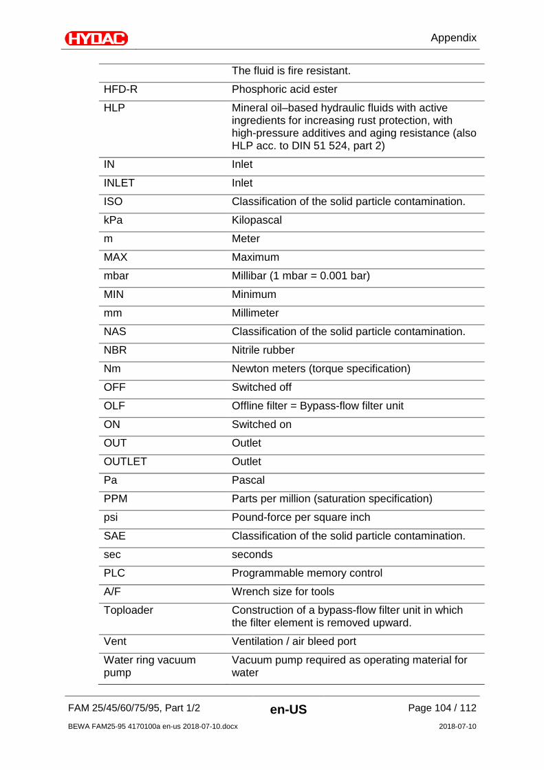
Appendix
FAM 25/45/60/75/95, Part 1/2 en-US Page 104 / 112
BEWA FAM25-95 4170100a en-us 2018-07-10.docx 2018-07-10
The fluid is fire resistant.
HFD-R Phosphoric acid ester
HLP Mineral oil–based hydraulic fluids with active ingredients for increasing rust protection, with high-pressure additives and aging resistance (also HLP acc. to DIN 51 524, part 2)
IN Inlet
INLET Inlet
ISO Classification of the solid particle contamination.
kPa Kilopascal
m Meter
MAX Maximum
mbar Millibar (1 mbar = 0.001 bar)
MIN Minimum
mm Millimeter
NAS Classification of the solid particle contamination.
NBR Nitrile rubber
Nm Newton meters (torque specification)
OFF Switched off
OLF Offline filter = Bypass-flow filter unit
ON Switched on
OUT Outlet
OUTLET Outlet
Pa Pascal
PPM Parts per million (saturation specification)
psi Pound-force per square inch
SAE Classification of the solid particle contamination.
sec seconds
PLC Programmable memory control
A/F Wrench size for tools
Toploader Construction of a bypass-flow filter unit in which the filter element is removed upward.
Vent Ventilation / air bleed port
Water ring vacuum pump
Vacuum pump required as operating material for water

Appendix
FAM 25/45/60/75/95, Part 1/2 en-US Page 105 / 112
BEWA FAM25-95 4170100a en-us 2018-07-10.docx 2018-07-10
Water Saturation Water Saturation
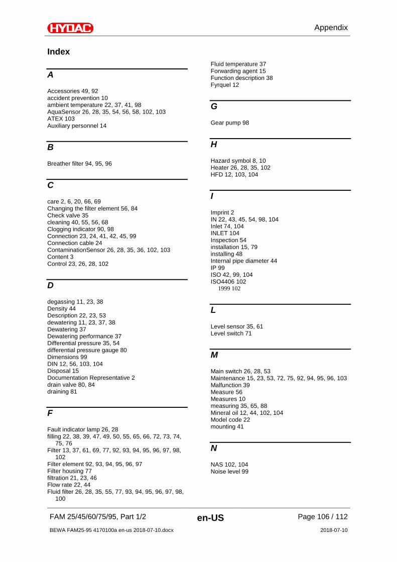
Appendix
FAM 25/45/60/75/95, Part 1/2 en-US Page 106 / 112
BEWA FAM25-95 4170100a en-us 2018-07-10.docx 2018-07-10
Index
A
Accessories 49, 92 accident prevention 10 ambient temperature 22, 37, 41, 98 AquaSensor 26, 28, 35, 54, 56, 58, 102, 103 ATEX 103 Auxiliary personnel 14
B
Breather filter 94, 95, 96
C
care 2, 6, 20, 66, 69 Changing the filter element 56, 84 Check valve 35 cleaning 40, 55, 56, 68 Clogging indicator 90, 98 Connection 23, 24, 41, 42, 45, 99 Connection cable 24 ContaminationSensor 26, 28, 35, 36, 102, 103 Content 3 Control 23, 26, 28, 102
D
degassing 11, 23, 38 Density 44 Description 22, 23, 53 dewatering 11, 23, 37, 38 Dewatering 37 Dewatering performance 37 Differential pressure 35, 54 differential pressure gauge 80 Dimensions 99 DIN 12, 56, 103, 104 Disposal 15 Documentation Representative 2 drain valve 80, 84 draining 81
F
Fault indicator lamp 26, 28 filling 22, 38, 39, 47, 49, 50, 55, 65, 66, 72, 73, 74,
75, 76 Filter 13, 37, 61, 69, 77, 92, 93, 94, 95, 96, 97, 98,
102 Filter element 92, 93, 94, 95, 96, 97 Filter housing 77 filtration 21, 23, 46 Flow rate 22, 44 Fluid filter 26, 28, 35, 55, 77, 93, 94, 95, 96, 97, 98,
100
Fluid temperature 37 Forwarding agent 15 Function description 38 Fyrquel 12
G
Gear pump 98
H
Hazard symbol 8, 10 Heater 26, 28, 35, 102 HFD 12, 103, 104
I
Imprint 2 IN 22, 43, 45, 54, 98, 104 Inlet 74, 104 INLET 104 Inspection 54 installation 15, 79 installing 48 Internal pipe diameter 44 IP 99 ISO 42, 99, 104 ISO4406 102
1999 102
L
Level sensor 35, 61 Level switch 71
M
Main switch 26, 28, 53 Maintenance 15, 23, 53, 72, 75, 92, 94, 95, 96, 103 Malfunction 39 Measure 56 Measures 10 measuring 35, 65, 88 Mineral oil 12, 44, 102, 104 Model code 22 mounting 41
N
NAS 102, 104 Noise level 99
Appendix
FAM 25/45/60/75/95, Part 1/2 en-US Page 107 / 112
BEWA FAM25-95 4170100a en-us 2018-07-10.docx 2018-07-10
O
OFF 61, 104 Offline filter 104 Oil filler neck 71 Oil pan 36 Oil separator 71, 74 Oil sight glass 71, 74 operating 6, 7, 8, 11, 12, 14, 15, 22, 38, 39, 40, 46,
47, 49, 53, 58, 70, 72, 75, 79, 81, 82, 84, 85, 100, 103, 104
Operating elements 53 Operation 13, 15, 23, 47, 49, 53, 98 Operations control 15 OUT 22, 43, 45, 98, 104 Outlet 41, 104 OUTLET 104
P
Power consumption 22 Pressure differential 44 Pressure sensor 35, 54 Proper/Designated Use 11 Protection class 22 Publisher 2 Pump 26, 28, 35, 61, 98
R
replacement 58, 72, 90, 91 Rotary vane vacuum pump 47, 55, 74, 92, 94, 95,
96, 98, 102, 103
S
SAE 102, 104 select 7 Sensor 61, 103
Service 74, 89, 101 setting 35, 38, 39, 41, 70 Signal word 9, 10 signal words 10 Size 37, 67, 98, 102 Solid particle contamination 103 Specialist personnel 14, 15 Suction hose 24 Suction port connection 71 switching off 53 switching on 47, 53 Synthetic ester 12
T
to shut down 18 Transport 15 transporting 18, 19 troubleshooting 53 Troubleshooting 15 Type label 22
V
Vacuum 23, 26, 28, 35, 36, 61, 72, 75, 92, 93, 94, 95, 96, 103, 104
Vacuum column 26, 28, 35, 36, 93 Vacuum pump 23, 26, 28, 35, 72, 75, 92, 94, 95, 96,
103, 104 vacuum pump oil 41, 49, 50, 72, 75, 103 Vegetable oils 12 Viscosity 100
W
Water content 37 Water ring vacuum pump 47, 55, 92, 94, 95, 96,
102, 104 Water Saturation 105 Weight 22, 99


HYDAC FILTER SYSTEMS GMBH Industriegebiet Postfach 1251 66280 Sulzbach/Saar 66273 Sulzbach/Saar Germany Germany Tel: +49 6897 509 01 Central Fax: +49 6897 509 9046 Technology Fax: +49 6897 509 577 Sales Internet: www.hydac.com E-mail: [email protected]
Copyright © 2022 FDOKUMEN