
joint venture power plant project mobil producing nigeria ...
697
ENVIRONMENTAL IMPACT ASSESSMENT OF JOINT VENTURE POWER PLANT PROJECT MOBIL PRODUCING NIGERIA UNLIMITED Mobil House, Lekki Expressway, Victoria Island, Lagos, Nigeria FINAL REPORT JULY 2013
-
Upload
khangminh22 -
Category
Documents
-
view
1 -
download
0
Transcript of joint venture power plant project mobil producing nigeria ...

ENVIRONMENTAL IMPACT ASSESSMENT
OF JOINT VENTURE POWER PLANT PROJECT
MOBIL PRODUCING NIGERIA UNLIMITED Mobil House, Lekki Expressway,
Victoria Island, Lagos, Nigeria
FINAL REPORT JULY 2013
ENVIRONMENTAL IMPACT ASSESSMENT OF
JOINT VENTURE POWER PLANT PROJECT
The Joint Venture Power Project (JVPP) located at QIT is also known as the Qua Iboe Power Project (QIPP). The QIPP name is registered with the NERC in order to distinguish it from other Joint Venture
Independent Power Projects. These two terms have been used interchangeably in this report.
Client : MOBIL PRODUCING NIGERIA UNLIMITED Mobil House, Lekki Expressway,
Victoria Island, Lagos, Nigeria
Date of Report : July 2013 Project Manager: Fidelis Effiom Name Position Signature Date Approved by Bassey Akpan Managing Director Checked by Prof Ani Nkang QHSE Manager Version Status 1 Final Report 01/07/2013 BGI Resources Limited, 278b PH/Aba Expressway Port Harcourt. Nigeria. Tel: 234-084-611462. Fax: 234-084-613008 GSM: 08035382451 E-mal: [email protected], Website: www.bgiresourcesltd.com
Table of Contents
EIA of Joint Venture Power Plant (JVPP) Project ii
TABLE OF CONTENTS
TITLE PAGES
STATUS PAGE .......................................................................................................................... i TABLE OF CONTENTS .................................................................................................... ii-xvi LIST OF FIGURES ...................................................................................................... xvii-xviii LIST OF PLATES .............................................................................................................xix-xx LIST OF TABLES .......................................................................................................... xxi-xxii LIST OF APPENDICES ....................................................................................................... xxiii LIST OF ABBREVIATIONS AND ACRONYMS .................................................... xxiv-xxvi EIA PREPARERS ............................................................................................................... xxvii ACKNOWLEDGEMENT .................................................................................................. xxviii EXECUTIVE SUMMARY ............................................................................................. ES - 23 CHAPTER ONE
1.0 INTRODUCTION ....................................................................................................... 1 - 1 1.1 General ....................................................................................................................... 1 - 1 1.2 The Proponent ............................................................................................................ 1 - 1 1.3 EIA Objectives ........................................................................................................... 1 - 2 1.4 Terms of Reference ................................................................................................... 1 - 2 1.5 EIA Methodology ..................................................................................................... 1 - 3 1.6 Legal and Administrative Framework for the EIA .................................................... 1 - 4 1.6.1 Federal Environmental Management Framework and Corresponding
Agency Jurisdictional Authority .................................................................. 1 - 5 1.6.1.1 National Environmental Standards and Regulations Enforcement Agency Act 2007(NESREA) ..................................................................... 1 - 6 1.6.1.2 National Environnemental Protection (Effluent Limitations) Regulation (S.1.8) 1991 ................................................................................ 1 - 6 1.6.1.3 National Environnemental Protection Regulation (S.I.9) 1991 ....... 1 - 7 1.6.1.4 National Environnemental Protection (Management of Solid Hazardous Wastes Regulation (S.1.15) 1991 .............................................. 1 - 7 1.6.1.5 National Policy on the Environnent .................................................. 1 - 7 1.6.1.6 Environmental Impact Assessment Act No 86 of 1992 .................. 1 - 8 1.6.1.7 EIA Sectoral Guidelines of the Federal Ministry of Environment (FMENV) ..................................................................................................... 1 - 8 1.6.1.8 Harmful Waste Act 1988 ................................................................ 1 - 9

Table of Contents
EIA of Joint Venture Power Plant (JVPP) Project iii
1.6.1.9 Water Resources Act 1993 ............................................................ 1 - 10 1.6.1.10 National Oil Spill Detection and Response Agency Act of 2006 1 - 10 1.6.1.11 Petroleum Control Act 1967 and all Amendments, CAP 351 ...... 1 - 10 1.6.1.12 Petroleum Act 1969 and all Amendments, CAP 350 ................. 1 - 11 1.6.1.13 Oil Pipeline Act and Oil & Gas Pipelines Regulations 1958 (amended 1995) .......................................................................................... 1 - 12 1.6.1.14 Mineral Oils Safety Regulations (MOSR) 1963 (Amended, 1997) ....................................................................................... 1 - 13 1.6.1.15 The Associated Gas Re-Injection Decree No. 99 of 1979 ........... 1 - 13 1.6.1.16 Standards Organization of Nigeria Conformity Assessment Program (SONCAP) .................................................................................................. 1 - 14 1.6.1.17 Land Management ....................................................................... 1 - 14 1.6.1.18 The Inland Waterways Authority Act 13 of 1997 ....................... 1 - 15 1.6.1.19 Regulation of Dock Facilities ...................................................... 1 - 15 1.6.1.20 Criminal Code ............................................................................... 1 - 15
1.6.2 Laws Protecting Flora and Fauna ................................................................ 1 - 15 1.6.2.1 Parks, Game Reserves and other Protected Areas ........................ 1 - 16 1.6.2.2 Stubbs Creek Forest Reserve ......................................................... 1 - 16 1.6.2.3 Endangered Species (Control of International Trade and Traffic) Act ............................................................................................................. 1 - 16 1.6.2.4 Sea Fisheries Act No. 71 of 1992 .................................................. 1 - 16
1.6.3 State Environmental Management Framework ........................................... 1 - 17 1.6.4 International Treaties on the Environment .................................................. 1 - 18
1.6.4.1 International Convention for the Prevention of Pollution of the Sea by Oil 1954 as amended in 1962........................................................... 1 - 18
1.6.4.2 International Convention on Oil Pollution, Preparedness, Response and Cooperation; ............................................................................. 1 - 18
1.6.4.3 Convention on International Trade on Endangered Species of Wild Fauna and Flora 1974 ..................................................................... 1 - 18
1.6.4.4 International Convention on Civil Liability for Oil Pollution Damage ...................................................................................................... 1 - 18 1.6.4.5 Convention on the Prevention of Marine Pollution by Dumping of Wastes and Other Matter e ......................................................................... 1 - 18 1.6.4.6 United Nations Convention on Climate Change ............................. 1 - 18 1.6.4.7 Vienna Convention for the Protection of the Ozone Layer ........... 1 - 18 1.6.4.8 Convention on Conservation of Migratory Species of Wild

Table of Contents
EIA of Joint Venture Power Plant (JVPP) Project iv
Animals ...................................................................................................... 1 - 19 1.6.4.9 United Nations Guiding Principles on the Human Environment: .. 1 - 19 1.6.4.10 International Union for Conservation of nature and Natural Resources (IUCN) Guidelines (1996); e ..................................................................... 1 - 19
1.6.5 Electrical Power Sector Regulatory Framework .......................................... 1 - 19 1.6.5.1 Electricity Act, 1976 ...................................................................... 1 - 20 1.6.5.2 Electricity Amendment Act 1998 .................................................. 1 - 23 1.6.5.3 Electricity Power Sector Reform Act (2005) ................................. 1 - 23
1.6.6 World Bank .................................................................................................. 1 - 25 1.7 Summary of License, Permit and Approval Requirements Discussion ................... 1 - 25 1.8 ExxonMobil Policies, Strategies and Standards ..................................................... 1 - 26
1.8.1 ExxonMobil’s Corporate Policies .............................................................. 1 - 27 1.8.2 Operations Integrity Management System (OIMS) .................................... 1 - 27
1.9 Structure of the Report ............................................................................................. 1 - 28
CHAPTER TWO
2.0 PROJECT JUSTIFICATION........................................................................................ 2 - 1 2.1 General ........................................................................................................................... 2 - 1 2.2 Alternatives Development & Analysis .......................................................................... 2 - 1 2.2.1 Analysis of Alternative Site Locations ........................................................... 2 - 3
2.2.1.1. Option 1: Site on Non-MPN Locations .......................................... 2 - 3 2.2.1.2. Option 2: Site on MPN Locations ................................................... 2 - 4
2.2.2 Analysis of Alternative Development Strategies ............................................ 2 – 8 2.2.3. Analysis of Alternative Technological/Process Design ............................... 2 – 10 2.2.4 “No Action” Alternative ............................................................................... 2 – 12
2.3 Project Alternative Ranking ....................................................................................... 2 – 22 2.4. Summary of the preferred Alternative for the Proposed Project ............................... 2 – 23 2.5. Overview of Basis for the Selection of the Proposed Project as the Preferred Alternative .................................................................................................. 2 – 23 2.6. Comparative Assessment of No Option and Preferred Alternative ............................ 2 – 25 2.7. Conclusion ................................................................................................................... 2 - 26

Table of Contents
EIA of Joint Venture Power Plant (JVPP) Project v
CHAPTER THREE
3.0 PROJECT DESCRIPTION ............................................................................................. 3 -1 3.1 Project Objective ............................................................................................................ 3 - 1 3.2 Project Location ............................................................................................................. 3 - 1
3.2.1 Project Site Boundaries .................................................................................... 3 - 4 3.3 Project Background and History ..................................................................................... 3 - 6
3.3.1 Project Scope .................................................................................................. 3 - 6 3.3.2 Power Generation Process ............................................................................... 3 - 7 3.3.3 Power Plant Efficiency .................................................................................... 3 - 9 3.3.4 Design Code ..................................................................................................... 3 - 9 3.3.5 Plant Layout .................................................................................................... 3 - 9 3.3.5.1 Buildings ..................................................................................................... 3 - 14 3.3.5.2 Storage Facilities ........................................................................................ 3 - 15 3.3.6 Power Plant Components .............................................................................. 3 - 16 3.3.6.1 Gas Turbine Generators ............................................................................. 3 - 17 3.3.6.2 Combustion Turbine Exhaust Stack ........................................................... 3 - 18 3.3.6.3 Essential and Black-Start Generators ........................................................ 3 - 18 3.3.6.4 Electrical Transformers ............................................................................... 3 - 18 3.3.6.5 Switchgear................................................................................................... 3 - 18 3.3.6.6 Switchyard ................................................................................................. 3 - 18 3.3.6.7 Uninterruptible Power Supply ................................................................... 3 - 18 3.3.6.8 Mechanical Utilities Trench ....................................................................... 3 - 19 3.3.6.9 Fuel Gas Supply ......................................................................................... 3 - 19 3.3.6.10 Storm Water Retention Pond ................................................................... 3 - 20 3.3.6.11 Water System ............................................................................................ 3 - 20 3.3.6.12 Industrial Wastewater Collection & Treatment System .......................... 3 - 21 3.3.6.13 Sanitary Sewage Collection & Treatment System ................................... 3 - 22 3.3.6.14 Drain System ............................................................................................ 3 - 22 3.3.6.15 Fire Protection System ............................................................................. 3 - 23 3.3.6.16 Storm Water Effluent Treatment System ................................................. 3 - 23 3.3.6.17 Miscellaneous Storage ............................................................................. 3 - 24 3.3.6.18 Compressed Air System ........................................................................... 3 - 24 3.3.6.19 Nitrogen System ....................................................................................... 3 - 24 3.3.6.20 Vent System ............................................................................................. 3 - 24 3.3.6.21 Utilities ..................................................................................................... 3 - 24
Table of Contents
EIA of Joint Venture Power Plant (JVPP) Project vi
3.3.6.22 Roads and Parking ................................................................................... 3 - 24 3.3.6.23 Security ..................................................................................................... 3 - 26 3.3.7 Additional Power Plant Components Required for the Combined Cycle Plant Option .................................................................................................. 3 - 27 3.3.7.1 Heat Recovery Steam Generator ................................................................ 3 - 27 3.3.7.2 Steam Turbine Generator (STG ) ................................................................ 3 - 27 3.3.7.3 Air-cooled Condenser ................................................................................. 3 - 27 3.3.7.4 Boiler Water Treatment .............................................................................. 3 - 27 3.3.8 Offshore Components ................................................................................... 3 - 28 3.3.8.1 Pipeline Design Characteristics .................................................................. 3 - 28 3.3.8.2 Pipeline System Layout ............................................................................. 3 - 34
3.4 Project Execution Schedule ........................................................................................ 3 - 34 3.5 Onshore Site Preparation Activities ............................................................................ 3 - 34
3.5.1 Geotechnical Investigations .......................................................................... 3 - 34 3.5.2 Clearing and Grubbing ................................................................................... 3 - 35 3.5.3 Excavation, Backfill, and Grading ................................................................ 3 - 35 3.5.4 Site Drainage .................................................................................................. 3 - 37 3.5.5 Foundations .................................................................................................... 3 - 37 3.5.6 Workers Camp ............................................................................................... 3 - 38 3.5.7 Concrete Batch Plant...................................................................................... 3 - 38 3.5.8 Proposed Material Off-loading Facility (MOF) ............................................. 3 - 40
3.6 Construction Activities ................................................................................................ 3 – 41 3.6.1 Construction Works ...................................................................................... 3 - 41 3.6.2 Temporary Site Facilities ............................................................................... 3 - 42 3.6.3 Utilities ........................................................................................................... 3 - 42 3.6.4 Construction Equipment ............................................................................... 3 - 43 3.6.5 Logistics ......................................................................................................... 3 - 43 3.6.6 Painting ......................................................................................................... 3 - 46 3.6.7 Fire Protection ................................................................................................ 3 - 46 3.6.8 Offshore Pipeline Installation ........................................................................ 3 - 46 3.6.9 Hydrotesting ................................................................................................... 3 - 46 3.6.10 Security ........................................................................................................ 3 - 47 3.6.11 Waste Management ...................................................................................... 3 - 48 3.6.12 Construction Water Usage Summary......................................................... 3 - 448
3.7 Operational Activities ................................................................................................... 3 - 50
Table of Contents
EIA of Joint Venture Power Plant (JVPP) Project vii
3.7.1 Operations ...................................................................................................... 3 - 50 3.7.2 Materials and Waste Management ................................................................. 3 - 50 3.7.3 Operating Waste Expected Volumes ............................................................. 3 - 51 3.7.4 Air Emissions ................................................................................................. 3 - 52 3.7.5 Noise .............................................................................................................. 3 - 52
3.8 Safety and Environmental Engineering ........................................................................ 3 - 53 3.9 Operations Integrity Management System.................................................................... 3 - 54
3.9.1 OIMS Supporting Programs .......................................................................... 3 - 54 3.9.1.1 Malaria Control Program ............................................................................ 3 - 54 3.9.1.2 Next Steps to Zero Program ........................................................................ 3 - 55
3.10 Decommissioning Activities ....................................................................................... 3 - 55
CHAPTER FOUR
4.0 ENVIRONMENATAL BASELINE STUDY ............................................................... 4 - 1 4.1 Overview ......................................................................................................................... 4 - 1 4.2 Study Approach .............................................................................................................. 4 - 1 4.3 Designation of Project Area of Influence and Sensitive Receptors ................................ 4 - 2 4.4 Physical Geography .................................................................................................... 4 - 112
4.4.1 Climate and Rainfall ...................................................................................... 4 - 12 4.4.2 Relief/Topography ......................................................................................... 4 - 12 4.4.3 Regional Geology ......................................................................................... 4 – 13
4.4.3.1 The Benin Formation ..................................................................... 4 – 13 4.4.3.2 The Agbada Formation .................................................................. 4 – 13 4.4.3.3 The Akata Formation ..................................................................... 4 – 13
4.4.4 Aggregate Resources ..................................................................................... 4 - 14 4.4.5 Natural Events ................................................................................................ 4 - 14
4.5 Seismicity ...................................................................................................................... 4 - 14 4.5.1 Floods, Fires, and Storms............................................................................... 4 - 17
4.6 Soils............................................................................................................................... 4 - 18 4.6.1 Soil Texture Profile ........................................................................................ 4 - 18 4.6.2 Soil Sampling ................................................................................................ 4 - 18
4.6.2.1 Physical and Chemical Properties ................................................... 4 - 19 4.6.2.2 Metals and Mineral Content............................................................ 4 - 20 4.6.2.3 Organic Matter ................................................................................ 4 - 20 4.6.2.4 Microbiological Properties – Bacteria and Fungi ........................... 4 - 20
Table of Contents
EIA of Joint Venture Power Plant (JVPP) Project viii
4.7. Terrestrial Biological Resources .................................................................................. 4 - 21 4.7.1 Project Setting ............................................................................................... 4 - 21 4.7.2 Habitat Fragmentation ................................................................................... 4 - 24 4.7.3 Methodology for Biological Resource Assessment ....................................... 4 - 25 4.7.4 Vegetation Assessment .................................................................................. 4 - 25
4.7.4.1 Ethnobotanical Resources ............................................................... 4 - 27 4.7.5 Wildlife Assessment ..................................................................................... 4 - 28 4.7.6 Wetlands and Riparian Corridors................................................................... 4 - 29 4.7.7 Rare, Vulnerable or Endangered Species ....................................................... 4 - 29 4.7.8 Unique or High Value Habitat Features......................................................... 4 - 42
4.7.8.1 QIT Lake ........................................................................................ 4 - 42 4.7.9 Protected Biological Resources in the Region ............................................... 4 - 44
4.8 Marine Resources.......................................................................................................... 4 - 44 4.8.1 Offshore Sediment Sampling – Lean Fuel Gas Pipeline ............................... 4 - 44
4.8.1.1 Physical and Chemical Properties ................................................... 4 - 46 4.8.1.2 Metals and Mineral Content............................................................ 4 - 46 4.8.1.3 Organic Matter ................................................................................ 4 - 46 4.8.1.4 Microbiological Properties – Bacteria and Fungi ........................... 4 - 46 4.8.1.5 Benthic Habitat Assessment ........................................................... 4 - 47 4.8.1.6 Analyses Summary ......................................................................... 4 - 47
4.8.2 Nearshore Sediment Sampling ....................................................................... 4 - 47 4.8.2.1 Physical and Chemical Properties ................................................... 4 - 48 4.8.2.2 Metals and Mineral Content ........................................................... 4 - 49 4.8.2.3 Organic Matter ................................................................................ 4 - 49 4.8.2.4 Microbiological Properties – Bacteria and Fungi ........................... 4 - 49 4.8.2.5 Benthic Habitat Assessment .......................................................... 4 - 49 4.8.2.6 Analyses Summary ........................................................................ 4 - 49
4.8.3 Offshore Water Sampling –Lean Fuel Gas Pipeline ..................................... 4 – 50 4.8.3.1 Physical and Chemical Properties ................................................... 4 - 52
4.8.3.2 Metals and Mineral Content............................................................ 4 - 52 4.8.3.3 Organic Matter ................................................................................ 4 - 52 4.8.3.4 Microbiological Properties – Bacteria and Fungi ........................... 4 - 52 4.8.3.5 Plankton ......................................................................................... 4 - 53 4.8.3.6 Analyses Summary ......................................................................... 4 - 53
4.8.4 Nearshore Water Sampling .......................................................................... 4 – 53
Table of Contents
EIA of Joint Venture Power Plant (JVPP) Project ix
4.8.4.1 Physical and Chemical Properties ................................................... 4 - 54 4.8.4.2 Metals and Mineral Content............................................................ 4 - 55 4.8.4.3 Organic Matter ................................................................................ 4 - 55 4.8.4.4 Microbiological Properties – Bacteria and Fungi ........................... 4 - 55 4.8.4.5 Phytoplankton ................................................................................. 4 - 55 4.8.4.6 Zooplankton .................................................................................... 4 - 56 4.8.4.7 Analyses Summary ......................................................................... 4 - 56
4.8.5 Offshore Sampling –Rich Gas Pipeline ......................................................... 4 - 56 4.8.5.1 Physical and Chemical Properties .................................................. 4 - 58 4.8.5.2 Metals and Mineral Content............................................................ 4 - 58 4.8.5.3 Organic Matter ................................................................................ 4 - 58 4.8.5.4 Microbiological Properties – Bacteria and Fungi ........................... 4 - 58 4.8.5.5 Benthic Habitat Assessment .......................................................... 4 - 59 4.8.5.6 Phytoplankton ................................................................................. 4 - 59 4.8.5.7 Zooplankton .................................................................................... 4 - 59 4.8.5.8 Analyses Summary ......................................................................... 4 - 60
4.8.6 Additional Marine Data ................................................................................. 4 - 60 4.8.6.1 Existing Offshore Conditions ......................................................... 4 - 60 4.8.6.2 Seafloor Clearance Feature ............................................................. 4 - 63 4.8.6.3 Bathymetry ...................................................................................... 4 - 66 4.8.6.4 Gulf of Guinea Currents................................................................. 4 – 68 4.8.6.5 Regional Currents/Description of shoreline Processes .................. 4 – 70 4.8.6.6 Waves .............................................................................................. 4 - 70 4.8.6.7 Seawater Salinity ............................................................................ 4 - 71
4.8.7 Marine Fauna ................................................................................................. 4 - 71 4.8.7.1 Marine Mammals ............................................................................ 4 - 71 4.8.7.2 Seabirds ........................................................................................... 4 - 73 4.8.7.3 Sea Turtles ...................................................................................... 4 - 80 4.8.7.4 Marine Fishes .................................................................................. 4 - 82
4.8.8 Marine Plants ................................................................................................. 4 - 91 4.8.9 Unique, High Value, or Sensitive Marine Resources .................................... 4 - 91 4.8.10 Rare, Vulnerable, or Endangered Species .................................................... 4 - 91
4.9 Air Quality .................................................................................................................... 4 - 91 4.9.1 Wind Speed and Direction Data .................................................................... 4 - 91 4.9.2 Background Air Quality ................................................................................. 4 - 91
Table of Contents
EIA of Joint Venture Power Plant (JVPP) Project x
4.9.2.1 Onshore Air Quality Samples ......................................................... 4 - 91 4.9.2.2 Offshore Air Quality Samples ....................................................... 4 - 93 4.9.2.3 Air Quality Status ........................................................................... 4 - 93 4.9.2.4 Air Dispersion Study....................................................................... 4 - 93
4.10 Noise ........................................................................................................................... 4 - 98 4.10.1 Noise Data Discussion ................................................................................ 4 - 98
4.11 Water Resources ....................................................................................................... 4 - 101 4.11.1 Surface Water Sediment Sampling ........................................................... 4 - 101
4.11.1.1 Physical and Chemical Properties ............................................... 4 - 102 4.11.1.2 Metals and Mineral Content........................................................ 4 - 102 4.11.1.3 Organic Matter ............................................................................ 4 - 102 4.11.1.4 Microbiological Properties – Bacteria and Fungi ....................... 4 - 103 4.11.1.5 Benthic Habitat Assessment ...................................................... 4 - 104 4.11.1.6 Analyses Summary ..................................................................... 4 - 104
4.11.2 Surface Water Sampling ............................................................................ 4 - 104 4.11.2.1 Physical and Chemical Properties ............................................... 4 - 105 4.11.2.2 Metals and Mineral Content........................................................ 4 - 105 4.11.2.3 Organic Matter ............................................................................ 4 - 105 4.11.2.4 Microbiological Properties – Bacteria and Fungi ....................... 4 - 106 4.11.2.5 Phytoplankton ............................................................................. 4 - 107 4.11.2.6 Zooplankton ................................................................................ 4 - 107 4.11.2.7 Analyses Summary ..................................................................... 4 - 107
4.11.3 Groundwater Resource............................................................................... 4 - 107 4.12 Socioeconomic, Archaeological, and Cultural Resources ........................................ 4 - 109
4.12.1 Human Settlements .................................................................................... 4 - 109 4.12.1.1 Languages ................................................................................... 4 - 112 4.12.1.2 Religious Profile ........................................................................ 4 - 112 4.12.1.3 Demographic Profile ................................................................... 4 - 112 4.12.1.4 Education Status.......................................................................... 4 - 113 4.12.1 5 Settlement Pattern and Housing Structure .................................. 4 - 113 4.12.1.6 Land Tenure ................................................................................ 4 - 114
4.12.2 Economic Profile ....................................................................................... 4 - 115 4.12.2.1 Occupational Profile ................................................................... 4 - 115 4.12.2.2 Income Distribution .................................................................... 4 - 115
4.12.3 Public Utilities ........................................................................................... 4 - 123
Table of Contents
EIA of Joint Venture Power Plant (JVPP) Project xi
4.12.3.1 Electricity .................................................................................... 4 - 123 4.12.3.2 Potable Water .............................................................................. 4 - 123
4.12.4 Community Health Facilities ..................................................................... 4 - 123 4.12.4.1 Community Health ...................................................................... 4 - 124
4.12.5 Cultural Resources ..................................................................................... 4 - 124 4.12.6 Archaeological Resources .......................................................................... 4 - 124 4.12.7 Consultations.............................................................................................. 4 - 124
4.13 Health and Safety ...................................................................................................... 4 - 130 4.13.1 Road Hazards ............................................................................................. 4 - 130 4.13.2 Occupational Work Hazards ...................................................................... 4 - 132 4.13.3 Power Plant Operations.............................................................................. 4 - 132 4.13.4 Tropical Infectious Diseases ...................................................................... 4 - 132
4.13.4.1 Food/Waterborne Diseases ......................................................... 4 - 133 4.13.4.2 Arthropod-Borne Diseases ......................................................... 4 – 133
4.13.4.2.1. Malaria ....................................................................... 4 – 133 4.13.4.2.2 Yellow Fever ............................................................... 4 – 134 4.13.4.2.3 River Blindness (Onchocerciasis) ............................... 4 – 134 4.13.4.2.4 Loiasis ......................................................................... 4 – 134
4.13.5 Venomous Snakes ...................................................................................... 4 - 135 4.13.6 Spiders........................................................................................................ 4 - 135
4.14 Services / Utilities ..................................................................................................... 4 - 136 4.14.1 Potable and Process/Operations Water ...................................................... 4 - 136 4.14.2 Wastewater ................................................................................................ 4 - 136 4.14.3 Communications ........................................................................................ 4 - 136 4.14.4 Electrical .................................................................................................... 4 - 136 4.14.5 Medical Facilities ....................................................................................... 4 - 137 4.14.6 Security / Fire Protection Services ............................................................. 4 - 137 4.14.7 Solid and Industrial Waste Disposal .......................................................... 4 - 137
4.15 Transportation ........................................................................................................... 4 - 137 4.15.1 Roads / Highways ..................................................................................... 4 - 138 4.15.2 Ports ........................................................................................................... 4 - 138 4.15.3 Airports ...................................................................................................... 4 - 138
CHAPTER FIVE 5.0 POTENTIAL ENVIRONMENTAL, SAFETY AND HEALTH IMPACTS ................ 5 - 1
Table of Contents
EIA of Joint Venture Power Plant (JVPP) Project xii
5.1 Soils and Geology ........................................................................................................... 5 - 2 5.1.1 Potential Structural Damage Due to Seismicity and Faulting ......................... 5 - 2
5.1.1.1 Impact Analysis ................................................................................ 5 - 2 5.1.1.2 Residual Impacts .............................................................................. 5 - 4
5.1.2 Engineering Constraints of Soils and Geology ................................................ 5 - 4 5.1.2.1 Impact Analysis ............................................................................... 5 - 4 5.1.2.2 Residual Impacts .............................................................................. 5 - 5
5.1.3 Soil Erosion ...................................................................................................... 5 - 5 5.1.3.1 Impact Analysis ................................................................................ 5 - 5 5.1.3.2 Residual Impacts ............................................................................... 5 - 6
5.1.4 Fuel or Chemical Spills to Soils ...................................................................... 5 - 7 5.1.4.1 Impact Analysis ................................................................................ 5 - 7 5.1.4.2 Residual Impacts ............................................................................... 5 - 7
5.2 Terrestrial Biological Resources ..................................................................................... 5 - 8 5.2.1 Loss of Natural Vegetation .............................................................................. 5 - 8
5.2.1.1 Impact Analysis ................................................................................ 5 - 8 5.2.1.2 Residual Impacts ............................................................................... 5 - 9
5.2.2 Loss of Local Biodiversity ............................................................................... 5 - 9 5.2.2.1 Impact Analysis .............................................................................. 5 - 10 5.2.2.2 Residual Impacts ............................................................................. 5 - 10
5.2.3 Loss, Degradation, or Fragmentation of Wildlife Habitat ............................ 5 - 11 5.2.3.1 Impact Analysis ............................................................................. 5 - 11 5.2.3.2 Residual Impacts ............................................................................. 5 - 12
5.2.4 Adverse Impacts to Local Special-Status Wildlife Species ........................... 5 - 13 5.2.4.1 Impact Analysis .............................................................................. 5 - 13 5.2.4.2 Residual Impacts ............................................................................. 5 - 15
5.2.5 Adverse Impacts to Local Special-Status Plant Species ................................ 5 - 15 5.2.5.1 Impact Analysis .............................................................................. 5 - 15 5.2.5.2 Residual Impacts ............................................................................ 5 - 16
5.2.6 Sedimentation, Hydrological, and Water Quality Effects on Aquatic Fauna and Flora ..................................................................................................... 5 - 16
5.2.6.1 Impact Analysis .............................................................................. 5 - 16 5.2.6.2 Residual Impacts ............................................................................ 5 - 17
5.3 Marine Resources ......................................................................................................... 5 - 18 5.3.1 Changes to Existing Coastline Due to the New Material Off-Loading
Table of Contents
EIA of Joint Venture Power Plant (JVPP) Project xiii
Facility .................................................................................................................. 5 - 18 5.3.1.1 Impact Analysis .............................................................................. 5 - 18 5.3.1.2 Residual Impacts ............................................................................ 5 - 19
5.3.2 Loss or Disturbance of Coastal Marine Habitat Due to New Material Off-Loading Facility ............................................................................................... 5 - 19
5.3.2.1 Impact Analysis .............................................................................. 5 - 19 5.3.2.2 Residual Impacts ............................................................................. 5 - 20
5.3.3 Impacts to Marine Resources Resulting from Pipeline Installation ............... 5 - 20 5.3.3.1 Impact Analysis .............................................................................. 5 - 20 5.3.3.2 Residual Impacts ............................................................................ 5 - 21
5.3.4 Impacts to Marine Resources Resulting from Pipeline Leaks during Operations ............................................................................................................... 5 - 21
5.3.4.1 Impact Analysis .............................................................................. 5 - 21 5.3.4.2 Residual Impacts ............................................................................. 5 - 22
5.3.5 Seawater Quality Impacts Due to Hydrostatic Test Water Discharge ........... 5 - 22 5.3.5.1 Impact Analysis .............................................................................. 5 - 22 5.3.5.2 Residual Impacts ............................................................................. 5 - 23
5.4 Air Quality .................................................................................................................... 5 - 23 5.4.1 Early Site Preparation and Construction-Related Air Quality Impacts ......... 5 - 23
5.4.1.1 Impact Analysis .............................................................................. 5 - 23 5.4.1.2 Residual Impacts ............................................................................. 5 - 24
5.4.2 Transportation Related Air Quality Impacts .................................................. 5 - 24 5.4.2.1 Impact Analysis .............................................................................. 5 - 24 5.4.2.2 Residual Impacts ............................................................................ 5 - 25
5.4.3 Operational Related Air Quality Impacts ...................................................... 5 - 25 5.4.3.1 Impact Analysis .............................................................................. 5 - 31 5.4.3.2 Residual Impacts ............................................................................. 5 - 31
5.5 Noise ............................................................................................................................. 5 - 31 5.5.1 Early Site Preparation and Construction Impacts on Ambient Noise ............ 5 - 32
5.5.1.1 Impact Analysis .............................................................................. 5 - 32 5.5.1.2 Residual Impacts ............................................................................. 5 - 37
5.5.2 Transportation Related Increases in Ambient Noise Level ........................... 5 - 37 5.5.2.1 Impact Analysis .............................................................................. 5 - 37 5.5.2.2 Residual Impacts ............................................................................. 5 - 38
5.5.3 Operation Related Increases in Ambient Noise Level ................................... 5 - 38
Table of Contents
EIA of Joint Venture Power Plant (JVPP) Project xiv
5.5.3.1 Impact Analysis .............................................................................. 5 - 38 5.5.3.2 Residual Impacts ............................................................................. 5 - 38
5.6 Water Resources ........................................................................................................... 5 - 41 5.6.1 Surface Water Impacts Due to Storm Water Run-off and Sedimentati41 during Construction ............................................................................................... 5 - 41
5.6.1.1 Impact Analysis .............................................................................. 5 - 41 5.6.1.2 Residual Impacts ............................................................................. 5 - 43
5.6.2 Changes in Surface Water Quality Due Discharge of Sanitary Sewage, Storm Water and Wastewater during Operations .................................................. 5 - 44
5.6.2.1 Impact Analysis .............................................................................. 5 - 44 5.6.2.2 Residual Impacts ............................................................................. 5 - 48
5.6.3 Effects of Inadvertent Spill Discharges to Surface Waters ............................ 5 - 48 5.6.3.1 Impact Analysis .............................................................................. 5 - 48 5.6.3.2 Residual Impacts ............................................................................. 5 - 48
5.6.4 Effects of Inadvertent Spills to Groundwater ................................................ 5 - 49 5.6.4.1 Impact Analysis .............................................................................. 5 - 49 5.6.4.2 Residual Impacts ............................................................................. 5 - 49
5.6.5 Impacts to Surface Waters Due to the Discharge of Hydrostatic Test Water 5 - 50 5.6.5.1 Impact Analysis .............................................................................. 5 - 50 5.6.5.2 Residual Impacts ............................................................................. 5 - 50
5.7 Socioeconomic Resources ............................................................................................ 5 - 50 5.7.1 Local Employment and Business Growth and Development Due to the Availability of Electricity ....................................................................................... 5 - 51
5.7.1.1 Impact Analysis .............................................................................. 5 - 51 5.7.1.2 Residual Impacts ............................................................................ 5 - 51
5.7.2 Increased Opportunities for Individuals and Organizations that Utilize Electricity Produced by the Proposed Project ......................................................... 5 - 52
5.7.2.1 Impact Analysis .............................................................................. 5 - 52 5.7.2.2 Residual Impacts ............................................................................. 5 - 52
5.8 Health & Safety............................................................................................................. 5 - 53 5.8.1 Health and Safety Issues Associated with Tropical Diseases ........................ 5 - 53
5.8.1.1 Impact Analysis .............................................................................. 5 - 53 5.8.1.2 Residual Impacts ............................................................................. 5 - 54
5.8.2 Safety / Risk Issues Associated with Site Clearing and Equipment Operation5 - 54 5.8.2.1 Impact Analysis .............................................................................. 5 - 54 5.8.2.2 Residual Impacts ............................................................................ 5 - 54
Table of Contents
EIA of Joint Venture Power Plant (JVPP) Project xv
5.8.3 Encounters with Venomous Snakes .............................................................. 5 - 55 5.8.3.1 Impact Analysis .............................................................................. 5 - 55 5.8.3.2 Residual Impacts ............................................................................. 5 - 55
5.8.4 Safety Issues Associated with Construction Activities .................................. 5 - 56 5.8.4.1 Impact Analysis .............................................................................. 5 - 56 5.8.4.2 Residual Impacts ............................................................................. 5 - 56
5.8.5 Safety/Risks Associated with Power Plant Operations .................................. 5 - 57 5.8.5.1 Impact Analysis ............................................................................. 5 - 57 5.8.5.2 Residual Impacts ............................................................................. 5 - 57
5.9 Cumulative Impacts ...................................................................................................... 5 - 57
CHAPTER SIX 6.0 MITIGATION AND AMELIORATIVE MEASURES ................................................ 6 - 1 6.1 Management Procedure for Mitigation Measures........................................................... 6 - 1 CHAPTER SEVEN 7.0 ENVIRONMENTAL MANAGEMENT PLAN........................................................... 7 - 1 7.1 General ........................................................................................................................... 7 - 1 7.2 EMP Objectives for the Proposed Project ...................................................................... 7 - 1 7.3 Use and Maintenance of the EMP .................................................................................. 7 - 2 7.4 MPN SHE Policies and Management Systems ............................................................... 7 - 2 7.5 MPN’s Operations Integrity Management System (OIMS) ........................................ 7 - 2 7.6 Environmental Management System .............................................................................. 7 - 2 7.7 Waste Management Plan................................................................................................. 7 - 4 7.8 Risk Assessment and Management ............................................................................ 7 - 11 7.9 Detailed Design Guidelines ....................................................................................... 7 - 11 7.10 Emergency Response Procedures ............................................................................... 7 - 12 7.11 Miscellaneous Fire Fighting Equipment s .................................................................. 7 - 13 7.12 Regulatory Compliance Plan ...................................................................................... 7 - 13 7.13 Security Plan ............................................................................................................... 7 - 13 7.14 Project Health and Safety Plan ................................................................................... 7 - 14 7.15 Accident/Incident Management Plan .......................................................................... 7 - 16 7.16 Transport Operations ................................................................................................. 7 - 16 7.17 Spill Prevention and Response Plan .......................................................................... 7 - 17 7.18 Communication ........................................................................................................... 7 - 17
Table of Contents
EIA of Joint Venture Power Plant (JVPP) Project xvi
7.19 EPC Contractor’s EMP ............................................................................................... 7 - 18 7.20 Commissioning/Handover Plan .................................................................................. 7 - 19 7.21 Site Inspection and Maintenance Procedure ............................................................... 7 - 19 7.22 Community Consultation and Development Plan....................................................... 7 - 20 7.23 Quality Assurance / Quality Control Procedures ........................................................ 7 - 21 7.24 Training Requirements................................................................................................ 7 - 21 7.25 Decommissioning and Abandonment Plan ................................................................. 7 - 22 7.26 Environmental Monitoring Programme ...................................................................... 7 - 22 7.27 Environmental Assessment ........................................................................................ 7 – 28
CHAPTER EIGHT
8.0 DECOMMISSIONING .................................................................................................. 8 - 1 8.1 Decommissioning Schedule ............................................................................................ 8 - 1 8.2 Policies, Standards and Guidelines for Decommissioning ............................................. 8 - 1 8.3 Decommissioning Strategy and Plan .............................................................................. 8 - 1 8.4 Conclusion ...................................................................................................................... 8 - 2 APPENDICES ............................................................................................................................

List of Figures
EIA of Joint Venture Power Plant (JVPP) Project xvii
LIST OF FIGURES TITLE PAGES Figure 1.1: FMENV EIA Management Procedure ............................................................... 1 - 9 Figure 1.2: Electric Power Sector Reform Act of 2005 ...................................................... 1 - 24 Figure 2-1 Aerial photograph showing JVPP (QIT) site relative to other sites .................... 2 - 4 Figure 2-2 JVPP Proposed QIT site ..................................................................................... 2 – 6 Figure 2-3 Site Map showing all Location Options considered ........................................... 2 - 7 Figure 2-4 Rich Gas Pipeline Route Options: QIT to the EA Complex (Option A) versus QIT to Oso Complex (Option B) .................................................................................................. 2 - 9 Figure 3-1 Location of Akwa Ibom State within Nigeria ..................................................... 3 - 2 Figure 3-2 Aerial View of QIT and Proposed Project Site ................................................... 3 - 3 Figure 3-3 Lean Fuel Gas Pipeline Route ............................................................................. 3 - 4 Figure 3-4 QIT Approximate Tract Boundary ...................................................................... 3 - 5 Figure 3-5 QIT within the Stubbs Creek Forest Reserve ...................................................... 3 - 6 Figure 3-6 QIT Photo Rendering with Proposed JV Power Plant ...................................... 3 - 11 Figure 3-7 JVPP General Layout Schematic for the Simple-Cycle Power Plant Option ... 3 - 12 Figure 3-8 JVPP General Layout Schematic for the Combined-Cycle Power Plant Option ............................................................................................................. 3 - 13 Figure 3-9 Control Building Layout ................................................................................... 3 - 14 Figure 3-10 JVPP Access Roads and Entrances ................................................................. 3 - 26 Figure 3-11a Pipeline Route Depiction: The Lean Fuel Gas Pipeline from the OSO Complex to QIT and the Rich Gas Pipeline from QIT to the EA Complex ....................................... 3 - 30 Figure 3-11b Pipeline Route Depiction: The Lean Fuel Gas Pipeline from the OSO Complex to QIT .................................................................................................................................. 3 - 31 Figure 3-11c Pipeline Route Depiction: The Rich Gas Pipeline from QIT to the East Area Complex .............................................................................................................................. 3 - 32 Figure 3-12 Proximity of Project Site to Port Calabar and Port Harcourt .......................... 3 - 45 Figure 4-1 Onshore Sensitive Receptor Locations ............................................................... 4 - 2 Figure 4-2a Soils and Geology Area of Influence ................................................................ 4 - 4 Figure 4-2b Terrestrial Biological Area of Influence ........................................................... 4 - 5 Figure 4-2c Air and Noise Area of Influence ....................................................................... 4 - 6 Figure 4-2d Water Resources Area of Influence .................................................................. 4 - 7 Figure 4-2e Socioeconomic Area of Influence ..................................................................... 4 - 8 Figure 4-2f Health Area of Influence.................................................................................. 4 - 19 Figure 4-2g Safety Area of Influence ............................................................................... 4 - 110 Figure 4-2h Transportation Area of Influence .................................................................... 4 - 11
List of Figures
EIA of Joint Venture Power Plant (JVPP) Project xviii
Figure 4-3 Generalized Tectonic Map of Central West Africa........................................... 4 - 16 Figure 4-4 Composite Soil Sample Collection Locations................................................... 4 - 19 Figure 4-5 Proposed Project Location Within the Stubbs Creek Forest Reserve .............. 4 - 22 Figure 4- 6Vegetation Sample Collection Location ........................................................... 4 - 27 Figure 4-7 Offshore Sediment Sample Collection Locations ............................................. 4 - 43 Figure 4-8 Nearshore Sediment Sample Collection Locations ........................................... 4 - 48 Figure 4-9 Offshore Water Sample Collection Locations .................................................. 4 - 49 Figure 4-10 Nearshore Water Sample Collection Locations .............................................. 4 - 54 Figure 4-11 Offshore Sample Collection Location for the rich Gas Pipeline..................... 4 - 57 Figure 4-12 Offshore QIT/JVPP Existing MPN Gas/Oil Fields and Pipeline Routes ........ 4 - 61 Figure 4-13 Pipeline Route Depiction: The Lean Fuel Gas Pipeline from the Oso Complex to QIT and the Rich Gas Pipeline from QIT to the EA Complex ........................................... 4 - 62 Figure 4-14 Bathymetric Chart of the Gulf of Guinea ........................................................ 4 - 67 Figure 4-15 Generalized Current Patterns in the Gulf of Guinea ....................................... 4 - 69 Figure 4-16 Sediment dispersion at the mouth of the Qua Ibo River ................................. 4 - 70 Figure 4-17 Onshore Air Quality Sample Collection Locations ........................................ 4 - 92 Figure 4-18 Offshore Air Quality Sample Collection Locations ........................................ 4 - 97 Figure 4-19 In-Plant Noise Sample Collection Locations ................................................ 4 - 100 Figure 4-20 Remote (from JVPP) Noise Sample Collection Locations .......................... 4 - 101 Figure 4-21 Onshore Sediment Sample Collection Locations .......................................... 4 - 103 Figure 4-22 Water Sample Collection Locations .............................................................. 4 - 106 Figure 4-23 Ground Water (Perched Water) Sample Collection Locations ..................... 4 - 108 Figure 4-24 Local Government Areas within the stubbs Creek Forest Reserve ............... 4 - 110 Figure 4-25Road routes from Onne Port/Port Harcourt to the QIT Industrial Complex (WorleyParsons 2005) ..................................................................................................... 4 - 131 Figure 5-1 Seismic Zones and Historical Earthquake occurrence in Central West Africa ... 5 - 3 Figure 5-2 Noise Contours for the Simple Cycle and Combined Cycle Power Plant Operations ........................................................................................................................... 5 - 40 Figure 6.1: Management Procedure for Mitigation Measures .............................................. 6 - 2 Figure 7.1 MPN’s EMS Flow Chart ...................................................................................... 7 -3 Figure 7.2 MPN’s Integrated Waste Management Approach ............................................... 7 - 6 Figure 7.3 Project SHES Monitoring Organization ............................................................ 7 - 24

List of Plates
EIA of Joint Venture Power Plant (JVPP) Project xix
LIST OF PLATES
TITLE PAGES
Plate 4-1: A typical coastal fishing settlement in the Stubbs Creek Forest Reserve. ........ 4 - 23 Plate 4-2: A Stubbs Creek Forest hunter displays a just-killed adult male Mona monkey (Baker 2005) ....................................................................................................................... 4 - 24 Plate 4-3: Nypa frucitans, (Nipa Palms) adjacent to Douglas Creek .................................. 4 - 25 Plate 4-4: Forest destruction for farming purposes within the Stubbs Creek Forest Reserve (Shell RBA 2009) ......................................................................................................................... 4 - 42 Plate 4-5: Timber harvest in the Stubbs Creek Forest Reserve (Shell RBA 2009) ............ 4 - 43 Plate 4-6: Fuel wood harvested from the Stubbs Creek Forest Reserve displayed for sale (Shell RBA 2009). .............................................................................................................. 4 - 43 Plate 4-7: Human settlements located adjacent to the northern bank of Douglas Creek .. 4 - 104 Plate 4-8: Housing located adjacent to the northern bank of Douglas Creek .................. 4 - 105 Plate 4-9: A traditional house at Ntak Inyang in Esit Eket LGA (Shell RBA 2009) ........ 4 - 107 Plate 4-10: A non-functional water project in Esit Eket LGA (Shell RBA 2009) ........... 4 - 113 Plate 4.11: Paramount Ruler of Mbo, HRH Edidem Edet Atai Essang III and other
chiefs being consulted in Ebughu, Mbo LGA .................................................................. 4 - 116 Plate 4.12: Consultation with Village Council Chairman, Mr. Uduak Udoh Tom and other members in Ikot Etetuk, Ikot Abasi LGA ......................................................................... 4 - 116 Plate 4.13: Consultation with Chief Emmanuel William Akpan and locals of Ukat
Aran in Nsit Ubium ........................................................................................................... 4 - 117 Plate 4.14: Consultation with Chief Monday Daniel Uwem and cross section of
Idung Offiong Community in Eket LGA .......................................................................... 4 - 117 Plate 4.15: Consultation with Elder Samuel Ata Akadu in Edo. Esit Eket LGA ............. 4 - 118 Plate 4.16: Group photograph after consultation with Obong Alban Okon Asuquo
JP and a cross section of community members in Ikot Akan,Uruan LGA ....................... 4 - 118 Plate 4.17: Consultation with Rtd Major Chief Ekandem Udoh Akpan and a
cross section of community members in Itu Andem, Ibiono Ibom LGA ......................... 4 - 119 Plate 4.18: Group photograph after consultation with Hon. George M. Francis

List of Plates
EIA of Joint Venture Power Plant (JVPP) Project xx
and a cross section of community leaders in Okoroinyang, Eastern Obolo LGA. ........... 4 - 119 Plate 4-19: Dirt road to Okorinyang in Eastern Obolo LGA (near Ibeno LGA) ............. 4 - 120 Plate 4-20: A multi-wheel/multi axis trailer (Height 1120 mm ± 300 mm)…………… 4 - 121
List of Tables
EIA of Joint Venture Power Plant (JVPP) Project xxi
LIST OF TABLES TITLE PAGES
Table 1-1 Regulatory Agency Jurisdictional Summary ...................................................... 1 - 26
Table 1-2 License, Permit and Approval Requirements (not all inclusive) ....................... 1 - 27
Table 2-1 QIPP EIA Comparative Assessment of Project Alternatives ............................. 2 - 14
Table 2-2 QIPP EIA Summary of Alternatives ................................................................. 2 - 20
Table 2-3 QIPP EIA Comparative Evaluation of Project Alternatives ............................... 2 - 21
Table 3-1Technical Summary of Proposed Rich Gas and Fuel Gas Pipelines ................... 3 - 33
Table 3-2 Excavation and Backfill Estimates for the Simple Cycle Power Plant Option .. 3 - 36
Table 3-3 Excavation and Backfill Estimates for the Combined Cycle Power Plant Option ............................................................................................................. 3 - 36
Table 3-4 Concrete and Raw Material Usage Estimates for Construction ......................... 3 - 39
Table 3-5 Estimated Truck Loads Required for Batch Plant Operations ........................... 3 - 40
Table 3-6 Rough Order of Magnitude of Water Usage by Activity during
Construction (Simple Cycle Option) .................................................................................. 3 - 48
Table 3-7 Rough Order of Magnitude of Water Usage by Activity during Construction (Combined Cycle Option) .................................................................................................. 3 - 49
Table 3-8 Simple Cycle Power Plant Operational Waste Generation Estimate ................. 3 - 51
Table 3-9 Combined Cycle Power Plant Operational Waste Generation Estimate ............ 3 - 52
Table 4-1 Project Area of Influence in Relation to Major Environmental Resource ........... 4 - 3
Table 4-2 Baseline Vegetation Assessment Summary ....................................................... 4 - 26
Table 4-3 Ethnobotanical Flora with Potential Utilitarian Benefit ..................................... 4 - 28
Table 4-4 Special-Status Terrestrial Species Recorded or Potentially Occurring in the Project Vicinity ............................................................................................................................... 4 - 30
Table 4-5 Interpreted Seabed Conditions along the Proposed OSO-QIT Lean Fuel Gas Pipeline Route ..................................................................................................................... 4 - 64
Table 4-1 Special Status Marine Mammals Recorded in the Gulf of Guinea .................... 4 - 72
Table 4-2 Special Status Seabirds Recorded in the Gulf of Guinea .................................. 4 - 77
Table 4-3 Special Status Sea Turtles Recorded in the Gulf of Guinea ............................... 4 - 80
Table 4-9 Special Status Marine Fishes Recorded in the Gulf of Guinea .......................... 4 - 82
List of Tables
EIA of Joint Venture Power Plant (JVPP) Project xxii
Table 4-10 World Bank Emission Guidelines for gas turbines >50 MWth per unit ........... 4 - 94 Table 4-11 Project Emission Standards .............................................................................. 4 - 94 Table 4-12 Project Imission Standards .............................................................................. 4 – 95
Table 4-13 Assumed ambient air pollutants preload level for QIPP area………………...4 - 95 Table 4-14: IP Leq Sound Levels……………………………………………...…………4 - 48 Table 4-15: MP Leq Sound Levels………………………………………………………4 - 99 Table 4-16 Project Vicinity LGA Demographic Profile …………………………...4 - 113 Table 4-17 Average Monthly Income in Stubbs Creek Forest Reserve Communities ..... 4 - 115
Table 4-18 Socioeconomic Data for 13 Villages in Stubbs Creek Forest Reserve ......... 4 - 116
Table 5-1 Nigerian and World Bank Emission Guidelines for Stationary Sources ............ 5 - 21
Table 5-4 Air Emissions Estimates .................................................................................... 5 - 22
Table 5-3 Expected Greenhouse Gas Emissions ................................................................ 5 - 23
Table 5-4 Greenhouse Gas Emissions Offset ..................................................................... 5 - 23
Table 5-5 Construction Equipment Acoustic Emissions: Clearing and Grubbing ........... 5 – 26
Table 5-6 Construction Equipment Acoustic Emissions: Excavation, Backfill
& Grading .......................................................................................................................... 5 - 27
Table 5-7 Construction Equipment Acoustic Emissions: Foundation Work ...................... 5 - 28
Table 5-8 Construction Equipment Acoustic Emissions: Equipment Hook-up/
Installation .......................................................................................................................... 5 - 29
Table 5-9World Bank Noise Level Guideline .................................................................... 5 - 29
Table 5-10 Total SPL per Work Activity vs. Relative Noise Criteria ................................ 5 - 30
Table 5-11 MPN Noise Sound Level Limits for Interior Buildings .................................. 5 - 30
Table 5-12 World Bank Sanitary Sewage Discharge Effluent Guidelines ........................ 5 - 35
Table 5-5 Interim Effluent Limitation Guidelines in Nigeria For all categories or Industries and Effluent Limits Proposed by the Project ...................................................................... 5 - 37
Table 6.1 Mitigation Measures proffered for identified impacts of the various phases of the proposed Power Plant Project ............................................................................................... 6 - 3
Table 7.1: Waste Management Guidelines for MPN’ Joint Venture Power Plant Project .. 7 - 8
Table 7.2: Overall Monitoring Programme for Power Plant Project .................................. 7 - 25
Table 7.3: Overall Mitigation Programme for Power Plant Project……………………...7 - 26

List of Appendices
EIA of Joint Venture Power Plant (JVPP) Project xxiii
LIST OF APPENDICES
Appendix I: References
Appendix II: Field Methodologies
Appendix III: Social Impact Assessment Questionnaire
Appendix IV: Health Impact Assessment Questionnaire
Appendix V: Evidence of Consultation
Appendix VI: Terms of Reference
Appendix VII: MOF Scope of work
Appendix VIII: MPN Operations Integrity Management System
EIA of Joint Venture Power Plant (JVPP) Project
List of Abbreviations and Acronyms xxiv
LIST OF ACRONYMS AND ABBREVIATIONS
AKSMER Akwa Ibom State Ministry of Environment and Mineral Resources
AQ Air Quality (Sample Station)
ALARP As Low As Reasonable Practicable
ASTM American Society for Testing Materials
AC Alternating Current
BMP Best Management Plan
BOP Balance of Plant
BTPO Building the Production Organization
BRT Bonny River Terminal
CH4 Methane
Ca Calcium
CCPPs Combined-Cycle Power Plants
Cd Cadmium
Cfu/g Colony Forming Unit Per Gram
Cfu/ml Colony Forming Unit Per Mililiter
CITES Convention on International Trade on Endangered Species
CO Carbon monozide
CO2 Carbon Dioxide
COD Chemical Oxygen Demand
CHEWs Community Health Extension Workers
Cr Chromium
CP Combined Cycle Power Option
CPUE Catch-Per-Unit-Effort
Cu Copper
dBA Decibels
DC Direct Current
DCS Distributed control System
DEC Diehylcarbamazine
DO Dissolved Oxygen
DPR Department of Petroleum Resources
EPC Engineering, Procurement Construction
EIA of Joint Venture Power Plant (JVPP) Project
List of Abbreviations and Acronyms xxv
EAR Environmental Audit Report
EIA Environmental Impact Assessment
EIS Environmental Impact Statement
EGASPIN Environmental Guideline and Standards for the Petroleum
Industry in Nigeria
EMP Environmental Management Plan
E&R Environmental & Regulatory
EMDC ExxonMobil Development Company
E&RC Environmental and Regulatory Compliance
EMM Environmental Management Manual
EPIC Engineering, Procurement, Installation and Commissioning
EPSR Electric Power Sector Reform
Fe Iron
FMA Federal Ministry of Aviation
FEPA Federal Environmental Protection Agency
FGDs Focus Group Discussions
FMENV Federal Ministry of Environment
GTG Gas Turbine Generator
GPS Global Positioning System
Gpm Gallons per Minute
HAZMAT Hazardous Material
HB Heterotrophic Bacteria
HMI Human Interface
HNO3 Nitric Acid
H2S Hydrogen Sulphide
HRSG Heat Recovery Steam Generator
HSE Health, Safety and Environment
H2SO4 Tetraoxosulphate VI Acid
HUB Hydrocarbon Utilizing Bacteria
HUF Hydrocarbon Utilizing Fungi
IDA International Development Association
IMC International Maritime Conventions
IMO International Maritime Organization
IP Immission Point (Location of noise receptors)
EIA of Joint Venture Power Plant (JVPP) Project
List of Abbreviations and Acronyms xxvi
ISO International Organization for Standardization
JVPP Joint Venture Power Plant
JHA Job Hazard Analysis
JSA Job Safety Analysis
K Potassium
KWHr Kilowatt per hour
Leq Equivalent Continuous Noise Level
LGA Local Government Area
LGC Local Government Council
LMRAs Last Minute Risk Assessments
LME Large Marine Ecosystem
LP&C Loss prevention and Control
LT Long Term
LTO License to Operate
MARPOL International Convention for Prevention of Pollution from Ship
MCP Malaria Control Program
M&OH Medical & Occupational Health
Mg Magnesium
Mg/Kg Milligram per Kilogram
Mg/l Milligram per Liter
mmHg Millimeter Mercury
MOF Material Off-Loading facility
MoU Memorandum of Understanding
MPN Mobil Producing Nigeria
Na Sodium
NACE National Association of Corrosion Engineers
NAPIMS National Petroleum Investment Management Services
NESREA National Environmental Standards and Regulations Enforcement Agency
NEPA Nigerian Electric Power Authority
NERC Nigerian Electrical Regulatory Commission
NGL Natural Gas Liquids
NNPC Nigerian National Petroleum Corporation
NOSDRA National Oil Spill Detection and Response Agency
EIA of Joint Venture Power Plant (JVPP) Project
List of Abbreviations and Acronyms xxvii
NSTZ Nest Step to zero
NO2 Nitrogen IV Oxide
NOx Nitrogen Oxides
Ni Nickel
NPC National Population Commission
NTU Nephelometric Turbidity Units
OIMS Operations Integrity Management System
OML Oil Mining Lease
PAH Poly-Aromatic Hydrocarbon
Pb Lead
PFP Passive Fire Protection
Ph Hydrogen ion Concentration
PHCN Power Holding Company of Nigeria
PM Project Manager
PMT Project Management Team
PPE Personal Protective Equipment
Ppm Part Per Million
ppmv Parts per million volume PSM Process Safety Management
PTW Permit to Work
PSD Particle Size Distribution
Psia Pounds per square inch absolute
Psig Pounds per square inch guage
Q2 Second Quarter
QC Quality Control
QIT Qua Iboe Terminal
RBA Rapid Biodiversity Assessment
RO-RO Roll On-Roll Off (barge)
RAM Risk Assessment Matrix
RPD Relative Percent Difference
RCP Regulatory Compliance Plan
SO4 Sulphate
SO2 Sulphur IV Oxide

EIA of Joint Venture Power Plant (JVPP) Project
List of Abbreviations and Acronyms xxviii
SPM Suspended Particulate Matter
STD Sexually Transmitted Diseases
SCFR Stubbs Creek Forest Reserve
SCM Standard Cubic Meters
STG Steam Turbine Generator
SCPP Simple Cycle power Plant Option
SC Simple Cycle
SOP Standard Operating Procedure
SSHE Security, Safety, Health and Environment
TCN Transmission Company of Nigeria
TDS Total Dissolved Solid
THB Total Heterotrophic Bacteria
THC Total Hydrocarbon Content
THF Total Heterotrophic Fungi
THFC Total Heterotrophic Fungal Count
TOC Total Organic Content
ToR Terms of Reference
TPH Total Petroleum Hydrocarbon
TSS Total Suspended Solid
UN United Nations
UPS Uninterrupted Power Supply
VOC Volatile Organic Content
V Vanadium
VOCS Volatile Organic Compounds
VHWs Volunteer Village Health Workers
VGT Vegetation Transect
WHO World Health Organization
WHP Wellhead Platform
Zn Zinc
% Percent OC Degree Celsius
µ Micron

EIA of Joint Venture Power Plant (JVPP) Project
List of Abbreviations and Acronyms xxix
= Equal to
< Less Than
> Greater than
≥ Greater or Equal to
≤ Less or Equal to

EIA Preparers
EIA of Joint Venture Power Plant (JVPP) Project xxx
EIA PREPARERS
Mr. Bassey Akpan - Overall Project Management/Technical Review
Mr. Fidelis Effiom - Project Manager/Geology/Geomorphology
Prof. Ani Nkang - Vegetation and Wildlife
Dr. Afam Anene - Hydrobiology/Fishery Studies
Dr. Edet Antai - Hydrobiology/Fishery Studies
Dr. Rim-rukeh Akpofure - Impact Assessment
Mr. Hanson Uyi - Sediment sampling
Engr. P. Okonkwo - HSE /Air Quality & Noise sampling
Mr. S. Ibekwe - Water Chemistry/Microbiology
Mr. Solomon Dike - Survey /Geo-Positioning
Mr. Charles Ntor - Digital Mapping/Report Production
Dr. Anne Asuquo - Health studies
Dr. Damian Agom - Socio-economic studies
Mr. Moses Abah - Laboratory Analysis Coordination
Mr. Ademola Olayioye - Laboratory Analysis Coordination
Mr. S. Richard - Field Assistant/Water Sampling
Ms. Margeret Onije - Report Production
Mrs. Assumpta Okere - Report Production
MPN Team
Shawn Simmons, Ph.D - Lead Environmental & Regulatory Advisor
Dana M. Olivo - Environmental & Regulatory Advisor
Glory C. Odemene - SHE/Regulatory Coordinator
Regulators at Field Sampling
Mr. I. J. Abba - Federal Ministry of Environment
Mr. T.L Joshua - Federal Ministry of Environment
Mr. M. Salihu - Department of Petroleum Resources
Mr. B. M. Atijegoba - Department of Petroleum Resources
Mr. I.G. Ukpe - Akwa Ibom State Ministry of Environment and
Mineral Resources
Mr. E. Imose - Akwa Ibom State Ministry of Environment and
Mineral Resources
Acknowledgement
EIA of Joint Venture Power Plant (JVPP) Project xxx
ACKNOWLEDGEMENT
The Management of Mobil Producing Nigeria Unlimited (MPN) and her joint venture
partners, wish to express deep appreciation to the government of the Federal Republic
of Nigeria, the Department of Petroleum Resources (DPR), and the Federal Ministry of
Environment for their efforts towards the conduct of this Environmental Impact
Assessment (EIA) in line with Nigerian and global sustainable development policies.
Same appreciation goes to the Akwa-Ibom State Ministry of Environment and Mineral
Resources (AKSMEMR) and the State Local Government Authorities for their
support.
Our thanks also go to our coastal communities for their immense cooperation and
support. The expertise of our environmental consultant; BGI Resources Limited is also
acknowledged.
The efforts of our Project Team comprising personnel from various MPN departments
are highly commended.

EXECUTIVE SUMMARY
Executive Summary
EIA of Joint Venture Power Plant (JVPP) Project Page ES- 1
EXECUTIVE SUMMARY
ES.1 INTRODUCTION Mobil Producing Nigeria Unlimited (MPN), in a joint venture with the Nigerian National Petroleum Corporation (NNPC), proposes to execute a power plant project in proximity to Qua Iboe Terminal (QIT) to provide export power to the Nigerian national grid using natural gas fuel from the Oso Reservoirs, offshore Akwa Ibom State. The main objectives of the proposed project include the following: • Monetizing gas resources; • Providing approximately 575 MW of electrical power to Nigerian national grid, thereby
boosting the energy sector; and • Stimulating industrial and socio-economic activities in the project area and nation
through job creation and related project expenditures.
MPN has carried out this Environmental Impact Assessment (EIA) of the proposed Joint Venture Power Plant Project in compliance with the Environmental Impact Assessment (EIA) Act No. 86 of 1992 a nd the requirements of the Federal Ministry of Environment (FMENV) procedural guideline as well as the Department of Petroleum Resources (DPR) Environmental Guidelines and Standards for the Petroleum Industry in Nigeria (EGASPIN, 2002). The objectives of this EIA study are to: • To gather comprehensive baseline information and existing data of the site s o as to
establish the ecological baseline conditions of the project area; • To establish the environmental sensitivities prevalent in the project area; • To identify, quantify and assess the likely negative and positive environmental impacts
of the proposed project as presently designed; • To identify, evaluate and predict the potential and associated impacts of the proposed
project on the biophysical, socio-economic and cultural settings of the area with adequate interfacing and project interaction;
• To identify health hazards that may arise from different phases of the project execution and evaluate local population exposure to these hazards;
• To recommend control measures in order to mitigate and/or eliminate significant impacts on the proposed project environment;
• To identify any environmental and socioeconomic issues and concerns that may, in the future, affect the successful operation of the project and advise on appropriate approaches to address them;
• To develop an effective Environmental Management Plan (EMP) to coordinate the management of the identified impacts throughout all phases of the project.
Legal and Administrative Framework The EIA of the proposed JVPP Project was carried out in accordance with regulations, guidelines and standards of the Federal Ministry of Environment, Akwa Ibom State legislations on the environment and all other relevant National legislations, and International Agreement and Conventions. The laws governing electricity generation, as well as the electricity deregulation act formed part of the legal framework.
Executive Summary
EIA of Joint Venture Power Plant (JVPP) Project Page ES- 2
ES 2 PROJECT JUSTIFICATION Electricity is widely accepted as a basic necessity of life. It is needed in our homes and offices as well as in the commercial and industrial sectors, to sustain numerous activities. There is a high and growing demand for electric power in Nigeria and this has resulted in a generally intermittent power supply across the country. Most companies and homes resort to diesel generators. NNPC required the international oil companies operating in Nigeria, Exxonmobil included, to build power plants. In response, MPN is progressing the development of a power project in proximity to QIT that will use fuel gas from the Oso Reservoirs, off Ibeno shore in Akwa Ibom State. Benefits of the Proposed Project The benefits of the proposed Joint Venture Power Plant Project include: Monetizing gas resources through more efficient and beneficial utilization of the vast gas
reserve in Nigeria. Providing electric power to the Nigerian national grid Supply of reliable electricity to consumers, allowing some of them to discontinue use of
diesel powered generators: this will have beneficial environmental consequences. Creating/enhancing employment opportunities for Nigerians and facilitating
improvement in the living standards. Economic, Technical and Environmental Sustainability of the Proposed Project Fuel gas from the Oso Reservoirs will ensure continuous supply of fuel to the power plant. Coupled with the current and high demand for electric power in the country the project is envisaged to be economically and commercially sustainable. In order to ensure the technical sustainability of the project, MPN will ensure its contractors abide by regulatory standards, industry best practices and the company’s world class Operations Integrity Management System (OIMS). T he contractors will develop documents to ensure flawless operations during the campaign. MPN and its contractors will develop operating manuals and appropriate documentation regarding the proper operation and maintenance of the facilities prior to start-up. Environmental advantages inherent in the project, especially the use of gas (rather than diesel fuel) as the primary fuel source results in less air quality emissions on a per kWHr generating basis. Also, the developed Environmental Management Plan (EMP) will ensure that prescribed mitigation measures are strictly implemented. In addition, consultation will be maintained with stakeholders (e.g. communities and regulators) to identify concerns as they arise and implement associated remedies. This will also ensure all stakeholders are carried along through out the duration of the project. Project Development options Project alternatives considered location, technology, and construction as well as the health, safety and environmental implications of the proposed project. The aim of the proposed JVPP Project is to assist in meeting present, and the expected increase, in demand for electricity supply in Nigeria using gas. If the proposed project were not to proceed, it is likely that the government’s initiative to increase electric power generation in the country and also monetize gas will be compromised. The no project option would therefore hamper economic development and overall service delivery in the country.
Executive Summary
EIA of Joint Venture Power Plant (JVPP) Project Page ES- 3
Project Site Selection The site selection process for the proposed Project focused on citing the facility on property where MPN held a Certificate of Occupancy and with close proximity to existing MPN facility in order to take advantage of potential synergies associated with utilities, security, and fire fighting. Site Option A is in an undeveloped area within a region that largely consists of a mangrove forests, approximately 3 km north of MPN’s Bonny River Industrial Complex as shown in Figure 2-1. Site Option B is also an undeveloped area consisting of highly disturbed secondary lowland rainforest, on the north and adjacent to MPN’s QIT Industrial Complex as shown in Figure 2-1. Site Option B is environmentally preferable to Site Option A because it will not lead to the destruction of highly productive and important mangrove forest habitat. Hence, impacts associated with dredging and backfill acquisition to aquatic species which provide subsistence to Finima Creek Village will be avoided. Table 2-1 presents a matrix comparison between site location Options A and B. Only those impacts to environmental and human resources that are effective discriminators between the two options are addressed in Table 2-1. Accordingly, impacts associated with air quality, noise, health and safety, and transportation are not addressed. ES 3 PROJECT DESCRIPTION The proposed Project includes all facilities necessary to construct/install and commission/start-up of a natural gas-fired 575 MW simple-cycle power plant that will export power to the Nigerian national electrical grid. T he scope of this Environmental Impact Assessment (EIA) will also address the installation of a new subsea pipeline to transport flash gas from QIT to the OSO complex, the installation of a new subsea pipeline to deliver lean fuel gas from the OSO complex to the southern boundary of the QIT facility and all necessary modifications to the OSO complex for the receipt and processing of the flash gas and to export the lean fuel gas.
Project Location The location of the proposed Project is within the Niger Delta Basin Akwa-Ibom State (Figure 3-1) at approximate coordinates 4o30’ North and 8o05’ East. The proposed Project will be located east and within close proximity of the Qua Iboe River estuary. The QIPP facility is to be located in the southwestern corner of the Stubbs Creek Forest Reserve approximately 4 km south of the Reserve’s northern border and 5 km east of its western border. Directly north of the Project site and nearly adjacent to its northeastern border is Douglas Creek (Figure 3-2). Adjacent to the Project’s southern border is MPN’s Qua Iboe Terminal (QIT) facility. The QIT facility is bordered to the south by the Atlantic Ocean. This facility serves as the JV’s crude oil and condensate treating, storage and shipping facility for its offshore production operations. T he facility consists of crude oil and condensate storage tanks, crude oil stabilization trains, power generation, warehouses and offices. T he fuel gas to operate the power plant will originate from the offshore OSO complex with backup fuel to be provided by Nsimbo Wellhead Platform (WHP), as necessary (Figure 3-3). The OSO complex is located about 53 kilometers (km) or 33 miles offshore between the Qua Iboe River to the East and the Imo River to the West.
The proposed Project will comprise a simple cycle gas turbine power plant of approximately 575 MW at ISO conditions located at the proposed Project. Natural gas will be the fuel for the power plant. There will be associated connections to the electricity and gas grids. The area of the proposed Project is approximately 230,000 square meters (m2). H owever, the plant area consisting of the Gas Turbine Generator (GTG) units and support infrastructure will only occupy the lower portion of the site or about 100,000 m2. The configuration of the

Executive Summary
EIA of Joint Venture Power Plant (JVPP) Project Page ES- 4
plant will be a s ingle shaft arrangement which consists of a g as turbine and generator arranged on a single shaft or power train. The actual number of GTGs installed at the plant, either 3 or 4, will depend upon which manufacturer is selected through competitive tender as the nominal size of the turbine varies from manufacturer to manufacturer. Buildings A concrete control building will contain a plant manager’s office, lockers, lavatories, and showers. T he balance of plant (BOP) electrical equipment will be housed in an electrical room that is separated from the control room by a fire wall. Also included in the control building is the Distributed Control System (DCS). T his system is housed in an environmentally-controlled room located in the control building. A metal pre-engineered shop/warehouse/maintenance office building will be provided. A concrete pad will be located adjacent to this building where a single spare transformer will be stored. An open walled mechanical equipment shelter will be located on a concrete pad adjacent to the metal pre-engineered building. This shelter will house equipment like firewater pump, Wastewater treatment system, Nitrogen generator and other equipment. Also a switchyard control building will be pre-fabricated to house associated equipment. A guard house with a lavatory will be installed at the main gate. Fuel Gas Pipeline Natural gas fuel for the GTGs will be provided from offshore fuel gas reservoirs. Fuel gas will be supplied at greater than 615 pound pe r square inch absolute (psia) from a 305 millimeter (mm) (12 inch) or possibly up to a 406 mm diameter pipeline tapped into a larger gas main, the latter which will be located at the southwest corner of the QIT facility. The nominal 305 mm diameter pipeline will be routed above ground on concrete/structural steel support/sleepers through the QIT facility, about 823 m (2,700 ft), to a fuel gas conditioning skid. It is anticipated that a single fuel gas conditioning skid will be used to service all GTGs. T he purpose of the fuel gas conditioning skid is to reduce the gas pressure (if required) from 615 ps ia to around 350 ps ia. T he main distribution pipe leaving the conditioning skid is a 356 mm (14 inch) diameter carbon steel pipe. The distribution pipe will run along the north side of the plant in the mechanical utilities trench and will reduce in size as it progresses after the branch for each GTG. Each GTG branch will be a 203 mm (8 inch) carbon steel line. The pipelines will be designed and installed in accordance with MPN’s standard practices for such facilities. The design life will be 25 years. The pipeline will be designed to withstand extreme storm events (i.e. 100 year), marine growth and buoyancy and corrosion issues. Workers Camp A workers camp will be developed to house approximately 250 personnel, mainly professional staff consisting of EPC construction management, expatriate construction supervisors, project team representatives and owner representatives. It is expected that local labor will acquire room and board in neighboring communities or in the town of Eket. The camp will include the necessary amenities such as a dining hall and kitchen and primary health care facility. Other services and infrastructure will likely include a water treatment plant, sewage treatment plant, power generation, fuel storage, miscellaneous storage and fire-fighting equipment. National labor, about 750 personnel including the aforementioned 250 personnel residing in the workers camp are expected to be bused to and from the project site from neighboring towns and the camp each day. At a minimum, a security convoy will be provided for the buses traveling to and from the workers camp. It is expected that at about 30 buses will be used for up to 600 days for this activity.
Executive Summary
EIA of Joint Venture Power Plant (JVPP) Project Page ES- 5
The Marine Material Off-loading Facility (MOF) The MOF will be constructed just off the beach at the south-east corner of the QIT facility. It is expected that this facility will be completely removed once all materials have been delivered to the Project. The MOF will provide a breakwater and an area for mooring and unloading of heavy equipment from roll-on/roll-off barges. The near-shore area will be dredged to about 1 meter in depth and 366-457 meters (400-500 yards) seaward, so as to be deep enough for a barge to approach the unloading pier without grounding. Dredge materials will likely be returned to the sea, directed to the east in the “down-current” direction. The MOF will be constructed of high strength polyester or polypropylene large geo-textile tubes that will be filled with beach sand. Upon completion of the project, the geo-textiles will be cut and the sand will be released back onto the beach. The geo-textile fabric will be disposed in accordance with applicable Nigerian waste management regulatory requirements and MPN waste management standards and requirements.
Waste Management Solid and liquid wastes will be generated through the various phases of the project. Labeled containers, located at appropriate locations around the project site will be used for the safe containment of solid wastes. Wastes will be accumulated, segregated, collected on a regular basis and removed from the work area by MPN approved Waste Management Contractors whose facilities have been confirmed capable of handling these wastes. T ransportation, treatment, and disposal will be properly document and files maintained.
Project Execution Schedule MPN proposes to design and construct a natural gas fired 575 MW power plant over an approximate 36 m onths period beginning in the 1st quarter of 2013. C onstruction of the pipeline system is expected to take approximately 12 m onths and will be completed in advance of completion of the power plant. As practicable, most pipeline work will occur during the months from October to May to take advantage of better weather conditions, (i.e. for safety reasons). ES 4 THE EXISTING ENVIRONMENT DESCRIPTION The existing environmental baseline milieu condition of JVPP Project Area, within which MPN plans to carry out power plant construction activities, is described based on information from literature research, two (2) seasons’ field sampling / measurements / observation, and results of laboratory analyses of collected environmental samples. Regional Meteorological / Metocean Features The overview of meteorological and metocean features (air temperature, relative humidity, rainfall, winds, waves, currents and water levels, among others) of the area presented herein was based primarily on information from literature research. H owever, mean daily temperature values recorded during the fieldwork period in the project area ranged from 25 0C to 33.9 0C during the wet season and 27.00C to 38.70C during the dry season while relative humidity is generally high (around 80%) in the morning and greater than 50% in the afternoon throughout the year. R ainfall data from the project area shows that the annual rainfall in the area is in excess of 2,500mm. The two major wind regimes in the study area are the North-East and the South-West Trade Winds, while currents are mainly the Guinea current and South Equatorial (Gabon – Congo) undercurrents.
Executive Summary
EIA of Joint Venture Power Plant (JVPP) Project Page ES- 6
Air Quality Characteristics / Noise Levels Appendix II-1 of QIT monthly wind direction and speed data for the years 2004-2009 shows that the annual prevailing wind direction is from the southwest year-round with an average speed of 6 knots (6.9 miles/hour, statute). In the onshore part of the study area, the SPM level ranged from 22.70 µg/m3 to 26.50µg/m3 in dry season and from 15.65 µg/m3 to 22.00µg/m3 in rainy season. These values are below FMENV limits of 250µg/m3 of suspended particulate matter (SPM). Air pollutant gases measurements carried out within the Project Area showed that other air quality parameters measured include Hydrogen Sulphide (H2S) with concentrations ranging from <0.01ppm to 0.06 ppm in the dry season and from <0.01 – 0.20ppm in the rainy season, while Ammonia values were <0.01ppm during the dry season and ranged from <0.01 to 0.03 ppm during the rainy season. The concentrations of NO2 ranged from 0.20ppm to 0.90ppm in the dry season and from 1.30ppm to 1.60ppm in the rainy season while SO2 concentrations was within detection limit of <0.01 in both seasons.
In the offshore area, the SPM level ranged from 8.38 µg/m3 to 12.80 µg/m3 in dry season and from 17.10 µ g/m3 to 18.0µg/m3 in rainy season. These values are below FMENV (1992) limits of 90µg/m3 of suspended particulate matter (SPM) for daily average. However, there is a remarkable seasonal variation in the SPM values measured across all stations in the study area. The concentration of NO2 ranged from 0.10ppm to 0.90ppm in the dry season and from 0.80ppm to 1.50ppm in the rainy season while SO2 concentrations ranged from 0.01ppm to 0.04ppm in the dry season and from 0.10 ppm to 0.10ppm in the rainy season.
Noise measurements were collected using a Type 1 Pulsar 33 sound level meter. The Survey was conducted in agreement with MPN’s general requirements for a community sound level survey in Global Practice 02-01-01, Facility Sound Level Design criteria. The equipment sound level, Leq was measured over a 24 hour period over 4 days. The measurements were collected at seven IP locations, relatively within the QIT facility while the six MPN locations are at or near community locations remote from the proposed JV power plant and QIT facilities. The Daytime (07000 hours to 2200 hour s) and Nighttime (2200 hours to 0700 hours) Leq at each of the measurement locations and the equivalent sound levels were calculated. The IP daytime Leq sound levels varied from 59.9 dBA to 75.8 dBA while the IP nighttime Leq sound levels varied from 50.0 dBA to 74.4 dBA.
Physical/Chemical Characteristics of Water & Sediment Continuous surface to bottom measurements for project area seawater column temperature indicated regions of discontinuity (or thermocline) in the temperature gradient, consistent across profiled seawater stations and with trend in tropical ocean waters. Salinity and density as well as other physical characteristics (pH, total suspended solids and turbidity) were generally consistent with reported levels in tropical ocean waters and similar water environments offshore Nigeria. T he characteristics of samples from the nearshore area, Douglas Creek and QIT lake showed trends consistent with values reported for similar environments in the Niger Delta. The sediments of the area were generally gray in colour, soft and with visible shell fragments in sample from some offshore stations and predominantly silty, clay in texture. These were consistent in all collected samples.
Executive Summary
EIA of Joint Venture Power Plant (JVPP) Project Page ES- 7
Analytical data obtained indicated that the concentrations of phenol (in water), polyaromatic and aliphatic hydrocarbons (in sediments) were within background, indicating that the seawater and sediments were uncontaminated by these substances at the time of survey. The heavy metals (Pb, Cd, Cr, Cu, Fe, Mn, Ba, Co, Ag, Ni, & Zn) concentrations in the surface seawater and sediment samples were generally consistent across sampling stations and well within toxic limits for bottom dwelling organisms. The levels of essential nutrients (nitrate & sulphate) in the surface water of the area compared well with ranges recorded in similar environments in Nigeria and were consistent across sampling stations. Microbiological Characteristics of Water & Sediment Analytical results of surface water and sediment samples indicated a generally low microbial load across all the stations in the study area. Plankton and Macro Benthic Abundance and Diversity Phytoplankton The species richness varied slightly between stations with Bacillariophyceae dominating the community with 47.1% in the offshore area, 47% in Douglas Creek and nearshore area. Zooplankton Copepoda dominated the zooplankton with the highest number of species (13) recorded in the Lake. The Order Copepoda dominated the zooplankton in the waters of the project area with 162 individuals (53%) in the near shore stations and was representative of 8 species. Macro Benthic Organisms The numbers of species recorded per sampling station varied from 8 - 27 per 0.1m2 in the near shore environment to 2 - 8 per 0.1m2 in the offshore stations. The highest number of benthic organisms (24 and 27 pe r 0.1 m 2) and species (11 and 12) were recorded in the artificial lake.
Soil Characteristics The soils in the project area are developed on beach sand deposits of the Pleistocene Epoch. Soils developed on beach ridges along the Atlantic Coast are sandy as they were deposited by ocean waves and tidal currents. T he soils are young and poorly drained and developed because of the high water table in the region. The concentrations of hydrocarbons in soils of the project area indicated the soil is relatively free from contamination. Heavy metals exists in variable oxidation states in soils, particularly those that belong to the d-group of the periodic table, each with different reactive, toxicological, physiological and bio-concentration potential. The concentrations range of heavy metals for surface and subsurface soil (As, Cr, Fe, Hg, Mn, Ni, Pb, Cd, Ba, Cu, Co, Zn, and Ag) in the study area compare favourably with the naturally occurring/normally encountered concentrations and are also consistent with other recent studies in the Niger Delta soils, which are generally acid soils. The predominant bacterial species were Actinomyces, Pseudomonas, and Bacillus.
Vegetation and Wildlife Most of the study area can be described as a regenerating secondary forest. The bushy perennial shrub, Alchornia cordifolia, occurred commonly and with frequencies of up to 81.8
Executive Summary
EIA of Joint Venture Power Plant (JVPP) Project Page ES- 8
% in some locations. T he exotic nipa palm (Nypa fruticans) and the salt-water fern, Acrostichum aureum, which can tolerate the salinities of brackish waters, dominated the shoreline along Douglas Creek. Specimens of Nypa fruticans, the dominant shoreline indicator species, were mostly less than 4 m high. Herbaceous genera were abundant and included members of the Families Asteraceae (Chromolaena odorata, Ageratum conyzoides), Poaceae (Panicum maximum, Sporobolus pyramidalis), Cyperaceae (Scleria verrucosa, Fimbristylis obtusifolia), Araceae (Cyrtosperma senegalense), Dilleniaceae (Tetracera alnifolia). Stubbs Creek Forest Reserve The QIT facility (and the proposed JVPP facility) is located in the southwestern corner of the Stubbs Creek Forest Reserve. S tubbs Creek Forest Reserve (SCFR) in Akwa Ibom State, South-East Nigeria lies approximately between latitude 40321 and 40 381N, and Longitudes 70541 and 80 181 E. The Reserve like other tropical forests of the world is a highly disturbed environment that needs management intervention to save it from extinction. SCFR is known to contain abundant tree species at various stages of development, some of which display a high frequency of occurrence. Some of the species include; Xylopia Aethiopica, Pachypodanthium Staudtii, Hylodendron Gabunnense, Uapaca staudtii, Klainedoxa Gabonensis. Wildlife The mammalian species in the project area were predominantly rodents (small mammals) like Cricertomys gambianus (giant rat), Rattus rattus (common rat) and Xerus erythropus sp (squirrel). The avifauna in the project area were the most conspicuous form of vertebrate wildlife and included weaver birds (Plesiositagra cucullatus), kites (Milvus migrans), hawks (Polyboroides radiatus) and water birds (Halcyon senegalensis). Herpetofaunal species included a variety of lizards and snakes. Fisheries Resources and Seabirds of Project Area Marine fisheries in the study area comprise, dermersal, pelagic and shellfish stocks that are of economic importance. Marine fishery resources include pelagic species such as clupeids (such as bonga), shad and sardines, the mullets, barracudas, sharks and mackerels. The demersals include croakers, threadfins, grunters, snappers, sole, skates and rays. The hairtails, sickle fish and breams are among the eurybenthic species. T he crustaceans are mainly shrimps especially Penaeus notialis, Nematopalaemon hastatus and Parapenaeopsis atlantica. The diversity and abundance of fisheries population in the area is high. The dominant fish species identified from the catches of the artisanal fishermen in the area are mainly of pelagic and demersal origin. Common fishing techniques observed and reported within the study area include, hook and line fishing, basket trap fishing, ring gillnet fishing, cast-net/dragnet fishing, set-net fishing and commercial trawling. Cast net and set net fishing are reported to be most common fishing methods during the rainy season whilst beach seining and the use of traps were more popular in the dry season. Shellfish such as the crabs, prawns, shrimp, lobster and cephalopods abound in the study area as well as inshore waters near the coast of Akwa Ibom State. Within the lagoons, creeks and estuaries that empty into the Gulf of Guinea, the dominant species of shellfish is Macrobranchium while Penaeus kerathurus (Tiger shrimp), Parapaenopsis atlantica and species of Nematopalaemon occur inshore and coastal waters at depths between 0-20m where artisanal fishermen actively fish them.

Executive Summary
EIA of Joint Venture Power Plant (JVPP) Project Page ES- 9
Seabirds Migratory birds visiting the West coast of Africa include: Corys, Sooty Shearwaters, Wilson’s Storm Petrel, Skuas, Gulls (Blackheaded Sabines) and Terns (common Artic Damara). The most commonly identified Nigerian coastal/nearshore birds include egret (Egretta gularis), purple heron (Ardea purpurea), pintail duck (Anas acuta), white-fronted plover (Charadrius marginatus) and curlew (Numenius arquata).
ES 5 SOCIO-ECONOMIC PROFILE AND CONSULTATION Akwa Ibom State is the 15th most populous state in Nigeria with a high population density, ranging between 285-400 persons per square kilometre. The State is inhabited by a total population of 3,920,208 people made of up of 2,044,510 males and 1,875,698 females. The people of Akwa Ibom State are believed to have originated from one ancestral Ibibio stock. Present day Akwa-Ibom is made up of three distinct ethnic groups of Ibibio, Annang and Oron. Ibibio is however spoken and understood among all linguistic groups. T he local traditional political organisation consists of five tiers of authority, consisting of the Nuclear Family Heads; extended (lineage) Family Heads (Obong Ekpuk) and Village Heads (Ete Idung) who superintend over various families. The literacy rate in Akwa Ibom State is 75.8% which is quite higher. About 49.4% of dwelling houses in Akwa Ibom state are made of cement/concrete mixture while 32.96% are made up of mud materials. Food and education account for over 50% of the mean monthly household expenditure. Majority of the people in the study area source their drinking water from untreated water sources like river, streams, and ponds. Only 4% households obtain drinking water from public tap system. The Federal Office of Statistics [FOS] (2004) revealed that poverty level in Akwa Ibom State decreased from 72.3% in 1996 t o 39.86% in 2004. H owever, unemployment is also relatively high (80%) in the 15 - 34 years age group. On infrastructural development a lot still has to be done in order to revamp the socio-economic/infrastructure base of the State. Interactions with inhabitants reveal that common diseases in the study area include malaria, typhoid, cholera, pneumonia, tetanus and whooping cough etc. ES 6 POTENTIAL IMPACT ASSESSMENT AND MITIGATION The potential and associated impacts of the proposed JVPP Project Area have been identified and evaluated using standard procedures. Various source references including past project experience, professional judgment and knowledge of the project environment and project activities as well as the FMENV sectoral guidelines on oil and gas industry have been used in the assessment. A summary of the significant impacts that would result from the proposed project and proffered mitigation measures are presented below; Soils and geology: The potential impacts of the proposed Project within the area are structural damage due to seismicity and faulting, engineering constraints of soils and geology, soil erosion and fuel or chemical spills to soils. These impacts are less than significant. However, potential impacts of structural damage due to seismicity and faulting on onshore and offshore location and operations will be mitigated via compliance of the facility design to latest edition of the International Building Code. Impacts of engineering properties of the in-situ soils on the performance behavior of structures during construction and operation will be mitigated through appropriate subsurface investigations to determine the stratigraphy and physical properties of the soils underlying a project site and design of proposed Project in accordance to British Standard Institutions Code of Practice for Earthworks. S oils erosion will be mitigated by implementation of Erosion and Sedimentation Control Plan while spills will be controlled by the use of Spill Prevention and Response Plan.

Executive Summary
EIA of Joint Venture Power Plant (JVPP) Project Page ES- 10
Terrestrial Biological Resources: Biological resources are analyzed with respect to loss of natural vegetation and local biodiversity and fragmentation of wildlife habitat will occur at the local level with less than significant impact. However, adverse impacts on wildlife habitat, special status wildlife and plants species and sedimentation, hydrological and water quality effects on aquatic flora and fauna are potentially significant and appropriate mitigation measures are proposed.
Marine Resources: Changes to existing coastline due to the new Material Off-loading Facility (MOF) would be potentially significant but short term, it w ill be mitigated by a Beach Monitoring and Mitigation Action Plan. Others such as loss or disturbance of coastal marine habitat due to new material off-loading facility and impacts to marine resources resulting from pipeline installation and impacts to marine resources resulting from pipeline leaks during operations and seawater quality impacts due to hydrostatic test water discharge have less than significant impacts. Air Quality: Air emissions resulting from early site preparation and construction related activities, transportation related air quality impacts and operational related air quality impacts are not expected to significantly affect the air quality in the region outside of the QIT industrial complex. T hey are however considered potentially significant to on-site construction personnel and will be mitigated through Best Management Practices (BMPs). If the power plant is not operated at peak efficiency, pollutant emissions will be higher than is necessary and is therefore considered potentially significant. Mitigation measures include incorporating the results of dispersion models that ensure ambient NOx concentration of 10 ug/m3 into the design, conducting stack sampling at commissioning and thereafter, once per year to ensure that NOx concentration meets Project commitment of 25 ppm at the stack based on a dry O2 content of 15% and appropriate maintenance and/or operating changes whenever the limit is exceeded.
Noise: The impacts of early site preparation and construction, and transportation related increases on ambient noise, particularly during excavation, backfill and grading work activity only are considered significant and unavoidable because there are no f easible mitigation measures available to reduce the impact below the appropriate threshold. It is however short term. All interior building noise emissions will not exceed 45 dBA for sleeping quarters and 55 dBA for all other living areas which falls within Nigerian and World Bank requirement. Hence, there are no expected impacts associated with noise emissions regarding workers construction camp. Operational related increases in ambient noise will result from the GTGs. World Bank recommend 70 dBA at the proposed Project’s fence-line and 45 dBA for the closest off-site sensitive noise receptor since the power plant will operate 24-hours per day. In order to ensure compliance, the proposed Project will specify a noise emission of 60 dBA at 400 feet for each GTG package. This technology is readily available. Water Resources: Potentially significant impacts on surface water due to storm water runoff and sedimentation during construction will be controlled by construction of storm water retention pond and implementation of Erosion and Sedimentation Control Plan. Changes in surface water quality due to discharge of sanitary sewage, storm water and wastewater, and
Executive Summary
EIA of Joint Venture Power Plant (JVPP) Project Page ES- 11
effects of inadvertent spill discharges to surface waters are considered potentially significant and will be controlled via implementation of SPRP and appropriate waste management system. Effects of inadvertent spills to groundwater, and surface water quality impacts due to hydrostatic test water discharge will register no impacts. Socioeconomic Resources: Positive economic impacts are predicted for opportunities for local employment and company growth, development due to the availability of electricity and increased income opportunities for Nigerian companies that will utilize the electricity produced by the proposed project. Short term employment provision of 750 for simple cycle and 1,500 for combine cycle and long term employment of up to 750 people are anticipated in addition to several other economic benefits as a result of the boosted power supply. Health and Safety: There will be no impact associated with health related issues because the Project will conduct a Health Risk Assessment, develop and implement a Health Plan will appropriately address disease prevention programs for endemic diseases, immunization programs for non-immunes, health education and awareness program. Health-related issues will also be effectively managed through the Malaria Control Program. The potentially significant impacts of safety/risks issues associated with site clearing and equipment operation will be managed through the Project Safety Plan and BMP. Encounter with venomous snakes is potentially significant and will be addressed by the Project Safety and Health Plans. Safety issues associated with construction activities and safety/risks associated with Power Plant Operations will present no impact and possibilities will be managed through the Project’s specific plans and SOP. Services and Utility: To meet the estimated 140 million liters (37 million gallons) of fresh water requirement during construction for the simple cycle power plant option and 225 million liters (60 million gallons) for the combined cycle power plant, two 100% capacity on-site wells approximately 183 meters (600 feet) below ground surface or until fresh water is found will be provided. D uring operations, about 300,000 l iters/year (about 80,000 gallons/year) of fresh water will be required for the life of the plant to successfully operate simple cycle power plant and that 200.6 million liters/year (about 50 million gallons/year) of fresh water. Due to the insufficient information to assess the long term ability of this deep aquifer to meet the needs of the Project throughout its life-cycle at this time, the uncertainty is categorized as a potentially significant. A ground water management plan will address this. If however the aquifer is insufficient and has to be made up supplies from Douglas Creek or the Atlantic Ocean, a supplemental report to this EIA will be prepared to address any potential impacts associated with these options. Wastewater treatment capacity and infrastructure will be managed with appropriate wastewater treatment facility and storm water retention pond and therefore will have no impact. Adequate provisions would be available to ensure that communication services infrastructure, electric service and infrastructure, medical services and solid and hazardous waste disposal services and infrastructures will have no impact. Project security Plan will be developed to address security and fire suppression services and infrastructure. Transportation Infrastructure: Constraints associated with existing roadway infrastructure, and potential safety issues associated with heavy truck transport of materials as well as
Executive Summary
EIA of Joint Venture Power Plant (JVPP) Project Page ES- 12
transportation of personnel are potentially significant. Journey Management Plan and assessment of land routes, prior to and after construction will be utilized for the management of these impacts. ES 7 ENVIRONMENTAL MANAGEMENT PLAN The environmental management plan (EMP) is essentially a management tool and a separate component of the EIA report. It provides the assurance that the mitigation measures developed for the significant impacts of a proposed project will be implemented and maintained throughout the project lifecycle. T he EMP also outlines MPN’s management strategies for safety, health and environment (SHE) stewardship in the proposed JVPP Project Area. The main elements of the EMP are: • resourcing and responsibilities for implementing specific mitigation measures; • guidelines for waste management; • guidelines for training programmes; • emergency response / contingency plan; • environmental monitoring plan; • guidelines for audit and review; and • guidelines for decommissioning and abandonment. ES 8 CONCLUSION The EIA of the proposed Joint Venture Power Plant Project has been carried out using data obtained from a two seasons (wet and dry) sampling and measurement in the area as well as research / literature survey on studies in Nigeria. The overall goal of the EIA is to ensure that potential environmental and social impacts of the proposed project are identified and evaluated and adequate mitigation proffered for significant impacts. The field analysis result showed that the physical, chemical and biological characteristics of the seawater column, surface seawater and surficial sediments, were consistent across the area. T he composition of plankton and benthic macro fauna species indicated unique grouping with abundance that relate to the nutrients and chemical composition of the ecosystem. The impact assessment of the proposed project indicated that it would beneficially impact on the national economy and the overall well being of the Nigerian people. This would be by way of improved electric power supply and the anticipated impact on local economy. The project will also ensure the gainful utilization of the nation’s vast gas reserve whilst also providing direct and indirect employment opportunities for Nigerians.
The identified significant adverse impacts can be prevented, reduced or ameliorated by implementing the recommended mitigation measures. C onsequently, adherence to the established EMP will ensure proactive and effective implementation of the proffered mitigations throughout the project duration.

CHAPTER ONE
Chapter One
EIA of Joint Venture Power Plant (JVPP) Project 1-1
CHAPTER ONE 1.0 INTRODUCTION
1.1 General Mobil Producing Nigeria Unlimited (MPN), a major operator in the upstream sector of oil and gas industry intends to execute a power plant project in proximity to Qua Iboe Terminal (QIT) to provide export power to the Nigerian national grid using natural gas fuel from the Oso Reservoirs, offshore Akwa Ibom State. The main objectives of the proposed project include the following:
• Monetizing gas resources; • Providing approximately 575 MW of electrical power to Nigerian national
grid, thereby boosting the energy sector; and • Stimulating industrial and socio-economic activities in the project area and
nation through job creation and related project expenditures. In line with Mobil Producing Nigeria Unlimited (MPN) Safety, Health and Environment Policy, and in conformance to the regulations governing the environment of Nigeria, MPN commissioned BGI Resources Limited to carry out the EIA of the Joint Venture Power Plant project.
MPN has carried out and presents this Environmental Impact Assessment (EIA) of the proposed Joint Venture Power Plant project in compliance with the Environmental Impact Assessment (EIA) Act No. 86 of 1992 and the requirements of the Federal Ministry of Environment (FMENV) procedural guidelines as well as the Department of Petroleum Resources (DPR) Environmental Guidelines and Standards for the Petroleum Industry in Nigeria (Part VIII, Section 3.1.2, EGASPIN, 2002).
1.2 The Proponent Mobil Producing Nigeria Unlimited (MPN), the project proponent, is one of the leading oil producers in Nigeria. The company commenced operations in 1955 under the name Mobil Exploration Nigeria Incorporated (MENI). In 1961, MENI was granted Oil Prospecting Licenses (OPL) offshore present day Akwa Ibom State. The company’s first discovery, “Ata1”, was drilled in 1964. Production of crude oil commenced in 1970 from Idoho field. MPN is the operator of the Nigerian National Petroleum Corporation (NNPC) and MPN Joint Venture (JV), with a 40% interest in the Joint Venture. The Federal Government of Nigeria holds the remaining 60% interest through the NNPC. MPN is also a subsidiary of ExxonMobil Corporation. The existing NNPC/MPN Joint Venture currently operates over 90 offshore platforms comprising of about 300 producing wells at a production capacity of over 700,000 barrels per day of crude, condensate, and Natural Gas Liquids (NGL). The company currently operates offshore in OMLs- 67, 68, 69, 70 and 104. Presently, MPN maintains many producing fields namely: Asabo, Adua, Ekpe, Yoho, Isobo, Ata, Edop, Oso, Etim, Inim, Utue, Iyak, Eku, Enang, Nkuku, Ubit, Usari, Idoho, Inanga, Mfem, and Asasa.

Chapter One
EIA of Joint Venture Power Plant (JVPP) Project 1-2
1.3 EIA Objectives The main objectives of the EIA study include the following:
• To gather comprehensive baseline information and existing data of the site so as to establish the ecological baseline conditions of the project area;
• To establish the environmental sensitivities prevalent in the project area; • To identify, quantify and assess the likely negative and positive
environmental impacts of the proposed project as presently designed; • To identify, evaluate and predict the potential and associated impacts of the
proposed project on the biophysical, socio-economic and cultural settings of the area with adequate interfacing and project interaction;
• To identify health hazards that may arise from different phases of the project execution and evaluate local population exposure to these hazards;
• To recommend control measures in order to eliminate and/or mitigate significant impacts on the proposed project environment;
• To identify any environmental and socioeconomic issues and concerns that may, in the future, affect the successful operation of the project and advise on appropriate approaches to address them;
• To put in place an effective Environmental Management Plan (EMP) to coordinate the management of the identified impacts throughout all phases of the project.
1.4 Terms of Reference Terms of Reference (ToR) was submitted to the Federal Ministry of Environment (FMEnv) and the Department of Petroleum Resources (DPR) respectively in line with the EIA Procedural Guidelines (FEPA, 1995). The ToR is attached in appendix VI and contains the Scope of Work, EIA Objective and Methodology, Description of Proposed Project and Environment, Regulatory Requirement, Impact Identification, Prediction, Evaluation and Environmental Management Plan. The EIA was designed to address the total environment of the project area by concentrating its investigations on the following:
• A two-season field sampling and survey program of the project area, to validate/supplement the information/data currently available.
• Review of relevant national and international environmental regulatory requirements guiding power plant construction and fuel gas pipeline installation activities and operation.
• Comprehensive literature review to define the biophysical and socio-economic characteristics of the project area.
• Laboratory analyses of the samples collected from the field survey/sampling program.
• Environmental, socio-economic and health impact identification, prediction, interpretation and evaluation.
• Development of avoidance and/or mitigation measures and monitoring program as applicable to be incorporated into an Environmental Management Plan (EMP), and
• Preparation of both draft and final EIA reports in line with the Federal Ministry of Environment (FMENV) and Department of Petroleum Resources (DPR) guidelines and standards.

Chapter One
EIA of Joint Venture Power Plant (JVPP) Project 1-3
1.5 EIA Methodology The purpose of the EIA is to identify and assess the impacts of the project on the environment, as well as develop appropriate mitigations measures for effective management of adverse impacts. The study approach involved a blend of multidisciplinary standard methods from the pure science, engineering and social sciences in order to obtain data/information for impact identification, and to establish avoidance and mitigation measures. The EIA generally involves literature review, baseline/field data acquisition, consultations, impact identification and assessment and the development of appropriate impact avoidance/mitigation measures ultimately leading to an Environmental Management Plan.
Literature Review A literature review was undertaken to acquire information on climate, geology, soil, vegetation, health, socio-economics and other environmental components of the proposed project area. The materials reviewed include textbooks, articles, journals, maps, photographs and previous EIA reports.
Baseline/Field Data Acquisition Field data acquisition was carried out to ground-truth existing information and acquire new data to better characterize the environmental and socio-economic baseline conditions of the project area. Field data to support environmental and socioeconomic status of the project area were acquired during a two season field data gathering program carried out between 2nd and 9th September, 2008 (wet season) and 11th and 20th March, 2009 (dry season). Data were acquired on vegetation, wildlife, soil, air quality/noise, surface/ground water, hydrobiology, socio-economics and health. Consultation MPN views consultation as a continuous process that needs to be sustained throughout the life-span of the proposed project.
Consultations were carried out with all relevant stakeholders to ensure that their views and opinions concerning the proposed project and its associated and potential impacts are integrated into the EIA process. Socio-economic consultations within the host communities were also carried out to create awareness and integrate the communities’ opinion into the EIA process. The result of such consultations forms the basis for the potential impact assessment which is an integral part of this EIA report. The stakeholders consulted include but not limited to:
• Federal Ministry of Environment; • Department of Petroleum Resources; • Akwa Ibom State Ministry of Environment and Mineral Resources
(AKSMEMR); • Sixteen (16) Local Government Areas (LGAs) and more than 30 coastal
communities within Akwa Ibom State. The LGAs consulted were Esit Eket, Ibeno, Onna, Eket, Mbo, Mkpat Enin, Ikot Abasi, Eastern-Obolo, Oron, Uruan, Itu, Ibiono-Ibom, Okobo, Oruk-Anam, Ukanafun, and Nsit-Ubium.
• Relevant departments within MPN; and • Partners (NNPC) and other relevant stakeholders.
Chapter One
EIA of Joint Venture Power Plant (JVPP) Project 1-4
MPN will maintain the established communication and consultation links with Regulatory Agencies and other stakeholders including host communities. Potential and Associated Impact Assessment and Mitigation An approach consistent with ISO 14001 was used to assess the identified potential environmental, socioeconomic and health impacts of the proposed project. The process involves the interactive and descriptive analyses of relationships between the proposed project and the various components of the proposed project environment such as its biophysical, health, and social aspects. In addition, professional judgment, knowledge of the ecosystem where the project will be located, experience on similar projects and a consideration of the opinions of experts/consultants were used in identifying potential impacts, evaluating the associated risks, determining appropriate impact avoidance, and developing mitigation measures.
1.6 Legal and Administrative Framework for the EIA Overview This section identifies the environmental performance standards that will be used in the environmental analysis to assess changes in the existing condition of resources due to the project. The regulatory agencies and their corresponding jurisdictional limits in regard to the Project are identified and discussed. Finally, the primary legal requirements or permits, approvals and notifications required for the proposed Project are presented and briefly discussed. However, a more complete list of these requirements will be developed and incorporated into a project specific Regulatory Compliance Plan (RCP). The purpose of the RCP will be to present the specific process that will be followed by the Project to identify and ensure compliance with all applicable regulations..
Regulatory Constraints Based on available information, there are no environmental regulatory constraints that would restrict development and implementation of the proposed Project. Although it will be located in the state-managed Stubbs Creek Forest Reserve, there is no issue of use compatibility between the proposed Project and the legal requirements that govern the Reserve. Furthermore, there are no known rare, threatened or endangered species located in or adjacent to the proposed Project area. There are no indigenous people that will be affected or require relocation as a result of the proposed Project.
Nigerian Government Administrative Subdivisions
There are essentially three tiers of governance in Nigeria. The first tier is the Federal Government of Nigeria which is divided into 36 states and a Federal Capital Territory. The next two tiers of governance are the States which are further sub-divided into 774 local government councils (LGCs). The constitutional framework for environmental management remains highly centralized. The federal and state governments are given the primary responsibility for developing and implementing the legislative framework for environmental management. At the state level, relevant institutions exist for the enforcement or implementation of environmental policies. The major cross-sectoral regulator of the environment at the federal level is the Federal Ministry of Environment (FMENV).

Chapter One
EIA of Joint Venture Power Plant (JVPP) Project 1-5
For effective coordination between the federal and state agencies, the FMENV has offices in each of the 36 states, each headed by a senior personnel designated as “Controller of the Environment,” whose function is to liaise with the headquarters of the Ministry in Abuja, regarding developments in the environmental sector in the state of his posting. Responsibilities on environmental issues in the states lie with the State Ministries of Environment whose functions include: liaising with the Federal Ministry of Environment to achieve the National Policy on Environment and co-operating with FMENV and other National Directorates/Agencies in the performance of environmental functions including giving environmental education / awareness to the citizenry.
The primary responsibility of LGCs is economic planning and development. LGCs do not enact laws, but can enforce requirements that pertain to natural resource conservation provided such requirements do not run counter to those of either the state or federal government. LGCs are required to ensure that laws derived from the upper two tiers of government are not compromised in their areas of jurisdiction. Another tier of government, albeit an informal one, exists beneath the LGCs. Most rural communities have traditional or cultural governance organizations composed of elected individuals within the community such as village elders, chiefs, or traditional heads who exercise influence over the local population. Though not provided for in Nigeria’s constitution, they nevertheless serve to resolve social-economic issues within their respective communities. MPN will prepare a project specific Community Engagement Plan to address the project-related concerns of neighboring communities as identified in the socio-economics section of this EIA. The proposed Project will be located in Akwa Ibom State. Akwa Ibom State is made up of 31 LGCs, with Uyo as its capital city. The Project will be located in Ibeno LGC.
1.6.1 Federal Environmental Management Framework and Corresponding Agency Jurisdictional Authority
This section presents the principal regulations that will govern the proposed Project. The specific provisions within each piece of legislation that has relevance to the Project is also identified and discussed along with the corresponding regulatory agency responsible for implementing the regulation. Moreover, the environmental performance criterion to be used in the environmental analysis is identified. The basis for environmental policy in Nigeria can be found in Section 20 of the 1999 Constitution of the Federal Republic of Nigeria. Pursuant to section 20, provisions for the protection and improvement of the environment and safe guarding of water, air, land, forests and wildlife in Nigeria are provided. The principal regulatory framework for managing the environment in Nigeria is as follows:
A. National Environmental Standards and Regulations Enforcement Agency Act
2007 B. Environmental Impact Assessment Act 1992 C. EIA Sectoral Guidelines of the Federal Ministry of Environment (FMENV) D. National Environmental Protection (Effluent Limitations) Regulation (S.1.8) 1991
Chapter One
EIA of Joint Venture Power Plant (JVPP) Project 1-6
E. National Environmental Protection Regulation (S.1.9) 1991 F. National Environmental Protection (Management of Solid Hazardous Wastes
Regulation (S.1.15) 1991 G. National Policy on the Environment H. Harmful Waste Act 1988 I. Water Resources Act 1993 J. National Oil Spill Detection and Response Agency Act 2006 K. Petroleum Control Act 1967, and all amendments, CAP 351 L. Petroleum Act 1969 and all amendments, CAP 350 M. Oil Pipeline Act and Oil and Gas Pipelines Regulations 1958 (Amended 1995) N. Minerals Oils Safety Regulations (MOSR) 1963 (Amended, 1997) O. The Associated Gas Re-Injection Act No 99 of 1979 P. Others
1.6.1.1 National Environmental Standards and Regulations Enforcement Agency Act 2007(NESREA)
The National Environmental Standards and Regulations Enforcement Agency (NESREA) Act repealed the Federal Environmental Protection Agency Act (FEPA Act) and established the National Environmental Standards and Regulations Enforcement Agency. NESREA is an agency of the FMENV. It is responsible for enforcing compliance with all environmental standards, rules, laws, policies and guidelines for all industrial sectors except the petroleum sector. It is also responsible for development of biodiversity conservation and sustainable development programs and coordination and liaisons with relevant stakeholders within and outside of Nigeria on matters pertaining to environmental policies, regulations, laws and standards. Although the NESREA Act repealed the FEPA Act, it nonetheless retained subsidiary legislation made pursuant to that Act. This legislation is still applicable under NESREA and is as follows: 1. National Environmental Protection (Effluent Limitation) Regulations 2. National Environmental Protection (Pollution Abatement in Industries and
Facilities Generating Waste) Regulations 3. National Environmental Protection (Management of Solid and Hazardous Waste)
Regulations
The standards for environmental control embodied in the above listed legislation will serve as criteria for assessing the impacts that may result from the JV power plant and its ancillary facilities (i.e. exclusive of activities associated with pipeline installation and pipeline operations as detailed in 1.6.1M).
1.6.1.2 National Environmental Protection (Effluent Limitations) Regulation (S.1.8) 1991 This regulation makes it mandatory for industries generating wastes to install anti-pollution and pollution abatement equipment on site. The regulation is specific to each category of waste generating facility with respect to limitations of solid and liquid discharges or gaseous emissions into the ecosystem. Appropriate penalties for contravention are also specified in the regulation.
Chapter One
EIA of Joint Venture Power Plant (JVPP) Project 1-7
1.6.1.3 National Environmental Protection Regulation (S.I.9) 1991 The National Environmental Protection (Pollution Abatement in Industries Producing Waste) Regulation of 1991 regulates the release of toxic substances, requirement for pollution monitoring unit, machinery for combating pollution and contingency plan by industries. It also provides that industries producing wastes should submit lists and details of chemicals used by such industries to FMENV as well as permissible limits of discharge into public drains. It details protection of workers, requirements for environmental audit and penalty for contravention. Paragraph 15 (2) of S.1.9 states that no oil in any form shall be discharged into public drains, rivers, lakes, seas, atmosphere or underground injection without the permit issued by FMENV or any organization designated by the ministry. Paragraph 17 of the same section also states that an industry or a facility which is likely to release gaseous, particulate, liquid or solid untreated discharges shall install into its system, appropriate abatement equipment in such a manner as may be determined by the agency.
1.6.1.4 National Environmental Protection (Management of Solid Hazardous Wastes Regulation (S.1.15) 1991 This regulation spells out the requirements for groundwater protection, surface impoundment, land treatment, waste piles, landfills, incinerators, etc. It also describes the hazardous chemical products and dangerous waste constituents. Specifically, S .1.15 provides a comprehensive list of Wastes that are classified as being dangerous to the environment. It also gives detail on the contingency planning and emergency procedure to be followed in case of sudden release of any of these hazardous wastes into the environment.
1.6.1.5 National Policy on the Environment The overall goal of achieving sustainable development in Nigeria is the main aim of the National Policy on Environment [1989]. The policy details implementation strategies for the various sectors such as the human population, land use and conservation, water resources management, forestry/wildlife protected areas, marine and coastal resources, sanitation and waste management, toxic and hazardous substances mining and mineral resources, agricultural chemicals, energy production and use, air pollution, noise pollution, working environment [occupational, health and safety]; settlements recreational space, greenbelts monuments and cultural property. The policy also provides for public participation, institutional arrangements, legal basis, obedience to international treaties and obligations. The provisions of the policy include:
Monitoring for all Nigerians, a quality environment for their health and well being, conserving and using the environment and natural resources for the benefit of present and future generations;
Restoring, maintaining and enhancing the ecosystems and ecological process essential for the functions of the biosphere to present biological diversity and the principle of optimum sustainable yield in the use of living natural resources and ecosystems;
Raising public awareness and promoting understanding of essential linkages between the environment and development and to encourage individual and community participation in the environmental improvement efforts; and
The co-operation in good faith with other countries, international organization / agencies to achieve optimal use of trans-boundary natural resources and effective
Chapter One
EIA of Joint Venture Power Plant (JVPP) Project 1-8
prevention or abatement of trans-boundary environmental pollution while stipulating an environmental problem-solving approach predicated on an integrated, holistic and systemic view.
1.6.1.6 Environmental Impact Assessment Act No 86 of 1992
The Environmental Impact Assessment Act (EIA Act) establishes the EIA as an action-forcing document which ensures that the policies and goals defined in the Act are infused into the proposed Project. The purpose of the EIA is to provide a full and fair discussion of the significant environmental impacts resulting from the Project, and to inform the decision-makers and the public of reasonable alternatives which will avoid or minimize any adverse impacts. The FMENV is responsible for administering and enforcing this law. The law empowers FMENV to monitor and certify in writing, environmental assessments on all projects for which an EIA is mandatory pursuant to Schedule E of the Act. In September 1995, FEPA published the EIA Sectoral Guidelines for Oil and Gas Industry projects. These guidelines are intended to assist in the proper and detailed execution of EIA of oil and gas projects in consonance with EIA Act of 1992. The FMENV EIA management procedure is presented in Figure 1.1. The Act requires an EIA to be developed for most upstream oil and gas projects and some power generation and transmission projects. In reviewing the Act, the sections of applicability (or closely applicable) to the proposed Project, i.e. require development of an EIA, are those entailing:
1. The construction of a combined cycle power station (The proposed Project is for a
simple cycle power plant; consideration of a combined cycle power plant is addressed in the Alternatives Analysis section of this document); and
2. The construction of offshore pipelines whose length is in excess of 50 kilometers.
Thus, FMENV’s authority to monitor and certify the Project’s EIA would encompass the entire Project as detailed in the Project Description.
1.6.1.7 EIA Sectoral Guidelines of the Federal Ministry of Environment (FMENV) Federal Environmental Protection Agency (FEPA) now Federal Ministry of Environment (FMENV) was established by Act 58 of 1988 to monitor and prevent the pollution of the environment following the Koko toxic wastes dump incident. This empowered FEPA to prepare Environmental Guidelines and Standards as instruments for prevention of environmental pollution. This Act also gives specific powers to FMENV to facilitate environmental assessment of projects.0
In addition, FEPA regulations S.1.8, S.1.9 and S.1.15 of 1991 provided guidelines and standards for the following: - Solid and Hazardous waste management - Effluent limitations - Pollution abatement in industries generating wastes.
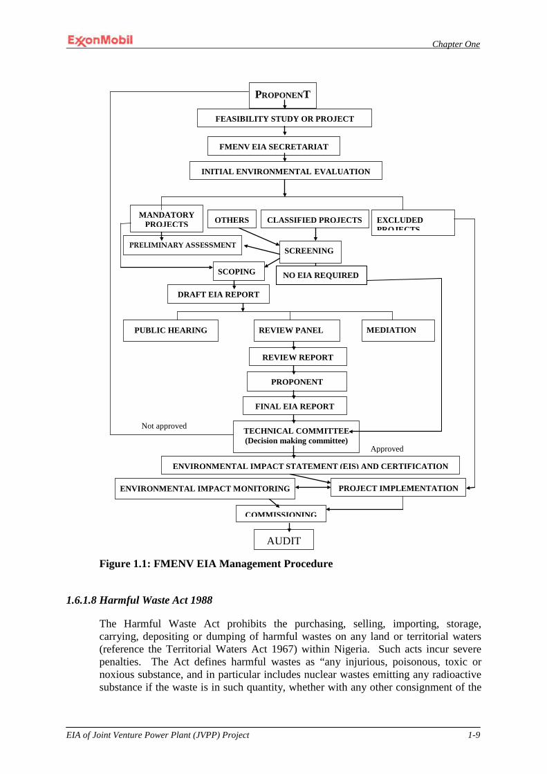
Chapter One
EIA of Joint Venture Power Plant (JVPP) Project 1-9
Figure 1.1: FMENV EIA Management Procedure
1.6.1.8 Harmful Waste Act 1988
The Harmful Waste Act prohibits the purchasing, selling, importing, storage, carrying, depositing or dumping of harmful wastes on any land or territorial waters (reference the Territorial Waters Act 1967) within Nigeria. Such acts incur severe penalties. The Act defines harmful wastes as “any injurious, poisonous, toxic or noxious substance, and in particular includes nuclear wastes emitting any radioactive substance if the waste is in such quantity, whether with any other consignment of the
PROPONENT
FEASIBILITY STUDY OR PROJECT
FMENV EIA SECRETARIAT
INITIAL ENVIRONMENTAL EVALUATION
MANDATORY PROJECTS OTHERS CLASSIFIED PROJECTS EXCLUDED
PROJECTS
PRELIMINARY ASSESSMENT SCREENING
SCOPING
DRAFT EIA REPORT
MEDIATION REVIEW PANEL PUBLIC HEARING
REVIEW REPORT
FINAL EIA REPORT
PROPONENT
TECHNICAL COMMITTEE (Decision making committee)
ENVIRONMENTAL IMPACT STATEMENT (EIS) AND CERTIFICATION
ENVIRONMENTAL IMPACT MONITORING PROJECT IMPLEMENTATION
COMMISSIONING
AUDIT
Approved
Not approved
NO EIA REQUIRED
Chapter One
EIA of Joint Venture Power Plant (JVPP) Project 1-10
same or of different substance, as to subject any person to the risk of death, fatal injury, or incurable impairment of physical and mental health.” While the requirements of this Act are applicable to the Project, the types of wastes described by it are not expected to be generated at any point during the life of the Project.
1.6.1.9 Water Resources Act 1993
The Water Resources Act vests in the Federal Government of Nigeria the right to control the use of all surface water and groundwater in the nation. Pursuant to this Act, the Minister of Water Resources may prohibit or regulate the carrying out of any activity on land or water that may interfere with the quantity or quality of any water in any watercourse or groundwater. The Act allows anyone to acquire the right, i.e. a license from the Minister, to use or take water from any watercourse or any groundwater for any purpose in accordance with the Act and any regulations pursuant thereto. The Act further empowers the Minister to impose a fee on the issuance of such license. During the preliminary engineering phase, the Project will obtain any license, as required pursuant to section 13(a) of the Act, to install the groundwater wells as described in the Project Description.
1.6.1.10 National Oil Spill Detection and Response Agency Act of 2006
The National Oil Spill Detection and Response Agency (NOSDRA), a parastatal agency under the FMENV was established by an Act of the National Assembly in 2006. NOSDRA is vested with the responsibility to develop and coordinate the implementation of the National Oil Spill Contingency Plan (NOSCP) for Nigeria in accordance with the International Convention on Oil Pollution Preparedness, Response and Cooperation 1990, to which Nigeria is a signatory. NOSDRA is also mandated to be the lead agency in ensuring a timely, effective, and appropriate response to oil spills. NOSDRA is also tasked with ensuring that the clean up and remediation of all impacted sites is performed to the “best practical extent.” The agency is empowered to monitor, assist, or where necessary, direct cleanup responses. It is further tasked to identify high risk/priority areas in the oil-producing environment (i.e. the Niger delta) that require protection as well as to ensure oil industry compliance with all applicable environmental regulations. As of this writing, there does not appear to be any federally-determined limit or threshold for spill reporting. As such, all spills regardless of quantity are to be reported to NOSDRA. There also does not appear to be any prescriptive cleanup standard for addressing oil spills; hence the requirement to clean up is to the “best practical extent.”
1.6.1.11 Petroleum Control Act 1967 and all Amendments, CAP 351
According to the preamble to the Petroleum Control Act, the Minister of Petroleum Resources is empowered with the responsibility “to control and regulate activities of petroleum companies on petroleum and petroleum products.” Hence, the Minister of Petroleum Resources jurisdictional authority in regard to this Project is limited to the

Chapter One
EIA of Joint Venture Power Plant (JVPP) Project 1-11
offshore components of the Project whose battery limits are more fully described as follows:
1. The flash gas pipeline commencing at QIT, beginning at the shutdown valve
located onshore and terminating at the tie-in points to the existing OSO system; and
2. The lean gas pipeline commencing at the tie-in points at the existing OSO process system and terminating at the onshore pipeline shutdown valve.
Pursuant to the Petroleum Control Act, oil companies transacting business in Nigeria can be directed by the Minister to register with the Ministry of Petroleum Resources and to provide all information as required by the Ministry at the time of registration. During periods of public emergencies, the Ministry may require persons having facilities for storage of petroleum to accept petroleum from the government for storage on terms appearing to be fair and reasonable to the Ministry. Further, the Ministry may also require oil companies to provide crude oil to the government as necessary and to distribute through its supply system petroleum or petroleum products imported by or on behalf of the federal government or to deliver by any convenient means petroleum or petroleum products to any service declared in the direction to be an essential service to the community. Section 7 to the Petroleum Control Act which addresses the Ministry’s power to make regulations was repealed by the Petroleum Act 1969, third schedule, Cap 350.
1.6.1.12 Petroleum Act 1969 and all Amendments, CAP 350
The 1969 Petroleum Act is the primary piece of legislation that regulates oil and gas activities in Nigeria. Section 9(b)(iii) of the Act empowers the Minister of Petroleum Resources to make regulations to prevent the pollution of water courses and the atmosphere. Pursuant to this provision, the following regulations have been made of which the underlined ones have significant applicability to the offshore portion of the proposed Project: Petroleum (Drilling and Production) Regulations; Mineral Oils Safety Regulations Cap 350; Petroleum Regulations; Oils in Navigable Waters Act, Cap 337; Oil and Gas Pipelines Regulations; Oil Pipelines Act, Cap 203; and Petroleum Refining Regulations. Within these Acts and regulations the Ministry asserts that it has the authority to establish guidelines, standards, and procedures for environmental control. Thus, the Department of Petroleum Resources (DPR) in 1981 issued the interim Environmental Guidelines and Standards for the Petroleum Industry (EGASPIN) which has subsequently been revised such that the latest version is the 2002 edition. Pursuant to EGASPIN 2002, the oil and gas industry is required to prepare an EIA on all oil and gas related projects without limitation. The applicability of this requirement to the Project would however be limited to those activities that fall within the jurisdictional authority of the DPR as defined in the Petroleum Control Act. EGASPIN Part VI. Section E. 3.1.2 requires an EIA to be conducted for all crude oil and gas delivery pipelines that are in excess of 20 kilometers in length. Another obligation within the jurisdiction of the DPR that has relevance to this Project is the condition for a petroleum pipeline license pursuant to the Oil Pipelines
Chapter One
EIA of Joint Venture Power Plant (JVPP) Project 1-12
Act, sections 7, 8, 11, 16, 17, 30 and 31(2). A pipeline license will be required for each of the pipelines presented in Table 2-1 in section 2.3.7.1. Additionally, the DPR’s EGASPIN Part IV.E.7 stipulates that the petroleum industry is to prepare spill prevention plans, conduct spill reporting, and obtain cleanup certifications to address inadvertent spills and leaks. Similar to NOSDRA, threshold standards for spill clean ups and spill reporting are not addressed in EGASPIN. As such, spills are to be cleaned to the best practical extent and are to be reported regardless of quantity.
1.6.1.13 Oil Pipeline Act and Oil & Gas Pipelines Regulations 1958 (amended 1995) The purpose of this Acts as contained in the 1958 Act is "to make provision for licenses to be granted for the establishment and maintenance of pipelines incidental and supplementary to oil fields and oil mining, and for purpose ancillary to such pipeline". Section 11(2) of the Act provides for the definition of an oil pipeline as follows: "For the purposes of this Act an oil pipeline means a pipeline for the conveyance of mineral oils, natural gas and any of their derivatives or components, and also any substance (including steam and water) used or intended to be used in the production of refining or conveying of minerals oils, natural gas and any of their derivatives or components". This definition of Oil Pipeline solves any problem of nomenclature/ambiguity caused by the naming of the Act.
It is clear from section 11(2) that the word "Oil" used in qualifying pipeline also includes natural gas production of refining or conveying of natural gas and any of its derivatives or components. In section 3 of the Act, it is the Minister of Petroleum Resources who has the power to grant permit to survey routes for oil pipelines and to grant oil pipeline license. It therefore follows that there are two different types of license that are obtainable under the Oil Pipelines Act namely 1) Permit to survey and 2) Oil Pipeline License. These laws regulate the right to establish, maintain and operate oil pipelines and ancillary facilities in Nigeria. The Act requires that applications for permits to survey an oil pipeline route be submitted to the Minister for Petroleum Resources. Upon the completion of the survey, the holder of a permit to survey may apply to the Minister of Petroleum Resources for an Oil Pipeline License, subject to the payment of the prescribed fees. The license entitles the holder to enter and take possession or use a strip of the land specified in the license and thereafter to construct, maintain and operate a pipeline and its ancillary facilities.
The Oil and Gas Pipeline Regulations of 1995 provide detailed regulations for the design, construction and inspection of oil and effluent water disposal pipelines in addition to guidelines for the design and construction of oil transmission and distribution pipelines. The regulations further provide for procedures for upgrading pipelines or changing the substances transmitted by a pipeline and for the discontinued use or abandonment of the pipeline system. The Act makes it mandatory for the holder of a pipeline license to pay compensation to any person that suffers damage as a result of any ancillary installation.
The Oil Pipeline Act and the Oil and Gas Pipelines Regulations of 1995, do not require project proponents to conduct an EIA, but rather to undertake a route survey. However, integrating the requirements of the Act and Regulations into the framework
Chapter One
EIA of Joint Venture Power Plant (JVPP) Project 1-13
of the EIA is the most expedient approach to ensuring that all the provisions contained in these statutes are fully complied with.
1.6.1.14 Mineral Oils Safety Regulations (MOSR) 1963 (Amended, 1997) These regulations provide that a license or lease shall:
• Ensure that no pipeline is put into operation without the approval of the Director of Petroleum Resources.
• Make sure that the right of way of every pipeline is free of overgrowth and weeds in order to allow for easy access for conducting operational tests, other maintenance works and for the prompt detection of leakages.
• Carry out cathodic protection potential surveys on all buried pipelines at intervals of not more than 2 years to ensure that every section of the protected line attains a negative potential of not less than 850mV with respect to a copper/copper sulphate reference electrode.
• Provide clear, comprehensive, safe and practical operational procedures and guidelines for the workforce.
• Develop and maintain contingency procedures and measures for the safety of personnel and equipment in an emergency.
• Maintain a documented system, setting out the responsibilities of the competent persons involved in onshore and offshore operations, their mutual relations and lines of reporting and communications.
• Ensure that personal protective equipment is judiciously used and maintained in a serviceable condition at all times.
• Ensure that pressure vessels and fittings used in oilfield operations are examined in accordance with the manufacturer’s recommendations and good oilfield practices.
• Ensure that pressure vessel equipment and associated piping used in oilfield installations meet the National Association of Corrosion Engineers (NACE) or other recognized equivalent standards for monitoring and controlling corrosion, with respect to their design, construction, routine inspection, testing and maintenance.
• Ensure that crane and hoist equipment used for work is operated by a trained person who ensures that the equipment is inspected and maintained as recommended by their manufacturers; and
• Safely handle all diving operations and the activities of diving contractors, to ensure that, as far as is reasonably practicable, the activities are carried out in accordance with all relevant local legislation codes, standards and international safe diving practices.
1.6.1.15 The Associated Gas Re-Injection Act No. 99 of 1979 The Associated Gas Re-injection Regulations 1984 provides condition for issuance of certificate by the Minister of Petroleum Resources for continued flaring of gas. Many companies do not meet any of the requirements for issuance of the certificate but are operating under the provisions of the Associated Gas Re-injection (Amendment) Act No. 7, 1985 which amends section 3(2) of the Associated Gas Re-injection Act of 1979 and permits payment of certain prescribed fees per 28.317 standard cubic meters (SCM) of gas flared.
Chapter One
EIA of Joint Venture Power Plant (JVPP) Project 1-14
On this basis, the Associated Gas Re-injection Act, 1979 was introduced, in order to reduce the flaring of associated gas. Article 3 of that Act, stated that gas flaring without the Minister’s permission in writing would cease by 1 January 1984. The goal proved unrealistic and in 1985, a-n amendment to the Act, The Associated Gas Re-injection (Amendment) Act 1985 provided for the continued flaring of associated gas if the Minister issued a certificate. These provisions were again modified by the Petroleum (Drilling and Production) (Amendment) Act 1988, which provides for a sum to be charged for every 1,000 standard cubic meters of gas flared.
Some regulations of atmospheric quality and air pollution are also carried out through the provisions of a number of other legislative instruments. For example Article 247 of the Criminal Code 1958 concerning Noxious Acts, states that anyone who vitiates the atmosphere is guilty of a misdemeanor and is liable to penal sanctions. Others Federal Government regulatory requirements include;
1.6.1.16 Standards Organization of Nigeria Conformity Assessment Program (SONCAP)
Standards Organization of Nigeria Conformity Assessment Program (SONCAP) is an arm of Standards Organization of Nigeria responsible for regulating every product that is imported into the country with the exception of oil and gas facilities. The power plant equipment will require certification by SONCAP and this will entail the submission of an application and the Product Certificate from the Manufacturers for validation.
1.6.1.17 Land Management
The Land Use Act of 1978 nationalized land holding in Nigeria. The Act vests all land in a State, excluding land vested in the Federal Government or its agencies, solely in the Governor of that State who is to hold such land in trust for the people and is thus responsible for its allocation in all urban areas to individual residents or businesses in the State. Similar powers with respect to non-urban areas are conferred to LGCs. The legal status of land users in Nigeria is thus one of occupancy rather than ownership. Pursuant to Part II Section 9 of the Act, the Governor may issue a certificate of occupancy when any entity or person is in occupation of land under a customary right of occupancy and applies in a prescribed manner. The terms, conditions and annual fee pursuant to the certificate of occupancy are enforceable against the holder and successors.
Certificate of Occupancy Documents
MPN has obtained two separate certificates of occupancy documents which jointly encompass the land tract boundary for the QIT/JVPP facilities. These certificates of occupancy documents are essentially lease agreements between MPN and the Akwa Ibom state government. These documents are scheduled to expire in the year 2048 for tract number 1BE/2/98 and in the year 2053 for tract number 1BE/16/2003.
Chapter One
EIA of Joint Venture Power Plant (JVPP) Project 1-15
Pursuant to these documents, the Governor’s approval is required in advance of erecting any new structure on the QIT/JVPP property. During the preliminary engineering phase, the Project will seek approval from the Governor or any officer delegated such authority, in advance of erecting any of the structures required for the proposed Project.
1.6.1.18 The Inland Waterways Authority Act 13 of 1997 This act gives the statutory backing to the National Inland Waterways Authority. This authority is concerned with the regulation of activities in the inland waterways within the territorial boundaries of Nigeria.
1.6.1.19 Regulation of Dock Facilities
The Project proposes to construct a materials off-loading facility to be located just off the beach at the south-east corner of QIT facility. The facility will provide a breakwater and an area for mooring and unloading heavy equipment from roll-on/roll-off barges. The authority to license and regulate off-loading facilities that reside within 100 meters of the Atlantic shoreline resides with the Nigerian Ports Authority. Pursuant to Part VIII section 33 of the Nigerian Ports Authority Act, No. 38 of 1999, the Project will obtain any license as may be required. The Project will also adhere to all requirements as may be applicable pursuant to Act No. 38 regarding its construction and operation.
1.6.1.20 Criminal Code The Nigerian Criminal Code makes it an offence punishable with up to 6 months imprisonment for any person who: violates the atmosphere in any place so as to make it noxious to the health of
persons in general dwelling or carrying on business in the neighborhood, or passing along a public way; or
does any act which is, and which he knows or has reason to believe to be, likely to spread the infection of any disease dangerous to life, whether human or animal.
There are also other regulations including: Wild Animals Preservation Act Cap 132 LFN 1990; Explosives Regulations, 1967; River Basins Development Authority Act, 1987; and Natural Resources Conservation Act Cap 286 LFN 1990.
1.6.2 Laws Protecting Flora and Fauna
Nigeria’s National Forestry Policy was approved in 2006. The legislation to support this Policy known as the National Forestry Act is currently under review. Once passed, the National Forestry Act will be administered by the Federal Department of Forestry which is a parastatal agency of the FMENV. Limited information available on the draft Forestry Act indicates that its goal is to economically exploit forests resources in a sustainable manner with careful consideration given to biological diversity and ecosystem protection.
Chapter One
EIA of Joint Venture Power Plant (JVPP) Project 1-16
1.6.2.1 Parks, Game Reserves and other Protected Areas
There are three categories of protected areas in Nigeria established to protect flora and fauna. These categories are the National Parks, Game Reserves and Forest Reserves. At the national level, the mandate for wildlife conservation and protected areas management is the responsibility of the National Parks Service, an agency within the FMENV. There are seven national parks spread across the country. These parks receive the highest level of protection in accordance with the National Parks Service Act of 1999, Act 46. A variety of game reserves are managed by the states in which they reside in an effort to preserve wildlife species. States also manage innumerable forest reserves with the intention of preserving trees and other plant species along with associated wildlife. There are no National Parks located near the proposed Project as none of the seven Parks are located within Akwa Ibom state. However, the onshore portion of the proposed Project will be located in the southwestern corner of the Stubbs Creek Forest Reserve.
1.6.2.2 Stubbs Creek Forest Reserve
The Stubbs Creek Forest Reserve was established in 1931 under Order 45 and subsequently amended in 1941, 1955 and 1962. This Reserve is one of the last remaining significant, but highly disturbed forest reserves in the Niger Delta region. The proposed power plant facility will be located in the southwestern corner of the Reserve. The Akwa Ibom state government is responsible for managing the Stubbs Creek Forest Reserve in accordance with Order 45. The Order allows local inhabitants access to the reserve so as not to deprive them of their historical use of the associated forest such as hunting, fishing, and extracting water.
1.6.2.3 Endangered Species (Control of International Trade and Traffic) Act
Nigeria acceded to the Convention on International Trade on Endangered Species of Wild Fauna and Flora (CITES) in 1974. The treaty’s goal is to ensure that international trade in specimens of wild animals and plants do not threaten their survival. In accordance with Nigeria’s obligations under CITES, the government enacted the Endangered Species (Control of International Trade and Traffic) Act, which seeks to control and in some cases prohibit the trafficking or trade of special status species, as defined by the Act, including the commercial exploitation of such species. The Project will not involve the trafficking of “special status species” as defined by the Act. The proposed project will use the International Union for the Conservation of Nature’s (IUCN’s) “Red List Book” to determine the species to address in this environmental analysis. More will be said about the IUCN and the Red List book in later chapters of this document.
1.6.2.4 Sea Fisheries Act No. 71 of 1992 This Act makes Provision for the control, regulation and protection of sea fisheries in the territorial waters of Nigeria.

Chapter One
EIA of Joint Venture Power Plant (JVPP) Project 1-17
“ No person shall operate or navigate any motor fishing boat within the territorial waters of Nigeria unless a license in respect of that vessel has been issued to the owner thereof (sect. 1 (1)). Owners of a motor fishing boat may apply to a Licensing Officer for a license in respect of the motor fishing boat. An application shall be in the form and manner as may be prescribed and shall contain the particulars specified in section 2. Conditions for the issue of a license are set out in section 3. Licenses shall be given yearly or quarterly. Persons aggrieved by any refusal by a Licensing Officer to issue or renew a license or by the cancellation or suspension of a license may appeal to the Federal Commissioner responsible for fisheries (sect. 5). Authorized persons (not defined) may take actions set out in section 7 for the purpose of enforcing any provision of this Act. Regulation making powers of the Commissioner are specified in section 11. (The law also prohibits some methods of fishing.”
1.6.3 State Environmental Management Framework
The different States within Nigeria have the power to enact laws to protect the environment within their respective jurisdiction. The Akwa Ibom state government enacted the Environmental Protection and Waste Management Agency Law, Cap 47. The law established the Agency, the Akwa Ibom Environmental Protection and Waste Management Agency (though now defunct) to be supervised by Ministry of Environment. Since it is defunct, all the responsibilities are vested within the Ministry of Environment and Mineral Resources. The role of the Ministry covers more areas than those of the defunct agency. Some of its principal function is to ensure responsible management of municipal and sanitary wastes as well as regulating the discharges of manufacturing and other business facilities. Pursuant to section 7 of the Law, the Agency is empowered to collect a pollutant fee from those industries listed in Schedule II. The proposed Project does not fall into any of the industrial categories listed in Schedule II. It thus appears that the Law would have limited applicability to the Project. Clauses that will likely have applicability to the Project are sections 28 and 29. Section 28 prohibits the discharge of any oil or grease brought about by any manufacturing or other type of business into any public drain, water course, water gorge or roads verge. However, section 27 of the Law clarifies that such discharge is lawful provided the discharging entity obtains a state permit for the discharge and does not permit a release above the state mandated threshold criteria. Section 29 prohibits the emission or release of any injurious gas by any manufacturing industry or other type of business above a regulatory threshold. Such gas is defined as sulfur dioxide, ammonia, chlorine, smoke, metallic dusts, particulates and “injurious gases.” In summary, the Project may need to obtain a state discharge permit for its retention pond to address any inadvertent release of oil or grease from its retention pond to Douglas Creek as described in the project description. The air pollutants identified in section 29 of the Law are not expected to be emitted from the proposed Project and thus no further action would be expected. However, the Project will confer with the State Environmental Ministry to ensure that its understanding of this provision of the Law is consistent with the Ministry’s interpretation of the Law.
Chapter One
EIA of Joint Venture Power Plant (JVPP) Project 1-18
1.6.4 International Treaties on the Environment
Nigeria has ratified numerous international treaties on the environment. Under Nigerian law, it is necessary to incorporate a treaty into domestic legislation before it can have the full force of law. In many cases, the ratified treaties have yet to be implemented into the laws of Nigeria. As such, the courts in Nigeria may not enforce them. The following environmental treaties have been ratified by Nigeria and have implementing legislation in-place:
1.6.4.1 International Convention for the Prevention of Pollution of the Sea by Oil 1954 as
amended in 1962; implemented by the Oil in Navigable Waters Act of 1968; addresses the discharge of oil from ships;
1.6.4.2 International Convention on Oil Pollution, Preparedness, Response and
Cooperation; implemented by the National Oil Spill Detection and Response Agency Act 2006; addresses development and implementation of the Nation’s Oil Spill Contingency Plan; and
1.6.4.3 Convention on International Trade on Endangered Species of Wild Fauna and Flora 1974; implemented by the Endangered Species Act; seeks to control and in some cases prohibit the trafficking of special status species.
1.6.4.4 International Convention on Civil Liability for Oil Pollution Damage: the Convention as amended up to 1971 provides uniform international rules and procedures for determining the question of liability and providing adequate compensation to persons who suffer damage caused by the escape or discharge of oil from ships.
1.6.4.5 Convention on the Prevention of Marine Pollution by Dumping of Wastes and Other Matter: This convention known as the London Convention of 1972 has been replaced by the 1996 Protocol which was adopted on 7 November 1996, and entered into force on 24 March 2006. The 1972 Convention permits dumping to be carried out provided certain conditions are met. The severity of these conditions varies according to the danger to the environment presented by the materials themselves and there is a "black list" containing materials which may not be dumped at all. The 1996 Protocol is much more restrictive, however, it permits dumping in certain circumstances.
1.6.4.6 United Nations Convention on Climate Change: The convention on climate change was signed in 1992 during the Rio Earth Summit but put into force in 1994. The convention calls on developed countries and economies in transition to limit their emissions of the greenhouse gases which cause global warming, although does not impose mandatory emissions restrictions on developing countries.
1.6.4.7 Vienna Convention for the Protection of the Ozone Layer: The convention was instituted in 1985 and places general obligations on countries to take appropriate measures to protect human health and the environment against adverse effects resulting from human activities which tend to modify the ozone layer.

Chapter One
EIA of Joint Venture Power Plant (JVPP) Project 1-19
1.6.4.8 Convention on Conservation of Migratory Species of Wild Animals: This convention also known as the Bonn Convention of 1979 stipulates actions for the conservation and management of migratory species including habitat conservation.
1.6.4.9 United Nations Guiding Principles on the Human Environment: The United Nations (UN), concerned about negative environmental trends since its formation, published two major concept documents: Guiding Principles on the Human Environment, 1972 and the Rio Declaration on Environment and Development. Ten of these Guiding Principles were defined as formal declarations that express the basis on which an environmental policy can be built and which provide a foundation for action. The principles relevant to the proposed project are summarized below;
Principle 2 The natural resources of the earth, including the air, water, land, flora and fauna and especially representative samples of natural ecosystems, must be safeguarded for the benefit of present and future generations through careful planning or management, as appropriate. Principle 3 The capacity of the earth to produce vital renewable resources must be maintained and, wherever practicable, restored or improved. Principle 6 The discharge of toxic substances or of other substances and the release of heat, in such quantities or concentrations as to exceed the capacity of the environment to render them harmless, must be halted in order to ensure that serious or irreversible damage is not inflicted upon the ecosystems. The just struggle of the peoples against pollution should be supported. Principle 7 States shall take all possible steps to prevent pollution of the seas by substances that are liable to create hazards to human health, to harm living resources and marine life, to damage amenities or to interfere with other legitimate uses of the sea.
1.6.4.10 International Union for Conservation of nature and Natural Resources (IUCN) Guidelines (1996); The World Conservation Union – IUCN Red List of threatened animals provides taxonomic, conservation status and distribution information on species that have been evaluated using the IUCN Red List categories. This system is designed to determine relative risk of extinction and the main purpose of the red list is to catalogue the species that are regarded as threatened at the global level i.e. at risk of overall extinction. The 1996 red list also included information on species that are categorized as extinct: on species that cannot be assessed because of insufficient data: and on certain species in the lower risk category. Nigeria as a member categorizes species using the red list.
1.6.5 Electrical Power Sector Regulatory Framework
The major power utility company in Nigeria, the National Electric Power Authority (NEPA), now known as the Power Holding Company of Nigeria (PHCN) is owned by

Chapter One
EIA of Joint Venture Power Plant (JVPP) Project 1-20
the Nigerian Federal Government. Until recently, it has been the main electric power monopoly for the generation, transmission and distribution of centralized power grid.
1.6.5.1 Electricity Act, 1976 This provides for the regulation and control of power generation, transmission, supply and use of electrical energy in Nigeria. This Act is enforced by the Power Holding Company of Nigeria (PHCN). The relevant parts to the JVPP Project includes;
Part V
This part stipulates safety regulations and uses of electrical energy, and equipment affecting new installations. It deals with conditions of direct-current supply with earth return in Regulation 41, system earthing in 42, Delta and star-connected systems with earthed and isolated neutrals in 44 and 45 respectively.
Part VI Regulation 94 stipulates the standard requirements on insulation for cable
whether a.c or d.c and for all voltages, while 95 lists regulations on trenching and protection of cables from damage, giving the depth at which the cables should be laid (1 meter minimum) and a minimum distance of 300mm between cables. It also requires that cable should be laid in sifted soil or sand to prevent damage by stones and protected against mechanical damage with interlocked tile sufficiently wide to give a minimum overlap of 50mm of each side and 150mm above the cables. The cable routes shall also be indicated at surface level with cable marker at suitable intervals, particularly at positions where the cable changes direction.
Regulation 96 requires protection of cables at a point at least 50cm below ground where cables enter or leave the ground, while 97 requires that all proposals in respect of railway crossing be submitted to General Manager in accordance with regulation 64 which requires the Licencee to serve a written notice to appropriate authorities prior to placing electric line(s) other than a service line in the proximity of railway line.
Part VII Regulation 101 of this part stipulates their provisions requiring the following:
I. That outdoor substations and switch stations be efficiently protected by fencing not less than 2.5metres which shall be earthed separately from the substation earth;
II. Appropriately labeled danger notices shall be displayed on the Licensees works;
III. Any metal work accessible from the ground, shall be connected to an earth mat, situated such that the operator is situated within its area; and
IV. Suitable provision shall be made to guard against danger of the system becoming accidentally charged above its normal voltage by leakage, or contact with the system at the higher voltage.
V. Section 2 of the same regulation gives provisions for sub-stations situated inside a building. It requires the mandatory removal of oil from the oil-receptacle for oil-immersed transformers or switches to guard against the
Chapter One
EIA of Joint Venture Power Plant (JVPP) Project 1-21
danger of fire as a precaution and that spare oil be stored in an area away from any such substation or switch station.
Regulation 102 requires the protection of all transformers by primary fuses or
overload circuit breakers adjacent to the transformer. Part VIII Regulation 104 deals with automatic protection and isolation of circuits. It
requires that: 1. Means be provided at the origination of every main circuit to automatically
cut off the supply of energy in the event of (a) the passage of current of such magnitude and duration as would be liable
to damage the line or its associated joint and fitting. (b) Leakage of current to earth in excess of the amount permitted by the
regulations. 2. The means provided in compliance with Regulation 104(1) shall be circuit
breakers constructed and installed in conformity with the relevant Nigerian Standard and they shall be capable of interruption, without damage to the equipment or danger to the operator, system short-circuit currents likely to be handled under conditions of use to which they are subjected and further shall similarly withstand without damage to the equipment or damage to the operator, the currents flowing if closure is made on a line or circuit which is short circuited.
3. Every automatic device shall be provided with means so that it can be locked in the “off” position to prevent unauthorized interference. During the time that the device is locked in the “off” position the relevant keys for the lock shall be kept in safe custody as prescribed by Regulation 75(3).
Regulation 105 gives general conditions as to transformation and control for
energy at high voltage being transformed, converted or otherwise controlled in sub-or switching – stations for which the following provisions shall be effective:
I. Sub-and switch stations shall preferably be erected above ground, but where
necessarily constructed underground there shall be due provision for ventilation.
II. Outdoors substations and switch stations shall be enclosed within a chain link or woven wire or mild steel fence that cannot be climbed.
III. Fire – resisting casing on the premises of a consumer preferable of metal connected with earth shall completely enclose all electric lines and so secured to prevent access to electricity charged parts by an unauthorized person. It also requires appropriate danger notice on the works stating the Licensees name, address and telephone number at which an officer will be in attendance at all times.
Further construction details for specified cases are captured in Regulation 106,
while 107 gives precautions against fire risk. Precautions are the draining way of any oil, which may leak, from tanks, receptacles or chamber in switching station using oil-immersed transformers and provision for extinguishing any fire, which may occur. It also prohibits the storage of oil in any station.

Chapter One
EIA of Joint Venture Power Plant (JVPP) Project 1-22
Regulation 108 makes provisions for faults between transformer windings.

Chapter One
EIA of Joint Venture Power Plant (JVPP) Project 1-23
Part IX Regulations 109 - 111 appertain to switch boards, connection with earth, power
stations, 114 spell out regulations for horizontal clearance in passage ways, power-houses and sub-stations enclosures, 116 deals with notice on electric shock treatment and 119 gives precautions against excess leakage.
Regulation 120 gives provisions, which apply to connection with earth of high voltage systems.
Part X Contained in part X are regulations 121 - 134. Relevant legislation is contained
in Regulations 121; standard construction of electric lines; 122 - 123: protection against energy; precaution against shock and fire; protection from lightning and precautions against metal works becoming electrically charged respectively.
Regulations 127 - 129 concern insulation or protection, receptacles for electric lines and apparatus and underground shafts.
Regulations 133 appertains to placing of electric cables below ground, requiring the licensee not to place cables on the opposite side of the streets to the telegraph line unless the Director of Electrical services expressly authorizes in writing a relaxation of these requirements.
Regulation 134 requires the exchange of plant between the licensee and Director of Telecommunications for any existing works placed below ground.
1.6.5.2 Electricity Amendment Act 1998 The electricity amendment Act No. 28 of 1998 was the legislative backing to commence the deregulation of the electricity sector in Nigeria. Hitherto National Electric Power Authority (NEPA) had the statutory responsibility to generate, distribute and supply power in Nigeria. This Act promulgated by the Federal Government of Nigeria clearly demonstrates the readiness to allow competition in the power sector of Nigeria. By this Act it is expected that both national and international investors interested in the sale of electricity will be willing to compete favourably in power generation, distribution and supply. This Act automatically abolishes all the monopoly previously enjoyed by NEPA. Section (2) of this Act amends the electricity Act among other things to make it clear that licenses under the Act may be granted to any person, other than the National Electricity Power Authority, a state Government or any of its agencies. Section (3) sates that a person granted licenses under subsection (1) of this section shall be subject to the terms and conditions of the license and have the same rights and obligations as the Authority, a state Government and/or agencies. Section (4) states that the issuance of a license under this Act shall not be deemed to give to the licensee a monopoly of the exclusive right to supply electricity within the area authorized by the license.
1.6.5.3 Electricity Power Sector Reform Act (2005): The Nigerian Electricity Regulatory Commission (NERC) In order to engender greater efficiency and sustainability, the government instituted a series of reforms that commenced in 2005 with the passage of the Electric Power Sector Reform (EPSR) Act (figure 1.2). The EPSR Act led to the restructuring of the existing power utility into six separate generation companies, eleven distribution companies and one Transmission Company all of which are owned by PHCN in the
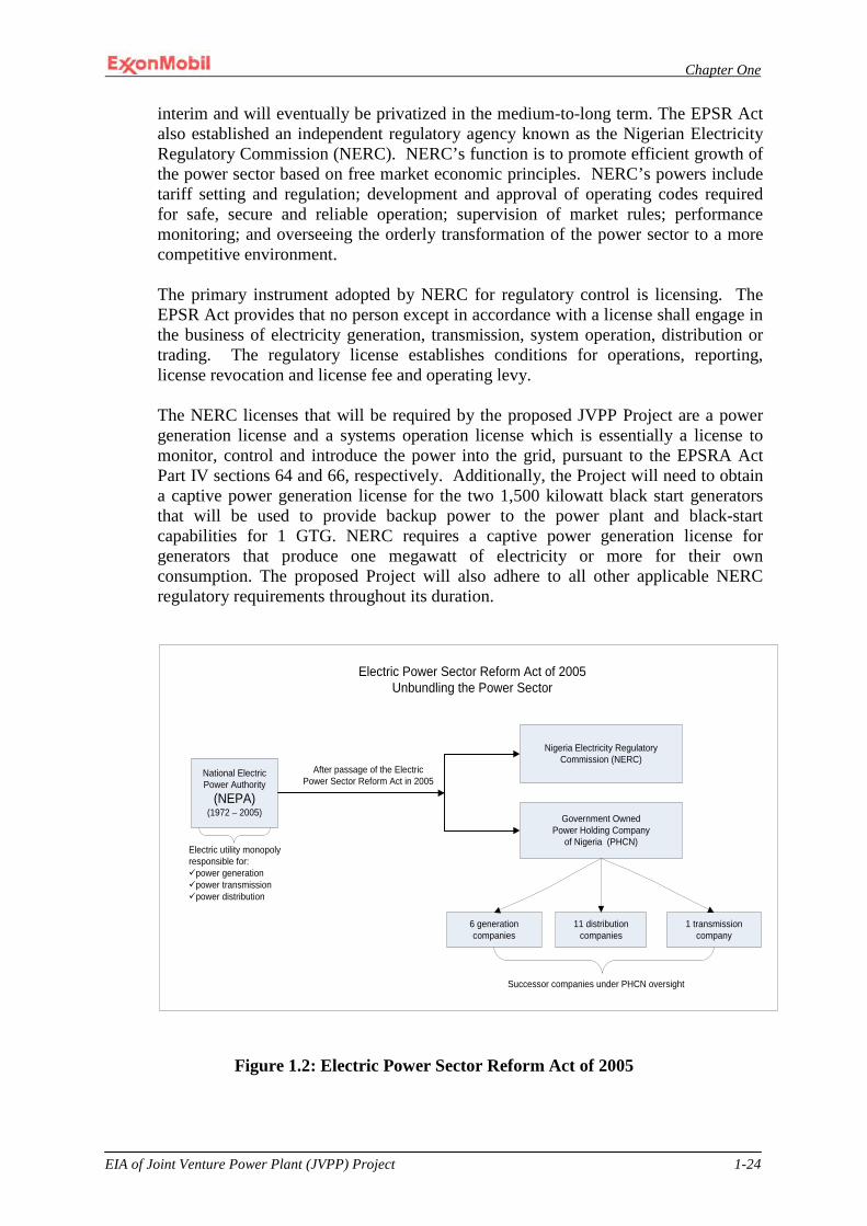
Chapter One
EIA of Joint Venture Power Plant (JVPP) Project 1-24
interim and will eventually be privatized in the medium-to-long term. The EPSR Act also established an independent regulatory agency known as the Nigerian Electricity Regulatory Commission (NERC). NERC’s function is to promote efficient growth of the power sector based on free market economic principles. NERC’s powers include tariff setting and regulation; development and approval of operating codes required for safe, secure and reliable operation; supervision of market rules; performance monitoring; and overseeing the orderly transformation of the power sector to a more competitive environment. The primary instrument adopted by NERC for regulatory control is licensing. The EPSR Act provides that no person except in accordance with a license shall engage in the business of electricity generation, transmission, system operation, distribution or trading. The regulatory license establishes conditions for operations, reporting, license revocation and license fee and operating levy. The NERC licenses that will be required by the proposed JVPP Project are a power generation license and a systems operation license which is essentially a license to monitor, control and introduce the power into the grid, pursuant to the EPSRA Act Part IV sections 64 and 66, respectively. Additionally, the Project will need to obtain a captive power generation license for the two 1,500 kilowatt black start generators that will be used to provide backup power to the power plant and black-start capabilities for 1 GTG. NERC requires a captive power generation license for generators that produce one megawatt of electricity or more for their own consumption. The proposed Project will also adhere to all other applicable NERC regulatory requirements throughout its duration.
Figure 1.2: Electric Power Sector Reform Act of 2005
National Electric Power Authority
(NEPA)(1972 – 2005) Government Owned
Power Holding Company of Nigeria (PHCN)
6 generation companies
11 distribution companies
1 transmission company
Nigeria Electricity Regulatory Commission (NERC)
Electric Power Sector Reform Act of 2005Unbundling the Power Sector
After passage of the Electric Power Sector Reform Act in 2005
Electric utility monopoly responsible for:üpower generationüpower transmissionüpower distribution
Successor companies under PHCN oversight
Chapter One
EIA of Joint Venture Power Plant (JVPP) Project 1-25
1.6.6 World Bank
It is anticipated that the Project may involve the International Development Association (IDA) branch of the World Bank to financially guarantee the gas supply payment obligations of PHCN to MPN; MPN is in a Joint Venture with the government-owned Nigerian National Petroleum Corporation in regard to this Venture. In anticipation of this event, the impact criteria considered in the environmental analysis will consider World Bank standards and safeguard policies as detailed in World Bank Group Environmental, Health and Safety Guidelines issued in 2007. The guideline identifies general as well as industry specific requirements for onshore and offshore projects. The World Bank guide provides ten safeguards which projects are to consider. These safeguards have been review and only four are considered applicable to this project. The four key safeguard policies considered are OP 4.01 Environmental Assessment, OP 4.04 Natural Habitats, OP 4.11 Physical Cultural Resources and OP 4.12 Involuntary Resettlement. The OP 4.01- Environmental Assessment ensures that projects that seek World Bank financing are socially and environmentally sound and stable. It also ensures that decision makers are well informed about potential risks and also involved in the decision making process. OP 4.04 confirms that projects are not being implemented on preserved or reserved plots of land protected by legislation or law. The identification of physical and cultural resources is the premise of OP 4.11 and is designed to protect these resources from exploitation without compensation or other considerations. The OP 4.12 Involuntary Resettlement is targeted at minimizing involuntary resettlement of persons, provide transparent compensation and ensure proper settlement of affected persons. For project related conditions, the more stringent standard, be it Nigerian, Company or World Bank’s will apply.. Safeguard OP 4.01 is being addressed through the formal development and implementation of this Environmental, Socioeconomic and Health Impact Assessment report as required by the FGN. This ESHIA will identify the project activities, evaluate its impact and propose mitigation and monitoring obligations throughout the life cycle of the project. OP 4.04 is not applicable since the project area is not considered a critical natural habitat as defined by the policy although it is located near the Stubbs Creek Reserves. The Reserves were created by a colonial Ordinance in the 1930s. That Ordinance has now been overtaken by the current operative law: the Land Use Act of 1978. OP 4.11 and 4.12 will be addressed through the development, implementation, and monitoring of Project Resettlement Action Plan. Although the project will not require resettlement of persons, the RAP will provide appropriate strategies for the identification and management of project affected persons and resources.
1.7 Summary of License, Permit and Approval Requirements Discussion
Section 1.6 has identified and discussed those regulatory agencies expected to have responsibility for authorizing the principal environmental or regulatory licenses, permits and/or approvals needed for the construction and operation of this Project. Table 1-1 summarizes these regulatory agencies and their corresponding jurisdictional authority as it pertains to the Project.

Chapter One
EIA of Joint Venture Power Plant (JVPP) Project 1-26
Table 1-1: Regulatory Agency Jurisdictional Summary
Regulatory Agency Project Battery Limits NESREA Project onshore facilities1
FMENV- EIA Certification Entire project
Ministry of Water Resources Project onshore facilities
NOSDRA Entire project
DPR Project offshore facilities2
State Ministry of Environment Project onshore facilities
Nigerian Ports Authority Material off-loading facility
NERC Project onshore facilities
Note: 1) Project onshore facilities are defined as the power plant and all ancillary facilities excluding facilities described in chapter three. NESREA performance standards would also apply to the MOF (e.g. waste management standards, etc.). 2) Project offshore facilities battery limits are defined in chapter three.
Table 1-2 summarizes the licenses, permits and approvals that were discussed in this section. This table is not inclusive of all Project requirements. As stated earlier, a Regulatory Compliance Plan will be prepared to ensure that all host country environmental and other regulatory requirements established by laws and regulations are identified and implemented as required.
1.8 ExxonMobil Policies, Strategies and Standards The Company has developed a set of global environmental standards for its operations and joint ventures. These standards describe what an operation is required to do in relation to environmental management, helping to ensure consistent environmental performance worldwide. These standards, as applicable to the Project, will be considered in the environmental analysis if they are more stringent than host country standards or in the absence of host country requirements. The specifics of these standards will be described as they are used in later chapters of this document. The general policies for MPN in the areas of safety, health and environment are summarized below. MPN’s strategies for meeting the objectives of the policies are discussed subsequently.
Table 1-2: License, Permit and Approval Requirements (not all inclusive)

Chapter One
EIA of Joint Venture Power Plant (JVPP) Project 1-27
Permit, License or Approval Requirements Regulatory Agency Description
Permit Required Ministry of Water Resources Ground water well installation
Permit Required (Possibly) Akwa Ibom Ministry of Environment
Inadvertent discharge of oil or grease from the retention
pond to Douglas Creek Approval Required Akwa Ibom State Government Installation of new structures
on the property License Required Nigerian Ports Authority Installation and operation of a
material off-loading facility License Required Nigerian Electricity Regulatory
Commission Power generation
License Required Nigerian Electricity Regulatory Commission
Systems operation
License Required Nigerian Electricity Regulatory Commission
Captive power generation
License Required Department of Petroleum Resources
Pipeline installation and operation
License Required Standards Organization of Nigeria Conformity Assessment
Program
Importation of power plant and associated facilities
1.8.1 ExxonMobil’s Corporate Policies ExxonMobil is committed to conducting its business in a manner that protects the safety and health of employees, others involved in its operations, its customers, and the general public. Furthermore, it is committed to conducting its business in a manner that is compatible with the balanced environmental and economic needs of the communities in which it operates. This commitment requires compliance with all applicable laws and regulations, facilities that are designed and operated to high standards, and the systematic identification and management of risks.
1.8.2 Operations Integrity Management System (OIMS) In addition to legal requirements, the Project will also be expected to comply with MPN’s OIMS expectations. OIMS comprises of eleven primary elements. For each element, there is a principle and a set of expectations for the conduct of activities. The eleven primary elements are:
• Management, Leadership, Commitment, and Accountability – ensures that workers understand the goals and management commitment to excellence in safety, health, environment, and operational integrity.
• Risk Assessment and management - ensures that risks involved in operations are recognized so that they can be appropriately addressed through facility design and/or operating practices.
• Facilities Design and Construction- ensures elements for the protection of people and the environment are incorporated into the design of facilities and the plans for installation and operation.
Chapter One
EIA of Joint Venture Power Plant (JVPP) Project 1-28
• Process and Facilities Information/Documentation – ensures that the systems are designed to protect people and the environment.
• Personnel and Training - ensures that personnel understand the systems that are in place.
• Operations and Maintenance – ensures that facilities are maintained and operated in ways that ensure the protection of people and the environment.
• Management of Change - ensures that new personnel are informed of existing systems, that affected personnel are informed of changes in the systems, and that safety and environmental aspects are considered when making changes.
• Third Party Services – through contracts, oversight and other mechanisms, third party contractors are held to the same standards as MPN.
• Incident Investigation and Analysis – seeks to understand the causes of any incident, so that effective controls or systems can be implemented to prevent reoccurrence.
• Community Awareness and Emergency Preparedness – though not highly applicable in an offshore project far removed from communities, this ensures appropriate outreach and awareness programs are implemented to establish effective emergency procedures and to allay concerns.
• Operations Integrity Assessment and Improvement – ensures that safety and environmental performance is monitored against targets to ensure MPN is meeting its goals to protect people and the environment and seeks the means to improve systems and processes, particularly when goals are not being met.
1.9 Structure of the Report This EIA consist of eight chapters. Chapter one is an introduction providing the background information about the Project, the proponent and the legal/administrative framework for the EIA in Nigeria. The second chapter discusses the Project’s justification and presents the need/value and the envisaged sustainability of the project as well as the development options considered. Chapter Three contains a description of the proposed project activities including engineering/detailed design, project management and operations philosophies and the project execution schedule. The fourth chapter describes the existing biophysical and socioeconomic status of the Project area as well as the health status of the residents based on a literature review and field surveys. This chapter also contains a summary of the consultation program for the proposed project.
The potential and associated environmental, socioeconomic, and health impacts of the proposed project are presented in chapter five while chapter six proffers mitigation and enhancement measures, and alternatives for the identified adverse impacts. chapter seven describes the Environmental Management Plan that MPN proposes to implement during the execution of the proposed Power Plant Project while chapter eight concludes the report with the decommissioning plans and strategies of the plant and associated facilities.

CHAPTER TWO
Chapter Two
EIA of Joint Venture Power Plant (JVPP) Project 2-1
CHAPTER TWO
2.0 PROJECT JUSTIFICATION
2.1 General
EIA project alternatives analyses provide transparent and objective basis for the identification of best means for project execution that complies with regulatory, stakeholder, company and sponsors’ requirements. The process gives due consideration to not only the technical and economic aspects but also to the environmental, safety, health, security and social aspects. Early identification and due consideration of these aspects, along with the other key components of the proposed project, allows for proper planning and effective implementation that are targeted towards accomplishing project objectives. This chapter therefore presents the needs, benefits and methodology for selecting the optimal alternative that will meet project objectives, local, national and international requirements.
2.1.1 The Need for the Project Electricity is widely accepted as a basic necessity of life, needed for domestic, commercial and industrial purposes. There is a high and growing demand for electric power in Nigeria which has led businesses and individuals to the frequent use of generators to supplement power supply. However, to boost the national power supply, NNPC requested the involvement of international oil companies operating in Nigeria, ExxonMobil included, in the development of power plants. It is in response to this that MPN is progressing the development of a Joint Venture Power Project, in proximity to its Qua Iboe Terminal (QIT) facility, which will utilize fuel gas from the Oso Reservoirs, off Ibeno shore in Akwa Ibom State.
2.1.2 Potential Benefits of the Project Project alternative options have been comparatively evaluated in this section. Each section provides due consideration of the benefits and disadvantages of the options. In addition, the technical, economic, environmental, safety, health, security and social impacts of the project were also duly considered for each option.
2.2 Alternatives Development & Analysis
Alternatives are different means of completing the proposed Project while still meeting the purpose of the proposed activity. Furthermore, the alternatives analysis is intended to address other means of completing the proposed Project that could avoid or minimize adverse impacts that would be associated with the proposed project. Alternatives may include, but are not limited to, location or site alternatives, process or technology alternatives, the no-action alternative, etc. The “No Action”alternative provides the baseline against which the impacts of the other alternatives are compared. Major alternatives addressed for this power project are as follows:
• Analysis of alternative site locations • Analysis of alternative plant layouts
Chapter Two
EIA of Joint Venture Power Plant (JVPP) Project 2-2
• Analysis of alternative technological/process designs • Analysis of “No Action” alternative
Key considerations for each project alternative evaluated the implications of the proposed project activities or absence of it on various aspects such as;
• Safety and Security- this includes potential safety and security exposures and
expenses that are associated with the proposed project with due consideration to the work locations, personnel and activities. It also includes safety and security risks that may arise if the proposed project is not executed.
• Displacement/Land take- the possibilities of project land requirements, displacement of persons, associated environmental disruptions as well as the absence of these if the project is rejected.
• Environment- release of emissions and discharge of substances into the proposed project environment in the course of work, the impacts on various environmental aspects, and likelihood of avoiding these by not going ahead with the proposed project.
• Social- the influence of the proposed project and related activities on standards of living and general quality of life as power supply becomes reliable, people acquire and improve skills as well as their earning power, and business and other developmental opportunities abound. It also includes possible conflicts that may arise due to influx of people and the consequent social changes that may arise.
• Public Health- the possibilities of improved or degenerative health conditions as people congregate within and around the proposed project site and environs. The likely cumulative impacts of proposed project related emissions and discharges on the health of workers and residents in comparison to that arising from continued use of diesel powered generators if the proposed project is rejected.
• Economics- likely costs and gains of investment, construction, operations and maintenance of the proposed plant and associated facilities, as well as the additional costs or savings due to the option under consideration.
• Effectiveness in meeting the proposed project objectives- core project objectives include compliance to the directive by the Federal Government of Nigeria on boosting power supply as well as gas flare elimination.
• Regulatory, corporate and stakeholder requirements- this considers government, legal, corporate and stakeholders’ expectations. It also includes permits, licenses and monitoring requirements with respect to specific project options in order to ensure compliance of anticipated project activities.
• Technical feasibility- ease and acceptability of proposed technology with respect to existing technologies and possible tie ins
• Synergy- ability of the option in question to fit into existing facilities and operations that may be required to enhance project activities
The above criteria played varying but significant roles in comparing project alternatives. Two strategies, qualitative and semi-quantitative, were used to determine the acceptable alternative. Qualitative Approach: This method highlighted the advantages and disadvantages of each project alternative with respect to specific criterion of interest as presented from sections 2.2.1 through 2.2.4 and summarized in Tables2.1 and 2.2.

Chapter Two
EIA of Joint Venture Power Plant (JVPP) Project 2-3
Semi-Quantitative Approach: The performance of the different alternatives with respect to specific criteria of interest was ranked on an ordinal scale as presented in Table 2.3.
2.2.1 Analysis of Alternative Site Locations
This section describes the methodology by which alternative site locations were identified and comparatively assessed in order to determine the most appropriate location that meets requirements for successful implementation of the proposed project. Project alternatives were evaluated as part of the conceptual design process, and alternatives that provided credible environmental protection/management, excellent safety performance, sufficient security for personnel that will be exposed in the course of work and that are cost-effective with respect to best available technologies and locations were considered.
The initial site selection process for the proposed Project focused on citing the facility at a location that met the following criteria:
• The facility to preferably be cited near an existing MPN facility so as to take
advantage of potential synergies associated with utilities, security, and firefighting.
• The facility to be located on property where MPN held a Certificate of Occupancy for easy access to potentially to-be-shared resources, for better controls and proper interface arrangements with existing facilities.
2.2.1.1 Option 1: Site on Non-MPN Locations
The non-MPN locations considered for the project included Port Harcourt, Onne, and Bonny. For all locations, the acquisition of land on which to site the power plant was not economically viable. In some cases land was not available. Specifically for the potential site at Bonny, it was identified that extensive filling of up to 1 million cubic meters of the project site would be required and any associated transmission line (T-line) would be difficult to construct because of the swampy environment along the proposed routes. These potential locations listed above were ultimately rejected because of their overall negative impacts especially with respect to the level of risk exposure, schedule delays, excessive cost and significant environmental, safety, security and socioeconomic impacts that could be incurred as a result of those choices. It was concluded that these exposures would be eliminated or significantly reduced by locating the plant close to an existing MPN facility.
Due to the enormous synergies that could be garnered by locating the power plant in proximity to an existing MPN facility, it was decided that potential locations be explored in Eket at the Qua Iboe Terminal.

Chapter Two
EIA of Joint Venture Power Plant (JVPP) Project 2-4
Afam
BRT
QIT
Afam
BRT
QIT
Figure 2.1 Aerial photograph showing JVPP (QIT) site relative to other sites
2.2.1.2 Option 2: Site on MPN locations
Besides the decision to maximize the potential for operating synergies, which led to the decision to limit the power plant location considerations to existing MPN sites in Eket, several geotechnical investigations and past design experiences consistently revealed that QIT rests on dense soils, suitable for foundation structures and hence would not require massive filling like the other locations previously considered. This made it the prime option. About six locations were initially considered out of which three 3 viable locations emerged (Figure 2.2).
• Site B2 – This site is within QIT. It is located in an area already prepared and preloaded for future tanks. Changing the use of this area is likely to have implications on operations and maintenance of both the current and proposed facilities. In as much as proximity is considered an advantage for the purpose of synergy, the proposed plant is expected to function as an independent project at minimal interferences with the existing ones. Hence, its position within the existing QIT facilities is considered too close, likely to result in obstructive interferences between both operations and was therefore ruled out.
• Site B3: This is a Greenfield site north of QIT and west of Daewoo camp. It is outside the QIT Plant, making it a Greenfield project and minimizes interference with QIT operations. It also offers the most minimal environmental impacts and safety exposure, most cost effective with low

Chapter Two
EIA of Joint Venture Power Plant (JVPP) Project 2-5
schedule risks in comparison to all the other options. The following additional considerations further stood it out above the other locations;
It appears to be level, requiring minimal grading and filling.
There is sufficient land between the site and Douglas Creek to provide room for construction laydown and future potential expansion.
It has least impact on existing MPN facilities. It is also adjacent to existing construction facilities and would therefore require no demolition.
It is closest to Ikot Abasi thereby decreasing the T-line cost and associated risks.
In view of the enormous advantage offered by this option above the other location alternatives, it was therefore selected for the proposed power plant.
• Site B6: This is equally a green field site, positioned north of QIT and east of the Daewoo Camp. Although it offered similar characteristics and benefits as option B3, it however lacked the key advantages that distinguished Site B3 from the rest and was therefore rejected.
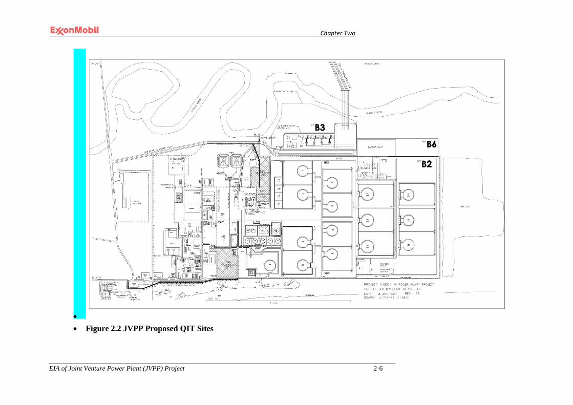
Chapter Two
EIA of Joint Venture Power Plant (JVPP) Project 2-6
• • Figure 2.2 JVPP Proposed QIT Sites
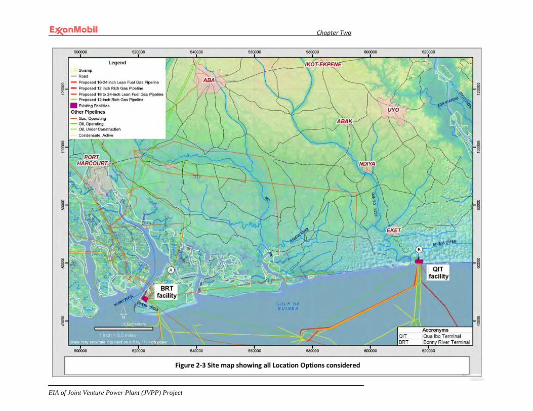
Chapter Two
EIA of Joint Venture Power Plant (JVPP) Project
2-7
Figure 2-3 Site map showing all Location Options considered
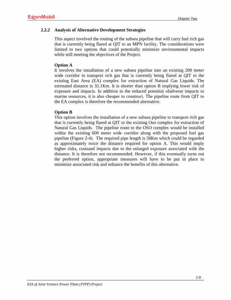
Chapter Two
EIA of Joint Venture Power Plant (JVPP) Project
2-8
2.2.2 Analysis of Alternative Development Strategies
This aspect involved the routing of the subsea pipeline that will carry fuel rich gas that is currently being flared at QIT to an MPN facility. The considerations were limited to two options that could potentially minimize environmental impacts while still meeting the objectives of the Project. Option A It involves the installation of a new subsea pipeline into an existing 200 meter wide corridor to transport rich gas that is currently being flared at QIT to the existing East Area (EA) complex for extraction of Natural Gas Liquids. The estimated distance is 35.1Km. It is shorter than option B implying lower risk of exposure and impacts. In addition to the reduced potential ofadverse impacts to marine resources, it is also cheaper to construct. The pipeline route from QIT to the EA complex is therefore the recommended alternative. Option B This option involves the installation of a new subsea pipeline to transport rich gas that is currently being flared at QIT to the existing Oso complex for extraction of Natural Gas Liquids. The pipeline route to the OSO complex would be installed within the existing 600 meter wide corridor along with the proposed fuel gas pipeline (Figure 2-4). The required pipe length is 58Km which could be regarded as approximately twice the distance required for option A. This would imply higher risks, costsand impacts due to the enlarged exposure associated with the distance. It is therefore not recommended. However, if this eventually turns out the preferred option, appropriate measures will have to be put in place to minimize associated risk and enhance the benefits of this alternative.
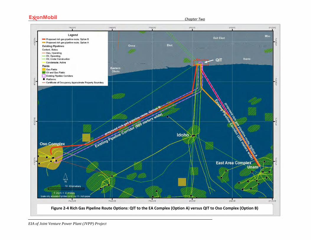
Chapter Two
EIA of Joint Venture Power Plant (JVPP) Project
2-9
Figure 2-4 Rich Gas Pipeline Route Options: QIT to the EA Complex (Option A) versus QIT to Oso Complex (Option B)
Chapter Two
EIA of Joint Venture Power Plant (JVPP) Project
2-10
2.2.3 Analysis of Alternative Technological/Process Design
The core criteria used for considering and choosing between technological/design alternatives are as follows: • Overall safety of the personnel working in the proposed project facility and
the public living in the vicinity of the project area. • Environmental impact of the proposed project with respect to its effects on air
quality, surface and underground water, soil, geographical terrain, vegetation, wildlife, socioeconomics, noise and other environmental aspects.
• Potential impacts to communities, their health, lifestyle and activities such as businesses, transportation, recreation, etc.
• Best available/practicable technologies that is not only familiar, but also acceptable within the applicable area in order to ensure maintenance and sustenance.
• Feasibility of construction, operation and maintenance in view of satisfactory and cost effective practices.
• Availability and reliability of fuel supply for the proposed plant operation such as the use and volume of natural gas or diesel requirements
• Mitigation and monitoring requirements that will ensure safe and environmentally sound operations.
• Acceptance by stakeholders with due considerations of technical, environmental, regulatory and cost implications of implementation and maintenance of proposed project.
• Other institutional, regulatory, national and international requirements of proposed project.
Based on the above, the summaries of technological/process considerations are as follows; Simple and Combined Cycles Considerations: The key considerations were
the Simple and Combined Cycles. The Simple Cycle option is simpler to install, to operate and to maintain. It also involves lower investment, operating and maintenance costs. However, the power delivery is less. It utilizes more fuel which results in higher emission. The Combined Cycle would require more major equipment for additional heat recovery, (steam generators and steam turbines,) which will increase the complexity of the operations, leading to higher annual Operations and Maintenance costs. It will also require more resources such as increased personnel, water, land, etc. for its operations and maintenance. These imply increased mitigation, monitoring and regulatory compliance conditions and costs. The initial investment cost is equally higher. Although it would utilize lower fuel, savings in this direction is minimal considering the low gas value. That however implies reduced emissions hence it is considered more environmentally friendly than the simple cycle option.
Chapter Two
EIA of Joint Venture Power Plant (JVPP) Project
2-11
Life cycle cost analysis will be used to decide the preferred option. However, both options have been considered in detail for the purpose of the EIA Study.
GTG Sizing and Selection: The GTGs are considered critical long lead equipment for the Project. The sizing and selection considered the following;
o Frame 6 is too small for the service, capable only of delivering about 40MW per unit. Using this option will imply procurement of several units in order to meet the required capacity. This would equally result in incremental requirement of resources and utilities for its operations and maintenance. It would also mean more complicated processes of operations and maintenance for the several systems that would be involved.Higher fuel consumption by the several units will lead to consequent increase in emissions and discharges. This will subsequently raise the monitoring, mitigation and other regulatory compliance requirements. All of these will result is excessive cost that may not be effective for sustainable operations of the proposed project.
o Frame 7E is designed to operate 3,600 rpm (60Hz) whereas Nigeria requires a 3,000 rpm machine that can generate power at 50Hz. It therefore was unacceptable.
o Frame 9E proved efficient for stand-alone power plant because of its ability to deliver the required capacity of 575 MW with minimal units of 125MW each. Other added advantages include itslife cycle and cost efficiency. It is also widely utilized in Nigeria making it a very familiar technology both with the power regulatory and generation companies as well as other operating companies within the country. The lower capital cost involved in comparison to its higher power delivery,operationsand maintenance requirements all add up to make it a cost efficient option. It is however not the latest in terms of technology. However, the need to provide a plant that is rugged, familiar, widely applicable and acceptable in Nigeria further qualified it as the preferred option.
o Fuel: On the fuel design basis for the GTGs, single source fuel system versus dual fuel system using diesel were considered. The single source fuel system provides the opportunity to maximize the usage of natural gas, which is safer, more reliable and environmentally friendly. The added advantage of the availability of natural gas is that it is a cheaper and cleaner fuel. Finding beneficial uses for it would help in reduction of gas flaring and consequent increase greenhouse gases emissions. It will further enhance compliance with government’s initiatives to stop flaring. All of these add up to makes the use of natural gas an outstanding and favorable choice. The key advantage of the dual fuel system is that it would provide a backup plan in case

Chapter Two
EIA of Joint Venture Power Plant (JVPP) Project
2-12
there is shortage or failure in the supply of natural gas. However, the dual fuel system would require large volume of diesel and massive storage facilities. The uncertainties associated with the supply of diesel will have significant impact on operations when the large volume requirements are considered. The logistics required to meet operating conditions would be significant, implying intense traffics, increased noise and dusts generations as well as possibilities of accidents. This in addition to the emissions associated with the use of diesel, likely discharges and spills during transfers,all of which would increase adverse environmental impacts. Besides the higher investment costs, operations and maintenance would be very expensive as well as monitoring, mitigation and regulatory compliance requirements. The fuel gas pipeline supply for single source fuel proved more environmentally and economically attractive and was therefore chosen.
2.2.4 “No Action” Alternative
No action is a possible alternative. In that case, no land will be taken. Anticipated social conflicts due to congregation of people with diverse background, understanding, and perspectives will be eliminated. Potential environmental disturbances that would result from the construction activities and the operations of the plant will also be avoided. “No Action” will prevent the safety and health challenges that could lead to accidents, dusts and noise, all arising due to heavy traffic associated with the project. In addition, the adverse economic impacts on those who derive their means of livelihood from and within the proposed project area will be equally be prevented. The other implications are that all the envisaged benefits of the proposed JVPP project will be forfeited. These include:
• Nigeria has vast reserves of natural gas which for years are being flared.
Recent developments include Federal Government of Nigeria’s efforts to find alternative uses for natural gas in order to stop the flaring. This will not only provide beneficial uses for these resources, it will also provide means of monetizing rather than wasting these valuable resources. The power project therefore will provide means for utilization of natural gas as well as aid in the flare out program. Consequently, considering the “No Action” option will frustrate the efforts to stop flaring, to utilize and monetize natural gas.
• The “No Action” alternative will also imply that electric power will not be made available for the Nigerian national grid. Currently, there is insufficient power supply and this reflects in every aspect of business and life in general. Failing to improve supply of electricity to consumers will
Chapter Two
EIA of Joint Venture Power Plant (JVPP) Project
2-13
imply that the expected income from such a provision will be lost, as well as anticipated developments that go with reliable power supply.
• Inability to enhance power supply through the proposed project will encourage the continued use of diesel generators by individuals and business entities. This will reflect in increased emissions, with adverse cumulative impacts on health and the environment. This therefore implies that pursing the project will reduce environmental pollution by lowering dependence on hydrocarbon powered generators and eliminate the potentials of adverse health and environmental effects of such emissions.
• Development, be it human, economic or social, is almost impossible without sufficient power supply. The “No Action” Alternative means that people will continue to struggle in darkness and stasis. However, by boosting power supply, not only will the quality of life be improved, enhanced opportunities will abound, directly and indirectly, within and around the communities, and spread across to the general populace.
• Regular power supply would create employment opportunities for indigenes and non-indigenes. It would also foster skills acquisition and enhancement through direct and indirect engagement of Nigerians in various aspects of the project via local content development. Improved income that will result from these engagements will further enhance quality of life within and around the project environs. “No Project” option means these opportunities would be given up.
• Compliance with the Federal Government directive on power supply to all oil companies operating in Nigeria is another major driver for this project. Failing to go ahead with the proposed project would imply noncompliance and the adverse consequences that this may attract. Besides the civic responsibility of organizations to participate in the development of its operating areas, no organization wants to jeopardize its relationship with the government of its operations areas. This would be the implication of not executing the proposed project and is therefore not worth pursuing.
Considering the summary of the advantages and disadvantages presented in Table 2.1, the gross negative impacts of the “No-Project”alternative made it unacceptable. The first implication is the failure to boost the nation’s electricity power supply. The consequence is the continuing dependence on hydrocarbon powered generators with its attendant adverse safety, health and environmental impacts. The primary objective of the proposed JVPP Project, which is to assist in meeting the above needs will ultimately be defeated.
Government’s initiative to increase electric power generation in the country will be hampered as the company ultimately fails to comply with the directive on power provision. It does not provide effective means of utilizing richly available gas resources in Nigeria, which does not help the national goal of gas flare reduction and elimination. Considering that electric power supply is a major tool

Chapter Two
EIA of Joint Venture Power Plant (JVPP) Project
2-14
for growth and development, failure to meet current and future demand will certainly have considerable environmental, social and economic implications. Although the “No-Project” Alternative does rule out the adverse impacts that may be associated with the other alternatives, yet it does not justify waiving the enormous benefits associated with the proposed project. Hence, the “No Project”alternative was rejected.
Table 2.1 QIPP EIA Comparative Assessment of Project Alternatives
Project Alternatives
Advantages Disadvantages
No Project • Land that would have been taken by the project would remain available
• Population that depend on this land for farming and hunting will continue to access and use it
• Those living around the proposed project area will not be displaced
• No potential of environmental discharge that could have been caused by the project
• Conflicts that could arise between workers and community personnel/members would be prevented
• No proposed project related environmental disturbances such as generation of noise, dust and fumes from vehicles and equipment, as well as disruption of vegetation and habitat, etc.
• Failure to comply with Nigerian government directive on power supply
• Constraints to compliance with Nigerian government planned flare elimination
• Failure to profitably utilize and possibly monetize available vast gas reserves
• Continued flaring leading to increased greenhouse emissions
• Continued environmental degradation as a result of continuous use of hydrocarbon powered generators
• Increased health implications as a result of continuous emission due to usage of hydrocarbon driven generators
• Lack of power for human, communal and industrial development
• Lack of job provision for the general populace
• No skills acquisition and development • No business development opportunities • No improvement in general standard of
living as a result of improved income and provision of reliable power supply
• Continued exploitation of the proposed project area and vicinity around it by limited few
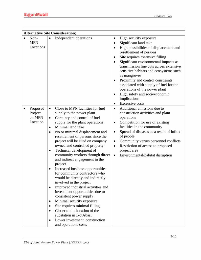
Chapter Two
EIA of Joint Venture Power Plant (JVPP) Project
2-15
Alternative Site Consideration; • Non-
MPN Locations
• Independent operations • High security exposure • Significant land take • High possibilities of displacement and
resettlement of persons • Site requires extensive filling • Significant environmental impacts as
transmission line cuts across extensive sensitive habitats and ecosystems such as mangroves
• Proximity and control constraints associated with supply of fuel for the operations of the power plant
• High safety and socioeconomic implications
• Excessive costs • Proposed
Project on MPN Location
• Close to MPN facilities for fuel supply to the power plant
• Certainty and control of fuel supply for the plant operations
• Minimal land take • No or minimal displacement and
resettlement of persons since the project will be sited on company owned and controlled property
• Technical development of community workers through direct and indirect engagement in the project
• Increased business opportunities for community contractors who would be directly and indirectly involved in the project
• Improved industrial activities and investment opportunities due to consistent power supply
• Minimal security exposure • Site requires minimal filling • Closer to the location of the
substation in IkotAbasi • Lower investment, construction
and operations costs
• Additional emissions due to construction activities and plant operations
• Competition for use of existing facilities in the community
• Spread of diseases as a result of influx of people
• Community versus personnel conflicts • Restriction of access to proposed
project area • Environmental/habitat disruption
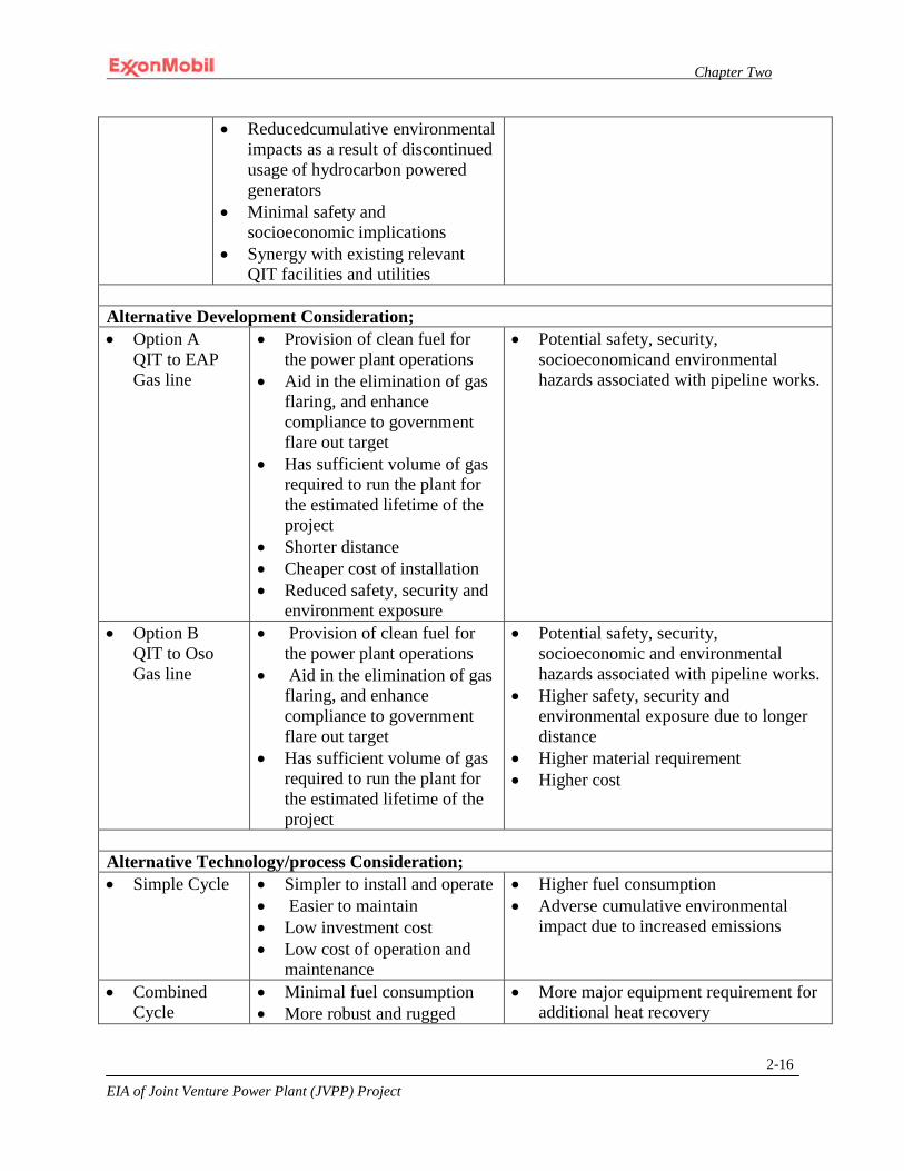
Chapter Two
EIA of Joint Venture Power Plant (JVPP) Project
2-16
• Reducedcumulative environmental impacts as a result of discontinued usage of hydrocarbon powered generators
• Minimal safety and socioeconomic implications
• Synergy with existing relevant QIT facilities and utilities
Alternative Development Consideration; • Option A
QIT to EAP Gas line
• Provision of clean fuel for the power plant operations
• Aid in the elimination of gas flaring, and enhance compliance to government flare out target
• Has sufficient volume of gas required to run the plant for the estimated lifetime of the project
• Shorter distance • Cheaper cost of installation • Reduced safety, security and
environment exposure
• Potential safety, security, socioeconomicand environmental hazards associated with pipeline works.
• Option B QIT to Oso Gas line
• Provision of clean fuel for the power plant operations
• Aid in the elimination of gas flaring, and enhance compliance to government flare out target
• Has sufficient volume of gas required to run the plant for the estimated lifetime of the project
• Potential safety, security, socioeconomic and environmental hazards associated with pipeline works.
• Higher safety, security and environmental exposure due to longer distance
• Higher material requirement • Higher cost
Alternative Technology/process Consideration; • Simple Cycle
• Simpler to install and operate • Easier to maintain • Low investment cost • Low cost of operation and
maintenance
• Higher fuel consumption • Adverse cumulative environmental
impact due to increased emissions
• Combined Cycle
• Minimal fuel consumption • More robust and rugged
• More major equipment requirement for additional heat recovery

Chapter Two
EIA of Joint Venture Power Plant (JVPP) Project
2-17
system • Efficient operations • Less emissions
• Being a more robust system, has incremental construction, installation and operations requirements with respect to personnel, equipment, materials, land space, utilities, etc.
• Requires a unique set of skills to operate
• More complex to maintain • High investment cost • High operations and maintenance costs
• GT size
Frame 6 • Effective for lower power
supply • Too small to meet the required 575
MW • Capable of delivering only 40 MW • Would require more units and more
operators • Higher operating and maintenance
requirements due to increased units in order to meet the power requirement
• Increased emissions and monitoring requirements
• Higher cumulative costs • GT size
Frame 7E • Effective for locations where
operating conditions meet regulatory requirements
• Operates at 3,600 rpm which is above Nigerian operation requirement
• Operates at 60 Hertz instead of 50 Hz as required by Nigerian regulations
• Does not meet power regulatory requirements and is therefore unacceptable
• GT Size Frame 9E
• Capable of delivering required capacity of 575 MW
• Operates at 3,000 rpm and 50 Hz, which is as required
• Effective for required service delivery
• More Cost efficient which implies lower capital and maintenance cost/MW
• Wide application within Nigeria
• The Project will enter into long term service agreement
• More rugged and robust
• Not the standard worldwide combined cycle power plant
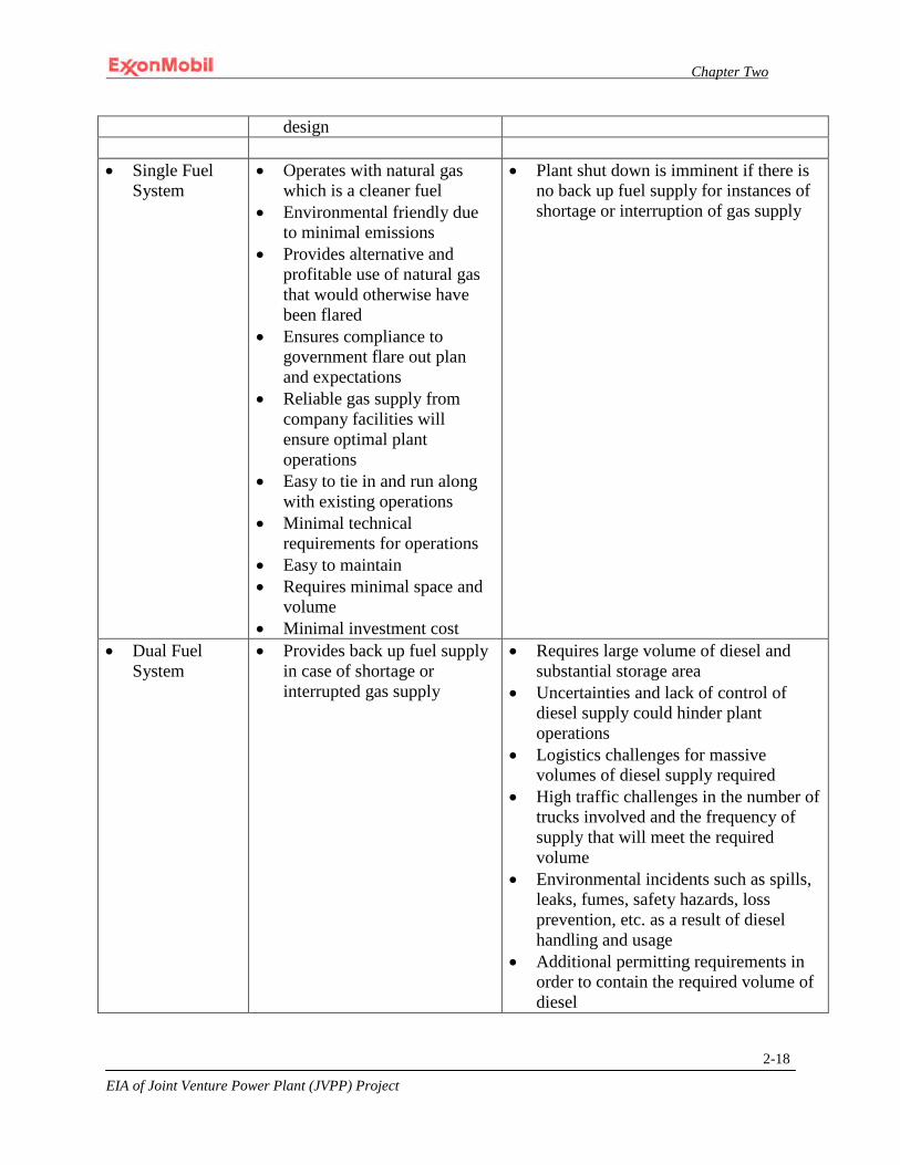
Chapter Two
EIA of Joint Venture Power Plant (JVPP) Project
2-18
design • Single Fuel
System
• Operates with natural gas which is a cleaner fuel
• Environmental friendly due to minimal emissions
• Provides alternative and profitable use of natural gas that would otherwise have been flared
• Ensures compliance to government flare out plan and expectations
• Reliable gas supply from company facilities will ensure optimal plant operations
• Easy to tie in and run along with existing operations
• Minimal technical requirements for operations
• Easy to maintain • Requires minimal space and
volume • Minimal investment cost
• Plant shut down is imminent if there is no back up fuel supply for instances of shortage or interruption of gas supply
• Dual Fuel System
• Provides back up fuel supply in case of shortage or interrupted gas supply
• Requires large volume of diesel and substantial storage area
• Uncertainties and lack of control of diesel supply could hinder plant operations
• Logistics challenges for massive volumes of diesel supply required
• High traffic challenges in the number of trucks involved and the frequency of supply that will meet the required volume
• Environmental incidents such as spills, leaks, fumes, safety hazards, loss prevention, etc. as a result of diesel handling and usage
• Additional permitting requirements in order to contain the required volume of diesel

Chapter Two
EIA of Joint Venture Power Plant (JVPP) Project
2-19
• Higher emissions particularly for the NOx
• High water consumption • Higher compliance challenges with
respect to effluent and emissions monitoring
• Higher investment cost • Expensive to maintain • Complicated operations and
maintenance
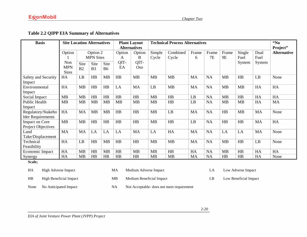
Chapter Two
EIA of Joint Venture Power Plant (JVPP) Project
2-20
Table 2.2 QIPP EIA Summary of Alternatives
Basis Site Location Alternatives Plant Layout Alternatives
Technical Process Alternatives “No Project” Alternative Option
1 Non MPN Sites
Option 2 MPN Sites
Option A
QIT-EA
Option B
QIT-Oso
Simple Cycle
Combined Cycle
Frame 6
Frame 7E
Frame 9E
Single Fuel System
Dual Fuel System Site
B2 Site B3
Site B6
Safety and Security Impact
HA LB HB MB HB MB MB MB MA NA MB HB LB None
Environmental Impact
HA MB HB HB LA MA LB MB MA NA MB MB HA HA
Social Impact MB MB HB HB HB HB MB HB LB NA MB HB HA HA Public Health Impact
MB MB MB MB MB MB MB HB LB NA MB MB HA MA
Regulatory/Stakeholder Requirements
HA MA MB MB HB HB MB LB MA NA HB MB MA None
Impact on Core Project Objectives
MB MB HB HB HB HB MB HB LB NA HB HB MA HA
Land Take/Displacement
MA MA LA LA LA MA LA HA MA NA LA LA MA None
Technical Feasibility
HA LB HB MB HB HB MB MB MA NA MB HB LB None
Economic Impact HA MB HB MB HB MB MB HB HA NA MB HB HA HA Synergy HA MB HB HB HB HB MB MB MA NA HB HB HA None
Scale;
HA High Adverse Impact MA Medium Adverse Impact LA Low Adverse Impact
HB High Beneficial Impact MB Medium Beneficial Impact LB Low Beneficial Impact
None No Anticipated Impact NA Not Acceptable- does not meet requirement

Chapter Two
EIA of Joint Venture Power Plant (JVPP) Project
2-21
Table 2.3 QIPP EIA Comparative Evaluation of Project Alternatives
Project Alternatives
Criteria Scores
“No Project” Alternative Option
1 Non MPN Sites
Option 2 MPN Sites
Option A
QIT- EA
Option B
QIT-Oso
Simple Cycle
Combined Cycle
Frame 6
Frame 7E
Frame 9E
Single Fuel
System
Dual Fuel
System Site B2
Site B3
Site B6
Safety and Security Impacts
--- + +++ ++ +++ ++ ++ ++ -- --- ++ +++ + /
Environmental Impact
--- ++ +++ +++ - -- + ++ -- --- - ++ --- ---
Social Impact
++ ++ +++ +++ +++ +++ ++ +++ + --- ++ +++ --- ---
Public Health Impact
++ ++ ++ ++ ++ ++ ++ +++ + --- ++ ++ --- --
Regulatory/Stakeholder Requirements
--- -- ++ ++ +++ +++ ++ + -- --- +++ ++ -- 0
Impact on Core Project Objectives
++ ++ +++ +++ +++ +++ ++ +++ + --- +++ +++ ++ ---
Land Take/Displacement
-- -- - - - -- - -- -- --- - - -- 0
Technical Feasibility --- -- +++ ++ +++ +++ ++ ++ -- --- ++ +++ -- 0 Economic Impact --- ++ +++ ++ +++ ++ ++ +++ --- --- ++ +++ --- --- Synergy --- ++ +++ +++ +++ +++ ++ ++ -- --- ++ +++ -- 0
Chapter Two
EIA of Joint Venture Power Plant (JVPP) Project
2-22
Scale;
+++ Considerable Positive Impact
++ Significant Positive Impact
+ Marginal Positive Impact
0 No Expected Impact
- Marginal Negative Impact
-- Significant Negative Impact
--- Considerable Negative Impact
/ Uncertainty Range
The above sections and tables identified the pros and cons of each possible option. From the qualitative analysis demonstrated in tables 2-1 and 2-2, it is obvious that “No Project” alternative does more harm to the environment, to health and safety, to social and economic wellbeing of the people and the nation at large, and also to non-compliance to Federal Government of Nigerian objectives with respect to gas flaring, power supply and national content development.
From the above table, it is obvious that the proposed option offers the best alternatives with respect to safety, health and environmental considerations, as well as social and economic development opportunities. The associated adverse impacts are relatively minimal in comparison to the tremendous and far reaching implications of the “No Project” alternative as outlined in the tables above.
Presently, conclusive decisions are yet to be made on the project technology/process design alternatives as well as the routing for the gas line that convey the fuel rich gas out of QIT. However, these options have been duly considered and the advantages and disadvantages highlighted to aid in appropriate decision making processes.
2.3 Project Alternatives Rankings
While sections 2.2.1 through 2.2.4 and Table 2.1 provide a qualitative assessment of the advantages and disadvantages of each project alternative, the impacts of some criteria however were summarized and aggregated in Table 2.2 in order to determine the preferred option in comparison to the other alternatives. On the other hand, explicit ranks were assigned to theperformance of each project alternative on each criterion of interest. The alternatives were ranked in a manner consistent with the expected impacts described in sections 2.2 and presented in Table 2.3.This further enhances the comparison ofproject alternatives with each other and with respect to the “No-Action”alternative.

Chapter Two
EIA of Joint Venture Power Plant (JVPP) Project
2-23
2.4 Summary of the Benefits of Preferred Alternative for the Proposed Project
After detailed evaluations of the merits and demerits of the various options highlighted above, the chosen option for the proposed JVPP project provides substantial benefits in comparison to the other options.
• Option 2 on QIT site B3 was selected for its safety, health, environment (SHE) gains and socioeconomic viability.
• Frame 9 size GTGs (e.g., GE 9E’s or other GTGs from MHI, Alstom or Siemens) was selected with a single source fuel system. This facility besides being robust and rugged, has the added advantage of wide application in Nigeria. In addition, sufficient qualitative an considerable quantitative analysis have been provided to guide on the decision of technological/process selection.
• For all of the considered locations, both at Bonny and at QIT, the possibility of constructing a temporary Materials Offloading Facility (MOF), with the option to convert to permanent, would be required. Should MPN Operations decide to keep the MOF on long term, then additional construction activities would be required to convert the facility into a permanent structure.
• The proposed power plant is to be constructed as a stand-alone facility. However, existing QIT facilities will be used or expanded as required for support of the proposed project.
• QIT has large footprint with available space, infrastructure to leverage on and proximity to offshore platform for reliable fuel gas supply.
2.5 Overview of Basis for the Selection of the Proposed Project as the Preferred Alternative
Envisaged Sustainability
The key challenge of sustainable development is to ensure an economically justified project that makes viable contributions towards the ever increasing demand for energy while safeguarding the quality of the environment. The selection of the location and technology for the proposed project has been done with the aim of ensuring sustainable development.
Social and Economic Sustainability
The proposed project is envisaged to require an average weighted usage of 111.2 MSCFD of gas at 95% availability of plant over an estimated lifetime of 25 years. The gas will be supplied by the Dom Gas project. The expected
Chapter Two
EIA of Joint Venture Power Plant (JVPP) Project
2-24
volume of gas from the Dom Gas Project is about 400 MSCFD and is therefore sufficient to sustain the project throughout its estimated lifetime.
The Power Plant Project will create employment and skill acquisition opportunities for Nigerians through direct and indirect involvement of diverse personnel, contractors, consultants, suppliers, operators and other professionals during the planning, engineering, construction and operational phases of the project. Also, the adherence to prudent business practices in contracting for goods and services will ensure transparency and enhance ethical as well as commercial benefits.
In assuming the social responsibility of providing the power plant, the NNPC and MPN Joint Venture relationship not only achieves enhanced compliance to government’s directive in this direction but also through extensive consultations, held with all stakeholders, put relevant machineries in motion that will foster a harmonious and productive working relationship between all the parties involved be it regulators and licensing authorities, government partners, host communities and Non-Governmental organizations.
Environmental Sustainability
The environmental sustainability of the project is reflected through the following:
• Beneficial utilization of natural gas as a primary fuel source for the plant. This is a major environmental consideration and advantage that will reduce air pollution.
• In order to further enhance its environmental viability, due environmental impact assessment as well as avoidance/mitigation and monitoring measures will be integrated into the Project and implemented throughout its lifetime.
• A Project-specific Social and Environmental Management Plan will be implemented in the course of the Project.
Technical Sustainability
The project is technically viable because it relies on proven and effective technologies that will be executed with adherence to international and Nigerian engineering design, appropriate construction codes and standards, as well as generally accepted power industry operating practices.
ExxonMobil has engaged and will continue to engage experts with proven international experiences in the field of power plant development, installation, commissioning, operation and maintenance, in addition to the application of
Chapter Two
EIA of Joint Venture Power Plant (JVPP) Project
2-25
Best Available Technologies. All contractors that will be involved in the Project will equally be held accountable to international and national standards.
While relying on its worldwide experience, ExxonMobil and its contractors will develop standard operating manuals/procedures, and appropriate documentation for effective operation and maintenance of the Power Plant and associated facilities. These materials will be used as the basis for providing facility-specific training to relevant personnel prior to start-up. Personnel with requisite experiences will be involved in the transition and early operations.
2.6 Comparative Assessment of No Option and Preferred Alternative
If the No Action alternative is adopted;
• No land will be taken and project associated disturbances will be prevented. However, this does not secure the environment in any way as the areas are under possible degradation as a result of continuous exploitation
• Limited members of the community may use the area for income-earning activities such as agriculture and hunting at most, though the property belongs to MPN, but this earning cannot be compared to the improved standard of living and enhanced quality of life that would be spread throughout the community and beyond as a result of enhanced power supply
• Potential adverse impacts associated with the project would be avoided if the “No-Action” Alternative is chosen. However, when compared to the magnitude of the loss of the absence of the project, this seeming gain counts eventually as no profit to the government, the company and the general populace;
o Power is a key requirement for social and economic development o Use of natural gas will
help the government’s effort to stop flaring, help in reduction of greenhouse gases that are further
complicated as a result of continued flaring, provide cleaner fuel reduce and possibly eliminate further environmental
degradation as a result of the continued use of diesel generators
o Besides the temporary and permanent job opportunities and skills acquisition and development prospects that the job will provide majority of the community members, and the rippling effects of that in beneficiaries’ standard of living, it will also provide openings for businesses to thrive as reliable and dependable source

Chapter Two
EIA of Joint Venture Power Plant (JVPP) Project
2-26
of power is a key driving factor for investment opportunities and industrial development
2.1 Conclusion
With due considerations to optimal safety, security, environmental, technical and cost implications, the chosen and recommended options for the proposed JVPP project provide substantial benefits in comparison to the others.

CHAPTER THREE
Chapter Three
EIA of Joint Venture Power Plant (JVPP) Project 3-1
CHAPTER THREE
3.0 PROJECT DESCRIPTION
3.1 Project Objective
The objective of the Joint Venture Power Plant (JVPP) Project is to successfully complete the design, construction/installation and commission/start-up of a natural gas-fired 575 Megawatt (MW) power plant that will export power to the Nigerian national electrical grid. This environmental analysis will address both potential configurations, simple and combined cycle. The Project will meet the business objective of the Joint Venture (JV) between the Nigerian National Petroleum Company (NNPC) and Mobil Producing Nigeria (MPN) which is to monetize JV gas reserves. The Project will also support the Federal Government of Nigeria’s objective to reliably increase domestic power generation in order to promote economic growth and development.
3.2 Project Location
The location of the proposed Project is within the Niger Delta Basin within Akwa-Ibom State (Figure 3-1) at approximate coordinates 4o30’ North and 8o05’ East. The proposed Project will be located east and within close proximity of the Qua Iboe River estuary. The QIPP facility is to be located in the southwestern corner of the Stubbs Creek Forest Reserve approximately 4 km south of the Reserve’s northern border and 5 km east of its western border. Directly north of the Project site and nearly adjacent to its northeastern border is Douglas Creek (Figure 3-2). Adjacent to the Project’s southern border is MPN’s Qua Iboe Terminal (QIT) facility. The QIT facility is bordered to the south by the Atlantic Ocean. QIT serves as the JV’s crude oil and condensate storage and shipping facility for its offshore production operations. The QIT facility consists of crude oil and condensate storage tanks, crude oil stabilization trains, power generation, warehouses and offices. The fuel gas to operate the power plant will originate from the offshore OSO complex with backup fuel to be provided by the Nsimbo Wellhead Platform (WHP), as necessary (Figure 3-3). The OSO complex is located approximately 53 kilometers (km) (33 miles) offshore between the Qua Iboe River to the East and the Imo River to the West.

Chapter Three
EIA of Joint Venture Power Plant (JVPP) Project 3-2
Figure 3-1 Location of Akwa Ibom State within Nigeria
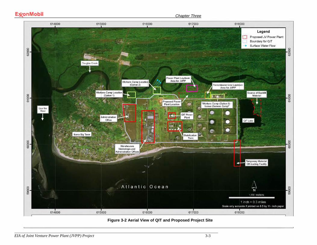
Chapter Three
EIA of Joint Venture Power Plant (JVPP) Project 3-3
Figure 0-2 Aerial View of QIT and Proposed Project Site Figure 3-2 Aerial View of QIT and Proposed Project Site

Chapter Three
EIA of Joint Venture Power Plant (JVPP) Project 3-4
Figure 3-3 Lean Fuel Gas Pipeline Route
3.2.1 Project Site Boundaries
MPN has obtained two separate certificates of occupancy documents which jointly encompass the land tract boundary for the QIT/JVPP facilities. Although the area was initially designated as a forest, in Nigerian context, a forest reserve is not considered a conservation area. Instead, it is a reserve for timber production and therefore is not a critical natural habitat. In addition, the Land Use Act authorizes the governor to use, change use of and transfer lands. MPN acquired the lands for industrial and commercial purposes. The approximate land tract boundary pursuant to the certificate of occupancy documents is outlined in red in Figure 3-4. These certificates of occupancy documents are essentially lease agreements between MPN and the Akwa Ibom state government.
These documents are scheduled for renewal in the year 2048 for tract number 1BE/2/98 and in the year 2053 for tract number 1BE/16/2003. Pursuant to these documents, the State Governor’s approval must be obtained in advance of erecting any new structure on the property.
As shown in Figure 3-4, the approximate boundary for the certificate of occupancy land tract is as follows: Douglas Creek to the north; a small portion of the beach to the south; to the east, the boundary is located about 1,523 meters (0.95 miles) from the northeast corner of the QIT footprint; and the western boundary is co-located with the eastern border of Ibeno Town.
Douglass Creek is a distributary which runs in meanders along the northern boundary of MPN’s QIT (Fig. 3-2). The Creek is also known as Mbo River.
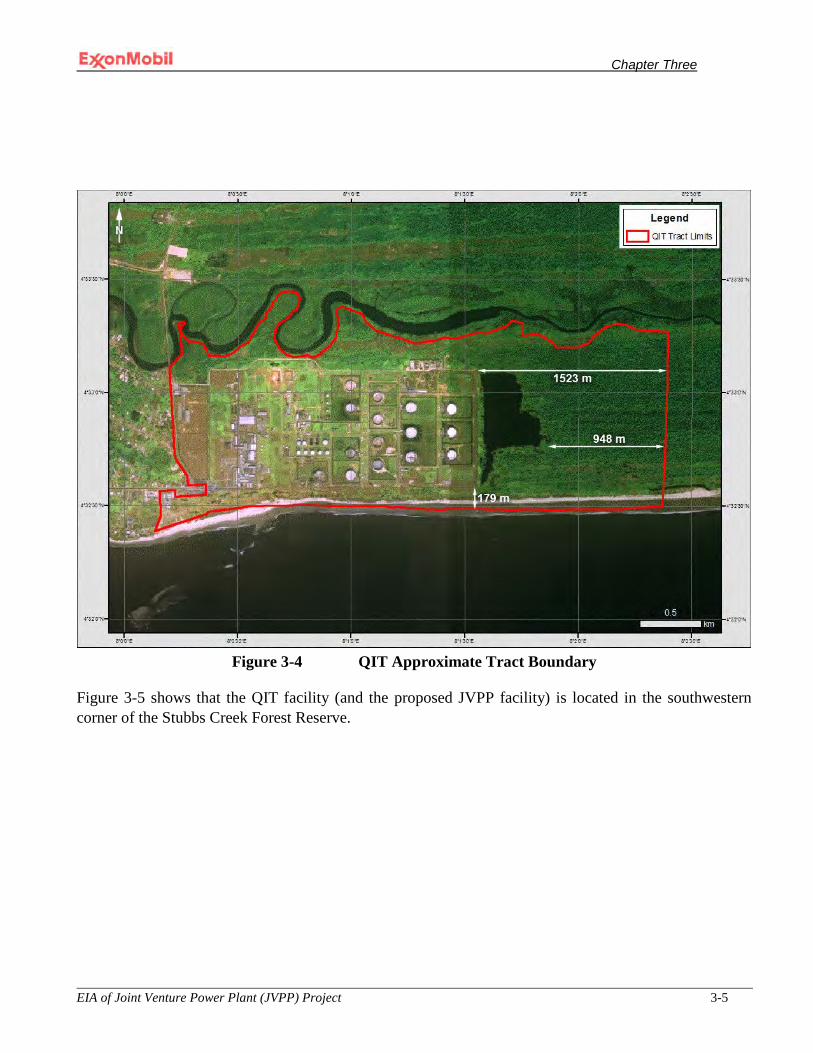
Chapter Three
EIA of Joint Venture Power Plant (JVPP) Project 3-5
Figure 3-4 QIT Approximate Tract Boundary
Figure 3-5 shows that the QIT facility (and the proposed JVPP facility) is located in the southwestern corner of the Stubbs Creek Forest Reserve.
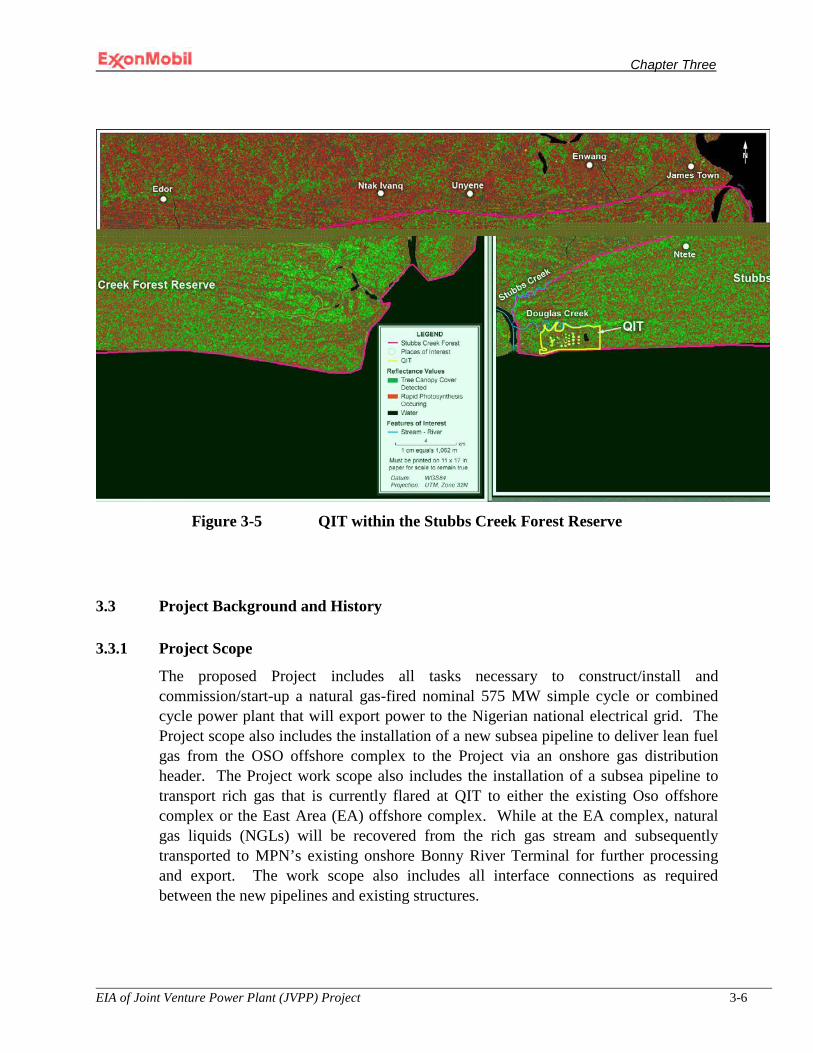
Chapter Three
EIA of Joint Venture Power Plant (JVPP) Project 3-6
Figure 3-5 QIT within the Stubbs Creek Forest Reserve
3.3 Project Background and History
3.3.1 Project Scope
The proposed Project includes all tasks necessary to construct/install and commission/start-up a natural gas-fired nominal 575 MW simple cycle or combined cycle power plant that will export power to the Nigerian national electrical grid. The Project scope also includes the installation of a new subsea pipeline to deliver lean fuel gas from the OSO offshore complex to the Project via an onshore gas distribution header. The Project work scope also includes the installation of a subsea pipeline to transport rich gas that is currently flared at QIT to either the existing Oso offshore complex or the East Area (EA) offshore complex. While at the EA complex, natural gas liquids (NGLs) will be recovered from the rich gas stream and subsequently transported to MPN’s existing onshore Bonny River Terminal for further processing and export. The work scope also includes all interface connections as required between the new pipelines and existing structures.
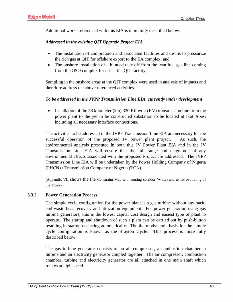
Chapter Three
EIA of Joint Venture Power Plant (JVPP) Project 3-7
Additional works referenced with this EIA is more fully described below:
Addressed in the existing QIT Upgrade Project EIA
• The installation of compression and associated facilities and tie-ins to pressurize the rich gas at QIT for offshore export to the EA complex; and
• The onshore installation of a blinded take off from the lean fuel gas line coming from the OSO complex for use at the QIT facility.
Sampling in the onshore areas at the QIT complex were used in analysis of impacts and therefore address the above referenced activities.
To be addressed in the JVPP Transmission Line EIA, currently under development
• Installation of the 58 kilometer (km) 330 Kilovolt (KV) transmission line from the
power plant to the yet to be constructed substation to be located at Ikot Abasi including all necessary interface connections.
The activities to be addressed in the JVPP Transmission Line EIA are necessary for the successful operation of the proposed JV power plant project. As such, the environmental analysis presented in both this JV Power Plant EIA and in the JV Transmission Line EIA will ensure that the full range and magnitude of any environmental effects associated with the proposed Project are addressed. The JVPP Transmission Line EIA will be undertaken by the Power Holding Company of Nigeria (PHCN) / Transmission Company of Nigeria (TCN). (Appendix VII shows the the Constraint Map with routing corridor (white) and tentative routing of the TLine)
3.3.2 Power Generation Process
The simple cycle configuration for the power plant is a gas turbine without any back-end waste heat recovery and utilization equipment. For power generation using gas turbine generators, this is the lowest capital cost design and easiest type of plant to operate. The startup and shutdown of such a plant can be carried out by push-button resulting in startup occurring automatically. The thermodynamic basis for the simple cycle configuration is known as the Brayton Cycle. This process is more fully described below.
The gas turbine generator consists of an air compressor, a combustion chamber, a turbine and an electricity generator coupled together. The air compressor, combustion chamber, turbine and electricity generator are all attached in one main shaft which rotates at high speed.

Chapter Three
EIA of Joint Venture Power Plant (JVPP) Project 3-8
The air compressor takes in large quantities of air from the atmosphere and compresses it in the combustion chamber. Fuel is then injected into the combustion chamber and ignited. This addition of heat energy and combustion gases raises the temperature of the combined gases to over 1,300°C and greatly increases the velocity of these gases as they move from the combustion chamber through the turbine.
The effect of this high velocity gas flow through the turbine drives both the air compressor to supply air and the electricity generator to produce the rated electrical power output (125 –165 MW per unit, depending on the manufacturer). The expansion of the hot gases through the turbine, and the extraction of mechanical work from them via the turbine, reduces the temperature of the gases to approximately 600°C. The higher gas discharge temperature is for the simple cycle case. The premise of a combined cycle power plant configuration uses the waste heat to generate steam, which in turn generates more power. Air dispersion feasibility study was carried out to investigate the expected air pollution situation of the Qua Iboe Power Plant Project. The study used a combined cycle power plant configuration consisting of 3 gas turbines with associated heat recovery steam generators (HRSG) and evaluated the preload level of pollution (background pollution) on site as well as additional project pollution effects during different load operations. The study is discussed in Chapter 4 and the results are included in Appendix VIII. Findings from the study validates the height of the HRSG stack against World Bank stack height calculation guidelines and fulfillment of the Irrelevance criteria for emission of pollutants to surrounding areas. The validation has given further information on how high the stack must be to fulfill the NO2 emission limit for the irrelevance criteria as well as for people and vegetation. However, the steam cycle requires much more cooling water and chemically treated feed water. The waste heat is then discharged to the atmosphere through a stack. The electricity generated (at 15 kV) is subsequently fed to transformers (200 MVA) where the voltage is stepped up from 15 kV to 330 kV for transmission by a local substation to the national grid
The operation as just described refers to a simple cycle power plant. For the combined cycle power plant option the hot exhaust gases normally discharged into the atmosphere via a stack can instead be directed to a Heat Recovery Steam Generator (HRSG) to produce high-pressure steam to drive a steam turbine. This process can yield approximately 50% more electricity than can be produced by the simple-cycle power plant option. The spent steam is subsequently condensed to water at the end of the turbine through use of air cooled condensers and then recycled back to the HRSG. While the temperature of the hot gases produced in this scenario is reduced to approximately 1000C; the composition of the gases is not altered in any other respect. These gases are subsequently discharged to the atmosphere via a stack located on top of the HRSG. The World Bank guideline for HRSG stack height calculation has been used and a minimum stack height of 87.5m recommended. However, the operation of QIPP during base load case and with an HRSG stack height of 45m would not keep the

Chapter Three
EIA of Joint Venture Power Plant (JVPP) Project 3-9
emission values for NO2 in all surrounding areas lower than the required irrelevance criteria for people or vegetation. For CO and PM10, the irrelevance criteria can be kept in the surrounding areas..
3.3.3 Power Plant Efficiency
The expected net efficiency or conversion of chemical energy into electrical energy will be 33% for the simple cycle power plant option and about 50% for the combined cycle power plant option. Both power plant options will employ technology recognized as being the most advanced for power production on the scale proposed. At the heart of both simple and combined cycle configurations are the highly reliable gas turbine generators. These machines suffer few unplanned shut downs because of the rigorous, proven program of scheduled maintenance. The units undergo a three-part series of structured, specific maintenance activities at regular intervals of operating hours. At approximately 12,000 factored hours, each unit undergoes a Combustion Inspection. At 24,000 factored hours a Hot Gas Path Inspection is performed, comprising the combustion inspection and turbine maintenance. Finally at 48,000 factored hours, a Major Inspection is commenced which includes the combustion and turbine inspections and adds the compressor section. Depending upon which particular outage is due, the gas turbine units range from 83.5% to 97.5% annual availability.
3.3.4 Design Code
The power plant and supporting infrastructure will be built in accordance with all applicable Nigerian standards and requirements including the following codes:
• International Standard Organization (ISO) for structural; • ISO for mechanical; • International Electrotechnical Commission (IEC) for electrical; • IEC for instrumentation; • National Fire Protection Association (NFPA) 850 including other applicable
NFPA standards; • International Building Code; and • Company standard practices for process piping and pipeline design and
installation.
3.3.5 Plant Layout
The proposed Project will be either a simple cycle or a combined cycle gas turbine power plant of approximately 575 MW at ISO conditions located at the proposed Project site (Figure 3-2). Natural gas will be the fuel for the power plant. There will be associated connections to the electricity and gas grids.

Chapter Three
EIA of Joint Venture Power Plant (JVPP) Project 3-10
The estimated area for the simple cycle power plant is 230,000 square meters (m2) of which 60,000 m2 represents the area for the power plant laydown area and 20,000 m2 represents the area for the Transmission Line laydown area. The estimated area for the combined cycle power plant option is 360,000 m2 of which 120,000 m2 represents the area for the power plant laydown area and 20,000 m2 represents the area for the Transmission Line laydown area (Figure 3-2). The current study as well as concepts analyses equally considered both options as the final decision of which option to be adopted by the project lies with the Joint Venture partners. The configuration of the power plant will be a single shaft arrangement which consists of a gas turbine and generator arranged on a single shaft or power train. The actual number of GTGs installed for the simple cycle power plant option will be either 3 or 4 depending upon which manufacturer is selected through competitive tender as the nominal size of the turbine varies from manufacturer to manufacturer. The number of GTGs for the combined cycle power plant option will be one GTG less than the simple-cycle power plant option. A general layout of a typical power plant configuration is presented in Figure 3-6. Figures 3-7 and 3-8 present a general layout for the simple cycle and combined cycle power plant option respectively, based on use of the GE Frame 9AE GTG system.

Chapter Three
EIA of Joint Venture Power Plant (JVPP) Project 3-11
Figure 3-6 QIT Photo Rendering with Proposed JV Power Plant All equipment and material in the JV power plant will be new. Equipment will be selected to ensure high reliability and availability with low forced outage rates and minimal maintenance. Further, the equipment layout will be designed to permit safe access to all items of the plant for inspection, operation and maintenance.

Chapter Three
EIA of Joint Venture Power Plant (JVPP) Project 3-12
Figure 3-7: JVPP General Layout Schematic for the Simple-Cycle Power Plant Option

Chapter Three
EIA of Joint Venture Power Plant (JVPP) Project 3-13
Figure 3-8: JVPP General Layout Schematic for the Combined-Cycle Power Plant Option
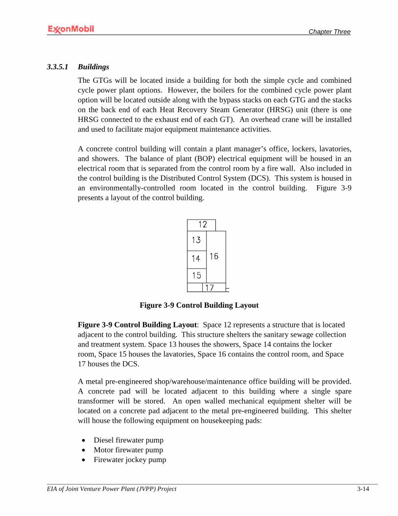
Chapter Three
EIA of Joint Venture Power Plant (JVPP) Project 3-14
3.3.5.1 Buildings
The GTGs will be located inside a building for both the simple cycle and combined cycle power plant options. However, the boilers for the combined cycle power plant option will be located outside along with the bypass stacks on each GTG and the stacks on the back end of each Heat Recovery Steam Generator (HRSG) unit (there is one HRSG connected to the exhaust end of each GT). An overhead crane will be installed and used to facilitate major equipment maintenance activities.
A concrete control building will contain a plant manager’s office, lockers, lavatories, and showers. The balance of plant (BOP) electrical equipment will be housed in an electrical room that is separated from the control room by a fire wall. Also included in the control building is the Distributed Control System (DCS). This system is housed in an environmentally-controlled room located in the control building. Figure 3-9 presents a layout of the control building.
Figure 3-9 Control Building Layout
Figure 3-9 Control Building Layout: Space 12 represents a structure that is located adjacent to the control building. This structure shelters the sanitary sewage collection and treatment system. Space 13 houses the showers, Space 14 contains the locker room, Space 15 houses the lavatories, Space 16 contains the control room, and Space 17 houses the DCS.
A metal pre-engineered shop/warehouse/maintenance office building will be provided. A concrete pad will be located adjacent to this building where a single spare transformer will be stored. An open walled mechanical equipment shelter will be located on a concrete pad adjacent to the metal pre-engineered building. This shelter will house the following equipment on housekeeping pads:
• Diesel firewater pump • Motor firewater pump • Firewater jockey pump

Chapter Three
EIA of Joint Venture Power Plant (JVPP) Project 3-15
• Plant water pump skid • De-mineralized water pump skid • Potable water treatment system and pump • Wastewater treatment system • Air compressors, dryer and receiver tank • Potable and de-mineralized water treatment system • Wastewater treatment system • Nitrogen generator
A switchyard control building will be pre-fabricated to house associated equipment. A guard house with a lavatory will be installed at the main gate.
The approximate building dimensions and heights for major facility components are presented below. These sizes may be slightly larger if the combined cycle power plant option is selected for implementation.
• Concrete control building: 23 meters (m) long by 18 m wide by 9 m tall [75 feet
(ft) by 60 ft by 30 ft]; • Shop/warehouse maintenance office building: 49 m long by 13.7 m wide by 12 m
tall [160 ft by 45 ft by 40 ft]; • Open walled mechanical equipment shelter: 46 m long by 7.6 m wide by 12 m tall
[150 ft by 25 ft by 40 ft]; • Switchyard control building: 15.2 m long by 6 m wide by 4.6 m tall [50 ft by 20 ft
by15 ft]; and • Guard house: 9 m long by 10.7 m wide by 4.6 m tall [30 ft by 35 ft by 15 ft].
In addition to the buildings described above, a building to house the steam turbine generator will also be provided if the combined cycle power plant option is implemented. The approximate dimensions for this building are as follows: • Steam turbine generator building: 50 m long by 40 m wide by 30 m tall [164 ft by
131 ft by 98 ft].
3.3.5.2 Storage Facilities
A list of storage facilities and their corresponding approximate dimensions are presented below. The size of the storage tanks will be slightly larger for the combined cycle power plant option. Also, the storm water retention pond will be increased by approximately 60% if the combined cycle power plant option is implemented. The storage facilities are listed below:
• One 3,785 liter (1,000 gallon) vertical drain tank: 1.4 m in diameter by 3 m tall; • One 3,785 liter (1,000 gallon) vertical drain tank: 1.4 m in diameter by 3 m tall;
Chapter Three
EIA of Joint Venture Power Plant (JVPP) Project 3-16
• One 567,800 liter (150,000 gallon) fire water vertical storage tank: 10.2 m in diameter by 9 m tall;
• One 3,785 liter (1,000 gallon) potable water vertical storage tank: 1.4 m in diameter by 3 m tall;
• One 37,853 liter (10,000 gallon) de-mineralized water storage tank: 3 m diameter by 6 m tall;
• One 45,423 liter (12,000 gallon) diesel storage tank: 8 m long by 3.6 m wide by 3.3 m tall; and
• A storm water retention pond: 73 m long by 41 m wide by 4.6 m deep.
3.3.6 Power Plant Components
The principal components of the power plant facility will be as follows:
• Gas turbine generators (GTGs) • Combustion turbine exhaust stack • Essential and black-start generators • Electrical transformers • Switchgear • Switchyard • Uninterruptible Power Supply • Mechanical utilities trench • Fuel gas supply • Storm water retention pond • Water system • Wastewater collection and treatment system • Sanitary sewage collection and treatment system • Drain system • Fire protection system • Storm water effluent treatment system • Miscellaneous storage • Compressed air system • Nitrogen system • Utilities • Roads and parking • Security
In addition to the plant components listed above, the combined cycle power plant option will include the following additional plant components:
• Heat Recovery Steam Generator • Steam turbine generator

Chapter Three
EIA of Joint Venture Power Plant (JVPP) Project 3-17
• Air-cooled condenser • Boiler water treatment • Chemical laboratory including testing equipment and chemicals
3.3.6.1 Gas Turbine Generators
Approximately four GE-9EA GTGs or equivalent from an alternate manufacturer (1 less GTG for the combined cycle power plant option) will be installed. To minimize incremental impacts to the existing airshed, natural gas fuel was selected as the fuel of choice for this Project. Gas fired plants in general produce negligible quantities of particulate matter and sulfur oxides, and nitrogen oxides are 60% less than plants that use coal (assuming emissions reduction measures are not employed).
The combustion gas turbines will meet an emissions limit for nitrogen oxides (NOx) of 50 milligrams/normal cubic meter (mg/Nm3) or 25 parts per million volume (ppmv) based on a dry oxygen (O2) content of 15%.
The GTGs will come equipped with a foundation slab approximately 256 m long by 36.6 m wide (840 ft by 120 ft) surrounded by auxiliary equipment such as, but not necessarily limited to:
• Gas turbine starting and cool-down system; • Gas turbine lube oil system; • Gas turbine hydraulic oil system; • Gas turbine low NOx fuel gas system; • Gas turbine and generator cooling water systems including fin fan coolers,
instrumentation and cooling water pumps; • Compressor water wash skid; • Water mist fire protection system; • Auxiliary power, lighting, fire detection and climate control of enclosures (e.g.,
control panels); • Combustion air inlet filters and ducting; • Exhaust gas ducting, stack, silencer, and insulation; • Local enclosures for gas turbine control panels, motor control centers (MCCs),
and battery room; • MCCs for gas turbine components; • Controller, Uninterrupted Power Supply (UPS) and Human Interface (HMI)
Equipment in the control room for gas turbines and gas turbine accessories; • Cooling blowers for exhaust frames; and • BOP Distributed Control System (DCS).
Chapter Three
EIA of Joint Venture Power Plant (JVPP) Project 3-18
3.3.6.2 Combustion Turbine Exhaust Stack
The exhaust gas from each GTG will flow into a stack whose height will be determined by dispersion modeling studies. The stack will be included as part of the auxiliary equipment that accompanies the GTG packaged unit. The exhaust stack will include as necessary, the following accessories:
• Test platforms; stack lighting platforms and caged ladders; • Test ports and connections as necessary to monitor fuel combustion efficiency; • Maintenance access opening; • Silencers for noise abatement, and possibly • Aircraft warning lights.
3.3.6.3 Essential and Black-Start Generators
Two 1,500 Kilowatt (KW) 6,600 Volt 50 Hertz (HZ) standby generators firing No. 2 diesel fuel will provide backup power to the power plant and black-start capabilities for 1 GTG. It is expected that the generators will each be housed in 12 m long by 3 m tall (40 ft by 10 ft) ISO containers suitable for installation in a coastal environment.
3.3.6.4 Electrical Transformers
The electricity generated will be fed to a generator transformer where the voltage will be stepped up from 15 kV to 330 kV. Power will flow from the 200 MVA transformer to the electrical switchyard and then to the national electricity grid.
The transformers will be outdoor three-phase units. They will be filled with FR-3 fire resistant oil; an environmentally friendly non-toxic, fire-resistant, biodegradable, vegetable-based coolant and will include a blast/fire wall type foundation to mitigate risk to plant personnel and adjacent equipment.
3.3.6.5 Switchgear
Switchgear (i.e., electrical disconnects, fuses and/or circuit breakers) used to isolate electrical equipment will be installed as required and per code.
3.3.6.6 Switchyard
The outdoor switchyard will connect the main transformers to the transmission system.
3.3.6.7 Uninterruptible Power Supply
A UPS system will be provided to power all the instrumentation, control and monitoring circuits required for startup, operation, normal and emergency shutdown and off-line housekeeping of the facility. In addition to static switch transfers, the UPS will provide filtered and regulated power.
Chapter Three
EIA of Joint Venture Power Plant (JVPP) Project 3-19
Lightening protection will be provided where necessary in accordance with National Fire Protection Association (NFPA) standard No.780, Underwriters Laboratory (UL) standards 96 & 96A and Lightening Protection Institute Standards 175, 176 and 177 per manufacturer’s recommendations. Air terminal and related accessories will be UL listed and labeled.
3.3.6.8 Mechanical Utilities Trench
A concrete mechanical utilities trench with checkered plate covers will be installed beginning at the maintenance shop and will run north along the west side of the plant to the oil/water separator and then east along the north side of the plant. Bar grating will be installed under the checkered plates at road crossings for structural support. Infrastructure for the following mechanical services will be installed in the trench:
• Fuel gas; • Instrument and service air; • Nitrogen for purges; • Plant water; • De-mineralized water; • Water wash waste mains; • Potable water; and • Plant drains mains.
3.3.6.9 Fuel Gas Supply
Fuel gas for the GTGs will be provided from the existing offshore OSO complex. The OSO complex will supply lean fuel gas (i.e., the NGL’s have been extracted from the gas) at no less than 615 pound per square inch absolute (psia). The gas will flow into a 406-610 (16-24 inch) pipeline and will be transported to the QIT facilities located about 51.8 km (28 nautical miles) away (Figure 3-3). Upon arrival onshore, the pipeline will be tied into a 300 millimeter (mm) (12 inch) {or possibly up to a 400 mm (16 inch)} diameter process piping at a point to be located in the southwest corner of the QIT facility.
The nominal 300 mm (12 inch) diameter onshore process piping will be routed above ground on concrete/structural steel sleepers through the QIT facility, about 823 m (2,700 ft), to a fuel gas conditioning skid. It is anticipated that a single fuel gas conditioning skid will be used to service all GTGs. The purpose of the fuel gas conditioning skid is to reduce the gas pressure (if required) from 615 psia to around 350 psia. The main distribution piping leaving the conditioning skid is a 350 mm (14 inch) diameter carbon steel pipe. This distribution piping will run along the north side of the plant in the mechanical utilities trench and will reduce in size as it progresses after the branch for each GTG. Each GTG branch will be a 200 mm (8 inch) carbon steel pipe.
Chapter Three
EIA of Joint Venture Power Plant (JVPP) Project 3-20
The fuel gas conditioning skid will be sized for a 150 million standard cubic feet per day (MSCFD) capacity. It will contain the following pieces of equipment:
• Pressure reducing station (615 psia to 350 psia); • Knock-out drum; • Coalescing filter/separator ( a 2-stage separator); and • Fuel gas heater.
The knock-out drum and coalescing filter will drain to a 3,785 liter (1,000 gallon) drain tank. Condensate collected in the drain tank will be pumped to QIT in a 102 mm (4 inch) diameter schedule 40 carbon steel pipe routed adjacent to the fuel gas supply piping on the concrete/structural steel sleepers. The disposal of the coalescing filters, if replaceable (i.e., not metal) will be in accordance with applicable Nigerian regulatory requirements and MPN waste management and disposal standards.
3.3.6.10 Storm Water Retention Pond
All plant storm water and wastewater will flow to the plant storm water retention pond in advance of discharging to the Douglas Creek. Section 3.3.6.14 describes the waste streams that will discharge after treatment to the plant water retention pond.
The size of the storm water retention pond will increase by approximately 60% if the combine cycle power plant option is implemented.
3.3.6.11 Water System
Water for plant operations will be supplied from two 100% capacity (i.e., full backup) on-site wells to be drilled to approximately 180 meters (600 feet) deep or until fresh (i.e., potable) water is found. The well pumps will be sized for 250 gallons per minute (gpm) at 1,000 feet of head to enable both pumps operating together to replenish the fire water supply system within eight hours. The raw water will be filtered through two 100% capacity (i.e., one spare) multimedia filters and be stored in an atmospheric about 568,000 liters (150,000 gallon) carbon steel bolted plant/fire water storage tank. The tank will be equipped with an atmospheric breather/relief valve. Blow down from the multimedia filters will be sent to the wastewater storage tank. A standpipe arrangement will be used to ensure a minimum of 454,000 liters (120,000 gallons) are reserved for firewater (about 2 hours at 1,000 gpm).
A plant water system will be provided with hose bib stations placed at various locations around the plant. The plant water system will use two 100% capacity skid water storage tank. Each pump will be sized for 100 gpm at 70 pounds per square inch, gravity (psig).

Chapter Three
EIA of Joint Venture Power Plant (JVPP) Project 3-21
A portion of the treated raw water, now called plant water will then be treated further to produce potable water. This will be accomplished by passing the water through a granular activated carbon unit to remove organic compounds if present and then treating it further with a small amount of sodium hypochlorite for disinfection. This water will be used sinks, showers and lavatories. Blowdown from the filter will be sent to the wastewater storage tank. Treated potable water will be stored in a 3,800 liter (1,000 gallon) fiber reinforced plastic tank. Potable water piping will be copper and distributed with a potable water pump system including expansion tank. A safety shower and eyewash will be installed in the potable water chemical treatment area.
It is expected that a reverse osmosis (RO) system together with other equipment will be used to produce de-mineralized (i.e., de-ionized) water for the GT water wash system. A water softener (or instead anti-scale environmental benign anti-scale chemicals will be used) will be installed upstream of the RO equipment to prevent scaling of the RO membranes. Blowdown from the water softener and RO system will be sent to the wastewater storage tank. De-mineralized water will be stored in a 37,900 liter (10,000 gallon) atmospheric carbon steel lined tank which is enough for four off-line GT water washes. The management and disposal of all filters will be handled in accordance with applicable Nigerian regulatory requirements and MPN waste management and disposal standards.
The capacities referenced in this section may be slightly higher if the combined cycle gas turbine power plant option is implemented.
3.3.6.12 Industrial Wastewater Collection & Treatment System
A wastewater treatment/storage tank will be provided to collect intermittent liquid waste from, but possibly not limited to, the following services:
• GT compressor wash water; • Multimedia raw water filter blow down (i.e., fire water); • Potable water granular activated carbon filter blowdown; • RO blowdown; and • Boiler blowdown (i.e., de-ionized water if the combined cycle power plant option
is implemented).
Effluent wastewater will be treated using either a traditional treatment approach or an alternate technology such as bioreactors whose effluent will contain little to no sludge. If a traditional treatment approach is used the process will employ forced aeration to reduce the Biological Oxygen Demand (BOD) and hydrocarbon content. All effluents regardless of which treatment method is employed, traditional or bioreactor, will meet all applicable Nigerian or World Bank Safeguard Policy requirements, whichever is
Chapter Three
EIA of Joint Venture Power Plant (JVPP) Project 3-22
more stringent. Following treatment, the wastewater will pass through an oil/water separator with an integral grit settling chamber to remove any remaining oils and/or suspended solids if present. A coagulant will be metered into the discharge from the oil/water separator to stabilize the remaining colloids and promote flocculation of remaining suspended solids, although none are expected to be present given the nature of the wastewater anticipated to be generated. The resulting effluent will be discharged to Douglas Creek after initially passing through the storm water retention pond.
Sludge, if any, will be dried in a filter press and subsequently disposed in accordance with applicable Nigerian regulatory requirements and MPN waste management and disposal standards. In keeping with good environmental stewardship, the Project will make every effort to employ technology that will minimize as much as possible or completely avoid if possible sludge generation; see Table 3-8 and Table 3-9.
3.3.6.13 Sanitary Sewage Collection & Treatment System
Sanitary sewage wastewater from lavatories, sinks, and showers will discharge to a sanitary lift station located adjacent to the plant where it will be pumped to a membrane bio-reactor. The effluent from the bio-reactor will be discharged to Douglas Creek after first passing through the storm water retention pond in accordance with applicable Nigerian regulatory requirements or World Bank Safeguard Policy requirements, whichever is more stringent. Solid wastes will be dried using a rotary sanitary dryer and hauled off-site for disposal in accordance with applicable Nigerian regulatory requirements and MPN waste management and disposal standards. Table 3-8 and Table 3-9 provide project waste projections.
3.3.6.14 Drain System
GTG Wash Water Drain System – A 9,463 liter (2,500 gallon) stainless steel water wash drain tank will be provided for each GTG. The drain tank will be located in a concrete pit. Each tank will include a pump to transfer the waste to the wastewater storage/treatment tank.
Plant Drain System – There are four basic types of drains for the power plant; these are 1. Outside and inside equipment, including laboratory sink drains - process drains for the collection of chemical wash waters or other balance of plant process wastewaters; as needed, sumps and sump pumps will be used. These industrial wastewaters will be directed to the wastewater treatment plant. After treatment, the effluent will be directed to the storm water retention pond for eventual discharge into Douglas Creek; 2 - Outside equipment - containment area drains for the collection of storm water that has come into contact with some amounts of oil drips; as needed, sumps and sump pumps will be used. These waste waters will be directed through an oil/water separator which will subsequently flow into the storm water retention pond for eventual discharge into Douglas Creek;

Chapter Three
EIA of Joint Venture Power Plant (JVPP) Project 3-23
3 - Outside paved areas for vehicle traffic and parking lots - containment area drains for the collection of storm water that has come into contact with some amounts of oil drips. These waste waters will be managed exactly as described previously in item number 2; and 4 - Outside plant areas not paved; the waters from this area will be directed to the storm water retention pond for eventual discharge into Douglas Creek.
All waters previously described will be discharged to the storm water retention pond prior to discharging into Douglas Creek.
3.3.6.15 Fire Protection System
A closed-loop Fire Protection Water Supply and Distribution System which conforms to industry standards will be installed under the open walled mechanical equipment shelter. The primary fire protection system will be the fire water system. However, the fire protection system will also consist of a fire detection system and a combustible gas detection system.
The fire protection system will consist of an electric motor driven firewater pump, diesel engine driven firewater pump, electric motor jockey pump along with hydrants and monitors. Each fire hydrant will have an underground curb valve box with a 6-inch non-rising stem. Post indicator valves will be installed in the main loop between every 5 hydrants.
A standpipe arrangement will be used to ensure a minimum of 454,240 liters (120,000 gallons) are reserved for firewater (about 2 hours at 1,000 gpm). Makeup water will be supplied from the treated raw water system. A secondary system using water provided from Douglas Creek may also be employed, if necessary. Finally, all GTG package units will come equipped with a water mist system designed for fire suppression.
3.3.6.16 Storm Water Effluent Treatment System The plant site will be raised with fill compared to the surrounding land and therefore no plant flooding is anticipated. Fill material will be acquired from QIT Lake. Approximately 482,000 m3 of fill material for the simple cycle and 781,000 m3 for combined cycle power plant will be required to bring the “plant footprint” to the required datum. It is expected that storm water will collect in the underground plant drains piping which will be directed to the storm water retention pond and then to Douglas Creek after passing through an oil/water separator.

Chapter Three
EIA of Joint Venture Power Plant (JVPP) Project 3-24
A diversion ditch will be built on the south side of the road between the power plant and QIT in order to capture any rainwater coming from QIT that may drain towards the power plant site. The ditch will divert the rainwater toward Douglas Creek.
3.3.6.17 Miscellaneous Storage
Diesel fuel for the essential generators will be stored in a 45,400 liter (12,000 gallon) carbon steel code approved double wall dike tank. The dry weight of the tank will be about 18,000 pounds (lbs) and the weight of the fuel is about 85,000 lbs. Fuel will be unloaded from truck shipments using a permanent fuel unloading skid with a centrifugal pump and all required accessories including fuel filters. The unloading skid nominal capacity is 757 liters/min (200 gpm).
The management and disposal of fuel filters will be conducted in accordance with applicable Nigerian regulatory requirements and MPN waste management and disposal standards.
3.3.6.18 Compressed Air System
Instrument air and service air of 8 - 12 bara pressure, will be provided by two 100% capacity rotary screw, air compressors, with appropriate air filters, dryers and coolers. Compressed air service stations will be installed around the plant so every plant location is accessible with a maximum 23 m (75 ft) hose. Each compressor will be controlled from the manufacturer’s standard controller with supervisory control from the BOP DCS. Depending upon configuration, the volumetric flow capacity will be 500 – 1300 m3/h.
A single heatless type twin tower regenerative desiccant dryer/filter skid package will be used to maintain a 200F dew point in the compressed air system. The dryer system will include an upstream coalescing filter and a downstream filter. The filters and the desiccant (i.e., when it no longer can be regenerated) will be disposed in accordance with applicable Nigerian regulatory requirements and MPN waste management and disposal standards.
The dryer system will discharge into an air receiver. The receiver will supply both the instrument and service air systems. A backpressure control valve will be installed in the service air system to ensure the instrument air header pressure does not fall below 90 psig.
To ensure that energy is used as efficiently as possible, air use reduction opportunities will be reviewed and assessed during the design phase of the Project. The delivery of compressed air will be assessed to ensure that only the volume and associated pressure required by the end use is what is transferred.

Chapter Three
EIA of Joint Venture Power Plant (JVPP) Project 3-25
3.3.6.19 Nitrogen System
A nitrogen generator will be provided to generate nitrogen for purging fuel gas lines before maintenance. The nitrogen generator will use air from the service air system and be sized for 5 SCFM of nitrogen production. The nitrogen generator will discharge into a receiver.
3.3.6.20 Vent System
A vent stack will be provided to release emergency discharges only from blowdown and relief valves.
3.3.6.21 Utilities
Normal alternating current (AC), emergency AC and direct current (DC) lighting systems will be provided to ensure the availability of necessary illumination during normal and emergency operations. The normal AC will provide illumination for the plant when the unit auxiliary power system is available.
A page/party communications system will be provided for communication in the plant. The communication system will include a plant-wide paging system. Handsets, paging amplifiers and loudspeakers will be located as required to provide adequate plant coverage. Five party lines will be provided for up to five simultaneous two-way conversations. The system will be fully integrated into the existing systems at QIT and will allow for a system-wide public address, emergency alarms and operational communications. Additionally, a data and telephone network infrastructure system will be provided throughout the offices and work areas.
3.3.6.22 Roads and Parking
All roads and parking areas will be concrete. Each GTG including the switchyard area will be encircled with a plant road. The entire facility will be encircled by a plant road which will run inside the plant’s security fence. The main entrance to the JV power plant will likely be at the southwest corner of the plant and a second entrance will be located at the south-east corner of the plant. There will be two parking areas for the plant; a visitor parking lot (approximately 250 m2) will be located to the east side of the Guard House and a plant personnel parking lot (approximately 500 m2) will be located to the east of the Control Room Building.
There is currently a perimeter road that runs around the QIT facility outside of its security fence, with the exception being the southern plant road which runs on the inside of the security fence. The northern portion of this road will run along the southern border of the power plant. It will serve as the power plant’s heavy haul road, essentially supporting the truck traffic that will transport heavy equipment to the plant site from the Material Offloading Facility during construction (Section 3.5.6). Figure 3-10 presents a proposed facility layout with shading to depict the approximate
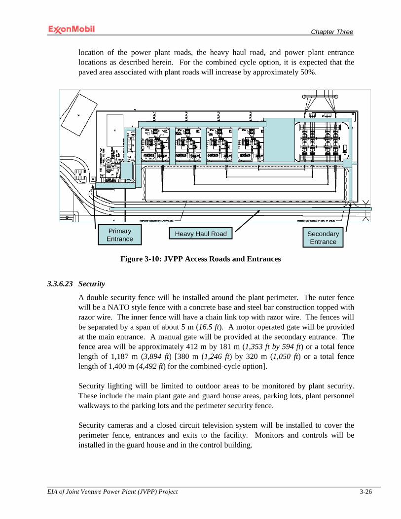
Chapter Three
EIA of Joint Venture Power Plant (JVPP) Project 3-26
location of the power plant roads, the heavy haul road, and power plant entrance locations as described herein. For the combined cycle option, it is expected that the paved area associated with plant roads will increase by approximately 50%.
Figure 3-10: JVPP Access Roads and Entrances
3.3.6.23 Security
A double security fence will be installed around the plant perimeter. The outer fence will be a NATO style fence with a concrete base and steel bar construction topped with razor wire. The inner fence will have a chain link top with razor wire. The fences will be separated by a span of about 5 m (16.5 ft). A motor operated gate will be provided at the main entrance. A manual gate will be provided at the secondary entrance. The fence area will be approximately 412 m by 181 m (1,353 ft by 594 ft) or a total fence length of 1,187 m (3,894 ft) [380 m (1,246 ft) by 320 m (1,050 ft) or a total fence length of 1,400 m (4,492 ft) for the combined-cycle option].
Security lighting will be limited to outdoor areas to be monitored by plant security. These include the main plant gate and guard house areas, parking lots, plant personnel walkways to the parking lots and the perimeter security fence.
Security cameras and a closed circuit television system will be installed to cover the perimeter fence, entrances and exits to the facility. Monitors and controls will be installed in the guard house and in the control building.
Primary Entrance
Secondary Entrance
Heavy Haul Road
Chapter Three
EIA of Joint Venture Power Plant (JVPP) Project 3-27
3.3.7 Additional Power Plant Components Required for the Combined Cycle Plant Option
3.3.7.1 Heat Recovery Steam Generator
Water for the HRSG will be obtained from the on-site water wells which have undergone appropriate treatment. Information obtained from QIT on the capacity of existing wells confirmed that available water will sufficiently meet the power project water requirements. Exhaust gas from the gas turbines will be used to produce steam which will feed a steam turbine. The cooled exhaust gases will then be emitted to the atmosphere. The HRSG will be multi-pressure and will be unfired. It is expected that approximately three HRSGs will be required.
3.3.7.2 Steam Turbine Generator (STG)
The steam turbine will be a multiple cylinder type suitable for direct coupling to a two-pole generator for power generation at 50 Hz. The thermal energy of the steam generated by the HRSG will be converted to mechanical energy in order to drive a generator to produce electric power. The exhaust steam will flow radially out of the steam turbine to an air-cooled condenser system.
3.3.7.3 Air-cooled Condenser
An air-cooled condenser with forced air circulation will be used to condense and recover exhaust steam. This option is environmentally preferable to the traditional water-cooled condensers for rejecting heat in combined-cycle power plants (CCPPs). This option reduces the amount of makeup water required thereby conserving water resources; it also avoids thermal discharges which along with water conservation avoid potential impacts to aquatic habitats; and it also enables heat contained in the condensate to be recovered thereby conserving on energy resources. Condensate collected is sent to a de-aeration drum where live steam is injected to strip out oxygen. Makeup water is also added at this location. From the condensate de-aeration drum, the water is fed to the boiler feed water pumps.
3.3.7.4 Boiler Water Treatment
The steam-water cycle will be a closed-loop system relying on de-mineralized make-up water whose source and treatment are more fully described in Section 3.3.6.11. Further treatment may be required to ensure the water is de-aerated (removal of oxygen) and pH controlled to prevent corrosion. Ammonia (NH3), sodium hydroxide (NaOH) or sodium phosphate (Na3PO4) may be used for pH control and oxygen scavenging chemicals may also be used, if required.
The purchase, transport, handling, storage and disposal of any chemicals used by this Project will be managed in accordance with MPN’s hazardous materials management

Chapter Three
EIA of Joint Venture Power Plant (JVPP) Project 3-28
procedures and, as applicable, Nigerian regulatory requirements or World Bank Safeguard Policies, whichever of these two requirements is more stringent.
3.3.8 Offshore Components
The principal components of the offshore facilities will be as follows:
Installation of a new subsea pipeline into an existing 600 meter wide corridor (Figure 3-11a and Figure 3-11b) to deliver lean fuel gas primarily methane from the existing OSO complex to an onshore gas distribution header to be located in the southwest corner of the QIT facility;
Installation of a new subsea pipeline into an existing 200 meter wide corridor (Figure 3-11a and Figure 3-11c) to transport rich gas that is currently being flared at QIT to the existing East Area (EA) complex for extraction of Natural Gas Liquids;
Installation of a new subsea 12 inch pipeline into an existing 60.9 meter wide corridor to deliver rich gas that is currently being flared at QIT to the OSO complex;
All interface connections as required between the new pipelines and existing structures and any new additional structural elements as may be required; and
Installation of a subsea isolation valve for both pipelines.
3.3.8.1 Pipeline Design Characteristics
Lean fuel gas will be imported by a pipeline to be installed into an existing 600 meter wide corridor (e.g., contains pipelines) from the existing OSO complex to an onshore gas distribution header to be located in the southwest corner of QIT facility, see Figure 3-11a and Figure 3-11b. The lean fuel gas pipeline will be a 406-610 mm (16-24 inch) diameter pipeline that is approximately 51.8 km (28 nautical miles).
The rich gas will be transported in a subsea dense phase pipeline 305 millimeter (12 inch) diameter pipeline that is about 35.1 kilometer (km) (19 nautical miles) long in an existing 200 meter wide corridor (e.g., contains pipelines) to MPN’s existing EA complex (Figure 3-11a and Figure 3-11c). The composition of the rich gas is approximately 55% methane, 15% ethane, 19% propane and the rest mainly butane and other alkane hydrocarbons.
Another alternative is the transportation of the rich gas, in a subsea dense phase pipeline 305 millimeter (12 inch) diameter pipeline that is about 58.46 kilometer (km) (31.6 nautical miles) long in an existing 60.96 meter wide corridor (e.g., contains pipelines) from MPN’s onshore QIT facility to existing OSO complex.
Seabed bathymetric data for both pipeline routes is presented in the Baseline Study section of this document. MPN has acquired pursuant to the Oil Pipelines Act a

Chapter Three
EIA of Joint Venture Power Plant (JVPP) Project 3-29
petroleum pipeline license for the lean fuel gas pipeline from the Department of Petroleum Resources (DPR).
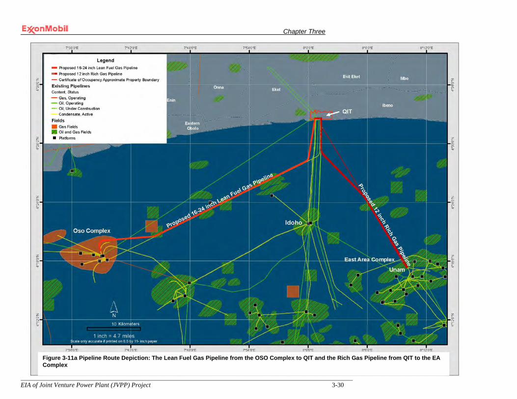
Chapter Three
EIA of Joint Venture Power Plant (JVPP) Project 3-30
Figure 0-11a Lean Fuel Gas Pipeline from OSO to QIT & Rich Gas Pipeline from QIT to the EA Complex Figure 3-11a Pipeline Route Depiction: The Lean Fuel Gas Pipeline from the OSO Complex to QIT and the Rich Gas Pipeline from QIT to the EA Complex

Chapter Three
EIA of Joint Venture Power Plant (JVPP) Project 3-31
Figure 2-11b Lean Fuel Gas Pipeline from Oso to QIT Figure 3-11b Pipeline Route Depiction: The Lean Fuel Gas Pipeline from the OSO Complex to QIT
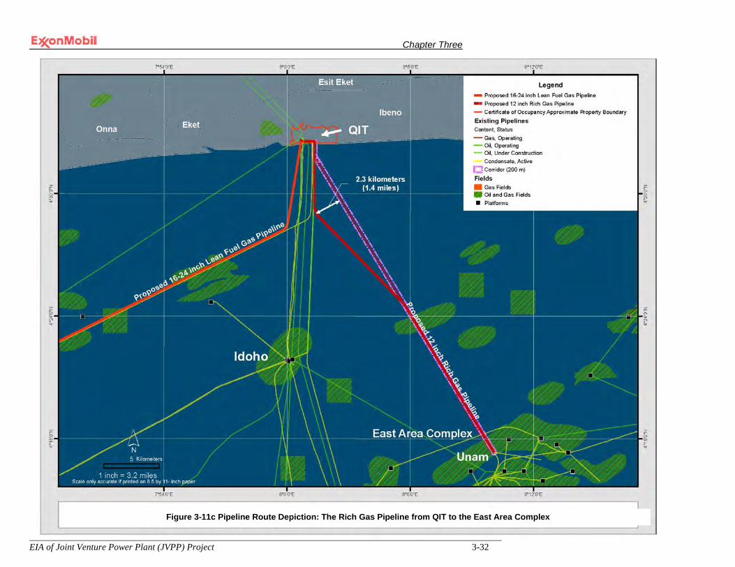
Chapter Three
EIA of Joint Venture Power Plant (JVPP) Project 3-32
Figure 2-11c Rich Gas Pipeline from QIT to the EA ComplexFigure 3-11c Pipeline Route Depiction: The Rich Gas Pipeline from QIT to the East Area Complex
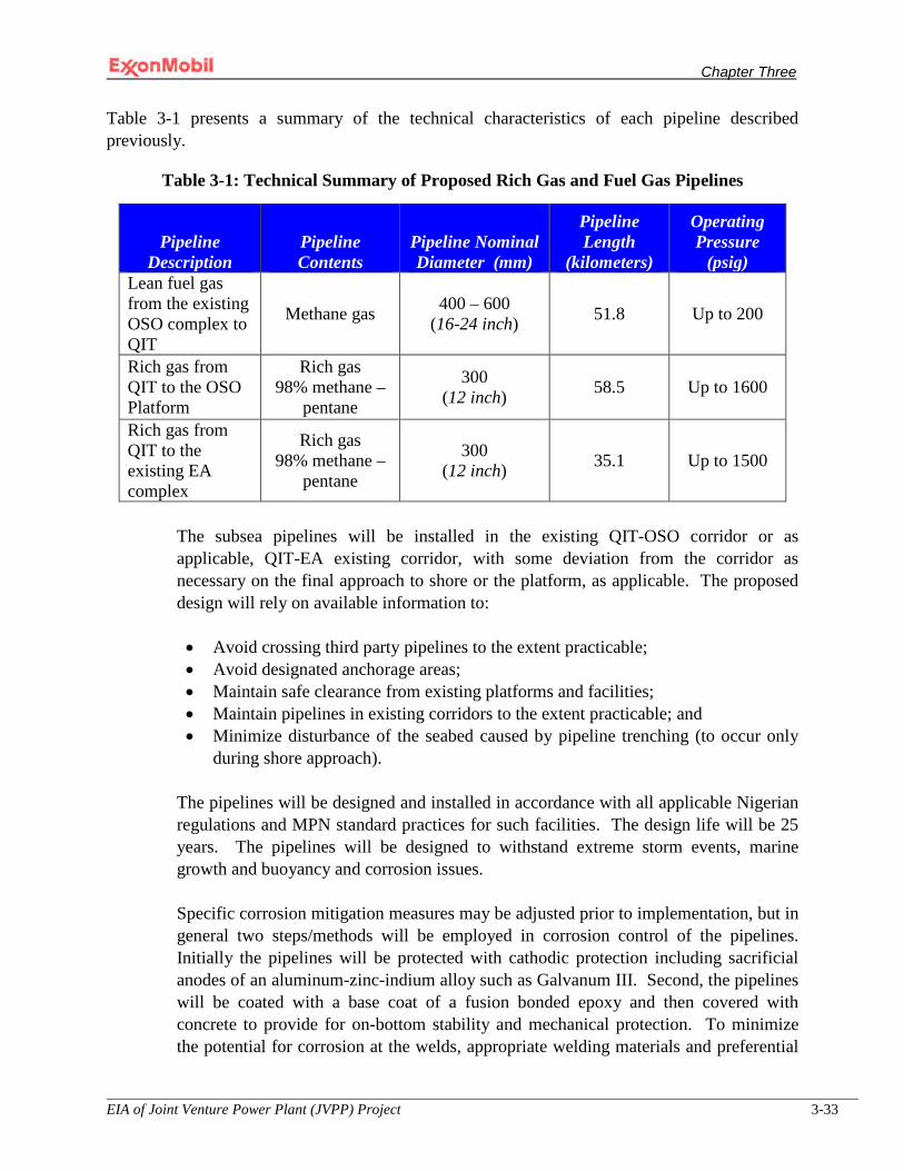
Chapter Three
EIA of Joint Venture Power Plant (JVPP) Project 3-33
Table 3-1 presents a summary of the technical characteristics of each pipeline described previously.
Table 3-1: Technical Summary of Proposed Rich Gas and Fuel Gas Pipelines
Pipeline Description
Pipeline Contents
Pipeline Nominal Diameter (mm)
Pipeline Length
(kilometers)
Operating Pressure
(psig) Lean fuel gas from the existing OSO complex to QIT
Methane gas 400 – 600 (16-24 inch) 51.8 Up to 200
Rich gas from QIT to the OSO Platform
Rich gas 98% methane –
pentane
300 (12 inch) 58.5 Up to 1600
Rich gas from QIT to the existing EA complex
Rich gas 98% methane –
pentane
300 (12 inch) 35.1 Up to 1500
The subsea pipelines will be installed in the existing QIT-OSO corridor or as applicable, QIT-EA existing corridor, with some deviation from the corridor as necessary on the final approach to shore or the platform, as applicable. The proposed design will rely on available information to:
• Avoid crossing third party pipelines to the extent practicable; • Avoid designated anchorage areas; • Maintain safe clearance from existing platforms and facilities; • Maintain pipelines in existing corridors to the extent practicable; and • Minimize disturbance of the seabed caused by pipeline trenching (to occur only
during shore approach).
The pipelines will be designed and installed in accordance with all applicable Nigerian regulations and MPN standard practices for such facilities. The design life will be 25 years. The pipelines will be designed to withstand extreme storm events, marine growth and buoyancy and corrosion issues.
Specific corrosion mitigation measures may be adjusted prior to implementation, but in general two steps/methods will be employed in corrosion control of the pipelines. Initially the pipelines will be protected with cathodic protection including sacrificial anodes of an aluminum-zinc-indium alloy such as Galvanum III. Second, the pipelines will be coated with a base coat of a fusion bonded epoxy and then covered with concrete to provide for on-bottom stability and mechanical protection. To minimize the potential for corrosion at the welds, appropriate welding materials and preferential

Chapter Three
EIA of Joint Venture Power Plant (JVPP) Project 3-34
corrosion weld testing will be specified for both the pipeline manufacturer and the installer. The design of the pipelines will facilitate internal corrosion inspection and monitoring through the process of intelligent pigging.
3.3.8.2 Pipeline System Layout
During design, efforts will be made to minimize pipeline crossings to the extent practicable. However, some crossings may occur. When crossings are required, suitable bridging methods such as concrete mattresses will be employed to protect the two crossing pipelines and to manage bending stress on the overlying pipeline related to spanning.
Hydrographic surveys of the pipeline routes may be conducted. This information including data or analysis acquired during previous hydrographic studies will be employed to determine if route modifications to avoid obstacles is indicated. In addition to avoiding hazards, the pipelines will not be routed under mooring lines or within 200 meters of permanently installed anchors or piles.
3.4 Project Execution Schedule
The design and construction of a natural gas fired nominal 575 MW simple cycle power plant is expected to take approximately 48 months from EPC contract award (an approximate 12 month extension to this schedule should be expected if the combined cycle power plant option is implemented). Construction/installation of the pipelines is expected to take approximately 12 months. As practicable, most pipeline work will occur during the months from October to May to take advantage of better weather conditions, (i.e., for safety reasons). The project schedule is attached as Appendix VI.
3.5 Onshore Site Preparation Activities
The site preparation activities will include geotechnical investigations, site clearing and grubbing, followed by backfill to the required datum. These and other activities are more fully described below.
3.5.1 Geotechnical Investigations
The first sequence in site preparation activities involves the clearing of paths to permit access for the equipment needed to conduct the geotechnical investigation. Approximately five to eight subsurface boreholes and six to twelve cone penetration tests will be completed at the Project site during this phase of the Project. Upon completion of the investigation, the drill cuttings will be spread on the ground near to the vicinity where they were obtained. All equipment and temporary facilities used during the study will be removed. Standard procedures typically used in the industry to minimize impacts to soil, water and biological resources will be employed during these geotechnical investigations.
Chapter Three
EIA of Joint Venture Power Plant (JVPP) Project 3-35
It is anticipated that land associated with geotechnical investigations will subsequently be cleared for various infrastructure needs for the proposed Project (i.e., there will be no intervening restoration). However, if the area is not cleared and grubbed for the proposed Project, it will be restored to a condition that approximates the previous site condition.
3.5.2 Clearing and Grubbing
The second sequence during the site preparation phase is clearing and grubbing, establishing a temporary road network into the project site and constructing temporary fencing as required. The area to be cleared and grubbed and filled includes sufficient areas for the power plant, workers construction camp, construction facilities such as the power plant laydown area, transmission line laydown area and temporary construction offices and other various materials preparation and staging areas, hereafter referred to as the “plant footprint”. Clearing and grubbing will occur within the limits of this work scope in preparation for site excavation, backfill and grading. The limits of the work are not expected to exceed 230,000 m2 or about 57 acres for the simple cycle power plant option and 360,000 m2 or about 89 acres for the combined cycle power plant option. As part of the site clearing activities, MPN will require the Engineering Procurement and Construction (EPC) contractor to develop and implement an Erosion and Sedimentation Control Plan to prevent or minimize the potential for adverse effects to the environment including water quality degradation due to soil erosion and sedimentation in the general project area including areas located downstream from the construction site that are within the Project area of influence. Additionally, the EPC contractor will be required to develop and implement a Spill Prevention and Response Plan (SPRP) to prevent the release of chemicals or other such similar substances to the environment, to identify and respond to releases if such were to occur, and to demonstrate compliance with all applicable environmental and best management practices regarding spill prevention and response. The SPRP will identify relevant spill prevention, response and management procedures and equipment that would be put in place to prevent potential spills. Brush and vegetation will be piled and discarded into local disposal sites in accordance with applicable Nigerian regulations and MPN waste management standards and practices. Woody debris and cut trees may be placed at the edge of the Project site with access provided to the local community members to remove the material for their personal use.
3.5.3 Excavation, Backfill, and Grading
Excavation, backfill and grading activities will start following clearing and grubbing activities. The first stage in the process will involve stripping the topsoil, i.e., organic matter, debris and other material unsuitable for permanent engineered fill, to approximately 0.5 meters. It is estimated that the simple cycle power “plant footprint”

Chapter Three
EIA of Joint Venture Power Plant (JVPP) Project 3-36
and combined cycle power “plant footprint” will require removal of about 110,000 m3 of topsoil and 180,000 m3 of topsoil, respectively, Table 3-2 and Table 3-3. The stripped topsoil will then be stockpiled on-site and protected from erosion as well as mixture with other materials such as aggregate. It will subsequently be used to construct an on-site landscape berm with any remainder possibly shared with the local community. Fresh water from QIT’s firewater loop or from tanker trucks will be used for dust control as needed throughout the construction phase, about 18,900 to 37,850 liters per day (5,000 to 10,000 gallons per day) over a two year period for the simple cycle power plant option and 37,800 to 75,700 liters per day (10,000 to 20,000 gallons per day) over a two year period for the combined cycle power plant option (see Table 3-6 and 3-7).
Table 3-2 Excavation and Backfill Estimates for the Simple Cycle Power Plant Option
Description Excavated material Required fill material Power plant, Workers Construction Camp and Balance of Plant
70,000 meters3
(91,553 yd3) 350,000 meters3
(457,765 yd3)
Power plant and Transmission Line laydown areas
40,000 meters3
(52,316 yd3) 132,000 meters3
(172,643 yd3)
Total 110,000 meters3
(143,869 yd3) 482,000 meters3
(630,408 yd3)
Table 3-3 Excavation and Backfill Estimates for the Combined Cycle Power Plant Option
Description Excavated material Required fill material Power plant, Workers Construction Camp and Balance of Plant
110,000 meters3
(143,869 yd3) 550,000 meters3
(719,345 yd3)
Power plant and Transmission Line laydown areas
70,000 meters3
(91,553 yd3) 231,000 meters3
(302,125 yd3)
Total 180,000 meters3
(235,422 yd3) 781,000 meters3
(1,021,470 yd3)
Following removal of the topsoil, excavation of the foundations for equipment, tanks and other vessels and slabs will begin. At that time, temporary on-site roadways, ditches and culverts will be constructed and erosion controls installed.
Temporary drainages will be sized to handle the anticipated design rainfall and runoff quantities from the disturbed areas. Best Management Practices (BMPs) as identified in the EPC contractor’s Erosion and Sedimentation Control will be incorporated into the overall clearing, excavation, backfill and grading process to minimize the impacts of erosion. All work associated with excavation, embankment and grading activities
Chapter Three
EIA of Joint Venture Power Plant (JVPP) Project 3-37
will be conducted in a manner to control the potential for sedimentation within non-manmade aquatic environments located adjacent to the work site/QIT. Approximately 482,000 m3 of fill material and 781,000 m3 of fill material for the simple cycle and combined cycle power plant options respectively will be required to bring the “plant footprint” to the required datum (Table 3-2 and Table 3-3, respectively). The fill material will be acquired from QIT Lake, a man-made lake depicted in Figure 3-2. The area within the red dotted line on Figure 3-2 shows the area where the fill material will be acquired. The fill material will be mixed with water from QIT Lake in a 10/90 percent mass ratio respectively and transported to the site, about 2 km (1.25 miles) away, through use of a hydraulic pump. It is estimated that approximately 2 x 10⁹ liters (528.3 million gallons) of water for the simple cycle option and or 3.2 x 10⁹ liters of water (845.3 million gallons) for the combined cycle power plant option will be acquired from QIT Lake. The water source for QIT Lake is both the Douglas Creek and rainwater. As such, this slurry water will be allowed to drain into the storm water retention pond prior to discharging into Douglas Creek.
3.5.4 Site Drainage
Construction activities during site preparation will use natural drainages and temporary drainages at the Project site until the permanent drainage system is operational. Silt fences will be installed as per the EPC contractor’s Erosion and Sedimentation Control Plan to manage silt-contaminated surface runoff.
3.5.5 Foundations
Piled foundations for heavy equipment will be required. The GTGs will be the heaviest load for the simple cycle option. Each GTG will each require about 50 piles 400 mm (15.7 inches) in diameter and 20 meters (65.6 feet) long to be bored and driven into the earth. Each GTG slab will be approximately 1,500 mm (4.9 ft) thick and consist of 500 m3 of concrete per slab. All other equipment is assumed to rest on shallow foundations. Light equipment is assumed to rest on 450 mm thick slabs and heavier equipment is assumed to rest on 750 mm thick slabs.
For the combined cycle power plant option, the three HRSGs will each require 100 piles 400 mm in diameter and 20 meters long drilled into the earth. Each of the three GTGs will require 50 piles 400 mm in diameter and 20 meters long and the STG will require 100 piles 400 mm in diameter and 20 meters long, drilled into the earth. Each slab for the HRSG, GTG and STG will be approximately 1,500 mm thick supported on concrete piles with 500 m3 of concrete per slab. All other equipment will rest on shallow foundations. As is the case for the simple cycle power plant option, light equipment is assumed to rest on 450 mm thick slabs and heavier equipment is assumed to rest on 750 mm thick slabs.
Chapter Three
EIA of Joint Venture Power Plant (JVPP) Project 3-38
The concrete for the piles and foundations will be batched on-site and transported to the pour site in concrete mixer trucks. Noise during construction could arise from piling of foundations. As a result, MPN will limit construction activities to daylight hours to the extent possible and practical.
3.5.6 Workers Camp
A workers camp is under consideration for development to house approximately 350 personnel (500 personnel if the combined cycle power plant option is implemented), mainly professional staff consisting of EPC construction management, expatriate construction supervisors, project team representatives and owner representatives. It is expected that a significant portion of national labor employed for the Project will be from the host communities and therefore will not require to be accommodated. The rest will acquire room and board in neighboring communities or in the town of Eket. The camp will include the necessary amenities such as a dining hall and kitchen and a primary health care facility. Other services and infrastructure will likely include a water treatment plant, sewage treatment plant, power generation, fuel storage, miscellaneous storage and fire-fighting equipment. Three possible locations are under consideration for the camp as noted in Figure 3-2. National labor, about 750 personnel in addition to the previously mentioned 350 personnel (assume 1,500 national labor personnel and 500 mainly professional personnel if the combined cycle power plant option is implemented) residing either in the workers camp or in neighboring villages will be bussed to and from the project site each day. At a minimum, a security convoy will be provided for the buses traveling to and from the workers camp. It is expected that about 30 buses (60 buses for the combined cycle power plant option) will be used for up to 600 days (1,000 days for the combined cycle power plant option) for this activity.
Security at the workers camp is expected to consist of a combination of expatriate security managers and local national guards some of whom will be recruited from the host communities. Perimeter security, entry control points as well as roving security patrols will likely be used.
3.5.7 Concrete Batch Plant
One or possibly two concrete batch plants will be established at the site to provide concrete during the construction phase. The production capacity of the batch plant facility was assumed to be 50 m3/hour for budgeting purposes. However, the actual size may vary somewhat depending upon the model selected by the EPC contractor. It is estimated that 9,530 m3 of concrete will be required for construction of the simple cycle power plant option and that 20,660 m3 of concrete will be required for construction of the combined cycle power plant option.
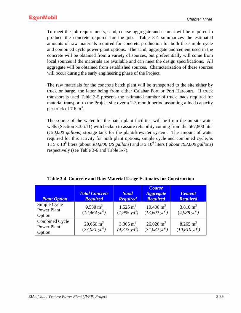
Chapter Three
EIA of Joint Venture Power Plant (JVPP) Project 3-39
To meet the job requirements, sand, coarse aggregate and cement will be required to produce the concrete required for the job. Table 3-4 summarizes the estimated amounts of raw materials required for concrete production for both the simple cycle and combined cycle power plant options. The sand, aggregate and cement used in the concrete will be obtained from a variety of sources, but preferentially will come from local sources if the materials are available and can meet the design specifications. All aggregate will be obtained from established sources. Characterization of these sources will occur during the early engineering phase of the Project.
The raw materials for the concrete batch plant will be transported to the site either by truck or barge, the latter being from either Calabar Port or Port Harcourt. If truck transport is used Table 3-5 presents the estimated number of truck loads required for material transport to the Project site over a 2-3 month period assuming a load capacity per truck of 7.6 m3.
The source of the water for the batch plant facilities will be from the on-site water wells (Section 3.3.6.11) with backup to assure reliability coming from the 567,800 liter (150,000 gallons) storage tank for the plant/firewater system. The amount of water required for this activity for both plant options, simple cycle and combined cycle, is 1.15 x 10⁶ liters (about 303,800 US gallons) and 3 x 10⁶ liters ( about 793,000 gallons) respectively (see Table 3-6 and Table 3-7).
Table 3-4 Concrete and Raw Material Usage Estimates for Construction
Plant Option Total Concrete
Required Sand
Required
Coarse Aggregate Required
Cement Required
Simple Cycle Power Plant Option
9,530 m3
(12,464 yd3) 1,525 m3
(1,995 yd3) 10,400 m3
(13,602 yd3) 3,810 m3
(4,988 yd3)
Combined Cycle Power Plant Option
20,660 m3
(27,021 yd3) 3,305 m3
(4,323 yd3) 26,020 m3
(34,082 yd3) 8,265 m3
(10,810 yd3)

Chapter Three
EIA of Joint Venture Power Plant (JVPP) Project 3-40
Table 3-5 Estimated Truck Loads Required for Batch Plant Operations
Plant Option
Truck Loads Required for
Sand
Truck Loads Required for
Coarse Aggregate
Truck Loads Required for
Cement Simple Cycle Power Plant Option 201 1,369 502
Combined Cycle Power Plant Option 435 3,424 1,088
Note: Assumes a concrete production capacity of 50 m3/hour and a load capacity per truck of 7.6 m3
3.5.8 Material Off-loading Facility (Proposed MOF)
A Material Off-Loading Facility (MOF) will be constructed on the ocean shore, on the eastern end of QIT (Figure 3-2). The QIT Material Offloading Facility (MOF) is intended to support Roll-on/Roll-off (Ro/Ro) Operations as well as potential heavy lift crane operations related to the QIPP Project. The elements that are envisioned to be included in the MOF facilities include open staging areas, fueling of vessels at the waterfront (not storage), potable water storage and distribution, sanitary sewer distribution, an Operations building to support MOF operations and passengers, storage warehouse, Ro/Ro facility, offshore crew vessel moorings, marine police vessel moorings, security infrastructure (fencing, lighting, access control). The overall site requires a navigation channel to be dredged from the ocean through the beach. The layout consists of a 300 m long service wharf (with an east–west orientation) that parallels the shoreline. The overall wharf width is 45 m wide in order to accommodate the laydown area, storage warehouse, passenger building, and water storage tank. The waterfront consists of two Crew Vessel Piers, 2 Marine Police Piers, and the Heavy Lift Ro/Ro Dock. Individual components include: Approximately 16,625 m² marginal and service wharf built at elevation +3.50 m with a roll-off berth at +2.30m MLW. The marginal wharf is designated for barge and heavy lift area. The heavy lift area will enable roll-off operations for the delivery of heavy equipment. The dock is to handle mobile cranes to provide lift-off operations for the delivery of heavy equipment, construction materials, and construction modules during construction of QIPP. Two (2) 1,500 m² (75 m long by 20m wide) cellular cofferdam piers, built at elevation +3.50 m, would be constructed to accommodate the four (4) crew vessels with two on each pier. The piers should be capable of mooring fast surfer boats.

Chapter Three
EIA of Joint Venture Power Plant (JVPP) Project 3-41
Two (2) piers, built also at elevation +3.50 m, would be constructed to accommodate up to four (4) marine police boats. These structures would consist of approximately 187.5 m² of steel pipe pile-supported concrete deck slab superstructures. The two 37.5 m long by 5 m wide piers, would hold two boats each and are only designed for pedestrian traffic. The Heavy Lift Ro/Ro Dock should be able to accommodate 50 m long by 18 m wide barges. Berthing and mooring will be with the stern or bow of the barge towards the pier head. The barge would be moored alongside the dock at +3.5 m MLW while a provision for roll-off onto a ramp at + 2.3 m MLW would also be provided. The minimum design width for a roll-off ramp is 20 m. A portable water system consisting of 2 boreholes, water treatment and a storage tank capable of storing 1,150,000 L of water should be provided. Provision should be made for refueling vessels at the MOF. As such, fuel lines will be laid from the MOF to the existing fuel storage tanks at QIT
A building approximately 500 sq. m to serve as administrative office and passenger waiting area should be erected. The MOF will also store materials and supplies that will be utilized to support operations. Therefore, a covered storage warehouse approximately 500 sq. m and 7 m clear height on the interior will be constructed
3.6 Construction Activities
Construction and/or installation of the power plant and auxiliary equipment will be sequenced with site preparation activities. The following subsections describe the activities associated with various components of the Project that may have an impact on the environment.
3.6.1 Construction Works
Employment: The construction labor force for the simple cycle power plant option is expected to average about 350 professional staff (500 for the combined-cycle power plant option) consisting of EPC construction management, expatriate construction supervisors, project team representatives and owner representatives including about 750 national labor personnel (1500 for the combined-cycle option). The expected construction labor force for the offshore component facilities will be about 170 workers.
Work Hours: Working hours will normally be daylight hours from 7:00 a.m. - 7:00 p.m. In the event that evening hours are worked, emphasis will be placed on proper lighting, proper job procedure and overall safety.
Chapter Three
EIA of Joint Venture Power Plant (JVPP) Project 3-42
3.6.2 Temporary Site Facilities
Temporary offices facilities essentially construction trailers will be established. Connex boxes will be used to store, dispense and secure consumables, small tools and small equipment. Environmentally sensitive materials such as electronics and instrumentation will be stored in environmentally controlled containers until issued for installation to the power plant.
The Transmission Line laydown area will be about 20,000 m2 (Figure 3-2). This area will be used during the early stages of the Project. It will be covered with about 203 mm (8 inches) of crushed rock to aid in keeping materials dry and to provide a surface suitable for vehicle traffic. Later during the construction phase, the area will be filled with electrical structures to hold the 330 KV power cables for each of the GTGs; these power cables will be routed from each GTG step-up transformer to the east and then up into the power plant’s substation.
Large plant items will be delivered to the site either by barge to be off-loaded at the proposed MOF or by road on specialized long transporter vehicles, see Sections 3.5.8 and 3.6.5 for further details.
3.6.3 Utilities
Throughout the construction period, bottled drinking water will be delivered to the job site by means of a tractor trailer truck for use by construction labor. Non-potable water for construction purposes will be obtained from the onsite wells to be installed by the EPC contractor and which are described in more detail in Section 3.3.6.11. Following completion of construction activities, the water wells will be converted to the Plant’s permanent water supply source.
Temporary portable sanitation units will be employed for construction labor including the labor to be housed in the nearby workers camp, described more fully in Section 3.5.6. The EPC contractor will be responsible for pump-out and disposal of all sanitary waste. The EPC contractor will also be responsible for the management and disposal of all office wastes, construction wastes and construction labor camp wastes generated as a result of the Project.
The management and disposal of all construction generated waste streams will be conducted in accordance with all applicable Nigerian waste management regulations including MPN waste management and disposal standards. To ensure compliance with this commitment, MPN will contractually require its EPC contractor to develop and implement a waste management plan (WMP) consistent with its waste management standards and practices. The EPC contractor’s WMP and any subsequent revisions will require approval from MPN. To further ensure compliance, MPN will conduct periodic assessments of the EPC contractor’s waste management activities. The EPC

Chapter Three
EIA of Joint Venture Power Plant (JVPP) Project 3-43
Contractor will be required to promptly resolve any findings from these assessments to MPN’s satisfaction.
Satellite uplink for telephone and internet access will be employed to ensure communication during the construction phase of the project. Construction lighting will be accomplished by relying on mobile light towers, mainly required to illuminate the site each night for security.
Temporary diesel electric generators will be used to provide office lighting and service other light loads. It is expected that temporary construction power will be provided by the EPC contractor using approximately two 125 KW tow behind diesel generators for about 16 months if the simple cycle power plant option is implemented and four 125 KW tow behind diesel generators for about 32 months if the combined cycle power plant option is implemented. Additionally all welding will be done with diesel welding machines, about fifteen 250 amp machines for 16 months for the simple cycle power plant option and about thirty 250 amp machines for 32 months for the combined cycle power plant option.
3.6.4 Construction Equipment
Heavy duty diesel vehicles and stationary construction equipment will be used during construction activities. It is expected that two diesel powered cranes, one 100-ton crane and one 500-ton crane, will be used during construction if the simple cycle power plant option is implemented and that three diesel powered cranes, one 100-ton crane and two 500-ton cranes, will be used during construction if the combined-cycle power plant option is implemented. Following construction these cranes will be stored at the power plant for use as needed during plant operations.
3.6.5 Logistics
The existing QIT roads and government access roads to QIT are considered to meet the Project requirements except for the heaviest equipment components such as the GTGs (STG and HRSG if the combined cycle power plant option is implemented). As a result, the GTG equipment (and the HRSG and STG for the combined cycle power plant option) will likely be barged to the MOF from either Port Harcourt/Onne Port or from Calabar Port. The berthing capability at Calabar Port is less than Port Harcourt/Onne Port so Port Harcourt/Onne Port may be the Port of choice. Calabar Port has a maximum draught of 6 m (19.6 ft) and can accommodate a vessel of maximum length of 151 m (495 ft) whereas Port Harcourt has a maximum draught of 7.4 m (24.2 ft) and can accommodate a vessel of maximum length of 184 m (604 ft). The estimated barge time from Port Harcourt/Onne Port to QIT is two and one-half 24-hour days one way and the estimated barge time from Calabar Port to QIT is one 24-hour day one way, see Figure 3-122.

Chapter Three
EIA of Joint Venture Power Plant (JVPP) Project 3-44
The primary access road to the project site will be the existing road to Eket. In advance of construction, a thorough assessment will be made of the current condition of that road including any bridges and crossings. During construction, the Project will monitor the impact on this road and other local roads caused by truck traffic employed in support of the Project and ensure proper implementation of approved mitigation measures. Near the conclusion of construction, a final assessment of the roads and bridges potentially affected by the Project will be made. As needed, the road and bridges will be restored to their pre-Project condition.

Chapter Three
EIA of Joint Venture Power Plant (JVPP) Project 3-45
Figure 3-12: Proximity of Project Site to Calabar Port and Port Harcourt

Chapter Three
EIA of Joint Venture Power Plant (JVPP) Project 3-46
3.6.6 Painting
Piping, equipment packages, vessels and structural steel will be brought on-site from their respective manufacturer/fabricator with primer and finish coats applied. This will reduce the problems in the field associated with painting in a tropical wet environment and the generation of waste. To further avoid the need to paint, where possible hot dip galvanized steel will be used. If painting is indicated, painting activities will commence when erection and final inspection of piping, mechanical equipment and structural steel have reached the point where painting can proceed without rework. Painting will be done in accordance with standard industry practices.
3.6.7 Fire Protection
The storm water retention basin described in Section 3.3.6.10 may be used for fire suppression during construction. Alternatively, Douglas Creek may serve this purpose in which case submersible pumps with screens will be used to pump water from the creek.
3.6.8 Offshore Pipeline Installation
The offshore pipeline will be laid on the seafloor without trenching except for the shore approach. For the shore approach, a cofferdam will be used before trenching. Trenching will likely be limited to areas where the water depth is 4.6 m (15 ft) or less. The base plan is for cofferdam/trenching to continue through the shore crossing in order to lay the pipe 5 feet deep. However, the feasibility of crossing under the beach using directional drilling will be investigated during the design phase. If feasible, this approach would avoid interference with company constructed and operated roads. If directional drilling is used, environmentally benign water-based muds will be used to provide lubrication during the drilling process.
The pipelines will be installed using a combination derrick-pipelay vessel employing conventional, joint-by-joint welding/laying techniques. The pipelay vessels will be equipped in an S-lay configuration. On each vessel, 12 m (40 ft) long joints of steel pipe will be welded either manually or by automatic equipment depending on the contractor. Other stations on the vessel will conduct non-destructive inspections of the pipe and the welds and will apply a field coating to the joints.
In laying the pipelines, the pipelay vessels will likely use anchors to maintain position and pull the vessel along the prescribed pipeline route. As the vessel progresses along the route, two anchor handling tug vessels will periodically reposition the anchors. The pipelay operation will be supported by a supply shuttling operation involving two or more pipe haul barges and their associated tugs.
3.6.9 Hydrotesting
After installation of the two offshore-to-onshore pipelines and the onshore process piping, each system will be separately hydrotested in line with EGASPIN and MPN requirements.
Chapter Three
EIA of Joint Venture Power Plant (JVPP) Project 3-47
Regulatory and company requirements include obtaining DPR and MPN permits for chemicals to be used, completion of EGASPIN appendix IX-1 form for effluent discharge, development of the hydrotest procedure, and involvement of DPR representatives during the hydrotest activities. An approved procedure will be followed with the participation and observation of DPR representatives. The discharge will be paced and the rate is logged. The charts and records would be available for reference and confirmation. DPR’s participation is to ensure that the hydrotest is carried out in line with approved standards and procedures. At completion, requisite forms are endorsed by these representatives and are included as part of the final hydrotest report. For the offshore pipelines, this will be accomplished by first flushing them with filtered seawater. Each pipeline will then be gauged by pigging and then tested for pressure/structural integrity using inhibited seawater per project specifications. Following the hydrostatic test, the pipelines will be dewatered using a pig; the seawater being discharged into the sea. Any remaining water residue will then be removed by injecting and sweeping the pipeline with dry air until the Project required effluent dew point is reached. Following MPN acceptance criteria for air drying, each pipeline will then be nitrogen purged and blanketed. The process for hydrostatic testing for the onshore fuel gas process piping system will be similar to that employed for the offshore subsea pipelines except that pigs will not be used and seawater will not be used. Instead, the process piping will be flooded with fresh water from QIT’s firewater system. Once full of water, the hydrostatic test will be conducted per EGASPIN and MPN requirements using inhibited fresh water. Following the hydrostatic test, the onshore process piping system will be dewatered using a drain located at a low point on the line; the water likely being discharged into the onsite storm water retention pond which eventually discharges into Douglas Creek. Similar to the offshore pipelines, any remaining water residue in the piping system will be removed by injecting dry air. Following MPN acceptance that the specifications for air drying have been met, the piping system will be nitrogen purged and blanketed.
Small concentrations of a corrosion inhibitor, a biocide, and/or an oxygen scavenger may be added to the seawater/fresh water to avoid corrosion of the pipe. The chemicals used for this activity will be selected from the list of chemicals approved for hydrostatic testing by the Department of Petroleum Resources (DPR). Additionally, each selected chemical will be further scrutinized by MPN’s Occupational Health group to assure that the chemical is environmentally friendly in advance of use. In conducting this activity, MPN will comply with all applicable Nigerian regulatory requirements that pertain to the use and disposal of chemicals employed for hydrostatic testing.
3.6.10 Security
As soon as feasibly possible, a construction fence topped with razor wire will be installed around the entire construction site including the laydown areas to provide a secured construction area. Construction lighting will be accomplished by relying on mobile light towers to illuminate the Project site each night for security.
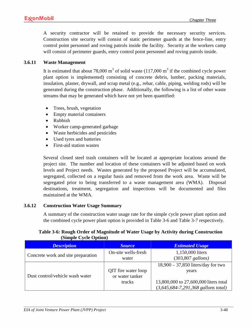
Chapter Three
EIA of Joint Venture Power Plant (JVPP) Project 3-48
A security contractor will be retained to provide the necessary security services. Construction site security will consist of static perimeter guards at the fence-line, entry control point personnel and roving patrols inside the facility. Security at the workers camp will consist of perimeter guards, entry control point personnel and roving patrols inside.
3.6.11 Waste Management
It is estimated that about 78,000 m3 of solid waste (117,000 m3 if the combined cycle power plant option is implemented) consisting of concrete debris, lumber, packing materials, insulation, plaster, drywall, and scrap metal (e.g., rebar, cable, piping, welding rods) will be generated during the construction phase. Additionally, the following is a list of other waste streams that may be generated which have not yet been quantified:
• Trees, brush, vegetation • Empty material containers • Rubbish • Worker camp-generated garbage • Waste herbicides and pesticides • Used tyres and batteries • First-aid station wastes
Several closed steel trash containers will be located at appropriate locations around the project site. The number and location of these containers will be adjusted based on work levels and Project needs. Wastes generated by the proposed Project will be accumulated, segregated, collected on a regular basis and removed from the work area. Waste will be segregated prior to being transferred to a waste management area (WMA). Disposal destinations, treatment, segregation and inspections will be documented and files maintained at the WMA.
3.6.12 Construction Water Usage Summary
A summary of the construction water usage rate for the simple cycle power plant option and the combined cycle power plant option is provided in Table 3-6 and Table 3-7 respectively.
Table 3-6: Rough Order of Magnitude of Water Usage by Activity during Construction (Simple Cycle Option)
Description Source Estimated Usage
Concrete work and site preparation On-site wells-fresh water
1,150,000 liters (303,807 gallons)
Dust control/vehicle wash water QIT fire water loop
or water tanker trucks
18,900 – 37,850 liters/day for two years
13,800,000 to 27,600,000 liters total (3,645,684-7,291,368 gallons total)

Chapter Three
EIA of Joint Venture Power Plant (JVPP) Project 3-49
Description Source Estimated Usage Backfill mixture for power plant foot print and laydown area; 10/90 percent fill/water ratio
QIT Lake 2,000,000,000 liters (528,360,000 gallons)
Potable water includes construction camp Bottled water
5,000 liters/day for 2 years
3,650,000 liters total (964,257 gallons total)
Sanitary water usage includes construction camp On-site water wells
152,500 liters/day for 2 years
111,325,000 liters total (29,409,839 gallons)
Hydrostatic testing – offshore Seawater 9,600,000 liters (2,179,200 gallons)
Hydrostatic testing – onshore Firewater loop at QIT
107,000 liters (28,267 gallons)
Table 3-7: Rough Order of Magnitude of Water Usage by Activity during Construction (Combined Cycle Option)
Description Source Estimated Usage
Concrete work and site preparation On-site wells-fresh water 3,000,000 liters (792,540 gallons)
Dust control/vehicle wash water QIT fire water loop or water tanker trucks
37,850 - 75,700 liters/day for two years
27,630,500 to 55,261,000 liters
total (7,299,425-14,598,851 gallons)
Backfill mixture for power plant foot print and laydown area; 10/90 percent fill/water ratio
QIT Lake 3,200,000,000 liters (845,376,000 gallons)
Potable water includes construction camp Bottled water
7,500 liters/day for 2 years
5,475,000 liters total (1,446,386 gallons)
Sanitary water usage includes construction camp On-site water wells
230,000 liters/day for two years
167,900,000 liters total (44,355,822 gallons)
Hydrostatic testing – offshore Seawater 9,600,000 liters (2,179,200 gallons)
Hydrostatic testing - onshore Firewater loop at QIT 107,000 liters (28,267 gallons)
Chapter Three
EIA of Joint Venture Power Plant (JVPP) Project 3-50
3.7 Operational Activities
Upon completion of construction and commissioning, the power plant will start-up in a stepwise fashion. To ensure the safe start-up and operation of the plant, a comprehensive Operational Safety Management Program will be implemented to ensure overall effectiveness of hazard control through all stages of activity. The primary elements of this program will include the following:
• Site operating procedures; • Personnel training; • Emergency procedures; • Pre-start-up safety review; and • Regular audits and reporting.
Site operation procedures will be developed to identify personnel responsibilities and to document start-up, normal and abnormal operations, and shutdown situations. Emergency procedures will be prepared for plant control actions required to achieve safe holding and shutdown conditions and to ensure the safety of personnel. The pre-start-up review will be structured to ensure that all construction meets intended specifications and written safety, operating, maintenance and emergency procedures. In addition, the pre-start-up review will ensure that these specifications and procedures are in place and that appropriate training of personnel has been completed. See also Section 7.8 discussing risk management. A safety policy and procedures manual will be prepared for the power plant. The safety policy and procedures will be subject to periodic audits and reviews to ensure continued effective performance. Hazardous incidents, if any, will be investigated to establish what factors contributed to the incident. Necessary changes to procedures and practices will then be implemented based on recommendations identified during the investigation.
3.7.1 Operations
Employment: Plant operations staffing will include approximately 55 employees and contractors excluding security. Staffing/headcount figures do not include offshore resources required to supply fuel gas.
Work Hours: Operators will run the facilities 24-hours on two 12-hour production shifts 365 days per year producing the nominal 575 MW.
3.7.2 Materials and Waste Management
Site specific operating procedures will be developed for the use, handling and disposal of raw materials and wastes. Only competent personnel will be authorized to handle hazardous materials on site. All chemicals stored will be subject to host country handling and storage requirements in addition to the information on the Material Safety Data Sheet and MPN materials management standards, whichever is more stringent. Periodic audits will be instituted to ensure the facility’s waste and raw materials management practices adhere to host country requirements and MPN standards. All waste transported off-site for proper

Chapter Three
EIA of Joint Venture Power Plant (JVPP) Project 3-51
disposition will be done so by government and MPN inspected and approved licensed contractors whose practices are in accordance with relevant legislation.
3.7.3 Operating Waste Expected Volumes
The operational waste streams expected to be generated during the operation of the simple cycle and combined-cycle power plant options is presented in Tables 3.8 and 3.9, respectively.
Table 3-8 Simple Cycle Power Plant Operational Waste Generation Estimates
Type of waste stream Source of waste stream Quantity
Office trash Plant area 5,475 kg/year (12,070 lbs/year)
Wastewater and sanitary liquor1
Turbine wash water and sanitary liquor
300,000 liters/year (79,254 gallons/year)
Sanitary sewage cake Sewage treatment plant 0 (if possible) -200,00 kg/year (0 – 440,924 lbs/year)
Oily sludge Oil water separator 378 kg/year (833 lbs/year)
Waste lubrication oils GTGs 93 kg/year (205 lbs/year)
Waste lubrication oils Trucks 255 kg/year (562 lbs/year)
1 Principally consist of sanitary liquor and the rest is turbine wash water.

Chapter Three
EIA of Joint Venture Power Plant (JVPP) Project 3-52
Table 3-9 Combined Cycle Power Plant Operational Waste Generation Estimates
Type of waste stream Source of waste stream Quantity
Office trash Plant area 10,950 kg/year (24,141 lbs/year)
Industrial wastewater liquor2
Boiler blow-down (i.e., de-ionized water) and turbine wash down water
200,640,000 liters/year (50,160,000 gallons/year)
Sanitary liquor Sewage treatment plant 450,000 liters/year (118,881 gallons/year)
Sanitary sewage cake Sewage treatment plant 0 (if possible) -240,00 kg/year (0 – 529,109 lbs/year)
Oily sludge Oil water separator 378 kg/year (833 lbs/year)
Waste lubrication oils GTGs/STG 93 kg/year (205 lbs/year)
Waste lubrication oils Trucks 255 kg/year (562 lbs/year)
3.7.4 Air Emissions
Natural gas is the most environmentally benign fossil fuel available for power stations. When it is burned it produces carbon dioxide (CO2), water vapor and traces of oxides of nitrogen (NOx). To minimize the release of NOx, the GTGs will come equipped with low NOx burners designed not to exceed 25 ppmv at the stack based on a dry O2 content of 15% at the stack.
3.7.5 Noise
A noise assessment has been performed for the proposed Project. The results are discussed in the Impacts Analysis chapter of this document.
2Principally consist of Boiler blow-down water (i.e., de-ionized water) and the remainder is turbine wash water.
Chapter Three
EIA of Joint Venture Power Plant (JVPP) Project 3-53
3.8 Safety and Environmental Engineering The requirements of the Process Safety Management (PSM) Standard promulgated in the United States are considered “best industry” practices and have been and will continue to be used throughout the design and detailed designed phase of this Project. Formal reviews will be undertaken to ensure that all major hazards are identified, analyzed and controlled. As part of the systematic risk assessment process, hazard identification and hazard and operability (HAZOP) studies will be conducted. These hazard analysis studies will be conducted to identify hazards and risks to personnel, environmental resources, and facilities. The purpose of these studies is to quantify the scale of impacts to insure that design, construction and operational measures are adequate and that risks are reduced to as low as practicable. These studies will be conducted in accordance with relevant industry and MPN guidelines.
To ensure safety of personnel and to prevent loss of assets in the execution of this Project, all EPC contractors retained to work on this Project will be required to develop detailed procedures for carrying out all installation and commissioning activities. To implement this procedure, a job safety analysis (JSA) will be applied to higher risk tasks to be incorporated into the procedure. The JSA is a tool used by work crews to implement a task safely. It involves careful planning of the task, an assessment of its potential hazards, and plan development to eliminate or minimize the identified risks. Similar to a JSA, work crews will also be required to conduct a job environmental analysis or JEA on all higher risk tasks to ensure that such tasks are conducted in an environmentally sound manner.
Other measures that MPN will take to ensure that the Project is completed in a safe and environmentally sound manner include, but are not limited to the following:
• Retention of experienced contractors capable of executing the work in a safe and
environmentally sound manner; • Use of contracts that require EPC contractor adherence to applicable Nigerian safety
and environmental regulations and guidelines, World Bank Safeguard policies, as applicable, and environmental commitments made by MPN to regulatory authorities;
• Use of Permit to Work to ensure that interaction between various contractors does not result in risks to personnel or operations; and
• Supervision of field activities by experienced MPN personnel.
Finally, the MPN’s commitment to managing Security, Safety, Health and Environmental (SSHE) risks inherent in its business operations are addressed in a disciplined management framework called Operations Integrity Management System (OIMS). This management system will be adhered to throughout the duration of this Project, (i.e., from design through decommissioning). The specifics of this management system are discussed more thoroughly in Section 3.9 below.

Chapter Three
EIA of Joint Venture Power Plant (JVPP) Project 3-54
3.9 Operations Integrity Management System ExxonMobil’s (including its subsidiary MPN) Operations Integrity Management System provides a standard systematic framework to manage Security, Safety, Health, and Environmental risks and achieve consistent, reliable and incident free results. Application of the OIMS framework is required across all Company organizations worldwide with particular emphasis placed on design, construction and operation.
OIMS core elements are aligned with the basic continuous improvement cycle of Plan-Do-Check/Correct-Review. Essentially, management establishes policy, sets expectations and provides the resources for successful operations. Management systems or a series of action steps are developed to ensure that the stated objectives are achieved and sustained. Verification activities follow to assess if the management systems action steps are functioning. Measurement activities implemented in conjunction with the verification step, quantify the degree to which system objectives and results are achieved. Finally, findings are resolved and documented.
OIMS requires that all projects develop and implement plans to address security, safety, health, environmental and regulatory management as well as journeyman safety. Routine or commonly anticipated impacts that are associated with proposed Projects (including this JVPP Project) are always addressed by OIMS. As such, the impacts identified in this environmental analysis will be limited to those not specifically addressed in any routine project operation.
The Company’s OIMS program has been assessed by the Lloyd’s Register Group. Lloyd’s is an independent risk management organization whose primary mission is to improve their clients’ quality, safety, environmental and business performance throughout the world. The Lloyd’s Register Group has cited the Company as “being among the leaders in the extent to which environmental management and safety considerations have been integrated into ongoing business practices.” To learn more about MPN’s OIMS program, the reader is referred to Appendix VII.
3.9.1 OIMS Supporting Programs
The Company has developed several programs designed to support or supplement the OIMS program. A couple of these programs have direct applicability to the proposed Project and are therefore detailed below.
3.9.1.1 Malaria Control Program and AIDS/HIV Program
The Company has developed a Malaria Control Program (MCP) designed to minimize the risk of contracting Malaria for personnel working in endemic areas. The Program known as the “ABCD Plan” for Malaria Prevention consists of Awareness, Bite prevention techniques, Chemoprophlaxis use (anti-malarial medications) for all non-immune personnel, and early Diagnosis of all potential malaria cases.
Chapter Three
EIA of Joint Venture Power Plant (JVPP) Project 3-55
In addition to the MCP, the company has also developed AIDS/HIV Program in order to help its personnel live and work safely. The STOPAIDS Program was launched in 2004 and targets workplace HIV prevention programs to encourage safer behavior. It features locally sponsored medical and other benefit plans in which HIV/AIDS is addressed like other illnesses as well as community projects that help strengthen local health care capacity.
3.9.1.2 Next Steps to Zero Program
The Next Steps to Zero (NSTZ) program is a continuous improvement roadmap incorporating behavior based safety tools in pursuit of the Company’s vision that “Nobody Gets Hurt”. The Company has identified “Hazard Recognition” and the identification of “At-risk Behaviors” as two near term focus areas. Project teams are expected to use hazard recognition tools such as JSAs and Last Minute Risk Assessments (LMRAs) to identify and mitigate hazards/unsafe job conditions as well as behavior based observation tools (e.g., observation and intervention) to identify and correct at-risk behaviors.
3.10 Decommissioning Activities
The design life of the proposed Project facilities is expected to be 25 years, although its useful life may extend beyond this limit. During its operating life, the performance and integrity of the Project facilities including its auxiliary components will be monitored in accordance with the operations and maintenance procedures developed prior to commissioning. When the facility reaches the end of its safe operating life or alternatively when the economic life is reached, it will be decommissioned.
Decommissioning will be conducted with safety and the environment as top priorities and in a manner consistent with MPN’s decommissioning guidelines, applicable Nigerian regulatory requirements and any applicable international best industry standards. A decommissioning team will be established and will be responsible for the development of a decommissioning plan. The specifics associated with this Plan will be based in part on the circumstances at that time and the technology available to best manage the closure of the operations.

CHAPTER FOUR
Chapter Four
EIA of Joint Venture Power Plant (JVPP) Project 4-1
CHAPTER FOUR
4.0 ENVIRONMENTAL BASELINE STUDY
4.1 Overview
This chapter presents the baseline conditions for the environmental resources that may be affected by the proposed Project. The subject areas addressed in this chapter are the existing conditions pertaining to the physical (e.g., geology, water, air etc.), biological, and socio-economic environments.
4.2 Study Approach
A literature search was conducted for the relevant study area so as to acquire background information on the environmental resources of the project site. Information on population and demographics was obtained from the National Population Commission and Akwa Ibom State Office of Statistics. Additional socioeconomic data was acquired through use of survey questionnaires, one-on-one interviews, and local community meetings. Meteorological data was obtained from MPN’s QIT facility.
Soil, groundwater, surface water, sediment and vegetative sample collection and analysis program including a noise assessment study was conducted to document baseline conditions in and around the proposed Project site. These activities occurred from 2-9 September 2008 and from 11-20 March 2009. As part of the overall aquatic sampling effort, representative sampling of freshwater invertebrate fauna occurred at a number of locations in Douglas Creek and in the manmade QIT Lake. Similarly, representative samples of marine benthic organisms were collected from a number of near-shore locations within close proximity to QIT and from offshore locations where the proposed pipelines will be installed. Vegetation and wildlife surveys were conducted in the Project vicinity. Because the proposed Project will be located within the Stubbs Creek Forest Reserve (Reserve), this environmental baseline assessment has made extensive use of the data presented in the “Report on the Rapid Biodiversity Assessment of the Stubbs Creek Forest Reserve” (RBA) prepared on behalf of the Shell Oil Company in February 2009. The purpose of the Shell study was to develop a baseline for the flora and fauna that occur within the Stubbs Creek Forest Reserve. The flora or vegetation assessment for the RBA was developed using a combination of informal interviews, literature review, and line-transect walks from different points into the forest. More extensive studies involved vegetation sample collections, species within the Reserve.
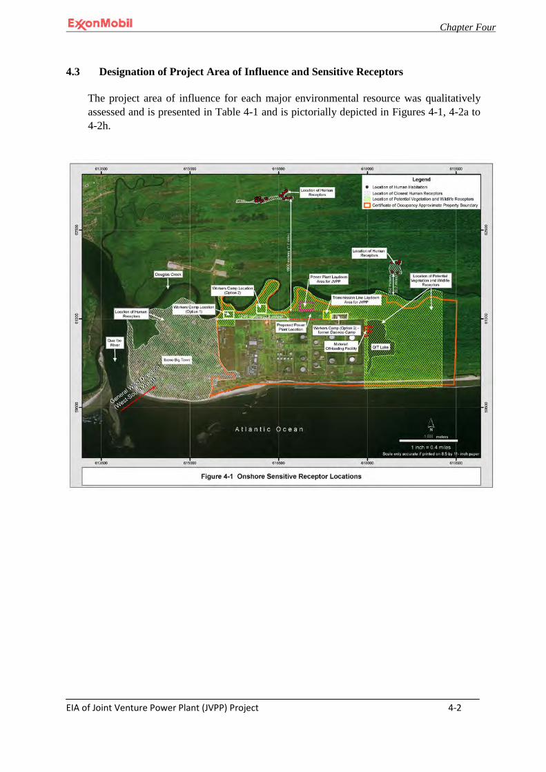
Chapter Four
EIA of Joint Venture Power Plant (JVPP) Project 4-2
4.3 Designation of Project Area of Influence and Sensitive Receptors
The project area of influence for each major environmental resource was qualitatively assessed and is presented in Table 4-1 and is pictorially depicted in Figures 4-1, 4-2a to 4-2h.
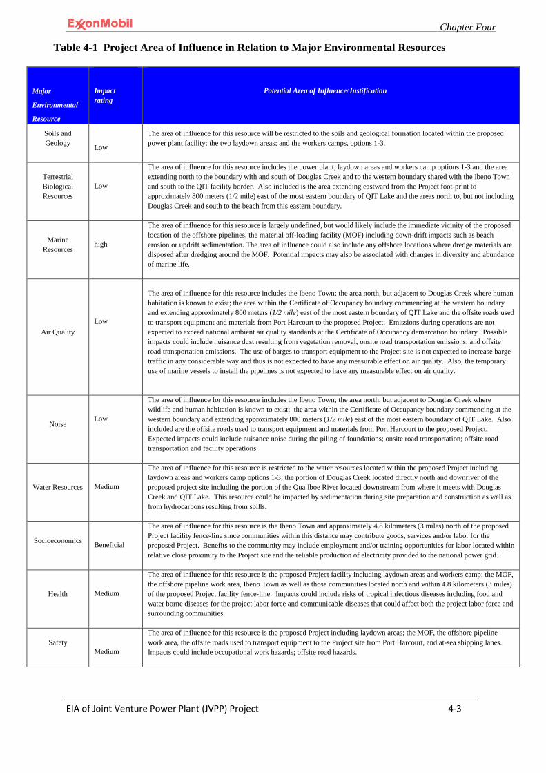
Chapter Four
EIA of Joint Venture Power Plant (JVPP) Project 4-3
Major
Environmental
Resource
Impact rating
Potential Area of Influence/Justification
Soils and Geology
Low
The area of influence for this resource will be restricted to the soils and geological formation located within the proposed power plant facility; the two laydown areas; and the workers camps, options 1-3.
Terrestrial Biological Resources
Low
The area of influence for this resource includes the power plant, laydown areas and workers camp options 1-3 and the area extending north to the boundary with and south of Douglas Creek and to the western boundary shared with the Ibeno Town and south to the QIT facility border. Also included is the area extending eastward from the Project foot-print to approximately 800 meters (1/2 mile) east of the most eastern boundary of QIT Lake and the areas north to, but not including Douglas Creek and south to the beach from this eastern boundary.
Marine Resources
high
The area of influence for this resource is largely undefined, but would likely include the immediate vicinity of the proposed location of the offshore pipelines, the material off-loading facility (MOF) including down-drift impacts such as beach erosion or updrift sedimentation. The area of influence could also include any offshore locations where dredge materials are disposed after dredging around the MOF. Potential impacts may also be associated with changes in diversity and abundance of marine life.
Air Quality
Low
The area of influence for this resource includes the Ibeno Town; the area north, but adjacent to Douglas Creek where human habitation is known to exist; the area within the Certificate of Occupancy boundary commencing at the western boundary and extending approximately 800 meters (1/2 mile) east of the most eastern boundary of QIT Lake and the offsite roads used to transport equipment and materials from Port Harcourt to the proposed Project. Emissions during operations are not expected to exceed national ambient air quality standards at the Certificate of Occupancy demarcation boundary. Possible impacts could include nuisance dust resulting from vegetation removal; onsite road transportation emissions; and offsite road transportation emissions. The use of barges to transport equipment to the Project site is not expected to increase barge traffic in any considerable way and thus is not expected to have any measurable effect on air quality. Also, the temporary use of marine vessels to install the pipelines is not expected to have any measurable effect on air quality.
Noise
Low
The area of influence for this resource includes the Ibeno Town; the area north, but adjacent to Douglas Creek where wildlife and human habitation is known to exist; the area within the Certificate of Occupancy boundary commencing at the western boundary and extending approximately 800 meters (1/2 mile) east of the most eastern boundary of QIT Lake. Also included are the offsite roads used to transport equipment and materials from Port Harcourt to the proposed Project. Expected impacts could include nuisance noise during the piling of foundations; onsite road transportation; offsite road transportation and facility operations.
Water Resources
Medium
The area of influence for this resource is restricted to the water resources located within the proposed Project including laydown areas and workers camp options 1-3; the portion of Douglas Creek located directly north and downriver of the proposed project site including the portion of the Qua Iboe River located downstream from where it meets with Douglas Creek and QIT Lake. This resource could be impacted by sedimentation during site preparation and construction as well as from hydrocarbons resulting from spills.
Socioeconomics
Beneficial
The area of influence for this resource is the Ibeno Town and approximately 4.8 kilometers (3 miles) north of the proposed Project facility fence-line since communities within this distance may contribute goods, services and/or labor for the proposed Project. Benefits to the community may include employment and/or training opportunities for labor located within relative close proximity to the Project site and the reliable production of electricity provided to the national power grid.
Health
Medium
The area of influence for this resource is the proposed Project facility including laydown areas and workers camp; the MOF, the offshore pipeline work area, Ibeno Town as well as those communities located north and within 4.8 kilometers (3 miles) of the proposed Project facility fence-line. Impacts could include risks of tropical infectious diseases including food and water borne diseases for the project labor force and communicable diseases that could affect both the project labor force and surrounding communities.
Safety
Medium
The area of influence for this resource is the proposed Project including laydown areas; the MOF, the offshore pipeline work area, the offsite roads used to transport equipment to the Project site from Port Harcourt, and at-sea shipping lanes. Impacts could include occupational work hazards; offsite road hazards.
Table 4-1 Project Area of Influence in Relation to Major Environmental Resources
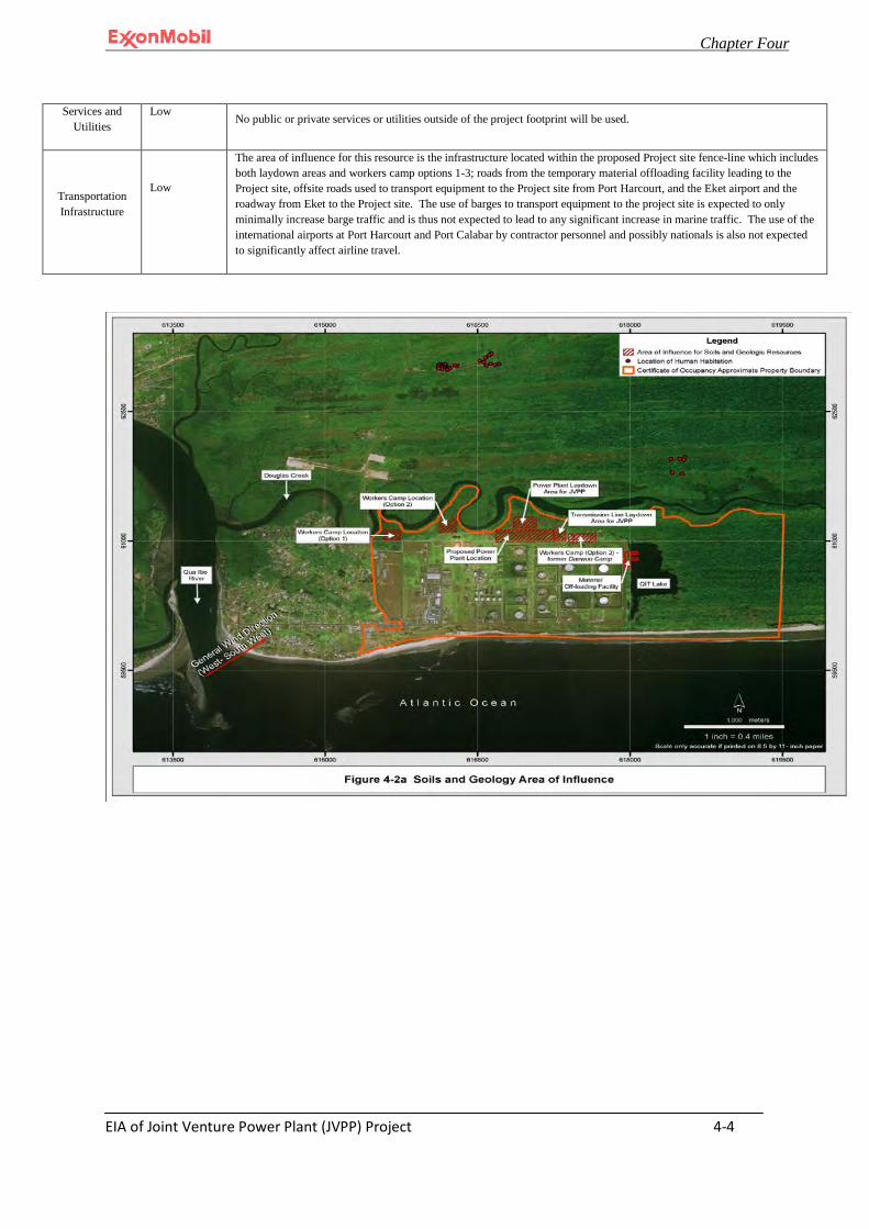
Chapter Four
EIA of Joint Venture Power Plant (JVPP) Project 4-4
Services and Utilities
Low No public or private services or utilities outside of the project footprint will be used.
Transportation Infrastructure
Low
The area of influence for this resource is the infrastructure located within the proposed Project site fence-line which includes both laydown areas and workers camp options 1-3; roads from the temporary material offloading facility leading to the Project site, offsite roads used to transport equipment to the Project site from Port Harcourt, and the Eket airport and the roadway from Eket to the Project site. The use of barges to transport equipment to the project site is expected to only minimally increase barge traffic and is thus not expected to lead to any significant increase in marine traffic. The use of the international airports at Port Harcourt and Port Calabar by contractor personnel and possibly nationals is also not expected to significantly affect airline travel.
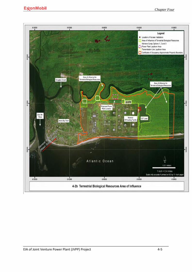
Chapter Four
EIA of Joint Venture Power Plant (JVPP) Project 4-5
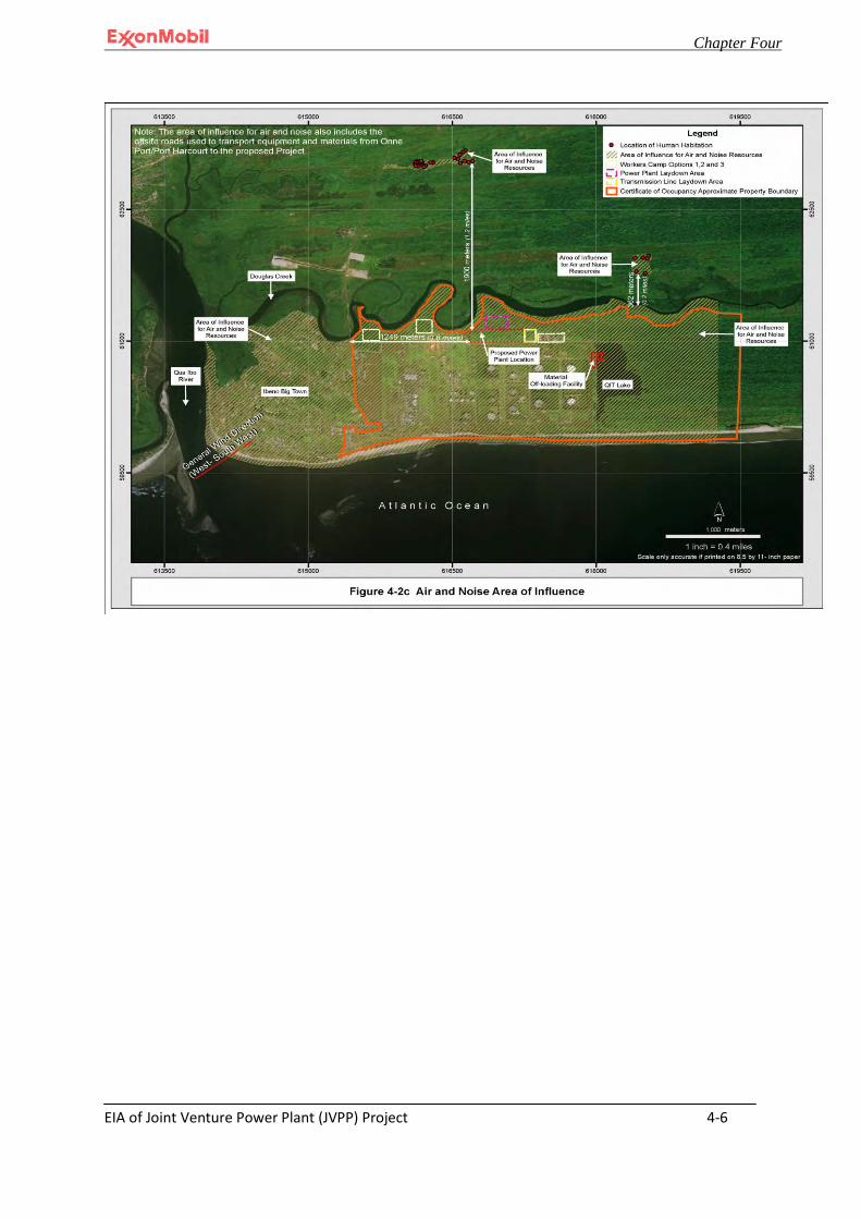
Chapter Four
EIA of Joint Venture Power Plant (JVPP) Project 4-6
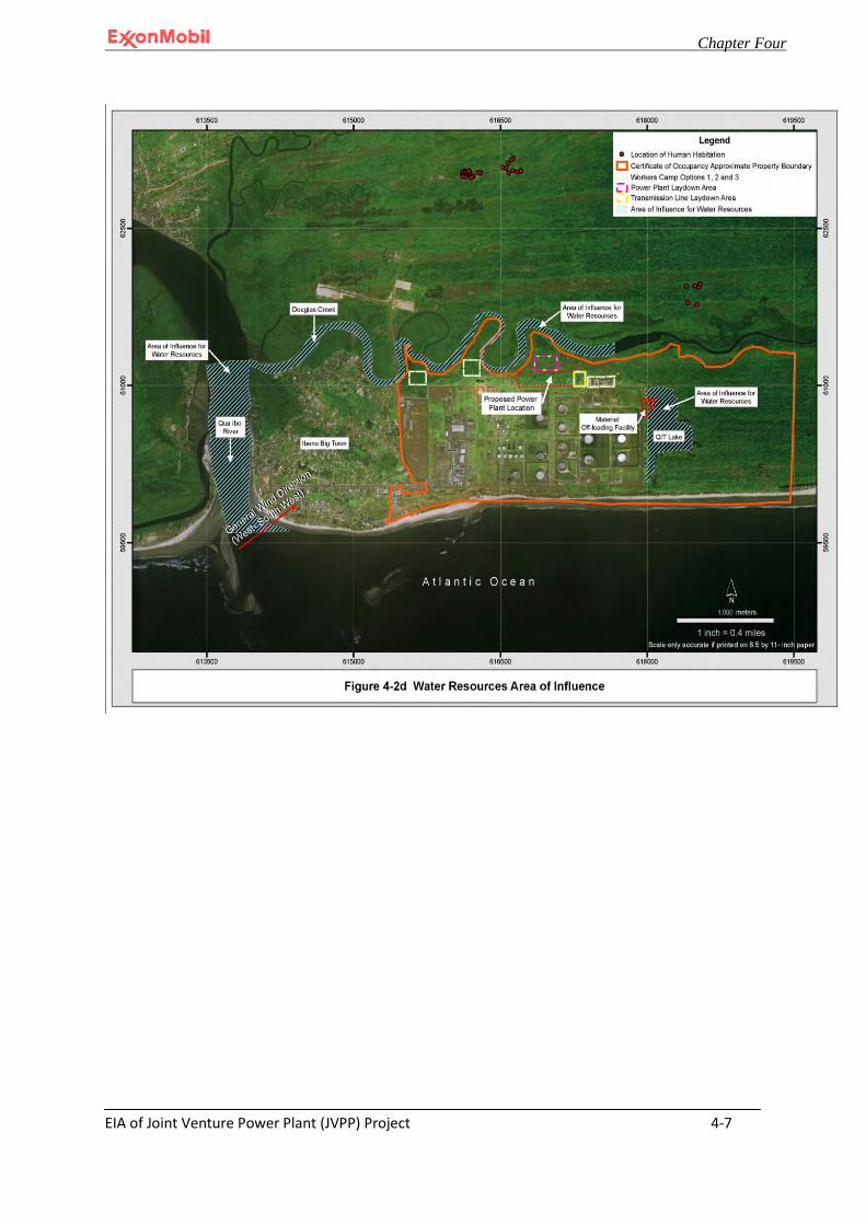
Chapter Four
EIA of Joint Venture Power Plant (JVPP) Project 4-7
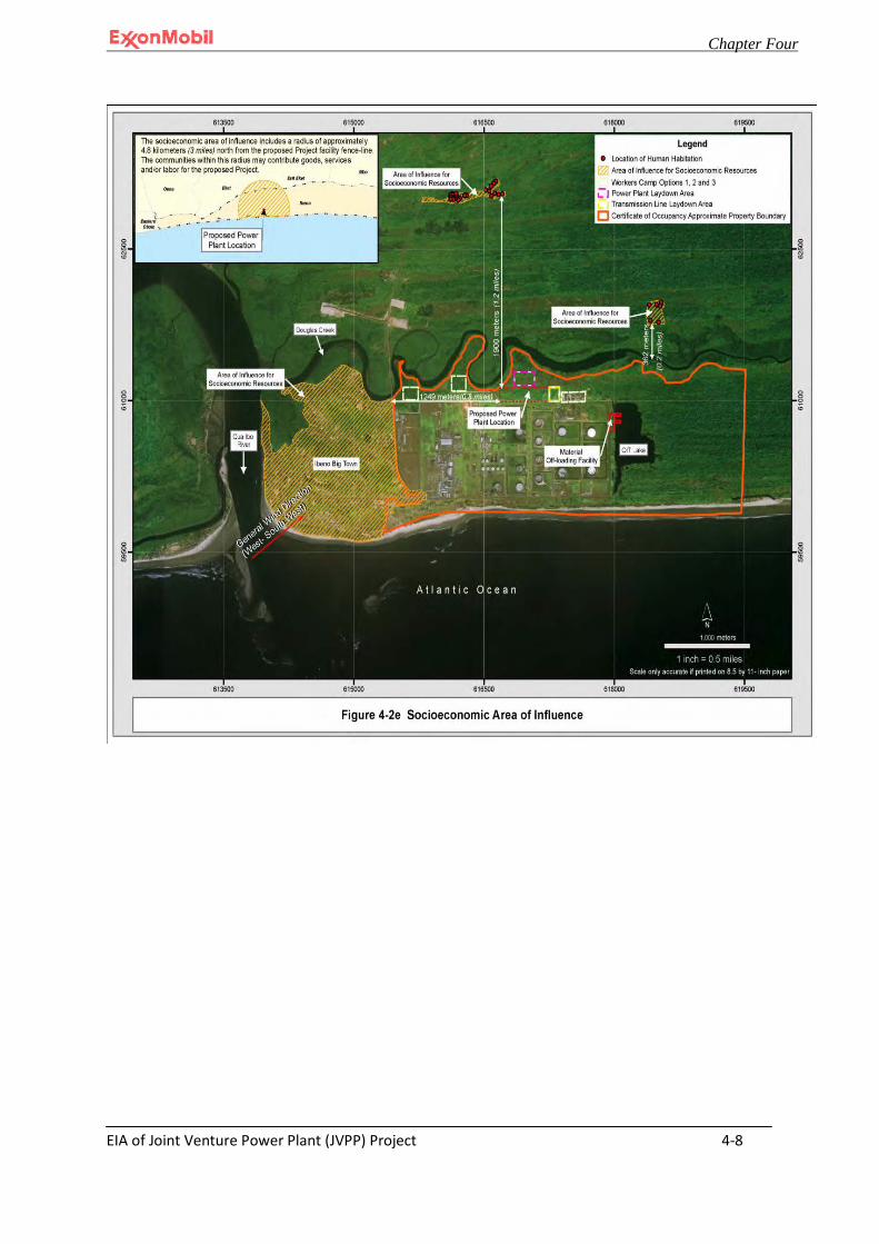
Chapter Four
EIA of Joint Venture Power Plant (JVPP) Project 4-8

Chapter Four
EIA of Joint Venture Power Plant (JVPP) Project 4-9
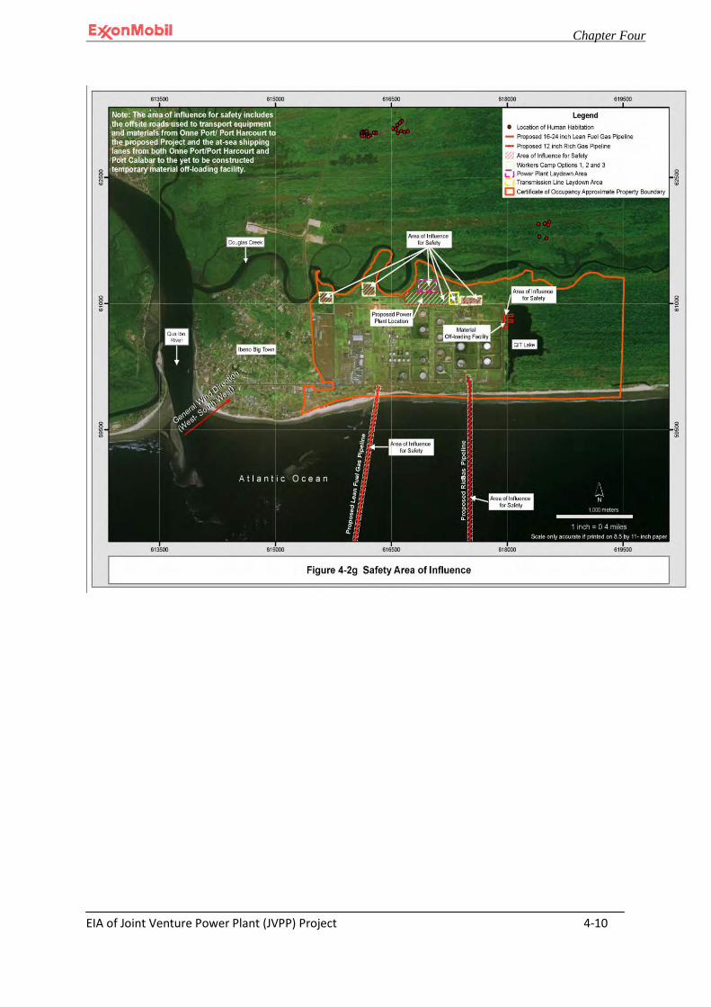
Chapter Four
EIA of Joint Venture Power Plant (JVPP) Project 4-10
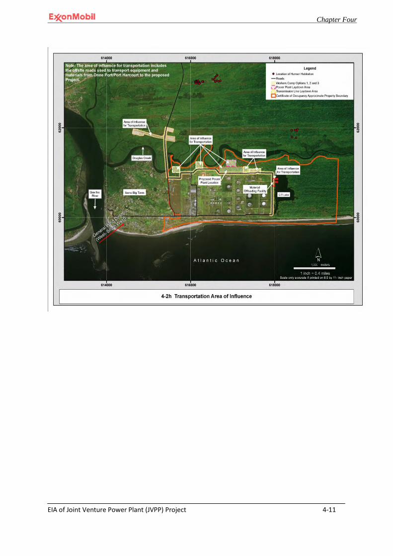
Chapter Four
EIA of Joint Venture Power Plant (JVPP) Project 4-11
Chapter Four
EIA of Joint Venture Power Plant (JVPP) Project 4-12
4.4 Physical Geography
4.4.1 Climate and Rainfall
The Project is located within latitude 04O 38.5' N and longitude 07O 52.2' E just north of the Equator in the humid tropics and within close proximity to the Atlantic Ocean (Figures 4-1 through 4-3). Based on the findings of the meteorological study and 15 years data of the area ranging from 1997 to 2011 (see appendix II), the climate can generally be described as tropical with high temperatures and abundant rainfall. The mean annual temperature in the project vicinity as recorded at QIT from 1997-2011 was 26.5°Celsius (C) or approximately 78° Fahrenheit with a range differential of less than 1°C. The area is characterized by essentially two seasons, a long rainy season followed by a dusty, dry season. The rainy season begins in March and lasts up till late September with a peak period in June. During most of the rainy season cloud cover is nearly continuous resulting in the area receiving approximately 1,500 hours of sunshine per year. The average annual rainfall in the project vicinity per QIT records from 1997-2011 ranged from 6,355 millimeters (mm) to 6,695 mm with an average of 4,564 mm or 180 inches. The dry season begins in late October and last to early March with peak conditions experienced in early December through February. However, even during the dry season an average monthly rainfall of 185 mm was recorded at QIT from 1997-2011. Relative humidity as recorded at QIT from 1997-2011 ranged from 71-91% with the maximum recorded in August and September and the minimum recorded in February. Evaporation in the area is typically high with annual values ranging from 1,500 mm to 1,800 mm. Appendix II-1 to this EIA presents the meteorological data recorded at MPN’s QIT facility that is referenced in this section.
4.4.2 Relief/Topography
The Project vicinity is characterized by alluvium-estuarine, sediments, fluvial deposits and deltaic deposits of tidal rivers and creeks. Typical examples are the Douglas creek and Stubbs creek (see Figure 4-2d). The relief of the proposed Project location is primarily flat with a slope gradient of 0-2%. The site will require fill material following grub and clear activities to achieve a finished grade with a high point elevation (El.) of approximately + 3.50 meters (+11.5 feet) and a low point El. +3 meters (+10 feet). Note that the minimum elevation shall not be less than QIT elevation which is estimated to be +3 meters. All elevations are measured relative to Mean Sea Level (MSL). Ground water elevation varies seasonally, but is typically considered to be at grade for design purposes.
Chapter Four
EIA of Joint Venture Power Plant (JVPP) Project 4-13
4.4.3 Regional Geology
The proposed Project will be within the Niger Delta which is located at the southern end of Nigeria. This area encompasses the lower Qua Iboe River Basin, cross river and Imo river basins. The tertiary Niger Delta petroleum system has been identified in this region. The stratigraphy of this tertiary system is divided into three diachronous units of the Eocene to the recent age that form a major regressive cycle. These three units are described more fully below (QIT Upgrade EIA, 2003).
4.4.3.1 The Benin Formation
The Benin Formation is the uppermost formation in the region. It represents the coastal and delta top-sands and gravels which are poorly sorted and often cross bedded with clay/shale beds. The thickness is variable, but has an upper limit of approximately 2000 meters (Wright et al, 1985).
4.4.3.2 The Agbada Formation
The Agbada Formation underlies the Benin Formation. It represents the immediate off-shore and continental-shelf environment. Its thickness ranges from a few hundred meters to over 4000 meters.
The Agbada Formation is the major hydrocarbon bearing unit in the Niger Delta. Petroleum is produced from sandstone and unconsolidated sands predominantly in the Agbada Formation. Characteristics of the reservoirs in the Agbada Formation are controlled by the depositional environment and depth of burial. Deposition of the Agbada Formation began in the Eocene Epoch (Palaeogene Period, Cenozoic era). The formation consists of paralic siliciclastics over 3700 meters thick and represents the actual deltaic portion of the sequence. The clastics accumulated in delta-front, delta-topset, and fluvio-deltaic environments. In the lower Agbada Formation, shale and sandstone beds were deposited in equal proportions, however, the upper portion is mostly sand with only minor shale interbeds (Wright et al. 1985).
4.4.3.3 The Akata Formation
The Akata Formation consists of thick shale sequences, turbidite sands and minor amounts of clay and silt. It is between 600 and 6000 meters thick.
The primary source rock of the Akata Formation is the marine-shale facies of the delta. The turbidite sand in the upper Akata Formation is also a potential target in deep water offshore and possibly beneath currently producing intervals onshore (Wright et al, 1985).
Chapter Four
EIA of Joint Venture Power Plant (JVPP) Project 4-14
4.4.4 Aggregate Resources
To meet Project requirements, sand, coarse aggregate and cement will be required to produce the concrete required for the Project (see Table 3-4 for quantities). The aggregate and cement used in the concrete will be obtained from a variety of sources, but preferentially will come from local sources if the materials are available and can meet the design specifications. Ongoing studies are currently being conducted to determine which sources have the raw materials to meet design quality specifications for the Project and how much is available. All aggregate will be obtained from established sources.
4.4.5 Natural Events
4.5 Seismicity
The tectonic setting of the continental shelf offshore of the Gulf of Guinea, West Africa is characterized geologically as a passive continental margin. This passive margin setting, which extends along the western length of the African continent, is attributed to initial continental separation of South America from Africa and subsequent opening of the Atlantic Ocean. The major tectonic features in the vicinity of Nigeria are the Benue Trough and Romanche Fracture Zone that extends through Ghana. The Benue Trough is believed to be a failed arm of the rifting event that opened the Atlantic Ocean. Presently, the Benue Trough is an area of seismicity and young volcanic activity that is closely associated with the Cameroon Volcanic Line. The Cameroon Line and Benue Trough are the near-shore and on-land extensions of the Ascension Fracture Zone that parallels the Romanche Fracture Zone to the south. (ABS Consulting 2005).
Seismicity in the region of Nigeria is sparsely distributed as is typical for passive continental margins. Nonetheless, the Benue Trough has one of the highest rates of seismicity in West Africa. Historical accounts of earthquakes in the vicinity of the Niger Delta area include earthquakes in 1636, 1862, 1906, and 1939 in the Accra, Ghana area. A magnitude 6.5 earthquake in 1862 almost completely destroyed Accra and the coastal region of Ghana and Togo (EQE 2001).
The primary tectonic feature west of Nigeria is the Romanche Fracture Zone offshore of southern Ghana. Although the Niger Delta lies between these two active trends, this particular area has experienced very little earthquake activity historically (ABS Consulting 2005). The probabilistic seismic hazard analysis conducted by ABS Consulting on behalf of the Project, indicated that ground rupture is unlikely to occur at the proposed Project site. In terms of ground shaking, the seismic ground acceleration at bedrock level is about 2% of gravity or less, based on the analysis on the proposed Project site by the same consulting firm. Nonetheless, seismic design

Chapter Four
EIA of Joint Venture Power Plant (JVPP) Project 4-15
and construction will be conducted for all structures in accordance with the International Building Code.
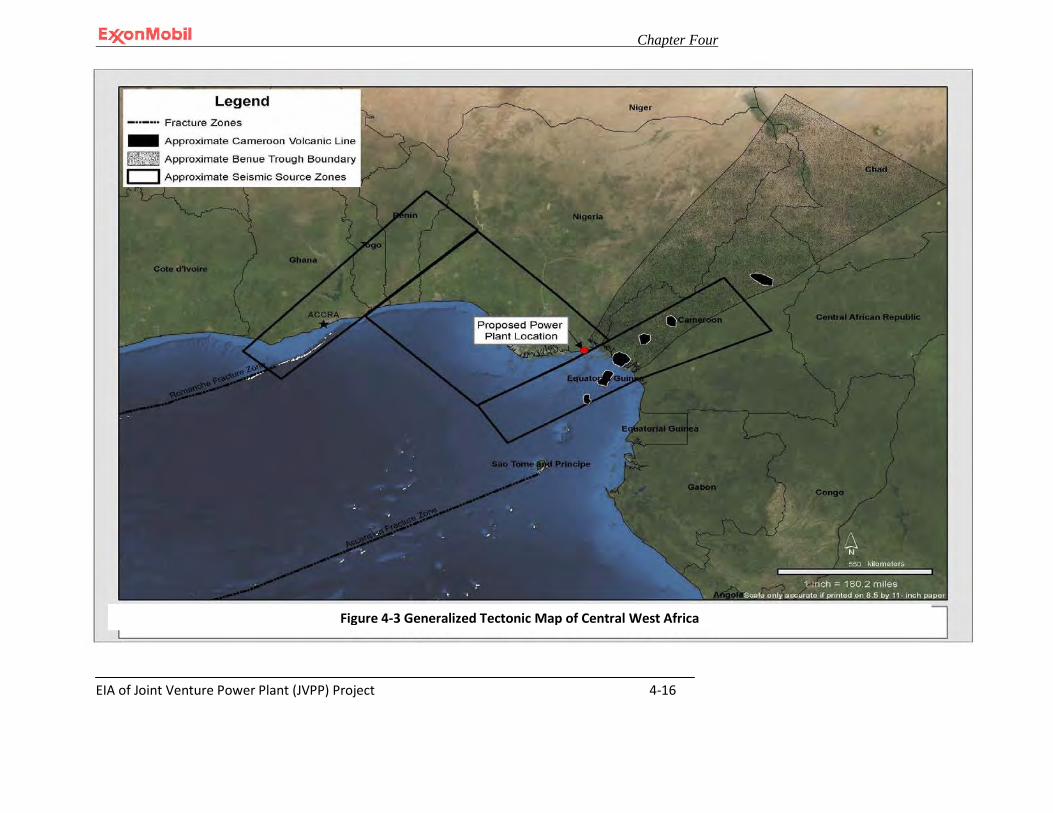
Chapter Four
EIA of Joint Venture Power Plant (JVPP) Project 4-16
Figure 4-3 Generalized Tectonic Map of Central West Africa
Chapter Four
EIA of Joint Venture Power Plant (JVPP) Project 4-17
Secondary effects associated with a relatively large earthquake on a regional fault can include ground lurching, soil liquefaction and dynamic settlement, and tsunamis. These secondary effects are discussed more fully below.
Ground or soil lurching refers to the rolling motion of the ground surface produced by the passage of seismic surface waves. Effects of this nature are generally significant near the edge of alluvial valleys or shores where the thickness of soft sediments vary appreciably under structures. There are no significant soft sediment deposits at the proposed Project site.
Liquefaction and dynamic settlement of soils can be caused by strong vibratory motion due to earthquakes. Both research and historical data indicate that clean loose, saturated, granular soils are susceptible to liquefaction and dynamic settlement while the stability of silty clays and clays is not adversely affected by vibratory motion. Liquefaction is typified by a loss of shear strength in the affected soil layer, thereby causing the soil to flow as a liquid. Excessive settlements and sand boils at the ground surface may manifest this effect. The predominant types of soils that have been reported for the proposed Project site, medium dense to very dense fine to medium sands to a depth of 8.23m (27-feet) below existing grade followed by approximately 4.57m (15-feet) of soft to firm, but mostly firm clays to silty clays, are not typically prone to liquefaction.
A tsunami is a sea wave generated by a submarine earthquake, landslide, or volcanic activity that displaces a relatively large volume of water in a very short period of time. The Pacific Ocean is by far the most active zone for tsunami generation, although tsunamis have been generated in many other bodies of water including the Caribbean and Mediterranean seas, and Indian and Atlantic oceans. The United States National Oceanic and Atmospheric Administration (NOAA) catalog of tsunamis (2003) indicates that there were no known tsunamis generated in the Atlantic Ocean for the period from 1982 to 2001. No more current information is available in regards to this issue. Based on this information and the fact that a tsunami is less likely to be produced by low magnitude earthquakes, the risk of tsunami occurrence is considered to be negligible for the proposed Project area.
4.5.1 Floods, Fires, and Storms
Natural hazards that occur within the Project area of influence site include flash floods, lightning, and thunderstorms during extreme rainfall events. Additionally, severe windstorms occasionally occur.

Chapter Four
EIA of Joint Venture Power Plant (JVPP) Project 4-18
4.6 Soils
4.6.1 Soil Texture Profile
Several geotechnical investigations have been conducted in the past within the Certificate of Occupancy land tract boundary. Data acquired from the soil study carried out by the sampling and from previous investigations on the area indicate that the stratigraphy of the soils generally consists of very loose/soft organic materials from grade to about 1.52m (5 feet). Below the top soil, medium to very dense silty fine to medium sands occur to about 5.49m (18ft) to 8.23m (27ft). This stratum is followed by approximately 3.05m (10ft) to 4.57m (15ft) of soft silty clays to clays or firm sandy to very sandy clay or clayey silt which are underlain by dense to very dense silty fine to medium sands to depths of 20.12m (66 feet).(Appendix II-83).
4.6.2 Soil Sampling
Soil baseline characterization study was conducted during the wet season from 1st-4th
September 2008 and during the dry season from 17-20 March 2009. Soil samples shown in (Appendix II-83) were collected at depths ranging from 0-15cm (0-5.9 inches) below grade and at depths ranging from 15-30cm (5.9 – 11.8) inches below grade. Soil samples 3 through 5 and 9 through 13 reside outside the Project area of influence as defined in (Figure 4-4). The composite soil samples collected within the proposed Project area of influence were each analyzed for various physical and chemical properties including metals, mineral and nutrient content, organic matter and microbiological properties. The results of these analyses are discussed in the subsequent sections below. Analytical results are presented in Appendix II to this EIA.
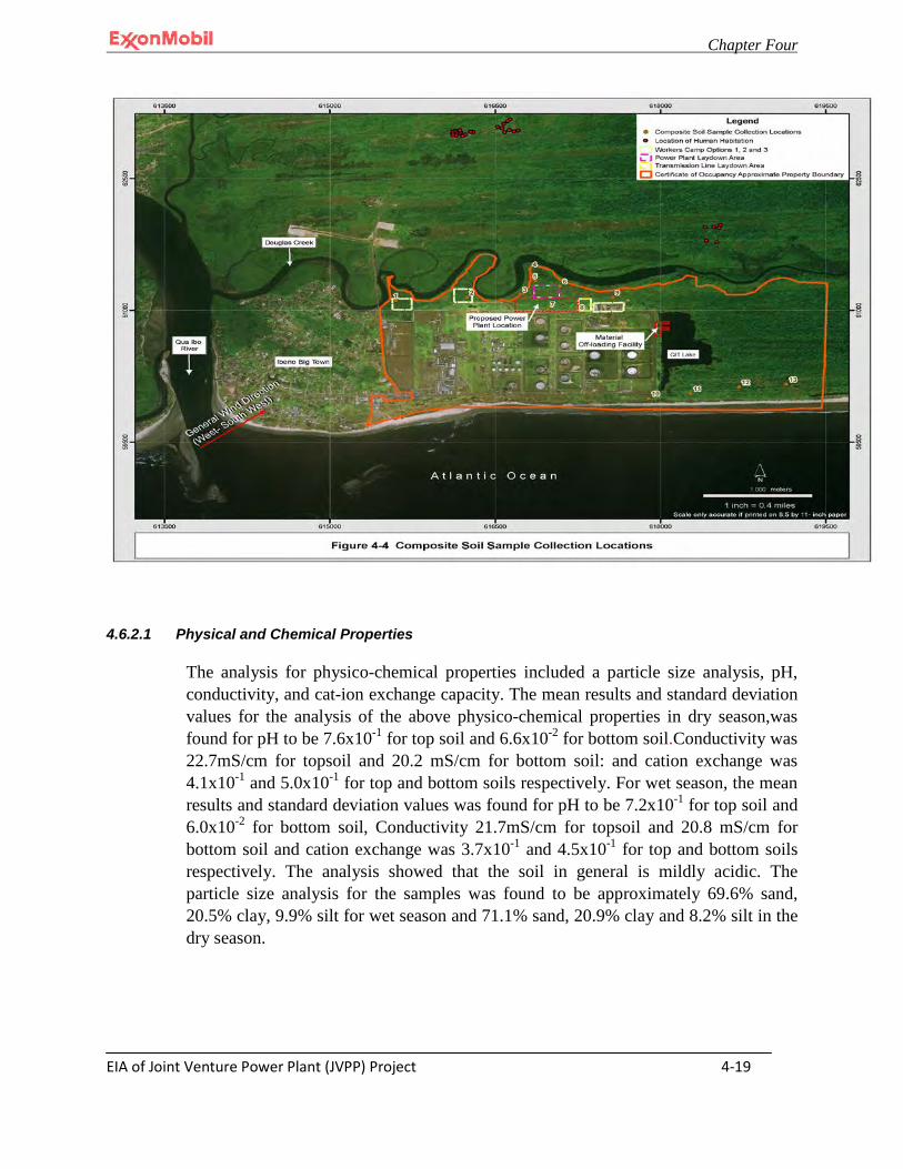
Chapter Four
EIA of Joint Venture Power Plant (JVPP) Project 4-19
4.6.2.1 Physical and Chemical Properties
The analysis for physico-chemical properties included a particle size analysis, pH, conductivity, and cat-ion exchange capacity. The mean results and standard deviation values for the analysis of the above physico-chemical properties in dry season,was found for pH to be 7.6x10⁻¹ for top soil and 6.6x10⁻² for bottom soil.Conductivity was 22.7mS/cm for topsoil and 20.2 mS/cm for bottom soil: and cation exchange was 4.1x10⁻¹ and 5.0x10⁻¹ for top and bottom soils respectively. For wet season, the mean results and standard deviation values was found for pH to be 7.2x10⁻¹ for top soil and 6.0x10⁻² for bottom soil, Conductivity 21.7mS/cm for topsoil and 20.8 mS/cm for bottom soil and cation exchange was 3.7x10⁻¹ and 4.5x10⁻¹ for top and bottom soils respectively. The analysis showed that the soil in general is mildly acidic. The particle size analysis for the samples was found to be approximately 69.6% sand, 20.5% clay, 9.9% silt for wet season and 71.1% sand, 20.9% clay and 8.2% silt in the dry season.
Chapter Four
EIA of Joint Venture Power Plant (JVPP) Project 4-20
4.6.2.2 Metals and Mineral Content
The composite soil samples were analyzed for heavy metals such as lead, iron, manganese, copper, zinc, nickel, vanadium, chromium, barium, mercury, arsenic, silver, cobalt and cadmium as well as minerals such as phosphorus, calcium, magnesium, sodium and potassium.
The results for heavy metal concentration had a lower limit of <0.001 mg/kg and an upper limit of 96.81 mg/kg for topsoil in dry season .For bottom soil, a lower limit of <0.001mg/kg and an upper limit of 98.321mg/kg was recorded. In wet season, a lower limit of <0.01 mg/kg and an upper limit of 132.650 mg/kg was recorded for topsoil while a lower limit of <0.01mg/kg and an upper limit of 145.600mg/kg was recorded for subsoil. The detailed results are located in Appendix II-129 to this EIA.
4.6.2.3 Organic Matter Various analyses were conducted to assess different hydrocarbon fractions present in the samples. One of the most significant measurements conducted was for poly-aromatic hydrocarbon (PAH) content. The PAH content for all samples was found to be below the detection limit.
There will be a 12,000-gallon diesel storage tank on-site during operations and mobile diesel powered vehicles present during construction operations. Knowing the baseline condition for PAH (i.e., below detection limit) will enable the Project to use it as an indicator parameter to assess the presence or absence of residual diesel in the unlikely event of a spill.
4.6.2.4 Microbiological Properties – Bacteria and Fungi
The soil samples were analyzed for microbiological parameters and ranges recorded for both topsoil and subsoil respectively in both wet and dry season: total heterotrophic bacteria, hydrocarbon utilizing bacteria, total heterotrophic fungi, hydrocarbon utilizing fungi and coliform. (see Appendix II-90). The upper limit for the total coliform bacteria measured for topsoil was 2300 cfu per gram and 2000 cfu per gram for subsoil .The lower limits for top and sub soil were found to be 100 cfu per gram and 0 cfu per gram respectively, during the dry season. However for wet season, the upper limit for the total coliform bacteria measured for topsoil was 3500 cfu per gram and 3800 cfu per gram for subsoil .The lower limits for top and sub soil were found to be 200 cfu per gram and 400 cfu per gram respectively.
Chapter Four
EIA of Joint Venture Power Plant (JVPP) Project 4-21
4.7 Terrestrial Biological Resources
4.7.1 Project Setting
The onshore portion of the proposed Project will be located within the QIT certificate of occupancy land tract boundary. Stubbs Creek Forest Reserve covers approximately 310 km2 and was established in 1931 under Order 45 and subsequently amended in 1941, 1955 and 1962. The Reserve is considered to be one of the last significant tracts of forest in the region, though intact forest is estimated to cover only 80 km2 in the center of the Reserve (Baker 2005). The Reserve is managed by the Akwa Ibom State government in accordance with Order 45.

Chapter Four
EIA of Joint Venture Power Plant (JVPP) Project 4-22
Figure 4-5 Proposed Project Location Within the Stubbs Creek Forest Reserve
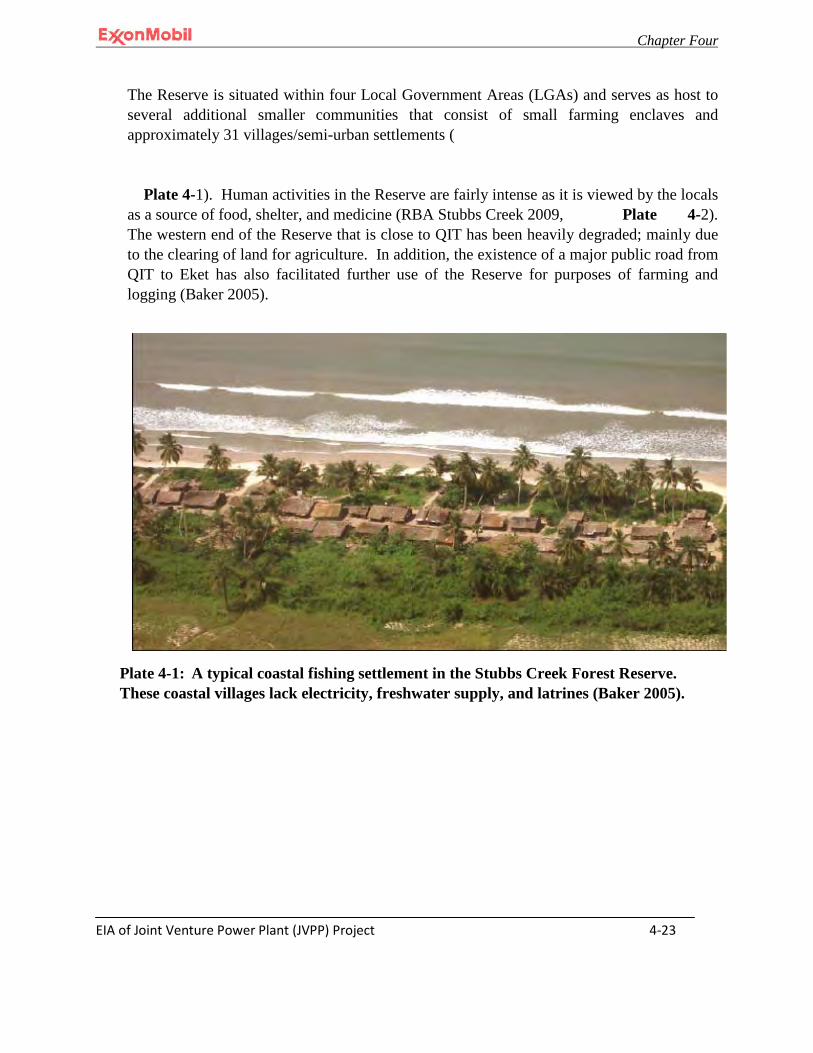
Chapter Four
EIA of Joint Venture Power Plant (JVPP) Project 4-23
The Reserve is situated within four Local Government Areas (LGAs) and serves as host to several additional smaller communities that consist of small farming enclaves and approximately 31 villages/semi-urban settlements ( Plate 4-1). Human activities in the Reserve are fairly intense as it is viewed by the locals as a source of food, shelter, and medicine (RBA Stubbs Creek 2009, Plate 4-2). The western end of the Reserve that is close to QIT has been heavily degraded; mainly due to the clearing of land for agriculture. In addition, the existence of a major public road from QIT to Eket has also facilitated further use of the Reserve for purposes of farming and logging (Baker 2005).
Plate 4-1: A typical coastal fishing settlement in the Stubbs Creek Forest Reserve.
These coastal villages lack electricity, freshwater supply, and latrines (Baker 2005).
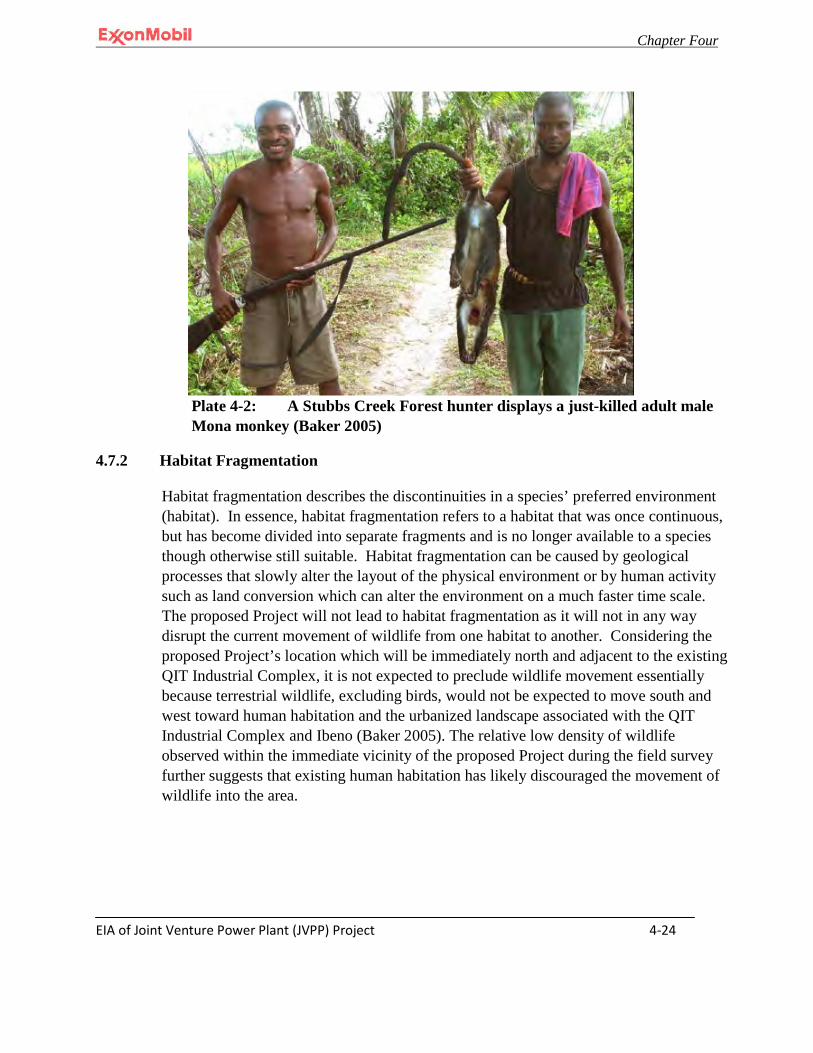
Chapter Four
EIA of Joint Venture Power Plant (JVPP) Project 4-24
Plate 4-2: A Stubbs Creek Forest hunter displays a just-killed adult male Mona monkey (Baker 2005)
4.7.2 Habitat Fragmentation
Habitat fragmentation describes the discontinuities in a species’ preferred environment (habitat). In essence, habitat fragmentation refers to a habitat that was once continuous, but has become divided into separate fragments and is no longer available to a species though otherwise still suitable. Habitat fragmentation can be caused by geological processes that slowly alter the layout of the physical environment or by human activity such as land conversion which can alter the environment on a much faster time scale. The proposed Project will not lead to habitat fragmentation as it will not in any way disrupt the current movement of wildlife from one habitat to another. Considering the proposed Project’s location which will be immediately north and adjacent to the existing QIT Industrial Complex, it is not expected to preclude wildlife movement essentially because terrestrial wildlife, excluding birds, would not be expected to move south and west toward human habitation and the urbanized landscape associated with the QIT Industrial Complex and Ibeno (Baker 2005). The relative low density of wildlife observed within the immediate vicinity of the proposed Project during the field survey further suggests that existing human habitation has likely discouraged the movement of wildlife into the area.
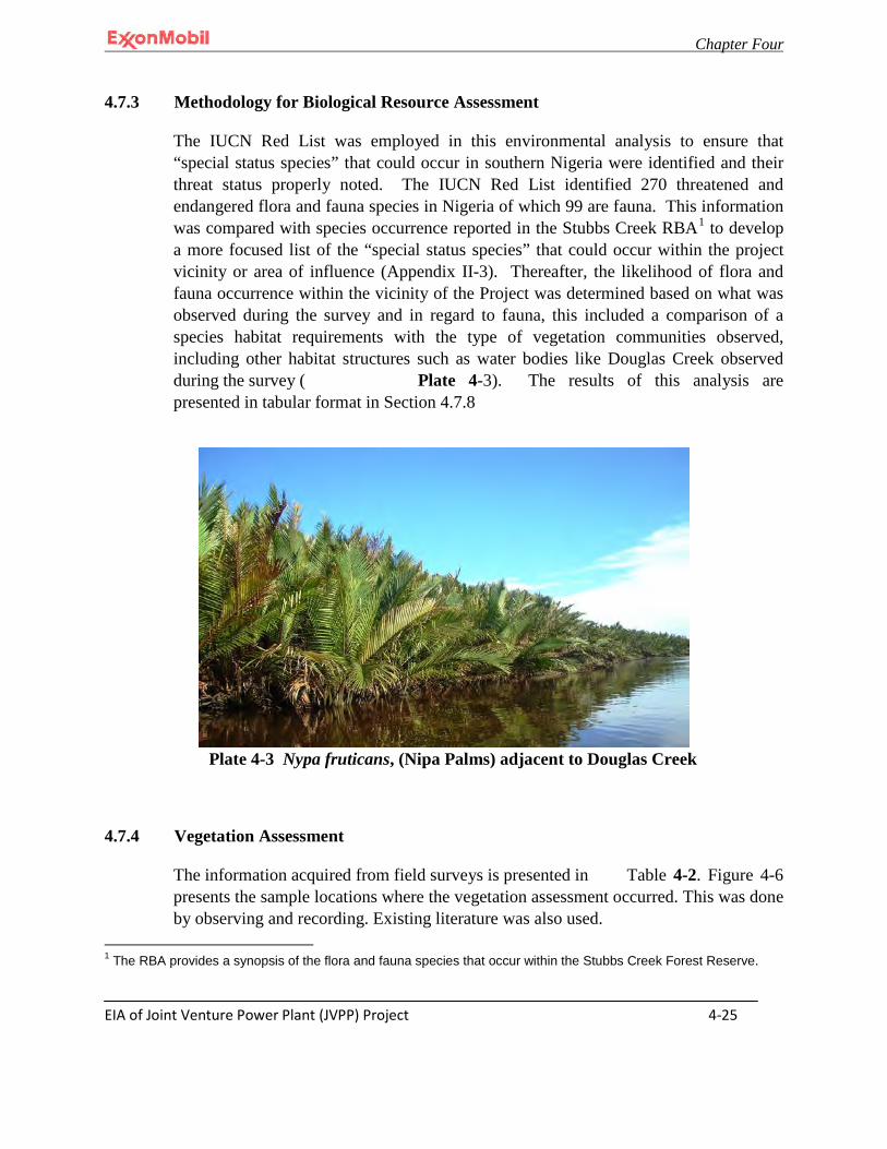
Chapter Four
EIA of Joint Venture Power Plant (JVPP) Project 4-25
4.7.3 Methodology for Biological Resource Assessment
The IUCN Red List was employed in this environmental analysis to ensure that “special status species” that could occur in southern Nigeria were identified and their threat status properly noted. The IUCN Red List identified 270 threatened and endangered flora and fauna species in Nigeria of which 99 are fauna. This information was compared with species occurrence reported in the Stubbs Creek RBA1 to develop a more focused list of the “special status species” that could occur within the project vicinity or area of influence (Appendix II-3). Thereafter, the likelihood of flora and fauna occurrence within the vicinity of the Project was determined based on what was observed during the survey and in regard to fauna, this included a comparison of a species habitat requirements with the type of vegetation communities observed, including other habitat structures such as water bodies like Douglas Creek observed during the survey ( Plate 4-3). The results of this analysis are presented in tabular format in Section 4.7.8
Plate 4-3 Nypa fruticans, (Nipa Palms) adjacent to Douglas Creek
4.7.4 Vegetation Assessment
The information acquired from field surveys is presented in Table 4-2. Figure 4-6 presents the sample locations where the vegetation assessment occurred. This was done by observing and recording. Existing literature was also used.
1 The RBA provides a synopsis of the flora and fauna species that occur within the Stubbs Creek Forest Reserve.
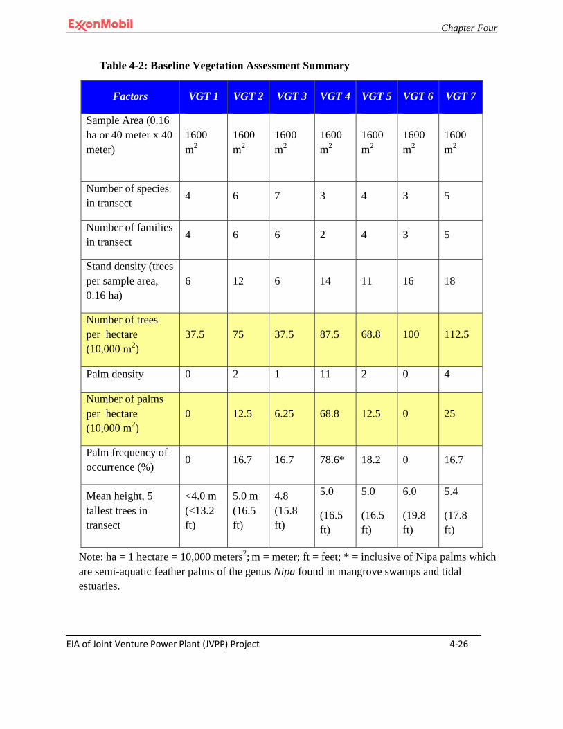
Chapter Four
EIA of Joint Venture Power Plant (JVPP) Project 4-26
Table 4-2: Baseline Vegetation Assessment Summary
Factors VGT 1 VGT 2 VGT 3 VGT 4 VGT 5 VGT 6 VGT 7
Sample Area (0.16 ha or 40 meter x 40 meter)
1600 m2
1600 m2
1600 m2
1600 m2
1600 m2
1600 m2
1600 m2
Number of species in transect
4 6 7 3 4 3 5
Number of families in transect
4 6 6 2 4 3 5
Stand density (trees per sample area, 0.16 ha)
6 12 6 14 11 16 18
Number of trees per hectare (10,000 m2)
37.5 75 37.5 87.5 68.8 100 112.5
Palm density 0 2 1 11 2 0 4
Number of palms per hectare (10,000 m2)
0 12.5 6.25 68.8 12.5 0 25
Palm frequency of occurrence (%)
0 16.7 16.7 78.6* 18.2 0 16.7
Mean height, 5 tallest trees in transect
<4.0 m (<13.2 ft)
5.0 m (16.5 ft)
4.8 (15.8 ft)
5.0
(16.5 ft)
5.0
(16.5 ft)
6.0
(19.8 ft)
5.4
(17.8 ft)
Note: ha = 1 hectare = 10,000 meters2; m = meter; ft = feet; * = inclusive of Nipa palms which are semi-aquatic feather palms of the genus Nipa found in mangrove swamps and tidal estuaries.
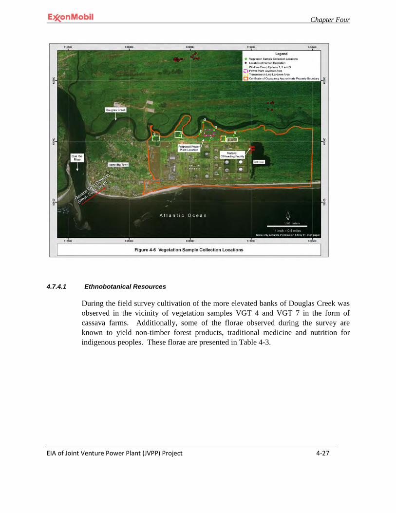
Chapter Four
EIA of Joint Venture Power Plant (JVPP) Project 4-27
4.7.4.1 Ethnobotanical Resources
During the field survey cultivation of the more elevated banks of Douglas Creek was observed in the vicinity of vegetation samples VGT 4 and VGT 7 in the form of cassava farms. Additionally, some of the florae observed during the survey are known to yield non-timber forest products, traditional medicine and nutrition for indigenous peoples. These florae are presented in Table 4-3.
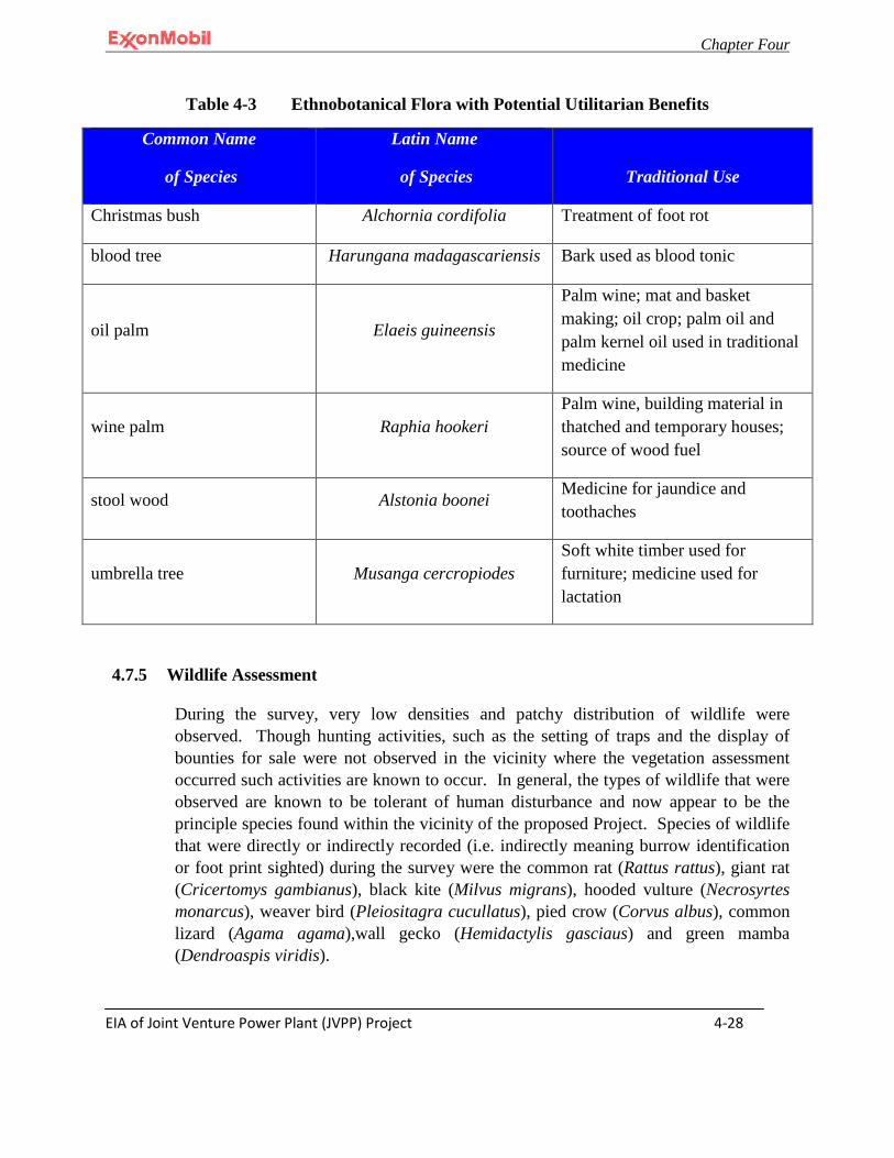
Chapter Four
EIA of Joint Venture Power Plant (JVPP) Project 4-28
Table 4-3 Ethnobotanical Flora with Potential Utilitarian Benefits
Common Name
of Species
Latin Name
of Species Traditional Use
Christmas bush Alchornia cordifolia Treatment of foot rot
blood tree Harungana madagascariensis Bark used as blood tonic
oil palm Elaeis guineensis
Palm wine; mat and basket making; oil crop; palm oil and palm kernel oil used in traditional medicine
wine palm Raphia hookeri Palm wine, building material in thatched and temporary houses; source of wood fuel
stool wood Alstonia boonei Medicine for jaundice and toothaches
umbrella tree Musanga cercropiodes Soft white timber used for furniture; medicine used for lactation
4.7.5 Wildlife Assessment
During the survey, very low densities and patchy distribution of wildlife were observed. Though hunting activities, such as the setting of traps and the display of bounties for sale were not observed in the vicinity where the vegetation assessment occurred such activities are known to occur. In general, the types of wildlife that were observed are known to be tolerant of human disturbance and now appear to be the principle species found within the vicinity of the proposed Project. Species of wildlife that were directly or indirectly recorded (i.e. indirectly meaning burrow identification or foot print sighted) during the survey were the common rat (Rattus rattus), giant rat (Cricertomys gambianus), black kite (Milvus migrans), hooded vulture (Necrosyrtes monarcus), weaver bird (Pleiositagra cucullatus), pied crow (Corvus albus), common lizard (Agama agama),wall gecko (Hemidactylis gasciaus) and green mamba (Dendroaspis viridis).
Chapter Four
EIA of Joint Venture Power Plant (JVPP) Project 4-29
4.7.6 Wetlands and Riparian Corridors
There are no wetlands or riparian corridors on the proposed Project facility footprint. However, the area of influence includes QIT Lake and the adjacent reach of Douglas Creek.
4.7.7 Rare, Vulnerable or Endangered Species
Table 4-4 presents a list of “special status species” and their corresponding likelihood of occurrence within the vicinity of the proposed Project based on the analysis procedure described in Section 4.6.3. Special status species, for the purposes of this assessment, are considered to be species with a status of Near Threatened or greater according to the IUCN. This assessment of likelihood of occurrence is presented in terms of the probability of occurrence (see definitions below).
• Known to Occur – species has been observed or documented within or immediately
adjacent to the proposed Project site. • High Potential – species has not been documented within or immediately adjacent to
the proposed Project site, but should be expected on more than 50% of visits to suitable habitat at or near the project site during the appropriate season and time of day.
• Moderate Potential – species has not been documented within or immediately adjacent to the proposed Project site, but should be expected on less than 50% of visits to suitable habitat at or near the proposed Project site during the appropriate season and time of day.
• Low Potential – species has not been documented within or immediately adjacent to the proposed Project site nor is it likely to occur on the proposed Project site, but its presence cannot be completely discounted due to incomplete information on the taxon’s distribution or habitat requirements.
• No Potential – species does not occur within the proposed Project site due to the lack of required habitat features for the species or the known range of the species is well defined and does not include the project site.
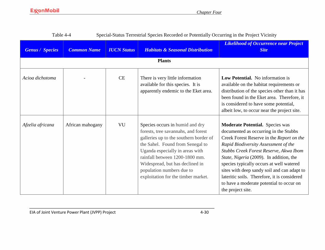
Chapter Four
EIA of Joint Venture Power Plant (JVPP) Project 4-30
Table 4-4 Special-Status Terrestrial Species Recorded or Potentially Occurring in the Project Vicinity
Genus / Species Common Name IUCN Status Habitats & Seasonal Distribution Likelihood of Occurrence near Project
Site
Plants
Acioa dichotoma
-
CE
There is very little information available for this species. It is apparently endemic to the Eket area.
Low Potential. No information is available on the habitat requirements or distribution of the species other than it has been found in the Eket area. Therefore, it is considered to have some potential, albeit low, to occur near the project site.
Afzelia africana
African mahogany
VU
Species occurs in humid and dry forests, tree savannahs, and forest galleries up to the southern border of the Sahel. Found from Senegal to Uganda especially in areas with rainfall between 1200-1800 mm. Widespread, but has declined in population numbers due to exploitation for the timber market.
Moderate Potential. Species was documented as occurring in the Stubbs Creek Forest Reserve in the Report on the Rapid Biodiversity Assessment of the Stubbs Creek Forest Reserve, Akwa Ibom State, Nigeria (2009). In addition, the species typically occurs at well watered sites with deep sandy soil and can adapt to lateritic soils. Therefore, it is considered to have a moderate potential to occur on the project site.
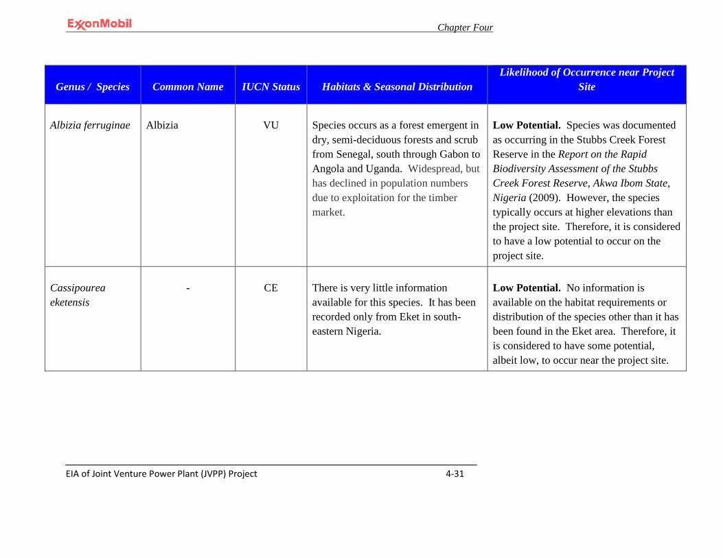
Chapter Four
EIA of Joint Venture Power Plant (JVPP) Project 4-31
Genus / Species Common Name IUCN Status Habitats & Seasonal Distribution Likelihood of Occurrence near Project
Site
Albizia ferruginae
Albizia
VU
Species occurs as a forest emergent in dry, semi-deciduous forests and scrub from Senegal, south through Gabon to Angola and Uganda. Widespread, but has declined in population numbers due to exploitation for the timber market.
Low Potential. Species was documented as occurring in the Stubbs Creek Forest Reserve in the Report on the Rapid Biodiversity Assessment of the Stubbs Creek Forest Reserve, Akwa Ibom State, Nigeria (2009). However, the species typically occurs at higher elevations than the project site. Therefore, it is considered to have a low potential to occur on the project site.
Cassipourea eketensis
-
CE
There is very little information available for this species. It has been recorded only from Eket in south-eastern Nigeria.
Low Potential. No information is available on the habitat requirements or distribution of the species other than it has been found in the Eket area. Therefore, it is considered to have some potential, albeit low, to occur near the project site.

Chapter Four
EIA of Joint Venture Power Plant (JVPP) Project 4-32
Genus / Species Common Name IUCN Status Habitats & Seasonal Distribution Likelihood of Occurrence near Project
Site
Hymenostegia talbotiis
-
CE
This little-known species has been recorded only from Eket in south-eastern Nigeria.
Low Potential. No information is available on the habitat requirements or distribution of the species other than it has been found in the Eket area. Therefore, it is considered to have some potential, albeit low, to occur near the project site.
Napoleonaea lutea
-
CE
This species, along with N. reptans, is poorly documented and apparently confined to Eket in south-eastern Nigeria.
Low Potential. No information is available on the habitat requirements or distribution of the species other than it has been found in the Eket area. Therefore, it is considered to have some potential, albeit low, to occur near the project site.
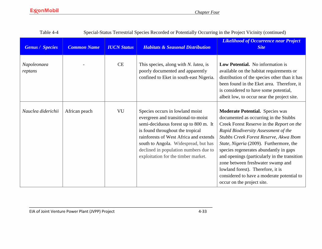
Chapter Four
EIA of Joint Venture Power Plant (JVPP) Project 4-33
Table 4-4 Special-Status Terrestrial Species Recorded or Potentially Occurring in the Project Vicinity (continued)
Genus / Species Common Name IUCN Status Habitats & Seasonal Distribution Likelihood of Occurrence near Project
Site
Napoleonaea reptans
-
CE
This species, along with N. lutea, is poorly documented and apparently confined to Eket in south-east Nigeria.
Low Potential. No information is available on the habitat requirements or distribution of the species other than it has been found in the Eket area. Therefore, it is considered to have some potential, albeit low, to occur near the project site.
Nauclea diderichii
African peach
VU
Species occurs in lowland moist evergreen and transitional-to-moist semi-deciduous forest up to 800 m. It is found throughout the tropical rainforests of West Africa and extends south to Angola. Widespread, but has declined in population numbers due to exploitation for the timber market.
Moderate Potential. Species was documented as occurring in the Stubbs Creek Forest Reserve in the Report on the Rapid Biodiversity Assessment of the Stubbs Creek Forest Reserve, Akwa Ibom State, Nigeria (2009). Furthermore, the species regenerates abundantly in gaps and openings (particularly in the transition zone between freshwater swamp and lowland forest). Therefore, it is considered to have a moderate potential to occur on the project site.
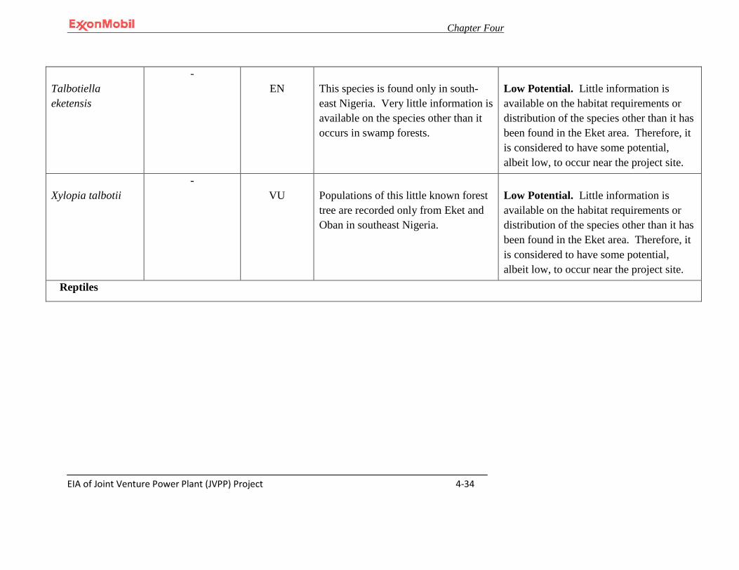
Chapter Four
EIA of Joint Venture Power Plant (JVPP) Project 4-34
Talbotiella eketensis
-
EN
This species is found only in south-east Nigeria. Very little information is available on the species other than it occurs in swamp forests.
Low Potential. Little information is available on the habitat requirements or distribution of the species other than it has been found in the Eket area. Therefore, it is considered to have some potential, albeit low, to occur near the project site.
Xylopia talbotii -
VU
Populations of this little known forest tree are recorded only from Eket and Oban in southeast Nigeria.
Low Potential. Little information is available on the habitat requirements or distribution of the species other than it has been found in the Eket area. Therefore, it is considered to have some potential, albeit low, to occur near the project site.
Reptiles

Chapter Four
EIA of Joint Venture Power Plant (JVPP) Project 4-35
Osteolaemus tetraspis
West African dwarf crocodile
VU
Species ranges across tropical lowland regions of sub-Saharan West Africa and West Central Africa encompassing countries as far West as Senegal, reaching the Central African Republic in the East, and ranging as far south as Angola. Individuals reside in permanent ponds in swamps and areas of slight current of rain forest rivers.
Known to Occur. Species was documented as occurring in the Stubbs Creek Forest Reserve in the Report on the Rapid Biodiversity Assessment of the Stubbs Creek Forest Reserve, Akwa Ibom State, Nigeria (2009). Furthermore, suitable habitat is provided by the adjacent Douglas Creek.
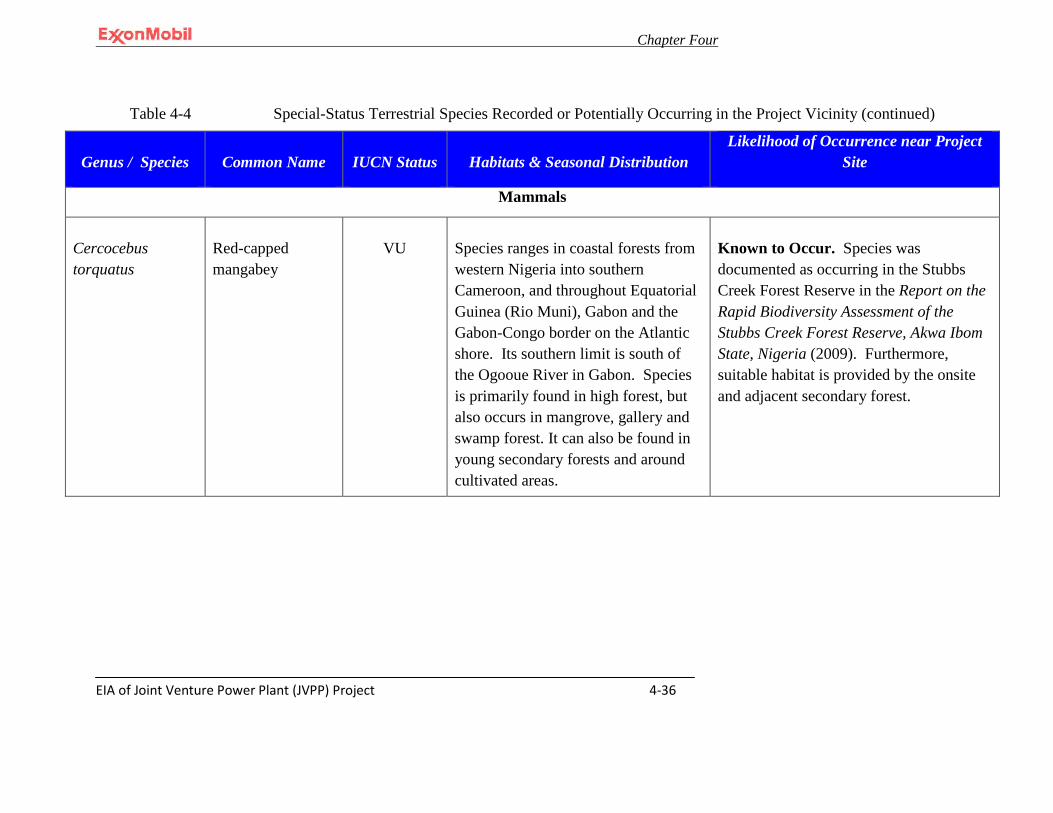
Chapter Four
EIA of Joint Venture Power Plant (JVPP) Project 4-36
Table 4-4 Special-Status Terrestrial Species Recorded or Potentially Occurring in the Project Vicinity (continued)
Genus / Species Common Name IUCN Status Habitats & Seasonal Distribution Likelihood of Occurrence near Project
Site
Mammals
Cercocebus torquatus
Red-capped mangabey
VU
Species ranges in coastal forests from western Nigeria into southern Cameroon, and throughout Equatorial Guinea (Rio Muni), Gabon and the Gabon-Congo border on the Atlantic shore. Its southern limit is south of the Ogooue River in Gabon. Species is primarily found in high forest, but also occurs in mangrove, gallery and swamp forest. It can also be found in young secondary forests and around cultivated areas.
Known to Occur. Species was documented as occurring in the Stubbs Creek Forest Reserve in the Report on the Rapid Biodiversity Assessment of the Stubbs Creek Forest Reserve, Akwa Ibom State, Nigeria (2009). Furthermore, suitable habitat is provided by the onsite and adjacent secondary forest.
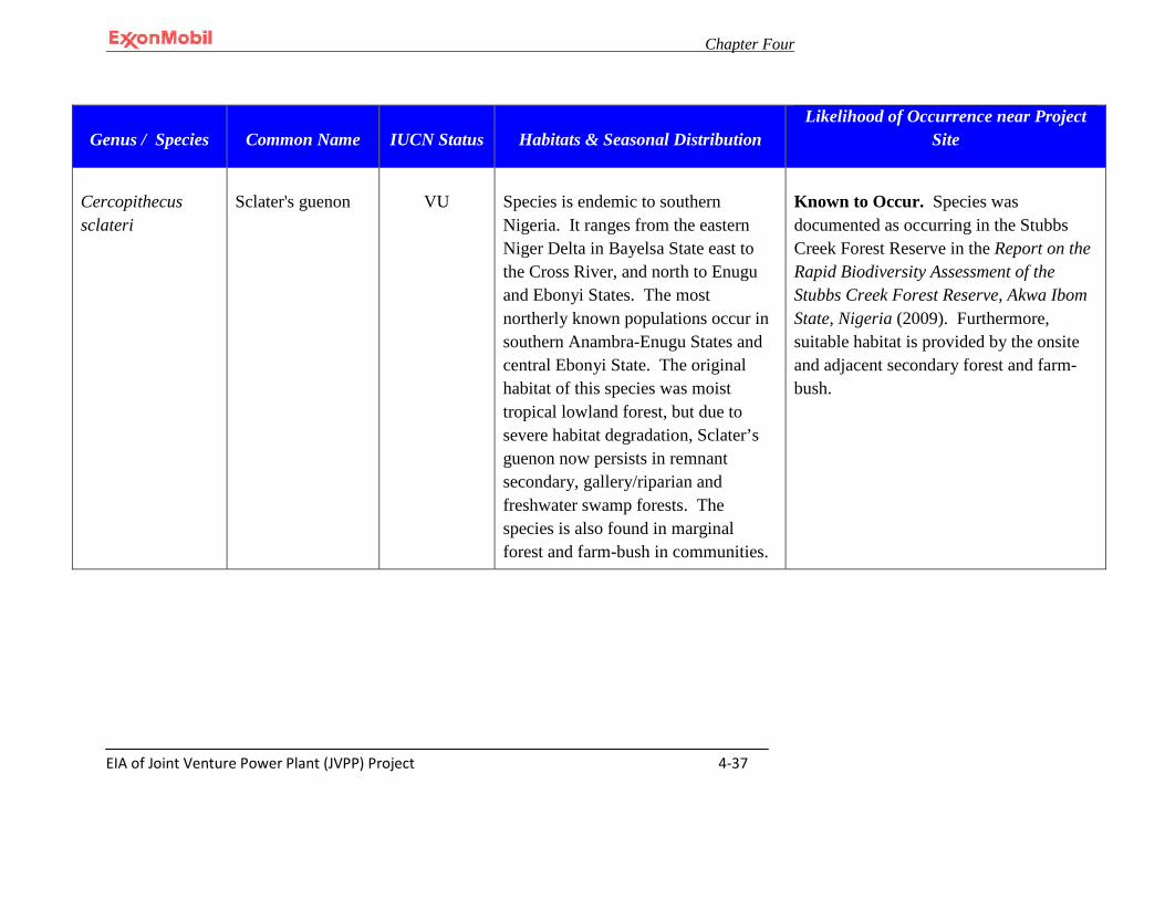
Chapter Four
EIA of Joint Venture Power Plant (JVPP) Project 4-37
Genus / Species Common Name IUCN Status Habitats & Seasonal Distribution Likelihood of Occurrence near Project
Site
Cercopithecus sclateri
Sclater's guenon
VU
Species is endemic to southern Nigeria. It ranges from the eastern Niger Delta in Bayelsa State east to the Cross River, and north to Enugu and Ebonyi States. The most northerly known populations occur in southern Anambra-Enugu States and central Ebonyi State. The original habitat of this species was moist tropical lowland forest, but due to severe habitat degradation, Sclater’s guenon now persists in remnant secondary, gallery/riparian and freshwater swamp forests. The species is also found in marginal forest and farm-bush in communities.
Known to Occur. Species was documented as occurring in the Stubbs Creek Forest Reserve in the Report on the Rapid Biodiversity Assessment of the Stubbs Creek Forest Reserve, Akwa Ibom State, Nigeria (2009). Furthermore, suitable habitat is provided by the onsite and adjacent secondary forest and farm-bush.
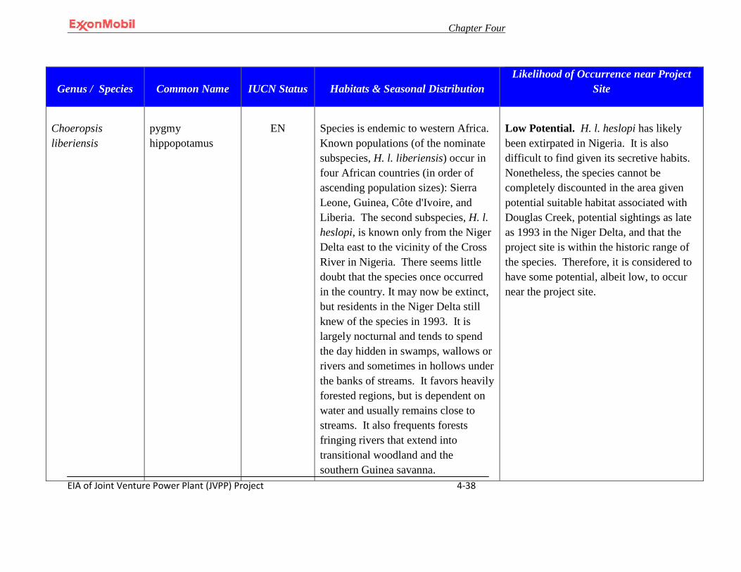
Chapter Four
EIA of Joint Venture Power Plant (JVPP) Project 4-38
Genus / Species Common Name IUCN Status Habitats & Seasonal Distribution Likelihood of Occurrence near Project
Site
Choeropsis liberiensis
pygmy hippopotamus
EN
Species is endemic to western Africa. Known populations (of the nominate subspecies, H. l. liberiensis) occur in four African countries (in order of ascending population sizes): Sierra Leone, Guinea, Côte d'Ivoire, and Liberia. The second subspecies, H. l. heslopi, is known only from the Niger Delta east to the vicinity of the Cross River in Nigeria. There seems little doubt that the species once occurred in the country. It may now be extinct, but residents in the Niger Delta still knew of the species in 1993. It is largely nocturnal and tends to spend the day hidden in swamps, wallows or rivers and sometimes in hollows under the banks of streams. It favors heavily forested regions, but is dependent on water and usually remains close to streams. It also frequents forests fringing rivers that extend into transitional woodland and the southern Guinea savanna.
Low Potential. H. l. heslopi has likely been extirpated in Nigeria. It is also difficult to find given its secretive habits. Nonetheless, the species cannot be completely discounted in the area given potential suitable habitat associated with Douglas Creek, potential sightings as late as 1993 in the Niger Delta, and that the project site is within the historic range of the species. Therefore, it is considered to have some potential, albeit low, to occur near the project site.
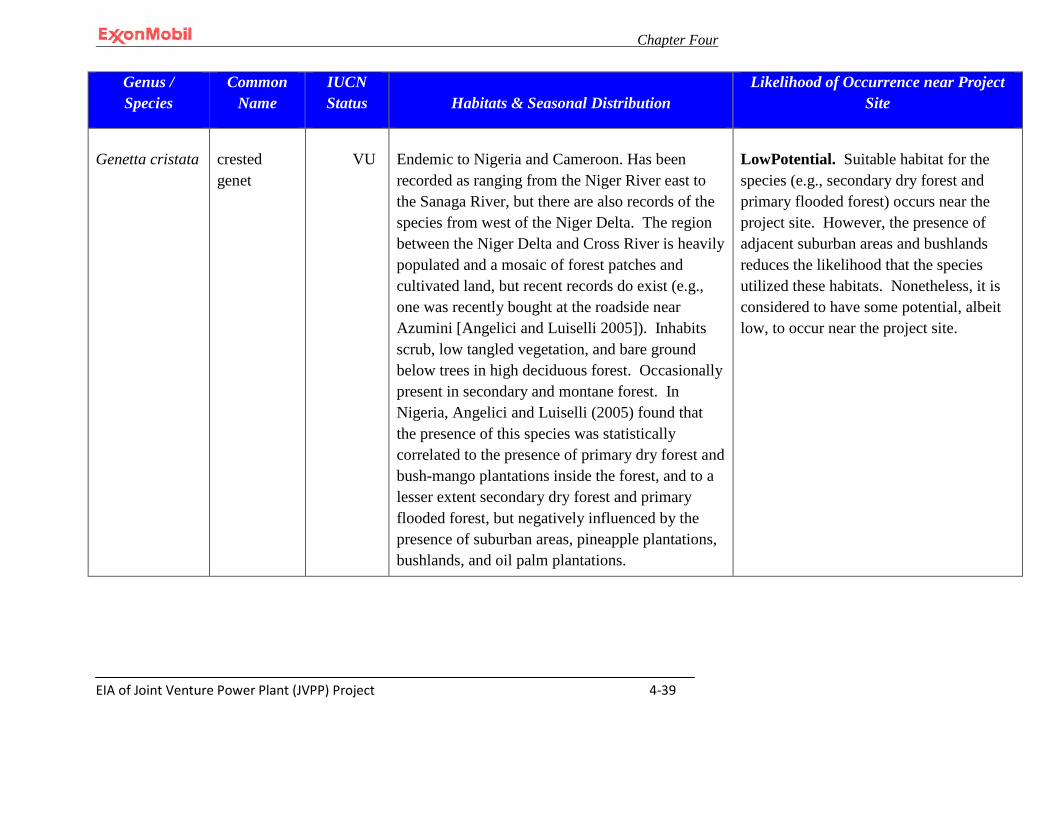
Chapter Four
EIA of Joint Venture Power Plant (JVPP) Project 4-39
Genus / Species
Common Name
IUCN Status Habitats & Seasonal Distribution
Likelihood of Occurrence near Project Site
Genetta cristata
crested genet
VU
Endemic to Nigeria and Cameroon. Has been recorded as ranging from the Niger River east to the Sanaga River, but there are also records of the species from west of the Niger Delta. The region between the Niger Delta and Cross River is heavily populated and a mosaic of forest patches and cultivated land, but recent records do exist (e.g., one was recently bought at the roadside near Azumini [Angelici and Luiselli 2005]). Inhabits scrub, low tangled vegetation, and bare ground below trees in high deciduous forest. Occasionally present in secondary and montane forest. In Nigeria, Angelici and Luiselli (2005) found that the presence of this species was statistically correlated to the presence of primary dry forest and bush-mango plantations inside the forest, and to a lesser extent secondary dry forest and primary flooded forest, but negatively influenced by the presence of suburban areas, pineapple plantations, bushlands, and oil palm plantations.
LowPotential. Suitable habitat for the species (e.g., secondary dry forest and primary flooded forest) occurs near the project site. However, the presence of adjacent suburban areas and bushlands reduces the likelihood that the species utilized these habitats. Nonetheless, it is considered to have some potential, albeit low, to occur near the project site.
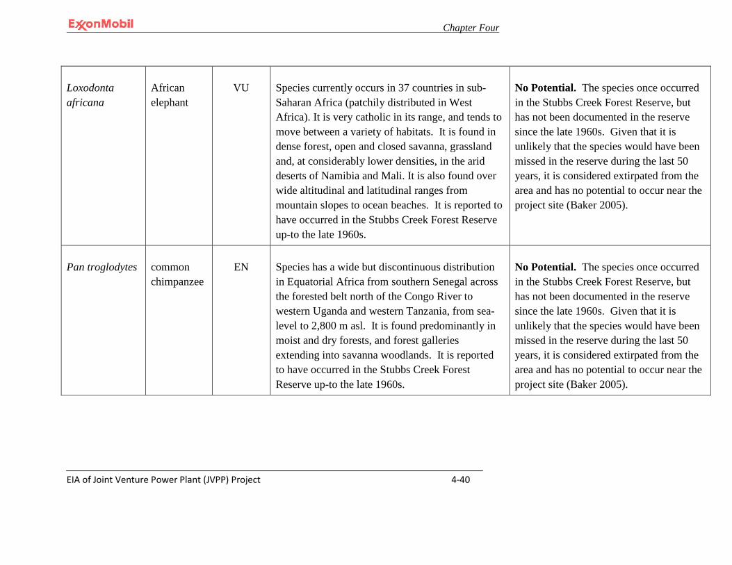
Chapter Four
EIA of Joint Venture Power Plant (JVPP) Project 4-40
Loxodonta africana
African elephant
VU
Species currently occurs in 37 countries in sub-Saharan Africa (patchily distributed in West Africa). It is very catholic in its range, and tends to move between a variety of habitats. It is found in dense forest, open and closed savanna, grassland and, at considerably lower densities, in the arid deserts of Namibia and Mali. It is also found over wide altitudinal and latitudinal ranges from mountain slopes to ocean beaches. It is reported to have occurred in the Stubbs Creek Forest Reserve up-to the late 1960s.
No Potential. The species once occurred in the Stubbs Creek Forest Reserve, but has not been documented in the reserve since the late 1960s. Given that it is unlikely that the species would have been missed in the reserve during the last 50 years, it is considered extirpated from the area and has no potential to occur near the project site (Baker 2005).
Pan troglodytes
common chimpanzee
EN
Species has a wide but discontinuous distribution in Equatorial Africa from southern Senegal across the forested belt north of the Congo River to western Uganda and western Tanzania, from sea-level to 2,800 m asl. It is found predominantly in moist and dry forests, and forest galleries extending into savanna woodlands. It is reported to have occurred in the Stubbs Creek Forest Reserve up-to the late 1960s.
No Potential. The species once occurred in the Stubbs Creek Forest Reserve, but has not been documented in the reserve since the late 1960s. Given that it is unlikely that the species would have been missed in the reserve during the last 50 years, it is considered extirpated from the area and has no potential to occur near the project site (Baker 2005).
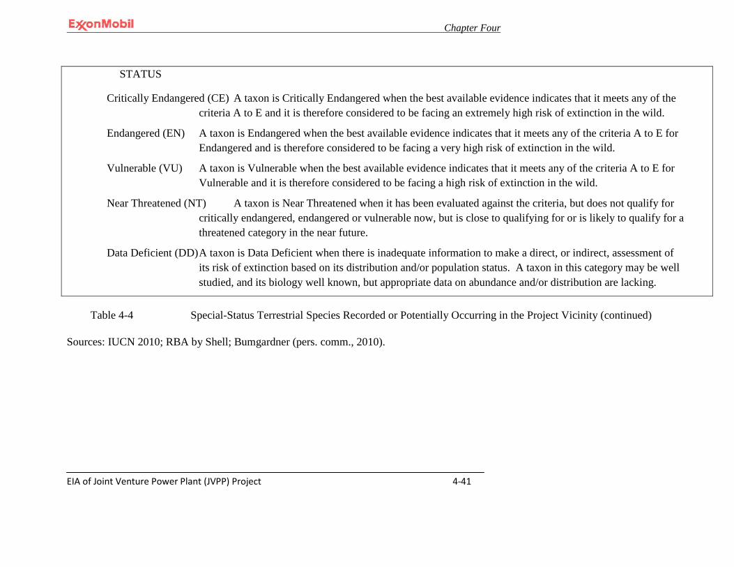
Chapter Four
EIA of Joint Venture Power Plant (JVPP) Project 4-41
Table 4-4 Special-Status Terrestrial Species Recorded or Potentially Occurring in the Project Vicinity (continued) Sources: IUCN 2010; RBA by Shell; Bumgardner (pers. comm., 2010).
STATUS
Critically Endangered (CE) A taxon is Critically Endangered when the best available evidence indicates that it meets any of the criteria A to E and it is therefore considered to be facing an extremely high risk of extinction in the wild.
Endangered (EN) A taxon is Endangered when the best available evidence indicates that it meets any of the criteria A to E for Endangered and is therefore considered to be facing a very high risk of extinction in the wild.
Vulnerable (VU) A taxon is Vulnerable when the best available evidence indicates that it meets any of the criteria A to E for Vulnerable and it is therefore considered to be facing a high risk of extinction in the wild.
Near Threatened (NT) A taxon is Near Threatened when it has been evaluated against the criteria, but does not qualify for critically endangered, endangered or vulnerable now, but is close to qualifying for or is likely to qualify for a threatened category in the near future.
Data Deficient (DD) A taxon is Data Deficient when there is inadequate information to make a direct, or indirect, assessment of its risk of extinction based on its distribution and/or population status. A taxon in this category may be well studied, and its biology well known, but appropriate data on abundance and/or distribution are lacking.

Chapter Four
EIA of Joint Venture Power Plant (JVPP) Project
4-42
4.7.8 Unique or High Value Habitat Features
The project area of influence includes the Stubbs Creek Forest Reserve which has been identified as an important area biologically. However, that portion of the Reserve that is within the project area of influence has been severely degraded ( Plate 4-4& Plate 4-5 & 4-6). The most noticeable threat to the Stubbs Creek Forest Reserve is the rapid removal of trees for logging and farming. Timber extraction occurs year round. The west end of the Reserve near QIT has been heavily degraded mainly due to the clearing of land for agriculture (Baker 2005).
Plate 4-4: Forest destruction for farming purposes within the Stubbs Creek Forest Reserve (Shell RBA 2009)
4.7.8.1 QIT Lake
In order for a waterbody to be considered an important resource, there has to be documented information to suggest that it is used by a special status species or provides a unique or limited resource that is important to local wildlife (e.g. colonial bird nesting site) that cannot be found elsewhere within the vicinity of the proposed Project. The manmade QIT Lake does not meet these criteria.

Chapter Four
EIA of Joint Venture Power Plant (JVPP) Project
4-43
Plate 4-5: Timber harvest in the Stubbs Creek Forest Reserve (Shell RBA 2009)
Plate 4-6: Fuel wood harvested from the Stubbs Creek Forest Reserve displayed for sale (Shell RBA 2009).
Chapter Four
EIA of Joint Venture Power Plant (JVPP) Project
4-44
4.7.9 Protected Biological Resources in the Region
The Stubbs Creek Forest Reserve is the primary biological resource consideration in the vicinity of the proposed project. However, because the Stubbs Creek Forest Reserve has been severely degraded, there are no protected biological resources within the area of influence of the proposed Project. Presently, there are no protective measures in place to address the resources in the Reserve including special-status species. No other areas designated for the protection of biological resources occur in the region.
4.8 Marine Resources
4.8.1 Offshore Sediment Sampling – Lean Fuel Gas Pipeline
Sediment baseline characterization study was conducted during the dry season and wet season. A total of 20 sediment samples were collected in the vicinity where the proposed lean fuel gas pipeline will be installed as shown in Figure 4-7. Of the 20 sediment samples collected, sample numbers 1, 2, 3, 5, 6 and 20 were collected outside of the project area of influence as defined in Table 4-1 (ie., not along the proposed pipeline corridor or within 1609 meters [one mile] of the proposed pipeline) rendering them and their associated analyses not applicable to this environmental analysis. Thus, the analytical results associated with these sample points will not be considered in this environmental analysis.
The other 12 sediment samples were each analyzed for a variety of physical and chemical properties such as metals, mineral and nutrient content, organic matter, and microbiological properties. These analyses are discussed more fully below. The specific analytical results for all sediment samples collected during the dry and wet season can be found in Appendix II-115 to this EIA.
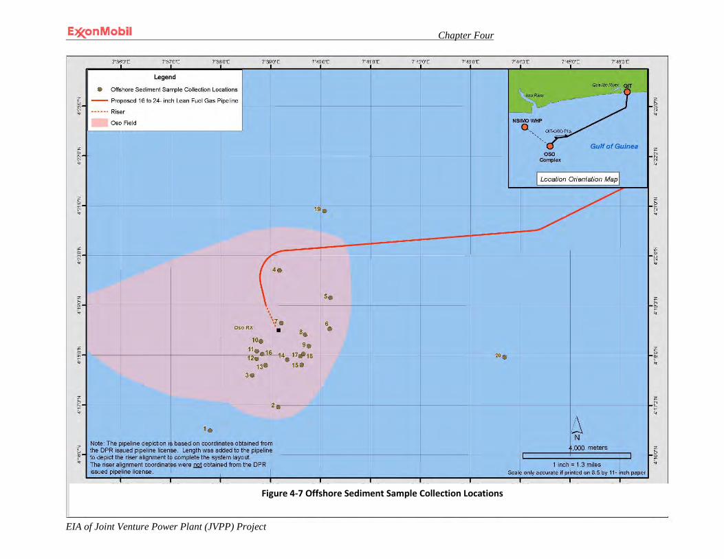
Chapter Four
EIA of Joint Venture Power Plant (JVPP) Project
4-45
Figure 4-13 Offshore Sediment Sample Collection Locations
Figure 4-7 Offshore Sediment Sample Collection Locations
Chapter Four
EIA of Joint Venture Power Plant (JVPP) Project
4-46
4.8.1.1 Physical and Chemical Properties
The analyses for physico-chemical properties included a particle size analysis, pH, conductivity, and cat-ion exchange capacity. The analysis showed the sediments at these locations to be mildly alkaline. The particle size analysis showed the sediments during the dry season to be composed on average of 78% sand, 12% clay and 10% silt whereas during the wet season these values were found to be on average 85% sand, 10% clay and 9% silt. The difference between the dry season and wet season analyses are within the normally acceptable environmental criteria for relative percent difference (RPD).
4.8.1.2 Metals and Mineral Content
Analysis for heavy metals such as lead, iron, manganese, copper, zinc, nickel, chromium, barium, silver, cobalt and cadmium as well as minerals such as calcium, magnesium, sodium and potassium was conducted.
The results for heavy metal concentration had a lower limit of <0.01 mg/kg and an upper limit of 1372.252 mg/kg in dry season. For wet season, a lower limit of <0.02 mg/kg and an upper limit of 1376.650 mg/kg were also recorded. The detailed results are located in Appendix II(120-144) to this EIA.
4.8.1.3 Organic Matter
Various analyses were conducted to assess different hydrocarbon fractions present in the samples. See Section 4.8.1.5 below.
4.8.1.4 Microbiological Properties – Bacteria and Fungi
The sediment samples were analyzed for microbiological parameters to include total heterotrophic bacteria, hydrocarbon utilizing bacteria, total heterotrophic fungi, hydrocarbon utilizing fungi and total coliform. Total coliform is an “indicator" organism measured to assess the microbiological quality of water or as in this case, sediment. The concentration of indicator bacteria in ocean water has been used for decades to measure recreational water safety as well as the water quality where shellfish and other aquatic organisms are routinely harvested and consumed by humans. Indicator bacteria are not necessarily pathogenic, but are found abundantly in wastes with human contributions where pathogenic organisms such as viruses are likely to exist. The level of indicator bacteria in bathing waters (e.g., swimming) has been shown to correlate with the incidence of illness in swimmers. Recreational water quality programs worldwide collect samples, test for indicator bacteria and post, close or otherwise restrict access to recreational waters that exceed the established threshold for these bacteria. The upper limit for the total coliform
Chapter Four
EIA of Joint Venture Power Plant (JVPP) Project
4-47
bacteria measured in the sediments during the dry sampling event was 100 coliform forming units (cfu) per gram and during the wet season sampling event it was 90 cfu per gram.
4.8.1.5 Benthic Habitat Assessment
The term benthic refers to anything associated with or occurring on the bottom of a body of water. The plants and animals that live on or in the bottom substrates are known as the benthos. Benthic habitats can best be defined as bottom environments with distinct physical, geochemical, and biological characteristics. The offshore waters in the Project vicinity consist mostly of soft bottom communities including mollusks, crustaceans, worms, and other such organisms. Many of these creatures feed on benthic deposits. Thus, they are important in reworking the nutrients of the seafloor. These organisms are also an important food source for demersal fishes.
The offshore sediment sampling survey identified a total of 16 benthos species representing 4 taxonomic groups: Annelids, Arthropods, Echinoderms and Mollusks. Total diversity per 0.1 m2 (1 ft2) varied from station to station ranging from 2 species at stations fourteen and sixteen to 7 species at station eleven with most stations averaging around 5 species. The number of individuals from all species ranged from 3 at station nineteen to as nine at stations four, seven, ten and eleven. The average number of individuals for all species for stations four and seven through eleven averaged around 8 and the average number of individuals for stations thirteen through nineteen was around 4.
4.8.1.6 Analyses Summary
The data collection and analyses discussed in this section were conducted in the vicinity where the Project proposes to install a subsea pipeline pressured at 700 to 1200 psig to transport lean fuel gas (i.e., primarily methane gas) to the onshore portion of the Project. In the unlikely event of a pipeline leak, the methane gas due to its physical properties will bubble to the surface and dissipate into the atmosphere yielding minimal impact to surrounding marine flora or fauna. Thus, in consideration of the data acquired for offshore sediments this environmental analysis will consider the benthic habitat assessment data to gauge potential impacts to benthic communities resulting from pipeline installation and the total coliform measurements which can serve as a snapshot in time of the microbiological quality of the ocean sediment in the vicinity where the lean fuel gas pipeline will be installed.
4.8.2 Nearshore Sediment Sampling
A baseline sediment characterization study was conducted during the dry season and wet season. Six nearshore sediment samples were collected from the locations where the proposed material off-loading facility (MOF) is planned as shown in Figure 4-8. The samples were each analyzed for a variety of physical and chemical properties such
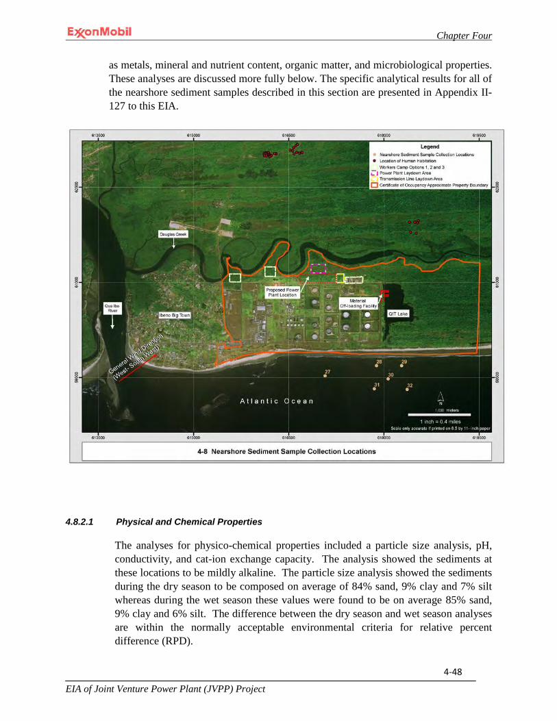
Chapter Four
EIA of Joint Venture Power Plant (JVPP) Project
4-48
as metals, mineral and nutrient content, organic matter, and microbiological properties. These analyses are discussed more fully below. The specific analytical results for all of the nearshore sediment samples described in this section are presented in Appendix II-127 to this EIA.
4.8.2.1 Physical and Chemical Properties
The analyses for physico-chemical properties included a particle size analysis, pH, conductivity, and cat-ion exchange capacity. The analysis showed the sediments at these locations to be mildly alkaline. The particle size analysis showed the sediments during the dry season to be composed on average of 84% sand, 9% clay and 7% silt whereas during the wet season these values were found to be on average 85% sand, 9% clay and 6% silt. The difference between the dry season and wet season analyses are within the normally acceptable environmental criteria for relative percent difference (RPD).

Chapter Four
EIA of Joint Venture Power Plant (JVPP) Project
4-49
4.8.2.2 Metals and Mineral Content
Analysis for heavy metals such as lead, iron, manganese, copper, zinc, nickel, chromium, barium, silver, cobalt and cadmium as well as minerals such as calcium, magnesium, sodium and potassium was conducted.
The results for heavy metal concentration had a lower limit of <0.01 mg/kg and an upper limit of 1169.342 mg/kg in dry season. For wet season, a lower limit of <0.01mg/kg and an upper limit of 1267.90 mg/kg were also recorded. The detailed results are located in Appendix II-129 to this EIA.
4.8.2.3 Organic Matter
Various analyses were conducted to assess different hydrocarbon fractions present in the samples.
4.8.2.4 Microbiological Properties – Bacteria and Fungi
The sediment samples were analyzed for microbiological parameters including total heterotrophic bacteria, hydrocarbon utilizing bacteria, total heterotrophic fungi, hydrocarbon utilizing fungi and coliform.
As mentioned in the offshore sediment sampling section, total coliform indicates that the water or in this case the sediments have come into contact with plant or animal life. The upper limit for the total coliform bacteria measured in the sediments where the proposed MOF will be installed was found to be 120 cfu per gram during the dry season and 70 cfu per gram during the wet season.
4.8.2.5 Benthic Habitat Assessment
The nearshore sediment sampling survey identified a total of 14 benthos species representing 4 taxonomic groups: Annelids, Arthropods, Echinoderms and Mollusks. Total diversity per 0.1 m2 (1 ft2) varied from station to station ranging from 4 species at stations twenty-seven, twenty-nine, thirty-one and thirty-two and 6 species at stations twenty-eight and thirty. The number of individuals from all species ranged from 4 at station thirty-two, 6 at stations twenty-seven and twenty-nine to 7 at stations twenty-eight and thirty and 8 at station thirty-one.
4.8.2.6 Analyses Summary
The data collection and analyses discussed in this section were conducted in the vicinity where the proposed MOF will be installed.
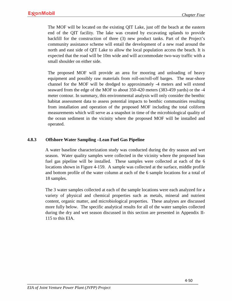
Chapter Four
EIA of Joint Venture Power Plant (JVPP) Project
4-50
The MOF will be located on the existing QIT Lake, just off the beach at the eastern end of the QIT facility. The lake was created by excavating uplands to provide backfill for the construction of three (3) new product tanks. Part of the Project’s community assistance scheme will entail the development of a new road around the north and east side of QIT Lake to allow the local population access the beach. It is expected that the road will be 10m wide and will accommodate two-way traffic with a small shoulder on either side.
The proposed MOF will provide an area for mooring and unloading of heavy equipment and possibly raw materials from roll-on/roll-off barges. The near-shore channel for the MOF will be dredged to approximately -4 meters and will extend seaward from the edge of the MOF to about 350-420 meters (383-459 yards) or the -4 meter contour. In summary, this environmental analysis will only consider the benthic habitat assessment data to assess potential impacts to benthic communities resulting from installation and operation of the proposed MOF including the total coliform measurements which will serve as a snapshot in time of the microbiological quality of the ocean sediment in the vicinity where the proposed MOF will be installed and operated.
4.8.3 Offshore Water Sampling –Lean Fuel Gas Pipeline
A water baseline characterization study was conducted during the dry season and wet season. Water quality samples were collected in the vicinity where the proposed lean fuel gas pipeline will be installed. These samples were collected at each of the 6 locations shown in Figure 4-159. A sample was collected at the surface, middle profile and bottom profile of the water column at each of the 6 sample locations for a total of 18 samples.
The 3 water samples collected at each of the sample locations were each analyzed for a variety of physical and chemical properties such as metals, mineral and nutrient content, organic matter, and microbiological properties. These analyses are discussed more fully below. The specific analytical results for all of the water samples collected during the dry and wet season discussed in this section are presented in Appendix II-115 to this EIA.
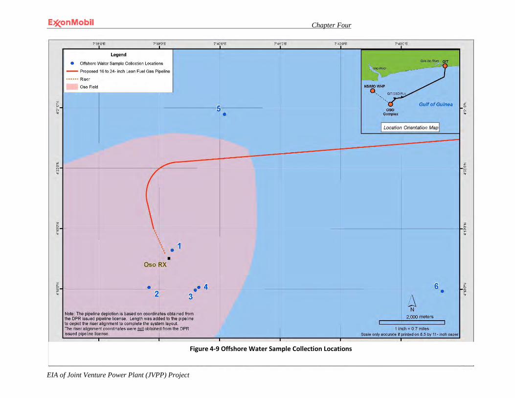
Chapter Four
EIA of Joint Venture Power Plant (JVPP) Project
4-51
Figure 4-15 Offshore Water Sample Collection Locations
Figure 4-9 Offshore Water Sample Collection Locations

Chapter Four
EIA of Joint Venture Power Plant (JVPP) Project
4-52
4.8.3.1 Physical and Chemical Properties
The analyses for physical-chemical properties included pH, dissolved oxygen, total dissolved solids, total suspended solids, conductivity, temperature, turbidity chemical oxygen demand and biological demand. The recorded measurements are located in Appendix II-116 to this EIA.
4.8.3.2 Metals and Mineral Content
The offshore water samples were analyzed for heavy metals such as lead, iron, manganese, cadmium, zinc, nickel, vanadium, chromium, silver, cobalt and copper as well as minerals such as calcium, magnesium, sodium, potassium, chloride, sulfate and nitrate.
The results for heavy metal concentration had a lower limit of <0.01 mg/l and an upper limit of 0.450 mg/l in dry season. For wet season, a lower limit of <0.01mg/l and an upper limit of 0.700 mg/l were also recorded. The detailed results are located in Appendix II-137 to this EIA.
4.8.3.3 Organic Matter
Oil and grease analysis was conducted for each of the water samples. Concentrations during the dry and wet season sampling events ranged from 0.1 mg/l to 2.4 mg/l. See Section 4.8.1.6.
4.8.3.4 Microbiological Properties – Bacteria and Fungi
The offshore water samples were analyzed for the following microbiological parameters including total heterotrophic bacteria, hydrocarbon utilizing bacteria, total heterotrophic fungi, hydrocarbon utilizing fungi and coliform. The upper limit for the total coliform bacteria measured in the ocean water during the dry season in the vicinity where the lean fuel gas pipeline will be installed and operated was measured to be 180 cfu per milliliter and the upper limit for the total coliform bacteria measured in the ocean water during the wet season at the same sample points where the dry season sampling was conducted was found to be 250 cfu per milliliter.
Chapter Four
EIA of Joint Venture Power Plant (JVPP) Project
4-53
4.8.3.5 Plankton
Planktonic forms comprise the primary elements of marine foods. These microscopic plants (phytoplankton) and animals (zooplankton) are eaten by macroscopic zooplankton and some small schooling fishes, which in turn are eaten by larger invertebrates and fishes. These organisms are consumed by still larger organisms, including marine mammals and seabirds.
Phytoplankton
The offshore water sampling survey identified a total of 17 phytoplankton species representing 4 taxonomic groups: Bacillariophyceae, Chlorophyceae, Cyanophyceae and Dinophyceae. Total diversity per 0.1 m2 (1 ft2) varied from station to station ranging from 7 in station four to 8 in stations one and two to 10 in station three, to 12 in station five. The number of individuals from all species ranged from 82 in station two to 88 in stations one and three, to 218 in station five.
Zooplankton
The offshore water sampling survey identified a total of 17 zooplankton species representing 5 taxonomic groups: Copepoda, Ostracoda, Rotifera, Gastropoda and Fish larvae. However, fish larvae were only identified in sample 6. Total diversity per 0.1 m2 (1 ft2) varied from station to station ranging from 7 in stations one and four to 9 in station three, to 11 in station five. The number of individuals from all species ranged from 24 in station one to 56 in station five.
4.8.3.6 Analyses Summary
The baseline data discussed in this section will be used to demonstrate that expected project activities will not have any direct impact on the environment (See Chapter Five). Noteably, the total coliform data serves as a snapshot in time of the microbiological quality of the ocean water in the vicinity where the lean fuel gas pipeline will be installed and operated.
4.8.4 Nearshore Water Sampling
Water sampling program was conducted during the dry and wet season in the vicinity where the proposed MOF will be installed and operated. Six nearshore water samples were collected at the locations shown in Fig 4-10. These samples were each analyzed for various physical and chemical properties including metals, mineral and nutrient content, organic matter and microbiological properties. These analyses are more fully
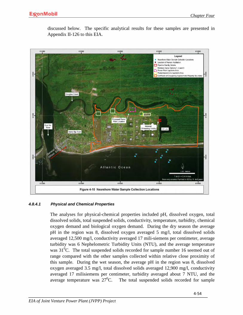
Chapter Four
EIA of Joint Venture Power Plant (JVPP) Project
4-54
discussed below. The specific analytical results for these samples are presented in Appendix II-126 to this EIA.
4.8.4.1 Physical and Chemical Properties
The analyses for physical-chemical properties included pH, dissolved oxygen, total dissolved solids, total suspended solids, conductivity, temperature, turbidity, chemical oxygen demand and biological oxygen demand. During the dry season the average pH in the region was 8, dissolved oxygen averaged 5 mg/l, total dissolved solids averaged 12,500 mg/l, conductivity averaged 17 mili-siemens per centimeter, average turbidity was 6 Nephelometric Turbidity Units (NTU), and the average temperature was 310C. The total suspended solids recorded for sample number 16 seemed out of range compared with the other samples collected within relative close proximity of this sample. During the wet season, the average pH in the region was 8, dissolved oxygen averaged 3.5 mg/l, total dissolved solids averaged 12,900 mg/l, conductivity averaged 17 milisiemens per centimeter, turbidity averaged about 7 NTU, and the average temperature was 270C. The total suspended solids recorded for sample
Chapter Four
EIA of Joint Venture Power Plant (JVPP) Project
4-55
number 15 seemed out of range compared with the other samples collected within relative close proximity of this sample. The specific measurements recorded for each sample during the wet and dry season is presented in Appendix 4-4 to this EIA.
4.8.4.2 Metals and Mineral Content
The nearshore water samples were analyzed for heavy metals such as lead, iron, manganese, cadmium, zinc, nickel, vanadium, chromium, silver, cobalt and copper as well as minerals such as calcium, magnesium, sodium, potassium, chloride, sulfate and nitrate.
The results for heavy metal concentration had a lower limit of <0.01 mg/l and an upper limit of 0.920 mg/l in dry season. For wet season, a lower limit of <0.01mg/l and an upper limit of 0.764 mg/l were also recorded. The detailed results are located in Appendix II-144 to this EIA.
4.8.4.3 Organic Matter
Oil and grease analysis was conducted for each of the water samples. Concentrations during the dry and wet season ranged from about 1.4 mg/l to 3 mg/l.
4.8.4.4 Microbiological Properties – Bacteria and Fungi
The nearshore water samples were analyzed for microbiological parameters including total heterotrophic bacteria, hydrocarbon utilizing bacteria, total heterotrophic fungi, hydrocarbon utilizing fungi and coliform. The total coliform content, the upper limit for total coliform bacteria was found to be 60 cfu per milliliter during the dry season sampling event. The upper limit for the total coliform bacteria during the wet season sampling event was found to be 90 cfu per milliliter.
4.8.4.5 Phytoplankton
The nearshore water sampling survey identified a total of 17 phytoplankton species representing 4 taxonomic groups: Bacillariophyceae, Chlorophyceae, Cyanophyceae and Dinophyceae. Total diversity per 0.1 m2 (1 ft2) varied from station to station ranging from 7 in station seventeen, 8 in station thirteen, 9 in stations fifteen and eighteen to 10-11 in stations sixteen and fourteen, respectively. The number of individuals from all species ranged from 49 in station seventeen to 68 in station eighteen.

Chapter Four
EIA of Joint Venture Power Plant (JVPP) Project
4-56
4.8.4.6 Zooplankton
The offshore water sampling survey identified a total of 17 zooplankton species representing 4 taxonomic groups: Copepoda, Ostracoda, Rotifera and Gastropodaand. Total diversity per 0.1 m2 (1 ft2) varied from station to station ranging from 8 in station fifteen, to 9 in stations thirteen and sixteen, to 10 in station eighteen, to 11 in stations fourteen and seventeen. The number of individuals from all species ranged from 28 in stations fourteen and sixteen to 36 in station seventeen.
4.8.4.7 Analyses Summary
It is not expected that the installation and operation of the proposed MOF will impact any of the baseline data discussed in this section with the possible exception of the microbiological and plankton organisms. Noteably, the total coliform data serves as a snapshot in time of the microbiological quality of the ocean water in the vicinity where the proposed MOF will be installed and operated.
4.8.5 Offshore Sampling –Rich Gas Pipeline
A baseline characterization study was conducted during the dry and wet season. One surface water sample was collected from sample point PLQ-2 and a sediment sample was collected at each sample point PLQ1 through PLQ4 during the dry and wet season sampling events as shown in Fig 4-11. These samples were analyzed for a variety of physical and chemical properties such as metals, mineral and nutrient content, organic matter, and microbiological properties. These analyses are discussed more fully below. The specific analytical results for these samples are presented in Appendix II-4 to this EIA.
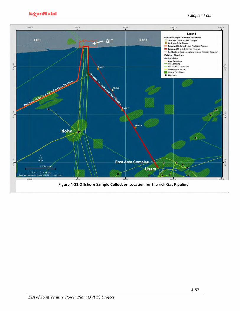
Chapter Four
EIA of Joint Venture Power Plant (JVPP) Project
4-57
Figure 4-11 Offshore Sample Collection Location for the rich Gas Pipeline
Chapter Four
EIA of Joint Venture Power Plant (JVPP) Project
4-58
4.8.5.1 Physical and Chemical Properties
The analyses for the physico-chemical properties for the PLQ-2 water sample included temperature, conductivity, salinity, dissolved oxygen, redox potential, pH, turbidity, total suspended solids, chemical oxygen demand and chloride. The difference between the dry season and wet season analyses are within the normally acceptable environmental criteria for relative percent difference (RPD). The analyses for the physico-chemical properties for the four sediment samples collected during the dry and wet season sampling events included pH, total organic carbon, redox potential and particle size distribution. The difference between the dry season and wet season analyses are within the normally acceptable environmental criteria for relative percent difference (RPD). The specific measurements recorded for each sample during the wet and dry season is presented in Appendix II-30 to this EIA.
4.8.5.2 Metals and Mineral Content
Water sample PLQ-2 and sediment samples PLQ1-PLQ4 were analyzed for heavy metals such as cobalt, cadmium, total chromium, copper, iron, manganese, nickel, lead, silver, barium (sediment samples only) and zinc as well as minerals such as calcium, magnesium, sodium, potassium and chloride (water sample only). The recorded measurements are located in Appendix II-31 to this EIA.
4.8.5.3 Organic Matter
The water samples were analyzed for oil and grease, phenol and total petroleum hydrocarbons while the sediment samples were analyzed for various aliphatic hydrocarbons and poly-aromatic hydrocarbons. If a leak were to occur, the pipeline contents due to their physical properties (i.e., the composition being approximately 55% methane, 15% ethane, 19% propane and the rest mainly butane and other alkane hydrocarbons) would be expected to bubble to the surface of the ocean and subsequently dissipate into the atmosphere.
4.8.5.4 Microbiological Properties – Bacteria and Fungi
The water and sediment samples were each analyzed for microbiological parameters including total heterotrophic bacteria, hydrocarbon utilizing bacteria, total heterotrophic fungi, hydrocarbon utilizing fungi and coliform. Total coliform data will be used to provide a snapshot of the microbiological quality of the ocean water in the vicinity where the rich gas pipeline will be installed and operated
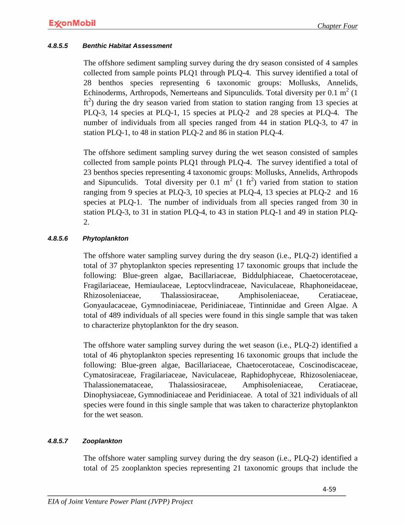
Chapter Four
EIA of Joint Venture Power Plant (JVPP) Project
4-59
4.8.5.5 Benthic Habitat Assessment
The offshore sediment sampling survey during the dry season consisted of 4 samples collected from sample points PLQ1 through PLQ-4. This survey identified a total of 28 benthos species representing 6 taxonomic groups: Mollusks, Annelids, Echinoderms, Arthropods, Nemerteans and Sipunculids. Total diversity per 0.1 m2 (1 ft2) during the dry season varied from station to station ranging from 13 species at PLQ-3, 14 species at PLQ-1, 15 species at PLQ-2 and 28 species at PLQ-4. The number of individuals from all species ranged from 44 in station PLQ-3, to 47 in station PLQ-1, to 48 in station PLQ-2 and 86 in station PLQ-4.
The offshore sediment sampling survey during the wet season consisted of samples collected from sample points PLQ1 through PLQ-4. The survey identified a total of 23 benthos species representing 4 taxonomic groups: Mollusks, Annelids, Arthropods and Sipunculids. Total diversity per 0.1 m2 (1 ft2) varied from station to station ranging from 9 species at PLQ-3, 10 species at PLQ-4, 13 species at PLQ-2 and 16 species at PLQ-1. The number of individuals from all species ranged from 30 in station PLQ-3, to 31 in station PLQ-4, to 43 in station PLQ-1 and 49 in station PLQ-2.
4.8.5.6 Phytoplankton
The offshore water sampling survey during the dry season (i.e., PLQ-2) identified a total of 37 phytoplankton species representing 17 taxonomic groups that include the following: Blue-green algae, Bacillariaceae, Biddulphiaceae, Chaetocerotaceae, Fragilariaceae, Hemiaulaceae, Leptocvlindraceae, Naviculaceae, Rhaphoneidaceae, Rhizosoleniaceae, Thalassiosiraceae, Amphisoleniaceae, Ceratiaceae, Gonyaulacaceae, Gymnodiniaceae, Peridiniaceae, Tintinnidae and Green Algae. A total of 489 individuals of all species were found in this single sample that was taken to characterize phytoplankton for the dry season.
The offshore water sampling survey during the wet season (i.e., PLQ-2) identified a total of 46 phytoplankton species representing 16 taxonomic groups that include the following: Blue-green algae, Bacillariaceae, Chaetocerotaceae, Coscinodiscaceae, Cymatosiraceae, Fragilariaceae, Naviculaceae, Raphidophyceae, Rhizosoleniaceae, Thalassionemataceae, Thalassiosiraceae, Amphisoleniaceae, Ceratiaceae, Dinophysiaceae, Gymnodiniaceae and Peridiniaceae. A total of 321 individuals of all species were found in this single sample that was taken to characterize phytoplankton for the wet season.
4.8.5.7 Zooplankton
The offshore water sampling survey during the dry season (i.e., PLQ-2) identified a total of 25 zooplankton species representing 21 taxonomic groups that include the

Chapter Four
EIA of Joint Venture Power Plant (JVPP) Project
4-60
following: Polychaeta, Amphiopoda, Copepoda, Acartidae, Calanidae, Candacidae, Eucalanidae, Euchaetidae, Metridiidae, Pontellidae, Pseudocalanidae, Temoridae, Oithonidae, Onceaidae, Macrosetellidae, Appendicularia, Pisces, Echinoidea, Gastropoda, Lamellibranchia and Foraminifera. A total of 164 individuals of all species were found in the dry season samples.
The offshore water sampling survey during the wet season (i.e., PLQ-2) identified a total of 23 zooplankton species representing 19 taxonomic groups that include the following: Polychaeta, Copepoda, Acartidae, Aetideidae, Calanidae, Centropagidae, Eucalanidae, Euchaetidae, Paracalanidae, Pseudocalanidae, Corycaeidae, Oithonidae, Onceaidae, Macrosetellidae, Sagittidae, Appendicularia, Pisces, Gastropoda and Lamellibranchia. A total of 227 individuals of all species were found in the wet season samples.
4.8.5.8 Analyses Summary
The data collection and analyses discussed in this section were conducted in the vicinity where the Project proposes to install a subsea pipeline to transport rich gas that is currently being flared at QIT to the existing East Area (EA) complex for extraction of Natural Gas Liquids. This environmental analysis will consider the benthic habitat assessment data to gauge potential impacts to benthic communities resulting from the installation of the pipeline.
4.8.6 Additional Marine Data
Seafloor features, currents, and marine weather are highly significant elements of the marine environment. Knowledge of the marine environmental baseline, coupled with information on the environments favored by various organisms is extremely useful in understanding why various organisms occur in some regions and not in others. In turn, such knowledge is necessary in assessing potential impacts to marine resources.
4.8.6.1 Existing Offshore Conditions
The offshore where the lean fuel gas pipeline and rich gas pipeline are proposed for installation and operation is a brownfield area consisting of over 200 miles of pipeline including numerous platforms as presented in Fig 4-12. The proposed lean fuel gas pipeline will be installed within an existing 600 meter wide corridor pipeline route and the rich gas pipeline will be installed within an existing 200 meter wide pipeline corridor route (Fig 4-13).

Chapter Four
EIA of Joint Venture Power Plant (JVPP) Project
4-61
Figure 4-12 Offshore QIT/QIPP Existing MPN Gas/Oil Fields and Pipeline Routes

Chapter Four
EIA of Joint Venture Power Plant (JVPP) Project
4-62
Figure 4-13 Pipeline Route Depiction: The Lean Fuel Gas Pipeline from the Oso Complex to QIT
Chapter Four
EIA of Joint Venture Power Plant (JVPP) Project
4-63
4.8.6.2 Seafloor Clearance Features
Findings from particle size analysis show that sediment samples were found to be approximately 91.2% sand, 5.74% clay, 2.2% silt for wet season and 88.1% sand, 5.83% clay and 2.62% silt in the dry season. Hence, the geotechnical and geophysical investigation conducted by Structural Analysis and Geotechnical Engineering Limited for the OSO to QIT pipeline route (i.e., lean fuel gas pipeline) on behalf of MPN and a similar type of investigation conducted on behalf of MPN for the QIT to East Area pipeline route (i.e., rich gas pipeline) by Gardline Surveys, Inc have thier results presented in Table 4-5 and Table 4-6 respectively. This is also summarized below:
• Pipeline Crossings – All expected pipeline crossings were located in the expected
positions. • Hazards-In general there were no hazards that would affect the approach of either
pipeline to the platform or to the shore, as applicable. • Seabed and Shallow Soils- For most locations, soils covering the seabed consist of
very soft sandy/silty clays, with thickness typically 1.5 meters or thicker. This is typically underlain by a channelized sequence of sandy clays/sands.
• Rock and Coral Outcrops-These structures provide an uncommon, patchily distributed habitat that often supports flora and fauna that do not occur in other habitats. These flora and fauna are therefore often limited in distribution and easily disturbed. However, consistent with the geology of the study areas and MPN’s longstanding experience operating in this region, no rock or coral outcrops were noted during either of the seabed clearance studies. Therefore, species typically associated with these structures are not expected to be present in the vicinity of the proposed Project.

Chapter Four
EIA of Joint Venture Power Plant (JVPP) Project
4-64
Table 4-5 Interpreted Seabed Conditions along the Proposed OSO-QIT Lean Fuel Gas Pipeline Route
KP Range (km)
Bathymetry Seabed Interpretation Shallow Soil Interpretation
0 – 8.4
(OSO – TP A4)
17.5 m - 15.1 m
Maximum seafloor gradient is 1:3500.
The surface sediments consisting of clay and sand have high variability in the lateral extent. Minor sand streamers are in evidence. The sediment is also gasified and the gas is presumed to be biogenic.
For 0.5 m to 1.5 m BML, soft to firm sandy silty clay or very loose to loose fine to medium sand with substantial clay contents compose the top soil. The clay at surface is mostly soft, and firm clay is usually beneath sand.
8.4 – 23.6
(TP A4 – 11.2 km northeast
of TP A3)
15.1 m – 15.7 m
Maximum seafloor gradient is 1:3500.
The surface sediments consisting of clay and sand have high variability in the lateral extent. Minor sand streamers are in evidence. The sediment is also gasified and the gas is presumed to be biogenic.
For 0.5 m to 1.7 m BML, soft to firm sandy silty clay or very loose to loose fine to medium sand with substantial clay contents compose the top soil. The clay at surface is mostly soft, and firm clay is usually beneath sand.
23.6 – 44.4
(11.2 km northeast of TP A3 – TP
A1)
15.1 m – 10.0 m
Maximum seafloor gradient is 1:3500.
The surface sediments are mostly clay. Numerous trawl scars are indicative of frequent fishing activity and also the slight cohesive nature of the surface sediments. The sediment is also gasified and the gas is presumed to be biogenic.
For 1.0 m to 1.7 m BML, very soft sandy silty clay composes the top soil. Sporadic sand spots may be found at mudline or underlying the clay layer.
44.4 – 51.8
(TP A1 – QIT)
10.0 m – 5.0 m
The seafloor gradient at the shore approach is approximately 1:1000 with the maximum dip gradient as 1:400.
The surface sediments are mostly clay, except near shore where sand is the surface sediment. Numerous trawl scars are indicative of frequent fishing activity and also the slight cohesive nature of the surface sediments. The sediment is also gasified and the gas is presumed to be biogenic.
Near shore, the surface soil is mostly sand. Further offshore, for 1.0 m to 1.5 m BML, very soft sandy silty clay composes the top soil. Sporadic sand spots may be found at mudline or underlying the clay layer.
Source: Structural Analysis and Geotechnical Engineering Limited (Revised edition); “Pipeline Route Geotechnical and Geophysical Investigation OSO and EDOP Developments Offshore Nigeria, GEO 0001193.” (1988/1989)
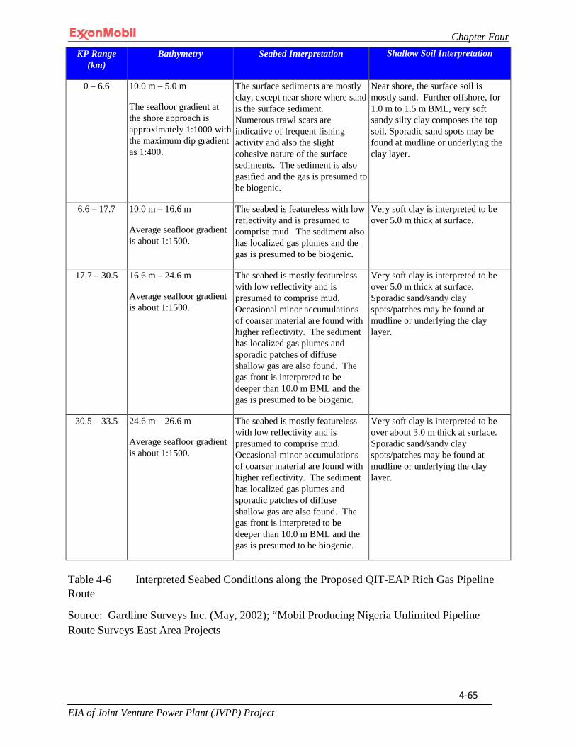
Chapter Four
EIA of Joint Venture Power Plant (JVPP) Project
4-65
Table 4-6 Interpreted Seabed Conditions along the Proposed QIT-EAP Rich Gas Pipeline Route
Source: Gardline Surveys Inc. (May, 2002); “Mobil Producing Nigeria Unlimited Pipeline Route Surveys East Area Projects
KP Range (km)
Bathymetry Seabed Interpretation Shallow Soil Interpretation
0 – 6.6
10.0 m – 5.0 m
The seafloor gradient at the shore approach is approximately 1:1000 with the maximum dip gradient as 1:400.
The surface sediments are mostly clay, except near shore where sand is the surface sediment. Numerous trawl scars are indicative of frequent fishing activity and also the slight cohesive nature of the surface sediments. The sediment is also gasified and the gas is presumed to be biogenic.
Near shore, the surface soil is mostly sand. Further offshore, for 1.0 m to 1.5 m BML, very soft sandy silty clay composes the top soil. Sporadic sand spots may be found at mudline or underlying the clay layer.
6.6 – 17.7
10.0 m – 16.6 m
Average seafloor gradient is about 1:1500.
The seabed is featureless with low reflectivity and is presumed to comprise mud. The sediment also has localized gas plumes and the gas is presumed to be biogenic.
Very soft clay is interpreted to be over 5.0 m thick at surface.
17.7 – 30.5
16.6 m – 24.6 m
Average seafloor gradient is about 1:1500.
The seabed is mostly featureless with low reflectivity and is presumed to comprise mud. Occasional minor accumulations of coarser material are found with higher reflectivity. The sediment has localized gas plumes and sporadic patches of diffuse shallow gas are also found. The gas front is interpreted to be deeper than 10.0 m BML and the gas is presumed to be biogenic.
Very soft clay is interpreted to be over 5.0 m thick at surface. Sporadic sand/sandy clay spots/patches may be found at mudline or underlying the clay layer.
30.5 – 33.5 24.6 m – 26.6 m
Average seafloor gradient is about 1:1500.
The seabed is mostly featureless with low reflectivity and is presumed to comprise mud. Occasional minor accumulations of coarser material are found with higher reflectivity. The sediment has localized gas plumes and sporadic patches of diffuse shallow gas are also found. The gas front is interpreted to be deeper than 10.0 m BML and the gas is presumed to be biogenic.
Very soft clay is interpreted to be over about 3.0 m thick at surface. Sporadic sand/sandy clay spots/patches may be found at mudline or underlying the clay layer.

Chapter Four
EIA of Joint Venture Power Plant (JVPP) Project
4-66
4.8.6.3 Bathymetry
The Gulf of Guinea encompasses a large section of the west coast of Central Africa. The coastline of the gulf stretches from west to east along the northern edge, while south of the equator the gulf extends north to south, as shown in the bathymetric chart (Figure 4-14). This gulf was formed when South America separated from Africa as a result of continental drift. The continental shelf of the region is considered a passive continental margin and consists of a highly extended crustal remnant of the initial continent. Beyond the continental shelf extends an oceanic basin. A smaller basin stretches from mainland Equatorial Guinea to the Republic of Congo. The Bight of Biafra extends from the Niger Delta to Cape Lopez in Gabon.
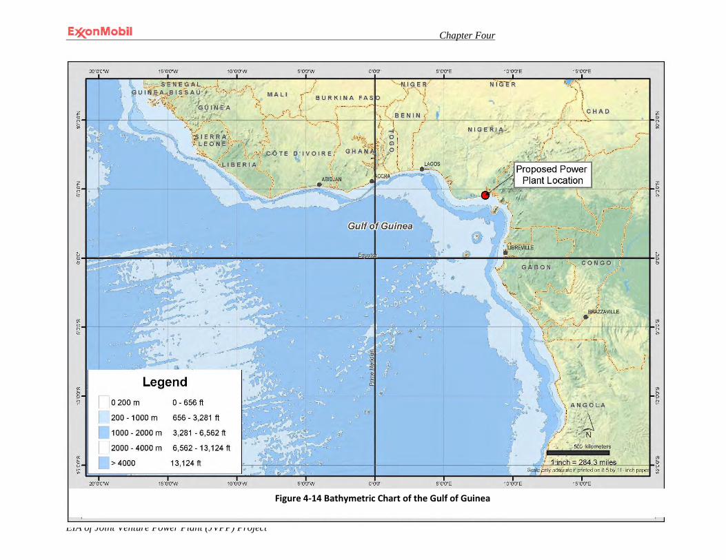
Chapter Four
EIA of Joint Venture Power Plant (JVPP) Project
4-67
Figure 4-20 Bathymetry Chart of the Gulf of Guinea
Figure 4-14 Bathymetric Chart of the Gulf of Guinea
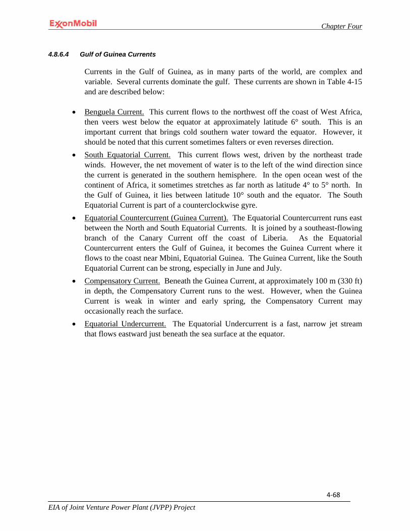
Chapter Four
EIA of Joint Venture Power Plant (JVPP) Project
4-68
4.8.6.4 Gulf of Guinea Currents
Currents in the Gulf of Guinea, as in many parts of the world, are complex and variable. Several currents dominate the gulf. These currents are shown in Table 4-15 and are described below:
• Benguela Current. This current flows to the northwest off the coast of West Africa,
then veers west below the equator at approximately latitude 6° south. This is an important current that brings cold southern water toward the equator. However, it should be noted that this current sometimes falters or even reverses direction.
• South Equatorial Current. This current flows west, driven by the northeast trade winds. However, the net movement of water is to the left of the wind direction since the current is generated in the southern hemisphere. In the open ocean west of the continent of Africa, it sometimes stretches as far north as latitude 4° to 5° north. In the Gulf of Guinea, it lies between latitude 10° south and the equator. The South Equatorial Current is part of a counterclockwise gyre.
• Equatorial Countercurrent (Guinea Current). The Equatorial Countercurrent runs east between the North and South Equatorial Currents. It is joined by a southeast-flowing branch of the Canary Current off the coast of Liberia. As the Equatorial Countercurrent enters the Gulf of Guinea, it becomes the Guinea Current where it flows to the coast near Mbini, Equatorial Guinea. The Guinea Current, like the South Equatorial Current can be strong, especially in June and July.
• Compensatory Current. Beneath the Guinea Current, at approximately 100 m (330 ft) in depth, the Compensatory Current runs to the west. However, when the Guinea Current is weak in winter and early spring, the Compensatory Current may occasionally reach the surface.
• Equatorial Undercurrent. The Equatorial Undercurrent is a fast, narrow jet stream that flows eastward just beneath the sea surface at the equator.
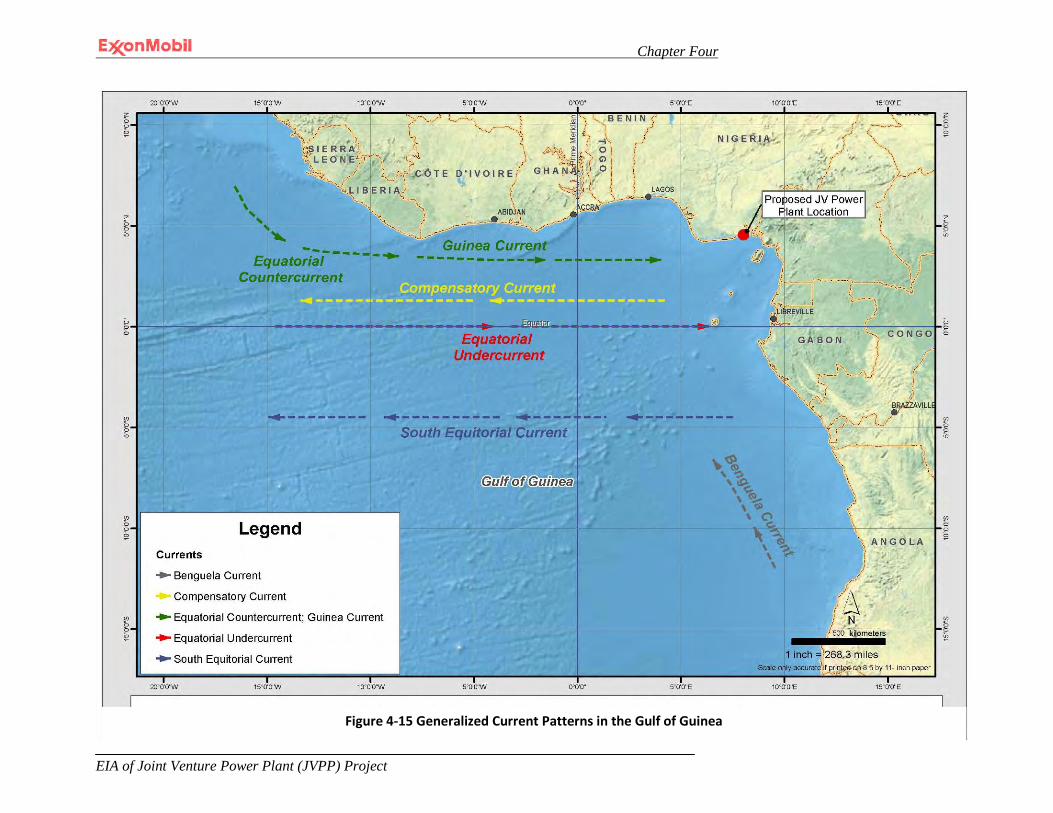
Chapter Four
EIA of Joint Venture Power Plant (JVPP) Project
4-69
Figure 4-21 Generalized Current Patterns in the Gulf of Guinea
Figure 4-15 Generalized Current Patterns in the Gulf of Guinea

Chapter Four
EIA of Joint Venture Power Plant (JVPP) Project
4-70
4.8.6.5 Regional Currents/Description of Shoreline Processes
From Nigeria to Gabon, the tremendous influx of freshwater from rivers and deltas mixes with salt water and generates localized currents caused by the differences in water density. This in turn affects other currents, particularly during the rainy season. Strong tidal movements also affect coastal currents.
The Qua Iboe River is part of the large Niger River Delta. The coastline in this area of Africa runs west to east along the Bight of Biafra. Not far to the east of the Qua Iboe River, the coastline turns to a northwest-southeast orientation as it passes behind the shadow of Bioko Island (Equatorial Guinea). Wave conditions are almost entirely out of the south or southwest according to the statistics presented in the Ocean-weather hind-cast. Therefore it can be concluded that sediment transport in this area is nearly uni-directional from west to the east ( Moffatt & Nichol International 1997).
Figure 4-16 Sediment dispersion at the mouth of the Qua Iboe River
4.8.6.6 Waves
The wave height in the exposed ocean waters off the Project coast is 1-2 meters (3.3-6.5 ft) at about 10-16 second period. Maximum significant wave height is 3.2 m (10.5 ft) (Moffatt and Nichols 1997).
Chapter Four
EIA of Joint Venture Power Plant (JVPP) Project
4-71
4.8.6.7 Seawater Salinity
Salinity measurements recorded in the vicinity of the proposed Project during the spring when the water profile was fully mixed was found to range from 22 part per trillion (ppt) to 25.5 ppt when the surface air temperature ranged from 27.20C to 29.50C. During the neap tide measurements, temperature stratification in the water column occurred. The salinity then varied from 21 ppt at the surface to 27.8 ppt at the bottom and the surface air temperature ranged from 27.10C to 28.50C (Ingenieursbureau Svasek, 1996).
4.8.7 Marine Fauna
Table 4-7 through Table 4-10 present the IUCN conservation status associated with each “special status species” of marine mammal, seabird, sea turtle and fish known to occur within the Guinea Current Large Marine Ecosystem (LME) as defined by the National Oceanic and Atmospheric Administration (NOAA) of the United States of America. The associated likelihood of occurrence as defined in section 5.7.8 is also provided for each of these special-status marine species. Special-status species, for the purposes of this assessment, refers to those species with a status of Near Threatened or greater according to the IUCN.
The Guinea Current LME extends from 200W to 120E along the west coast of Africa and from 120N to 160S. It includes the east flowing Guinea current in the north and the narrow Angola current that runs along the Atlantic coast of Africa, south from Guinea Current to where it mixes with the Benguela Current at approximately 150S, thereby forming the Angola-Benguela frontal zone.
4.8.7.1 Marine Mammals
A summary of the special status marine mammals known to occur within the Guinea Current LME and their associated IUCN conservation status is presented in Table 4-6.
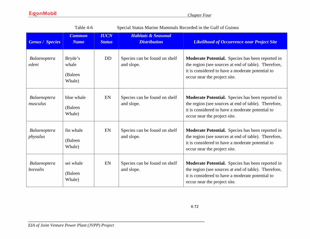
Chapter Four
EIA of Joint Venture Power Plant (JVPP) Project
4-72
Table 4-6 Special Status Marine Mammals Recorded in the Gulf of Guinea
Genus / Species Common
Name IUCN Status
Habitats & Seasonal Distribution Likelihood of Occurrence near Project Site
Balaenoptera edeni
Bryde’s whale
(Baleen Whale)
DD
Species can be found on shelf and slope.
Moderate Potential. Species has been reported in the region (see sources at end of table). Therefore, it is considered to have a moderate potential to occur near the project site.
Balaenoptera musculus
blue whale
(Baleen Whale)
EN
Species can be found on shelf and slope.
Moderate Potential. Species has been reported in the region (see sources at end of table). Therefore, it is considered to have a moderate potential to occur near the project site.
Balaenoptera physalus
fin whale
(Baleen Whale)
EN
Species can be found on shelf and slope.
Moderate Potential. Species has been reported in the region (see sources at end of table). Therefore, it is considered to have a moderate potential to occur near the project site.
Balaenoptera borealis
sei whale
(Baleen Whale)
EN
Species can be found on shelf and slope.
Moderate Potential. Species has been reported in the region (see sources at end of table). Therefore, it is considered to have a moderate potential to occur near the project site.

Chapter Four
EIA of Joint Venture Power Plant (JVPP) Project
4-73
Genus / Species Common
Name IUCN Status
Habitats & Seasonal Distribution Likelihood of Occurrence near Project Site
Physeter macrocephalus
sperm whale (Toothed Whale)
VU
Species can be found on slope and open ocean (possibly year-round - especially females and young).
Moderate Potential. Species has been reported in the region (see sources at end of table). Therefore, it is considered to have a moderate potential to occur near the project site.
Mesoplodon europaeus
Gervais’ beaked whale (Toothed Whale)
DD
Species can be found on slope and basins.
Moderate Potential. Species has been reported in the region (see sources at end of table). Therefore, it is considered to have a moderate potential to occur near the project site.
Mesoplodon densirostris
Blainville’s beaked whale (Toothed Whale)
DD
Species can be found on slope and basins.
Moderate Potential. Species has been reported in the region (see sources at end of table). Therefore, it is considered to have a moderate potential to occur near the project site.
Orcinus orca
killer whale (Toothed Whale)
DD
Species can be found on shelf, slope, and offshore (year-round).
Moderate Potential. Species has been reported in the region (see sources at end of table). Therefore, it is considered to have a moderate potential to occur near the project site.

Chapter Four
EIA of Joint Venture Power Plant (JVPP) Project
4-74
Genus / Species Common
Name IUCN Status
Habitats & Seasonal Distribution Likelihood of Occurrence near Project Site
Feresa attenuata
pygmy killer whale (Toothed Whale)
DD
Species can be found on shelf to offshore and is pelagic (possibly year-round).
Moderate Potential. Species has been reported in the region (see sources at end of table). Therefore, it is considered to have a moderate potential to occur near the project site.
Table 4-6 Special Status Marine Mammals Recorded in the Gulf of Guinea (continued)
Genus / Species Common
Name IUCN Status
Habitats & Seasonal Distribution Likelihood of Occurrence near Project Site
Pseudorca crassidens
false killer whale
DD
Species can be found on shelf to offshore and is pelagic.
Moderate Potential. Species has been reported in the region (see sources at end of table). Therefore, it is considered to have a moderate potential to occur near the project site.
Globicephala melaena
long-finned pilot whale
DD
Species can be found on shelf, slope, and offshore.
Moderate Potential. Species has been reported in the region (see sources at end of table). Therefore, it is considered to have a moderate potential to occur near the project site.
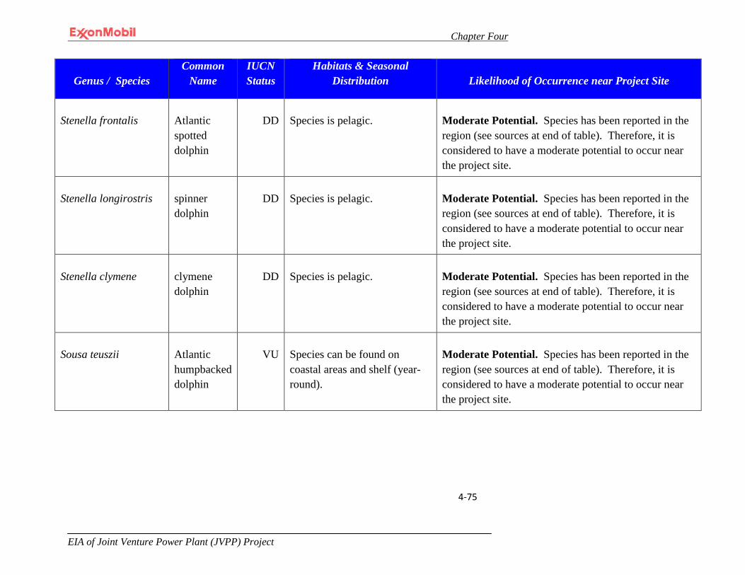
Chapter Four
EIA of Joint Venture Power Plant (JVPP) Project
4-75
Genus / Species Common
Name IUCN Status
Habitats & Seasonal Distribution Likelihood of Occurrence near Project Site
Stenella frontalis
Atlantic spotted dolphin
DD
Species is pelagic.
Moderate Potential. Species has been reported in the region (see sources at end of table). Therefore, it is considered to have a moderate potential to occur near the project site.
Stenella longirostris
spinner dolphin
DD
Species is pelagic.
Moderate Potential. Species has been reported in the region (see sources at end of table). Therefore, it is considered to have a moderate potential to occur near the project site.
Stenella clymene
clymene dolphin
DD
Species is pelagic.
Moderate Potential. Species has been reported in the region (see sources at end of table). Therefore, it is considered to have a moderate potential to occur near the project site.
Sousa teuszii
Atlantic humpbacked dolphin
VU
Species can be found on coastal areas and shelf (year-round).
Moderate Potential. Species has been reported in the region (see sources at end of table). Therefore, it is considered to have a moderate potential to occur near the project site.
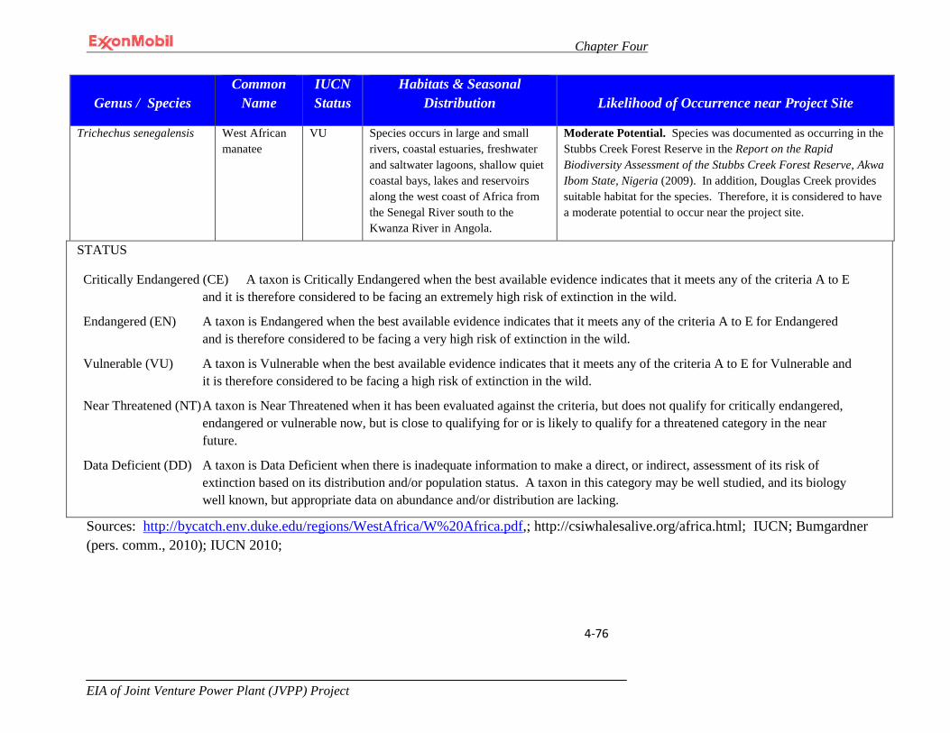
Chapter Four
EIA of Joint Venture Power Plant (JVPP) Project
4-76
Genus / Species Common
Name IUCN Status
Habitats & Seasonal Distribution Likelihood of Occurrence near Project Site
Trichechus senegalensis West African manatee
VU Species occurs in large and small rivers, coastal estuaries, freshwater and saltwater lagoons, shallow quiet coastal bays, lakes and reservoirs along the west coast of Africa from the Senegal River south to the Kwanza River in Angola.
Moderate Potential. Species was documented as occurring in the Stubbs Creek Forest Reserve in the Report on the Rapid Biodiversity Assessment of the Stubbs Creek Forest Reserve, Akwa Ibom State, Nigeria (2009). In addition, Douglas Creek provides suitable habitat for the species. Therefore, it is considered to have a moderate potential to occur near the project site.
STATUS
Critically Endangered (CE) A taxon is Critically Endangered when the best available evidence indicates that it meets any of the criteria A to E and it is therefore considered to be facing an extremely high risk of extinction in the wild.
Endangered (EN) A taxon is Endangered when the best available evidence indicates that it meets any of the criteria A to E for Endangered and is therefore considered to be facing a very high risk of extinction in the wild.
Vulnerable (VU) A taxon is Vulnerable when the best available evidence indicates that it meets any of the criteria A to E for Vulnerable and it is therefore considered to be facing a high risk of extinction in the wild.
Near Threatened (NT) A taxon is Near Threatened when it has been evaluated against the criteria, but does not qualify for critically endangered, endangered or vulnerable now, but is close to qualifying for or is likely to qualify for a threatened category in the near future.
Data Deficient (DD) A taxon is Data Deficient when there is inadequate information to make a direct, or indirect, assessment of its risk of extinction based on its distribution and/or population status. A taxon in this category may be well studied, and its biology well known, but appropriate data on abundance and/or distribution are lacking.
Sources: http://bycatch.env.duke.edu/regions/WestAfrica/W%20Africa.pdf,; http://csiwhalesalive.org/africa.html; IUCN; Bumgardner (pers. comm., 2010); IUCN 2010;
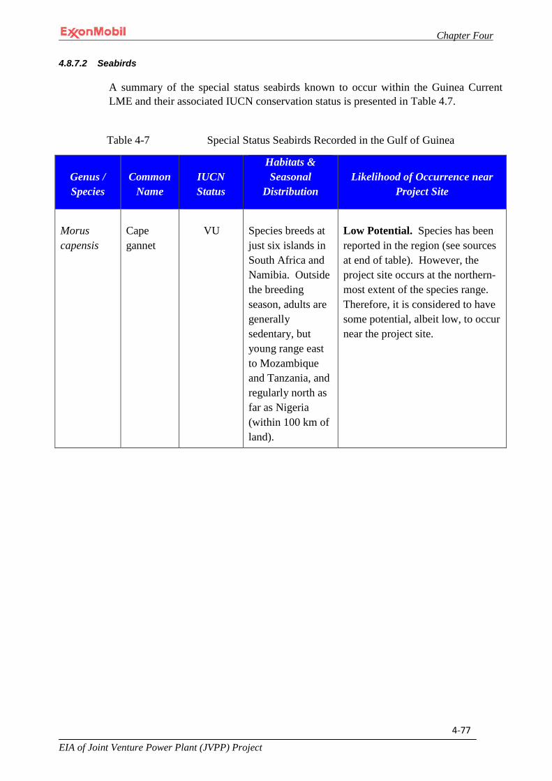
Chapter Four
EIA of Joint Venture Power Plant (JVPP) Project
4-77
4.8.7.2 Seabirds
A summary of the special status seabirds known to occur within the Guinea Current LME and their associated IUCN conservation status is presented in Table 4.7.
Table 4-7 Special Status Seabirds Recorded in the Gulf of Guinea
Genus / Species
Common Name
IUCN Status
Habitats & Seasonal
Distribution Likelihood of Occurrence near
Project Site
Morus capensis
Cape gannet
VU
Species breeds at just six islands in South Africa and Namibia. Outside the breeding season, adults are generally sedentary, but young range east to Mozambique and Tanzania, and regularly north as far as Nigeria (within 100 km of land).
Low Potential. Species has been reported in the region (see sources at end of table). However, the project site occurs at the northern-most extent of the species range. Therefore, it is considered to have some potential, albeit low, to occur near the project site.
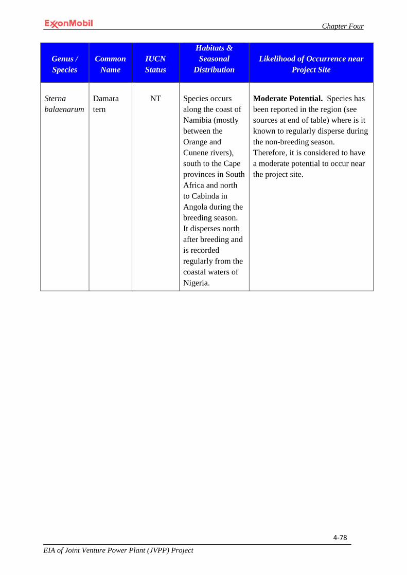
Chapter Four
EIA of Joint Venture Power Plant (JVPP) Project
4-78
Genus / Species
Common Name
IUCN Status
Habitats & Seasonal
Distribution Likelihood of Occurrence near
Project Site
Sterna balaenarum
Damara tern
NT
Species occurs along the coast of Namibia (mostly between the Orange and Cunene rivers), south to the Cape provinces in South Africa and north to Cabinda in Angola during the breeding season. It disperses north after breeding and is recorded regularly from the coastal waters of Nigeria.
Moderate Potential. Species has been reported in the region (see sources at end of table) where is it known to regularly disperse during the non-breeding season. Therefore, it is considered to have a moderate potential to occur near the project site.
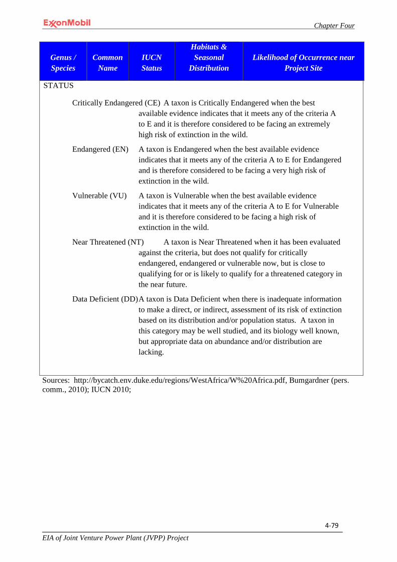
Chapter Four
EIA of Joint Venture Power Plant (JVPP) Project
4-79
Genus / Species
Common Name
IUCN Status
Habitats & Seasonal
Distribution Likelihood of Occurrence near
Project Site
STATUS
Critically Endangered (CE) A taxon is Critically Endangered when the best available evidence indicates that it meets any of the criteria A to E and it is therefore considered to be facing an extremely high risk of extinction in the wild.
Endangered (EN) A taxon is Endangered when the best available evidence indicates that it meets any of the criteria A to E for Endangered and is therefore considered to be facing a very high risk of extinction in the wild.
Vulnerable (VU) A taxon is Vulnerable when the best available evidence indicates that it meets any of the criteria A to E for Vulnerable and it is therefore considered to be facing a high risk of extinction in the wild.
Near Threatened (NT) A taxon is Near Threatened when it has been evaluated against the criteria, but does not qualify for critically endangered, endangered or vulnerable now, but is close to qualifying for or is likely to qualify for a threatened category in the near future.
Data Deficient (DD) A taxon is Data Deficient when there is inadequate information to make a direct, or indirect, assessment of its risk of extinction based on its distribution and/or population status. A taxon in this category may be well studied, and its biology well known, but appropriate data on abundance and/or distribution are lacking.
Sources: http://bycatch.env.duke.edu/regions/WestAfrica/W%20Africa.pdf, Bumgardner (pers. comm., 2010); IUCN 2010;

Chapter Four
EIA of Joint Venture Power Plant (JVPP) Project
4-80
4.8.7.3 Sea Turtles
A summary of the special sea turtles known to occur within the Guinea Current LME and their associated IUCN conservation status is presented in Table 4.8.
Table 4-8 Special Status Sea Turtles Recorded in the Gulf of Guinea
Genus / Species Common Name IUCN Status
Habitats & Seasonal
Distribution Likelihood of Occurrence
near Project Site
Caretta caretta
loggerhead sea turtle
EN
Species is coastal to pelagic (year-round).
Moderate Potential. Species has been reported in the region (see sources at end of table). Therefore, it is considered to have a moderate potential to occur near the project site.
Chelonia mydas
green sea turtle
EN
Species is coastal to pelagic (year-round).
Moderate Potential. Species has been reported in the region (see sources at end of table). Therefore, it is considered to have a moderate potential to occur near the project site.
Lepidochelys olivacea
olive ridley sea turtle
EN
Species is coastal to pelagic (year-round).
Moderate Potential. Species has been reported in the region (see sources at end of table). Therefore, it is considered to have a moderate potential to occur near the project site.
Lepidochelys kempii
Kemp’s ridley sea turtle
CE
Species is coastal to pelagic (year-round).
Moderate Potential. Species has been reported in the region (see sources at end of table). Therefore, it is considered to have a moderate potential to occur near the project site.
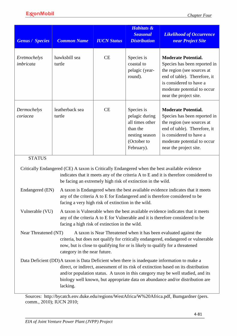
Chapter Four
EIA of Joint Venture Power Plant (JVPP) Project
4-81
Genus / Species Common Name IUCN Status
Habitats & Seasonal
Distribution Likelihood of Occurrence
near Project Site
Eretmochelys imbricata
hawksbill sea turtle
CE
Species is coastal to pelagic (year-round).
Moderate Potential. Species has been reported in the region (see sources at end of table). Therefore, it is considered to have a moderate potential to occur near the project site.
Dermochelys coriacea
leatherback sea turtle
CE
Species is pelagic during all times other than the nesting season (October to February).
Moderate Potential. Species has been reported in the region (see sources at end of table). Therefore, it is considered to have a moderate potential to occur near the project site.
STATUS
Critically Endangered (CE) A taxon is Critically Endangered when the best available evidence indicates that it meets any of the criteria A to E and it is therefore considered to be facing an extremely high risk of extinction in the wild.
Endangered (EN) A taxon is Endangered when the best available evidence indicates that it meets any of the criteria A to E for Endangered and is therefore considered to be facing a very high risk of extinction in the wild.
Vulnerable (VU) A taxon is Vulnerable when the best available evidence indicates that it meets any of the criteria A to E for Vulnerable and it is therefore considered to be facing a high risk of extinction in the wild.
Near Threatened (NT) A taxon is Near Threatened when it has been evaluated against the criteria, but does not qualify for critically endangered, endangered or vulnerable now, but is close to qualifying for or is likely to qualify for a threatened category in the near future.
Data Deficient (DD) A taxon is Data Deficient when there is inadequate information to make a direct, or indirect, assessment of its risk of extinction based on its distribution and/or population status. A taxon in this category may be well studied, and its biology well known, but appropriate data on abundance and/or distribution are lacking.
Sources: http://bycatch.env.duke.edu/regions/WestAfrica/W%20Africa.pdf, Bumgardner (pers. comm., 2010); IUCN 2010;
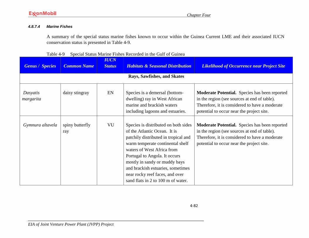
Chapter Four
EIA of Joint Venture Power Plant (JVPP) Project
4-82
4.8.7.4 Marine Fishes
A summary of the special status marine fishes known to occur within the Guinea Current LME and their associated IUCN conservation status is presented in Table 4-9. Table 4-9 Special Status Marine Fishes Recorded in the Gulf of Guinea
Genus / Species Common Name IUCN Status Habitats & Seasonal Distribution Likelihood of Occurrence near Project Site
Rays, Sawfishes, and Skates
Dasyatis margarita
daisy stingray
EN
Species is a demersal (bottom-dwelling) ray in West African marine and brackish waters including lagoons and estuaries.
Moderate Potential. Species has been reported in the region (see sources at end of table). Therefore, it is considered to have a moderate potential to occur near the project site.
Gymnura altavela
spiny butterfly ray
VU
Species is distributed on both sides of the Atlantic Ocean. It is patchily distributed in tropical and warm temperate continental shelf waters of West Africa from Portugal to Angola. It occurs mostly in sandy or muddy bays and brackish estuaries, sometimes near rocky reef faces, and over sand flats in 2 to 100 m of water.
Moderate Potential. Species has been reported in the region (see sources at end of table). Therefore, it is considered to have a moderate potential to occur near the project site.
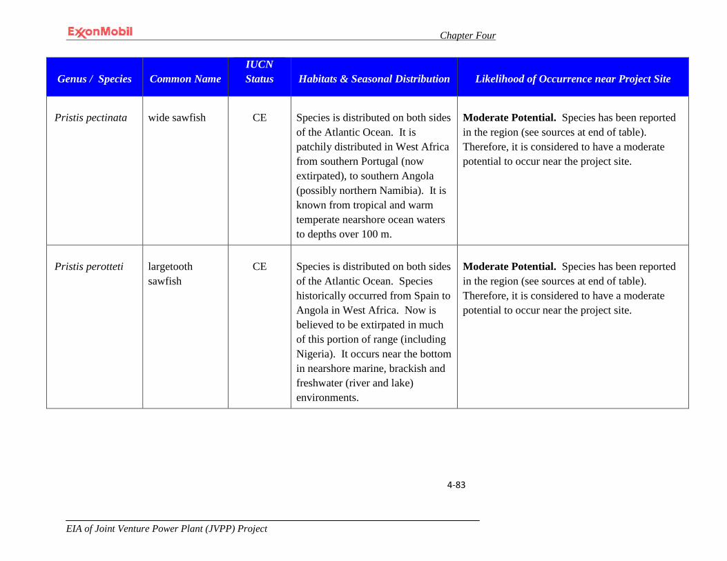
Chapter Four
EIA of Joint Venture Power Plant (JVPP) Project
4-83
Genus / Species Common Name IUCN Status Habitats & Seasonal Distribution Likelihood of Occurrence near Project Site
Pristis pectinata
wide sawfish
CE
Species is distributed on both sides of the Atlantic Ocean. It is patchily distributed in West Africa from southern Portugal (now extirpated), to southern Angola (possibly northern Namibia). It is known from tropical and warm temperate nearshore ocean waters to depths over 100 m.
Moderate Potential. Species has been reported in the region (see sources at end of table). Therefore, it is considered to have a moderate potential to occur near the project site.
Pristis perotteti
largetooth sawfish
CE
Species is distributed on both sides of the Atlantic Ocean. Species historically occurred from Spain to Angola in West Africa. Now is believed to be extirpated in much of this portion of range (including Nigeria). It occurs near the bottom in nearshore marine, brackish and freshwater (river and lake) environments.
Moderate Potential. Species has been reported in the region (see sources at end of table). Therefore, it is considered to have a moderate potential to occur near the project site.

Chapter Four
EIA of Joint Venture Power Plant (JVPP) Project
4-84
Genus / Species Common Name IUCN Status Habitats & Seasonal Distribution Likelihood of Occurrence near Project Site
Pristis pristis
common sawfish
CE
Species historically occurred in the eastern Atlantic Ocean and Mediterranean Sea, but is now extirpated from its European range. In West Africa it occurs from Portugal south to Angola (possibly to Namibia). It occurs near the bottom in nearshore marine, brackish and freshwater environments.
Moderate Potential. Species has been reported in the region (see sources at end of table). Therefore, it is considered to have a moderate potential to occur near the project site.

Chapter Four
EIA of Joint Venture Power Plant (JVPP) Project
4-85
Table 4-9 Special Status Marine Fishes Recorded in the Gulf of Guinea (continued)
Genus / Species Common Name
IUCN Status Habitats & Seasonal Distribution
Likelihood of Occurrence near Project Site
Rhinobatos albomaculatus
white-spotted guitarfish
VU
Species occurs near the bottom in shallow coastal waters from southern Senegal to Angola. Mangrove forests in the Gulf of Guinea may be important nursery grounds for the species.
Moderate Potential. Species has been reported in the region (see sources at end of table). Therefore, it is considered to have a moderate potential to occur near the project site.
Rhinobatos cemiculus
blackchin guitarfish
EN
Species occurs in marine and brackish waters from Portugal south to Angola (including the Mediterranean Sea). It is demersal, living over sandy or muddy substrates, at depths ranging from shallow water to approximately 100 m.
Moderate Potential. Species has been reported in the region (see sources at end of table). Therefore, it is considered to have a moderate potential to occur near the project site.
Rhinobatos irvinei
spineback guitarfish
VU
Species occurs in shallow coastal waters (to about 30 m) from Morocco south to Angola. Mangrove forests in the Gulf of Guinea may be important nursery grounds for the species.
Moderate Potential. Species has been reported in the region (see sources at end of table). Therefore, it is considered to have a moderate potential to occur near the project site.

Chapter Four
EIA of Joint Venture Power Plant (JVPP) Project
4-86
Genus / Species Common Name
IUCN Status Habitats & Seasonal Distribution
Likelihood of Occurrence near Project Site
Rhinobatos rhinobatos
common guitarfish
EN
Species occurs as a bottom-dwelling species over sandy, muddy, shell and occasionally macro-algal covered substrates (generally between 10 and 100 m in depth) from France (Bay of Biscay) and the Mediterranean Sea south to Angola.
Moderate Potential. Species has been reported in the region (see sources at end of table). Therefore, it is considered to have a moderate potential to occur near the project site.
Rhynchobatus luebberti
Lubbert’s guitarfish
EN
Species is found in coastal waters of West Africa from Mauritania south to Angola. It occurs as a demersal species over soft mud or sand from the intertidal zone to 70 m, but generally not deeper than 35 m.
Moderate Potential. Species has been reported in the region (see sources at end of table). Therefore, it is considered to have a moderate potential to occur near the project site.
Rostroraja alba
bottlenose skate
EN
Species occurs in the eastern Atlantic Ocean from the southern British Isles south to South Africa (including the Mediterranean Sea), and extending into the southwestern parts of the Indian Ocean. It is a bottom-dwelling species of sandy and detrital bottoms from coastal waters to the upper slope region between 40 and 400 m and exceptionally down to 500 m.
Moderate Potential. Species has been reported in the region (see sources at end of table). Therefore, it is considered to have a moderate potential to occur near the project site.

Chapter Four
EIA of Joint Venture Power Plant (JVPP) Project
4-87
Genus / Species Common Name
IUCN Status Habitats & Seasonal Distribution
Likelihood of Occurrence near Project Site
Galeorhinus galeus
liver-oil shark
VU
Species is widespread in cold to warm temperate waters. It is primarily found near the bottom, but ranges through the water column from the surfline and very shallow water to well offshore.
Moderate Potential. Species has been reported in the region (see sources at end of table). Therefore, it is considered to have a moderate potential to occur near the project site.
Isurus oxyrinchus
shortfin mako shark
VU
Species is a coastal, oceanic species occurring from the surface to at least 500 m in depth. It is widespread in temperate and tropical waters of all oceans from about 50°N (up to 60°N in the northeast Atlantic) to 50°S. It is occasionally found close inshore where the continental shelf is narrow. It is not normally found in waters below 16°C
Moderate Potential. Species has been reported in the region (see sources at end of table). Therefore, it is considered to have a moderate potential to occur near the project site.
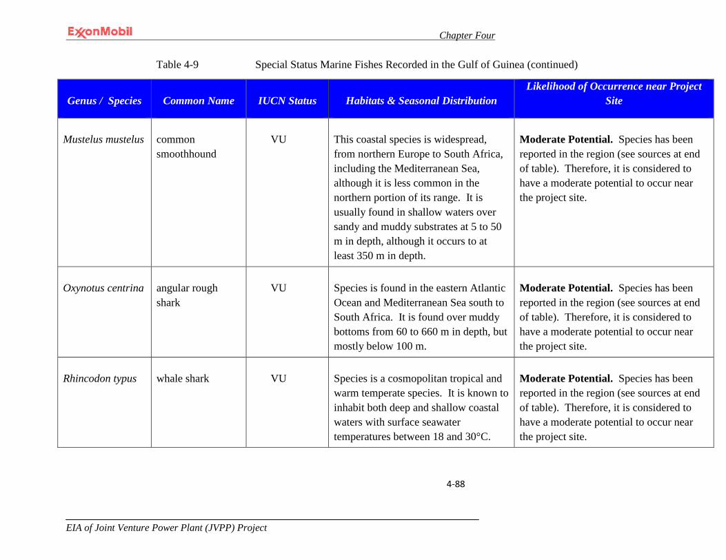
Chapter Four
EIA of Joint Venture Power Plant (JVPP) Project
4-88
Table 4-9 Special Status Marine Fishes Recorded in the Gulf of Guinea (continued)
Genus / Species Common Name IUCN Status Habitats & Seasonal Distribution Likelihood of Occurrence near Project
Site
Mustelus mustelus
common smoothhound
VU
This coastal species is widespread, from northern Europe to South Africa, including the Mediterranean Sea, although it is less common in the northern portion of its range. It is usually found in shallow waters over sandy and muddy substrates at 5 to 50 m in depth, although it occurs to at least 350 m in depth.
Moderate Potential. Species has been reported in the region (see sources at end of table). Therefore, it is considered to have a moderate potential to occur near the project site.
Oxynotus centrina
angular rough shark
VU
Species is found in the eastern Atlantic Ocean and Mediterranean Sea south to South Africa. It is found over muddy bottoms from 60 to 660 m in depth, but mostly below 100 m.
Moderate Potential. Species has been reported in the region (see sources at end of table). Therefore, it is considered to have a moderate potential to occur near the project site.
Rhincodon typus
whale shark
VU
Species is a cosmopolitan tropical and warm temperate species. It is known to inhabit both deep and shallow coastal waters with surface seawater temperatures between 18 and 30°C.
Moderate Potential. Species has been reported in the region (see sources at end of table). Therefore, it is considered to have a moderate potential to occur near the project site.

Chapter Four
EIA of Joint Venture Power Plant (JVPP) Project
4-89
Genus / Species Common Name IUCN Status Habitats & Seasonal Distribution Likelihood of Occurrence near Project
Site
Sphyrna lewini
scalloped hammerhead shark
EN
Species is a coastal and semioceanic shark that is circumglobal in coastal warm temperate and tropical seas, from the surface and intertidal to at least 275 m in depth. It is probably present all along the West Africa coast, but confirmed only from Mauritania, Senegal, Gambia, Ivory Coast, Guinea, Guinea Bissau, Sierra Leone, Gabon, and Congo.
Low Potential. Species has been reported in the region (see sources at end of table). However, it has not been reported from Nigeria. Therefore, it is considered to have some potential, albeit low, to occur near the project site.
Squatina oculata
smoothback angel shark
CE
Species was formerly a common demersal species over large areas of coastal and outer continental shelf sediment habitat in the Mediterranean Sea and eastern Atlantic Ocean. It generally occurs from >20 to 500 m, but mostly between 50 and 100 m in depth.
Moderate Potential. Species has been reported in the region (see sources at end of table). Therefore, it is considered to have a moderate potential to occur near the project site.

Chapter Four
EIA of Joint Venture Power Plant (JVPP) Project
4-90
Genus / Species Common Name IUCN Status Habitats & Seasonal Distribution Likelihood of Occurrence near Project
Site
STATUS
Critically Endangered (CE) A taxon is Critically Endangered when the best available evidence indicates that it meets any of the criteria A to E and it is therefore considered to be facing an extremely high risk of extinction in the wild.
Endangered (EN) A taxon is Endangered when the best available evidence indicates that it meets any of the criteria A to E for Endangered and is therefore considered to be facing a very high risk of extinction in the wild.
Vulnerable (VU) A taxon is Vulnerable when the best available evidence indicates that it meets any of the criteria A to E for Vulnerable and it is therefore considered to be facing a high risk of extinction in the wild.
Near Threatened (NT) A taxon is Near Threatened when it has been evaluated against the criteria, but does not qualify for critically endangered, endangered or vulnerable now, but is close to qualifying for or is likely to qualify for a threatened category in the near future.
Data Deficient (DD) A taxon is Data Deficient when there is inadequate information to make a direct, or indirect, assessment of its risk of extinction based on its distribution and/or population status. A taxon in this category may be well studied, and its biology well known, but appropriate data on abundance and/or distribution are lacking.
Sources: http://bycatch.env.duke.edu/regions/WestAfrica/W%20Africa.pdf, Bumgardner (pers. comm., 2010); IUCN 2010.

Chapter Four
EIA of Joint Venture Power Plant (JVPP) Project
4-91
4.8.8 Marine Plants
Data available on the marine plants of the region is very limited. The baseline for this resource will not be assessed because the frequency of contact with marine plants in this environment is very rare.
4.8.9 Unique Marine Resources
No unique marine habitat features were identified in the immediate vicinity of the offshore Project site. Also, there are no marine turtle nesting beaches or coral reefs that are known to occur near the Project site based on a review of the available literature.
4.8.10 Rare, Vulnerable, or Endangered Species
Table 4-10 present the present the “special status species” known to occur within the Guinea Current LME based on the references presented at the end of each table. However, the available literature for these species provides no evidence that high densities of these species occur within the vicinity of the offshore portion of the Project nor is there any evidence from the literature that any important habitats (e.g., calving grounds) exist within the offshore Project vicinity.
4.9 Air Quality
4.9.1 Wind Speed and Direction Data
The annual prevailing wind direction is from the southwest year-round with an average speed of 6 knots (6.9 miles/hour, statute). This information is based on the monthly wind direction and speed data recorded at QIT for the years 1997-2011 (See Appendix II-1 to this EIA.)
4.9.2 Background Air Quality
4.9.2.1 Onshore Air Quality Samples
One instantaneous air quality measurement was collected during a dry season sampling event and two instantaneous air quality measurements were collected during a wet season sampling event from each of the sample collection locations depicted in Figure 4-17.
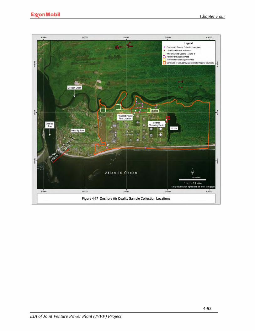
Chapter Four
EIA of Joint Venture Power Plant (JVPP) Project
4-92
Chapter Four
EIA of Joint Venture Power Plant (JVPP) Project
4-93
4.9.2.2 Offshore Air Quality Samples
One instantaneous air sample was collected at sample point PLQ-2 as presented in Table 4-18 and three instantaneous air quality measurements were also collected from the offshore locations presented in Figure 4-18. There are no human or wildlife receptors at the offshore locations that could be exposed to a release above the regulatory or industry accepted threshold.
4.9.2.3 Air Quality Status
The main source of natural air pollution in the area of influence is fugitive dust. Prevailing winds from the southwest are likely to entrain and carry dust from dry areas. Additionally, the Harmattan winds are known to transport large quantities of dust from the Sahara desert to the area of influence during the dry season.
Major sources of anthropogenic air pollution in the area of influence are likely caused by gas flaring at QIT, wood burning for domestic cooking (see Section 4.12.4.1) and the operation of motor vehicles. The flaring operations will cease following installation of the rich gas pipeline.
4.9.2.4 Air Dispersion Study
In addition to the above, an air dispersion study was conducted in the proposed project location to further investigate the expected air pollution situation of the Qua Iboe Power Plant Project. The study used a combined cycle power plant configuration consisting of 3 gas turbines with associated heat recovery steam generators (HRSG). It evaluated the preload level of pollution (background pollution) on site and discussed the additional project pollution effects during different load operations. Furthermore the study validated the height of the HRSG stack against World Bank stack height calculation guidelines and fulfillment of the Irrelevance criteria for emission of relevant pollutants to surrounding areas. The validation provided further information on how high the stack must be to fulfill the NO2 emission limit for the irrelevance criteria for people and vegetation.
The likely emissions of concern are NO2, CO and PM10. The amount and nature of air emissions depends on factors such as the fuel, the type and design of the combustion unit, operating practices, emission control measures (primary, secondary) and the overall system efficiency. Limit values for these pollutants have been set according to WHO and World Bank standards, which shall be used as the basis for QIPP. In addition, the internationally accepted irrelevance criterion rule shall be followed. In the USA this rule is known under the name “thresholds of significance“. According to this

Chapter Four
EIA of Joint Venture Power Plant (JVPP) Project
4-94
rule additional emissions can be accepted independent from any preload level of pollution as long as they are lower than 1% of the limit value per year.
As part of the emissions prognosis a dispersion grid calculation was made. The dispersion calculation was performed according to “TA Luft” (a technical standard for air quality protection in Germany). It was performed with IMMI-Software version 2010-2 Premium. The “TA Luft” uses a Gaussian plume model for atmospheric dispersion modeling. The immission results are the same for all investigated cases (base load and part load). Only the immission values vary.
Table 4-10: World Bank Emission Guidelines for gas turbines >50 MWth per unit
Pollutant Maximum allowed value * in mg/m³ Remarks
NOx 51 Dry gas with 15% O2 Content
CO NA
PM10 NA
* EA may justify more stringent or less stringent limits due to ambient environment, technical and economic considerations.
Table 4-11: Project Emission Standards
Pollutant Maximum allowed value in mg/m³ Remarks Source
NOx 51 Dry gas with 15% O2 Content
World Bank
CO NA
PM10 NA
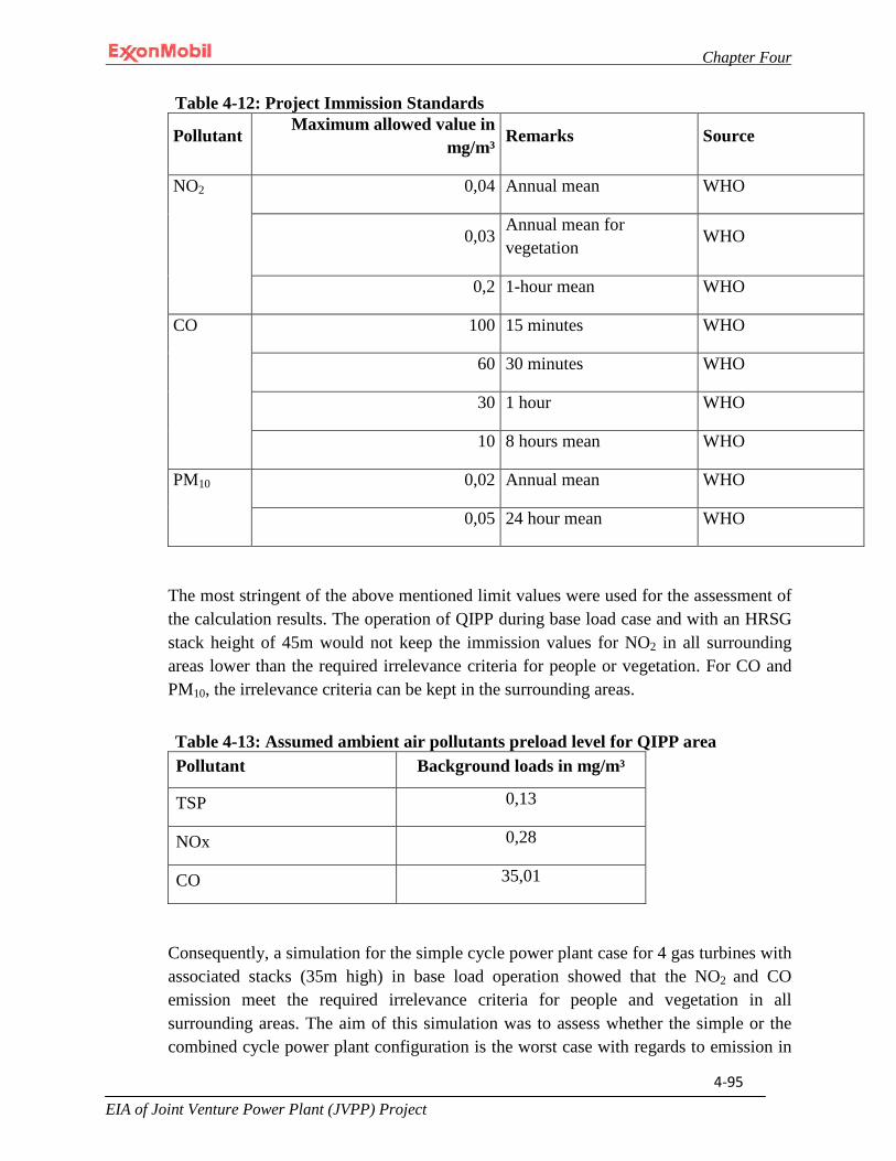
Chapter Four
EIA of Joint Venture Power Plant (JVPP) Project
4-95
Table 4-12: Project Immission Standards
Pollutant Maximum allowed value in mg/m³ Remarks Source
NO2 0,04 Annual mean WHO
0,03 Annual mean for vegetation
WHO
0,2 1-hour mean WHO
CO 100 15 minutes WHO
60 30 minutes WHO
30 1 hour WHO
10 8 hours mean WHO
PM10 0,02 Annual mean WHO
0,05 24 hour mean WHO
The most stringent of the above mentioned limit values were used for the assessment of the calculation results. The operation of QIPP during base load case and with an HRSG stack height of 45m would not keep the immission values for NO2 in all surrounding areas lower than the required irrelevance criteria for people or vegetation. For CO and PM10, the irrelevance criteria can be kept in the surrounding areas.
Table 4-13: Assumed ambient air pollutants preload level for QIPP area Pollutant Background loads in mg/m³
TSP 0,13
NOx 0,28
CO 35,01
Consequently, a simulation for the simple cycle power plant case for 4 gas turbines with associated stacks (35m high) in base load operation showed that the NO2 and CO emission meet the required irrelevance criteria for people and vegetation in all surrounding areas. The aim of this simulation was to assess whether the simple or the combined cycle power plant configuration is the worst case with regards to emission in

Chapter Four
EIA of Joint Venture Power Plant (JVPP) Project
4-96
the surroundings and whether the simple cycle power plant meets the irrelevance criteria. The positive result for NO2 and CO emission can be assigned also to PM10, This is because in simple cycle operation the flue gas temperature at the gas turbine stack outlet is significantly higher (temperatures about 5500C to 5800C) than at the HRSG stack outlet in combined cycle operation thus influencing the rising and distribution of the emissions into the atmosphere in a positive way.
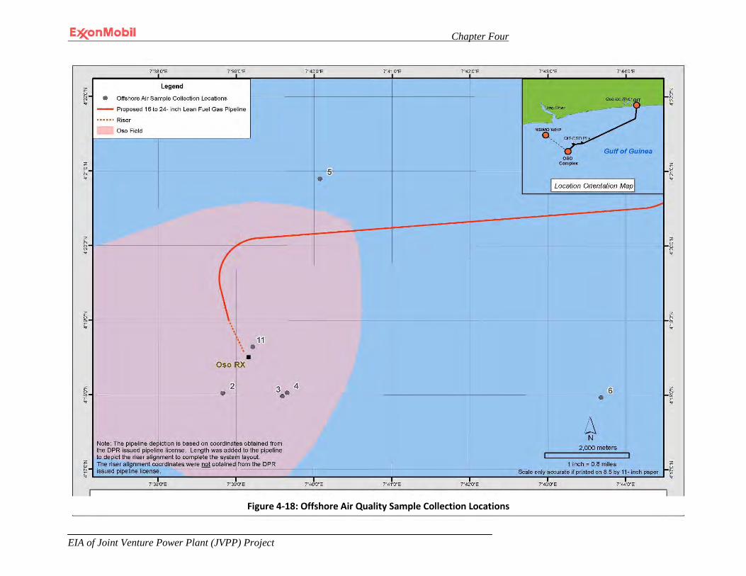
Chapter Four
EIA of Joint Venture Power Plant (JVPP) Project
4-97
Figure 4-24 Offshore Air Quality Sample Locations
Figure 4-18: Offshore Air Quality Sample Collection Locations

Chapter Four
EIA of Joint Venture Power Plant (JVPP) Project
4-98
4.10 Noise
Noise measurements were collected from 17 September, 2010 to 2 October, 2010. The measurements were collected using a Type 1 Pulsar 33 sound level meter. A wind screen was used and the sound level meter calibrated with an acoustic calibrator. The Survey was conducted in agreement with MPN’s general requirements for a community sound level survey in Global Practice 02-01-01, Facility Sound Level Design criteria.
The equipment sound level, Leq was measured over a 24 hour period over 4 days, 18 September to 21 September. The measurements were collected at 7 locations on the facility and 6 locations in the community. The daytime and night time sound levels for the facility and community locations were collected. The raw noise data is presented in Appendix II-5.
4.10.1 Noise Data Discussion
Using the 1 minute equivalent sound level Leq data the Daytime (07000 hours to 2200 hours) and Nighttime (2200 hours to 0700 hours) Leq at each of the measurement locations were calculated. The equivalent sound levels were calculated by taking the logarithmic average of all the reported 1 minute Leq data at each measurement location for the appropriate time period. Data for thirteen measurement locations were reported. The seven IP locations are relatively within the QIT facility while the six MP locations are at or near community locations remote from the proposed JV power plant and QIT facilities.
The IP daytime Leq sound levels varied from 59.9 dBA to 75.8 dBA. The IP nighttime Leq sound levels varied from 50.0 dBA to 74.4 dBA. It is believed that IP 3 is strongly influenced by the QIT flare. Table 4-14 presents the IP Leq sound levels.
Table 4-14: IP Leq Sound Levels
Sample Point
Daytime (0700 to 2200)
dBA
Nighttime (2200 to 0700)
dBA
IP1 67.4 57.7
IP2 64.9 56.5
IP3 75.8 74.4
IP4 60.6 61.6
IP5 59.9 53.7
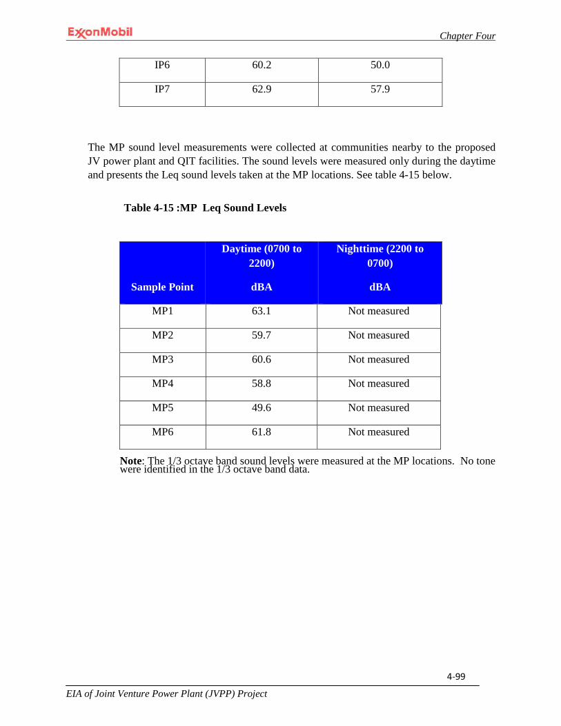
Chapter Four
EIA of Joint Venture Power Plant (JVPP) Project
4-99
IP6 60.2 50.0
IP7 62.9 57.9
The MP sound level measurements were collected at communities nearby to the proposed JV power plant and QIT facilities. The sound levels were measured only during the daytime and presents the Leq sound levels taken at the MP locations. See table 4-15 below.
Table 4-15 :MP Leq Sound Levels
Sample Point
Daytime (0700 to 2200)
dBA
Nighttime (2200 to 0700)
dBA
MP1 63.1 Not measured
MP2 59.7 Not measured
MP3 60.6 Not measured
MP4 58.8 Not measured
MP5 49.6 Not measured
MP6 61.8 Not measured
Note: The 1/3 octave band sound levels were measured at the MP locations. No tone were identified in the 1/3 octave band data.

Chapter Four
EIA of Joint Venture Power Plant (JVPP) Project
4-100

Chapter Four
EIA of Joint Venture Power Plant (JVPP) Project
4-101
4.11 Water Resources
Surface water resources include lakes, rivers and streams within a defined area of potential effect or watershed. The study include sampling and analysis of both surface and groundwater resources. Detailed discussion on the findings are provided in subsequent sections.
4.11.1 Surface Water Sediment Sampling
A sediment baseline characterization study was conducted during the dry season and wet season in both Douglas Creek and QIT Lake. Four sediment samples were collected from Douglas Creek and two sediment samples were collected from QIT Lake at the locations depicted in Fig 4-21. The samples were each analyzed for various
Chapter Four
EIA of Joint Venture Power Plant (JVPP) Project
4-102
physical and chemical properties including metals, mineral and nutrient content, organic matter and microbiological properties. These analyses are more fully discussed below. The specific analytical results for these samples are presented in Appendix II 151-152.
4.11.1.1 Physical and Chemical Properties
The analyses for physical-chemical properties included a particle size analysis, pH, conductivity, and cat-ion exchange capacity. The analysis showed the sediments to be mildly alkaline. The particle size analysis showed the sediments to be composed of approximately 92% sand, 5% clay and the remainder silt for the sediments in Douglas Creek, while for QIT Lake the sediments were found to be composed of approximately 89% sand, 7% clay and the remainder silt.
4.11.1.2 Metals and Mineral Content
The sediment samples were analyzed for heavy metals such as lead, iron, manganese, cadmium, zinc, nickel, barium, chromium, silver, cobalt and copper as well as minerals such as calcium, magnesium, sodium, potassium and potassium.
The results for heavy metal concentration for sediment samples in Douglass and QIT lake for heavy metals had a lower limit of <0.01 mg/kg and an upper limit of 1168.224mg/kg in dry season. For wet season, a lower limit of <0.01mg/kg and an upper limit of 11,032.60 mg/kg were also recorded. The detailed results are located in Appendix II-155 to this EIA.
4.11.1.3 Organic Matter
Various analyses were conducted to assess different hydrocarbon fractions present in the samples. The discussion presented in Section 4.11.2.3 is applicable here.

Chapter Four
EIA of Joint Venture Power Plant (JVPP) Project
4-103
4.11.1.4 Microbiological Properties – Bacteria and Fungi
The sediment samples collected from Douglas Creek and QIT Lake were each analyzed for the following microbiological parameters including total heterotrophic bacteria, hydrocarbon utilizing bacteria, total heterotrophic fungi, hydrocarbon utilizing fungi and coliform.
As previously mentioned, total coliform, is an “indicator" organism measured to assess the microbiological quality of water or as in this case, sediment. This information can be used to assess the relative safety for humans to consume shellfish and other aquatic organisms from Douglas Creek. QIT Lake, on the other hand, is a manmade lake located on property controlled by MPN. As such, members of the public do not have access to it for fishing or other purposes.
The total coliform bacteria measured in Douglas Creek during the dry season sampling event ranged from 10 cfu/gram (g) at sample point twenty-three to 30 cfu/g at sample point twenty-two and 40 cfu/g at sample point twenty-one. The total

Chapter Four
EIA of Joint Venture Power Plant (JVPP) Project
4-104
coliform bacteria measured in Douglas Creek during the wet season sampling event ranged from 10 cfu/g at sample point twenty-three to 10 cfu/g at sample point twenty-two and 100 cfu/g at sample point twenty-one.
The total coliform bacteria measured in QIT Lake during the dry season sampling event was found to be 40 cfu/g at sample point twenty-six and 20 cfu/g at sample point twenty-five. The total coliform bacteria measured in QIT Lake during the wet season sampling event was found to be 240 cfu/g at sample point twenty-six and 100 cfu/g at sample point twenty-five.
4.11.1.5 Benthic Habitat Assessment
The sediment sampling survey in Douglas Creek and QIT Lake identified a total of 14 benthos species representing 4 taxonomic groups: annelids, arthropods, echinoderms and mollusks. Total diversity within Douglas Creek per 0.1 m2 (1 ft2) varied from station to station ranging from 4 species at stations twenty-one and twenty-three to 6 species at station twenty-two. The number of individuals from all species ranged from 3 at stations twenty-one and twenty-three to 4 species at station twenty-two. Total diversity within QIT Lake per 0.1 m2 (1 ft2) ranged from 2 species at station twenty-six to 3 species at station twenty-five. The number of individuals from all species in QIT Lake ranged from 2 species at station twenty-six to 4 species at station twenty-five.
4.11.1.6 Analyses Summary
It is not expected that the activities associated with the onshore portion of the Project will significantly impact the baseline data discussed in this section with the possible exception of the total coliform, benthic species, oil and grease and PAH baseline data. Total coliform will be used to provide a snapshot in time of the microbiological quality of the sediment at the outset of the Project.
4.11.2 Surface Water Sampling
A surface water baseline characterization study was conducted during the dry season and wet season. During this period surface water samples were collected from Douglas Creek and QIT Lake at the locations shown in Fig 4-22. The samples were each analyzed for various physical and chemical properties including metals, mineral and nutrient content, organic matter and microbiological properties. These analyses are more fully discussed below. The specific analytical results for these samples are presented in Appendix II to this EIA.
Chapter Four
EIA of Joint Venture Power Plant (JVPP) Project
4-105
4.11.2.1 Physical and Chemical Properties
The analyses for physical-chemical properties included pH, dissolved oxygen, total dissolved solids, total suspended solids, conductivity, temperature, turbidity, chemical oxygen demand and biological oxygen demand. The specific measurements recorded for each sample during the wet and dry season are presented in Appendix II.
4.11.2.2 Metals and Mineral Content
The surface water samples were analyzed for heavy metals such as lead, iron, manganese, cadmium, zinc, nickel, vanadium, chromium, silver, cobalt and copper as well as minerals such as calcium, magnesium, sodium, potassium, chloride, sulfate and nitrate.
The results for heavy metal concentration for surface water samples in douglass and QIT lake had a lower limit of <0.01mg/l and an upper limit of 0.410mg/l in dry season. For wet season, a lower limit of <0.01mg/l and an upper limit of 1.287mg/l were also recorded. The detailed results are located in Appendix II-155 to this EIA.
4.11.2.3 Organic Matter
Various analyses were conducted on each water sample to assess the presence of different hydrocarbon fractions. As stated previously, there will be a 12,000-gallon diesel storage tank on-site during operations and mobile diesel powered vehicles present during construction operations. The direction of surface water flow is from the proposed Project area located directly south of Douglas Creek into the Atlantic ocean. Thus, knowing the baseline composition of PAH and oil/grease could serve as indicator parameters to assess an impact to Douglas Creek in the unlikely event of a spill.
A hydraulic pump will be used to dredge QIT Lake. This dredged material will be used as fill material to bring the power plant, lay-down area and workers camp footprints to the required datum. Knowing the baseline composition of PAH and oil/grease could serve as indicator parameters to assess an impact to QIT Lake in the unlikely event of a pump leak.
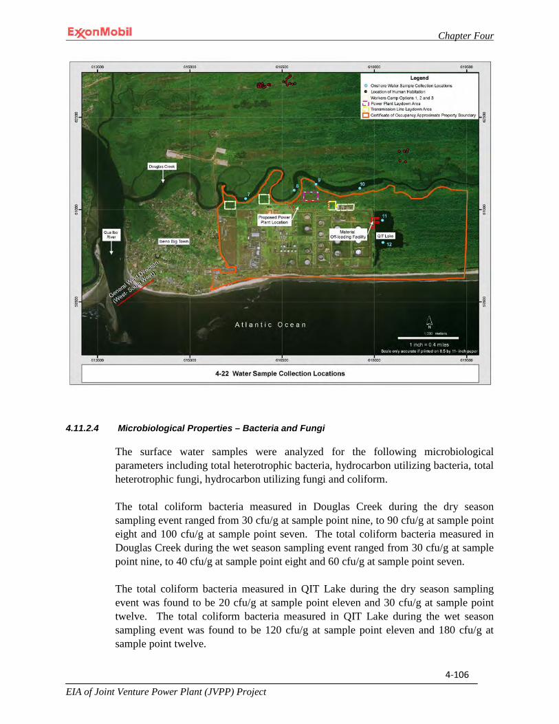
Chapter Four
EIA of Joint Venture Power Plant (JVPP) Project
4-106
4.11.2.4 Microbiological Properties – Bacteria and Fungi
The surface water samples were analyzed for the following microbiological parameters including total heterotrophic bacteria, hydrocarbon utilizing bacteria, total heterotrophic fungi, hydrocarbon utilizing fungi and coliform.
The total coliform bacteria measured in Douglas Creek during the dry season sampling event ranged from 30 cfu/g at sample point nine, to 90 cfu/g at sample point eight and 100 cfu/g at sample point seven. The total coliform bacteria measured in Douglas Creek during the wet season sampling event ranged from 30 cfu/g at sample point nine, to 40 cfu/g at sample point eight and 60 cfu/g at sample point seven.
The total coliform bacteria measured in QIT Lake during the dry season sampling event was found to be 20 cfu/g at sample point eleven and 30 cfu/g at sample point twelve. The total coliform bacteria measured in QIT Lake during the wet season sampling event was found to be 120 cfu/g at sample point eleven and 180 cfu/g at sample point twelve.

Chapter Four
EIA of Joint Venture Power Plant (JVPP) Project
4-107
4.11.2.5 Phytoplankton
The surface water sampling survey identified a total of 17 phytoplankton species representing 4 taxonomic groups: bacillariophyceae, chlorophyceae, cyanophyceae and dinophyceae. Total diversity per 0.1 m2 (1 ft2) in Douglas Creek ranged from 7 in station eight, to 8 in station nine, to 10 in station seven. The number of individuals from all species in Douglas Creek ranged from 50 in station eight to 114 in station seven. Total diversity per 0.1 m2 (1 ft2) in QIT Lake was 5 in station eleven and 7 in station twelve. The number of individuals from all species in QIT Lake was 44 in station eleven and 50 in station twelve.
4.11.2.6 Zooplankton
The water sampling survey identified a total of 16 zooplankton species representing 4 taxonomic groups: copepoda, ostracoda, rotifera, and gastropoda. Total diversity per 0.1 m2 (1 ft2) in Douglas Creek ranged from 4 in station eight, to 5 in station nine, to 6 in station seven. The number of individuals from all species in Douglas Creek ranged from 12 in station eight to 18 in station seven. Total diversity per 0.1 m2 (1 ft2) in QIT Lake was 5 in station eleven and 6 in station twelve. The number of individuals from all species in QIT Lake was 14 in station eleven and 16 in station twelve.
4.11.2.7 Analyses Summary
It is not expected that the activities associated with the onshore portion of the Project will significantly impact the baseline data discussed in this section with the possible exception of the total coliform, benthic species, oil and grease and PAH baseline data. Total coliform will be used to provide a snapshot in time of the microbiological quality of the sediment at the outset of the Project.
4.11.3 Groundwater Resources
During a dry and wet season sampling, the Project field team collected water samples from four boreholes as shown in Figure 4-22. The regional fresh water aquifer that underlies the Project site has been documented in several geotechnical investigations over the years as being located approximately 183 meters (600 feet) below grade. The water table where the shallow boreholes are completed likely resulted from the presence of low permeable silt and clay soils known to underlie the Project site. These types of soils provide a barrier to significant downward movement of water from the surface to the aquifer under the site, although localized downward movement may occur where thinner or predominately silt/sandy soils exist at depths of 20.12m(66 feet). As coastal plain sands, the lithology of the area is very favorable for the storage and extraction of groundwater. Groundwater recharge is spatially distributed as there is high permeability, recharge potential and considerable
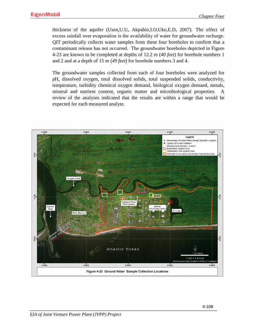
Chapter Four
EIA of Joint Venture Power Plant (JVPP) Project
4-108
thickness of the aquifer (Usen,U.U, Akpabio,I.O,Uko,E.D, 2007). The effect of excess rainfall over evaporation is the availability of water for groundwater recharge. QIT periodically collects water samples from these four boreholes to confirm that a contaminant release has not occurred. The groundwater boreholes depicted in Figure 4-23 are known to be completed at depths of 12.2 m (40 feet) for borehole numbers 1 and 2 and at a depth of 15 m (49 feet) for borehole numbers 3 and 4.
The groundwater samples collected from each of four boreholes were analyzed for pH, dissolved oxygen, total dissolved solids, total suspended solids, conductivity, temperature, turbidity chemical oxygen demand, biological oxygen demand, metals, mineral and nutrient content, organic matter and microbiological properties. A review of the analyses indicated that the results are within a range that would be expected for each measured analyte.

Chapter Four
EIA of Joint Venture Power Plant (JVPP) Project
4-109
4.12 Socioeconomic, Archaeological, and Cultural Resources
The principle sources of information used to prepare this baseline description are the field survey undertaken by the BGI team, survey conducted by the Shell team and reported in their Rapid Biodiversity Report of the Stubbs Creek Forest Reserve (2009), and by Baker (2005) on Distribution and Conservation status of species in southern Nigeria, as well as Internet research.
4.12.1 Human Settlements
The proposed power plant will be constructed within the Stubbs Creek Forest Reserve on a land-plot located directly adjacent to MPN’s existing QIT industrial facility (Figure 4-24). Based on the findings of the socioeconomic studies, the communities located in and around the Stubbs Creek Forest Reserve belong to four Local Government Areas (LGAs): Eket, Esit Eket, Ibeno and Mbo (Figure 4-3024). The dominant groups of people within these LGAs are the Eket people from Esit Eket and Eket LGAs, the Ibeno people from the Ibeno LGA, and the Mbo people from the Mbo LGA. Other groups that have migrated to the Reserve include the Igbos, Yorubas, Hausas and Fulanis in addition to non-Nigerians principally from Cameroon and Ghana. The socioeconomic questionnaire used for the study is included in Appendix III. Details of findings are provided in subsequent discussion.
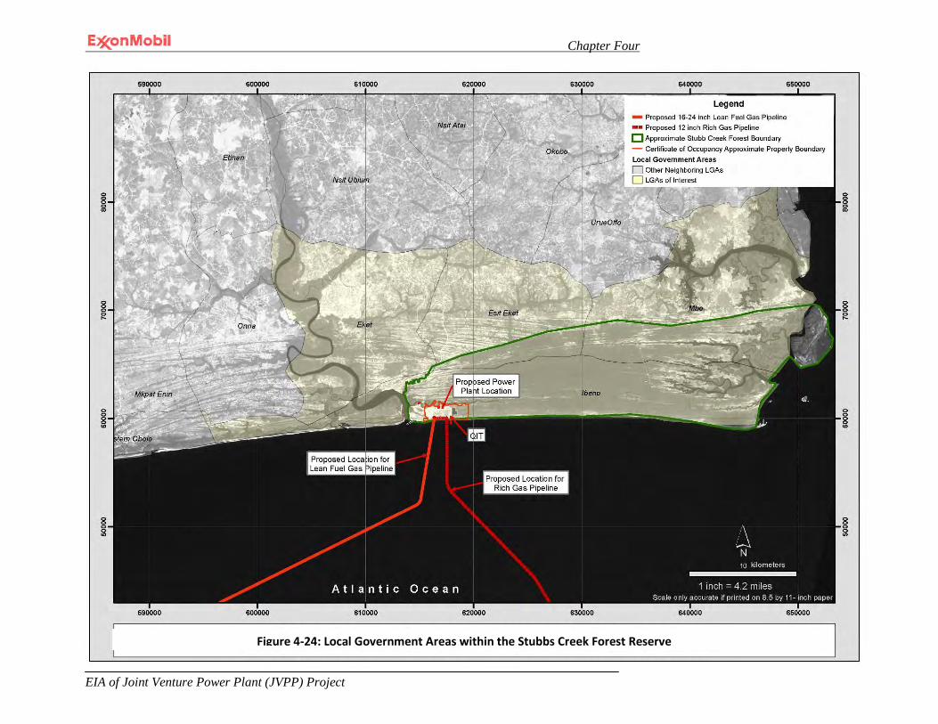
Chapter Four
EIA of Joint Venture Power Plant (JVPP) Project
4-110
Figure 4-30 Local Government Areas within the Stubb Creek Forest Resever
Figure 4-24: Local Government Areas within the Stubbs Creek Forest Reserve

Chapter Four
EIA of Joint Venture Power Plant (JVPP) Project
4-111
Human settlements located in close proximity to the proposed Project area include the small cluster of houses or huts located directly north and in some cases adjacent to Douglas Creek. The inhabitants of this area are natives of Eket and Esit Eket LGA (Plate 4-7). The people located in Ibeno Town, located outside of and directly adjacent to the western boundary of the certificate of occupancy land tract, are also located within close proximity to the proposed Project area.
Plate 4-7: Human settlements located adjacent to the northern bank of Douglas Creek

Chapter Four
EIA of Joint Venture Power Plant (JVPP) Project
4-112
Plate 4-8: Housing located adjacent to the northern bank of Douglas Creek
4.12.1.1 Languages
Traditional languages are commonly spoken amongst the various ethnic groups. For example, the Eket people speak Ekid, Ibeno people speak Ibeno and Mbo people speak Oron. In addition to these traditional languages, English is the official language spoken in all branches of government and at all public functions.
4.12.1.2 Religious Profile
The predominant religion within and around the Reserve is Christianity. Many of the people interviewed identified themselves as Christians from either the Orthodox Church or Pentecostal Church. However, regardless of the influence of Christianity some people still practice native African religions. The Shell RBA report states that articles of sacrifice were observed around the scattered shrines throughout the Stubb Creek Forest Reserve.
4.12.1.3 Demographic Profile
Based on the National Population Commission report and the Akwa Ibom State local government report, human population density in Akwa Ibom state is approximately 466 people per km2 or about 3% of Nigeria’s population. The 4 LGAs that the Stubb

Chapter Four
EIA of Joint Venture Power Plant (JVPP) Project
4-113
Forest Reserve is located within comprise approximately 10% of the Akwa Ibom State population.
Table 4-16 presents the demographic breakdown for each LGA.
Table 4-16 Project Vicinity LGA Demographic Profile
LGA Male Female
Eket 88,635 83,922
Esit Eket 33,942 29,759
Ibeno 41,311 34,069
Mbo 55,395 48,617
Total 219,283 196,367
Sources: National Population Commission. (2012).Akwa Ibom Local Governments Reports (2012).
Other population data collected, documents that the population is skewed downwards towards the lower age brackets, with most of the population less than 26 years of age. Infants accounted for 24.5% of the population and primary and secondary school age children accounted for about 26% of the population. The active labor force was estimated to consist of approximately 33% of the population while the elderly population comprised approximately 16% of the population.
4.12.1.4 Education Status
The consultation team noted the following educational challenges throughout the area of influence. These are as follows:
• Most schools require significant repair and upgrading to adequately and safely
accommodate all students; • Teacher’s quarters were lacking in all of the schools visited; • Parents complained of a lack of qualified teachers; and • There is a widespread lack of basic educational equipment such as blackboards, chairs,
tables and other learning aids.
4.12.1.5 Settlement Pattern and Housing Structure
The communities located within the area of influence are spread over 31 villages/semi-urban settlements in addition to smaller fishing/faming enclaves. Settlements in the
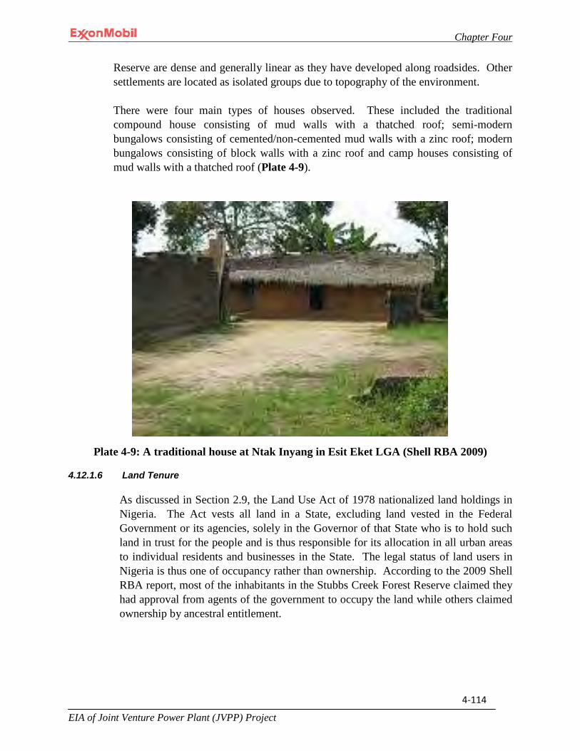
Chapter Four
EIA of Joint Venture Power Plant (JVPP) Project
4-114
Reserve are dense and generally linear as they have developed along roadsides. Other settlements are located as isolated groups due to topography of the environment.
There were four main types of houses observed. These included the traditional compound house consisting of mud walls with a thatched roof; semi-modern bungalows consisting of cemented/non-cemented mud walls with a zinc roof; modern bungalows consisting of block walls with a zinc roof and camp houses consisting of mud walls with a thatched roof (Plate 4-9).
Plate 4-9: A traditional house at Ntak Inyang in Esit Eket LGA (Shell RBA 2009)
4.12.1.6 Land Tenure
As discussed in Section 2.9, the Land Use Act of 1978 nationalized land holdings in Nigeria. The Act vests all land in a State, excluding land vested in the Federal Government or its agencies, solely in the Governor of that State who is to hold such land in trust for the people and is thus responsible for its allocation in all urban areas to individual residents and businesses in the State. The legal status of land users in Nigeria is thus one of occupancy rather than ownership. According to the 2009 Shell RBA report, most of the inhabitants in the Stubbs Creek Forest Reserve claimed they had approval from agents of the government to occupy the land while others claimed ownership by ancestral entitlement.
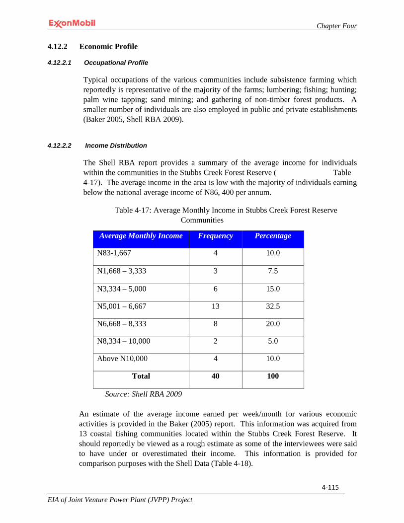
Chapter Four
EIA of Joint Venture Power Plant (JVPP) Project
4-115
4.12.2 Economic Profile
4.12.2.1 Occupational Profile
Typical occupations of the various communities include subsistence farming which reportedly is representative of the majority of the farms; lumbering; fishing; hunting; palm wine tapping; sand mining; and gathering of non-timber forest products. A smaller number of individuals are also employed in public and private establishments (Baker 2005, Shell RBA 2009).
4.12.2.2 Income Distribution
The Shell RBA report provides a summary of the average income for individuals within the communities in the Stubbs Creek Forest Reserve ( Table 4-17). The average income in the area is low with the majority of individuals earning below the national average income of N86, 400 per annum.
Table 4-17: Average Monthly Income in Stubbs Creek Forest Reserve Communities
Average Monthly Income Frequency Percentage
N83-1,667 4 10.0
N1,668 – 3,333 3 7.5
N3,334 – 5,000 6 15.0
N5,001 – 6,667 13 32.5
N6,668 – 8,333 8 20.0
N8,334 – 10,000 2 5.0
Above N10,000 4 10.0
Total 40 100
Source: Shell RBA 2009
An estimate of the average income earned per week/month for various economic activities is provided in the Baker (2005) report. This information was acquired from 13 coastal fishing communities located within the Stubbs Creek Forest Reserve. It should reportedly be viewed as a rough estimate as some of the interviewees were said to have under or overestimated their income. This information is provided for comparison purposes with the Shell Data (Table 4-18).
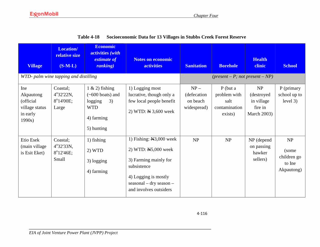
Chapter Four
EIA of Joint Venture Power Plant (JVPP) Project
4-116
Table 4-18 Socioeconomic Data for 13 Villages in Stubbs Creek Forest Reserve
Village
Location/ relative size
(S-M-L)
Economic activities (with
estimate of ranking)
Notes on economic activities Sanitation Borehole
Health clinic School
WTD- palm wine tapping and distilling (present – P; not present – NP)
Ine Akpautong (official village status in early 1990s)
Coastal; 4o32'22N, 8o14'00E; Large
1 & 2) fishing (~600 boats) and logging 3) WTD
4) farming
5) hunting
1) Logging most lucrative, though only a few local people benefit
2) WTD: N 3,600 week
NP – (defecation on beach
widespread)
P (but a problem with
salt contamination
exists)
NP (destroyed in village
fire in March 2003)
P (primary school up to
level 3)
Etio Esek (main village is Esit Eket)
Coastal; 4o32'33N, 8o12'46E; Small
1) fishing
2) WTD
3) logging
4) farming
1) Fishing: N3,000 week
2) WTD: N5,000 week
3) Farming mainly for subsistence
4) Logging is mostly seasonal – dry season –and involves outsiders
NP NP NP (depend on passing
hawker sellers)
NP
(some children go
to Ine Akpautong)

Chapter Four
EIA of Joint Venture Power Plant (JVPP) Project
4-117
Village
Location/ relative size
(S-M-L)
Economic activities (with
estimate of ranking)
Notes on economic activities Sanitation Borehole
Health clinic School
Itak Idim Ekpe
(main village is Esit Eket)
Coastal; 4o32'39N, 8o11'43E; Small
1) fishing
2) WTD
3) logging (<5 people involved)
4) farming
1) Fishing: N25,000 week
2) WTD: N3,000 week
3) Logging: 100,000N week
NP NP NP (depend on passing
hawker sellers)
NP
Ine Eteudo (main village is Uqao)
Coastal; 4o32'43N, 8o10'41E; Small
1) logging
2) WTD
3) fishing
4) farming
1) Logging: N100,000 month (dry season)
2) WTD: N10,000 month (dry season)
NP NP NP (depend on passing
hawker sellers)
NP
Atia (main village is Esit Eket)
Coastal; 4o32'44N, 8o09'29E; Small
1) WTD
2) fishing
3) logging
4) petty trading 5) farming (mainly for subsistence)
1) WTD: N5,200 week
2) Fishing: N3,000 week
3) Logging: N400,000 week (for outside contractors only)
NP NP NP (depend on passing
hawker sellers)
NP
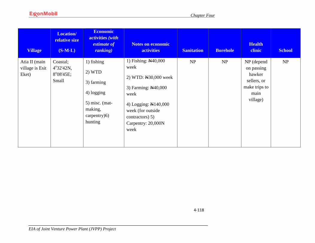
Chapter Four
EIA of Joint Venture Power Plant (JVPP) Project
4-118
Village
Location/ relative size
(S-M-L)
Economic activities (with
estimate of ranking)
Notes on economic activities Sanitation Borehole
Health clinic School
Atia II (main village is Esit Eket)
Coastal; 4o32'42N, 8o08'45E; Small
1) fishing
2) WTD
3) farming
4) logging
5) misc. (mat-making, carpentry)6) hunting
1) Fishing: N40,000 week
2) WTD: N30,000 week
3) Farming: N40,000 week
4) Logging: N140,000 week (for outside contractors) 5) Carpentry: 20,000N week
NP NP NP (depend on passing
hawker sellers, or
make trips to main
village)
NP
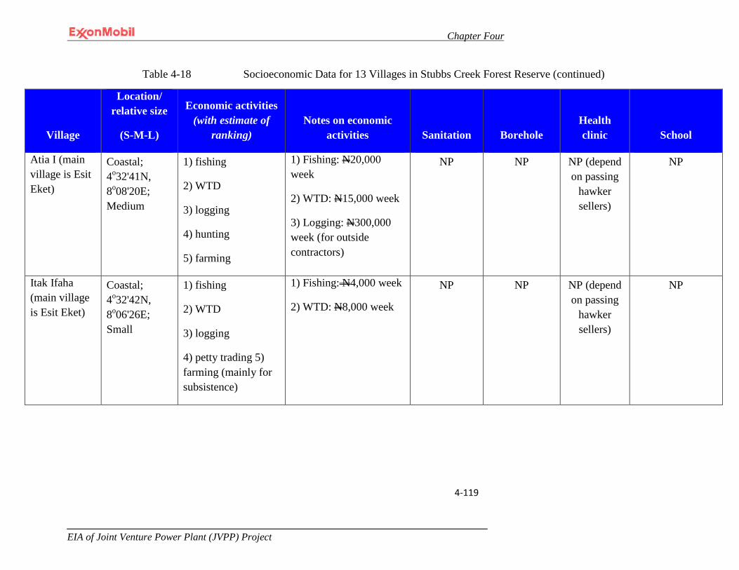
Chapter Four
EIA of Joint Venture Power Plant (JVPP) Project
4-119
Table 4-18 Socioeconomic Data for 13 Villages in Stubbs Creek Forest Reserve (continued)
Village
Location/ relative size
(S-M-L)
Economic activities (with estimate of
ranking) Notes on economic
activities Sanitation Borehole Health clinic School
Atia I (main village is Esit Eket)
Coastal; 4o32'41N, 8o08'20E; Medium
1) fishing
2) WTD
3) logging
4) hunting
5) farming
1) Fishing: N20,000 week
2) WTD: N15,000 week
3) Logging: N300,000 week (for outside contractors)
NP NP NP (depend on passing
hawker sellers)
NP
Itak Ifaha (main village is Esit Eket)
Coastal; 4o32'42N, 8o06'26E; Small
1) fishing
2) WTD
3) logging
4) petty trading 5) farming (mainly for subsistence)
1) Fishing: N4,000 week
2) WTD: N8,000 week
NP NP NP (depend on passing
hawker sellers)
NP

Chapter Four
EIA of Joint Venture Power Plant (JVPP) Project
4-120
Village
Location/ relative size
(S-M-L)
Economic activities (with estimate of
ranking) Notes on economic
activities Sanitation Borehole Health clinic School
Ndito-Eka- Iba (main village is Eket)
Coastal; GPS coordinates unavailable; Large
1) fishing
2) WTD
3) farming (mainly for subsistence)
4) logging (considered very minor)
1) Fishing: N2,500 week
2) WTD: N10,000 week
NP P (since 2002, but dispensing
mechanism not yet
completed)
NP P
(UBE federal gov’t school, but no access in rainy
season; church serves as primary
1-3)
Ntaikang (official village status in early 1990s; Ibeno LGA)
Coastal; 4o32'37N, 8o02'56E; Large
1) fishing
2) WTD
3) farming (mainly for subsistence)
1) Fishing: N5,000 week
2) WTD: N3,500 week
NP – (defecation on beach
widespread)
NP NP NP
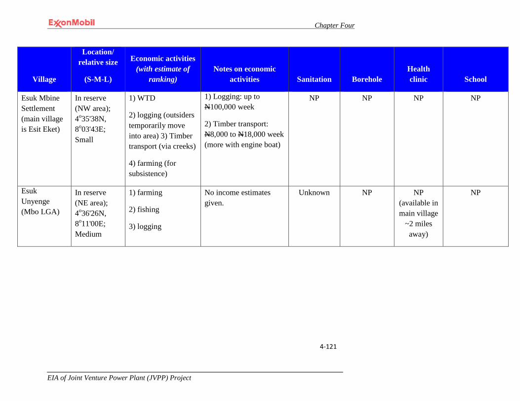
Chapter Four
EIA of Joint Venture Power Plant (JVPP) Project
4-121
Village
Location/ relative size
(S-M-L)
Economic activities (with estimate of
ranking) Notes on economic
activities Sanitation Borehole Health clinic School
Esuk Mbine Settlement (main village is Esit Eket)
In reserve (NW area); 4o35'38N, 8o03'43E; Small
1) WTD
2) logging (outsiders temporarily move into area) 3) Timber transport (via creeks)
4) farming (for subsistence)
1) Logging: up to N100,000 week
2) Timber transport: N8,000 to N18,000 week (more with engine boat)
NP NP NP NP
Esuk Unyenge (Mbo LGA)
In reserve (NE area); 4o36'26N, 8o11'00E; Medium
1) farming
2) fishing
3) logging
No income estimates given.
Unknown NP NP (available in main village
~2 miles away)
NP
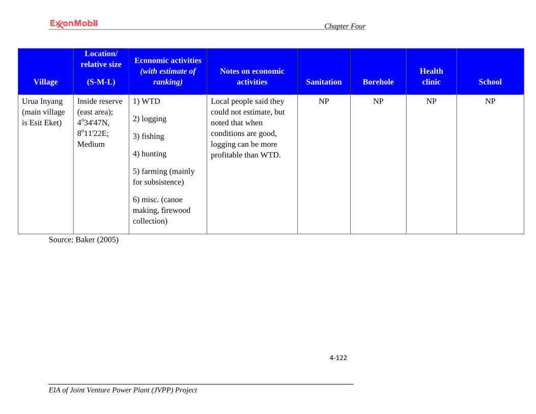
Chapter Four
EIA of Joint Venture Power Plant (JVPP) Project
4-122
Village
Location/ relative size
(S-M-L)
Economic activities (with estimate of
ranking) Notes on economic
activities Sanitation Borehole Health clinic School
Urua Inyang (main village is Esit Eket)
Inside reserve (east area); 4o34'47N, 8o11'22E; Medium
1) WTD
2) logging
3) fishing
4) hunting
5) farming (mainly for subsistence)
6) misc. (canoe making, firewood collection)
Local people said they could not estimate, but noted that when conditions are good, logging can be more profitable than WTD.
NP NP NP NP
Source: Baker (2005)

Chapter Four
EIA of Joint Venture Power Plant (JVPP) Project 4-123
4.12.3 Public Utilities
4.12.3.1 Electricity
Most of the communities in the area of influence lack electricity. In the few communities that have electricity, the power supply is sporadic.
4.12.3.2 Potable Water
Results from public consultation visits documented that 98% of the communities visited lacked potable water. The water available for drinking and other domestic purposes was found to be contaminated with feces and other waste materials. Typical drinking water sources ranged from rivers/springs, lakes/ponds and rainwater. The Shell RBA report provides a similar account. The majority of the drinking water boreholes developed by the government or various international agencies were observed during the field exercise and the Shell RBA survey to be nonfunctional due to a lack of maintenance (Plate: 4-10). The economic survey information acquired by the Baker team and presented in Table 4-13 documents that none of the 13 coastal fishing communities within the Stubbs Creek Forest Reserve have sanitation facilities and only 2 communities have a functional borehole, albeit with either operational or water quality problems.
Plate: 4-10: A non-functional water project in Esit Eket LGA (Shell RBA 2009)
4.12.4 Community Health Facilities
Observations during the study demonstrate that health care facilities in and around the area of influence are sparse and generally inadequate. Many of these facilities

Chapter Four
EIA of Joint Venture Power Plant (JVPP) Project 4-124
are not properly equipped with medicine and trained personnel. The closest modern health care facilities are located in Uquo and Eket. Findings from the field study indicate that many people rely on traditional medicine which may be due to the shortage of modern medical facilities in the areas. This was confirmed by Baker (2005) and shown in Table 4-13. The Health Impact Assessment tool utilized for the study is included in Appendix IV. Details of findings are discussed in subsequent sections.
4.12.4.1 Community Health
The study team visited several communities within the area of influence and identified that the most significant source of chemical exposure experienced by community members was from wood smoke produced by fire wood used for cooking and for smoking fish. In all of the communities visited, firewood was found to be the main source of energy for these activities.
Wood burning is known to release many air pollutants such as hydrocarbons which can injure lungs and make breathing difficult; e.g., carbon monoxide which reduces the blood’s ability to supply oxygen to body tissues. The principal toxins associated with wood burning are oxides of nitrogen which can lower a child’s resistance to lung infections and particulate matter in sizes less than 2.5 microns in diameter (PM2.5) which can enter deep into the lungs where it can cause a change in the structure of the lung tissue (DEQ,March 2009). The study team visited several community health centers including the Akwa Ibom State Ministry of Health and learned that there is a high incidence of respiratory diseases in the area of influence (especially in the communities where large scale fish smoking occurs) (DEQ,March 2009).
4.12.5 Cultural Resources
Most communities celebrate many traditional festivals associated with fishing and farming. While most people described themselves as Christian, strong attachment to ancestral deities through articles of sacrifice was observed in scattered shrines within the area of influence.
4.12.6 Archaeological Resources
Review of available studies has shown no evidence of archaeological resources in the area of influence.
4.12.7 Consultations
The consultation team met with various communities located within the area of influence to discuss the proposed Project and to receive their input and concerns in
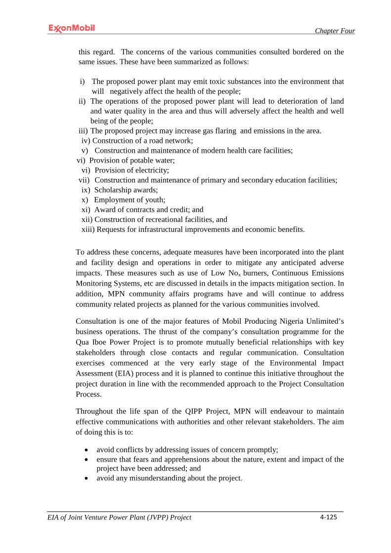
Chapter Four
EIA of Joint Venture Power Plant (JVPP) Project 4-125
this regard. The concerns of the various communities consulted bordered on the same issues. These have been summarized as follows:
i) The proposed power plant may emit toxic substances into the environment that
will negatively affect the health of the people; ii) The operations of the proposed power plant will lead to deterioration of land
and water quality in the area and thus will adversely affect the health and well being of the people;
iii) The proposed project may increase gas flaring and emissions in the area. iv) Construction of a road network; v) Construction and maintenance of modern health care facilities;
vi) Provision of potable water; vi) Provision of electricity;
vii) Construction and maintenance of primary and secondary education facilities; ix) Scholarship awards; x) Employment of youth; xi) Award of contracts and credit; and xii) Construction of recreational facilities, and xiii) Requests for infrastructural improvements and economic benefits.
To address these concerns, adequate measures have been incorporated into the plant and facility design and operations in order to mitigate any anticipated adverse impacts. These measures such as use of Low Nox burners, Continuous Emissions Monitoring Systems, etc are discussed in details in the impacts mitigation section. In addition, MPN community affairs programs have and will continue to address community related projects as planned for the various communities involved.
Consultation is one of the major features of Mobil Producing Nigeria Unlimited’s business operations. The thrust of the company’s consultation programme for the Qua Iboe Power Project is to promote mutually beneficial relationships with key stakeholders through close contacts and regular communication. Consultation exercises commenced at the very early stage of the Environmental Impact Assessment (EIA) process and it is planned to continue this initiative throughout the project duration in line with the recommended approach to the Project Consultation Process.
Throughout the life span of the QIPP Project, MPN will endeavour to maintain effective communications with authorities and other relevant stakeholders. The aim of doing this is to:
• avoid conflicts by addressing issues of concern promptly; • ensure that fears and apprehensions about the nature, extent and impact of the
project have been addressed; and • avoid any misunderstanding about the project.
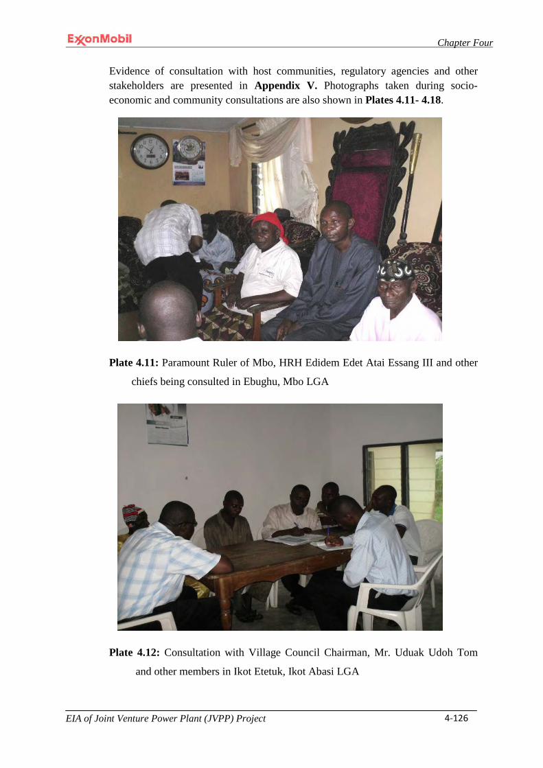
Chapter Four
EIA of Joint Venture Power Plant (JVPP) Project 4-126
Evidence of consultation with host communities, regulatory agencies and other stakeholders are presented in Appendix V. Photographs taken during socio-economic and community consultations are also shown in Plates 4.11- 4.18.
Plate 4.11: Paramount Ruler of Mbo, HRH Edidem Edet Atai Essang III and other
chiefs being consulted in Ebughu, Mbo LGA
Plate 4.12: Consultation with Village Council Chairman, Mr. Uduak Udoh Tom
and other members in Ikot Etetuk, Ikot Abasi LGA
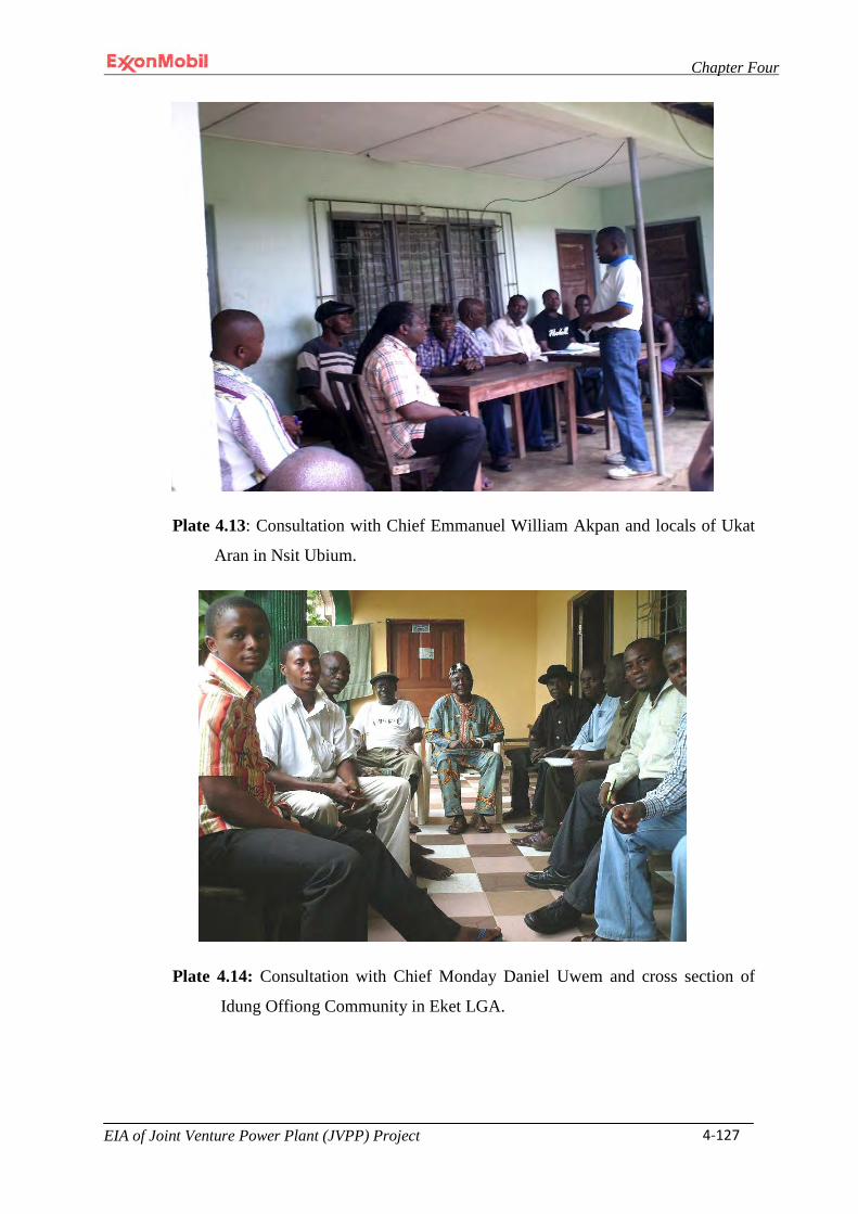
Chapter Four
EIA of Joint Venture Power Plant (JVPP) Project 4-127
Plate 4.13: Consultation with Chief Emmanuel William Akpan and locals of Ukat
Aran in Nsit Ubium.
Plate 4.14: Consultation with Chief Monday Daniel Uwem and cross section of
Idung Offiong Community in Eket LGA.
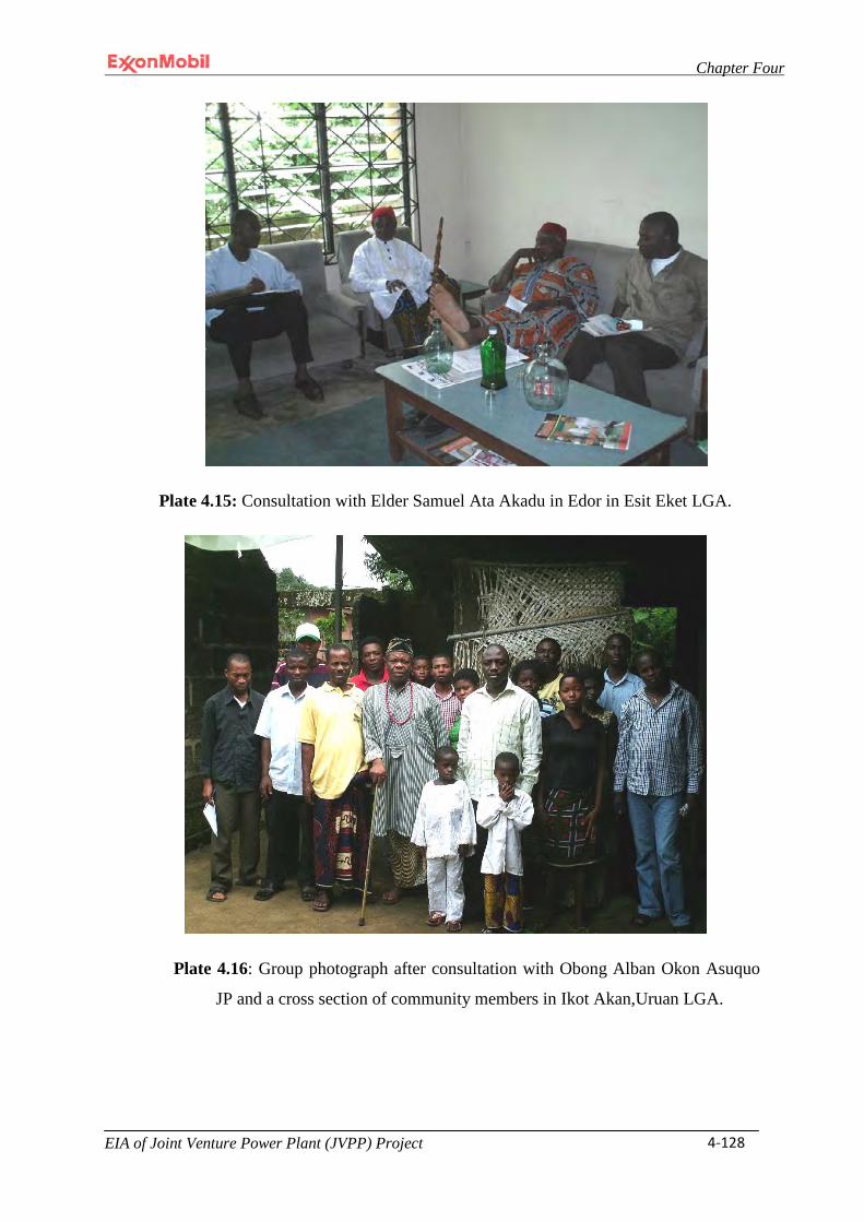
Chapter Four
EIA of Joint Venture Power Plant (JVPP) Project 4-128
Plate 4.15: Consultation with Elder Samuel Ata Akadu in Edor in Esit Eket LGA.
Plate 4.16: Group photograph after consultation with Obong Alban Okon Asuquo
JP and a cross section of community members in Ikot Akan,Uruan LGA.
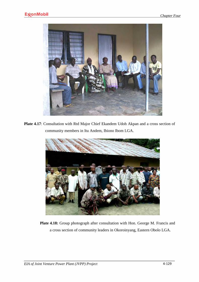
Chapter Four
EIA of Joint Venture Power Plant (JVPP) Project 4-129
Plate 4.17: Consultation with Rtd Major Chief Ekandem Udoh Akpan and a cross section of
community members in Itu Andem, Ibiono Ibom LGA.
Plate 4.18: Group photograph after consultation with Hon. George M. Francis and
a cross section of community leaders in Okoroinyang, Eastern Obolo LGA.
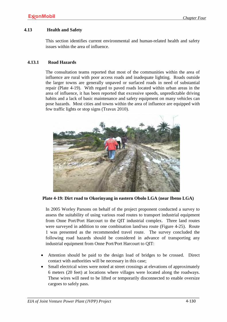
Chapter Four
EIA of Joint Venture Power Plant (JVPP) Project 4-130
4.13 Health and Safety
This section identifies current environmental and human-related health and safety issues within the area of influence.
4.13.1 Road Hazards
The consultation teams reported that most of the communities within the area of influence are rural with poor access roads and inadequate lighting. Roads outside the larger towns are generally unpaved or surfaced roads in need of substantial repair (Plate 4-19). With regard to paved roads located within urban areas in the area of influence, it has been reported that excessive speeds, unpredictable driving habits and a lack of basic maintenance and safety equipment on many vehicles can pose hazards. Most cities and towns within the area of influence are equipped with few traffic lights or stop signs (Travax 2010).
Plate 4-19: Dirt road to Okorinyang in eastern Obolo LGA (near Ibeno LGA)
In 2005 Worley Parsons on behalf of the project proponent conducted a survey to assess the suitability of using various road routes to transport industrial equipment from Onne Port/Port Harcourt to the QIT industrial complex. Three land routes were surveyed in addition to one combination land/sea route (Figure 4-25). Route 1 was presented as the recommended travel route. The survey concluded the following road hazards should be considered in advance of transporting any industrial equipment from Onne Port/Port Harcourt to QIT:
• Attention should be paid to the design load of bridges to be crossed. Direct
contact with authorities will be necessary in this case; • Small electrical wires were noted at street crossings at elevations of approximately
6 meters (20 feet) at locations where villages were located along the roadways. These wires will need to be lifted or temporarily disconnected to enable oversize cargoes to safely pass.
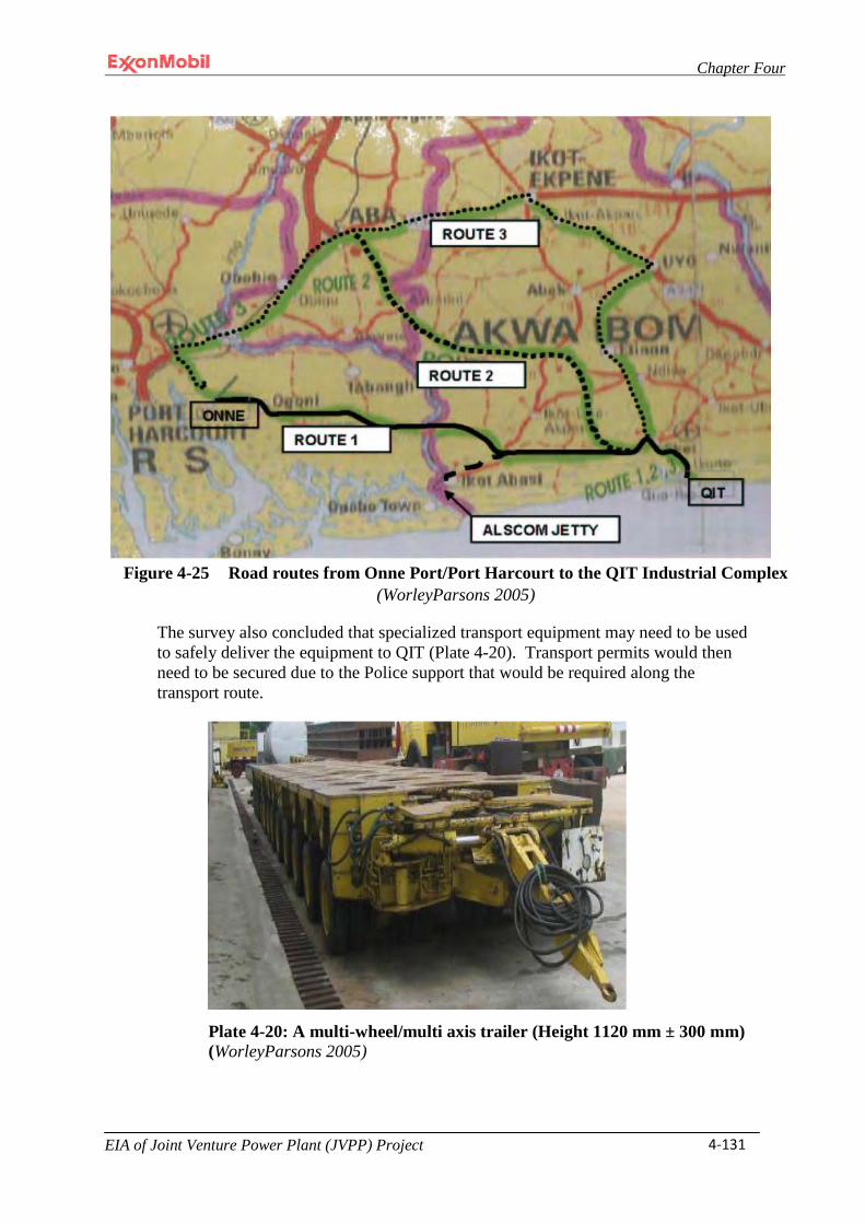
Chapter Four
EIA of Joint Venture Power Plant (JVPP) Project 4-131
Figure 4-25 Road routes from Onne Port/Port Harcourt to the QIT Industrial Complex (WorleyParsons 2005)
The survey also concluded that specialized transport equipment may need to be used to safely deliver the equipment to QIT (Plate 4-20). Transport permits would then need to be secured due to the Police support that would be required along the transport route.
Plate 4-20: A multi-wheel/multi axis trailer (Height 1120 mm ± 300 mm) (WorleyParsons 2005)

Chapter Four
EIA of Joint Venture Power Plant (JVPP) Project 4-132
4.13.2 Occupational Work Hazards
Occupational hazards that can result from construction resulting from the proposed Project could include, but are not limited to:
• Site clearing; • Excavation; • Concreting and forming; • Grinding; • Welding; • Pressure testing; • Material handling; • Handling of steel; • Handling of timber; • Rebar installation; • Backfilling of excavations; • Concrete pours; • Transportation/lifting of heavy equipment; • Erection of scaffolding; • Maintenance of scaffolding; • Dismantling of scaffolding; • Erection of fencing; • Removal of waste material; • Installation of piping and valves; • Electrical work; and • Earthworks
4.13.3 Power Plant Operations
A simple cycle power plant is considered to be relatively easy to operate when compared to a combined cycle power plant. As such, it requires a lower level of operator competency. Startup and shutdown of a simple cycle plant can be accomplished via a push-button. Alternatively, the operation of a combined cycle plant requires more processes which increases complexity and thereby requires a higher level of competency of its operators and correspondingly more manpower to ensure safe operations.
4.13.4 Tropical Infectious Diseases
Nigeria is subject to diseases not typically found in developed nations. A review of information provided by the United States Department of State and World Health Organization (WHO) indicate that several tropical diseases are endemic to the region. These tropical diseases can be classified into significant groupings: food/water-borne diseases and arthropod-borne diseases.
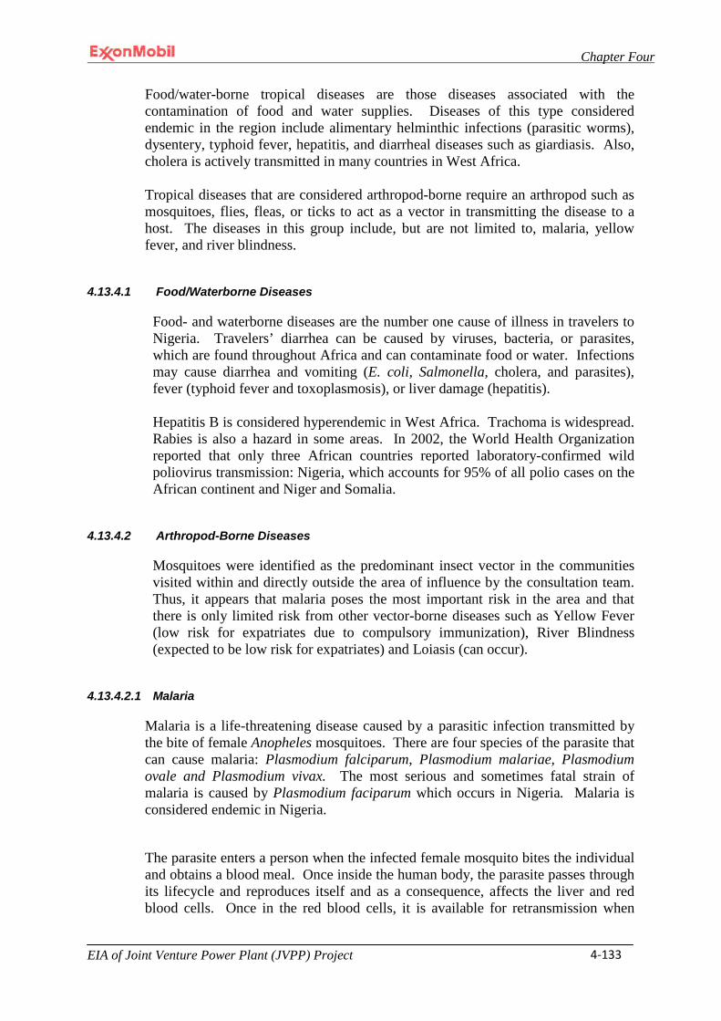
Chapter Four
EIA of Joint Venture Power Plant (JVPP) Project 4-133
Food/water-borne tropical diseases are those diseases associated with the contamination of food and water supplies. Diseases of this type considered endemic in the region include alimentary helminthic infections (parasitic worms), dysentery, typhoid fever, hepatitis, and diarrheal diseases such as giardiasis. Also, cholera is actively transmitted in many countries in West Africa.
Tropical diseases that are considered arthropod-borne require an arthropod such as mosquitoes, flies, fleas, or ticks to act as a vector in transmitting the disease to a host. The diseases in this group include, but are not limited to, malaria, yellow fever, and river blindness.
4.13.4.1 Food/Waterborne Diseases
Food- and waterborne diseases are the number one cause of illness in travelers to Nigeria. Travelers’ diarrhea can be caused by viruses, bacteria, or parasites, which are found throughout Africa and can contaminate food or water. Infections may cause diarrhea and vomiting (E. coli, Salmonella, cholera, and parasites), fever (typhoid fever and toxoplasmosis), or liver damage (hepatitis).
Hepatitis B is considered hyperendemic in West Africa. Trachoma is widespread. Rabies is also a hazard in some areas. In 2002, the World Health Organization reported that only three African countries reported laboratory-confirmed wild poliovirus transmission: Nigeria, which accounts for 95% of all polio cases on the African continent and Niger and Somalia.
4.13.4.2 Arthropod-Borne Diseases
Mosquitoes were identified as the predominant insect vector in the communities visited within and directly outside the area of influence by the consultation team. Thus, it appears that malaria poses the most important risk in the area and that there is only limited risk from other vector-borne diseases such as Yellow Fever (low risk for expatriates due to compulsory immunization), River Blindness (expected to be low risk for expatriates) and Loiasis (can occur).
4.13.4.2.1 Malaria
Malaria is a life-threatening disease caused by a parasitic infection transmitted by the bite of female Anopheles mosquitoes. There are four species of the parasite that can cause malaria: Plasmodium falciparum, Plasmodium malariae, Plasmodium ovale and Plasmodium vivax. The most serious and sometimes fatal strain of malaria is caused by Plasmodium faciparum which occurs in Nigeria. Malaria is considered endemic in Nigeria.
The parasite enters a person when the infected female mosquito bites the individual and obtains a blood meal. Once inside the human body, the parasite passes through its lifecycle and reproduces itself and as a consequence, affects the liver and red blood cells. Once in the red blood cells, it is available for retransmission when
Chapter Four
EIA of Joint Venture Power Plant (JVPP) Project 4-134
another mosquito takes a blood meal. Within the mosquito, it goes through more lifecycle changes to the point where the mosquito will have the potential to infect other individuals, thus completing the cycle.
Malaria produces flu-like symptoms such as fevers, vomiting, and headaches. If not treated, the progression of the disease may be life-threatening. Malaria can kill by infecting and destroying the red blood cells resulting in anemic conditions or by blocking the capillaries of vital organs such as the brain. Nigeria has one of the highest incidence rates of malaria of any country in sub Saharan West Africa. This is because up to 12% of Anopheles mosquitoes in Nigeria have been found to carry the Plasmodium faciparum, whereas in most places in West Africa only 2- 4% of mosquitoes are infected. In Nigeria, 98% of the malaria diagnosed is from Plasmodium faciparum.
4.13.4.2.2 Yellow Fever
Yellow fever is a viral disease caused by the yellow fever virus, a virus belonging to the Flaviviridae family of viruses. In Africa there are two distinct genetic types (called topotypes) associated with East and West Africa, respectively. Transmission of the virus is by a biting mosquito. The mosquito can also pass the virus onto its offspring through its infected eggs. The eggs produced are resistant to drying and lie dormant until they hatch when the rainy season begins. The virus remains dormant during a 3- to 6-day incubation period. Afterwards, there may be two disease phases. While some individuals may not demonstrate any symptoms, the acute phase is normally characterized by fever, muscle pain with prominent backache, headache, shivers, loss of appetite, nausea, or vomiting. Often the high fever is accompanied by a reduced pulse. After 3-4 days, most patients improve and their symptoms disappear. However, approximately 15% of infected individuals may progress to the toxic phase within 24 hours. The fever reappears and the individual may quickly develop jaundice. The infected individual may complain of abdominal pain with vomiting and exhibit bleeding from the mouth, nose, eyes, and/or stomach. As a consequence of the bleeding, blood may appear in the vomit and feces. Kidney function may deteriorate and is characterized by abnormal protein levels in the urine (albuminuria) to full complete kidney failure with no urine production (anuria). Half of the patients in this phase will die within 10-14 days. The remainder will recover without significant organ damage.
4.13.4.2.3 River Blindness (Onchocerciasis)
Onchocerciasis is transmitted by black flies and is highly endemic in Nigeria. Exposure of longer than just a week or two is all that is generally required for infection. The “black flies” (Simulium spp.) are some of the most tenacious biting flies in Africa, especially near the fast-flowing rivers where the insects breed. Furthermore, the outcome of a single black fly bite can result in the transmission of river blindness. This disease is caused by nematode worms
Chapter Four
EIA of Joint Venture Power Plant (JVPP) Project 4-135
(Onchocerca volvulus) that form nodules under the skin after entering a human via the infective bite of the female fly. These adult worms produce tiny offspring called microfilariae that move around the body causing intense itching. When the microfilariae enter the eye they can cause blindness. A drug is available that kills the microfilariae. However, it does not kill the adult worms which can live up to 12 years in the human body and continue to produce the damaging microfilariae.
4.13.4.2.4 Loiasis
Loiasis is transmitted by large tabanid flies (any of the various bloodsucking flies that have a single pair of functional wings and are of the family Tabanidae) and is highly endemic in forested areas of southeastern Nigeria. Exposure of a week or two is generally all that is required for infection. Loiasis is transmitted to humans by day-biting Chrysops dimidiatus and Chrysops silaceus flies. Once inside the human body, the nematode larva develops slowly into a mature adult in about a year. During this period, it lives and moves around the layers of skin and often makes frequent excursions through the subdermal connective tissues of the skin where it is often noticed by the host. Once they reach maturity, the adults will mate and produce microfilariae. Microfilariae have been recovered from spinal fluids, urine, and sputum. During the day they are found in peripheral blood, but during the noncirculation phase, they may be found in the lungs. The fly ingests microfilariae during a blood meal to repeat the life cycle. Most of the problems associated with Loa loa infections occur when the migrating adult worms appear near the surface of the skin. The worms often appear around the eye where they can be easily seen and extracted before they damage the conjuctiva. Immune reactions to the migrating worms can also cause swelling in the arms and legs that may lead to the formation of cystlike enlargements of the connective tissues around the tendon sheaths. These swellings can be extremely painful when moved. Dying worms can also cause chronic abscesses. The current drugs that are available only kill the microfilariae, and have no effect on the adult worms. Diethylcarbamazine (DEC) was the main drug used until Ivermectin became available. DEC often had fatal side effects causing encephalitis. Adult worms seen under the skin can be removed fairly easily by minor surgery, but many of the worms are not readily visible.
4.13.5 Venomous Snakes
There are at least ten venomous snakes whose presence in and around the moist rainforest region of Ibeno and within the area of influence has been confirmed. These species include western forest centipede eater (Aparallactus modestus), variable bush viper (Atheris squamiger), slender stiletto-snake (Atractaspis aterrima), Gaboon viper (Bitis gabonica), rhinoceros viper (Bitis nasicornis), Jameson’s mamba (Dendroaspis jamesoni), forest cobra (Naja melanoleuca), black spitting cobra (Naja nigricollis), Blanding’s tree snake (Toxicodryas blandingii) and the African puff adder (Bitis arietans arietans) (Akani 1999 and <www.latoxan.com/VENOM/SNAKE>).

Chapter Four
EIA of Joint Venture Power Plant (JVPP) Project 4-136
4.13.6 Spiders
Limited data is available on types of spiders present in the area of influence.
4.14 Services / Utilities
4.14.1 Potable and Process/Operations Water
There is no available public or private potable water system within the vicinity of the proposed Project. Bottled drinking water will be imported to the Project site during the construction period by means of a tractor trailer truck for use by construction labor. Non-potable water for construction purposes will be obtained from the onsite wells to be installed by the EPC contractor and which are described in detailed in Section 3.3.6.11. Following completion of construction activities, the water wells will be converted into the proposed power plant’s permanent water supply source.
4.14.2 Wastewater
No public or private wastewater or sanitary system exists within the vicinity of the proposed Project. During construction temporary portable sanitation units will be employed for labor including the labor to be housed in the nearby construction labor camp (described more fully in Section 3.6.3). The EPC contractor will be responsible for pump-out and disposal of all sanitary wastes. The wastewater collection and treatment system and sanitary collection and treatment system to be employed during facility operations are described in Section 3.3.6.12.
4.14.3 Communications
Local phone and Internet connections are limited. A Satellite uplink for telephone and Internet access will be employed to ensure communications during the construction phase of the project. A telecommunications plan will be developed and implemented to ensure that during operations a full suite of infrastructure, equipment and services are available for use. These services include, but are not limited to: desktop personal computers; a campus wide local area network; microwave and satellite communications infrastructure to Q.I.T Ibeno, Ibeno, Onne Port, Eket, Lagos and other areas as appropriate; mobile radios, portable radios and base stations for plant operations and security; marine VHF or other suitable means of communication with manned platforms and with marine vessels as required for facility operations.
4.14.4 Electrical
Most of the communities in the area of influence lack electricity. In the few communities that have electricity, the power supply is sporadic. The proposed Project will generate its own power for use during the construction and operational phases. During construction the proposed Project will rely on temporary diesel electric generators to provide office lighting and service other

Chapter Four
EIA of Joint Venture Power Plant (JVPP) Project 4-137
light loads. Construction lighting will be accomplished by using mobile light towers, mainly required to illuminate the site each night for security. During operations the proposed Project will use two 1,500 KW 6,600 Volt 50HZ standby generators firing No. 2 diesel fuel as backup power to the power plant and for black-start capabilities for one GTG.
4.14.5 Medical Facilities
Standard health care facilities in and around the vicinity of the project site are sparse and generally inadequate. Thus, the proposed Project will set up a modern medical clinic to support Project personnel. The clinic will be staffed with doctors and nurses. Initial treatment of major trauma will be addressed at the medical clinic, but more complicated treatment will be addressed by evacuating the patient to the nearest national or international facility capable of rendering the needed medical assistance.
4.14.6 Security / Fire Protection Services
Security will be managed during construction and facility operations by leveraging existing on-site security personnel. As soon as feasibly possible, a construction fence topped with razor wire will be installed around the entire construction site including the permanent laydown area to provide a secured construction area (see Sections 3.3.6.22 and 3.6.10).
There is no public fire protection services provided within the vicinity of the proposed Project. However, fire-fighting equipment is located at the existing QIT industrial complex and can be used to respond to fire emergencies. Section 3.3.6.15 describes the Fire Protection System that will be employed during facility operations.
4.14.7 Solid and Industrial Waste Disposal
On-site infrastructure will be created to manage the storage of all wastes generated as a result of the proposed Project in accordance with all applicable Nigerian regulations and Company standards (Section 3.6.11 and 3.7.2). Final disposal of all wastes will be managed by licensed third-party contractors who operate government permitted disposal or recycle/reclamation facilities in accordance with all applicable Nigerian regulations and MPN standards.
4.15 Transportation
Roads/highways and the Eket Airport and international airport facilities located at Port Harcourt and Calabar are considered transportation infrastructure that are within the area of influence of the proposed Project. Port facilities at either Onne/Port Harcourt or Calabar are also within the area of influence of the proposed Project because one or both of these Ports could
Chapter Four
EIA of Joint Venture Power Plant (JVPP) Project 4-138
be used for barge transport of Project required materials and equipment to the proposed Project Site.
4.15.1 Roads / Highways
The existing QIT roads and government access road to QIT are believed to be sufficient to meet Project requirements except for the heaviest equipment components such as the GTGs which will be transported to the site via barge (see Section 4.15.2). The existing heavy haul road from the yet to be installed MOF will require a tie-in to the existing QIT Road. This will be accomplished through use of a heavy base. This new road base may also be required at the proposed Project site to facilitate transport of the heaviest equipment components to their foundations. Section 4.13.1 provides further discussion regarding road conditions from Onne/Port Harcourt to the proposed Project site.
4.15.2 Ports
The Nigeria Port Authority’s facilities at Onne/Port Harcourt and Calabar will serve as the primary portals for import of project materials into Nigeria. Coastal water transport operations between Onne/Port Harcourt to QIT and Port Calabar to QIT will be facilitated through third-party water transport contractors. A preliminary investigation of these facilities indicates that upgrades to accommodate project requirements are not needed.
4.15.3 Airports
The Company maintains airport facilities in Eket. Company/contractor personnel will be transported to the site via this airport facility. Nationals and possibly some contractor personnel requiring transport to the proposed Project site may use a combination of road transportation in conjunction with the international airport facilities located at Port Harcourt and Calabar. These facilities are expected to be able to accommodate project requirements without any upgrades or changes.

CHAPTER FIVE

Chapter Five
EIA of Joint Venture Power Plant (JVPP) Project 5-1
CHAPTER FIVE
5.0 POTENTIAL ENVIRONMENTAL, SAFETY AND HEALTH IMPACTS
This chapter describes the impacts or changes to the existing environment that could occur as a result of the proposed Project. Where there are quantifiable or qualifiable differences in the known or potential impacts between the simply cycle gas turbine power plant option and the combined cycle gas turbine power plant option, these differences are identified to the extent feasible. Where there are no measurable differences or no differences are expected, the impact analysis applies equally to either option.
The impacts presented herein have been evaluated to the extent possible to reflect their magnitude, timing, duration and probability of occurrence. Feasible measures to avoid, minimize, or compensate for the identified impacts are presented where such measures are available. These measures are consistent with international industry best practice and are necessary due to site-specific conditions. Residual impacts are also identified for any impact which cannot be fully mitigated or for which a high level of uncertainty exists for the efficacy of the mitigation measure. For clarification, the significance of each impact was evaluated against four potential outcomes. Each of these outcomes is presented and defined below:
1. No effect, used when no change to the existing environmental condition is
expected.
2. Less than significant, used when the change to the existing environmental condition is not expected to exceed a defined threshold.
3. Significant, used when the change to the existing environmental condition is definitely expected to exceed a defined threshold.
4. Significant and unavoidable, used when an impact is significant (i.e., clearly exceeds a defined significance threshold) and for which there is no available or feasible mitigation to reduce the impact below the significance threshold.
This chapter is organized to address each of the environmental resources presented in Table 4-1. The Area of Influence for each environmental resource is presented in Table 4-1, and where clearly defined, pictorially presented in Figures 4-2a through 4-2h (see also Section 4.3). A tabular summary of the impacts of the various aspects of the project is included in chapter six.

Chapter Five
EIA of Joint Venture Power Plant (JVPP) Project 5-2
5.1 Soils and Geology This section addresses both the potential impacts to the proposed Project due to the environment such as from natural hazards and the potential impacts from the proposed Project to the environment i.e., geology/soils located within the area of influence as defined in Table 4-1. The impacts specifically discussed are:
• Potential Structural Damage Due to Seismicity and Faulting. • Engineering Constraints of Soils and Geology. • Soil Erosion. • Fuel or Chemical Spills to Soils
5.1.1 Potential Structural Damage Due to Seismicity and Faulting
5.1.1.1 Impact Analysis
Onshore The seismic hazard analysis performed by ABS Consulting1 in 2005 for the project area on behalf of MPN documents that the proposed Project will occur at a location that is within a seismic source zone considered to be relatively inactive when compared to its two neighboring seismic zones (see Section 4.5). Six earthquakes have historically been recorded as occurring in the magnitude range of 4.0 to 4.9 along the Cameroon Volcanic Zone. The magnitude of these earthquakes indicates that that they have been relatively minor, the effects limited to a 30-mile radius from the epicenter, no where near to where the proposed Project will be constructed. Based on this information, including the fact that none of the magnitudes of these earthquakes exceed the Project design basis, it is not expected that structural damage to the proposed Project would occur if these historical conditions were to reoccur.
1 All seismic coefficients and factors used for all calculations conducted by ABS consulting defaulted to the use of soil classification D per the International Building Code (or ASCE 7-05), i.e., stiff soils.
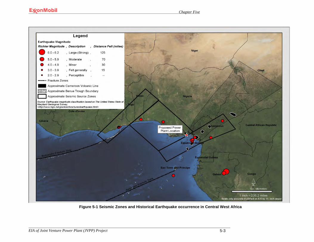
Chapter Five
EIA of Joint Venture Power Plant (JVPP) Project 5-3
Figure 0-1 Seismic Zones and Historical Earthquake Occurrence in Central West Africa
Figure 5-1 Seismic Zones and Historical Earthquake occurrence in Central West Africa

Chapter Five
EIA of Joint Venture Power Plant (JVPP) Project 5-4
Further analysis by ABS on behalf of MPN resulted in an estimate of what the expected peak ground acceleration would be for the Project vicinity in the event of an earthquake. ABS determined this value to be 0.02g where g is the acceleration of gravity, 9.8 m/sec2. The peak ground acceleration is a measure of an earthquake’s acceleration on the ground for a 475-year return period. This essentially means that ground motion of 0.02g has a 1 chance in 475 of being exceeded each year which equates to a 10% probability of exceeding this value in 50 years. While the probability of such an event is low it is still important to note that the actual occurrence of such an event would yield motion that would not exceed the Project design basis. This coupled with the fact that the onshore sediments underlying the Project as identified by prior geotechnical investigations are not prone to liquefaction due to their reported soil conditions (i.e., consisting of firm clays to silty clays and medium dense to very dense sands), indicates that there is minimal overall hazard to the proposed Project posed by seismicity and faulting. Thus, it is concluded that this impact is less than significant.
Offshore For the pipeline facilities, the combination of low risk of seismic activity in the region and absence of significant faulting and pipeline construction materials that have tolerances for moderate ground movement would result in minimal overall hazard. It is therefore concluded that the impact to the pipelines associated with seismicity and faulting to be less than significant.
5.1.1.2 Mitigation Measures
No mitigation measures are proposed for less than significant impacts.
5.1.1.3 Residual Impacts
The seismic hazard most likely to be detrimental to the proposed Project is ground motion resulting from an earthquake that exceeds the design basis. The probability of such an event is extremely low. Project components could incur damage if such an event were to occur. The subsequent damage could result in potential health and safety or environmental impacts if the natural gas-fired power plant and its ancillary components were to be significantly damaged. Such impacts cannot be completely mitigated. However, such impacts have been minimized through the design of the facility in accordance with the latest edition of the International Building Code.
5.1.2 Engineering Constraints of Soils and Geology
5.1.2.1 Impact Analysis
Engineering properties of the in-situ soils have the potential to affect the performance behavior of structures during construction and operation. The compressibility and shear strength of the soils beneath planned structures is a factor in determining appropriate soil-bearing values and passive earth pressures for foundation design. The proposed Project will be designed consistent with the foundation standards presented in
Chapter Five
EIA of Joint Venture Power Plant (JVPP) Project 5-5
British Standard Institutions CP 2004: 1973, Code of Practice for Foundations and British Standard 6031: 1981, Code of Practice for Earthworks. In summary, these specifications require that the foundations be designed by a qualified engineer and constructed in accordance with recognized structural engineering practices after appropriate subsurface investigations have been conducted to determine the stratigraphy and physical properties of the soils underlying a project site and/or used for construction.
Following excavation, backfill material will be obtained from QIT Lake (see Figure 3-2 and Sections 3.5.3 and 3.5.5). This material will be mixed with water in a 10/90 percent mass ratio, respectively, and transported to the Project site by means of a hydraulic pump. It is expected that the degree of compaction possible with these soils will be sufficient to meet project requirements and thus ensure there is no potential for liquefaction of the soils. This assumption is based on the backfill material’s known soil texture and drainage characteristics including its past performance when used as backfill in support of several projects at the QIT facility. As technically indicated, pile foundations will be used where necessary. At this time, it is anticipated that the use of pile foundations will be limited to only the heaviest of equipment such as the GTGs, STG and HRSGs.
Preliminary studies including past experience indicate a high degree of likelihood that the soils obtained from QIT Lake will meet Project requirements. However, there is a small degree of uncertainty in regards to whether these soils will have the necessary engineering properties. Consequently, this impact is considered significant.
5.1.2.2 Mitigation Measures
The mitigation measure presented below will be prior to Project design to alleviate any uncertainty in the soils ability to meet project requirements is to conduct sufficient testing on soils from QIT Lake to ensure they meet Project performance standards. If they do not, then identify alternate on-site or existing off-site sources for such material and retest to ensure conformance with Project requirements.
5.1.2.3 Residual Impacts
No residual impacts are anticipated provided the recommended mitigation measure and foundation codes previously referenced are incorporated into the final design for the proposed Project.
5.1.3 Soil Erosion
5.1.3.1 Impact Analysis
Activities associated with the construction of the power plant and ancillary structures will occur exclusively within the limits of MPN’s certificate of occupancy boundaries and will be concentrated within the area of influence for soils and geological resources
Chapter Five
EIA of Joint Venture Power Plant (JVPP) Project 5-6
as defined in Table 4-1. Clearing and grubbing activities are expected to occur within the limits of 230,000 m2 (57 acres) for the simple cycle power plant and 360,000 m2 (89 acres) for the combined cycle power plant. Tables 3-2 and 3-3 present the soil excavation and backfill estimates for the simple cycle and combined cycle power plants, respectively.
Clearing and grubbing, excavation, stockpiling, backfilling and grading activities could result in soil erosion. Eroded soils from the project site could cause sedimentation within non-manmade aquatic environments located adjacent to the work site such as Douglas Creek. The sedimentation of any nearby water body can lead to significant water quality degradation. Further, the occurrence of heavy rains known to occur in the region, about 4,564 mm annually (15 feet annually) could complicate the maintenance of any erosion control measures. Rains of this magnitude can often lead to sheet erosion. However, because the construction site is nearly level, it is expected that such geography will help to minimize soil losses. Temporary drainages in support of construction activities will be sized to handle anticipated design rainfall and runoff quantities from the disturbed areas. All such measures including others designed to control and/or manage soil erosion will be put into place in advance of any soil disturbance activity.
To avoid and/or minimize adverse impacts due to soil erosion during early site preparation and construction, the proposed Project will develop and implement an Erosion and Sedimentation Control Plan as referenced in Section 3.5.2. Measures that may be employed per this Plan to avoid or minimize soil erosion impacts may include, but not be limited to, the covering of stockpiled topsoil, installation of wind and/or silt fences, and reseeding of disturbed areas. Standard post-construction and restoration activities will also be implemented to reduce the long-term impacts from soil erosion. These measures may consist of, but not be limited to, debris removal and disposal, the dismantling of all temporary facilities such as staging and laydown areas, leveling or filling of tire ruts, and reseeding of areas disturbed by construction activities with vegetation similar to what was removed. Efforts will be made to ensure that disturbed areas are restored to their original condition to the extent practicable.
The development and implementation of an Erosion and Sedimentation Control Plan by the proposed Project will address the expected impacts associated with soil erosion provided the measures implemented are effective. However, if the thresholds defined in the Plan are exceeded, the impacts associated with topsoil loss could be significant.
5.1.3.2 Mitigation Measures
To ensure the effectiveness of the erosion control measures committed to in the Erosion and Sedimentation Control Plan the following mitigation measures will be implemented by the proposed Project’s Environmental Management Team:

Chapter Five
EIA of Joint Venture Power Plant (JVPP) Project 5-7
A. Conduct daily visual monitoring of erosion control measures particularly during and immediately following periods of precipitation to ascertain their effectiveness at providing soils protection and erosion control. Document and maintain all such inspections in separate inspection reports and track all resolutions to completion.
B. Develop key performance indicators to assess the effectiveness of erosion control for incorporation into the Erosion and Sedimentation Control Plan. Example indicators include, but are not limited to the following: observation of significant visible erosion and/or density and cover of non-nuisance vegetation that are similar to adjacent undisturbed lands.
C. Incorporate routine maintenance practices into the Erosion and Sedimentation Control Plan to ensure that erosion control measures are properly installed and effectively maintained.
D. Implement additional mitigation consistent with the measures identified in the Erosion and Sedimentation Control Plan if monitoring indicates that excessive erosion is occurring particularly during prolonged precipitation events.
5.1.3.3 Residual Impacts
Some loss of soils will occur regardless of the effectiveness of the implemented erosion control measures, particularly given the heavy rains that occur in the area. However, this loss is expected to be minimized due to implementation of the erosion control measures.
5.1.4 Fuel or Chemical Spills to Soils
5.1.4.1 Impact Analysis
Construction related impacts to soils could occur from the accidental release of contaminants such as fuels, lubricants and antifreeze. These types of materials will likely be stored in one or both of the laydown areas and possibly in the workers camp all of which will be maintained throughout construction; see Figure 3-2. Any accidental spills would result in localized soil contamination, the expected impact being minimal due to the low frequency and volume of spills and leaks. The proposed Project has committed to developing a Spill Prevention and Response (SPR) Plan (Section 3.5.2) which will present the procedures to control, contain and remove any spill if one were to occur. It is therefore concluded that soil contamination would be less than significant and that containment of spills or leaks of contaminants if they were to occur would be adequately addressed in accordance with the SPR Plan.
5.1.4.2 Mitigation Measures
Concrete containment area will be used for the storage of hydrocarbons and chemicals. This will ensure that spills are properly contained and soils in the area, are not contaminated by the spill. Concrete pads and drip pans will also be used during refueling to prevent spillages. These will be clearly identified in the SPR Plan.
Chapter Five
EIA of Joint Venture Power Plant (JVPP) Project 5-8
5.1.4.3 Residual Impacts
No long–term residual impacts are expected provided the containment of spills or leaks are managed in accordance with the Project’s SPR Plan.
5.2 Terrestrial Biological Resources Impacts to terrestrial biological resources could occur within the area of influence as defined in Table 4-1 as a result of the proposed Project. These potential impacts which are discussed in greater detail below are as follows:
• Loss of Natural Vegetation • Loss of Local Biodiversity • Loss, Degradation, or Fragmentation of Wildlife Habitat • Adverse Impacts to Local Special-Status Wildlife Species • Adverse Impacts to Local Special-Status Plants Species • Sedimentation, Hydrological, and Water Quality Effects on Aquatic Fauna and Flora
5.2.1 Loss of Natural Vegetation
5.2.1.1 Impact Analysis
Up to 230,000 m2 [23 hectares/57 acres] of highly disturbed secondary lowland rainforest is expected to be removed during construction activities for buildings, staging and laydown areas including other facilities and the workers camp if the simple cycle gas turbine power plant option is constructed. Conversely, up to 360,000 m2 [36 hectares/89 acres] of highly disturbed secondary lowland rainforest will be removed during construction activities if the combined cycle gas turbine power plant option is constructed (see Section 3.5.2).
Natural vegetation would be permanently removed in the areas designated for clearing. However, vegetation could also be indirectly affected in areas adjacent to clearing. Conditions at the edge of clearings could be altered making it unsuitable to support certain plant species due to changes in the amounts of nutrients, light, and water (i.e., too little or too much). In addition, lack of water, increased exposure to sunlight [particularly relevant in trees that occur in the lower layers of tropical forests], and lack of nutrients often cause plants to be more prone to stress, disease, and infestation. Thus, some species grow well under cooler, moister, shaded forest conditions, but do not do well on the edge of the forest where temperature, light, and moisture conditions are different from inside the forest.
Natural vegetation loss would result from clearing, grubbing, scalping, removal of trees and stumps, and removal and disposal of all vegetation and debris within the limits of clearing. However, the loss of this vegetation is considered less than significant in the context of the Stubbs Creek Forest Reserve given the following parameters:

Chapter Five
EIA of Joint Venture Power Plant (JVPP) Project 5-9
A. The proposed Project is within the boundaries of the existing two certificates of occupancy that jointly encompass the land tract boundary for the QIT/JVPP facilities (within which the existing QIT Industrial Complex already occurs) and has been used by MPN since 1970.
B. The Stubbs Creek Forest Reserve has undergone degradation resulting in only a fraction of the original pristine forest (Baker 2005). The remaining 80 km2 of intact forest (in the center of the Reserve) is not associated with the land tract within which the proposed Project would be located (see Section 4.7).
C. The loss of up to 36 ha (89 acres) (i.e., 0.36 km2) of highly disturbed secondary lowland rainforest represents less than 0.12 percent of the existing 310 km2 of forest within the Stubbs Creek Forest Reserve.
5.2.1.2 Mitigation Measures
No mitigation measures are proposed for less than significant impacts.
5.2.1.3 Residual Impacts
No long–term residual impacts are expected.
5.2.2 Loss of Local Biodiversity
5.2.2.1 Impact Analysis
During excavation, backfilling, and grading, topsoil (i.e., organic matter, debris, and other material) not suitable for permanent engineered fill will be stripped. In addition, approximately 10,400 m3 of aggregate and 1,525 m3 of sand will be stored on-site for use during the early site preparation and construction phases for the simple cycle power plant option, while approximately 26,020 m3 of aggregate and 3,305 m3 of sand will be stored for use during the early site preparation and construction phases for the combined cycle power plant option. Many species make use of or occur in the topsoil and litter layers in lowland rainforest. Consequently, these activities will result in the loss of individuals of those species that are not capable of leaving the site prior to clearing or stockpiling (generally sedentary and slow-moving reptiles, amphibians, fossorial [i.e., subterranean or burrowing] mammals, and invertebrates). In addition, topsoils in most tropical environments are acidic, thin, and nutrient poor. Thus, the productivity of these soils is highly dependent on the rapid recycling of nutrients that takes place in the upper layers of the soil profile. These upper layers are subject to weathering, erosion, leaching, precipitation, atmospheric deposition, and the actions of decomposers (detritivores). The nutrient recycling capability within tropical forest soils is as dependent upon the large number of detritivores and fungi (especially mycorrhizal fungi) as it is on soil moisture, air and soil temperatures, and chemical and physical soil characteristics. If not properly protected, these organisms and their associated nutrient recycling capabilities will be lost in topsoils that are stockpiled for

Chapter Five
EIA of Joint Venture Power Plant (JVPP) Project 5-10
later use. Thus, resulting in further loss of biodiversity above and beyond that associated with direct vegetation removal.
However, observations made during the 2 September 2008 and 17 and 19 March 2009 reconnaissance field surveys indicated that wildlife diversity in the forest within the vicinity of the proposed Project to be very low since relatively few mammals, amphibians, and reptiles were recorded (Section 4.7.2). In addition, bird species diversity was very low (only 4 species were recorded during the reconnaissance-level surveys even though birds are generally the easiest species to record during such surveys). Lastly, the existing plant diversity within the Project site (based on the number of trees species within each of several 0.16-hectare sample areas) is very low with only 3 to 7 species (Table 4-2). This overall very low biodiversity is likely attributed to the following which has been observed in or near the Project site in the Stubbs Creek Forest Reserve (Shell RBA 2009):
A. Harvest pressure (timber): Chain saw noise coming from multiple directions
indicative of intense logging activities is a common occurrence in the Stubbs Creek Forest Reserve (Plates 4-5 and 4-6).
B. Farming activity is indiscriminate near the fringes of the Stubbs Creek Forest Reserve with many abandoned farmlands and freshly cleared plots, leaving open areas of the forest as evidence of forest encroachment, habitat fragmentation, and biodiversity loss (Plate 4-4).
C. Hunting pressure: Spent cartridges for shooting wildlife as well as observations of hunters returning from their trade are common in the Stubbs Creek Forest Reserve (Plate 4-2).
It is anticipated that the impacts of ground and vegetation clearing and other associated effects of developing and operating the proposed Project will result in the loss of some biodiversity at the local level (i.e., within the immediate vicinity of the proposed Project), but would have no impacts on a regional level (i.e., either the Stubbs Creek Forest Reserve or Niger Delta) since the Project site is relatively small and only supports highly disturbed secondary lowland rainforest (which has a lower biodiversity than primary lowland rainforest or less disturbed secondary lowland rainforest). In addition, it is unlikely that there are existing species that are unique to the Project site. Therefore, this impact is considered less than significant.
5.2.2.2 Mitigation Measures
No mitigation measures are proposed for less than significant impacts.
5.2.2.3 Residual Impacts
No long-term residual impacts are expected.

Chapter Five
EIA of Joint Venture Power Plant (JVPP) Project 5-11
5.2.3 Loss, Degradation, or Fragmentation of Wildlife Habitat
5.2.3.1 Impact Analysis
The clearing of the secondary lowland rainforest for the proposed Project will result in a loss of wildlife habitat. In addition, some wildlife species that are unable to move prior to clearing will be lost. These latter species are likely to include sedentary and slow-moving reptiles, amphibians, fossorial mammals, and invertebrates. Other wildlife could be forced to move from currently occupied or utilized habitat. This movement may result in adverse impacts on the relocated wildlife populations since they may not be able to meet their life history requirements in the adjacent habitats. Thus, an overall reduction in population may occur for some species. Forest obligate species (i.e., species that live only in forests) would be affected more than other species. However, some species may increase if the new conditions are more suitable for the species or if the species is released from competition with other affected species. Such species would include urban-tolerant species such as the village weaver (Ploceus cucullatus) and black kite (Milvus migrans).
All wildlife that is able to move in advance of and during clearing operations would likely move into adjacent areas (at least initially). Thus, competition for resources with the adjacent resident populations would likely occur. Again, populations would be expected to diminish to the carrying capacity of the adjacent habitat. Wildlife populations in adjacent forest would also be affected in other ways as a result of the new disturbance (e.g., noise from construction and other edge effects associated with clearing and operation of the proposed facilities). However, experience has shown that many species become habituated to higher noise levels provided they do not change in intensity (even the most habituated animals startle at loud, unpredictable noises). Thus, it is expected that many wildlife species will continue to occupy the secondary lowland rainforest located immediately adjacent to the proposed Project and most indirect effects to wildlife habitat would be limited to the forest that is within less than 300 m (984 ft) from the proposed Project’s boundary fence.
Some temporary degradation of wildlife habitat could also occur at QIT Lake (a man-made lake) given that the lake is the proposed source of fill material that will be required to bring the “plant footprint” to the required datum. The fill material will be removed with a hydraulic pump and transported as “slurry” through a pipeline. This action will result in potential impacts to terrestrial wildlife that include noise impacts from the hydraulic pump, human presence, and disturbance of vegetation at the access points along the lakeshore where the hydraulic pump, pipeline, and other equipment enter the lake.
Habitat fragmentation describes the discontinuities in a species’ preferred environment (habitat). In essence, habitat fragmentation refers to a habitat that was once continuous, but has become divided into separate fragments and is no longer available to a species though otherwise still suitable (Section 4.7.2). Habitat fragmentation can
Chapter Five
EIA of Joint Venture Power Plant (JVPP) Project 5-12
be caused by geological processes that slowly alter the layout of the physical environment or by human activity such as land conversion which can alter the environment on a much faster time scale. The proposed Project would not lead to habitat fragmentation as it would not in any way disrupt the current movement of wildlife from one habitat to another. Considering the proposed Project’s location which will be immediately north and adjacent to the existing QIT Industrial Complex and other lands within the certificates of occupancy, it is not expected to preclude wildlife movement essentially because terrestrial wildlife, excluding birds, would not be expected to move south and west toward human habitation and the urbanized landscape associated with the QIT Industrial Complex and Ibeno Big Town (Figure 4-5). The relative low density of wildlife observed within the immediate vicinity of the proposed Project during the field team reconnaissance survey further suggests that existing human habitation has likely discouraged the movement of wildlife into the area. Though no impacts would occur from the proposed Project due to habitat fragmentation, there will be an overall loss of wildlife habitat associated with the proposed Project. This latter impact is considered significant.
5.2.3.2 Mitigation Measures
Impacts associated with the loss or degradation of wildlife habitat as a result of the proposed Project will be minimized through the implementation of the following mitigation measures:
A. Delineate the limits of clearing on appropriate scale site maps and flag the limits of
clearing to minimize the loss of natural vegetation.
B. Limit the number of infrastructure access points along QIT Lake to the minimum necessary to acquire the fill material that is needed for the proposed Project.
C. Mark trees and shrubs that are to be retained with flagging and avoid compaction of the adjacent soils (where possible).
D. Use local, native plant species in areas to be landscaped where feasible. Native species are best adapted to the local conditions, more likely to become established, require minimal maintenance, and are less likely to cause problems from the introduction of nonnative species (due to competition with native species).
E. Use salvaged and stockpiled topsoil to the extent possible in revegetation efforts, erosion control, and landscaping.
5.2.3.3 Residual Impacts
Residual impacts associated with the proposed Project could include permanent loss of wildlife habitat (on the Project site), minor degradation of wildlife habitat (immediately adjacent to the Project site), possible relocation and adjustment of those that remain around the proposed Project site.
Chapter Five
EIA of Joint Venture Power Plant (JVPP) Project 5-13
5.2.4 Adverse Impacts to Local Special-Status Wildlife Species
5.2.4.1 Impact Analysis
The proposed Project has the potential to result in adverse impacts to a small number of special-status wildlife species that may occur on or near the Project site. These species, which are identified in Table 4-4 as having a moderate or higher probability of occurring near the Project site, include West African dwarf crocodile (Osteolaemus tetraspis), red-capped mangabey (Cercocebus torquatus), and Sclater's guenon (Cercopithecus sclateri). Though the secondary lowland rainforest that is associated with the Project site is highly disturbed, there is a moderate potential for red-capped mangabey and Sclater's guenon to occasionally occur on or near the site. The red-capped mangabey (listed as vulnerable by the IUCN) is found from western Nigeria, east and south through Cameroon and Equatorial Guinea, to Gabon. Locally, it has been recorded within the Stubbs Creek Forest Reserve. It is threatened by habitat loss. It is generally found in the lower levels of lowland rainforest, especially in swamp forests. Their flexibility on the ground and among the trees allows them to utilize a broad range of habitats including agricultural areas. The species typically uses the trees to obtain foods and to hide and sleep, but they often escape predators on the ground. As with many African primates, habitat loss, habitat degradation and hunting threaten the species. It was once widespread, but this species is now disappearing from areas where agriculture has expanded into its habitat or it is exposed to hunting pressure. It is subject to intensive hunting, particularly in Cameroon and Nigeria since its noisy, far-reaching calls make it an easy target to locate. It may also be caught in wire snares that are set near villages to trap small ground-dwelling mammals.
The Sclater’s guenon is an arboreal and diurnal primate that lives in the coastal forests of southern Nigeria (including most primary, secondary and degraded forests within its range). Sclater's guenon was thought to be nearly extinct until the late 1980s. The species is now known to occur in several isolated populations between the Niger and Cross Rivers in southern Nigeria. The species does not occur in any officially protected areas, but three populations of Sclater's guenon are known to be protected by local people who consider the monkeys to have sacred status. Furthermore, it is known to occur in the Stubbs Creek Forest Reserve. Mostly because of hunting and habitat fragmentation and loss, and thus increasing population isolation and decline, Sclater's guenon is listed as vulnerable by the IUCN. It is thought to have lost 30% of its total population in the last quarter century. Hunting is widespread across its range, and the species faces increasing forest loss and degradation. Nonetheless, it has been able to persist in the human-dense region of southern Nigeria, likely because of its small size, adaptability, cryptic nature, and general non-preferred status among hunters relative to other monkeys. Both of the above species would be unlikely to occur regularly near the Project site. However, they cannot be dismissed given their known occurrence in the Stubbs Creek Forest Reserve and the habitat types that occur on and near the proposed Project site.
Chapter Five
EIA of Joint Venture Power Plant (JVPP) Project 5-14
The West African dwarf crocodile ranges across the tropical lowland regions of sub-Saharan West Africa and West Central Africa. It is a slow, timid, and mainly nocturnal reptile. As with all crocodilians, it is an adept predator of vertebrates, large invertebrates such as crustaceans and, when presented with the opportunity, also eats carrion. Foraging is mainly done in or near the water, though in areas with substantial ground cover, they may expand their feeding pattern to land in extensive forays, especially following rains. The species typically digs out a burrow (sometimes with a submerged entrance) to hide in and rest during the day. An individual lacking the right conditions to create a burrow often utilizes tree roots that hang over the creeks or ponds in which it lives. Where survey data is available, it shows some degree of decline, either by hunting for bush meat or habitat loss due to deforestation. However, it is a widespread and may be more numerous than it appears from limited observations. Given its known occurrence in the Stubbs Creek Forest Reserve and the presence of suitable habitat in Douglas Creek and QIT Lake, it is considered likely to occur on or near the Project site.
Each of the above species could be adversely impacted by the proposed Project due to habitat loss and habitat degradation. Though habitats in the area are already highly disturbed, construction activities would introduce additional short-term disturbance in the area around the existing QIT Industrial Complex. Furthermore, human presence around QIT Lake would introduce short-term disturbance in an area that currently receives little disturbance. These disturbances could be sufficient to cause individuals of these species to avoid habitats that otherwise receive at least occasional use. These impacts are considered significant.
5.2.4.2 Mitigation Measures
Impacts associated with the loss or degradation of wildlife habitat for special-status wildlife species that may occur in the vicinity of the Project site can be minimized through the implementation of the following mitigation measures:
A. Ensure the inclusion of wildlife sightings into Project reporting. Reports to include: species, number of animals sighted, number of sightings, timing, and location.
B. If any of the special-status species specifically identified above are found, the following measures will be implemented:
(a) Communicate the location of special-status species found to Project Team in order to minimize potential disruption.
(b) Establish access exclusion zones, as needed. (c) Locate all infrastructure access points to QIT Lake to avoid potential disturbance or
conduct passive relocation of species. (d) Deposit woody debris that is removed from other portions of the Project site at the
water’s edge of QIT Lake to provide additional habitat for the species. The woody debris will be located away from any infrastructure access points. C. Conduct endangered species awareness training for all construction and operation personnel working on the Project site prior to each individual working on the site. Note
Chapter Five
EIA of Joint Venture Power Plant (JVPP) Project 5-15
that the endangered species awareness training must contain, at a minimum, the following components for each of the species of concern (i.e., West African dwarf crocodile, red-capped mangabey, and Sclater's guenon):
(a) Description of each species (including behavior). (b) Habitats that are used by each species. (c) Move those that are unable to escape to safer locations (d) Areas within or immediately adjacent to the Project site that are or have been used by
each species. (e) Measures that are implemented as part of the proposed Project to avoid or minimize
adverse impacts to each species. (f) Reporting procedures if any of these species are observed.
5.2.4.3 Residual Impacts
Residual impacts associated with the proposed Project would include the permanent loss of habitat (on the Project site) and minor degradation of habitat (immediately adjacent to the Project site) for the special-status species that utilize the Project site.
5.2.5 Adverse Impacts to Local Special-Status Plant Species
5.2.5.1 Impact Analysis
No special-status plant species have been documented within or adjacent to the Project site. Furthermore, the lowland secondary rainforest that occurs on the Project site is highly disturbed. Therefore, special-status plant species are not expected to occur on the Project site and be impacted during construction of the proposed Project. However, a literature search identified two special-status plant species that occur in habitats that occur on or adjacent to the Project site and are therefore considered to have at least a moderate potential for occurring on the site. These species are the African mahogany (Afzelia africana) and African peach (Nauclea diderichii) (see Table 4-4). Each of these species is designated as vulnerable by the IUCN. Focused surveys for these species have not been conducted on the Project site. However, both species have been recorded elsewhere in the Stubbs Creek Forest Reserve. If present on the project site, clearing of secondary lowland rainforest on the site during construction could result in the removal of individuals of these species which could be significant.
5.2.5.2 Mitigation Measures
To avoid or minimize the loss of special-status plants the following mitigation measures should be implemented:
A. Ensure the inclusion of special-status species plant sightings into Project reporting. Reports to include: species, area covered, and location
B. If any of the special-status species specifically identified above are found, the following measures will be implemented:
Chapter Five
EIA of Joint Venture Power Plant (JVPP) Project 5-16
a. Communicate the location of special-status species found to Project Team in order to minimize potential disruption.
b. Establish signs and exclusionary flagging around those portions of the Project site in which existing or planted African mahogany and African peach are located.
C. Conduct endangered species awareness training for all construction and operation personnel working on the Project site prior to each individual working on the site. Note that the endangered species awareness training must contain, at a minimum, the following components for each of the species of concern (i.e., African mahogany and African peach):
(a) Description of each species. (b) Habitats that each species occupies. (c) Areas within or immediately adjacent to the Project site that are occupied by each
species. (d) Measures that are implemented as part of the proposed Project to avoid or minimize
adverse impacts to each species. (e) Reporting procedures if either of these species is observed.
5.2.5.3 Residual Impacts
Residual impacts associated with the proposed Project would include the permanent loss of special-status plant species habitat (on the Project site) for the species that utilize the Project site.
5.2.6 Sedimentation, Hydrological, and Water Quality Effects on Aquatic Fauna and Flora
5.2.6.1 Impact Analysis
The proposed Project has the potential to result in increased sedimentation/siltation in Douglas Creek due to increased storm water runoff (particularly after the natural vegetation has been cleared from the Project site). Such sedimentation/siltation would most likely occur during the wet season. Furthermore, siltation of QIT Lake would occur during hydraulic suction for the acquisition of fill material for the proposed Project. An increase in sedimentation/siltation could have a variety of adverse impacts on the fauna and flora of the affected aquatic systems. These impacts include, but are not limited to:
A. Deposition of sediments over submerged areas that are utilized by important or
critical life history stages of aquatic plant or wildlife species.
B. Decreases in water clarity that preclude the necessary behaviors of aquatic animals (e.g., feeding, courtship, and predator avoidance
C. Decreased aquatic plant productivity.
D. Reduction in the available dissolved oxygen.

Chapter Five
EIA of Joint Venture Power Plant (JVPP) Project 5-17
An Erosion and Sedimentation Control Plan will be developed for the proposed Project as per Section 3.5.2 to effectively reduce sedimentation/siltation in the potentially affected water bodies (i.e., Douglas Creek and QIT Lake). All storm water, wastewater and “slurry“ water (i.e., piped water and material from QIT Lake) from the proposed Project will flow to the plant water retention pond in advance of discharging to the Douglas Creek. The retention pond will allow settling of much of the entrained sediments and silts. The above described impacts are therefore significant.
5.2.6.2 Mitigation Measures
To ensure the effectiveness of the Erosion and Sedimentation Control Plan to minimize impacts to aquatic fauna and flora from construction of the proposed Project, the following mitigation measures should be implemented:
A. Limit the amount of vegetation clearing and ground disturbance during the wet season
(if feasible) to reduce the runoff and resulting sedimentation/siltation within local aquatic systems.
B. To the extent possible, reduce surface runoff velocity and erosion during periods of excessive precipitation.
C. Conduct all work associated with excavation, embankment, and grading activities in a manner that controls potential sedimentation within aquatic and wetland environments located adjacent to the work areas (i.e. Douglas Creek, QIT Lake).
D. Utilize natural drainages and temporary drainages during early site preparation construction activities at the Project site until the permanent drainage system is operational.
E. Install silt fences as required to control silt-contaminated surface runoff.
F. Develop intercept ditches in conjunction with the on-site roads.
G. Establish buffer zones between work areas and local aquatic and wetland environments to minimize potential adverse effects on these resources (where possible).
H. Monitor the effectiveness of the erosion controls. During periods of precipitation, the engineering controls described above should be visually inspected on a regular basis to ascertain their effectiveness at providing erosion control. If monitoring indicates the need for additional measures during excessive precipitation events, implement other appropriate measures to reduce surface flow velocity and provide additional damming to reduce erosive effects.
5.2.6.3 Residual Impacts
All significant sedimentation, hydrological, and water quality impacts to aquatic fauna and flora would be temporary (i.e., during construction). Therefore, no long-term residual impacts are anticipated.
Chapter Five
EIA of Joint Venture Power Plant (JVPP) Project 5-18
5.3 Marine Resources Impacts to marine resources could occur within the area of influence as defined in Table 4-1 as a result of the proposed Project. These potential impacts which are discussed in greater detail below are as follows:
Changes to Existing Coastline due to the New Material Off-loading Facility (MOF) Loss or Disturbance of Coastal Marine Habitat Due to New Material Off-Loading
Facility Impacts to Marine Resources Resulting from Pipeline Installation Impacts to Marine Resources Resulting from Pipeline Leaks during Operations Seawater Quality Impacts Due to Hydrostatic Test Water Discharge
5.3.1 Changes to Existing Coastline Due to the New Material Off-Loading Facility
5.3.1.1 Impact Analysis
A temporary MOF will be constructed off the beach at the south-east corner of the QIT facility. It is expected that this facility will be removed following completion of construction. The MOF will provide an area for mooring and unloading of heavy equipment and possibly raw materials from roll-on/roll-off barges.
The near-shore channel for the MOF will be dredged to approximately -4 meters and will extend seaward from the edge of the MOF to about 350-420 meters (380-460 yards) or the -4 meter contour. The maximum dredging will occur at the shore connection and taper off towards the open ocean. The average dredging height will be such that it is deep enough for a barge to approach the unloading pier without grounding. Dredge materials are expected to be returned to the sea directed to the east in the “down-current” direction. Maintenance dredging of the channel will likely be necessary for the life of the MOF.
To provide lee shelter for barge mooring, a breakwater will be placed directly to the west of the MOF. The breakwater will likely be beach/shore connected and may, depending upon coastal engineering analysis, extend the full length of the channel and MOF. The MOF itself (as opposed to the channel) is expected to extend seaward from the shoreline to a distance yet to be determined by coastal engineering analysis.
In order to assess the upstream and down-drift impacts associated with installation of the MOF, the final exact design needs to be developed. Potential impacts as a result of this structure could include beach erosion down-drift of the site location and up-drift beach accretion. Because of the uncertainty with the final design and its resulting effect, the impact to the environment will be assumed to be significant.

Chapter Five
EIA of Joint Venture Power Plant (JVPP) Project 5-19
5.3.1.2 Mitigation Measures
To address the uncertainty resulting from potential upstream and down-drift impacts resulting from installation of the MOF, the Environmental Management Plan will include beach monitoring and mitigation activities:
A. Beach monitoring and mitigation activities may include: observation of net loss in
beach or coastline down-drift from the site location. If beach erosion is noted, control measures and in extreme cases replenishment activities will be undertaken.
B. Net increases in sedimentation or accretion up-drift of the MOF will be noted and as required dredging operations will be instituted.
5.3.1.3 Residual Impacts
No long–term residual impacts are expected.
5.3.2 Loss or Disturbance of Coastal Marine Habitat Due to New Material Off-Loading Facility
5.3.2.1 Impact Analysis
The piles for the MOF will likely be constructed of heavy sheet metal, but pre-engineering cylindrical piles could also be used. The breakwater will be constructed of corrugated metal sheet piles or prefabricated concrete piles or some other structures and will be removed at demobilization of site works. Pile driving typically generates a loud, concussive sound that disturbs marine organisms causing them to flee the area of disturbance. Disturbance generally consists of a startle response in which an animal is frightened and exhibits behavioral changes (e.g., sudden dive, evasive tactics, rapid departure from the pile driving site, or other maneuvers). Such impacts are generally not significant unless the disturbance is chronic (i.e., involves pile driving over a long period) and results in permanent abandonment of the area by a species. Construction of the MOF is expected to take place over a 3-6 month period. The noise associated with pile driving is expected to last from 4 to 12 weeks. Thus, the disturbance associated with pile driving is expected to be short-term as it will cease upon completion of pile driving. MPN has installed and operated pipelines and numerous platforms in the waters near to where the MOF will be constructed. During this period there have been no recorded mortality incidents involving marine mammals, fish or sea turtles as result of the operations engaged in by MPN. It is thus believed that any potential noise impacts associated with piling driving on the marine habitat will be short term and thus less than significant.
Previous marine surveys in the immediate vicinity of the proposed MOF provide no evidence that hard bottom habitats (e.g., coral or rock outcrops) occur in the area (Section 4.8.6.2). Therefore, pile driving and breakwater creation are not expected to impact this important habitat type. Further, the construction of the breakwater for the
Chapter Five
EIA of Joint Venture Power Plant (JVPP) Project 5-20
MOF will result in the creation of new hard bottom habitat. Given the lack of hard bottom habitat in the Project area, the establishment of this new habitat is considered to be a short-term beneficial impact resulting from the proposed Project.
Excavation of sediments down to bedrock will not be required to secure the temporary MOF. Excavation will likely be accomplished through the use of either a clamshell bucket or a hydraulic cutter-head dredge. While the use of these techniques is common practice in such construction activities, they have the potential to result in impacts to marine resources during the excavation or disposal of the sediments. However, limited excavation within a small area for a short period of time would only be expected to have localized, short-term impacts on benthic organisms. Such impacts involve removal of individuals in the sediments, clogging of the filtering and/or respiratory openings of sessile benthic organisms in the adjacent area, and temporary abandonment of the area by mobile organisms. However, these impacts are considered less than significant because the local benthic organisms are not considered rare, vulnerable, threatened, or endangered. In addition, only a small area would be impacted and the siltation would rapidly clear upon completion of the excavation due to the relatively strong currents in the area.
Finally, impacts similar to those described above could occur during disposal of excavated sediments if disposal occurs in nearshore waters other than immediately downdrift of the MOF. Such impacts have the potential to be significant. However, if the disposal occurred downdrift of the MOF this impact would be considered less than significant as these materials would contribute to the deposition of silts and sediments that normally occurred before interruption by the MOF of the nearshore current and sediment transport mechanism.
5.3.2.2 Mitigation Measures
The mitigation measures to minimize impacts associated with nearshore excavation and disposal of sediments will be to dispose of any excavated materials, including rocks and sand, at an appropriate downdrift location such that these materials minimize any downdrift beach erosion impacts caused by location of the MOF and interruption of normal nearshore currents and silt/sediment transport.
5.3.2.3 Residual Impacts
No long–term residual impacts are expected.
5.3.3 Impacts to Marine Resources Resulting from Pipeline Installation
5.3.3.1 Impact Analysis
The offshore area where the lean fuel gas pipeline and rich gas pipeline will be installed is a brownfield area consisting of over 200 miles of pipeline including numerous platforms (Figure 4-12). It is proposed that the lean fuel gas pipeline be
Chapter Five
EIA of Joint Venture Power Plant (JVPP) Project 5-21
installed within an existing 600 meter wide corridor pipeline route and the rich gas pipeline be installed within an existing 200 meter wide pipeline corridor route. Except for the shore approach where a cofferdam will likely be used before trenching both pipelines will be laid on the seafloor.
For the shore approach, a cofferdam will be used before trenching. Trenching will likely be limited to areas where the water depth is 4.6 m (15 ft) or less. The base plan is for cofferdam/trenching to continue through the shore crossing. However, the feasibility of crossing under the beach using directional drilling will be investigated during the design phase. If feasible, this approach would avoid interference with company constructed and operated roads. If directional drilling is used, environmentally benign water-based muds will be used to provide lubrication during the drilling process.
Geotechnical and geophysical investigations for both pipeline routes have revealed that no rock or coral outcrops were noted as occurring within the vicinity of the proposed Project (Table 4-5 and Table 4-6). These findings are consistent with the geology of the study areas and MPN’s longstanding experience operating in the region. Therefore, flora and fauna species typically associated with these structures are not expected to be present in the vicinity of the proposed Project. Given the type of habitat that is associated with the pipeline corridors (i.e., very soft sandy/silty clays, with thickness typically 1.5 meters or thicker) and the presence of other existing pipelines within the corridors, impacts associated with pipeline installation would result in a negligible change in the existing conditions. Most impacts that could occur to marine resources (particularly benthic resources) from pipeline installation have already occurred as a result of the corridors being in an existing brownfield area. Consequently, any impact to marine resources from the new pipeline installation is considered to be less than significant.
5.3.3.2 Mitigation Measures
No mitigation measures are proposed for less than significant impacts.
5.3.3.3 Residual Impacts
No long–term residual impacts are expected.
5.3.4 Impacts to Marine Resources Resulting from Pipeline Leaks during Operations
5.3.4.1 Impact Analysis
A leak from either the lean fuel gas pipeline or the rich gas pipeline could occur anywhere along the alignment of those pipelines. However, such an occurrence would be of low likelihood due to MPN’s emphasis on accident prevention and pipeline safety through programs such as hazard operability analysis, fault tree analysis and other pipeline risk assessment and continual maintenance programs. However, if such
Chapter Five
EIA of Joint Venture Power Plant (JVPP) Project 5-22
an event were to occur through a small leak, a long-term leak or an abrupt (even explosive) blowout, the potential impact to marine biota is expected to be less than significant. This is because the properties of these compressible fluids would cause them under such a scenario to rapidly rise to the surface and dissipate into the atmosphere. MPN’s experience in working with such fluids has shown that marine life entrained in the path of the gas as it rises to the surface can suffer from asphyxiation. However, those outside the plume as it rises to the surface appear to suffer no lethal effects.
Another concern surrounding subsea gas discharges often expressed by mariners is whether or not the gas plume could result in buoyancy loss to the point where a ship would sink if it were in the plume. Studies have been completed to investigate this concern (Milgram 1984 and Hammett 1985). These studies have shown that the vessels will not sink. It has been shown that the loss in buoyancy caused by the rising gas can be overcome by the upward momentum of the plume. The significant radial flow of water away from the plume rise location would push vessels away from the bubble zone and the bubble rise location is very dynamic due to the plume’s turbulent nature. All of these factors eliminate the chance of a vessel sinking due to the presence of the bubble plume. Therefore, this is a less than significant impact.
5.3.4.2 Mitigation Measures
No mitigation measures are proposed for less than significant impacts.
5.3.4.3 Residual Impacts
No long–term residual impacts are expected.
5.3.5 Seawater Quality Impacts Due to Hydrostatic Test Water Discharge
5.3.5.1 Impact Analysis
Following installation of the two offshore-to-onshore pipelines hydrostatic testing will be conducted to ensure structural integrity as described in Section 3.6.9. Approximately 9.6 million liters (2.2 million, gallons) of seawater will be used for the hydrostatic test. Small concentrations of a corrosion inhibitor, biocide, and/or an oxygen scavenger may be added to the test water to avoid pipe corrosion. The chemicals used for this activity will be selected from a list of chemicals approved for hydrostatic testing by the Department of Petroleum Resources. Additionally, each selected chemical will be further scrutinized by MPN’s Occupational Health group to assure that the chemical is environmentally friendly in advance of use. An approved procedure will be utilized and the process will be witnessed by DPR representatives. After testing is complete, the test water will be discharged into the ocean. The discharge will be paced and the rate logged. Resultant charts and records will be stored for record purposes. The effluent discharge will meet those Nigerian regulatory requirements that govern the disposal of hydrostatic test waters. Thus, the disposal of
Chapter Five
EIA of Joint Venture Power Plant (JVPP) Project 5-23
the test water is expected to have no measurable effect on seawater quality and is considered less than significant.
5.3.5.2 Mitigation Measures
No mitigation measures are proposed for less than significant impacts.
5.3.5.3 Residual Impacts
No long–term residual impacts are expected.
5.4 Air Quality Impacts to air quality could occur within the area of influence as defined in Table 4-1 as a result of the proposed Project. These potential impacts which are discussed in greater detail below are as follows:
• Early Site Preparation and Construction Related Air Quality Impacts • Transportation Related Air Quality Impacts • Operational Related Air Quality Impacts
5.4.1 Early Site Preparation and Construction-Related Air Quality Impacts
5.4.1.1 Impact Analysis
Air emissions resulting from site preparation and construction activities are not expected to significantly affect the air quality in the region outside of the QIT industrial complex. The expected emissions would mainly consist of dust resulting from excavation and backfilling activities; stockpiling of materials; vehicle movement on unpaved roads; and operation of one or possibly two temporary concrete batch plant facilities. For vehicular transportation through the community, the roads are tarred. Dust generation is therefore expected to be minimal unlike closer to the project area where the road may not be paved. This type of dust tends to be of a relatively large diameter and as such is inclined to deposit within a shorter distance than smaller, lighter particulate matter. Therefore, it is expected that most of the fugitive dust will deposit within the boundaries of the Project site. Thus, these emissions could be significant to on-site construction personnel. To address this potential impact, the proposed Project will employ the following mitigation measures to minimize fugitive dust emissions.
5.4.1.2 Mitigation Measures
The following mitigation measures will be implemented:
A. To minimize dust emissions, plant roads and areas between stockpiles and conveyor hoppers will be covered or treated to the extent practicable with water or some other environmentally benign dust-suppressant material.
Chapter Five
EIA of Joint Venture Power Plant (JVPP) Project 5-24
B. Dust from stockpiles will be controlled by covering or by treating with water or some other environmentally benign dust-suppressant material.
C. Open-bodied vehicles transporting materials will cover with a tarp or water or treat materials as appropriate to reduce emissions
D. Trucks will not be allowed to track concrete or other construction material from the Project site onto public roads.
The following mitigation measures apply to the concrete batch plant facilities:
A. Spills of batching materials (e.g., fly ash, sand, aggregate, or additives) must be cleaned up or controlled to minimize dust.
B. To the extent practicable, the batch plants should be located downwind of the existing onsite (i.e. QIT industrial complex) development.
C. All dry material transfer points will be ducted through a fabric filter or some other appropriate filter unless there are no visible emissions from the transfer point.
D. All transfer points will be equipped with a wet suppression system to control fugitive particulate emissions unless there are no visible emissions
E. Equip all bulk storage silos including auxiliary bulk storage trailers with fabric or some other appropriate type filter.
F. Maintain silo vent filters in proper operating condition
G. The fabric dust collection system employed will be capable of controlling particulates using the best technology available.
H. All conveyors will be covered unless the material being transferred results in no visible emissions
5.4.1.3 Residual Impacts
No long-term residual impacts to air quality are anticipated since atmospheric emissions associated with site preparation and construction would cease upon completion of construction.
5.4.2 Transportation Related Air Quality Impacts
5.4.2.1 Impact Analysis
The use of barges to transport equipment or possibly raw materials during construction to the Project site is not expected to increase barge traffic in any considerable way. The number of barges necessary to meet Project requirements is expected to be relatively insignificant when compared to the overall number of shipping, barge and small marine craft that already transverse the offshore area in the vicinity of the proposed Project. Thus, the use of barges for equipment and material transport to the

Chapter Five
EIA of Joint Venture Power Plant (JVPP) Project 5-25
Project site or the use of marine vessels to install the lean fuel gas and rich gas offshore pipelines is not expected to have any measurable effect on air quality.
Off-road diesel equipment and mobile sources will be employed throughout construction. Also, either heavy duty diesel trucks or barge will be used to transport raw materials such as sand, aggregate and cement to the Project site for concrete production. If trucks are used, up to 2,070 trucks would be required over a 2-3 month period if the simple cycle power plant option is implemented and up to 4,950 trucks would be required for the same period if the combined cycle power plant option is implemented. Diesel exhaust emissions were not estimated or evaluated by modeling as these emissions will be short term and typically of low concentration (0.18 g/Km to 0.53 g/Km) and thus is not expected to have any significant effect on the air quality in the region2.
Although there are no mobile source emission regulations in Nigeria, in keeping with best industry practices the proposed Project will keep diesel emissions to a minimum. Diesel exhaust is known to contain several chemicals and compounds that may be detrimental to human health over the long-term with repeated exposure. Thus, exposure of on-site workers to diesel exhaust could be significant.
5.4.2.2 Mitigation Measures
The mitigation measures to minimize diesel usage and emissions during construction activities will include idling reduction awareness activities for onsite diesel powered equipment and mobile vehicles. Contractors would be required to maintain equipment in good running condition, including use of acceptable fuel quality and emission controls- vehicles with unacceptable amounts of visible exhaust will not be allowed on the site
5.4.2.3 Residual Impacts
No long-term residual transportation-related impacts to air quality are anticipated given the source’s negligible contribution to local air quality impacts and the short-term nature of these contributions.
5.4.3 Operational Related Air Quality Impacts
5.4.3.1 Impact Analysis
Fuel Selection to Minimize Emissions The proposed Project is seeking to use natural gas, an existing domestically abundant fuel stream to generate electricity for domestic use. The use of natural gas offers a number of environmental benefits over other sources of energy, particularly other fossil fuels. For example, coal and oil are composed of much more complex molecules
2 “Source Apportionment of Fine and Ultra-fine Particles in California,” prepared by University of California; August 2007.

Chapter Five
EIA of Joint Venture Power Plant (JVPP) Project 5-26
with a higher carbon ratio and higher nitrogen and sulfur contents. This means that when combusted, coal and oil release higher levels of harmful emissions, including a higher ratio of carbon emissions, nitrogen oxides (NOx), and sulfur dioxide (SO2). Coal and fuel oil also release ash particles into the environment, substances that do not burn, but instead are carried into the atmosphere and contribute to pollution. The combustion of natural gas, on the other hand, releases negligible quantities of sulfur and nitrogen oxides (about 60% less than plants that use coal assuming emission reductions measures are not employed), virtually no ash or particulate matter, and lower levels of carbon dioxide, carbon monoxide, and other reactive hydrocarbons.
Technology Selection to Minimize Emissions The proposed Project will employ technology recognized as being the most advanced for power production on the scale proposed regardless of which option is selected, simple cycle or combined cycle. However, because the combined cycle power plant option will capture normally wasted heat and use it to generate electricity, it will use less fuel to generate the same amount of energy as the simple cycle option while generating fewer emissions. The net efficiency for the natural gas-fired combined cycle power plant option will be about 50% compared to the simple cycle option net efficiency of 33%. As a benchmark, coal and oil generation units are typically only 30 and 35% efficient, respectively.3
Expected Pollutant Emissions During the operational phase of the proposed Project atmospheric emissions will principally be generated from the natural gas-fired turbine generators (GTGs) used to produce about 575 megawatts of electricity for domestic use. Atmospheric emissions from the GTGs will predominately consist of oxides of nitrogen (NOx), carbon monoxide (CO) and carbon dioxide (CO2). Additionally, none of these air emissions will give rise to odors external to the site. According to the Electric Power Annual 2009 of the United States Energy Information Administration, the emission coefficients (in pounds CO2/Million Btu) of diesel is 161.4, for LPG is139.0, and for Natural Gas is117.1 Table 5-1 presents the emissions limits and guidelines the proposed Project must meet to operate a GTG power plant in Nigeria.
Nitrogen Oxide –NOx produced from gas turbines is predominately nitrogen dioxide (NO2). The nitrogen dioxide emissions are produced during combustion (i.e., the reaction of natural gas with air). Ground level emissions of NOx are known to be the precursors to the formation of ground level ozone. Most ground level NOx results from automobile exhaust rather than stationary combustion sources such as power plants.4 Regardless, the proposed Project will design the stacks in accordance with good engineering practice to be equipped with sufficient height and dispersion to
3 Natural Gas Supply Organization Website 4 Oklahoma Department of Environmental Quality

Chapter Five
EIA of Joint Venture Power Plant (JVPP) Project 5-27
ensure that low level accumulation of NOx that could originate from the Project is avoided.
Carbon Monoxide – Carbon monoxide emissions are a measure of combustion completion as higher values of CO indicate more incomplete combustion or less oxidation of CO to CO2.
Carbon Dioxide – Carbon dioxide is one of the major greenhouse gases under the United Nations Framework Convention on Climate Change. As stated previously, the proposed Project will use natural gas, a less carbon intensive fossil fuel to generate electricity thereby ensuring that the least amount of carbon dioxide is generated per unit of energy. According to the Electric Power Annual 2009 of the United States Energy Information Administration, the emission coefficients (in pounds CO2/Million Btu) of diesel is 161.4, for LPG is139.0, and for Natural Gas is117.1
Table 5-1 Nigerian and World Bank Emission Guidelines for Stationary Sources
Pollutant
Nigerian Federal Ministry of
Environment
World Bank Guideline for
Combustion Turbines Project Emission
Commitment
Nitrogen Oxides (expressed as NO2)
100-350 mg/m3
(milligrams per normal cubic meter)
51 mg/m3 (milligrams per normal cubic meter)5
51 mg/m3 (25 ppmv)
ppmv = parts per million volume
Operating Strategy to Minimize Emissions The formation of nitrogen oxides can be controlled by modifying operational parameters of the combustion process. The proposed Project will meet an emissions limit for nitrogen oxides (NO2) of 50 milligrams/normal cubic meter (mg/Nm3) or 25 parts per million by volume (ppmv) at the stack based on a dry oxygen (O2) content of 15%, see According to the Electric Power Annual 2009 of the United States Energy Information Administration, the emission coefficients (in pounds CO2/Million Btu) of diesel is 161.4, for LPG is139.0, and for Natural Gas is117.1 Table 5-1. To meet this standard, the combustion temperature and air to fuel ratio will be monitored to ensure operations occur at optimal proportions so as to minimize the production of NOx. Accordingly the generation of carbon monoxide will also be kept to a minimum by optimally maintaining the required air to fuel ratio so that complete combustion occurs. Carbon monoxide is a result of incomplete combustion or insufficient oxygen required for combustion.
5 Table 5 “Emission Guidelines for Combustion Turbine”, World Bank EHS Guidelines Thermal Power Plants
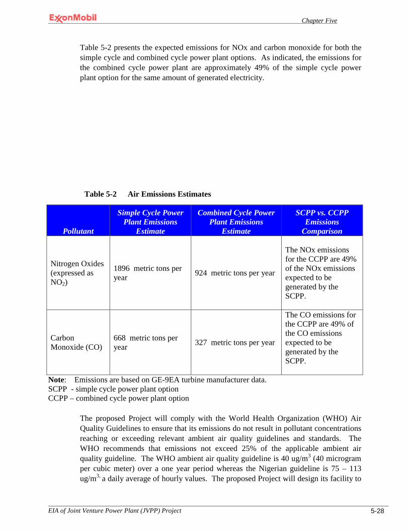
Chapter Five
EIA of Joint Venture Power Plant (JVPP) Project 5-28
Table 5-2 presents the expected emissions for NOx and carbon monoxide for both the simple cycle and combined cycle power plant options. As indicated, the emissions for the combined cycle power plant are approximately 49% of the simple cycle power plant option for the same amount of generated electricity.
Table 5-2 Air Emissions Estimates
Pollutant
Simple Cycle Power Plant Emissions
Estimate
Combined Cycle Power Plant Emissions
Estimate
SCPP vs. CCPP Emissions
Comparison
Nitrogen Oxides (expressed as NO2)
1896 metric tons per year
924 metric tons per year
The NOx emissions for the CCPP are 49% of the NOx emissions expected to be generated by the SCPP.
Carbon Monoxide (CO)
668 metric tons per year 327 metric tons per year
The CO emissions for the CCPP are 49% of the CO emissions expected to be generated by the SCPP.
Note: Emissions are based on GE-9EA turbine manufacturer data. SCPP - simple cycle power plant option CCPP – combined cycle power plant option
The proposed Project will comply with the World Health Organization (WHO) Air Quality Guidelines to ensure that its emissions do not result in pollutant concentrations reaching or exceeding relevant ambient air quality guidelines and standards. The WHO recommends that emissions not exceed 25% of the applicable ambient air quality guideline. The WHO ambient air quality guideline is 40 ug/m3 (40 microgram per cubic meter) over a one year period whereas the Nigerian guideline is 75 – 113 ug/m3, a daily average of hourly values. The proposed Project will design its facility to
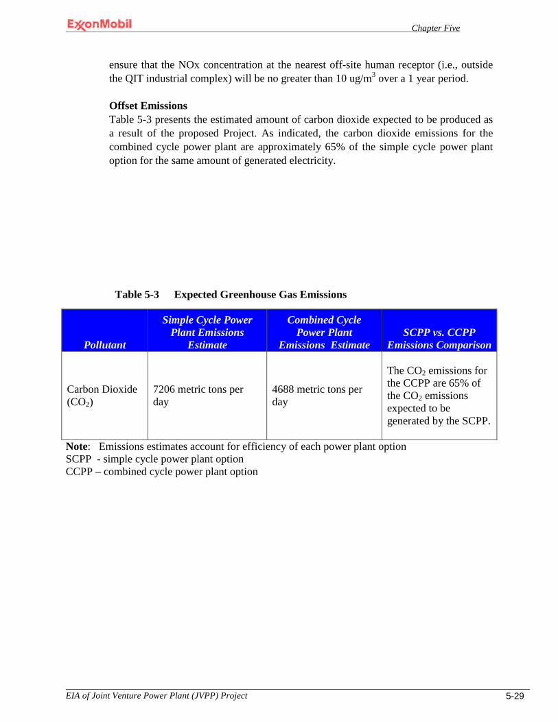
Chapter Five
EIA of Joint Venture Power Plant (JVPP) Project 5-29
ensure that the NOx concentration at the nearest off-site human receptor (i.e., outside the QIT industrial complex) will be no greater than 10 ug/m3 over a 1 year period.
Offset Emissions Table 5-3 presents the estimated amount of carbon dioxide expected to be produced as a result of the proposed Project. As indicated, the carbon dioxide emissions for the combined cycle power plant are approximately 65% of the simple cycle power plant option for the same amount of generated electricity.
Table 5-3 Expected Greenhouse Gas Emissions
Pollutant
Simple Cycle Power Plant Emissions
Estimate
Combined Cycle Power Plant
Emissions Estimate SCPP vs. CCPP
Emissions Comparison
Carbon Dioxide (CO2)
7206 metric tons per day
4688 metric tons per day
The CO2 emissions for the CCPP are 65% of the CO2 emissions expected to be generated by the SCPP.
Note: Emissions estimates account for efficiency of each power plant option SCPP - simple cycle power plant option CCPP – combined cycle power plant option
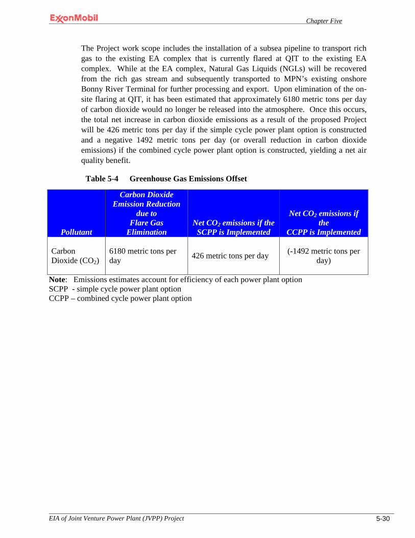
Chapter Five
EIA of Joint Venture Power Plant (JVPP) Project 5-30
The Project work scope includes the installation of a subsea pipeline to transport rich gas to the existing EA complex that is currently flared at QIT to the existing EA complex. While at the EA complex, Natural Gas Liquids (NGLs) will be recovered from the rich gas stream and subsequently transported to MPN’s existing onshore Bonny River Terminal for further processing and export. Upon elimination of the on-site flaring at QIT, it has been estimated that approximately 6180 metric tons per day of carbon dioxide would no longer be released into the atmosphere. Once this occurs, the total net increase in carbon dioxide emissions as a result of the proposed Project will be 426 metric tons per day if the simple cycle power plant option is constructed and a negative 1492 metric tons per day (or overall reduction in carbon dioxide emissions) if the combined cycle power plant option is constructed, yielding a net air quality benefit.
Table 5-4 Greenhouse Gas Emissions Offset
Pollutant
Carbon Dioxide Emission Reduction
due to Flare Gas
Elimination Net CO2 emissions if the
SCPP is Implemented
Net CO2 emissions if the
CCPP is Implemented
Carbon Dioxide (CO2)
6180 metric tons per day
426 metric tons per day
(-1492 metric tons per
day)
Note: Emissions estimates account for efficiency of each power plant option SCPP - simple cycle power plant option CCPP – combined cycle power plant option

Chapter Five
EIA of Joint Venture Power Plant (JVPP) Project 5-31
Economic Viability It is in the interest of the proposed Project to keep pollutant emissions to a minimum for environmental reasons as well as economic reasons. The Project’s economic viability is dependent upon it generating as much electricity as possible while keeping fuel usage to as low as reasonably possible. The generation of NOx or carbon monoxide in higher concentrations than originally planned would mean that the facility is not operating optimally. As such, the cost of producing electricity would be higher than originally projected.
The proposed Project, would result in the beneficial production of electricity with minimal cumulative impact on the pollutant emissions that currently occur at QIT as a result of the flares. In as much as pollutant emissions with any type of fossil fuel are unavoidable, these emissions will however be minimized. If the power plant is not operated at peak efficiency, pollutant emissions will be higher than is necessary. Since there is some potential for this to occur, this impact is considered significant.
5.4.3.2 Mitigation Measures
To further mitigate potential atmospheric impacts of the proposed Project, the following will be implemented:
A. Conduct design reviews and performance tests to confirm NOx concentration limits
and other regulated parameters are incorporated into the design.
B. Conduct stack sampling once per year and once at commissioning to assess if the NOx concentration (measured as nitrogen dioxide) meets the Project commitment not to exceed 25 ppmv at the stack based on a dry O2 content of 15%. Appropriate maintenance and/or operating changes will be implemented, if necessary, to maintain design parameters.
5.4.3.3 Residual Impacts
No long term residual impacts to air quality are anticipated since all emissions are expected to be within applicable World Bank or WHO guidelines.
5.5 Noise Impacts to ambient noise conditions within the area of influence as defined in Table 4-1 are discussed in greater detail below are as follows:
• Early site preparation and construction impacts on ambient noise • Transportation related increases in ambient noise • Operational related increases in ambient noise
Chapter Five
EIA of Joint Venture Power Plant (JVPP) Project 5-32
5.5.1 Early Site Preparation and Construction Impacts on Ambient Noise
5.5.1.1 Impact Analysis
Noise emissions resulting from early site preparation and construction activities were calculated based on a construction sequence of four major activities as follows: clearing and grubbing; excavation, backfill and grading; foundation work; and equipment hook-up/installation. Within these four activities, work areas were identified that would be occurring simultaneously. For example, Table 5-5 presents the initial construction activity, clearing and grubbing. During that activity work would be occurring at three separate locations: the power plant, laydown areas and workers camp; QIT Lake; and the MOF. Table 5-5 also presents the equipment expected to be operating at each work area along with the associated sound power level at 50 feet for each piece of equipment; the expected time each piece of equipment would operate; and the total acoustic energy for the activity or Leq. Accordingly, Table 5-6 through Table 5-8 present the same type of information as that presented in Table 5-5 for each of the other three work areas: excavation, backfill and grading; foundations; and hook-up/installation, respectively. Table 5-9 presents the World Bank guidelines for both absolute and relative noise emissions criteria. Pursuant to Table 5-9, the absolute criteria for construction activities is 55 dBA for off-site noise sensitive receptors as construction activities are expected to occur only during daylight hours. Additionally, noise emissions from construction must also adhere to the World Bank’s noise emission relative criteria which require that the maximum increase in background levels not exceed an a additional 3 dB at the nearest receptor location offsite. For this analysis, sample point MP5 (Figure 4-20) is the closest off-site sensitive noise receptor to the proposed Project. Accordingly, MP5 was selected as the benchmark ambient noise emission level. The MP5 ambient emission level, 49.6 dBA (Table 4-12), along with the Activity Sound Pressure Level (SPL) (calculated from the data in Table 5-5 through Table 5-8) for each work activity was then used to calculate the noise emission that would be expected at MP5 for each major work event, see Table 5-10. The total SPL for each major work event was then compared against the absolute criteria of 55 dBA and the relative criteria (i.e., in this case 52.6 dBA) to assess if an impact would occur. As shown in Table 5-10 the absolute criteria of 55 dBA would not be exceeded for any of the work areas; however, the relative criteria would be exceeded by 1.2 dBA for the excavation, backfill and grading work activity only. Thus, this impact is considered to be significant and unavoidable, but it would also be short term. It is significant and unavoidable. However, to reduce the impact on personnel, we will ensure the use of personal protective equipment.
In regard to permissible noise emissions at the on-site workers construction camp, MPN’s noise emissions standards will govern. Per these standards, all interior building noise emissions will not exceed 45 dBA for sleeping quarters and 55 dBA for all other
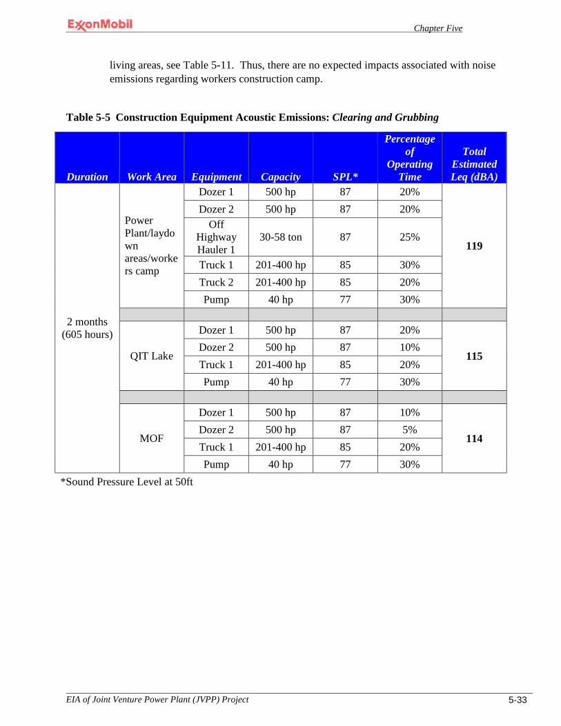
Chapter Five
EIA of Joint Venture Power Plant (JVPP) Project 5-33
living areas, see Table 5-11. Thus, there are no expected impacts associated with noise emissions regarding workers construction camp.
Table 5-5 Construction Equipment Acoustic Emissions: Clearing and Grubbing
Duration Work Area Equipment Capacity SPL*
Percentage of
Operating Time
Total Estimated Leq (dBA)
2 months (605 hours)
Power Plant/laydown areas/workers camp
Dozer 1 500 hp 87 20%
119
Dozer 2 500 hp 87 20% Off
Highway Hauler 1
30-58 ton 87 25%
Truck 1 201-400 hp 85 30% Truck 2 201-400 hp 85 20% Pump 40 hp 77 30%
QIT Lake
Dozer 1 500 hp 87 20%
115 Dozer 2 500 hp 87 10% Truck 1 201-400 hp 85 20% Pump 40 hp 77 30%
MOF
Dozer 1 500 hp 87 10%
114 Dozer 2 500 hp 87 5% Truck 1 201-400 hp 85 20% Pump 40 hp 77 30%
*Sound Pressure Level at 50ft

Chapter Five
EIA of Joint Venture Power Plant (JVPP) Project 5-34
Table 5-6 Construction Equipment Acoustic Emissions: Excavation, Backfill & Grading
Duration Work Area Equipment Capacity SPL*
Percentage of Operating
Time
Total Estimated Leq (dBA)
8 months (2419 hours)
Power Plant/laydown areas/workers
camp
Dozer 1 500 hp 87 20%
121
Dozer 2 500 hp 87 20% Off Highway
Hauler 1 30-58 ton 87 25%
Off Highway Hauler 2 30-58 ton 87 25%
Truck 1 201-400 hp 85 20%
Truck 2 201-400 hp 85 20%
Truck 3 201-400 hp 85 20%
Backhoe 1 1-1.5 cu. ft. 83 20%
Backhoe 2 1-1.5 cu. ft. 83 20%
Grader 1 300 hp 86 20%
Grader 2 300 hp 86 20%
QIT Lake
Shovel 1 2.25-5 cu yd 85 30%
119
Shovel 1 2.25-5 cu yd 85 30% Off Highway
Hauler 1 30-58 ton 87 25%
Off Highway Hauler 2 30-58 ton 87 25%
Truck 1 201-400 hp 85 20%
Backhoe 1 1-1.5 cu. ft. 83 20%
MOF {Completed}
Pile Driver 1200-18000 ft-lb/blow 93 15%
119
Truck 1 201-400 hp 85 20%
Truck 2 201-400 hp 85 20%
Mobil Crane 1 11-20 ton 83 8% Derick Crane
1 21-100 ton 84 10%
Welder 1 73 15%
Welder 2 73 30%
Backhoe 1 1-1.5 cu. ft. 83 20%
*Sound Pressure Level at 50ft
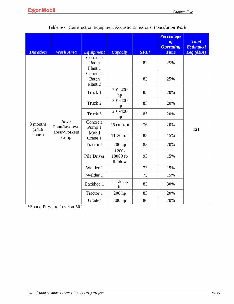
Chapter Five
EIA of Joint Venture Power Plant (JVPP) Project 5-35
Table 5-7 Construction Equipment Acoustic Emissions: Foundation Work
Duration Work Area Equipment Capacity SPL*
Percentage of
Operating Time
Total Estimated Leq (dBA)
8 months (2419 hours)
Power Plant/laydown areas/workers
camp
Concrete Batch Plant 1
83 25%
121
Concrete Batch Plant 2
83 25%
Truck 1 201-400 hp 85 20%
Truck 2 201-400 hp 85 20%
Truck 3 201-400 hp 85 20%
Concrete Pump 1 25 cu.ft/hr 76 20%
Mobil Crane 1 11-20 ton 83 15%
Tractor 1 200 hp 83 20%
Pile Driver 1200-
18000 ft-lb/blow
93 15%
Welder 1 73 15% Welder 1 73 15%
Backhoe 1 1-1.5 cu. ft. 83 30%
Tractor 1 200 hp 83 20% Grader 300 hp 86 20%
*Sound Pressure Level at 50ft
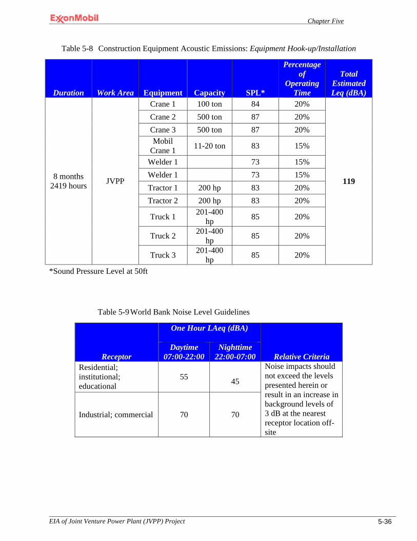
Chapter Five
EIA of Joint Venture Power Plant (JVPP) Project 5-36
Table 5-8 Construction Equipment Acoustic Emissions: Equipment Hook-up/Installation
Duration Work Area Equipment Capacity SPL*
Percentage of
Operating Time
Total Estimated Leq (dBA)
8 months 2419 hours JVPP
Crane 1 100 ton 84 20%
119
Crane 2 500 ton 87 20% Crane 3 500 ton 87 20% Mobil
Crane 1 11-20 ton 83 15%
Welder 1 73 15% Welder 1 73 15% Tractor 1 200 hp 83 20% Tractor 2 200 hp 83 20%
Truck 1 201-400 hp 85 20%
Truck 2 201-400 hp 85 20%
Truck 3 201-400 hp 85 20%
*Sound Pressure Level at 50ft
Table 5-9 World Bank Noise Level Guidelines
Receptor
One Hour LAeq (dBA)
Relative Criteria Daytime
07:00-22:00 Nighttime
22:00-07:00 Residential; institutional; educational
55 45
Noise impacts should not exceed the levels presented herein or result in an increase in background levels of 3 dB at the nearest receptor location off-site
Industrial; commercial 70 70
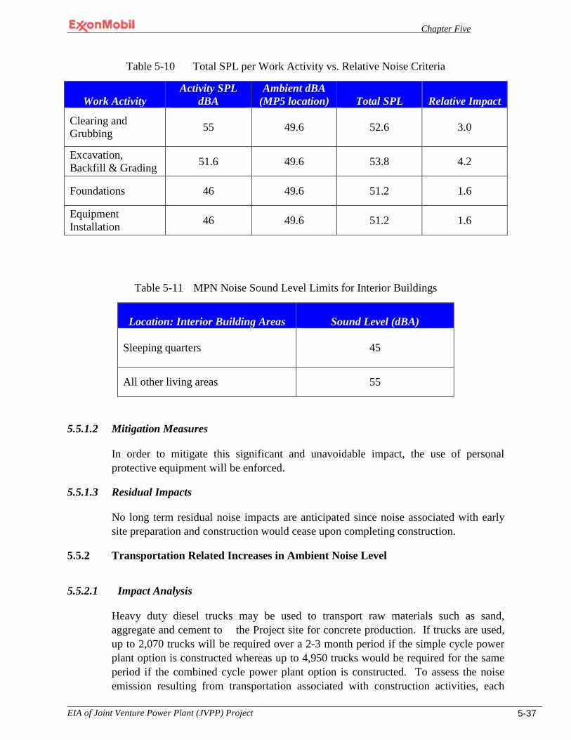
Chapter Five
EIA of Joint Venture Power Plant (JVPP) Project 5-37
Table 5-10 Total SPL per Work Activity vs. Relative Noise Criteria
Work Activity Activity SPL
dBA Ambient dBA
(MP5 location) Total SPL Relative Impact
Clearing and Grubbing
55
49.6 52.6 3.0
Excavation, Backfill & Grading 51.6 49.6 53.8 4.2
Foundations 46 49.6 51.2 1.6
Equipment Installation 46 49.6 51.2 1.6
Table 5-11 MPN Noise Sound Level Limits for Interior Buildings
Location: Interior Building Areas Sound Level (dBA)
Sleeping quarters
45
All other living areas 55
5.5.1.2 Mitigation Measures
In order to mitigate this significant and unavoidable impact, the use of personal protective equipment will be enforced.
5.5.1.3 Residual Impacts
No long term residual noise impacts are anticipated since noise associated with early site preparation and construction would cease upon completing construction.
5.5.2 Transportation Related Increases in Ambient Noise Level
5.5.2.1 Impact Analysis
Heavy duty diesel trucks may be used to transport raw materials such as sand, aggregate and cement to the Project site for concrete production. If trucks are used, up to 2,070 trucks will be required over a 2-3 month period if the simple cycle power plant option is constructed whereas up to 4,950 trucks would be required for the same period if the combined cycle power plant option is constructed. To assess the noise emission resulting from transportation associated with construction activities, each
Chapter Five
EIA of Joint Venture Power Plant (JVPP) Project 5-38
truck was considered to be a point source. Then noise emission calculations were used to determine how far from the road a noise receptor would need to be to receive an emission of 55 dBA or less (see Table 5-9). The assumptions used were that trucks would travel over a 2 ½ month period, 6 days per week at 12 hours per day. For the simple cycle power plant option is was estimated that approximately 1 truck would pass by a fixed point on a road once every 10 minutes or 10% of the time whereas for the combined cycle power plant option it was estimated that 1 truck would pass by a fixed point on a road once every 4.6 minutes or 21% of the time.
The result of the calculations showed that for the simple cycle (SC) power plant option that a noise receptor would need to be a minimum of 153 meters away from the road to receive a noise emission of 55 dBA whereas for the combined cycle (CC) power plant option, the noise receptor would need to be about 216 meters away from the road. The significance of this estimate is that people could be residing within the construction truck traffic corridor, i.e., 153 meters for SC option and 216 meters for the CC option. Thus, this impact is considered to be significant and unavoidable, but it would also be short term in that it would be limited to a 2 ½ month period. It is significant and measures for the management of the impact of construction traffic noise are indicated below.
5.5.2.2 Mitigation Measures
• Ensure the road worthiness of trucks to minimize the noise impact. • Restrict movement of vehicles to day time.
5.5.3.3 Residual Impacts
No long-term residual impacts from transportation-related noise are anticipated.
5.5.3 Operation Related Increases in Ambient Noise Level
5.5.3.1 Impact Analysis
The principle source of noise emissions during the operations phase of the proposed Project will originate from the GTGs whether the simple cycle or combined cycle power plant option is implemented. In accordance with World Bank noise emissions guidelines, the criterion is 70 dBA at the proposed Project’s fence-line and 45 dBA for the closest off-site sensitive noise receptor, given that the power plant will operate 24-hours per day ( Table 5-9). To meet these requirements, the proposed Project will need to specify a noise emission of 60 dBA at 400 feet for each GTG package. This technology is readily available.
Figure 0-2 presents a contour of the expected noise emissions during operations for both the simple cycle and combined cycle power plant options (i.e., 60 dBA at 400 feet for each GTG package). As shown in Figure 0-2, the area outside of the purple contour will be less than 45 dBA and the area outside of the JV Power Plant fence-line

Chapter Five
EIA of Joint Venture Power Plant (JVPP) Project 5-39
will be less than 70 dBA. Thus, an impact associated with noise emissions during operation of the proposed Project will occur if the noise specifications for the GTG package are improperly specified. Therefore, this impact is considered to be significant.
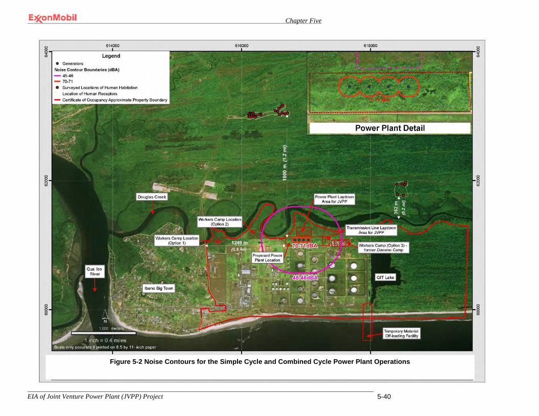
Chapter Five
EIA of Joint Venture Power Plant (JVPP) Project 5-40
Figure 0-2 Noise Contours for the Simple Cycle and Combined Cycle Power Plant Options
Figure 5-2 Noise Contours for the Simple Cycle and Combined Cycle Power Plant Operations
Chapter Five
EIA of Joint Venture Power Plant (JVPP) Project 5-41
5.5.3.2 Mitigation Measures
The mitigation measures would be that the equipment specification package will require the GTGs to meet a 60 dBA at 400 feet criteria to ensure compliance with World Bank noise emission guidelines.
5.5.3.3 Residual Impacts
Assuming measures are taken to ensure noise emission levels meet World Bank guidelines, no long-term residual noise impacts are anticipated during operation of the proposed Project.
5.6 Water Resources Impacts to water resources within the area of influence as defined in Table 4-1 could occur as a result of the proposed Project. These potential impacts which are discussed in greater detail below are as follows:
• Surface Water Impacts Due to Storm Water Runoff and Sedimentation during
Construction. • Changes in Surface Water Quality Due to Discharge of Sanitary Sewage, Storm
Water and Wastewater. • Effects of Inadvertent Spill Discharges to Surface Waters. • Effects of Inadvertent Spills to Groundwater. • Surface Water Quality Impacts Due to Hydrostatic Test Water Discharge.
5.6.1 Surface Water Impacts Due to Storm Water Run-off and Sedimentation during Construction
5.6.1.1 Impact Analysis
Construction frequently causes significant alterations in the characteristics of the affected land. One such change is an increase in the overall imperviousness of the project soils which can dramatically affect a site's surface water flow patterns. An increase in storm water runoff may increase the amount of sediment and other pollutants discharged into receiving water bodies. As such, the water quality in the receiving water body could become degraded overtime resulting in aquatic habitat alteration. Thus, traditional storm water management controls attempt to limit increases in the amount of runoff and hence pollutant loads that can be discharged to water bodies from land impacted by construction.
To slow pollutant and/or sedimentation loads resulting from storm water runoff, the proposed Project will construct a storm water retention pond during the site preparation phase that will remain functional throughout project life. All storm water generated during construction will be diverted to this basin and allowed to settle prior to

Chapter Five
EIA of Joint Venture Power Plant (JVPP) Project 5-42
discharging into Douglas Creek. During site preparation, construction activities will rely on natural drainages and temporary drainages at the Project site until the permanent drainage system is operational. During construction, one or possibly two temporary concrete batch plants will be established at the site to provide concrete during the construction phase. The feed water for the batch plants will be the two onsite deep groundwater wells. It is estimated that approximately 9,530 m3 (12,464 yd3) of concrete will be required if the simple cycle power plant option is constructed and 20,660 m3 (27,021 yd3) of concrete will be required if the combined cycle power plant option is constructed. The production of concrete at the project site will generate wastewater resulting from truck wash systems, washing of the central mix plant and conveyor wash downs. Freshwater used for dust control and to maintain moisture content of the aggregate as per concrete specifications would also generate wastewater. However, the wastewater generated from these latter two activities is expected to be minimal, if any.
Discharges from batch plants typically are high in pH, contain total suspended solids and in some cases also contain oil and grease. It is estimated that approximately 20 gallons of discharge water will be generated for each cubic yard of concrete produced6. Thus, it is conservatively estimated that about 943,675 liters (249,300 gallons) of wash water discharge would be generated if the simple cycle power plant option were constructed and that 2,045,955 liters (540,500 gallons) of wash water discharge would be generated if the combined cycle power plant option were constructed.
In order to minimize the discharge of pollutant laden storm water from the project site, the proposed Project will develop and implement an Erosion and Sedimentation Control Plan (see Section 3.5.2). All storm water pollutant prevention, control and treatment measures proposed in this Plan would be put into place in advance of any soil disturbance.
The development and implementation of an Erosion and Sedimentation Control Plan by the proposed Project will address the expected impacts associated with storm water runoff including sedimentation provided the measures implemented are effective. The impacts associated with storm water runoff and sedimentation is considered significant.
5.6.1.2 Mitigation Measures
To ensure the effectiveness of the storm water management provisions as presented in the Erosion and Sedimentation Control Plan the following mitigation measures will be implemented by the proposed Project’s Environmental Management Team:
A. Assess the effectiveness of runoff control measures for incorporation into the Erosion and Sedimentation Control Plan
6 S. Abdol and William J. Mbwambo; “Environmentally Friendly Solutions for the Disposal of Concrete Wash Water from Ready Mixed Concrete Operations; University of Florida, Gainesville, Florida.”

Chapter Five
EIA of Joint Venture Power Plant (JVPP) Project 5-43
B. Establish monitoring for pH, total suspended solids and oil/grease for the single discharge outfall to Douglas Creek to ensure compliance with Plan established thresholds. The pH should be monitored using simple pH strips (maintaining limits from 6-9), total suspended solids should be qualitatively monitored for the appearance or lack thereof of a cloudy appearance in the outfall and visual observation should be used to determine the presence or absence of an oily sheen to assess the presence or absence of oil/grease.
C. Conduct visual monitoring of runoff control measures particularly during and immediately following periods of precipitation to ascertain their effectiveness. Document and maintain all such inspections in separate inspection reports and track all resolutions to completion.
D. Implement additional mitigation consistent with the measures identified in the Erosion and Sedimentation Control Plan if monitoring indicates that excessive runoff and sedimentation is occurring, (i.e., exceeds a threshold), particularly during prolonged precipitation events.
E. Incorporate standard maintenance practices into the Erosion and Sedimentation Control Plan to ensure that runoff control measures are properly installed and effectively maintained.
F. Identify in the Erosion and Sedimentation Control Plan measures to control site conditions through pollution prevention practices so as to minimize the need to collect and treat storm water.
G. Locate the temporary batch plants away from watercourses and drain courses to the extent practicable. Construct berms around batch plant equipment to facilitate proper containment and cleanup of releases. Do not dispose of concrete into the storm water drainage system or any watercourses.
H. Identify a designated area to washout concrete trucks and another designated area for equipment washing.
I. Periodic inspection of the concrete batch plant facilities while present at the project site.
5.6.1.3 Residual Impacts
Occasional siltation of surface waters in the vicinity of the Project may occur since erosion control measures are rarely 100 percent effective. However, these impacts are expected to be temporary and limited to extremely large storm events.

Chapter Five
EIA of Joint Venture Power Plant (JVPP) Project 5-44
5.6.2 Changes in Surface Water Quality Due to Discharge of Sanitary Sewage, Storm Water and Wastewater during Operations
5.6.2.1 Impact Analysis
Sanitary Sewage Discharge Sanitary sewage wastewater from lavatories, sinks, and showers will discharge to a sanitary lift station located adjacent to the plant where it will be pumped to a membrane bio-reactor. The effluent from the bio-reactor will meet the effluent guidelines in the World Bank’s Environmental Health and Safety Guideline standards which are presented in Table 5-12.
Table 5-12 World Bank Sanitary Sewage Discharge Effluent Guidelines
Pollutant Units Threshold Values pH pH 6-9
Biological Oxygen Demand mg/la 30
Chemical Oxygen Demand mg/l 125
Total nitrogen mg/l 10
Total phosphorus mg/l 2
Oil and grease mg/l 10
Total suspended solids mg/l 50 (30 mg/l will be the threshold met by the proposed Project)b
Total coliform bacteria MPNc/100 ml 400 Notes: a milligrams per liter b Nigerian Federal Ministry of Environment effluent limit c Most Probable Number
Storm Water Discharge Outside equipment containment areas for the collection of storm water that has come into contact with some amount of oil drips will pass through an oil/water separator prior to discharge into the storm water retention ponds. Storm water containment areas whose origin is from outside paved areas such as vehicle traffic and parking lots that also have the potential to come into contact with some amount of oil drips will be directed through an oil/water separator prior to discharge to the storm water retention pond. The threshold or not to exceed level for oil/grease discharge into the storm water retention pond will be 10 mg/l.

Chapter Five
EIA of Joint Venture Power Plant (JVPP) Project 5-45
Wastewater Discharge Wastewater will originate from three basic processes which are subsequently described. Raw water from two on-site groundwater wells located approximately 183 meters (600 feet) deep will be filtered through a multimedia filter to remove dissolved solids. The blowdown from the multimedia filter will thus consist of water with dissolved solids and will subsequently be sent to a wastewater storage tank to await further treatment prior to discharge to the storm water retention pond.
A portion of the treated raw water, now called plant water, will then be treated further to produce potable water. This will be accomplished by passing the water through a granular activated carbon unit to remove organic compounds if present, and then treating it further with a small amount of sodium hypochlorite for disinfection. The blowdown will subsequently be sent to the wastewater storage tank referenced previously to await further treatment prior to discharge. The blowdown will principally consist of a small amount of sodium hypochlorite or household bleach.
The third wastewater stream will result from efforts to generate de-ionized or de-mineralized water for the GT wash water system and for the boilers should the combined cycle power plant option be selected. This will be accomplished by placing a water softener unit upstream of a reverse osmosis unit. The water softener unit will use ion exchange to remove scaling ions such as calcium and magnesium and the reverse osmosis unit will serve to eliminate any metals. The resulting blowdown will consist of metal salts in solution principally calcium, magnesium, sodium and iron. Similar to the two wastewater streams previously described, the blowdown will be sent to the wastewater storage tank for further treatment.
The blowdown wastewater streams just described will be treated using either a traditional treatment approach or bioreactor technology. Treatment will likely be intermittent based on having sufficient quantity in the wastewater holding tank to warrant treatment. It is expected that approximately 300,000 liters/year (79,254 gallons/year) of wastewater will require treatment if the simple cycle power plant option is implemented and about 200,640,000 liters/year (50,160,000 gallons/year) of wastewater will require treatment if the combined cycle power plant option is implemented; a factor of about 669 times more water requiring treatment when considering the combined cycle plant option.
If a traditional treatment approach is used the wastewater blowdown will be aerated to cause the metals to precipitate out of solution. These metals will subsequently be removed from the wastewater stream and disposed in accordance with Nigerian and MPN waste management requirements. The resulting effluent will then flow to a storm water retention pond. If bioreactor technology is employed, the wastewater pollutants will be consumed by microorganisms prior to releasing the treated effluent to flow to the storm water retention pond.

Chapter Five
EIA of Joint Venture Power Plant (JVPP) Project 5-46
We propose to monitor for pollutants potentially present in the proposed Project’s wastewater effluent. Monitoring will focus only on those pollutants that have the potential to be generated as a result of proposed Project activities. Table 5-13 column 3 entitled, “Project Proposed Performance Standard for Wastewater Effluent Limits” presents those pollutants that the Project proposes to assess.

Chapter Five
EIA of Joint Venture Power Plant (JVPP) Project 5-47
Table 5-13 Interim Effluent Limitation Guidelines in Nigeria For all categories or Industries and Effluent Limits Proposed by the Project
Parameter
Nigerian Federal Ministry Effluent Limits for discharge into
surface water (mga/l) Project Proposed Performance Standard for Wastewater Effluent
Limits (mg/l) pH 6-9 6-9
BOD @ 200C 50 30
Total suspended solids 30 30
Oil and grease 10 10
Iron (as Fe) 20 20
Chlorine (free) 1.0 1.0
Copper Less than 1 Less than 1
Lead Less than 1 Less than 1
Calcium (Ca2+) 200 200
Magnesium (as Mg2+) 200 200
Coliforms 400 MPNb/100 ml daily average 400 MPNb/100 ml Notes: a milligrams per liter b Most Probable Number NA – pollutants not applicable to the proposed Project’s effluent wastewater stream
Chapter Five
EIA of Joint Venture Power Plant (JVPP) Project 5-48
The implementation of the monitoring program proposed herein is expected to be protective against adverse surface water impacts provided the thresholds or effluent limits are not exceeded. Accordingly, there is some potential for these thresholds to be exceeded. Thus, these impacts are considered to be significant.
5.5.2.2 Mitigation Measures
To ensure the effectiveness of the proposed monitoring program, if the threshold or effluent limits are exceeded, process modifications or appropriate equipment maintenance measures will promptly be implemented to ensure compliance.
5.6.2.3 Residual Impacts
No long–term residual impacts are expected.
5.6.3 Effects of Inadvertent Spill Discharges to Surface Waters
5.6.3.1 Impact Analysis
Accidental spills of petroleum or other toxic products into an adjacent water body such as Douglas Creek during facility construction or operation could be harmful or significant to aquatic organisms depending upon the type, quantity and concentration of the spill. To address these types of potential impacts, the proposed Project has committed to developing a SPR Plan to address construction activities only (Section 3.5.2). The SPRP be developed to ensure effectiveness prevention, control and clean up of spill.
5.6.3.2 Mitigation Measures
To ensure the effectiveness of the SPR Plan, the following mitigation measures will be implemented:
A. The SPR Plan will capture both the construction and operations phase.
B. SPR Plan contents will address spill prevention and preparedness procedures; spill reporting procedures; spill clean-up procedures and the type, quantity, and location of emergency response equipment to address spills.
C. The SPR Plan will present a summary table of the type, quantity, storage method and location for each raw material, hazardous material, chemical, fuel, lubricant oil, etc. that will be stored at the proposed Project site.
D. The use of concrete containment areas, concrete pads and drip pans for spill prevention and management will also be highlighted in the SPR Plan.
E. Fuel trucks transporting fuel to Project on-site equipment will be required to travel only on MPN approved on-site access roads.

Chapter Five
EIA of Joint Venture Power Plant (JVPP) Project 5-49
F. Equipment may not be fueled or parked overnight within 31 meters (about 100 feet) from a water body.
G. Hazardous materials including chemicals, fuels and lubricating oils may not be stored within 31 meters (about 100 feet) from a water body.
H. Construction, cleanup and maintenance crews will carry sufficient supplies of absorbent and barrier materials while working to allow the rapid containment and recovery of spilled materials.
I. Construction crews and maintenance crews will carry sufficient tools to stop leaks while working.
J. Secondary containment will be provided for stored liquid materials. Containment will provide sufficient volume to contain precipitation from a 25-year storm event plus 10% of the aggregate volume of all containers or more than 100% of the largest container, whichever is greater.
5.6.3.3 Residual Impacts
No long–term residual impacts are expected.
5.6.4 Effects of Inadvertent Spills to Groundwater
5.6.4.1 Impact Analysis
The soils at the Project site are known to consist of silts and clays. These types of soils tend to be impermeable such that they function as a barrier to any significant downward movement of liquids from the surface. Thus, contaminants from accidental spills at the site would not be expected to rapidly percolate to the shallow water zone located about 12-15 meters (40-49 feet) below ground surface. To further minimize the potential of any accidental spills to the environment, the Project will confirm implementation of the SPR Plan.
5.6.4.2 Mitigation Measures
No mitigation measures are required.
5.6.4.3 Residual Impacts
No long–term residual impacts are expected.
Chapter Five
EIA of Joint Venture Power Plant (JVPP) Project 5-50
5.6.5 Impacts to Surface Waters Due to the Discharge of Hydrostatic Test Water
5.6.5.1 Impact Analysis
Hydrostatic testing will be conducted on the onshore fuel gas process piping to ensure structural integrity as described in Section 3.6.9. This testing will occur prior to commencing operations. Approximately 107,000 liters (28,267 gallons) of fresh water obtained from the onsite firewater standpipe will be used for the hydrostatic test. Small concentrations of a corrosion inhibitor, biocide, and/or an oxygen scavenger may be added to the test water to avoid pipe corrosion. The chemicals used for this activity will be selected from a list of chemicals approved for hydrostatic testing by the Nigerian Department of Petroleum Resources. Additionally, each selected chemical will be further scrutinized by MPN’s Occupational Health group to assure that the chemical is environmentally friendly in advance of use. After testing is complete, the test water will be discharged into the storm water collection system which will discharge into the storm water retention pond and subsequently into Douglas Creek. The effluent discharge will meet those Nigerian regulatory requirements that govern the disposal of hydrostatic test waters. Thus, the disposal of hydrostatic test water is expected to have no impact on surface water resources.
5.6.5.2 Mitigation Measures
No mitigation measures are proposed based on the discussion above.
5.6.5.3 Residual Impacts
No long–term residual impacts are expected.
5.7 Socioeconomic Resources The proposed Project is expected to have positive economic benefits on the surrounding population within the area of influence as defined in Table 4-1. The beneficial impacts expected to occur as a result of the proposed Project are as follows:
• Local Employment and Business Growth & Development Due to the Availability of
Electricity. • Increased Opportunities for Individuals and Organizations that Utilize the Electricity
Produced by the Proposed Project.
Chapter Five
EIA of Joint Venture Power Plant (JVPP) Project 5-51
5.7.1 Local Employment and Business Growth & Development Due to the Availability of Electricity
5.7.1.1 Impact Analysis
The proposed Project will have a positive impact with respect to jobs by providing long term employment for up to 55 people. In addition, the proposed Project will result in short-term employment opportunities. Skilled and unskilled personnel will be recruited from the Project communities to support various project activities. It is anticipated that the project will encourage skills development and acquisition for indigenes working on the project. EPC contractor will be directly responsible for engagement and development of personnel. However, in order to ensure smooth working relations as well as proper and fair engagement, EPC contractor will work closely with MPN Public Relations and Project Community Relations representative. This will also ensure the contractor works in compliance with MPN’s Community and Labor Relations Principles and Guidelines. The guideline is a standard engagement procedure that is designed to provide transparent process of engagement and compensations in order to promote incident free workplace. At peak employment, up to 750 (1,500 for combined cycle option) jobs will be created in the construction phase. Operations to be carried out on-site will include site preparation, concrete production, piling, foundation work, erection of structural steel work, erection of cladding and roofing to structures, and mechanical and electrical works. There will also be indirect employment associated with the provision of equipment and other materials in support of construction such as, but not limited to, transport services including materials such as sand, gravel and cement, and catering services. Possible adverse impact would be in the allocation of employment opportunities to the host communities. Community engagement strategies are addressed in the MPN’s Labor Relations Principles and Guidelines. , Implementation of agreed ratio of engagement from all the communities concerned will be implemented by the EPC. The plan will be followed as is typical with MPN’s practice thus eliminating the likelihood of resource allocation becoming a problem. Another possible adverse impact is social and cultural conflicts. This will be greatly reduced by provision of camping and recreational facilities for foreign workers close to the project site. The induction trainings will also be structured to educate workers on conflicts avoidance, reporting and management procedures. In view of these therefore, it is concluded that the proposed Project will have an overall beneficial short and long-term socio-economic impact on the surrounding area, providing jobs and investments while helping the wider Nigerian economy through the development of a highly cost effective means of electricity generation.
5.7.1.2 Mitigation Measures
Since the impact is beneficial, no mitigation measures are needed.
Chapter Five
EIA of Joint Venture Power Plant (JVPP) Project 5-52
5.7.1.3 Residual Impacts
The employment and business opportunities available throughout the operation phase will produce long–term beneficial residual impacts.
5.7.2 Increased Opportunities for Individuals and Organizations that Utilize Electricity Produced by the Proposed Project
5.7.2.1 Impact Analysis
The Federal Government of Nigeria is seeking to reliably increase domestic power generation in order to promote economic growth and hence an improved standard of living for the Nigerian people. The survey for this assessment, identified that most of the communities within the area of socioeconomic influence (see Table 4-1) lack electricity. It was further reported that in the few communities that had electricity, the power supply was sporadic.
The proposed Project will provide an additional ISO 575 MW of power to the national grid in support of the government’s effort to ensure reliable electrical power for its people. Additional and reliable electricity is expected to result in business opportunities that do not currently exist or are extremely limited (e.g., sales of electrical tools, machinery, and equipment; repair of electrical tools, machinery, and equipment). Electricity can contribute to a better standard of living. This can include the use of modern appliances that can make life more comfortable. It also enhances education and literacy. Students can read and study while using modern facilities to further their academic development. Further, the decrease usage of diesel generators will save the consumer money. In addition, by having reliable electricity, overall emissions from generators will be reduced, thus having a decreased adverse effect on the environment.
Therefore, it is concluded that the proposed Project will have an overall beneficial socio-economic impact on the wider Nigerian economy through the generation of additional, reliable electricity for domestic use.
5.7.2.2 Mitigation Measures
Since the impacts are beneficial, no mitigation measures are needed.
5.7.2.3 Residual Impacts
The individual and organizational opportunities available throughout the operation phase will produce long–term beneficial residual impacts.
Chapter Five
EIA of Joint Venture Power Plant (JVPP) Project 5-53
5.8 Health & Safety Impacts to health and safety within the area of influence as defined in Table 4-1 could occur as a result of the proposed Project. These potential impacts which are discussed in greater detail below are as follows:
• Health and Safety Issues Associated with Tropical Diseases. • Safety/Risks Issues Associated with Site Clearing and Equipment Operation • Encounters with Venomous Snakes. • Safety Issues Associated with Construction Activities. • Safety/Risks Associated with Power Plant Operations.
5.8.1 Health and Safety Issues Associated with Tropical Diseases
5.8.1.1 Impact Analysis
A variety of diseases that are considered endemic to the West African region, e.g., Nigeria, pose potential health risks for employees and contractors that will work on the proposed Project. One of the most potent of these diseases is malaria. MPN has developed a Malaria Control Program (MCP) designed to minimize the risk of contracting Malaria for its non-immune employee and contractor personnel who work in malaria endemic areas. All non-immune personnel who travel to Nigeria are required to use Chemoprophlaxis or anti-malarial medications, recognize the symptoms of malaria, and implement other protective measures to avoid infection such as the use of insect repellent and the donning of special clothing to protect against mosquito bite penetration. ExxonMobil recognizes the devastating impact of HIV/AIDS and is committed to helping its personnel live and work safely. This is accomplished through STOP AIDS, a program that was launched in 2004 in addition to its support the world AIDS Day on December 1 of every year. The key elements of STOP AIDS include; • Workplace HIV prevention education to help mitigate HIV/AIDS risks by
changing behavior and attitudes. • Voluntary access to community-based confidential counseling and testing. • Access to community-based equitable HIV/AIDS care and treatment via
company-sponsored health plans. • "Outside the fence line" programs to strengthen and develop local health care
capacity.
MPN's management system requires that a process be put into place to identify and evaluate health risks from its facilities that could potentially affect employees, contractors and the public. As such, the proposed Project will prepare a Project Health Plan and conduct Health Risk Assessments, as appropriate. The Project Health Plan will present a disease prevention program that will address the diseases

Chapter Five
EIA of Joint Venture Power Plant (JVPP) Project 5-54
endemic in the vicinity of the proposed Project such as vector borne diseases, respiratory diseases, sexually transmitted diseases, and waterborne and food-borne diseases. The Project Health Plan will also present an immunization program for non-immune nationals and expatriate staff who will work at the proposed Project site. Included in this Plan will be a health, education and awareness program which will be implemented in association with the proposed Project. The EPC contractor will also be required to develop a project specific health plan for project management’s approval. Thus, health-related issues associated with the proposed Project will be effectively addressed and managed through implementation of and compliance with the Malaria Control Program, workplace HIV prevention program and the Project Health Plans (i.e., there will be no impact associated with these health-related issues).
5.8.1.2 Mitigation Measures
No additional mitigation measures are proposed.
5.8.1.3 Residual Impacts
No long–term residual impacts are expected.
5.8.2 Safety / Risk Issues Associated with Site Clearing and Equipment Operation
5.8.2.1 Impact Analysis
Early site preparation will involved the cutting of trees and woody debris including the clearing of brush and vegetation. The procedure for safely addressing site clearing, tree felling, grading and equipment operations will be addressed in the Project Safety Plan. This impact is considered to be significant.
5.8.2.2 Mitigation Measures
The following mitigation measures will be implemented to address potential safety issues associated with early site preparation:
A. Confirm that the Project Safety Plan addresses site clearing, tree felling, grading and
equipment operations to ensure that these activities are executed in a safe manner.
B. Provide personnel with a Health and Safety orientation prior to early site preparation activities that addresses the safe operating procedures presented or referenced in the Project Safety Plan.
5.8.2.3 Residual Impacts
No long–term residual impacts are expected.

Chapter Five
EIA of Joint Venture Power Plant (JVPP) Project 5-55
5.8.3 Encounters with Venomous Snakes
5.8.3.1 Impact Analysis
There are at least ten species of venomous snakes that occur in and around the moist rainforest region of Eket and within the area of influence of the proposed Project. These species include the western forest centipede eater (Aparallactus modestus), variable bush viper (Atheris squamiger), slender stiletto-snake (Atractaspis aterrima), Gaboon viper (Bitis gabonica), rhinoceros viper (Bitis nasicornis), Jameson’s mamba (Dendroaspis jamesoni), forest cobra (Naja melanoleuca), black spitting cobra (Naja nigricollis), Blanding’s tree snake (Toxicodryas blandingii) and the African puff adder (Bitis arietans arietans). Due to the potential for these snakes to be present in the vicinity of the proposed Project, health impacts from snake bites could occur.
During early site preparation and construction, site workers will have the potential to be exposed to venomous snakes. However, on-site medical care facilities will be equipped with antivenin serum and staffed with competent doctors and nurses capable of stabilizing patients with snakebites prior to evacuating them to the nearest medical facility capable of rendering the needed treatment. The Project Health Plan will require construction workers to participate in a health awareness orientation prior to commencing work at the site. This orientation will address among other things how to avoid snake bites and what to do if bitten by a snake. The health related issues associated with snake bites are considered a significant impact that could occur.
During operations, exposure to venomous snakes will decrease because fewer people will be on-site and few if any activities associated with operations are likely to occur in a vegetated area where snakes are likely to be encountered. Still, whereas the project site will generally be cleared of vegetation, surface drainage ditches could be infested with vegetation that could harbor such species.
5.8.3.2 Mitigation Measures
The following mitigation measure will be implemented to ensure that adequate facilities and personnel are maintained at the Project site to address health related issues associated with venomous snake bites:
A. The Project Health and Safety Plans will require all construction personnel to attend an
orientation in advance of commencing work to address the contents of the Health Plan including how to avoid snake bites and what to do if bitten by a snake.
5.8.3.3 Residual Impacts
No long–term residual impacts are expected.
Chapter Five
EIA of Joint Venture Power Plant (JVPP) Project 5-56
5.8.4 Safety Issues Associated with Construction Activities and Increased Traffic
5.8.4.1 Impact Analysis
Construction activities associated with the proposed Project will have no potential to affect the safety of the public in off-site areas (with the exception of increased truck traffic if barge transport is not maximized)). However, occupational health and safety during construction is a key concern. The construction phase of the proposed Project will involve, but not be limited to, excavation, erection of temporary facilities, foundation preparation, and electrical and mechanical work. These activities will expose the workforce to potential hazards. However, occupational health standards and use of appropriate personal protective equipment will be implemented in accordance with MPN and best industry practices including Nigerian regulatory requirements and World Bank guidelines. As such, the exposure to occupational health and safety issues will be no greater on this Project than would normally be expected at any other large civil-engineering project.
The only off-site health and safety issue associated with construction involves the movement of equipment, aggregate materials or spoils material to and from the Project site. The movement of these materials could involve travel by loaded trucks if barge transport is not utilized. The total number of trucks required during construction will be less than what would be required during early site preparation. Further, the types of potential impacts associated with truck traffic during construction will be similar to those expected during the site preparation phase, but will be considerably less in magnitude (given less movement of materials and hence fewer truck trips). These types of impacts are more fully addressed in Section Error! Reference source not found..
In accordance with MPN's management system, a comprehensive Project Safety Plan will be developed to address safety issues associated with construction activities. To supplement this Plan, Standard Operating Procedures (SOPs) will be developed to address construction-specific health and safety procedures. These SOPs will be incorporated by reference into the Project Safety Plan. All on-site project personnel will be required to be trained on the contents of the Project Safety Plan before being allowed to work at the Project site. Consequently, there will be no safety issues associated with the proposed Project that will not be addressed by the comprehensive Project Safety Plan and thus there is no impact associated with this issue
5.8.4.2 Mitigation Measures
No additional mitigation measures are proposed for the above.
5.8.4.3 Residual Impacts
No long–term residual impacts are expected.
Chapter Five
EIA of Joint Venture Power Plant (JVPP) Project 5-57
5.8.5 Safety/Risks Associated with Power Plant Operations
5.8.5.1 Impact Analysis
The basic technology to be employed in the proposed Project will be either simple cycle gas turbine or combined cycle gas turbine technology. Both options will utilize well understood technology that is presently used successfully in many equivalent projects throughout the world. MPN has extensive GTG operational experience at the QIT facility and its parent affiliate has substantial experience in operating combined cycle gas turbine power plants at its petrochemical and refinery facilities located worldwide. This operational experience will be leveraged to ensure that there will be no health and safety implications to the off-site public or onsite workers associated with the proposed Project.
All personnel will be technically competent and suitably qualified to undertake their assigned tasks. Personnel with responsibilities for operations, maintenance, health and safety and the environment will receive task specific training and personal protective equipment, as required for their respective duties. All site personnel will receive Emergency Response and Environmental Awareness Training which will address topics on waste management, energy, water minimization and noise control techniques. Additional training for appropriate personnel will address fire fighting techniques and first aid, both conducted in accordance with best industry practices. The program will ensure that appropriate training is received by personnel in advance of a change in job responsibilities. And finally, as detailed in Section 3.7 an operational safety program will be instituted to ensure overall effectiveness of hazard control throughout all stages of activities. Therefore, it is believed that the occupational health and safety risks associated with operation of either the simple cycle or combined cycle power plant will be minimized to the extent possible. Thus, diligent implementation of the occupational safety program is not expected to result in an impact to health and safety associated with power plant operations.
5.8.5.2 Mitigation Measures
No additional mitigation measures are proposed.
5.8.5.3 Residual Impacts
No long–term residual impacts are expected.
5.9 Cumulative Impacts The proposed Project is a stand-alone project that occurs in an established, well known industrial area. It is recognized that there are other projects going on in the same area. The various impacts of this proposed Project on the environmental aspects
Chapter Five
EIA of Joint Venture Power Plant (JVPP) Project 5-58
have been identified and appropriate mitigation measures proposed for applicable conditions. There are no other new project activities expected in the immediate area of the proposed Project, and the anticipated cumulative impacts to air quality, water resources, and noise that are associated with the proposed Project, would not be additive, over the life of the project. .
The proposed Project would contribute to cumulative impacts to terrestrial biological resources and marine resources, however, the project-specific impacts of the proposed Project to terrestrial biological resources in the Stubbs Creek Forest Reserve are generally not significantThe net impact of cannot be measured, but is expected to result in a net zero impact. Consequently, no additional mitigation measures are proposed to address this impact.
Though the project-specific impacts of the proposed Project to marine resources in the Gulf of Guinea are generally not significant, the proposed Project would contribute incrementally to further degradation of local marine resources due to the increased presence of infrastructure and vessels in these marine waters. Though the proposed Project contributes to this cumulative impact, it should be noted that the project’s contribution is relatively minor. Furthermore, these incremental impacts will be well managed by the plans, procedures, and mitigation measures to be put in place by the proposed Project. This suggests that proposed Project’s contribution will not be cumulatively significant. Consequently, no additional mitigation measures are proposed.

CHAPTER SIX
Chapter Six
EIA of Joint Venture Power Plant (JVPP) Project 6-1
CHAPTER SIX 6.0 IMPACT MITIGATION MEASURES
The principal objective of the EIA is the development and establishment of suitable procedures (mitigation measures) for identified, significant and adverse impacts of a proposed project. This chapter presents the mitigation measures for the identified associated and potential environmental impacts for the proposed Power Plant project. The mitigation measures have been proffered to prevent, eliminate or minimize the impacts and their effects to levels that are considered as low as reasonably practicable (ALARP). In proffering mitigation measures, the primary objectives were: • Prevention – ensuring that significant and adverse potential impacts and risks do
not occur. • Reduction – ensuring that the effects or consequences of those significant
associated and potential impacts that cannot be prevented are reduced to as low as reasonably practicable. Reasonable practicability was determined in reference to best industry practice and to economic, environmental, technical, health and safety considerations.
• Control – ensuring that residual associated impacts are reduced to a level as low as reasonably practicable.
6.1 Management Procedure for Mitigation Measures
The management procedures employed for the establishment of mitigation measures for the identified impacts is presented in Fig. 6.1. Mitigation measures have been proffered for adverse significant potential impacts. These measures (prevention, reduction, control strategies) were developed for the adverse impacts through review of industry experience (past project experience), consultations and expert discussions with multi-disciplinary team of engineers and scientists.
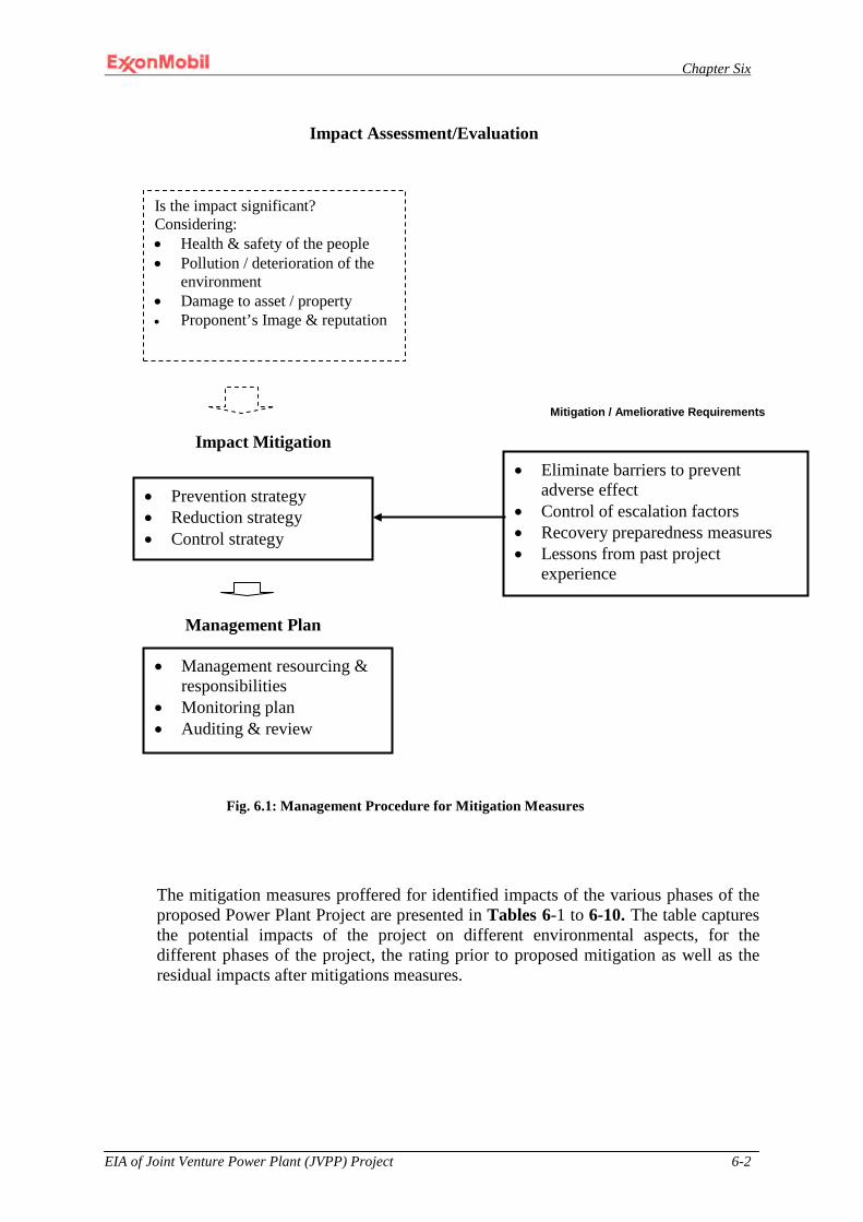
Chapter Six
EIA of Joint Venture Power Plant (JVPP) Project 6-2
The mitigation measures proffered for identified impacts of the various phases of the proposed Power Plant Project are presented in Tables 6-1 to 6-10. The table captures the potential impacts of the project on different environmental aspects, for the different phases of the project, the rating prior to proposed mitigation as well as the residual impacts after mitigations measures.
Is the impact significant? Considering: • Health & safety of the people • Pollution / deterioration of the
environment • Damage to asset / property • Proponent’s Image & reputation
Impact Assessment/Evaluation
• Prevention strategy • Reduction strategy • Control strategy
Mitigation / Ameliorative Requirements
Impact Mitigation
• Management resourcing & responsibilities
• Monitoring plan • Auditing & review
Management Plan
• Eliminate barriers to prevent adverse effect
• Control of escalation factors • Recovery preparedness measures • Lessons from past project
experience
Fig. 6.1: Management Procedure for Mitigation Measures

Chapter Six
EIA of Joint Venture Power Plant (JVPP) Project 6-3
Table 6 Proffered mitigation measures for Identified Impacts.

Chapter Six
EIA of Joint Venture Power Plant (JVPP) Project 6-4
Potential Impact Impact rating Mitigation / Monitoring Measures Project Phase Residual Ranking & Impact 6-1 Environmental Aspect: Soils and Geology
Potential Structural Damage Due to Seismicity and Faulting
Low No mitigation measures are required for less than significant impacts.
CO Ranking: Low Impact: The seismic hazard most likely to be detrimental to the proposed Project is ground motion resulting from an earthquake that exceeds the design basis. The probability of such an event is extremely low. Project components could incur damage if such an event were to occur. The subsequent damage could result in potential health and safety or environmental impacts if the natural gas-fired power plant and its ancillary components were to be significantly damaged. Such impacts cannot be completely mitigated. However, such impacts have been minimized through the design of the facility in accordance with the latest edition of the International Building Code.
Engineering Constraints of Soils and Geology
Low A. Conduct sufficient testing on soils from QIT Lake to ensure they meet Project performance standards. If they do not, then identify alternate on-site or existing off-site sources for such material and retest to ensure conformance with Project requirements.
D Ranking: Low Impact: No residual impacts are anticipated provided the recommended mitigation measure and foundation codes previously referenced are incorporated into the final design for the
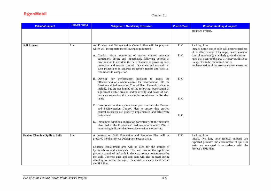
Chapter Six
EIA of Joint Venture Power Plant (JVPP) Project 6-5
Potential Impact Impact rating Mitigation / Monitoring Measures Project Phase Residual Ranking & Impact proposed Project.
Soil Erosion Low An Erosion and Sedimentation Control Plan will be prepared which will incorporate the following requirements: A. Conduct visual monitoring of erosion control measures
particularly during and immediately following periods of precipitation to ascertain their effectiveness at providing soils protection and erosion control. Document and maintain all such inspections in separate inspection reports and track all resolutions to completion.
B. Develop key performance indicators to assess the
effectiveness of erosion control for incorporation into the Erosion and Sedimentation Control Plan. Example indicators include, but are not limited to the following: observation of significant visible erosion and/or density and cover of non-nuisance vegetation that are similar to adjacent undisturbed lands.
C. Incorporate routine maintenance practices into the Erosion
and Sedimentation Control Plan to ensure that erosion control measures are properly implemented and effectively maintained
D. Implement additional mitigation consistent with the measures
identified in the Erosion and Sedimentation Control Plan if monitoring indicates that excessive erosion is occurring.
E C
E C
E C
E C
E C
Ranking: Low Impact: Some loss of soils will occur regardless of the effectiveness of the implemented erosion control measures (particularly given the heavy rains that occur in the area). However, this loss is expected to be minimized due to implementation of the erosion control measures.
Fuel or Chemical Spills to Soils
Low A construction Spill Prevention and Response Plan will be prepared per the Project Description Section 3.5.2. Concrete containment area will be used for the storage of hydrocarbons and chemicals. This will ensure that spills are properly contained and soils in the area, are not contaminated by the spill. Concrete pads and drip pans will also be used during refueling to prevent spillages. These will be clearly identified in the SPR Plan.
E C Ranking: Low Impact: No long–term residual impacts are expected provided the containment of spills or leaks are managed in accordance with the Project’s SPR Plan.

Chapter Six
EIA of Joint Venture Power Plant (JVPP) Project 6-6
Potential Impact Impact rating Mitigation / Monitoring Measures Project Phase Residual Ranking & Impact
6-2 Environmental Aspect: Terrestrial Biological Resources
Loss of Natural Vegetation
Medium To reduce impacts on vegetation, site clearing for the proposed project activities shall be limited to only essential areas. Areas cleared for temporary uses will be re-vegetated with native vegetation at the completion of works in the areas.
C Ranking: Low Impact: Residual impacts associated with the proposed Project would include the permanent loss of vegetation on the Project site. However, such loss shall be limited to areas that will be built up whereas temporary areas will be reclaimed after the project.
Loss of Local Biodiversity
Low No mitigation measures are required for less than significant impacts.
Ranking: Low Impact: No long-term residual impacts are expected.
Loss, Degradation, or Fragmentation of Wildlife Habitat
Medium A. Delineate the limits of clearing on appropriate scale site maps and flag the limits of clearing to minimize the loss of natural vegetation.
B. Limit the number of infrastructure access points along QIT
Lake to the minimum necessary to acquire the fill material that is needed for the proposed Project.
C. Mark trees and shrubs that are to be retained with flagging
and avoid compaction of the adjacent soils (where possible). D. Use local, native plant species in areas to be landscaped
where feasible. Native species are best adapted to the local conditions, more likely to become established, require minimal maintenance, and are less likely to cause problems from the introduction of nonnative species (due to competition with native species).
E. Use salvaged and stockpiled topsoil to the extent possible in
revegetation efforts, erosion control, and landscaping.
E
C
E C
E C
E C O
E C O
Ranking: Low Impact: Residual impacts associated with the proposed Project could include permanent loss of wildlife habitat (on the project site), minor degradation of wildlife habitat (immediately adjacent to the project site), and urbanization of the local wildlife diversity during the life of the proposed Project.
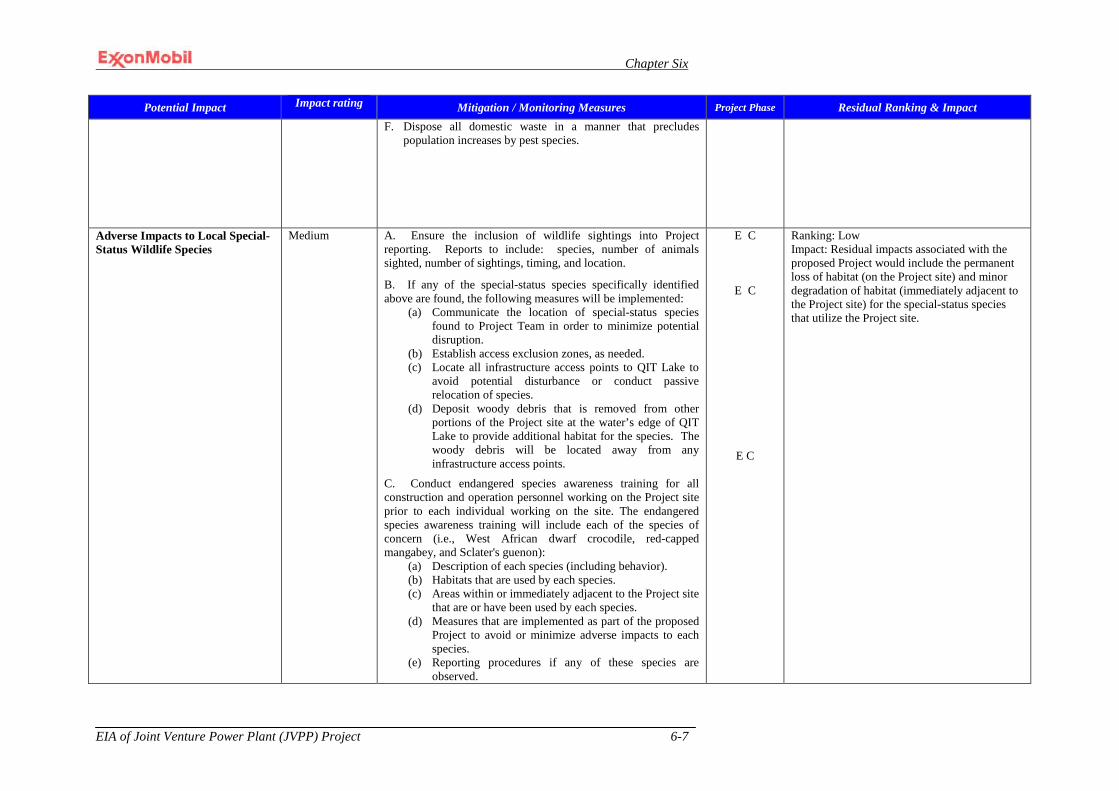
Chapter Six
EIA of Joint Venture Power Plant (JVPP) Project 6-7
Potential Impact Impact rating Mitigation / Monitoring Measures Project Phase Residual Ranking & Impact F. Dispose all domestic waste in a manner that precludes
population increases by pest species.
Adverse Impacts to Local Special-Status Wildlife Species
Medium A. Ensure the inclusion of wildlife sightings into Project reporting. Reports to include: species, number of animals sighted, number of sightings, timing, and location.
B. If any of the special-status species specifically identified above are found, the following measures will be implemented:
(a) Communicate the location of special-status species found to Project Team in order to minimize potential disruption.
(b) Establish access exclusion zones, as needed. (c) Locate all infrastructure access points to QIT Lake to
avoid potential disturbance or conduct passive relocation of species.
(d) Deposit woody debris that is removed from other portions of the Project site at the water’s edge of QIT Lake to provide additional habitat for the species. The woody debris will be located away from any infrastructure access points.
C. Conduct endangered species awareness training for all construction and operation personnel working on the Project site prior to each individual working on the site. The endangered species awareness training will include each of the species of concern (i.e., West African dwarf crocodile, red-capped mangabey, and Sclater's guenon):
(a) Description of each species (including behavior). (b) Habitats that are used by each species. (c) Areas within or immediately adjacent to the Project site
that are or have been used by each species. (d) Measures that are implemented as part of the proposed
Project to avoid or minimize adverse impacts to each species.
(e) Reporting procedures if any of these species are observed.
E C
E C
E C
Ranking: Low Impact: Residual impacts associated with the proposed Project would include the permanent loss of habitat (on the Project site) and minor degradation of habitat (immediately adjacent to the Project site) for the special-status species that utilize the Project site.
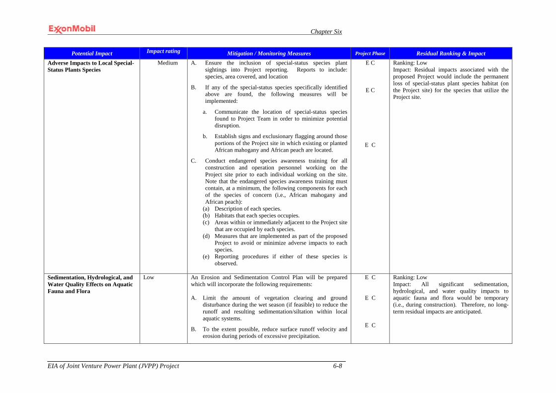
Chapter Six
EIA of Joint Venture Power Plant (JVPP) Project 6-8
Potential Impact Impact rating Mitigation / Monitoring Measures Project Phase Residual Ranking & Impact Adverse Impacts to Local Special-Status Plants Species
Medium A. Ensure the inclusion of special-status species plant sightings into Project reporting. Reports to include: species, area covered, and location
B. If any of the special-status species specifically identified above are found, the following measures will be implemented:
a. Communicate the location of special-status species found to Project Team in order to minimize potential disruption.
b. Establish signs and exclusionary flagging around those portions of the Project site in which existing or planted African mahogany and African peach are located.
C. Conduct endangered species awareness training for all construction and operation personnel working on the Project site prior to each individual working on the site. Note that the endangered species awareness training must contain, at a minimum, the following components for each of the species of concern (i.e., African mahogany and African peach):
(a) Description of each species. (b) Habitats that each species occupies. (c) Areas within or immediately adjacent to the Project site
that are occupied by each species. (d) Measures that are implemented as part of the proposed
Project to avoid or minimize adverse impacts to each species.
(e) Reporting procedures if either of these species is observed.
E C
E C
E C
Ranking: Low Impact: Residual impacts associated with the proposed Project would include the permanent loss of special-status plant species habitat (on the Project site) for the species that utilize the Project site.
Sedimentation, Hydrological, and Water Quality Effects on Aquatic Fauna and Flora
Low An Erosion and Sedimentation Control Plan will be prepared which will incorporate the following requirements: A. Limit the amount of vegetation clearing and ground
disturbance during the wet season (if feasible) to reduce the runoff and resulting sedimentation/siltation within local aquatic systems.
B. To the extent possible, reduce surface runoff velocity and erosion during periods of excessive precipitation.
E C
E C
E C
Ranking: Low Impact: All significant sedimentation, hydrological, and water quality impacts to aquatic fauna and flora would be temporary (i.e., during construction). Therefore, no long-term residual impacts are anticipated.
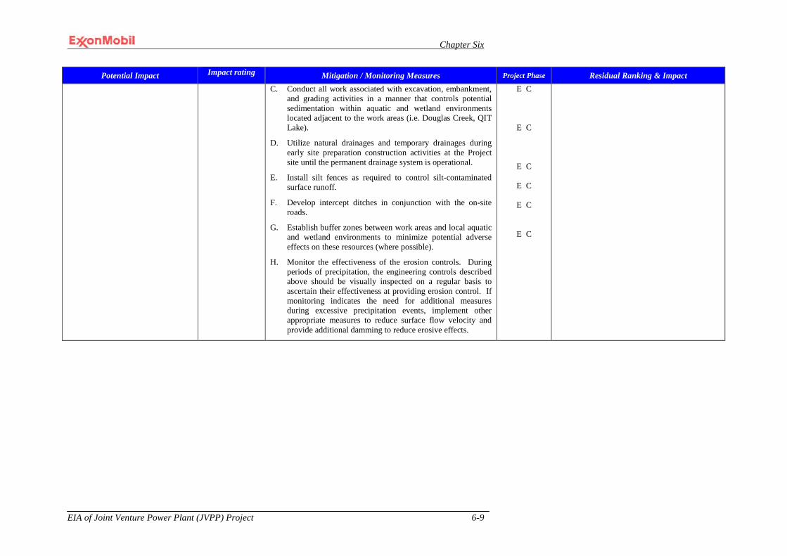
Chapter Six
EIA of Joint Venture Power Plant (JVPP) Project 6-9
Potential Impact Impact rating Mitigation / Monitoring Measures Project Phase Residual Ranking & Impact C. Conduct all work associated with excavation, embankment,
and grading activities in a manner that controls potential sedimentation within aquatic and wetland environments located adjacent to the work areas (i.e. Douglas Creek, QIT Lake).
D. Utilize natural drainages and temporary drainages during early site preparation construction activities at the Project site until the permanent drainage system is operational.
E. Install silt fences as required to control silt-contaminated surface runoff.
F. Develop intercept ditches in conjunction with the on-site roads.
G. Establish buffer zones between work areas and local aquatic and wetland environments to minimize potential adverse effects on these resources (where possible).
H. Monitor the effectiveness of the erosion controls. During periods of precipitation, the engineering controls described above should be visually inspected on a regular basis to ascertain their effectiveness at providing erosion control. If monitoring indicates the need for additional measures during excessive precipitation events, implement other appropriate measures to reduce surface flow velocity and provide additional damming to reduce erosive effects.
E C
E C
E C
E C
E C
E C
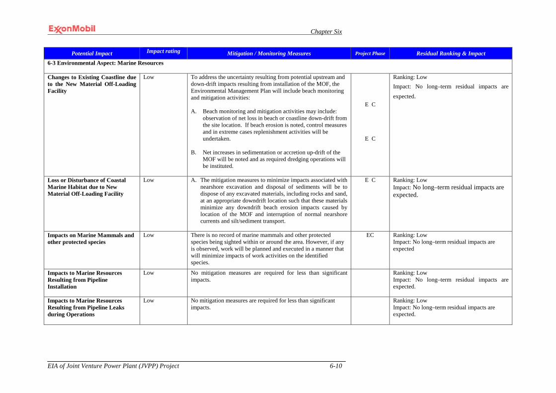
Chapter Six
EIA of Joint Venture Power Plant (JVPP) Project 6-10
Potential Impact Impact rating Mitigation / Monitoring Measures Project Phase Residual Ranking & Impact 6-3 Environmental Aspect: Marine Resources
Changes to Existing Coastline due to the New Material Off-Loading Facility
Low To address the uncertainty resulting from potential upstream and down-drift impacts resulting from installation of the MOF, the Environmental Management Plan will include beach monitoring and mitigation activities: A. Beach monitoring and mitigation activities may include:
observation of net loss in beach or coastline down-drift from the site location. If beach erosion is noted, control measures and in extreme cases replenishment activities will be undertaken.
B. Net increases in sedimentation or accretion up-drift of the
MOF will be noted and as required dredging operations will be instituted.
E C
E C
Ranking: Low Impact: No long–term residual impacts are
expected.
Loss or Disturbance of Coastal Marine Habitat due to New Material Off-Loading Facility
Low A. The mitigation measures to minimize impacts associated with nearshore excavation and disposal of sediments will be to dispose of any excavated materials, including rocks and sand, at an appropriate downdrift location such that these materials minimize any downdrift beach erosion impacts caused by location of the MOF and interruption of normal nearshore currents and silt/sediment transport.
E C Ranking: Low Impact: No long–term residual impacts are expected.
Impacts on Marine Mammals and other protected species
Low There is no record of marine mammals and other protected species being sighted within or around the area. However, if any is observed, work will be planned and executed in a manner that will minimize impacts of work activities on the identified species.
EC Ranking: Low Impact: No long–term residual impacts are expected
Impacts to Marine Resources Resulting from Pipeline Installation
Low No mitigation measures are required for less than significant impacts.
Ranking: Low Impact: No long–term residual impacts are expected.
Impacts to Marine Resources Resulting from Pipeline Leaks during Operations
Low No mitigation measures are required for less than significant impacts.
Ranking: Low Impact: No long–term residual impacts are expected.
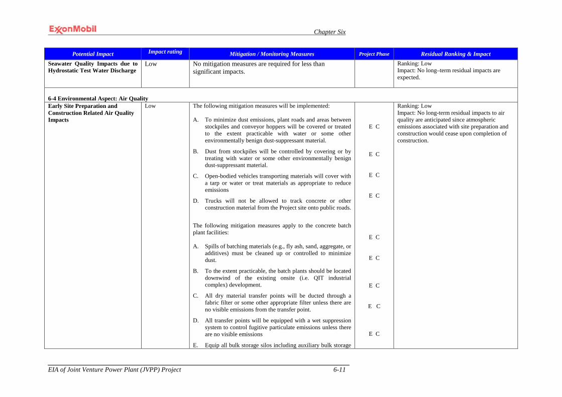
Chapter Six
EIA of Joint Venture Power Plant (JVPP) Project 6-11
Potential Impact Impact rating Mitigation / Monitoring Measures Project Phase Residual Ranking & Impact Seawater Quality Impacts due to Hydrostatic Test Water Discharge
Low No mitigation measures are required for less than significant impacts.
Ranking: Low Impact: No long–term residual impacts are expected.
6-4 Environmental Aspect: Air Quality Early Site Preparation and Construction Related Air Quality Impacts
Low The following mitigation measures will be implemented: A. To minimize dust emissions, plant roads and areas between
stockpiles and conveyor hoppers will be covered or treated to the extent practicable with water or some other environmentally benign dust-suppressant material.
B. Dust from stockpiles will be controlled by covering or by treating with water or some other environmentally benign dust-suppressant material.
C. Open-bodied vehicles transporting materials will cover with a tarp or water or treat materials as appropriate to reduce emissions
D. Trucks will not be allowed to track concrete or other construction material from the Project site onto public roads.
The following mitigation measures apply to the concrete batch plant facilities: A. Spills of batching materials (e.g., fly ash, sand, aggregate, or
additives) must be cleaned up or controlled to minimize dust.
B. To the extent practicable, the batch plants should be located downwind of the existing onsite (i.e. QIT industrial complex) development.
C. All dry material transfer points will be ducted through a fabric filter or some other appropriate filter unless there are no visible emissions from the transfer point.
D. All transfer points will be equipped with a wet suppression system to control fugitive particulate emissions unless there are no visible emissions
E. Equip all bulk storage silos including auxiliary bulk storage
E C
E C
E C
E C
E C
E C
E C
E C
E C
Ranking: Low Impact: No long-term residual impacts to air quality are anticipated since atmospheric emissions associated with site preparation and construction would cease upon completion of construction.

Chapter Six
EIA of Joint Venture Power Plant (JVPP) Project 6-12
Potential Impact Impact rating Mitigation / Monitoring Measures Project Phase Residual Ranking & Impact trailers with fabric or some other appropriate type filter.
F. Maintain silo vent filters in proper operating condition
G. The fabric dust collection system employed will be capable of controlling particulates using the best technology available.
H. All conveyors will be covered unless the material being transferred results in no visible emissions
E C
E C
E C
Off-site Transportation Related Air Quality Impacts
Low A. The mitigation measures to minimize diesel usage and emissions during construction activities will include idling reduction awareness activities for onsite diesel powered equipment and mobile vehicles.
E C Ranking: Low Impact: No long-term residual transportation-related impacts to air quality are anticipated given the negligible contribution to cumulative emissions from this source.
Operational Related Air Quality Impacts
High To further mitigate potential atmospheric impacts of the proposed Project, the following will be implemented: A. Conduct design reviews and performance tests to confirm
NOx concentration limits and other regulated parameters are incorporated into the design.
B. Conduct continuous emissions monitoring and report quarterly
C. Conduct stack sampling once per year and once at commissioning to assess if the NOx concentration (measured as nitrogen dioxide) meets the Project commitment not to exceed 25 ppmv at the stack based on a dry O2 content of 15%. Appropriate maintenance and/or operating changes will be implemented, if necessary, to maintain design parameters.
D O
O
Ranking: Low Impact: No long term residual impacts to air quality are anticipated since all emissions are expected to be within applicable World Bank or WHO guidelines.

Chapter Six
EIA of Joint Venture Power Plant (JVPP) Project 6-13
Potential Impact Mitigation / Monitoring Measures Project Phase Residual Impact 6-5 Environmental Aspect: Noise
Early Site Preparation and Construction Impacts on Ambient Noise
Low • Ensure the road worthiness of trucks to minimize the noise
impact.
• Restrict movement of vehicles to day time
No long term residual noise impacts are anticipated since noise associated with early site preparation and construction would cease upon completing construction.
Transportation Related Increases in Ambient Noise
Low There are no mitigation measures for short term significant and unavoidable impacts. The estimate assumes that all vehicles are operating optimally.
No long term residual noise impacts are anticipated since noise associated with early site preparation and construction would cease upon completing construction.
Operational Related Increases in Ambient Noise
Low A. The equipment specification package will require the GTGs to meet a 60 dBA @ 400 feet criteria to ensure compliance with World Bank noise emission guidelines.
D Assuming measures are taken to ensure noise emission levels meet World Bank guidelines, no long-term residual noise impacts are anticipated during operation of the proposed Project.
6-6 Environmental Aspect: Water Resources
Surface Water Impacts due to Storm Water Runoff and Sedimentation during Construction
Medium To ensure the effectiveness of the storm water management provisions as presented in the Erosion and Sedimentation Control Plan the following mitigation measures will be implemented by the proposed Project’s Environmental Management Team: A. Assess the effectiveness of runoff control measures for
incorporation into the Erosion and Sedimentation Control Plan
B. Establish monitoring for pH, total suspended solids and oil/grease for the single discharge outfall to Douglas Creek to ensure compliance with Plan established thresholds. The pH should be monitored using simple pH strips (maintaining limits from 6-9), total suspended solids should be qualitatively monitored for the appearance or lack thereof of a cloudy appearance in the outfall and visual observation should be used to determine the presence or absence of an oily sheen to assess the presence or absence of oil/grease.
C. Conduct visual monitoring of runoff control measures particularly during and immediately following periods of precipitation to ascertain their effectiveness. Document and
E C
E C
E C
E C
Occasional siltation of surface waters in the vicinity of the Project may occur since erosion control measures are rarely 100 percent effective. However, these impacts are expected to be temporary and limited to extremely large storm events.

Chapter Six
EIA of Joint Venture Power Plant (JVPP) Project 6-14
Potential Impact Mitigation / Monitoring Measures Project Phase Residual Impact maintain all such inspections in separate inspection reports and track all resolutions to completion.
D. The use of concrete containment areas, concrete pads and drip pans for spill prevention and management will also be highlighted in the SPR Plan.
E. Implement additional mitigation consistent with the measures identified in the Erosion and Sedimentation Control Plan if monitoring indicates that excessive runoff and sedimentation is occurring, (i.e., exceeds a threshold), particularly during prolonged precipitation events.
F. Incorporate standard maintenance practices into the Erosion and Sedimentation Control Plan to ensure that runoff control measures are properly installed and effectively maintained.
G. Identify in the Erosion and Sedimentation Control Plan measures to control site conditions through pollution prevention practices so as to minimize the need to collect and treat storm water.
H. Locate the temporary batch plants away from watercourses and drain courses to the extent practicable. Construct berms around batch plant equipment to facilitate proper containment and cleanup of releases. Do not dispose of concrete into the storm water drainage system or any watercourses.
I. Identify a designated area to washout concrete trucks and another designated area for equipment washing.
J. Periodic inspection of the concrete batch plant facilities while present at the project site.
E C
E C
E C
E C
E C
Changes in Surface Water Quality due to Discharge of Sanitary Sewage, Storm Water and Wastewater
Low A. To ensure the effectiveness of the proposed monitoring program, if the threshold or effluent limits are exceeded, process modifications or appropriate equipment maintenance measures will promptly be implemented to ensure compliance.
E C O No long–term residual impacts are expected.

Chapter Six
EIA of Joint Venture Power Plant (JVPP) Project 6-15
Potential Impact Mitigation / Monitoring Measures Project Phase Residual Impact Effects of Inadvertent Spill Discharges to Surface Waters
Low To ensure the effectiveness of the SPR Plan, the following mitigation measures will be implemented: A. The SPR Plan will capture both the construction and
operations phase.
B. SPR Plan contents will address spill prevention and preparedness procedures; spill reporting procedures; spill clean-up procedures and the type, quantity, and location of emergency response equipment to address spills.
C. The SPR Plan will present a summary table of the type, quantity, storage method and location for each raw material, hazardous material, chemical, fuel, lubricant oil, etc. that will be stored at the proposed Project site.
D. Fuel trucks transporting fuel to Project on-site equipment will be required to travel only on MPN approved on-site access roads.
E. Equipment may not be fueled or parked overnight within 31 meters (about 100 feet) from a water body.
F. Hazardous materials including chemicals, fuels and lubricating oils may not be stored within 31 meters (about 100 feet) from a water body.
G. Construction, cleanup and maintenance crews will carry sufficient supplies of absorbent and barrier materials while working to allow the rapid containment and recovery of spilled materials.
H. Construction crews and maintenance crews will carry sufficient tools to stop leaks while working.
I. Secondary containment will be provided for stored liquid materials. Containment will provide sufficient volume to contain precipitation from a 25-year storm event plus 10% of the aggregate volume of all containers or more than 100% of the largest container, whichever is greater.
E C O
E C O
E C O
E C O
E C O
E C O
E C O
E C O
E C O
No long–term residual impacts are expected.
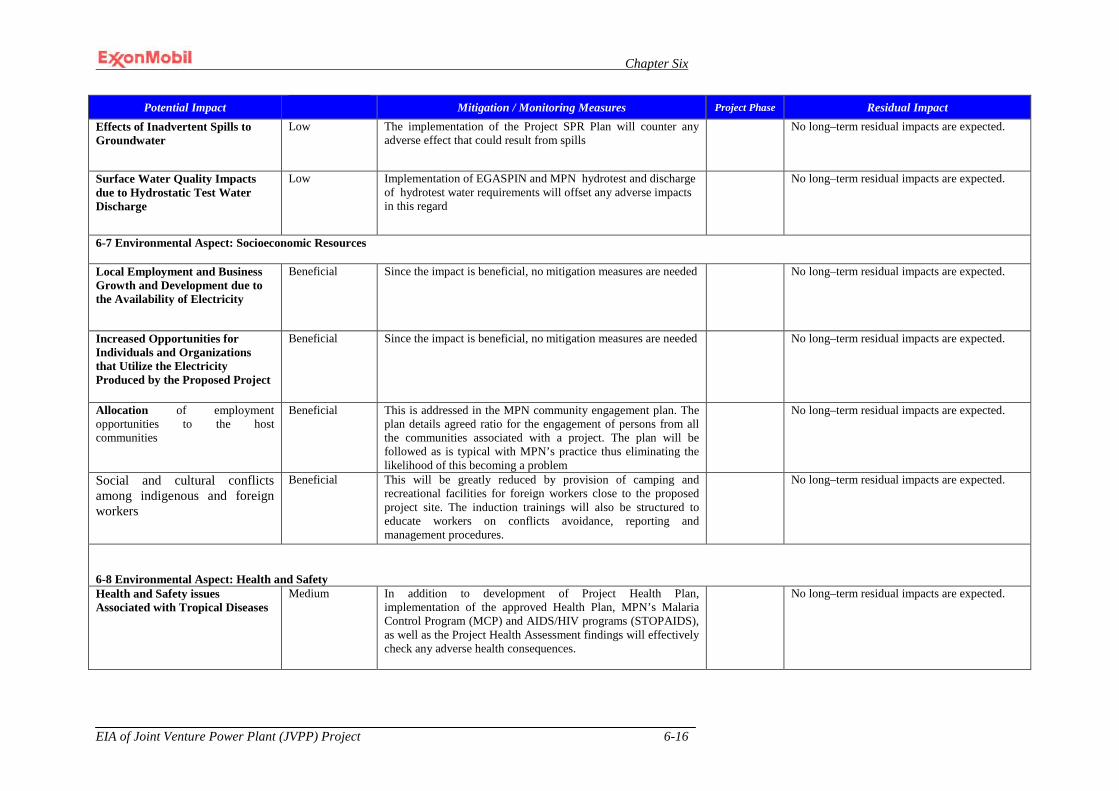
Chapter Six
EIA of Joint Venture Power Plant (JVPP) Project 6-16
Potential Impact Mitigation / Monitoring Measures Project Phase Residual Impact Effects of Inadvertent Spills to Groundwater
Low The implementation of the Project SPR Plan will counter any adverse effect that could result from spills
No long–term residual impacts are expected.
Surface Water Quality Impacts due to Hydrostatic Test Water Discharge
Low Implementation of EGASPIN and MPN hydrotest and discharge of hydrotest water requirements will offset any adverse impacts in this regard
No long–term residual impacts are expected.
6-7 Environmental Aspect: Socioeconomic Resources
Local Employment and Business Growth and Development due to the Availability of Electricity
Beneficial Since the impact is beneficial, no mitigation measures are needed No long–term residual impacts are expected.
Increased Opportunities for Individuals and Organizations that Utilize the Electricity Produced by the Proposed Project
Beneficial Since the impact is beneficial, no mitigation measures are needed No long–term residual impacts are expected.
Allocation of employment opportunities to the host communities
Beneficial This is addressed in the MPN community engagement plan. The plan details agreed ratio for the engagement of persons from all the communities associated with a project. The plan will be followed as is typical with MPN’s practice thus eliminating the likelihood of this becoming a problem
No long–term residual impacts are expected.
Social and cultural conflicts among indigenous and foreign workers
Beneficial This will be greatly reduced by provision of camping and recreational facilities for foreign workers close to the proposed project site. The induction trainings will also be structured to educate workers on conflicts avoidance, reporting and management procedures.
No long–term residual impacts are expected.
6-8 Environmental Aspect: Health and Safety Health and Safety issues Associated with Tropical Diseases
Medium In addition to development of Project Health Plan, implementation of the approved Health Plan, MPN’s Malaria Control Program (MCP) and AIDS/HIV programs (STOPAIDS), as well as the Project Health Assessment findings will effectively check any adverse health consequences.
No long–term residual impacts are expected.
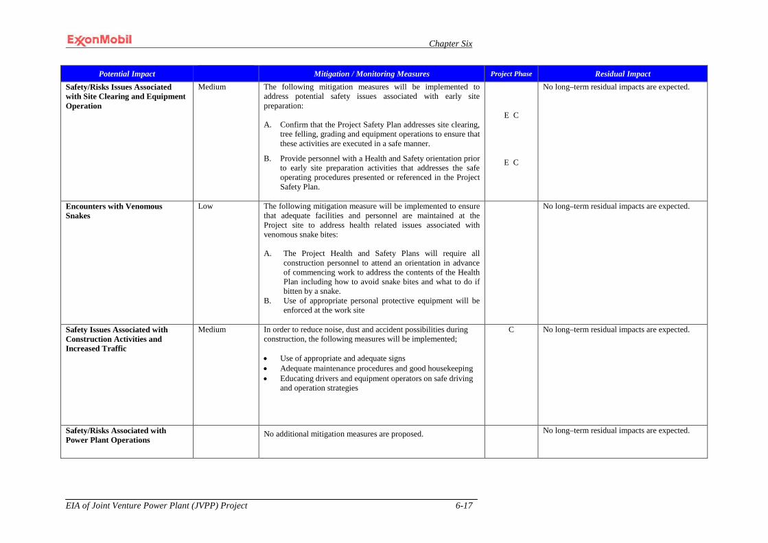
Chapter Six
EIA of Joint Venture Power Plant (JVPP) Project 6-17
Potential Impact Mitigation / Monitoring Measures Project Phase Residual Impact Safety/Risks Issues Associated with Site Clearing and Equipment Operation
Medium The following mitigation measures will be implemented to address potential safety issues associated with early site preparation: A. Confirm that the Project Safety Plan addresses site clearing,
tree felling, grading and equipment operations to ensure that these activities are executed in a safe manner.
B. Provide personnel with a Health and Safety orientation prior to early site preparation activities that addresses the safe operating procedures presented or referenced in the Project Safety Plan.
E C
E C
No long–term residual impacts are expected.
Encounters with Venomous Snakes
Low The following mitigation measure will be implemented to ensure that adequate facilities and personnel are maintained at the Project site to address health related issues associated with venomous snake bites: A. The Project Health and Safety Plans will require all
construction personnel to attend an orientation in advance of commencing work to address the contents of the Health Plan including how to avoid snake bites and what to do if bitten by a snake.
B. Use of appropriate personal protective equipment will be enforced at the work site
No long–term residual impacts are expected.
Safety Issues Associated with Construction Activities and Increased Traffic
Medium In order to reduce noise, dust and accident possibilities during construction, the following measures will be implemented; • Use of appropriate and adequate signs • Adequate maintenance procedures and good housekeeping • Educating drivers and equipment operators on safe driving
and operation strategies
C No long–term residual impacts are expected.
Safety/Risks Associated with Power Plant Operations
No additional mitigation measures are proposed.
No long–term residual impacts are expected.

Chapter Six
EIA of Joint Venture Power Plant (JVPP) Project 6-18
Potential Impact Mitigation / Monitoring Measures Project Phase Residual Impact 6-9 Services and Utilities
Insufficient fresh water to meet project requirements
In the event it is determined that there is insufficient capacity in the aquifer to meet Project requirements, alternative sources will be explored.
D No long–term residual impacts are expected.
Wastewater treatment capacity and Infrastructure
No additional mitigation measures are proposed. No long–term residual impacts are expected.
Communication services infrastructure
No additional mitigation measures are proposed. No long–term residual impacts are expected.
Electric service and infrastructure
No additional mitigation measures are proposed. No long–term residual impacts are expected.
Medical services
No additional mitigation measures are proposed. No long–term residual impacts are expected.
Solid and hazardous waste disposal services and infrastructures
No additional mitigation measures are proposed. No long–term residual impacts are expected.
Security and fire suppression services and infrastructure
No additional mitigation measures are proposed.
No long–term residual impacts are expected.
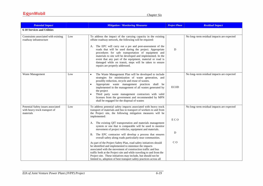
Chapter Six
EIA of Joint Venture Power Plant (JVPP) Project 6-19
Potential Impact Mitigation / Monitoring Measures Project Phase Residual Impact 6-10 Services and Utilities
Constraints associated with existing roadway infrastructure
Low To address the impact of the carrying capacity in the existing offsite roadway network, the following will be required: A. The EPC will carry out a pre and post-assessment of the
roads that will be used during the project. Appropriate procedures for safe transportation of equipment and materials to site will be developed and implemented. In the event that any part of the equipment, material or road is damaged while on transit, steps will be taken to ensure repairs are properly addressed.
D
No long–term residual impacts are expected
Waste Management Low • The Waste Management Plan will be developed to include strategies for minimization of waste generation, and possibly reduction, recycle and reuse of wastes.
• Appropriate waste management practices shall be implemented in the management of all wastes generated by the project
• Third party waste management contractors with valid licenses from the government and recommended by MPN shall be engaged for the disposal of wastes
ECOD
No long–term residual impacts are expected
Potential Safety issues associated with heavy truck transport of materials
Low To address potential safety impacts associated with heavy truck transport of materials and bus to transport of workers to and from the Project site, the following mitigation measures will be implemented: A. The existing QIT transportation and materials management
system or one that is comparable will be used to monitor movement of project vehicles, equipment and materials.
B. The EPC contractor will develop a process that ensures overall safety along roads particularly near communities.
As part of the Project Safety Plan, road safety initiatives should be identified and implemented to minimize the impacts associated with the movement of construction traffic and bus traffic both at the Project site and while traveling to and from the Project site. These initiatives may include, but should not be limited to, adoption of best transport safety practices across all
E C O
D
C O
No long–term residual impacts are expected

Chapter Six
EIA of Joint Venture Power Plant (JVPP) Project 6-20
Potential Impact Mitigation / Monitoring Measures Project Phase Residual Impact aspects of project operations with the goal of preventing traffic accidents and minimizing injuries; regular maintenance of vehicles and use of manufacturer approved parts to minimize potentially serious accidents caused by equipment malfunction or premature failure; and where road transport is significant, measures should be taken to minimize pedestrian interaction with construction vehicles.
D = Design E = Early Site Preparation C = Construction O = Operation

CHAPTER SEVEN
Chapter Seven
EIA of Joint Venture Power Plant (JVPP) Project 7-1
CHAPTER SEVEN
7.0 ENVIRONMENTAL MANAGEMENT PLAN (EMP) 7.1 General
The World Bank (1999) defines Environmental Management Plan (EMP) as the set of mitigation, monitoring and institutionalized measures that must be ensured during the implementation and operation of a project to eliminate adverse environmental and social impacts or at least reduce them to acceptable levels. The EMP is the essential and stand-alone component of an EIA that provides the assurance that the mitigation measures developed for reducing the effects of adverse associated and potential impacts of the proposed project to as low as reasonably practicable (ALARP) are implemented and maintained throughout the project life span. In this regard the EMP outlines strategies and procedures for ensuring that mitigation measures prescribed in an EIA are implemented at all phases of the project development. In addition to this function, the EMP may also be used to ensure compliance with statutory requirements, corporate safety and environmental policies. In line with MPN SHE policy of good environmental practice, the EMP of the Power Plant Project has been designed in accordance with regulatory specifications and is presented in this chapter.
7.2 EMP Objectives for the Proposed Project
The overall objective of the Environmental Management Plan for the JV Power Plant Project is to demonstrate that the environmental aspects and the potential and associated impacts of the proposed project have been identified and evaluated. This also ensures that measures are put in place to mitigate the significant adverse impacts in line with Nigeria Environmental Policy, MPN SHE policy and ISO 14001 EMS Specifications as well as demonstrate that MPN has an effective plan for controlling significant adverse impacts of the proposed project.
These objectives shall be achieved by: • ensuring compliance with existing legislation and MPN’s SHE policy; • enhancing and demonstrating sound environmental performance, built around the
principle of continuous improvement; • integrating environmental issues fully into the proposed power plant project
development and its operational philosophies; • promoting environmental management awareness among workers; • rationalizing and streamlining existing environmental activities to add value to
efficiency and effectiveness; • encouraging and achieving the highest physical and socio-economic performance
and response from individual employees and contractors throughout the duration of the power plant development project;
• enabling management to establish environmental priorities for the proposed project;
• ensuring that appropriate recovery preparedness is in place in the event that control is lost during implementation and operation of the proposed project; and
• providing the basis and standards to be used in overall planning, monitoring, auditing and reviewing of socio-economic and environmental performance throughout the project life span.
Chapter Seven
EIA of Joint Venture Power Plant (JVPP) Project 7-2
7.3 Use and Maintenance of the EMP
The EMP is a dynamic working tool that lasts from the inception to completion and decommissioning of the project. The EMP shall be updated and revised periodically, throughout the life span of the project so as to incorporate new and better environmental technologies, regulations, management systems, guidelines and economic policies. Constructive suggestions by users (contractors and management) shall be assessed and integrated into the EMP.
7.4 MPN SHE Policies and Management Systems
MPN’s commitment to sound environmental performance has its foundation in the company’s integrated policy statement on Safety, Health and Environment (SHE). MPN’s SHE policies are aimed at ensuring that all MPN operations are sustainable. The MPN shall conduct its business on the Power Plant Project in a socially responsible and ethical manner that protects safety, health and the environment in line with its SHE policies. Hence MPN is committed to managing emissions and effluents emanating from the proposed project based on accepted monitoring practices in accordance with national and international standards.
7.5 MPN’s Operations Integrity Management System (OIMS) The implementation of the EMP for the proposed Power Plant Project shall be guided by the MPN’s OIMS. OIMS is MPN’s systematic, structured and disciplined approach to identifying and preventing unwanted outcomes and reduce safety, health and environmental risk in project development and operations. MPN shall require major engineering, procurement and construction (EPC) contractors to have SHE management systems in place comparable to MPN’s OIMS system. Key improvements, which have resulted from the successful implementation of OIMS, include: • widespread understanding of hazards (i.e. risks) and how to manage them; • adequate and approved design and construction standards and procedures; • key drawings and documents in ‘as-built’ condition; • minimum job skills defined, personnel trained and competency assured; • emergency response plans documented and response drills conducted routinely; • appropriate operating procedures – documented, understood and used; • periodic assessments of OIMS procedures and feed back for improvement; and • special controls on hazardous work (e.g. work permit system, energy control,
confined space, hazardous material handling [HAZMAT]), simultaneous operations guidelines (SIMOPS) ).
7.6 Environmental Management System
The MPN Environmental Management System (EMS) is used to methodically manage project and operating activities that may potentially result in significant environmental impacts during their life span. The EMS communicates MPN’s commitment to managing environmental aspects of its business consistent with the company’s policies and business objectives. The MPN EMS flow chart is presented in Figure 7.1
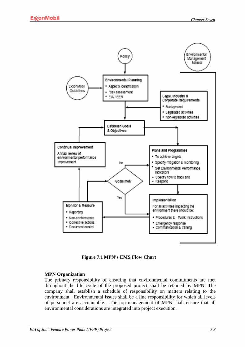
Chapter Seven
EIA of Joint Venture Power Plant (JVPP) Project 7-3
Figure 7.1 MPN’s EMS Flow Chart
MPN Organization The primary responsibility of ensuring that environmental commitments are met throughout the life cycle of the proposed project shall be retained by MPN. The company shall establish a schedule of responsibility on matters relating to the environment. Environmental issues shall be a line responsibility for which all levels of personnel are accountable. The top management of MPN shall ensure that all environmental considerations are integrated into project execution.
Chapter Seven
EIA of Joint Venture Power Plant (JVPP) Project 7-4
OIMS Element 1: Management, Leadership, Commitment and Accountability require the identification of management and personnel with key environmental management duties, and establishment of roles, responsibilities, and accountabilities for conducting these duties.
Management and personnel responsibilities for environmental management have been documented in MPN’s Environmental Management Manual (EMM) and the Environmental Monitoring Programme. Sections 1.2 and 2.3 of the EMM establish the roles and responsibilities for: • Project Management; • Operations Management; • Line Management; • MPN’s Environmental and Regulatory Compliance (E&RC) Unit; • MPN Projects/Operations Management; and • ExxonMobil Development Company (EMDC) and other ExxonMobil companies.
Project Management MPN’s project management team (PMT) will oversee the design, installation, commissioning, and start-up of the facilities. The PMT shall have as its focal point a Project Manager (PM). The PM shall be responsible for all technical, socio-economic and environmental - related matters throughout the installation phase of the project to ensure compliance with regulatory requirements as well as MPN policies, procedures, and guidelines. The PMT is in place, the PM identified, and roles and responsibilities assigned.
During operations, MPN Operations shall assume the responsibility for ensuring compliance with applicable regulatory requirements as well as MPN policies, procedures, and guidelines.
7.7 Waste Management Plan The handling, storage and disposal of all wastes that will be generated during project execution shall be in accordance with MPN approved Waste Management Plan, which is part of MPN’s Environmental Management OIMS system. MPN’s Waste Management Plan was developed in compliance with DPR/FMEnv regulations and incorporates other national and international waste regulations and best practices.
These regulations are binding on all staff and contractors involved in the proposed project with respect to the: • emission or release of pollutants and exhaust gases; • discharge or spill of untreated effluent into creeks/rivers/seas; • discharge of solid wastes (including domestic waste) on land and/or at sea; and • generation of noise and vibration.
MPN’s waste management objectives are to:

Chapter Seven
EIA of Joint Venture Power Plant (JVPP) Project 7-5
• reduce risks to human health and the environment; • develop or identify environmentally sound treatment, storage and disposal
procedures and facilities (onsite and offsite); • reduce waste management costs, including potential long-term liability in waste
generation, treatment and disposal; and • fully control waste streams and eliminate `unwanted practices’ such as use of non-
authorized dumpsites.
Wastes handling and disposal procedures shall be well defined at source and a waste inventory register kept. Wastes generated during the proposed project shall be handled, stored, recycled, and disposed based on the nature of each waste stream. The project-specific waste management guidelines shall take into consideration the nature of each waste stream to be generated during the life time of the proposed project.
During the installation phase of the project, the PMT shall be responsible for ensuring that wastes of the PMT and its contractors are handled and disposed in a manner compatible with MPN’s waste management procedures and applicable national laws.
Each contractor is required to submit a Waste Management Plan that will outline: • a summary of wastes that will be generated; • treatment methods; • transportation methods; • minimization techniques; • tracking and manifesting system; and • monitoring systems.
Only MPN approved third party waste management facilities will be used for the disposal of wastes generated in the course of the project. These facilities have appropriate regulatory approvals for safe disposal of wastes. PMT shall oversee this during construction phase and MPN Operations shall assume that responsibility during the operations phase of the project.
Waste Minimization Guidelines Waste minimization implies reduction of the volume or toxicity of waste materials to the greatest extent possible (Figure 7.2). MPN shall employ, as applicable, an integrated waste management approach with the basic principles of waste minimization which include prevention (source reduction); recycling, reuse, recovery; and treatment before final disposal. Opportunities shall be exploited to ensure minimization of wastes throughout the project.
Waste Segregation Guidelines For effective implementation of appropriate waste disposal methods, it is important that wastes be segregated, preferably at source into clearly designated bins at strategic locations. It is the responsibility of the contractors, during their operations, to provide enough clearly marked bins at strategic locations within the worksites in the project area to ensure proper segregation. Particular attention shall be given to work areas where a variety of wastes are generated.
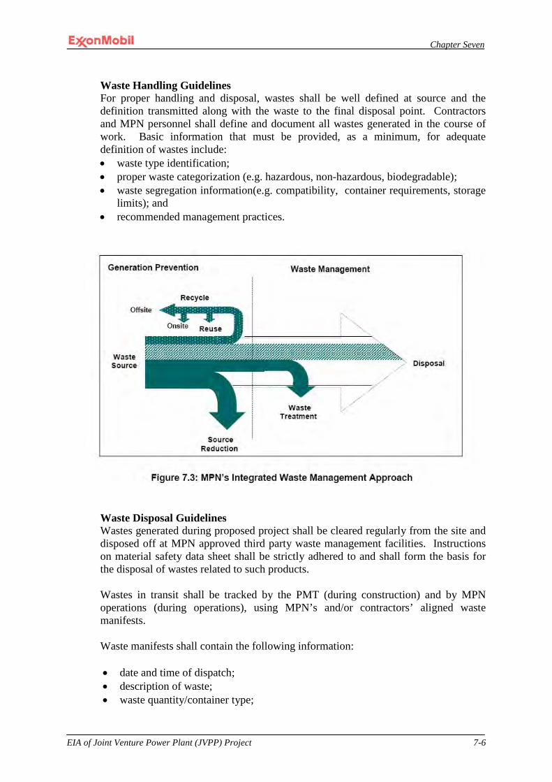
Chapter Seven
EIA of Joint Venture Power Plant (JVPP) Project 7-6
Waste Handling Guidelines For proper handling and disposal, wastes shall be well defined at source and the definition transmitted along with the waste to the final disposal point. Contractors and MPN personnel shall define and document all wastes generated in the course of work. Basic information that must be provided, as a minimum, for adequate definition of wastes include: • waste type identification; • proper waste categorization (e.g. hazardous, non-hazardous, biodegradable); • waste segregation information(e.g. compatibility, container requirements, storage
limits); and • recommended management practices.
Waste Disposal Guidelines Wastes generated during proposed project shall be cleared regularly from the site and disposed off at MPN approved third party waste management facilities. Instructions on material safety data sheet shall be strictly adhered to and shall form the basis for the disposal of wastes related to such products.
Wastes in transit shall be tracked by the PMT (during construction) and by MPN operations (during operations), using MPN’s and/or contractors’ aligned waste manifests.
Waste manifests shall contain the following information: • date and time of dispatch; • description of waste; • waste quantity/container type;
Chapter Seven
EIA of Joint Venture Power Plant (JVPP) Project 7-7
• waste source (place of origin); • designated disposal site and method; • consignee name and means of transportation; • Provision for endorsement of receiving party to confirm or refute what was
delivered against what was dispatched
MPN Waste Management Plan requires that all waste manifests, including those for contractors, be returned to MPN, filed, maintained and periodically assessed to ensure compliance with the Plan and manifests provisions. Gaps identified in the assessment process are pointed out to the contractors to assign responsibility and completion dates. The contractor response is tracked for compliance.
Accommodations, catering services and work sites shall maintain acceptable standards of hygiene and good housekeeping.
Table 7.1 presents the waste management guidelines for the Power Plant Project.

Chapter Seven
EIA of Joint Venture Power Plant (JVPP) Project 7-8
Table 7.1: Waste Management Guidelines for MPN’s Joint Venture Power Plant Project
Waste/Emission Category Hazard Origin Disposal Option(s)
Empty drums, aerosol cans & water bottles
Potentially hazardous (non-combustible)
Dependent on original contents of drums/cans
Packing of lubricating oil, fuel oil and corrosion inhibition chemicals, potable water
Drums to be taken to MPN approved waste management facility where the residues from drums/cans shall be purged and cleaned before reuse or returned to the supplier. Aerosol cans/water bottles shall be sent to MPN approved third party waste management facilities for recycling.
Oil/fuel filter cartridges, waste water filters.
Hazardous (non-combustible)
Potential surface water & soil/sediment contamination from hydrocarbons
Internal combustion engines, compressors & rotating equipment.
Safely contained and transported to an MPN approved third party waste management facility for disposal
Oily rags & sorbents; used protective clothing (hand gloves, coveralls, hard - shoes, rainwear, etc.)
Hazardous (combustible)
Potential surface water & soil/sediment contamination from hydrocarbons
Maintenance and spill clean-up operations, regular work wear.
Where possible, oily rags and protective clothing shall be washed and reused at site. Otherwise, these wastes shall be drained of excess hydrocarbon, packaged separately and safely contained for transportation to an MPN approved third party waste management facility for disposal.
Scrap metals, metal chippings, scrap cables
Non-hazardous (non-combustible)
Safety risks Scrapped equipment/engine parts/miscellaneous refuse metals
Safely contained for transportation to an MPN approved third party waste management facility for recycling and reuse
Medical wastes (soiled dressings, empty drug containers, used needles & syringes, expired drugs, blood & blood products, cultures and stocks)
Hazardous (combustible)
Potential health risk MPN clinics/health centers, first-aid treatment.
All medical wastes shall be packaged separately and safely contained for transportation to an MPN approved third party waste management facility for incineration and disposal.
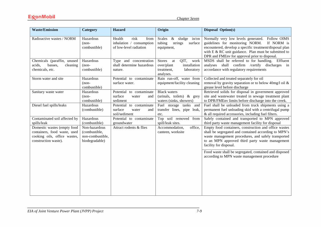
Chapter Seven
EIA of Joint Venture Power Plant (JVPP) Project 7-9
Waste/Emission Category Hazard Origin Disposal Option(s)
Radioactive wastes / NORM Hazardous (non-combustible)
Health risk from inhalation / consumption of low-level radiation
Scales & sludge in/on tubing strings surface equipment,
Normally very low levels generated. Follow OIMS guidelines for monitoring NORM. If NORM is encountered, develop a specific treatment/disposal plan with E & RC unit guidance. Plan must be submitted to DPR and FMEnv for approval prior to disposal.
Chemicals (paraffin, unused acids, basses, cleaning chemicals, etc.
Hazardous (non-combustible)
Type and concentration shall determine hazardous nature.
Stores at QIT, work over/plant installation treatment, laboratory analyses.
MSDS shall be referred to for handling. Effluent analyses shall confirm /certify discharges in accordance with regulatory requirements
Storm water and site Hazardous (non-combustible)
Potential to contaminate surface water.
Rain run-off, water from equipment/facility cleaning
Collected and treated separately for oil removal by gravity separation or to below 40mg/l oil & grease level before discharge
Sanitary waste water Hazardous (non-combustible)
Potential to contaminate surface water and sediment
Black waters (urinals, toilets) & grey waters (sinks, showers)
Retrieved solids for disposal in government approved site and wastewater treated in sewage treatment plant to DPR/FMEnv limits before discharge into the creek.
Diesel fuel spills/leaks Hazardous (combustible)
Potential to contaminate surface water and soil/sediment
Fuel storage tanks and transfer lines, pipe leak, etc.
Fuel shall be unloaded from truck shipments using a permanent fuel unloading skid with a centrifugal pump & all required accessories, including fuel filters.
Contaminated soil affected by spills/leak
Hazardous (combustible)
Potential to contaminate groundwater
Top soil removed from spill/leak sites.
Safely contained and transported to MPN approved third party waste management facility for disposal
Domestic wastes (empty food containers, food waste, used cooking oils, office wastes, construction waste).
Non-hazardous (combustible, non-combustible, biodegradable)
Attract rodents & flies Accommodation, office, canteen, worksite
Empty food containers, construction and office wastes shall be segregated and contained according to MPN’s waste management procedures, and safely transported to an MPN approved third party waste management facility for disposal.
Food waste shall be segregated, contained and disposed according to MPN waste management procedure
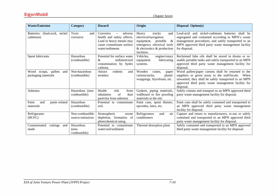
Chapter Seven
EIA of Joint Venture Power Plant (JVPP) Project 7-10
Waste/Emission Category Hazard Origin Disposal Option(s)
Batteries: (lead-acid, nickel cadmium)
Toxic and corrosive
Corrosive – adverse health and safety effects. Lead or heavy metals may cause contaminate surface water/sediments
Heavy trucks and electrical/navigation equipment, portable & emergency electrical tools & electronics & production facilities.
Lead-acid and nickel-cadmium batteries shall be segregated and contained according to MPN’s waste management procedures, and safely transported to an MPN approved third party waste management facility for disposal.
Spent lubricants Hazardous (combustible)
Potential for surface water & sediment/soil contamination by hydro carbons.
Vehicles, engine/rotary equipment lubricating systems.
Reclaimed lube oils shall be stored in drums or re-usable portable tanks and safely transported to an MPN approved third party waste management facility for disposal..
Wood scraps, pallets and packaging materials
Non-hazardous (combustible)
Attract rodents and termites
Wooden crates, paper cartons/sacks, plastic wrappings, Styrofoam, etc.
Wood pallets/paper cartons shall be returned to the suppliers or given away to the staff/locals. When unwanted, they shall be safely transported to an MPN approved third party waste management facility for disposal.
Asbestos Hazardous (non-combustible)
Health risk from inhalation of dust particles from asbestos
Gaskets, piping materials, wallboard or fire proofing materials at the site
Safely contain and transport to an MPN approved third party waste management facility for disposal.
Paint and paint–related materials
Hazardous (combustible)
Potential to contaminate soil.
Paint cans, spent thinner, epoxides, latex, etc.
Paint cans shall be safely contained and transported to an MPN approved third party waste management facility for disposal.
Refrigerants (HCFC)
Non-combustible source-emissions
Stratospheric ozone depletion, formation of photochemical smog.
Refrigerators and air conditioners
Capture and return to manufacturers, re-use or safely contained and transported to an MPN approved third party waste management facility for disposal.
Contaminated cuttings and muds
Hazardous (non-combustible)
Potential to contaminate water/soil/sediment
Thermal desorption plant Safely contained and transported to an MPN approved third party waste management facility for disposal.
Chapter Seven
EIA of Joint Venture Power Plant (JVPP) Project 7-11
7.8 Risk Assessment and Management
Wathern (1986) defined Risk Assessment as formal quantification of probability and uncertainty that provides quantitative measures of risk levels. Risk refers to the possibility of uncertainties, adverse consequences, most fundamental estimates of possible health and other consequences. A risk assessment typically includes a determination of the types of hazard posed, together with estimates of probability of their occurrences. It also includes the population at risk of exposure and adverse consequences (Conservation Foundation, 1984).
Risk management shall be an integral part of the proposed Power Plant Project. Risks related to project execution and operations shall be identified in a structured approach. Risk assessments shall be planned and conducted in advance of appropriate milestones or activities (including decommissioning / abandonment) to minimize risks and avoid schedule interruption. Appropriate personnel, such as operators, process/facilities engineers, and SHE specialists, shall be included in risk and hazard assessments to ensure that risks are correctly identified and assessed, and that mitigation measures adopted are practicable and effective. Results of risk assessments and the associated risk reduction measures shall be evaluated by appropriate levels of management, documented, executed, and followed up to completion in order to reduce risks to an acceptable level at a reasonable cost. Upon project completion, risks and their associated resolutions shall be documented by the PMT for handover to MPN Operations management personnel who shall take over operations of the commissioned facility.
The responsibility for risk management in the proposed project shall lie with both the PMT and the contractors. The majority of workers to be involved in the construction phase of the project shall be contractors; therefore MPN’s PMT shall pay particular attention to applying appropriate control, mitigation and monitoring of contractor activities. MPN shall ensure contractors have SHE systems in place, consistent with MPN’s systems. The contractors, working in accordance with the Job Specifications developed by MPN, shall have the direct responsibility for executing the work using sound engineering, fabrication, installation, and commercial practices, while maintaining adequate controls. The designs shall take into account applicable laws and regulations, and in the absence of such, generally accepted industry and engineering standards will be applied. The contractors shall develop operating manuals and appropriate documentation regarding the proper operation, start-up, shut-down and maintenance of the facility for approval by the PMT. These documents shall be provided in a timely manner such that facility specific training can be given to personnel prior to start-up.
7.9 Detailed Design Guidelines
MPN’s detailed design guidelines are contained in its OIMS system – Managing Design Practices, Standards, and Deviations. This system identifies relevant standards, codes, practices and specifications that apply to the technical/operating design to be used for the operations of the Power Plant Project. This management system also addresses the control of deviations from approved standards, codes, practices and specifications, and provides feedback to improve them. The PMT shall ensure applicable requirements are incorporated into the project design including defined project specifications and standards, Nigeria’s environmental guidelines and

Chapter Seven
EIA of Joint Venture Power Plant (JVPP) Project 7-12
standards, MPN’s environmental policies and procedures, and any design change recommendations resulting from this EIA. With regard to changes in design or deviations from standard practice, once project construction baselines have been established, changes are managed through a structured and systematic evaluation and documentation process that includes the following elements: • identification and documentation of reasons for the proposed change; • evaluation of risk to safety, health, environment, security, or project cost and
schedule (as applicable); • approval at an appropriate management level following endorsement of relevant
specialists; • implementation, including communication and training to those impacted as well
as acquisition of any requisite permit; and • documentation and verification that the approved change has been implemented.
7.10 Emergency Response Procedures
Before mobilization to the site, the PMT and contractors shall demonstrate that potentially significant hazards and potential impacts of the project activities have been identified and the associated risks well evaluated; and that controls and recovery measures to effectively manage these risks and impacts are in place. Where necessary, MPN shall assist the contractors with the provision of a generic hazard list for guidance.
In case of an emergency during the life span of the Power Plant Project, the MPN Emergency Response Procedure shall be activated. Its objectives, among others, are to ensure: • no loss of life and to prevent injuries; • the environment is protected; • manpower, equipment and funds are available to effectively contain and clean up
chemical spills; and • good record keeping is maintained and accurate information concerning
emergencies are disseminated to the workers, members of the public and government.
The PMT and contractors shall identify all potential emergency situations and collectively review the existing MPN Emergency Response Procedures with particular reference to site specific activities for use in such scenarios as explosions and/or fires, medical evacuation, man-over-board, hydrocarbon/chemical spills, weather related emergencies, civil disturbances by near-coastal communities, hostage taking, kidnapping, etc. Emergency drills shall be conducted periodically by the contractor to demonstrate preparedness for response. Records of the drills should be kept for reference purposes. A schedule for drills and testing of emergency response equipment shall be prepared by all contractors on the proposed project and approved by Project Manager (PM).
Every contractor on the proposed project shall prepare and submit for approval to the PM or his designee a contingency management plan covering all potential emergency situations and possible incidents for which response might be beyond the capability of site facilities.
Chapter Seven
EIA of Joint Venture Power Plant (JVPP) Project 7-13
The procedures cover the following issues: • search for sources of fire/leaks; • isolation of sources/supply points; • notification of authorities; • safety precautions and environmental protection; • repair methods and procedures; • emergency repair; • contractor arrangements; • notification to regulatory and other agencies, police, fire brigade, media, and local
government; • evacuation of personnel, visitors and public, if warranted; and • re-commissioning and start-up.
7.11 Miscellaneous Fire Fighting Equipment
The primary fire protection system will be the fire water system. However, the fire protection system will also consist of a fire detection system and a combustible gas detection system. A closed-loop Fire Protection Water Supply and Distribution System that complies with industry standards, fire resistant, as well as fire protection systems such as electric motor driven firewater pump, diesel engine driven firewater pump, electric motor jockey pump along with hydrants and monitors, and water mist system for fire suppression will all be utilized for fire protection.
7.12 Regulatory Compliance Plan All environment-related regulations as they apply to proposed JV Power Plant Project have been documented and described in this EIA. MPN management shall ensure compliance with these regulations throughout the project life span. MPN’s detailed regulatory compliance processes are contained in its OIMS system –Compliance with Laws, Regulations, and Permits. In summary, applicable laws and regulations have been identified for the proposed project through the expertise of the MPN Environmental and Regulatory Compliance Unit (RCU) and from recent EIAs. Project-specific compliance requirements have also been interpreted and documented in a Regulatory Compliance Plan (RCP), approved by the Project Manager (PM). RCP requirements are therefore incorporated into the project detailed design and the project execution plan by the PMT to ensure compliance to established industry, national and international laws, regulations and permits. Compliance with regulations will be the responsibility of MPN Operations and monitored by MPN RCU in conjunction with relevant regulatory agencies (NERC, FMEnv, AKSMEMR) during operations of the proposed project.
7.13 Security Plan
During construction, the Project Manager (PM) leading the PMT shall liaise with MPN Security to ensure that adequate arrangements are made to effectively handle security-related incidents. The PMT shall identify, evaluate and manage the risks to personnel and properties arising from malicious practices, violent crime, civil disorder or armed conflicts. All security activities shall be consistent with MPN’s security guidelines. In addition, each EPC contractor shall be required to prepare a project security plan and submit it to the PM for review and approval before mobilization to

Chapter Seven
EIA of Joint Venture Power Plant (JVPP) Project 7-14
site. However, security matters will be the responsibility of MPN Operations in liaison with MPN Security during operations of the project.
7.14 Project Health and Safety Plan
During the execution of the Power Plant Project, hazards shall be identified, assessed, registered and mitigated; also recovery measures shall be put in place for the consequences of hazards if the controls failed. MPN manages their employee worker and contractor safety programmes primarily through the OIMS system – Personnel Safety Management. This Management System addresses OIMS requirements for creating a positive safety culture, establishing and maintaining both on- and off-the-job safety programmes, establishing and maintaining a structured safety organization, and providing a system of performance tracking and recognition. The management system includes safety training and induction programmes, processes for communicating policy, plans, status, improvement ideas and experience, along with field-level hazard identification and job planning with appropriate follow-up processes. The implementation of MPN’s Personnel Safety Management Programme shall be the responsibility of the PMT during construction and MPN Operations during operations. Safety performance will be monitored jointly by the PMT and MPN’s Loss Prevention & Controls (LP&C) during construction and by LP&C during operations.
MPN manages their worker health programme through their OIMS system – Occupational Health Management. This management system addresses the identification of workplace health hazards, evaluation, control and communication of health risks, management of medical fitness and health assessments, and maintaining programmes for exposure monitoring. The management system also provides for clinical management of occupational health illnesses and injuries. Prior to implementation, the PMT shall review MPN’s Occupational Health Management programme to ensure its adequacy for proposed project-specific activities. The PMT shall implement and, in conjunction with MPN’s Medical & Occupational Health (M&OH) department, shall monitor the Occupational Health Management programme throughout the construction phase. MPN Operations will have responsibility for programme implementation during operations, as monitored by MPN’s Medical & Occupational Health (M&OH).
Safety, health and environmental training for personnel and contractors are managed through MPN’s OIMS system – Personnel Training. This management system addresses developing a training system to help close competency gaps and to identify and provide for periodic refresher training to help maintain competency. It includes developing individual training plans based on performance appraisals and the job selection process, as well as identifying/developing and improving training courses that meet MPN’s needs. During project operations, MPN Operations shall liaise with MPN’s Human Resources Department to identify the competency gaps and training needs of personnel based on their performance on-the-job. Training plans and formal SHE classroom personnel training shall be carried out by the Environmental & Regulatory Compliance (E&RC) Unit.
One of the serious health issues managed as part of OIMS is malaria. MPN’s OIMS has therefore established aggressive goals for malaria prevention. The goal is zero cases in non-immune workers and zero serious cases in semi-immune workers.
Chapter Seven
EIA of Joint Venture Power Plant (JVPP) Project 7-15
MPN has implemented a Malaria Control Programme (MCP) to achieve the goals and to protect the personnel. Employees and contractors are included in the MCP and all written contracts in Nigeria include a requirement for an MCP. Individuals and small contractors are included in MPN’s malaria testing pool. A contractor management process verifies compliance with the MCP requirement. The MCP has four basic elements: A, B, C and D, which are explained below: A – Awareness: Implementation of an awareness campaign to help the personnel understand the disease, the risk, and prevention methods.
B – Bite Prevention: Implementation of a bite prevention programme to help people understand that they will not develop malaria if bite is prevented. Some bite prevention measures include: • wearing long sleeve shirts and trousers with socks; • using a minimum of 20% DEET insect repellent on exposed skin; • using permethrin (insecticide) treated clothing; • using bed nets in facilities that do not have mosquito proof quarters; and • implementing an aggressive vector control programme that includes space
spraying, removal of standing water and habitat destruction.
C – Chemoprophylaxis: Non-immune workers must take an approved chemoprophylaxis that is proven to be effective in preventing malaria infection in areas with the risk of Falciparum malaria.
D – Diagnosis: Implementation of a programme for early diagnosis and cure of the disease. Implementation measures for early diagnosis include: • ensure access to rapid diagnosis kits; • develop capacity to enable local medical providers to measure parasittemia in
Falciparum risk areas; • ensure process is in place to provide appropriate treatment of cases; and • ensure process is in place to provide medical counseling to non-immune personnel
diagnosed with malaria and to notify the MCP Administrator to enter them in the Frequent Test Pool.
Compliance with and implementation of the MCP elements are included in the verification process. Data are collected and maintained to verify full implementation of MCP and to ensure that the MCP is fully implemented for all employees and all contractors working on their behalf.
Contractors shall provide adequate health services as well as site first aid services for their workers. The first aid services shall be extended to visiting personnel and casual workers. All power plant installation activities shall be properly managed through careful planning and the application of relevant SHE policies including the following: • use of Permit to Work (PTW); • job hazard analysis and tool box meetings;
Chapter Seven
EIA of Joint Venture Power Plant (JVPP) Project 7-16
• use of PPE in designated hazard areas; • prohibition of alcohol during work hours and at work sites and facilities; • prohibition of use of petrol engines for operations; • regular emergency drills; and • prohibition of smoking in fire hazard areas.
7.15 Accident/Incident Management Plan
As part of the Project Health and Safety Plan, prevention of workplace accidents and incidents during the execution of the JV Power Plant Project shall be achieved primarily through MPN’s OIMS system – Work Management. This management system addresses work planning and control of maintenance and construction work at work sites. This work management system includes job planning and permitting, shift/tour handover meetings and logs, special procedures governing higher risk activities, control of simultaneous activities, energy isolation and workplace preparation, management controls for temporarily defeated safety devices, and facility reinstatement/restart preparation operations. It also includes requirements for reviewing completed jobs and capturing / communicating lessons learned about the work and the work management system. It shall be the responsibility of the PMT to monitor the implementation of MPN’s work management programme during the construction/startup of the proposed project.
Compliance to regulatory standards, operations/maintenance codes and specifications as well as SHE guidelines shall form the basis for the execution of the proposed Power Plant Project. However, emergency situations could still occur as a result of equipment failure, weather, negligence and/or sabotage. Consequently, contingency plans shall be developed as back-up to other containment systems put in place to handle such occurrences.
7.16 Transport Operations The Project Manager (PM) shall manage all transportation operations in line with the following guidelines in order to forestall accidents/incidents.
Pre-mobilization of Vehicles/ Boats and Trucks/ Barges All vehicles/boats and trucks/barges to be used for transportation of equipment, materials and personnel shall be pre-mobilized. The pre-mobilization shall be conducted to confirm that the vehicles and boats are fit for the purpose and that the drivers/captains and their assistants have the necessary competencies needed for the journeys. It shall also be confirmed during the pre-mobilization exercise that a job hazard analysis (JHA) has been conducted for the trip and that all recommended precautions (mitigation measures) have been understood.
Journey Management MPN and contractors shall set out their procedures for the safe use of vehicles/boats and trucks/barges including, but not limited to, safety of equipment and/or personnel carried, speed limits, driving/sailing and rest times, maintenance schedules, log books, measures against unauthorized usage, driver/captain assessment, etc.
Journey management procedures shall be developed to include, but not be limited to, the following:
Chapter Seven
EIA of Joint Venture Power Plant (JVPP) Project 7-17
specific road safety initiatives that will minimize the impacts associated with the movement of construction traffic and bus traffic both at the Project site and while traveling to and from the Project site
planning trips to prevent of traffic accidents and minimizing injuries; regular maintenance of vehicles and use of manufacturer approved parts to
minimize potentially serious accidents caused by equipment malfunction or premature failure;
measures to minimize journeys and pedestrian interaction with construction vehicles.
• Selection of appropriate vehicles/boats and drivers/captains for the job; • Utilizing the safest travel times and roads/routes are selected;
7.17 Spill Prevention and Response Plan
SPRP shall be developed by MPN and its contractors for safe transportation, storage and distribution of hydrocarbon and chemicals. SPRP shall detail the plan for proper containment and management of spills as well as appropriate reporting procedures.
7.18 Communication
Actions will be taken to ensure a full suite of telecommunication infrastructure, equipment and services are available for throughout the project. These will include satellite uplink for telephone and internet access, desktop personal computers, mobile radios, portable radios and base, campus wide local area network, microwave and satellite communications infrastructure to QIT, Onne Port, Eket, Lagos and other areas as appropriate. MPN’s PMT and its contractors shall maintain effective two-way communication on SHE and security issues in all activities during construction phase of the proposed project. This shall include awareness programmes to motivate staff and contractors. Safety, Health, Environment (SHE) and security information and experience shall be shared between the PMT and contractors to facilitate improvement in SHE and security performance during the project execution. With the supervision of PMT, the SHE section shall plan and execute the SHE/Security awareness programmes to familiarize Project personnel at all levels with the importance of compliance with MPN’s SHE policy, the Regulatory Compliance Plan, and the Security Plan, and with their individual roles and responsibilities in achieving compliance. Each person shall be aware of the risk associated with work activities, as well as the controls, mitigation measures and emergency response procedures that have been established. They shall also be aware of the potential consequence of departure from established operating procedures.
Consequently, each contractor shall have a project communication focal point to enhance communications with the PMT and various contractors’ sites. Similar SHE awareness communication programmes shall be maintained during the operations phase. The PMT shall ensure contractors set up appropriate procedures and lines of communication to handle SHE and security issue (e.g. direct access to the nearest clinic, direct access to emergency services, etc.). Engineering Procurement Construction (EPC) contractors (during construction) shall provide appropriate communication systems (e.g. two-way radios, telephones and fax machines) to ensure ease of communication between their base, work sites, their entire workforce and the PMT in an emergency. PMT (during construction) and MPN Operations (during operations) shall have similar communications ability either using MPN or contractor systems.

Chapter Seven
EIA of Joint Venture Power Plant (JVPP) Project 7-18
The PMT shall employ appropriate SHE programme goals and communication tools (e.g. plans and performance targets, SHE performance board, minutes of meetings, posters, bulletins, video, news flash, e-mail, and SHE news magazines) to effectively promote Safety, Health and Environment and create awareness among MPN and contractor personnel involved in the proposed project. Also, appropriate SHE incentive programmes shall be established by the PMT to promote individual SHE performance improvements. These shall be supervised by the PMT and MPN Operations throughout the construction and operations phases of the project, respectively.
7.19 EPC Contractor’s EMP
An Environmental Management Plan shall be developed by the EPC contractors. This shall capture all identified environmental issues and management strategies. The EMP shall also include the following; • Identification of environmentally sensitive areas, ways to conserve biodiversity
within MPN premises and areas of its influence • control of biological hazards to the Company’s and Contractors’ personnel • description of the goals and objectives of the plan • initiatives and ways to conserve biodiversity • management of data and reporting • programme for awareness and training
These objectives establish the rationale for the plan in qualitative terms, and the goals should provide a quantifiable measurement of the plan success. In order to measure the progress of the EMP toward environmental conservation efforts within Company premises and its area of operations, the following goals will be targeted: • zero spills/leaks affecting environmentally sensitive areas; and • zero wildlife–related recordable injuries.
The following objectives are proposed: • encourage respect and conservation of wildlife/biodiversity; and • address initiatives involving the biodiversity issue in a participatory way.
Make sure that Company activity has minimal impact on environmentally sensitive habitats. Erosion and Sedimentation Control Plan: This plan will outline strategies for the prevention and possible minimization of adverse impacts due to soil erosion during the site preparation and construction. Corrosion Control Plan: It is anticipated that the EPC Specifications for the pipelines and facilities will ensure that they are appropriately coated and/or otherwise protected from corrosion as necessary before installation in line with industry/company standards and codes of practice as well as national environmental regulations. It shall be the responsibility of MPN Operations to ensure this is considered through the life
Chapter Seven
EIA of Joint Venture Power Plant (JVPP) Project 7-19
of the project. Storage tanks, generators, transformers, etc. shall be taken out for service at routine intervals; drain, and clean to allow for inspection, repair and evaluation of their corrosion state and replacement of internal anodes and / or repair of protective coatings as appropriate in accordance with Operations & Maintenance Procedures.
7.20 Commissioning/Handover Plan
The commissioning and handing over of any project is associated with risks and this phase of the JVPP Project shall be evaluated by MPN Operations, the PMT, TCN and contractor staff. This shall be documented in a detailed commissioning procedure and guideline approved by the PM and MPN Operations. The Engineering, Procurement, Installation and Commissioning (EPIC) contract strategy shall allow time for familiarization of the commissioning/operation team. The Building the Production Organization (BTPO) process is used to identify start-up issues, assign accountability to develop solutions, and to track the items until they are completed. The BTPO process allows for effective supervision and carry-over of the punch-list items into the operations phase. A pre-commissioning (pre-start up) audit shall be carried out for the proposed project by the PMT and TCN.
A specific commissioning plan covering significant contractor and MPN commissioning activities, particularly control of potentially dangerous operations during the commissioning activities shall be developed and approved prior to the actual commissioning.
7.21 Site Inspection and Maintenance Procedures
Site Inspection Regular inspection of the project site shall be carried out by the PMT and representatives of the Federal Ministry of Environment and Akwa Ibom State Ministry of Environment and Mineral Resources, and the Department of Petroleum Resources throughout the life span of the project. The frequency will be determined by the agencies. The main objective of such inspection shall be to assess compliance level with mitigation measures and recommendations of the EIA. Whenever the Site Inspection Team requests for such inspection, the site shall therefore be made accessible to the inspectors upon authentication of identity in order to: • examine and inspect all equipment that could cause pollution; • collect samples of any effluent discharges or solid waste deposition for analyses
and interpretation; and • examine all construction and operation log books for environmentally related
issues.
After each inspection, the Team shall compile a site inspection report detailing the • specific areas and activities inspected; • highlights of any observed non-compliance/ persistent negligence • Recommendations for correction of observed non-compliances.
The recommendations shall be followed up until closure.

Chapter Seven
EIA of Joint Venture Power Plant (JVPP) Project 7-20
Maintenance Procedures A well defined management system shall be put in place in order to assist in maintaining the technical integrity of the facilities and ensure compliance with power related regulatory requirements. MPN’s maintenance programme is governed by their OIMS system – Maintenance Procedures. This management system deals with establishing processes to prepare and maintain necessary maintenance procedures. The system identifies the procedures which are required, classifies them wit respect to their impact on operating integrity, controls deviations from procedures, and updates them to capture lessons learned. It also addresses levels of competency and training needed for facility-specific procedures and competency verification.
The maintenance system shall include plans and procedures for: • normal maintenance (routine and breakdown maintenance performed by the
Maintenance Technicians involved in the proposed project); • preventive maintenance (activities carried out at pre-determined intervals); • inspection (in accordance with a pre-defined programme and based on statutory
and company requirements).
The MPN site Maintenance Supervisor shall incorporate the new installations into the existing comprehensive maintenance and inspection programme for all equipment and machinery before commencement of operations. The maintenance and inspection schedule contained in the programme shall be designed in line with manufacturer’s specifications for the equipment, good engineering practice and in compliance to regulatory requirements.
7.22 Community Consultation and Development
MPN shall activate her community relations plans which comprise dialogue, negotiation and consultation, among others. MPN has put in place some community assistance projects as a way of discharging its social responsibilities. MPN shall also endeavor to provide employment opportunity to local indigenes as a way of promoting good communal relations. Relying on the fact that ‘consultation makes good business sense’, MPN shall therefore communicate with stakeholders from inception to decommissioning of the project through a proactive and structured approach. As outlined in the MPN Community Awareness Procedures Manual, the following consultation techniques shall be applied by MPN: • Holding informal field visits and courtesy calls with the community leaders and
other stakeholders to discuss the effectiveness of the addressed social issues on the lives of the people as well as other concerns of the project;
• Direct contact with the affected communities for their opinions on the project (through questionnaires, interviews and visual observations);
• Holding focus group discussion to discuss welfare, clarify misconceptions and address new issues regarding the project;
• Holding focus group discussions aimed at identifying new ways of rendering socio-economic assistance to the local people; and
• Holding formal and informal meetings and dialogue with the TCN, FMEnv and FMEnv to review issues, discuss any misunderstandings, clarify requirements, etc.
The Project’s Community Relations Adviser shall work with External Affairs Department, E&RC Unit and the contractors to ensure that stakeholders are identified during the early stages of the project and appropriately consulted. This consultation

Chapter Seven
EIA of Joint Venture Power Plant (JVPP) Project 7-21
shall continue throughout the life span of the project. In addition to MPN’s community relations policies and strategies, a Community Relations Plan will be developed to facilitate the consultation process and assistance agreements made between MPN and the stakeholder communities. The plan will describe the socio-economic assistance projects that have been completed, the high priority projects that have been agreed and are to be pursued in the near future, and the projects that have a lower priority. The Plan will also describe the process of ongoing community consultation and dialogue that is to be maintained. EPC contractors' interface with the communities will be in line with MPN community relations guidelines.
7.23 Quality Assurance / Quality Control Procedures
MPN shall routinely assess its performance as well as contractor contributions against MPN’s work instructions and procedures in order to continually improve MPN employees and contractors’ safety, health and environmental performance. Performance shall be measured through periodic inspections, audits, and assessments; all of which are required by MPN's management system.
Periodic audits shall be performed to assess compliance with the management system and regulatory requirements. Regular reviews of progress reports will be conducted to monitor various safety and health statistics for performance indicators. MPN shall also conduct environmental management reviews and verification to evaluate the overall status and adequacy of its environmental policy, systems and procedures in relation to environmental issues, regulations and changing circumstances.
7.24 Training Requirements
Detailed training programme requirements of MPN are contained in its OIMS system – Personnel Training. All MPN employees and contractor personnel shall receive general SHE awareness training to be organized by the SHE Unit. Additional training shall be provided depending on the requirements of an individual’s assignment and the work to be performed. Training of staff and contractor personnel for the project shall be continuous to adequately equip them with relevant skills for safe operation. In developing the staffing plan, job description, required training and experience will be developed for each job position. This includes training for new employees as well as routine refresher training. All workers involved in the use of industrial chemicals shall be trained in the potential hazards of the different types of chemicals that are to be used, the associated safety and storage procedures, and transportation requirements. The preparation of these materials for shipping/flight shall be included as part of the training. MPN E&RC Unit shall work with Line Management and Human Resources Department to identify and provide adequate training positions that require specific environmental competencies and to ensure that training matrices include these requirements. On the other hand, the Human Resources Department shall be responsible for maintaining records of training requirements and training attended. They shall also be responsible for developing current training programmes and duly notifying Supervisors within the PMT or MPN Operations for planning purposes.
Programme on facility orientation training shall be developed and organized for new personnel at the facilities. New hires shall be trained technically and in environmental awareness to ensure they possess adequate knowledge and skills to perform their job functions without compromising the integrity of the operations and to ensure that they
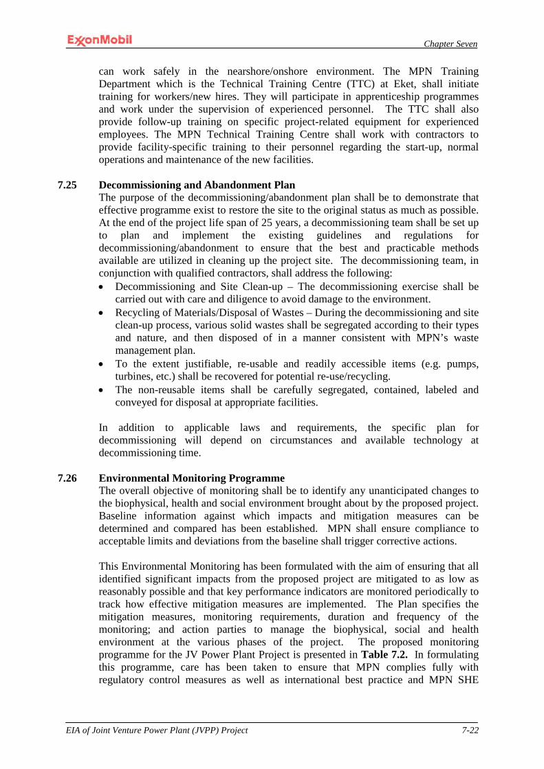
Chapter Seven
EIA of Joint Venture Power Plant (JVPP) Project 7-22
can work safely in the nearshore/onshore environment. The MPN Training Department which is the Technical Training Centre (TTC) at Eket, shall initiate training for workers/new hires. They will participate in apprenticeship programmes and work under the supervision of experienced personnel. The TTC shall also provide follow-up training on specific project-related equipment for experienced employees. The MPN Technical Training Centre shall work with contractors to provide facility-specific training to their personnel regarding the start-up, normal operations and maintenance of the new facilities.
7.25 Decommissioning and Abandonment Plan
The purpose of the decommissioning/abandonment plan shall be to demonstrate that effective programme exist to restore the site to the original status as much as possible. At the end of the project life span of 25 years, a decommissioning team shall be set up to plan and implement the existing guidelines and regulations for decommissioning/abandonment to ensure that the best and practicable methods available are utilized in cleaning up the project site. The decommissioning team, in conjunction with qualified contractors, shall address the following: • Decommissioning and Site Clean-up – The decommissioning exercise shall be
carried out with care and diligence to avoid damage to the environment. • Recycling of Materials/Disposal of Wastes – During the decommissioning and site
clean-up process, various solid wastes shall be segregated according to their types and nature, and then disposed of in a manner consistent with MPN’s waste management plan.
• To the extent justifiable, re-usable and readily accessible items (e.g. pumps, turbines, etc.) shall be recovered for potential re-use/recycling.
• The non-reusable items shall be carefully segregated, contained, labeled and conveyed for disposal at appropriate facilities.
In addition to applicable laws and requirements, the specific plan for decommissioning will depend on circumstances and available technology at decommissioning time.
7.26 Environmental Monitoring Programme
The overall objective of monitoring shall be to identify any unanticipated changes to the biophysical, health and social environment brought about by the proposed project. Baseline information against which impacts and mitigation measures can be determined and compared has been established. MPN shall ensure compliance to acceptable limits and deviations from the baseline shall trigger corrective actions.
This Environmental Monitoring has been formulated with the aim of ensuring that all identified significant impacts from the proposed project are mitigated to as low as reasonably possible and that key performance indicators are monitored periodically to track how effective mitigation measures are implemented. The Plan specifies the mitigation measures, monitoring requirements, duration and frequency of the monitoring; and action parties to manage the biophysical, social and health environment at the various phases of the project. The proposed monitoring programme for the JV Power Plant Project is presented in Table 7.2. In formulating this programme, care has been taken to ensure that MPN complies fully with regulatory control measures as well as international best practice and MPN SHE
Chapter Seven
EIA of Joint Venture Power Plant (JVPP) Project 7-23
Policy. The proposed program represents the minimum monitoring that will be achieved along with the specific mitigation measures proposed in Chapter 6.
Environmental monitoring of the project is therefore advocated in order to ensure that the mitigation processes put in place have adequately taken care of the predicted impacts. This will necessitate establishing programmes to address the following: • alteration to the biological, chemical and physical characteristics of the recipient
environment; • social and health issues; • determination of term and residual effect; and • how mitigation measures are implemented. MPN’s process for ensuring compliance with environmental monitoring requirements is contained in its management system. In particular, MPN has an Environmental Monitoring Programme within its EMP that outlines the specific requirements to ensure compliance with EIA environmental monitoring commitments. In addition to its own monitoring actions, MPN shall facilitate the impact mitigation monitoring of the project in liaison with relevant regulatory authorities (FME, NERC, FMEnv, and AKSMEMR).
Monitoring Objectives The overall objectives of this monitoring programme are to: • ensure compliance with regulatory emission and discharge limits; • monitor changes in existing physico-chemical, biological and social
characteristics of the environment, compared both to the environmental baseline and predicted conditions;
• determine whether any environmental changes are caused by the project or by other forces;
• determine the effectiveness of the control and mitigation measures; and • highlight areas of concern not considered by the EIA and provide a basis for
recommending additional mitigation measures.
Conditions required for optimum performance will be incorporated into the design to ensure that the facility operates with minimal environmental impacts. Appropriate engineering designs, operations and maintenance strategies will be minimize averse impacts. Stack sampling shall be conducted during commissioning and thereafter, yearly to ensure that NOx does not exceed 25 ppmv at the stack based on a dry O2 content of 15%. If this exceeded, appropriate maintenance and operating changes will be engaged until compliance is achieved.
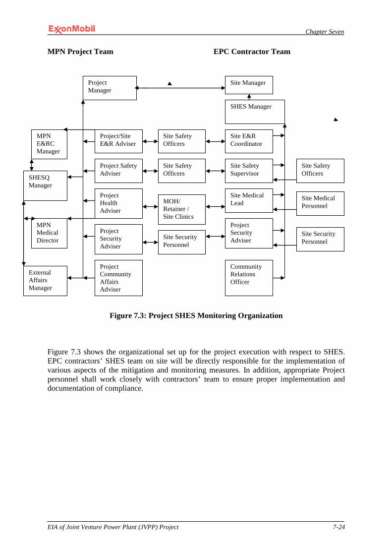
Chapter Seven
EIA of Joint Venture Power Plant (JVPP) Project 7-24
MPN Project Team EPC Contractor Team
Figure 7.3: Project SHES Monitoring Organization Figure 7.3 shows the organizational set up for the project execution with respect to SHES. EPC contractors’ SHES team on site will be directly responsible for the implementation of various aspects of the mitigation and monitoring measures. In addition, appropriate Project personnel shall work closely with contractors’ team to ensure proper implementation and documentation of compliance.
Project Manager
Project Safety Adviser
Project Health Adviser
Project/Site E&R Adviser
Project Community Affairs Adviser
Project Security Adviser
Site Safety Officers
MOH/ Retainer / Site Clinics
Site Manager
SHES Manager
Site Safety Supervisor
Site E&R Coordinator
Site Medical Lead
Project Security Adviser
Site Safety Officers
Site Medical Personnel
Community Relations Officer
Site Security Personnel
External Affairs Manager
MPN E&RC Manager
MPN Medical Director
SHESQ Manager
Site Safety Officers
Site Security Personnel
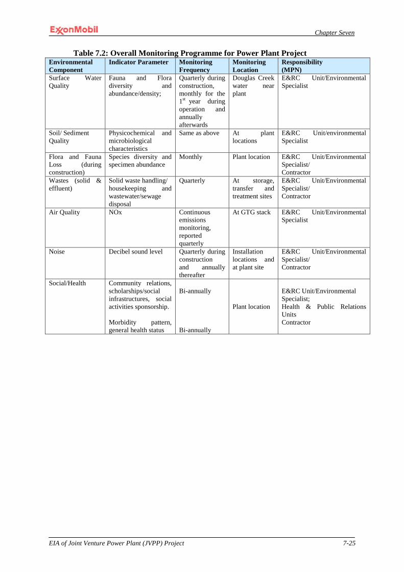
Chapter Seven
EIA of Joint Venture Power Plant (JVPP) Project 7-25
Table 7.2: Overall Monitoring Programme for Power Plant Project Environmental Component
Indicator Parameter Monitoring Frequency
Monitoring Location
Responsibility (MPN)
Surface Water Quality
Fauna and Flora diversity and abundance/density;
Quarterly during construction, monthly for the 1st year during operation and annually afterwards
Douglas Creek water near plant
E&RC Unit/Environmental Specialist
Soil/ Sediment Quality
Physicochemical and microbiological characteristics
Same as above At plant locations
E&RC Unit/environmental Specialist
Flora and Fauna Loss (during construction)
Species diversity and specimen abundance
Monthly Plant location E&RC Unit/Environmental Specialist/ Contractor
Wastes (solid & effluent)
Solid waste handling/ housekeeping and wastewater/sewage disposal
Quarterly At storage, transfer and treatment sites
E&RC Unit/Environmental Specialist/ Contractor
Air Quality NOx Continuous emissions monitoring, reported quarterly
At GTG stack E&RC Unit/Environmental Specialist
Noise Decibel sound level Quarterly during construction and annually thereafter
Installation locations and at plant site
E&RC Unit/Environmental Specialist/ Contractor
Social/Health Community relations, scholarships/social infrastructures, social activities sponsorship. Morbidity pattern, general health status
Bi-annually Bi-annually
Plant location
E&RC Unit/Environmental Specialist; Health & Public Relations Units Contractor

Chapter Seven
EIA of Joint Venture Power Plant (JVPP) Project 7-26
Table 7.3: Overall Mitigation Programme for Power Plant Project
Environmental Component Key Impact Mitigation Measures Responsibility
Soils and Geology
Engineering Constraints of Soils and Geology
Soils tests to ensure conformance with Project requirements.
MPN
Soil Erosion Develop Erosion and Sedimentation Control Plan; visual monitoring of erosion control measures and key performance indicators; and routine maintenance
EPC
Fuel or Chemical Spills to Soils
Develop Spill Prevention and Response Plan; use concrete pads, drip pans and concrete containment in hydrocarbons and chemical storage area
EPC/Operator
Terrestrial Biological Resources
Loss, Degradation, or Fragmentation of Wildlife Habitat
Delineate and flag limits of clearing to minimize vegetation loss; limit infrastructural access points along QIT Lake for fill material collection; retain trees and shrubs with flagging; avoid compaction of the adjacent soils (where possible); use salvaged and stockpiled topsoil for revegetation, and local, native plant species where landscaping is required; safe dispose of domestic wastes
EPC/Operator
Adverse Impacts to Local Special-Status Wildlife Species
Wildlife sightings, reporting and protection, endangered species awareness training for all construction and operation personnel
EPC
Adverse Impacts to Local Special-Status Plants Species
Special-status species plant sightings, reporting and protection, endangered species awareness training for all construction and operation personnel
EPC
Sedimentation, Hydrological, and Water Quality Effects on Aquatic Fauna and Flora
Erosion and Sedimentation Control Plan; limit vegetation clearing and ground disturbance to reduce runoff; plan activities to control sedimentation; use drainages, silt fences, intercept ditches, and buffer zones to minimize potential adverse effects; and monitor effectiveness of erosion controls.
EPC
Marine Resources
Changes to Existing Coastline due to Material Off-Loading Facility
Project specific EMP to be implemented along with EIA EMP with site specific Beach monitoring and mitigation measures
EPC
Loss or Disturbance of Coastal Marine Habitat due to Material Off-Loading Facility
Mitigation measures to minimize impacts of nearshore excavation; safe disposal of excavated materials to minimize downdrift beach erosion impacts, interruption of normal nearshore currents and silt/sediment transport.
EPC
Impacts on Marine Mammals and other protected species
Work planned and executed to minimize impacts on any identified species
Air Quality Early Site Preparation and Construction Related Air Quality Impacts
Open vehicles, roads and exposed areas covered or wetted to minimize dust emissions; trucks not allowed to track materials from site to public road; use concrete batch plant in a manner that minimizes dust
EPC
Off-site Transportation Related Air Quality Impacts
Minimize diesel usage and emissions during construction activities.
EPC
Operational Related Air Design reviews and performance tests to confirm NOx EPC/Operator

Chapter Seven
EIA of Joint Venture Power Plant (JVPP) Project 7-27
Quality Impacts
concentration and other regulated parameters; continuous emissions monitoring and quarterly report; stack sampling at commissioning & annually, subsequently; appropriate maintenance and/or operating procedures
Noise Early Site Preparation and Construction Impacts on Ambient Noise
Minimize noise impact by restricting movement to day time and ensuring use of only road worthy trucks
EPC
Transportation and Operational Related Increases in Ambient Noise
Vehicles maintained in good conditions; GTGs to meet 60 dBA @ 400 feet criteria.
EPC/Operator
Water Resources
Surface Water Impacts due to Storm Water Runoff and Sedimentation during Construction
Implementation of Erosion and Sedimentation Control Plan (includes storm water management via sampling/monitoring of Douglas Creek, visual monitoring of runoff control measures); use of drip pans, concrete pads and containment areas for spill prevention and management; locate batch plants away from water- and drain-courses; berms around batch plant equipment for proper containment and cleanup; safe disposal of concrete materials
EPC
Changes in Surface Water Quality due to Discharge of Sanitary Sewage, Storm Water and Wastewater
Effective monitoring program to ensure threshold are not exceeded; timely process modifications or appropriate equipment maintenance to restore discrepancies
EPC/Operator
Effects of Inadvertent Spill Discharges to Surface Waters
Effective implementation of the SPR Plan for appropriate spill prevention, preparedness, clean-up and reporting procedures; Project fuel trucks to travel only on MPN approved on-site access roads; fuel or hazardous materials handling not allowed within 31 meters (about 100 feet) from a water body; provision of safe and sufficient secondary containment, for liquid storage
EPC/Operator
Effects of Inadvertent Spills to Groundwater
Effective implementation of the SPR Plan EPC/Opertor
Surface Water Quality Impacts due to Hydrostatic Test Water Discharge
Implementation of EGASPIN and MPN hydrotest and discharge of hydrotest water requirements
EPC
Socioeconomic Resources
Allocation of employment opportunities to the host communities
Implementation of MPN community engagement plan. EPC/Operator/MPN
Social and cultural conflicts among indigenous and foreign workers
Induction trainings with focus on conflicts avoidance, reporting and management; provision of camping and recreational facilities for foreign workers close to the proposed project site.
EPC/Operator/MPN
Health and Safety
Health and Safety issues Associated with Tropical Diseases
Implementation of Project Health Plan, MPN’s Malaria Control Program (MCP) and AIDS/HIV programs (STOPAIDS), and Project Health Assessment
EPC/Operator/MPN
Safety/Risks Issues Associated with Site Clearing and Equipment Operation
Implementation of Project Safety Plan, Health and Safety orientation prior to work commencement, approved work procedures, and use of appropriate personnel protective equipment
EPC/Operator/MPN
Encounters with Venomous Snakes
Implementation of Project Safety Plan, Health and Safety orientation prior to work commencement, approved work procedures, use of appropriate personnel protective equipment and medical services
EPC/Operator/MPN
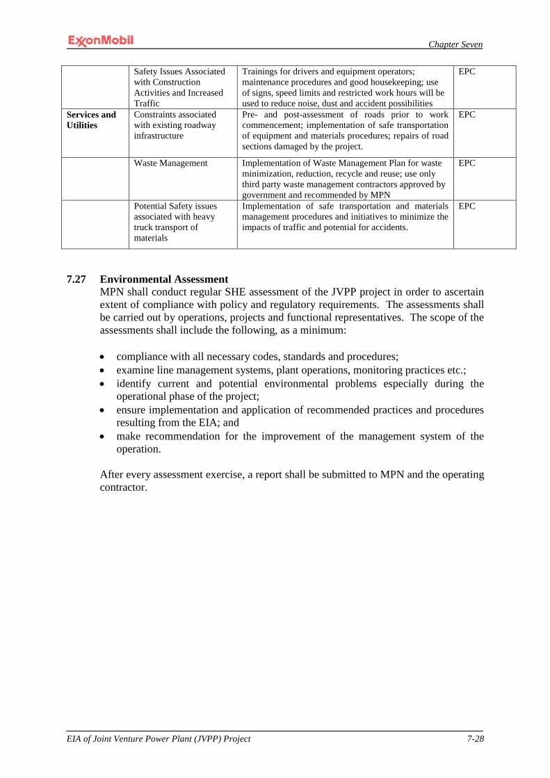
Chapter Seven
EIA of Joint Venture Power Plant (JVPP) Project 7-28
Safety Issues Associated with Construction Activities and Increased Traffic
Trainings for drivers and equipment operators; maintenance procedures and good housekeeping; use of signs, speed limits and restricted work hours will be used to reduce noise, dust and accident possibilities
EPC
Services and Utilities
Constraints associated with existing roadway infrastructure
Pre- and post-assessment of roads prior to work commencement; implementation of safe transportation of equipment and materials procedures; repairs of road sections damaged by the project.
EPC
Waste Management Implementation of Waste Management Plan for waste minimization, reduction, recycle and reuse; use only third party waste management contractors approved by government and recommended by MPN
EPC
Potential Safety issues associated with heavy truck transport of materials
Implementation of safe transportation and materials management procedures and initiatives to minimize the impacts of traffic and potential for accidents.
EPC
7.27 Environmental Assessment
MPN shall conduct regular SHE assessment of the JVPP project in order to ascertain extent of compliance with policy and regulatory requirements. The assessments shall be carried out by operations, projects and functional representatives. The scope of the assessments shall include the following, as a minimum: • compliance with all necessary codes, standards and procedures; • examine line management systems, plant operations, monitoring practices etc.; • identify current and potential environmental problems especially during the
operational phase of the project; • ensure implementation and application of recommended practices and procedures
resulting from the EIA; and • make recommendation for the improvement of the management system of the
operation. After every assessment exercise, a report shall be submitted to MPN and the operating contractor.

CHAPTER EIGHT

Chapter Eight
EIA of Joint Venture Power Plant (JVPP) Project 8-1
CHAPTER EIGHT
8.0 DECOMMISSIONING AND CONCLUSION 8.1 Decommissioning Schedule
The design life of the proposed power plant facility is 25 years. However, the useful life may extend beyond that. During operations, the performance and the integrity of the systems component of the facilities will be monitored with respect to PHCN/TCN and MPN operations and maintenance procedures. At the end of their safe life, or alternatively, when the economic life is reached, the facilities will be decommissioned.
8.2 Policies, Standards and Guidelines for Decommissioning The decommissioning of the facilities will be conducted in line with MPN, PHCN/TCN, FMEnv, and International Maritime Organization (IMO) safety, environment and decommissioning requirements. MPN’s management systems of operations integrity, safety and environment prevalent at the time of decommissioning will be applicable. Contractors executing the work shall be expected to carry out their activities in compliance to these standards and guidelines.
8.3 Decommissioning Strategy and Plan A decommissioning team will be established to plan and execute a safe and environmentally acceptable decommissioning program within the approved guidelines and standards. The procedure will be developed for approval by MPN management and will include risk assessment. The decommissioning plans will be reviewed with PHCN/TCN and FMEnv. The decommissioning activities will include the following; Demolition and Site Clean Up: The demolition exercise will be skillfully
implemented to prevent spill or discharge of hazardous materials that has the potential to cause damage to the environment.
Materials Recycling / Waste Disposal: Various materials generated in the course of demotion and site clan up will be segregated, contained, transported, reused, recycled and disposed of in line with MPN waste management procedures. Useful materials shall be recovered for reuse and recycling to minimize waste while non reusable ones will be properly handled for disposal by MPN approved third party waste management facilities.
In addition to applicable laws, regulations and standard requirements, the project specific decommissioning plan will take advantage of the available technology at the time. Gas lines will be flushed, pigged and cleaned to removed entrained hydrocarbons prior to being filled with seawater, capped and left in place or removed according to the approved practice at the time of decommissioning. Since none of the lines will be transporting oil, the likelihood of oil escaping into the environment is very negligible. However, measures will be taken to ensure that decommissioning process attributes priority attention to safety and the environment.
Chapter Eight
EIA of Joint Venture Power Plant (JVPP) Project 8-2
8.4 CONCLUSION
The EIA of the proposed Joint Venture Power Plant Project has been carried out in accordance with the regulatory requirements established by the FMEnv, MPN SHE policy and other relevant statutory laws. The potential impacts of the proposed project on the existing environment were identified and evaluated, and the impact assessment was based on the interactions between the project activities and the various environmental components as contained in chapter 6 of this report. The potential and associated impacts assessment of the proposed project activities indicated that the project would beneficially and significantly impact the national economy and the overall well being of the Nigerian people. This would be by way of improved power supply which will enhance business and comfort. It would also result in provision of direct and indirect employment opportunities for Nigerians. The magnitude of the anticipated adverse impacts of the proposed project activities on the exiting environment, socio-economic and health were rated. Thereafter, mitigation measures were proffered to reduce the magnitude of identified adverse impacts, to a level as low as reasonably practicable (ALARP). These mitigation measures are incorporated in the Environmental Management Plan developed specially for this project, which will be used through out the life cycle of the project (site preparation to decommissioning).
Consequently, the EMP has been developed to ensure effective implementation of prescribed mitigation measures within the framework of MPN’s Operations Integrity Management System (OIMS).

APPENDIX I
Appendix I
EIA of Joint Venture Power Plant (JVPP) Project I-1
APPENDIX I
REFRENCES
Abel A.M (1990): The Earth –auditing Effects of Noise and Annoyance: The Journal of
Otolaryngology 19; 1-13 Akani, Godfrey C., Ikomah F. Barieenee, Dario Capizzi and Luca Luiselli (April 1999)
“Snake Communities of Moist Rainforest and Derived Savanna Sites of Nigeria: Biodiversity Patterns and Conservation Priorities.”
Akpokodje, E. G., 1998, Engineering geology of the Niger Delta
Allen J. R.L (1964): The Nigeria continental margin bottom sediment morphology and
geological evolution. Marine geology: 1; 289 -332
Allen J. R.L (1965): Late quaternary Niger Delta and adjacent areas. Sedimentary
Environments and Lithofacies. AAPG bull, V.I pp 547 – 600
American Public Health Association (APHA) (1992) Standards for the Examination of water
and Wastewater 18th Edition
Appelo, C. A. J. and Postma, D. (2005). Geochemistry of Ocean, Rotterdam, Balkema: IPC
Inc.
Arshad M. A and R. Lal. 1996. Soil water parameters and soil quality.
Atlas of Federal Republic of Nigeria (1978)
Atgn, R.S., EL-Agha, O., Zararsz, A., Kocatas, A., Parlak, H., and Tuncel, G. (2000).
Investigation of the sediment pollution in Izmir Bay: trace elements, Spectrochimica
Acta part B, 55:1151-1164
Ayoade J. O (1995): introduction to Climatology for the tropics: Spectrum Books Limited
Badri, M.A. and Aston, S.R. (1983). Observation on heavy metal geochemical associations in
polluted and non-polluted estuarine sediments. Environ. Pollut. Ser. B.6: 181-193
Baker, Lynn R. (2005) “Distribution and Conservation Status of the Sclater’s Guenon (Cercopithecus sclateri) in Southern Nigeria
Bohn, H. L; B. L. Mc Neal and G. A. O’ Conner (1985). Soil Chemistry. A Willy –
Interscience Pub. John Wiley and Sons, New York.
Bradford, S.A. (1993), Corrosion Control, Physical and chemical properties
(US Dept., of Interior, 1968). Manual
Canter L.W and Hill, L G (1977) Hand book of variables for environmental impact
assessment. Ann Arbor science publisher Inc, ANN
Appendix I
EIA of Joint Venture Power Plant (JVPP) Project I-2
Cooper, J. Williams, A. J. and Britton, P. L. (1984): Distribution Populations sizes and
Conservation of Breeding Srabieds in the Afrotropical Region in Status and
Conservation of the world’s Seabirds
Conoco (2004) Oil prospecting lease 248 E nvironmental baseline survey: Report no
CO/EIA/011/04.
Courant, R., Powell, C.B. and Micthell, J. (1985). Water Type Classification of Niger Delta
River and Creek Waters. The Petroleum Industry and the Nigerian Environment,
Proceedings of a Seminar on the Petroleum Industry and the Nigerian Environment held
in Kaduna, Nigeria.
Daly H.E (1996): Beyond Growth; the Economic of sustainable Development. Boston;
Beacon Press
Derek H. and Oguntoyinbo J. (1987). Climatology of West Africa. Published by Hutchinson
(South Africa) and Noble Books (Totowa, New Jersey, USA).
Donahue, R.L., Miller, R.w., and Shickluna, J.C. (1990). Soils: An Introduction to Soils and
Plants Growth. India: Prentice Hall Inc.
Donahue, 1990). Overall soil nutrient. And Soil acidity
DPR (2002). Environmental Guidelines and Standards for the Petroleum Industry in Nigeria
(EGASPIN). D epartment of Petroleum Resources ( DPR), Ministry of Petroleum
Resources, Lagos.
EGASPIN (2002): Environmental Guidelines and Standards for the Petroleum Industry.
Department of Petroleum Resources, Ministry of Petroleum Resources
Ekundayo, EO;(2004) Land based on heavy metal and phosphorus saption characteristics of
soil
Emerson, S. and Abell, J. (2001). The Biological Pump in the Subtropical North Pacific
Ocean. Chicago: USA: Pretence Inc.
Enger and Smith (2004) Environmental Science; A study of Interrelationships. ; McGraw Hill
Environmental Impact Assessment of East Area Projects Natural Gas Liquids II Project; March, 2005
ESSO (1998): OPL 209 E nvironmental Impact Assessment Update for Drilling Operations
Exploration Well: ERHA
Ezeala, D.O.(1984). Changes in the nutritional quality of fermented cassava tubes meal,
J..Agric food chem., 32:467-469.
Appendix I
EIA of Joint Venture Power Plant (JVPP) Project I-3
Falkland, A. C and Woodroffe, C. D (1997). Geology and hydrogeology of sea environment,
Hanolulu; Elsevier Science Publishers.
Federal Environmental Protection Agency (FEPA) (1991). National Guidelines and Standards
for Industrial Effluents, Gaseous Emissions and Hazardous Waste Management in
Nigeria. Lagos: Government Printing Press.
FMANR, 1990. Literature Review on Soil Fertility Investigations in Nigeria
FMENV (FEPA), (1995): Environmental Impact Assessment Sectoral Guidelines for Oil and
Gas Industry Projects. FMENV, Abuja, Nigeria.
FMENV (FEPA) (1991): National Environmental Protection Regulations. Regulations S.I.8
(Effluent Limitation); Regulations S.I.9 (Pollution Abatement in Industries
Generating Wastes) and Regulations S.I.15 (Management of Solid and Hazardous
Wastes).
FPDD, Fertilizer Procurement and Distribution Division (1990). A Review of Soil and
Fertilizer Use Research in Nigeria. In: Literature Review on Soil Fertility
Investigations in Nigeria (Eds Enwezor et al.), produced in Five Volumes by the
Fertilizer Procurement and Distribution Division (FPDD), Federal Ministry of
Agriculture and Natural Resources, Lagos, Nigeria. 281pp]
Fugro Consultants Nigeria Limited (2006) “Final Report on QGFE Geotechnical Investigation for Mobil Producing Nigeria,” Report Number: 25022
Gardline Surveys Inc. (May 2002) “Mobil Producing Nigeria Unlimited Pipeline Route Surveys East Area Projects,” (Note-QIT to EA)
Gee and Stoner, (1989): The role of geology and soils in controlling surface water acidity in
Wales.
Global Environmental Monitoring Systems(GEMS) (1992) An Operational Guide. 3rd Edition.
Gobo A.E (1998): Meteorology and Man's Environment. Africa-link Books, Ibandan
Hammett, D.S. and S. Forex. 1985. Drill Vessels Float in Aerated Water. Offshore Europe,10-13 September 1985, A berdeen, UK. Society of Petroleum Engineers of AIME.
Hastenrath S., 1985: Climate and Circulation of the Tropics D. Reidel Publishing Company,
455 pp.
Holland, E.A., and D.C. Coleman. (1987): Particulate soil organic matter changes across a
grassland cultivation sequence
Horsfall, M.J. and Spiff, A. (2002): Distribution and partitioning of trace metals in sediments
of the lower reaches of the New Calabar River, Port-Harcourt, Nigeria,
Environment Monitoring and Assessment, 78: 309-326.
ILF Consulting Engineers (2009), “Simple Cycle-Combined Cycle Study.”
Appendix I
EIA of Joint Venture Power Plant (JVPP) Project I-4
Ingenieursbureau Svasek (1996) “NGL Export Jetty Hydraulic Conditions and Mooring Loads.” Latoxan, “Catalog of Venoms of Snakes from all Families”, http://www.latoxan.com/VENOM/SNAKE
International Union for the Conservation of Nature and Natural Resources (IUCN) (1992)
Coastal and marine biodiversity report for UNEP: Identification, establishment, and
management of specially protected areas in the WACAF region. Gland, Switzerland.
Keller, K., Slater, R. D., Beuler, M. and Key, R. M. (2002): Possible biological and physical
trends in North Pacific Ocean. Deep sea 7:118 – 123.
Keily, G (1998) Environmental Engineering London: McGraw-Hill International Limited
King, R.P (1996) Length – weight relationship of Nigerian coastal water fish. Naga
ICLARM.19 (4):52- 58. (Publ.), London.
Kings, C. A. M. (1975). Introduction to Physical Oceanography, London: Edmund Arnold
Publishers.
Kentucky Water Watch (KWW) (2001): Dissolved Oxygen and Water Quality: http://.fluid.
Stateky. Us/www/ramp/rms2.htm.
Kpokodje, E. G. 1998. The importance of engineering geological mapping in the
development of the Niger Delta Basin. Bulletin of the International Association of
Engineering Geology, 19, 101–108.
Leifer, I., B. P. Luyendyk, J. Boles, and J. F. Clark. 2006. Natural Marine Seepage Blowout: Contribution to Atmospheric Methane, Global Biogeochem. Cycles, 20, GB3008, doi:10.1029/2005GB002668
Longhurst A.R. and Paul (1965): A Survey of the Fish Resources of the Eastern Gulf of
Guinea. J . Cons.CIEM, 29(3): 302-34. C ited in Marine Fishery Resources of
Nigeria:
McBride, M.B, (1989) Reaction Controlling heavy metal solubility in soil. Advance sol
science pp 1-56
Milgram, J. H., and P. R. Erb. How Floaters Respond to Subsea Blowouts, Petroleum Engineer, June 1984. pp. 64-72.
Moffatt & Nichols. (1997) “Proposed Barge Unloading Facilities -Feasibility Study Review.” Moore and Loeppert, 1987 Methods of pH determination in Calcareous Soil
Niger Delta Environmental Survey (NDES) (1997) :Final Report of Phase 1. Volume 1.
Nigeria LNG Ltd (Dec.1997): EIA Report on the Revised Gas Transmission System Route;
prepared by SGS Environment.
Appendix I
EIA of Joint Venture Power Plant (JVPP) Project I-5
NPDC/AENR, (2004): Environmental Impact Assessment (EIA) of Okono/Okpoho Fields
(OML 119). Nigerian Petroleum Development Company/Agip Energy and Natural
Resources.
NDES:Niger Delta Environmental Survey (2003). P hase 1 R eport on the Niger Delta
Environment
Ocean Sciences (1964): T he state of the ocean. A publication of United States Naval
Institute, Annapolis, Maryland.
Ochoa, M.P (2005) “QIT Gas Flare Elimination Project; Golder & Associates Project Number: 053-4781
Odu, C.T.I., Nwabushi, L.C., Esurusu, O.F and Ogunwale, J.A. (1985): Environmental Study
on Soils and Vegetation of bthe Nigerian Agip Oil Company Operational Areas.
Oguntoyinbo J. and Deck (1987): Climatology of West Africa. P ublished by Hutchinson
(South Africa) and Noble Books (Totowa, New Jersey, USA). 82-103pp
Rim-Rukeh and Okokoyo P.A (2004) Self- Purification capacity of Orog odo River, Abgor,
Nigeria; A journal of Empirical Research
Okokoyo P.A and Rim-Rukeh (2004) Sand Bend Filtration in Refinery Wastewater polishing;
A journal of Empirical Research
Okoye, B.C.O (1991): Heavy metals and organisms in the Lagos, Lagoon. International
Oomkens, E (1974): lithofacies relatios in the late quarternary Niger Delta Complex
sedimentology 21, 195 -222.
Palmer, Darren (2009) “US EPA Region 4 Telecommunication” Proceedings on t he International Seminar on t he Petroleum Industry and the Nigerian
Environment , Lagos.
Pekey, H, Karakas, D, Ayberk, S, Tolun, L, and Bakoglu, M. (2004). Ecological risk
assessment using trace elements from surface sediments of Izmit Bay
(Northeastern Marmara, sea) Turkey, Marine Pollution Bulletin 48: 946-953.
Project Global/Global By all dataacatch Assessment of Long-Lived Species, “Regional Assessment West Africa” Duke Center for Marine Conservation, Duke Marine Laboratory.”
Puyate and Rim-Rukeh, (2008): Effects of refinery waste water on Orogodo River Research Planning Institute (RPI) (1985). Environmental Baseline Studies for the
Establishment of Control Criteria and Standards Against Petroleum Related
Pollution in Nigeria.

Appendix I
EIA of Joint Venture Power Plant (JVPP) Project I-6
Rim-Rukeh et al., (2006): Public Participation and consultation in Nigeria’s EIA Processes. NES
Ross S.L. Environmental Research Ltd. 2009. Assessing Risk and Modeling a Sudden Gas Release Due to Gas Pipeline Ruptures. Report to U.S. Department of the Interior Minerals Management Service. pp. 1-93.
Shell Oil. (2009) “Report on the Rapid Biodiversity Assessment of the Stubbs Creek Forest Reserve, Akwa Ibom State, Nigeria
SPDC (2001): Utapate and OML- 13 Re-development EIA scoping Report September, 2001.
Soil Survey Staff (SSS) (1992). Soil Taxonomy. Washington USDA Publishers Against
petroleum related pollution in Nigeria.
Soil Survey Staff (SSS) (1975). Soil Taxonomy. Washington USDA Publishers
STAR (2003) Environmental Baseline survey of Agbami Field in OPL 216. F inal Report.
No. S0307C.
State of Oregon Department of Environmental Quality, DEQ (March 2009); “Woodsmoke Pollution.”
Strickland, J.D.H. and Parsons, T.R. (1968). A practical handbook of seawater analysis.
London: Bioscience publishers Inc.
Structural Analysis and Geotechnical Engineering Limited; “Pipeline Report Geotechnical and Geophysical Investigation 1988/1989 and EDOP Development Offshore Nigeria, GEO 0001193;” (Note-OSO to QIT)
Texas A & M University, “Soil Basics,” <http://organiclifestyles.tamu.edu/soil/index.html> Thenhaus, Paul C. (2001) “Seismic Hazard Results for the Nsimbo, Yoho, and Ubit Offshore
Sites, Nigeria, West Africa; EQE Project Number: 745076.001 Thenhaus, Paul C. (2005) “Seismic Hazard Results for Qua Ibo Terminal, Nigeria;” ABS
Group Consulting, Inc., Project Number: 1444309 Travax Traveler Health Report, “Nigeria.” Usen,U.U., Akpabio,I.O.,Uko,E.D.,(2007):”Akwa Ibom State and Water resources”.
Wickstead, J. H (1965), Introduction to Science of Deep Sea, London: Hutchinson Pub. Co.
Ltd.
Wright J. B., Hastings D. A., Jones W. B, Williams H. R (1985): Geology and Mineral
Resources of West Africa.
World Bank (1999) Environmental Assessment Sourcebook
World Bank (1995) Africa: A framework for integrated coastal zone management.

APPENDIX II

Appendix II
___________________________________________
EIA of Joint Venture Power Plant (JVPP) Project
II-1
Appendix II Environmental Baseline Assessment

Appendix II
___________________________________________ EIA of Joint Venture Power Plant (JVPP) Project II-2
APPENDIX II-1 WEATHER DATA AT QIT
The following tables summarize weather data at QIT: • QIT (1998-2008) MEAN MONTHLY TEMPERATURE VALUES (0C) (JANUARY TO DECEMBER)
• QIT (1998-2008) RELATIVE HUMIDITY MONTHLY AVERAGES(%) (JANUARY TO DECEMBER)
• QIT (1998-2008) MONTHLY WIND DIRECTION (DEGREES) AND SPEED DATA (MPH) (JANUARY TO DECEMBER).
• QIT (1998-2008) MONTHLY RAINFALL (mm) FOR (JANUARY TO DECEMBER).

Appendix II
___________________________________________ EIA of Joint Venture Power Plant (JVPP) Project II-3
QIT (1998-2008) MEAN MONTHLY TEMPERATURE VALUES HEIGHT 11.15' ABOVE SEA LEVEL LOCATION: LAT. - 04O 38.5' N; LONG. - 07O 52.2' E
YEAR JAN FEB MAR. APR. MAY JUNE JULY AUG. SEPT. OCT. NOV. DEC.
1998 24.8 27.4 27.6 27.2 27.0 25.9 25.6 26.3 25.7 25.5 26.7 26.2 1999 25.3 26.5 27.1 26.9 25.9 25.8 25.1 26.2 24.9 25.4 26.2 29.9 2000 31.5 29.3 27.0 31.8 28.5 28.4 26.8 25.9 27.0 26.1 26.0 28.7 2001 25.2 27.5 26.6 27.0 25.0 25.1 24.2 26.3 25.1 25.5 27.4 28.2 2002 26.0 28.4 26.7 27.4 26.5 26.2 25.2 26.1 24.9 26.2 26.9 26.7 2003 25.7 28.1 25.8 27.1 27.0 26.1 24.3 26.0 25.2 25.6 26.5 27.0 2004 26.9 28.1 28.5 27.4 26.7 25.9 25.2 25.3 25.6 26.2 26.8 26.5 2005 25.8 28.5 27.6 28 27 26.1 25.2 25.3 25.6 25.5 27.1 27.0 2006 26.0 27.4 27.7 27.4 26.5 26.2 25.4 25.1 24.9 26.2 26.8 26.7 2007 25.7 28.2 27.8 27.1 27.0 26.1 25.6 25.0 25.2 25.6 26.4 27.0 2008 24.1 27.7 27.5 27.2 25.8 25.4 25.2 25.2 25.7 26.4 26.9 27.0 MEAN 28.7 27.9 29.9 30.4 23.9 28.7 27.7 28.3 27.9 25.6 27.0 30.1
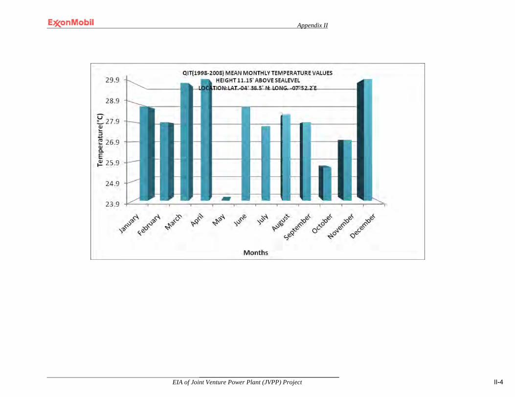
Appendix II
___________________________________________ EIA of Joint Venture Power Plant (JVPP) Project II-4
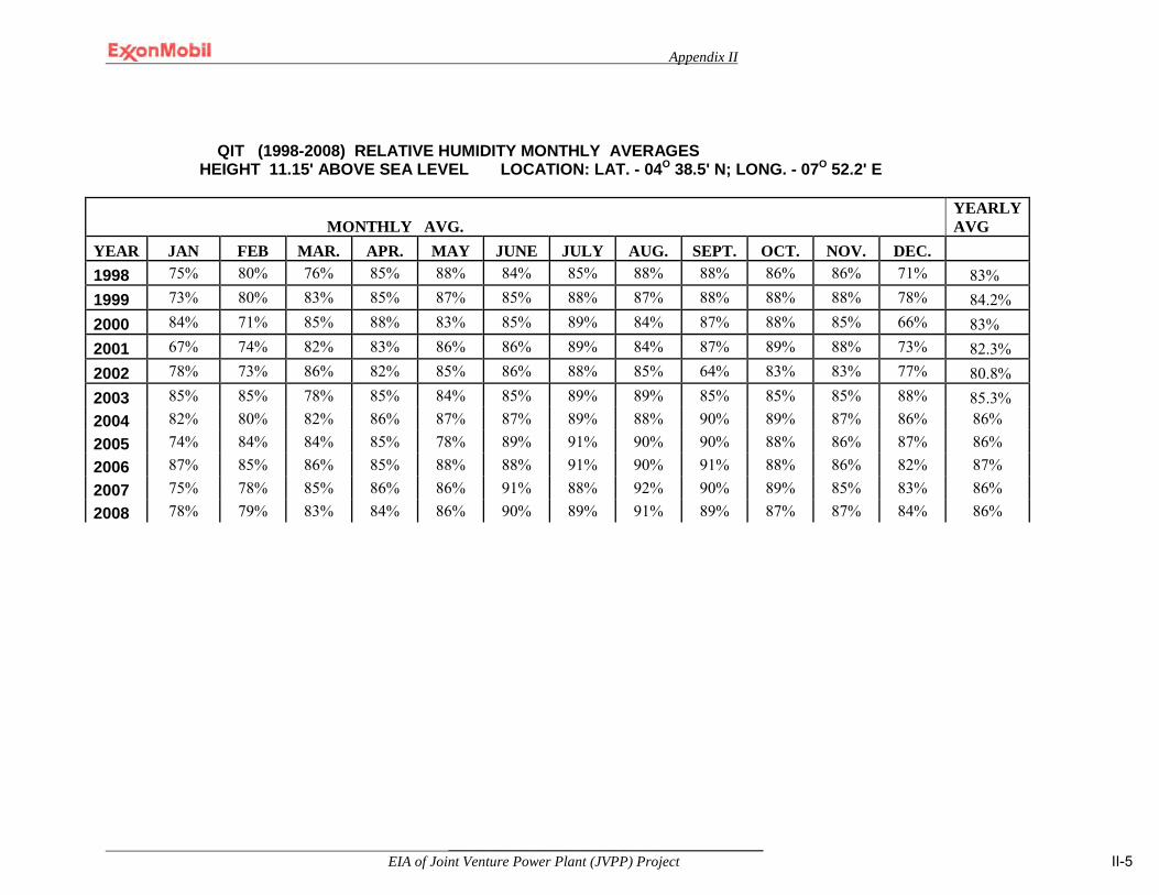
Appendix II
___________________________________________ EIA of Joint Venture Power Plant (JVPP) Project II-5
QIT (1998-2008) RELATIVE HUMIDITY MONTHLY AVERAGES HEIGHT 11.15' ABOVE SEA LEVEL LOCATION: LAT. - 04O 38.5' N; LONG. - 07O 52.2' E
MONTHLY AVG. YEARLY AVG
YEAR JAN FEB MAR. APR. MAY JUNE JULY AUG. SEPT. OCT. NOV. DEC. 1998 75% 80% 76% 85% 88% 84% 85% 88% 88% 86% 86% 71% 83%
1999 73% 80% 83% 85% 87% 85% 88% 87% 88% 88% 88% 78% 84.2% 2000 84% 71% 85% 88% 83% 85% 89% 84% 87% 88% 85% 66% 83% 2001 67% 74% 82% 83% 86% 86% 89% 84% 87% 89% 88% 73% 82.3% 2002 78% 73% 86% 82% 85% 86% 88% 85% 64% 83% 83% 77% 80.8% 2003 85% 85% 78% 85% 84% 85% 89% 89% 85% 85% 85% 88% 85.3% 2004 82% 80% 82% 86% 87% 87% 89% 88% 90% 89% 87% 86% 86% 2005 74% 84% 84% 85% 78% 89% 91% 90% 90% 88% 86% 87% 86% 2006 87% 85% 86% 85% 88% 88% 91% 90% 91% 88% 86% 82% 87% 2007 75% 78% 85% 86% 86% 91% 88% 92% 90% 89% 85% 83% 86% 2008 78% 79% 83% 84% 86% 90% 89% 91% 89% 87% 87% 84% 86%

Appendix II
___________________________________________ EIA of Joint Venture Power Plant (JVPP) Project II-6
QIT MONTHLY WIND DIRECTION (DEGREES) AND SPEED DATA (MPH)
YEAR JAN FEB MAR. APR. MAY JUNE JULY AUG. SEPT. OCT. NOV. DEC. MEAN
1998 198/06 167/06
188/06
185/06
180/06
193/09
156/08 236/04 224/04
201/07
198/06
198/06 202/06
1999 224/04 219/04 207/04 196/04 202/04 236/04 204/04 204/04 200/04 205/03 180/08 215/05 210/04
2000 216/06 218/05 210/05 222/05 225/06 188/03 229/04 217/05 212/03 201/04 216/06 201/04 224/05
2001 239/06 233/06 230/06 224/06 219/05 222/05 210/05 222/05 221/06 239/05 234/06 228/05 230/06
2002 201/04 211/06 234/04 196/04 192/03 206/04 244/04 230/04 213/04 208/03 224/05 230/04 213/04
2003 212/05 215/06 219/04 234/06 222/05 198/04 217/05 206/04 235/05 196/04 192/04 202/04 222/04
2004 227/04 226/06 229/06 207/06 220/05 223/06 239/06 233/06 230/06 224/06 219/05 222/05 225/06
2005 238/05 223/06 208/05 209/05 205/05 195/05 206/06 242/06 233/05 224/04 223/05 235/04 220/05
2006 244/05 216/06 218/05 210/05 222/05 225/06 239/05 234/06 228/05 230/04 213/04 208/03 224/05
2007 231/03 234/04 196/04 192/04 213/03 216/05 208/04 217/05 207/04 198/04 163/03 192/03 206/04
2008 199/03 212/03 206/04 204/04 211/04 213/04 204/04 244/04 232/04 222/04 213/04 216/04 215/04
2009 228/04 215/04 221/04 197/03 201/04 219/04 229/04 245/04 236/04 235/04 221/03 236/04 224/04
MEAN 181/10 216/10 206/10 211/10 206/10 197/10 229/10 231/10 223/10 209/10 205/10 213/10 213/10
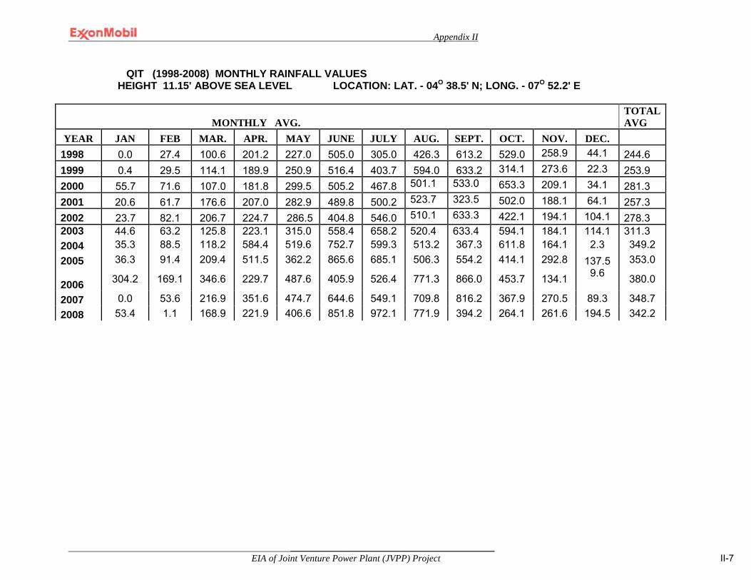
Appendix II
___________________________________________ EIA of Joint Venture Power Plant (JVPP) Project II-7
QIT (1998-2008) MONTHLY RAINFALL VALUES HEIGHT 11.15' ABOVE SEA LEVEL LOCATION: LAT. - 04O 38.5' N; LONG. - 07O 52.2' E
MONTHLY AVG. TOTAL AVG
YEAR JAN FEB MAR. APR. MAY JUNE JULY AUG. SEPT. OCT. NOV. DEC. 1998 0.0 27.4 100.6 201.2 227.0 505.0 305.0 426.3 613.2 529.0 258.9 44.1 244.6
1999 0.4 29.5 114.1 189.9 250.9 516.4 403.7 594.0 633.2 314.1 273.6 22.3 253.9 2000 55.7 71.6 107.0 181.8 299.5 505.2 467.8 501.1 533.0 653.3 209.1 34.1 281.3 2001 20.6 61.7 176.6 207.0 282.9 489.8 500.2 523.7 323.5 502.0 188.1 64.1 257.3 2002 23.7 82.1 206.7 224.7 286.5 404.8 546.0 510.1 633.3 422.1 194.1 104.1 278.3 2003 44.6 63.2 125.8 223.1 315.0 558.4 658.2 520.4 633.4 594.1 184.1 114.1 311.3 2004 35.3 88.5 118.2 584.4 519.6 752.7 599.3 513.2 367.3 611.8 164.1 2.3 349.2 2005 36.3 91.4 209.4 511.5 362.2 865.6 685.1 506.3 554.2 414.1 292.8 137.5 353.0
2006 304.2 169.1 346.6 229.7 487.6 405.9 526.4 771.3 866.0 453.7 134.1 9.6 380.0
2007 0.0 53.6 216.9 351.6 474.7 644.6 549.1 709.8 816.2 367.9 270.5 89.3 348.7 2008 53.4 1.1 168.9 221.9 406.6 851.8 972.1 771.9 394.2 264.1 261.6 194.5 342.2
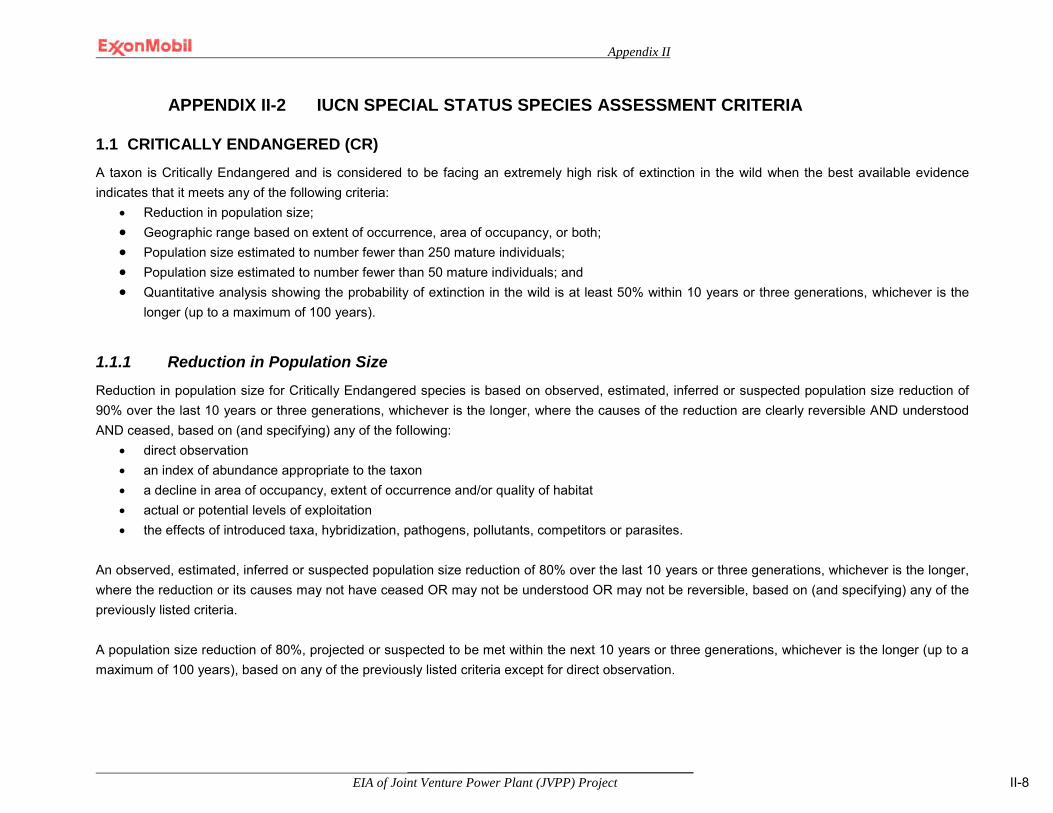
Appendix II
___________________________________________ EIA of Joint Venture Power Plant (JVPP) Project II-8
APPENDIX II-2 IUCN SPECIAL STATUS SPECIES ASSESSMENT CRITERIA 1.1 CRITICALLY ENDANGERED (CR) A taxon is Critically Endangered and is considered to be facing an extremely high risk of extinction in the wild when the best available evidence indicates that it meets any of the following criteria:
• Reduction in population size; • Geographic range based on extent of occurrence, area of occupancy, or both; • Population size estimated to number fewer than 250 mature individuals; • Population size estimated to number fewer than 50 mature individuals; and • Quantitative analysis showing the probability of extinction in the wild is at least 50% within 10 years or three generations, whichever is the
longer (up to a maximum of 100 years).
1.1.1 Reduction in Population Size Reduction in population size for Critically Endangered species is based on observed, estimated, inferred or suspected population size reduction of 90% over the last 10 years or three generations, whichever is the longer, where the causes of the reduction are clearly reversible AND understood AND ceased, based on (and specifying) any of the following:
• direct observation • an index of abundance appropriate to the taxon • a decline in area of occupancy, extent of occurrence and/or quality of habitat • actual or potential levels of exploitation • the effects of introduced taxa, hybridization, pathogens, pollutants, competitors or parasites.
An observed, estimated, inferred or suspected population size reduction of 80% over the last 10 years or three generations, whichever is the longer, where the reduction or its causes may not have ceased OR may not be understood OR may not be reversible, based on (and specifying) any of the previously listed criteria.
A population size reduction of 80%, projected or suspected to be met within the next 10 years or three generations, whichever is the longer (up to a maximum of 100 years), based on any of the previously listed criteria except for direct observation.

Appendix II
___________________________________________ EIA of Joint Venture Power Plant (JVPP) Project II-9
An observed, estimated, inferred, projected or suspected population size reduction of 80% over any 10 year or three generation period, whichever is longer (up to a maximum of 100 years in the future), where the time period must include both the past and the future, and where the reduction or its causes may not have ceased or may not be understood or may not be reversible, based on any of the previously listed criteria.
1.1.2 Geographic Range Based on Extent of Occurrence in the Area of Occupancy or Both Species are considered Critically Endangered when extent of occurrence is estimated to be less than 100 individuals per km2, with estimates indicating at least two of the following factors:
• Severely fragmented or known to exist at only a single location. • Continuing decline, observed, inferred or projected, in any of the following:
- extent of occurrence - area of occupancy - area, extent and/or quality of habitat - number of locations or subpopulations - number of mature individuals.
• Extreme fluctuations in any of the following: - extent of occurrence - area of occupancy - number of locations or subpopulations - number of mature individuals.
Species are considered Critically Endangered when area of occupancy is estimated to be less than 10 individuals per km2, with estimates indicating at least two of the following factors:
• Severely fragmented or known to exist at only a single location. • Continuing decline, observed, inferred or projected, in any of the following:
- extent of occurrence - area of occupancy - area, extent and/or quality of habitat - number of locations or subpopulations - number of mature individuals.
• Extreme fluctuations in any of the following:

Appendix II
___________________________________________ EIA of Joint Venture Power Plant (JVPP) Project II-10
- extent of occurrence - area of occupancy - number of locations or subpopulations - number of mature individuals.
1.1.3 Population Size Estimated to Number Fewer than 250 Mature Individuals This criterion refers to Critically Endangered taxon when either of the following criteria exists:
• An estimated continuing decline of at least 25% within three years or one generation, whichever is longer, (up to a maximum of 100 years in the future)
• A continuing decline, observed, projected, or inferred, in numbers of mature individuals and at least one of the following (a–b): - Population structure in the form of one of the following:
◦ no subpopulation estimated to contain more than 50 mature individuals ◦ at least 90% of mature individuals in one subpopulation
- Extreme fluctuations in number of mature individuals. 1.2 ENDANGERED (EN) A taxon is Endangered and is considered to be facing a very high risk of extinction in the wild when the best available evidence indicates that it meets any of the following criteria:
• Reduction in population size; • Geographic range based on extent of occurrence, area of occupancy, or both; • Population size estimated to number fewer than 2,500 mature individuals; • Population size estimated to number fewer than 250 mature individuals; and • Quantitative analysis showing the probability of extinction in the wild is at least 20% within 20 years or five generations, whichever is the
longer (up to a maximum of 100 years).
1.2.1 Reduction in Population Size Reduction in population size for Critically Endangered species is based on observed, estimated, inferred or suspected population size reduction of 70% over the last 10 years or three generations, whichever is the longer, where the causes of the reduction are clearly reversible and understood and ceased, based on (and specifying) any of the following:
• direct observation

Appendix II
___________________________________________ EIA of Joint Venture Power Plant (JVPP) Project II-11
• an index of abundance appropriate to the taxon • a decline in area of occupancy, extent of occurrence and/or quality of habitat • actual or potential levels of exploitation • the effects of introduced taxa, hybridization, pathogens, pollutants, competitors or parasites.
An observed, estimated, inferred or suspected population size reduction of 50% over the last 10 years or three generations, whichever is the longer, where the reduction or its causes may not have ceased or may not be understood or may not be reversible, based on (and specifying) any of the previously listed criteria. A population size reduction of ³50%, projected or suspected to be met within the next 10 years or three generations, whichever is the longer (up to a maximum of 100 years), based on (and specifying) any of the previously listed criteria except for direct observation. An observed, estimated, inferred, projected or suspected population size reduction of ³50% over any 10 year or three generation period, whichever is longer (up to a maximum of 100 years in the future), where the time period must include both the past and the future, and where the reduction or its causes may not have ceased or may not be understood or may not be reversible, based on (and specifying) any of the previously listed criteria.
1.2.2 Geographic Range Based on Extent of Occurrence in Area of Occupancy or Both: Species are considered Endangered when the extent of occurrence is estimated to be less than 5,000 individuals per km2, with estimates indicating at least two of the following factors:
• Severely fragmented or known to exist at no more than five locations. • Continuing decline, observed, inferred or projected, in any of the following:
- extent of occurrence - area of occupancy - area, extent and/or quality of habitat - number of locations or subpopulations - number of mature individuals
• Extreme fluctuations in any of the following: - extent of occurrence - area of occupancy - number of locations or subpopulations

Appendix II
___________________________________________ EIA of Joint Venture Power Plant (JVPP) Project II-12
- number of mature individuals. Species are considered Endangered when the area of occupancy is estimated to be less than 500 individuals per km2, with estimates indicating at least two of the following factors:
• Severely fragmented or known to exist at no more than five locations. • Continuing decline, observed, inferred or projected, in any of the following:
- extent of occurrence - area of occupancy - area, extent and/or quality of habitat - number of locations or subpopulations - number of mature individuals.
• Extreme fluctuations in any of the following: - extent of occurrence - area of occupancy - number of locations or subpopulations - number of mature individuals.
1.2.3 Population Size Estimated to Number Fewer than 2,500 Mature Individuals This criterion refers to Endangered taxon when either of the following criteria exist:
• An estimated continuing decline of at least 20% within five years or two generations, whichever is longer, (up to a maximum of 100 years in the future) OR
• A continuing decline, observed, projected, or inferred, in numbers of mature individuals AND at least one of the following (a–b): - Population structure in the form of one of the following:
◦ no subpopulation estimated to contain more than 250 mature individuals, OR ◦ at least 95% of mature individuals in one subpopulation.
- Extreme fluctuations in number of mature individuals.

Appendix II
___________________________________________ EIA of Joint Venture Power Plant (JVPP) Project II-13
1.3.1 VULNERABLE (VU) A taxon is Vulnerable and is considered to be facing a high risk of extinction in the wild when the best available evidence indicates that it meets any of the following criteria:
• Reduction in population size; • Geographic range based on extent of occurrence, area of occupancy, or both; • Population size estimated to number fewer than 10,000 mature individuals; • Population very small or restricted; or • Quantitative analysis showing the probability of extinction in the wild is at least 10% within 100
years.
1.3.2 Reduction in Population Size Reduction in population size for Vulnerable species is based on a n observed, estimated, inferred or suspected population size reduction of 50% over the last 10 years or three generations, whichever is the longer, where the causes of the reduction are: clearly reversible AND understood AND ceased, based on (and specifying) any of the following:
• direct observation • an index of abundance appropriate to the taxon • a decline in area of occupancy, extent of occurrence and/or quality of habitat • actual or potential levels of exploitation • the effects of introduced taxa, hybridization, pathogens, pollutants, competitors or parasites.
An observed, estimated, inferred or suspected population size reduction of 30% over the last 10 years or three generations, whichever is the longer, where the reduction or its causes may not have ceased OR may not be understood OR may not be reversible, based on (and specifying) any of the previously listed factors. A population size reduction of ³30%, projected or suspected to be met within the next 10 years or three generations, whichever is the longer (up to a maximum of 100 years), based on (and specifying) any of the previously listed factors except for direct observation. An observed, estimated, inferred, projected or suspected population size reduction of ³30% over any 10 year or three generation period, whichever is longer (up to a maximum of 100 years in the future), where the time period must include both the past and the future, and where the reduction or its causes may not have ceased OR may not be understood OR may not be reversible, based on (and specifying) any of the previously listed factors..
1.3.3 Geographic Range Based on Extent of Occurrence in the Area of Occupancy or Both Species are considered Vulnerable when the extent of occurrence is estimated to be less than 20,000 individuals per km2, with estimates indicating at least two of the following factors:
• Severely fragmented or known to exist at no more than 10 locations. • Continuing decline, observed, inferred or projected, in any of the following:
- extent of occurrence

Appendix II
___________________________________________ EIA of Joint Venture Power Plant (JVPP) Project II-14
- area of occupancy - area, extent and/or quality of habitat - number of locations or subpopulations - number of mature individuals.
• Extreme fluctuations in any of the following: - extent of occurrence - area of occupancy - number of locations or subpopulations - number of mature individuals.
Species are considered Vulnerable when the area of occupancy is estimated to be l ess than 2,000 individuals per km2, with estimates indicating at least two of the following factors:
• Severely fragmented or known to exist at no more than 10 locations. • Continuing decline, observed, inferred or projected, in any of the following:
- extent of occurrence - area of occupancy - area, extent and/or quality of habitat - number of locations or subpopulations - number of mature individuals.
• Extreme fluctuations in any of the following: - extent of occurrence - area of occupancy - number of locations or subpopulations - number of mature individuals.
1.3.3 Population Size Estimated to Number Fewer than 10,000 Mature Individuals This criterion refers to Vulnerable taxon when either of the following criteria exist:
• An estimated continuing decline of at least 10% within 10 years or three generations, whichever is longer, (up to a maximum of 100 years in the future) OR
• A continuing decline, observed, projected, or inferred, in numbers of mature individuals AND at least one of the following (a–b): - Population structure in the form of one of the following:
◦ no subpopulation estimated to contain more than 1,000 mature individuals ◦ all mature individuals are in one subpopulation.
- Extreme fluctuations in number of mature individuals.
1.3.4 Population Very Small or Restricted This criterion refers to Vulnerable taxon when either of the following criteria exist:
• Population size estimated to number fewer than 1,000 mature individuals. • Population with a very restricted area of occupancy (typically less than 20 km2) or number of
locations (typically five or fewer) such that it is prone to the effects of human activities or stochastic events within a very short time period in an uncertain future, and is thus capable of becoming Critically Endangered or even Extinct in a very short time period.

Appendix II
___________________________________________ EIA of Joint Venture Power Plant (JVPP) Project II-15
APPENDIX II-3 FLORA & FUANA IDENTIFIED IN STUBBS CREEK FOREST RESERVE
Table II-1 Species list of plants identified in the Stubbs Creek Forest Reserve (Shell RBA 2009)
Species Family Trees
Acacia polycantha Mimosaceae
Albizia adianthifolia Fabaceae
Albizia ferruginae Fabaceae
Albizia zygia Fabaceae
Alstonia boonei Apocynaceae
Anthocleista djalonensis Loganiaceae
Avicennia germinans Avicenniaceae
Bridelia stenocarpa Euphorbiaceae
Cleistopholis patens Annonaceae
Dacryoides edulis Burseraceae
Elaeis guinensis Arecaceae
Ficus Moraceae
Funtumia elastica Apocynaceae
Gmelina arborea Verbernaceae
Irvingia gabonensis Ixonanthaceae
Laguncularia racemosa Combretaceae
Mangifera indica Anacardiaceae
Mitragyna ciliata Rubiaceae
Musanga cercropioides Cecropiaceae
Nauclea diderichii Rubiaceae
Nypa fruticans Aracacaea
Pentaclethra macrophyla Mimosaceae
Picralima nitida Apocynaceae
R. pheonix Arecaceae
R. reclinata Arecaceae
Raphia hookeri Arecaceae

Appendix II
___________________________________________ EIA of Joint Venture Power Plant (JVPP) Project II-16
Table II-1 Species list of plants identified in the Stubbs Creek Forest Reserve (Shell RBA 2009) (continued)
Species Family Trees
Rhizophora racemosa Rhizophoraceae
Senna alata Fabaceae
Spondias mombin Anacardiaceae
Symphonia globulifera Hypericaceae
Tabernaemontana pachyisphon Apocynaceae
Tectona grandis Verbernaceae
Terminalia catappa Combretaceae
Terminalia superba Combretaceae
Uapaca spp. Euphorbiaceae
Vaocanga africana Apocynaceae
Shrubs
Afzelia africana Fabaceae
Alchornea cordifolia Euphorbiaceae
Alchornea laxiflora Euphorbiaceae
Anthonata macrophyla Caesalpiniaceae
Bambusa vulgaris Poaceae
Baphia nitida Fabaceae
Bridelia micrantha Euphorbiaceae
Calamus rotang Arecaceae
Cnestis ferruginea Connaraceae
Costus lucanusianus Costaceae
Dalbergia hostilis Fabaceae
Dalium guinensis Caesalpiniaceae
Erythrina senegalensis Papilionaceae
Glyphoea brevis Tiliaceae
Harungana madagascariensis Hypericaceae
Landolphia dulcis Apocynaceae

Appendix II
___________________________________________ EIA of Joint Venture Power Plant (JVPP) Project II-17
Species Family Maniophyton fulvum Euphorbiaceae
Table II-1 Species list of plants identified in the Stubbs Creek Forest Reserve (Shell RBA 2009) (continued)
Species Family Shrubs
Pandanus candelabrum Pandanaceae
Psittacanthus robustus (mistletoe) Loranthaceae
Rauvolfia vomitoria Apocynaceae
Syzygium aromaticum Myrataceae
Theobroma cacao Sterculiaceae
Herbs
Afromomum melegueta Zingiberaceae
Ananas comosus Bromeliaceae
Anchomanes difformis Araceae
Cannabis sativa Cannabaceae
Chromolaena odorata Asteraceae
Clappertonia filicifolia Tiliaceae
Colocasia esculentum Araceae
Costus afer Costaceae
Crinium natans Amaryllidaceae
Culcasia scandens Araceae
Diodia scandens Rubiaceae
Dryopteris Spp. Dryopteridaceae
Emilia sonchifolia Asteraceae
Ipomoea involucrata Convolvulaceae
Musa paradisiaca Musaceae
Palisota hirsuta Commelinaceae
Pteridium Spp. Dennstaedtiaceae
Pteris Spp. Pteridaceae
Smilax kraussiana Smilaceae
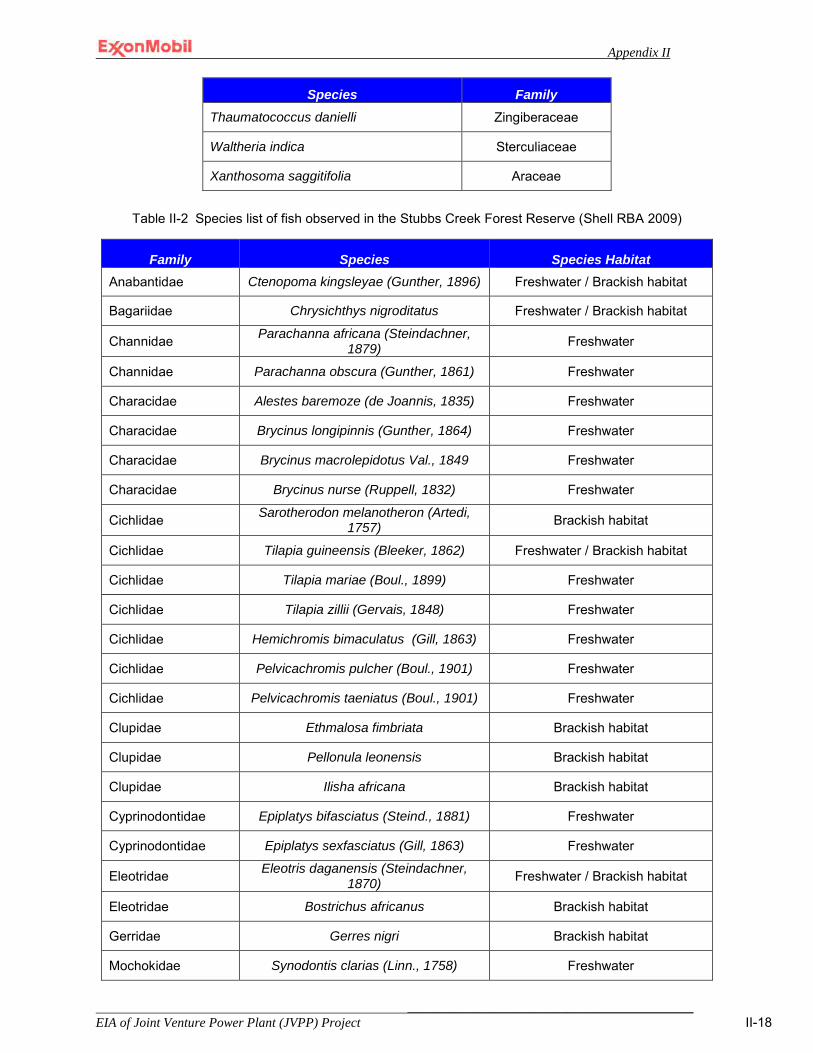
Appendix II
___________________________________________ EIA of Joint Venture Power Plant (JVPP) Project II-18
Species Family Thaumatococcus danielli Zingiberaceae
Waltheria indica Sterculiaceae
Xanthosoma saggitifolia Araceae
Table II-2 Species list of fish observed in the Stubbs Creek Forest Reserve (Shell RBA 2009)
Family Species Species Habitat Anabantidae Ctenopoma kingsleyae (Gunther, 1896) Freshwater / Brackish habitat
Bagariidae Chrysichthys nigroditatus Freshwater / Brackish habitat
Channidae Parachanna africana (Steindachner, 1879) Freshwater
Channidae Parachanna obscura (Gunther, 1861) Freshwater
Characidae Alestes baremoze (de Joannis, 1835) Freshwater
Characidae Brycinus longipinnis (Gunther, 1864) Freshwater
Characidae Brycinus macrolepidotus Val., 1849 Freshwater
Characidae Brycinus nurse (Ruppell, 1832) Freshwater
Cichlidae Sarotherodon melanotheron (Artedi, 1757) Brackish habitat
Cichlidae Tilapia guineensis (Bleeker, 1862) Freshwater / Brackish habitat
Cichlidae Tilapia mariae (Boul., 1899) Freshwater
Cichlidae Tilapia zillii (Gervais, 1848) Freshwater
Cichlidae Hemichromis bimaculatus (Gill, 1863) Freshwater
Cichlidae Pelvicachromis pulcher (Boul., 1901) Freshwater
Cichlidae Pelvicachromis taeniatus (Boul., 1901) Freshwater
Clupidae Ethmalosa fimbriata Brackish habitat
Clupidae Pellonula leonensis Brackish habitat
Clupidae Ilisha africana Brackish habitat
Cyprinodontidae Epiplatys bifasciatus (Steind., 1881) Freshwater
Cyprinodontidae Epiplatys sexfasciatus (Gill, 1863) Freshwater
Eleotridae Eleotris daganensis (Steindachner, 1870) Freshwater / Brackish habitat
Eleotridae Bostrichus africanus Brackish habitat
Gerridae Gerres nigri Brackish habitat
Mochokidae Synodontis clarias (Linn., 1758) Freshwater
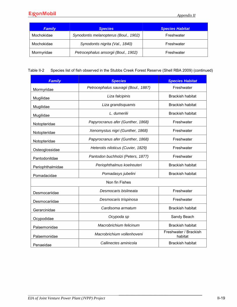
Appendix II
___________________________________________ EIA of Joint Venture Power Plant (JVPP) Project II-19
Family Species Species Habitat Mochokidae Synodontis melanopterus (Boul., 1902) Freshwater
Mochokidae Synodontis nigrita (Val., 1840) Freshwater
Mormyridae Petrocephalus ansorgii (Boul., 1902) Freshwater
Table II-2 Species list of fish observed in the Stubbs Creek Forest Reserve (Shell RBA 2009) (continued)
Family Species Species Habitat
Mormyridae Petrocephalus sauvagii (Boul., 1887) Freshwater
Mugilidae Liza falcipinis Brackish habitat
Mugilidae Liza grandisquamis Brackish habitat
Mugilidae L. dumerilii Brackish habitat
Notopteridae Papyrocranus afer (Gunther, 1868) Freshwater
Notopteridae Xenomystus nigri (Gunther, 1868) Freshwater
Notopteridae Papyrocranus afer (Gunther, 1868) Freshwater
Osteoglossidae Heterotis niloticus (Cuvier, 1829) Freshwater
Pantodonitdae Pantodon buchholzi (Peters, 1877) Freshwater
Periophthalmidae Periophthalmus koelreuteri Brackish habitat
Pomadacidae Pomadasys jubelini Brackish habitat
Non fin Fishes
Desmocariidae Desmocaris bislineata Freshwater
Desmocariidae Desmocaris trispinosa Freshwater
Gerarcinidae Cardisoma armatum Brackish habitat
Ocypodidae Ocypoda sp Sandy Beach
Palaemonidae Macrobrichium felicinum Brackish habitat
Palaemonidae Macrobrichium vollenhoveni Freshwater / Brackish habitat
Penaeidae Callinectes aminicola Brackish habitat

Appendix II
___________________________________________ EIA of Joint Venture Power Plant (JVPP) Project II-20
Table II-3 Species list of amphibians observed in the Stubbs Creek Forest Reserve (Shell RBA 2009)
Common name Scientific name Remarks Ranidae
Galam white-lipped frog Ptychadena sp. Rana galamensis
Habitats include tropical forests; swamps; seasonal freshwater marshes, gardens and degraded forests.
African reed frog Xenopus laevis Hyperolius sp.
Popular laboratory animal used as models for gene and protein expression studies.
Bufonidae Common African toad Bufo regularis Flat-backed Toad Bufo maculatus
Rhachophoridae African foam-nest Tree Frog
Chiromantis rufescens Eggs laid in foam nest above water
Table II-4 Species list of reptiles observed in the Stubbs Creek Forest Reserve (Shell RBA 2009)
Common name Scientific name Remarks Crocodilidae
West African dwarf crocodile
Osteolaemus tetraspis A species with distribution ranging from west Africa to the Great Lakes region of Africa. Listed as appendix 1 species in CITES. Hunting and trading in it is prohibited under CITES.
Nile crocodile Crocodylus frontatus Endangered per CITES Long-snouted crocodile Mecistops cataphractus Endangered per CITES
Boidae Rock python Python sebae An endangered species. Hunted for the leather
and bush meat trade. Royal python Python regius And endangered species. Hunted for the leather
and bushmeat trade. Black neck spitting cobra Naja nigricollis A venomous snake
Colubridae Forest sand snake Psammophis phillipsi Grayia’s water snake Grayia sp.
Varanidae Nile monitor Varanus niloticus An endangered species. Skin is avidly sought
after for the leather industry Agamidae
Common rainbow lizard Agama agama Scincidae
Five-lined skink Mabuya quinquetaeniata A common skink. Forest mabuya M. maculilabris
Trionichlidae Flat-shelled turtle Cyclanorbis sp.
Pelomedusidae West Africa mud turtle Pelusios spp. Flap shelled turtle Cyclanorbis sp.
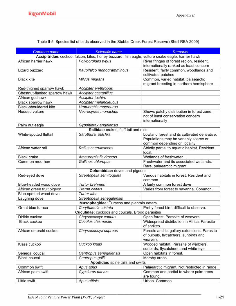
Appendix II
___________________________________________ EIA of Joint Venture Power Plant (JVPP) Project II-21
Table II-5 Species list of birds observed in the Stubbs Creek Forest Reserve (Shell RBA 2009)
Common name Scientific name Remarks Accipitridae: cuckoo, falcon, kites, honey buzzard, fish eagle, vulture snake eagle, harrier hawk
African harrier hawk Polyboroides typus River fringes of forest region, resident, internationally ranked as least concern
Lizard buzzard Kaupifalco monogrammincus Resident, fairly common, woodlands and cultivated patches
Black kite Milvus migrans Common, varied habitat, palaearctic migrant breeding in northern hemisphere
Red-thighed sparrow hawk Accipiter erythropus Chestnut-flanked sparrow hawk Accipiter castanilius African goshawk Accipiter tachiro Black sparrow hawk Accipiter melanoleucus Black-shouldered kite Urotriorchis macrourus Hooded vulture Necrosyrtes monachus Shows patchy distribution in forest zone,
not of least conservation concern internationally
Palm nut eagle Gypohierax angolensis Rallidae: crakes, fluff tail and rails
White-spotted fluftail Sarothura pulchra Lowland forest and its cultivated derivative. Populations may be variably scarce or common depending on locality
African water rail Rallus caerulescens Strictly partial to aquatic habitat. Resident local.
Black crake Amaurornis flavirostris Wetlands of freshwater Common moorhen Gallinus chloropus Freshwater and its associated wetlands.
Rare, palaearctic migrant Columbidae: doves and pigeons
Red-eyed dove Streptopelia semitoquata Various habitats in forest. Resident and common
Blue-headed wood dove Turtur brehmeri A fairly common forest dove African green fruit pigeon Treron calvus Varies from forest to savanna. Common. Blue-spotted wood dove Turtur afer Laughing dove Streptopelia senegalensis
Musophagidae: Turacos and plantain eaters Great blue turaco Corythaeola cristata Pretty forest bird, difficult to observe.
Cuculidae: cuckoos and coucals. Brood parasites Didiric cuckoo Chrysococcyx caprius Open forest. Parasite of weavers. Black cuckoo Cuculus clasmosus Widespread distribution in Africa. Parasite
of shrikes. African emerald cuckoo Chrysocoocyx cupreus Forests and its gallery extensions. Parasite
of bulbuls, flycatchers, sunbirds and weavers
Klass cuckoo Cuckoo klaas Wooded habitat. Parasite of warblers, sunbirds, flycatchers, and white-eye
Senegal coucal Centropus senegalensis Open habitats in forest. Black coucal Centropus grillii Marshy areas.
Apodidae: spine tails and swifts Common swift Apus apus Palaearctic migrant. Not restricted in range African palm swift Cypsiurus parvus Common and partial to where palm trees
are found. Little swift Apus affinis Urban. Common
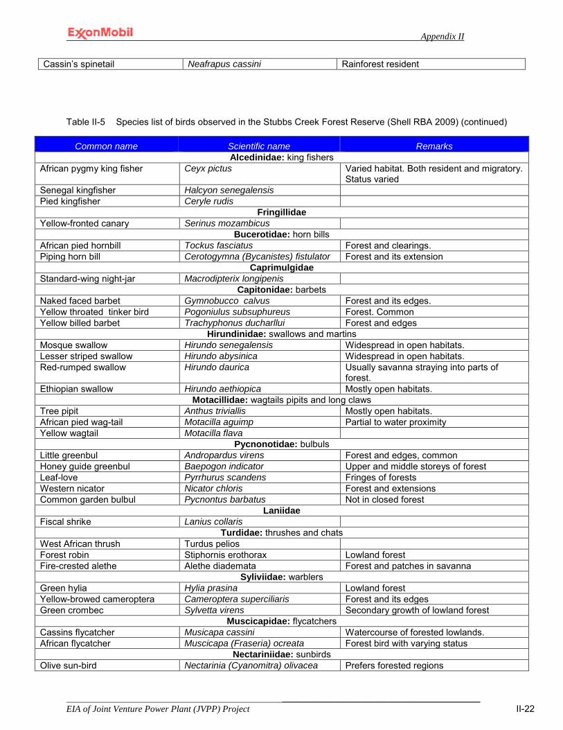
Appendix II
___________________________________________ EIA of Joint Venture Power Plant (JVPP) Project II-22
Cassin’s spinetail Neafrapus cassini Rainforest resident
Table II-5 Species list of birds observed in the Stubbs Creek Forest Reserve (Shell RBA 2009) (continued)
Common name Scientific name Remarks Alcedinidae: king fishers
African pygmy king fisher Ceyx pictus Varied habitat. Both resident and migratory. Status varied
Senegal kingfisher Halcyon senegalensis Pied kingfisher Ceryle rudis
Fringillidae Yellow-fronted canary Serinus mozambicus
Bucerotidae: horn bills African pied hornbill Tockus fasciatus Forest and clearings. Piping horn bill Cerotogymna (Bycanistes) fistulator Forest and its extension
Caprimulgidae Standard-wing night-jar Macrodipterix longipenis
Capitonidae: barbets Naked faced barbet Gymnobucco calvus Forest and its edges. Yellow throated tinker bird Pogoniulus subsuphureus Forest. Common Yellow billed barbet Trachyphonus ducharllui Forest and edges
Hirundinidae: swallows and martins Mosque swallow Hirundo senegalensis Widespread in open habitats. Lesser striped swallow Hirundo abysinica Widespread in open habitats. Red-rumped swallow Hirundo daurica Usually savanna straying into parts of
forest. Ethiopian swallow Hirundo aethiopica Mostly open habitats.
Motacillidae: wagtails pipits and long claws Tree pipit Anthus triviallis Mostly open habitats. African pied wag-tail Motacilla aguimp Partial to water proximity Yellow wagtail Motacilla flava
Pycnonotidae: bulbuls Little greenbul Andropardus virens Forest and edges, common Honey guide greenbul Baepogon indicator Upper and middle storeys of forest Leaf-love Pyrrhurus scandens Fringes of forests Western nicator Nicator chloris Forest and extensions Common garden bulbul Pycnontus barbatus Not in closed forest
Laniidae Fiscal shrike Lanius collaris
Turdidae: thrushes and chats West African thrush Turdus pelios Forest robin Stiphornis erothorax Lowland forest Fire-crested alethe Alethe diademata Forest and patches in savanna
Syliviidae: warblers Green hylia Hylia prasina Lowland forest Yellow-browed cameroptera Cameroptera superciliaris Forest and its edges Green crombec Sylvetta virens Secondary growth of lowland forest
Muscicapidae: flycatchers Cassins flycatcher Musicapa cassini Watercourse of forested lowlands. African flycatcher Muscicapa (Fraseria) ocreata Forest bird with varying status
Nectariniidae: sunbirds Olive sun-bird Nectarinia (Cyanomitra) olivacea Prefers forested regions

Appendix II
___________________________________________ EIA of Joint Venture Power Plant (JVPP) Project II-23
Olive-bellied sunbird Nectarinia (Cinnyris) chloropygia Versatile forest bird inhabiting clearings, edges and ct
Green-headed sun-bird Nectarinia verticalis Forest and extensions Collared sun-bird Anthrepyes (Hedydipna) collaris Forest and its degrade derivatives Copper sun-bird Nectarinia curpea Forest Variable sun-bird Nectarinia venusta Various coastal forest patches
Table II-5 Species list of birds observed in the Stubbs Creek Forest Reserve (Shell RBA 2009) (continued)
Common name Scientific name Remarks Dicruridae: drongos
Shining drongo Dicrurus atripennis Forest bird. Resident, variably common or uncommon
Square-tailed drongo Dicrurus ludwigii Bird of secondary growth or edge. Not commonly encountered.
Corvidae: crows magpies and ravens Pied crow Corvus albus Urban and ubiquitous
Oriolidae: orioles Black-headed oriole Oriolus brachyrhynchus Lowland forest fairly common
Passeridae: sparrows Grey-headed sparrow Passer griseus Urban
Ploceidae: typical weavers Village weaver Ploceus cucullatus Common, colonial, destroys economic
trees Yellow-mantled weaver Colliuspasser macrourus
Estrillidae: estrildids finches Bronze manikin Lonchura (Spermetes) cuculatus Varied Black-and-white manikin Lonchura (Spermetes) bicolar Grassy habitat
Viduidae: indigo birds and whydahs Pin-tailed whydah Vidua macroura Sub-saharan breeder

Appendix II
___________________________________________ EIA of Joint Venture Power Plant (JVPP) Project II-24
Table II-6 Species list of mammals observed in the Stubbs Creek Forest Reserve (Shell RBA 2009)
Common name Scientific Remarks
Pholidota: scaly ant eaters Tree pangolin (Long-tailed pangolin)
Uromanis (Manis) tetradactyla Listed as an endangered species in Nigeria. There are possibly two species of scaly ant-eaters in the SCFR. U. Tetradactyla is small, black-faced with very long prehensile tail. It is a resident of permanent rivers and wide spread from Senegal to Angola. Its typical habitat is riverine swamp forest. Lives in holes in trees or abandoned insect nests.
Tree pangolin Phataginus (Manis) tricuspis Listed as an endangered species in Nigeria. An arboreal, small pangolin whose scales are serrated with three cusps. Habitat is rain forest and particularly secondary forest growth. Heavily hunted for bushmeat trade and use in folk traditional medical practices as charm.
Rodentia: rats, squirrels, flying squirrels, porcupines etc Fire-footed rope squirrel Funisciurus pyrropus Partial to areas with abundant palm. Hunted for food and bushmeat. Red-cheeked rope squirrel Funisciurus leucogenys Partial to forest floor, common Giant forest squirrel Protoxerus strangeri Partial to swamp with tall tree. Hunted for food and bushmeat. Regarded as
least concern in IUCN list because of presence in several protected areas in its wide-spread range
Gambian sun squirrel Heliosciurus gambianus Wide-ranging forests in sub-Saharan Africa. Hunted for food and bush meat. Red-legged sun squirrel Heliosciurus rufobrachium Widespread, probably preferring palm-containing areas. Green squirrel Paraxerus poensis Partial to forest fringes and where oil palm trees are dominant Tree squirrel Xerus erythropus
Palm squirrel Hunted for food and bushmeat Grass mouse Lemniscomys barbatus Ground squirrel Funisciurus sp
Hystricidae: the distinction between the crested and ‘non-crested’ porcupines was very evident Crested porcupine Hystrix cristata Distinguished by prominent crest made of spiny hairs from head to shoulders
along its back. Though found along forest margins, typical habitat is rocky landscape.
Brush-tailed porcupine Atherurus africana Though population in its range may not be in danger, it is avidly sought after as a priced item in the bush meat trade.
Thryonomidae: cane rats Marsh cane- rat (cutting grass, grass-cutter)
Thryonomis swinderianus Species is focus of current efforts at domestication of bushmeat to alleviate pressure from wild sources. Heavily hunted in its range all over much of Africa. Prolific rate of reproduction is saving grace.

Appendix II
___________________________________________ EIA of Joint Venture Power Plant (JVPP) Project II-25
Table II-6 Species list of mammals observed in the Stubbs Creek Forest Reserve (Shell RBA 2009) (continued)
Common name Scientific Remarks Cricetidae: larger (pouched) rats
Giant rat Cricetomys gambianus Strictly nocturnal. One was trapped. Quite common and avidly hunted for the bush-meat market
Anomaluridae: slender bodied, with membrane which permits gliding flight Lord Derby’s Anomalurus derbianus Hunted for food and bushmeat. Habitat is moist forest. Alteration of forest
structure which accompanies logging is a threat to its populations Beecroft’s Anomulare Anomalurus beecrofti Population widespread but declining. Hunted for bushmeat trade
Leporidae: hares Scrub hare Lepus saxatilis (syn: crawshayi) Secondary growth and cultivation mosaic. Hunted for bushmeat.
Primata: old world monkeys and apes Hominidae: chimpanzees, gorillas
Chimpanzee Pan troglodytes Heavily hunted and conflicts occur with humans. Classified as endangered nationally and by IUCN
Cercopithecoidea: African monkeys Red-capped mangabey Cercocebus torquatos. Listed as appendix 2 in CITES, Vulnerable in IUCN classification and B under
African Convention, it is heavily hunted for meat. Partial to swamps Sclater’s guenon Cercopithecus sclateri Vulnerable/ Endangered Greater white-nosed (Putty-nosed) monkey
Cercopithecus nictitans Forest dweller
Mona monkey Cercopithecus mona Forested swamps and gallery extensions. Heavily hunted for bush meat. Loridae: woolly-coated, arboreal, monkey-like hands. Commonly called bush babies
Demidoff’s (dwarf) galago Galgoides demidoff Dense secondary forest. Hunted for folk medicine Bossman’s potto Perodoctus potto Lowland and secondary forest
Carnivora: flesh eating mammals African Civet Civettictis Viverra civetta Forest, its mosaic and marshy extensions. Heavily hunted Blotched genet Genetta tigrina
(maculata) Wide ranging through Africa.
African palm civet Nandina binotata Forest and surrounding mosaic. Hunted Blotched genet Genetta tigrina Riverine and secondary forest. Heavily hunted Sevaline genet Genetta servalina Lowland and mountain forests. Heavily hunted Spotted-necked clawless otter Lutra maculicolis Marshes and associated territory. Destroys fish nets and gets entangled.
Environmental deterioration is a major factor affecting population. Cusimanse mongoose Crossarchus obscurus Mash mongoose Atilax paludinosa

Appendix II
___________________________________________ EIA of Joint Venture Power Plant (JVPP) Project II-26
Table II-6 Species list of mammals observed in the Stubbs Creek Forest Reserve (Shell RBA 2009) (continued)
Common name Scientific Remarks
Chiroptera Yellow house bat
Scotophilus dinganii
Hammerheaded fruit bat Hypsignathus monstrosus Veldkamp’s fruit bat Nanonycteris veldkampi
Sirennia: sea cow, wholly aquatic Manatee Trichechus senegalensis A family group of three individuals swam through the edge of the Ethiope
bordering on the Turf in early May 2008. Species is endangered globally throughout its range. Classified as vulnerable* by IUCN, and a national Appendix 1 in Endangered Species Act.
Artiodactyla: even-toed ungulates Bush pig Potamochoerus porcus An important bush-meat species, the pig is avidly hunted. Conflicts between
chimpanzees and farmers as a crop raider are well established. Population under pressure seriously. Its occurrence in the Turf is a positive value.
Bush buck Tragelaphus scriptus Prominent in bush meat trade, under heavy hunting in Nigeria as a priced item.
Sitatunga or marshbuck Tragelaphus spekii Distinctive white spots distinguish this marsh dwelling, amphibious antelope. Tragulidae: deer-like antelopes
Water Chevrotain Hyemoschus aquaticus Species suffering from dwindling habitat and bush meat trade. Solitary and secretive their presence difficult to ascertain.
Grey duiker Sylvicapra grimmia An important item in the bush meat trade Maxwell’s duiker
Cephalophus dorsalis
Tree hyrax Dendtohyrax arborea
Data in Table II-1 – Table II-6 are provided by the “Report on the Rapid Biodiversity Assessment of the Stubbs Creek Forest Reserve; Aka Ibom State, Nigeria; February 2009 sponsored by the Shell Oil Company.
Appendix II
___________________________________________ EIA of Joint Venture Power Plant (JVPP) Project II-27
Appendix II-4 Baseline Characterization Data
The data in this appendix is presented exactly as reported by the EIA contractor. As an example, the number of significant figures presented in the data sheets is shown exactly how it was reported by the contractor. In reviewing and assessing these data, it was not possible to calculate the field and laboratory precision and accuracy of the reported values or assess any of the data against the PARCC1 parameters due to a lack of information regarding the field and analytical Standard Operating Procedures followed by the contractor. However, this data is being presented because it offers the best information available regarding the existing environmental characteristics of the site. Also, none of these data were used to assess the significance of an impact. Significance threshold was determined based on exceedance of a threshold as defined in the Policy, Legal and Administrative chapter of this document or where such thresholds were not defined, they were developed. The reader will find the criteria for threshold development, where applicable, in the Impacts and Mitigation chapter of this document.
1 PARCC Parameters- Use of the PARCC parameters as indicators of data quality as been promoted by the USEPA guidance documents. The PARCC acronym stands for the Precision, Accuracy, Representativeness, Completeness and Comparability.
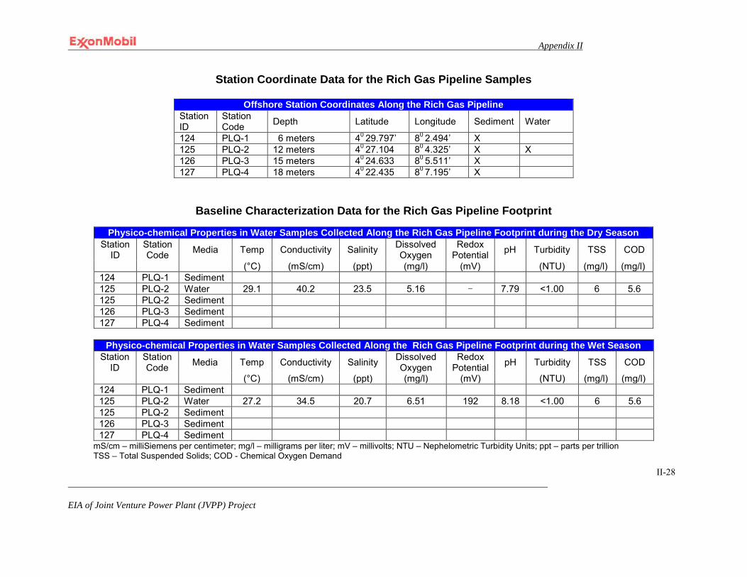
Appendix II
EIA of Joint Venture Power Plant (JVPP) Project
II-28
Station Coordinate Data for the Rich Gas Pipeline Samples
Offshore Station Coordinates Along the Rich Gas Pipeline
Station ID
Station Code Depth Latitude Longitude Sediment Water
124 PLQ-1 6 meters 40 29.797’ 80 2.494’ X 125 PLQ-2 12 meters 40 27.104 80 4.325’ X X 126 PLQ-3 15 meters 40 24.633 80 5.511’ X 127 PLQ-4 18 meters 40 22.435 80 7.195’ X
Baseline Characterization Data for the Rich Gas Pipeline Footprint
Physico-chemical Properties in Water Samples Collected Along the Rich Gas Pipeline Footprint during the Dry Season Station
ID Station Code Media Temp Conductivity Salinity Dissolved
Oxygen Redox
Potential pH Turbidity TSS COD
(°C) (mS/cm) (ppt) (mg/l) (mV) (NTU) (mg/l) (mg/l) 124 PLQ-1 Sediment 125 PLQ-2 Water 29.1 40.2 23.5 5.16 - 7.79 <1.00 6 5.6 125 PLQ-2 Sediment 126 PLQ-3 Sediment 127 PLQ-4 Sediment
Physico-chemical Properties in Water Samples Collected Along the Rich Gas Pipeline Footprint during the Wet Season
Station ID
Station Code Media Temp Conductivity Salinity Dissolved
Oxygen Redox
Potential pH Turbidity TSS COD
(°C) (mS/cm) (ppt) (mg/l) (mV) (NTU) (mg/l) (mg/l) 124 PLQ-1 Sediment 125 PLQ-2 Water 27.2 34.5 20.7 6.51 192 8.18 <1.00 6 5.6 125 PLQ-2 Sediment 126 PLQ-3 Sediment 127 PLQ-4 Sediment
mS/cm – milliSiemens per centimeter; mg/l – milligrams per liter; mV – millivolts; NTU – Nephelometric Turbidity Units; ppt – parts per trillion TSS – Total Suspended Solids; COD - Chemical Oxygen Demand
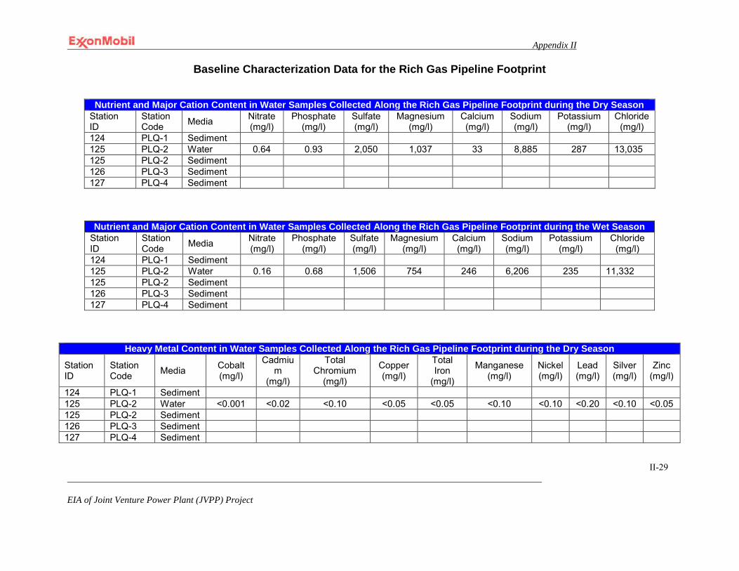
Appendix II
EIA of Joint Venture Power Plant (JVPP) Project
II-29
Baseline Characterization Data for the Rich Gas Pipeline Footprint
Nutrient and Major Cation Content in Water Samples Collected Along the Rich Gas Pipeline Footprint during the Dry Season Station ID
Station Code Media Nitrate
(mg/l) Phosphate
(mg/l) Sulfate (mg/l)
Magnesium (mg/l)
Calcium (mg/l)
Sodium (mg/l)
Potassium (mg/l)
Chloride (mg/l)
124 PLQ-1 Sediment 125 PLQ-2 Water 0.64 0.93 2,050 1,037 33 8,885 287 13,035 125 PLQ-2 Sediment 126 PLQ-3 Sediment 127 PLQ-4 Sediment
Nutrient and Major Cation Content in Water Samples Collected Along the Rich Gas Pipeline Footprint during the Wet Season Station ID
Station Code Media Nitrate
(mg/l) Phosphate
(mg/l) Sulfate (mg/l)
Magnesium (mg/l)
Calcium (mg/l)
Sodium (mg/l)
Potassium (mg/l)
Chloride (mg/l)
124 PLQ-1 Sediment 125 PLQ-2 Water 0.16 0.68 1,506 754 246 6,206 235 11,332 125 PLQ-2 Sediment 126 PLQ-3 Sediment 127 PLQ-4 Sediment
Heavy Metal Content in Water Samples Collected Along the Rich Gas Pipeline Footprint during the Dry Season
Station ID
Station Code Media Cobalt
(mg/l)
Cadmium
(mg/l)
Total Chromium
(mg/l)
Copper (mg/l)
Total Iron
(mg/l)
Manganese (mg/l)
Nickel (mg/l)
Lead (mg/l)
Silver (mg/l)
Zinc (mg/l)
124 PLQ-1 Sediment 125 PLQ-2 Water <0.001 <0.02 <0.10 <0.05 <0.05 <0.10 <0.10 <0.20 <0.10 <0.05 125 PLQ-2 Sediment 126 PLQ-3 Sediment 127 PLQ-4 Sediment
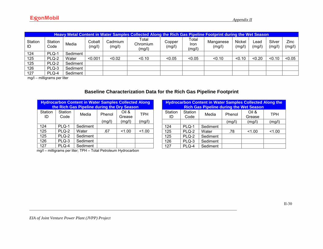
Appendix II
EIA of Joint Venture Power Plant (JVPP) Project
II-30
Heavy Metal Content in Water Samples Collected Along the Rich Gas Pipeline Footprint during the Wet Season
Station ID
Station Code Media Cobalt
(mg/l) Cadmium
(mg/l)
Total Chromium
(mg/l)
Copper (mg/l)
Total Iron
(mg/l)
Manganese (mg/l)
Nickel (mg/l)
Lead (mg/l)
Silver (mg/l)
Zinc (mg/l)
124 PLQ-1 Sediment 125 PLQ-2 Water <0.001 <0.02 <0.10 <0.05 <0.05 <0.10 <0.10 <0.20 <0.10 <0.05 125 PLQ-2 Sediment 126 PLQ-3 Sediment 127 PLQ-4 Sediment mg/l – milligrams per liter
Baseline Characterization Data for the Rich Gas Pipeline Footprint
mg/l – milligrams per liter; TPH – Total Petroleum Hydrocarbon
Hydrocarbon Content in Water Samples Collected Along the Rich Gas Pipeline during the Wet Season
Station ID
Station Code Media Phenol Oil &
Grease TPH
(mg/l) (mg/l) (mg/l) 124 PLQ-1 Sediment 125 PLQ-2 Water .78 <1.00 <1.00 125 PLQ-2 Sediment 126 PLQ-3 Sediment 127 PLQ-4 Sediment
Hydrocarbon Content in Water Samples Collected Along the Rich Gas Pipeline during the Dry Season
Station ID
Station Code Media Phenol Oil &
Grease TPH
(mg/l) (mg/l) (mg/l) 124 PLQ-1 Sediment 125 PLQ-2 Water .67 <1.00 <1.00 125 PLQ-2 Sediment 126 PLQ-3 Sediment 127 PLQ-4 Sediment
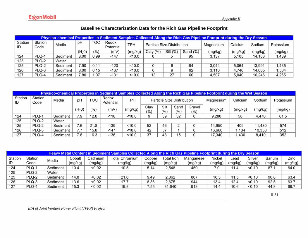
Appendix II
EIA of Joint Venture Power Plant (JVPP) Project
II-31
Baseline Characterization Data for the Rich Gas Pipeline Footprint
Physico-chemical Properties in Sediment Samples Collected Along the Rich Gas Pipeline Footprint during the Dry Season Station ID
Station Code Media pH
TOC
Redox Potential TPH Particle Size Distribution Magnesium Calcium Sodium Potassium
(H20) (%) (mV) (mg/kg) Clay (%) Silt (%) Sand (%) (mg/kg) (mg/kg) (mg/kg) (mg/kg) 124 PLQ-1 Sediment 8.00 0.99 -147 <10.0 0 5 95 3,137 5,105 14,163 1,439 125 PLQ-2 Water 125 PLQ-2 Sediment 7.90 0.11 -120 <10.0 0 6 94 3,044 5,064 13,991 1,435 126 PLQ-3 Sediment 8.00 0.15 -167 <10.0 0 9 92 3,110 4,746 14,005 1,504 127 PLQ-4 Sediment 7.80 1.07 -131 <10.0 13 27 60 4,507 5,040 16,246 4,265
Physico-chemical Properties in Sediment Samples Collected Along the Rich Gas Pipeline Footprint during the Wet Season Station ID
Station Code Media pH TOC Redox
Potential TPH Particle Size Distribution Magnesium Calcium Sodium Potassium
(H20) (%) (mV) (mg/kg) Clay (%)
Silt (%)
Sand (%)
Gravel (%) (mg/kg) (mg/kg) (mg/kg) (mg/kg)
124 PLQ-1 Sediment 7.9 12.0 -118 <10.0 9 59 32 0 9,280 58 4,470 61.5 125 PLQ-2 Water 125 PLQ-2 Sediment 7.6 21.8 -139 <10.0 52 46 2 0 14,950 409 11,480 574 126 PLQ-3 Sediment 7.7 15.8 -147 <10.0 42 57 1 0 16,660 1,134 10,350 512 127 PLQ-4 Sediment 7.8 16.3 -136 <10.0 37 48 15 0 17,340 1,430 8,410 352
Heavy Metal Content in Sediment Samples Collected Along the Rich Gas Pipeline Footprint during the Dry Season Station ID
Station Code Media Cobalt
(mg/kg) Cadmium (mg/kg)
Total Chromium (mg/kg)
Copper (mg/kg)
Total Iron (mg/kg)
Manganese (mg/kg)
Nickel (mg/kg)
Lead (mg/kg)
Silver (mg/kg)
Barium (mg/kg)
Zinc (mg/kg)
124 PLQ-1 Sediment 10.4 <0.02 10.5 5.14 2,548 459 7.0 11.4 <0.10 87.1 64.0 125 PLQ-2 Water 125 PLQ-2 Sediment 14.8 <0.02 21.6 9.49 2,362 807 16.3 11.5 <0.10 90.8 63.4 126 PLQ-3 Sediment 13.6 <0.02 17.7 8.36 2,675 944 13.4 12.4 <0.10 92.5 63.7 127 PLQ-4 Sediment 15.3 <0.02 19.8 7.55 31,640 913 14.4 10.6 <0.10 44.8 66.7
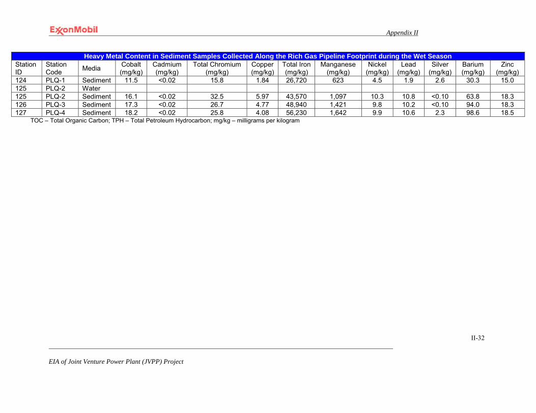
Appendix II
EIA of Joint Venture Power Plant (JVPP) Project
II-32
Heavy Metal Content in Sediment Samples Collected Along the Rich Gas Pipeline Footprint during the Wet Season
Station ID
Station Code Media Cobalt
(mg/kg) Cadmium (mg/kg)
Total Chromium (mg/kg)
Copper (mg/kg)
Total Iron (mg/kg)
Manganese (mg/kg)
Nickel (mg/kg)
Lead (mg/kg)
Silver (mg/kg)
Barium (mg/kg)
Zinc (mg/kg)
124 PLQ-1 Sediment 11.5 <0.02 15.8 1.84 26,720 623 4.5 1.9 2.6 30.3 15.0 125 PLQ-2 Water 125 PLQ-2 Sediment 16.1 <0.02 32.5 5.97 43,570 1,097 10.3 10.8 <0.10 63.8 18.3 126 PLQ-3 Sediment 17.3 <0.02 26.7 4.77 48,940 1,421 9.8 10.2 <0.10 94.0 18.3 127 PLQ-4 Sediment 18.2 <0.02 25.8 4.08 56,230 1,642 9.9 10.6 2.3 98.6 18.5
TOC – Total Organic Carbon; TPH – Total Petroleum Hydrocarbon; mg/kg – milligrams per kilogram
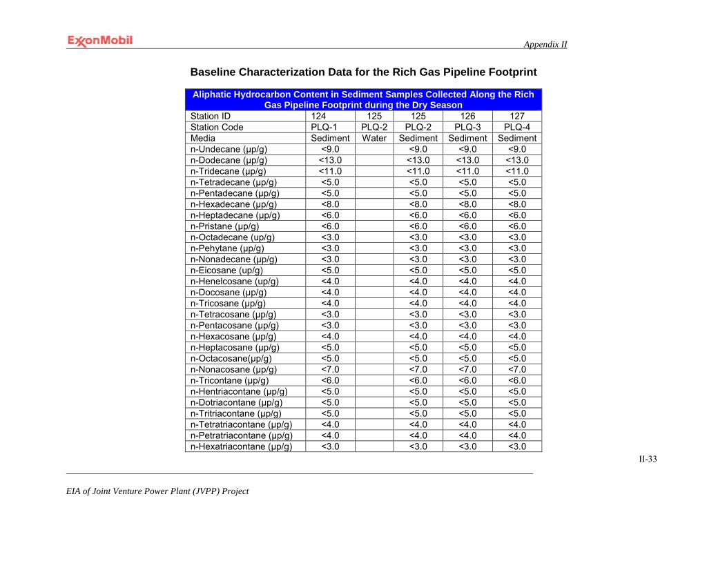
Appendix II
EIA of Joint Venture Power Plant (JVPP) Project
II-33
Baseline Characterization Data for the Rich Gas Pipeline Footprint
Aliphatic Hydrocarbon Content in Sediment Samples Collected Along the Rich Gas Pipeline Footprint during the Dry Season
Station ID 124 125 125 126 127 Station Code PLQ-1 PLQ-2 PLQ-2 PLQ-3 PLQ-4 Media Sediment Water Sediment Sediment Sediment n-Undecane (μp/g) <9.0 <9.0 <9.0 <9.0 n-Dodecane (μp/g) <13.0 <13.0 <13.0 <13.0 n-Tridecane (μp/g) <11.0 <11.0 <11.0 <11.0 n-Tetradecane (μp/g) <5.0 <5.0 <5.0 <5.0 n-Pentadecane (μp/g) <5.0 <5.0 <5.0 <5.0 n-Hexadecane (μp/g) <8.0 <8.0 <8.0 <8.0 n-Heptadecane (μp/g) <6.0 <6.0 <6.0 <6.0 n-Pristane (μp/g) <6.0 <6.0 <6.0 <6.0 n-Octadecane (up/g) <3.0 <3.0 <3.0 <3.0 n-Pehytane (μp/g) <3.0 <3.0 <3.0 <3.0 n-Nonadecane (μp/g) <3.0 <3.0 <3.0 <3.0 n-Eicosane (up/g) <5.0 <5.0 <5.0 <5.0 n-Henelcosane (up/g) <4.0 <4.0 <4.0 <4.0 n-Docosane (μp/g) <4.0 <4.0 <4.0 <4.0 n-Tricosane (μp/g) <4.0 <4.0 <4.0 <4.0 n-Tetracosane (μp/g) <3.0 <3.0 <3.0 <3.0 n-Pentacosane (μp/g) <3.0 <3.0 <3.0 <3.0 n-Hexacosane (μp/g) <4.0 <4.0 <4.0 <4.0 n-Heptacosane (μp/g) <5.0 <5.0 <5.0 <5.0 n-Octacosane(μp/g) <5.0 <5.0 <5.0 <5.0 n-Nonacosane (μp/g) <7.0 <7.0 <7.0 <7.0 n-Tricontane (μp/g) <6.0 <6.0 <6.0 <6.0 n-Hentriacontane (μp/g) <5.0 <5.0 <5.0 <5.0 n-Dotriacontane (μp/g) <5.0 <5.0 <5.0 <5.0 n-Tritriacontane (μp/g) <5.0 <5.0 <5.0 <5.0 n-Tetratriacontane (μp/g) <4.0 <4.0 <4.0 <4.0 n-Petratriacontane (μp/g) <4.0 <4.0 <4.0 <4.0 n-Hexatriacontane (μp/g) <3.0 <3.0 <3.0 <3.0
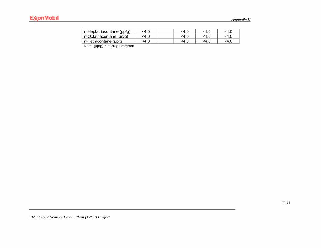
Appendix II
EIA of Joint Venture Power Plant (JVPP) Project
II-34
n-Heptatriacontane (μp/g) <4.0 <4.0 <4.0 <4.0 n-Octatriacontane (μp/g) <4.0 <4.0 <4.0 <4.0 n-Tetracontane (μp/g) <4.0 <4.0 <4.0 <4.0 Note: (μp/g) = microgram/gram

Appendix II
EIA of Joint Venture Power Plant (JVPP) Project II-35
Baseline Characterization Data for the Rich Gas Pipeline Footprint
Aliphatic Hydrocarbon Content in Sediment Samples Collected Along the Rich Gas Pipeline Footprint during the Wet Season
Station ID 124 125 125 126 127 Station Code PLQ-1 PLQ-2 PLQ-2 PLQ-3 PLQ-4 Media Sediment Water Sediment Sediment Sediment n-Undecane (μp/g) <9.0 <9.0 <9.0 <9.0 n-Dodecane (μp/g) <13.0 <13.0 <13.0 <13.0 n-Tridecane (μp/g) <11.0 <11.0 <11.0 <11.0 n-Tetradecane (μp/g) <5.0 <5.0 <5.0 <5.0 n-Pentadecane (μp/g) <5.0 <5.0 <5.0 <5.0 n-Hexadecane (μp/g) <8.0 <8.0 <8.0 <8.0 n-Heptadecane (μp/g) <6.0 <6.0 <6.0 <6.0 n-Pristane (μp/g) <6.0 <6.0 <6.0 <6.0 n-Octadecane (up/g) <3.0 <3.0 <3.0 <3.0 n-Pehytane (μp/g) <3.0 <3.0 <3.0 <3.0 n-Nonadecane (μp/g) <3.0 <3.0 <3.0 <3.0 n-Eicosane (up/g) <5.0 <5.0 <5.0 <5.0 n-Henelcosane (up/g) <4.0 <4.0 <4.0 <4.0 n-Docosane (μp/g) <4.0 <4.0 <4.0 <4.0 n-Tricosane (μp/g) <4.0 <4.0 <4.0 <4.0 n-Tetracosane (μp/g) <3.0 <3.0 <3.0 <3.0 n-Pentacosane (μp/g) <3.0 <3.0 <3.0 <3.0 n-Hexacosane (μp/g) <4.0 <4.0 <4.0 <4.0 n-Heptacosane (μp/g) <5.0 <5.0 <5.0 <5.0 n-Octacosane(μp/g) <5.0 <5.0 <5.0 <5.0 n-Nonacosane (μp/g) <7.0 <7.0 <7.0 <7.0 n-Tricontane (μp/g) <6.0 <6.0 <6.0 <6.0 n-Hentriacontane (μp/g) <5.0 <5.0 <5.0 <5.0 n-Dotriacontane (μp/g) <5.0 <5.0 <5.0 <5.0 n-Tritriacontane (μp/g) <5.0 <5.0 <5.0 <5.0 n-Tetratriacontane (μp/g) <4.0 <4.0 <4.0 <4.0 n-Petratriacontane (μp/g) <4.0 <4.0 <4.0 <4.0 n-Hexatriacontane (μp/g) <3.0 <3.0 <3.0 <3.0 n-Heptatriacontane (μp/g) <4.0 <4.0 <4.0 <4.0 n-Octatriacontane (μp/g) <4.0 <4.0 <4.0 <4.0 n-Tetracontane (μp/g) <4.0 <4.0 <4.0 <4.0 Note: (μp/g) = microgram/gram

Appendix II
EIA of Joint Venture Power Plant (JVPP) Project II-36
Baseline Characterization Data for the Rich Gas Pipeline Footprint
Polyaromatic Hydrocarbon Content in Sediment Samples Collected Along the Rich Gas Pipeline Footprint during the Dry Season
Station ID 124 125 125 126 127 Station Code PLQ-1 PLQ-2 PLQ-2 PLQ-3 PLQ-4 Media Sediment Water Sediment Sediment Sediment Unit of measure mg/kg mg/kg mg/kg mg/kg Naphthalene <1.00 <1.00 <1.00 <1.00 2-Methylnaphtalene <1.00 <1.00 <1.00 <1.00 Acenaphthylene <0.20 <0.20 <0.20 <0.20 Acenaphthene <1.00 <1.00 <1.00 <1.00 Fluorene <0.70 <0.70 <0.70 <0.70 Phenanthrene <0.70 <0.70 <0.70 <0.70 Anthracene <0.20 <0.20 <0.20 <0.20 Fluorathene <0.20 <0.20 <0.20 <0.20 Pyrene <0.20 <0.20 <0.20 <0.20 Benzo(a)anthracene <0.30 <0.30 <0.30 <0.30 Chrysene <0.20 <0.20 <0.20 <0.20 Benzo(b)fluorathene <0.20 <0.20 <0.20 <0.20 Benzo(k)fluorathene <0.20 <0.20 <0.20 <0.20 Benzo(a)pyrene <0.20 <0.20 <0.20 <0.20 Dibenzo(a,h)anthracene <0.20 <0.20 <0.20 <0.20 Benzo(g,h,l)perylene <0.20 <0.20 <0.20 <0.20 Indeno(1,2,3-d)pyrene <0.20 <0.20 <0.20 <0.20
Note: (mg/kg) = milligrams per kilogram
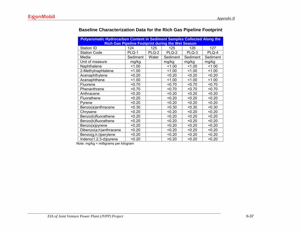
Appendix II
EIA of Joint Venture Power Plant (JVPP) Project II-37
Baseline Characterization Data for the Rich Gas Pipeline Footprint
Polyaromatic Hydrocarbon Content in Sediment Samples Collected Along the Rich Gas Pipeline Footprint during the Wet Season
Station ID 124 125 125 126 127 Station Code PLQ-1 PLQ-2 PLQ-2 PLQ-3 PLQ-4 Media Sediment Water Sediment Sediment Sediment Unit of measure mg/kg mg/kg mg/kg mg/kg Naphthalene <1.00 <1.00 <1.00 <1.00 2-Methylnaphtalene <1.00 <1.00 <1.00 <1.00 Acenaphthylene <0.20 <0.20 <0.20 <0.20 Acenaphthene <1.00 <1.00 <1.00 <1.00 Fluorene <0.70 <0.70 <0.70 <0.70 Phenanthrene <0.70 <0.70 <0.70 <0.70 Anthracene <0.20 <0.20 <0.20 <0.20 Fluorathene <0.20 <0.20 <0.20 <0.20 Pyrene <0.20 <0.20 <0.20 <0.20 Benzo(a)anthracene <0.30 <0.30 <0.30 <0.30 Chrysene <0.20 <0.20 <0.20 <0.20 Benzo(b)fluorathene <0.20 <0.20 <0.20 <0.20 Benzo(k)fluorathene <0.20 <0.20 <0.20 <0.20 Benzo(a)pyrene <0.20 <0.20 <0.20 <0.20 Dibenzo(a,h)anthracene <0.20 <0.20 <0.20 <0.20 Benzo(g,h,l)perylene <0.20 <0.20 <0.20 <0.20 Indeno(1,2,3-d)pyrene <0.20 <0.20 <0.20 <0.20
Note: mg/kg = milligrams per kilogram
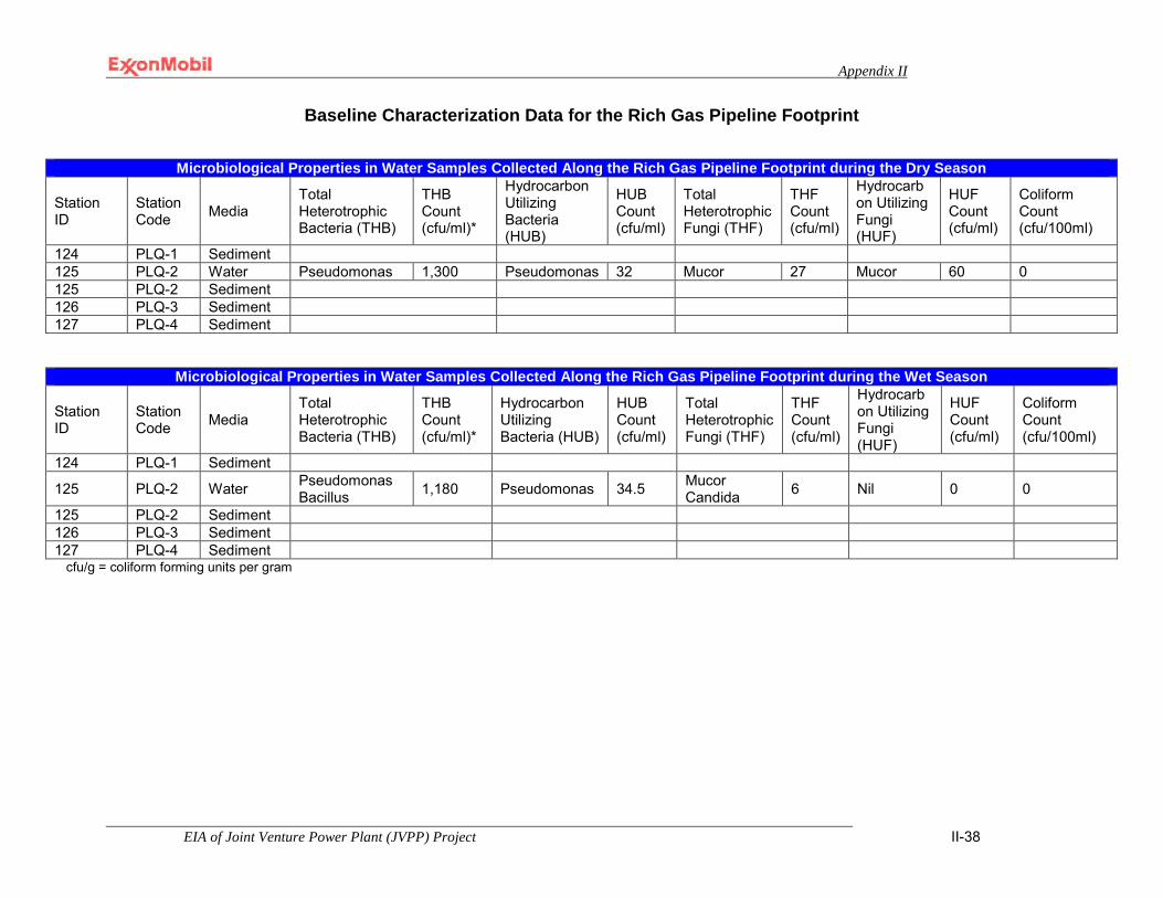
Appendix II
EIA of Joint Venture Power Plant (JVPP) Project II-38
Baseline Characterization Data for the Rich Gas Pipeline Footprint
Microbiological Properties in Water Samples Collected Along the Rich Gas Pipeline Footprint during the Dry Season
Station ID
Station Code Media
Total Heterotrophic Bacteria (THB)
THB Count (cfu/ml)*
Hydrocarbon Utilizing Bacteria (HUB)
HUB Count (cfu/ml)
Total Heterotrophic Fungi (THF)
THF Count (cfu/ml)
Hydrocarbon Utilizing Fungi (HUF)
HUF Count (cfu/ml)
Coliform Count (cfu/100ml)
124 PLQ-1 Sediment 125 PLQ-2 Water Pseudomonas 1,300 Pseudomonas 32 Mucor 27 Mucor 60 0 125 PLQ-2 Sediment 126 PLQ-3 Sediment 127 PLQ-4 Sediment
Microbiological Properties in Water Samples Collected Along the Rich Gas Pipeline Footprint during the Wet Season
Station ID
Station Code Media
Total Heterotrophic Bacteria (THB)
THB Count (cfu/ml)*
Hydrocarbon Utilizing Bacteria (HUB)
HUB Count (cfu/ml)
Total Heterotrophic Fungi (THF)
THF Count (cfu/ml)
Hydrocarbon Utilizing Fungi (HUF)
HUF Count (cfu/ml)
Coliform Count (cfu/100ml)
124 PLQ-1 Sediment
125 PLQ-2 Water Pseudomonas Bacillus 1,180 Pseudomonas 34.5 Mucor
Candida 6 Nil 0 0
125 PLQ-2 Sediment 126 PLQ-3 Sediment 127 PLQ-4 Sediment
cfu/g = coliform forming units per gram

Appendix II
EIA of Joint Venture Power Plant (JVPP) Project II-39
Baseline Characterization Data for the Rich Gas Pipeline Footprint
Microbiological Properties in Sediment Samples Collected Along the Rich Gas Pipeline Footprint during the Dry Season
Station ID
Station Code Media
Total Heterotrophic Bacteria (THB)
THB Count (cfu/ml)
Hydrocarbon Utilizing Bacteria (HUB)
HUB Count (cfu/ml)
Total Heterotrophic Fungi (THF)
THF Count (cfu/ml)
Hydrocarbon Utilizing Fungi (HUF)
HUF Count (cfu/ml)
Coliform Count (cfu/100ml)
124 PLQ-1 Sediment Pseudomonas 2,170,000 Pseudomonas 160 Candida 10 Nil 0 0
125 PLQ-2 Water
125 PLQ-2 Sediment Pseudomonas 2,040,000 Pseudomonas 540 Mucor Candida 160 Mucor 10 0
126 PLQ-3 Sediment Pseudomonas 2,180,000 Pseudomonas 565 Mucor Candida 200 Mucor 10 0
127 PLQ-4 Sediment Pseudomonas 1,960,000 Pseudomonas 660 Penicillium
Mucor Candida 160 Mucor 10 0
Microbiological Properties in Sediment Samples Collected Along the Rich Gas Pipeline Footprint during the Wet Season
Station ID
Station Code Media
Total Heterotrophic Bacteria (THB)
THB Count (cfu/ml)
Hydrocarbon Utilizing Bacteria (HUB)
HUB Count (cfu/ml)
Total Heterotrophic Fungi (THF)
THF Count (cfu/ml)
Hydrocarbon Utilizing Fungi (HUF)
HUF Count (cfu/ml)
Coliform Count (cfu/100ml)
124 PLQ-1 Sediment Pseudomonas 590,000 Pseudomonas 190 Nil 0 Nil 0 0
125 PLQ-2 Water
125 PLQ-2 Sediment Pseudomonas Bacillus 740,000 Pseudomonas 260 Nil 0 Nil 0 0
126 PLQ-3 Sediment Pseudomonas Bacillus 690,000 Nil 0 Nil 0 Nil 0 0
127 PLQ-4 Sediment Pseudomonas Bacillus 830,000 Pseudomonas 50 Mucor 20 Nil 0 0
cfu/g = coliform forming units per gram
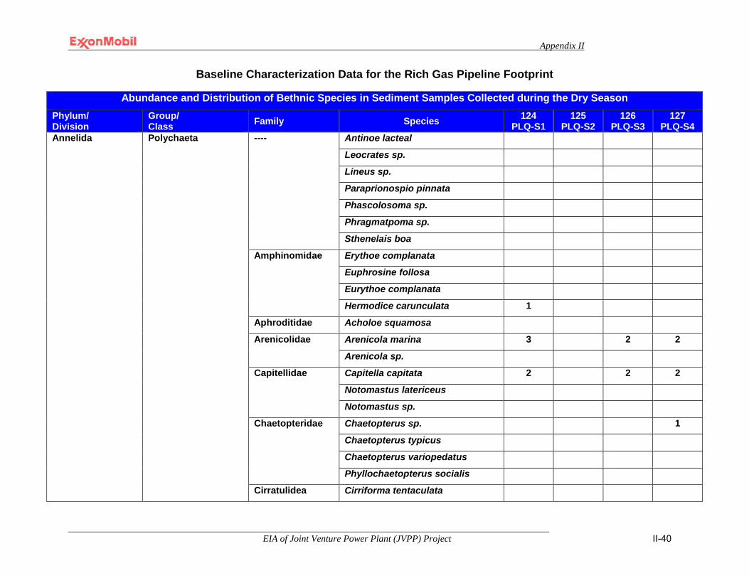
Appendix II
EIA of Joint Venture Power Plant (JVPP) Project II-40
Baseline Characterization Data for the Rich Gas Pipeline Footprint
Abundance and Distribution of Bethnic Species in Sediment Samples Collected during the Dry Season
Phylum/ Division
Group/ Class Family Species 124
PLQ-S1 125
PLQ-S2 126
PLQ-S3 127
PLQ-S4 Annelida Polychaeta ---- Antinoe lacteal
Leocrates sp.
Lineus sp.
Paraprionospio pinnata
Phascolosoma sp.
Phragmatpoma sp.
Sthenelais boa
Amphinomidae Erythoe complanata
Euphrosine follosa
Eurythoe complanata
Hermodice carunculata 1
Aphroditidae Acholoe squamosa
Arenicolidae Arenicola marina 3 2 2
Arenicola sp.
Capitellidae Capitella capitata 2 2 2
Notomastus latericeus
Notomastus sp.
Chaetopteridae Chaetopterus sp. 1
Chaetopterus typicus
Chaetopterus variopedatus
Phyllochaetopterus socialis
Cirratulidea Cirriforma tentaculata

Appendix II
EIA of Joint Venture Power Plant (JVPP) Project II-41
Baseline Characterization Data for the Rich Gas Pipeline Footprint
Abundance and Distribution of Bethnic Species in Sediment Samples Collected during the Dry Season (continued) Phylum/ Division
Group/ Class Family Species 124
PLQ-S1 125
PLQ-S2 126
PLQ-S3 127
PLQ-S4 Annelida Polychaeta Eunicidae Eunice antennata
Eunice norvegica 3 2 Eunice sp. Lysidice ninetta 3 Marphysa belli Marphysa sanguinea
Euphrosinidae Euphrosinidae capensis Flabelligeridae Flabelligera sp. Glyceridae Glycera gigantica
Glycera sp. 2 Lumbriconeridae Lumbriconereis sp. Lumbrinereidae Lumbrinereis sp. Maldanidae Euclymene sp.
Maldane sarsi Nicomanche lumbricalis Nicomanche sp. Petaloproctus terricola
Nephtyidae Nephtys hombergi Nephtys sp. 3 1
Nereidae
Nereis diversicolor Nereis lemallosa 2 2 Nereis sp. Platynereis dumerill Platynereis sp. 1

Appendix II
EIA of Joint Venture Power Plant (JVPP) Project II-42
Baseline Characterization Data for the Rich Gas Pipeline Footprint
Abundance and Distribution of Bethnic Species in Sediment Samples Collected during the Dry Season (continued) Phylum/ Division
Group/ Class Family Species 124
PLQ-S1 125
PLQ-S2 126
PLQ-S3 127
PLQ-S4 Annelida Polychaeta Phyllodocidae Eteone foliosa
Eulalia sp.
Sabellidae Sabella spallanzanii
Serpulidae Ficopomatus sp.
Hydroides Norvegica
Spirobis sp.
Spionidae Polydora ligni
Spiophanes bombyx
Syllidae Autolytus prolifer
Eusyllis bloomstrandi
Sylis sp.
Trypanosyllis gemmulifera
Terabellidae Terebella sp.
Annelida Total 11 9 4 10

Appendix II
EIA of Joint Venture Power Plant (JVPP) Project II-43
Baseline Characterization Data for the Rich Gas Pipeline Footprint
Abundance and Distribution of Bethnic Species in Sediment Samples Collected during the Dry Season (continued) Phylum/ Division
Group/ Class Family Species 124
PLQ-S1 125
PLQ-S2 126
PLQ-S3 127
PLQ-S4 Arthropoda Crustacea ---- Apeseudes sp.
Bateaus jucundus
Caridina sp.
Harpacticoids
Isodus sp.
Ligia sp. 1
Saron marmoratus
Shrimp larvae
Alpheidae Alpheus crassimanus
Alpheus macrocheles
Ampeliscidae Ampelisca
Callianassidae Callianasa sp.
Corophidae Corophium sp. 4 2 10 4
Gammaridae Gammarus sp.
Hippolytidae Thoralus cranchii
Idoteidae Idotea sp.
Idothea baltica
Ischyroceridae Jassa falcate
Jassa sp.
Leucosiidae Ebalia cranchii
Lysianassidae Lysianassa ceratina
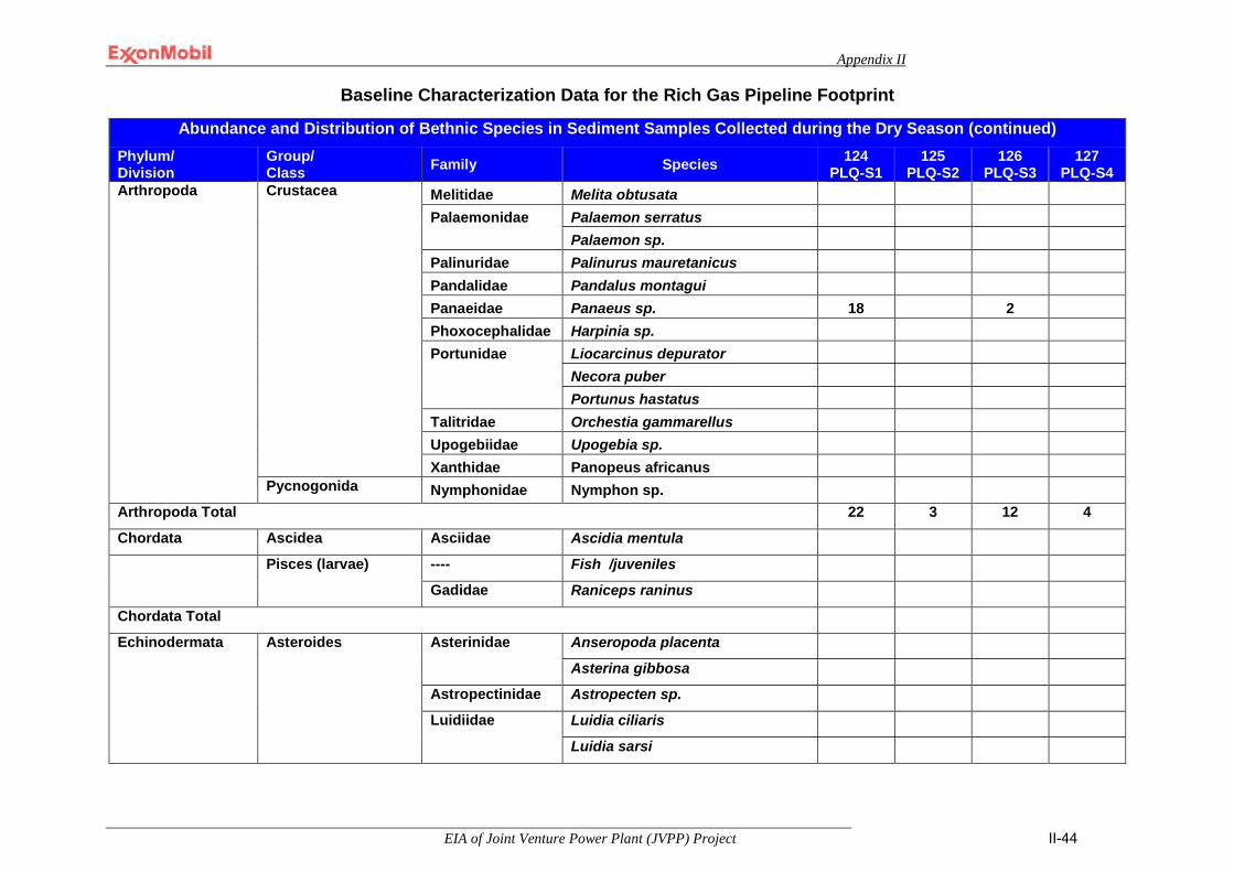
Appendix II
EIA of Joint Venture Power Plant (JVPP) Project II-44
Baseline Characterization Data for the Rich Gas Pipeline Footprint
Abundance and Distribution of Bethnic Species in Sediment Samples Collected during the Dry Season (continued) Phylum/ Division
Group/ Class Family Species 124
PLQ-S1 125
PLQ-S2 126
PLQ-S3 127
PLQ-S4 Arthropoda Crustacea Melitidae Melita obtusata
Palaemonidae Palaemon serratus Palaemon sp.
Palinuridae Palinurus mauretanicus Pandalidae Pandalus montagui Panaeidae Panaeus sp. 18 2 Phoxocephalidae Harpinia sp. Portunidae Liocarcinus depurator
Necora puber Portunus hastatus
Talitridae Orchestia gammarellus Upogebiidae Upogebia sp. Xanthidae Panopeus africanus
Pycnogonida Nymphonidae Nymphon sp. Arthropoda Total 22 3 12 4
Chordata Ascidea Asciidae Ascidia mentula
Pisces (larvae) ---- Fish /juveniles
Gadidae Raniceps raninus
Chordata Total
Echinodermata Asteroides Asterinidae Anseropoda placenta
Asterina gibbosa
Astropectinidae Astropecten sp.
Luidiidae Luidia ciliaris
Luidia sarsi
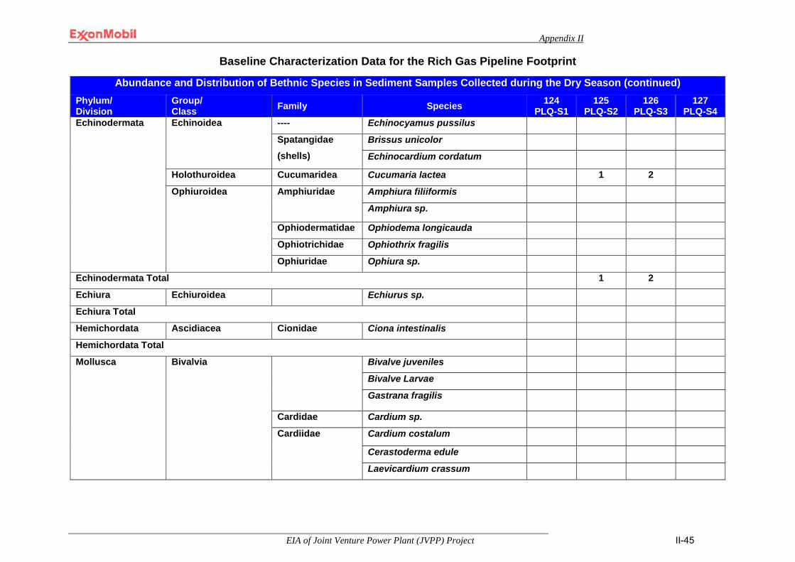
Appendix II
EIA of Joint Venture Power Plant (JVPP) Project II-45
Baseline Characterization Data for the Rich Gas Pipeline Footprint
Abundance and Distribution of Bethnic Species in Sediment Samples Collected during the Dry Season (continued) Phylum/ Division
Group/ Class Family Species 124
PLQ-S1 125
PLQ-S2 126
PLQ-S3 127
PLQ-S4 Echinodermata Echinoidea
---- Echinocyamus pussilus
Spatangidae (shells)
Brissus unicolor
Echinocardium cordatum
Holothuroidea Cucumaridea Cucumaria lactea 1 2
Ophiuroidea Amphiuridae Amphiura filiiformis
Amphiura sp.
Ophiodermatidae Ophiodema longicauda
Ophiotrichidae Ophiothrix fragilis
Ophiuridae Ophiura sp.
Echinodermata Total 1 2
Echiura Echiuroidea Echiurus sp.
Echiura Total
Hemichordata Ascidiacea Cionidae Ciona intestinalis
Hemichordata Total
Mollusca
Bivalvia Bivalve juveniles
Bivalve Larvae
Gastrana fragilis
Cardidae Cardium sp.
Cardiidae Cardium costalum
Cerastoderma edule
Laevicardium crassum
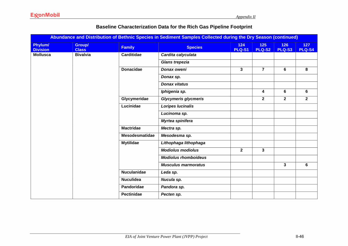
Appendix II
EIA of Joint Venture Power Plant (JVPP) Project II-46
Baseline Characterization Data for the Rich Gas Pipeline Footprint
Abundance and Distribution of Bethnic Species in Sediment Samples Collected during the Dry Season (continued) Phylum/ Division
Group/ Class Family Species 124
PLQ-S1 125
PLQ-S2 126
PLQ-S3 127
PLQ-S4 Mollusca
Bivalvia Carditidae Cardita calyculata
Glans trepezia
Donacidae Donax oweni 3 7 6 8
Donax sp.
Donax vitatus
Iphigenia sp. 4 6 6
Glycymeridae Glycymeris glycmeris 2 2 2
Lucinidae Loripes lucinalis
Lucinoma sp.
Myrtea spinifera
Mactridae Mectra sp.
Mesodesmatidae Mesodesma sp.
Mytilidae Lithophaga lithophaga
Modiolus modiolus 2 3
Modiolus rhomboideus
Musculus marmoratus 3 6
Nuculanidae Leda sp.
Nuculidea Nucula sp.
Pandoridae Pandora sp.
Pectinidae Pecten sp.
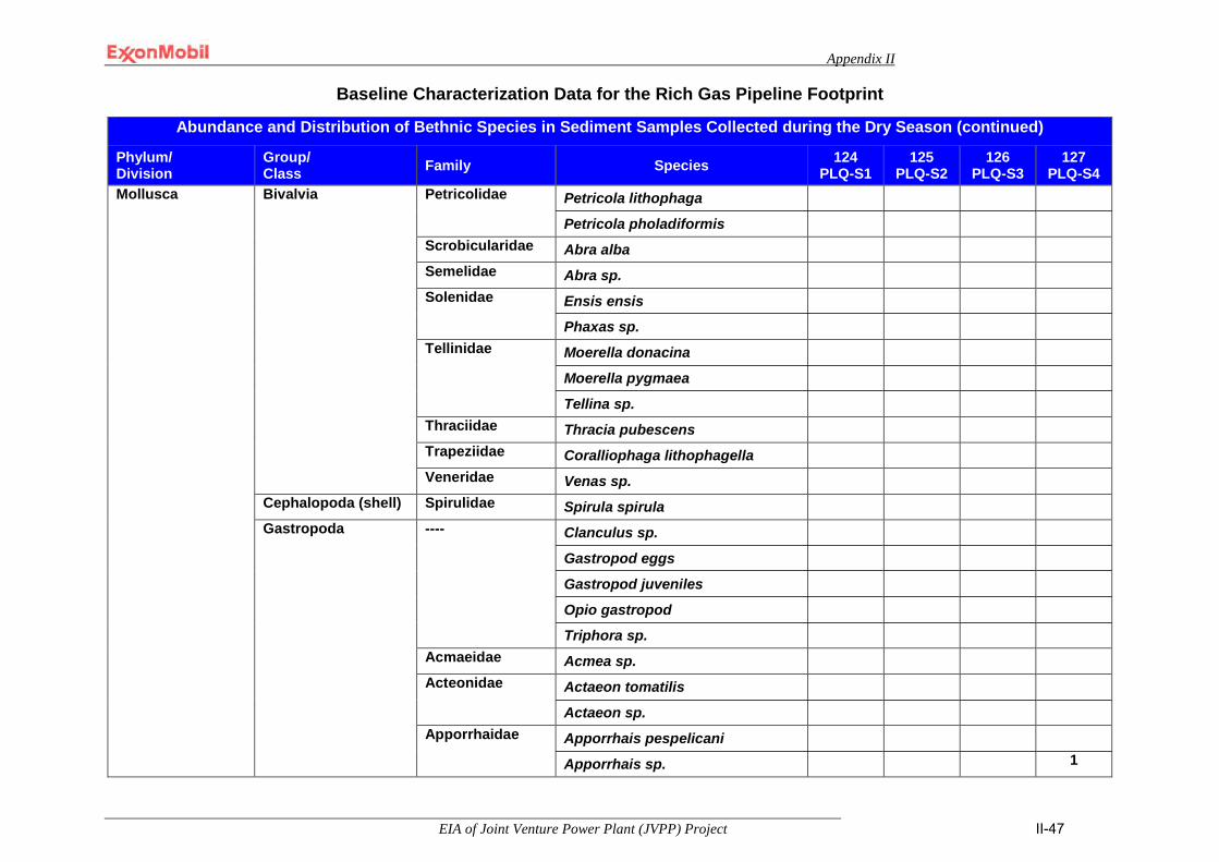
Appendix II
EIA of Joint Venture Power Plant (JVPP) Project II-47
Baseline Characterization Data for the Rich Gas Pipeline Footprint
Abundance and Distribution of Bethnic Species in Sediment Samples Collected during the Dry Season (continued)
Phylum/ Division
Group/ Class Family Species 124
PLQ-S1 125
PLQ-S2 126
PLQ-S3 127
PLQ-S4 Mollusca Bivalvia Petricolidae Petricola lithophaga
Petricola pholadiformis
Scrobicularidae Abra alba
Semelidae Abra sp.
Solenidae Ensis ensis
Phaxas sp.
Tellinidae Moerella donacina
Moerella pygmaea
Tellina sp.
Thraciidae Thracia pubescens
Trapeziidae Coralliophaga lithophagella
Veneridae Venas sp.
Cephalopoda (shell) Spirulidae Spirula spirula
Gastropoda ---- Clanculus sp.
Gastropod eggs
Gastropod juveniles
Opio gastropod
Triphora sp.
Acmaeidae Acmea sp.
Acteonidae Actaeon tomatilis
Actaeon sp.
Apporrhaidae Apporrhais pespelicani
Apporrhais sp. 1
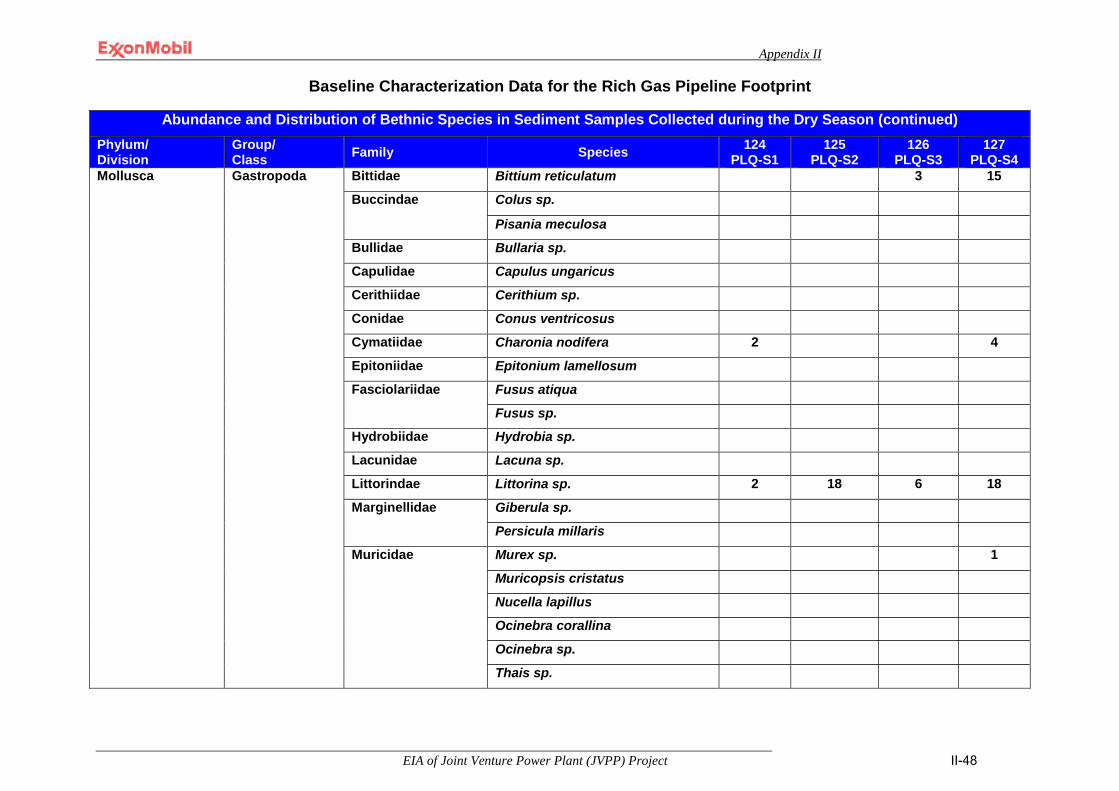
Appendix II
EIA of Joint Venture Power Plant (JVPP) Project II-48
Baseline Characterization Data for the Rich Gas Pipeline Footprint
Abundance and Distribution of Bethnic Species in Sediment Samples Collected during the Dry Season (continued) Phylum/ Division
Group/ Class Family Species 124
PLQ-S1 125
PLQ-S2 126
PLQ-S3 127
PLQ-S4 Mollusca Gastropoda Bittidae Bittium reticulatum 3 15
Buccindae Colus sp.
Pisania meculosa
Bullidae Bullaria sp.
Capulidae Capulus ungaricus
Cerithiidae Cerithium sp.
Conidae Conus ventricosus
Cymatiidae Charonia nodifera 2 4
Epitoniidae Epitonium lamellosum
Fasciolariidae Fusus atiqua
Fusus sp.
Hydrobiidae Hydrobia sp.
Lacunidae Lacuna sp.
Littorindae Littorina sp. 2 18 6 18
Marginellidae Giberula sp.
Persicula millaris
Muricidae Murex sp. 1
Muricopsis cristatus
Nucella lapillus
Ocinebra corallina
Ocinebra sp.
Thais sp.
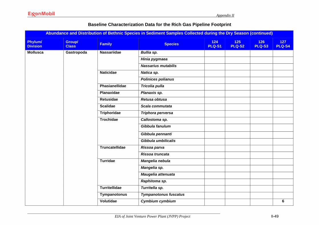
Appendix II
EIA of Joint Venture Power Plant (JVPP) Project II-49
Baseline Characterization Data for the Rich Gas Pipeline Footprint
Abundance and Distribution of Bethnic Species in Sediment Samples Collected during the Dry Season (continued)
Phylum/ Division
Group/ Class Family Species 124
PLQ-S1 125
PLQ-S2 126
PLQ-S3 127
PLQ-S4 Mollusca Gastropoda Nassariidae Bullia sp.
Hinia pygmaea
Nassarius mutabilis
Naticidae Natica sp.
Polinices polianus
Phasianellidae Tricolia pulla
Planaxidae Planaxis sp.
Retusidae Retusa obtusa
Scalidae Scala commutata
Triphoridae Triphora perversa
Trochidae Callostoma sp.
Gibbula fanulum
Gibbula pennanti
Gibbula umbilicalis
Truncatellidae Rissoa parva
Rissoa truncata
Turridae Mangelia nebula
Mangelia sp.
Maugelia attenuata
Raphitoma sp.
Turritellidae Turritella sp.
Tympanotonus Tympanotonus fuscatus
Volutidae Cymbium cymbium 6
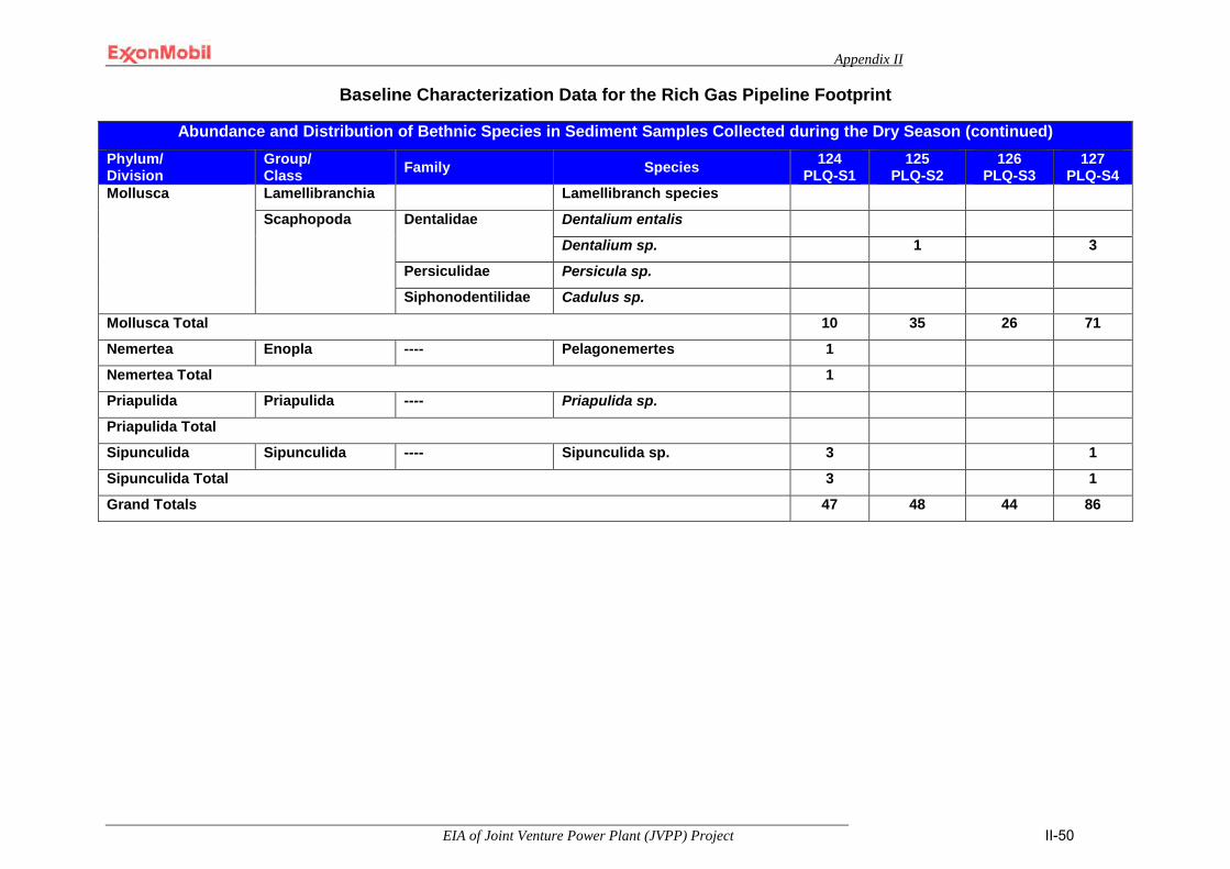
Appendix II
EIA of Joint Venture Power Plant (JVPP) Project II-50
Baseline Characterization Data for the Rich Gas Pipeline Footprint
Abundance and Distribution of Bethnic Species in Sediment Samples Collected during the Dry Season (continued) Phylum/ Division
Group/ Class Family Species 124
PLQ-S1 125
PLQ-S2 126
PLQ-S3 127
PLQ-S4 Mollusca Lamellibranchia Lamellibranch species
Scaphopoda Dentalidae Dentalium entalis
Dentalium sp. 1 3
Persiculidae Persicula sp.
Siphonodentilidae Cadulus sp.
Mollusca Total 10 35 26 71
Nemertea Enopla ---- Pelagonemertes 1
Nemertea Total 1
Priapulida Priapulida ---- Priapulida sp.
Priapulida Total
Sipunculida Sipunculida ---- Sipunculida sp. 3 1
Sipunculida Total 3 1
Grand Totals 47 48 44 86
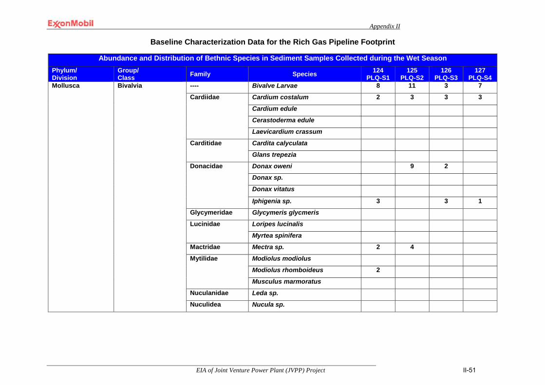
Appendix II
EIA of Joint Venture Power Plant (JVPP) Project II-51
Baseline Characterization Data for the Rich Gas Pipeline Footprint
Abundance and Distribution of Bethnic Species in Sediment Samples Collected during the Wet Season
Phylum/ Division
Group/ Class Family Species 124
PLQ-S1 125
PLQ-S2 126
PLQ-S3 127
PLQ-S4 Mollusca Bivalvia
---- Bivalve Larvae 8 11 3 7
Cardiidae Cardium costalum 2 3 3 3
Cardium edule
Cerastoderma edule
Laevicardium crassum
Carditidae Cardita calyculata
Glans trepezia
Donacidae Donax oweni 9 2
Donax sp.
Donax vitatus
Iphigenia sp. 3 3 1
Glycymeridae Glycymeris glycmeris
Lucinidae Loripes lucinalis
Myrtea spinifera
Mactridae Mectra sp. 2 4
Mytilidae Modiolus modiolus
Modiolus rhomboideus 2
Musculus marmoratus
Nuculanidae Leda sp.
Nuculidea Nucula sp.

Appendix II
EIA of Joint Venture Power Plant (JVPP) Project II-52
Baseline Characterization Data for the Rich Gas Pipeline Footprint
Abundance and Distribution of Bethnic Species in Sediment Samples Collected during the Wet Season (continued) Phylum/ Division
Group/ Class Family Species 124
PLQ-S1 125
PLQ-S2 126
PLQ-S3 127
PLQ-S4 Mollusca Bivalvia Pectinidae Pecten sp.
Scrobicularidae Abra alba Solenidae Ensis ensis 2
Solen marginatus 11 2 Tellinidae Angulus distortus
Tellina sp. Trapeziidae Coralliophaga lithophagella Veneridae Circumphalus casina 1
Dosina exoleta 1 3 Venas sp.
Gastropoda Acteonidae Actaeon tomatillis L. Apporrhaidae Apporrhais pespelicani 3 2 Bittidae Bittium reticulatum 2 Buccinidae Buccinum sp. Bullidae Bulairia sp. Capulidae Capulus ungaricus Cymatiidae Charonia nodifera 1 Fasciolariidae Fusus antiqua
Fusus sp. Littorindae Littorina littoralis
Littorina sp.
Marginellidae Marginella milliaris Muricidae Murex sp.
Ocinebra coralline Ocinebra sp.
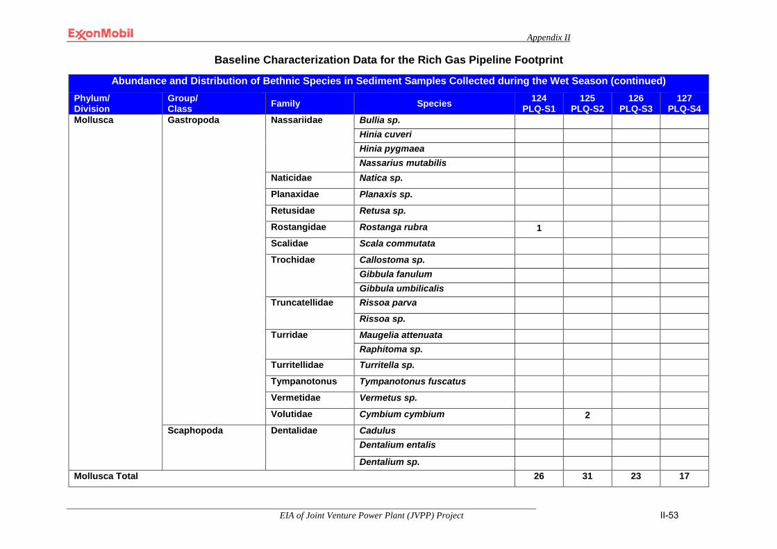
Appendix II
EIA of Joint Venture Power Plant (JVPP) Project II-53
Baseline Characterization Data for the Rich Gas Pipeline Footprint
Abundance and Distribution of Bethnic Species in Sediment Samples Collected during the Wet Season (continued) Phylum/ Division
Group/ Class Family Species 124
PLQ-S1 125
PLQ-S2 126
PLQ-S3 127
PLQ-S4 Mollusca Gastropoda Nassariidae Bullia sp.
Hinia cuveri Hinia pygmaea Nassarius mutabilis
Naticidae Natica sp. Planaxidae Planaxis sp. Retusidae Retusa sp. Rostangidae Rostanga rubra 1 Scalidae Scala commutata Trochidae Callostoma sp.
Gibbula fanulum Gibbula umbilicalis
Truncatellidae Rissoa parva Rissoa sp.
Turridae Maugelia attenuata Raphitoma sp.
Turritellidae Turritella sp. Tympanotonus Tympanotonus fuscatus Vermetidae Vermetus sp. Volutidae Cymbium cymbium 2
Scaphopoda Dentalidae
Cadulus Dentalium entalis Dentalium sp.
Mollusca Total 26 31 23 17
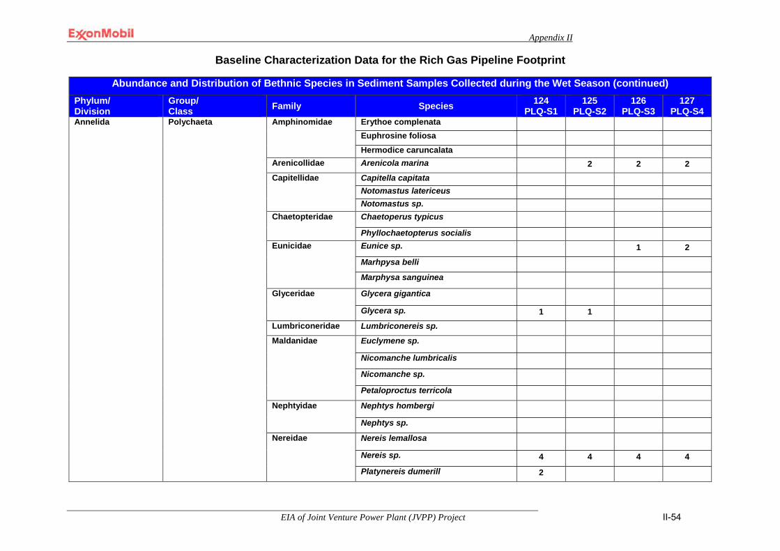
Appendix II
EIA of Joint Venture Power Plant (JVPP) Project II-54
Baseline Characterization Data for the Rich Gas Pipeline Footprint
Abundance and Distribution of Bethnic Species in Sediment Samples Collected during the Wet Season (continued) Phylum/ Division
Group/ Class Family Species 124
PLQ-S1 125
PLQ-S2 126
PLQ-S3 127
PLQ-S4 Annelida Polychaeta Amphinomidae Erythoe complenata
Euphrosine foliosa Hermodice caruncalata
Arenicollidae Arenicola marina 2 2 2 Capitellidae Capitella capitata
Notomastus latericeus Notomastus sp.
Chaetopteridae Chaetoperus typicus
Phyllochaetopterus socialis Eunicidae Eunice sp. 1 2
Marhpysa belli Marphysa sanguinea
Glyceridae Glycera gigantica
Glycera sp. 1 1 Lumbriconeridae Lumbriconereis sp. Maldanidae Euclymene sp.
Nicomanche lumbricalis
Nicomanche sp.
Petaloproctus terricola Nephtyidae Nephtys hombergi
Nephtys sp. Nereidae Nereis lemallosa
Nereis sp. 4 4 4 4
Platynereis dumerill 2
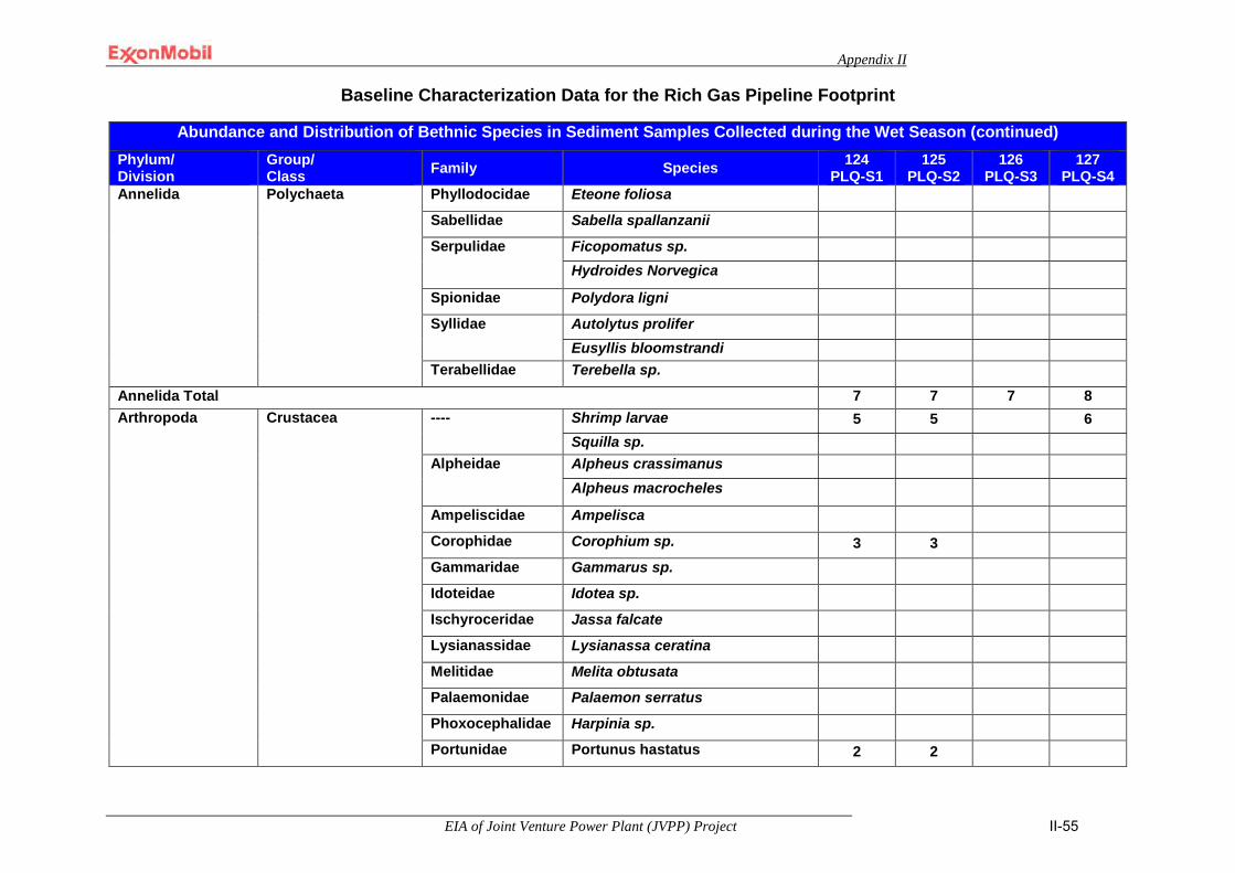
Appendix II
EIA of Joint Venture Power Plant (JVPP) Project II-55
Baseline Characterization Data for the Rich Gas Pipeline Footprint
Abundance and Distribution of Bethnic Species in Sediment Samples Collected during the Wet Season (continued) Phylum/ Division
Group/ Class Family Species 124
PLQ-S1 125
PLQ-S2 126
PLQ-S3 127
PLQ-S4 Annelida Polychaeta Phyllodocidae Eteone foliosa
Sabellidae Sabella spallanzanii Serpulidae Ficopomatus sp.
Hydroides Norvegica Spionidae Polydora ligni Syllidae Autolytus prolifer
Eusyllis bloomstrandi Terabellidae Terebella sp.
Annelida Total 7 7 7 8 Arthropoda
Crustacea ---- Shrimp larvae 5 5 6 Squilla sp.
Alpheidae Alpheus crassimanus Alpheus macrocheles
Ampeliscidae Ampelisca Corophidae Corophium sp. 3 3 Gammaridae Gammarus sp. Idoteidae Idotea sp. Ischyroceridae Jassa falcate Lysianassidae Lysianassa ceratina Melitidae Melita obtusata Palaemonidae Palaemon serratus Phoxocephalidae Harpinia sp. Portunidae Portunus hastatus 2 2
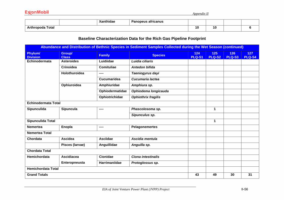
Appendix II
EIA of Joint Venture Power Plant (JVPP) Project II-56
Xanthidae Panopeus africanus Arthropoda Total 10 10 6
Baseline Characterization Data for the Rich Gas Pipeline Footprint
Abundance and Distribution of Bethnic Species in Sediment Samples Collected during the Wet Season (continued)
Phylum/ Division
Group/ Class Family Species 124
PLQ-S1 125
PLQ-S2 126
PLQ-S3 127
PLQ-S4 Echinodermata Asteroides Luidiidae Luidia ciliaris
Crinoidea Comituliae Antedon bifida
Holothuroidea ---- Taeniogyrus dayi
Cucumaridea Cucumaria lactea
Ophiuroidea Amphiuridae Amphiura sp.
Ophiodermatidae Ophiodema longicauda
Ophiotrichidae Ophiothrix fragilis
Echinodermata Total
Sipunculida Sipuncula ---- Phascolosoma sp. 1
Sipunculus sp.
Sipunculida Total 1
Nemertea Enopla ---- Pelagonemertes
Nemertea Total
Chordata Ascidea Asciidae Ascidia mentula
Pisces (larvae) Anguillidae Anguilla sp.
Chordata Total
Hemichordata Ascidiacea Enteropneusta
Cionidae Ciona intestinalis
Harrimaniidae Protoglossus sp.
Hemichordata Total
Grand Totals 43 49 30 31
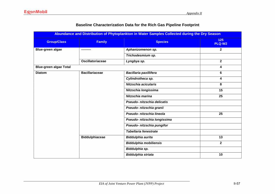
Appendix II
EIA of Joint Venture Power Plant (JVPP) Project II-57
Baseline Characterization Data for the Rich Gas Pipeline Footprint
Abundance and Distribution of Phytoplankton in Water Samples Collected during the Dry Season
Group/Class Family Species 125 PLQ-W2
Blue-green algae --------- Aphanizomenon sp. 2
Trichodesmium sp.
Oscillatoriaceae Lyngbya sp. 2
Blue-green algae Total 4
Diatom Bacillariaceae Bacillaria paxillifera 6
Cylindrotheca sp. 4
Nitzschia acicularis 8
Nitzschia longissima 15
Nitzschia marina 25
Pseudo- nitzschia delicatis
Pseudo- nitzschia granii
Pseudo- nitzschia lineola 25
Pseudo- nitzschia longissima
Pseudo- nitzschia pungifor
Tabellaria fenestrate
Biddulphiaceae Biddulphia aurita 13
Biddulphia mobiliensis 2
Biddulphia sp.
Biddulphia striata 10
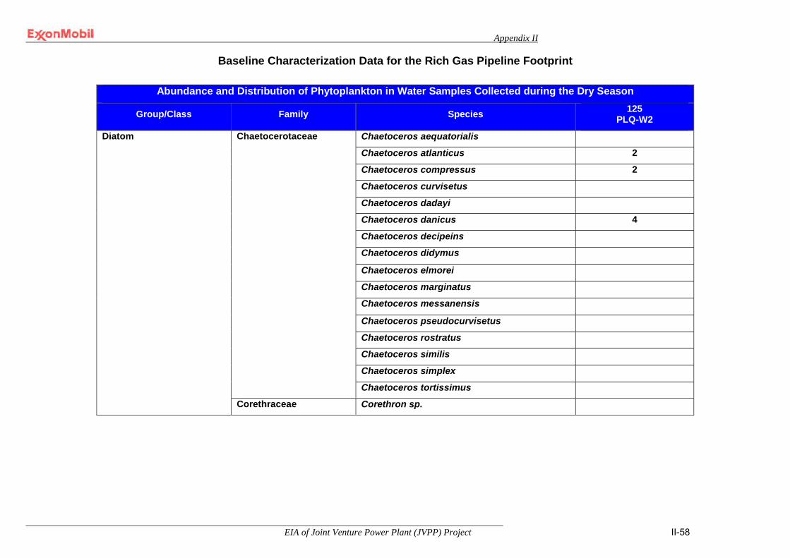
Appendix II
EIA of Joint Venture Power Plant (JVPP) Project II-58
Baseline Characterization Data for the Rich Gas Pipeline Footprint
Abundance and Distribution of Phytoplankton in Water Samples Collected during the Dry Season
Group/Class Family Species 125 PLQ-W2
Diatom Chaetocerotaceae Chaetoceros aequatorialis
Chaetoceros atlanticus 2
Chaetoceros compressus 2
Chaetoceros curvisetus
Chaetoceros dadayi
Chaetoceros danicus 4
Chaetoceros decipeins
Chaetoceros didymus
Chaetoceros elmorei
Chaetoceros marginatus
Chaetoceros messanensis
Chaetoceros pseudocurvisetus
Chaetoceros rostratus
Chaetoceros similis
Chaetoceros simplex
Chaetoceros tortissimus
Corethraceae Corethron sp.
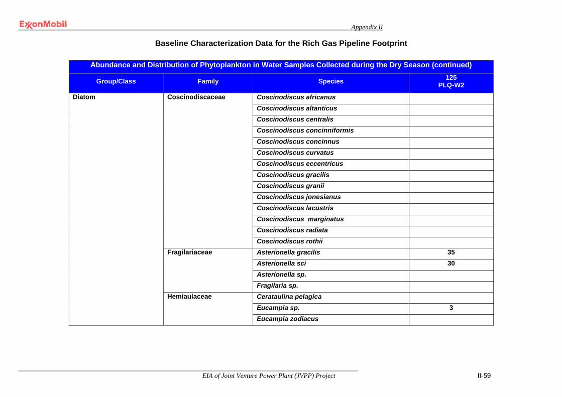
Appendix II
EIA of Joint Venture Power Plant (JVPP) Project II-59
Baseline Characterization Data for the Rich Gas Pipeline Footprint
Abundance and Distribution of Phytoplankton in Water Samples Collected during the Dry Season (continued)
Group/Class Family Species 125 PLQ-W2
Diatom Coscinodiscaceae Coscinodiscus africanus Coscinodiscus altanticus Coscinodiscus centralis Coscinodiscus concinniformis Coscinodiscus concinnus Coscinodiscus curvatus Coscinodiscus eccentricus Coscinodiscus gracilis Coscinodiscus granii Coscinodiscus jonesianus Coscinodiscus lacustris Coscinodiscus marginatus Coscinodiscus radiata Coscinodiscus rothii
Fragilariaceae Asterionella gracilis 35 Asterionella sci 30 Asterionella sp. Fragilaria sp.
Hemiaulaceae Cerataulina pelagica Eucampia sp. 3 Eucampia zodiacus

Appendix II
EIA of Joint Venture Power Plant (JVPP) Project II-60
Baseline Characterization Data for the Rich Gas Pipeline Footprint
Abundance and Distribution of Phytoplankton in Water Samples Collected during the Dry Season (continued)
Group/Class Family Species 125 PLQ-W2
Diatom Hemidiscaceae Azpeitia africana Azpeitia nodulifera
Leptocylindraceae Leptocylindricus curvatus Leptocylindricus danicus 26 Leptocylindricus minimus
Lithodesmiaceae Bellarochea malleus Bellarochea sp. Ditylum brightwellii Lithodesmium undulatum
Melosiraceae Paralia suicata Naviculaceae Navicula angulata
Navicula fusiformes Navicula sp. Navicula transitans Pinularia distans Pinularia major Pleurosigma angulatum 8 Pleurosigma directum Pleurosigma elongatus
Phaeocystaceae Phaeocystis sp.
Raphidoneidaceae Cocconeis amphiceros
Cocconeis diminuta 6
Cocconeis sp.

Appendix II
EIA of Joint Venture Power Plant (JVPP) Project II-61
Baseline Characterization Data for the Rich Gas Pipeline Footprint
Abundance and Distribution of Phytoplankton in Water Samples Collected during the Dry Season (continued)
Group/Class Family Species 125 PLQ-W2
Diatom Rhizosoleniaceae Guinardia sp. Rhizosolenia alata 100 Rhizosolenia cylindricus Rhizosolenia longiseta Rhizosolenia setigera 80 Rhizosolenia styliformis Thalassiothrix longissima 10
Streptothecaceae Streptotheca sp. Thalassionemataceae Thalassionema bacillare
Thalassionema nitzschioides Thalassiosiraceae Cyclotella aestivalis
Cyclotella littoralis Cyclotella meneghiniana Cyclotella sp Cyclotella striata 8 Skeletonema costatum 2 Synedra acus Synedra pelegica 6 Synedra sp. Thalassiosira ferelineata Thalassiosira minuscula Thalassiosira punctigera Thalassiosira sp.
Triceratiaceae Triceratium sp. Diatom Total 430
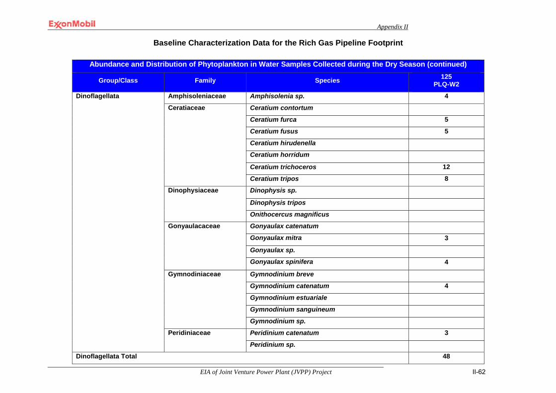
Appendix II
EIA of Joint Venture Power Plant (JVPP) Project II-62
Baseline Characterization Data for the Rich Gas Pipeline Footprint
Abundance and Distribution of Phytoplankton in Water Samples Collected during the Dry Season (continued)
Group/Class Family Species 125 PLQ-W2
Dinoflagellata Amphisoleniaceae Amphisolenia sp. 4
Ceratiaceae Ceratium contortum
Ceratium furca 5
Ceratium fusus 5
Ceratium hirudenella
Ceratium horridum
Ceratium trichoceros 12
Ceratium tripos 8
Dinophysiaceae Dinophysis sp.
Dinophysis tripos
Onithocercus magnificus
Gonyaulacaceae Gonyaulax catenatum
Gonyaulax mitra 3
Gonyaulax sp.
Gonyaulax spinifera 4
Gymnodiniaceae Gymnodinium breve
Gymnodinium catenatum 4
Gymnodinium estuariale
Gymnodinium sanguineum
Gymnodinium sp.
Peridiniaceae Peridinium catenatum 3
Peridinium sp.
Dinoflagellata Total 48

Appendix II
EIA of Joint Venture Power Plant (JVPP) Project II-63
Baseline Characterization Data for the Rich Gas Pipeline Footprint
Abundance and Distribution of Phytoplankton in Water Samples Collected during the Dry Season (continued)
Group/Class Family Species 125 PLQ-W2
Tintinnid Tintinnidaceae
Codonella amphorella
Flavella ehrenbergii
Tintinnidae Rhabdonella amor 4
Tintinnid Total 4
Euglenophyceae Euglenaceae Euglena acusiforms
Euglena sp.
Euglenophyceae Total
Green Algae (Chlorophyta)
Coelastraceae Ankistrodesmus sp. 3
Green Algae (Chlorophyta) Total 3
Grand total 489
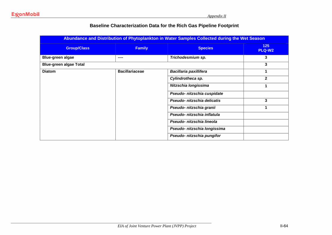
Appendix II
EIA of Joint Venture Power Plant (JVPP) Project II-64
Baseline Characterization Data for the Rich Gas Pipeline Footprint
Abundance and Distribution of Phytoplankton in Water Samples Collected during the Wet Season
Group/Class Family Species 125 PLQ-W2
Blue-green algae ---- Trichodesmium sp. 3
Blue-green algae Total 3
Diatom Bacillariaceae Bacillaria paxillifera 1
Cylindrotheca sp. 2
Nitzschia longissima 1
Pseudo- nitzschia cuspidate
Pseudo- nitzschia delicatis 3
Pseudo- nitzschia granii 1
Pseudo- nitzschia inflatula
Pseudo- nitzschia lineola
Pseudo- nitzschia longissima
Pseudo- nitzschia pungifor

Appendix II
EIA of Joint Venture Power Plant (JVPP) Project II-65
Baseline Characterization Data for the Rich Gas Pipeline Footprint
Abundance and Distribution of Phytoplankton in Water Samples Collected during the Wet Season (continued)
Group/Class Family Species 125 PLQ-W2
Diatom Chaetocerotaceae Chaetoceros aequatorialis 4
Chaetoceros atlanticus 5
Chaetoceros compressus 13
Chaetoceros curvisetus
Chaetoceros dadayi 4
Chaetoceros danicus
Chaetoceros decipeins
Chaetoceros didymus
Chaetoceros elmorei
Chaetoceros messanensis
Chaetoceros pseudocurvisetus
Chaetoceros rostratus
Chaetoceros similis
Chaetoceros simplex 2
Chaetoceros tortissimus

Appendix II
EIA of Joint Venture Power Plant (JVPP) Project II-66
Baseline Characterization Data for the Rich Gas Pipeline Footprint
Abundance and Distribution of Phytoplankton in Water Samples Collected during the Wet Season (continued)
Group/Class Family Species 125 PLQ-W2
Diatom Coscinodiscaceae Coscinodiscus africanus 66
Coscinodiscus altanticus 27
Coscinodiscus centralis 61
Coscinodiscus concinniformis
Coscinodiscus concinnus 8
Coscinodiscus curvatus
Coscinodiscus eccentricus
Coscinodiscus gracilis 38
Coscinodiscus granii
Coscinodiscus jonesianus
Coscinodiscus lacustris
Coscinodiscus listanus 8
Coscinodiscus radiata
Coscinodiscus rothii
Cymatosiraceae Cymatosira belgica 3
Cymatosira lorenziana 2
Fragilariaceae Asterionella socialis
Asterionella sp. 3
Fragilaria sp. 2
Hemidiscaceae Azpeitia africana
Azpeitia nodulifera
Lithodesmiaceae Bellarochea malleus
Ditylum brightwellii
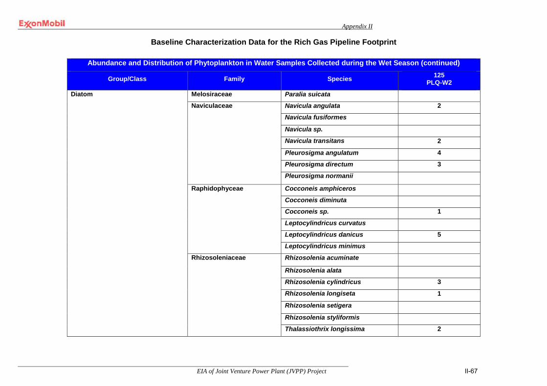
Appendix II
EIA of Joint Venture Power Plant (JVPP) Project II-67
Baseline Characterization Data for the Rich Gas Pipeline Footprint
Abundance and Distribution of Phytoplankton in Water Samples Collected during the Wet Season (continued)
Group/Class Family Species 125 PLQ-W2
Diatom Melosiraceae Paralia suicata
Naviculaceae Navicula angulata 2
Navicula fusiformes
Navicula sp.
Navicula transitans 2
Pleurosigma angulatum 4
Pleurosigma directum 3
Pleurosigma normanii
Raphidophyceae Cocconeis amphiceros
Cocconeis diminuta
Cocconeis sp. 1
Leptocylindricus curvatus
Leptocylindricus danicus 5
Leptocylindricus minimus
Rhizosoleniaceae Rhizosolenia acuminate
Rhizosolenia alata
Rhizosolenia cylindricus 3
Rhizosolenia longiseta 1
Rhizosolenia setigera
Rhizosolenia styliformis
Thalassiothrix longissima 2
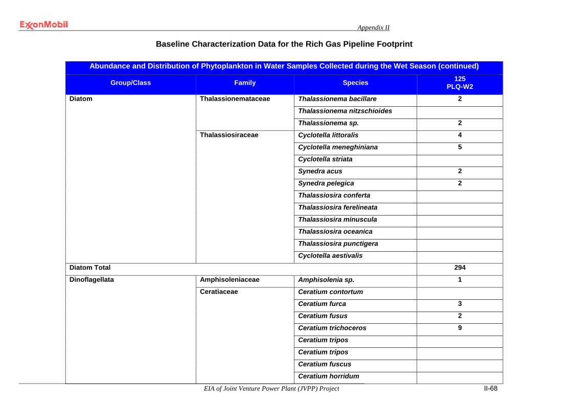
Appendix II
EIA of Joint Venture Power Plant (JVPP) Project II-68
Baseline Characterization Data for the Rich Gas Pipeline Footprint
Abundance and Distribution of Phytoplankton in Water Samples Collected during the Wet Season (continued)
Group/Class Family Species 125 PLQ-W2
Diatom Thalassionemataceae Thalassionema bacillare 2
Thalassionema nitzschioides
Thalassionema sp. 2
Thalassiosiraceae Cyclotella littoralis 4
Cyclotella meneghiniana 5
Cyclotella striata
Synedra acus 2
Synedra pelegica 2
Thalassiosira conferta
Thalassiosira ferelineata
Thalassiosira minuscula
Thalassiosira oceanica
Thalassiosira punctigera
Cyclotella aestivalis
Diatom Total 294
Dinoflagellata Amphisoleniaceae Amphisolenia sp. 1
Ceratiaceae Ceratium contortum
Ceratium furca 3
Ceratium fusus 2
Ceratium trichoceros 9
Ceratium tripos
Ceratium tripos
Ceratium fuscus
Ceratium horridum
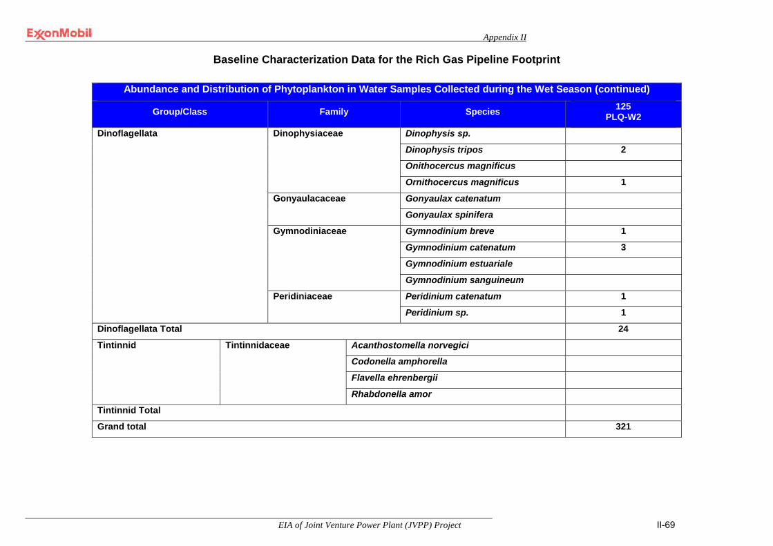
Appendix II
EIA of Joint Venture Power Plant (JVPP) Project II-69
Baseline Characterization Data for the Rich Gas Pipeline Footprint
Abundance and Distribution of Phytoplankton in Water Samples Collected during the Wet Season (continued)
Group/Class Family Species 125 PLQ-W2
Dinoflagellata Dinophysiaceae Dinophysis sp.
Dinophysis tripos 2
Onithocercus magnificus
Ornithocercus magnificus 1
Gonyaulacaceae Gonyaulax catenatum
Gonyaulax spinifera
Gymnodiniaceae Gymnodinium breve 1
Gymnodinium catenatum 3
Gymnodinium estuariale
Gymnodinium sanguineum
Peridiniaceae Peridinium catenatum 1
Peridinium sp. 1
Dinoflagellata Total 24
Tintinnid Tintinnidaceae
Acanthostomella norvegici
Codonella amphorella
Flavella ehrenbergii
Rhabdonella amor
Tintinnid Total
Grand total 321

Appendix II
EIA of Joint Venture Power Plant (JVPP) Project II-70
Baseline Characterization Data for the Rich Gas Pipeline Footprint
Abundance and Distribution of Zooplankton in Water Samples Collected during the Dry Season
Division Group/Class Family Species 125 PLQ-W2
Annelida Polychaeta ---- Polychaete larvae 3
Annelida Total 3
Arthropoda/Crustacea Amphipoda ---- Euthemisto libellula 10
Parathemisto oblivia
Arthropoda/ Harpacticoida Scyllaridae Scyllaris sp.
Copepoda ---- Meta-nauplius larvae
Nauplius larvae 6
Copepoda/Calanoida ---- Scolecithricella minor
Acartidae Acartia denae 4
Acartia discaudata
Acartia negligens
Acartia pulmosa
Acartia spinata
Acrocalanidae Acrocalanus anderson
Aetideidae Aetideus amatus
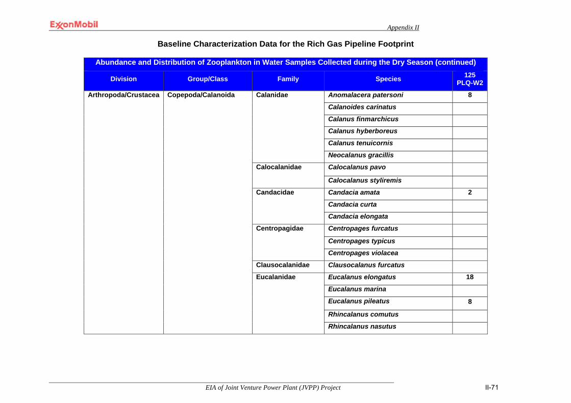
Appendix II
EIA of Joint Venture Power Plant (JVPP) Project II-71
Baseline Characterization Data for the Rich Gas Pipeline Footprint
Abundance and Distribution of Zooplankton in Water Samples Collected during the Dry Season (continued)
Division Group/Class Family Species 125 PLQ-W2
Arthropoda/Crustacea Copepoda/Calanoida Calanidae Anomalacera patersoni 8
Calanoides carinatus
Calanus finmarchicus
Calanus hyberboreus
Calanus tenuicornis
Neocalanus gracillis
Calocalanidae Calocalanus pavo
Calocalanus styliremis
Candacidae Candacia amata 2
Candacia curta
Candacia elongata
Centropagidae Centropages furcatus
Centropages typicus
Centropages violacea
Clausocalanidae Clausocalanus furcatus
Eucalanidae Eucalanus elongatus 18
Eucalanus marina
Eucalanus pileatus 8
Rhincalanus comutus
Rhincalanus nasutus
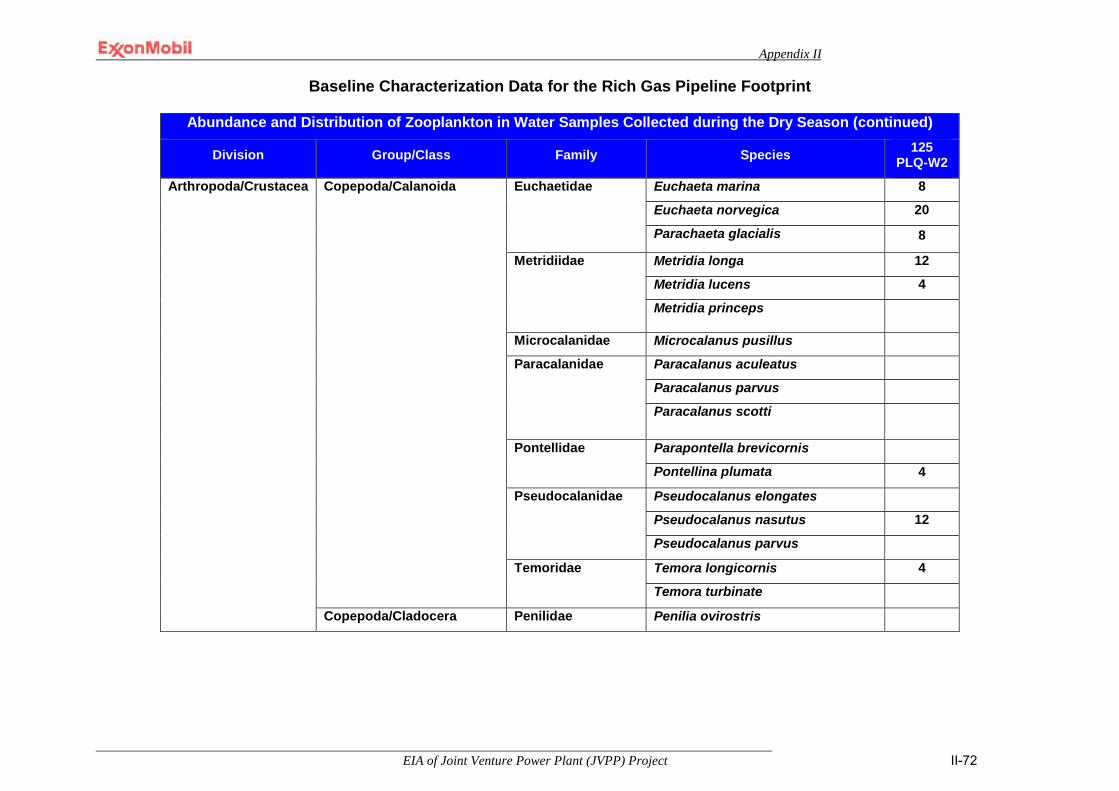
Appendix II
EIA of Joint Venture Power Plant (JVPP) Project II-72
Baseline Characterization Data for the Rich Gas Pipeline Footprint
Abundance and Distribution of Zooplankton in Water Samples Collected during the Dry Season (continued)
Division Group/Class Family Species 125 PLQ-W2
Arthropoda/Crustacea Copepoda/Calanoida
Euchaetidae Euchaeta marina 8
Euchaeta norvegica 20
Parachaeta glacialis 8
Metridiidae Metridia longa 12
Metridia lucens 4
Metridia princeps
Microcalanidae Microcalanus pusillus
Paracalanidae Paracalanus aculeatus
Paracalanus parvus
Paracalanus scotti
Pontellidae Parapontella brevicornis
Pontellina plumata 4
Pseudocalanidae Pseudocalanus elongates
Pseudocalanus nasutus 12
Pseudocalanus parvus
Temoridae Temora longicornis 4
Temora turbinate
Copepoda/Cladocera Penilidae Penilia ovirostris

Appendix II
EIA of Joint Venture Power Plant (JVPP) Project II-73
Baseline Characterization Data for the Rich Gas Pipeline Footprint
Abundance and Distribution of Zooplankton in Water Samples Collected during the Dry Season (continued)
Division Group/Class Family Species 125 PLQ-W2
Arthropoda/Crustacea Copepoda/Cyclopoida Corycaeidae Corycaeus flaccus
Corycaeus venusta
Farranula gracilis
Oithonidae Oithona atlantica
Oithona plumifera
Oithona setigera
Oithona similis 4
Onceaidae Oncea conifera 4
Oncea omata
Sappihirinidae Copilia mirabilis
Copepoda/Harpacticoida Macrosetellidae Macrosetella gracilis 2
Macrosetella rosea
Microsetellidae Microsetella norvegica
Miracidae Miracia efferata
Miracia ornata
Arthropoda/Crustacea Total 138
Chaetognatha Chaetognath Sagittidae Sagitta elegans
Sagitta enflata
Sagitta friderici
Sagitta minima
Sagitta sagitta
Sagitta sp.
Chaetognatha Total
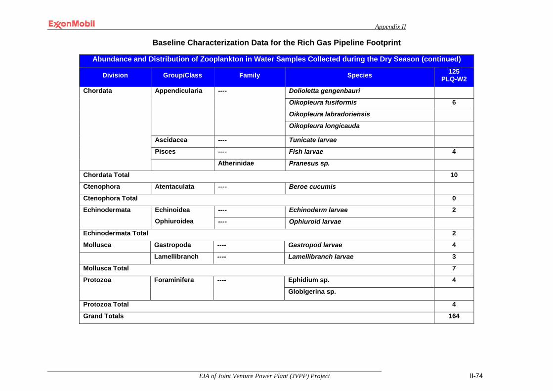
Appendix II
EIA of Joint Venture Power Plant (JVPP) Project II-74
Baseline Characterization Data for the Rich Gas Pipeline Footprint
Abundance and Distribution of Zooplankton in Water Samples Collected during the Dry Season (continued)
Division Group/Class Family Species 125 PLQ-W2
Chordata Appendicularia ---- Dolioletta gengenbauri
Oikopleura fusiformis 6
Oikopleura labradoriensis
Oikopleura longicauda
Ascidacea ---- Tunicate larvae
Pisces ---- Fish larvae 4
Atherinidae Pranesus sp.
Chordata Total 10
Ctenophora Atentaculata ---- Beroe cucumis
Ctenophora Total 0
Echinodermata Echinoidea Ophiuroidea
---- Echinoderm larvae 2
---- Ophiuroid larvae
Echinodermata Total 2
Mollusca Gastropoda ---- Gastropod larvae 4
Lamellibranch ---- Lamellibranch larvae 3
Mollusca Total 7
Protozoa Foraminifera ---- Ephidium sp. 4
Globigerina sp.
Protozoa Total 4
Grand Totals 164

Appendix II
EIA of Joint Venture Power Plant (JVPP) Project II-75
Baseline Characterization Data for the Rich Gas Pipeline Footprint
Abundance and Distribution of Zooplankton in Water Samples Collected during the Wet Season
Division Group/Class Family Species 125 PLQ-W2
Annelida Polychaeta ---- Polychaete larvae 7 Annelida Total 7 Arthropoda/Crustacea Copepoda ---- Meta-nauplius larvae
Nauplius larvae
31 Copepoda/Calanoida Acartidae Acartia denae
Acartia discaudata 15 Acartia negligens Acartia pulmosa Acartia spinata
Aetideidae Aetideus amatus 13 Calanidae Anomalacera patersoni
Calanoides carinatus 6 Calanus finmarchicus 13 Calanus tenuicornis Neocalanus gracillis
Calocalanidae Calocalanus pavo Calocalanus styliremis
Candacidae Candacia amata Candacia curta Candacia elongata
Centropagidae Centropages furcatus Centropages typicus 28 Centropages violacea
Clausocalanidae Clausocalanus furcatus

Appendix II
EIA of Joint Venture Power Plant (JVPP) Project II-76
Baseline Characterization Data for the Rich Gas Pipeline Footprint
Abundance and Distribution of Zooplankton in Water Samples Collected during the Wet Season
Division Group/Class Family Species 125 PLQ-W2
Arthropoda/Crustacea Copepoda/Calanoida Eucalanidae Eucalanus elongatus 5 Eucalanus marina Eucalanus pileatus Rhincalanus comutus Rhincalanus nasutus
Euchaetidae Euchaeta marina
Euchaeta norvegica 6
Metridiidae Metridia princeps
Microcalanidae Microcalanus pusillus
Paracalanidae Acrocalanus Anderson 7
Paracalanus aculeatus
Paracalanus parvus 31
Paracalanus scotti
Paracalanus sp.
Pontellidae Parapontella brevicornis Pontellina plumata
Pseudocalanidae
Pseudocalanus elongates 11 Pseudocalanus nasutus Pseudocalanus parvus
Temoridae Temora longicornis Temora turbinate

Appendix II
EIA of Joint Venture Power Plant (JVPP) Project II-77
Baseline Characterization Data for the Rich Gas Pipeline Footprint
Abundance and Distribution of Zooplankton in Water Samples Collected during the Wet Season (continued)
Division Group/Class Family Species 125 PLQ-W2
Arthropoda/Crustacea Copepoda/Cladocera Penilidae Penilia ovirostris Copepoda/Cyclopoida Corycaeidae Corycaeus flaccus
Corycaeus venusta 5 Farranula gracilis 3
Oithonidae Oithona atlantica Oithona plumifera Oithona setigera 8 Oithona similis 3
Onceaidae Oncea conifera 3 Oncea omata
Sappihirinidae Copilia mirabilis Copepoda/Harpacticoida Ectinosomidae Microsetella norvegica
Macrosetellidae Macrosetella gracilis 11 Macrosetella rosea
Miracidae Miracia efferata Miracia ornata
Scyllaridae Scyllaris sp. Malacostraca ---- Eucopia sp.
Arthropoda/Crustacea Total 199
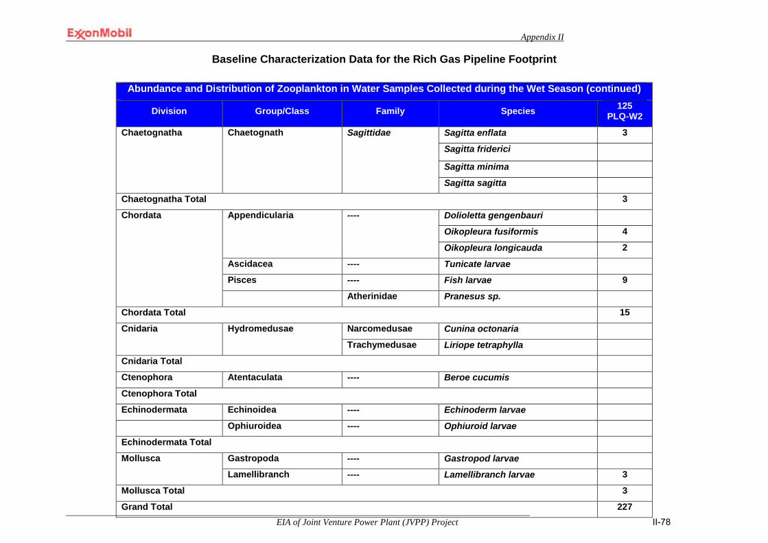
Appendix II
EIA of Joint Venture Power Plant (JVPP) Project II-78
Baseline Characterization Data for the Rich Gas Pipeline Footprint
Abundance and Distribution of Zooplankton in Water Samples Collected during the Wet Season (continued)
Division Group/Class Family Species 125 PLQ-W2
Chaetognatha Chaetognath Sagittidae Sagitta enflata 3
Sagitta friderici
Sagitta minima
Sagitta sagitta
Chaetognatha Total 3
Chordata Appendicularia ---- Dolioletta gengenbauri
Oikopleura fusiformis 4
Oikopleura longicauda 2
Ascidacea ---- Tunicate larvae
Pisces ---- Fish larvae 9
Atherinidae Pranesus sp.
Chordata Total 15
Cnidaria Hydromedusae Narcomedusae Cunina octonaria
Trachymedusae Liriope tetraphylla
Cnidaria Total
Ctenophora Atentaculata ---- Beroe cucumis
Ctenophora Total
Echinodermata Echinoidea ---- Echinoderm larvae
Ophiuroidea ---- Ophiuroid larvae
Echinodermata Total
Mollusca Gastropoda ---- Gastropod larvae
Lamellibranch ---- Lamellibranch larvae 3
Mollusca Total 3
Grand Total 227
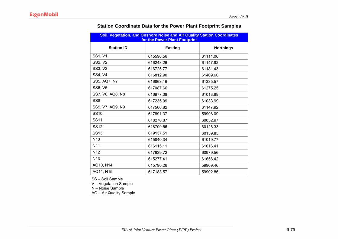
Appendix II
EIA of Joint Venture Power Plant (JVPP) Project II-79
Station Coordinate Data for the Power Plant Footprint Samples
SS – Soil Sample V – Vegetation Sample N – Noise Sample AQ – Air Quality Sample
Soil, Vegetation, and Onshore Noise and Air Quality Station Coordinates for the Power Plant Footprint
Station ID Easting Northings
SS1, V1 615596.56 61111.06 SS2, V2 616243.26 61147.92 SS3, V3 616725.77 61181.43 SS4, V4 616812.90 61469.60 SS5, AQ7, N7 616863.16 61335.57 SS6, V5 617087.66 61275.25 SS7, V6, AQ8, N8 616977.08 61013.89 SS8 617235.09 61033.99 SS9, V7, AQ9, N9 617566.82 61147.92 SS10 617891.37 59998.09 SS11 618270.87 60052.97 SS12 618709.56 60126.33 SS13 619137.51 60159.85 N10 615840.34 61019.77 N11 616115.11 61016.41 N12 617639.72 60979.56 N13 615277.41 61656.42 AQ10, N14 615790.26 59909.46 AQ11, N15 617183.57 59902.86
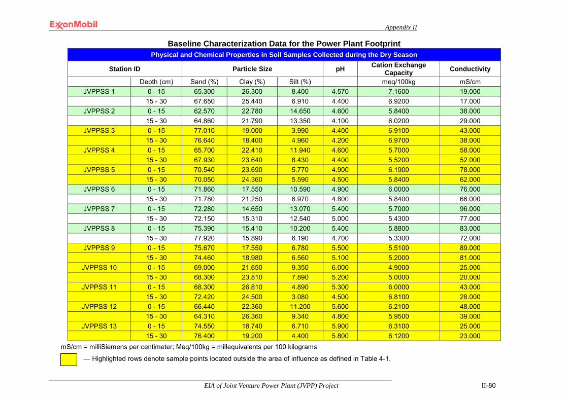
Appendix II
EIA of Joint Venture Power Plant (JVPP) Project II-80
Baseline Characterization Data for the Power Plant Footprint
mS/cm = milliSiemens per centimeter; Meq/100kg = millequivalents per 100 kilograms
— Highlighted rows denote sample points located outside the area of influence as defined in Table 4-1.
Physical and Chemical Properties in Soil Samples Collected during the Dry Season
Station ID Particle Size pH Cation Exchange Capacity Conductivity
Depth (cm) Sand (%) Clay (%) Silt (%) meq/100kg mS/cm JVPPSS 1 0 - 15 65.300 26.300 8.400 4.570 7.1600 19.000
15 - 30 67.650 25.440 6.910 4.400 6.9200 17.000 JVPPSS 2 0 - 15 62.570 22.780 14.650 4.600 5.8400 38.000
15 - 30 64.860 21.790 13.350 4.100 6.0200 29.000 JVPPSS 3 0 - 15 77.010 19.000 3.990 4.400 6.9100 43.000
15 - 30 76.640 18.400 4.960 4.200 6.9700 38.000 JVPPSS 4 0 - 15 65.700 22.410 11.940 4.600 5.7000 58.000
15 - 30 67.930 23.640 8.430 4.400 5.5200 52.000 JVPPSS 5 0 - 15 70.540 23.690 5.770 4.900 6.1900 78.000
15 - 30 70.050 24.360 5.590 4.500 5.8400 62.000 JVPPSS 6 0 - 15 71.860 17.550 10.590 4.900 6.0000 76.000
15 - 30 71.780 21.250 6.970 4.800 5.8400 66.000 JVPPSS 7 0 - 15 72.280 14.650 13.070 5.400 5.7000 96.000
15 - 30 72.150 15.310 12.540 5.000 5.4300 77.000 JVPPSS 8 0 - 15 75.390 15.410 10.200 5.400 5.8800 83.000
15 - 30 77.920 15.890 6.190 4.700 5.3300 72.000 JVPPSS 9 0 - 15 75.670 17.550 6.780 5.500 5.5100 89.000
15 - 30 74.460 18.980 6.560 5.100 5.2000 81.000 JVPPSS 10 0 - 15 69.000 21.650 9.350 6.000 4.9000 25.000
15 - 30 68.300 23.810 7.890 5.200 5.0000 20.000 JVPPSS 11 0 - 15 68.300 26.810 4.890 5.300 6.0000 43.000
15 - 30 72.420 24.500 3.080 4.500 6.8100 28.000 JVPPSS 12 0 - 15 66.440 22.360 11.200 5.600 6.2100 48.000
15 - 30 64.310 26.360 9.340 4.800 5.9500 39.000 JVPPSS 13 0 - 15 74.550 18.740 6.710 5.900 6.3100 25.000
15 - 30 76.400 19.200 4.400 5.800 6.1200 23.000

Appendix II
EIA of Joint Venture Power Plant (JVPP) Project II-81
Baseline Characterization Data for the Power Plant Footprint Physical and Chemical Properties in Soil Samples Collected during the Wet Season
Station ID Particle Size pH Cation Exchange Capacity Conductivity
Depth (cm) Sand (%) Clay (%) Silt (%) meq/100kg mS/cm JVPPSS 1 0 - 15 67.300 25.300 7.400 4.500 5.590 20.000
15 - 30 68.970 26.320 4.710 4.200 5.290 15.000 JVPPSS 2 0 - 15 62.670 32.680 14.650 4.400 4.820 35.000
15 - 30 60.860 25.790 13.350 4.100 5.020 30.000 JVPPSS 3 0 - 15 76.010 19.000 5.980 4.300 5.810 45.000
15 - 30 75.640 18.400 5.960 4.000 5.820 40.000 JVPPSS 4 0 - 15 64.060 24.100 11.900 4.800 4.630 55.000
15 - 30 63.930 23.640 8.250 4.400 4.500 50.000 JVPPSS 5 0 - 15 73.540 16.210 10.250 5.000 5.190 70.000
15 - 30 76.050 28.360 7.690 4.800 4.740 60.000 JVPPSS 6 0 - 15 72.860 17.550 9.590 5.200 4.910 90.000
15 - 30 70.170 21.250 8.580 4.700 4.820 75.000 JVPPSS 7 0 - 15 72.280 12.290 14.250 5.800 4.610 95.000
15 - 30 62.150 10.980 22.540 4.900 4.250 81.000 JVPPSS 8 0 - 15 77.330 13.280 16.740 5.300 4.770 70.000
15 - 30 67.920 15.890 24.570 4.800 4.220 65.000 JVPPSS 9 0 - 15 75.670 26.110 6.780 5.700 4.310 80.000
15 - 30 70.460 14.980 5.970 5.600 4.180 70.000 JVPPSS 10 0 - 15 68.330 22.320 9.350 4.700 3.830 22.000
15 - 30 70.300 21.810 7.890 4.500 3.920 11.000 JVPPSS 11 0 - 15 68.300 26.810 4.890 5.000 4.890 44.000
15 - 30 72.420 23.000 4.580 4.600 5.670 25.000 JVPPSS 12 0 - 15 61.910 26.360 11.730 5.400 5.620 48.000
15 - 30 67.420 23.360 9.220 4.700 5.480 38.000 JVPPSS 13 0 - 15 74.050 20.220 5.730 5.500 5.210 25.000
15 - 30 75.120 19.400 5.480 4.800 5.040 20.000

Appendix II
EIA of Joint Venture Power Plant (JVPP) Project II-82
Baseline Characterization Data for the Power Plant Footprint Nutrient and Major Cation Content in Soil Samples Collected during the Dry Season
Station ID Magnesium Phosphorus Sodium Potassium Calcium Depth (cm) mg/kg mg/kg mg/kg mg/kg mg/kg
JVPPSS 1 0 - 15 20.321 4.560 10.472 4.231 0.438 15 - 30 25.608 3.080 9.631 2.621 0.692
JVPPSS 2 0 - 15 15.402 9.600 12.493 8.331 0.469 15 - 30 20.300 5.000 10.321 2.649 0.821
JVPPSS 3 0 - 15 96.805 13.500 83.721 44.821 4.720 15 - 30 98.321 5.000 72.642 23.420 6.432
JVPPSS 4 0 - 15 10.620 14.700 20.324 23.924 0.470 15 - 30 40.631 7.200 30.236 15.431 0.495
JVPPSS 5 0 - 15 33.670 15.800 4.769 3.629 0.439 15 - 30 48.920 12.300 2.621 1.082 0.327
JVPPSS 6 0 - 15 20.810 25.000 20.620 40.392 0.364 15 - 30 21.000 13.600 18.724 23.920 0.429
JVPPSS 7 0 - 15 30.480 20.60 3.421 15.471 0.962 15 - 30 40.720 13.90 2.672 10.349 0.428
JVPPSS 8 0 - 15 11.890 28.00 5.768 20.662 0.838 15 - 30 13.680 14.20 3.891 11.731 0.108
JVPPSS 9 0 - 15 28.690 19.300 3.841 18.921 0.121 15 - 30 21.360 11.700 6.772 21.420 0.219
JVPPSS 10 0 - 15 2.150 15.600 3.836 4.310 0.621 15 - 30 4.000 10.500 1.671 2.964 0.271
JVPPSS 11 0 - 15 2.390 18.200 1.091 26.472 0.419 15 - 30 3.920 12.000 1.824 10.784 0.210
JVPPSS 12 0 - 15 4.210 20.000 1.632 10.789 0.639 15 - 30 8.930 14.600 1.062 8.231 0.275
JVPPSS 13 0 - 15 3.140 21.000 0.673 40.993 0.421 15 - 30 7.420 16.100 0.231 28.721 0.281
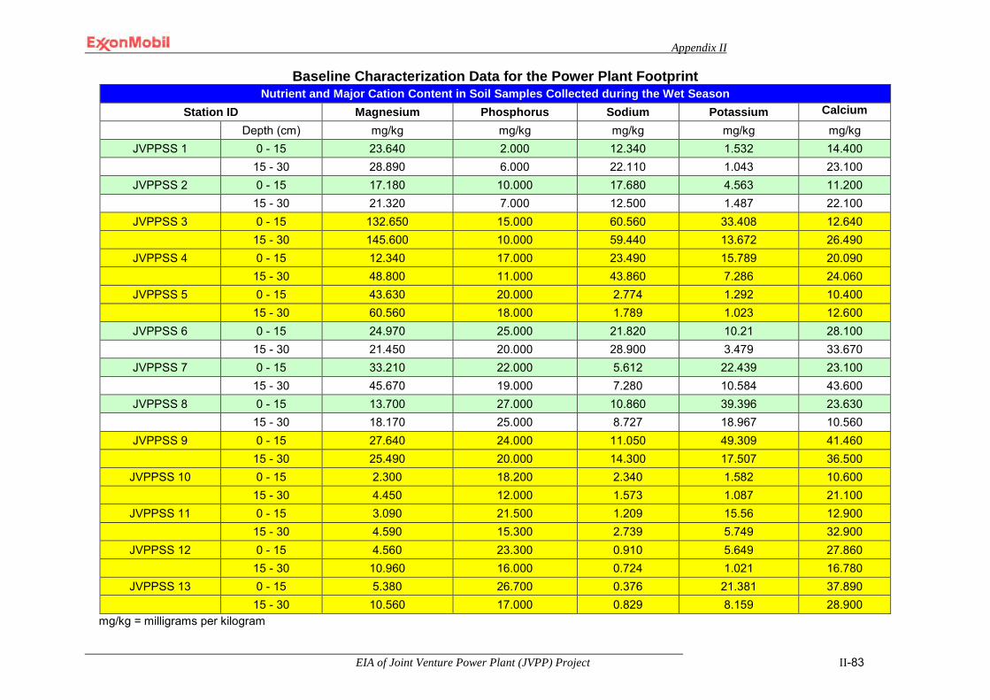
Appendix II
EIA of Joint Venture Power Plant (JVPP) Project II-83
Baseline Characterization Data for the Power Plant Footprint
mg/kg = milligrams per kilogram
Nutrient and Major Cation Content in Soil Samples Collected during the Wet Season Station ID Magnesium Phosphorus Sodium Potassium Calcium
Depth (cm) mg/kg mg/kg mg/kg mg/kg mg/kg JVPPSS 1 0 - 15 23.640 2.000 12.340 1.532 14.400
15 - 30 28.890 6.000 22.110 1.043 23.100 JVPPSS 2 0 - 15 17.180 10.000 17.680 4.563 11.200
15 - 30 21.320 7.000 12.500 1.487 22.100 JVPPSS 3 0 - 15 132.650 15.000 60.560 33.408 12.640
15 - 30 145.600 10.000 59.440 13.672 26.490 JVPPSS 4 0 - 15 12.340 17.000 23.490 15.789 20.090
15 - 30 48.800 11.000 43.860 7.286 24.060 JVPPSS 5 0 - 15 43.630 20.000 2.774 1.292 10.400
15 - 30 60.560 18.000 1.789 1.023 12.600 JVPPSS 6 0 - 15 24.970 25.000 21.820 10.21 28.100
15 - 30 21.450 20.000 28.900 3.479 33.670 JVPPSS 7 0 - 15 33.210 22.000 5.612 22.439 23.100
15 - 30 45.670 19.000 7.280 10.584 43.600 JVPPSS 8 0 - 15 13.700 27.000 10.860 39.396 23.630
15 - 30 18.170 25.000 8.727 18.967 10.560 JVPPSS 9 0 - 15 27.640 24.000 11.050 49.309 41.460
15 - 30 25.490 20.000 14.300 17.507 36.500 JVPPSS 10 0 - 15 2.300 18.200 2.340 1.582 10.600
15 - 30 4.450 12.000 1.573 1.087 21.100 JVPPSS 11 0 - 15 3.090 21.500 1.209 15.56 12.900
15 - 30 4.590 15.300 2.739 5.749 32.900 JVPPSS 12 0 - 15 4.560 23.300 0.910 5.649 27.860
15 - 30 10.960 16.000 0.724 1.021 16.780 JVPPSS 13 0 - 15 5.380 26.700 0.376 21.381 37.890
15 - 30 10.560 17.000 0.829 8.159 28.900

Appendix II
EIA of Joint Venture Power Plant (JVPP) Project II-84
Baseline Characterization Data for the Power Plant Footprint
Heavy Metal Content in Soil Samples Collected during the Dry Season
Station ID Cobalt Cadmium Chromium Copper Iron Manganese Nickel Lead Silver Vanadium Barium Arsenic Mercury Zinc
Depth (cm) mg/kg mg/kg mg/kg mg/kg mg/kg mg/kg mg/kg mg/kg mg/kg mg/kg mg/kg mg/kg mg/kg mg/kg
JVPPSS 1 0 - 15 0.120 0.012 0.025 1.500 12.340 20.430 0.136 0.210 <0.01 <0.01 1.200 0.001 <0.01 2.200 15 - 30 0.330 0.013 0.034 1.800 20.400 22.720 0.313 0.350 <0.01 <0.01 2.300 0.010 <0.01 3.200
JVPPSS 2 0 - 15 0.160 0.010 0.028 0.462 14.320 12.720 0.327 0.150 <0.01 <0.01 1.400 0.001 <0.01 2.160 15 - 30 0.410 0.001 0.036 0.837 22.720 18.740 0.632 0.162 <0.01 <0.01 3.300 0.001 <0.01 2.610
JVPPSS 3 0 - 15 0.340 0.003 0.042 0.739 15.190 93.450 0.834 0.172 <0.01 <0.01 2.000 0.001 <0.01 2.851 15 - 30 0.630 0.004 0.031 0.984 36.720 98.630 0.992 0.210 <0.01 <0.01 3.000 0.013 <0.01 1.520
JVPPSS 4 0 - 15 0.410 0.002 0.048 0.648 11.400 8.630 0.241 0.421 <0.01 <0.01 1.500 0.014 <0.01 1.521 15 - 30 0.540 0.001 0.029 0.821 22.610 13.420 0.692 0.532 <0.01 <0.01 3.100 0.012 <0.01 1.620
JVPPSS 5 0 - 15 0.040 0.020 0.034 0.142 6.320 33.670 0.092 0.439 <0.01 <0.01 1.600 0.015 <0.01 1.381 15 - 30 0.120 0.021 0.025 0.210 18.470 48.920 0.314 0.532 <0.01 <0.01 2.100 0.016 <0.01 0.839
JVPPSS 6 0 - 15 0.080 0.002 0.046 0.082 9.830 20.810 0.125 0.216 <0.01 <0.01 1.700 0.013 <0.01 1.000 15 - 30 0.310 0.001 0.015 0.162 25.740 21.000 0.472 0.125 <0.01 <0.01 2.600 0.018 <0.01 0.620
JVPPSS 7 0 - 15 0.090 0.002 0.010 0.110 8.480 30.480 0.030 0.158 <0.01 <0.01 1.720 0.015 <0.01 2.419 15 - 30 0.430 0.006 0.020 0.238 27.920 40.720 0.243 0.173 <0.01 <0.01 2.500 0.018 <0.01 2.021
JVPPSS 8 0 - 15 0.070 0.003 0.046 0.201 11.710 11.890 0.920 0.292 <0.01 <0.01 1.800 0.013 <0.01 0.972 15 - 30 0.180 0.006 0.052 0.263 30.410 13.680 2.431 0.272 <0.01 <0.01 2.500 0.014 <0.01 1.410
JVPPSS 9 0 - 15 0.040 0.008 0.031 0.428 7.690 28.690 4.431 0.362 <0.01 <0.01 1.600 0.011 <0.01 2.419 15 - 30 0.090 0.012 0.046 0.629 21.320 21.360 6.321 0.521 <0.01 <0.01 3.000 0.010 <0.01 2.000
JVPPSS 10 0 - 15 0.130 0.007 0.026 0.083 6.130 2.150 0.423 0.672 <0.01 <0.01 0.600 0.012 <0.01 0.539 15 - 30 0.090 0.006 0.042 0.290 26.930 4.000 0.672 0.362 <0.01 <0.01 1.900 0.013 <0.01 0.539
JVPPSS 11 0 - 15 0.030 0.006 0.039 0.329 37.930 2.390 0.233 0.471 <0.01 <0.01 0.300 0.014 <0.01 0.842 15 - 30 0.080 0.001 0.055 0.210 69.720 3.920 0.641 0.363 <0.01 <0.01 1.400 0.015 <0.01 0.752
JVPPSS 12 0 - 15 0.030 0.001 <0.01 0.010 83.410 4.210 0.361 0.389 <0.01 <0.01 0.200 0.016 <0.01 0.319 15 - 30 0.130 0.004 <0.01 0.013 99.330 8.930 0.742 0.421 <0.01 <0.01 1.000 0.010 <0.01 0.438
JVPPSS 13 0 - 15 0.180 0.003 <0.01 0.011 54.310 3.140 0.420 0.473 <0.01 <0.01 0.800 0.015 <0.01 0.609 15 - 30 0.370 0.005 <0.01 0.013 63.490 7.420 0.821 0.521 <0.01 <0.01 2.000 0.013 <0.01 0.947

Appendix II
EIA of Joint Venture Power Plant (JVPP) Project II-85
Baseline Characterization Data for the Power Plant Footprint Heavy Metal Content in Soil Samples Collected during the Wet Season
Station ID Cobalt Cadmium Chromium Copper Iron Manganese Nickel Lead Silver Vanadium Barium Arsenic Mercury Zinc
Depth (cm) mg/kg mg/kg mg/kg mg/kg mg/kg mg/kg mg/kg mg/kg mg/kg mg/kg mg/kg mg/kg mg/kg mg/kg
JVPPSS 1 0 - 15 0.01 0.032 0.321 0.131 33.330 5.630 0.129 0.012 <0.01 <0.01 1.700 0.004 <0.01 0.876 15 - 30 0.06 0.067 0.69 0.281 54.390 2.684 0.211 0.023 <0.01 <0.01 3.900 0.001 <0.01 1.689
JVPPSS 2 0 - 15 0.03 0.006 0.356 0.043 23.400 5.800 0.256 0.032 <0.01 <0.01 3.4000 0.006 <0.01 1.459 15 - 30 0.08 0.003 0.673 0.128 47.500 6.392 0.431 0.054 <0.01 <0.01 6.7000 0.005 <0.01 1.378
JVPPSS 3 0 - 15 0.07 0.019 0.639 0.167 35.700 2.690 0.329 0.034 <0.01 <0.01 4.1000 0.014 <0.01 1.749 15 - 30 0.05 0.012 0.965 0.44 66.100 3.692 0.509 0.078 <0.01 <0.01 6.7000 0.016 <0.01 1.326
JVPPSS 4 0 - 15 0.09 0.032 0.439 0.134 21.100 1.683 0.163 0.010 <0.01 <0.01 3.0000 0.013 <0.01 0.839 15 - 30 0.01 0.068 0.821 0.163 35.980 1.840 0.278 0.033 <0.01 <0.01 6.2000 0.011 <0.01 0.275
JVPPSS 5 0 - 15 0.02 0.072 0.471 0.096 12.600 7.420 0.12 0.540 <0.01 <0.01 3.0000 0.017 0.01 0.776 15 - 30 0.04 0.089 0.629 0.132 28.900 3.284 0.243 0.580 <0.01 <0.01 4.2000 0.014 <0.01 0.376
JVPPSS 6 0 - 15 0.03 0.007 0.469 0.092 19.130 2.184 0.233 0.084 <0.01 <0.01 3.4000 0.019 <0.01 0.409 15 - 30 0.01 0.003 0.73 0.135 43.200 2.285 0.219 0.025 <0.01 <0.01 5.2000 0.016 <0.01 0.205
JVPPSS 7 0 - 15 0.08 0.015 0.318 0.084 17.860 2.042 0.367 0.046 <0.01 <0.01 2.5000 0.017 <0.01 1.863 15 - 30 0.02 0.019 0.631 0.132 42.640 1.942 0.137 0.086 <0.01 <0.01 4.1000 0.018 <0.01 1.043
JVPPSS 8 0 - 15 0.01 0.012 0.438 0.109 22.340 1.050 0.126 0.021 <0.01 <0.01 1.5000 0.015 <0.01 0.675 15 - 30 0.01 0.019 0.705 1.173 69.320 1.573 0.289 0.052 <0.01 <0.01 3.3000 0.017 <0.01 0.91
JVPPSS 9 0 - 15 0.05 0.022 0.437 0.211 15.640 1.503 0.162 0.057 <0.01 <0.01 2.1000 0.014 <0.01 1.693 15 - 30 0.03 0.034 0.581 0.333 49.000 3.200 0.321 0.082 <0.01 <0.01 5.6000 0.012 <0.01 1.005
JVPPSS 10 0 - 15 0.05 0.013 0.351 0.063 19.100 2.480 0.148 0.012 <0.01 <0.01 1.0000 0.016 <0.01 0.485 15 - 30 0.06 0.013 0.573 0.154 41.280 3.631 0.312 0.054 <0.01 <0.01 3.6000 0.013 <0.01 0.275
JVPPSS 11 0 - 15 0.03 0.003 0.371 0.009 78.070 8.503 0.159 0.011 <0.01 <0.01 0.8000 0.019 <0.01 0.309 15 - 30 0.01 0.009 0.641 0.109 102.480 3.940 0.367 0.026 <0.01 <0.01 2.2000 0.016 <0.01 0.3
JVPPSS 12 0 - 15 0.04 0.008 0.143 <0.01 118.590 4.603 0.13 0.015 <0.01 <0.01 0.3000 0.013 <0.01 0.111 15 - 30 0.08 0.013 0.356 <0.01 145.180 2.610 0.289 0.016 <0.01 <0.01 2.0000 0.016 <0.01 0.26
JVPPSS 13 0 - 15 0.02 0.011 0.189 <0.01 103.210 5.392 0.15 0.012 <0.01 <0.01 1.3000 0.015 <0.01 1.308 15 - 30 0.1 0.01 0.456 <0.01 135.260 3.802 0.321 0.032 <0.01 <0.01 3.5000 0.011 <0.01 1.218

Appendix II
EIA of Joint Venture Power Plant (JVPP) Project II-86
Baseline Characterization Data for the Power Plant Footprint Hydrocarbon Content in Soil Samples Collected during the Dry Season
Station ID TOC THC PAH Aliphatics Oil & Grease TPH Depth (cm) % mg/kg mg/kg mg/kg mg/kg mg/kg
JVPPSS 1 0 - 15 2.370 1.380 <0.01 2.201 0.560 1.000 15 - 30 2.190 2.100 <0.01 1.103 0.630 2.390
JVPPSS 2 0 - 15 1.400 6.420 <0.01 2.561 0.840 3.980 15 - 30 0.580 3.000 <0.01 1.207 0.670 8.320
JVPPSS 3 0 - 15 2.320 16.420 <0.01 3.185 1.320 1.600 15 - 30 2.050 8.320 <0.01 2.430 0.650 1.700
JVPPSS 4 0 - 15 2.890 18.530 <0.02 3.474 2.760 4.900 15 - 30 2.430 5.300 <0.03 1.260 0.750 1.500
JVPPSS 5 0 - 15 2.190 15.320 <0.04 3.261 1.220 3.650 15 - 30 1.590 4.560 <0.05 1.800 0.640 0.973
JVPPSS 6 0 - 15 2.390 32.670 <0.06 8.532 3.210 2.500 15 - 30 1.690 17.490 <0.07 3.740 1.020 2.650
JVPPSS 7 0 - 15 2.700 27.600 <0.08 6.472 0.270 5.400 15 - 30 2.320 21.690 <0.09 7.320 0.190 1.532
JVPPSS 8 0 - 15 1.300 32.430 <0.10 8.420 0.630 3.261 15 - 30 1.210 16.290 <0.11 4.320 0.430 0.830
JVPPSS 9 0 - 15 1.430 30.590 <0.12 8.210 0.310 3.420 15 - 30 1.230 46.310 <0.13 9.210 0.160 0.621
JVPPSS 10 0 - 15 0.490 2.340 <0.14 0.821 0.870 2.485 15 - 30 0.260 1.500 <0.15 0.521 0.310 2.150
JVPPSS 11 0 - 15 1.960 5.620 <0.16 1.620 1.230 3.130 15 - 30 1.430 3.270 <0.17 1.629 0.320 0.154
JVPPSS 12 0 - 15 1.430 3.470 <0.18 1.428 2.620 2.175 15 - 30 1.210 1.390 <0.19 0.362 1.200 1.396
JVPPSS 13 0 - 15 2.100 3.590 <0.20 1.472 3.960 1.419 15 - 30 1.980 1.670 <0.21 0.621 1.740 3.163
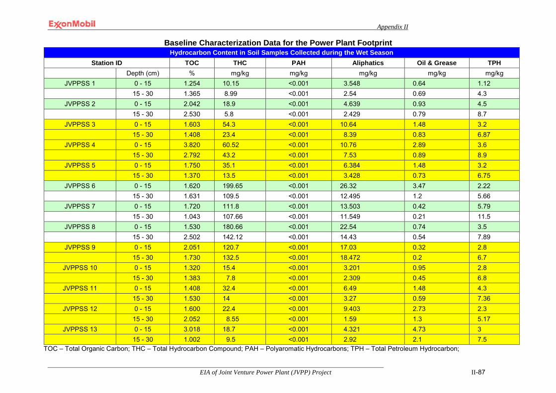
Appendix II
EIA of Joint Venture Power Plant (JVPP) Project II-87
Baseline Characterization Data for the Power Plant Footprint
TOC – Total Organic Carbon; THC – Total Hydrocarbon Compound; PAH – Polyaromatic Hydrocarbons; TPH – Total Petroleum Hydrocarbon;
Hydrocarbon Content in Soil Samples Collected during the Wet Season Station ID TOC THC PAH Aliphatics Oil & Grease TPH
Depth (cm) % mg/kg mg/kg mg/kg mg/kg mg/kg JVPPSS 1 0 - 15 1.254 10.15 <0.001 3.548 0.64 1.12
15 - 30 1.365 8.99 <0.001 2.54 0.69 4.3 JVPPSS 2 0 - 15 2.042 18.9 <0.001 4.639 0.93 4.5
15 - 30 2.530 5.8 <0.001 2.429 0.79 8.7 JVPPSS 3 0 - 15 1.603 54.3 <0.001 10.64 1.48 3.2
15 - 30 1.408 23.4 <0.001 8.39 0.83 6.87 JVPPSS 4 0 - 15 3.820 60.52 <0.001 10.76 2.89 3.6
15 - 30 2.792 43.2 <0.001 7.53 0.89 8.9 JVPPSS 5 0 - 15 1.750 35.1 <0.001 6.384 1.48 3.2
15 - 30 1.370 13.5 <0.001 3.428 0.73 6.75 JVPPSS 6 0 - 15 1.620 199.65 <0.001 26.32 3.47 2.22
15 - 30 1.631 109.5 <0.001 12.495 1.2 5.66 JVPPSS 7 0 - 15 1.720 111.8 <0.001 13.503 0.42 5.79
15 - 30 1.043 107.66 <0.001 11.549 0.21 11.5 JVPPSS 8 0 - 15 1.530 180.66 <0.001 22.54 0.74 3.5
15 - 30 2.502 142.12 <0.001 14.43 0.54 7.89 JVPPSS 9 0 - 15 2.051 120.7 <0.001 17.03 0.32 2.8
15 - 30 1.730 132.5 <0.001 18.472 0.2 6.7 JVPPSS 10 0 - 15 1.320 15.4 <0.001 3.201 0.95 2.8
15 - 30 1.383 7.8 <0.001 2.309 0.45 6.8 JVPPSS 11 0 - 15 1.408 32.4 <0.001 6.49 1.48 4.3
15 - 30 1.530 14 <0.001 3.27 0.59 7.36 JVPPSS 12 0 - 15 1.600 22.4 <0.001 9.403 2.73 2.3
15 - 30 2.052 8.55 <0.001 1.59 1.3 5.17 JVPPSS 13 0 - 15 3.018 18.7 <0.001 4.321 4.73 3
15 - 30 1.002 9.5 <0.001 2.92 2.1 7.5
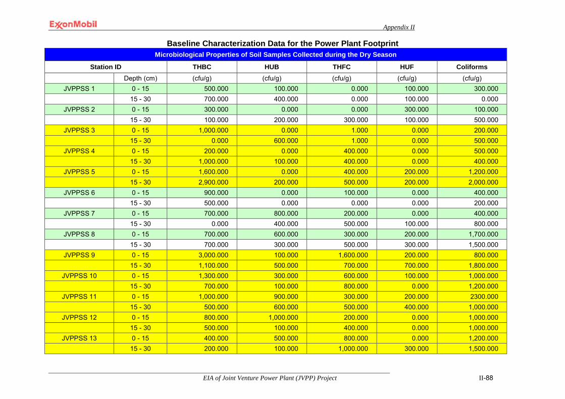
Appendix II
EIA of Joint Venture Power Plant (JVPP) Project II-88
Baseline Characterization Data for the Power Plant Footprint Microbiological Properties of Soil Samples Collected during the Dry Season
Station ID THBC HUB THFC HUF Coliforms Depth (cm) (cfu/g) (cfu/g) (cfu/g) (cfu/g) (cfu/g)
JVPPSS 1 0 - 15 500.000 100.000 0.000 100.000 300.000 15 - 30 700.000 400.000 0.000 100.000 0.000
JVPPSS 2 0 - 15 300.000 0.000 0.000 300.000 100.000 15 - 30 100.000 200.000 300.000 100.000 500.000
JVPPSS 3 0 - 15 1,000.000 0.000 1.000 0.000 200.000 15 - 30 0.000 600.000 1.000 0.000 500.000
JVPPSS 4 0 - 15 200.000 0.000 400.000 0.000 500.000 15 - 30 1,000.000 100.000 400.000 0.000 400.000
JVPPSS 5 0 - 15 1,600.000 0.000 400.000 200.000 1,200.000 15 - 30 2,900.000 200.000 500.000 200.000 2,000.000
JVPPSS 6 0 - 15 900.000 0.000 100.000 0.000 400.000 15 - 30 500.000 0.000 0.000 0.000 200.000
JVPPSS 7 0 - 15 700.000 800.000 200.000 0.000 400.000 15 - 30 0.000 400.000 500.000 100.000 800.000
JVPPSS 8 0 - 15 700.000 600.000 300.000 200.000 1,700.000 15 - 30 700.000 300.000 500.000 300.000 1,500.000
JVPPSS 9 0 - 15 3,000.000 100.000 1,600.000 200.000 800.000 15 - 30 1,100.000 500.000 700.000 700.000 1,800.000
JVPPSS 10 0 - 15 1,300.000 300.000 600.000 100.000 1,000.000 15 - 30 700.000 100.000 800.000 0.000 1,200.000
JVPPSS 11 0 - 15 1,000.000 900.000 300.000 200.000 2300.000 15 - 30 500.000 600.000 500.000 400.000 1,000.000
JVPPSS 12 0 - 15 800.000 1,000.000 200.000 0.000 1,000.000 15 - 30 500.000 100.000 400.000 0.000 1,000.000
JVPPSS 13 0 - 15 400.000 500.000 800.000 0.000 1,200.000 15 - 30 200.000 100.000 1,000.000 300.000 1,500.000
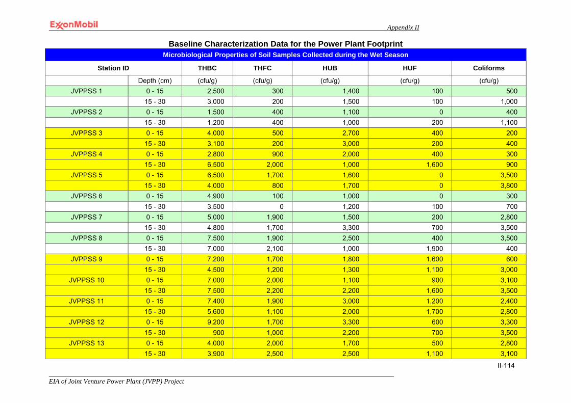
Appendix II
EIA of Joint Venture Power Plant (JVPP) Project
II-114
Baseline Characterization Data for the Power Plant Footprint Microbiological Properties of Soil Samples Collected during the Wet Season
Station ID THBC THFC HUB HUF Coliforms
Depth (cm) (cfu/g) (cfu/g) (cfu/g) (cfu/g) (cfu/g) JVPPSS 1 0 - 15 2,500 300 1,400 100 500
15 - 30 3,000 200 1,500 100 1,000 JVPPSS 2 0 - 15 1,500 400 1,100 0 400
15 - 30 1,200 400 1,000 200 1,100 JVPPSS 3 0 - 15 4,000 500 2,700 400 200
15 - 30 3,100 200 3,000 200 400 JVPPSS 4 0 - 15 2,800 900 2,000 400 300
15 - 30 6,500 2,000 1,000 1,600 900 JVPPSS 5 0 - 15 6,500 1,700 1,600 0 3,500
15 - 30 4,000 800 1,700 0 3,800 JVPPSS 6 0 - 15 4,900 100 1,000 0 300
15 - 30 3,500 0 1,200 100 700 JVPPSS 7 0 - 15 5,000 1,900 1,500 200 2,800
15 - 30 4,800 1,700 3,300 700 3,500 JVPPSS 8 0 - 15 7,500 1,900 2,500 400 3,500
15 - 30 7,000 2,100 1,000 1,900 400 JVPPSS 9 0 - 15 7,200 1,700 1,800 1,600 600
15 - 30 4,500 1,200 1,300 1,100 3,000 JVPPSS 10 0 - 15 7,000 2,000 1,100 900 3,100
15 - 30 7,500 2,200 2,200 1,600 3,500 JVPPSS 11 0 - 15 7,400 1,900 3,000 1,200 2,400
15 - 30 5,600 1,100 2,000 1,700 2,800 JVPPSS 12 0 - 15 9,200 1,700 3,300 600 3,300
15 - 30 900 1,000 2,200 700 3,500 JVPPSS 13 0 - 15 4,000 2,000 1,700 500 2,800
15 - 30 3,900 2,500 2,500 1,100 3,100
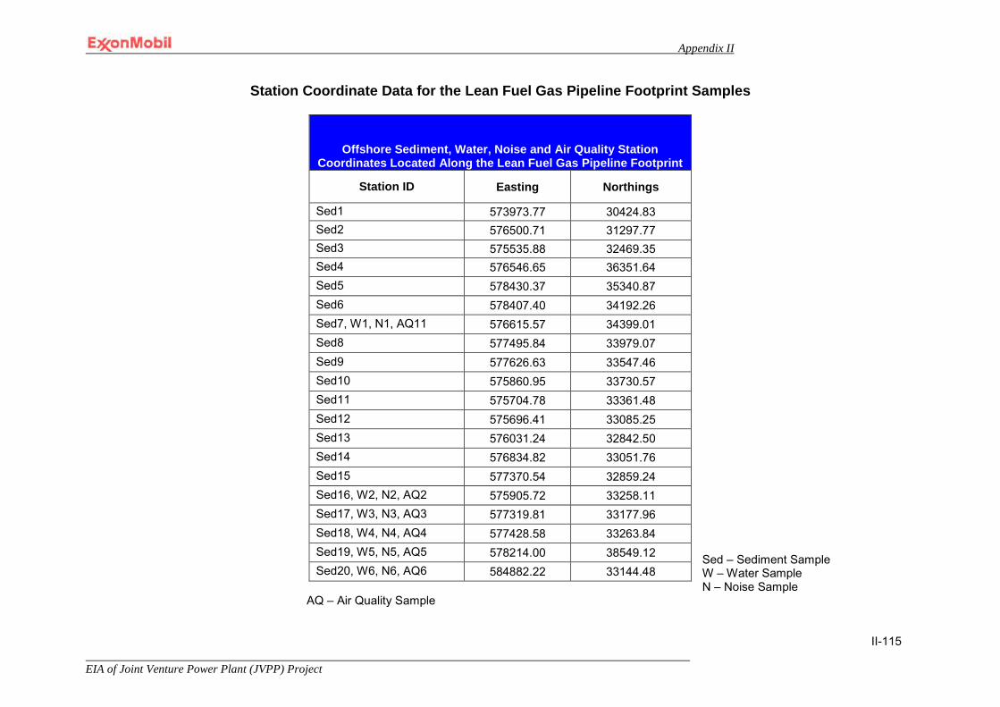
Appendix II
EIA of Joint Venture Power Plant (JVPP) Project
II-115
Station Coordinate Data for the Lean Fuel Gas Pipeline Footprint Samples
Sed – Sediment Sample W – Water Sample N – Noise Sample
AQ – Air Quality Sample
Offshore Sediment, Water, Noise and Air Quality Station Coordinates Located Along the Lean Fuel Gas Pipeline Footprint
Station ID Easting Northings
Sed1 573973.77 30424.83 Sed2 576500.71 31297.77 Sed3 575535.88 32469.35 Sed4 576546.65 36351.64 Sed5 578430.37 35340.87 Sed6 578407.40 34192.26 Sed7, W1, N1, AQ11 576615.57 34399.01 Sed8 577495.84 33979.07 Sed9 577626.63 33547.46 Sed10 575860.95 33730.57 Sed11 575704.78 33361.48 Sed12 575696.41 33085.25 Sed13 576031.24 32842.50 Sed14 576834.82 33051.76 Sed15 577370.54 32859.24 Sed16, W2, N2, AQ2 575905.72 33258.11 Sed17, W3, N3, AQ3 577319.81 33177.96 Sed18, W4, N4, AQ4 577428.58 33263.84 Sed19, W5, N5, AQ5 578214.00 38549.12 Sed20, W6, N6, AQ6 584882.22 33144.48
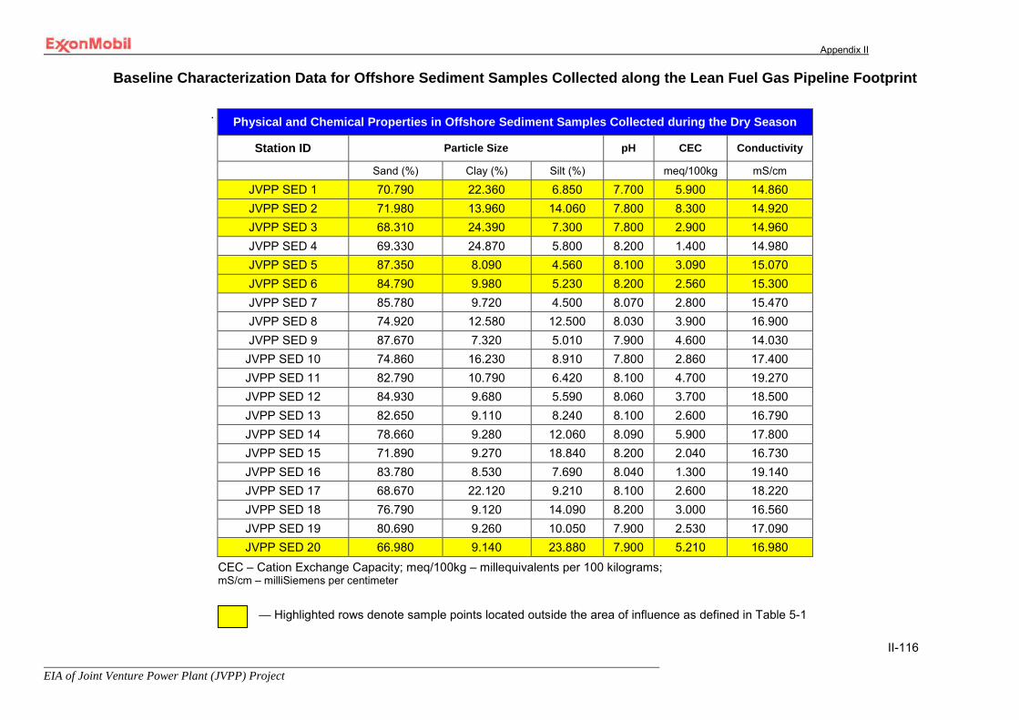
Appendix II
EIA of Joint Venture Power Plant (JVPP) Project
II-116
Baseline Characterization Data for Offshore Sediment Samples Collected along the Lean Fuel Gas Pipeline Footprint
.
CEC – Cation Exchange Capacity; meq/100kg – millequivalents per 100 kilograms; mS/cm – milliSiemens per centimeter
— Highlighted rows denote sample points located outside the area of influence as defined in Table 5-1
Physical and Chemical Properties in Offshore Sediment Samples Collected during the Dry Season
Station ID Particle Size pH CEC Conductivity
Sand (%) Clay (%) Silt (%) meq/100kg mS/cm
JVPP SED 1 70.790 22.360 6.850 7.700 5.900 14.860 JVPP SED 2 71.980 13.960 14.060 7.800 8.300 14.920 JVPP SED 3 68.310 24.390 7.300 7.800 2.900 14.960 JVPP SED 4 69.330 24.870 5.800 8.200 1.400 14.980 JVPP SED 5 87.350 8.090 4.560 8.100 3.090 15.070 JVPP SED 6 84.790 9.980 5.230 8.200 2.560 15.300 JVPP SED 7 85.780 9.720 4.500 8.070 2.800 15.470 JVPP SED 8 74.920 12.580 12.500 8.030 3.900 16.900 JVPP SED 9 87.670 7.320 5.010 7.900 4.600 14.030
JVPP SED 10 74.860 16.230 8.910 7.800 2.860 17.400 JVPP SED 11 82.790 10.790 6.420 8.100 4.700 19.270 JVPP SED 12 84.930 9.680 5.590 8.060 3.700 18.500 JVPP SED 13 82.650 9.110 8.240 8.100 2.600 16.790 JVPP SED 14 78.660 9.280 12.060 8.090 5.900 17.800 JVPP SED 15 71.890 9.270 18.840 8.200 2.040 16.730 JVPP SED 16 83.780 8.530 7.690 8.040 1.300 19.140 JVPP SED 17 68.670 22.120 9.210 8.100 2.600 18.220 JVPP SED 18 76.790 9.120 14.090 8.200 3.000 16.560 JVPP SED 19 80.690 9.260 10.050 7.900 2.530 17.090 JVPP SED 20 66.980 9.140 23.880 7.900 5.210 16.980
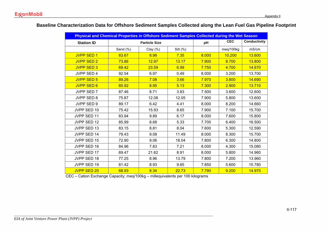
Appendix II
EIA of Joint Venture Power Plant (JVPP) Project
II-117
Baseline Characterization Data for Offshore Sediment Samples Collected along the Lean Fuel Gas Pipeline Footprint
Physical and Chemical Properties in Offshore Sediment Samples Collected during the Wet Season
Station ID Particle Size pH CEC Conductivity
Sand (%) Clay (%) Silt (%) meq/100kg mS/cm
JVPP SED 1 83.67 8.98 7.35 8.000 10.200 13.600 JVPP SED 2 73.86 12.97 13.17 7.900 8.700 13.800 JVPP SED 3 69.42 23.59 6.99 7.750 4.700 14.670 JVPP SED 4 92.54 6.97 0.49 8.000 3.200 13.700 JVPP SED 5 89.26 7.08 3.66 7.970 3.800 14.690 JVPP SED 6 85.92 8.95 5.13 7.300 2.900 13.710 JVPP SED 7 87.46 8.71 3.83 7.500 3.600 12.600 JVPP SED 8 75.87 12.08 12.05 7.900 5.800 13.600 JVPP SED 9 89.17 6.42 4.41 8.000 8.200 14.660
JVPP SED 10 75.42 15.93 8.65 7.900 7.100 15.700 JVPP SED 11 83.94 9.89 6.17 8.000 7.600 15.800 JVPP SED 12 85.99 8.68 5.33 7.700 6.400 16.500 JVPP SED 13 83.15 8.81 8.04 7.600 5.300 12.590 JVPP SED 14 79.43 9.08 11.49 8.000 8.300 15.700 JVPP SED 15 72.90 9.06 18.04 7.800 6.300 14.800 JVPP SED 16 84.96 7.83 7.21 8.000 4.300 15.080 JVPP SED 17 69.47 21.62 8.91 8.000 5.800 14.960 JVPP SED 18 77.25 8.96 13.79 7.800 7.200 13.960 JVPP SED 19 81.42 8.93 9.65 7.850 5.600 15.780 JVPP SED 20 68.93 8.34 22.73 7.790 9.200 14.970
CEC – Cation Exchange Capacity; meq/100kg – millequivalents per 100 kilograms

Appendix II
EIA of Joint Venture Power Plant (JVPP) Project
II-118
Baseline Characterization Data for Offshore Sediment Samples Collected along the Lean Fuel Gas Pipeline Footprint
Nutrient and Major Cation Content in Offshore Sediment Samples Collected during the Dry Season
Station ID Magnesium Calcium Sodium Potassium mg/kg mg/kg mg/kg mg/kg
JVPP SED 1 139.200 18.430 188.436 13.200 JVPP SED 2 123.500 20.280 193.271 18.900 JVPP SED 3 169.050 16.720 159.400 20.320 JVPP SED 4 139.040 15.300 147.401 17.320 JVPP SED 5 121.700 52.000 180.368 32.300 JVPP SED 6 140.420 63.700 209.973 26.720 JVPP SED 7 138.900 72.921 220.949 22.930 JVPP SED 8 112.420 82.315 213.941 33.620 JVPP SED 9 141.800 84.512 218.372 26.890
JVPP SED 10 126.470 88.150 189.743 28.730 JVPP SED 11 113.800 83.000 130.160 30.730 JVPP SED 12 125.430 82.050 238.490 38.930 JVPP SED 13 120.700 95.932 233.750 23.420 JVPP SED 14 131.630 98.720 220.486 20.480 JVPP SED 15 126.410 97.321 231.300 31.430 JVPP SED 16 120.430 82.432 216.462 16.230 JVPP SED 17 132.690 112.150 155.621 15.470 JVPP SED 18 103.590 88.345 213.301 13.820 JVPP SED 19 158.900 83.913 212.750 12.750 JVPP SED 20 142.770 64.320 210.218 10.920
mg/kg – milligrams per kilogram
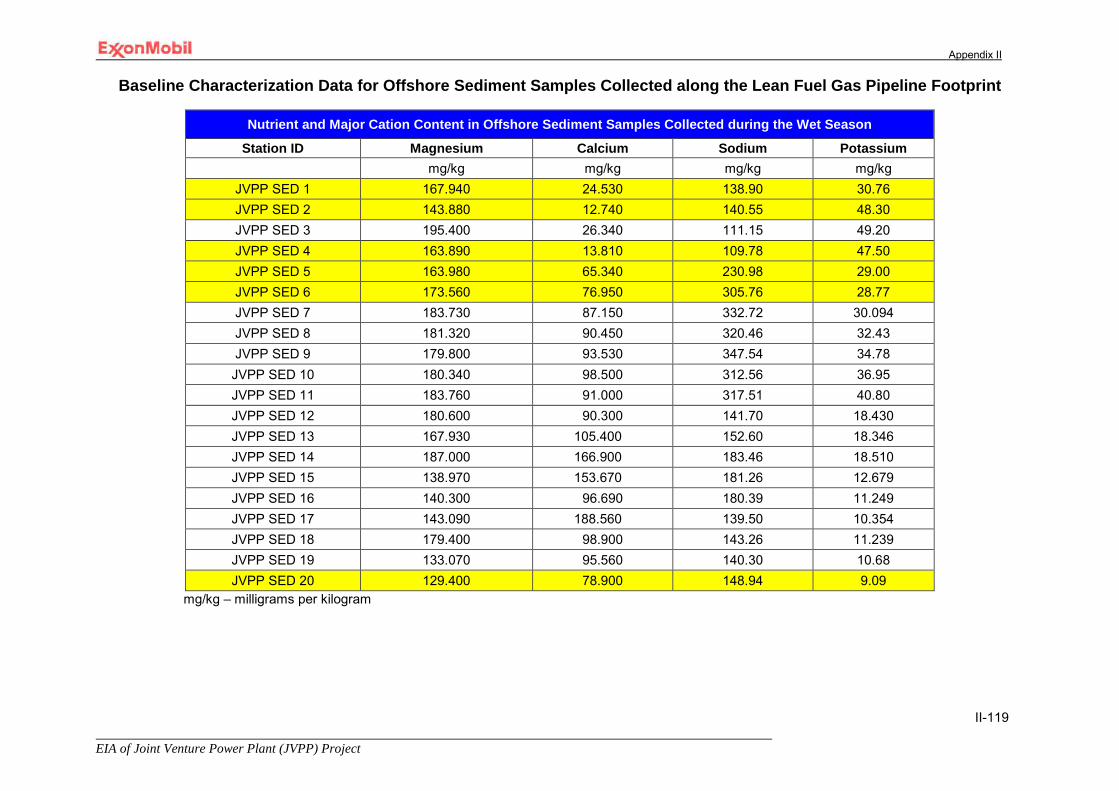
Appendix II
EIA of Joint Venture Power Plant (JVPP) Project
II-119
Baseline Characterization Data for Offshore Sediment Samples Collected along the Lean Fuel Gas Pipeline Footprint
Nutrient and Major Cation Content in Offshore Sediment Samples Collected during the Wet Season
Station ID Magnesium Calcium Sodium Potassium mg/kg mg/kg mg/kg mg/kg
JVPP SED 1 167.940 24.530 138.90 30.76 JVPP SED 2 143.880 12.740 140.55 48.30 JVPP SED 3 195.400 26.340 111.15 49.20 JVPP SED 4 163.890 13.810 109.78 47.50 JVPP SED 5 163.980 65.340 230.98 29.00 JVPP SED 6 173.560 76.950 305.76 28.77 JVPP SED 7 183.730 87.150 332.72 30.094 JVPP SED 8 181.320 90.450 320.46 32.43 JVPP SED 9 179.800 93.530 347.54 34.78 JVPP SED 10 180.340 98.500 312.56 36.95 JVPP SED 11 183.760 91.000 317.51 40.80 JVPP SED 12 180.600 90.300 141.70 18.430 JVPP SED 13 167.930 105.400 152.60 18.346 JVPP SED 14 187.000 166.900 183.46 18.510 JVPP SED 15 138.970 153.670 181.26 12.679 JVPP SED 16 140.300 96.690 180.39 11.249 JVPP SED 17 143.090 188.560 139.50 10.354 JVPP SED 18 179.400 98.900 143.26 11.239 JVPP SED 19 133.070 95.560 140.30 10.68 JVPP SED 20 129.400 78.900 148.94 9.09
mg/kg – milligrams per kilogram
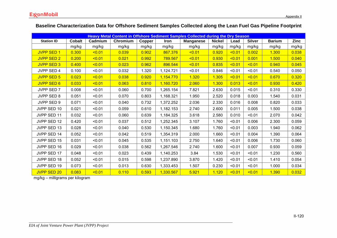
Appendix II
EIA of Joint Venture Power Plant (JVPP) Project
II-120
Baseline Characterization Data for Offshore Sediment Samples Collected along the Lean Fuel Gas Pipeline Footprint
Heavy Metal Content in Offshore Sediment Samples Collected during the Dry Season Station ID Cobalt Cadmium Chromium Copper Iron Manganese Nickel Lead Silver Barium Zinc
mg/kg mg/kg mg/kg mg/kg mg/kg mg/kg mg/kg mg/kg mg/kg mg/kg mg/kg JVPP SED 1 0.300 <0.01 0.039 0.902 867.376 <0.01 0.920 <0.01 0.002 1.300 0.038 JVPP SED 2 0.200 <0.01 0.021 0.992 789.567 <0.01 0.930 <0.01 0.001 1.500 0.040 JVPP SED 3 0.400 <0.01 0.023 0.962 896.544 <0.01 0.835 <0.01 <0.01 0.940 0.045 JVPP SED 4 0.100 <0.01 0.032 1.320 1,124.721 <0.01 0.846 <0.01 <0.01 0.540 0.050 JVPP SED 5 0.023 <0.01 0.038 0.920 1,154.770 1.320 1.305 <0.01 <0.01 0.670 0.320 JVPP SED 6 0.033 <0.01 0.063 0.810 1,160.720 2.060 1.300 0.013 <0.01 0.930 0.420 JVPP SED 7 0.008 <0.01 0.060 0.700 1,265.154 7.821 2.630 0.015 <0.01 0.310 0.330 JVPP SED 8 0.051 <0.01 0.070 0.803 1,168.321 1.950 2.520 0.018 0.003 1.540 0.031 JVPP SED 9 0.071 <0.01 0.040 0.732 1,372.252 2.036 2.330 0.016 0.008 0.820 0.033
JVPP SED 10 0.021 <0.01 0.059 0.610 1,182.153 2.740 2.600 0.011 0.005 1.500 0.038 JVPP SED 11 0.032 <0.01 0.060 0.639 1,184.325 3.618 2.580 0.010 <0.01 2.070 0.042 JVPP SED 12 0.420 <0.01 0.037 0.512 1,252.345 3.107 1.760 <0.01 0.006 2.300 0.059 JVPP SED 13 0.028 <0.01 0.040 0.530 1,150.345 1.680 1.760 <0.01 0.003 1.940 0.062 JVPP SED 14 0.052 <0.01 0.042 0.519 1,354.319 2.000 1.660 <0.01 0.004 1.390 0.064 JVPP SED 15 0.031 <0.01 0.045 0.535 1,151.103 2.750 1.640 <0.01 0.006 1.730 0.060 JVPP SED 16 0.029 <0.01 0.038 0.562 1,267.546 2.740 1.600 <0.01 0.007 0.930 0.059 JVPP SED 17 0.048 <0.01 0.023 0.439 1,140.253 3.84 1.530 <0.01 <0.01 1.230 0.560 JVPP SED 18 0.052 <0.01 0.015 0.598 1,237.890 3.870 1.420 <0.01 <0.01 1.410 0.054 JVPP SED 19 0.073 <0.01 0.013 0.630 1,333.453 1.507 0.230 <0.01 <0.01 1.000 0.034 JVPP SED 20 0.083 <0.01 0.110 0.593 1,330.567 5.921 1.120 <0.01 <0.01 1.390 0.032
mg/kg – milligrams per kilogram

Appendix II
EIA of Joint Venture Power Plant (JVPP) Project
II-121
Baseline Characterization Data for Offshore Sediment Samples Collected along the Lean Fuel Gas Pipeline Footprint
Heavy Metal Content in Offshore Sediment Samples Collected during the Wet Season
Station ID Cobalt Cadmium Chromium Copper Iron Manganese Nickel Lead Silver Barium Zinc
mg/kg mg/kg mg/kg mg/kg mg/kg mg/kg mg/kg mg/kg mg/kg mg/kg mg/kg JVPP SED 1 0.0720 0.026 0.582 0.412 768.67 0.058 0.417 0.063 0.018 3.200 0.689 JVPP SED 2 0.042 0.027 0.428 0.368 860.20 0.063 0.238 0.072 0.010 2.800 0.589 JVPP SED 3 0.0630 0.029 0.438 0.398 887.56 0.051 0.173 0.045 0.012 2.200 0.439 JVPP SED 4 0.0420 0.025 0.458 0.450 890.96 0.039 0.174 0.056 0.018 1.800 0.407 JVPP SED 5 0.033 0.010 0.732 0.330 1,105.5 4.704 0.319 0.033 0.013 1.300 1.149 JVPP SED 6 0.049 0.021 0.693 0.305 1,208.8 3.702 0.312 0.059 0.01 1.500 0.421 JVPP SED 7 0.031 0.029 0.879 0.269 1,223.4 8.503 0.494 0.071 0.018 1.600 1.149 JVPP SED 8 0.021 0.020 0.634 0.289 1,245.33 2.884 0.467 0.068 0.01 1.000 0.643 JVPP SED 9 0.038 0.010 0.541 0.316 1,280.89 3.480 0.421 0.065 0.01 1.700 0.684 JVPP SED 10 0.032 0.012 0.631 0.287 1,300.08 2.974 0.490 0.060 0.012 2.100 0.690 JVPP SED 11 0.044 0.015 0.692 0.335 1,310.42 3.772 0.450 0.059 0.014 1.200 0.704 JVPP SED 12 0.020 0.012 0.589 0.171 1,376.650 3.290 0.394 0.058 0.019 1.800 0.898 JVPP SED 13 0.027 0.025 0.631 0.179 1,345.64 2.840 0.386 0.049 0.018 1.600 0.900 JVPP SED 14 0.0275 0.023 0.655 0.156 1,396.56 2.960 0.372 0.043 0.014 1.200 0.881 JVPP SED 15 0.082 0.024 0.662 0.179 1,349.50 3.805 0.350 0.040 0.013 1.400 0.821 JVPP SED 16 0.094 0.023 0.544 0.177 1,277.45 3.9503 0.335 0.039 0.013 1.500 0.805 JVPP SED 17 0.039 0.015 0.433 0.158 1,289.87 4.903 0.330 0.037 0.014 1.300 0.801 JVPP SED 18 0.027 0.012 0.377 0.178 1,267.89 4.953 0.320 0.035 0.015 1.000 0.800 JVPP SED 19 0.002 0.021 0.342 0.175 1,241.54 2.406 0.210 0.032 0.01 1.400 0.780 JVPP SED 20 0.029 0.024 0.411 0.184 1,211.50 6.509 0.315 0.030 <0.01 1.600 0.760
mg/kg – milligrams per kilogram

Appendix II
EIA of Joint Venture Power Plant (JVPP) Project
II-122
Baseline Characterization Data for Offshore Sediment Samples Collected along the Lean Fuel Gas Pipeline Footprint
Hydrocarbon Content in Offshore Sediment Samples Collected during the Dry Season Station ID TOC THC PAH Aliphatics Oil & Grease TPH
% mg/kg mg/kg mg/kg mg/kg mg/kg JVPP SED 1 3.430 8.900 <0.01 3.200 2.341 2.200 JVPP SED 2 3.290 10.760 <0.01 3.500 1.337 1.060 JVPP SED 3 3.060 14.600 <0.01 4.280 30.093 2.060 JVPP SED 4 2.510 14.680 <0.01 4.370 1.337 1.200 JVPP SED 5 2.320 15.730 <0.01 5.200 18.720 1.120 JVPP SED 6 2.420 14.210 <0.01 4.210 10.365 1.320 JVPP SED 7 2.710 13.550 <0.01 3.210 24.743 2.160 JVPP SED 8 2.690 12.500 <0.01 2.390 13.040 2.310 JVPP SED 9 2.530 9.500 <0.01 2.940 1.438 1.300 JVPP SED 10 3.670 9.400 <0.01 2.403 14.378 2.000 JVPP SED 11 2.430 15.000 <0.01 3.359 22.737 2.100 JVPP SED 12 2.480 6.700 <0.01 1.500 16.719 2.100 JVPP SED 13 2.350 8.400 <0.01 1.207 5.809 1.900 JVPP SED 14 2.430 7.500 <0.01 1.265 6.874 2.100 JVPP SED 15 2.620 8.500 <0.01 1.290 12.372 2.430 JVPP SED 16 2.690 9.600 <0.01 2.306 16.384 1.630 JVPP SED 17 2.710 10.700 <0.01 4.320 8.253 1.490 JVPP SED 18 2.810 10.490 <0.01 3.500 20.062 2.600 JVPP SED 19 3.470 13.200 <0.01 3.297 17.387 2.320 JVPP SED 20 3.510 11.500 <0.01 2.407 16.384 1.390
TOC – Total Organic Carbon; THC – Total Hydrocarbon Compound; PAH – Polyaromatic Hydrocarbons; TPH – Total Petroleum Hydrocarbon; mg/kg – milligrams per kilogram

Appendix II
EIA of Joint Venture Power Plant (JVPP) Project
II-123
Baseline Characterization Data for Offshore Sediment Samples Collected along the Lean Fuel Gas Pipeline Footprint
Hydrocarbon Content in Offshore Sediment Samples Collected during the Wet Season
Station ID TOC THC PAH Aliphatics Oil & Grease TPH % mg/kg mg/kg mg/kg mg/kg mg/kg
JVPP SED 1 2.502 44.500 <0.01 16.320 2.450 2.220 JVPP SED 2 2.090 41.720 <0.01 13.304 1.440 1.300 JVPP SED 3 1.301 44.120 <0.01 13.487 3.200 2.120 JVPP SED 4 1.209 43.210 <0.01 12.960 1.700 2.090 JVPP SED 5 1.205 100.150 <0.01 15.305 2.720 1.320 JVPP SED 6 2.303 120.200 <0.01 24.596 1.730 1.230 JVPP SED 7 1.272 111.150 <0.01 18.600 3.210 1.540 JVPP SED 8 1.203 100.450 <0.01 17.590 1.470 2.340 JVPP SED 9 2.404 112.340 <0.01 16.590 2.680 2.1200
JVPP SED 10 1.302 106.450 <0.01 15.820 1.880 2.410 JVPP SED 11 2.203 118.100 <0.01 18.503 3.770 2.210 JVPP SED 12 1.290 85.800 <0.01 14.530 3.280 2.620 JVPP SED 13 2.053 90.200 <0.01 15.000 1.570 2.36 JVPP SED 14 2.306 90.000 <0.01 14.950 4.080 2.670 JVPP SED 15 2.840 95.200 <0.01 15.630 3.130 1.300 JVPP SED 16 2.703 100.200 <0.01 18.640 3.560 1.490 JVPP SED 17 2.207 105.060 <0.01 19.493 4.620 2.120 JVPP SED 18 2.107 115.200 <0.01 20.384 3.150 1.800 JVPP SED 19 2.110 118.100 <0.01 22.160 2.560 2.100 JVPP SED 20 2.539 120.170 <0.01 24.300 2.180 1.200
TOC – Total Organic Carbon; THC – Total Hydrocarbon Compound; PAH – Polyaromatic Hydrocarbons; TPH – Total Petroleum Hydrocarbon; mg/kg – milligrams per kilogram
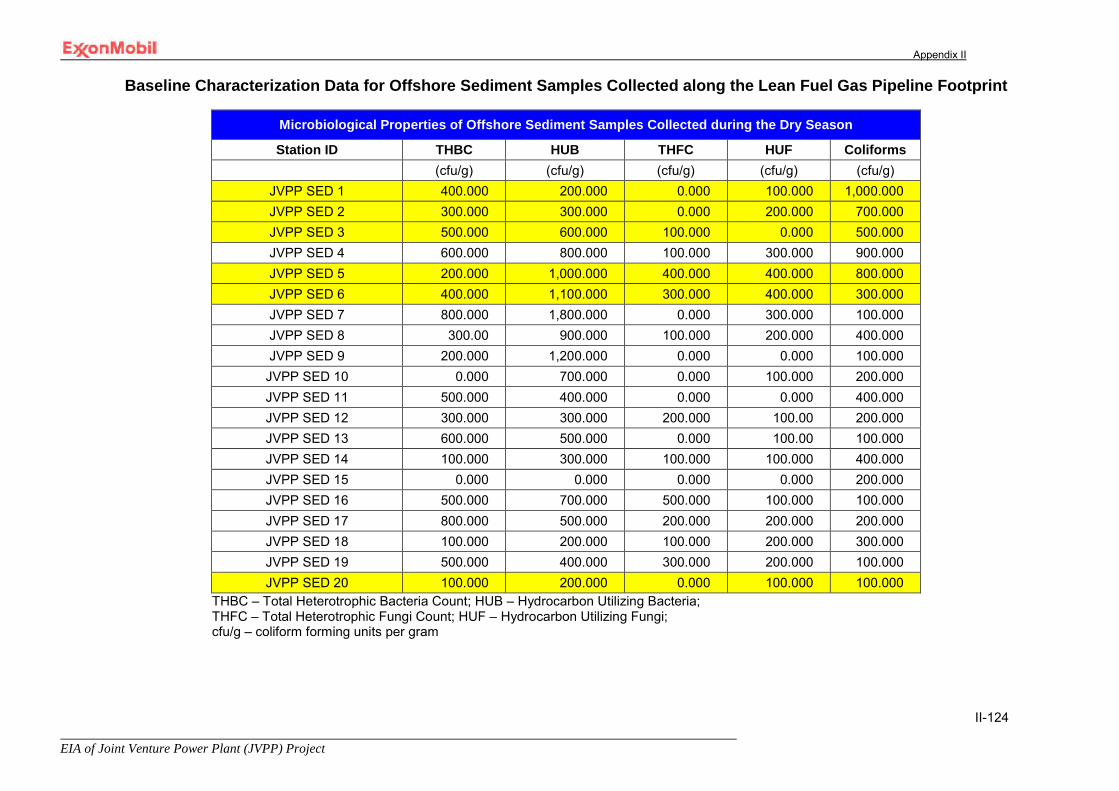
Appendix II
EIA of Joint Venture Power Plant (JVPP) Project
II-124
Baseline Characterization Data for Offshore Sediment Samples Collected along the Lean Fuel Gas Pipeline Footprint
Microbiological Properties of Offshore Sediment Samples Collected during the Dry Season
Station ID THBC HUB THFC HUF Coliforms (cfu/g) (cfu/g) (cfu/g) (cfu/g) (cfu/g)
JVPP SED 1 400.000 200.000 0.000 100.000 1,000.000 JVPP SED 2 300.000 300.000 0.000 200.000 700.000 JVPP SED 3 500.000 600.000 100.000 0.000 500.000 JVPP SED 4 600.000 800.000 100.000 300.000 900.000 JVPP SED 5 200.000 1,000.000 400.000 400.000 800.000 JVPP SED 6 400.000 1,100.000 300.000 400.000 300.000 JVPP SED 7 800.000 1,800.000 0.000 300.000 100.000 JVPP SED 8 300.00 900.000 100.000 200.000 400.000 JVPP SED 9 200.000 1,200.000 0.000 0.000 100.000 JVPP SED 10 0.000 700.000 0.000 100.000 200.000 JVPP SED 11 500.000 400.000 0.000 0.000 400.000 JVPP SED 12 300.000 300.000 200.000 100.00 200.000 JVPP SED 13 600.000 500.000 0.000 100.00 100.000 JVPP SED 14 100.000 300.000 100.000 100.000 400.000 JVPP SED 15 0.000 0.000 0.000 0.000 200.000 JVPP SED 16 500.000 700.000 500.000 100.000 100.000 JVPP SED 17 800.000 500.000 200.000 200.000 200.000 JVPP SED 18 100.000 200.000 100.000 200.000 300.000 JVPP SED 19 500.000 400.000 300.000 200.000 100.000 JVPP SED 20 100.000 200.000 0.000 100.000 100.000
THBC – Total Heterotrophic Bacteria Count; HUB – Hydrocarbon Utilizing Bacteria; THFC – Total Heterotrophic Fungi Count; HUF – Hydrocarbon Utilizing Fungi; cfu/g – coliform forming units per gram
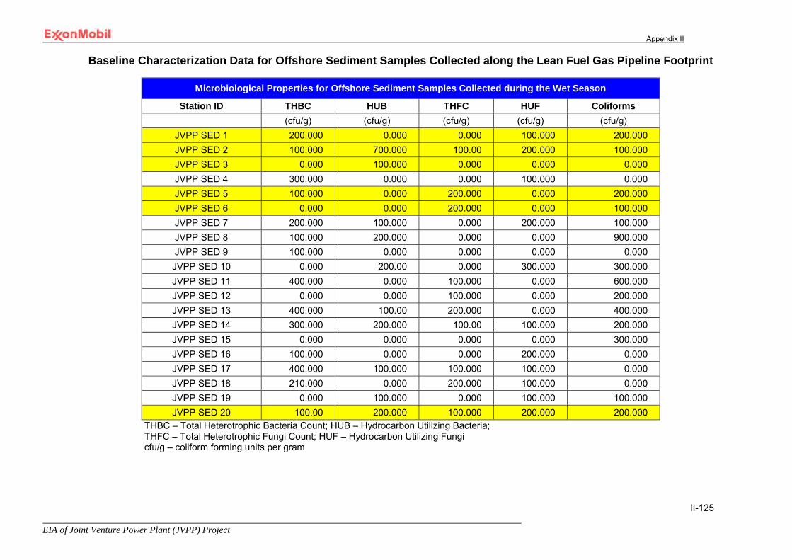
Appendix II
EIA of Joint Venture Power Plant (JVPP) Project
II-125
Baseline Characterization Data for Offshore Sediment Samples Collected along the Lean Fuel Gas Pipeline Footprint
Microbiological Properties for Offshore Sediment Samples Collected during the Wet Season
Station ID THBC HUB THFC HUF Coliforms (cfu/g) (cfu/g) (cfu/g) (cfu/g) (cfu/g)
JVPP SED 1 200.000 0.000 0.000 100.000 200.000 JVPP SED 2 100.000 700.000 100.00 200.000 100.000 JVPP SED 3 0.000 100.000 0.000 0.000 0.000 JVPP SED 4 300.000 0.000 0.000 100.000 0.000 JVPP SED 5 100.000 0.000 200.000 0.000 200.000 JVPP SED 6 0.000 0.000 200.000 0.000 100.000 JVPP SED 7 200.000 100.000 0.000 200.000 100.000 JVPP SED 8 100.000 200.000 0.000 0.000 900.000 JVPP SED 9 100.000 0.000 0.000 0.000 0.000 JVPP SED 10 0.000 200.00 0.000 300.000 300.000 JVPP SED 11 400.000 0.000 100.000 0.000 600.000 JVPP SED 12 0.000 0.000 100.000 0.000 200.000 JVPP SED 13 400.000 100.00 200.000 0.000 400.000 JVPP SED 14 300.000 200.000 100.00 100.000 200.000 JVPP SED 15 0.000 0.000 0.000 0.000 300.000 JVPP SED 16 100.000 0.000 0.000 200.000 0.000 JVPP SED 17 400.000 100.000 100.000 100.000 0.000 JVPP SED 18 210.000 0.000 200.000 100.000 0.000 JVPP SED 19 0.000 100.000 0.000 100.000 100.000 JVPP SED 20 100.00 200.000 100.000 200.000 200.000
THBC – Total Heterotrophic Bacteria Count; HUB – Hydrocarbon Utilizing Bacteria; THFC – Total Heterotrophic Fungi Count; HUF – Hydrocarbon Utilizing Fungi cfu/g – coliform forming units per gram

Appendix II
EIA of Joint Venture Power Plant (JVPP) Project
II-126
Station Coordinate Data for the Nearshore Samples
Sed – Sediment Sample W – Water Sample
Nearshore Sediment and Water Sample Station Coordinates Station ID Easting Northings
Sed27, W13 617070.91 59526.14 Sed28, W14 617881.80 59686.98 Sed29, W15 618277.19 59686.98 Sed30, W16 618066.09 59479.23 Sed31, W17 617848.29 59321.74 Sed32, W18 618364.31 59311.69
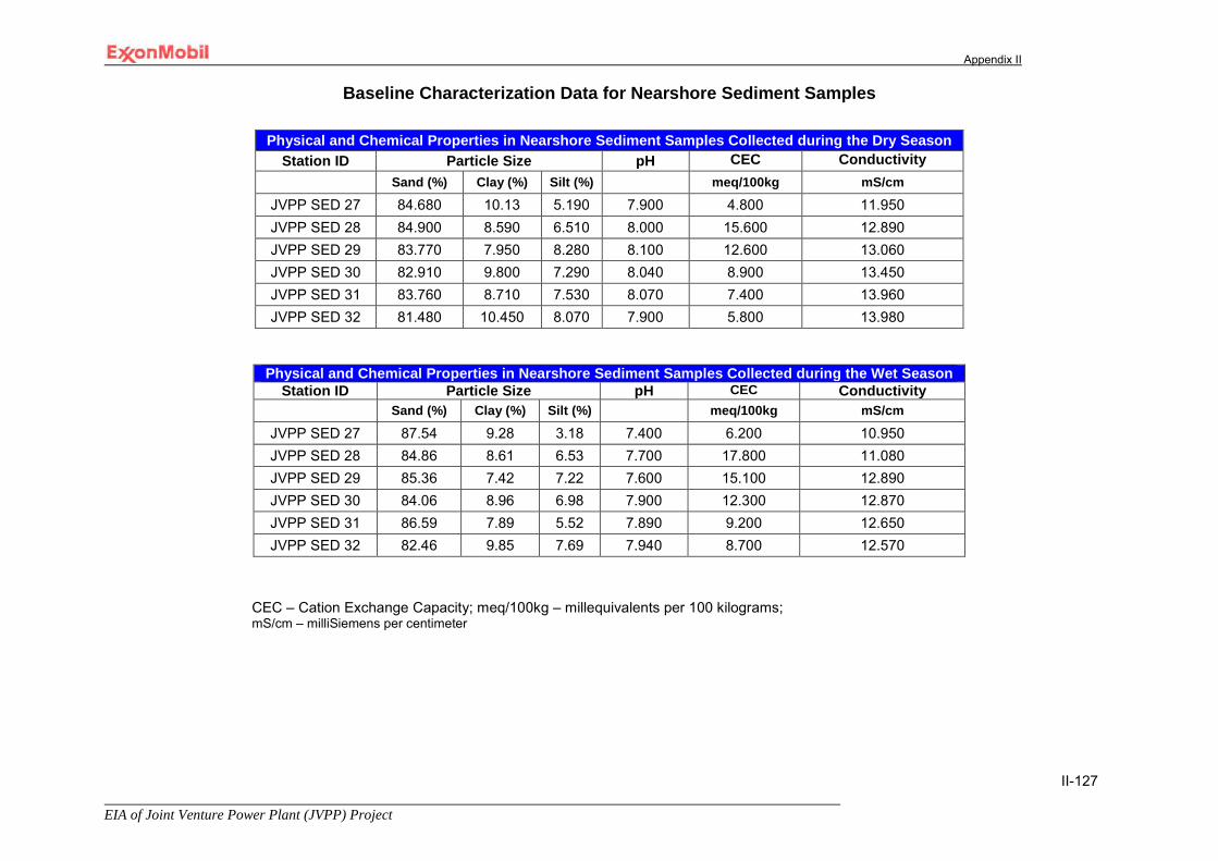
Appendix II
EIA of Joint Venture Power Plant (JVPP) Project
II-127
Baseline Characterization Data for Nearshore Sediment Samples
CEC – Cation Exchange Capacity; meq/100kg – millequivalents per 100 kilograms; mS/cm – milliSiemens per centimeter
Physical and Chemical Properties in Nearshore Sediment Samples Collected during the Dry Season Station ID Particle Size pH CEC Conductivity
Sand (%) Clay (%) Silt (%) meq/100kg mS/cm
JVPP SED 27 84.680 10.13 5.190 7.900 4.800 11.950 JVPP SED 28 84.900 8.590 6.510 8.000 15.600 12.890 JVPP SED 29 83.770 7.950 8.280 8.100 12.600 13.060 JVPP SED 30 82.910 9.800 7.290 8.040 8.900 13.450 JVPP SED 31 83.760 8.710 7.530 8.070 7.400 13.960 JVPP SED 32 81.480 10.450 8.070 7.900 5.800 13.980
Physical and Chemical Properties in Nearshore Sediment Samples Collected during the Wet Season Station ID Particle Size pH CEC Conductivity
Sand (%) Clay (%) Silt (%) meq/100kg mS/cm
JVPP SED 27 87.54 9.28 3.18 7.400 6.200 10.950 JVPP SED 28 84.86 8.61 6.53 7.700 17.800 11.080 JVPP SED 29 85.36 7.42 7.22 7.600 15.100 12.890 JVPP SED 30 84.06 8.96 6.98 7.900 12.300 12.870 JVPP SED 31 86.59 7.89 5.52 7.890 9.200 12.650 JVPP SED 32 82.46 9.85 7.69 7.940 8.700 12.570
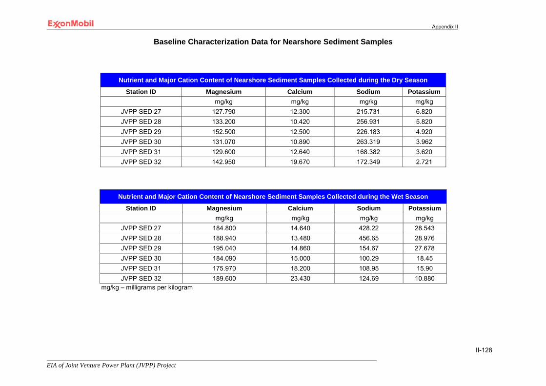
Appendix II
EIA of Joint Venture Power Plant (JVPP) Project
II-128
Baseline Characterization Data for Nearshore Sediment Samples
Nutrient and Major Cation Content of Nearshore Sediment Samples Collected during the Dry Season
Station ID Magnesium Calcium Sodium Potassium mg/kg mg/kg mg/kg mg/kg
JVPP SED 27 127.790 12.300 215.731 6.820 JVPP SED 28 133.200 10.420 256.931 5.820 JVPP SED 29 152.500 12.500 226.183 4.920 JVPP SED 30 131.070 10.890 263.319 3.962 JVPP SED 31 129.600 12.640 168.382 3.620 JVPP SED 32 142.950 19.670 172.349 2.721
Nutrient and Major Cation Content of Nearshore Sediment Samples Collected during the Wet Season
Station ID Magnesium Calcium Sodium Potassium mg/kg mg/kg mg/kg mg/kg
JVPP SED 27 184.800 14.640 428.22 28.543 JVPP SED 28 188.940 13.480 456.65 28.976 JVPP SED 29 195.040 14.860 154.67 27.678 JVPP SED 30 184.090 15.000 100.29 18.45 JVPP SED 31 175.970 18.200 108.95 15.90 JVPP SED 32 189.600 23.430 124.69 10.880
mg/kg – milligrams per kilogram

Appendix II
EIA of Joint Venture Power Plant (JVPP) Project
II-129
Baseline Characterization Data for Nearshore Sediment Samples
Heavy Metal Content in Nearshore Sediment Samples Collected during the Dry Season Station ID Cobalt Cadmium Chromium Copper Iron Manganese Nickel Lead Silver Barium Zinc
mg/kg mg/kg mg/kg mg/kg mg/kg mg/kg mg/kg mg/kg mg/kg mg/kg mg/kg JVPP SED 27 0.290 <0.01 0.082 0.681 1,148.602 <0.01 3.540 0.043 0.014 1.500 1.130 JVPP SED 28 0.260 <0.01 0.630 0.920 1,169.342 <0.01 3.810 0.046 0.015 2.300 1.240 JVPP SED 29 0.380 <0.01 0.049 0.672 1,152.609 <0.01 3.920 0.048 0.016 2.600 1.300 JVPP SED 30 0.170 <0.01 0.023 1.320 1,190.000 <0.01 0.732 <0.01 0.013 1.850 0.910 JVPP SED 31 0.620 <0.01 0.020 0.990 721.345 <0.01 0.815 <0.01 0.012 2.600 0.580 JVPP SED 32 0.370 <0.01 0.042 1.030 786.321 <0.01 0.835 <0.01 0.010 2.980 0.067
Heavy Metal Content in Nearshore Sediment Samples Collected during the Wet Season
Station ID Cobalt Cadmium Chromium Copper Iron Manganese Nickel Lead Silver Barium Zinc
mg/kg mg/kg mg/kg mg/kg mg/kg mg/kg mg/kg mg/kg mg/kg mg/kg mg/kg JVPP SED 27 0.0310 0.025 1.880 0.269 1,038.4 0.049 0.659 0.089 <0.01 3.000 1.782 JVPP SED 28 0.0318 0.026 1.650 0.345 1,267.90 0.037 0.676 0.090 <0.01 3.300 1.800 JVPP SED 29 0.0831 0.024 1.550 0.254 1,067.87 0.082 0.693 0.091 <0.01 3.100 1.820 JVPP SED 30 0.022 0.017 0.431 0.450 658.20 0.069 0.246 0.029 0.020 1.200 1.627 JVPP SED 31 0.0837 0.013 0.417 0.365 698.50 0.022 0.316 0.030 0.021 2.300 1.563 JVPP SED 32 0.054 0.020 0.589 0.494 742.70 0.047 0.367 0.035 0.015 2.500 0.984
mg/kg – milligrams per kilogram
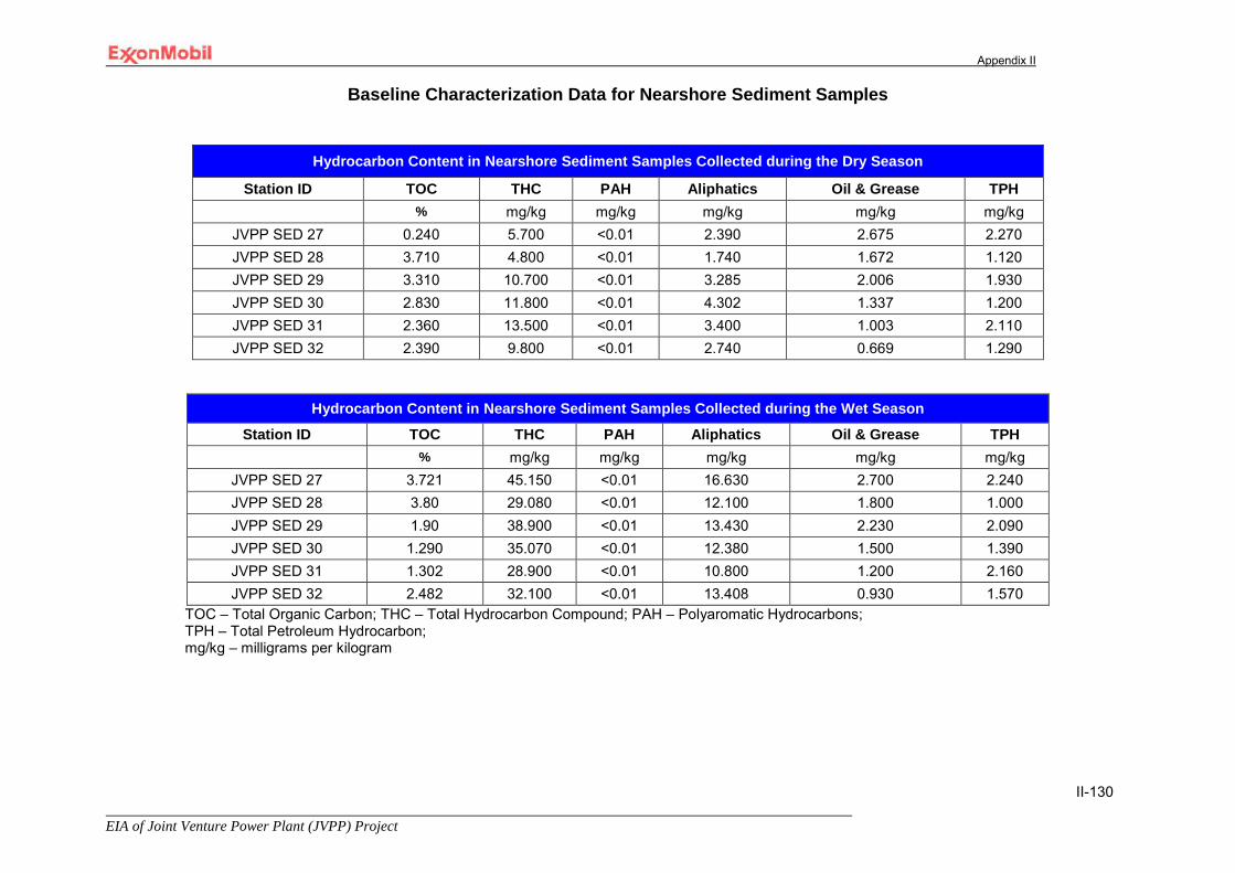
Appendix II
EIA of Joint Venture Power Plant (JVPP) Project
II-130
Baseline Characterization Data for Nearshore Sediment Samples
Hydrocarbon Content in Nearshore Sediment Samples Collected during the Dry Season
Station ID TOC THC PAH Aliphatics Oil & Grease TPH % mg/kg mg/kg mg/kg mg/kg mg/kg
JVPP SED 27 0.240 5.700 <0.01 2.390 2.675 2.270 JVPP SED 28 3.710 4.800 <0.01 1.740 1.672 1.120 JVPP SED 29 3.310 10.700 <0.01 3.285 2.006 1.930 JVPP SED 30 2.830 11.800 <0.01 4.302 1.337 1.200 JVPP SED 31 2.360 13.500 <0.01 3.400 1.003 2.110 JVPP SED 32 2.390 9.800 <0.01 2.740 0.669 1.290
Hydrocarbon Content in Nearshore Sediment Samples Collected during the Wet Season
Station ID TOC THC PAH Aliphatics Oil & Grease TPH % mg/kg mg/kg mg/kg mg/kg mg/kg
JVPP SED 27 3.721 45.150 <0.01 16.630 2.700 2.240 JVPP SED 28 3.80 29.080 <0.01 12.100 1.800 1.000 JVPP SED 29 1.90 38.900 <0.01 13.430 2.230 2.090 JVPP SED 30 1.290 35.070 <0.01 12.380 1.500 1.390 JVPP SED 31 1.302 28.900 <0.01 10.800 1.200 2.160 JVPP SED 32 2.482 32.100 <0.01 13.408 0.930 1.570
TOC – Total Organic Carbon; THC – Total Hydrocarbon Compound; PAH – Polyaromatic Hydrocarbons; TPH – Total Petroleum Hydrocarbon; mg/kg – milligrams per kilogram
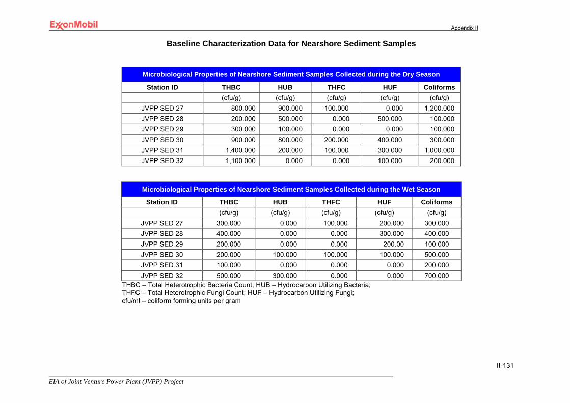
Appendix II
EIA of Joint Venture Power Plant (JVPP) Project
II-131
Baseline Characterization Data for Nearshore Sediment Samples
Microbiological Properties of Nearshore Sediment Samples Collected during the Dry Season
Station ID THBC HUB THFC HUF Coliforms (cfu/g) (cfu/g) (cfu/g) (cfu/g) (cfu/g)
JVPP SED 27 800.000 900.000 100.000 0.000 1,200.000 JVPP SED 28 200.000 500.000 0.000 500.000 100.000 JVPP SED 29 300.000 100.000 0.000 0.000 100.000 JVPP SED 30 900.000 800.000 200.000 400.000 300.000 JVPP SED 31 1,400.000 200.000 100.000 300.000 1,000.000 JVPP SED 32 1,100.000 0.000 0.000 100.000 200.000
Microbiological Properties of Nearshore Sediment Samples Collected during the Wet Season
Station ID THBC HUB THFC HUF Coliforms (cfu/g) (cfu/g) (cfu/g) (cfu/g) (cfu/g)
JVPP SED 27 300.000 0.000 100.000 200.000 300.000 JVPP SED 28 400.000 0.000 0.000 300.000 400.000 JVPP SED 29 200.000 0.000 0.000 200.00 100.000 JVPP SED 30 200.000 100.000 100.000 100.000 500.000 JVPP SED 31 100.000 0.000 0.000 0.000 200.000 JVPP SED 32 500.000 300.000 0.000 0.000 700.000
THBC – Total Heterotrophic Bacteria Count; HUB – Hydrocarbon Utilizing Bacteria; THFC – Total Heterotrophic Fungi Count; HUF – Hydrocarbon Utilizing Fungi; cfu/ml – coliform forming units per gram
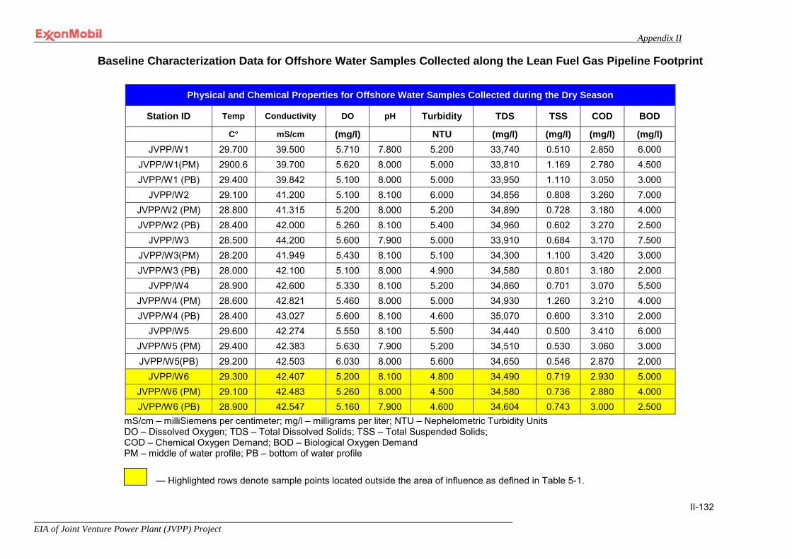
Appendix II
EIA of Joint Venture Power Plant (JVPP) Project
II-132
Baseline Characterization Data for Offshore Water Samples Collected along the Lean Fuel Gas Pipeline Footprint
mS/cm – milliSiemens per centimeter; mg/l – milligrams per liter; NTU – Nephelometric Turbidity Units DO – Dissolved Oxygen; TDS – Total Dissolved Solids; TSS – Total Suspended Solids; COD – Chemical Oxygen Demand; BOD – Biological Oxygen Demand PM – middle of water profile; PB – bottom of water profile
— Highlighted rows denote sample points located outside the area of influence as defined in Table 5-1.
Physical and Chemical Properties for Offshore Water Samples Collected during the Dry Season
Station ID Temp Conductivity DO pH Turbidity TDS TSS COD BOD
C° mS/cm (mg/l) NTU (mg/l) (mg/l) (mg/l) (mg/l) JVPP/W1 29.700 39.500 5.710 7.800 5.200 33,740 0.510 2.850 6.000
JVPP/W1(PM) 2900.6 39.700 5.620 8.000 5.000 33,810 1.169 2.780 4.500 JVPP/W1 (PB) 29.400 39.842 5.100 8.000 5.000 33,950 1.110 3.050 3.000
JVPP/W2 29.100 41.200 5.100 8.100 6.000 34,856 0.808 3.260 7.000 JVPP/W2 (PM) 28.800 41.315 5.200 8.000 5.200 34,890 0.728 3.180 4.000 JVPP/W2 (PB) 28.400 42.000 5.260 8.100 5.400 34,960 0.602 3.270 2.500
JVPP/W3 28.500 44.200 5.600 7.900 5.000 33,910 0.684 3.170 7.500 JVPP/W3(PM) 28.200 41.949 5.430 8.100 5.100 34,300 1.100 3.420 3.000 JVPP/W3 (PB) 28.000 42.100 5.100 8.000 4.900 34,580 0.801 3.180 2.000
JVPP/W4 28.900 42.600 5.330 8.100 5.200 34,860 0.701 3.070 5.500 JVPP/W4 (PM) 28.600 42.821 5.460 8.000 5.000 34,930 1.260 3.210 4.000 JVPP/W4 (PB) 28.400 43.027 5.600 8.100 4.600 35,070 0.600 3.310 2.000
JVPP/W5 29.600 42.274 5.550 8.100 5.500 34,440 0.500 3.410 6.000 JVPP/W5 (PM) 29.400 42.383 5.630 7.900 5.200 34,510 0.530 3.060 3.000 JVPP/W5(PB) 29.200 42.503 6.030 8.000 5.600 34,650 0.546 2.870 2.000
JVPP/W6 29.300 42.407 5.200 8.100 4.800 34,490 0.719 2.930 5.000 JVPP/W6 (PM) 29.100 42.483 5.260 8.000 4.500 34,580 0.736 2.880 4.000 JVPP/W6 (PB) 28.900 42.547 5.160 7.900 4.600 34,604 0.743 3.000 2.500
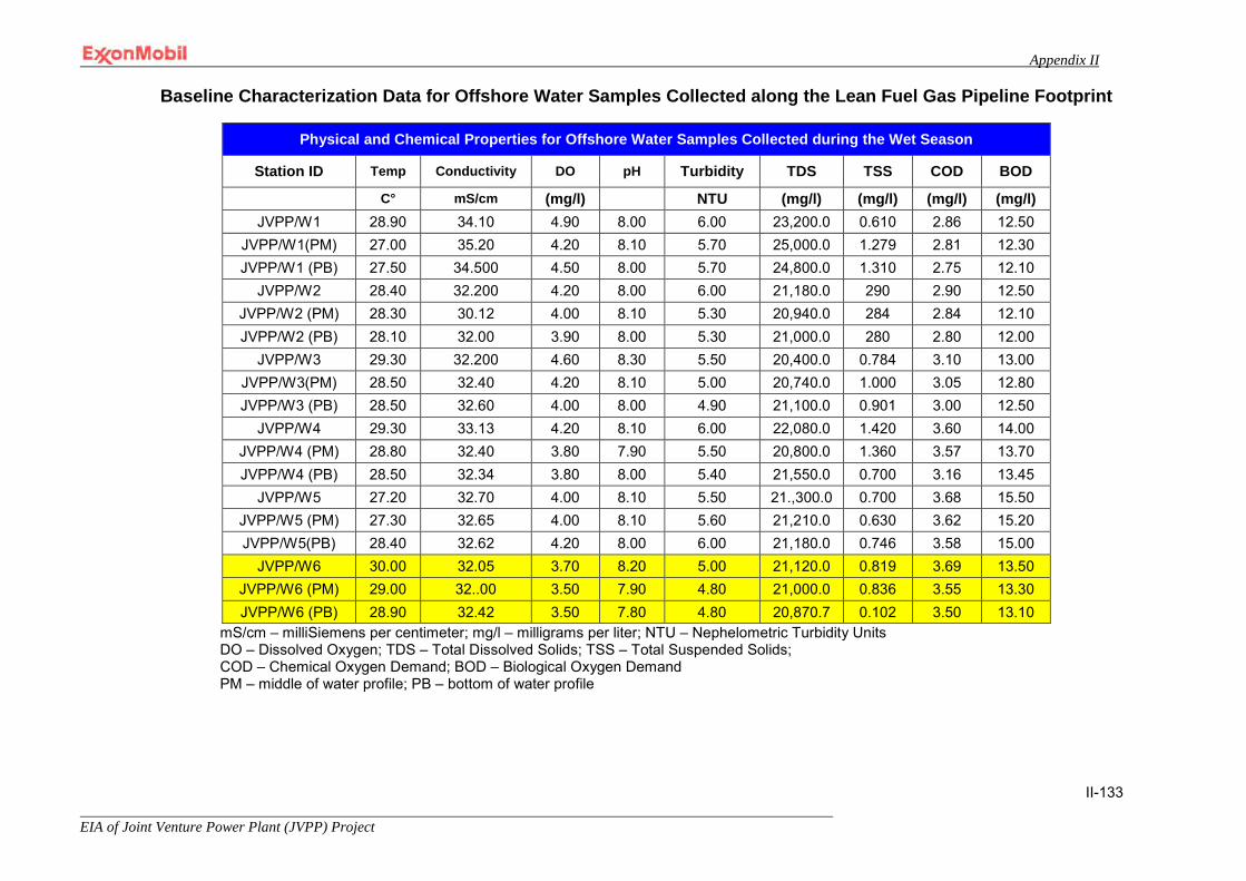
Appendix II
EIA of Joint Venture Power Plant (JVPP) Project
II-133
Baseline Characterization Data for Offshore Water Samples Collected along the Lean Fuel Gas Pipeline Footprint
Physical and Chemical Properties for Offshore Water Samples Collected during the Wet Season
Station ID Temp Conductivity DO pH Turbidity TDS TSS COD BOD
C° mS/cm (mg/l) NTU (mg/l) (mg/l) (mg/l) (mg/l) JVPP/W1 28.90 34.10 4.90 8.00 6.00 23,200.0 0.610 2.86 12.50
JVPP/W1(PM) 27.00 35.20 4.20 8.10 5.70 25,000.0 1.279 2.81 12.30 JVPP/W1 (PB) 27.50 34.500 4.50 8.00 5.70 24,800.0 1.310 2.75 12.10
JVPP/W2 28.40 32.200 4.20 8.00 6.00 21,180.0 290 2.90 12.50 JVPP/W2 (PM) 28.30 30.12 4.00 8.10 5.30 20,940.0 284 2.84 12.10 JVPP/W2 (PB) 28.10 32.00 3.90 8.00 5.30 21,000.0 280 2.80 12.00
JVPP/W3 29.30 32.200 4.60 8.30 5.50 20,400.0 0.784 3.10 13.00 JVPP/W3(PM) 28.50 32.40 4.20 8.10 5.00 20,740.0 1.000 3.05 12.80 JVPP/W3 (PB) 28.50 32.60 4.00 8.00 4.90 21,100.0 0.901 3.00 12.50
JVPP/W4 29.30 33.13 4.20 8.10 6.00 22,080.0 1.420 3.60 14.00 JVPP/W4 (PM) 28.80 32.40 3.80 7.90 5.50 20,800.0 1.360 3.57 13.70 JVPP/W4 (PB) 28.50 32.34 3.80 8.00 5.40 21,550.0 0.700 3.16 13.45
JVPP/W5 27.20 32.70 4.00 8.10 5.50 21.,300.0 0.700 3.68 15.50 JVPP/W5 (PM) 27.30 32.65 4.00 8.10 5.60 21,210.0 0.630 3.62 15.20 JVPP/W5(PB) 28.40 32.62 4.20 8.00 6.00 21,180.0 0.746 3.58 15.00
JVPP/W6 30.00 32.05 3.70 8.20 5.00 21,120.0 0.819 3.69 13.50 JVPP/W6 (PM) 29.00 32..00 3.50 7.90 4.80 21,000.0 0.836 3.55 13.30 JVPP/W6 (PB) 28.90 32.42 3.50 7.80 4.80 20,870.7 0.102 3.50 13.10
mS/cm – milliSiemens per centimeter; mg/l – milligrams per liter; NTU – Nephelometric Turbidity Units DO – Dissolved Oxygen; TDS – Total Dissolved Solids; TSS – Total Suspended Solids; COD – Chemical Oxygen Demand; BOD – Biological Oxygen Demand PM – middle of water profile; PB – bottom of water profile

Appendix II
EIA of Joint Venture Power Plant (JVPP) Project
II-134
Baseline Characterization Data for Offshore Water Samples Collected along the Lean Fuel Gas Pipeline Footprint
Nutrient and Major Cation Content in Offshore Water Samples Collected during the Dry Season
Station ID Nitrate Sulfate Magnesium Calcium Sodium Potassium Chloride
(mg/l) (mg/l) (mg/l) (mg/l) (mg/l) (mg/l) (mg/l) JVPP/W1 0.461 31.760 160.320 149.300 6,142.321 158.861 31,062.5
JVPP/W1(PM) 1.060 18.750 150.320 139.420 6,233.572 160.721 23,962.5 JVPP/W1 (PB) 1.280 13.680 148.290 132.620 6,548.363 162.321 23,962.5
JVPP/W2 0.890 13.680 113.720 156.400 6,106.532 166.210 27,550.0 JVPP/W2 (PM) 1.030 28.624 109.340 151.600 6,285.663 166.210 23,075.0 JVPP/W2 (PB) 1.420 17.968 98.380 143.720 6,530.529 168.921 29,287.5
JVPP/W3 1.830 19.640 93.050 159.400 7,436.490 169.031 23,075.0 JVPP/W3(PM) 1.150 25.600 92.090 152.600 7,531.594 169.062 25,737.5 JVPP/W3 (PB) 1.080 24.448 86.920 147.800 7,732.201 169.120 28,400.0
JVPP/W4 1.560 29.936 46.720 162.920 7,659.393 163.243 32,873.5 JVPP/W4 (PM) 0.960 28.880 44.310 157.600 7,830.410 163.280 26,625.0 JVPP/W4 (PB) 0.420 23.040 68.790 151.600 8,005.382 163.502 29,287.5
JVPP/W5 1.833 18.880 102.450 170.300 5,284.385 165.030 23,962.5 JVPP/W5 (PM) 0.190 19.648 100.080 168.250 5,429.330 165.060 39,937.5 JVPP/W5(PB) 0.370 31.536 100.050 165.630 5,764.680 165.060 22,187.5
JVPP/W6 0.420 23.040 132.000 173.290 6,731.043 165.103 36,387.5 JVPP/W6 (PM) 0.740 32.368 120.360 170.600 6,932.736 167.120 32,837.5 JVPP/W6 (PB) 1.020 19.792 102.320 169.470 7,053.295 167.150 20,412.5
mg/l – milligrams per liter PM – middle of water profile; PB – bottom of water profile

Appendix II
EIA of Joint Venture Power Plant (JVPP) Project
II-135
Baseline Characterization Data for Offshore Water Samples Collected along the Lean Fuel Gas Pipeline Footprint
Nutrient and Major Cation Content of Offshore Water Samples Collected during the Wet Season
Station ID Nitrate Sulfate Magnesium Calcium Sodium Potassium Chloride
(mg/l) (mg/l) (mg/l) (mg/l) (mg/l) (mg/l) (mg/l)
JVPP/W1 1.298 28.48 164.50 153.290 6,329.479 150.823 29,300 JVPP/W1(PM) 1.407 19.40 153.85 142.306 6,456.304 151.865 21,795 JVPP/W1 (PB) 1.373 15.695 152.50 137.219 6,963.39 154.932 20,749
JVPP/W2 1.572 18.40 119.95 161.628 6,271.479 155.949 26,496 JVPP/W2 (PM) 1.480 25.30 112.75 155.310 6,303.40 156.687 22,100 JVPP/W2 (PB) 1.416 20.19 105.10 148.530 6,628.364 159.432 28,370
JVPP/W3 1.584 23.484 102.15 163.207 7,629.305 160.061 21,750 JVPP/W3(PM) 1.545 27.38 100.00 156.628 7,734.598 160.098 24,290 JVPP/W3 (PB) 1.491 26.40 94.50 150.527 7,847.389 160.123 26,400
JVPP/W4 1.444 22.60 52.65 165.740 7,943.205 160.243 34,000 JVPP/W4 (PM) 1.417 26.38 50.25 159.430 8,285.492 160.340 25,600 JVPP/W4 (PB) 1.339 26.30 72.50 156.319 8,367.284 160.503 28,310
JVPP/W5 1.380 29.37 108.70 173.490 5,930.490 161.026 25,963 JVPP/W5 (PM) 1.302 15.63 105.35 171.390 6,185.493 161.234 37,394 JVPP/W5(PB) 1.307 32.65 105.10 168.429 6,321.280 161.432 23,610
JVPP/W6 1.334 26.39 139.00 175.395 6,938.381 161.659 34,189 JVPP/W6 (PM) 1.276 23.44 122.50 173.371 7,001.632 162.043 33,601 JVPP/W6 (PB) 1.345 18.50 112.25 171.300 7,168.539 162.508 23,405
mg/l – milligrams per liter PM – middle of water profile; PB – bottom of water profile

Appendix II
EIA of Joint Venture Power Plant (JVPP) Project
II-136
Baseline Characterization Data for Offshore Water Samples Collected along the Lean Fuel Gas Pipeline Footprint
Heavy Metal Content in Offshore Water Samples Collected during the Dry Season Station ID Cobalt Cadmium Chromium Copper Iron Manganese Nickel Lead Silver Vanadium Zinc
(mg/l) (mg/l) (mg/l) (mg/l) (mg/l) (mg/l) (mg/l) (mg/l) (mg/l) (mg/l) (mg/l) JVPP/W1 0.210 0.008 0.232 <0.01 0.001 0.016 <0.01 0.037 <0.01 0.017 0.263
JVPP/W1(PM) 0.316 0.001 0.218 <0.01 0.001 0.013 <0.01 0.039 <0.01 0.013 0.268 JVPP/W1 (PB) 0.150 0.007 0.213 <0.01 0.002 0.016 <0.01 0.040 <0.01 0.018 0.273
JVPP/W2 0.320 0.003 0.210 0.032 0.001 0.013 <0.01 0.028 <0.01 0.017 0.181 JVPP/W2 (PM) 0.355 0.007 0.197 0.037 0.002 0.017 <0.01 0.032 <0.01 0.011 0.193 JVPP/W2 (PB) 0.380 0.009 0.186 0.042 0.001 0.020 <0.01 0.030 <0.01 0.019 0.200
JVPP/W3 0.402 0.001 0.170 0.035 0.001 0.012 <0.01 0.030 <0.01 0.013 0.162 JVPP/W3(PM) 0.350 0.003 0.169 0.038 0.001 0.013 <0.01 0.032 <0.01 0.017 0.189 JVPP/W3 (PB) 0.400 0.005 0.165 0.040 0.001 0.010 <0.01 0.034 <0.01 0.015 0.190
JVPP/W4 0.315 0.003 0.165 0.025 0.002 0.014 <0.01 0.037 <0.01 0.013 0.092 JVPP/W4 (PM) 0.350 0.008 0.160 0.027 0.003 0.016 <0.01 0.039 <0.01 0.016 0.098 JVPP/W4 (PB) 0.380 0.005 0.158 0.030 0.005 0.021 <0.01 0.039 <0.01 0.020 0.100
JVPP/W5 0.310 0.006 0.153 0.041 0.019 0.023 <0.01 0.026 <0.01 0.013 0.121 JVPP/W5 (PM) 0.360 0.002 0.150 0.043 0.019 0.024 <0.01 0.028 <0.01 0.001 0.131 JVPP/W5(PB) 0.380 0.009 0.081 0.045 0.011 0.017 <0.01 0.029 <0.01 0.002 0.042
JVPP/W6 0.400 0.010 0.080 0.051 0.010 0.022 <0.01 0.030 <0.01 0.001 0.096 JVPP/W6 (PM) 0.435 0.017 0.079 0.055 0.011 0.018 <0.01 0.033 <0.01 0.008 0.099 JVPP/W6 (PB) 0.450 0.012 0.077 0.060 0.015 0.022 <0.01 0.033 <0.01 0.004 0.042
mg/l – milligrams per liter PM – middle of water profile; PB – bottom of water profile
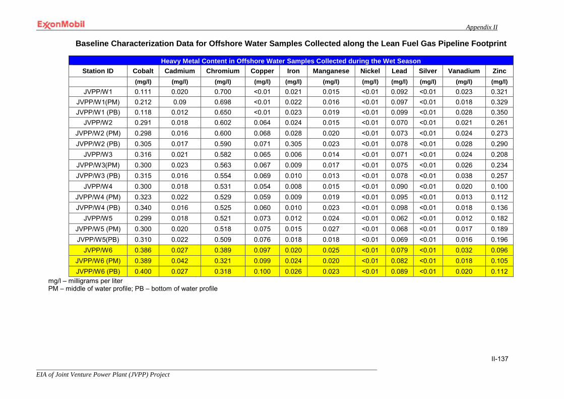
Appendix II
EIA of Joint Venture Power Plant (JVPP) Project
II-137
Baseline Characterization Data for Offshore Water Samples Collected along the Lean Fuel Gas Pipeline Footprint
Heavy Metal Content in Offshore Water Samples Collected during the Wet Season Station ID Cobalt Cadmium Chromium Copper Iron Manganese Nickel Lead Silver Vanadium Zinc
(mg/l) (mg/l) (mg/l) (mg/l) (mg/l) (mg/l) (mg/l) (mg/l) (mg/l) (mg/l) (mg/l) JVPP/W1 0.111 0.020 0.700 <0.01 0.021 0.015 <0.01 0.092 <0.01 0.023 0.321
JVPP/W1(PM) 0.212 0.09 0.698 <0.01 0.022 0.016 <0.01 0.097 <0.01 0.018 0.329 JVPP/W1 (PB) 0.118 0.012 0.650 <0.01 0.023 0.019 <0.01 0.099 <0.01 0.028 0.350
JVPP/W2 0.291 0.018 0.602 0.064 0.024 0.015 <0.01 0.070 <0.01 0.021 0.261 JVPP/W2 (PM) 0.298 0.016 0.600 0.068 0.028 0.020 <0.01 0.073 <0.01 0.024 0.273 JVPP/W2 (PB) 0.305 0.017 0.590 0.071 0.305 0.023 <0.01 0.078 <0.01 0.028 0.290
JVPP/W3 0.316 0.021 0.582 0.065 0.006 0.014 <0.01 0.071 <0.01 0.024 0.208 JVPP/W3(PM) 0.300 0.023 0.563 0.067 0.009 0.017 <0.01 0.075 <0.01 0.026 0.234 JVPP/W3 (PB) 0.315 0.016 0.554 0.069 0.010 0.013 <0.01 0.078 <0.01 0.038 0.257
JVPP/W4 0.300 0.018 0.531 0.054 0.008 0.015 <0.01 0.090 <0.01 0.020 0.100 JVPP/W4 (PM) 0.323 0.022 0.529 0.059 0.009 0.019 <0.01 0.095 <0.01 0.013 0.112 JVPP/W4 (PB) 0.340 0.016 0.525 0.060 0.010 0.023 <0.01 0.098 <0.01 0.018 0.136
JVPP/W5 0.299 0.018 0.521 0.073 0.012 0.024 <0.01 0.062 <0.01 0.012 0.182 JVPP/W5 (PM) 0.300 0.020 0.518 0.075 0.015 0.027 <0.01 0.068 <0.01 0.017 0.189 JVPP/W5(PB) 0.310 0.022 0.509 0.076 0.018 0.018 <0.01 0.069 <0.01 0.016 0.196
JVPP/W6 0.386 0.027 0.389 0.097 0.020 0.025 <0.01 0.079 <0.01 0.032 0.096 JVPP/W6 (PM) 0.389 0.042 0.321 0.099 0.024 0.020 <0.01 0.082 <0.01 0.018 0.105 JVPP/W6 (PB) 0.400 0.027 0.318 0.100 0.026 0.023 <0.01 0.089 <0.01 0.020 0.112
mg/l – milligrams per liter PM – middle of water profile; PB – bottom of water profile
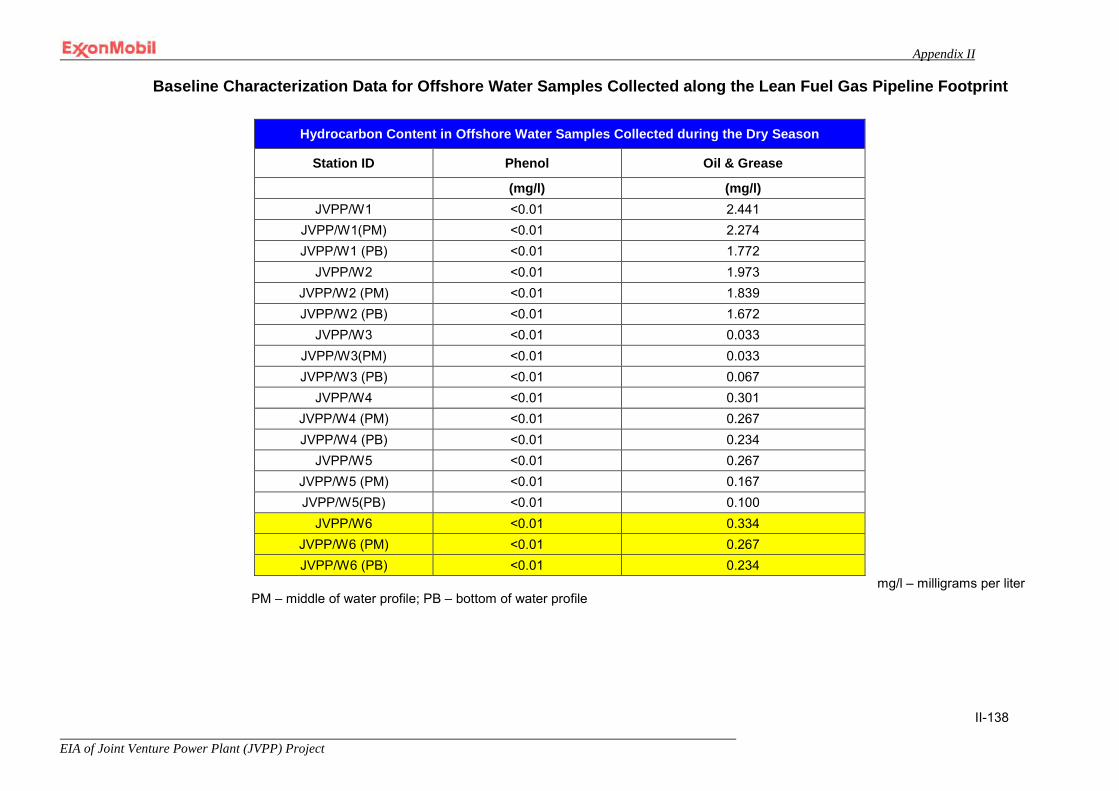
Appendix II
EIA of Joint Venture Power Plant (JVPP) Project
II-138
Baseline Characterization Data for Offshore Water Samples Collected along the Lean Fuel Gas Pipeline Footprint
mg/l – milligrams per liter PM – middle of water profile; PB – bottom of water profile
Hydrocarbon Content in Offshore Water Samples Collected during the Dry Season
Station ID Phenol Oil & Grease
(mg/l) (mg/l) JVPP/W1 <0.01 2.441
JVPP/W1(PM) <0.01 2.274 JVPP/W1 (PB) <0.01 1.772
JVPP/W2 <0.01 1.973 JVPP/W2 (PM) <0.01 1.839 JVPP/W2 (PB) <0.01 1.672
JVPP/W3 <0.01 0.033 JVPP/W3(PM) <0.01 0.033 JVPP/W3 (PB) <0.01 0.067
JVPP/W4 <0.01 0.301 JVPP/W4 (PM) <0.01 0.267 JVPP/W4 (PB) <0.01 0.234
JVPP/W5 <0.01 0.267 JVPP/W5 (PM) <0.01 0.167 JVPP/W5(PB) <0.01 0.100
JVPP/W6 <0.01 0.334 JVPP/W6 (PM) <0.01 0.267 JVPP/W6 (PB) <0.01 0.234
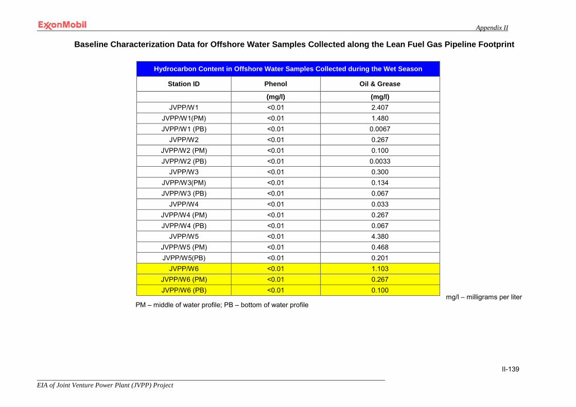
Appendix II
EIA of Joint Venture Power Plant (JVPP) Project
II-139
Baseline Characterization Data for Offshore Water Samples Collected along the Lean Fuel Gas Pipeline Footprint
mg/l – milligrams per liter
PM – middle of water profile; PB – bottom of water profile
Hydrocarbon Content in Offshore Water Samples Collected during the Wet Season
Station ID Phenol Oil & Grease
(mg/l) (mg/l) JVPP/W1 <0.01 2.407
JVPP/W1(PM) <0.01 1.480 JVPP/W1 (PB) <0.01 0.0067
JVPP/W2 <0.01 0.267 JVPP/W2 (PM) <0.01 0.100 JVPP/W2 (PB) <0.01 0.0033
JVPP/W3 <0.01 0.300 JVPP/W3(PM) <0.01 0.134 JVPP/W3 (PB) <0.01 0.067
JVPP/W4 <0.01 0.033 JVPP/W4 (PM) <0.01 0.267 JVPP/W4 (PB) <0.01 0.067
JVPP/W5 <0.01 4.380 JVPP/W5 (PM) <0.01 0.468 JVPP/W5(PB) <0.01 0.201
JVPP/W6 <0.01 1.103 JVPP/W6 (PM) <0.01 0.267 JVPP/W6 (PB) <0.01 0.100

Appendix II
EIA of Joint Venture Power Plant (JVPP) Project
II-140
Baseline Characterization Data for Offshore Water Samples Collected along the Lean Fuel Gas Pipeline Footprint
Microbiological Properties of Offshore Water Samples Collected during the Dry Season
Station ID THBC THFC HUB HUF Coliforms Sulfur Reducing Bacteria
(cfu/ml) (cfu/ml) (cfu/ml) (cfu/ml) (cfu/ml) (cfu/ml)
JVPP/W1 1,000.000 1,600.000 500.000 0.000 100.000 1,000.0 JVPP/W1(PM) 500.000 200.000 100.000 500.000 100.000 200.0 JVPP/W1 (PB) 200.000 200.000 0.000 0.000 500.000 300.0
JVPP/W2 1,400.000 2,000.000 2,000.000 100.000 1,500.000 800.0 JVPP/W2 (PM) 1,500.000 1,000.000 400.000 0.000 1,800.000 700.0 JVPP/W2 (PB) 900.000 3,200.000 300.000 0.000 1,200.000 200.0
JVPP/W3 500.000 100.000 500.000 0.000 1,700.000 0.0 JVPP/W3(PM) 2,600.000 1,300.000 1,300.000 0.000 1,700.000 400.0 JVPP/W3 (PB) 700.000 600.000 0.000 100.000 1,900.000 200.0
JVPP/W4 1,000.000 100.000 1,400.000 0.000 500.000 100.0 JVPP/W4 (PM) 1,100.000 2,000.000 0.000 0.000 1,500.000 500.0 JVPP/W4 (PB) 1,400.000 2,000.000 1,100.000 0.000 1,000.000 1,000.0
JVPP/W5 3,200.000 1,700.000 500.000 0.000 1,700.00 700.0 JVPP/W5 (PM) 1,500.000 1,100.000 200.000 0.000 300.000 800.0 JVPP/W5(PB) 500.000 200.000 600.00 0.000 8,000.000 400.0
JVPP/W6 1,300.000 300.000 1,100.000 100.000 700.000 700.0 JVPP/W6 (PM) 300.000 400.000 0.000 400.000 400.000 200.0 JVPP/W6 (PB) 1,600.000 2,000.000 100.000 0.000 400.000 200.0
THBC – Total Heterotrophic Bacteria Count; HUB – Hydrocarbon Utilizing Bacteria; THFC – Total Heterotrophic Fungi Count; HUF – Hydrocarbon Utilizing Fungi; cfu/ml – coliform forming units per milliliter PM – middle of water profile; PB – bottom of water profile
.
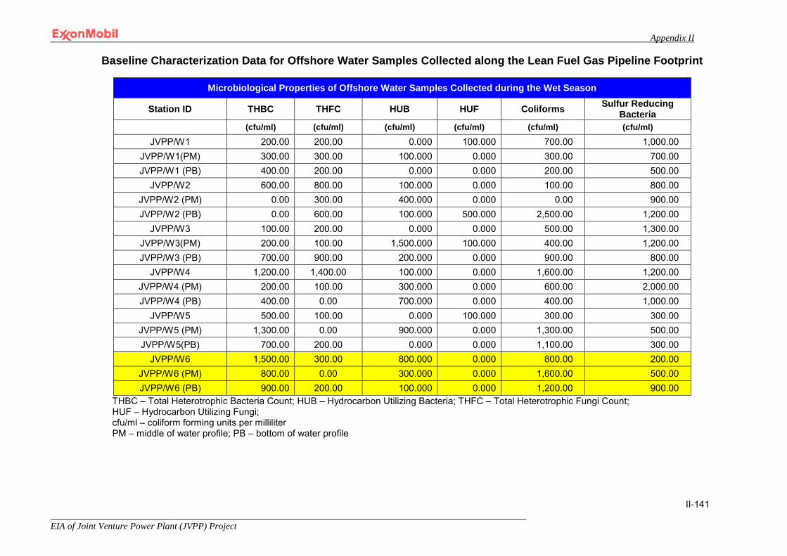
Appendix II
EIA of Joint Venture Power Plant (JVPP) Project
II-141
Baseline Characterization Data for Offshore Water Samples Collected along the Lean Fuel Gas Pipeline Footprint
Microbiological Properties of Offshore Water Samples Collected during the Wet Season
Station ID THBC THFC HUB HUF Coliforms Sulfur Reducing Bacteria
(cfu/ml) (cfu/ml) (cfu/ml) (cfu/ml) (cfu/ml) (cfu/ml)
JVPP/W1 200.00 200.00 0.000 100.000 700.00 1,000.00 JVPP/W1(PM) 300.00 300.00 100.000 0.000 300.00 700.00 JVPP/W1 (PB) 400.00 200.00 0.000 0.000 200.00 500.00
JVPP/W2 600.00 800.00 100.000 0.000 100.00 800.00 JVPP/W2 (PM) 0.00 300.00 400.000 0.000 0.00 900.00 JVPP/W2 (PB) 0.00 600.00 100.000 500.000 2,500.00 1,200.00
JVPP/W3 100.00 200.00 0.000 0.000 500.00 1,300.00 JVPP/W3(PM) 200.00 100.00 1,500.000 100.000 400.00 1,200.00 JVPP/W3 (PB) 700.00 900.00 200.000 0.000 900.00 800.00
JVPP/W4 1,200.00 1,400.00 100.000 0.000 1,600.00 1,200.00 JVPP/W4 (PM) 200.00 100.00 300.000 0.000 600.00 2,000.00 JVPP/W4 (PB) 400.00 0.00 700.000 0.000 400.00 1,000.00
JVPP/W5 500.00 100.00 0.000 100.000 300.00 300.00 JVPP/W5 (PM) 1,300.00 0.00 900.000 0.000 1,300.00 500.00 JVPP/W5(PB) 700.00 200.00 0.000 0.000 1,100.00 300.00
JVPP/W6 1,500.00 300.00 800.000 0.000 800.00 200.00 JVPP/W6 (PM) 800.00 0.00 300.000 0.000 1,600.00 500.00 JVPP/W6 (PB) 900.00 200.00 100.000 0.000 1,200.00 900.00
THBC – Total Heterotrophic Bacteria Count; HUB – Hydrocarbon Utilizing Bacteria; THFC – Total Heterotrophic Fungi Count; HUF – Hydrocarbon Utilizing Fungi; cfu/ml – coliform forming units per milliliter PM – middle of water profile; PB – bottom of water profile

Appendix II
EIA of Joint Venture Power Plant (JVPP) Project
II-142
Baseline Characterization Data for Nearshore Water Samples
Physical and Chemical Properties of Nearshore Water Samples Collected during the Wet Season
Station ID Temp Conductivity DO pH Turbidity TDS TSS COD BOD
C° mS/cm (mg/l) NTU (mg/l) (mg/l) (mg/l) (mg/l) JVPP/W13 26.80 14.70 4.00 8.50 7.00 12,510.0 0.740 3.43 10.00 JVPP/W14 27.00 17.4 4.00 8.70 7.20 12,480.0 0.715 3.45 13.00 JVPP/W15 27.10 17.8 4.70 8.10 7.00 12,900.0 1.160 3.47 13.50 JVPP/W16 27.80 18.30 4.50 8.00 6.50 13,600.0 0.940 3.49 10.00 JVPP/W17 27.20 18.00 4.50 8.70 7.30 13,000.0 0.963 3.51 11.50 JVPP/W18 27.00 17.90 4.20 7.90 7.00 12,990.0 0.988 3.52 7.50
mS/cm – milliSiemens per centimeter; mg/l – milligrams per liter; NTU – Nephelometric Turbidity Units DO – Dissolved Oxygen; TDS – Total Dissolved Solids; TSS – Total Suspended Solids; COD – Chemical Oxygen Demand; BOD – Biological Oxygen Demand
Physical and Chemical Properties of Nearshore Water Samples Collected during the Dry Season
Station ID Temp Conductivity DO pH Turbidity TDS TSS COD BOD
C° mS/cm (mg/l) NTU (mg/l) (mg/l) (mg/l) (mg/l) JVPP/W13 30.500 15.200 4.800 8.020 6.000 10,800.000 0.064 2.310 4.500 JVPP/W14 30.800 16.260 5.000 8.020 6.300 11,100.000 0.092 2.390 4.000 JVPP/W15 30.600 16.527 5.070 8.030 5.800 11,300.000 0.561 2.440 5.500 JVPP/W16 30.600 19.632 4.800 7.780 7.000 14,250.000 4.089 2.470 6.600 JVPP/W17 31.000 19.340 4.960 8.020 4.900 14,113.000 0.508 2.600 5.500 JVPP/W18 30.8000 18.718 4.850 7.930 4.300 13,566.000 0.200 2.550 6.000
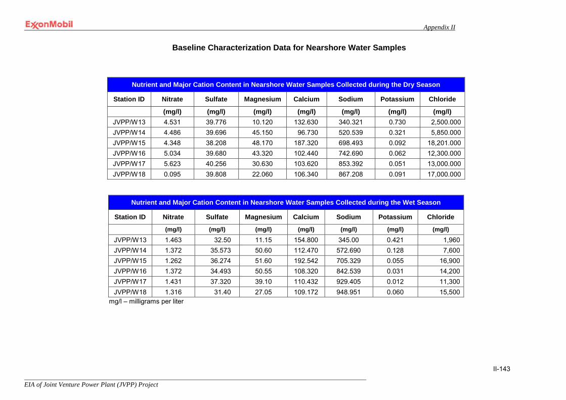
Appendix II
EIA of Joint Venture Power Plant (JVPP) Project
II-143
Baseline Characterization Data for Nearshore Water Samples
Nutrient and Major Cation Content in Nearshore Water Samples Collected during the Dry Season
Station ID Nitrate Sulfate Magnesium Calcium Sodium Potassium Chloride
(mg/l) (mg/l) (mg/l) (mg/l) (mg/l) (mg/l) (mg/l) JVPP/W13 4.531 39.776 10.120 132.630 340.321 0.730 2,500.000 JVPP/W14 4.486 39.696 45.150 96.730 520.539 0.321 5,850.000 JVPP/W15 4.348 38.208 48.170 187.320 698.493 0.092 18,201.000 JVPP/W16 5.034 39.680 43.320 102.440 742.690 0.062 12,300.000 JVPP/W17 5.623 40.256 30.630 103.620 853.392 0.051 13,000.000 JVPP/W18 0.095 39.808 22.060 106.340 867.208 0.091 17,000.000
Nutrient and Major Cation Content in Nearshore Water Samples Collected during the Wet Season
Station ID Nitrate Sulfate Magnesium Calcium Sodium Potassium Chloride
(mg/l) (mg/l) (mg/l) (mg/l) (mg/l) (mg/l) (mg/l)
JVPP/W13 1.463 32.50 11.15 154.800 345.00 0.421 1,960 JVPP/W14 1.372 35.573 50.60 112.470 572.690 0.128 7,600 JVPP/W15 1.262 36.274 51.60 192.542 705.329 0.055 16,900 JVPP/W16 1.372 34.493 50.55 108.320 842.539 0.031 14,200 JVPP/W17 1.431 37.320 39.10 110.432 929.405 0.012 11,300 JVPP/W18 1.316 31.40 27.05 109.172 948.951 0.060 15,500
mg/l – milligrams per liter

Appendix II
EIA of Joint Venture Power Plant (JVPP) Project
II-144
Baseline Characterization Data for Nearshore Water Samples
Heavy Metal Content in Nearshore Water Samples Collected during the Dry Season Station ID Cobalt Cadmium Chromium Copper Iron Manganese Nickel Lead Silver Vanadium Zinc
(mg/l) (mg/l) (mg/l) (mg/l) (mg/l) (mg/l) (mg/l) (mg/l) (mg/l) (mg/l) (mg/l) JVPP/W13 0.102 0.002 0.190 <0.01 0.630 0.018 <0.01 0.018 <0.01 0.023 0.102 JVPP/W14 0.100 0.001 0.186 <0.01 0.062 0.016 <0.01 0.008 <0.01 0.017 0.189 JVPP/W15 0.250 0.020 0.190 <0.01 0.417 0.019 <0.01 0.013 <0.01 0.014 0.191 JVPP/W16 0.920 0.004 0.192 <0.01 0.325 0.018 <0.01 0.012 <0.01 0.021 0.203 JVPP/W17 0.700 0.011 0.196 <0.01 0.300 0.014 <0.01 0.010 <0.01 0.023 0.309 JVPP/W18 0.536 0.002 0.025 <0.01 0.260 0.016 <0.01 0.005 <0.01 0.022 0.390
Heavy Metal Content in Nearshore Water Samples Collected during the Wet Season Station ID Cobalt Cadmium Chromium Copper Iron Manganese Nickel Lead Silver Vanadium Zinc
(mg/l) (mg/l) (mg/l) (mg/l) (mg/l) (mg/l) (mg/l) (mg/l) (mg/l) (mg/l) (mg/l) JVPP/W13 0.028 0.012 0.321 <0.01 1.000 0.033 <0.01 0.045 <0.01 0.025 0.200 JVPP/W14 0.155 0.031 0.306 <0.01 0.112 0.027 <0.01 0.032 <0.01 0.019 0.261 JVPP/W15 0.140 0.011 0.308 <0.01 0.764 0.028 <0.01 0.029 <0.01 0.017 0.263 JVPP/W16 0.119 0.018 0.310 <0.01 0.674 0.026 <0.01 0.026 <0.01 0.023 0.278 JVPP/W17 0.116 0.012 0.315 <0.01 0.560 0.025 <0.01 0.024 <0.01 0.027 0.421 JVPP/W18 0.015 0.013 0.350 <0.01 0.432 0.030 <0.01 0.020 <0.01 0.024 0.467
mg/l – milligrams per liter

Appendix II
EIA of Joint Venture Power Plant (JVPP) Project
II-145
Baseline Characterization Data for Nearshore Water Samples
mg/l – milligrams per liter
Hydrocarbon Content in Nearshore Water Samples Collected during the Dry Season
Station ID Phenol Oil & Grease
(mg/l) (mg/l) JVPP/W13 <0.01 2.107 JVPP/W14 <0.01 3.009 JVPP/W15 <0.01 1.739 JVPP/W16 <0.01 1.438 JVPP/W17 <0.01 1.939 JVPP/W18 <0.01 1.505
Hydrocarbon Content in Nearshore Water Samples Collected during the Wet Season
Station ID Phenol Oil & Grease
(mg/l) (mg/l) JVPP/W13 <0.01 1.471
JVPP/W14 <0.01 2.407 JVPP/W15 <0.01 0.702 JVPP/W16 <0.01 2.407
JVPP/W17 <0.01 1.487 JVPP/W18 <0.01 1.379

Appendix II
EIA of Joint Venture Power Plant (JVPP) Project
II-146
Baseline Characterization Data for Nearshore Water Samples
Microbiological Properties of Nearshore Water Samples Collected during the Dry Season
Station ID Media THBC HUB THFC HUF Coliforms Sulfur
Reducing Bacteria
(cfu/ml) (cfu/ml) (cfu/ml) (cfu/ml) (cfu/ml) (cfu/ml)
JVPP/W13 Water 100.000 400.000 900.000 300.000 600.000 0.0 JVPP/W14 Water 200.000 0.000 300.000 200.000 0.000 100.0 JVPP/W15 Water 400.000 0.000 200.000 0.000 0.000 300.0 JVPP/W16 Water 0.000 0.000 200.000 0.000 100.000 400.0 JVPP/W17 Water 400.000 0.000 100.000 200.000 400.000 300.0 JVPP/W18 Water 300.000 0.000 100.000 300.000 500.000 100.0
Microbiological Properties of Nearshore Water Samples Collected during the Wet Season
Station ID Media THBC HUB THFC HUF Coliforms Sulfur
Reducing Bacteria
(cfu/ml) (cfu/ml) (cfu/ml) (cfu/ml) (cfu/ml) (cfu/ml)
JVPP/W13 Water 700.00 0.00 0.00 0.00 700.00 1,100.00 JVPP/W14 Water 600.00 100.00 100.00 0.00 900.00 700.00 JVPP/W15 Water 300.00 0.00 0.00 0.00 500.00 1,000.00 JVPP/W16 Water 800.00 100.00 100.00 0.00 800.00 400.00 JVPP/W17 Water 2,000.00 0.00 0.00 0.00 500.00 600.00 JVPP/W18 Water 900.00 200.00 200.00 100.00 600.00 700.00
THBC – Total Heterotrophic Bacteria Count; HUB – Hydrocarbon Utilizing Bacteria; THFC – Total Heterotrophic Fungi Count; HUF – Hydrocarbon Utilizing Fungi; cfu/ml – coliform forming units per milliliter

Appendix II
EIA of Joint Venture Power Plant (JVPP) Project
II-147
Station Coordinate Data for Sediment and Surface Water Samples Collected within the Power Plant Footprint
Sed – Sediment Sample W – Water Sample
Baseline Characterization Data for Sediment Samples Collected within the Power Plant Footprint
Physical and Chemical Properties in Douglas Creek and QIT Lake Sediment Samples Collected during the Wet Season
Station ID Sample Location Particle Size pH Cation Exchange Capacity Conductivity
Sand (%) Clay (%) Silt (%) meq/100kg mS/cm
JVPP SED 21 Douglas Creek 93.12 5.840 1.04 7.500 9.300 12.500 JVPP SED 22 Douglas Creek 92.29 5.630 2.08 7.400 13.700 11.090
Douglas Creek and QIT Lake Sediment and Water Sample Station Coordinates Station ID Sample Location Easting Northings
Sed21, W7 Douglas Creek 615904.83 61178.08 Sed22, W8 Douglas Creek 616695.62 61315.46 Sed23, W9 Douglas Creek 617050.80 61412.63 Sed24, W10 Douglas Creek 617764.52 61345.62 Sed25, W11, QIT Lake 618129.76 60826.24 Sed26, W12, QIT Lake 618139.81 60464.36
Physical and Chemical Properties in Douglas Creek and QIT Lake Sediment Samples Collected during the Dry Season
Station ID Sample Location Particle Size pH Cation Exchange Capacity Conductivity
Sand (%) Clay (%) Silt (%) meq/100kg mS/cm
JVPP SED 21 Douglas Creek 92.100 5.760 2.140 8.000 7.800 12.800 JVPP SED 22 Douglas Creek 91.180 5.720 3.100 7.900 12.530 11.250 JVPP SED 23 Douglas Creek 92.680 5.160 2.160 7.900 8.900 12.000 JVPP SED 24 Douglas Creek 92.410 4.450 3.150 7.800 3.700 11.200 JVPP SED 25 QIT Lake 88.780 7.270 3.950 7.900 5.700 11.000 JVPP SED 26 QIT Lake 89.960 7.090 2.950 7.700 8.900 12.050

Appendix II
EIA of Joint Venture Power Plant (JVPP) Project
II-148
JVPP SED 23 Douglas Creek 94.21 4.650 1.14 7.800 10.200 12.400 JVPP SED 24 Douglas Creek 92.43 4.32 3.25 7.600 4.600 12.100 JVPP SED 25 QIT Lake 90.89 5.47 3.64 7.300 8.300 10.500 JVPP SED 26 QIT Lake 90.32 6.83 2.85 7.400 9.700 11.200
meq/100kg – millequivalents per 100 kilograms; mg/l – milligrams per liter; mS/cm – milliSiemens per centimeter
— Highlighted rows denote sample points located outside the area of influence as defined in Table 5-1.
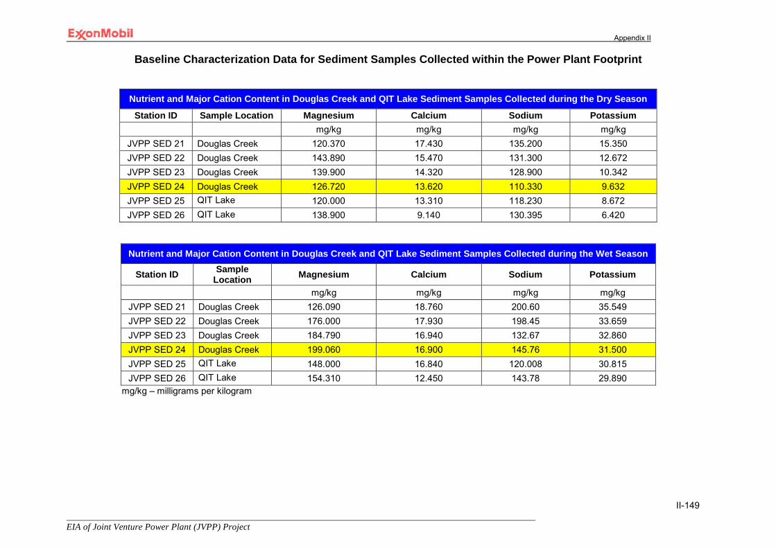
Appendix II
EIA of Joint Venture Power Plant (JVPP) Project
II-149
Baseline Characterization Data for Sediment Samples Collected within the Power Plant Footprint
Nutrient and Major Cation Content in Douglas Creek and QIT Lake Sediment Samples Collected during the Dry Season
Station ID Sample Location Magnesium Calcium Sodium Potassium mg/kg mg/kg mg/kg mg/kg
JVPP SED 21 Douglas Creek 120.370 17.430 135.200 15.350 JVPP SED 22 Douglas Creek 143.890 15.470 131.300 12.672 JVPP SED 23 Douglas Creek 139.900 14.320 128.900 10.342 JVPP SED 24 Douglas Creek 126.720 13.620 110.330 9.632 JVPP SED 25 QIT Lake 120.000 13.310 118.230 8.672 JVPP SED 26 QIT Lake 138.900 9.140 130.395 6.420
Nutrient and Major Cation Content in Douglas Creek and QIT Lake Sediment Samples Collected during the Wet Season
Station ID Sample Location Magnesium Calcium Sodium Potassium
mg/kg mg/kg mg/kg mg/kg JVPP SED 21 Douglas Creek 126.090 18.760 200.60 35.549 JVPP SED 22 Douglas Creek 176.000 17.930 198.45 33.659 JVPP SED 23 Douglas Creek 184.790 16.940 132.67 32.860 JVPP SED 24 Douglas Creek 199.060 16.900 145.76 31.500 JVPP SED 25 QIT Lake 148.000 16.840 120.008 30.815 JVPP SED 26 QIT Lake 154.310 12.450 143.78 29.890
mg/kg – milligrams per kilogram
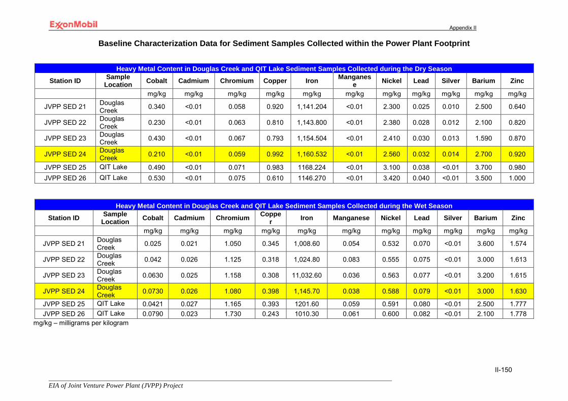
Appendix II
EIA of Joint Venture Power Plant (JVPP) Project
II-150
Baseline Characterization Data for Sediment Samples Collected within the Power Plant Footprint
Heavy Metal Content in Douglas Creek and QIT Lake Sediment Samples Collected during the Dry Season
Station ID Sample Location Cobalt Cadmium Chromium Copper Iron Manganes
e Nickel Lead Silver Barium Zinc
mg/kg mg/kg mg/kg mg/kg mg/kg mg/kg mg/kg mg/kg mg/kg mg/kg mg/kg
JVPP SED 21 Douglas Creek 0.340 <0.01 0.058 0.920 1,141.204 <0.01 2.300 0.025 0.010 2.500 0.640
JVPP SED 22 Douglas Creek 0.230 <0.01 0.063 0.810 1,143.800 <0.01 2.380 0.028 0.012 2.100 0.820
JVPP SED 23 Douglas Creek 0.430 <0.01 0.067 0.793 1,154.504 <0.01 2.410 0.030 0.013 1.590 0.870
JVPP SED 24 Douglas Creek 0.210 <0.01 0.059 0.992 1,160.532 <0.01 2.560 0.032 0.014 2.700 0.920
JVPP SED 25 QIT Lake 0.490 <0.01 0.071 0.983 1168.224 <0.01 3.100 0.038 <0.01 3.700 0.980 JVPP SED 26 QIT Lake 0.530 <0.01 0.075 0.610 1146.270 <0.01 3.420 0.040 <0.01 3.500 1.000
Heavy Metal Content in Douglas Creek and QIT Lake Sediment Samples Collected during the Wet Season
Station ID Sample Location Cobalt Cadmium Chromium Coppe
r Iron Manganese Nickel Lead Silver Barium Zinc
mg/kg mg/kg mg/kg mg/kg mg/kg mg/kg mg/kg mg/kg mg/kg mg/kg mg/kg
JVPP SED 21 Douglas Creek 0.025 0.021 1.050 0.345 1,008.60 0.054 0.532 0.070 <0.01 3.600 1.574
JVPP SED 22 Douglas Creek 0.042 0.026 1.125 0.318 1,024.80 0.083 0.555 0.075 <0.01 3.000 1.613
JVPP SED 23 Douglas Creek 0.0630 0.025 1.158 0.308 11,032.60 0.036 0.563 0.077 <0.01 3.200 1.615
JVPP SED 24 Douglas Creek 0.0730 0.026 1.080 0.398 1,145.70 0.038 0.588 0.079 <0.01 3.000 1.630
JVPP SED 25 QIT Lake 0.0421 0.027 1.165 0.393 1201.60 0.059 0.591 0.080 <0.01 2.500 1.777 JVPP SED 26 QIT Lake 0.0790 0.023 1.730 0.243 1010.30 0.061 0.600 0.082 <0.01 2.100 1.778
mg/kg – milligrams per kilogram
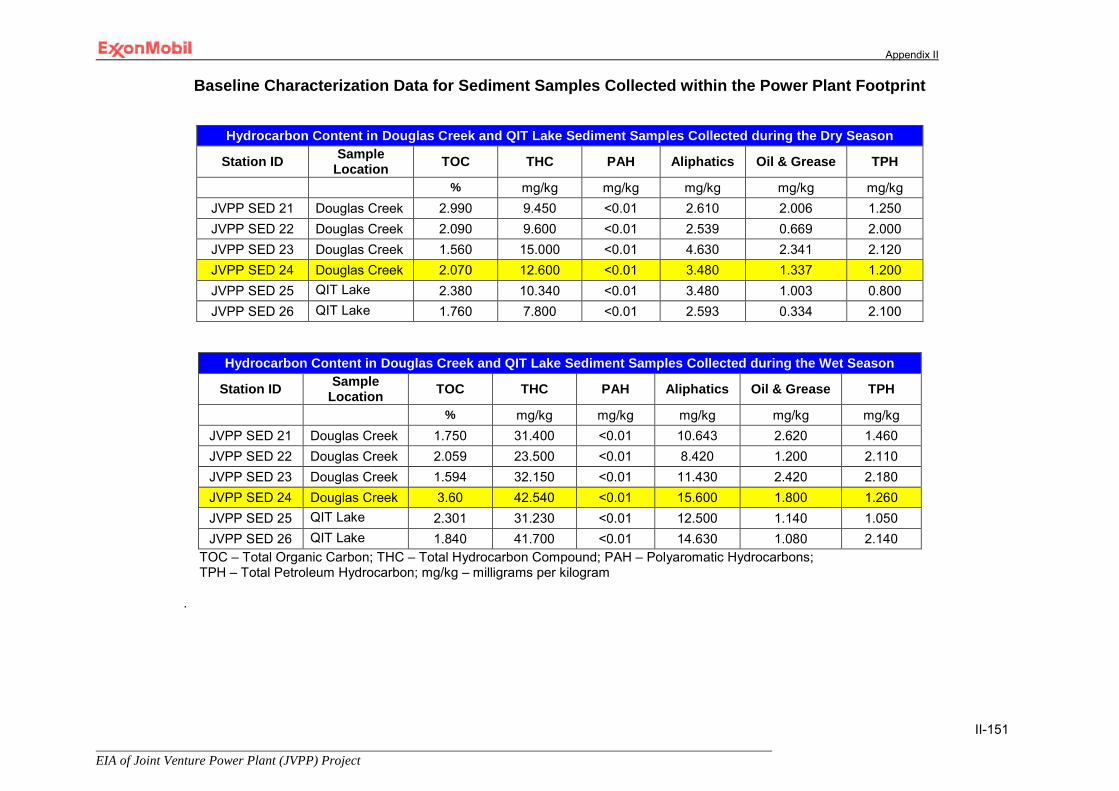
Appendix II
EIA of Joint Venture Power Plant (JVPP) Project
II-151
Baseline Characterization Data for Sediment Samples Collected within the Power Plant Footprint
Hydrocarbon Content in Douglas Creek and QIT Lake Sediment Samples Collected during the Dry Season
Station ID Sample Location TOC THC PAH Aliphatics Oil & Grease TPH
% mg/kg mg/kg mg/kg mg/kg mg/kg JVPP SED 21 Douglas Creek 2.990 9.450 <0.01 2.610 2.006 1.250 JVPP SED 22 Douglas Creek 2.090 9.600 <0.01 2.539 0.669 2.000 JVPP SED 23 Douglas Creek 1.560 15.000 <0.01 4.630 2.341 2.120 JVPP SED 24 Douglas Creek 2.070 12.600 <0.01 3.480 1.337 1.200 JVPP SED 25 QIT Lake 2.380 10.340 <0.01 3.480 1.003 0.800 JVPP SED 26 QIT Lake 1.760 7.800 <0.01 2.593 0.334 2.100
Hydrocarbon Content in Douglas Creek and QIT Lake Sediment Samples Collected during the Wet Season
Station ID Sample Location TOC THC PAH Aliphatics Oil & Grease TPH
% mg/kg mg/kg mg/kg mg/kg mg/kg JVPP SED 21 Douglas Creek 1.750 31.400 <0.01 10.643 2.620 1.460 JVPP SED 22 Douglas Creek 2.059 23.500 <0.01 8.420 1.200 2.110 JVPP SED 23 Douglas Creek 1.594 32.150 <0.01 11.430 2.420 2.180 JVPP SED 24 Douglas Creek 3.60 42.540 <0.01 15.600 1.800 1.260 JVPP SED 25 QIT Lake 2.301 31.230 <0.01 12.500 1.140 1.050 JVPP SED 26 QIT Lake 1.840 41.700 <0.01 14.630 1.080 2.140
TOC – Total Organic Carbon; THC – Total Hydrocarbon Compound; PAH – Polyaromatic Hydrocarbons; TPH – Total Petroleum Hydrocarbon; mg/kg – milligrams per kilogram
.
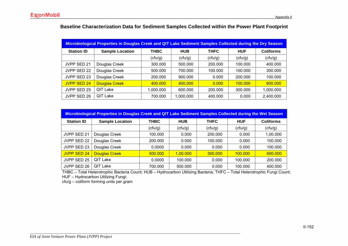
Appendix II
EIA of Joint Venture Power Plant (JVPP) Project
II-152
Baseline Characterization Data for Sediment Samples Collected within the Power Plant Footprint
Microbiological Properties in Douglas Creek and QIT Lake Sediment Samples Collected during the Dry Season
Station ID Sample Location THBC HUB THFC HUF Coliforms (cfu/g) (cfu/g) (cfu/g) (cfu/g) (cfu/g)
JVPP SED 21 Douglas Creek 300.000 500.000 200.000 100.000 400.000 JVPP SED 22 Douglas Creek 500.000 700.000 100.000 100.000 300.000 JVPP SED 23 Douglas Creek 200.000 900.000 0.000 200.000 100.000 JVPP SED 24 Douglas Creek 400.000 400.000 0.000 100.000 800.000 JVPP SED 25 QIT Lake 1,000.000 600.000 200.000 300.000 1,000.000 JVPP SED 26 QIT Lake 700.000 1,000.000 400.000 0.000 2,400.000
Microbiological Properties in Douglas Creek and QIT Lake Sediment Samples Collected during the Wet Season
Station ID Sample Location THBC HUB THFC HUF Coliforms (cfu/g) (cfu/g) (cfu/g) (cfu/g) (cfu/g)
JVPP SED 21 Douglas Creek 100.000 0.000 200.000 0.000 1,00.000 JVPP SED 22 Douglas Creek 200.000 0.000 100.000 0.000 100.000 JVPP SED 23 Douglas Creek 0.0000 0.000 0.000 0.000 100.000 JVPP SED 24 Douglas Creek 500.000 1,00.000 300.000 100.000 600.000 JVPP SED 25 QIT Lake 0.0000 100.000 0.000 100.000 200.000 JVPP SED 26 QIT Lake 700.000 500.000 0.000 100.000 400.000
THBC – Total Heterotrophic Bacteria Count; HUB – Hydrocarbon Utilizing Bacteria; THFC – Total Heterotrophic Fungi Count; HUF – Hydrocarbon Utilizing Fungi; cfu/g – coliform forming units per gram
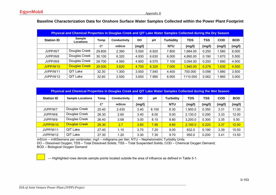
Appendix II
EIA of Joint Venture Power Plant (JVPP) Project
II-153
Baseline Characterization Data for Onshore Surface Water Samples Collected within the Power Plant Footprint
Physical and Chemical Properties in Douglas Creek and QIT Lake Water Samples Collected during the Wet Season
Station ID Sample Locations Temp Conductivity DO pH Turbidity TDS TSS COD BOD
C° mS/cm (mg/l) NTU (mg/l) (mg/l) (mg/l) (mg/l) JVPP/W7 Douglas Creek 25.40 2.430 3.40 8.100 8.30 1,900.0 0.350 3.31 11.00 JVPP/W8 Douglas Creek 26.30 2.60 3.40 8.00 9.00 2,130.0 0.290 3.33 12.00 JVPP/W9 Douglas Creek 26.40 3.68 3.00 8.10 8.80 3,200.0 0.300 3.35 5.50 JVPP/W10 Douglas Creek 26.30 2.7 3.60 7.90 9.60 2,100.0 0.220 3.37 12.00 JVPP/W11 QIT Lake 27.40 1.10 3.70 7.20 9.00 832.0 0.190 3.39 15.50 JVPP/W12 QIT Lake 27.30 1.20 3.30 7.30 9.70 950.0 0.200 3.41 13.50
mS/cm – milliSiemens per centimeter; mg/l – milligrams per liter; NTU – Nephelometric Turbidity Units DO – Dissolved Oxygen; TDS – Total Dissolved Solids; TSS – Total Suspended Solids; COD – Chemical Oxygen Demand; BOD – Biological Oxygen Demand
— Highlighted rows denote sample points located outside the area of influence as defined in Table 5-1.
Physical and Chemical Properties in Douglas Creek and QIT Lake Water Samples Collected during the Dry Season
Station ID Sample Locations Temp Conductivity DO pH Turbidity TDS TSS COD BOD
C° mS/cm (mg/l) NTU (mg/l) (mg/l) (mg/l) (mg/l) JVPP/W7 Douglas Creek 29.800 2.390 5.000 6.920 7.800 1,684.00 0.250 1.580 6.000 JVPP/W8 Douglas Creek 30.100 6.320 4.930 6.630 6.000 4,890.00 0.190 1.670 5.500 JVPP/W9 Douglas Creek 29.700 4.560 4.900 6.570 7.100 3,094.00 0.200 1.690 4.500 JVPP/W10 Douglas Creek 29.000 3.820 4.700 6.320 7.000 1,940.00 0.279 1.630 4.500 JVPP/W11 QIT Lake 32.30 1.300 3.500 7.540 4.400 700.000 0.098 1.880 3.500 JVPP/W12 QIT Lake 32.60 2.500 3.650 7.990 6.900 1110.000 0.062 1.860 3.000

Appendix II
EIA of Joint Venture Power Plant (JVPP) Project
II-154
Baseline Characterization Data for Onshore Surface Water Samples Collected within the Power Plant Footprint
Nutrient and Major Cation Content in Douglas Creek and QIT Lake Water Samples Collected the during Dry Season
Station ID Sample Locations Nitrate Sulfate Magnesium Calcium Sodium Potassium Chloride
(mg/l) (mg/l) (mg/l) (mg/l) (mg/l) (mg/l) (mg/l) JVPP/W7 Douglas Creek 2.656 23.536 145.200 23.400 18.739 39.823 2,380.000 JVPP/W8 Douglas Creek 2.931 27.408 110.150 17.100 12.368 27.720 2,130.000 JVPP/W9 Douglas Creek 3.022 17.456 134.300 13.490 7.920 19.692 980.000 JVPP/W10 Douglas Creek 3.434 10.944 89.400 10.320 10.035 9.520 560.000 JVPP/W11 QIT Lake 3.708 2.240 25.600 2.820 174.090 2.603 480.000 JVPP/W12 QIT Lake 4.028 2.336 15.300 2.920 253.759 2.203 296.000
Nutrient and Major Cation Content in Douglas Creek and QIT Lake Water Samples Collected the during Wet Season
Station ID Sample Locations Nitrate Sulfate Magnesium Calcium Sodium Potassium Chloride
(mg/l) (mg/l) (mg/l) (mg/l) (mg/l) (mg/l) (mg/l)
JVPP/W7 Douglas Creek 1.344 17.904 153.6 0.345 21.393 38.845 2,800 JVPP/W8 Douglas Creek 1.322 23.552 121.8 0.327 14.382 25.643 1,900 JVPP/W9 Douglas Creek 1.427 15.616 144.35 0.354 5.920 17.687 1,160 JVPP/W10 Douglas Creek 1.331 12.544 99.50 0.790 10.538 8.342 700 JVPP/W11 QIT Lake 1.281 2.272 26.60 1.974 295.95 1.534 600 JVPP/W12 QIT Lake 1.495 1.968 16.20 1.853 343.8 1.111 400
mg/l – milligrams per liter

Appendix II
EIA of Joint Venture Power Plant (JVPP) Project
II-155
Baseline Characterization Data for Onshore Surface Water Samples Collected within the Power Plant Footprint
Heavy Metal Content in Douglas Creek and QIT Lake Water Samples Collected during the Dry Season
Station ID Sample Locations Cobalt Cadmium Chromium Copper Iron Manganese Nickel Lead Silver Vanadium Zinc
(mg/l) (mg/l) (mg/l) (mg/l) (mg/l) (mg/l) (mg/l) (mg/l) (mg/l) (mg/l) (mg/l)
JVPP/W7 Douglas Creek 0.410 0.003 0.002 <0.01 0.215 0.001 <0.01 <0.01 <0.01 0.018 0.023
JVPP/W8 Douglas Creek 0.216 0.025 0.008 <0.01 0.143 0.017 <0.01 <0.01 <0.01 0.021 0.021
JVPP/W9 Douglas Creek 0.150 0.010 0.005 <0.01 0.725 0.018 <0.01 <0.01 <0.01 0.015 0.013
JVPP/W10 Douglas Creek 0.220 0.015 0.001 <0.01 0.220 0.016 <0.01 <0.01 <0.01 0.016 0.010
JVPP/W11 QIT Lake 0.155 0.031 0.011 <0.01 0.771 0.013 <0.01 <0.01 <0.01 0.025 0.015 JVPP/W12 QIT Lake 0.150 0.017 0.196 <0.01 0.820 0.021 <0.01 0.021 <0.01 0.020 0.050
Heavy Metal Content in Douglas Creek and QIT Lake Water Samples Collected during the Wet Season
Station ID Sample Locations Cobalt Cadmium Chromium Copper Iron Manganese Nickel Lead Silver Vanadium Zinc
(mg/l) (mg/l) (mg/l) (mg/l) (mg/l) (mg/l) (mg/l) (mg/l) (mg/l) (mg/l) (mg/l)
JVPP/W7 Douglas Creek 0.072 0.008 0.082 <0.01 0.321 0.08 <0.01 0.015 <0.01 0.020 0.039
JVPP/W8 Douglas Creek 0.042 0.020 0.078 <0.01 0.789 0.023 <0.01 0.013 <0.01 0.026 0.022
JVPP/W9 Douglas Creek 0.034 0.015 0.072 <0.01 1.257 0.027 <0.01 0.008 <0.01 0.018 0.016
JVPP/W10 Douglas Creek 0.040 0.040 0.071 <0.01 0.321 0.025 <0.01 0.007 <0.01 0.019 0.012
JVPP/W11 QIT Lake 0.033 0.022 0.070 <0.01 1.253 0.022 <0.01 0.006 <0.01 0.028 0.019 JVPP/W12 QIT Lake 0.030 0.010 0.067 <0.01 1.287 0.031 <0.01 0.003 <0.01 0.022 0.090
mg/l – milligrams per liter
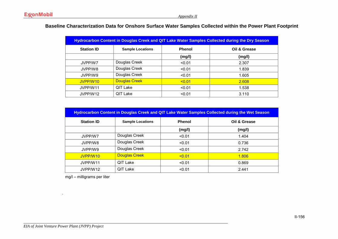
Appendix II
EIA of Joint Venture Power Plant (JVPP) Project
II-156
Baseline Characterization Data for Onshore Surface Water Samples Collected within the Power Plant Footprint
mg/l – milligrams per liter
.
Hydrocarbon Content in Douglas Creek and QIT Lake Water Samples Collected during the Dry Season
Station ID Sample Locations Phenol Oil & Grease
(mg/l) (mg/l) JVPP/W7 Douglas Creek <0.01 2.307 JVPP/W8 Douglas Creek <0.01 1.839 JVPP/W9 Douglas Creek <0.01 1.605 JVPP/W10 Douglas Creek <0.01 2.608 JVPP/W11 QIT Lake <0.01 1.538 JVPP/W12 QIT Lake <0.01 3.110
Hydrocarbon Content in Douglas Creek and QIT Lake Water Samples Collected during the Wet Season
Station ID Sample Locations Phenol Oil & Grease
(mg/l) (mg/l) JVPP/W7 Douglas Creek <0.01 1.404 JVPP/W8 Douglas Creek <0.01 0.736 JVPP/W9 Douglas Creek <0.01 2.742 JVPP/W10 Douglas Creek <0.01 1.806 JVPP/W11 QIT Lake <0.01 0.869 JVPP/W12 QIT Lake <0.01 2.441
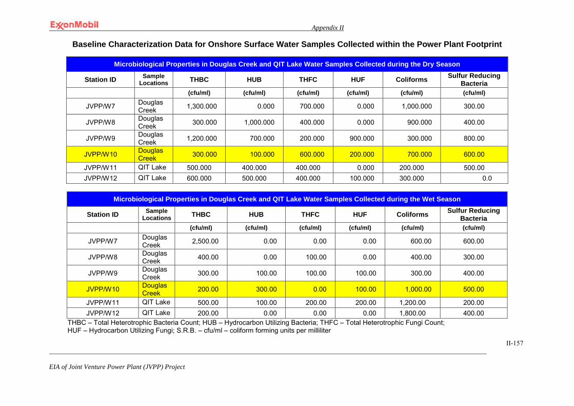
Appendix II
EIA of Joint Venture Power Plant (JVPP) Project
II-157
Baseline Characterization Data for Onshore Surface Water Samples Collected within the Power Plant Footprint
Microbiological Properties in Douglas Creek and QIT Lake Water Samples Collected during the Dry Season
Station ID Sample Locations THBC HUB THFC HUF Coliforms Sulfur Reducing
Bacteria (cfu/ml) (cfu/ml) (cfu/ml) (cfu/ml) (cfu/ml) (cfu/ml)
JVPP/W7 Douglas Creek 1,300.000 0.000 700.000 0.000 1,000.000 300.00
JVPP/W8 Douglas Creek 300.000 1,000.000 400.000 0.000 900.000 400.00
JVPP/W9 Douglas Creek 1,200.000 700.000 200.000 900.000 300.000 800.00
JVPP/W10 Douglas Creek 300.000 100.000 600.000 200.000 700.000 600.00
JVPP/W11 QIT Lake 500.000 400.000 400.000 0.000 200.000 500.00 JVPP/W12 QIT Lake 600.000 500.000 400.000 100.000 300.000 0.0
Microbiological Properties in Douglas Creek and QIT Lake Water Samples Collected during the Wet Season
Station ID Sample Locations THBC HUB THFC HUF Coliforms Sulfur Reducing
Bacteria (cfu/ml) (cfu/ml) (cfu/ml) (cfu/ml) (cfu/ml) (cfu/ml)
JVPP/W7 Douglas Creek 2,500.00 0.00 0.00 0.00 600.00 600.00
JVPP/W8 Douglas Creek 400.00 0.00 100.00 0.00 400.00 300.00
JVPP/W9 Douglas Creek 300.00 100.00 100.00 100.00 300.00 400.00
JVPP/W10 Douglas Creek 200.00 300.00 0.00 100.00 1,000.00 500.00
JVPP/W11 QIT Lake 500.00 100.00 200.00 200.00 1,200.00 200.00 JVPP/W12 QIT Lake 200.00 0.00 0.00 0.00 1,800.00 400.00
THBC – Total Heterotrophic Bacteria Count; HUB – Hydrocarbon Utilizing Bacteria; THFC – Total Heterotrophic Fungi Count; HUF – Hydrocarbon Utilizing Fungi; S.R.B. – cfu/ml – coliform forming units per milliliter
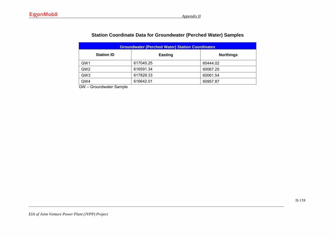
Appendix II
EIA of Joint Venture Power Plant (JVPP) Project
II-158
Station Coordinate Data for Groundwater (Perched Water) Samples
Groundwater (Perched Water) Station Coordinates
Station ID Easting Northings
GW1 617045.25 60444.02 GW2 616591.34 60067.25 GW3 617829.33 60061.54 GW4 616642.01 60957.87
GW – Groundwater Sample
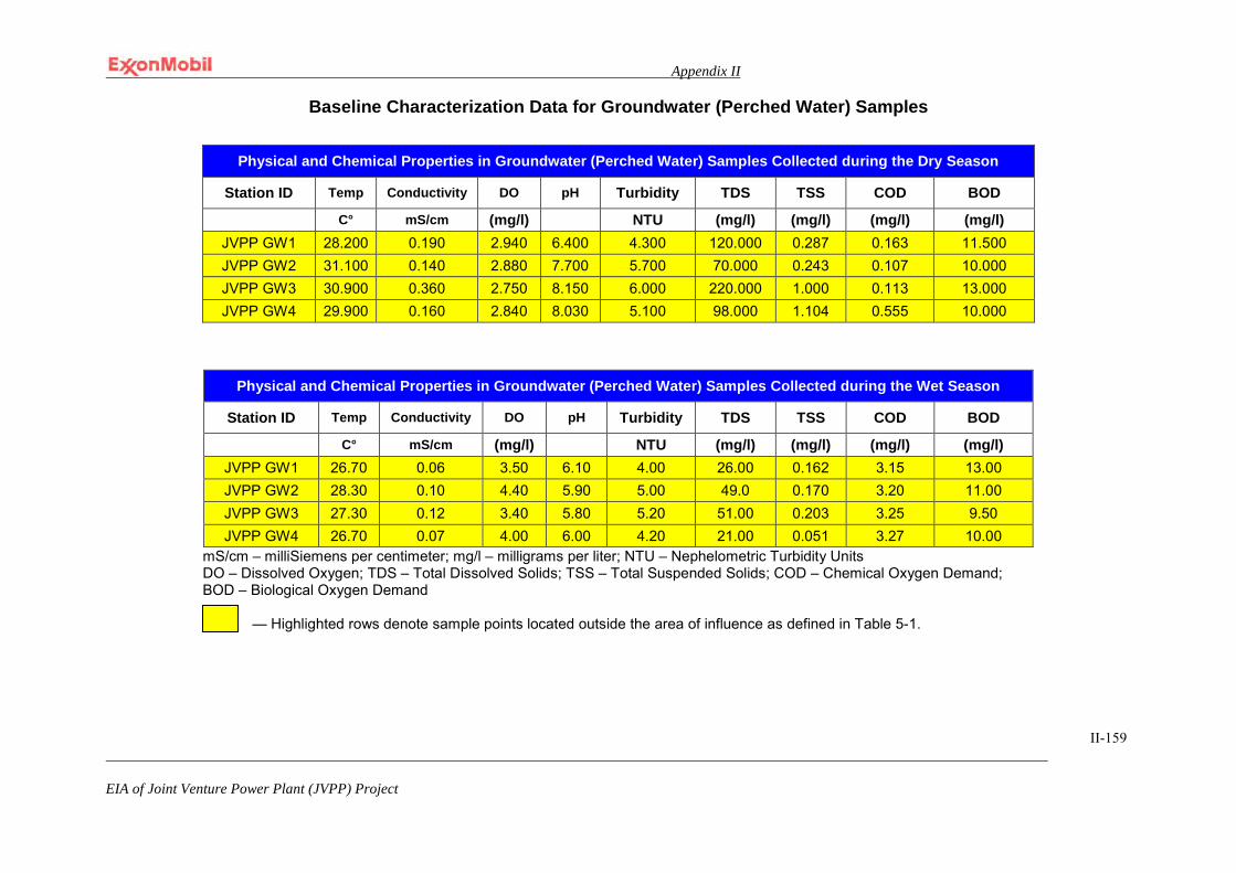
Appendix II
EIA of Joint Venture Power Plant (JVPP) Project
II-159
Baseline Characterization Data for Groundwater (Perched Water) Samples
Physical and Chemical Properties in Groundwater (Perched Water) Samples Collected during the Wet Season
Station ID Temp Conductivity DO pH Turbidity TDS TSS COD BOD
C° mS/cm (mg/l) NTU (mg/l) (mg/l) (mg/l) (mg/l) JVPP GW1 26.70 0.06 3.50 6.10 4.00 26.00 0.162 3.15 13.00 JVPP GW2 28.30 0.10 4.40 5.90 5.00 49.0 0.170 3.20 11.00 JVPP GW3 27.30 0.12 3.40 5.80 5.20 51.00 0.203 3.25 9.50 JVPP GW4 26.70 0.07 4.00 6.00 4.20 21.00 0.051 3.27 10.00
mS/cm – milliSiemens per centimeter; mg/l – milligrams per liter; NTU – Nephelometric Turbidity Units DO – Dissolved Oxygen; TDS – Total Dissolved Solids; TSS – Total Suspended Solids; COD – Chemical Oxygen Demand; BOD – Biological Oxygen Demand
— Highlighted rows denote sample points located outside the area of influence as defined in Table 5-1.
Physical and Chemical Properties in Groundwater (Perched Water) Samples Collected during the Dry Season
Station ID Temp Conductivity DO pH Turbidity TDS TSS COD BOD
C° mS/cm (mg/l) NTU (mg/l) (mg/l) (mg/l) (mg/l) JVPP GW1 28.200 0.190 2.940 6.400 4.300 120.000 0.287 0.163 11.500 JVPP GW2 31.100 0.140 2.880 7.700 5.700 70.000 0.243 0.107 10.000 JVPP GW3 30.900 0.360 2.750 8.150 6.000 220.000 1.000 0.113 13.000 JVPP GW4 29.900 0.160 2.840 8.030 5.100 98.000 1.104 0.555 10.000
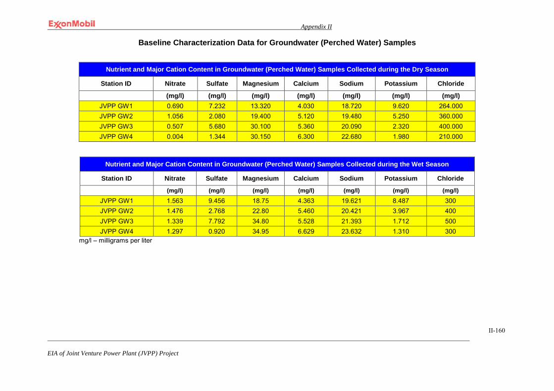
Appendix II
EIA of Joint Venture Power Plant (JVPP) Project
II-160
Baseline Characterization Data for Groundwater (Perched Water) Samples
Nutrient and Major Cation Content in Groundwater (Perched Water) Samples Collected during the Dry Season
Station ID Nitrate Sulfate Magnesium Calcium Sodium Potassium Chloride
(mg/l) (mg/l) (mg/l) (mg/l) (mg/l) (mg/l) (mg/l) JVPP GW1 0.690 7.232 13.320 4.030 18.720 9.620 264.000 JVPP GW2 1.056 2.080 19.400 5.120 19.480 5.250 360.000 JVPP GW3 0.507 5.680 30.100 5.360 20.090 2.320 400.000 JVPP GW4 0.004 1.344 30.150 6.300 22.680 1.980 210.000
Nutrient and Major Cation Content in Groundwater (Perched Water) Samples Collected during the Wet Season
Station ID Nitrate Sulfate Magnesium Calcium Sodium Potassium Chloride
(mg/l) (mg/l) (mg/l) (mg/l) (mg/l) (mg/l) (mg/l)
JVPP GW1 1.563 9.456 18.75 4.363 19.621 8.487 300 JVPP GW2 1.476 2.768 22.80 5.460 20.421 3.967 400 JVPP GW3 1.339 7.792 34.80 5.528 21.393 1.712 500 JVPP GW4 1.297 0.920 34.95 6.629 23.632 1.310 300
mg/l – milligrams per liter
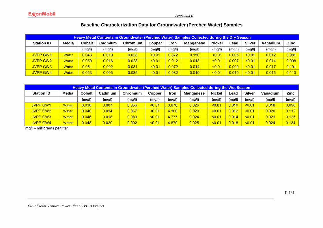
Appendix II
EIA of Joint Venture Power Plant (JVPP) Project
II-161
Baseline Characterization Data for Groundwater (Perched Water) Samples
Heavy Metal Contents in Groundwater (Perched Water) Samples Collected during the Wet Season Station ID Media Cobalt Cadmium Chromium Copper Iron Manganese Nickel Lead Silver Vanadium Zinc
(mg/l) (mg/l) (mg/l) (mg/l) (mg/l) (mg/l) (mg/l) (mg/l) (mg/l) (mg/l) (mg/l) JVPP GW1 Water 0.038 0.007 0.056 <0.01 3.876 0.026 <0.01 0.010 <0.01 0.018 0.098 JVPP GW2 Water 0.040 0.014 0.067 <0.01 4.100 0.020 <0.01 0.012 <0.01 0.020 0.112 JVPP GW3 Water 0.046 0.018 0.083 <0.01 4.777 0.024 <0.01 0.014 <0.01 0.021 0.125 JVPP GW4 Water 0.048 0.020 0.092 <0.01 4.879 0.025 <0.01 0.018 <0.01 0.024 0.134
mg/l – milligrams per liter
Heavy Metal Contents in Groundwater (Perched Water) Samples Collected during the Dry Season Station ID Media Cobalt Cadmium Chromium Copper Iron Manganese Nickel Lead Silver Vanadium Zinc
(mg/l) (mg/l) (mg/l) (mg/l) (mg/l) (mg/l) (mg/l) (mg/l) (mg/l) (mg/l) (mg/l) JVPP GW1 Water 0.043 0.019 0.028 <0.01 0.872 0.150 <0.01 0.006 <0.01 0.012 0.081 JVPP GW2 Water 0.050 0.016 0.028 <0.01 0.912 0.013 <0.01 0.007 <0.01 0.014 0.098 JVPP GW3 Water 0.051 0.002 0.031 <0.01 0.972 0.014 <0.01 0.009 <0.01 0.017 0.101 JVPP GW4 Water 0.053 0.005 0.035 <0.01 0.982 0.019 <0.01 0.010 <0.01 0.015 0.110
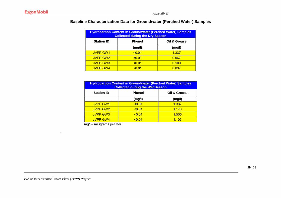
Appendix II
EIA of Joint Venture Power Plant (JVPP) Project
II-162
Baseline Characterization Data for Groundwater (Perched Water) Samples
Hydrocarbon Content in Groundwater (Perched Water) Samples Collected during the Wet Season
Station ID Phenol Oil & Grease
(mg/l) (mg/l) JVPP GW1 <0.01 1.337 JVPP GW2 <0.01 1.170 JVPP GW3 <0.01 1.505 JVPP GW4 <0.01 1.103
mg/l – milligrams per liter
.
Hydrocarbon Content in Groundwater (Perched Water) Samples Collected during the Dry Season
Station ID Phenol Oil & Grease
(mg/l) (mg/l) JVPP GW1 <0.01 1.337 JVPP GW2 <0.01 0.067 JVPP GW3 <0.01 0.100 JVPP GW4 <0.01 0.037
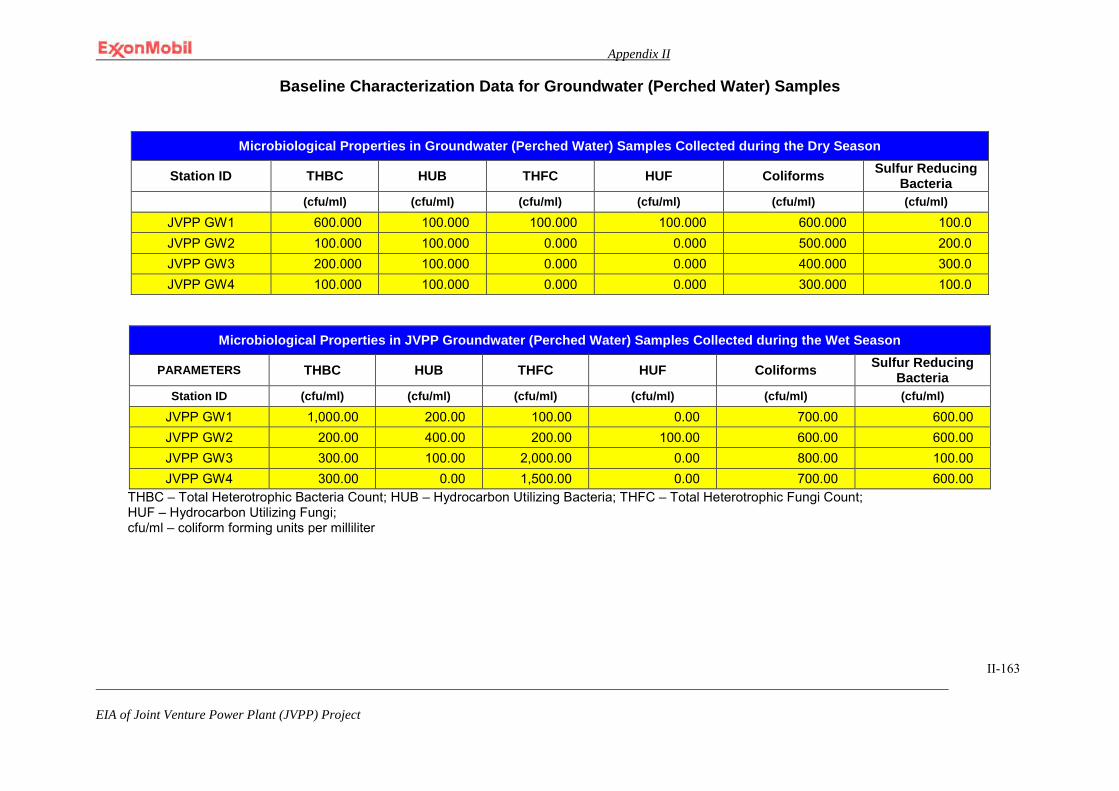
Appendix II
EIA of Joint Venture Power Plant (JVPP) Project
II-163
Baseline Characterization Data for Groundwater (Perched Water) Samples
Microbiological Properties in JVPP Groundwater (Perched Water) Samples Collected during the Wet Season
PARAMETERS THBC HUB THFC HUF Coliforms Sulfur Reducing Bacteria
Station ID (cfu/ml) (cfu/ml) (cfu/ml) (cfu/ml) (cfu/ml) (cfu/ml)
JVPP GW1 1,000.00 200.00 100.00 0.00 700.00 600.00 JVPP GW2 200.00 400.00 200.00 100.00 600.00 600.00 JVPP GW3 300.00 100.00 2,000.00 0.00 800.00 100.00 JVPP GW4 300.00 0.00 1,500.00 0.00 700.00 600.00
THBC – Total Heterotrophic Bacteria Count; HUB – Hydrocarbon Utilizing Bacteria; THFC – Total Heterotrophic Fungi Count; HUF – Hydrocarbon Utilizing Fungi; cfu/ml – coliform forming units per milliliter
Microbiological Properties in Groundwater (Perched Water) Samples Collected during the Dry Season
Station ID THBC HUB THFC HUF Coliforms Sulfur Reducing Bacteria
(cfu/ml) (cfu/ml) (cfu/ml) (cfu/ml) (cfu/ml) (cfu/ml)
JVPP GW1 600.000 100.000 100.000 100.000 600.000 100.0 JVPP GW2 100.000 100.000 0.000 0.000 500.000 200.0 JVPP GW3 200.000 100.000 0.000 0.000 400.000 300.0 JVPP GW4 100.000 100.000 0.000 0.000 300.000 100.0
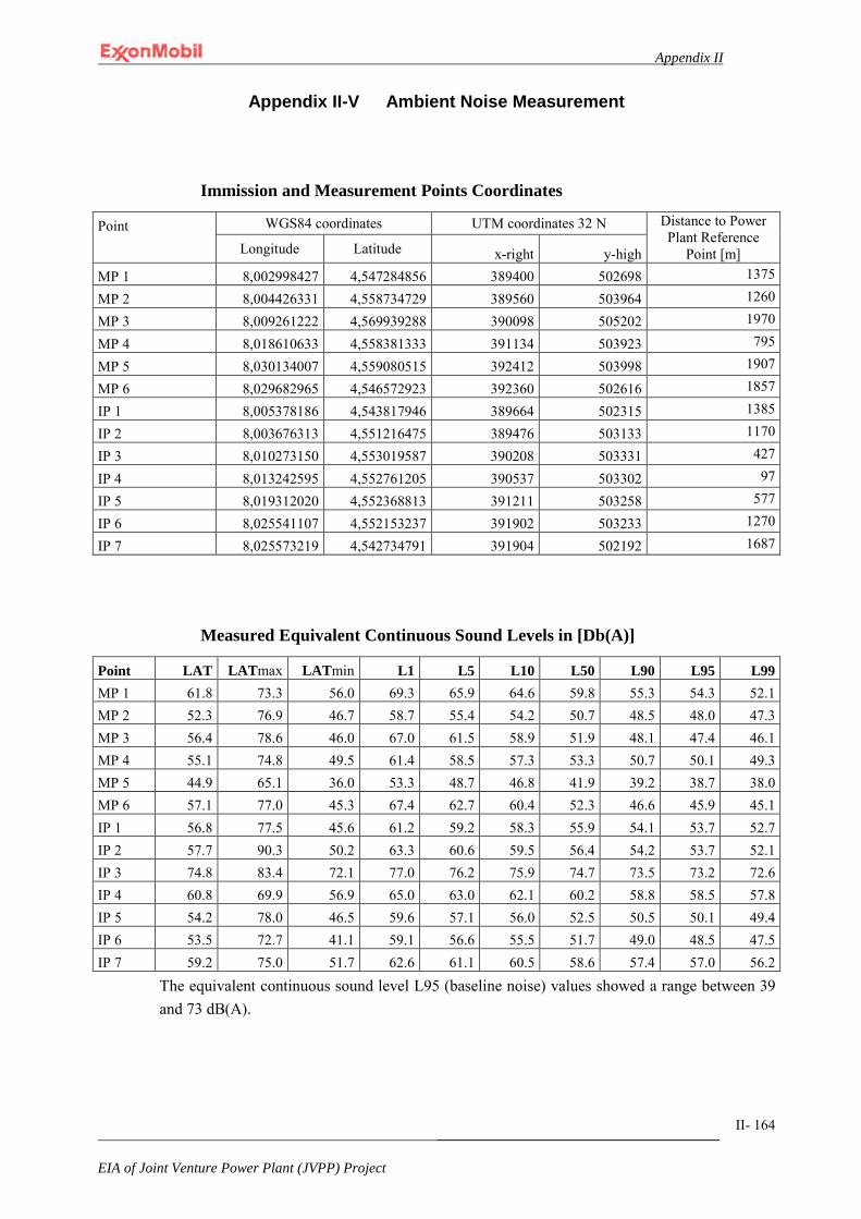
Appendix II
_______________________________________
EIA of Joint Venture Power Plant (JVPP) Project
II- 164
Appendix II-V Ambient Noise Measurement
Immission and Measurement Points Coordinates
Point WGS84 coordinates UTM coordinates 32 N Distance to Power Plant Reference
Point [m] Longitude Latitude x-right y-high MP 1 8,002998427 4,547284856 389400 502698 1375
MP 2 8,004426331 4,558734729 389560 503964 1260
MP 3 8,009261222 4,569939288 390098 505202 1970
MP 4 8,018610633 4,558381333 391134 503923 795
MP 5 8,030134007 4,559080515 392412 503998 1907
MP 6 8,029682965 4,546572923 392360 502616 1857
IP 1 8,005378186 4,543817946 389664 502315 1385
IP 2 8,003676313 4,551216475 389476 503133 1170
IP 3 8,010273150 4,553019587 390208 503331 427
IP 4 8,013242595 4,552761205 390537 503302 97
IP 5 8,019312020 4,552368813 391211 503258 577
IP 6 8,025541107 4,552153237 391902 503233 1270
IP 7 8,025573219 4,542734791 391904 502192 1687
Measured Equivalent Continuous Sound Levels in [Db(A)]
Point LAT LATmax LATmin L1 L5 L10 L50 L90 L95 L99 MP 1 61.8 73.3 56.0 69.3 65.9 64.6 59.8 55.3 54.3 52.1 MP 2 52.3 76.9 46.7 58.7 55.4 54.2 50.7 48.5 48.0 47.3 MP 3 56.4 78.6 46.0 67.0 61.5 58.9 51.9 48.1 47.4 46.1 MP 4 55.1 74.8 49.5 61.4 58.5 57.3 53.3 50.7 50.1 49.3 MP 5 44.9 65.1 36.0 53.3 48.7 46.8 41.9 39.2 38.7 38.0 MP 6 57.1 77.0 45.3 67.4 62.7 60.4 52.3 46.6 45.9 45.1 IP 1 56.8 77.5 45.6 61.2 59.2 58.3 55.9 54.1 53.7 52.7 IP 2 57.7 90.3 50.2 63.3 60.6 59.5 56.4 54.2 53.7 52.1 IP 3 74.8 83.4 72.1 77.0 76.2 75.9 74.7 73.5 73.2 72.6 IP 4 60.8 69.9 56.9 65.0 63.0 62.1 60.2 58.8 58.5 57.8 IP 5 54.2 78.0 46.5 59.6 57.1 56.0 52.5 50.5 50.1 49.4 IP 6 53.5 72.7 41.1 59.1 56.6 55.5 51.7 49.0 48.5 47.5 IP 7 59.2 75.0 51.7 62.6 61.1 60.5 58.6 57.4 57.0 56.2
The equivalent continuous sound level L95 (baseline noise) values showed a range between 39 and 73 dB(A).

Appendix II
_______________________________________
EIA of Joint Venture Power Plant (JVPP) Project
II- 165
Exxon_GP020101-UPST Community Sound Level Limits
Location Sound-Level [dB(A)]
Day Night
Residential: Rural 50 40
Residential: Suburban (including hospitals, churches, mosques, schools, and similar zones)
55 45
Residential: Urban (including apartments) 60 50
Mixed industrial and residential, with some commercial, retail, or light industry
65 55
Predominantly industrial, few dwellings 70 60
All industrial, no dwellings 75 75
Sound Level Limits to be applied to MPs and IPs
Point Ambient Sound Level Regulation Limit Values Sound Level Limit to be
applied
L95 1 3dB(A) - Criteria Community Sound Level
[dB(A)] [dB(A)] [dB(A)] [dB(A)]
MP 1 54 57 50 (Urban) 50
MP 2 48 51 60 (predom. Industrial) 51
MP 3 47 50 40 (Rural) 40
MP 4 50 53 N/A 2 53
MP 5 39 42 40 (Rural) 40
MP 6 46 49 40 (Rural) 40
IP 1 54 57 55 (mixed Industrial) 55
IP 2 54 57 55 (mixed Industrial) 55
IP 3 73 76 75 (all Industrial) 75
IP 4 59 62 60 (predom. Industrial) 60
IP 5 50 53 55 (mixed Industrial) 53
IP 6 49 52 75 (all Industrial) 52
IP 7 57 60 75 (all Industrial) 60 1 Values rounded to full dB(A) 2 MP 4 indicate no settlements, no sound level criteria required
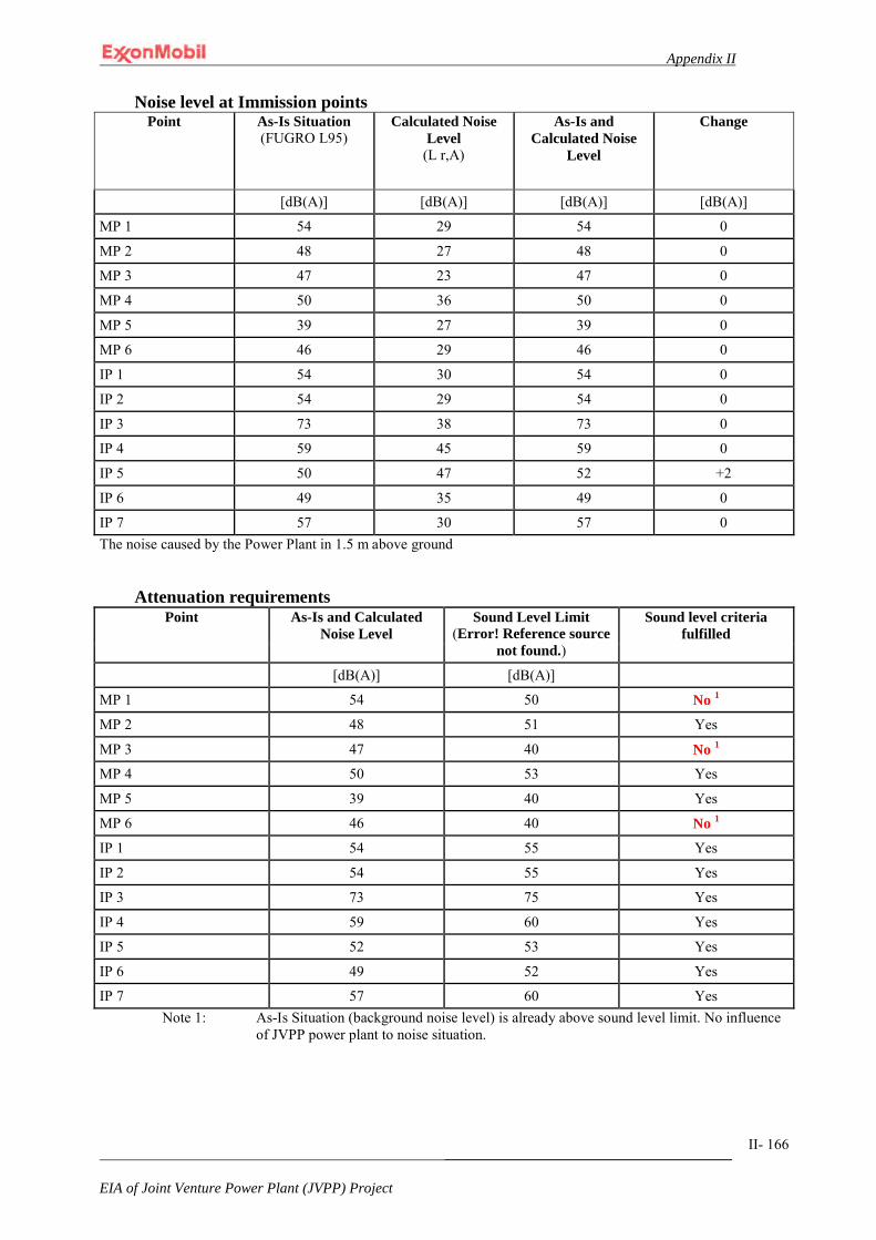
Appendix II
_______________________________________
EIA of Joint Venture Power Plant (JVPP) Project
II- 166
Noise level at Immission points Point As-Is Situation
(FUGRO L95) Calculated Noise
Level (L r,A)
As-Is and Calculated Noise
Level
Change
[dB(A)] [dB(A)] [dB(A)] [dB(A)]
MP 1 54 29 54 0
MP 2 48 27 48 0
MP 3 47 23 47 0
MP 4 50 36 50 0
MP 5 39 27 39 0
MP 6 46 29 46 0
IP 1 54 30 54 0
IP 2 54 29 54 0
IP 3 73 38 73 0
IP 4 59 45 59 0
IP 5 50 47 52 +2
IP 6 49 35 49 0
IP 7 57 30 57 0 The noise caused by the Power Plant in 1.5 m above ground
Attenuation requirements Point As-Is and Calculated
Noise Level Sound Level Limit
(Error! Reference source not found.)
Sound level criteria fulfilled
[dB(A)] [dB(A)]
MP 1 54 50 No 1
MP 2 48 51 Yes
MP 3 47 40 No 1 MP 4 50 53 Yes
MP 5 39 40 Yes
MP 6 46 40 No 1
IP 1 54 55 Yes
IP 2 54 55 Yes
IP 3 73 75 Yes
IP 4 59 60 Yes
IP 5 52 53 Yes
IP 6 49 52 Yes
IP 7 57 60 Yes Note 1: As-Is Situation (background noise level) is already above sound level limit. No influence
of JVPP power plant to noise situation.

APPENDIX III
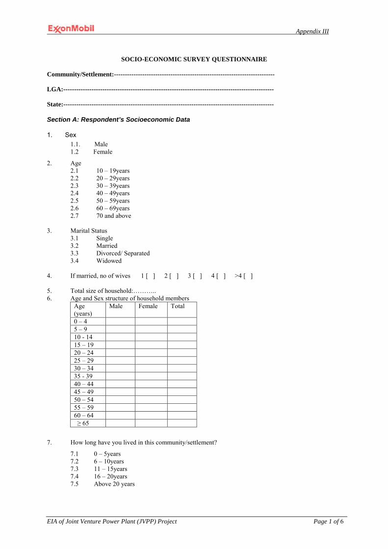
Appendix III
EIA of Joint Venture Power Plant (JVPP) Project Page 1 of 6
SOCIO-ECONOMIC SURVEY QUESTIONNAIRE
Community/Settlement:-------------------------------------------------------------------------- LGA:------------------------------------------------------------------------------------------------- State:-------------------------------------------------------------------------------------------------
Section A: Respondent’s Socioeconomic Data
1. Sex 1.1. Male 1.2 Female
2. Age 2.1 10 – 19years 2.2 20 – 29years 2.3 30 – 39years 2.4 40 – 49years 2.5 50 – 59years 2.6 60 – 69years 2.7 70 and above
3. Marital Status
3.1 Single 3.2 Married 3.3 Divorced/ Separated 3.4 Widowed
4. If married, no of wives 1 [ ] 2 [ ] 3 [ ] 4 [ ] >4 [ ] 5. Total size of household:……….. 6. Age and Sex structure of household members
Age (years)
Male Female Total
0 – 4 5 – 9 10 - 14 15 – 19 20 – 24 25 – 29 30 – 34 35 - 39 40 – 44 45 – 49 50 – 54 55 – 59 60 – 64 ≥ 65
7. How long have you lived in this community/settlement?
7.1 0 – 5years 7.2 6 – 10years 7.3 11 – 15years 7.4 16 – 20years 7.5 Above 20 years
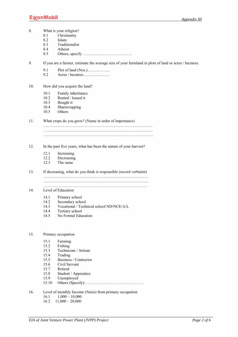
Appendix III
EIA of Joint Venture Power Plant (JVPP) Project Page 2 of 6
8. What is your religion? 8.1 Christianity 8.2 Islam 8.3 Traditionalist 8.4 Atheist 8.5 Others, specify ……………………………….
9. If you are a farmer, estimate the average size of your farmland in plots of land or acres / hectares.
9.1 Plot of land (Nos.)…………….. 9.2 Acres / hectares………………..
10. How did you acquire the land?
10.1 Family inheritance 10.2 Rented / leased it 10.3 Bought it 10.4 Sharecropping 10.5 Others
11. What crops do you grow? (Name in order of importance) ………………………………………………………………………. ………………………………………………………………………. ……………………………………….……………………………….
12. In the past five years, what has been the nature of your harvest?
12.1 Increasing 12.2 Decreasing 12.3 The same
13. If decreasing, what do you think is responsible (record verbatim)
……………………………………………………………………. ……………………………………………………………………. ……………………………………………………………………
14. Level of Education
14.1 Primary school 14.2 Secondary school 14.3 Vocational / Technical school ND/NCE/A/L 14.4 Tertiary school 14.5 No Formal Education
15. Primary occupation
15.1 Farming 15.2 Fishing 15.3 Technician / Artisan 15.4 Trading 15.5 Business / Contractor 15.6 Civil Servant 15.7 Retired 15.8 Student / Apprentice 15.9 Unemployed 15.10 Others (Specify):……………………………………..
16. Level of monthly Income (Naira) from primary occupation
16.1 1,000 – 10,000 16.2 11,000 – 20,000

Appendix III
EIA of Joint Venture Power Plant (JVPP) Project Page 3 of 6
16.3 21,000 – 30,000 16.4 31,000 – 40,000 16.5 41,000 – 50,000 16.6 51,000 – 60,000 16.7 61,000 – 70,000 16.8 71,000 – 80,000 16.9 Above 80,000
17. Do you have a secondary occupation? Yes [ ] No [ ] 18. If yes, which of these
Farming Fishing Technician / Artisan Trading Business / Contractor Civil Servant Apprentice technician Others (Specify):……………………..…………….
19. Level of monthly Income (Naira) from secondary occupation 1,000 – 10,000
11,000 – 20,000 21,000 – 30,000 31,000 – 40,000 41,000 – 50,000
51,000 – 60,000 61,000 – 70,000
71,000 – 80,000 Above 80,000
Section B: Socioeconomic Impacts 21. What period of the year ( use seasons) is important to your community for:
21.1 Farming………………….. 21.2 Fishing…………………… 21.3 Trading………………….. 21.4 Festivals…………………
22. What are the important environmental resources in your community 22.1 Forest resources 22.2 River / Creek water 22.3 Ancestral sites 22.4 Animals 22.5 Others (specify)………………………………………………
23. Name the sacred sites in your community
23.1 …………………………. 23.2 …………………………. 23.3 …………………………. 23.4 ………………………….
24. List the environmental problems in the settlement 24.1 Soil fertility 24.2 Pest attack / invasion 24.3 Erosion problems 24.4 Flooding 24.5 Water pollution 24.6 Others (specify)……………………………….…..
25. Has your economic activity (ies) been affected in any way in the past two to five years? 25.1 Yes 25.2 No

Appendix III
EIA of Joint Venture Power Plant (JVPP) Project Page 4 of 6
26. If yes, in what specific way have you been affected and what is responsible in your opinion? ………………………………………………………………………………….. ………………………………………………………………………………….. ………………………………………………………………………………… 27. Has your fishing ground/farmland been lost/reduced in size due to company’s operational activities?
27.1 Yes 27.2 No
28. If yes, in what way(s) did you lose the fishing ground/farmland?
28.1 ………………………………. 28.2 ………………………………. 28.3 ………………………………..
Section C: Relationship with Companies 29. Name the companies within your settlement area
……………………………………………………………………………………. ………………………………………………………………………………… 30. What have you gained personally from the company (ies) operation in your area?
30.1 Employment 30.2 Scholarship for children/ward 30.3 Skills acquisition 30.4 None 30.5 Others (specify)……………………………………………………..
31. If none, what personal benefit do you expect from the company (ies)?
31.1 Employment opportunities 31.2 Award of scholarships 31.3 Small monetary grant to farmers/fishermen 31.4 Provision of agricultural inputs/tools 31.5 Others (specify)……………………………………………
32. What has your community gained from the companies in your area?
32.1 Provision of portable water 32.2 Electricity supply 32.3 Healthcare facility/center 32.4 Repair/tarring of community/link roads 32.5 Assistance with school building/chairs and tables 32.6 None 32.7 Others (specify)
33. If none, what would you expect the company (ies) to do for your community?
33.1 Employment opportunities 33.2 Education / scholarship 33.3 Provision of portable water supplies 33.4 Electricity / road / market 33.5 Assistant with agricultural inputs 33.6 Others (specify)………………………………………..…..
34. What is your attitude towards companies who or wish to work in your area?
34.1 Support / welcome their activities 34.2 Resist their presence 34.3 Demand compensation 34.4 I don’t care about them
35. What industry related social problem does to your community experience?
35.1 Youth delinquency 35.2 Land Dispute 35.3 Chieftaincy tussle 35.4 Inter family problems 35.5 Inter village tribal conflicts

Appendix III
EIA of Joint Venture Power Plant (JVPP) Project Page 5 of 6
35.6 Unemployment 35.7 Alcoholism / prostitution 35.8 Others (specify)
36. Who should speak for the community on company – community matters? 36.1 Community Leader / Paramount Chief 36.2 Community Chief 36.3 The Youth Leader 36.4 Community Representatives
Thank you very much for the co – operation.
ENVIRONMENTAL IMPACT ASSESSMENT
FOCUSED GROUP DISCUSSION SCHEDULE
A: IDENTIFICATION: Name of Community: ____________________________________
VARIABLES VALUES Venue of FGD Date of FGD Name of Moderator Number of participants Men
Women Youths
B: SOCIAL/POLITICAL ORGANIZATION 1.Name of Community/Settlement _________________________ [ ] Urban [ ] Rural
2. Ward_________________ LGA: ________________ State; ____________
3. Head of Community: _________________________________
4. Which is the topmost decision making organ of your community? 5. What other organs of village organization do you have? Age Grades, etc. 6. Chieftaincy matters/Traditional Power structure
7. Land ownership system C: ETHNIC COMPOSITION
1. Major or dominant Tribe 2. Other sub-groups or tribes 3. Major language spoken 4. Other languages or dialects 5. Dominant non-indigenous group
D: COMMERCIAL ACTIVITIES
1. Markets – periodicity, proximity 2. Hotels, Restaurants etc 3. Shops/Supermarkets 4. Welding/Vulcanizing 5. Carpentry/Boat making 6. Fishing/Fishing gear/Fish types/Fish smoking 7. Economic Trees and distribution 8. Farming/Major Crops
E: SOCIAL INFRASTRUCTURE 1. Health
- Type of health Institution

Appendix III
EIA of Joint Venture Power Plant (JVPP) Project Page 6 of 6
- Type and number of medical personnel - Traditional medical practices
2. Schools - Primary/Secondary - Number and distribution of staff - Number of pupils, sex distribution - Ownership of schools
3. Community Associations existing in the community 4. Churches and number and names in the community 5. Type of settlement and arrangement of houses 6. How is household waste disposed 7. Electricity and provider 8. Water supply (Type, source and provider) 9. Police Station/Post, proximity 10. Estimated number of housing units in community 11. Types of road within the community 12. Major means of transportation & Cost/Communication links
F: CULTURAL RESOURCES 1. Festivals: Annual/Periodicity 2. Shrines/Heritage sites 3. Reserved Forests/Bushes 4. Sacred sites 5. Archaeological/Historic sites 6. Craft centers 7. Taboos/observances
G: RECREATIONAL FACILITIES/TOURISM
1. Existing playground/game field 2. Community centre 3. Areas of tourist’s attraction – Spring, wildlife 4. Cultural ceremonies displays/dances
H: LIKELY IMPACTS ON:
1. Population structure 2. Land use 3. Employment 4. Income/Revenue 5. General commerce 6. Cultural resources 7. Property 8. Transport 9. Others
I. MITIGATING MEASURES/STRATEGIES AS OPINED BY COMMUNITY J. COMMUNITY VIEWS ABOUT THE PROPOSED PROJECT. 1. Positive effect 2. Negative effects K. COMMUNITY VIEWS ABOUT THE NEW PROJECT

APPENDIX IV

Appendix IV
EIA of Joint Venture Power Plant (JVPP) Project
Page 1 of 7
HEALTH SURVEY QUESTIONNAIRE
This questionnaire is designed to enable us obtain information for the Health Impact assessment for the Agbada Oil and Gas Field Project. We need your assistance and cooperation in answering the questions asked below. Your answers will be treated as confidential. Please fill in or tick as appropriate. (A) Socio-Demographic Variables
(1) Name of Town / Village……………………………………………………………………
(2) Age (Last Birthday)………………………………………………………………………
(3) Sex: (a) Male (b) Female
(4) What is your marital status? Single Married Divorced Separated Widow/Widower
(5) Educational Status:
a) No formal education b) Primary School c) Secondary school d) Tertiary ( NCE / OND / AL / HND / Degree) e) Higher degree
(6) Occupation: (a) Farming (b) Fishing (c) Trading (d) Civil servant (e) Others (specify)………………………………
(7) In Your work place, what health problems are you exposed to:……………….. ………………………………………………………………………………………… (8) Income Per month (Adults only)………………………………………………
(9) How much does it cost you to take care of your family in a month?………….
(10) Religion…………………………………………………
(11) Ethnic group…………………………………………….
(12) How long have you lived in this community? ……………………..
(13) Have you changed your residence in this community within the last five (5) years? Yes/No
(14) If your answer to question 6 is yes, please state why?
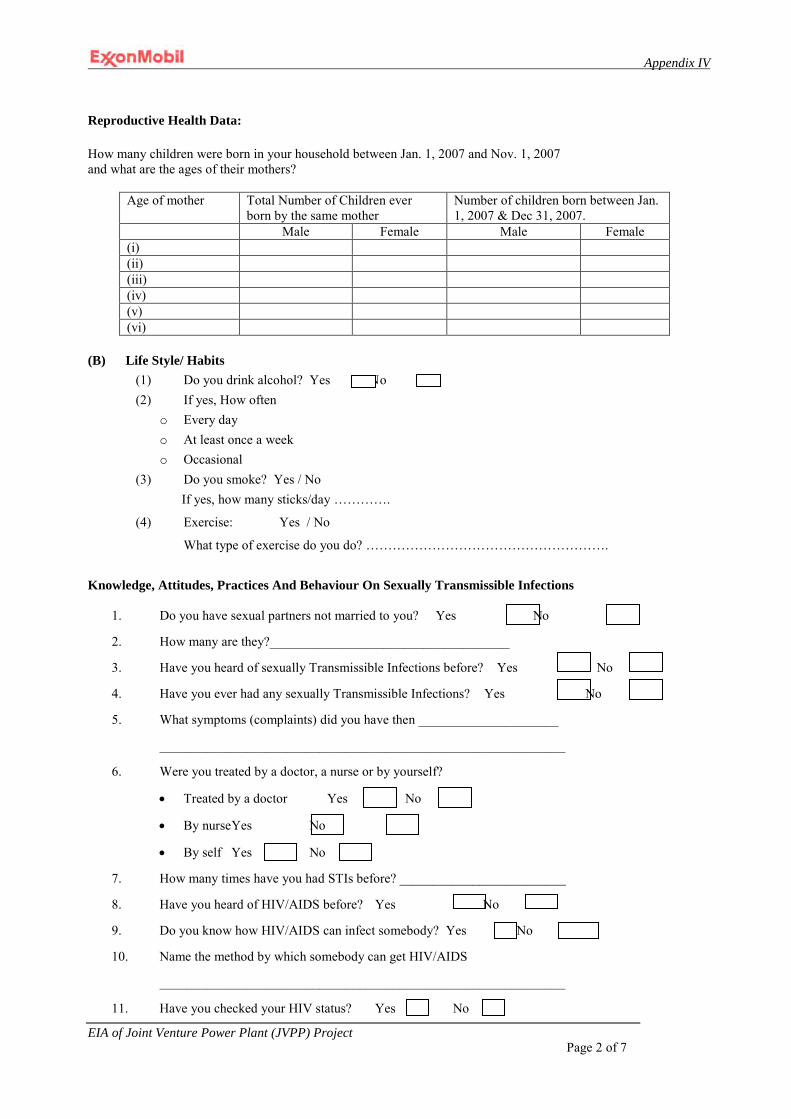
Appendix IV
EIA of Joint Venture Power Plant (JVPP) Project
Page 2 of 7
Reproductive Health Data: How many children were born in your household between Jan. 1, 2007 and Nov. 1, 2007 and what are the ages of their mothers?
Age of mother Total Number of Children ever born by the same mother
Number of children born between Jan. 1, 2007 & Dec 31, 2007.
Male Female Male Female (i) (ii) (iii) (iv) (v) (vi)
(B) Life Style/ Habits
(1) Do you drink alcohol? Yes No (2) If yes, How often
o Every day o At least once a week o Occasional
(3) Do you smoke? Yes / No If yes, how many sticks/day ………….
(4) Exercise: Yes / No
What type of exercise do you do? ……………………………………………….
Knowledge, Attitudes, Practices And Behaviour On Sexually Transmissible Infections
1. Do you have sexual partners not married to you? Yes No
2. How many are they?____________________________________
3. Have you heard of sexually Transmissible Infections before? Yes No
4. Have you ever had any sexually Transmissible Infections? Yes No
5. What symptoms (complaints) did you have then _____________________
_____________________________________________________________
6. Were you treated by a doctor, a nurse or by yourself?
• Treated by a doctor Yes No
• By nurse Yes No
• By self Yes No
7. How many times have you had STIs before? _________________________
8. Have you heard of HIV/AIDS before? Yes No
9. Do you know how HIV/AIDS can infect somebody? Yes No
10. Name the method by which somebody can get HIV/AIDS
_____________________________________________________________
11. Have you checked your HIV status? Yes No

Appendix IV
EIA of Joint Venture Power Plant (JVPP) Project
Page 3 of 7
12. Do you know anybody who has HIV/AIDS? Yes No
13. How many do you? _____________________________
14. Has any member of your family, friend or community had or having tuberculosis?
Yes No
Morbidity and Mortality:
1. Please list persons (if any) who died in your household between Jan. 1, 2007 and Dec 31, 2007. Name (Optional) Sex Age Cause of death (if known)
(i) (ii) (iii) (iv) (v) (vi) (vii) (viii)
2. Please indicate number of members of your household that suffered from each of the different
diseases listed below between Jan. 1, 2007 and Dec 31, 2007. (If any) Type of Disease Male Female Total
(i) Diarrhoea (ii) Dysentery (iii) Measles (iv) Pneumonia (v) Typhoid Fever (vi) Malaria (vii) Cholera (viii) Polio (ix) Yellow Fever (x) Chicken pox (xi) Diphtheria (xii) Cancer (xiii) Tetanus (xiv) Tuberculosis (xv) AIDS (xvi) Guinea worm (xvii) Sleeping Sickness (xviii) River blindness (xix) Stroke (xx) Others (Specify)
3. Please indicate how many members of your family that are below 5 years who have suffered from
the under-listed conditions between Jan. 1, 2007 and Dec 31, 2007. Clinical Condition Male Female Total (i) Kwashiokor (ii) Anaemia (iii) Rickets (iv) Goitre (v) others (specify)
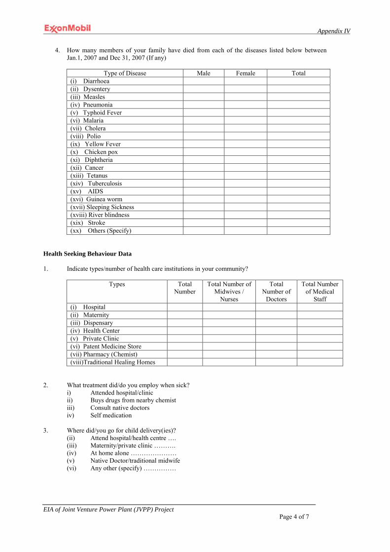
Appendix IV
EIA of Joint Venture Power Plant (JVPP) Project
Page 4 of 7
4. How many members of your family have died from each of the diseases listed below between Jan.1, 2007 and Dec 31, 2007 (If any)
Type of Disease Male Female Total
(i) Diarrhoea (ii) Dysentery (iii) Measles (iv) Pneumonia (v) Typhoid Fever (vi) Malaria (vii) Cholera (viii) Polio (ix) Yellow Fever (x) Chicken pox (xi) Diphtheria (xii) Cancer (xiii) Tetanus (xiv) Tuberculosis (xv) AIDS (xvi) Guinea worm (xvii) Sleeping Sickness (xviii) River blindness (xix) Stroke (xx) Others (Specify)
Health Seeking Behaviour Data 1. Indicate types/number of health care institutions in your community?
Types Total
Number Total Number of
Midwives / Nurses
Total Number of
Doctors
Total Number of Medical
Staff (i) Hospital (ii) Maternity (iii) Dispensary (iv) Health Center (v) Private Clinic (vi) Patent Medicine Store (vii) Pharmacy (Chemist) (viii)Traditional Healing Homes
2. What treatment did/do you employ when sick?
i) Attended hospital/clinic ii) Buys drugs from nearby chemist iii) Consult native doctors iv) Self medication
3. Where did/you go for child delivery(ies)?
(ii) Attend hospital/health centre …. (iii) Maternity/private clinic ………. (iv) At home alone ………………… (v) Native Doctor/traditional midwife (vi) Any other (specify) ……………

Appendix IV
EIA of Joint Venture Power Plant (JVPP) Project
Page 5 of 7
Environmental Health Data: 1. What is the major source of water available to your household? (tick the correct option)
(i) River/Stream (ii) Well (iii) Pond (iv) Rain Water (v) Public pipe-borne water (vi) Mono pump (vii) Borehole (Commercial) (viii) Borehole (private) (ix) Commercial tanker
2. What type(s) of residential houses do you have in your community?
(Tick the correct option) Types of Houses (by Nature of construction Materials) Total Number (i) Wood (Batcher) (ii) Mud (iii) Corrugated iron sheets (zinc batcher) (iv) Cellophane (nylon) (v) Thatch (vi) Block (cement or brick) (vii) Others (Specify)
3. How many persons live in a house?___________________________ 4. How many rooms are in your house / residence?_______________________________
5. What type of toilet facility do you use? Please tick from below.
(1) Pit (2) Bush
(3) Prier head
(4) Bucket
(5) Water closet
(6) Others (specify)_______________________________________
6. How do you dispose of your household refuse? Please tick from the list below.
i) Private open dump ii) Public open dump iii) Organized collection (by Local Government, Community etc) iv) Organized collection *by Individual – Commercial) v) Burning vi) Bush vii) Burying viii) River/Stream

Appendix IV
EIA of Joint Venture Power Plant (JVPP) Project
Page 6 of 7
FOCUS GROUP DISCUSSION QUESTIONS
1. Name of Town/Village …………………………………………………………… Lifestyle/habits
1. What are the common types of food eaten in the community ………………... 2. Is there any food taboos Yes / No 3. What is the average life span (expectancy) in your community.
(a) Male ………………………. (b) Female ………………………… 4. What are the common health problems in your community?…………………..
………………………………………………………………………………………… 5. When are these health problems common during the year
S/No Disease RAINY SEASON DRY SEASON
6. Which of these health problems pose the greatest threat to your community (5 diseases to be listed in order of frequency) ………………………………….. …………………………………………………………………………………………………………………………………………………………………………………………
7. What are the most important causes of death in your community? Among : (i) Children under 5 years …………………………………………………… (ii) Adults ……………………………………………………………………….
8. How many deaths in the last one year among: (i) Whole community …………………………………… (ii) Children under 5 years …………………………….. (iii) Adults (Women of child bearing age) …………
9. What refuse do you generate? ………………………………………………… 10. How do you store your refuse …………………………………………………. 11. How do you dispose your refuse? …………………………………………….. 12. What is your method of sewage disposal? …………………………………… 13. Do you have drainage in your community? ………………………………….. 14. Does your community get flooded or water logged? ……………………….. 15. What is the source of the flooding?…………………………………………… 16. What is the source of your drinking water? …………………………………. 17. Do you treat your water before drinking? ……………………………………. 18. Do you wash your hands before eating/ ……………………………………… 19. Do you wash your hands after defaecating? (Toileting)……………………. 20. What are health facilities in your communities ……………………………… 21. Do you think Oil and Exploration and Production is causing any health problems in your
community? Yes: No:
If yes, what are the problems?……………………………………………………
22. How do you think these problems can be minimized? …………………………
23. What do you think are the most important five health needs of your community?
…………………………………………………………………………
…………………………………………………………………………
24. Do you have the followings in your community (a) House Fly/cockroach/Mosquito/Lice/Black fly/Tsetse fly/and rats.
Thank you.

Appendix IV
EIA of Joint Venture Power Plant (JVPP) Project
Page 7 of 7
HEALTH SURVEY - FOCUS GROUP DISCUSSION QUESTIONS
2. Name of Town/Village …………………………………………………………… Lifestyle/habits
25. What are the common types of food eaten in the community ………………... 26. Is there any food taboo Yes / No 27. What is the average life span (expectancy) in your community.
(a) Male ………………………. (b) Female ………………………… 28. What are the common health problems in your community?…………………..
………………………………………………………………………………………… 29. When are these health problems common during the year
S/No Disease RAINY SEASON DRY SEASON
30. Which of these health problems pose the greatest threat to your community (5 diseases to be listed in order of frequency) ………………………………….. …………………………………………………………………………………………………………………………………………………………………………………………
31. What are the most important causes of death in your community? Among : (i) Children under 5 years …………………………………………………… (ii) Adults ……………………………………………………………………….
32. How many deaths in the last one year among: (i) Whole community …………………………………… (ii) Children under 5 years …………………………….. (iii) Adults (Women of child bearing age) …………
33. What refuse do you generate? ………………………………………………… 34. How do you store your refuse …………………………………………………. 35. How do you dispose your refuse? …………………………………………….. 36. What is your method of sewage disposal? …………………………………… 37. Do you have drainage in your community? ………………………………….. 38. Does your community get flooded or water logged? ……………………….. 39. What is the source of the flooding?…………………………………………… 40. What is the source of your drinking water? …………………………………. 41. Do you treat your water before drinking? ……………………………………. 42. Do you wash your hands before eating/ ……………………………………… 43. Do you wash your hands after defaecating? (Toileting)……………………. 44. What are health facilities in your communities ……………………………… 45. Do you think Oil and Exploration and Production is causing any health problems in
your community? Yes: No:
If yes, what are the problems?……………………………………………………
46. How do you think these problems can be minimized? …………………………
47. What do you think are the most important five health needs of your community?
…………………………………………………………………………
…………………………………………………………………………
48. Do you have the followings in your community (a) House Fly/cockroach/Mosquito/Lice/Black fly/Tsetse fly/and rats.
Thank you.

APPENDIX V

Appendix V
EIA of Joint Venture Power Plant (JVPP) Project V-1
1
EASTERN OBOLO LGA
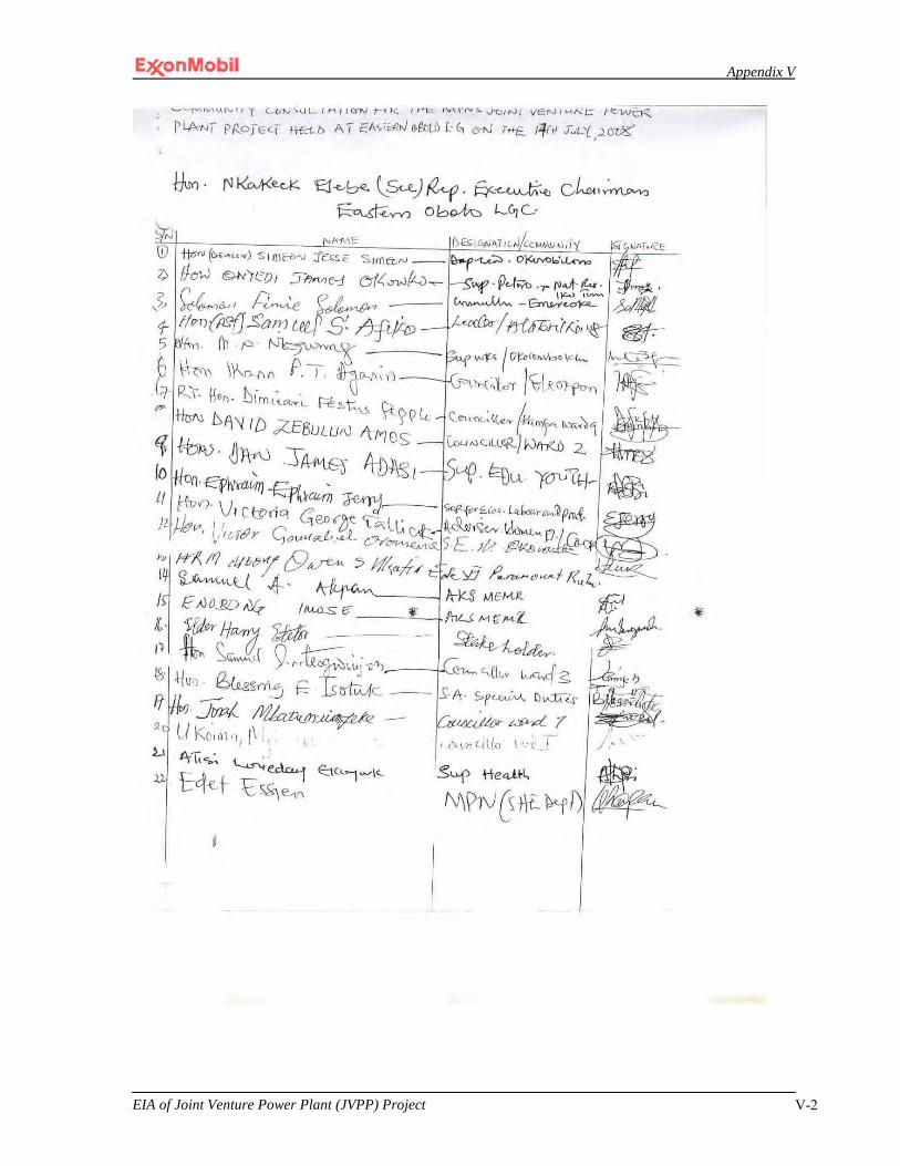
Appendix V
EIA of Joint Venture Power Plant (JVPP) Project V-2

Appendix V
EIA of Joint Venture Power Plant (JVPP) Project V-3

Appendix V
EIA of Joint Venture Power Plant (JVPP) Project V-4

Appendix V
EIA of Joint Venture Power Plant (JVPP) Project V-5

Appendix V
EIA of Joint Venture Power Plant (JVPP) Project V-6
2
EKET LGA

Appendix V
EIA of Joint Venture Power Plant (JVPP) Project V-7
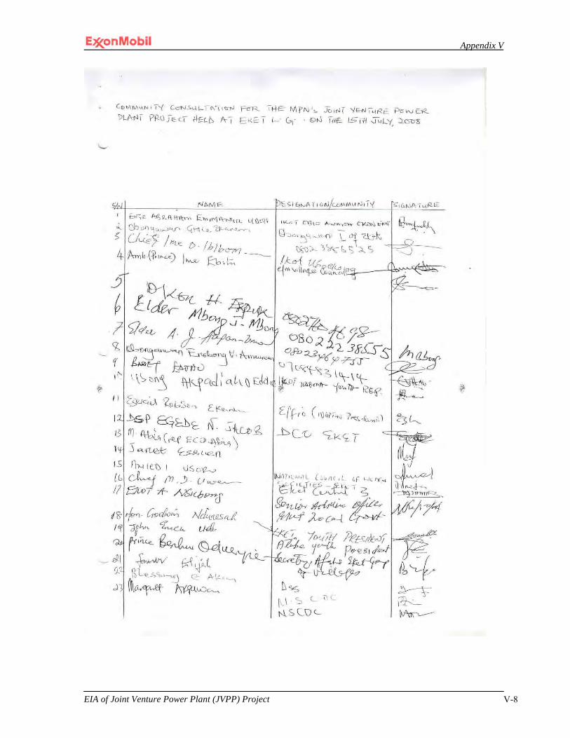
Appendix V
EIA of Joint Venture Power Plant (JVPP) Project V-8

Appendix V
EIA of Joint Venture Power Plant (JVPP) Project V-9

Appendix V
EIA of Joint Venture Power Plant (JVPP) Project V-10
3
ESIT EKET LGA

Appendix V
EIA of Joint Venture Power Plant (JVPP) Project V-11
Appendix V
EIA of Joint Venture Power Plant (JVPP) Project V-12

Appendix V
EIA of Joint Venture Power Plant (JVPP) Project V-13
Appendix V
EIA of Joint Venture Power Plant (JVPP) Project V-14

Appendix V
EIA of Joint Venture Power Plant (JVPP) Project V-15

Appendix V
EIA of Joint Venture Power Plant (JVPP) Project V-16
4
IBENO LGA

Appendix V
EIA of Joint Venture Power Plant (JVPP) Project V-17

Appendix V
EIA of Joint Venture Power Plant (JVPP) Project V-18

Appendix V
EIA of Joint Venture Power Plant (JVPP) Project V-19

Appendix V
EIA of Joint Venture Power Plant (JVPP) Project V-20
Appendix V
EIA of Joint Venture Power Plant (JVPP) Project V-21

Appendix V
EIA of Joint Venture Power Plant (JVPP) Project V-22
5
IBIONO IBOM LGA

Appendix V
EIA of Joint Venture Power Plant (JVPP) Project V-23

Appendix V
EIA of Joint Venture Power Plant (JVPP) Project V-24
Appendix V
EIA of Joint Venture Power Plant (JVPP) Project V-25
Appendix V
EIA of Joint Venture Power Plant (JVPP) Project V-26

Appendix V
EIA of Joint Venture Power Plant (JVPP) Project V-27
Appendix V
EIA of Joint Venture Power Plant (JVPP) Project V-28
Appendix V
EIA of Joint Venture Power Plant (JVPP) Project V-29
6
IKOT ABASI LGA

Appendix V
EIA of Joint Venture Power Plant (JVPP) Project V-30
Appendix V
EIA of Joint Venture Power Plant (JVPP) Project V-31
Appendix V
EIA of Joint Venture Power Plant (JVPP) Project V-32

Appendix V
EIA of Joint Venture Power Plant (JVPP) Project V-33

Appendix V
EIA of Joint Venture Power Plant (JVPP) Project V-34

Appendix V
EIA of Joint Venture Power Plant (JVPP) Project V-35
7
ITU LGA

Appendix V
EIA of Joint Venture Power Plant (JVPP) Project V-36

Appendix V
EIA of Joint Venture Power Plant (JVPP) Project V-37
Appendix V
EIA of Joint Venture Power Plant (JVPP) Project V-38

Appendix V
EIA of Joint Venture Power Plant (JVPP) Project V-39
8
MBO LGA
Appendix V
EIA of Joint Venture Power Plant (JVPP) Project V-40

Appendix V
EIA of Joint Venture Power Plant (JVPP) Project V-41
Appendix V
EIA of Joint Venture Power Plant (JVPP) Project V-42

Appendix V
EIA of Joint Venture Power Plant (JVPP) Project V-43

Appendix V
EIA of Joint Venture Power Plant (JVPP) Project V-44
9
MKPAT ENIN LGA

Appendix V
EIA of Joint Venture Power Plant (JVPP) Project V-45

Appendix V
EIA of Joint Venture Power Plant (JVPP) Project V-46

Appendix V
EIA of Joint Venture Power Plant (JVPP) Project V-47

Appendix V
EIA of Joint Venture Power Plant (JVPP) Project V-48
10
NSIT UBIUM LGA
Appendix V
EIA of Joint Venture Power Plant (JVPP) Project V-49

Appendix V
EIA of Joint Venture Power Plant (JVPP) Project V-50

Appendix V
EIA of Joint Venture Power Plant (JVPP) Project V-51

Appendix V
EIA of Joint Venture Power Plant (JVPP) Project V-52

Appendix V
EIA of Joint Venture Power Plant (JVPP) Project V-53
11
OKOBO LGA

Appendix V
EIA of Joint Venture Power Plant (JVPP) Project V-54
Appendix V
EIA of Joint Venture Power Plant (JVPP) Project V-55
Appendix V
EIA of Joint Venture Power Plant (JVPP) Project V-56
Appendix V
EIA of Joint Venture Power Plant (JVPP) Project V-57

Appendix V
EIA of Joint Venture Power Plant (JVPP) Project V-58
12
ONNA LGA

Appendix V
EIA of Joint Venture Power Plant (JVPP) Project V-59

Appendix V
EIA of Joint Venture Power Plant (JVPP) Project V-60
Appendix V
EIA of Joint Venture Power Plant (JVPP) Project V-61
Appendix V
EIA of Joint Venture Power Plant (JVPP) Project V-62

Appendix V
EIA of Joint Venture Power Plant (JVPP) Project V-63

Appendix V
EIA of Joint Venture Power Plant (JVPP) Project V-64

Appendix V
EIA of Joint Venture Power Plant (JVPP) Project V-65

Appendix V
EIA of Joint Venture Power Plant (JVPP) Project V-66

Appendix V
EIA of Joint Venture Power Plant (JVPP) Project V-67

Appendix V
EIA of Joint Venture Power Plant (JVPP) Project V-68
13
ORON LGA

Appendix V
EIA of Joint Venture Power Plant (JVPP) Project V-69

Appendix V
EIA of Joint Venture Power Plant (JVPP) Project V-70

Appendix V
EIA of Joint Venture Power Plant (JVPP) Project V-71
Appendix V
EIA of Joint Venture Power Plant (JVPP) Project V-72
14
ORUK ANAM LGA

Appendix V
EIA of Joint Venture Power Plant (JVPP) Project V-73

Appendix V
EIA of Joint Venture Power Plant (JVPP) Project V-74

Appendix V
EIA of Joint Venture Power Plant (JVPP) Project V-75
15
UKANAFU LGA
Appendix V
EIA of Joint Venture Power Plant (JVPP) Project V-76

Appendix V
EIA of Joint Venture Power Plant (JVPP) Project V-77

Appendix V
EIA of Joint Venture Power Plant (JVPP) Project V-78

Appendix V
EIA of Joint Venture Power Plant (JVPP) Project V-79
16
URUAN LGA
Appendix V
EIA of Joint Venture Power Plant (JVPP) Project V-80
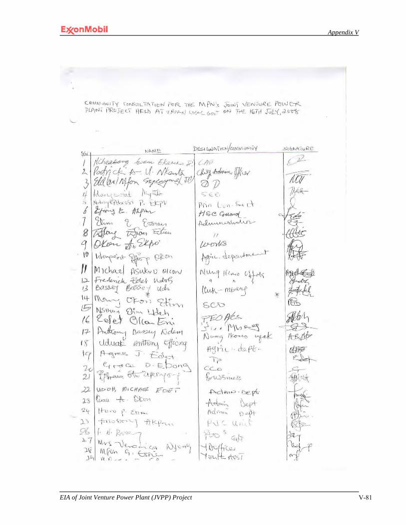
Appendix V
EIA of Joint Venture Power Plant (JVPP) Project V-81
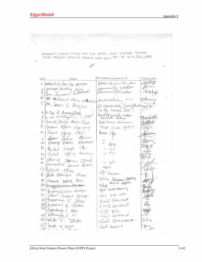
Appendix V
EIA of Joint Venture Power Plant (JVPP) Project V-82
Appendix V
EIA of Joint Venture Power Plant (JVPP) Project V-83

Appendix V
EIA of Joint Venture Power Plant (JVPP) Project V-84

APPENDIX VI

Appendix VI
___________________________________________ EIA of Joint Venture Power Plant (JVPP) Project Page VI-1
Terms of Reference:
Environmental Impact Assessment for the Proposed
NNPC/MPN Joint Venture Power Plant (JV PP) Project
Project Proponent:
Mobil Producing Nigeria Unlimited
Appendix VI
___________________________________________ EIA of Joint Venture Power Plant (JVPP) Project Page VI-2
INTRODUCTION 1.1 General
This document presents the Terms of Reference (TOR) for the Environmental Impact Assessment (ESHIA) of the NNPC/MPN Joint Venture Power Plant (JV PP) Project proposed by the joint venture partners Nigerian National Petroleum Corporation (NNPC) and Mobil Producing Nigeria Unlimited (MPN). This is in compliance with the requirements of the ESHIA Act No. 86 of 1992.
1.2 Project Activities The proposed JV PP project is designed to economically utilize natural gas occurring on Oil Mining Lease 70. Specifically, the project will: • produce electricity for the Nigerian national electricity grid. To achieve this goal, the JV PP project will include the design and i nstallation of a thermal power plant and associated utility systems, as well as other activities. In addition, offshore drilling will be required to supply gas to the power plant. The ESHIA shall consider all of the involved facilities and activities throughout the project life from installation through operations to decommissioning. Aside from gas well drilling and workover activity, no additional resource development or offshore infrastructure development is required. Natural gas supplied to the project will be derived from existing offshore fields operated by MPN. Transport of the natural gas from the offshore facilities to the plant site will be via gas pipelines installed as part of the Qua Iboe Gas Flare Elimination (QGFE) project. The offshore scope of the QGFE project was covered under the ESHIA for the East Area Projects – Additional Oil Recovery Project. A more detailed overview of the project scope is provided in Section 2 of this TOR.
1.3 Project Benefits The proposed NNPC/MPN JV PP project will provide the following key benefits: • direct economic benefits accruing to the Government of Nigeria (via the NNPC),
the Government of Akwa Ibom State (allocation related to the production of a natural resource), and MPN;
• provision of electric power to the Nigerian national power grid to assist in meeting Nigerian energy needs; and
• employment and skill acquisition opportunities for Nigerians through direct and indirect involvement of contractors, consultants, suppliers and other professionals during the permitting, construction and operational phases of the project.
1.4 TOR Objectives
This TOR document has been pr epared to provide a f ramework for achieving the overall objectives of the ESHIA. This document: • outlines the general scope of the ESHIA study including the overall data
requirements for the proposed project and the affected environment; • defines the relevant framework of legal and administrative requirements for the
proposed project; • defines the procedures and protocols for identification and assessment of
associated and potential impacts, and for selection of appropriate mitigation (prevention, recovery, control) measures for such impacts; and

Appendix VI
___________________________________________ EIA of Joint Venture Power Plant (JVPP) Project Page VI-3
• defines the elements expected to be included in an effective Environmental Management Plan (EMP) developed as part of the ESHIA.
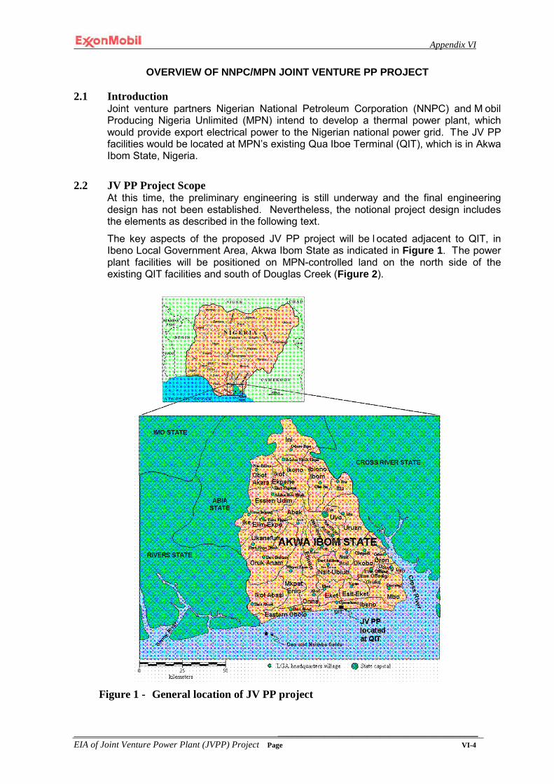
Appendix VI
___________________________________________ EIA of Joint Venture Power Plant (JVPP) Project Page VI-4
OVERVIEW OF NNPC/MPN JOINT VENTURE PP PROJECT
2.1 Introduction Joint venture partners Nigerian National Petroleum Corporation (NNPC) and M obil Producing Nigeria Unlimited (MPN) intend to develop a thermal power plant, which would provide export electrical power to the Nigerian national power grid. The JV PP facilities would be located at MPN’s existing Qua Iboe Terminal (QIT), which is in Akwa Ibom State, Nigeria.
2.2 JV PP Project Scope
At this time, the preliminary engineering is still underway and the final engineering design has not been established. Nevertheless, the notional project design includes the elements as described in the following text.
The key aspects of the proposed JV PP project will be l ocated adjacent to QIT, in Ibeno Local Government Area, Akwa Ibom State as indicated in Figure 1. The power plant facilities will be positioned on MPN-controlled land on the north side of the existing QIT facilities and south of Douglas Creek (Figure 2).
Figure 1 - General location of JV PP project

Appendix VI
___________________________________________ EIA of Joint Venture Power Plant (JVPP) Project Page VI-5
Figure 2 - Location of JV PP project with respect to Qua Iboe Terminal
The onshore scope of the project notionally will include the following:
• Thermal Power Plant – notionally capable of producing ~575 MW (per International Standards Organisation ratings) of power for export to the Nigerian electrical grid. Consideration will also be given to equipping the plant to provide as much as 60MW back-up power to QIT. The plant is expected to include: − 4 gas turbine generators (GTGs) (Frame 9E or similar totally enclosed water-air
cooled) equipped with dry low-NOx burners; − switchyards, breakers, transformers, and other equipment required to
accommodate provision of 330kV power to the export transmission lines, which are to be owned and operated by Power Holding Company of Nigeria (PHCN) or its successors, and potentially 11kV electrical power to QIT; and
− supporting facilities and utilities, including + central control room (CCR); + administration building, including medical and emergency response
facilities; + warehouse/maintenance shop; + control and instrumentation and safety shut-down systems; + fuel gas conditioning system, including a knock out drum, separator,
coalescing filter/separator, and, as necessary, a fuel gas preheater; + water wells (notionally 2 at estimated ~300m depth); + water treatment and storage systems to supply plant and fire water, as well
as demineralised water for turbine washing; + fire fighting systems; + storm water system with drains to handle plant and road run-off and a
storm water retention basin with outflow to Douglas Creek;

Appendix VI
___________________________________________ EIA of Joint Venture Power Plant (JVPP) Project Page VI-6
+ sanitary waste system (notionally a packaged unit with effluent to storm water retention basin);
+ waste water treatment system (notionally a packaged industrial wastewater treatment plant (e.g., for the turbine wash wastewater); with effluent water directed to the stormwater retention basin);
+ back-up/emergency power generation system with associated diesel fuel storage;
+ process drain systems and oily water separator - oily waters and drains from the process areas of the power plant would be directed to the oil/water separator with clean effluent water directed to the stormwater retention basin and with the collected oily waste periodically pumped out of the sump and disposed via QIT’s oily water treatment system;
+ mobile heavy lift cranes (e.g., 100T and 500T capacity) for maintenance of GTGs and other material handling equipment; and
+ potable water, which is currently expected to be provided by bottled water but could conceivably be provided by modification of the planned water treatment facilities.
• Pipeline – A pipeline (notionally ~41cm diameter) will bring gas from the QGFE pipeline to the Power Plant. This will traverse the QIT property and no external pipeline right of way development is required.
• Electrical Transmission Lines/Cables – one or more transmission lines and/or buried cables will be used to carry electrical power from the PP to the QIT electrical network if the QIT back-up power option is pursued.
• Related Works – − Construction Yard and Laydown Areas – Construction and laydown areas
covering roughly 110,000m2 will be established north of the plant site to support the construction activities and subsequent operations phase maintenance activities.
− Site preparation and fill – Various heavy equipment (e.g., bulldozers, dump trucks, loaders, graders, dredges, compactors and other heavy equipment) will be used to clear and fill the site to an appropriate elevation. Fill requirements are anticipated to be roughly 160,000m3 for the JV PP site and associated roads.
− Pilings for equipment and facility foundations – Pile drivers and other equipment will be used to develop stable foundations to support GTGs and other facilities.
− Concrete Batch Plant – Development and operation of a concrete batch plant will be required to support construction of foundations and other facilities.
− Materials Offloading Facility (MOF) – If one has not already developed at QIT for another project, it will be necessary to develop a beach landing-type of MOF to accommodate the delivery of heavy equipment (e.g., gas turbines and generators on the order of 225T each, transformers, etc.) to the site. Notionally, the MOF would be a contained sand ramp with a matted transport surface. Barges could be stern grounded and roll-on / roll-off trailer off-loading accomplished.
− Dredging for Access to MOF (and potentially for fill)– Dredging is expected to be required to provide access for barges and other transport vessels bringing materials and supplies to the plant site. Experience has shown that sedimentation along the shore at QIT is rapid. Thus, maintenance dredging may be required during the construction period. The dredging may also provide fill for the construction site and laydown areas.
Appendix VI
___________________________________________ EIA of Joint Venture Power Plant (JVPP) Project Page VI-7
− Acquisition of Fill Material – To the extent that fill is not obtained from MOF-related dredging activities, fill for the site may also be obtained from borrow pits in the local area.
− Plant Access Road – It is expected that no significant new road will be required for access to the site. The existing perimeter crushed stone road running along the northern fence of QIT from the road to Eket will be used for construction access. A portion of this road will likely be upgraded as part of the QGFE project. The JV PP project will upgrade the remainder of the road (i.e., ~ 1.2km of the road that continues beyond the QGFE project turnoff) to provide access to the PP.
− Materials Transport – Pending results of a transportation study, the heaviest materials and supplies are currently expected to be brought to the site principally by water transport. Once ashore, they will be transported to the site via roads. Transport via existing roads/highways may be a reasonable alternative for certain materials and transport by air via the airstrip in Eket may also be used.
− Materials Handling – Cranes and other material handling equipment will be used to erect the power plant facilities and/or move equipment into place.
− Facility Roads and Drainage – Roads and appropriate drainage facilities will be established within the plant and storage sites to support construction and operations activities. Plant roads are expected to be of crushed stone with asphalt overlay.
− Fencing and Gates – Double fencing will be installed around the entire facility site to provide security for the plant. This will include a fully equipped security gatehouse to control all access to plant and to inter-fence space.
− Housing for Workers (Temporary) – Camps will be developed to provide housing and life support (including waste management) for a substantial proportion of non-local workers (principally managers and expatriates with specialized skills). The majority of workers are expected to be local citizens that would continue to reside in their homes.
− Housing for Plant Operators (Permanent) – Though there is a finite possibility of such development, it is currently not expected that permanent housing and life support facilities (including waste management) would be established for the personnel that will operate the IPP facility. Most employees of the power plant will be local citizens that will reside in their own homes. Non-local personnel are expected to be housed in MPN’s existing facilities.
The offshore scope of the project notionally will include the following:
• Well Drilling and Workover Activity – A modest drilling and workover programme will be required to initiate the blowdown of the Oso field reservoirs expected to provide the feed gas for the power plant. Drilling activity will be supported by existing platforms (Oso RB and Oso RC), which already have appropriate manifolds, other equipment, and pipelines to support connection of the proposed wells. Drilling and workover activity is anticipated to include: − 2 new wells; − 4 major workovers, requiring use of a jack-up drilling rig; and − 2 minor workovers (no rig required).
2.3 Approach
Project planning and design will involve a rigorous three-step process including conceptual design, preliminary engineering design based on po wer industry
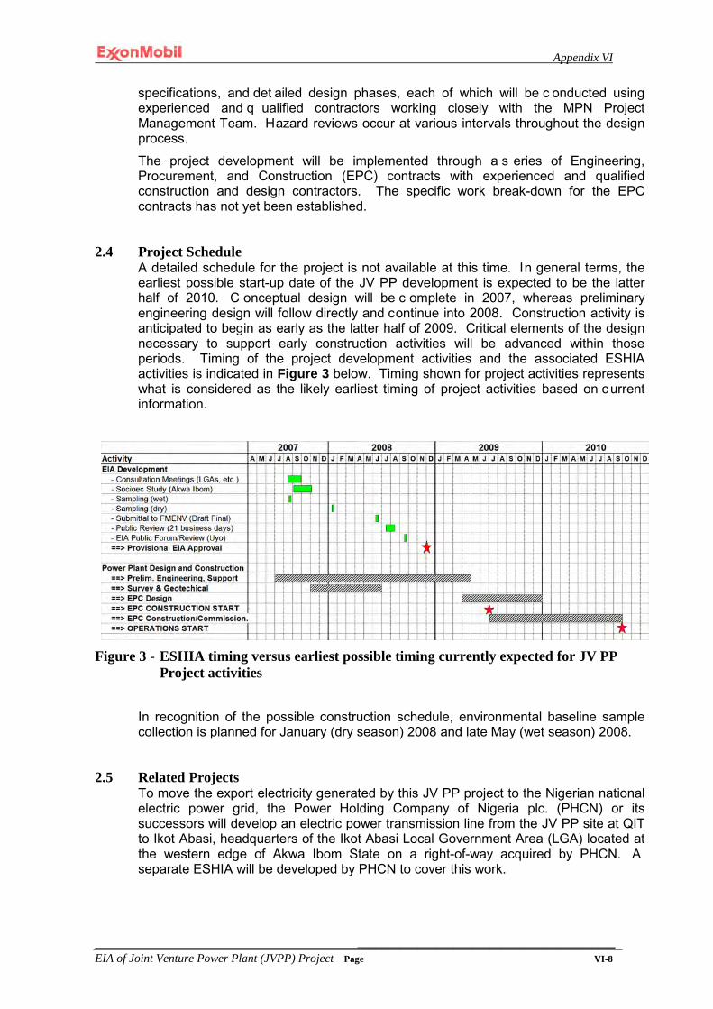
Appendix VI
___________________________________________ EIA of Joint Venture Power Plant (JVPP) Project Page VI-8
specifications, and det ailed design phases, each of which will be c onducted using experienced and q ualified contractors working closely with the MPN Project Management Team. Hazard reviews occur at various intervals throughout the design process.
The project development will be implemented through a s eries of Engineering, Procurement, and Construction (EPC) contracts with experienced and qualified construction and design contractors. The specific work break-down for the EPC contracts has not yet been established.
2.4 Project Schedule A detailed schedule for the project is not available at this time. In general terms, the earliest possible start-up date of the JV PP development is expected to be the latter half of 2010. C onceptual design will be c omplete in 2007, whereas preliminary engineering design will follow directly and continue into 2008. Construction activity is anticipated to begin as early as the latter half of 2009. Critical elements of the design necessary to support early construction activities will be advanced within those periods. Timing of the project development activities and the associated ESHIA activities is indicated in Figure 3 below. Timing shown for project activities represents what is considered as the likely earliest timing of project activities based on c urrent information.
Figure 3 - ESHIA timing versus earliest possible timing currently expected for JV PP Project activities
In recognition of the possible construction schedule, environmental baseline sample collection is planned for January (dry season) 2008 and late May (wet season) 2008.
2.5 Related Projects To move the export electricity generated by this JV PP project to the Nigerian national electric power grid, the Power Holding Company of Nigeria plc. (PHCN) or its successors will develop an electric power transmission line from the JV PP site at QIT to Ikot Abasi, headquarters of the Ikot Abasi Local Government Area (LGA) located at the western edge of Akwa Ibom State on a right-of-way acquired by PHCN. A separate ESHIA will be developed by PHCN to cover this work.
Appendix VI
___________________________________________ EIA of Joint Venture Power Plant (JVPP) Project Page VI-9
TERMS OF REFERENCE
3.1 Scope of Work
The scope of work for this ESHIA shall involve an extensive literature survey, a comprehensive field data gathering exercise (dry and wet seasons) within the project environment at QIT, consultation activities and a c omprehensive socioeconomic baseline assessment of communities in the vicinity. This will allow an effective characterisation of the project area. Specifically, the ESHIA work scope shall entail:
• review of national and international environmental regulations guiding the
activities to be carried out as well as consultation with relevant stakeholders; • project definition (See Section 3.5); • baseline environmental data collection and analysis (See Section 3.6); • baseline social description data collection/ analysis and consultation (See
Section 3.7); • impact identification, prediction, interpretation and evaluation (See Section 3.8); • impact mitigation and control (See Section 3.9); • social and env ironmental management planning (including plans for
decommissioning, closure or abandonment) (See Section 3.10); and • preparation of draft and final ESHIA reports following approved guidelines and
procedures (See Section 3.11). It is noteworthy that these are not distinct stages of assessment. There are overlaps and there is necessary feedback from one stage to another.
3.2 ESHIA Objectives The main objectives of the ESHIA of the proposed project are to:
• identify the environmental regulations that will affect the proposed IPP Project; • establish the baseline conditions of the project location thereby identifying the
resources (including social) that might be a ffected by actions associated with the proposed project;
• understand the proposed project facilities and activities thereby identifying the potential and associated effects of, and hazards posed by, the pursuit of the project;
• recommend preventive, reduction and c ontrol measures for identified potential/associated adverse impacts of the project;
• develop a cost effective EMP that recommends plans and pr ocedures to manage the consequences and recover from exceptional events throughout the lifetime of the project;
• provide the basis for consultation with regulatory authorities, the public and other stakeholders; and
• support subsequent applications for associated environmental permits. The key result of the ESHIA process will be the findings and recommendations that will be translated into specific actions. The ESHIA will also be used as basis for communication with relevant stakeholders, with reference to the issues identified during the course of the study.
The ESHIA reports and procedures shall conform to the requirements and guidelines of the Federal Ministry of Environment (FMENV), the Department of Petroleum
Appendix VI
___________________________________________ EIA of Joint Venture Power Plant (JVPP) Project Page VI-10
Resources (DPR), and Akwa Ibom Ministry of Environment and Mineral Resources (AKSMEMR), and MPN.
3.3 ESHIA Methodology
The methodologies to be used for this study are outlined below. Desktop Studies/Literature Review Desktop studies shall be under taken to acquire an env ironmental database required for the ESHIA studies. The literature search shall include information from previous studies around areas with similar environmental characteristics. M aterials to be considered shall include textbooks, articles, reports, maps, and phot ographs, as acquired at national and international levels. Consultation Consultation shall be carried out throughout the project life cycle. MPN shall carry out consultation with all relevant stakeholders to ensure that their views and opinions concerning the proposed project and its associated and potential impacts are integrated into the ESHIA process. The results of such consultations shall be included as a bas is for potential impact assessment and s hall be c learly documented in the ESHIA report. The stakeholders to be consulted shall include but not be limited to:
• the FMENV; • the DPR; • the AKSMEMR • relevant departments of MPN; • host communities; and • relevant non-governmental organisations (NGOs).
Field Research Field research shall be used to complement and v erify information gathered from desktop studies. The fieldwork shall be to determine the specific ecological baseline and socio-economic conditions of the project environment. Specifically, the survey shall cover the following environmental components:
• the physical environment – water and sediment characteristics, soil characteristics, oceanography, air quality, noise and potential natural hazards;
• the biological environment – water, sediment, and soil microbiology, benthos, plankta, flora and fauna (particularly rare and endangered species);
• the socio-economic and cultural environment - population, landuse and patterns of land ownership and tenure, community structure, employment, distribution, public health, cultural heritage, customs, aspirations and attitudes, etc.
Potential and Associated Impact Assessment The identification and ev aluation of the associated and potential impacts of the proposed project shall be based on appropriate standards and/or acceptable environmental assessment tools such as the ISO 14001 approach and the Hazard and Effect Management Process (HEMP). The Risk Assessment Matrix (RAM) shall be used in determining the risks posed by the identified potential and associated impacts in order to proffer appropriate mitigation measures. I n predicting impacts, the experiential/practical ‘worst case scenario’ approach shall be applied to determine the extreme effects of project activities on environmental components, while ‘consensus of opinions’ shall be us ed to determine the importance of affected environmental
Appendix VI
___________________________________________ EIA of Joint Venture Power Plant (JVPP) Project Page VI-11
components. The impact evaluation results shall form the basis for developing the EMP for the proposed project.
3.4 Regulatory Requirements
The main Nigeria regulatory provisions related to the ESHIA process include, but are not limited to, the following: Environmental Impact Assessment Act The Environmental Impact Assessment (ESHIA) Act No. 86, 1992 stipulates that the public or private sector of the economy shall not embark on or undertake or authorise projects or activities without prior consideration of the environmental effects at early stages. Where the extent, nature or location of a proposed project or activity is such that it is likely to significantly affect the environment, its ESHIA shall be un dertaken in accordance with the provisions of the Act. Generally, the ESHIA shall be conducted in line with the following guidelines:
• Environmental Impact Assessment Sectoral Guidelines for Oil & Gas Industry Projects, FMENV, 1995
• Environmental Impact Assessment Procedural Guidelines, FMENV, 1995 DPR Requirements The operations of the Oil and Gas Industry in Nigeria are governed by the Petroleum Act 1969. Section 8(1)b (iii) of the Act empowers the Federal Ministry of Petroleum Resources to make regulations for the prevention of pollution. In order to effectively plan, protect and pr udently enhance the environmental resources in the areas of oil industry development in Nigeria, the DPR was set up by Section 191 of NNPC Act, 1979. DPR requires that holders of exploration, prospecting, exploitation, refining, transportation and m arketing licenses of petroleum resources take/adopt practical precautions and all steps practicable to prevent pollution, and cause as little damage as possible to the environment in their areas of operation. Consequent upon growing concern for adverse environmental impacts or damages arising from oil development-related pollution, the DPR in 1991 issued Environmental Guidelines and S tandards for the Petroleum Industry in Nigeria (EGASPIN). The EGASPIN, which was revised in 2002, requires that a programme of seabed survey be carried out prior to commencement of any drilling operation or of many types of development activities to define the ecological baseline condition of the locations affected. EGASPIN is currently being revised. As applicable, new requirements resulting from the guidance revision will be considered in the project design and in the development of the ESHIA. The general guidelines for ecological seabed survey sampling and analysis are detailed in Part II, Appendix II - 4 of EGASPIN 2002. Criminal Code The Nigerian Criminal Code makes it an o ffence punishable with up to 6 m onths imprisonment for any person who:
• violates the atmosphere in any place so as to make it noxious to the health of persons in general dwelling or carrying on business in the neighbourhood, or passing along a public way; or
Appendix VI
___________________________________________ EIA of Joint Venture Power Plant (JVPP) Project Page VI-12
• does any act which is, and which he k nows or has reason to believe to be, likely to spread the infection of any disease dangerous to life, whether human or animal.
3.5 Project Description
The ESHIA shall document a c lear description of the proposed project in a m anner comprehensible to all stakeholders. The description shall include but not be limited to the following:
• location, geographic scale; • project design and design basis, design parameters, specifications and criteria,
technology used; • material and energy requirement; • construction/installation of facilities and equipment; • operations and maintenance of the facilities and equipment; • quantification of routine, operational discharges and emissions, to water, air
and land, noise, vibration, light, heat, waste management; • assessment of project and environmental risks and hazards; • contingency plans and emergency response philosophies; • project risk and hazard prevention philosophy; and • project schedule.
3.6 Environmental Description
The ESHIA shall include a comprehensive and scientific description of the ecological baseline conditions of the proposed project area. The scope of baseline study will include the following:
3.6.1 Relevant Data from Existing Approved ESHIAs
The ESHIA will include relevant information from recent ESHIAs done in the project area. In particular, it is anticipated that this ESHIA study will incorporate pertinent data from the QIT Upgrade ESHIA, the East Area Projects – Additional Oil Recovery Project ESHIA, and the East Area Projects – NGL II Project ESHIA including:
• soils, vegetation, and wildlife data from the areas near QIT; and • sediment and water data (including benthos and plankta) data from areas
offshore of QIT. 3.6.2 Field Work and Laboratory Analysis
The ESHIA shall include an env ironmental baseline study of the potentially affected environment. The design of this study is considered in greater detail in Attachment 1. In summary, the baseline study will have the following attributes.
• Baseline sampling shall be conducted in both the rainy and dry seasons to
obtain data representing the two regimes. • All positions for sampling shall be referenced to the geographical coordinates. • The study methodology shall be c onsistent with the requirements of DPR
Environmental Guidelines and Standards for the Petroleum Industry in Nigeria (EGASPIN, 2002), and the FMENV guidelines for projects of this nature (FMENV, 1995).
• Field sampling methods and l aboratory procedures shall be c onsistent with established and standard methodologies (ASTM, APHA, and USEPA) and also with FMENV and DPR guidelines stated above.
Appendix VI
___________________________________________ EIA of Joint Venture Power Plant (JVPP) Project Page VI-13
3.6.2.1 Sediment Studies Samples of the upper five to twenty centimeters (5-20cm) of the sediments will be collected and analyzed for the following:
• Physico - chemistry: pH, total hydrocarbon content, electrical conductivity, redox potentials, particle size, aliphatic hydrocarbons, aromatic hydrocarbons, etc.
• Metals: Mn, Fe, Cu, Zn, Ag, Pb, Ni, Cd, Cr, Co, Ca, Mg, K, Na, Ba • Sediment Microbiology: Hydrocarbon utilizing bacteria, total heterotrophic
bacteria, etc. • Hydrobiology: Benthic macrofauna
3.6.2.2 Water Studies
Water samples will be collected from selected stations and analyzed for the following: • Physico-chemistry: Total dissolved solids, turbidity, chemical oxygen demand
(COD), oil and grease, chloride, phenols, nitrate, sulfate, pH, temperature, conductivity, salinity, dissolved oxygen (DO), redox potential, biochemical oxygen demand (BOD)
• Metals: Mn, Fe, Cu, Zn, Ag, Pb, Ni, Cd, Cr, Co, Ca, Mg, K, Na • Water Microbiology: Total heterotrophic bacteria, hydrocarbon utilizing bacteria,
etc. • Hydrobiology: phytoplankton and zooplankton
3.6.2.3 Air and Noise Studies
Air samples will be collected from selected stations and analyzed for the following: NO2, SO2, CO, H2S, CH4, VOC, particulates, temperature, wind speed, wind direction. Noise measurements will also be conducted at air sampling stations.
3.6.2.4 Soil Studies
Upper (e.g., top 15 cm) and lower (15-30 cm) soil samples are to be collected at each location. Soil samples collected will be analyzed for the following:
• Physico - chemistry: pH, total hydrocarbon content, electrical conductivity, redox potentials, particle size, aliphatic hydrocarbons, aromatic hydrocarbons, etc.
• Metals: Mn, Fe, Cu, Zn, Ag, Pb, Ni, Cd, Cr, Co, Ca, Mg, K, Na, Ba, As, Hg, V • Soil Microbiology: Hydrocarbon utilizing bacteria, total heterotrophic bacteria,
etc. 3.6.3 Physical Characteristics
Various data sources will be examined to develop additional information regarding the physical characteristics of the project environment. Areas of investigation for this general topic will include:
Climate and Meteorology
• Description of regional climate including temperature, rainfall, sunshine and cloudiness, wind speed, wind direction, seasonal variations and e xtremes, micro climates and determining factors; and
• Description of air quality: localised ambient air pollutants, noise sources, ambient noise levels, proximity of human and ecological habitats to noise sources.
Oceanographic conditions
• Hydrography and H ydrology: waves, tides, current, speed, water masses, seabed water temperature, surface water temperature; and
• Bathymetry: water depth, topography
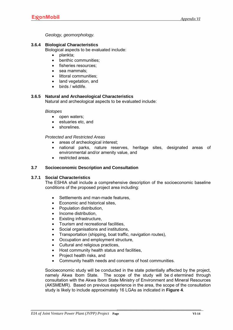
Appendix VI
___________________________________________ EIA of Joint Venture Power Plant (JVPP) Project Page VI-14
Geology, geomorphology.
3.6.4 Biological Characteristics Biological aspects to be evaluated include:
• plankta; • benthic communities; • fisheries resources; • sea mammals; • littoral communities; • land vegetation, and • birds / wildlife.
3.6.5 Natural and Archaeological Characteristics
Natural and archeological aspects to be evaluated include:
Biotopes • open waters; • estuaries etc, and • shorelines.
Protected and Restricted Areas
• areas of archeological interest; • national parks, nature reserves, heritage sites, designated areas of
environmental and/or amenity value, and • restricted areas.
3.7 Socioeconomic Description and Consultation 3.7.1 Social Characteristics
The ESHIA shall include a comprehensive description of the socioeconomic baseline conditions of the proposed project area including:
• Settlements and man-made features, • Economic and historical sites, • Population distribution, • Income distribution, • Existing infrastructure, • Tourism and recreational facilities, • Social organisations and institutions, • Transportation (shipping, boat traffic, navigation routes), • Occupation and employment structure, • Cultural and religious practices, • Host community health status and facilities, • Project health risks, and • Community health needs and concerns of host communities.
Socioeconomic study will be conducted in the state potentially affected by the project, namely Akwa Ibom State. The scope of the study will be d etermined through consultation with the Akwa Ibom State Ministry of Environment and Mineral Resources (AKSMEMR). Based on previous experience in the area, the scope of the consultation study is likely to include approximately 16 LGAs as indicated in Figure 4.

Appendix VI
___________________________________________ EIA of Joint Venture Power Plant (JVPP) Project Page VI-15
Figure 4 - LGAs likely to be studied/consulted during ESHIA socioeconomic consultation effort, subject to consultation with AKSMEMR
3.7.2 Consultation
Throughout the life of the project activity, MPN will maintain effective communications with authorities and other relevant stakeholders. The intention of doing this is to:
• avoid conflicts by addressing issues promptly; • ensure that fears and apprehensions about the nature, scale and impact of the
operation have been addressed; and • avoid any misunderstanding about the development.
MPN will make the draft ESHIA available to the regulatory agencies (DPR and FMENV), stakeholders and the public for comments.
3.8 Impact Identification, Prediction and Evaluation Once the data is acquired from the baseline study, the ESHIA should be conducted under the following steps:
• Identification of Potential Environmental Issues and Impacts: This shall
identify potential environmental issues and impacts (including social) due to the proposed development for both routine and accidental events. All impacts shall be identified and classified as normal or abnormal, beneficial or adverse, cumulative, short or long-term, temporary or permanent, direct or indirect, residual or
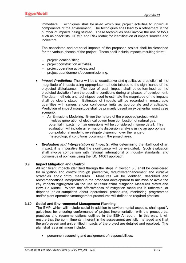
Appendix VI
___________________________________________ EIA of Joint Venture Power Plant (JVPP) Project Page VI-16
immediate. Techniques shall be us ed which link project activities to individual components of the environment. The techniques shall lead to a refinement in the number of impacts being studied. These techniques shall involve the use of tools such as checklists, HEMP, and Risk Matrix for identification of impact sources and indicators. The associated and potential impacts of the proposed project shall be described for the various phases of the project. These shall include impacts resulting from: − project location/siting, − project construction activities, − project operation activities, and − project abandonment/decommissioning.
• Impact Prediction: There will be a quantitative and q ualitative prediction of the magnitude of impacts using appropriate methods tailored to the significance of the projected disturbance. The size of each impact shall be de termined as the predicted deviation from the baseline conditions during all phases of development. The data, methods and techniques used to estimate the magnitude of the impacts shall be clearly stated. Estimates of impacts will be recorded in measurable quantities with ranges and/or confidence limits as appropriate and pr acticable. Prediction of impact magnitude shall be primarily based on experiential worst case scenario. − Air Emissions Modeling: Given the nature of the proposed project, which
involves generation of electrical power from combustion of natural gas, potential impacts from air emissions will be considered in some detail. This evaluation will include air emissions dispersion analysis using an appropriate computational model to investigate dispersion over the range of meteorological conditions occurring in the project area.
• Evaluation and Interpretation of Impacts: After determining the likelihood of an
impact, it is imperative that the significance will be evaluated. Such evaluation shall involve comparison with national, international or industry standards, and consensus of opinions using the ISO 14001 approach.
3.9 Impact Mitigation and Control
All significant impacts identified through the steps in Section 3.8 shall be considered for mitigation and control through preventive, reductive/enhancement and curative strategies and c ontrol measures. Measures will be identified, described and recommendations incorporated in the proposed development to minimise or avoid the key impacts highlighted via the use of Risk/Hazard Mitigation Measures Matrix and Bow–Tie Model. Where the effectiveness of mitigation measures is uncertain, or depends on as sumptions about operational procedures, monitoring programmes and/or plant operations/management procedures will define the required practice.
3.10 Social and Environmental Management Planning
The EMP, which will include social in addition to environmental aspects, shall specify guidelines for ensuring conformance of project implementation with the procedures, practices and recommendations outlined in the ESHIA report. In this way, it will ensure that the commitments inherent in the assessment are fully managed and that the unforeseen and unidentified impacts of the project are detailed and resolved. The plan shall as a minimum include:
• personnel resourcing and assignment of responsibilities;

Appendix VI
___________________________________________ EIA of Joint Venture Power Plant (JVPP) Project Page VI-17
• ensuring conformance of detailed design with concept design; • ensuring conformance of construction/installation activities with specified
standard practices and philosophies; • ensuring conformance of operations and maintenance activities with specified
standard practices and philosophies; • the procedures for dealing with changes and project modifications; • contingency plan; • waste management plan; • inspection, auditing and monitoring guidelines for all phases of project; • decommissioning and abandonment of project; and • remediation plan after decommissioning.
3.11 Documentation
The ESHIA process shall be documented in accordance with regulatory requirements and guidelines. The technical output that shall be written / produced to reflect the various stages of the ESHIA process are indicated below:
• Field report; • Draft ESHIA report in accordance with FMENV ESHIA Sectoral Guidelines for
Infrastructure Projects; and • Final ESHIA report to address all comments and observations made by the
regulatory authorities and stakeholders.
Appendix VI
___________________________________________ EIA of Joint Venture Power Plant (JVPP) Project Page VI-18
REFERENCES
1. Department of Petroleum Resources (2002). The Environmental Guidelines and Standards for the Petroleum Industry in Nigeria. (and recent updates of this document)
2. Federal Environmental Protection Agency, The Presidency, Abuja, (1995):
Environmental Impact Assessment Sectoral Guidelines for Oil & Gas Industry Projects.
3. Federal Environmental Protection Agency: The Presidency, Abuja, (1995):
Environmental Impact Assessment Procedural Guidelines.
4. The Presidency, Federal Republic of Nigeria, (1992): National Environmental Impact Assessment Act No. 86.
5. World Bank (1996): Environmental Assessment Sourcebook Update –
Environmental Assessment

TOR for ESHIA of JV PP Project, Attachment 1: Sampling Plan for ESHIA
Attachment 1 Page 19 of 24
Attachment 1
Sampling Plan for
JV PP Project Environmental Impact Assessment Baseline Environmental Survey
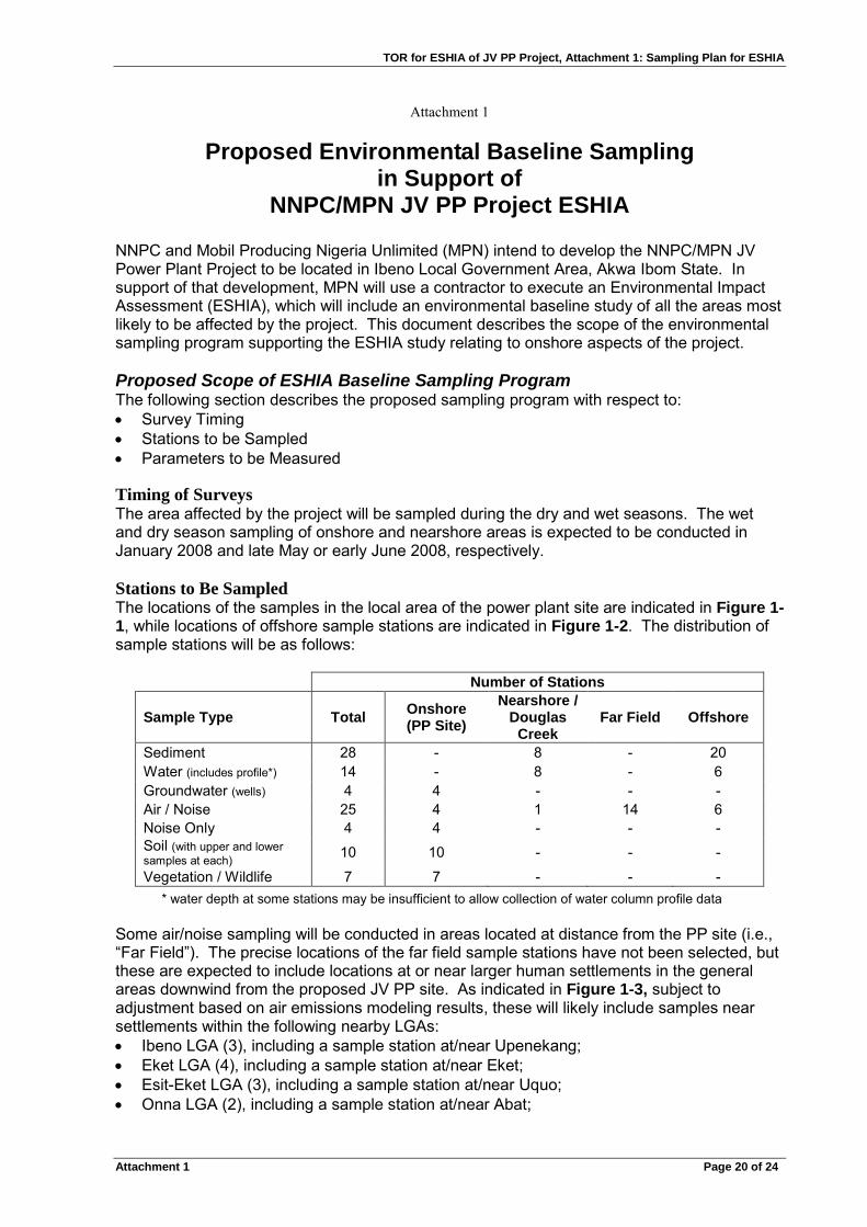
TOR for ESHIA of JV PP Project, Attachment 1: Sampling Plan for ESHIA
Attachment 1 Page 20 of 24
Attachment 1
Proposed Environmental Baseline Sampling in Support of
NNPC/MPN JV PP Project ESHIA NNPC and Mobil Producing Nigeria Unlimited (MPN) intend to develop the NNPC/MPN JV Power Plant Project to be located in Ibeno Local Government Area, Akwa Ibom State. In support of that development, MPN will use a contractor to execute an Environmental Impact Assessment (ESHIA), which will include an environmental baseline study of all the areas most likely to be affected by the project. This document describes the scope of the environmental sampling program supporting the ESHIA study relating to onshore aspects of the project. Proposed Scope of ESHIA Baseline Sampling Program The following section describes the proposed sampling program with respect to: • Survey Timing • Stations to be Sampled • Parameters to be Measured Timing of Surveys The area affected by the project will be sampled during the dry and wet seasons. The wet and dry season sampling of onshore and nearshore areas is expected to be conducted in January 2008 and late May or early June 2008, respectively. Stations to Be Sampled The locations of the samples in the local area of the power plant site are indicated in Figure 1-1, while locations of offshore sample stations are indicated in Figure 1-2. The distribution of sample stations will be as follows:
Number of Stations
Sample Type Total Onshore (PP Site)
Nearshore / Douglas
Creek Far Field Offshore
Sediment 28 - 8 - 20 Water (includes profile*) 14 - 8 - 6 Groundwater (wells) 4 4 - - - Air / Noise 25 4 1 14 6 Noise Only 4 4 - - - Soil (with upper and lower samples at each) 10 10 - - -
Vegetation / Wildlife 7 7 - - - * water depth at some stations may be insufficient to allow collection of water column profile data
Some air/noise sampling will be conducted in areas located at distance from the PP site (i.e., “Far Field”). The precise locations of the far field sample stations have not been selected, but these are expected to include locations at or near larger human settlements in the general areas downwind from the proposed JV PP site. As indicated in Figure 1-3, subject to adjustment based on air emissions modeling results, these will likely include samples near settlements within the following nearby LGAs: • Ibeno LGA (3), including a sample station at/near Upenekang; • Eket LGA (4), including a sample station at/near Eket; • Esit-Eket LGA (3), including a sample station at/near Uquo; • Onna LGA (2), including a sample station at/near Abat;
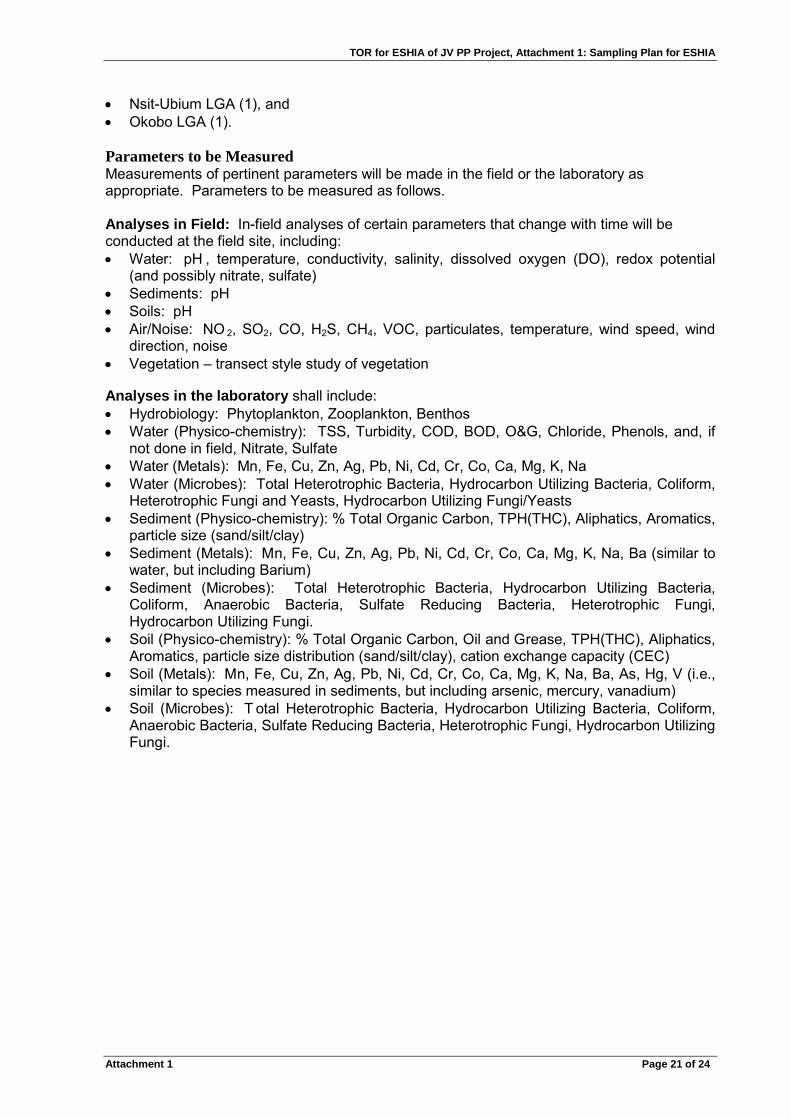
TOR for ESHIA of JV PP Project, Attachment 1: Sampling Plan for ESHIA
Attachment 1 Page 21 of 24
• Nsit-Ubium LGA (1), and • Okobo LGA (1). Parameters to be Measured Measurements of pertinent parameters will be made in the field or the laboratory as appropriate. Parameters to be measured as follows. Analyses in Field: In-field analyses of certain parameters that change with time will be conducted at the field site, including: • Water: pH , temperature, conductivity, salinity, dissolved oxygen (DO), redox potential
(and possibly nitrate, sulfate) • Sediments: pH • Soils: pH • Air/Noise: NO 2, SO2, CO, H2S, CH4, VOC, particulates, temperature, wind speed, wind
direction, noise • Vegetation – transect style study of vegetation Analyses in the laboratory shall include: • Hydrobiology: Phytoplankton, Zooplankton, Benthos • Water (Physico-chemistry): TSS, Turbidity, COD, BOD, O&G, Chloride, Phenols, and, if
not done in field, Nitrate, Sulfate • Water (Metals): Mn, Fe, Cu, Zn, Ag, Pb, Ni, Cd, Cr, Co, Ca, Mg, K, Na • Water (Microbes): Total Heterotrophic Bacteria, Hydrocarbon Utilizing Bacteria, Coliform,
Heterotrophic Fungi and Yeasts, Hydrocarbon Utilizing Fungi/Yeasts • Sediment (Physico-chemistry): % Total Organic Carbon, TPH(THC), Aliphatics, Aromatics,
particle size (sand/silt/clay) • Sediment (Metals): Mn, Fe, Cu, Zn, Ag, Pb, Ni, Cd, Cr, Co, Ca, Mg, K, Na, Ba (similar to
water, but including Barium) • Sediment (Microbes): Total Heterotrophic Bacteria, Hydrocarbon Utilizing Bacteria,
Coliform, Anaerobic Bacteria, Sulfate Reducing Bacteria, Heterotrophic Fungi, Hydrocarbon Utilizing Fungi.
• Soil (Physico-chemistry): % Total Organic Carbon, Oil and Grease, TPH(THC), Aliphatics, Aromatics, particle size distribution (sand/silt/clay), cation exchange capacity (CEC)
• Soil (Metals): Mn, Fe, Cu, Zn, Ag, Pb, Ni, Cd, Cr, Co, Ca, Mg, K, Na, Ba, As, Hg, V (i.e., similar to species measured in sediments, but including arsenic, mercury, vanadium)
• Soil (Microbes): T otal Heterotrophic Bacteria, Hydrocarbon Utilizing Bacteria, Coliform, Anaerobic Bacteria, Sulfate Reducing Bacteria, Heterotrophic Fungi, Hydrocarbon Utilizing Fungi.

TOR for ESHIA of JV PP Project, Attachment 1: Sampling Plan for ESHIA
Attachment 1 Page 22 of 24
Figure 1-1: Locations of onshore and nearshore baseline study sampling stations near JV PP site, Akwa Ibom State.
Locations of water well samples (4) not shown.
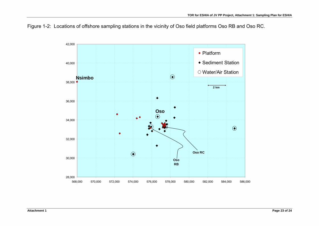
TOR for ESHIA of JV PP Project, Attachment 1: Sampling Plan for ESHIA
Attachment 1 Page 23 of 24
Figure 1-2: Locations of offshore sampling stations in the vicinity of Oso field platforms Oso RB and Oso RC.
28,000
30,000
32,000
34,000
36,000
38,000
40,000
42,000
568,000 570,000 572,000 574,000 576,000 578,000 580,000 582,000 584,000 586,000
Platform
Sediment Station
Water/Air Station
2 km
Oso
Nsimbo
Oso RB
Oso RC

TOR for ESHIA of JV PP Project, Attachment 1: Sampling Plan for ESHIA
Attachment 1 Page 24 of 24
Figure 1-3: Locations (shown in yellow) of Akwa Ibom State LGAs near JV PP site expected to be sampled as part of “far field” air quality sampling effort.

APPENDIX VII

QIT Material Offloading Facility (MOF) Scope of Work
Page 1 of 5
Project Description
The QIT Material Offloading Facility (MOF) is intended to support Roll-on/Roll-off (Ro/Ro) Operations as well as potential heavy lift crane operations related to the QIPP Project. The elements that are envisioned to be included in the MOF facilities include:
• Open staging areas • Fueling of vessels at the waterfront (not storage) • Potable water storage and distribution • Sanitary sewer distribution • An Operations building to support MOF operations and passengers • Storage Warehouse • Ro/Ro Facility • Offshore Crew Vessel moorings • Marine Police Vessel moorings • Security infrastructure (fencing, lighting, access control)
The MOF will be located on the existing QIT Lake, shown in Figure 1 on the eastern end of QIT. The lake was created by excavating uplands to provide backfill for the construction of three (3) new product tanks around 1997. The layout of the MOF is presented in Figure 2and shows a bypass road that will be built as part of the current project to mitigate the impact of the MOF on local traffic.
Figure 1: MOF located on the QIT Lake

QIT Material Offloading Facility (MOF) Scope of Work
Page 2 of 5
Facilities Description The overall site requires a navigation channel to be dredged from the ocean through the beach and into the lake. In addition, bathymetric elevations of the lake suggest that some dredging is required in the lake itself to achieve the required depths. Figures 3 through 9 provide the details for the MOF. The layout consists of a 305m long service wharf (with a north–south orientation) that parallels the existing perimeter bypass road around QIT. The overall wharf width is 45 m wide in order to accommodate the laydown area, storage warehouse, passenger building, and water storage tank. The waterfront consists of two Crew Vessel Piers, 2Marine Police Piers, and the Heavy Lift Ro/Ro Dock. Individual components include:
• Approximately 16,438 m² marginal and service wharf built at elevation +3.50 m with a roll-off berth at +2.30m MLW. The marginal wharf is designated for barge and heavy lift area. The heavy lift area will enable roll-off operations for the delivery of heavy equipment. The dock is to handle mobile cranes to provide lift-off operations for the delivery of heavy equipment, construction materials, and construction modules during construction of QIPP.
• Two (2) 1,500 m² (75 m long by 20m wide) cellular cofferdam piers, built at elevation
+3.50 m, would be constructed to accommodate the four (4) crew vessels with two on each pier. The piers should be capable of mooring fast surfer boats.
• Two (2) piers, built also at elevation +3.50 m, would be constructed to accommodate up
to four (4) marine police boats. These structures would consist of approximately187.5 m² of steel pipe pile-supported concrete deck slab superstructures. The two37.5m long by 5m wide piers, would hold two boats each and are only designed for pedestrian traffic.
• The Heavy Lift Ro/Ro Dock should be able to accommodate 50 m long by 18 m wide barges. Berthing and mooring will be with the stern or bow of the barge towards the pier head. The barge would be moored alongside the dock at +3.5 m MLW while a provision for roll-off onto a ramp at + 2.3 m MLW would also be provided. The minimum design width for a roll-off ramp is 20 m.
• A portable water system consisting of 2 boreholes, water treatment and a storage tank capable of storing 1,150,000 L of water should be provided.
• Provision should be made for refueling vessels at the MOF. As such, fuel lines will be laid from the MOF to the existing fuel storage tanks at QIT
• A building approximately 500 sq. m to serve as administrative office and passenger waiting area should be erected. The MOF will also store materials and supplies that will be utilized to support operations. Therefore, a covered storage warehouse approximately 500 sq. m and 7 m clear height on the interior will be constructed.

QIT Material Offloading Facility (MOF) Scope of Work
Page 3 of 5
Navigation & Dredging In order to access the lake, a dredged channel (dredged to -4.0 meters MLW) will need to be constructed to provide access from the ocean and across the beach shoreline. The overall design dredge elevation for vessels is -4m MLW. The offshore channel sizing assumes “one-way” traffic. The Crew Vessel will require a depth of 4.5 m in the outer channel. The channel will need to extend approximately 2.3km from the existing high water line on the beach to the naturally occurring -4.5m contour. Inner channel conditions, landward of the existing shoreline and in the Lake, will be designed with a 70 meter width and a -4.0 meter depth. The dredged channel assumes side slopes of 1V:3H, with shore protection required for the prevalent swell and wakes from passing vessels on the access channel (rock rip rap or concrete mattress) along the edges of the channel (cut at a side slope of 1V:3H). The offshore channel will be designed to be 90m wide. Due to the overall anticipated sediment transport and accretion in the outer channel. Beyond the shoreline, the channel will be dredged to -4.5m MLW, with a 90 meter width. It is proposed that rock jetties be constructed on either side of the channel to approximately the -2.5 m MLW to protect the channel from waves and decrease overall sedimentation. The overall navigation area should be sized to accommodate a 110m diameter turning area for the Crew Vessels, at the northern end of the lake. Ample maneuvering room should be provided for the barge to transit into the lake and past the other waterfront structures to the Heavy Lift Ro/Ro Dock. To facilitate navigation of vessels along the channel and into the basin, lateral navigation aids should be provided. The aids would consist of beacons (steel piles with lights and day boards) spaced intermittently along the channel approximately 2 km apart on the sides of the channel. At the end of the entrance of breakwaters, a series of lights would be placed to delineate the transition into the inner channel. Breakwater Design Proposed breakwater cross-section is presented in Figure 9. A three-layer rock armor breakwater design is suggested but other alternatives such as concrete armor units may be proposed. The breakwaters should extend about 400 m from the shore into the sea. Security Considerations The overall layout of the MOF at the Lake requires fencing to secure the exposed areas of the facility from unintended shore side intruders. Access to the facility is proposed to be by a manned security gate located at the single entry point to the facility from the access road to the QIPP location. Adjacent to the fence, an elevated guard tower is proposed to provide additional presence as well as being able to see approaching vehicles and personnel.

QIT Material Offloading Facility (MOF) Scope of Work
Page 4 of 5
In addition to the gate and fencing, it is proposed that lighting be provided along the perimeter of the security fence as well as to provide light levels that allow operations on the waterfront facilities. In order to provide security from the water, a security bunker should be located on the southeast corner of the Service Wharf which will allow security personnel to visually observe the navigation channel leading into the facility from the ocean. Firewater Impacts The QIT Lake provides backup firewater protection to QIT in case of an emergency. The requirement to dredge an access channel into the lake will cause it to become saltwater that is subjected to tidal fluctuations. Therefore, a new backup firewater supply source is required. To address this, a new water supply is to be provided by placing a water intake with pumps on Douglas Creek which runs along the north side of QIT. The water would be pumped from the creek to the tie-in point to QIT the fire protection system. Local Population Impacts The beach that runs along the south side of QIT is used by the local population to access developments that are located east of QIT. There is no existing road infrastructure that leads from the town of Qua Iboe to the east along the shoreline. The requirement to dredge a 90m wide access channel from the ocean into the lake will create a permanent barrier to using the beach for access to and from Qua Iboe. Mitigation for this is to install a new road around the north and east side of QIT Lake that will allow the local population to access the beach. The bypass road is proposed to be paved, 10m wide and will accommodate two-way traffic with a small shoulder on either side. See Figure 1 for a preliminary route which can be further optimized.

QIT Material Offloading Facility (MOF) Scope of Work
Page 5 of 5
Figure 2: Layout of the MOF located on the QIT Lake

APPENDIX VIII

Appendix VIII
EIA of Joint Venture Power Plant (JVPP) Project
I-1
Appendix VIII Operations Integrity Management System
The Operations Integrity Management System (OIMS) framework consists of 11 elements, each of which includes an underlying principle and a set of expectations to be met in the Design, Construction and Operation of the Company’s Facilities. O perating Management are responsible for ensuring that Management Systems are put in place that satisfy all of the Expectations in the Framework. The OIMS framework is pictorially presented below.
Appendix VIII
EIA of Joint Venture Power Plant (JVPP) Project
I-2
1. ELEMENT 1: MANAGEMENT, LEADERSHIP, COMMITMENT AND ACCOUNTABILITY Management establishes policy, provides perspective, sets expectations, and provides the resources for successful operations. A ssurance of operations integrity requires management leadership and commitment visible to the organization and accountability at all levels.
1.1 Systems for Operations Integrity management are established, communicated and supported at every level in the organization.
1.2 Managers and supervisors credibly demonstrate commitment and personal accountability for Operations Integrity, promote an open and trusting environment, and understand how their behaviors impact others. Commitment is demonstrated through active and visible participation.
1.3 Manager and supervisor knowledge and skills, including leadership skills and behaviors, are developed to effectively apply Operations Integrity management tools and systems.
1.4 Management establishes the scope, priority and pace for System implementation and improvement, considering the complexity and risks involved with their operations and products.
1.5 Roles, responsibilities, authorities and accountabilities within the Systems are known and exercised.
1.6 Clear goals and objectives are established for the Systems, and performance is evaluated against these goals and objectives.
1.7 Expectations are translated into procedures and practices.
1.8 The workforce is actively engaged in the Operations Integrity process, and relevant learnings are shared across the organization.
1.9 Performance is evaluated, and the degree to which expectations are met is assessed. The results are stewarded to corporate management.
1.10 Managers responsible for businesses Operated by Others (OBO) communicate OIMS principles to the Operator and encourage the adoption of OIMS or similar systems.
2. ELEMENT 2: RISK ASSESSMENT AND MANAGEMENT Comprehensive risk assessments can reduce safety, health, environmental and security risks and mitigate the consequences of incidents by providing essential information for decision making.
2.1 Risk is managed by identifying hazards, assessing consequences and probabilities, and evaluating and implementing prevention and mitigation measures.
2.2 Risk assessments are conducted for ongoing operations, for projects and for products in order to identify and address potential hazards to personnel, facilities, the public and the environment.
2.3 Periodic risk assessments are performed by qualified personnel, including expertise from outside the immediate unit, as appropriate.
2.4 Risk assessments are updated at specified intervals and as changes occur.
Appendix VIII
EIA of Joint Venture Power Plant (JVPP) Project
I-3
2.5 Assessed risks are addressed by specified levels of management appropriate to the nature and magnitude of the risk, and decisions are clearly documented.
2.6 A follow-up process is in place to ensure that risk-management decisions are implemented.
3. ELEMENT 3: FACILITIES DESIGN AND CONSTRUCTION Inherent safety and security can be enhanced, and risks to health and the environment minimized, by using sound standards, procedures and management systems for facility design, construction and startup activities.
3.1 Project management procedures are documented, well understood and executed by qualified personnel.
3.2 Criteria are established and procedures are in place for conducting and documenting risk assessments at specific project stages to ensure that Operations Integrity objectives are met.
3.3 The design and construction of new or modified facilities use approved design practices and standards that:
meet or exceed applicable regulatory requirements
embody responsible requirements where regulations are not adequately protective
address other important operations integrity considerations, including Environmental Aspects and Human Factors
3.4 Deviation from approved design practices and standards, or from the approved design, is permitted only after review and approval by the designated authority, and after the rationale for the decision is documented.
3.5 A process is in place for evaluating the application of new or updated standards with operations integrity implications for existing facilities.
3.6 Quality-assurance processes are in place, which ensure that facilities and materials received meet design specifications and that construction is in accordance with the applicable standards.
3.7 A pre-startup review is performed and documented to confirm that:
■ construction is in accordance with specifications
■ Operations Integrity measures are in place
■ emergency, operations and maintenance procedures are in place and adequate
■ risk-management recommendations have been addressed and required actions taken
■ training of personnel has been accomplished
■ regulatory and permit requirements are met
4. ELEMENT IV: INFORMATION AND DOCUMENTATION Accurate information on the configuration and capabilities of processes and facilities, properties of products and materials handled, potential Operations Integrity hazards, and regulatory requirements is essential to assess and manage risk.
Appendix VIII
EIA of Joint Venture Power Plant (JVPP) Project
I-4
4.1 Drawings, pertinent records and documentation necessary for sound design, operation, inspection and maintenance of facilities are identified, accessible, accurate and appropriately safeguarded.
4.2 Information on t he potential hazards of materials involved in operations is kept current and accessible.
4.3 Information on potential hazards associated with products, and guidance to enable proper handling, use and disposal, are documented and communicated.
4.4 Information on applicable laws and regulations, licenses, permits, codes, standards and practices is documented and kept current.
5. ELEMENT 5: PERSONNEL AND TRAINING Control of operations depends upon pe ople. A chieving Operations Integrity requires the appropriate screening, careful selection and placement, ongoing assessment and proper training of employees, and the implementation of appropriate Operations Integrity programs.
5.1 A process is in place for screening, selection, placement and ongoing assessment of the qualifications and abilities of employees to meet specified job requirements.
5.2 Criteria are in place to ensure that necessary levels of individual and collective experience and knowledge are maintained and are carefully considered when personnel changes are made.
5.3 Initial, ongoing and periodic refresher training is provided to meet job and legal requirements and to ensure understanding of the proper protective measures to mitigate potential Operations Integrity hazards. This training includes:
■ assessment of employee knowledge and skills relative to requirements
■ training documentation
■ assessment of training effectiveness 5.4 The assessment and documentation of, and feedback on, employee performance address Operations
Integrity elements.
5.5 Behavior-based processes for reducing risks of incidents, including personnel safety, process safety, security, and environmental considerations, are in place. It is expected that:
■ employees and contractors consistently recognize and proactively mitigate operational, procedural and physical hazards
■ employees and contractors proactively and routinely identify and eliminate their at-risk behaviors and those of their co-workers
■ Human Factors, workforce engagement, and leadership behaviors are addressed
■ behaviors, at-risk conditions and other precursors that can lead to incidents are recorded, analyzed and addressed
5.6 A process is in place to identify and evaluate health risks related to operations that potentially affect employees, contractors, or the public. Based upon assessed risk:
exposures are monitored
proper protective and preventive measures are implemented

Appendix VIII
EIA of Joint Venture Power Plant (JVPP) Project
I-5
early detection and diagnosis are provided
pertinent health data is recorded and reviewed
medical fitness for work is determined, as appropriate
6. ELEMENT VI: OPERATIONS AND MAINTENANCE Operation of facilities within established parameters and according to regulations is essential. Doing so requires effective procedures, structured inspection and maintenance programs, reliable Operations Integrity critical equipment, and qualified personnel who consistently execute these procedures and practices.
6.1 Operating, maintenance and inspection procedures are developed, implemented and constantly used. These procedures include, where appropriate:
special procedures for activities with potentially higher risk
operating envelope considerations
regulatory and Environmental Aspects considerations
Human Factors considerations
Procedures are updated at specified intervals and changes are made.
6.2 A work permit process incorporates checks and authorizations that are consistent with mechanical and operational risks.
6.3 Critical equipment is identified and tested, and it undergoes preventive maintenance.
6.4 The temporary disarming, deactivation or unavailability of critical equipment is managed.
6.5 Mechanical integrity programs are in place and stewarded to assure the testing, inspection, and maintenance of equipment.
6.6 Interfaces between operations are assessed, and procedures are in place to manage identified risks.
6.7 Environmental Aspects are addressed and controlled, consistent with policy, regulatory requirements and business plans. Environmental Business Planning is conducted and integrated into business plans.
6.8 Environmental performance, including emissions, discharges, and wastes, is tracked and stewarded to meet performance goals.
6.9 Applicable laws, regulations, permits and other governmental requirements are anticipated and met, and the resulting operating requirements are documented and communicated to those affected. Compliance is periodically verified.
6.9 Proper long-term shutdown or abandonment of facilities is planned and managed.
6.10 Quality-assurance processes are in place, ensuring that facilities and materials received meet designated specifications.
Appendix VIII
EIA of Joint Venture Power Plant (JVPP) Project
I-6
7. ELEMENT VII: MANAGEMENT OF CHANGE Changes in operations, procedures, site standards, facilities, or organizations must be evaluated and managed to ensure that Operations Integrity risks arising from these changes remain at an acceptable level.
7.1 A process is in place for the management of both temporary and permanent changes.
7.2 The process for managing change addresses:
■ authority for approval of changes
■ analysis of Operations Integrity implications
■ compliance with regulations and approved standards
■ acquisition of needed permits
■ documentation, including reason for change
■ communication of risks associated with the change and required mitigation measures
■ time limitations
■ training 7.3 Temporary changes do not exceed initial authorization for scope or time without review and
approval.
8. ELEMENT VIII: THIRD-PARTY SERVICES Third parties doing work on the company's behalf impact its operations and its reputation. It is essential that they perform in a manner that is consistent and compatible with the Company’s policies and business objectives.
8.1 Third-party services are evaluated and selected using criteria that include an assessment of capabilities to perform work in a safe and environmentally sound manner.
8.2 Third-party performance requirements are defined and communicated. They include:
■ responsibility for providing personnel appropriately screened, trained, qualified and able to perform specified duties
■ a process for self-monitoring and stewardship 8.3 Interfaces between organizations providing and receiving services are effectively managed.
8.4 Third-party performance, including leadership, is monitored and assessed, feedback is provided, and deficiencies are corrected.
9. ELEMENT IX: INCIDENT INVESTIGATION AND ANALYSIS Effective incident investigation, reporting and follow-up are necessary to achieve Operations Integrity. They provide the opportunity to learn from reported incidents and to use the information to take corrective action and prevent recurrence.
Appendix VIII
EIA of Joint Venture Power Plant (JVPP) Project
I-7
9.1 A process is in place for reporting, investigating, analyzing and documenting actual safety, security, health, environmental and regulatory-compliance incidents and significant near misses.
9.2 Procedures are in place for the Law Department to investigate, analyze and advise on incidents when necessary.
9.3 Procedures exist for actual incidents and near misses, other than those investigated by the Law Department, which:
■ provide for timely investigation
■ consider potential consequences in determining the level of investigation
■ identify root causes and contributing factors
■ determine and ensure implementation of actions needed to prevent recurrence of this and related incidents
■ reflect legal input 9.4 Findings are retained, periodically analyzed to determine where improvements to practices,
standards, procedures or management systems are warranted, and used as a basis for improvement.
9.5 A process is in place to share lessons learned from actual incidents and near misses among ExxonMobil organizations, and to interact with others as appropriate to facilitate improvements in performance.
10. ELEMENT X: COMMUNITY AWARENESS AND EMERGENCY PREPAREDNESS Effective management of stakeholder relationships is important to enhance the trust and confidence of the communities where we operate. Emergency planning and preparedness are essential to ensure that, in the event of an incident, all necessary actions are taken for the protection of the public, environment and company personnel and assets.
10.1 Community expectations and concerns about our operations, including those of the workforce, are sought, recognized and addressed in a timely manner.
10.2 Emergency-preparedness, response and business continuity plans are documented, accessible and clearly communicated. The plans, based on assessed Operations Integrity risks, include:
■ response actions that address significant incident scenarios
■ organizational structure, responsibilities and authorities
■ internal and external communications procedures
■ procedures for accessing personnel and equipment resources
■ procedures for assessing essential Operations Integrity information
■ procedures for interfacing with other company and external emergency response organizations
■ process for periodic updates
10.3 Equipment, facilities and trained personnel needed for emergency response are defined and readily available.

Appendix VIII
EIA of Joint Venture Power Plant (JVPP) Project
I-8
10.4 Simulations and drills are periodically conducted, which include consideration of external communications and involvement. Learnings are identified and addressed.
11. ELEMENT XI: OPERATIONS INTEGRITY ASSESSMENT AND IMPROVEMENT Assessment of the degree to which expectations are met is essential to improve Operations Integrity and maintain accountability.
11.1 Operations are assessed at predetermined frequencies to establish the degree to which the Operations Integrity expectations are met.
11.2 The frequency and scope of assessments reflect the complexity of the operation, level of risk and performance history.
11.3 Assessments are conducted by multidisciplinary teams, including expertise from outside the immediate unit.
11.4 Findings from assessments are resolved and documented.
11.5 The effectiveness of the assessment process is reviewed periodically, and findings are used to make improvements.