Harga Sewa Mobil Fortuner New, Harga Mobil Mewah, Harga Mobil Mobil Mewah
Upload
khangminh22Category
view
0download
0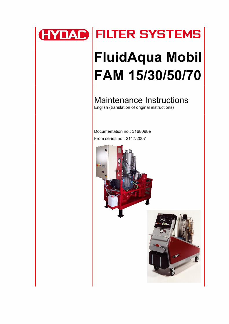
FluidAqua MobilFAM 15/30/50/70
Maintenance Instructions English (translation of original instructions)
Documentation no.: 3168098e
From series no.: 2117/2007

FAM 15/30/50/70 Trademarks
Trademarks
The trademarks of other companies are exclusively used for the products of those companies.
Copyright © 2009 by HYDAC FILTER SYSTEMS GMBH all rights reserved
All rights reserved. This manual may not be reproduced in part or whole without the express written consent of HYDAC Filter Systems GmbH. Contraventions are liable to compensation.
Exclusion of Liability
We made every endeavor to ensure the accuracy of the contents of this document. However, errors cannot be ruled out. Consequently, we accept no liability for such errors as may exist nor for any damage or loss whatsoever which may arise as a result of such errors. The content of the manual is checked regularly. Any corrections required will be incorporated in future editions. We welcome any suggestions for improvements.
All details are subject to technical modifications.
Technical specifications are subject to change without notice.
HYDAC FILTER SYSTEMS GMBHPostfach 12 5166273 Sulzbach / Saar
Documentation Representative
Mr. Günter Harge
c/o HYDAC International GmbH, Industriegebiet, 66280 Sulzbach / Saar
Telephone: ++49 (0)6897 509 1511
Telefax: ++49 (0)6897 509 1394
E-mail: [email protected]
HYDAC FILTER SYSTEMS GMBH en(us) Page 2 / 40
IuW FAM15-70 3168098e en-us 2011-05-26.doc 2011-05-26

FAM 15/30/50/70 Content
HYDAC FILTER SYSTEMS GMBH en(us) Page 3 / 40
IuW FAM15-70 3168098e en-us 2011-05-26.doc 2011-05-26
Content
Trademarks ...............................................................................................................2
Documentation Representative...............................................................................2
Content......................................................................................................................3
Introduction ..............................................................................................................4
Abbreviations and symbols.....................................................................................4
Safety information and instructions .......................................................................5
Inspection and maintenance overview...................................................................7
Performing inspection and maintenance work....................................................10
Checking the warning message lamp...................................................................10 Change Air filter ....................................................................................................10 Cleaning the intake filter (nur FAM15/30/50) ........................................................11
Water Ring Vacuum Pump.....................................................................................12
Check and Clean the Level Switch .......................................................................12 Switching Status - Level Sensor Water Ring Vacuum Pump/PLC........................12 Replacing the Water Filter ....................................................................................13 Cleaning the Cooling Fins.....................................................................................13 Flushing and Cleaning the Vacuum Pump ...........................................................14
Cleaning the Condensation Cooler ...................................................................17
Maintenance of Water Filter Combination (optional) ..........................................19
Back-Flush Water Filter Combination ...............................................................19 Checking / setting the downstream pressure ....................................................20
Rotary Vane Vacuum Pump...................................................................................21
Changing oil and oil filter...................................................................................22 Replacing the Air De-oiling Element .................................................................23
Changing the Filter Element on the Main Filter ....................................................24 Filter housing 1300/2600...................................................................................24 Changing the filter element: ..............................................................................25 MRF Filter Housing ...........................................................................................28
Fuction test - Level sensor Vacuum chamber.....................................................30
Switching Status - Level Sensor Vacuum Column/PLC........................................31
Testing the Float Switch in the Oil Pan ................................................................32
Oil Mist Separator Maintenance ...........................................................................33 Changing the filter element ...............................................................................34
Replacement Parts and Accessories List ............................................................35
Contact / Service ....................................................................................................37

FAM 15/30/50/70 Introduction
Introduction
The safety of all persons coming into contact with the FAM and the availability of the installation essentially depend on the ability to master the unit.
Service and maintenance work to be carried out at regular intervals are described in these operating instructions.
We recommend in addition that the unit be given annual servicing by our HYDAC Servicenter1.
In the event of necessary repairs, we will be happy to offer you our support and to supply you with original replacement parts.
Abbreviations and symbols
This symbol denotes safety information, the nonobservance of which can endanger persons and the environment
This symbol denotes safety precautions which can endanger persons by electrical shock if not observed.
This symbol indicates important notes for the proper handling and operation of the unit/software. The nonobservance of these notes can lead to damage to or failure of the unit/software.
Under this symbol you will find user's tips and particularly useful information.
Wear eye protection. Appropriate and authorized eye protection (safety goggles) must be worn when using cleaning materials or compressed air.
Wear protective gloves. Appropriate and authorized safety gloves must be worn when handling cleaning materials or compressed air.
The tools that are required are listed after this symbol.
1 Contact addressees can be found under Chapter 0
HYDAC FILTER SYSTEMS GMBH en(us) Page 4 / 40
IuW FAM15-70 3168098e en-us 2011-05-26.doc 2011-05-26

FAM 15/30/50/70 Safety information and instructions
HYDAC FILTER SYSTEMS GMBH en(us) Page 5 / 40
IuW FAM15-70 3168098e en-us 2011-05-26.doc 2011-05-26
Safety information and instructions
The inspection, maintenance and service work prescribed in the introduction are to be carried out in a professional and timely manner. Necessary service work on the installation is not to be carried out except by personnel who are in possession of the required pertinent knowledge and/or professional expertise; otherwise the manufacturer's own specialists should be called in to perform the work.
The tasks should only be carried out by specialists who have in their possession the knowledge necessary for carrying out these tasks following completion of pertinent training and schooling measures.
Unit operating personnel is to be informed of the work that is planned before the beginning of the work and the responsible supervisor is to be appointed.
The servicing area is to be secured with a wide perimeter insofar as this is necessary.
If the unit installation is shut down for maintenance and servicing measures, then it is mandatory that measures be implemented to secure against unauthorized restarting, e.g. by locking the main or operating switch with personal safety padlocks. Do not fail to keep the key in your own possession.
Appropriate signs are to be mounted indicating that maintenance, servicing or cleaning measures are being carried out on the unit.
When dismantling individual parts and modules, do not fail to take care to ensure that no hazards can ensue for service personnel, e.g. from unexpected movements of valves, pumps, etc. If the possibility of this kind of hazard cannot be excluded, then appropriate preventative security measures are to be implemented, e.g. through the placement of blocks or support or by fastening equipment in place.
Individual parts and modules of the unit should not be dismantled unless it has been ensured that the personnel assigned these tasks have in their possession the necessary specialist knowledge required to carry out these tasks in an appropriately professional and safety-oriented manner. Specialists from the manufacturer's company should be called upon in case of uncertainty.
If the use of lifting equipment is required when replacing individual parts or modules, then it is mandatory that care be taken to ensure that the parts are secured safely with hitching equipment and that the load lifting equipment has the bearing capacity required.
Use only appropriate and properly functioning lifting equipment.
Never stand or work under suspended loads.
When carrying out assembly work above body height, use either the ladders and lifting stages provided for that purpose or other appropriate alternatives. Do not use any parts of the unit as footholds for climbing. Keep all grips, steps, railings, platforms, ladders, etc. free of dirt.
Cover or seal shut all openings into which cleaning agents are not allowed to penetrate because of safety and/or functional considerations before cleaning the unit with high-pressure cleaners or other cleaning agents. This applies in particular for electromotors, switching devices, distributor boxes and control cabinets.
Remove all covers/seals again after cleaning has been completed.

FAM 15/30/50/70 Safety information and instructions
HYDAC FILTER SYSTEMS GMBH en(us) Page 6 / 40
IuW FAM15-70 3168098e en-us 2011-05-26.doc 2011-05-26
Do not fail to take care to ensure that all pumps are shut off before working on pipe and/or hose tubing lines and fittings that carry or contain fluids or vapors. The pipe and/or hose tubing lines must be completely cooled down and depressurized. The associated shut-off valves leading into and away from the the affected pipeline sections and fittings must be closed and secured against unintended opening. The pumping medium itself is to be drained off if possible.
After cleaning, check all pipe and hose tubing lines and fittings for leakage, loose connections, abrasion or other damage. Eliminate any deficiencies found without delay.
During maintenance and servicing work, always tighten any screw connections that have become loose!
If it is necessary to dismantle any safety devices during maintenance, cleaning or servicing measures, then these devices are to be reinstalled and inspected immediately following completion of the maintenance, cleaning or servicing measures.

FAM 15/30/50/70 Inspection and maintenance overview
HYDAC FILTER SYSTEMS GMBH en(us) Page 7 / 40
IuW FAM15-70 3168098e en-us 2011-05-26.doc 2011-05-26
Inspection and maintenance overview
The inspection and maintenance work listed here are necessary conditions for ensuring both long service life and error-free operation of the unit.
In addition, you will find further information in the operating manuals published by the manufacturers of the components which are supplied with the unit.
See
pag
e
24 h
rs o
r d
aily
500
hrs
o
r m
on
thly
3000
hrs
or
sem
i-an
ual
ly
6000
hrs
or
ann
ual
ly
FAM
Visual inspection for leakage - X
Check the screwed fittings to see that they have been properly resecured.
- X
Check the measurement technology equipment / Underpressure manometer / Dynamic pressure manometer at the fluid filter
- X
Check malfunction message lamps (lamp test) 10 X
Change Air filter 10 X
Intake filter cleaning (suction filter) 11 X
Water ring vacuum pump
Check and Clean the Level Switch 12 X
Replacing the Water Filter 13 X
Cleaning the Cooling Fins on the Water cooler 13 X
Flushing and Cleaning the Vacuum Pump, completely
14 X
Cleaning the Condensation Cooler 17 X
Back-flush water filter combination (only for version with automatic water intake)2
19 X
2 FAM-x-x-x-x/xxxx-x-x-x-SW-x-/x

FAM 15/30/50/70 Inspection and maintenance overview
HYDAC FILTER SYSTEMS GMBH en(us) Page 8 / 40
IuW FAM15-70 3168098e en-us 2011-05-26.doc 2011-05-26
See
pag
e
24 h
rs o
r d
aily
500
hrs
o
r m
on
thly
3000
hrs
or
sem
i-an
ual
ly
6000
hrs
or
ann
ual
ly
Rotary Valve Pump Vacuum Pump
Check oil level, replace oil and oil filter 22 X
Replacing the Air De-oiling Element3 23 X
Check and clean the ventilator hood - X
Emptying / filling pump
Check and clean the ventilator hood - X
Fluid Filter
Changing the Filter Element 24 X
Emptying and cleaning the filter housing - X
Oil mist separator
Changing the filter element 34 X
Electrics
Check cable conduits for damage, replacing as necessary.
- X
Measure the engine power consumption of all engines and compare the values with the type label.
- X
Perform electrical safety inspection in accordance with DIN VDE 0702 and/or corresponding national regulation.
- X
Measure power consumption of the heater and compare values with type label (applies only to versions with integrated heater) - X
3 Oil mist or increased electricity consumption by the drive engine (response of the engine protection switch) can be traced back to a soiled air de-oiling element. The air de-oiling element should be replaced without delay.

FAM 15/30/50/70 Inspection and maintenance overview
HYDAC FILTER SYSTEMS GMBH en(us) Page 9 / 40
IuW FAM15-70 3168098e en-us 2011-05-26.doc 2011-05-26
See
pag
e
24 h
rs o
r d
aily
500
hrs
o
r m
on
thly
3000
hrs
or
sem
i-an
ual
ly
6000
hrs
or
ann
ual
ly
Function test
Check and clean the level sensor in the vacuum chamber
- X
Float switch oil pan - malfunction message and E-STOP function
- X
Functional test of all components in manual operation4
- X
4 See Operating and Maintenance Instructions FAM 15/30/50/70, Chapter on Operation / Manual Menu

FAM 15/30/50/70 Performing inspection and maintenance work
Performing inspection and maintenance work
The pictures and illustrations in the descriptions are examples. They do not represent all of the different product variants.
Checking the warning message lamp
Performance instructions: Set the FAM on the main switch to "ON".
A lamp test will be carried out automatically after switching on during which all of the warning message lamps will light up briefly.
Change Air filter
You will require:
Air filter (for part-no., see replacement parts list)
Performance instructions:
The air filter must be replaced every six months. If the FAM is operated in a very dusty / humid environment, then replacement must be carried out at shorter intervals. Unscrew the air filter by hand Screw on the new air filter by hand
(no O-ring is required)
HYDAC FILTER SYSTEMS GMBH en(us) Page 10 / 40
IuW FAM15-70 3168098e en-us 2011-05-26.doc 2011-05-26

FAM 15/30/50/70 Performing inspection and maintenance work
Cleaning the intake filter (nur FAM15/30/50)
You will require:
Compressed air
Open-end wrench, SW 55
To install / dismount the suction screen, proceed as follows:
1. Unscrew the screw plug (1) counterclockwise with an open-jaw wrench.
2. Remove strainer insert (3) and clean it.
3. To clean the suction screen, wash it out with solvent and then dry it using compressed air.
3. Check strainer insert (3) and the seal ring (2) on the screw plug for damage and replace if necessary.
4. Install the new strainer insert (3).
5. Turn the screw plug (1) clockwise manually.
Firmly screw in the screw plug (1) with the open-jaw wrench.
6. After commissioning, check the suction strainer fittings for leaks.
12
3
HYDAC FILTER SYSTEMS GMBH en(us) Page 11 / 40
IuW FAM15-70 3168098e en-us 2011-05-26.doc 2011-05-26

FAM 15/30/50/70 Water Ring Vacuum Pump
Water Ring Vacuum Pump
Check and Clean the Level Switch
Performance instructions:
Remove the covering tin.
Unscrew the 4 fastening screws.
Pull out the level switch.
Check the level switch for dirt and damage.
Check the function of the float switch(es) on the basis of the PLC inlet. See the illustration below in this connection. The main switch of the FAM must be set to "ON" position while doing so.
The suction strainer is re-mounted in reverse order.
!
Switching Status - Level Sensor Water Ring Vacuum Pump/PLC
Stainless steel - level switch Plastic - level switch
Leve
l sen
sor
I1.0 I1.4 I1.0 I1.4 I1.0 I1.4 I1.0 I1.4
off off on on off off on on
PLC
HYDAC FILTER SYSTEMS GMBH en(us) Page 12 / 40
IuW FAM15-70 3168098e en-us 2011-05-26.doc 2011-05-26
FAM 15/30/50/70 Water Ring Vacuum Pump
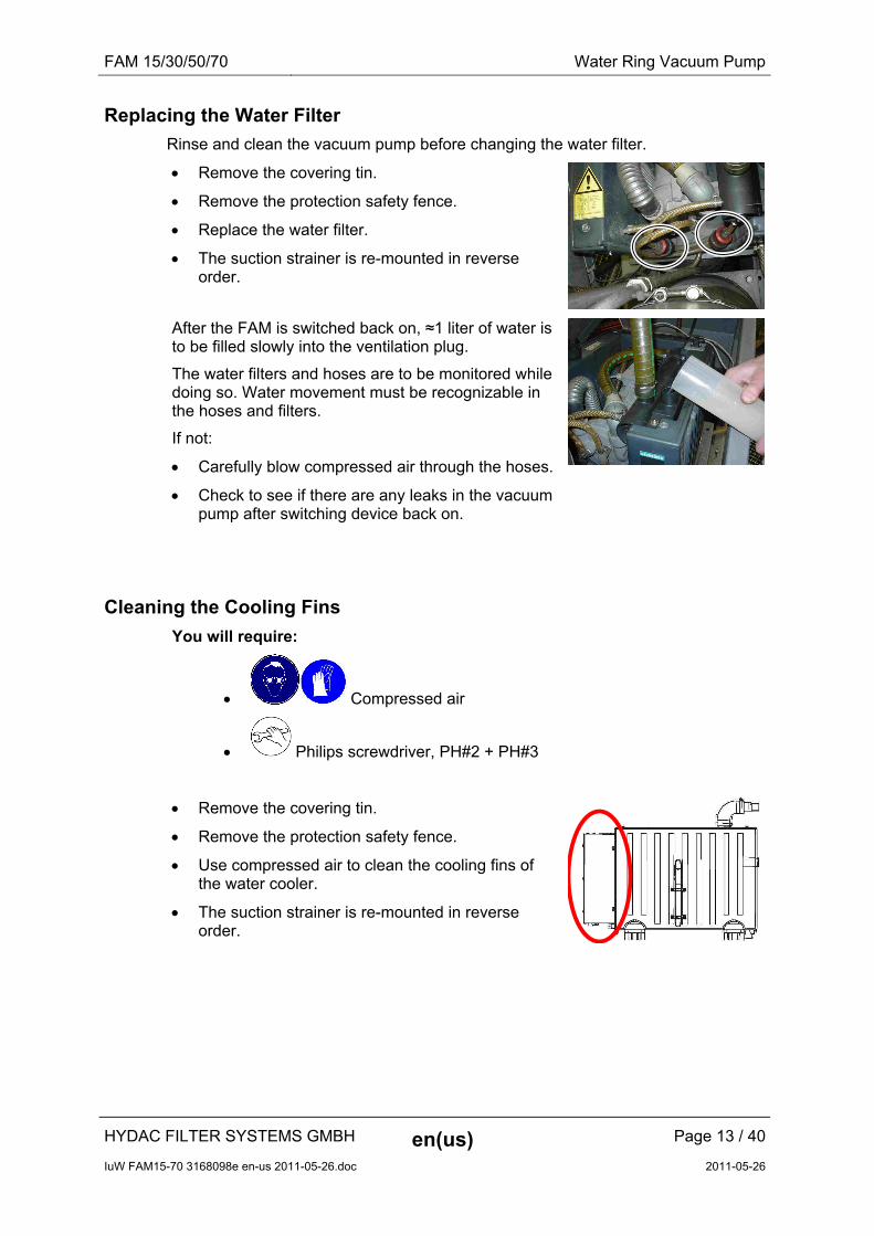
Replacing the Water Filter
Rinse and clean the vacuum pump before changing the water filter.
Remove the covering tin.
Remove the protection safety fence.
Replace the water filter.
The suction strainer is re-mounted in reverse order.
After the FAM is switched back on, ≈1 liter of water is to be filled slowly into the ventilation plug.
The water filters and hoses are to be monitored while doing so. Water movement must be recognizable in the hoses and filters.
If not:
Carefully blow compressed air through the hoses.
Check to see if there are any leaks in the vacuum pump after switching device back on.
Cleaning the Cooling Fins
You will require:
Compressed air
Philips screwdriver, PH#2 + PH#3
Remove the covering tin.
Remove the protection safety fence.
Use compressed air to clean the cooling fins of the water cooler.
The suction strainer is re-mounted in reverse order.
HYDAC FILTER SYSTEMS GMBH en(us) Page 13 / 40
IuW FAM15-70 3168098e en-us 2011-05-26.doc 2011-05-26

FAM 15/30/50/70 Water Ring Vacuum Pump
Flushing and Cleaning the Vacuum Pump
To perform these tasks, you will need the following tools and equipment:
Compressed air VacuCleaner 1.75 liters (the part no. can be found in the spare parts list) Measuring beaker (minimum capacity 2 liters) Funnel Hot water, ideally 60-65°C ≈35 liters Philips screwdriver, PH#2
Philips screwdriver, PH#3
Flat-bladed screwdriver 0.6x4.5x100
Face spanner 3-11-60
Empty the vacuum pump through the evacuation line.
Remove the 5 attachment screws on the side cover plate of the water cooler.
Remove the cover plate of the water cooler.
HYDAC FILTER SYSTEMS GMBH en(us) Page 14 / 40
IuW FAM15-70 3168098e en-us 2011-05-26.doc 2011-05-26

FAM 15/30/50/70 Water Ring Vacuum Pump
Open the strap of the feed line hose [1].
Pull the feed line hose off the support.
[1]
Open the strap of the return line and pull the return line off the support/T-piece.
Carefully blow compressed air into the return line (see direction of the arrow).
Fluid sprays out of the feed line hose.
Blow out the cooler thoroughly with compressed air.
The suction strainer is re-mounted in reverse order.
Remove the cover plate (1), the level switch (2) and the bung plug (3) from the filling opening.
Fill the pump with hot water (60-65°C) through the filling opening or the opening for the level switch until the water emerges from the filling opening.
Close the filling opening with the bung plug.
Fill the VacuCleaner with ≈ 1.75 liters through the level sensor opening.
Install the level sensor.
HYDAC FILTER SYSTEMS GMBH en(us) Page 15 / 40
IuW FAM15-70 3168098e en-us 2011-05-26.doc 2011-05-26

FAM 15/30/50/70 Water Ring Vacuum Pump
Start the vacuum pump in manual mode.
Use the vacuum gauge to set the vacuum of the vacuum column to ≈250 mbar (abs.).
After 5 minutes, collect ≈2 liters of the cleaning fluid in a measuring beaker through the evacuation line.
Carefully fill the cleaning fluid that has been collected into the outlet port.
Fasten the suction line.
Operate vacuum pump for 45 minutes in manual mode.
Empty the vacuum pump through the evacuation line.
Remove the bung plugs from the level switch opening and the filling opening.
Rinse the vacuum pump with tap water through the level switch opening and the filling opening.
Take care to ensure that the drain ball valve is open for this purpose.
Close the drain ball valve. Fill the vacuum pump until water emerges from the filling opening.
Screw in the bung plugs.
Mount the level switch.
Check to see if there are any leaks in the vacuum pump after switching device back on.
Mount the cover plate.
HYDAC FILTER SYSTEMS GMBH en(us) Page 16 / 40
IuW FAM15-70 3168098e en-us 2011-05-26.doc 2011-05-26

FAM 15/30/50/70 Water Ring Vacuum Pump
Cleaning the Condensation Cooler
To perform these tasks, you will need the following tools and equipment:
Compressed air
VacuCleaner (for part-no., see spare parts list).
Bucket (≈25 liter) or comparable vessel
Hot water (Temperature ≈60-65°C)
O-rings (1x 67.95 x 2.62, 1x 72.62 x 3.53) (for part-no. see spare parts list)
Philips screwdriver, PH#2
Philips screwdriver, PH#3
Flat-bladed screwdriver 0.6x4.5x100
Hexagon screwdriver (wrench) Size 5
To clean the condensation cooler, proceed as follows:
Remove the cover plate.
Remove all of the hoses attached to the condensation cooler.
Place unambiguous marking on the hoses for later re-assembly.
Unscrew the condensation cooler and pull it out.
Remove the four front cap screws. Remove the cap.
HYDAC FILTER SYSTEMS GMBH en(us) Page 17 / 40
IuW FAM15-70 3168098e en-us 2011-05-26.doc 2011-05-26

FAM 15/30/50/70 Water Ring Vacuum Pump
Carefully remove the cooler insert by rotating it.
Apply compressed air to free the insert of coarse contamination.
Place the insert for ≈45 minutes in a cleaning bath with hot water (temperature ≈60-65°C) and 5% VacuCleaner. Example: 10 l water + 0.5 l VacuCleaner.
Afterwards, rinse out the insert with clear water. Blow it out with compressed air.
Clean the cooler housing.
Mount the new O-rings. Lubricate them lightly for this purpose.
Assemble in reversed order of sequence.
Check to see if there are any leaks in the vacuum pump after switching device back on.
Mount the cover plate.
HYDAC FILTER SYSTEMS GMBH en(us) Page 18 / 40
IuW FAM15-70 3168098e en-us 2011-05-26.doc 2011-05-26

FAM 15/30/50/70 Maintenance of Water Filter Combination (optional)
Maintenance of Water Filter Combination (optional)
Back-Flush Water Filter Combination
The water filter combination is a possible option for the version with water ring vacuum pump.
To perform these tasks, you will need the following tools and equipment:
Collecting vessel (25 liter)
A water inlet pressure of at least 1.5°bar.
Proceed as follows to back-flush the water filter combination:
Place a collecting vessel underneath (≈ 25-liter).
Open the ball valve by turning the back-flush button until it stops.
Take care to ensure that the marking bars are in vertical position. The back-flush system is activated.
It is possible to remove filtered water during the back-flushing sequence.
Close the ball valve after ≈15 sec. A longer back-flushing period may be required with filters that are heavily clogged.
Set the next date for manual back-flushing with the aid of the memory ring.
HYDAC FILTER SYSTEMS GMBH en(us) Page 19 / 40
IuW FAM15-70 3168098e en-us 2011-05-26.doc 2011-05-26

FAM 15/30/50/70 Maintenance of Water Filter Combination (optional)
Checking / setting the downstream pressure
Downstream pressure is the term used for the pressure after the filter combination.
Reduce the pressure to prevent strong turbulence in the vacuum pump tank when the operating pressure is high.
The downstream pressure at the filter combination is set ex-works to 5 bar.
To adjust the downstream pressure, proceed as follows:
1. Close the locking feature [1].
2. Relieve the pressure in the pipe between the locking features [1] and [2], e.g. by tapping the water. For example using water spigots.
3. Loosen the flat-blade screw [4]. Do not screw out completely!
4. Depressurize the nominal value spring by turning the adjustment grip to the left (-).
5. Close the locking feature [2].
6. Slowly open the locking feature [1].
7. Set the nominal value of 5 bar (downstream pressure) by rotating the adjustment grip. Turning the the right (+) increases the nominal value, turning to the left (-) decreases the nominal value. (Read the value on the manometer) If the downstream pressure is set to a lower value, then the output side must be relieved of pressure in order for the desired downstream pressure to adjust.
8. Tighten the flat-blade screw firmly [4].
9. Slowly open the locking feature [2].
HYDAC FILTER SYSTEMS GMBH en(us) Page 20 / 40
IuW FAM15-70 3168098e en-us 2011-05-26.doc 2011-05-26

FAM 15/30/50/70 Rotary Vane Vacuum Pump
Rotary Vane Vacuum Pump
15
Item Description
1 Oil separator
2 Inlet flange
3 Oil sight glass
4 Screw plug
5 Screw plug
6 Exhaust valve
7 Rotor vane
8 Rotor
9 Air de-oiling element
10 Exhaust cover
11 Oil filter
12 Demister
13 Oil sump
14 Service cover
15 Leaf spring
The following descriptions are in reference to these positions.
HYDAC FILTER SYSTEMS GMBH en(us) Page 21 / 40
IuW FAM15-70 3168098e en-us 2011-05-26.doc 2011-05-26

FAM 15/30/50/70 Rotary Vane Vacuum Pump
HYDAC FILTER SYSTEMS GMBH en(us) Page 22 / 40
IuW FAM15-70 3168098e en-us 2011-05-26.doc 2011-05-26
Changing oil and oil filter
The first oil change must take place after 100 operating hours. Later oil changes after ≈ 3000 hours or every six months.
The vacuum pump must be at operating state temperature when the oil is changed:
Put the FAM into operation for 10 minutes.
Switch off the FAM at the main switch.
Wait until the pressure in the vacuum column has reached atmospheric pressure (≈ 1000 mbar abs).
To perform these tasks, you will need the following tools and equipment:
Compressor oil VE101 (for part-no., see replacement parts list)
Maintenance set, comprising oil filter, air deoiling element, ventilation cover seal (for part-no., see replacement parts list).
Fork wrenches SW 27 / SW 32
To change the oil, proceed as follows:
1. Put a suitable container in place to catch the used oil.
2. Open the screw plug (4) and allow the used oil to drain into the container. Dispose of the used oil properly.
3. Close the screw plug when the flow of oil diminishes. Let the pump run again briefly for a few seconds,
4. Open the plug screw once again and drain off the remaining oil.
5. Screw in the plug screw and tighten it firmly.
6. Remove the oil filter (11) and dispose of it properly.
7. Install the new oil filter (11).
8. Fill in new oil through the oil filling screw plug (5) until the MAX marking (3) has been reached.

FAM 15/30/50/70 Rotary Vane Vacuum Pump
Replacing the Air De-oiling Element
Oil mist or increased electricity consumption by the drive engine (response of the engine protection switch) are signs of a soiled air de-oiling element.
To replace the air de-oiling element, proceed as follows:
1. Remove the 4 attachment screws of the ventilation cover (10).
2. Undo the leaf spring safety screw (15).
3. Remove the leaf spring (15).
4. Remove the air de-oiling element (9) and replace it with a new element.
5. Replace the ventilation cover seal (10).
6. The suction strainer is re-mounted in reverse order.
The air de-oiling element becomes saturated with oil during operation. A slight lowering of the oil filling level after the air de-oiling element has been replaced is therefore quite normal.
HYDAC FILTER SYSTEMS GMBH en(us) Page 23 / 40
IuW FAM15-70 3168098e en-us 2011-05-26.doc 2011-05-26

FAM 15/30/50/70 Rotary Vane Vacuum Pump
Changing the Filter Element on the Main Filter
WARNING Hydraulic system is under pressure
Bodily injury
► The hydraulic system must be depressurized before performing any work on the hydraulic system.
► Switch off the FAM before replacing the filter element.
Filter housing 1300/2600
The filter bowl must be depressurized, meaning that the pressure gauge integrated in the cover plate has to display "0 bar" => the housing is at zero pressure.
HYDAC FILTER SYSTEMS GMBH en(us) Page 24 / 40
IuW FAM15-70 3168098e en-us 2011-05-26.doc 2011-05-26
FAM 15/30/50/70 Rotary Vane Vacuum Pump
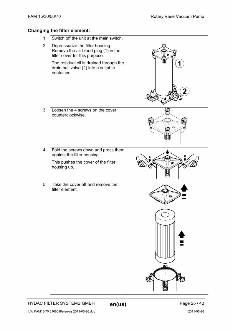
Changing the filter element:
1. Switch off the unit at the main switch.
2. Depressurize the filter housing. Remove the air bleed plug (1) in the filter cover for this purpose.
The residual oil is drained through the drain ball valve (2) into a suitable container.
3. Loosen the 4 screws on the cover counterclockwise.
4. Fold the screws down and press them against the filter housing.
This pushes the cover of the filter housing up.
5. Take the cover off and remove the filter element.
HYDAC FILTER SYSTEMS GMBH en(us) Page 25 / 40
IuW FAM15-70 3168098e en-us 2011-05-26.doc 2011-05-26

FAM 15/30/50/70 Rotary Vane Vacuum Pump
6. Clean:
the inside of the filter bowl of coarse dirt
the sealing surfaces on the filter head and on the cover.
6. For easier installation of the
filter element, wet the O-ring on the filter element with the operating medium.
7. Press the new filter element down into the filter mount by turning it slightly.
Do not use striking tools for this.
8. Check the O-ring on the cover for damage and replace it if necessary.
Lightly wet the O-ring on the cover with medium.
HYDAC FILTER SYSTEMS GMBH en(us) Page 26 / 40
IuW FAM15-70 3168098e en-us 2011-05-26.doc 2011-05-26

FAM 15/30/50/70 Rotary Vane Vacuum Pump
9. Put the cover on.
Observe correct placement of the O-ring on the cover while doing so. It must not be damaged.
10. Fold the 4 screws upward and, working cross-wise and clockwise, screw them in with uniform tightness.
11. Close the drain valve.
12. Switch the unit on.
13. Check the unit for any leaks.
14. The unit is ready for operation.
HYDAC FILTER SYSTEMS GMBH en(us) Page 27 / 40
IuW FAM15-70 3168098e en-us 2011-05-26.doc 2011-05-26

FAM 15/30/50/70 Rotary Vane Vacuum Pump
MRF Filter Housing
1. The ventilation plug contains an air vent slit - do not unscrew all the way.
Depressurizing the filter housing: Carefully open the air-vent plug in the cover using a size 10 mm Allen wrench and wait until the integrated manometer shows 0 bar.
2. Open the drain valve on the contamination side.
Collect the fluid that emerges.
Close the drain valve as soon as no more medium emerges.
3. Undo the tension clamps between the cover
and the topmost intermediate piece with the aid of a SW 13 mm open-end wrench.
4. Remove the cover and place it on a clean
surface.
5. Undo all of the star grips [A] remove the element holding plate [B].
[A]
[B]
6. Remove all of the elements and dispose of them in accordance with local regulations.
7. Clean the inside of the filter housing. 8. Preparing the new elements by moistening the
O-ring on each element with the operating medium.
9. Install all of the new elements by applying
pressure while slightly rotating the element into the element receptacle.
Do not use excessive force or a hammer, etc.
HYDAC FILTER SYSTEMS GMBH en(us) Page 28 / 40
IuW FAM15-70 3168098e en-us 2011-05-26.doc 2011-05-26
FAM 15/30/50/70 Rotary Vane Vacuum Pump
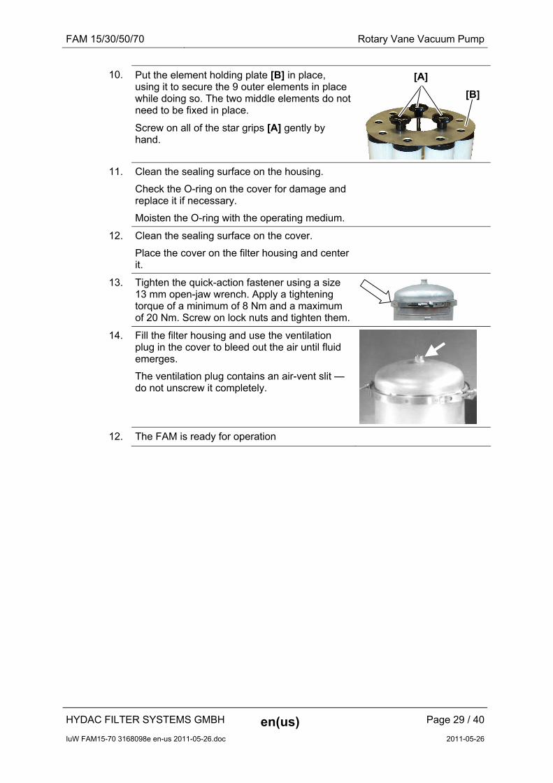
10. Put the element holding plate [B] in place, using it to secure the 9 outer elements in place while doing so. The two middle elements do not need to be fixed in place.
Screw on all of the star grips [A] gently by hand.
[A]
[B]
11. Clean the sealing surface on the housing.
Check the O-ring on the cover for damage and replace it if necessary.
Moisten the O-ring with the operating medium.
12. Clean the sealing surface on the cover.
Place the cover on the filter housing and center it.
13. Tighten the quick-action fastener using a size 13 mm open-jaw wrench. Apply a tightening torque of a minimum of 8 Nm and a maximum of 20 Nm. Screw on lock nuts and tighten them.
14. Fill the filter housing and use the ventilation plug in the cover to bleed out the air until fluid emerges.
The ventilation plug contains an air-vent slit — do not unscrew it completely.
12. The FAM is ready for operation
HYDAC FILTER SYSTEMS GMBH en(us) Page 29 / 40
IuW FAM15-70 3168098e en-us 2011-05-26.doc 2011-05-26

FAM 15/30/50/70 Fuction test - Level sensor Vacuum chamber
Fuction test - Level sensor Vacuum chamber
You will require:
Philips screwdriver, PH#2 + PH#3
Fork wrench SW13
Performance instructions: Remove 4 nuts from the cover of the vacuum
chamber
Undo the safety screw of the level sensor plug.
Pull out the plug
Carefully remove the cover together with the level sensor
Hang the cover to the vacuum chamber as shown in the accompanying illustration.
Check the level sensor for dirt and clean as needed.
Check the functioning of the float level sensor on the basis of the PLC inlets. Move the float away by hand. The main switch of the FAM must be set to "ON" position while doing so. See the illustration below in this connection.
HYDAC FILTER SYSTEMS GMBH en(us) Page 30 / 40
IuW FAM15-70 3168098e en-us 2011-05-26.doc 2011-05-26

FAM 15/30/50/70 Fuction test - Level sensor Vacuum chamber
Switching Status - Level Sensor Vacuum Column/PLC
If the upper float is shifted upward, then the fault message "Vacuum chamber overfilled" must appear on the text display. Acknowledge the message with the "RESET" key.
Carry out assembly in reversed order of sequence.
!
Leve
l sen
sor
I0.3 I0.4 I0.5 I0.3 I0.4 I0.5
on off on off on off
P
LC
HYDAC FILTER SYSTEMS GMBH en(us) Page 31 / 40
IuW FAM15-70 3168098e en-us 2011-05-26.doc 2011-05-26

FAM 15/30/50/70 Testing the Float Switch in the Oil Pan
Testing the Float Switch in the Oil Pan
Proceed as follows to test the float switch:
1. Use your fingers to raise the float switch in the oil pan.
2. The FAM must switch off and the fault message "Pan overfilled. Please drain and seal leaky site on the FAM" appears in the display.
3. Release the float switch and acknowledge the fault message by pressing the F3 key.
4. The FAM resumes operation.
5. The function of the float switch is thus ensured and the check has been successfully completed.
HYDAC FILTER SYSTEMS GMBH en(us) Page 32 / 40
IuW FAM15-70 3168098e en-us 2011-05-26.doc 2011-05-26

FAM 15/30/50/70 Testing the Float Switch in the Oil Pan
Oil Mist Separator Maintenance
Item Description
1 Separator head
2 Separator pot
3 Clogging indicator
4 Filling level display
The oil mist separator is located between the vacuum column and the vacuum pump.
A filter element is used to retain the oil mist and the oil in the oil mist separator and the oil is collected in the separator pot, where it is continuously suctioned off and returned to the vacuum column.
The filter element (for part-no., see replacement parts list) is to be replaced on a regular basis in accordance with the maintenance schedule.
The clogging indicator (3) of the oil mist separator is not functioning.
HYDAC FILTER SYSTEMS GMBH en(us) Page 33 / 40
IuW FAM15-70 3168098e en-us 2011-05-26.doc 2011-05-26

FAM 15/30/50/70 Testing the Float Switch in the Oil Pan
Changing the filter element
When changing the filter element, proceed as follows:
1. Use the display to end automatic operation of the FAM. Afterwards, wait ≈1 minute, until normal pressure (ambient pressure) has been established in the vacuum chamber.
2. Rotate the separator pot [2] by 1/8th turn to the left (bayonet seal) and remove from the bottom.
3. Rotate the old filter element out in clockwise direction and dispose of in an environmentally friendly manner in accordance with local regulations.
Insert a new filter element and screw it into the separator head by turning it counterclockwise.
No tools are to be used for dismantling or installing the filter element.
4. Insert the separator pot (2) into the separator head (1) and secure with a 1/8th turn to the right in the bayonet seal.
5. The unit is now ready for use.
HYDAC FILTER SYSTEMS GMBH en(us) Page 34 / 40
IuW FAM15-70 3168098e en-us 2011-05-26.doc 2011-05-26
FAM 15/30/50/70 Replacement Parts and Accessories List
HYDAC FILTER SYSTEMS GMBH en(us) Page 35 / 40
IuW FAM15-70 3168098e en-us 2011-05-26.doc 2011-05-26
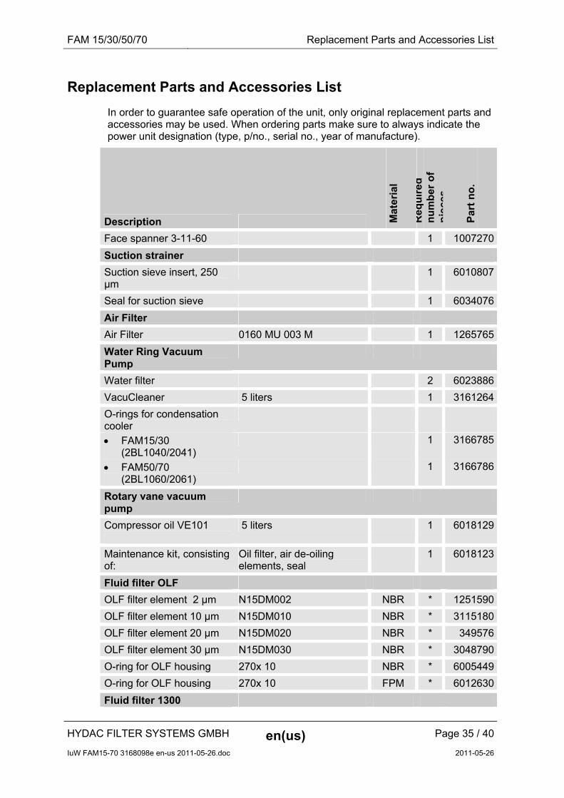
Replacement Parts and Accessories List
In order to guarantee safe operation of the unit, only original replacement parts and accessories may be used. When ordering parts make sure to always indicate the power unit designation (type, p/no., serial no., year of manufacture).
Description Mat
eria
l
Req
uir
ed
nu
mb
er o
f p
iece
s
Par
t n
o.
Face spanner 3-11-60 1 1007270
Suction strainer
Suction sieve insert, 250 µm
1 6010807
Seal for suction sieve 1 6034076
Air Filter
Air Filter 0160 MU 003 M 1 1265765
Water Ring Vacuum Pump
Water filter 2 6023886
VacuCleaner 5 liters 1 3161264
O-rings for condensation cooler
FAM15/30 (2BL1040/2041)
1 3166785
FAM50/70 (2BL1060/2061)
1 3166786
Rotary vane vacuum pump
Compressor oil VE101
5 liters 1 6018129
Maintenance kit, consisting of:
Oil filter, air de-oiling elements, seal
1 6018123
Fluid filter OLF
OLF filter element 2 µm N15DM002 NBR * 1251590
OLF filter element 10 µm N15DM010 NBR * 3115180
OLF filter element 20 µm N15DM020 NBR * 349576
OLF filter element 30 µm N15DM030 NBR * 3048790
O-ring for OLF housing 270x 10 NBR * 6005449
O-ring for OLF housing 270x 10 FPM * 6012630
Fluid filter 1300

FAM 15/30/50/70 Replacement Parts and Accessories List
HYDAC FILTER SYSTEMS GMBH en(us) Page 36 / 40
IuW FAM15-70 3168098e en-us 2011-05-26.doc 2011-05-26
Description Mat
eria
l
Req
uir
ed
nu
mb
er o
f p
iece
s
Par
t n
o.
1300 filter element 3 µm 1300 R 003 BN3HC/-KB NBR 1 1263059
1300 filter element 3 µm 1300 R 003 BN3HC/V-KB FPM 1 1263760
1300 filter element 5 µm 1300 R 005 BN3HC/-KB NBR 1 1263060
1300 filter element 5 µm 1300 R 005 BN3HC/V-KB FPM 1 1263761
1300 Filter element 10 µm 1300 R 010 BN3HC/-KB NBR 1 1263061
1300 Filter element 10 µm 1300 R 010 BN3HC/V-KB FPM 1 1263762
1300 filter element 20 µm 1300 R 020 BN3HC/-KB NBR 1 1263062
1300 filter element 20 µm 1300 R 020 BN3HC/-V-KB FPM 1 1263763
Fluid filter 2600
2600 filter element 3 µm 2600 R 003 BN3HC/-KB NBR 1 1263071
2600 filter element 3 µm 2600 R 003 BN3HC/-V-KB FPM 1 1263784
2600 filter element 5 µm 2600 R 005 BN3HC/-KB NBR 1 1263072
2600 filter element 5 µm 2600 R 005 BN3HC/-V-KB FPM 1 1263785
2600 Filter element 10 µm 2600 R 010 BN3HC/-KB NBR 1 1263073
2600 Filter element 10 µm 2600 R 010 BN3HC/-V-KB FPM 1 1263786
2600 filter element 20 µm 2600 R 020 BN3HC/-KB NBR 1 1263074
2600 filter element 20 µm 2600 R 020 BN3HC/-V-KB FPM 1 1263787
Oil mist separator
Filter element 1 6061300
*) Dependent on the fluid filter size

FAM 15/30/50/70 Contact / Service
HYDAC FILTER SYSTEMS GMBH en(us) Page 37 / 40
IuW FAM15-70 3168098e en-us 2011-05-26.doc 2011-05-26
Contact / Service
For product information, technical support or if you have comments or suggestions concerning this manual, please contact:
HYDAC FILTER SYSTEMS GMBH
Telephone: ++49 (0) 6897 509 1174
Telefax: ++49 (0) 6897 509 846
E-mail: [email protected]
Regular inspection and maintenance work is indispensable for ensuring trouble-free operation and long service life for your FluidAqua Mobil.
Our HYDAC Servicenter offers you these tasks within agreed-upon time frames and at fixed prices.
HYDAC Service GmbH Rehgrabenstrasse 3 66128 Saarbrücken - Dudweiler
Germany
Telephone: ++49 (0)681 509 883
Telefax: ++49 (0)681 509 324
E-mail: [email protected]


Notes
HYDAC FILTER SYSTEMS GMBH Industriegebiet Postfach 1251 66280 Sulzbach/Saar 66273 Sulzbach/Saar Germany Germany Phone: +49 (0) 6897 509 01 Central Fax: +49 (0) 6897 509 846 (Technical Department) Fax: +49 (0) 6897 509 577 (Sales Department) Internet: www.hydac.com Email: [email protected]
Copyright © 2022 FDOKUMEN