![Dolenjska grupa [Text] (uploaded 10. 10. 2014)](https://static.fdokumen.com/doc/165x107/631e9ee1dc32ad07f307ab90/dolenjska-grupa-text-uploaded-10-10-2014.jpg)
FAM 10 FAM 10/15 - HYDAC
72
FAM 10 FAM 10/15 FluidAqua Mobil Operating and maintenance instructions, part 1/2 English (translation of original instructions) Keep for future reference. Document no.: 4170097b (Valid for FAM-xx-x-x-x-xx-x-C-x-x)
-
Upload
khangminh22 -
Category
Documents
-
view
1 -
download
0
Transcript of FAM 10 FAM 10/15 - HYDAC

FAM 10 FAM 10/15
FluidAqua Mobil Operating and maintenance instructions, part
1/2 English (translation of original instructions)
Keep for future reference.
Document no.: 4170097b (Valid for FAM-xx-x-x-x-xx-x-C-x-x)

Imprint
FAM 10, Instructions, part 1/2 en-US Page 2 / 72
BEWA FAM10-15 1-2 4170097b en-us 2018-05-23.docx 2018-05-23

Imprint
FAM 10, Instructions, part 1/2 en-US Page 3 / 72
BEWA FAM10-15 1-2 4170097b en-us 2018-05-23.docx 2018-05-23
Imprint
Publisher and responsible for the content: HYDAC FILTER SYSTEMS GMBH Postfach 1251 66273 Sulzbach / Saarland Germany Phone: +49 6897 509 01 Fax: +49 6897 509 846 E-mail: [email protected] Homepage: www.hydac.com Court of Registration: Saarbrücken, HRB 17216 Executive directors: Mathias Dieter,
Dipl.Kfm. Wolfgang Haering
Documentation Representative
Mr. Günter Harge c/o HYDAC International GmbH, Industriegebiet, 66280 Sulzbach / Saar Phone: +49 6897 509 1511 Fax: +49 6897 509 1394 E-mail: [email protected]
© HYDAC FILTER SYSTEMS GMBH
All rights reserved. No part of this work may be reproduced in any form (print, photocopy or by other means) or processed, duplicated or distributed using electronic systems without the written consent of the publisher. These documents have been created and inspected with the greatest care. However, errors cannot be ruled out completely. All details are subject to technical modifications. Technical specifications are subject to change without notice.

Content
FAM 10, Instructions, part 1/2 en-US Page 4 / 72
BEWA FAM10-15 1-2 4170097b en-us 2018-05-23.docx 2018-05-23
Content
Imprint ............................................................................................................ 3
Documentation Representative ................................................................... 3
Content .......................................................................................................... 4
Preface ........................................................................................................... 6
Technical Support ........................................................................................ 6 Product modification .................................................................................... 6 Warranty ...................................................................................................... 6 Using the documentation ............................................................................. 7
General safety information .......................................................................... 8
Hazard symbols ........................................................................................... 8 Signal words and their meaning in the general safety information and instructions ........................................................................................... 9 Structure of the general safety information and instructions ...................... 10 Observe regulatory information ................................................................. 10 Proper/Designated Use ............................................................................. 11 Improper Use or Use Deviating from Intended Use ................................... 13 Qualifications of personnel / target group .................................................. 14 Wear suitable clothing ............................................................................... 16 Stoppage in an emergency (EMERGENCY STOP) ................................... 16
Unpacking the unit ...................................................................................... 16
Transporting the unit .................................................................................. 17
Transporting with a forklift .......................................................................... 17 Transporting with a crane .......................................................................... 18 Transporting by train / truck ....................................................................... 18
Checking the scope of delivery ................................................................. 19
Description of unit ...................................................................................... 20
Unit designs ............................................................................................... 20 Servicedescription ..................................................................................... 21
Description of function ............................................................................... 22
Cleaning in Bypass Flow ........................................................................... 24 Purifying and transferring by pumping ....................................................... 24 Unit system components ........................................................................... 25
Unit dimensions .......................................................................................... 27
Stationary version ...................................................................................... 27 Mobile version ........................................................................................... 28
Hydraulicdiagram ........................................................................................ 29
Unit setup and connection ......................................................................... 31

Content
FAM 10, Instructions, part 1/2 en-US Page 5 / 72
BEWA FAM10-15 1-2 4170097b en-us 2018-05-23.docx 2018-05-23
Setting up the unit ...................................................................................... 31 Connection overview ................................................................................. 32 Notes on pipes and hoses ......................................................................... 33
Connecting the inlet (IN) ......................................................................... 35 Connecting the outlet (OUT)................................................................... 35
Preparing the Vacuum Pump ..................................................................... 36 Filling up the rotary vane vacuum pump ................................................. 36
Electrical connection of the unit ................................................................. 37 Rotating field .......................................................................................... 37
Operating Elements on the FAM ................................................................ 39
Switching on / switching off / commissioning and error messages ...... 40
Performing Maintenance ............................................................................ 41
Function testing of the fault indicator lamp ................................................ 44 Change the air filter ................................................................................... 44 Testing the AquaSensor ............................................................................ 44
Cleaning the suction strainer..................................................................... 45
Rotary vane vacuum pump components .................................................. 46
Performing an oil change ........................................................................... 46 Replacing the Air De-oiling Element .......................................................... 47
Replacing the filter element on the fluid filter .......................................... 48
Maintaining the oil mist separator (optional) ............................................ 53
Replacing the filter element on the oil mist separator ................................ 55
Testing the float switch in the oil pan ....................................................... 56
Checking the level sensor of the vacuum column ................................... 57
Locating spare parts ................................................................................... 59
FAM 10 ...................................................................................................... 59 Fluid filter (OLF 5) ...................................................................................... 59 Rotary vane vacuum pump ........................................................................ 59
Taking the unit out of operation ................................................................ 61
Disposing of the unit .................................................................................. 61
Technical data ............................................................................................. 62
Appendix ..................................................................................................... 64
Contact Customer Service / Service .......................................................... 64 Model Code ............................................................................................... 65 Explanation of terms and abbreviations ..................................................... 66 Index .......................................................................................................... 68

Preface
FAM 10, Instructions, part 1/2 en-US Page 6 / 72
BEWA FAM10-15 1-2 4170097b en-us 2018-05-23.docx 2018-05-23
Preface
These operating instructions were made to the best of our knowledge. Nevertheless and despite the greatest care, it cannot be excluded that mistakes could have crept in. Therefore please understand that, in the absence of any provisions to the contrary hereinafter, our warranty and liability – for any legal reasons whatsoever – are excluded in respect of the information in these operating instructions. In particular, we shall not be liable for lost profit or other financial loss. This exclusion of liability does not apply in cases of intent and gross negligence. Moreover, it does not apply to defects which have been deceitfully concealed or whose absence has been guaranteed, nor in cases of culpable harm to life, physical injury and damage to health. If we negligently breach any material contractual obligation, our liability shall be limited to foreseeable damage. Claims due to Product Liability shall remain unaffected.
Technical Support Contact our technical sales department if you have any questions on our product. When contacting us, please always include the model code, serial no. and part no. of the product: Fax: +49 6897 509 9046 E-mail: [email protected]
Product modification We would like to point out that changes to the product (e.g. purchasing options, etc.) may result in the information in the operating instructions no longer being completely accurate or sufficient. After modification or repair work that affects the safety of the product has been carried out on components, the product may not be returned to operation until it has been checked and released by a HYDAC technician. Please notify us immediately of any modifications made to the product whether by you or a third party.
Warranty For the warranty provided by us, please refer to the terms of delivery of HYDAC FILTER SYSTEMS GMBH. You will find these under www.hydac.com -> General terms and conditions.

Preface
FAM 10, Instructions, part 1/2 en-US Page 7 / 72
BEWA FAM10-15 1-2 4170097b en-us 2018-05-23.docx 2018-05-23
Using the documentation
Note that the method described for locating specific information does not release you from your responsibility of carefully reading all these instructions prior to starting the unit up for the first time and at regular intervals in the future.
What do I want to know? I determine which topic I am looking for. WHERE can I find the information I’m looking for? The documentation has a table of contents at the beginning. There, I select the chapter I'm looking for and the corresponding page number.
deHYDAC Filtertechnik GmbHBeWa 123456a de
Seite x
Produkt / Kapitel
200x-xx-xx
The documentation number with its index enables you to order another copy of the operating and maintenance instructions. The index is incremented every time the manual is revised or changed.
Chapter description
Page number Edition date
Document language
Documentation no. with index/
file name

General safety information
FAM 10, Instructions, part 1/2 en-US Page 8 / 72
BEWA FAM10-15 1-2 4170097b en-us 2018-05-23.docx 2018-05-23
General safety information
The unit was built according to the statutory provisions valid at the time of delivery and satisfies current safety requirements. Any residual hazards are indicated by general safety information and instructions and are described in the operating instructions. Observe all safety and warning instructions attached to the unit. They must always be complete and legible. Do not operate the unit unless all the safety devices are present. Secure the hazardous areas which may arise between the unit and other equipment. Maintain the unit inspection intervals prescribed by law. Document the results in an inspection certificate and keep it until the next inspection.
Hazard symbols These symbols are listed for all general safety information and instructions in these operating instructions which indicate particular dangers to persons, property or the environment. Observe these instructions and act with particular caution in such cases. Pass all safety information and instructions on to other users.
General hazard
Danger due to electrical voltage / current
Exposed electrical components Danger of electrical shock
Danger due to operating pressure

General safety information
FAM 10, Instructions, part 1/2 en-US Page 9 / 72
BEWA FAM10-15 1-2 4170097b en-us 2018-05-23.docx 2018-05-23
Risk of burns due to hot surfaces
Substances that are health hazards or irritants
Signal words and their meaning in the general safety information and instructions
DANGER DANGER – The signal word indicates a hazardous situation with a high level of risk, which, if not avoided, will result lethal or serious injury.
WARNING WARNING – The signal word indicates a hazardous situation with a medium level of risk, which, if not avoided, can result lethal or serious injury.
CAUTION CAUTION – The signal word indicates a hazardous situation with a low level of risk, which, if not avoided, can result in minor or moderate injury.
NOTICE NOTICE – The signal word indicates a hazardous situation with a high level of risk, which, if not avoided, will result in damage to property.

General safety information
FAM 10, Instructions, part 1/2 en-US Page 10 / 72
BEWA FAM10-15 1-2 4170097b en-us 2018-05-23.docx 2018-05-23
Structure of the general safety information and instructions All warning instructions in this manual are highlighted with pictograms and signal words. The pictogram and the signal word indicate the severity of the danger. Warning instructions listed before an activity are laid out as follows:
HAZARD SYMBOL
SIGNAL WORD
Type and source of danger
Consequence of the danger
Measures to avert danger
Observe regulatory information Observe the following regulatory information and directives:
• Legal and local regulations for accident prevention.
• Legal and local regulations for environmental protection.
• Country-specific regulations, organization-specific regulations.

General safety information
FAM 10, Instructions, part 1/2 en-US Page 11 / 72
BEWA FAM10-15 1-2 4170097b en-us 2018-05-23.docx 2018-05-23
Proper/Designated Use Use the unit only for the application described in the following. The FAM is for dewatering, filtering and degassing hydraulic and lubricating oils. In addition, it removes free water, emulsified water and a large percentage of the water found in solution. Intended use of the product also extends to the following:
• Observing all instructions contained in the instruction manual.
• Performing inspection and maintenance work.

General safety information
FAM 10, Instructions, part 1/2 en-US Page 12 / 72
BEWA FAM10-15 1-2 4170097b en-us 2018-05-23.docx 2018-05-23
Depending on the version (see model code), the FAM may only be used for the following media (see model code):
FAM
type
Sui
tabl
e op
erat
ing
med
ium
Sea
ling
mat
eria
l
Hos
es
FAM-xx-M-…
Mineral oil, tested with mineral oil. Mineral oils acc. to DIN 51524 Gear oils acc. to DIN 51517, 51524 Other hydraulic and lubrication oils which require or are compatible with NBR seals
NBR NBR
FAM-xx-I-… Insulation oil*, checked with (e.g. Shell Diala). Mineral oils acc. to DIN 51524 Gear oils acc. to DIN 51517, 51524 Other hydraulic and lubrication oils which require or are compatible with NBR seals
NBR NBR
FAM-xx-B-… Biologically tested with fast-biodegrading fluid on an ester basis. Synthetic ester (HEES) DIN 51524/2 Vegetable oils (HETG, HTG) Hydraulic and lubrication oils which require or are compatible with Viton seals.
FKM (FPM, Viton®)
NBR
FAM-xx-X-… HFD-R fluids, tested with (e.g. Fyrquel). Not for phosphate esters that require EPDM seals.
FKM (FPM, Viton®)
UPE/PE-PA
*Note that the unit must only be operated on transformers which are not operational and not connected to the power supply.

General safety information
FAM 10, Instructions, part 1/2 en-US Page 13 / 72
BEWA FAM10-15 1-2 4170097b en-us 2018-05-23.docx 2018-05-23
Improper Use or Use Deviating from Intended Use
DANGER
Danger due to unanticipated use of the unit
Bodily injury and damage to property will result when operated improperly.
Never operate the unit in potentially explosive atmospheres.
The unit is only to be used with permissible media.
NOTICE
Impermissible operating conditions
The unit will be damaged
The unit may be used only in connection with the media mentioned below.
Any use extending beyond this or deviating therefrom shall not be considered intended use. HYDAC Filter Systems GmbH will assume no liability for any damage resulting from such use. This risk is borne solely by the owner. Improper use may result in hazards and/or will damage the unit. Examples of improper use:
• Operation in potentially explosive atmospheres.
• Operation with a non-approved medium.
• Operation under non-approved operational conditions.
• Operation when the safety devices are defective.
• Modifications to the power unit made by the user or purchaser.
• Inadequate monitoring of parts that are subject to wear and tear.
• Improperly performed repair work.

General safety information
FAM 10, Instructions, part 1/2 en-US Page 14 / 72
BEWA FAM10-15 1-2 4170097b en-us 2018-05-23.docx 2018-05-23
Qualifications of personnel / target group Persons who work on the power unit must be aware of the associated hazards when using the power unit. Operating and specialist personnel must have read and understood the operating instructions, in particular the general safety information, and applicable regulations before beginning work. The operating instructions and applicable regulations are to kept so they are accessible for operating and specialist personnel. These operating instructions are intended for: Operating personnel: such persons have been instructed in power unit operation and are aware of potential hazards due to improper use. Specialist personnel: such persons with corresponding specialist training and several years' work experience. They are able to assess and perform the work assigned to them, they are also able to recognize potential dangers.

General safety information
FAM 10, Instructions, part 1/2 en-US Page 15 / 72
BEWA FAM10-15 1-2 4170097b en-us 2018-05-23.docx 2018-05-23
Activity Person Knowledge
Transport / storage Forwarding agent Specialist personnel
• Proof of knowledge of cargo securing instructions
• Safe handling/operation of hoisting and lifting equipment
Hydraulic / electrical installation, first commissioning, Maintenance Troubleshooting repair, Decommissioning Disassembly
Specialist personnel
• Safe handling/use of tools
• Fitting and connection of hydraulic lines and connections
• Fitting and connection of electrical lines, electrical machinery, sockets, etc.
• Checking the phase sequence
• Product-specific knowledge
Operation Operations control
Specialist personnel
• Product-specific knowledge
• Knowledge about how to handle operating media.
• Knowledge about contamination due to solids and water
Disposal Specialist personnel
• Proper and environmentally-friendly disposal of materials and substances
• Decontamination of contaminants
• Knowledge about reuse

Unpacking the unit
FAM 10, Instructions, part 1/2 en-US Page 16 / 72
BEWA FAM10-15 1-2 4170097b en-us 2018-05-23.docx 2018-05-23
Wear suitable clothing Loosely worn clothing increases the danger of getting caught or wound up in rotating parts and the danger of getting snagged on projecting parts. You can be severely injured or killed.
• Wear close-fitting clothing.
• Do not wear any rings, chains or any other jewelry.
• Wear work safety shoes.
Stoppage in an emergency (EMERGENCY STOP) In the event of an emergency, turn the main switch by 90° in a counter-clockwise direction to shut down the entire unit. The entire unit downstream of this switch is voltage-free and depressurized.
Normal pressure is restored to the vacuum column after ≈ 1 minute.
Unpacking the unit
Before delivery, the FAM is inspected for leaks and proper functioning at the factory, then carefully packed for shipment. When receiving and unpacking the unit, check it for damage in transit. Dispose of the packaging material in an environmentally friendly manner.

Transporting the unit
FAM 10, Instructions, part 1/2 en-US Page 17 / 72
BEWA FAM10-15 1-2 4170097b en-us 2018-05-23.docx 2018-05-23
Transporting the unit
CAUTION
High empty weight (> 300 kg depending on version)
Danger of bodily injury
Use at least 2 persons to shift the mobile unit.
NOTICE
Using components for pushing/pulling
The unit will be damaged.
Never use the components to push or pull the unit. Use only the grips provided for shifting.
Drain the unit completely before transport. Seal off the inlets and/or outlets. Shift the FAM manually using the rollers. When doing so, use only the grips provided on the FAM frame for pushing. Before shifting the unit, make sure to release the hand brake on the steering rollers. Once the FAM is in its new position, actuate the hand brake on the steering rollers.
Transporting with a forklift Use the lift eyes when transporting the unit with a forklift.

Transporting the unit
FAM 10, Instructions, part 1/2 en-US Page 18 / 72
BEWA FAM10-15 1-2 4170097b en-us 2018-05-23.docx 2018-05-23
Transporting with a crane The unit has four eyelets on the frame for fastening lifting accessories.
NOTICE
Unsuitable lifting accessories
The unit will be damaged / Components will be damaged / destroyed
Use only suitable lifting accessories to raise or lash the unit. Take care to ensure that the lifting accessories do not cause any
pressures to be brought to bear against the components on the unit.
Transporting by train / truck For transport by rail or truck, supports must be placed under the mobile unit so that the rollers are subjected to no load pressure. The unit is to be secured with suitable belts.

Checking the scope of delivery
FAM 10, Instructions, part 1/2 en-US Page 19 / 72
BEWA FAM10-15 1-2 4170097b en-us 2018-05-23.docx 2018-05-23
Checking the scope of delivery
Upon receiving the FAM check it for any damage in transit. The FAM may not be set up and installed unless it is in perfect order. Any damage in transit is to be reported to the forwarding agent or the department in charge immediately; the unit may not be commissioned until this damage is properly remedied. The following items are supplied:
Qty Designation
1 FluidAqua Mobil, ready for connection with suction and pressure hose
1
Technical documentation consisting of: - Operating and maintenance instructions, Part 1/2 - Operating and maintenance instructions, Part 2/2 - Electrical circuit diagram - Additional documents - Report / Certificate - CE declaration of conformity
1 Vacuum pump oil, 1 liter
1 Control cabinet key
1 Adapter set, metric --> Inch, (see page 32)

Description of unit
FAM 10, Instructions, part 1/2 en-US Page 20 / 72
BEWA FAM10-15 1-2 4170097b en-us 2018-05-23.docx 2018-05-23
Description of unit
The FluidAqua Mobil was developed for the dewatering, filtration and degassing of hydraulic and lubricating oils. It removes free water, emulsified water and a large percentage of the water to be found in solution. The integrated fluid filter ensures an efficient separation of solid particles. The drying and degassing of the medium is achieved by the negative pressure in the vacuum column.
Unit designs
Stationary (FAM-xx-x-1-…) Mobile (FAM-xx-x-2-…)
In comparison to the stationary version, the mobile version of the FAM has: - 2 casters, 2 fixed casters
- Suction hose, length 5 m
- Return hose, length = 5 m
- Connection cable, electric, length 10 m

Description of unit
FAM 10, Instructions, part 1/2 en-US Page 21 / 72
BEWA FAM10-15 1-2 4170097b en-us 2018-05-23.docx 2018-05-23
Servicedescription The FluidAqua Mobil is able to dewater authorized fluids down to a water content of less than 100 ppm and transformer oils down to less than 10 ppm. As an approximate guideline, the dimensioning of the FluidAqua Mobil can be defined in accordance with the tank volume. Tank volume in liters Filter Size
< 2,000 FAM5
1,000 – 7,000 FAM10/15
7,000 – 15,000 FAM25
15,000 – 25,000 FAM 45 / FAM 45E
25,000 – 35,000 FAM60
35,000 – 45,000 FAM 75 / FAM 75E
> 45,000 FAM95 Generally speaking, however, it must be taken into account that the design depends on the application, the fluid and the ambient temperature, the fluid amount and the water input into the system. These exercise a great influence over the dewatering performance. It is for that reason that the specifications can serve only as a starting point. The dewatering performance is dependent upon: Dewatering
performance
Water content
Fluid temperature
Detergent additives
Volumetric flow of the FAM

Description of function
FAM 10, Instructions, part 1/2 en-US Page 22 / 72
BEWA FAM10-15 1-2 4170097b en-us 2018-05-23.docx 2018-05-23
Description of function
AS
M
M
M
CS
M
OUT IN
1629
2827*
6*
5
13
14
15
25
7
24
26
3
2
1
20*
21*
23*
22*
* Option
Option Contamination Sensor
9
4
8 30
19
19
19
10
11
Connect up the power unit in bypass flow with the tank that is to be cleaned. After the unit is switched on, the filling pump (3) begins to convey the fluid from the tank through the suction filter (1) into the vacuum column (5) . The vacuum pump (16) sets up the negative pressure in the vacuum column (5) required for dewatering and degassing. The negative pressure is regulated using the negative pressure setting (14), measured continuously using the negative pressure sensor (15) and displayed on the control panel in the control cabinet. The fluid percolates downwards in the vacuum column over a special tower packing and collects in the lower area. The evacuation pump (7) switches on after the Max [19, center] level is reached. As a result of the higher flow rate of the evacuation pump, the filling level in the vacuum column drops up to the Min [19, bottom] level. Once this is reached, the return valve (2/2-way solenoid valve) (26) opens and a partial volume flow is returned into the vacuum column. The return valve (2/2-way solenoid valve) (26) closes the again after the Max [19, center] level is reached. Air is drawn in through the air filter (13) as a result of the negative pressure in the vacuum column (5). In the counter flow, this air absorbs the moisture of the fluid and is then drawn off by the vacuum pump (16) through an oil mist separator (17).

Description of function
FAM 10, Instructions, part 1/2 en-US Page 23 / 72
BEWA FAM10-15 1-2 4170097b en-us 2018-05-23.docx 2018-05-23
Using the AquaSensors (2) installed, the saturation level of the fluid drawn in is measured and displayed on the control panel. The saturation level indicates what percent of maximum possible water is dissolved in the oil. A value of 0% would indicate water-free oil and 100% would mean oil that is completely saturated with water. It is possible to use the saturation level to control the power unit. All of the functions on the control panel can be selected, except for the regulation of the vacuum pressure. The electrical control of the Siemens S7 series monitors the functioning of the unit. Malfunction and error messages are displayed in plain text in the correspondingly available national language. All E-STOP messages will lead to a direct switch-off of the unit. After the FluidAqua Mobil is shut down using the control panel, the filling pump and the rotary vane of the vacuum pump, and the supply pump in the existing ContaminationSensor, are switched off. Exception: If the heater is switched on, then a cooling phase of 60 seconds will intervene during which the heater is first shut off. Afterwards, all of the pumps will be switched off, except for the evacuation pump. Afterwards, all of the pumps will be switched off, except for the evacuation pump. The evacuation pump runs until the Min (19, bottom) filling level in the vacuum column is reached. The run-down phase status is shown in the display. The unit is switched off when the Min (19, bottom) filling level in the vacuum column is reached. The water that is absorbed is expelled as water vapor from the rotary vane vacuum pump.

Description of function
FAM 10, Instructions, part 1/2 en-US Page 24 / 72
BEWA FAM10-15 1-2 4170097b en-us 2018-05-23.docx 2018-05-23
Cleaning in Bypass Flow The FAM is connected with suction and pressure lines to the tank and cleans the medium found there in continuous operation.
Purifying and transferring by pumping The FAM is connected to the contaminated oil tank with the suction hose and pumps the fluid into the tank for the purified oil while cleaning it at the same time.
(A) = Waste oil tank
(B) = Pure oil tank The fill level of the clean-oil tank is to be monitored constantly during this process to prevent overfilling. You achieve permanently better levels of purity by operating the system continuously in bypass flow.

Description of function
FAM 10, Instructions, part 1/2 en-US Page 25 / 72
BEWA FAM10-15 1-2 4170097b en-us 2018-05-23.docx 2018-05-23
Unit system components

Description of function
FAM 10, Instructions, part 1/2 en-US Page 26 / 72
BEWA FAM10-15 1-2 4170097b en-us 2018-05-23.docx 2018-05-23
Item Designation 1 Suction screen 2 AquaSensor AS1000 3 Filling pump 4 Non-return valve 5 Vacuum column 6 Heater (Option) 7 Evacuation pump 8 Non-return valve at the outlet (OUT) 9 Fluid filter for separating solid particles 11 Fluid filter drainage 13 Air filter and dryer 14 Needle valve for vacuum setting 15 Pressure sensor for vacuum measurement 16 Vacuum pump 19 Vacuum column level sensor 24 Float switch, oil pan 25 Vacuum column drainage 27 Temperature sensor (optional for heater) 28 Vacuum pump drainage 29 Level sensor for vacuum pump 30 Ball valve at the inlet (IN) 40 Switch cabinet 41 Main switch / E-STOP 42 Fault indicator lamp 43 Control panel 44 SensorMonitoring Unit SMU1200 (optional) 45 Cable holder 46 Hose retainer 51 Caster with immobilization brake 52 Rigid caster 55 Sliding grip

Unit dimensions
FAM 10, Instructions, part 1/2 en-US Page 27 / 72
BEWA FAM10-15 1-2 4170097b en-us 2018-05-23.docx 2018-05-23
Unit dimensions
The different versions of the FAM series have the following illustrated dimensions.
Stationary version

Unit dimensions
FAM 10, Instructions, part 1/2 en-US Page 28 / 72
BEWA FAM10-15 1-2 4170097b en-us 2018-05-23.docx 2018-05-23
Mobile version

Hydraulicdiagram
FAM 10, Instructions, part 1/2 en-US Page 29 / 72
BEWA FAM10-15 1-2 4170097b en-us 2018-05-23.docx 2018-05-23
Hydraulicdiagram

Hydraulicdiagram
FAM 10, Instructions, part 1/2 en-US Page 30 / 72
BEWA FAM10-15 1-2 4170097b en-us 2018-05-23.docx 2018-05-23
Item Designation 1 Suction screen 2 AquaSensor AS1000 3 Filling pump 4 Non-return valve 5 Vacuum column 6 Heater (Option) 7 Evacuation pump 8 Non-return valve at the outlet (OUT) 9 Fluid filter for separating solid particles 10 Differential pressure switch for filter monitoring 11 Fluid filter drainage 13 Air filter and dryer 14 Needle valve for vacuum setting 15 Pressure sensor for vacuum measurement 16 Vacuum pump 19 Vacuum column level sensor 20 Pump to the ContaminationSensor CS1000 (optional) 21 ContaminationSensor CS1000 (optional) 22 Pressure relief valve CS1000 (optional) 23 Pressure relief valve CS1000 (optional) 24 Float switch, oil pan 25 Vacuum column drainage 26 Return valve 27 Temperature sensor (optional for heater) 28 Vacuum pump drainage 29 Level sensor for vacuum pump 30 Ball valve at the inlet (IN)
Unit setup and connection
FAM 10, Instructions, part 1/2 en-US Page 31 / 72
BEWA FAM10-15 1-2 4170097b en-us 2018-05-23.docx 2018-05-23
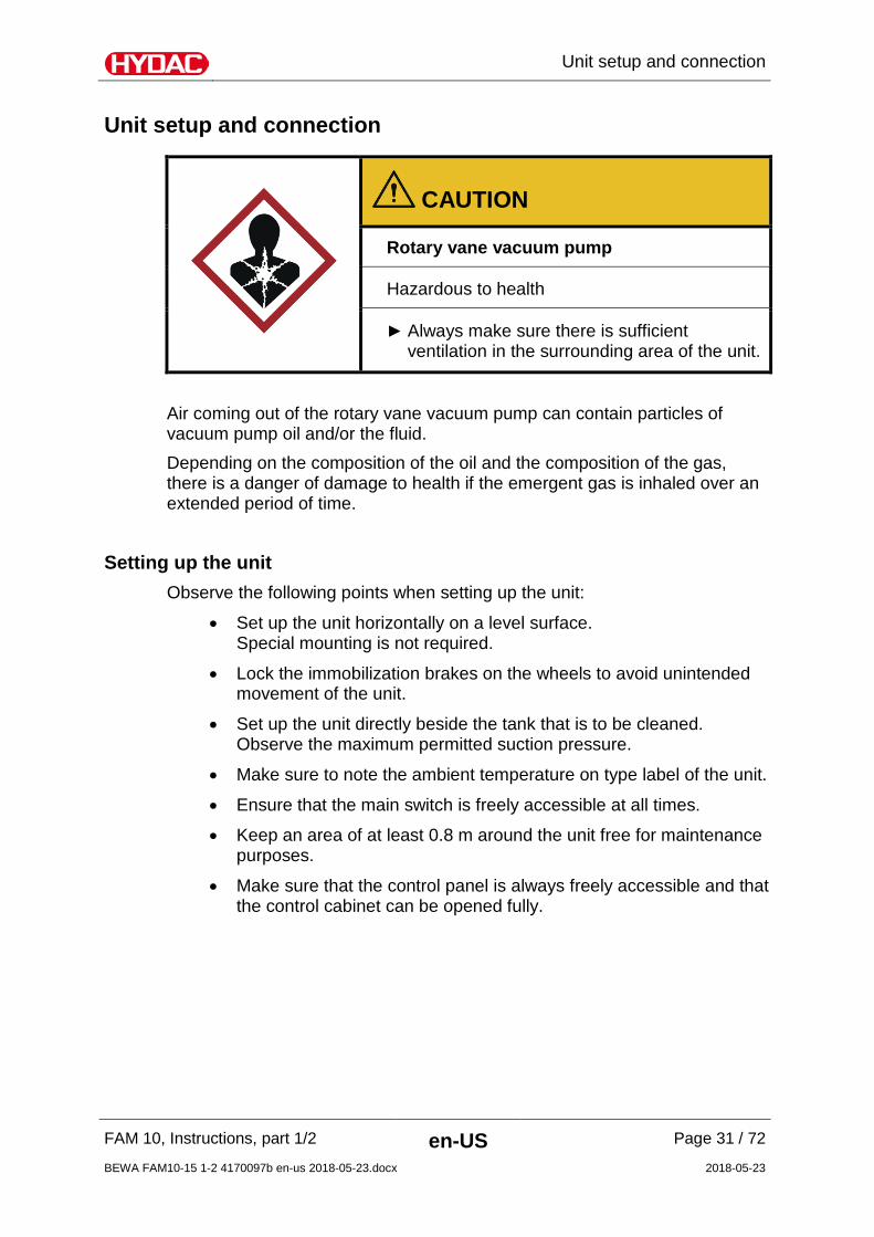
Unit setup and connection
CAUTION
Rotary vane vacuum pump
Hazardous to health
Always make sure there is sufficient ventilation in the surrounding area of the unit.
Air coming out of the rotary vane vacuum pump can contain particles of vacuum pump oil and/or the fluid. Depending on the composition of the oil and the composition of the gas, there is a danger of damage to health if the emergent gas is inhaled over an extended period of time.
Setting up the unit Observe the following points when setting up the unit:
• Set up the unit horizontally on a level surface. Special mounting is not required.
• Lock the immobilization brakes on the wheels to avoid unintended movement of the unit.
• Set up the unit directly beside the tank that is to be cleaned. Observe the maximum permitted suction pressure.
• Make sure to note the ambient temperature on type label of the unit.
• Ensure that the main switch is freely accessible at all times.
• Keep an area of at least 0.8 m around the unit free for maintenance purposes.
• Make sure that the control panel is always freely accessible and that the control cabinet can be opened fully.

Unit setup and connection
FAM 10, Instructions, part 1/2 en-US Page 32 / 72
BEWA FAM10-15 1-2 4170097b en-us 2018-05-23.docx 2018-05-23
Connection overview The stationary and mobile FAM versions have different scopes of delivery. The stationary FAM has positions 1-4, while the mobile FAM also has positions 5-8.
Item
1 FAM inlet connector 28L / M36x2 (external thread)*
2 Adapter Adapter G1 A (external thread)**
3 FAM outlet connector
18L / M26x1.5 (external thread)*
4 Adapter Adapter G1/2 A (external thread)**
5 Suction hose connection
28L / M36x2 (internal thread)***
6 Adapter Adapter G1 A (external thread)**
7 Pressure hose connection
18L / M26x1.5 (female thread)***
8 Adapter Adapter G1/2 A (external thread)**
*) Connection type D in accordance with ISO 8434-1 series L (corresponds to ISO 12151, form S, series L)
**) Stud end according to ISO 1179-2 (form E)
*** )Connection type N in accordance with ISO 8434-4 series L (corresponds to ISO 12151, form SWS, series L)

Unit setup and connection
FAM 10, Instructions, part 1/2 en-US Page 33 / 72
BEWA FAM10-15 1-2 4170097b en-us 2018-05-23.docx 2018-05-23
Notes on pipes and hoses
NOTICE
Non-permitted pressure at the inlet IN / outlet OUT
Failure malfunction
Determine the pressure to be anticipated at the inlet/outlet with the prescribed values.
Note that the cross-section of the connected hoses/piping must be at least as large as the cross-section of the inlet/outlet port sizes. In order to keep the pressure loss as low as possible, use as few screwed fittings as possible. Connect all connectors to the unit without initial stress. The pressure at the inlet Pe / outlet Pa depends on the height differential between the FAM fluid surface in the tank port (aspiration height ∆P(height)) and the line losses (∆P(line)). If the FAM is above the fluid surface in the tank, determine the pressure as follows:
Pe = -∆P(height) -∆P(line)
Pa = -∆P(height) +∆P(line) If the FAM is below the fluid surface in the tank, determine the pressure as follows:
Pe = +∆P(Height) -∆P(Line)
Pa = +∆P(height) +∆P(line) Caution: Pe perm/Pa perm refers to the inlet/outlet FAM without hose. The respective values for Pe perm/Pa perm can be found in the technical data on page 62.
Estimate the pressure loss ∆P(height) as follows:∆P(height)[bar] = h/10. Here, h refers to the distance between the inlet (IN) / outlet (OUT) on the FAM and the fluid surface in the tank
The pressure differential in a hydraulic line (∆P(line)) depends on the following:
• Flow rate
• Kinematic viscosity
• Pipe dimensions
• Fluid density

Unit setup and connection
FAM 10, Instructions, part 1/2 en-US Page 34 / 72
BEWA FAM10-15 1-2 4170097b en-us 2018-05-23.docx 2018-05-23
The pressure loss in straight pipes (∆P(line)) can be calculated as follows:
Δp ≈ 6.8 * L / d4 * Q * V * D Δp = Pressure differential in [bar]
L = Pipe length [m]
d = Internal pipe diameter [mm]
Q = Flow rate [l/min]
V = Kinematic viscosity [mm²/s]
D = Density [kg/dm³] Mineral oil-based hydraulic oil has a density of ≈ 0.9 kg/dm³.
The density (D) is: Mineral hydraulic oil HLP 0.85 … 0.90 kg / dm³
Phosphate ester HFDR 1.00 … 1.10 kg / dm³
Insulation oil 0.90 … 1.00 kg / dm³
Lubricating oil 0.90 … 0.95 kg / dm³ Find the flow rate in chapter "Technical data" on page 62. Additional threaded connections and pipe bends increase the pressure differential and must be taken into account. Keep the height difference between the pump and the oil level in the tank as low as possible. Avoid constrictions in the connected hoses. They compromise output and increase the risk of cavitation. Make sure that no tension or vibrations are carried over to the pump or filter housing when the pipes are connected. Use hoses or expansion joints if necessary.

Unit setup and connection
FAM 10, Instructions, part 1/2 en-US Page 35 / 72
BEWA FAM10-15 1-2 4170097b en-us 2018-05-23.docx 2018-05-23
Connecting the inlet (IN) The maximum permitted pressure Pe perm at the inlet to the FAM can be found in the technical data. Use a negative pressure-resistant, flexible hose or a pipe for the suction-side connection. Note that the cross-section of the connected hoses/piping must be at least as large as the cross-section of the inlet/outlet port sizes. The shape of the tank connection should be set up in such a way that it will always be lower than the level of the oil.
NOTICE
Contamination too high
The unit will be damaged
Do not prime directly at the bottom of the tank Do not prime in the sump Never prime without a built-in suction screen
The greatest contamination is found on the bottom of the tank. All impurities and other particles are deposited on the bottom of the tank. All impurities and other particles are deposited on the bottom of the tank.
Connecting the outlet (OUT)
The maximum permitted pressure at the outlet Pa perm can be found in the technical data.
NOTICE
Connection OUT closed off
The FAM switches over to error mode
Check to be sure that all of the locking fixtures at the inlet/outlet are in "open" position each time before start-up.
To prevent air from entering the medium, make sure that the pressure hose with lance is always below the oil level in operation.

Unit setup and connection
FAM 10, Instructions, part 1/2 en-US Page 36 / 72
BEWA FAM10-15 1-2 4170097b en-us 2018-05-23.docx 2018-05-23
Preparing the Vacuum Pump The rotary vane vacuum pump is not filled with oil at the time the FAM is delivered. A sufficient amount of vacuum pump oil for the initial filling is included in the scope of delivery.
NOTICE
Operation without vacuum pump oil
The rotary vane vacuum pump will be destroyed
The rotary vane vacuum pump requires oil as its operating medium. Check the oil level before start-up, refilling with vacuum pump oil if
necessary.
The maximum filling volume for vacuum pump oil is 0.3 liters. The oil level is monitored automatically by the integrated float switch while the FAM is in operation. A message will appear on the control panel when the MIN MAX filling level has been reached.
Filling up the rotary vane vacuum pump Remove the safety screw for the plug at the level switch (1). Remove the plug (2) for the level switch. Unscrew the level switch (3) from the vacuum pump. Fill up with vacuum pump oil through the filling nozzle (4) . Check the oil level through the inspection glass (5). For trouble-free operation, we recommend a filling level centered between the MIN and MAX markings. The suction strainer is re-mounted in reverse order.
12
34
5

Unit setup and connection
FAM 10, Instructions, part 1/2 en-US Page 37 / 72
BEWA FAM10-15 1-2 4170097b en-us 2018-05-23.docx 2018-05-23
Electrical connection of the unit
DANGER
Exposed electrical components in the switch cabinet
Danger of fatal injury due to electric shock
Any work involving the electrical system may only be done by a properly trained, certified electrician.
The electrical connection of units without connection plugs to the power supply module may be performed only by a technician with corresponding knowledge and skills. Make sure that the voltage and frequency specifications on the FAM type label correspond to the existing mains voltage. If a plug is present on the FAM or if a plug is mounted, then the FAM is to be operated from a correspondingly fused socket.
The electrical data on the type label of the unit is binding, not that on the type label of the control cabinet.
Rotating field
Make sure there is a clockwise rotating field. If this is not the case, then the phases can be rotated in the 16A/32 A connection plug with the aid of the phase changing switch in the plug. In the 63A version and units without a connector (60 Hz version), both phases on the terminal block X0 (e.g. L1 and L2) must be switched.

Unit setup and connection
FAM 10, Instructions, part 1/2 en-US Page 38 / 72
BEWA FAM10-15 1-2 4170097b en-us 2018-05-23.docx 2018-05-23
A phase sequence relay checks the correct phase sequence after switch-on. In the event of an incorrect phase sequence, error message no. 29 is shown on the control panel. Additional details can be viewed in part 2/2 of the Operating and maintenance instructions.

Operating Elements on the FAM
FAM 10, Instructions, part 1/2 en-US Page 39 / 72
BEWA FAM10-15 1-2 4170097b en-us 2018-05-23.docx 2018-05-23
Operating Elements on the FAM
The following operating elements are to be found on the FAM:
Item Description
A Main switch with E-STOP function
B Alarm signal lamp (yellow)
C Control panel (for details see Operation and Maintenance Instructions, part 2/2)
D Needle valve to set the pressure in the vacuum column
E SensorMonitoring Unit SMU1200 (optional) (See the appropriate operating instructions for details)

Switching on / switching off / commissioning and error messages
FAM 10, Instructions, part 1/2 en-US Page 40 / 72
BEWA FAM10-15 1-2 4170097b en-us 2018-05-23.docx 2018-05-23
Switching on / switching off / commissioning and error messages
Details on switching on/off, commissioning and error messages/troubleshooting can be found in the Operation and Maintenance Instructions, part 2/2.

Performing Maintenance
FAM 10, Instructions, part 1/2 en-US Page 41 / 72
BEWA FAM10-15 1-2 4170097b en-us 2018-05-23.docx 2018-05-23
Performing Maintenance
Before performing any maintenance work, pull out the plug on the FAM and wind up the power cord to prevent the unit from being switched on again. The Unit is to be disconnected from the power supply and protected against being inadvertently switched back on when performing any maintenance, servicing, inspection or repair work. Once maintenance work is complete, check that the safety devices are still working properly. Any screwed fittings which have been undone/removed are to be checked to see that they have been properly resecured.
See
pag
e
24 h
ours
/ da
ily
500
hour
s /
mon
thly
3000
hou
rs /
ever
y si
x m
onth
s
6000
hou
rs /
annu
ally
26,0
00 h
ours
/ 3
year
s
FAM
Check the FAM for any leaks (visual check). - X
Check the screwed fittings to see that they have been properly resecured.
- X
Inspection of the measurement technology / Pressure sensor in the vacuum column / Differential pressure manometer on the fluid filter / AquaSensor on connection IN / ETS on the vacuum column (optional)
- X
Check the fault indicator lamps / perform a lamp test 44 X
Change the air filter 44 X
Clean the suction strainer. 45 X
Replacing the vacuum column level sensor (See retrofit instructions UA 4284625, included in the scope of delivery of the
X

Performing Maintenance
FAM 10, Instructions, part 1/2 en-US Page 42 / 72
BEWA FAM10-15 1-2 4170097b en-us 2018-05-23.docx 2018-05-23
See
pag
e
24 h
ours
/ da
ily
500
hour
s /
mon
thly
3000
hou
rs /
ever
y si
x m
onth
s
6000
hou
rs /
annu
ally
26,0
00 h
ours
/ 3
year
s
spare part)
Vacuum pump
Checking the oil level - X
Changing oil 46 X
Replacing the Air De-oiling Element 47 X
Check and clean the ventilator hood - X
Emptying / filling pump
Check and clean the ventilator hood - X
Fluid filter
Changing the filter element 48 X
Emptying and cleaning the filter housing - X
Oil mist separator (optional)
Changing the filter element 53 X
Electric System
Check cable conduits for damage, replacing as necessary
- X
Measure the engine power consumption of all engines and compare the values with the type label t
- X
Testing the AquaSensor - X
Perform electrical safety inspection in accordance
- X

Performing Maintenance
FAM 10, Instructions, part 1/2 en-US Page 43 / 72
BEWA FAM10-15 1-2 4170097b en-us 2018-05-23.docx 2018-05-23
See
pag
e
24 h
ours
/ da
ily
500
hour
s /
mon
thly
3000
hou
rs /
ever
y si
x m
onth
s
6000
hou
rs /
annu
ally
26,0
00 h
ours
/ 3
year
s
with DIN VDE 0702 and/or corresponding national regulation.
Measure power consumption of the heater and compare values with type label (applies only to versions with integrated heater)
- X
Function Test
Testing the oil pan float switch 53 X
Checking and cleaning the vacuum column level sensor
57 X
Completely replace all of the hoses after 5 years. The pictures and illustrations in the descriptions are examples. They do not represent all of the different product variants.

Performing Maintenance
FAM 10, Instructions, part 1/2 en-US Page 44 / 72
BEWA FAM10-15 1-2 4170097b en-us 2018-05-23.docx 2018-05-23
Function testing of the fault indicator lamp To perform the function test of the fault indicator lamp, follow these steps: 1. Switch the unit on using the main switch (A).
2. An automatic lamp test is conducted after the unit has been switched on. The fault indicator lamp (B) lights up briefly during this test.
3. The function test of the fault indicator lamp has been completed.
Change the air filter Replace the air filter (1) every six months. If you are operating the unit in a very dusty/damp environment, the replacement interval is accordingly shorter. 1. Manually unscrew the air filter (1).
2. Dispose of the air filter in an environmentally friendly manner.
3. Manually screw on the new air filter (1) and tighten this manually until secure.
4. The air filter replacement has been completed.
Testing the AquaSensor Check the AquaSensor annually with the calibration and adjustment set (HYDAC p/no. 3122629). Replace the AquaSensor if it exhibits great deviations. The part no. can be found in the spare parts list.

Cleaning the suction strainer
FAM 10, Instructions, part 1/2 en-US Page 45 / 72
BEWA FAM10-15 1-2 4170097b en-us 2018-05-23.docx 2018-05-23
Cleaning the suction strainer
NOTICE
Operation without a suction strainer
The pump will be destroyed
The unit may not be operated without the suction strainer. Clean the suction screen regularly.
To protect the pump from coarse contamination particles and other foreign bodies, a dirt trap with a strainer insert is fitted at the pump inlet. Clean the suction strainer at regular intervals. To install / dismount the suction screen, proceed as follows: 1. Unscrew the screw plug (1)
counterclockwise using an open-jaw wrench.
123
2. Remove and clean the sieve insert (3).
3. To clean the suction screen, wash it out with solvent and then dry it using compressed air.
3. Check the sieve insert (3) and seal ring (2) on the screw plug for damage and, if necessary, replace it.
4. Install the sieve insert (3).
5. Turn the screw plug (1) clockwise manually. Tighten the screw plug (1) using the open-jaw wrench.
6. After commissioning, check the suction strainer fittings for leaks.

Rotary vane vacuum pump components
FAM 10, Instructions, part 1/2 en-US Page 46 / 72
BEWA FAM10-15 1-2 4170097b en-us 2018-05-23.docx 2018-05-23
Rotary vane vacuum pump components
l
ma i
g
h
d
c
k
Item Designation
a Oil filler neck
c Oil drain
d Oil sight glass
g Oil separator
h Suction port connection
i Gas outlet
k Safety screw on the plug
l Plug for the level sensor
m Level switch in the vacuum pump The following descriptions are in reference to these positions.
Performing an oil change The first oil change must take place after 100 operating hours. This increases the interval to approx. 3000 hours or every six months.

Rotary vane vacuum pump components
FAM 10, Instructions, part 1/2 en-US Page 47 / 72
BEWA FAM10-15 1-2 4170097b en-us 2018-05-23.docx 2018-05-23
The vacuum pump must be at operating state temperature when the oil is changed: Put the FAM into operation for 10 minutes. Switch off the FAM at the main switch. Wait until the pressure in the vacuum column has reached the atmospheric pressure (≈ 1000 mbar absolute). To perform these tasks, you will need the following tools and equipment:
• Compressor oil (for part no., see the spare parts list)
• Maintenance set, comprising oil filter, air deoiling element, ventilation cover seal (for the part No., see spare parts list)
• Fork wrenches SW 27 / SW 32 To change the oil, proceed as follows:
1. Put a suitable container in place to catch the used oil.
2. Open the oil drain (c) and allow the used oil to drain into the container. Dispose of the used oil properly.
3. Close the screw plug when the flow of oil diminishes. Let the pump run again briefly for a few seconds,
4. Open the plug screw once again and drain off the remaining oil.
5. Screw in the plug screw and tighten it firmly.
6. Remove the oil filter and dispose of it properly.
7. Install the new oil filter.
8. Fill in fresh vacuum pump oil through the oil filling screw plug (a). Ensure that the level is in the middle between the MIN and MAX (d) markings. For details, refer to the section "Filling up the rotary vane vacuum pump" on page 36..
Replacing the Air De-oiling Element Oil mist or increased electricity consumption by the drive engine (response of the engine protection switch) are signs of a soiled air de-oiling element. To replace the air de-oiling element, proceed as follows: 1. Remove the ventilation cover (i) from the oil separator (g) 2. Undo the screw in the middle of the filter spring, but do not remove this. 3. Press the filter spring down and rotate it out of the depression. 4. Remove the filter spring from the oil separator(g). 5. Pull the air de-oiling element out of the oil separator (g). 6. Make sure that the new air deoiling element is provided with a new O-

Replacing the filter element on the fluid filter
FAM 10, Instructions, part 1/2 en-US Page 48 / 72
BEWA FAM10-15 1-2 4170097b en-us 2018-05-23.docx 2018-05-23
ring. 7. Install the air de-oiling element in such a way that the opening is
situated correctly in the holder in the oil separator (g). 8. Ensure that the tip of the screws in the center of the filter spring
protrudes ≈ 2 – 5 thread turns out of the filter spring. 9. Install the filter spring in such a way that the ends are secured to
prevent them from slipping by lugs in the receptacles in the oil separator (g) and the tip of the screw engages in the recess of the air de-oiling element.
10. Tighten the screw in the filter spring until the head of the screw impacts against the spring steel sheet.
11. Make sure that the seal under the ventilation cover (i) is clean and undamaged. Replace the seal if necessary.
12. Fasten the ventilation cover (i) with seal and hexagon-head screws to the oil separator (g).
The air de-oiling element becomes saturated with oil during operation. A slight lowering of the oil filling level after the air de-oiling element has been replaced is therefore quite normal.
Replacing the filter element on the fluid filter
As soon as the error message "change fluid filter" appears on the display the filter should be taken out of the housing and be replaced by a new one. To change the filter element, proceed as follows:
1. Switch off the system and close the locking devices at the inlet and outlet ports. Make sure that the unit cannot be inadvertently switched back on during maintenance work.
2. Place a suitable container (1) to collect
the catch the operating medium. Depressurize the filter housing. Open the drain plug (2) on the filter bowl carefully and drain the filter housing fully using the drain screw (6mm) on the floor of the filter housing. The volume is approx. 2 liters. After draining, replace the drain plug on

Replacing the filter element on the fluid filter
FAM 10, Instructions, part 1/2 en-US Page 49 / 72
BEWA FAM10-15 1-2 4170097b en-us 2018-05-23.docx 2018-05-23
the filter bowl.
3. Release the tensioning clamp (1) on the filter housing and remove it downwards (2). Use a 6 mm (1) Allen wrench.
4. Pull the filter bowl including filter element
downwards.

Replacing the filter element on the fluid filter
FAM 10, Instructions, part 1/2 en-US Page 50 / 72
BEWA FAM10-15 1-2 4170097b en-us 2018-05-23.docx 2018-05-23
5. Remove (2) the filter element by turning (1) slightly out of the filter bowl. Dispose of the used filter element in an environmentally correct manner.
6. Clean the inside of the filter bowl of dirt
and deposits.

Replacing the filter element on the fluid filter
FAM 10, Instructions, part 1/2 en-US Page 51 / 72
BEWA FAM10-15 1-2 4170097b en-us 2018-05-23.docx 2018-05-23
7. Check the O-ring on the filter bowl for damage. Replace it if necessary. Moisten the O-ring on the filter bowl with the operating medium.
8. Moisten the O-rings on the new filter element with the operating medium.
9. Turning it slightly, press the new filter
element down into the mount on the filter bowl.

Replacing the filter element on the fluid filter
FAM 10, Instructions, part 1/2 en-US Page 52 / 72
BEWA FAM10-15 1-2 4170097b en-us 2018-05-23.docx 2018-05-23
10. Push the filter bowl with the filter element up into the mount on the filter head.
11. Slide the tensioning clamp (1) from the
bottom over the filter bowl to the top over the bead on the filter bowl / filter head. Tighten the housing clamp with an Allen wrench SW 6mm in a clockwise direction. The tightening torque is 5 Nm.
12. Check that the drain plug on the filter
bowl is secure.

Maintaining the oil mist separator (optional)
FAM 10, Instructions, part 1/2 en-US Page 53 / 72
BEWA FAM10-15 1-2 4170097b en-us 2018-05-23.docx 2018-05-23
13. The filter element change is now complete. After commissioning, check the filtration unit for leaks.
Maintaining the oil mist separator (optional)
Item Designation
1 Separator head
2 Separator pot
3 Clogging indicator
4 Filling level display

Maintaining the oil mist separator (optional)
FAM 10, Instructions, part 1/2 en-US Page 54 / 72
BEWA FAM10-15 1-2 4170097b en-us 2018-05-23.docx 2018-05-23
The oil mist separator is located between the vacuum column and the vacuum pump. A filter element is used to retain the oil mist and the oil in the oil mist separator and the oil is collected in the separator pot, where it is continuously suctioned off and returned to the vacuum column. The filter element (for part-no., see replacement parts list) is to be replaced on a regular basis in accordance with the maintenance schedule. The clogging indicator (3) of the oil mist separator is not functioning.

Maintaining the oil mist separator (optional)
FAM 10, Instructions, part 1/2 en-US Page 55 / 72
BEWA FAM10-15 1-2 4170097b en-us 2018-05-23.docx 2018-05-23
Replacing the filter element on the oil mist separator Proceed as follows to replace the filter element on the oil mist separator:
1. Stop automatic mode. Afterwards, wait ≈ 1 minute, until normal pressure (ambient pressure) has been established in the vacuum chamber.
2. Rotate the separator pot (2) 1/8th of a turn to the left (bayonet seal) and remove from the bottom.
3. Turn the used filter element clockwise to remove
and dispose of it in an environmentally correct manner. (The element shown here may vary visually) Insert the filter element and screw it into the separator head by turning it counterclockwise. Do not use any tools to dismantle or install the filter element.
4. Insert the separator pot (2) into the separator head
(1), and secure it in the bayonet seal with a 1/8th turn to the right.
5. The filter element replacement on the oil mist
separator is now complete.

Testing the float switch in the oil pan
FAM 10, Instructions, part 1/2 en-US Page 56 / 72
BEWA FAM10-15 1-2 4170097b en-us 2018-05-23.docx 2018-05-23
Testing the float switch in the oil pan
Proceed as follows to test the float switch in the oil pan:
1. Use your fingers to raise the float switch in the oil pan.
2. The unit must switch off and the fault
message "Pan overfilled" must appear in display of the control panel.
3. Release the float switch and acknowledge the fault message by pressing the F3 key.
4. The unit continues to operate -> You have tested the function of the float switch positively.
5. If the unit does not switch off after the lifting of the float switch and no fault message appears, contact the HYDAC Service.

Checking the level sensor of the vacuum column
FAM 10, Instructions, part 1/2 en-US Page 57 / 72
BEWA FAM10-15 1-2 4170097b en-us 2018-05-23.docx 2018-05-23
Checking the level sensor of the vacuum column
Conditions for the check:
1. Pull out the power plug or deenergize the unit.
Replace the installed level sensor 2. Pull out the level sensor connector.
3. Remove the level sensor of the column.
4. Now reinsert the connector of the level sensor.
5. Carry out the corresponding resistance measurement on the respective PLC inputs. To do this, remove the single leads from the inputs E 0.3; E 0.4 and E 0.5.

Checking the level sensor of the vacuum column
FAM 10, Instructions, part 1/2 en-US Page 58 / 72
BEWA FAM10-15 1-2 4170097b en-us 2018-05-23.docx 2018-05-23
6. Set the multimeter to resistance measurement.
7. Insert the instrument leads on the multimeter into the bushings for resistance measurement.
8. Connect one instrument lead with +24V DC, e.g. with a crocodile clip.
9. Also connect the second instrument lead with the wire from E 0.3; E 0.4; E 0.5 of the contact to be measured e.g. with a crocodile clip.
10. Now bring each float into position by it closing the contact.
11. The contact is OK if the unit for measurement displays a resistance of ≤ 1.2 Ω after a measuring time of around 5 seconds. If there are larger resistance values, the contact is already damaged and no longer switches reliably, which leads to sporadic failures.
24 V DC

Locating spare parts
FAM 10, Instructions, part 1/2 en-US Page 59 / 72
BEWA FAM10-15 1-2 4170097b en-us 2018-05-23.docx 2018-05-23
Locating spare parts
FAM 10
Qty. Designation Part no.
1 Breather filter 0160 MU 003 M 1265765
1 Suction strainer 1" assy., consisting of:
635624
1x strainer insert, 250µm 6016797 1x sealing ring 6033969
1 Vacuum pressure gauge 639989
1 3/2 directional valve 6014177
1 Pressure hose, Length = 5 m 6013308
1 Suction hose, Length = 5 m 6004781
1 Level sensor (vacuum column) 4392182
1 Filter element of oil mist separator (optional)
3584078
*) available on request
Fluid filter (OLF 5)
Qty. Designation Part no.
1 Filter element, filtration rating 2 µm N5DM002 349494
1 Filter element, filtration rating 5 µm N5DM005 3068101
1 Filter element, filtration rating 10 µm
N5DM010 3102924
1 Filter element, filtration rating 20 µm
N5DM020 3023508
*) available on request
Rotary vane vacuum pump
Quantity
Designation Part no.
1 Service kit vacuum pump consisting of exhaust filter and seals
6014161
Locating spare parts
FAM 10, Instructions, part 1/2 en-US Page 60 / 72
BEWA FAM10-15 1-2 4170097b en-us 2018-05-23.docx 2018-05-23
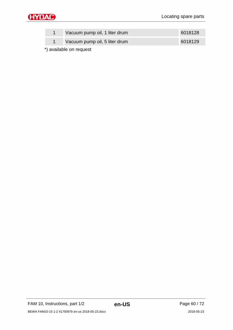
1 Vacuum pump oil, 1 liter drum 6018128
1 Vacuum pump oil, 5 liter drum 6018129 *) available on request

Taking the unit out of operation
FAM 10, Instructions, part 1/2 en-US Page 61 / 72
BEWA FAM10-15 1-2 4170097b en-us 2018-05-23.docx 2018-05-23
Taking the unit out of operation
Drain the unit completely, including all of its components, the same way as is done before putting it into storage. Pull out the power plug and securely fasten the hoses and power cord to the unit. Store the unit in a clean, dry (non-condensing) space. Refer to the technical data for the permissible storage temperature range. In the case of storage periods greater than 1 year, please contact HYDAC FILTER SYSTEMS GMBH.
Disposing of the unit
Dispose of the packaging material in an environmentally friendly manner. After dismantling the unit and separating the various materials, dispose of the unit in an environmentally friendly manner.

Technical data
FAM 10, Instructions, part 1/2 en-US Page 62 / 72
BEWA FAM10-15 1-2 4170097b en-us 2018-05-23.docx 2018-05-23
Technical data
Refer to the type label for specific data of the unit. FAM10 FAM10/15
Flow rate at the inlet (IN) 10 l/min @ 50Hz 12 l/min @ 60Hz
15 l/min @ 50Hz 18 l/min @ 60Hz
Flow rate at the outlet (OUT) 18 l/min @ 50Hz 22 l/min @ 60Hz
23 l/min @ 50Hz 28 l/min @ 60Hz
Electrical power consumption 1800 W without heater 4700 W with heater
2000 W without heater 4900 W with heater
Weight when empty ≈ 300 kg ≈ 300 kg
Operating pressure 6 bar
Permissible suction pressure at suction port (without suction hose) Pe perm.
-0.2 … 0.6 bar
Permitted pressure at the outlet (without pressure hose) Pa perm.
0 … 3.5 bar
Viscosity range 15 to 800 mm²/s
Pump type
Vacuum pump Rotary vane vacuum pump
Rotary vane vacuum pump
Filling pump Vane pump Vane pump Evacuation pump Gear pump Gear pump
Fluid filter size OLF5
Filter element type N5DMxxx
Dirt holding capacity in accordance with ISO 4572 200 g
Clogging indicator VM 2 C.0
Power cable, length 10 m
Degree of protection IP 54
Hoses, length 5 m
Hoses, material See the model code, page 65
Connection inlet/outlet see page32
Technical data
FAM 10, Instructions, part 1/2 en-US Page 63 / 72
BEWA FAM10-15 1-2 4170097b en-us 2018-05-23.docx 2018-05-23
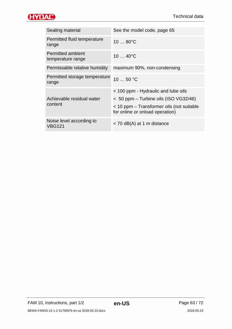
Sealing material See the model code, page 65
Permitted fluid temperature range 10 … 80°C
Permitted ambient temperature range 10 … 40°C
Permissable relative humidity maximum 90%, non-condensing
Permitted storage temperature range 10 … 50 °C
Achievable residual water content
< 100 ppm - Hydraulic and lube oils < 50 ppm – Turbine oils (ISO VG32/46) < 10 ppm – Transformer oils (not suitable for online or onload operation)
Noise level according to VBG121 < 70 dB(A) at 1 m distance

Appendix
FAM 10, Instructions, part 1/2 en-US Page 64 / 72
BEWA FAM10-15 1-2 4170097b en-us 2018-05-23.docx 2018-05-23
Appendix
Contact Customer Service / Service For product information or technical support or if you have comments or suggestions concerning this manual, please contact: HYDAC FILTER SYSTEMS GMBH Phone: +49 6897 509 1174 Fax: +49 6897 509 9046 E-mail: [email protected] Regular inspection and maintenance work is indispensable for ensuring trouble-free operation and long service life for your FluidAqua Mobil. Our HYDAC Servicenter offers you these tasks within agreed-upon time frames and at fixed prices. HYDAC SERVICE GMBH Friedrichsthaler Str. 15A, Werk 13 66540 Neunkirchen-Heinitz Germany Phone: +49 681 509 9518 Fax: +49 681 509 2324 E-mail: [email protected]

Appendix
FAM 10, Instructions, part 1/2 en-US Page 65 / 72
BEWA FAM10-15 1-2 4170097b en-us 2018-05-23.docx 2018-05-23
Model Code FAM 10 M 2 A - 05 - R - H - C1 - A - 00 /-V Product FAM = FluidAqua Mobil Filter Size 10 = 10 l/min @ 50 Hz
12 l/min @ 60 Hz
10/15 = 15 l/min @ 50 Hz 18 l/min @ 60 Hz
Operating fluid M = Mineral oil – NBR seals I = Insulation oil – NBR seals X = HDF-R media – FKM seals B = Readily biologically degradable (on ester base)
FKM seals
Mechanical type 1 = Stationary 2 = mobile (with rollers and hose holder) Voltage/frequency/power supply A = 400 V, 50 Hz, 3 Ph B = 415 V, 50 Hz, 3 Ph C = 200 V, 50 Hz, 3 Ph D = 200 V, 60 Hz, 3 Ph E = 220 V, 60 Hz, 3 Ph F = 230 V, 60 Hz, 3 Ph G = 380 V, 60 Hz, 3 Ph H = 440 V, 60 Hz, 3 Ph I = 500 V, 50 Hz, 3 Ph K = 480 V, 60 Hz, 3 Ph L = 220 V, 50 Hz, 3 Ph N = 575 V, 60 Hz, 3 Ph O = 460 V, 60 Hz, 3 Ph X = other voltage Filter size fluid filter 05 = OLF5 Type of vacuum pump R = Rotary vane
vacuum pump
Heater H = Heater Z = Without heater Control concept C1 = Comfort, control panel language in de/en/fr/es/pt/it/nl/da/fi/sv C2 = Comfort, control panel language in de/en/bg/hu/ru/pl/zh (Others languages on request) Instrumentation A = AquaSensor AC1 = AquaSensor + ContaminationSensor ISO4406:1999 AC2 = AquaSensor + ContaminationSensor SAE AS 4059(D) AC3 = AquaSensor + ContaminationSensor NAS 1638 Modification number 00 = You will always receive the current version. Supplementary details V = FKM seals

Appendix
FAM 10, Instructions, part 1/2 en-US Page 66 / 72
BEWA FAM10-15 1-2 4170097b en-us 2018-05-23.docx 2018-05-23
Explanation of terms and abbreviations An explanation of terms and abbreviations follows below:
%Sat. % Water saturation, degree of saturation
% saturation % Water saturation, degree of saturation
°C Degrees Celsius
°F Degrees Fahrenheit
abs. Absolute (e.g. in pressure specifications)
AC Alternating current
Air Bleed Ventilation / air bleed port
AquaSensor Sensor for water saturation in % and temperature
AS AquaSensor
ATEX ATmosphères Explosibles = Explosive atmosphere
OM Operating mode
BeWa Operating and Maintenance Instructions
ContaminationSensor Sensor for solid particle contamination in fluid.
CS ContaminationSensor
DC Direct current
DIN Deutsche Industrie Norm [German Industry Standard]
DN Nominal Diameter
Drain Drainage port
Rotary vane vacuum pump
Vacuum pump required as operating material for vacuum pump oil
EC European Community
ESC Escape
EU European Union
FAM FluidAqua Mobil
Solid particle contamination
Solid particles such as dirt, non-iron or metallic particles found in the fluid.
FPM (FKM / Viton®) Fluoroelastomer rubber
HFD Water-free synthetic fluids with a higher density than mineral oil or water. These fluids can cause problems with the intake characteristics of pumps and attack many sealing materials.

Appendix
FAM 10, Instructions, part 1/2 en-US Page 67 / 72
BEWA FAM10-15 1-2 4170097b en-us 2018-05-23.docx 2018-05-23
The fluid is fire resistant.
HFD-R Phosphoric acid ester
HLP Mineral oil–based hydraulic fluids with active ingredients for increasing rust protection, with high-pressure additives and aging resistance (also HLP acc. to DIN 51 524, part 2)
IN Inlet
INLET Inlet
ISO Classification of the solid particle contamination.
kPa Kilopascal
m Meter
MAX Maximum
mbar Millibar (1 mbar = 0.001 bar)
MIN Minimum
mm Millimeter
NAS Classification of the solid particle contamination.
NBR Nitrile rubber
Nm Newton meters (torque specification)
OFF Switched off
OLF Offline filter = Bypass-flow filter unit
ON Switched on
OUT Outlet
OUTLET Outlet
Pa Pascal
PPM Parts per million
psi Pound-force per square inch
SAE Classification of the solid particle contamination.
sec seconds
PLC Programmable memory control
A/F Wrench size for tools
Toploader Construction of a bypass-flow filter unit in which the filter element is removed upward.
Vent Ventilation / air bleed port
Water Saturation Water Saturation

Appendix
FAM 10, Instructions, part 1/2 en-US Page 68 / 72
BEWA FAM10-15 1-2 4170097b en-us 2018-05-23.docx 2018-05-23
Index
A
accident prevention 10 ambient temperature 21, 31, 63 AquaSensor 26, 30, 41, 42, 44, 65, 66 ATEX 66
B
Breather filter 59
C
care 3, 6, 18 Changing the filter element 42 cleaning 24, 42, 43 Clogging indicator 53, 62 Compressor oil 47 Connection 20, 32, 35, 62 Connection cable 20 ContaminationSensor 23, 30, 65, 66 Content 4 Control 19, 26, 39, 65
D
degassing 11, 20, 22 Density 34 Description 20, 22, 39 dewatering 11, 20, 21, 22 Dewatering 21 Dewatering performance 21 Differential pressure 30, 41 DIN 12, 42, 66, 67 Disposal 15 Documentation Representative 3 drain plug 48, 52 draining 48
F
Fault indicator lamp 26 filling 22, 23, 36, 42, 47, 48 Filter 13, 21, 59, 62, 65 Filter element 59, 62 Filter element type 62 filtration 20, 53, 59 Float switch 26, 30 Flow rate 33, 34, 62 Fluid filter 26, 30, 42, 59, 62 Fluid temperature 21 Forwarding agent 15 Fyrquel 12
G
Gear pump 62
H
Hazard symbol 8, 10 Heater 26, 30, 65 HFD 12, 66, 67
I
Imprint 3 IN 26, 30, 33, 35, 41, 62, 67 Inlet 67 INLET 67 Inspection 41 installation 15 Internal pipe diameter 34 IP 62 ISO 32, 62, 63, 67 ISO4406 65
1999 65
L
Level sensor 26, 30, 59 Level switch 46
M
Main switch 26, 39 Maintenance 15, 39, 40, 41, 47, 66 Malfunction 23 Measure 42, 43 Measures 10 measuring 58 Mineral oil 12, 34, 65, 67 mounting 31
N
NAS 65, 67 Noise level 63
O
OFF 67 Offline filter 67 Oil filler neck 46 Oil separator 46 Oil sight glass 46

Appendix
FAM 10, Instructions, part 1/2 en-US Page 69 / 72
BEWA FAM10-15 1-2 4170097b en-us 2018-05-23.docx 2018-05-23
operating 6, 7, 8, 12, 13, 14, 15, 24, 36, 39, 44, 46, 47, 48, 51, 66
Operation 13, 15, 36, 39, 40, 45 Operations control 15 OUT 26, 30, 33, 35, 62, 67 Outlet 67 OUTLET 67
P
Pressure differential 34 Pressure hose 32, 59 Pressure sensor 26, 30, 41 Proper/Designated Use 11 Publisher 3 Pump 30, 36, 62
R
replacement 44, 54, 55 Rigid caster 26 Rotary vane vacuum pump 31, 46, 59, 62, 65, 66
S
SAE 65, 67 select 7 Sensor 66 Service 56, 59, 64 setting 22, 26, 30, 31 Signal word 9, 10 signal words 10 Size 21, 65 Solid particle contamination 66 Specialist personnel 14, 15
Suction hose 20, 32, 59 Suction port connection 46 Suction screen 26, 30 switching off 40 switching on 40 Synthetic ester 12
T
Temperature 26, 30 Temperature sensor 26, 30 to shut down 16 Transformer oil 63 Transport 15 transporting 17 troubleshooting 40 Troubleshooting 15 Turbine oil 63
V
Vacuum 19, 26, 30, 36, 42, 59, 60, 62, 66 Vacuum column 26, 30 Vacuum pressure gauge 59 Vacuum pump 19, 26, 30, 42, 60, 62, 66 vacuum pump oil 31, 36, 47, 66 Vane pump 62 Vegetable oils 12 Viscosity 62
W
Water content 21 Water Saturation 67 Weight 62


HYDAC FILTER SYSTEMS GMBH Industriegebiet Postfach 1251 66280 Sulzbach/Saar 66273 Sulzbach/Saar Germany Germany Tel: +49 6897 509 01 Central Fax: +49 6897 509 9046 Technology Fax: +49 6897 509 577 Sales Internet: www.hydac.com E-mail: [email protected]