"faM- ' 58 621579 - International Atomic Energy Agency
121
jJUL 2 4 1998 ^- ENGINEERING DATA TRANSMITTAL "faM- ' 58 621579 2. To:, (Receiving Organization) Distribution 3. From: (Originating Organization) SST Engineering 4. Related EDT No.: None 5. Proj./Prog./Dept./Div.: W-320 6. Design Authority/ Design Agent/Cog. Engr.: JW Bailey/John Huber 7. Purchase Order No.: None 8. Originator Remarks: Report on OTP-320-010 9. Equip./Component No.: NA 10. System/Bldg./Facility: 241-AY 11. Receiver Remarks: 11A. Design Baseline Document? [] Yes [X] No 12. Major Assm. Dwg. No.: . . H-2-824485 . 13. Permit/Permit Application No.: NA ' 14. Required Response Date-:-• ASAP DATA TRANSMITTED (A) Item No. (B) Document/Drawing No. (C) Sheet (D) Rev. (E) Title or Description of Dat Transmitted Approval Desig- nator Origi- nator Dispo- Receiv- er Dispo- HNF-2965 All Operational Test Report for the AY-102 Enraf Densitometer Control and Acquisition System Approval Designator (FJ Reason for Transmittal (G) Disposition <H) & (I) E, S, Q, D or N/A. (see WHC-CM-3-5, Sec.12.7) 1. Approval 4. Review 2. Release 5. Post-Review 3. Information 6. Dist. (Receipt Acknow. Required) 1. Approved 4. Reviewed no/comment 2. Approved w/comment 5. Reviewed w/comment 3. Disapproved w/comment 6. Receipt acknowledged 17. SIGNATURE/DISTRIBUTION (See Approval Designator for required signatures) (H) Disp. (L) Date (M) MSLR (Kl Signature (I) Date IM! MSIN Design Authority JU Bailey I NA Design Agent N/A Cog.Eng. JH Huber 7-6'l At Cog. Hgr. RE Larson j g g ^ &M\yfaftt T1-t>7 -SS-/3- tu) ~-3fO , "•1-z.J Safety Va D 7// */f» Originator Authorized Representative Date for Receiving Organization " Design Authority/ Cognizant Manager 21. DOE APPROVAlf ( i f required) Ctrl. No. [] Approved [3 Approved w/comments [] Disapproved w/comments BD-7400-172-2 (05/96) GEF097 BO-74OO-17;M
-
Upload
khangminh22 -
Category
Documents
-
view
5 -
download
0
Transcript of "faM- ' 58 621579 - International Atomic Energy Agency

jJUL 2 4 1998 - ENGINEERING DATA TRANSMITTAL
"faM- ' 58621579
2. To:, (Receiving Organization)
Distribution3. From: (Originating Organization)
SST Engineering4 . Related EDT No. :
None5. Proj./Prog./Dept./Div.:
W-320
6. Design Authority/ Design Agent/Cog.Engr.:
JW Bailey/John Huber
7. Purchase Order No. :
None8. Originator Remarks:Report on OTP-320-010
9. Equip./Component No. :
NA10. System/Bldg./Facility:
241-AY1 1 . Receiver Remarks: 11A. Design Baseline Document? [ ] Yes [ X ] No 12. Major Assm. Dwg. No. :
. . H-2-824485 .13. Permit/Permit Application No.:
NA '14. Required Response Date-:-•
ASAP
DATA TRANSMITTED
(A)ItemNo.
(B) Document/Drawing No.
(C)Sheet
(D)Rev. (E) Title or Description of Dat
Transmitted
ApprovalDesig-nator
Origi-nator
Dispo-
Receiv-er
Dispo-
HNF-2965 All Operational TestReport for the AY-102Enraf DensitometerControl andAcquisition System
Approval Designator (FJ Reason for Transmittal (G) Disposition <H) & (I)
E, S, Q, D or N/A.(see WHC-CM-3-5,Sec.12.7)
1. Approval 4. Review2. Release 5. Post-Review3. Information 6. Dist. (Receipt Acknow. Required)
1. Approved 4. Reviewed no/comment2. Approved w/comment 5. Reviewed w/comment3. Disapproved w/comment 6. Receipt acknowledged
17. SIGNATURE/DISTRIBUTION(See Approval Designator for required signatures)
(H)Disp. (L) Date (M) MSLR (Kl Signature (I) Date IM! MSIN
Design Authority JU Bailey I
NA Design Agent N/A
Cog.Eng. JH Huber 7-6'l AtCog. Hgr. RE Larson jgg^&M\y fa f t t T1-t>7
-SS-/3- tu) ~-3fO , "•1-z.JSafety Va
D 7// */f»
OriginatorAuthorized Representative Datefor Receiving Organization "
Design Authority/Cognizant Manager
2 1 . DOE APPROVAlf ( i f requ i red)C t r l . No.
[] Approved[3 Approved w/comments[] Disapproved w/comments
BD-7400-172-2 (05/96) GEF097
BO-74OO-17;M

DISCLAIMER
Portions of this document may beillegible in electronic image products.Images are produced from the best
available original document.

HNF-2965, Rev. 0
Operational Test Report for the AY-102 EnrafDensitometer Control and Acquisition System
John HuberLockheed Martin Hanford Corporation, Richland, WA 99352U.S. Department of Energy Contract DE-AC06-96RL13200
UC: 512 and 2030Charge Code: D29PRTotal Pages:/?,<?
EDT/ECN:Org Code:B&R Code: EW3120071
609€e9-$g£74800 '
Key Words: Enraf, Densitometer, Gauge, Gage, ATG, 854, Level, LIT, LevelIndicating Transmitter, Density Indicating Transmitter, Logger, L0Gvl8
Abstract: This Operational Test Report documents the Enraf Series 854AY-102 Operational Test Procedure, OTP-320-010. This report formalizesacceptance of the densitometer and Enraf Control Panel Software systemfor use on AY-102.
TRADEMARK DISCLAIMER. Reference herein to any specific commercial product, process, or service bytrade name, trademark, manufacturer, or otherwise, does not necessarily constitute or imply itsendorsement, recommendation, or favoring by the United States Government or any agency thereof orits contractors or subcontractors.
Printed in the United States of America. To obtain copies of this document, contact: DocumentControl Services, P.O. Box 950, Mailstop H6-08, Richland WA 99352, Phone (509) 372-2420;Fax (509) 376-4989.
Re lease lApp rova l / Release Stamp
Approved for Public Release
A-6400-073 (01/97) GEF321

HNF-2965Revision 0
Operational Test Reportfor the
AY-102 Tank Densitometer Control and Acquisition System
J. H. HuberSingle-Shell Tank Engineering
July 7, 1998

HNF-2965Revision 0
Table of Contents
1.0 Introduction 3
2.0 Description of Test 3
2.1 Criteria 3
3.0 Test Method and Test Equipment 4
4.0 Test Results 54.1 Discussion of Test Results 5
4.2 Discussion of Test Exceptions 6
5.0 Conclusions and Recommendations 9
6.0 References 10
Appendix A A-1
Appendix B B-1
Appendix C C-1

HNF-2965Revision 0
1.0 Introduction
On June 2 through June 10, 1998, the AY-102 Tank Densitometer Control andAcquisition System was operationally tested per OTP-320-010 Revision A-0. The testwas performed at the Department of Energy's Hanford Site, 200 East Area, 241 -AYTank Farm. The test validated the functionality of the Enraf 854 ATG DensitometerGauge and Enraf Control Panel software for use by project W-320, Waste RetrievalSluicing System (WRSS).
2.0 Description of Test
The purpose of the test procedure was two fold: (1) to verify the functionality ofthe Enraf 854 ATG as a Densitometer; and (2) to verify the functionality of the EnrafControl Panel Software density acquisition routines. The densitometer was previouslyacceptance tested per HNF-SD-WM-ATP-077. The software was previouslyacceptance tested per HNF-1991.
2.1 Criteria
The following criteria were used to determine whether the density acquisitionsystem passed or failed the test.
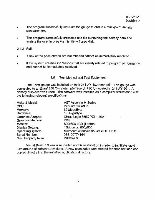
2.1.1 Pass.
• The gauge responds correctly (as described in vendor documentation, Ref. 1) toall commands sent through the program.
• If gauge related error codes are encountered, they may be cleared either throughthe Portable Enraf Terminal (PET) or the program. However, the program, whilerunning, must provide some indication of all the gauges' related errorsencountered.
• Each flush nozzle on the flushing spool yields a minimum of 1.3 gpm of flow at 80psig or greater.
• The program successfully instructs the gauge to obtain a tank sediment level.
• The program successfully instructs the gauge to obtain a single-point densitymeasurement.
HNF-2965Revision 0
• The program successfully instructs the gauge to obtain a multi-point densitymeasurement.
• The program successfully creates a text file containing the density data andassists the user in copying this file to floppy disk.
2.1.2 Fail.
• If any of the pass criteria are not met and cannot be immediately resolved.
• If the system crashes for reasons that are clearly related to program performanceand cannot be immediately resolved.
3.0 Test Method and Test Equipment
The Enraf gauge was installed on tank 241-AY-102 riser 15E. The gauge wasconnected to an Enraf 858 Computer Interface Unit (CIU) located in 241-AY-801. Adensity displacer was used. The software was installed oh a computer workstation withthe following relevant specifications.
Make & Model: AST Ascentia M SeriesCPU: Pentium 133MHzMemory: 32 MegaByteHarddrive: 1.5 GigaByteGraphics Adapter: Cirrus Logic 755X PC11.30AGraphics Memory: 2MBMonitor: 800x600 LCD (Laptop)Display Setting: 16bit color, 800x600Operating system: Microsoft Windows 95 ver 4.00.950.BSerial Number: 088100774164Gov. Property Num: WC63269
Visual Basic 5.0 was also loaded on this workstation in order to facilitate rapidturn-around of software revisions. A new executable was created for each revision andcopied directly into the installed application directory.

HNF-2965Revision 0
The workstation was physically located in the 241-AY-801 building. Theworkstation was placed on a table near the Data Acquisition System (DAS) cabinetwhere the CIL) was installed. The workstation was connected to the CIU via RS-232Ccable. The CIU address was set to "0"; and the baud rate setting was 1200 (seeException 1). The gauge address was set to "00".
A flush hose equipped with a calibrated pressure gauge was used to connect toeach flush nozzle. Since a calibrated flow rate meter was not available, flow rate wascalculated using flow totalizer readings and a stop watch.
4.0 Test Results
4.1 Discussion of Test Results
A reproduction of the master control copy of the operational test procedure isfound in Appendix A. The data sheets containing all data taken are included as a partof Attachment A. Related calculations are found in Appendix B. The work instructionwith sign-offs and data entries for follow up work request 2E-98-1244 is found inAppendix C.
On June 2, 1998, the operational test was started. The workstation was set upwith only one exception (see Exception 1). The flush spool was successfully tested withall nozzles flowing at 1.3 gpm or greater at a pressure of 120 psig. On June 8, asediment check was attempted and obtained with one exception (see Exception 3).That same day, a single-point density measurement was obtained at the 280-inch levelHowever, the density value returned from the gauge was approximately .93 g/cm3 whichwas somewhat lower than expected (see Exception 5). A multi-point densityprofile measurement was then attempted. But given the start level and sediment levelrequired by the procedure, the program calculated a very large (though correct) numbe-of measurements (23) to be obtained. Since an inordinate amount of time would berequired to obtain 23 density measurements, the multi-point density profilemeasurement was then aborted until some minor programming errors could be fixedand new start level and sediment level could be determined for the multi-point densityprofile (see Exception 4).
On June 10, 1998 a multi-point density profile was obtained. The systemoperated without incident, However, density values were also lower than expected (seeException 8).

HNF-2965Revision C
On July 2,1998, the volume of a new density displacer was measured in theshop using two methods in addition to the vendor's stated displacer volume. Thedisplacer volume is engraved on the displacer. The vendor's stated displacer volumeand measurements by the two methods to a precision of 0.1 cm3 were within + 0.5 cm3.On July 3, the new displacer was installed. New density measurements were thenobtained on July 6 which were within the expected range. As shown in section B.3 inappendix B, the measured densities on June 10,1998 and July 2,1998 can be justified.
4.2 Discussion of Test Exceptions
4.2.1 Exception 1
During the setup of the workstation and connection to the CIU, it was found thatcommunication could not be achieved to the gauge when trying to function at 2400baud. Vendor documentation was reviewed to determine the problem. No solution triec1
was effective. Since communication at 2400 baud was not a requirement, it wasdecided to set up the system for 1200 baud, which worked fine.
4.2.2 Exception 2
The program would not allow a displacer to be raised upward. It directed theuser to affect the operation using the PET. Since raising of the displacer with theprogram was not a specific requirement, the PET was used as directed by the program.However, it was found later that the program code was intentionally written to requirethe use of the PET when the displacer was within 6 inches of the adapter flange (toprotect the gauge force transducer). However, an error was found in the logic of thecode. The error resulted in the requirement that the PET be used during any "raise"command. The code was revised and now works as intended.
4.2.3 Exception 3
When trying to perform a sediment check, the gauge display on the program, thePET and the gauge showed "### ###" (pound signs) after the level value instead of "Ml!!!" (exclamation points) or "in INN". Since the program is controlled by the "in INN"character string to tell when the sediment level is reached, the program went into aninfinite loop. The Test Engineer had to decide when the sediment had been reachedas evidenced by the unchanging level readings. The Test Engineer determined that the"WM" item in the gauge needed to be changed from "ANNN" to "AANN", which would"approve" the gauge for sediment level use.
The parameter was changed as described and the test was resumed. A quick

HNF-2965Revision 0
check was made by entering command 12 to verify that pound symbols did not appear.The test was then resumed.
4.2.4 Exception 4
The system attempted a multi-point density profile without problems until it wasnoted that the second data point was obtained at a tank level equivalent to twice theinterval below the first. The third and forth measurements were obtained at correctintervals. Also, the way the procedure was written, the system was going to attempt 23data points which would require 69 minutes or more. The Test Engineer ordered anAbort.
The Test Engineer then troubleshooted and modified the program code to correctthe double-interval problem. It was also decided to lower the start level to 89 inches,and raise the sediment level entry to 17 inches. This would yield 6 data points, reducirgthe time of the participants spent in the field by 51 minutes. The Test Engineerdetermined that 6 data points were sufficient to verify system operability.
4.2.5 Exception 5
During the original run of section 5.7, the Test Engineer noted that the specificgravity measurements were coming in too low (~.93O). In order to gathertroubleshooting information, the Test Engineer provided a set of steps to perform toobtain a displacer weight submerged in the liquid. This weight turned out to be 113grams. It was agreed to continue testing, since the remaining test would verifyoperability of the workstation/gauge system regardless of the readings obtained by thegauge. It was believed that the problem with the specific gravity readings resided withthe gauge and displacer setup parameters. The procedure was changed by a ProcessChange Authorization (PCA) to reflect the additional steps.
The 113-gram value was taken back to the office, along with the 242-gram freedisplacer weight. Given an expected specific gravity of 1.03, the calculated volume ofthe displacer should have been about 125 cm3 as opposed to 140, which was originallyentered into the gauge.
Additional information was requested from the vendor, including the actualequation used by the gauge to calculate density values. The equation (see Appendix F)revealed that the wire weight and submerged wire volume were included. Thisinformation was significant in that the wire material installed in Hanford gauges is80%-Platinum-20%-lridium which is approximately three times heavier than stainlesssteel wire. The wire weight values shipped with the gauges are the default stainlesssteel values. Calculations showed that if input correctly, the wire weight values for the

HNF-2965Revision 0
80%-platinum-20%-iridium wire would bring the density readings closer to the expectedvalues. The 80%-platinum-20%-iridium wire is standard wire that is used in all Enraflevel gauges at Hanford.
On July 3, 1998, a new displacer was installed after being carefully calibrated inthe shop. On July 6, 1998, correct volume and wire weight values were entered into th?gauge. A density reading was then obtained at the 280-inch level. The resultingmeasurement was 1039 Kg/m3 which was within the range expected.
4.2.6 Exception6
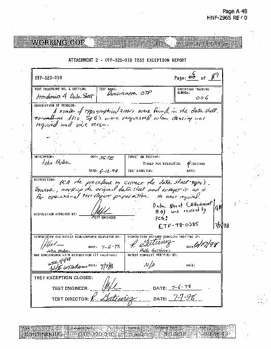
A number of typographical errors were found in the data sheet. Also, specificgravities were requested to be recorded when density values were actually needed andvice versa. The procedure was revised by a PCA to correct the errors.
4.2.7 Exception 7
Exceptions were not filled out in the field, but marked up directly on theprocedure and agreed to by all participants. This was done to minimize time in the field(ALARA concerns). The exceptions were written up immediately at the conclusion oftesting. A PCA was prepared and approved.
4.2.8 Exception 8
As indicated in exception 5, the densities were coming in too low. This issue isbeing handled as its own exception due to the seriousness of the problem.
A work package (2E-98-1244) was prepared to replace the displacer currentlyinstalled on the gauge with a carefully "calibrated" displacer. As mentioned in Exception5, a new displacer was calibrated per this work package and installed. A fieldacceptance was performed as described in the work instructions of the package (SeeAppendix C).
The densitometer is now performing within specifications.
4.2.9 Exception 9
/tfstep 5.7.24, the R9 value was not exactly equal to the last density recorded inthe density log file. This is acceptable, since the R9 value should NOT be expected tobe exactly equal to said value. The last value is, in fact, an average of R0 through R9,which may or may not be equivalent to R9 itself.

HNF-2965Revision C
5.0 Conclusions and Recommendations
The results of the Operational Test Procedure show that the density acquisitionsystem consisting of the Enraf Control Panel Software program and the Enraf 854Densitometer functions as intended. The system is acceptable for use with Enraf 854Advanced Technology Gauges and Enraf 858 Computer Interface Units. Specificrecommendations have arisen from the testing which, if implemented, will greatlyenhance and ensure the accuracy of the densitometer gauge.
5.1 Calibrate Density Displacers Prior to Installation
The accuracy of any given density measurement is highly dependent on theaccuracy of the volume measurement of the displacer. As the displacer is continuallydipped into the liquid to obtain a density or sludge measurement, waste will accumulateon the displacer. As enough waste builds up to affect the apparent volume, readingswill become less accurate. Upon replacement of a density displacer, the tagged volumeof the displacer will need to be verified to within 0.5 cm3. An error analysis wasperformed in section B.3. For a density error of 5 Kg/m3, the maximum alloweddisplacer volume error was found to be ±0.7 cm3 for waste fluid with a specific gravity of1.0. Review of the numerical calculation reveals that as the specific gravity increasesthe tolerance value decreases.
5.2 Find a Permanent Location for the Workstation
The computer workstation had to be set up by opening the DAS and CIU cabinetdoors. The doors had to remain open to accommodate the RS-232C cable connection.Over time, this may jeopardize the integrity of the data obtained through the DAS and/o-CIU through repeated setup and tear down of the workstation.
5.3 Wash Density Displacers and Wire Frequently
The wire was observed to accumulate waste product during the test. Since theinternal electronics account for wire volume in the density calculation, waste build-up onthe wire may effect the accuracy of the readings. Waste accumulation on the displacerwill effect readings in the same manner. Waste accumulation will also increase doserates at the gauge's drum housing, which further complicates gauge maintenanceactivities.
5.4 Do Not Use a New Density Displacer Greater than 250 grams in weight.
While preparing to perform work package 2E-98-1244, it was discovered that thecloser in weight a displacer is to 300 grams, the greater the error in weight

HNF-2965Revision 0
measurement. For example, a displacer actually weighing 291 grams was found tohave a level gauge measured weight of 287 grams. Such a weight difference cansignificantly etffect density measurement. In this case, the specific gravity of water atstandard temperature and pressure would come in at .971 if the 287 gram value wasused for the displacer free weight (as opposed to .998).
The vendor was contacted regarding this issue. They pointed out that our forcetransducer calibrations are performed within the range of 25 grams to 250 grams.Force transducer accuracy would falter outside of this range. This places a maximumlimit on tank waste specific gravity to be approximately 1.7 depending on displacervolume. The maximum specific gravity limit of 1.7 is derived by dividing 225 grams, themaximum weight difference, by 135 cm3, the nominal displacer volume, and dividing byreference density (1 gram/cm3).
Although the weight of a new displacer should be less than 250 grams, it isacceptable to allow the weight to increase to 255 grams as waste accumulates on thedisplacer. This is provided the actual weight is always entered into the gauge's "DW"parameter. Numerical calculations were made in section B.6 on three cases wherewaste accumulates on the displacer. Analysis of these calculations show that if thegauges "DW" is reprogrammed the density error is less than 1%.
5.5 Enter Wire Weight Value into Gauge WW Item
Calculations per Appendix B indicate that the wire weight value, which defaults tothat of 316 stainless steel, can significantly affect density readings. A wire weight valueof 0.69 should be entered into the WW item in the gauge software. The80%-platinum-20%-iridium wire is the standard wire used for all Enraf level gauges usedat Hanford. The original Enraf level gauges were installed with stainless steel wire untila wire broke due to chloride induced cracks in the wire. Most of the risers where Enraflevel gauges are now installed have polyvinyl chloride liners. These liners release smellamounts of chlorine gas when they are irradiated from the tank waste.
6.0 References
(1) Instruction Manual Series 854 ATG Level Gauge. Enraf Inc., Part No. 4416.220,Version 2.2 (See CV-31560, vendor information file).
(2) Instruction Manual 854 ATG Density Software Package. Enraf Inc., Part No.0000.564.4416.221-40, Version 1.0 (See CV-31560, vendor information file).
10

HNF-2965Revision 0
(3) System Requirements for Enraf Control Panel Software. Lockheed MartinHanford Corporation, HNF-1569, dated February 25,1998.
(4) PCA ETF-98-354, June 3,1998 [PCA changed revision of OTP-320-010 fromA-0 to A-1, and replaced pages 15, 33, and 42 in OTP-320-010.]
(5) PCA ETF-98-385, June 24,1998 [PCA changed revision of OTP-320-010 fromA-1 to A-2, and replaced pages 10, 16, 17, 20, 25, 31, 33, 44]
11

HNF-2965Revision 0
Appendix A
Acceptance Test ProcedureOTP-320-010
Master Control Copy
A-l

Page A-2HNF-2965 REV 0
WORKING CO*-1
TANK FAIir.l PI ANT 01 I RAT IONAI RSI PliOCVDURL
W-320 ENRAF SERIES 854 DENSITOMETER OPERATIONAL TEST
Last Full Revision: A-0
Release Date: 5/19/98
USQ Screening Number: TF-98-0317
Approval Designator: ES
POSITION/ORG DELEGATE
NCO D.R. Jonas
Shift Manager J.E. Andrews
QA Engineer C.A. Sams
Safety Engineer S.U. Zaman
Environmental Enq. P.C. Miller
RadCon Enaineer R.J. Reeder
COG Engineer J. Huber
Acceptance Review D.C. Ashworth
Approval Authority T.J. Kellev
Justification: Engineering raquest
Summary of Changes: New procedure for Pioject W-320
DATE
5/15/98
5/15/98
S,17/98
5/17/98
5/17/98
5/17/98
5/16/98
5/19/98
5/18/98
typo - - -
CONTINUOUS bl'P-320-010 _A"-0 ' -j ' -" 5/1-^/98 • = 1 of

Page A-3HNF-2965 RE/ 0
WORKING Jun 3,
TABLE OF CONTENTS PAGE
1.0 PURPOSE AND SCOPE 31.1 PURPOSE . . 31.2 SCOPE 3
2.0 INFORMATION 32.1 TERMS AND DEFINITIONS 32.2 RESPONSIBILITIES 42.3 REFERENCES 62.4 GENERAL INFORMATION . . -. 62.5 RECORDS . , 9
3.0 PRECAUTIONS AND LIMITATIONS . 93.1 PERSONNEL SAFETY . J 93.2 RADIATION AND CONTAMINATION CONTROL 93.3 ENVIRONMENTAL COMPLIANCE 93.4. LIMITS ....:... 10
4 . 0 P R E R E Q U I S I T E S . . . . " . 1 14 .1 SPECIAL TOOLS, EQUIPMENT, AND SUPPLIES 114.2 PERFORMANCE DOCUMENTS 114.3 CONDITIONS AND ACTIONS 12
5.0 PROCEDURE 145 . 1 SET PRELIMINARY. CONDITIONS 145 . 2 INITIALIZE WORKSTATION 145.3 CHECK COMMUNICATIONS AND GAUGE SETUP 165.4 VERIFY RINSE SPOOL ASSEMBLY FUNCTIONS . . 215.5 DETERMINE SEDIMENT LEVEL . . . . 255.6 SINGLE INTERFACE DENSITY MEASUREMENT . 275.7 MULTIPLE INTERFACE DENSITY PROFILE 305.8 WASHING DISPLACER AND WIRE . . - . 325.9 FAULT RECOVERY 335 . 1 0 TEST CLOSURE 35
FIGURE 1 - DENSITOMETER TEST SETUP DIAGRAM ' 36
FIGURE 2 - SUGGESTED PRESSURE TEST SETUP 37
ATTACHMENT 1 - 0 1 P - 3 2 0 - 0 1 0 TEST LOG 38
ATTACHMENT 2 - OTP-320 -010 TFST EXCEPTION REPORT 39
ATTACHMENT 3 - OTP-320 -010 SIGNATURE LOG 40
PROCEDURE HISTORY SIGNATURE SHEET . . ' . . . . , . . ' 43
CONTINUOUS A-0 i ? "! •*" 1

Page A-4HNF-2965 RE/ 0
W_ORKJNG_COP' Print . ,<n: JL.II 3, 58 6-:3
1.0 PURPOSE AND SCOPE
1.1 PURPOSE
This procedure provides instructions for operational testing of theW-320Enraf Advanced Technology Gauge Densitometer, CommunicationsInterface Unit, and Enraf Control Panel software functions asdesigned. Testing is expected to take one week to complete.
1.2 SCOPE
This procedure involves the W-320 Enraf Densitometer system.Instructions are provided to verify correct operation of the leveland density data acquisition system. Operational testing willverify that the hardware and software function according to intent.
The following itoms will be tested for operation (referenceFigure 1): . . .
• W-320 Enraf Series 854 Advanced Technology Gauge withdensity option installed. •
• W-320 i-nraf Series 858 Communication Interface Unit
• W-320 tn'raf Control Panel software and interconnectingcables, running on a Windows95/NT workstation.
2.0 INFORMATION
2.1 TERMS AND DEFINITIONS
2"". 1.1 ECP - Enraf Control Panel
PET - Portable Enraf lerminal
CIU - Control Interface Unit
DST - Double-Shell lank
2.1.2
2.1.3
2.1.4
2.1.5 gauge - refers to Enraf densitometer ui der test throughoutthis procedure.
OrR-320-010 A-0 5/19/98 3 of .43-

Page A-5HNF-2965 RE" 0
»r im. , in- J.'.i * ?.
2.2 RESPONSIBILITIES
2.2.1 Test Enyinee':
• Provide technical support during testing.
• Irovides programming support during testing.
• Revievs test documents to validate acceptance.
' Pacords. equipment sta '. s and dat-: per this procedure.
• Rtords data exceptions andother notes as requiredon Uie OTP data sheets.
•> Prepares post testing documents.
2.2.2 Craft, [rMs W intenarce a,id/or Construction Forces):
o pKov'de assistance during OTP testing.
• •• P.dvi'Je equipment for performance if this OTP.
2.2.3 Health i.'hysi.-rs Technician:
*• P-;rfor:a' •adiDlogical ! :)ioiiitorin9
2.2.4 Quality Control inspector: '
• Reviews: recorded test data for accuracy andcompleteness at complsticn of te^t.
"~T? • * V \ \ ' , 'Type
C0NT1NU6US-! 0TP-^2;j.01C -L AO I 5/19/98 I 4 of 43

Page A-6HNF-2965 RB' 0
WORKING COPT*' "rtnt. jjtj. JIM j ,
2.2 RESPONSIBILITIES (Oont.)
2 2.5 Test Ll-ecV:
2.2 .6
• i'4sp.''n?ib'e for overall control of the testing[iSiice^ .:nd change record authorisation for this OTP.
• Ensures ;>11 required data are collected.
• ;V.fe fl'-d1 productive accpnpl ishtni% of testing.
•:'• '• EisureS Safe workiny conditions.'.Snd practices.
• Ensures;compliance wi th . t ls t doc'Nents-and TechnicalS^fety.Requirements/Docu^ints ' {V Rs/OSDs) duringtesting';"'. .' .. • .'•'• •
• (;fiiMUii":Cf.tes and coocdiriates tes t i ng w i th DST Sh i f tMihaye?,... . .
• . E-'.-iures review and approval of a l l modi f ica t ions tot es t procedures ara completed p r i o r to re turn totesting. •. .-, . •'.; ' '
' Acts aj a dir5>;t l ine of cummunicscion. End. ;.i-ihtral f/i?d: pcint cf c Ktrql durir.g normal, abnormal,-ai;J c«S'..alty sHuoiiionsv ; ;•:. .
• Conducts pretest briefings,1 as required.
• Schedules/reschedules, tests, as inquired..
e Conducts pre-job. systera walkdowns.
• Reviews test documents to vslidate acceptance.'
• Verifies "all test instrumentation is within currentcalibration cycle.
Operations (ijCOs): ;
• Performs1, flushing of Enraf displacer and wire.
• Records test data, as required.
type
CONTINUOUSHo-
OTP-3?C-01O 5 of 43

Page A-7HNF-2965 RB' 0
WORKING CO?H h'irtxQm-. to ?, 9& s.'58'«
2.3 REFERENCES-
• 6-TF-I25, i , \ f S»ues 85" M< i len' ICP an1 cal ibrat ion
• TO-020-420, Cjloan LIT Tapes, Plummets and O'splacers; ReplaceFIC/Robertshiw Tapes arid Plummets
• H-2-824485, perisHoitieter Mer:ha,;ical: Ins ta l la t ion
II-2-& 545?' iinrW'8!)4 F-'ectricsl i-..Uall- -tio:.
« Instruction. •!anuj)l. Series '154 Advanced Te'c'r/o]ogy Gauges levelgauge, Part lo. -,41*5.220, Version 2.2, ENRi-.! • B.V., TheN e t h e r l a n d s ^ - } - ; ; } ' - . - - . ' • - . - ' • • . ••.' [ • .
• Ins t a l l atiC:;;. I n f r - Model 854 Advanced Technology Gauges ServoPowered Tai-f-Se ><e; Part h!o 4416.6S1, V- i -sUn 1.0, RNRAF B.V.,The Nethar'i.'..-ids •'.-' , ' '•• '• . >
• Ins t ruct io ! i .MaKi ik : i : 854 Advanced Technology i ' iuges dens i t yso f tware pafj'.age, :"-art No. 564.4416 2 i : l - 40 , Vers ion 1.0, cNRAFB.V., The N^t'heria'rids , :
• Instruct ion. .Maf ius i . Ser ies mi l-ori ' ib le ENR,':S Te rm ina l , PartN c , .4-ri&-.?10v-:V3:-:i;-oirvl--a-,;;lfffiA!t-.-fo\f-:.y.-Th:i.-.:i-.;ihei;la2ds-: -->>•• • •
• Instruct ion"Minui-." : ' , S e r i e ; S5S CoiT.inunictt i jr,s I n t e r f a c e U n i t ,Par t No-v 4416:5013, ..Version ZiV,: F.NRAF B .V . ; : Tha Nether lands
2.4 GENERAL ^ '
• 2 . 4 . 1 - (,i
2.4.1.1 Change control shall be in accordance withl:Nr-IP-08-:2-. •- . -. ; v
2.4.1.2 1 he test cognizant ji igin'ier may \ i!;e and implement"6n-i!it--spot'''chsiiges/sntiiMficati jr;« to the EnrafCcotrol. Pane] Software, s. reqgi.'uiJ,' during test ing.S'.ft'ware changes shall i f ! const: vie a procedurec-:a»ige. Al l • suftware chiTigus sh.-.n be'ducuiiiented asa:> EXCEPTION per Section 2.4.2.
Type
.CONTINUOUS g/15/93 '-•• "6 of 43

Page A-8HNF-2965 REV 0
WORKING rep
2.4 GENERAL IMFt VI.-
2 .4 .2
(CPV
2.4.2 1 rest ax eptions art used to do'-jnsnt unexpectedresets and io"n t i „ a^pr >oria * actions, not toCI IC I I " ent perform e i qLiren cs
ZA.L 2 M i l , i e t i o s h a l e g , a ' e q u e n t i a limbe id . r o r c c , t uc'iift 1 OTP-320 JK)s t L j
2.4.? 3 At a>hr nc 2 0TP-3e ,-01) est ctption Report,:>i i l l , f i V c d " j t to i - "A , i disposition uachc -,t >e non
?.4.3 AtAR' JJ\ei^'>I
2.4.^ 1 i l l i s pi Kedur l c n ' i t os a l l ^d" ,s expected as at e - . l t i f testing and i.ovides in t'-uctions for
~"ig to ho^e ^'ah f1*
2.4.3 2 U'b ni, 'aim r pf> oe xedu >b hall be jseJ whenr pi. i i j to u" '_ ea ila-m l • o cur during
2.4.3 3 Ji JApc I L I a'cin> e e i v u during testing shall beKgged 3b test excepnon aid evaluated by the TestDirector for effect on the test,
2.4.4 f o n t i ' t IPS' Lirecfor and lest tngircdi for ad i i t io rd ii l i t ucticn i f changing plant cond.it i is affect testingoi del ys <tei i test d1 i ' ion past e J of t ie (testing)shi f t
2.4.5 I f d u r i ' j perfjr"ia>ice u t is jrocfcdue any of tnef j l l o / i ng t j id i l ion<- an-< fou d IHMEi'AlELY noti fy thedssigipj l j s t Pirecto and [<.,<• tngi , &•
?
• \ y tqin nsnt ITR fUI Lion KHICII c< J preventf i l T ' l 1 em of fun. lona1 i tquirF -nts
• Personn'. I error cr pr^cef'jrai inadequacy which couldpiavent f ' f i l l f f on t o[ p ocedyrO requirements
• An) otner unexpected aior-alies
Tebt Director s i a l l as e>s the offeci. on the pUnt and thetest and dir> t either contin a ion cf t c test in thesame ~e t ioc, procoed"1 i j to r'>tiei- a*fa h™ent or ssctionuf the esf, •. s j '^ei .sun of i l J te^i p-r step 2 4 10 andes*abl i i i n j a i-ifo cund Mon for tHu < lent
I ftev ati
V98 of 43

Page A-9HNF-2965 RB' 0
WO&KING
2 . 4 G E N E R A l WC'f~M> t_' '•• ('"'-•wit ' . .
2.4.6 Cor.ip1y"'w"it!-,;.Vi-;RS' Lpck'-V'd TauiVequiresents, HNF-IP-0842,Volum:-;- l l , 't i-.tion -' .'J. .' V
2.4.7 Al l Keis.ufljngC'.hd Test-Fqi.-.:; lu~t,i use-.! d j r 'ng performanceof th:s'pre'(.S''^'ui"s t> roTi-wr q •r.l it. i* ' .'e data, with the?xcefV!?:iJ: b{;':'."i-''.'ii'J -;av.!cs . ' ; • : ' i a ' I •••»••..•! the followingrequv .•••\ICT-S'. • : ' ;. ; ;
• BiwitHisi i ts curr-nt t& l i / . r j t ion ycla es evidenced> • by 'sii". -:; fixeo csWcr-.-. icm "". be i •... : .
< " . Bi:'.t:'ai W e : --f th;;- /es .ad r*\ga. '
'• • •• •'VS'Uli.'. '•:£(. Jiv --.VJ' .'•'••: ;ns? - i :ni v i f i :'.. a te- : f-th-e-art'iimvta'.i';ohs)',.eiii:a1 : o '. r re^.ts,- tt:r: n t?;-j ac-.;iracy
. ipcciV'isj in t l is ;•'jcetfMi.e.-
2.4.8 Til l ing jfieavui e:-.ents. s!:al! .ba.ir'Je wit!!'t'jfiime?.vai lcB!«' i ' ; i i : ig deyi-ai : ~ ... • • ..
••. •• 2 . 4 . 9 . S i t S " i l f > i . : . . > J i O \ ' . S -"'••' .'•• • • - > • ' , ' . - • • •'•••.•:••'•'.*•••
'••••• i;'j.V,'tint'ii;at;*';.'Abi:c.f:v' ••-.Hoi -S^jSi't ic-pants;1; :iind:'-. ; >• •• ai i: Othei'.. d./'i^'oerfc iiitfVii:. t(.< t;io..test. un:.::. :;-.;
2.4.9'2'•:•' 0^-cnVM* $! ; iHC-^i ' lete' al 1 ..,urinal 'ROUNDS' DATA;SHSf IS (net pert i f : l h i £ pvoceiura) throughout , !
: I'"*":Orniancev O'; t'iisprocedac't"! ' ' '
2.4.10' • SUSPDISIOH Of TEST ANf;BESUMlfie/lXSl'V.::. ' • * ' : ' : ••' ••'• '
2.4.10.1 U-st O'i.i ectpr 'rn'a.y unilatef."! \j,. '•;»• any reason, stop' ta .ti'iiij. i'nj pi '.ce' &q'jipra^ni in a safe cc .d i t i on . A l l
:u:ipensioi of le t t ing •>: a l l badcvur-entfJ onVtta':hmn.t 1. OTP.-aXf 0.•'•)'.Test Lc'i).'.
2.4.10.2 I f a section of't*ie : tesi: '!-• s..:sp't jed for any reason, ; r ior ; i - ; . .cornpl£t;Uig a l l v-i.ops,./hi. Test Directori l ia l l "estabT'.iiiii"1iriitiiV'-.i.'ondHi ."'.i-jiec'essary.'to-.
. Ybs ;se 1:_-:;t;ng .0 "•that: sc t l ion. . previously .: .• . •.co*p|f vSd. s'ectib iV need -i,of ba.restated.unless • • •d• re'cvid Ly the fe i t Direc'toi' to t i t ab l i sh conditions/••iquire^' to r&sun:i? :the test.. ;. • •
CON HNUOUS AO I 6/1 "'98 8 of ;43

Page A-10HNF-2965RE/0
WORKING C C " . . H ,J .n .>. - ?
2.5 RECORDS
The performance copy <if-t:'e Cyfrvt iona'i Test PJ :•-edure and allcompleted attachments s'-all be filed as a permanent test record(Operational Test R'epbr't). :\
3.0 PRECAUTIONS AND LIMITATIONS
3.1 PERSONNEL SAFETY
NONE
3.2 RADIATION A*!D CONTAMINATION CONTROL
3.2.1 Raising s.d'fspla'cer that, has Been submerged in the tankwaste may relult in excessive radiation exposure when thedispifcir approaches th> bal '.yalvt'.. •
3.2.2 Work pt;lpqrt'*<i'i:: riJirv! ;.:;ca:1 j.-e-s ' ;il I be reviewed byTWRS Rau';.>i2r?:al Cor'S:.'c-T"T-'Sjf.-.a'6hitvj >---J TechnicalSupport p;.-ii)-.- ii i'eT?fi'-;eV(; •'•':"'P-0S42,--Vo1 VJI,
" Sect i : ; i f V. L;' • • • '
3.3 ENVIRONMENTAL'COMPLIANCE
NONE. ' ' : ' ' ' ' '.
' CONTINUOUS 9 of 43.

Page A-l lHNF-2965 RE' 0
WORKING CGP\ Prim
3.4 LIMITS
3.4.1 All pi-rtions of t.'e t.'st jh«l.l ie coirr-leted before thesyster. is ei'f.er &c<:e-;itnd or rejectee
3.4.2 All electrical and mechanical apparatus shall be operatedas designed. .
ACCEPTANCE CRITERIA.
3.4.3 This Operational Test Procedure will be consideredsuccessful if "all the following criteria are met:
3.4.3.1 Workstation/Computer
• Boots up to Windows95/NT...• Communicates.to Advanced Technology Gauges via
CommunicatiGn Interface.Un^t usi;ij ENRAF ControlP a n e l r r ' i K J r a i a . . ' • • ' • • •
• C!}taii;i tjnk density i.-.tSrfsce pi ufiles.• Obtains single point dens.ity measurement• Outputs density data to text file• Obtains sediment level.
3.4;3.2 Advanced Technology Gauge (Enraf)
» Responds with an error code = 000 or 0000 (indicatingno problems) for XPU and SPU of Advanced TechnologyGauge.
• Reports ?n II surface level within 1.5 inches ofaccepted waste level.
• Reports a density for unmixed supernatant between0,98 an-i'l.l specific'.gravity (spG).
3.4.3.3 Rinse Spool Assembly Spray Nozzle
• Flow through each spray nozzle is 1.3 Gallons perminute or greater when 80 psi (minimum) is applied.
CONTINUOUS OTP-VU-OM A-0 | b."1-)-Or . ;.)ot13

Page A-12HNF-2965 REV 0
C.OP;.
3.4 LIMITS (Cont.)
3.4.4 Indicates Quality Control (QC) hold points. When eachhold point is reached, no further steps are to beperformed until a QC representative has signed offrequired step(s).
3.4.5 Indicates Health Physics (HP) hold points. When each holdpoint is reached, no further steps are to be performeduntil an HP representative has signed off requiredstep(s).
4.0 PREREQUISITES
4.1 SPECIAL TOOLS, EQUIPMENT, ASViC SUPPLIES
The following supplies liisy be needea to perform this procedure:
• Portable Enfaf Terminal (PET), Model Number 847• 3.5 inch data diskette(s)• Hose to fit.rinse spool assembly flush connections to tank farm
water supply . • • • .. • Pressure gauge (water)- capable of.indicating 80 to 100 psi with
an accuracy of ± 5 psi .• Flow meter, capable of indicating 1 to 2 gpm with an accuracy of
+ 0.1 GPM• Fittings, as needed to connect hose, pressure gauge, and flow
meter to tank farm water source. This will include a 1/4" maleto 3/8" female quick-disconnect adapter for connecting theflush rig to each individual sjjray-'nozzle
• Stop watchRoutine Liquid Level Hush'Data Sheet (10-020-420)
• Desktop/Laptop computer, IBM Compatible, 486/66/16MB RAM(minimum) running Windows95/NT with a minimum 1.0GB Harddriveand Enraf Control Panel software pre-installed as provided bythe Test Engineer.
4.2 PERFORMANCE DOCUMENTS
• 6-TF-125, Enraf Series 854 Maintenance and Calibration• T0-020-420J Clean LIT Tapes, Plummets and Displacers; Replace
FIC/Robertshaw Tapes and Plummets• TO-040-540, Water Surveillance and Usage
CONTINUOUS I O1P-350 01O ! A CV *.
b<1 <),!)!> 1 I of

Page A-13HNF-2965RE7 0
WORKING. COP'
4.3 CONDITIONS AND ACTIONS
NOTE - Steps 4.3.1 through 4.3.9 may be performed, in any order.
4.3.1
•
4.3.2
4.3.3
4.3.4
4.3.5
4.3.6
NOTE
4.3.7
CONDUCT a pretest briefing for all personnel involved inthe performance of this Operational Test Procedure.
. A daily pre-job briefing shall be performed by the TestDirector and documented in Attachment 1, OTP-320-010 TestLog
VERIFY Health "Physics Technician support availability.
PERFORM a walkdown inspection of the work area for unusualand/or hazardous conditions.
TEST DIRECTOR INITIALS/DATE:
ESTABLISH communication between control room and equipmentlocations.
TEST DIRECTOR INITIALS/DATE: RGfENSURE the o f f i c i a l Operational Test Procedure copy andal l ot! e r u ! o ooopi-s t.a beused dur i^ j testing are thel a t v : t c.op,':r J revision. • •
TEST DIRECTOR INITIALS/DATE: ~RGI
REVIEW Lock and Tag Logbook to verify all components areavailable for the test.
TEST DIRECTOR INITIALS/DATE:
Signature Log requirement is ongoing as new individualsbecome involved in the procedure.
ENSURE all personnel to be involved with performance ofthis procedure have completed Attachment 3, OTP-320-010Signature Log: ; - ' • • .
type
CONTINUOUS OTP-;>20-010 J _A-p. 5/19/98Page ^ ,
.12 of 43

Page A-14HNF-2965 REV 0
WORKING COP1
4.3 CONDITIONS AND ACTIONS (Cont.j
4.3.8 VERIFY a copy jt" the lEtesi &-TF-12b. "Enraf Series 854Maintenance Snd Calibration" data sheet(s) are on hand forthe gauge.
TEST DIRECTOR INITIALS/DATE:
4.3.9 OBTAIN release from Operations management prior tocontinuing this test.
TEST DIRECTOR INITIALS/DATE:RG ,
CONTINUOUS' J . •- p •
Cm»-'320i)IO ' A-0

Page A-15HNF-2965 RE' 0
L WORKING COP
5.0 PROCEDURENOTE - "RECORD" in a step indicates that data and/or initials are to
be entered on Attachment 4, OTP-320-010 Data Sheet whenconditions in the step are met.
Host Enraf Control Panel Program screens can be opened in morethan one way; usually through "selecting" menu items with theALT-x method, whve x is the underlined menu letter by or by"mouse clicking" he desired item. Either method may be used.
5.1 SET PRELIMINARY CONDITIONS
5.1.1 ENSURE gauge displacer is above isolation ball valve.
5.1.2 ENSURE isolation ball valve is CLOSED and SECURE.
5.1.3 ENSURE power to computer is "OFF".
5.1.4 RECORD'Section 5.1 complete.
5.2 INITIALIZE WORKSTATION
5.2.1 IHSUJtE jjower.la Compile it ion interface. Unit and gaugeis ON. .
5.2.2 ENSURE power to computer system ON.
NOTE - CASS/TMACS operator: 373-2618.
5.2.3 ENSURE workstation time is set to within ± 1 minute ofTank Monitoring and Control System (TtiACS) system time.
IF not, DOUBLE-CLICK the system clock on the Windows95task bar AND USE the dialog window displayed to set thetime and date.
5.2.4 START Enraf Control Panel program.
CONTINUOUS OJP-'?.vO-0!U . A-0 '• V in . :n : ! ' of -1

Page A-16HNF-2965 RE/ 0
WORKING COF ]
5.2 INITIALIZE WORKSTATION (Cont,)
NOTE - The ECP password must be obtained from the Test Engineer.
5.2.5 WAIT until "ECP Logon" screen OPENS,THEN: .
• ENTER the Operator's name in the "User Name" window.
• ENTER the password provided by the Test Engineer in the"Password" window.
• SELECT "Ok"
5.2.6 VERIFY ''Enraf Control Panel" screen OPENS.
5.2.7 RECOXD iectiu;; 5.2 "O.iipiete.
CONTINUOUS I OTP-3?i;-0u> ' A O !,/1').«>» i i >> ofLI

Page A-17HNF-2965RE/0
WORKING COP1
5.3 CHECK COMMUNICATIONS AND GAUGE SETUP
5.3.1 SELECT "Setup" then "CIU Setup" from Enraf Control Panel.
5.3.2 VERIFY "CIU Setup" screen OPENS.
5.3.3 RECORD setup correct.
5.3.4 VERIFY setup parameters are configured per Table 1.
TABLE 1 - GAUGE SETUP PARAMETERS
PARAMETER
Baud rate
Turn Around
Scan Rate
PARAMETER
CIU address
Gauge Address
Comm Port
fuESIRED VALUE ,
&m/2.ac>K K"
800
?.-:••;.•
;• VALUE - Per Test Engineer
o . , .1 .
• = OK
/,
5.3.5
5.3.6
5.3.7
5.3.8
NOTE -
5.3.9
IF any parameters in Table 1 are incorrect, PLACE cursorin associated text vindow AND
CHANGE parameter.
WHEN all parameters are correct.
THEN SELECT "Ok". • .
RECORD gauge setup correct.
SELECT1''Setup" then "Gauge Sstup/CoVifiy." from EnrafControl Panel.
Enraf Control. Panel shows a progress bar as it polls thegauge.
WAIT while program connects to gauge,
THEN VERIFY "Gauge Setup/Configuration" screen OPENS.
DCONTINUOUS A O b/1.3.08 o f %-.
Page A-18HNF-2965RE/0
WORKING COP'.
5.3 CHECK COMMUNICATIONS AND GAUGE SETUP (Cont.)
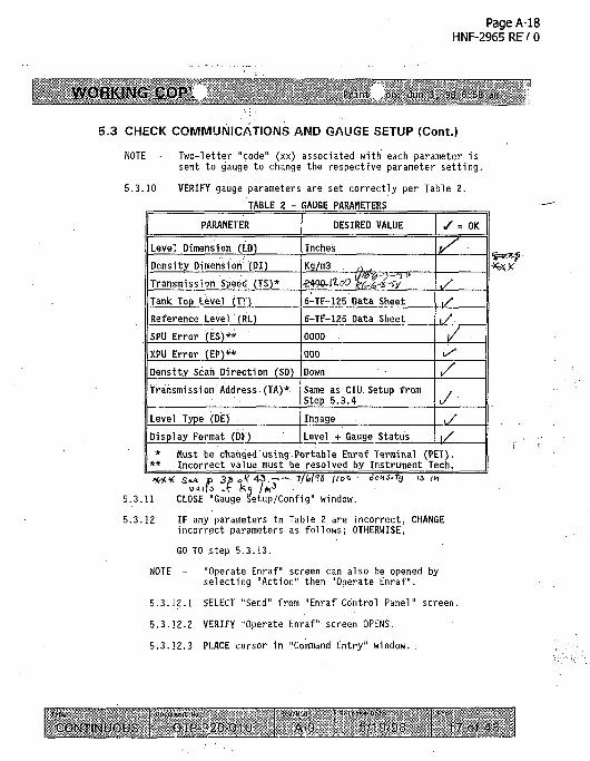
NOTE - Two-letter "code" (xx) associated with each parameter issent to gauge to change the respective parameter setting.
5.3.10 VERIFY gauge parameters are. set correctly per Table 2.
TABLE 2 - GAUGE PARAMETERS
PARAMETER
Level Dimension (LD)
Density Dimension (DI)
Transmission Speed (TS)*
Tank Top Level (TT)
Reference Level (RL)
SPU Error (ES)**
XPU Error (EP)**
Density Scan Direction (SD)
Transmission Address (TA)*
Level Type (DE)
Display Format (DF)
DESIRED VALUE
Inches
Kg/m3 n .
«*.*» !££&?"6-TF-125 Data Sheet
6-TF-125 Data Sheet
0000
000
Down
Same as CIU Setup fromStep 5.3.4
Innage
Level + Gauge Status
• = OK
f/ •
, /
,/
•/.
y,/./
* Must be changed using Portable Enraf Terminal (PET).** Incorrect value must be resolved by Instrument Tech.
5.3.11 CLOSE "Gauge Setup/Config" window.
5.3.12 IF any parameters in Table 2 are incorrect, CHANGEincorrect parameters as follows; OTHERWISE,
GO TO step 5.3.13.
NOTE - "Operate Enraf" screen can also be opened byselecting "Action" then "Operate Enraf".
5.3.12.1 SELECT "Send" from "Enraf Control Panel" screen.
5.3.12.2 VERIFY "Operate Enraf" screen OPENS.
5.3.12.3 PLACE cursor in "Command Entry" window. .
CONTINUOUS -r^O D!O A-0 b 1 :)Of. : V of

Page A-19HNF-2965 RE/ 0
WORKING COP1
5.3 CHECK COMMUNICATIONS AND GAUGE SETUP (Cont.)
5 .3 .12 .4 ENTER "W1=ENRAF1" AND SELECT "Send" .
5.3.12.5 WHEN the "Service Level Command..." screen opens,ENTER the password (obtained from the Test Director).
5.3.12.6 flACE ciii ior in "C--nimand &try" window.
5.3.12.7 ENTER "W?«ENRAF2" AND SELECT "Send".
5.3.12.8 WHEN the""Service Level Command..." screen opens,ENTER the password (obtained from the Test Director).
5.3.12.9 ENTER desired parameter in "Command Entry" Window perTable 3,- AND SELECT "Send".
TABLE 3 - PARAMETER ENTRY FORMATS
COMMAND- '
LD=I
DI=K
SD=U
DE=I
DF=B
RL=+xxxxx.xx
TT=+xxxxx.xx
TI=ABxyz,D
: ' COMMAND FUNCTION
SETS LEVEL UNITS TO "INCHES"
SETS DENSITY UNITS TO "Kg/m3"
SETS DENSITY SCAN DIRECTION TO "UP"
SETS LEVEL TYPE TO "INNAGE"
SETS DISPLAY TO READ LEVEL AND GAUGE STATUS
SMALL X IS NUMBER TO BE ENTERED.ADD LEADING ZEROS IF NOT LISTED IN 6-TF-125 DATA
SAME AS "RL". ABOVE
ABxyz IS EQUIVALENT TO TANK NAME (AY102)
5.3.12.10 CHECK "Communication Record" window as follows:
A. IF response .includes .-"&" (command accepted), GO TOstep 5.3.12.11.
NOTE - Error message will also appear when command isnot accepted.
B. IF response includes "!" (command NOT accepted),RESEND command AND ,
GO TO step 5.3.12.10.D.
CONTINUOUS"1 .
OTP-SiOOu A O I •> o f 1 "J

Page A-20HNF-2965 RF' 0
WORKING CO13'
5.3 CHECK COMMUNICATIONS AND GAUGE SETUP (Cont.)
C. IF response is three or less characters in length{e.g., "l@0"} (error in communications), SELECT "L"in "Enraf Control Panel" screen, ANP
GO TO step 5.3.12.10.D.
0. IF command is accepted ("&") on second attempt, GO TOstep 5.3.12.11; OTHERWISE,
SO TO Section 5.9. :
5.3.12.11 REPEAT steps 5 .3 .12.9 and 5.3.12.10 f o r eachparameter to be changed. .
5.3.12.12 ENTER "CX" AND SELECT "Send".
NOTE - Gauge reinitialization is indicated by "II" in line 2of the gauge display and may take a minute or two toappear.
5.3.12.13 WAIT until gauge reinitializes. ,
5.3.13 RECORD gauge parameters correct.
SELECT- "UN" in "Operate Enraf" screen.5.3.14
5.3.15
5.3.15
WAIT UNTIL gauge displacer moves down to rest on isolationball valve (unless already there).
WAIT until "Gauge Display" window shows "xxx.xx in INN"(xxx.xx represents a level in inches).
NOTE - When TG command is issued "Gauge Display" in "EnrafControl Panel" screen will show "TG" on second line andexclamation points next to level reading (xxx.xx !! ! ! ! ) .
5.3.17 SELECT "TG" in "Operate Enraf" screen.
5.3.18 WAIT until "Gauge Display" window shows "xxx.xx in INN"(TG completed).
5.3.19 RECORD current "Gauge. Display" window level reading,THEN SELECT "CA" in "Operate Enraf" screen.
. Level Reading bP,f>. lifi
CONTINUOUS OrP-"-5?0-OiO AO 5 10. OP.

Page A-21HNF-2965 RE' 0
WORKING COP\ •Vim, mi: JUT 3, 98 6:of am
5.3 CHECK COMMUNICATIONS AND GAUGE SETUP (Cont.)
CAUTION
After selecting "CA" and then "Yes" to the WARNING, the displacer should notbe permitted to raise all the way to the ENRAF adapter flange beforeperforming step 5.3.21. This may cause serious errors within the gauge.
5.3.20 WHEN "WARNING:".You are about to Raise the Displacer"appears, SELECT "Yes".
5.3.21 WAIT no more than two seconds, SELECT "FR" in "OperateEnraf" screen.
5.3.22 REQUEST Health Physics Technician to monitor for increasesin dose rates.
5.3.23 ENSURE "Gauge Display" window level reading increases(displacer raised). • •
5.3.24 RECORD.Section 5.3 complete.
CONTINUOUS A O i. 1 !),«V -A 4.'

Page A-22HNF-2965RE/0
WORKING COP
5.4 VERIFY RINSE SPOOL ASSEMBLY FUNCTIONS
5.4.1 IF isolation ball valve is CLOSED,OPEN AND SECURE isolation ball valve.
5.4.2 TEST rinse spool piece spray nozzles as follows:
5.4.2.1 IF using tank farm supply raw water, GO TO step5.4.2.4.
5.4.2.2 OBTAIN truck with 'level indicating transmitter flushtank OR tank on skid.
5.4.2.3 POSITION flush pump and tank as close as possible tothe deniitometer.
NOTE - Authorization for the addition of flush water toeither an active or inactive tank, must be obtainedfrom the Shift Manager. Operations supervisor's
. signature is required in Section 4.3 of thisprocedure and on the Data Sheet.
5.4.2.4 RECORD the tank number and tank liquid level on theRoutine Liquid Level Flush Data Sheet from TO-020-420AND CHECK the column for ENRAF.
5.4.?.5. DISCONNECT-one'of the existing densitometer hosesfrom one of the three spray nozzles AND TAPE the hosee'id.
orp-v-'o o.o A1) of X

Page A-23HNF-2965 REV 0
.WORKING COP\ Print 01- Juii >, 33 5:E5 .in.
5.4 VERIFY RINSE SPOOL ASSEMBLY FUNCTIONS (Cont.)
ft*' NOTE - The first connected nozzle shall be considered to be.SPRAY NOZZLE 1.
5.4.2.6 CONNECT the flush assembly (see Figure 2) to the openspray nozzle.
NOTE - Harking the spray nozzles is beneficial in keepingtrack of which nozzles have been tested so that nonozzle is is tested more than once.
5.4.2.7 MARK the spray nozzle using any convenient method(e.g., marking pen, tape, chalk, rag hanging over theport, etc.).
5.4.2.8 START flush tank motor OR OPEN the raw water controlvalve, as applicable.
5.4.2.9 ALLOW pressure to stabilize AND RECORD pressure onOTP-320-010 Data Sheet.
5.4.2.10 RESET the stop watch.
NOTE - The stop watch needs to be started simultaneouslywith the.reading of the water meter.
5.4.2.11 REQUEST an operator to read the water meter readingAND START the stop watch.
5.4.2.12 RECORD the water meter reading as the INITIAL watera meter reading oelow.
" 1?«IT1AL water reading (Nozzle 1) 2>5~7%(f 1 gal Ions
INITIAL water reading (Nozzle Z)3579t/-& gallons
INITIAL water reading (Nozzle 3)-
NOTE - The stop watch needs to be stopped simultaneously 7S°-8"with the reading of the water muter.
5.4.2.13 WHEN a minimum of 1 minute (60 seconds) has passed,REQUEST an operator to read the water meter readingAND STOP the stop watch.
CONTINUOUS orp-':'iO-ou' "T^T7^™" :>?. of K-

Page A-24HNF-2965RF/0
WORKING COP1. •>i: Jun 3, T& 6-53 3ii
5.4 VERIFY RINSE SPOOL ASSEMBLY FUNCTIONS (Cont.)
5.4.2.14 RECORD the water meter reading as the FINAL watermeter reading below.
FINAL water reading (Nozzle 1) 5 7$v- 7 gaV|ons
FINAL water reading (Nozzle 2)
FINAL water reading (Nozzle a.)^7TTC?^allons
5.4.2; 15 RECORD the time on the stop watches the pLAPSED timebelow.
ELAPSED time (No'zzle i) GO seconds
ELAPSED time* (Nozzle 2)
ELAPSED *iine (Nozzle 3)<
5.4.2.16 CALCUI.ArE^the flow rate using the followingequations:
For Spray Nozzle 1:FINAL water reading - INITIAL water reading = A (gal)'
= oc. I gal
A + ELAPSED t ime = B ( g a l / s e c )
g a l / s e c
x 60 sec/min ='C (gpm)
jC&Si— x 60 sec/min =• gpm
For Spray Nozzle 2:FINAL water reading - INITIAL water reading = A (gal)
A * ELAPSED time = B (gal /secL
/• y * to I " Jp.OiH gal/sec
B x 60 sec/min = C (gpm)
. O X x 60 sec/itiin = gpm
i CONTINUOUS ' A-C1 •• - i t '
5/1:) :)L'. .-: \ of 4. '

Page A-25HNF-2965 RE*/ 0
WORKING COP\
5.4 VERIFY RINSE SPOOL ASSEMBLY FUNCTIONS (Cont.)
For Spray Nozzle 3:FINAL water reading - INITIAL water reading = A (gal)
A + ELAPSED time = B (gal/sec)
_/ = ,O3>I gal/sec
B x 60 sec/mi n = C (gpm)
^ L . . . x 60 sec/min - 1^3 gpm
5.4.2.17 STOP flush tank motor OR CLOSE the raw water controlvalve, as applicable.
5.4.2.18 RECORD final water meter reading on Water Usage DataSheet from TO-040-540.
5.4.2.19 REPEAT steps 5.4.2.6 through 5.4.2.18 UNTIL all threespray nozzles have been tested.
5.4.2.20 RECORD flow rate (gpm) for each of the three spraynozzles on OTP-320-010 DATA SHEET.
5.4.2.21 DISCONNECT flush assembly from nozzle.
5.4.2.22 RECONNECT the densitometer flush hose.
5.4.3 DISCONNECT flush assembly from water source.
5.4.4 RECORD Section 5.4 complete on OTP-320-010 DATA SHEET.
CONTINUOUS OTP 370-0 IU A-0 •5 10. Or: nf 1

Page A-26HNF-2965RE/0
WORKING
5.5 DETERMINE SEDIMENT LEVEL
5.5.1 SELECT DENSITY from "Enraf Control Panel" screen.
5.5.2 WHEN "Get Density Data" screen OPENS, SELECT "GET" next to"Sediment Level" window.
NOTE - Step 5.5.3 initializes eoitinnications if not already done.
5.5.3 WHEN "Dip Displacer?" warning appears, SELECT "YES".
5.5.4 WHEN "Input Wire Tension" window OPENS,THEN:
NOTE - Test Engineer may have operator click "Calculate" and usethe "Buoyancy Calculation" to determine wire tension.
5.5.4.1 OBTAIN wire tension from Test Engineer,
5.5.4.2 ENTER obtained value in "Input Wire Tension" window,
5.5:4.3 RECORD "Wire Tension" value.
5.5.4.4 CLICK 0'/. to input wire tension. .J.
- or ,5.5.5 WAIT until sediment check is complete (as indicated
"System Status" window, located at bottom of "Get DensityData" screen, and "Output Log" window).
5.5.5 IF prompted to restart Sediment Level Check; (errors occurred), REPEAT steps 5.5.2 through 5.5.5.
5.5.7 IF repeated errors occur, NOTIFY Test Director and TestEngineer.
5.5.8 Test Engineer: DETERMINE whether heavier displacer isrequired, OR other causes^ ^
5.5.9 IF directed to install heavier displacer,
5.5.9.1 GO TO procedure 6-TF-125, ENRAF SERIES 854MAINTENANCE AND CALIBRATION.
5.5.9.2 INSTALL new displacer (300 grams max wt.),
5.5.9.3 RETURN to this procedure at Section 5.5.
CONTINUOUS ' o rp--;?o u i u A-O :>'i:vu- ?b of "3,

Page A-27HNF-2965RE/0
, |.€jOP\ . Print-- on: Jun 6-Sg am,
5.5 DETERMINE SEDIWIEIT LEVEL (Cont.)
5.5.10 SELECT "Yes" when prompted to return displacer to tankwaste surface.
5.5.11 RECORD Sediment Level on Attachment 4.
5.5.12 PERFORM Section 5.8,THEN RETURN to step 5.5.13
5.5.13 RECORD Section 5.5 complete.
-\\[ CONTINUOUS' O"

Page A-28HNF-2965 RB' 0
WORKING COP1.
5.6 SINGLE INTERFACE DENSITY MEASUREMENT
NOTES - This section verifies the ECP software will obtain asingle interface density measurement as designed.
Step 5.6.1 halts all communications and resets programwindows and internal flags.
5.6.1 SELECT "Connect" then "Reset Program" from "Enraf ControlPanel" screen.
5.6.2 ENSURE isolation ball valve is OPEN.
5.6.3. SELECT "Density" from "Enraf Control Panel" screen.
5.6.4 OBTAIN a current waste level from TMACS,AND RECORD.
5.6.5 ENTER level recorded in step 5.6.4 minus 24 inches in"StartLevel" window.
3' QT--11Level from step 5.6.4
5.6.6 ENTER sediment level from step 5.5.11 in"Sediment Level" window.
5.6.7 ENTER "-1" in "Interval (inches)" window.
5.6.8 SELECT Scan Direction "Down".
5.6.9 SELECT "Go".
5.6.10 VERIFY gauge animation indicates displacer moving DOWN,AND RECORD.
NOTE - Once displacer reaches Start Level, density measurementmay take up to ten minutes.
Dialogue window appears when density profile is complete.
5.6.11 WAIT until dialogue window with log file name and "ViewFile?" prompt appears,THEN SELECT "Yes".
CONTINUOUS OTP'3?0-(;IO ! AO , 3' i :v:\" | 2 / of -13

Page A-29HNF-2965 RB' 0
WORKING COP1.
5.6 SINGLE INTERFACE DENSITY MEASUREMENT (Cont.)
5.6.12 RECORD the Density Data filename of the density log f i l e .
Density Data FilenameT
5.6.13 VERIFY/RECORD "Output Log" file results:
5.6.13.1 File reports single density value
5.6.13.2 Density is at level entered in step 5.6.5.
5.6.13.3 Log file "Average Density" value.
5.6.13.4 Log file "Density" value.
5.6.14 SELECT "File" then "Exit" from the "ECP File Editor"screen. . . :
5.6.15 ENSURE,a 3.5'inch floppy disk is in the floppy drive ANDSELECT*"File", then "Copy DAT to floppy" from the "EnrafControl Panel" screen.
5.6.16 ENSURE the correct file from step 5.6.12 is shown in the"Copy to Disk?" screen.
5.6.17 IF the incorrect file name is shown, CONTACT the TestEngineer for assistance in locating the correct file.
5.6.18 SELECT "Yes" from the "Copy to Disk?" screen.
5.6.19 IF a floppy is not yet in the drive, INSERT it now ANDSELECT "OK" at the "Insert disk into drive a:" screen.
5.6.20 IF the "Overwrite?" screen appears, THEN SELECT "Cancel"AND CONTACT the Test Engineer for assistance.
5.6.21 CLICK "Setup," THEN SELECT "PCET".
5.6.22 WHEN "SERVICE PASSWORD ENTRY" screen OPENS,THEN E^TER the password (obtained from the Test Director)AND SELECT "Ok".
5.6.23 VERIFY "PC Enraf Terminal" screen OPENS.
NOTE - "SC" is the command name to return the average densityvalue calculated by the gauge.,The gauge actually takes10 measurements at the single point.
5.6.24 ENTER "SC" in "Command Entry" window AND SELECT "Send".
CONTINUOUS A-0 I b.13.9?. ?Kni

Page A-30HNF-2965 RB' 0
WORKING COP P ' i r - o r : Ju'i 3. ?S C:so
5.6 SINGLE INTERFACE DENSITY MEASUREMENT (Cont.)
5.6.25 RECORD "SC" value returned in "Communications Record"window, AND VERIFY it matches "Average Density" in step5.6.13.3.
NOTE - "RO" (letter "R", number "0") is the command that returnsthe first measurement in the 10 measurement scan. ROthorugh R9 will be the same number for an interfacemeasurement.
5.6.26 ENTER "RO" (letter R, number zero) in "Command Entry"window AND SELECT "Send".
5.6.27 RECORD "RO" value returned in "Communications Record"window, AND VERIFY it matches "Density" in step 5.6.13.4.
5.6.28 PERFORM Section 5.8,THEN RETURN to step 5.6.29.
5.6.29 RECORD*Section 5.6 complete.
Jype
CONTtNUOUSjJocumrnt Ho-
.OTP-3?0-010ftuv/Koa
A-0fcetqase- ttnte -
5/19/98 2Qof 43-

Page A-31HNF-2965RE/0
WORKING COP
5.7 MULTIPLE INTERFACE DENSITY PROFILE
5.7.1 SELECT "Density" from "Enraf Control Panel" screen.
5.7.2 ENTER level from step 5.6.5 in "Start Level" window.
5.7.3 ENTER sediment level from step 5.5.11 in"Sediment Level" window.
5.7.4 ENTER "12" in "Interval, (inches)" window.
5.7.5 SELECT Scan Direction "Down".
5.7.6 SELECT "Go".
5.7.7 VERIFY gauge animation indicates displaced moving DOWN,AND RECORD.
NOTE - Dialogue window appears when density profile is complete.
5.7.8 WAIT until dialogue window with log file name and "ViewFile?" prompt appears,THEM SELECT "Yes".
5.7.9 RECORD the -Beftsity-Data filename from the "ECP f i l eEditor" screen.
Density Data Filename^Af/ofrMm f;ies\\?.642T-O<5 ->-• OAT G/$T£:% cb-io-ms ;
5.7.10 RECORD "Start Level" from 5.6.4 and "Sediment Level" fromstep 5.5.11.
5.7.11 PERFORM calculation for Expected Number Of Measurements ondata sheet.
5.7.12 VERIFY/RECORD "Output Log" f i l e resul ts:
5.7.12.1 Number of density measurements in log f i l e .
. 5.7.12.2 Al l density values 0.95 to 1.1 SpG.
5.7.12.3 Last log f i l e "Density" value.
5.7.13 SELECT "Fi le" then "Exit" from the "FCP Fi le Editor"screen.
5.7.14 ENSURE a 3.5 inch floppy disk is in the floppy drive ANDSELECT "Fi le" then "Copy DAT to ' f loppy" from the "EnrafControl Panel" screen:
~,F
CONTINUOUS OTP-120-010 ' A-')

Page A-32HNF-2965 RB' 0
NOTE - The PET need not be connected to the gauge if the ECP program is used.If the ECP is used, the "ENTER command" action is performed by either clickingthe appropriate button in the "Operate Enraf" screen, or entering the commandin the "Command Entry" window and then clicking the "Send" button or pressing<ENTER> to execute the command.
5.7.A CONNECT the PET to the gauge (if required).
5.7.B ENTER command [12] to lower displacer into waste.
5.7.C WHEN the displacer reaches a level of 280 inches, ENTER command[FR],
5.7.D ENTER command [MF] to weigh the displacer.
5.7.E WHEN "FR" appears in the PET display, ENTER command [WQ].
5.7.F RECORD the displacer weight.
Displacer wt. fn liquid | f > '''•$** g r ams
5.7.G ENTER command [II], then [UN].
5.7.H WHEN the displacer reaches the waste surface, ENTER command [CA]to raise it approximately 6 inches above the surface. STOP thedispiacev with the [FR] command.
5.7.1 DISCONNECT the PET from the gauge.
~ 10-
<W-5U-oio ArO

Page A-33HNF-2965 RE\' 0
5.7 MULTIPLE INTERFACE DENSITY PROFILE (Cont.)
5.7.15 ENSURE the correct file from step 5.7.9 is shown in the"Copy to Disk?" screen.
5.7.16 IF the incorrect file name is shown, CONTACT the TestEngineer for assistance in locating the correct file.
5.7.17 SELECT "Yes" from the "Copy to Disk?" screen.
5.7.18 IF a floppy is not yet in the drive, INSERT it now ANDSELECT "OK" at the "Insert disk into drive a:" screen.
5.7.19 IF the "Overwrite?" screen appears, THEN SELECT "Cancel"AND CONTACT the Test Engineer for assistance.
5.7.20 CLICK "Setup", THEN SELECT "PCET1.
5.7.21 WHEN SERVICE PASSWORD ENTRY screen OPENS,THEN ENTER the password, (obtained from the Test Director)AND SELECT "Ok".
5.7.22 VERIFY "PC Enraf Terminal" screen OPENS.
5.7.23 ENTER "R9" in "Command Entry" window AND SELECT "Send".
5.7.24 RECORD "R9" value returned in "Communications Record"window, AND VERIFY it matches "Last Density" in step5.7.12.3.
5.7.25 CLOSE tho "PC Enraf Terminal" screen.
5.7.26 PERFORM Section 5.8,THEN RETURN to step 5.7.27.
5.7.27 RECORD Section 5.7 complete.
[^CONTINUOUS j OTP 3.'<(;-OUJ ' A-0

Page A-34HNF-2965 REV 0
WORKING COP\ Prin-. on- Ji.n \ 33 6:5S .-n
5.8 WASHING DISPLACER AND WIRE
NOTE -
5.8.1
NOTES -
5.8.2
5.8.3
5.8.4
5.8.5
5.8.6
5.8.7
5.8.8
This section is performed as called out in other sectionsof this procedure. The ECP software is not used.
IF not already connected, CONNECT PET to gauge per TestDirector instruction.
Do not return displacer to the waste surface when flushingis complete.
The 1/4" male'to 3/8" female adapter is not needed forroutine flushing, just the standard flush rig fromTO-020-420.
FLUSH per procedure TO-020-420 AND 6-TF-125, Section 5.6,until the displacer visually appears to be clean and doserate, as measured by the Health Physics Technician, is nolonger being reduced, OR as directed by the Test Director.
ENTER command [W2=EHRAF2].
ENTER command [DW=+xxxxxxxxE+03] where .xxxxxxxx is thelast recordod displacer weight on the 6-TF-125 data sheet(during flushing). ^ f J
ENTER command [Sl=+.xxxxxxxxE+03] where .xxxxxxxx is theOW value above minus 15 grams.
REPEAT step 5.8.5 for [S3] and [RM].
ENTER command = [EX].
WAIT for the.gauge to'reinitialize, THEN
EflTER command = [FR] (not returning displacer to wastesurface).
... . f ,_-,; — .CONTINUOUS OrP-3?i;01fi A-0 .J.?-)!13

Page A-35HNF-2965 REV 0
WORKING COP'. on. Jur 3, ?8 6:58 air ]
5.9 FAULT RECOVERY
NOTE - The following steps are performed if a fault conditionoccurs with the gauge. It may not be necessary to performall steps in order to recover.
5.9.1 SELECT "L" in "Enraf Control Panel" screen.
5.9.2 WAIT while program attempts to connect to gauge, if notalready, and obtain a level reading.
5.9.3 IF "Gauge Display" window returns a valid level reading(xxx.xx in INN or !'s), EXIT this section.
5.9.4 SELECT "Setup, THEN SELECT "POET".
5.9.5 WHEN "SERVICE PASSWORD ENTRY" screen OPENS,
THEN ENTER "ecpws" in password window AND SELECT "Ok".
5.9.6 VERIFY.J'PC Enraf Terminal" screen OPENS.
5.9.7 SELECT "Get a Level".5.9.8 IF "Gauge Display" window shows valid level
(xxx.xx.in INN or !'s),THEN SELECT "Close" in "PC Enraf Terminal" screen AND
RETURN to the section that called out this section.
5.9.9 ENTER "W2-ENRAF2" in "Command Entry" window AND SELECT ; '"Send".
5.9.9.1 WAIT until "&" is returned in "Communications Record"window,THEN WAIT approximately 15 seconds additional.
5.9.9.2 ENTER "EX" in "Command Entry" window AND SELECT"Send".
5.9.9.3 WAIT for gauge to reinitialize,THEN WAIT approximately 30 seconds additional.
5 . 9 . 9 . 4 SELECT "Get a L e v e l " .
CONTINUOUS OTP-'S?0-CIU ' AO ' b l : ) ' ' )? , 3o -,f

Page A-36HNF-2965 REV 0
WORKING COP*
5.9 FAULT RECOVERY (Cont.)
CAUTION
If displacer is too high up in the riser when LT command is issued, it maybe drawn too far up into the gauge causing permanent damage. The TestDirector may verbally authorize LT command to be issued, but displacer mustbe halted before it enters the gauge (less than 3 seconds).
5.9.9.5 IF a valid level is returned,THEN:
A. SELECT "LT" AND WAIT approximately 3 seconds,
B. SELECT "FR".
C. IF displacer RAISES,THEN:
• ENTER "EP" in "Command Entry" window.• SELECT "Send".• CHECK error codes in "Communications Record"
window.
• ENTER "ES" in "Command Entry" window.SELECT "Send".
• CHECK error codes in "Communications Record"window.
D. IF there are NO error codes, SELECT "Hose" in "PCEnraf Terminal" screen AND EXIT this section.
5.9.10 IF gauge will not clear using above steps, NOTIFY TestDirector.
| CONTINUOUS , orp-'5>o-v!;o ! A-0 _ ').•!•).:):; ;u\ of •¥ -

Page A-37HNF-2965 RE' 0
WORKING COP .
5.10 TEST CLOSURE
5.10.1 FILL OUT a Water Usage data sheet encompassing the entiretest usage.
5.10.2 QUALITY CONTROL:
QUALITY CONTROL SIfiNATURE/DATE:
REVIEW all attachments forcompleteness, legibility, andaccuracy.
/ ikln'SYTIO
5.10.3 Listed.reviewers SIGN below indicating all acceptancecriteria has been met and that the installed EnrafAdvanced Technology Gauge Densitometer, CommunicationInterface Unit, and Enraf Control Panel software programis functional and ready for operational use.
TEST DIRECTOR: ^ Jj^f^J
COG ENGINEER: M/
DST SHIFT MANAGER: J j j £ ^
DATE: ?-<;-? 8DflTE:<?^-?s>
CONTINUOUS. •-. I .1 • •. . . • : I C . . • . •
OTP-^:'ooiO ; A O _ [ ^ 1 ^ 1 ) J 1 -"> "f A '••

Page A-38HNF-2965 RB' 0
WORKING COPX.
Modem
LAPTOP/DESKTOP
CIU
EXISTING CONNECTION
L.
JINFRARED CONNECTOR
PORTABLE ENRAF TERMINAL
ENRAF ATG
FIGURE 1 - DENSITOMETER TEST SETUP DIAGRAM
CONTINUOUS A-ii i r. : ri :",:) !.T M: of

Page A-39HNF-2965 RE' 0
WORKING COP\
FIGURE 2 - SUGGESTED PRESSURE TEST SETUP
EXAMPLE ONLY
- CONNECTS TO ITEM TO BE FLUSHED
FLEXIBLE, ELECTRICALLYCONDUCTIVE HOSE3-FEET LONG (MINIMUM)
FLUSH HOSE(ANY MATERIAL)
CONTINUOUS OTP-'3?0 Oil,' AC 5 "i 9-5)8 I .'!/ i f 43

Page A-40HNF-2965 REV 0
WORKING COP\
ATTACHMENT 1 - OTP-320-010 TEST LOS
OTP-320-010 Page: / of 3
TIME/DATE DESCRIPTION
A V4r>
If? ftbiox ..
fncfcCXU tfwwi
'*$7/ / • -
centj*ilue<fl
-to -fte- OU
A-fv A-
.'chrfi-J!cuvn\ .7}
/T-3 df OTP
CZIL.ifaf A 72c/is
A CedtUrnS a*JlSe±\vQ'\ ". ¥
CONTINUOUS OTP-3:-'OOIO ' A-0 : "5/1!), >•» of i 1

Page A-41HNF-2965RE/0
WORKING COP\
ATTACHMENT 1 - OTP-320-010 TEST LOG
OTP-320-010 of
TIME/DATE DESCRIPTION
/2aqe- 7-
-937
LO-S2O SJJUIXJL* -H . (o-S.
This fact, [irulirtzJ4T~ A1 /UL/O
l-hf [ } p
"h J/dd. sUadfr M~t- SSL /heh 'trills,AXJJLS0 /u/£. +JJL
a/Ano tett'bi
Qfso
wO bail.
(TKI
CONTINUOUS orp-vooio i 6,3'0!3 ! $'> ot 1 j

Page A-42HNF-2965 RFV 0
WORKING COPY
ATTACHMENT 1 - OTP-320-010 TEST LOG
OTP-32O-O1O
TIME/DATE DESCRIPTION
fffj-fr^J »*rCc fx^L^SL- •?6.*l-,lH
Ceo-* j*rfa) .
-
Page:_J_ of 3
CONTINUOUS 1 OTP-5?i, OlO , \ - ' 6'3'9'j J i of 4 i

Page A-43
HNF-2965 REV 0
WORKING cop - 3 • , • 1 .> .
ATTACHMENT 2 - OTP-320-010 TEST EXCEPTION REPORT
OTP-320-010
TEST PROCEDURE NO. & SECTION: TEST NAME:
DESCRIPTION OF PROBLEM:
ORIGINATOR: ORG: S s y f T
DATE: k- j -J t -TJ
DISPOSITION: <;. t, -
"JA-V LJ ovf \toO, &xs?: res
DISPOSITION APPROVED BY: / % & % / ^ < _<" TEST ENGINEER
DISPOSITION AND RETEST REQUIREMENTS COMPLETED BY
/t/^^u^ DftTE.7
QAE CONCURRENCE WITH D I S P O S I T I O N ( i f r e q u i r e d ) :
£C/0- IMf- WE- ^
TEST EXCEPTION CLOSED: / / / 7
TEST ENGINEER: //7C.
TEST DIRECTOR:^f^ xJj<Ss
^cfes- OTP
12-0 0 r&i']i\jZn~ f^fc-t- c
i
Page: | of 9
~]\ EXCEPTION TRACKINGNUMBER:
1 °o.i-
'•*60O_ fse bfevwT
•*&*-/ ClU. <f-
IMPACT ON TESTING:
D HOLD FOR RESOLUTION JS'CONTINUE
TEST DIRECTOR: DATE:
i S-.Z.
DISPOSITION ACTIONS COMPLETE VERIFIED BY:'
DATE:
A ^ , ^ D A T E .
/
OATE: Ipliy
7-6-IS
7-7-?/
I Docisn^nt No-. 1 R-e'
; J OJP-320-010 L_type ;
CONTINUOUS A-0 5/1 3/98 39 of 43

Page A-44
HNF-2965 RE\' 0
WORKING COP
ATTACHMENT 2 - OTP-320-010 TEST EXCEPTION REPORT
OTP-320-010
TEST PROCEDURE NO. & SECTION:
S.I.10 . i - -DESCRIPTION OF PROBLEM:
vpWuinJ. • f f (> is ab
ORIGINATOR: ORG
John Ifafef-
DATE
DISPOSITION: / / • «~ -
,.1,. J ()*-•— it
vJ£ INL /&!.-. fi'sfopr'ftictiirs. If H nvT CSiCrt
DISPOSITION APPROVED BY: 1 //
TEST NAME:
*?ll not- all
bj fir iUis
7TEST ENGINEER
DISPOSITION AND RETEST REQUIREMENTS
QAE CONCURRENCE WITH DISPOSITION ( i
TEST EXCEPTION CLOSED:
TEST ENGINEER:
TEST DIRECTOR: A./
COMPLETED BY:
f required):
carx
OVP
Paqe: 2.
EXCEPTIONNUMBER:
dispka-\ to fa rxjst
CQJ/*7zw\ ft^cllsO ' l^y f Cc
of ftTRACKING
oot
IMPACT ON TESTING:
• BOLD FOR RESOLUTION |S CONTINUE
TEST DIRECTOR: • DATE:
cir<£-
£TF - ? ?" &*
DISPOSITION ACTIONS COMPLETE VERIFIED
RETEST COMPLETE VERIFIED BY:
AJfJ- D4TE.
DATE: -7~6~fy8
DATE: /'I/O
%
BY:
/
Type ,
CONTINUOUS OTP-320-010
RGV/frjQd
A-0
Release Date
5/19/98
Page
39 of 43

Page A-45HNF-2965 RB' 0
WORKING COP
ATTACHMENT 2 - OTP-320-010 TEST EXCEPTION REPORT
OTP-320-010 Page:, JlTEST PROCEDURE NO. S SECTION: EXCEPTION TRACKING
NUMBER:
DESCRIPTION OF PROBLEM:
'/!! . ( ' / ' or " ' " IHH''.. Sm'c
c^uL,
7<^ .szdi^^fWAI ikt-\ iU ik.At- jwfy< fo
Ay Ai_ ipcfa
(/St.
'• SSTS- IMPACT ON TESTING:
• BOLD FOR RESOLUTION ^CONTINUE
TEST DIRECTOR: DATE:
DISPOSITION:
•~F
•tit
DISPOSITION APPROVED BY:
sy-.itx^. to
T^St ENGINEER
DISPOSITION AND RETEST REQUIREMENTS COMPLETED BY:
QAE CONCURRENCE WITHVisPOSITION Of requi red) :
*-- v/7/?s
nDISPOSITION ACTIONS COMPLETE VERIFIED BY:
RETEST COMPLETE VERIFIED BY:
TEST EXCEPTION CLOSED:
TEST ENGINEER: _
I: J<. Jis/TEST DIRECTOR:
DATE: 7-6-?f
DATE: 7 ^
Typo
CONTINUOUSPoconc.ii; Ho.
OTP-320-010Rev/Mod
A-0 5/19/98Pgge .
39 of 43

Page A-46HNF-2965RE/0
WORKINC; f:nr>
ATTACHMENT 2 - OTP-320-010 TEST EXCEPTION REPORT
OTP-320-010 Page: 4 of
TEST PROCEDURE NO. S SECTION: TEST NAME: EXCEPTION TRACKINGNUMBER:
oofDESCRIPTION OF PROBLEM:
Jtso^fk. '^-y fin p/evn/>?: 23 Jk/isiry
coKtx.ofi 0 «,if4f
IMPACT ON TESTING:
D HOLD FOR RESOLUTION ^CON
TEST DIRECTOR: DATE:
DISPOSITION:n mM^k.k w*-
t?"' n yie/J> S J&sfo pom IS
DISPOSITION APPROVED BY:TEST ENGINEER
DISPOSITION AND RETEST REQUIREMENTS COMPLETED BY:
DATE: ~7-(C- t'o
OAE CONCURRENCE WITH DISPOSITION ('if required):
DISPOSITION ACTIONS COMPLETE VERIFIED BY:
RETEST COMPLETE VERIFIED BY:
TEST EXCEPTION CLOSED:
TEST ENGINEER: / w !
TEST DIRECTOR: 7\. ,,
D'ATE: 7-C- Y°>
DATE: I j ' 9
Type ~* j Dopum?nt No.
CONTINUOUS I OTP-320-010 A-0ROICDSC Oato
5/1 9/98Page |
39 of 43 !

Page A-47HNF-2965 REV 0
c;nr
ATTACHMENT 2 - OTP-320-010 TEST EXCEPTION REPORT
OTP-320-010
TEST PROCEDURE NO- & SECTION:
DESCRIPTION OF PROBLEM:
ORIGINATOR: , ORG
DATE
DISPOSITION: ^ ^ ^
pDISPOSITION APPROVED BY: W^/d-
TEST HAHE:1 fit-n&IW
72,
f
<• TEST ENGINEER
DISPOSITION AND RETEST REQUIREMENTS
/////
(fr0^ DATE
QAE CONCURRENCE WITH DISPOSITION ( i
TEST EXCEPTION CLOSED:
TEST ENGINEER:
TEST DIRECTOR: -^f
COMPLETED BY:
?-6 n'• required):
/k.
'J:s-±:rzf
Paqe: 5> of p
EXCEPTION TRACKINGNUMBER:
Do5~
IMPACT ON TESTING:
D HOLD FOR RESOLUTION "|l£ CONTINUE
TEST DIRECTOR: DATE:
. .„. _ ^
DISPOSITION AfTIONS COMPLETE VERIFIED BY:
RETEST COMPLETE VERIFIED BY:
/Vj/T- DATE:
DATE: !-<*' f%
UAJbt - DATE: 7 * 7 "9 $
Jype j DoctOTent So. j Rev/Mod
CONTINUOUS 1 OTP-3 20-0/iO | A-0Release Date
5/1 9/98 39 of 43
Page A-48HNF-2965RE/0
WORKING COF
ATTACHMENT 2 - OTP-320-010 TEST EXCEPTION REPORT
OTP-320-010
TEST PROCEDURE NO. 8, SECTION:
DESCRIPTION OF PROBLEM:
J numil^ <Jf yypo'
ORIGINATOR: ' ' ORG
DATE
DISPOSITION: / y /J ^>/Q
TEST NAME:
S l*J &~€-
S£7£
/TEST ENGINEER
DISPOSITION AND RETEST REQUIREMENTS
l/^- DATE
COMPLETED BY
QAE CONCURRENCE WITH DISPOSITION ( i f r equ i red ) :
TEST EXCEPTION CLOSED:
TEST ENGINEER:
TEST DIRECTOR: %
/JAW Q7P
Paqe: •&
EXCEPTIONNUMBER:
r of $A?
TRACKING
oo 6
'kh.skt
IMPACT ON TESTING:
D HOLD FOR RESOLUTION ^CONTINUE
TEST DIRECTOR: DATE:
Cif/YV*
7om. Mi KK-S
DISPOSITION ACTIONS COMPLETE VERIFIED
RETEST
o
COMPLETE VERIFIED 8Y:
AJ/j$~ DATE
DATE: 7
DATE: 1-1-9*
\S
41*
BY:
Type I Dppiancnt Ho.
CONTINUOUS [ OTP-G20-01O
Rev/Hod
A-0
Release? fcate
5/19/98 39 Of 43

Page A-49HNF-2965RE/0
WORKING COF
ATTACHMENT 2 - 0TP-320-O1O TEST EXCEPTION REPORT
OTP-320-010
TEST PROCEDURE NO. & SECTION: TEST NAME: - ^
OtKlSlTb
DESCRIPTION OF PROBLEM:
ORIGINATOR: ORG: < ; j - , • > . .
DATE: (~IZ~ty%
DISPOSITION:
DISPOSITION APPROVED BY: 1/'$£-*-1 TEST ENGINEER
DISPOSITION AND RETEST REQUIREMENTS COMPLETED BY:
QAE CONCURRENCE WITH DISPOSITION ( i f r e q u i r e d ) :
ifiiytrff uj>(. ddowP"*' 7/7/w
TEST EXCEPTION CLOSED: /?
TEST ENGINEER: (ifl/<-—
TEST DIRECTOR:-^. */j+ftf/J.
i^a\ ere
Paqe: ~7 of VI
EXCEPTION TRACKINGNUMBER:
IMPACT ON TESTING:
D HOLD FOR RESOLUTION {^CONTINUE
TEST DIRECTOR: DATE:
DISPOSITION ACTIONS COMPLETE VERIFIED 8Y:
RETEST COMPLETE VERIFIED BY:
/•)/Jh DATE:
DATE: ' / ^ ~ ? ' 6
SA^U DATE: / " / ./<-> .((
CONTINUOUS OTP-320-010 A-'O 5/1 9/98Page s
39 Of 43

Page A-50HNF-2965 RB' 0
WORMNC* COl1'
ATTACHMENT 2 - OTP-320-010 TEST EXCEPTION REPORT
OTP-320-010
TEST PROCEDURE HO. & SECTION:
S77 • . '
TEST NAME:
• DESCRIPTION OF PROBLEM:,
ORIGINATOR: ORG: $<^y&
DATE: g - ( Z - ^ g
DISPOSITION: j _ , « / , _
DISPOSITION APPROVED BY: v/#£C—./ TEST ENGINEER
0ISPOSIT l6 f l AND RETEST REQUIREMENTS COMPLETED BY:
ML(Jlr—• DATE. 7-^-fgOAE CONCURRENCE WITH DISPOSITION ( i f r e q u i r e d ) :
^ S ^ ' DATE: • ,
TEST EXCEPTION CLOSED: /j ,
TEST ENGINEER: //&•—
TEST DIRECTOR: *f\, (pQrvl7A
J&. Off '
Page: o of * '
EXCEPTION TRACKINGNUMBER:
IMPACT ON TESTING:
D HOLD FOR RESOLUTION ^CONTINUE
TEST DIRECTOR: DATE:
ihln
DISPOSITION ACTIONS COMPLETE VERIFIED BY:
/ JidmM/ DATE: u-ytRETEST COMPLETE VERIFIED BY:
A^/4 ' DAIE:
DATE: 7-6-'*'"&
fyAA?'.; DATE: '7'(i?-??/
RGV/Mcd
CONTINUOUS j _ OTP-320-010 J A-O_Setqasc Date- *
5/1 9/98Page
39 of 43
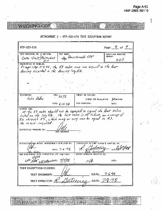
Page A-51HNF-2965 RE\' 0
WORKING COP
ATTACHMENT 2 - OTP-320-010 TEST EXCEPTION REPORT
0TP-320-O1O Page: 9 of f
TEST PROCEDURE. NO. & SECTION:
lv'pt'mS.I
EXCEPTION TRACKINGNUMBER:
oo9DESCRIPTION OF PROBLEM:
IMPACT ON TESTING:
D HOLD FOR RESOLUTION ^CONTINUE
TEST DIRECTOR: ' DATE:
DISPOSITION:Ptt ik. Z-1 ifav< sJwJT xjp
/ihkj °n W- /o^ filk .' TA MST Y*IIX is,£o r/irn^k £9 , ^A>c£ r»Aif or/A re- •H.sr d'
DISPOSITION APPROVED BY: .TE3T ENGINEER
DISPOSITIOfi/ANB RETEST REQUIREMENTS COMPLETED BY:
DATE: 1-6^%
OAE CONCURRENCE WITH DISPOSITION (if required):
11
- 7/7/?
OISPOSITION ACTIOHS COMPLETE VERIFIED BY:
RETEST COMPLETE VERIFIED BY:
TEST EXCEPTION CLOSED:
TEST ENGINEER: _
TEST DIRECTOR: Is.
DATE: 7-6-98
- DATE: '7/] '
Type j Document Ho-.
CONTINUOUS | 0TP-32CK) 10_Rev/Mod
A-0Release Oate
5/1 9/98 39 of 43

Page A-52HNF-2965 RB' 0
WORKING COP
ATTACHMENT 3 - QTP-320-010 SIGNATURE LOG
All persons involved in procedure performance, data recording, andverification or evaluation of test steps shall complete a log entry.
LG
<WFf,,-
/? L-
/ £<
E^.
f/Jmo
NAME
/ & (
heL h1
H &
(PRINT)
/
£A
i/ _ /
SIGNATURE
1 J
~\ ^"
i
•
INITIALS
%F
&
irpc
m
CONTINUOUS OTP-3''0-01O A-0 Ij, V.)-'\' 40 ot '. >

Page A-53HNF-2965 REV 0
WORKING COP'.
ATTACHMENT 4 - OTP-320-010 DATA SHEET
DATE OF TEST:
ilNUHBE§ff§Jf§§g|fll§ 111111
^'WS'AiSm:^;;^::1
SECIWNlgOfGOHPUEtlN/A
N/fiJQ.
iillllulgpliislllIBill
tmm lyii)I|ifEp^pp|^|pissftRlwaillBilW;
(psi)
II (gpm)
aiai Illlllllllllllllllill.- ~ • : . • • : : : : • : • • • • ' ; . ; . • . • . • ' . • : • • . • - • . : , • ;
(gpm)
liffli\K
j l i l l l
•joi-.T?YES'-=;:-':...&;!
ffi-J
516J13M!
LOG F I L £ AVERASK ..
5V6513M
M t e r o ; SEDIMENT;:
Pv95,T0
qAVERAGE"
lype
CONTINUOUSPOd-snont ffo. " j ilev/*iod j •Release DatR
. - OTP-320?010 | A-0 j 6/19/98 . 41 of 43

Page A-54HNF-2965 REV 0
WORKING COF Pri, I on. Jun 8, 98 14.07 pm
ATTACHMENT 4 - OTP-320-010 DATA SHEET
DATE OF TEST:
EXPECTED RESULT
EQUAL TO LOG FILEDENSITY
SECTION 5.6 COMPLETE TEST DIRECTOR; INIJIALS/_DATE_
5.7.7 ^DISPLACER KOVES DOWN [YES
RECORD
AS-FOUNDVALUE
INITIALS
5.7.10
5.7.11
5.7.12.1
- 6(Start Level - Sediment Level) - 12 = Expected No. Measurements(Drop Decimals) _
NO. OF MEASUREMENTSRETURNED
VALUE ±1
5.7.12.2 IALL DENSITY VALUES IN
5^7.12.3
5.7.24
RANGE,.
LOG FILE LAST-
5.7.27
-&-6i<f-
R9
YES f(0.95 TO 1.1 SpG) __0.95 TO 1.1 SpG (f) -»<.q03S2(SpG)
EQUAL TO LOG FILEDENSITY
SECTION 5.7 COMPLETE
b.10.3-iTEST ACCEPTED
TEST DIRECTORINITIALS/DATE
TEST DIRECTORINITIALS/DATE
Mo
.85910
COMMENTS j include step nmto-):
pCy\ ETF ~
- tc.9i6-U j,,,
Dtj ~- C> • Exp~'!)$-C>yi>2>~
15,4-,
I :- ' i i ie' 't "• .
INTINUOUS J_ _OTP-;: CONTINUOUS 320-010rfov.H^ P. if . c •;.
A-1 [ _ 6/3/98 | 42 of 43

Page A-55HNF-2965 RB' 0
WORKING Cf. Prim, on: Jiiii i , ?8 6-id a.i>
PROCEDURE HISTORY SIGNATURE SHEET
CONTINUOUS OTP-'320-010 | AO | li'1:)0R 13 of U

HNF-2965Revision 0
Appendix B
Calculations
B-l

HNF-2963REV0
Prepared by: JH Huber/JH' BussellDate: 7/21/98
DESIGN CALCULATIONS
PAT YOUNGChecked by:Date:; 7/21/98
Page 1 OF 29
Subject:. Analysis of Densitometer Density Readings
Introduction:
On June 8th, 1998 during execution of OTP-320-010, density readings of AY-102 liquid wastewere obtained using the ENRAF 854 ATG Densitometer gauge. Readings were expected to bein the range of 960 Kg/m3 to 1050 Kg/m3. However readings were coming in at 930 Kg/m3. It isdesired to determine the equation governing the internal density calculations within the gauge.In addition, on June 10,1998, a submerged weight of the displacer of 113.79 grams wasobtained. The free weight of the displacer was recorded to be 242.12 grams. The displacervolume programmed into the gauge was 140.81 cm3.
B.1 Derivation of the Density Equation
LEVEL GAUGE
WIRE
WASTE SURFACE
Pw = Wire DensitypA = Ambient Air DensitypWF = Waste Fluid DensityLI = Wire Hang Length in AirL2 = Wire Hang Length in Waste Fluid
Figure 1
Assumptions:
1.2.
Hydrostatic influences are negligible due to relatively small size of displacer.Density of the waste fluid is uniform to a point below the displacer.
B-2

HNF-296'REV0
Prepared by: JHiHuber/JH BussellDate: 7/21/98
DESIGN CALCULATIONS
PAT YOUNGChecked by:Date: 7/21/98
Page 2 OF 29
Subject:. Analysis of Densitometer Density Readings
Free Body Diagram of thedisplacer: h h
iH
BWI BWII-
BD
DISPLACER/WIRESYSTEM
Dg \ / g
Figure 2
The body is at rest and static conditions apply, therefore vertical forces must sum to zero:
FWg - 0
Where:FT = Wire Tension Force Measured by Enraf Level GaugeFBW| = L1 Wire Buoyant Force in AirFBWN = L2 Wire Buoyant Force in Waste FluidFBD = Displacer Buoyant ForceF^ = Displacer WeightFw = Weight of L1 and L2 Wire
(1)
B - 3
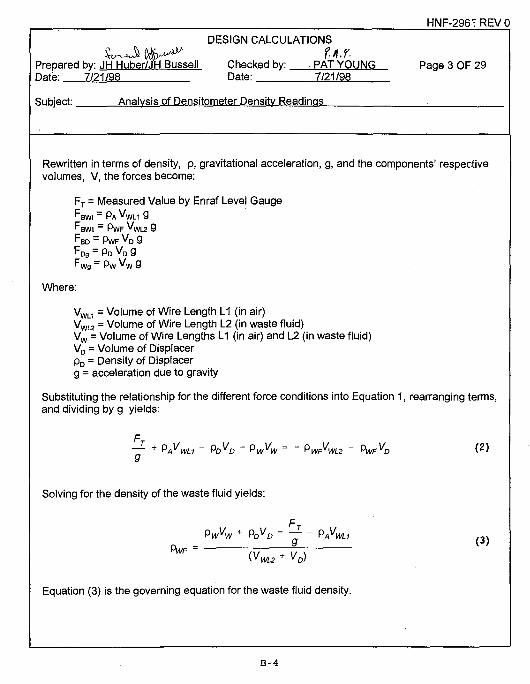
HNF-296' REV 0
DESIGN CALCULATIONS
S u O U.r.Prepared by: JH Huber/JH Bussell Checked by: PAT YOUNG Page 3 OF 29Date: 7/21/98 Date: 7/21/98
Subject: Analysis of Densitometer Density Readings .
Rewritten in terms of density, p, gravitational acceleration, g, and the components' respectivevolumes, V, the forces become:
FT = Measured Value by Enraf Level GaugeFBWI = PA V W L I 9
BWN = PwF "WL2 9FBD = PWF VD 9FDg = PD VD gFWg = Pw VW 9
Where:
VWL1 = Volume of Wire Length L1 (in air)VWL2 = Volume Of Wire Length L2 (in waste fluid)Vw = Volume of Wire Lengths L1 (in air) and L2 (in waste fluid)VD = Volume of DisplacerpD = Density of Displacerg = acceleration due to gravity
Substituting the relationship for the different force conditions into Equation 1, rearranging terms,and dividing by g yields:
+ PVWL1 ~ PDVD ~ PwVW = ~ PWFVW
Solving for the density of the waste fluid yields:
Pwvw + PDVD - -f ~ PAVWU 3 )
9wF" o v T ^ v
Equation (3) is the governing equation for the waste fluid density.
B - 4

HNF-2965REV0
DESIGN CALCULATIONSv c3» p.A./.
Prepared by: JH Huber/JH Bussell Checked by: PAT YOUNG Page 4 OF 29Date: 7/21/98 Date: 7/21/98
Subject: Analysis of Densitometer Density Readings
B.1.1 Dimensional Analysis
a. The mass of the wire, L1 (in air) and L2 (in waste fluid), is given by:
Mw = Pw v w
The units used for wire mass by the Enraf level gauge are grams with respect to theEnraf level gauge configuration. One programmable constant is used in the Enraf levelgauge to calculate the mass of the wire:
[WW]=wire linear density in gm/m
The measured level parameter subtracted from the tank top constant [TT] provides thewire length in meters. The wire linear density is measured in air. The measured densityincludes the buoyant force. Hence the wire buoyant force in air term, pA VWL1, is not usedby Enraf in their density calculation equation.
b. The free mass of the displacer is given by:
MD = PD V D
The units used for the mass of the displacer are grams with respect to the Enraf levelgauge configuration. Two programmable constants are used in the Enraf level gauge todefine this equation:
[DW]=displacer free weight in gm (does not include the wire)
This displacer weight is in air.
[DV]=displacer volume
c. The submerged mass of the wire, L2, mass of the wire in air, L1, and the submergedmass of the displacer measured by the Enraf level gauge is given by:
B - 5

HNF-2965 REV 0
DESIGN CALCULATIONS
Prepared by: JH Huber/JH Bussell Checked by: PAT YOUNG Page 5 OF 29Date: 7/21/98 Date: 7/21/98
Subject: Analysis of Densitometer Density Readings
The units used for the mass of the submerged displacer and wire, L1 (in air) and L2 (inwaste fluid) are grams. This quantity is a measured quantity. It can be manuallyobtained by requesting the weight of the displacer at the desired level.
d. The change in effective mass from the buoyant force from air on the wire, L1 (in air) isgiven by:
This term is neglected by Enraf in their density calculation because it is small and wireweight is measured in air. See comparison of material densities shown below.
e. The units for VWL2 are in cubic centimeters. One programmable constant is used in theEnraf level gauge to calculate the immersed volume of wire:
[WV]=wire volume/length in cm3/meter
The immersed volume is calculated by subtracting the level of the displacer from the tanklevel (surface). The resulting immersion depth is then multiplied by [WV] to obtain theimmersion volume.
Equation (3) with units then becomes:
3 _ Mw 9m + MDgm - Ms gm - (pAVWL1) gm Kg
WF ' (VWL2cm3 +VDcm*) 103 gm
B-6

HNF-2965 REV 0
Prepared by: JH Huber/JDate: 7/21/98
DESIGN CALCULATIONS
ussell Checked by: PAT YOUNGChecked by:Date: 7/21/98
Page 6 OF 29
Subject:. Analysis of Densitometer Density Readings
Now consider the following densities:
Material
Air
Waste Fluid
Wire Density
Density
0.001225 gm/cm3
1 gm/cm3 to 2 gm/cm3
7.75 gm/cm3 to 21.64 gm/cm3
The buoyancy effects of air as fluid acting on the wire length L1 are negligible compared to thewire density (less than 0.01 % of the wire density).
Rewriting Equation (3) neglecting the buoyancy of the wire in air term:
PWF Kg/m3 =3 _ Mwgm + MDgm - Ms gm 103 Kg cm3
(4){VWL2cm3 + VDcm3) gm
Rewriting Equation (4) using the Enraf programmable constants defined above:
PWF= [WW\*([T7] -Dn)gm + [DW\ gm - Ms gm 1Q3 Kg cm3
(([W] " °n) * [WV\ cm3 + [DV\ cm3) gm m3
B - 7

HNF-2965REV0
DESIGN CALCULATIONSS ^ ^ CM
Prepared by: JH Huber/JH Bussell Checked by: PAT YOUNG Page 7 OF 29Date: 7/21/98 Date: 7/21/98
Subject: Analysis of Densitometer Density Readings
Where:Measured Quantities:
Dn=Level of displacer at a density measurement point in meters (This value isdisplayed in inches but for this calculation we will assume that it is in meters.)[Y4]=is tank level (surface) in meters (This value is displayed in inches but fcr thiscalculation we will assume that it is in meters.)Ms=Measured weight of submerged displacer and wire in grams
Programmed Constants (These constants are programmed when the Enraf level gauge iscalibrated as a densitometer and are fixed.):
[WW]=wire linear density gm/m[TT]=Tank Top level in meters (This value is programmed in inches but for thiscalculation it will be assumed that the value is in meters.)[DW]=Displacer weight in gm[DV]=Displacer volume in gm[WV]=Wire linear density in cm3/m
Rewriting Equation (4) in the form of the equation provided by Enraf:
K . 3_ [DWjgm - Wire Tension(submerged)gm + Wire Weight gm ^(PKgcm3
([DV\ cm3 + Immersed Wire Volume cm3) gm m3
The wire tension term in the above equation includes the effective mass of displacer andattached wire. The wire weight term is mass of the wire, L1 (in air) and L2 (in waste fluid).Equation (7), below, was provided by Enraf. See page B-27 (calculation page 26) for a copy ofthe FAX from Enraf containing this equation.
B-6

HNF-2965 REV 0
DESIGN CALCULATIONS
Prepared by: JH Huber/JH Bussell Checked by: PAT YOUNG Page 8 OF 29Date: 7/21/98 Date: 7/21/98
Subject: Analysis of Densitometer Density Readinas
R Ka/m3-displacer we'9ht 9m " wire Tensi°n9m + Wire Weight gm . .(DV cm3 + Immersed Wire Volume cm3)
t 103 Kgcm3 (7)
gm m3
+ amb. Air dens. + A2
The terms A1 and A2 are calibration constants to permit a field calibration of the densitometer.Normally A1 is equal to 1.0 and A2 is equal to 0.0.
B-9

HNF-2965 REV 0
DESIGN CALCULATIONS
Prepared by: JH Huber/JH Mussel I Checked by: PAT YOUNGDate: 7/21/98 Date: 7/21/98
Page 9 OF 29
Subject:. Analysis of Densitometer Density Readings
Now consider the effect of buoyancy of waste layer on the measured density:
WASTE SURFACEV
SURFACE AREA = A
TANK LAYER-CONTAININGDISPLACER mg PTOpgAL7
Where:A = Waste tank surface AreapA = Density of airpTOP = Waste fluid density at top of the tank layer containing the densitometer dispiacerPBOT = Waste fluid density at bottom of the tank layer containing the densitometerdispiacerpWF = Actual Waste Fluid Densitymg = Weight of the tank layer containing the densitometer dispiacerg = Gravitational accelerationLTOP = Distance to the top of the densitometer dispiacer|_BOT = Distance to the bottom of the densitometer dispiacerV = Volume of the tank layer containing the densitometer dispiacermmeas = Measured mass of the tank layer containing the densitometer
B-10

HNF-29C5 REV 0
DESIGN CALCULATIONS
WMMM U.Y.Prepared by: JH Huber/JH Bussell Checked by: PAT YOUNG Page 10 C17 29Date: 7/21/98 Date: 7/21/98
Subject: Analysis of Densitometer Density Readings
The weight of the tank layer containing the displacer is:
mneas9 = <3& (PTOPLTOP ~ PBOTLBO^ " PA <3 V
The pressure from the atmospheric pressure will cancel out because of the pressure differencein the term. The densities, pT0P, pB0T, pWF, are nearly equal. Equation (7A) becomes afterfactoring out g and rearranging the first term in terms of the volume of the tank layer:
(7B)
Now solving for the measured density mmeas/V:
( 7 C )
The variable, praeas, is measured density of waste fluid. Now rearranging Equation (7C) to solvefor pWF:
(VD)
Equation (7D) is in the form of Equation (7) and the added ambient air density term has beenjustified. The programmable parameter [RF] should be programmed to 1.225 Kg/m3 if it isdesired to reference the density measurement to vacuum or [RF] should be programmed to 0.0if is desired to reference the density measurement to air. In either case, the difference inmeasured density is very small, approximately 0.1%. For additional explanation, see section3.2.1, Ambient air density correction, in reference 4.
B - l l

HNF-2965 REV 0
DESIGN CALCULATIONS
Prepared by: JH Huber/JH Bussell Checked by: PAT YOUNG Page 11 C F 29Date: 7/21/98 Date: 7/21/98
Subject: Analysis of Densitometer Density Readings
B.2 NUMERICAL ANALYSIS OF GAUGE DENSITY CALCULATION
From Vendor Fax information, Product Density (Rn):
DW(free) - DW(submerged) + Wire WeightRn = * A1 * 1000 + amb Air dens. + A2
DV + Immersed Wire Volume
a. Calculate the AY102 tank waste density from data obtained on June 10, 1998 assumingPt-lr wire is being used and using the following assumptions:
Programmed Fixed Constants:[DW](free) = displacer weight = 242.12 gm[DV] = displacer volume =140.81 cm3
[A1] = Density correction factor = 1.0 (Ref. Vendor Fax)[A2] = Density correction offset = 0.0 (Ref. Vendor Fax)[RF] = amb. Air Dens.= 1.225 Kg/m3 (Obtained from gauge)
The density measurement is referenced to vacuum. This term is thechange in density from buoyant force on the waste from air.
[WV] = linear wire volume 0.032 crrrVm (Obtained from gauge)[WW] = linear wire density 0.25 gm/m[TT] = tank top = 699.61 inches (Ref 6-TF-125 data sheet)[RF] = amb. Air Dens. = 1.225 Kg/m3
Measured Values:[DW](submerged) = Wire Weight =113.79 gmDensity Measurement Point Level = 280 inchesTank Level = 300 inches
Assumed ValuesDensity of Platinum = 21.45 gm/cm3 (Ref. 1)Density of Iridium = 22.42 gm/cm3 (Ref. 1)Density of Pt + Ir Wire= 0.8*(21.45 gm/cm3) + 0.2*(22.42 gm/cm3) =
21.644 gm/cm3 (80%-Pt and 20% -!r Wire)
B-12

HNF-29P5 REV 0
DESIGN CALCULATIONS
Prepared by: JH Huber/JH Bussell Checked by: PAT YOUNG Page 12 C c 29Date: 7/21/98 Date: 7/21/98
Subject: Analysis of Densitometer Density Readings
Initial Calculations:Extended wire length = TT - Level = 699.61 inches - 280 inches =
420.35 inches * 1 meter/39.37 inches = 10.68 meters
Wire Weight = 0.032 cm3/m * 21.64 gm/cm3 * 10.68 m = 7.40 gm
Immersed Wire Volume = Immersed Wire Length * [WV]Immersed Wire Length = 300 inches - 280 inches =20 inches * 1 meter/39.37 inches = 0.508 meters
Immersed Wire Volume = 0.508 meters * 0.032cm3/m = 0.0162 cm3
242.12 gm-113.79 gm +7.40gm Kg cm3 KgDn - - - - * 1 n * 1 nnn +1 995 — + n n
140.81 cm3+ 0.0162 cm3 gm m3 m3
gm m3 cm3
Rna = 965.04 Kg/m3 * = 0.965 gm/cm3 * = 0.965 S P G103Kgcm3 1 gm
The above calculated specific gravity is a very interesting result since it is within theexpected range specified in the OTP (0.96 to 1.1).
b. Now perform the calculation same calculation as in "a" assuming stainless steel wire:
Density of steel = 0.28 Ib/in3 * 1728 in3/ff * 16.018 Kg/m3 / Ib/fl3 = 7750 Kg/rr3
(Conversion factor for Kg/m3 to Ib/ft3 from Ref. 2)
7750 Kg/m3 * 1000 gm/1Kg * 1m3/1000000 cm3 = 7.75 gm/cm3
Wire Weight = 0.032 cm3/m * 7.75 gm/cm3 * 10.68 m = 2.65 gm
Wire Weight calculated by the gauge ([WW] = 0.25 gm/m):0.25 gm/m * 10.68 m = 2.67 gm
Use the wire weight value, [WW], from Enraf level gauge in the calculation:
B-13

HNF-2965 REV 0
DESIGN CALCULATIONS
Prepared by: JH Huber/JH Bussell Checked by: PAT YOUNG Page 13 C F 29Date: 7/21/98 Date: 7/21/98
Subject: Analvsis of Densitometer Density Readinas
242.12 gm - 113.79 gm + 2.67 gm Kg cm3 Kg• n - * in* innn +1 99s; +nn
140.81 cm3+ 0.0162 cm3 gm m3 m3
gm m3 cm3
Rnb = 931.45 Kg/m3 * = 0.931 gm/cm3 * = 0.931 SpG103 Kg cm3 1 gm
The specific gravity is very close to the value measured on June 10,1998 which was notwithin the expected range (0.96 to 1.1).
c. Now assume the displacer volume is 135cm3, which is closer to design specificationvolumes.
Assume wire is Pt-lr wire, wire weight = 7.40 gm.
242.12 gm-113.79 gm + 7.40 gm Kg cm3 Kg• n _ * 1 n * mnn + 1 99=; - - + n n
135 cm3+ 0.0162 cm3 gm m3 m3
gm m3 cm3
Rnc = 1006.5 Kg/m3 * = 1.006 gm/cm3 * = 1.006103Kgcm3 1 gm
B-14

HNF-2965 REV 0
DESIGN CALCULATIONS
Prepared by: JH Huber/JH Bussell Checked by: PAT YOUNG Page 14 C F 29Date: 7/21/98 Date: 7/21/98
Subject: Analysis of Densitometer Density Readings
d. It is evident from comparison of Rna and Rnb that the wire weight is significant. The wireweight value for Platinum-lridium wire needs to be converted to the format used by thegauge and programmed accordingly. (The wire weight value [WW] was reprogrammed inthe Enraf level gauge by work package 2E-98-1244. See page C-16, work step 7.21.4,for this work instruction.)
Converting wire weight to [WW] format:
The [WW] value for stainless steel is 0.25 gm/m. This number is calculated bymultiplying the [WV] value by the density of stainless steel as follows
[WV] * density of wire = [WW]:
0.032 crrvVm * 7.75 gm/cm3 = 0.248 gm/m - 0.25 gm/m
So, for the Platinum-lridium wire:
0.032 cm3/m * 21.64 gm/cm3 = 0.692 gm/m ~ 0.69 gm/m
B.3 Error Analysis of Density Measurement
a. The analysis of the error can be developed by deriving the differential of Equation (3) andby summing the increments as the root of the sum of squares. This approach will p'ovidea conservative error estimate.
Assume: Buoyant force of wire in the air term is negligible from Equation (3).. This termis three to four orders of magnitude smaller than the other terms. The term has besndeleted starting with Equation (4) and this error analysis.
- ^ K « > 2 (?)
B-15

HNF-29P5 REV 0
DESIGN CALCULATIONSf. Ay.
Prepared by: JH Huber/JH Bussell Checked by: PAT YOUNG Page 15 CF 29Date: 7/21/98 Date: 7/21/98
Subject: Analysis of Densitometer Density Readings
Where:
AMW = Error in wire mass measurement (L1 and L2)AMD = Error in displacer mass measurementAMS = Error in mass measurement of submerged displacer (wire + displacer)AVD = Error in displacer volume measurementAVWL2 = Error in Immersed wire volume
Obtain the partial derivatives:
(M2+MD-MS)
(9)
dr = K' TTr—ri7T do)
K • , „ ,., T , , 2 = P»r • ,v + v , ( I D
(M + M -M) i*• ,' ° „ ' = P»r- , „ + „ . (12)
B-16
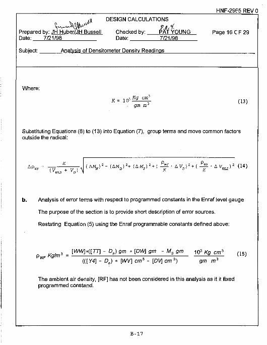
HNF-2965 REV 0
DESIGN CALCULATIONS
Prepared bv: JH Huber/JH Bussell Checked bv: PAT YOUNG Page 16 CF 29Date: 7/21/98 Date:. 7/21/98
Subject: Analysis of Densitometer Density Readings
Where:
Substituting Equations (8) to (13) into Equation (7), group terms and move common factorsoutside the radical:
i f " AVp)2 + ( I T
b. Analysis of error terms with respect to programmed constants in the Enraf level gauge
The purpose of the section is to provide short description of error sources.
Restating Equation (5) using the Enraf programmable constants defined above:
- Dn) gm + [DW\ gm - Ms gm 103 Kg cm
{{[Y4] - Do) * [WV] cm3 + [DV\ cm3) gm m3
The ambient air density, [RF] has not been considered in this analysis as it it fixedprogrammed constand.
B-17

HNF-2965 REV 0
DESIGN CALCULATIONSfj.i.
Prepared by: Jfl Huber/JH Bussell Checked by: PAT YOUNG Page 17 C F 29Date: 7/21/98 Date: 7/21/98
Subject: Analysis of Densitometer Density Readings
(1) AMW =Error in wire weightMW = [WW]*([TT]-Dn)
[WW] is a programmable constant that does not change during operation ofthe Enraf level gauge.
[TT] is a programmable constant that does not change during the ope-ationof the level gauge.
Dn is the level at which the density is measured.Possible Errors: 1. Wire Length
Level is specified to an accuracy of 1 mmand sensitivity of 0.1 mm.
2. Thermal expansion of the wireThe wire is used in a relatively constanttemperature environment.
(2) AMD = Error in the displacer weightMD = [DW]
[DW] is a programmable constant that does change during the operat:on ofthe Enraf level gauge.
Possible Errors: 1. Initial weight or mass determination errors
2. Waste build-up on displacer weight frominitial weight
(3) AMS = Error in the weight of submerged displacer and wireMs = weight of submerged displacer and wire
Possible Errors: 1. Force transducer accuracy
2. Waste build-up on displacer and wire
B-18

HNF-2965 REV 0
DESIGN CALCULATIONS
Prepared by: JhTHuber/JH Bussell Checked by: PAT YOUNG Page 18 CF 29Date: 7/21/98 Date: 7/21/98
Subject: Analysis of Densitometer Density Readings
(4) AVD = Error in displacer volumeVD = [DV]
[DV] is a programmable constant that does not change during the operationof the Enraf level gauge.
Possible Errors: 1. Initial volume measurement determination
2. Waste build-up on displacer changingvolume
(5) AVWL2 = Error in Immersed wire volume[WV]
The wire weight for the entire wire L1 (in air) and L2 ( in waste fluid) isbased on the weight of the wire in air. The buoyant force on the immersedwire from the waste fluid is based on the measured density not on theactual density above the measurement point. However, the density of thewaste fluid, in general, will be less than or nearly equal to the density at themeasurement point. The other factor is that the ratio of the wire volume tothe displacer volume is very small compared to the displacer volume, lessthan 0.05%. Thus, this error is negligible.
Dn is the level at which the density is measured.
Possible Errors: 1. Wire LengthLevel is specified to an accuracy of 1 mmand sensitivity of 0.1 mm.
2. Thermal expansion of the wireThe wire is used in a relatively constanttemperature environment.
B-19

HNF-2935 REV 0
DESIGN CALCULATIONS
Prepared by: JH Huber/JH BussellDate: 7/21/98
Checked by:Date:
PAT YOUNG7/21/98
Page 19 OF 29
Subject:. Analysis of Densitometer Density Readings
[Y4] = is tank level (surface)
Possible Errors: 1. Wire LengthLevel is specified to an accuracy o* 1 mmand sensitivity of 0.1 mm.
Thermal expansion of the wireWire is operated in a relatively constanttemperature environment.
Waste build-up results in level erro*because of different immersion dep'h inwaste
[WV] is a programmable constant that does not change during the operationof the Enraf level gauge.
Possible Errors: 1. Error is wire size
2. Waste build-up on wire changing wirevolume per unit length
c. Now calculate the maximum mass error for a 5 Kg/m3 density change:
Assume pWF = 1000 Kg/m3
Setting ApWF = 5 Kg/m3 and solving for AMD:
AMn= 140.81cm3gmcm
1000 Kg cm3
Kg* 5 =±0.7gm
m3
B-20

HNF-2965 REV 0
DESIGN CALCULATIONS
Prepared by: JH Huber/JH Busseli Checked by: PAT YOUNG Page 20 C e 29Date: 7/21/98 Date: 7/21/98
Subject: Analysis of Densitometer Density Readinas
d. Now calculate the maximum volume error for a 5 Kg/m3 density change:
Assume pWF = 1000 Kg/m3
Setting ApWF = 5 Kg/m3 and solving for AVD:
gm cm3 103Kgcm3 m3 KgAVD= 140.81 cm3 * * * * 5 =±0.7 cm3
103 Kg cm3 gmcm3 103Kg m3
B-21

HNF-29P5 REV 0
DESIGN CALCULATIONS
Prepared by: Jfl"Huber/JH Bu'ssell Checked by: PATYOUNG Page21 CF29Date: 7/21/98 Date: 7/21/98
Subject: Analysis of Densitometer Density Readings
B.4 EFFECT OF WEIGHT DIFFERENCE ON FORCE TRANSDUCER
Some informal experiments were performed in the shop. It was noted that whenrequesting the gauge to weigh different calibrated weights, the force transducer wa > offby up to 4 gm at the high end (~300 gm) and less than 3 gm at the low end (~150 gm).The force transducer is calibrated at four points, 25 gm, 100 gm, 175 gm, and 250 gm.This indicates that force transducer error may be larger outside the calibrated range thatwithin the calibrated range. This was discussed with the vendor who indicated tha' errorshould be linear within the range of the force transducer calibration. This range spans25 gm to 250 gm. This is significant, because the weight error may not cancel wh3ndetermining the difference between displacer free weight [DW] (free) and submergedweight, wire tension. Administratively, this means that procedures will need to bedeveloped for in-field force transducer calibrations and displacer volume calibratiors, andthat displacer weights will need to be limited to 250 grams or less.
From B.3 above, the required weight error resulting in a 5 Kg/cm3 change is ±0.7 g-n.The specified density accuracy for instrument is ± 5 Kg/cm3- As the weight errorbecomes larger the estimated error will increase proportionally with this error model.
B.5 THE EFFECT OF DISPLACER VOLUME ON DENSITY READINGS
From B.3, the maximum displacer volume error to limit the density error to 5 Kg/m3 is±0.7 cm3. Thus, the volume of the displacer needs to be known within ~±0.5 cm3.
B-22

HNF-29P5 REV 0
DESIGN CALCULATIONS
^ $) JJ.f.Prepared by: JH Huber/JH Bussell Checked by: PAT YOUNG Page 22 C^ 29Date: 7/21/98 Date: 7/21/98
Subject: Analysis of Densitometer Density Readings
B.6 NUMERICAL ANALYSIS OF THE EFFECT OF WASTE BUILD-UP ON DISPLACERON DENSITY READINGS
A simplified numerical analysis will be performed considering 1 cm3 of waste becomesattached to the displacer.
a. Assume that the specific gravity of the waste attached to the displacer is 1.0 and thewaste has the same density as in B.2 c:
Displacer Measured Mass Change from Buoyant Forces = 1 gm - 0.931 gm = 0.07 gm
242.12 gm - (113.79 gm + 0.07 gm) + 7.40 gm Kg cm3 KgRna= * 1.0* 1000 +1.225 +0.0
135 cm3 +1 cm3 + 0.0162 cm3 gm m3 m3
gm m3 cm3
Rna = 997.4 Kg/m3 * = 0.997 gm/cm3 * = 0.997 SpG103Kgcm3 1 gm
b. Assume that the specific gravity of the waste attached to the displacer is 4.0 and th3waste has the same density as in B.2 c:
Displacer Measured Mass Change from Buoyant Forces = 4 gm - 0.931 gm = 3.07 gm
242.12 gm- (113.79 gm + 3.07 gm) + 7.40 gm Kg cm3 KgPr» — * i n * i n n n •+•1 99^
135 cm3 + 1 cm3 + 0.0162 cm3 gm m3 m3
gm m3 cm3
Rnb = 976.5 Kg/m3 * = 0.977 gm/cm3 * = 0.977 SpG103Kgcm3 1 gm
B-23

HNF-29S5 REV 0
DESIGN CALCULATIONS
\ K M fj.y.Prepared by: JH Huber/JH Bussell Checked by: PAT YOUNG Page 23 CF 29Date: 7/21/98 Date: 7/21/98
Subject: Analysis of Densitometer Density Readings
c. Assume that the specific gravity of the waste attached to the displacer is 2.0 and thewaste has the same density as in B.2 c:
Displacer Measured Mass Change from Buoyant Forces = 2 gm - 0.931 gm = 1.07 gm
242.12 gm-(113.79gm +1.07 gm) + 7.40 gm Kg cm3 KgRnc = * 1.0 * 1000 + 1.225 +0.0
d.
135 cm3 + 1 cm3 + 0.0162 cm3
gm m3
391.3 Kg/m3 * = 0.9913 g/cm3 * -103Kgcm3
Results
SpG of Waste Attached to Disolacer
No Waste Attached
1.0
2.0
4.0
cm3
=0.9911 gm
Measured
1.006
0.997
0.991
0.977
gm m
SpG
SpG
m3
Error
-0.9%
-1.5%
-2.9%
The above numerical analysis of three cases where waste builds up on the displacershows that the measured density will be lower than the actual waste density. If the freeweight of the displacer is reprogrammed with the new weight of the displacer then thedensity error can reduced by a significant amount. In the case of where the attachsdwaste has SpG = 4.0, the error can be reduced to about -0.2%.
B-24

HNF-2965 REV 0
DESIGN CALCULATIONS
Prepared by: JH Huber/JH Bussell Checked by: PAT YOUNG Page 24 C c 29Date: 7/21/98 Date: 7/21/98
Subject: Analysis of Densitometer Density Readings
B.7 LIMIT ON WASTE SpG FOR 250 GRAM DISPLACER (VOL. 135 cm3)
In B.4, it was stated that displacer weights will need to be limited to 250 gm or less. Thislimitation will place a corresponding limitation on waste density in which the densitometercan operate. There will be a waste specific gravity value at which the displacer will notsink. This calculation will assume a displacer volume of 135 cm3, and using the tested242 gm displacer mass.
The limit is equivalent to the SpG at which the buoyant force balances the displace-weight or in simpler terms, the displacer and waste fluid densities are equal:
242 gmRnUMrr = = 1.79 gm/cm3 * cm3/1 gm = 1.79 SpG
135 cm3
B.8 CONCLUSIONS AND RECOMMENDATIONS
Three parameters were found to be of significance with regard to densitometermeasurements.
1. Wire weight. The wire weights currently programmed in all ENRAF 854ATGsare that for 316 stainless steel wire. However, the wire currentlybeing used is 80%-Platinum-20%-lridium, which is significantly heavier.Consequently.initial density readings were less than anticipated.
RECOMMENDATION: Enter the 0.69 value into the [WW] item of thegauge. (The wire weight value [WW] was reprogrammed in the Enraf levelgauge by work package 2E-98-1244. See page C-16, work step 7.24 4, forthis work instruction.)
2. Force Transducer Error. The force transducer error is not linear fordisplacer weights outside of the calibration range. An accumulated error ofas little as ±0.7 gram can effect the accuracy of density readings by asmuch as ±5 Kg/m3.
RECOMMENDATION: Develop procedure for in-field force transduce-calibration and do not use displacers of weight 250 grams-force or greater.
B-25

HNF-29P5 REV 0
DESIGN CALCULATIONS% ! ff e,Y.
Prepared by: JH Huber/JH Bussell Checked by: PAT YOUNG Page 25 C* 29Date: 7/21/98 Date: 7/21/98
Subject: Analysis of Densitometer Density Readings
3. Displacer Volume. To acheive an accuracy of + 5 Kg/m3, the displacervolume must be verified to within ±0.5 cm3.
RECOMMENDATION: Develop procedure for initial displacer volumecalibration to within 0.5 cm3.
4. Ambient Air Density. The ambient air density, [RF], offsets the measureddensity to reference it to vacuum. If it is desired to reference it to air thenthe ambient air density, [RF], should be set to 0.0.
RECOMMENDATION: Since the change is approximalely 0.1%, leave theambient air density as is, [RF]=+.1225000e+01. It can easily be charged inthe future.
References:
1. CRC Handbook of Chemistry and Physics, 50th Ed., The Chemical Rubber Co.,Cleveland, Ohio, 1969.
2. Mechanical Engineering Reference Manual, 8th Ed., Professional Publications, Betmont,CA, 1990.
3. Instruction Manual Series 854 ATG Level Gauge, Version 2.3, Enraf Inc., March 1S96(Part No. 4416.220)
4. Instruction Manual Series HIMS Hybrid Inventory Management System with HPU/CPU-Board, Version 1.1, June 1998 (Part No. 4416.241)
B-26

JUN 12 ' 9 8 16:48 FR ENRfiF12 JUS '93 10:22 ENRflF EJ.V.
Fax to: Enraf Inc.Attention Mr. G. SellersCountry USAYour ref.Fax no. Auto
Number of pages (including this page):
Mi •
281 443 6776 TO 15093735030^ " P.02/02
EnrafB.V.Rontgenwegi, 2624 BD Delft -P.O. Box 812,2600 AV Delft C. C- •The Netherlands .Tel. +3115 26 98 600Fax +31 15 2819 574
From: P. van HoutenC.C. E. BretscherOur ref.Date ju'n! 12, 1998
Subject: S54 ATG DENSITY CALCULATION
Dear Gayland,
With reference to the telephone conversation yesterday,
During the density measurement will be the density calculated as follow:
Rn^ displacer weight -. wire tension -t- wire weigh! * A1 * 1000 * amb. Air dens+ A2DV + immersed wire volume
displacer weight = [DW]wire tension = averaged measured wire tension t W WSwire weight = wire weight with respect to [TT]DV = displacer volume itemimmersed wire volume = the volume of the immersed measuring wire
(Y4 - Dn) * (VW]Y^ = Las" v=::d image II levelDn = density measurement nDn = DN M D K - DN) /9 * n, n between 0 and 9DK = upper density measurement levelDN = lower density measurement level
amb. Air dens = Ambient air density [RF] itemA1 = density correction factor [Ai] itemA2 = density correction offset [A2] itemfactor 1 ooo = needed because the used dimensions of the items
The average wire tension, is the average of the 6 measurement cycles used with the TPrnsssurernsjnt.
To calibrate the 854 density measurement in the field, she A1 and A2 items are addsd.
Far the description of the IP and "i'p density scan refer to document no. 4416.221.
Regard:-;.
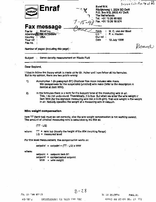
ENRAF:Enraf
Fax messageFax toAttentioiCountryYour ref.Fax no.
Enraf Inc.
!"0SA
Number of pages (including this page):
Enraf B.V.RonUrenweg 1.2624 BD DelftP.O. Box B12, 2S00 AV DslftThe NetherlandsTel. +31 1526 98 600Fax. +31 1 5 2 6 1 9 S 7 4
Fromc.c.Our ref.Date
M. C. van der StootP. v. Houten
15 July 1998
~&f-
Subject : Servo density measurement on Waste Fluid
Dear Gayiand,
I -tried to follow the theory which is made up by Mr. Huber and I can follow all his formulas.But to my opinion, there are two points wrong:
1) Assumption 1 (in paragraph B1) Displacer free mass includes wire mass.We compensate for the suspended (unrolled) wire mass (refer to the description initemlistatitemWW).
2) In the formulas there is a term for the buoyant force of the measuring wire In air.This, I do not understand. Theoretically, it is true. But when we enter the wire weight iritem W W (for the standard measuring wire this is 0.25 g/m), that wire weight is the wefghtin air. Nobody specifies the weight of a measuring wire in vacuum.
Wire weight compensation
Item T T (tank top) must be set correctly, else the wire weight compensation Is not working correct.The amount of unrolled measuring wire is calculated by the 854 as:
<TT-LQ)
where: TT = tank top (mostly tho height of the 854 mounting flange)LQ c measured level
For the level measurement, the compensation works as:
setpolnt' = setpolnt + (TT - LQ) x WW
where:setpoint = sstpoint item S Isetpoint' = compensated setpolnt
W W = wire weight
JUL 15 "38 87=IS
170/10'd EB££Zi£G0St 01 9 i i 9 £t7t? XS2
31 15 3619574 PSGE.Bt
ad 02:31: ss, L\ m r

The displacer weight is calculated by the 854 as;
weight = weight' - (TT - LQ) x WW
where: weight = compensated weightweight' = measured weight
Density measurement
The wire weight compensation remains active during the density measurement as the dis.placer iscompletely immersed in the product.
An extra compensation is required for the immersed part of tha measuring wire, which is subject tobuoyance force.Then we need item VW (wire volume). With the standard measuring wire, the wire volume is:0,032 em3/m.
To be calculated as:
Knds x 100 = !4jtx0.022x 100 = 0.0314 em3/m
where:0.02 = diameter measuring wire tern]
(diameter standard measuring wire: 0.2 mm)100 = volume is taken over one metre length (1 m = 100 em)
The default setting for item WV is +.32000000E-01 (floating point format)
When 3 density dip is made (either with a tank profile or an interface profile), the level value is stored(last valid level, Hem LV) and the distance of each of the ten density measurements is known (theseare items DO, 01 , . . . t»).
The immersed amount of measuring wire volume is addad by the displacer volume (item DV).
The compensation for the immersed part of the measuring wire is calculated by the 854 as:
DV = DV + (LV - On) x WV
where:DV = displacer voluma plus immersed wire volumeDV = displacer volumeLV = last valid level)On = density innage level (n ranging from 0 to 9)WV = wire volume
B 1JUL 15 '98 07: IS 31 15 2519574 P«SE.?2
£0£Z£A£60SI 01 SUB ZW ISZ d«3N3 ad 0£:3T 86, IX 1H£

talc
The density is calculated by the 854 as:
R - Oispiacerweight - Wire tension * Wire weight" Displacervolume * Immersed wire volume
where:Rn = measured servo density (n: 0 . . 9)A1 - density scale factor (normally not used)A2 = density offset factor (normally not used)RF <= ambient air density plj]
Wire tension = the force in the measuring wire, measured by the 854 level gauge
The first part of the density formula is calculated in the dimension: a/cn,3, then multiplying by the factor
1600 converts the density to the dimension of "•/„,' and then the ambient air density {hem RF) can t •»added.
The purpose for the ambient air density item is to provide the measured density as a density value inair (RF = 0), or as a density value in vacuum (RF = 1.225).
The density gain and offset factor (items A1 and A2) are normally not used.
This is all there is.
Back to the original problem
What remains is the fact that the measured density does not comply with the real density of theproduct.
1) We need data from the used measuring wire;its diameterits weight / length unit
That has to be given in the corresponding items WV and WW.
2) Please check once more the displacer data:ris weigth -> to be given in item DWits volume -> to be given in item DV
3) If possible and not done before, calibrate the force transducer with the test weights.
Regards,
Maarien van der Sloot
B-3O
01 9 i i 9 EJTfr 182 dt)dN3 <MJ V'
HNF-2965Revision 0
Appendix C
2E-98-1244 Work Instruction"Replace Densitometer Displacer"
Master Control Copy
c-i
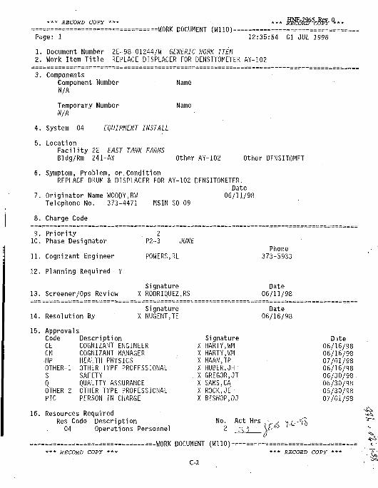
RECORD COPY
Page: 1=WORK DOCUMENT (W11O)====
12:35:54 01 JUL 1998
1. Document Number 2E-98-01244/W GENERIC MORK ITEM2. Work Item Title REPLACE DISPLACER FOR DENSITOMETER AY-102
ComponentsComponent NumberN/A
Temporary NumberN/A
System 04 EQUIPMENT INSTALL
LocationFacility 2E EAST TANK FARMSBldg/Rm 241-AY
Name
Name
Other AY-102 Other DENSITOMET
Symptom, Problem, or. ConditionREPLACE DRUM & DISPLACER FOR AY-102 DENSITOMETER.
DateOriginator Name WOODY,BW 06/11/98Telephone No. 373-4471 MSIN SO-09
8. Charge Code
9. Priority
10. Phase Designator
11. Cognizant Engineer
12. Planning Required • Y
13. Screener/Ops Review
2P2-3
POWERS,RL
JUNE
SignatureX RODRIQUEZ,RS
Phone373-5933
Date06/11/98
14.
15.
Resolution BySignature
X NUGENTJEDate
06/16/98
16
ApprovalsCode DescriptionCE COGNIZANT ENGINEERCM COGNIZANT MANAGERHP HEALTH PHYSICSOTHER-1 OTHER TYPE PROFESSIONALS SAFETYQ QUALITY ASSURANCEOTHER-2 OTHER TYPE PROFESSIONALPIC PERSON IN CHARGE
Resources RequiredRes Code Description
04 Operations Personnel
SignatureX HARTY,WMX HARTY.WMX HAAN.TPX HUBER,JHX GREGOR.JTX SAMS.CAX ROCK.JEX BISHOP,DJ
** RECORD COPY ***======W0RK DOCUMENT (W110>=
C-2
Date06/16/9806/16/9807/01/9806/16/9806/30/98 .06/30/9806/30/9807/01/98
*** RECORD COPY ***

*•* RECORD COPY *** HNF-2965, Rev. 0 ttt RECQRD copy »,=================================WORK DOCUMENT (W110)==========================«Page: 2 12:35:54 01 JUL 1998
1. Document Number 2E-98-01244/W GENERIC WORK ITEM2. Work Item Title REPLACE DISPLACER FOR DENSITOMETER AY-102
18 Instrument Technician 254A HEALTH PHYSICS TECHNICIAN 197 Quality Control 1 ,± K/- . .1AA OPERATIONS/PIC 1 ~s3Z " 1
22 Electrician 1
~J<I i'^'jTff^ " '],a.-}o4J Tcck- ,
RECORD COPY ***
=W0RK DOCUMENT (W110)=
C-3
RECORD COPY ***

*** RECORD COPY *** HNF-2965, Rev. 0 *»* REC0RD COPY
=================================WORK DOCUMENT (WHO) ==========================Page: 3 12:35:54 01 JUL 1998
1. Document Number 2E-98-01244/W GENERIC l/IORK ITEM2. Work Item Title REPLACE DISPLACER FOR DENSITOMETER AY-102
Signature . Date17. Pre-Work Review . X GUTIERREZ,RV • 07/01/9818. Tagout Number
Type Signature Date19. Work Release P SEE PARTIAL RELEASE SHEET
20. Work Suspension (See Work Suspension Sheet)PIC
21. PIC BORROWMAN,JE PIC Org. 77140
Resolution/Retest
1 SCOPE:
1.1 This work package provides work steps to shop-calibrate a spare densitometer displacer andreplace the existing Project W-320 ENRAF 854Densitometer (WST-DIT-602A) drum and displacerin the field. The Densitometer is installed inTank 241-AY-102, Riser 15E.
2 DESCRIPTION (Summary):
2.1 Perform shop-calibration of spare ENRAFDensitometer displacer per work steps in thiswork package ( Steps 7.1 through 7.32 ).
2.2 Replace existing 241-AY-102 ENRAF Densitometerdisplacer and drum in field with shop-calibrateddisplacer and new drum per approved maintenanceprocedure 6-TF-125 and operating procedureTO-320-420, as required ( Steps 7.33 through7.41 ).
2.3 Adjust newly installed ENRAF Densitometerdisplacer volume per work steps in this workpackage ( Steps 7.42 through 7.42.7).
2.4 Perform operational test of newly installedENRAF Densitometer displacer per test steps thiswork package ( Section 10 ).
2.5 Flush installed ENRAF Densitometer displacer perapproved operating procedure TO-020-420 after-operational testing ( Section 10 ) is complete.
============================W0RK DOCUMENT (Wl10)==============================** RECORD COPY *** ••• RECORD COPY ***
C-4

RECORD COPY **
Page: 4
HNF-2965, Rev. 0
=====«=WORK DOCUMENT (W110) =RECORD COPY
12:35:54 01 JUL 1998
1. Document Number 2E-98-01244/W GENERIC UORK ITEM2. Work Item Title REPLACE DISPLACER FOR DENSITOMETER AY-102
2.6 Restore area as required.
REFERENCE DOCUMENTS, PERMITS AND SPECIAL PROCEDURES:
3.1
3.2
3.3
3.4
3.5
3.6
3.7
3.8
3.9
6-TF-125:
TO-020-420:
H-2-817634:
H-2-818560, !
H-2-95413:
ECN-644543
Sht. 05:
Flammable Gas Review.
RWP E-1093.
Waste Plannit
ENRAF Series 854Maintenance andCalibration.
Clean Level IndicatingTransmitter Tapes,Plummets and Displacers;Replace Food InstrumentCorporati on/RobertshawTapes and Plummets.
Instm ENRAF Nonius AssyInstallation & RiserSchedule.
Project W-320 P&ID Tank241-AY-102.
Instm Liquid LevelIndication & AlarmInstallation & Details.
Level Gauge Upgrade.
iq Checklist.
3.10 Job Hazards Analysis ( JHA ).
3.11 Bill of Materials ( BOM ).
3.12 USQ # TF-98-0317, Rev. 002.
PRECAUTIONS, LIMITATIONS & NOTES:
4.1 Except for steps requiring HP hold pointsignatures, any steps in this instruction thatare NOT required for completion shall be
RECORD COPY ***=W0RK DOCUMENT (W110)=
C-5
•* RECORD COPY **

*** RECORD COPY •** HNF-2965, Rev. 0 *** RECORD COPY ***
= = = = = = = === == ====== ==== = = = = = = = = = = =WORK DOCUMENT (W110)==============================Page: 5 12:35:54 01 JUL 1998
1. Document Number 2E-98-01244/W GENERIC UORK ITEM2. Work Item Title REPLACE DISPLACER FOR DENSITOMETER AY-102
indicated as such by entering ' N/A ' in theappropriate sign off space and explained on theWork Record Document.
4.2 Except for steps requiring HP hold pointsignatures, sections or steps.of this workinstruction may be performed out of sequence,with regards to maintenance or plant conditions.
NOTE - Steps 4.3 through 4.4 apply ONLY to the fieldwork activities associated with densitometerdisp.lacer and drum replacement.
4.3 Per HNF.-IP-1266, portions of this activity areclassified as a "Dome Space Intrusive, LocallyWaste Disturbing Operation" associated with anactively ventilated Facility Group 2 tank, 241-AY-102.
4.3.1 Flush connections are valved quickdisconnects less than 1 in. in diameter.Drum and displacer replacementactivities are performed with theisolation valve closed. Densitometerreadings are taken with containmentestablished and equipment isnonsparking.
4.3.2 Before installation of the flushconnections to the spray nozzles,flammable gas entry monitoringrequirements must be met as described inthe work resolution.
4.3.3 There are no TSR controls associatedwith Ignition Source or Flammable Gasfor the work steps identified in thisJCS work package. Thus, HNF-IP-12665.9, 5.10, & 5.11 are not applicable.
4.4 An assessment of this work package was completedand found that there were no dome load concerns.
4.5 If displacer exposures exceed Radiation WorkPermit whole-body exposure limits, IMMEDIATELYstop work, place equipment in a safe condition,and notify Supervisor/Lead or CognizantEngineer.
==========================WORK DOCUMENT (W110)==============================RECORD COPY *** *** RECORD COPY ***
C-6

*•* RECORD COPY *•* HNF-2965, Rev. 0 * „ RECORD COPY=================================WORK DOCUMENT (W110)==========================Page: 6 12:35:54 01 JUL 1998
1. Document Number 2E-98-01244/W GENERIC t-IORK ITEM2. Work Item Title REPLACE DISPLACER FOR DENSITOMETER AY-102
5 MATERIALS AND EQUIPMENT REQUIRED:
NOTE - Materials and equipment required for shopcalibration activities are listed in step 5.1;materials and equipment required for field workactivities ( densitometer displacer and drumreplacement ) are listed in step 5.2.
5.1 Equipment required ( shop calibration work ):
5.1.1 Enraf 854 ATG gauge w/calibrated force. transducer.
5.1.2 Water-filled container, 15-in. deep( minimum ).
5.1.3 Graduated beaker, 800 ml ( minimum ).
5.1.4 Thermometer, 0-212 deg F.
5.1.5 Density Displacer, RECORD tagged data:
Tagged Weight 'LALt[ grams
Tagged Volume i%>? cm3
5.2 Equipment required ( field replacement work ):
5.2.1 See Bill of Materials ( BOM ).
5.2.2 See 6-TF-125, Step 4.1 ( replacement ).
5.2.3 See TO-020-420, Step 4.1 ( flushing ).
6 PREREQUISITES:
NOTE - This work package implements both shop work andfield work. The prerequisite steps below applyONLY to performance of field work activitiesstarting with Step 7.33.
6.1 Conduct a PRE-JOB SAFETY MEETING using thePre-job Safety Meeting form. Review appropriateJob Safety Analysis ( JSA ), and Radiation WorkPermit ( RWP ) and other applicable permits.
==============================W0RK DOCUMENT (Wl10)==================*=======•** RECORD COPY *** •** RECORD COPY
C-7

*** RECORD COPY *** HNF-2965, Rev. 0 „„.„. REC0RD copy
=================================WORK DOCUMENT (W110)==========================Page: 7 12:35:54 01 JUL 1998
1. Document Number 2E-98-01244/W GENERIC WORK ITEM2. Work Item Title REPLACE DISPLACER FOR DENSITOMETER AY-102
= = = = = = =: = = = = =;=z = = = = = = = = = = =: = =: = = = = =: = = = = = = = = = = = = = = = = = =: = = = — = = = — = = = =•— = =: = =:===: —~=i~ = ^ = = = -= = ;
6.2 Verify latest approved working procedures on theday work is to be performed.
SUPVSupervTsor/Le'Sd Sign Date
6.3 If radioactive/hazardous waste as defined byTO-100-052 will be generated by the performanceof this activity, the Waste Planning Checklistor Tank Farm Container Request Form shall becompleted and delivered to Generator WasteServices ( GWS ) and a copy included in thiswork package.
6.4 Verify 241-AZ-702 Ventilation System ( W-030 )is operating at 241-AY Facility during workactivities.
6.4.1 If active ventilation system fails or isshut down at 241-AY Facility during thisactivity, work shall cease until activeventilation is restored.
6.4.2 All personnel supporting this activityshall evacuate the farm and theimmediate work area shall be placed in a
C' safe shutdown mode.
6.4.3 Notify East Tank Farm Shift Manager.
6.5 If performance of this activity should requireentry into areas that require respiratoryprotection, protection and monitoringrequirements shall be identified by IH&Spersonnel. Specific instructions shall beaddressed in the Pre-Job Safety Meeting.
6.5.1 IH&S is responsible for monitoring andestablishing breathing air zones.
6.6 Notify CASS/TMACS operator (373-1005 or373-2618) of testing activities on affectedequipment and associated alarms before start ofeach shift.
6.7 Ensure batteries in portable ENRAF terminal arefully charged.
==============================W0RK DOCUMENT (WHO) =============================*** RECORD COPY *** *** RECORD COPY ***
C-8

•** RECORD COPY *•* HNF-2965, Rev. 0 *** RECORD COPY
=============================!=i===WORK DOCUMENT (Wl 10)==========================Page: 8 12:35:54 01 JUL 19981. Document Number 2E-98-01244/W GENERIC UORK ITEM2. Work Item Title REPLACE DISPLACER FOR DENSITOMETER AY-102
7 SPECIFIC WORK INSTRUCTIONS:
***************#*******#******#**********************-*CALIBRATE DENSITY DISPLACER ( SHOP CALIBRATION WORK ):
* * * * * * * * * * * * *
7.1 FILL beaker with at least 400 ml of water andrecord actual water level:
Initial water level reading in beaker(miniscus) *-7 oo ml •
7.2 PLACE displacer and snap hook into beaker andrecord actual water level:
Final water level reading in beaker (miniscus)gS5~ ml.
7.3 SUBTRACT initial water level reading from finalwater level reading:
_JFinal Level Init ial Level= \ IS ml (cm3)
Displacer/Snap Vol.
7.4 INSTALL displacer and snap hook on ENRAF gauge.
7.5 PLACE gauge and displacer over large water-filled container.
7.6 SETUP gauge per manufacturer's instructions,with the following parameters:
RL =,00070^00TT =+00105.00MH =+00090.00HH =-00100.00HA =---00095.00MZ =-1-00090.00LA =^00001.00LL =+00000.00
7.7 SET gauge Reference Level (RL) by placing a -piece of wood or cardboard across opening of the
==============================W0RK DOCUMENT (W110)==============================*** RECORD COSY *** *** RECORD COPY ***
C-9

*** RECORD COPY *** HNF-2965, Rev. 0 **„ REC0RD C0FY *»*
= = = = = = = = = = = = = = = = = = = = = = == = = = = = = = = =WORK DOCUMENT (W110)==============================Page: 9 • . . 12:35:54 01 JUL 1998
1. Document Number 2E-98-01244/W GENERIC I>IORK ITEM2. Work Item Title REPLACE DISPLACER FOR DENSITOMETER AY-102
water-filled container and allowing thedisplacer to come to rest on the wood/cardboard.
7.8. ENTER command [W2=ENRAF2].
7.9 ENSURE displacer is at rest on thewood/cardboard and gauge is reporting a validlevel reading.
7.10 ENTER command [AR] and allow gauge toreinitialize.
7.11 ENTER command [EX] and allow gauge toreinitialize.
7.12 ENTER command [CA], wait 1-second minimum, thenENTER command [FR].
7.13 ENTER command [MF].
7.14 WHEN "FR" appears in gauge display, ENTERcommand [WQ] and record result.
WQ(FREE) = ,z40l~tog6£ + o'(> grams
7.15 Verify that WQ(FREE) is within +/- 3 grams oftagged weight recorded in Step 5.1.5
SUPV
(QC)QualitytCwitrol Sign' Date
7.16 If WQ(FREE) is not within +/- 3 grams of taggedweight, then calibrate force transducer permanufacturer's instructions and repeat Steps7.12 through 7.15.
7.17 REMOVE wood/cardboard from water-filledcontainer and allow displacer to seek waterlevel in container.
7.18 RECORD container water level from the gaugedisplay:
==========================W0RK DOCUMENT (WHO) ==========================RECORD COPY •** *** RECORD COPY
C-10

RECORD COPY *** ' 5 ' R e v 0 *** RECORD COPY=WORK DOCUMENT (W110)=
Page: 10 12:35:54 01 JUL 1998
1. Document Number 2E-98-01244/W GENERIC IrlORK ITEM2. Work Item Title REPLACE DISPLACER FOR DENSITOMETER AY-102
Water Level 6 b'. 03 inches
7.19 SUBTRACT 8 inches from recorded water level:0 3
inchesWater Level
= J (?. $3 inches
Submerged Level
7.20 ENTER command [S2] and record value:
S2 = • . g> 5oooocg grams
7.21 IF S2 does NOT equal 50 grams, THEN:
7.21.1 ENTER command [W2=ENRAF2].
7.21.2 ENTER command [S2=+.05000000E+03].7.21.3 ENTER command [EX] and wait for gauge to
reinitialize.
NOTE - After entering command [FR], do NOT press<ENTER> until displacer reaches Submerged Levelcalculated above.
7.22 ENTER command [UN] <ENTER>, [12] <ENTER> then[FR].
7.23 MEASURE water temperature near displacer:
Water Temp. "7 3" Deg F
7.24 ENTER command [MF].
7.25 WHEN "FR" appears in gauge display, ENTERcommand [WQ] and record result:
WQ(Submerged) = grams
7.26 ENTER command [UN] then [II] to return displacerto surface.
7.27 PROVIDE Engineer with water temperature reading,obtain calculated water specific gravity and •record below:
= = = = = = = = = = = = = = = = = = = = = = = = ; = = WORK DOCUMENT (W110)=====================«===RECORD COPY *** *** RECORD COPY
C-ll

>** RECORD COPY *** HNF-2965, Rev. 0 *** RECORD COPY *=================================WORK DOCUMENT (WHO)===========================Page: 11 12:35:54 01 JUL 1998
1. Document Number 2E-98-01244/W GENERIC UORK ITEM2. Work Item Title REPLACE DISPLACER FOR DENSITOMETER AY-102
- 9/7 7 SpG (g/ctn3)Water Spec i f i c Gravi ty
7.28 CALCULATE d isp lacer volume as f o l l o w s :
WQ(FREE) WQ(Submerged)
SpG . Volume cm3
7.29 Verify Tagged Volume ( Step 5.1.5 ),Displacer/Snap Volume ( Step 7.3 ) andCalculated Displacer Volume ( Step 7.28 ) areall within +/- 0.5 cm3 of each other.
SUPV
(QC)
COG
^ S u p !
%
7^ ^*s'Sbr/Lead
^ / /Control
Sign
ySign
Date
Date
/ iklnj&6gnizant Engineer Sign Date
7.30 If volumes are NOT within +/- 0.5 cm3 of eachother, then stop work and notify CognizantEngineer.
7.31 Cognizant Engineer to determine displacer volumevalue to be used.
7.32 Quality Control to retag displacer ( with snap )for transport to field installation site withdisplacer volume determined by CognizantEngineer and displacer weight and serial numberfrom original tag and record below:
Displacer
Displacer
Displacer
Volume:
Weight:
Ser. No.:
\fyt cm3
, 1 grams
Ol
= = = = = = = = = = = = = = = = = = = = = = = = = = = = = W 0 R K DOCUMENT (W110)==========================* • * RECORD COPY *** * * * RECORD COPY
C-12

RECORD COPY *•* HNF-2965,Rev. 0 ,„ RECORD COPY ***
=WORK DOCUMENT (HI10)======Page: 12 12:35:54 01 JUL 1998
1. Document Number 2E-98-01244/W GENERIC HORK ITEM2. Work Item Title REPLACE DISPLACER FOR DENSITOMETER AY-102
Quality Control Sign Date
*******************************************************REPLACE DISPLACER & DRUM ( FIELD REPLACEMENT WORK ):*******************************************************
7.33 Ensure prerequisites in section 6.0 have beenmet.
7.34 Quality Control to verify displacer and drumidentification per BOM Suppl. #0 beforeinstallation.
(QC)
7.35 ENSURE all tagging and tape is removed fromdisplacer before installation.
NOTE - Lockout/tagouts needed to support workactivities are per HNF-IP-0842, Vol. II, Sect.4.9.1, "Lock and Tag Program".
7.36 Operations install lock and tag or PLD to de-energize 241-AY-102 Densitometer to support thefollowing work steps or as directed bySupervisor/Lead.
( Suggested isolation point: 241-AY-102,WST-HS-602B; H-2-95413 and ECN-64453 ).
7.36.1 Craft perform zero energy check asrequired to facilitate work activities.
NOTE - Fittings are less than 1-inch in diameter,therefore bonding is not required.
NOTE - Tank vapor space flammable gas concentrationsmay be verified via tank 241-AY-102 SHMS Cabinet(VTP-PNL-605B), if operable and calibrated, orby obtaining a physical sample at the SamplingPort located near VTP-PNL-605B SHMS cabinet.
7.37 Perform flammable gas entry monitoring asfollows:
7.37.1 IF SHMS is operable, OBTAIN SHMS data
==========================H0RK DOCUMENT (Wl10)==========================RECORD COPY *** *** RECORD COPY
C-13
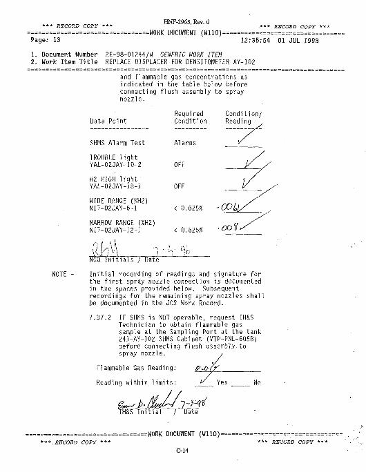
*•* RECORD COPY ***
Page: 13
HNF-2965, Rev. 0=WORK DOCUMENT (W1IO)==
*** RECORD COPY *
12:35:54 01 JUL 1998
1. Document Number 2E-98-01244/W GENERIC UORK ITEM2. Work Item Title REPLACE DISPLACER FOR DENSITOMETER AY-102
NOTE -
and flammable gas concentrations asindicated in the table below beforeconnecting flush assembly to spraynozzle.
Data PointRequiredCondition
Condition/Reading
SHMS Alarm Test
TROUBLE lightYAL-02JAY-10-2
H2 HIGH lightYAL-02JAY-18-1
WIDE RANGE (%H2)NIT-02JAY-6-1
NARROW RANGE (%H2)NIT-O2JAY-12-1
Alarms
OFF
OFF
< 0.625% -COLj
< 0.625% • °°^
' ' I
N£0 Initials / Date
Initial recording of readings and signature forthe first spray nozzle connection is documentedin the spaces provided below. Subsequentrecordings for the remaining spray nozzles shallbe documented in the JCS Work Record.
7.37.2 IF SHMS is NOT operable, request IH&STechnician to obtain flammable gassample at the Sampling Port at the tank241-AY-102 SHMS Cabinet (VTP-PNL-605B)before connecting flush assembly tospray nozzle. ,
Flammable Gas Reading:
Reading within limits:
P-o/f
Yes No
2±3H&S In i t i a l / Date
***.RECORD COPY=W0RK DOCUMENT (W110)====
C-14*** RECORD COPY

*** RECORD COPY *•* HNF-2965, Rev. 0 „, RECORD COPY **
=================================W0RK DOCUMENT (W1IO)=========—=======—=======Page: 14 . 12:35:54 01 JUL 1998
1. Document Number 2E-98-01244/W GENERIC WORK ITEM2. Work Item Title REPLACE DISPLACER FOR DENSITOMETER AY-102
7.37.3 VERIFY that flammable gas concentrationof tank vapor space is less than orequal to 25% of Lower Flammability LimitOR less than or equal to 0.625% H2 as/%ad by VTP-PNL-605B SHMS.
-t -H—. n — ; — ' s ' 9
eadifht / Date
7.37.4 IF flammable gas concentrations aregreater than 25% of Lower FlammabilityLimit (LFL) OR greater than 0.625% H2 asread by VTP-PNL-605B SHMS, STOP work.
7.37.4.1 NOTIFY Shift Manager that an out-of-specification condition existsfor BIO-TSR, AC 5.11.
7.37.4.2 COMPLETE actions as directed byShift Manager.
7.38 FLUSH displacer at 241-AY-102 Densitometer perTO-020-420.
7.39 HPT perform radiation survey on removeddisplacer. At HPT or Supervisor/lead direction,shield displacer with rubber matting/padding.
7.40 REPLACE displacer and drum at 241-AY-102Densitometer per 6-TF-125, Section 5.8.
7.41 REMOVE Lock and tags or PLD, as required.
*******************************************************ADJUST DISPLACER VOLUME ( NONINTRUSIVE FIELD WORK ):*******************************************************
7.42 Adjust ENRAF 854 Densitometer displacer volumeand wire weight as follows:
7.42.1 Connect ENRAF PET to Densitometer.
7.42.2 Enter command [W2=ENRAF2].
NOTE - Cognizant Engineer will provide displacer volume( DV ) value to. use for installation.
==========================W0RK DOCUMENT (WHO) ============================RECORD COPY *** *** RECORD COPY **
C-15
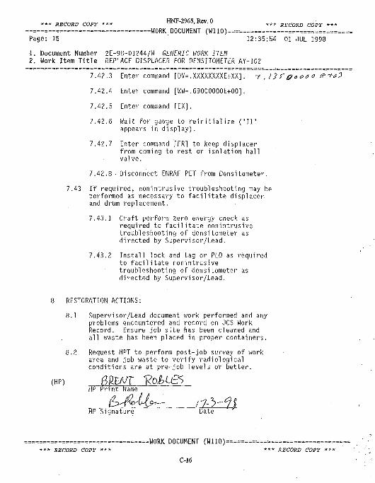
*** RECORD COPY *** HNF-2965, Rev. 0 „„ RECQRD CQpy ,=================================WORK DOCUMENT (W110)===========================Page: 15 12:35:54 01 JUL 1998
•1. Document Number 2E-98-01244/W GENERIC I//ORK ITEM
2. Work Item Title REPLACE DISPLACER FOR DENSITOMETER AY-102
7.42.3 Enter command [DV=.XXXXXXXXE+XX]. ~f , /} r p ooa o
1AIA Enter command [WW=.69000000E+00].
7.42.5 Enter command [EX].7.42.6 Wait for gauge to reinitialize ("11"
appears in display).
7.42.7 Enter command [FR] to keep displacerfrom coming to rest on isolation ballvalve.
7.42.8 • Disconnect ENRAF PET from Densitometer.
7.43 If required, nonintrusive troubleshooting may beperformed as necessary to facilitate displacer.and drum replacement.
7.43.1 Craft perform zero energy check asrequired to facilitate nonintrusivetroubleshooting of densitometer asdirected by Supervisor/Lead.
7.43.2 Install lock and tag or PLD as requiredto facilitate nonintrusivetroubleshooting of densitometer asdirected by Supervisor/Lead.
8 RESTORATION ACTIONS:
8.1 Supervisor/Lead document work performed and anyproblems encountered and record on JCS WorkRecord. Ensure job site has been cleaned andall waste has been placed in proper containers.
8.2 Request HPT to perform post-job survey of workarea and job waste to verify radiologicalconditions are at pre-job levels or better.
HP Print Name
l~2^y(kyv-\^— / "7- ~>-HP Signature Date
= = = = = = = = = = = = = = = = = = = = = = = = = = = = = = W O R K DOCUMENT (W110)====—==—======—==========* * * RECORD COPY * * * * * * RECORD COPY * • *
C-16

HNF-2965 Rev 0* • RECORD COPY • * * ' *** RECORD COPY ***
=WORK DOCUMENT (W110)======Page: 16 12:35:54 01 JUL 1998
1. Document Number 2E-98-01244/W GENERIC MORK ITEM
2. Work Item Title REPLACE DISPLACER FOR DENSITOMETER AY-102
9 POST-MAINTENANCE TESTING:
9.1 • N/A
10 OPERATIONAL FUNCTIONAL TESTS:
*********** *******A****A************-A-*A-******AA-t*** ****
TEST DENSITOMETER DISPLACER ( FIELD OPERABILITY TEST ):*******************************************************
NOTE - These steps may be performed using either PET orENRAF Control Panel ( ECP ) software. If usingECP software, "ENTER command..." shall beinterpreted as "SELECT appropriate ECP commandfor..."
10.1 Ensure prerequisite steps in Section 6.0 aremet.
10.2 HPT to perform pre-job survey of work area.
HPT Initial Date
10.3 OPEN isolation ball valve.
10.4 ENTER command [UN].
10.5 ENTER command [II].
10.6 ENTER command [DK=+00280.00] ( this is a levelbelow waste surface ).
10.7 ENTER command [DN=+00280.00].
10.8 WHEN displacer reaches waste surface and "inINN" appears on gauge display, ENTER command[IP] ( causes ENRAF to obtain a density readingat 280.00 inches ).
10.9 WHEN "II" appears in line 2 of gauge display,enter command [SC] and record result:
kg/m3Average Density at 280.00 inches
10.10 VERIFY Average Density reading is between
= = = = = = = = = = = = = = = = = = = = = = = = = = = = ! = = W0RK DOCUMENT (HI10)==========================*** RECORD COPY *** •** RECORD COPY
C-17

HNF-2965, Rev. 0*** RECORD COPY *•• , *** RECORD COPY
=WORK DOCUMENT (WHO) =======Page: 17 12:35:54 01 JUL 1998
1. Document Number 2E-98-01244/W GENERIC WORK ITEM
2. Work Item Title REPLACE DISPLACER FOR DENSITOHETER AY-102
960 Kg/m3 and 1050 kg/m3.
is" Yes No
SUPV
(QC) ^ j W Q ^ / 1-1,-38.Qua! i/ty Control Sign Date
COG l/f/jU^ 1^-7-6-Cognizant Engineer Sign Date
10.11 ENTER command [12].
10.12 WHEN displacer reaches approximately 280.00inches, enter command [FR] and record level.
t 7f- 2 f inchesSubmerged Level
10.13 ENTER command [MF].
10.14 WHEN "FR" appears in l ine 2 of gauge display,enter command [WQ] and record result:
-/ . / QjyfJoC. £-tol grams 9
WQ(Submerged AY-102) z VJ? £>63 3„ , f 3 <!>
10.15 ENTER command [DW] and record value: ./ #•> ' S ^
[__ gramsWQ(FREE)
10.16 ENTER command [DV] and record value:
DV -f . / j r > ^ ^ ^ g ^
10.17 CALCULATE density as follows:
WQ(FREE) WQ(Submerged AY-102)
DV " Density
10.18 Verify Average Density Reading ( Step 10.9 ) andCalculated Density ( Step 10.17 ) are within
=============================W0RK DOCUMENT (Wl10)==========================*** RECORD COPY *** *** RECORD COPY
C-18

*** RECORD COPY *** HNF-2965, Rev. 0 „„„ REC0RD CQpy ..
=================================H0RK DOCUNENT (W110)============================Page: 18 12:35:54 01 OUL 1998
1. Document Number 2E-98-01244/W GENERIC WORK ITEM2. Work Item Title REPLACE DISPLACER FOR DENSITOMETER AY-102 O
3,...~. of each other. K 7~Gty /
SUPV
(QC)
COG ftognizanf Engineer Sign Date10.19 If density values are NOT within +/- 10 kg/m3 of
each other, then stop work and notify CognizantEngineer.
10.20 Perform troubleshooting to facilitate testingdensitometer as directed by Cognizant Engineer.
10.20.1 Craft perform zero energy check asrequired to facilitate testingdensitometer as directed bySupervisor/Lead.
10.20.2 Install lock and tag or PLD asrequired to facilitate testingdensitometer as directed bySupervisor/Lead.
10.21 REPEAT entry monitoring steps 7.37.1 through7.37.4.2 as required before connecting flushassembly to spray nozzle.
10.22 FLUSH displacer at 241-AY-102 Densitometer perTO-020-420.
30.23 When flushing complete, POSITION displacerapproximately 80 inches below isolation ballvalve ( with isolation ball valve OPEN ).
10.24 Supervisor/Lead document work performed and anyproblems encountered and record on J-5. Ensurejob site has been cleaned.and all waste has beenplaced in proper containers.
10.25 Request HPT to perform post-job survey of workarea and job waste to verify radiological
==============================W0RK DOCUMENT (W110)==============================**• RECORD COPY *** * *** RECORD COPY ***
C-19

*** RECORD COPY ***
Page: 19
HNF-2965, Rev. 0
«WORK DOCUMENT (W110)=====*** RECORD COPY *
12:35:54 01 JUL 1998
1. Document Number 2E-98-01244/W GENERIC WORK ITEM2. Work Item Title REPLACE DISPLACER FOR DENSITOMETER AY-102
conditions are at pre-job levels or better.
HPTTTntTiT
22. Reference DocumentsHNF-IP-1266WHC-SD-WM-HSP-002HNF-SD-WM-TSR-006TO-1OO-O52
23. Field Work Complete
24. Ops_Acceptance
25. Post Review
TypeMISC .MISCMISCPROC
Signaturei r. ./
RECORD COPY
=W0RK DOCUMENT (M10)===
C-20
*** RECORD COPY

HNF-2965, Rev. 0
DOCUMENT ACCEPTANCE REVffiW FORM Page 1 of __ 1_
=TF"98-385Procedure Change Number . USQ Screening No.
A-2-qP-320-010 A-l • . •Document No. Rev./Mod.
Plant Operating Procedure • Alarm Response Procedure
73 Operator Round Sheet • Facility Sampling Schedule
• Other Type Document •
D Operating Specification Document(Requires Checklist)
Approval Designator
73 Criticality Specifications
73 Maintenance Procedure
1-320 Enraf Series 854 Densitometer Operational Test7Nocument Title
Prepared By
John HuberName
Coq Enq/SSTETitle/Organization
C7J New or'Revised - Full Review Required
Procedure Change Authorization
[—] Administrative Change
W Procedure Changes/Changed Pages/Summary of change Pages 10. 17. 20. 25. 31 . 33. 44 16
r OCUMENT IS ACCEPTABLE
WithAs Is Changes
Noted
PROCEDURE REVIEWERS SIGNATURES
nature - OSttSeir Operator/User) (Print Name)sures thafth/procedure has been field validated and comments incorporated.
(ignature -'S gor Operations SupporfManager)Verifies documentation is complete, including Change Summary Signature Sheet and ensures Radiological review is complete ormarks Radiological Controls as N/A
D
an
a
a'
(Signature -Radiological Controls)
- Other)
(Print Name) . (Title/Org) (Date)
(Print Name)
(Sigtyiture- Cognizant Engineer) (Print Name) <Title/Org)Ensures that the technical aspects of the procedure are correct, and that the procedure has been reviewed per the approval designator.Enters the USQ Screening No.
PROCED'
(SignatureJ
lUREJKRITER
(Print Name) fTille/Org)
A PPROVAL AUTHORITY
(Signature)S Vw /O i T
t Name)C/CS/9S
(Date)
C-21

DOCUMENT ACCEPTANCE REVIEW FORM Page 1 of 1_
Procedure Change Number USQ Screening No.
OTp-Zto-otoDocument No.
Screening
Rev./Mod.
M Plant Operating Procedure • AJarm Response Procedure
D Operator Round Sheet D Facility Sampling Schedule
G Criticality Specifications • Other Type Document
• Maintenance Procedure • Operating Specification Document(Requires Checklist)
Approval Designator
T<-STDocument Title
Prepared By
Name
Title/Organization
I I New or Revised - Full Review Recuired
Procedure Change Authorization
p i Administrative Change
Procedure Changes/Changed Pages/Surniary of change PMLS 'SP. i l .
PROCEDURE REVIEWERS SIGNATURES
(Signature - SIor Operations Support Sta'nager)Verifies documentation is complete, including Change Summary Signature Sheet and ensures Radiological review is complete cr
D
fi
D
•D
marks Radiological Controls as N/A
A/A)gical Controls) (Print Name) (Title/Org)
(Print Name) (Title/Org)
(S jjiattfre - Cognizant Engineer) (Print Name) . - - ^ (TitM/Grg) (fiavt)Ensures that the technical aspects of the procedure are correct, and that the procedure has been reviewed per the approval designator.Enters the USQ Screening No.
PROCEj
(y (SignatJTeV' " ~(/J ' ~^ (Print Name)"'WZZte^fAPPROVAL AUTHORITY
(Signature ) (Print Name) (Title/Oig).
C-22