Validation of a morphometric reconstruction technique applied to a juvenile pelvis
11
http://pih.sagepub.com/ Medicine Engineers, Part H: Journal of Engineering in Proceedings of the Institution of Mechanical http://pih.sagepub.com/content/225/1/48 The online version of this article can be found at: DOI: 10.1243/09544119JEIM810 2011 225: 48 Proceedings of the Institution of Mechanical Engineers, Part H: Journal of Engineering in Medicine P J Watson, P O'Higgins, M J Fagan and C A Dobson Validation of a Morphometric Reconstruction Technique Applied to a Juvenile Pelvis Published by: http://www.sagepublications.com On behalf of: Institution of Mechanical Engineers can be found at: Proceedings of the Institution of Mechanical Engineers, Part H: Journal of Engineering in Medicine Additional services and information for http://pih.sagepub.com/cgi/alerts Email Alerts: http://pih.sagepub.com/subscriptions Subscriptions: http://www.sagepub.com/journalsReprints.nav Reprints: http://www.sagepub.com/journalsPermissions.nav Permissions: http://pih.sagepub.com/content/225/1/48.refs.html Citations: by guest on September 15, 2011 pih.sagepub.com Downloaded from
Transcript of Validation of a morphometric reconstruction technique applied to a juvenile pelvis

http://pih.sagepub.com/Medicine
Engineers, Part H: Journal of Engineering in Proceedings of the Institution of Mechanical
http://pih.sagepub.com/content/225/1/48The online version of this article can be found at:
DOI: 10.1243/09544119JEIM810
2011 225: 48Proceedings of the Institution of Mechanical Engineers, Part H: Journal of Engineering in MedicineP J Watson, P O'Higgins, M J Fagan and C A Dobson
Validation of a Morphometric Reconstruction Technique Applied to a Juvenile Pelvis
Published by:
http://www.sagepublications.com
On behalf of:
Institution of Mechanical Engineers
can be found at:Proceedings of the Institution of Mechanical Engineers, Part H: Journal of Engineering in MedicineAdditional services and information for
http://pih.sagepub.com/cgi/alertsEmail Alerts:
http://pih.sagepub.com/subscriptionsSubscriptions:
http://www.sagepub.com/journalsReprints.navReprints:
http://www.sagepub.com/journalsPermissions.navPermissions:
http://pih.sagepub.com/content/225/1/48.refs.htmlCitations:
by guest on September 15, 2011pih.sagepub.comDownloaded from
Validation of a morphometric reconstruction techniqueapplied to a juvenile pelvisP J Watson1*, P O’Higgins2, M J Fagan1, and C A Dobson1
1Department of Engineering, University of Hull, UK2Department of Anatomy, Hull York Medical School, University of York, UK
The manuscript was received on 1 February 2010 and was accepted after revision for publication on 17 June 2010.
DOI: 10.1243/09544119JEIM810
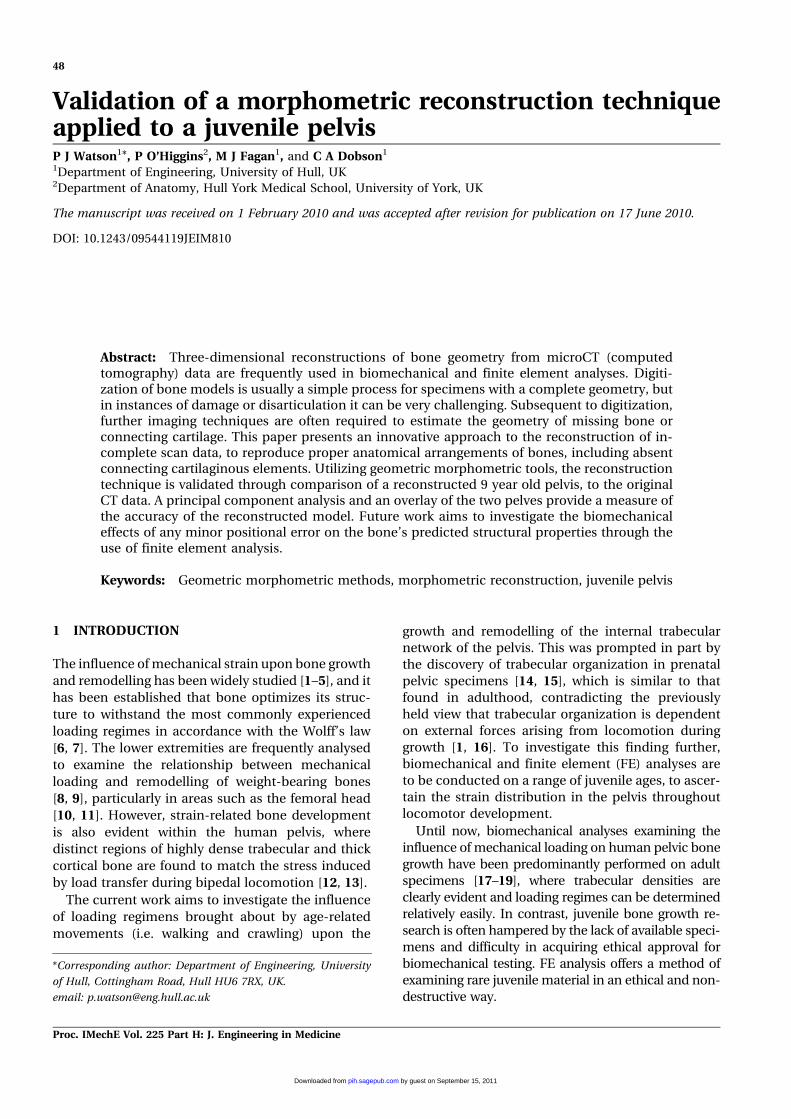
Abstract: Three-dimensional reconstructions of bone geometry from microCT (computedtomography) data are frequently used in biomechanical and finite element analyses. Digiti-zation of bone models is usually a simple process for specimens with a complete geometry, butin instances of damage or disarticulation it can be very challenging. Subsequent to digitization,further imaging techniques are often required to estimate the geometry of missing bone orconnecting cartilage. This paper presents an innovative approach to the reconstruction of in-complete scan data, to reproduce proper anatomical arrangements of bones, including absentconnecting cartilaginous elements. Utilizing geometric morphometric tools, the reconstructiontechnique is validated through comparison of a reconstructed 9 year old pelvis, to the originalCT data. A principal component analysis and an overlay of the two pelves provide a measure ofthe accuracy of the reconstructed model. Future work aims to investigate the biomechanicaleffects of any minor positional error on the bone’s predicted structural properties through theuse of finite element analysis.
Keywords: Geometric morphometric methods, morphometric reconstruction, juvenile pelvis
1 INTRODUCTION
The influence of mechanical strain upon bone growth
and remodelling has been widely studied [1–5], and it
has been established that bone optimizes its struc-
ture to withstand the most commonly experienced
loading regimes in accordance with the Wolff’s law
[6, 7]. The lower extremities are frequently analysed
to examine the relationship between mechanical
loading and remodelling of weight-bearing bones
[8, 9], particularly in areas such as the femoral head
[10, 11]. However, strain-related bone development
is also evident within the human pelvis, where
distinct regions of highly dense trabecular and thick
cortical bone are found to match the stress induced
by load transfer during bipedal locomotion [12, 13].
The current work aims to investigate the influence
of loading regimens brought about by age-related
movements (i.e. walking and crawling) upon the
growth and remodelling of the internal trabecular
network of the pelvis. This was prompted in part by
the discovery of trabecular organization in prenatal
pelvic specimens [14, 15], which is similar to that
found in adulthood, contradicting the previously
held view that trabecular organization is dependent
on external forces arising from locomotion during
growth [1, 16]. To investigate this finding further,
biomechanical and finite element (FE) analyses are
to be conducted on a range of juvenile ages, to ascer-
tain the strain distribution in the pelvis throughout
locomotor development.
Until now, biomechanical analyses examining the
influence of mechanical loading on human pelvic bone
growth have been predominantly performed on adult
specimens [17–19], where trabecular densities are
clearly evident and loading regimes can be determined
relatively easily. In contrast, juvenile bone growth re-
search is often hampered by the lack of available speci-
mens and difficulty in acquiring ethical approval for
biomechanical testing. FE analysis offers a method of
examining rare juvenile material in an ethical and non-
destructive way.
*Corresponding author: Department of Engineering, University
of Hull, Cottingham Road, Hull HU6 7RX, UK.
email: [email protected]
48
Proc. IMechE Vol. 225 Part H: J. Engineering in Medicine
by guest on September 15, 2011pih.sagepub.comDownloaded from
Ossification of the juvenile skeleton is incomplete
until late adolescence, and therefore fusion of the
three pelvic bones (ilium, ischium, and pubis) (see
Fig. 1) into the single innominate bone does not
occur in humans until this time [20]. Prior to fusion,
cartilage provides connectivity between bones, to
such a degree that the acetabulum is not fully ossified
until 16–18 years of age [21]. Therefore, when con-
sidering juvenile bones that have incomplete fusion,
it is essential for any FE analysis that the relative
positions of the bones and the geometry of the
cartilaginous material are modelled accurately to
represent the situation in vivo.
Computerized biomechanical analyses of bone
structures require the digitization of magnetic reson-
ance imaging (MRI) or computed tomography (CT)
data to produce accurate three-dimensional volume
models [22, 23]. There are many competent software
packages that aid in the segmentation and construc-
tion of these models, enabling the internal and
external architecture to be replicated faithfully from
the scan data.
Geometric morphometric methods (GMMs) [24–26]
facilitate comparison of configurations of landmarks
between forms and, since they preserve geometry at all
stages of analysis, visualization of results in terms of
geometry is straightforward. Variations among land-
mark configurations can be represented through the
use of thin-plate splines [27] to warp associated
volumes and surfaces [28]. Here these methods were
used digitally to warp a developed hemi-pelvis to a
known juvenile geometry, hence providing a template
to enable the repositioning of disarticulated bones.
This paper presents a new approach to the recon-
struction of incomplete scan data to produce FE
models that replicate proper anatomical arrangements
of bones, including absent connecting cartilaginous
elements. It is presented using statistical and warping
tools from geometric morphometrics to reconstruct
a model of a juvenile hemi-pelvis from scan data
containing each of its three constituent bones.
The technique was validated through the use of a
complete clinical CT scan of a 9 year old (i.e. soft
tissue included). The three bones of the left hemi-
pelvis were individually segmented from the scan,
and then repositioned within a warped hemi-pelvic
template of a similar form. The relative orientation
of the positioned bones was then compared to their
positions in the original complete CT scan.
2 METHOD
The general geometric morphometric reconstruction
will first be described, followed by the details of the
specific data used for the validation of the technique.
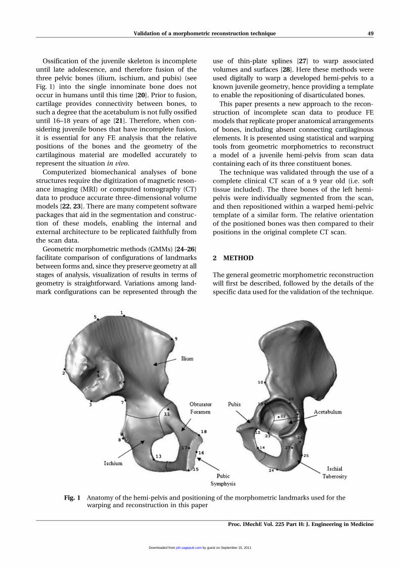
Fig. 1 Anatomy of the hemi-pelvis and positioning of the morphometric landmarks used for thewarping and reconstruction in this paper
Validation of a morphometric reconstruction technique 49
Proc. IMechE Vol. 225 Part H: J. Engineering in Medicine
by guest on September 15, 2011pih.sagepub.comDownloaded from
2.1 Geometric morphometric reconstructionmethod
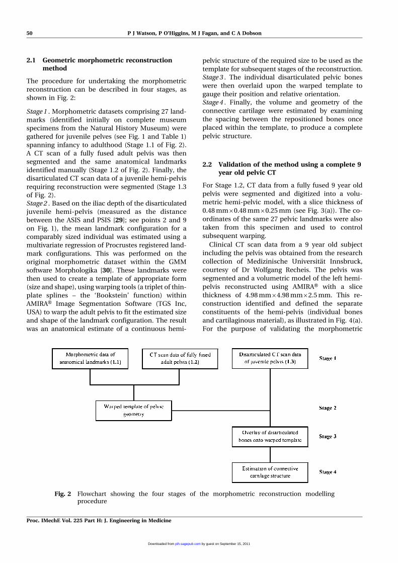
The procedure for undertaking the morphometric
reconstruction can be described in four stages, as
shown in Fig. 2:
Stage 1 . Morphometric datasets comprising 27 land-
marks (identified initially on complete museum
specimens from the Natural History Museum) were
gathered for juvenile pelves (see Fig. 1 and Table 1)
spanning infancy to adulthood (Stage 1.1 of Fig. 2).
A CT scan of a fully fused adult pelvis was then
segmented and the same anatomical landmarks
identified manually (Stage 1.2 of Fig. 2). Finally, the
disarticulated CT scan data of a juvenile hemi-pelvis
requiring reconstruction were segmented (Stage 1.3
of Fig. 2).Stage 2 . Based on the iliac depth of the disarticulated
juvenile hemi-pelvis (measured as the distance
between the ASIS and PSIS [29]; see points 2 and 9
on Fig. 1), the mean landmark configuration for a
comparably sized individual was estimated using a
multivariate regression of Procrustes registered land-
mark configurations. This was performed on the
original morphometric dataset within the GMM
software Morphologika [30]. These landmarks were
then used to create a template of appropriate form
(size and shape), using warping tools (a triplet of thin-
plate splines – the ‘Bookstein’ function) within
AMIRAH Image Segmentation Software (TGS Inc,
USA) to warp the adult pelvis to fit the estimated size
and shape of the landmark configuration. The result
was an anatomical estimate of a continuous hemi-
pelvic structure of the required size to be used as the
template for subsequent stages of the reconstruction.Stage 3 . The individual disarticulated pelvic bones
were then overlaid upon the warped template to
gauge their position and relative orientation.Stage 4 . Finally, the volume and geometry of the
connective cartilage were estimated by examining
the spacing between the repositioned bones once
placed within the template, to produce a complete
pelvic structure.
2.2 Validation of the method using a complete 9year old pelvic CT
For Stage 1.2, CT data from a fully fused 9 year old
pelvis were segmented and digitized into a volu-
metric hemi-pelvic model, with a slice thickness of
0.48 mm60.48 mm60.25 mm (see Fig. 3(a)). The co-
ordinates of the same 27 pelvic landmarks were also
taken from this specimen and used to control
subsequent warping.
Clinical CT scan data from a 9 year old subject
including the pelvis was obtained from the research
collection of Medizinische Universitat Innsbruck,
courtesy of Dr Wolfgang Recheis. The pelvis was
segmented and a volumetric model of the left hemi-
pelvis reconstructed using AMIRAH with a slice
thickness of 4.98 mm64.98 mm62.5 mm. This re-
construction identified and defined the separate
constituents of the hemi-pelvis (individual bones
and cartilaginous material), as illustrated in Fig. 4(a).
For the purpose of validating the morphometric
Fig. 2 Flowchart showing the four stages of the morphometric reconstruction modellingprocedure
50 P J Watson, P O’Higgins, M J Fagan, and C A Dobson
Proc. IMechE Vol. 225 Part H: J. Engineering in Medicine
by guest on September 15, 2011pih.sagepub.comDownloaded from
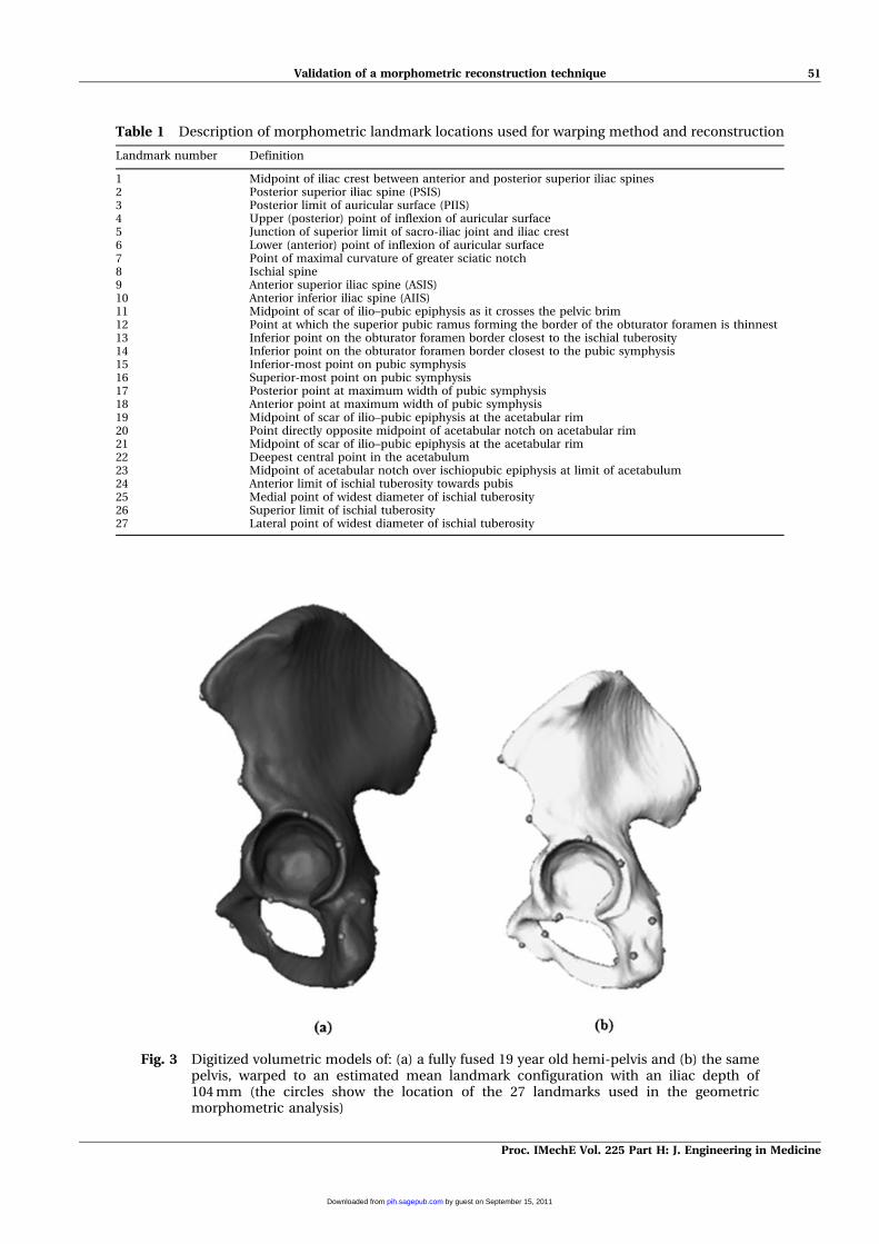
Table 1 Description of morphometric landmark locations used for warping method and reconstruction
Landmark number Definition
1 Midpoint of iliac crest between anterior and posterior superior iliac spines2 Posterior superior iliac spine (PSIS)3 Posterior limit of auricular surface (PIIS)4 Upper (posterior) point of inflexion of auricular surface5 Junction of superior limit of sacro-iliac joint and iliac crest6 Lower (anterior) point of inflexion of auricular surface7 Point of maximal curvature of greater sciatic notch8 Ischial spine9 Anterior superior iliac spine (ASIS)10 Anterior inferior iliac spine (AIIS)11 Midpoint of scar of ilio–pubic epiphysis as it crosses the pelvic brim12 Point at which the superior pubic ramus forming the border of the obturator foramen is thinnest13 Inferior point on the obturator foramen border closest to the ischial tuberosity14 Inferior point on the obturator foramen border closest to the pubic symphysis15 Inferior-most point on pubic symphysis16 Superior-most point on pubic symphysis17 Posterior point at maximum width of pubic symphysis18 Anterior point at maximum width of pubic symphysis19 Midpoint of scar of ilio–pubic epiphysis at the acetabular rim20 Point directly opposite midpoint of acetabular notch on acetabular rim21 Midpoint of scar of ilio–pubic epiphysis at the acetabular rim22 Deepest central point in the acetabulum23 Midpoint of acetabular notch over ischiopubic epiphysis at limit of acetabulum24 Anterior limit of ischial tuberosity towards pubis25 Medial point of widest diameter of ischial tuberosity26 Superior limit of ischial tuberosity27 Lateral point of widest diameter of ischial tuberosity
Fig. 3 Digitized volumetric models of: (a) a fully fused 19 year old hemi-pelvis and (b) the samepelvis, warped to an estimated mean landmark configuration with an iliac depth of104 mm (the circles show the location of the 27 landmarks used in the geometricmorphometric analysis)
Validation of a morphometric reconstruction technique 51
Proc. IMechE Vol. 225 Part H: J. Engineering in Medicine
by guest on September 15, 2011pih.sagepub.comDownloaded from
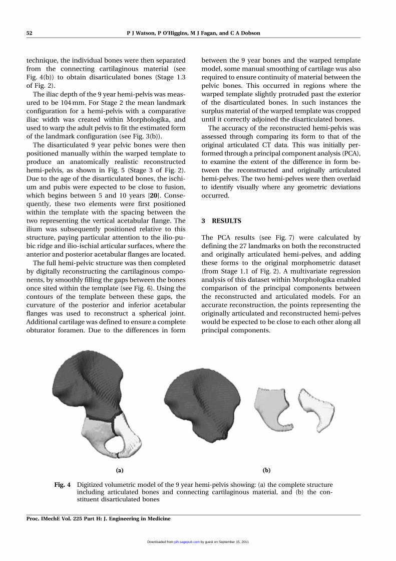
technique, the individual bones were then separated
from the connecting cartilaginous material (see
Fig. 4(b)) to obtain disarticulated bones (Stage 1.3
of Fig. 2).
The iliac depth of the 9 year hemi-pelvis was meas-
ured to be 104 mm. For Stage 2 the mean landmark
configuration for a hemi-pelvis with a comparative
iliac width was created within Morphologika, and
used to warp the adult pelvis to fit the estimated form
of the landmark configuration (see Fig. 3(b)).
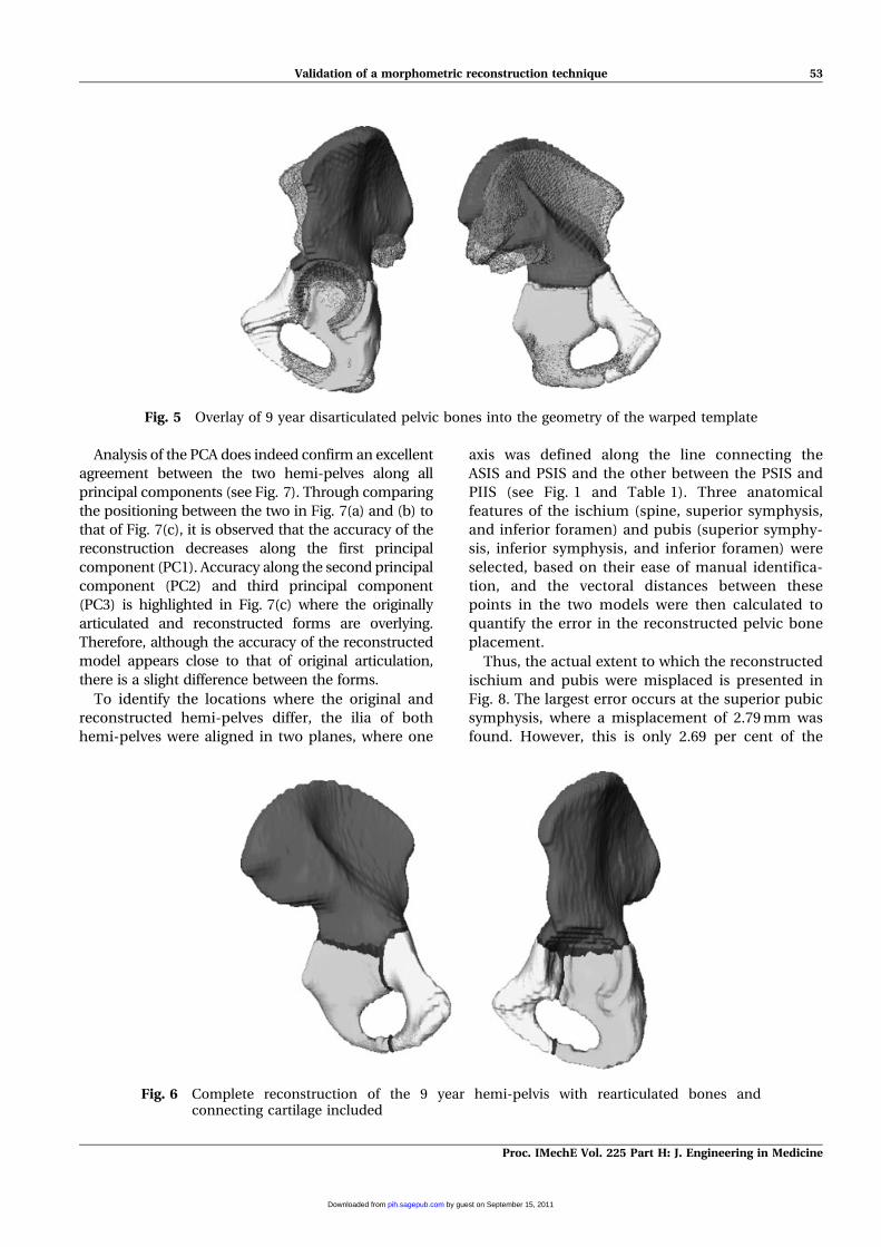
The disarticulated 9 year pelvic bones were then
positioned manually within the warped template to
produce an anatomically realistic reconstructed
hemi-pelvis, as shown in Fig. 5 (Stage 3 of Fig. 2).
Due to the age of the disarticulated bones, the ischi-
um and pubis were expected to be close to fusion,
which begins between 5 and 10 years [20]. Conse-
quently, these two elements were first positioned
within the template with the spacing between the
two representing the vertical acetabular flange. The
ilium was subsequently positioned relative to this
structure, paying particular attention to the ilio-pu-
bic ridge and ilio-ischial articular surfaces, where the
anterior and posterior acetabular flanges are located.
The full hemi-pelvic structure was then completed
by digitally reconstructing the cartilaginous compo-
nents, by smoothly filling the gaps between the bones
once sited within the template (see Fig. 6). Using the
contours of the template between these gaps, the
curvature of the posterior and inferior acetabular
flanges was used to reconstruct a spherical joint.
Additional cartilage was defined to ensure a complete
obturator foramen. Due to the differences in form
between the 9 year bones and the warped template
model, some manual smoothing of cartilage was also
required to ensure continuity of material between the
pelvic bones. This occurred in regions where the
warped template slightly protruded past the exterior
of the disarticulated bones. In such instances the
surplus material of the warped template was cropped
until it correctly adjoined the disarticulated bones.
The accuracy of the reconstructed hemi-pelvis was
assessed through comparing its form to that of the
original articulated CT data. This was initially per-
formed through a principal component analysis (PCA),
to examine the extent of the difference in form be-
tween the reconstructed and originally articulated
hemi-pelves. The two hemi-pelves were then overlaid
to identify visually where any geometric deviations
occurred.
3 RESULTS
The PCA results (see Fig. 7) were calculated by
defining the 27 landmarks on both the reconstructed
and originally articulated hemi-pelves, and adding
these forms to the original morphometric dataset
(from Stage 1.1 of Fig. 2). A multivariate regression
analysis of this dataset within Morphologika enabled
comparison of the principal components between
the reconstructed and articulated models. For an
accurate reconstruction, the points representing the
originally articulated and reconstructed hemi-pelves
would be expected to be close to each other along all
principal components.
Fig. 4 Digitized volumetric model of the 9 year hemi-pelvis showing: (a) the complete structureincluding articulated bones and connecting cartilaginous material, and (b) the con-stituent disarticulated bones
52 P J Watson, P O’Higgins, M J Fagan, and C A Dobson
Proc. IMechE Vol. 225 Part H: J. Engineering in Medicine
by guest on September 15, 2011pih.sagepub.comDownloaded from
Analysis of the PCA does indeed confirm an excellent
agreement between the two hemi-pelves along all
principal components (see Fig. 7). Through comparing
the positioning between the two in Fig. 7(a) and (b) to
that of Fig. 7(c), it is observed that the accuracy of the
reconstruction decreases along the first principal
component (PC1). Accuracy along the second principal
component (PC2) and third principal component
(PC3) is highlighted in Fig. 7(c) where the originally
articulated and reconstructed forms are overlying.
Therefore, although the accuracy of the reconstructed
model appears close to that of original articulation,
there is a slight difference between the forms.
To identify the locations where the original and
reconstructed hemi-pelves differ, the ilia of both
hemi-pelves were aligned in two planes, where one
axis was defined along the line connecting the
ASIS and PSIS and the other between the PSIS and
PIIS (see Fig. 1 and Table 1). Three anatomical
features of the ischium (spine, superior symphysis,
and inferior foramen) and pubis (superior symphy-
sis, inferior symphysis, and inferior foramen) were
selected, based on their ease of manual identifica-
tion, and the vectoral distances between these
points in the two models were then calculated to
quantify the error in the reconstructed pelvic bone
placement.
Thus, the actual extent to which the reconstructed
ischium and pubis were misplaced is presented in
Fig. 8. The largest error occurs at the superior pubic
symphysis, where a misplacement of 2.79 mm was
found. However, this is only 2.69 per cent of the
Fig. 5 Overlay of 9 year disarticulated pelvic bones into the geometry of the warped template
Fig. 6 Complete reconstruction of the 9 year hemi-pelvis with rearticulated bones andconnecting cartilage included
Validation of a morphometric reconstruction technique 53
Proc. IMechE Vol. 225 Part H: J. Engineering in Medicine
by guest on September 15, 2011pih.sagepub.comDownloaded from
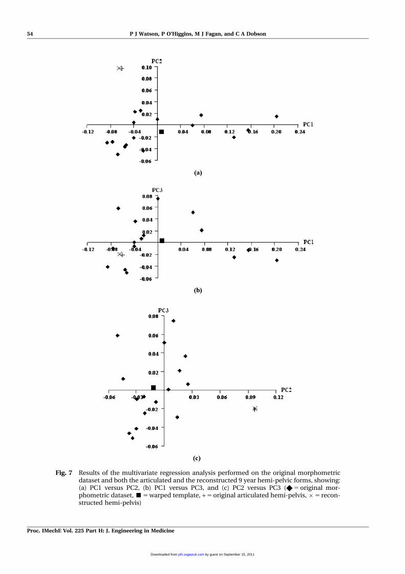
Fig. 7 Results of the multivariate regression analysis performed on the original morphometricdataset and both the articulated and the reconstructed 9 year hemi-pelvic forms, showing:(a) PC1 versus PC2, (b) PC1 versus PC3, and (c) PC2 versus PC3 (X 5 original mor-phometric dataset, &5 warped template, + 5 original articulated hemi-pelvis,65 recon-structed hemi-pelvis)
54 P J Watson, P O’Higgins, M J Fagan, and C A Dobson
Proc. IMechE Vol. 225 Part H: J. Engineering in Medicine
by guest on September 15, 2011pih.sagepub.comDownloaded from
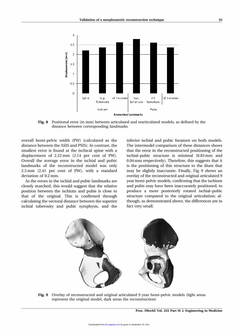
overall hemi-pelvic width (PW) (calculated as the
distance between the ASIS and PSIS). In contrast, the
smallest error is found at the ischical spine with a
displacement of 2.22 mm (2.14 per cent of PW).
Overall the average error in the ischial and pubic
landmarks of the reconstructed model was only
2.5 mm (2.41 per cent of PW), with a standard
deviation of 0.2 mm.
As the errors in the ischial and pubic landmarks are
closely matched, this would suggest that the relative
position between the ischium and pubis is close to
that of the original. This is confirmed through
calculating the vectoral distance between the superior
ischial tuberosity and pubic symphysis, and the
inferior ischial and pubic foramen on both models.
The intermodel comparison of these distances shows
that the error in the reconstructed positioning of the
ischial–pubic structure is minimal (0.83 mm and
0.04 mm respectively). Therefore, this suggests that it
is the positioning of this structure to the ilium that
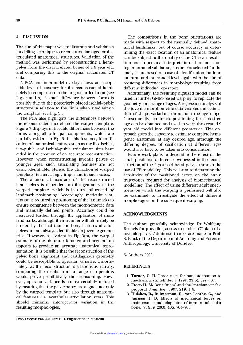
may be slightly inaccurate. Finally, Fig. 9 shows an
overlay of the reconstructed and original articulated 9
year hemi-pelvic models, confirming that the ischium
and pubis may have been inaccurately positioned, to
produce a more posteriorly rotated ischial–pubic
structure compared to the original articulation; al-
though, as demonstrated above, the differences are in
fact very small.
Fig. 8 Positional error (in mm) between articulated and rearticulated models, as defined by thedistance between corresponding landmarks
Fig. 9 Overlay of reconstructed and original articulated 9 year hemi-pelvic models (light areasrepresent the original model, dark areas the reconstruction)
Validation of a morphometric reconstruction technique 55
Proc. IMechE Vol. 225 Part H: J. Engineering in Medicine
by guest on September 15, 2011pih.sagepub.comDownloaded from
4 DISCUSSION
The aim of this paper was to illustrate and validate a
modelling technique to reconstruct damaged or dis-
articulated anatomical structures. Validation of the
method was performed by reconstructing a hemi-
pelvis from the disarticulated bones of a 9 year old,
and comparing this to the original articulated CT
data.
A PCA and intermodel overlay shows an accep-
table level of accuracy for the reconstructed hemi-
pelvis in comparison to the original articulation (see
Figs 7 and 8). A small difference between forms is
possibly due to the posteriorly placed ischial–pubic
structure in relation to the ilium when sited within
the template (see Fig. 9).
The PCA also highlights the differences between
the reconstructed model and the warped template.
Figure 7 displays noticeable differences between the
forms along all principal components, which are
partially evident in Fig. 5. In this instance, identifi-
cation of anatomical features such as the ilio–ischial,
ilio–pubic, and ischial–pubic articulation sites have
aided in the creation of an accurate reconstruction.
However, when reconstructing juvenile pelves of
younger ages, such articulating features are not
easily identifiable. Hence, the utilization of warped
templates is increasingly important in such cases.
The anatomical accuracy of the reconstructed
hemi-pelves is dependent on the geometry of the
warped template, which is in turn influenced by
landmark positioning. Accordingly, meticulous at-
tention is required in positioning of the landmarks to
ensure congruence between the morphometric data
and manually defined points. Accuracy could be
increased further through the application of more
landmarks, although their number will ultimately be
limited by the fact that the bony features of adult
pelves are not always identifiable on juvenile geome-
tries. However, as evident in Fig. 3(b), the warped
estimate of the obturator foramen and acetabulum
appears to provide an accurate anatomical repre-
sentation. It is possible that the reconstruction of the
pelvic bone alignment and cartilaginous geometry
could be susceptible to operator variance. Unfortu-
nately, as the reconstruction is a laborious activity,
comparing the results from a range of operators
would prove prohibitively time-consuming. How-
ever, operator variance is almost certainly reduced
by ensuring that the pelvic bones are aligned not only
by the warped template but also through anatomi-
cal features (i.e. acetabular articulation sites). This
should minimize interoperator variation in the
resulting morphologies.
The comparisons in the bone orientations are
made with respect to the manually defined anato-
mical landmarks, but of course accuracy in deter-
mining the exact location of an anatomical feature
can be subject to the quality of the CT scan resolu-
tion and to personal interpretation. Therefore, dur-
ing intermodel validation, landmarks selected for the
analysis are based on ease of identification, both on
an intra- and intermodel level, again with the aim of
reducing differences in morphology resulting from
different individual operators.
Additionally, the resulting digitized model can be
used in further GMM-based warping, to replicate the
geometry for a range of ages. A regression analysis of
the juvenile morphometric data enables the estima-
tion of shape variations throughout the age range.
Consequently, landmark positioning for a desired
age can be obtained and used to warp the created 9
year old model into different geometries. This ap-
proach gives the capacity to estimate complete hemi-
pelvic anatomies at any desired age, although the
differing degrees of ossification at different ages
would also have to be taken into consideration.
Future work plans to determine the effect of the
small positional differences witnessed in the recon-
struction of the 9 year old hemi-pelvis, through the
use of FE modelling. This will aim to determine the
sensitivity of the positioned errors on the strain
trajectories required for analysis of biomechanical
modelling. The effect of using different adult speci-
mens on which the warping is performed will also
be examined, to investigate the effect of different
morphologies on the subsequent warping.
ACKNOWLEDGMENTS
The authors gratefully acknowledge Dr WolfgangRecheis for providing access to clinical CT data of ajuvenile pelvis. Additional thanks are made to Prof.S. Black of the Department of Anatomy and ForensicAnthropology, University of Dundee.
F Authors 2011
REFERENCES
1 Turner, C. H. Three rules for bone adaptation tomechanical stimuli. Bone, 1998, 23(5), 399–407.
2 Frost, H. M. Bone ‘mass’ and the ‘mechanostat’: aproposal. Anat. Rec., 1987, 219, 1–9.
3 Huiskes, R., Ruimerman, R., van Lenthe, G., andJanssen, J. D. Effects of mechanical forces onmaintenance and adaptation of form in trabecularbone. Nature, 2000, 405, 704–706.
56 P J Watson, P O’Higgins, M J Fagan, and C A Dobson
Proc. IMechE Vol. 225 Part H: J. Engineering in Medicine
by guest on September 15, 2011pih.sagepub.comDownloaded from
4 Rauch, F. and Schoenau, E. The developing bone:slave or master of its cells and molecules. Pediat.Res., 2001, 50(3), 309–314.
5 Ehrlich, P. J. and Lanyon, L. E. Mechanical strainand bone cell function: a review. Osteoporosis Int.,2002, 13, 688–700.
6 Wolff, J. Das Gesetz der Transformation derKnochen, 1892 (Hirschwald, Berlin).
7 Wolff, J. The law of bone remodelling (Translatedby P. Maquet and R. Furlong), 1986 (SpringerVerlag, Berlin).
8 Drapeau, M. S. M. and Streeter, M. A. Modellingand remodelling responses to normal loading inthe human lower limb. Am. J. Phys. Anthropol.,2006, 129(3), 403–409.
9 Ulrich, D., van Rietbergen, B., Laib, A., andRuegsegger, P. The ability of three-dimensionalstructural indices to reflect mechanical aspects oftrabecular bone. Bone, 1999, 25, 55–60.
10 Ryan, T. M. and Krovitz, G. E. Trabecular boneontogeny in the proximal femur. J. Human Evolu-tion, 2006, 51(6), 591–602.
11 Tsubota, K., Suzuki, Y., Yamada, Y., Hojo, M.,Makinouchi, A., and Adachi, T. Computer simula-tion of trabecular remodelling in human proximalfemur using large-scale voxel FE models; approachto understanding Wolff’s law. J. Biomechanics,2009, 42, 1088–1094.
12 Macchiarelli, R., Bondioli, L., Galichon, V., andTobias, P. V. Hip bone trabecular architectureshows uniquely distinctive locomotor behaviour inSouth African australopithecines. J. Human Evolu-tion, 1999, 26(2), 211–232.
13 Rook, L., Bondiolo, L., Kohler, M., Moya-Sola, S.,and Macchiarelli, R. Oreopithecus was a bipedalape after all. Evidence from the iliac cancellousarchitecture. Proc. Natl Acad. Sci. USA, 1999,96(15), 8795–8799.
14 Cunningham, C. and Black, S. Development of thefetal ilium – challenging concepts of bipedality.J. Anatomy, 2008, 214(1), 91–99.
15 Cunningham, C. and Black, S. Anticipating biped-alism: trabecular organization in the newbornilium. J. Anatomy, 2009, 214, 817–829.
16 Gosman, J. H. and Ketcham, R. A. Patterns inontogeny of human trabecular bone from Sun-Watch in the prehistoric Ohio Valley; general fea-tures of microstructural change. Am. J. Phys.Anthropol., 2008, 138(3), 318–332.
17 Dalstra, M., Huiskes, R., Odgaads, A., and vanErning, L. Mechanical and textural properties of
pelvic trabecular bone. J. Biomechanics, 1993, 26(5),523–535.
18 Dalstra, M. and Huiskes, R. Load transfer acrossthe pelvic bone. J. Biomechanics, 1995, 28(6), 715–724.
19 Majumder, S. and Roychowdhury, A. Biomecha-nical analysis of human pelvis under musculo-skeletal load using 3D finite element method. Int. J.Appl. Mechanics and Engng, 2005, 10(4), 647–665.
20 Scheuer, L. and Black, S. Developmental juvenileosteology, edition 1, 2000 (Academic Press, Lon-don).
21 Palastanga, N., Field, D., and Soames, R. Anatomyand human movement: structure and function,edition 4, 2002 (Butterworth-Heinemann, Edin-burgh).
22 Anderson, A. E., Peters, C. L., Tuttle, B. D., andWeiss, J. A. Subject-specific finite element model ofthe pelvis: development, validation and sensitivitystudies. J. Biomechanics, 2005, 117, 364–373.
23 Phillips, A. T. M., Pankaj, P., Howie, C. R., Usani,A. S., and Simpson, A. H. R. W. Finite elementmodelling of the pelvis: inclusion of muscular andligamentous boundary conditions. Med. EngngPhysics, 2006, 29, 739–748.
24 Dryden, I. L. and Mardia, K. V. Statistical shapeanalysis, 1998 (John Wiley & Sons Ltd, Chichester).
25 O’Higgins, P. Advances in approaches to the studyof morphological variation in the hominid fossilrecord: biology, landmarks and geometry. J. Anat-omy, 2000, 197, 103–120.
26 Zelditch, M. L., Swiderski, D. L., Sheets, H. D., andFink, W. L. Geometric morphometrics for biologists:a primer, 2004 (Elsevier Academic Press, NewYork).
27 Bookstein, F. L. Principal warps: thin plate splinesand the decomposition of deformations. IEEETrans. on Pattern Anal. Mach. Intell., 1987, 11,567–585.
28 Lapeer, R. J. A. and Prager, R. W. 3D shaperecovery of a newborn skull using thin-platesplines. Computerised Med. Imaging and Graphics,2000, 24, 194–304.
29 Kirkwood, R. N., Culham, E. G., and Costigan, P.Radiographic and non-invasive determination ofthe hip joint center location: effect on hip jointmoments. Clin. Biomechaincs, 1999, 14, 227–235.
30 O’Higgins, P. and Jones, N. Facial growth inCercocebus torquatus: an application of threedimensional geometric morphometric techniquesto the study of morphological variation. J. Anat-omy, 1998, 193, 251–272.
Validation of a morphometric reconstruction technique 57
Proc. IMechE Vol. 225 Part H: J. Engineering in Medicine
by guest on September 15, 2011pih.sagepub.comDownloaded from