USING THE 20 BIT FLOW LABEL FIELD IN THE IPV6 HEADER TO INDICATE DESIRABLE QUALITY OF SERVICE ON THE...
115
USING THE 20 BIT FLOW LABEL FIELD IN THE IPV6 HEADER TO INDICATE DESIRABLE QUALITY OF SERVICE ON THE INTERNET by BHANU PRAKASH B.E., B.M.S. College of Engineering, 2000 A thesis submitted to the Faculty of Graduate School of the University of Colorado in partial fulfillment of the requirement for the degree of Master of Science Interdisciplinary Telecommunications Program 2004
Transcript of USING THE 20 BIT FLOW LABEL FIELD IN THE IPV6 HEADER TO INDICATE DESIRABLE QUALITY OF SERVICE ON THE...
USING THE 20 BIT FLOW LABEL FIELD IN THE IPV6 HEADER TO
INDICATE DESIRABLE QUALITY OF SERVICE ON THE INTERNET
by
BHANU PRAKASH
B.E., B.M.S. College of Engineering, 2000
A thesis submitted to the
Faculty of Graduate School of the
University of Colorado in partial fulfillment
of the requirement for the degree of
Master of Science
Interdisciplinary Telecommunications Program
2004
This thesis entitled:Using the 20 bit Flow Label Field in the IPv6 header to indicate desirable
Quality of Service on the Internetwritten by Bhanu Prakash
has been approved for the Interdisciplinary Telecommunications Program
__________________________________Dr. Douglas C. Sicker
__________________________________Dr. Timothy X. Brown
__________________________________Mr. Kevin Epperson
Date________________
The final copy of this thesis has been examined by the signatories, and we find that both the content and the form meet acceptable presentation standards of
scholarly work in the above mentioned discipline.
iii
Prakash, Bhanu (M.S., IPv6 [Interdisciplinary Telecommunication Program])
Using the 20 bit Flow Label Field in the IPv6 header to indicate desirable Quality
of Service on the Internet
Thesis directed by Associate Professor Douglas C. Sicker
The traditional Internet as designed in the early 1970s was aimed
primarily for packet transmission over a switched network. Delay, latency,
bandwidth, packet loss and jitter on the network were factors that were not
considered to be of much importance when the initial simple networks were built.
Due to the complexity of present day applications and communication needs, the
above factors which influence the quality of communications bear a lot of
significance.
The present work proposes an efficient scheme to use the 20 bits of the
IPv6 flow label field to indicate the desirable Quality of Service parameters on the
Internet.
iv
ACKNOWLEDGEMENT
I would like to acknowledge the support and immensely helpful advice
provided by my advisors, Dr. Douglas C. Sicker, Mr. Kevin Epperson and Dr.
Timothy X. Brown.
v
CONTENTS
CHAPTER
1. INTRODUCTION 1
1.1. Hypothesis 2
1.2. Motivation 3
1.3. Thesis Overview 4
2. OVERVIEW OF BACKGROUND MATERIAL 8
2.1. Definition of Quality of Service (QoS) 8
2.2. Importance and Use of QoS 10
2.3. Issues related to QoS 11
2.4. Parameters used to measure QoS at the Network Layer 12
2.5. Current architectures and protocol support for QoS 17
2.5.1. TCP/IP 17
2.5.2. Frame Relay 22
2.5.3. ATM 23
2.5.4. Integrated Services Architecture 28
2.5.5. Differentiated Services Architecture 32
2.5.6. MPLS 35
2.5.7. IPv6 37
3. IPv6 FLOW LABEL 42
3.1. IPv6 Flow Label Field Definition 42
vi
3.2. IPv6 Flow Label Specification 44
3.3. IPv6 Flow Label Requirements 45
3.4. IPv6 Flow Label Values (Review of Current Efforts) 46
3.4.1. Review - draft-conta-ipv6-flow-label-02.txt 47
3.4.2. Review - draft-conta-diffserv-ipv6-f1-classifier-01.txt 53
3.4.3. Review - draft-banerjee-flowlabel-ipv6-qos-03.txt 55
3.4.4. Review - draft-jagadeesan-rad-approach-service-01.txt 62
4. SPECIFICATION FOR THE VALUES OF THE IPv6 FLOW
LABEL FIELD
63
4.1. Classification for various approaches 63
4.1.1. No QoS requirement 64
4.1.2. Pseudo-Random Number approach 64
4.1.3. Support for direct parametric representation of
desired values
65
4.1.4. Support for the DiffServ Model 72
4.1.5. Support for future use 72
4.2. Rationale 73
4.2.1. No QoS requirement 74
4.2.2. Pseudo-Random number approach 75
4.2.3. Direct Parametric representation 75
4.2.3.1.One Way Delay Parameter 77
4.2.3.2.IP Delay Variation Parameter 79
4.2.3.3.Bandwidth Parameter 80
vii
4.2.3.4.One Way Packet Loss Parameter 82
4.2.3.5.Other Parameters 83
4.2.4. DiffServ Architecture 84
4.2.5. Support for future use 85
5. IMPLEMENTATION SCENARIOS 86
5.1. DiffServ Implementation Scenario 86
5.2. IntServ Implementation Scenario 88
5.3. Direct Parametric Representation Implementation Scenario 90
5.4. Other Considerations 93
6. SUMMARY, CONCLUSIONS AND FUTURE WORK 95
BIBLIOGRAPHY 98
APPENDIX
A. Examples of Parametric representation 102
viii
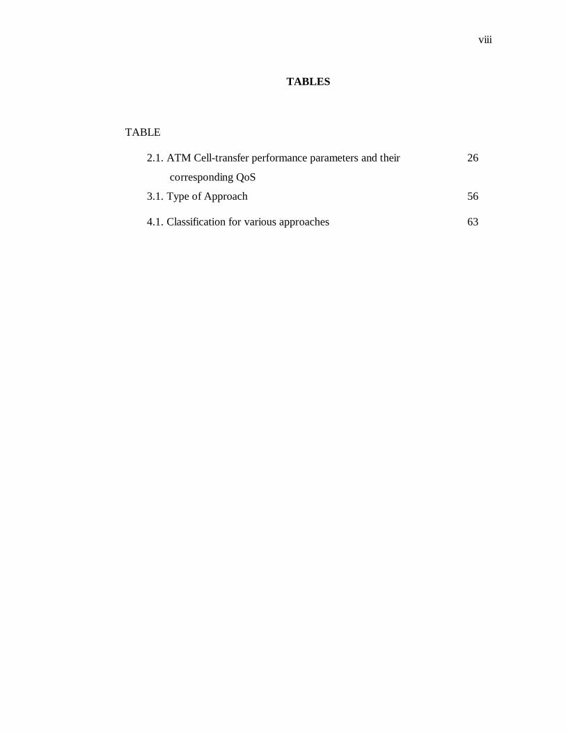
TABLES
TABLE
2.1. ATM Cell-transfer performance parameters and their
corresponding QoS
26
3.1. Type of Approach 56
4.1. Classification for various approaches 63
ix
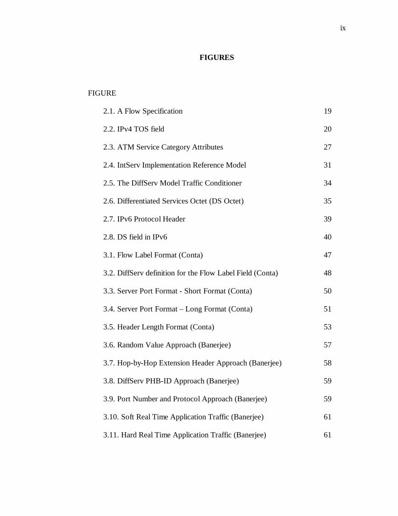
FIGURES
FIGURE
2.1. A Flow Specification 19
2.2. IPv4 TOS field 20
2.3. ATM Service Category Attributes 27
2.4. IntServ Implementation Reference Model 31
2.5. The DiffServ Model Traffic Conditioner 34
2.6. Differentiated Services Octet (DS Octet) 35
2.7. IPv6 Protocol Header 39
2.8. DS field in IPv6 40
3.1. Flow Label Format (Conta) 47
3.2. DiffServ definition for the Flow Label Field (Conta) 48
3.3. Server Port Format - Short Format (Conta) 50
3.4. Server Port Format – Long Format (Conta) 51
3.5. Header Length Format (Conta) 53
3.6. Random Value Approach (Banerjee) 57
3.7. Hop-by-Hop Extension Header Approach (Banerjee) 58
3.8. DiffServ PHB-ID Approach (Banerjee) 59
3.9. Port Number and Protocol Approach (Banerjee) 59
3.10. Soft Real Time Application Traffic (Banerjee) 61
3.11. Hard Real Time Application Traffic (Banerjee) 61
x
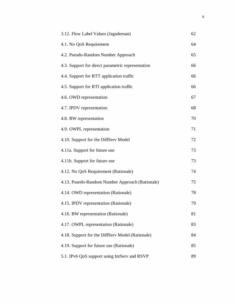
3.12. Flow Label Values (Jagadeesan) 62
4.1. No QoS Requirement 64
4.2. Pseudo-Random Number Approach 65
4.3. Support for direct parametric representation 66
4.4. Support for RTT application traffic 66
4.5. Support for RTI application traffic 66
4.6. OWD representation 67
4.7. IPDV representation 68
4.8. BW representation 70
4.9. OWPL representation 71
4.10. Support for the DiffServ Model 72
4.11a. Support for future use 73
4.11b. Support for future use 73
4.12. No QoS Requirement (Rationale) 74
4.13. Psuedo-Random Number Approach (Rationale) 75
4.14. OWD representation (Rationale) 78
4.15. IPDV representation (Rationale) 79
4.16. BW representation (Rationale) 81
4.17. OWPL representation (Rationale) 83
4.18. Support for the DiffServ Model (Rationale) 84
4.19. Support for future use (Rationale) 85
5.1. IPv6 QoS support using IntServ and RSVP 89
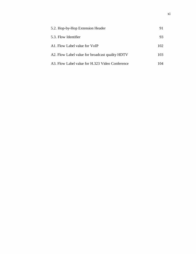
xi
5.2. Hop-by-Hop Extension Header 91
5.3. Flow Identifier 93
A1. Flow Label value for VoIP 102
A2. Flow Label value for broadcast quality HDTV 103
A3. Flow Label value for H.323 Video Conference 104
1
CHAPTER 1
INTRODUCTION
The Internet is a vast network of computers which is used for communications.
Over the past few decades the Internet has grown in size incomparable to any
other technology. The Internet which was for a few decades ago available only to
the scientific community is today a tool which is widely available to the common
user.
As each day passes, the present day Internet is exploited more and more
for day to day communications. Corporations and individuals alike are using the
Internet today for private and corporate communications. The Internet today
caters to a multitude of people with different needs. Simple tasks such as sending
and receiving e-mails, chatting online with friends and co-workers, browsing and
surfing the web, downloading music and videos to complex functions such as
organizing an online corporate meeting with voice and video, broadcasting live
music and video, switching voice traffic from the traditional PSTN circuit
switched network on the Internets packet switched network are some of the tasks
performed daily on the Internets’ complex network.
The traditional Internet as designed in the early 1970s was aimed
primarily for packet transmission over a switched network. Delay, latency,
bandwidth, packet loss and jitter on the networks were factors that were not
2
considered to be of much importance when the initial simple networks were built.
Due to the complexity of present day applications and communication needs, the
above factors which influence the quality of communications bear a lot of
significance.
Various efforts have been made is the past to introduce mechanisms to
request, control and provide for the requested quality of service over the Internet.
In the context of this work Quality of Service refers to the ability of the network
provider or the network by itself to provide certain guarantees for the transmission
of the requestors’ traffic. This would eventually change the traditional Internets’
best-effort service model to a controlled and regulated effort service model.
1.1. Hypothesis
Internet Protocol version 4 (IPv4) is the current widely deployed Layer 31
protocol on the Internet. Due to the rapid and vast growth of the Internet,
researchers are developing the next version of IPv4 namely Internet Protocol
version 6 (IPv6) to counter the growth and to allow for more functionality. Work
on the IPv6 protocol has been ongoing for almost a decade and the protocol is
currently in the experimental stage. The basic framework for the protocol has
been built and widely accepted. Many corporations and Internet Service Providers
1 The Inter Protocol (IP) operates at Layer 3 of the Open Systems Interconnect (OSI)
model protocol stack
3
have already deployed the protocol in their production networks. Researchers and
corporations all over the world are working together to define and provide for
additional functionality for this new protocol.
One such functionality provided by IPv6 is the provision of a 20 bit field
in its header for provision of Quality of Service. This 20 bit field is known as the
Flow Label field. The content of this field is not yet currently defined.
In this thesis, I propose an approach in which the current unspecified 20-
bit Flow Label field in the IPv6 header can be efficiently used to indicate the
necessary Quality of Service requirements as dictated by the present day Internets
data, voice and multimedia communication needs. I support my approach by
qualitatively analyzing the various QoS proposals and architectures and then
propose a specification which satisfies all requirements for indicating the required
QoS at the network layer.
1.2. Motivation
Communication over the Internet involves data, voice and multimedia
communications. Current communication needs dictate certain Quality of Service
requirements. Live voice and multimedia communication for example require a
certain guarantee since they are Real-Time-Intolerant in nature. Various protocols
designed for packet communication over the Internet have provided for features
4
which enable a network provider or the underlying network to provide for the
requested Quality of Service.
The architects of IPv4 did not provide for a rich feature set which would
enable the network to provide for levels of Quality of Service. IPv4 provided the
ability to mark the packets into different classes of service (CoS). An intelligent
device such as a router could offer a differentiated level of service based on the
packets’ marked class.
The framers of the IPv6 protocol noted the Quality of Service
requirements and provided for an enhancement in the protocol design. IPv6 offers
a 20 bit field in its header called the Flow Label field which can be used to set the
various parameters by a QoS enabled device. The content of the flow label field
has still not yet been exploited. This thesis work makes an effort to contribute to
the development of the protocol by proposing an approach for using the 20 bits in
the flow label field to indicate the requested Quality of Service.
1.3. Thesis Overview
The term Quality of Service is often used in different context by different
entities. To a backbone engineer in an ISP, QoS means the ability of the network
to forward packets across the network backbone with limited or acceptable delay
and no jitter. More often top level ISPs are equipped with huge bandwidth which
5
is more often termed as the ‘capacity glut’ and hence it is not evaluated as an
important criterion for providing QoS. To a smaller ISP, the bandwidth may be
something to be taken into consideration along with the other factors since the
smaller ISPs have connections to the larger ISPs at fewer points. This might be an
object of concern if the smaller ISPs have a large volume of customer traffic and
limited bandwidth to pass on this traffic across their network and to the upstream
ISP. To the customer QoS refers to the ability of his provider and the entire
network to provide for an end-to-end service which guarantees the customer with
enough bandwidth to carry his traffic, no packet loss, limited delay and limited or
no jitter. This is more important for a customer who intends to use the Internet for
voice and multimedia communications. On the contrary to a Sales Engineer QoS
offered by his network is basically an enhancement offered by the provider which
would allow the Sales Engineer to market his products with added functionality.
In the context of this work, QoS refers to the ability of the network or the network
provider to provide for varying levels of service based on the requirements of the
customer. The customer or the QoS enabled device has the ability to request for
resources or request for control over certain parameters which influence packet
communication.
This work concentrates on developing a scheme for indicating required
QoS between nodes in the Internet. The majority of the Internets nodes or routers
operate at layer 3 of the OSI stack. Widely used architectures and protocols such
as TCP/IP, MPLS, ATM and Frame Relay offer a means for providing Quality of
6
Service. Each architecture or protocol define and provide for Quality of Service in
a way unique to the architecture or protocol. Protocols at various layers of the OSI
stack are also equipped to provide for QoS depending on how QoS is defined at
that layer. This work reviews the various technologies and identifies the various
parameters which are required to provide for varying levels of QoS for the IPv6
protocol. As an outcome of the research this work suggests a scheme which can
be implemented to provide QoS using the 20 bit flow label field in the IPv6
header.
Research Question: How can the 20 bit Flow Label field in the IPv6 header be
used to indicate the desired Quality of Service over the Internet?
Significance: Ongoing research is being performed by the Internet Engineering
Task Force (IETF) IPv6 working group to develop QoS enhancements for the
IPv6 protocol. Concurrently the IETF IP Performance Metrics Charter (IPPM)
and the Internet Traffic Engineering Charter (TEWG) are working on providing
guidelines and solutions for providing QoS over the IP network. Provision of QoS
using the IPv6 protocol will enable users to request for certain levels of service
from their providers. It will also enable the providers to engineer and provide the
requested levels of service to its consumers
Contestability: This work is important since it provides a solution for using the 20
bits in the IPv6 flow label field to indicate the required QoS from the network.
7
Currently the 20 bits of the Flow Label field are unused. This work aims at
providing an acceptable scheme for using the 20 bits of the Flow Label field.
Specifics: The outcome of this work is a definition of what the 20 bits in the Flow
Label fields should represent. The work addresses the issue of using the 20 bit
Flow Label field specifically.
Methodology: The thesis methodology is inductive in nature. It gains theoretical
view points from certain cases and applies this to gain a solution. An engineering
research method is adopted in this work where in various proposals, architectures
and solutions are studied and a solution which best fits current needs is proposed.
8
CHAPTER 2
OVERVIEW OF BACKGROUND MATERIAL
A review of the current architectures and protocol support for providing QoS over
the Internet is necessary to better understand the nature and requirements of QoS.
In this study, QoS support in architectures and protocols such as TCP/IP, MPLS,
ATM and Frame Relay are briefly reviewed to observe how these architectures
and protocols are geared towards offering QoS on the Internet. Also a review of
the current widely used QoS architectures such as IntServ and DiffServ and the
current efforts of the IETF are included to understand the constraints and needs of
QoS. The aim of these reviews is to produce a set of useful and concise
requirements which can be used to effectively architecture the 20 bits of the IPv6
Flow Label.
2.1. Definition of QoS
The Internet was traditionally built to carry traffic on a best-effort service
model. In a best-effort service model the networks and the underlying network
elements and protocols transported the users’ traffic from the source to the
destination but did not provide the user with any guarantee of packet delivery. In
the event of congestion introduced due to the lack of bandwidth the Internet
would drop the packets. Additionally the Internet would also not provide with any
guarantees with respect to the time in which the data was transported. This default
9
behavior of the Internet is not suitable for real time traffic such as voice and
multimedia traffic. A certain assurance needs to be provided to the user in case of
a network congestion or delay.
Quality of Service refers to the ability of the network, its elements and its
providers to provide for a certain assurance and consistency to transport a users’
traffic. QoS can be defined as “any mechanism that provides distinction of traffic
types, which can be classified and administered differently throughout the
network” [Ferg98]. The above definition can be explained further with a brief
example. Consider an organization which intends to have a remote video
conference over the Internet with its remote branch situated at a different
geographical location. The nature of this traffic begin real-time intolerant requires
that the network it passes through, transports the traffic with limited or no delay
and jitter. Also the network transporting this traffic needs to control all the packet
loss parameters in order to ensure that none of the packets in the transmission are
lost. The network also could ensure that in the case where the bandwidth is scarce,
the network has to reserve enough bandwidth for this traffic to pass through. QoS
mechanisms allow the application or the user to request for a certain guarantee
thereby classifying the packets of this transmission into a separate class or flow.
QoS mechanisms also allow the network administrator to administer and control
the resources necessary for the successful transmission of these packets. Finally
QoS mechanisms allow the intervening routers to process this request by
10
reserving network resources such as bandwidth and controlling delay, jitter and
packet loss.
2.2. Importance and Use of QoS
The present Internet has become a media that carries data, voice and
multimedia traffic. The applications used today such as those for VOIP, online
video conferencing, content multicasting etc. are more differentiated and require
different levels of service for real-time and non-real-time traffic [Hagen02]. To
provide these different levels of service a certain Quality of Service has to be
assured and provisioned for the user. Currently the consumer market for the
Internet is growing and encompasses various types of consumers with varying
needs. Quality of Service measures provides for the consumers who expect
consistent quality regarding throughput, delay or jitter [Hagen02]. QoS introduces
intelligent management techniques and avoids delays for sensitive traffic in the
event of network congestion [Alcatel99].
A service request from a customer forms a contract between the customer
and the Service Provider [Tann97] and QoS ensures that the service requested by
the customer is provided by the Service Provider. QoS aids in accountability for
the customer as well as the Service Provider. Finally competition will be
introduced between ISPs to provide for better QoS thus aiding the consumer
[Ferg98].
11
2.3. Issues related to QoS
QoS has not been an area that has been widely understood and accepted
with various individuals and organizations defining it to suit their requirement.
“Quality of Service (QoS) is one of the most elusive, confounding, and confusing
topics in data networking today” [Ferg98]. Efforts by organizations such as the
IETF are underway to better define QoS and the underlying principles and
practices that govern this technology. Along with this QoS faces various issues.
Various network protocols offering QoS support such as IP, ATM, MPLS
operate in the Internet which give rise to the problem of choosing the correct
protocol for a specific setup and the ability to integrate the various protocol to
offer an end-to-end QoS support [Alcatel99]. Various QoS architectures such as
IntServ and DiffServ have been developed but there has not been a common
consensus on which technology to use [Hagen02]. Bandwidth is not infinite and
introducing QoS in a bandwidth deprived network does not offer any solution.
QoS does not increase the bandwidth but only aims at utilizing it as effectively as
possible [Alcatel99]. Reliable QoS measuring tools have not been developed
which would provide the Service Provider and the customer to determine whether
adequate QoS capability is being provided [Ferg98]. The IPPM charter of the
IETF is currently working on providing a baseline for defining QoS
measurements. Vendor support to QoS is mostly through integrated software that
offers QoS support. This might relatively cause a performance drop due to the
12
delay introduced in the processing and hence it is essential that QoS be supported
at the hardware level too [Alcatel99].
2.4. Parameters used to measure QoS at the Network Layer
The traditional parameters used to measure Network QoS have been
bandwidth, delay, buffer requirements, packet loss, latency and jitter [Hagen99]
[Ferg98]. Bandwidth is also commonly known as throughput. The bandwidth of a
link refers to the ability of the link to transfer data at a rate expressed commonly
in bits per second. Higher bandwidth provides the link with a higher capacity to
transport data at a faster rate. Bandwidth is an important factor in evaluating and
providing for QoS since lower bandwidth links lead to congestion, packet loss and
packet transmission delays when there is too much data to be transported on the
link. Delays in packet transmission affect the quality of real-time traffic. Real
time traffic can be categorized on Real-Time-Tolerant (RTT) and Real-Time-
Intolerant (RTI) traffic. Live video feeds and multimedia traffic are examples of
real-time intolerant traffic. Packets belonging to such traffic require minimal
delay across networks. Real-time-tolerant traffic such as an audio streaming
session can tolerate a little delay in transmission due to the buffering and
reconstruction capabilities offered by intelligent end devices. To assure adequate
QoS, delay has to be kept minimal. Packet loss results due to various factors such
as low bandwidth and congestion on links. Intelligent end devices are capable of
reconstructing data using various algorithms. But extreme packet losses may
13
result in the inability to reconstruct data. Also RTI applications are very sensitive
to packet losses. Latency is defined as the time taken for a packet of data to move
from the source to the destination. Latency is a combination of all delays accrued
during the packet transmission such as the propagation delay, the transmission
delay, the processing delay and other induced delays. Latency is commonly
measured by the round-trip-time which is the time taken for a packet to travel
from the source to the destination and back to the source. Latency can be
introduced at various points in the path. While offering end-to-end QoS this is an
important parameter that has to be considered. The QoS enabled devices have to
negotiate such that the latency in-between various points along the path are kept
minimal. Jitter is defined as the variation in the delay introduced between
different packets of a single transmission. Jitter may be caused due to timing
issues, bandwidth constraints, network congestion or a synchronization problem.
End systems are capable of buffering data and handling delays in order to provide
the packets in a synchronized format to the upper layers. Jitter introduces
uncertainty and makes it difficult for the intelligent algorithms to buffer and
reconstruct data. This is very important for RTI traffic. Jitter is hence considered
an important parameter in evaluating QoS.
To provide for efficient QoS on the Internet the quality, performance, and
reliability of Internet data delivery services has to be studied and known.
Parameters have to be identified which allow us to study and measure the Internet.
The IETF IPPM working group (IPPM-WG) is involved in defining specific
14
metrics and procedures for accurately measuring and documenting these metrics2.
The IPPM-WG is currently developing procedures for measuring the individual
metrics and how these metrics characterize features that are important to different
service classes, such as bulk transport, periodic streams, or multimedia streams
[IPPM-WG]. The IPPM has identified the following metrics to measure IP
performance:
1. Connectivity
RFC 2678 lists the various metrics to measure connectivity between pairs of
hosts (IP addresses) on the Internet [RFC2678]. It defines five analytic3
metrics namely Type-P-Instantaneous-Unidirectional-Connectivity (measures
Instantaneous One-way Connectivity), Type-P-Instantaneous-Bidirectional-
Connectivity (measures Instantaneous Two-way Connectivity), Type-P-
Interval-Unidirectional Connectivity (measures One-way Connectivity), Type-
P-Interval-Bidirectional-Connectivity (measures Two-way Connectivity) and
Type-P1-P2-Interval-Temporal-Connectivity (measures Two-way Temporal
Connectivity).
2 The Working Group can he accessed online at http://ietf.org/html.charters/ippm-
charter.html3 An analytical metric refer to those metrics defined in terms of the theoretical, abstract
properties of the components. These are the properties used to analyze the component mathematically [Pa96]
15
2. One-way delay and loss
RFC 2679 defines the Type-P-One-way-Delay singleton4 analytic metric “to
measure a single observation of one-way delay” [RFC2679]. Using this metric
it introduces the Type-P-One-way-Delay-Poisson-Stream sample5 analytic
metric used “to measure a sequence of singleton delays measured at times
taken from a Poisson process”. RFC 2680 defines the Type-P-One-way-Loss
singleton analytic metric “to measure a single observation of packet
transmission or loss” [RFC2680]. Using this metric it introduces the Type-P-
One-way-Loss -Poisson-Stream sample analytic metric used “to measure a
sequence of singleton transmissions and/or losses measured at times taken
from a Poisson process” [RFC2680].
3. Round-trip delay and loss
RFC 2681 defines the Type-P-Round-trip-Delay singleton analytic metric “to
measure a single observation of round-trip delay” [RFC2681]. Using this
metric it introduces the Type-P-Round-trip-Delay-Poisson-Stream sample
analytic metric used “to measure a sequence of singleton delays measured at
times taken from a Poisson process” [RFC2681].
4 RFC 2330 defines a singleton metric as “By a ‘singleton’ metric, we refer to metrics
that are, in a sense, atomic. For example, a single instance of “bulk throughput capacity” from one host to another might be defined as a singleton metric, even though the instance involves measuring the timing of a number of Internet packets.”
5 RFC 2330 defines a sample metric as “By a ‘sample’ metric, we refer to metrics derived from a given singleton metric by taking a number of distinct instances together. For example, we might define a sample metric of one-way delays from one host to another as an hour's worth of measurements, each made at Poisson intervals with a mean spacing of one second.”
16
4. Delay variation
RFC 3393 defines the Type-P-One-way-ipdv single analytic metric “to define
a single instance of an ipdv6 measurement” [RFC3393]. Using this metric it
introduces the Type-P-one-way-ipdv-Poisson-stream sample analytic metric
“to make it possible to compute the statistics of sequences of ipdv
measurements” [RFC3393].
5. Loss patterns
RFC 3357 defines two derived metrics namely the Type-P-One-Way-Loss-
Distance-Stream and Type-P-One-Way-Loss-Period-Stream “used to capture
packet loss patterns” [RFC3357]. RFC 3357 notes that “The loss period metric
captures the frequency and length (burstiness) of loss once it starts, and the
loss distance metric captures the spacing between the loss periods.”
[RFC3357]
6. Packet reordering
The ‘Type-P-Reordered’ metric is defined to classify “arriving packets with
sequence numbers smaller than their predecessors as out-of-order or
reordered” [ID2004]. The memo also defines sample metrics “to quantify the
extent of reordering in several useful dimensions” [ID2004]. It also defines
additional metrics to “quantify the frequency of reordering and the distance
between separate occurrences” [ID2004].
6IP Packet Delay Variation (ipdv) is the difference between the one-way-delay of the
selected packets [RFC3393]
17
7. Bulk transport capacity (BTC)7
RFC 3148 defines the “Congestion Avoidance Capacity” (CAC) metric as
“the data rate (bits per second) of a fully specified implementation of the
Congestion Avoidance algorithm, subject to the restriction that the
Retransmission Timeout and Slow-Start algorithms are not invoked”
[RFC3148]. RFC 3148 “…defines a framework for standardizing multiple
BTC (Bulk Transport Capacity) metrics that parallel the permitted transport
diversity” [RFC3148].
8. Link bandwidth capacity
Work is still ongoing at the IETF to define the link bandwidth capacity
metrics. No documents have been published at this time.
2.5. Current architectures and protocol support
This section provides a review of the QoS support offered by the current
architectures and protocols over the Internet.
2.5.1. TCP/IP
TCP/IP is the most commonly used end-to-end protocol suite on the
Internet. The TCP/IP protocol stack is equipped with providing for QoS at various
7“Bulk Transport Capacity (BTC) is a measure of a network's ability to transfer
significant quantities of data with a single congestion-aware transport connection (e.g., TCP).” [RFC3148]
18
layers. The IPv4 protocol which operates at Layer 3 of the TCP/IP stack provides
for a TOS (Type of Service) field in its header to provide for Differentiated Class
of Service (CoS). Differentiated CoS provides for a method in which the traffic is
classified into different classes so that the various traffic classes can be handled
differently when they move across the network [Ferg98]. At the IP layer the
differentiation is performed by identifying and classifying traffic based on a
combination of elements such as the Protocol, Source Port, Destination Port,
Source address, Destination address, Ingress interface and the flow associated
with the particular packet [Ferg98]. The two common approaches proposed to
differentiate traffic using IPv4 are the per-flow differentiation and the
differentiation using the IP precedence bits in the IPv4 TOS field [Ferg98]
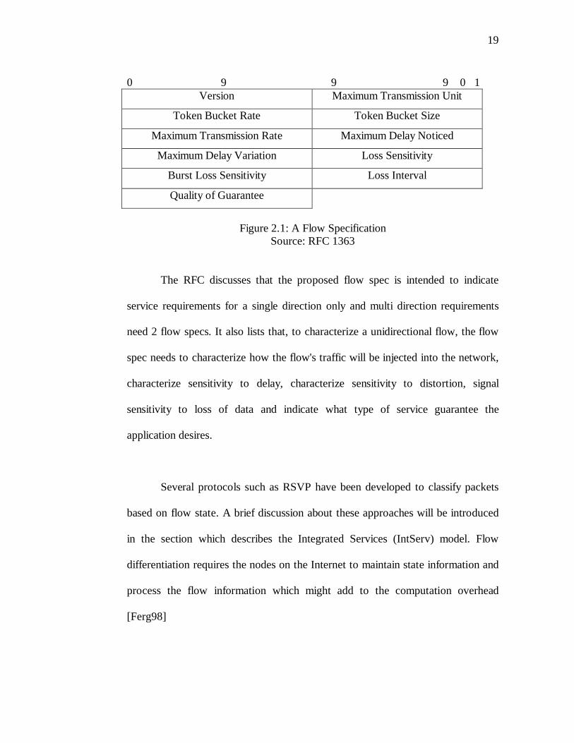
RFC 1363 defines a flow specification for information and possible
experimentation. It defines a flow specification (flow spec) as “ … a data
structure used by internetwork hosts to request special services of the
internetwork, often guarantees about how the internetwork will handle some of
the hosts’ traffic” [RFC1363]. RFC 1363 lists a flow spec which could be used
“… to describe any flow requirement, both for guaranteed flows and for
applications that simply want to give hints to the internetwork about their
requirements” [RFC1363]. The format of the flow spec listed in RFC 1363 is
shown in figure 2.1.
19
0 9 9 9 0 1Version Maximum Transmission Unit
Token Bucket Rate Token Bucket Size
Maximum Transmission Rate Maximum Delay Noticed
Maximum Delay Variation Loss Sensitivity
Burst Loss Sensitivity Loss Interval
Quality of Guarantee
Figure 2.1: A Flow SpecificationSource: RFC 1363
The RFC discusses that the proposed flow spec is intended to indicate
service requirements for a single direction only and multi direction requirements
need 2 flow specs. It also lists that, to characterize a unidirectional flow, the flow
spec needs to characterize how the flow's traffic will be injected into the network,
characterize sensitivity to delay, characterize sensitivity to distortion, signal
sensitivity to loss of data and indicate what type of service guarantee the
application desires.
Several protocols such as RSVP have been developed to classify packets
based on flow state. A brief discussion about these approaches will be introduced
in the section which describes the Integrated Services (IntServ) model. Flow
differentiation requires the nodes on the Internet to maintain state information and
process the flow information which might add to the computation overhead
[Ferg98]
20
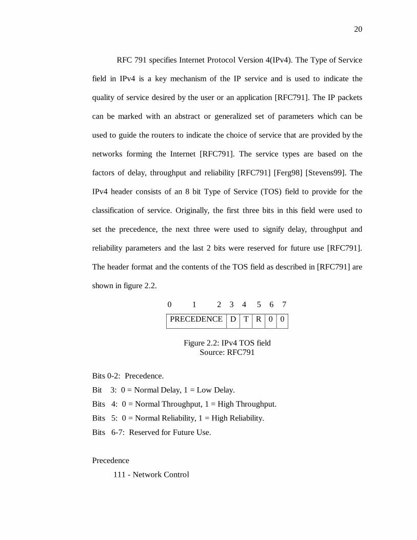
RFC 791 specifies Internet Protocol Version 4(IPv4). The Type of Service
field in IPv4 is a key mechanism of the IP service and is used to indicate the
quality of service desired by the user or an application [RFC791]. The IP packets
can be marked with an abstract or generalized set of parameters which can be
used to guide the routers to indicate the choice of service that are provided by the
networks forming the Internet [RFC791]. The service types are based on the
factors of delay, throughput and reliability [RFC791] [Ferg98] [Stevens99]. The
IPv4 header consists of an 8 bit Type of Service (TOS) field to provide for the
classification of service. Originally, the first three bits in this field were used to
set the precedence, the next three were used to signify delay, throughput and
reliability parameters and the last 2 bits were reserved for future use [RFC791].
The header format and the contents of the TOS field as described in [RFC791] are
shown in figure 2.2.
0 1 2 3 4 5 6 7
PRECEDENCE D T R 0 0
Figure 2.2: IPv4 TOS fieldSource: RFC791
Bits 0-2: Precedence.
Bit 3: 0 = Normal Delay, 1 = Low Delay.
Bits 4: 0 = Normal Throughput, 1 = High Throughput.
Bits 5: 0 = Normal Reliability, 1 = High Reliability.
Bits 6-7: Reserved for Future Use.
Precedence
111 - Network Control
21
110 - Internetwork Control
101 - CRITIC/ECP
100 - Flash Override
011 - Flash
010 - Immediate
001 - Priority
000 - Routine
Currently the 3 bit precedence field8 is ignored [Stevens99] and the next 4
bits are used to denote the QoS parameters necessary to classify the packets into
different classes [Ferg98] [Stevens99] [RFC1349]. The current implementation
uses bits 3 through 6 to set values for delay, throughput, reliability, monetary cost
and normal service. The semantics for the 4 bits is as follows:
1000 -- minimize delay
0100 -- maximize throughput
0010 -- maximize reliability
0001 -- minimize monetary cost
0000 -- normal service
Monetary cost can be minimized by using optimal routing solutions.
Routing protocol support based on the TOS field have been developed in routing
protocols such as OSPF and IS-IS to enable the computation of paths based on the
value specified in the TOS field [Ferg98] [Stevens99] [RFC1583] [RFC1195].
8 The Precedence field was used to denote the importance or priority of the datagram
[RFC1349]
22
The TOS field has never been used extensively and uniformly [Ferg98]
[Stevens99]. The TOS values are fixed and represent a limited and small set of
QoS definitions. This raises scalability issues when larger QoS definitions are
required to handle larger and differentiated traffic volumes [Ferg98] [RFC1363].
In such a scenario parametric service (using flows) results in better optimization
of the network since it makes it possible to define various parameters as opposed
to the well known constant values specified by the TOS field [RFC1363].
Transmission Control Protocol (TCP) which is the layer 4 protocol in the
TCP/IP architecture provides for QoS by supporting features such as Congestion
Management, Queue Management, Link Efficiency, Traffic Shaping and Traffic
Policing [Stevens99] [RFC793].
2.5.2. Frame Relay
Frame Relay was a technology developed to offer packet-switched
network services for ISDN networks. Frame Relay is a “…high-performance
WAN protocol that operates at the physical and data link layers of the OSI
reference model” [Cisco04]. CCITT recommendation Q.921 specifies the framing
format for Frame Relay. It uses the Forward Error Congestion Notification
(FECN), Backward Error Congestion Notification (BECN) and the Discard
Eligible (DE) bits in the Frame Relay header to provide for congestion control
mechanisms.
23
Every Frame Relay Virtual Circuit (VC) is administratively configured
with a Committed Information Rate (CIR) which is the maximum transfer rate
allowed on the particular VC [Ferg98] [Stallings01]. When a node transmits at a
rate greater than its allotted CIR, the DE bits in the excessive frames are set and in
the event of a congestion on the Frame relay network, these frames are discarded
by the switches on the network [Stallings01] [Ferg98]. This allows for the
accommodation of traffic bursts and also enables the Frame relay network to
control congestion [Ferg98].
BECN bits are set in the frame header when any frame relay switch
notices congestion on the frame relay network. BECN bits inform the originating
node to restrict the transmission of additional traffic. FECN bits on the other hand
are set by any switch on the frame relay network to inform the receiving node of
possible delays due to congestion.
2.5.3. ATM
Asynchronous Transfer Mode (ATM) was a technology developed by
ITU-T to provide a common format for voice, video and data services with
different bandwidth requirements. ATM uses standard 53 byte size cells to
transport voice, video, or data traffic over high-speed transmission media, such as
24
T1, T3, E1, E3 and SONET [Stallings01]. Currently the ATM Forum9 manages
the standards and specifications related to ATM.
ATM has a rich feature set for providing QoS over ATM networks. The
ATM service architecture provides for the definition of six service categories
which can be requested during connection setup [AFTM99]. The ATM services
can be categorized into [AFTM99]:
1. Constant Bit Rate (CBR) – used by connections that request a static amount of
bandwidth that is continuously available during the connection lifetime
2. Real-Time Variable Bit Rate (rt-VBR) – used by applications that require a
tightly constrained delay and delay variation, as would be appropriate for
voice and video applications
3. Non-Real-Time (nrt-VBR) – used by non-real-time applications have bursty
traffic characteristics
4. Unspecified Bit Rate (UBR) – used by non-real-time applications which do
not require tightly constrained delay and delay variation
5. Available Bit Rate (ABR) – a service category for which the limiting ATM
layer transfer characteristics provided by the network may change subsequent
to connection establishment
9 The ATM Forum is an international non-profit organization formed with the objective
of accelerating the use of ATM (Asynchronous Transfer Mode) products and services through a rapid convergence of interoperability specifications. In addition, the Forum promotes industry cooperation and awareness. The ATM forum can be accessed online at http://www.atmforum.com/
25
6. Guaranteed Frame Rate (GFR) – used by non-real-time applications that may
require a minimum rate guarantee and can benefit from accessing additional
bandwidth dynamically available in the network
The ATM Forums’ Traffic Management Specification 4.1 specifies six
parameters to characterize the traffic characteristics of an ATM connection. The
six traffic parameters are Peak Cell rate (PCR), Sustainable Cell Rate (SCR),
Maximum Burst Size (MBS), Minimum Cell Rate (MCR), Cell Delay Variation
Tolerance (CDVT) and Maximum Frame Size (MFS) [AFTM99].
The ATM Forums’ Private Network-Network Interface Specification
v.1.110 specifies eight topology state parameters. The topology metrics are Cell
Delay Variation (CDV), Maximum Cell Transfer Delay (maxCTD), Cell Loss
Ratio (CLR), Administrative Weight (AW), Maximum Cell Rate (maxCR),
Available Cell Rate (AvCR), Cell Rate Margin (CRM) and Variance Factor (VF).
The ATM Forums’ Traffic Management Specification 4.1 specifies six
QoS parameters namely Peak-to-Peak Cell Delay Variation (Peak-to-Peak CDV),
Maximum Cell transfer Delay (maxCTD), Cell Loss Ratio (CLR), Cell Error
Ratio (CER), Severely Errored Cell Block Ratio (SECBR) and Cell Misinsertion
Ratio (CMR).
10Private Network-Network Interface Specification Version 1.1 (PNNI 1.1) is available
online at: ftp://ftp.atmforum.com/pub/approved-specs/af-pnni-0055.002.pdf
26
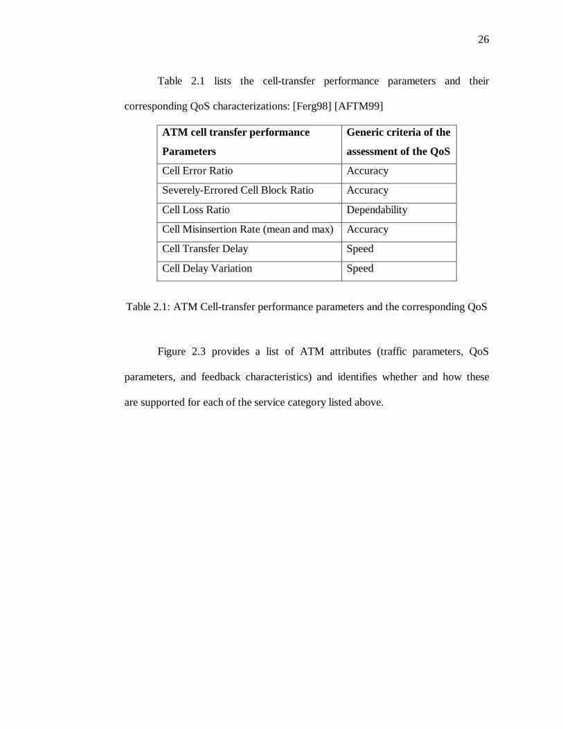
Table 2.1 lists the cell-transfer performance parameters and their
corresponding QoS characterizations: [Ferg98] [AFTM99]
ATM cell transfer performance
Parameters
Generic criteria of the
assessment of the QoS
Cell Error Ratio Accuracy
Severely-Errored Cell Block Ratio Accuracy
Cell Loss Ratio Dependability
Cell Misinsertion Rate (mean and max) Accuracy
Cell Transfer Delay Speed
Cell Delay Variation Speed
Table 2.1: ATM Cell-transfer performance parameters and the corresponding QoS
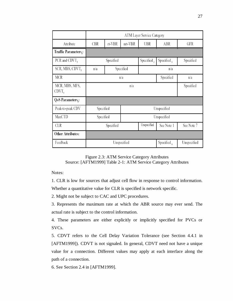
Figure 2.3 provides a list of ATM attributes (traffic parameters, QoS
parameters, and feedback characteristics) and identifies whether and how these
are supported for each of the service category listed above.
27
Figure 2.3: ATM Service Category AttributesSource: [AFTM1999] Table 2-1: ATM Service Category Attributes
Notes:
1. CLR is low for sources that adjust cell flow in response to control information.
Whether a quantitative value for CLR is specified is network specific.
2. Might not be subject to CAC and UPC procedures.
3. Represents the maximum rate at which the ABR source may ever send. The
actual rate is subject to the control information.
4. These parameters are either explicitly or implicitly specified for PVCs or
SVCs.
5. CDVT refers to the Cell Delay Variation Tolerance (see Section 4.4.1 in
[AFTM1999]). CDVT is not signaled. In general, CDVT need not have a unique
value for a connection. Different values may apply at each interface along the
path of a connection.
6. See Section 2.4 in [AFTM1999].
28
7. CLR is low for frames that are eligible for the service guarantee. Whether a
quantitative value for CLR is specified is network specific.
2.5.4. Integrated Services Architecture
The IETF Network Working Group recognized the need to provide for
QoS on the Internet to support real-time and non-real-time IP services. As a result
of the research and work done by the IETF, the Integrated Services Architecture
(IntServ) was proposed by the IETFs Integrated Services Working Group11. The
IntServ architecture proposes an extension to the traditional Internet architecture
to support the growing needs of real-time and non-real-time services for
applications such as “teleconferencing, remote seminars, telescience, and
distributed simulation” [RFC1633]. The IntServ architecture does not suggest any
changes to the underlying traditional Internet architecture, but proposes
extensions to the architecture to support real-time application needs [RFC1633]
[Ferg98] [Stallings01]. The extensions comprise of two elements [RFC1633]:
1. An extended service model
2. A reference implementation framework
QoS requirements, resource sharing requirements, packet dropping
allowances, usage feedback and a resource reservation protocol are the five key
components of the IntServ architecture. [Ferg98] [RFC1633]
11Accessible online at http://www.ietf.org/html.charters/IntServ-charter.html
29
The IntServ model classifies the Internet traffic in two broad categories
namely Real-Time (Inelastic) traffic and Non-Real-Time (Elastic) traffic. It
classifies the Real-Time Traffic further into Real-Time-Tolerant and Real-Time-
Intolerant application traffic.
The IntServ architecture defines three service classes namely
Guaranteed Services, Controlled Load Services and Best Effort Services. The
Best Effort Service Class refers to the traditional best-effort Internet services.
The Guaranteed Service Class is characterized by the following key
elements [RFC1633] [Ferg98] [Stallings01]:
1. Assured data rate
2. Specified upper bound on the queuing delay
3. No queuing losses
The Controlled Load Service Class is characterized by the following key
elements [RFC1633] [Ferg98] [Stallings01]:
1. Approximates the behavior of “best effort service under unloaded conditions”
2. No upper bound on queuing delay but ensures mostly that the delay does not
exceed the maximum transit delay
3. Almost no queuing loss (better than best-effort-services)
30
The IntServ architecture enables an application to request a reservation
for a particular flow12 by defining a particular traffic specification (TSpec). Based
on the TSpec defined, the required level of Guaranteed or Controlled-Load QoS is
offered by the network for the application’s data flow.
Traffic control in the IntServ architecture is implemented using four
components [RFC1633] [Ferg98] [Stallings01]:
1. Packet Scheduler: manages the forwarding of different packet streams using a
set of traffic queues and other mechanisms
2. Classifier: maps packets to a particular class such that the different classes are
treated differently by the packet scheduler
3. Admission Control: determines whether a new flow can be granted the
requested QoS without impacting earlier guarantees
4. Reservation Setup Protocol: used to create and maintain flow-specific state
information in the end nodes and all the intervening nodes along the path of a
particular flow.
12 A flow is defined in [RFC1633] as “a distinguishable stream of related datagrams
that results from a single user activity and requires the same QoS”
31
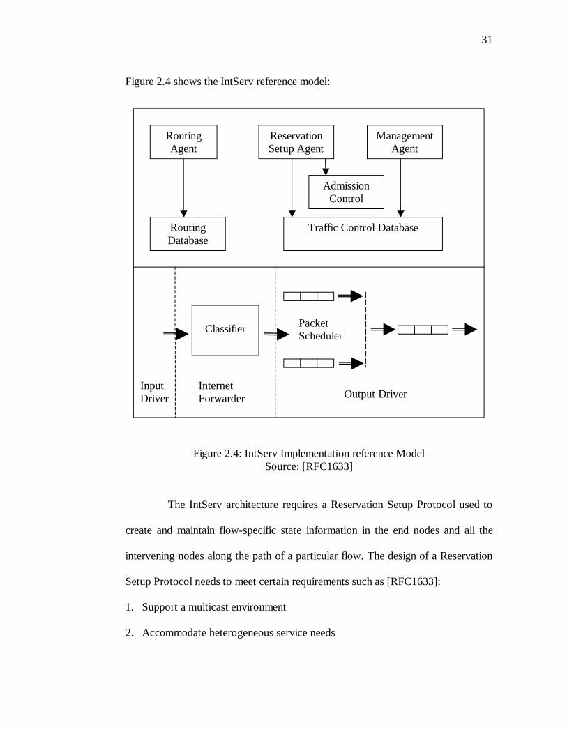
Figure 2.4 shows the IntServ reference model:
Figure 2.4: IntServ Implementation reference ModelSource: [RFC1633]
The IntServ architecture requires a Reservation Setup Protocol used to
create and maintain flow-specific state information in the end nodes and all the
intervening nodes along the path of a particular flow. The design of a Reservation
Setup Protocol needs to meet certain requirements such as [RFC1633]:
1. Support a multicast environment
2. Accommodate heterogeneous service needs
Routing Agent
Reservation Setup Agent
Management Agent
Admission Control
Routing Database
Traffic Control Database
InputDriver
Classifier
InternetForwarder Output Driver
Packet Scheduler
32
3. flexible control for sharing reservations along branches of the multicast trees
4. ability to add/delete a sender/receiver to an existing set
5. must be robust and scale well to large multicast groups
6. provide for advance reservation of resources
The Resource Reservation Setup Protocol (RSVP)13 is designed to meet
the above requirements and is used largely to support the IntServ architecture.
To summarize, the IntServ architecture uses a reservation setup protocol
such as RSVP to reserve resources before the actual transfer of data. The resource
reservation and allocation allows the network to offer requested QoS guarantees
for real-time and non-real-time application traffic over the Internet. In the IntServ
architecture every node along the path of the flow needs to maintain the state
information and process sophisticated packet classification, marking, policing and
shaping operations.
2.5.5. Differentiated Services Architecture
Parallel to the IntServ efforts, the IETF Differentiated Services (DiffServ)
Working Group14 focused on efforts to propose an architecture which would use
relatively simple and coarse methods to provide differentiated class of service to
13The IETF RFC 2205 describes the mechanics and protocol specification for RSVP and
is available online at http://ietf.org/rfc/rfc2205.txt?number=220514Accessible online at http://www.ietf.org/html.charters/diffserv-charter.html
33
the Internet traffic. The DiffServ architecture uses the concept of marking the IP
packets to denote the per-hop behavior (PHB) which is used to provide the
requisite QoS for Internet traffic [RFC2475] [Stallings01].
In the DiffServ model the traffic entering the network is classified and
conditioned at the network boundary and is assigned to an appropriate behavior
aggregate that is identified by a differentiated-services codepoint (DS codepoint)
[RFC2475] [Stallings01]. The packets are then forwarded according to the PHB
associated with each DS codepoint.
The characteristics of the DiffServ architecture are as follows. [RFC2475]
[Stallings01]:
1. IP packets are marked at the network boundary to denote the QoS
requirements
2. A Service Level Agreement (SLA) is established between the provider and the
customer
3. The DiffServ aware routers treat all packets belonging to the same DS
codepoint in a similar manner
4. Each DiffServ aware router in the network forward the classified packets
individually based on the PHB configured for that particular DS codepoint
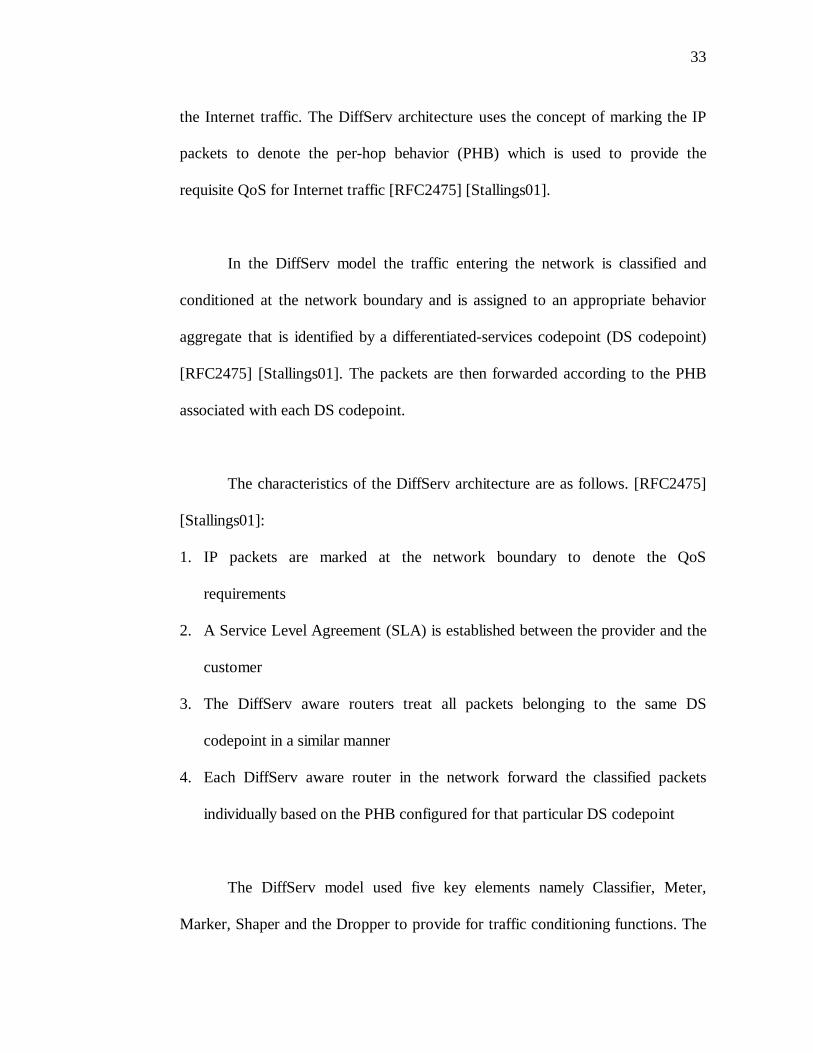
The DiffServ model used five key elements namely Classifier, Meter,
Marker, Shaper and the Dropper to provide for traffic conditioning functions. The
34
Classifier separates the incoming packets into different classed based on the
specified DS codepoint, the Meter confirms whether the traffic flow confirms
with the traffic profile specified in the Traffic Conditioning Agreements (TCA),
the Marker re-marks the DS codepoint of a packet if necessary, the Shaper
confirms whether the traffic stream is in confirmation with the specified traffic
profile and delays some or all of the packets if the stream does not confirm to the
traffic profile and finally the Dropper polices the stream by dropping packets of a
stream if the traffic stream is not in compliance with the traffic profile. The
interaction of these elements is illustrated in figure 2.5.
Figure 2.5: The DiffServ Model Traffic ConditionerSource: RFC2475
Classifier MarkerShaper/Dropper
Meter
35
In the DiffServ architecture the packets belonging to a service aggregate
are treated based on the PHB defined for that aggregate. [RFC3140] identifies the
semantics and the usage of the PHB identification codes to be used for DiffServ.
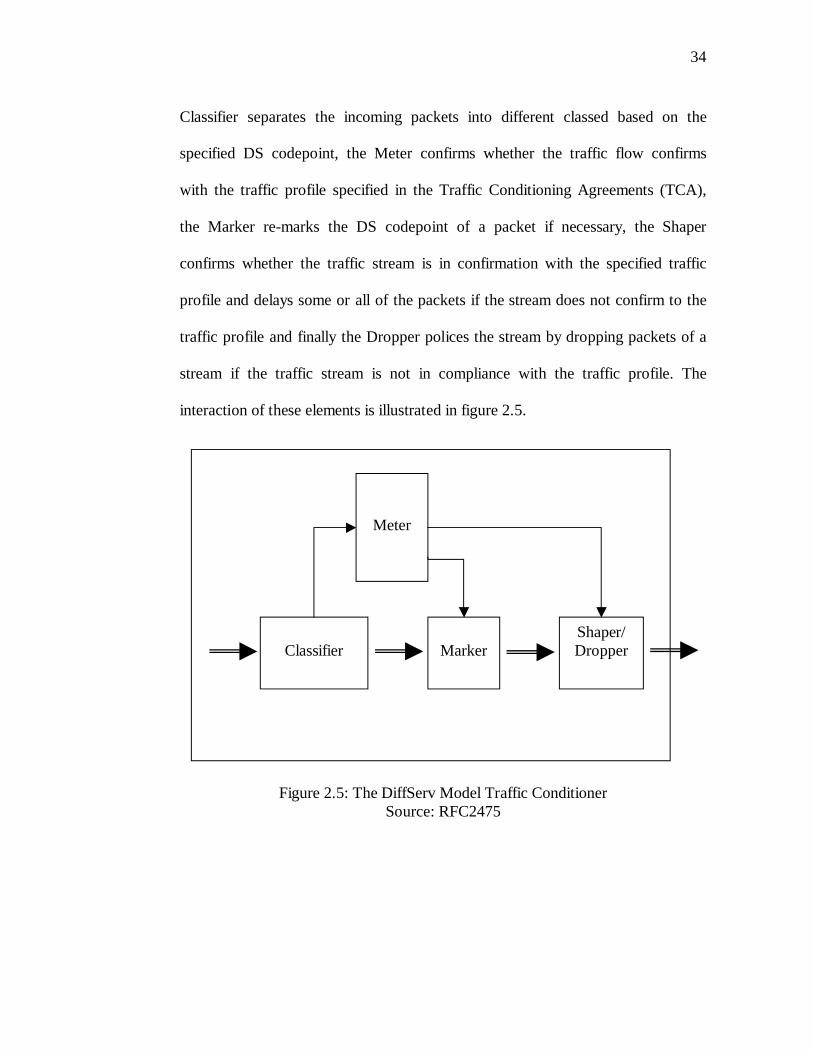
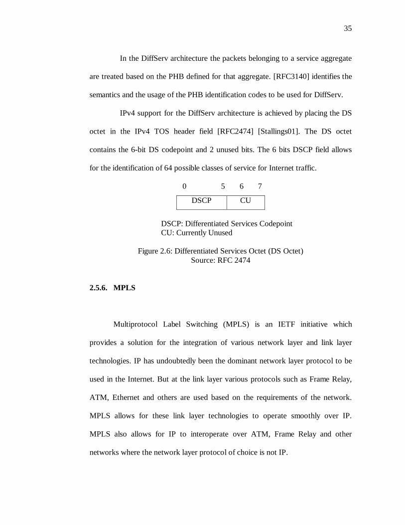
IPv4 support for the DiffServ architecture is achieved by placing the DS
octet in the IPv4 TOS header field [RFC2474] [Stallings01]. The DS octet
contains the 6-bit DS codepoint and 2 unused bits. The 6 bits DSCP field allows
for the identification of 64 possible classes of service for Internet traffic.
0 5 6 7
DSCP CU
DSCP: Differentiated Services CodepointCU: Currently Unused
Figure 2.6: Differentiated Services Octet (DS Octet)Source: RFC 2474
2.5.6. MPLS
Multiprotocol Label Switching (MPLS) is an IETF initiative which
provides a solution for the integration of various network layer and link layer
technologies. IP has undoubtedly been the dominant network layer protocol to be
used in the Internet. But at the link layer various protocols such as Frame Relay,
ATM, Ethernet and others are used based on the requirements of the network.
MPLS allows for these link layer technologies to operate smoothly over IP.
MPLS also allows for IP to interoperate over ATM, Frame Relay and other
networks where the network layer protocol of choice is not IP.
36
MPLS uses the concept of labels to mark packets entering the MPLS
network. The packets are then switched or routed along Label Switched Paths
(LSP) which are a sequence of MPLS enabled routers known as Label Switched
Routers (LSR) [RFC3031]. The packet headers are processed only once at the
ingress point in an MPLS network and the process of label switching imposes less
processing of the packet headers at the intermediate routers which results in a
simpler, faster and scalable network [Ferg98] [RFC3031].
The process of label tagging bears interest when providing QoS in an
MPLS network. Packets entering an MPLS network can be tagged with different
labels based on the information carried in the packets header such as the IPv4
TOS information [Ferg98]. This also holds true for ATM cells. Based on the
labels, the MPLS packet can now travel across different LSPs which can be built
separately to cater to various traffic engineering needs. MPLS support for
DiffServ is achieved by allowing the “ … network administrator to select how
DiffServ Behavior Aggregates (BAs) are mapped onto Label Switched Paths
(LSPs) so that he/she can best match the DiffServ, Traffic Engineering and
protection objectives within his/her particular network” [RFC3270]. RSVP is used
as a signaling protocol to establish LSPs in an MPLS network which allows for
IntServ support in MPLS [RFC3209].
37
2.5.7. IPv6
Internet Protocol version 6 (IPv6) specified in RFC 2460 is the latest
version of the Internet Protocol. The current widely used version is IPv4. IPv6
was conceived by the IETF to counter the demanding growth of the Internet and
the inability of the current version to cope up with the growth. The protocol is still
in the experimental stage. The basic framework of the protocol is complete and
has been widely accepted and deployed by the Internet community. Architects,
Planners, Engineers and Scientists are currently working on adding to the
enhancements to the IPv6 protocol.
Even though the foreseeable depletion of the IPv4 address space was the
primary trigger for the development of a new version of the IP protocol, many
other requirements and enhancements such as security and QoS requirements
contributed to the urgent need to develop a more flexible and enhanced version of
the protocol. The major goals of the IPv6 protocol were to increase address space,
improve security, simplify multicasting and add Quality of Service features. The
major changes from IPv4 to IPv6 as specified in [RFC2460] are as follows:
1. Expanded Addressing Capabilities
IPv6 increases the IP address size from 32 bits to 128 bits, to support more
levels of addressing hierarchy, a much greater number of addressable nodes,
and simpler auto-configuration of addresses. The scalability of multicast
38
routing is improved by adding a “scope” field to multicast addresses. And a
new type of address called an “anycast address” is defined, used to send a
packet to any one of a group of nodes.
2. Header Format Simplification
Some IPv4 header fields have been dropped or made optional, to reduce the
common-case processing cost of packet handling and to limit the bandwidth
cost of the IPv6 header.
3. Improved Support for Extensions and Options
Changes in the way IP header options are encoded allows for more efficient
forwarding, less stringent limits on the length of options, and greater
flexibility for introducing new options in the future.
4. Flow Labeling Capability
A new capability is added to enable the labeling of packets belonging to
particular traffic “flows” for which the sender requests special handling, such
as non-default quality of service or “real-time” service.
5. Authentication and Privacy Capabilities
Extensions to support authentication, data integrity, and (optional) data
confidentiality are specified for IPv6.
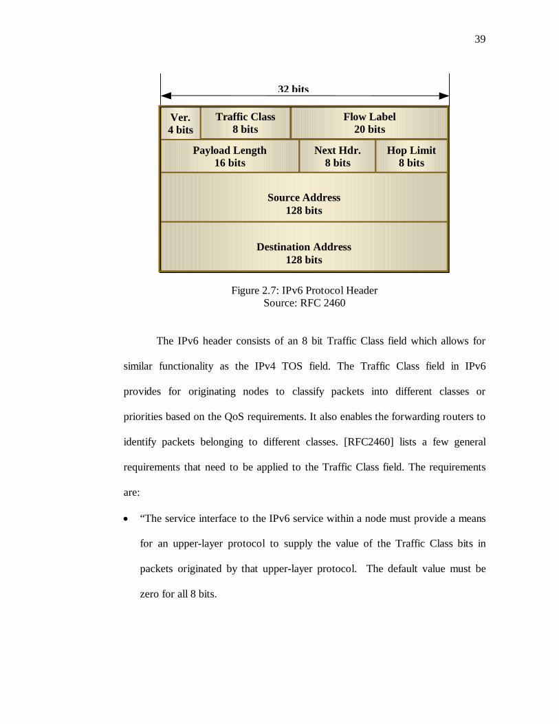
The IPv6 protocol header as described in [RFC 2460] is shown in figure 2.7.
39
Figure 2.7: IPv6 Protocol HeaderSource: RFC 2460
The IPv6 header consists of an 8 bit Traffic Class field which allows for
similar functionality as the IPv4 TOS field. The Traffic Class field in IPv6
provides for originating nodes to classify packets into different classes or
priorities based on the QoS requirements. It also enables the forwarding routers to
identify packets belonging to different classes. [RFC2460] lists a few general
requirements that need to be applied to the Traffic Class field. The requirements
are:
“The service interface to the IPv6 service within a node must provide a means
for an upper-layer protocol to supply the value of the Traffic Class bits in
packets originated by that upper-layer protocol. The default value must be
zero for all 8 bits.
Ver.4 bits
Traffic Class8 bits
Flow Label20 bits
Payload Length16 bits
Next Hdr.8 bits
Hop Limit8 bits
Source Address128 bits
Destination Address128 bits
32 bits
40
Nodes that support a specific (experimental or eventual standard) use of some
or all of the Traffic Class bits are permitted to change the value of those bits in
packets that they originate, forward, or receive, as required for that specific
use. Nodes should ignore and leave unchanged any bits of the Traffic Class
field for which they do not support a specific use.
An upper-layer protocol must not assume that the value of the Traffic Class
bits in a received packet are the same as the value sent by the packet's source.”
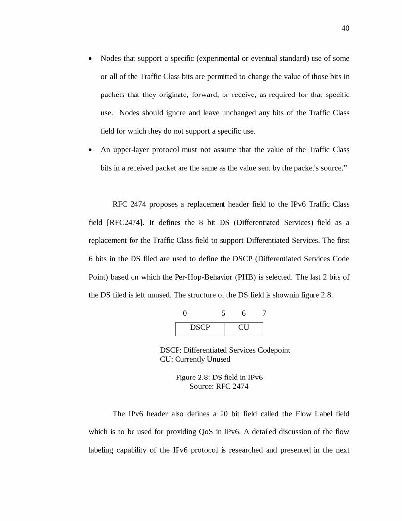
RFC 2474 proposes a replacement header field to the IPv6 Traffic Class
field [RFC2474]. It defines the 8 bit DS (Differentiated Services) field as a
replacement for the Traffic Class field to support Differentiated Services. The first
6 bits in the DS filed are used to define the DSCP (Differentiated Services Code
Point) based on which the Per-Hop-Behavior (PHB) is selected. The last 2 bits of
the DS filed is left unused. The structure of the DS field is shownin figure 2.8.
0 5 6 7
DSCP CU
DSCP: Differentiated Services CodepointCU: Currently Unused
Figure 2.8: DS field in IPv6Source: RFC 2474
The IPv6 header also defines a 20 bit field called the Flow Label field
which is to be used for providing QoS in IPv6. A detailed discussion of the flow
labeling capability of the IPv6 protocol is researched and presented in the next

41
chapter. This thesis work aims at defining a structure for the flow label field
which will be used for providing QoS in IPv6 networks at the network layer.
42
CHAPTER 3
IPv6 FLOW LABEL
The IPv6 header includes a 20 bit field called the Flow Label field which adds
flow labeling capability for IPv6. The flow label field enables an IPv6 enabled
host to label a sequence of packets for which the host requests special handling by
the IPv6 routers [RFC2460]. This enables the host to request non-default quality
of service from the IPv6 network.
3.1 IPv6 Flow Label Field Definition
The IPv6 specification defines a flow as “… a sequence of packets sent
from a particular source to a particular (unicast or multicast) destination for which
the source desires special handling by the intervening routers. The nature of that
special handling might be conveyed to the routers by a control protocol, such as a
resource reservation protocol, or by information within the flow's packets
themselves, e.g., in a hop-by-hop option” [RFC 2460]. It notes the following with
regards to the nature of a flow.
1. Multiple active flows might be present between a source and the destination
along with other traffic which may not be associated with a particular flow
2. A flow can be uniquely identified by the combination of a source address and
non-zero flow label
3. A packet that is not associated with a flow should carry a flow label value of 0
43
4. Packets that belong to the same flow should be sent with the same source
address, destination address and the same non-zero flow label
The IPv6 specification introduces the flow label field and broadly defines
the semantics and usage of the flow label field. The value of the flow label field
enables the IPv6 router to classify and assign the packets to various flows and
process the flows as per the QoS requirements of a particular flow. The IPv6
specification notes the following with regards to the nature of the IPv6 flow
labels.
1. Flow labels are assigned to a flow by the flow's source node
2. The flow labels must be chosen (pseudo) randomly and uniformly from the
range of 1 - FFFFF hex. The randomly chosen value of the flow labels enables
any set of bits within the Flow Label field suitable for use as a hash key by
routers, for looking up the state associated with the flow
3. The maximum lifetime of any flow-handling state established along a flow's
path must be specified as part of the description of the state-establishment
mechanism, e.g., the resource reservation protocol or the flow-setup hop-by-
hop option.
4. A source must not reuse a flow label for a new flow within the max lifetime of
any flow-handling state that might have been established for the prior use of
the flow label
5. Hosts or routers that do not support the functions of the Flow Label field are
required to set the field to zero when originating a packet, pass the field on
44
unchanged when forwarding a packet, and ignore the field when receiving a
packet
3.2 IPv6 Flow Label Specification
RFC 3697 defines a standardized specification for the IPv6 flow label
field. A summary of the specification as listed in [RFC3697] is as follows15:
1. The IPv6 20 bit flow label field is used by a source to label packets of a flow
2. Packets not belonging to any flow are labeled with a flow label value of zero
3. The triplet value of the Flow Label, Source Address, and Destination Address
fields is used by the packet classifiers to identify a particular packets’ flow
4. The Flow Label value set by the source MUST be delivered unchanged to the
destination node(s).
5. The performance of the IPv6 routers should not depend on the distribution of
the flow label values and no mathematical or other properties should be
assumed based on the flow label values
6. The flow State lifetime is 120 seconds and packets arriving with the same
flow label value after 120 seconds should not be treated as belonging to the
same old flow unless either the flow state has been explicitly refreshed within
the lifetime duration or the duration is explicitly specified to be a value other
than 120 seconds
15The original content (RFC 3697 Section 2) has been reformatted and presented as a list
item to aid in easier reading
45
7. The use of the Flow Label field does not necessarily signal any requirement
on packet reordering
8. An IPv6 node that is not participating in the flow-specific treatment process
must ignore the flow label field when receiving or forwarding a packet
3.3 IPv6 Flow Label Requirements
RFC 3697 specifies the flow labeling requirements for the IPv6 flow label
field. A summary of the specification as listed in [RFC3697] is as follows16:
1. Flows should be unique for different transport connections and application
data streams in order for proper flow label based classification
2. A source node which does not assign traffic to flows must set the Flow Label
to zero
3. Application and transport layer protocols should be able to specify Flow Label
values so that they can define what packets constitute a flow
4. The source node should be able to select unused Flow Label values for flows
not requesting a specific value to be used
5. A source node must ensure that it does not unintentionally reuse Flow Label
values it is currently using or has recently used when creating new flows
16The original content (RFC 3697 Section 3 and Section 4) have been reformatted and
presented as a list item to aid in easier reading.
46
6. Flow Label values previously used with a specific pair of source and
destination addresses must not be assigned to new flows with the same
address pair within the flow state lifetime of 120 seconds
7. Accidental Flow Label value reuse must be avoided by providing for
sequential or pseudo-random generation of new flow values
8. The method for flow state establishment must provide the means for flow state
clean-up from the IPv6 nodes providing the flow-specific treatment
9. Flow state establishment methods must be able to recover from the case where
the requested flow state cannot be supported
3.4 IPv6 Flow Label Values (Current Efforts)
Various proposals have been made to the IETF to define the 20 bits of the
flow label field in the IPv6 header. These proposals have been made in the form
of IETF drafts which are reviewed by the IETF IPv6 working group. The IETF
IPv6 working group reviews the drafts and if the proposals meet the criteria, then
they are converted to IETF standards. So far none of the proposals have been
accepted for standardization by the IETF. The proposals are reviewed in the
following sections to better aid in the process of defining the 20 bits if the IPv6
flow label field.
47
3.4.1 Review of “draft-conta-ipv6-flow-label-02.txt” [ID2001a]
This draft makes a proposal for the IPv6 Flow Label specification. It
proposes a change in the flow label specification made in RFC 2640 by proposing
that a flow label value can be changed en-route by intervening nodes, with the
condition that its original significance be maintained, or restored, when necessary
[ID2001a]. This is certainly necessary when the source intends to convey specific
information to the end-node. This draft notes that the ability is necessary if the
flow label carries a hop-by-hop significance or if the neighboring routers have
specific arrangements or agreements (which are not universal). The drawback
would certainly be the complexity involved as against a proposal for non-mutable
flow labels [ID2001a].
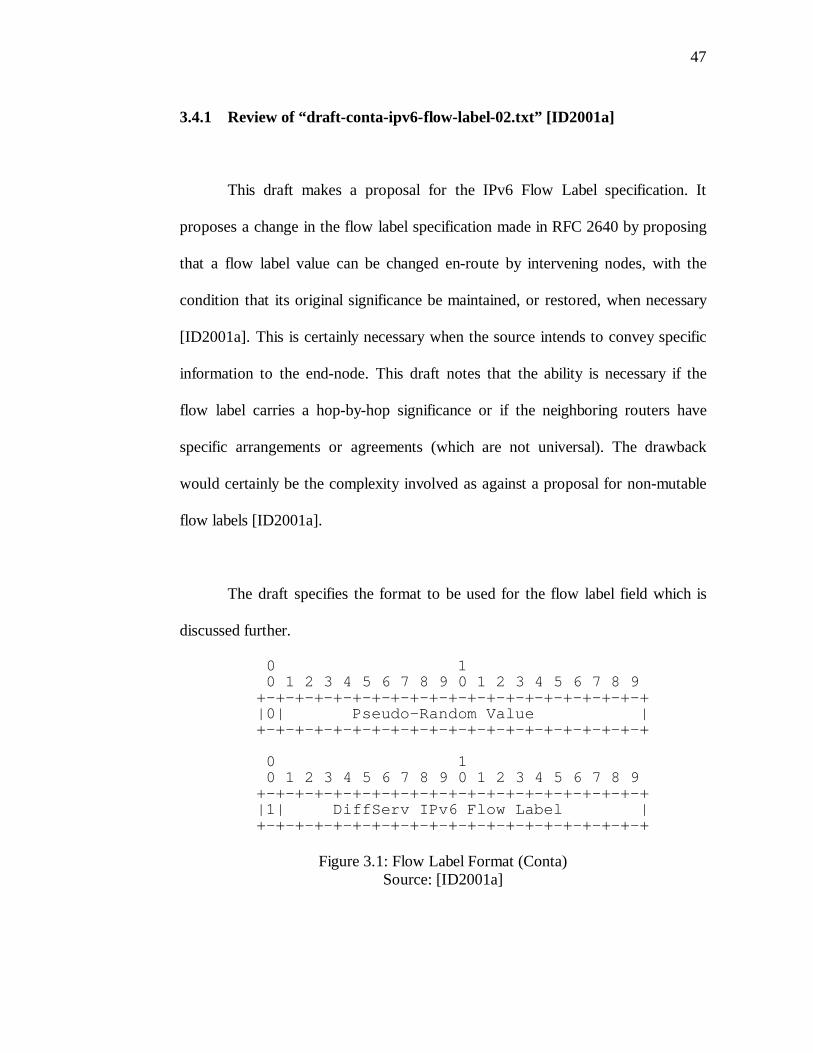
The draft specifies the format to be used for the flow label field which is
discussed further.
0 1 0 1 2 3 4 5 6 7 8 9 0 1 2 3 4 5 6 7 8 9 +-+-+-+-+-+-+-+-+-+-+-+-+-+-+-+-+-+-+-+-+ |0| Pseudo-Random Value | +-+-+-+-+-+-+-+-+-+-+-+-+-+-+-+-+-+-+-+-+
0 1 0 1 2 3 4 5 6 7 8 9 0 1 2 3 4 5 6 7 8 9 +-+-+-+-+-+-+-+-+-+-+-+-+-+-+-+-+-+-+-+-+ |1| DiffServ IPv6 Flow Label | +-+-+-+-+-+-+-+-+-+-+-+-+-+-+-+-+-+-+-+-+
Figure 3.1: Flow Label Format (Conta)Source: [ID2001a]
48
The specified format provides support for random number method of
selecting a flow label value as required by the specification made in RFC2640.
Advantages:
1. This approach preserves compatibility with the random number method of
selecting a Flow Label value defined in the RFC2640
2. It captures the DiffServ treatment intended to be applied to the packet
3. The flow label value is not locally mapped and hence is suitable for use in a
end-to-end header field
Disadvantages:
1. This approach captures less info than the port and protocol number normally
used in a DiffServ MF classifier
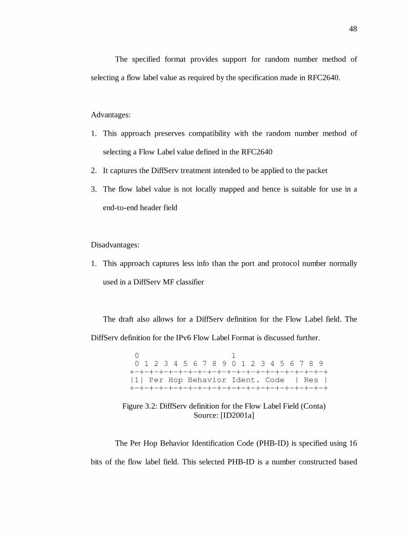
The draft also allows for a DiffServ definition for the Flow Label field. The
DiffServ definition for the IPv6 Flow Label Format is discussed further.
0 1 0 1 2 3 4 5 6 7 8 9 0 1 2 3 4 5 6 7 8 9 +-+-+-+-+-+-+-+-+-+-+-+-+-+-+-+-+-+-+-+-+ |1| Per Hop Behavior Ident. Code | Res | +-+-+-+-+-+-+-+-+-+-+-+-+-+-+-+-+-+-+-+-+
Figure 3.2: DiffServ definition for the Flow Label Field (Conta)Source: [ID2001a]
The Per Hop Behavior Identification Code (PHB-ID) is specified using 16
bits of the flow label field. This selected PHB-ID is a number constructed based
49
on the “Differentiated Services Per-Hop-Behavior Identification Code” and is in
confirmation with RFC 3140. This format allows for DiffServ support in IPv6
using the Flow Label field. The “Res” bits are reserved for future use.
Advantages:
1. This approach allows for efficient processing of packets in the QoS engines in
IPv6 forwarding devices
Disadvantages:
1. The end nodes have to force the correct Flow Label in the IPv6 headers of
outgoing packets or the first hop routers have to do this job. For this the
routers have to be configured with MF classifiers which needs extra
computations to be done by the routers
The draft also makes suggestions to the other ways in which the 20 bits of the
flow label field could be used to convey host-to-host header information and the
host-to-host protocol type. The suggested formats are discussed in the following
sections.
50
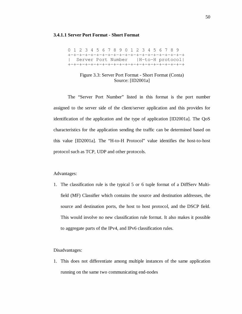
3.4.1.1 Server Port Format - Short Format
0 1 2 3 4 5 6 7 8 9 0 1 2 3 4 5 6 7 8 9+-+-+-+-+-+-+-+-+-+-+-+-+-+-+-+-+-+-+-+-+| Server Port Number |H-to-H protocol|+-+-+-+-+-+-+-+-+-+-+-+-+-+-+-+-+-+-+-+-+
Figure 3.3: Server Port Format - Short Format (Conta)Source: [ID2001a]
The “Server Port Number” listed in this format is the port number
assigned to the server side of the client/server application and this provides for
identification of the application and the type of application [ID2001a]. The QoS
characteristics for the application sending the traffic can be determined based on
this value [ID2001a]. The “H-to-H Protocol” value identifies the host-to-host
protocol such as TCP, UDP and other protocols.
Advantages:
1. The classification rule is the typical 5 or 6 tuple format of a DiffServ Multi-
field (MF) Classifier which contains the source and destination addresses, the
source and destination ports, the host to host protocol, and the DSCP field.
This would involve no new classification rule format. It also makes it possible
to aggregate parts of the IPv4, and IPv6 classification rules.
Disadvantages:
1. This does not differentiate among multiple instances of the same application
running on the same two communicating end-nodes
51
2. The 12 bits which specify the server port number can be used to specify ports
from 1 to 4095 (well-known ports from 1 to1024 and a subset of the registered
ports from 1025 to 4095 can be defined using this format for QoS
qualifications. The rest are ignored as ports to which traffic does not require
any QoS)
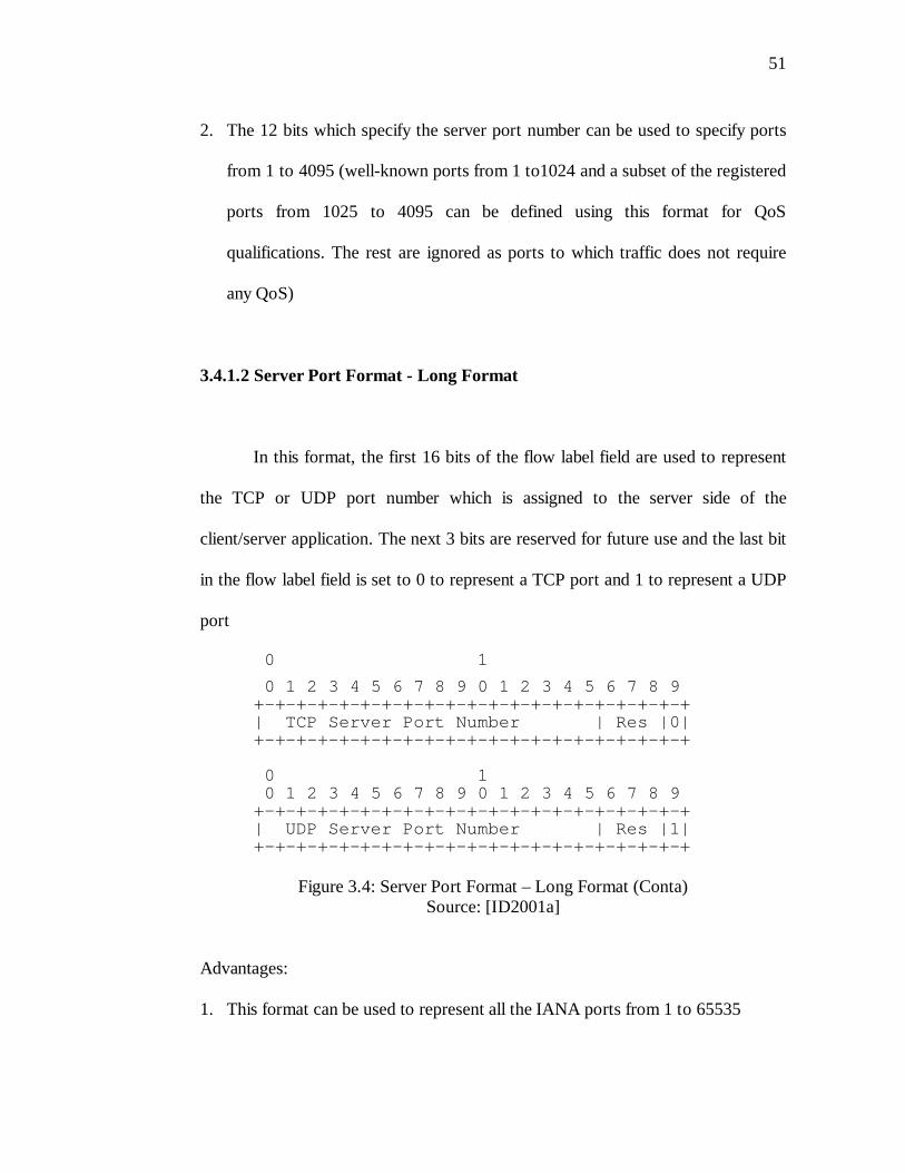
3.4.1.2 Server Port Format - Long Format
In this format, the first 16 bits of the flow label field are used to represent
the TCP or UDP port number which is assigned to the server side of the
client/server application. The next 3 bits are reserved for future use and the last bit
in the flow label field is set to 0 to represent a TCP port and 1 to represent a UDP
port
0 1
0 1 2 3 4 5 6 7 8 9 0 1 2 3 4 5 6 7 8 9 +-+-+-+-+-+-+-+-+-+-+-+-+-+-+-+-+-+-+-+-+ | TCP Server Port Number | Res |0| +-+-+-+-+-+-+-+-+-+-+-+-+-+-+-+-+-+-+-+-+
0 1 0 1 2 3 4 5 6 7 8 9 0 1 2 3 4 5 6 7 8 9 +-+-+-+-+-+-+-+-+-+-+-+-+-+-+-+-+-+-+-+-+ | UDP Server Port Number | Res |1| +-+-+-+-+-+-+-+-+-+-+-+-+-+-+-+-+-+-+-+-+
Figure 3.4: Server Port Format – Long Format (Conta)Source: [ID2001a]
Advantages:
1. This format can be used to represent all the IANA ports from 1 to 65535
52
2. No new classification rule is needed
Disadvantages:
1. This format confines the label to represent either TCP or UDP flows since
these are the two extensively used protocols. This format hence limits the QoS
capability to be offered only to TCP and UDP and hence is not scalable
2. This format cannot differentiate among multiple instances of the same
application running on the same two communication end nodes
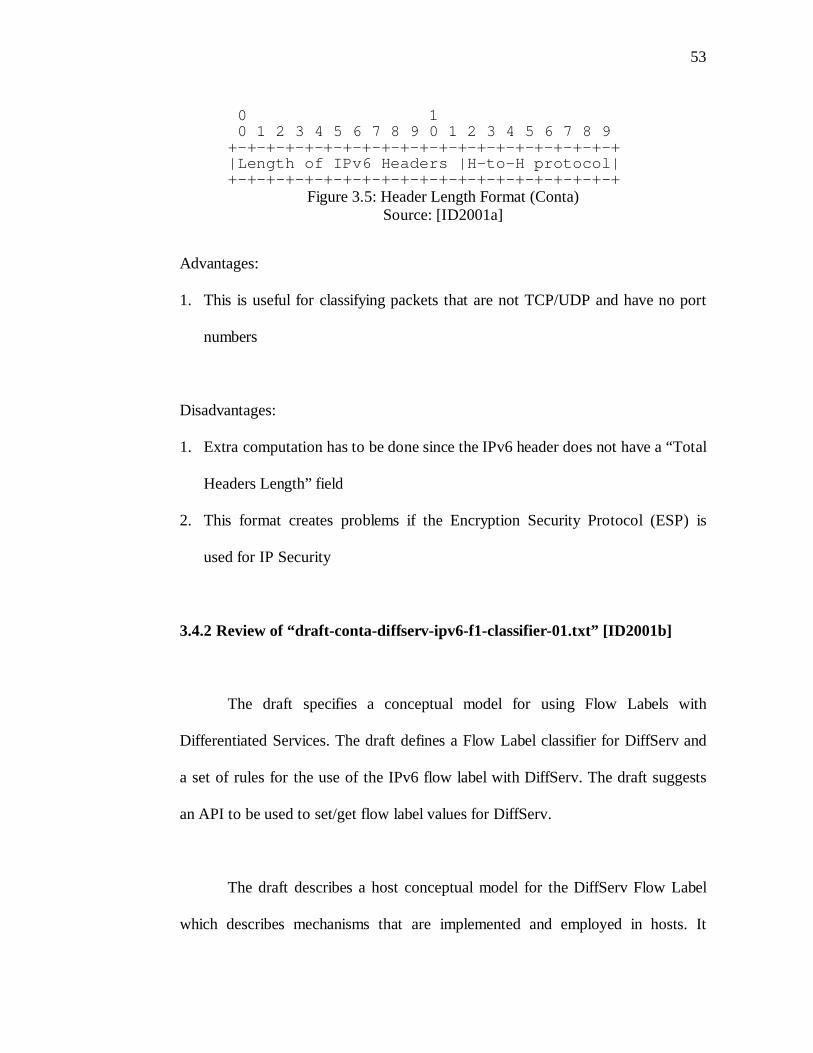
3.4.1.3 Header Length Format
This format proposes the use the first 16 bits in the flow label field to
represent the length of IPv6 headers (length of main headers plus the length of the
IPv6 extension headers preceding the host-to-host or transport header). This
format proposes that “The length of the IPv6 headers in the flow label value
would provide the information which a DiffServ QOS engine classifier could use
to locate and fetch the source and destination ports, and apply those, along with
the source and destination address and the host-to-host protocol from the flow
label, to match the source and destination address, the source and destination ports
and the protocol identifier elements of a DiffServ M-F classifier [ID2001a]”
53
0 1 0 1 2 3 4 5 6 7 8 9 0 1 2 3 4 5 6 7 8 9 +-+-+-+-+-+-+-+-+-+-+-+-+-+-+-+-+-+-+-+-+ |Length of IPv6 Headers |H-to-H protocol| +-+-+-+-+-+-+-+-+-+-+-+-+-+-+-+-+-+-+-+-+
Figure 3.5: Header Length Format (Conta)Source: [ID2001a]
Advantages:
1. This is useful for classifying packets that are not TCP/UDP and have no port
numbers
Disadvantages:
1. Extra computation has to be done since the IPv6 header does not have a “Total
Headers Length” field
2. This format creates problems if the Encryption Security Protocol (ESP) is
used for IP Security
3.4.2 Review of “draft-conta-diffserv-ipv6-f1-classifier-01.txt” [ID2001b]
The draft specifies a conceptual model for using Flow Labels with
Differentiated Services. The draft defines a Flow Label classifier for DiffServ and
a set of rules for the use of the IPv6 flow label with DiffServ. The draft suggests
an API to be used to set/get flow label values for DiffServ.
The draft describes a host conceptual model for the DiffServ Flow Label
which describes mechanisms that are implemented and employed in hosts. It
54
describes the mechanisms to select the “host flow label values”. The draft
specified that the label selection should be in confirmation with the contractual
agreements made between the user and the network provider (SLAs, SLSs, TCAs
and TCSs). The draft mentions that the host flow label values can be selected in
three possible ways:
1. An arbitrary number - any value between 1 and the maximum allowed. It must
be specified in contractual agreements between the user and network
providers and the value can be stored on the host, in a system, group,
individual user, application database or in a network distributed database
2. A random number - any value between 1 and the maximum allowed. The
random generated value to be used in the flow label should be specified in the
contractual agreements between the user and the network provider.
3. IANA number - any value between 1 and the maximum allowed. The value is
specified by the IANA
The draft describes the router conceptual model for the DiffServ Flow
Label which describes mechanisms that are implemented and employed by the
routers that forward the IPv6 packets. These mechanisms consist basically in
configuring or setting flow label classifiers (classification rules) and the
classification processing done by the classification engines. The model describes
a flow label classifier as a tuple “C” that contains the following:
55
C = (Source Address, Source Address prefix, Destination Address, Destination
Address Prefix Length, Flow Label)
The classifier can also be represented as:
Flow Label Classifier:
Type: IPv6 3 tuple
IPv6DestAddrValue: IPv6 address
IPv6DestPrefixLength: byte value
IPv6ScrAddrValue: IPv6 address
IPv6SrcPrefixLength: byte value
IPv6FlowLabel: 20 bit value
These values are set based on the contractual agreements between the user
and the network provider. The QoS engine in the routers processing the packets
match the header information (including the “host flow label value”) with the
flow label classification rules (including the “router flow label values”) to provide
the DiffServ classification.
3.4.3. Review of “draft-banerjee-flowlabel-ipv6-qos-03.txt” [ID2002a]
This draft reviews various proposals that have already been made and
evaluates whether the proposals are to be used or not for defining the value of the
flow label field. The draft also specifies a hybrid approach which includes options
to provide IntServ as well as DiffServ based support for IPv6 QoS. The draft
specifies a pointer to an experimental QoS scheme called MultServ [ID2002a].
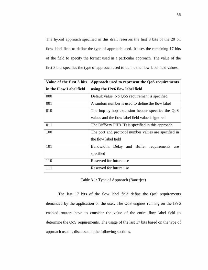
56
The hybrid approach specified in this draft reserves the first 3 bits of the 20 bit
flow label field to define the type of approach used. It uses the remaining 17 bits
of the field to specify the format used in a particular approach. The value of the
first 3 bits specifies the type of approach used to define the flow label field values.
Value of the first 3 bits
in the Flow Label field
Approach used to represent the QoS requirements
using the IPv6 flow label field
000 Default value. No QoS requirement is specified
001 A random number is used to define the flow label
010 The hop-by-hop extension header specifies the QoS
values and the flow label field value is ignored
011 The DiffServ PHB-ID is specified in this approach
100 The port and protocol number values are specified in
the flow label field
101 Bandwidth, Delay and Buffer requirements are
specified
110 Reserved for future use
111 Reserved for future use
Table 3.1: Type of Approach (Banerjee)
The last 17 bits of the flow label field define the QoS requirements
demanded by the application or the user. The QoS engines running on the IPv6
enabled routers have to consider the value of the entire flow label field to
determine the QoS requirements. The usage of the last 17 bits based on the type of
approach used is discussed in the following sections.
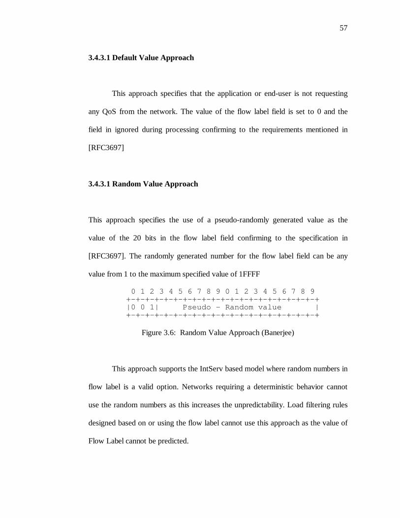
57
3.4.3.1 Default Value Approach
This approach specifies that the application or end-user is not requesting
any QoS from the network. The value of the flow label field is set to 0 and the
field in ignored during processing confirming to the requirements mentioned in
[RFC3697]
3.4.3.1 Random Value Approach
This approach specifies the use of a pseudo-randomly generated value as the
value of the 20 bits in the flow label field confirming to the specification in
[RFC3697]. The randomly generated number for the flow label field can be any
value from 1 to the maximum specified value of 1FFFF
0 1 2 3 4 5 6 7 8 9 0 1 2 3 4 5 6 7 8 9 +-+-+-+-+-+-+-+-+-+-+-+-+-+-+-+-+-+-+-+-+ |0 0 1| Pseudo - Random value | +-+-+-+-+-+-+-+-+-+-+-+-+-+-+-+-+-+-+-+-+
Figure 3.6: Random Value Approach (Banerjee)
This approach supports the IntServ based model where random numbers in
flow label is a valid option. Networks requiring a deterministic behavior cannot
use the random numbers as this increases the unpredictability. Load filtering rules
designed based on or using the flow label cannot use this approach as the value of
Flow Label cannot be predicted.
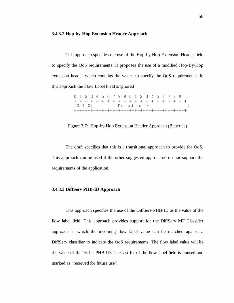
58
3.4.3.2 Hop-by-Hop Extension Header Approach
This approach specifies the use of the Hop-by-Hop Extension Header field
to specify the QoS requirements. It proposes the use of a modified Hop-By-Hop
extension header which contains the values to specify the QoS requirements. In
this approach the Flow Label Field is ignored
0 1 2 3 4 5 6 7 8 9 0 1 2 3 4 5 6 7 8 9 +-+-+-+-+-+-+-+-+-+-+-+-+-+-+-+-+-+-+-+-+ |0 1 0| Do not care | +-+-+-+-+-+-+-+-+-+-+-+-+-+-+-+-+-+-+-+-+
Figure 3.7: Hop-by-Hop Extension Header Approach (Banerjee)
The draft specifies that this is a transitional approach to provide for QoS.
This approach can be used if the other suggested approaches do not support the
requirements of the application.
3.4.3.3 DiffServ PHB-ID Approach
This approach specifies the use of the DiffServ PHB-ID as the value of the
flow label field. This approach provides support for the DiffServ MF Classifier
approach in which the incoming flow label value can be matched against a
DiffServ classifier to indicate the QoS requirements. The flow label value will be
the value of the 16 bit PHB-ID. The last bit of the flow label field is unused and
marked as “reserved for future use”
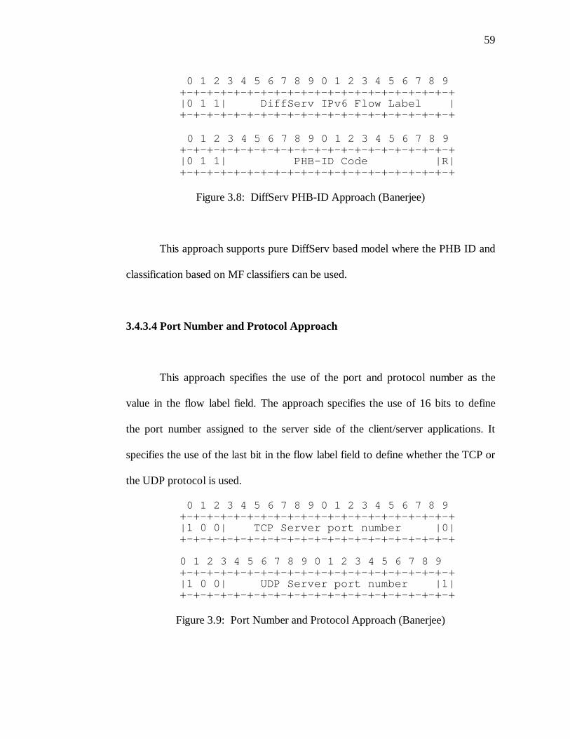
59
0 1 2 3 4 5 6 7 8 9 0 1 2 3 4 5 6 7 8 9 +-+-+-+-+-+-+-+-+-+-+-+-+-+-+-+-+-+-+-+-+ |0 1 1| DiffServ IPv6 Flow Label | +-+-+-+-+-+-+-+-+-+-+-+-+-+-+-+-+-+-+-+-+
0 1 2 3 4 5 6 7 8 9 0 1 2 3 4 5 6 7 8 9 +-+-+-+-+-+-+-+-+-+-+-+-+-+-+-+-+-+-+-+-+ |0 1 1| PHB-ID Code |R| +-+-+-+-+-+-+-+-+-+-+-+-+-+-+-+-+-+-+-+-+
Figure 3.8: DiffServ PHB-ID Approach (Banerjee)
This approach supports pure DiffServ based model where the PHB ID and
classification based on MF classifiers can be used.
3.4.3.4 Port Number and Protocol Approach
This approach specifies the use of the port and protocol number as the
value in the flow label field. The approach specifies the use of 16 bits to define
the port number assigned to the server side of the client/server applications. It
specifies the use of the last bit in the flow label field to define whether the TCP or
the UDP protocol is used.
0 1 2 3 4 5 6 7 8 9 0 1 2 3 4 5 6 7 8 9 +-+-+-+-+-+-+-+-+-+-+-+-+-+-+-+-+-+-+-+-+ |1 0 0| TCP Server port number |0| +-+-+-+-+-+-+-+-+-+-+-+-+-+-+-+-+-+-+-+-+ 0 1 2 3 4 5 6 7 8 9 0 1 2 3 4 5 6 7 8 9 +-+-+-+-+-+-+-+-+-+-+-+-+-+-+-+-+-+-+-+-+ |1 0 0| UDP Server port number |1| +-+-+-+-+-+-+-+-+-+-+-+-+-+-+-+-+-+-+-+-+
Figure 3.9: Port Number and Protocol Approach (Banerjee)
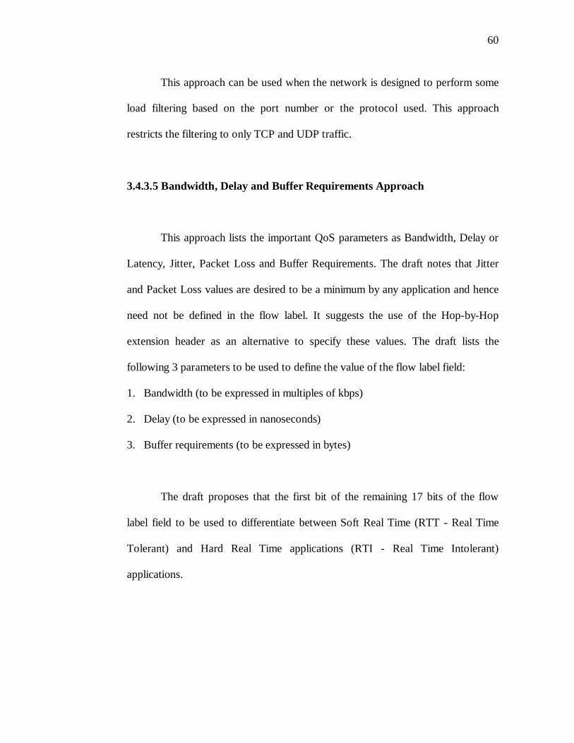
60
This approach can be used when the network is designed to perform some
load filtering based on the port number or the protocol used. This approach
restricts the filtering to only TCP and UDP traffic.
3.4.3.5 Bandwidth, Delay and Buffer Requirements Approach
This approach lists the important QoS parameters as Bandwidth, Delay or
Latency, Jitter, Packet Loss and Buffer Requirements. The draft notes that Jitter
and Packet Loss values are desired to be a minimum by any application and hence
need not be defined in the flow label. It suggests the use of the Hop-by-Hop
extension header as an alternative to specify these values. The draft lists the
following 3 parameters to be used to define the value of the flow label field:
1. Bandwidth (to be expressed in multiples of kbps)
2. Delay (to be expressed in nanoseconds)
3. Buffer requirements (to be expressed in bytes)
The draft proposes that the first bit of the remaining 17 bits of the flow
label field to be used to differentiate between Soft Real Time (RTT - Real Time
Tolerant) and Hard Real Time applications (RTI - Real Time Intolerant)
applications.
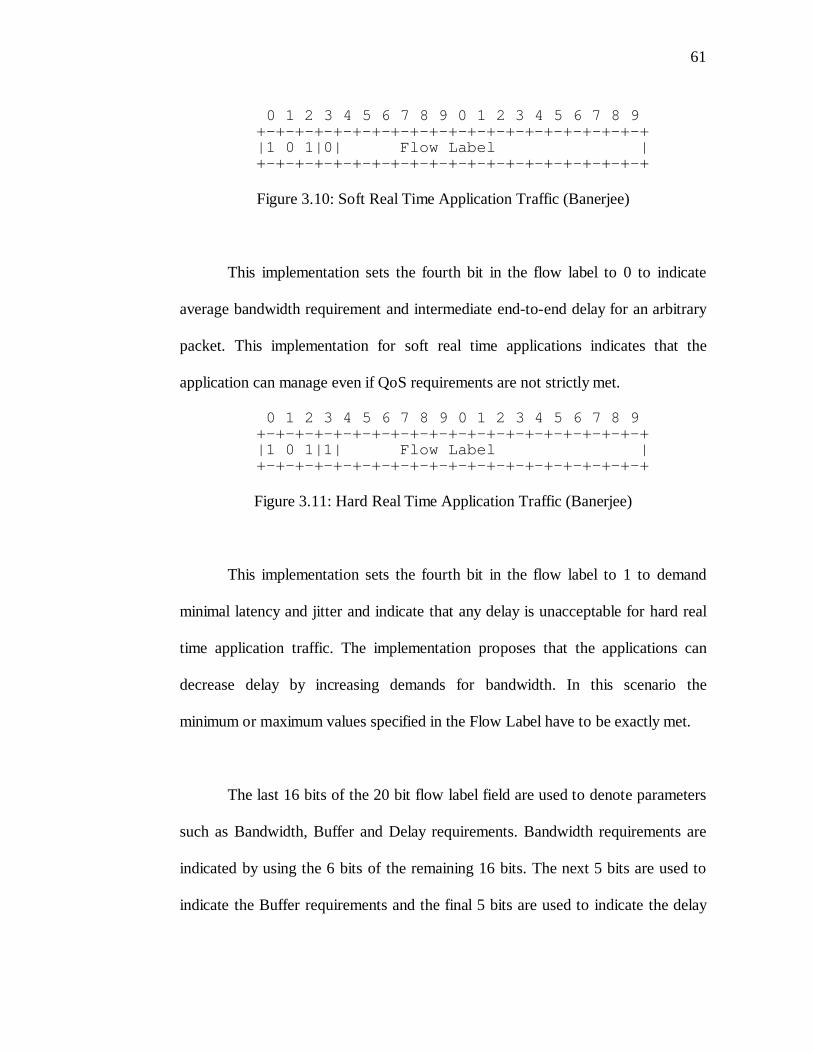
61
0 1 2 3 4 5 6 7 8 9 0 1 2 3 4 5 6 7 8 9 +-+-+-+-+-+-+-+-+-+-+-+-+-+-+-+-+-+-+-+-+ |1 0 1|0| Flow Label | +-+-+-+-+-+-+-+-+-+-+-+-+-+-+-+-+-+-+-+-+
Figure 3.10: Soft Real Time Application Traffic (Banerjee)
This implementation sets the fourth bit in the flow label to 0 to indicate
average bandwidth requirement and intermediate end-to-end delay for an arbitrary
packet. This implementation for soft real time applications indicates that the
application can manage even if QoS requirements are not strictly met.
0 1 2 3 4 5 6 7 8 9 0 1 2 3 4 5 6 7 8 9 +-+-+-+-+-+-+-+-+-+-+-+-+-+-+-+-+-+-+-+-+ |1 0 1|1| Flow Label | +-+-+-+-+-+-+-+-+-+-+-+-+-+-+-+-+-+-+-+-+
Figure 3.11: Hard Real Time Application Traffic (Banerjee)
This implementation sets the fourth bit in the flow label to 1 to demand
minimal latency and jitter and indicate that any delay is unacceptable for hard real
time application traffic. The implementation proposes that the applications can
decrease delay by increasing demands for bandwidth. In this scenario the
minimum or maximum values specified in the Flow Label have to be exactly met.
The last 16 bits of the 20 bit flow label field are used to denote parameters
such as Bandwidth, Buffer and Delay requirements. Bandwidth requirements are
indicated by using the 6 bits of the remaining 16 bits. The next 5 bits are used to
indicate the Buffer requirements and the final 5 bits are used to indicate the delay
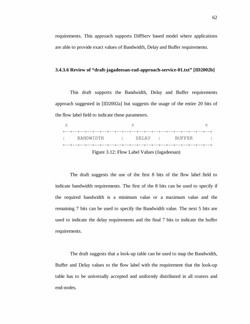
62
requirements. This approach supports DiffServ based model where applications
are able to provide exact values of Bandwidth, Delay and Buffer requirements.
3.4.3.6 Review of “draft-jagadeesan-rad-approach-service-01.txt” [ID2002b]
This draft supports the Bandwidth, Delay and Buffer requirements
approach suggested in [ID2002a] but suggests the usage of the entire 20 bits of
the flow label field to indicate these parameters.
0 9 9
+--+--+--+--+--+--+--+--+--+--+--+--+--+--+--+--+--+--+--+--+
| BANDWIDTH | DELAY | BUFFER |
+--+--+--+--+--+--+--+--+--+--+--+--+--+--+--+--+--+--+--+--+
Figure 3.12: Flow Label Values (Jagadeesan)
The draft suggests the use of the first 8 bits of the flow label field to
indicate bandwidth requirements. The first of the 8 bits can be used to specify if
the required bandwidth is a minimum value or a maximum value and the
remaining 7 bits can be used to specify the Bandwidth value. The next 5 bits are
used to indicate the delay requirements and the final 7 bits to indicate the buffer
requirements.
The draft suggests that a look-up table can be used to map the Bandwidth,
Buffer and Delay values to the flow label with the requirement that the look-up
table has to be universally accepted and uniformly distributed in all routers and
end-nodes.
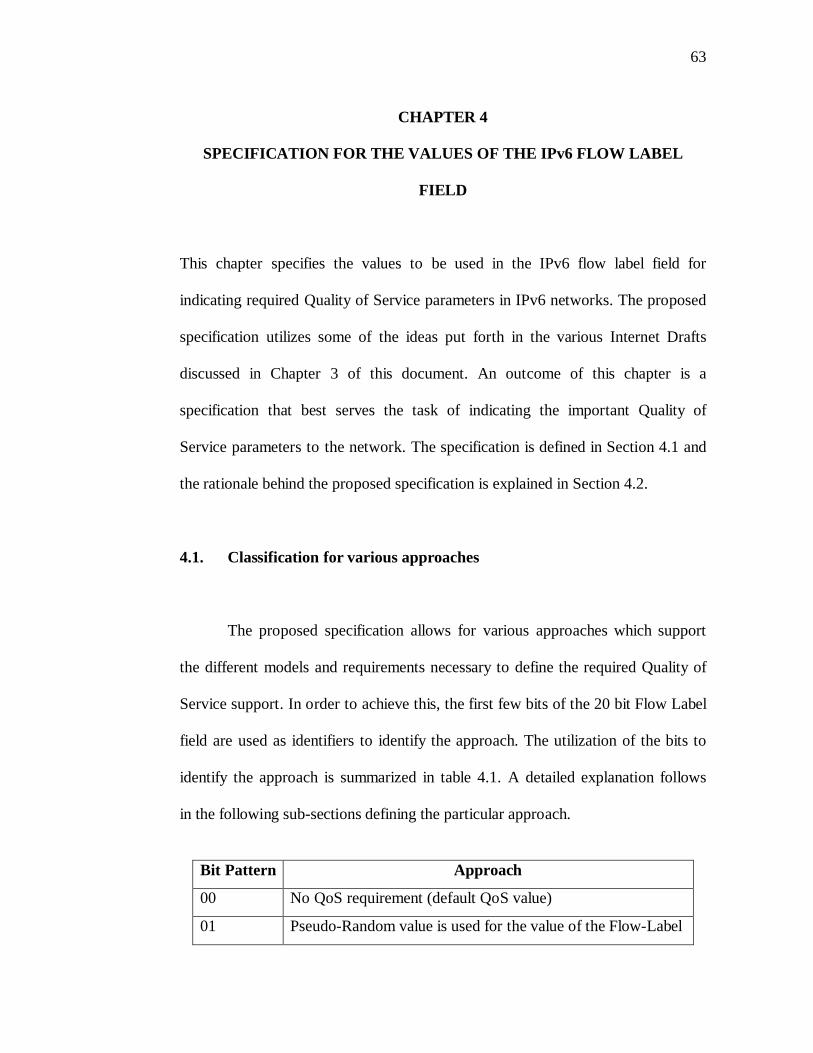
63
CHAPTER 4
SPECIFICATION FOR THE VALUES OF THE IPv6 FLOW LABEL
FIELD
This chapter specifies the values to be used in the IPv6 flow label field for
indicating required Quality of Service parameters in IPv6 networks. The proposed
specification utilizes some of the ideas put forth in the various Internet Drafts
discussed in Chapter 3 of this document. An outcome of this chapter is a
specification that best serves the task of indicating the important Quality of
Service parameters to the network. The specification is defined in Section 4.1 and
the rationale behind the proposed specification is explained in Section 4.2.
4.1. Classification for various approaches
The proposed specification allows for various approaches which support
the different models and requirements necessary to define the required Quality of
Service support. In order to achieve this, the first few bits of the 20 bit Flow Label
field are used as identifiers to identify the approach. The utilization of the bits to
identify the approach is summarized in table 4.1. A detailed explanation follows
in the following sub-sections defining the particular approach.
Bit Pattern Approach
00 No QoS requirement (default QoS value)
01 Pseudo-Random value is used for the value of the Flow-Label
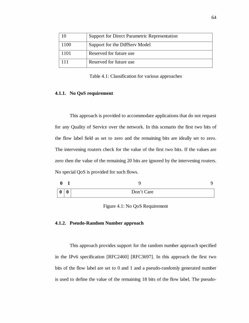
64
10 Support for Direct Parametric Representation
1100 Support for the DiffServ Model
1101 Reserved for future use
111 Reserved for future use
Table 4.1: Classification for various approaches
4.1.1. No QoS requirement
This approach is provided to accommodate applications that do not request
for any Quality of Service over the network. In this scenario the first two bits of
the flow label field as set to zero and the remaining bits are ideally set to zero.
The intervening routers check for the value of the first two bits. If the values are
zero then the value of the remaining 20 bits are ignored by the intervening routers.
No special QoS is provided for such flows.
0 1 9 9
0 0 Don’t Care
Figure 4.1: No QoS Requirement
4.1.2. Pseudo-Random Number approach
This approach provides support for the random number approach specified
in the IPv6 specification [RFC2460] [RFC3697]. In this approach the first two
bits of the flow label are set to 0 and 1 and a pseudo-randomly generated number
is used to define the value of the remaining 18 bits of the flow label. The pseudo-
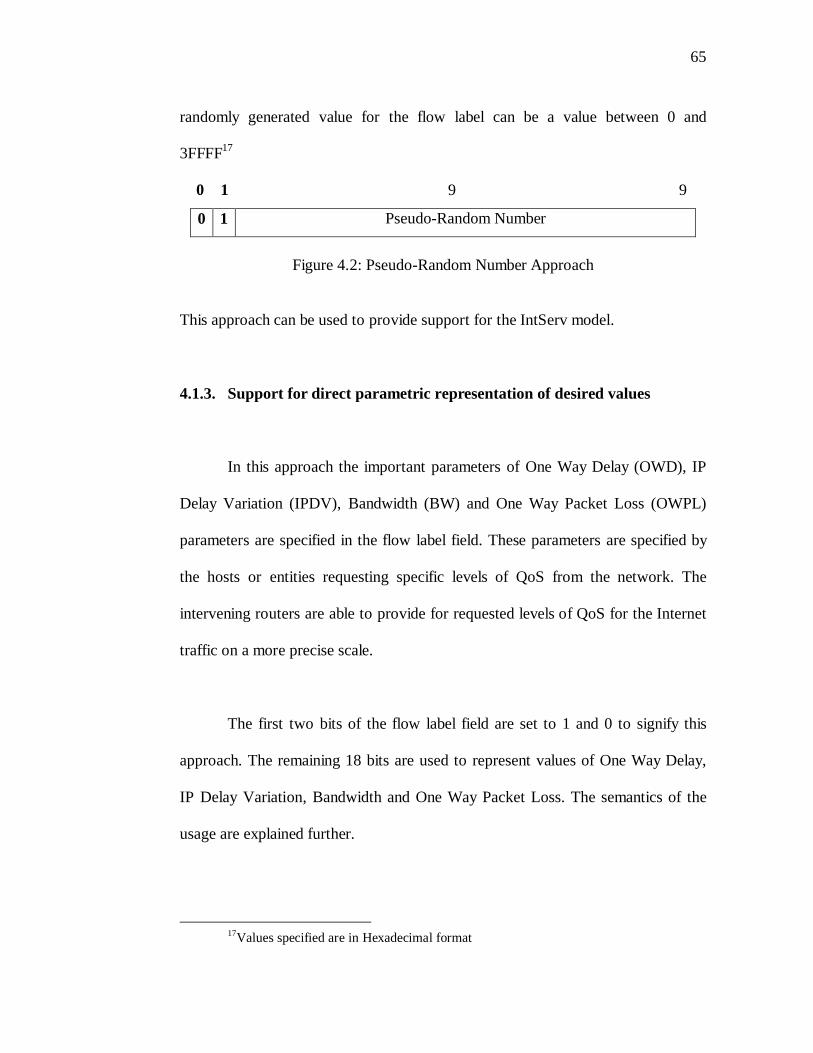
65
randomly generated value for the flow label can be a value between 0 and
3FFFF17
0 1 9 9
0 1 Pseudo-Random Number
Figure 4.2: Pseudo-Random Number Approach
This approach can be used to provide support for the IntServ model.
4.1.3. Support for direct parametric representation of desired values
In this approach the important parameters of One Way Delay (OWD), IP
Delay Variation (IPDV), Bandwidth (BW) and One Way Packet Loss (OWPL)
parameters are specified in the flow label field. These parameters are specified by
the hosts or entities requesting specific levels of QoS from the network. The
intervening routers are able to provide for requested levels of QoS for the Internet
traffic on a more precise scale.
The first two bits of the flow label field are set to 1 and 0 to signify this
approach. The remaining 18 bits are used to represent values of One Way Delay,
IP Delay Variation, Bandwidth and One Way Packet Loss. The semantics of the
usage are explained further.
17Values specified are in Hexadecimal format
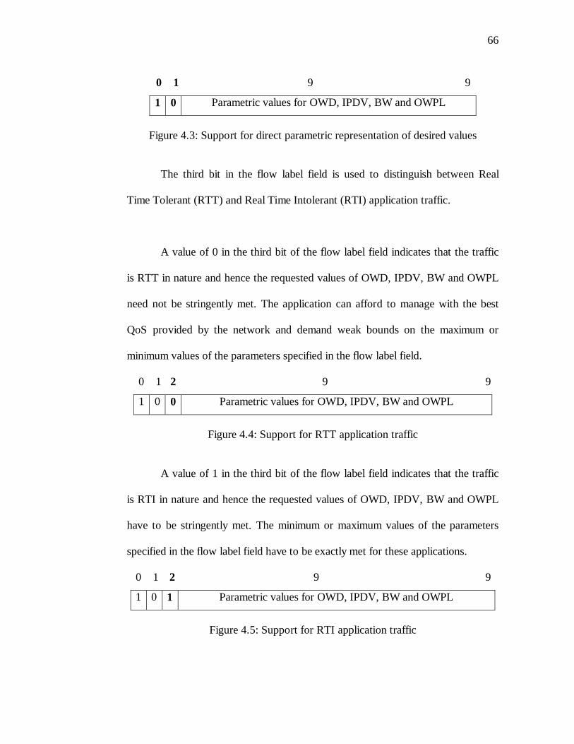
66
0 1 9 9
1 0 Parametric values for OWD, IPDV, BW and OWPL
Figure 4.3: Support for direct parametric representation of desired values
The third bit in the flow label field is used to distinguish between Real
Time Tolerant (RTT) and Real Time Intolerant (RTI) application traffic.
A value of 0 in the third bit of the flow label field indicates that the traffic
is RTT in nature and hence the requested values of OWD, IPDV, BW and OWPL
need not be stringently met. The application can afford to manage with the best
QoS provided by the network and demand weak bounds on the maximum or
minimum values of the parameters specified in the flow label field.
0 1 2 9 9
1 0 0 Parametric values for OWD, IPDV, BW and OWPL
Figure 4.4: Support for RTT application traffic
A value of 1 in the third bit of the flow label field indicates that the traffic
is RTI in nature and hence the requested values of OWD, IPDV, BW and OWPL
have to be stringently met. The minimum or maximum values of the parameters
specified in the flow label field have to be exactly met for these applications.
0 1 2 9 9
1 0 1 Parametric values for OWD, IPDV, BW and OWPL
Figure 4.5: Support for RTI application traffic
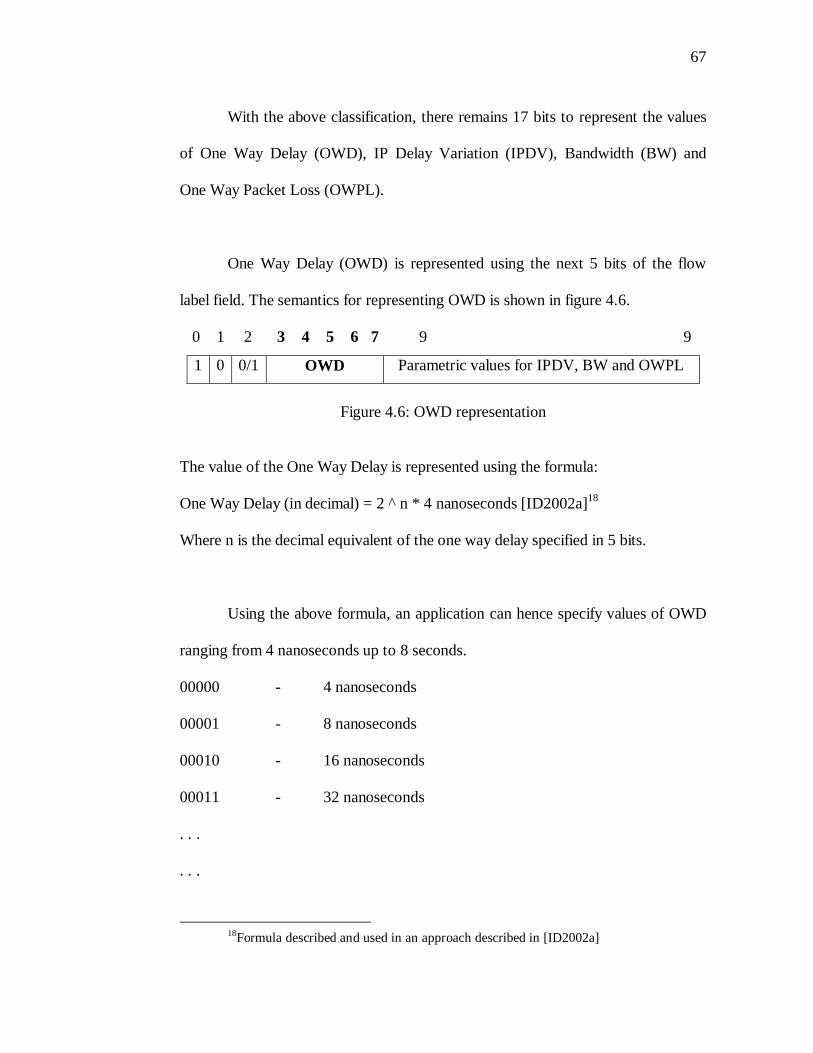
67
With the above classification, there remains 17 bits to represent the values
of One Way Delay (OWD), IP Delay Variation (IPDV), Bandwidth (BW) and
One Way Packet Loss (OWPL).
One Way Delay (OWD) is represented using the next 5 bits of the flow
label field. The semantics for representing OWD is shown in figure 4.6.
0 1 2 3 4 5 6 7 9 9
1 0 0/1 OWD Parametric values for IPDV, BW and OWPL
Figure 4.6: OWD representation
The value of the One Way Delay is represented using the formula:
One Way Delay (in decimal) = 2 ^ n * 4 nanoseconds [ID2002a]18
Where n is the decimal equivalent of the one way delay specified in 5 bits.
Using the above formula, an application can hence specify values of OWD
ranging from 4 nanoseconds up to 8 seconds.
00000 - 4 nanoseconds
00001 - 8 nanoseconds
00010 - 16 nanoseconds
00011 - 32 nanoseconds
. . .
. . .
18Formula described and used in an approach described in [ID2002a]
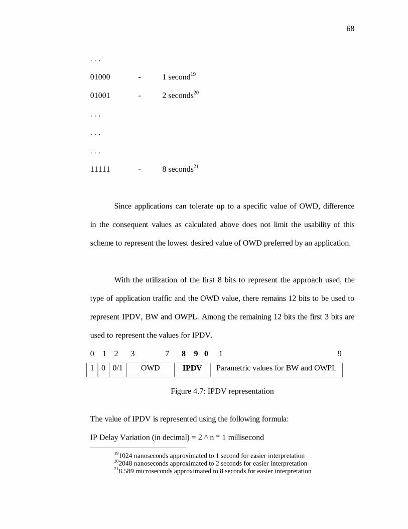
68
. . .
01000 - 1 second19
01001 - 2 seconds20
. . .
. . .
. . .
11111 - 8 seconds21
Since applications can tolerate up to a specific value of OWD, difference
in the consequent values as calculated above does not limit the usability of this
scheme to represent the lowest desired value of OWD preferred by an application.
With the utilization of the first 8 bits to represent the approach used, the
type of application traffic and the OWD value, there remains 12 bits to be used to
represent IPDV, BW and OWPL. Among the remaining 12 bits the first 3 bits are
used to represent the values for IPDV.
0 1 2 3 7 8 9 0 1 9
1 0 0/1 OWD IPDV Parametric values for BW and OWPL
Figure 4.7: IPDV representation
The value of IPDV is represented using the following formula:
IP Delay Variation (in decimal) = 2 ^ n * 1 millisecond
191024 nanoseconds approximated to 1 second for easier interpretation202048 nanoseconds approximated to 2 seconds for easier interpretation218.589 microseconds approximated to 8 seconds for easier interpretation
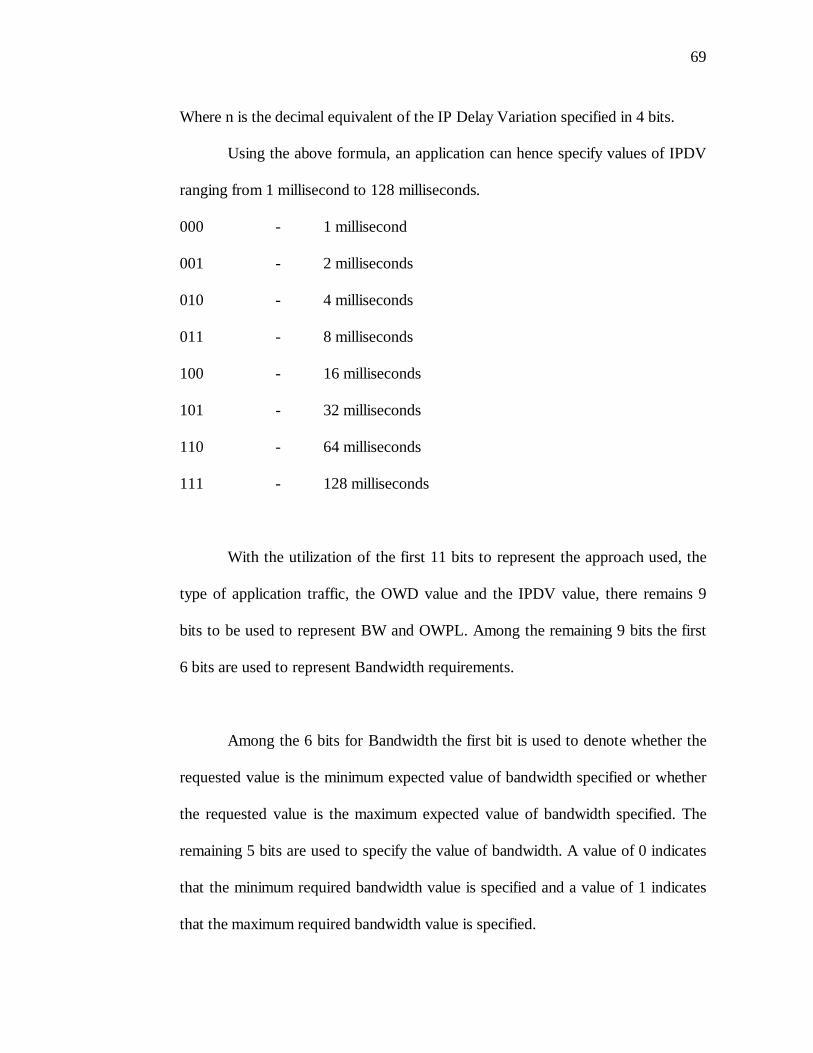
69
Where n is the decimal equivalent of the IP Delay Variation specified in 4 bits.
Using the above formula, an application can hence specify values of IPDV
ranging from 1 millisecond to 128 milliseconds.
000 - 1 millisecond
001 - 2 milliseconds
010 - 4 milliseconds
011 - 8 milliseconds
100 - 16 milliseconds
101 - 32 milliseconds
110 - 64 milliseconds
111 - 128 milliseconds
With the utilization of the first 11 bits to represent the approach used, the
type of application traffic, the OWD value and the IPDV value, there remains 9
bits to be used to represent BW and OWPL. Among the remaining 9 bits the first
6 bits are used to represent Bandwidth requirements.
Among the 6 bits for Bandwidth the first bit is used to denote whether the
requested value is the minimum expected value of bandwidth specified or whether
the requested value is the maximum expected value of bandwidth specified. The
remaining 5 bits are used to specify the value of bandwidth. A value of 0 indicates
that the minimum required bandwidth value is specified and a value of 1 indicates
that the maximum required bandwidth value is specified.
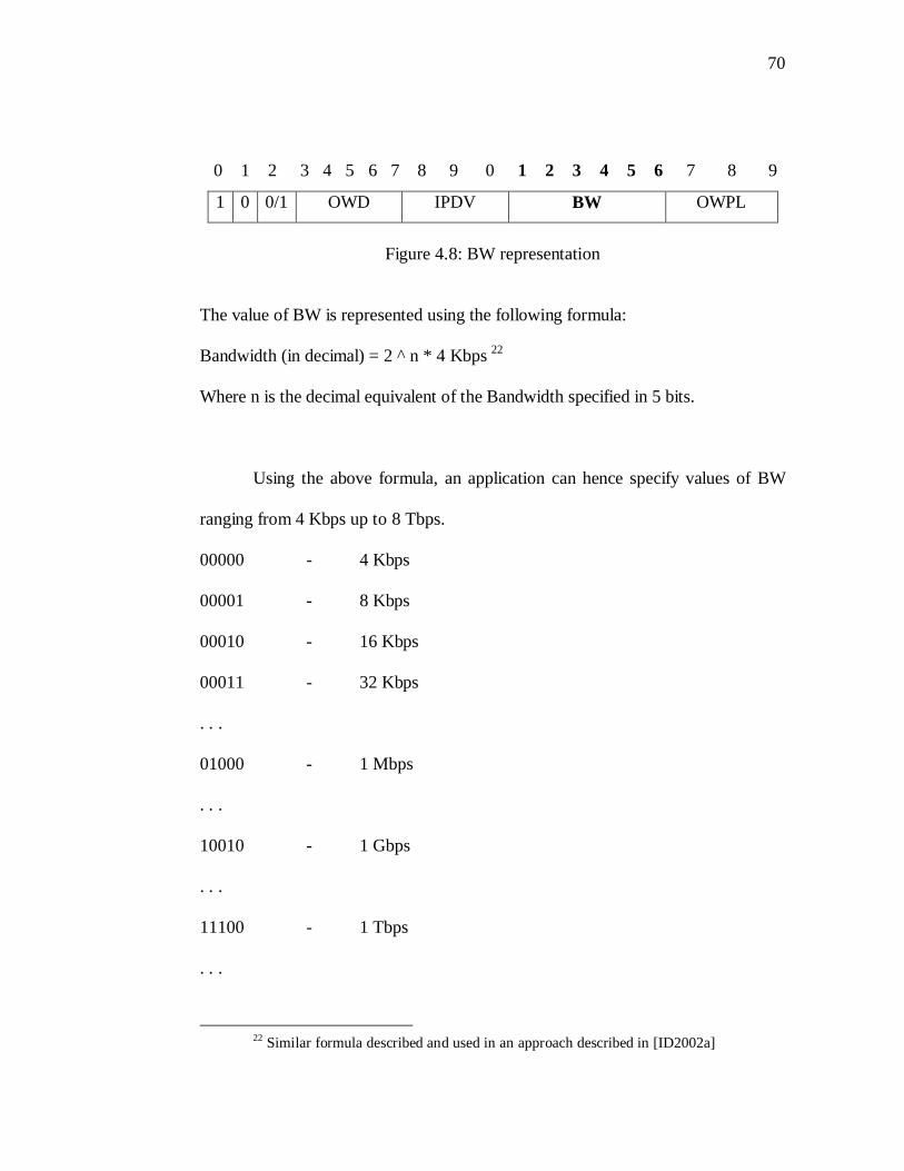
70
0 1 2 3 4 5 6 7 8 9 0 1 2 3 4 5 6 7 8 9
1 0 0/1 OWD IPDV BW OWPL
Figure 4.8: BW representation
The value of BW is represented using the following formula:
Bandwidth (in decimal) = 2 ^ n * 4 Kbps 22
Where n is the decimal equivalent of the Bandwidth specified in 5 bits.
Using the above formula, an application can hence specify values of BW
ranging from 4 Kbps up to 8 Tbps.
00000 - 4 Kbps
00001 - 8 Kbps
00010 - 16 Kbps
00011 - 32 Kbps
. . .
01000 - 1 Mbps
. . .
10010 - 1 Gbps
. . .
11100 - 1 Tbps
. . .
22 Similar formula described and used in an approach described in [ID2002a]
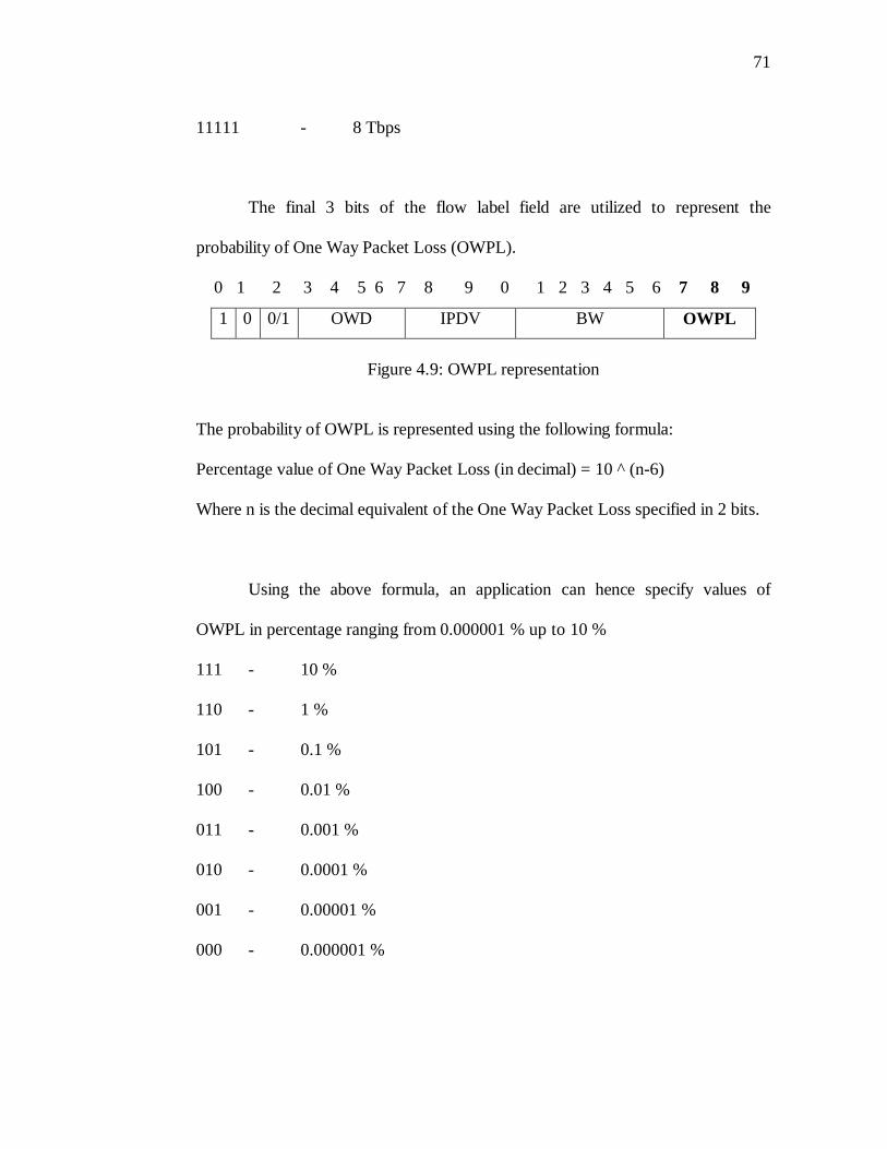
71
11111 - 8 Tbps
The final 3 bits of the flow label field are utilized to represent the
probability of One Way Packet Loss (OWPL).
0 1 2 3 4 5 6 7 8 9 0 1 2 3 4 5 6 7 8 9
1 0 0/1 OWD IPDV BW OWPL
Figure 4.9: OWPL representation
The probability of OWPL is represented using the following formula:
Percentage value of One Way Packet Loss (in decimal) = 10 ^ (n-6)
Where n is the decimal equivalent of the One Way Packet Loss specified in 2 bits.
Using the above formula, an application can hence specify values of
OWPL in percentage ranging from 0.000001 % up to 10 %
111 - 10 %
110 - 1 %
101 - 0.1 %
100 - 0.01 %
011 - 0.001 %
010 - 0.0001 %
001 - 0.00001 %
000 - 0.000001 %
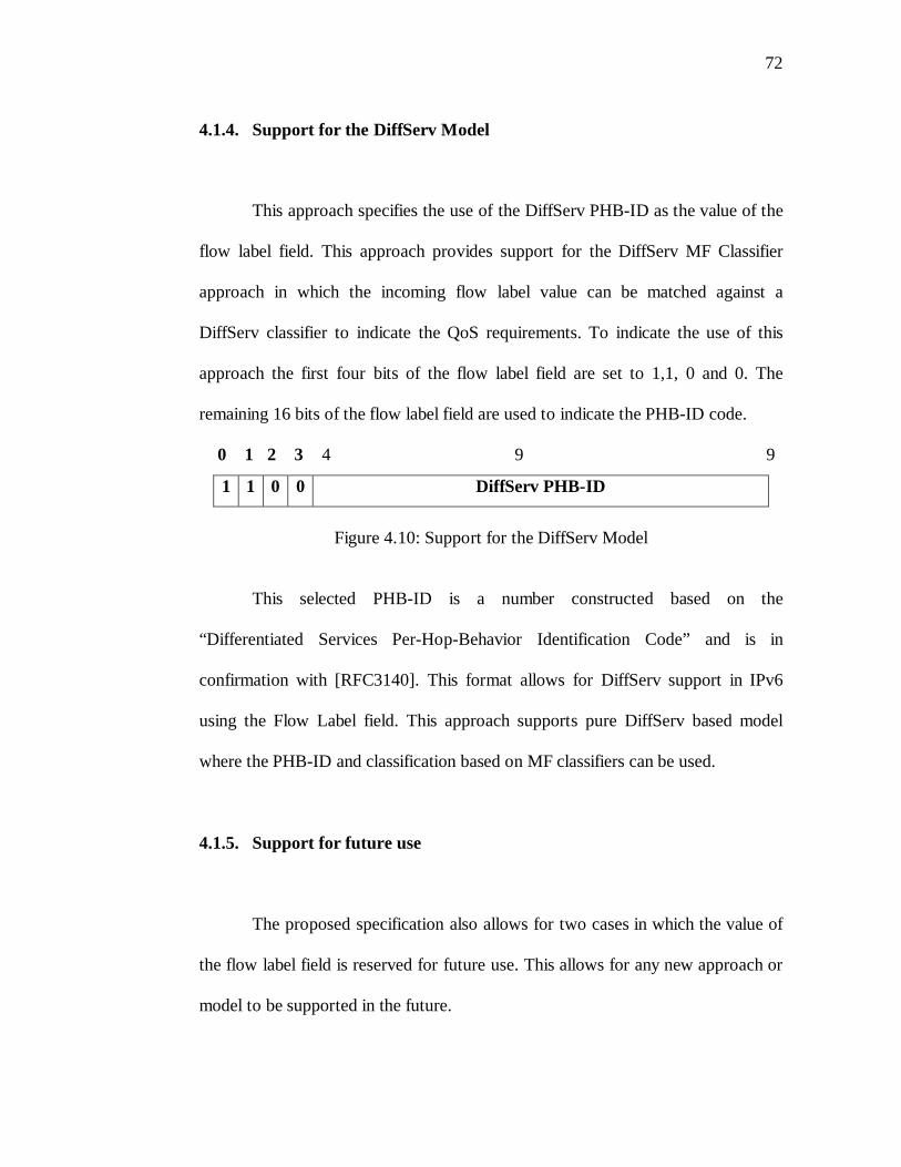
72
4.1.4. Support for the DiffServ Model
This approach specifies the use of the DiffServ PHB-ID as the value of the
flow label field. This approach provides support for the DiffServ MF Classifier
approach in which the incoming flow label value can be matched against a
DiffServ classifier to indicate the QoS requirements. To indicate the use of this
approach the first four bits of the flow label field are set to 1,1, 0 and 0. The
remaining 16 bits of the flow label field are used to indicate the PHB-ID code.
0 1 2 3 4 9 9
1 1 0 0 DiffServ PHB-ID
Figure 4.10: Support for the DiffServ Model
This selected PHB-ID is a number constructed based on the
“Differentiated Services Per-Hop-Behavior Identification Code” and is in
confirmation with [RFC3140]. This format allows for DiffServ support in IPv6
using the Flow Label field. This approach supports pure DiffServ based model
where the PHB-ID and classification based on MF classifiers can be used.
4.1.5. Support for future use
The proposed specification also allows for two cases in which the value of
the flow label field is reserved for future use. This allows for any new approach or
model to be supported in the future.

73
If the first four bits of the flow label field are set to 1, 1, 0 and 1 then the
value of the flow label field is currently ignored and signifies that it is reserved
for future use.
0 1 2 3 4 9 9
1 1 0 1 Reserved for Future Use
Figure 4.11a: Support for future use
Similarly if the value of the first three bits of the flow label field is set to
1, 1, and 1 then the value of the flow label field is currently ignored and signifies
that it is reserved for future use.
0 1 2 3 9 9
1 1 1 Reserved for Future Use
Figure 4.11b: Support for future use
4.2. Rationale
This section provides the rationale for the proposed specification
explained in the previous section. The proposed specification allows for the most
efficient use of the 20 bits of the flow label field. By using the bits in the specified
format, it makes if possible for various important QoS models and approaches to
use the flow label. Thereby it does not impose a specific model and approach on
the end user. The end user or application is free to choose the model or approach
which suits it best. The proposed approach results in a simple, scalable, modular
and generic implementation to provide for QoS using the IPv6 flow label field.
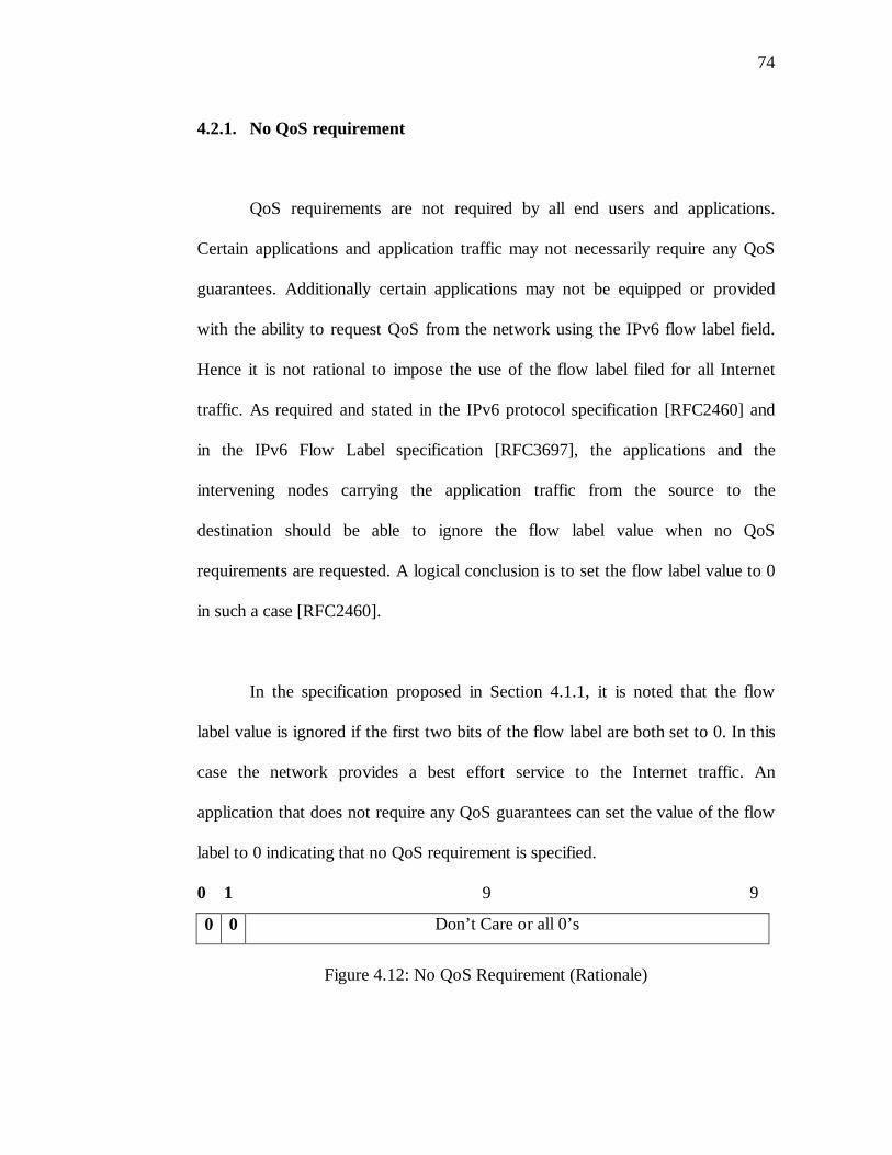
74
4.2.1. No QoS requirement
QoS requirements are not required by all end users and applications.
Certain applications and application traffic may not necessarily require any QoS
guarantees. Additionally certain applications may not be equipped or provided
with the ability to request QoS from the network using the IPv6 flow label field.
Hence it is not rational to impose the use of the flow label filed for all Internet
traffic. As required and stated in the IPv6 protocol specification [RFC2460] and
in the IPv6 Flow Label specification [RFC3697], the applications and the
intervening nodes carrying the application traffic from the source to the
destination should be able to ignore the flow label value when no QoS
requirements are requested. A logical conclusion is to set the flow label value to 0
in such a case [RFC2460].
In the specification proposed in Section 4.1.1, it is noted that the flow
label value is ignored if the first two bits of the flow label are both set to 0. In this
case the network provides a best effort service to the Internet traffic. An
application that does not require any QoS guarantees can set the value of the flow
label to 0 indicating that no QoS requirement is specified.
0 1 9 9
0 0 Don’t Care or all 0’s
Figure 4.12: No QoS Requirement (Rationale)
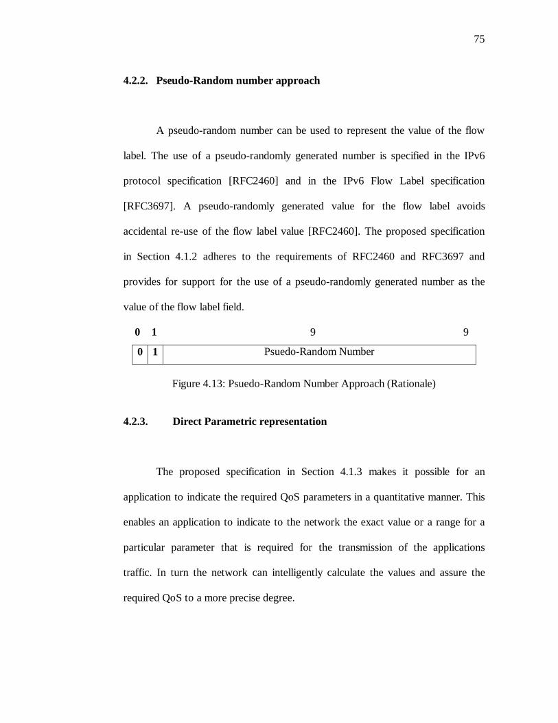
75
4.2.2. Pseudo-Random number approach
A pseudo-random number can be used to represent the value of the flow
label. The use of a pseudo-randomly generated number is specified in the IPv6
protocol specification [RFC2460] and in the IPv6 Flow Label specification
[RFC3697]. A pseudo-randomly generated value for the flow label avoids
accidental re-use of the flow label value [RFC2460]. The proposed specification
in Section 4.1.2 adheres to the requirements of RFC2460 and RFC3697 and
provides for support for the use of a pseudo-randomly generated number as the
value of the flow label field.
0 1 9 9
0 1 Psuedo-Random Number
Figure 4.13: Psuedo-Random Number Approach (Rationale)
4.2.3. Direct Parametric representation
The proposed specification in Section 4.1.3 makes it possible for an
application to indicate the required QoS parameters in a quantitative manner. This
enables an application to indicate to the network the exact value or a range for a
particular parameter that is required for the transmission of the applications
traffic. In turn the network can intelligently calculate the values and assure the
required QoS to a more precise degree.
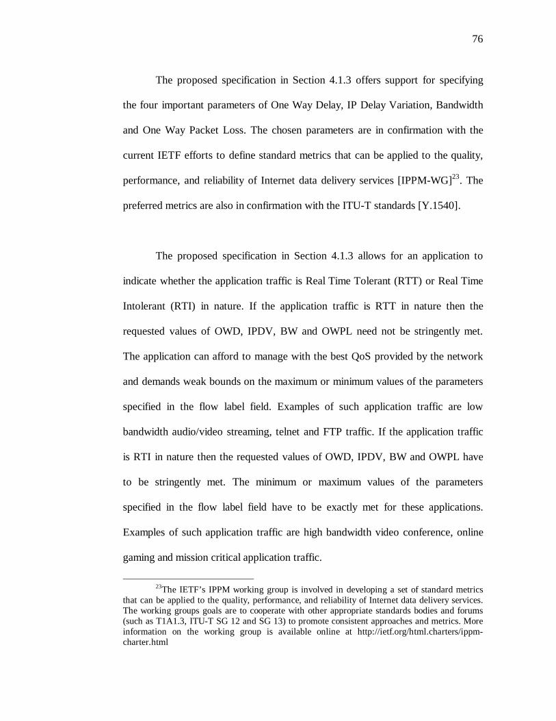
76
The proposed specification in Section 4.1.3 offers support for specifying
the four important parameters of One Way Delay, IP Delay Variation, Bandwidth
and One Way Packet Loss. The chosen parameters are in confirmation with the
current IETF efforts to define standard metrics that can be applied to the quality,
performance, and reliability of Internet data delivery services [IPPM-WG]23. The
preferred metrics are also in confirmation with the ITU-T standards [Y.1540].
The proposed specification in Section 4.1.3 allows for an application to
indicate whether the application traffic is Real Time Tolerant (RTT) or Real Time
Intolerant (RTI) in nature. If the application traffic is RTT in nature then the
requested values of OWD, IPDV, BW and OWPL need not be stringently met.
The application can afford to manage with the best QoS provided by the network
and demands weak bounds on the maximum or minimum values of the parameters
specified in the flow label field. Examples of such application traffic are low
bandwidth audio/video streaming, telnet and FTP traffic. If the application traffic
is RTI in nature then the requested values of OWD, IPDV, BW and OWPL have
to be stringently met. The minimum or maximum values of the parameters
specified in the flow label field have to be exactly met for these applications.
Examples of such application traffic are high bandwidth video conference, online
gaming and mission critical application traffic.
23The IETF’s IPPM working group is involved in developing a set of standard metrics
that can be applied to the quality, performance, and reliability of Internet data delivery services. The working groups goals are to cooperate with other appropriate standards bodies and forums (such as T1A1.3, ITU-T SG 12 and SG 13) to promote consistent approaches and metrics. More information on the working group is available online at http://ietf.org/html.charters/ippm-charter.html
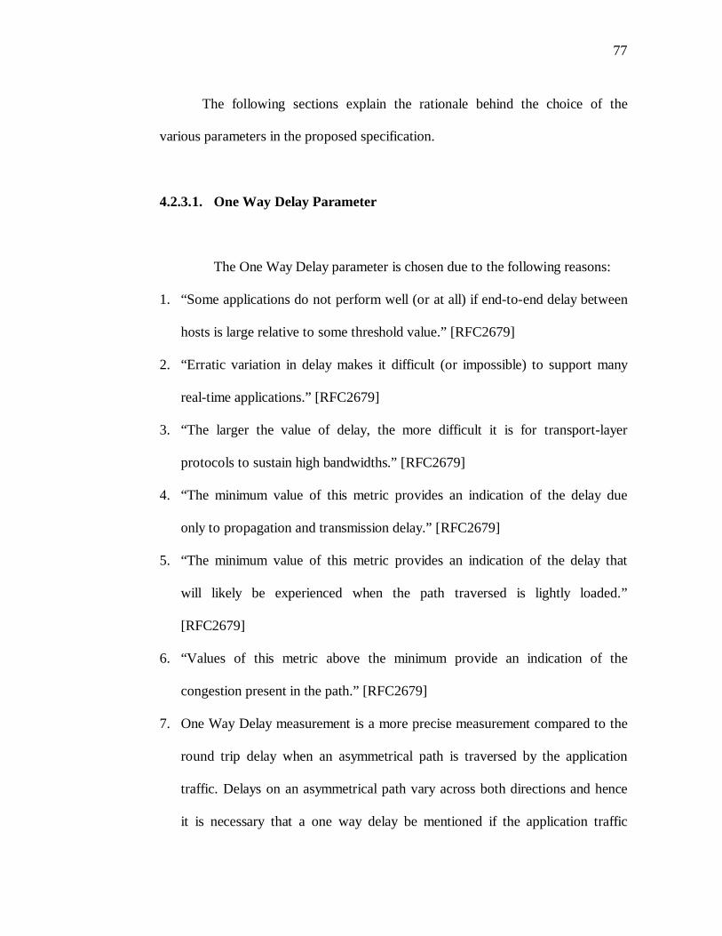
77
The following sections explain the rationale behind the choice of the
various parameters in the proposed specification.
4.2.3.1. One Way Delay Parameter
The One Way Delay parameter is chosen due to the following reasons:
1. “Some applications do not perform well (or at all) if end-to-end delay between
hosts is large relative to some threshold value.” [RFC2679]
2. “Erratic variation in delay makes it difficult (or impossible) to support many
real-time applications.” [RFC2679]
3. “The larger the value of delay, the more difficult it is for transport-layer
protocols to sustain high bandwidths.” [RFC2679]
4. “The minimum value of this metric provides an indication of the delay due
only to propagation and transmission delay.” [RFC2679]
5. “The minimum value of this metric provides an indication of the delay that
will likely be experienced when the path traversed is lightly loaded.”
[RFC2679]
6. “Values of this metric above the minimum provide an indication of the
congestion present in the path.” [RFC2679]
7. One Way Delay measurement is a more precise measurement compared to the
round trip delay when an asymmetrical path is traversed by the application
traffic. Delays on an asymmetrical path vary across both directions and hence
it is necessary that a one way delay be mentioned if the application traffic
78
requires stringent delay control over both paths. Additionally in some
instances the application might require QoS guarantees in only one direction.
[RFC2679]. An example of this is a one way interactive multimedia session.
In the proposed specification is Section 4.1.3, values of One Way Delay
is represented using 5 bits of the flow label field.
0 1 2 3 4 5 6 7 9 9
1 0 0/1 OWD Parametric values for IPDV, BW and OWPL
Figure 4.14: OWD representation (Rationale)
As discussed in Section 4.1.3, the value of the One Way Delay can be a
value between 4 nanoseconds and 8 seconds. Delay sensitive applications can
specify the amount of one way delay they can withstand from the network. The
upper bound on the delay ranging from 4 nanoseconds to 8 seconds provide
support for all categories of real-time and non-real time Internet application traffic
[Y.1541] 24 [SEQN]25 [I2-QWG]26 [EDIN]27.
24The ITU-T Y.1541 Recommendation specifies the acceptable values for the end-to-end
delay QoS parameter. 25The SEQUIN project involving eight partners in seven countries and co-funded by the
European Commission under the Information Society Technologies (IST) Programme has conducted a survey to identify the important parameters required for providing QoS. It identifies One Way Delay as an important parameter. It classifies application traffic into 4 classes and lists the acceptable values of One Way Delay to be 150 ms, 400 ms and 1 s for a particular class
26A survey conducted for Internet 2 to identify network QoS needs of advanced interned application identifies OWD as an important parameter for providing QoS. Values for the OWD mentioned and within the range of 4 nanoseconds and 8 seconds
27The EURESCOM project has conducted a study and identified the permissible delay values for its 2 classes of service. The values range between 150 msec and 800 msec
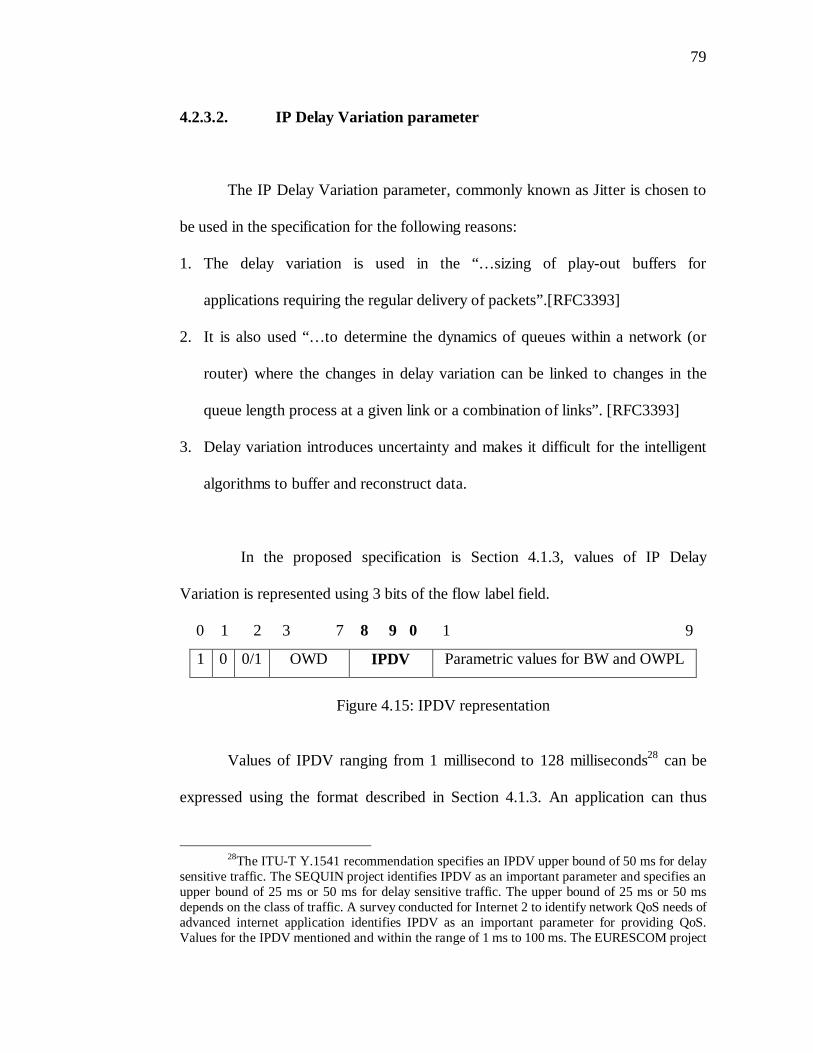
79
4.2.3.2. IP Delay Variation parameter
The IP Delay Variation parameter, commonly known as Jitter is chosen to
be used in the specification for the following reasons:
1. The delay variation is used in the “…sizing of play-out buffers for
applications requiring the regular delivery of packets”.[RFC3393]
2. It is also used “…to determine the dynamics of queues within a network (or
router) where the changes in delay variation can be linked to changes in the
queue length process at a given link or a combination of links”. [RFC3393]
3. Delay variation introduces uncertainty and makes it difficult for the intelligent
algorithms to buffer and reconstruct data.
In the proposed specification is Section 4.1.3, values of IP Delay
Variation is represented using 3 bits of the flow label field.
0 1 2 3 7 8 9 0 1 9
1 0 0/1 OWD IPDV Parametric values for BW and OWPL
Figure 4.15: IPDV representation
Values of IPDV ranging from 1 millisecond to 128 milliseconds28 can be
expressed using the format described in Section 4.1.3. An application can thus
28The ITU-T Y.1541 recommendation specifies an IPDV upper bound of 50 ms for delay
sensitive traffic. The SEQUIN project identifies IPDV as an important parameter and specifies an upper bound of 25 ms or 50 ms for delay sensitive traffic. The upper bound of 25 ms or 50 ms depends on the class of traffic. A survey conducted for Internet 2 to identify network QoS needs of advanced internet application identifies IPDV as an important parameter for providing QoS. Values for the IPDV mentioned and within the range of 1 ms to 100 ms. The EURESCOM project
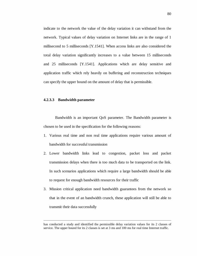
80
indicate to the network the value of the delay variation it can withstand from the
network. Typical values of delay variation on Internet links are in the range of 1
millisecond to 5 milliseconds [Y.1541]. When access links are also considered the
total delay variation significantly increases to a value between 15 milliseconds
and 25 milliseconds [Y.1541]. Applications which are delay sensitive and
application traffic which rely heavily on buffering and reconstruction techniques
can specify the upper bound on the amount of delay that is permissible.
4.2.3.3 Bandwidth parameter
Bandwidth is an important QoS parameter. The Bandwidth parameter is
chosen to be used in the specification for the following reasons:
1. Various real time and non real time applications require various amount of
bandwidth for successful transmission
2. Lower bandwidth links lead to congestion, packet loss and packet
transmission delays when there is too much data to be transported on the link.
In such scenarios applications which require a large bandwidth should be able
to request for enough bandwidth resources for their traffic
3. Mission critical application need bandwidth guarantees from the network so
that in the event of an bandwidth crunch, these application will still be able to
transmit their data successfully
has conducted a study and identified the permissible delay variation values for its 2 classes of service. The upper bound for its 2 classes is set at 3 ms and 100 ms for real time Internet traffic.
81
In the proposed specification is Section 4.1.3, the Bandwidth parameter
is represented using 6 bits of the flow label field. One bit is used to provide the
application with an option to request for a minimum or a maximum amount of
bandwidth. The remaining 5 bits are used to specify the value of the bandwidth
required.
0 1 2 3 4 5 6 7 8 9 0 1 2 3 4 5 6 7 8 9
1 0 0/1 OWD IPDV BW OWPL
Figure 4.16: BW representation
Values of bandwidth ranging from a minimum of 4 Kbps to a maximum of
8 Tbps can be specified using this approach. The maximum value of 8 Tbps
provides support for any futuristic applications and implementations. It is
assumed that applications that require a bandwidth guarantee have a minimum
bandwidth requirement of 4 Kbps and upwards. In the event when a particular
application requires a bandwidth guarantee of less than 4 Kbps, the following
proposals hold good.
1. The application can be assured a default bandwidth of 4 Kbps if there is
enough bandwidth available to spare on the network
2. In the event when the network does not have the minimum bandwidth
resources to allocate for a single application, the application flow can be
aggregated with other flows which have the same or similar flow requirement.
This aggregate flow can then be allocated a minimum bandwidth of 4 Kbps.
82
4.2.3.4. One Way Packet Loss parameter
The One Way Packet Loss parameter is chosen to be used in the
specification for the following reasons:
1. “Some applications do not perform well if end-to-end loss between hosts is
large relative to some threshold value” [RFC2680]
2. “Excessive packet loss may make it difficult to support certain real-time
applications” [RFC2680]
3. “The larger the value of packet loss, the more difficult it is for transport-layer
protocols to sustain high bandwidths” [RFC2680]
4. “The sensitivity of real-time applications and of transport-layer protocols to
loss become especially important when very large delay-bandwidth products
must be supported” [RFC2680]
5. Round-trip packet loss measurements measure the performance of two distinct
paths which may be asymmetric. “Even when the two paths are symmetric,
they may have radically different performance characteristics due to
asymmetric queueing” [RFC2680]
6. “Performance of an application may depend mostly on the performance in one
direction” [RFC2680]
7. “In quality-of-service (QoS) enabled networks, provisioning in one direction
may be radically different than provisioning in the reverse direction, and thus
the QoS guarantees differ. Measuring the paths independently allows the
verification of both guarantees” [RFC2680]
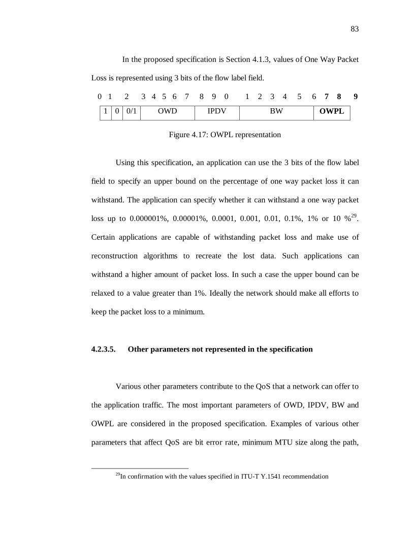
83
In the proposed specification is Section 4.1.3, values of One Way Packet
Loss is represented using 3 bits of the flow label field.
0 1 2 3 4 5 6 7 8 9 0 1 2 3 4 5 6 7 8 9
1 0 0/1 OWD IPDV BW OWPL
Figure 4.17: OWPL representation
Using this specification, an application can use the 3 bits of the flow label
field to specify an upper bound on the percentage of one way packet loss it can
withstand. The application can specify whether it can withstand a one way packet
loss up to 0.000001%, 0.00001%, 0.0001, 0.001, 0.01, 0.1%, 1% or 10 %29.
Certain applications are capable of withstanding packet loss and make use of
reconstruction algorithms to recreate the lost data. Such applications can
withstand a higher amount of packet loss. In such a case the upper bound can be
relaxed to a value greater than 1%. Ideally the network should make all efforts to
keep the packet loss to a minimum.
4.2.3.5. Other parameters not represented in the specification
Various other parameters contribute to the QoS that a network can offer to
the application traffic. The most important parameters of OWD, IPDV, BW and
OWPL are considered in the proposed specification. Examples of various other
parameters that affect QoS are bit error rate, minimum MTU size along the path,
29In confirmation with the values specified in ITU-T Y.1541 recommendation
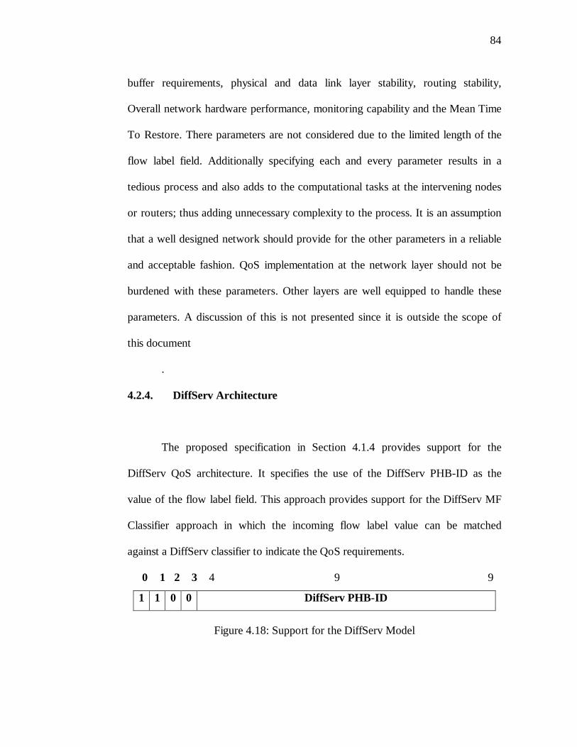
84
buffer requirements, physical and data link layer stability, routing stability,
Overall network hardware performance, monitoring capability and the Mean Time
To Restore. There parameters are not considered due to the limited length of the
flow label field. Additionally specifying each and every parameter results in a
tedious process and also adds to the computational tasks at the intervening nodes
or routers; thus adding unnecessary complexity to the process. It is an assumption
that a well designed network should provide for the other parameters in a reliable
and acceptable fashion. QoS implementation at the network layer should not be
burdened with these parameters. Other layers are well equipped to handle these
parameters. A discussion of this is not presented since it is outside the scope of
this document
.
4.2.4. DiffServ Architecture
The proposed specification in Section 4.1.4 provides support for the
DiffServ QoS architecture. It specifies the use of the DiffServ PHB-ID as the
value of the flow label field. This approach provides support for the DiffServ MF
Classifier approach in which the incoming flow label value can be matched
against a DiffServ classifier to indicate the QoS requirements.
0 1 2 3 4 9 9
1 1 0 0 DiffServ PHB-ID
Figure 4.18: Support for the DiffServ Model
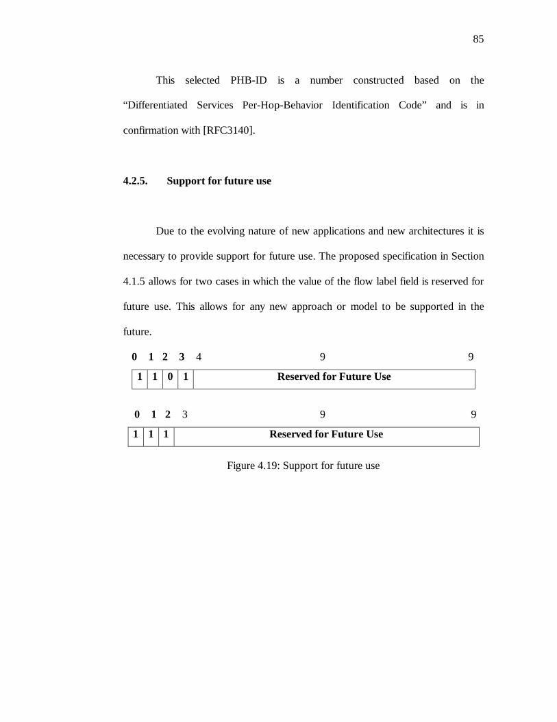
85
This selected PHB-ID is a number constructed based on the
“Differentiated Services Per-Hop-Behavior Identification Code” and is in
confirmation with [RFC3140].
4.2.5. Support for future use
Due to the evolving nature of new applications and new architectures it is
necessary to provide support for future use. The proposed specification in Section
4.1.5 allows for two cases in which the value of the flow label field is reserved for
future use. This allows for any new approach or model to be supported in the
future.
0 1 2 3 4 9 9
1 1 0 1 Reserved for Future Use
0 1 2 3 9 9
1 1 1 Reserved for Future Use
Figure 4.19: Support for future use
86
CHAPTER 5
IMPLEMENTATION SCENARIOS
In this chapter a few implementation scenarios are discussed. Values for the Flow
Label have been discussed in the previous chapter. To enable the implementation
of QoS in IPv6 networks using the IPv6 Flow Label field various tasks have to be
completed. The applications and the transport layer protocols have to be enabled
to set the values of the flow label field. Next the flow establishment procedures
have to be developed. The following sections discuss possible ways in which the
flow establishment process can be achieved for the various approaches discussed
in Chapter 3.
5.1. DiffServ Implementation Scenario
In a DiffServ aware network, the host application or upper layer protocol
sets the value of the flow label field. The value chosen for the flow label field
incorporates a 16 bit DiffServ PHB-ID code. The incoming packets are policed by
each of the intervening routers based on the value of the PHB-ID carried in the
Flow Label field. The nature of the policing is based on the DiffServ Classifier
present on the intervening routers.
The values of the DiffServ Classifier are based strictly on the contractual
agreements between the user and the network provider. The contractual
87
agreements consist of the Service Level Agreements (SLA), Service Level
Specifications (SLS), Traffic Conditioning Agreements (TCA) and Traffic
Conditioning Specifications (TCS). Based upon these agreements a DiffServ Flow
Label Classifier can be represented as [ID2001a]:
C = (Source Address, Source Address Prefix Length, Destination Address,
Destination Address Prefix Length, Flow Label Value)
Or
C l = (Source Address, Source Address Prefix Length, Destination Address,
Destination Address Prefix Length, Flow-Label-Min: Range)
The Classifiers on the intervening routers can be set up by manual
configuration, dynamic configuration or any other feasible method. When a
DiffServ aware node receives a packet with the Flow Label field consisting of a
DiffServ PHB-ID code, the classification engine on the node matches the
incoming packets header information with the classification rules present on the
router. Once the classification process is completed the DiffServ process
continues to provide for the requested QoS. The classification engines on the
intervening nodes would match the incoming packet information to the
classification rules as follows [ID2001a]:
Incoming Packet Header (Source Address, Destination Address, Flow Label)
matched against
Classification Rule ( C or C l )
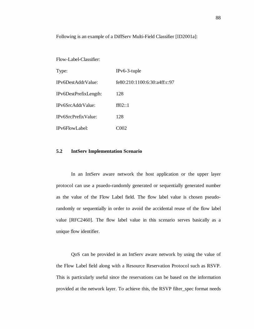
88
Following is an example of a DiffServ Multi-Field Classifier [ID2001a]:
Flow-Label-Classifier:
Type: IPv6-3-tuple
IPv6DestAddrValue: fe80:210:1100:6:30:a4ff:c:97
IPv6DestPrefixLength: 128
IPv6SrcAddrValue: ff02::1
IPv6SrcPrefixValue: 128
IPv6FlowLabel: C002
5.2 IntServ Implementation Scenario
In an IntServ aware network the host application or the upper layer
protocol can use a psuedo-randomly generated or sequentially generated number
as the value of the Flow Label field. The flow label value is chosen pseudo-
randomly or sequentially in order to avoid the accidental reuse of the flow label
value [RFC2460]. The flow label value in this scenario serves basically as a
unique flow identifier.
QoS can be provided in an IntServ aware network by using the value of
the Flow Label field along with a Resource Reservation Protocol such as RSVP.
This is particularly useful since the reservations can be based on the information
provided at the network layer. To achieve this, the RSVP filter_spec format needs
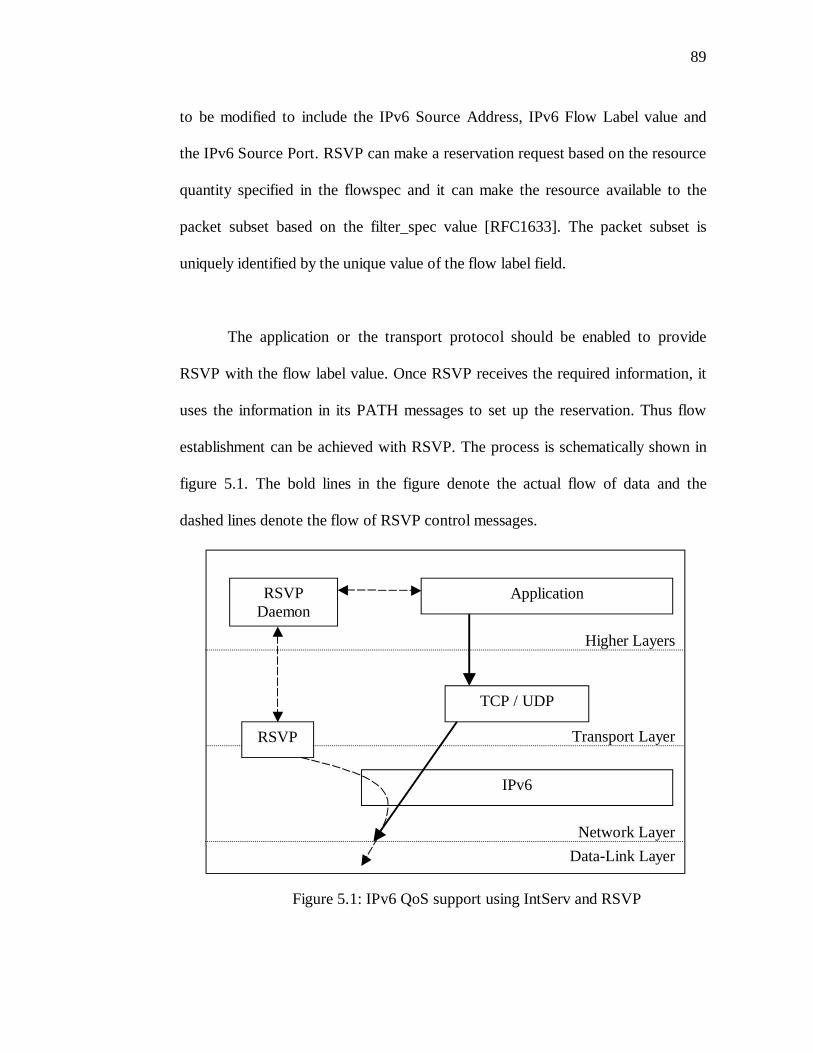
89
to be modified to include the IPv6 Source Address, IPv6 Flow Label value and
the IPv6 Source Port. RSVP can make a reservation request based on the resource
quantity specified in the flowspec and it can make the resource available to the
packet subset based on the filter_spec value [RFC1633]. The packet subset is
uniquely identified by the unique value of the flow label field.
The application or the transport protocol should be enabled to provide
RSVP with the flow label value. Once RSVP receives the required information, it
uses the information in its PATH messages to set up the reservation. Thus flow
establishment can be achieved with RSVP. The process is schematically shown in
figure 5.1. The bold lines in the figure denote the actual flow of data and the
dashed lines denote the flow of RSVP control messages.
Figure 5.1: IPv6 QoS support using IntServ and RSVP
ApplicationRSVP Daemon
Higher Layers
TCP / UDP
RSVP
IPv6
Transport Layer
Network Layer
Data-Link Layer
90
5.3. Direct Parametric Representation Implementation Scenario
The direct parametric approach proposed in Section 4.1.3 allows an IPv6
host to specify the values of the important QoS parameters to the network. Flow
state establishment for this approach can be achieved using RSVP in a manner
similar to the approach discussed in the previous section. The application or the
transport layer protocol can specify the value of the flow label to RSVP. The IPv6
flow label in a packet will indicate the required values of QoS parameters to
RSVP. RSVP can use this value in its flowspec to make a resource reservation
and it can make the resource available to the packet subset based on the
filter_spec value. To enable this approach the source, destination and all the
intervening network nodes have to be RSVP capable. Additionally the amount of
traffic generated by RSVP may not make it a practical solution for delivering end-
to-end QoS on the Internet.
As an alternative solution, the Hop-by-Hop extension header in IPv6 can
be used to set up a flow state. The Hop-by-Hop extension header is used to carry
optional information that must be examined by every node along a packets’
delivery path [RFC2640]. The format of the Hop-by-Hop extension header is
shown in figure 5.2.
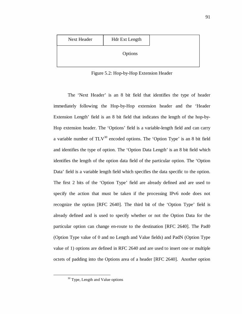
91
Figure 5.2: Hop-by-Hop Extension Header
The ‘Next Header’ is an 8 bit field that identifies the type of header
immediately following the Hop-by-Hop extension header and the ‘Header
Extension Length’ field is an 8 bit field that indicates the length of the hop-by-
Hop extension header. The ‘Options’ field is a variable-length field and can carry
a variable number of TLV30 encoded options. The ‘Option Type’ is an 8 bit field
and identifies the type of option. The ‘Option Data Length’ is an 8 bit field which
identifies the length of the option data field of the particular option. The ‘Option
Data’ field is a variable length field which specifies the data specific to the option.
The first 2 bits of the ‘Option Type’ field are already defined and are used to
specify the action that must be taken if the processing IPv6 node does not
recognize the option [RFC 2640]. The third bit of the ‘Option Type’ field is
already defined and is used to specify whether or not the Option Data for the
particular option can change en-route to the destination [RFC 2640]. The Pad0
(Option Type value of 0 and no Length and Value fields) and PadN (Option Type
value of 1) options are defined in RFC 2640 and are used to insert one or multiple
octets of padding into the Options area of a header [RFC 2640]. Another option
30 Type, Length and Value options
Next Header Hdr Ext Length
Options
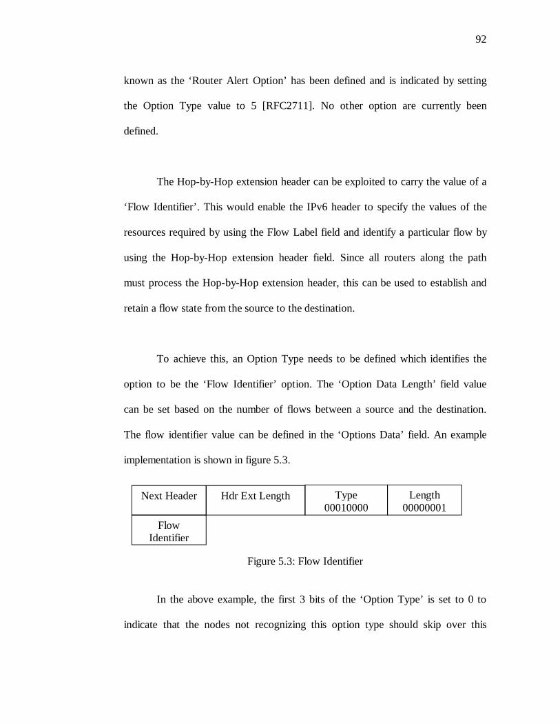
92
known as the ‘Router Alert Option’ has been defined and is indicated by setting
the Option Type value to 5 [RFC2711]. No other option are currently been
defined.
The Hop-by-Hop extension header can be exploited to carry the value of a
‘Flow Identifier’. This would enable the IPv6 header to specify the values of the
resources required by using the Flow Label field and identify a particular flow by
using the Hop-by-Hop extension header field. Since all routers along the path
must process the Hop-by-Hop extension header, this can be used to establish and
retain a flow state from the source to the destination.
To achieve this, an Option Type needs to be defined which identifies the
option to be the ‘Flow Identifier’ option. The ‘Option Data Length’ field value
can be set based on the number of flows between a source and the destination.
The flow identifier value can be defined in the ‘Options Data’ field. An example
implementation is shown in figure 5.3.
Figure 5.3: Flow Identifier
In the above example, the first 3 bits of the ‘Option Type’ is set to 0 to
indicate that the nodes not recognizing this option type should skip over this
Next Header Hdr Ext Length Type00010000
Length00000001
Flow Identifier
93
option and continue processing the header and that the option mush not change
en-route from the source to the destination [RFC2640]. The fourth bit in the
‘Option Type’ field is set to 1 to indicate that the Option Data carried in this
option is the ‘Flow Identifier’. The ‘Option Length’ field is set to 1 to indicate
that the Option Data carried in this option is 8 bits long. The Flow Identifier can
be a number which is pseudo-randomly generated or sequentially generated. This
would avoid accidental reuse of the value for the Flow Identifier. In this example
the Flow Identifier field can carry 256 different values of flows between a source
and a destination. If more identifiers are required then the value of the ‘Option
Length’ field can be increased which thereby increases the size of the Option Data
field.
5.4. Other Considerations
Provision of QoS using the flow label field in IPv6 also requires the ability
of the intervening nodes to signal the source of any issues relating to the flow
label or the flow state. Such events may occur due to the inability of an
intervening node to provide the requested QoS before or after the flow state
establishment process. In such an event the intervening node should be able to
signal the source before it flushes out the stale flow labels or flow state. The
signaling can be achieved by the use of an ICMPv6 (Internet Control Message
Protocol Version 6) packet with a particular Type and Code. This packet can be
94
sent from the router to the source and based on the response received from the
source the intervening router may flush out or retain the flow state [ID2002b].
95
CHAPTER 6
SUMMARY, CONCLUSIONS AND FUTURE WORK
In this thesis, various approaches to the use of the 20 bit Flow Label field in the
IPv6 protocol header have been discussed. As an outcome, an efficient approach
has been proposed which utilizes the 20 bits of the Flow Label field to indicate
Quality of Service requirements to the network.
In Chapter 2, a review of the current architectures and protocol support for
providing QoS over the Internet is provided to better understand the nature and
requirements of QoS. QoS support in architectures and protocols such as TCP/IP,
MPLS, ATM and Frame Relay are briefly reviewed to observe how these
architectures and protocols are geared towards offering QoS on the Internet. Also
a review of the current widely used QoS architectures such as IntServ and
DiffServ and the current efforts of the IETF are included to understand the
constraints and needs of QoS. These reviews assist in producing a set of useful
and concise requirements which can are used to effectively architecture the 20 bits
of the IPv6 Flow Label.
In Chapter 3, the 20 bit Flow Label field is reviewed in more detail. The
definition, specification and the requirements of the Flow Label field are
presented in detail. Additionally the various approaches which were proposed
96
earlier are reviewed. These critical reviews help in determining the correct
requirements for the usage of the Flow Label field.
In Chapter 4, a new specification for the values to be used in the IPv6
Flow Label field for indicating Quality of Service parameters in IPv6 networks is
proposed. An outcome of this chapter is a specification that best serves the task of
indicating the important Quality of Service parameters to the network. The
specification is defined in Section 4.1 and the rationale behind the proposed
specification is explained in Section 4.2.
In Chapter 5, possible implementation scenarios which would enable the
deployment of QoS using IPv6 are discussed. The scenarios discuss
implementation schemes for DiffServ, IntServ and also for the parametric
representation approach proposed in this work.
The suggested approach provides an efficient solution to the use of the
IPv6 Flow Label field. It offers support for the use of various important QoS
models such as IntServ and DiffServ to provide for QoS. It also supports the
direct parametric representation of the important QoS parameters. The proposed
approach is scalable and offers support for future use. The emphasis of this work
is to result into a practically acceptable specification that could effectively be used
to implement Quality of Service in IPv6 that has so far been elusive in the
absence of a clear, verifiable and complete specification.
97
In addition to this work, various tasks have to be accomplished to achieve
the implementation of QoS in IPv6. First and foremost, applications and higher
layer protocols need to be equipped with the ability to specify the flow label
values. Adequate APIs need to be developed to achieve this task. Second, the flow
state establishment process need to be developed. The flow establishment process
should satisfy all the requirements for the IPv6 flow label field. Finally, methods
have to be developed to enable the source, destination and the intervening nodes
to be QoS aware so that they can participate in the process of requesting and
providing QoS in IPv6 networks using the IPv6 flow label field.
98
BIBLIOGRAPHY
[AFTM99] The ATM Forum Technical Committee. March1999. “Traffic Management Specification Version 4.1”. ftp://ftp.atmforum.com/pub/approved-specs/af-tm-0121.000.pdf
[Alcatel99] Alcatel Internetworking. February 2002. Quality of Service (QoS). http://www.ind.alcatel.com/library/e-briefing/eBrief_QoS.pdf
[Cisco04] Cisco Internetworking Technologies Handbook. June 2004. Frame Relay. http://www.cisco.com/univercd/cc/td/doc/cisintwk/ito_doc/frame.pdf
[EDIN] EURESCOM, QUASIMODO – QUAlity of ServIce MethODOlogies and
solutions within the service framework: Measuring, Managing and Charging QoS. Project P906. January 2001. “Methodologies and tools for QoS measurement and management”. http://www.eurescom.de/Public/
Projects/p900-series/P906/P906.htm
[Ferg98] Ferguson, P., & Huston, G. (1998). Quality of Service: Delivering QoS on the Internet and in Corporate Networks. New York, NY: Wiley Press.
[Hagen02] Hagen, S. (2002). IPv6 Essentials. Sebastopol, CA: O’Reilly Press.
[I2-QWG] Miras, D. (November 2002). Network QoS Needs of Advanced Internet Applications: A Survey. Internet2 Draft. http://qos.internet2.edu/wg/apps/fellowship/Docs/Internet2AppsQoSNeeds.pdf
[ID2001a] Conta, A., & Carpenter, B. (July 2001). A proposal for the IPv6 Flow Label Specification. draft-conta-ipv6-flow-label-02.txt. IETF Internet Draft.
[ID2001b] Conta, A., & Rajahalme, J. (November 2001). A model for Diffserv use of the IPv6 Flow Label Specification. draft-conta-diffserv-ipv6-fl-classifier-01.txt. IETF Internet Draft.
[ID2002a] Banerjee, R., Malhotra, S.P., & Mahaveer, M. (April 2002). A Modified Specification for use of the IPv6 Flow Label for providing efficient Quality of Service using a hybrid approach. draft-banerjee-flowlabel-ipv6-qos-03.txt. IETF Internet Draft
99
[ID2002b] Jagadeesan, H. & Singh, T. (March 2002). A Radical Approach in providing Quality-of-Service over the Internet using the 20-bit IPv6 Flow Label field. draft-jagadeesan-rad-approach-service-01.txt
[ID2004] Morton, A., Ciavattone, L., Ramachandran, G., Shalunov, S., & Perser, J. (February 2004). Packet Reordering Metric for IPPM. draft-ietf-ippm-reordering-05.txt. IETF Draft. http://ietf.org/internet-drafts/draft-ietf-ippm-reordering-05.txt
[IPPM-WG] IP Performance Metrics (ippm). (June 2004). IETF Working Group Charter Statement. IETF. http://ietf.org/html.charters/ippm-charter.html
[PA96] Paxson, V. Towards a Framework for Defining Internet Performance Metrics. (June 1996), Proceedings of INET '96. ftp://ftp.ee.lbl.gov/papers/metrics-framework-INET96.ps.Z
[RFC1195] Callon, R. Use of OSI IS-IS for Routing in TCP/IP and Dual Environments. (December 1990). IETF RFC. http://ietf.org/rfc/rfc1195.txt?number=1195
[RFC1349] Almquist, P. (July 1992). Type of Service in the Internet Protocol Suite. IETF RFC. http://ietf.org/rfc/rfc1349.txt?number=1349
[RFC1363] Partridge, C. (September 1992). A Proposed Flow Specification. IETF RFC. http://ietf.org/rfc/rfc1363.txt?number=1363
[RFC1583] Moy, J. (March 1994). OSPF Version 2. IETF RFC. http://ietf.org/rfc/rfc1583.txt?number=1583
[RFC1633] Braden, R., Clark, D., & Shenker, S. (June 1994). Integrated Services in the Internet Architecture: an Overview. IETF RFC.http://ietf.org/rfc/rfc1633.txt?number=1633
[RFC2205] Braden, Ed. R., Zhang, L., Berson, S., Herzog, S., & Jamin, S. (September 1997). Resource ReSerVation Protocol (RSVP) - Version 1 Functional Specification. IETF RFC. http://ietf.org/rfc/ rfc2205.txt?number=2205
[RFC2330] Paxson, V., Almes, G., Mahdavi, J., & Mathis, M. (May 1998). Framework for IP Performance Metrics. IETF RFC http://ietf.org/rfc/rfc2330.txt?number=2330
[RFC2460] Deering, S. & Hinden, R. (December 1998). Internet Protocol, Version 6 (IPv6) Specification. IETF RFC. http://ietf.org/rfc/rfc2460.txt?number=2460
100
[RFC2474] Nichols, K., Blake, S., Baker, F., & Black, D. (December 1998). Definition of the Differentiated Services Field (DS Field) in the IPv4 and IPv6 Headers. IETF RFC. http://ietf.org/rfc/rfc2474.txt?number=2474
[RFC2475] Blake, S., Black, D., Carlson. M., Davies, E., Wang, Z., & Weiss, W. (December 1998). An Architecture for Differentiated Services. IETF RFC. http://ietf.org/rfc/rfc2475.txt?number=2475
[RFC2678] Mahdavi, J., & Paxon, V. (September 1999). IPPM Metrics for Measuring Connectivity. IETF RFC. http://ietf.org/rfc/rfc2678.txt?number=2678
[RFC2679] Almes, A., Kalidindi, S., Zekauskas, M. (September 1999). A One-way Delay Metric for IPPM. IETF RFC. http://ietf.org/rfc/rfc2679.txt?number=2679
[RFC2680] Almes, A., Kalidindi, S., Zekauskas, M. (September 1999). A One-way Packet Loss Metric for IPPM. IETF RFC. http://ietf.org/rfc/rfc2680.txt?number=2680
[RFC2681] Almes, A., Kalidindi, S., Zekauskas, M. (September 1999). A Round-trip Delay Metric for IPPM. IETF RFC. http://ietf.org/rfc/rfc2681.txt?number=2681
[RFC3031] Rosen, E., Viswanathan, A., & Callon, R. (January 2001). Multiprotocol Label Switching Architecture. IETF RFC. http://ietf.org/rfc/rfc3031.txt?number=3031
[RFC3140] Black, D., Brim, S., Carpenter, B., & Le Faucheur, F. (June 2001). Per Hop Behavior Identification Codes. http://ietf.org/rfc/rfc3140.txt?number=3140
[RFC3148] Mathis, M., & Allman, M. (July 2001). A Framework for Defining Empirical Bulk Transfer Capacity Metrics. IETF RFC. http://ietf.org/rfc/rfc3148.txt?number=3148
[RFC3209] Awduche, D., Berger, L., Li, T., Srinivasan, V., & Swallow, G. (December 2001). RSVP-TE: Extensions to RSVP for LSP Tunnels. IETF RFC. http://ietf.org/rfc/rfc3209.txt?number=3209
[RFC3270] Le Faucheur, F., Davie, B., Davari, S., Vaananen, P., Krishnan, R., Cheval, P., & Heinanen. J. (May 2002). Multi-Protocol Label Switching (MPLS) Support of Differentiated Services. IETF RFC. http://ietf.org/rfc/rfc3270.txt?number=3270
101
[RFC3357] Koodli, R., & Ravikanth, R. (August 2002). One-way Loss Pattern Sample Metrics. IETF RFC. http://ietf.org/rfc/rfc3357.txt?number=3357
[RFC3393] Demichelis, C., & Chimento, P. (November 2002). IP Packet Delay Variation Metric for IP Performance Metrics (IPPM). IETF RFC. http://ietf.org/rfc/rfc3393.txt?number=3393
[RFC3697] Rajahalme, J., Conta, A., Carpenter, B., & Deering, S. (March 2004). IPv6 Flow Label Specification. IETF RFC. http://ietf.org/rfc/rfc3697.txt?number=3697
[RFC791] Postel, J. (ed.), (September 1981). INTERNET PROTOCOL. IETF RFC. http://ietf.org/rfc/rfc0791.txt?number=791
[RFC793] Postel, J. (ed.), (September 1981). TRANSMISSION CONTROL PROTOCOL. IETF RFC. http://ietf.org/rfc/rfc0793.txt?number=793
[SEQN] Campenella, M., Chivalier, P., Sevasti, A., & Simar, N. (March 2001) Deliverable 2.1: Quality of Service Definition. SEQUIN Project. http://www.dante.net/sequin/deliverables/SEQ-01-030.pdf
[Stallings01] Stallings, W. (Eds.). (2001). Data & Computer Communications (Sixth Ed.). Delhi, India: Addison Wesley Longman Press.
[Stevens99] Stevens, R. (Eds.). (1999). TCP/IP Illustrated, Volume 1: The Protocols. Delhi, India: Addison Wesley Longman Press.
[Tann97] Tanenbaum, A. (Eds.). (1997). Computer Networks, Third Edition. Delhi, India: Prentice-Hall Press
[Y.1540] Internet protocol data communication service – IP packet transfer and availability performance parameters. (December 2002). ITU-T Recommendation Y.1540.
[Y.1541] Network performance objectives for IP-based services. (May 2002).ITU-T Recommendation Y.1541.
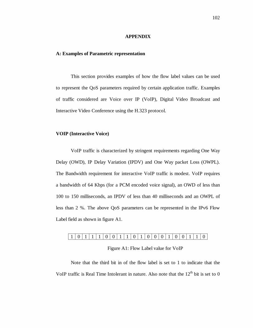
102
APPENDIX
A: Examples of Parametric representation
This section provides examples of how the flow label values can be used
to represent the QoS parameters required by certain application traffic. Examples
of traffic considered are Voice over IP (VoIP), Digital Video Broadcast and
Interactive Video Conference using the H.323 protocol.
VOIP (Interactive Voice)
VoIP traffic is characterized by stringent requirements regarding One Way
Delay (OWD), IP Delay Variation (IPDV) and One Way packet Loss (OWPL).
The Bandwidth requirement for interactive VoIP traffic is modest. VoIP requires
a bandwidth of 64 Kbps (for a PCM encoded voice signal), an OWD of less than
100 to 150 milliseconds, an IPDV of less than 40 milliseconds and an OWPL of
less than 2 %. The above QoS parameters can be represented in the IPv6 Flow
Label field as shown in figure A1.
1 0 1 1 1 0 0 1 1 0 1 0 0 0 1 0 0 1 1 0
Figure A1: Flow Label value for VoIP
Note that the third bit in of the flow label is set to 1 to indicate that the
VoIP traffic is Real Time Intolerant in nature. Also note that the 12th bit is set to 0
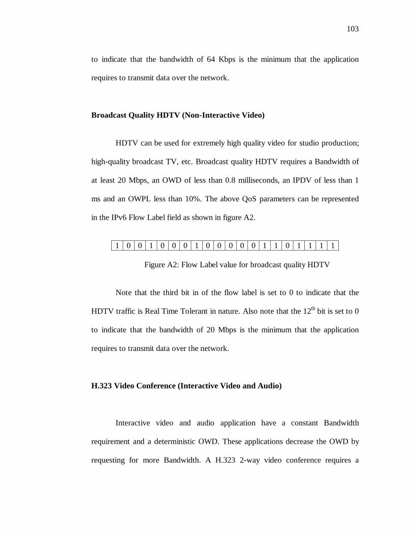
103
to indicate that the bandwidth of 64 Kbps is the minimum that the application
requires to transmit data over the network.
Broadcast Quality HDTV (Non-Interactive Video)
HDTV can be used for extremely high quality video for studio production;
high-quality broadcast TV, etc. Broadcast quality HDTV requires a Bandwidth of
at least 20 Mbps, an OWD of less than 0.8 milliseconds, an IPDV of less than 1
ms and an OWPL less than 10%. The above QoS parameters can be represented
in the IPv6 Flow Label field as shown in figure A2.
1 0 0 1 0 0 0 1 0 0 0 0 0 1 1 0 1 1 1 1
Figure A2: Flow Label value for broadcast quality HDTV
Note that the third bit in of the flow label is set to 0 to indicate that the
HDTV traffic is Real Time Tolerant in nature. Also note that the 12th bit is set to 0
to indicate that the bandwidth of 20 Mbps is the minimum that the application
requires to transmit data over the network.
H.323 Video Conference (Interactive Video and Audio)
Interactive video and audio application have a constant Bandwidth
requirement and a deterministic OWD. These applications decrease the OWD by
requesting for more Bandwidth. A H.323 2-way video conference requires a
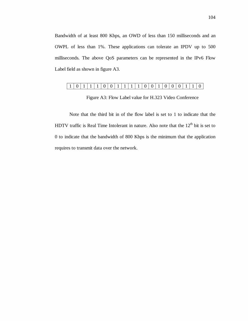
104
Bandwidth of at least 800 Kbps, an OWD of less than 150 milliseconds and an
OWPL of less than 1%. These applications can tolerate an IPDV up to 500
milliseconds. The above QoS parameters can be represented in the IPv6 Flow
Label field as shown in figure A3.
1 0 1 1 1 0 0 1 1 1 1 0 0 1 0 0 0 1 1 0
Figure A3: Flow Label value for H.323 Video Conference
Note that the third bit in of the flow label is set to 1 to indicate that the
HDTV traffic is Real Time Intolerant in nature. Also note that the 12th bit is set to
0 to indicate that the bandwidth of 800 Kbps is the minimum that the application
requires to transmit data over the network.