USER'S MANUAL TC200/ TC210/ TC300/ TC310 Series
63
;’RFTGTT5RT12 TC200 Series Desktop Barcode Printers User Manual Series Lists: TC200 / TC300 TC210 / TC310 Thermal Transfer Direct Thermal
-
Upload
khangminh22 -
Category
Documents
-
view
0 -
download
0
Transcript of USER'S MANUAL TC200/ TC210/ TC300/ TC310 Series

;’RFTGTT5RT12
TC200 Series Desktop Barcode Printers
User Manual Series Lists:
TC200 / TC300
TC210 / TC310
Thermal Transfer Direct Thermal

I
Copyright information
© 2021 TSC Auto ID Technology Co., Ltd.
The copyright in this manual, the software and firmware in the printer described are owned by TSC Auto ID Technology Co., Ltd.
All rights reserved.
CG Triumvirate is a trademark of Agfa Corporation. CG Triumvirate Bold Condensed font is under license from the Monotype
Corporation. Windows is a registered trademark of Microsoft Corporation.
All other trademarks are the property of their respective owners. Information in this document is subject to change without
notice and does not represent a commitment on the part of TSC Auto ID Technology Co. No part of this manual may be
reproduced or transmitted in any form or by any means, for any purpose other than the purchaser’s personal use, without the
expressed written permission of TSC Auto ID Technology Co.

II
Table of Contents 1. Introduction .......................................................................................................................................................................................................1
1.1 Product Specification ...................................................................................................................................................................................2
1.1.1 Printer Optional Features ..........................................................................................................................................................................4
1.2 General Specification ...................................................................................................................................................................................5
1.3 Print Specification ........................................................................................................................................................................................5
1.4 Ribbon Specification ....................................................................................................................................................................................6
1.5 Media Specification ......................................................................................................................................................................................6
2. Operation Overview ...........................................................................................................................................................................................7
2.1 Unpacking and Inspection ............................................................................................................................................................................7
2.2 Printer Overview ..........................................................................................................................................................................................8
2.2.1 Front View .............................................................................................................................................................................................8
2.2.2 Interior View ..........................................................................................................................................................................................9
2.3.2 Rear View ............................................................................................................................................................................................ 10
3. Setup ............................................................................................................................................................................................................... 11
3.1 Setting up the Printer ................................................................................................................................................................................. 11
3.2 Open / Close the Top Cover ...................................................................................................................................................................... 12
3.3 Loading the Ribbon .................................................................................................................................................................................... 13
3.4 Loading the Media ..................................................................................................................................................................................... 15

III
3.5 Loading the Fan-fold Media ....................................................................................................................................................................... 17
3.6 External Label Roll Mount Installation (Option) .................................................................................................................................... 18
3.7 Loading Label in Peel-Off Mode (Option) ................................................................................................................................................... 20
3.8 Loading Label in Cutter Mode (Option) ...................................................................................................................................................... 21
4. LED and Button Functions ............................................................................................................................................................................... 22
4.1 LED Indicator ............................................................................................................................................................................................. 22
4.2 Regular Button Function ............................................................................................................................................................................ 22
4.3 Power-on Utilities ....................................................................................................................................................................................... 23
5. TSC Console ................................................................................................................................................................................................... 24
5.1 Start TSC Console ..................................................................................................................................................................................... 24
5.2 Setup Ethernet Interface ............................................................................................................................................................................ 26
5.3 Set WiFi and Add to TSC Console Interface .............................................................................................................................................. 28
5.4 Initialize the Printer WiFi Setting ................................................................................................................................................................ 31
5.5 Printer Function ......................................................................................................................................................................................... 32
5.6 Setting Post-Print Action ............................................................................................................................................................................ 33
6. LCE Menu Function ......................................................................................................................................................................................... 34
6.1 Enter the Menu .......................................................................................................................................................................................... 34
6.2 Main Menu Overview ................................................................................................................................................................................. 35
6.3 TSPL .......................................................................................................................................................................................................... 36

IV
6.4 ZPL2 .......................................................................................................................................................................................................... 38
6.5 Sensor ....................................................................................................................................................................................................... 41
6.6 Interface ..................................................................................................................................................................................................... 42
6.6.1 Serial Comm........................................................................................................................................................................................ 43
6.6.2 Ehernet ................................................................................................................................................................................................ 44
6.7 File Manager .............................................................................................................................................................................................. 45
6.8 Diagnostic .................................................................................................................................................................................................. 46
6.9 Advanced ................................................................................................................................................................................................... 47
6.10 Service ..................................................................................................................................................................................................... 48
7. TroubleShooting .............................................................................................................................................................................................. 49
8. Maintenance .................................................................................................................................................................................................... 49
9. Angency Compliance and Approvals ............................................................................................................................................................... 54
10. Revise History ............................................................................................................................................................................................... 57

1
1. Introduction
Thank you very much for purchasing TSC bar code printer.
The TC200/210 series of thermal transfer desktop barcode printer, label printer with its new, smaller footprint, offers the high
performance that customers have come to expect from TSC™. Durable, reliable and fast, the TC200/210 generates 4-inch-wide
labels, tags or receipts at up to 6 ips, offering a price-performance combination that is unmatched by other desktop thermal barcode
printers on the market.
As with all TSC printers, the TC200/210 series features the TSPL-EZ™ printer-control language, which is fully compatible with other
TSC printer languages, while supporting TPLE (Translation Printer Language Eltron® ) and TPLZ (Translation Printer Language
Zebra® ). The languages automatically decipher and translate the format of each label as it is sent to the printer. TSPL-EZ™ also
features internal scalable True Type fonts (based on the Monotype® font engine), which are typically found only in more expensive
printers.
This document provides an easy reference for operating this printer. TSC printers include the Windows labeling software for
creating your label template. For system integration, the TSPL/TSPL2 printer programming manual or SDKs can be found on TSC
website at: https://www.tscprinters.com.

2
1.1 Product Specification
Product standard feature TC200/TC300
model
TC210/TC310
model
Thermal transfer/ or direct thermal V V
1 operating button and 1 LED with 3 colors V V
6 operating buttons and 1 LED with 3 colors V V
320 x 240 TFT LCD (UI of operating menu) V V
32-bit RISC high performance processor (Atmel 9260/ 210 MHz) V V
32-bit RISC high performance processor (Atmel 9G25/ 400 MHz) V V
Center alignment holder with spiral spring V V
Gap transmissive sensor (Fixed, center of offset 4 from center) V V
Black mark reflective sensor (Position adjustable) V V
Ribbon encoder sensor V V
Head open sensor V V
Automatic media/ribbon sensor selecting V V
4 MB Flash memory V V
128 MB Flash memory V V
8 MB DRAM V V
64 MB DDR2 DRAM V V
SD card reader for memory expansion, up to 4 GB V V
SD card reader for memory expansion, up to 32 GB V V
RS-232 interface (Max. 115,200 bps) V V
USB 2.0 interface (Full speed mode) V V
USB 2.0 interface (Hi speed mode) V V
Internal Ethernet print server (10/100 Mbps) interface V V
USB host V V
Parallel (SPP mode) V V

3
Standard industry emulations right out of the box including Eltron® and Zebra® language support V V
Internal 8 alpha-numeric bitmap fonts V V
Fonts and bar codes can be printed in any one of the four directions (0, 90,180, 270 degree) V V
Internal Monotype Imaging® true type font engine with one CG Triumvirate Bold Condensed scalable
font V V
Downloadable fonts from PC to printer memory V V
Unicode UTF8 support V V
Bar code, graphics/image printing V V

4
1.1.1 Printer Optional Features
The printer offers the following optional features.
Product option feature User
option Dealer option
Factory option
Peel-off kit
Paper length: 1” ~ 6”
Note:
This peel-off module is supported for the thermal/ plain label only.
V
Regular cutter (full cut guillotine cutter)
Media thickness: 0.06~ 0.19 mm
Media length: 1” ~ max. length
Max. width: 110 mm
Media type: receipt and label liner w/o glue
Note: Except for the linerless cutter, all regular/heavy duty/care label cutters DO NOT cut on
media with glue.
V
KP-200 Plus keyboard display unit V
KU-007 Plus programmable smart keyboard V
External roll mount with 3” core label spindle V
Sleeve adapter V
External Bluetooth module (serial interface) V
802.11 b/g/n wireless module (serial interface) V
Parallel port for TC210/TC310 series (replace USB host) V
Real time clock & Buzzer V

5
1.2 General Specification
General Specifications
Physical dimensions 203 mm(W) x 191.5 mm(H) x 259.3 mm(D)
Weight TC200/TC300: 2.2 kg TC210/TC310: 2.3 kg
Mechanism Clamshell with Double-walled plastic
Power External universal switching power supply • Input: AC 100-240V/ 2.5A, 50-60 Hz • Output: 90W
Environmental condition Operation: 5 ~ 40˚C (41 ~ 104˚F), 25~85% non-condensing Storage: -40 ~ 60 ˚C (-40 ~ 140˚F), 10~90% non-condensing
Environmental concern Comply with RoHS, WEEE, REACH
1.3 Print Specification
Print Specifications TC200 TC210 TC300 TC310
Print head resolution (dots per inch/mm)
203 dots/inch (8 dots/mm)
300 dots/inch (12 dots/mm)
Printing method Thermal transfer/ or direct thermal
Dot size (width x length)
0.125 x 0.125 mm (1 mm = 8 dots)
0.084 x 0.084 mm (1 mm = 12 dots)
Print speed (inches per second)
Up to 6 IPS Up to 4 IPS
Max. 3 ips for peeler mode
Max. print width 108 mm (4.25”) 105.6 mm (4.15”)
Max. print length 2,286 mm (90”) 25,400 mm (1000”) 1,016 mm (40”) 11,430 mm (450”)
Printout bias Vertical: 1 mm max.
Horizontal: 1 mm max.

6
1.4 Ribbon Specification
Ribbon Specifications
Ribbon outside diameter Max. 40 mm OD
Ribbon length 110 meter
Ribbon core inside diameter 0.5” ID core
Ribbon width 40 mm ~110 mm
Ribbon wound type Ink coated outside wound
1.5 Media Specification
Media Specifications
Media roll capacity Max. 5” OD
Media core diameter 1” & 1.5 ID core
Media type Continuous, die-cut, black mark, external fan-fold, notch
Media wound type Outside wound
Media width 20 mm ~ 112 mm
Media thickness 0.06 mm ~ 0.19 mm
Label length 10 mm ~ max. print length
Label length (peeler mode) 25.4 mm ~ 152.4 mm (1” ~ 6”)
Label length (cutter mode) 25.4 ~ max. print length
Black mark Min. 8 mm (W) x 2 mm (H)
Gap height Min. 2 mm

7
2. Operation Overview
2.1 Unpacking and Inspection
This printer has been specially packaged to withstand damage during shipping. Please carefully inspect the packaging and printer
upon receiving the bar code printer. Please retain the packaging materials in case you need to reship the printer.
One printer unit
One Windows labeling software/Windows driver CD disk
One quick installation guide
One power cord
One auto switching power supply
One USB interface cable
If any parts are missing, please contact the Customer Service Department of your purchased reseller or distributor.

8
1. Menu button
2. Feed button
3. LCD display
4. LED indicator
5. Navigation button
6. Ribbon access cover
7. Paper exit chute
8. Top cover open lever
9. SD card socket
2.2 Printer Overview
2.2.1 Front View
6
1 2
4 5 3
7
8
9
For TC210 series
For TC200 series
2 4

9
1. Ribbon rewind hub
2. Ribbon rewind gear
3. Gap sensor (receiver)
4. Media holder
5. Media holder locking switch
6. Gap sensor (transmitter)
7. Print head
8. Ribbon supply hub
9. Top cover support
10. Media guide adjustment button
11. Media guides
12. Black mark sensor
13. Platen roller
2.2.2 Interior View
6
1
2
4
5
3
7
8
9
10
11
13
12

10
2.3.2 Rear View
1. Ethernet interface
2. USB interface
3. USB host
4. RS-232C interface
5. Power jack socket
6. Power switch
7. External label entrance chute
8. Parallel interface
5 2 3 6 4
7
1
For TC200 series
For TC210 series
5 2 8 6 4 1

11
3. Setup
3.1 Setting up the Printer
1. Place the printer on a flat, secure surface.
2. Make sure the power switch is off.
3. Connect the printer to the computer with the provided USB cable.
4. Plug the power cord into the AC power cord socket at the rear of the printer,
and then plug the power cord into a properly grounded power outlet.Place the
printer on flat surface.
Note: Please switch OFF the printer before plugging in the power cord to printer power jack.

12
3.2 Open / Close the Top Cover
1. Open the printer’s top cover and lift the top cover to
the maximum open angle.
2. Top cover support at the rear of the printer will
engage with lower inner cover to hold the printer
top cover open.
3. Hold the top cover and press the top cover support
to disengage the top cover support with lower inner
cover. Gently close the top cover.

13
3.3 Loading the Ribbon
1. Open the printer’s top cover and lift the top cover to
the maximum open angle.
2. Open the ribbon access cover and the media cover.
3. Insert the ribbon right side onto the supply hub.
Align the notches on the left side and mount onto
the spokes.
4. Insert the paper core right side onto the rewind
hub. Align the notches on the left side and mount
onto the spokes.

14
5. Stick the ribbon onto the ribbon rewind paper core.
6. Turn the ribbon rewind gear until the ribbon plastic
leader is thoroughly wounded and the black section
of the ribbon covers the print head.
7. Close the ribbon access cover and the top cover.
Loading path for ribbon

15
3.4 Loading the Media
1. Open the printer’s top cover and lift the top cover to the maximum open angle.
2. Separate and hold open the
media holders.
3. Place the roll between the holders and close them onto the core.
4. Place the paper, printing side face up, through the media sensor and place the label leading edge onto the platen roller. Move the media guides to fit the label width by turning the guide adjuster knob.
5. Close the top cover gently.
6. Use software or LCD menu
function to set the media
sensor type and calibrate
the selected sensor. (refer
to chpter 4&5)

16
Loading path for media
※ For black mark media type, please make the side of the black mark face downward to the black mark sensor and align
the position by adjusting black mark sensor.

17
3.5 Loading the Fan-fold Media
1. Open the printer top cover then insert the fan-fold
media through the external label entrance chute.
2. Separate and hold open the media holders.
Note: Press down the media holder lock switch
to hold the media firmly.
3. Hold the top cover and press the top cover support
to disengage the top cover support with lower inner
cover, then gently close the top cover.

18
3.6 External Label Roll Mount Installation (Option)
1. Attach an external paper roll mount on the bottom of
the printer.
2. Insert a 3” label spindle into a paper roll. And install
it on the external paper roll mount.

19
3. Open the printer’s top cover and separate the
media holders to fit the media width. Press down
the media holder lock switch to fix the media
holder.
4. Feeds the media through the rear external label
entrance chute. And place the paper, printing side
face up, through the media sensor and place the
label leading edge onto the platen roller. Move the
media guides to fit the label width by turning the
guide adjuster knob.
5. Disengage the top cover support and close the top
cover gently. Use software or LCD menu function to
set the media sensor type and calibrate the
selected sensor. (refer to chpter 4&5)

20
3.7 Loading Label in Peel-Off Mode (Option)
1. Refer section 3.3 to load the media, then pull the label through the front of the printer and take some labels off only leave the liner.
2. Open the peel-off module
cover. Feed the liner into
peel-off cover slot.
3. Close the peel-off module. Use software or LCD menu function to enable the peel-off mode.
4. Disengage the top cover support to close the top cover. Printer is ready for peel-off mode.

21
3.8 Loading Label in Cutter Mode (Option)
1. Please refer to section 3.3 to load the media. Lead the media through the cutter paper opening.
2. Close the printer cover.
3. Use software or LCD menu function to set the
media sensor type and calibrate the selected
sensor. (refer to chpter 4 & 5)
4. Use software or LCD menu function to enable the cutter mode.
5. Press the FEED button to test.

22
4. LED and Button Functions
4.1 LED Indicator
Color Meaning
(Green) Solid: Power is on and ready to be used.
Flash :System is downloading data or printer is paused.
(Amber) System is clearing data.
(Red) Solid - Printer head open, cutter error.
Flash - Printing error, such as paper empty, paper jam, ribbon empty, or memory error etc.
4.2 Regular Button Function
1. Feed labels
When the printer is ready, press the button to feed one label to the beginning of next label.
2. Pause the printing job
When the printer is printing, press the button to pause a printing job. When the printer is paused, the LED will be green blinking.
Press the button again to continue the printing job.

23
4.3 Power-on Utilities
Power-on Utilities provides the basic functions and can be activated by below procedures:
Turn off the power > Hold the Feed button > Open the power > Release the Feed button depending on the color of the LED.
Sequences of the settings:
LED Colors
Functions
Amber Red
(5 blinks)
Amber
(5 blinks)
Green
(5 blinks)
Green /
Amber
(5 blinks)
Red / Amber
(5 blinks) Solid green
1. Sensor Calibration
(Gap / black mark sensor) Release
2. Self-Test
(And enter dump mode) Release
3. Factory Default Release
4. Bline Calibration Release
5. Gap Calibration Release
6. READY
(Skip AUTO.BAS) Release

24
5. TSC Console
TSC Console is a management tool combining the Printer Management, Diagnostic Tool, CommTool and Printer Webpage settings,
which enables you to adjust printer’s settings/status; change printers’ settings; download graphics, deploy fonts, graphics, label
templates or upgrade the firmware to the group of printers, and send additional commands to printers at the same time.
※ Printer firmware version before A2.12 will only use 9100 Port as command port; Printer firmware after A2.12 will use
6101 Port as command port.
5.1 Start TSC Console
1. Double click TSC Console icon to start the software.
2. Manually add the devices by clicking Printer > Add Printers.
25
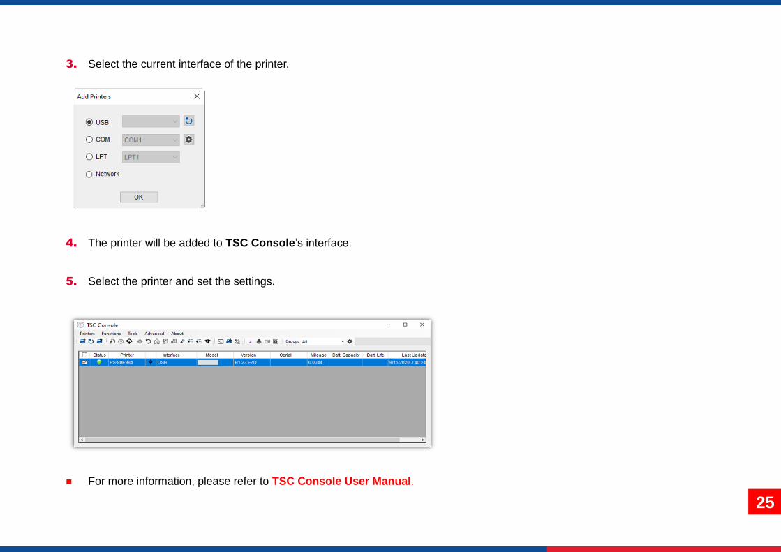
3. Select the current interface of the printer.
4. The printer will be added to TSC Console’s interface.
5. Select the printer and set the settings.
For more information, please refer to TSC Console User Manual.

26
5.2 Setup Ethernet Interface
Use USB or COM to establish the interface on TSC Console.
Double click to enter the Printer Configuration Page > Click Ethernet tab > Check the IP Address.

27
Return to TSC Console main page > Click Add Printer on the top left of the window.
Choose Network > Key in the IP Address > Click Discover to establish the Ehternet interface.
The notification will pop up > Click OK to close the window > The Ethernert interface will be shown on TSC Console.

28
5.3 Set WiFi and Add to TSC Console Interface
Use USB or COM Port to set up the interface.
(refer to chp.5.1)
Double click to enter the printer configuration page.
Click Get to receive printer’s information.
Click Wi-Fi to the wi-fi setting page.
1
2

29
For WPA-Personal
I. Fill-in the SSID.
II. Select the Encryption option to WPA-Personal.
III. Fill-in the Key.
IV. Select DHCP to ON. (For OFF option, please fill-in the IP Address, Subnet Mask and Gateway)
V. After setting, click the Set button. Note: Before setting, the entered field will be shown in yellow for reminding. On DHCP, user can change the printer name by another model name in “Printer Name” field. User also can change the raw port in “Raw Port” field.
For WPA-Enterprise
I. Fill-in the SSID.
II. Select the Encryption option to WPA2-Enterprise.
III. Select DHCP to ON (For OFF option, please fill-in the IP Address, Subnet Mask and Gateway)
IV. Select the EAP Type option. (For EAP-TLS option, please upload the CA and Key for mutual authentication, integrity-protected cipher suite negotiation, and key exchange between two endpoints.)
V. After setting, click the Set button. Note: Before setting, the entered field will be shown in yellow for reminding. On DHCP, user can change the printer name by another model name in “Printer Name” field. User also can change the raw port in “Raw Port” field.
1
2
3
2
1

30
After clicking Set button, it'll pop-up the window tip
as below shown.
IP address will be shown in the “IP address” field .
IP address should be shown within about 5~15
seconds after printer turn on. If not, please refer to
steps below to initialize the printer Wi-Fi module
settings then to setup it again.
Remove the cable between the computer and the
printer.
Go to main page, click Add Printer to add the
printer via Network.
Select the printer and enter the setting page by
double clicking the printer.
Click the Print Test Page button to print the test
page via Wi-Fi interface.

31
5.4 Initialize the Printer WiFi Setting
1. Return to the main page of TSC Console.
2. Click Functions to expand the page.
3. Click Wi-Fi Default to initialize the printer Wi-Fi module setting to factory default setting.

32
5.5 Printer Function
Printer Function could be found in Printer Configuration. “Printer Function” will be shown on the left side of the window.
Functions Description
Calibrate Sensor Detect media types and the size of the label
RTC Setup Synchronize printer with Real Time Clock on PC
Factory Default Initialize the printer to default settings
Reset Printer Reboot printer
Print Test Page Print test page according to the specified label size and sensor type.
Configuration Page Print printer configurations
Dump Text Activate the printer to dump mode
Ignore AUTO.BAS Ignore AUTO.BAS file when printer boot up.
Exit Line Mode Exit the line mode to page mode
Enter Line Mode Leave page mode and enter line mode
Reset WiFi Restore the WiFi settings to defaults.

33
5.6 Setting Post-Print Action
When the printer is equipped with other opton kits, ex: cutter, peeler, rewinder, please select the mode after finishing the calibration.
Follow below procedure to set the post action for the printing:
Refer Chp 5.1 to Connect the printer with TSC Console > Double click the printer > The Printer Configuration Page will pop up > Click
Get to load information > Go to Common Tab > Find Post-Print Action > Select the mode depends on users’ application > Click Set.

34
6. LCE Menu Function
6.1 Enter the Menu
Press the “Menu” button to enter the main menu. Use the “Cross” button to select the item on main menu. The selected item will turn red. Press the “Feed” button to enter the setting list. Note: This LCD function is optional for TC210 and TC310 series.

35
6.2 Main Menu Overview
There are 8 categories on the menu. Users can easily set the settings of the printer without connecting the computer. Please refer
to following sections for more details.
Service : To restore printer settings to defaults and
checking information for printer.
File Manager : To check and manage printer’s
memory storage.
Advanced : To set LCD, initialization, cutter
type,…etc.
Sensor : To calibrate the selected media sensor.
Interface : To set the printer interface settings.
Diagnostic : To check printer and help users to
troubleshoot the problems.
ZPL2 : To set up the printer settings ZPL2.
TSPL : To set up the printer settings for TSPL

36
6.3 TSPL
TSPL category can set up the printer settings for TSPL.
Se
ttin
g
TSPL
Speed
Density
Direction
Print mode
None
Batch Mode
Peeler Mode
Cutter Mode
Cutter Batch
Offset
Shift X
Shift Y
Reference X
Reference Y
Code Page
Country

37
Note: If printing from enclosed software/driver, the software/driver will send out the commands, which will overwrite the settings set
from the panel.
Item Description Default
Speed Set the print speed. N/A
Density Set the printing darkness. 8
Direction
Set the printout direction. Setting Value: 0 and 1.
Direction 0: Direction 1:
0
Print mode
Set the print mode. There are 5 modes in total: None: Next label top of form is aligned to the print head burn line location. (Tear Off Mode) Batch Mode: Once finishing the printing process, label will be fed to the tear plate location. Peeler Mode: Enable the label peel off mode. Cutter Mode: Enable the label cutter mode. Cutter Batch: Cut the label once at the end of the printing job.
Batch Mode
Offset Adjust media stop location. Available value setting range: -999 dots to 999 dots. 0 dot
Shift X Adjust print position. Available value setting range: -999 dots to 999 dots.
0 dot
Shift Y 0 dot
Reference X Set the origin of printer coordinate system horizontally and vertically. Available setting range: 0 dot to 999 dots.
0 dot
Reference Y 0 dot
Code page Set the code page of international character set. 850
Country Set the country code. Available setting value range: 1 to 358. 001

38
6.4 ZPL2
This “ZPL2” category can set up the printer settings for ZPL2.
Menu ZPL2
Darkness
Print Speed
Tear Off
Print Mode
Tear Off
Peeler Off
CutterPrint Width
List Fonts
List Images
List Formats
List Setup
Control Prefix
Format Prefix
Delimiter Char
Media Power Up
Feed
Calibration
Length
No Motion
Head Close
Feed
Calibration
Length
No MotionLabel Top
Left Position
Reprint ModeEnabled
Disabled
Format Convert
None
150 -> 300
150 -> 600
200 -> 600
300 -> 600

39
Item Description Default
Density Set the printing darkness. Available setting range: 0 to 30. 16
Print Speed Set the print speed.
6 (203dpi)
4 (300dpi)
3 (600dpi) Tear Off Adjust media stop location. Available setting value range: -120~120 dots. 0 dot
Print mode
Set the print mode. There are 4 modes:
Tear Off: Next label top of form is aligned to the print head heating line location.
Peeler Off: Enable the label peel off mode.
Cutter: Enable the label cutter mode
Tear Off
Print Width Set the print width. Available setting range: 2 ~ 999 dots. 812
List Fonts Print the current fonts list from the memory devices to the label. N/A
List Images Print current printer available images list stored at the memory device to the label. N/A
List Formats Print current printer available formats list from the memory devices to the label. N/A
List Setup Print current printer configuration to the label. N/A
Control Prefix Set control prefix character. N/A
Format Prefix Set format prefix character. N/A
Delimiter Char Set delimiter character. N/A

40
Media Power Up
Set the action of the media when turning on the printer.
Feed: Printer will advance one label.
Calibration: Printer will make calibration.
Length: Printer determine length and feed label.
No Motion: Printer will not move media.
No Motion
Head Close
Set the action of the media when closing the print head.
Feed: Printer will advance one label.
Calibration: Printer will make calibration.
Length: Printer determine length and feed label.
No Motion: Printer will not move media.
No Motion
Label Top Adjust print position vertically on the label. Value range: -120 to +120 dots. 0
Left Position Adjust print position horizontally on the label. Value range:-9999 to +9999 dots. 0
Reprint Mode Reprint the last label by pressing button on printer’s control panel. Disabled
Format Convert Select the bitmap scaling factor. The first number is the original dots per inch (dpi) value; the second the dpi which you would like to scale.
None
Note: printing from other software/drive will overwrite the settings set from the panel.

41
6.5 Sensor
This option is used to calibrate the selected sensor. We recommend calibrate the sensor before printing when changing the media.
Item Description Default
Auto Calibration Set the media sensor type and calibrate the selected sensor automatically. N/A
Manual Calibration In case Auto Calibration does not work, please use “Manual” function to set the paper length and gap/bline size to complete the calibration setting.
N/A
Threshold Detect Set sensor sensitivity in fixed or auto. Auto
Maximum Length Set the maximum length for label calibration. 254 mm
Advanced Set the minimum paper length and maximum gap/bline length for auto-calibratIon. N/A
Menu Sensor
Auto Calibration
Gap
Black Mark
Continuous
Preprint
Manual Calibration Standard
Gap
Black Mark
Continuous
Threshold Detect
Auto
Fixed
Maximum Length
Advanced

42
6.6 Interface
Interface can set the printer interface settings.
Menu Interface
Serial
Ethernet
Wi-Fi
Bluetooth

43
6.6.1 Serial Comm
Serial comm can set the printer RS-232 settings.
Item Description Default
Baud Rate Set the RS-232 baud rate. 9600
Parity Set the RS-232 parity. None
Data Bits Set the RS-232 Data Bits. 8
Stop Bit(s) Set RS-232 Stop Bits. 1
Menu Interface Serial
Baud Rate
1200 bps
2400 bps
4800 bps
9600 bps
19200 bps
38400 bps
57600 bps
115200 bps
Parity
None
Odd
Even
Data Bits7
8
Stop Bit(s)1
2

44
6.6.2 Ehernet
Ethernet configures internal Ethernet configuration and checks the printer’s Ethernet module status, and reset the Ethernet module.
Item Description Default
Status Check the Ethernet IP address and MAC setting status. N/A
Config. DHCP: On or OFF the DHCP (Dynamic Host Configuration Protocol) network protocol. Static IP: Use this menu to set the printer’s IP address, subnet mask and gateway.
DHCP
Menu Interface EthernetStatus
Config

45
6.7 File Manager
File Manager is used to check the printer available memory, show the files list, delete the files or run the files that saved in the printer DRAM/Flash/Card memory.
Menu File Manager
DRAM
FLASH

46
6.8 Diagnostic
Item Description
Print Config. Print current printer configuration to the label. The configuration printout contains print head test pattern, which is useful for checking the dot damage on the print head heater.
Dump Mode
Captures the data from the communications port and prints out the data received by printer. In the dump mode, all characters will be printed in 2 columns. The left side characters are received from your system and right side data are the corresponding hexadecimal value of the characters. It allows users or engineers to verify and debug the program. Dump mode requires 4” wide paper width.
Print Head Check print head’s temperature and bad dots.
Display Check LCD’s color state.
Sensor Check sensors intensity and reading state.
Menu Diagnostic
Print Config.
Dump Mode
Print Head
Display
Sensor
Diag Gap
Diag Black Mark
Diag Ribbon End
Diag Media

47
6.9 Advanced
Menu Advanced
Display Brightness
Date & Time
Language
Item Description
Display Brightness This item is used to setup the brightness for display.
Date & Time This item is used to setup the date and time on display.
Language This item is used to setup the language on display.

48
6.10 Service
This feature is used to restore printer settings to defaults and checking information for printer.
Menu Service
Initialization
Printer Information
Contact us
Item Description
Initialization This feature is used to restore printer settings to defaults.
Printer Information This feature is used to check printer serial number, printed mileage(m), labels(pcs.) and cutting counter.
Contact us This feature is used to check the contact information for tech support service

49
7. TroubleShooting
Problem Possible Cause Recovery Procedure
Power indicator does not illuminate * The power cord is not properly
connected. * Plug the power cord in printer and outlet. * Switch the printer on.
TSC Console shows “Head Open”. - The LCD shows “Carriage Open”.
* The printer head is open. * Please close the print carriages.
TSC Console shows “Ribbon Encoder Err.”
- The LCD shows “No Ribbon”.
* Running out of ribbon. * The ribbon is installed incorrectly.
* Supply a new ribbon roll. * Please refer to the steps on section 3.3 to re-install the
ribbon.
TSC Console shows “Out of Paper”. - The LCD shows “No Paper”
* Running out of label. * The label is installed incorrectly. * Gap/black mark sensor is not
calibrated.
* Supply a new label roll. * Please refer to the steps on section 3.4 to reinstall the
label roll. * Calibrate the gap/black mark sensor.
TSC Console shows “Paper Jam”. - The LCD shows “Paper Jam”
* Gap/black mark sensor is not set properly.
* Make sure label size is set properly. * Labels may be stuck inside the printer
mechanism.
* Calibrate the media sensor. * Set media size correctly. * Remove the stuck label inside the printer mechanism.
- The LCD shows “Take Label”. * Peel-off function is enabled.
* If the peel-off module is installed, please remove the label.
* If there is no peel-off module in front of the printer, please switch off the printer and install it.
* Check if the connector is plugging correctly.
Not Printing
* Check if interface cable is well connected to the interface connector.
* Check if wireless or Bluetooth device is well connected between host and printer.
* The port specified in the Windows driver is not correct.
* Re-connect cable to interface or change a new cable.
* If using serial cable,
- Please replace the cable with pin to pin connected.
- Check the baud rate setting. The default baud rate
setting of printer is 9600,n,8,1.
* If using the Ethernet cable,
- Check if the Ethernet RJ-45 connector green LED is
lit on.
- Check if the Ethernet RJ-45 connector amber LED is
blinking.
- Check if the printer gets the IP address when using
DHCP mode.

50
- Check if the IP address is correct when using the
static IP address.
- Wait a few seconds let the printer get the
communication with the server then check the IP
address setting again.
* Please reset the wireless device setting.
* Select the correct printer port in the driver.
* Print head’s harness connector is not well connected
with printheat. Turn off the printer and plug the
connector again.
* Check your program if there is a command PRINT at
the end of the file and there must have CRLF at the end
of each command line.
No print on the label * Label or ribbon is loaded not correctly. * Use wrong type paper or ribbon
* Follow the instructions in loading the media and ribbon. * Ribbon and media are not compatible. * Verify the ribbon-inked side. * The print density setting is incorrect. * Clean the print head.
Poor Print Quality
* Ribbon and media is loaded incorrectly * Dust or adhesive accumulation on the
print head. * Print density is not set properly. * Print head element is damaged. * Ribbon and media are incompatible. * The print head pressure is not set
properly.
* Reload the supply. * Clean the print head. * Clean the platen roller. * Adjust the print density and print speed. * Run printer self-test and check the print head test
pattern if there is dot missing in the pattern. * Change proper ribbon or proper label media. * The release lever does not latch the print head
properly.
Cutter is not working * The connector is loose. * Cutter jam. * Cutter PCB is damaged.
* Plug in the connect cable correctly. * Remove the label. * Make sure the thickness of label is less than 0.19 mm. * Replace a cutter driver IC board.
Can’t downloading the file to memory (FLASH / DRAM/CARD)
* The space of memory is full. * Delete unused files in the memory.
SD card is unable to use * SD card is damaged. * SD card doesn’t insert correctly.
* Use the supported capacity SD card. Please refer to section 2.2.1
* Insert the SD card again.
Missing printing on the left or right side of label
* Wrong label size setup. * Set the correct label size.
Gray line on the blank label * The print head is dirty. * The platen roller is dirty.
* Clean the print head. * Clean the platen roller.

51
Irregular printing * The printer is in Hex Dump mode. * The RS-232 setting is incorrect.
* Turn off and on the printer to skip the dump mode. * Re-set the Rs-232 setting.
Label feeding is not stable (skew) when printing
* The media guides do not touch the edge of the media.
* If the label is moving to the right side, please move the label guide to left.
* If the label is moving to the left side, please move the label guide to right.
Skip labels when printing * Label size is not specified properly. * Sensor sensitivity is not set properly. * The media sensor is covered with dust.
* Check if label size is setup correctly. * Calibrate the sensor by Auto Gap or Manual Gap
options. * Clear the GAP/Black mark sensor by blower.
Wrinkle Problem
* Printhead pressure is incorrect. * Ribbon installation is incorrect. * Media installation is incorrect. * Print density is incorrect. * Media feeding is incorrect.
* Please set the suitable density to have good print quality.
* Make sure the label guides touch the edge of the media guide.
RTC time is incorrect when reboot the printer
* The battery has run down. * Check if there is a battery on the main board.
The printing position of small label is incorrect
* Media sensor sensitivity is not set properly.
* Label size is incorrect. * The parameter Shift Y is incorrect. * The vertical offset setting in the driver is
incorrect.
* Calibrate the sensor sensitivity again. * Set the correct label size and gap size. * Use DiagTool to fine tune the parameter of Shift Y. * If using the software BarTender, please set the vertical
offset in the driver.

52
8. Maintenance
This session presents the clean tools and methods to maintain the printer.
For Cleaning
Depending on the media used, the printer may accumulate residues (media dust, adhesives, etc.) as a by-product of normal
printing. To maintain the best printing quality, you should remove these residues by cleaning the printer periodically. Regularly
clean the print head and supply sensors once change a new media to keep the printer at the optimized performance and extend
printer life.
For Disinfecting
Sanitize your printer to protect yourself and others and can help prevent the spread of viruses.
Important
- Set the printer power switch to O (Off) prior to performing any cleaning or disinfecting tasks. Leave the power cord
connected to keep the printer grounded and to reduce the risk of electrostatic damage.
- Do not wear rings or other metallic objects while cleaning any interior area of the printer.
- Use only the cleaning agents recommended in this document. Use of other agents may damage the printer and void its
warranty.
- Do not spray or drip liquid cleaning solutions directly into the printer. Apply the solution on a clean lint-free cloth and then
apply the dampened cloth to the printer.
- Do not use canned air in the interior of the printer as it can blow dust and debris onto sensors and other critical
components.
- Only use a vacuum cleaner with a nozzle and hose that are conductive and grounded to drain off static build up.
- All reference in these procedures for use of isopropyl alcohol requires that a 99% or greater isopropyl alcohol content be
used to reduce the risk of moisture corrosion to the printhead.
- Do not touch printhead by hand. If you touch it careless, please use 99% Isopropyl alcohol to clean it.
- Always taking personal precaution when using any cleaning agent.

53
Cleaning Tools
Cotton swab
Lint-free cloth
Brush with soft non-metallic bristles
Vacuum cleaner
75% Ethanol (for disinfecting)
99% Isopropyl alcohol (for printhead and platen roller cleaning)
Genuine printhead cleaning pen
Mild detergent (without chlorine)
Cleaning Process:
Printer Part Method Interval
Print Head
I. Always turn off the printer before cleaning the printhead.
II. Allow the printhead to cool for at least one minute.
III. Use a cotton swab and 99% Isopropyl Alcohol or genuine print head cleaning pen to clean the print head surface.
Clean the print head when changing a new label roll.
Platen Roller I. Turn off the printer.
II. Rotate the platen roller and wipe it thoroughly with the lint-free 99% Isopropyl Alcohol.
Clean the platen roller when changing a new label roll
Peel Bar Use the lint-free cloth with 99% Isopropyl Alcohol to wipe it. As needed
Sensor Use brush with soft non-metallic bristles or a vacuum cleaner, to remove paper dust. Clean upper and lower media sensors to ensure reliable Top of Form and Paper Out sensing.
Monthly
Exterior Clean the exterior surfaces with a clean, lint-free cloth (water-dampened cloth). If necessary, use a mild detergent or desktop cleaning solution then use the 75% Ethanol to wipe it.
As needed
Interior Clean the interior of the printer by removing any dirt and lint with a vacuum cleaner, as described above, or use a brush with soft non-metallic bristles then use the 75% Ethanol to wipe it.
As needed

54
9. Angency Compliance and Approvals
EN 55032, Class B EN 55024 EN 60950-1; EN 61000-3-2; EN 61000-3-3
FCC part 15B, Class B ICES-003, Class B This equipment has been tested and found to comply with the limits for a Class B digital device, pursuant to part 15 of the FCC Rules. These limits are designed to provide reasonable protection against harmful interference in a residential installation. This equipment generates, uses and can radiate radio frequency energy and, if not installed and used in accordance with the instructions, may cause harmful interference to radio communications. However, there is no guarantee that interference will not occur in a particular installation. If this equipment does cause harmful interference to radio or television reception, which can be determined by turning the equipment off and on, the user is encouraged to try to correct the interference by one or more of the following measures:
-Reorient or relocate the receiving antenna.
-Increase the separation between the equipment and receiver.
-Connect the equipment into an outlet on a circuit different from that to which the receiver is connected.
-Consult the dealer or an experienced radio/ TV technician for help.
This device complies with Part 15 of the FCC Rules. Operation is subject to the following two conditions: (1) This device may cause harmful interference, and (2) this device must accept any interference received, including interference that may cause undesired operation. This Class B digital apparatus complies with Canadian ICES-003. Cet appareil numérique de la classe B est conform à la norme NMB-003 du Canada.
AS/NZS CISPR 32, Class B

55
UL 60950-1(2nd Edition) CSA C22.2 No. 60950-1-07(2nd Edition)
EN 60950-1
GB 4943.1 GB 9254, Class B GB 17625.1
Energy Star for Imaging Equipment Version 2.0
Note: There may have certification differences in the series models, please refer to product label for accuracy.
Important safety instructions:
1. Read all of these instructions and keep them for later use.
2. Follow all warnings and instructions on the product.
3. Disconnect the power plug from the AC outlet before cleaning or if fault happened.
Do not use liquid or aerosol cleaners. Using a damp cloth is suitable for cleaning.
4. The mains socket shall be installed near the equipment and easily accessible.
5. The unit must be protected against moisture.
6. Ensure the stability when installing the device, Tipping or dropping could cause damage.
7. Make sure to follow the correct power rating and power type indicated on marking label
provided by manufacture.
8. Please refer to user manual for maximum operation ambient temperature.
WARNING:
Hazardous moving parts, keep fingers and other body parts away.

56
CAUTION:
(For equipment with RTC (CR2032) battery or rechargeable battery pack)
Risk of explosion if battery is replaced by an incorrect type.
Dispose of used batteries according to the Instructions as below.
1. DO NOT throw the battery in fire.
2. DO NOT short circuit the contacts.
3. DO NOT disassemble the battery.
4. DO NOT throw the battery in municipal waste.
5. The symbol of the crossed out wheeled bin indicates that the battery should not be placed in municipal waste.
Caution: The printhead may be hot and could cause severe burns. Allow the printhead to cool.
CAUTION:
Any changes or modifications not expressly approved by the grantee of this device could void the user's authority to operate the
equipment.

57
10. Revise History
Date Content Editor