
GOT SIMPLE Series User's Manual
310
GOT SIMPLE Series User's Manual -GS21 model
-
Upload
khangminh22 -
Category
Documents
-
view
0 -
download
0
Transcript of GOT SIMPLE Series User's Manual

GOT SIMPLE SeriesUser's Manual
-GS21 model

SAFETY PRECAUTIONS(Always read these precautions before using this equipment.)
Before using this product, please read this manual and the relevant manuals introduced in this manual carefully and pay full
attention to safety to handle the product correctly.
The precautions given in this manual are concerned with this product.
In this manual, the safety precautions are ranked as "WARNING" and "CAUTION".
Note that the caution level may lead to a serious accident according to the circumstances.
Always follow the instructions of both levels because they are important to personal safety.
Please save this manual to make it accessible when required and always forward it to the end user.
[DESIGN PRECAUTIONS]
WARNING● Some failures of the GOT or cable may keep the outputs on or off. Some failures of a touch panel may
cause malfunction of the input objects such as a touch switch. An external monitoring circuit should be
provided to check for output signals which may lead to a serious accident. Not doing so can cause an
accident due to false output or malfunction.
● Do not use the GOT as the warning device that may cause a serious accident. An independent and
redundant hardware or mechanical interlock is required to configure the device that displays and
outputs serious warning. Not doing so can cause an accident due to false output or malfunction.
● When the GOT detects its backlight failure, the GOT disables the input operation on the touch
switch(s). Thus, operators cannot operate the GOT with touches. The GOT backlight failure can be
checked with a system signal of the GOT.
● Even when the display section has dimmed due to a failure of the liquid crystal section or the backlight
on the GOT, the input operation of the touch switches may still be enabled. This may cause an
incorrect operation of the touch switches. For example, if an operator assumes that the display
section has dimmed because of the screen save function and touches the display section to cancel
the screen save, a touch switch may be activated.
WARNING Indicates that incorrect handling may cause hazardous conditions, resulting in death or severe injury.
CAUTIONIndicates that incorrect handling may cause hazardous conditions, resulting in medium or slight personal injury or physical damage.
1

2
[DESIGN PRECAUTIONS]
[DESIGN PRECAUTIONS]
WARNING● The display section of the GOT is an analog-resistive type touch panel. Simultaneous pressing of two
or more areas on the display section may activate the switch between those areas. Do not press two
or more areas simultaneously on the display section. Doing so may cause an accident due to incorrect
output or malfunction.
● When programs or parameters of the controller (such as a PLC) that is monitored by the GOT are
changed, be sure to shut off the power of the GOT promptly and power on the GOT again. Not doing
so can cause an accident due to false output or malfunction.
● If a communication fault (including cable disconnection) occurs during monitoring on the GOT,
communication between the GOT and PLC CPU is suspended and the GOT becomes inoperative. A
system where the GOT is used should be configured to perform any significant operation to the
system by using the switches of a device other than the GOT on the assumption that a GOT
communication fault will occur. Not doing so can cause an accident due to false output or malfunction.
● To maintain the security (confidentiality, integrity, and availability) of the GOT and the system against
unauthorized access, DoS*1 attacks, computer viruses, and other cyberattacks from unreliable
networks and devices via network, take appropriate measures such as firewalls, virtual private
networks (VPNs), and antivirus solutions.
Mitsubishi Electric shall have no responsibility or liability for any problems involving GOT trouble and
system trouble by unauthorized access, DoS attacks, computer viruses, and other cyberattacks.
*1 DoS: A denial-of-service (DoS) attack disrupts services by overloading systems or exploiting
vulnerabilities, resulting in a denial-of-service (DoS) state.
CAUTION● Do not bundle the control and communication cables with main-circuit, power or other wiring. Run the
above cables separately from such wiring and keep them a minimum of 100mm apart. Not doing so
noise can cause a malfunction.
● Do not press the GOT display section with a pointed material as a pen or driver. Doing so can result in
a damage or failure of the display section.
● When the GOT is connected to the Ethernet network, the available IP address is restricted according
to the system configuration.
When multiple GOTs are connected to the Ethernet network:
Do not set the IP address (192.168.3.18) for the GOTs and the controllers in the network.
When a single GOT is connected to the Ethernet network:
Do not set the IP address (192.168.3.18) for the controllers except the GOT in the network.
Doing so can cause the IP address duplication. The duplication can negatively affect the
communication of the device with the IP address (192.168.3.18). The operation at the IP address
duplication depends on the devices and the system.
● Turn on the controllers and the network devices to be ready for communication before they
communicate with the GOT. Failure to do so can cause a communication error on the GOT.
● When the GOT is subject to shock or vibration, or some colors appear on the screen of the GOT, the
screen of the GOT might flicker.

[MOUNTING PRECAUTIONS]
[MOUNTING PRECAUTIONS]
WARNING● Be sure to shut off all phases of the external power supply used by the system before mounting or
removing the GOT main unit to/from the panel. Not doing so can cause the unit to fail or malfunction.
CAUTION● Use the GOT in the environment that satisfies the general specifications described in this manual. Not
doing so can cause an electric shock, fire, malfunction or product damage or deterioration.
● When mounting the GOT to the control panel, tighten the mounting screws in the specified torque
range (0.36N·m to 0.48N·m) with a Phillips-head screwdriver No.2. Undertightening can cause the
GOT to drop, short circuit or malfunction. Overtightening can cause a drop, short circuit or malfunction
due to the damage of the screws or the GOT.
● Remove the protective film of the GOT. When the user continues using the GOT with the protective
film, the film may not be removed.
● Operate and store the GOT in environments without direct sunlight, high temperature, dust, humidity,
and vibrations.
● Do not use the GOT in an environment with oil or chemicals. Doing so may cause failure or
malfunction due to the oil or chemical entering into the GOT.
3

4
[WIRING PRECAUTIONS]
[WIRING PRECAUTIONS]
WARNING● Be sure to shut off all phases of the external power supply used by the system before wiring. Failure
to do so may result in an electric shock, product damage or malfunctions.
CAUTION● Please make sure to ground FG terminal of the GOT power supply section by applying 100Ω or less
which is used exclusively for the GOT. Not doing so may cause an electric shock or malfunction.
● Correctly wire the GOT power supply section after confirming the rated voltage and terminal
arrangement of the product. Not doing so can cause a fire or failure.
● Tighten the terminal screws of the GOT power supply section in the specified torque range (0.5N·m to
0.6N·m). Undertightening can cause a short circuit or malfunction. Overtightening can cause a short
circuit or malfunction due to the damage of the screws or the GOT.
● Exercise care to avoid foreign matter such as chips and wire offcuts entering the GOT. Not doing so
can cause a fire, failure or malfunction.
● Plug the communication cable into the GOT interface or the connector of the connected unit, and
tighten the mounting screws and the terminal screws in the specified torque range. Undertightening
can cause a short circuit or malfunction. Overtightening can cause a short circuit or malfunction due to
the damage of the screws or unit.

[TEST OPERATION PRECAUTIONS]
[STARTUP/MAINTENANCE PRECAUTIONS]
[STARTUP/MAINTENANCE PRECAUTIONS]
WARNING● Before performing the test operations of the user creation monitor screen (such as turning ON or OFF
bit device, changing the word device current value, changing the settings or current values of the
timer or counter, and changing the buffer memory current value), read through the manual carefully
and make yourself familiar with the operation method. During test operation, never change the data of
the devices which are used to perform significant operation for the system. False output or
malfunction can cause an accident.
WARNING● When power is on, do not touch the terminals. Doing so can cause an electric shock or malfunction.
● Before starting cleaning or terminal screw retightening, always switch off the power externally in all
phases.
Not doing so can cause the unit to fail or malfunction.
Undertightening can cause a short circuit or malfunction.
Overtightening can cause a short circuit or malfunction due to the damage of the screws or unit.
CAUTION● Do not disassemble or modify the unit. Doing so can cause a failure, malfunction, injury or fire.
● Do not touch the conductive and electronic parts of the unit directly. Doing so can cause a unit
malfunction or failure.
● The cables connected to the unit must be run in ducts or clamped. Not doing so can cause the unit or
cable to be damaged due to the dangling, motion or accidental pulling of the cables or can cause a
malfunction due to a cable connection fault.
● When unplugging the cable connected to the unit, do not hold and pull from the cable portion. Doing
so can cause the unit or cable to be damaged or can cause a malfunction due to a cable connection
fault.
● Do not drop the module or subject it to strong shock. A module damage may result.
● Before touching the unit, always touch grounded metals, etc. to discharge static electricity from
human body, etc. Not doing so can cause the unit to fail or malfunction.
5

6
[TOUCH PANEL PRECAUTIONS]
[PRECAUTIONS WHEN THE DATA STORAGE IS IN USE]
[PRECAUTIONS WHEN THE DATA STORAGE IS IN USE]
[DISPOSAL PRECAUTIONS]
CAUTION● For the analog-resistive film type touch panels, normally the adjustment is not required.
However, the difference between a touched position and the object position may occur as the period
of use elapses. When any difference between a touched position and the object position occurs,
execute the touch panel calibration.
● When any difference between a touched position and the object position occurs, other object may be
activated. This may cause an unexpected operation due to incorrect output or malfunction.
WARNING● If the SD card mounted on drive A of the GOT is removed while the GOT is accessed, processing for
the GOT might be interrupted about for 20 seconds. The GOT cannot be operated during this period.
The functions that run in the background including a screen updating, alarm, logging, scripts, and
others are also interrupted. Since this interruption makes an impact to the system operation, it might
cause failure. After inhibiting access to the SD card on the GOT utility screen, check that the SD card
access LED is off and remove the SD card.
CAUTION● If the data storage mounted on the GOT is removed while the GOT is accessed, the data storage and
files are damaged. To remove the data storage from the GOT, check that the access to the data
storage in SD card access LED, the system signal, and others is not performed.
● When removing the SD card from the GOT, make sure to support the SD card by hand as it may pop
out. Failure to do so may cause the SD card to drop from the GOT, resulting in a failure or break.
● Before removing the USB device from the GOT, follow the procedure for removal on the utility screen
of the GOT. After the successful completion dialog is displayed, remove the USB device by hand
carefully. Failure to do so may cause the USB device to drop from the GOT, resulting in a failure or
break.
CAUTION● When disposing of this product, treat it as industrial waste.
[TRANSPORTATION PRECAUTIONS]
CAUTION● Make sure to transport the GOT main unit and/or relevant unit(s) in the manner they will not be
exposed to the impact exceeding the impact resistance described in the general specifications of this
manual, as they are precision devices. Failure to do so may cause the unit to fail. Check if the unit
operates correctly after transportation.
● When fumigants that contain halogen materials such as fluorine, chlorine, bromine, and iodine are
used for disinfecting and protecting wooden packaging from insects, they cause malfunction when
entering our products. Please take necessary precautions to ensure that remaining materials from
fumigant do not enter our products, or treat packaging with methods other than fumigation (heat
method). Additionally, disinfect and protect wood from insects before packing products.
7

8
CONTENTSSAFETY PRECAUTIONS . . . . . . . . . . . . . . . . . . . . . . . . . . . . . . . . . . . . . . . . . . . . . . . . . . . . . . . . . . . . . . . . . . . .1
INTRODUCTION. . . . . . . . . . . . . . . . . . . . . . . . . . . . . . . . . . . . . . . . . . . . . . . . . . . . . . . . . . . . . . . . . . . . . . . . . .14
About Manual . . . . . . . . . . . . . . . . . . . . . . . . . . . . . . . . . . . . . . . . . . . . . . . . . . . . . . . . . . . . . . . . . . . . . . . . . . . .14
Quick Reference . . . . . . . . . . . . . . . . . . . . . . . . . . . . . . . . . . . . . . . . . . . . . . . . . . . . . . . . . . . . . . . . . . . . . . . . . .15
Abbreviations and Generic Terms . . . . . . . . . . . . . . . . . . . . . . . . . . . . . . . . . . . . . . . . . . . . . . . . . . . . . . . . . . . . .16
CHAPTER 1 OVERVIEW 19
1.1 Features . . . . . . . . . . . . . . . . . . . . . . . . . . . . . . . . . . . . . . . . . . . . . . . . . . . . . . . . . . . . . . . . . . . . . . . . . . . . . . . 20
Rough procedure. . . . . . . . . . . . . . . . . . . . . . . . . . . . . . . . . . . . . . . . . . . . . . . . . . . . . . . . . . . . . . . . . . . . . . . . . 21
CHAPTER 2 SYSTEM CONFIGURATION 23
2.1 Overall Configuration . . . . . . . . . . . . . . . . . . . . . . . . . . . . . . . . . . . . . . . . . . . . . . . . . . . . . . . . . . . . . . . . . . . . 23
2.2 Component List . . . . . . . . . . . . . . . . . . . . . . . . . . . . . . . . . . . . . . . . . . . . . . . . . . . . . . . . . . . . . . . . . . . . . . . . . 23
Explanation of the GOT model name . . . . . . . . . . . . . . . . . . . . . . . . . . . . . . . . . . . . . . . . . . . . . . . . . . . . . . . . . 23
GOT. . . . . . . . . . . . . . . . . . . . . . . . . . . . . . . . . . . . . . . . . . . . . . . . . . . . . . . . . . . . . . . . . . . . . . . . . . . . . . . . . . . 24
Extension unit . . . . . . . . . . . . . . . . . . . . . . . . . . . . . . . . . . . . . . . . . . . . . . . . . . . . . . . . . . . . . . . . . . . . . . . . . . . 24
Software . . . . . . . . . . . . . . . . . . . . . . . . . . . . . . . . . . . . . . . . . . . . . . . . . . . . . . . . . . . . . . . . . . . . . . . . . . . . . . . 24
Option . . . . . . . . . . . . . . . . . . . . . . . . . . . . . . . . . . . . . . . . . . . . . . . . . . . . . . . . . . . . . . . . . . . . . . . . . . . . . . . . . 25
CHAPTER 3 SPECIFICATIONS 27
3.1 General Specifications . . . . . . . . . . . . . . . . . . . . . . . . . . . . . . . . . . . . . . . . . . . . . . . . . . . . . . . . . . . . . . . . . . . 27
3.2 Performance Specifications . . . . . . . . . . . . . . . . . . . . . . . . . . . . . . . . . . . . . . . . . . . . . . . . . . . . . . . . . . . . . . . 28
3.3 Power Supply Specifications . . . . . . . . . . . . . . . . . . . . . . . . . . . . . . . . . . . . . . . . . . . . . . . . . . . . . . . . . . . . . . 30
3.4 GOT Connector Specifications . . . . . . . . . . . . . . . . . . . . . . . . . . . . . . . . . . . . . . . . . . . . . . . . . . . . . . . . . . . . 31
RS-232 interface . . . . . . . . . . . . . . . . . . . . . . . . . . . . . . . . . . . . . . . . . . . . . . . . . . . . . . . . . . . . . . . . . . . . . . . . . 31
RS-422 interface and RS-422/485 interface . . . . . . . . . . . . . . . . . . . . . . . . . . . . . . . . . . . . . . . . . . . . . . . . . . . . 31
CHAPTER 4 PART NAME 33
4.1 Front Panel. . . . . . . . . . . . . . . . . . . . . . . . . . . . . . . . . . . . . . . . . . . . . . . . . . . . . . . . . . . . . . . . . . . . . . . . . . . . . 33
4.2 Back Panel . . . . . . . . . . . . . . . . . . . . . . . . . . . . . . . . . . . . . . . . . . . . . . . . . . . . . . . . . . . . . . . . . . . . . . . . . . . . . 34
4.3 Bottom . . . . . . . . . . . . . . . . . . . . . . . . . . . . . . . . . . . . . . . . . . . . . . . . . . . . . . . . . . . . . . . . . . . . . . . . . . . . . . . . 37
CHAPTER 5 EMC DIRECTIVE 39
5.1 Overview. . . . . . . . . . . . . . . . . . . . . . . . . . . . . . . . . . . . . . . . . . . . . . . . . . . . . . . . . . . . . . . . . . . . . . . . . . . . . . . 39
Conforming standards in the EMC Directive . . . . . . . . . . . . . . . . . . . . . . . . . . . . . . . . . . . . . . . . . . . . . . . . . . . . 39
5.2 EMC Directive Requirements . . . . . . . . . . . . . . . . . . . . . . . . . . . . . . . . . . . . . . . . . . . . . . . . . . . . . . . . . . . . . . 40
Installing the GOT on the control panel . . . . . . . . . . . . . . . . . . . . . . . . . . . . . . . . . . . . . . . . . . . . . . . . . . . . . . . . 40
Installing a noise filter (power supply line filter) . . . . . . . . . . . . . . . . . . . . . . . . . . . . . . . . . . . . . . . . . . . . . . . . . . 41
System configuration. . . . . . . . . . . . . . . . . . . . . . . . . . . . . . . . . . . . . . . . . . . . . . . . . . . . . . . . . . . . . . . . . . . . . . 42
Connection of power cables and ground cables . . . . . . . . . . . . . . . . . . . . . . . . . . . . . . . . . . . . . . . . . . . . . . . . . 42
Fabricating a connection cable . . . . . . . . . . . . . . . . . . . . . . . . . . . . . . . . . . . . . . . . . . . . . . . . . . . . . . . . . . . . . . 43
Grounding a cable . . . . . . . . . . . . . . . . . . . . . . . . . . . . . . . . . . . . . . . . . . . . . . . . . . . . . . . . . . . . . . . . . . . . . . . . 46
CHAPTER 6 INSTALLATION 47
6.1 Control Panel Inside Dimensions for Mounting GOT. . . . . . . . . . . . . . . . . . . . . . . . . . . . . . . . . . . . . . . . . . . 47
6.2 Panel Cutting Dimensions . . . . . . . . . . . . . . . . . . . . . . . . . . . . . . . . . . . . . . . . . . . . . . . . . . . . . . . . . . . . . . . . 48
6.3 Mounting Position . . . . . . . . . . . . . . . . . . . . . . . . . . . . . . . . . . . . . . . . . . . . . . . . . . . . . . . . . . . . . . . . . . . . . . . 49

CO
NT
EN
TS
6.4 Control Panel Temperature and Mounting Angle . . . . . . . . . . . . . . . . . . . . . . . . . . . . . . . . . . . . . . . . . . . . . . 50
6.5 Installation Procedure. . . . . . . . . . . . . . . . . . . . . . . . . . . . . . . . . . . . . . . . . . . . . . . . . . . . . . . . . . . . . . . . . . . . 51
CHAPTER 7 WIRING 53
7.1 Power Supply Wiring. . . . . . . . . . . . . . . . . . . . . . . . . . . . . . . . . . . . . . . . . . . . . . . . . . . . . . . . . . . . . . . . . . . . . 54
Cable types and wire end processing . . . . . . . . . . . . . . . . . . . . . . . . . . . . . . . . . . . . . . . . . . . . . . . . . . . . . . . . . 54
Wiring example . . . . . . . . . . . . . . . . . . . . . . . . . . . . . . . . . . . . . . . . . . . . . . . . . . . . . . . . . . . . . . . . . . . . . . . . . . 55
GOT's ground . . . . . . . . . . . . . . . . . . . . . . . . . . . . . . . . . . . . . . . . . . . . . . . . . . . . . . . . . . . . . . . . . . . . . . . . . . . 55
The cause of malfunctions related wiring/Remedy . . . . . . . . . . . . . . . . . . . . . . . . . . . . . . . . . . . . . . . . . . . . . . . 56
7.2 Wiring Inside and Outside the Panel . . . . . . . . . . . . . . . . . . . . . . . . . . . . . . . . . . . . . . . . . . . . . . . . . . . . . . . . 58
Wiring inside . . . . . . . . . . . . . . . . . . . . . . . . . . . . . . . . . . . . . . . . . . . . . . . . . . . . . . . . . . . . . . . . . . . . . . . . . . . . 58
Outside the panel . . . . . . . . . . . . . . . . . . . . . . . . . . . . . . . . . . . . . . . . . . . . . . . . . . . . . . . . . . . . . . . . . . . . . . . . 58
Attaching surge killers to control equipment . . . . . . . . . . . . . . . . . . . . . . . . . . . . . . . . . . . . . . . . . . . . . . . . . . . . 59
CHAPTER 8 OPTION 61
8.1 SD Card . . . . . . . . . . . . . . . . . . . . . . . . . . . . . . . . . . . . . . . . . . . . . . . . . . . . . . . . . . . . . . . . . . . . . . . . . . . . . . . 61
Applicable SD card . . . . . . . . . . . . . . . . . . . . . . . . . . . . . . . . . . . . . . . . . . . . . . . . . . . . . . . . . . . . . . . . . . . . . . . 61
Installation/removal procedure of SD card . . . . . . . . . . . . . . . . . . . . . . . . . . . . . . . . . . . . . . . . . . . . . . . . . . . . . 61
CHAPTER 9 UTILITY FUNCTION 63
9.1 Utility Execution . . . . . . . . . . . . . . . . . . . . . . . . . . . . . . . . . . . . . . . . . . . . . . . . . . . . . . . . . . . . . . . . . . . . . . . . 63
9.2 Utility Function List . . . . . . . . . . . . . . . . . . . . . . . . . . . . . . . . . . . . . . . . . . . . . . . . . . . . . . . . . . . . . . . . . . . . . . 64
9.3 Utility Display. . . . . . . . . . . . . . . . . . . . . . . . . . . . . . . . . . . . . . . . . . . . . . . . . . . . . . . . . . . . . . . . . . . . . . . . . . . 66
Display operation of main menu . . . . . . . . . . . . . . . . . . . . . . . . . . . . . . . . . . . . . . . . . . . . . . . . . . . . . . . . . . . . . 68
Utility basic configuration. . . . . . . . . . . . . . . . . . . . . . . . . . . . . . . . . . . . . . . . . . . . . . . . . . . . . . . . . . . . . . . . . . . 70
Basic operation of settings change . . . . . . . . . . . . . . . . . . . . . . . . . . . . . . . . . . . . . . . . . . . . . . . . . . . . . . . . . . . 71
CHAPTER 10 LANGUAGE SETTING (LANGUAGE) 73
10.1 Display language setting . . . . . . . . . . . . . . . . . . . . . . . . . . . . . . . . . . . . . . . . . . . . . . . . . . . . . . . . . . . . . . . . . 73
Display language setting function . . . . . . . . . . . . . . . . . . . . . . . . . . . . . . . . . . . . . . . . . . . . . . . . . . . . . . . . . . . . 73
Language setting operation. . . . . . . . . . . . . . . . . . . . . . . . . . . . . . . . . . . . . . . . . . . . . . . . . . . . . . . . . . . . . . . . . 73
CHAPTER 11 COMMUNICATION INTERFACE SETTING (COMMUNICATION SETTING)75
11.1 Standard I/F Setting. . . . . . . . . . . . . . . . . . . . . . . . . . . . . . . . . . . . . . . . . . . . . . . . . . . . . . . . . . . . . . . . . . . . . . 75
Standard I/F functions . . . . . . . . . . . . . . . . . . . . . . . . . . . . . . . . . . . . . . . . . . . . . . . . . . . . . . . . . . . . . . . . . . . . . 75
Standard I/F display operation. . . . . . . . . . . . . . . . . . . . . . . . . . . . . . . . . . . . . . . . . . . . . . . . . . . . . . . . . . . . . . . 75
Display contents of standard I/F . . . . . . . . . . . . . . . . . . . . . . . . . . . . . . . . . . . . . . . . . . . . . . . . . . . . . . . . . . . . . 76
Detail information setting operation. . . . . . . . . . . . . . . . . . . . . . . . . . . . . . . . . . . . . . . . . . . . . . . . . . . . . . . . . . . 79
Channel setting operation . . . . . . . . . . . . . . . . . . . . . . . . . . . . . . . . . . . . . . . . . . . . . . . . . . . . . . . . . . . . . . . . . . 82
Driver setting operation . . . . . . . . . . . . . . . . . . . . . . . . . . . . . . . . . . . . . . . . . . . . . . . . . . . . . . . . . . . . . . . . . . . . 83
11.2 GOT IP Address Setting . . . . . . . . . . . . . . . . . . . . . . . . . . . . . . . . . . . . . . . . . . . . . . . . . . . . . . . . . . . . . . . . . . 84
Standard . . . . . . . . . . . . . . . . . . . . . . . . . . . . . . . . . . . . . . . . . . . . . . . . . . . . . . . . . . . . . . . . . . . . . . . . . . . . . . . 84
Display operation of GOT IP address . . . . . . . . . . . . . . . . . . . . . . . . . . . . . . . . . . . . . . . . . . . . . . . . . . . . . . . . . 84
Setting operation . . . . . . . . . . . . . . . . . . . . . . . . . . . . . . . . . . . . . . . . . . . . . . . . . . . . . . . . . . . . . . . . . . . . . . . . . 85
11.3 Ethernet Communication . . . . . . . . . . . . . . . . . . . . . . . . . . . . . . . . . . . . . . . . . . . . . . . . . . . . . . . . . . . . . . . . . 86
Setting function for Ethernet communication. . . . . . . . . . . . . . . . . . . . . . . . . . . . . . . . . . . . . . . . . . . . . . . . . . . . 86
Display operation of Ethernet communication. . . . . . . . . . . . . . . . . . . . . . . . . . . . . . . . . . . . . . . . . . . . . . . . . . . 86
Display contents of Ethernet setting . . . . . . . . . . . . . . . . . . . . . . . . . . . . . . . . . . . . . . . . . . . . . . . . . . . . . . . . . . 87
11.4 Communication Monitor . . . . . . . . . . . . . . . . . . . . . . . . . . . . . . . . . . . . . . . . . . . . . . . . . . . . . . . . . . . . . . . . . . 90
9

10
Communication monitor functions . . . . . . . . . . . . . . . . . . . . . . . . . . . . . . . . . . . . . . . . . . . . . . . . . . . . . . . . . . . . 90
Communication monitor display operation . . . . . . . . . . . . . . . . . . . . . . . . . . . . . . . . . . . . . . . . . . . . . . . . . . . . . 90
Screen display content . . . . . . . . . . . . . . . . . . . . . . . . . . . . . . . . . . . . . . . . . . . . . . . . . . . . . . . . . . . . . . . . . . . . 91
11.5 Ethernet Check . . . . . . . . . . . . . . . . . . . . . . . . . . . . . . . . . . . . . . . . . . . . . . . . . . . . . . . . . . . . . . . . . . . . . . . . . 93
11.6 Setting the Transparent Mode . . . . . . . . . . . . . . . . . . . . . . . . . . . . . . . . . . . . . . . . . . . . . . . . . . . . . . . . . . . . . 95
11.7 Keyword . . . . . . . . . . . . . . . . . . . . . . . . . . . . . . . . . . . . . . . . . . . . . . . . . . . . . . . . . . . . . . . . . . . . . . . . . . . . . . . 96
Keyword functions . . . . . . . . . . . . . . . . . . . . . . . . . . . . . . . . . . . . . . . . . . . . . . . . . . . . . . . . . . . . . . . . . . . . . . . . 96
Keyword display operation . . . . . . . . . . . . . . . . . . . . . . . . . . . . . . . . . . . . . . . . . . . . . . . . . . . . . . . . . . . . . . . . . 96
Regist . . . . . . . . . . . . . . . . . . . . . . . . . . . . . . . . . . . . . . . . . . . . . . . . . . . . . . . . . . . . . . . . . . . . . . . . . . . . . . . . . 97
Delete . . . . . . . . . . . . . . . . . . . . . . . . . . . . . . . . . . . . . . . . . . . . . . . . . . . . . . . . . . . . . . . . . . . . . . . . . . . . . . . . 100
Clear . . . . . . . . . . . . . . . . . . . . . . . . . . . . . . . . . . . . . . . . . . . . . . . . . . . . . . . . . . . . . . . . . . . . . . . . . . . . . . . . . 102
Protect . . . . . . . . . . . . . . . . . . . . . . . . . . . . . . . . . . . . . . . . . . . . . . . . . . . . . . . . . . . . . . . . . . . . . . . . . . . . . . . . 104
CHAPTER 12 DISPLAY AND OPERATION SETTINGS (GOT SET UP) 105
12.1 Display Settings. . . . . . . . . . . . . . . . . . . . . . . . . . . . . . . . . . . . . . . . . . . . . . . . . . . . . . . . . . . . . . . . . . . . . . . . 105
Display setting functions . . . . . . . . . . . . . . . . . . . . . . . . . . . . . . . . . . . . . . . . . . . . . . . . . . . . . . . . . . . . . . . . . . 105
Display operation of display setting . . . . . . . . . . . . . . . . . . . . . . . . . . . . . . . . . . . . . . . . . . . . . . . . . . . . . . . . . . 106
Display setting operations . . . . . . . . . . . . . . . . . . . . . . . . . . . . . . . . . . . . . . . . . . . . . . . . . . . . . . . . . . . . . . . . . 107
12.2 Operation Setting (Settings for Operation) . . . . . . . . . . . . . . . . . . . . . . . . . . . . . . . . . . . . . . . . . . . . . . . . . . 108
Operation setting functions . . . . . . . . . . . . . . . . . . . . . . . . . . . . . . . . . . . . . . . . . . . . . . . . . . . . . . . . . . . . . . . . 108
Display operation of operation setting . . . . . . . . . . . . . . . . . . . . . . . . . . . . . . . . . . . . . . . . . . . . . . . . . . . . . . . . 109
Setting operation of operation . . . . . . . . . . . . . . . . . . . . . . . . . . . . . . . . . . . . . . . . . . . . . . . . . . . . . . . . . . . . . . 110
Position correction of the touch panel (touch panel calibration setting) . . . . . . . . . . . . . . . . . . . . . . . . . . . . . . 111
Setting the utility call keys . . . . . . . . . . . . . . . . . . . . . . . . . . . . . . . . . . . . . . . . . . . . . . . . . . . . . . . . . . . . . . . . . 113
12.3 Inherent Information . . . . . . . . . . . . . . . . . . . . . . . . . . . . . . . . . . . . . . . . . . . . . . . . . . . . . . . . . . . . . . . . . . . . 115
Setting function for inherent information . . . . . . . . . . . . . . . . . . . . . . . . . . . . . . . . . . . . . . . . . . . . . . . . . . . . . . 115
Display operation of inherent information . . . . . . . . . . . . . . . . . . . . . . . . . . . . . . . . . . . . . . . . . . . . . . . . . . . . . 115
Setting operation for inherent information . . . . . . . . . . . . . . . . . . . . . . . . . . . . . . . . . . . . . . . . . . . . . . . . . . . . . 115
12.4 GOT internal device monitor . . . . . . . . . . . . . . . . . . . . . . . . . . . . . . . . . . . . . . . . . . . . . . . . . . . . . . . . . . . . . 116
Setting the GOT internal device monitor . . . . . . . . . . . . . . . . . . . . . . . . . . . . . . . . . . . . . . . . . . . . . . . . . . . . . . 116
GOT internal device monitor display operation . . . . . . . . . . . . . . . . . . . . . . . . . . . . . . . . . . . . . . . . . . . . . . . . . 116
GOT internal device monitor setting operation . . . . . . . . . . . . . . . . . . . . . . . . . . . . . . . . . . . . . . . . . . . . . . . . . 117
12.5 VNC Server Function. . . . . . . . . . . . . . . . . . . . . . . . . . . . . . . . . . . . . . . . . . . . . . . . . . . . . . . . . . . . . . . . . . . . 118
VNC server function setting. . . . . . . . . . . . . . . . . . . . . . . . . . . . . . . . . . . . . . . . . . . . . . . . . . . . . . . . . . . . . . . . 118
Display operation of the VNC server function setting . . . . . . . . . . . . . . . . . . . . . . . . . . . . . . . . . . . . . . . . . . . . 118
VNC server function setting operation. . . . . . . . . . . . . . . . . . . . . . . . . . . . . . . . . . . . . . . . . . . . . . . . . . . . . . . . 119
12.6 License Management . . . . . . . . . . . . . . . . . . . . . . . . . . . . . . . . . . . . . . . . . . . . . . . . . . . . . . . . . . . . . . . . . . . 120
License management setting. . . . . . . . . . . . . . . . . . . . . . . . . . . . . . . . . . . . . . . . . . . . . . . . . . . . . . . . . . . . . . . 120
Display operation of the license management setting . . . . . . . . . . . . . . . . . . . . . . . . . . . . . . . . . . . . . . . . . . . . 120
Setting operation of license management . . . . . . . . . . . . . . . . . . . . . . . . . . . . . . . . . . . . . . . . . . . . . . . . . . . . . 121
12.7 IP Filter Setting . . . . . . . . . . . . . . . . . . . . . . . . . . . . . . . . . . . . . . . . . . . . . . . . . . . . . . . . . . . . . . . . . . . . . . . . 122
IP filter setting . . . . . . . . . . . . . . . . . . . . . . . . . . . . . . . . . . . . . . . . . . . . . . . . . . . . . . . . . . . . . . . . . . . . . . . . . . 122
Display operation of the IP filter setting . . . . . . . . . . . . . . . . . . . . . . . . . . . . . . . . . . . . . . . . . . . . . . . . . . . . . . . 122
Setting procedure for the IP filter. . . . . . . . . . . . . . . . . . . . . . . . . . . . . . . . . . . . . . . . . . . . . . . . . . . . . . . . . . . . 123
CHAPTER 13 SECURITY LEVEL AND OPERATOR SETTINGS (SECURITY SETTING)129
13.1 Security Level Authentication . . . . . . . . . . . . . . . . . . . . . . . . . . . . . . . . . . . . . . . . . . . . . . . . . . . . . . . . . . . . 129
13.2 Operator Authentication . . . . . . . . . . . . . . . . . . . . . . . . . . . . . . . . . . . . . . . . . . . . . . . . . . . . . . . . . . . . . . . . . 131
Operator information management . . . . . . . . . . . . . . . . . . . . . . . . . . . . . . . . . . . . . . . . . . . . . . . . . . . . . . . . . . 131

CO
NT
EN
TS
Password change . . . . . . . . . . . . . . . . . . . . . . . . . . . . . . . . . . . . . . . . . . . . . . . . . . . . . . . . . . . . . . . . . . . . . . . 141
Function setting . . . . . . . . . . . . . . . . . . . . . . . . . . . . . . . . . . . . . . . . . . . . . . . . . . . . . . . . . . . . . . . . . . . . . . . . . 143
13.3 Login/Logout . . . . . . . . . . . . . . . . . . . . . . . . . . . . . . . . . . . . . . . . . . . . . . . . . . . . . . . . . . . . . . . . . . . . . . . . . . 145
CHAPTER 14 CLOCK SETTINGS (TIME SETTING AND DISPLAY) 147
14.1 Time Setting and Display . . . . . . . . . . . . . . . . . . . . . . . . . . . . . . . . . . . . . . . . . . . . . . . . . . . . . . . . . . . . . . . . 147
Time setting and display functions . . . . . . . . . . . . . . . . . . . . . . . . . . . . . . . . . . . . . . . . . . . . . . . . . . . . . . . . . . 147
Clock synchronization method. . . . . . . . . . . . . . . . . . . . . . . . . . . . . . . . . . . . . . . . . . . . . . . . . . . . . . . . . . . . . . 148
Time setting . . . . . . . . . . . . . . . . . . . . . . . . . . . . . . . . . . . . . . . . . . . . . . . . . . . . . . . . . . . . . . . . . . . . . . . . . . . . 149
Adjusting the clock. . . . . . . . . . . . . . . . . . . . . . . . . . . . . . . . . . . . . . . . . . . . . . . . . . . . . . . . . . . . . . . . . . . . . . . 151
Local time . . . . . . . . . . . . . . . . . . . . . . . . . . . . . . . . . . . . . . . . . . . . . . . . . . . . . . . . . . . . . . . . . . . . . . . . . . . . . 155
CHAPTER 15 CONTROL OF VARIOUS DATA (DATA CONTROL) 159
15.1 Data Storage Location . . . . . . . . . . . . . . . . . . . . . . . . . . . . . . . . . . . . . . . . . . . . . . . . . . . . . . . . . . . . . . . . . . 159
Data type and storage location . . . . . . . . . . . . . . . . . . . . . . . . . . . . . . . . . . . . . . . . . . . . . . . . . . . . . . . . . . . . . 159
Checking version of basic system application. . . . . . . . . . . . . . . . . . . . . . . . . . . . . . . . . . . . . . . . . . . . . . . . . . 161
15.2 OS information. . . . . . . . . . . . . . . . . . . . . . . . . . . . . . . . . . . . . . . . . . . . . . . . . . . . . . . . . . . . . . . . . . . . . . . . . 163
15.3 Resource Data Information. . . . . . . . . . . . . . . . . . . . . . . . . . . . . . . . . . . . . . . . . . . . . . . . . . . . . . . . . . . . . . . 165
Alarm information . . . . . . . . . . . . . . . . . . . . . . . . . . . . . . . . . . . . . . . . . . . . . . . . . . . . . . . . . . . . . . . . . . . . . . . 165
Recipe information. . . . . . . . . . . . . . . . . . . . . . . . . . . . . . . . . . . . . . . . . . . . . . . . . . . . . . . . . . . . . . . . . . . . . . . 170
Logging information . . . . . . . . . . . . . . . . . . . . . . . . . . . . . . . . . . . . . . . . . . . . . . . . . . . . . . . . . . . . . . . . . . . . . . 176
Image file management . . . . . . . . . . . . . . . . . . . . . . . . . . . . . . . . . . . . . . . . . . . . . . . . . . . . . . . . . . . . . . . . . . . 180
Operation log information . . . . . . . . . . . . . . . . . . . . . . . . . . . . . . . . . . . . . . . . . . . . . . . . . . . . . . . . . . . . . . . . . 184
15.4 SD Card Access. . . . . . . . . . . . . . . . . . . . . . . . . . . . . . . . . . . . . . . . . . . . . . . . . . . . . . . . . . . . . . . . . . . . . . . . 190
Functions of SD card access. . . . . . . . . . . . . . . . . . . . . . . . . . . . . . . . . . . . . . . . . . . . . . . . . . . . . . . . . . . . . . . 190
Display operation of SD card access. . . . . . . . . . . . . . . . . . . . . . . . . . . . . . . . . . . . . . . . . . . . . . . . . . . . . . . . . 190
Operation of SD card access. . . . . . . . . . . . . . . . . . . . . . . . . . . . . . . . . . . . . . . . . . . . . . . . . . . . . . . . . . . . . . . 190
15.5 SD Card Format . . . . . . . . . . . . . . . . . . . . . . . . . . . . . . . . . . . . . . . . . . . . . . . . . . . . . . . . . . . . . . . . . . . . . . . . 191
15.6 Clear data . . . . . . . . . . . . . . . . . . . . . . . . . . . . . . . . . . . . . . . . . . . . . . . . . . . . . . . . . . . . . . . . . . . . . . . . . . . . . 193
Clear data functions. . . . . . . . . . . . . . . . . . . . . . . . . . . . . . . . . . . . . . . . . . . . . . . . . . . . . . . . . . . . . . . . . . . . . . 193
Clear data display . . . . . . . . . . . . . . . . . . . . . . . . . . . . . . . . . . . . . . . . . . . . . . . . . . . . . . . . . . . . . . . . . . . . . . . 193
Clear data operation . . . . . . . . . . . . . . . . . . . . . . . . . . . . . . . . . . . . . . . . . . . . . . . . . . . . . . . . . . . . . . . . . . . . . 193
15.7 Data Copy. . . . . . . . . . . . . . . . . . . . . . . . . . . . . . . . . . . . . . . . . . . . . . . . . . . . . . . . . . . . . . . . . . . . . . . . . . . . . 194
Display operation of data copy . . . . . . . . . . . . . . . . . . . . . . . . . . . . . . . . . . . . . . . . . . . . . . . . . . . . . . . . . . . . . 194
Operation of data copy . . . . . . . . . . . . . . . . . . . . . . . . . . . . . . . . . . . . . . . . . . . . . . . . . . . . . . . . . . . . . . . . . . . 195
15.8 BACKUP/RESTORE. . . . . . . . . . . . . . . . . . . . . . . . . . . . . . . . . . . . . . . . . . . . . . . . . . . . . . . . . . . . . . . . . . . . . 197
BACKUP/RESTORE . . . . . . . . . . . . . . . . . . . . . . . . . . . . . . . . . . . . . . . . . . . . . . . . . . . . . . . . . . . . . . . . . . . . . 197
System configuration. . . . . . . . . . . . . . . . . . . . . . . . . . . . . . . . . . . . . . . . . . . . . . . . . . . . . . . . . . . . . . . . . . . . . 198
Access range. . . . . . . . . . . . . . . . . . . . . . . . . . . . . . . . . . . . . . . . . . . . . . . . . . . . . . . . . . . . . . . . . . . . . . . . . . . 202
Precautions . . . . . . . . . . . . . . . . . . . . . . . . . . . . . . . . . . . . . . . . . . . . . . . . . . . . . . . . . . . . . . . . . . . . . . . . . . . . 202
Security and password . . . . . . . . . . . . . . . . . . . . . . . . . . . . . . . . . . . . . . . . . . . . . . . . . . . . . . . . . . . . . . . . . . . 205
Operation of backup/restore . . . . . . . . . . . . . . . . . . . . . . . . . . . . . . . . . . . . . . . . . . . . . . . . . . . . . . . . . . . . . . . 211
Operation of backup . . . . . . . . . . . . . . . . . . . . . . . . . . . . . . . . . . . . . . . . . . . . . . . . . . . . . . . . . . . . . . . . . . . . . 212
Operation of restore. . . . . . . . . . . . . . . . . . . . . . . . . . . . . . . . . . . . . . . . . . . . . . . . . . . . . . . . . . . . . . . . . . . . . . 214
Operation of keyword . . . . . . . . . . . . . . . . . . . . . . . . . . . . . . . . . . . . . . . . . . . . . . . . . . . . . . . . . . . . . . . . . . . . 216
15.9 Errors and Corrective Actions . . . . . . . . . . . . . . . . . . . . . . . . . . . . . . . . . . . . . . . . . . . . . . . . . . . . . . . . . . . . 217
CHAPTER 16 GOT SELF CHECK (DEBUG) 219
16.1 Device Monitor Function. . . . . . . . . . . . . . . . . . . . . . . . . . . . . . . . . . . . . . . . . . . . . . . . . . . . . . . . . . . . . . . . . 219
System configuration. . . . . . . . . . . . . . . . . . . . . . . . . . . . . . . . . . . . . . . . . . . . . . . . . . . . . . . . . . . . . . . . . . . . . 219
11
12
Devices that can be monitored . . . . . . . . . . . . . . . . . . . . . . . . . . . . . . . . . . . . . . . . . . . . . . . . . . . . . . . . . . . . . 220
Precautions . . . . . . . . . . . . . . . . . . . . . . . . . . . . . . . . . . . . . . . . . . . . . . . . . . . . . . . . . . . . . . . . . . . . . . . . . . . . 220
Display operation of device monitor . . . . . . . . . . . . . . . . . . . . . . . . . . . . . . . . . . . . . . . . . . . . . . . . . . . . . . . . . 221
Information displayed on the device monitor screen and key functions . . . . . . . . . . . . . . . . . . . . . . . . . . . . . . 222
Basic operation of device monitor . . . . . . . . . . . . . . . . . . . . . . . . . . . . . . . . . . . . . . . . . . . . . . . . . . . . . . . . . . . 224
Device registration. . . . . . . . . . . . . . . . . . . . . . . . . . . . . . . . . . . . . . . . . . . . . . . . . . . . . . . . . . . . . . . . . . . . . . . 225
Quick test. . . . . . . . . . . . . . . . . . . . . . . . . . . . . . . . . . . . . . . . . . . . . . . . . . . . . . . . . . . . . . . . . . . . . . . . . . . . . . 228
16.2 FX List Editor . . . . . . . . . . . . . . . . . . . . . . . . . . . . . . . . . . . . . . . . . . . . . . . . . . . . . . . . . . . . . . . . . . . . . . . . . . 232
Display operation of FX list editor . . . . . . . . . . . . . . . . . . . . . . . . . . . . . . . . . . . . . . . . . . . . . . . . . . . . . . . . . . . 232
Specifications . . . . . . . . . . . . . . . . . . . . . . . . . . . . . . . . . . . . . . . . . . . . . . . . . . . . . . . . . . . . . . . . . . . . . . . . . . 234
Access range. . . . . . . . . . . . . . . . . . . . . . . . . . . . . . . . . . . . . . . . . . . . . . . . . . . . . . . . . . . . . . . . . . . . . . . . . . . 235
Precautions . . . . . . . . . . . . . . . . . . . . . . . . . . . . . . . . . . . . . . . . . . . . . . . . . . . . . . . . . . . . . . . . . . . . . . . . . . . . 235
Display operation. . . . . . . . . . . . . . . . . . . . . . . . . . . . . . . . . . . . . . . . . . . . . . . . . . . . . . . . . . . . . . . . . . . . . . . . 236
Operation procedures . . . . . . . . . . . . . . . . . . . . . . . . . . . . . . . . . . . . . . . . . . . . . . . . . . . . . . . . . . . . . . . . . . . . 238
Selection and operation of modes . . . . . . . . . . . . . . . . . . . . . . . . . . . . . . . . . . . . . . . . . . . . . . . . . . . . . . . . . . . 240
Displaying sequence programs . . . . . . . . . . . . . . . . . . . . . . . . . . . . . . . . . . . . . . . . . . . . . . . . . . . . . . . . . . . . . 241
Searching commands/devices. . . . . . . . . . . . . . . . . . . . . . . . . . . . . . . . . . . . . . . . . . . . . . . . . . . . . . . . . . . . . . 243
Writing commands. . . . . . . . . . . . . . . . . . . . . . . . . . . . . . . . . . . . . . . . . . . . . . . . . . . . . . . . . . . . . . . . . . . . . . . 245
Changing operands, set values. . . . . . . . . . . . . . . . . . . . . . . . . . . . . . . . . . . . . . . . . . . . . . . . . . . . . . . . . . . . . 249
Deleting commands. . . . . . . . . . . . . . . . . . . . . . . . . . . . . . . . . . . . . . . . . . . . . . . . . . . . . . . . . . . . . . . . . . . . . . 250
Sequence program all clear. . . . . . . . . . . . . . . . . . . . . . . . . . . . . . . . . . . . . . . . . . . . . . . . . . . . . . . . . . . . . . . . 251
PLC diagnostics. . . . . . . . . . . . . . . . . . . . . . . . . . . . . . . . . . . . . . . . . . . . . . . . . . . . . . . . . . . . . . . . . . . . . . . . . 252
Parameter setting . . . . . . . . . . . . . . . . . . . . . . . . . . . . . . . . . . . . . . . . . . . . . . . . . . . . . . . . . . . . . . . . . . . . . . . 254
Keyword. . . . . . . . . . . . . . . . . . . . . . . . . . . . . . . . . . . . . . . . . . . . . . . . . . . . . . . . . . . . . . . . . . . . . . . . . . . . . . . 256
List monitor . . . . . . . . . . . . . . . . . . . . . . . . . . . . . . . . . . . . . . . . . . . . . . . . . . . . . . . . . . . . . . . . . . . . . . . . . . . . 258
Action for an incorrect key input . . . . . . . . . . . . . . . . . . . . . . . . . . . . . . . . . . . . . . . . . . . . . . . . . . . . . . . . . . . . 259
Error messages and corrective actions . . . . . . . . . . . . . . . . . . . . . . . . . . . . . . . . . . . . . . . . . . . . . . . . . . . . . . . 260
16.3 FX3U-ENET-ADP Communication Setting Function . . . . . . . . . . . . . . . . . . . . . . . . . . . . . . . . . . . . . . . . . . 261
Specifications . . . . . . . . . . . . . . . . . . . . . . . . . . . . . . . . . . . . . . . . . . . . . . . . . . . . . . . . . . . . . . . . . . . . . . . . . . 261
Display operation of FX3U-ENET-ADP communication setting function . . . . . . . . . . . . . . . . . . . . . . . . . . . . . . 262
Setting operation . . . . . . . . . . . . . . . . . . . . . . . . . . . . . . . . . . . . . . . . . . . . . . . . . . . . . . . . . . . . . . . . . . . . . . . . 263
CHAPTER 17 MAINTENANCE 267
17.1 Touch Panel Calibration . . . . . . . . . . . . . . . . . . . . . . . . . . . . . . . . . . . . . . . . . . . . . . . . . . . . . . . . . . . . . . . . . 267
17.2 Touch Panel Check . . . . . . . . . . . . . . . . . . . . . . . . . . . . . . . . . . . . . . . . . . . . . . . . . . . . . . . . . . . . . . . . . . . . . 269
17.3 Clean. . . . . . . . . . . . . . . . . . . . . . . . . . . . . . . . . . . . . . . . . . . . . . . . . . . . . . . . . . . . . . . . . . . . . . . . . . . . . . . . . 271
CHAPTER 18 BootOS and System Application Installation Using Data Storage 273
18.1 Installing when starting the GOT . . . . . . . . . . . . . . . . . . . . . . . . . . . . . . . . . . . . . . . . . . . . . . . . . . . . . . . . . . 274
18.2 Installing using the data control function (Utility) . . . . . . . . . . . . . . . . . . . . . . . . . . . . . . . . . . . . . . . . . . . . 274
CHAPTER 19 INSTALLATION OF Boot OS AND BASIC SYSTEM APPLICATION 275
19.1 Boot OS and Basic System Application to be Installed. . . . . . . . . . . . . . . . . . . . . . . . . . . . . . . . . . . . . . . . 275
19.2 Prior Preparations for Installing Boot OS and System Application . . . . . . . . . . . . . . . . . . . . . . . . . . . . . . 276
CHAPTER 20 ERROR MESSAGE LIST 277
CHAPTER 21 MAINTENANCE AND INSPECTION 279
21.1 Daily Inspection. . . . . . . . . . . . . . . . . . . . . . . . . . . . . . . . . . . . . . . . . . . . . . . . . . . . . . . . . . . . . . . . . . . . . . . . 280
21.2 Periodic Inspection . . . . . . . . . . . . . . . . . . . . . . . . . . . . . . . . . . . . . . . . . . . . . . . . . . . . . . . . . . . . . . . . . . . . . 280

CO
NT
EN
TS
21.3 Cleaning Method . . . . . . . . . . . . . . . . . . . . . . . . . . . . . . . . . . . . . . . . . . . . . . . . . . . . . . . . . . . . . . . . . . . . . . . 281
21.4 Backlight Shutoff Detection . . . . . . . . . . . . . . . . . . . . . . . . . . . . . . . . . . . . . . . . . . . . . . . . . . . . . . . . . . . . . . 282
Backlight shutoff detection and external alarm . . . . . . . . . . . . . . . . . . . . . . . . . . . . . . . . . . . . . . . . . . . . . . . . . 282
CHAPTER 22 TROUBLESHOOTING 283
22.1 GOT Restoration Sheets . . . . . . . . . . . . . . . . . . . . . . . . . . . . . . . . . . . . . . . . . . . . . . . . . . . . . . . . . . . . . . . . . 283
GOT status check sheet . . . . . . . . . . . . . . . . . . . . . . . . . . . . . . . . . . . . . . . . . . . . . . . . . . . . . . . . . . . . . . . . . . 284
GOT installation status check sheet . . . . . . . . . . . . . . . . . . . . . . . . . . . . . . . . . . . . . . . . . . . . . . . . . . . . . . . . . 287
System configuration check sheet. . . . . . . . . . . . . . . . . . . . . . . . . . . . . . . . . . . . . . . . . . . . . . . . . . . . . . . . . . . 293
CHAPTER 23 CONNECTION 295
CHAPTER 24 APPENDIX 297
24.1 External Dimensions . . . . . . . . . . . . . . . . . . . . . . . . . . . . . . . . . . . . . . . . . . . . . . . . . . . . . . . . . . . . . . . . . . . . 297
REVISIONS. . . . . . . . . . . . . . . . . . . . . . . . . . . . . . . . . . . . . . . . . . . . . . . . . . . . . . . . . . . . . . . . . . . . . . . . . . . . .304
WARRANTY . . . . . . . . . . . . . . . . . . . . . . . . . . . . . . . . . . . . . . . . . . . . . . . . . . . . . . . . . . . . . . . . . . . . . . . . . . . .305
TRADEMARKS . . . . . . . . . . . . . . . . . . . . . . . . . . . . . . . . . . . . . . . . . . . . . . . . . . . . . . . . . . . . . . . . . . . . . . . . . .306
13

14
INTRODUCTIONThank you for choosing Mitsubishi Electric Graphic Operation Terminal (GOT).
Before using the product, read this manual carefully and make sure you understand the functions and performance of the
GOT for correct use.
About ManualThe following manuals related to this product are available.
Refer to each manual in accordance with the intended use.
e-Manual
e-Manual refers to the Mitsubishi Electric FA electronic book manuals that can be browsed using a dedicated
tool.
e-Manual has the following features:
Required information can be cross-searched in multiple manuals.
Other manuals can be accessed from the links in the manual.
Hardware specifications of each part can be found from the product figures.
Pages that users often browse can be bookmarked.
Screen creation software manuals
Connection manuals
GOT SIMPLE series manuals
Manual name Manual number(Model code)
Format
GT Works3 Installation Instructions - PDF
GT Designer3 (GOT2000) Screen Design Manual SH-081220ENG
(1D7ML9)
e-Manual
GT Converter2 Version3 Operating Manual for GT Works3 SH-080862ENG
(1D7MB2)
e-Manual
Manual name Manual number(Model code)
Format
GOT2000 Series Connection Manual (Mitsubishi Product) For GT Works3 Version1 SH-081197ENG
(1D7MJ8)
e-Manual
GOT2000 Series Connection Manual (Non Mitsubishi Product 1) For GT Works3 Version1 SH-081198ENG PDF
e-Manual
GOT2000 Series Connection Manual (Non Mitsubishi Connecting Non-Mitsubishi products to the
GOT Product 2) For GT Works3 Version1
SH-081199ENG PDF
e-Manual
GOT2000 Series Connection Manual (Microcomputer, MODBUS Products, Peripherals) For GT
Works3 Version1
SH-081200ENG PDF
e-Manual
Manual name Manual number Format
GOT SIMPLE Series User's Manual JY997D52901 PDF
e-Manual

Quick Reference
Creating projects • Obtaining the specifications and operation methods of GT Designer3
• Setting available functions on GT Designer3
• Creating a screen displayed on the GOT
• Obtaining useful functions to increase efficiency of drawing
• Setting details for figures and objects
• Setting functions for the data collection or trigger action
• Setting functions to use peripheral devices
• Simulating a created project on a personal computer
GT Designer3 (GOT2000) Screen Design Manual
Connecting a controller to the GOT • Obtaining information of Mitsubishi products applicable to the GOT
• Connecting Mitsubishi products to the GOT
• Connecting multiple controllers to one GOT (Multi-channel function)
• Establishing communication between a personal computer and a controller via the GOT (FA transparent function)
GOT2000 Series Connection Manual (Mitsubishi Product) For GT Works3 Version1
• Obtaining information of Non-Mitsubishi products applicable to the GOT
• Connecting Non-Mitsubishi products to the GOT
GOT2000 Series Connection Manual (Non Mitsubishi Product 1) For GT Works3 Version1
GOT2000 Series Connection Manual (Non Mitsubishi Connecting Non-Mitsubishi products to the GOT Product 2) For GT
Works3 Version1
• Obtaining information of peripheral devices applicable to the GOT
• Connecting peripheral devices including a bar code reader to the GOT
GOT2000 Series Connection Manual (Microcomputer, MODBUS Products, Peripherals) For GT Works3 Version1
Transferring data to the GOT • Writing data to the GOT
• Reading data from the GOT
• Verifying an editing project to a GOT project
GT Designer3 (GOT2000) Screen Design Manual
Others • Obtaining specifications (including part names, external dimensions, and options) of each GOT
• Installing the GOT
GOT SIMPLE Series User's Manual
• Operating the utility
GOT SIMPLE Series User's Manual
• Configuring the gateway function
GT Designer3 (GOT2000) Screen Design Manual
15

16
Abbreviations and Generic Terms
GOT
Communication interface
Option
Software
■Software related to GOT
Abbreviations and generic terms Description
GOT SIMPLE
Series
GS21 GS21-W-N GS2110-WTBD-N
GS2107-WTBD-N
GS21-W GS2110-WTBD
GS2107-WTBD
Abbreviations and generic terms Description
Serial multi-drop connection unit GT01-RS4-M
Abbreviations and generic terms Description
SD card NZ1MEM-2GBSD, NZ1MEM-4GBSD, NZ1MEM-8GBSD, NZ1MEM-16GBSD, L1MEM-2GBSD, L1MEM-
4GBSD
Abbreviations and generic terms Description
GT Works3 SW1DNC-GTW3-J, SW1DND-GTW3-J, SW1DNC-GTW3-E, SW1DND-GTW3-E, SW1DND-GTW3-C
GT Designer3 Version1 Screen drawing software GT Designer3 for GOT2000/GOT1000 series
GT Designer3 Screen drawing software for GOT2000 series included in GT Works3
GT Designer3 (GOT2000)
GT Designer3 (GOT1000) Screen drawing software for GOT1000 series included in GT Works3
GT Simulator3 Screen simulator GT Simulator3 for GOT2000/GOT1000/GOT900 series

■Other software
Others
Abbreviations and generic terms Description
GX Works3 SW□DND-GXW3-E (-EA) type programmable controller engineering software
(□ indicates a version.)
GX Works2 SW□DNC-GXW2-□ type programmable controller engineering software
(□ indicates a version.)
GX Simulator3 Simulation function of GX Works3
GX Simulator2 Simulation function of GX Works2
GX Simulator SW□D5C-LLT-E (-EV) type ladder logic test tool function software package
(SW5D5C-LLT (-V) or later versions)
(□ indicates a version.)
GX Developer SW□D5C-GPPW-E (-EV)/SW□D5F-GPPW (-V) type software package
(□ indicates a version.)
GX LogViewer SW□DNN-VIEWER-E type software package
(□ indicates a version.)
PX Developer SW□D5C-FBDQ-E type FBD software package for process control
(□ indicates a version.)
MT Works2 Motion controller engineering environment MELSOFT MT Works2 (SW□DNDMTW2-E)
(□ indicates a version.)
MT Developer SW□RNC-GSV type integrated start-up support software for motion controller Q series
(□ indicates a version.)
CW Configurator C Controller module configuration and monitor tool (SW1DND-RCCPU-E)
(□ indicates a version.)
MR Configurator2 SW□DNC-MRC2-E type servo configuration software
(□ indicates a version.)
MR Configurator MRZJW□-SETUP type servo configuration software
(□ indicates a version.)
FR Configurator Inverter setup software (FR-SW□-SETUP-WE)
(□ indicates a version.)
NC Configurator2 CNC parameter setting support tool (FCSB1221)
NC Configurator CNC parameter setting support tool
FX Configurator-FP Parameter setting, monitoring, and testing software packages for FX3U-20SSC-H (SW□D5CFXSSCE)
(□ indicates a version.)
FX3U-ENET-L Configuration tool FX3U-ENET-L type Ethernet module setting software (SW1D5-FXENETL-E)
RT ToolBox2 Robot program creation software (3D-11C-WINE)
MX Component MX Component Version□ (SW□D5C-ACT-E, SW□D5C-ACT-EA)
(□ indicates a version.)
MX Sheet MX Sheet Version□ (SW□D5C-SHEET-E, SW□D5C-SHEET-EA)
(□ indicates a version.)
CPU Module Logging Configuration Tool CPU module logging configuration tool (SW1DNN-LLUTL-E)
Abbreviations and generic terms Description
SIEMENS Siemens AG
PLC Programmable controller manufactured by each corporation
17

18
MEMO

1
1 OVERVIEWAbout GOTA GOT is installed on the panel surface of a control panel or operating panel and connects to the PLC within the control panel.
The GOT carries out switch operation, lamp display, data display, message display, etc.
For the display screen, two kinds of screens are available: user screen and utility screen.
■User screenThe user screen is a screen drawn by drawing software.
The objects "Touch switch", "Lamp display", "Comment display", and "Numeric display" can be arbitrarily arranged on the
display.
Moreover, multiple screens created within drawing software can be individually selected or overlapped for the display.
For details, refer to the following.
GT Designer3 (GOT2000) Screen Design Manual
■Utility ScreenThe utility screen is a factory drawn horizontal screen that cannot be edited.
The utility screen can be displayed on the GOT by installing the standard monitor OS from drawing software or an SD card to
the GOT.
Such as [Brightness] and [Time setting] can be set from the utility screen.
For details, refer to the following.
Page 63 UTILITY FUNCTION to Page 283 TROUBLESHOOTING
PLC
Connector forprogram
GOT
1 OVERVIEW 19

20
1.1 FeaturesMonitoring for turning on or off bit devices of a PLC, forcibly turning on or off the bit devices of a PLC, monitoring the word
device set value/current value and changing that numeric values are easily made.
General-purpose properties of the display unitThe display unit is used for engineers' stage replacement, setting change and troubleshooting or for operation guidance to an
operator.
• Monitor
• Forcibly turning on or off
• Set value change
• Trouble check
Improved monitoring performance and connectivity to FA devices • Multiple languages are displayed using the Unicode2.1-compatible fonts and beautiful characters are drawn using the
TrueType, high quality fonts, and outline fonts *1
• Two types of display modes are available: 65536-color display and monochrome
A fine and beautiful full-color display which shows even small characters clearly, is enabled in the 65536-color display by
adopting the high intensity, wide viewing angle and high definition TFT color liquid crystal display.
(Also compatible with digital screen displays with 65536 colors, BMP, etc.)
High speed monitoring through high speed communication at maximum of 115.2kbps
• High speed display and high speed touch switch response
• The operation performance is improved by the analog touch panel.
*1 Outline fonts are compatible only with GS21-W-N.
More efficient GOT operations including screen design, startup, adjustment, management and maintenance works • The 9MB/15MB built-in flash memory is included as standard. *1
• SD card interface is included as standard.
• RS-232 interface is included as standard.
• RS-422 interface and RS-422/485 interface are included as standard. *2
• USB interface (device) is included as standard.
• Ethernet interface is included as standard.
• System font types are increased by the adoption of the font installation system.
• Three types of alarms (user alarm, alarm history, and alarm popup display) are integrated, and realizing an efficient alarm
notification.
• "When, what, and how" the operation was performed can be checked with the GOT by using the operation log function
(GS21-W-N only).
*1 The memory capacity vary by model.*2 The available interfaces vary by model.
Enhanced support of FA setup toolsConnecting the GOT and the personal computer enables programming, rising, and adjustment of Mitsubishi Electric FA
devices from the personal computer via the GOT.
1 OVERVIEW1.1 Features

1
Rough procedureThe following shows the procedures before operating a GOT and the descriptions of each item.Install GT Designer3 in a personal computer.GT Works3 Installation Instructions
GS21 General Description
Create project data. GT Designer3 (GOT2000) Screen Design Manual
Wire for the GOT power supply and the controller.7. WIRING
GOT2000 Series Connection Manual for GT Works3 Version1
Wire for the controller power supply and I/O. Controller manuals
Turn on the power of the GOT and controller.
Install the OS to the GOT. GT Designer3 (GOT2000) Screen Design Manual
Check that the OS is installed to the GOT.
Download project data. GT Designer3 (GOT2000) Screen Design Manual
Check that the monitoring is normal.
Turn on the controller power and check that the GOT recognizes the controller.
1 OVERVIEW1.1 Features 21

22
MEMO
1 OVERVIEW1.1 Features

2
2 SYSTEM CONFIGURATION
2.1 Overall ConfigurationThe overall configuration of GOT is as follows.
For the connection methods applicable to GS series and cable, refer to the following.
GOT2000 Series Connection Manual For GT Works3 Version1
*1 Only hard copy of the screen can be printed.
2.2 Component List
Explanation of the GOT model name
Bar code reader(Commercially available)
Personal computer(Commercially available)
Printer*1
(Commercially available)
SD card
GS21 series
0 7 - W
Panel color
10: 10" wide screen07: 7" wide screen
Screen size
W: 800×480Resolution
D: 24VDCPower type
T: TFT colorDisplay section
B: Black
T B DG S 2 1 - N
N: Function extension versionNone: Standard
Specially supported specification
2 SYSTEM CONFIGURATION2.1 Overall Configuration 23

24
GOT
Extension unitOnly available to GS21-W-N.
Communication unit
Software
*1 The desired number of licenses (2 or more) can be purchased. For details, please contact your local sales office.*2 Volume license product and additional license product are also available. For more details, please refer to the MELSOFT iQ Works
catalog (L(NA)08232ENG).*3 The product includes the following software.
System Management Software [MELSOFT Navigator]Programmable Controller Engineering Software [MELSOFT GX Works3, GX Works2, GX Developer]Motion Controller Engineering Software [MELSOFT MT Works2]GOT Screen Design Software [MELSOFT GT Works3]Robot Engineering Software [MELSOFT RT ToolBox3 mini]Inverter Setup Software [MELSOFT FR Configurator2]Servo Setup Software [MELSOFT MR Configurator2]
*4 This product does not include a DVD-ROM. The license certificate indicating the product ID number is issued only.*5 Each GOT requires one license.*6 Only available to GS21-W-N.
Product name Model Specifications
GOT GS2110-WTBD-N 10" [800 × 480 dots], TFT color liquid crystal, 65536 colors
24VDC, Memory capacity: 15MB, built-in Ethernet interface, built in RS-232 interface, built in
RS-422/485 interface
GS2107-WTBD-N 7" [800 × 480 dots], TFT color liquid crystal, 65536 colors
24VDC, Memory capacity: 15MB, built-in Ethernet interface, built in RS-232 interface, built in
RS-422/485 interface
GS2110-WTBD 10" [800 × 480 dots], TFT color liquid crystal, 65536 colors
24VDC, Memory capacity: 9MB, built-in Ethernet interface, built in RS-232 interface, built in
RS-422 interface
GS2107-WTBD 7" [800 × 480 dots], TFT color liquid crystal, 65536 colors
24VDC, Memory capacity: 9MB, built-in Ethernet interface, built in RS-232 interface, built in
RS-422 interface
Product name Model Specifications
Serial multi-drop connection unit GT01-RS4-M For the GOT multi-drop connection
Product name Model Description
HMI/GOT Screen Design Software
MELSOFT GT Works3
SW1DND-GTWK3-E English version Standard license product DVD-ROM
SW1DND-GTWK3-EA Volume license product *1
SW1DND-GTWK3-EAZ Additional license product *1*4
SW1DND-GTWK3-C Simplified Chinese
version
Standard license product DVD-ROM
FA Integrated Engineering Software
MELSOFT iQ Works *2*3SW2DND-IQWK-E English version Standard license product DVD-ROM
VNC server function license *5*6 GT25-VNCSKEY-1 1 license
GT25-VNCSKEY-5 5 licenses
GT25-VNCSKEY-10 10 licenses
GT25-VNCSKEY-20 20 licenses
2 SYSTEM CONFIGURATION2.2 Component List

2
Option
Connection cables for MITSUBISHI PLCs (Sold separately)
Connection cables for SIEMENS PLCs (Sold separately)
SD card (Sold separately)
Product name Model Cable length
Description
RS-422 conversion cable FA-CNV2402CBL 0.2 m For connecting the QCPU/L02SCPU(-P) and the RS-422 cable (GT01-C□R4-
25P, GT10-C□R4-25P, GT21-C□R4-25P5)
For connecting the L6ADP-R2 and the RS-422 cable (GT01-C□R4-25P, GT10-
C□R4-25P, GT21-C□R4-25P5)
[MINI-DIN 6-pin ←→ D-sub 25-pin]
FA-CNV2405CBL 0.5 m
RS-422
Cable
FXCPU direct connection
cable, FX expansion
board connection cable
GT01-C10R4-8P 1m For connecting FXCPU (MINI DIN 8 pins connector) and GOT
For connecting FXCPU expansion board (MINI DIN 8 pins connector) and
GOTGT01-C30R4-8P 3m
GT01-C100R4-8P 10m
GT01-C200R4-8P 20m
GT01-C300R4-8P 30m
QnA/A/FXCPU direct
connection cable,
computer link connection
cable
GT01-C30R4-25P 3m QnA/A motion controller (A series)
For connecting FXCPU (D-Sub 25 pins connector) and GOT
For connecting FA-CNV CBL and GOT
For connecting serial communication unit (AJ71QC24(N)-R4) and GOT
GT01-C100R4-25P 10m
GT01-C200R4-25P 20m
GT01-C300R4-25P 30m
Computer link connection
cable
GT09-C30R4-6C 3m For connecting computer link unit/serial communication unit and GOT
GT09-C100R4-6C 10m
GT09-C200R4-6C 20m
GT09-C300R4-6C 30m
RS-232
cable
QCPU direct connection
cable
GT01-C30R2-6P 3m For connecting QCPU and GOT
FX expansion board
connection cable, FX
special adaptor
connection cable
GT01-C30R2-9S 3m For connecting FXCPU expansion board (D-Sub 9 pins connector) and GOT
For connecting FXCPU special adaptor (D-sub 9 pins connector) and GOT
FX special adaptor
connection
GT01-C30R2-25P 3m For connecting FXCPU special adaptor (D-sub 25 pins connector) and GOT
Computer link connection
cable
GT09-C30R2-9P 3m For connecting computer link unit/serial communication unit and GOT
GT09-C30R2-25P 3m
Product name Model Cable length Description
RS-232 cable GT09-C30R20801-9S 3m For connecting SIEMENS HMI Adapter and GOT
Product name Model Description
SD card NZ1MEM-2GBSD SD memory card 2GB
NZ1MEM-4GBSD SDHC memory card 4GB
NZ1MEM-8GBSD SDHC memory card 8GB
NZ1MEM-16GBSD SDHC memory card 16GB
L1MEM-2GBSD SD memory card 2GB
L1MEM-4GBSD SDHC memory card 4GB
2 SYSTEM CONFIGURATION2.2 Component List 25

26
PC connection cable (Sold separately)
Bar code reader (Sold separately)
*1 Some models with the operations checked by our company are usable. For the operation-checked models, contact your local distributor.
Product name Model Cable length Description
Project data transfer
cable
GT09-C30USB-5P 3m For connecting GOT (USB Mini-B) and personal computer (USB)
Product name Model Description
Bar code - Commercially-available bar code reader*1
2 SYSTEM CONFIGURATION2.2 Component List

3
3 SPECIFICATIONS
3.1 General Specifications
*1 Includes the temperature inside the enclosure of the control panel on which the GOT is installed.*2 If the ambient temperature exceeds 40°C, the absolute humidity must not exceed 90% RH at 40°C.*3 Do not use or store the GOT under pressures higher than the atmospheric pressure of altitude 0m (0ft.). Failure to observe this
instruction may cause a malfunction. When the air inside the control panel is purged by pressurization, the surface sheet may be lifted by high pressure. As a result, the touch panel may be difficult to press, and the sheet may be peeled off.
*4 This indicates the section of the power supply to which the equipment is assumed to be connected between the public electrical power distribution network and the machinery within the premises. Category II applies to equipment for which electrical power is supplied from fixed facilities. The surge voltage withstand level for up to the raged voltage of 300V is 2500V.
*5 This index indicates the degree to which conductive pollution is generated in the environment where the equipment is used. In pollution degree 2, only non-conductive pollution occurs but temporary conductivity may be produced due to condensation.
Item Specifications
Operating ambient temperature*1 0 to 50°C
Storage ambient temperature -20 to 60°C
Operating/Storage ambient humidity 10% RH to 90% RH, non-condensing*2
Vibration resistance Conforms to IEC
61131-2
Frequency Acceleration Half amplitude Sweep Count
Under
intermittent
vibration
5 to 8.4Hz - 3.5mm 10times each in
X, Y and Z
directions8.4 to 150Hz 9.8m/s2 -
Under
continuous
vibration
5 to 8.4Hz - 1.75mm -
8.4 to 150Hz 4.9m/s2 -
Shock resistance Conforms to IEC 61131-2 (147m/s2, 3 times each in the X, Y, and Z directions)
Operating atmosphere No greasy fumes, corrosive gas, flammable gas, excessive conductive dust, and direct sunlight (as well as at storage)
Operating altitude*3 2000m (6562ft) max.
Overvoltage category*4 II or less
Pollution degree*5 2 or less
Cooling method Self-cooling
Grounding Grounding with a ground resistance of 100 Ω or less by using a ground cable that has a cross-sectional area of 2
mm2 or more. If impossible, connect the ground cable to the control panel.
3 SPECIFICATIONS3.1 General Specifications 27

28
3.2 Performance SpecificationsThe following shows the performance specifications.
Item Specifications
GS2110-WTBD-N GS2107-WTBD-N GS2110-WTBD GS2107-WTBD
Display
section*1*2Type TFT color liquid crystal
Screen size 10" 7" 10" 7"
Resolution WVGA: 800 × 480 dots
Display size W222(8.74) × H132.5(5.22)
[mm] (inch)
W154(6.06) × H85.9(3.38)
[mm] (inch)
W222(8.74) × H132.5(5.22)
[mm] (inch)
W154(6.06) × H85.9(3.38)
[mm] (inch)
Display
character
16-dot standard font: 50 characters × 30 rows (two-byte characters)
12-dot standard font: 66 characters × 40 rows (two-byte characters)
Display color 65536 colors
Brightness 32-level adjustment
Backlight*3 LED-type (no replacement required)
Touch panel*4 Type Analog-resistive film type
Key size Minimum 2 × 2 dots *7 (per key)
Number of
points touched
simultaneously
Simultaneous 2-point presses prohibited (Only one point can be touched.)*5
Life 1 million times (operating force 0.98N max.)
Memory C drive Flash memory (Internal) (15MB), for storing project data,
OS
Flash memory (Internal) (9MB), for storing project data, OS
Life (Number of write times) 100,000times
Built-in
interface
RS-422/485 RS-422/485, 1ch
Transmission speed: 115200/57600/38400/19200/9600/
4800bps
Connector shape: D-sub 9 pins (Female)
Application: For communicating with controllers
Terminating resistor: 330 Ω, 110 Ω, OPEN (Selectable by
the terminating resistor setting switch.)*9
-
RS-422 - RS-422, 1ch
Transmission speed: 115200/57600/38400/19200/9600/
4800bps
Connector shape: D-sub 9 pins (Female)
Application: For communicating with controllers
Terminating resistor: 330Ω fixed
RS-232 RS-232, 1ch
Transmission speed: 115200/57600/38400/19200/9600/4800bps
Connector shape: D-sub 9 pins (Male)
Application: For communication with controllers and a bar code reader
For PC connection (Project data read/write, FA transparent function)
Ethernet Data Transfer method: 100BASE-TX, 10BASE-T, 1ch
Connector shape: RJ-45 (modular jack)
Application: For communication with controllers
For PC connection (Project data read/write, FA transparent function)
USB (Device) 1 channel (rear face)
USB version: USB1.1 (Full-Speed 12 Mbps)
Connector shape: Mini-B
Application: For PC connection (Project data read/write, FA transparent function)
SD card Conforms to the SD standard, 1ch
Supported memory card: SDHC memory card, SD memory card
Application: Project data read/write, logging data save
Buzzer output Single tone (LONG/SHORT/OFF adjustable)
Protective structure IP65F (only the front part of the panel)*6*8
External dimensions W272(10.71) × H214(8.43)
× D56(2.21) [mm] (inch)
W206(8.11) × H155(6.11) ×
D50(1.97) [mm] (inch)
W272(10.71) × H214(8.43)
× D56(2.21) [mm] (inch)
W206(8.11) × H155(6.11) ×
D50(1.97) [mm] (inch)
Panel cutting dimensions W258(10.16) × H200(7.88)
[mm] (inch)
W191(7.52) × H137(5.40)
[mm] (inch)
W258(10.16) × H200(7.88)
[mm] (inch)
W191(7.52) × H137(5.40)
[mm] (inch)
Weight (excluding a fitting) Approx. 1.3 (2.9) [kg] (lb) Approx. 0.9 (2.0) [kg] (lb) Approx. 1.3 (2.9) [kg] (lb) Approx. 0.9 (2.0) [kg] (lb)
3 SPECIFICATIONS3.2 Performance Specifications

3
*1 Bright dots (always lit) and dark dots (unlit) may appear on a liquid crystal display panel. It is impossible to completely avoid this symptom, as the liquid crystal display comprises of a great number of display elements. Flickers and partial discoloration may be generated on the liquid crystal display panel due to individual differences of panels. Please note that these phenomena appear due to its characteristic and are not caused by product defect.
*2 Flickering may occur due to vibration, shock, or the display colors.*3 To prevent the display section from burning in and lengthen the backlight life, enable the screen save function and turn off the backlight.*4 When a stylus is used, the touch panel has a life of 100 thousand touches.
The stylus must satisfy the following specifications.Material: Polyacetal resinTip radius: 0.8mm or more
*5 If you touch two points or more simultaneously on the touch panel, a touch switch near the touched points may operate unexpectedly. Do not press two or more areas simultaneously on the touch panel.
*6 Note that this does not guarantee all users' operation environment.The GOT may not be used in an environment where the GOT is exposed to oil or chemicals for a long time, or where oil mist fills the air.
*7 Minimum size of a key that can be arranged.To ensure safe use of the product, the following settings are recommended.Key size: 16 × 16 dots or largerDistance between keys: 16 dots or more
*8 The suffix "F" of "IP65F" is a symbol that indicates protection rate against oil. It is described in the Appendix of Japanese Industrial Standard JIS C 0920.
*9 For the GOT multi-drop connection, set the terminating resistor setting switch of the GOT according to the connection type.For details on the GOT multi-drop connection, refer to the following.GOT2000 Series Connection Manual (Mitsubishi Electric Products) For GT Works3 Version1
Compatible software package
(Version of GT Designer3)
Version 1.250L or later Version 1.105K or later
Item Specifications
GS2110-WTBD-N GS2107-WTBD-N GS2110-WTBD GS2107-WTBD
3 SPECIFICATIONS3.2 Performance Specifications 29

30
3.3 Power Supply Specifications
Operation at momentary power failure
The GOT continues to operate even upon 5ms or shorter instantaneous power failure.
The GOT stops operating if there is extended power failure or voltage drop, while it automatically resumes
operation as soon as the power is restored.
Item Specifications
GS2110-WTBD-N GS2107-WTBD-N GS2110-WTBD GS2107-WTBD
Input power supply voltage 24VDC (+10% -15%), ripple voltage 200mV or less
Power consumption 7.6W (317mA/24V) or less 6.5W (271mA/24V) or less 7.6W (317mA/24V) or less 6.5W (271mA/24V) or less
Power consumption (At
backlight off)
3.8W (158mA/24V) or less 3.8W (158mA/24V) or less 3.8W (158mA/24V) or less 3.8W (158mA/24V) or less
Inrush current 17A or less (6ms, 25°C, at the maximum load)
Permissible instantaneous
power failure time
Within 5ms
Noise immunity Conforms to IEC61000-4-4, 2kV (power supply line)
Dielectric withstand voltage 350VAC for 1 minute (across power supply terminals and earth)
Insulation resistance 500VDC across power terminals and earth, 10 MΩ or more by an insulation resistance tester
3 SPECIFICATIONS3.3 Power Supply Specifications

3
3.4 GOT Connector SpecificationsThe following shows the specifications of connectors for the GOT.
Refer to this section for creating a connection cable by the user.
RS-232 interfaceThe following shows the connector for the RS-232 interface of the GOT.
For the connection cable connector of the GOT side, use a connector and a connector cover which can be connected to the
GOT connector.
Connector specifications
Connector pin arrangement
RS-422 interface and RS-422/485 interfaceThe following shows the connector for the RS-422 interface and RS-422/485 interface of the GOT.
For the connection cable connector of the GOT side, use a connector and a connector cover which can be connected to the
GOT connector.
Connector specifications
Connector pin arrangement
GOT Connector type Connector model Manufacturer
GS series D-sub 9 pins (Male)
Inch screw type
17LE-23090-27(D3CC) DDK Ltd.
GOT Connector type Connector model Manufacturer
GS series D-sub 9 pins (Female)
M2.6 mm screw type
17LE-13090-27(D3AC) DDK Ltd.
D-Sub 9pin male
GOT main part connectorsee from the front
1 5
6 9
D-Sub 9pin female
GOT main part connectorsee from the front
5 1
9 6
3 SPECIFICATIONS3.4 GOT Connector Specifications 31

32
MEMO
3 SPECIFICATIONS3.4 GOT Connector Specifications

4
4 PART NAME
4.1 Front Panel
No. Name Specifications
(1) Display section Displays the utility screen and the user creation screen.
(2) Touch panel For operating the touch switches in the utility screen and the user creation screen
(1)(2)
4 PART NAME4.1 Front Panel 33

34
4.2 Back Panel
GS21-W-N • GS2110-WTBD-N
• GS2107-WTBD-N
For the names of parts, refer to the following.
Page 36 Parts names of the back panel
(8) (13)(11) (7)
(5)(10)
(9)
(2)(1)(4)(12) (6)
(8) (9) (10)
(6)(2)
(5)
(1)(4)(12)
(13)(11) (7)
4 PART NAME4.2 Back Panel

4
GS21-W • GS2110-WTBD
• GS2107-WTBD
For the names of parts, refer to the following.
Page 36 Parts names of the back panel
(8)(11) (13)
(5)
(10)(9)
(3)(1)(4)(12) (6)
(8) (9) (10)
(6)(3)
(5)
(1)(4)(12)
(13)(11)
4 PART NAME4.2 Back Panel 35

36
Parts names of the back panel
No. Name Specifications
(1) RS-232 interface For communicating with controller (PLC, microcomputer board, RFID, etc) or personal
computer (OS installation, project data download, FA transparent) (D-sub 9-pin male)
(2) RS-422/485 interface For communicating with controller (PLC, microcomputer board, etc) (D-sub 9-pin female)
(3) RS-422 interface For communicating with controller (PLC, microcomputer board, etc) (D-sub 9-pin female)
(4) Ethernet interface For Ethernet communication with controller (PLC, microcomputer board, etc) (RJ-45
connector)
(5) USB interface (Device) USB interface for data transfer and saving
(6) Hole for preventing the USB cable from unplugging Hole for preventing the USB cable from unplugging with a banding band
(7) Terminating resistor setting switch For switching the terminating resistor setting of the RS-422/485 communication port to
330 Ω, 110 Ω, or OPEN
(8) Rating plate Model name, current consumption, production number, hardware version, and Boot OS
version are described.
(9) SD card interface Interface for mounting an SD card to the GOT
(10) SD card access LED ON: SD card is accessed, OFF: SD card is not accessed
(11) Vertical installation arrow mark For the vertical installation, install the GOT so that the arrow points upward.
(12) Power terminal Power terminal and FG terminal (for power supply (24VDC) to GOT and grounding)
(13) Ethernet communication status LED SD RD: Green light while data are being sent or received, 100M: Green light when the
transmission speed is 100Mbps
4 PART NAME4.2 Back Panel

4
4.3 Bottom
GS21-W-N • GS2110-WTBD-N
• GS2107-WTBD-N
For the names of parts, refer to the following.
Page 37 Parts names of the bottom
GS21-W • GS2110-WTBD
• GS2107-WTBD
For the names of parts, refer to the following.
Page 37 Parts names of the bottom
Parts names of the bottom
No. Name Specifications
(1) Hole for unit installation fittings Hole for the inserting installation fittings (accessory) during the GOT installation to the
panel (4 holes at top and bottom)
(1)
(1)
(1)
(1)
4 PART NAME4.3 Bottom 37

38
MEMO
4 PART NAME4.3 Bottom

5
5 EMC DIRECTIVE
5.1 OverviewFor the products sold in European countries, the conformance to the EMC Directive, which is one of the European Directives,
has been a legal obligation since 1996.
Manufacturers, who recognize that their products comply with the EMC Directive must declare that their products comply with
the Directives and put a CE mark on the products.
Sales representative in EuropeThe sales representative in Europe is as shown below.
Company name: Mitsubishi Electric Europe BV
Address: Mitsubishi-Electric-Platz 1, 40882 Ratingen, Germany
Conforming standards in the EMC DirectiveThe GOT complies with the following standards in the EMC Directive.
*1 The GOT is an open type device (designed to be integrated in equipment).Make sure to install the GOT on a control panel.This test item is conducted in the condition where the GOT is installed on a control panel and combined with the MITSUBISHI PLC.
*2 QP: Quasi-peak value, Mean: Average value*3 This test item is conducted in the following conditions.
· 30 MHz to 230 MHzQP: 40 dBμV/m (measured at 10 m)· 230MHz to 1000MHzQP: 47 dBμV/m (measured at 10 m)
Applied standard
Test standard Test details Standard value
EN61131-2: 2007 CISPR16-2-3
Radiated noise*1Test for measuring electromagnetic emissions
from the product
• 30 MHz to 230 MHz
QP: 30 dBμV/m (measured at 30m)*2*3
• · 230MHz to 1000MHz
QP: 37 dBμV/m (measured at 30m)*2*3
IEC61000-4-2
Electrostatic immunity*1Immunity test in which static electricity is
applied to the cabinet of the equipment
• Contact discharge: ±4 kV
• Aerial discharge: ±8kV
IEC61000-4-3
Radiated electromagnetic field,
amplitude modulation*1
Immunity test in which an electric field is applied
to the product
80 MHz to 1000 MHz: 10 V/m
1.4GHz to 2GHz: 3V/m
2.0GHz to 2.7GHz: 1V/m
(80% amplitude modulation at 1 kHz)
IEC61000-4-4
Fast transient burst noise*1Immunity test in which burst noise is applied to
the power cables and the signal lines
Power cable: 2 kV
Digital I/O: 1 kV
Analog I/O: 1 kV
Signal cable: 1 kV
IEC61000-4-5
Surge immunity*1Immunity test in which lightening surge is
applied to the product
• DC power type
Power cable (between cable and ground): ±0.5 kV
Power cable (between cables): ±0.5 kV
Data communication port: ±1kV
IEC61000-4-6
Conducted RF immunity*1Immunity test in which a noise inducted on the
power cable and the signal lines is applied
Power cable: 10V
Data communication port: 10V
IEC61000-4-8
Power supply frequency magnetic
field immunity
Test for checking normal operations under the
circumstance exposed to the ferromagnetic field
noise of the power supply frequency (50/60 Hz)
30 A/m
5 EMC DIRECTIVE5.1 Overview 39

40
5.2 EMC Directive RequirementsThe EMC Directive requires the following.
• Strong electromagnetic waves are not emitted to the outside.: Emission (Electromagnetic interference)
• The product is not affected by the electromagnetic waves from the outside.: Immunity (Electromagnetic sensitivity)
To comply with the EMC Directive, this section explains the precautions for configuring equipment integrating the GOT.
The data described herein are produced with our best, based on the regulation requirements and standards obtained by
Mitsubishi. However, the data do not guarantee that the whole equipment produced according to the data comply with the
above directive.
The manufacturer of the equipment must determine the method to comply with the EMC Directive and conformance to the
directive.
Installing the GOT on the control panelThe GOT is an open type device (designed to be integrated in equipment).
Make sure to install the GOT in a control panel.
This restriction ensures safety and also has a large effect of suppressing noise generated from the GOT by using the control
panel.
Control panel • The control panel must be conductive.
• When fixing a top or bottom plate of the control panel with bolts, do not coat the plate and bolt surfaces so that they contact
each other. Connect the door and the box using a thick grounding cable to ensure the low impedance under high frequency.
• To ensure electric conductivity in the large area as much as possible between an inner plate and the control panel, do not
coat the fixing bolt area of the inner plate and the control panel.
• Ground the control panel using a thick grounding cable to ensure the low impedance under high frequency.
• The diameter of cable holes on the control panel must be 10 cm or less. If the diameter of the hole is 10 cm or more, radio
waves may leak. To reduce the chance of radio waves leaking out, ensure that the space between the control panel and its
door is as small as possible. Pasting the following EMI gasket directly on the painted surface seals the space, reducing the
leak of electric waves.
Our test has been carried out on a panel having the damping characteristics of 37 dB max. and 30 dB mean (measured by 3m
method with 30 to 300 MHz).
Connection of power and ground cablesGround the GOT and connect power supply cables as shown below.
■Wiring the ground cableProvide a ground point near the GOT.
Ground the frame ground terminal (FG terminal) of the GOT with the thickest and shortest cable as possible.
■Ground cable lengthThe ground cable length must be 30 cm or shorter.
The FG terminals pass the noise generated in the PLC system to the ground.
Therefore, ensure an impedance as low as possible.
Since the ground cables relieve the noise, the cables themselves carry a large noise.
Thus, short wiring prevents the cable from acting as an antenna.
(A long conductor is an antenna radiating noise more efficiently.)
Manufacturer Series name Contact
KITAGAWA INDUSTRIES CO., LTD. RFSG series (Recommended Product) +81-587-34-3651
5 EMC DIRECTIVE5.2 EMC Directive Requirements

5
■Treatment of the power cable and the ground cableTwist the ground cable led from the ground point with the power cable.
Twisting with the ground cable relieves more noise from the power cable to the ground.
When a noise filter is installed to the power cable, twisting the power cable and the ground cable may not be required.
Installing a noise filter (power supply line filter)A noise filter is a part to effectively reduce conducted noise.
Except some models, installation of a noise filter to the power supply lines is not necessary. However, installing the noise filter
can reduce conducted noise.
The noise filter is effective to reduce conducted noise in the band of 10 MHz or less.
Use a noise filter equivalent to the following noise filters (double π-type filters).
PrecautionsThe following shows the precautions for installing a noise filter.
■Prohibition of bundling cablesDo not bundle the input and output cables of the noise filter.
Bundling the cables inducts the noise from the output-side cable into the input-side cable where noise has been eliminated by
the noise filter.
■Grounding the noise filterConnect the ground terminal of the noise filter to the control panel with a short cable as much as possible (approximately 10
cm).
Model Manufacturer Rated current Rated voltage
FN343-3/05 SCHAFFNER 3A 250V
FN660-6/06 SCHAFFNER 6A
RSHN-2003 TDK 3A
Input side (power supply side)
Output side (device side)
Filter
Wire the input and output cables separately.
Filter
Input side (power supply side)
Induction
Output side (device side)
Bundling the input and output cables inducts noise.
Bundling
5 EMC DIRECTIVE5.2 EMC Directive Requirements 41

42
System configuration
GOTUse the following GOTs having a CE mark on the rating plate.
The following models are compliant with the EMC Directive at factory shipment.
When any GOT other than the following does not comply with the EMC Directive.
Connection typeThe following table lists the connection types compliant with the EMC Directive.
○: Compliant with EMC Directive, ×: Not compliant with EMC Directive
*1 For the details of each connection type, refer to the following manual.GOT2000 Series Connection Manual (GT Works3 Version1) for the controller used
*2 When connecting the GOT to other controllers such as a non-Mitsubishi PLC, fabricate connection cables and configure the system following the EMC Directive specifications.Page 44 Non-Mitsubishi PLC, inverter, and servo amplifier connections
Connected devices
When connecting the GOT to a non-Mitsubishi PLC, refer to the manual about the EMC Directive compliance
of the connected device (such as a PLC and a microcomputer).
Connection of power cables and ground cablesCarry out wiring and connect the power and ground cables according to the following instruction.
By the different wiring or connection method, the system may not comply with EMC Directive.
Wiring methodFor connection of power cables and ground cables, refer to the following.
Ground the frame ground terminal (FG terminal) of the GOT with the thickest and shortest cable as possible.
Page 58 Wiring Inside and Outside the Panel
Product name Model
GS2110 GS2110-WTBD-N
GS2110-WTBD
GS2107 GS2107-WTBD-N
GS2107-WTBD
Connection type*1 GS21
Ethernet connection ○
Direct CPU connection ○
Computer link connection ○
Other connections
(Connection with non-Mitsubishi PLC, inverter, servo amplifier)
○*2
5 EMC DIRECTIVE5.2 EMC Directive Requirements

5
Fabricating a connection cableFabricate the cables used for the GOT by the methods as shown in this section.
The fabrication requires a ferrite core, cable clamp, and cable shielding materials.
The following products have passed the Mitsubishi EMC Directive compliance test.
• ZCAT3035-1330 ferrite core (TDK Corporation)
• AD75CK-type cable clamp (Mitsubishi Electric Corporation)
Ethernet connection
■Ethernet cableStrip off the sheath at both ends of the cable as shown in the figure below to expose braided shield for grounding. The braided
shield sections are used for grounding with a cable clamp.
Page 46 Grounding a cable
• Connecting to the Ethernet interface of the GOT
Direct CPU connection
■RS-232 cable and RS-422 cableInstall a ferrite core to the cable in the positions as shown in the figure below.
Personal computer sideGOT side
230or less 40 40 400or less(9.06) (1.57) (1.57) (9.06)
Unit: mm (inch)
Ferrite core(ZCAT3035-1330)
120or less(4.72)
120or less(4.72)
PLC sideGOT s ide
230 or less 40 40 400 or less(9.06) (1.57) (1.57) (9.06)
Unit: mm (inch)
Ferrite core(ZCAT3035-1330)
Finishing of wearing
120 or less(4.72)
120 or less(4.72)
5 EMC DIRECTIVE5.2 EMC Directive Requirements 43

44
Computer link connection
■RS-232 cable and RS-422 cableStrip off the sheath at both ends of the cable as shown in the figure below to expose braided shield sections for grounding.
The braided shield sections are used for grounding with a cable clamp.
Page 46 Grounding a cable
Non-Mitsubishi PLC, inverter, and servo amplifier connectionsCreate the cables (RS-232 cable, RS-422/485 cable) for connecting the GOT and a controller by yourself.
For how to create a cable, refer to the following.
GOT2000 Series Connection Manual For GT Works3 Version1
100 or less
Ferrite core(ZCAT3035-1330)
100 or less(3.94)
230 or less 40 40(9.06) (1.58) (1.58)
230 or less(9.06)
(3.94)
GOT side PLC CPU side
Unit: mm (inch)
5 EMC DIRECTIVE5.2 EMC Directive Requirements

5
Treatment of the RS-232 cable and RS-422/485 cable
When the GOT is connected to a controller, configure the system according to the EMC Directive
specifications for the controller.
The following shows the recommended instructions to comply with the EMC Directive.
However, the manufacturer of the equipment must determine the method to comply with the EMC Directive
and conformance to the directive.
• RS-422/485 cable
When connecting each signal wire (except SG and FG wires), twist two signal wires as shown below.
Connect two or more SG wires.
• RS-232 cable
Twist each signal wire (except SG and FG wires) with the SG wire.
Install a ferrite core to the cable in the positions as shown in the figure below.
Strip off the sheath at the both ends of the cable as shown in the figure below to expose braided shield for
grounding. The braided shield sections are used for grounding with a cable clamp.
SDA RDA
RDBSDB
RDA
RDB
SDA
SDB
RD
RDSD
SD
DTR
DTR
DSR
DSR
SG SG
100 or less
Ferrite core(ZCAT3035-1330)
100 or less(3.94)
230 or less 40 40(9.06) (1.58) (1.58)
230 or less(9.06)
(3.94)
GOT side PLC CPU side
Unit: mm (inch)
5 EMC DIRECTIVE5.2 EMC Directive Requirements 45

46
Grounding a cable
Grounding methodGround the cable and ground cable to the control panel where the GOT and the PLC are installed.
Ground the braided shield section of the cable to the control panel with the cable clamp (AD75CK).
PrecautionsDo not arrange the cable clamp close to the other cables that are not clamped.
The noise from the control panel may enter the cable clamp and adversely affect the GOT.
Braided shield
Cable clampsFor the attachment details of cable clamps, refer toAD75CK-type Cable Clamping Instruction Manual<IB-68682>.
5 EMC DIRECTIVE5.2 EMC Directive Requirements

6
6 INSTALLATION
6.1 Control Panel Inside Dimensions for Mounting GOT
Mount the GOT onto the control panel while considering the following control panel inside dimensions.
For the vertical installation, install the GOT so that the vertical installation arrow printed on the GOT rear face points upward.
Applicable cable
Some cables may need to be longer than the specified dimensions when connecting to the GOT. Therefore,
consider the connector dimensions and bending radius of the cable as well for installation.
MOUNTING PRECAUTIONS WARNING• Be sure to shut off all phases of the external power supply used by the system before mounting or removing the GOT
main unit to/from the controller.Not doing so can cause the unit to fail or malfunction.
MOUNTING PRECAUTIONS CAUTION•
•
•
•
• Tighten the mounting screws within the specified torque range.Undertightening can cause the GOT to drop, short circuit or malfunction. In addition, undertightening can disable waterproof or oil proof effect.Overtightening can cause a drop, short circuit or malfunction due to the damage of the screws or the GOT. In addition, the waterproof effect and oilproof effect may not be available due to the "distortion" of GOT or panel.
Operate and store the GOT in environments without direct sunlight, dust, lamp black, conductive dust, corrosive gas, combustible gas, high temperature, condensation, wind, rain, vibrations and impacts.Electric shock, fire, malfunction, product damage or deterioration can be caused.
Connect connection cables securely to the specified connectors while the power is turned OFF.Imperfect connection may cause malfunction or failure.
Never drop cutting chips and electric wire chips into the ventilation window of the GOT when you drill screw holes or perform wiring.Otherwise, fire, failure or malfunction may be caused.
Use the GOT in the environment that satisfies the general specifications described in this manual.Not doing so can cause an electric shock, fire, malfunction or product damage or deterioration.
Unit: mm(inch)
30(1
.18)
6 INSTALLATION6.1 Control Panel Inside Dimensions for Mounting GOT 47

48
6.2 Panel Cutting DimensionsCut holes in the following dimensions on the panel.
Ensure 10mm of space in upper and lower parts of the panel for mounting fixtures.
For the vertical installation, install the GOT so that the vertical installation arrow printed on the GOT rear face points upward.
Unit: mm (inch)
The C dimension shows the measurements for installing fittings on the control panel.
Model A B C Panel thickness
GS2110-WTBD-N
GS2110-WTBD
258(10.16")
(+2(0.08), 0(0))
200(7.88")
(+2(0.08), 0(0))
10(0.39") or more 1.6(0.06") to 4(0.16")
GS2107-WTBD-N
GS2107-WTBD
191(7.52")
(+2(0.08), 0(0))
137(5.40")
(+2(0.08), 0(0))
10(0.39") or more 1.6(0.06") to 4(0.16")
A
CC
B
A
C CB
Horizontal Vertical
6 INSTALLATION6.2 Panel Cutting Dimensions

6
6.3 Mounting PositionWhen mounting the GOT, the following clearances must be maintained from other structures and devices.
For the vertical installation, install the GOT so that the vertical installation arrow printed on the GOT rear face points upward.
Horizontal installation
Vertical installation
Installation Environment A, D [mm] (inch) B [mm] (inch) C [mm] (inch) E [mm] (inch)
In the presence of radiated-noise or heat-
generating equipment nearby
50mm (1.97") or more Horizontal: 80mm (3.14")
or more
Vertical: 50mm (1.97") or
more
Horizontal: 50mm (3.14")
or more
Vertical: 80mm (3.14") or
more
100mm (3.94") or
more
In the absence of radiated-noise or heat-
generating equipment nearby
20mm (0.79") or more 20mm (0.79") or more 20mm (0.79") or more 20mm (0.79") or more
C D E
Panel thickness: 1.6 to 4mm(0.06" to 0.16")
B
A
B A
C
D
E
Panel thickness: 1.6 to 4mm(0.06" to 0.16")
6 INSTALLATION6.3 Mounting Position 49

50
6.4 Control Panel Temperature and Mounting AngleWhen mounting the main unit to a control panel or similar fixture, set the GOT display section as shown below.
Horizontal installationWhen the temperature inside the control panel is 40 to 50°C, the mounting angle should be in the range from 60 to 105
degrees.
The GOT will have a longer lifetime if used within the mounting angles shown above.
Ideally, the temperature inside the control panel should not exceed 0 to 40°C.
Vertical installationWhen the temperature inside the control panel is 40 to 50°C, the mounting angle should be in the range from 60 to 105
degrees.
The GOT will have a longer lifetime if used within the mounting angles shown above.
Ideally, the temperature inside the control panel should not exceed 0 to 40°C.
GOTback panel
GOTdisplaysection
Control panel,etc.
105°
60°
GOTback panel
GOTdisplaysection
Control panel,etc.
105°
60°
6 INSTALLATION6.4 Control Panel Temperature and Mounting Angle

6
6.5 Installation ProcedureThe GOT is designed to be embedded into a panel. Mount the GOT by following the procedure below.
Refer to Page 48 Panel Cutting Dimensions for the panel cutting dimensions.
In addition, the thickness of the installation panel face must be 1.6 to 4mm.
Check that the packing is firmly attached with the GOT.
If the packing is loose, attach the packing to the GOT securely.
1. Inserting into the panel face
Insert the GOT from the front side of the panel.
2. Fixing the GOT
Engage the hook of the mounting fixture (accessory) to the unit fixing hole of the
GOT and fix them by tightening the mounting screws (accessory) in the torque
range of 0.36 to 0.48N·m.
3. A protection film is attached on the display section of GOT prior to shipment.
Remove the film when the installation is completed.
Mounting hole
Mounting fitting
Mounting screw
6 INSTALLATION6.5 Installation Procedure 51

52
Cautions on installation
• Tightening the mounting screw
Tighten the mounting screw within the specified torque.
Under tightening can cause the GOT to drop. In addition, undertightening can disable waterproof or oil proof
effect.
Failure to do so may damage the unit, or distort the panel and make a surface waviness on the display area,
leading to deterioration of the visibility or incorrect input from the touch panel. In addition, undertightening can
disable waterproof or oil proof effect.
Specified torque range: 0.36 to 0.48N·m
• Installation panel surface
Make sure that the panel surface is free from warpage, flaws and irregularities. Warpage, flaws and
irregularities may disable the waterproof effect.
Select proper panel thickness under consideration of the panel strength.
(For example, the panel strength may be insufficient depending on the panel material and dimensions even if
the panel thickness is acceptable.
Insufficient panel strength may cause warpage depending on the installation positions of the GOT and other
equipment.)
6 INSTALLATION6.5 Installation Procedure

7
7 WIRING
This chapter describes the wiring to the GOT power supply section.
For the connection with a PLC, refer to the following.
GOT2000 Series Connection Manual For GT Works3 Version1
For the dimensional drawing of connection cables, refer to the following.
Page 297 External Dimensions
General preventive measures against noise
There are two kinds of noises: Radiated noise that is transmitted into the air and Conductive noise that is
directly transmitted along connected lines. Countermeasures must be taken considering both kinds of noises
and referring to the following 3 points.
• Protecting against noise
Keep signal lines away from noise sources such as a power cable or a high-power drive circuit.
Shield the signal lines.
• Reducing generated noise
Use a noise filter, etc. to reduce the level of the noise generated due to a source such as a high-power motor
drive circuit.
Attach surge killers to the terminals on the no fuse breakers (NFB), electromagnetic contactors, relays,
solenoid valves, and generators to suppress noise interference.
• Releasing noise to the ground
Make sure to connect the ground cable to the ground.
Use a short and thick cable to lower its ground resistance.
Ground the power system and the control system separately.
Be sure to shut off all phases of the external power supply used by the system before wiring.Failure to do so may result in an electric shock, product damage or malfunctions.Please make sure to ground FG terminal of the GOT power supply section by applying 100Ω or less which is used exclusively for the GOT.Not doing so may cause an electric shock or malfunction.Correctly wire the GOT power supply section after confirming the rated voltage and terminal arrangement of the product.Not doing so can cause a fire or failure.
Exercise care to avoid foreign matter such as chips and wire offcuts entering the GOT.Not doing so can cause a fire, failure or malfunction.
Tighten the terminal screws of the GOT power supply section in the specified torque range.Undertightening can cause a short circuit or malfunction.Overtightening can cause a short circuit or malfunction due to the damage of the screws or the GOT.
WARNINGWIRING PRECAUTIONS
•
•
•
•
•
Plug the communication cable into the connector to be connected, and tighten the mounting screws and the terminal screws in the specified torque range.Undertightening can cause a short circuit or malfunction.Overtightening can cause a short circuit or malfunction due to the damage of the screws or unit.
CAUTIONWIRING PRECAUTIONS
•
7 WIRING 53

54
7.1 Power Supply WiringConnect the power supply to the power terminals on the back panel of the GOT.
Use a specified size power supply wire to prevent voltage drop, and tighten the terminal screws firmly to a specified torque.
Do not exceed the number of wires that are allowed to be connected.
Secure the wires to prevent stress from being directly applied to the terminal block or wire connections.
Cable types and wire end processingProcess the end of the electrical wire (solid or stranded), or attach a ferrules with plastic sleeve to the wire end.
Terminal screws should be tightened to between 0.3 to 0.5N·m. Terminal screws must be secured to prevent a loose
connection thus avoiding a malfunction.
When tightening terminal screws, do not exceed the specified torque. Failure to do so may cause equipment failures or
malfunctions.
Electrical wire size
Wire end processing
■Connecting the wire directlyTwist the end of the stranded wire. Make sure there are no wire whiskers.
Do not solder the wire end.
■Using a ferrules with plastic sleeve to connect the wireA wire with a too thick of a wire sheath may not fit the insulation sleeve. Refer to the outline drawing for how to select the
proper size wire.
Electrical wire size
Solid wire Stranded wire Ferrules with plastic sleeve
0.5 to 2.5mm2
AWG20 to AWG14
0.5 to 2.5mm2
AWG20 to AWG14
0.5 to 2.5mm2
AWG20 to AWG14
Manufacturer Model Crimper type
Phoenix Contact Inc. AI 0.75-8BU (0.5 to 0.75mm2) CRIMPFOX UD6
AI 1.0-8RD (0.75 to 1.0mm2)
AI 1.5-8BK (1.0 to 1.5mm2)
AI 2.5-8BU (1.5 to 2.5mm2)
Approx. 6mm
8 to 12mm14 to 18mm2.8 to 4.2mm
Terminalcontactsection
Insulation sleeve
7 WIRING7.1 Power Supply Wiring

7
ToolsUse a small driver with a straight, untapered blade as shown below to tighten the power terminals.
Wiring exampleConnect the power supply to the power terminals on the back panel of the GOT.
Tightening torque for the power terminals: 0.5 to 0.6N·m
GOT's ground
Grounding the GOT and other devicesMake sure to carry out the followings for grounding.
• Carry out the independent grounding if possible. Provide class D (class 3) grounding. (Ground resistance must be 100Ω or
less.)
• If the independent grounding is impossible, carry out the shared grounding as shown in fig.2) below.
• Use the cable of 2mm2 or longer for grounding. Set the grounding point closer to the GOT to make the grounding cable
short as possible.
Manufacturer Model
Phoenix Contact Inc. SZS 0.6 3.5
0.6mm 3.5mm
Use a driverwith a flat end
Class Dgrounding
DC24V +10%- 15%
OtherdeviceGOT
OtherdeviceGOT
OtherdeviceGOT
(1) Independent ground ...... Best condition
(2) Shared grounding ...... Good condition
(3) Common grounding ...... Not allowed
Grounding(100Ω or less)
Grounding(100Ω or less)
7 WIRING7.1 Power Supply Wiring 55

56
The cause of malfunctions related wiring/RemedyGrounding of the GOT may cause electric potential difference and noise interference, which may result in GOT malfunctions.
These problems may be resolved by taking the following measures.
Wiring path of the GOT's ground cable and power lineBundling the GOT's ground cable and power line together can cause interference noise, which may result in malfunctions.
Keeping the GOT's ground cable and power line away from each other will help minimize noise interference.
Connecting the ground cable from the panel that houses control equipment to the panel to which the GOT is groundedWhen running a single ground cable from the panel that houses such piece of control equipment as a sequencer to the panel
to which the GOT is grounded, the ground cable may have to be directly connected to the terminal on the GOT.
If electric potential difference between the ground points created by it causes malfunctions, lowering the voltage as shown in
Remedy 1 below may solve the problem.
FG
Power supply for power equipment
Power supply for power equipment
Good: Wiring the ground cable awayfrom the power cable
FG
Bad: Bundling the ground cable andthe power cable
FGGround cable fromthe panel that housescontrol equipment
Connection cable
7 WIRING7.1 Power Supply Wiring

7
• Remedy 1 (Refer to the figures Remedy 1-1 and 1-2 below.)
If the electric potential difference between the ground cable and the panel that houses the GOT is creating problems, connect
the ground cable to the panel also. If the wiring method as shown in Remedy 1-1 is not feasible, follow Remedy 1-2.
If taking Remedy 1 worsens noise interference, taking Remedy 2 may alleviate it.
• Remedy 2 (Refer to the figures Remedy 2-1 and 2-2 below.)
Attach a ferrite core to the cable if noise from the GOT panel has adverse effects on the GOT when Remedy 1 is taken. Wind
the wire around the ferrite core several times (approx. 3times), if a ferrite core is used. If the wiring method as shown in
Remedy 2-1 is not feasible, follow Remedy 2-2.
FGGround cable fromthe panel that housescontrol equipment
Connection cable
Panelgrounding
Panelgrounding
Remedy1-1
Use the thickestcable possible.
FG
Connection cable
Remedy1-2
Ground cable fromthe panel that housescontrol equipmentUse the thickestcable possible.
Ground cable fromthe panel that housescontrol equipment
Connection cable
Remedy2-1
Use the thickestcable possible.
Ground cable fromthe panel that housescontrol equipmentUse the thickestcable possible.
FG
Connection cable
Remedy2-2
FG
Panelgrounding
Panelgrounding
Ferrite core Ferrite core
7 WIRING7.1 Power Supply Wiring 57

58
7.2 Wiring Inside and Outside the Panel
Wiring insideRun power lines, servo amplifier drive wires, and communication cables so that they do not cross each other.
Noise interference that is generated by cables that cross each other may cause malfunctions.
Surge suppressors are an effective way to filter out surge noise that is generated from no fuse breakers (NFB),
electromagnetic contactors (MC), relays (RA), solenoid valves, and induction motors.
Refer to the section to follow for surge killers.
Page 59 Attaching surge killers to control equipment
Outside the panelTo pull the power line and communication cable out of the panel, make two pullout holes away from each other and pull the
cables through.
Putting both cables through the same pullout hole will increase noise interference.
Keep the power line and communication cable inside the duct at least 100mm away from each other.
If that is not possible, the use of a metal separator inside the duct can reduce noise interference.
NFB
MC
PLC
MC RA RA
Terminal block
Crossing power lines andcommunication cables
GOT connection cable
PLC I/O wire
Drive control wire
NFB
MC
PLC
MC RA RA
Terminal block
Uncrossed power lines andcommunication cables
GOT connection cable
PLC I/O wire
Drive control wire
Powercable
Powercable
Power line
Connectioncable
Pullout hole Pullout hole
ConnectioncablePower line
100mm or more
Separator
Signal linePower line
Power line Wiring duct
Signal line
7 WIRING7.2 Wiring Inside and Outside the Panel

7
Attaching surge killers to control equipmentIf communication errors happen in synch with the on/off signals from certain control equipment (referred to as "load" hereafter)
such as no fuse breakers, electromagnetic contactors, relays, solenoid valves, and induction motors, surge noise interference
is suspected.
If this problem happens, keep the ground cable and communication cable away from the load.
If that is not possible, an installation of a surge killer will help reduce noise interference.
Place the surge killer as close to the load as possible.
Remedy for AC inductive load
Remedy for DC inductive load
Output
AC
C
RL: Load
Keep the ground cable andcommunication cable awayfrom each other.
Place the surge killernear the load.Output equipment
such as PLC output unit
Output
DC
D L: Load
Keep the ground cable andcommunication cable awayfrom each other.
Place the surge killernear the load.Output equipment
such as PLC output unit
7 WIRING7.2 Wiring Inside and Outside the Panel 59

60
MEMO
7 WIRING7.2 Wiring Inside and Outside the Panel

8
8 OPTION
8.1 SD CardThe SD card is used to transfer the OS or project data and to save the data of the alarm history function.
For details, refer to the following.
Page 159 CONTROL OF VARIOUS DATA (DATA CONTROL)
Applicable SD cardThe following SD cards are applicable for GOT.
Installation/removal procedure of SD cardInstall/remove the SD card when the power supply of the GOT is OFF or [Access inhibit] is set in the [SD card access] setting
of the GOT.
Installation
Model Specifications
L1MEM-2GBSD SD memory card 2GB
L1MEM-4GBSD SDHC memory card 4GB
NZ1MEM-2GBSD SD memory card 2GB
NZ1MEM-4GBSD SDHC memory card 4GB
NZ1MEM-8GBSD SDHC memory card 8GB
NZ1MEM-16GBSD SDHC memory card 16GB
1. Touch [Main Menu] [Data] [SD card access]
[Permissions] to set [Access inhibit].
Page 190 SD Card Access
Check that the SD card access LED turns off.
When the SD card access LED is off, the SD card can be
installed or removed even when the GOT is on.
2. Insert a SD card into the SD card interface with its front
side (nameplate side) outside.
3. Touch [SD card access] [Access inhibit] to set
[Permissions]. Check that the SD card access LED
turns on.
SD cardsurface
8 OPTION8.1 SD Card 61

62
Removal
Precautions when removing the SD card
• Do not pull out the SD card or power OFF the GOT while the SD card access LED is lit. To do so may cause
data corruption or malfunction.
• When removing the SD card from the GOT, make sure to support the SD card by hand as it may pop out.
Failure to do so may cause the SD card to drop from the GOT, resulting in a failure or break.
1. Touch [Main Menu] [Data] [SD card access]
[Permissions] to set [Access inhibit].
Page 190 SD Card Access
Check that the SD card access LED turns off.
When the SD card access LED is off, the SD card can be
installed or removed even when the GOT is on.
2. Push the SD card all the way inside and leave your
finger once, then remove the SD card.
8 OPTION8.1 SD Card

9
9 UTILITY FUNCTIONUtility is a function, which carries out connection of GOT and controller, screen display and operation method settings,
program/data control and self-check etc.
9.1 Utility ExecutionFor utility execution, utility has to be displayed by installing Boot OS and package data in the C drive (built in flash memory).
There are following two methods for installing Boot OS and package data.
Refer to the following for the installation which uses GT Designer3.
GT Designer3 (GOT2000) Screen Design Manual
For the installation methods of package data with an SD card, refer to the following.
Page 273 BootOS and System Application Installation Using Data Storage
Install directly from GT Designer3
Via a USB interface orEthernet interface
GT Designer3
GT Designer3
Writing package data
2) GT Designer3→SD card→GOT
GOT
GOT
Installing package data
Installing Boot OS or Package data
When GOT is remote, install using SD card easily
Install SD card tothe GOT
SD card
1) GT Designer3→GOT
9 UTILITY FUNCTION9.1 Utility Execution 63

64
9.2 Utility Function ListThe items in the following list can be set/operated on the utility screens.
Item Functions overview Reference
Language Switching message languages Page 73 LANGUAGE
SETTING (LANGUAGE)
Comm. Setting Standard I/F Assigning channel number and communication driver to communication
interface
Page 75 Standard I/F
Setting
GOT IP Address Configuring GOT Ethernet setting Page 84 GOT IP
Address Setting
Ethernet communication Displaying the contents of Ethernet setting, changing the host Page 86 Ethernet
Communication
Comm. Monitor Checking the serial communication port communication Page 90
Communication Monitor
Ethernet check Checking the Ethernet communication port communication Page 93 Ethernet
Check
Transparent mode Setting the channel No. to be used for the communication for the FA
transparent function
Page 95 Setting the
Transparent Mode
Keyword Setting or deleting sequence program protection key words and canceling
sequence program protection status for the FXCPU connection
Page 96 Keyword
GOT setup Display Setting the title display period Page 105 Display
SettingsSetting the screen save time
Adjusting brightness
Operation Setting the buzzer sound Page 108 Operation
Setting (Settings for
Operation)Setting the window move buzzer
Setting the key reaction speed
Touch panel calibration
Setting the utility call keys
Unique info Setting the GOT ID No. Page 115 Inherent
Information
GOT internal device monitor Setting the Use/Disuse the GOT internal device monitor of GOT
diagnostics
Page 116 GOT internal
device monitor
VNC server function VNC server function setting (GS21-W-N) Page 118 VNC Server
Function
License management Displaying the screen for registering and canceling a license (GS21-W-N) Page 120 License
Management
IP filter setting Setting the IP filter usage, filtering method, target IP address, and
exception IP address
Page 122 IP Filter
Setting
Security
Setting
Security level Changing the security level Page 129 Security
Level Authentication
Operator Operator management Page 131 Operator
AuthenticationPassword change
Function setting
Login/Logout - Page 145 Login/Logout
Time setting Time setting Page 147 Time Setting
and Display
9 UTILITY FUNCTION9.2 Utility Function List

9
Data OS information OS information Page 163 OSinformation
Resource Data Alarm info. Converting alarm log files in G2A format → CSV/TXT format
Deleting or copying alarm log files
Page 165 Alarm
information
Recipe info. Converting recipe files in G2P format → CSV/TXT format
Converting CSV/TXT format → Recipe files in G2P format
Deleting or copying recipe files
Page 170 Recipe
information
Logging info. Deleting or copying logging files Page 176 Logging
information
Image file Deleting or copying hard copy files Page 180 Image file
management
Operation log
information
Converting operation log files in G2O format → CSV/TXT format
Deleting or copying operation log files
Page 184 Operation
log information
SD card access Setting the access permission of the SD card Page 190 SD Card
Access
SD card format Formatting the SD card Page 191 SD Card
Format
Clear data Clearing the project data and resource data on the GOT Page 193 Clear data
Data copy Transferring the project data or OS to the SD card Page 194 Data Copy
Backup/restore Setting the backup and restoration Page 197 BACKUP/
RESTORE
Debug Device monitor Device monitor of PLC, test function, current value change of the buffer
memory and the buffer memory monitor of intelligent module
Page 219 Device
Monitor Function
FX list editor Changing parameters and sequence program of FX PLC Page 232 FX List
Editor
FX3U-ENET-ADP Configuring the communication setting for FX3U-ENET-ADP stored in the
FXCPU
Page 261 FX3U-
ENET-ADP Communication
Setting Function
Maintenance Touch panel calibration Calibrating the touch panel reading error Page 267 Touch Panel
Calibration
Touch panel check Checking the touch panel operation Page 269 Touch Panel
Check
Clean Displaying the screen for cleaning the display Page 271 Clean
Item Functions overview Reference
9 UTILITY FUNCTION9.2 Utility Function List 65

66
9.3 Utility DisplayTo display setting screens for each utility, the main menu has to be displayed first.
Main menuThe menu items that can be set at the GOT utility are displayed.
Touching a menu item in the main menu will display the setting screen or following selection screen for the item.
System message switch buttonThis button switches the language used for the utility.
When touching the [Language] button, the Select Language screen is displayed.
1. Touch the language button of a desired language and touch the [OK] button to select the language.
2. Touching the [ ] button switches the language on the utility to the selected one.
9 UTILITY FUNCTION9.3 Utility Display

9
• When starting the GOT without selecting any language or the selected language and the installed fonts arenot matched
The following screen will be displayed.
Touching the button of a desired language restarts the GOT and the language is switched to the selected one.
• Selectable languages
The system message switch button is displayed only for the selectable languages.
The selectable languages differ depending on the fonts installed in the GOT.
For the relation between the selectable languages and the fonts, refer to the following.
GT Designer3 (GOT2000) Screen Design Manual
• System language switching using the device
The system language can be switched using the system language switching device set with GT Designer3.
For the setting method of the system language switching device, refer to the following.
GT Designer3 (GOT2000) Screen Design Manual
9 UTILITY FUNCTION9.3 Utility Display 67
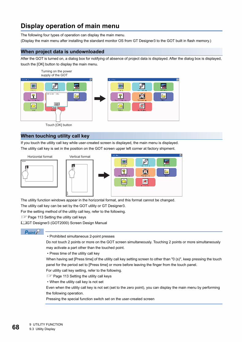
68
Display operation of main menuThe following four types of operation can display the main menu.
(Display the main menu after installing the standard monitor OS from GT Designer3 to the GOT built in flash memory.)
When project data is undownloadedAfter the GOT is turned on, a dialog box for notifying of absence of project data is displayed. After the dialog box is displayed,
touch the [OK] button to display the main menu.
When touching utility call keyIf you touch the utility call key while user-created screen is displayed, the main menu is displayed.
The utility call key is set in the position on the GOT screen upper left corner at factory shipment.
The utility function windows appear in the horizontal format, and this format cannot be changed.
The utility call key can be set by the GOT utility or GT Designer3.
For the setting method of the utility call key, refer to the following.
Page 113 Setting the utility call keys
GT Designer3 (GOT2000) Screen Design Manual
• Prohibited simultaneous 2-point presses
Do not touch 2 points or more on the GOT screen simultaneously. Touching 2 points or more simultaneously
may activate a part other than the touched point.
• Press time of the utility call key
When having set [Press time] of the utility call key setting screen to other than "0 (s)", keep pressing the touch
panel for the period set to [Press time] or more before leaving the finger from the touch panel.
For utility call key setting, refer to the following.
Page 113 Setting the utility call keys
• When the utility call key is not set
Even when the utility call key is not set (set to the zero point), you can display the main menu by performing
the following operation.
Pressing the special function switch set on the user-created screen
Turning on the powersupply of the GOT
Touch [OK] button
Horizontal format Vertical format
9 UTILITY FUNCTION9.3 Utility Display

9
When touching special function switch (utility)If you touch the special function switch (utility) while user-created screen is displayed, the main menu is displayed.The special function switch (utility) can be set as a touch switch that is displayed on a user-created screen by GT Designer3.
For the details of the special function switch, refer to the following.
GT Designer3 (GOT2000) Screen Design Manual
When limiting the display and operation of the utility
When limiting the display and operating users, set a password to the GOT using GT Designer3.
If a user tries to display the main menu of the utility, the password is displayed.
Refer to the following for the details related to the password setting.
GT Designer3 (GOT2000) Screen Design Manual
Special function switch (Utility)
9 UTILITY FUNCTION9.3 Utility Display 69

70
Utility basic configurationThe basic configuration of utility is as follows.
Title displayThe screen title name is displayed in title display part.
Close/Return buttonWhen a middle screen of the layers is displayed, if the [ ] (Close/return) button in the right corner of screen is touched, returns
to the previous screen.
If this button is touched when directly displayed from monitor screen, the screen is closed and returns to monitor screen.
Scroll buttonFor screens in which the content does not fit on one screen page, there is a right or down scroll button on the screen.
Scroll one line/column.
Scroll window.
Title display Close/Return button
Display
Title display
Title display
9 UTILITY FUNCTION9.3 Utility Display

9
Basic operation of settings changeChange of setting value
■Setting item, select buttonTouch the select button to change the settings.
The setting methods differ depending on the setting items.
The following types of setting method are available.
Switching the setting value
The button repeats every time it is pressed.
Enter the setting value with a keyboard.
Use these keys to enter numerical values. Touch the button to display a keyboard on the GOT screen.
For the keyboard operations, refer to the next page.
Move to another setting screen.
Touch the button to move to each setting screen.
For the setting method of each setting item, refer to the setting operation of each setting screen.
■[ ] (Close/Return) buttonReflect or cancel the changed settings.
[ ] (Close/Return) button
Touching this button closes the screen. Depending on the setting item, the GOT restarts.
Touch the [ ] button, and then the dialog box shown below is displayed.
(If no setting is changed, the dialog is not displayed.)
Operate following the message of the dialog box.
Description Selection button Description Selection button
SHORT LONG OFF
9 UTILITY FUNCTION9.3 Utility Display 71

72
Keyboard operations1. Touch the numerical value to be changed.
2. The keyboard for entering numerical values and a cursor are displayed. The display position of the keyboard differs
depending on the position of the touched numerical value. (The keyboard is displayed at a position that does not disturb
users to input numerical values.)
3. Input numerical value by the keyboard.
• [0] to [9] Key: Enter numerical values.
• [Enter] Key: Completes the numerical value input and closes the keyboard.
• [Cancel] Key: Cancels the numerical value input and closes the keyboard.
• [Del] Key: Deletes one character.
• [AC] Key: Deletes all characters.
• [*] key and the keys which are not mentioned do not function.
4. Touching the [Enter] key completes the numerical value input and closes the keyboard.
Cursor
keyboard
9 UTILITY FUNCTION9.3 Utility Display

10
10 LANGUAGE SETTING (LANGUAGE)
10.1 Display language setting
Display language setting functionThis function allows display language selection.
The items which can be set are shown below.
Language setting operation
Language
Switching the display language of the utility by devices
Any device can be used for switching the display language of the utility. For details, refer to the following.
GT Designer3 (GOT2000) Screen Design Manual
When using devices to switch the display language of the utility, it does not change even if the display
language is switched from the GOT utility screen.
Item Description Setting range
Language Display language in which the utility functions and dialog windows are displayed can be selected or
confirmed in this menu
Japanese/English/Chinese
<At factory shipment: Chinese>
1. Touch [Language] to bring up the set up screen.
2. Select a display language by touching the corresponding button.
3. After changing the setting, touch the [ ] button. The setting is saved
and the setting screen is closed.
Main Menu
Touch [Language]
Touch a language to be displayed.
Touch
10 LANGUAGE SETTING (LANGUAGE)10.1 Display language setting 73

74
MEMO
10 LANGUAGE SETTING (LANGUAGE)10.1 Display language setting

11
11 COMMUNICATION INTERFACE SETTING (COMMUNICATION SETTING)
The following communication interfaces can be set.
11.1 Standard I/F Setting
Standard I/F functions
Standard I/F display operation
Item Functions overview Reference
Comm. Setting Standard I/F Assigning channel number and communication driver to communication
interface
Page 75 Standard I/F Setting
GOT IP Address Configuring GOT Ethernet setting Page 84 GOT IP Address
Setting
Ethernet communication Displaying the contents of Ethernet setting, changing the host Page 86 Ethernet
Communication
Comm. Monitor Checking the serial communication port communication Page 90 Communication
Monitor
Ethernet check Checking the Ethernet communication port communication Page 93 Ethernet Check
Transparent mode Setting the channel No. to be used for the communication for the FA
transparent function
Page 95 Setting the
Transparent Mode
Keyword Setting or deleting sequence program protection key words and canceling
sequence program protection status for the FXCPU connection
Page 96 Keyword
Function Description
Channel no. display Displays the channel number (CH No) that has been assigned by drawing
Communication driver display Displays the communication driver that has been assigned by drawing software
Communication parameters display Displays the communication parameters of the controllers that has been assigned by drawing software
Main Menu Comm. Setting
Touch [Comm. Setting].
Touch [Standard I/F].
Standard I/F
11 COMMUNICATION INTERFACE SETTING (COMMUNICATION SETTING)11.1 Standard I/F Setting 75
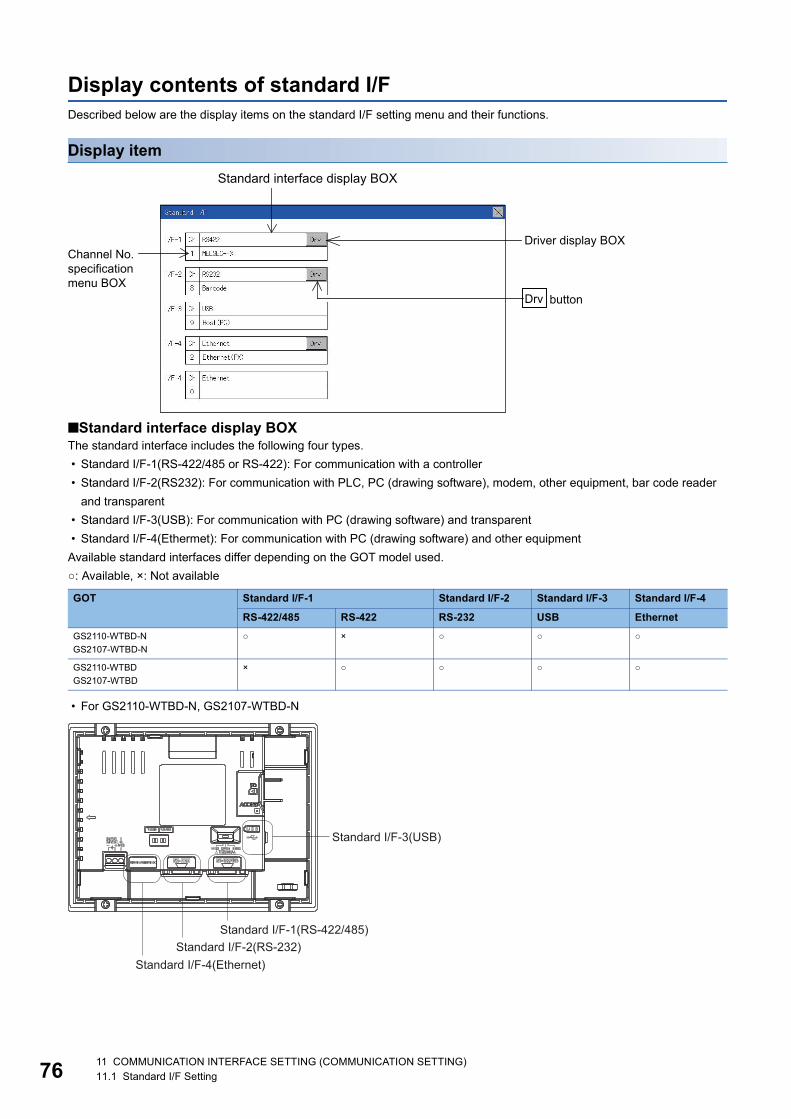
76
Display contents of standard I/FDescribed below are the display items on the standard I/F setting menu and their functions.
Display item
■Standard interface display BOXThe standard interface includes the following four types.
• Standard I/F-1(RS-422/485 or RS-422): For communication with a controller
• Standard I/F-2(RS232): For communication with PLC, PC (drawing software), modem, other equipment, bar code reader
and transparent
• Standard I/F-3(USB): For communication with PC (drawing software) and transparent
• Standard I/F-4(Ethermet): For communication with PC (drawing software) and other equipment
Available standard interfaces differ depending on the GOT model used.
○: Available, ×: Not available
• For GS2110-WTBD-N, GS2107-WTBD-N
GOT Standard I/F-1 Standard I/F-2 Standard I/F-3 Standard I/F-4
RS-422/485 RS-422 RS-232 USB Ethernet
GS2110-WTBD-N
GS2107-WTBD-N
○ × ○ ○ ○
GS2110-WTBD
GS2107-WTBD
× ○ ○ ○ ○
Standard interface display BOX
Channel No.specification menu BOX
Driver display BOX
Drv button
Standard I/F-3(USB)
Standard I/F-1(RS-422/485)
Standard I/F-4(Ethernet)Standard I/F-2(RS-232)
11 COMMUNICATION INTERFACE SETTING (COMMUNICATION SETTING)11.1 Standard I/F Setting

11
• For GS2110-WTBD, GS2107-WTBD
■Channel No. specification menu BOXSet a channel number to be used by the standard interface.
Page 82 Channel setting operation
For the detail of the drivers which can be assigned to each channel, refer to the following.
Page 77 Driver display BOX
*1 "9" is automatically set to the standard I/F-3(USB).
■Driver display BOXThe driver display box displays the names of communication drivers assigned to channels or the communication drivers set in
the communication settings of drawing software.
For details of the communication drivers to be displayed, refer to the following.
GT Designer3 (GOT2000) Screen Design Manual
"Disuse" is displayed in the driver display box in the following cases:
• The communication driver is not installed.
Page 83 Driver setting operation
• "0" is set in the channel number specification menu box.
The channel number of the standard I/F-3(USB) is fixed to "9".
■[Drv] buttonDisplays the driver setting screen.
Select the driver to use on the driver setting screen.
Page 83 Driver setting operation
The [Drv] button is displayed in the following case.
• When a channel number other than channel 0 or 9 is set to the standard I/F-1, standard I/F-2, and standard I/F-4
0: Set when the communication interface is not used.
1, 2: Set when connecting to a controller.
8: Set when connecting to a bar code reader or RFID.
9: *1 Set when connecting to a PC (drawing software).
*: Set this channel when the gateway function (except when the connection with controllers is the Ethernet connection) or the Ethernet download function
is used.
Standard I/F-3(USB)
Standard I/F-1(RS-422)
Standard I/F-4(Ethernet)Standard I/F-2(RS-232)
11 COMMUNICATION INTERFACE SETTING (COMMUNICATION SETTING)11.1 Standard I/F Setting 77

78
Precautions for communication between GOT and connected devices
• Installing [Communication driver] and downloading [Communication Settings]
To perform communication with the connected device, the following actions are necessary.
1) Installing communication drivers (Up to 2 drivers)
2) Assigning channel numbers and communication drivers to communication interfaces
3) Downloading contents (project data) assigned in step 2)
Perform 1), 2) and 3) with drawing software.
For details, refer to the following.
GT Designer3 (GOT2000) Screen Design Manual
• When the communication settings have not been downloaded
If the communication settings have not been downloaded with drawing software, set the communication
settings on the drawing software or in the GOT utility screen.
11 COMMUNICATION INTERFACE SETTING (COMMUNICATION SETTING)11.1 Standard I/F Setting

11
Detail information setting operation
For Standard I/F-1(RS422) and Standard I/F-2(RS232)
1. Touch each driver display box of the standard I/F-1 and standard I/F-
2.
2. The screen jumps to the detailed information screen and the
communication parameter will appear.
3. Touch the numerical values of baud rate to switch them repeatedly.
The numerical values are set using the ten-key depending on the setting.
"0" to "9":
Use these keys to enter numerical values. Enter "0" to disable the screen
saver function.
"ESC":
Closes the ten-key window without saving any value entered
"AC":
Deletes the entire string of numerical characters that are being entered
"DEL":
Deletes a digit from a string of numerical characters that are being
entered
"ENT":
Enters the value for the clock that has been entered and closes the ten-
key pad window
"+/-":
Switches between positive and negative values. (Only positive values are
valid for the clock setting.)
"." :
Invalid key (not used)
Touch [Driver display BOX].
Ex. 4800bps 9600bps 19200bps
11 COMMUNICATION INTERFACE SETTING (COMMUNICATION SETTING)11.1 Standard I/F Setting 79

80
Communication parameters
The types of items that are in the communication parameter setting menu depend on the type of
communication driver that is installed on the GOT in use.
Refer to the section below for the setting contents of various drivers.
GT Designer3 (GOT2000) Screen Design Manual
4. Touch the [ ] button to display the window confirming whether to
save the settings.
5. Touch the [YES] button to save the settings and restart. Touch the
[NO] button to discard the changes.
11 COMMUNICATION INTERFACE SETTING (COMMUNICATION SETTING)11.1 Standard I/F Setting

11
For Standard I/F-4(Ethernet)
Communication parameter setting by drawing software
Set the communication parameter for each communication driver by selecting [Common] [Controller
Setting].
GT Designer3 (GOT2000) Screen Design Manual
1. Touch the driver display box of a communication parameter to be
set.
2. The screen is switched to the communication detail setting. Set the
communication parameter on this screen.
GOT IP address setting
Page 84 GOT IP Address Setting
3. When the [ ] button is touched, it returns to the previous screen.
4. Touch the [ ] button to display the window confirming whether to
save the settings.
5. Touch the [YES] button to save the settings and restart. Touch the
[NO] button to discard the changes.
11 COMMUNICATION INTERFACE SETTING (COMMUNICATION SETTING)11.1 Standard I/F Setting 81

82
Channel setting operation
Channel number setting operation
1. Touch the channel No. specification menu box to be set.
2. When the channel setting window appears, select the channel
number.
3. When the channel number is selected, the settings are fixed and the
window returns to the previous one. Therefore, touch the [ ] button.
4. Touch the [ ] button to display the window confirming whether to
save the settings.
5. Touch the [YES] button to save the settings and restart. Touch the
[NO] button to discard the changes.
Touch
Touch
11 COMMUNICATION INTERFACE SETTING (COMMUNICATION SETTING)11.1 Standard I/F Setting

11
Driver setting operation
Driver setting operation
1. Touch [Drv] button to bring up the driver setting window.
2. The available driver names are displayed on the driver setting
screen. Select the driver to use.
3. When the channel number is selected, the settings are fixed and the
window returns to the previous one. Therefore, touch the [ ] button.
4. Touch the [ ] button to display the window confirming whether to
save the settings.
5. Touch the [YES] button to save the settings and restart. Touch the
[NO] button to discard the changes.
Touch [Drv]
Touch
11 COMMUNICATION INTERFACE SETTING (COMMUNICATION SETTING)11.1 Standard I/F Setting 83

84
11.2 GOT IP Address SettingThis section describes the GOT Ethernet setting.
The GOT Ethernet setting can also be set with drawing software. For details, refer to the following.
GT Designer3 (GOT2000) Screen Design Manual
StandardThe table below shows the communication setting items and setting range.
*1 Set the value "0.0.0.0" when not using the subnet mask and default gateway.
Display operation of GOT IP address
Communication setting items Setting range Remark
IP Address 0.0.0.1 to 223.255.255.254 If a value outside the setting range is entered, the error message
"SET NUMBER IS INCORRECT." appears.Subnet Mask*1 192.0.0.0 to 255.255.255.252
Default gateway*1 0.0.0.1 to 223.255.255.254
Per. S/W port No. 1024 to 5010, 5014 to 49152, 49171 to 65534 Set the port number for the GOT download.
Transparent port No. 1024 to 5010, 5014 to 49152, 49171 to 65534 Set the port number for the transparent of the GOT.
Main Menu Comm. Setting
Touch [Comm. Setting].
Touch [GOT IP Address].
GOT IP Address
11 COMMUNICATION INTERFACE SETTING (COMMUNICATION SETTING)11.2 GOT IP Address Setting

11
Setting operation1. Touch the numerical part of the octet to be changed among the 1st to 4th
octets.
2. When the ten-key pad appears, enter a numerical value in up to 3 digits,
and touch the key. If a numerical value outside the setting range is
entered, the following error message appears. Enter a numerical value
again.
For the details of the setting range, refer to the following.
Page 261 Specifications
3. If necessary, change the setting of [Per. S/W port No.] and [Transparent port
No.].
4. After the setting change, touch the [×] key.
5. When the screen shown on the left appears, touch the [YES] key.
Touch the numerical partof the octet to be changed.
Touch
Touch[×]
Touch [YES]
11 COMMUNICATION INTERFACE SETTING (COMMUNICATION SETTING)11.2 GOT IP Address Setting 85

86
11.3 Ethernet Communication
Setting function for Ethernet communicationThe contents of the Ethernet set in GT Designer3 can be checked.
The setting of the host station can be changed.
For the Ethernet setting, refer to the following.
GOT2000 Series Connection Manual for the controller used
Display operation of Ethernet communication
Channel Setting
Ethernet setting
Comm. SettingMain menu
Touch [Comm. Setting]. Touch [Ethernet setting].
11 COMMUNICATION INTERFACE SETTING (COMMUNICATION SETTING)11.3 Ethernet Communication

11
Display contents of Ethernet settingThe following describes the setting items and the display contents of the Ethernet setting.
Channel select tabChannels can be switched.
Switching to the channel which does not have the Ethernet setting is not available.
Ethernet setting itemsThe contents of the Ethernet setting configured in GT Designer3 are displayed.
Changing [Host], [Net No.], [Station No.] and [IP Address] are available.
Page 88 Change of host
Page 88 Change of Net No.
Page 89 Change of station No.
Page 89 Change of IP address
How to cancel the change of the setting in the [Ethernet setting] screen.
Cancel the settings changed in the [Ethernet setting] screen with the [Restore default settings] button.
The changed settings remain until they are canceled with the [Restore default settings] button.
The changed settings are not canceled even if writing the project data or system application to the GOT.
When the project data is written to the GOT without canceling the changed settings, those changed settings
are reflected to the Ethernet setting of the written project data.
(If the written project data does not have a channel with same Ethernet settings as that of the channel
changed in [Ethernet setting] screen, the changed settings are not reflected.)
Ethernet setting items
Channel select tab
11 COMMUNICATION INTERFACE SETTING (COMMUNICATION SETTING)11.3 Ethernet Communication 87

88
■Change of host
■Change of Net No.
1. Touch the device to be set as the host.
2. After the setting change, touch the [×] key. When the screen shown
on the left appears, touch the [YES] key.
1. Touch the Net No. to be changed, and input the network No. to be
changed by the numeric keypad displayed.
2. After the setting change, touch the [×] key. When the screen shown
on the left appears, touch the [YES] key.
Touch YES.
Touch YES.
11 COMMUNICATION INTERFACE SETTING (COMMUNICATION SETTING)11.3 Ethernet Communication

11
■Change of station No.
■Change of IP address
1. Touch the station No. to be changed, and input the station No. of the
destination Ethernet module to be changed by the numeric keypad
displayed.
2. After the setting change, touch the [×] key. When the screen shown
on the left appears, touch the [YES] key.
1. Touch the IP address to be changed, input the destination IP
address to be changed by the numeric keypad displayed.
2. After the setting change, touch the [×] key. When the screen shown
on the left appears, touch the [YES] key.
Touch YES.
Touch YES.
11 COMMUNICATION INTERFACE SETTING (COMMUNICATION SETTING)11.3 Ethernet Communication 89

90
11.4 Communication Monitor
Communication monitor functions
Communication monitor display operation
Function Description
Communication port-selection status display Indicates the connection status of Standard I/F-1 and I/F-2.
Communication status display Displays the communication status (SD: send, RD: receive)
Communication error status display Displays an error message when a communication error occurs
Comm. SettingMain Menu
Comm. Monitor
Touch [Comm. Setting].
Touch [Comm. Monitor].
11 COMMUNICATION INTERFACE SETTING (COMMUNICATION SETTING)11.4 Communication Monitor

11
Screen display content
Connection status of the communication portsIndicates the connection status of Standard I/F-1 and I/F-2.
Listed in the table below are display items and the connection status (channel number).
Communication statusDisplays the communication status of each communication port.
The SD and RD symbols appear in white on red ( , ) while data are being sent or received, and in black on gray
( , ) at other times. They may appear lit depending on the communication status.
The SD and RD symbols on the screen indicate normal communication or cable disconnection.
Setting example
■[During normal communication (with connection to a device that supports the transparent mode)]
■[When the connecting cable with the controller is disconnected]
Display item Channel number Remark
PLC Ch1 "PLC" appears when connected to a controller (PLC or microcomputer)
Barcode Ch8 "BCR" appears when connected to a bar code reader
TRANS. Ch9 "TRANS." appears when the controller that is allocated to one of the communication ports supports the
transparent mode
"TRANS." automatically changes to "PC" when communicating with drawing software
Host(PC) Ch9 "PC" appears when the controller that is allocated to one of the communication ports does not support the
transparent mode
Printer ChA Appears when connected to a printer.
Port Channel number Controller type
I/F-1 Ch1 MELSEC-FX
I/F-2 Ch8, Ch9 -
Connection status of the communication ports Communication error status
Communication status
The SD and RD symbols for I/F-1
Only the SD symbol next to I/F-1 blinks.
11 COMMUNICATION INTERFACE SETTING (COMMUNICATION SETTING)11.4 Communication Monitor 91

92
Communication error statusCommunication error status of each port is displayed on this screen.
The following table describes the communication status that each display item shows.
Display item Status Action
NO ERROR No error Communication is executed normally.
ERR Ovr. Overrun error The receive data is sent continuously with a short interval.
Let the baud rate (communication speed) be equivalent between the GOT and counterpart equipment.
ERR Frm. Framing error The communication frames of GOT and PLC are inconsistent.
Confirm the communication settings of GOT and PLC, such as data length, stop bit and baud rate.
ERR Prt. Parity error The parity check conditions of GOT and PLC are inconsistent.
Let the parity check condition (odd or even) of GOT and PLC be consistent.
ERR Text Text error The sum data is inconsistent. Or the contents of the receive data are not consistent with the send command from
the GOT.
Let the communication settings and contents of data be consistent between the GOT and counterpart equipment.
(If NAK is received while the GOT is connected to the microcomputer board, a text error occurs.)
TIME OUT Communication timeout Though receiving is started, receive data is not sent.
Check the wiring between the GOT and its communication target.
(When the GOT is connected to the microcomputer board, confirm the terminator, CR, wiring, etc.)
ERR Line Control line error The control line is not operating correctly.
Confirm the wiring of the control line.
ERR Cmd. Command error A command contained in the receive data is not consistent with the send command from the GOT.
11 COMMUNICATION INTERFACE SETTING (COMMUNICATION SETTING)11.4 Communication Monitor

11
11.5 Ethernet Check
Ethernet check functionThe Ethernet status check function sends a ping to check the connection status of Ethernet.
Display operation of Ethernet check
Ethernet check
Main Menu Debug
Touch [Debug].
Touch [Ethernet check].
11 COMMUNICATION INTERFACE SETTING (COMMUNICATION SETTING)11.5 Ethernet Check 93

94
Operation of Ethernet status check
1. If the select button of [Destination IP] is touched, a keyboard is
displayed. Enter the IP address of the other terminal with the
keyboard. <Default: 192.168.3.39>
2. If the [Send ping] button is touched, a ping is sent to the IP
address entered in [Destination IP]. The timeout time is 5sec.
When the communication is completed
The [Response received.] dialog box is displayed.
When a communication error occurs
The [Timeout occurred.] dialog box is displayed.Touch
11 COMMUNICATION INTERFACE SETTING (COMMUNICATION SETTING)11.5 Ethernet Check

11
11.6 Setting the Transparent Mode
Function of the transparent modeWhen using the multi-channel function, the channel No. of a controller to which the FA transparent function is executed can be
set. For the multi-channel function and the FA transparent function, refer to the following.
GOT2000 Series Connection Manual (Mitsubishi Product) For GT Works3 Version1
Display operation the transparent mode setting
Operation the transparent mode
Function Description Setting range
ChNo. The channel No. of a controller to which the FA transparent function is executed can be set. 1/2
(Default: 1)
1. When the transparent ChNo. (numerical part) on the left is
touched, the screen for selecting a communication driver is
displayed. Select the channel to execute the FA transparent
function.
2. If the [ ] button is touched, it returns to the GOT setup
screen.
Transparent mode
Main Menu Comm. Setting
Touch [Comm Setting]
Touch [Transparent mode]
11 COMMUNICATION INTERFACE SETTING (COMMUNICATION SETTING)11.6 Setting the Transparent Mode 95

96
11.7 Keyword
Keyword functionsThe operation related to a keyword of the FX series PLC can be performed.
Keyword display operation
Function Description
Regist Keyword is registered.
Delete Registered keyword is deleted.
Clear Keyword protection is cleared.
Protect A keyword with cleared protection is reactivated for protection.
Main Menu Comm. Setting
Channel Setting
Keyword
Touch[Comm. Setting]
Touch[Keyword]
11 COMMUNICATION INTERFACE SETTING (COMMUNICATION SETTING)11.7 Keyword

11
RegistKeyword is registered.
1. Touch "Regist" to display the selection screen for the registration.
For the FX series PLC, which is not compatible with Customer
Keyword, the keyword entry screen of [Step3] is displayed. Start
the operation from [Step3]. For the Customer Keyword
compatible models, refer to the manual of the PLC to be used.
2. Select [Keyword] or [Keyword+Custom]. To register only
Keyword and 2nd keyword, touch [Keyword]. To register
Customer Keyword, touch [Keyword+Custom].
3. Input a keyword. Touch the display part of the keyword to be
registered.
4. The keyboard for entering a keyword is displayed. Character
types to be input can be changed by touching the [KEY] button.
Enter a keyword and touch the [ENT] key. For the keyword, 8
digits from 0 to 9 or A to F must be set.
5. After completing the keyword entry, touch [Next]. When
[Keyword+Custom] is selected on the selection screen for the
registration, the Customer Keyword entry screen is displayed.
Enter it in the same way as for Keyword and 2nd keyword.
Touch
Touch
Touch
Touch
11 COMMUNICATION INTERFACE SETTING (COMMUNICATION SETTING)11.7 Keyword 97

98
6. Set Registration condition. Touch Registration condition to
change the setting contents.
7. After setting Registration condition, touch the [Execute] key. The
registration of the keyword is completed.
8. The registration of the keyword is completed. Touch [OK].
TouchAll Protect Write Protect R/W Protect
Touch
Touch
11 COMMUNICATION INTERFACE SETTING (COMMUNICATION SETTING)11.7 Keyword

11
Selection availability of Registration conditionThe following table lists the PLCs that can select Registration condition.
*1 Refer to the manual for the PLC in use for the models that are compatible with the 2nd keyword.*2 Registration options can be selected among "R/W Protect", "Write Protect", or "All online operation protection". For access restrictions of
each setting, refer to the manual of the PLC to be used.
Selection of keyword protection levelFor the devices which can perform the online operation of FX PLC, 3 levels of protection can be set.
When the monitoring or setting change by online devices is needed, set the keyword taking the following into consideration.
■When only keyword is registeredProtection level is selected by the head character of keyword.
All Protect: Set the keyword starting with one of A, D to F, or 0 to 9.
Read/incorrect write protection: Set the keyword starting with B.
Erroneous write prohibition: Set the keyword starting with C.
■When keyword and 2nd keyword are registered
Applicability of monitoring for each keyword protection levelThe applicability of monitoring for each protection level is as follows.
*1 When the T, C set values are specified indirectly, changing devices is available.
Difference between "All online operation protection" and "All Protect"When "All online operation protection" is selected, both device display and input by the programming tool or GOT are
prohibited.
When "All Protect" is selected, device display and input are possible although operations by the programming tool are all
prohibited.
Target PLC Setting
When keyword and 2nd keyword are registered When only keyword is registered
FX PLC compatible with 2nd keyword*1 Registration options can be selected.*2 Registration options cannot be
selected.FX PLC not compatible with 2nd keyword*1 -
Item When only keyword is registered When keyword and 2nd keyword are registered
Keyword unregistered/protection canceled
All operation protect
Read/Incorrect write protection
Erroneous write prohibition
All online operation prohibited
R/W Protect
Write Protect
Device monitoring ○ ○ ○ × ○ ○ ○
Device
change
T, C setting values
and file register (from
D1000)
×*1 ×*1 ×*1 × ○ ○ ○
Other than the above ○ ○ ○ × ○ ○ ○
11 COMMUNICATION INTERFACE SETTING (COMMUNICATION SETTING)11.7 Keyword 99

10
DeleteRegistered keyword is deleted.
1. Touch [Delete] to display the keyword entry screen.
2. Input a keyword. Touch the display part of the registered
keyword.
Target PLC Setting
FX PLC compatible with 2nd keyword Input a keyword to be deleted.
FX PLC not compatible with 2nd keyword Input a keyword to be deleted only into "keyword".
"2nd keyword" is ignored.
3. The keyboard for entering a keyword is displayed. Enter a
keyword and touch the [ENT] key. Character types to be input
can be changed by touching the [KEY] button.
4. After completing the keyword entry, touch [Next].
Touch
Touch
Touch
Touch
011 COMMUNICATION INTERFACE SETTING (COMMUNICATION SETTING)11.7 Keyword

11
5. Touch the [Execute] key.
6. The keyword is deleted. Touch [OK].
Touch
Touch
11 COMMUNICATION INTERFACE SETTING (COMMUNICATION SETTING)11.7 Keyword 101

10
ClearTo access an FX PLC where a keyword has been registered, keyword protection is cleared.
1. Touch [Clear] to display the keyword entry screen.
2. Input a keyword. Touch the display part of the registered
keyword.
Target PLC Setting
FX PLC compatible with customer keyword Input a keyword or customer keyword to clear the protection.
FX PLC compatible with 2nd keyword Input a keyword to clear the protection.
FX PLC not compatible with 2nd keyword Input a keyword into "keyword" to clear the protection.
"2nd keyword" is ignored.
3. The keyboard for entering a keyword is displayed. Enter a
keyword and touch the [ENT] key. Character types to be input
can be changed by touching the [KEY] button.
4. After completing the keyword entry, touch [Next].
Touch
Touch
Touch
Touch
211 COMMUNICATION INTERFACE SETTING (COMMUNICATION SETTING)11.7 Keyword

11
5. Touch the [Execute] key.
6. The protection is cleared. Touch [OK].
Touch
Touch
11 COMMUNICATION INTERFACE SETTING (COMMUNICATION SETTING)11.7 Keyword 103

10
ProtectA keyword with cleared protection is reactivated for protection. Keyword protection function is valid when the 2nd keyword is
registered.1. Touch [Protect] to switch to the keyword protection status.
2. The keyword is protected. Touch [OK].
Touch
411 COMMUNICATION INTERFACE SETTING (COMMUNICATION SETTING)11.7 Keyword

12
12 DISPLAY AND OPERATION SETTINGS (GOT SET UP)
The setting screens related to the display or operation can be displayed from the utility screen.
In the setting screen for display and the setting screen for operation, the following settings can be set.
12.1 Display Settings
Display setting functionsSetting regarding display is possible.
The items which can be set are described below. If touch the each item part, the respective setting becomes possible.
*1 Even if 0 is set, the title screen is still displayed. The title screen is always displayed for 4 seconds or more (depending on the project data).
• Display setting by GT Designer3
Set title display period, screen save time and screen save backlight by selecting [Common] [GOT
Environmental Setting] [GOT Setup] on GT Designer3.
When change a part of the setting, change the setting by the GOT display setting after downloading the
project data.
GT Designer3 (GOT2000) Screen Design Manual
• Screen save time
By using the system information function, the screen save function can forcibly enabled from a controller
(Forced Screen Saver Disable Signal) or the screen saving time set in the utility can be disabled (Automatic
Screen Saver Disable Signal).
GT Designer3 (GOT2000) Screen Design Manual
Item Description Reference
Display settings Setting the title display period and screen saving time Page 105 Display setting functions
Brightness
Operation settings Setting buzzer volume, window move buzzer, and key reaction speed Page 110 Setting operation of operation
Touch panel calibration Page 111 Position correction of the touch panel
(touch panel calibration setting)
Utility call key Page 113 Setting the utility call keys
Item Description Setting range
Opening time The title display period at the main unit boot can be set. 0 to 60 seconds*1
(At factory shipment: 5 seconds)
Screen save time The period from the user stops the touch panel operation till the screen save function
starts can be set.
0 to 60 minutes
(At factory shipment: 0 minute)
Brightness Brightness can be adjusted.
Page 107 Brightness
-
12 DISPLAY AND OPERATION SETTINGS (GOT SET UP)12.1 Display Settings 105

10
Display operation of display setting
Main Menu
GOT setup
Display
Touch [GOT setup].
Touch [Display].
612 DISPLAY AND OPERATION SETTINGS (GOT SET UP)12.1 Display Settings

12
Display setting operations
The title display period and screen saving time
Brightness
1. If the setting items (numbers) are touched, a keyboard is
displayed. Input numeric with the keyboard.
2. Set the title display period with the ten-key pad window and touch
"ENT".
1. Touch [Brightness] to bring up the Brightness setting window.
2. Touch the [+] and [-] buttons to adjust the brightness of the
screen.
3. Touch the [ ] button to reflect the setting.
Touch
Adjust brightness with the [−]and [+] buttons.
Touch
12 DISPLAY AND OPERATION SETTINGS (GOT SET UP)12.1 Display Settings 107

10
12.2 Operation Setting (Settings for Operation)
Operation setting functionsSetting regarding GOT operation can be set.
The items which can be set are described below. If touch the each item part, the respective setting becomes possible.
*1 The more the value set for [Key reaction] is high, the more the key reaction speed slows.
For example, when the GOT recognizes touching the GOT screen once as touching the screen twice, set a higher value for [Key reaction].
Operation setting by GT Designer3
Set buzzer volume and window move buzzer volume by selecting [Common] [GOT Environmental Setting]
[GOT Setup] of GT Designer3.
When change a part of the setting, change the setting by the GOT display setting after downloading the
project data.
GT Designer3 (GOT2000) Screen Design Manual
Function Description Setting range
Buzzer volume Buzzer volume setting can be changed. OFF/SHORT/LONG
(At factory shipment: SHORT)
Window move buzzer Whether turn ON/OFF buzzer when move window can be selected. ON/OFF
(At factory shipment: ON)
Key reaction The touch panel sensitivity when touching the GOT screen can be set. (For preventing
chattering)
±0 to +120*1
Calibration Calibrates the touch panel sensitivity
Page 111 Position correction of the touch panel (touch panel calibration setting)
-
Utility call Utility call key setting screen can be displayed
Page 113 Setting the utility call keys
-
"Key reaction" [ms] Standard (±0) +10 +20 +40 +80 +120
812 DISPLAY AND OPERATION SETTINGS (GOT SET UP)12.2 Operation Setting (Settings for Operation)

12
Display operation of operation setting
Touch the itemto be changed.
Main Menu
GOT setup
Operation
Touch [GOT setup].
Touch [Operation].
12 DISPLAY AND OPERATION SETTINGS (GOT SET UP)12.2 Operation Setting (Settings for Operation) 109

11
Setting operation of operation
Buzzer volume
Window move buzzer
Key reaction setting
*1 The more the value set for [Key reaction] is high, the more the key reaction speed slows.
For example, when the GOT recognizes touching the GOT screen once as touching the screen twice, set a higher value for [Key reaction].
1. Touch a setting item to change the setting.
(Buzzer volume: )
2. Touch the [ ] button to save the changes.
1. Touch a setting item to change the setting.
(Window move buzzer: )
2. Touch the [ ] button to save the changes.
1. If touch the setup item, the setup contents*1are changed.
2. After changing the setting, touch the [ ] button. The setting is
saved and the setting screen is closed.
SHORT LONG OFF
ON OFF
"Key reaction" [ms] Standard (±0) +10 +20 +40 +80 +120
012 DISPLAY AND OPERATION SETTINGS (GOT SET UP)12.2 Operation Setting (Settings for Operation)

12
Position correction of the touch panel (touch panel calibration setting)
Touch panel calibration setting functionTouch panel reading error can be corrected.
Normally the adjustment is not required, however, the difference between a touched position and the object position may
occur as the period of use elapses.
When any difference between a touched position and the object position occurs, correct the position with this function.
Touch panel calibration setting display operation
Run Stop Run Stop
Before adjustment After adjustment
The [Run] will operate though youintended to touch the [Stop] button.
The [Stop] button can be touchedwithout fail.
Main menu GOT setup
OperationCalibration
Touch [GOT setup].
Touch [Operation].
Touch [Calibration].
12 DISPLAY AND OPERATION SETTINGS (GOT SET UP)12.2 Operation Setting (Settings for Operation) 111
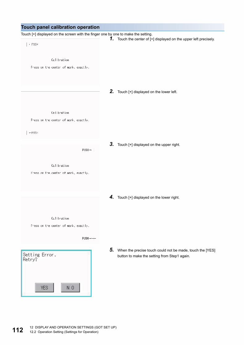
11
Touch panel calibration operationTouch [+] displayed on the screen with the finger one by one to make the setting.
1. Touch the center of [+] displayed on the upper left precisely.
2. Touch [+] displayed on the lower left.
3. Touch [+] displayed on the upper right.
4. Touch [+] displayed on the lower right.
5. When the precise touch could not be made, touch the [YES]
button to make the setting from Step1 again.
212 DISPLAY AND OPERATION SETTINGS (GOT SET UP)12.2 Operation Setting (Settings for Operation)
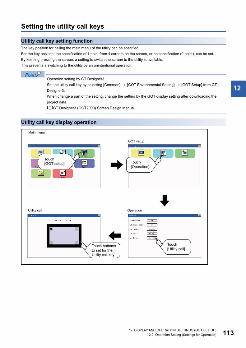
12
Setting the utility call keys
Utility call key setting functionThe key position for calling the main menu of the utility can be specified.
For the key position, the specification of 1 point from 4 corners on the screen, or no specification (0 point), can be set.
By keeping pressing the screen, a setting to switch the screen to the utility is available.
This prevents a switching to the utility by an unintentional operation.
Operation setting by GT Designer3
Set the utility call key by selecting [Common] [GOT Environmental Setting] [GOT Setup] from GT
Designer3.
When change a part of the setting, change the setting by the GOT display setting after downloading the
project data.
GT Designer3 (GOT2000) Screen Design Manual
Utility call key display operation
Main menu
GOT setup
OperationUtility call
Touch [GOT setup]. Touch
[Operation].
Touch [Utility call].
Touch bottoms to set for the Utility call key.
12 DISPLAY AND OPERATION SETTINGS (GOT SET UP)12.2 Operation Setting (Settings for Operation) 113

11
Utility call key setting operation
• When the utility call key is not set (set to 0-point)
Even when the utility call key is not set (set to the zero point), you can display the main menu by performing
the following operation.
Pressing the special function switch set on the user-created screen
Page 68 Display operation of main menu
• Precautions on using the alarm popup display
When [Display Position Switching] is set to [Yes] in the alarm popup display setting, set either of the following
for the utility call key.
Setting the position of the utility call key to the upper-right or lower-left corner
Setting [Press Time] of the utility call key to 1 or more seconds
When [Press Time] is set to 0 and the key position is set to the lower-left corner, the operation is as described
below. If the positions of the key and the alarm popup display overlap, the utility screen appears by switching
the display position of the alarm popup display.
For the alarm popup display, refer to the following.
GT Designer3 (GOT2000) Screen Design Manual
• When limiting the display and operation of the utility
When limiting the display and operating users, set a password to the GOT using GT Designer3. If a user tries
to display the main menu of the utility, the password is displayed.
Refer to the following for the details related to the password setting.
GT Designer3 (GOT2000) Screen Design Manual
1. Touch or displayed at the four corners of the setting
screen. The button repeats every time it is pressed.
Change the part to be set as a key position to . For the key
position, 0 or 1 point can be specified.
2. When setting 1 point, specify the time to switch to the utility in
case of keeping pressing the key position. Touch the time input
area.
3. Touching the input area displays a keyboard. Input numeric with
the keyboard.
4. Touch the [ ] button to save the changes.
412 DISPLAY AND OPERATION SETTINGS (GOT SET UP)12.2 Operation Setting (Settings for Operation)

12
12.3 Inherent Information
Setting function for inherent informationConfigure inherent information settings.
Display operation of inherent information
Setting operation for inherent information
Item Description Setting range
GOT ID No. Set the ID No. as the inherent information for the GOT. 0 to 32767
<Default: 0>
1. If touching the setting items, keyboard is displayed.
Input numeric with the keyboard.
2. If touch the [ ] button, the GOT restarts and operates
with the changed settings.
Main menu GOT setup
Unique info
Touch [GOT setup].
Touch [Unique info].
12 DISPLAY AND OPERATION SETTINGS (GOT SET UP)12.3 Inherent Information 115

11
12.4 GOT internal device monitor
Setting the GOT internal device monitorSet whether to Use/Disuse the GOT internal device monitor of GOT diagnostics.
GOT internal device monitor display operation
Item Description Setting range
GOT dev. monitor Set whether to Use/Disuse the GOT internal device monitor of GOT diagnostics. Disuse/Use
<Default: Disuse>
GOT device change Set whether to Allow/Forbid the GOT internal devices to be changed. Forbid/Allow
<Default: Forbid>
Main menu GOT setup
GOT dev. monitor (When using [GOT dev. monitor])
GOT dev. monitor (When not using [GOT dev. monitor])
Touch[GOT Setup].
Touch[GOT dev. monitor].
612 DISPLAY AND OPERATION SETTINGS (GOT SET UP)12.4 GOT internal device monitor

12
GOT internal device monitor setting operation1. When using the GOT internal device monitor of GOT diagnostics, touch the setting item and set [Use].
2. When allowing the GOT internal devices to be changed, touch the setting item of [GOT device change] and set [Allow].
3. After changing the settings, touch the [×] button to save the changes and close the setting window.
12 DISPLAY AND OPERATION SETTINGS (GOT SET UP)12.4 GOT internal device monitor 117

11
12.5 VNC Server FunctionOnly available to GS21-W-N.
VNC server function settingIn the VNC server function setting, the authorization guarantee time for the VNC server function can be set.
For the details of the VNC server function, refer to the following.
GT Designer3 (GOT2000) Screen Design Manual
• Authorization guarantee time cancel signal (GS1792.b8)
When the Authorization guarantee time cancel signal (GS1792.b8) turns on, the authorization guarantee time
setting is disabled.
• Relationship with the GOT network interaction function setting
The VNC server function setting is independent of the GOT network interaction function setting.
Both of the settings are enabled.
Display operation of the VNC server function setting
Item Description Setting range
Authorization
guarantee time
The time that the authorized equipment holds the authorization after you operate the authorized
equipment can be set.
(The unauthorized equipment cannot obtain the authorization until the set time elapses.)
0 to 3600 seconds
<At factory shipment: 0
seconds>
Main menu GOT setup
VNC server
Touch[GOT Setup].
Touch[VNC server].
812 DISPLAY AND OPERATION SETTINGS (GOT SET UP)12.5 VNC Server Function

12
VNC server function setting operation
Authorization guarantee time1. Touch the input field for [Ope. guaranteed time] to display a keyboard.
Input the authorization guarantee time with the keyboard.
2. Touch the [×] button to apply the new setting and close the setting screen.
1.
12 DISPLAY AND OPERATION SETTINGS (GOT SET UP)12.5 VNC Server Function 119

12
12.6 License ManagementOnly available to GS21-W-N.
License management settingTo use functions which require a license, register the license to the GOT.
To delete the license registered to the GOT, perform the operation also on the license management screen.
You can register or delete licenses for the VNC server function.
For details on the VNC server function, refer to the following.
Page 118 VNC Server Function
Display operation of the license management setting
Item Description Setting range
VNC server function Register or delete the license for the VNC server function. -
Main menu GOT setup
License manager
Touch[License manager].
Touch[GOT Setup].
012 DISPLAY AND OPERATION SETTINGS (GOT SET UP)12.6 License Management

12
Setting operation of license management
When registering a license number for the GOT1. Touch the license number input area on the license management screen, and then the keyboard appears on the bottom
of the screen.
2. Touch the [Regist] button to register the input license number.
If the [×] button is touched without touching the [Regist] button, the license number is not registered.
3. After a license number is registered, touch the [×] button to close the license management screen.
When releasing a license number for the GOT1. Touch the [Cancel reg.] button to release the registered license number.
2. Touch the [×] button to close the license management screen.
How to acquire a license number
For how to acquire a license number, please consult your local Mitsubishi (Electric System) Service center or
representative.
12 DISPLAY AND OPERATION SETTINGS (GOT SET UP)12.6 License Management 121

12
12.7 IP Filter Setting
IP filter settingIP addresses from which access to the GOT is allowed or blocked can be set.
For the details of the IP filter setting, refer to the following.
GT Designer3 (GOT2000) Screen Design Manual
*1 Leave the boxes blank if you do not set any IP addresses.
Display operation of the IP filter setting
Item Description Setting range
IP filter usage You can set whether to use or not the IP filter function. Yes/No
<Default: No>
Transmit/Block You can set whether to allow or block access from the IP addresses specified in [IP
address setting].
• If [Transmit] is selected
Access from the IP addresses that are set for [Target IP address] is allowed.
Access from the IP addresses that are set for [Exception IP address] is blocked.
• If [Block] is selected
Access from the IP addresses that are set for [Target IP address] is blocked.
Access from the IP addresses that are set for [Exception IP address] is allowed.
Transmit/Block
<Default: Transmit>
IP address
setting
Range You can set whether to register IP addresses by specifying a range.
To specify a range, set the start IP address and the end IP address for [Target IP
address].
Selected/Not selected
<Default: Not selected>
Target IP address You can set IP addresses or IP address ranges to be filtered.
Up to 4 ranges can be set.
0.0.0.0 to 255.255.255.255*1
<Default: Blank>
Exception IP
address
This item can be set only when [Range] is selected.
For an IP address range specified in [Target IP address], set IP addresses excluded
from being filtered.
Up to 16 addresses can be set for one range specified in [Target IP address].
0.0.0.0 to 255.255.255.255*1
<Default: Blank>
Touch[IP filter setting].
GOT setup
IP filter setting
212 DISPLAY AND OPERATION SETTINGS (GOT SET UP)12.7 IP Filter Setting

12
Setting procedure for the IP filter
Setting the IP filter1. Select [Yes] for [IP filter usage] by touching the current selection.
2. Select [Transmit] or [Block] for [Transmit/Block] by touching the current selection.
3. Touch the [Setting] button of [IP address setting] to display the [IP address setting] screen.
Refer to the following, and set an IP address.
Page 124 Adding a target IP address
Page 125 Deleting a target IP address
Page 126 Specifying IP address ranges
Page 127 Setting exception IP addresses
4. After configuring the settings, touch the [×] button to display the [IP filter setting] screen.
5. Touch the [×] button to display the following screen.
6. Touch the [YES] button to restart the GOT and reflect the setting.
To cancel the new settings, touch the [NO] button to return to the [GOT setup] screen.
1.2.3.
1.4.
12 DISPLAY AND OPERATION SETTINGS (GOT SET UP)12.7 IP Filter Setting 123

12
■Adding a target IP address
1. Touch a target row to select it.
2. Touch the same row again to display the following screen.
3. Touch a number to display a software keyboard.
Input an IP address to be added.
4. Touch the [×] button to display the previous screen.
1.1.
1.3.1.4.
412 DISPLAY AND OPERATION SETTINGS (GOT SET UP)12.7 IP Filter Setting

12
■Deleting a target IP address
1. Touch a target row to select it.
2. Touch the [Del] button to display the following screen.
3. Touch the [YES] button to delete the selected IP address.
To cancel the deletion and return to the previous screen, touch the [NO] button.
1.
2.
12 DISPLAY AND OPERATION SETTINGS (GOT SET UP)12.7 IP Filter Setting 125

12
■Specifying IP address ranges
1. Touch a checkbox in [Range] to select the row.
2. Touch the same row again to display the screen shown below.
3. Touch a number to display a software keyboard. Input the start IP address and end IP address of the range to be filtered.
4. Touch the [×] button to display the previous screen.
1.1. 1.2.
1.3.1.3.
1.4.
612 DISPLAY AND OPERATION SETTINGS (GOT SET UP)12.7 IP Filter Setting
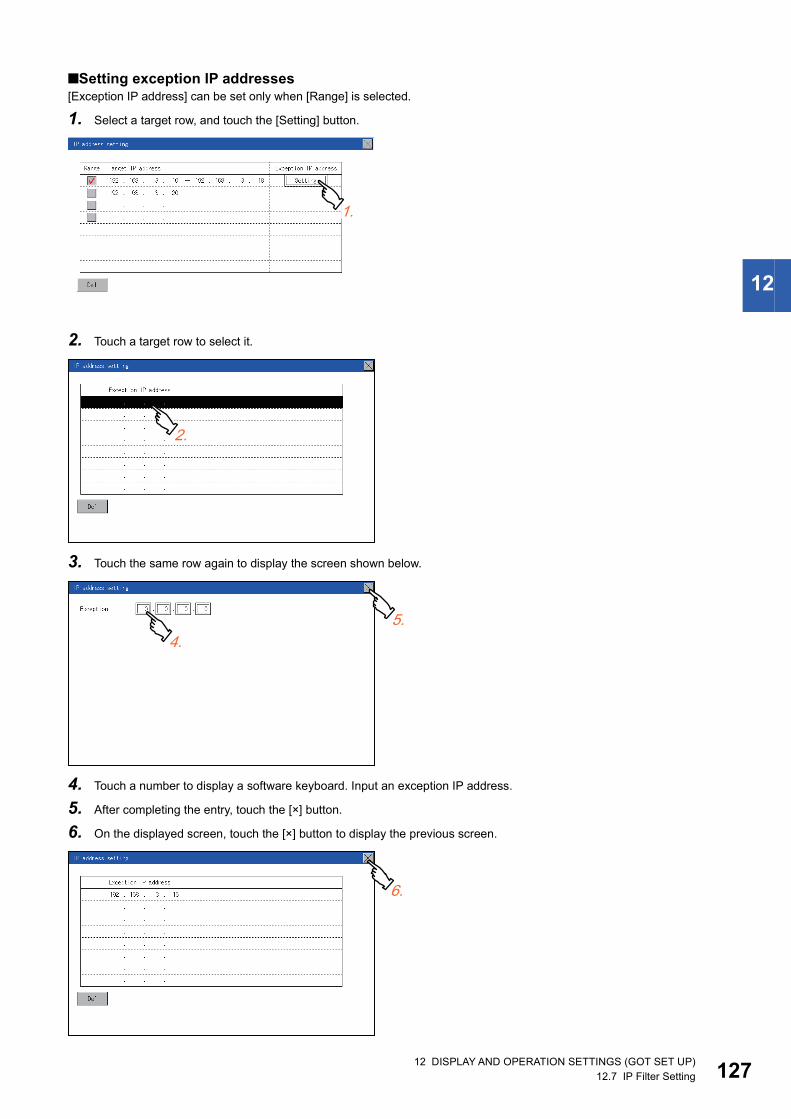
12
■Setting exception IP addresses[Exception IP address] can be set only when [Range] is selected.
1. Select a target row, and touch the [Setting] button.
2. Touch a target row to select it.
3. Touch the same row again to display the screen shown below.
4. Touch a number to display a software keyboard. Input an exception IP address.
5. After completing the entry, touch the [×] button.
6. On the displayed screen, touch the [×] button to display the previous screen.
1.
1.2.
1.4.1.5.
1.6.
12 DISPLAY AND OPERATION SETTINGS (GOT SET UP)12.7 IP Filter Setting 127

12
MEMO
812 DISPLAY AND OPERATION SETTINGS (GOT SET UP)12.7 IP Filter Setting

13
13 SECURITY LEVEL AND OPERATOR SETTINGS (SECURITY SETTING)
13.1 Security Level Authentication
Security level change functionsChanges the security level to the same security level set by each object or screen switch.
To change the security level, enter the password for the security level set with GT Designer3.
GT Designer3 (GOT2000) Screen Design Manual
Restrictions on screen display
The security level change screen cannot be displayed when project data do not exist in GOT.
Change the security level after downloading the project data to GOT.
Display operation of security level change
the password of the changed security level is input.
Main Menu Security setting
Security levelSecurity Level Change
Touch [GOT setup].
Touch [Operator].
Touch [Level Change].
13 SECURITY LEVEL AND OPERATOR SETTINGS (SECURITY SETTING)13.1 Security Level Authentication 129

13
Security level change operation
■Input operation of password
About forgetting to return to the original level after changing security level temporarily
When use GOT after temporarily changing the security level, do not forget to return the security level to the
original level.
1. By touching [0] to [9], [A] to [F] key, the password of the
changed security level is input. Character types to be
input can be changed by touching the [KEY] button.
2. When correcting the input character, touch [Del] key to
delete the correcting character and input the password
again.
3. After inputting password, touch the [Enter] key. When
the password is not matched, displays the error
message.
4. If [OK] button is touched it returns to the password input
screen again.
5. If the [ ] button is touched, it returns to the security
setting screen.
013 SECURITY LEVEL AND OPERATOR SETTINGS (SECURITY SETTING)13.1 Security Level Authentication

13
13.2 Operator Authentication
Operator information management
Operator management
■Operator management functionThe function enables displaying a list of the operator information and adding, changing, or deleting the operator information to
be used.
A password for operator authentication can be changed when the password is out of date.
Functions for the operator authentication (automatic logout time, authentication method, password expiration date, etc.) can
be set.
For details of the operator authentication functions, refer to the following.
GT Designer3 (GOT2000) Screen Design Manual
■Display operation of operator management
Function Description Reference page
Operator info. Enables adding, editing, deleting, importing, and exporting the operator information. Page 131 Operator management
Page 134 Operator management
Add Add operator information to the GOT. Page 135 Add operation
Edit Edit the operator information stored in the GOT. Page 137 Edit operation
Delete Delete the operator information stored in the GOT. Page 138 Deletion operation
Restore Restore the current operator information to the previous saved one. Page 139 Import operation
Import Import the operator information that is already exported to an SD card to the GOT. Page 139 Import operation
Export Export the operator information stored in the GOT to an SD card. Page 140 Export operation
Password change Enables changing passwords to be used for login and logout in/out of the GOT. Page 141 Password change
Function Enables setting the automatic logout time and password expiration date. Page 143 Function setting
Operator info.
Main Menu
Security setting
Operator info.
Touch [Security setting].
Touch [Operator].
Touch [Operator info.].
13 SECURITY LEVEL AND OPERATOR SETTINGS (SECURITY SETTING)13.2 Operator Authentication 131

13
■Display example of operator managementOperator information management screen
No. Item Description
(a) Operator Name Displays operator names.
(b) ID Displays operator IDs.
(c) Level Displays security levels for operators.
(d) Update Displays the last updated dates of the operator information.
(e) Operation keys Execution keys for each function
(f) Drive in use Displays and sets the storage location for imported and exported operator information.
To switch the drive, touch the key. (A: Standard SD card)
Only when the drive E is installed on the GOT, the user can switch the drive in use.
(a)
(b)
(e)(f)
(c) (d)
213 SECURITY LEVEL AND OPERATOR SETTINGS (SECURITY SETTING)13.2 Operator Authentication

13
■Operator information edit screenTouch the [Add] button or touch the [Edit] button with the operator information selected on the Operator information
management screen, and then the Operator information edit screen is displayed.
The operator information can be edited.
*1 Since the key window is for hexadecimal format, the setting range can be input in the range of A to F or 0 to 9.
No. Item Description
(a) Operator Name The operator name to be edited is displayed or input an operator name to be added. (Up to 16 alphanumeric characters)
(b) Operator ID The operator ID to be edited is displayed or input an operator name to be added.
(Setting range: 1 to 32766, Maximum number of registrations: 255)
(c) Level Displays the security level for the operator or input the security level for an operator to be added. (0 to 15)
(d) Password Input a password. (Up to 16 alphanumeric characters)
(e) Expiration Switches the setting of the item disabled and enabled.
(f) External auth Switches the setting of the item [Disuse] and [Use].
(g) Ext.auth. ID The external authentication ID is displayed or input an external authentication ID.
(External authentication ID setting range: alphanumerics *1 4 to 32 digits)
(h) Save Saves the settings.
(e)
(d)
(f)(g)
(h)
(a)
(c)(b)
13 SECURITY LEVEL AND OPERATOR SETTINGS (SECURITY SETTING)13.2 Operator Authentication 133

13
■Operator management operation1. Touch [Operator] [Operator info.].
2. The Admin password authentication screen is
displayed, and then input the administrator password.
Character types to be input can be changed by touching
the [KEY] button.
When the input is completed, touch the [Enter] key.
3. When the administrator password is correctly input, the
Operator information management screen is displayed.
For operation of operating switches, refer to the
following.
[Add]
Page 135 Add operation
[Edit]
Page 137 Edit operation
[Delete]
Page 138 Deletion operation
[Import]
Page 139 Import operation
[Export]
Page 140 Export operation
4. Touching the [ ] button displayed on the upper right
returns to the previous screen.
413 SECURITY LEVEL AND OPERATOR SETTINGS (SECURITY SETTING)13.2 Operator Authentication

13
■Add operationAdd operator information to the GOT.
1. Touch the [Add] button.
2. The Operator information edit screen is displayed,
and then touch an item to be edited.
(a) OperatorName
(b) OperatorID
(c) Level
(d) Password
(e) Expiration
(f) External auth
(g) Ext.auth. ID
(a) If the operator name is touched, a keyboard is displayed. Input an
operator name with the keyboard.
Character types to be input can be changed by touching the [KEY]
button.
When the input is completed, touch the [ENT] key.
(b) If the operator ID is touched, a keyboard is displayed. Input an operator
ID.
Character types to be input can be changed by touching the [KEY]
button.
When the input is completed, touch the [ENT] key.
(c) If the level is touched, a keyboard is displayed. Input an operator level.
Character types to be input can be changed by touching the [KEY]
button.
When the input is completed, touch the [ENT] key.
When the level of the logged-in operator is changed during editing of the
operator information, a new level is not reflected until you log out of the
GOT once and log in the GOT again.
13 SECURITY LEVEL AND OPERATOR SETTINGS (SECURITY SETTING)13.2 Operator Authentication 135

13
(d) For changing passwords during editing, touch the password. A keyboard
is displayed, and then input a password.
When the input is completed, touch the [ENT] key.
When the password input is completed, the New password input
confirmation dialog box is displayed. Input the same password.
(e) For switching the setting of [Make a permanent password], touch the
[Expiration] dialog box to switch the setting.
[Terminable] [Permanent]
(f) For using the external authentication, touch the [External auth] dialog box
to switch the setting.
[Disuse] [Use]
(g) Touch Ext.auth ID to display the external authentication ID input dialog,
and enter the external recognition ID.
When the input is completed, touch the [Enter] key.
When the authentication method is set to "External auth", the external
authentication ID can be input with the external authentication device.
3. When the [Save] button is touched after all items
are input, the input operator information is saved.
Touching the [ ] button displayed on the upper right
returns to the previous screen.
613 SECURITY LEVEL AND OPERATOR SETTINGS (SECURITY SETTING)13.2 Operator Authentication

13
■Edit operationEdit the operator information stored in the GOT.
1. Select the operator information to be edited with
touching the operator information.
2. Touch the [Edit] button.
3. The Operator information edit screen is displayed, and
then touch an item to be edited.
(a) Level
(b) Password
(c) Expiration
(f) External auth
(g) Ext.auth. ID
For how to edit operator information, refer to the following.
Page 134 Operator management operation
4. When the [Save] button is touched after all items are
input, the input operator information is saved. Touching
the [ ] button displayed on the upper right returns to the
previous screen.
13 SECURITY LEVEL AND OPERATOR SETTINGS (SECURITY SETTING)13.2 Operator Authentication 137

13
■Deletion operationDelete the operator information stored in the GOT.
1. Select the operator information to be deleted with
touching the operator information.
2. Touching the [Delete] button deletes the selected
operator information. Touching the [ ] button displayed
on the upper right returns to the previous screen.
813 SECURITY LEVEL AND OPERATOR SETTINGS (SECURITY SETTING)13.2 Operator Authentication

13
■Import operationImport the operator information that is already exported to an SD card to the GOT.
1. Touch the [Import] button.
2. The dialog box shown left is displayed. When the [YES]
button is touched, the Admin password authentication
screen is displayed. Input the administrator password.
Character types to be input can be changed by touching
the [KEY] button. When the input is completed, touch
the [Enter] key.
3. When the administrator password is correctly input, the
dialog box shown left is displayed and the operator
information stored in an SD card is imported to the GOT.
13 SECURITY LEVEL AND OPERATOR SETTINGS (SECURITY SETTING)13.2 Operator Authentication 139

14
■Export operationExport the operator information stored in the GOT to an SD card.
1. Touch the [Export] button.
2. The dialog box shown left is displayed.
3. Touch the following buttons according to the output
format for the file.
Binary file:
[BINARY] button
CSV file:
[CSV] button
4. The dialog box shown left is displayed. When the [YES]
button is touched, the Admin password authentication
screen is displayed. Input the administrator password.
Character types to be input can be changed by touching
the [KEY] button.
When the input is completed, touch the [Enter] key.
5. When the administrator password is correctly input, the
dialog box shown left is displayed and the operator
information stored in the GOT is exported to an SD
card. (file name: AUTHINF.G2U)
013 SECURITY LEVEL AND OPERATOR SETTINGS (SECURITY SETTING)13.2 Operator Authentication

13
Password change
Password change functionThe passwords to be used for the operator authentication can be changed.
For the password change, log into the GOT in advance with the operator name corresponding to the password to be changed.
Display operation of password change
Password change
Main Menu Security setting
Operator
Touch [Security setting].
Touch [Operator].
Touch [Password change].
13 SECURITY LEVEL AND OPERATOR SETTINGS (SECURITY SETTING)13.2 Operator Authentication 141

14
Password change operation
1. Touch [Security setting] [Login/Logout] to log into the
GOT with the operator ID whose password is to be
changed.
2. Touch [Password change] in the operator setting menu,
and then the Password change dialog box is displayed.
3. Input the current password on the Password change
dialog box. Character types to be input can be changed
by touching the [KEY] button.
When the input is completed, touch the [Enter] key.
4. Input a new password.
5. After inputting a new password, input the new password
again.
6. When the new password is correctly input, the dialog
box shown left is displayed and the password is
changed.
213 SECURITY LEVEL AND OPERATOR SETTINGS (SECURITY SETTING)13.2 Operator Authentication

13
Function setting
Function setting functionThe functions for the operator information can be set. The following items can be set.
Display operation of function setting
Item Description Reference page
Auth method The authentication method is fixed to the password authentication. Page 145 Login/Logout
Auto logout time The time from when the last time the GOT is operated until when you automatically log
out of the GOT can be set. (1 to 60 minutes, 0 is invalid.)
Page 144 Function setting operation
Expiration date Set the item for regularly changing the password to be used for the operator
authentication. (1 to 1000 days, 0 is invalid.)
When the password is out of date after setting the password, the GOT requests the
password change.
Page 144 Function setting operation
Function
Main Menu Security setting
Operator
Touch [Security setting].
Touch [Operator].
Touch [Function].
13 SECURITY LEVEL AND OPERATOR SETTINGS (SECURITY SETTING)13.2 Operator Authentication 143

14
Function setting operation
1. Touch [Operator] [Function], and then the Admin
password authentication dialog box is displayed.
2. When the administrator password is correctly input,
the Function setting screen in displayed. Touch an
item to be set.
(a) Auto logout time
(b) Expiration date
(a) Touch [Auto logout time], and then the Auto logout time edit dialog box is
displayed. Input the time.
When the input is completed, touch the [ENT] key.
(b) Valid byte count
Set the valid byte count for external authentication ID.
(Only available when [External auth] is set as the authentication method.)
3. Touching the [ ] button displayed on the upper right
returns to the previous screen.
413 SECURITY LEVEL AND OPERATOR SETTINGS (SECURITY SETTING)13.2 Operator Authentication

13
13.3 Login/LogoutTo manage the operator or change the password, log into the GOT.
Display operation of login/logout
Main Menu Security setting
Login/Logout
Touch [Security setting].
Touch [Login/Logout].
13 SECURITY LEVEL AND OPERATOR SETTINGS (SECURITY SETTING)13.3 Login/Logout 145

14
Operation of login/logout
■Login
■Logout
1. Log into the GOT by inputting an operator name and its
password.
1. Touch [Security setting] [Login/Logout], and then the
screen shown left is displayed. Touch the [YES] button.
613 SECURITY LEVEL AND OPERATOR SETTINGS (SECURITY SETTING)13.3 Login/Logout

14
14 CLOCK SETTINGS (TIME SETTING AND DISPLAY)
The clock data (date and time) are displayed and set in the clock setting menu.
14.1 Time Setting and Display
Time setting and display functionsConfigure the time related settings.
Changing times
When the time is changed on the Time setting & display screen, the changed time is written in a
programmable controller.
As a result, the time of the programmable controller can be changed on the GOT even though [Adjust] is set
for [Time setting].
(The clock data of the controller set as [Adjust CH No.] of [Adjust the clock] in [GOT Setup] ([Clock Setting]) of
GT Designer3 is changed.)
For details of [Adjust], refer to the following.
GT Designer3 (GOT2000) Screen Design Manual
Function Description Reference
Time setting Set the current time. Page 149 Time setting
Adjust Synchronize the clock data of the GOT with the clock data of the controller. Page 151 Adjusting the clock
Local time Set the time zone of the local time in the clock data of the GOT. Page 155 Local time
14 CLOCK SETTINGS (TIME SETTING AND DISPLAY)14.1 Time Setting and Display 147

14
Clock synchronization methodThe following shows the clock synchronization method on the GOT
Details of the clock synchronization method
For the details of the clock synchronization method, refer to the following.
GT Designer3 (GOT2000) Screen Design Manual
Clock synchronization method Description
Adjust Acquire the clock data of the controller and change the clock data of the GOT.
When the GOT is powered on, set the clock data of the GOT to that of the controller.
Since the GOT does not have to hold the clock data while the GOT is powered off, no battery is required.
To set the controller clock data of the controller, refer to the manual of the controller you use.
Clock data
2013/4/112 : 45 : 07
2013/4/112 : 45 : 07
PLC GOT
814 CLOCK SETTINGS (TIME SETTING AND DISPLAY)14.1 Time Setting and Display

14
Time settingSet the current time.
Time setting
Display operation of the time setting
Function Description Reference
Current time Carry out the display and setup of GOT clock data. Page 150 Current time
Touch[Time setting].
Main menu Time setting
14 CLOCK SETTINGS (TIME SETTING AND DISPLAY)14.1 Time Setting and Display 149

15
Setting procedure for the time setting
■Current timeCarry out the display and setting of GOT clock data.
The setup methods of clock data are shown below.
1. Touch either the date or time to be changed.
2. Enter date or time on the ten-key pad.
The day of the week is displayed automatically according to the input date.
The following shows the setting range of the date.
Jan. 1, 2000 to Dec. 31, 2037
"0" to "9":
Use these keys to enter numerical values
"ESC":
Closes the ten-key window without saving any value entered for the date or time
"AC":
Deletes the entire string of numerical characters that are being entered
"DEL":
Deletes a digit from a string of numerical characters that are being entered
"ENT":
Enters the value for the date or clock that has been entered and closes the ten-key pad window
"+/-":
Switches between positive and negative values. (Only positive values are valid for the date or clock setting.)
"." :
Invalid key (not used)
3. After setting either the date or time, touch the [×] button to save the changes and close the setting window.
Touch the item to be changed.
014 CLOCK SETTINGS (TIME SETTING AND DISPLAY)14.1 Time Setting and Display

14
Adjusting the clockSynchronize the clock data of the GOT with the clock data of the controller.
Clock adjustment setting
*1 If [Adjust the clock] is deselected or [Trigger Type] is set to [Sampling] in [GOT Setup] in the project data, only [Sampling] is selectable as the trigger type for the clock adjustment in the utility.
*2 If [Adjust the clock] is deselected or [Trigger Type] is set to [Sampling] in [GOT Setup] in the project data, [No setting] is displayed in [Device].
Settings of [Adjust] in the utility
Configure the settings in the utility and in [GOT Setup] on GT Designer3 by the same method.
GT Designer3 (GOT2000) Screen Design Manual
Function Description Setting range
Time setting Switch the Use/Disuse of Adjust. Disuse/Use
<Default: Disuse>
Reference CH No. Set a reference channel of the external controller. 1 to 2
<Default: 1>
Trigger type Set the trigger type for the clock adjustment.*1
• When selecting [Sampling] for [Trigger type], set the sampling interval for the clock
adjustment.
• When selecting [Rise] or [Fall] for [Trigger type], information on the device set as a
trigger is displayed.*2
Trigger type: Rise/Fall/Sampling
<Default: Sampling>
Sampling interval: 1 to 1440
<Default: 60>
Time zone of target unit Switch Specified/Unspecified of the time zone of target. Unspecified/Specified
<Default: Unspecified>
Time zone When selecting [Specify the time zone of target unit], set the time zone. GMT-12:00 to GMT+13:00
<Default: GMT+9:00>
Time difference from GMT Time zone of target is set by specifying the time difference from GMT. Hour: -12 to 13
Minute: 0, 15, 30, or 45
<Default: 0 hour 0 minute>
14 CLOCK SETTINGS (TIME SETTING AND DISPLAY)14.1 Time Setting and Display 151

15
Display operation of the clock adjustment
Touch[Time setting].
Main menu
Touch[Use].
Time setting(When using "Adjust")
Touch[Disuse].
Touch[Disuse].
Time setting(When not using "Adjust")
214 CLOCK SETTINGS (TIME SETTING AND DISPLAY)14.1 Time Setting and Display

14
Display operation of the clock adjustment
■Reference CH No.
1. Touch the setting item to change the selection.
2. After changing the settings, touch the [×] button to save the changes and close the setting window.
■Trigger Type
1. Touch the setting item to change the selection.
2. If you select [Sampling], set the sampling interval for the clock adjustment.
Touch the entry box on the left side of [Min.] to display a software keyboard.
Input a value with the keyboard.
3. After changing the settings, touch the [×] button to save the changes and close the setting window.
14 CLOCK SETTINGS (TIME SETTING AND DISPLAY)14.1 Time Setting and Display 153

15
■Set the time zone of target.
1. When specifying the time zone of target, touch the setting item of [Time zone of target].
2. Touch the setting item of [Time zone of target].
3. Touch the setting item to set the time difference from GMT.
4. After changing the settings, touch the [×] button to save the changes and close the setting window.
414 CLOCK SETTINGS (TIME SETTING AND DISPLAY)14.1 Time Setting and Display

14
Local timeSet the time zone of the local time in the clock data of the GOT.
Local time setting
Function Description Setting range
Local time Switch Spcified/Unspecified the time zone in the clock data of the GOT. Unspecified/Specified
<Default: Unspecified>
Time zone of GOT Set the time zone in the clock data of the GOT. GMT-12:00 to GMT+13:00/Custom
<Default: GMT+9:00>
Time difference from GMT [Time zone of GOT] is set by specifying the time difference from GMT. Hour: -12 to 13
Minute: 0, 15, 30, or 45
<Default: 0 hour 0 minute>
14 CLOCK SETTINGS (TIME SETTING AND DISPLAY)14.1 Time Setting and Display 155

15
Display operation of the local time
Touch[Time setting].
Main menu
Touch the setting item.
Time setting(When using "Local time")
Touch[Unspecified].
Touch[Unspecified].
Time setting(When not using "Local time")
614 CLOCK SETTINGS (TIME SETTING AND DISPLAY)14.1 Time Setting and Display
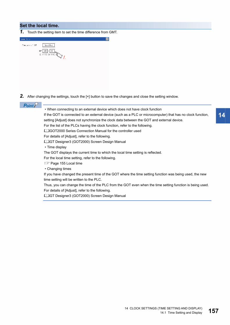
14
Set the local time.1. Touch the setting item to set the time difference from GMT.
2. After changing the settings, touch the [×] button to save the changes and close the setting window.
• When connecting to an external device which does not have clock function
If the GOT is connected to an external device (such as a PLC or microcomputer) that has no clock function,
setting [Adjust] does not synchronize the clock data between the GOT and external device.
For the list of the PLCs having the clock function, refer to the following.
GOT2000 Series Connection Manual for the controller used
For details of [Adjust], refer to the following.
GT Designer3 (GOT2000) Screen Design Manual
• Time display
The GOT displays the current time to which the local time setting is reflected.
For the local time setting, refer to the following.
Page 155 Local time
• Changing times
If you have changed the present time of the GOT where the time setting function was being used, the new
time setting will be written to the PLC.
Thus, you can change the time of the PLC from the GOT even when the time setting function is being used.
For details of [Adjust], refer to the following.
GT Designer3 (GOT2000) Screen Design Manual
14 CLOCK SETTINGS (TIME SETTING AND DISPLAY)14.1 Time Setting and Display 157

15
MEMO
814 CLOCK SETTINGS (TIME SETTING AND DISPLAY)14.1 Time Setting and Display

15
15 CONTROL OF VARIOUS DATA (DATA CONTROL)
A system application, project data (screen data), or alarm data which is written in the GOT or SD card can be displayed, and
the data can be transferred between the GOT and SD card.
The format of the SD card is also possible.
15.1 Data Storage Location
Data type and storage location
SystemThe data storage location and transferring (write/read) route for each data type are shown below.
Also, the data storage locations are shown below.
The data of the build in flash memory (Project data, etc.) can be saved.
*1 The SD card can be used from Utility.Page 163 OS information
*2 When using the project data stored in the Standard SD Card (A drive) with the GOT, hold the SD card installed to the GOT.
Item Data type Storage location
Boot OS Built in flash memory (C drive)
*1 Basic system application Standard SD card (A drive)
Built in flash memory (C drive)*2Communication driver
Advanced system application
*1 Project data
(Including recipe setting, alarm conditions, time action, and GOT setup.)
Standard SD card (A drive)
Built in flash memory (C drive)*2
Read
Upload
Write
WriteInstall/Download
PCGT Designer3
A drive(Built-in SD card)
SD card(when installed in GOT)
Inserting/Removing
SD card(when installed in PC)
C drive(Built-in flash memory)
Copy files onWindows
System application
Boot OSProject data
Install, Write : Upload, Read :
Boot OSSystem application
Project dataBoot OS
System application
Project data
Project dataProject data
Project data
Boot OS
Boot OS
System application
Project data
15 CONTROL OF VARIOUS DATA (DATA CONTROL)15.1 Data Storage Location 159

16
At maintenance
Checking available space of the storage memory
To save resource data, check available space of the storage memory.
Item Data type Storage location
Alarm data (Advanced alarm log file, alarm log file) Standard SD card (A drive)
C drive (Built-in flash memory)
Recipe data (Advanced recipe file, Recipe file)
Logging (Logging file)
Image file (Hard copy function)
Read
Copy Copy PCGT Designer3
A drive(Standard SD card)
SD card(when installed in GOT) Inserting/
Removing
SD card(when installed in PC)
C drive(Built-in flash memory)
Copy files onWindows
Install, Write :Upload, Read :
Alarm
RecipeLogging
Hard copy
AlarmHard copy
AlarmHard copy
Alarm
RecipeLogging
Hard copy
Alarm
Recipe
Logging
Hard copy
015 CONTROL OF VARIOUS DATA (DATA CONTROL)15.1 Data Storage Location

15
Checking version of basic system applicationConfirm the basic system application version carefully when installing the Boot OS and basic system application.
When the basic system application is installed, the GOT checks and compares the basic system application version
automatically.
When install Boot OSWhen the Boot OS to be installed has the older major version, GOT displays the installation disapproving message to cancel
the installation so that the older version may not be written.
(Even when the version of the Boot OS to be installed has the same or later version, the version information and the dialog
box for selecting continue/not continue will be displayed.)
When install basic system application or communication driverWhen a basic system application or communication driver has already been installed, the version information of the basic
system application which has been installed and the dialog box for selecting whether to continue the installation or not will be
displayed.
Moreover, when the different versions will coexist among all applications (basic system application and communication driver)
by installing the basic system application, the installation disapproving dialog box will be displayed and the installation process
is canceled.
When download project dataThe GOT automatically compares the version between the project data to be downloaded and the installed basic system
application.
When the versions are different, the dialog box confirming whether to install the basic system application together is
displayed.
When downloading the project data from an SD card, storing the project data and basic system application beforehand is
recommended.
The version of each system application installed in the GOT can be checked by displaying the property of the system
application information screen.
For the display operation of the screen, refer to the following.
Page 163 OS information
Explanation of OS version01.00.00.B
Boot OS version(Appears only when the propertyof the Boot OS is displayed.)Minor versionMajor version
15 CONTROL OF VARIOUS DATA (DATA CONTROL)15.1 Data Storage Location 161

16
Version confirmation of Boot OS by rating plate
Confirm the version of Boot OS installed in the GOT at product shipment by rating plate of GOT rear face.
MODELGRAPHIC OPERATION TERMINAL
GS2107-WTBD
PASSED
IN 24VDCMAX 6.50W002692412C1C83013913AA00029-A
Hardware VersionBoot OS version
AA2013-09
POWERMAC ADD.SERIALDATE
215 CONTROL OF VARIOUS DATA (DATA CONTROL)15.1 Data Storage Location

15
15.2 OS information
OS informationEach file name or folder name of Boot OS and package data stored in each drive (A: Standard SD card or C: Built-in flash
memory) can be displayed in a list.
Also, each file can be installed and updated.
Precautions when basic system application file is used
When the boot drive of the basic system application is set to "A: Standard SD card", a basic system
application file cannot be installed or updated.
OS information
Function Description Reference page
Information display of files and folders Displays the kind, name, data size, creation date and time of the file or folder. Page 164 Display example
of system application
information
Main Menu Data
OS information
Touch [Data].
Touch [OS information].
15 CONTROL OF VARIOUS DATA (DATA CONTROL)15.2 OS information 163

16
Display example of system application information
No. Item Description
(1) Name Displays the file name or folder name in the selected drive or folder.
When the number of the characters of the file name or folder name exceeds 20, the 21th character and later are not displayed.
(2) Version information Displays the software version.
OS information Storage file/folder display screen
(1) (2)
415 CONTROL OF VARIOUS DATA (DATA CONTROL)15.2 OS information

15
15.3 Resource Data Information
Alarm information
Function of alarm informationAdvanced alarm log files and alarm log files stored in each drive (A: Standard SD card or C: Built-in flash memory) is
displayed.
The functions below can be carried out for files.
For details of the advanced alarms, refer to the following manual.
GT Designer3 (GOT2000) Screen Design Manual
The display operation of alarm information
Function Description Reference page
Information display of files and folders Displays name, data size, creation date and time of file or
folder.
Page 166 The display example of alarm information
Page 167 The display operation of alarm information
G2A CSV conversion Converts the G2A file of an alarm log file to a CSV file. Page 168 G2A → CSV conversion operation, G2A →
TXT conversion operation
G2A TXT conversion Converts the G2A file of an alarm log file to a Unicode
text file.
Page 168 G2A → CSV conversion operation, G2A →
TXT conversion operation
Del Deletes the file. Page 168 Deletion operation
Copy Copies the file. Page 169 Copy operation
Select a drive and operate alarm log files
Main Menu Data
Resource DataSelect drive
Touch [Data].
Touch [Resource Data].
Touch [Alarm info].
15 CONTROL OF VARIOUS DATA (DATA CONTROL)15.3 Resource Data Information 165

16
The display example of alarm information
Display of creation date and time
The creation date and time display is not updated even if a file is created or updated while displaying the
alarm information display screen.
If the screen currently displayed is closed (by moving the screen to the folder of the upper hierarchy, etc.) and
the same screen is displayed again, the updated contents are displayed.
No. Item Description
(1) Select drive The drive which displays file or folder can be selected.
When an SD card is not installed, the following drives are not displayed.
• SD card: [A: Standard SD card]
(2) Kind Indicates whether the displayed name is file or folder.
Displays the extension for a file and "DIR" for a folder.
(3) Name Displays the file name or folder name.
For the long file/folder name, entire part may not be displayed.
Confirm the non-displayed part with the [Copy] button, etc.
Page 167 Alarm information operation
After confirmation, touch the [Cancel] button to cancel the operation.
(4) Size Displays the size of the file displayed in Name.
(5) Date, Time Displays the creation date and time of each file.
(6) Operation switch Execution switch of each function.
Alarm information: Storage file/folder display screenAlarm information screen
(1) (3)(2) (4)
(6)
(5)
615 CONTROL OF VARIOUS DATA (DATA CONTROL)15.3 Resource Data Information
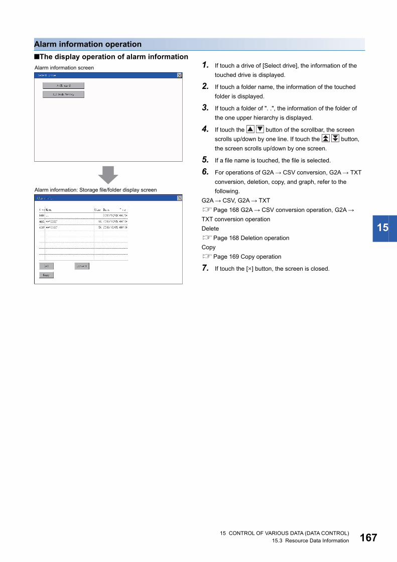
15
Alarm information operation
■The display operation of alarm information1. If touch a drive of [Select drive], the information of the
touched drive is displayed.
2. If touch a folder name, the information of the touched
folder is displayed.
3. If touch a folder of ". .", the information of the folder of
the one upper hierarchy is displayed.
4. If touch the button of the scrollbar, the screen
scrolls up/down by one line. If touch the button,
the screen scrolls up/down by one screen.
5. If a file name is touched, the file is selected.
6. For operations of G2A → CSV conversion, G2A → TXT
conversion, deletion, copy, and graph, refer to the
following.
G2A → CSV, G2A → TXT
Page 168 G2A → CSV conversion operation, G2A →
TXT conversion operation
Delete
Page 168 Deletion operation
Copy
Page 169 Copy operation
7. If touch the [ ] button, the screen is closed.
Alarm information: Storage file/folder display screen
Alarm information screen
15 CONTROL OF VARIOUS DATA (DATA CONTROL)15.3 Resource Data Information 167

16
■G2A → CSV conversion operation, G2A → TXT conversion operationThe selected G2A file is converted to a CSV file or Unicode text file.
■Deletion operationDeletes the selected file.
1. Touch the G2A file to be converted.
2. Touch [Convert].
3. The following dialog box is displayed when touching the
following button according to the file type to convert to.
CSV file:
[CSV] button
Unicode text file:
[TXT] button
4. Touch the [OK] button. The file is overwritten with the
converted file.
1. Touch the file to be deleted.
2. If touch the [Delete] button, the dialog box mentioned
left is displayed. If the [YES] button is touched, the file is
deleted. If the [NO] button is touched, the deletion is
canceled.
815 CONTROL OF VARIOUS DATA (DATA CONTROL)15.3 Resource Data Information

15
■Copy operationCopies the selected file.
1. Touch the file to be copied.
2. If the [Copy] button is touched, the Select drive screen
is displayed.
3. Select a drive.
4. Select the copy destination folder and touch [Execute].
The file is copied.
15 CONTROL OF VARIOUS DATA (DATA CONTROL)15.3 Resource Data Information 169

17
Recipe information
Before using recipe information
For writing/reading into/from a controller with this function or editing of recipe files on the personal computer,
refer to the following.
Specifications and operating procedure are described.
GT Designer3 (GOT2000) Screen Design Manual
Function of recipe informationThe recipe file used in the recipe function can be copied, deleted, and output in a file.
In addition, it is possible to writing/reading into/from a controller by using this function, without creating the screen to operate
the recipe. (Recipe setting of GT Designer3 is required.)
Display operation of recipe information
Function Description Reference page
Recipe information screen Information display of files
and folders
Displays name, data size, creation date and time
of file or folder.
Page 171 Example of advanced recipe
information display
Page 172 Recipe information operation
G2P CSV conversion Converts a G2P file of a recipe file to a CSV file. Page 173 G2P → CSV conversion
operation, G2P → TXT conversion operation
G2P TXT conversion Converts a G2P file of a recipe file to a Unicode
text file.
Page 173 G2P → CSV conversion
operation, G2P → TXT conversion operation
CSV/TXT G2P
conversion
Converts a CSV file or Unicode text file to a G2P
recipe file.
Page 174 CSV/TXT → G2P conversion
operation
Delete Deletes the file or folder. Page 174 Deletion operation
Copy Copies the file. Page 175 Copy operation
Select a drive and operate alarm log files
Main Menu Data
Resource DataSelect drive
Touch [Data].
Touch [Resource Data].
Touch [Recipe info].
015 CONTROL OF VARIOUS DATA (DATA CONTROL)15.3 Resource Data Information

15
Example of advanced recipe information display
■Recipe information screen
About the displayed file
The files other than that for recipe are not displayed on the recipe information screen.
No. Item Description
(1) Select drive The target drive can be selected. (Even if an SD card is not installed, this message appears.)
(2) Kind Indicates whether the displayed name is file or folder.
Displays the extension for a file and "DIR" for a folder.
(3) Name Displays the file name or folder name.
For the long file/folder name, entire part may not be displayed.
(4) Size Displays the size of the file displayed in Name.
(5) Date, Time Displays the creation date and time of each file.
(6) Operation switch Execution switch of each function.
Recipe InformationStorage file/folder display screenRecipe Information screen
(1)(3)(2) (4)
(6)
(5)
15 CONTROL OF VARIOUS DATA (DATA CONTROL)15.3 Resource Data Information 171

17
Recipe information operation
■Display operation of recipe information1. If touch a drive of [Select drive], the information of the
touched drive is displayed.
2. If touch a folder name, the information of the touched
folder is displayed.
3. If touch a folder of ". .", the information of the folder of
the one upper hierarchy is displayed.
4. If touch the button of the scrollbar, the screen
scrolls up/down by one line. If touch the button,
the screen scrolls up/down by one screen.
5. If a file name is touched, the file is selected.
6. For operation of operating switches, refer to the
following.
G2P CSV, G2P TXT
Page 173 G2P → CSV conversion operation, G2P →
TXT conversion operation
CSV/TXT G2P
Page 174 CSV/TXT → G2P conversion operation
Delete
Page 174 Deletion operation
Copy
Page 175 Copy operation
7. If touch the [ ] button, the screen is closed.
215 CONTROL OF VARIOUS DATA (DATA CONTROL)15.3 Resource Data Information
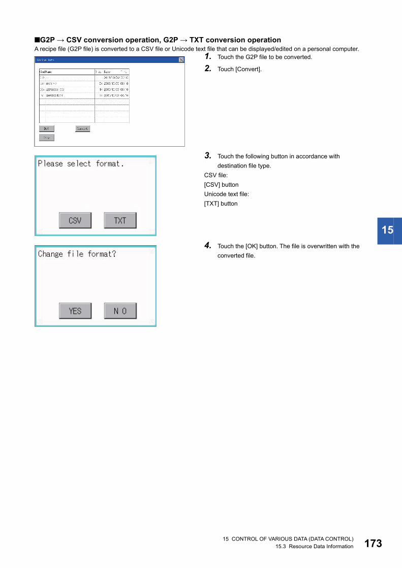
15
■G2P → CSV conversion operation, G2P → TXT conversion operationA recipe file (G2P file) is converted to a CSV file or Unicode text file that can be displayed/edited on a personal computer.
1. Touch the G2P file to be converted.
2. Touch [Convert].
3. Touch the following button in accordance with
destination file type.
CSV file:
[CSV] button
Unicode text file:
[TXT] button
4. Touch the [OK] button. The file is overwritten with the
converted file.
15 CONTROL OF VARIOUS DATA (DATA CONTROL)15.3 Resource Data Information 173
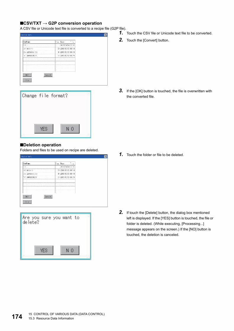
17
■CSV/TXT → G2P conversion operationA CSV file or Unicode text file is converted to a recipe file (G2P file).
■Deletion operationFolders and files to be used on recipe are deleted.
1. Touch the CSV file or Unicode text file to be converted.
2. Touch the [Convert] button.
3. If the [OK] button is touched, the file is overwritten with
the converted file.
1. Touch the folder or file to be deleted.
2. If touch the [Delete] button, the dialog box mentioned
left is displayed. If the [YES] button is touched, the file or
folder is deleted. (While executing, [Processing...]
message appears on the screen.) If the [NO] button is
touched, the deletion is canceled.
415 CONTROL OF VARIOUS DATA (DATA CONTROL)15.3 Resource Data Information

15
■Copy operationFiles to be used in recipe are copied.
Precautions
■Precautions for operationPrecautions during folder/file operation (Create/Delete/Copy/File output, etc.)
Even if the access to the SD card is inhibited while the GOT is processing folders and files, the processing continues.
(Example: Even if the access to the SD card is inhibited while the GOT is creating a folder, the folder is created.)
Therefore, do not pull out the SD card while the "Processing..." message is on the screen after the access to the SD card is
inhibited.
While GOT is accessing to other file (Alarm data, etc)
When folder/file processing for the recipe is executed while the GOT is in access to other file (SD card access LED ON), the
GOT executes folder/file processing for the recipe after the processing for other file has completed.
Therefore, it may take some time to finish the process of the recipe folder/file. (The "Processing..." message is displayed on
the screen.)
Estimation of processing time
The process may take time depending on the setting of advanced recipe file to be operated. (The more
number of blocks increases, the longer it takes to process recipe folder/file.)
The process for creating the first file may take time depending on the setting of advanced recipe file.
1. Touch the file to be copied.
2. If the [Copy] button is touched, the Select drive screen
is displayed.
3. Select a drive.
4. Select the copy destination folder and touch [Execute].
The file is copied.
15 CONTROL OF VARIOUS DATA (DATA CONTROL)15.3 Resource Data Information 175

17
Logging information
Function of logging informationLogging files created with the logging function can be copied, deleted or renamed, etc.
Without using a personal computer, you can manage logging files on the GOT.
For details of the logging function, refer to the following.
GT Designer3 (GOT2000) Screen Design Manual
Display operation of logging information
Function Description Reference page
Information display of files and folders Displays name, data size, creation date and time of file or
folder.
Page 177 Example of logging information
display
Page 177 Logging information operation
Delete Deletes the file or folder. Page 178 Deletion operation
Copy Copies the file. Page 179 Copy operation
Select a drive andoperate logging datafiles
Main Menu Data
Logging info.Select drive
Touch [Data].
Touch [Resource Data].
Touch [Logging info].
615 CONTROL OF VARIOUS DATA (DATA CONTROL)15.3 Resource Data Information

15
Example of logging information display
About the displayed file
The files other than that for logging are not displayed on the logging information screen.
Logging information operation
■Display operation of logging information
No. Item Description
(1) Select drive The target drive can be selected. (Even if an SD card is not installed, this message appears.)
(2) Kind Indicates whether the displayed name is file or folder.
Displays the extension for a file and "DIR" for a folder.
(3) Name Displays the file name or folder name.
For the long file/folder name, entire part may not be displayed.
(4) Size Displays the size of the file displayed in Name.
(5) Date, Time Displays the creation date and time of each file.
(6) Operation switch Execution switch of each function.
1. If touch a drive of [Select drive], the information of the
touched drive is displayed.
2. If touch a folder name, the information of the touched
folder is displayed.
3. If touch a folder of ". .", the information of the folder of
the one upper hierarchy is displayed.
4. If touch the button of the scrollbar, the screen
scrolls up/down by one line. If touch the button,
the screen scrolls up/down by one screen.
5. If a file name is touched, the file is selected.
6. For operation of operating switches, refer to the
following.
Delete
Page 178 Deletion operation
Copy
Page 179 Copy operation
7. If touch the [ ] button, the screen is closed.
Logging InformationStorage file/folder display screenLogging Information
(1)
(3)(2) (4)
(6)
(5)
15 CONTROL OF VARIOUS DATA (DATA CONTROL)15.3 Resource Data Information 177

17
■Deletion operationFolder and file to be used on logging are deleted.
1. Touch the folder or file to be deleted.
2. If touch the [Delete] button, the dialog box mentioned
left is displayed. If the [YES] button is touched, the file or
folder is deleted. (While executing, [Processing...]
message appears on the screen.) If the [NO] button is
touched, the deletion is canceled.
815 CONTROL OF VARIOUS DATA (DATA CONTROL)15.3 Resource Data Information

15
■Copy operationFolder to be used in logging is copied.
Precautions
■Precautions for operationPrecautions during folder/file operation (Create/Delete/Copy/File output, etc.)
Even if the access to the SD card is inhibited while the GOT is processing folders and files, the processing continues.
(Example: Even if the access to the SD card is inhibited while the GOT is creating a folder, the folder is created.)
Therefore, do not pull out the SD card while the "Processing..." message is on the screen after the access to the SD card is
inhibited.
While GOT is accessing to other file (Alarm data, etc)
When folder/file processing for the logging is executed while the GOT is in access to other files (SD card access LED ON), the
GOT executes folder/file processing for the logging after the processing for other files is completed.
Therefore, it may take some time to finish the process of the logging folder/file.
(The "Processing..." message is displayed on the screen.)
1. Touch the file to be copied.
2. If the [Copy] button is touched, the Select drive screen
is displayed.
3. Select a drive.
4. Select the copy destination folder and touch [Execute].
The file is copied.
15 CONTROL OF VARIOUS DATA (DATA CONTROL)15.3 Resource Data Information 179

18
Image file management
Function of image file managementDeletes, copies, and moves the file created by the hard copy function. For details of the hard copy function, refer to the
following.
GT Designer3 (GOT2000) Screen Design Manual
Display operation of image file management
Function Description Reference page
Information display of files and folders Displays the kind, name, data size, creation date and
time of the file or folder.
Page 181 Display example of image file
management
Page 182 Operation of image file management
Delete Deletes the file. Page 182 Deletion operation
Copy Copies the file. Page 183 Copy operation
Select a drive andoperate Image datafiles
Main Menu Data
Resource dataSelect drive
Touch [Data].
Touch [Resource Data].
Touch [Image file].
015 CONTROL OF VARIOUS DATA (DATA CONTROL)15.3 Resource Data Information

15
Display example of image file management
Display of creation date and time
The creation date and time display is not updated even if a file is created or updated while the image file
management screen is displayed. To display the updated creation date and time, close the screen currently
displayed (by moving to the upper hierarchy folder, etc.) and display the screen again.
No. Item Description
(1) Select drive The drive which displays file or folder can be selected.
When an SD card is not installed, the following drives are not displayed.
• SD card: [A: Standard SD card]
(2) Kind Indicates whether the displayed name is file or folder.
Displays the extension for a file and "DIR" for a folder.
(3) Name Displays the file name or folder name.
For the long file/folder name, entire part may not be displayed.
Confirm the non-displayed part with the [Copy] button, etc.
Page 183 Copy operation
After confirmation, touch the [Cancel] button to cancel the operation.
(4) Size Displays the size of the file displayed in Name.
(5) Date, Time Displays the creation date and time of each file.
(6) Operation switch Execution switch of each function.
(2) (3)
(6)
(4) (5)
Image file Information
(1)
Image file InformationStorage file/folder display screen
15 CONTROL OF VARIOUS DATA (DATA CONTROL)15.3 Resource Data Information 181

18
Operation of image file management
■Display operation of image file management
■Deletion operationDeletes the selected file.
1. If touch a drive of [Select drive], the information of the
touched drive is displayed.
2. If touch a folder name, the information of the touched
folder is displayed.
3. If touch a folder of ". .", the information of the folder of
the one upper hierarchy is displayed.
4. If touch the button of the scrollbar, the screen
scrolls up/down by one line. If touch the button,
the screen scrolls up/down by one screen.
5. If a file name is touched, the file is selected.
6. For the operations of the delete, copy, and rename,
refer to the following.
Delete
Page 182 Deletion operation
Copy
Page 183 Copy operation
7. If touch the [ ] button, the screen is closed.
1. Touch the file to be deleted.
2. If touch [Delete] button, the screen mentioned left is
displayed. If the [YES] button is touched, the file is
deleted. If the [NO] button is touched, the deletion is
canceled.
215 CONTROL OF VARIOUS DATA (DATA CONTROL)15.3 Resource Data Information

15
■Copy operationCopies the selected file.
1. Touch the file to be copied.
2. If the [Copy] button is touched, the Select drive screen
is displayed. Select a drive.
3. If the copy destination folder is touched, the screen
display is changed to the folder of copy destination. At
this time, it cannot be copied into the same folder where
the file exists. Select other folders.
4. If touch the [Execute] button, the file is copied.
15 CONTROL OF VARIOUS DATA (DATA CONTROL)15.3 Resource Data Information 183
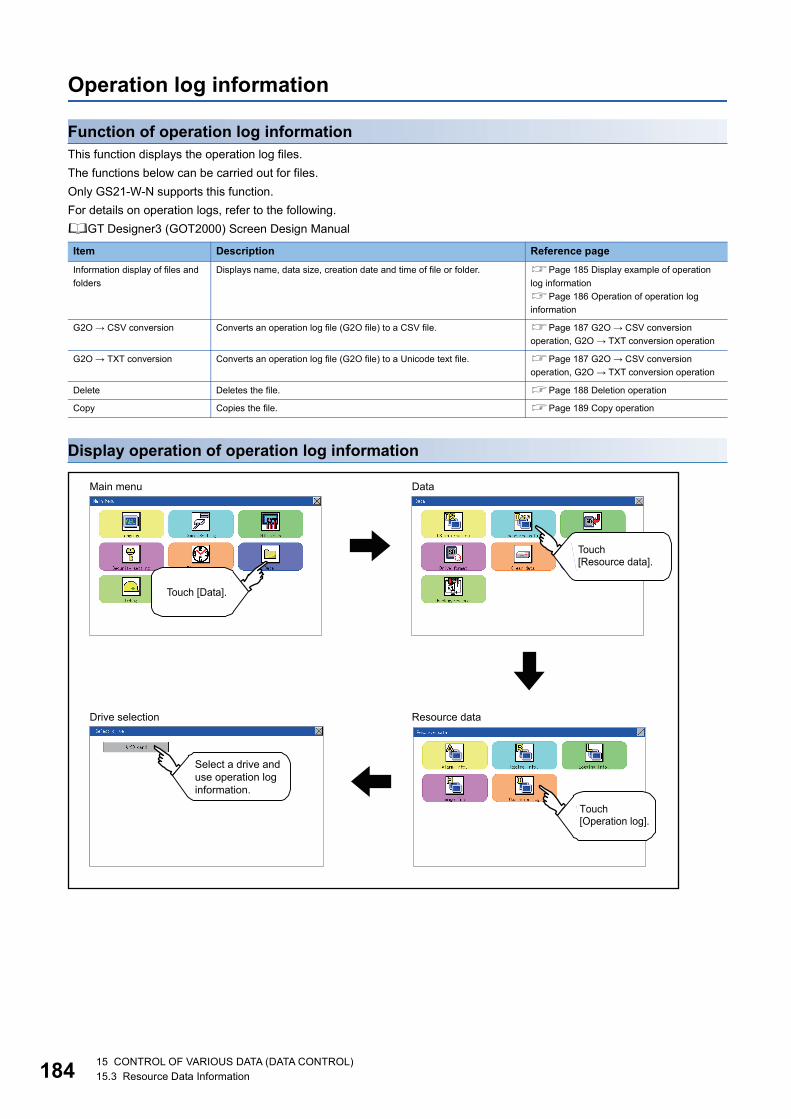
18
Operation log information
Function of operation log informationThis function displays the operation log files.
The functions below can be carried out for files.
Only GS21-W-N supports this function.
For details on operation logs, refer to the following.
GT Designer3 (GOT2000) Screen Design Manual
Display operation of operation log information
Item Description Reference page
Information display of files and
folders
Displays name, data size, creation date and time of file or folder. Page 185 Display example of operation
log information
Page 186 Operation of operation log
information
G2O → CSV conversion Converts an operation log file (G2O file) to a CSV file. Page 187 G2O → CSV conversion
operation, G2O → TXT conversion operation
G2O → TXT conversion Converts an operation log file (G2O file) to a Unicode text file. Page 187 G2O → CSV conversion
operation, G2O → TXT conversion operation
Delete Deletes the file. Page 188 Deletion operation
Copy Copies the file. Page 189 Copy operation
Main menu Data
Resource dataDrive selection
Touch [Data].
Touch [Resource data].
Touch[Operation log].
Select a drive and use operation log information.
415 CONTROL OF VARIOUS DATA (DATA CONTROL)15.3 Resource Data Information

15
Display example of operation log information
No. Item Description
(1) Select drive The drive which displays file or folder can be selected.
(Data storage drives are displayed even no data storage is installed.)
(2) Kind Indicates whether the displayed name is file or folder.
Displays the extension for a file and "DIR" for a folder.
(3) Name Displays the file name or folder name.
For the long file/folder name, entire part may not be displayed.
(4) Size Displays the size of the file displayed in Name.
(5) Date, Time Displays the creation date and time of each file.
(6) Operation switch Execution switch of each function.
(6)
(2)
(3) (4) (5)
(1)
15 CONTROL OF VARIOUS DATA (DATA CONTROL)15.3 Resource Data Information 185

18
Operation of operation log information
■Display operation of operation log information
When the Prohibit Operation Log Information Operation signal (GS522.b3) is turned on, the [Del], [Copy], and
[Convert] buttons are not displayed.
For the details, refer to the following.
GT Designer3 (GOT2000) Screen Design Manual
1. If a drive of [Select drive] is touched, the information of
the touched drive is displayed.
2. If a folder name is touched, the information of the
touched folder is displayed.
3. If a folder of ". ." is touched, the information of the folder
in one upper hierarchy is displayed.
4. If the button of the scrollbar is touched, the
screen scrolls up/down by one line.
5. If a file name is touched, the file is selected.
6. For G2O → CSV conversion, G2O → TXT conversion,
deleting, copying, and renaming, refer to the following.
G2O → CSV or G2O → TXT conversion
Page 187 G2O → CSV conversion operation, G2O →
TXT conversion operation
Delete
Page 188 Deletion operation
Copy
Page 189 Copy operation
7. If the [×] button is touched, the screen is closed.
615 CONTROL OF VARIOUS DATA (DATA CONTROL)15.3 Resource Data Information

15
■G2O → CSV conversion operation, G2O → TXT conversion operationA selected G2O file is converted to a CSV file or Unicode text file.
1. Touch the G2O file to be converted.
2. Touch [Convert].
3. The destination selection screen appears.
Select the destination.
4. The following dialog box is displayed when touching the
following button according to the file type to convert to.
• CSV file: [CSV] button
• Unicode text file: [TXT] button
5. Touch the [YES] button. The converted file is created.
6. If a file with the same name exists, the overwrite
confirmation dialog appears.
Touch the [YES] button to overwrite the file.
Touch the [NO] button to cancel the conversion.
15 CONTROL OF VARIOUS DATA (DATA CONTROL)15.3 Resource Data Information 187

18
■Deletion operationDeletes the selected file.
1. Touch the file to be deleted.
2. If the [Delete] button is touched, the dialog box
mentioned below is displayed.
If the [YES] button is touched, the file is deleted.
If the [NO] button is touched, the deletion is canceled.
815 CONTROL OF VARIOUS DATA (DATA CONTROL)15.3 Resource Data Information

15
■Copy operationCopies the selected file.
1. Touch the file to be copied.
2. If the [Copy] button is touched, the Select drive screen
is displayed.
3. Select a drive.
4. Select the copy destination folder and touch [Execute].
The file is copied.
15 CONTROL OF VARIOUS DATA (DATA CONTROL)15.3 Resource Data Information 189

19
15.4 SD Card Access
Functions of SD card accessWhen the GOT is turned on, an SD card can be installed or removed to/from the GOT without damage to the data in the SD
card.
Display operation of SD card access
Operation of SD card access1. Touch a setting item to change the setting.
[Permissions] [Access inhibit]
When installing or removing an SD card, always set [Access
inhibit].
SD card access
Main Menu Data
015 CONTROL OF VARIOUS DATA (DATA CONTROL)15.4 SD Card Access

15
15.5 SD Card Format
Function of SD card formatAn SD card is formatted.
Display operation of SD card format
Main Menu Data
Touch [Data].
Touch [SD card format].
15 CONTROL OF VARIOUS DATA (DATA CONTROL)15.5 SD Card Format 191

19
Operation of SD card format
Restrictions on formatting
• When using an unformatted SD card in the GOT, format it by a personal computer. The GOT cannot format
the unformatted SD card.
• The format of the GOT does not change the file system (Example: FAT16) of the SD card and inherits the
file system before the format.
1. Install an SD card to the GOT. For installation/removal
procedure of an SD card, refer to the following.
Page 61 Installation/removal procedure of SD card
2. Touch and select the drive to format by drive selection.
3. If touch the [FORMAT] button, the password input
screen is displayed.
4. Type and touch the [Enter] key. The dialog
box shown on the left will appear. (The password is fixed
to 1111.) Confirm the contents of the dialog box, and
touch the [YES] button to format the SD card. To cancel
the format, touch the [NO] button.
5. When the formatting is completed, the completion dialog
mentioned left is displayed.
6. To close the dialog box, touch the [OK] button.
1 1 1 1
215 CONTROL OF VARIOUS DATA (DATA CONTROL)15.5 SD Card Format

15
15.6 Clear data
Clear data functionsThis function deletes the project data and resource data that are written to the GOT.
Clear data display
Clear data operation
Canceling deletion
Data deletion cannot be canceled once the [YES] button is pressed at the confirm deletion prompt.
Double check before touching the [YES] button.
1. Touch the type of data on the screen to be deleted.
2. The dialog box on the left is displayed for confirmation.
Touch the [YES] button to delete the data, or the [NO]
button to cancel.
Clear data
Main Menu Clear data
Touch [Data].
Touch [Clear data].
Touch [Project data]or [Resource data].
Touch
15 CONTROL OF VARIOUS DATA (DATA CONTROL)15.6 Clear data 193

19
15.7 Data CopyThe project data and basic system application are transferred by using an SD card.
Copy from the memory board to the GOT
Copying from the memory board to the GOT when turning on the power to the GOT.
Refer to the following.
Page 274 Installing using the data control function (Utility)
Display operation of data copy
Main Menu Data
Data copy
Touch [Data].
Touch [Data copy].
415 CONTROL OF VARIOUS DATA (DATA CONTROL)15.7 Data Copy

15
Operation of data copy1. Select the copy direction. The selection mark is
displayed on the side of the selected key.
GOT SD card:
Copy the data from the GOT to the SD card.
SD card GOT:
Copy from the SD card to the GOT
2. After selecting the direction, touch the [OK] button. To
abort copy, touch the [ABORT] button.
3. Confirm the copy direction and copy target. When they
are set correctly, touch the [OK] button. To change the
setting, touch the [CANCEL] button.
4. The dialog box on the left is displayed for confirmation.
Touch the [YES] button to start copying and [NO] button
to abord.
5. While the copy is executed, the dialog box on the left is
displayed.
Touch
Touch
Touch
Touch
15 CONTROL OF VARIOUS DATA (DATA CONTROL)15.7 Data Copy 195

19
When installing or removing an SD card
Always set [Permissions] on the GOT. For details, refer to the following.
Page 190 SD Card Access
Error displayWhen copying is not available between the GOT and the SD card, check the following contents according to the GOT error
display.
6. Copy is completed. If the [×] button is touched, the
screen is closed. If an error occurs during copy, an error
message appears. For details of error messages, refer
to the following.
Page 196 Error display
When only the project data was copied to the GOT, touch the
[ESC] button to restart the GOT and display the user-created
screen.
When the basic system application was copied, the GOT will
automatically start up and display the user-created screen.
(If the project data does not exist, a message appears to
notify that the project data does not exist.)
Error message Remedy
SD card is not attached. Install an SD card to the GOT.
GOT type is unmatch. The model set for the data in the SD card does not match with that of the copy target GOT.
Use the same model data as that of the copy target GOT.
Write protection switch ON. The write protection switch of the SD card is ON.
Turn off the write protection switch.
Available package data is notexisted. There is no data to be a copy target in the copy source.
Store the data to be copied in the copy source and copy it again.
Touch
615 CONTROL OF VARIOUS DATA (DATA CONTROL)15.7 Data Copy

15
15.8 BACKUP/RESTORE
BACKUP/RESTORESetting data, including a sequence program, parameters, and setting values, for a controller connected to the GOT can be
saved (backed up) in a memory card or USB memory in the GOT.
The following shows features of the backup/restore function.
Backing up or restoring system without personal computer for reducing downtimeSetting data for a controller connected to the GOT can be backed up, and the data can be restored to the controller.
With backing up setting data for a controller, the data can be restored to the controller with the GOT connected to the
controller even though the controller has to be replaced because of problems, including failures. As a result, the system can
be easily restored.
Enabling creating the same system without personal computerWith restoring the backed up setting data to controllers in other systems, the same system can be created without a personal
computer.
Improving securityWhen the backup/restore function is used, browsing and changing setting data is limited with a password and the security is
improved.
SD card
Backing up setting data to a SD card
Restore the backup data to the controller.
SD card
Password authentication
Password authentication
15 CONTROL OF VARIOUS DATA (DATA CONTROL)15.8 BACKUP/RESTORE 197

19
System configurationThis section describes the system configuration for the backup/restore function.
For connection type settings and precautions regarding the communication unit/cable and connection type, refer to the
following.
GOT2000 Series Connection Manual (Mitsubishi Products) for GT Works3 Version1
Target controller
*1 Use a PLC CPU with the function version of B or later.*2 To restore the backup data containing a special parameter, use the following version of CPU.
· FX3U(C) version: 3.10 or later· FX3G(C) version: 2.00 or later
Connection typeThis function can be used in the following connection types.
( : Applicable, : Partly restricted, : Inapplicable)
*1 The LCPU does not support the connection type.*2 When the GOT is connected to LCPU, use L6ADP-R2.*3 Backup/Restore cannot be used when using CC-Link IE field network Ethernet adapter.*4 The restoration cannot be performed to a QCPU with the factory-settings or whose memory is formatted.
Required hardwareThe backup / restore, SD card is required.
Controller Model
MELSEC iQ-F FX5U, FX5UC, FX5UJ
QCPU(Q mode) Basic model*1 Q00JCPU, Q00CPU, Q01CPU
High performance model*1 Q02CPU, Q02HCPU, Q06HCPU, Q12HCPU, Q25HCPU
Universal model Q00UJCPU, Q00UCPU, Q01UCPU, Q02UCPU, Q03UDCPU, Q04UDHCPU,
Q06UDHCPU, Q10UDHCPU, Q13UDHCPU, Q20UDHCPU, Q26UDHCPU,
Q03UDECPU, Q04UDEHCPU, Q06UDEHCPU, Q10UDEHCPU,
Q13UDEHCPU, Q20UDEHCPU, Q26UDEHCPU, Q50UDEHCPU,
Q100UDEHCPU, Q03UDVCPU, Q04UDVCPU, Q06UDVCPU, Q13UDVCPU,
Q26UDVCPU
LCPU L02CPU, L06CPU, L26CPU, L26CPU-BT, L26CPU-PBT, L02CPU-P,
L06CPU-P, L26CPU-P, L02SCPU, L02SCPU-P
FX CPU*2 FX0, FX0S, FX0N, FX1, FX2, FX2C, FX1S, FX1N, FX1NC, FX2N, FX2NC,
FX3U, FX3UC, FX3G, FX3GC, FX3S
Function Connection type between GOT and controller
Name Description Direct CPU connection
Computer link connection
Ethernet connection
Backup/restore Backs up setting data for a controller connected to the GOT and restores
the data to the controller.
*2 *4 *3*4
815 CONTROL OF VARIOUS DATA (DATA CONTROL)15.8 BACKUP/RESTORE

15
Data to be backed up and restoredThe following shows data to be backed up and restored.
Data other than the the following data cannot be backed up and restored.
■Basic model QCPU
*1 The file register in the Flash card installed in the CPU is always restored without confirming saving.Select whether restoring or not the file register stored in the SRAM card or standard RAM in the dialog box displayed when restoration is executed.When the file register is not restored, the existing file register is deleted.Therefore, programs of the controller may not work normally.If a problem occurs in the operation of the controller after restoration, perform the restoration again, including to the file register.
■High Performance model QCPU
*1 The file register in the Flash card installed in the CPU is always restored without confirming saving.Select whether restoring or not the file register stored in the SRAM card or standard RAM in the dialog box displayed when restoration is executed.When the file register is not restored, the existing file register is deleted.Therefore, programs of the controller may not work normally.If a problem occurs in the operation of the controller after restoration, perform the restoration again, including to the file register.
*2 The item can be backed up only.
Item Description File name
Parameter Parameter for operating a programmable controller PARAM.QPA
Intelligent function module parameter Parameter for intelligent function modules IPARAM.QPA
Sequence program Program that the CPU operates MAIN.QPG
SFC program Sequence program with the SFC programming format MAIN-SFC.QPG
File register*1 Data stored in file registers MAIN.QDR
Device comment Device comment to be stored in a programmable controller MAIN.QCD
Device initial value Setting the device initial value MAIN.QDI
Item Description File name
Parameter Parameter for operating a programmable controller PARAM.QPA
Intelligent function module parameter Parameter for intelligent function modules IPARAM.QPA
Program Program that the CPU operates (Including SFC program) ***.QPG
Device comment Device comment to be stored in a programmable controller ***.QCD
Boot operation specification file Batch file for starting programs stored in ROM and others AUTOEXEC.QBT
Device initial value Setting the device initial value ***.QDI
File register*1 Data stored in file registers ***.QDR
Sampling trace file*2 Sampling trace data that the specified device data is continuously collected
with the specified timing
***.QTD
Failure history data*2 Failure history data that are recorded self-diagnostic results ***.QFD
Programmable controller user data Any user-created data stored in a memory card ***.*** (Optional)
15 CONTROL OF VARIOUS DATA (DATA CONTROL)15.8 BACKUP/RESTORE 199

20
■Universal model QCPU
*1 The file register in the Flash card installed in the CPU is always restored without confirming saving.Select whether restoring or not the file register stored in the SRAM card or standard RAM in the dialog box displayed when restoration is executed.When the file register is not restored, the existing file register is deleted.Therefore, programs of the controller may not work normally.If a problem occurs in the operation of the controller after restoration, perform the restoration again, including to the file register.
*2 The item can be backed up only.
■LCPU
*1 The file register in the Flash card installed in the CPU is always restored without confirming saving.Select whether restoring or not the file register stored in the SRAM card or standard RAM in the dialog box displayed when restoration is executed.When the file register is not restored, the existing file register is deleted.Therefore, programs of the controller may not work normally.If a problem occurs in the operation of the controller after restoration, perform the restoration again, including to the file register.
*2 The item can be backed up only.
Item Description File name
Parameter Parameter for operating a programmable controller PARAM.QPA
Intelligent function module parameter Parameter for intelligent function modules IPARAM.QPA
Program Program that the CPU operates (Including SFC program) ***.QPG
Device comment Device comment to be stored in a programmable controller ***.QCD
Boot operation specification file Batch file for starting programs stored in ROM and others AUTOEXEC.QBT
Device initial value Setting the device initial value ***.QDI
File register*1 Data stored in file registers ***.QDR
Sampling trace file*2 Sampling trace data that the specified device data is continuously collected
with the specified timing
***.QTD
Programmable controller user data Any user-created data stored in a memory card ***.*** (Optional)
File for storing device data Device data used for the SP.DEVST and S.DEVLD instructions DEVSTORE.QST
Drive heading The heading of the drive QN.DAT
Remote password Remote password settings 00000000.QTM
Monitor sequence extension Data to increase the speed of monitors from other stations. MONITOR.Q0*
Latch data backup file Stores the backup data for the latch data backup function to the standard
ROM.
LCHDAT00.QBK
Data logging setting file Setting the data logging LOGCOM.QLG
LOG01.QLG to LOG10.QLG
Menu definition file Menu defining files MENUDEF.QDF
015 CONTROL OF VARIOUS DATA (DATA CONTROL)15.8 BACKUP/RESTORE

15
■FX CPU
*1 The data can be backed up or restored with the FX3U(C) series and FX3G(C) series only.*2 The data can be backed up or restored with the FX3U(C) series only.*3 The data are stored in the FX3U-32MT-LT-2 only.
■Data for software
Backup data
■Storing backup dataWhen backups for the same channel are executed several times, the backup data is overwritten by SD card.
■Storage location for backupBackup data are stored in a SD card with the following folder structure.
■Folders for backup dataBackup data are stored by the folder, and a folder name (YYMMDDXX) is set as follows.
Item Description File name
Parameter Parameter for operating a programmable controller INFO.FPG
Device comment Device comment to be stored in a programmable controller
Sequence program Program that the CPU operates
Special program*1 Positioning setting/Initial value parameter
File register Data stored in file registers
Extension file register*2 Data stored in extension file registers
Built-in CC-Link/LT setting*3 CC-Link/LT parameter
Special parameter*1 Special adapter/special block parameter saved in the main unit
Item Description File name
Label program Data for GX Developer PROJINFO.CAB
Symbolic data Symbolic data for PX Developer #FBDQINF.BIN
Source
information
Simple project (with label) GX Works2 data SRCINFOM.CAB
SRCINFOM.C32
Structured project GX Works2 data SRCINFOI.CAB
SRCINFOI.C32
New source
information
Simple project (with label) GX Works2 data SRCINF1M.CAB
SRCINF2M.CAB
SRCINF1M.C32
SRCINF2M.C32
Structured project GX Works2 data SRCINF1I.CAB
SRCINF2I.CAB
SRCINF1I.C32
SRCINF2I.C32
SD card SD card in the drive set as the storage location for backup data
BACKUP
SYS1BKUP
SYS2BKUP
YYMMDDXX Folder for storing backup data
YYMMDDXX00 (fixed)
Backup date (01 to 31)
Backup month (01 to 12)
Backup year (the last two digits of the year)
15 CONTROL OF VARIOUS DATA (DATA CONTROL)15.8 BACKUP/RESTORE 201

20
Access range
Access range with connection typesThe following shows a target controller of the backup/restore execution with each connection type.
With multi-channel functionWith the multi-channel function, the backup and restoration is executed per channel.
Backing up/restoring data for multiple CPU systemOnly batch backup of all controllers is executed.
Backup of only specified ones among the controllers Nos. 1 to 4 is not supported.
Precautions
Precautions for backup
■Data that cannot be backed upThe GOT cannot back up device current values and data stored in device memories.
For collecting device current values, use the recipe function.
For how to use the recipe function, refer to the following manual.
GT Designer3 (GOT2000) Screen Design Manual
For collecting data stored in device memories, use GX Developer.
■Names of files to be backed upWhen characters other than the characters defined in the shift JIS code and ASCII code are used for file names, the file
names may not be correctly displayed with the data backed up on the GOT.
For using the backup/restore function, use characters in the JIS code and ASCII code for file names.
■Backing up intelligent function module parametersFor backing up an intelligent function module parameter (IPARAM.QPA), only the parameters that can be stored in the PLC
CPU are the target parameters.
To store other intelligent function module parameters than those, GX Configurator applied to GX Works2 and the intelligent
function module is required.
For the intelligent function module parameters that can be stored in the PLC CPU, refer to the following.
GX Works2 Version 1 Operating Manual (Intelligent Function Module)
■Compatibility of backup dataThe backup data used in GS21 cannot be used in GT27, GT25, and GT23.
The backup data used in GT27, GT25, and GT23 cannot be used in GS21.
Connection type Target controller
Computer link connection Host station
Ethernet connection Host station
215 CONTROL OF VARIOUS DATA (DATA CONTROL)15.8 BACKUP/RESTORE

15
Precautions for restore
■Communication status between GOT and target controllersFor restoring data, enable the target controllers of the restoration to communicate with the GOT.
When the target controllers of the restoration cannot communicate with the GOT, the restoration cannot be executed.
■STOP status during restorationCPUs for the programmable controller is in the STOP status with the remote STOP before the restoration.
For the CNC C70, the CNC ladder is in the STOP status.
The CPUs and CNC ladder remain in the STOP status after the restoration is completed.
Restart the controllers.
■When restoration is canceledWhen the restoration is canceled, all the data are not restored to the controllers and the controllers may not correctly operate.
When the restoration is canceled, be sure to execute the restoration again.
The CPUs and CNC ladder remain in the STOP status after the restoration is canceled.
Restart the controllers.
■System configuration with controllers for restorationSet the same system configuration with the controllers for the restoration as those for the backup.
Failure to do so disables the GOT to restore data to the controllers.
When the system configuration with the controllers for the restoration is the same as those for the backup, the GOT can
restore data to the controllers even if the connection type and CH No. for the restoration differ from those for the backup.
■Controller operationsControllers may malfunction by changing set values, device values, and others during the restoration.
Check that data to be restored is the appropriate data, and then execute the restoration with paying attention to the controller
operations.
Common precautions for backup and restore
■Password for backup/restoreWhen a password for a controller is changed after setting the password for the backup/restore, set a new password for the
backup/restore.
For setting the password for the backup/restore, refer to the following.
Page 205 Security and password
■Precautions for GT Designer3 (GOT2000)Do not execute the following operations with GT Designer3 (GOT2000) during the backup/restore.
Boot OS installation, package data, the communication driver, the standard monitor OS, and the extended function system
application download
When the above operations are executed, the backup/restore is stopped.
■Precautions for GX DeveloperDo not access the target controller of the backup/restore with GX Developer during the backup/restore.
Doing so stops the backup/restore.
Do not execute the backup/restore on the GOT while the target controller of the backup/restore is accessed by GX Developer.
Doing so causes a communication error on GX Developer. (The backup/restore is executed.)
■CPU with a security keyThe backup/restore cannot be executed on the CPU on which the security key is set.
To execute the backup/restore, check the setting of the CPU.
When the target controllers of the backup/restore include both the CPU with the security key and the CPU without the security
key, the backup/restore is executed only for the CPU without the security key.
15 CONTROL OF VARIOUS DATA (DATA CONTROL)15.8 BACKUP/RESTORE 203

20
Precautions for QCPUThe restoration to QCPU with the factory-settings or whose memory is formatted is available only in the following cases.
• For a single CPU system: When the connection type is the bus connection or direct CPU connection
• For a multiple CPU system: When the connection type is the direct CPU connection
However, in a multiple CPU system which includes a QCPU with the factory-settings or whose memory is formatted, batch
restoration to multiple controllers cannot be performed.
Restore each controller with the following procedure.
Precautions for FXCPU
■Attaching a memory cassetteWhen a memory cassette is attached to a FXCPU, data in the memory cassette is backed up.
When a memory cassette is not attached to the FXCPU, data in the built-in memory is backed up.
■Keyword settingThe following table shows whether the backup/restore function is executed or not by each keyword setting.
(Executed: Not executed: )
■Keyword for restoring dataWhen data are restored to a target FXCPU, a keyword in the FXCPU is held.
For setting or disabling a keyword for the FXCPU, refer to the following manual.
GOT2000 Series User’s Manual (Utility)
Programming manual for the FXCPU used
■Backup data which contains source informationWhen the target FXCPU of the restoration does not support source information, the backup data which contains source
information cannot be restored.
Function Protection that cannot be disabled by keyword
With keyword Without keyword
Write protection
Read/Write protection
All operation protection
Write protection Read/Write protection
All operation protection
Enabled Enabled Enabled Enabled Disabled Enabled Disabled Enabled Disabled
(Trigger)
Backup
Restore
Restoring data to controller No.1
Resetting controller No.1
Restoring data to controller No.2
Resetting controller No.2
415 CONTROL OF VARIOUS DATA (DATA CONTROL)15.8 BACKUP/RESTORE

15
Security and passwordBy setting the passwords, the password authentication is available when the backup/restore is executed.
The password authentication uses the password for the backup/restore and passwords for controllers.
The following shows the passwords used for the backup/restore.
After the first backup (after setting the password for the backup/restore), the user has no need to input the passwords for the
controllers. (The passwords for the controllers are automatically verified.)
The following shows the security advantages.
Before setting password for backup/restore
When the user forgets the password for the backup/restore, the backup/restore cannot be executed.
In that case, execute the backup again by using a formatted or new SD card.
For how to set the password for the backup/restore, refer to the following.
Page 206 Setting password for backup/restore
How to use the password for the backup/restore, refer to the following.
Page 208 How to use password for backup/restore
Password Description
Password for backup/restore Password for the backup/restore function
Set the password on the GOT at the first backup.
Before setting the password, set passwords for controllers in advance.
Passwords for controllers Passwords set for the files for the target controllers of the backup/restore
Set this password using the setting software of the controller when the file is written to the controller.
User Advantage
Administrator No need to disclose the passwords for the controllers to the operator
(Preventing anyone other than the administrator to browse or edit setting data for the controllers.)
Operator The backup/restore is executed by using the password for the backup/restore only.
(No need to input passwords for the controllers)
SD card
Restore
Backup
Authentication of the password for the backup/restore
Authentication of the password for the backup/restore
Automatic authentication of passwords for the controller
Automatic authentication of passwords for the controller
15 CONTROL OF VARIOUS DATA (DATA CONTROL)15.8 BACKUP/RESTORE 205

20
Setting password for backup/restoreThe password for the backup/restore can be set only when the following condition is satisfied at the first backup.
• When passwords are set for the files for the backup target controller
At the first backup, the password authentication for the controller is required.
The following shows the operating procedure at the first backup.
For details, refer to the following.
Page 211 Operation of backup/restore
No
No
Start
Touch [Backup] in the main menu on the GOT. (The first backup)*1
Is a password set for the file to be backed up?
Is the password correct?
The file is backed up.
Is there another file?
Is there another controller to be backed up? (when with controller list file)
Set the password for the backup/restore. (Set 32 or less alphanumeric characters for the password.)
Backup completed
Yes
Yes
No
No
Yes
Is there another unit?(In the multiple CPU system)
No
Yes
Yes
Input the password for the controller. (When the password for the first file is verified, the other files are automatically verified using the password for the first file. When the automatic verification fails, input the corresponding password.)
When a keyword is set, disable the keyword.
FXCPUOther than the FXCPU
615 CONTROL OF VARIOUS DATA (DATA CONTROL)15.8 BACKUP/RESTORE

15
*1 For details, refer to the following.Page 211 Operation of backup/restore
• Setting password
For ensuring the security, setting a password of 8 or more characters that cannot be easily guessed is
recommended.
When the password is leaked, the same system can be created. Pay enough attention to managing the
password.
• FXCPU keyword
To back up or restore data in the FXCPU, disable a keyword in advance.
Page 216 Operation of keyword
15 CONTROL OF VARIOUS DATA (DATA CONTROL)15.8 BACKUP/RESTORE 207

20
How to use password for backup/restore
■BackupThe following shows the operating procedure for the backup after setting the password for the backup/restore.
Page 211 Operation of backup/restore
*1 For details, refer to the following.Page 211 Operation of backup/restore
Start
Touch [Backup] in the main menu on the GOT.(The second or later backup)*1
Input the password for the backup/restore.
The passwords for the controller stored as the backup setting data are automatically verified for each file.
The file is backed up.
Input the correct password for the controller.
Backup completed
No
Yes(Other than the FXCPU)
No
No
No
No
No
Yes
Yes
Yes
Yes
Yes
Is a password set for the file to be backed up?
Is there another unit?(In the multiple CPU system)
No
Yes Is there another controller to be backed up? (when with controller list file)
Have the passwords for the controllers ever been changed?
Is the password correct?
Is the password correct?
Is there another file?
Set the password for the backup/restore. (Set 32 or less alphanumeric characters for the password.)
Yes(FXCPU)When a keyword is set,disable the keyword.
815 CONTROL OF VARIOUS DATA (DATA CONTROL)15.8 BACKUP/RESTORE

15
When passwords for controllers are changed
When the password input is cancelled and the backup is stopped, the backed up files until the backup is
stopped are all deleted.
15 CONTROL OF VARIOUS DATA (DATA CONTROL)15.8 BACKUP/RESTORE 209

21
■RestorationThe following shows the operating procedure for the restoration after setting the password for the backup/restore.
*1 For details, refer to the following.Page 211 Operation of backup/restore
Start
Touch [Restore] in the main menu.*1
Input the password for the backup/restore.
The passwords for the controller contained in the backup data are automatically verified.
Input the correct password for the controller.
The file is restored.
Restoration completed
No
Yes(Other than the FXCPU)
No
No
No
No
Yes
Yes
Yes
Yes
Is the password correct?
Is the password correct?
Is there another file?
Is a password set for the file to be restored?
Is there another unit?(In the multiple CPU system)
No
Yes Is there another controller to be backed up? (when with controller list file)
When a keyword is set, disable the keyword.When a programmable controller isthe RUN status, change the status to the STOP status.
Yes(FXCPU)
015 CONTROL OF VARIOUS DATA (DATA CONTROL)15.8 BACKUP/RESTORE

15
When passwords for controllers are changed
When the password input is cancelled and the restoration is stopped, the restored files until the restoration is
stopped remain in the controller.
When only any of the files are restored, the data can be inconsistent in the entire system.
Operation of backup/restore
When the connected equipment is not an FX CPU, the [Keyword] switch is not displayed.
SD card SD card
SD card
SD card
File 1 File 1File 2 File 2File 3 File 3
File 1File 2File 3
File 1File 2File 3
File 1File 2File 3
File 1File 2File 3
File 1File 2File 3
File 1File 2File 3
Start the restoration. When a password for the controller is changed, the password verification is required.
Input the password.
Controller Controller
Controller
Controller
When the password input is cancelledThe restoration is stopped, and the restored file remains in the controller.
When the correct password is inputThe restoration is completed.
Not matched
Main Menu Data
Backup/restore
Touch[Data].
Touch[Backup/restore].
15 CONTROL OF VARIOUS DATA (DATA CONTROL)15.8 BACKUP/RESTORE 211

21
Operation of backupThis section describes the backup operation screen.
The screen operation procedure varies depending on the PLC CPU type and password status. For the details of the
operation procedure, refer to the following.
Page 205 Security and password1. Touch [Backup].
2. Touch [Execute]. Touching any switch (among [CPU No.
1], [CPU No. 2], [CPU No. 3] and [CPU No. 4]) is invalid.
3. When the left screen appears, touch [YES].
4. When the left screen appears, touch [OK], and input the
password on the key window.
215 CONTROL OF VARIOUS DATA (DATA CONTROL)15.8 BACKUP/RESTORE

15
5. When the password is set in a program in the PLC CPU,
the left screen appears. Touch [OK], and input the
password on the key window. When the input of the
password is completed, the backup processing is
executed.
6. The left screen is displayed while the backup processing
is executed.
7. When the backup processing is finished, the left screen
appears. Touch [OK]. In the case of FX CPU, the
following screen appears. Touch [OK], and input the
password.
15 CONTROL OF VARIOUS DATA (DATA CONTROL)15.8 BACKUP/RESTORE 213

21
Operation of restoreThis section describes the restoration operation screen.
The screen operation procedure varies depending on the PLC CPU type and password status. For the details of the operation
procedure, refer to the following.
Page 205 Security and password1. Touch [Restore].
2. Select the CPU unit to be restored by pressing a switch
(among [CPU No. 1], [CPU No. 2], [CPU No. 3] and
[CPU No. 4]). When the connected equipment is an FX
CPU, touching any switch (among [CPU No. 1], [CPU
No. 2], [CPU No. 3] and [CPU No. 4]) is invalid.
3. Touch [Execute].
4. When the left screen appears, touch [YES].
415 CONTROL OF VARIOUS DATA (DATA CONTROL)15.8 BACKUP/RESTORE

15
5. When the left screen appears, touch [OK], and input the
password on the key window.
6. When the password is set in a program in the PLC CPU,
the left screen appears. Touch [OK], and input the
password on the key window. When the input of the
password is completed, the restoration processing is
executed.
7. The left screen is displayed while the restoration
processing is executed.
8. When the restoration processing is finished, the left
screen appears. Touch [OK].
15 CONTROL OF VARIOUS DATA (DATA CONTROL)15.8 BACKUP/RESTORE 215

21
Operation of keywordWhen the connected FX Series PLC is protected by the keyword, the protection disabling operation is available.
1. Touch [Keyword].
2. The left screen appears. Disable the protection of the
FX Series PLC.
Page 96 Keyword
615 CONTROL OF VARIOUS DATA (DATA CONTROL)15.8 BACKUP/RESTORE

15
15.9 Errors and Corrective Actions
Common to backup and restoration
Backup
Error Cause Corrective action
The backup data are not found. The backup data are not stored in the SD card in
the GOT.
No SD card is installed to the drive specified for
storing the backup data.
• Install SD card with the backup data stored.
• Check the storage location for the backup data
with the utility.
The backup/restore cannot be executed because
the user does not know the password for the
backup/restore.
The user does not remember the password.
The password is incorrect.
• Check with the administrator of the system
regarding the password for the backup/restore.
• Execute the backup again by using a formatted
or new SD card.
The backup/restore cannot be completed because
a communication error occurs between the GOT
and a controller during the backup/restore.
The communication settings and communication
driver for the GOT are incorrectly set.
Check if the communication settings and
communication driver for the GOT are correctly
set.
Because parameters for the controller are
incorrectly set, the controller dose not recognize
the GOT.
Check if the parameters for the controller is
correctly set with tools, including GX Developer, for
the controller.
The controller is turned off. Turn on the controller.
The cable is not correctly connected. Check the cable.
Error Cause Corrective action
The backup data cannot be written into SD card. No SD card is installed to the GOT. Install a SD card to the drive specified for storing
the backup setting or backup data.
The SD card does not have free space. Install a SD card with enough free space.
Delete unnecessary files in the SD card.
The SD card is set to write-protect. Set the SD card to writable.
The attributes of backup data files stored in the SD
card cannot be changed with the GOT. Set the files
to writable with a personal computer.
The drive does not exist. Check if the drive specified for storing the backup
setting or backup data exists. (Check if the SD card
is connected on the GOT.)
Setting data (files and data) cannot be obtained
from the controller.
The GOT cannot communicate with the controller. Check the following.
GOT
• Check if the cable is correctly connected to the
GOT.
• Check if the correct communication driver is
installed on the GOT.
• Check if the communication settings are
correctly set.
Controller
• Check if the parameters are set.
• Check if the cable is correctly connected to the
controller.
• Check if the controller is turned on.
The backup cannot be executed because
passwords for files of the controller are set.
The user does not remember the password. The
password is incorrect. (The first backup)
Passwords for files of the controller are changed.
Check with the administrator of the system
regarding the passwords for files of the controller.
15 CONTROL OF VARIOUS DATA (DATA CONTROL)15.9 Errors and Corrective Actions 217

21
Restoration
Error Cause Corrective action
Setting data (files and data) cannot be written into
the controller.
The GOT cannot communicate with the controller. Check the following.
GOT
• Check if the cable is correctly connected to the
GOT.
• Check if the correct communication driver is
installed on the GOT.
• Check if the communication settings are
correctly set.
Controller
• Check if the parameters are set.
• Check if the cable is correctly connected to the
controller.
• Check if the controller is turned on.
The target controller of the restoration is a different
kind of controller from the target controller of the
backup.
• Check if the system configuration for the
restoration is the same as that for the backup.
• Check if the target controller of the restoration is
the same as that of the backup or the same kind
of controller.
The restoration cannot be executed because
passwords for files of the controller are set.
• The passwords for files written in the controller
are changed.
Check with the administrator of the system
regarding the passwords for files of the controller.
815 CONTROL OF VARIOUS DATA (DATA CONTROL)15.9 Errors and Corrective Actions

16
16 GOT SELF CHECK (DEBUG)
The debug includes functions to check the PLC system status and to improve troubleshooting efficiency.
The following is available as the debug.
16.1 Device Monitor FunctionFor a controller connected to the GOT, forcibly turning on or off devices of the controller and changing the set value or present
value are available.
System configurationThis section describes the controller names and connection types between the GOT and a controller that are applicable to the
device monitor function.
For details of communication units and cables for each connection type, refer to the following manual.
GOT2000 Series Connection Manual For GT Works3 Version1
Target controller
Required system application
Checking method of the version of basic system application and communication driver
Check the version of the basic system application and communication driver installed in the GOT at [System
Application Information] of the utility.
Refer to the following for details.
Page 163 OS information
Item Description Reference
Device monitor For a controller connected to the GOT, forcibly turning on or off devices of the
controller and changing the set value or present value are available.
Page 219 Device Monitor Function
FX list editor The sequence program of FX PLC can be edited. Page 232 FX List Editor
FX3U-ENET-ADP
communication setting function
The communication set value of the FX3U-ENET-ADP stored in the CPU can be
changed.
Page 261 FX3U-ENET-ADP
Communication Setting Function
Controller Connection type
QCPU (Q mode) Direct CPU connection, Computer link connection, CC-Link(G4) connection
QnACPU Direct CPU connection, Computer link connection
FX CPU Direct CPU connection
System application Version
Basic system application -
Communication driver MELSEC-Q/L/QnA -
MELSEC-FX -
CC-Link(G4) -
16 GOT SELF CHECK (DEBUG)16.1 Device Monitor Function 219

22
Devices that can be monitoredFor further information about the monitor device names that can be monitored and the scope, see the following:
GT Designer3 (GOT2000) Screen Design Manual
Precautions
Monitoring and testing real number dataReal number data cannot be monitored and tested.
All word devices containing real number data are monitored in integer data (binary data).
Monitoring devices in 32-bit (two-word) moduleWhen monitoring word devices (T, C, D, W, etc.) in 32-bit (two-word) module, those with 32 bits of data remaining are
monitored.
Devices with 16 bits (one-word) of data remaining are not monitored.
If an odd number is specified for the first monitor device number, the last device number of the specified controller will not be
displayed.
(Example) When the data entry of the QnACPU is monitored in units of 32 bits from odd numbers (D1, D3...)
Changing the timer/counter set values of QnACPUThe timer/counter set values of QnACPUs whose date on the CPU rating plate is after [9707B] can be changed.
<Information on the rating plate>
D1017 D1018 D1019 D1020 D1021 D1022 D1023 (Device name)
Unit of monitor display Nothing displayed
PROGRAMMBLE CONTROLLER
DATE 9707 B
Function versionDate of manufacture
016 GOT SELF CHECK (DEBUG)16.1 Device Monitor Function

16
Display operation of device monitor
Main Menu Debug
Device monitor Channel Setting
Touch [Debug].
Touch [Device monitor].
16 GOT SELF CHECK (DEBUG)16.1 Device Monitor Function 221

22
Information displayed on the device monitor screen and key functions
Device monitor screenThe information displayed on the device monitor screen is described below.
No. Item Settings
1) Device name Displays the device name.
2) Device No. Displays the device number.
3) Bit device ON/OFF
Timer/Counter contact ON/OFF
Displays ON/OFF information of bit devices and timer/counter contacts
: ON : OFF
4) Data type DW : Indicates that the device value is a 32-bit (two-word) module.
Nothing displayed: Indicates that the device value is a 16-bit (one-word) module.
5) Present value of word device
Present value and set value of timer/
counter*1
[Decimal number]
16-bit (one-word) module: Six digits (including a digit for a sign) are displayed. (Display example: -12345)
32-bit (two-word) module: Ten digits (including a digit for a sign) are displayed. (Display example: -123456789)
[Hexadecimal number]
16-bit (one-word) module: Four digits are displayed. (Display example: H AB12)
32-bit (two-word) module: Eight digits are displayed. (Display example: H ABCDE123)
6) Counting method Displays the counting method when registering the counters from C200 to C255.
UP: Up count mode DOWN: Down count mode
7) Reset coil ON/OFF Displays the reset coil state when registering the timer/counter for the FXCPU.
: ON : OFF
8) N/W Sets or displays the network No. when the PLC is on the network.
9) ST Sets or displays the station No. when the station No. is assigned to the PLC.
10) CPU No. 0 to 4: This item must be set only when the GOT is connected to the Q series CPU in the multiple CPU system
or QnUCPU.
Changing the CPU No. cancels the registration for all the devices.
Page 225 Device registration
(1)
(6)
(7)
(2) (3) (5)(8) (9) (10)(4)
216 GOT SELF CHECK (DEBUG)16.1 Device Monitor Function

16
Key functionsThe following table describes the key functions displayed on the device monitor screen.
Key switch Function
DEV Switches the screen to the device registration key window for registering devices to be monitored.
Page 225 Device registration
TEST Switches the quick test mode between enabled and disabled states.
Page 228 Quick test
DEC/HEX Switches the numerical notation of word device values between decimal and hexadecimal numbers.
Scrolls the data list up and down by one line and displays the devices before or after the device which is currently registered and
placed in the top or bottom line.
: Scrolls the list up by one line to display the device number right before the device number displayed in the top line.
: Scrolls the list down by one line to display the device number right after the device number displayed in the bottom line.
Exits the device monitor, and then the screen returns to the debug screen.
16 GOT SELF CHECK (DEBUG)16.1 Device Monitor Function 223

22
Basic operation of device monitorThe following explains basic operations of the device monitor.
*1 For the details, refer to the following.Page 225 Device registration
*2 For the details, refer to the following.Page 228 Quick test
Debug
With no registered device With registered devices
DEV TEST DEC/HEX
Register devices if necessary.*1
Execute the quick test if necessary.*2
Switch the numerical notation of word device values between decimal and hexadecimal numbers if necessary.
Touch [Device monitor].
Touch Touch Touch
416 GOT SELF CHECK (DEBUG)16.1 Device Monitor Function

16
Device registrationThe following explains the procedures for device registration.
For the keyboard operations, refer to the next page.
No. Item Settings
1) Data type 32 : Indicates that the device value is a 32-bit (two-word) module.
Nothing displayed: Indicates that the device value is a 16-bit (one-word) module.
2) Device name Set the device name and device number to be monitored.
3) Device No.
Specify the CPU No. of the device to be registered when connecting the GOT to a Q series CPU in the multiple CPU system or QnUCPU.
Device monitor
Connecting to a Q series CPUin the multiple CPU system or QnUCPU
1) 2) 3)
Connecting to a CPUother than the Q seriesCPU in the multiple CPUsystem and QnUCPU
When registering multipledevices, repeat theprocedures.
Touch the DEV key.
Set 1) to 3) by using the keyboard,and then touch the ENT key.The device registration iscompleted.
Input the CPU No. with theten-key, and then touch theENT key.
Keyboard
Touch
Touch
16 GOT SELF CHECK (DEBUG)16.1 Device Monitor Function 225

22
Keyboard operations
• Keyboard functions
• Input procedures
Ends the device registration.
Select a data type.[32]: Sets to the two-word.[16]: Sets to the one-word.
Device name keyboard
Deletes all input numbers. Registers the input device.(The device registration is completed.)
Device number keyboard
Ends the device registration.
Input a device name. (ex:D)
Select a data type. (ex:16 bit)
Input a device number. (ex:12)
The device registration is completed by touching the [ENT] key.
Touch [16] key.
Touch [32] key.
616 GOT SELF CHECK (DEBUG)16.1 Device Monitor Function

16
Precautions for device registration
• Data type
Device monitor screens display the data type as shown below.
DW : 32-bit (two-word) module
Nothing displayed : 16-bit (one-word) module
• CPU No. specification
Changing the CPU No. after registering devices cancels the registration for all the devices.
Check the CPU No. before registering the devices.
• Station No. specification
Changing the station No. after registering devices cancels the registration for all the devices.
Check the station No. before registering the devices.
• Holding registered devices
The registration for the devices is not canceled after exiting the device monitor.
Restarting the GOT cancels the registration for all the devices.
• The number of registered devices
The number of registered devices must be within the maximum number of devices that can be displayed on
the GOT.
For registering an additional device, the registration for the device in the top line is canceled and the additional
device is displayed in the bottom.
16 GOT SELF CHECK (DEBUG)16.1 Device Monitor Function 227

22
Quick test
The quick test operation procedure for monitor devices is described below.
WARNING● Before performing the quick test operations of device monitor (such as turning ON or OFF bit device, changing the word
device current value, changing the settings or current values of the timer or counter), read through the manual carefully and make yourself familiar with the operation method.During quick test operation, never change the data of the devices which are used to perform significant operation for the system. False output or malfunction can cause an accident.
Device monitor
Enable the quick test mode.
(1) Quick test of bit devices (2) Quick test of word devices
Check that the quick test operation is enabled.
Touch
816 GOT SELF CHECK (DEBUG)16.1 Device Monitor Function
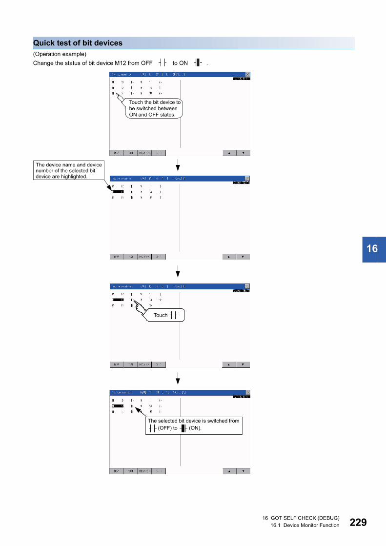
16
Quick test of bit devices(Operation example)
Change the status of bit device M12 from OFF to ON .
The selected bit device is switched from (OFF) to (ON).
Touch the bit device tobe switched betweenON and OFF states.
The device name and devicenumber of the selected bitdevice are highlighted.
Touch
16 GOT SELF CHECK (DEBUG)16.1 Device Monitor Function 229

23
Quick test of word devices(Operation example)
Change the device value of word device D200 from 43 to 100.
Conditions: Data range: 16 bits, device value display format: decimal number
The device value of D200 ischanged from 43 to 100.
Touch the device valueto be changed.
Input a device value by using thekeyboard.Input "100" for the operation example.
Touch [ENT] key.
016 GOT SELF CHECK (DEBUG)16.1 Device Monitor Function

16
When the cursor is displayed
When the cursor is displayed, touch the [ ] or [ ] key to move the cursor to the upper or lower registered
device.
Touch
16 GOT SELF CHECK (DEBUG)16.1 Device Monitor Function 231

23
16.2 FX List EditorThe MELSEC-FX list editor can change the sequence programs on the FX PLC.
Display operation of FX list editor
Main menu Debug
Cannel Setting
FX list editor
Touch [Debug].
Touch [FX list editor].
216 GOT SELF CHECK (DEBUG)16.2 FX List Editor

16
Parameters and sequence programs are easy to maintain.You can check or partly correct, change or add FX PLC parameters and sequence programs simply by operating keys.
You can easily edit sequence programs without preparing any peripheral unit other than the GOT.
Errors that occur during list editing can be checked easily.Error messages, error codes, and number of steps for errors that occur in the FX PLC can be checked.
Details can be checked immediately even for errors that occur during list editing.
Commands and devices can be searched and displayed.Commands and devices used in sequence programs can be searched.
The correction position can be searched for cases such as when you want to correct a specific device.
Changed
(Example of changing sequence program commands)
LD X000OUT Y020LD X001
LD X000OUT Y030LD X001
Searched deviceM800
Displays the searched device.
LD M 800
OUT T 10K 100
LD X 002
16 GOT SELF CHECK (DEBUG)16.2 FX List Editor 233

23
Specifications
System configurationThis section describes the system configuration of the MELSEC-FX list editor.
For the setting method in each connection form, used communication unit/cable and cautions on connection form, refer to the
following manual.
GOT2000 Series Connection Manual For GT Works3 Version1
Controllers that can be edited with the MELSEC-FX list editorTarget controller*1:FXCPU
*1 FX list editor is not applicable to for MELSEC iQ-F series.
Connection formsThis function can be used in the following connection types.
( : Available, : Unavailable)
*1 MELSEC-FX list editor cannot be used when using CC-Link IE field network Ethernet adapter.*2 Available only when using FX3 series.
Functions list and monitor conditionsThe following shows the memory that can be monitored by the MELSEC-FX list editor and the FX PLC status conditions.
( : Can be monitored : Can be monitored under certain conditions : Cannot be monitored)
*1 The operation is available only when the protect switch is OFF.*2 The available memory differs depending on the FX PLC being used.
For details, refer to the following.The hardware manual of the FX PLC being used
Function name Connection form between GOT and PLC
Name Description Direct CPU connection Ethernet connection*1
MELSEC-FX list editor Sequence program writing, parameter setting,
PLC diagnostics and keyword registration, etc.
*2
Function Memory that can be monitored*2 FX PLC status
Reference
Built-in memory
RAM memory cassette
EEPROM memory cassette, flash memory cassette
EPROM memory cassette
Reading
sequence
programs
Displaying sequence
programs
RUN/STOP Page 241 Displaying
sequence programs
Searching commands/
devices
Page 243 Searching
commands/devices
Writing
sequence
programs
Writing commands *1 For Stop only Page 245 Writing commands
Changing operands/
set values
Page 250 Deleting
commands
Inserting commands Page 245 Writing commands
Deleting commands Page 250 Deleting
commands
Sequence program all clear Page 251 Sequence program
all clear
PLC diagnostics RUN/STOP Page 252 PLC diagnostics
Parameter setting Display Page 254 Parameter setting
Setting *1 For Stop only
Keyword RUN/STOP Page 256 Keyword
416 GOT SELF CHECK (DEBUG)16.2 FX List Editor

16
Access rangeFor the FXCPU in Ethernet connection, the GOT can monitor only the host station.
The access range other than the above is the same as the access range when the GOT is connected to a controller.
For details of the access range, refer to the following.
GT Designer3 (GOT2000) Screen Design Manual
GOT2000 Series Connection Manual (Mitsubishi Product) For GT Works3 Version1
Precautions
Using other peripheral equipment for sequence program/parameter changeWhen using the MELSEC-FX list editor, do not change programs or parameters in the PLC CPU from other peripheral
equipment.
If programs or parameters are changed, exit the MELSEC-FX list editor once and start the MELSEC-FX list editor again.
If the program on one PLC is changed carelessly from multiple units of peripheral equipment (including GOT), the contents of
the program in the PLC CPU and the peripheral equipment may not be the same, resulting in an unintended operation of the
PLC CPU.
Sequence program changeStop the FX PLC before changing (writing, inserting, deleting) a sequence program or changing parameters.
Operation is not possible with the FX PLC running.
If you press the [GO] key but the system does not proceed to the next operation (for example, a search)Check the input contents (applied instruction number, device value, etc.).
When using list monitorOnly devices to be used for basic instructions can be monitored.
The status of devices (word, bit) to be used for application instructions cannot be monitored.
16 GOT SELF CHECK (DEBUG)16.2 FX List Editor 235

23
Display operation
Operation to displayThe following describes the outline for displaying the operation screen of the MELSEC-FX list editor.
*1 For information on how to set a special function switch, refer to the following.GT Designer3 (GOT2000) Screen Design Manual
*2 For details on the operation method, refer to the following.Page 256 Keyword
• How to display the utility
For how to display the utility, refer to the following.
Page 64 Utility Function List
• If the project data has not been downloaded
The MELSEC-FX list editor can be started from the utility even if the project data has not been downloaded to
the GOT.
Start
Turn on the power to the GOT.
The MELSEC-FX list editor is started.
Display the utility. Touch the special function switch.*1
Starting from the utility Starting from the special functionswitch (MELSEC-FX list editor)set in the project data
End
Enter the keyword.*2
After the utility is displayed, touch[Debug] [MELSEC-FX List editor]from the main menu.For how to display the utility, referto the user's manual of the GOT tobe used.
When no keywordis registered in theconnected FX PLC
When a keyword isregistered in theconnected FX PLC
616 GOT SELF CHECK (DEBUG)16.2 FX List Editor

16
Changing screensThis section describes how to change the screen.
*1 With setting special function switches (FX list monitor), the list monitor can be started on the monitor screen.When the list monitor is started on the monitor screen, the list editor cannot be used.For how to set special function switches, refer to the following.GT Designer3 (GOT2000) Screen Design Manual
Utility Main Menu or
user-created monitor screen
Start
Communication setting window
[ChNo.]
[PLC diagnostics]
[Parameter setting]
MORE
MORE
CLR OP
GO
[Keyword setup]
[List Monitor]
OP
CLR
GO
GO
GO
*1
16 GOT SELF CHECK (DEBUG)16.2 FX List Editor 237

23
Operation proceduresThis section describes the contents of the MELSEC-FX list editor and the key functions displayed on the screen.
Key arrangement and a list of key functionsThe arrangement and functions of the keys displayed on the MELSEC-FX List Editor window are described below.
Displayed contents
No. Item Display contents
1) Channel No Displays the currently selected channel number.
Touching "ChNo." displays the communication setting window.
The communication setting window is not displayed if the MELSEC-FX list editor is started from the FX ladder monitor.
2) Mode Displays a mode for MELSEC-FX list editor.
Page 240 Selection and operation of modes
[Monitor] is displayed when the list monitor is executed.
Page 258 List monitor
3) Error message Displays the contents of errors that occur with the MELSEC-FX list editor.
Page 260 Error messages and corrective actions
4) List display area Displays the sequence program in list format (12 digits).
The position (line) that can be edited is displayed with a bar.
5) Key area Displays the keys that can be used with the MELSEC-FX list editor.
4)
1)
5)
3)
2)
816 GOT SELF CHECK (DEBUG)16.2 FX List Editor

16
Key functionsThe table below shows the functions of the keys that are used for the operation on the MELSEC-FX list editor screen.
Keyboard switchingTouching the MORE button switches the command keyboard 1 and command keyboard 2.
When you touch the button for a keyboard function, the optimum keyboard for input for that function is displayed
automatically.
Key Function
Displays the currently selected channel number.
The communication setting window is not displayed if the MELSEC-FX list editor is started from the FX ladder monitor.
Selects a mode for MELSEC-FX list editor.
Page 240 Selection and operation of modes
Displays the PLC diagnostics, parameter setting, and keyword selection menu.
Switches between command keyboard 1 and command keyboard 2.
Page 239 Keyboard switching
When inputting commands: Cancels the key input when only part of the command has been input.
Page 259 Action for an incorrect key input
When option menu is displayed: Closes the option menu.
Commands cannot be deleted with this key.
Page 250 Deleting commands
Space key.
This key is used when setting timers and counters, writing applied commands, etc.
Displays the list from a specified step number when the step number is input.
Moves the list display area bar up and down and switches the line being edited.
Determines the key operation.
Inputs commands, device names, etc.
The key contents depend on the input contents.
The commands that can be used differ depending on the target FX PLC.
Refer to the manual for the FX PLC to be used.
Exits the MELSEC-FX list editor.
to ,
to , etc.
Touch
Touch
Command keyboard 1 Command keyboard 2
16 GOT SELF CHECK (DEBUG)16.2 FX List Editor 239

24
Selection and operation of modesThe MELSEC-FX list editor has four modes: READ, WRITE, INSERT, and DELETE.
Select an appropriate mode for the intended operation.
For more information on the mode to select, refer to the function operations from subsection 15.3.8.
How to change modesTouch the MODE button.
Each time you touch this button, the mode changes.
In the case the mode cannot be changedIn the following cases, the mode can be changed to the READ mode only.
If you try to change to other than READ mode, an error message is displayed.
To change to other than READ mode, take the action below.
Error message Cause Corrective action
PLC is running The FX PLC is in the RUN status. Stop the FX PLC.
Can not write. The protect switch of the EEPROM memory cassette is on. Switch off the protect switch of the EEPROM memory
cassette.
The EPROM memory cassette is enabled. Set a memory other than EPROM as the memory to write to.
Touch the button.
The current mode is displayed.
016 GOT SELF CHECK (DEBUG)16.2 FX List Editor

16
Displaying sequence programsSequence programs are read from the FX PLC to the GOT and displayed.
There are two displaying methods: specifying the step number, and scrolling one screen at a time.
Display using cursor keys
■Operation
■ExampleScroll one line upward or downward.
Display specifying the step number
■Operation
■ExampleDisplaying step number 123.
When the specified step number is the operand of an applied instruction
If the specified step number is a timer (T) or counter (C) set value or the operand of an applied instruction, that
command section is displayed at the head.
Scroll with OR
128 MPP
129 DIV 23
D56
K200
128 MPP
129 DIV 23
D56
K200
128 MPP
129 DIV 23
D56
K200
Scrolling one line upward Scrolling one line downward
STEP GOInput the step number.
STEP
GO
Input the step number
Step number
0 LD X 000
1 OUT Y 000
2 LDI M 100
3 MOV 12
123 MOV 12
K 200
D 58
128 MPP
123
3 MOV 12
16 GOT SELF CHECK (DEBUG)16.2 FX List Editor 241
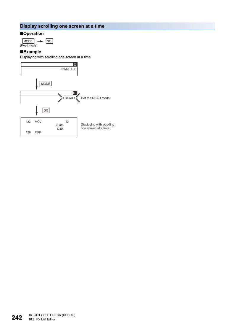
24
Display scrolling one screen at a time
■Operation
■ExampleDisplaying with scrolling one screen at a time.
MODE GO
(Read mode)
MODE
GO
Set the READ mode.
Displaying with scrolling
one screen at a time.
123 MOV 12
K 200
D 58
128 MPP
< WRITE >
< READ >
216 GOT SELF CHECK (DEBUG)16.2 FX List Editor

16
Searching commands/devicesDisplays a command or device by searching it in sequence program from Step 0.
Command search
■Operation
*1 If the command you want to search for is not on the keyboard, touch the key to switch to the other keyboard.When searching for an applied instruction, touch the key and input the applied instruction number.When searching for a label, touch or and input the pointer number.Page 245 Writing commands
*2 Input only when searching for commands requiring a device name and device number.*3 After the search results are displayed, you can continue searching with the same conditions by touching the key. Touching any key
other than the key ends the search.
■ExampleSearching for LD M8000
Pointer (P, I) searches
For pointer searches, only labels are searched.
Pointers specified as operands in applied instructions are not searched.
MODE
(Read mode)
*1 *2 *3
Select the command to search for.
Input the device name and device number.
GO GO
MOREFNC
P I
GOGO
M 8 0 0 0 GO
GO(Continue to search with the same conditions)
MODE
LD
< WRITE >
< READ >
Search command
Select the command to search for.( )
Set the READ mode.
3 MOV 12
8 LD M 8000
9 OUT T 10
K 100
12 LD X 002
24 LD M 8000
25 OUT T 0
K 100
28 OUT T 1
LD
16 GOT SELF CHECK (DEBUG)16.2 FX List Editor 243

24
Device search
■Operation
*1 After the search results are displayed, you can continue searching with the same conditions by touching the key. Touching any key other than the key ends the search.
■ExampleSearching for LD M8000
Devices that cannot be searched
The following devices cannot be searched.
• Pointers, interrupt pointers
• Constant K, constant H, constant E
• Digit specification of bit device
• Special function unit/block buffer memory
• Devices specified with the operand of an applied instruction
Pointers and interrupt pointers can be searched for with command searches.
Page 243 Command search
* 1
MODE SP GO GOInput the device name and device number.
(Read mode)
GOGO
GO(Continue to search with the
same conditions)
GO
MSP 8 0 0 0
MODE
Search device
Set the
READ mode.
3 MOV 12
8 LD M 8000
9 OUT T 10
K 100
12 LD X 002
24 LD M 8000
25 OUT T 0
K 100
28 OUT T 1
M8000< WRITE >
< READ >
416 GOT SELF CHECK (DEBUG)16.2 FX List Editor

16
Writing commandsWrites a sequence program to the FX PLC. (Overwrite/Insert)
Writing basic commands
■OperationsInputting command only (Ex.: ANB, ORB command etc.)
Inputting command and device (LD, AND commands etc.)
Inputting command, No. 1 device, No. 2 device (MC, OUT (T, C) commands, etc.)
Moving the cursor to the position to write the command
When starting to write a command, place the cursor on the command line (the line on which the step number
is displayed).
You cannot write a command with the cursor on an operand or set value line.
MODE GOStop the FX PLC Input the command
For overwriting: (WRITE mode)
For insertion: (INSERT mode)
MODE
GO
Stop the FX PLC
Input the device name and device number
Input the command
For overwriting: (WRITE mode)
For insertion: (INSERT mode)
GOSP
MODEStop the FX PLC Input the device name and device numberInput the command
For overwriting: (WRITE mode)
For insertion: (INSERT mode)
Input the device name and device number
Command line (Place the cursor on this line.)
Operand, set value line (Cannot operate on this line.)
2 LDI M 100
3 MOV 12
D 0
D 10
16 GOT SELF CHECK (DEBUG)16.2 FX List Editor 245

24
■ExampleWriting ORB command
Inputting LD X000
ORB GO
MODE
Set the
WRITE or
INSERT
mode
With or , move the
cursor to the position to
overwrite/insert the command.
Stop the FX PLC
4 LDI X 004
5 AND X 005
6 NOP
7 NOP
4 LDI X 004
5 AND X 005
6 ORB
7 NOP
< READ >
< WRITE >
0XLD GO
MODE
Set the
WRITE or
INSERT
mode.
Stop the FX PLC
0 NOP
1 NOP
2 NOP
3 NOP
0 LD X 000
1 NOP
2 NOP
3 NOP
< READ >
< WRITE >
With or , move the
cursor to the position to
overwrite/insert the command.
616 GOT SELF CHECK (DEBUG)16.2 FX List Editor
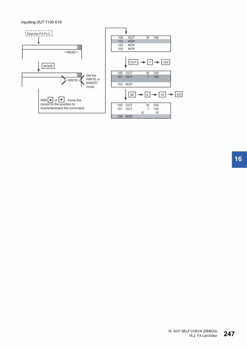
16
Inputting OUT T100 K19
OUT
SP K 19 GO
100T
100 OUT M 100
101 NOP
102 NOP
103 NOP
100 OUT M 100
101 OUT T 100
103 NOP
100 OUT M 100
101 OUT T 100
K 19
104 NOP
MODE
< READ >
< WRITE >
With or , move the
cursor to the position to
overwrite/insert the command.
Set the
WRITE or
INSERT
mode.
Stop the FX PLC
16 GOT SELF CHECK (DEBUG)16.2 FX List Editor 247

24
Writing applied instructions
■Operation
*1 (double word command) and (pulse execution format command) can also be input after the applied instruction number is input.*2 Inputting in the order is also possible.*3 When a command specifies multiple devices for operations, input the key followed by the device name and device number.
• Moving the cursor to the position to write the command
When starting to write a command, place the cursor on the command line (the line on which the step number
is displayed).
You cannot write a command with the cursor on any other line.
• Commands using a text string constant for a command operand (such as ASC command)
With the MELSEC-FX list editor, text string constants cannot be written as operands. (such as ASC
commands)
Use GX Developer for writing such commands.
■ExampleInput "DMOVP D0 D2".
Applied instruction number
*1
*1
*2
Stop the FX PLC
Input the device name and device number.
MODE
P SP GO
FNC D
For overwriting: (WRITE mode)
For insertion: (INSERT mode)
D PP D
2 LDI M 100
3 MOV 12
D 0
D 10
Command line (Place the cursor on this line.)
Operand, set value line (Cannot operate on this line.)
SPD 1 2 P
SPD 0 D 2 GO
MODE
FNC
200 NOP
201 NOP
202 NOP
203 NOP
200 FNC
201 NOP
202 NOP
203 NOP
200 DMOVP 12
203 NOP
200 DMOVP 12
D 0
D 2
209 NOP
*1
< READ >
< WRITE >
Set the
WRITE or
INSERT
mode.
With or , move the
cursor to the position to
overwrite/insert the command.
Stop the FX PLC
816 GOT SELF CHECK (DEBUG)16.2 FX List Editor

16
Changing operands, set valuesChanges the operand section of an applied instruction and OUT (T, C) command set value.
Operation
*1 For decimal numbers, input K, then the number.For hexadecimal numbers, input H, then the number.
Moving the cursor to the line on which the operand or set value is to be changed
When starting to change an operand or a set value, place the cursor on the line of the operand or set value to
be changed (the line on which the step number is not displayed).
If you place the cursor on the command line, the input operation is not possible.
ExampleChanging "MOV D0 D10" to "MOV D0 D123"
MODE SP GO
(Read mode)
Stop the FX PLC Input the device name and device number
D 1 2 3SP GO
MODE
3 MOV 12
D 0
D 10
8 LD M 10
3 MOV 12
D 0
D 123
8 LD M 10
< READ >
< WRITE >
Set the
WRITE
mode.
Stop the FX PLC
Move the cursor to the changed
location with or
16 GOT SELF CHECK (DEBUG)16.2 FX List Editor 249
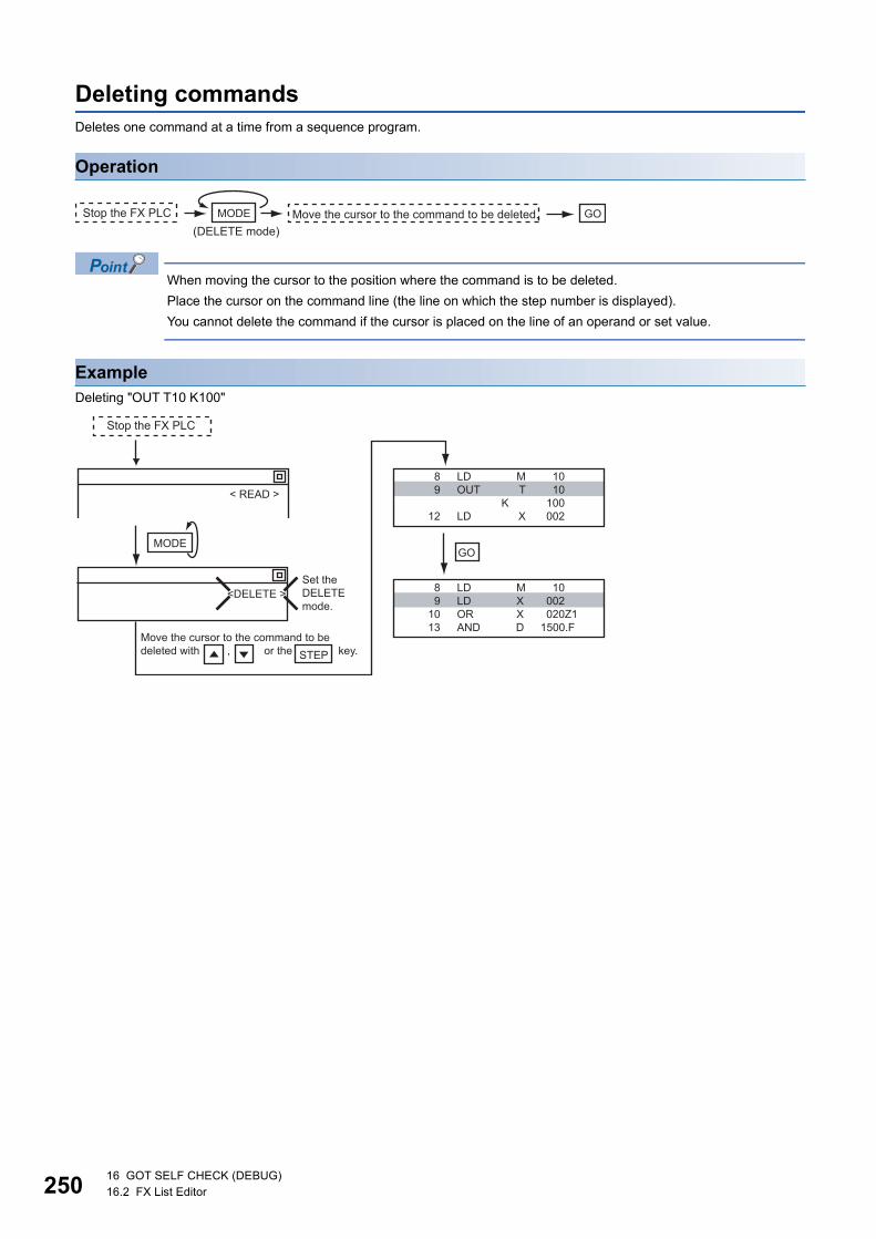
25
Deleting commandsDeletes one command at a time from a sequence program.
Operation
When moving the cursor to the position where the command is to be deleted.
Place the cursor on the command line (the line on which the step number is displayed).
You cannot delete the command if the cursor is placed on the line of an operand or set value.
ExampleDeleting "OUT T10 K100"
MODE GOStop the FX PLC Move the cursor to the command to be deleted.
(DELETE mode)
GO
8 LD M 10
9 OUT T 10
K 100
12 LD X 002
8 LD M 10
9 LD X 002
10 OR X 020Z1
13 AND D 1500.F
MODE
STEP
Set the
DELETE
mode.
Move the cursor to the command to be
deleted with , or the key.
< READ >
<DELETE >
Stop the FX PLC
016 GOT SELF CHECK (DEBUG)16.2 FX List Editor
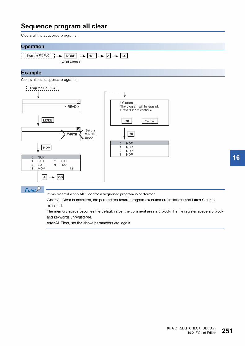
16
Sequence program all clearClears all the sequence programs.
Operation
ExampleClears all the sequence programs.
Items cleared when All Clear for a sequence program is performed
When All Clear is executed, the parameters before program execution are initialized and Latch Clear is
executed.
The memory space becomes the default value, the comment area a 0 block, the file register space a 0 block,
and keywords unregistered.
After All Clear, set the above parameters etc. again.
(WRITE mode)
MODE NOP A GOStop the FX PLC
MODE OK
OK
Cancel
NOP
A GO
! Caution
The program will be erased.
Press "OK" to continue.
0 NOP
1 OUT Y 000
2 LDI M 100
3 MOV 12
0 NOP
1 NOP
2 NOP
3 NOP
< WRITE >
< READ >
Stop the FX PLC
Set the
WRITE
mode.
16 GOT SELF CHECK (DEBUG)16.2 FX List Editor 251

25
PLC diagnosticsDisplays the FX PLC error message, error code, and step at which the error occurred.
Operation
PLC diagnostics screenThe following describes the contents displayed on the PLC diagnostics screen and the function of on-screen key.
■Displayed contents
Error details
For details of the FX PLC errors, refer to the following.
Programming manual for the FXCPU used
No. Item Display contents
1) Error message Displays the error message. (I/O configuration error/PLC hardware error/PC/HPP communication error/Serial communication
error/Parameter error/Syntax error/Circuit error/Operation error)
2) Detail Displays the error code.
3) Step Displays the step number in the sequence program at which the error occurred.
(This is displayed only for a syntax error, circuit error, or operation error.)
OP GO [PLC diagnostics]
OP
GO
Select [PLC diagnostics] with or
1) 2) 3)
216 GOT SELF CHECK (DEBUG)16.2 FX List Editor

16
■Key functionThe table below shows the functions of the keys that are used for the operation on the PLC diagnostics screen.
Key Function
Exits the PLC diagnostics.
16 GOT SELF CHECK (DEBUG)16.2 FX List Editor 253

25
Parameter settingSets FX PLC parameters.
Parameters that can be changed and change targets
■Parameters that can be changedThe parameters that can be changed with the MELSEC-FX list editor and the target FX PLCs are as follows.
: Can be set/changed : Cannot be set/changed
*1 When connecting an FX0(S), set "0". Setting other than "0" causes a parameter error.*2 When the parameters are initialized, the display on the MELSEC-FX list editor is different from the FX PLC default values, but do not
change the latch range. Changing the latch range causes an error.
■Change targetsWhen a memory cassette is mounted, the parameters in the memory cassette are targeted for changes.
Operation
*1 When checking parameters (not changing), it is not necessary to stop the PLC.
Item Target CPU
FX0(S)/FX0N
FX1 FX2(C) FX1S FX1N(C) FX2N(C) FX3S FX3G(C) FX3U(C)
Memory space setting
File register space setting *1
Latch range setting *2 *2 *2
RUN terminal setting
Initialization of parameters
Stop the FX PLC [Parameter setting] OP GO*1
OP
GO
Select [Parameter setting] with or .
*1Stop the FX PLC
416 GOT SELF CHECK (DEBUG)16.2 FX List Editor

16
Parameter setting screenThe following describes the contents displayed on the PLC diagnostics screen and the function of on-screen key.
■Displayed contents
• Memory space for kana comments after changing memory space, file register space
If the memory space is set smaller than the total of the file register space and kana comment space, the kana
comment space is automatically reduced.
(With the MELSEC-FX list editor, the kana comment space is not displayed.)
Note that if any setting as described below is made, the kana comment space is reduced.
(Settings that reduce kana comment space and the kana comment space after setting change)
Settings resulting in Nm < Nf 500 + Nk 500 + 500
Nm: Memory space after change (steps)
Nf: File register space after change (blocks)
Nk: Comment space before change (blocks)
• Settable range and default value
The settable range and the default value depend on the FX PLC type.
For details of the settable range and the default value, refer to the following.
Programming manual for the FX PLC used
■Key functionsThe table below shows the functions of the keys that are used for the operation on the parameter setting screen.
No. Item Display contents
1) Memory capacity Sets the memory space (number of steps).
If you touch the section, you can change the memory space.
2) File reg. capacity Sets the memory space (number of blocks) allocated to the file register.
Touch the section and input the number of blocks.
3) Latch range Sets the latch range (power failure hold area).
Touch the number display section and input the value.
4) RUN terminal input Sets whether or not to use one of the FX PLC input terminals for RUN input.
Touch the section and set the device to be set for the RUN terminal.
5) Default Initializes the parameters
Key Function
Initializes the parameters
Completes the changed setting contents.
Ends parameter setting.
1)
2)
3)
4)
5)
Kana comment space (steps) after setting change =500
Nm-Nf 500-500
16 GOT SELF CHECK (DEBUG)16.2 FX List Editor 255

25
KeywordRegisters, deletes, releases protection for, and sets protection for the FX PLC keywords.
Function usability of the MELSEC-FX list editor for keyword protection levelsThe functions that can be used with the MELSEC-FX list editor depend on the keyword protection level.
: Available, : Unavailable
*1 When the 2nd keyword is set to an FX PLC that supports 2nd keyword, it becomes " " (cannot be used).*2 The names within the parentheses ( ) are for when a keyword + 2nd keyword is set.
Operation
Function Keyword protection level Reference
All operation protect(All on-line operation protect)*2
Read/Incorrect write protection(Read/Write protection)*2
Erroneous write prohibition(Write protection)*2
Keyword not registered/keyword protection canceled
Reading
sequence
programs
Displaying sequence
programs
Page 241 Displaying sequence
programs
Searching
commands/devices
Page 243 Searching commands/
devices
Writing
sequence
programs
Writing commands Page 245 Writing commands
Changing operands/
set values
Page 250 Deleting commands
Inserting commands Page 245 Writing commands
Deleting commands Page 250 Deleting commands
Sequence program all clear Page 251 Sequence program all clear
PLC diagnostics *1 Page 252 PLC diagnostics
Parameter setting Page 254 Parameter setting
OP
GO
Select [Keyword setup] with or .
OP GO[Keyword setup]
616 GOT SELF CHECK (DEBUG)16.2 FX List Editor

16
Keyword screen and protection levelWhen [Keyword setup] is selected with the MELSEC-FX list editor, the keyword screen is displayed.
For the keyword operation, refer to the following.
Page 96 Keyword
Keywords
For details of the keyword, refer to the following.
Programming manual for the FX PLC used
16 GOT SELF CHECK (DEBUG)16.2 FX List Editor 257

25
List monitorThe status of contacts and coils in a sequence program is displayed.
Operation
Starting list monitor with special function switches (FX list monitor)
With setting special function switches (FX list monitor), the list monitor can be started on the monitor screen.
When the list monitor is started on the monitor screen, the list editor cannot be used.
For how to set special function switches, refer to the following.
GT Designer3 (GOT2000) Screen Design Manual
OP
GO
Select [List Monitor] with or .
When the list monitor is started on the FX list editor screen, the step numbers displayed on the FX list editor screen is displayed on the list monitor screen.
OP GO[ List Monitor ]
816 GOT SELF CHECK (DEBUG)16.2 FX List Editor

16
Displays and key functionsThe following describes the displays for the list monitor.
*1 The status of contacts and coils is displayed as below.
Action for an incorrect key inputIf an incorrect key is input, cancel the input contents.
Operations
■Before touching the key (before reading/writing the input contents)Before touching the key, touch the key.
■After touching the key (after reading/writing the input contents)Write the command again.
Page 245 Writing commands
Commands finalized by writing and inserting operations are revised (overwritten) with the program writing.
No. Item Display contents
1) List display area*1 The status of contacts and coils is displayed on the left of device displays.
2) Keys The same operations as in the READ mode of the FX list editor can be executed.
Page 241 Displaying sequence programs
3) [ ] Ends the list monitor.
(When the list monitor is executed on the FX list editor screen, the screen is switched to the FX list editor screen.)
Type of instruction Description Status
■ Displayed ■ Not displayed
LD, AND, OR (Contact instruction (Normal open)) Contact ON OFF
LDI, ANI, ORI (Contact instruction (Normal close)) Contact OFF ON
OUT, SET TC: Coil ON OFF
Except TC: Contact ON OFF
RST TC: Reset ON OFF
Word device Value: 0 Value: Except 0
Except TC and word device:
Contact
OFF ON
MC, STL Contact ON OFF
LDP, ANDP, ORP, LDF, ANDF, ORF
(Rise or fall contact instruction)
Not monitored Always ■ not displayed
2)
1)
3)
GOGO CLR
GO
16 GOT SELF CHECK (DEBUG)16.2 FX List Editor 259

26
Error messages and corrective actionsThis section describes the error messages displayed when the MELSEC-FX list editor is executed, and corrective action.
How to erase an error message
An error message is not erased even if the cause of the error is eliminated.
To erase an error message, touch a key on the MELSEC-FX list editor screen.
Error message Description Corrective action
Can not display while protected. The all-operation protect, anti-plagiarism, or
incorrect write protect keyword is set.
• Check the protected operation.
• Clear the keyword protection or delete the keyword.
Page 256 KeywordCan not operate while protected.
PLC parameter error. An FX PLC parameter is defective. Set correct parameters in the FX PLC.
PLC communications error. The communication with the FX PLC is
defective.
• Check the FX PLC, cable, and GOT for abnormality.
• Check whether the communication settings are correct or not.
PLC is running. A writing operation etc. has been made while
the FX PLC is running.
Stop the FX PLC.
Can not write. • The memory to write to is EPROM.
• The protect switch of the EEPROM is on.
• Set other than EPROM for the memory to write to.
• Switch off the protect switch of the EEPROM.
Step number is out of a range. The specified step number exceeded the
maximum number.
Specify a step number below the maximum value.
Not found. The specified command cannot be found. Proceed to the next operation.
Not found. The specified device cannot be found. Proceed to the next operation.
Step overflow. The program may exceed the available
space.
(Writing is not executed.)
Check the program memory space and delete commands to keep it
within the space.
Page 250 Deleting commands
Command error. An invalid command (non-existent
command) was specified.
Input the correct command.
016 GOT SELF CHECK (DEBUG)16.2 FX List Editor

16
16.3 FX3U-ENET-ADP Communication Setting FunctionIn GX Works2, the communication set value of the FX3U-ENET-ADP stored in the CPU can be changed.
This function is not available when the communication set value of the FX3U-ENET-ADP is not set in advance in the CPU.
Communication setting in the CPU
In GX Works2, set in advance the communication set value of the FX3U-ENET-ADP to the CPU.
For the details of the communication setting, refer to the following.
FX3U-ENET-ADP User's manual
Specifications
System configurationThis section describes the system configuration of the FX3U-ENET-ADP communication setting function.
For the setting method in each connection form, used communication unit/cable and cautions on connection form, refer to the
following manual.
GOT2000 Series Connection Manual For GT Works3 Version1
■Required basic system application
■Connection type( : Applicable, : Partly restricted, : Inapplicable)
■Communication setting itemsThe table below shows the communication setting items and setting range.
*1 Set the value "0.0.0.0" when not using the subnet mask pattern and default router IP address.
Operating system Version
Basic system application -
Communication driver MELSEC-FX -
Function Connection type between GOT and controller
Name Description Direct CPU connection
GOT multidrop connection
FX3U-ENET-ADP communication
setting function
The communication set value of the FX3U-ENET-ADP
stored in the CPU can be changed.
Communication setting items Setting range Remark
IP address 0.0.0.1 to 223.255.255.254 If a value outside the setting range is entered, the error message "SET
NUMBER IS INCORRECT." appears.Subnet mask pattern*1 192.0.0.0 to 255.255.255.252
Default router IP address*1 0.0.0.1 to 223.255.255.254
16 GOT SELF CHECK (DEBUG)16.3 FX3U-ENET-ADP Communication Setting Function 261

26
Display operation of FX3U-ENET-ADP communication setting function
Main Menu Debug
When the communicationset value of theFX3U-ENET-ADP is notstored in the CPU
When reading from theCPU is protected by thekeyword When the communication set value of
the FX3U-ENET-ADP is stored in the CPU
Touch [FX3U-ENET-ADP]
Channel Setting
Touch [OK]
Touch [×]
Touch [Debug]
Touch [OK]
216 GOT SELF CHECK (DEBUG)16.3 FX3U-ENET-ADP Communication Setting Function

16
Setting operation1. Touch the numerical part of the octet to be changed
among the 1st to 4th octets.
2. When the ten-key pad appears, enter a numerical value
in up to 3 digits, and touch the key. If a numerical
value outside the setting range is entered, the following
error message appears. Enter a numerical value again.
For the details of the setting range, refer to the following.
Page 261 Specifications
3. The changed IP address is displayed. At this time, the
changed communication set value of the FX3U-ENET-
ADP is not written to the CPU. Touch the [ ] key.
4. When the screen shown on the left appears, touch the
[YES] key.
Touch the numerical partof the octet to be changed.
Touch
Touch[×]
Touch [YES]
16 GOT SELF CHECK (DEBUG)16.3 FX3U-ENET-ADP Communication Setting Function 263

26
5. When the screen shown on the left appears, the
changed communication set value of the FX3U-ENET-
ADP is written normally to the CPU. For making valid
the contents of setting, turn OFF the power of the CPU,
and then turn it ON again. Change the setting of the
subnet mask pattern and default router IP address using
the same procedure if necessary. An error message
appears in the following cases. Touch the key to
return to the step 1., and perform the setting procedure
again.
When the CPU is running
The following error message appears. Stop the running
status of the CPU.
When a communication error occurs
Set the communication between the GOT and the CPU to the
normal status.
When the memory cassette is write-protected
Set to OFF the write-protect switch of the memory cassette.
When writing to the CPU is protected by the keyword
Clear the protection by the keyword against writing.
416 GOT SELF CHECK (DEBUG)16.3 FX3U-ENET-ADP Communication Setting Function

16
When the CPU stores the symbolic information
When the setting such as IP address is changed using this function and then the program is read by the
programming tool from the CPU that stores the symbolic information, the following warning appears. However,
the changed value is read correctly. Convert and compile the project again.
16 GOT SELF CHECK (DEBUG)16.3 FX3U-ENET-ADP Communication Setting Function 265

26
MEMO
616 GOT SELF CHECK (DEBUG)16.3 FX3U-ENET-ADP Communication Setting Function

17
17 MAINTENANCE17.1 Touch Panel Calibration
Touch panel calibration setting functionTouch panel reading error can be corrected.
Normally the adjustment is not required, however, the difference between a touched position and the object position may
occur as the period of use elapses.
When any difference between a touched position and the object position occurs, correct the position with this function.
Touch panel calibration setting display operation
Run Stop Run Stop
Before adjustment After adjustment
The [Run] will operate though youintended to touch the [Stop] button.
The [Stop] button can be touchedwithout fail.
Main Menu Maintenance
Calibration
Touch [Maintenance].
Touch [Calibration].
17 MAINTENANCE17.1 Touch Panel Calibration 267

26
Touch panel calibration operationTouch [+] displayed on the screen with the finger one by one to make the setting.
1. Touch the center of [+] displayed on the upper left
precisely.
2. Touch [+] displayed on the lower left.
3. Touch [+] displayed on the upper right.
4. Touch [+] displayed on the lower right.
5. When the precise touch could not be made, touch the
[YES] button to make the setting from Step1 again.
817 MAINTENANCE17.1 Touch Panel Calibration

17
17.2 Touch Panel CheckTouch panel check functionTouch panel check function checks whether there is no dead zone area of 2 dots 2 dots.
Display operation of Touch panel check
Notes on Touch panel check
If the touched part is not filled with yellow color, there are the following two possible causes.
1. Display part failure
2. Touch panel failure
In that case, contact your local Mitsubishi (Electric System) Service.
Main Menu Maintenance
Panel check
Touch [Maintenance].
Touch [Panel check].
17 MAINTENANCE17.2 Touch Panel Check 269

27
Touch panel check operationsIf touch [Panel check] of self-check, a black-filled screen is displayed over the entire screen area.
Checking the upper left part of the screen
Only the upper left part of the screen cannot be filled with yellow.
If the screen returns to the self-check by touching the upper left part, judge that the upper left area operates
normally.
1. Touch a part of the screen. The touched part becomes a
yellow-filled display. Up to 40 parts becomes yellow-
filled displays.
2. If [ ] on the upper right is touched, the screen returns to
the self-check.
Black-filled screenYellowcolor
017 MAINTENANCE17.2 Touch Panel Check

17
17.3 CleanIn utility, the screen can be set as not to be effected by touching the screen when clean with clothes.For cleaning method, refer to the following.
Page 281 Cleaning Method
Display operation of clean
Display operation of clean
For details of cleaning method, refer to the following.
Page 281 Cleaning Method
1. Touching the [ ] key closes the screen. Even if touch
points other than the upper left corner and upper right
corner of the screen, the GOT does not operates.
Main Menu Maintenance
Clean
Touch [Maintenance].
Touch [Clean].
Touch
17 MAINTENANCE17.3 Clean 271

27
MEMO
217 MAINTENANCE17.3 Clean

18
18 BootOS and System Application Installation Using Data Storage
There are the following two types for the installation of BootOS and system applications using a data storage.
Installing when starting the GOTPage 274 Installing when starting the GOT
All the system applications and project data stored in the data storage are transferred to the GOT when powering on the GOT.
This installing method is effective in the following cases.
• The GOT utility cannot be displayed.
• The system application is not installed.
Installing using the data control function (Utility)Page 274 Installing when starting the GOT
By operating the utility, select the system application or project data stored in the data storage and transfer them to the GOT.
Precautions on installing BootOS, system applications
• Installing both BootOS and system applications
After completing BootOS installation, install system applications. When installing BootOS, the built-in flash
memory in the GOT is initialized and goes to the status at factory shipment. (All system applications and
project data are erased.)
BootOS is installed in the GOT at factory shipment. It is not necessary to install BootOS when not upgrading it.
• Installation cannot be interrupted.
Do not perform any of the following during a BootOS or system application installation.
Failure to do so may result in installation failure, causing the GOT malfunction.
Powering off the GOT
Pressing the reset button of the GOT
Removing the data storage
If the installation failure and the GOT malfunction occur, take the following action.
If BootOS installation failed:
Please consult your local Mitsubishi (Electric System) Service center or representative.
If the basic system application installation failed:
Page 274 Installing when starting the GOT
18 BootOS and System Application Installation Using Data Storage 273

27
18.1 Installing when starting the GOT
When installing with an SD card1. Power OFF the GOT, and install the SD card where the BootOS, system application or project data is stored in the SD
card interface of the GOT.
2. Power on the GOT. While touching the lower right side of the GOT screen, power on the GOT. (1-point press installation
function)
3. The BootOS or system application is installed in the built-in flash memory. Do not pull out the SD card or power OFF the
GOT.
4. The GOT restarts automatically after the installation is completed.
5. After confirming normal restart, confirm that the SD card access LED is not lit, and remove the SD card from the SD card
interface of the GOT.
18.2 Installing using the data control function (Utility)
Operation procedure
1. Power OFF the GOT, and attach the SD card which
stores the basic system application and communication
driver to the GOT.
2. While touching the upper left corner of the GOT screen,
power ON the GOT.
3. When the screen shown on the left appears, select the
[Data copy].
For details of install, refer to the following.
Page 194 Data CopyTouch [Data copy].
418 BootOS and System Application Installation Using Data Storage18.1 Installing when starting the GOT

19
19 INSTALLATION OF Boot OS AND BASIC SYSTEM APPLICATION
To execute the GOT utility, install the Boot OS and system applications on the C drive (built-in flash memory) of the GOT, or
set the boot drive of the package data to [A: Standard SD card] and insert an SD card with the package data into the GOT.
(Boot OS is installed in the GOT at factory shipment. It is not necessary to install Boot OS when upgrading of it is
unnecessary.)
This chapter explains the installation using GOT.
Refer to the following for the installation which uses GT Designer3.
GT Designer3 (GOT2000) Screen Design Manual
19.1 Boot OS and Basic System Application to be Installed
Under-mentioned Boot OS and basic system application are necessary to execute utility.
System application name Function overview
Boot OS Required for the control of GOT and the communication between PC and GOT.
Installed at factory shipment.
(Boot OS can also be installed from GT Designer3. When Boot OS is installed, the GOT is initialized and goes to the
status at factory shipment. When Boot OS needs to be reinstalled, the basic system application has to be installed in the
GOT.)
System application Required for the GOT operation as the monitoring function of GOT, installation and deletion of the system application or
project data, touch key control or display function of the screen and guidance.
Required for display and operation of the user-created screen and utility screen.
Not installed in GOT at factory shipment.
Install it from GT Designer3 or an SD card.
The GOT can starts without a package data installed.
Install the SDcard in GOT
Set the OS boot drive to[A: Standard SD card].
Install the SDcard in GOTSD card
Install from GOT to GOTusing a SD card.
SD card
Package datainstall
GOT
GT Designer3 SD card GOT
GOT SD card GOT
Write package data
Package dataupload
GT Designer3
GOT
GOT
19 INSTALLATION OF Boot OS AND BASIC SYSTEM APPLICATION19.1 Boot OS and Basic System Application to be Installed 275

27
19.2 Prior Preparations for Installing Boot OS and System Application
For the installation using GOT, the data storage that is storing Boot OS or the system application is required.
There are the following three methods for the installation of Boot OS and system application.
[To Memory Card] from GT Designer3GT Designer3 (GOT2000) Screen Design Manual
Uploading from another GOT (the package data has been installed)Page 273 BootOS and System Application Installation Using Data Storage
Using an SD card that stores data with OS boot drive set to A driveGT Designer3 (GOT2000) Screen Design Manual
Precautions when installing Boot OS and the package data into an SD card
When installing Boot OS and the package data into the SD card, be sure to execute by the utility of another
GOT or GT Designer3.
The installation is not executed properly with the SD card to which data is uploaded from the utility of GOT or
copied by software other than GT Designer3.
Note the available capacity of the SD card.
The available capacity of Boot OS and system applications can be confirmed by [To Memory Card] or [Write
Option] of GT Designer3.
Write Option
Available space of the data
Available space of the system application
619 INSTALLATION OF Boot OS AND BASIC SYSTEM APPLICATION19.2 Prior Preparations for Installing Boot OS and System Application

20
20 ERROR MESSAGE LIST
This chapter describes the error message and the corrective actions displayed on the GOT.
Error message Action
SCREEN DOES NOT EXIST. • Specified base screen does not exist in the project data.
• Specified base screen is out of the permissible area. Specify the existing base screen.
SCREEN ERROR The monitored device No. is out of the permissible area of the targeted PLC CPU.
Set the device within the range that can be monitored by the monitored PLC CPU and
parameter settings.
COMM. ERROR Error occurred while writing in the device.
• Check the cable omission and the status of the PLC.
DEVICE ERROR. Error occurred while writing in the device
Correct the device.
SET NUMBER IS INCORRECT. The input value was illegal when writing to the device.
Check the input value.
PLC IS RUNNING. The operation, which could not be performed during RUN of PLC CPU, was performed.
Stop the PLC CPU.
CAN NOT WRITE. The memory cassette installed in the PLC CPU is EPROM or E2PROM, and it is in a
protected status.
Confirm the memory cassette installed in PLC CPU.
THIS FUNC IS PROTECTED. The key word is set in PLC CPU.
Cancel the key word.
CAN NOT USE THE FUNCTION. The function cannot be used with the package data configuration written in the GOT.
• Review the package data configuration.
• Install the latest version of GT Designer3 and write the package data again to the GOT.
DATA IS NOT FOUND. The package data is not downloaded or the package data is not sufficient.
Download the package data.
PASSWORD IS INCORRECT. The input password does not match the security level password or the utility start-up
password.
Check the target password.
Password cannot be changed because you are not logged in. When authenticating the operator, the password cannot be changed before logging in.
Log in.
The password does not match, the GOT cannot be booted. The passwords for transmitting the data from package data on Drive C and package data
directly started from memory card do not match, so the GOT cannot be started.
Match the data transmission passwords.
20 ERROR MESSAGE LIST 277

27
MEMO
820 ERROR MESSAGE LIST

21
21 MAINTENANCE AND INSPECTION
The GOT does not include consumable components that will cause the shorten life.
However, the liquid crystal screen and backlight have life length.
For the life of the LCD screen or backlight, refer to the following.
Page 28 Performance Specifications
STARTUP AND MAINTENANCE PRECAUTIONS WARNING• When power is on, do not touch the terminals.
Doing so can cause an electric shock or malfunction.• Before starting cleaning or terminal screw retightening, always switch off the power externally in all phases.
Not doing so can cause the unit to fail or malfunction.Undertightening can cause a short circuit or malfunction.Overtightening can cause a short circuit or malfunction due to the damage of the screws or unit.
STARTUP AND MAINTENANCE PRECAUTIONS CAUTION• Do not disassemble or modify the unit.
Doing so can cause a failure, malfunction, injury or fire.• Do not touch the conductive and electronic parts of the unit directly.
Doing so can cause a unit malfunction or failure.• The cables connected to the unit must be run in ducts or clamped.
Not doing so can cause the unit or cable to be damaged due to the dangling, motion or accidental pulling of the cables or can cause a malfunction due to a cable connection fault.
• When unplugging the cable connected to the unit, do not hold and pull from the cable portion.Doing so can cause the unit or cable to be damaged or can cause a malfunction due to a cable connection fault.
• Before touching the unit, always touch grounded metals, etc. to discharge static electricity from human body, etc.Not doing so can cause the unit to fail or malfunction.
DISPOSAL PRECAUTIONS CAUTION• When disposing of this product, treat it as industrial waste.
21 MAINTENANCE AND INSPECTION 279

28
21.1 Daily Inspection
Daily inspection items
21.2 Periodic Inspection
Yearly or half-yearly inspection itemsThe following inspection should also be performed when equipment has been moved or modified or the wiring changed.
Item Inspection Item Inspection Method Criterion Corrective action
1 GOT mounting status Check for loose mounting
screws.
Securely mounted Retighten screws within the specified
torque range
2 Connection
status
Loose terminal screws Retighten screws with
screwdriver
Not loose Retighten terminal screws
Proximate solderless
terminals
Visual check Proper space Correction
Loose connectors Visual check Not loose Retighten connector fixing screws
3 Usage status Foreign material
attachment
Visual check No foreign matter sticking Remove, clean
Item Inspection Item Inspection Method Criterion Action
1 Surrounding
environment
Ambient temperature Make measurement with
thermometer or hygrometer.
Measure corrosive gas.
0 to 50°C For use in control panel, temperature
inside control panel is ambient
temperatureAmbient humidity 10 to 90%RH
Atmosphere No corrosive gas
2 Power supply voltage check 24VDC Measure voltage
across terminals.
20.4 to 26.4VDC Change supply power
3 Mounting
status
Looseness Move module Should be mounted firmly Retighten screws
Foreign material
attachment
Visual check No foreign matter sticking Remove, clean
4 Connection
status
Loose terminal screws Retighten screws with
screwdriver
Not loose Retighten terminal screws
Proximate solderless
terminals
Visual check Proper space Correction
Loose connectors Visual check Not loose Retighten connector fixing screws
021 MAINTENANCE AND INSPECTION21.1 Daily Inspection

21
21.3 Cleaning MethodUse the GOT always in a clean condition.
Cleaning and disinfecting the GOT • For your safety, be sure to turn off the GOT before cleaning and disinfecting the surface.
• Carefully wipe the GOT screen with a soft cloth moistened with neutral detergent or ethanol.
Do not apply too much disinfectant to the cloth.
If you use alcohol for disinfection, the main component of the alcohol must be ethanol or isopropyl alcohol.
• Do not spray disinfectant directly to the GOT because doing so may cause electrical failure of the GOT and peripheral
devices.
• After wiping the surface, dry the GOT completely before turning it on.
For the display operation of the [Clean] screen, refer to the following.
Page 271 Clean
PrecautionsDo not use the following solvents.
Solvents may deform the protective sheet, dissolve the surface, or peel the paint on the surface.
• Chlorine-based cleaners (bleach or other solvents)
• Peroxides (including hydrogen peroxide)
• Acetone, ammonia, paint thinner, benzene, methylene chloride, toluene, or other solvents
Clean
21 MAINTENANCE AND INSPECTION21.3 Cleaning Method 281

28
21.4 Backlight Shutoff DetectionA GOT has a built-in backlight for the liquid crystal display.
When a GOT detects the backlight shutoff, the POWER LED alternately flashes with orange/green color.
The brightness of the backlight degrades as the usage period passes. Replace the backlight when it is shut off or the display
gets blurry.
For the replacement of the backlight, contact your local distributor.
Backlight lifeThe usage period of the backlight can be extended by setting [Screen saving backlight off] in the GOT utility function (GOT
setup). For details, refer to the following.
Page 105 DISPLAY AND OPERATION SETTINGS (GOT SET UP)
Backlight shutoff detection and external alarmWhen the GOT has detected that the backlight is shut off, the system information set by using drawing software is turned on.
The information of the backlight shutoff can be output from a PLC to an external device (such as lamp and buzzer) by using
the system information.
An alarm for prevention of touch operation should be set and the external interlock should also be set for the dangerous load.
For system information details, refer the following.
GT Designer3 (GOT2000) Screen Design Manual
• Example of alarm for external devices (such as lamp and buzzer)
System information is used to output the backlight shutoff detection signal from a FX series PLC to an external
device.
Condition: The write device is D20 and all data is used (the [Select All] button on the setting screen of drawing
software is clicked) for the system information assignment.
D36 b14: Backlight shutoff detection (System number 2-2)
This signal turns on when the backlight shutoff is detected.
This signal is used in a sequence programs shown below.
• Caution when the backlight is shut off
Even when the backlight is shut off, the touch keys are available.
Replace the dead backlight as soon as possible.
M34 Output to external device of PLCActivated the output upon backlightshutoff detection.
Backlight shutoff detection
M8000MOV D36 K4M20
RUN monitor
Y***
*indicates the output number at which the external device is connected.
221 MAINTENANCE AND INSPECTION21.4 Backlight Shutoff Detection

22
22 TROUBLESHOOTING
The following shows the GOT restoration sheets.
22.1 GOT Restoration SheetsThis section describes how to restore the GOT that operates improperly in the check sheet format.
The following describes how to use each sheet.
When the GOT does not operate or operates improperly (GOT status check sheet)When the GOT does not operate or operates improperly, check the cause of a malfunction by following the GOT status check
sheet and take corrective actions.
After the GOT is restored, see how the GOT works.
When wiring needs to be modified (GOT installation status check sheet)As a result of the GOT status check, if the cause of the malfunction or others is due to the noise generated by the GOT wiring
status, take a corrective action for wiring by using the GOT installation status check sheet.
After the GOT is restored, see how the GOT works.
When a corrective action other than the above is required (System configuration check sheet)If a malfunction or others still occurs even after the above checks, fill out the system configuration check sheet with details
about your system, and consult your local sales office.
When sending the actual product, attach the GOT restoration sheets (GOT status check sheet, GOT installation status check
sheet, and System configuration check sheet) which are checked in this section.
Keep a copy of each sheet.
22 TROUBLESHOOTING22.1 GOT Restoration Sheets 283

28
GOT status check sheetCheck the GOT starting from the GOT status.
Mark checkboxes that apply to the symptom of your GOT.
Follow the instructions in the corrective action column.
GOT status
■Frequency of a case where the GOT does not operate or the screen is not displayed properly
■Display of error message
■Screen display
Check Symptom Cause/Status Corrective action
□ Always Frequency:
• Example: Once a month
Proceed to the following.
Display of error message□ Sometimes
Check Symptom Cause/Status Corrective action
□ Can be confirmed Error message:
• Example: Communication error
Take the corrective action for the confirmed error
message.
If the status does not change with the corrective action,
proceed to the following.
Screen display
□ Cannot be confirmed Proceed to the following.
Screen display
Check Symptom Cause/Status Corrective action
□ The screen is entirely black. The possible cause is a failure of the liquid crystal
or an error of the Boot OS.
Take corrective actions in the following order.
1) Re-install the Boot OS.
2) Re-install the standard monitor OS.
If the GOT is not restored by the above operations,
proceed to the following.
Actual product investigation
□ The screen is entirely white. The possible cause is a hardware failure of the
GOT.
Proceed to the following.
Actual product investigation
□ A line appears on the screen. The possible cause is a hardware failure of the
GOT.
Example: A vertical line appears on the screen.
Proceed to the following.
Actual product investigation□ Other display errors
□ The screen is frozen. The screen display is not updated and operation
is unavailable.
Proceed to the following.
Buzzer sound
422 TROUBLESHOOTING22.1 GOT Restoration Sheets

22
■Buzzer sound
Status where the GOT screen is frozen (When the screen operation stops)
■Objects that are not displayed on the monitor screen
PLC CPU status
■PLC error
Check Symptom Cause/Status Corrective action
□ No buzzer sound Buzzer sound:
• Example: The buzzer repeats in the rhythm of
"beep-beep-beep, beep, beep-beep".
Proceed to the following.
Status where the GOT screen is frozen (When the
screen operation stops)□ Beeps randomly
□ Beeps in a pattern
□ Beeps without a pause The possible cause is the activated Buzzer Output
signal. When the reading device of the system
information is set, the device may be turned on
and the Buzzer Output signal may be activated.
Check the setting of the reading device.
If the Buzzer Output signal has no error, proceed to the
following.
Status where the GOT screen is frozen (When the
screen operation stops)
Check Symptom Cause/Status Corrective action
□ Exists Detail:
• Example: The numerical display is not
displayed.
Proceed to the following.
PLC CPU status□ None
Check Symptom Cause/Status Corrective action
□ Always The possible cause is CONTROL-BUS. ERROR,
SP. UNIT LAY. ERROR, or other errors.
Proceed to the following.
GOT Restoration Sheets
□ Sometimes The possible cause is noise or a hardware failure.
Frequency:
• Example: Once a month
Proceed to the following.
GOT restoration procedure
□ Normal operation -
22 TROUBLESHOOTING22.1 GOT Restoration Sheets 285

28
GOT restoration procedureFollow the procedure below starting from 1), and check if the GOT is restored.
Perform the action in each check item and mark the corresponding checkbox.
If the GOT is restored, take the action after restoration.
If the GOT is not restored, proceed to the next check item.
*1 Make sure to turn off the PLC first, and turn off and then on the GOT.
Actual product investigationWhen the GOT still operates improperly even after the corrective actions described above are taken, contact your local
distributor.
Depending on the error status, the actual product may need to be returned to us.
In that case, attach the GOT status check sheet, GOT installation status check sheet, and system configuration check sheet
(Write down your system configuration used on the sheet).
No. Check item Check Cause Action after restoration
1) The GOT is restored by using the reset
switch on the GOT.
□ Restored
□ Not restored
It may be a temporary malfunction
due to noise.
Perform the following.
Page 287 GOT installation status
check sheet2) The GOT is restored by powering on
and off the GOT.*1□ Restored
□ Not restored
3) The GOT is restored by resetting or
powering on and off the PLC CPU.
□ Restored
□ Not restored
4) The GOT is restored by powering on
and off the GOT and the PLC CPU
simultaneously.
□ Restored
□ Not restored
5) The GOT is restored by reconnecting
cables.
□ Restored
□ Not restored
The possible cause is a cable
connection fault.
Connect cables securely.
If an error occurs again, proceed to the
following.
Actual product investigation
6) The GOT is restored by reinstalling
project data.
□ Restored
□ Not restored
In such a case where the GOT is
powered off during installation of
project data or OS, the data may be
corrupted.
Do not power off the GOT during data
transmission.
If an error occurs again, proceed to the
following.
Actual product investigation
7) The GOT is restored by reinstalling OS. □ Restored
□ Not restored
8) Take the preventive measures against
noise, which is described in the
following.
Page 287 GOT installation status
check sheet
□ Restored
□ Not restored
It may be a temporary malfunction
due to noise.
Perform the following.
Page 287 GOT installation status
check sheet
9) The GOT is not restored even after the
corrective actions in 1) to 8) are taken.
- Proceed to the following.
Actual product investigation
622 TROUBLESHOOTING22.1 GOT Restoration Sheets

22
GOT installation status check sheetCheck the installation status of your GOT regarding the following items.
Wiring inside
Outside the panel
Wiring of the GOT's FG cables and power lines
Countermeasures to prevent surges
Installation status
Grounding status of the control panel where the GOT is installed
Power supply system
Mark the checkboxes that apply to the current status, and take the measures if necessary.
Only when the corrective actions are taken, put a check mark in the check box of "Effective" or "Ineffective" depending on the
results of the actions.
Wiring inside
■Actual statusPower lines such as power supply cables or servo amplifier drive cables and communication cables are crossed each other in
the wiring duct in the control panel.
■Corrective action for when the cables are crossed each otherWiring the power lines and the communication cables to keep them away from each other in the control panel will help
minimize noise interference.
Check result
□ Crossed
□ Not crossed
Result
□ Effective
□ Ineffective
NFB
MC MC RA RA
NFB
MC MC RA RA
22 TROUBLESHOOTING22.1 GOT Restoration Sheets 287

28
Outside the panel
■Actual statusPower lines and communication cables are bundled together.
■Corrective action for when they are bundledAs shown in the figure below, leading the power line and communication cable separately from different places to the outside
of the control panel reduces the influence of noise from the power line.
Separating the communication cable from the power line or using a separator (made of metal) in the duct, as shown below,
reduces the influence of noise.
Wiring of the GOT's FG cables and power lines
■Actual statusThe GOT's FG cables and power lines are bundled together.
■Corrective action for when they are bundledKeeping the GOT's FG cables and power lines away from each other will help minimize noise interference.
Check result
□ Bundled
□ Not bundled
Result
□ Effective
□ Ineffective
Result
□ Effective
□ Ineffective
Check result
□ Bundled
□ Not bundled
Result
□ Effective
□ Ineffective
Power line
Communication cable
Communication cablePower line
Power line
Wiring duct
Separator
Power line
Signal line Communication
cable
100mm or more
GOT
FG
Power for the power equipment
FG
Power for the power equipment
GOT
822 TROUBLESHOOTING22.1 GOT Restoration Sheets

22
Countermeasures to prevent surges
■Actual statusSurge suppressors are used for wiring equipment (loads) such as no fuse breakers, electromagnetic contactors, relays,
solenoid valves, and induction motors.
(When surge suppressors are used, write their models and the names of devices for which the surge suppressors are used in
the following table.)
• Entry column for surge suppressors
■Corrective action for when surge suppressors are not usedUsing surge suppressors on the wiring near loads can reduce interference of the GOT surge.
Check result
□ Used
□ Not used
Model of surge suppressor Device for which the surge suppressor is used
Result
□ Effective
□ Ineffective
AC
CL
ROutput
PLC
AC
CL
ROutput
PLC
The surge suppressor must be attached close to the load
22 TROUBLESHOOTING22.1 GOT Restoration Sheets 289

29
Installation status
■Actual statusThe FG cables of control equipment (such as a PLC) and power equipment (such as a servo amplifier) are connected each
other as shown in a.
■Corrective action for when it is trueCarry out the independent grounding at two points as shown in Figure A.
Independent grounding will help minimize noise interference.
If the independent grounding is impossible, carry out the shared grounding as shown in Figure B.
Check result
□ True
□ False
Figure A Figure B
Result
□ Effective
□ Ineffective
GOT
FG
Connection cable
Panel grounding
Panelgrounding
FG
FG
CN1BCN1A
CN3CN2 LG
a
PLCServo
FG
Connection cable
Panel grounding
Grounding forpower system
Grounding forpower system
Terminal block
Terminal block
FG
FG
CN1BCN1A
CN3CN2
LG
PLCServo
GOT
FG
Connection cable
Panel grounding
Panel grounding
FG
FG
CN1BCN1A
CN3CN2
LG
PLCServo
GOT
022 TROUBLESHOOTING22.1 GOT Restoration Sheets

22
Grounding status of the control panel where the GOT is installed
■Actual statusA ground cable is led from the control panel where control equipment such as a PLC is installed to the control panel where the
GOT is installed.
■Corrective action for when it is true • Measure 1
Connecting a ground cable to the panel where the GOT in installed as shown in Figure A reduces electric potential difference
between the ground points, which may avoid malfunction of the GOT.
If the wiring shown in Figure A cannot be carried out, perform the wiring as shown in Figure B.
• Measure 2
Attaching a ferrite core to the ground cable connected to the control panel where the GOT is installed, as shown in Figure C,
will help minimize noise interference.
If the wiring shown in Figure C cannot be carried out, perform the wiring as shown in Figure D.
Check result
□ True
□ False
Figure A Figure B
Result
□ Effective
□ Ineffective
Figure C Figure D
Result
□ Effective
□ Ineffective
Connection cable
GOT
FGGround cable led from the panel having the control equipment
GOT
Ground to the panel.
Ground cable
Use a short and thick wire as possible.
FG
Connection cable
GOT
Ground to the panel.
Ground cable FG
Connection cable
GOT
Ground to the panel.
Ferrite coreGround cable
FG
Connection cable
Use a short and thick wire as possible.
GOT
Ground to the panel.
Ground cable FG
Connection cable
Ferrite core
22 TROUBLESHOOTING22.1 GOT Restoration Sheets 291

29
Power supply system
■Actual statusI/O equipment (such as a relay) and power equipment (such as a servo amplifier) use the power supply in the same system as
the one of the GOT.
■Corrective action for when it is trueCarry out the wiring with the power supply of the GOT separated from the one of the I/O equipment and power equipment and
connect an isolation transformer. This will help minimize noise interference.
Check result
□ True
□ False
Result
□ Effective
□ Ineffective
Main powerAC200V PLC power
I/O power I/Oequipment
PLCGOT
Main circuit powerPowerequipment
Main powerAC200V PLC power
I/O power I/Oequipment
Isolation transformer
PLCGOT
Main circuit powerPowerequipment
222 TROUBLESHOOTING22.1 GOT Restoration Sheets

22
System configuration check sheetFill in the following table with the details of the system configuration, such as the GOT type and unit model.
System configuration for the GOT
System configuration of the PLC
Entry column for writing the status of the phenomenon (when the GOT still operates improperly after corrective actions are taken)
Item System configuration
Usage Model
GOT -
Communication interface Used, Not used
Cable between the PLC and GOT -
Cable length - m
Item System configuration
Usage Model
Power supply unit -
CPU module -
Serial communication unit
/computer link unit
Used, Not used
Network unit Used, Not used
Interrupt module Used, Not used
Positioning module Used, Not used
Number of extended PLC stages - stages
When other units or devices are used, write their names. -
Write the details of the error operations. (Such as when the GOT screen is frozen or the screen is displayed improperly)
22 TROUBLESHOOTING22.1 GOT Restoration Sheets 293

29
MEMO
422 TROUBLESHOOTING22.1 GOT Restoration Sheets

23
23 CONNECTION
This chapter describes connection types which are supported by GOT SIMPLE series.
Refer to the following manuals.
GOT2000 Series Connection Manual (Mitsubishi Product) For GT Works3 Version1 *1
GOT2000 Series Connection Manual (Non Mitsubishi Product 1) For GT Works3 Version1 *1
GOT2000 Series Connection Manual (Non Mitsubishi Product 2) For GT Works3 Version1 *1
GOT2000 Series Connection Manual(Microcomputer, MODBUS, Products, Peripherals) For GT Works3 Version1 *1
*1 An icon, , is given in these manuals.The icon indicates the following.
The presence of refers to the connection type supported by the GOT SIMPLE series.
The absence of refers to the connection type unsupported by the GOT SIMPLE series.
23 CONNECTION 295

29
MEMO
623 CONNECTION
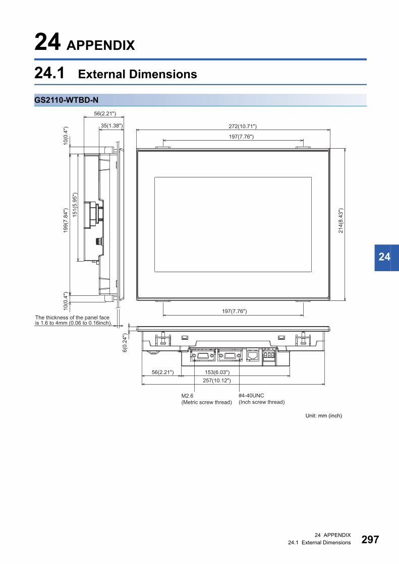
24
24 APPENDIX
24.1 External Dimensions
GS2110-WTBD-N
272(10.71")
56(2.21")
35(1.38")
10(0
.4")
10(0
.4")
199(
7.84
")
6(0.
24")
214(
8.43
")
151(
5.95
")
197(7.76")
153(6.03")56(2.21")257(10.12")
197(7.76")The thickness of the panel face is 1.6 to 4mm (0.06 to 0.16inch).
Unit: mm (inch)
M2.6(Metric screw thread)
#4-40UNC(Inch screw thread)
24 APPENDIX24.1 External Dimensions 297

29
GS2107-WTBD-N10
(0.4
")10
(0.4
") 144(5.67")
154.2(6.08")35.8(1.41")
206(8.11")
155(
6.11
")
6(0.
24")
190(7.49")
136(
5.36
")
112(
4.41
")
50(1.97")
26(1.03") 144(5.67")
The thickness of the panel face is 1.6 to 4mm (0.06 to 0.16inch).
Unit: mm (inch)
M2.6(Metric screw thread)
#4-40UNC(Inch screw thread)
824 APPENDIX24.1 External Dimensions

24
GS2110-WTBD
M2.6(Metric screw thread)
#4-40UNC(Inch screw thread)
272(10.71")
56(2.21")
35(1.38")10
(0.4
")10
(0.4
")19
9(7.
84")
6(0.
24")
214(
8.43
")
151(
5.95
")197(7.76")
153(6.03")56(2.21")257(10.12")
The thickness of the panel face is 1.6 to 4mm (0.06 to 0.16inch).
197(7.76")
Unit: mm (inch)
24 APPENDIX24.1 External Dimensions 299

30
GS2107-WTBD
Unit: mm (inch)
10(0
.4")
10(0
.4") 144(5.67")
154.2(6.08")35.8(1.41")
206(8.11")
155(
6.11
")
6(0.
24")
190(7.49")
The thickness of the panel face is 1.6 to 4mm (0.06 to 0.16inch).
136(
5.36
")
112(
4.41
")
50(1.97")
26(1.03")
M2.6(Metric screw thread)
#4-40UNC(Inch screw thread)
144(5.67")
024 APPENDIX24.1 External Dimensions

24
Communication cableGT01-C30R4-25P
Unit: mm (inch)
GT01-C□□□R4-25P
Unit: mm (inch)
GT01-C□□□R4-8P
Unit: mm (inch)
□□□ value L length (mm (inch))
100 10000 (393.7")
200 20000 (787.4")
300 30000 (1181.1")
□□□ value L length (mm (inch))
10 1000 (39.37")
30 3000 (118.11")
100 10000 (393.7")
200 20000 (787.4")
300 30000 (1181.1")
3000(118.11")
Φ7
50(1.97") 53(2.09")
55(2
.17"
)
16(0.63")16(0.63")
35(1
.38"
)
M2.6
M2.6
(0.28")
L
Φ7
50(1.97") 53(2.09")
55(2
.17"
)
16(0.63")16(0.63")
35(1
.38"
)
M2.6
M2.6
(0.28")
L
Φ6
40(1.57")
Φ25(0.98")×33(1.30")(0.24")
Approx. Φ13(0.51")M2.6
50(1.97")16(0.63")
35(1
.38"
)
24 APPENDIX24.1 External Dimensions 301

30
GT01-C30R2-25P
Unit: mm (inch)
GT01-C30R2-9S
Unit: mm (inch)
GT01-C30R2-6P
Unit: mm (inch)
Φ6
#4-40UNC
M2.6
3000(118.11")50(1.97") 53(2.09")
55(2
.17"
)
16(0.63")16(0.63")
35(1
.38"
) (0.24")
#4-40UNC #4-40UNC
Φ6
3000(118.11")50(1.97") 50(1.97") 16(0.63")16(0.63")
35(1
.38"
)
35(1
.38"
)
(0.24")
Φ7
Approx. 14
#4-40UNC
Φ20(0.79") ×28 (1.10")
3000(118.11")50(1.97")16(0.63")
35(1
.38"
)
40(1.57")
(0.28")
(0.55")
Approx. 14(0.55")
224 APPENDIX24.1 External Dimensions

24
MEMO
24 APPENDIX24.1 External Dimensions 303

304
REVISIONS* The manual number is given on the bottom left of the back cover.
© 2014 MITSUBISHI ELECTRIC CORPORATION
Print Date * Manual Number Revision
Jan., 2014 JY997D52901A First printing
Jul., 2014 JY997D52901B Compatible with GT Works3 Version1.118Y
• BACKUP/RESTORE function compatible
Oct., 2014 JY997D52901C WARRANTY is changed.
Jan., 2015 JY997D52901D Clerical error correction
Dec., 2015 JY997D52901E Some correction
May, 2016 JY997D52901F Some correction
Jan., 2017 JY997D52901G Some correction
Apr., 2017 JY997D52901H Compatible with GT Works3 Version1.175H
• GOT internal device monitor is supported.
• Clock synchronization is supported.
Jan., 2019 JY997D52901I Some correction
Jan., 2020 JY997D52901J Compatible with GT Works3 Version1.230Q
• The backup/restoration function supports FX5UJ.
Oct., 2020 JY997D52901K Some correction
Jan., 2021 JY997D52901L Compatible with GT Works3 Version1.250L
• Abbreviations and generic terms used in this manual are changed.
• The models (GS2110-WTBD-N, GS2107-WTBD-N) are added.
• GS21-W-N supports the RS-485 communication, VNC server function, license management, and
operation log information.
Feb., 2021 JY997D52901M Some correction
This manual confers no industrial property rights or any rights of any other kind, nor does it confer any patent licenses. Mitsubishi Electric Corporation cannot
be held responsible for any problems involving industrial property rights which may occur as a result of using the contents noted in this manual.

305
WARRANTYPlease confirm the following product warranty details before using this product.
If any faults or defects (hereinafter "Failure") found to be the responsibility of Mitsubishi occurs during use of the product within the gratis warranty term, the product shall be replaced at no cost via the sales representative.
The gratis warranty term of the product shall be for twelve (12) months after the date of purchase or delivery to a designated place.Note that after manufacture and shipment from Mitsubishi, the maximum distribution period shall be six (6) months, and the longest gratis warranty term after manufacturing shall be eighteen (18) months.
• Failure occurring from inappropriate storage or handling, carelessness or negligence by the user. Failure caused by the user's hardware or software design.
• Failure caused by unapproved modifications, etc., to the product by the user.• When the Mitsubishi product is assembled into a user's device, Failure that could have been avoided if functions or structures,
judged as necessary in the legal safety measures the user's device is subject to or as necessary by industry standards, had been provided.
• Failure that could have been avoided if consumable parts designated in the instruction manual had been correctly serviced or replaced.
• Replacing consumable parts such as the battery, backlight and fuses.• Failure caused by external irresistible forces such as fires or abnormal voltages, and Failure caused by force majeure such as
earthquakes, lightning, wind and water damage.• Failure caused by reasons unpredictable by scientific technology standards at time of shipment from Mitsubishi.• Any other failure found not to be the responsibility of Mitsubishi or that admitted not to be so by the user.
(1) Gratis Warranty Term
(2) Gratis Warranty Range(a) The customer shall be responsible for the primary failure diagnosis unless otherwise specified.(b) The range shall be limited to normal use within the usage state, usage methods and usage environment, etc., which follow the
conditions and precautions, etc., given in the instruction manual, user's manual and caution labels on the product.(c) Even within the gratis warranty term, the following cases are not guaranteed.
Gratis Warranty Term and Gratis Warranty Range■1.■1.
Repair and Analysis■2.■2.The repair and the failure analysis are not executed to the product.
Discontinuation of production■3.■3.
Regardless of the gratis warranty term, Mitsubishi shall not be liable for compensation to: Exclusion of loss in opportunity and secondary loss from warranty liability■4.■4.
The specifications given in the catalogs, manuals or technical documents are subject to change without prior notice.Changes in product specifications■5.■5.
(1) In using the Mitsubishi graphic operation terminal, the usage conditions shall be that the application will not lead to a major accident even if any problem or fault should occur in the graphic operation terminal device, and that backup and fail-safe functions are systematically provided outside of the device for any problem or fault.
(2) The Mitsubishi graphic operation terminal has been designed and manufactured for applications in general industries, etc. Thus, applications in which the public could be affected such as in nuclear power plants and other power plants operated by respective power companies, and applications in which a special quality assurance system is required, such as for Railway companies or Public service purposes shall be excluded from the graphic operation terminal applications.In addition, applications in which human life or property that could be greatly affected, such as in aircraft, medical applications, incineration and fuel devices, manned transportation equipment for recreation and amusement, and safety devices, shall also be excluded from the graphic operation terminal range of applications.However, in certain cases, some applications may be possible, providing the user consults the local Mitsubishi representative outlining the special requirements of the project, and providing that all parties concerned agree to the special circumstances, solely at our discretion.In some of three cases, however, Mitsubishi Electric Corporation may consider the possibility of an application, provided that the customer notifies Mitsubishi Electric Corporation of the intention, the application is clearly defined and any special quality is not required.
Product application■6.■6.
(1) Damages caused by any cause found not to be the responsibility of Mitsubishi.(2) Loss in opportunity, lost profits incurred to the user by Failures of Mitsubishi products.
(1) Discontinuation of production shall be notified with Mitsubishi Technical Bulletins, etc.(2) Product supply (including spare parts) is not available after production is discontinued.
(3) Special damages and secondary damages whether foreseeable or not, compensation for accidents, and compensation for damages to products other than Mitsubishi products.
(4) Replacement by the user, maintenance of on-site equipment, start-up test run and other tasks.

306JY997D52901M
TRADEMARKSMELDAS, MELSEC, iQ Platform, MELSOFT, GOT, CC-Link, CC-Link/LT, and CC-Link IE are trademarks or registered
trademarks of Mitsubishi Electric Corporation in Japan and other countries.
Microsoft, Windows, Windows Vista, Windows NT, Windows Server, SQL Server, Visual C++, Visual C#, Visual Basic, Excel,
and Access are trademarks or registered trademarks of Microsoft Corporation in the United States and other countries.
Ethernet is a registered trademark of Xerox Corporation in the United States.
MODBUS is a trademark of Schneider Electric SA.
DeviceNet is a trademark of ODVA (Open DeviceNet Vendor Association, Inc.).
VNC is a registered trademark of RealVNC Ltd. in the United States and other countries.
Unicode is a trademark or registered trademark of Unicode, Inc. in the United States and other countries.
PictBridge is a registered trademark of Canon Inc.
Adobe and Adobe Reader are registered trademarks of Adobe Systems Incorporated.
Oracle and JavaScript are registered trademarks of Oracle Corporation and/or its affiliates in the United States and other
countries.
QR Code is a trademark or registered trademark of DENSO WAVE INCORPORATED in Japan, the United States, and/or
other countries.
Anybus is a registered trademark of HMS Industrial Networks AB.
Android and Google Chrome are trademarks or registered trademarks of Google Inc.
IOS is a trademark or registered trademark of Cisco in the U.S. and other countries and is used under license.
Safari and iPhone are trademarks of Apple Inc. registered in the United States and other countries. The iPhone trademark is
used under license from AIPHONE CO., LTD.
Other company and product names herein are trademarks or registered trademarks of their respective owners.


JY997D52901M(2102)MEE
MODEL: -
MODEL CODE: -
Specifications subject to change without notice.
When exported from Japan, this manual does not require application to theMinistry of Economy, Trade and Industry for service transaction permission.
HEAD OFFICE : TOKYO BUILDING, 2-7-3 MARUNOUCHI, CHIYODA-KU, TOKYO 100-8310, JAPANNAGOYA WORKS : 1-14 , YADA-MINAMI 5-CHOME , HIGASHI-KU, NAGOYA , JAPAN