User's Manual Confocal Quantitative Image Cytometer - iBiOs
268
User’s Manual Confocal Quantitative Image Cytometer IM 80J01A01-01E The translation of the original instructions ~However warning labels are not the same.~ IM 80J01A01-01E Yokogawa Electric Corporation 10 th Edition
-
Upload
khangminh22 -
Category
Documents
-
view
1 -
download
0
Transcript of User's Manual Confocal Quantitative Image Cytometer - iBiOs

User’s
Manual
Confocal Quantitative Image Cytometer
IM 80J01A01-01E
The translation of the original instructions
~However warning labels are not the same.~
IM 80J01A01-01E
Yokogawa Electric Corporation 10th Edition

This document corresponds to the following versions of
software
Measurement software R1.04

i
IM 80J01A01-01E
Introduction
Thank you for purchasing the Confocal Quantitative Image Cytometer
CQ1.
This manual describes the functions, installation and wiring procedures,
operating procedures and handling precautions of the CQ1. Before you
start to use the CQ1, please read this manual carefully to enable
correct use of the system. After reading this manual, keep it in a handy
place so that you can refer to it whenever necessary.
Notes
The information contained in this manual is subject to change
without prior notice due to improvements in performance and
functionality or for other reasons.
This manual has been prepared with the utmost care; however, if
you have any questions, or note any errors, please contact our
branch or sales office of the neighborhood.
Unauthorized reproduction or reprinting of this manual in whole or
in part is prohibited.
Follow the operating instructions to keep stable system
operation. .
Trademarks
Microsoft and Windows are registered trademarks or trademarks
of Microsoft Corporation in the United States and other countries.
In this document, registered trademarks or trademarks are not
indicated by ™ and ®.
History
June 2014: 1st edition issued
October 2014: 2nd edition issued
March 2015: 3rd edition issued
March 2015: 4th edition issued
April 2015: 5th edition issued
October 2015: 6th edition issued
June 2016: 7th edition issued
June 2016: 8th edition issued
July 2016: 9th edition issued
April 2017:10th edition issued

ii
IM 80J01A01-01E
For Safe Use of This Equipment
To ensure safe and correct use of this equipment, be sure to follow the
precautions below when using this equipment. If this equipment is used in
a manner not specified in this manual, the protection provided by this
equipment may be impaired. If you do not follow the precautions when
using the equipment, we assume no responsibility nor provide any
guarantee regarding its safety and function.
Following symbols are used in the manual in the following cases.
WARNING
This symbol describes precautions to avoid hazardous situations that
could result in a bodily injury or death of the user upon mishandling
and/or incorrect use of the equipment.
CAUTION
This symbol describes precautions to avoid hazardous situations that
could result in a minor bodily injury of the user, or that could result in
damage to the equipment upon mishandling and/or incorrect use of the
equipment.
POWER ON
This symbol indicates POWER ON.
POWER OFF
This symbol indicates POWER OFF.

iii
IM 80J01A01-01E
Following warning labels are attached on this equipment. Warning label (1)
This warning label indicates that the operator must refer to the instruction manual to prevent injury and/or damages on the instrument.
Warning label (2)
This warning label indicates that this is laser product and operator must prevent injury and/or damages of skin or eyes from laser exposure.
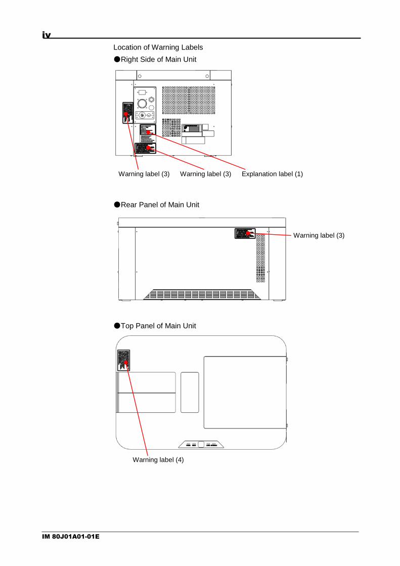
Warning label (3)
This label warns the users on dangers that require safety control measures when using the laser. To be specific, the users are cautioned that opening this cover results in emission of visible and invisible Class 3B laser beam and that entry of this beam into the eyes or its contact with the skin is a potential health hazard.
Warning label (4)
This label warns the users on dangers that require safety control measures when using the laser. To be specific, the users are cautioned that opening this cover results in emission of visible and invisible Class 3B laser beam and that entry of this beam into the eyes or its contact with the skin is a potential health hazard.
Aperture label
Warning sign to indicate the laser aperture.
Explanation label (1)
This is a Class 1 laser product.
Explanation label (2)
Warning sign to indicate the wavelength, maximum laser output power and laser class. The Utility Box belongs to the Class 3B laser product.
iv
IM 80J01A01-01E
Location of Warning Labels
●Right Side of Main Unit
●Rear Panel of Main Unit
●Top Panel of Main Unit
Warning label (3) Explanation label (1)
Warning label (4)
Warning label (3)
Warning label (3)

v
IM 80J01A01-01E
●Rear Panel of Main Unit (Transmission Illumination Option)
●Front Panel of Utility Box
●Rear Panel of Utility Box
Warning label (3)
Warning label (3)
Warning label (1)
Warning label (1)
Warning label (2)
Explanation label (2)

vi
IM 80J01A01-01E
●Right Side of Utility Box
Aperture label

vii
IM 80J01A01-01E
Observe the following precautions to prevent hazardous situations that
could result in a bodily injury or death of the user, such as electric
shock, or that could result in damage to the equipment.
WARNING
Be sure to turn on the power to the equipment after confirming that
the power-supply voltage of the equipment matches the voltage of
the supplied power. Always use the dedicated power cable
supplied with your equipment.
This is a Class 1 laser product. However, the equipment houses a
Class 3B laser, which is protected by the enclosure and the
interlocks provided at openings. When using this product, heed the
precautions explained in “Laser Products Handling Precautions.”
Controls and adjustments other than according to the procedures
specified herein will result in dangerous exposure to laser.
If you use Gas Mixer, CQ1 emits max. 20 % CO2 mixture gas at a
rate of 200ml/min. If CO2 concentration in the air exceeds 3%, it
may be harmful to the human body. Be sure to provide ventilation,
lead exhaust gas from CQ1 to outside of the room, or take other
appropriate measures. It is also recommended that an alarm
system be installed in case of emergency.
If you use Gas Mixer, CQ1 emits min. 0.1% low O2 gas at a rate of
200ml/min. If O2 concentration in the air drops below 18%, it may be
harmful to the human body. Be sure to provide ventilation, lead
exhaust gas from CQ1 to outside of the room, or take other
appropriate measures. It is also recommended that an alarm system
be installed in case of emergency.
Do not put a container with liquid or powder on the Main Unit,
Utility Boxes or cables of this instrument. Also, do not spill liquid or
powder on these materials. These materials may cause electric
shock and suffer electrical or mechanical damages.
Do not use the equipment by wet hand. It may cause electric
shock and suffer electrical or mechanical damages.

viii
IM 80J01A01-01E
CAUTION
Use the I/O terminals of the equipment within the ranges of the
specifications to prevent damage to the equipment.
This product uses precision optics. Therefore, do not use the
equipment in locations where there are large vibrations, a lot of
dust, high humidity and high temperature (in places near heating
equipment or exposed to direct sunlight), rapid changes in the
temperature (in places subject to dew condensation), or corrosive
or combustible gases.
Never touch any of the internal parts of this product. And never
take apart or modify this product. The optical system housed in the
product may become dirty, damaged or out of calibration and so
on, leading to equipment failure.
If the equipment has malfunctions or damages, please
immediately cease use and contact us.
This product is designed with the intention to use in industrial
environment. If this product is used in residential environment, it
may have influences to other equipments..

ix
IM 80J01A01-01E
Laser Products Handling Precautions
Laser products are classified according to their exposure emission
limit determined by the wavelength and power characteristics of
laser beam. A different set of common safety standards applies to
each class of products. The product explained herein belongs to
Class 1. However, the equipment houses a Class 3B laser, which
is protected by the enclosure and the interlocks provided at
openings.
Only service personnel can remove the covers on which a warning
label is attached. If these covers are removed, Class 3B laser
beam will be emitted. Directly looking into Class 3B laser beam or
beam reflected on a mirror may cause eye damage and is
extremely dangerous. Exercise due caution when handling this
product.
(Reference)
In the IEC standard, the laser classes are briefly explained as follows:
Class 1:Essentially safe. Continue to look into the Class 1 laser will not cause any
danger.
Class 2:If the Class 2 laser is looked into for a period not more than 0.25 second, there is
no risk of danger.
Class 3B:Looking into the laser beam from this class of equipment is dangerous. Even if
the specification of the laser equipment used does not exceed this class, there
is still a risk of eye injury.
Safety Standards
A class 1 laser is safe under all conditions of normal use. This
means the maximum permissible exposure can not be exceeded.
This equipment is designed in accordance with the IEC60825-1
Radiation safety standards for laser products and these lasers
must be labeled with the following label, but are exempt from the
requirements of the Laser Safety Program.
Preventive Measures on Safety
Mirror reflection
Metals and other glossy reflective surfaces reflect the laser beam.
Exercise caution to prevent unexpected mirror reflection.
Beam path
Never look directly into the laser beam or touch the laser beam.
CLASS 1 LASER PRODUCT

x
IM 80J01A01-01E
WEEE(Waste Electrical and Electronic Equipment),
Directive
(This directive is only valid in the EU.)
This instrument complies with the WEEE Directive marking
requirement. The marking above indicates that you must not
discard this instrument in domestic household waste.
Product Category
With reference to the instrument type in the WEEE directive Annex
1, this product is classified as a “Monitoring and Control instrument”
product.
When disposing this instrument in the EU, contact the distributer
whom you bought it from. Do not dispose in domestic household
waste.
Indemnity
Yokogawa shall provide no warranty regarding this product, unless
otherwise specified separately in the “Warranty Rule.”
Yokogawa shall assume no responsibility for any loss suffered by
a customer or third party as a result of use of this product, or any
loss or indirect loss suffered by a customer or third party due to a
defect in this product or any other problem not predictable by
Yokogawa.

xi
IM 80J01A01-01E
Checking the Content of the Package
After opening the package box, check if the following items are
included before beginning to use of this product. Should you find that a
wrong product has been delivered or any of the items is missing or if
you notice any abnormality on the exterior, please contact the dealer
from which you purchased your product.
CQ1
Part Quantity Description
CQ1 Main Unit
1
Confocal fluorescent microscope system to observe cells cultured in vessels such as Microplate or slide glass
USB cable
1 Communication cable to connect CQ1 main unit and workstation
Main Unit⇔UTB cable
1 Power supply and communication cable to connect CQ1 main unit and utility box
Utility Box
1 Equipment for supply power and excitation laser light
Optical Fiber
1 Optical fiber to guide laser from utility box into main unit
AC Cord (CQ1)
1 AC cord for utility box (Supplied by dealer)

xii
IM 80J01A01-01E
CQ1 (Continue from previous page)
Part Quantity Description
Key
1 Key switch on utility box
Tie-wrap
1 Tie-wrap for bundle USB cable and
Main Unit⇔UTB cable
Remote Interlock
1 Remote interlock connector on Utility Box
Objective Lens Part Quantity Description
Objective lens
1~6
To be installed on CQ1 main unit One to six lenses are installable depending on the specification. Please refer to Parts List: CMPL 80J01A01-01 for details.
Workstation
Part Quantity Description
Workstation
1 Attached with mouse, key board, back-up CD and instruction manual.
AC Cord (WS)
1 AC cord for workstation. (Supplied by dealer)

xiii
IM 80J01A01-01E
Option (Sold separately)
Part Quantity Description
Monitor
1 (Supplied by dealer)
AC Cord (Monitor)
1 (Supplied by dealer)
Monitor⇔WS cable
1 (Supplied by dealer)
Transmission Illumination
1
Transmitted light for phase contrast/ bright field observation There are following 2 types - Bright field/ Phase contrast
switchable type (manual) - Phase contrast type
Gas mixer
(TOKAI HIT, GM-8000)
1 Supply mixture gas that O2 and CO2 concentration is contolled to stage attachment
Gas mixer
connecting tube
1
Tube to connect CQ1 main unit and Gas mixer Attached if stage heater option is selected
Stage attachment
(All wells imaging type)
1 Stage attachment that all wells of microplate can be imaged

xiv
IM 80J01A01-01E
Option (Sold separately, continue from
previous page)
Part Quantity Description
Stage attachment (Chambered type)
1
Stage attachment which can keep the temperature, O2 CO2 concentration and humidity constant
Sample holder for
triple 35 mm dishes
1 Sample holder for set three 35 mm dishes
Sample holder for single 60 mm dish
1 Sample holder for set one 60 mm dish
Sample holder for
slide glass (ISO 8037/1)
1 Sample holder for set four slide glasses (ISO 8037/1)
Sample holder for
cover glass chamber
1 Sample holder for set one cover glass chamber
60 mm dish ring
1 Hold silicone rubber when using chambered type stage attachment and 60 mm dish
Rubber for 60 mm dish
1 Set on 60 mm dish when using chambered type stage attachment
Holding plate for CGC
1 Hold silicone rubber when using chambered type stage attachment and cover glass chamber
Rubber for CGC
1 - 4
Set on cover glass chamber when using chambered type stage attachment Shape is different by type of cover glass chamber

xv
IM 80J01A01-01E
Sample holders are set into the stage attachment as shown below.
Sample
Sample holder
Stage attachment
XY stage

xvi
IM 80J01A01-01E
How to use this manual
This user manual consists of Chapters 1 to 9, the details of which are
explained below.
Chapter Title and Content
1 Function Overview A functional overview of this equipment is explained.
2 Before Use Precautions for use and installation/wiring methods are explained.
3 Name of Each Part/Starting and Shutting Down the Equipment The name of each part and starting/shutdown of the equipment are explained.
4 Measurement procedures Procedures for measurement are explained
5 Functions of measurement software Screen of measurement software is explained
6 Maintenance Maintenance parts and consumable parts are explained.
7 Troubleshooting Error messages and troubleshooting procedures for this equipment are explained.
8 Specifications Specifications of this equipment are described.
9 Warranty Rule The rules of warranty applicable to this equipment are explained.

xvii
IM 80J01A01-01E
Content
1 Function Overview .......................................... 1-1
1.1 About the CQ1 ........................................................................... 1-1
1.2 Principle of the Nipkow Disk System with Micro-lens ............. 1-3
2 Precautions for Use/Installation ................. 2-1
2.1 Precautions for Use ................................................................................................... 2-1
2.2 Installing the Equipment ........................................................................................ 2-2
2.3 Wiring the Peripherals.............................................................................................. 2-6
2.4 Connecting the Power ............................................................................................. 2-7
3 Name of Each Part/Starting and
Shutting Down the Equipment .................... 3-1
3.1 Name and Function of Each Part ..................................................................... 3-1
3.2 Starting and Shutting Down of CQ1 ............................................................... 3-8
3.3 Starting and Shutting Down of Gas Mixer (Option) ......................... 3-13
4 Measurement Procedures ............................. 4-1
4.1 Measurement Procedures ..................................................................................... 4-1
4.2 Basic Protocol Setting ........................................................................................... 4-31
4.3 Sample Searching ..................................................................................................... 4-33
4.4 Imaging Setting ........................................................................................................... 4-36
4.5 Analysis Protocol Setting .................................................................................... 4-39
4.6 Object Recognizing Condition Setting ...................................................... 4-42
4.7 Protocol Saving ........................................................................................................... 4-43
4.8 Sample Measurement ............................................................................................. 4-45

xviii
IM 80J01A01-01E
5 Functions of CQ1 Software .......................... 5-1
5.1 Outline .................................................................................................................................. 5-1
5.2 Main Menu ......................................................................................................................... 5-3
5.3 Operation Mode Panel .............................................................................................. 5-8
5.4 Control Panel (CQ Mode) ...................................................................................... 5-10
5.5 Control Panel (HDD Mode) .................................................................................. 5-56
5.6 Viewer ................................................................................................................................ 5-80
5.7 Status Panel ................................................................................................................ 5-122
5.8 Viewer Layout ............................................................................................................ 5-123
5.9 Channel Setting......................................................................................................... 5-124
5.10 Trimming Parameter ............................................................................................. 5-126
5.11 User Setting ................................................................................................................. 5-127
5.12 Activation Setting ................................................................................................... 5-128
5.13 Advanced Editor ....................................................................................................... 5-129
6 Maintenance...................................................... 6-1
6.1 Maintenance of Workstation ............................................................................... 6-1
7 Trouble Shooting ............................................. 7-1
7.1 Trouble Shooting during Measurement Preperation ......................... 7-1
7.2 Trouble Shooting during Imaging .................................................................... 7-4
7.3 Trouble Shooting during Analyzing .............................................................. 7-15
7.4 Other Trouble Shootings ...................................................................................... 7-17
8 Specifications ................................................... 8-1
8.1 Details of MS codes ................................................................................................... 8-1
8.2 General Specifications ............................................................................................ 8-4
8.3 Measurement sample vessels ........................................................................... 8-5
8.4 Applicable Standards ............................................................................................... 8-6
9 Warranty Rule ................................................... 9-1

<1. Function Overview> 1-1
IM 80J01A01-01E
1 Function Overview
1.1 About the CQ1
CQ1 is designed to quantitatively measure biological information from
image data of each cell at high reproducibility. It enables acquisition of
such information as cell functions, signal transduction, cell mobility
(such as invasion) or morphological information from quantified image
data after image processing, which is rather difficult to obtain by
conventional flow cytometetric analysis. Different from flow
cytometetric analysis in which cells are washed away, CQ1 measures
the cells in their culture vessels such as microplate, thus it is possible
to analyze the same cells repeatedly or follow their temporal changes.
Features of CQ1
●High precision quantification of morphological information without
detaching off the cells
It is possible to precisely quantify biological function or characteristics
of each cell in a natural situation without breaking cell mass or
detaching cell layers from culture dish. In addition to two-dimensional
information, such as the area, various three-dimensional information,
such as volume, surface area, cell number and location, granule
location within each cell, fluorescent intensity, can be well visualized
and displayed as graphs.
●Live cell observation
Our proprietary confocal scanner unit, CSU series, is a confocal
scanner which can be attached on an optical microscope to enable
confocal observation. The best features of the CSU are the capabilities
of high-speed confocal imaging with a minimal level of cellular
photo-damage and photo-bleaching. Equipped with the CSU, the CQ1
enables three-dimensional and multi-color live cell observation. CQ1 is
suitable for quality control, inspection and experiments of the studies in
cell engineering field, since you don’t have to spoil the cells after
observation.
●Highly reproducible data
Highly reproducible data can be acquired by stabilizing excitation laser
power with the power monitor function, and also by periodical
calibration to eliminate effects of any other variations.

1-2 <1. Function Overview>
IM 80J01A01-01E
Measurement values
CQ1 outputs the following measurement values by analyzing confocal
images of fluorescently labelled each cell.
Measurement Unit Measurement
Method
Description
Morphological
features
Area µm2 2D
measurement
Measure the area of objects.
Circumference µm 2D
measurement
Measure the circumference of object.
Circularity - 2D
measurement
Compare the area of the circumscribed
circle and the area of the object.
Circularity is expressed by a positive
number of less than 1.0, and perfect circle
is 1.0
Volume µm3 3D
measurement
Measure total volume of objects.
Surface area µm2 3D
measurement
Measure total surface area of objects.
Sphericity - 3D
measurement
Compare the volume of an intracellular
structure and its circumscribed globe.
Sphericity is expressed by a positive
number of less than 1.0, and perfect globe
is 1.0.
Diameter µm 2D
measurement
Measure diameter of the circumscribed
circle of an object.
3D
measurement
Measure diameter of the circumscribed
globe of an object.
Intensity Sum - 2D/3D
measurement
Measure the sum of pixel intensity of
objects.
Average - 2D/3D
measurement
Measure average pixel intensity of
objects.
Standard
deviation
- 2D/3D
measurement
Measure standard deviation of pixel
intensity of objects.
Minimum - 2D/3D
measurement
Measure minimum pixel intensity among
objects.
Maximum - 2D/3D
measurement
Measure maximum pixel intensity among
objects.

<1. Function Overview> 1-3
IM 80J01A01-01E
1.2 Principle of the Nipkow Disk System with Micro-lens
Two disks, including the “pinhole array disk” having many pinholes
arranged in a helical pattern, and the “Micro-lens array disk” that
condenses excitation laser to individual pinholes, are rotated jointly at
high speed to perform multiple scans over the observation area with
approximately 1,000 laser beams.
Multiple beam scans are performed not only at high speed, but also
with each beam exciting fluorochromes at high efficiency and very low
laser intensity. These results in an optimal live cell observation system
where phototoxicity and fluorescence photobleaching are suppressed
notably compared to any conventional systems while allowing
high-resolution real confocal imaging.
Operating Principle of the Micro-lens enhanced dual Nipkow Disk
System


<2. Precautions for Use/Installation> 2-1
IM 80J01A01-01E
2 Precautions for Use/Installation
2.1 Precautions for Use
Handling Precautions for This Equipment
This equipment uses plastic parts. When cleaning these plastic
parts, wipe with a dry, soft cloth without using water or any solution.
Never use benzene, thinner or any other chemical or cleaning
solution. Doing so may result in discoloration, deformation or
damage.
Do not bring electrically charged objects near the signal terminals.
Doing so may result in failure.
Do not spill any volatile chemical over the display or keep the
display in contact with any rubber or plastic product for an
extended period of time.
Do not install patches (Windows Update, service pack, security
patch and so on) to update operating system. Also, do not change
environment setting (display setting, power management and so
on) of Workstation.Control board and Software may not work
normally by these changes.
Do not install the third-party software which YOKOGAWA doesn’t
specify to Workstation. The performance of CQ1 may reduce.In
addition, 8.3 filename generation of Windows NTFS file system is
invalid in Workstation for performance improvement. Therefore,
the third-party software may not work normally.
Do not install any third-party hardware to CQ1 Main Unit, Utility
Box, and Workstation. The third-party hardware may fail.
In case of connecting Workstation to Internet, please install an
antivirus program which your affiliated facilitate designated and
perform virus check periodically.Please don’t perform virus check
during CQ1 operation because performance may reduce.
Do not give shocks to this equipment.
Should you notice smoke coming out of the Main Unit, foul smell,
abnormal noise or any other abnormality, immediately pull out the
power cable from inlet of equipment.
If the product has failed, contact us without attempting to
disassemble any of the internal assemblies or take any other
action to resolve the problem yourself.
Do not put anything on CQ1 Main Unit.
2-2 <2. Precautions for Use/Installation>
IM 80J01A01-01E
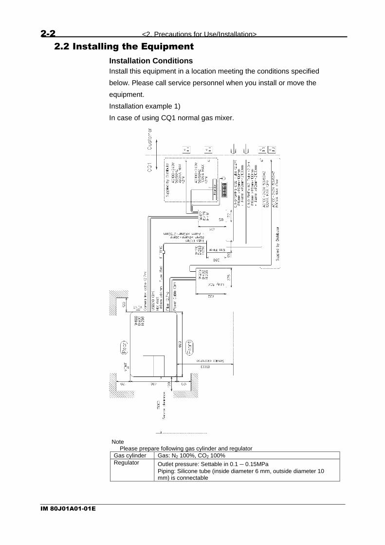
2.2 Installing the Equipment
Installation Conditions
Install this equipment in a location meeting the conditions specified
below. Please call service personnel when you install or move the
equipment.
Installation example 1)
In case of using CQ1 normal gas mixer.
Note Please prepare following gas cylinder and regulator
Gas cylinder Gas: N2 100%, CO2 100%
Regulator Outlet pressure: Settable in 0.1 – 0.15MPa
Piping: Silicone tube (inside diameter 6 mm, outside diameter 10 mm) is connectable

<2. Precautions for Use/Installation> 2-3
IM 80J01A01-01E
Installation example 2)
In case of using gas mixer that user prepares.

2-4 <2. Precautions for Use/Installation>
IM 80J01A01-01E
※CQ1 does not include the pedestal and desk.
Location where enough space is available
If the ventilation openings are blocked, the equipment may
become hot and eventually damaged. Provide enough space
around CQ1 Main Unit and Utility Box.
・CQ1 Main Unit
Minimum Clearance
Front: 120 mm, Back: 120 mm, Above: 200 mm, Side: 120 mm
Recommended Table Size:
W 700 mm x D 500 mm x H 700 mm or larger
Withstand load: 100 kg or larger
・Utility Box
Minimum Clearance
Back: 50 mm, Above: 50 mm, Side: 50 mm
(Avoid placing on floor directly)
・Gas Mixer
Minimum Clearance
Back: Provide enough space not to buckle tubes and cables
Side: 50 mm (Avoid placing on floor directly)
Avoid installing at highly humid and / or hot place such as close to
heaters or under direct sunshine, or frequent temperature
changes.※1
Location of minimal mechanical vibration
Never set any vibrating devices, such as centrifuge or mixer, on
the same table with CQ1. Doing so may disrupt optical
performance.

<2. Precautions for Use/Installation> 2-5
IM 80J01A01-01E
Level location
When installing this equipment, make sure the equipment does
not tilt.
Location of minimal soot, steam, dust, corrosive gases and so on.
Location where electric power supply system of more than
AC100V, 14A (1,400W) is available.
※1
Subjecting the equipment to a sudden temperature shift may cause condensation.
Installation Environment
Operating Temperature Range
CQ1: 15 – 35 ℃
Gas Mixer: 20 – 35 ℃
Operating Humidity Range
CQ1: 20 – 70 % RH, non-condensing
Gas Mixer: 10 – 85 % RH, non-condensing

2-6 <2. Precautions for Use/Installation>
IM 80J01A01-01E
2.3 Wiring the Peripherals
Connect the cables after confirming that the power switch on the
equipment is turned off.
CAUTION
Please don’t connect any cables other than specified by YOKOGAWA.
Workstation
Utility Box
CQ1Main Unit
Fib
er
AC Code (CQ1)
Po
we
r S
up
ply
Camera Link Cable
USB Cable
Gas Mixer
CO
2
N2
Joint
Display
Cable
AC Code
(Display)
AC Code
(WS)
Ma
in U
nit⇔
Utilit
y B
ox
Cab
le
Remote
Interlock
AC Code
(Gas Mixer)
Gas Mixer
Tube

<2. Precautions for Use/Installation> 2-7
IM 80J01A01-01E
WARNING
Pulling a cable wired to this instrument with a strong force may
cause damage to the cable or connected terminals on the
instrument. Provide each cable with an ample allowance so that
the input terminals on the instrument will not receive a direct
pulling force.
Securely connect all tubes from the gas cylinder (CO2 100%, N2
100%) through the gas regulator to the gas inlet tube to prevent
gas leakage. It is recommended to install a gas leakage alarm
system to avoid risk by gas leakage.
CAUTION
Please refrain from applying the following processing on the CQ1
workstation. If you do, there is a risk of malfunction of this instrument.
In case, any problems happened as a result of such inappropriate
processing, you are liable for the cost of repair.
Install patches (Windows Update, service pack, security patch) to
update operating system.
Install any third-party software which YOKOGAWA doesn’t
specify.
Install any third-party hardware.
Use any third-party software and hardware.
Connect to the internet.
2.4 Connecting the Power
Connect the plug on the other end of the power cable to a power outlet
meeting the following conditions. For the power outlet, use a 3-pole
socket with a protective grounding terminal.
Rated power-supply voltage:100 to 240 VAC
Rated power frequency:50 / 60 Hz
Allowable power-supply frequency fluctuation range:48~63Hz
Maximum power consumption:Main Unit, Utility Box 800VA
Gas Mixer 40VA
Workstation 400VA
Note Subjecting the equipment to a sudden temperature shift may cause condensation.

2-8 <2. Precautions for Use/Installation>
IM 80J01A01-01E
Before connecting the power, take heed of the following warnings and
cautions. Failure to do so may result in electric shock or equipment
damage.
WARNING
Power supply
Be sure to turn on the power to the equipment after confirming
that the power-supply voltage of the equipment matches the
voltage of the power supply
Power cable and plug
To prevent electric shock and fire, use the power cable supplied
by Yokogawa. For the main power plug, only use a power socket
with a protective grounding terminal. Use of an extension cable
without protective grounding wire will disable the protective
operations
Protective grounding
To prevent electric shock, be sure to provide protective grounding
before turning on the power to the equipment. The power cable
supplied with this equipment is a 3-pin type with a grounding wire.
Accordingly, use a 3-pin power socket with a protective grounding
terminal. If a 3-pin to 2-pin conversion adapter (usable only in
Japan) is used, securely connect the grounding wire of the
conversion adapter to the protective grounding terminal.
Need for protective grounding
Do not cut the protective grounding wire running inside or outside
this equipment or remove the connected wires from the protective
grounding terminals. Doing so will put this equipment in a
dangerous condition.
Defects in protective functions
If any of the protective functions such as protective grounding or
any fuse is suspected as faulty, do not operate this equipment.
Also check the protective functions to ensure absence of defects
before operating this equipment
Use in gas
Do not operate this equipment in a location where it may come in
contact with flammable or explosive gases or vapors. Using this
equipment in such environment is very dangerous

<2. Precautions for Use/Installation> 2-9
IM 80J01A01-01E
Removal of the case
The case must not be removed except by Yokogawa’s service
personnel. Some parts in this equipment carry high voltage and a
Class 3B laser is also housed inside. Accordingly, removing the
case presents dangerous situations.
External connections
Connect each external device after providing proper protective
grounding.


<3. Name of Each Part/Starting and Shutting Down the Equipment> 3-1
IM 80J01A01-01E
3 Name of Each Part/Starting and Shutting
Down the Equipment
3.1 Name and Function of Each Part
CQ1 Main Unit
(1) Door
Door opens/closes either manually by the door button, or through
the software; [CQ]button→[Sample]tab→[Sample Loader]→
[Open] button・[Close]button. Open door and load sample vessels,
such as microplate, dish or slide glass, here.
(2) POWER Lamp
Lights when the power switch on the Utility Box is ON, and lights
out when the power switch is OFF
(3) READY Lamp
Lights when the initialization of this equipment finished and get
ready to use
(4) Door OPEN/CLOSE Button
OPEN/CLOSE the door of the sample loading port
(5) LASER Lamp
Lights when the laser emits, and lights out when laser is OFF
(6) INTERLOCK Lamp
Lights when the door or cover is open. Laser emission stops when
this lamp lights
(1)
(2) (3) (6) (5) (4)
(7)
(8)

3-2 <3. Name of Each Part/Starting and Shutting Down the Equipment >
IM 80J01A01-01E
(7) Sub Cover
Sub cover is opened when pouring distilled water into bath. Also,
sub cover is opened when service maintenance.
(8) Illumination Setting Part
In case of transmission Illumination option, illumination unit is set
on this part.
(9) Fiber Port
Port to connect the fiber to CQ1 Main Unit
(10) USB Connector
Connector for USB cable connection with the Workstation cable
(11) Gas Inlet Port
Port to connect the tube from Gas Mixer (option)
(12) Camera Cable Port
Inlet port to insert camera link cable to CQ1
(13) Power Cable Connector
Port to connect the power cable from Utility Box
(14) Gas Outlet Port
Port to exhaust the gas from chamber on XY stage when using
Gas Mixer
(10)
(11)
(13)
(12)
(14)
(9)

<3. Name of Each Part/Starting and Shutting Down the Equipment> 3-3
IM 80J01A01-01E
Transmission Illumination
(1) Switching lever (bright field/ phase contrast)
Switch the method of transmission illumination. Pull the lever
toward to switch to bright field. Push the lever back to switch to
phase contrast.
(1)

3-4 <3. Name of Each Part/Starting and Shutting Down the Equipment >
IM 80J01A01-01E
Utility Box
(1) Key switch
Laser power gets on and off by this key
(2) POWER Lamp
Lights when the power switch (7) of Utility Box is on, and lights out
when the switch is off
(3) MAIN UNIT Lamp
Lights when connected with CQ1 Main Unit
(4) GAS MIXER Lamp
Not in use
(5) READY Lamp
Lights when lasers are enable, and lights out when lasers are
disable, and flicks when lasers are initializing
(6) EMISSION Lamp
Lights when laser emits, and lights out when laser is off
(7) Power Switch
Switch ON to power on CQ1 Main Unit
Switch OFF to power off CQ1 Main Unit
(1) (2)
(3)
(4)
(5)
(6)
(7)

<3. Name of Each Part/Starting and Shutting Down the Equipment> 3-5
IM 80J01A01-01E
(8) Breaker
For the Utility Box
(9) Power Cable Connector
Port to connect power cable
(10) Maintenance Connector
Not in use
(11) Remote Interlock Connector
Port to connect lase interlock connector
(12) Reserved Connector
Not in use
(13) CQ1 Main Unit Power Cable Connector
Port to connect power cable
(14) Fiber Port
Port to insert the fiber to Utility Box
(9) (8)
(10)
(11) (12)
(13) (14)

3-6 <3. Name of Each Part/Starting and Shutting Down the Equipment >
IM 80J01A01-01E
Gas Mixer (Option)
(1) Power Switch
Switch ON to power on Gas Mixer
Switch OFF to power off Gas Mixer
(2) CO2 Concentration
Controller to set CO2 Concentration of output mixture gas
(3) O2 Concentration
Controller to set O2 Concentration of output mixture gas
(4) Gas Flow
Controller to set flow rate of output mixture gas
(5) 100 % CO2 IN
Port to connect the tube from CO2 gas cylinder via the regulator
(6) 100 % N2 IN
Port to connect the tube from N2 gas cylinder via the regulator
(7) Mix Gas OUT
Port to connect the tube to CQ1 Main Unit
(8) GM LINK
Not in use
(9) DC IN
Port to connect cable of attached AC adapter
(1)
(2)
(3)
(4)
Front Rear
(7)
(6)
(5)
(8)
(9)

<3. Name of Each Part/Starting and Shutting Down the Equipment> 3-7
IM 80J01A01-01E
Workstation
(1) USB Connector
Connect to the USB connector (8) on the CQ1 Main Unit. Connect
supplied cable as shown above.
(2) Camera Link Cable Connector
Connect camera link cable out of CQ1 Main Unit as shown above.
(1)
(2)

3-8 <3. Name of Each Part/Starting and Shutting Down the Equipment >
IM 80J01A01-01E
3.2 Starting and Shutting Down of CQ1
3.2.1 Starting CQ1
(1) Turn the power switch ON, then turn the key switch ON..
CAUTION
Please confirm below before starting the equipment.
Is the equipment correctly installed?
(Refer to 2.2 Installing the Equipment)
Are the cables correctly connected?
(Refer to 2.3 Wiring the Peripherals)
Immediately pull out the AC cord from inlet of equipment, when
you notice smoke coming out of the main unit, foul smell,
abnormal noise or any other abnormality.
(2) Power ON the Workstation.
(3) Confirm that there is enough free space in data (D:) disk drive.
Data volume of one image that CQ1 outputs is about 11MB. Keep
free space in data (D:) disk drive by considering total image
quantity to acquire.
Also, free space of data (D:) disk drive is smaller than 1GB,
measurement setting can’t be carried out normally.
Power Switch
Key Switch

<3. Name of Each Part/Starting and Shutting Down the Equipment> 3-9
IM 80J01A01-01E
(4) Wait until Ready lamp on Utility Box turn ON after blinking. (It
takes about 1 minute from turning the key switch on).
Click the desktop icon of the Workstation to start CQ1 Software.
READY lamp
3-10 <3. Name of Each Part/Starting and Shutting Down the Equipment >
IM 80J01A01-01E
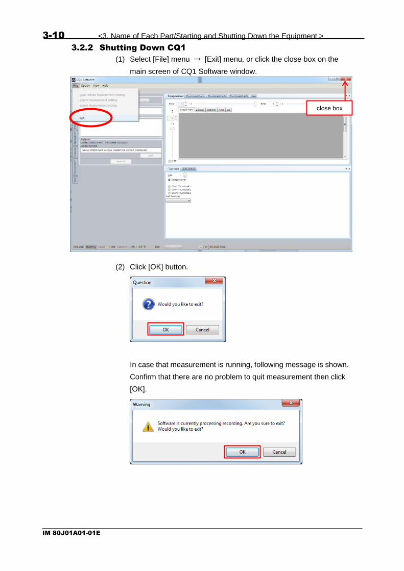
3.2.2 Shutting Down CQ1
(1) Select [File] menu → [Exit] menu, or click the close box on the
main screen of CQ1 Software window.
(2) Click [OK] button.
In case that measurement is running, following message is shown.
Confirm that there are no problem to quit measurement then click
[OK].
close box
<3. Name of Each Part/Starting and Shutting Down the Equipment> 3-11
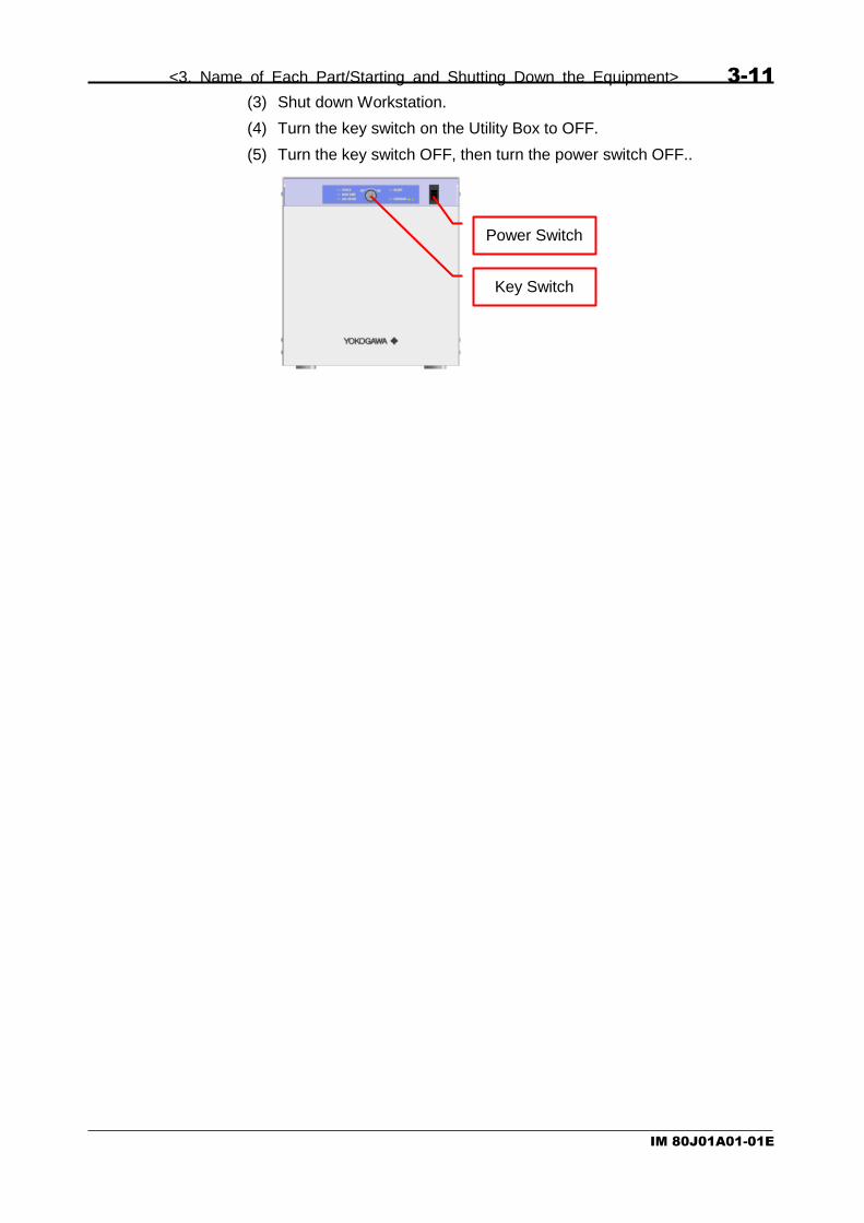
IM 80J01A01-01E
(3) Shut down Workstation.
(4) Turn the key switch on the Utility Box to OFF.
(5) Turn the key switch OFF, then turn the power switch OFF..
Power Switch
Key Switch

3-12 <3. Name of Each Part/Starting and Shutting Down the Equipment >
IM 80J01A01-01E
3.2.3 Offline Mode
You can start CQ1 Software by “offline mode” without turning
equipment on. It is convenient for viewing data or analyzing without
measurement.
Starting procedure is different from above. Select”CQ1 Offline” from
Windows start menu. (It is not icon on desktop).

<3. Name of Each Part/Starting and Shutting Down the Equipment> 3-13
IM 80J01A01-01E
3.3 Starting and Shutting Down of Gas Mixer (Option)
3.3.1 Starting Gas Mixer
(1) Confirm that valve ③ of regulator is closed.
(2) Confirm that valve ② is loosened by slight counterclockwise
rotating.
(3) Open valve ① of gas cylinder.
(4) Open valve ③ of regulator.
(5) By clockwise rotating valve ②, adjust outlet pressure (meter B) to
be in the range of 0.1 MPa – 0.15 MPa.
(6) Turn the power switch of Gas Mixer.
3.3.2 Shutting Down Gas Mixer
(1) Close valve ③ of regulator to stop gas supply. (If the gas cylinder
will not be used for long time, close valve ① of gas cylinder after
closing valve ③.)
(2) Turn the power switch of Gas Mixer.
①
②
③
Meter B Meter A Power Switch


<4. Measurement Procedures> 4-1
IM 80J01A01-01E
4 Measurement Procedures
4.1 Measurement Procedures
Turn the power switch ON, then turn the key switch ON..
CAUTION
Immediately pull out the AC cord from inlet of equipment, when you
notice smoke coming out of the main unit, foul smell, abnormal noise or
any other abnormality.
4.1.1 Exchanging Procedures of Stage Attachment
If you don’t need to exchange stage attachment, go to procedure
shown in 4.1.5 Setting Samples.
Features of each stage attachment are as following.
All Well Imaging Type
Chambered Type
※Sealing Blocks
Capable of imaging all wells of microplate Capable of keeping the temperature,
CO2, O2 concentration and humidity
Note The range which can be imaged is different between types of stage attachment. For details, please refer to Technical Information TI 80J01A01-01E (Supported Sample Vessels).
Power Switch
Key Switch

4-2 <4. Measurement Procedures>
IM 80J01A01-01E
<In case of exchanging All Well Imaging Type to Chambered Type>
Click “Sample” tab → “OPEN” Button of CQ1 Software or do long press
(3 seconds) of Door OPEN/CLOSE Button of CQ1 Main Unit to open
the door.
Turn the key switch OFF, then turn the power switch OFF..
Loosen 2 screws.
Door OPEN/CLOSE Button
Power Switch
Key Switch

<4. Measurement Procedures> 4-3
IM 80J01A01-01E
Push lever and lift up to remove Stage Attachment.
CAUTION
Lift up Stage Attachment vertically because it is positioned by pin.
Be careful not to collide with cover.
Lever
Pin

4-4 <4. Measurement Procedures>
IM 80J01A01-01E
Prepare Stage Attachment to set.
Direct clamp as following diagram and set Stage Attachment.
Be careful not to collide with cover.
Put Stage Attachment on the stage and set it with pushing lever.
Clamp
Lever

<4. Measurement Procedures> 4-5
IM 80J01A01-01E
CAUTION
Be careful not to touch sample setting part of Chambered Type Stage
Attachment when put it on the stage. This part is easily-broken.
Fasten 2 screws.
CAUTION
Confirm that Stage Attachment does not tilt.
Sample setting part
Stage Attachment
Stage
OK
NG

4-6 <4. Measurement Procedures>
IM 80J01A01-01E
Set Sealing Block for Clamp on the clamp.
In case of using microplate, set Sealing Block for Microplate as
following diagram.

<4. Measurement Procedures> 4-7
IM 80J01A01-01E
Turn the power switch ON, then turn the key switch ON..
CAUTION
After turning power switch ON, the door closes automatically. Please
be careful not to pinch your fingers or others.
Immediately pull out the AC cord from inlet of equipment, when you
notice smoke coming out of the main unit, foul smell, abnormal noise or
any other abnormality.

4-8 <4. Measurement Procedures>
IM 80J01A01-01E
<In case of exchanging Chambered Type to All Well Imaging Type>
Click “Sample” tab → “OPEN” Button of CQ1 Software or do long press
(3 seconds) of Door OPEN/CLOSE Button of CQ1 Main Unit to open
the door.
Turn the key switch OFF, then turn the power switch OFF..
Remove Sealing Block for Microplate if it is set.
Door OPEN/CLOSE Button
Power Switch
Key Switch
<4. Measurement Procedures> 4-9
IM 80J01A01-01E
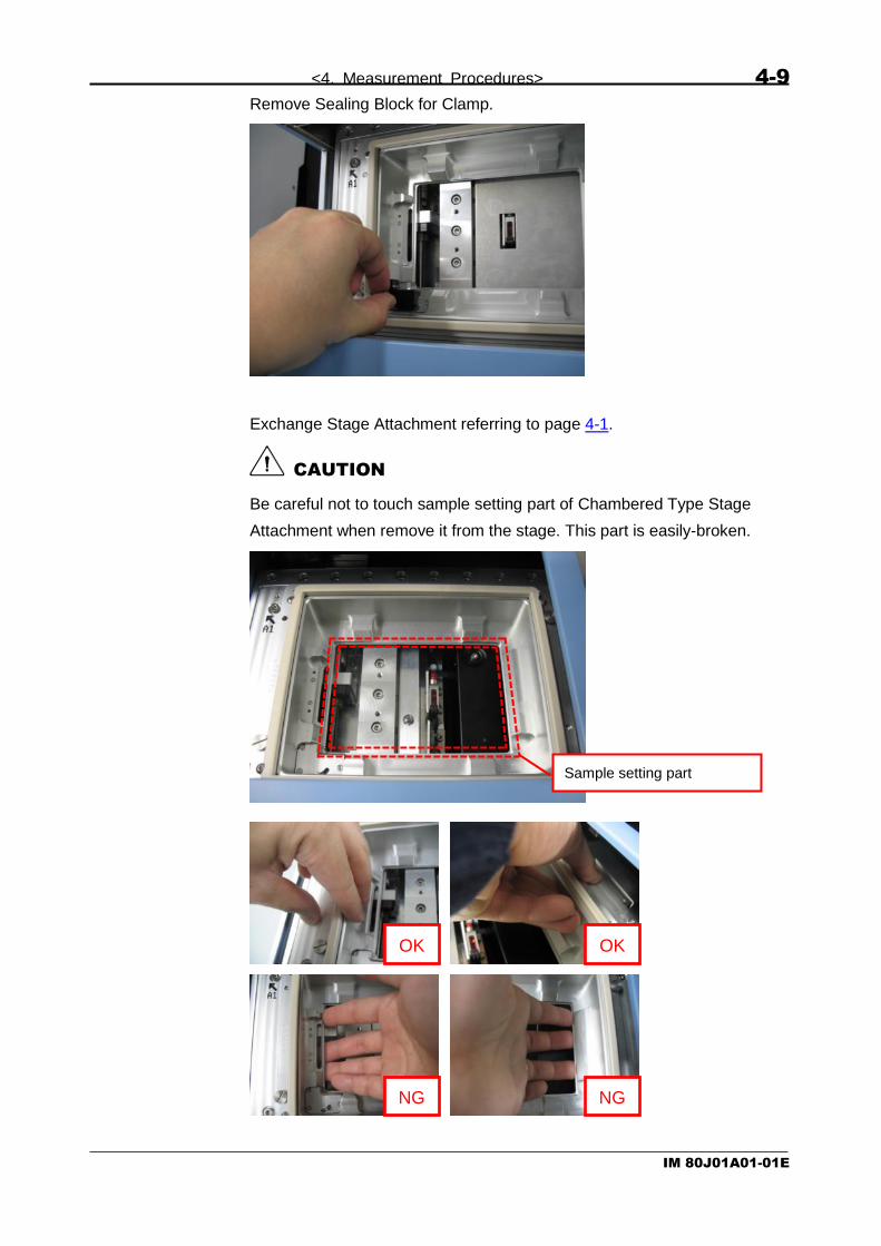
Remove Sealing Block for Clamp.
Exchange Stage Attachment referring to page 4-1.
CAUTION
Be careful not to touch sample setting part of Chambered Type Stage
Attachment when remove it from the stage. This part is easily-broken.
Sample setting part
OK
NG
OK
NG

4-10 <4. Measurement Procedures>
IM 80J01A01-01E
Turn the power switch ON, then turn the key switch ON..
CAUTION
After turning power switch ON, the door closes automatically. Please
be careful not to pinch your fingers or others.
Immediately pull out the AC cord from inlet of equipment, when you
notice smoke coming out of the main unit, foul smell, abnormal noise or
any other abnormality.

<4. Measurement Procedures> 4-11
IM 80J01A01-01E
4.1.2 Procedures of Filling Water for Humidification
This procedure is only perfomed for controlling environment around
sample. If you don’t need environment control, go to procedure shown
in 4.1.5 Setting Samples.
In case that measurement is running, click “Pause” button to pause.
Click “Sample” tab → “OPEN” Button of CQ1 Software or do long press
(3 seconds) of Door OPEN/CLOSE Button of CQ1 Main Unit to open
the door.
Turn the key switch OFF, then turn the power switch OFF..
Door OPEN/CLOSE Button
Power Switch
Key Switch

4-12 <4. Measurement Procedures>
IM 80J01A01-01E
Loosen 2 screws and remove sub cover.
Loosen 4 screws and remove bath cover.
CAUTION
Please don’t remove screws from bath cover.
During temperature controlling, water drops are formed on the
downside of the bath cover. Please be careful not to drop water
inside the equipment when removing bath cover.
If water drops inside the equipment, wipe it completely before
turning CQ1 on.
Bath cover
Water drop

<4. Measurement Procedures> 4-13
IM 80J01A01-01E
If the waterbath is empty, pour 25 ml of distilled water.
(It is recommended to pour by syringe.)
Pour distilled water to cover whole area of the bath.
OK NG

4-14 <4. Measurement Procedures>
IM 80J01A01-01E
CAUTION
It is acceptable that the bath is not filled with water.
If too much water is poured, it causes water immersion into the
equipment and failure of the equipment.
CAUTION
After measurement, wipe water in the bath and on the downside of bath
cover everytime.
NG
Note
Appropriate humidity level is maintained over 6 hours when
25 ml of water is poured.
Water drop on the
downside of bath cover
Water remains in the
bath

<4. Measurement Procedures> 4-15
IM 80J01A01-01E
Set bath cover and tighten 4 screws.
In case that the screws can’t be fastened properly, adjust position of
bath cover so that the screws are fastened properly.
Set sub cover and tighten 2 screws.
Turn the power switch ON, then turn the key switch ON..
CAUTION
After turning power switch ON, the door closes automatically. Please
be careful not to pinch your fingers or others.
Immediately pull out the AC cord from inlet of equipment, when you
notice smoke coming out of the main unit, foul smell, abnormal noise or
any other abnormality.
Power Switch
Key Switch

4-16 <4. Measurement Procedures>
IM 80J01A01-01E
Click “Rec” button in case of restarting measurement.
(It takes about 2 minutes that “Rec” button becomes available after
turning power switch ON.)
Note In case that starting time of the next timepoint comes during the pausing time, measurement starts again as following sequence.
①
Interval
Interval Interval Interval Interval
Interval Interval Interval Interval
①
①
Interval Interval Interval
② ③ ④ ⑤
②
②
③
③
④
④
⑤
⑤
Measuring<Timepoint>
Interrupting
No interrupting
Interrupting timeis in interval
Interrupting timeis over interval
In case of the time-lapse measurement that pause for filling water and others is supporsed, it is recommended to set interval so that time span from finishing measurement of the timepoint to starting of next timepoint become longer than 10 minutes.

<4. Measurement Procedures> 4-17
IM 80J01A01-01E
4.1.3 Procedures of Setting Gas Mixer
This procedure is only perfomed when controlling environment around
sample. If you don’t need environment control, go to procedure shown
in 4.1.5 Setting Samples.
Start Gas Mixer by referring to 3.3 Starting and Shutting Down of Gas
Mixer (Option).
In this section, procedures are described for example by setting as
following.
- Sample vessel: microplate
- CO2 concentration in chamber: 5 %
- O2 concentration in chamber: atomostic concentration (≓ 20 %)
For other settings, please refer to Technical Information TI
80J01A05-01E (Setting Parameter of Gas Mixer).
By “Up/ Down” key of “GAS FLOW”, set mixture gas flow rate to 150
(ml / min) and push “Enter”.
By “Up/ Down” key of “CO2 CONCENTRATION”, set CO2 concentration
to 6.0 (%). By “Up/ Down” key of “O2 CONCENTRATION”, set O2
concentration to 20.0 (%).

4-18 <4. Measurement Procedures>
IM 80J01A01-01E
4.1.4 Procedures of Setting Stage Heater
This procedure is only perfomed when controlling environment around
sample. If you don’t perform environment control, go to procedure
shown in 4.1.5 Setting Samples.
Click “ON” button in “Environment” window -> “Temperature Control”.
Click “Edit” button.

<4. Measurement Procedures> 4-19
IM 80J01A01-01E
It changes to temperature setting window. Input control temperature to
“Setting” and click “Set”.
Guarranty range of chamber temperature depends on room
temperature (refer to following chart).
For example, to set chamber temperature 37 ℃, set room temperature
20 ℃ - 30 ℃.
10 1515
20
20 25 30 35
25
30
35
40
45
Room Temperature [℃]
Ch
am
be
r T
em
pe
ratu
re [℃
]
Note
If 35 mm dishes is used, input “control temperature – 0.8 ℃”
(example: If you want to set chamber temperature to 37 ℃,
input “36.2” to “Setting” )

4-20 <4. Measurement Procedures>
IM 80J01A01-01E
4.1.5 Setting Samples
<Caution when setting samples>
If the sample which is taken from cold environment, such as refrigerator,
is set into CQ1 at once, condensation occurs on the bottom of sample
vessel and autofocus may not operate normally.
Also, temperature of sample vessel changes rapidly after it is set into
CQ1, strain of sample vessel occurs and autofocus may not operate
normally.
In case of unusing Stage Heater, set sample into CQ1 after acclimating
to room temperature. In case of the sample taken from refrigerator,
acclimating time is about 30 minutes. In case that condensation occurs
on the bottom of sample vessel, please wipe it away.
In case of using Stage Heater, set sample into CQ1 as soon as
possible after taken it from incubator.

<4. Measurement Procedures> 4-21
IM 80J01A01-01E
<In case of using 35 mm dish>
Set dishes on sample holder.
Lift up leaf spring, set a dish, and push down leaf spring to fix a dish.
CAUTION
Same dishes must be set on all 3 positions.
Sample holder for 35 mm dishes
Lift up leaf spring
Set a dish and push down leaf
spring to fix a dish.
Set dishes on all 3 positions.

4-22 <4. Measurement Procedures>
IM 80J01A01-01E
<In case of using 60 mm dish>
(Only when controlling environment) Set rubber on the dish.
Set dish on sample holder.
(Only when controlling environment) Set a dish ring.
Dish ring

<4. Measurement Procedures> 4-23
IM 80J01A01-01E
Fix a dish by leaf spring.
Lift up leaf spring
Set a dish and push down leaf
spring to fix a dish
In case of performing
environment control
In case of not performing
environment control
4-24 <4. Measurement Procedures>
IM 80J01A01-01E
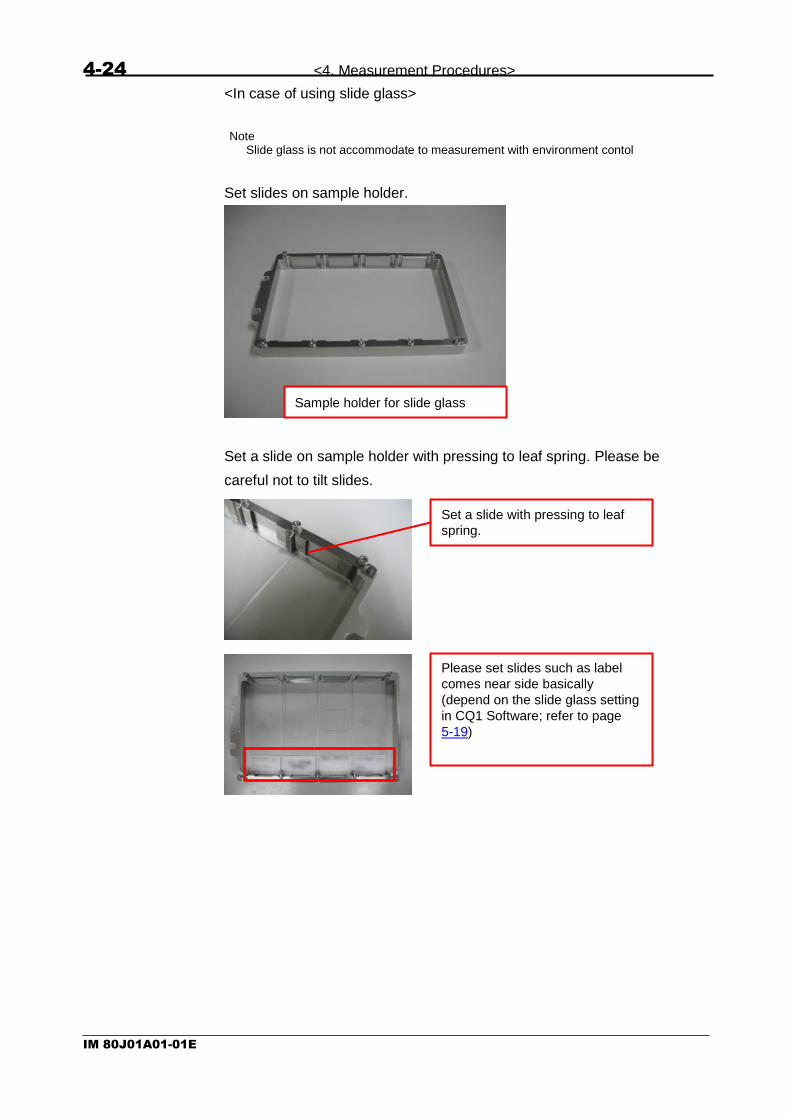
<In case of using slide glass>
Note Slide glass is not accommodate to measurement with environment contol
Set slides on sample holder.
Set a slide on sample holder with pressing to leaf spring. Please be
careful not to tilt slides.
Sample holder for slide glass
Set a slide with pressing to leaf
spring.
Please set slides such as label
comes near side basically
(depend on the slide glass setting
in CQ1 Software; refer to page
5-19)

<4. Measurement Procedures> 4-25
IM 80J01A01-01E
CAUTION
Set slides not to put cover glass on sample holder.
Cover glass
Slide glass
Sample holder
×

4-26 <4. Measurement Procedures>
IM 80J01A01-01E
<In case of using cover glass chamber>
(Only when controlling environment) Remove rid from cover glass
chamber, set rubber on the cover glass chamber fastly and set rid
again.
Set cover glass chamber pushing A1 well to corner indicated by arrow.
For IWAKI (2 holes) For NUNC Lab-Tec I
(3 holes)
For NUNC Lab-Tec II
(4 holes)
For MATSUNAMI (5 holes)
Rubber list
OK
NG

<4. Measurement Procedures> 4-27
IM 80J01A01-01E
(Only when controlling environment) Set a holding plate.
Fix a cover glass chamber by leaf spring.
Holding plate
In case of performing
environment control
In case of not performing
environment control
Set a cover glass chamber and
push down leaf spring to fix
4-28 <4. Measurement Procedures>
IM 80J01A01-01E
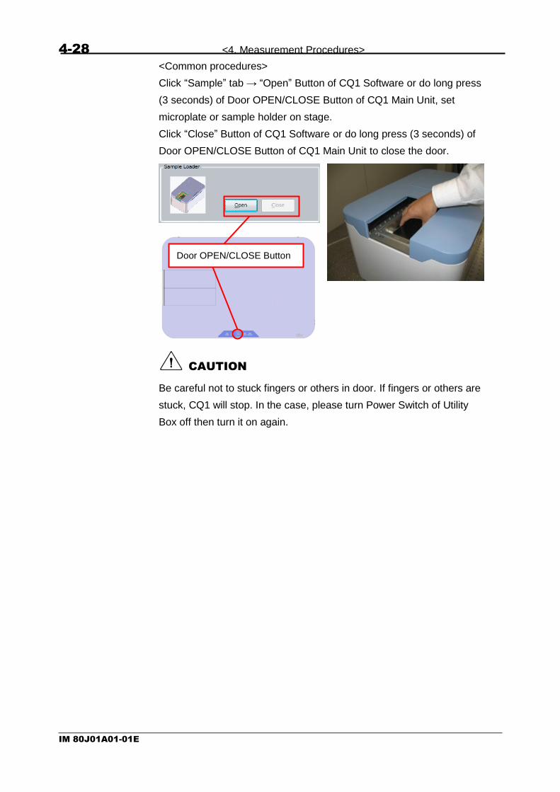
<Common procedures>
Click “Sample” tab → “Open” Button of CQ1 Software or do long press
(3 seconds) of Door OPEN/CLOSE Button of CQ1 Main Unit, set
microplate or sample holder on stage.
Click “Close” Button of CQ1 Software or do long press (3 seconds) of
Door OPEN/CLOSE Button of CQ1 Main Unit to close the door.
CAUTION
Be careful not to stuck fingers or others in door. If fingers or others are
stuck, CQ1 will stop. In the case, please turn Power Switch of Utility
Box off then turn it on again.
Door OPEN/CLOSE Button

<4. Measurement Procedures> 4-29
IM 80J01A01-01E
In case of using sample holder, set it in CQ1 as projection portion faces
left-side of CQ1.
CAUTION
If you don’t set microplate or sample holder properly, it may result to
equipment damage. Please confirm that 4 corners of the microplate or
sample holder are set on stage and it is moved lightly (not to be stuck
to edge of sample setting place).
CAUTION
Immediately pull out the AC cord from inlet of equipment, when you
notice smoke coming out of the main unit, foul smell, abnormal noise or
any other abnormality.
Projection Portion Projection Portion
OK
NG

4-30 <4. Measurement Procedures>
IM 80J01A01-01E
If you perform measurement by protocol which has been made, go to
procedure shown in 4.8 Sample Measurement.
<4. Measurement Procedures> 4-31
IM 80J01A01-01E
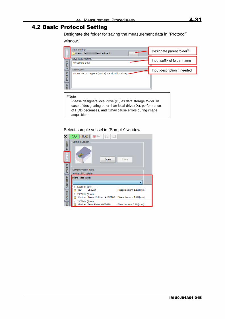
4.2 Basic Protocol Setting
Designate the folder for saving the measurement data in “Protocol”
window.
Select sample vessel in “Sample” window.
Designate parent folder※
Input suffix of folder name
Input description if needed
※Note
Please designate local drive (D:) as data storage folder. In
case of designating other than local drive (D:), performance
of HDD decreases, and it may cause errors during image
acquisition.

4-32 <4. Measurement Procedures>
IM 80J01A01-01E
Switch to “Imaging” window.
Double click imaging channel setting part to open “Channel Setting”.
Set the lasers and emission filters for each imaging channel.
(For details, refer to 5.9 Channel Setting)
Double click

<4. Measurement Procedures> 4-33
IM 80J01A01-01E
4.3 Sample Searching
Search the position that samples exist (suitable position to imaging) by
low magnification objective lens.
Set the viewer layout to “Image & Map”.
In “Imaging” window, select imaging channel, well and objective lens.
For sample searching, use low magnification objective lens (2x – 10x).
Select imaging channel
Select well
Select objective lens

4-34 <4. Measurement Procedures>
IM 80J01A01-01E
In “Z stack” of “Imaging” window (refer to page 5-28), click “Search” to
search Z position which samples exist.
After Z position search, click “<<” to apply the result of searching to Z
Stack parameter.
In “Map” window, select “Map Mode” (refer to page 5-95) and select
sample searching region by mouse drug.
Click “Start” to start map imaging.
Apply the result of searching to Z Stack parameter.
Select “Map mode”
Drag the region for searching

<4. Measurement Procedures> 4-35
IM 80J01A01-01E
After map imaging, select “Test imaging mode” (refer to page 5-94),
change objective lens to that for measurement, and select suitable field
for measurement.
Note
Blue region in “Map” window can’t be designated as imaging region because
objective lens interferes with stage attachment, sample holder and sample
vessel.
Select “Test imaging mode”
Select suitable field for measurement
Change objective lens for that for measurement.

4-36 <4. Measurement Procedures>
IM 80J01A01-01E
4.4 Imaging Setting
If needed, perform following (1) – (3) setting.
(1) Imaging channel setting
“Channels” window of “Imaging” window (refer to page 5-22),
change “Excitation Power” and/or “Exposure” of each imaging
channel.
<In case of using Transmission Illumination with Bright Field/
Phase Contrast>
Push the lever back in case of acquiring phase contrast image.
Pull the lever toward in case of acquiring bright field image.
Select imaging channel
Change “Excitation Power” and/or “Exposure”
Push Back ⇒ Phase contrast
(PH)
Pull toward ⇒ Bright field (BF)

<4. Measurement Procedures> 4-37
IM 80J01A01-01E
(2) Autofocus and 2D/ 3D imaging setting
In “Z Stack” window of “Imaging” window (refer to page 5-28),
change autofocus setting.
Change “Range” and “Slices”. As well, set 1 to “Slices” and 2D
measurement is executed. Set 2 or more and 3D measurement is
executed.
(3) Time-lapse setting
In “Time-lapse Condition” window of “Imaging” window (refer to
page 5-32), change “Interval” and “Duration”. If time-lapse
measurement is not performed, set “1” to “Duration”.
Change “Range” and “Slices”
Change autofocus setting
Change “Interval”
and “Duration”

4-38 <4. Measurement Procedures>
IM 80J01A01-01E
<About CQ1 autofocus>
CQ1 can perform 2 types of autofocus, which are laser based and
image based.
Laser Autofocus detects surface of bottom plate or cover glass by laser
and set the surface as Z base position. Please note that surface to
detect (Z base positon) is different by the kind of sample vessel. (Refer
to following table.)
Image Autofocus acquires image by designated channel and sets the Z
position that maximum intensity is obtained as Z base position. Microplate
① Laser Autofocus detecting surface (slide glass)
② Laser Autofocus detecting surface
(microplate, dish, cover glass chamber)※
③ Image Autofocus detecting position
Dish
Slide
Cover glass chamber
※ In case that laser autofocus doesn’t operete normally when using microplate, dish
or cover glass chamber, surface to detect would be changed to lower surface of bottom plate of sample vessel. For details, please refer to page 5-20.
In “Map” window, select “Rec Mode” (refer to page 5-96) and select
measuring Area by mouse drug.
Culture medium and others
Bottom plate,
Cover glass
① ② ③
Select “Rec mode”
Drag the Area for measuring.

<4. Measurement Procedures> 4-39
IM 80J01A01-01E
4.5 Analysis Protocol Setting
Set the viewer layout to “ImageViewer & Chart”.
Pre-acquire the images for analysis setting.
In “Wells” window of “Imaging” window (refer to page 5-25), make ①
button to status (green) , select a few wells from wells for measure※ (selected wells become light blue), and click “PreRec”.
Click “Stop” button to stop measurement.
※ Selection of negative control well(s) and positive control
well(s) is effectual.
①
Select a few wells

4-40 <4. Measurement Procedures>
IM 80J01A01-01E
Select “Application” tab, check to “Execute Analysis”, and click “Load”.
Select “User” tab if you use analysis protocol which is set and saved
previously. Select “Application” tab if you use analysis protocol which is
preloaded in CQ1 Software (Cell Cycle, FISH and so on). Select
“Template” tab if you use basic protocol which is preloaded in CQ1
Software.
Select analysis protocol and click “Load” to load analysis protocol.
(For details, refer to page 5-37)
Check
Select either “User”, “Application” or ”Template”
Select analysis protocol

<4. Measurement Procedures> 4-41
IM 80J01A01-01E
If needed, in “Object Detect Setting” window of “Application” window
(refer to page 5-44), change setting of object recognizing of each
imaging channel.
If needed, in “Link Setting” window of “Application” window (refer to
page 5-46), change link setting between each object.

4-42 <4. Measurement Procedures>
IM 80J01A01-01E
4.6 Object Recognizing Condition Setting
In “Analysis” window, click “Single Preview” (single object) or “Preview”
(all objects) to confirm result of object recognizing. If it is necessary to
improve the result, adjust recognizing condition as following.
If it is necessary to improve more, click “Edit”, open “Advanced Editor”
and set detailed recognizing condition.
(For details, refer to 5.4.5 Analysis Window)
Open “Advanced Editor”
Adjust recognizing condition
Detect all objects Detect single object

<4. Measurement Procedures> 4-43
IM 80J01A01-01E
In “Wells” window of “Analysis” window (refer to page 5-51), make
① button to status (green), select wells which were executed
“PreRec” above procedure (selected wells become pink), and click
“PreAnalyze”.
Confirm that objects are detected properly in multiple wells. If it is
necessary to improve the result, adjust detecting condition in the field
which object isn’t detected properly.
4.7 Protocol Saving
In “Wells” window of “Imaging” window (refer to page 5-25), make ①
button to status (green), select all wells for measurement in the
protocol (selected wells become light blue).
①
①
Select all wells for measurement in the protocol

4-44 <4. Measurement Procedures>
IM 80J01A01-01E
Select “Protocol” tab and click “Save As”.
Input name and descriptions of the protocol. Click “Save” to save the
protocol.

<4. Measurement Procedures> 4-45
IM 80J01A01-01E
4.8 Sample Measurement
In case of measurement by saved protocol, select protocol from
“Protocol” window.
Note In case of measuring other sample in same protocol again, please load the protocol in each time. If the protocol is not loaded, autofocus may not operate normally.
Set the viewer layout to “ImageViewer & Chart”.
Click “Rec” to start measurement. By clicking this button, imaging by
the condition set in 4.4 Imaging Setting and analyzing by the condition
set in 4.5 Analysis Protocol Setting and 4.6 Object Recognizing
Condition Setting are executed.
Image dataset and analysis dataset are saved in the folder designated
in 4.2 Basic Protocol Setting.
① Select protocol
② Show detail of protocol
③ Click “Load”
“”
② ①
4-46 <4. Measurement Procedures>
IM 80J01A01-01E
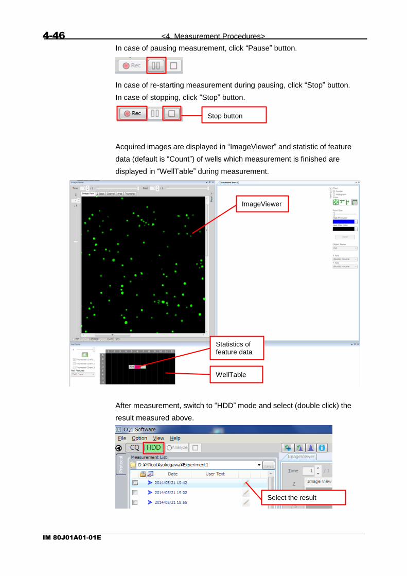
In case of pausing measurement, click “Pause” button.
In case of re-starting measurement during pausing, click “Stop” button.
In case of stopping, click “Stop” button.
Acquired images are displayed in “ImageViewer” and statistic of feature
data (default is “Count”) of wells which measurement is finished are
displayed in “WellTable” during measurement.
After measurement, switch to “HDD” mode and select (double click) the
result measured above.
Stop button
Select the result
ImageViewer
WellTable
Statistics of feature data

<4. Measurement Procedures> 4-47
IM 80J01A01-01E
Make ① button to status (white) and select well in “WellTable”.
Acquired images and result of recognition are displayed in
“ImageViewer”.
Make ① button to status (green), check number of Thumbnail
Chart to display and select wells in “WellTable”. Scattergrams or
histograms are displayed in “ThumbnailChart”.
For details of each window, refer to following
“WellTables” -> 5.6.5 WellTable Window
“ImageViewer” -> 5.6.2 ImageViewer Window
“ThumbnailChart” -> 5.6.4 ThumbnailChart Window
ImageViewer
WellTable
ThumbnailChart
①

4-48 <4. Measurement Procedures>
IM 80J01A01-01E
In case of retrying analysis, reset analyzing condition by referring 4.5
Analysis Protocol Setting and 4.6 Object Recognizing Condition Setting,
and click “Analyze”
In case of stopping analysis process, click “Stop” button.
Output acquired images, window snapshot of CQ1 Software or CSV
data and so on in “Output” window.
(For details, refer to 5.5.4 Output Window.)

<5. Functions of CQ1 Software> 5-1
IM 80J01A01-01E
5 Functions of CQ1 Software
5.1 Outline
CQ1 Software is the application software to control both CQ1 Main Unit
and Utility Box and runs sample measurement.
There are two operating modes; CQ mode and HDD mode, and the
window display changes depending on the mode.
(1) CQ Mode
Controls both CQ1 Main Unit and Utility Box and runs sample
measurement. Measurement data are saved in either the HDD of
workstation or network drive.
5.6 Viewer 5.4 Control Panel (CQ
Mode)
5.7 Status Panel
5.3 Operation Mode Panel
5.2 Main Menu
5.8 Viewer Layout

5-2 <5. Functions of CQ1 Software>
IM 80J01A01-01E
(2) HDD Mode
This mode is to view measurement data or to retry image analysis
under modified analysis conditions.
In HDD mode, it is able to output data for report such as screen
shot, movie, feature data and so on.
5.6 Viewer 5.5 Control Panel (HDD
Mode)
5.7 Status Panel
5.3 Operation Mode Panel
5.2 Main Menu
5.8 Viewer Layout

<5. Functions of CQ1 Software> 5-3
IM 80J01A01-01E
5.2 Main Menu
5.2.1 File Menu
(1) Save Measurement Protocol as Default
Save the default measurement condition file. Its channel setting
and analysis conditions shall be applied at the next start.
(2) Save as Measurement Protocol
Save the current measurement condition file.

5-4 <5. Functions of CQ1 Software>
IM 80J01A01-01E
(3) Load Measurement Protocol
Load measurement condition fle designated by file read-in dialog.
In CQ mode, conditions such as objective lens, sample vessel, Z
stack, Fields to be imaged and analysis conditions are applied.
Fields to be imaged aren’t applied if stage attachment and sample
holder isn’t matched.
In HDD mode, only analysis conditions are applied.
(4) Save Contrast and Region View Setting
This function is valid only in HDD mode. Save “Contrast
Enhancement” and “Region” setting of Tool function (Refer to
5.6.9 Tool Function). In case of not analyzed data, only “Contrast
Enhancement” setting is saved.
(5) Exit
Exit from CQ1 Software.

<5. Functions of CQ1 Software> 5-5
IM 80J01A01-01E
5.2.2 Option Menu
(1) Channel Setting
Open Channel Setting window to set imaging channels. Please
refer to “5.9 Channel Setting” for details.
(2) Trimming Parameter
Open Trimming Parameter window i to change stitch parameter.
Please refer to “5.10 Trimming Parameter” for details.
(3) User Setting
Open User Setting window to change user setting. Please refer to
“5.11 User Setting” for details.
(4) Activation Setting
Open Activation Setting window to manage license of CQ1
Software. Please refer to “5.12 Activation Setting” for details.
CAUTION
Please do not operate Activation Setting window except when
necessary such as updating CQ1 Software. CQ1 Software might
be inoperatable. For updating CQ1 Software, please contact the
dealer.

5-6 <5. Functions of CQ1 Software>
IM 80J01A01-01E
(5) Run as External Control
Following “Robot Service Hosting” window opens and changes to
the external control mode that high-order computer controls CQ1.
Select this menu in case of operating CQ1 with external robot.
Click “Cancel” to quit external control.
5.2.3 View Menu
Viewers corresponding to each menu item are shown. Please refer to
“5.6 Viewer” for details.

<5. Functions of CQ1 Software> 5-7
IM 80J01A01-01E
5.2.4 Help Menu
(1) About CQ1
Version information is shown.
(2) Make System Analysis Report
Collect system analysis information and output a compressed file
of log and calibration file under CVSysRep folder on desktop. The
output data will be used for system maintenance service when
error occures.
It takes a few minute to collect system information. It is
recommended to check to select date when error is occurred
because the all date log data is quite huge.

5-8 <5. Functions of CQ1 Software>
IM 80J01A01-01E
5.3 Operation Mode Panel
Operation mode panel screen changes depending on CQ mode and
HDD mode.
5.3.1 Operation mode panel in CQ mode.
(1) Control Panel Display SHOW/HIDE button
Button to change SHOW/HIDE of control panel display.
: Click to HIDE control panel display
: Click to SHOW control panel display
(2) CQ Mode Button
Highlighted in the CQ mode but nothing happens by clicking this
button. (Refer to 5.1 Outline (1) CQ Mode)
(3) HDD Mode Button
Click to shift CQ1 Software to HDD mode. Cannot click it during
measurement. (Refer to 5.1 Outline (2) HDD Mode)
(4) Rec Button
Click to start measurement after setting measurement conditions
on the control panel.
(5) Pause Button
Click to pause measurement.
(6) Stop Button
Click to stop measurement.
This button becomes available when Pause button was clicked
during measurement.
(1) (2) (3) (4) (5) (6)

<5. Functions of CQ1 Software> 5-9
IM 80J01A01-01E
5.3.2 Operation Mode Panel in HDD Mode.
(1) Control Panel Display SHOW/HIDE Button
Button to change SHOW/HIDE of control panel display.
: Click to HIDE control panel display
: Click to SHOW control panel display
(2) CQ Mode Button
Click to shift CQ1 Software to CQ mode. Cannot click it during
analyzing measurement data. (Refer to 5.1 Outline (1) CQ Mode)
(3) HDD Mode Button
Highlighted in the HDD mode but nothing happens by clicking this
button. (Refer to 5.1 Outline (2) HDD Mode)
(4) Analyze Button
To start analysis of measurement data, select saved data on
control panel, set analysis conditions at “Application window” and
“Analysis window”, and click this button.
(5) Stop Button
Click to stop data analysis.
(1) (2) (3) (4) (5)

5-10 <5. Functions of CQ1 Software>
IM 80J01A01-01E
5.4 Control Panel (CQ Mode)
In CQ mode, click left-side tabs to set measurement conditions and so
on.

<5. Functions of CQ1 Software> 5-11
IM 80J01A01-01E
5.4.1 Protocol Window
Protocol means sample measurement conditions such as imaging
conditions specified at “Imaging window”, and analysis conditions
specified at “Application window” and “Analysis window”. “Protocol
window” is to save or load Protocol, and specify the folder name to
save measurement data obtained under the Protocol.
(1) Save Setting
Specify a storage folder to save measurement data. To change the
storage folder, click button to show folder selection menu.
(1)
(2)
(3)
(4)
(5)
(6)
(7)

5-12 <5. Functions of CQ1 Software>
IM 80J01A01-01E
(2) Save Folder Name
For each measurement, CQ1 Software prepares a measurement
data folder within the data storage folder specified by “Save
Setting”, and save images and numerical data. ”Save Folder
Name” is used as a suffix of measurement data folder name.
Name format of MeasurementData folder is
“yyyyMMddTHHmmss_<string input in “Save Folder name”>”. For
example, in case of beginning measurement at April 1, 2014, 12°
34′56″, MeasuremenData folder name is
“20140401T123456_Test”.
Under MeasurementData folder, sub-folders are created as the
following configuration. There are folders not to be created by
mesurement setting.
Note
Please designate local drive (D:) as data storage folder. In
case of designating other than local drive (D:), performance
of HDD decreases, and it may cause errors during image
acquisition.
Absolute path (total folder name from “D:”) of strage folder
can’t be over 90 letters.

<5. Functions of CQ1 Software> 5-13
IM 80J01A01-01E
(3) Description
Fill in the outline of measurement data.
Input contents can be confirm in (9) Pen Button of 5.5.1 Protocol
Window or 5.6.7 Information Window (For details, please refer to
each section).
DataFolder
Calibration Folder to store calibration data
MeasurementData
Folder to store acquired OME-TIFF image Image
Projection Folder to store projection result (if Z > 1)
Analyses Folder to store analysis result
Folder to be created by each analysis
・・・
Log
Map
Reports
Other files
MeasurementResult.ome.tif
Analysis_<Date>
FCS
ICE
Reports
Other files
Folder for each measurement data
(Folder name is set at “Save Folder Name”
Folder to store FCS format data
Folder to store ICE format data
Snapshot (.png, .jpg)
Folder to store log data
Folder to store Map imge
Folder to store image data
Measurement result file
(OME-TIFF)
Designated in “Save Setting”
Note
Over 39 letters can’t be input for “Save Folder Name”.
Please utilize following “Description” as memo for
measurement.

5-14 <5. Functions of CQ1 Software>
IM 80J01A01-01E
(4) Protocol
List of Protocols saved in Workstation is shown. By selecting a
Protocol, its details are shown. Click “x” button on the upper right
to close the Protocol detail window.
(5) Load Button
Click this button after selecting a Protocol from the list to load it in
the control panel.
Select protocol
Show detail of protocol

<5. Functions of CQ1 Software> 5-15
IM 80J01A01-01E
(6) Save As Button
File save dialog appears by clicking this button to save
measurement conditions specified in the control panel. XML file
name is shown in the “Name” column of Protocol list.
Fill in the outline of protocol.Contents can be confirm in 5.6.7
Information Window (For details, please refer to the section).
(7) Delete Button
Select a Protocol from the list, and click this button to show “Delete
Protocol File” dialog. Click “YES” to delete Protocol.

5-16 <5. Functions of CQ1 Software>
IM 80J01A01-01E
5.4.2 Sample Window
Sample window is to select sample vessel type, such as microplate or
slide glass, to load on CQ1.
(1) Sample Loader
Click Open button to open the door on CQ1 Main Unit when the
XY-stage is located at the door.
Click Close button to close the door when XY-stage moves to the
measuring position to get ready for imaging.
(2) Sample Vessel Type
Select sample vessel type loaded in CQ1 Main Unit.
CQ1 Main Unit automatically recognizes the loaded sample holder
type, and shows sample holder type name at the “Attachment”
column of “Sample Vessel Type”, to show selectable sample type
in the menu depending on sample holder type.
Sample holder Description
None CQ1 Software recognizes as if microplate is loaded, and enables selection of “Microplate Type”
Triple 35 mm dishes CQ1 Software recognizes a Triple 35 mm dishes sample holder is loaded in which up to three 35 mm dishes can be set, and enables selection of “Dish Type”.
CAUTION Set dishes to all 3 positions.
Single 60 mm dish CQ1 Software recognizes a Single 60 mm dish sample holder is loaded in which one 60 mm dish can be set, and enables selection of “Dish Type”.
Slide glass ISO 8037/1
CQ1 Software recognizes a slideglass sample holder is loaded in which up to four slide glasses can be set, and enables selection of “Slide Type”.
Cover glass chamber CQ1 Software recognizes a cover glass chamber sample holder is loaded in which one cover glass chamber can be set, and enables selection of “Cover Glass Chamber Type”.
(1)
(2)
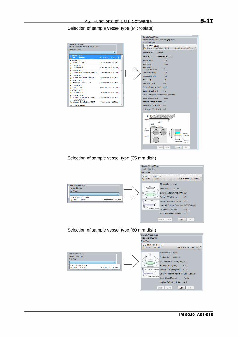
<5. Functions of CQ1 Software> 5-17
IM 80J01A01-01E
Selection of sample vessel type (Microplate)
Selection of sample vessel type (35 mm dish)
Selection of sample vessel type (60 mm dish)

5-18 <5. Functions of CQ1 Software>
IM 80J01A01-01E
Selection of sample vessel type (Slide glass)
Selection of sample vessel type (Cover glass chamber)

<5. Functions of CQ1 Software> 5-19
IM 80J01A01-01E
By using “Edit” button at the bottom of “Sample Vessel Type”, it is
possible to modify sample shape and create customized sample type.
(Example: 35 mm dish)
(Example: slide glass)
①
③
⑦ ②
④
⑧ ⑨
⑤
① ⑨ ②
⑥
③
⑦ ⑧
⑤

5-20 <5. Functions of CQ1 Software>
IM 80J01A01-01E
① Delete Button
Delete the sample vessel type selected in “Sample Vessel Type”
menu. Default sample vessel types are key-marked and cannot be
removed by Delete Button.
② Edit Button
Start editting parameters of selected sample vessel type in
“Sample Vessel Type” menu in which name and size of vessel
type can be modified. → ③ Edit Window
③ Edit Window
Input parameters such as sample vessel name and dimensions.
Refer to displayed diagram in the window for dimensions to be
input.
④ Measure Button (Invalid when using slide glass)
Measure the bottom thickness of sample vessel. This function can
be used when 10x dry objective lens (UPLSAPO10X2) is selected.
⑤ Laser AF Bottom Detection
By checking the box, surface to detect by laser autofocus is
changed to lower surface of bottom plate of sample vessel. This is
checked when laser autofocus doesn’t operete normally. For
details of laser autofocus, please refer to page 5-28
⑥ Cell Position (Only valid when using slide glass)
Select relative position between slide glass and sample.
<Bottom>
<Top>
Slide glass (≒1 mm)
Cover glass (≒0.17 mm)
Slide glass (≒1 mm)

<5. Functions of CQ1 Software> 5-21
IM 80J01A01-01E
⑦ Save Button
Save modified parameters and finish editing.
⑧ Cancel Button
Cancel modified parameter setting and finish editing.
⑨ Set Button
Overwrite newly set parameters on selected sample vessel type
and finish editing. You cannot click this button when a key-marked
type is selected.

5-22 <5. Functions of CQ1 Software>
IM 80J01A01-01E
5.4.3 Imaging Window
Imaging window is to specify sample imaging conditions
(1) Channels
① Imaging channel list
Show the list of imaging channels specified by; “Option” menu →
“Channel Setting” menu. Also, by double-clicking each channel,
“Channel Setting” window (refer to 5.9 Channel Setting) opens.
Name Description
# Number of imaging channel
Excitation Light source information (laser or transmission illumination)
Emission Emission filter information
Acquisition Image acquisition conditions of camera, such as exposure time or binning.
①
④
③ ②
⑤
⑦
⑥ ⑧

<5. Functions of CQ1 Software> 5-23
IM 80J01A01-01E
② Excitation Power
Specify light source power (laser or lamp) in the range of 0.0%~
100.0% ※. It is able to specify any way shown following. (The
same goes for ③, ④)
③ Exposure
Specify camera exposure time in the range of 50ms~10,000ms
(10 sec.)
④ Pinhole Disk Speed
Specify rotation speed of the pinhole disk array of confocal unit in
the range of 1,800rpm~4,000rpm. Default value is 3,600rpm.
⑤ Binning Number
Specify binning condition of the camera. Set binning number
bigger and image resolution become lower, image brightness
become higher, and data size become smaller
Binning Number
Description
1 Unuse binning function. One camera pixel is saved as one pixel of image data.
2 Combine adjacent 2X2 camera pixels and save as one pixel of image data.
4 Combine adjacent 4X4 camera pixels and save as one pixel of image data.
8 Combine adjacent 8X8camera pixels and save as one pixel of image data.
Binning 1
Binning 2
Binning 4
Direct input Up/ Down button Slider bar
※Note
Guaranteed power range of transmission illumination is
10.0 % — 100.0 %.

5-24 <5. Functions of CQ1 Software>
IM 80J01A01-01E
⑥ Flat Field Correction
Correct peripheral image darkness caused by shading of the
microscope. (Default: checked)
⑦ Chromatic Aberration
Correct chromatic aberration caused by difference of wavelength.
(Default: checked)
⑧ Laser Enhancement
Check to enhance excitation power. If checked, value of excitation
power turns red.
Note
Normally excitation power is calibrated by power irradiated
on sample. If check this box, the calibration is disabled and
excitation laser is output by non-calibrated laser power.

<5. Functions of CQ1 Software> 5-25
IM 80J01A01-01E
(2) Wells
① Selected sample vessel
Diagram of sample vessel selected at “Sample window” is shown.
Unselected wells are shown in white. Gray wells are unselectable
due to interference of objective lens.
By clicking white well when button ③ is (white), the well is
selected for preview (red frame). By left-clicking or left-dragging
wells when button ③ is (green), the wells are selected for
Rec (light blue). By right-clicking or right-dragging, selection for
Rec is canceled.
② Same Area
Check here to capture images of the same Area in all wells of
microplate, slide. If unchecked, imaging Areas can be selected
individually for each well.
③ Select measurement area
Refer to above ①.
④ All Select
All wells are selected for Rec. This botton is displayed when
“Same Area” is checked.
Slide Glass Sample Holder
①
②
③
④
⑤
⑥
⑦
Gray: Unselectable
White: Unselected
Red frame:
Selected for preview
Light blue:
Selected for Rec
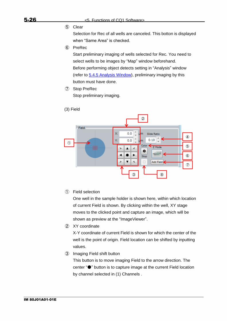
5-26 <5. Functions of CQ1 Software>
IM 80J01A01-01E
⑤ Clear
Selection for Rec of all wells are canceled. This botton is displayed
when “Same Area” is checked.
⑥ PreRec
Start preliminary imaging of wells selected for Rec. You need to
select wells to be images by “Map” window beforehand.
Before performing object detects setting in “Analysis” window
(refer to 5.4.5 Analysis Window), preliminary imaging by this
button must have done.
⑦ Stop PreRec
Stop preliminary imaging.
(3) Field
① Field selection
One well in the sample holder is shown here, within which location
of current Field is shown. By clicking within the well, XY stage
moves to the clicked point and capture an image, which will be
shown as preview at the “ImageViewer”.
② XY coordinate
X-Y coordinate of current Field is shown for which the center of the
well is the point of origin. Field location can be shifted by inputting
values.
③ Imaging Field shift button
This button is to move imaging Field to the arrow direction. The
center “●” button is to capture image at the current Field location
by channel selected in (1) Channels .
①
②
④
⑤
⑥
⑦
③
⑧

<5. Functions of CQ1 Software> 5-27
IM 80J01A01-01E
④ Slide Ratio
Specify the travel distance when moving the imaging Field by
imaging Field shift button. Field size is a travel distance unit. For
example, by setting 0.10, the stage moves 1/10 of the Field size,
and setting 1.00 moves by one Field size.
⑤ Color
Click this button to capture images at the current Field position at
all channels selected at “ImageViewer”.
⑥ Z Mode
Select to run Z Stack imaging or not while preview imaging.
Z Mode Description
Capture one image at the Center of Z Stack.
Capture “Slices” images at “StepHight” interval between Top and Bottom of Z Stack.
⑦ Add Field
Specify current imaging Field as the measurement location. The
measurement filed is shown in “Map” window of “Viewer”.
⑧ Stop
Click this button to stop imaging which was started by either
mouse click of image Field or by clicking imaging Field shifting
button.

5-28 <5. Functions of CQ1 Software>
IM 80J01A01-01E
(4) Z Stack
<About CQ1 autofocus>
CQ1 can perform 2 types of autofocus, which are laser based and
image based.
Laser Autofocus detects surface of bottom plate or cover glass by laser
and set the surface as Z base position. Please note that surface to
detect (Z base positon) is different by the kind of sample vessel. (Refer
to following table.)
Image Autofocus acquires image by designated channel and sets the Z
position that maximum intensity is obtained as Z base position. Microplate
① Laser Autofocus detecting surface (slide glass)
② Laser Autofocus detecting surface (microplate, dish, cover glass chamber)
③ Image Autofocus detecting position
Dish
Slide
Cover glass chamber
※ In case that laser autofocus doesn’t operete normally when using microplate, dish
or cover glass chamber, surface to detect would be changed to lower surface of bottom plate of sample vessel. For details, please refer to page 5-20.
①
③
②
④
⑤ ⑥
⑦
Culture medium and others
Bottom plate,
Cover glass
① ② ③

<5. Functions of CQ1 Software> 5-29
IM 80J01A01-01E
① Preview
If checked, automatically capture images and show in
“ImageViewer” whenever you change Z position.
② Laser AF
Autofocus unit detects the interface of cover glass of the sample
holder when capturing preview or time-lapse images, and save the
Z-zero-position in the system. It is useful to avoid focus-out caused
by tilted glass surface, when capturing images in wide field.
Laser autofocus works at each measurement time when checked,
but works only once for every Field if unchecked.
③ Image AF
Image Autofocus searches for objects by moving imaging position
in Z direction, after Laser autofocus searched for the glass
interface.
When checked, Image Autofocus runs when imaging started by
“Start” button at “Map” window in “Viewer”, or when measurement
started by “PreRec” button in “Wells”.
④ Laser AF・Image AF Setting
Click “▼” button to show Laser autofocus and Image autofocus
setting window.
Run Laser AF at every field
Run Laser AF at the center of Area once
Run Image AF at every field
Run Image AF at the center of Area once
Set Z range for Image AF
Set slice number of Image AF
Set step size of Image AF
Select the channel for Image AF sampling
Set light power (laser or lamp)
Set camera exposure time
Resume Laser AF/Image AF setting
(settings in red broken rectangle) to default

5-30 <5. Functions of CQ1 Software>
IM 80J01A01-01E
⑤ Objective lens information
Information of selected objective lens such as model name,
magnification and NA and working distance is shown.
⑥ Z Stack Parameter
Top is the upper limit of Z Stack, and Bottom is the lower limit of Z
Stack. Center is the center position of Top and Bottom. When the
Center value is changed, Top and Bottom values parallel shift by
the same value. Input unit is 0.1um.
With the radio button at the left of “Top”, “Center” and “Bottom”,
values can be changed by slider.
Range means the distance between Top and Bottom. To fix the
Range value, click the key button at the left to click down. If either
Top or Bottom value is changed when “Range” is fixed, the other
value parallel shifts by the same amount.
“Slices” is to set the number of Z Stack images to capture.
“Step” is the imaging interval (step height) of Z Stack. Click left
button to set suitable “Step” of selected objective lens※.
⑦ Search
“Search” button is to search for sample position through Z Stack
imaging.
button is to set search conditions.
button is to input search results on “Center” of Z Stack.
button is to input search results on “Range” of Z stack.
※ Action of clicking this button in each objective lens is as
following.
- Phase contrast lens -> This button is unavailable.
- Dry lens: 2x, 4x -> “1” is set to “Slices”
- Other than above, following step height is set to “Step”.
Dry lens: 10x -> 15 µm, 20x -> 5 µm, 40x -> 2 µm
Lens for thick bottom vessel: 20x -> 5 µm
Long working distance lens: 20x -> 9 µm, 40x -> 4 µm
Set search range
Set slice number for search
Set Z-step size for search

<5. Functions of CQ1 Software> 5-31
IM 80J01A01-01E
(5) Objective Lens
Select objective lens here. Selected lens is highlighted.
(6) Time-lapse Setting
Switch the time-lapse acquisition mode (normal mode/ fast mode
(option)).
If you didn’t buy this option, this menu isn’t shown and the time-lapse
acquisition mode is always normal mode.
① Normal
In this mode, sequence of imaging in each well, field, channel and
Z slice has a priority. These sequences of imaging are performed
at interval and duration set at “Time-lapse Condition” described
below.
② Fast (option)
In this mode, time-lapse imaging has a priority. Time-lapse
imaging of speed and time length set at “Fast Time-lapse
Condition” is performed in each well and field. Numbers of channel
and Z slice are fixed to “1”. When switching to this mode, the
selected channel remains and the others are removed
automatically. Also, “Chromatic Abberation” becomes invalid
automatically.
This mode is not correspond to on-the-fly analysis. To analyze
image data acquired by this mode, it is necessary to acquire image
data by CQ mode then analyze by HDD mode.
① ②
Note
Don’t select “Fast” mode if setting of folder structure of saving
data is “By Time Point” (Refer to 5.11 User Setting).
In case to use “Fast” mode, select Main Menu -> “Option” ->
“User Setting” and select setting other than “By Time Point”.

5-32 <5. Functions of CQ1 Software>
IM 80J01A01-01E
(7) Time-lapse Condition
Set time-lapse imaging setting in Normal mode
① Interval
Set the interval of time-lapse measurement in seconds. The
specified time and acquisition time are shown on the right.
② Duration
Specify the total number of repetitions. The total time is shown on
the right.
③ Renewal Button
Display total image number and total file volume. By clicking this
button, total file volume and total image number are renewed.
If HDD space is not enough, display warning sign.
①
②
③
④
Total image number (Total file volume)

<5. Functions of CQ1 Software> 5-33
IM 80J01A01-01E
④ Variable Time-lapse
An interval change event at a specific time point can be preset.
Time Point: Time point to change interval
Interval (sec): New interval
Past: Time for interval change
<In case of constant interval time-lapse>
Set “Interval” and “Duration”. Select row and click “ - ” to delete the
“Variable Time-lapse” setting.
<In case of variable interval time-lapse>
Set “Interval”, “Duration” and “Variable Time-lapse”. In this case,
“Interval” is applied until first time point to change interval.
In case of setting as above
Time point Interval (min)
①1~19 10
②20~49 5
③50~100 20
Note
If larger value than “Duration” is designated for “Time Point”, measurement
finishes at “Duration”.
①Select
(総ファイル容②Click
(総ファイル容

5-34 <5. Functions of CQ1 Software>
IM 80J01A01-01E
(8) Fast Time-lapse Condition
Set time-lapse imaging setting in Fast mode (option).
If you didn’t buy this option, this menu isn’t shown.
① Total Period
Set the term of time-lapse measurement by seconds. The
calculated number of acquisition times is shown on the right.
② Acquisition Speed
In case of setting acquisition speed and exposure individually,
check “FPS”. Upper limit of acquisition speed is determined by
exposure, binning and trimming. If the value exceeding upper limit
is input, value is changed to actual upper limit automatically.
In case that “FPS” is unchecked, acquisition speed according to
exposure is set automatically. Acquisition speed is limited by
binning and trimming.
The calculated acquisition interval is shown on the right.
①
②
③
Note
Imaging speed in Fast mode is up to 20 fps. To perform 20
fps imaging, following setting is needed.
- Set exposure to 50 ms.
- Uncheck “FPS”.
- Set binning 2 and over or narrow field of view to 1/4 and
under in area by trimming
(refer to 5.10 Trimming Parameter)

<5. Functions of CQ1 Software> 5-35
IM 80J01A01-01E
③ Renewal Button
Display total image number and total file volume. By clicking this
button, total file volume and total image number are renewed.
If HDD space is not enough, display warning sign.
(9) Priority
In case of multiple Z slice, multiple channel imaging, set priority of
imaging sequence.
(In Fast mode, numbers of channel and Z slice are fixed to “1”. So
setting of this item has not special meaning. )
① Z Stack
Multiple Z slice imaging by certain channel is performed in priority
to multiple channel imaging.
② Channel
Multiple channel imaging by certain Z slice is performed in priority
to multiple Z slice imaging.
This setting becomes available in case that Z Offset of all channels
are set to “0”. (refer to 5.9 Channel Setting )
Total image number (Total file volume)
① ②
Z3 ③ ⑥ ⑨ Z3 ⑦ ⑧ ⑨
Z2 ② ⑤ ⑧ Z2 ④ ⑤ ⑥
Z1 ① ④ ⑦ Z1 ① ② ③
Channel 1 Channel 2 Channel 3 Channel 1 Channel 2 Channel 3
Z prior imaging Channel prior imaging

5-36 <5. Functions of CQ1 Software>
IM 80J01A01-01E
5.4.4 Application Window
Application window is for setting image analysis conditions.
(1) Execute Analysis
When checked, runs measurement and analysis at the same time, and
runs measurement only when unchecked.
(3)
(6)
(8)
(2)
(1)
(7)
(9)
(4)
(5)

<5. Functions of CQ1 Software> 5-37
IM 80J01A01-01E
(2) Load
Load Analysis Protocol
◆Load Analysis Protocol (User Window)
◆Load Analysis Protocol (Application Window)
①
⑥
⑤ ②
⑦
④
③ ⑧
⑨

5-38 <5. Functions of CQ1 Software>
IM 80J01A01-01E
◆Load Analysis Protocol (TemplateWindow)
① List of Analysis Protocol (User Window)
Show the list of protocols saved by user.
Name Description
Date Date of saving the analysis protocol
Name Name of analysis protocol
Analysis Analysis target Link Name of Link Setting
Detect Show the name defined by Object Detect Setting
② Details of Link Setting
(In this document, “Link” means linkage among objects which is
imaged by different channel.)
Show details of Link Setting of the Analysis Protocol selected at
①, ⑨ or ⑩.
③ List of Object Detection Setting
Show the Object Detect List of the Analysis Protocol selected at
①, ⑨ or ⑩.
Name Description
Ch Show the channel for detection
Name Show the name of object detect
④ Description
Description of the Analysis Protocol being selected at ①, ⑨ or
⑩.
⑤ Load
Load the Analysis Protocol being selected at ①, ⑨ or ⑩.
⑩

<5. Functions of CQ1 Software> 5-39
IM 80J01A01-01E
⑥ Cancel
Close the window
⑦ Other File
Load Analysis Protocol from arbitrary protocol.
⑧ Delete
Delete Analysis Protocol selected in ①. Protocol selected in ⑨
or ⑩ can’t be deleted

5-40 <5. Functions of CQ1 Software>
IM 80J01A01-01E
⑨ Analysis Protocol List (Application Window)
Show Analysis Protocols preloaded in CQ1 Software.
Name Description
CellCycle Protocol for Cell Cycle
Colony measurement
Protocol for analyzing colony
Spheroid structure Protocol for 3D Analysis (Spheroid, tissue slice and so on.)
Multinucleated cell Protocol for analyzing multinucleated cell
Circulating tumor cells
Protocol for analyzing circulating tumor cell
FISH Protocol for FISH Analysis
Total count in individual object
Protocol for counting objects of multiple categories in image
Neurite outgrowth Protocol for analyzing neurite outgrowth
⑩ Analysis Protocol List (Template Window)
Show basic Analysis Protocols preloaded in CQ1 Software
Name Description
Nucleus Protocol for analyze nucleus (one object)
Dots in Nucleus Protocol for analyze nucleus and one category of dots
2 Color Dots in Nucleus
Protocol for analyze nucleus and two categories of dots
Nucleus and Cell body
Protocol for analyze nucleus and cell body
Nucleus and Cytoplasm
Protocol for analyze nucleus and cytoplasm
Dots in Cell body Protocol for analyze nucleus, cell body and dots in cell body
Dots in Nucleus Cytoplasm
Protocol for analyze nucleus, cytoplasm and dots
2 Color Dots in Cell body
Protocol for analyze nucleus, cell body and two categories of dots in cell body
2 Color Dots in Nucleus Cytoplasm
Protocol for analyze nucleus, cytoplasm and two categories of dots
Membrane Protocol for analyze nucleus, cell body and cell membrane
Dots in Membrane Protocol for analyze nucleus, cell body, cell membrane and dots
Nucleus and pseudo-Cell body
Protocol for analyze nucleus and psudo cell body (uniformly expanded nucleus region)
Nucleus and pseudo-Cytoplasm
Protocol for analyze nucleus and psudo cytoplasm (uniformly expanded nucleus region)

<5. Functions of CQ1 Software> 5-41
IM 80J01A01-01E
(3) Save
Save the Analysis Protocol.
① Name
Define the name of Protocol which is also used as file name.
② Description
Input description of the Protocol.
③ Save
Save the Protocol.
④ Cancel
Close the window without saving the Protocol.
①
②
④ ③

5-42 <5. Functions of CQ1 Software>
IM 80J01A01-01E
(4) Z Analysis Setting
Set the analysis method for multi-Z images. Either one in following
table must be selected.
Slice 3D image generated from Multi-Z images is analyzed
MIP
MIP image generated from Multi-Z images is analyzed MIP is a function to build a single image by putting together pixels associated with the largest signals (smallest signals in transmission illumination image) among identical pixels from multiple image data captured on the confocal plane in the Z-axis direction It is able to display and analyze 3D objects as one image
Sum
Sum image generated from Multi-Z images is analyzed Sum is a function to create a single image by putting together pixels associated with the summation signals among identical pixels from multiple image data captured on the confocal plane in the Z-axis direction It is able to display and analyze 3D objects as one image It is efficient if fluorescent intensity of sample is low
Select Z slice images to analyze
ALL Select all Z slices for analysis target
Selected Select Z slices for analysis target by following menu opened by “Option” button
Click “Option” button and select Z slices for analysis target by following
menu.
① Total
Show all acquired Z slices number.
② Range selection
Set range of Z slices to select for analysis target.
③ All range selection
Set whole range of Z slices to select for analysis target.
④ Sampling
Select Z slices for analysis target by interval designated by “Skip”.
⑤ Skip
Input interval of Z slices selection.
①
② ③
④
⑥
⑦ ⑧
⑨ ⑩
⑤

<5. Functions of CQ1 Software> 5-43
IM 80J01A01-01E
⑥ [>>]
Apply selection range of Z slices.
⑦ Unselected
Show unselected Z slices for analysis target. Total number of
unselected Z slices is shown at the bottom right.
⑧ Selected
Show selected Z slices for analysis target. Total number of
selected Z slices is shown at the bottom right.
⑨ OK
Fix Z slices range setting for analysis target.
⑩ Cancel
Cancel Z slices range setting and close window
(4) Time-lapse Setting
Select images of time point to analyze
ALL Select all time point images for analysis target
Selected Select images of time point for analysis target by following menu opened by “Option” button
Click “Option” button and select time point for analysis target by
following menu.
① Total
Show all acquired time points number.
② Range selection
Set range of time points to select for analysis target.
③ All range selection
Set whole range of time points to select for analysis target.
①
② ③
④
⑦
⑧ ⑨
⑪ ⑫
⑤
⑥
⑩

5-44 <5. Functions of CQ1 Software>
IM 80J01A01-01E
④ Sampling
Select time points for analysis target by interval designated by
“Skip” or total number of time points designated by “Total”.
⑤ Skip
Input interval of time points selection.
⑥ Total
Input total number of time points to select.
⑦ >>
Apply selection range of time points.
⑧ Unselected
Show unselected time points for analysis target. Total number of
unselected time points is shown at the bottom right.
⑨ Selected
Show selected time points for analysis target. Total number of
selected time points is shown at the bottom right.
⑩ [>>], [<<]
Move time points between “Unselected” <-> “Selected”.
⑪ OK
Fix time points range setting for analysis target.
⑫ Cancel
Cancel time points range setting and close window
(6) Objective Detect Setting
Show the list of current Object Detect Setting.
Name Description
Link Show if the detected object is linked or not.
Checked Linked
Unchecked Unlinked
Name Show the object name to detect
Reference Ch Show the channel number, light source and BP filters of the object detect channel.

<5. Functions of CQ1 Software> 5-45
IM 80J01A01-01E
(7) Edit Object Detect Setting
Edit object detect settings. Up to 10 objects can be added.
① Object list to detect
Show the list of object detect setting
Name Description
Link Show if the detected object is being linked or not.
Checked Linked
Unchecked Unlinked
Name Edit name of the object to detect
Reference Ch Select object detect channel. Only the confocal channel is selectable. However, Phase Contrast channel is selected if no confocal channel is installed.
② Add
Add an Object Detect Setting to the end of the list.
③ Copy
Copy selected Object Detect Setting and add to the end of the list.
However, Link cannot be copied.
④ Remove
Remove selected Object Detect Setting.
⑤ ▲
Raise up analysis order of selected Object Detect Setting by one
step.
⑥ ▼
Step down analysis order of the selected Object Detect Setting by
one step.
⑦ OK
Close window after confirming the object Detect Setting. If a
warning sign appears, reconfirm the Protocol at “Analysis” window.
①
⑥
⑤
② ⑦ ④ ③ ⑧

5-46 <5. Functions of CQ1 Software>
IM 80J01A01-01E
⑧ Cancel
Cancel the modification and close window.
(8) Link Setting
Show the current Link Setting. The node one-step above the object is
called “Root node”, and the one below is called “Sub node”.
◆Link Setting Items
Item Description
Link Name Name of entire linked objects
Link Tree Tree to show correlations among objects
Root Node Top node
Sub Node Other nodes
◆Conditions of Sub Nodes
Item Description
Method
Method for linking
Adjacent to Root Node
Included within Root Node
Relationship
Relationship with Root Node
One-to-one relationship
One-to-many relationship
Root Node
Sub Node

<5. Functions of CQ1 Software> 5-47
IM 80J01A01-01E
(9) Edit Link Setting
Edit Link Setting. Please note the unlinkable conditions shown below.
・ Sub node cannot be added to an “one-to-many” link.
・ Object Detect cannot be linked to “one-to-one” more than once.
・ Object Detect cannot be linked to both “one-to-one” and
“one-to-many”.
① Name
Set an entire name of all linked objects
② Link Tree
Show currently set Link Tree. Please refer to (7) Link Setting (page
(8) Link Setting
③ 5-46) for items in the tree.
①
⑥ ⑤
②
⑦ ④ ③

5-48 <5. Functions of CQ1 Software>
IM 80J01A01-01E
④ Add
Add a Sub Node to the selected node.
i. Append
Select the Object Detect to be linked. The list of Object Detect
Setting is shown.
ii. Link Condition
Select link condition. Please refer to ◆Conditions of Sub
Nodes in (7) Link Setting (page 5-46).
iii. OK
Close window after confirming changes.
iv. Cancel
Cancel changes and close window.
i
iv iii
ii

<5. Functions of CQ1 Software> 5-49
IM 80J01A01-01E
⑤ Edit
Edit selected node setting.
i. Append
Select the reference Object Detect Setting from the list to be
shown.
ii. OK
Close window after confirming changes.
iii. Cancel
Cancel changes and close window.
i. Append
Select a reference Object Detect Setting from the list to be
shown.
ii. Link Condition
Select link condition. Please refer to ◆Conditions of Sub
Nodes in (7) Link Setting (page 5-46).
iii. OK
Close window after confirming changes.
iv. Cancel
Cancel changes and close window.
i
iii ii
i
v
iv iii
ii

5-50 <5. Functions of CQ1 Software>
IM 80J01A01-01E
⑥ Remove
Remove selected nodes except for Root Node. Root Node cannot
be removed. Sub nodes of removed node are also removed
altogether.
⑦ OK
Close window after confirming link setting.
⑧ Cancel
Cancel changes and close window.

<5. Functions of CQ1 Software> 5-51
IM 80J01A01-01E
5.4.5 Analysis Window
Set each method and parameter of Object Detect.
(1) Wells
This function works after test imaging by “PreRec” at “Imaging” window.
① Selected Sample Vessel
Diagram of sample vessel selected at “Sample window” is shown.
Imaged wells are shown in gray. Not imaged wells are shown in
black.
By clicking gray well when button ③ is , the well is selected
for preview (red frame). By left-clicking or left-dragging wells when
button ③ is , the wells are selected for Analysis (pink). By
right-clicking or right-dragging, selection for Analysis is canceled.
② Selection of Analysis Area
Refer to above ①.
③ All Select
All imaged wells are selected for Analysis.
④ Clear
Selection for Analysis of all wells is canceled.
⑤ PreAnalyze
Start preliminary analysis of selected wells for Analysis.
⑥ PreAnalyze stop
Stop preliminary analysis.
② ③ ④ ⑤ ⑥
①
Black: Not-imaged
(Unselectable)
Gray: Imaged
(Unselected)
Red frame:
Selected for Preview
Pink:
Selected for Analysis
Note
Results of preliminary analysis are not saved.
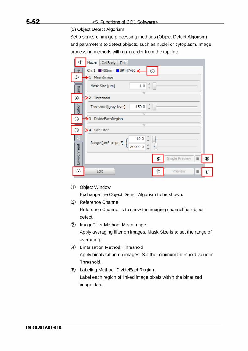
5-52 <5. Functions of CQ1 Software>
IM 80J01A01-01E
(2) Object Detect Algorism
Set a series of image processing methods (Object Detect Algorism)
and parameters to detect objects, such as nuclei or cytoplasm. Image
processing methods will run in order from the top line.
① Object Window
Exchange the Object Detect Algorism to be shown.
② Reference Channel
Reference Channel is to show the imaging channel for object
detect.
③ ImageFilter Method: MeanImage
Apply averaging filter on images. Mask Size is to set the range of
averaging.
④ Binarization Method: Threshold
Apply binalyzation on images. Set the minimum threshold value in
Threshold.
⑤ Labeling Method: DivideEachRegion
Label each region of linked image pixels within the binarized
image data.
①
③
④
⑤
⑥
⑦ ⑩ ⑪
⑧ ⑨
②

<5. Functions of CQ1 Software> 5-53
IM 80J01A01-01E
⑥ LabelTransform Method: SizeFilter
Filter each labeled region based on its size (area for 2D analysis,
and volume for 3D analysis).
⑦ Edit
“Advanced Editor” window opens. For detail, refer to 5.13
Advanced Editor.
⑧ Single Preview Analysis
Apply selected object detection to designated Field in well
selected for preview.
⑨ Stop Single Preview Analysis
⑩ Preview Analysis
Apply all object detections to designated Field in well selected for
preview.
⑪ Stop Preview Analysis

5-54 <5. Functions of CQ1 Software>
IM 80J01A01-01E
5.4.6 Environment Window
Environment window is to set the operation environment of CQ1 Main
Unit.
(1) Temperature Control
Activate/ inactivate of stage heater and its temperature.
Click “Edit” to set temperature.
① ON
Activate temperature control.
② OFF
Inactivate temperature control.
③ Setting
Set temperature. To apply, click ⑤Set.
④ Cancel
Cancel changes of temperature setting.
⑤ Set
Apply changes of temperature setting.
(2) Camera Temperature
Show current camera temperature.
(3)
(4)
(2)
(1)
(3)
(4)
(2)
<Stage Heater mounted model> <Stage Heater unmounted model>
③
④ ⑤
① ②

<5. Functions of CQ1 Software> 5-55
IM 80J01A01-01E
(3) XY Stage
Set moving speed of XY stage. [Edit] button is to select XY stage
speed.
① Speed
Select XY stage speed. Default setting is the fastest. If samples
are easy to ablate from sample vessel, slow setting is
recommended.
To apply, click ③Set
② Cancel
Cancel XY stage speed change
③ Set
Set XY stage speed
(3) Laser-Power Calibration
Click “Calibrate” button to show “Laser-Power Calibration” dialog, and
click “Yes” to proceed calibration, but no calibration by clicking “No”.
Laser power calibration is performed to maintain excitation laser power
irradiated to samples against “Excitation Power” set in “Imaging”
window (refer to 5.4.3 Imaging Window). It takes a few minutes per 1
laser line to calibrate.
In case that error occurs in laser power calibration, optical adjustment
is needed. Please contact the dealer.
① ② ③
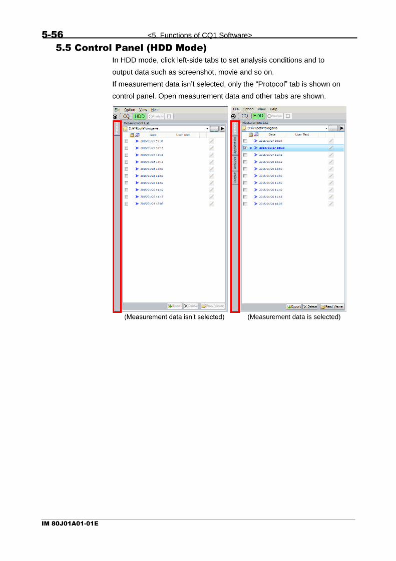
5-56 <5. Functions of CQ1 Software>
IM 80J01A01-01E
5.5 Control Panel (HDD Mode)
In HDD mode, click left-side tabs to set analysis conditions and to
output data such as screenshot, movie and so on.
If measurement data isn’t selected, only the “Protocol” tab is shown on
control panel. Open measurement data and other tabs are shown.
(Measurement data isn’t selected)
(Measurement data is selected)

<5. Functions of CQ1 Software> 5-57
IM 80J01A01-01E
5.5.1 Protocol Window
In HDD mode, measurement data list which is saved in the folder
selected by “Measurement List” is shown at Protocol window. In
detailed view, more information is shown than brief view.
(4)
(5) (6) (7) (1)
(3)
(9)
(16) (17) (18)
(8)
(2)
Basical display mode
Advanced display mode
(10) (11) (12) (13) (14) (15)
Right click menu
(19)
(20)
(21)
(22)
(23)
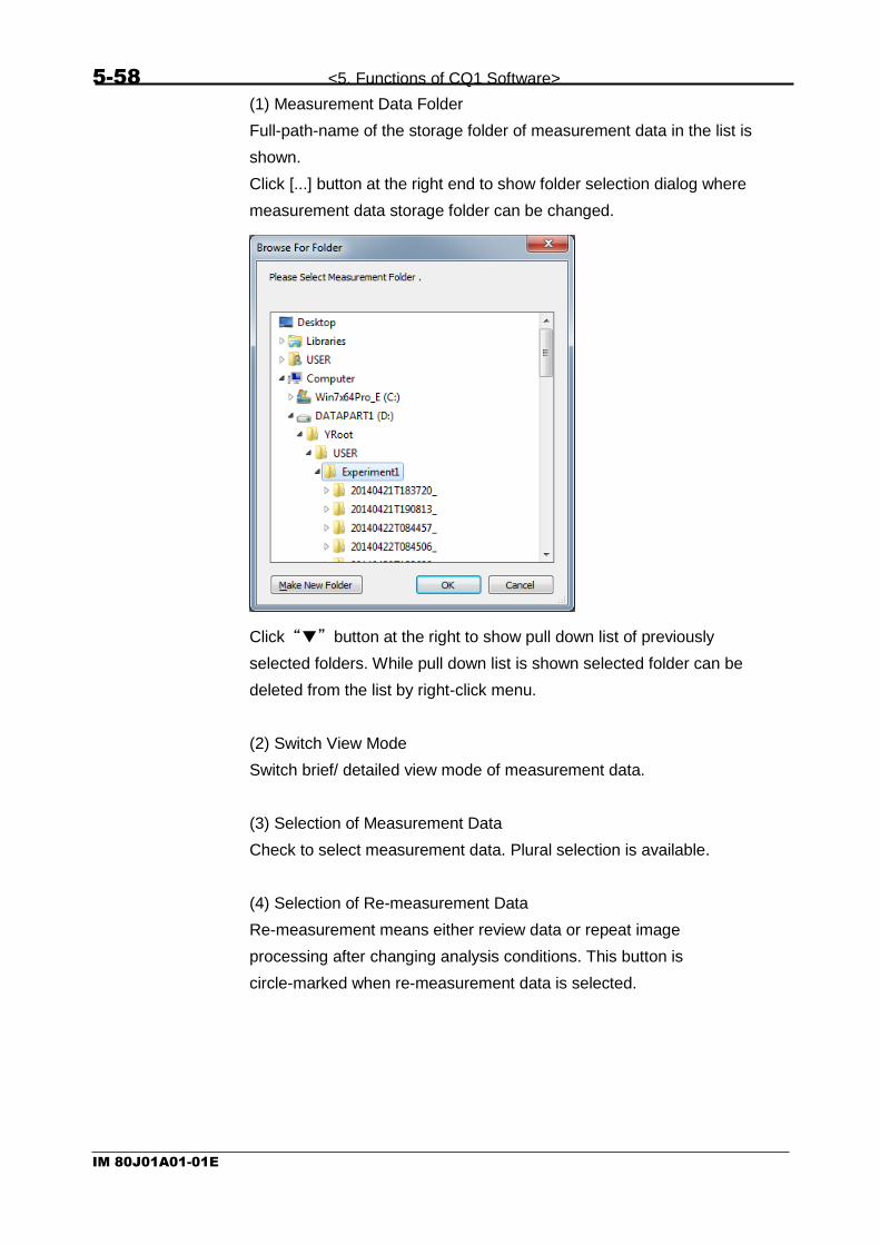
5-58 <5. Functions of CQ1 Software>
IM 80J01A01-01E
(1) Measurement Data Folder
Full-path-name of the storage folder of measurement data in the list is
shown.
Click [...] button at the right end to show folder selection dialog where
measurement data storage folder can be changed.
Click “▼” button at the right to show pull down list of previously
selected folders. While pull down list is shown selected folder can be
deleted from the list by right-click menu.
(2) Switch View Mode
Switch brief/ detailed view mode of measurement data.
(3) Selection of Measurement Data
Check to select measurement data. Plural selection is available.
(4) Selection of Re-measurement Data
Re-measurement means either review data or repeat image
processing after changing analysis conditions. This button is
circle-marked when re-measurement data is selected.

<5. Functions of CQ1 Software> 5-59
IM 80J01A01-01E
(5) Existence of Feature Data
If quantified data is included in measurement data, 「 」 mark is
attached. Click 「 」 mark to show pull down list of feature data. To
close this list, click anywhere outside of the list.
① Quantified data selection check box
Check to select feature data. Plural selection is available.
② Storage folder name of feature data.
③ Select re-quantify data
Re-quantify data means to review or repeat image analysis on
existing feature data. This button will be circle-marked when
selected.
④ Delete
Delete selected feature data, available when more than 2 boxes
are checked.
⑤ Read Viewer
Show the re-feature data (circled feature data) in “Viewer”,
available when re-feature data is selected.
②
①
④ ③ ⑤

5-60 <5. Functions of CQ1 Software>
IM 80J01A01-01E
(6) Date
Date and time of the measurement are shown.
(7) User Text
Show the text in “Save Folder Name” at “Protocol” window of CQ
mode.
(8) Camera Icon
Show that report data such as snapshot exists. It is able to confirm
snapshot and movie in report folder by putting pointer on this icon
(9) Pen Button
Show the text in “Description” of “Protocol” window of CQ mode.
Click this button to show text, which can be overwritten. Click outside of
this window to close.
(10) Status
Show the result status of measurement data. It is able to confirm that
measurement is finished or canceled and so on.
(11) Holder
Show sample holder used for measurement.
(12) Sample Vessel
Show sample vessel used for measurement.
(13) Measurement information
Show number of well, time point, Z-stack and channel.
(14) Analysis Folder
Click pen button and input text

<5. Functions of CQ1 Software> 5-61
IM 80J01A01-01E
Show selected re-analyzed data.
(15) Description
Show the text in “Description” at “Protocol” window of CQ mode.
(16) (21) Export
Export checked measurement data to other folder or drive.
Click this button after selecting measurement data to show folder
selection dialog. Select either folder or drive to export data and click
“OK”. Data format of saving folder must be NTFS.
After export is compleated, folder that measurement data is exported is
opened. Name of measurement data folder is the same as that of
original measurement data folder.
(17) (23) Delete
Delete checked measurement data. Click “Yes” for confirmation
message to delete.

5-62 <5. Functions of CQ1 Software>
IM 80J01A01-01E
(18) (19) Read Viewer
Click to show lastly selected※ data in the “Viewer”.
Viewer display changes depending on the existence of quantified data
as below.
① No feature data:
Show images
② Feature data is selected:
Show selected feature data, which is the same with the case of
clicking “Read Viewer” after selecting feature data.
③ Featured data is unselected:
Show images
(20) Open Folder
Open the folder that measurement data is saved by windows explorer.
(22) Export (Custom)
Export measurement data with image processing.
Click this button after selecting measurement data to show folder
selection dialog. Data format of saving folder must be NTFS.
Select saving holder and click “OK”. Then “Export Setting” window is
shown. For detail, refer to next page.
※ Circle mark is shown by lastly selected data.

<5. Functions of CQ1 Software> 5-63
IM 80J01A01-01E
① Output Option
Select the data to export. It is unselectable if there are no data
corresponding to original data.
◆Items of Output Option
Item Description
Slices Export slice images
MIP Export the MIP (refer to page 5-42) image
Sum Export the Sum (refer to page 5-42) image
①
②
④
⑥ ⑦
⑤
③
⑧
Progress dialog
Dialog to notice completion

5-64 <5. Functions of CQ1 Software>
IM 80J01A01-01E
② Tile
Transform images acquired by Area imaging to single tiled image
and output.
For using this function, it is necessary that images are acquired by
same condition (“Same Area” in “Imaging” window is checked).
◆Items of Tile Correction Option
Item Description
Stitch If checked, images are arranged by image processing and tiled. If unchecked, images are overlapped by trimming parameter and tiled. To use this function, it is necessary to enable overlap acquisition.
(For details, refer to 5.10 Trimming Parameter)
Target Channel Number
Select channel to perform arrangement. It is available if “Stitch” is checked.
Overlap Parameter (Pixel)
Designate the image size to perform arrangemetn. It is available if “Stitch” is checked.
TargetImage of XY Position
Designate the image to perform arrangement. If images are acquired as 3D, “MIP” and “Sum” is selectable. It is available if “Stitch” is checked.
③ Help (Tile)
Display help message in the case that this function is not
available.
④ Time-lapse Convert
Convert plural measurement data as one time-lapse data and
output. It is necessary to select plural measurement data acquired
by same measurement condition.
⑤ Help (Timelaps Convert)
Display help message in the case that this function is not
available.
Uncheck Check

<5. Functions of CQ1 Software> 5-65
IM 80J01A01-01E
⑥ OK
Start data export by set parameter.
Progress dialog is displayed after export is started. Dialog to notice
completion is displayed after export is completed.
Click “OK” and folder that measurement data is exported is
opened.
Folder configuration, folder name and file name of exported data
are as following.
※1
④Time-lapse Convert: unselected, ②Tile: unselected
→”Export”
④Time-lapse Convert: unselected, ②Tile: selected
→”Tile”
④Time-lapse Convert: selected
→”TimelapseConvert” ※2
Name format is <yyyyMMdd>T<HHmmss>. In case of April 10, 2015, 12°34′
56″
→20150410T123456 ※3
In case that ②Tile is selected, FieldIndex is “0001” ※4
In case that ④Time-lapse Convert is selected, continued number is assigned as
timepoint. ※5
In case of MIP, <Z position> is “000”. In case of Sum, <Z position> is “SUM”.
⑦ Cancel (ExportSetting Window)
Close “ExportSetting” window without export.
⑧ Cancel (Progress dialog)
Cancel export.
DataFolder
MeasurementData
Folder name is as following <original measurement data folder name><export
type※1
>_<exporting time and date※2
>
Folder to store acquired OME-TIFF image Image
Projection Folder to store projection result (if Z > 1)
・・・
Other Files
Folder designated in above procedure
・・・
W<wellIndex>F<FieldIndex※3
>T<timepoint※4
> Z<Z position>C<channelIndex>.tif
・・・
W<wellIndex>F<FieldIndex※3
>T<timepoint※4
> Z<Z position
※5
>C<channelIndex>.tif

5-66 <5. Functions of CQ1 Software>
IM 80J01A01-01E
5.5.2 Application Window
Application window is to set image analysis conditions of existing
measurement data. Please refer to 5.4.4 Application Window for
details.
(1) Analysis Folder Suffix
Set suffix of analysis folder name
(2) Load
Load Analysis Protocol
(3)
(6)
(8)
(2)
(1)
(7)
(9)
(4)
(5)
Note
Over 30 letters can’t be input for “Analysis Folder Suffix”.

<5. Functions of CQ1 Software> 5-67
IM 80J01A01-01E
(3) Save
Save Analysis Protocol
(4) Z Analysis Setting
Select Z slice images to analyze
(5) Time-lapse Setting
Select images of time point to analyze
(6) Object Detect Setting
Show existing Object Detect Setting list
(7) Edit Object Detect Setting
(8) Link Setting
Show current Link Setting
(9) Edit Link Setting

5-68 <5. Functions of CQ1 Software>
IM 80J01A01-01E
5.5.3 Analysis Window
Set methods and parameters for Object Detect
(1) Wells
① Selected Sample Vessel
Diagram of sample vessel selected at “Sample window” is shown.
Imaged wells are shown in gray. Not imaged wells are shown in
black.
By clicking gray well when button ③ is (white), the well is
selected for preview (red frame). By left-clicking or left-dragging
wells when button ③ is (green), the wells are selected for
Analysis (pink). By right-clicking or right-dragging, selection for
Analysis is canceled.
② Selection of Analysis Area
Refer to above ①.
③ All Select
All imaged wells are selected for Analysis.
④ Clear
Selection for Analysis of all wells is canceled.
⑤ PreAnalyze
Start preliminary analysis of selected wells for Analysis.
⑥ PreAnalyze stop
Stop preliminary analysis.
(2) Object Detect Algorism
Please refer to (2) Object Detect Algorism of 5.4.5 Analysis Window
(page 5-52).
② ③ ④ ⑤ ⑥
①
Black: Not-imaged
(Unselectable)
Gray: Imaged
(Unselected)
Red frame:
Selected for Preview
Pink:
Selected for Analysis

<5. Functions of CQ1 Software> 5-69
IM 80J01A01-01E
5.5.4 Output Window
Output images and charts and others displayed in CQ1 software as
images in designated folder (Report folder).
(1) Image Export
① Output Folder
Click to open Report folder. Report folder is generated in following
path.
②
③
⑥ ⑦
④
⑧ ①
⑤
DataFolder
MeasurementData Folder designated in “Protocol”
tab→”Save Folder Name”
Analysis
Reports
Analysis_<Date>
Reports
Folder designated in “Protocol”
tab→”Save Setting”
Report folder
Imaging and analyzing
Only imaging

5-70 <5. Functions of CQ1 Software>
IM 80J01A01-01E
② Snapshot/ Movie
Output snapshot or movie (Only time-lapse data) of displayed
content of CQ1 Software. Content and file name to be output are
as following.
Capture Output Content File Name
Image Image shown in “ImageViewer”
Snapshot: Image_W<wellIndex>F<FieldIndex>T<timep
oint>Z<Z position※1>.png/.jpg
Movie: Movie_W<wellIndex>F<FieldIndex>Z<Z
position※1>T<start timepoint>-T<end
timepoint>.wmv/.mp4 Window Whole window of
CQ1 Software Snapshot: Window_<time and date of outputting
snapshot※2>.png/.jpg
Movie: Movie_W<wellIndex>F<FieldIndex>Z<Z
position※1>T<start timepoint>-T<end
timepoint>.wmv/.mp4 Thumbnail Chart*
Chart window Snapshot: Chart*_<time and date of outputting
snapshot※2>.png/.jpg
Movie: Movie_W<wellIndex>F<FieldIndex>Z<Z
position※1>T<start timepoint>-T<end
timepoint>.wmv/.mp4 ※1
In case of MIP, <Z position> is “MIP”. In case of Sum, <Z position> is “SUM”. ※2
Name format is <yyyyMMdd>_<HHmmss>. In case of April 10, 2015, 12°34′
56″
→20150410_123456
Also, snapshot or movie can be output by following button.
③ Snap Format
Set output format of snapshot.
“png” is for PNG format, and “jpg” is for JPEG format.
Snapshot
Movie

<5. Functions of CQ1 Software> 5-71
IM 80J01A01-01E
④ Movie Making Conditions
Timepoint Designate time point to save movie
Begin Time point of movie beginning
End Time point of movie ending
Set “Begin” and “End” to data existing range
Express Check to reduce images to convert to movie. If checked, designated number of image from “Begin” to “End” are picked up and converted to movie.
Frame Rate Designate frame rate of movie
⑤ Movie Format
Set output format of movie.
“wmv” is for WMV format, and “mp4” is for MP4 format.
Note
In the case of time-lapse data which is acquired by “variable
time-lapse” (refer to page 5-32), movie is made by
designated constant frame late without considering actual
imaging “Interval.
In made move, the range of short “Interval” seems to be slow
and the range of long “Interval” seems to be fast.

5-72 <5. Functions of CQ1 Software>
IM 80J01A01-01E
⑥ Convert
Click this button to open “Convert Setting” window. Click “OK” to
convert images.
Merge Option Select method for channel marging
Merge Color
Output with color marging. (Output format is PNG or JPG. Designate either by “Extension Option”)
Each Color
Output each channel as color image. (Output format is PNG or JPG. Designate either by “Extension Option”)
Each Gray Output each channel as gray image (Output format is 8 bit-Tiff)
Extension Option Select output format
png PNG format
jpg JPG format
File Option Select output range
Current Image
Output images displayed in “ImageViewer”
All Image
Output projected images (MIP, Sum and so on) of all fields of all
wells and all timepoints※
File Name (Prefix String)
Designate letters to add to file name (Designated as “Sample_” in above diagram.)
※Note
Contrast that set by “Contrast Enhancement” is applied to each output image. (“Auto” is invalid)
Contrast that set by left is
applied to each output image
even if “Auto” is checked

<5. Functions of CQ1 Software> 5-73
IM 80J01A01-01E
Sub folder is generated in Report folder and converted images are
saved in the sub folder. Sub folder name and file name are as
following.
Merge Option
Sub Folder Name File Name
Merge Color
Convert_<convert
edtime and date※1>
<string input in “File Name”>W<wellIndex>F<FieldIndex>T<timepoi
nt>Z<Z position※2>.png/.jpg
Each Color
Convert_<convert
edtime and date※1>
<string input in “File Name”>W<wellIndex>F<FieldIndex>T<timepoi
nt>Z<Z position※2>C<channelIndex>.png/.jpg
Each Gray
Tiff_<Converted
time and date※1>
<string input in “File Name”>W<wellIndex>F<FieldIndex>T<timepoi
nt>Z<Z position※2>C<channelIndex>.png/.jpg
※1 Name format is <yyyyMMdd>T<HHmmss>. In case of April 10, 2015, 12°34′
56″→20150410T123456 ※2
In case of MIP, <Z position> is “000”. In case of Sum, <Z position> is “SUM”.
⑦ 3D Viewer (ImageJ)
Transfer image data to ImageJ and display as 3D image. This
function is available when “ImageViewer” setting is “Slice” (refer to
page 5-87).
For detail, please refer to next page
⑧ Image Output
Output images of measurement data selected at “Protocol”
window in TIFF format. Click this button, designate letters to add to
file name and click “OK”.
Note
The purpose of this function is exporting CQ1 data to ImageJ,
which is other software. If you don’t use ImageJ whose
version is different from that of installed in CQ1 Workstation
(1.47v), this function is not guaranteed.

5-74 <5. Functions of CQ1 Software>
IM 80J01A01-01E
Procedure of 3D Viewing
①In “Image Export”, select “Send to” → “ImageJ 3D Viewer”
②Set the configuration of 3D Viewer. After setting, click “OK”
①Z slice Designate the Z range for 3D projection
②Scale Factor Condensation (1=100%, 0.5=50%)
③Set the ROI of 3D projection. After setting, click “OK”.
(If you don’t set ROI, whole area of image is displayed in 3D Viewer.)
①Z slider Designate displayed Z position of preview window.
①
②
①

<5. Functions of CQ1 Software> 5-75
IM 80J01A01-01E
④3D Viewer is displayed. Zoom by wheel of mouse. Rotate by left
button drag of mouse.
⑤Show the procedures to save snapshot of 3D Viewer. From menu of
3D Viewer, select “View” → “Take snapshot”.
⑥Set image resolution of snapshot. After setting, click “OK”.

5-76 <5. Functions of CQ1 Software>
IM 80J01A01-01E
⑦Image of snapshot is displayed. From menu of ImageJ, select “File”
→ “Save as” and save snapshot in arbitrary format (TIFF, PNG and so
on).
⑧Show the procedures to save 3D rotation movie. From menu of 3D
Viewer, select “View” → “Record 360 deg rotation”.

<5. Functions of CQ1 Software> 5-77
IM 80J01A01-01E
⑨3D rotation movie is displayed. From menu of ImageJ, select “File”
→ “Save as” and save 3D rotation movie in arbitrary format (TIFF, AVI
and so on).

5-78 <5. Functions of CQ1 Software>
IM 80J01A01-01E
(2) Analysis Data Export
Click button in “Image Export” to open Report folder. Report folder
is generated in following path.
① Output Items
Select output items.
“Object” is to output feature data of each cell, and “Statistic” is to
output statistic of feature data per each well
② Output Range (Well)
Select output data range. “All” is to cover all analyzed wells, “Wells”
is to cover selected wells (yellow wells in WellTable) and “Well” is
to cover currently selected wells (wells in green area in WellTable)
③ Output Range (Timepoint)
Select time point range to output as follows
・Individual: Time points of currently selected range
・Each: All analyzed time points
(data file is devided corresponding to each time point)
・Total: All analyzed time points
(all time points data is saved in one file)
①
②
⑤ ⑥ ⑦
③
④
DataFolder
MeasurementData
Folder designated in “Protocol”
tab→”Save Folder Name”
Analysis
Analysis_<date>
Report
s
Folder designated in “Protocol”
tab→”Save Setting”
Report folder
FCS
ICE
Folder to store FCS data
Folder to store ICE data
CSV Folder to store CSV data

<5. Functions of CQ1 Software> 5-79
IM 80J01A01-01E
④ ICE Option
Check to save mask file in ICE format.
⑤ CSV Output
Output data in CSV format
Sub folder name and file name in CSU folder is as following
Output Item
Output Range (Timepoint)
Sub Folder Name File Name
Object Individual <Output Range (Well)>_Individual_<outputting time and
date※1>
[<Name of measurement data folder>]Feature_Cell.csv
Each <Output Range (Well)>_Each_<output
ting time and date※1>
[<Name of measurement data folder>]Feature_T<timepoint>_Cell.csv
Total <Output Range (Well)>_Total_<output
ting time and date※1>
[<Name of measurement data folder >]Feature_Cell.csv
Statistic - (No sub folder) [<Name of measurement data folder >]Statistics.csv
※1 Name format is <yyyyMMdd>T<HHmmss>. In case of April 10, 2015, 12°34′
56″→20150410T123456
⑥ FCS Output
Output data in FCS format. “Statistic” can’t be selected as output
item.
⑦ ICE Output
Output data in ICE format. “Statistic” can’t be selected as output
item.
Note
If row of CSV data exceeds 1,000,000, the data can’t be
opened by spreadsheet software such as Microsoft® Excel.
In the case, reduce row of CSV file by outputting the data per
well.
Also, if file name (absolute path) of CSV data exceeds 256
letters, the data can’t be opened.

5-80 <5. Functions of CQ1 Software>
IM 80J01A01-01E
5.6 Viewer
In “Viewer”, captured images, image-detected regions, list of
measurement and statistic of feature data, and scattergram of
measurement data are shown.
5.6.1 Operation of Viewer
Click tab to switch display of each window.

<5. Functions of CQ1 Software> 5-81
IM 80J01A01-01E
Drag tab to move the window.

5-82 <5. Functions of CQ1 Software>
IM 80J01A01-01E
Drag tab to square mark as following to add the tab to the window.
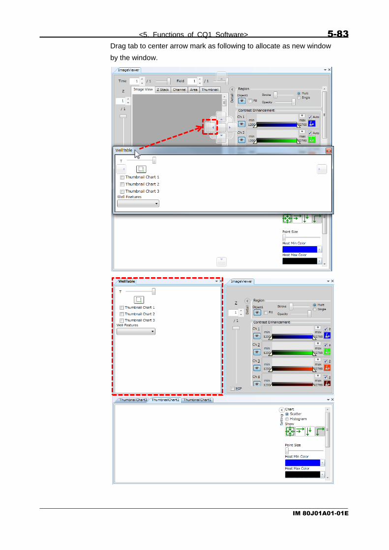
<5. Functions of CQ1 Software> 5-83
IM 80J01A01-01E
Drag tab to center arrow mark as following to allocate as new window
by the window.

5-84 <5. Functions of CQ1 Software>
IM 80J01A01-01E
Drag tab to peripheral arrow mark as following to allocate as new
window at end of “Viewer”.

<5. Functions of CQ1 Software> 5-85
IM 80J01A01-01E
Click “x” mark in upper right of each window to close selected window.
Windows can be set to default position by “Viewer Layout” button. For
detail, refer to 5.8 Viewer Layout.

5-86 <5. Functions of CQ1 Software>
IM 80J01A01-01E
5.6.2 ImageViewer Window
<Basic operation>
In “ImageViewer”, it is able to move image by right-dragging. Also, it is
able to zoom image by operation of mouse wheel.
This operation is same in 5.6.3 MAP Window.
<Explanation of term: “Field” and “Area”>
CQ1 can image not only one field but also multiple tiled fields. In this
section and next section 5.6.3 MAP Window, single field is described
“Field” and group of multiple tiled field is described “Area”.
Field
1 2
3 4
5 6
Area

<5. Functions of CQ1 Software> 5-87
IM 80J01A01-01E
“ImageViewer” has five windows; (1) Image View, (2) Z Stack, (3)
Channel, (4) Area, and (5) Thumbnail. Common functions of 5 windows
are shown in ①~④, below.
① Time
Set the time point to display.
② Field/Area
“Image View”, “Z Stack” and “Channel” windows are to set “Field”
to display, and “Area” window is to set “Area” to display.
During measurement, only the ongoing measurement is shown,
thus display settings cannot be changed.
③ Z
Set Z position to display.
During measurement, only the ongoing measurement is shown,
thus display settings cannot be changed.
④ Z Option
Check “MIP” to display MIP image. Check “Sum” to display Sum
image.
(1) (2) (3) (4)
①
②
③
④
(5)

5-88 <5. Functions of CQ1 Software>
IM 80J01A01-01E
(1) Image View Window.
It is possible to display multi-channel images as one image by setting
Time, Field and Z.

<5. Functions of CQ1 Software> 5-89
IM 80J01A01-01E
(2) Z Stack Window
Display tiled images from bottom to top in Z by setting Time and Field.
MIP and Sum check box is not available here. Please refer to (6) View
Option of 5.6.9 Tool Function (page 5-120) about image size.

5-90 <5. Functions of CQ1 Software>
IM 80J01A01-01E
(3) Channel Window
Separately display images of each channel from a multi-channel image
by setting Time,Field and Z. Please refer to (6) View option of 5.6.9
Tool Function (page 5-120) for display modes.

<5. Functions of CQ1 Software> 5-91
IM 80J01A01-01E
(4) Area Window
Display image of Area by tile.
Change to “Area” from “Field”

5-92 <5. Functions of CQ1 Software>
IM 80J01A01-01E
(5) Thumbnail Window
Display thumbnail images of wells selected at WellTable window. .
Can change Field and Z at each
well

<5. Functions of CQ1 Software> 5-93
IM 80J01A01-01E
5.6.3 MAP Window
MAP viewer has (1) Test imaging mode, (2) Map mode, and (3) Rec
mode. Their common functions are shown in ①~④ below.
① Objective lens selection
Selected lens is highlighted.
② Map clear
Clear the map in display.
③ Area List
Display Area list. If there is more than one Area, the leading
number of “Field” is shown.
④ Unimagable Region
Blue region in “Map” window can’t be designated as imaging
region because objective lens interferes with stage attachment,
sample holder and sample vessel.
(1) (2) (3)
① ② ③
④

5-94 <5. Functions of CQ1 Software>
IM 80J01A01-01E
(1) Test Imaging Mode
Capture test image of clicked Field at a single channel by one-click.
Field to be imaged is shown as red square.

<5. Functions of CQ1 Software> 5-95
IM 80J01A01-01E
(2) Map Mode
Capture map image by selecting a region by left-drug of mouse.
Selected region is shown in green.
① Start
Start map-imaging.
② MultiWell Start
Start map-imaging of multiple wells.
③ Stop
Stop map-imaging.
④ Clear Selection
Clear selection of map-imaging region.
② ③ ① ④

5-96 <5. Functions of CQ1 Software>
IM 80J01A01-01E
(3) Rec Mode
Set Area(s) to be imaged. Clicked Area is selected and highlighted in
orange. Selected Area can be moved by left-drag.
① Start
Capture test images of selected Area (highlighted by orage frame)
at one channel, and display on the map.
② Start Color
Capture test images of selected Area (highlighted by orage frame)
by multiple channels under the same conditions for the
measurement.
③ Stop
Stop ① and ② above.
④ Remove it
Remove selected Area. Area numbers will be renewed.
⑤ Remove all
Remove all Areas.
⑥ Define FOV
Define the FOV (Field of View) at either 4 or 9, automatically.
④ ③ ② ① ⑤ ⑥

<5. Functions of CQ1 Software> 5-97
IM 80J01A01-01E
5.6.4 ThumbnailChart Window
ThumbnailChart has two data display modes, (1) Scatter mode, and (2)
Histogram mode. ThumbnailChart1, ThumbnailChart2 and
ThumbnailChart3 have the same function.
(1)
(2)
Y Axis
X Axis
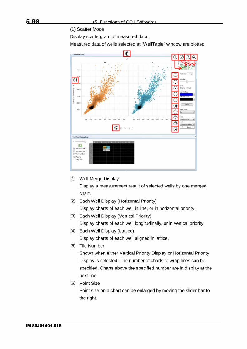
5-98 <5. Functions of CQ1 Software>
IM 80J01A01-01E
(1) Scatter Mode
Display scattergram of measured data.
Measured data of wells selected at “WellTable” window are plotted.
① Well Merge Display
Display a measurement result of selected wells by one merged
chart.
② Each Well Display (Horizontal Priority)
Display charts of each well in line, or in horizontal priority.
③ Each Well Display (Vertical Priority)
Display charts of each well longitudinally, or in vertical priority.
④ Each Well Display (Lattice)
Display charts of each well aligned in lattice.
⑤ Tile Number
Shown when either Vertical Priority Display or Horizontal Priority
Display is selected. The number of charts to wrap lines can be
specified. Charts above the specified number are in display at the
next line.
⑥ Point Size
Point size on a chart can be enlarged by moving the slider bar to
the right.
② ③ ① ④ ⑪
⑬
⑫
⑤
⑥
⑦
⑧
⑨
⑩
⑪
⑫ ⑬
⑭

<5. Functions of CQ1 Software> 5-99
IM 80J01A01-01E
⑦ Color
“Same” is to display all wells on a chart in the same color.
“Each” is to color wells in different colors by each well.
⑧ Heat Min Color
Select the color for low density area in a chart.
⑨ Heat Max Color
Select the color for high density area in a chart.
⑩ Detail
Dialog to select display range of X-axis and Y-axis is shown, in
which Min. and Max. display range and interval of X and Y axis
can be set. Logarithmic scale is selectable for each axis. If
enormously small value compared to axis size is set for Interval X
or Interval Y, the value isn’t applied.
⑪ Object Name
Select object detect name to plot.
⑫ X Axis
Set the specified measurement value on X axis
⑬ Y Axis
Set the specified measurement value on Y axis
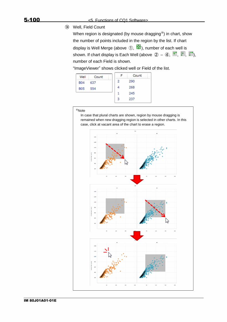
5-100 <5. Functions of CQ1 Software>
IM 80J01A01-01E
⑭ Well, Field Count
When region is designated (by mouse dragging※) in chart, show
the number of points included in the region by the list. If chart
display is Well Merge (above ①, ), number of each well is
shown. If chart display is Each Well (above ② – ④, , , ),
number of each Field is shown.
“ImageViewer” shows clicked well or Field of the list.
※Note
In case that plural charts are shown, region by mouse dragging is
remained when new dragging region is selected in other charts. In this
case, click at vacant area of the chart to erase a region.

<5. Functions of CQ1 Software> 5-101
IM 80J01A01-01E
(2) Histogram Mode
Display histograms of measurement data.
Measurement data of yellow wells specified at “WellTable”window are
plotted.
① Well Merge Display
Display a measurement result of selected wells by one merged
chart.
② Each Well Display (Horizontal Priority)
Display charts of each well in line, or in horizontal priority.
③ Each Well Display (Vertical Priority)
Display charts of each well longitudinally, or in vertical priority.
④ Each Well Display (Lattice)
Display charts of each well aligned in lattice.
⑤ Tile Number
Shown when either Vertical Priority Display or Horizontal Priority
Display is selected. The number of charts to wrap lines can be
specified. Charts above the specified number are shown in the
next line.
② ③ ① ④
⑤
⑥
⑦
⑧
⑨
⑩
⑪
⑩
⑪

5-102 <5. Functions of CQ1 Software>
IM 80J01A01-01E
⑥ Resolution Size
Change the width (resolution size) of the histogram.
By moving slider bar to the right, width of the bar will be extended
(to make the resolution size coarser.
⑦ Heat Min Color
Set the color of the bar on a chart.
⑧ Detail
Dialog to select display of X-axis and Y-axis is shown. Min. and
Max. display ranges, and interval of X and Y axis can be set.
Logarithmic scale is selectable for each axis. If enormously small
value compared to axis size is set for Interval X or Interval Y, the
value isn’t applied.
⑨ Object Name
Select object detect name to plot.
⑩ X Axis
Set specified measurement value on X axis.

<5. Functions of CQ1 Software> 5-103
IM 80J01A01-01E
⑪ Well, Field Count
When region is designated (by mouse dragging) in chart, show the
number of points included in the region by the list. If chart display
is Well Merge (above ①, ), number of each well is shown. If
chart display is Each Well (above ② – ④, , , ), number
of each Field is shown.
“ImageViewer” shows clicked well or Field of the list.
※Note
In case that plural charts are shown, seleted region is remained when
new region is selected in other charts. In this case, click at vacant
area of the chart to erase a region.

5-104 <5. Functions of CQ1 Software>
IM 80J01A01-01E
(3) Jump Function
The detected object in corresponding image will be shown by clicking a
spot plotted in scattergram. On the other hand, a corresponding spot in
scattergram will be cross-marked by clicking an object.
By designating rectangle region in scattergram by mouse dragging, the
detected objects corresponding to spots in designated region in image
will be shown.

<5. Functions of CQ1 Software> 5-105
IM 80J01A01-01E
The detected object in corresponding image will be shown by clicking a
bin in histogram. On the other hand, a corresponding bin in histogram
will be marked by a vertical line by clicking an object.
By designateing region in histogram by mouse dragging, the detected
objects corresponding to bins in designated region in image will be
shown.

5-106 <5. Functions of CQ1 Software>
IM 80J01A01-01E
5.6.5 WellTable Window
In “WellTable” window, it is able to select wells to be shown at
ThumbnailChart 1, ThumbnailChart 2 and ThumbnailChart 3 (2), and to
select the statistic of feature data of each well (3).
(1) T
Set time point to display.
(2) Select Display Range
Wells become selectable by left button dragging when this button
becomes (green) by clicking. By right button, wells are
unselected. Wells become yellow during selecting. Color of wells
are designated automatically after selecting.
(3) Thumbnail Chart Selection
By checking [Thumbnail Chart 1] checkbox, the chart of selected
wells will be shown at “ThumbnailChart1” window, and so are the
same with [Thumbnail Chart 2] and [Thumbnail Chart 3].
(2)
(1)
(3)
(4)
Before well selection (heat map)
During well selection
After well selection
(colors are designated automatically)
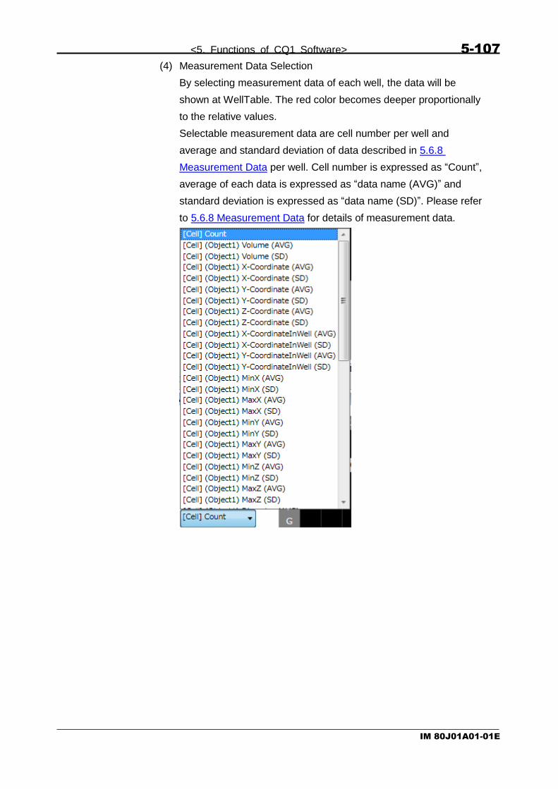
<5. Functions of CQ1 Software> 5-107
IM 80J01A01-01E
(4) Measurement Data Selection
By selecting measurement data of each well, the data will be
shown at WellTable. The red color becomes deeper proportionally
to the relative values.
Selectable measurement data are cell number per well and
average and standard deviation of data described in 5.6.8
Measurement Data per well. Cell number is expressed as “Count”,
average of each data is expressed as “data name (AVG)” and
standard deviation is expressed as “data name (SD)”. Please refer
to 5.6.8 Measurement Data for details of measurement data.

5-108 <5. Functions of CQ1 Software>
IM 80J01A01-01E
5.6.6 FeatureTable Window
In “FeatureTable” window, it is able to confirm measurement value of
detected object such as cell, granule and so on. Please refer to 5.6.8
Measurement Data about shown items.
To confirm measurement value, click object in “ImageViewer” or data in
either ThumbnailChart.

<5. Functions of CQ1 Software> 5-109
IM 80J01A01-01E
Note Either case that there are no feature data or that cell or granule have never selected, nothing is shown in FeatureTable. In case that range of either axis is designated, the data which is not shown in the chart is not shown at FeatureTable.
In case that the data of object selected in ImageViewer is shown in the
chart, the information of the object is shown in FeatureTable
In case that the data of object selected in ImageViewer is NOT shown in
the chart, the information of the object is NOT shown in FeatureTable.

5-110 <5. Functions of CQ1 Software>
IM 80J01A01-01E
5.6.7 Information Window
“Information” window is, to confirm information of measurement data.
This function is only for “HDD mode”. In “CQ1 mode”, display nothing.
(1) Comment
Show Description of measurement data.
(2) Protocol
Show Protocol of measurement data.
(3) Log
Show log of measurement data.
(4) Report
Show snap shot of measurement data.
(1) (2) (3) (4)

<5. Functions of CQ1 Software> 5-111
IM 80J01A01-01E
5.6.8 Measurement Data
CQ1 Software outputs following measurement value.
(1) 2-Dimentional Measurement
Item Description
Area Area [µm2]
X-Coordinate X coordinate of centroid [µm] (In reference to upper left of image)
Y-Coordinate Y coordinate of centroid [µm] (In reference to upper left of image)
X-CoordinateInWell X coordinate of centroid [µm] (In reference to center of well)
Y-CoordinateInWell Y coordinate of centroid [µm] (In reference to center of well)
MinX Min.X axis [µm] (In reference to upper left of image)
MaxX Max.X axis [µm] (In reference to upper left of image)
MinY Min.Y axis [µm] (In reference to upper left of image)
MaxY Max.Y axis [µm] (In reference to upper left of image)
Diameter Diameter [µm]
Circumference Contour length [µm]
Circularity Circularity
SkeletonLength Length of line object [µm]
JunctionCount Junction count of line object
BranchCount Branch count of line object
TotalIntensityCHn Total image intensity※ in channel “n”
MeanIntensityCHn Mean image intensity※ in channel “n”
SdvIntensityCHn Standard deviation of image intensity※ in channel “n”
MinIntensityCHn Min.image intensity※ in channel “n”
MaxIntensityCHn Max. image intensity※ in channel “n” ※Note
Value that background(about 100) is subtracted is output.

5-112 <5. Functions of CQ1 Software>
IM 80J01A01-01E
(2) 3-Dimentional Measurement
Item Description
Volume Volume [µm3]
X-Coodinate X coordinate of centroid [µm] (In reference to upper left of Z=1-image)
Y-Coodinate Y coordinate of centroid [µm] (In reference to upper left of Z=1-image)
Z-Coodinate Z coordinate of centroid [µm] (In reference to upper left of Z=1-image)
X-CoordinateInWell X coordinate of centroid [µm] (In reference to center of well)
Y-CoordinateInWell Y coordinate of centroid [µm] (In reference to center of well)
MinX Min.X axis [µm] (In reference to upper left of Z=1-image)
MaxX Max.X axis [µm] (In reference to upper left of Z=1-image)
MinY Min.Y axis [µm] (In reference to upper left of Z=1-image)
MaxY Max.Y axis [µm] (In reference to upper left of Z=1-image)
MinZ Min. Z axis [µm] (In reference to upper left of Z=1-image)
MaxZ Max.Z axis [µm] (In reference to upper left of Z=1-image)
Diameter Diameter [µm]
Lateralarea Lateral area [µm2]
Surfacearea Surface area [µm2]
Sphericity Sphericity
SkeletonLength Length of line object [µm]
JunctionCount Junction count of line object
BranchCount Branch count of line object
TotalIntensityCHn Total image intensity※ in channel “n”
MeanIntensityCHn Average image intensity※ in channel “n”
SdvIntensityCHn Standard deviation of image intensity※ in channel “n”
MinIntensityCHn Min. image intensity※ in channel “n”
MaxIntensityCHn Max. image intensity※ in channel “n” ※Note
Value that background(about 100) is substructed is output.
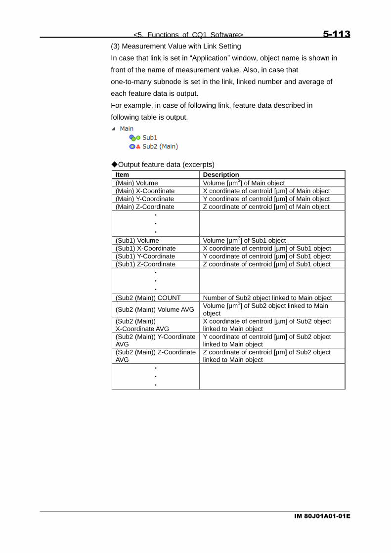
<5. Functions of CQ1 Software> 5-113
IM 80J01A01-01E
(3) Measurement Value with Link Setting
In case that link is set in “Application” window, object name is shown in
front of the name of measurement value. Also, in case that
one-to-many subnode is set in the link, linked number and average of
each feature data is output.
For example, in case of following link, feature data described in
following table is output.
◆Output feature data (excerpts)
Item Description
(Main) Volume Volume [µm3] of Main object
(Main) X-Coordinate X coordinate of centroid [µm] of Main object
(Main) Y-Coordinate Y coordinate of centroid [µm] of Main object
(Main) Z-Coordinate Z coordinate of centroid [µm] of Main object
・
・
・
(Sub1) Volume Volume [µm3] of Sub1 object
(Sub1) X-Coordinate X coordinate of centroid [µm] of Sub1 object
(Sub1) Y-Coordinate Y coordinate of centroid [µm] of Sub1 object
(Sub1) Z-Coordinate Z coordinate of centroid [µm] of Sub1 object
・
・
・
(Sub2 (Main)) COUNT Number of Sub2 object linked to Main object
(Sub2 (Main)) Volume AVG Volume [µm
3] of Sub2 object linked to Main
object
(Sub2 (Main)) X-Coordinate AVG
X coordinate of centroid [µm] of Sub2 object linked to Main object
(Sub2 (Main)) Y-Coordinate AVG
Y coordinate of centroid [µm] of Sub2 object linked to Main object
(Sub2 (Main)) Z-Coordinate AVG
Z coordinate of centroid [µm] of Sub2 object linked to Main object
・
・
・

5-114 <5. Functions of CQ1 Software>
IM 80J01A01-01E
5.6.9 Tool Function
Tool Function is to change the display style of image-detected regions
in “ImageViewer”, or contrast of images.
- Show detected area.
- Detected area is shown in
“Image View Tab” and ”Thumbnail Tab”.
(1)
(2)
(3)
(4)
(6)
(5)

<5. Functions of CQ1 Software> 5-115
IM 80J01A01-01E
(1) Region
Set display options for image-detected region. This setting is applied to
only “Image View” window and “Thumbnail” window of “Viewer”.
① Display detected region
Eye-mark shuts or opens by each click.
When opened, the image-detected region is shown in
“ImageViewer” and not shown when closed.
② Fill
All image-detected regions will be colored if checked, and only
their outline will be colored if unchecked.
③ Stroke
Outline of region gets thicker by moving this slider to the right. The
slider bar is not valid if “Fill” is checked.
④ Opacity
Opacity of the color of image-detected regions increase by sliding
the bar to the left.
⑤ Multi/Single
[Multi] is to color detected regions with multiple colors.
[Single] is to color detected regions with the one selected by
“Color”.
①
②
③
④ ⑥
⑦
⑤

5-116 <5. Functions of CQ1 Software>
IM 80J01A01-01E
⑥ Color
Select color of detected regions. Invalid if “Multi” is selected.
⑦ Show Object ID
Check to show ID of detected regions.

<5. Functions of CQ1 Software> 5-117
IM 80J01A01-01E
(2) Contrast Enhancement
Display intensity histograms of images of each channel, and Max. /Min,
intensity of displayed images.
① Ch
Channel number
② Merge Setting Button
Eye-mark shuts or opens by each click of this button.
Images of current channel are shown in “ImageViewer” when the
eye is open, and not shown if closed.
③ Intensity Display
Intensity information of displayed image is shown.
・ Intensity Range (Max./Min,)
・ Intensity distribution (Histogram)
・ Intensity range of displayed image (Intensity range setting
button)
④ Manual Contrast Range
Contrast range can be manually adjusted by unchecking [Auto].
③
①
②
④ ⑤
⑥
Set the Min. contrast value
Set the Max. contrast value

5-118 <5. Functions of CQ1 Software>
IM 80J01A01-01E
⑤ Automatic Contrast Adjustment
By checking [Auto], contrast is automatically adjusted according to
the intensity of images.
⑥ Pseudo-color Setting Button
Set the pseudo color of displayed image in the current channel.
(3) Image Information
Show detail information of the image displayed in “ImageViewer”.
(4) Auto Play
Operate each slider bar in “ImageViewer”.
① Slider bar operation
: Move to first image : Stop auto play
: Start auto play : Move to last image
② Auto play speed
Designate speed of auto play from 1 (slow) – 4 (fast).
③ Looping auto play
④ Slider bar selection
Select slider to operate.
T: Time Z: Z position W: Well F: Field
① ② ③
④

<5. Functions of CQ1 Software> 5-119
IM 80J01A01-01E
(5) Overlay Tools
Overlay information such as text or size on the displayed images in
“ImageViewer”.
① Scale Bar
Add “scale bar” on images.
By dragging in “ImageViewer”, position and length can be changed.
Also, by right-click menu, color, with/ without of caption, with/
without of edge step and pitch of length changing can be changed
and delete can be performed.
② Text Box
Add any text on images.
Edit text in “ImageViewer”. By dragging, position can be changed.
Also, by right-click menu, color and font can be changed and
delete can be performed.
③ Time Stamp
Add time stamp on images.
By dragging in “ImageViewer”, position can be changed. Also, by
right-click menu, color and font can be changed and delete can be
performed.
④ Clear All
Clear all added information from images.
① ② ③ ④

5-120 <5. Functions of CQ1 Software>
IM 80J01A01-01E
(6) View Option
Slider to change size of images displayed in “ImageViewer”, when “Z
Stack” window at “ImageViewer” is open.
Items to change display mode in “ImageViewer” are shown when
“Channel window” at “ImageViewer” is open.
① Each Channel
Display all channels independently
② Laser and Lamp
Marge confocal channels, but display transmission illumination
channel separately.
③ Show Caption
Show captions such as channel number on each image.
Items to change display mode in “ImageViewer” when “Thumbnail
window” at “Imageviewer” is open.
① Each Well Display (Horizontal Priority)
Display image of each well in line or in horizontal priority.
② Each Well Display (Vertical Priority)
Display image of each well longitudinally or in vertical priority.
③ Each Well Display (Lattice)
Display image of each well in lattice.
④ Tile Number
Shown when either Vertical Priority Display or Horizontal Priority
Display is selected. The number of images to wrap lines can be
specified.
① ②
③
① ② ③ ④

<5. Functions of CQ1 Software> 5-121
IM 80J01A01-01E
5.6.10 Progress Bar
During measurement, progress information is displayed in upper right
of viewer.
① Status
Executing process is shown.
② Progress
Progress of measurement is shown
③ Elapsed Time
Elapsed time of measurement is shown.
④ Remaining Time
Remaining time of measurement is shown
⑤ Message
①
②
③
④
⑤

5-122 <5. Functions of CQ1 Software>
IM 80J01A01-01E
5.7 Status Panel
(1) Communication Status with CQ1 Main Unit
ONLINE: Connected with CQ1 Main Unit
OFFLINE: Unconnected with CQ1 Main Unit
(2) Laser Status
ON: Lasers are ready to use
LOCKED: Interlock is working
(3) Chamber Status (Only in Stage Heater mounted model)
Show chamber temperature (Current/ Setting).
Back ground become red if Current > Setting + 1℃.
Back ground become light blue if Current < Setting -1℃
Display of setting temperature become “OFF” if temperature
control is off.
(4) Camera Status
Camera Temperature (Current value/Set value) is shown
(5) Software Status
Idle: Idling
Recording: Under measurement
Pause Waiting: Status in between “Pause” and “Stop” buttons on
Status Mode Panel under CQ Mode.
Preview: Preview imaging is ongoing
Analysis: Analysis is ongoing
Connecting: Connection with CQ1 Main Unit is ongoing
(6) Progress Status
Progress status of measurement is shown by well number
(completed wells/total wells) and by the progress bar.
(7) HDD Disk Space
Show free disk space of HDD
(1) (2) (3) (5) (6) (7) (4)

<5. Functions of CQ1 Software> 5-123
IM 80J01A01-01E
5.8 Viewer Layout
4 layouts are selectable by “Viewer Layout”.
(1) ImageViewer & Map
Change viewer layout for image capturing
(2) ImageViewer & Chart
Change viewer layout suitable for the analysis of each single cell
by using charts
(3) Chart
Change viewer layout for chart analysis.
(4) Information
Change viewer layout for viewing information of the CQ1
(2) (3) (4) (1)

5-124 <5. Functions of CQ1 Software>
IM 80J01A01-01E
5.9 Channel Setting
(1) Method
Select imaging method
(2) Excitation
Select light source
(3) Emission
Select emission filter
(4) Camera
Select camera (unselectable in previous version)
(5) Z Offset [µm]
Set Z offset of each channel (default: 0.0 (µm))
(6) Add
Add imaging channel. Up to 10 channels can be set.
This button is invalid if 10 channels are already selected.
(1) (2) (3) (4)
(6) (7) (8)
(5)
(9) (10)
Note
<In case of Transmission Illumination (Phase Contrast) is mounted>
If “PhaseContrast” is selected, phase contrast lens must be selected.
“BrightField” is unselectable.
<In case of Transmission Illumination
(Bright Field/ Phase Contast) is mounted>
If “PhaseContrast” is selected, push the lever of transmission
illumination back and select phase contrast lens.
If “BrightField” is selected, pull the lever of transimission illumination
forward.
<In case of Transmission Illumination is unmounted>
“PhaseContrast” and “BrightField” are unselectable.

<5. Functions of CQ1 Software> 5-125
IM 80J01A01-01E
(7) Remove
Remove selected channels. This button is invalid if only one
channel is selected.
(8) Default
Restore channel setting to the default.
(9) OK
Close “Channel Setting” window with applying changes. Analysis
conditions are reset if channel setting is changed.
(10) Cancel
Close “Channel Setting” window without applying changes.
Note
If channel which is used in analysis setting, the other channel
is applied to the setting automatically.

5-126 <5. Functions of CQ1 Software>
IM 80J01A01-01E
5.10 Trimming Parameter
(1) Trimmed image from center
Check to trim acquired images by following paremeter.
Trimmed area isn’t displayed.
In case of tiling images with stitching (refer to page 5-64), check
the box.
(2) X
Set the crosswise trimming ratio of images
(3) Y
Set the vertical trimming ratio of images
(4) Save as trimmed image
If checked, trimmed images are saved. If unchecked, images
without trimming is kept are saved.
In case of tiling images with stitching (refer to page 5-64), uncheck
the box.
(5) OK
Close “Trimming Parameter” window with applying changes.
(6) Cancel
Close “Trimming Parameter” window without applying changes.
(1)
(2) (3)
(4)
(5) (6)
Note
In case that correction of “Chromatic Aberration” is available
in “Imaging” tab (refer to 5.4.3 Imaging Window) and the box
is unchecked, blank space may occure in saved images.

<5. Functions of CQ1 Software> 5-127
IM 80J01A01-01E
5.11 User Setting
(1) Folder structure of saving data
Set folder structure for saving image as following.
None:
Save all images in 1 folder
By Field:
Create folders for each Field to save images by Field.
By Well:
Create folders for each well to save images by well.
By Time Point:
Create folders for each time point to save images.
(2) OK
Close “User Setting” window with applying changes.
(3) Cancel
Close “User Setting” window without applying changes.
(1)
(2) (3)

5-128 <5. Functions of CQ1 Software>
IM 80J01A01-01E
5.12 Activation Setting
CAUTION
Please do not operate Activation Setting window except when
necessary such as updating CQ1 Software. CQ1 Software might be
inoperatable. For updating CQ1 Software, please contact the dealer.
(1) MID
MID is shown.
(2) Message
Message to explain status of license is shown.
(3) Days left
Days until license expiration is shown.
(4) Activation code
Activation code is shown.
(5) Remove license
Select this radio button and click “Continue >>” to remove license.
(6) Version
Version of CQ1 Software is shown.
(7) Enter Application
Select this radio button and click “Continue >>” to return to Main
window.
(8) Status
Status of license is shown.
(9) Cancel
Close “Activation Setting” window without applying changes.
****-****
****-****-****-****-****-*
1.xx.yy.z
(1)
(2)
(4)
(5)
(6)
(7) (8)
(9
)
(3)

<5. Functions of CQ1 Software> 5-129
IM 80J01A01-01E
5.13 Advanced Editor
In the “Advanced Editor” window, “object detecting algorism” which was
defined at “Application” window, can be edited.
(1)
(2)
(3)
(4)

5-130 <5. Functions of CQ1 Software>
IM 80J01A01-01E
(1) Edit object detecting algorism
Object detecting algorism which was defined at “Application”
window, can be edited.
① Selection of Object
Select the object detecting algorism.
② Display of Image
Click this button to show the image of reference channel used as
input image for object detection in “Analysis Viewer” (refer to
following (2)).
①
②
④
③
⑥
⑤ ⑦

<5. Functions of CQ1 Software> 5-131
IM 80J01A01-01E
③ Addition of Image Processing Method
Click ”+” button to show the list of image processing methods
which are usable within the processing group. The selected
method will be added at the end of the group.
Group Method Name Description
ImageFilter MeanImage Average images by mean value
Sobel Acquire Sobel image as the primary differential value,
Laplace Acquire Laplace image as the secondary differential value,
Gaussian Process linear convolution by Gaussian mask
DilationImage Dilate images
ErosionImage Erode images
MedianImage Average images by median value
ThresholdTruncation Change value over threshold to threshold value
ThresholdToZero Change value under threshold to “0”
AddImage Add images
AddSImage Add defined value to images
SubImage Subtract images
SubSImage Subtract defined value from images
MulImage Multiply images
MulSImage Multiply images by defined value
DivImage Divide images
DivSImage Divide images by defined value
Binarization Threshold
Binarize all images with the same threshold
ThresholdOtsu Binarize all images with a fixed threshold calculated by Otu’s method.
AdaptiveThreshold Binarize images with variable threshold according to image location
ThresholdSigma Binarize images with fixed threshold calculated from the standard deviation of background image
AdaptiveSigmaThreshold
Binarize with dynamic thresholds calculated from the standard deviation of background image
BinarizeTransform DilationCircle Dilate binarized region in a circular shape
DilationRectangle Dilate binarized reign in a rectangular shape
ErosionCircle Erode binarized region in a circular shape
ErosionRectangle Erode binarized region in a rectangular shape
ClosingCircle Close circularly dilated binarized region
ClosingRectangle Close rectangular dilated binarized region
OpeningCircle Open circularly eroded binarized region
OpeningRectangle Open rectangular eroded binarized region
FindMaximumDistance Obtain maximum metric value of from background
FindMaximumImage Obtain maxmal value in binalized region
OrImage Obtain union of two binarized regions
Skeleton3D Extract center line of binarized region
Pruning3D Remove branches of extracted center line
AndImage Obtain cross union of two binarized regions
XorImage Obtain symmetric difference set of two binarized regions

5-132 <5. Functions of CQ1 Software>
IM 80J01A01-01E
Group Method Name Description
Labeling DivideEachRegion Attach the same label on adjacent axis
EndPointLabeling Attach label on endpoint of center line
JuncPointLabeling Attach label on junction point of center line
LineLabeling Attach label on center line
LabelTransform DilateRegion Dilate labeled region
ErodeRegion Erode labeled region
SubRegion Subtract labeled region
AndRegion Obtain cross union of labeled region
ExpandRegion3D Expand labeled region within the specified range
OrExpandRegion3D Expand after obtaining the union of labeled region and specified range
ExpandImage3D Expand labeled region within the specified range gradually
OrExpandImage3D Expand after obtaining the union of labeled region and specified range gradually
FillUp Fill up holes of region
ExcludeEdge Exclude edge of region
SizeFilter Filter by size of region
DiameterFilter Filter by diameter of region
RoundnessFilter Filter by roundness of region
MeanIntensityFilter Filter by mean intensity※ of region
ROIFilter Filter by location of region ※Note
“MeanIntensity” in this procedure contains background (about 100). It is different from “MeanIntensity” output as measurement value.
④ Removal of Image Processing Method
Click “-“ button to remove methods. Within “Binarization” and
“Labeling” groups, at least one method has to be selected, thus
the last one method cannot be removed.
If a method specified as “Input” for succeeding method is removed,
the “Input” of its referenced method will become “Lost Reference”
and cause error. To correct such error, it is necessary to re-specify
“Input”.
⑤ Moving Image Processing Method
Image Processing Method can be moved up and down by clicking
“▼” or “▲” buttons at the right side. However, moving a method
above “Input” specified method also results in “Lost Reference “.
Removed Method
Delete
Reference
Reference

<5. Functions of CQ1 Software> 5-133
IM 80J01A01-01E
⑥ Input Setting
“Custom Object Detection Methods” setting window can be
selected from drop-down menu.
In the case of the second or later Object Detect, it is possible to
use the output data by the methods of the previous object detect,
as “Input”.
⑦ Performing Image Processing Method
Click each method name to perform image processing until clicked
method and to display the result at “Analysis Viewer”.
In “CQ1 mode”, image processing is performable after test
imaging (by clicking “PreRec” of “Imaging” window). In “HDD
mode”, performable consistently.
If “Lost Reference” exist at “Input” setting, image processing is
unperformable because algorism is not proper.
Previous Output: Data of the
last processing
Nuclei[1] MeanImage:Data
obtained by one-step previous
method.
Ch.1~4 Source:Images at
each channel
Nuclei[1] MeanImage: Data
processed by the method
defined for other object.

5-134 <5. Functions of CQ1 Software>
IM 80J01A01-01E
(2) Analysis Viewer
“Analysis Viewer” shows acquired image or processed image.
①
② ③ ④ ⑤ ⑥ ⑦

<5. Functions of CQ1 Software> 5-135
IM 80J01A01-01E
① Displaying Image
Show following 4 types of image. Call ii, iii and iv processed image.
i. Acquired Image
Acquired image of reference channel to use as input image for
object detection. This image is displayed by contrast of black →
white.
ii. Filtered Image
Processed image after performing methods of “ImageFilter”
group. This image is displayed by contrast of black → light blue.

5-136 <5. Functions of CQ1 Software>
IM 80J01A01-01E
iii. Binarized Image
Processed image after performing methods of “Binarization” or
“Binarize Transform” group. This image is displayed by binary
image (objects are red and background is black). Finally filtered
image is overlapped.
iv. Region Image
Processed image after performing methods of “Labeling” or
“LabelTransform” group. Detected regions are displayed by
individually colored outline. Finally filtered image and binarized
image are overlapped.

<5. Functions of CQ1 Software> 5-137
IM 80J01A01-01E
② Time
Set time point of image to display.
③ Well
Set well to display.
④ Field
Set Field to display.
⑤ Z
Set Z position of image to display.
⑥ Brightness Value
Show the brightness value of pointed pixel.
⑦ Number of Detected Object
Show number of detected object when region image is displayed.
Note
When above ② – ④ setting is changed, display of viewer
returns to acquired image.

5-138 <5. Functions of CQ1 Software>
IM 80J01A01-01E
(3) Analysis Viewer Setting
Change the setting of “Analysis Viewer”
① Single View Mode
Display acquired/ processed image by single view.
② Dual View Mode
Display acquired/ processed image by dual view.
① ② ③ ④

<5. Functions of CQ1 Software> 5-139
IM 80J01A01-01E
③ Quad View Mode
Display acquired/ processed image by quad view.
④ Before/ After View Mode
Display pre-processed image above of window and
post-processed image below.
In this view, it is convenient to confirm how image processing of
the method works.
(4) OK
Determine the editing and close the window. If “Lost Reference”
exists, this button is unavailable.
(5) Cancel
Cancel the editing and close the window.


<6. Maintenance> 6-1
IM 80J01A01-01E
6 Maintenance
6.1 Maintenance of Workstation
System requirement
CQ1 system requires system (C:) disk drive whose volume is
larger than 200GB.
Keep free space of hard disk drive
For measurement, please keep free space of system (C:) disk
drive larger than 30GB, and data (D:) disk drive larger than 1GB.
Defragmentation of hard disk drive
Fragmentation becomes advanced by repeating write and deletes
data. Please do defragmentation of hard disk drive (both data (D:)
and system (C:)) once in a half year, at least.
Procedure: Open the defragmentation window from property of
disk. Run [Analyze disk] and check the progress of fragmentation.
Then run [Defragmentation of disk].


<7. Trouble Shooting> 7-1
IM 80J01A01-01E
7 Trouble Shooting
7.1 Trouble Shooting during Measurement Preperation
Problem Probable Cause / Corrective Action
The power cannot be turned ON.
It might be that the power plug is not connected to the power outlet.
⇒ Check the connection between them.
It might be that CQ1 Main Unit and Utility Box are not conneted by the power calbe.
⇒ Check the connection between them.
It might be that the main power switch on the front panel of Utility Box is not turned ON.
⇒ Turn the Power switch ON.
The door of CQ1 Main Unit can not open.
It might be that the initilalization does not end.
⇒ Wait until the initialization ends.
It might be that the measurement is being processed.
⇒ Wait until the measurement ends.
⇒ It may take time for door opening in case that stage speed is set to low.
The stage does not run. It might be that the door of CQ1 Main Unit is open.
⇒ Close it.
It might be that sub cover of CQ1 Main Unit is open.
⇒ Close it.
The micorplate can not be set on the stage.
It might be that the stage attachment for microplates is not set on the stage.
⇒ Set the stage attachment on the stage.
⇒ The microplate can not be set depending on its shape. For detail,
please contact the dealer※1.
The slideglass(es) can not be set on the stage.
It might be that the stage attachment is not set on the stage.
⇒ Set the stage attachment on the stage.
It might be that the sample holder for slideglass is not set on the stage attachment.
⇒ Set the slideglass(es) on the sample holder for slideglass and set sample holder on the stage attachment.

7-2 <7. Trouble Shooting>
IM 80J01A01-01E
Problem Probable Cause / Corrective Action
The dish(es) can not be set on the stage.
It might be that the stage attachment is not set on the stage.
⇒ Set the stage attachment on the stage.
It might be that the sample holder for dish is not set on the stage attachment.
⇒ Set the dish(es) on the sample holder for dish and set sample holder on the stage attachment.
The cover glass chamber can not be set on the stage.
It might be that the stage attachment is not set on the stage.
⇒ Set the stage attachment on the stage.
It might be that the sample holder for cover glass chamber is not set on the stage attachment.
⇒ Set the cover glass chamber on the sample holder for cover glass chamber and set sample holder on the stage attachment.
The CQ1 Software does not run. It might be that the CQ1 Software is run before Windows startup process ends.
⇒ Select “CQ1 Software” on Start Menu of Windows.
It might be that the connection between CQ1 Main Unit and Workstation is not built.
⇒ Connect them by the USB Cable.
⇒ Confirm that door is not open.
Sample vessel cannot be recognaized.
It might be that the sample holder on the stage is not in proper condition.
⇒ Set sample holder on the stage properly.
It might be that the sample holder is not set in proper direction.
⇒ Set sample holder on the stage as projection portion faces left-side of CQ1.
⇒ Recognition of microplate may difficult depending on its shape. For detail, please contact the
dealer※1.
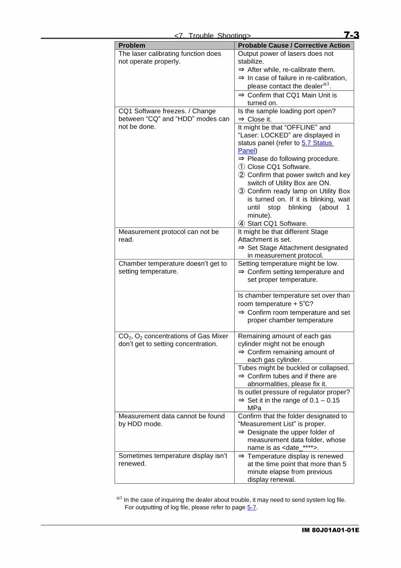
<7. Trouble Shooting> 7-3
IM 80J01A01-01E
Problem Probable Cause / Corrective Action
The laser calibrating function does not operate properly.
Output power of lasers does not stabilize.
⇒ After while, re-calibrate them.
⇒ In case of failure in re-calibration,
please contact the dealer※1.
⇒ Confirm that CQ1 Main Unit is turned on.
CQ1 Software freezes. / Change between “CQ” and “HDD” modes can not be done.
Is the sample loading port open?
⇒ Close it.
It might be that “OFFLINE” and “Laser: LOCKED” are displayed in status panel (refer to 5.7 Status Panel)
⇒ Please do following procedure.
① Close CQ1 Software.
② Confirm that power switch and key
switch of Utility Box are ON.
③ Confirm ready lamp on Utility Box
is turned on. If it is blinking, wait
until stop blinking (about 1
minute).
④ Start CQ1 Software.
Measurement protocol can not be read.
It might be that different Stage Attachment is set.
⇒ Set Stage Attachment designated in measurement protocol.
Chamber temperature doesn’t get to setting temperature.
Setting temperature might be low.
⇒ Confirm setting temperature and set proper temperature.
Is chamber temperature set over than
room temperature + 5℃?
⇒ Confirm room temperature and set proper chamber temperature
CO2, O2 concentrations of Gas Mixer don’t get to setting concentration.
Remaining amount of each gas cylinder might not be enough
⇒ Confirm remaining amount of each gas cylinder.
Tubes might be buckled or collapsed.
⇒ Confirm tubes and if there are abnormalities, please fix it.
Is outlet pressure of regulator proper?
⇒ Set it in the range of 0.1 – 0.15 MPa
Measurement data cannot be found by HDD mode.
Confirm that the folder designated to “Measurement List” is proper.
⇒ Designate the upper folder of measurement data folder, whose name is as <date_****>.
Sometimes temperature display isn’t renewed.
⇒ Temperature display is renewed at the time point that more than 5 minute elapse from previous display renewal.
※1
In the case of inquiring the dealer about trouble, it may need to send system log file.
For outputting of log file, please refer to page 5-7.

7-4 <7. Trouble Shooting>
IM 80J01A01-01E
7.2 Trouble Shooting during Imaging
Problem Probable Cause / Corrective Action
The image cannot be acquired. / The acquired image is dark.
It might be that the exposure time is short.
⇒ Set it longer.
It might be that the laser intensity is low.
⇒ Set it higher.
It might be that the imaging camera is not recognized.
⇒ Restart the whole system properly. Please refer to 3.2 Starting and Shutting Down.
It might be that the microplate is not set in precisely.
⇒ Set it so the “A1” well locates on the left rear position from the front of CQ1 Main Unit.
⇒ Set it so that 4 corners set on stage precisely.
It might be that the slideglass(es) are (is) not set in proper direction.
⇒ Set it(them) in proper direction(s).
⇒ Set slide glass to move over to left side of sample holder.
It might be that the door of CQ Main Unit opens.
⇒ Close it.
It might be that the key switch of Utility Box is OFF.
⇒ Turn the key switch ON.
⇒ Confirm ONLINE and Laser: ON in status panel (refer to 5.7 Status Panel)
⇒ Confirm that contrast setting is proper. (Refer to page 5-117)
It might be that viewer status is turned to undisplayed ( ).
⇒ Turn it to displayed status ( ). (Refer to page 5-117)
Image become bright suddenly Confirm whether the check box “Laser Enhancement” of “Imaging” window is checked or not.
⇒ If checked, laser power can increase suddenly.
⇒ Confirm that contrast setting is proper. (Refer to page 5-117)
The laser autofocus does not operate properly.
It might be that there are scratches / dusts on the bottom surface of sample.
⇒ Clean the surface and remove dusts and water on it.
⇒ Use the sample without scratches on the bottom surface.
Sample vessel might tilt
⇒ Remove sample vessel once and set it again carefully.

<7. Trouble Shooting> 7-5
IM 80J01A01-01E
Problem Probable Cause / Corrective Action
The laser autofocus does not operate properly.
Kind of sample vessel might be wrong.
⇒ Confirm that sample vessel corresponds to that of designated in measurement protocol.
It might be that sample vessel which is not registered is used.
⇒ Register the sample vessel (refer to page 5-19)
⇒ Use registered sample vessel
Is gel used for cell culture?
⇒ In “Sample Vessel Type” of Sample window, check “Laser AF Bottom Detector”. (Refer to page 5-19)
Is sample vessel whose cell culture surface is processed especially?
⇒ In “Sample Vessel Type” of Sample window, check “Laser AF Bottom Detector”. (Refer to page 5-19)
⇒ In case of measuring other sample in same protocol again, please load the protocol in each time.
The Image autofocus does not operate properly.
It might be that sample is too dark or bright dusts exist in sample vessel.
⇒ Uncheck “ImageAF”
Quality of map image is bad ⇒ Zoom map image, and map image is shown in original resolution
Despite focusing by “Search” function, images acquired by “Rec” are defocused.
In case that “Rec” position is far from “Search” position, Z position that sample exist may different.
⇒ Perform focusing by “Search” at “Rec” position.
Waiting occurs during the measurement.
It might occur in case when image acquisition and heavy duty analysis are processed concurrently.
⇒ It is recommended that image acquisition and analysis are processed separately.
“Rec” is unavailable It might be that imaging Area is not set.
⇒ Set imaging Area.
It might be that well for “Rec” isn’t selected.
⇒ Select well for “Rec”.
The error occurs just after “Rec” button being clicked.
It might be that the parameter(s) set in analysis is (are) not appropriate.
⇒ Reset the parameters.
It might occur that memories of workstation run out because of heavy duty analysis.
⇒ Reset protocol.
It might occur that memories of workstation run out because of too many number of Z stack.
⇒ Reduce the number of Z stack.

7-6 <7. Trouble Shooting>
IM 80J01A01-01E
Problem Probable Cause / Corrective Action
The laser calibrating function does not operate properly.
Output power of lasers does not stabilize.
⇒ After while, re-calibrate them.
⇒ In case of failure in re-calibration,
please contact the dealer※1.
The brightness on the corners of image being acquired is dark.
Confirm that the check box “Flat Field Correction” of “Imaging” window is checked.
⇒ In case that the corners of image are still dark despite the check box is checked, please adjust Trimming Parameter (refer to 5.10 Trimming Parameter) to cut the edge of images for temporary measure. The whole system needs maintenance for primal measure.
Please contact the dealer※1.
Objects in image look like they shift to XY direction by Z movement
Sample vessel might tilt
⇒ Remove sample vessel once and set it again carefully.
Sample vessel might be distorted.
⇒ Acquire images of 4 corners of sample vessel and compare their tilt. Additionally, acquire images of plural Fields in the well and compare their tilt. If direction of object shift is different, sample vessel might be distorted. If direction of object shift is same, CQ1 might have an abnormality of stage. In this case, please contact
the dealer※1.
Sample set part of Stage Attachment may be distorted.
⇒ If sample set part of Stage Attachment is distorted, replacement is needed. In this
case, please contact the dealer※1.
Sample position is different among channels.
Confirm that the check box “Chromatic Aberration” of “Imaging” window is checked.
⇒ If it is checked and sample position is different, maintenance is needed. Please contact the
dealer※1.
It is impossible to acquire whole well ⇒ It is impossible to acquire outer area of well by combination of objective lens and sample vessel.
“Chromatic Aberration” correction doesn’t work properly at image edge in measurement using low magnification lens
⇒ In case of using low magnification lens, there are affect of aberration which cannot correct by CQ1 function. If there are problems in analysis, cut the edge of image (about 10 %) by trimming (refer to 5.10 Trimming Parameter).

<7. Trouble Shooting> 7-7
IM 80J01A01-01E
Problem Probable Cause / Corrective Action
Z position of bottom of sample vessel can not be found.
⇒ Reset the range of “Search” function wider by using “▼” button beside “Search” button.
⇒ Confirm that sample vessel is set properly.
The sample can not be found. It might be that there are not any cells in F.O.V.
⇒ First, run “Preview map image acquisition” function in “Map” window, and, after that, reset the Field position to region containing cells according to the result of the function described above.
Well(s) can not be selected by “Imaging” / “Analysis” / “Well Table” windows.
It might be that “Select measurement area” mode is ineffective.
⇒ Click button to set the mode effective.
Measurement and analysis can not be run simultaneously.
It might be that “CQ” mode is not selected.
⇒ Select “CQ” mode.
It might be that the check box of “Execute Analysis” in “Application” window is not checked.
⇒ Check the check box described above.
Lasers do not operate. It might be that the key switch switch is not turned ON.
⇒ Turn it ON.
It might be that the remote interlock connector is not connected to the paired port.
⇒ Connect the connector to the paired port.
It might be that the door is open.
⇒ Close it.
It might be that sub cover is open.
⇒ Close it.
⇒ Confirm ONLINE and Laser: ON in status panel (refer to 5.7 Status Panel)
There is(are) gap(s) in resultant image of “Map” window.
⇒ There is occasionally happened that the gap appears according to the magnification of resultant image of “Map” window.
There are dark fields sometimes in map imaging.
⇒ Uncheck auto contrast. (refer to page 5-117)
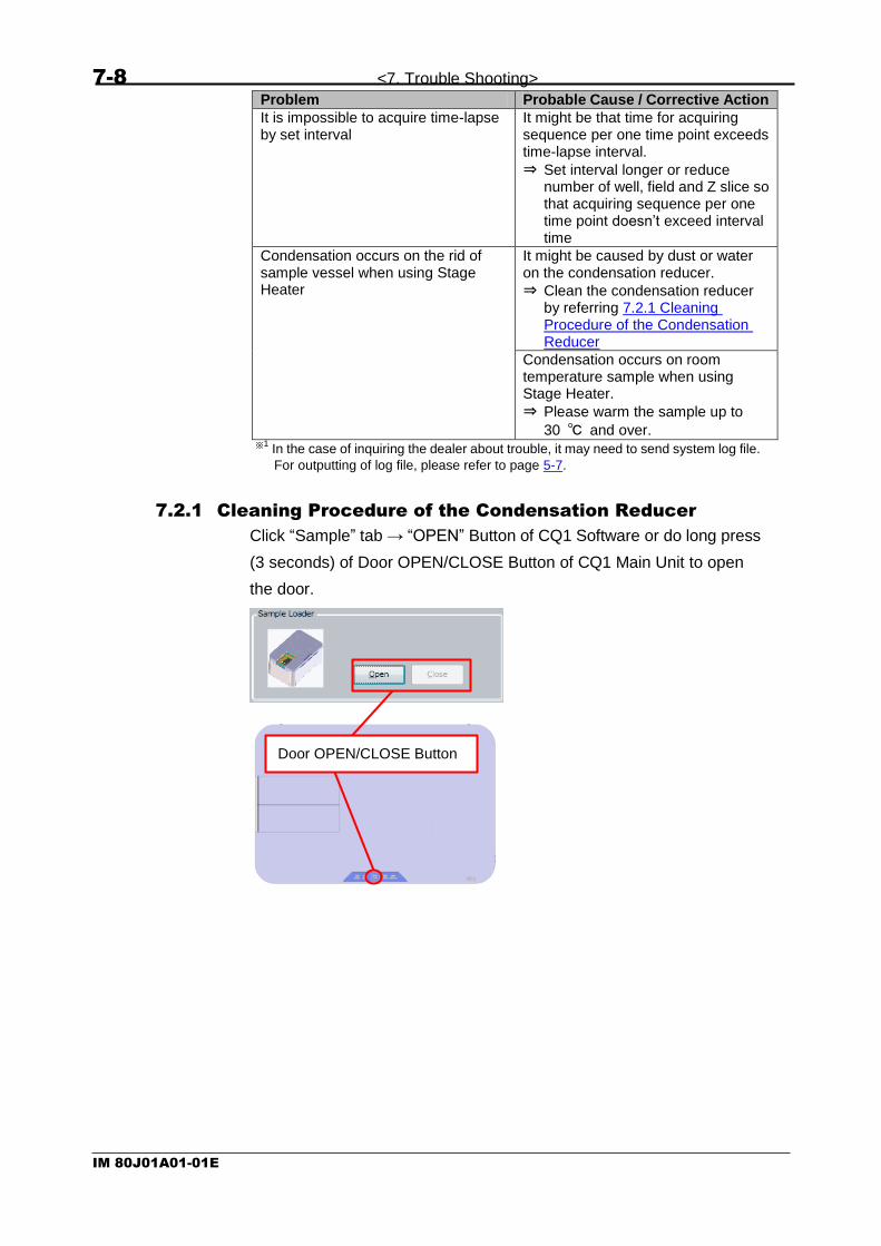
7-8 <7. Trouble Shooting>
IM 80J01A01-01E
Problem Probable Cause / Corrective Action
It is impossible to acquire time-lapse by set interval
It might be that time for acquiring sequence per one time point exceeds time-lapse interval.
⇒ Set interval longer or reduce number of well, field and Z slice so that acquiring sequence per one time point doesn’t exceed interval time
Condensation occurs on the rid of sample vessel when using Stage Heater
It might be caused by dust or water on the condensation reducer.
⇒ Clean the condensation reducer by referring 7.2.1 Cleaning Procedure of the Condensation Reducer
Condensation occurs on room temperature sample when using Stage Heater.
⇒ Please warm the sample up to
30 ℃ and over. ※1
In the case of inquiring the dealer about trouble, it may need to send system log file.
For outputting of log file, please refer to page 5-7.
7.2.1 Cleaning Procedure of the Condensation Reducer
Click “Sample” tab → “OPEN” Button of CQ1 Software or do long press
(3 seconds) of Door OPEN/CLOSE Button of CQ1 Main Unit to open
the door.
Door OPEN/CLOSE Button

<7. Trouble Shooting> 7-9
IM 80J01A01-01E
Turn the key switch OFF, then turn the power switch OFF..
Loosen 2 screws and remove sub cover.
Power Switch
Key Switch

7-10 <7. Trouble Shooting>
IM 80J01A01-01E
Loosen 4 screws and remove bath cover.
CAUTION
Please don’t remove screws from bath cover.
During temperature controlling, water drops are formed on the
downside of the bath cover. Please be careful not to drop water
inside the equipment when removing bath cover.
If water drops inside the equipment, wipe it completely before
turning CQ1 on.
Bath cover
Water drop

<7. Trouble Shooting> 7-11
IM 80J01A01-01E
If there is water in the bath, remove it by syringe and others.
Hold the tube and the block of condensation reducer, slide them right
and pull off the tube from the bath.
Rotate the block counterclockwise then pull off the block.
Condensation
reducer

7-12 <7. Trouble Shooting>
IM 80J01A01-01E
If there is dust or water on the 2 holes on the edge of the block, wipe
them.
If there is dust or water in the slit, wipe them.
After cleaning, insert the edge of the block into the slit of the bath and
rotate it clickwise.
Slit

<7. Trouble Shooting> 7-13
IM 80J01A01-01E
Slide the tube and the block left and insert the tube to the bath hole.
Hold the tube and the block then slide them left to insert the tube to the
hole until the end.
Set bath cover and tighten 4 screws.
In case that the screws can’t be fastened properly, adjust position of
bath cover so that the screws are fastened properly.

7-14 <7. Trouble Shooting>
IM 80J01A01-01E
Set sub cover and tighten 2 screws.

<7. Trouble Shooting> 7-15
IM 80J01A01-01E
7.3 Trouble Shooting during Analyzing
Problem Probable Cause / Corrective Action
“Pre Analysis” function does not run after the measurement.
“Pre Analysis” function does not run in “CQ”mode.
⇒ Change the oprerating mode from “CQ” mode to “HDD” mode, and then run “Pre Analysis”.
Nothing is shown in Thumbnail Chart window.
⇒ Select well to show chart in Well Table window
Heat map display in Well Table window disappeares.
Heat map isn’t shown if wells are selected in Well Table window.
⇒ Unselect wells
Cells can not be recognized. It might be that the threshold of binarization is too high.
⇒ First, reconfirm the intensity range of image by using “Image Viewer function image acquisition” function, and, after that, reset the threshold properly (and, set “Object Detectivity” higher).
It might be that the range of “Size Filter” is not porper.
⇒ Reset the range of “Size Filter” properly with visualization of “Chart” function.
It might be that viewer status for is turned to undisplayed ( ).
⇒ Turn it to displayed status ( ). (Refer to page 5-115)
It might be that Area window is selected in ImageViewer
⇒ Recognized result is not shown in Area window. Select Image View window. (refer to page 5-88)
It might be that Z position that sample doesn’t exist is shown by viewer.
⇒ Adjust Z position.
The defined line of boundary on cells is not smooth.
It might be that the intensity on the boundary fluctuates or is too dark.
⇒ Increase the intensity of image by making the exposure time longer or increasing laser output power.
⇒ To define outer envelope of the boundary as the resultant boundary, add “Closing Circle” command to “Binarize Transform” block by using “Edit” of “Analysis” window.
⇒ To define inner envelope of the boundary as the resultant boundary, add “Opening Circle” command to “Binarize Transform” block by using “Edit” of “Analysis” window.
How to clear recognition showing? ⇒ Turn viewer status to undisplayed status ( ). (Refer to page 5-115)

7-16 <7. Trouble Shooting>
IM 80J01A01-01E
Problem Probable Cause / Corrective Action
Well(s) can not be selected by “Imaging” / “Analysis” / “Well Table” windows.
It might be that “Select measurement area” mode is ineffective.
⇒ Click button to set the mode effective.
Chart(s) can not be displayed in “Thumbnail Chart ” window.
It might be that the check box whose title is the same as that of the chart window which should display the chart is not checked.
⇒ Check the check box described above.
The measurement data can not be read.
Is proper folder selected?
⇒ Select “MeasurementData” folder described in diagram at page 5-13.
“Send to” can not be selected Isn’t “MIP” or “Sum” in “Z Option” at ImageViewer (refer to 5-88) selected?
⇒ Select “Slice” in “Z Option” to show 3D image by “Send to”
Analysis result, by stored analysis protocol, is strange
Analysis is not performed normally if measurement condition (channel, exposure and so on) is changed.
⇒ Edit analysis protocol to match measurement condition.
Where are plural analysis results of one measurement data by different analysis protocols?
⇒ Analysis result list is shown by
clicking “ ”. (refer to page 5-59)
“3D Viewer” of “Image J” freezes. It might be that the size of image is too large.
⇒ Set the value of “Scaling“ smaller.
It might be that the display driver of WS or PC is unproper. It might occure when OS is upgraded.
⇒ Please inquire the WS or PC vender.
Analysis does not operate properly because it recognizes wall of well(s) as the menbrance of cell(s).
⇒ Set the size of cell(s) to detect properly by using “Size Filter” command.
⇒ Set the value of “ROI Size Raito” of “ROI Filter” function smaller so that ROI becomes inner area of each well.
Analysis is run repeatedly on the same cell(s).
It might be that adjecet images are overlayed partially.
⇒ Acquire images not so that adjacent images are overlayed.
⇒ Set the value of “ROI Size Raito” of “ROI Filter” function smaller not so that adjacent images are overlayed.
Only partial range of image is output by “Snapshot”
By “Snapshot”, range of image shown in ImageViewer is output.
⇒ Show whole image at ImageViewer and click “Snapshot”.

<7. Trouble Shooting> 7-17
IM 80J01A01-01E
Problem Probable Cause / Corrective Action
Measurement data cannot be found by HDD mode.
Confirm that the folder designated to “Measurement List” is proper.
⇒ Designate the upper folder of measurement data folder, whose name is as <date_****>.
※1 In the case of inquiring the dealer about trouble, it may need to send system log file.
For outputting of log file, please refer to page 5-7.
7.4 Other Trouble Shootings
Problem Probable Cause / Corrective Action
Image Viewer window and/or Thumbnail Chart window disappear
⇒ These windows can be shown by Menu -> “View” menu.
Access to hard disk drive becomes slower.
It might be that the free space on the HDD is small.
⇒ Keep the free space by deleting unused files. (It is recommended that Windows command “Defrag” is run after deleting unused files.)
While image acquisition and analysis are performed simultaneously, sound of moter movement become noisy.
⇒ There are no influences to measurement.
※1
In the case of inquiring the dealer about trouble, it may need to send system log file.
For outputting of log file, please refer to page 5-7.


<8. Specifications> 8-1
IM 80J01A01-01E
8 Specifications
8.1 Details of MS codes
8.1.1 CQ1 Main Unit
Model Code
Suffix Code Option Description
CQ1 Confocal Quantitative Image Cytometer
Laser -L11 Wavelength:488 nm
-L21 Wavelength:488, 561 nm
-L22 Wavelength:405, 488 nm
-L23 Wavelength:488, 640 nm
-L31 Wavelength:405, 488, 561 nm
-L32 Wavelength:405, 488, 640 nm
-L33 Wavelength:488, 561, 640 nm
-L41 Wavelength:405, 488, 561, 640 nm
Dichroic mirror
-M1 DM :405, 488, 561, 640 nm
Transmission Illumination
-P Phase Contrast
-T Bright Field/ Phase Contrast
-N -
Stage Heater -H With Stage Heater
-N Without Stage Heater
Stage Attachment -A1 All Wells Imaging Type
-A2 Chambered Type
Workstation -W1 Standard Workstation
Language, Shipping Form AC Cord
-J Japanese, with Monitor, with AC Cord
-N Japanese, without Monitor, with AC Cord
-E English, without Monitor, without AC Cord
Dummy Code -N Dummy Code
Subcode -00 Always “-00”
Software Option /FTL Fast Time-lapse
Custom Order /Z Custom Order
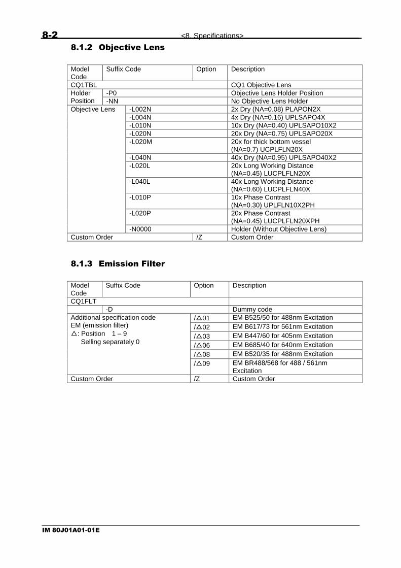
8-2 <8. Specifications>
IM 80J01A01-01E
8.1.2 Objective Lens
Model Code
Suffix Code Option Description
CQ1TBL CQ1 Objective Lens
Holder Position
-P0 Objective Lens Holder Position
-NN No Objective Lens Holder
Objective Lens -L002N 2x Dry (NA=0.08) PLAPON2X
-L004N 4x Dry (NA=0.16) UPLSAPO4X
-L010N 10x Dry (NA=0.40) UPLSAPO10X2
-L020N 20x Dry (NA=0.75) UPLSAPO20X
-L020M 20x for thick bottom vessel (NA=0.7) UCPLFLN20X
-L040N 40x Dry (NA=0.95) UPLSAPO40X2
-L020L 20x Long Working Distance (NA=0.45) LUCPLFLN20X
-L040L 40x Long Working Distance (NA=0.60) LUCPLFLN40X
-L010P 10x Phase Contrast (NA=0.30) UPLFLN10X2PH
-L020P 20x Phase Contrast (NA=0.45) LUCPLFLN20XPH
-N0000 Holder (Without Objective Lens)
Custom Order /Z Custom Order
8.1.3 Emission Filter
Model Code
Suffix Code Option Description
CQ1FLT
-D Dummy code
Additional specification code EM (emission filter)
△: Position 1 – 9
Selling separately 0
/△01 EM B525/50 for 488nm Excitation
/△02 EM B617/73 for 561nm Excitation
/△03 EM B447/60 for 405nm Excitation
/△06 EM B685/40 for 640nm Excitation
/△08 EM B520/35 for 488nm Excitation
/△09 EM BR488/568 for 488 / 561nm Excitation
Custom Order /Z Custom Order

<8. Specifications> 8-3
IM 80J01A01-01E
8.1.4 Options
Model Code
Suffix Code Option Description
CQ1PRT
Language -J Japanese
-E English
Gas Mixer /MX2-D Gas Mixer
Stage Attachment /SAT1 All Wells Imaging Type
/SAT2 Chambered Type
Sample Holder /HDA01 For Triple 35 mm Dishes
/HDA02 For Single 60 mm Dish
/HDA03 For Slide Glass (ISO 8037/1)
/HDA04 For Cover Glass Chamber
Sealing Parts for Sample Holder /CB601 60 mm Dish Ring
/CB602 Rubber for 60 mm Dish
/CBT01 Holding Plate for CGC
/CBT02 Rubber for CGC (IWAKI)
/CBT03 Rubber for CGC (NUNC Lab-Tek I)
/CBT04 Rubber for CGC (NUNC Lab-Tek II)
/CBT05 Rubber for CGC (MATSUNAMI)

8-4 <8. Specifications>
IM 80J01A01-01E
8.2 General Specifications
Main Unit Type Standard Model Transmission Illumination Option
Confocal Scanning Method
Microlens enhanced dual Nipkow disk system
Scanning speed 4000 rpm
Excitation laser wavelength
Select 1 – 4 lasers from 405 nm,488 nm,561 nm,and 640 nm
Phase contrast illumination
- Option:LED transmission
illumination
Camera sCMOS,2560 x 2160 pixel,16.6 mm x 14.0 mm
Objective lens Up to 6 lenses from below list are installable
Dry:2x,4x,10x,20x,40x
Long working distance:20x,40x
Phase contrast:10x,20x
External dimensions
W 600 mm x D 400 mm x H 298 mm
W 600 mm x D 400 mm x H 437 mm
Mass Without Stage Heater: 38 kg With Stage Heater: 41.3 kg
Without Stage Heater: 40 kg With Stage Heater: 43.3 kg
Noise level 46 dB max A-weighted sound pressure level is less than 70dB
Utility Box External dimensions
W 275 mm x D 432 mm x H 298 mm
Mass 18 kg
Gas Mixer External dimensions
W 170 mm x D 260 mm x H 280 mm
Mass 5.2 kg
Workstation for measurement
External dimensions
W 172 mm x D 417 mm x H 298 mm
Mass 14 kg
Measurement software Set measurement condition; Display image data and charts, Map imaging; Quantified data analysis; Reporting; 3D Imaging; Multi-color imaging; Multi-position imaging Data format: 16 bit OME-TIFF file
Operating temperature range
CQ1 15 – 35 ℃
Gas Mixer 20 – 30 ℃
Operating humidity range
CQ1 20 – 70 % RH No condensing
Gas Mixer 10 – 85 % RH No condensing
Power consumption 100 – 240 VAC 50 / 60 Hz Main Unit, Utility box 800 VA Gas Mixer 40 VA Workstation 400 VA
Note
Specifications are subject to change without notice.

<8. Specifications> 8-5
IM 80J01A01-01E
8.3 Measurement sample vessels
(1) Microplate
Following microplate types are applicable
・ 6 well
・ 12 well
・ 24 well
・ 48 well
・ 96 well
・ 384 well※1
・ 1536 well※1
(2) Dish
Following dish types are applicable
・ 35 mm Dish (By using 35 mm dish sample holder, up to
3 dishes are measurable in one experiment)
・ 60 mm Dish (By using 60 mm dish sample holder, one dish
is measureable in one experiment)
(3) Slide glass
By using slideglass sample holder, up to 4 slide glasses are
applicable in one experiment
(4) Cover Glass Chamber
By using cover glass chamber holder, one cover glass chambdr is
applicable in one experiment
※1
If 384 well microplate is measured by 2x objective lens, multiple wells are measured
by one FOV. Therefore in this case, measurement is inhibited. (Warning is displayed.) If 1536 well microplate is measured by 2x/ 4x objective lens, multiple wells are measured by one FOV. Therefore in this case, measurement is inhibited. (Warning is displayed.)
For details of sample vessels usable in CQ1, please refer to Technical
Information (TI 80J01A01-01E).

8-6 <8. Specifications>
IM 80J01A01-01E
8.4 Applicable Standards
◆CE Marking
●EMC Directives:
This product belongs to Class A which is designed to be used under
industrial environment. If used under household environment, risk of
radio interference could arise, and the user may have to take
appropriate measures.
This product satisfies the requisite minimal immunity level. If being
used under other environment than controlled area, this product may
suffer external influence, and the user may have to take appropriate
measures
EN/IEC 61326-1 Class A, Table 1 (Basic immunity requirements)
Electrical equipment for measurement, control and laboratory use
- EMC requirements - Part 1: General requirements
Performance Criteria
Performance Criteria※
ESD
IEC 61000-4-2 B
Radiated electromagnetic field
IEC 61000-4-3 A
EFT/Burst
IEC 61000-4-4 B
Surge
IEC 61000-4-5 B
Conducted disturbance
IEC 61000-4-6 A
Power freq. magnetic field
IEC 61000-4-8 A
Voltage dips
IEC 61000-4-11
B (0.5,1cycle 0%)
C (25 cycles 70%)
Short interruptions
IEC 61000-4-11 C
※Performance Criteria
A: The equipment continues to operate to specification. B: When the noise is applied, the equipment will go to be fluctuated. However, if the
noise is removed, it continues to operate to specification. C: When the noise is applied, temporary degradation or less of function is observed
and to recover the normal condition, an operator intervention or system reset is required.

<8. Specifications> 8-7
IM 80J01A01-01E
EN/IEC 55011 Group 1, Class A
Industrial, scientific and medical equipment.
Radio-frequency disturbance characteristics. Limits and methods of
measurement
EN/IEC 61000-3-2 Class A
Electromagnetic compatibility (EMC)
- Part 3-2: Limits - Limits for harmonic current emissions (equipment
input current <= 16 A per phase)
EN/IEC 61000-3-3
Electromagnetic compatibility (EMC)
- Part 3-3: Limits - Limitation of voltage changes, voltage fluctuations
and flicker in public low-voltage supply systems, for equipment with
rated current ≤16 A per phase and not subject to conditional connection

8-8 <8. Specifications>
IM 80J01A01-01E
◆CE Marking
●Machinery Directive:
ISO12100
Safety of machinery
-- General principles for design
-- Risk assessment and risk reduction
EN/IEC 13849-1
Safety of machinery
-- Safety-related parts of control systems
-- Part 1: General principles for design
EN/IEC 61010-1
Safety requirements for electrical equipment for measurement, control,
and laboratory use
- Part 1: General requirements
EN/IEC 60825-1
Safety of laser products
- Part 1: Equipment classification and requirements
●Environmental Standard:
EN 50581
◆Laser Safety Standard
EN/IEC 60825-1
Safety of laser products
- Part 1: Equipment classification and requirements
FDA Laser Safety Regulation
Information of Inner laser parts
● 405 nm laser for excitation
- AEL laser safty class: 3B
- Maximum output power: 100 mW
- Wavelength: 405 nm
- Pulse duration & repeating frequency: Continuous mode
- Angular subtense: 0.1 rad

<8. Specifications> 8-9
IM 80J01A01-01E
● 488 nm laser for excitation
- AEL laser safty class: 3B
- Maximum output power: 60 mW
- Wavelength: 488 nm
- Pulse duration & repeating frequency: Continuous mode
- Angular subtense: 0.1 rad
● 561 nm laser for excitation
- AEL laser safty class: 3B
- Maximum output power: 50 mW
- Wavelength: 561 nm
- Pulse duration & repeating frequency: Continuous mode
- Angular subtense: 0.1 rad
● 640 nm laser for excitation
- AEL laser safty class: 3B
- Maximum output power: 100 mW
- Wavelength: 640 nm
- Pulse duration & repeating frequency: Continuous mode
- Angular subtense: 0.1 rad
● Laser for autofocus
- AEL laser safty class: 3R
- Maximum output power: 2.5 mW
- Wavelength: 785 nm
- Pulse duration & repeating frequency: Continuous mode
- Angular subtense: 0.1 rad


<9. Warranty Rule> 9-1
IM 80J01A01-01E
9 Warranty Rule
The warranty period is one year from the date of purchase. Failures
that occur within the warranty period will be repaired free of charge.
The warranty only covers this product.
If any of the following conditions applies, repair will be charged even
within the warranty period:
●Failures or damage caused by inappropriate handling or use
●Failures or damage caused by handling, use, or storage that exceed
the tolerance of the design and specifications
●Failures or damage caused by repairs and modifications made by
the user
●Failures or damage caused by transportation, movement, dropping,
or the like occurring after purchase
●Failures or damage caused by a fire, natural disaster (earthquake,
storm, flood, lightning and so on), salt damage, gas damage, and
abnormal voltage.
●Failures caused by the following processing on the workstation.
■Install patches (Windows Update, service pack, security
patch) to update operating system.
■Install the third-party software which YOKOGAWA doesn’t
specify.
●Failures caused by water leakage due to following processing.
■Over filling water into Stage Attachment (Chambered type).
Any other damage not attributable to Yokogawa is outside the scope of
this warranty.
Should you require any repair, please consult Yokogawa.

9-2 <9. Warranty Rule>
IM 80J01A01-01E
Manufacturer
International Sales Team. Life Science Center
Measurement Business HQ
Yokogawa Electric Corporation
2-3 Hokuyodai, Kanazawa-shi,
Ishikawa 920-0177, Japan
Phone +81-76-258-7028 Fax +81-76-258-7029
E-mail: [email protected]
Web site http://www.yokogawa.com/scanner
Please contact the dealer inquiries about this product.