
user manual electrical installation meter mpi-502 - Sonel SA
56
-
Upload
khangminh22 -
Category
Documents
-
view
0 -
download
0
Transcript of user manual electrical installation meter mpi-502 - Sonel SA


USER MANUAL
ELECTRICAL INSTALLATION METER
MPI-502
SONEL S.A.
Wokulskiego 11
58-100 Świdnica
Version 1.22 21.06.2021

MPI-502 – USER MANUAL 2
The MPI-502 is a modern, state-of-the art measuring instrument, easy to operate and safe. Read this manual to avoid mistakes during the measurements and prevent operational problems.

MPI-502 – USER MANUAL 3
CONTENTS
1 Safety ................................................................................................................ 5
2 Measurements .................................................................................................. 6
2.1 Switching on and off, display backlight ....................................................... 6 2.2 Selecting general measurement parameters ............................................. 6 2.3 Remembering the last measurement result ............................................... 8 2.4 Alternating voltage measurement ............................................................... 8 2.5 Voltage and frequency measurement ........................................................ 8 2.6 Verifying the protective conductor connection correctness ........................ 8 2.7 Measurements of fault loop parameters ..................................................... 9
2.7.1 Selecting the lead length ................................................................................................... 9 2.7.2 Prospective short-circuit current ...................................................................................... 10 2.7.3 Measurement of fault loop parameters in the L-N and L-L systems ................................. 11 2.7.4 Measurement of fault loop parameters in the L-PE system ............................................. 13 2.7.5 Measurement of fault loop impedance in the L-PE system protected by an RCD ............ 15
2.8 Measurement of resistance to earth ......................................................... 16 2.9 Measurement of the residual current device parameters ......................... 17
2.9.1 Measurement of the RCD tripping current ....................................................................... 17 2.9.2 Measurement of the RCD tripping time ........................................................................... 19 2.9.3 Automatic RCD parameters measurement ...................................................................... 21
2.10 Low-voltage resistance measurement ..................................................... 27 2.10.1 Continuity measurements of protective conductors and equipotential bonding (with the
200mA current) .......................................................................................................... 27 2.10.2 Low-current resistance measurement ............................................................................. 28 2.10.3 Test leads resistance compensation – auto-zeroing ........................................................ 30
3 Memory of measurement results .................................................................. 31
3.1 Entering the measurement results to te memory ..................................... 31 3.2 Changing the cell and bank number ......................................................... 33 3.3 Browsing the memory ............................................................................... 33 3.4 Clearing the memory ................................................................................ 35
3.4.1 Clearing the bank ............................................................................................................ 35 3.4.2 Clearing the whole memory ............................................................................................. 36
3.5 Communication with computer ................................................................. 37 3.5.1 Package for cooperation with computer .......................................................................... 37 3.5.2 Data transmission with Bluetooth 4.2 module .................................................................. 37 3.5.3 Data transmission ........................................................................................................... 38
4 Troubleshooting ............................................................................................. 39
5 Power supply .................................................................................................. 41
5.1 Monitoring the power supply voltage ........................................................ 41 5.2 Replacing the batteries ............................................................................. 41 5.3 General rules of using the Nickel Metal Hydride (Ni-MH) batteries ............... 42
6 Cleaning and maintenance ........................................................................... 42
7 Storage ............................................................................................................ 43

MPI-502 – USER MANUAL 4
8 Dismantling and disposal ............................................................................. 43
9 Technical specification ................................................................................. 43
9.1 Basic information ...................................................................................... 43 9.2 Additional information ............................................................................... 48
9.2.1 Additional uncertainty according to IEC 61557-3 (Z) ....................................................... 48 9.2.2 Additional uncertainty according to IEC 61557-4 (R ±200mA) ......................................... 48 9.2.3 Additional uncertainty according to IEC 61557-6 (RCD) .................................................. 48
10 Accessories .................................................................................................... 49
10.1 Standard accessories ............................................................................... 49 10.2 Optional accessories ................................................................................ 49
11 Manufacturer .................................................................................................. 50
12 Laboratory services ....................................................................................... 51
MPI-502 – USER MANUAL 5
1 Safety
The MPI-502 meter is designed for testing the protection against electric shock in the mains sys-tems. The meter is used to make measurements which results determine the electrical installation safety level. Consequently, in order to ensure safe operation and correct measurement results, ob-serve the following recommendations:
Before you proceed to operate the meter, acquaint yourself thoroughly with the present manual and observe the safety regulations and recommendations of the manufacturer.
Any application that differs from those specified in the present manual may cause damage of the instrument and a serious hazard to its user.
The MPI-502 meters must be operated solely by appropriately qualified personnel with relevant certificates to perform measurements of electric installation. Operation of the instrument by unau-thorized personnel may result in damage to the device and constitute a hazard to the user.
Using this manual does not exclude the need to comply with occupational health and safety regu-lations and with other relevant fire regulations required during the performance of a particular type of work. Before starting the work with the device in special environments, e.g. potentially fire-risk/explosive environment, it is necessary to consult it with the person responsible for health and safety.
It is unacceptable to operate the following:
a damaged meter which is completely or partially out of order,
leads with damaged insulation,
a meter which ahs been stored to long in unsuitable conditions (for example is wet). When the meter is transferred from cold environment to warm and humid one, do not make measure-ments until the meter warms up to the ambient temperature (about 30 minutes).
Remember that the message on the display means that the power supply voltage is too low and indicates the need to replace/ charge the batteries. The measurements performed with the meter with insufficient supply voltage have additional measuring errors which are impossible to be evaluated by the user and cannot be the basis to determine the correct protection of the tested in-stallation.
Do not leave the discharged batteries in the meter as they can leak and damage the instrument.
Before starting the measurement, check if the leads are connected to correct measuring termi-nals.
Never use the meters with open or only partially closed battery compartment cover and use only the power supplies specified in this manual.
Repairs may be performed solely by an authorized service outlet.
NOTE
Use only standard and optional accessories intended for a given instrument which are
listed in the “Equipment” section. Using other accessories may cause damage of the
measuring terminal and additional measuring errors.
Note:
Due to continuous development of the meter software, the display view for some functions
may be a bit different from the view shown in this manual.

MPI-502 – USER MANUAL 6
Note:
An attempt to install drivers in 64-bit Windows 8 may result in displaying "Installation
failed" message.
Cause: Windows 8 by default blocks drivers without a digital signature.
Solution: Disable the driver signature enforcement in Windows.
2 Measurements
WARNING:
During the measurements (fault loop impedance, RCD) never touch the earthed and ac-
cessible parts in the tested electrical installation.
WARNING:
During the measurement do not switch the range selector as this may cause damage of
the meter and hazard for the user.
2.1 Switching on and off, display backlight
To switch on the meter, briefly press the button. To switch off, press the same button
longer (the message appears). To switch on/off the display and keypad backlight during the meter
operation, briefly press the button.
2.2 Selecting general measurement parameters
Keeping the SET/SEL button de-pressed, switch on the meter and wait for the parameter selection screen to appear.
Use the and buttons to go to next pa-rameter.
Use the and buttons to change the pa-rameter value. The value or symbol to be changed is flashing.
The symbol indicates an active parameter, the symbol indicates an inactive one.
Set the parameters according to the following algorithm:

MPI-502 – USER MANUAL 7
Parameter Mains
voltage
Voltage for calculating IK: rated/ measured
RCD-AUTO
parameters
Auto-OFF
Change PIN
Supply source
selection Buzzer
Software updating
Symbol(s)
?
Parameter
symbol(s)
...
Press ENTER to save the changes and go to the measurement function.
or
Press ESC to go the measurement function with-out saving the changes.
Notes:
- Before the first measurements, set the mains rated voltage Un (220/380V, 230/400V or 240/415V) which is applicable in the test location. The voltage is used to calculate the prospective short-circuit current, if this option was chosen from the main menu.
- The symbol means the positive phase or polarization, the symbol – a negative one.
- The symbol in the time to auto-off settings, indicates absence of such time.
- The RCD Auto mode settings are described in section 2.7.3.
- PIN settings – see section 3.5.2 Data transmission. - To upgrade the software, please proceed do point 3.5.1.

MPI-502 – USER MANUAL 8
2.3 Remembering the last measurement result
The result of the last measurement is remembered until the next measurement is activated, the measurement parameters are changed or the measuring function is changed with the dial switch. Use
the ESC button to go to the starting screen of a given function and press ENTER to display the last measurement result. Use the same procedure to display the last measurement result after the meter has been switched off (applies to the measurements of Z, RCD and RCONT).
2.4 Alternating voltage measurement
The meter measures and displays the mains alternating voltage in all measurement functions
with the exception of R. The voltage is measured for the 45..65Hz frequency range. The test leads should be connected as for a given measuring function.
2.5 Voltage and frequency measurement
Set the dial switch to the U,f posi-tion.
Read the measure-ment result: voltage in the auxiliary display field, frequency in the main field.
2.6 Verifying the protective conductor connection correctness
orPE
Connect the meters as shown in the figure, touch the contact electrode with your finger and wait
about 1 second. When the voltage on the PE conductor is detected, the instrument displays the
message (error in the installation, the PE con-ductor is connected to the phase conductor) and generates a continuous audio signal. This option is available for all measurement functions related
to the RCD’s and fault loop, except for ZL-N,L-L.

MPI-502 – USER MANUAL 9
Notes:
WARNING:
When dangerous voltage on the protective conductor PE is detected, discontinue the
measurements immediately and repair the electrical installation.
- Make sure that during the measurements you are not standing on an uninsulated floor as this may cause erroneous results. - The threshold value, which triggers the signal of exceeded allowable voltage on PE conduit, is ap-proximately 50 V.
2.7 Measurements of fault loop parameters
If the tested mains includes residual current devices, for the duration of measurement they
should be omitted by bypassing. Remember however that bypassing changes the tested
circuit and the results may very slightly differ from the actual values.
After the measurement, restore the mains to its original state and check operation of the
residual current device.
This note does not apply to the earth loop impedance measurements with the
ZL-PE RCD function.
Measurements of fault loop impedance performed downstream of inverters are ineffective
and their results are unreliable. This is due to the instability of internal impedance in in-
verter circuits during its operation. The measurements of fault loop impedance should not
be performed directly downstream of inverters.
2.7.1 Selecting the lead length
Set the dial switch to one of the fault loop impedance measure-ment ranges.
Set the parameters according to the following algorithm and the rules for setting the general parameters.
NOTE: The WS-05 and WS-01 leads are detected by the
meter and you cannot select their length (the symbol is displayed). When you are using the leads with banana plugs, before you start the measurements set the correct phase conductor length complying with the test leads length.

MPI-502 – USER MANUAL 10
Notes:
Using original leads and selecting correct length is a guarantee of keeping the declared
measuring accuracy.
2.7.2 Prospective short-circuit current
The meter always measures the impedance, and the displayed short-circuit current is calculat-ed according to the following formula:
S
nk
Z
UI
where: Un – rated voltage of the tested mains, ZS – measured impedance.
Based on the rated voltage Un selected in the general settings (section 2.1), the meter automat-ically detects the measurement with phase-to-neutral or phase-to-phase voltage and includes this in the calculations. If the tested mains voltage is out of tolerance range, the meter will not be able to determine the correct rated voltage for calculation of short-circuit current. In such case, horizontal lines will be dis-played instead of the short-circuit current. The figure below shows the voltage ranges for which the short-circuit current is calculated.
230 400 440 U [V]
U voltage ranges for which the
short-circuit current is calculatedL-N
Voltage range for which the impedance is measured
207 253 360
220 380 418198 242 342
373 415 440216 240 264
440 U [V]
U [V]
U =220Vn
U =230Vn
U =240Vn
U voltage ranges for which the
short-circuit current is calculatedL-L

MPI-502 – USER MANUAL 11
2.7.3 Measurement of fault loop parameters in the L-N and L-L systems
Switch on the meter. Set the dial switch to
the ZL-L ZL-N position.
Select the leads length as described in 2.6.1 according to the needs.
orN L N La) b)
Connect the test leads as shown in the figure a) for meas-urement in the L-N circuit or b) measurement in the L-L circuit
The meter is ready for measurement. Phase conductor
length or the sym-bol. UL-N or UL-L voltage
Press START to perform the measure-ment.
Read the main result: the fault loop imped-ance ZS and the mains voltage during the measurement.

MPI-502 – USER MANUAL 12
Press to read additional results.
IK short-circuit current.
R fault loop resistance
XL fault loop reactance
Note:
- Save the result in the memory (see sections 3.1 and 3.2) or press ESC to return to the voltage measurement. - Making a large number of tests over a short time causes the meter to emit a lot of heat. As a result the casing may become warm. This is normal, and the meter has an overheat protection. - The minimum time between successive measurements is 5 seconds. This value is controlled by the
meter which displays the message when you can make the next measurement.
MPI-502 – USER MANUAL 13
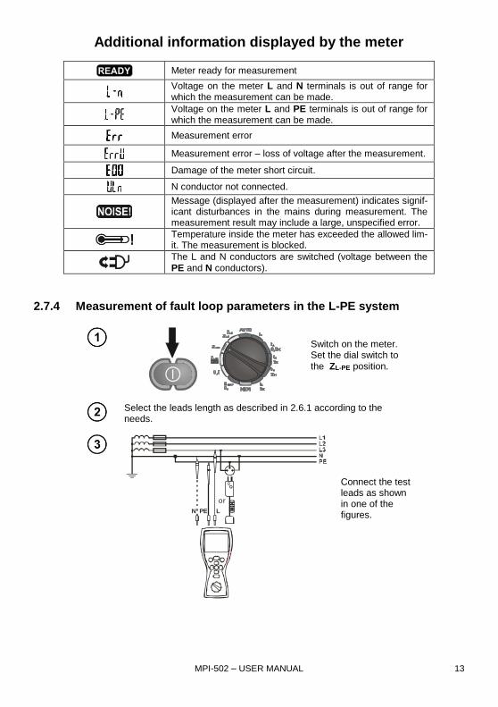
Additional information displayed by the meter
Meter ready for measurement
Voltage on the meter L and N terminals is out of range for which the measurement can be made.
Voltage on the meter L and PE terminals is out of range for which the measurement can be made.
Measurement error
Measurement error – loss of voltage after the measurement.
Damage of the meter short circuit.
N conductor not connected.
Message (displayed after the measurement) indicates signif-icant disturbances in the mains during measurement. The measurement result may include a large, unspecified error.
Temperature inside the meter has exceeded the allowed lim-it. The measurement is blocked.
The L and N conductors are switched (voltage between the
PE and N conductors).
2.7.4 Measurement of fault loop parameters in the L-PE system
Switch on the meter. Set the dial switch to
the ZL-PE position.
Select the leads length as described in 2.6.1 according to the needs.
or
N LPE
Connect the test leads as shown in one of the figures.
MPI-502 – USER MANUAL 14
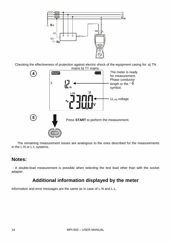
PE L
0
a)
b)
Checking the effectiveness of protection against electric shock of the equipment casing for: a) TN mains b) TT mains.
The meter is ready for measurement. Phase conductor
length or the symbol. UL-PE voltage
Press START to perform the measurement.
The remaining measurement issues are analogous to the ones described for the measurements in the L-N or L-L systems.
Notes: - A double-lead measurement is possible when selecting the test lead other than with the socket adapter.
Additional information displayed by the meter Information and error messages are the same as in case of L-N and L-L.

MPI-502 – USER MANUAL 15
2.7.5 Measurement of fault loop impedance in the L-PE system protected
by an RCD
The MPI-502 allows the fault loop impedance measurements without making changes in the mains with the residual current devices with rated current of minimum 30mA.
Switch on the meter. Set the dial switch to
the ZL-PE
RCD position.
Select the leads length as described in 2.6.1 according to the needs.
Connect the test leads as shown in one of the figures.
The remaining measurement issues are analogous to the ones described for the measurements in the L-N or L-L systems.
Notes:
- The measurement takes maximum about 32 seconds. You can discontinue the measurement by
pressing the ESC button. - In the electrical installations with the 30mA residual current devices the sum of the installation leak-age currents and the test current may trip the RCD. In such case, try to reduce the leakage current of the tested installation (i.e. by disconnecting the loads).

MPI-502 – USER MANUAL 16
Additional information displayed by the meter Information and error messages are the same as in case of L-N and L-L.
2.8 Measurement of resistance to earth
The MPI-502 instrument can be used for approximate measurements of resistance to earth For this purpose, the phase conductor is used as secondary source of voltage which generates test cur-rent. Connection diagram for the instrument for such measurement in the TN-C, TN-S and TT sys-
tems is shown in the figure below, the dial switch must be set to the ZL-PE position.
L
PE
N(PEN)
Ru
Rr
During the measurement check the connections of the measured earth electrode with the electri-cal installation. For correct measurement, the tested earthing system should be disconnected from the electrical installation (N and PE conductors). If you want to measure the earth electrode, for in-stance in the TN-C-S system and simultaneously use the phase of the same system as an auxiliary source of current, disconnect the PE and N conductors from the measured earth electrode (see figure below). Otherwise, the meter will measure an incorrect value (the test current will flow not only through the measured earthing system.
L
PE
N
Ru
Rr
L1L1L2L3
PE
Disconnect
Note:
WARNING:
Disconnection of protective conductors is serous life hazard for the staff performing the
measurements and also third parties. When the measurements are completed, the protec-
tive and neutral conductors MUST be reconnected.

MPI-502 – USER MANUAL 17
- If it is not possible to disconnect the conductors, use an earth resistance meter from the MRU range. - As the measurement result is the sum of impedances of the measured earth electrode, operational earthing system, source and phase conductor, it contains a positive error. However, if such error does not exceed a limit value for the tested earthing system, it can be concluded that the earthing has been made correctly and and there is no need for a more accurate measurement methods.
2.9 Measurement of the residual current device parameters
2.9.1 Measurement of the RCD tripping current
Switch on the meter. Set the dial switch to
the IA position.
Set the parameters according to the following algorithm and the rules for setting the general parameters.
Parameter In Current
waveform RCD type UL
Measurement mode
or
N LPE
Connect the test leads as shown in the figure.

MPI-502 – USER MANUAL 18
The meter is ready for measurement. UL-PE voltage
Press START to perform the measurement.
Read the main measurement result: IA current.
Press to read additional results.
Tripping time tAI at the IA cur-rent
Touch voltage UB

MPI-502 – USER MANUAL 19
Protective conductor resistance for RCD - RE
Notes:
- If only the measurement of UB, RE is selected, these values are measured with the 0,4In current
without tripping the RCD. If the RCD trips during the measurement, press ESC to go to the next measurements. - Due to the specific character of the measurement (step increase of the IA current), the measurement
result for the tripping time tAI in this mode may include a positive error or the message may be displayed due to the RCD inertia. If the result is outside the allowed range for a given RCD, repeat the measurement in the tA mode (see section 2.7.2).
- Save the result in the memory (see section 3.2) or press the ESC button to display the voltage only.
The last measurement result is remembered until you press the START button or change the dial switch position.
Additional information displayed by the meter
Meter ready for measurement
Voltage on the meter L and N terminals is out of range for which the measurement can be made.
The L and N conductors are switched (voltage between the
PE and N conductors).
Temperature inside the meter has exceeded the allowed limit. The measurement is blocked.
RCD did not trip or tripped during the UB, RE measure-ment.
RE measurement range is exceeded
After the UB RE measurement, the tA measurement was not performed because the RE and voltage values did not allow generating the required current value.
Safe touch voltage is exceeded.
2.9.2 Measurement of the RCD tripping time
Switch on the meter. Set the dial switch to
the tA position with the
selected IΔn multiplica-tion factor.

Set the parameters according to the following algorithm and the rules for setting the general parameters.
Parameter In Current
waveform RCD type UL
Measurement mode
or
N LPE
Connect the test leads as shown in the figure.
The meter is ready for measurement. UL-PE voltage
Press START to perform the measurement.

MPI-502 – USER MANUAL 21
Read the main meas-urement result: tripping time tA.
Press to read additional results.
Touch voltage UB
Protective conductor resistance for RCD - RE
Notes and information displayed by the meter as in section 2.8.1.
2.9.3 Automatic RCD parameters measurement
The instrument can perform automatic measurement of the RCD tripping time tA, tripping current IA, touch voltage UB and earth resistance RE. In this mode, you do not need to activate the measure-ment each time, and your role is only to initiate the measurement and reset the RCD after each trip-ping. In the MPI-502 main menu, you can choose two main AUTO modes: - FULL mode - STANDARD mode Mode selection is described in section 2.2.

MPI-502 – USER MANUAL 22
2.9.3.1 FULL mode
Switch on the meter. Set the dial switch to
the AUTO position.
If the displayed parameters are different than shown below, set them according to the following algorithm and the rules for setting the gen-eral parameters.
Parameter In RCD kind RCD type UL
or
N LPE
Connect the test leads as shown in the figure.
The meter is ready for measurement. UL-PE voltage

MPI-502 – USER MANUAL 23
Press START to perform the measurement.
Reset the tested RCD after each tripping.
Read the main meas-
urement result: -
or .
Use the ENTER button to save the results in the memory, the and arrows to view the result
components. or the ESC button to go to the voltage display mode.
The meter can perform the following measurements: For RCD AC:
Item Measured parameters
Measurement conditions
Multiplication
factor In Initial phase (polarization)
1. ZL-PE
2. UB, RE
3. tA 0.5In positive
4. tA 0.5In negative
5.* tA 1In positive
6.* tA 1In negative
7.* tA 2In positive
8.* tA 2In negative
9.* tA 5In positive
10.* tA 5In negative
11.* IA positive
12.* IA negative
* points at which an RCD in good working order should trip

MPI-502 – USER MANUAL 24
For RCD A:
Item Measured parameters
Measurement conditions
Multiplication
factor In Initial phase (polarization)
1. ZL-PE
2. UB, RE
3. tA 0,5In positive
4. tA 0,5In negative
5.* tA 1In positive
6.* tA 1In negative
7.* tA 2In positive
8.* tA 2In negative
9.* tA 5In positive
10.* tA 5In negative
11.* IA positive
12.* IA negative
13.* tA 0.5In positive
14.* tA 0.5In negative
15.* tA 1In positive
16.* tA 1In negative
17.* tA 2In positive
18.* tA 2In negative
19.* tA 5In positive
20.* tA 5In negative
21.* IA positive
22.* IA negative
* points at which an RCD in good working order should trip
Notes:
- Number of measured parameters depends on settings in the main menu. - UB and RE are measured always.
- If during the UB/RE measurement, the RCD has tripped at 50% In, or has not tripped in the remain-ing cases, or the preset safe voltage value UL has been exceeded, the measurement is discontinued. - The meter automatically skips the measurements which are not possible, for example when the se-lected current IΔn and multiplication factor are beyond the meter’s measuring range.
Additional information displayed by the meter
RCD in good working order.
Defective RCD.
Reset RCD.
The remaining information displayed by the meter as in section 2.8.1.

MPI-502 – USER MANUAL 25
2.9.3.2 STANDARD mode
Switch on the meter. Set the dial switch to
the AUTO position.
If the displayed parameters are different than shown below, set them according to the following algorithm and the rules for setting the gen-eral parameters.
Parameter In Current
waveform RCD type UL
or
N LPE
Connect the test leads as shown in the figure.

MPI-502 – USER MANUAL 26
The meter is ready for measurement. UL-PE voltage
Press START to perform the measurement.
Reset the tested RCD after each tripping.
Read the main meas-
urement result: -
or .
Notes:
- Measured parameters are the same as in the table for the FULL and RCD AC mode only for select-ed current waveform. - The remaining notes and in formation as in section 2.8.3.1.

MPI-502 – USER MANUAL 27
2.10 Low-voltage resistance measurement
Do not connect to the meter voltage above 440VDC as this can damage the in-
strument.
2.10.1 Continuity measurements of protective conductors and equipoten-
tial bonding (with the 200mA current)
Switch on the meter. Set the dial switch to
the RCONT Rx.
If necessary, set the RCONT measurement according to the following algorithm.
Press ENTER to confirm.
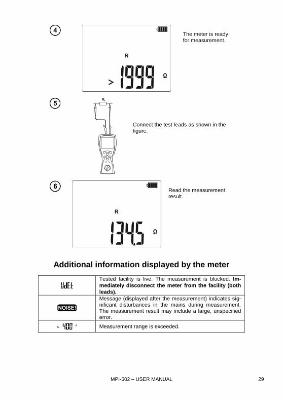
The meter is ready for measurement.
RX
N L
Connect the test leads as shown in the fig-ure. The measurement starts automatically
for resistance values below 100.

MPI-502 – USER MANUAL 28
Read the measurement result which is an arithme-tic mean of two measure-ments at the 200mA cur-rent flowing in opposite di-rections.
Press START to start the next measure-ment without disconnecting the test leads or to measure the resistance above
>100.
Additional information displayed by the meter
Tested facility is live. The measurement is blocked. Im-
mediately disconnect the meter from the facility (both
leads).
Message displayed after the measurement, it indicates significant divergences between the partial measurements (point ). The measurement result may include a large, unspecified error. Possible causes: - too much disturbances in the measured object, - instability of the object or of the meter’s connection with the object (unreliable galvanic connection).
Measurement range is exceeded.
2.10.2 Low-current resistance measurement
Switch on the meter. Set the dial switch to
the RCONT Rx position.
If necessary, set the R measurement according to the following al-gorithm.
Press ENTER to confirm.
MPI-502 – USER MANUAL 29
The meter is ready for measurement.
RX
N L
Connect the test leads as shown in the figure.
Read the measurement result.
Additional information displayed by the meter
Tested facility is live. The measurement is blocked. Im-
mediately disconnect the meter from the facility (both
leads).
Message (displayed after the measurement) indicates sig-nificant disturbances in the mains during measurement. The measurement result may include a large, unspecified error.
Measurement range is exceeded.

MPI-502 – USER MANUAL 30
2.10.3 Test leads resistance compensation – auto-zeroing
Switch on the meter. Set the dial switch to
the RCONT Rx position.
Set auto-zeroing according to the following algorithm.
N L
Close the test leads.
Press START to commence the auto-zeroing.
When auto-zeroing is com-pleted, the meter automati-cally goes to the “ready for measurement” screen.
Notes:
- The message is still displayed after switching to one of the measurement functions (re-sistance or continuity measurement) in order to indicate that the measurement is being made with compensated test leads resistance.
- To remove compensation, perform the activities described above but with open test leads. The
message will be displayed, and the message will not be displayed in the measurement screen.
Additional information displayed by the meter
Tested facility is live. The measurement is blocked. Immediately
disconnect the meter from the facility (both leads).

MPI-502 – USER MANUAL 31
3 Memory of measurement results
The MPI-502 meters have the memory for 10000 individual measurement results. The whole memory is divided into 10 banks with 99 cells each. Due to dynamic memory allocation, each cell can contain a different number of individual results, depending on the needs. This ensures optimum memory use. Each result can be saved in a cell of a specified number and in a chosen bank, thus al-lowing the user to assign the cell numbers to measurement points, and the bank numbers to tested facilities, make the measurement in any sequence and repeat the measurements without losing other data.
The memory of measurement results is not cleared when the meter is switched off. The data can be read later or transmitted to a computer. The number of the current cell and bank is not changed, either.
Notes: - One cell can contain the results of measurements made for all measurement functions. - After each entry of measurement result to a cell, the cell number is automatically increased. To en-ter the successive results relating to a given measurement point (facility) to one cell, set the correct cell number before each entry.
- Only the results of measurements activated with the START button can be entered to the memory (with exception of auto-zeroing in the low-voltage resistance measurement). - It is recommended to clear the memory after reading the data or before a new series of measure-ments, results of which can be saved in the same cells as previous ones.
3.1 Entering the measurement results to te memory
After the measurement, press
ENTER. The meter is in the memory enter mode.
Cell is empty.
Cell includes the same type of result that is to be entered.
Cell includes the dis-played types of meas-urement results.
MPI-502 – USER MANUAL 32
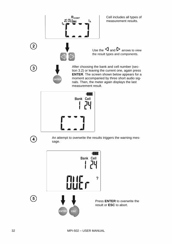
Cell includes all types of measurement results.
Use the and arrows to view
the result types and components.
After choosing the bank and cell number (sec-tion 3.2) or leaving the current one, again press
ENTER. The screen shown below appears for a moment accompanied by three short audio sig-nals. Then, the meter again displays the last measurement result.
An attempt to overwrite the results triggers the warning mes-
sage.
Press ENTER to overwrite the
result or ESC to abort.

MPI-502 – USER MANUAL 33
Notes: - In case of RCD’s, this warning will be displayed also when an attempt is made to enter a given result
type (component) of the measurement made at a different set In current or for a different set RCD
type (ordinary/ selective) than the results saved in this cell. Entering the results for a different In cur-rent or other RCD type will cause deletion of all previously saved results for a given RCD. - The saved data include a complete set of results (main and additional) for a given measurement function plus the set measurement parameters.
3.2 Changing the cell and bank number
After the measurement, press
ENTER. The meter is in the memory enter mode.
The cell number is flash-ing.
Use the SET/SEL button to set the active (flashing) cell or bank number.
Use the and ar-rows to change the cell or bank number.
3.3 Browsing the memory
Switch on the meter. Set the dial switch to the MEM position.
The content of last saved cell is displayed. The cell number is flashing. The bank and cell number which you wish to browse is changed with
the SET/SEL button and then with
the and arrows. If the cell/ bank number is flashing, it can be changed.

MPI-502 – USER MANUAL 34
The sequence of saving the individual measurement results is given in the table below:
Item Measurement function (result group)
Component results
1 ZL-N, L-L
ZL-N or ZL-L and UL-N or UL-L
IK
R
XL
2 ZL-PE lub ZL-PE RCD
ZL-PE and UL-PE
IK
R
XL
3 RCONT R
RCD
UB
RE
tA at 0,5In,
tA at 0,5In,
tA at 1In,
tA at 1In,
tA at 2In,
tA at 2In,
tA at 5In,
tA at 5In,
IA,
IA,
tAI, (absence for RCD AUTO)
tAI, (absence for RCD AUTO)
as above (12 rows) for pulsating current
i

MPI-502 – USER MANUAL 35
3.4 Clearing the memory
3.4.1 Clearing the bank
Switch on the meter. Set the dial switch to the MEM position.
Set the number of bank to be cleared as described in 3.2. Set the cell number to
(before 1). The message appears, signal-ing that the meter is ready to delete.
Press ENTER.
The and symbols appear, requiring confirma-tion.
Press ENTER to start deleting or ESC to abort.
The deletion pro-gress is shown on the screen as scroll-ing cell numbers. When deletion is completed, the me-ter generates three short audio signals and sets the cell number to 1.

MPI-502 – USER MANUAL 36
3.4.2 Clearing the whole memory
Switch on the meter. Set the dial switch to the MEM position.
Set the bank number to
(before 0). The mes-sage appears, signaling that the meter is ready to delete.
Press ENTER.
The and symbols appear, requiring confirma-tion.
Press ENTER to start deleting or ESC to abort.
The deletion pro-gress is shown on the screen as scrolling bank and cell numbers. When deletion is completed, the meter generates three short audio signals and sets the cell number to 1.

MPI-502 – USER MANUAL 37
3.5 Communication with computer
3.5.1 Package for cooperation with computer
In order to ensure the communication of the meter with a computer, Bluetooth/OR-1 module is re-
quired with an additional software. A program that may be used for this purpose is Sonel Reader. It allows users to read and display the measurement data stored in the meter memory. This program may be downloaded free from the manufacturer's website: www.sonel.pl. It is also provided on DVD, supplied with the meter. Information on the availability of other programs cooperating with the meter may be obtained from the manufacturer or its authorized distributors. The software may be used for many devices manufactured by SONEL S.A. which are equipped with the USB interface and/or wireless module. Detailed information regarding software is available from the manufacturer or an authorised dis-tributor.
3.5.2 Data transmission with Bluetooth 4.2 module
The feature is available in meters with serial number prefix EE.
Switch on the meter. Set the dial switch to the MEM position.
Press the SET/SEL button (for about 2 sec). The following screen appears, in-quiring about initiation of wireless communication.
Press ENTER. The wireless communi-cation screen will appear.
MPI-502 – USER MANUAL 38
Connect Bluetooth module to the USB socket of the PC, unless it is integrated into the PC.
During the process of pairing the meter with a PC enter PIN code compatible with the PIN code of the meter defined in main settings.
On the computer start data storing programme. To transmit the da-ta, follow the instruction from your software.
Press ESC to exit the communication mode.
Standard pin for Bluetooth is the „0123”. Settings in the meter according to section 2.2.
3.5.3 Data transmission
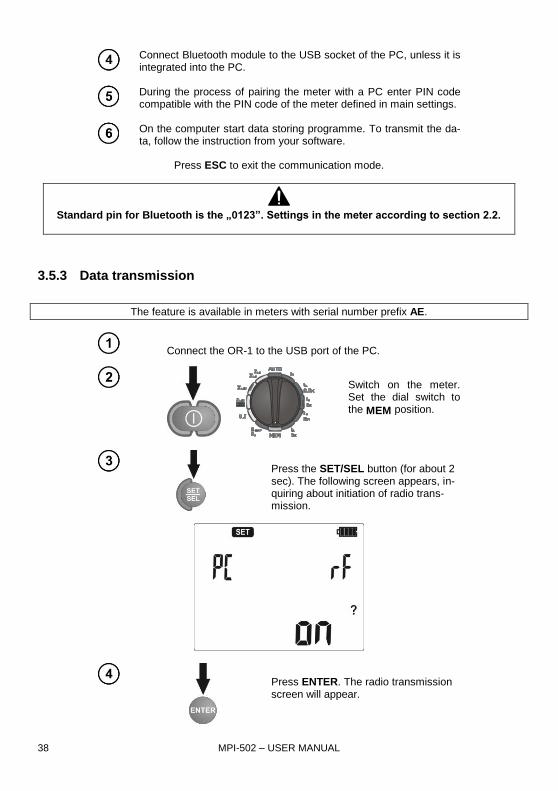
The feature is available in meters with serial number prefix AE.
Connect the OR-1 to the USB port of the PC.
Switch on the meter. Set the dial switch to the MEM position.
Press the SET/SEL button (for about 2 sec). The following screen appears, in-quiring about initiation of radio trans-mission.
Press ENTER. The radio transmission screen will appear.

MPI-502 – USER MANUAL 39
To transmit the data, follow the instruction from your software. Press ESC to exit the communication mode.
Note:
Standard pin for OR-1 is the „123”. Settings in the meter according to section 2.2.
4 Troubleshooting
Before sending the instrument for repairs, call our service. Perhaps the meter is not damaged, and the problem has been caused by some other reasons.
The meter can be repaired only at outlets authorized by the manufacturer. Troubleshooting of typical problems during the use of the meter is described in the table below.
Measurement
function Symptom Cause Action
All The meter will not switch
off with the button. The symbol appears during voltage measure-ment. The meter switches off during preliminary test.
Discharged or incorrectly placed batteries.
Check if the batteries are placed correctly; replace or charge the batteries. If this has not helped, send the meter for repair.
Measurement errors after the meter has been trans-ferred from cold envi-ronment to warm and humid one.
No acclimatization Do not make measurement until the meter reaches the ambient temperature (about 30 minutes) and dries.
Fault loop and
RCD
Successive results in the same measurement point are significantly different
Incorrect connections in the tested installation
Check and remove the de-fects
Mains with a lot of dis-turbance or unstable voltage
Make more measurements, average the results

MPI-502 – USER MANUAL 40
Measurement
function Symptom Cause Action
Fault loop The meter indicates the values close to zero or ze-ro irrespective of the measurement location, and displayed values are signif-icantly different than ex-pected
Incorrectly chosen test leads in the meter set-tings
RCD During the touch voltage or earth resistance measurement, the RCD trips (RCD trips at only
40% of the In set).
In set too high Set correct In
Relatively high leakage currents in the installation
Reduce the leakage cur-rents
Defects in the installation Verify the correctness of N and PE connections
The RCD does not trip during the tripping test
In set too low Set correct In
Incorrectly set current waveform
Set correct current wave-form
Damaged RCD test the RCD with the TEST button; replace if necessary
Defects in the installation Verify the correctness of N and PE connections
During the tripping cur-rent measurement, the
symbol is displayed
even if the RCD has tripped.
The RCD tripping time is longer than the meas-urement time.
RCD should be considered defective.
Large differences be-tween repeated meas-urements of the RCD tripping time
Pre-magnetization of the transformer core inside the RCD
Normal for some direct ac-tion residual current devic-es; try to make next meas-urements at reversed polar-ity of the residual current.
Measurement of tA or IA is impossible
Touch voltage generated during the tA or IA, meas-urement may exceed the safe voltage level – the measurement is automat-ically blocked
Check connections in the protective conductor
Verify correct RCD selec-tion in terms of rated resid-ual current
In set too high Set correct In
Unstable UB or RE meas-urement results, i.e. suc-cessive results in the same measurement point are significantly different
Significant leakage cur-rents, highly variable
The symbol is not
displayed even if the voltage between the con-
tact electrode and the PE
conductor exceeds the detector tripping thresh-old (about 50V)
Contact electrode does not function well or the meter’s input circuits are damaged
Sent the meter for repair; use of defective meter is
not permitted
Dial switch is not set cor-rectly
Contact electrode is active for the measurements of earth loop parameters and RCD, with the exception of the ZL-N,L-L UL-N,L-L function

MPI-502 – USER MANUAL 41
5 Power supply
5.1 Monitoring the power supply voltage
The batteries charging level is indicated by the symbol located in the top right-hand corner of the screen:
Batteries charged.
Batteries discharged.
Replace or charge the batteries! Remember that:
the message on the display indicates insufficient power supply voltage and the need to re-place or charge the batteries,
the measurements made with the meter with insufficient power supply voltage have additional measurement error which is impossible to be estimated by the user.
5.2 Replacing the batteries
The power supply of the MPI-502 meter is from four LR6 alkaline batteries or four NiMH recharge-able batteries (size AA). The batteries are in an compartment in the bottom part of the casing.
WARNING:
Before replacing the batteries, disconnect the test leads from the meter.
To replace the batteries: 1. Disconnect the leads from the measurement circuit and switch off the meter. 2. Unscrew the bolt fastening the battery compartment cover (in the bottom part of the casing). 3. Replace all batteries. Observe correct polarity when putting new batteries (“-“ at the spring part of
the contact plate). Reversed polarity of the batteries will not damage the meter or the batteries, but the meter will not work.
4. Put the cover in place and fasten it with the bolt.
NOTE!
After replacement of batteries, set the power supply type in the main menu be-
cause correct charging level indication depends on this. Discharging characteris-
tics of batteries and rechargeable batteries are different.
NOTE!
If batteries leak in the compartment, send the meter to the service outlet.
Rechargeable batteries should be charged in an external charger.

MPI-502 – USER MANUAL 42
5.3 General rules of using the Nickel Metal Hydride (Ni-MH) batteries
- If you are not going to use the instrument for a longer time, remove the rechargeable batteries and store them separately. - Store the rechargeable batteries in a dry, cool and well ventilated place and protect them from direct sunlight. The long storage temperature should be below 30 degrees C. If the batteries are stored long at high temperatures, the chemical processes may reduce their life. - The NiMH rechargeable batteries usually withstand 500-1000 charging cycles. Such batteries achieve full capacity after forming (2-3 discharging and charging cycles). The most important factor which influences the battery life is the discharge level. The deeper the discharge level, the shorter the battery life. - The memory effect appears in the NiMH batteries in a limited scope. These batteries can be re-charged without more serious consequences. It is, however, recommended to discharge them com-pletely every few cycles.
- During the storage of the Ni-MH rechargeable batteries, they are subject to self-discharge process at the rate of about 30% a month. Keeping the batteries at high temperatures may accelerate this pro-cess even two times. In order not to allow an excessive discharging of the batteries (after which the forming will be needed), recharge the batteries once in a while (even unused batteries). - Modern, fast chargers detect too low and too high temperature of the batteries and respond accord-ingly. If the temperature is too low, the charging process should not start as it might irrevocably dam-age a rechargeable battery. The battery temperature increase is a signal to stop the charging and is typical. In addition to faster temperature increase of a battery which will not be fully charged, charging at high ambient temperatures results, however, in a reduced life. - Remember that with fast charging, the batteries are charged to about 80% of their capacity; better results can be achieved by continuing the charging process: the charger then goes into the small cur-rent charging mode and after a few hours the batteries are fully charged. - Do not charge and do not use the batteries at extreme temperatures as they reduce the life of batter-ies. Avoid using the battery-powered devices in very hot places. The rated operating temperature must be observed at all times.
6 Cleaning and maintenance
NOTE!
Use only the maintenance methods presented by the manufacturer in this
manual.
Clean the meter casing and the case with a wet cloth, using generally available detergents. Do not use any solvents and cleaning media which could scratch the casing (powder, paste, etc.). The probes can be cleaned with water and then wiped dry. Before longer storage, it is recom-mended to lubricate the probes with any machine grease. Clean the spools and leads with water and detergents, then wipe dry. The meter electronic system is maintenance free.

MPI-502 – USER MANUAL 43
7 Storage
When storing the instrument, observe the following recommendations:
disconnect all leads from the meter,
thoroughly clean the meter and all accessories,
wind long test leads onto the spools,
if you are not going to use the instrument for a longer time, remove the batteries,
during a prolonged storage recharge the batteries from time to time to prevent total discharging.
8 Dismantling and disposal
Used electric and electronic equipment should be collected selectively, i.e. not placed with other types of waste.
Used electronic equipment shall be sent to the collection point according to the Used Electric and Electronic Equipment Act.
Before sending the instrument to the collection point, do not dismantle any parts by yourself. Observe local regulations on disposal of packagings and used batteries.
9 Technical specification
9.1 Basic information
“m.v.” abbreviation in determination of basic uncertainty means a standard measured value.
Voltage measurement
Range Resolution Basic uncertainty
0.0...299.9V 0.1V (2% m.v. + 6 digits)
300...500V 1V (2% m.v. + 2 digits)
Frequency range: 45...65Hz
Frequency measurement
Range Resolution Basic uncertainty
45.0...65.0Hz 0.1Hz (0,1% m.v. + 1 digit)
Voltage distribution: 50...500V
ZL-PE, ZL-N, ZL-L fault loop impedance measurement
ZS fault loop impedance measurement Measurement range according to IEC 61557:
Test lead Measurement range ZS
1,2m 0,13...1999
5m 0,17...1999
10m 0,21...1999
20m 0,29...1999
WS-01, -05 0,19...1999

MPI-502 – USER MANUAL 44
Display ranges:
Display range Resolution Basic uncertainty
0...19.99 0.01 (5% m.v. + 3 digits)
20.0...199.9 0.1 (5% m.v. + 3 digits)
200...1999 1 (5% m.v. + 3 digits)
Rated operating voltage UnL-N/ UnL-L: 220/380V, 230/400V, 240/415V
Voltage operating range: 180…270V (dla ZL-PE i ZL-N) and 180…460V (for ZL-L)
Mains rated frequency fn: 50Hz, 60Hz
Frequency operating range: 45…65Hz
Maximum test current: 7.6A dla 230V (3x10ms), 13.3A for 400V (3x10ms)
Check of PE terminal connection correctness with the contact electrode (for ZL-PE)
Readings of fault loop impedance RS and fault loop reactance XS
Display range Resolution Basic uncertainty
0..19.99 0.01 (5% + 5 digits) of ZS value
20.0..199.9 0.1 (5% + 5 digits) of ZS value
Calculated and displayed values ZS<200
Readings of short-circuit current IK Measurement ranges according to IEC 61557 can be calculated from the measurement ranges ZS and rated voltages.
Display range Resolution Basic uncertainty
0.110…1.999A 0.001 A
Calculated on the basis of uncertainty for the fault loop
2.00...19.99A 0.01 A
20.0...199.9A 0.1 A
200...1999A 1 A
2.00...19.99kA 0.01 kA
20.0…40.0kA 0.1 kA
Prospective fault current calculated and displayed by the meter may slightly differ from the val-ue calculated by the user with a calculator, basing on the displayed value of the impedance, because the meter calculates the current from unrounded value of fault loop impedance (which is used for displaying). As the correct value, consider Ik current value, displayed by the meter or by firmware.
ZL-PE fault loop impedance measurement RCD (without tripping the RCD)
ZS fault loop impedance measurement
Measurement range according to IEC 61557: 0.5…1999 for the 1.2m, WS01 and WS05 leads, and
0.51...1999 for the 5m, 10m and 20m leads
Display range Resolution Basic uncertainty
0...19.99 0.01 (6% m.v. + 10 digits)
20.0...199,9 0.1 (6% m.v. + 5 digits)
200...1999 1 (6% m.v. + 5 digits)
Does not trip the RCD’s with IΔn ≥ 30mA
Rated operating voltage Un: 220V, 230V, 240V
Voltage operating range: 180…270V
Mains rated frequency fn: 50Hz, 60Hz
Frequency operating range: 45…65Hz
Check of PE terminal connection correctness with the contact electrode

MPI-502 – USER MANUAL 45
Readings of fault loop impedance RS and fault loop reactance XS
Display range Resolution Basic uncertainty
0..19.99 0.01 (6% + 10 digits) of ZS value
20.0..199.9 0.1 (6% + 5 digits) of ZS value
Calculated and displayed values ZS<200
Readings of short-circuit current IK Measurement ranges according to IEC 61557 can be calculated from the measurement ranges ZS and rated voltages.
Display range Resolution Basic uncertainty
0.110…1.999A 0.001 A
Calculated on the basis of uncertainty for the fault loop
2.00...19.99A 0.01 A
20.0...199.9A 0.1 A
200...1999A 1 A
2.00...19.99kA 0.01 kA
20.0…24.0kA 0.1 kA
Prospective fault current calculated and displayed by the meter may slightly differ from the val-ue calculated by the user with a calculator, basing on the displayed value of the impedance, because the meter calculates the current from unrounded value of fault loop impedance (which is used for displaying). As the correct value, consider Ik current value, displayed by the meter or by firmware.
Measurement of the RCD parameters
Rated operating voltage Un: 220V, 230V, 240V
Voltage operating range: 180…270V
Mains rated frequency fn: 50Hz, 60Hz
Frequency operating range: 45…65Hz
RCD tripping test and tA tripping time measurement (for tA measurement function) Measurement range according to IEC 61557: 10ms ... to the upper limit of displayed value
RCD type Multiplication
factor setting
Measurement
range Resolution Basic uncertainty
general
0,5 In 0..300ms
1 ms ± 2% m.v. ±2 cyfry1)
1 In
2 In 0..150ms
5 In 0..40ms
selective
0,5 In 0..500ms
1 In
2 In 0..200ms
5 In 0..150ms 1) for In = 10mA and 0,5 In the uncertainty is ± 2% m.w. ±3 digits
Residual current feed accuracy:
for 1*In, 2*In and 5*In ..................................................................... 0..8%
for 0,5*In .................................................................................... –8..0%

MPI-502 – USER MANUAL 46
RMS leakage current during the RCD tripping time measurement
In
Multiplication factor setting
0,5 1 2 5
10 5 3,5 10 20 20 40 50 100
30 15 10,5 30 42 60 84 150 210
100 50 35 100 140 200 280 500
300 150 105 300 420
500 250 175 500
RE - protective conductor resistance for RCD
Selected RCD
rated current
Measurement
range Resolution Test current Basic uncertainty
10 mA 0.01k
..5.00 k 0,01 k
4 mA 0...+10% m.v ±8 digits
30 mA 0,01k
..1.66k 12 mA
0...+10% m.v. ±5 digits
100 mA 1 ..500
1
40 mA 0...+5% m.v. ±5
digits 300 mA 1 ..166 120 mA
500 mA 1 ..100 200 mA
Measurement of touch voltage UB refererd to rated residual current
Measurement range according to IEC 61557: 10...50V
Measure-
ment range Resolution Test current Basic uncertainty
0..9,9V 0.1 V 0.4 x In
0..10% m.v. ± 5 dig-its
10.0..99.9V 0..15% m.v.
RCD IA tripping current measurement for sinusoidal residual current Measurement range according to IEC 61557: (0.3...1,0)IΔn
Selected RCD
rated current
Measurement
range Resolution Test current
Basic uncertain-
ty
10 mA 3.0..10.0mA 0,1 mA
0,3 x In..1,0 x In 5 % In
30 mA 9,0..30,0 mA
100 mA 30..100 mA
1 mA 300 mA 90..300 mA
500 mA 150..500 mA
It is possible to start the measurement from positive or negative half-period of forced residual cur-rent
Test current flow time ............................... max. 3200 ms
RCD IA tripping current measurement for unidirectional pulsating residual current
Measurement range according to IEC 61557: (0.4...1,4)In for In≥30mA and (0,4...2)In for In=10mA
Selected RCD
rated current
Measurement
range Resolution Test current
Basic uncer-
tainty
10mA 4.0..20.0mA 0.1mA
0,35 x In..2,0 x In 10 % In 30mA 12.0..42.0mA
0,35 x In..1,4 x In 10 % In 100mA 40..140mA 1mA
300mA 120..420mA
It is possible to start the measurement from positive or negative half-period of forced residual current
Test current flow time ............................... max. 3200 ms

MPI-502 – USER MANUAL 47
Low-voltage continuity and resistance measurement
Continuity measurements of protective conductors and equipotential bonding with the
200mA current
Measurement range according to IEC 61557-4: 0,12…400
Range Resolution Basic uncertainty
0,00...19,99 0,01
(2% m.v. + 3 digits) 20,0...199,9 0,1
200...400 1
Voltage on open terminals: 4…9V
Output current at R<2: min 200mA (ISC: 200...250mA)
Test leads resistance compensation
Measurements for both current polarities
Low-current resistance measurement
Range Resolution Basic uncertainty
0.0...199.9 0.1 (3% m.v. + 3 digits)
200...1999 1
Voltage on open terminals: 4…9V
Short-circuit current ISC: <8mA
Audio signal for measured resistance < 30 ± 50%
Test leads resistance compensation
Other technical specifications a) Insulation type ..................................................... double, according to EN 61010-1 and IEC 61557 b) Measurement category ................................................ IV 300V (III 600V) according to EN 61010-1 c) casing protection rating according to EN 60529 ........................................................................ IP67 d) meter power supply .............. LR6 alkaline batteries or AA size NiMH rechargeable batteries (4pcs) e) dimensions .............................................................................................................. 220x98x58 mm f) meter weight ................................................................................................................. about 0.6 kg
g) storage temperature ..................................................................................................... –20...+70C
h) operating temperature ...................................................................................................... 0...+50C i) humidity ............................................................................................................................. 20...90%
j) reference temperature ..................................................................................................... +23 ± 2C k) reference humidity ............................................................................................................. 40...60% l) altitude (above sea level) ................................................................................................... <2000 m m) time to Auto-OFF .............................................................................300, 600, 900 seconds or none n) number of Z or RCD measurements (for rechargeable batteries) ....................................................
............................................................................................... >5000 (2 measurements per minute) o) display ........................................................................................................................LCD segment p) measurement results memory .................................................................... 990 cells, 10000 entries q) transmission of results ....................................................... radio interface, waveband ISM 433 MHz r) quality standard ........... development, design and manufacture according to ISO 9001, ISO 14001,
PN-N-18001 s) instrument conforming to IEC 61557 t) product meets the EMC requirements (resistance for industrial environments) according to the
standards ........................................................................................ EN 61326-1 and EN 61326-2-2
MPI-502 – USER MANUAL 48
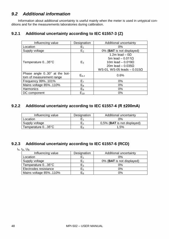
9.2 Additional information
Information about additional uncertainty is useful mainly when the meter is used in untypical con-ditions and for the measurements laboratories during calibration.
9.2.1 Additional uncertainty according to IEC 61557-3 (Z)
Influencing value Designation Additional uncertainty
Location E1 0%
Supply voltage E2 0% (BAT is not displayed)
Temperature 0...35°C E3
1.2m lead – 0Ω 5m lead – 0.011Ω 10m lead – 0.019Ω 20m lead – 0.035Ω
WS-01, WS-05 leads – 0.015Ω
Phase angle 0..30° at the bot-tom of measurement range
E6.2 0.6%
Frequency 99%..101% E7 0%
Mains voltage 85%..110% E8 0%
Harmonics E9 0%
DC component E10 0%
9.2.2 Additional uncertainty according to IEC 61557-4 (R ±200mA)
Influencing value Designation Additional uncertainty
Location E1 0%
Supply voltage E2 0,5% (BAT is not displayed)
Temperature 0...35°C E3 1,5%
9.2.3 Additional uncertainty according to IEC 61557-6 (RCD)
IA, tA, UB
Influencing value Designation Additional uncertainty
Location E1 0%
Supply voltage E2 0% (BAT is not displayed)
Temperature 0...35°C E3 0%
Electrodes resistance E5 0%
Mains voltage 85%..110% E8 0%
MPI-502 – USER MANUAL 49
10 Accessories
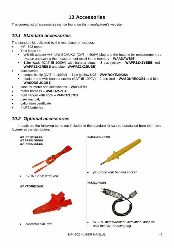
The current list of accessories can be found on the manufacturer's website.
10.1 Standard accessories
The standard kit delivered by the manufacturer includes:
MPI-502 meter
Test leads kit: WS-05 adapter with UNI-SCHUKO (CAT III 300V) plug and the buttons for measurement ac-
tivation and saving the measurement result in the memory – WAADAWS05
1.2m leads (CAT III 1000V) with banana plugs – 3 pcs (yellow – WAPRZ1X2YEBB, red -
WAPRZ1X2REBB and blue - WAPRZ1X2BUBB)
accessories
crocodile clip (CAT III 1000V) – 1 pc (yellow K02 – WAKROYE20K02)
blade probe with banana socket (CAT III 1000V) – 2 pcs (red – WASONREOGB1 and blue –
WASONBUOGB1)
case for meter and accessories – WAFUTM6
meter harness – WAPOZSZE4
rigid hanger with hook – WAPOZUCH1
user manual,
calibration certificate
4 LR6 batteries
10.2 Optional accessories
In addition, the following items not included in the standard kit can be purchased from the manu-facturer or the distributors:
WAPRZ005REBB WAPRZ010REBB
WAPRZ020REBB
5 / 10 / 20 m lead, red WAKRORE20K02
crocodile clip, red
WASONYEOGB1
pin probe with banana socket WAADAWS01
WS-01 measurement activation adapter
with the UNI-Schuko plug
MPI-502 – USER MANUAL 50
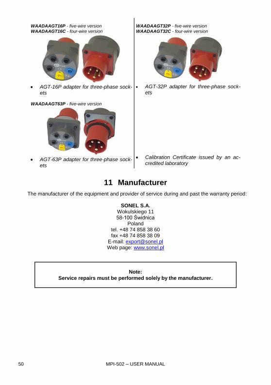
WAADAAGT16P - five-wire version
WAADAAGT16C - four-wire version
AGT-16P adapter for three-phase sock-
ets
WAADAAGT63P - five-wire version
AGT-63P adapter for three-phase sock-
ets
WAADAAGT32P - five-wire version
WAADAAGT32C - four-wire version
AGT-32P adapter for three-phase sock-
ets
Calibration Certificate issued by an ac-credited laboratory
11 Manufacturer
The manufacturer of the equipment and provider of service during and past the warranty period:
SONEL S.A. Wokulskiego 11 58-100 Świdnica
Poland tel. +48 74 858 38 60 fax +48 74 858 38 09
E-mail: [email protected] Web page: www.sonel.pl
Note:
Service repairs must be performed solely by the manufacturer.
MPI-502 – USER MANUAL 51
12 Laboratory services
SONEL Testing and Calibration Laboratory has been accredited by the Polish Center for Accreditation (PCA) - certificate no. AP 173. Laboratory offers calibration for the following instruments that are used for measuring electrical and non-electrical parameters.
● METERS FOR MEASUREMENTS OF ELECTRICAL PARAMETERS
o voltage meters,
o current meters (including clamp meters),
o resistance meters,
o insulation resistance meters,
o earth resistance and resistivity meters,
o RCD meters,
o short-circuit loop impedance meters,
o power quality analyzers,
o portable appliance testers (PAT),
o power meters,
o multimeters,
o multifunction meters covering the functions of the above-mentioned instruments,
● ELECTRICAL STANDARDS
o calibrators,
o resistance standards,
● METERS FOR MEASUREMENTS OF NON-ELECTRICAL PARAMETERS
o pyrometers,
o thermal imagers,
o luxmeters.
The Calibration Certificate is a document that presents a relation between the calibration standard of known accuracy and meter indications with associated measurement uncertainties. The calibration standards are normally traceable to the national standard held by the National Metrological Institute. According to ILAC-G24 „Guidelines for determination of calibration intervals of measuring instru-ments”, SONEL S.A. recommends periodical metrological inspection of the instruments it manufac-tures no less frequently than once every 12 months. For new instruments provided with the Calibration Certificate or Validation Certificate at the factory, re-calibration should be performed within 12 months from the date of purchase, however, no later than 24 months from the date of purchase.
ATTENTION !
The person performing the measurements should be absolutely sure about the efficiency of
the device being used. Measurements made with an inefficient meter can contribute to an in-
correct assessment of the effectiveness of health protection and even human life.

MPI-502 – USER MANUAL 52
NOTES