Exploitation of a parallel clustering algorithm on commodity hardware with P2P-MPI
Upload
independentCategory
view
2download
0
TMD-MPI for HPRCsManuel Saldana∗, Arun Patel∗, Christopher Madill§, Daniel Nunes†, Danyao Wang†,
Henry Styles‡, Andrew Putnam‡, Ralph Wittig‡, Paul Chow†∗Arches Computing Systems, Ontario, Canada
Email:{ms,ap}@archescomputing.com†University of Toronto, Department of Electrical and Computer Engineering, Ontario, Canada
Email:{cmadill,dnunes,wangda,pc}@eecg.toronto.edu§University of Toronto, Department of Biochemistry, Ontario, Canada
Email:{chris.madill}@utoronto.ca‡Xilinx, San Jose, California, USA
Email:{ralph.wittig, henry.styles, andrew.putnam}@xilinx.com
Abstract—High Performance Reconfigurable Computers(HPRCs) consist of one or more standard microprocessorstightly coupled with one or more reconfigurable FPGAs.HPRCs have been shown to provide good speedups and goodcost/performance ratios, but not necessarily ease of use, leadingto a slow acceptance of this technology. HPRCs introducenew design challenges, such as the lack of portability acrossplatforms, incompatibilities with legacy code, users reluctant tochange their code base, a prolonged learning curve, and the needfor a system-level Hardware/Software co-design developmentflow. This paper presents the evolution and current work onTMD-MPI, which started as an MPI-based programming modelfor Multiprocessor Systems-on-Chip implemented in FPGAs,and has now evolved to include multiple X86 processors.TMD-MPI is shown to address current design challenges inHPRC usage, suggesting that the MPI standard has enoughsyntax and semantics to program these new types of parallelarchitectures. Also presented is the TMD-MPI Ecosystem, whichconsists of research projects and tools that are developed aroundTMD-MPI to further improve HPRC usability.
I. INTRODUCTION
Portability in a typical High-Performance Computer (HPC)is achieved by using standards-based operating systems andsoftware layers (Middleware) that abstract machine-specifichardware from the software application, as shown in Figure 1on the left. The UNIX operating system (and its variants) andthe MPI [1] library are examples of those de-facto standardsthat enabled portable parallel applications across HPCs. ForHPRC designs to be truly portable, these concepts must beextended to the FPGAs, as they are now part of the application.Figure 1 shows how portability for HPRCs must come fromtwo sides: application software and application hardware.
For HPRC’s, the hardware operating system and hardwaremiddleware should provide a standard abstraction for applica-tion hardware engines to access host-specific resources, suchas external memory and communications. Examples of thesehost-specific communication resources are the X86-FPGAcommunication mediums, such as Intel’s Front Side Bus (FSB)or QuickPath [2], AMD’s HyperTransport [3], Cray’s RapidArray Transport [4], SGI’s Scalable System Port–NUMA linkconnection [5], or even PCI Express. Companies such as Cray,SGI, Intel, Nallatech, XtremeData, DRC and SRC provide
their own low-level software APIs and their own hardwareinterfaces for application hardware engines. HPRCs are nowin a similar stage as HPCs were before the appearance ofMPI [1] when every vendor had their own message-passingAPI to program their own supercomputers causing a lack ofportable designs. Currently, there is no implemented standardAPI for a high-level parallel programming model that includesthe interaction between X86 processors and FPGAs. Thereis, however, interesting progress done by the OpenFPGA[6]organization on this matter, which is compared against thiswork in Section V.
SW Application
SW Middleware
SW OS
HW Application
HW Middleware
HW OS
OS
Application
Middleware
Host-specific
Hardware
Host-specific
Hardware
X86s
FPGAs
Typical HPCs For HPRCs
Fig. 1. Comparison between HPC and HPRC abstraction layers
Previous work proposed TMD-MPI [7], [8], [9], [10] asa subset implementation of the MPI standard targeting Mul-tiprocessor System-on-Chip implementations across multipleFPGAs to abstract hardware details from the user as wellas to provide a well-known, high-level parallel programmingAPI. In three years, TMD-MPI has evolved in a bottom-upapproach to the point where it provides software and hardwaremiddleware layers of abstraction for communications to enablethe portable interaction between embedded processors, special-ized hardware computing engines and now X86 processors;all programmed under the same message passing paradigmmaking it a unified programming model for HPRCs.
This paper provides a summary of TMD-MPI’s philosophyand evolution, followed by a discussion of the new additions,current work and supporting tools and research projects calledthe “TMD-MPI ecosystem”. It is hoped that these research ef-

forts generate discussion in the community regarding whetherMPI is a good model for HPRCs or not, influencing perhapsexisting MPI implementations to include FPGA support. It istime to consider how to include acceleration technologies, suchas FPGAs, GPUs and CELL processors into a potential MPI-3 accelerator-aware standard because accelerator technologiesalso have data movement and synchronization requirements.
The rest of the paper is organized as follows. Section IIexplains the motivations that led to the development and use ofTMD-MPI. In Section III an updated version of the design flowbased on recent work is presented. Section IV provides a realexample of portability based on experiences using TMD-MPI.Section V contrasts TMD-MPI with related work regardingX86-FPGA communication. Section VI describes TMD-MPI’sarchitecture and HPRC reference platform. In Section VII, thecurrent functionality of TMD-MPI is described. Section VIIIpresents a synopsis of the projects that constitute the TMD-MPI Ecosystem. Finally, some concluding remarks are givenin Section IX.
II. MOTIVATION
TMD-MPI was initially developed to address the need fora programming model for the TMD machine being developedat the University of Toronto [10]. The TMD machine is ascalable Multi-FPGA configurable system designed to accel-erate computing intensive applications. The basic assumptionis that FPGAs have enough resources to implement entireapplications, as opposed to only parts of computations, suchas small computing kernels. The objective is to have a tightlycoupled mix of embedded processors (for control intensiveparts of the application) and specialized hardware engines (toaccelerate the compute-intensive parts of the application) allwithin the same FPGA or distributed among many FPGAs.
With multiple embedded processors and hardware engines(collectively referred to in this paper as computing elements,or CEs) interacting across multiple FPGAs, there is a needfor a networking infrastructure and a distributed programmingmodel. Most multi-FPGA systems have distributed memory(usually, each FPGA has its own external memory), and insideeach FPGA there might be multiple CEs, each with theirown local memory; hence, a programming model such asMPI seems adequate. With the appearance of tightly-coupledFPGAs and X86 processors sharing the main system mem-ory [11], [12], [13], [14], [15], TMD-MPI has been extended toinclude communication with X86 processors, marking TMD-MPI’s entrance to the HPRC world.
Figure 2 shows the generic model of a HPRC machine. Itis possibly a multi-host machine, where each host can haveone or more X86 processors and one or more FPGAs, eachprocessor with one or more X86 cores, and each FPGA withone or more computing elements inside. Note that in thismodel two or more FPGAs can indirectly share the sameconnection point to the host’s internal interconnection system(FPGAs 1, 2 and 3 share a connection). TMD-MPI shows thatthe MPI standard is a reasonable abstraction for addressing thecommunication and synchronization of such architectures.
X86 Multicore Host’s
Main
System
Memory
(Shared)
. . .
FPGA 1
FPGA 3FPGA 2
FPGA 0
X86 Multicore
Host’s Internal Interconnection System
Host 1
Host 2
Host N
. . .
. . .
Inte
r-H
ost
Ne
two
rk
Fig. 2. HPRC generic model
There are two challenges when programming an applicationfor this HPRC model. The first is the high-level, coarse-grainparallelization of the application, where decisions inherent tothe parallel algorithm, such as data partitioning, synchroniza-tion and load balancing are made. The second challenge is theefficient use of the available FPGAs, where low-level decisionsare taken, such as the number of pipeline stages, type offloating-point support and mapping a digital design to chipresources. A fully-automated flow for HPRCs that parallelizesan application and at the same time converts it into hardwareis a double challenge. This is especially true if a non-parallel-friendly, non-hardware-friendly language is used, such as C.
Perhaps at some point projects on high-productivity parallelprogramming languages, such as Chapel [16], X10 [17] andFortress [18] can cooperate with tools that automaticallygenerate HDL, such as ImpulseC [19], HandelC [20], Syn-fora [21], MitrionC [22], etc., to provide a fully-automatedflow that overcomes the extraordinary challenges of program-ming HPRCs.
In the meantime, efficient applications for HPRCs have to bedeveloped by a multidisciplinary team: a hardware engineer,a software engineer, and the application expert. The proposedapproach is to deal with the two HPRC programming chal-lenges independently. By parallelizing the code using MPI, theentire application is partitioned into smaller and simpler piecesof code, leaving the C-to-HDL tool (or hardware engineer)the easier task of turning into hardware more confined piecesof code. Writing high-level parallel code is still easier thanwriting low-level HDL code, so this approach is of great helpto the non-hardware knowledgeable user. The experience ofusing TMD-MPI shows that MPI applied to FPGAs offersa convenient and clean interface between hardware (HDL)designers and software developers that allows independentprogress of both due to the standard interface and well-defined semantics. Pragmatically, HPRCs exist now and the

user community cannot wait for fully automated tools tomagically appear and make them trivial to use. TMD-MPIand its surrounding ecosystem are examples of tools that existtoday.
III. DESIGN FLOW
As previously discussed, the two major challenges to im-plementing an application on HPRCs are coarse-grain paral-lelization and HDL coding. To address these challenges, a top-down, step-by-step design flow was developed to implementapplications using HPRCs. Figure 3 illustrates the updatedversion of the flow that was first introduced by Patel et.al. [10]. This new version includes the X86-FPGA interaction.
Step 1 begins by developing a prototype of the application ina high-level programming language such as C/C++. The result-ing code is sequential in nature and is only intended to providea prototype solution to the computing problem. At this stage,the application can be profiled to identify computationally-intensive routines. The results of this prototype design can becompared to the results of the final system and validate thecorrectness of the implementation at any step during the flow.
MPI Network
ApplicationPrototype
ProcessA
ProcessB
ProcessC
Step 1 - All-X86
Step 2 - All-X86
Step 3 - FPGA-X86 mix
Step 4 - FPGA-X86 mix
ProcessC
TMD_MPE
BA
ProcessCB
Hardware
Engine
Embedded
ProcessorX86 Processor
TMD-MPI Network
TMD-MPI Network
A
Sequential Program
Manual Parallelization
Accelerator Modeling
Accelerator Substitution
Fig. 3. Design Flow with TMD-MPI
Step 2 refines the prototype application by partitioning itinto simple, well-defined processes that can be replicated toexploit the implicit parallelism of the application. At this pointthe user should have at least a hint about what processes arethe most demanding, and therefore candidates for hardwareengines. The user should avoid the use of any operating systemcalls or any feature that a hardware engine could not support.Inter-process communication is achieved using MPI, allowingthe application to be developed and tested at the X86 level.No FPGA is involved yet. This approach has the advantage
of allowing the programmer access to standard tools fordeveloping, profiling and debugging. As an alternative to usingTMD-MPI, other MPI implementations, such as MPICH [23]or OpenMPI [24] can be used, however, the programmer mustuse only the available MPI functions implemented in TMD-MPI (see Section VII). Validation of the parallel algorithmcan be done at this point, by comparing against the sequentialversion.
In Step 3, selected software processes developed in Step 2are recompiled for embedded processors. The rest of theprocesses are still executed by the X86. The portability ofMPI allows the software to be recompiled and executed onthe embedded processors with the code practically unchanged.This is an optional intermediate step where hardware enginesare emulated by embedded processors in the FPGA. At thisstage, execution of the entire application using the FPGAs ispossible. This allows the interaction between X86 processors,embedded processors and emulated computing engines to betested and validated. This step gives the user the opportunityto better exploit communication locality by putting together inthe same FPGA control-intensive processes (embedded proces-sors) and compute-intensive processes (hardware engines) thathave an intense communication pattern.
The final step of the programming flow substitutes al-gorithms executing on embedded processors with hardwareengines. Translating the computationally-intensive processesinto hardware engines is done manually in the current flowusing typical FPGA design tools. However, since the systemhas already been partitioned into individual computing tasksand all communication primitives have been explicitly statedat this stage, C-to-HDL tools may also be used to performthis translation, or as discussedin Section VIII-C, MPI-to-HDLtools are feasible.
Once a computing engine has been designed, an additionalmessage-passing engine (TMD-MPE, Section VI-E) is usedto perform message passing functionality in hardware (e.g.,protocol processing, handling message queues, divide largemessages into packets), which simplifies the design of thecomputing engine. Special versions of the TMD-MPE canalso be used by the embedded processors as a communicationcoprocessor enabling a more efficient data exchange.
IV. AN EXAMPLE OF PORTABILITY AND SCALABILITY
This section gives an example of the portability that TMD-MPI provides to a reconfigurable computing application beingdeveloped in the rapidly evolving field of FPGAs.
For the last three years, research has been conducted atthe University of Toronto in collaboration with the Hospitalfor Sick Children to develop an FPGA-based machine toaccelerate Molecular Dynamics (MD) simulations. These areatomic-level simulations of biomolecular systems used inbiomedical research to design more effective drugs. The devel-opment of this machine began using the Amirix AP1000 PCIdevelopment boards [25]. Each board contains one XC2VP100FPGA, 64 MB of external memory and five serial I/O links,which allowed five of these boards to be fully interconnected.

The MD application coding was in progress when the newBEE2 platform [26] arrived with five XC2VP70 FPGAs perboard, 4 GB of external memory per FPGA, using parallelLVDS lines and 18 high-speed serial links. This platformis obviously more integrated, provides more resources andpotential for acceleration. Consequently, the development ofthe MD application continued on the BEE2 platform. TheMD code was still in progress when the even newer XilinxAccelerated Computing Platform (Xilinx ACP) arrived. Thisplatform has Virtex 5 FPGAs that can be connected directly tothe Intel FSB by inserting them into one of the CPU socketsin the motherboard. The FPGAs are tightly coupled to X86processors sharing 8 GB of memory, opening up more oppor-tunities for acceleration. Currently, the development continuesfor this platform.
The question is how can one develop an application ifthe hardware keeps changing. Furthermore, how can existingcode be isolated from future hardware changes. The impactof these hardware changes on the MD application has beenminimized by using TMD-MPI. Indeed, there were changes,but all of them in the system infrastructure (what is describedas SW/HW OS and SW/HW Middleware in Figure 1), notat the SW/HW application levels. The MD software code(written in C++) and the MD hardware engines (HDL) havebeen mostly the same, changing only in their natural evolutiontowards a more complete MD simulator.
One of the necessary changes was to regenerate someof the core netlists to take advantage of the newer Vir-tex 5 architecture. Another change was computing elementreallocations. The bonded and non-bonded force calculations(particular types of forces in MD) were performed by twodifferent computing elements that were located in the sameFPGA, but when switching from the AP1000 boards to theBEE2 boards the bonded forces compute engine had to bereallocated to another FPGA because the BEE2 board hassmaller FPGAs than the AP1000 board. Moreover, the bondedforce computing element was originally a PowerPC processor,then it became a MicroBlaze soft-processor, but most likely itwill end up being an X86 processor. Through all these changes,TMD-MPI provided tolerance to hardware changes and madeit possible to perform architectural explorations and proposechanges to achieve better performance without impacting theMD application code-base.
Another advantage of using TMD-MPI was the abstractionof the FPGA configuration process, which is usually not aseasy as to run as a typical program, and it is also a completelydifferent procedure between the AP1000 boards, the BEE2boards and the Xilinx ACP. Furthermore, in a HPRC, startingthe execution of a large number of X86 software processesand configuring a large number of FPGAs must be automated.By using mpirun/mpiexec scripts, a difference like this can beminimized and hidden from the user perspective.
V. RELATED WORK
TMD-MPI was created with the influence of the Multipro-cessor System-on-Chip [27] and Network-on-Chip research
fields. Related work of those areas to TMD-MPI is dis-cussed in previous work [8], [9] and briefly mentioned inSection VI-B. In this Section, current APIs for X86-FPGAcommunication are compared with TMD-MPI.
Currently, the most common usage of MPI on HPRCs is atthe host level [28], where X86 processors exchange messagesusing MPI and then forward the received data to the FPGAs,which is a mere slave to the X86 processor. This uses theX86 as a message relay introducing latencies and complicatingthe programming model because the user has to be aware oftwo different APIs: one for message-passing and another forinteracting with the FPGA. This section shows how MPI’shigh-level API can be used instead of low-level API calls toperform X86-FPGA communications, with the added benefitof a broader communication context, more abstraction and afamiliar API, providing a unified programming model. Notethat many features that are available in the MPI standard arenot implemented in TMD-MPI yet, and that certain featuresare not defined in the MPI standard but left open to the imple-mentation. Here references to MPI mean the API itself, andreferences to TMD-MPI means our particular implementationof MPI.
At the time of writing this paper, OpenFPGA has releasedits first General API Specification 0.4 (GenAPI) draft [29].Its objective is to propose an industry standard API for high-level language access to reconfigurable computing resourcesin a portable manner. The draft is an excellent compilation ofcommon X86-FPGA communication requirements for HPRCs.GenAPI shares practically all the same design goals as TMD-MPI, however, there is a fundamental difference: the scopeof the standard. GenAPI only focuses on the low-level X86-FPGA interaction, not making any assumptions on higher levelforms of communication, such as FPGA-initiated transfers,inter-host communications, inter-FPGA communications andintra-FPGA communications. In contrast, the MPI standard isagnostic of the communication media and requires that everyrank (a task in the MPI jargon) be able to initiate transfers atany time regardless of its physical location. In this sense, theFPGA is no longer a passive slave in the system.
Master SlaveX86 (core) X86 (core)X86 (core) FPGA (CE)FPGA (CE) X86 (core)FPGA (CE) FPGA (CE)Host (X86 core or CE) Host (X86 core or CE)
TABLE ITMD-MPI’S COMMUNICATION CAPABILITIES
Similar to GenAPI, HPRC vendors provide their own APIs,but with the same limited scope: X86-FPGA communication,which is a subset of the communications that TMD-MPI isable to provide. Table I summarizes these communication ca-pabilities. TMD-MPI will be able to provide communicationsat the host-to-host level, X86-to-X86 level, FPGA-to-FPGAlevel and intra-FPGA level (CE to CE); and in between these

categories as well. That is, a hardware engine inside an FPGAin one host can exchange data with another hardware engineinside another FPGA in a remote host, without the need of anX86 to start or negotiate the communications.
In TMD-MPI, because of its on-chip origins and itsdistributed nature, achieving multi-level communications isstraightforward. However, to make TMD-MPI portable acrossHPRC platforms, the low-level APIs are needed exclusivelyfor X86-FPGA communication. For example, on the XilinxACP platform a custom low-level API is being used, but inprinciple other APIs could be used, such as Intel’s AAL [30].The GenAPI standardization efforts would help TMD-MPIby not having to implement a different version for eachHPRC low-level API. By looking at some HPRC vendorAPIs [4], [5], [30] and GenAPI, four general categories canbe distinguished in the functions available: Initialization andtermination, FPGA management, data transfer, and memoryallocation. The APIs are driver-like interfaces to the FPGA(open, close, write, read, mmap, etc.), but a system-leveldesign of parallel applications that include FPGAs, needs ahigher-level of abstraction.
Some of the low-level API calls can be easily mapped toMPI calls. For example, MPI function MPI Init() is used toinitialize internal data structures, to open the FPGA deviceand to signal the FPGA to start running. The opposite,MPI Finalize() is used to signal the end of the applicationto the FPGA, remove the internal structures and close theFPGA device. MPI Send(), MPI Isend(), MPI Recv() andMPI Irecv() are used to send/receive data to/from the FPGA ina blocking and non-blocking manner. For memory allocation,MPI provides the MPI Alloc mem() and MPI Free mem()functions to allocate/deallocate memory that the FPGA canaccess. Of course the MPI standard does not define how todownload a bitstream to an FPGA, but this can be left open tothe implementation. Currently in TMD-MPI, downloading abitstream is part of the mpiexec or mpirun commands (butit will be part of TMD-MPI’s process manager in futureversions). An MPI example using some of these functions isshown in Section VI-C.
Another interesting effort trying to bring portability toHPRCs is Vforce [31]. The authors provide a high-levelobject-oriented framework based on the VISPL++ standard,which is a vector and image processing library API. Theirapproach is quite similar to ours in two fundamental points.First, one layer in their framework interacts with the low-level API calls rather than the final user’s code, insulatingthe application from hardware changes. TMD-MPI uses alow-level driver to access the FPGA, not the user’s code,which uses MPI calls. The second similarity is that theyallow domain experts, such as FPGA designers, to createspecialized hardware library components that can be interfacedwith their framework. MPI allows the creation of third-partyparallel libraries, and with TMD-MPI it is possible to havesoftware-hardware parallel libraries that interact based on anapplication-level message-passing protocol.
VI. TMD-MPI ARCHITECTURE
In this section the Xilinx ACP is first presented as anexample of the HPRC model described in Section II. Thenthe mechanism for TMD-MPI data transfers in the ACP usinga mix of shared and distributed memory is explained.
A. HPRC Implementation Platform
TMD-MPI has been used in a variety of platforms, but thefocus here will be on the Xilinx ACP as it is the newestplatform and the current target.
The base system is an instance of the HPRC model shownin Figure 2. It is an Intel quad-socket Server System, theS7000FC4UR. One of the processor sockets has an IntelQuad-core Xeon 7300 processor and the other socket has theXilinx ACP. Currently, the remaining sockets are not used,but more X86 processors or Xilinx ACPs could be added. TheXilinx ACP consists of a stack of up to three PCB layers(modules). The first layer (bottom-up) contains the bridgeFPGA (XC5VLX110) and is physically placed in one of theX86 sockets on the motherboard. Its function is to provide aconnection point to Intel’s FSB and provide communicationsfor the upper-level layers. The second and third layers areknown as dual-compute FPGA modules. Each module containstwo XC5VLX330 FPGAs in the same PCB. All the FPGAsare directly connected by LVDS lines in the same layer andbetween layers. The Xilinx ACP platform and the X86s canshare up to 64 GB of RAM through the FSB, and the machineis running a standard SMP Linux distribution. In this paper thismachine is used as a reference implementation platform forTMD-MPI, but most of the concepts can be applied to otherHPRCs as long as the FPGAs have access to main systemmemory.
B. Intra-FPGA and Inter-FPGA communication
A generic example for a multi-FPGA board is shown inFigure 4. The figure could physically represent five AP1000boards, one BEE2 board or one Xilinx ACP platform withone bridge FPGA and two dual-compute FPGA modules. Thegroup of FPGAs is called an FPGA cluster. The communica-tion is logically divided in Tiers based on its scope.
Tier 1 is the on-chip network that is used to exchangedata between multiple computing elements within the sameFPGA. This network is a set of point-to-point channels (a pairof FIFOs, one for transmission, one for reception), usuallyin a fully-connected topology, but other topologies can beused as well, depending on the communication needs. Thenetwork latency is usually a few clock cycles depending onthe topology. The bandwidth is limited by the FPGA frequencyand the width of the point-to-point channels.
The Tier 2 network is used for inter-FPGA communicationwithin the same FPGA cluster. The gateways are connectionpoints (bridges) between Tier 1 and Tier 2. Usually thisnetwork uses high-speed serial links or parallel LVDS lines.An important requirement is that this network has CRC andpacket retransmission that guarantees error free transfers. One

of the FPGAs, has a special gateway that connects Tier 2 toTier 3 and Tier 4.
Tier 3, not shown in the picture, would be all the com-munications within the same host: FPGA cluster-X86, X86-X86, and FPGA cluster-FPGA cluster. Finally, Tier 4, alsonot shown in the figure would be the host-host communication.
FPGA
FPGA FPGA
FPGA FPGA
PPC
µB
Tier 1
Network
To Tier 3 and Tier 4
Network
Tier 2
Network
(MGT/LVDS Links)Gateway node
TMD
MPE
Fig. 4. Inter-FPGA and Intra-FPGA communication
The Tier 1 network uses small distributed on-chip networkinterfaces (NetIfs), that forward packets to the right channelsbased on a routing table. The NetIfs use a buffer-less cut-through routing approach to reduce latency and to save on-chipresources. Some degree of buffering is implicit by using FIFOsas channels. Since all communication is FIFO-based, full andexists signals are used for flow control back-propagating thefull condition to the sender.
Figure 5 shows an example of a connection between twocomputing elements: a MicroBlaze in FPGA 1 and a hardwareengine in FPGA 2. Tier 1 and Tier 2 networks might havedifferent protocols, in which case the Bridge block will handlenetwork packet translations as they pass through the bridge.The bridge block can be as simple as just wires when packetformats between Tier 1 and Tier 2 are the same. However, inthe case of FPGA cluster-X86 communication the bridge isconsiderably more complicated, as will be seen Section VI-D.
Finally, the Off-chip Communication Controller (OCCC) isthe block handling the physical access to the communicationmedia (MGTs, LVDS, FSB, etc.). This block delivers error-free data to the FPGA from the outside world and vice-versa.In the case of the AP1000 boards, this block is the FSL Auroracore [32], which uses the Xilinx MGT and Aurora link layerprotocol for serial I/O. In the case of the BEE2, the blocks usedare the FSL interchip core for the LVDS interface (parallellink) and the FSL XAUI core for the 10Gbit XAUI interface(serial link). In the case of the Xilinx ACP platform, the blockis the Intel-Xilinx FSB protocol hardware core, which allowsthe FPGA to access the host’s shared memory.
C. Shared memory communication
TMD-MPI requires a distributed memory mind set from theuser, but it takes advantage of the shared memory to performthe message passing for X86-X86, FPGA-X86 and X86-FPGAcommunication in the same host. TMD-MPI provides twoways of performing shared memory transfers. One is the
BRIDGE OCCC
Network Interface (NetIf ) FIFO
Tier 1
Network
BRIDGE OCCCTier 1
Network
TMD
MPE
Tier 2
Network
Hardware
Engine
µB
FPGA_1 Gateway
FPGA_2
MicroBlaze with
TMD-MPI
Fig. 5. Inter-FPGA and Intra-FPGA communication
typical approach that performs an extra copy from the usersource buffer to an intermediate shared buffer, and lets thereceiver copy the data from the intermediate buffer to the userdestination buffer. The second approach available in TMD-MPI is a zero-copy technique, in which the sender or thereceiver can copy the data directly from the user source bufferto the user destination buffer, without incurring the extra copyto the intermediate buffer.
TMD-MPI will automatically select one or the other basedon how the buffer is created. If the source or destination(or both) buffers are allocated using the MPI Alloc mem()function then MPI will automatically select the zero-copy ap-proach, otherwise TMD-MPI will use the intermediate buffers.This works for both X86-X86 and FPGA-X86 communication.However, it does not mean that the user must allocate a bufferto be able to transfer it to the FPGA or to the X86. It justmeans that one way will be faster than the other dependingon the situation.
This is convenient because at the programming model levelthe user does not have to allocate every buffer to be sent, evenif it is a small payload. This is exemplified in Figure 6. Theuser can declare a variable or an array in a typical way and justsend them (the extra copy approach will be selected by TMD-MPI), or the user can allocate two buffers and send them (zero-copy will be selected by TMD-MPI). A zero-copy transfer isconvenient when transferring large amounts of data, usuallycritical to the performance of the application and justifyinga memory allocation. But a simple intermediate copy wouldsuffice for a non-critical small transfer, or when it is necessaryto transfer large data sets at initialization stages, again notcritical for performance; otherwise, extra memory allocationsmight be tedious for the programmer. In Figure 6, the variabledest can be the rank of an X86 processor, a MicroBlaze, aPowerPC or a hardware engine. The same API is used.
D. The MPI FSB Bridge
The communication at the X86-X86 level is achieved us-ing shared memory, and the computing elements inside theFPGA exchange messages using the Network-on-Chip. Toexchange messages between X86s and computing elements,the data must travel through a shared memory MPI bridge(MPI Bridge), which implements in hardware the same sharedmemory protocol that the X86 processors use, as shown in
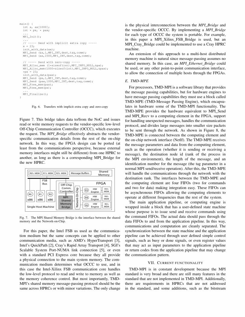
main() {int x, ax[1000];int * px, * pax;...MPI_Init();...// ----- Send with implicit extra copy -----x = 23;init_with_data(ax);MPI_Send (&x,1,MPI_INT,dest,tag,comm);MPI_Send (ax,1000,MPI_INT,dest,tag,comm);
// ----- Send with zero-copy -----MPI_Alloc_mem (1*sizeof(int),MPI_INFO_NULL,&px);MPI_Alloc_mem(1000*sizeof(int),MPI_INFO_NULL,&pax);
*px = 23;init_with_data(pax);MPI_Send (px,1,MPI_INT,dest,tag,comm);MPI_Send (pax,1000,MPI_INT,dest,tag,comm);MPI_Free_mem(pax);MPI_Free_mem(px);...MPI_Finalize();
}
Fig. 6. Transfers with implicit extra copy and zero-copy
Figure 7. This bridge takes data to/from the NoC and issuesread or write memory requests to the vendor-specific low-levelOff-Chip Communication Controller (OCCC), which executesthe request. The MPI Bridge effectively abstracts the vendor-specific communication details from the rest of the on-chipnetwork. In this way, the FPGA design can be ported (atleast from the communications perspective, because externalmemory interfaces might still be different) from one HPRC toanother, as long as there is a corresponding MPI Bridge forthe new HPRC.
R1
x86
FPGA Off-Chip
Comm.
Controller
MPI
Shared
Memory
Bridge Net
wor
k-O
n-C
hip
Single Host Machine
FSB
Bus
R5HW
EngineR5’s
MEM
R4HW
Engine
R4’s
MEM
R3HW
Engine
R3’s
MEM
R2
x86
R0
x86
Shared
MemoryR0’s MEM R1’s MEM R2’s MEM Message Buffers
Fig. 7. The MPI Shared Memory Bridge is the interface between the sharedmemory and the Network-on-Chip.
For this paper, the Intel FSB us used as the communica-tion medium but the same concepts can be applied to othercommunication media, such as AMD’s HyperTransport [3],Intel’s QuickPath [2], Cray’s Rapid Array Transport [4], SGI’sScalable System Port-NUMA link connection [5], or evenwith a standard PCI Express core because they all providea physical connection to the main system memory. The com-munication medium determines what OCCC to use, and inthis case the Intel-Xilinx FSB communication core handlesthe low-level protocol to read and write to memory as well asthe memory coherence control. But most importantly, TMD-MPI’s shared memory message-passing protocol should be thesame across HPRCs or with minor variations. The only change
is the physical interconnection between the MPI Bridge andthe vendor-specific OCCC. By implementing a MPI Bridgefor each type of OCCC the system is portable. For example,in this paper a MPI Xilinx FSB Bridge is used, but anMPI Cray Bridge could be implemented to use a Cray HPRCmachine.
An extension of this approach to a multi-host distributedmemory machine is natural since message-passing assumes noshared memory. In this case, an MPI Ethernet Bridge couldbe used, or any other point-to-point communication interface,to allow the connection of multiple hosts through the FPGAs.
E. TMD-MPE
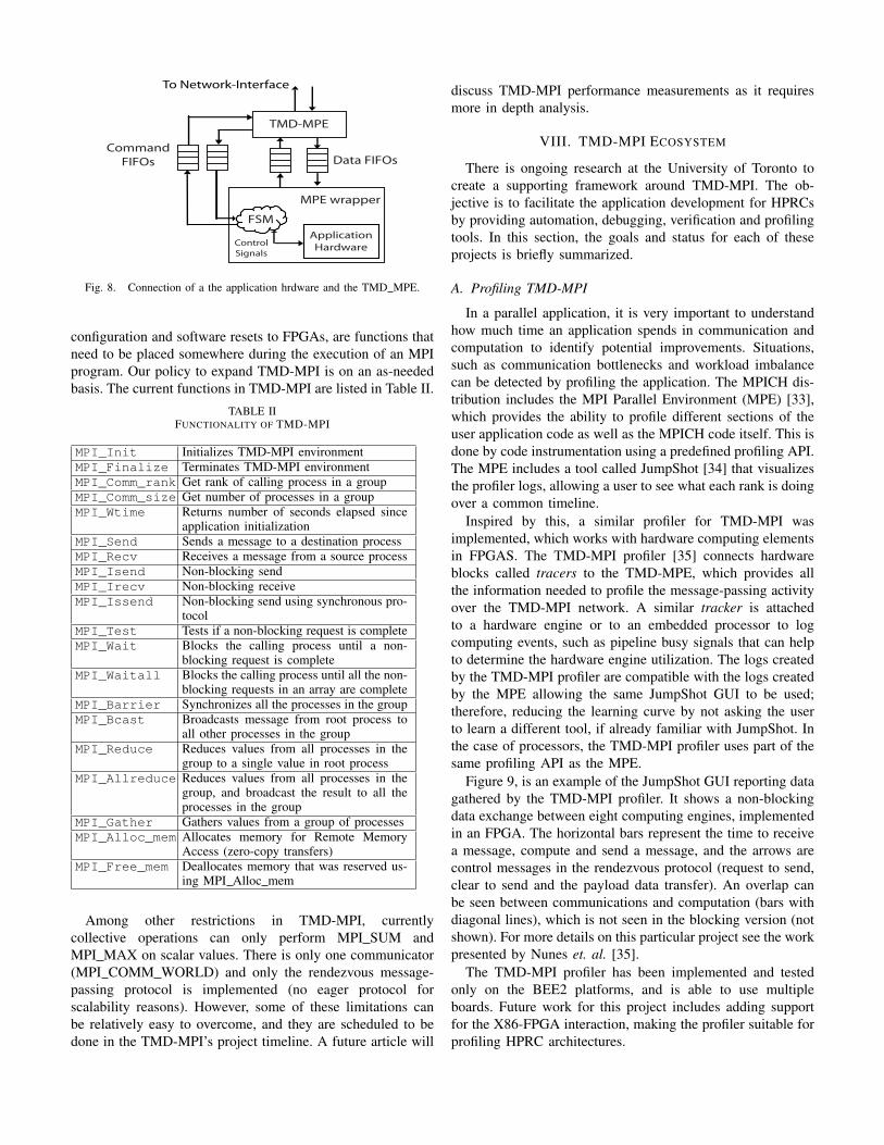
For processors, TMD-MPI is a software library that providesthe message passing capabilities, but for hardware engines tohave message passing capabilities they must use a block calledTMD-MPE (TMD-Message Passing Engine), which encapsu-lates in hardware some of the TMD-MPI functionality. TheTMD-MPE provides the hardware equivalent to MPI Sendand MPI Recv to a computing element in the FPGA, supportfor handling unexpected messages, handles the communicationprotocol, and divides large messages into smaller size packetsto be sent through the network. As shown in Figure 8, theTMD-MPE is connected between the computing element andthe on-chip network interface (NetIf). The TMD-MPE receivesthe message parameters and data from the computing element,such as the operation (whether it is sending or receiving amessage), the destination node id (rank of the process inthe MPI environment), the length of the message, and anidentification number for the message (the tag parameter in anormal MPI send/receive operation). After this, the TMD-MPEwill handle the communications through the network with thedestination rank. The interfaces between the TMD-MPE andthe computing element are four FIFOs (two for commandsand two for data) making integration easy. These FIFOs canbe asynchronous FIFOs allowing the computing elements tooperate at different frequencies than the rest of the system.
The main application pipeline, or computing engine iswrapped inside a block that has a user-defined state machinewhose purpose is to issue send and receive commands usingthe command FIFOs. The actual data should pass through thedata FIFOs to and from the application pipeline. In this way,communications and computation are cleanly separated. Thesynchronization between the state machine and the applicationpipeline can be achieved through user defined simple controlsignals, such as busy or done signals, or even register valuesthat may act as input parameters to the application pipelineor return codes from the application pipeline that may changethe communication pattern.
VII. CURRENT FUNCTIONALITY
TMD-MPI is in constant development because the MPIstandard is very broad and there are still many features in thestandard that are not implemented in TMD-MPI. Additionally,there are requirements in HPRCs that are not addressedin the standard, and some additions, such as the bitstream
TMD-MPE
MPE wrapper
Data FIFOsCommand
FIFOs
To Network-Interface
Application
Hardware
FSM
Control
Signals
Fig. 8. Connection of a the application hrdware and the TMD MPE.
configuration and software resets to FPGAs, are functions thatneed to be placed somewhere during the execution of an MPIprogram. Our policy to expand TMD-MPI is on an as-neededbasis. The current functions in TMD-MPI are listed in Table II.
TABLE IIFUNCTIONALITY OF TMD-MPI
MPI_Init Initializes TMD-MPI environmentMPI_Finalize Terminates TMD-MPI environmentMPI_Comm_rank Get rank of calling process in a groupMPI_Comm_size Get number of processes in a groupMPI_Wtime Returns number of seconds elapsed since
application initializationMPI_Send Sends a message to a destination processMPI_Recv Receives a message from a source processMPI_Isend Non-blocking sendMPI_Irecv Non-blocking receiveMPI_Issend Non-blocking send using synchronous pro-
tocolMPI_Test Tests if a non-blocking request is completeMPI_Wait Blocks the calling process until a non-
blocking request is completeMPI_Waitall Blocks the calling process until all the non-
blocking requests in an array are completeMPI_Barrier Synchronizes all the processes in the groupMPI_Bcast Broadcasts message from root process to
all other processes in the groupMPI_Reduce Reduces values from all processes in the
group to a single value in root processMPI_Allreduce Reduces values from all processes in the
group, and broadcast the result to all theprocesses in the group
MPI_Gather Gathers values from a group of processesMPI_Alloc_mem Allocates memory for Remote Memory
Access (zero-copy transfers)MPI_Free_mem Deallocates memory that was reserved us-
ing MPI Alloc mem
Among other restrictions in TMD-MPI, currentlycollective operations can only perform MPI SUM andMPI MAX on scalar values. There is only one communicator(MPI COMM WORLD) and only the rendezvous message-passing protocol is implemented (no eager protocol forscalability reasons). However, some of these limitations canbe relatively easy to overcome, and they are scheduled to bedone in the TMD-MPI’s project timeline. A future article will
discuss TMD-MPI performance measurements as it requiresmore in depth analysis.
VIII. TMD-MPI ECOSYSTEM
There is ongoing research at the University of Toronto tocreate a supporting framework around TMD-MPI. The ob-jective is to facilitate the application development for HPRCsby providing automation, debugging, verification and profilingtools. In this section, the goals and status for each of theseprojects is briefly summarized.
A. Profiling TMD-MPI
In a parallel application, it is very important to understandhow much time an application spends in communication andcomputation to identify potential improvements. Situations,such as communication bottlenecks and workload imbalancecan be detected by profiling the application. The MPICH dis-tribution includes the MPI Parallel Environment (MPE) [33],which provides the ability to profile different sections of theuser application code as well as the MPICH code itself. This isdone by code instrumentation using a predefined profiling API.The MPE includes a tool called JumpShot [34] that visualizesthe profiler logs, allowing a user to see what each rank is doingover a common timeline.
Inspired by this, a similar profiler for TMD-MPI wasimplemented, which works with hardware computing elementsin FPGAS. The TMD-MPI profiler [35] connects hardwareblocks called tracers to the TMD-MPE, which provides allthe information needed to profile the message-passing activityover the TMD-MPI network. A similar tracker is attachedto a hardware engine or to an embedded processor to logcomputing events, such as pipeline busy signals that can helpto determine the hardware engine utilization. The logs createdby the TMD-MPI profiler are compatible with the logs createdby the MPE allowing the same JumpShot GUI to be used;therefore, reducing the learning curve by not asking the userto learn a different tool, if already familiar with JumpShot. Inthe case of processors, the TMD-MPI profiler uses part of thesame profiling API as the MPE.
Figure 9, is an example of the JumpShot GUI reporting datagathered by the TMD-MPI profiler. It shows a non-blockingdata exchange between eight computing engines, implementedin an FPGA. The horizontal bars represent the time to receivea message, compute and send a message, and the arrows arecontrol messages in the rendezvous protocol (request to send,clear to send and the payload data transfer). An overlap canbe seen between communications and computation (bars withdiagonal lines), which is not seen in the blocking version (notshown). For more details on this particular project see the workpresented by Nunes et. al. [35].
The TMD-MPI profiler has been implemented and testedonly on the BEE2 platforms, and is able to use multipleboards. Future work for this project includes adding supportfor the X86-FPGA interaction, making the profiler suitable forprofiling HPRC architectures.

Fig. 9. Jumpshot GUI showing data gathered using the TMD-MPI profiler
B. Message Passing Simulation Framework
Compared to profiling, simulation is usually performedat the initial stages of the development to get a workingFPGA-based system. A profiler is used to help improve theperformance based on long-running, full-speed tests with realdata sets, whereas a simulator is used to develop a functionallycorrect system, and run tests with size-reduced data sets atsimulation speed. A simulation allows full visibility into theFPGA design and a fast code-debug-recompile cycle becausethere is no place-and-route process after a change in thehardware.
In the case of HPRCs, there are two components: theX86 software and the FPGA hardware. To design, debug andverify such architectures, co-design techniques are taken fromthe embedded world but applied to the HPC world. Thesetechniques are based on a system-level view of the application,and focuses on the interaction between hardware and soft-ware simultaneously, rather than designing two independententities that will not coordinate efficiently. For this reason,the Message-passing Simulation Framework (MSF) [36] wascreated, which allows X86 software processes (R0 and R1 inFigure 10) to exchange MPI messages with the computingelements implemented in the FPGA (R2 and R3), which isbeing emulated by a simulator.
In a typical MPI parallel program, an MPI rank is not testedin isolation from the other MPI ranks. It has to be testedwith all ranks running at once to verify the correct collectiveoperation and synchronization between them. With FPGAs ascontainers of MPI ranks, they must be part of the system-leveltesting process. The MSF’s objective is to test and debug user-defined MPI-based application-level protocols as well as thecorrect functionality of hardware engines, all at once.
Figure 10 shows how the FPGA is being simulated usingModelSim [37], but from the X86 processor perspective it ap-pears like a slow FPGA (simulation speed). The key element inthe MSF is the use of Modelsim’s Foreign Language Interface(FLI), which allows a C program to have access to Modelsim’ssimulation information, such as signals, register values andsimulation control parameters. The MSF FLI module (C code)replaces the vendor-specific Off-chip Communication Con-
troller (explained in Section VI-D) by providing the requiredfunctionality directly to the MPI Shared Memory Bridge. TheMSF FLI accepts the MPI bridge memory requests (addressand data) and performs the reads and writes directly to theshared memory buffers.
The MSF has been used to develop and debug the TMD-MPI infrastructure itself, but it can also be used in applicationsas well. A simulation of a LINPACK benchmark core exampleinteracting with X86s and more details on this project can befound in the work presented by Saldana et. al. [36].
X86
R0
X86
R1
ModelSim
MSF
FLI
Module
FPGA
R2
R3
MPI
Shared
Mem
Bridge
Shared Memory
Message Buffers
Fig. 10. The MSF FLI module in a HPRC
C. Not just C-to-HDL, but MPI-to-HDL
Currently, much research is being done on C-to-HDLtools because they will allow software developers, with noknowledge of hardware, to create FPGA-based hardware ac-celerators. However, this field is challenging because of thecomplexities of modern software and algorithms. A researchproject at the University of Toronto focuses on mixing MPIand a C-to-HDL tool (Synfora’s PICO Express FPGA [21]).The resulting tool flow is called AUTO [38]. The objective isto take an MPI program written in C as input and producea hardware computing engine that can be interfaced with theTMD-MPE allowing it to be part of the TMD-MPI network.
The basic assumptions are that a parallel MPI code (at leastfor the rank that is a candidate to be turned into hardware) issimpler than the entire sequential application to be parallelized,and that explicit statement of the communication requirements(MPI Send() and MPI Recv() function calls) can be easilyconverted to stream-like reads and writes to FIFOs. Rememberfrom Section VI-E that FIFOs are used as interfaces to theTMD-MPE, which takes care of the message-passing protocol.
Figure 11, shows the AUTO flow. First the MPI code inputis run through a preprocessing script that inserts codes thattranslate MPI function calls to stream operations in additionto hints and directives into a copy of the source code. Theannotated code is then passed to PICO Express (Synfora’scompiler), which translates it into verilog hardware files. Thesefiles are used by a packing script, which adds some controllogic code and returns a complete pcore directory structureand files ready to be integrated into the Xilinx EDK tool.
A hardware engine was created from a simple MPI programthat computes the Jacobi Iterations method to solve the HeatEquation using the AUTO flow. Results show that PICOExpress works well for a subset of the C language; futureadditions to support pointers, more flexible looping structures,and floating-point will be welcome. An MPI program as asuperset of a C program also suffers from the same lack of

features. However, the extra work required to parse the MPIpart over a plain C program is feasible. At this moment, theflow is designed to use Synfora, but a similar approach couldbe applied to ImpulseC, Handel-C, Mitrion-C, or any other C-to-HDL tool. See Wang [38] for more details on this project.
MPI + C
code
Preprocessing
Script
MPI + C
Modified
Function Verilog
Driver
code
PICO Express
Flow
Run.tcl
Packing
Script
Control
Block.v
A
Step 1: Preprocessing the
original MPI codeStep 2: PICO Flow
Step 3: Packaging to Xilinx EDK
pcore hardware module
TMD-MPE ready
Hardware
Engine
Fig. 11. MPI-to-HDL using the AUTO flow
IX. CONCLUSION
In this paper, the ideas that support MPI as a feasible pro-gramming model that abstracts the communications in a HPRChave been presented. The fact that MPI is based on a well-known and successful standard makes it even more appealingfor parallel software developers. In the case of HPRCs, MPIcan benefit from OpenFPGA’s API standardization efforts, itcan use C-to-HDL tools and encourage its improvements, andnothing prevents the use of a mixed shared memory plus MPIprogramming approach, if that helps to raise the programmingabstraction. MPI provides a standard API for HPRCs thatpromotes portability across HPRCs, a common programmingmodel for both software and hardware and easy scalability ofthe application.
TMD-MPI has been used and developed as a proof-of-concept implementation. Although it is still work in progress,it is currently being used to code an MD application in anHPRC.
ACKNOWLEDGMENT
We acknowledge the CMC/SOCRN, NSERC and Xilinx forthe hardware, tools and funding provided for this project.
REFERENCES
[1] The MPI Forum, “MPI: a message passing interface,” in Supercomputing’93: Proceedings of the 1993 ACM/IEEE conference on Supercomputing.New York, NY, USA: ACM Press, 1993, pp. 878–883.
[2] Intel, “Intel Quick Path Architecture (White Paper),” http://www.intel.com/technology/quickpath/whitepaper.pdf [Accessed: September, 2008].
[3] HyperTransport Consortium, http://www.hypertransport.org.[4] Cray Inc., CRAY XD1 FPGA Development, 2005, pp. 9-11, pp. 63-66.[5] SGI, Reconfigurable Application-Specific Computing Users Guide, Jan
2008, pp. 9-12, pp. 223-244.[6] “OpenFPGA,” http://www.openfpga.org/.[7] Manuel Saldana, “A Parallel Programming Model for a Multi-FPGA
Multiprocessor Machine,” Master’s thesis, University of Toronto, 2006.[8] M. Saldana and P. Chow, “TMD-MPI: An MPI Implementation for
Multiple Processors Across Multiple FPGAs,” in Proceedings of the16th International Conference on Field-Programmable Logic and Ap-plications, Madrid, Spain, 2006.
[9] M. Saldana, D. Nunes, E. Ramalho, and P. Chow, “Configurationand Programming of Heterogeneous Multiprocessors on a Multi-FPGASystem Using TMD-MPI,” in In the Proceedings of the 3rd InternationalConference on Reconfigurable Computing and FPGAs., San Luis Potosi,Mexico, 2006.
[10] A. Patel, C. A. Madill, M. Saldana, C. Comis, R. Pomes, and P. Chow,“A scalable fpga-based multiprocessor,” Field-Programmable CustomComputing Machines, 2006. FCCM ’06. 14th Annual IEEE Symposiumon, pp. 111–120, April 2006.
[11] Cray, Inc., “Cray XD1 Supercomputer for Reconfigurable Computing,”http://www.cray.com/downloads/FPGADatasheet.pdf [Accessed: Sept.2008].
[12] Nallatech, Inc., http://www.nallatech.com/.[13] SRC Computers, Inc., http://www.srccomp.com/.[14] DRC computer, http://www.drccomputer.com/.[15] Xtreme Data Inc., http://www.xtremedatainc.com/.[16] D. Callahan, B. Chamberlain, and H. Zima, “The cascade high produc-
tivity language,” High-Level Parallel Programming Models and Support-ive Environments, 2004. Proceedings. Ninth International Workshop on,pp. 52–60, April 2004.
[17] Ebcioglu, Saraswat, and Sarkar, “X10: an Experimental Language forHigh Productivity Programming of Scalable Systems,” Productivity andPerformance in High-End Computing (P-PHEC). Second InternationalWorkshop on, February 2005.
[18] Project Fortress Community, http://projectfortress.sun.com/Projects/Community/.
[19] Impulse Accelerated Technologies, Inc., http://www.impulsec.com.[20] Celoxica, LTD., http://www.celoxica.com.[21] Synfora, Inc., http://www.synfora.com.[22] Mitrionics, Inc., http://www.mitrionics.com.[23] W. Gropp, E. Lusk, N. Doss, and A. Skjellum, “A high-performance,
portable implementation of the MPI message passing interface standard,”Parallel Computing, vol. 22, no. 6, pp. 789–828, sep 1996.
[24] R. L. Graham, T. S. Woodall, and J. M. Squyres, “Open MPI: A FlexibleHigh Performance MPI,” in Proceedings, 6th Annual InternationalConference on Parallel Processing and Applied Mathematics, Poznan,Poland, September 2005.
[25] Amirix Systems, Inc., http://www.amirix.com/.[26] C. Chang, J. Wawrzynek, and R. W. Brodersen, “BEE2: A High-End
Reconfigurable Computing System,” IEEE Des. Test ’05, vol. 22, no. 2,pp. 114–125, 2005.
[27] A. Jerraya and W. Wolf, Eds., Multiprocessor Systems-on-Chip. MorganKaufmannn, 2004.
[28] V. Aggarwal, I. A. Troxel, and A. D. George, “Design and Analysisof Parallel N-Queens on Reconfigurable Hardware with Handel-C andMPI,” in 2004 MAPLD International Conference, Washington, DC,USA, 2004.
[29] “OpenFPGA GenAPI version 0.4 Draft For Comment,” http://www.openfpga.org/pages/Standards.aspx [Accessed: September, 2008].
[30] Intel, “Intel QuickAssist Technology AAL (White Paper),”http://download.intel.com/technology/platforms/quickassist/quickassistaal whitepaper.pdf [Accessed: September, 2008].
[31] N. Moore, A. Conti, M. Leeser, and L. King, “Vforce: An extensibleframework for reconfigurable supercomputing,” Computer, vol. 40,no. 3, pp. 39–49, March 2007.
[32] C. Comis, “A High-Speed Inter-Process Communication Architecture forFPGA-based Hardware Acceleration of Molecular Dynamics,” Master’sthesis, University of Toronto, 2005.
[33] MPI Parallel Environment, http://www-unix.mcs.anl.gov/perfvis/software/MPE/index.htm.
[34] O. Zaki, E. Lusk, W. Gropp, and D. Swider, “Toward scalable per-formance visualization with Jumpshot,” High Performance ComputingApplications, vol. 13, no. 2, pp. 277–288, Fall 1999.
[35] D. Nunes, M. Saldana, and P. Chow, “A Profiler for a HeterogeneousMulti-Core Multi-FPGA System,” in In Proceedings of the 2008 Inter-national Conference on Field-Programmable Tecnology, Taipei, Taiwan,2008, To appear.
[36] M. Saldana, E. Ramalho, and P. Chow, “A Message-passing Hard-ware/Software Co-simulation Environment to Aid in ReconfigurableComputing Design using TMD-MPI,” in In the Proceedings of the 5thInternational Conference on Reconfigurable Computing and FPGAs.,Cancun, Mexico, 2008., submitted.
[37] Mentor Graphics, Corp., http://www.mentor.com/.[38] D. Wang, “An Automated Flow to Generate Hardware Computing Nodes
from C for an FPGA-Based MPI Computing Network,” EngineeringScience Undergraduate Thesis, University of Toronto, 2008.
Copyright © 2022 FDOKUMEN