Use of Acoustic Waves for Non-Invasive Buckle Detection in Offshore Pipelines
13
10th Pipeline Technology Conference 2015 1 Use of Acoustic Waves for Non-Invasive Buckle Detection in Offshore Pipelines C. Molinari (1) , A. Calzavara (1) , P. Catena (1) , L. Pagani (1) , D. Rossin (1) , G. Bernasconi (2) , M. Signori (3) (1) Saipem SpA, via Martiri di Cefalonia 67, I-20097 San Donato Milanese, Italy (2) Aresys srl, via Flumendosa 16, I-20132 Milano, Italy (3) Solgeo srl, via Pastrengo 9, I-24068 Seriate, Italy Abstract During laying operations from a pipelay vessel, the pipeline integrity shall be guaranteed until complete deployment onto the seabed. Harsh environmental conditions, pipeline transit in load bearing structures (e.g. S-Lay stinger) and vessel motion can induce local deformations that may develop into major damages (e.g. local buckling) with possible critical consequences both during and after laying operations. Hence, online monitoring of the pipeline can be crucial for early detection of anomalies. Currently, the offshore industry uses circular mechanical gauges positioned inside the pipe at the touchdown point and connected to the vessel via wire cable. The management of the wire cable is cumbersome in deep waters on long pipeline projects. Saipem has developed a novel tool (IAU: Integrated Acoustic Unit) based on a non- invasive acoustic technology, with the aim at detecting deformations of the internal section of pipes. The IAU is based on the EAR (Extended Acoustic Radar) technology. The tool can remotely investigate long stretches (up to some km) of the line, classifying and quantifying the measured anomalies. It is also able to localize solid unexpected objects and obstacles (e.g. pigs, inline items). Further it can detect and track any water intrusion. It is basically composed of loudspeakers, microphones and dedicated acquisition and control units. This paper gives an overview of recent developments on buckle detection, and it describes the IAU structure, its basic working principle and the expected benefits of this novel technology. The prototyping and validation phases are described and results are presented specifically referring to recent and near to come projects.
Transcript of Use of Acoustic Waves for Non-Invasive Buckle Detection in Offshore Pipelines
10th Pipeline Technology Conference 2015
1
Use of Acoustic Waves for Non-Invasive Buckle Detection in Offshore Pipelines
C. Molinari(1), A. Calzavara(1), P. Catena(1), L. Pagani(1), D. Rossin(1),G. Bernasconi(2), M. Signori(3)
(1) Saipem SpA, via Martiri di Cefalonia 67, I-20097 San Donato Milanese, Italy(2) Aresys srl, via Flumendosa 16, I-20132 Milano, Italy
(3) Solgeo srl, via Pastrengo 9, I-24068 Seriate, Italy
Abstract
During laying operations from a pipelay vessel, the pipeline integrity shall beguaranteed until complete deployment onto the seabed. Harsh environmentalconditions, pipeline transit in load bearing structures (e.g. S-Lay stinger) and vesselmotion can induce local deformations that may develop into major damages (e.g. localbuckling) with possible critical consequences both during and after laying operations.Hence, online monitoring of the pipeline can be crucial for early detection of anomalies.Currently, the offshore industry uses circular mechanical gauges positioned inside thepipe at the touchdown point and connected to the vessel via wire cable. Themanagement of the wire cable is cumbersome in deep waters on long pipeline projects.
Saipem has developed a novel tool (IAU: Integrated Acoustic Unit) based on a non-invasive acoustic technology, with the aim at detecting deformations of the internalsection of pipes. The IAU is based on the EAR (Extended Acoustic Radar) technology.The tool can remotely investigate long stretches (up to some km) of the line, classifyingand quantifying the measured anomalies. It is also able to localize solid unexpectedobjects and obstacles (e.g. pigs, inline items). Further it can detect and track any waterintrusion. It is basically composed of loudspeakers, microphones and dedicatedacquisition and control units.
This paper gives an overview of recent developments on buckle detection, and itdescribes the IAU structure, its basic working principle and the expected benefits ofthis novel technology. The prototyping and validation phases are described and resultsare presented specifically referring to recent and near to come projects.
10th Pipeline Technology Conference 2015
2
1 Introduction
The integrity of offshore pipelines must be monitored and guaranteed, in order toprevent any leakage that can lead to costly accidents, such as disruption of the energysupply chain, flooding of the line, and environmental degradation. Also, the piggabilityof offshore pipelines is an important feature, imposed by relevant normatives [1]. Forboth integrity and piggability, it is a main concern during laying operations to preservethe internal geometry of pipelines and to monitor any potential buckle.
Deviations from nominal geometry might depend upon fabrication (ovality, toleranceson internal and outer diameter), welding operations (Hi-Lo, exceeding root weld) orlaying operations (stress and ovality increase during passage over the stinger, throughthe J-Lay tower or in the sagbend). Relevant normatives [1] consider these deviationsand fix proper limits.
Nowadays buckle detection during laying operations is performed using a mechanicaldevice, pulled within the pipe. The device consists of a trolley and a circular segmentedplate, and is connected through a cable to the internal line up clamp (Figure 1 andFigure 2). The overall size of the device is about 2-3 m of length; the circular plate isapprox. 95% of the internal pipe diameter. Moreover, since the device is preferablyplaced after the touch down point of the pipeline, the cable length would reach 3 kmand more in deep water.
Buckles are highlighted through a tension increase in the cable, monitored by meansof a load cell, caused by the stacking of the end plate in correspondence to a sectionconstriction. After buckle detection, the device is recovered and the approximate entityof the buckle is determined by measuring the deformation of the segmented end plate.
Several disadvantages and weak points are related to this kind of buckle detectionmethodology:
o the combination of cable, trolley and end plate results in a very intrusive object,constantly placed inside the pipeline and constantly monitored and managed duringthe laying operations, causing cycle time wasting;
o the cable connection between vessel and mechanical buckle detector is continuousand the involved cable length might reach several km;
o the launch, recovery and replacement operations at laying start and end and incorrespondence with water depth variations, are extremely time consuming;
o the mechanical buckle detector is able to highlight a single anomaly and in a quiteapproximate way;
o the tension measurement is influenced by the friction between cable and pipeline,i.e. the longer the cable and the contact region, the lower the reliability of themeasurement. Since the effect is emphasized in deep water, long cables representan operational limit in the application of mechanical buckle detectors.
10th Pipeline Technology Conference 2015
3
Moreover, the use of mechanical buckle detectors might be risky, considering thepossibility of:
o cable break during laying operations;o buckle detector stacking during motion;o internal coating damages related to the passage of the cable, and marginally of the
trolley and the end plate on the internal surface;o false-positive buckle detection due to cable-pipe and marginally due to trolley-pipe
friction.
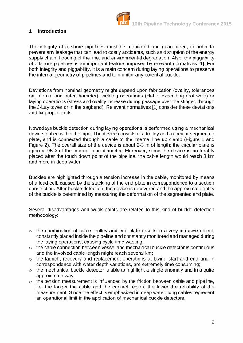
Figure 1: Mechanical Buckle Detector – Side View (Length approx. 2-3 m, end plate in red)
Figure 2: Mechanical Buckle Detector – Components (End Plate, Left – Trolley, Right)
The development of an innovative buckle detection technique derives from a specifictechnological need: the passage from an intrusive, local, approximate approach (thetypical mechanical buckle detector) to a non-intrusive, global, highly accurateapproach.
This need has been associated to the fact that a pipeline is a waveguide, able totransmit signals in its cavity or on its skin. Both acoustic and electromagnetic signalcan be used: the discrimination between different types of signals depends on thetarget of the application. The use of pipelines as waveguides is well-known and fieldproven. This technique is already applied for both onshore and offshore pipelineleakage detection and several patents have been registered. Also, the detection ofobjects “forgotten” inside the line has been performed with the aid of acoustic andelectromagnetic signals. The new frontier is represented by the opportunity to detectin a non-invasive way minimal section variations and progressive water fronts insidelaid pipelines.
10th Pipeline Technology Conference 2015
4
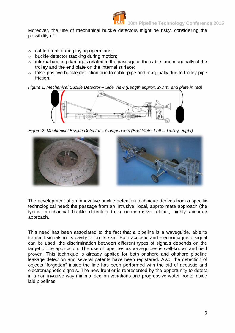
In 2001 Saipem, together with The Charles Stark Draper Laboratory, developed andtested a system capable of detecting pipe aberrations via the non-intrusive injection ofradio-frequency (RF) energy into the pipe. The approach considers the pipe as animperfect circular waveguide: RF energy is transmitted into an open pipe end whilemonitoring for energy reflected by the pipe walls. The signature of the reflection isquantified and evaluated, resulting in the detection of buckle size and position.
Figure 3: Schematic RF Buckle Detector System
The RF technique is described in Figure 3. A signal launcher is connected to thealignment tool, a low power wideband waveform is launched down the pipe and thedistribution of energy reflected from the internal geometry of the pipe is acquired by anelaboration unit, where signal processing algorithms estimate the internal geometry ofthe pipe. The energy returned from the pipeline is combined with the calibration errorand with the internal noise of the analyzer.
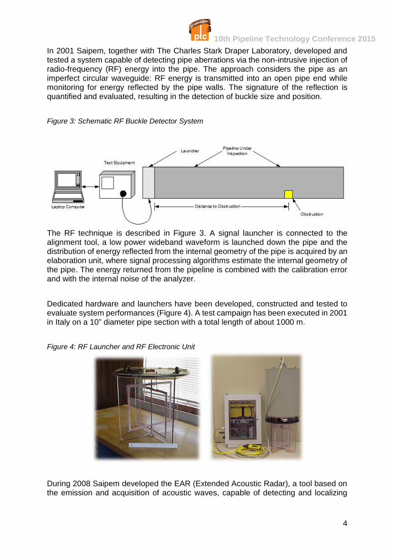
Dedicated hardware and launchers have been developed, constructed and tested toevaluate system performances (Figure 4). A test campaign has been executed in 2001in Italy on a 10” diameter pipe section with a total length of about 1000 m.
Figure 4: RF Launcher and RF Electronic Unit
During 2008 Saipem developed the EAR (Extended Acoustic Radar), a tool based onthe emission and acquisition of acoustic waves, capable of detecting and localizing
10th Pipeline Technology Conference 2015
5
obstructions up to several kilometers from the source. The tool has already beensuccessfully deployed on-site in order to localize lost objects in pipelines (mechanicalbuckle detector localization, OLT Livorno Project, 2009, and stuck pig localization,MEDGAZ Project, 2009).
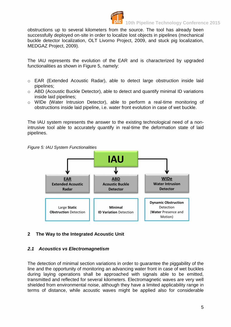
The IAU represents the evolution of the EAR and is characterized by upgradedfunctionalities as shown in Figure 5, namely:
o EAR (Extended Acoustic Radar), able to detect large obstruction inside laidpipelines;
o ABD (Acoustic Buckle Detector), able to detect and quantify minimal ID variationsinside laid pipelines;
o WIDe (Water Intrusion Detector), able to perform a real-time monitoring ofobstructions inside laid pipeline, i.e. water front evolution in case of wet buckle.
The IAU system represents the answer to the existing technological need of a non-intrusive tool able to accurately quantify in real-time the deformation state of laidpipelines.
Figure 5: IAU System Functionalities
2 The Way to the Integrated Acoustic Unit
2.1 Acoustics vs Electromagnetism
The detection of minimal section variations in order to guarantee the piggability of theline and the opportunity of monitoring an advancing water front in case of wet bucklesduring laying operations shall be approached with signals able to be emitted,transmitted and reflected for several kilometers. Electromagnetic waves are very wellshielded from environmental noise, although they have a limited applicability range interms of distance, while acoustic waves might be applied also for considerable
IAUABD
Acoustic BuckleDetector
EARExtended Acoustic
Radar
WIDeWater Intrusion
Detector
Large StaticObstruction Detection
MinimalID Variation Detection
Dynamic ObstructionDetection
(Water Presence andMotion)
10th Pipeline Technology Conference 2015
6
distances, despite the fact that their effectiveness might be affected by the presenceof environmental noise.
2.2 Physical Background
The evolution of sound waves in a cylindrically confined medium undergoes the theoryof sound propagation in rigid cylindrical tubes. The following assumptions are made:
o rigid pipes;o small amplitude, sinusoidal perturbations (no circulation and no turbulence);o adequate pipeline length (min. 200 m), in order to exclude boundary effects;o attenuation due to visco-thermal interaction with the pipe wall.
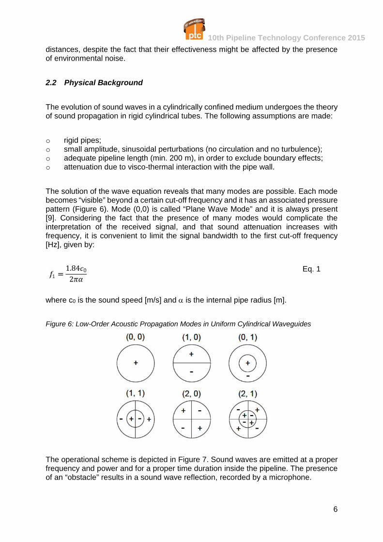
The solution of the wave equation reveals that many modes are possible. Each modebecomes “visible” beyond a certain cut-off frequency and it has an associated pressurepattern (Figure 6). Mode (0,0) is called “Plane Wave Mode” and it is always present[9]. Considering the fact that the presence of many modes would complicate theinterpretation of the received signal, and that sound attenuation increases withfrequency, it is convenient to limit the signal bandwidth to the first cut-off frequency[Hz], given by:
1.842 Eq. 1
where c0 is the sound speed [m/s] and is the internal pipe radius [m].
Figure 6: Low-Order Acoustic Propagation Modes in Uniform Cylindrical Waveguides
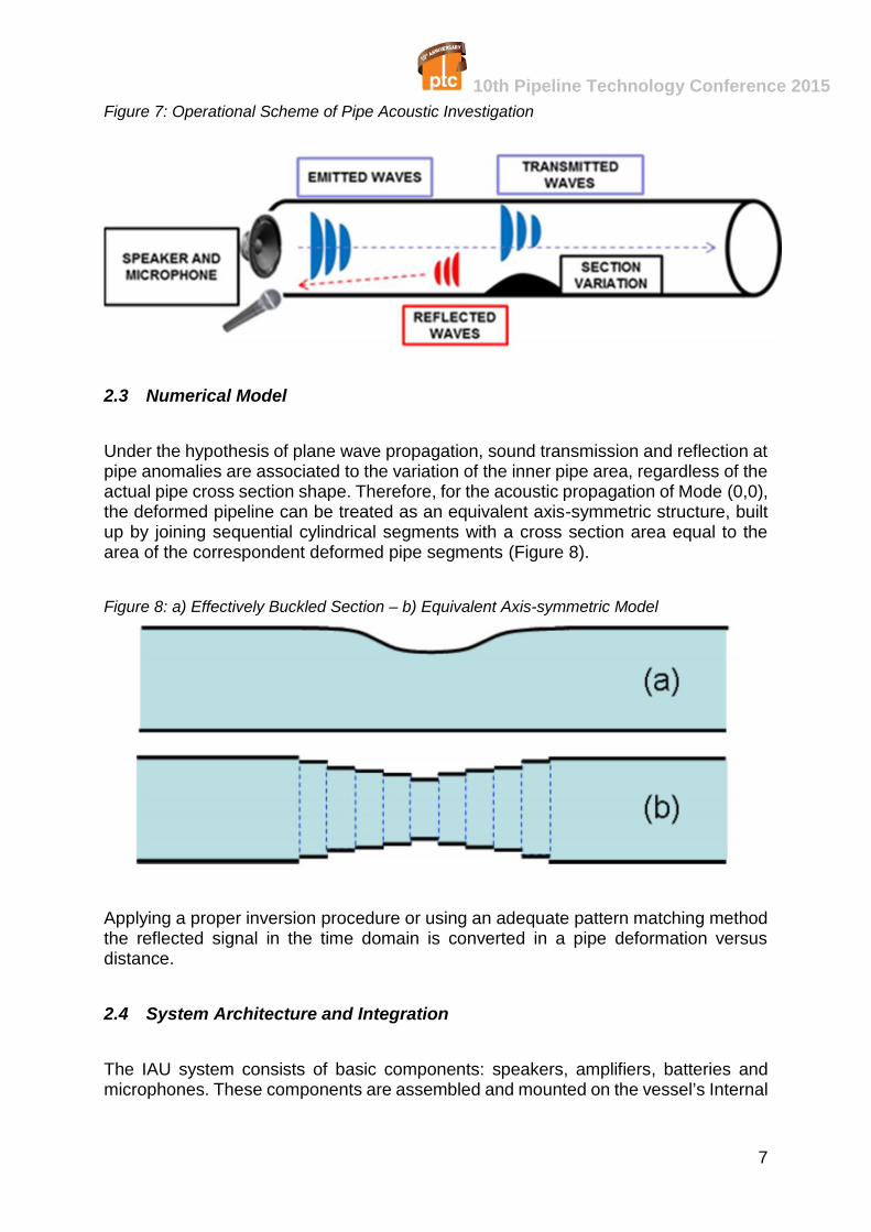
The operational scheme is depicted in Figure 7. Sound waves are emitted at a properfrequency and power and for a proper time duration inside the pipeline. The presenceof an “obstacle” results in a sound wave reflection, recorded by a microphone.
10th Pipeline Technology Conference 2015
7
Figure 7: Operational Scheme of Pipe Acoustic Investigation
2.3 Numerical Model
Under the hypothesis of plane wave propagation, sound transmission and reflection atpipe anomalies are associated to the variation of the inner pipe area, regardless of theactual pipe cross section shape. Therefore, for the acoustic propagation of Mode (0,0),the deformed pipeline can be treated as an equivalent axis-symmetric structure, builtup by joining sequential cylindrical segments with a cross section area equal to thearea of the correspondent deformed pipe segments (Figure 8).
Figure 8: a) Effectively Buckled Section – b) Equivalent Axis-symmetric Model
Applying a proper inversion procedure or using an adequate pattern matching methodthe reflected signal in the time domain is converted in a pipe deformation versusdistance.
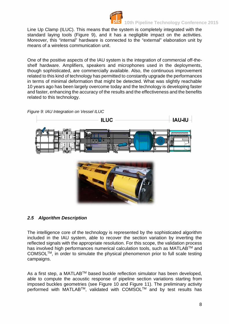
2.4 System Architecture and Integration
The IAU system consists of basic components: speakers, amplifiers, batteries andmicrophones. These components are assembled and mounted on the vessel’s Internal
10th Pipeline Technology Conference 2015
8
Line Up Clamp (ILUC). This means that the system is completely integrated with thestandard laying tools (Figure 9), and it has a negligible impact on the activities.Moreover, this “internal” hardware is connected to the “external” elaboration unit bymeans of a wireless communication unit.
One of the positive aspects of the IAU system is the integration of commercial off-the-shelf hardware. Amplifiers, speakers and microphones used in the deployments,though sophisticated, are commercially available. Also, the continuous improvementrelated to this kind of technology has permitted to constantly upgrade the performancesin terms of minimal deformation that might be detected. What was slightly reachable10 years ago has been largely overcome today and the technology is developing fasterand faster, enhancing the accuracy of the results and the effectiveness and the benefitsrelated to this technology.
Figure 9: IAU Integration on Vessel ILUC
2.5 Algorithm Description
The intelligence core of the technology is represented by the sophisticated algorithmincluded in the IAU system, able to recover the section variation by inverting thereflected signals with the appropriate resolution. For this scope, the validation processhas involved high performances numerical calculation tools, such as MATLABTM andCOMSOLTM, in order to simulate the physical phenomenon prior to full scale testingcampaigns.
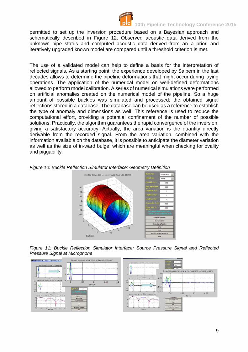
As a first step, a MATLABTM based buckle reflection simulator has been developed,able to compute the acoustic response of pipeline section variations starting fromimposed buckles geometries (see Figure 10 and Figure 11). The preliminary activityperformed with MATLABTM, validated with COMSOLTM and by test results has
10th Pipeline Technology Conference 2015
9
permitted to set up the inversion procedure based on a Bayesian approach andschematically described in Figure 12. Observed acoustic data derived from theunknown pipe status and computed acoustic data derived from an a priori anditeratively upgraded known model are compared until a threshold criterion is met.
The use of a validated model can help to define a basis for the interpretation ofreflected signals. As a starting point, the experience developed by Saipem in the lastdecades allows to determine the pipeline deformations that might occur during layingoperations. The application of the numerical model on well-defined deformationsallowed to perform model calibration. A series of numerical simulations were performedon artificial anomalies created on the numerical model of the pipeline. So a hugeamount of possible buckles was simulated and processed; the obtained signalreflections stored in a database. The database can be used as a reference to establishthe type of anomaly and dimensions as well. This reference is used to reduce thecomputational effort, providing a potential confinement of the number of possiblesolutions. Practically, the algorithm guarantees the rapid convergence of the inversion,giving a satisfactory accuracy. Actually, the area variation is the quantity directlyderivable from the recorded signal. From the area variation, combined with theinformation available on the database, it is possible to anticipate the diameter variationas well as the size of in-ward bulge, which are meaningful when checking for ovalityand piggability.
Figure 10: Buckle Reflection Simulator Interface: Geometry Definition
Figure 11: Buckle Reflection Simulator Interface: Source Pressure Signal and ReflectedPressure Signal at Microphone
10th Pipeline Technology Conference 2015
10
Figure 12: Inversion Procedure: From a priori Model to Estimated Model
2.6 Experimental Campaign
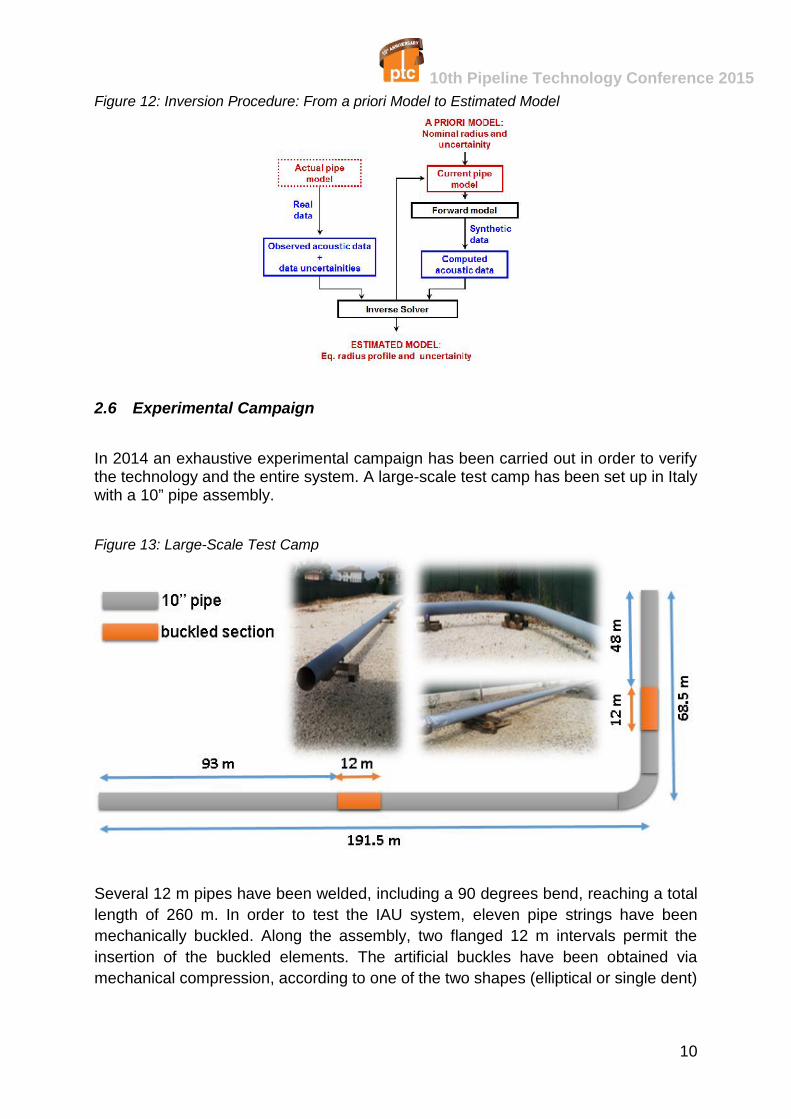
In 2014 an exhaustive experimental campaign has been carried out in order to verifythe technology and the entire system. A large-scale test camp has been set up in Italywith a 10” pipe assembly.
Figure 13: Large-Scale Test Camp
Several 12 m pipes have been welded, including a 90 degrees bend, reaching a totallength of 260 m. In order to test the IAU system, eleven pipe strings have beenmechanically buckled. Along the assembly, two flanged 12 m intervals permit theinsertion of the buckled elements. The artificial buckles have been obtained viamechanical compression, according to one of the two shapes (elliptical or single dent)
10th Pipeline Technology Conference 2015
11
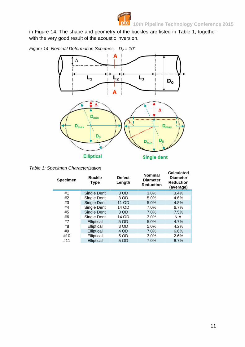
in Figure 14. The shape and geometry of the buckles are listed in Table 1, togetherwith the very good result of the acoustic inversion.
Figure 14: Nominal Deformation Schemes – D0 = 10”
Table 1: Specimen Characterization
Specimen BuckleType
DefectLength
NominalDiameter
Reduction
CalculatedDiameter
Reduction(average)
#1 Single Dent 3 OD 3.0% 3.4%#2 Single Dent 3 OD 5.0% 4.6%#3 Single Dent 11 OD 5.0% 4.8%#4 Single Dent 14 OD 7.0% 6.7%#5 Single Dent 3 OD 7.0% 7.5%#6 Single Dent 14 OD 3.0% N.A.#7 Elliptical 5 OD 5.0% 4.7%#8 Elliptical 3 OD 5.0% 4.2%#9 Elliptical 4 OD 7.0% 6.6%
#10 Elliptical 5 OD 3.0% 2.6%#11 Elliptical 5 OD 7.0% 6.7%
10th Pipeline Technology Conference 2015
12
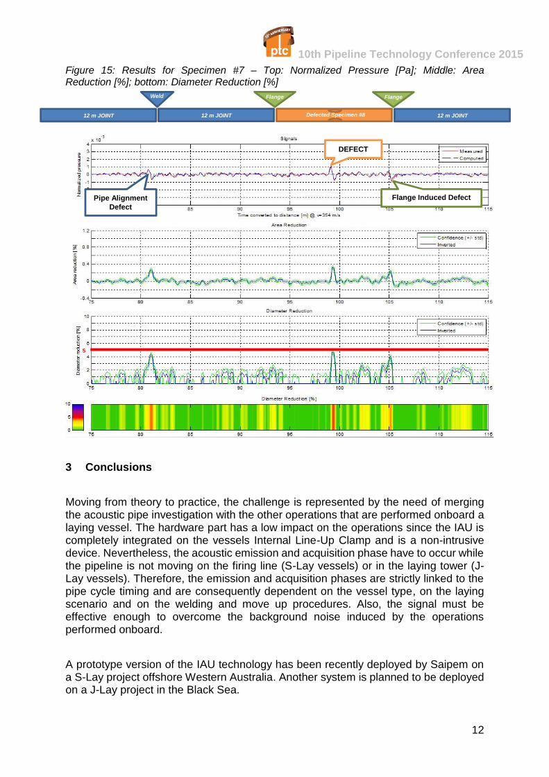
Figure 15: Results for Specimen #7 – Top: Normalized Pressure [Pa]; Middle: AreaReduction [%]; bottom: Diameter Reduction [%]
3 Conclusions
Moving from theory to practice, the challenge is represented by the need of mergingthe acoustic pipe investigation with the other operations that are performed onboard alaying vessel. The hardware part has a low impact on the operations since the IAU iscompletely integrated on the vessels Internal Line-Up Clamp and is a non-intrusivedevice. Nevertheless, the acoustic emission and acquisition phase have to occur whilethe pipeline is not moving on the firing line (S-Lay vessels) or in the laying tower (J-Lay vessels). Therefore, the emission and acquisition phases are strictly linked to thepipe cycle timing and are consequently dependent on the vessel type, on the layingscenario and on the welding and move up procedures. Also, the signal must beeffective enough to overcome the background noise induced by the operationsperformed onboard.
A prototype version of the IAU technology has been recently deployed by Saipem ona S-Lay project offshore Western Australia. Another system is planned to be deployedon a J-Lay project in the Black Sea.
5
Pipe AlignmentDefect
Flange Induced Defect
DEFECT
12 m JOINT12 m JOINT 12 m JOINT
Weld Flange Flange
Defected Specimen #8
10th Pipeline Technology Conference 2015
13
The deployment on operative projects has led Saipem to the need of certifying theacoustical buckle detection technology. Therefore a Technology Qualification Pathaccording to Ref. [2] will be established, aiming at the qualification of the IAU system.
4 References
[1] DNV GL, “DNV-OS-F101 (2013): Submarine Pipeline Systems”[2] DNV GL, “DNV-RP-A203 (2011): Qualification of New Technology”[3] Blackstock D.T., “Fundamentals of physical acoustics”, John Wiley & Sons, Inc.
2000.[4] Del Giudice S., Analysis of ducts by means of acoustic reflectometry, M.Sc.
Thesis, Politecnico di Milano, 2008.[5] Kennett B., Reflections, rays and reverberations, Bulletin of the Seismological
Society of America, 64, 1685-1696, 1974.[6] Kind R., Computation of reflection coefficients for layered media, Journal of
Geophysics, 42, 191-200, 1976.[7] Muller G., The reflectivity method: a tutorial, Journal of Geophysics, 58, 153-174,
1985.[8] Berndt B.C., “Ramanujan's Notebooks”, Springer-Verlag, New York, 1989.[9] Boyd R.J., Cohen W.E., Doran W.P., Tuminaro R.D., “Waveguide design and
fabrication”, Bell System Technical Journal, Vol. 56, No. 10, Dec. 1977, pp. 1875-1897.
[10] Pozar D.M., "Microwave Engineering", 2nd edition, Wiley 1997.