UPDATED FORM I - Environmental Clearance
39
PASHAMYLARAM COMMON INFRASTRUCTURE PVT. LTD. SY. NO. 236 (Part), 237 (Part) AND 242 (Part), PHASE II, IDA, PASHAMYLARAM, PATANCHERU MANDAL, MEDAK DISTRICT, TELANGANA UPDATED FORM I Project No. 0316‐21‐02 March 2016 Pashamylaram Common Infrastructure Pvt. Ltd., TSIIC Admn. Building, Phase I,IDA, Pashamailaram (V), Patancheru (M), Medak (Dist.)‐ 502 307 Phone: +91 08455‐226590/244489, 9393117750 E‐mail ID: [email protected] STUDIES AND DOCUMENTATION BY TEAM Labs and Consultants B‐115‐117 & 509, Annapurna Block, Aditya Enclave, Ameerpet, Hyderabad‐500 038. Phone: 040‐23748 555/23748616, Telefax: 040‐23748666 SUBMITTED TO STATE LEVEL ENVIRONMENT IMPACT ASSESSMENT AUTHORITY, TELANGANA, GOVERNMENT OF INDIA
-
Upload
khangminh22 -
Category
Documents
-
view
0 -
download
0
Transcript of UPDATED FORM I - Environmental Clearance

PASHAMYLARAM COMMON INFRASTRUCTURE PVT. LTD. SY. NO. 236 (Part), 237 (Part) AND 242 (Part),
PHASE II, IDA, PASHAMYLARAM, PATANCHERU MANDAL, MEDAK DISTRICT, TELANGANA
UPDATED FORM I
Project No. 0316‐21‐02March 2016
Pashamylaram Common Infrastructure Pvt. Ltd., TSIIC Admn. Building, Phase I,IDA, Pashamailaram (V), Patancheru (M), Medak (Dist.)‐ 502 307 Phone: +91 08455‐226590/244489, 9393117750 E‐mail ID: [email protected]
STUDIES AND DOCUMENTATION BY TEAM Labs and Consultants B‐115‐117 & 509, Annapurna Block, Aditya Enclave, Ameerpet, Hyderabad‐500 038. Phone: 040‐23748 555/23748616, Telefax: 040‐23748666
SUBMITTED TO STATE LEVEL ENVIRONMENT IMPACT ASSESSMENT AUTHORITY,
TELANGANA, GOVERNMENT OF INDIA

Pashamylaram Common Infrastructure Pvt. Ltd.
Form I Page 1
APPENDIX – I (See Paragraph – 6)
FORM I I) Basic Information
S.No. Item Details 1 Name of the Project/s Pashamylaram Common Infrastructure Pvt. Ltd. 2 S. No in the Schedule 7(h) –Category B & 1(d) –Category B 3 Proposed capacity/area/length/tonnage
to be handled/command area/lease area/number of wells to be drilled
Area:5 Acres The present proposal is for Amendment of our existing Environmental Clearance. Order No. SEIAA/TS/MDK‐82/2016 dated: 03.10.2016
Amendment S.No
Description As Mentioned To be Corrected
1 Condition No. (ii) of A. Specific Condition
Common Effluent Conveyance System should be constructed / Commissioned /maintained by the CETP Operator. Separate pipelines are to be laid for transport of influents from the member industries to CETP and to convey the treated effluents to the member industries for recycling.
Common Effluent Conveyance System should be operated by CETP Operator.
The effluents from the individual units, will be transferred after primary treatment within the individual units, by dedicated GPS tagged tank trucks.
The treated wastewater will be sent to the contributing individual units by dedicated tank trucks for reuse.
Capacity: 480 KLD and 2.5MW CPP. Cost of the project: 30.0 Crores
4 New/Expansion/Modernization New 5 Existing Capacity/Area etc. Not Applicable 6 Category of Project i.e 'A' or 'B' “A” 7 Does it attract the general condition? If
yes, please specify Yes. The Unit is Located in Notified Industrial Estate / Area. Critically Polluted Area of Pattancheru and Bollaram are located at a distance of 5.5 KM’s from the Site.
8 Does it attract the Specific condition? If yes, please specify.
No
9 Location Plot/Survey/Khasra No. Phase II, IDA Village Phashamylaram Tehsil Patancheru Mandal District Sangareddy District State Telangana

Pashamylaram Common Infrastructure Pvt. Ltd.
Form I Page 2
10 Nearest railway station/airport along with distance in kms.
Nagulapalli Railway Station – 9.8Km – SE, Shamshabad Airport – 42Km ‐ SE
11 Nearest Town, City, District Headquarters along with distance in kms.
Patancheru – 9.3Km ‐ SE
12 Village Panchayats, Zilla Parishad, Municipal Corporation, Local body (complete postal address with telephone nos. to be given)
Phashamylaram
13 Name of the Applicant M.Narasimha Reddy 14 Registered Address 15 Address for Correspondence: TSIIC Admn. Building, Phase – I, IDA, Pashamylaram,
Sangareddy District. Name M.Narasimha Reddy Designation(Owner/Partner/CEO) Director & CEO Address TSIIC Admn. Building, Phase – I, IDA, Pashamylaram,
Sangareddy District. Pin Code 502 307 E‐mail [email protected] Telephone Number 9393117750 Fax No.
16 Details of alternative Sites examined, if any. Location of these sites should be shown on a topo sheet.
‐NA‐
17 Interlinked Projects ‐NA‐ 18 Whether separate application of
interlinked project has been submitted? No
19 If yes, date of submission 20 If no, reason 21 Whether the proposal involves
approval/clearance under: if yes, details of the same and their status to be given. (a) The Forest (Conservation) Act, 1980? (b) The Wildlife (Protection) Act, 1972? (c) The C.R.Z Notification, 1991?
‐NA‐
22 Whether there is any Government Order/Policy relevant/relating to the site?
No
23 Forest land involved (hectares) No24 Whether there is any location pending
against the project and /or land in which the project is propose to be set up? (a) Name of the Court (b) Case No (c) Orders/directions of the Court, if any and its relevance with the proposed project.
No

Pashamylaram Common Infrastructure Pvt. Ltd.
Form I Page 3
(II) Activity 1. Construction, operation or decommissioning of the Project involving actions, which will cause physical changes in the locality (topography, land use, changes in water bodies, etc.) S.No. Information/Checklist confirmation Yes/No Details thereof (with approximate quantities
/rates, wherever possible) with source of information data
1.1 Permanent or temporary change in land use, land cover or topography including increase in intensity of land use (with respect to local land use plan)
NO The proposal is for a green field project. The land area used for the proposed plant is 5 acres. The land is plain and does not involve much of leveling/excavation.
1.2 Clearance of existing land, vegetation and buildings?
NO The land area is plain and is not used for any agricultural activity
1.3 Creation of new land uses? NO 1.4 Pre‐construction investigations e.g. bore
houses, soil testing? YES Soil test done and soil load bearing capacity
established. 1.5 Construction works?
NO Construction activity involves plant construction,
erection only.1.6 Demolition works? NO
1.7 Temporary sites used for construction works or housing of construction workers?
NO Construction labor from local villages shall be employed.
1.8 Above ground buildings, structures or earthworks including linear structures, cut and fill or excavations
YES Office buildings, Storage facilities for raw effluent and treated effluent shall be constructed. No major cut and fill or excavation is anticipated.
1.9 Underground works including mining or tunneling?
NO
1.10 Reclamation works? NO 1.11 Dredging? NO 1.12 Offshore structures? NO 1.13 Production and manufacturing
processes? NA
1.14 Facilities for storage of goods or materials?
NO
1.15 Facilities for treatment or disposal of solid waste or liquid effluents?
YES Solid waste shall be disposed to end users/recyclers or sent to incineration. Effluent generated from the plant are treated and reused. Details presented in Annexures
1.16 Facilities for long term housing of operational workers?
NO Local people shall be employed.
1.17 New road, rail or sea traffic during construction or operation?
YES Construction materials shall be transported to the site. The traffic density of the existing connecting road is negligible.
1.18 New road, rail, air waterborne or other transport infrastructure including new or altered routes and stations, ports,
NO

Pashamylaram Common Infrastructure Pvt. Ltd.
Form I Page 4
airports etc? 1.19 Closure or diversion of existing transport
routes or infrastructure leading to changes in traffic movements?
NO
1.20 New or diverted transmission lines or pipelines?
NO
1.21 Impoundment, damming, culverting, realignment or other changes to the hydrology of watercourses or aquifers?
NO
1.22 Stream crossings? NO 1.23 Abstraction or transfers of water form
ground or surface waters? YES Total water required shall be 250.9 KLD out of
which 218.9 KLD shall be drawn from TSIIC and the balance shall be recycled water.
1.24 Changes in water bodies or the land surface affecting drainage or run‐off?
NO
1.25 Transport of personnel or materials for construction, operation or decommissioning?
YES The construction material shall be drawn from local sources within 10 – 15 km. There is no transport of personnel, as the construction workers shall be drawn from local villages.
1.26 Long‐term dismantling or decommissioning or restoration works?
NO
1.27 Ongoing activity during decommissioning which could have an impact on the environment?
NO
1.28 Influx of people to an area in either temporarily or permanently?
YES The proposed project shall increase the employment potential and hence may lead to migration to surrounding villages.
1.29 Introduction of alien species? NO 1.30 Loss of native species or genetic
diversity? NO There are no major losses of tree/shrub species.
1.31 Any other actions? NO

Pashamylaram Common Infrastructure Pvt. Ltd.
Form I Page 5
2. Use of Natural resources for construction or operation of the Project (such as land, water, materials or energy, especially any resources which are non‐renewable or in short supply): S.No. Information/checklist confirmation Yes/No Details thereof (with approximate quantities
/rates, wherever possible) with source of information data
2.1 Land especially undeveloped or agricultural land (ha)
YES 5 acres. Located Phase II IDA, Phashamylaram, Sangareddy District, Telangana.
2.2 Water (expected source & competing users) unit: KLD
YES Total water required shall be 250.9 KLD which shall be drawn from TSIIC. (Water Balance Enclosed in Annexure)
2.3 Minerals (MT) NA 2.4 Construction material – stone,
aggregates, sand / soil (expected source – MT)
YES Shall be sourced from the local villages.
2.5 Forests and timber (source – MT) NO 2.6 Energy including electricity and fuels
(source, competing users) Unit: fuel (MT), energy (MW)
YES The required energy shall be drawn from TSTRANSCO. Backup DG sets of 2 x 500 KVA shall be provided to cater to energy requirement during load shut downs. The other energy source is Coal fired boiler of 25TPH. The required quantity of fuel is 18.5TPD.
2.7 Any other natural resources (use appropriate standard units)
NA

Pashamylaram Common Infrastructure Pvt. Ltd.
Form I Page 6
3. Use, storage, transport, handling or production of substances or materials, which could be harmful to human health or the environment or raise concerns about actual or perceived risks to human health. S.No. Information/Checklist confirmation
Yes/No Details thereof (with approximate quantities/rates, wherever possible) with source of information data
3.1 Use of substances or materials, which are hazardous (as per MSIHC rules) to human health or the environment (flora, fauna, and water supplies)
No
3.2 Changes in occurrence of disease or affect disease vectors (e.g. insect or water borne diseases).
NO
3.3 Affect the welfare of people e.g. by changing living conditions? YES
Shall increase the employment potential for locals and affect the living conditions for betterment.
3.4 Vulnerable groups of people who could be affected by the project e.g. hospital patients, children, the elderly etc., NO
No sensitive receptors are present in the immediate vicinity of the site. The project shall not have any significant impact on vulnerable groups of people.
3.5 Any other causes NO
4. Production of solid wastes during construction or operation or decommissioning (MT/month) S.No. Information/Checklist confirmation Yes/No Details thereof (with approximate
quantities/rates, wherever possible) with source of information data
4.1 Spoil, overburden or mine wastes NO 4.2 Municipal waste (domestic and or
commercial wastes) NO Wastes from canteen, other commercial wastes
like paper, empty containers etc. The canteen wastes and commercial wastes shall be in the range of 15 kg/day
4.3 Hazardous wastes (as per Hazardous Waste Management Rules)
YES The quantity of hazardous wastes generated during construction contains waste oils and batteries from DG set. The quantity of hazardous waste generated during operation contain stripper distillate, ATFD salts and ETP sludge etc. enclosed in Annexure
4.4 Other industrial process wastes YES Enclosed at Annexure
4.5 Surplus product NO 4.6 Sewage sludge or other sludge from
effluent treatment YES Sludge from Effluent treatment plant and Salts
from MEE & ATFD shall be sent to TSDF.
4.7 Construction or demolition wastes NO Construction activity involves creation of treatment facilities, Utility and Co‐Generation Power Plant.

Pashamylaram Common Infrastructure Pvt. Ltd.
Form I Page 7
4.8 Redundant machinery or equipment NO
4.9 Contaminated soils or other materials NO
4.10 Agricultural wastes NO
4.11 Other solid wastes NO Enclosed at Annexure
5. Release of pollutants or any hazardous, toxic or noxious substances to air (Kg/hr) S.No. Information/Checklist confirmation Yes/No Details thereof (with approximate
quantities/rates, wherever possible) with source of information data
5.1 Emissions from combustion of fossil fuels from stationary or mobile sources
YES Coal Shall be used as fuel. Quantity of fuel and emissions details are enclosed in Annexure
5.2 Emissions from production processes NO 5.3 Emissions from materials handling
including storage or transport NO Material transfer takes place in closed pipeline
systems. 5.4 Emissions from construction activities
including plant and equipment YES Dust may rise during transport of material and
construction activity. The dust emissions shall be mitigated by water spraying on the roads within the premises.
5.5 Dust or odors from handling of materials including construction materials, sewage and waste
NO
5.6 Emissions from incineration of waste NO5.7 Emissions from burning of waste in open
air (e.g. slash materials, construction debris)
NO
5.8 Emissions from any other sources NO

Pashamylaram Common Infrastructure Pvt. Ltd.
Form I Page 8
6. Generation of Noise and Vibration, and Emissions of Light and Heat: S.No. Information/Checklist confirmation Yes/No Details thereof (with approximate quantities/rates,
wherever possible) with source of information data with source of information data
6.1 From operation of equipment e.g. engines, ventilation plant, crushers
YES Material transport and construction equipment shall be source of noise, while transfer pumps, vacuum systems, DG sets are the sources of noise during operation.
6.2 From industrial or similar processes YES From DG sets, and controlled by providing Acoustic Enclosures.
6.3 From construction or demolition YES Noise during construction shall be due to construction equipment and emergency DG sets.
6.4 From blasting or piling NO
6.5 From construction or operational traffic
NO The increased traffic shall not have any significant impact.
6.6 From lighting or cooling systems NO
6.7 From any other sources NO
7.Risks of contamination of land or water from releases of pollutants into the ground or into sewers, surface waters, groundwater, coastal waters or the sea: S.No. Information/Checklist confirmation Yes/No Details thereof (with approximate quantities/rates,
wherever possible) with source of information data 7.1 From handling, storage, use or
spillage of hazardous materials NO All the hazardous materials will be stored in MS drums,
in a covered shed and no contamination of soil is expected
7.2 From discharge of sewage or other effluents to water or the land (expected mode and place of discharge)
NO All the wastes from domestic operations are sent to biological treatment system.
7.3 By deposition of pollutants emitted to air into the land or into water
NO Air Pollutants generated are let out into atmosphere after meeting the prescribed standards.
7.4 From any other sources NO 7.5 Is there a risk of long term build up
of pollutants in environment from these sources?
NO

Pashamylaram Common Infrastructure Pvt. Ltd.
Form I Page 9
8.Risk of accidents during construction or operation of the Project, which could affect human health or the environment S.No. Information/Checklist confirmation Yes/No Details thereof (with approximate
quantities/rates, wherever possible) with source of information data
8.1 From explosions, spillages, fires etc from storage, handling, use or production of hazardous substances
YES All Inbuilt Safety precautions will be adopted and there will not be any damage to environment or human health
8.2 From any other causes NA
8.3 Could the project be affected by natural disasters causing environmental damage (e.g? Floods, earthquakes, landslides, cloudburst etc)?
NO
9.Factors which should be considered (such as consequential development) which could lead to environmental effects or the potential for cumulative impacts with other existing or planned activities in the locality S. No. Information/Checklist confirmation Yes/No Details thereof (with approximate
quantities/rates, wherever possible) with source of information data
9.1 Lead to development of supporting. facilities, ancillary development or development stimulated by the project which could have impact on the environment e.g.: • Supporting infrastructure (roads, power supply, waste or waste water treatment, etc.) • housing development • extractive industries • supply industries • other
YES The project shall enhance the socio economic status of the area by increasing the demand for housing, improving the employment. There are no major support industries required for this plant.
9.2 Lead to after‐use of the site, which could haven impact on the environment
NO
9.3 Set a precedent for later developments NO
9.4 Have cumulative effects due to proximity to other existing or planned projects with similar effects
NO The baseline environmental status of the surrounding areas is within the prescribed limits as observed from the primary data.

Pashamylaram Common Infrastructure Pvt. Ltd.
Form I Page 10
(III) Environmental Sensitivity S.No. Areas Name/
Identity Aerial distance (within 15 km.) Proposed project location boundary
1 Areas protected under international conventions, national or local legislation for their ecological, landscape, cultural or other related value
NA
2 Areas which are important or sensitive for ecological reasons ‐ Wetlands, watercourses or other water bodies, coastal zone, biospheres, mountains, forests
YES Isnapur Cheru– North– 0.3 Km, Kotta Cheru – Northwest – 1.97 Km Pedda Cheru – North – 3.6 Km Lakdaram Cheru – North ‐ 4.9 Km Nakkavagu – Northeast – 5.8 Km
3 Areas used by protected, important or sensitive species of flora or fauna for breeding, nesting, foraging, resting, over wintering, migration
NA
4 Inland, coastal, marine or underground waters NO 5 State, National boundaries NO 6 Routes or facilities used by the public for access to
recreation or other tourist, pilgrim areas NO
7 Defense installations NO 8 Densely populated or built‐up area YES Phashamylaram is at a distance of 2.54
Km in Southeast.
9 Areas occupied by sensitive man‐made land uses (hospitals, schools, places of worship, community facilities)
NA 2.8 Km from the site
10 Areas containing important, high quality or scarce resources (ground water resources, surface resources, forestry, agriculture, fisheries, tourism, minerals)
NO
11 Areas already subjected to pollution or environmental damage. (those where existing legal environmental standards are exceeded)
NO
12 Areas susceptible to natural hazard which could cause the project to present environmental problems (earthquakes, subsidence, landslides, erosion, flooding or extreme or adverse climatic conditions)
NO

Pashamylaram Common Infrastructure Pvt. Ltd.
Form I Page 11
(IV) Proposed Terms of Reference for EIA studies Scope of Work of EIA “...The EIA shall cover the following: Description of the proposed project: The first task:” Description of the proposed project” forms a vital component of the Environmental Impact Assessment (EIA) as it provides the basis for evaluating the likely causes of Environmental Impacts.
Existing Environment and Baseline Conditions: The baseline assessment will be carried out to identify potentially sensitive and critical areas that may be affected by the project in an area of 10 km surrounding the project location. The critical and sensitive targets shall be plotted on land use map of project impact area. The existing environment and baseline conditions should be established from:‐ Analysis of existing information published and secondary data. ‐Consultation with relevant statutory authorities, and Field visits for supplementation of missing gaps.
The key subject areas which the EIA shall address include Ecology and Nature conservation, Air quality, surface and water quality in project impact area, soil quality, cultural heritage, landscape, land use, noise quality, etc. Natural habitats like national parks, wildlife reserves, sanctuaries, sacred grove, protected areas, forests, wetlands, major rivers and waterways if any, shall also be identified and marked.
Assessment of Environmental Impacts: Based upon the results from the review of existing information, field visits, site data collection and consultation, for each component of environment (physical, biological and socio economic) the positive, negative, direct and indirect, temporary and permanent impacts will be evaluated along with an indication of the degree of impact, i.e., whether the impact is significant, moderate, minor or negligible. The degree of impact shall also be quantified by using state of the art air quality impact prediction models based on ISCST3 algorithms.
Environment Management Plan And Mitigation Plan: For each significant negative impact identified, specialist shall work closely with the engineering team/technical consultants to suggest practicable measures to avoid or mitigate the impact. The mitigation of environmental impacts will be by three mechanisms. =>Introduction of mitigation features through the engineering practices. =>Implementation of environmental controls during construction and operation. =>Legislative control involving compliance with Indian environmental laws. The Environmental management plan shall include an estimate of capital and recurring costs of mitigation measures and will identify the institutional framework for implementation.
Monitoring Plan: Having identified the significant environmental impact that is likely to arise as a result of the project, the project team shall specify what monitoring is required during the various phases of the project cycle. The monitoring plan will identify parameters and frequency of monitoring and responsible organization.

Pashamylaram Common Infrastructure Pvt. Ltd.
Form I Page 12
I hereby give the undertaking that data and information given in the application and enclosures are true to the best of my knowledge and belief and I am aware that if any part of the data and information submitted is found to be false or misleading at any stage, the project will be rejected and clearance given, if any to the project will be revoked at our risk and cost. Date: Place:
Signature of the applicant With Name and Full Address
(Project Proponent/Authorized Signatory)
M.Narasimha Reddy
Director & CEO TSIIC Admn. Building, Phase – I, IDA, Pashamylaram, Sangareddy District.

PASHAMYLARAM COMMON INFRASTRUCTURE PVT. LTD. SY. NO. 236 (Part), 237 (Part) AND 242 (Part),
PHASE II, IDA, PASHAMYLARAM, PATANCHERU MANDAL, MEDAK DISTRICT, TELANGANA
ANNEXURES
Project No. 0316‐21‐02March 2016
Pashamylaram Common Infrastructure Pvt. Ltd., TSIIC Admn. Building, Phase I,IDA, Pashamailaram (V), Patancheru (M), Medak (Dist.)‐ 502 307 Phone: +91 08455‐226590/244489, 9393117750 E‐mail ID: [email protected]
STUDIES AND DOCUMENTATION BY TEAM Labs and Consultants B‐115‐117 & 509, Annapurna Block, Aditya Enclave, Ameerpet, Hyderabad‐500 038. Phone: 040‐23748 555/23748616, Telefax: 040‐23748666
SUBMITTED TO STATE LEVEL ENVIRONMENT IMPACT ASSESSMENT AUTHORITY,
TELANGANA, GOVERNMENT OF INDIA

Pashamylaram Common Infrastructure Pvt. Ltd. TOR Annexures
Team Labs and consultants 1‐1
ANNEXURE – I
Plant Location & Layout
The project site is located at Sy. No. 23 (Part), 237 (Part) and 242 (Part), Phase II, IDA,
Pashamylaram, Patancheru Mandal, Medak District, Telangana. The site is situated at 170
10’48.95” (N) latitude and 780 32’ 33.85” (E) longitude. Site is surrounded by internal IDA roads
in all directions except west, open plot in west direction. The nearest village from the site is
Pashamylaram located at a distance of 0.9 Km to the industrial estate premises. The main
approach road is NH9 (Hyderabad – Mumbai) passing at a distance of 2.3 km in north
direction. The nearest railway station is Lingampally at a distance of 17.3 km in southeast
direction and Shamshabad airport is located at a distance of 41 km in southeast direction. The
distance from Isnapur pedda cheru is 0.5 km in east direction, Nakkavagu stream is at a
distance of 6.2 km in northeast direction, flowing from north to south, Kotta cheruvu is at a
distance of 2 km in northwest direction, Lakdaram cheruvu is at a distance of 4.1 km in north
direction and Pedda cheruvu is at a distance of 4 km in northeast direction. There are no
Reserve forests, National parks, sanctuaries and ecologically sensitive areas within the impact
area of 10 km. The location map and site layout is as shown in Fig 1.1 and Fig 1.2.

Pashamylaram Common Infrastructure Pvt. Ltd. TOR Annexures
Team Labs and consultants 1‐2
Fig 1.1 Location of M/s. Pashamylaram Common Infrastructure Pvt. Ltd.,

Pashamylaram Common Infrastructure Pvt. Ltd. TOR Annexures
Team Labs and consultants 1‐3
Fig 1.2 Plant Layout of M/s. Pashamylaram Common Infrastructure Pvt. Ltd.
SE
WN
50 KL 50 KL
50 KL 50 KL
50 KL 50 KL
50 KL 50 KL
50 KL
50 KL 50 KL
50 KL
50 KL
50 KL
50 KL
50 KL

Pashamylaram Common Infrastructure Pvt. Ltd. Environmental Impact Assessment Report
A-4 Team Labs and Consultants
ANNEXURE – II
The technoeconomic feasibility considers the quantity of effluents generated in the member
units of Pashamylaram IDA and proposes to establish a Common Effluent Treatment Plant of
capacity 480 KLD and 2.5MW Co-generation power plant in an area of 5 acres located at Sy.
No. 23 (Part), 237 (Part) and 242 (Part), Phase II IDA, Pashamylaram, Patancheru Mandal, Medak
District, Telangana. The estimated cost of the Project is Rs. 30 Crores. The co-operative
consists of 23 members. List of member units and quantity of effluent from member units is
presented in Table 1.1.
Table 1.1 List of Member Units and Quantity of Effluent S.No Name of the Industry Type of products Location of the Plant Quantity
(KLD) 1 Sri Chaitanya Chlorides Pvt
Ltd API Intermediates Plot no:30-33, Phase
II,IDA, Phashamylaram 20
2 Lakshmi Sars Chem Tech Pvt Ltd
API Intermediates Plot no:276 c, Phase III,IDA, Phashamylaram
15
3 Arene Life Sciences Limited Bulk Drugs (API) and Intermediates
Plot no:48-50, Phase II,IDA, Phashamylaram
15
4 Satyadeva Pharmaceuticals Pvt Ltd
API Intermediates Plot no: 19,20,28 Phase II,IDA, Phashamylaram
15
5 Viraprakasha organics Pvt Ltd,Unit -II
API Intermediates Plot no:30-33, Phase I,IDA, Phashamylaram
40
6 Ogene Sysyems Bulk Drugs (API) and Intermediates
Plot no:218 and 219, Phase II,IDA, Phashamylaram
15
7 Piyanshu Chemicals API Intermediates Plot no:200 and 201, Phase II,IDA, Phashamylaram
12
8 Usha vital Care Pvt Ltd API Intermediates Plot no:190, Phase II,IDA, Phashamylaram
10
9 Venkar chemicals Pvt Ltd API Intermediates Plot no:64-67, Phase II,IDA, Phashamylaram
28.5
10 R.R Labs API Intermediates Plot no: 206, Phase II,IDA, Phashamylaram
10
11 Laasya Laboratories API Intermediates Plot no:24, Phase II,IDA, Phashamylaram
10
12 Nitya Labs API Intermediates Plot no:272 & 280 Phase II,IDA, Phashamylaram
30
13 Salubrious Laboratories pvt Ltd
API Intermediates Plot no:118 and 119, Phase II,IDA, Phashamylaram
8
14 Micro molecules(P)Ltd API Intermediates Phase II,IDA, Phashamylaram
5

Pashamylaram Common Infrastructure Pvt. Ltd. Environmental Impact Assessment Report
A-5 Team Labs and Consultants
15 Rantus Pharma Pvt Ltd Bulk Drugs (API) and Intermediates
Plot no:29, Phase II,IDA, Phashamylaram
20
16 Astha Labs Pvt Ltd Bulk Drugs (API) and Intermediates
Plot no:278, Phase II,IDA, Phashamylaram
15
17 MSN Labs Bulk Drugs (API) and Intermediates
Plot no:212 B,C,D, Phase II,IDA, Phashamylaram
20
18 Chromo labs Pvt Ltd Bulk Drugs (API) and Intermediates
Plot no:43, Phase II,IDA, Phashamylaram
15
19 Gensynth fine chemicals Intermediates Plot no:220 and239, Phase II,IDA, Phashamylaram
15
20 AVR Organics Pvt Ltd Intermediates Yahvapur village, Sadashivapet , Medak District
20
21 Reddy Industries Intermediates Plot no:180 -186, Phase II,IDA, Phashamylaram
10
22 Srinivasa Pharma Intermediates Plot no:228, Phase II,IDA, Phashamylaram
15
23 Suven Life sciences Bulk Drugs (API) and Intermediates
Plot no:262and270, Phase II,IDA, Phashamylaram
30
1.2 Process Description
The proposal has an objective of establishing effluent treatment system based on zero liquid
discharge to provide common effluent treatment facility for member units, which are mainly
involved in manufacturing synthetic organic chemicals. The treated wastewater is proposed
to be returned to member units for reuse. The steam requirement is met by installing a 25
TPH coal fired boiler. It is also envisaged to optimize the energy consumption, by installing
a co-generation unit of 2.5 MW, The schematic diagram of the proposed operations with
steam consumtption at the CETP facility is presented in Fig.1.3.

Pashamylaram Common Infrastructure Pvt. Ltd. Environmental Impact Assessment Report
A-6 Team Labs and Consultants
Fig 1.3 Schematic Diagram of Unit Operation at CETP
1.3 Effleunt Transfer and Storage
The effluents in the order of 475 KLD from the individual units, which are mostly located
within the industrial area shall be transfered after primary treatment within the individual
units, by dedicated GPS tagged tank trucks. A dedicated GPS tagged tank truck shall be used
to transfer effluent by the industrial unit ie., AVR Organics Pvt. Ltd., located outside the
estate.
The wastewater after reaching the CETP shall be transferred to a closed storage tank which
shall have a number of compartments. The effluents from each unit are tested on arrival to
ensure that there are no toxics like cyanides, bromides, fluorides etc, in addition to other
parameters like pH, TDS, COD, Suspended solids, oil and grease to make sure that effluents
are within the Inlet effluent quality standards of Common Effluent Treatment plant.
Effluents which are above the inlet standards shall be returned to member units for further
pre-treatment. These effluents after the statutory tests are trasnferred to the main storage
tank, which is covered with the vent connected to scrubber. These effluents are subjected to
Coal Fired Boiler 25 TPH @ 67 Kg/cm2(g)
Turbine for High Pressure Steam
21.25 TPH @ 67 Kg/cm2(g)
Stripper6 TPH @ 5 Kg/cm2(g)
Step-Down Steam @ 5 Kg/cm2(g) Step-Down Steam @ 5 Kg/cm2(g)
MEE12 TPH @ 5 Kg/cm2(g)
ATFD0.5 TPH @ 5 Kg/cm2(g)
Fuel DetailsCoal Cal. Value: 4800 K.calBoiler Efficiency: 85%
Biological Treatment Plant
RO Plants

Pashamylaram Common Infrastructure Pvt. Ltd. Environmental Impact Assessment Report
A-7 Team Labs and Consultants
treatment based on zero liquid discharge principle. The treated wastewater in the order of
460 KLD shall be sent to the contributing individual units by dedicated tank trucks for reuse
in cooling towers and or boilers. Inlet effluent quality standars of Common Effluent
Treatment Plant are presented in Table 1.2.
Table 1.2 Inlet Effluent standards of Common Effluent Treatment Plant S.No Parameter Concentration (mg/l)
1 pH 5.5 - 9.0 2 Temeprature OC 45 3 Oil & Grease 20 4 Phenolic Compounds (as C6H5OH) 5 5 Ammonical Nitrogen (as N) 50 6 Cyanide (as CN) 2 7 Chromium Hexavalent (as Cr6+) 2 8 Chromium (Total) (as Cr) 2 9 Copper (as Cu) 3 10 Lead (as Pb) 1 11 Nickel (as Ni) 3 12 Zinc (as Zn) 15 13 Arsenic (as As) 0.2 14 Mercury (as Hg) 0.01 15 Cadmium (as Cd) 1 16 Selenium (as Se) 0.05 17 Fluoride (as F) 15 18 Boron (as B) 2 19 Alpha emitters, Hc/ml 10 - 7 20 Beta emitters, He/ml 10 - 8
1.4 Process Description and Technical Specification of Effluent Treatment System
The Effluent management system is developed to ensure `Zero Liquid Discharge’. The
total effluents from member units are considered as High COD/ TDS effluents with
concentrations ranging from 20,000 to 50,000 mg/l of COD and 35,000 to 80,000 mg/l of
TDS. List of CETP facilities are presented below;
Collection Tanks Multiple Effect Evaporator (MEE) Neutralization Tanks Agitated Thin Film Dryer (ATFD) Setting Tanks Biological Treatment Plant Stripper RO System Step Down Turbine

Pashamylaram Common Infrastructure Pvt. Ltd. Environmental Impact Assessment Report
A-8 Team Labs and Consultants
The treatment system consists of collection tanks, Equalization, Neutralization, Settling
tank, Stripper, Multiple Effect Evaporator (MEE) followed by Agitated Thin Film Dryer
(ATFD). The organic distillate from the stripper is sent to cement plants for co-incineration
and aqueous bottom from stripper is sent to MEE followed by ATFD for evaporation. The
condensate from MEE and ATFD are sent to ETP (Biological). Salts from ATFD are disposed
to TSDF.
Condensate from MEE, ATFD, blow downs from utilities and wastewater from domestic
usage are treated in primary treatment consisting of equalization, neutralization, and
primary sedimentation followed by secondary biological treatment consisting of aeration
tank and clarifier.
The treated effluents after biological treatment are subjected to tertiary treatment in reverse
osmosis (Double RO) system. Permeate from RO returned to the member units for reuse
and rejects are sent to MEE followed by ATFD. Sludge from various units of Biological
treatment are thickened in sludge handling system and sent to TSDF. Schematic diagram of
effluent treatment system is presented in Fig 1.4. Technical specifications of effluent
treatment system are presented in Table 1.3 and 1.4 respectively.

Pashamylaram Common Infrastructure Pvt. Ltd. Environmental Impact Assessment Report
A-9 Team Labs and Consultants
Fig 1.4 Schematic Diagram of Zero Liquid Discharge System
Strip
per
Multip
le Effec
t Ev
apor
ator
Agita
ted Th
in
Film Dryer
Salts to TSD
F
Settlin
g tank
Equa
lization
&
Neu
tralization
Org
. Dist
illate
to
Cemen
t Ind
./TSD
F
Org
anic
Distillate
High TD
S &
COD
Condensate
Low TDS &
Low COD
Scre
enCh
ambe
r
Slud
ge
Drying B
ed
Oil
Skim
mer
Equa
lization
&
Neu
tralization
Aeratio
nTa
nkClarifier
Holding
Tank
Filte
rs
Trea
ted W
ater
Stor
age Ta
nk
Filte
r Pre
ss
Slud
ge Cak
e to
TSDF
RO Plant
Recy
cle W
ater
Colle
ction
Sump
To C
oolin
g To
wer
s
Rejects
Scru
bber Effluen
t &
RO Rejec
ts
ToMEE

Pashamylaram Common Infrastructure Pvt. Ltd. Environmental Impact Assessment Report
A-10 Team Labs and Consultants
Table 1.3 Technical Specifications of Effluent Treatment System Data Capacity : 600 m3/day Flow (Process + washings) : 485 m3/day BOD : 24758 mg/l COD : 49515 mg/l Total Dissolved Solids : 79196 mg/l BOD load : 12008 kg/day COD load : 24015 kg/day Total Dissolved Solids : 38410 kg/day 1. Bar Screen Chamber Flow rate : 75.00 m3/hr Peak factor : 3.00 Peak flow : 225.00 m3/hr Velocity through screen : 0.80 m/hr Clear area through rack opening : 281.25 Gross area : 1.20 times net area Gross area : 337.50 m Assuming the inclination of screen of 60° to horizontal. Gross area of screen needed would be 2.0X2.5 Mt. for ease of maintenance. 2. Oil & Grease Trap (O&G) Flow Rate : 25 Kg/hr Flow Rate in min : 0.417 m3/min Resident Time : 30.00 min Depth from inlet : 1.00 m Volume of the tank : 12.50 m3 Area : 12.50 m2 length of the tank (l=b) : 3.54 m (Say 4.0 m) Width of the tank : 3.54 m (Say 4.0 m) 3. Equalization tank Average flow : 50.0 m3/hr Peak flow : 175.00 Hydraulic retention time : 8 hrs. at peak flow Volume of the tank : 1400.0 m3 Assuming depth : 3 m Area : 466.7 m2 Assuming length to width ratio (1:1) ; l=b length of the tank : 21.6 m (Say 22.0 m) width of the tank : 21.6 m (Say 22.0 m) Air required for agitation : 0.01 m3/ m2 min Total air required : 1.05 m3/hr Air blower required : 3 m3/hr @ 3.8 mwc 4. Neutralization Tank Average flow : 50.0 m3/hr Hydraulic retention time : 12 hrs. at peak flow Volume : 600 m3 Tank : 2 no. Proposed based on Daily flow.

Pashamylaram Common Infrastructure Pvt. Ltd. Environmental Impact Assessment Report
A-11 Team Labs and Consultants
S.No Description Unit Capacity
Stripper for Process and Washings 1 Design Capacity KLD 600 2 Feed Rate Kg/hr 20-28 3 Specific Gravity of Feed ≈ 1.03 4 Initial Feed COD mg/l 20000-50000 5 Feed Total Solid % 1.5-2.0 6 High Heating Temperature OC 95 – 100 7 High COD Condensate recovery Kl/hr 0.5-2.0 8 Dry Saturated Steam at 5.0Kg/cm2 (g) Pressure TPH 4.0-6.0 9 Material of Construction (MOC) SS316 10 Cooling Water circulation rate for condenser m3/hr 500 11 Cooling Water Inlet Temperature OC 30 – 32 12 Cooling Water Outlet Temperature OC 38 – 40 13 Operating Condition Atmospheric
Multiple Effect Evaporator (MEE) 1 Design Capacity KLD 700 2 Feed Rate Kl/hr 25-30 3 Feed Concentration mg/l 35000 - 80000 4 Feed Temperature OC 30 5 Initial Solids % 5.0-10.0 6 Solids in Concentrate % 35 - 40 7 Concentrate Output Kl/hr 5.0-6.5 8 Water Evaporation Rate Kl/hr 20-25 9 Designed Water Evaporation Rate Kl/hr 22.5 10 Dry Saturated Steam at 5.0Kg/cm2 (g) Pressure TPH 10.0-12.0 11 Steam Economy (Kg Water Evaporation/Kg of Steam) 700 12 Cooling Water Circulation Rate at 30 – 32OC m3/hr 5.0-6.0 13 Cooling Water Inlet Temperature OC 30 – 32 14 Cooling Water Outlet Temperature OC 38 – 40
Agitated Thin Film Dryer (ATFD) 1 Design Capacity KLD 150 2 Feed Rate Kl/hr 5.0-6.5 3 Initial Feed Solid Content % 35 - 40 4 Final Moisture in Dry Bag-gable Product % 3.0-5.0 5 Water Evaporation Rate Kl/hr 4.0-5.0 6 Designed Water Evaporation Kl/hr 4.5 7 Solid Output in Bag-gable form at 5 – 10% moisture Kl/hr 1.5-2.0 8 Dry Saturated Steam at 5.0Kg/cm2 (g) Pressure TPH 0.3-0.5 9 Cooling Water Circulation Rate at 30 – 32OC m3/hr 300 10 Cooling Water Inlet Temperature OC 30 – 32 11 Cooling Water Outlet Temperature OC 38 – 40

Pashamylaram Common Infrastructure Pvt. Ltd. Environmental Impact Assessment Report
A-12 Team Labs and Consultants
Table 1.4 Technical Specifications of Biological Treatment Plant Biological Treatment Data Flow from MEE + ATFD : 547.4 KLD Boiler Blow down : 4.0 KLD Cooling Tower Blow down : 30.8 KLD Scrubbers : 2 KLD Domestic : 2 KLD Total Flow to Neutralization tank : 586.7 KLD Design Capacity : 750 m3/day Flow : 586.7 m3/day Peak flow : 1173.4 m3/day BOD : 4918 mg/l COD : 12295 mg/l Total Dissolved Solids : 297 mg/l BOD load : 2885 kg/day COD load : 7213 kg/day Total Dissolved Solids : 174 kg/day Neutralization Tank Average flow : 62.5 m3/hr Hydraulic retention time : 12 hrs. at peak flow Volume : 750 m3 Tank : 2 no. Proposed based on Daily flow. Aeration Tank - 16 BOD(yo) : 4918 mg/l % of BOD removed : 80 BOD Load : 2885.4 kg/day COD : 12295 mg/l COD Load : 7213 kg/day Outlet BOD : 984 mg/l MLSS : 6000 mg/l F/M ratio : 0.2 Flow : 750 m3/day Volume of the Tank : 678.4 m3 Check for Detention time : 21.7 Hours (12 - 24) Assuming depth : 3.5 m (4.0+0.5 F.B) Area of the tank : 193.82 m2 Width of the tank : 13.92 m Length of the Tank : 6.96 m BOD5 load in the aeration tank : 2885.37 Oxygen is required for every Kg of BOD5 to be removed : 2.00 kgs Oxygen requirement for areation : 5770.73 kg/day O2 in Air % : 0.21 % Density of Air : 1.20

Pashamylaram Common Infrastructure Pvt. Ltd. Environmental Impact Assessment Report
A-13 Team Labs and Consultants
Oxygen requirement : 50.00 m3/kg O2/day Air Required : 288536.64 m3/day : 7089.35 cfm Consider 35% excess considering the air required in the equalization tank. Total air required : 9570.63 Kg O2/day Clarifier - 2 Design quantity : 750 m3/m2-day Surface loading rate of average flow : 12 m2 Surface area provided : 62.5 m length of the tank (2l=b) : 7.91 m (Say 8.0 m) Width of the tank : 3.95 m (Say 4.0 m) Aeration Tank - 2 BOD(yo) : 323 mg/l % of BOD removed : 80 BOD Load : 189.4 kg/day COD : 1291 mg/l COD Load : 757 kg/day Outlet BOD : 65 mg/l MLSS : 5500 mg/l F/M ratio : 0.1 Flow : 750.0 m3/day Volume of the Tank : 516.4 m3 Check for Detention time : 16.5 Hours (12 - 24) Assuming depth : 3.5 m (4.5+0.6 F.B) Area of the tank : 147.55 m2 Width of the tank : 12.15 m Length of the Tank : 6.07 m BOD5 load in the aeration tank : 189.35 Oxygen is required for every Kg of BOD5 to be removed : 2.00 kgs Oxygen requirement for aeration : 378.70 kg/day O2 in Air % : 0.21 % Density of Air : 1.20 Oxygen requirement : 50.00 m3/kg O2/day Air Required : 18935.22 m3/day : 465.24 cfm Consider 35% excess considering the air required in the equalization tank. Total air required : 628.07 Kg O2/day Clarifier - 2 Design quantity : 750 m3/m2-day Surface loading rate of average flow : 12 m2 Surface area provided : 62.5 m length of the tank (2l=b) : 7.91 m (Say 2.0 m) Width of the tank : 3.95 m (Say 1.0 m)
Pashamylaram Common Infrastructure Pvt. Ltd. Environmental Impact Assessment Report
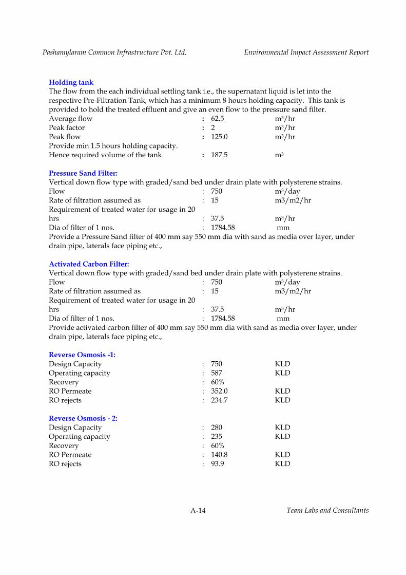
A-14 Team Labs and Consultants
Holding tank The flow from the each individual settling tank i.e., the supernatant liquid is let into the respective Pre-Filtration Tank, which has a minimum 8 hours holding capacity. This tank is provided to hold the treated effluent and give an even flow to the pressure sand filter. Average flow : 62.5 m3/hr Peak factor : 2 m3/hr Peak flow : 125.0 m3/hr Provide min 1.5 hours holding capacity. Hence required volume of the tank : 187.5 m3 Pressure Sand Filter: Vertical down flow type with graded/sand bed under drain plate with polysterene strains. Flow : 750 m3/day Rate of filtration assumed as : 15 m3/m2/hr Requirement of treated water for usage in 20 hrs : 37.5 m3/hr Dia of filter of 1 nos. : 1784.58 mm Provide a Pressure Sand filter of 400 mm say 550 mm dia with sand as media over layer, under drain pipe, laterals face piping etc., Activated Carbon Filter: Vertical down flow type with graded/sand bed under drain plate with polysterene strains. Flow : 750 m3/day Rate of filtration assumed as : 15 m3/m2/hr Requirement of treated water for usage in 20 hrs : 37.5 m3/hr Dia of filter of 1 nos. : 1784.58 mm Provide activated carbon filter of 400 mm say 550 mm dia with sand as media over layer, under drain pipe, laterals face piping etc., Reverse Osmosis -1: Design Capacity : 750 KLD Operating capacity : 587 KLD Recovery : 60% RO Permeate : 352.0 KLD RO rejects : 234.7 KLD Reverse Osmosis - 2: Design Capacity : 280 KLD Operating capacity : 235 KLD Recovery : 60% RO Permeate : 140.8 KLD RO rejects : 93.9 KLD
Pashamylaram Common Infrastructure Pvt. Ltd. Environmental Impact Assessment Report
A-15 Team Labs and Consultants
1.5 Process Description of Co-generation Power Plant
The steam required for the abvoe mentioned ZLD system is in the order of 18.5 TPH,
requiring a 25 TPH capacity boiler. It is proposed to utilize the steam initally for a power
plant of 2.5 MW capacity and the steam after step down shall be utilized for ZLD system.
The operational details of co-generation plant are presented as follows;
Using steam turbines, the cogeneration plant generates power. A 25 TPH @ 67 Kg/Cm2 (a)
pressure boiler will be installed to cater to the steam requirement of the turbine and for
process requirements. The electricity generated in the cogeneration plant will be used for
plant operations.
The fuel requirement of the imported / local coal is approx. 5.0 T/hrs. Fuel will be brought
by covered trucks and unloaded at site in covered shed. The fuel will be conveyed to the
boiler by conveyor system and fed to the boiler by Rotary feeders.
AFBC Atmospheric Fluidized Bed Combustion type boiler is chosen considering imported
coal and good combustion efficiency. Water is heated in the boiler to generate high pressure
super-heated steam at 67 Kg/Cm2 (a) at 485OC. The boiler capacity is 25TPH with thermal
efficiency of the boiler is 85%. The boiler will have Economizer, Air pre-heater to recover
maximum heat from the boiler flue gases. The boiler shall have standard accessories such as
Feed water pumps, Soot blowers, Dosing system, safety valves and cut offs .
Fresh air for fuel combustion will be supplied by FD fans. Pre heated hot air will be supplied
at combustion zone as secondary air through PA fans. ID fan will be used to exhaust the
waste flue gasses through a stack of adequate height as per PCB norms.
Air cooled condenser is selected considering the minimum usage of water. For auxiliary
cooling requirements of Generator, cooler, GVC etc, modular type FRP induced draft
auxiliary cooling tower will be provided. The balance steam from the turbine exhaust will be
condensed in an air cooled condenser and pumped back by CEP to the De-aerator and

Pashamylaram Common Infrastructure Pvt. Ltd. Environmental Impact Assessment Report
A-16 Team Labs and Consultants
further to the boiler. Turbine will have Turbovisory, safety devices, instrumentation, controls
and interlocks as per standard engineering practice.
The Generator is driven by the Turbine at 1500 rpm through reduction gear box. The
generator will have brushless Excitation system and closed circuit indirect water cooling
system. Power will be generated at 11kV, 3phase, 50cps frequency. The Generator will be
provided with HT breaker, LASCPT, NGR, AVR, Metering & Synchronization panels as per
standard engineering practices and protective measures.
The power produced at 11kV will be taken to plant's HT yard through cabling. All necessary
protections are incorporated such that power plant is protected from any electrical faults.
1.5.1 Process Description of Main equipment:
I. Boiler
The type of boiler used is AFBC boiler. The plant proposes to utilize Imported/Domestic
coal. Boiler feed water is supplied by a closed cycle system of evaporation through De-
aerators and boiler feed water pumps. The pressurized feed water will pass through the de-
aerator and economizer before reaching the boiler drum. The evaporated steam is separated
in a steam drum and further super-heated in super heater coils before supplying to turbine
for expansion and condensation of thermal energy to mechanical work. The turbine is
coupled to electric generator through gear box where the mechanical energy is converted to
electric energy.
The Saturated steam from the steam drum is led in to 2 stage super heater section mounted
at convective zone of the boiler. The super heater system will have two stages of super
heaters to achieve the rated steam outlet temperature of 485°C from 80% to 100% MCR load.
Intermediate spray type de-super heaters will be provided between the two stages of super
heater to control the steam temperature over the control load range. The unit will include an
economizer encased in the ducting after the boiler bank.

Pashamylaram Common Infrastructure Pvt. Ltd. Environmental Impact Assessment Report
A-17 Team Labs and Consultants
Technical Specification of AFBC Boiler Installation Outdoor Fuel Size 0 -6 mm Fuel Imported/Indian coal Type of Boiler Atmospheric fluidized bed Combustion Method of control of fuel feed By varying the speed of fuel feeding drives Fuel quantity (100% MCR)(Kg/hr.) 5000 Boiler Thermal efficiency on GCV basis 85+/-1% Rated capacity of Steam boiler (Kg/hr.) 25,000 Steam pressure (Ata) 45 Steam temperature (°C) 485 Boiler outlet Flue gas temp. (°C) 160 Feed Water inlet temperature at the inlet (°C) 30 Ambient temp. (°C) 40 Relative Humidity (%) 60 Ambient temp. (°C)
- Efficiency 40 - Insulation 50 - Electrical 50
Electrical Data -LT Volt (V) 415 + 10% - Control Volt (V) 110 + 10% - Frequency (HZ) 50
Compressed Air pressure (Kg/cm2) 5
II. Steam turbine generator The medium pressure and medium temperature steam generated in boiler will enter a multi-
stage turbine and will cause the turbine shaft to rotate. In this process, the steam will lose its
temperature and pressure. As the pressure is coming down volume will increase, thereby
increasing velocity of flow in the turbine. This thermal energy getting converted to mechanical
energy will rotate the turbine shaft which is rigidly coupled to generator. An electrical generator
coupled to the steam turbine shaft will rotate in a magnetic field and generate electrical power of
2.5 MW at voltage of 11 KV. A small percentage of electrical power thus produced will be used
in the power plant itself to energies the rotating equipment like the FD fan and ID fan of boiler,
the feed water pumps, lighting etc.

Pashamylaram Common Infrastructure Pvt. Ltd. Environmental Impact Assessment Report
A-18 Team Labs and Consultants
Technical Specifications of Turbine Parameter Specification No. of Turbines 1 (one) Type Multi stage, horizontal split casing, high speed with
gear box, impulse type, extraction cum Condensing with air cooled condenser
Rated Output 2.5 MW @ 25 TPH, process steam @ 67 Kg/cm2(g) Speed of Turbine Shaft 1500 RPM Speed of Generator Shaft 1500 RPM Gear box Provided with SF 1.3, Double helical single reduction
(Air breather ) Rotation (Viewed from turbine front) Clock Wise Main steam conditions at stop valve Inlet steam pressure
67 ATA, 485 C, 25tph
Type of Governing Electronic ( Wood ward)
Technical Specifications of Generator Parameter Specification No. Of generators 1(One) Type Three phase synchronous generator, totally enclosed air cooled
with air to water heat exchanger, horizontal and indoor. Output 2.5 MW Voltage 11 KV Frequency 50 Hz Speed 1500 RPM Power Factor 0.8 No. of Poles 4 Inlet cooling water temp 34°C Excitation Brushless Excitation system
1.5.2 Fuel Requirement
The proposed 25 TPH boiler will use imported / domestic coal as the main fuel. The
imported/ domestic coal consumption per hour is 5 MT. DG set operation during regular
power supply breakdown period only.

Pashamylaram Common Infrastructure Pvt. Ltd. Environmental Impact Assessment Report
A-19 Team Labs and Consultants
Characteristics of Proposed Fuels Fuel Quantity
(T/hr.) Properties
Moisture Volatile matter
Fixed Carbon
Ash% dry Basis
Gross heat Kcal/kg Dry basis
Proximate Analysis Imported Coal 3 30-32% 43.07 48.37 9.37 4500 Indian Coal 2 8-10% 43.07 39.9 42 3800
Fuel Quantity (T/hr.)
Carbon Content
Hydrogen Content
Nitrogen Content
Oxygen Content
Sulfur Content
Phosphorous Content
Ultimate Analysis Imported Coal 3 48.37% 2.51% 0.8% 8.56% 0.39% 0.07% Indian Coal 2 39.9% 2.48% 0.48% 6.76% 0.38% 0.07%

Pashamylaram Common Infrastructure Pvt. Ltd. Environmental Impact Assessment Report
A-20 Team Labs and Consultants
ANNEXURE – III
Water Requirement
Water is required for R&D, cooling tower makeup, steam generation and domestic purposes
within the CETP. The total water requirement shall be 250.9 KLD, out of which 218.9 KLD
shall be fresh water and balance 32 KLD shall be recycled water mainly to operate the co-
generation plant and utilities. The required water shall be drawn from ground water/TSIIC
(Industrial supply) in addition to reuse of treated wastewater. It may be noted that the
facility is meant for treating wastewater/effluents from various industries located within
the industrial area to the tune of 475 KLD. The wastewater meant for treatment is not
reflected in the water balance, as the treated wastewater is returned to the individual units
to the tune of 460 KLD.
Total Water Balance Purpose INPUT (KLD) OUTPUT (KLD)
Fresh Water Recycled Water Loss Effluent Boiler Feed 126 122 4 Cooling Tower 83.4 32 94.6 20.8 R&D Lab 5 5 Scrubbers 2 2 Domestic 2.5 0.5 2 Gross Total 218.9 32 217.1 33.8 Total 250.9 250.9

Pashamylaram Common Infrastructure Pvt. Ltd. Environmental Impact Assessment Report
A-21 Team Labs and Consultants
ANNEXURE – IV
Water Pollution:
Effluents from member units, CETP, R&D, utility blow downs and domestic wastewater
will be sent to the effluent treatment system. The treated effluent will be reused for cooling
towers makeup in the individual units.
Total Effluent Generated and Mode of Treatment Description Quantity
(KLD) Mode of Treatment
HTDS Effluents (TDS & COD> 15000 mg/l) Process Effluent (From Member Units)
475 Sent to Stripper followed by MEE and ATFD. Stripper Condensate sent to Cement Plants for Co-Incineration. MEE and ATFD Condensate sent to Biological treatment plant followed by RO. RO rejects sent to MEE. Permeate from RO is returned to individual units for reuse.
CETP R&D 5
Total - I 480 LTDS Effluents (TDS & COD< 15000 mg/l)
Boiler Blow downs 4 Sent to Biological Treatment System followed by RO. RO permeate reused for co-generation power plant cooling tower makeup. RO rejects sent to MEE.
Cooling Tower Blow downs 20.8 Scrubbers 2 Domestic 2 Total - II 28.8 Grand Total (I+II) 508.8
Treated Effluent Standards
Description Parametr Concentration (mg/l) Treated Effluent TDS < 50 mg/l
TSS < 10 mg/l COD < 20 mg/l

Pashamylaram Common Infrastructure Pvt. Ltd. Environmental Impact Assessment Report
A-22 Team Labs and Consultants
ANNEXURE – V
Emissions from Utilities
The sources of air pollution are 25 TPH Coal fired boiler and backup DG sets of 2 x 500 KVA.
The proposed air pollution control equipment for Coal fired boiler is Bag Filter. DG sets shall
be provided with stack heights based on the CPCB formula for effective stack height. The
emission rates of SO2, NOx and PM from each stack are presented in Table below
Emission Details of Pollutants from Stack S.
No Stack Connected to Stack
Ht (m)
Dia of stack
at top(m)
Temp. of exhaust
gases (OC)
Exit Velocity (m/sec)
Pollutant Emission Rate (g/sec)
PM SO2 NOx
1 25 TPH Coal fired Boiler 40 1.8 180 15 1.8 3.2 4.6 2 2 x 500 KVA DG Sets 5 0.2 200 6.8 0.002 0.025 0.04
* DG sets stack heights are above the roof level.
Technical Specifications of Bag Filter – 25 TPH Coal Fired Boiler
S.No Application Unit Value 1 Boiler Capacity TPH 25
Fuel Coal 2 Gas Volume m3/hr@170 degC 38500
Gas Temperature Deg C 200 Outlet emission mg/Nm3 <50 Flange to flange pr. drop mmWC 150 Maximum oxygen in flue gases Vol % 8.7 Model FGF3MFV10018FB No. of Bags 504 Filter area per bag m² 1.86 Total filter area m² 937.5 Air to cloth ratio m³/min/m² 1.5 Outlet Emission
3 Bags Diameter ID, mm 160 Length mm 3660 Material Nomex Max. operating temp. degC 200 Weight gm/m² 500-550 Permeability L/dm².min 150 to 180
4 Bag Cleaning Compressed air required Nm3/Hr 46 at 6-8 kg/cm2 No. pulse cum solenoid valve 15 Size of pulse valve NB 40

Pashamylaram Common Infrastructure Pvt. Ltd. Environmental Impact Assessment Report
A-23 Team Labs and Consultants
5 Material of Construction Casing MS
a Tube Sheet MS Cage MS Hopper MS
7 Terminal Points Dirty air Inlet of Poppet Valve, Flanged end Clean air Outlet of Bag Filter, Flanged end Dust discharge RALV Compressed air Inlet of Air Header Electricals Power Supply for Timer 230 V Ac
Diffuse Emissions
Emissions released from operations like distillation etc. Emissions from stripping of
effluents mainly contain low volatile organics. These emissions are passed through double
condensers followed by vacuum pump before releasing into atmosphere to mitigate odour.
Effluent transfer pumps shall be provided with mechanical seals. The transfer of effluents
shall be mainly by closed pipeline systems. Stripped low volatile organics are stored in
storage tank with condenser.. The influent storage tank is a major source of diffuse VOC
emissions, and it is proposed to provide a closed tank for initial storage of untreated
effluents, with scrubbers connected to the storage tank vent.
Fugitive Emissions
Fugitive emissions are anticipated from equipment leakage and transfer spills. The
periodic maintenance program shall ensure integrity of equipment mitigating the
equipment leakage. The fugitive emissions shall be reduced by closed transfer and handling
of all effluents.

Pashamylaram Common Infrastructure Pvt. Ltd. Environmental Impact Assessment Report
A-24 Team Labs and Consultants
ANNEXURE – VI
Solid Waste
Solid wastes are generated from wastewater treatment and utilities. The effluent treatment
system generates, stripper distillate, ATFD salts and ETP sludge. Coal fired boiler generate
ash while DG sets generate waste oil and used batteries. All the wastes except coal ash are
considered hazardous. The hazardous wastes of stripper distillate are sent to cement plants
for co-incineration, thereby reducing the load on TSDF facility and reducing consumption of
non renewable resource of coal in cement plant kilns. The inorganic wastes, salts from ATFD,
and ETP sludge are sent to TSDF facility located at Dundigal, Ranga Reddy district or to
cement plants contingent on acceptability. The waste oil and used batteries are sold to
authorized recyclers. Coal ash is sold to brick manufacturers in the local area. .
Total Solid Waste Generated and Mode of Disposal S.No Description Units Quantity Mode of Disposal
1 Ash from Boiler TPD 65 Sold to Brick manufactures 2 Stripper Distillate KLD 20 Sent to TSDF/Cement Industries for
Co-incineration. 3 Evaporation salts TPD 38.3 Sent to TSDF/Cement Plants for
blending. 4 ETP Sludge TPD 12 Sent to TSDF /Cement plants for
blending. 5 Waste oil LPM 110 Sent to Authorized Recyclers 6 Used batteries No.s/Yr 4 Sent to Authorized Recyclers
Ash Handling System
Ash will be of two types’ viz., bottom ash and fly ash. The bed ash will be about 20% of the
total ash and the remaining 80% of the total ash will be fly ash. Bag Filter (dust collector)
will separate all the fine ash particles. The efficiency of Bag Filter will be 90%. The bed ash
will be in loose lump farm and is collected in wet form on a submerged ash conveyor. The
conveyor discharges in to a hopper and can be loaded in to a trailer for disposal. The fly ash
collected at air pre heater, economizer and bag filter will be conveyed to an ash silo by a
network of screw conveyors and bucket elevator. The fly ash from the silo will be
conditioned with water before discharging on a truck for final disposal.

PASHAMYLARAM COMMON INFRASTRUCTURE PVT. LTD. SY. NO. 236 (Part), 237 (Part) AND 242 (Part),
PHASE II, IDA, PASHAMYLARAM, PATANCHERU MANDAL, MEDAK DISTRICT, TELANGANA
STUDIES AND DOCUMENTATION BY TEAM Labs and Consultants QCI: MoE&F OM, List A‐1, S.No.25. (An ISO 9001:2008, ISO 14001:2004 & OHSAS 18001:2007 Certified Organization) B‐115, Annapurna Block, Aditya Enclave Ameerpet, Hyderabad‐500 038. Phone: 040‐23748 555/616, Telefax: 040‐23748666 Email: [email protected]