University Advanced Design Program
356
NASA CR- 187041 ADVANCED DESIGN PROGRAM Proceedings of the 6 t h Annual Summer Conference University Advanced Design Program Hosted by NASA Lewis Research Center June I 1-1 5,1990 NATIONAL AERONAUTICS & SPACE ADMINISTRATION UNIVERSITIES SPACE RESEARCH ASSOCIATION
-
Upload
khangminh22 -
Category
Documents
-
view
2 -
download
0
Transcript of University Advanced Design Program
NASA CR- 187041
ADVANCED
DESIGN PROGRAM
Proceedings of the
6 t h Annual Summer Conference
University Advanced Design Program
Hosted by
NASA Lewis Research Center
June I 1 -1 5,1990
NATIONAL AERONAUTICS & SPACE ADMINISTRATION
UNIVERSITIES SPACE RESEARCH ASSOCIATION


NASA/USRA UNIVERSITY ADVANCED DESIGN PROGRAM
PROCEEDINGS OF THE 6th ANNUAL SUMMER CONFERENCE
June 11-15,1990

N W U S R A UNlVERSITY ADVANCED DESIGN PROGRAM 6th ANNUAL SUMMER CONFERENCE
The NASA/University Mvanced Design Program is operated by the Universities Space Research Association (USRA) under a contract with NASA Headquarters (NASW-4435). Inquiries mgxding the program may be directed to:
USRA Adv?nced Design R.ognm of tic^ 17225 El Camino Real, Suite 450 Houston, Texas 77058 (7 13)480-5939 FAX: (71 3)480-8862

-- -
iii
DEDICATION
We respectfully dedicate this Proceedings Volume to Mr. MelvinJ Hartmann of NASA's Lew& Research Center who r e W on July 3 afler 46 years of outstanriing service to NACQ and NASA. Mr. Hartmann's signijicant technical contn3utions include advances in both air breathing and mketp'Opu.l3ion systems, strengthening bani. reseanzh at Lewis Research Center, andptoviaing a major interne to univmerSlty based research in the mnuutics and space programs.
FOREWORD
The Program
7he NAS4A!BRA Uniuedty Advanced Desgn h g r a m is a unique program that brings together NASA engineers, students, and faculty from United States engineenneenng schools by integrating c u m t and future NASA ~ e / m m u t i c s engt'm'ng deszgn pvojects into the un im ' ty cummculum. ?Be Program was conceived in the fall of 1984 as apilot ptoject to foster engt'm'ng design education in the unim' tks and to suppfement NASrt's in-house effotZs in admncedplanning for space and aeronautics design. Nine unim'ties and Pw NASA centerspar$i@xzted in the first year of the$lotp'Oject. Close cooperation between the NASA centers and the univetsdtks, the m f d sdection of &gn topic, and the enthusiasm of the students has resulted in a very successful program that now includes fmty-three unim'ties and eight NASA centers. The study topics cover a broad range of potential space and mnautics projects that c o w be u m e n during a 20-3Oyearpe~iod beginning with the akployment of the w e Station Freedom scheduled for the mid- 1990s. Both manned and unmanned encieam am embraced and the systems a#macb to the design problem is emphasized. The student teams pursue the chosen problem during their senior year in a one- or two- semester capstone &sign course and submit a compreMw written repot.r at the conclusion of the project. Finally, student qtmsentatiws from each of the unim'ties summarize t M workr in oralpresentations at the annual Summer Conference, held at one of the NASA centen and attended by the unim' ty faculty, NASA and USRA personnel, and mqbace industry ~ sen ta t i v e s .
The Pmceedings Vdume
As the Advanced Design Program has gmwn in size, it bas also mahcred in tams of the qudity of the stua'mtprojects. ?Be compreMwfinal
repmts am rlistdmted thtpugb the Natiortal Technical In f m t i o n Service. However, the theresuCts of the stu iks reach only a smull audience, p ' r ' w y those who attend the Summer Conference. In otder to bmaden the rlistnBution, a P)rx&ngs oolume, which s u m h e s theproject msults and m u g b l y ~ k the Conference pwentahns, is publt'shed. %present volume npmenkF the student wn& accomplished during the 198990 academic- and npwted at the 6th Ann& Summer Conference hosted by the Lewis Research Centw, June 11-15, 1990.
ACKNOWLEDGMENTS
~ p u b l ~ ~ n was madepossible through the efforts of a great many people. First of all, we are gratem to the students, the uniYwsity f d t y , and tbeir teaching assistants for the excellent tee- wonk. SecoM zue are indebted to those inrh'vidualsfrom NASA H-m a n d m the NASA centers wbo conceived thepropm in the beginning, haveprouided ualuuble guhahnce thughout, and t h u g b tbeir keen i n t m t in the studmtprojects, are in latgepart respons0le for the bounrlless enthusiasm of the sfudents. AnaU' we thank the staff of the Publications Services Office of the Lunar and Planetmy Institute for the excellent wmk: in the preparation of the Pnul ADCeedings volume.
-USRA AdvancecC Design &gram OfJce
TABLE OF CONTENTS
Opening Remarks-Me1 Hartmann NASA Leuzlris Research Ceritcl-
Keynote Address - Raymond S. Colladay Martin Marietta CoIpor~1tion
SPACE PROJECT3
THE u m R S I n OF ALABAMA, HUNTSVILLE Fluid Phase Separation (FPS) Experiment for Flight on the Shuttle in a Get Away
Special (GAS) Canister: Design and Fabrication
u m R S I n OF ARIZONA Autonomous Space Processor for Orbital Debris
m u I n OF CALIFORNIA, LOS ANGELES Laboratory Simulation of the Rocket Motor Thrust as a "Follower" Force
UNIVERSITY OF CALIFORNIA, LOS ANGELES Design of a Scientific Probe for Obtaining Mars Surface Material
UNIVERsIn OF CENTRAL FLORIDA Postlanding Optimum Designs for the Assured Crew Return Vehicle
UNIVERSITY OF COLORADO Methods for the Development of a Bioregenerative Life Support System
UNNERSITY OF FLORIDA Implementation of Sensor and Control Designs for Bioregenerative Systems
FLORIDA A&M UNIVERSITY/FLORIDA STATE UNIVERSITY Conceptual Second-Generation Lunar Equipment
FLORIDA A&M UNIVERSITY/FI,ORIDA STATE UNIVERSITY Lunar Articulated Remote Transportation System
GEORGIA INSTITUX OF TECHNOLOGY Lunar Surface Vehicle Model Competition
GEORGIA INSTITUTE OF TECHNOLOGY Baggng System, Soil Stabilization Mat, and Tent Frame for a Lunar Bax
UNIVERSITY OF HOUSTON COLLEGE OF ARCHITECTLIRE Spaceport Aurora: An Orbiting Transportation Ntxlc
UNIVERSITY OF HOUSTON COLLEGE OF ARCHITECTURE In-situ Resource Utilization in the Design of Advanced 1.unar Facilities
UNIVERSITY OF IDAHO Preliminary Greenhouse Design for a Martian Colony: Structural, Solar Collection,
and Iight Distribution Systems
UNIVERSITY OF ILLINOIS, IJRBANA-CHAMPAIGN An Unmanned Robe to Pluto
KANSAS STATE UNIVERSITY Automation of Closed Environments in Space for Human Comfort and Safety
UNrVERsIn OF MARYLAND Project Exodus

UNIVERSITY OF MARYLAND Manned Mars Mission
UNIVER!51TY OF MARYLAND Walking Robot: A Design Project for Undergraduate Students
hWEACHUSETE LNSTITLiTE OF TECHNOLOGY Project Artemis
m m R s I n OF MICHIGAN Project Egress: The Design of an Assured Crew Return Vehicle for the Space Sration
UNIVERSITY OF MINNESmA Biconic Cargo Return Vehicle with an Advanced Recovery System
UNIVERSITY OF MINNErnA Winged Cargo Return Vehicle Conceptual Design
NAVAL POSTGRADUATE SCHOOL High-Latitude Communications Satellite (HILACS)
OHIO STATE UNIVEmITY Project WISH: The Emerald City
OLD DOMINION UNIVERSITY Design of an Autonomous Lunar Construction Vehicle
PENNSYIVANIA STATE u r v m R S I n Preliminary Subsystem Designs for the Assured Crew Return Vehicle (ACRV)
PRAIRIE VIEW A&M LiNmRSIn Replenishable Food Supply on Mars
m m R s I n OF PUERTO RICO Habitability: CAMELCrr N
RENSSELAER POLYTECHNIC INSTITUTE Investigations into a Potential "laser-NASP Trampon Technology
THE UNIVERSITY OF TEXAS, AUSTIN 1989-90 Project Summaries
THE UNIVERSlTY OF TEXAS, AUSTIN Project Summaries
IJNITED STATES NAVAL ACADEMY MIMES and GEOSHACK
ITAH STATE m m R S I n Microspacecraft and Earth Observation: Electrical Field (ELF) Measurement Project
VIRGINIA POLYTECHNIC AND STATE UNIVERSITY W e e Orbital Transfer Vehicles
UNIVERSITY OF WASHINrnN Megawatt Solar Power Systems for Lunar Surface Operations
u ~ m m I n OF WISCONSIN -MILWAUKEE Genes& Lunar Outpost: An Evolutionary Lunar Habitat
WORCESTER POLYTECHNIC INSTITUTE Integrated Support Structure for GASCAN 11

AERONAUTICS PROJErn
AUBURN UNIVERSITY Summary of 1989-90 Aeronautics Design Projects
CALIFORNIA STATE UNIVERSITY, NORTHRIDGE Autonomous Martian Flying Rover
CALIFORNIA STATE POLYTECHNIC UNIVERSITY, POMONA High Altitude Reconnaissance Aircraft
CALIFORNIA POLYTECHNIC STATE UNIVERSITY: SAN LUIS OBISPO The California Corridor Transportation System: A Design Summary
CASE WESTERN RESERVE UNIVERSITY 0-THREE: A High Altitude, Remotely Piloted Vehicle
u r v m R S I n OF KANSAS, LAWRENCE Preliminary Design of a Supersonic Short-Takeoff and Vertical-Landing (STOW-)
Fighter Aircraft
LJNNERSITY OF NOTRE DAME Design of a Remotely Piloted Vehicle for a Low Reynolds Number
Station Keeping Mission
THE OHIO STATE u m R s I n A Hypersonic Research Vehicle to Develop Scramjet Engines
ECOLE POLYTECHNIQUE FEMININE Carrier Aircraft
PURDUE u w w w n Design of a High Speed Business Transport
WORCESTER POLYTECHNIC INSTITUTE High Altitude, Microwave-Powered Atmospheric Sampling Aircraft
ALUMNI PROJECTS
UNIVERSITY OF WISCONSIN-MADISON


Opening Remarks
It is a pleasure to take part in the opening session of the University Advanced Design Program Summer Conference.
Over the next several days, we will be reviewing the design concepts developed by the teams and classes involved in the program. Raiews, critiques, and evaluations are a continuing and necessary step in the design and development of advanced aero- space systems. It occurs to me that some of you, having contributed to your team's efforts, may feel that the task is completed. It is only completed to a lwel where the concepts can be reviewed and further needs and the course of the design and devel- opment can be defined.
In the aerospace and similar technical areas, the design process blends neatly into the development and application phase. It is necessary to pass through a series of review steps along the way. Design changes and mWcations along with critical reviews may be expected to continue throughout the useful life of aerospace systems. This is the process that is used to continue to update and bring new knowledge and capability to extend the systems' useful Life. If this does not occur, it is probable that the design was too conservative to result in a profitable venture.
The greatest challenge to engineers engaged in design is the need to be continu- ously aware of advances that may provide increased capability. This new knowledge must be verified and applied to improved design and analysis methods and reduced to engineering practice as quickly as possible. To provide competitive designs, it is necessary that the latest information be available to the designers as well as the reviewer.
The personnel of the Lewis Research Center are pleased to host this conference and are glad that so many of you have journeyed to the North Coart to attend.
-Me1 Hartmam NRSA L e w i s Resemrh Center
PRECEDING PAGE BLANK NOT FlLMED

KEYNOTE ADDRESS
It's gotd to be here in the backyard of the Lewis Research Center and away from that piece of real estate on the Potomac otherwise known as Washington-the city of southern efficiency and northern charm. As an alumnus of the center, Lewis will always be a special place for me, and I still look back with fond memories of the years I spent here.
These are the best of times and the worst of times. In the next few minutes, I hope to persuade you that they are mostly the best of times. There is no doubt that we are facing the most dramatic change in the aerospace and defense business in 50 years.
The defense budget will continue its already four-year decline coming off the Reagan build-up. A complete reexamination of our national defense strategy of the last 40 years, following the dramatic events in Eastern Europe and the Soviet Union, will result in a major realignment and consolidation of the defense and aerospace industrial base. It's a lot different building up than building down. Tying to grow business in a declining market really sharpens your management skills. But the winners in this shakedown will be profitable. Change brings uncertainty and uncertainty carries with it risk; but with risk comes reward.
w hat does it mean for aerospace in particular? First of all, there will not Ix a peace dividend. But the space program will prosper, for NASA and defense, as compliance with new treaties must be verified largely from
space national technical means. There is some argument that because defense budgetswill decline, we should invest more in space to maintain a strong industrial base, but that downplays the importance of a U.S. space program-makes it sound like a space welfare program. The real reason space exploration will be supported is because the American people want it. They understand what the Congress will eventually realize, that the space program lets the country express its will to achieve great things and to satisfy an innate human desire to explore and learn, while at the same time infusing some of the skills and tools required to rekindle our industrial productivity.

I ~m be wen more bullish on the prospects for design engineering, as companies like mine recognize how important good design engineers are. I hold the view that design is critical to our future for several reasons.
First, because we are often dealing with space systems that cannot be adequately tested, we must rely heavily on design getting it right. The national aerospace plane is a good example; much of the design can't be tested as a system before the flight article. The shuttle is another example; the first test of the full orbiter system was the piloted landing tests and the first test of the complete system occurred on its maiden launch to space. That is trusting design, albeit with lots of subsystem tests.
Second, design, coupled with manufacturing in concurrent engineering, is what lets us build in quality and improve productivity. Since World War 11, we have approached product development like a relay race. Research and marketing comes up with an idea, hands it off to design, and they may develop a couple of hand-built prototypes to prove the soundness of the concept, and then it's thrown over to manufacturing to figure out how to build it. The first thing they do is send it back to engineering for changes, and on and on . . . you know the story.
0 ur problem in this country isn't a lack of technology and innovative ideas; it's getting products to the market on time. It just takes too long to get an idea from laboratory to field. In the US., we typically invest 2/3 of the cost
of development on product and 1/3 on process. It is just the reverse in Japan. But we're changmg all that, right? We know that the walls between design and
manufacturing need to be tom down. That's the social part of the fix and middle management is feeling threatened-you can actually get rid of a layer of management when you get teams of design, software, hardware, purchasing, manufacturing, and field support, all together and empower the people to make decisions. The other thing that has made concurrent engineering possible is the computer and information management systems that let all the functions talk to each other in a common medium.
At Martin Marietta, like our sister companies in the aerospace business, the change in culture is dramatic and the results are incredible.
While design is a small part of the product development effort, it has the major impact on cost.
Cost Incurred 'I'otal Cost Committed
Concrpt definition Design engineer Testingf Rtxcss planning Production

xiii
Through each phase, cost of a design change increases an order of magnitude, so the same design change that would cost, say, $100 in concept definition, would cost S 1 M to change in production.
Bringing design and manufacturing together, along with purcllasing and the vendors and sabcontractors, also has a major impact on time and quality. Our experience, again, like others, is that:
Development time is reduced by more than 50%; engineering changes are reduced by more than 70%; the time it takes to get a product to market is cut in half; and we gain quality improvement with almost no end in sight.
Quality means continuous improvement, and quality, built-in, costs less. For a long time that was counterintuitive. ~u~ustine's* law of "counterproductivity'' is proven over and over again:
"It costs a lot of money to build bad products." It costs a lot less to do it right the first time, one time. When you cut through all the rhetoric, the real issues are ( 1 ) time to market and
(2) quality. . . plus flexibility in responding to changing customers needs and market forces. If you do everything else right, cost takes care of itself.
We've been talking about product development, but let's look at the Washington end of the process for a minute. I use that as a euphemism to refer to the front end of the process of fielding an idea-the planning, budgeting, and acquisition process- when the government is the customer.
I have earned some license to be critical, because I've been there. It has long been recognized in Washmgton that the formation of a committee is a
powerful technique for avoiding responsibility, deferring diEcult decisions, and averting blame while at the same time maintaining a semblance of action.
Kelly Johnson, who built the legacy of the Lockheed Skunk Works had a particular disdain for committees. He described it in the following way: 'We're into an era where a committee designs airplanes. You never do anythmg totally stupid, you never do anythmg totally bright. You get an average wrong answer."
At Martin, I just formed a committee to deal with an issue so important that we've had meetings every other Friday for two consecutive weeks. Norm [Augustine] really believes in one of his other laws: "The optimum committee has no members. . . or maybe one . . . or at most three as long as one is absent and another is sick"
Congress has carried it to an extreme. They even have a committee on committees. Not only do we need to reduce the time to get things through the factory, we need to give some attention to reducing the time it takes to get programs through the budget and procurement cycle.
'~orrnan R Augustine, veteran aerospace executive, now Chairman and CEO of Martin Marietta Corporation.
xiv
ecently, I looked at most of the major military systems developed over the last 50 years and plotted the ratio of planning time-to-execution time against year that full-scale development was initiated. A gradual upward trend in the
1950s and 1% really began to take off beginning in the 1970s to the point where, now, we take nearly as long to plan and sell programs as we do to execute them.
Look at Space Station and how long the planning process has taken to move it through the administration and the congressional budget process. Keeping a program sold is also a challenge and, the longer the program stretches out, the harder it is.
I'm not even going to hazard a guess on what the planning-to-execution time for a mission to Mars will be. Special care will have to be taken in laying that program out to have a series of major accomplishments always before the public to hold their interest.
I am disturbed by the committee approach to overseeing our space program. The National Space Council can be an effective deliberative body for sorting out national priorities, building political conxnsus, advising the President, and cutting through the Washington bureaucracy. But, if it tries to sort out the best approach to the space exploration program and reserves too many decisions for itself instead of tuming the details over to NASA, then I have a problem. We have a civil space agency-the same one that took us to the Moon 20 years ago. It's time to give NASA the total responsibility and the authority to take us back.
Let me turn now to the future. Enpee r s and scientists, particularly you students in the audience, will be the ones going back to the Moon and to Mars and you will be helping to lead us back to being a productive nation, strong economically, and secure militarily. Only engineering can lead us back-not MBAs, not lawyers, not the service c~cupations. Engineers are the dtxrs, and design engineering is where it's at, as they my.
We will go back to the Moon to stay and to Mars. Robotics will continue to provide us mlth a surrogate presence in the universe. New military systems will have smart sensors in things that fly, swim, and drive, that allow us to project military force anywhere in the world. While we will not be in full-rate production on as many new systems because of the DOD budget decline, we will still upgrade existing systems. We can expect increased design activity through R&D and pre-production prototypes. And, when technical breakthroughs occur, we will take those systems to production to keep our defense modern and provide a credible deterrence. There will also be more emphasis on simulation, before, and in lieu of, bending metal. We will become more dependent on advances in communication and intelligent ?stems that give us infomation when we need it, where we need it, and in the form we need it.
Of course these will be challenging times. But again, speaking to the students in the audience, don't be discouraged by change. It is exciting and you will affect the course of that change.
When Alan Shepard blasted off on the first U.S. manned space mission, I was in high school and decided right then that 1 would be part of the space adventure. Ten years later, after collecting a few degrees, I was a green-behind-the-ears research engineer at Lewis. I no m n e r reported to work than the notice of layofi hit-it was in the post-Vietnam build-down in defense and this looked like it might be a bummer of a profession to be in. But just the opposite has been true. It has been, for me, the most rewarding and exciting career one could imagine. We go through these cycles, but the engineering profession rides them out, and the long-term trend is always the same-we need more good engineers.
I went into aerospace engineering and the space program becxuse I wanted to bt. part of an enterprise that inspires the human spirit. I am glad to x e so many of you are motivated by the same interest. Looking over the design projects on display, I'd say the future is in pretty good hands. 'Ihank you and best of luck to all of you.
-Raymond S. Colladay Kce tFesident, Resea~h and Development
Martin Marietta CorporaHon

Space Projects


FLUID PHASE SEPARATION (FPS) EXPERIMENT FOR FLIGHT ON THE SHUTI'LE IN A GET AWAY SPECLAL (GAS) CANISTER:
DESIGN AND FABRICATION N 9 1 , 1 g 1 2 2 THE UNIVERSITY OF ALABAMA, HUNTSVLLLE
The separation of fluid phases in microgravity environments is of importance to environmental control and life support systems (ECLSS) and materials processing in space. A successful fluid phase separation experiment will demonstrate a proof of concept for the separation technique and add to the knowledge base of material behavior. Ihe phase separation experiment will contain a premixed fluid that will be exposed to a microgravity environment. Mer the phase separation of the compound has occurred, small samples of each of the species will be taken for analysis on Euth. By correlating the time of separation and the temperature history of the fluid, it will be possible to characterize the process. The phase separation experiment is totally self-contained, with three levels of containment on all fluids, and provides all necessary electrical power and control. The controller W t e s the temperature of the fluid and controls data logging and sampling. An astronaut-activated switch will initiate the experiment and an unmaskable interrupt is provided for shutdown. ?he experiment has been integrated into space available on a manifeste Gef,Away Special (CL4.S) experiment, CONCAP 2, pan of the Consortium for Materials Complex Auton $, ous Payload (W) Program, scheduled for SIS 42 in April 1991. This document presents the design and the production of a fluid phase separation experiment for rapid implementation at low cost.
?he separation of fluid phases in microgravity is of interest for materials processing and long-duration Life support systems in space. On Earth, phase separation occurs due to buoyancy, but this is not the case in the microgravity environment of space. Therefore, materials processing relying on the phase separation of liquid mixtures will not occur in the same way as on Earth. This ditference could be used to advantage to develop new materials not presently available on Earth.
Fluid phase separation has direct application to current research concerning new metal alloys produced in micrograv- ity. To optimize the processing method for the alloys, the relationships between the different phases of the metal must be known (i.e., a phase diagram). Microgravity alters the phase diagram. To construct a new phase diagram, the molten metal needs to be analyzed while in space. It has been proposed that a simpler method could use special fluid mixtures to model the molten metals. This has the advantage that the transition temperature of phax separation for most fluids is sigmficantly lower than that of molten metals, so it will be easier to study the fluids in the laboratory and then correlate the data to the metals. The result will be a new space-based phase diagram that can be used to develop stronger, lighter-weight metals.
Another possible application concerns spacecraft thermal control systems. The heat kom components, experiments, and people must be dissipated kom the spacecraft environment. Present technology utilizes pumped liquid thermal transport systems for heat exchange. The heat dissipation is controlled by the mass flow rate of the system, which is determined by
PRECEDllbG PAGE BLANK NDT FiiMSD
the size of the pump. Large heat dissipation requires large pumps that use a prohibitively large amount of electrical power and add sigruficantly to the weight of the spacecraft. A specialized two-phase (liquid-to-liquid) thermal transport system could be more efficient in accomplishing this task Therefore, understanding the liquid-liquid phase separation process in space could aid in the design of closed environ- ments, such as the Space Station and the Mars mission.
A detailed understanding of the separation process is essential to the application of the fluid phase separation technology. Preluninary research concerning potential fluid mixtures and their behavior in space is underway. However, the fluid phase .separation process is a complex interaction between temperature and microgravity that is not possible to duplicate in an earthbound laboratory. An experiment is needed that will characterize the separation process in space and demonstrate a proof of concept for the fluid phase separation technique. Since this is a high priority project, it would be advantageous to fly the experiment ac soon as possible. At the University of Alabama in Huntsville, a fluid phase sepamtion experiment has been designed that satisfies all these requirements.
The experiment will record a complete temperature history of the fluids, along with samples of component species to be analyzed on Earth. The phase separation experiment is totally self-contained, with multiple containment levels for all fluids, and provides all necessary electrical power and control. Furthermore, the fluid phase separation experiment has a
PAGE a INTENTJONAUY BUM

Proceed lings of tbe .VASA/LJSRA Adrvanced Design Program 6tb Summer Conference
unique opportunity to take advantage of space available on a manifested Get Away Special (GAS) Canister, CONCAP 2, nhich is scheduled for STS 42 in April 1991.
This document presents a sumnwy of the design for the Fluid Phaw Separation (FPS) expcrin~cnt. It includes the description of the process, design of systems, and outline of a construction propam.
EXPERIMENTAL PROCESS
A mixture of succinc)nitrile and cylohexane is of particular intert-st. Succinonitrile is a solid at 20°C (room temperature) vld h ~ s a \aporization temperature of 85°C. This material is highly reactive with most metds exccept for gold and stainless steel. Plastics and rubber are ;dm reactive, but tenon is not. (:yclohexane is a liquid at room temperature and has a wporization tctnperature above 120°C. It is an organic solvent that will dissolve most adhesives. MI the materials used to contain and support the fluids must be carefully selected so a\ not to interact nith the liquids to produce erroneous results or jeo~arclizc ttle d e y of the experiment.
The experiment is a mixture of two fluids that are dormant both Ixxfore ;uld during launch. ' f ie mixture will not need to hc he;tted prior to the cxpriment stmt-up since the mixture &.ill contrast uniformly upon freezing. Just prior to the second sleep peritd, during a time of low activity, each of the fluid samples will hc heated to a predetemlined tcmpenture (less th;m 90°C) iuld allowed to stahilizc at that temperature for four to six hours. The controller will signal the heaters to shut cionn and the the 5ytem will begin to ctx)l. When the fluid reaches the transition temperature ( a function of composition, density, and initial tcmpcraturc ). the phase separation will then begin. accompanied by a release of heat. 'lhis will cause the
fluid temperature to temporarily stabilize. As phase separation continues, the fluid temperature will once again begin to fall and the sampling mechanism will be activated. The temper- ature of the fluid will be stabilized and maintained constant, permitting small samples of each of the species to be taken for analysis on Earth. By correlating the time of scyaration and the temperature history of the fluid, it will be possible to characterize the process. After the sampling is complete, the experiment will be deactivated for the duration of the space shuttle mission.
On Earth, differences in density typically drive the stparation process. In microgravity, minimal surface energy will be controlling the separation. It is anticipated that this mill produce two spherically shaped volumes containing the different component species. One component will be collected at the center of the fluid container, while the other will be wrapped around the first, positioned at the edge of the container. The fluid phase stpardtion experiment will be used to characterize this process.
DESIGN SUMMARY
The fluid phase separation experiment has a total weight of 11.8 Ib and a volume of 1105 in3, which is within the initial payload constraints impo.wd by CONCAP 2. This value includes six fluid containers and the support apparatus, the controller, and power supply. The overall dimensions are 14.5in (width) X 8.5 in (height) X 9.75 in (depth from the mounting plate). Volume of an individual fluid .sample is 0.22 in3 and the complete axwmbly is 0.8 1h. The GAS canister is shown in Fig. 1 with the relative placement o f the components within the GAS Can.
CONTROLLER
OUTER CONTAINMENT I S CUT AWC\Y TO EXPOSE INTERNAL COMPONENTS.
ALL OIMENSIONS ARE I N INCHES
Fig. I . (;A\ Cmister and Fluid Phase Experiment ORIGINAL PAGE IS Of POOR Q U A W

The Unitrersity of Alabama
STRUCTURAL SYSTEM
The structure will support the experiment and isolate the fluid phase separation experiment from the rest of the GAS Can. The whole experiment will he container1 within this shell and will allow the liquid containers and sanipling mechanism to be attached to the GAS Can mounting plate.
Several ideas for the shape of the outer shell were considered. The criteria used to c~aluate the proposed shape included size of the enclo.=d volume, minimization of the weight, ease of fabrication, and structural stability. The dimensions of the GAS canister and the allocated space provided by CONCAP 2 set the maximum dimensions. The experiment was to be located in the bottom, on one side of the canister, and have a height d no more than I 0 in. Iater, the height was further reduced to 8.5 in due to a change in the primary experiment, CONCAP 2.
It was decided that the volume occupied by the fluid phase. experiment should he large enough to fully contain six fluid sample containers, a controller, and a battery. Since the experiment had to he completely isolated from the other experinlents in the GAS canister, there needed to be a minimum of seams and joints in the outer shell. To maximize structural stability, the shell needed to he self-supporting.
The semicylinder was chosen as the best shape for the outer shell (Fig. 2). The shell will have a length of 14.5 in, a height of 8.5 in, and a depth (measured out from the mounting plate) of 9.25 in. The shell will hc formed h-om 0.031-in, type-304 stainless steel sheet, which is inert to the chemicals used for the fluids. By using thin steel, we can maintain the high strength and minimize the weight. The 304 stainless steel is easy to form and can be welded to increax: the strength of the shell and problde containment.
To reduce the weight, there is no backplane on the shell. The containment is maintained hy covering the GAS (hn mounting plate with a continuous 3-mm-thick teflon sheet. A 0.125-in-thick teflon O-ring g~ske t is placed between the outer shell and the mounting platc to absorb the displacements induced by thermal and mechanical loads. This will maintain a tight seal and prevent contamination of the other experi- ments in the GAS Can.
The shell is held to the mounting plate by 22 #10-24 grade 8 socket head bolts with 0.5-in washers. 'The bolt material is A-286 corrosion-resistant steel with an allowable stress ot' 20 Ksi. The holts are spaced at 2 in centers m u n d the 0.75- in fkange on the outcr shell. Although 22 h)l ts are not needed to support the outer shell, they are needed to maintain an adequate distributed pressure between the teflon gasket and the mounting plate to ensure a tight seal under launch loads. This bolt configuration prcxluces a worst-case niaximum bolt stress of 3000 psi, for a factor of safety of (3, under a 10-g load applied during the launch. The outcr shell experiences a maximum stress of 400 psi at launch, which is well helo~v the yield stress of the stainless steel and should prevent even ;I
fatigue failure of the outer shell. The shell wrill bt' penetrated ut three points. A l)-q~>e
electrical connector is located on the bottom of the shell to connect with con tn~l cables from the shuttle (located at the
Fig. 2 . Oi~tcr Shcll and lr~~tliclg Strc~w\
bottoni of the (;AS Can). The connector \\ill 1i;tr.c golrl-pl;rtcd pins and :I teflon gasket on the interior to prcbvcnt c'orrosioci ;md contanmination o f the (;AS (:;~n. 'llic other t\i.o openings ;ire covered uith 7-pcn teflon filters icr :I 30-1 t.~inlcx:? stcel housing. ' lhc tilters itre L i mm in di;~ci~ctcr ;end h;t\c ;I
maximum pressure of 1 0 0 psi at the inlet. with :III ;tllo\\~;~l>lc pressure dilkrence of 50 psi. ' l h i \\.ill permit the p~~rgi t ig 01' the fluid ph.~se sqxration cxperirner~t \+,it11 nitrogcn prior to launch. Also, thew hvo ports m i l l pcrniit r;rpiil dissip;ttion of the interior prcsurc while m;tint.tining cont;~inmcnt o f the fluid in the event [hilt the GAS (:;un is dc1)rcss11ri7c(t \\.liilc 111
s l ~ ~ c e . If this wvre to occur, the f l ~ r i t l n,o~cltl \~rl,limc to ;I solill ancl he trappetl I q the filter \vhilc the. nitrogen ga\ co~rld ewapc, prc~.cnting ;I nlpture ot'thc outcr s11c11
An 31i;lIybis of disl~l;tcccens sho\vccl th;~t dctlcction o f the large tliaphram-like surtitces were ;~c~cept;~l>lc, t , i~t ;I cI\n;lrni~, ;tnalysi\ sho\ved that the fi~ntlamcnt;tl frcclucncy o f \.il>cttion w~.s too lo\\ To improve thc d!n;uiiic rchpon\c 01' t1ic oicter shell. triangular rihs \verc added to thc top. hottom. and sirle o f the shcll. ' l h c ~ rihs hrokc up the .Ire;! tliat t~oulti frccSly oscill;~tc, ;~nct stitkncd the surt-:~ccs to out-of-pl;mc motiotr
FLIJID SAMPLING AND SPE<:ISlEN HE1RIEV.41. SYSTEbI
Within the outer shell is the fluitl ph ;~sc scp;rr;Ition exl>erimcnt 'lhe cltpcriti~cntal :Ipl,:cr;itu> is 'om[>osc.d o f tllr'ce suhs~stc.nis: the flitid containers, the 5;lniplitig rncch:lniscn, and
ORIGINAL PAGE IS OF POOR QUALITY

'ngs of tbe NASA/USRA Advanced Design Program 61b Summer Conference
the structural t i m e (inner shell). Size and weight restrictiom determined the maximum number of fluid sampling systems to six.
Many materials were considered for the fluid containers. Due to the unusual corrosive nature of the fluids, stainless steel, gold, and teflon were the only materials that were chen~ically suitable. A material with a low specilic gravity was desired to minimize weight. Furthermore, uniform thermal conductivity was necrssary to transfer heat from the external heaters into the fluid. Since the external heaters are to be positioned on the outside of the container, it is essential that the material have a high melting point. Finally, a high tensile strength will be needed to withstand the expected loads during the shuttle flight. All these criteria are met by tdon.
'lhe tcflon was n~achincd into the desired geometrical shape. A 0'5-in-diameter spherical fluid cavity is inside a truncated cone with a nominal wall thickness of 0.25 in. A flat octahedron plate passes through the sphere/cone dividing it in two hahres. hswmbly of the fluid containers is accomplished using a ferrule-type joint for i~lignment with six bolts to ensure XI adeiluatc scd. This will also provide the k t level of containment for the fluid. I h e orientation of the fluid containers is shown in Fig. 3.
Althouj$ a spherical shapc hoth inside and out would be optin~al for hcat flcw considerations, the exterior sphere is difficult to pr(K1t1ce. lherefore, a cone w* u.sed since it can I>c r..~\ily machincd ;~nd still provides a minimum of exposed surt;~cc t o ondu duct ,mil radiate hrat away from the fluid. The sltiipc \vill prtdt~ce an cvcn heat flow through the teflon container ;ind into the fluid sphere.
Provisions had to he made to fill the spherical cavity of each un~p lc c.ontainer after ~'i,w~llbl?. 711is problem was remedied by designing a special fill port that included a stainless steel tube press fit into the fluid container and .waled at the outside with I( rcnlo\shlc teflon plug. This ln-muts omfilling of the spherical cinit)' x) that no air pockets are present within the sphcrc
'lhc tcflon cuntiner hi a m;xiimun~ tensile strength of 3000 psi. mhic.11 is strong enough to withstand the increaw in internit1 prcs.s~~rc created hy partial baporization of the fluid
Fig 5. Irmrr Shcll Show~ng Two t ? d b md Mounting Plate
within the cavity (an internal pressure of 100psi). However, the controller should terminate the heating of the fluid before this pressure is reached.
Surroundmg the fluid containers is the inner stainless steel shell, which provides the structural support and acts as the second level of containment. The housing will be fabricated from the same material as the outer shell discussed earlier and will also have welded sans. The fluid containers will be mounted within this housing hut separated from the stainless steel shell by an insulating phenolic pad to minimize heat transfer away from the fluid spheres. Each of the fluid containers is attached to the inner shell by four #5-40 socket head screws threaded 0.375 in into the teflon. Under the worst loading case at the time of launch, the maximum load (including the preload) is 84 Ib per mew. This gives a safety fictor of 9 with respect to tear-out, bearing, and shear stresses.
The inner shell is constructed in two parts. A bax plate mounts the shell to the GAS cannister with 12 # 10-24 w e 8 socket head screws. The A-286 corrosion-resistant steel used in the screws has a 20-Ksi allowable tensile stress, which is four times greater than the maximum stress of 5000 psi that occurs at launch. The base plate has four flanges that are normal to the surface of the plate for attachment of the box containing the fluid spheres.
The box has four sides (open h n t and back), and is made slightly larger than the tabs of the bax- plate. The box is then bolted to the tabs on the base plate. Stainless steel nuts were spot welded to the base plate to accept the twelve #5-40 A- 286 steel socket head .screws. This was done to permit easier assembly of the experiment by allowing access to the front and back of the fluid spheres. To seal the box onto the base plate, a teflon O-ring gasket fits inside the tabs. To completely .seal the box, the front panel is attached using twc:lve #5-40 A-2% steel socket head screws and a teflon O-ring gasket. As before, stainless steel nuts are welded onto the inside edge of the box to accept the screws. This panel permits access to the spheres to fill them prior to launch.
The whole structure of the inner box has a maximum stress of 900 psi, which is well below the yield stress of the stainless steel, and should prevent failure of the inner shell. To stiffen the inner shell and to provide a rigid plate upon which to mount the rotary actuators, a stainless steel plate is welded across the interior of the box. Once all the components are in place, selected areas inside the box are filled with expanded polystyrene foam, which helps to dampen vibration and provides thermal insulation.
The sampling mechanism is composed of two tubes fitted one inside the other (Fig. 4). The exterior tube is rigidly mounted across the inside of the fluid sphere. It has two holes in the wall of the tube positioned such that one is at the center and the other is near the edge. A rotary actuator will rotate the inner tube to align the inner two holes with the outer two and permit d8usion of the fluid species into the inner tube. After sampling is completed, the inner tube will be rotated in a reverse direction to seal the samples within the innermost tube.
The exterior tube is limited to a diameter of approximately 0.050 in to limit the effects of wetting along the tube, which
The Uniuersit.+~ of Alabama
SAMPLE CHAMBER
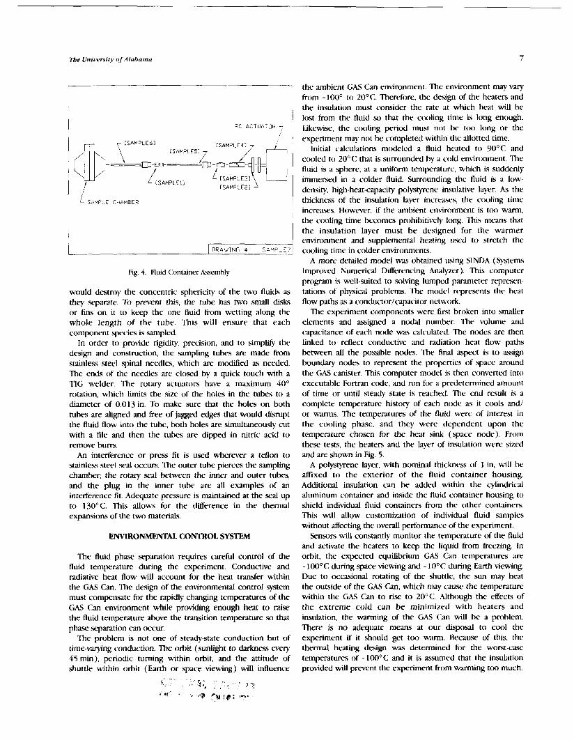
Fig. 4. Fluid Container Assembly
would destroy the concentric sphericity of the two fluids as they separate. To prevent this, the tube has two small disks or fins on it to keep the one fluid from wetting along the whole length of the tube. This will ensure that each component species is sampled.
In order to provide rigidity, precision, and to simplify the design and construction, the sampling tubes are made from stainless steel spinal needles, which are modified as needed. The ends of the needles are closed by a quick touch with a TIG welder. The rotary actuators have a maximum 40" rotation, which limits the size of the holes in the tubes to a diameter of 0.013 in. To make sure that the holes on both tubes are aligned and free of jagged edges that would disrupt the fluid flow into the tube, both holes are simultaneously cut with a file and then the tubes are dipped in nitric acid to remove bum.
An interference or press fit is used wherever a teflon to stainless steel seal occurs. The outer tube pierces the sampling chamber; the rotary seal between the inner and outer tubes, and the plug in the inner tube are all examples of an interference fit. Adequate pressure is maintained at the seal up to 130°C. This allows for the dserence in the thermal expansions of the two materials.
ENVIRONMENTAL CONTROL SYSTEM
The fluid phase separation requires careful control of the fluid temperature during the experiment. Conductive and radiative heat flow will account for the heat transfer within the GAS Can. The design of the environmental control system must compensate for the rapidly changing temperatures of the GAS Can environment while providing enough heat to raise the fluid temperature above the transition temperature so that phase separation can occur.
The problem is not one of steady-state conduction but of time-wrying conduc-tion. The orbit (sunlight to darkness every 45 min), periodic turning within orbit, and the attitude of shuttle within orbit (Earth or space viewing) will influence
the ambient GAS Can environment. The environment may vary from - lWO to 20°C. Therefore, the design of the heaters and the insulation must consider the rate at which heat will be lost from the fluid so that the ctx~ling time is long enough. Iikewisr, the cooling period must not be too long or the experiment may not be conlpleted within the allotted time.
Initial calculations modeled a fluid heated to 90°C and ctx)led to 20°C that is surrounded by a cold environment. The fluid is a sphere, at a uniform temperature, which is suddenly immersed in a colder fluid. Surrounding the fluid is a low- density, high-heat-capacity polystyrene insulative layer. As the thickness of the insulation layer increaws, the cooling time increases. However, if the ambient cnvinmnent is too warm, the cooling time becomes prohibitively long. This means that the insulation layer must be designed for the warmer environment and supplemental heating used to stretch the ctmling time in colder environments.
A more detailed model wa.5 obtained using SINDA (Systems Improved Numerical Differencing Analyzer). This computer program is well-suited to solving lumped parameter rcqx-esen- tations of physical problems. The mtKiel represents the heat flow paths as a conductor/capacitor network.
The experiment components were first broken into smaller elements and assigned a nodal number. The volume and capacitance of each node was calculated. The ntKies are then linked to reflect conductive and radiation heat flow paths between all the possible nodes. The final aspect is to assign boundary nodes to represent the properties of space around the GAS canister. This computer mtdel is then converted into executable Fortran ctde, and run for a predetermined amount of time or until steady state is reached. The end result is a complete temperature history of each node as it cools and/ or warms. The temperatures of the fluid were of interest in the cooling phase, and they were dependent upon the temperature chosen for the heat sink (.space node). From these tests, the heaters and the layer of insulation were sized and are shown in Fig. 5.
A polystyrene layer, with nominal thickness of 1 in, will be affixed to the exterior of the fluid container housing. Additional insulation can be added within the cylindrical aluminum container and inside the fluid container housing to shield individual fluid containers from the other containers. This will allow customization of individual fluid samples without affecting the overall performance of the experiment.
Sensors will constantly monitor the temperature of the fluid and activate the heaters to keep the liquid from freezing. In orbit, the expected equilibrium GAS Can temperatures are - 100°C during space viewing and - 10°C during Earth viewing. Due to occasional rotating of the shuttle, the sun may heat the outside of the GAS Can, which may cause the temperature within the GAS Can to rise to 20°C. Although the effects of the extreme cold can be minimized with heaters and insulation, the warming of the GAS Can will be a problem. There is no adequate means at our disposal to cool the experiment if it should get too warm. Became of this, the thermal hating design was determined for the worst-caw temperatures of -100°C and it is assumed that the insulation provided wiU prevent the experiment From warming too much.

Proceedings of tbe NASA/USRA Advanced Deslgn Program 6tb Summer Conference
CONTROLLER
The controller executes three primary functions. Funczion one provides active temperature control of six fluid samples during the experiment cycle. In addition, the temperature of the experiment battery pack will be regulated to maintain optimum battery output throughout the experiment cycle. Function two is the independent timing and control of each of the sample actuators once the phase transition is reached. Function three is the data logging in nonvolatile memory of experiment temperatures for the duration of the experiment's operation. Finally, the controller will monitor safety and control power for the experiment.
The control and data logging requirements for the Fluid
0 -120 f o -100 -80 -60 -4C -20 0 Phase Scpantion Experiment are relatively simple. The
TEMPERATURE (" C ) requirements fall into four catagories. These catagories constitute the logical division of work for the controller.
Fig. 5. 'firrmal Analysis of Cooling Time
Once the experiment begins, the fluid will be heated to a maximum temperature of 90°C over a I-hr period and then maintained at that temperature for 5 hr. This will require 81 mW/hr or 4% mW total. The fluid will also need to be cooled slowly, so intermittent heating may be required during cooling. Once sampling of the two fluid cwmponents W n s , the fluid temperature will be stabilized for an additional hour. This heating load is used to determine the size and number of heaters required.
The heat flow for a single fluid container is 81 mW/hr over a 6-hr period. &cause there is some thermal lag in transferring the load, and the heaters should not be in continuous operation, the heaters had to have a greater output than the heating load required. It was determined that the heaters should operate only one-third of the time, which requires 243 mW/hr. With six heaters chosen, the output from a single heater must be 40.5 mW/hr. Given that the voltage available from the battery is 6 V, the resistance of an individual heater was calculated to be 0.88 ohms. These requirements can be met by Thermofoil heaters, each having a diameter of 0.5 in, with an effective area of 0.1 5 sq in.
For control and safety, each heater will have a resistance thermometer laminated within it. The resistance thermometers (RTIIs) increase resistance with temperature, and are considered to be accurate and stable sensing devices. The RTD chosen will havt either platinum, nickel, copper, or nickel-iron elements.
Temperature sensors will also be needed to monitor the temperature of the sample, as well as the temperature of the battery. T h y niust have an output range 6rom 0- 10 V. For the sphere, it will be necessary to h.ave a coated sensor that will resist any type of reaction with the fluid. It must have a t t np ra tu re range at least from -50" to 1 50°C. A teflon-coated thermtxouple with a length of 0.05 in and a time constant of 1 .wc has k e n selrcted.
Category one is data storage. The nonvolatile electrically erasable and programmable memory (EEPROM) requirements are driven by the number of temperatures stored multiplied by the sample rate, multiplied by the experiment total operating time. A three-day experiment cycle time will generate 30,240 bytes that need to be stored.
Category two is active temperature control. The active control for temperature requires 13 separate temperature inputs, 2 each from each of the 6 fluid specimens plus 1 from the battery. In addition, there are seven temperature control outputs, one for each of the six experiments plus one output for the battery.
Category three is the control of the experiment actuators. There are six one-bit control outputs for the actuation of the experiment sample mechanisms. The timing for the sample mechanisms will be controlled by the temperature inputs from the experiments themselves. A minimum time delay between sample actuation will be used to prevent overloading of the batteries.
Category four covers the general control requirements. 'This includes the input from the GCD switch actuated by an astronaut to t q n and end the experiment. If there is an indicxtion that the battery charge is low (voltage is less than 4.75 V for an extended period), a nonmaskable interrupt will be sent to the controller to shut itself off. This is done for safety since this is the minimum reliable operating voltage for ITL digital logic. Al.w, a software timer will be monitored by the processor to indicxte that the controller is operating the experiment properly. If the experiment dtxs not .seem to he progressing (the fluid is not cooling, etc.), another nonmas- kable interrupt will be sent to shut off that portion of the experiment. Furthermore, if any of the heaters should fail in the "on" position, the controller would turn itself off to prevent thermal runaway.
To permit speed in construction and ensure certification for flight, the controller will be a modification of NSC 800 controller from the GAS Explorer Program. To test the logicxi sections and permit integration r~f thc experiment and controller, simulated mission tests will k performed at the University of Alabama in Huntsville.
The University of Alabama
POWER SUPPLY
A power supply is needed to provide power to various systems in the experiment: sample actuators, fluid heaters, battery heater, data acquisition and storage, and the experi- ment controller. Collectively, these systems require 3.2 amphours for a 60-hr experiment duration. A 6-V, 5- amphour Gates lead-acid monobloc battery, 5.47in long, 2.11 in wide, and 3.02 in high will provide the necessary electrical power. The battery weighs 2.43 lb, is self-contained in a flame-retardant material and is fight qualified.
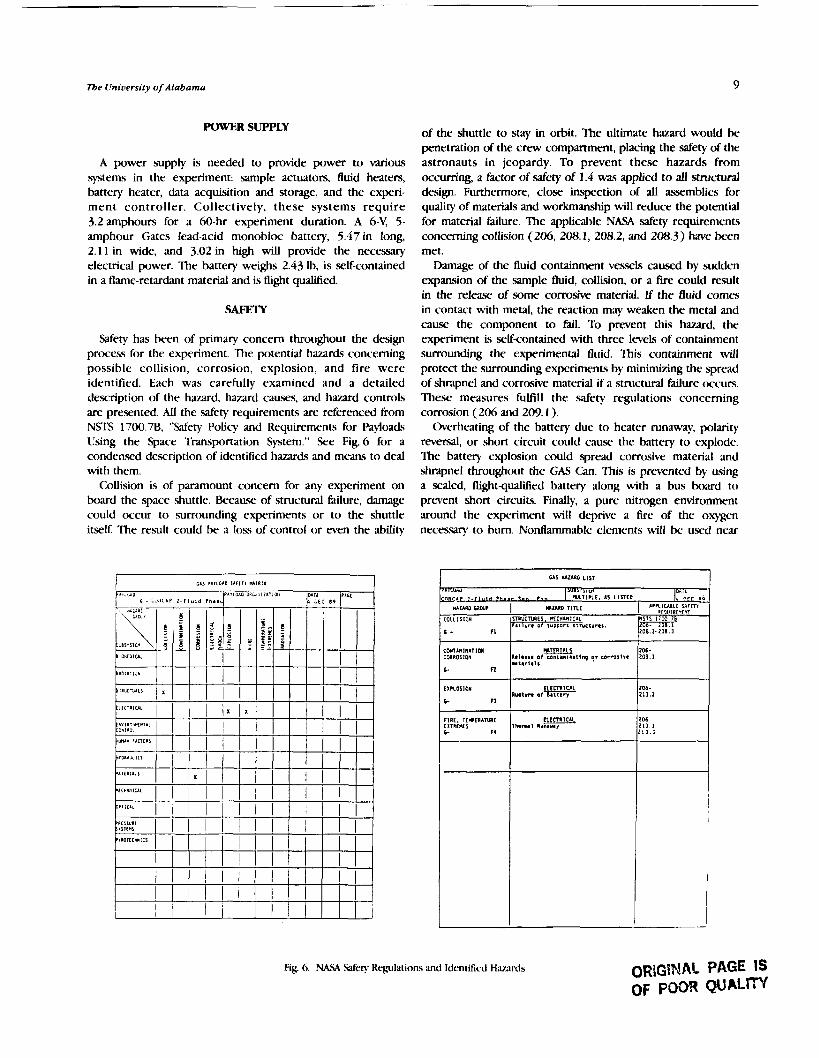
Safety has been of primary concern throughout the design process for the experiment. The potential hazards concerning possible collision, corrosion, explosion, and fire were identified. Each was carefully examined and a detailed description of the hazard, hazard causes, and hazard controls are presented. AU the safety requirements ate referenced from NSTS 1700.7B, "Safety Policy and Requirements for Payloads Using the Space Transportation System." See Fig. 6 for a condensed description of identified hazards and means to deal with them.
Collision is of paramount concern for any experiment on board the space shuttle. Because of structural failure, damage could occur to surrounding experiments or to the shuttle itself The result could be a loss of control or even the ability
of the shuttle to stay in orbit. The ultimate hazard would be penetration of the crew compartment, placing the safety of the astronauts in jeopardy. To prevent these hazards from occurring, a factor of safety of 1.4 was applied to all structural design. Furthermore, close inspection of all assemblies for quality of materials and workmanship will reduce the potential for material failure. The applicable NASA safety requirements concerning collision (206, 208.1, 208.2, and 208.3) have been met.
Damage of the fluid containment vessels caused by sudden expansion of the sample fluid, collision, or a fw could result in the rekase of some corrosive material. If the fluid comes in contact with metal, the reaction may weaken the metal and c ~ ~ u s e the component to fail. To prevent this hazard, the experiment is self-contained with three levels of containment surrounding the experimental fluid. This containment will protect the surrounding experiments by minimizing the spread of .shrapnel and corrosive material if a structural failure occurs. These measures fulfill the safety regulations concerning corrosion (206 and 2W. 1 ).
Overheating of the battery due to heater runaway, polarity reversal, or short circuit could cause the battery to explode. The battery explosion could spread corrosive material and shrapnel throughout the GAS Can. This is pwented by using a sealed, flight-qualified battery along with a bus board to prevent short circuits . Finally, a pure nitrogen environment around the experiment will dcprive a fire of the oxygen necessary to bum. Nontlamrnable elements will k u x d near
Fig. 6. NA!! .Safety Rcplations and Identified H m r d s ORIG\NAL PAGE IS OF POOR QUALm
'
7
GAS I(*uIID LIST
mu-" 5 W i I 1 1 ~ 4 bl, ' . i I " ' A w r <.. t." n R 1 I P L I . I S L l n [ o " PFC P O
uuao caw* COLLISIOII
C - n
CO*TIMINITIOI CORROSION
c n
I I?LOSIO#
C fl
IRE, TIWIRANRE l ITREtXS C i 4
I UURO ~ l n c
n R i K l U a t s . n c u n n r r n T a l l u r n o f support I ~ I Y C ~ Y T ~ S .
R11a111 of conzamlna t lnq corms1ve "t,,l,ll
I L C C T I I U L R u p t v n of Ba i te r ) ,
~ I ~ I C A ~ Thema1 nu-
I IVPLILML[ s ~ r r n etgu!nr*r 'n
NSTS 17w.7~
Ei.2.:;::;
206- 209 .1
206 - 211.2
206 2 1 1 . 1 2 1 1 . 2

Proceedings o/tbe NASA/USRA Adtranced Design Program 6tb Summer Conference
connections and all wiring and heaters will be properly inspected. The design is in line with the NASA safety regulations for explosion and fire (2(X>, 2 13.1, and 2 13.2).
PROJECr MANAGEMENT
The design has emphasized the use of prefabricated components whencver possible to quicken the procurement and aswmbky of the experiment. The delivery of the battery will hc. set for August so that the battery is not over six months old at the time o f launch. The acquisition of the controller is paramount to assembly of the experiment. Adequate time is needed to mtwiify and test the controller.
The project mra$ designed and aswmbled by engineering students at the linivrrsity of Alabama in Huntsville. The fall 1989 Senior Student Design class (ME 465) was the nucleus of the design team. The students were responsible for generating all the necessary design dt~umentation. They will also serve as the trnsition to the construction phase of the experiment. Construction has begun, with anticipated completion by August 1990. The current n~ork is done by stl~dents enrolled in a "Specid Topics <:lass: Advanced Space S)?items 1)esign."
The planned schedule for the construction of the fluid phase xyaration experiment is a fast-paced program to permit complete intepation of the exprriment into CONCAP 2. The development of the phase .stparation experiment must meet the existing time schedule for <:ON<'M 2. In the event that the phase. sc-paration cxprirnent hils to meet any o f the established requirements, it will be divorced from the <:ON<'AP 2 project.
l:igure7 shows the rwiwd time schedule for the phaw sc-pamtion experiment. It is anticipated that CONCAP 2 will fly on the GAS Bridge on S1'S 42, x-hcduled for April 19c90.
- Optimized design for the FPS Experiment (began preliminary design September, 1989 and finished design May, 1990)
- Use fast track method for fabrication of flight hardware (anticipate completion by July, 1990)
- Begin testing and qualifying, summer of 1990
- Integration of experiment into GAS can by Sepetember, 1990
- Delivery to NASA in November, 1990
- Fly on STS42 in April, 1991
Fig. 7. Time Schedule for Project
CONCLUSION
The fluid phase separation experiment will characterize the liquid-liquid phase separation process in a microgravity e n v i r o ~ i e n t . The experiment allows six samples of fluid to he monitored for three days while in orbit. The system will record temperature data *and obtain samples of the component species for analysis on Earth. The data will bc. analyzed to p n d u c e a phaw relationship or phasc diagram for the fluid mixture. Ultimately, it will add to the knowledge baw of material pnressing and provide information for the design of long-duration life support systems.
The current status of the project is that construction and aswmbly are underway. It is anticipated that the experiment will be ready for integration into CONCAP 2 by July, and therefore has an excellent chance d flying onboard the shuttle in April 1990.

AUTONOMOUS SPACE PROCESSOR FOR ORBITAL DEBRIS
UNIVERSITY OF ARIZONA
This work continues to dwelop advanced designs toward the ultimate goal of a GETAWAY special to demonstrate economical removal of orbital debris using locA resources in orhit. The fundamrntal technical feasibility was demonsmed in 1988 through theoretical calculations, quantitative computer animation, a solar focal point cutter, a robotic arm design. and a subxale model. last ycar improvements were made to the solar cutter and the robotic arm. Also performed last year was a mission mal~is that showed the feasibility of retrieving at least four large (>1500-kg) pieces of debris. A&mrrs made during this reporting period are the incorporation of digital control with the existing placement arm, the development of a new robotic manipulator ann, and the study of debris spin attenuation. These advances are discussed here.
INTRODUCTION DEBRIS SPIN ATTENUATION
We can hardly improve upon the lucid descriptions of the orbital debris issue by science writers('-4) and other popular news media Without doubt, the problems of orbital debris have grown to be of serious concern to astronomers, space technologists, and to terrestrial dwellers. The specific problems were presented at the 39th IAF Congress. The University of Arizona Space Engineering Design team is developing the design for economical removal of the larger debris pieces through local resource utilization. The fundamental idea is to concentrate solar energy into a point focus, cut the debris into precise shapes that can be added on to the "sweeper" craft, and robotically assemble the pieces into a manageable configuration. This is followed by one of three disposal modes: ( 1) retrieval by a spacecraft (STS, HERMES, BIJRAN, etc.), (2)precise ocean splashdown, or (3) planned burnup upon atmospheric reentry. The fundamen- tal space technologies to be demonstrated are solar cutting of candidate space debris materials, robotic assembly, and accurate disposal. In 1988 the University of Arizona began participation in the USRA program and demonstrated solar cutting and a subscale model robotic arm. In 1989, a full-scale robotic arm with manual controls was developed and the solar cutter/robotic arm assembly was shown to be technically feasible. Also in 1989, a mission analysis was performed in which the large debris environment was identified and a four- debris retrieval sample mission analysis showed the propellant requirements to be well within reason. This year, 1990, the existing robotic arm was converted to digital control using an IBM PC, a second robotic arm was developed for precise pick and place operations, and the problem of debris tumbling was addressed and various detumbling methods were investigated. This report is a summary of the work and explains the details of space engineering.
Consistent with the USRA philosophy, new undergraduate students were involved in the design process. This year, 11 new students were involved in the Autonomous Space Processor for Orbital Debris (ASPOD) design. The project continues to draw worldwide attention including correspon- dence with elementary and high schools.
The purpose of this project was to research and recommend methods of attenuating the rotational spin of orbital debris so that an ASPOD satellite can .safely grasp them for retrieval. 'To avoid possible damage to the ASPOD craft, only passive means of attenuation were investigated. The use of passive means is defined as the use of methods of attenuation that do not involve ASPOD in direct contact with space debris, thereby endangering it. Some of the design criteria and target specifications are ( 1 ) attenuate the rotation of an object spinning about one axis; ( 2 ) attenuate the rotation of an object having a mass of up to 2000kg and rotating with rotational speeds of up to 50 rpm; (3) attenuate the rotation of an object up to 7 m in diameter and up to 7 m in height; ( 4 ) use a minimal amount of energy; (5) attenuate at least four objects per mission; (6) require no maintenance; (7) must not interfere with the normal operation of other functional satellites; (8) must not create more debris; ( 9 ) must weigh less than about 500 1b; and (10) must have a reasonable expense relative to the space industry.
Satellites and most other space debris generally contain a certain amount of rotational energy. The problem of dealing with the rotation of a large, nonsymmetric object containing a lot of mass orbiting the Earth must be solved heforc the satellites can be safely and effectively collected.
A workable solution dealing with debris capture must allow the rotational energy of the debris to be contained or dissipated without transferring it to the collector satellite. The space debris that is proposed for collection is often very massive, 2 0 0 0 4 or more, with spin ratc3 of up to 50 rpm. These figures suggest that there can be quite a bit of angular momentum involved.
SOLUTIONS
As a first step, various attenuation methods were researched and evaluated. Of all the methods investigated, four were chosen as possible solutions and merited further analysis. Each of these four solutions uses a different physical principle (for example, consewation of angular momentum or conservation

Proc.rvdings of lbe >hyASA/(J.SRA Ad13anced Design Program 616 Summer Conference
of cnc.rg\ ) to ;tccornplish the ;tttrnuation of the utehte. Althou$i c;rch of tlir four designs nlerits further investigation, Li~r the, P ~ ~ S C . I I ~ the mo\t promising of the four was singled out for detAled and!.sis md testing.
Rr.eIc~d ttla&ht meeharitsni. The phyicd principle used in this nicttlod is to tr:u1sIate the rotational energy into linear kinetic cnern. then into ~x)tcntial e n e r ~ . ?his design uses ;I
rec*led cable capable of attaching itself to the debris by the cable's free end. Also contained in the reel mechanism is a generator allowing the cable to reel out, turning permanent magnets uound a stationary armature and storing that energy in a batter). This generator can then act as a motor by turning the storecl energy in shaft power, atlom~ng the cable to be reeled in. Once the free end of the cable is attached to the delwis in its plane of rotation, the reel is then allowed to freely move away tiom the debris due to centrifugal acceleration, yet is still tethered by the cable. 'fie rcel uill move away in a straight path wMr the debris continues to spin, and the att:tclinient point o f the cable on the debris will rotate with the debris, wrapping a portion of the cable around the debris. At this time the rrel will create a drag force on the cable by engagng the generator and then storing that energy. Due to the centripetal force of the reel attached to the much more n~~\s ivc picc,e of tiehris, the reel will attempt to move into a radi;d position about the debris' center of mass. Before it comes nellr this point some o f the stored energy will be used to rcel the rrel mechanism back into the debris, at which point the process nil1 start c x r . Some of the ad\-antages to this g3tc.m arc the em of attachment to essentially any shape of debris rind the relative simplicity of the mechanism. Some of the problenis are the difficdty in anaJy?iis and testing of the s?3tcni and the chance of the cable hecoming permanently entangled in protrusions on the debris.
(.bikd spring mechanism. Figure 1 presents the pro- p o s d coldguration tor the c.oiled spring mechanism. ?his propowci nlcc'hanisnl consist4 of a component for attaching to the delwis. ;I r;ttchct, ;I coiled spring. :uld a stabilizer. 'Ihc idca lxtiind this sc)lution is to al>~)rt> the rotational energy of the clclx-is ;ultl store i t in a coiled spring as potential m e w . The puqwsc of the ratchet is t o act as a I t~king mechanism for the q"-ing \\.hen 11 wind\ up completely. Winding up the spring. though. ricccx\i~atcs the 1 1 s of a stabilizer to hold the othcr cncl of the spring fixed. h stal~ilizer is thought o f a% a cno-c-ont rollccl k~roxopic. pkitfornl where ~ r o s c . o p c . s arc to hr uxd only ; ~ s wI1M)rs 'I'hc reSo1Vt.r (the "hrain" of the coritrol system ) uill hc continually feeding corrections throtigh the fi'cdh;tcli controlled Itwp to ketp the attachment to illc. platJi)rm tixcd in space. 'the greatest advanrage of this procc.4 i4 tI1;tt i t c;tn attenit;tte the rotation of the debris quickly. i c... uithin minutes I:iirthernmorc, thc attenuation o f the tlcl>ri is c.oriiplctc ( 10IY~x) '[he tfisach.mtages of this idea arc tt1ch r c q l ~ i r c i c t fi)r po\\cring the k?-rosopic ,wnson and 1irhric;tting the rCttchct. kiothcr Inore inlportant problem is that the ASPOI) will e\,cr~tttally Ix involved actively in the ptx)c-ch\ I>!- powering .x>\rr;tl thrusters m well as its momentum wticcls. Since this may crratc safety prol>ierrn for the whicle itsll. the idea \KLS abandoned for the time being and our effort wa.\ c,orlcc~ltratcd on tlevcloping p;~s.\i\'c nlcans of attenuation.
Artachment Locking M ~ h u u m Racchcr
Fig. 1. Coiled Spring Mechanism
Long cable mechanism For this design there ate two ways in which it could work One would be to let out a cable with a mass attached to the end, thereby increasing the moment of inertia and slowing the satellite down. This would not allow the satellite to come to a complete stop, but it could possibly slow the satellite down enough for a robotic arm to manipulate it. The cable would have to be cut off when maximum attenuation occurs, preferably so that it would reenter the Earth's atmosphere, because once the robotic arm attached to the satellite, the cable would reel in uncontrollably due to the momentum of the cable. The other method would be to leave the cable on for an extended amount of time and allow the gravity gradient to slow the satellite to a complete stop. The satellite could then be grabbed and the cable reeled in since the rotation of the satellite would be fully attenuated. Figure 2 shows a representation of this method.
Fig. 2 Long Cable Configuration

University of Arizona 15
Geared-bar mechanism The geared-bar mechanism is the solution selected by the attenuation research group for further development and is detailed below.
Geared-bar Mechanism
Tbeoty of opaaNon A representation of the gear bar can be seen in Fig. 3. The centrifugal acceleration acting on the flywheel forces the flywheel radially outward to the end of the geared bar. If the geared bar were smooth, the flywheel would just translate outward without spinning; however, the contact forces between the gear and the bar apply a torque about the center of the gear, forcing the flywheel to spin as well as translate. Mathematical analysis and experimentation show that as the angular rotation of the flywheel increases, the angular rotation of the debris decreases. A ratcheting mechanism is attached to the system so that when the flywheel reaches the end of the bar the flywheel will continue to rotate freely.
The effectiveness of our design depends on the length of the geared bar and the mass moment of inertia of the flywheel. It could happen that the configuration necessary to achieve an adequate amount of attenuation would be unfeasible to take into space due to the size and/or mass of the flywheel and the length of the bar. If this is shown to be true it should be possible to attach a motor to the flywheel and "reel" the flywheel back in, while the ratchet mechanism allows it to maintain its angular velocity and let it move out again. This process could be repeated as many times as necessary.
Fig. 3. Geared-bar Mechanism
Design A rudimentary device was fabricated for experi- mental purposes. The design that was used included a rubber wheel and friction bar to simulate the rack and pinion system. A small cart supporting the flywheel and friction wheel with a bearing rolled along a track that rqrt%nted the geared bar. The friction wheel rolled along a friction bar attached to the track forcing the nywheel to rotate. The combination of the flywheel and the cart simulated both the rotation and the translation of the flywheel. To simulate the ratcheting mechanism, the Mction bar was cut shorter than the track This allowed the flywheel to rotate freely once it reached the end of the track This design wa$ not adaptable to the use of a motor; however, it was felt that showing that the theory mechanism would work for one pass was sufficient to show that this method of attenuation was feasible. ~~ Previously, a large 'model representing space
debris was built for attenuation experimentation purposes. This model is an octagonal solid approximately 48 in in diameter and 72 in high with a calculated mas.. moment of inertia of 655 Ibm ft. The "debris" is attached to the ceiling and floor with a large metal rod about which it rotates. Lubricated bearings were used to minimize the frictional effects.
To gather data, a systematic process had to be developed to measure the time per revolution. A computer program was used to record the needed data. A mark -5 made on the "debris," which was then spun up to an appropriate speed. Each time the mark came into sight, a key was pressed on the computer. The program would then print the number of revolutions and measure the time elapsed. With this data, the program calculated the time between revolutions and revolution.. per minute. Finally, this information was exported to a spreadsheet program for further analysis and graphing.
To prove the effectiveness of the geared-bar mechanism, it was necessary to find a way to separate the effects of the changing mass moment of inertia due to the flywheel translating outward \.?i. the effects of the nxational kinetic energy being transferred to the flywheel. To do this, reference data had to be taken. These reference data con5isted of sc~~crd measurements with the fljwheel retracted and several with the flywheel extended. Before measurements could be taken with the geared-bar mechanism fully operational, one additional component needed to be added. Because the debris needed to be brought up to a functioning sqeed before the flywheel could be released, it was necessary to develop a rclese mechanism x) that the flywheel would not begn to move before the appropriate speed was attained. This was done by including an eyelet on the flywheel, and passing a pin through it that could be easily pulled out when needed without sigruficantly affecting the peed of the debris.
A.5 stated above, these measurements were taken for each case: the flywheel retracted, extended, and operational. Figures 4, 5, and 6 show the relative quality of the measure- ments for each case and their characteristic curves.
Although the reference data were taken, a standard procedure to spin up the debris at an equal rpm for each run was not developed, nor was there a way to measure the energy added to the system. It was necessary, therefore, to determine

Proceedings of tbe NASA/USRA Advanced Lksfgn Program 6tb Summer Conference
1 2 3 4 5 6 7 8 9 1 0 1 1 1 2 1 3 1 4 1 5 1 8
Number ol Revdutions
Fig. 4. Flywheel Retracted
1 2 3 4 5 6 7 8 9 1 0 1 1 1 2 1 3 1 4 1 5 1 6 1 7 1 8 1 9 2 0
Number of Revolulions
Fig 5. Flywheel Extended
1 2 3 4 5 6 7 8 9 1 0 1 1 1 2 1 3 1 4 1 5 1 6
Number of Revolutions
Fig. 6. Flywheel Translating
a method for comparing the data with the three different cases. Because of limitations with the graphing software used, it was felt that taking the points at which the debris cane to rest with each case and counting the maximum, common number of data points backward would be a reasonable method for developing a common reference. For example, the working case only included 14 data pints, so the last 14 data points for each case were used.
Figure 7 illustrates the effects between the three different cases. The line with the flywheel retracted is steep due to the low relative inertia. The line with the flywheel extended is Batter and the time of rotation longer due to the efkcts of increased mass moment of inertia. If the working case
w ID = n Time (seconds)
RET EXT WORK
Fig. 7. Experimental Comparison
decreased the rotational speed of the debris solely due to the elTects of the changing mass moment of inertia, one would expect the line for the working case to lie somewhere between the retracted and extended cases. In fact, the graph should begin at the approximate point of the retracted case because of the identical value for the mass moment of inertia and end near the same point of the extended case because the same amount of energy should still be in the system. It was not the group's goal to "prove" the effeczs of changing the mass moment of inertia, but to prove that the flywheel actually absorbs the energy of the debris. To confirm this, the graph of the working case should start near the point of the retracted case and end significantly below the extended cme. The working case line does confirm this hypothesis.
This experiment does not exactly model the case of debris spinning in space because satellites in space are not pinned, therefore the center of rotation would change as the flywheel mows out. The mass of the flywheel could be optimized to minimize these effects. Nonetheless, this sytem of attenuation will still work, because the center of rotation wiU always Lie between the centers of the debris and the flywheel, maintain- ing the centrifugal component of acceleration moving the flywheel outward.
In conclusion, and most importantly, the geared-bar mechanism of the experimental cxse d m absorb the rotational energy of a spinning body. For the 3 cases mentioned above, the time for the last 14 data points is 253 sec for the retracted case, 400 sec for the extended case, and 59 sec for the working case. The above experiment also proves that the attenuation is not solely due to the change in mass moment of inertia, but actually performs a significant amount of energy transfer. Conrputer modettng. In order to investigate the dynamics
of the geared-bar mechanism as an attenuator of the rotational energy of a satellite, several approximations to the actual case were considered. The first case, consisting of the two- dimensional analog (Fig. 8) of the actual case (Fig. 9), assuming perfect targeting and neglecting the attachment phase and the endpoint locking of the flywheel, was solved analytically.

Fig. 8. Attachment Parameters
Tota l angular mom. vector
due to asymmetr ies
=> precession
Fig. 9. Attachment Sensitivities
Under the above assumptions, the analysis suggested that an attenuation of about 50% could be attained for a rack length of 4 m, and an operation of 50 sec. 'Ihese results pertain to a satellite modeled as a 2000-kg cylinder, 4 m in height and 3 m in radius rotating at 50 rpm. The 40-kg Bywheel used in the analysis was 1 m in diameter, while the rack was assumed weightless. At this point it should be mentioned that the attenuation effects are highly dependent on the inertial properties of the satellite. Thus, it should be kept in mind that the diversity of satellites to be attenuated adds to the complications and limits the applicability of the design.
In order to investigate the effects of the geared-bar attenuator when it is not attached at right angles to the principal axis of rotation of the debris, as well as when it is attached off-center with respect to the satellite's center of mass (Fig. 9), an analysis was attempted on a software package available at the University of Arizona. This software facilitated a three-dimensional analysis and made it possible to animate the resulting effects, for visual and demonstrational purposes. For a satellite with inertial properties as mentioned above, the software shows attenuation as high as 70% during the first 5 sec for the two-dimensional case, but not more than 25% for the three-dimensional case that involves geometrical
asymmetries and precessions. The fact that the rack and pinion pint is not 100%, as was assumed by the s o h e , will lengthen the time needed for attenuation. Figures 10 and 11 show the angular velocity of the debris for the two- and three- dimensional cases respectively.
The results indicate that the targeting and alignment of our device is essential, and therefore a process of determining the center of mass of the debris before operation is essential. The software can provide results once the device is attached to the satellite; however, impact forces caused by the attachment process were not modeled.
To evaluate the model, a final comment on the effects upon impact needs to be made. Provided that no eccentric forces are present, i.e., perfect targeting, any components directed radially from the Earth will cause oscillations that are estimated to die out. Moreover, any angular components will result in shifting the orbit but not changing the orbit altitude. Thus, the effects on the debris will be mostly translational and will not greatly &ect the attenuation process.
on perfect targetting
rpprox 70% attenuation
1 Range ] 0 to 50 rpm
time t
Rngular Ueloclty #dot of satellite-debrls
Fig. 10. 2-D Computer Modeling
flunctuatlonr a n due to pncarlons I "---I 0 to 5 sec
attuhmont: 0ff-rmt.d
3-dim. problem -1
0 lo 50 rpm rpprox 20 %attenuation
time t
I Inguler Uelocity #dot of setelllte-debrls
Fig. 1 1. 3-D Computer Modeling

Proceedings oj lbe .VASA/U.SRA Advanced Design Program 6tb Summer Conference
A#acbnrent. Since the purpose of this project was to test processes for attenuation, the issue of attaching the mechanism to the satellite was not initially addressed. However, it was felt that developing a method of attachment was necessary to complete the subject of attenuating the rotational motion of orbital debris.
Several ideas were considered. Wrapping something around the satellite (similar to lassoing) was discarded because it could not be guaranteed that there would be a perfectly clear path all the way around every satellite due to auxiliary objects such as antennas. Grabbing the satellite was felt to be impractical because the skin of the satellite is very ffunsy (since its only purpose is to shield the inside from solar radiation and small particles) and could not sustain very large forces and moments.
The conceptual design of the device that was chosen to build was much Like an umbrella. The device would pierce the skin of the satellite and, once inside, open up to prevent the device kom slipping back out. As can be seen in Fig. 12, a motor turns a threaded rod and
the collar with the shorter links attached begins to move. Once the collar contacts the back-plate the collar no longer moves along the threaded rod and the shorter links then pull the larger links until both are at right angles to the threaded rod. The mechanism would have worked with only the longer rods, however, the design chosen minimizes the load that each link has to take and increaxs the mechanical advantage of each link, thereby requiring less energy.
The motor to drive the threaded screw would k a DC motor. The batteries would be charged prior to use using the power source available to ASPOD.
Conchdon The overall purpose of this part of the project was to research and design a mechanism that would slow or attenuate the rotation of a satellite. The solution found would involve launching a geared-bar mechanism to the piece of debris. The tip would pierce the skin and six links would then open up to keep the device in place. The &wheel would then be disconnected from its locked position and allowed to rotate out. This would transfer the rotational energy from the satellite
6-ln I lnk 1 2 t n l ink 60-dearee-anale a r m
bearing A c o l l a r bearing 0
f ront shaft beck p late
torguetube
threaded rod
Fig. 12. Attachment Ikvcc
to a more manageable form in the flywheel. This method was proven to work through experimentation and mathematical and computer analysis.
DIGITAL CONTROL OF PLACEMENT ARM
The ASPOD design incorporates a solar-p~wered metal cutter to facilitate dead satellite processing in a cost-dective manner. In order to position debris at the focal point it is necessary that the ASPOD be equipped with robotic arms. The arm function is to hold and move material to be cut in the focal plane of the solar concentrator. After this initial development stage, the gathering arm was controlled with a variable-speed on/off control panel. In order to automate the arm and to better simulate its operation in space, a hardware/ software controller was designed. The objective of the digital control was to eliminate the direct human interface initially needed to operate the a m and to replace it with a software interface that would accept commands entered into a PC terminal. The digital control would increase the accuracy of the arms' movements, and with the softw~re interface a program could be developed in order to perform a pick-and- place operation or a more defined cutting operation.
Design Specifications
The robotic a m 1 has five revolute joints a$ shown in Fig. 13 with axes and degrees of joint rotation. The most important component of thc whole n)bot sytem is the digital control system whose components are a power supply, voltage regulator, two motion controller boards (from Motion Enginecring), five motor drivers, five optical encodes, five DC motors, and an IBM PC. Two of the hardware parts-the power supply and the motor driver-required custom design and fabrication. These components were constructed by members of the team.
The hardware needed to build the power supply included a trdnsformer, a bridge, and two capacitors to produce a dual output of +25 V/-25 V with a smooth signal (resembling DC voltage). The +25 V was also connected to a voltage regulator to pnduce +S V for the optical enctxkr. Figure 14 shows the circuit design for both the power supply and the voltage regulator.
Five individual motor drivers (channels) were built within the motor driver. Each driver consisted of a high-voltage operational amplifier to ampli@ the input voltage from motion controller boards, transistors, capacitors, and resistors (see Fig. 15). The motor driver receives a voltage from the motion controller board between - 10 V/+ 10 V. The operational amplifier amplifies the voltage at values of +20 to -20V The transistor amplifies the current and then sends a voltage to drive the DC motors at each joint of the arm.
The optical encoders (HEDSS(500) are uxd to provide accurate motion detection. They provide a high-performance, optical incremental enctder that empha5izes high reliability and resolution, low cost, and e;Lw of assembly. The optical mctders were attached at the points of rotation to measure thc angle of rotation at each joint, and required a rigid mount ;md mtdification to the shaft at cach joint.

University of Arizona
Swlng of extended arm ( I degree of freedom)
/
Wrist rotates & bends
Gnpper closes & opens I 1 degree of freedom)
Tko motion controller (MC) boards control the five DC motors on the arm. The MC-400 is able to control four motors while MC-200 can control two motors. The two MC boards are connected to the computer and wired to the motor drivers. Included in the package with the controller boards were two types of solhare: the "Stand Alone Program" aids in the installation and testing of the optical encoders, and the MC boards and the "Utility Subroutine and Program" aid in the development of a customer-written program. The software can be written in either "C" or "BASIC." The MC controller boards were accompanied by a user guide to assist in installation and operation. The block diagram for the control system is shown in Fig. 16.
The decision was made to use these MC boards over other possible choices because the controller cards were designed around the HC'IX1000 general-purpose Motion Control IC. The HCTI,lOOO has the capacity to handle all encoder input decoding, phase commutation for steppers and brushless servomotors, digital filtering of the control signal, and
Fig. 13. Robotic Arm Showing Degrees of Freedom at Joints generation of analog or pulse-width-modulated motor command signals. It continually perfoms intensive tasks of digital motion control, thereby -freeing the PC for other planning tasks. The HCTLlOOO operation is controlled by a
-I I - bank of 64 internal registers that, in turn, can be accessed by - mapping within the PC memory. There is no need for interrupt-handling during operation.
I -W v To develo~ the control system. the robotic arm is viewed I -- .
1 as a continuous time-varying .mtem. The Laplace transform & - technique is used to simplify the analysis. The block didgram
in Fig. 17 depicts the feedback closed-loop system of the
Fig. 14. Power Supply and Voltage Regulator
lnpur
from Voltage
M C Board Transistor
0- + 10 B
Fig. 15. Circuit Design of Motor Driver
robotic arm control. The digital controller is an IBM computer, while the DAC is a digital-to-analog converter, and the ADC is an analog-to-digital converter. The amplifier is the motor driver circuit used to convert the low-level analog torque signal u(t) to a voltage v(t), which directly activates the joint motors. Since the joints are DC motors, the generated torque is proportional to the armature current. Therefore, the amplifier in Fig. 17 is an analog subsystem regulating the
FL i pu1= +, Encoders
I
Fig. 16. General Block Diagram for Robotic Arm <:ontrol System
\lotor Drive
Inciudec: Power supply producing +I. 25". +SV OP Ampl~fier & Trans~rtor
- \lotion Controller Boards
M C 200 Z-AXIS
Robotic Arm
Dl,4
DC Motors MC-400 4-AXIS
t 4

Procerdings of fbe .VASA/CISRA Adc'anced Design Program 61b Summer Conference
the machine is booted up or loaded. The future work of the
DAC Amplifier project will take place in the succeeding semesters by other Computer arm
MANJPULATOR ARM
The ASPOD spacecraft will need two robotic arms to successfully retrieve and process a piece of orbital debris. This
B(d', t i year the task was to design and fabricate a new robotic arm.
+ This arm was to be designed with the speciflc ASPOD mission in mind, and have the flexibility necessary for the handling of
Deured Opt~cal Encoder Large pieces of debris.
Fig. 17. Frt-dhack C l o d Loop System of Digital Control
current through variations in the applied armature voltage. The ADC block detects the position (encoders) and the speed (tachometers) of the pint motors and converts them into a form recognized by the digital controller. Thus, the sensors here represent an encoded disk (optical encoder) of the type ADC.
The status of the project at this point is that we have control of four of the five motors on the arm. A program was written in "C" that can demonstrate a predetermined movement of the arm and its return. Since the initial (zero) position sensors are not installed, the arm can only be controlled using the joint coordinates. ' b o sample programs were developed for this purpose. One uses the voltage to control the joints. It reads and records the quadrature counts from the optical encoders. The second program uses the trapezoidal profile position control in an interactive mode. It has been modified to execute a sequence of point-to-point positions in the specified envelope. The user at this point may move all joints simultaneously or move one joint at a time to a predefined position. %s requires only one keystroke to the keybard.
Limitations
There will be no subsequent contact with the orbiter once it has been launched; therefore, it must be reliable. The arm must have a hand capable of grabbing most space debris as well as grappling with a larger satellite. Control of the arm must be precise. Vibrations, as well as slop/backlash within the arm's actuator mechanisms, must be minimized. The design must be adaptable to digital control and the electrical v t e m must run off a 24-V power supply.
Design (Target) Specifications
In the process of generating alternative solutions the solar mirror structure was analyzed to determine the necessary DOFs. By approaching the problem in this manner, we would not have to analyze and build models to treat every design that did not have any immediate foreseeable problems. Analysis by this method led to a very unique solution.
First, it was determined that the easiest way to remove the lens from the holding slot was to translate it along an axis contained within the plane of the lens (see Fig. 18). We call this the hand axis from here on to clarify our discussion. Note that we assume the grasping mechanism to be attached to this axis.
Future Plan
The future plan of the s o h e project is to move the arm with all 5 degrees of freedom integrating in a "pick-and-place" fashion. The arm will also be momble to any predetermined position in the physical envelope of the apparatus (i.e., move anywhere defined in polar (r,q) coordinates). Future work involves some hardware and soliware amplifications. For the
Fig. 18. Hand Axis
hardware, some position sensors need to be installed for the initial (zero) paition, and an optical encoder installed at the -
.I) wrist. For the software aspect, the relationship between the inverse kinematics of the robot arm and the trajectory planning neds to be studied in more depth. and integration of the second arm must also be achieved. Components of this integration include state-of-the-art artificial intelligence and decentralized control algorithms. Additional considerations for the software portion include both error checking and recovery software that must be designed with the focal cutting point in mind as well as an initial (zero) position. AU the above points must be intrinsic to the computer software each time

It is important to note that none of the DOFs required by the hand to perform properly have been considered here. The reason is that the DOFs discussed so far are for location and orientation of the hands-i.e., getting the hand to the desired locations-whereas the DOFs required by the hand are for orientation of the hand to receive the object. Those DOFs will be discussed in the subproblems involving the hand.
Using the three fundamental DOFs, the configuration in Fig. 2 1 was proposed. Note that the ring was used to accomplish the rotation about the central axis so that no part
\ of the would be prone to moving through the focal point
Fig. 19. Central Axis Rotation
7 FOCAL POINT
(see Figs. 21 and 22).
Fig. 2 1
Fig. 20. Focal Point Within Reach
To reach all three lenses with the hand axis in this orientation with respect to each lens indindually, it is necessary to rotate about the central axis of the mirror structure (see Fig. 19).
The next requirement is for the arm to be able to reach the focal point. From Fig. 20 it can be seen that we need only to translate along an axis parallel to that of the central axis to meet this requirement. Finally, to reach debris located above the mirror structure the mechanism must be able to rotate about an axis perpendicular to the plane created by both the hand and central axis.
With these three DOFs we have a work area with roughly the shape of a cyhnder with half spheres at the ends. Adding more DOFs in the form of joints or extensions would be redundant at this point. The adding of redundancies may decrease the difficulty of specific tasks. For example, in the case where an obstruction prevents the arm from directly
?;- reaching an object, it may be necessary to have another joint in the arm to essentially reach around the obstruction. Fig. 22.

20 Proceedings oJ tbe NASAIUSR.4 Advanced Design Program 6tb Summer ConJerencs
Final Design
Polar drive mecbankm The purpose of the axial tracks is to translate the entire robotic arm structure along the body of the collector. This is accomplished through motor driven screws. The motors have an output of 100 oz-in at 30 rpm per motor. This velocity will cause the polar track assembly to move at a rate of 4 in/min. The reason for keeping the velocity low is to prevent unwanted oscillations in the system. The power screws are regular 0.5 in and 13 threads per in.
The main load of the polar tracks is taken up by the bearings inside the pillow blocks. The beamgs are 0.75-in linear bearings. ‘Tho linear bearing were used to prevent horizontal motion. The bearings ride on 60 case-hardened steel rods. This material was chosen because of its great stiEness capabilities and availability. Alongside the bearings, inside the pillow blocks, there are two couplings. The reason for using two is also to prevent horizontal deflection and to maximize the contact area between the pillow blocks and the driver screws.
The connection between the pillow blocks and the polar track is done through the flat plates that are welded to the polar track and the pillow blocks. The flat plates are bolted together.
The tracks, which were manufactured out of aluminum stock, are supported at the ends.
The circular track allows the arm to rotate about the focal point and align itself in a normal sense to the lens axis. The circular track allows the arm to access the mirror/lens structure without interference. A wide-base channel section (5 x 1.75-in cross-section ) provides the necessary contact points to mount the arm and yields a "chamber" of space essential to the drive mechanism. The channel material is 5052 aluminum and initially weighed 24 Ib. The weight was reduced to approximately 19 Ib by drilling thirty 2.5-in diameter holes along the web, evenly spaced 3.5 in apart center to center. The holes did not weaken the track but did slightly deform it. The track's inside diameter was reduced by approximately 0.5 in, which is not a problem.
The arm is mounted onto the arm-platform, which contacts the channel track at six points: four on the outside and two on the inside. The rollers are Kihan bearings that provide normal and lateral stability. The four outside bearings have k e n modified to prevent derailing. A washer has been pressed against the lip of the bearing. Rvo pairs of springs are incorporated in the design of the platform: one pair clamps the inside rollers to the platform providing normal stability, and the other pair ensures lateral contact of the bearings to the track. The springs are necessary to account for track irrcplarities.
n e drive is simply a dual chain/sprocket drive. Power is transferred through a 50:l worm gear reducer. The motor ordered was found to be faulty. It was rated at 10,000 rpm, 9 oz-in torque. Since it was to operate at shaft conditions of 500 rpm, 180 oz-in, this would give more than the needed torque of 50002-in. Testing showed motor output was nowhere near these specifications, so it was necessary to ux a motor that was found and worked. No characteristics are known about the motor. Testing of the circular track drive
mechanism showed that operation performance was adequate for loads of 15 to 20 Ib.
Elbow joint. The elbow joint provides one degree of keedom, which enables objects to be moved in or out of the focal point. It also supports access radially outward from the polar track providing access to objects that Lie outside the ASPOD's framework. The elbow consists of two major components.
The first piece holds the motor and worm, and braces the 5/16-in shaft with a 7/8-in OD roller bearing press fit at either side. The selected motor is shown below as motor #1. The worm is steel, s@e-tooth, and 32 pitch. The shaft is held in place with snap rings.
The second major part of the elbow joint has a 32-pitch, 100-tooth worm wheel pressed into it. The worm wheel mates the worm on the b t part when placed on the shaft. The shaft has a flat milled across it and is fixed to the worm wheel with a 5-40 set screw. The set xrew is 2 in long so it not only holds the shaft but also fixes the wheel to the second piece.
Both parts of the elbow have a I-in long hollow male fitting that is placed into a 1.5-in OD 0.0649411 thick pipe. All structural parts are made of aluminum; all fasteners are steel.
Motor rotor assem&&. The motor rotor assembly is a gearbox that holds the arm above the polar track and allows the arm to rotate a full 360". This provides access to objects in Front, behind, or to either side of the ASPOD. The gearbox consists of two 9-in x 4-in plates separated 2.5 in by four spacers. The motor drives a 24-pitch, 100-tooth worm wheel that is held on the end of the shaft/endcap with 5-40 set screw. The motor selected for the gearbox is identified as motor #l . The motor is held at the precise height and angle with the motor mount.
The shaft/endcap is machined to have a 3/8-in shaft on one end and a 1/2-in long hollow male fitting on the other. It protrudes through the top of the gearbox so that the 1.5-in pipe that holds the elhow joint can k attached. The part of the endcap that joins the shaft was threaded with 9/32-in 18 threads/in. The shaft fits through a bearing and is held by a 9/32-in nut. The bearing is held in place with a machined cap. The cap was machined to have a snug fit with the bearing circumference and have a 1/1000-in interference fit between the bearing and top plate. The cap is hstened to the plate with four (d32-in bolts.
Motor selectjon The following motors were selected for their torque and speed. The exact weight was unknown but a rough estimate considering their size was also considered. The motors needed to have this great amount of torque as our initial estimates of the arm weight were tcx) low. These motors will allow the arm to retain its original design capabilities of lifting a 2% plate at an extension of 33 in.
Motor # Quantity Torque (oz-in) Sped (rprn)
1 2 100 375 2 1 25 lo00 3 3 100 75 4 2 ' 5 30

Uniwrsitjr of Arizona 2 1
Grasping mechanism The requirements of the grasping mechanism are that it must be able to grab a thin flat plate ranging in thickness from 0.125 to 0.75 in, grasp a cylinder with a diameter ranging from 0.125 to 4.0in, and gmsp a sphere with a diameter equal to that of the cylinder. Other general requirements for the mechanism are that the weight be minimal, the ratio of the clamping to the actuator force be maximized, and that the force ratio be as nearly constant throughout the range of motion of the mechanism as possible.
For the design that was developed and built to meet the requirements, the ratio of the clamping force to the actuator force is 0.25 and is nearly constant throughout the clamping range. The ratio was determined by constructing a static force vector diagram on each design at intervals in their range of motion. There was a trade-off between the increased ratio and smaller size. The force ratio would increase if the distance between the two sets of four bar hkages were increased. 'Ibis design was chosen over five others because of its higher clamping force ratio, its smaller size, and its simplicity.
Harmonic dbratjons. Vibrations of any space structure create special problems. The payload must be deployed, be able to precisely grab objects, and not suffer damage due to fatigue trying to capture satellites.
The space shuttle has a natural harmonic frequency of 32 Hz that prevents it from carrying a payload with a correspcnding harmonic frequency less than or equal to 32 Hz. Such a payload (532 Hz) would certainly cause resonant vibrations of increasing amplitude. Damage to the shuttle resulting from resonance would be likely since it takes several hours to deploy any payload and the shuttle would be subject to the resonant vibrations until dc~lojment since there is no damping in space.
If the robotic arm is to grasp an object, the exact position of the manipulator must k known. I.ow frequency vibrations tend to have greater amplitude and the end of the arm could move more than an inch. Ilse of space-rated composite materials (higher structural stiffness) would help to alleviate this problem.
If the aniplitude of harmonic vibrations is too high, the robotic arm will experience high stresses. These stresses will cause fatigue damage if aluminum is the primary construction material of the arm. This is especially dangerous since space structures usually have little or no factor of safety. Composites have better fatiguing properties and should be used in all high- stress areas.
Conclusion. This year's research team designed and constructed the primary grappling arm. The arm has the ability to maneuver large and bulky objects into the focus of the Fresnel lens solar cutting device without obstructing the beam. A secondary function of the arm is to bc. able to repair or replace any of the Fresnel lenses if they are damaged. Both of these goals are met with the ASPOD robotic arm.
Most of the design specifications have been met. The arm can grasp a variety of objects kom round balls to flat plates. It can be adapted to computer control by future design teams. All motors operate at 24 V (some are rated slightly higher but this presents no problem). The arm appears able to replace Fresnel lenses and repair the mirror array. However, the arm is not lightweight; in fact, it is so ovenveight that the Polar Arc is in distress. The arm is not reliable enough to operate for months or years without service.
Replacement of some aluminum parts with graphite composites would greatly enhance the performance of the robotic arm. Not only will weight be drastically reduced, but problems due to the low harmonics (4 to 10 Hz depending on its position) of the arm &ill be improved.
ACKNOWLEDGMENTS
The support From IISRA and the technical monitoring of Mr. James D. Burke of JPI. are gratefully acknowledged. Mr. Milton Schick contributed greatly towards the dcwlopment of ASPOI).
Design project participants were 1)avk.i <:ampbell, Micky Marine, Daniel Bertles. Ilave Nichols, and Mohamid Saad with Dr. Kumar Ramohalli, faculty.
REFERENCES
I . Discover, December. 1988, p. 22. 2. GEO, March. 1989, p. 154. 3. Danish Science. December. 1988, p. 46. 4. Smithsonian, I)eccmber. 1988. 5. Arizona Daily Star. Februaq 2 1. 1987. 6. Tucson Citizcn, Februaiy 27. 1987. 7 . Arizona Republic. Aug~st 14, 1988. 8. Tbclion Citizen, Sc?ptc.mbcr 25. 1988. 9. American Way, May I 5, 1989.
10. A~~~~ &%zcc I k b i s , Johnson. Nichols I . . . Orhit Rtmk <:ompany. Malabar, Florida, 1087.
1 1 . %id 12. Ibid 13. lbid 14. "Debris Danger Zone," Natural Histor)., November. 1987. 15. "Hpen~I~wity Impact." NAM Activities. April-May. 1987.


LABORATORY SIMULATION OF THE ROCKET MOTOR THRUST AS A "FOLLOWER" FORCE
UNIVERSITY OF CAL,IFORNLA, LOS ANGELES
Ground tests of solid propellant rocket motors have shown that metal-containing propellants prtduce various amounts of slag (primarily aluminum oxide), which is trapped in the motor caw causing a loss of specfic impulse. Although not yet definitely established, the presence of a Liquid pool of slag also may contribute to nutational instabilities that have been observed with certain spin-stabilized, upper-stage vehicles. Because of the rocket's axial acceleration-absent in the ground tests-estimates of in-flight slag mass have been very uncertain. Yet such estimates are needed to determine the magnitude of the control authority of the systems required for eliminating the instability. A test rig with an eccentrically mounted hemispherical bowl wac designed and built that incorporates a "follower" force that properly aligns the thrust vector along the axis of spin. A program that computes the motion of a point mass in the spinning and precessing bowl was written. Using various rpm, friction factors, and initial starting conditionc, plots were generated showing the trace of the point mass around the inside o f the fuel tank. The,,a~aratus will be used extensively during the 1990- 1991 academic year and incorporate future design featuressuch as a variable nutation angle and a film height measuring instrument. Data obtained on the nutational instability characteristics will be used to determine order-of-magnitude estimates of control authority needed to minimize the sloshing effect.
INTRODUCTION
Many rocket motor solid propellants in current use contain a significant amount of aluminum, which, when burned, produces a slag consisting of aluminum oxide and elemental aluminum. Most of this material is expelled through the rocket motor nozzle and adds to the thrust, but some remains trapped in the motor caw. The melting point of the a-form of AI,O, is about 2050°C. below the temperature of the combustion gas. Thc liquid slag, in the form of small droplets, is subject to a combination of forces that include the drag from the combustion gas, the inertial force resulting from the axial acceleration of thc rocket, and (for spin-stabilized vehicles) the centrifugal force resulting from the vehicle spin.
The present analysis postulates that, because of the high level of turbulence in the motor, slag droplets entering the gas stream are ejected, and that trapped slag is formed primarily by liquid slag flowing along the surfaces toward the point of minimum potential energy in the accelerating and spinning motor. Also, the present analysis concludes that slag will accumulate to some degree in all spinning or accelerating rocket motors with aluminum-containing propellants and submerged nozzles.
A number of spin-stabilized vehicles that u.se aluminized propellant have shown a marked tendency for a "coning" instability, i.e., a precession with steadily increasing nutation angle. These motors have a submerged nozzle geometry, resulting in a downstream annular pocket that is likely to favor slag retention. It has been surmised, therefore, that the sloshing motion of a liquid slag pool may be a contributing cause of the ob.sen7ed flight instability. The effects of liquid slag on the stability of ~ p i ~ i n g vehicles is similar to the effects produced by fuel slosh in spacecraft. Slag retention also requires exarni- nation because of its potentially deleterious effect on spccific impulse.
PRECEDING PAGE BLANK NOT FILMED
Through installation of witness plates downstream of the nozzle, where some of the (now solid) slag particles are deposited, estimates of the size distribution and total mars of the expelled particles have been made. <;n~und tests of this type, however, take no account of the precessing of the droplets in the nozzle.
This report consists of a mechanical design that simulates the motion of a spherical fuel tank in a thrusting spacecraft. A true simulation o f the thrust was thought to be impossible because of the gravitational forces present in the laboratory. However, through the means of an eccentrically mounted spacecraft model on the top of a turntable, the simulation of thrust aligned with the vehicle axis is possible. The mechanical design was finished during the 1990 mlnter quarter and the test rig was built in the spring. Comparison of the initial description (see Fig. 1 ) with the design actually built (see Fig. 2) shows the evolution of the design concept. Qualitative analysis will be provided by photographs of fluid profiles at given time intends and quantitative analysis by correlation of film thickness from capacitance measurements between two platinum wires Itxated in the bowl. This sensor will be designed, built, and incorporated into the test rig slip-ring assembly during the 1990-1991 academic year. From these data, nutational instability characteristics and order-of- magnitude estimates of control authority needed to eliminate the instability will be determined.
A computer program was written to simulate the shape of a fluid in a ~ p i ~ i n g and precessing container with a nutation angle equal to zero. The fluid was assumed to be in hydrostatic equilibrium. The fluid depth as a function of position along with the shoreline of the fluid was determined. A more general code was written that computes the motion of a point ma55 in a spinning and precessing hemispherical container. Using
WE INTENIIONAUY BLANK

ORIGINAL PAGE BLACK AND WHITE PI-iOTOGRAPH
24 Proceed 'Ings oftbe NASA/USRA Adzlanced Design Program 6tb Summer Conference
1 general bearlng assembly 8 bowl pulley 2 AC motor (variable rprnl 9 bowl bearlng houslng assembly 3 pulley for motor shaft 10 bowl mountlng flange J inair1 dr~ve pulley 11 hern~spher~cal b o d (luc~te) 5 secondary pulley Istal~oriary i 12 bowl suporl shaft 6 rnaln shaft 13 rdler guide ; corltrol arrii
Fig. I r\ppar~tus Diagram ( Not to scdr )
various rpm and friction factors, plots were generated to compare the motion of the point mass and validate the theoretical mcdel (see Fig. 3).
MSCOZJS DISSIPATION
I h e degree of instability of a thrusting, spin-stabilized spacecraft depends strongly on the amount of internal energy dissipation. Thc. dominant energy dissipation mechanism is thought to be the sloshing of liquid slag at the bottom of the solid motor casing, which directly influences the body's motion. Oscillatory, and sometimes violent, motion of the fluid induces corresponding oscillations in the body. I'iscous effects in the fluid also influence the body causing the nutation angle to change, thereby alfecting stability. It is, therefore, important to estimate the energy losses in the fluid.
Once these energy losses are estimated, one can predict the body motion by reducing its kinetic energy at the same rate. This approach is known as the "energy sink" procedure. Due to thc growing nuration angle from energy dissipation, thrust corrections need to be made to stabilize the craft. This requires more fuel to be included for stabilization during launch, which ultimately increases launch mass. Having to fire these correcting thrusters at the right time creates yet another prtdlcm in the attitude dynamics and control of the spacecraft. Ideally, nutational instability characteristics and order-of- magnitude estimates of control authority needed to eliminate the instability would allow designers to provide the lightest control system necessary to minimize this phenomenon.
Fig. 2. Completed 'Sest Rig: ( a ) Top View Showing Liquid Sloshing in Bowl; ( b ) Side View Showing Dual Motor Assembly

Unirrersity oJ' Calf~ornia, Los Angeles
-0 '01 nufation angle = 16 aeg 1 rim at R = 0.15 rn
Fig. 3. Follow Force Iliagram
SCALE-MODEL PRINCIPLES
Many different models have been developed to test sloshing and its effect on spacecraft. Most of these models, however, are made to simulate the sloshing of a spacecraft in which thrust is absent. One of the recent problems is that an instability evidenced by a growing nutation angle has been observed during the firing of liquid and solid perigee and apogee motors. A new model to simulate this motion was needed that properly aligns the "thrust" vector with the mtdel axis.
A simple design of a spacecraft m d e l mounted eccentrically on a turntable can be used. This rig simulates the thrust as a "follower" force (see Fig. 4). Previous models were subjected to gravity forces acting at the center of mass, but the new model produces a combination of gravity and inertial forces that ren~ains aligned at all times with the vehicle axis. Hence, this thrust "follows" the model as it spins and precesses on the turntable.
marble point mass
R = turntable r a l u s
/q 0 = angular velocity
. -, @ R = centrifugal acceleration
Fig. 4. Computer Code Results: Ten Second Marble Trace
Because of space and cost constraints, it is necessary to have a model that is not full scale. It must then be shown that the model behaves in the same way as the spacecraft. Therefore, it is required for the mtxlel to have the same inertia ratio as the spacecraft
It also follows that the ratio of the precession rate to the spin rate be the same in both the model and the full-scale spacecraft. To simulate the ct,manlics of the sloshing requires that the Froude numbers of the mtdel and spacecraft be the same
Froude number = Rt(d@dt
Sohing for (d@/dt)-l
Using these equations, a good approximation of a thrusting spacecraft can be made in the laboratory.
MECHANICAL DESIGN
A distinct design evolution wa.5 experienced in attempting to construct a test rig that would adequately simulate the conditions present during the burn of a solid propellant rocket motor. As a preliminary experiment it was primarily designed to provide a qualitative analysis of fuel and slag sloshing and aid in the development of future experimentation.
The design problem was to simulate rotation about the rocket's own axis and the subsequent precession about an associated axis, both of which are effects of spin stabiliz~tion. It was initially agreed that dual rotating shafts were best fitted to produce the kinematics of the situation, and subsequently the design problem wds limited t o developing a system that would drive the two shafts with correct direction and rates of spin. In order to achieve this effect several proposals -,ere made, the first of which entailed using a set of belts and pulleys driven by a single electric motor. Succeeding designs included such elements as a planetary gear system, a set of rubber wheels, or a set of dual motors. In the end, the initial concept of belt., and pulltys was adopted for their availability and easc of use.
The rig is mounted on a half-inch-thick aluminum table, approximately I m square and held up by four 9-in-long aluminum legs. The main shaft is positioned vertically through the middle of the table, housed by a bearing assembly mounted to the underface of the table. This shaft is driven by a belt, connected to a variable-rpm electric motor aLw mounted beneath the table. To the top of the main shaft is mounted a control arm made from an aluminum T beam. On one side of the control arm is the fuel tank assembly and on the other, an equal counterweight made of lead plates.

Proceedlngs of Ibe NASrl/C!SRA Adr*anceJ Deslgn Program 6tb Summer Confirenre
The hemispherical bowl, turned from a lucite block, is mounted to a x c o n d shaft that rotates within the bearing housing mounted to the control arm. Positioned on the main shaft and on the bottom of the second shaft are two pul l ty . The pulley on the main shaft is secured and remains stationary mith resqxct to the table. The other pulley is secured to the .second sh;rft and produces tlie rotation of the bowl about its omn axis. A crossing belt connects the two pulleys, and as the main shaft rotates at an average rate of 40 rpm, the second shaft rotates twice as fast in the opposite direczion. In order to keep an adequate tension in the belt, the bearing a ~ e m b l y housing the shaft can shift horizontally by k0.5 in. In addition. an idler is included on the control arm to guide the belt and maintain its tension.
Iluring the next academic year (1990-1991) a sensor will be designed that determines the film thickness by measuring the capacitance between two platinum wires. This will hopefully provide a means to quant* the force and momen- tum produced by the rotating liquid in the bowl at various rpm. In order t o incorporate this instrument, an electric mnnection to the bowl is needed through a set of slip rings in the rotating mechanism. Just below the bowl and above the bearing assembly is mounted the first slip ring, and at the bottom of the main shaft below the bearing assembly is mounted the second slip ring. To connect the wires from the control arm to the x c o n d ring, a hole is drilled down the center and through the entire length of the shaft. Through this hole the wires are run to the slip ring.
COMPUTER SLMULATION
A theoretical analysis that approximates the fluid in the howl with a point mass was developed. Thc result WLS a sytem of two ordinary differential equations that can b e solved numerically hy Heun's method for initial value problems. A code was generated that determines the x, y, and z ctwrdinates of a "marble" rolling around inside the bowl gven a friction factor, initial starting ccw)rdinates, bowl rpm, and nutat ion angle. The friction factor was varied t o simuiate the effects of fluid viscosity and friction of the p ~ i n t mass. The k q e r the kiction value, the more of a damping eflect the marble exhibited. For smaller values, the marble took longer t o stabilize and row higher in thc howl (see Fig. 4) . When thc actual experiments hegin this bll, thc code can tx. properly validated with better estimates of the friction factor. rpni, and nutation angles neceswy to demonstrate a valid theorctical nlodel and test rig.
Participating students were Oscar Alvarez, Henry Bausley, Sam Cohen, Mipe l Falcon-Martin, Gary Furumoto (Group Leader), Asikin t-lorio. IYavid k i t t , and Amy Walsh. Faculty were James Marcolesco. TA, and R. X. Meper, Adjunct Rofessor.
DESIGN OF A XINWWIC PROBE FOR OBTAINING MARS SURFACE MATERIAL ~ 6 1 1 1 8 1 2 5
UNIVERSITY OF CALIFORNIA, LOS ANGELES
INTRODUCTION
Background
With the recent renewed interest in interplanetary and deep space exploratory missions, the Red Planet, Mars, which has captured people's imagination for centuries, has again become a center of attention. In the late 1%0s and early 1970s, a series of Mariner missions performed fly-by investigations of the Mars surface and atmosphere. Later, in the mid 1970s, the data gathered by these earlier Mariner missions ptaided the basis of the much-publicized Viking missions, whose main objective was to determine the possibility of extratermtrial life on Mars. More recently, with the dramatic changes in international politics, ambitious joint manned missions between the United States and the Soviet Union have been proposed to be launched in the early 2 1 st century.
In Light of these exciting developments, the Spacecraft Design course, which was newly established at UCLA under NWUSRA sponsorship, has developed its curriculum around a design project the synthesis of an unmanned martian landing probe. The students are required to conceive a preliminary design of a small spacecraft that is capable of landing at a
- ---- -- designated site,kollectiiniil samples, and then returning the samples to orbit. The goal of the project is to demonstrate the feasibility of such a mission.
Mission Requitements
The detailed mission requirements are as follows: Sctence objecfive. To collect 1.0 kg of swhce material
h m the planet Mars for return to Earth for chemical and mineralogical analysis. The surface material is to come from the Hellas depression near Crater 29 at latitude -28.5", longitude 283.0'.
Engineering objectfve. To design a Mars Surface Probe (MSP) that will descend from a Mars Orbiting Vehicle (MOV) to the surface of the planet, collect the surface material and return it to the MOV. The material can be in the form of granules obtained from drilling into the surface. The MOV with its attached MSP orbits about Mars in a circular path with the ascending node at 250' longitude, inclination angle +30°, altitude above the Mars mean surface of 600 km. As long as the MSP remains attached to the orbiting vehicle, all housekeeping functions such as electric power supply, command and telemetry, maintenance of constant temperature, etc., are provided to the MSP by the orbiting vehicle. The nominal temperature before the MSP is separated h m the MOV is 20°C.
The project itself was divided into four areas of specializa- tion: mechanical design, trajectory analysis, propulsion systems, and thermal control.
The main duty of the mechanical design specialist was to develop the general physical configuration of the spacecraft. Details such as the accessibility of the components, integration of subsystems, and mass property ~dculations had to be taken into account. In addition, the design of the soil collection mechanism, landing gears, and parachutes (if applicable) were also part of the mechanical designer's responsibility.
The trajectory specialist's first concern was to determine the optimum path necessary to allow the MSP to leave Mars orbit and land at the designated site. Detailed calculations were also performed by numerically solving the equations of motion of the vehicle at the vicinity of the planet surface, while taking into account atmospheric resistance. The ascending trajectory was a h determined to allow the rendezvous of the landtng vehicle and the orbiting mother ship.
The results from the trajectory analysis were then passed on to the propulsion specialist. Given this information, the propulsion specialist was required to determine the sizes of the rocket motors necessary for orbit maneuvering, deceler- ation, and ascent. The process of sizing of rocket motors includes propellant selection, estimation of propellant weight, nozzle sizing and design, and grain shape design (if solid propellant rockets are selected).
The thermal control engineer was responsible for the management of energy and for the thermal environment of the spacecraft. Aeroheating during atmospheric entry, internal temperature maintenance on the martian surface, and heat dissipation of electrical components were some of the major problems. The thermal specialist had to develop schemes of insulation, select appropriate batteries as power source, and analyze the heat transfer at various stages of the mission.
RESULTS OF ANALYSIS
Mechanical Design
General configurafion The general configuration of the MSP is developed to provide structural support of the propulsion system, the instrumentation required for the mission, and to withstand the landing impact. It also serws as the launch platform for the ascent rocket, which propels the payload into the rendezvous orbit (see Fig. 1 ).

Proceed 'fngs of tbe NASA/L'SRA Adzpanred &sign Program 6tb Summer Conference
TOP WEW
Vkh'cle decelemtion system. For mechanial simplicity, parachutes are selected as the deceleration system. A high- speed deceleration chute, with a 4.52-m diameter cruciform canopy, is deployed at an altitude of 20 km. A second parachute, which has a flat circular canopy (39.4 m in diameter), is used for terminal descent. The combination of the two parachutes enables the MSP to land on the martian surface at a vertical speed of 10 m/sec.
Landing gear. Even though the MSP does not have any ultrasensitive instrumentation on board, it is still necessary to provide a reasonably soft landing to prevent possible damage to the subsystems. Collapsible aluminum hontycomb materials and oleo-pneumatic-type hydraulic shock absorbers are implemented in the landing gear/shock absorption system design for this purpose. Calculations show that this des ip is capable of withstanding about 8000 N, which is approximately equivalent to a load factor of 5 g (see Fig. 2).
Sample coCIecffon mecbanisnr. The soil .sample collection mechanism takes adwntage of the atmosphere on Man. The device consists of a drill, an aspirator, and a 200-W DC motor that drives both the drill and the aspirator. Dust particles generated by the drilling action are collected into the payload canister by suction, which is generated by the aspirator (see Fig. 3). The mechanism is expected to be operating for at most 15 min.
THREE MEWS OF THE UNDING GEAR
Fig. 2. Iklsign of the Landing Pad
PAROAD SECTION
10 p*nolD SOIL C O U E C n O N
t MECHANISM
1 I
Fig. I . Three Possiblt. (:onfigurations of the MSP Fig. 3. The Soil Sample Collection Mechanism
ORIGINAL PAGE IS Of POOR Q U A L ~

Clniversity of California, Los Angeles 29
Table 1 . Swnmary of Mass Properties of the MSP
Item Vertical Horizontal lateral No. Name Mass ( k g ) Arm Inertia Arm x Inertia Arm y Inertia
MZ' MX' Mj2 ~ - - -
1 Payload 10 2 2 4,840 2 Power supply (upper stage) 5 5 125 3 Power supply (lower stage) 2 X 10 5 250 4 Parachute System Go 54 174,760 5 Structure 40 0 0 6 Heat shield 1 0 0 26 67,600 7 Sample acquisition systemw 3.6 14 706 8 Deorbit motor and fuel 4 x 2 8 6 4 x 1,008 9 kwent motor and fuel 4 x 16 12 4 X 2.304
10 Rendezvous motor and fuel 1 X 4 22 1.936 Totals (kg-cm') 403.6 - 263.665
' ~ a m ~ l e acquisition system includes 1.36-kg Motov and 2.27-kg drill asxmbly.
MSP/MOV Interface. A mechanism that allows the Outlfne of the mission scenario. Prior to trajector) reattachment of the MSP and MOV at the h a l stage of the analysis, the major stages of the MSP mission were identified. mission is also conceived. The design will permit a 7' angular These stages are listed in Table 2. misalignment and a 20-cm linear displacement during the rendezvous process (see Fig. 4). Fable 2. Mission Scenario
Moments of I n e r t f a . The moments of inertia of each major components of the MSP are summarized in Table 1. 0 MSP and MOV orbit Mars
1 MSP ~ a r a t e s from MOV, injection into descent orbit
Trajectory Analysis 2 De-orbit rockets jettisoned 3 Deceleration parachutes deployed 4 Terminal decent ~arachutes deplvved - .
The trajectory analysis was broken down into several steps MSP touch dnwnon Mars 6 MSP collects soil sample
First, an outline of the various stages of the mission was , me rocket motor is Bred developed. Second, given the landing site, the minimum 8 me ascent rocket is jettisoned relative velocity change required and time of separation of the MSP were determined. With this information, more detailed calculations were performed, taking into account aerodynamic drag and the deceleration mechanism to determine more precisely the path for landing the spacecraft. Finally, the ascent trajectory and the AV required for rendezvous orbit injection were calculated in a similar fashion. The results are summar- ized in the following sections.
Fig. 4. MSPiMOV Interface Mechanism
9 Rendemus rocket firing; injection into rendezvous orbit 10 MSP/MOV rendezvous
Delta-V determination. Since the MSP and MOV are originally in a circular orbit around Mars, the MSP must k injected into a new orbit that intersects the vicinity of the designated landing site with minimum fuel consumption. However, the MSP's angle of approach must be greater than 15" because of the geological features of the surface. Given this constraint and knowing the mass of Mars and the original orbit of the MSP/MOV, both the new orbit and the minimum change in velocity required to achieve the new orbit can be determined using the equations of orbital mechanics (we Fig. 5).
Similar analysis can be performed for the ascent trajecton. The minimum change in velocity required to boost the payload to the proper altitude and injection into the rendezvous orbit were determined.
Descent mjectory. As the MSP approaches the surface, the resistance of the martian atmosphere becomes more signfi- cant. Further, the deployment of the deceleration systems aEects the final stages of the trajectory greatly. Thus, the results of the prtliious section provide the initial condition of a more detailed trajectory calculation, taking into account various perturbations, to the ideal solution (Fig. 6). The equation to be solved is Newton's second law of motion in two dimen- sions; in our cast!, this is a -tern of nonlinear, second-order ditferential equations. These equations were solved numerically by Euler's method (Table 3).
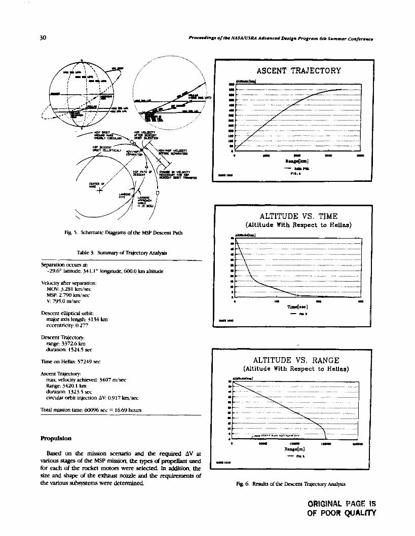
P r o m l l n g ~ 01th NASANSRA A d w n c d Design Program 61b Summer Confor-
Fig. 5. Schematic Dugrams of the MSP Descent Plth
Table 3. Swnmary of Trajectory An?lysis
Separation occurs at: -29.6' latitude, 34 1.1 longitude, 600.0 km altitude
Velocity after separation: MOV: 3.281 km/scur MSP: 2.790 km/sec V: 795.0 m/sec
Descent elliptical orbit: major axis length: 3 134 km eccentricity: 0.277
Descent Trajectory: range: 3372.6 km duntion: 1524.5 sec
T i on Hellas: 57249 sec
kmt Trajectov max. velocity a c h i d : 3407 m/sec Range: 3420.1 Ian duration: 1323.5 sec circular orbit injection AV: 0.917 km/sec
Total mission time: 600% sec = 16.69 horn
Propulsion
Based on the mission scenario and the required AV at various stages of the MSP mission, the types of propellant used for each of the rocket motors were selected In addition, the size and shape of the exhaust nozzle and the requirements of the various subsystems were detennined
(Altitude With Respect to Hellas)
. . . . . . . . . . . . . . . . . . . . . . . . . . . . . . . . . ...........................................................
...................................... .................................
- nu1
Fig 6. Results of the Descent Trajectory An?lysis
ORIGINAL PAGE iS OF POOR QUALnY

University of California, Los Angeles
PmpeUant mass estimation Given the change in velocity necessary at each stage of the mission and the estimation of total weight of the rest of the spacecraft by the mechanical designer, the propulsion specialist could estimate the mass of propellant needed. Given the mass and velocity prior to rocket firing and the h a l velocity, the mass expended to achieve the diange can be calculated by conservation of momentum. A summary of a sample calculation is listed in Table 4.
Table 4. System Mass at Different Phases of the Mission
Event Mass (kg) Suucture Dropped (kg) Propellant Used (kg)
Rocket nozzle design The exhaust nozzles must be carefully designed so that the performance (particularly the specific thrust) of each rocket engine can fulfill its function. For example, the ascent motor must have total thrust greater than its total weight in order to propel the payload into orbit. Ideal gas behavior is assumed throughout this analysis. The thrust force can be related to the nozzle throat area, exit area, and mass flow rate of the fuel/oxidizer mixture by 1-D compressible flow equations and thermodynamics laws. Since the exit area of the nozzle is essentially fixed by the physical size of the rocket itself, mass flow rate of the propellant and the throat area become the main variables. These variables are selected via iterative processes to yield the optimal thrust. Sample results are shown in Table 5.
Pmpkion subsystems (gimbal, skin thickness, and grain &sign). A nozzle gimbaling scheme is also developed to maintain the stability of the ascent. For solid rocket appli- cations, propellant grain shape is also determined to ensure an approximately constant generation of thrust in time (see Fig. 7).
Thermal Control
Thermal anakysts for MSP during eclipse. When solar radiation to the MSP is blocked by the planet, the intemal
Heat sbfeld/aembeating. During supersonic atmospheric entry, a large quantity of heat is generated by friction and the presence of a shock wave. Thermal analysis was performed c.n a graphite heat shield with thermal blankets (madc of aluminized Mylar, separated by dacron mesh) on the insiclc. df the shield. The calculation shows that the inside grdphitc shield will reach a tempera1 ure of 390 K With the help t ~f thermal blankets, the heat flux into the MSP itself will not cause any damage to the instruments.
MSP beat tramfer cbaracteristtcs at tbe martian surface. The major contributors of heat transfer during the MSPs stay on the martian surface are convective heat transfer due to winds, solar radiation, and the radiation of the martian surface (black body radiation). Analysis shows that, in order to maintain the 20°C internal temperature, 26 W is needed during daytime, and 48 W when solar rddiation is absent.
Tbermal environment maintenance scbeme. The power requirement of the thermal control and the electric$ components provides the basis for selecting a battery (Table 6). A zinclsilver battery, which is capable of an output of 28 V at 20amp/hours, was chosen because of its superior energy density and weight among the available off-the-shelf selections.
Thermal control was achieved by an adaptive feedback- control system with heating coils and electrical grids. A block diagram of such a system is shown in Fig. 8.
Tdereble wind speed An analysis was also performed on the maximum surface windspeed tolerated by the MSP before it tips over. Using simple but consenative assumptions about the drag coefficient of the MSP, it is shown that winds of up to 600 m/sec can be tolerated.
DISCUSSION AND CONCLUSION
Due to the time constraint of the course and shortage of test data of various components, many assumptions had to be made in the preceding analysis. Some of the more important ones are discussed in the following paragraphs.
Mechanical Designmeight Estimate
Since a detailed structural analysis was not performed, the weights of the various structural members of the MSP were estimated based on comparison with other spacecraft with similar missions. However, consenative estimates are used throughout the process, and a large margin of safety was kept.
temperature of the spacecraft must be maintained so that temperature-sensitive instrumentation (battery, for example) will function properly. Steady-state energy consenation analysis The actual atmospheric entry aerodynamics are quite shows that about 23 W of power is required to maintain a complex, as chemical species are generated and dissociated 20°C internal temperature. under the intense heating of hypersonic flow speed. A more
Table 5. Specifications of the Rocket Motors
Rocket Motor
Propellant Max. Flow Throat Exit 7f.pe (KC) Thrust (N) Rate (Irg/.sec) Diameter ( m ) Iliameter ( m )
Deorbit Liquid 298.0 3558.4 1.2 0.028 0.254 Ascent Solid 234.3 2'902.7 1.22 0.0008 0.180 Rendezvous Liquid 298.3 1170.1 0.40 0.0146 0.188
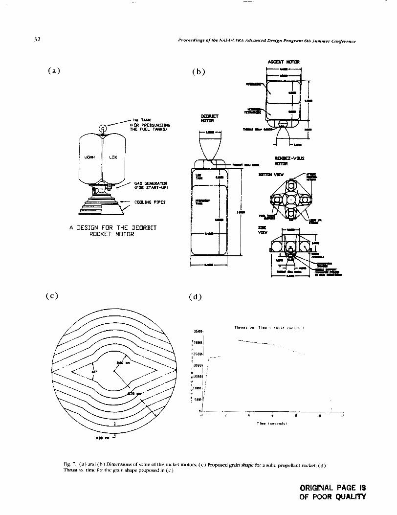
Proceedings of fbe .%'ASA/USRA Adrqanced Design Program 6tb Summer Conference
GAS GENERATaR (FOR START-UP)
A DESIGN FOR THE DEORBIT ROCKET MOTOR
Fig. '. ( a ) and ( h ) I)irncnsions of some of thr rcxkrt motors; ( c ) Roposcd p n shape for a solid propellant rocket; (d ) 'lhrubt n. timc for thc gr in shape proposed in ( c )
ORIGINAL PAGE IS OF POOR QUALrrY

~ I n i ~ ~ e r s i t y o j California, Los Angeles
Table 6 Power Requirement and Battery Selection
Phax of Power Required Control 'rune ( rnin) Energy Mission to maintain at Power ( W ) Required (J )
203 K (W)
Descent to 1 25.0 30 20.47 67,551 1 t o 3 10.0 30 4.90 1 1,760 On the ground Day: 25.76 30 490.00 1,639,340
Night: 47.78 30 49C-)0.00 2,286,730 Drill 200.0 15 180,000 Ascent 5 to 8 12.6 30 22.00 56,236 Total Energy Required: 4,241,616 Battery Selected: EP1 4445 with 20 amp/hr at 28 V
SZHR 7.0 with 7.0 amp/hr at 1.5 V/ceU Total Battery Weight: 20.75 kg
OTHER INPUTS
0THm OUTPUTS
Fig. 8. A Block Diagram of the Thermal Control Srjtem
detailed computational fluid dynamics analysis could provide much better insight.
Propulsion Systems
As mentioned before, ideal gas assumptions are used throughout the analysis.
Thermal Control
In nearly all calculations performed on the MSP thermal environment, steady-state is assumed. Thus, thermal inertia and transient response of individual components of the MSP were neglected.
Conclusion
This preliminary study of an interplanetary exploration mission has shown the feasibility of such a mission. The students have learned valuable lessons about the complexity of spacecraft design, even though the mission is relatively simple.
Participating students included Kevin S. Scott, James K Dawson, Gordon M. Eichhorst, Arun J. Jain, Daniel A. Klotz, Li-Ming Lee (Report Editor), Marygrace R Literatus, Sanjay S. Patel, Stewart G. Rydrnan, and Steven E. Woo. The instructor was R X. Meyer, Adjunct Professor.


P O S T W I N G OPTIMUM DESIGNS FOR THE ASSURED CREW RETURN VEHICLE N g 1 - 1 8 1 2 6 - .
UNIVERSITY OF CENTRAL FLORIDA
The optimized preliminary engineering design concepts for postlanding operations of a water-landing Assured Crew Return Vehicle (ACRV) during a medical rescue mission are presented. Two ACRVs will be permanently docked to Space Station Fmdom, hifilling NASA's commitment to Assured Crew Return Capability in the event of an accident or illness. The optimized configuration of the ACRV is bawd on an Apollo command module (ACM) derivative. The scenario assumes landing a sick or injured crewmemkr on water with the possibility of a delayed rescue. Design emphasis is placed on four major areas. First is the design of a mechanism that provides a safe and time-critical means of removing the sick or injured crewmember from the ACRV Support to the assisting rescue personnel is also provided. Sccond is the design of a system that orients and stabilizes the craft after landing so as to cause no further injury or discomfort to the already ill or injured crewmemher. Third is the design of a sytem that provides full medical support to a sick or injured crewmember aboard the ACRV from the time of separation from the space station to rescue by recovery orces. Last is the design of a system that provides for the comfort and safety of the entire cre Q r splashdown up to the point of rescue. The four systems are conceptually integrated into the ACRV
For years, America's journey into space has demonstrated the benefits associated with working in the unique environment of rnicrogravity. Continuing in this tradition, humans will soon launch an ambitious and far-reaching program to further the advancement of space technology. With the advent of Space Station Frwdom, the 1i.S. will enter an era marked by a permanent presence in space. Moreover, the .space station will allow continuous rather than intermittent operations to he conducted in orbit. The space station will open doors to many new methcwis of research and experimentation. Furthermore, humans will have a better oppmunity to observe the Earth and forecast future trends from a vantage point only partially exploited by previous shuttle missions.
Space Station Freedom will eventually be permanently manned by a crew of eight. The crew will be rotated and resupplied by flights of the orbiter on an interval currently planned for three months"). Due t o the isolation and potentially hazardous conditions involved in space operations, NASA is committed t o the policy of Assured Crew Return Capability for Space Station crews in the went: ( 1 ) a medical emergency occurs and an ill, injured, o r deconditioned crewmember must be rapidly t rampr ted from the Space Station to a definitive health care facility on Earth; ( 2 ) a Space Station catastrophe forces a rapid evacuation of the crew from the station; o r (3) the National Space Transportation System becomes unavailable, and an orderly evacuation of the crew Erom the Space Station becomes necessary. These events, o r Design Reference Missions (DRMs), can be met by a concept known as the Assured Crew Return Vehicle (ACRV). Currently, NASA is considering three classes of ACRVs: water landers, runway landers, and o p n land, o r nonrunway, landers.
The task objectives detailed in this report, will be limited to those required for a water-landing ACRV, medical and crew support subsystems, and postlanding operations. Some of the
medical and crew support subsystem designs will also support in-flight operational requirements. All designs presented follow the performance requirements and operational constraints supplied in JSC-3 10 1 7 "CERV Ststems Performance and Requirements Document."
DESIGN CONSIDERATIONS
The ambulatory nature of returning an ill, injured, o r deconditioned crewmember hack to Earth ahlard a water- landing ACRV requires new technologies and operational procedures. The possibility of further injury or illness would compromise the mission. Following arc general design considerations awxiated with the Apollo-based ACRV from the point immediately after splashdown to rescue hy recovery forces.
The first major concern is pn~viding crew egress and rescue personnel support subsystems. Thew subsystems include an emergency egress couch (EEC), a mechanism for remobing the couch safely, and the necessary hardware for the acsisting re.scue personnel.
The EEC plays a vital role in the medical portion of the A<:R\' mission. The EEC must insure the safrty of the sick or injured crewmember throughout all phases of the return mission. The design provides for the immobilization of the injured crewmember in a fully supine position from the hips up. Provisions are made to incorporate the necessary equipment in the couch to sustain the injured crewmember throughout the mission. The design insures the sick or injured crew- member is protected from the sea environment during egress.
The mechanism required to safely and quickly remove the EEC is termed the Rapid Egress System (RES). It must insure the minimum trauma removal of the sick or injured crew- member from the ACRV without endangering the rest of the

36 Proceedings of the NASA/LlSRA Advanced Design Program 6th Summer Conference
crew or rescue personnel. The RES is designed to include features that allow the couch and the injured crewmember to be safely transferred to a rescue vehicle. The design must provide the means for *lacing the couch a safe distance from the ACRV.
The incorporation of a rescue personnel support (RPS) system is mandated by the necessity to provide for the safety of the rescue personnel and crewmembers. Strategic place- ment and accessible design of handholds, supports, and platforms used by the rescue personnel facilitates the successful manipulation of the craft and medical couch during recovery operations.
The second major concern is the proper orientation, attitude control, and stabilization systems required for the ACRV in the marine environment. Experience gained ffom previous Apollo water landings has shown that some sea and weather conditiom cause severe discomfort to the crew. In the case of an injured crewman, this could cause further aggravation of an already existing injury, or wen death. Instabilities of yaw, pitch, and roll motions of the ACRV also cause the attending crewmember to be ineffective. A more serious problem arises if the ACRV lands in an inverted position. R-ue is impossible if the craft remains in this orientation.
The objective of the ACRV orientation s-ystem is to ensure an upright postlanding orientation. ACRV vehicles may have multiple stable positions, with only one being the preferred. The Apollo craft had both Stable-1 (upright) and Stable-2 (inverted) positions during its postlanding mission phase. The Apollo landed approximately 50% of the time in the Stable- 1 (preferred) position and, therefore, required a change of orientation nearly 50% of the time.
The attitude system is more than an extension of the orientation system. It provides an assisting buoyant force to counter the weight of the ACRV, which is approximately 10,000 Ib. The system raises and maintains the ACRV high enough above the water to allow safe crew egress and rescue support. The planform area of the craft (the total area as seen from above) increases as it asumes the postlanding position. This increases the moment required, through wave action, to tip the ACRV over to an undesirable position. The attitude system also furnishes an area on which rescue personnel can safely work on the cralt and place any necessary equipment.
The objective of the ACRV stabilization system is to provide for the stabilization -and damping of the rotational and linear motions induced through sea and weather conditions. These motions are roll, pitch, and yaw for rotational motions and have, surge, and sway for linear motions. Considering the circular 5)mmetry of the Apollo design, roU and pitch can be considered the same motion.
The range of motion to be stabilized is characterized by the frequency of the disturbance. Vibrations due to ocean-wave excitation of a hull occur primarily at fundamental frequencies between 1 and 3 Hz. The resonant frequency of a human is approximately 2-5 Hz'?'. ?his places the frequency range of the disturbances within the resonance frequency rang of a human, which may tend to stimulate motion sickness of the crewmembers.
The circular symmetry of the proposed ACRV presents a problem that is not encountered with typical ocean vessels. The roll in a ship only manifests itself in one direction, a plane normal to the deck. The motion of an ACRV is characterized by roll and pitch and may occur in any plane normal to the craft planform area. The stabilization systems developed for the control of ship roll only work for one direction'.'). The ACRV needs systems to dampen motions in all directions. This requirement limits the feasible choices for an effective ACRV stabilization subsystem.
The third major concern is associated with providing full medical support to an ill, injured, or deconditioned crew- member aboard the ACRV from the time of separation from the Space Station to fescue by recovev forces. While living and working on the Space Station, the astronauts will be involved in extravehiclar activities and other demanding pbs. It is likely an injury may occur that requires emergency medical care available only at a hospital on Earth.
Since the ACRV must bring ,an injured crewmember back to Earth safely, it must be designed and equipped to handle any possible medical emergency. It must provide full medical support to a seriously ill or injured crewmember and partial support to a crewmember with minor injuries during the time period between separation tiom the Space Station to crew recovery on Earth.
The medicxi support subsystems must k as simple and easy to use as possible. In the case of an emergency, the astronauts should not spend time making the medical systems work property. If the crew has been in .space for an extended period of time, they will be deconditioned and not function well in the gravity of Earth without assistance. Another major requirement is that the medicxi support subsystems be capable of operating without adverse effects on other ACRV subsystems or the ACRV crew compartment and environment.
The medical equipment for the ACRV consists of the dwices needed to maintain and/or monitor the crewmember's condition. The minimum medical equipment to be incorpo- nted into the ACRV includes defibrillator/heart monitor, IV pump, ventilator, blood prescure monitor, portable suction, and blood oxygen monitor.
Since the EEC is a self-conrained system, the administration, control, and removal of oxygen will be emphasized at the seat locations. The seat locations differ from the couch location in that a crewmember may need only pure oxygen administered at the seat and not require use of the EEC.
F i y , the fourth major concern is providing for the comfort and safety of the entire crew from splashdown to the time of rescue. The rescue team may not arrive at the craft for an extended period of time. Therefore. maintaining the comfort and health of the crew within thc ACRV is necessary. If the ACRV and its crew must remain on the water for 24 hours, then food, water, and nraste management systems need to be incorporated. An atmospheric and environmental control system to maintain a shirtsleeve environment also needs to be incorporated.
Providing a food supply for the ACRV bystem is important. Although humans can survive for weeks without food, ill,

University of Central Florida 37
injured, or deconditioned crewmembers may suffer if proper nutrition is not provided. Factors used in choosing ACRV food supply systems include shelf life, nutritional value, weight, sue, taste, and system complexity.
Water is important to the crew for consumption and washing. Requirements for the amount of drinking water vary. Factors used in choosing water systems candidates are size, weight, complexity, and existence of the needed technology.
Waste management is important to the ACRV systems to provide for crew comfort and to prevent contamination. Factors used to choose the system types are weight, size, complexity, simplicity, and existence of required technology. Convenience is also considered since experience has shown that inconvenient waste elimination systems encourage the desire to avoid these systems by not eating or drinking.
The atmosphere inside the ACRV will conform to conditions prexnt on Earth at sea level. This means the 0,-N, mix will be 20-BOX, and the cabin pressure will be set at 14.7psi. Systems used can be modeled after the atmosphere systems of the Skylab, space shuttle, and Hemes (European Space Plane) vehicles.
The contaminant control system removes known contami- nants, odors, and CO, from the atmosphere aboard the ACRV. A most challenging task is the postlanding control of temperature, humidity, and ventilation. The regulation of these environmental components is a crucial factor in the success of the ACRV in the ambulatory mission.
When the craft lands, it is assumed that all avionics systems will be turned off except for a position beacon and local two- way communications equipment. The life support electronics are all solid-state low-power systems. Therefore, the initial thermal model will only include the body heat generated by a crew of two, which can be estimated using ASHRAE tables(*). Body heat production is highly dependent on the activity level.
The primary problem with postlanding spacecraft tempera- ture controls is that the mode of heat expulsion used in space will not work on the Earth's surface. The heat expulsion system in space takes advantage of the low temperature in the shade from the sun and near-vacuum air pressures. The radiators are usualty mounted on the inside of the craft's skin to route the coolant fluid as close as possible to the radiative surface, the craft's outer skin. The coolant leaves the radiators and flows through the flash evaporators. When the radiatols cannot expel the total heat load, the flash evaporator is activated. Cooling is accomplished by throttling liquid water to the near-vacuum pressure of space. The water boils and the steam is expelled from the craft. The latent heat of steam and the mass transfer from the craft completes the heat expulsion process.
During reentry, the rddiators become less effective due to the heating of the craft's skin and the increase of the atmospheric temperature. In addition, the flash evaporator becomes less effective since the atmospheric pressure increases as the ship descends. At 100,000-ft elevation, the space cooling system becomes ineffective.
The time period of concern for this section of investigation begins when the craft has landed. However, some consider- ation will be given to the cooling .system design for the several
minutes before landing when the space cooling system is inoperable. Although flash evaporation does not occur below 100,000 ft, it is recommended that the primary thermal control system in the atmosphere be provided with an alternative hrat sink.
DESIGN SOLUTIONS
Crew Egress and Rescue Personnel Support
The design solutions associated with rapidly and safely removing a sick or injured crewmember from the ACRV and providing rescue personnel support will be addrewcl first. The hardware involved consists of an EEC, a mechanism to ficilitatc the removal of the couch, and the associated rescue support.
EEC is a specially designed couch for the ACRV medical mission and is termed the Special Purpose Couch (Fig. 1 ). 'lhe portion where the injured crewmember's legs reside is elevated with fully supine positioning from the hips up to aid in trauma cases. A hard cover with access ports encloscs the structure providing a self-contained environment within. Provisions are made within the couch to accommodate medical equipment and data transmission de-ices. Matc.ri;~l considerations ensure that the couch attains a positive huopnt nature should a mishap occur where the couch escapes into the water.
To facilitate the safe and rapid remo\.al o f the couch. the Four Link Injured Personnel Mechanism (FI-IPEM) h a been designed. The FLIPEM is a set of four bar linkages connected on both sides of a horizontal platform used to support the couch (Fig. 1). Once initiated, retaining latches relc;~w thc
Fig. 1 . Four-].ink lnjurcd Personnel Egress Mcchanisrn and Emergency Egress <:ouch System
ORIGINAL PAGE IS OF POOR QUAL17Y

38 Proceedings of tbe NAJjl/USRA Advanced Design Program 6th Summer Conference
FUPEM where nitrogen-charged piston cylinders drlw the R ; C + I A , ~
mechanism a set distance to the hatch opening. Ratchet SlSlH
locking systems arc incorporated to prcvrnt retraction. M e r \- . p r r
removal of the couch to the rescue ships, the platform used for the couch aids the remaining crewmembers in their egress. A I T I I ~
[DIIAL RIL The rescue personnel system configuration consists of a set tr i r Y
of handhold. and footholds to provide a source of secure --y--+. - '-/ footing, and D-rings to provide points for safety line attachments to aid the rescue personnel Retractable tethers are also incorporated to support both the divers and couch ulth a safety line for use during rough sea conditions.
I J
Orientation, Attitude, and Stabilization Systems
The three-balltmn orientation mtem utilized during the lunar program is chosen to attain the proper orientation of the Apollo crdi after splashdown. Three 6 . 2 4 diameter balloons, deployed from the top of the ACRV, upright the craft and provide double redundanc~ in case of single balloon failure. Individual canisters, activated manually or automatically, provide the 375 cu ft of CO, needed for inflation.
Attitude control is accomplished by a system consisting of three niultichmihered segments. Each .xXgment extends a thud o f the way arouncl the perimeter of the craft. One segment o f the ring resicles under the egress hatch and has a 6 x 6 x 3-fi rec.tangillrir appurtcnancc. '*is appurtenance acts as a plathrni on which to place the couch before removal by the rc.wur ship, md as a platform for use by the rescue ~ K O M ~ ~ .
Individual canisten of (;02 are used to inflate the rubberized L+ t )veli Kt~lar ring systeni.
'lhc stabilization of the ACRV during adverse sea and wcather conditions is accomplished by a deployable under- \rater pmchute s73tern. The basic premix of this system is t l i ; ~ t damping occurs through a weight force creating a moment. As the cr& o.willates, the pardchutes are forced to Inovc 1;lrge volumes of water. As the energy of the motion is disipated ty c~ercoming the inertia of the water and through shcir and d r q forces, the crafi will k stabilized.
'lhc. par~cliutc system is housed in the same compartment ;I.% the attitude ring systcni md deploys in conjunction with i t 'Ihc ~~aractii~tes are attached to cables that are weighted wit11 scg~ilcnts o f the A<:K\' skin. Three long cables are cxrcnded approximately six feet below the water line to m i d tlic wave action zone. '17ic possibility of entanglement incrcaws if more c;rl>lcs arc added or their length increased.
' ll~ree ;idditional parachute-cable systems are deployed to a depth just helow ttie water line. 'Ibex act to resist the heave ancl pitch motion5 of the crafi, while the longer cxbles reduce thc ylu. anrl surge rriotions. 'lhe entire orientation, attitude, anrl 5t;ibilization s~stcms can he .wen in Fig. 2.
Medical Support Systems
Fig. 2. Complete Orientation, Attitude, and Stabilization System
similar in configuration to the full-sized backpacks used by hikers. Currently, the Thomas Pack is employed abcvzd the shuttle fleet for the same type of application.
Extensive research was performed to d u - d t e suitable, "off- the-shelf" medical support equipment and monitors. As a result, .several brand names were selected that conformed to the ACRV prc+pni requirements. Selections were also made for a defibriUator/heart monitor, IV pump, ventilator, blocd pressure monitor, portable suction, and blood oxygen monitor. For all the selected equipment rubber isolators and honey- comb pads are incorporated to provide reduction to the loadings encountered during splashdown.
Each piece of equipment operates off a standard DC, 12-V source. The Apollo craft supplies both an AC and DC power source to run all flight systems. The Apollo DC source runs at a higher voltage; therefore, a modification is required to run the 12-V equipment. After the couch is removed from the FLIPEM, two 12-V Ni-Cad batteries function to supply power (for six hours) to the equipment. If all equipment is functioning the required power is approximately 80 W.
A deconditioned crewmember positioned on a normal flight couch, requiring only pure oxygen, will use a nasal cannula device to administer the oxygen. The nasal cannula is made up of one t u k that stparates into two tubes. The two tuhes reside in the nostrils of the crewmember and are held in place by Mction. The excess oxygen that is released from this system is filtered out by an air-dump device that captures the additional oxygen and expels it to the exterior of the craft or stores it in tanks.
niis portion of the report addresses solutions to the partial Crew Comfoft and Environmental Control Systems 111eclical support package, necessary medical equipment and monitors, and the oqgen administration and control systems. Design solutions for the food, water, and waste management, The Thomas Transport Pack was determined to be s a c i e n t atmosphere, contaminant/odor, and environmental control for uw as the partial medical support package. This system is systems are addressed.

Food systems rely on space shuttle contingency bars for their proven application and low volume and weight. Water supply qstems utilize plastic squeeze bottles for their ease of use and storage. The waste management system stems from a deribative of the Apollo-style waste hag system. Slight mtdifications to this sytem are necessary to q u w for usc by both men rtnd womm.
Atmosphere and contaminantlodor control systems are derived from existing systems ,already in use. The atmosphere control system is bawd on the Skylab atmosphere system. 'this system uses oxygen and nitrogen tanks, stored at 3000 psi rtnd regulated through valves, to pn)vide the appropriate atmos- phere. ACRV program requirements specify that a 14.7psi (Sblab: 5 psi) atn~osphere be maintained througho~rt the mission. Charcoal and lithium-hydroxide filters, used ahyard the shuttle, will be used to scrub the air for odors and CO,.
Maintaining environmental control within the ACRV throughout the mission is accomplished by flash evaporation with water above 100,000ft and flash evaporation with ammonia below 100,000 ft. Below 100,000 ft, the primary heat source runs through an ammonia boiler sytem that has been precooled at the space station, instead of through the radiator used in space. Though a precooled system is more efficient than a non-precooled system, the added complexity of interfacing with the space station coolant system will demand greater costs and design time. It is estimated that 110 lb of ammonia in a spherical tank would be required to maintain a comfortable temperature within the ACRV for a calm crew of two with no equipment (other than medical) running for a period up to 24 hours.
SUMMARY
ments and dcploy the parachutes. The pwachutes are attached to segments of the discarded ACRV skin, which forces the tension in the cahles. Six parachute-cable systems are dtployed in all. Three parachute-cable assemblies drop to 6 ft under the surface of the water to control the motions of ydw and surge. The remaining assemblies drop to approximately 1 ft under the surface to control the motions of heave and pitch.
The medical support equipment and monitors will function throughout the entire mission from separation to recovev. ?he ammonia boiler environmental control system that is used to maintain a shirtsleeve environment inside the craFt after splashdown is activated passing through 100,000 ft and functions until recovery. Food, water, and waste management systems are incorporated in case rescue is not immediate. Following hatch opening by the rescue personnel, the FLIPEM releases to deliver the medical couch to the hatch opening. The rescue personnel remove the couch along rails in the hatch and extension to a safe distance for attachment to cables used to lift the couch to the recovery ship. The remaining crew members exit using the platform left by the use of the F'I.IPEM.
ACKNOWLEDGMENTS The authors of this design synopsis are Kenneth C.
Hosteman, Graduate Teaching Assistant, and Professor Idoren A. Anderson. Appreciation is expressed to the senior design students in Aerospace and Mechanical Engineering, who contributed to the work. A special note of appreciation is due NASA and I!SRA, whose sponsorship made this work possible.
REFERENCES
1 . I). Herman, "Space Station Architectural C:onc-cpth and Functional Ca~ahiliw," . m e A&dicatio)rc at the Cnjsm~~uIs: 2 f s r (;o&rd
mis epO ddresses and pro\idn r,luticnr\ the design .~~bno&; .si?qx)sfum ed. J McBlnn. and L. Hcacock (\an I)iw): I:nivelt, Inc., 1983) p. 257.
considerations associated with the postlanding crew and 2. ,,, (;ierke and I), Gold,nan, uEgccts Of $hock and Vibr4rion medical support for a uater landing ACRL! After splashdowm In Man," Shock rod Vihratio~z IIN~UIIHX)~, 2nd cd., cd. (:. Hanis has occurred, the orientation balloon q3tem deploys, righting ;ind <:. Crede (New York: McGrdw-Hill Rx)k <:ompan)., 1976)
the ACRV (if needed) and maintaining it in the proper Ch.6xP.23. 3. S. Bkdgoveshchens@. 7hff)t-y of .Yhir, Motio ta , tranh. '1: uld I..
orientation. Then the attitude control ring is activated. The Strekog under of I- (New york, I)over inflation of the ring forces the arms of the underwater bhlic;lt,ons, I C X , ~ ) p. 508. parachute stabilization system to rotate out of their compan- 4 ASHRAE Standard 55' - 1985, p 375


METHODS FOR THE DEVELOPMENT OF A BIOREGENERATIVE LIFE SUPPORT SYSTEM
UNIVERSITY OF COLORADO
This paper is the result of a phase zero design project conducted for NASA Ames Research Center. Its goal is to establish the basis for the development of bioregenerative life support systems. This was accomplished through the spec*- cation of a comprehensive methodology that follows the process kom basic research through implementation. How- ever, before getting into the specifics of the methodology developed, a few points in understanding the driving forces of the space program being considered by NASA are necessary.
kc an agency, NASA is designed to promote and embrace the fields of aerospace sciences and technologies. NASA does this by advocating and soliciting public support for its many programs One aspect of this promotion involves outreach propams to educate students. The space program is full of imaginative possibilities that stimulate many students who may one day become scientists or engineers. Other people become advocates through sharing in NASA's achievements and the resulting national pride. Some of the most effective supporters are of course the myriad researchers, scientists, and astronauts who have performed the experiments that make up a large portion of the space program. These have added greatly to the nation's understanding of space, as well as our home planet, Earth.
Currently, NASA is undertaking the new task of the Space Exploration Initiative. This is a bold program to expand humankind's presence in space as well as to increase understanding of this unique environment. Since astronauts will be subject to this environment, it is hoped that many lessons will be learned about the way humans adapt and behave. Such fields as human physiology and psychology may be greatly enhanced. Away fkom Earth, the unique environment also enables specialized manufacturing for precision materials and pharmaceuticals. Applications of these technologies may then be used by industry and people on Earth, thus the benefits h-om the research and development in space are brought back home.
LIFE SUPPORT HISTORY
With the benefits of a manned space program in mind, the requirement to provide adequate life support measures bccomes evident. Initially, manned space program efforts were concentrated on putting the first astronauts in space as quickly as possible. Consequently, the Life support systems that were dweloped were little more than storage systems designed to supply astronauts with the minimum of air, food, and water that, once uxd , would be discarded or stored for return to
PReCEDlNG PAGE BLANK NOT FXMED
Earth, but not reused. For the early missions of short duration this approach was successfbl; yet ac mission length increased, sending expendable supplies proved to be expensive. Some efforts were made to remove carbon dioxide from the cxhin atmosphere with lithium-hydroxide "scrubbers." While this did not recycle carbon dioxide back into oxygen, it did extend mission duration capabilities.
Surprisingly, the technology now used on the shuttle has changed little from its predecessors on the Apollo missions. A simple projection of future requirements for a mission such as a 1000-day expedition to Mars with a crew of 10, shows that the mass of expendable supplies alone would be more that 100 metric tons. A way to resolve this problem is to utilize systems that recycle or reuse a l l or part of their mass.
PHYSICOCHEMICAL VS. BIOREGENERATIW SYSTEM!3
There are two basic approaches that can be taken to develop such systems: physicochemical and bioregenerative. The first of these is a system that uses physic4 or chemical methods to perform a particular life support task. The latter is a system that integrates physicd and chemicd methods to perform multiple life suppon tasks. In order to better understand these two approaches, we should examine their basic characteristics (see Fig. 1 ).
Physicochemical systems are in general more widely understood than their bioregenerative counterparts. The reason for this lies partly in the fact that most physicochemical devices are serial processors. These devices perform simple
NEVER BEEN PROVEN CREATES UNDESIRABLE
BYPRODUCTS LIMITED LIFETIME
HIGH RESUPPLY REQUIR
Fig. 1. Basic Characteristics
PAGE YQ) INTENTlONAUY BLANK

Proceedings oJtbe iVASA/USRA Aduanced Design Program 6tb Summer Conference
operations that are highly predictable and maintain constant performance characteristics. These systems are also relatively autonomous in that they do not necessarily rely on other systems to continue operation. However, this should not be interpreted to mean that physlcochemical systems are either completely understood or better suited to space applications.
In fact, no closed physicochemical system has ever been proven on Earth or in space. Nor are all the characteristics of such a system desirable. Several components of proposed systems produce hazardous byproducts. Furthermore, because of the manmade nature of the components, repair and replace- ment of parts is inevitable.
Unfortunately, bioregenerative systems have been poorly understood by the engineering community. Much of the reason for this lies in the multi- or parallel-processor characteristics of living organisms. Additionally, organisms do not have con- stant, predictable performance characteristics; rather, they operate within a range of performance characteristics that may differ between individuals, as well as between organisms.
Interestingly enough, it is this very characteristic of wide ranges of performance that makes biological systems ideal for use in life support activities. Furthermore, as the term biore- generative suggests, the system is alwap rebuilding itself. In effect, new processors are continuously available, thus minimizing the need for repair and spare parts.
Having selected a mostly bioregenerative system, one of thc major characteristics to take advantage of is the similarity of the system to the system that supports life on Earth. Earth has supported life in a robust manner for millennia and the problems that are sigruficant in the environment today might prove to be either disastrous or no more than a "hiccup" in the long term. One way of understanding these problems is the development of an independent and closely monitored model of the Earth's system. This model could be in the form of the biorcqymerative system proposed.
The main problem in understanding and developing bioregenerative systems is that there exists no standard, systematic way of dealing with them. At first dance, biological sytems appear to be too complicated and ambiguous to he of any practical value within a standard engineering system, let alone something as crucial as a life support system. IJpon closer inspection, it becomes clczu that, with some initial simplifica- tions, it is quite possible to control and manage these systems. As a starting point, it is possible to circumvent the inherent complexities of biological systems by introducing the concept of the "black box."
With this approach, any organism can be treated as a black box. As a black box, the contents and prtKesx1s that cmur within the organism cannot be determined through direct ob.wnation. Thus, the only way to characterize the contents of this box is through the description of the box's inputs and outputs. By characterizing only the inputs and outputs of an organism, the extremely difficult proces* of describing the vxious biological functions that occur within is avoided. A\ with my simplification, some degree of detail will be lost
depending on the magnitude of the simplification. &.sides losing information on the internal processes of the organism, we also lose detail on the temporal aspects of the organism. It will be shown later that the idormation lost is either integrated at a later time or can be considered to be essentially unimportant h e n dealt with from a systems standpoint.
To describe the inputs and outputs, an initial breakdown into the three major categories of gases, liquids, and solid5 is made. This breakdown is used because, with the exception of energy inputs, it is able to handle all the input/output requirements of biological systems. It should be noted that, due to multiple inputs and outputs, this "black box" organism is not simply a serial processor but a highly integrated parallel processor.
To provide further detail the general categories of gases, liquids, and solids are each given more specific subdivisions. Gases may be broken into oxygen, carbon dioxide, and nitrogen, Liquids into tissue water (water contained within the organism at time of harvest) and excreted water. Solids may be subdivided into c;ubohydrates, proteins, fats, nitrogen compounds, and others (vitamins, minerals, etc.). While these subdivisions were dficient for the characterization of our organisms, other subdivisions may be required for more "exotic" organisms. The characterization of certain types of bacteria, for instance, may require the addition of a hydrocar- bon input/output category.
This box can also be examined from the three dserent levels of a function, a process, and an operation (we Fig. 2). A function deals entirely with the nontemporal aqxcts of the inputs and outputs. The functional view of an organism is that, given certain inputs, the organism will produce certain outputs, without respect to time. A pnxess, on the other hand, concerns it.xlf with the fact that inputs and outputs occur over a timespan that is dependent upon the organism in question. Finally, the operation component takes into account the power, mass, and volume requirements that are nccessaq to support each organism.
There are two basic categories of organisms that can bc. used in the development of a bioregcnerdtive system: plants and animals. Plants can he classfied by a few general charactcr-
LlQL
S O L I D S
- S O L I D S
Fig. 2. Biol(~ca1 Chardctcriz~tion of 1nputfOutput
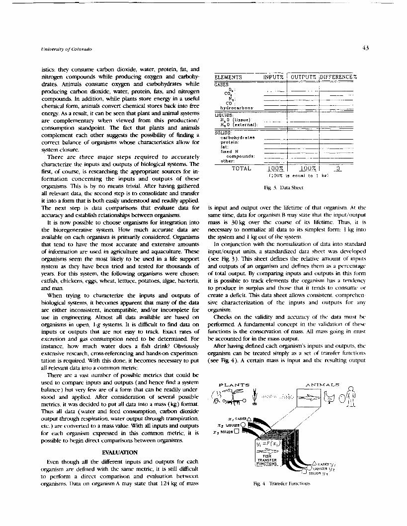
University of Colorado 43
istics: they consume carbon dioxide, water, protein, fat, and nitrogen compounds while producing oxygen and carbohy- drates. Animals consume oxygen and carbohydrates while producing carbon dioxide, water, protein, fats, and nitrogen compounds. In addition, while plants store energy in a useful chemical form, animals convert chemical stores back into free energy. As a result, it can be seen that plant and animal systems are complementary when viewed from this production/ consumption standpoint. The fact that plants and animals complement each other suggests the possibility of finding a correct balance of organisms whose characteristics allow for system closure.
There are three major steps required to accurately charac-terize the inputs and outputs of biological systems. The first, of course, is researching the appropriate sources for in- formation concerning the inputs and outputs of these organisms. This is by no means trivial. After having gathered all relevant data, the second step is to consolidate and transfer it into a form that is both easily understood and readily applied. The next step is data comparisons that evaluate data for accuracy and establish relationships between organisms.
It is now possible to choose organisms for integration into the bioregenerative system. How much accurate data are available on each organism is primarily considered. Organisms that tend to have the most accurate and extensive amounts of information are used in agriculture and aquaculture. These organisms seem the most likely to be used in a Life support system as they have been tried and tested for thousands of years. For this system, the following organisms were chosen: cadish, chickens, eggs, wheat, lettuce, potatoes, algae, bacteria, and man.
When trying to characterize the inputs and outputs of biological systems, it becomes apparent that many of the data are either inconsistent, incompatible, and/or incomplete for use in engineering. Almost all data available are bawd on organisms in open, 1-g systems. It is ditticult to find data on inputs or outputs that are not easy to track Exact rates of excretion and gas consumption need to be determined. For instance, how much water does a fish drink? Obviously extensive research, cross-referencing and hands-on experimen- tation is required. With this done, it becomes necessary to put all relevant data into a common metric.
There are a vast lumber of possible metrics that could be used to compare inputs and outputs (and hence find a system balance) but vety few are of a form that can be readily under- stood and applied. After consideration of several possible metrics, it wa.. decided to put all data into a mass (kg) format. Thus all data (water and feed consumption, carbon dioxide output through respiration, water output through transpiration, etc.) are converted to a mass value. With all inputs and outputs for each organism expressed in this common metric, it is possible to begin direct comparisons between organisms.
EVALUATION
Even though all the different inputs and outputs for each organism are defined with the same metric, it is still difficult to perform a direct comparison and evaluation between organisms. Data on organism A may state that 124 kg of m a s
ELEMENTS INPUTZ j OUTPUT% ]DIFFERENCES. - CASES: 1 1
N,: "" ---LC------
I I external):
SOLIDS: 1 1 carbohydrate^ I I protein:
(100X is eoual to 1 kul
fat: I fixed N 1
Fig. 3. Ddta Shcc.1
compounds: other:
TOTAL 100%
is input and output over the lifetime of that organism. At the same time, data for organism R may state that the input/output mass is 30 kg over the course of its lifetime. Thus, it is necessary to normalize all data to its simplest form: 1 kg into the system and 1 kg out of the system.
In conjunction with the normalization of data into standard input/output units, a standardized data sheet was developed (see Fig. 3). This sheet defines the relative anlount of inputs and outputs of an organism and defines them as a percentage of total output. By comparing inputs and outputs in this form it is possible to track elements the organism has a tendency to produce in surplus and those that i t tends to consume or create a deficit. This data sheet allows consistent, cornprehcn- sive characterization of the inputs and outputs for any organism.
Checks on the validity and accuracy of the data must be performed. A fundamental concept in the validation of thew functions is the conservation of mass. All mass going in must be accounted for in the mass output.
After having defined each organism's inputs and outputs, the organism can be treated simply as a set of transfer functions (see Fig. 4). A certain mass is input and the resulting output
1 0 0 % 1 - 0
PLANTS A N I M A L S -
Fig. 4 Trdnsfcr Functions

4-4 Proceedings oj tbe NASAIUSRA Adl'anced Desfgn Proxram 61b Summer Conference
of tlic subst:mce is detemmined by the organism transfer function. 'Ihus cvev biological systmi within the CEIS!! can be interpreted as a prepactiaged set of transfer functions. Now thcsc. organisms <.an he handled using well understtmd control \?stems methocis r;ither th;in from less understotd (for the ;n.cr;igc rngincer ) biologic;il approaches.
INTEGRATION
Now th;it any orginism can be treated as a transfer function, i t is possible to integrate multiple organisms into a closed s!stem. Integration refers to the use of an organism's outputs xs the inputs for any number of other organisms and thus input recluirernmts can be balanced with output production. As an example we will consider two ideal organisms in a
closed ?,)stern, the first of ukich (organism A) has a charac- teristic pattern of inputs and outputs given by its transfer hnctions. If we take a second organism (organism B) that is entirely conlplemcntary in terms of its inputs and outputs to organisnt A, it becomes possible to match inputs to outputs hetween the organisms and achieve a mass balance. If organism H has three times the amount of inputs and outputs ( ~ n kg) as comparcd to organism A, a m a s balance can be achieved by creating a system composed of three organism As ;inti a single organism 1%
Sincc the organisms being dealt with are not idral, it is nc;~rl! ,r given that &er matching inputs and outputs, there will be ~ ) n i c amount o f mass left over (surplus) or still required (deficit), without which a perfect balance will not be attainable.
For our system, the nine prc~iously mentioned organisms were integrated with a spreadsheet program ( x e Fig. 5). By summing the amounts of production (+) and consumption ( - ) of any single element across all nine organisms, it is possible to dctcrniinc whether thcrc is an overdl surplus or deficit of this clement. M e r deternmini~ig the total surplus or deficit of a c l l element. the absvlutr values of rach of these quantities arc summed to find a total system error or mass mismatch.
Although it aplxars that the mass mismatch within each clcnient would cauw ;t coniplete system failurc, in actualit)., this is not the case. Manmade physical systems are designed ivith singular, cii.xretr pcrfornrance characteristics. A car has ;I spcr~ifc ~ i t i n i ~ i i ~ ~ n t turning r~dius. a plane has a maxiniunt r;rtc of climb. and ;I rnicrou,i\~c oven requires a specific energ? input. 130th the inputs and outputs of thew physical systems arc specific., cswntially nonvaqing values, and a nlismatch of i ~ i p ~ ~ t s o r outpt~ts to the.w physical systems is unacctptablc.
Iiiolugical systems, on the other hand, have a range of perti)rnimce chwacteristics. Throirgh training, an individual V.UI iniprovc his or her perforrnancc in a s ~ c i f i c activity (time to run the -10-yard dash, for instance) by a significant pcrcentagc. A\ another example, nutritional inputs to a person can bc through a reniartiablr range with little o r no .serious cfkcts. 'lhus, tilr biolvgicd systems, mass mismatch rlocs n o t render the system unfeasible because of its adaptabili? or range of (,crfonn;ince characteristics. Biological organisms have an inn;rte tlcsihility and robust quality that is norntslly not fountl in ph!.sical s?stems; hence, biological
C O L M ERROR = E = $ "I.*! 0 TOTAL ERROR = $ I E ! ~ 0
1 Q &
Fig. 5 . System Mass Balance
from physicochemical systems (see Fig. 6) . Through inherent control mechanisms and ranges of performance organisms are effectively self-regulating. If the c h o n dioxide input into a plant is slightly reduced, for instance, the plant does not die but merely adapts to the new condition. It may not grow as quickly or as large, but it will live. Thus the attributes that make organisms difficult to work with (range of perfomlance characteristics, e tc . ) are the same attributes that make biological systems worthwhile.
-
PROCESS DESCRIFTION
.,<.'.#. n,
Any process takes place over time. This is cewainly true for organic "devices" such as a plant o r animal. For example, the time to maturity for lettuce is 30 days. Wheat and potatoes take 8 0 days. Single-celled organisms such as algae and bacteria hm very short doubling times of 4 hours and 2 days, respectively. Animals, howwer, have longer times; chickens take 120 days and catfish, 180. Eggs, a special cast in that they arc prtduced by another organism, are laid daily ( w e Fig. 7).
oz + +
ENGINEERING CONTROLS
mur - -
yste~i is have their own inhcrent "safety net" that is different Fig. 0. Wcty Net
+
nn - -
+ - -
run - A
-
clad
- + - - - L I -
r k n + - - + - -
- -

Fig. '. Timr to Maturity. Days
Each of the organisms selected, all of which are multipro- cessors, also h ~ s an associated growth cume that dictates its performance characteristics over time. This curve can be used to detcrnminr the flow rates of inputs and outputs cnrer time.
-- WIIEAT - - CATFISH
3 r - - - .--- -- .- -- - n
- 3 i---- t ----t----4 ---t----1--t--t--t4 0 20 40 60 80 100 120 140 160 180
TIME (days) 0-0 HZ0 A - A N cornpounda 0--0 carbohydrates *--mCOZ A-A02 V-V1.t 8-Wprolmln
Fig. 8. Performance Curves for W'heat and Catfish: Surplus and Deficit of Throughput Elements
Ail input flow rates arc thus directly proportional to the W . - - organism's mass. So too, all outputs, with the exception of the tissue of the organism itself, will be directly proportional. The 111111111111 0 ,6 rn2 P l a n l s 9 V 9 Y M 9 6.1 P l a n t s
reminder of outputs, in the fomm of the tissue mass, will ********** manifest itself as a spike in the output portion of the . . ....................................... . ....:... . .,..... .................... .,..:..:. 2 3 . 4 k g performance cume (see Fig. 8). ,..:..:. ,:..:., :. .I:.:.,.. .,:. :.: .,..: .::. ,. . : ,: " ' ,..: . ,:.... ..:.. .:. ,'.:.':. Algae
It is possible to integrate the mass balance over time. To & ~ ~ ~ o ~ o ~ o ~ D ~ o ' F T , ' F T , ' $ b ~ o ~ ~ ~ o & o 10.1 E~~~ d o this in ternms of supporting one human per day, the s c l a r &bnbOb-&O :li:O.O2kg B a c t e r i a for human input/output data must be multiplied to account for the average inputs and outputs of one human on ;I daily w0.2 C h i c k e n *- 2 . 2 Fish
. -
basis. This factor must then be used to multiply the scale Factors of the other organisms. These modified scale Factors are the number of organisms prtxiuced daily to achieve the desired halancc~. Bawd on these calculations, an example of a system balance to support one hunlan pcr day was achicvcd (.we Fig. 9).
Within this process description it is of g a t importance to have a sound understanding that the resultant configuration is dependant upon the time characteristics of each organism. In other words, further multiplication of the system balance figurcsby cach organism's respective time to maturity will deternline the number of organisms on average that must he growing at any one time. With this understanding one can then begin the operation and implenmentation phaw.
OPERATION AND IMPLEMENTATION
After achining a mass balance, bawd on transfer functions and the integration, the next step is to determine the possible configurations that could support such a balance. In so doing, one should exanline the implications of performance charac- teristics; mass, volume. and power requirements; and the sensitivity of the overall sjatem.
Fig. 9. System Balmcc to Support Onc liuman pcr I>ay
To understand the overall performance characteristics of the system the performance curves may be integrated with the system balance to understand the fluctuations in surpluses and deficits that occur for the \*hole gstern over time. This is accomplished by the superpsition of the curves based on the organisms' performance scaled to the number achieved in the system balance and their subsequent summation to create a sistem performance cunre. It is important to note that this curve will be a reflection of nhether a continuous prcxiuction qstem or a batched system is chosen, and that it is bawd on single design points, while the system operates in a range of characteristics (o r points). Thus, a Iwge portion of these surpluses and deficits will he absorbed by the organisms due to adaptive responses in their performance. This feature of performance flexibility can be thought of as an inherent b d e r on the system. As long as the surplus o r deficit for each element remains within the b d e r zone for the continued function of the organisms. the system uill support itself. It is also possible to acct~mmtKiate a l aqer surplus or deficit
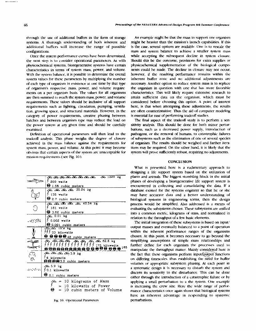
46 Proceedings oftbe NASA/USRA Aduanced Lksign Program 6tb Summer Conference
through the use of additional buffers in the form of storage systems. A thorough understanding of both inherent and additional buffers will increase the range of possible configurations.
Once the system performance curves have been determined, the next s t c ~ is to consider operational parameters. As with physicwhemical systems, bioregenerative systenw have certain characteristics in terms of system mass, power, and volume. With the system balance, it is possible to determine the overall system values for these parameters by multiplying the number of each of organism in existence at one time by that of organism's respective mass, power, and volume require- ments on a per organism basis. The values for all organisms arc then summed to reach the V t e m mass, power, and volume requirements. These values should be inclusive of all support requirements such as lighting, circulation, pumping, ventila- tion, growing space, and structural materials. However, in the category of power requirements, creative phasing between batches and between organism type may reduce the load on the power system at any given time and should be c-arefully examined.
Dttfinition of operational parameters will then lead to the trddeoff analysis. This phase weighs the degree of closure achiwed in the mas5 balance against the requirements for system maxs, power, and volume. At this point it may become obvious that certain aspects of the system are unacceptable for mission requirements (see Fig. 10).
n
f f f 33 kilowatts @9e9 48 cubic meters
@ 1.58 cubic meters &L &a &A A 30.24 kg f 135 watts
2.7 cubic meters &a Aa LS d AL 40.54 kg f 181 watts
w
. ..<.-::2:
- a & L m 3 . 9 kg 6 kilowatts 9 h W e 3 . 9 .ubic meters
@ 3.62 cubic meters Lm 0.01 kg
f 0.002 watts 0.001 cubic meters
Fig. 10. Operdtional Pxdmeters
* : ...*'. : . . .. - -
An example might be that the mass to support one organism might be heavier than the mission's launch capabilities. If this is the case, several options are available. One is to rescale the mass and system balance to achieve a smaller system mass while accepting the subsequent decline in system closure. Should this be the outcome, provisiom for extra supplies or physicochemicxl supplementation of the biolt>gical compo- nents could be made. The decline in closure may not occur, however, if the resulting performance remaim within the inherent buffer zone and no additional adjustments are necessary. Another option to reduce system mass is to replace the o'ganism in question with one that has more favorable characteristics. This will likely require extensive research to attain sufficient data on the organism, which must be considered before choosing this option. A point of interest here, is that when attempting these adjustments, the results are often counterintuitive. Thus the aid of computer modeling is essential for ease of performing tradeoff studies.
The final aspect of the tradeoff study is to perform a sm- sitivity analysis. This should be done for both minor pertur- bations, such as a decreased power supply, intrtxiuction o f pathogens, or the removal of humans, to catastrophic failures of subsystems such as the elimination of one or several species of oqanism. The results should be weighed and further itera- tions may be required. On the other hand, it is likely that the system will prove sufficiently robust, requiring no adjustments.
A 5.8 icg f 0.1 kilowatts
@ 0.1 cubic meters
CONCLUSION
a = 10 ki lograms of Mass f = 10 kilowatts of Power @ = 10 cubic m e t e r s of Volume
What is presented here is a rudimentary approach to designing a life support system based on the utilization of plants and animals. The biggest stumbling block in the initial phases of developing a bioregenerative life support system is encountered in collecting and consolidating the data. If a database existed for the systems engineer so that he or she may have accurate data and a better understanding of biological systems in engineering terms, then the design process would be simplified. Also addressed is a means of evaluating the subsytems chosen. These subsystems are unified into a common metric, kilograms of mass, and normalized in relation to the throughput of a few basic elements.
The initial integration of these subsystems is bawd on input/ output masses and eventually balanced to a point of operation within the inherent performance ranges of the organisms chosen. At this point, it becomes necessary to go beyond the simplifying assumptions of simple mass relationships and further define for each organism the processes used to manipulate the throughput matter. Mainly considered here is the fact that these organisms perform input output functions c-- on differing timescales, thus establishing the need for buffer volumes or appropriate subsystem phasing. At each p i n t in a systematic design it is necessary to disturb the system and discern its sensitivity to the disturbance. This can k done either through the intrcxiuction of a catastrophic failure or by applylng a small perturbation to a the system. One example is increasing the crew size. Here the wide range of perfor- mance characteristics once again shows that biological systems have an inherent advantage in responding to systemic perturbations.

(lniuersify of Colorado
Since the design of any space-based system depends on mass, power, and volume requirements, each subsystem must be evaluated in these terms. While one system, such as the caffish, proved itself to be mass (including support hardware) intensive, another system, the potatoes, proved itself to be power intensive. ?he ultimate design of a closed life support system will balance these criteria (mass, power, volume, closure, etc.) through the use of appropriate weighting factors based on mission constraints. This is an iterative process that also weighs these system design criteria against the system mass balance until all requirements are satisfied. These requirements are satisfied because bioregenerative systems operate within characteristic ranges. The mass blance is considered throughout the design process because this balance insures the closure of the system.
Phasing is another issue that must be addressed. Some systems are more suited for continuous h m t (daily egg collection), while for others, batch harvesting will be preferred (catfish or wheat). Storage facilities may be required to store system outputs to ensure the availability of needed inputs.
Since this is only a rudimentary analysis of a complex system, many other critical issues were not analyzed. Examples of these are labor requirements and the integration of bioregenerative with physicochemical systems. What has been shown, though, is that developing a bioregenerative system is possible Erom the design engineer's perspective once the approach has been ad- equately defined. Indeed, implementation can begm presently, and must do so in order to be utilized for the Space Station, the Moon, or eventually, Mars.
RECOMMENDATIONS
database with information on biological organisms were in place. This information might exist, but often in places or forms which are unusable to the systems engineer.
Another related problem is that a s iwcant amount of data on closed and well-monitored systems does not exist. Research and development of these systems is within our reach today and is not only of significance to NASA and the space program but to other entities, such as the planet Earth.
While bioregenerative-based systems are complex, their development is not unattainable or unreasonable. The basic methodology that has been provided has several steps, and in order to make a bioregenerative system a reality, one of the safest and most comprehensive ways would be to utilize each of these steps, coupled with support activities such as experimentation, modeling, and testing. With such a program, closed bioregenerative life support systems will soon be a reality, and manned missions to Mars will become feasible through self-reliance and less dependence on Earth resources.
ACKNOWLEDGMENTS
Special thanks to the students of the Space Habitation classes, Steve Johnson and Alex Hoehn, TAs, Dr. Marvin Luttges, and NASA/USRA. This paper was prepared by Michelle Goldman, Shawn Gomez, and Mike Voorhees. We thank Dr. Robert MacEkoy and Dr. Mark Kliss of NASA ARC for support.
As was mentioned earlier, the compilation and consolidation of information on biological systems mas a major obstacle to overcome. This obstacle could be minimized if a centralized

IMPLEMENTATION OF SENSOR AND CONTROL DESIGNS FOR BIOREGENERATIVE SYSTEMS
UNIVERSITY OF FLORIDA
The EGM 4000/4001 Engineering Design class is an interdisciplinary design course that allows students t o experience the design process. The projects involved the design of sensors and subsystems of a closed-loop life support system (CLLSS) with special emphasis on the Controlled Ecological Life Support System (CELSS) currently being developed at Kennedy Space Center (KSC) by NASA. This year's class comprised students majoring in Engineering Science, Aerospace Engineering, Agricultural Engineering, Mechanical Engineering, and Computer and Information Sciences. Consequently, the projects received support from students with many d i e r e n t interests and *areas of expertise.
To understand the work performed by the students, one must understand the purpc) .~ and concept of a CII.!! system. In the years to come, NASA will be constructing Moon bases and sending astronauts to other worlds on extended space missions. In order to support the crews, unreasonably large quantities of supplies would have to be sent from Earth. These supplies would be ditficult to transport and require large holds. To remedy this pn)blem, NASA plans to incorporate crops into the spacecraft. These crops would supply food for the crews, as well as provide beneficial psychological side effects. In addition, the plants would recycle the air and human waste and provide oxygen and water for the humans.
'IJe students in the design class were to work on supporting this broject. In order to d o this successfully, the course was LCJ .upanted into two phases. The first semester involved studying the various aspects of a CIJSS to determine sensing needs and develop ide-as. The .second semester involved first determining which of the ideas were most promising. Specific sensors were then designed and tested under laboratory conditions with promising results. Finally, recommendations for further development were proposed.
US!$ REQUIREMENTS
well as the possibility for sensing other parameters such as gas concentration, pressure, and humidity. The Nutrient Deliver) Group investigated the scnsing needs for monitoring the solution level in a porous membrane material and the requirements for measuring the ma<s flow rate in the delivery system. The Plant Health Gn)up examined the cau.ws and .symptoms of plant diseax and explored the various techniques for xnsing these health indicators. The g o u p investigating sensing needs for plant propagation and support focused on monitoring seed viability and measuring wed moisture content as well as defining the requirements for drying and storing the seeds. The Solids Processing Group covered the arms of harvesting, food proccxsing, and resource recycling, with a main focus on the sensing pt)hsibilities for regulating the recycling process.
Atmosphere and Temperature Control
This group determined that one possible wnsor is a relative humidity sensor that incorporates tiher optics. Another promising area is temperature or g ~ s profiling of a g row~h chamber. This could provide needed information o n the temperature gradients, a3 well as the gi~\ flows within a chamber. This information would allow, the determination of the ideal location for the \arious wnsors that would be incorporated within the chamber.
Nutrient Delivery
This group found a crucial need for a wetness sensor that would determine the wetness of a porous medium on which the plants would be growing. This is an area of great importance since a saturated medium could cause the rtx)ts to rot, and a dry rnediunl could destroy the plants. Consc- quently, a wetness sensor was pn1posc.d for .semester two.
Since an operational CLLSS system would incorporate many Plant Health different engineering and scientific disciplines, the clars was divided into subgroups that would study the diierent m a s of The sensing need found by this g o u p w;~1 obviously a pkant the system. The five areas of concentration were atmosphere health sensor. Therefore, the majoriq of the work conducted and temperature control, nutrient delivery systems, plant was directed toward disease gmpton1.r and available sensing health, plant propagation, and solids processing. The g o u p technologies. The technologies studied included both investigating atmosphere and temperature control f t ~ u s e d on destructive and nondestructive techniques including Moss- the temperature distribution within the growth chamber as bauer spectroscopy, fluorescence spectroscopy, visual imaging,
PRmED'N PAGE BLANK NOT RLMED uGL yx ~ N ~ ~ N ~ J O ~ ~ QU ORIGINAL PAGE is OF POOR QUALITY

50 Proceedings of tbe NASA/USRA Advanced Design Program 61b Summer Conference
nuclear magnetic resonance, and Mlious others. Also, expert systems were studied to help control the sensor system to be developed.
Plant Propagation
This group studied seed quality testing, x e d moisture sensing, wed drying, and seed storage. Quality is important in order to insure that the seed.. will germinate. The moisture content is critical to prevent rotting of the stored seeds and growth of hngi. ,Seed drying and storage techniques must be developed to mininlize damage to the seeds.
Resource Recycling
This group concentrated mainly on recycling the byproducts of a CIIS!!. This included harvesting, food processing, and waste rec~cling. The most promising projects were deternlined to be harvesting and food processing. These systems would need to be automated to relicvt. the crew From tedious work and allow them to concentrate on matters more directly awciated with the mission.
Based on the studies conducted during the first semester, the clacs proposed \,arious projects for development. 1he.x were rated and compared to determine which were most needed and feasible. This resulted in the selection of a seed moisture content sensor using infrxed diffuse reflectance, a porous medium wetness sensor, a plant health x-nsor using inh-xed digital imaging. and a controlling system for a rohot arnl and the plant health sensor using neural networks.
Seed Moisture Content
Moisture contcnt of soyl~ean seeds was chosen as the pn)perty that could Ixst k sc.n.wd for three reasons: ( I ) the test is nondestructive to the seeds; ( 2 ) the process of b-aqing nioisture content in the seeds for testing purposcs is a simple prtxcdure; ;md (5) the methtxi is easily automated. A moisture contcnt wnsor is important in a (:I.IS!! for several applications. If the device could k constructed to sense the moisture of seeds or wed pods while they were still attached to the plant, the optimum hmes t timc m q I x ' determined. If not used to determine hluvest timc, a nioisture content sensor could be uwd to determine whether a seed batch is retained for storage and replanting or wnt to food prcxessing, based on extremes in moisture content. Seeds ten) high in moisture may cause problems in storage as they are conducive to growth of mold and hngi and ;ire 1110re suscc~tible to mechanical damage tiuring hamesting and handling. Seed batches of low-percent moisture mq. havc dried on the plant ttx) long, reducing their vigor ancl storage life. 'Ihc nicasurcment of seed moisture content may also be instnlnicntal in controlling the drying times of wed hatc.hes hefore s torge.
The concept of using infrared reflectance as a rllellns to detemlinc the moistlrrc content of a seed batch is a technique b;ist-d on the property ot' water to absorb certain wavelengths
in the infrared spectrum. The band most widely used in on- line moisture determination is the 1.94-pm band within the infrared spectrum. Because light rays that interact with a rough surface are scattered, the best methtxi of sensing absorption properties is by diffuse reflectance.
In the design of this sensor system, two filters must be used-one that passes a water absorption band and another that passes a reference wavelength. The paqsed wavelengths interact with the surface of the seed sample prtxiucing a reflectance inversely proportional to the amount of infixed energy absorbed. Collecting the reflected energy and focusing it on a detector produces a corresponding voltage output. 'Ihe signal produced by the detector for each filter is recorded, and the ratio of the two reflectances is recorded. The two filters chosen were a 1.8-prn reference filter and a 1.94-pm bandpass filter. The detector type is lead sulfide, which is capahle of detecting both wavelengths of interest for the syrstem.
Seed batches of 250 g were prcqxared for testing. O k n drying, microwaving, and sun baking created seed samples of relatively low moisture content (approximately 6%)). To obtain high moisture contents, seed batches were soaked in Liquid water for different time intervals to achicve samples ranging from 20-35% moisture. The moisture content of each 250-g batch was then measured by a Burrows Model 700 digital moisture meter and the values w r e u.wd as the basis for test validation. The final tests performed under the optimal conditions resulted in reflectance measurements of seed .samples that successfully d8erentiatt.d between batches of different moisture contents.
Porous Medium Wetness
In order to maintain an efficient nutrient delivery system in a CLLSS, the ability to monitor the anlount of nutrient solution available to a plant through the porous medium is necessary. The most important factor in plant growth and prtductivity is soil water, which controls the uptake of most of the nutrients required for plant growth. Nutrient uptake of a crop \"arks throughout the crop season, as well as daily. Monitoring the wetness of the porous plate will pn)\ide data necessary to help control the amount of nutrient solution available to the plants throughout their growth cycle. This control can help to maintain healthy plants, prevent leakage to the <:I.IS!! atmosphere due to excess solution in the medium, and prcwnt air from entering into the delivery system due to a lack of solution in the medium.
The degree of wetness pertains to the relative concentration of water in a porous body, indcqxndent of the btxiy size. Two sensing methods were developed for monitoring the wetness of the porous medium; one that u.ws inh-xed reflectance and one based on heat dissipation. The infrared technique is similar to the approach used by the Seed Moisture Content Group. This technique is especially suited to sensing porous plate wetness since it measures surface moisture. The thermal technique was developed to exploit the fact that the thermal properties of water d 8 e r quite significantly from tho.% of air o r ceramics. The technique of measuring heat dissipation to

University of Florida
sense the degree of wetness in the porous medium is based on the fact that the rate of heat dissipation in a porous medium of low conductivity is sensitive to water content. A s the water decreases, a larger temperature gradient is needed to dissipate a given quantity of heat. The wetness of the porous medium can be correlated with the temperature gradients measured by the sensor for a given heat dissipation. These techniques allowed the wetness trend within the plates to be determined, though the exact moisture content was not quantified.
Plant Health Sensing
In order to maintain an extended space mission, it may be necessary to grow crops to support the astronauts physically and psychologically. The plants should be grown efliciently, with minimal interaction with the crew. This requires a number of automated systems to care for the crops. One such system should be able to monitor the health of the plants. This could be accomplished using three different levels. The k t of these levels would consist of a primary health sensor that could scan the entire crop in order to identify trouble areas. The secondary sensor would be able to examine a trouble area more in-depth to specify the location and extent of damage. Finally, the tertiary system would be able to analyze the trouble area for a specific cause and a possible solution for the problem. The primary and secondary sensors would be noninvasive, while the tertiary sensor may be destructive; however, the extent of the destruction could be minimized by the information gathered by the secondary .system.
This project centers upon the design and fabrication of a primary sensor .system. To sense the plant health, mrious factors may be examined. In this case, the amount of chlorophyll located in the plant tissue provided a direct correlation to plant health. It may be seen that health decreases as the chlorophyll concentration decreases. This may be readily seen in chlorotic and necrotic tissue. Chlorotic tissue shows a deficiency in chlorophyll through a yellowing of the tissue. Necrotic tissue is dead tissue, which is brown and dry in appearance.
Chlorophyll is detected through the use of IR radiation absorption. Absorption is measured through the use of a digitizing camera system. Light is reflected off the leaf and collected by the camera. The light is first passed through a bandpass filter in order to pass a wavelength of 671 nm, which corresponds to the peak absorption of cblmpbylfa. As the amount of chlorophyll decreases, the amount of 671-nm tight reflected will increase. This will be observed by the camera and recorded by a computer within an array of integers. This array represents the light intensities locxted within an image. Each number in the array represents a grey level and as the numbers increase, the intensity of tight increases. Using the 671-nm filter to analyze the chlorophyll content of the plant tissue, it was possible to obtain data that clearly displayed unhealthy regions on the leaf.
Neural Netwoks
The main purpose of this project is to try to adapt neural network theory to CUSS applications, or more specifically, to plant health. In order to do this, sequential programs are used
to simulate the parallel distributed processing of a neural network This project was separated into two phases. The first consisted of using neural networks to control a robot arm. The second consisted of using neural networks to determine the health status of a plant based on the data accumulated by the Plant Health Group.
The robot arm was to be trained to grasp an object. This object was assumed to be the stem of a soybean plant approximately 2 in above the growing surface. The first preliminary step was to design and train a network to transform two-dimensional Cartesian coordinates to polar coordinates. Networks for polar-to-Cartesian coordinate transformations were also developed. Therefore, coordinates could be entered in either form. The team found that by giving the network more information by increasing the number of input elements, the network's ability to generalize was enhanced.
Phase two of the project involved using neural network techniques to determine the state of health of a plant leaf in an automated fashion. The goal was to develop a program that would read in a file containing data on the infrared reflectance of a leaf and prepare the data for use by a neural network that would be trained to distinguish between a healthy and a sick leaf. Although the neural network was trained on a very limited number of unhealthy conditions, the purpose was to demon- strate the feasibility of the proctss.
The Plant Health Group provided 28 usable images. All the images were taken in one sitting, so the lighting intensity was constant. Welve of the leaves appeared healthy, and 1 6 appeared unhealthy. The Plant Health Group looked at a color graphic computer display of each leaf that was consistent with the leafs visual appearance. One of the apparently healthy leaves, however, showed a spot of some kind and was thus graded as suspicious. Arbitrary values were then %%signed to each category of leaf Healthy leaves were assigned 0.9, and unhealthy leaves were assigned 0. I . The su.spicious leaf was not assigned a value. A training set was created, consisting of 8 healthy leaves and 12 unhealthy ones. The other eight leaves, including the suspicious one, were saved for tc3ting. After training, the network output values were within about 0.001 of the expected values for the training set.
For the test .set, every leaf, except for two, was graded by the network to within 0.017 of the expected value based on visual classification. Of the other two, one which had been visually graded unhealthy was graded by the network at 0.761 and thus labeled suspicious. Visually, this leaf was healthy looking except for a brown edge. The other leaf, which had been visually classified as suspicious, w&% a%signed a value of 0.898 by the network, which was considered reasonable.
CONCLUSION
In conclusion, all the design projects were at least partially successful in producing a working prototype. Further work is recommended as follows: The Seed Moisture Content Group recommends that the system developed should be interfaced with a computer and integrated with fiber optic technology

52 Proceedtngs o j lbe NASA/USRA Advanced Destgn Program 61b Summer Conference
to further enhance the system. Also, infrared-light-emitting sensor. The Plant Health Group recommends continued diodes could be used in order to eliminate the need for m l e development of the project by incorporating three-dimensional filters. Currently, xveral members of the Porous Medium analysis and background distinction into the health sensor. Wetness Group are designing a self-contained unit that will be Neural network5 could be designed to distinguish the edge flown on a KC- 135 microgravity flight to further test the effects and the three-dimensional problems of visual imaging.

CONCEIvmTAL SECOND-GENERATION LUNAR EQUIPMENT
INTRODUCTION
The spring 1990 Intmduction to Design class was asked to conceptually design second-generation lunar vehicles and equipment as a semester design project.
The basic assumption made in designing second-generation lunar vehicles and equipment was that a network of permanent lunar bases already existed. The designs were to facilitate the transportation of personnel and materials. The eight topics to choose from included flying vehicles, ground-based vehicles, robotic arms, and life support systems. Rvo teams of two or three members competed on each topic and results were exhibited at a formal presentation.
A CLEAN-PROPELLANT-POWERED LUNAR FLYING TRANSPORT
The existence of lunar bases at different points of interest across the lunar surface would call for transportation means much more demanding than the original simple lunar rovers. A flying craft capable of traveling point-to-point distances in the range of 50-500 krn is developed in order to shorten mission time and overcome inhospitable terrain. This report concern the conceptual development of a cleanly fueled lunar flying vehicle to meet the second-generation requirements of material and personnel transportation between lunar bases. The possibility of exploration of remote areas by the same craft is also pursued. Three basic modes of operation are performed by modifications made at the lunar bases. The final design was named the Multi-Purpose Flyu~g Vehicle (MPFV).
Modes of Operation
A lunar flying vehicle should be designed to be as versatile as possible, and to perform a number of functions by means of modifications performed at lunar bases. The lower unit of the MPFV resembles a lunar lander design and remains the same for all modes. This unit contains the control, fuel, and propulsion systems for vehicle operation in all modes. The top sections are different for each of the modes. Through these modifications, the design should perform three basic functions: ( 1 ) the transportation of materials from a main base or depot to other bases or construction sites; (2) the transportation of personnel from base to base; and ( 3 ) the exploration of specific points on the lunar surface.
Propulsion Systems
The requirement of clean propellants effectively limited the choice of fuels and oxidizers to one combination. With the exception of cold jets and electric* propulsion, the hydrogen- oxygen reaction is one of the cleanest forms of combustion
known. Fortunately, the hydrogen-oxygen rocket engine also has one of the highest specific impulses known. The MPFV uses a centrally mounted LH,-LOX rocket for main thrust aid oxygen cold jet rockets for stabilization during ballistic flight.
Conclusion
The MPFV represents a second-generation conceptual design for a multipurpose flying transport to operate on the Moon during the years 2010-2030. The MPFV can be operated in three basic modes with conversions made at appropriately equipped bases. Cryogenically stored hydrogen and oxygen are used as fuel to reduce the emission of toxic materials. Transportation from point to point is accnmplished through the use of ballistic flight techniques consisting of short bursts of power followed by long periods of free parabolic flight.
EVA LIFE SUPPORT SYSTEM
The goal of the second-generation EVA suit is to increase operating time, safety, and efficiency without sacrificing the flexibility and geometrical character of the current Extra Mobility Unit (EMU). The basic design addressed to meet this goal has three distinct parts: ( 1 ) the redesign of the current EMU life support system; ( 2 ) the adaptation of an EMU oxygen rebreather and cooling system permanently affixed to a lunar vehicle; and ( 3 ) the interfacing of the two above systems to work in concert.
The new extended life support system will allow the crew member maximum flexibility and safety while performing extravehicular activities. The advantages of the suit for typical missions great distances from the lunar base are ( 1 ) the crew members do not expend the EMU'S consumables while riding in the lunar vehicle to and from a destination and (2) the possibility of a system failure resulting in a fatality is greatly decreased.
The new EMLJ design is basically a technological update of the current design's computer, oxygen delivery, and cooling systems. New features include the use of cryogenically stored oxygen, the ability to operate from an external life support .system (LS), liquid refreshment, and waste management.
System Redundancy
The safety of the crew member using the EVA suit is the primary concern of the life support gstem. A failure of one of the suit systems should not result in a Life threatening situation. The linear architecture of the current EVA suit presents many such cases, even with the use of in-line redundancy. The new EMLJ design will correct this deficiency
ORIGINAL PAGE IS OF POOR QUALrrY

54 Proceedings of the ,VASA/iJSRA Advunced Design Program 6th Summer Conference
by using a doubly redundant bilinear cross connect (BLCC) architecture developed for cave diving. Though this system is more complex, the use of inlprovrd technology and materials should allow the overall geometry of the existing system to remain the same. The improved system can be shown to be 14 times less likely to have a failure that would cause a fatality.
Conclusion
The redesigned EMU suit incorporates double redundancy in both .separate systems and computer controllers. Three onboard computers can be used with a "majority rules" decision making process for diagnostic decisions during suit operation. A full manual operation mtde can also be used if all control systems fail completely. The suit increases distance traveled and reduces the chance of failures resulting in fatalities.
PRESSURIZED LUNAR ROVER FOR GREATER DISTANCES
The goal of this project was to design a ground-based vehicle that will travel for longer distances than a 37.5-km radius from a lunar surface base. The existing design is limited to a 37.5- km radius due to the limitations of current EVA suits. Designing the pres~urized vehicle would eliminate these restrictions and would allow for much more comfortable operation in the vehicle. The manned vehicle would operate on a three-day mission, trawling within a radius of 150 km at a speed of 10- 15 km/hr, with a four-member crew. The primary function would be of an exploratory nature, involving experiments, photography, and computer analysis. Primary design consider- ations were structural, power, and control components.
S t r u d Design
The vehicle consists of a pressurized cabin that contains the life support for the crew members. It accommodates up to four crew members for an average mission time of three days. The windows atc similar to those wed on the space shuttle in that they consist of three separate structural members. A transpar- ent film covers the outside ghqs and is periodically rolled over it in order to clear dust-impaired vision, with the rolls of plastic to be cleaned at the lunar baws.
Power System
The power source used in the design is the Isotope Brayton Cycle, which trasfers thermal energy into shaft work by turbines. The c losd lw)p Brayton power cycle consists of four scyarate Itn~p systems involling q o n g a , sodium-potassium, freon, and propylene glycol. 'lhe isotope fuel may be either p,,24H po210 , or ~ m ' ~ ~ . These isotopes c m be packaged into convenient fuel modules that c m be shielded to prevent crew exposure to radiation and configured to eliminate the possibility of combining into a critical mass. The power load is maintained at as constant a level possible by the use of battery arrays to even the load. The power system is
vansported in a separate trailer behind the main vehicle in order to reduce the dangers presented to crew members by this energy source.
Conclusion
l%e first goal of the second-generation pressurized lunar rover will be to establish itself on lunar bases and to develop a database on the lunar surEace such that the accuracy of the topographic mapping can be confirmed for future development of unmanned missions. Based on present studies, the lunar vehicle will be feasible, but further development and rexarch is needed to verify assumptions.
ROBOTIC ARM DESIGN PROJECT
This project represents a group effort to explore the possibility of deploying a robotic arm on the Moon. The arm was or igudy conceived as a specimen-gathering device to be fitted on a lunar vehicle, but it has been revised to satisfy a wider range of tasks. The design of the Extendable Robotic Collection System (ERCOS) incorporates key issues of compactness, versatility, reliability, accuracy, and weight. The arm can be used on both lunar vehicles and at lunar haws for a variety of functions.
The robotic arm is composed of 9 Links and attains 6 degrees of freedom. It combines the concepts of both revolute and cylindrical robots. A telescoping tower assembly is used for the majority of the arm's movement with revolute and cylindrical pints at the extremity for detailed motion. The telescoping assembly has the ability to collapse into a compact sealed structure when the arm is not in ax.. The material used throughout the arm is aluminum 2014-T6. With the material and structure known, computer modeling was then used for stress and deflection measurements.
Environmental Considerations
The environmental condition that would have the greatest effect on the ERCOS system would be the variation of temperatures causing expansions and contractions. This problem is overcome by placing thermal sensors at even increments along the links and using their output in the controller program to actively compensate to assure positional certainty.
Conclusion
The ERCOS system is a direct descendant of the robotic arm on the Viking lander used on the surface of Mars. The primary mission of the ERCOS design is similar in the r e s j c t of soil gathering operations, but it can provide a wide range of xlvices to both stationary and mobile platforms. Different end effectors can be used with the basic robotic arm to provide the diierent functions as needed.

LUNAR ARTICULATED REMOTE TRANSPORTATION SYSTEM
FLORIDA A&M UNIVERSITY/FLORIDA STATE UNIVERSITY -
Thc stutlents of the FAMIJ/FX' Collge of Engineering continued their d a i p from 1988- 1989 on a first generation lunar transportation vehicle for use on the surface of the Moon hetween the years 2010 and 2020. Attention is focused on specific dcsign details on all components of the Lunar Articulated Remote Transportation System (Lunar ARTS). The Lunar ARTS will he a three-can, six-wheeled articulated vehicle. Its purpox mill he the trdn.sp)rtation of astronauts and/or materials for excavation purposcs at a short distance from the haw! (37.5 krn). The power qstem includes fuel cells for hoth the primar) system and the hack-up system. The vehicle ha\ thc option of being operated in a manned or unnunncld mode. The unmanned rntxle includes stereo irnq$ng with signal pnxxxsing for naliption. For manned missions the display console is a digital readout displayed on the inside of the astronaut's helmet. A microprtxessor is also on hoard the vehicle. Other components of the vehicle include a double wishhone/' tlcxible hcmi.spherical wheel suspension; chassis; a stecring system; motors; scat restraints; hcat rejection
:s??item$\ solar flare protection; dust protcction; and meteoroid protection. A one-quarter wale dynamic madel h&\ been built to study the dynamic behavior o f the whicle. The dyxamic mcdcl clo.wly capturcs the mechanical and electrical details of the total design.
OVERVIEW
It is inevitable that hunians will venture beyond the Earth's boundaries and into space. Permanent habitation of the Moon is the first step towards future exploration. First-generation exploration (year 2010-2020) will include a base inhabited by approximately 15 mtronauts (scientists, engncers, and doctors) whose purpose will be to explore the lunar surf;ice and begin the huilding of p e m m m t bases for lunar colony habitation, It will be necessary for the astronauts to have a reliable transportation s;)stcm during their lunar stay whose operation is indcyenclent on the time of day it is being u.wd (exccpt in the cast. of solar-flare activity). This transportation system must be able to provide adequate transportation for mo astronauts for a maximum excursion time of 10 hours. There must also be the capability of carrying additional payload such as additional people or large amounts of lunar regolith. The Lunar Articulated Remote Transportation System (I.unar ARTS or IARTS) is designed for this purpose.
This vehicle consists of three carts. I h e first cart carries the astronauts, the navigation equipment, the cameras, directional lighting and backup coniniunication system hardware. The second cart houws the pourer 45tem, the solar-flare protection blanket, and the hcat rejection system for the power system. The third cart will be u,wd for carrying cargo or for two additional astronauts. The vehicle will also have the capability of being operated in an unmanned mtde. ('sing the concept of articulation and detachable hitches, the vehicle will be able to operate with either two carts or three carts. The first twro carts will be permanently hitched together, while the second and third cart will he joined together with a flexil>le, removable hitch that will allow the ilstronauts to detach the third cart.
DESIGN REQlJlREMENTS FOR THE LUNAR ARTS
The design constraints for the I.unar AUIS include operation, performance, and configuration requirements. The design requirements were in accordance with the purpow of the
Lunar ARTS vehicle, which is t o transport awonauts and material on the Mtxm between the ycan 2010 and 2020.
Operation Requirements
This vehicle will be in operation hetween the years 2010 and 2020. Design criteria for the vehicle include ( 1 ) reliability and simplicity; ( 2 ) maximum payload capacity of 750 kg; (3 ) ease of operation; ( 4 ) maintainability; and ( 5 ) mobility.
The vehicle is assumed to operate in recent lunar sites of interest characterized by data froni previous landings. Two of the four sites lie on flat mare surfaces surrounded by mountains (Lacus Veris and T;tunrs Iittrow), one lies purely in flat mare (Nubiunl), and one is a rugged highlands region (South Pole).
Performance Requirements
1. The vehicle will perforni missions of 6 0 km (30 km d i u s from] haw) with paqwngers and 75.Okm (37.5km radius from base) without pasxngen per day. There is a maximuni of 10 hours per mission, which includes extra vehicular activity (EVA) time. The vehicle will travel with speeds up to 10 kmt'hr on a 0" slope.
2. The maximum slope angle is 30' while fully loaded. 3. The vehicle will provide controllable fonvard (0- 10 km/
hr) and reversc continuously ~ariable speed. 4. The vehicle will provide a mauiniuni stwring turn radius
of 30°. 5. There will he at least three displays that show total
distance tnvcled for a mission, total mileage of the vehicle, and a variable-control travcl display able to rewt the display of distance trrtveled to zero. There mill also he time displays that include total mission time, and a variable time with the capability of being rewt t o zero.
6. There will be three-diniensional vision capability for the navigation system. Two dimensions will be incorporated by stereo vision and the third dimension will use a laser range finder.

Proceedings o f the .VASA/ir.\RA Ad~%~tzc t .d 1)usigrz Prclgrurn 6th Sunlmer Cotlferenct .
'. Protection must be provided to the astronauts for (a ) dust accumulation, ( b ) solar reflection off Lunar ARTS surfaces, and ( c ) solar flare protection.
8. Iksign of the 1.unar ARTS shall include the following .dkty features: ( a ) no sharp protuberances; ( b ) a restraint s?stem to prevent astronauts troni being ejected from the vehiclc, ( c ) prokision of adequate handholds fclr ride stability; ( d ) c.on~ort; ( e ) no hot electrical components should be in contac~ with the astronauts; and (f) back-up system will be used so that no single failure of a component will endanger crew or will c;iusc an inoperable vehicle.
9. When I.unar ARTS is brought back to lunar base, the dust will hc removed.
10. I h e \.chicle will provide materials for drilling and sroragc.
Canfiguration Requirements
1. Each wheel will have the following characteristics: elastic, d i d wheels; rigd or semirigid chassis.
2. Maximum mass: 2?00 kg loaded; 1480 kg unloaded. J. Minimize operation impedance due to dust. 4. Stnlcturd system factor of .safety is 1.5. 5. Rovide storage space, pn~tection, and means of attaching
the I.i~n;u ARTS tcw)ls for lunar operation. 0. Hou.se and protect cable and wiring. 7 . Each wheel will must have a .sc-parate driving motor. 8. Provitfe display and control console. 9. Stnwture should hc optimized for lowest weight. 1 0 . Provide accommtdations for two astronauts with EYA
suits and a payload of 750 kg. Payload can include either lunar regolith or two additional astronauts with EVA suits.
1 1 . 'I'he power scturce will be no more than 25% of the vehicle \\.eight. This includes a back-up pourer system for locomotion and conlmunication, as well as the heat rejection systems for the vehicle.
11. .Astronauts traveling on the vehicle will have a switch on the vehicle to ovcrridc automated control of vehicle.
1.3. Provide t h c r n ~ d and nlicrometeoroid protection. 14. Prmide de\ice to remove lun;ir dust and debris from
I.unar AKI'S while away fronl base. 15, ko \ ide shock absorbers. 1 0 . 111e ci~rcssis of n c h cart shall not exceed the o\rerall
di~nensions of a length of 2.73 m ( 9 ft), a uidth of 1.83 m (0 ft) ;md a depth of 1.37 rn (4.5 ft).
POWER
I h c first analysis to be performed on the vehicle is the pt)\vcr system. This is extremely important, as all other systems designs are dependent upon the power system. In deciding on a power sTstem for the I.unar ARTS, it was necessary to calculate the power that WLS required for locomotion as well as the other components on the vehicle. This was done using two programs. The first was written to calculate the amount of 1n)wer needed for Itxomotion when the vehicle is operating fully loaded. Wheel condition had to he specified in order to calculate the Itxomotion energy of the vehicle. The value obtained for locomotion was then entered into the power
pnyyam in conjunction with all other components' power requirements to obtain a total power requirement for the vehicle.
Fuel Cells
When a total power requirement was obtained it was n e c e m q to decide on what power w t e m to use. Batteries were ruled out as a power system. Fuel cells were chosen as the mean.. for propulsion for the Lunar ARTS vehicle. Fuel cells am a technology that has already been proven successful in many space applications. NASA experts expect to have a lunar base established by the year 2005 that will use regenerative fuel cells and photovoltaics to .serve as the primary power source for the bax. This system can provide a continuous supply of hydrogen and oxygen for the Lunar ARTS.
Fuel cells are clasitied according to type of electrolyte, type of electrode, type of fuel, temperature, and type of catalyst.
The reactants that are used in the fuel cell stacks are hydrogen and oxygen with the by-products being heat and water. The reactants can be stored either as pressurized gases or as cryogenic liquids. Storing the reactants as cryogenic liquids reduces the size, weight, and meteoroid vulnerability of the storage tanks. Reactants will be stored as cryogenic liquids and will be heated upon leaving their storage tanks to be vaporized prior to entering the fuel cell s t ack ( the hydrogen and oxygen must enter the stacks as a gas for operation of the vehicle). After being cooled the water is stored as a liquid.
MOBILITY
Mobility of the Lunar ARTS incorporates five sections: suspension .system, wheel design, hitch design, chassis design and modeling, ,and center of mass. The design and analysis o f each was performed by independent groups, with sJ5tem integration incorporated throughout the design process. This was accomplished by having ail design personnel working on the mobility section meet weekly to discuss integration issues of the mobility components.
Suspension System
The suspension system is composed of three major components: flexible hemispherical wheels, a four-bar double- wishbone Linkage, and a compound spring shock absorber. The double-wishbone linkage limits the spi&e assembly t o vertical motion, thus keeping the tracking of the wheels in contact with the lunar surface. The compound spring in the shcxk absorber is coupled with flexible hemispherical wheels, and the system was modeled in DADS to determine the damping constant.
The spindle assembly at the end of the control arms holds the driving and steering motors as well as the gearing and linkages used to transmit the power effectivety. The primary steering is accomplished by electronic servomotors that rotate a spindle plate. The secondary, o r backup, steering is an open- loop on/off switch control operated from a power bus by m m s of a control stick o r joystick.

Wheels
The wheels of the Lunar ARTS are a hemispherical Kalar polymer composite shell supported on the inside by a polar array of geometrically curved ribs and protected on the outside by a Mylar cover. Of utmost importance to the wheels is their dynamic flexibility during day and night operation. The deformation of the shell as it rolls will be supported by the rib may , and protection against lunar dust buildup will come from the Mylar cover. This design offers a large ground-contact area to provide adequate traction on the lunar surface while minimizing the problem of lunar dust.
Chassis
Each of the three carts is a "shoebox" frame with wall supports and mounting beams for the suspension system. An open top was chosen instead of a closed truss design to allow an easier entry and/or loading of the mas!! around the center of the cart. This would reduce the task of balancing the center of mass from mission to mission. Lightweight material with radiation "shield? conducive to the needs of the heat rejection group will make up the walls of the carts.
The first cart is primarily for transportation of astronauts; navigation equipment and computers are also kept in a rear storage compartment. This is permanently fixed to the second cart, which holds the power system. The third cart is for transpc)rting hand tools, regolith accessories, and soil samples. Because the first cart is designed to carry the astronauts, its design will vary slightly kom the basic design of the second and third carts.
the motion of the ball and socket causes pure compression of the spring. In addition, the springs nmust Iiave different spring constants for two loading scenarios:
1. The vertical springs must b c designed to balance moments caused by a displaced c.m. ~lr determined by the center of maw constraints, plus a 200-Earth-pound astronaut boarding the passenger cart.
2. The side springs must not cause skidding of the cans during a turn. Notc that if the first two carts are in a turn to the right, then the starboard springs will be in compression and port side springs will be in tension and vice versa, so the spring constant is one-half for each spring.
The motion of the hitch has to allow for 30" of yaw, turning, in the horizontal plane between consecutive carts. In addition, it must allow for a maximunl of 25' pitch in the vertical plane and a final constraint of 45" roll between carts.
Pnlmary Steering
The steering is accomplished by electric scn.omotors that rotate the spindle plate. Pach wheel is ti~rned by a sepra tc servo that is controlled by the onlw)ard computer. 'The steering servo is mounted to the housing and is connected to the spindle plate by a four-bar linkage. When the scnro is actuated it will rotate the first link, which takes the rotational input, resulting in a translational output via the sccond link. 'lhis in turn will push or pull the third link, or spindle plate. The spindle plate will then rotate about the y -u i s created by the two sealed brar ing located at the top anti bottom of the spindle plate.
Secondary Steering Spindle
The third component in the four-bar linkage is the spindle awmhly. This awembly houses the servomotors and steering mechanisms, as well as serving as a mounting for the spindle plate. It is made of two parallel plates welded one on top of the other by connecting rods that keep them vertically aligned with each other. The connecting points to the control arms are therefore vertically aligned to keep a constant relative distance between the ends of the contn)l arms and to maintain a vertical parallelogm.
A vertical plate is mounted on the outer face of the housing with its normal parallel to the x-axis. This plate, referred to as the spindle plate, has bearing blocks located at the top center and the bottom center to allow rotation in the x-z plane. Holes are drilled in the top and bottom plates to c r a t e the vertical axis, about which the spindle plate rotates. The hub of the hemispherical wheels is mounted on the spindle aligned along the x-axis.
Hitch
The degrees of freedom constitute the major constraint in the hitch design. While the rolling motion takes place k t w e c n the second cart and the shaft, the pitch and yaw motions take place at the ball and socket joint on the first cart. The
The secondary steering or backup system is an open-loop on-off switch control operated from a power bus by tneans of a control stick or joptick. The power bus is wired tlircctl!. from the steering servos through the joystick to the p)\ver source. It will bypass all onhoard systems (i.e.. onboard computers, monitoring and control devices) in caw of hilure. The joystick and power bus are located in the center of the forward bench seat and will allow operation from either the left o r right side. Steering is accomplished hy switching thr power on and pushing the control stick in the desired direction of turning, left or ri@t. Once the desired wheel angle is obtained, the stick is then retumcd to its center upright position.
This backup system is only effective for o n k a r d system, wiring, or communication failures. Because this vehicle has four-wheel steering, if a steering .wwo fails, the vehicle can be steered by a single cart. The steering .wn'os for the damaged or &ected cart will he Itxked in the fornard position by an auxiliary pin that secures the stccring linkage t o the nonrotating spindle. This ill he done hy a handcmnk that tits into [he steering senro. Once the wheels arc locked, the cart with working systems mill steer like a two-wheel steering vehicle. The problem of complete steering smr) failure (all four wheels) was not considered becausc it would be highly
orientation, o r line of action, of the springs must be such that improbable.

Proceedings of the NASA/I!SRA4 Adt~urrrrc~J Design Program 6th Srrmmer (,'on/erence
DISPLAY CONSOLE
On the pra ious lunar expeditions one of the problems that arose WLS the inability of the astronauts to clearly .see the display information presented on the I.unar ARTS due to lunar dust. It is of the utmost importance that the astronaut be able to clearly see the display infomation at all times. It was, therefore, necessary t o design a system to solve these problems.
In the display of information the astronaut must be able to call up various .selections of data as needed for the completion of the mission goals. This could range from Lunar ARTS system information to scientific tools information status. To accomp- lish this task the display system must easily integrate with not only the Lunar ARTS systems but also ui th the numerous instruments and vehicles that could be put into use on various systems. To accomplish all the desired functions, it was decided that an inner-helmet device be u.wd. This device consists of a fiber optics system that displap its information on a holographic medium. The display of information is accomplished in the following manner: holographic film is placed uithin a 30' radius of the astronaut's right eye; this fiini is where the information is projected. The astronaut sees the information projected at infinity, which means that the information would seem to be floating in space. When the brain sees this image it superimposes it on the image that the left eye .sees; this gives the astronaut the s e n x that only one true image is being seen. The display system contains n o high- voltage supplies and is totally fiber optic. This is preferred because there is little power drain and the astronaut is exposed to no high voltages. Since the display system is simply a means of di.splaying information, it may act as a display for other instn~mentation as well. In the caw of a helmet failure, a backup hand-held display could be plugged into the system to take the helniet dispbay's place.
NAVIGATION AND COMMUNICATIONS
The object of the navigation system is to direct and control the movement of the Lunar ARTS Erom one lunar base t o another, or to ;my point in between. In designing the system many fiactors concerning and relating to this purpose- must be taken into consideration. Not all can bc. addressed here, so we will dral mostly with a description of the system and how some o f these f~c tors relate to the system.
Every control aspect of the Lunar ARTS incorporates communication systems. Thesc systems transnlit various signals including voice, data, video, and control signals. All these signals assist in the navigation of the vehicle. The following .sections suggest p r t~ess ing and mtwiulation schemes best suited to rach of the information QTS. In optimizing the design, rach discussion considers minimizing conversions and reducing noi.w effects.
The lunar environment d ic t~ tes the materials of electronic equipment. Lunar radiation affects the performance of the electronic component, and for this reason. the design necessitates the use of radiation-hardened components. Thesc components reduce the noise caused by radiation. I'he environmental effects of temperature also create undesirable
effects in the transmission of data. Therefore, not only must the components be radiation hardened, but should be relatively temperature insensitive through a broad range of temperatures t o produce predictable electronic systems. Aside from component considerations, solar effects on rddio waves need be reduced. Through the usc of relatively high carrier frequencies, such effects can k minimized.
The navigation sytem of the Lunar ARTS is required to enable the user to have remote or manual control of the vehicle. It will have the ability to determine precisc- distances of nearby objects for remote operations ;ind to x n d three- dimensional images to a remote station, along with reiwant parameters such as velocity, fuel Iclvel, and distance to target object. It also will employ a heads-up display (Hlil)) and interhelmet optical aid (IHOA) inside the astronaut's helmet.
Navigation
The core of the sy tem is the central processing computer located at the lunar base. In normal operation it will coordinate and prioritize s i t e m functions. A less comprehen- sive back-up system will be operational on the cart. Another key element of the system is the heads-up display (HUD) , a device much like the ones employed in jet fighters today. It serves as the primary Link between the pilot, the Lunar ARTS, and the lunar base. A stereo vision system provides a three- dimensional image for the pilot. A computer grid map of the lunar surface, in conjunction with the relay antennas, enables precise point-to-point navigation. In designing subsystems, emphasis is placed on minimization of mass and power requirements on the 1.unar ARTS, consolidation of as much hardware as possible at the lunar base, and maximum utilization of cutting-edge technolog)l.
There arc three difTerent mtdes of operation: on site, remote, and programmed. I h e p r i m q rntKLc is on site. In this nitKfe the pilot is with the Lunar ARTS on the mission, connected to and controlling the Lunar ARTS via the H[X>. At any time the pilot may elect to control the I.unar ARTS manually, and be guided by the lunar haw or by eyesight. ' f i e remote mode consists of the pilot using the HIJD to operate the Lunar AU'IS h m the lunar base. The HIJI) prolides a visual environment that is indistinguishable from on site operation. This mode is useful for missions h e r e a human presence is not necessary, or when the on-site pilot is unable to operate the Lunar ARTS. ' f i e programmed m t d c consists of the central prcxessor contn)l opcrating the Lunar ARTS from s o b a r e , normally without direct human intervention. It is capable of real-time adjustment to changing mission conditions. It relies on a grid map whose grid points are the ltxations of the communication relay antennrts A path can he learned and stored for later use. The HI;I) can be used in parallel t o monitor the mission or for minor intervention. This m t d e is most oftm used for routine missions likc resupply and raw materials transfer.
Communications
Voice and video signals sent between the cart and the haw utilize the standard practices for transmitting such signals. However, the other signal types require a more specific design.

Florida A 6 M llnic~ersity/Florida State liniversity 59
The data signals, transmitted from the cart to the base, transmit sensor values through analog FM signals. When reaching the base, a computer processes the data signals. Control signals, sent from the base to the cart, incorporate a digital FM transmission. Special byte-sized codes induce the desired changes.
Volce hwnsmission. Although FM transmission produces clear signals, amplitude modulation (AM) produces a clarity in the transmitted signal widely acceptable for voice transmission. The AM transmitter encodes the message signal in the amplitude of the carrier signal, a standard, high- frequency sine wave. In studying the fkequency response of voice signal, few frequencies are found in the near-zero range. Therefore, a single sideband (SSB) scheme for transmission is desired. In using SSB transmission, advantages include conservation of bandwidth as well as reduction in the power consumption due to the suppressed carrier. Vtdeo transmtssfon Because stereo vision is incorporated
in the design, two video signals need transmission. These signals, along with the data signal related to the range finder, present the required knowledge for processing the 3-0 signal at the base.
Standard video transmission incorporates AM for broadlast- ing. The recommendation for modulation is through vestigial sideband modulation (VSB) since, unlike voice signals, video signals contain a significant amount of low-frequency information. VSR modulation includes all the data of one sideband and part of the other sideband in its transmission. Thus, the transmission insures no loss in frequencies near zero and yet uses the same bandwidth as SSB transmission. In addition, the carrier signal should be included in the transmitted sigma1 to aid in the detection and demodulation of the signal.
HEAT RFJECTION AND PRCYIXCTION
The Lunar ARTS vehicle has to be equipped with a means of protecting the vehiclc from the environment it will encounter on the Moon and a means of rejecting heat frclm the power system and the electrical equipment. The heat
rejection system for the power system will incorporate a continuous loop of water originating in the water storage tank to reject the heat from the fuel cell stack. The water will pass from the water tank, through the stacks (to take away the by- products of water and heat), to a heat rejection system or storage system, and back to the water tank to be used again. The vehicle will be protected from meteoroid impact, solar flares, and dust accumulation. The protection and heat rejection systems depend greatly upon each other and were designed accordingly.
Worst-case scenario is taken into account for all calculations. This will occur when the sun is directly over the vehicle causing a lunar surface temperature of 230°F or 383 K During a lunar night, the temperature of the surface is at 4 K
Heat Rejection
Both the fuel cell system that powers the lunar rover and the electronic equipment give off heat that has to be rejected. Several different means of rejecting the heat were studied and the system that optimized the weight, amount of space, and amount of heat rejected was chosen. The system chosen to reject heat Erom the power system uses both active and passive cooling. This .system uses a combination of a radiator and storage system during the lunar days and only a radiator during the lunar nights. Multilayer insulation blankets will be used on those components that must k kept at a constant temperature.
The heat rejection system is dependent upon the environ- ment on the Moon. The incident radiant flux from the sun is 1360 Wlm2. The surrounding temperature is assumed to be that of deep space or -269°C ( 4 K). The heat Wection system must be capable of delivering 400 W of heat from the fuel cell stacks. The temperature of the water entering the heat rejection system will be '96°C or 369 K, while the temperature leaving the system is required to k 85OC or 358 K The amount of heat that has to be removed from the elcctrical components is 43.2 W. The systems chosen also have to provide for both meteoroid and dust pn~tection. It is atsumed that the temperature at the lunar base will k kept at 22°C or 295 K


LUNAR SURFACE VEHICLE MODEL COMPETITION
GEORGIA INSTITUTE OF TECHNOLOGY
During Fall and Winter quarters, Georgia Tech's School of Mechanical Engineering students designed machines and devices related to Lunar Base construction tasks. These include joint projects with Textile Engineering students and are listed here by project title.
FaQ Quarter (32 stttdenk): Lunar Environment Simulator via Drop Tower Technology Lunar Rated Fasteners Lunar Habitat Shelter Design of a Lunar Surface Trenching Machine Lunar Support System Lunar Worksite IUurnination (Daytime)
Winter Quarter (45 slmhts): Lunar Regolith Bagging S p e m Sunlight Diffusing Tent for Lunar Worksite Senice Apparatus for Lunar Launch Vehicles Lunar Communication/Power Cables and Teleoperated Deployment Machine Lunar Regolith Bag Collection and Emplacement Device Soil Stabilization Mat for Lunar Launch/Landing Site Lunar Rated Fastening Systems for Robotic Implementation Lunar Surface Cable/Conduit and Automated Deploy- ment System Lunar Regolith Bagging System Lunar Rated Fasteners and Fastening Systems
A special topics team of five Spring quarter students designed and constructed a remotely controlled crane implement for the SKITTER model that has been on exhibit at Atlanta's science and technology museum, SCITREK.
LUNAR SURFACE VEHICLE MODEL
Five other teams of Spring quarter students (51) designed entries for the "I.unar Surface Vehicle Mcxlel" competition that was held on May 31, 1990. These remotely controlled vehicles, each loaded a given payload, transported it over an obstacle course, unloaded it, and returned to the starting point. Their report titles are:
I.unar Surface Vehicle Mtxtel - Team Mars Lunar Surface Vehicle Model - Team Mercury I.unar Surfidcc Vehicle Model - Tram Ncptune I.unar Surface Vehicle Model - Team Pluto Lunar Surface Vehicle Model - Team Venus
The general rules of the judging and events along with the points distribution are outlined in the following section. and Table 1. In terms of lessons learned about system design meth- odology and project management, this competition proved to be extraordinarily dective. The event was covered by both the local and national news media. The crane implement model and the winning vehicle are to be exhibited at the NASA/IJSRA Summer Conference.
LUNAR SURFACE VEHICLE MODEL COMPETITION
General Rules
Remote ConhoL By radio, infrared sound, etc.
Mobility. 6 identical wheels, all-wheel drive, 3 axle centers, 3 wheels on each side, same trace, axle-to-axle centers greater than 1.5 times wheel diameter.
Power. Direct current, 50 V maximum, self-contained.
Speed. 5.0 km/hour maximum (Icvel paved surface).
Sake. Width 0.5 m maximum; Height 0.5 m maximum; Length 1.0 m maximum.
Turning. 3.0-m-diameter circle, (wall-to-wall), (Icvel paved surface).
Drawbar PuU Static force to a k measured at axle height on centerline of vehicle, (level dry sand).
Outnersbip. Complete system is the property of Georgia Tech.
Cost. Less than $1,000 fair market value; $500 maximum available bom NWUniversity Advanced Design Program.
Payload. Mass: 0.5 kg k 53%; Material: Aluminum; Size: Iargest overall dimension I5 cm maximum; Passive.
Denrollshation Start vehicle at least 1.0 m from payload, drive to payload, load payload on vehicle within whiclc's length and width, transport payload over obstacle course. unload payload and return vehicle to starting point. I0 minute time limit. 3:00 Thursday, May 31, 1990 on the Ga. Tech. Campus.
Slope. Uphill and downhill in dry sand, 10'%), 20'%,, and 30'%~ Sidehill in dry sand, 10!Y), 20!%, and 304,.
JwdgerC. Innovation in structure, power transmission. control, kinematics
"Lunar" appearance Quality of workmanship Safety
PReCEDlNG PAGE EFArbK N13T SikMED

Proceedings of tk NASMUSRA Advanced Deslgn Program 6tb Summer Conference
Obstacle Course Events
1. Place the payload and vehicle at their designated places. 2. Start the timer. 3. Drive the vehicle to the payload. 4. Load the payload. 5. Set the pull scde at axle level. 6. Connect the vehicle to the pull scale. 7. Measure the drawbar pull capacity in sand. 8. Disconnect the vehicle. 9. Drive through the .5 m by .5 m opening
10. Stop against the barricade for the length check 1 1. Drive close to curt>.
12. Stop momentarily. 13. b around a full circle between curbs. 14. Drive through the speed trap. 15. b around the pylon. 16. Drive through the speed trap. 17. Drive up, down and sidehill on the 10% slope sand. 18. Drive up, down and sidehill on the 20% slope sand. 19. Drive up, down and sidehill on the 30% slope sand. 20. Drive along the route to the unloading point. 2 1. Unload the payload. 22. Drive along the mute to the starting point. 23. Stop the timer.
Table 1. Competition Points Accumulation
Category/ Place or Award Criteria 1st 2nd 3rd 4th 5th
Judging: ~MOM~~OII Structure 2 0 0 1 0 0 50 0 0 Power Transmission 400 200 100 0 0 Control System 400 350 300 200 100 Kinematics 200 150 100 50 0
Judging: Aesthetics "Lunar" Appeamnce 300 200 100 0 0 Workmamhip 300 200 100 0 0
Judgtne;. Safety Very Safe wO Reasonably Safe 200 Unsafe 0
Sy3tem Cost: kss than Ll00 500 Less than $500 400 Lessthmt600 300 Less than WOO 100 Less than $1000 0
Spcrd: (Fastest = 1st) 400 300 200 100 0
Size: (Smallest = 1st) Width 200 100 0 0 0 Height 200 100 0 0 0 lmgth 200 100 0 0 0 Volume ( W H L ) 500 400 200 0 0
Turning Radius: (Last = 1st)
Drawhar hU: (Greatest = 1st)
Wright: Light& (Wl) 1200 51.05 Wl lo00 51.20 W, W X )
51.50 WI 600 52.0 W, 400
'Tine Over Course: (Lrast = 1st)
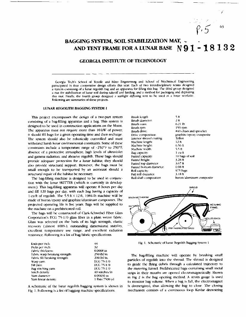
BAGGING SYSTEM, SOIL STABILIZATION MAT, - AM) TENT FRAME FOR A LUNAR BASE N 9 1 - 1 8 1 3 2
GEORGIA INSTITUTE OF TECHNOLOGY
Georgia Tech's School of Textile and Fiber Engineering and School of Mechanical Engineering participated in four cooperative design efforts this year. Each of two interdisciplinq tc-ams designed a s75tem consisting of a lunar regolith bag and an apparatus for filling this hag. The third goup designed a mat for stabilization of lunar soil during takeoff and landing, and a method for packagng and deploying this mat. Finally, the fourth g o u p designed a sunlight &fusing tent to be used as a lunar worksite. Following ue summaries of these projects.
LUNAR REGOLITH BAGGING SYSTEM 1
This project encompasses the design of a two-part system consisting of a bag-filling apparatus and a bag. This system is designed to be used in construction applications on the Moon. The apparatus must not require more than 10 kW of power; it should fill bags for a given operating time and then recharge. The system should also be robotically controlled and must withstand harsh lunar environmental constraints. Some of these constraints include a temperature range of -250°F to 250°E absence of a protective atmosphere, high levels of ultraviolet and gamma radiation, and abrasive regolith. These bags should provide adequate protection for a lunar habitat; they should also provide structural support. However, the bags must be small enough to be transported by an astronaut should a structural rttpair of the habitat be necessary.
The bag-filling machine is designed to be used in conjunc- tion with the lunar SKITTER (which is currently in dc~elop- ment). This bag-filling apparatus will operate 8 hours per day and fill 120 bags per day, with each bag having a capacity of 1 cu ft of regolith. The 5.5 ft X 12 ft, 1984-1b machine will be made of boron/qx)xy and graphite/aluminum composites. The projected operating life is five years. Bags will be supplied to the machine on a prefabricated roll.
The bags will bc constructed of Clark-Schwebel Fiber Glass Corporation's E<:G 75-1/0 glass fiber in a plain weave fabric. Glaqs was selected on the basis of its high strength, elastic recovery (almost loo%), outstanding dimen3ional stabiliy, excellent temperature use range, and excellent radiation resistance. Following is a list of bag/fabric specifications.
Ends per inch: Wcks per inch: Fahric thickness:
Brush length: Brush diameter: Brush mass: Brurh rpm: Brush drive: Drive composition: Interior shroud coating: Machine length: Machine height: Machine width: Bag capacity Funnel capacity: Funnel height: Fume1 top diameter: Fume1 bottom diameter: Roll capacity: Full roll diameter: RoU shaft composition:
5 ft 2 ft 6.21 Ib 150 rpm #40 chain and sprocket graphitelc~oxy coniposite Teflon 12 f t 0 56 A 5.5 ft 1 cuft 10 bags of soil 3.28 ft 3.67 ti 0.08 A 975 hags 3.18 ft boron/aluminurn composite
Fig. 1. Schematic of lunar Rcxolith Baggang Sy3tem 1
Fabric warp brelllung strength: 250 Ibf/in The bag-filling machine will operate by brushing small Fabric fill breaking strength: 200 Ibfiin. Warp y ~ n : ECG 75- 1 /0 particles o f regolith into the shroud. The shroud is designed Fill yarn: ECG 75-1/0 to guide the flying debris thrc)ugh a calculated trajectory to Bag stitching jm: ECG 75-1/0 the metering funnel. Prefabricated bags containing small metal Stitch density: 40 stitchesiin strips in their mouths are opened electromagnetically. Shown Yam diameter: 0.00036 in
1 lbm/7500 yd in Fig. 2 is the bag opening method. A strain gauge is used
Yam linear densir). to monitor bag volume. When a hag is full, the electromagnet
A schematic of the lunar regolith bagging system is shown in is deenergized, thus allowing the bag to close. The closing Fig. 1. Following is a list of bagging machine specifications. mechanism consists of a continuous loop Kevlar drawstring

rgs of tbe NASA/USRA Aduanced Desixn Program 61b Summer Conference
EXTENSION OF A R H T O OPEN B A G
5 4 ,/'
BAG OPENED AND ARn IS /.
Fig. 2. Bag Opening Method for f h g q g System 1
with raised barbs along its length, and two boron/alurninum composite balls mounted on the loop and adjacent to bag sides (as shown in Fig. 2). When a bag is full, it is cut away from the remainder of the roll with a diamond blade. As the bag drops from the machine, the composite balls slide into clutch slots. Meanwhile the barbed loop is pulled irreversibly through bag eyelets. The clutch then releases the balls, and the W1, sealed bag drops to the lunar surface. The drawstring is a convenient feature that a recovery team might exploit in retrieving and transporting these lunar sandbags.
LUNAR REGOLJTH BAGGING SYSTEM 2
As in the previous project, the goal of this design is to provide a satisfactory system for containing lunar regolith and for filling this container (bag). These bags are to be used in lunar construction applications. This system must operate under minimal power (less than 10 kW), and must withstand lunar environmental constraints such as .severe temperature gradients, ultraviolet and gamma radiation, and abrasion by regolith. These bags also should provide protection and structural support for a lunar habitat. Additionally, the bag size should Facilitate ease of transportation for either an astronaut or a transporting dwice.
The bag wiU be constructed of Keviar 149 in a ripstop weave. Though a Dupont scientist indicated that this fiber is suitable for this application, its behavior under gamma radiation is questionable. This fiber does, however, have many advantages that suggest its suitability for this application; among these are low density, high strength, good cut resistance, good puncture rc%istance, and good ultraviolet and electron radiation resistance. The proposed bag configuration is analogous to the geometry of a pillowcase. This shape offers
maximum packing potential (ratio of regolith volume to unfilled bag volume), good stackability, and low seam requirements. Following are bag specificxtions.
Bag fabric weight: Fabric temperature range: Bag seams: Stitch density: Bag width: Bag length: Bag Edbric thickness: Bag Mric volume: Maximum regolith volume: Bag m;lss/regoIith mas.:
6 oz/yd2 -300-800°F flat felled 7 - 12 stitches/in 36 in 72 in 0.0076 in 39 id 29702 in3 0.001554
For Earth-to-Moon transportation and for bag-filling purposes, unfilled bags will be stacked one inside the other in "Dixie cup" fashion. This stacking configuration will facilitate accuracy in mechanical bag placement for t i hg . A magnetic thread to be used for bag opening will be woven into the mouth of the bag. Four 8.75-in long magnetic buttons to be used for fastening a full bag will be sewn into a lip in the mouth of each bag.
The proposed bag-filling mechanism is analogous to a "fkench fry scoop." The scoop will be attached to a lunar truck by an electronic arm whose motions are controlled by an electronic microprocessor. In f i h g , the scoop will be inserted into a bag opening. An electromagnet will activate the magnetic thread in the bag mouth, and will withdraw the bag from the bundle. As the lunar truck moves forward, it will drag the scoop and the bag through the regolith at a depth of 2 in. Electronic weight sensors will monitor the amount of dirt in the bag and eventually acqivate the magnetic closure system. The proposed closure system consists of hooks that will draw the inner bag lip out and cause the button magnets to snap together and thus seal the bag. A h t a g e s of this bag-tilling system are minimal disruption of regolith, minimal contact between moving parts and airborne regolith, and valid sealing mechanism for lunar temperature range.
This system is designed to operate for 8 hour s per day and to fill approximately 16,000 cu ft of soil in 8 days
SOIL STABILIZATION MAT FOR LUNAR LAUNCH/LANDLNG SITE
Presented in this project is a method for providing soil stabilization for a lunar launch/landing site. Flying debris (i.e., unrestrained soil) associated with lunar landers has the potential to damage equipment and to injure personnel associated with future lunar colonies. The proposed mat is large enough to compensate for landing errors; its expected life span is 10 years (assuming quarterly use). A schematic of this mat is shown in Fig. 3. Design constraints include light weight, adequate heat resistance for takeoff, sufficient impact resistance (for landing), ease of transportation and deploy- ment, and low mat porosity.
The mat is to be constructed of Fiberite Corporation's PAN- based c;ubon fiber in a 2 X 2 basket weave. This structure will provide good tear strength, good crease resistance, and good

Georgia fnsti tutv of 7Lchtrolo~)'
Fig. 3. Schematic of Soil Stabilization Mat for I.unar Launch/Landing Site
abrasion resistance. The mat will be double layered and 0.066 in thick Forty panels measuring 100 m by 2.5 m each will be double stitched together using carbon thread and flat felled seams to form a square mat covering an area 100 m by 100 m. This mat will weigh 30,500 Ib, including seams.
Heat resistance for takeoff is a key requirement for this mat. Exhaust gases associated with takeoff reach a maximum temperature of 1500'C. Exposure time is, however, only a few seconds. With a maximum usage temperature of 2000°<:, carbon is appropriately heat resistant.
The mobility of yams with respect to one another within a basket weave imparts good tear resistance to the mat. It is not feasible to clear a landing site of sharp rock. It is, howt~c r , feasible to employ a fabric whose structure retards tear propagation.
Carbon fibers also resist ultraviolet and gamma radiation that cause organic fibers to degrade.
The stowage form of the stabilization mat is shown in Fig. 4.
The 100 m by 100 m mat is folded in accordion style over 10- m widths. The resulting form is then 10 m wide and 100 m long. This form is then rolled along the lengthwise direction to form a cylinder measuring 1.46 m in diameter and 10 m in length. Thus the mat will fit into the shuttle's cargo bay (12 m X 6 m X 6 m). The mat's weight (50,500 lb) will also be within the shuttle's 60,000-lb capacity. The mat deployment method is shown in Fig. 5. Metal strips in the mat will m e
role In accore8.n rashton
Fig. 4. Stowage of Soil Stabilization Mat
- I I 16 m+ stowed m a t conrlguratlon mat t I s unrolled by the m c l a l strlDS
p r o j e c t , l e I S hODked l o Ihe harness and rlred
fu l ly 6eDloyed m a t
Fig 5. Dt-ployment of Soil Stabilization Mat
as coil springs that will unroll the mat. A harpoon-like device will be attached to the edge of the accordion fold and fired. This harpoon, when fired, will complete mat deployment.
This mat is designed to accommodate landing and launches of space vehicles measuring up to 18.9 m (62 f t ) in length, 6.1 m (20 ti) in diameter, 27,216 kg (60,000 lb) in vehicle weight, and 15,876 kg (35,000 1b) in cargo weight. Following is a cost breakdown for the lunar mat.

rgs of tbe NASA/USRA Aduanced Dosign Program 616 Summer Cr~nference
Carbon fikn, 11000/lb 3 1 ,OoO,O()o Waving cost 100,000,000 Transportation to Moon, S25000/lb '75,000,000 Deplt~pent 2,000.MM) '1i)td '908,0(X),O(K)
Total estimated cost of production, transportation, and deployment of the lunar soil stabilization mat is I'WS million, with transportation comprising the bulk of the cost.
SUNLIGHT DIFFUSING TENT FOR LUNAR WORKSITE
Sunlight on the Earth has an intensity range of 100-1000 footcandles. Because the Moon lacks an Earth-like protective atmosphere, sunlight on the Moon is not ditfused. Lunar sunlight has an intensity of 120,000 footcandles. Alx), lunar sunlight is unidirectional. lhis unidirectionality c a w s objects on the Moon to be either extremely bright or extremely shadowed. These characteristics of lunar sunlight may cause severe distortion of an object's color and contmt on the Moon. Because many tools are color coded, light distortion may be a problem in the astronauts' working environment. Resented in this project is a means of overcoming this dilEculty. The proposed solution to this problem is a structure with an umbrella-like frame and tent cover.
A schematic of the tent frame is shown in Fig. 6. The pro- po.wd hexagonal structure consists of a tripod frame with three rafters. 'me three legs will provide stability on uneven surfaces, and attached wheels wiU provide mobility. Rafters connected to the three legs plus the three additional rafters nil1 form a hexagonal frame for the fahric cover and provide a large work rued. Torsion springs incorporated in the frame will enable the structure to be folded compactly and to be self-assembled.
Compression springs and extensional legs will reduce tent height for tmsportation requirements. The fabric cover, b e d tightly to the frame, will provide additional structural support.
Construction materials for this tent must withstand previously described harsh lunar conditions. Specific require- ments of the apparatus are low weight to minimize transpor- tation cost, minimal cargo space cxcupan~y, ability to .self- assemble, ability to both reduce light intensity and difuse light, mobility, and structural integrity.
The primary frame will he constructed of titanium and the springs of chrome silicon. 'me tent and cover will be constructed of Clark-Schwebel Fiber Glass Corporation's eight- harness .satin weave Style 7781 glms fabric. Fabric spcifica- tions rue as follows.
Ends per in: 57 Rcb per in: 54 Fabric weight: 8.95 ozlyd' Fabric thickness: O.Wl0 in Ends breaking strength: 350 Ibf/in
breaking strength: 340 lbf/in
This fabric will allow uniform light intensity of approxi- mately 350 footcandles. Manufactured in 8-ft widths, panels of fabric measuring 43 ft in length will be sewn tcgether in pairs. Measuring 15 ft in width, these double panels will form the sides of the structure. Panels will be attached to the frame by means of Tdon-coated fiber @ass loops.
A diagram of tent deployment is shoun in Fig. 7. In stage one, the structure wiU be fully compact. Restraining cords connecting the stand and the lg b m will ensure that the ufheels land precisely 15.4 ft from thc tent center. In stage two, legs will be rele-dwd while rafters are held stat ionq. In stage three, rafters will spring down and correctly position wheels. In stage four, both center-to-rafter and rafter-to-leg torsion springs uiU push the center sections upwards. In stage five, extensional leg latches will be relr~sed. The entire structure will "pop up" and fabric will drop over the legs. All loch ,md supports will be fully engaged at this stage.
Fig. 0. Sunlighr DBusing tent Frame Fig. 7. Tcnt l)eploy.n~enr

Georgia Institute of Technology
Astronauts may enter and exit the work tent via slits in the Edbric. Slits will measure 15 ft in length. Zippers will allow the slits to be opened an additional 13 ft. I* openings will lllow the tent to be mwed over b e obj/ects.
Listed below are structural speci6cations for the tent hme.
Lower leg section outer diameter Lower leg section wall thickness Upper leg section outer diameter Upper leg section wall thickness Rafter section (legs) height Rafter section (legs) width Rafter section (legs) thickness Rafter section (extensions) height Rafter d o n (extensions) width Rafter section (extensions) thickness Hanging extensions outer diameter Hanging extensions thickness Center locking device section height Center locking device section width Center locking device section thic)aresf Weight at center (springs and plate) Estimated weight of wheel assembly Estimated horizontal force at wheels Estimated compression spring weight Suess on upper leg at huge Stress on upper leg at lateral support Stress on rafter at lateral support Stress on main rafter at center Minimum compression spring force Minimum rafter to 1% torque Minimum center to rafter toque
Total weight Volume
2.75 in 0.063 in 3.25 in 0.063 in 4.00 in 1.00 in 0.063 in 3.00 in 1.00 in 0.031 in 1.50 in 0.03 1 in 2.00 in 1.00 in 0.063 in 10.0 Ib 5.0 Ib 100.0 Ib 4.2 Ib 4.69 x l#psr. -6.13X 10 p -6.70 X lo4 psi 8.4 X 10' psi 22.2 Ibf 2.29 X 10' in Ib 4.76 x ld in Ib


SPACEPORT AUROIW AN ORBITING TRANSPORTATION NODE
UNIVERSITY OF HOUSTON COLLEGE OF ARCHITECTURE
With recent announcements of the development of prrmanentlp stded facilities on the Moon and Mars, the national space plan is in need of an infra.structurc system for transportation and mainicn;cnce. A project team at the University of Houston: College of Arhtecture and the Sasakawa International (:enter for Space Architecture, recently examined components for a low Earth orhit (IEO) transportation ncde that supports a lunar build-up scenario. Areas of investigation includcd: idcnt@ing t~msportation ntde functions, identlfylng existing space systems and subsystems, analping \xriablc orhits, determining logistics strategies for maintenance, and investigating assured crew return systems. The ifinnation resulted In a requirements definition document, from which the team then addressed conctptual dcsips for a U.0 transportation ntxie. The primaq design drivers includcd: orbital stability, muin~hing human pcrlornimcc and safety, vehicle maintainability, and modularity within existing space inFr~ztructure. For orl,ital stal,ilih.
;ls thc h a c h n c the "power tower" cwnfipration provides a gravityedient dabilized facility and sen *:
for the various facility components. To maximize human pcrfonnance, human comfort ib strehwd throt~dl zoning of living and working activities, maintaining a consistent Icral \rertic;rl orientation, jwo~iding crew interaction and viewing areas and providing crew return vehicles. Vehicle maintainabilih is ;~ccomplisl;~lcd through dual hangars, dual work cupolas, work mtxiult3, telerohotics and a fuel d t p r Mtdularity is incorporated using Space Station Fwedorn mtxiule diameter, Space Station Freeciom "standard" rack, and interchangeable interior partitions. It is intended that the final design be flexible and adaptable to prrnidc a facility protorypr that can senice multiple mission profiles using mtdular space sixtems.
Background
President Bush has stated the goals for the United States space program. This national plan includes establishing permanently statred facilities on the Moon and Mars. These facilities will provide the foundation for extensive research on human response to longterm missions and the observation d our evolving solar system through astronomical instruments.
The first p h a x of the nation's space plan is Space Station Fmeric)m, which is a scientific facility conducting experiments in microgra\;ity. It does not, however, encompass the functions necessary to asist and maintain a lunar base in the near future. Phaw two of the national space plan is a permanently staffed lunar facility within the first decade of the twenty-first century.
Research at the University of Houston College of Architec- ture and the Sasakawa International Center for Space Architecture has been in progress to develop a facility that can provide mission support for lunar and Mars initiatives. Because lunar and Mars support missions differ, the project team concentrated on a transportation node that could support a lunar base. It is intended that the final design be flexible and expandable to provide a facility prototype that can senice single and/or multiple mission profiles using modular space systems and subgatems.
Problem Statement and Options
An orbiting facility is necessary for the construction and support of a lunar bax. This facility will serve as a s tc~ping stone for space exploration and advancmmnt.
First option. S. S. Fweedom should be redesigned and re- evaluated as a transportation node. This is costly, time
consuming and alters its prescnt function ;LS a microgravity research facility( '.
Second option. Phase in S . S. Frredom ;L\ a transportation node. This modification would delay pn)jectcd phases o f the national space plan (e.g. lunar facility)' ' '.
Tbird option. A stparate transportation node is tlesigned and developed to advance space initiatives. This option docs not interfere with S. S. &wdr)nt and provides a conccntratcd effort in the second era of y a c e trawl.
Options and Choice
The project tern1 weighed all three option3 ;md chosc to design a separate transportation node. ? h e project t a r n agrccd that to redesign S. S. Freedom as a transportation node v.~ould k in conflict with its present internatio~ral rcscxrch mission. Therefore, it was decided to design a second facility that bvould complement S. S. Freeric)tn and support a lunar bw. The project was given the name Spaccp)rt . 4 ~ m r ~ t , uhich signifies a ncw dawn, a new beginning in spacc exploration.
Assumptions
S. S. FTC'LYL)~?I will remain a purc scientific expcrimcntal facility All facility components Ijmitctl to orbiter payload I~ay sizc and mass capabilities. Shuttle and Orbital Maneuvering \.'chicle ( O h l \ ' ) requirctl for t ransportat ion ;und construct ion of spaccpr t Heat.) l.iti launch Vchiclc (HI.1.L') not required. Ir)w Earth Orhit ( I . E O ) facility; orbital altitude within proximity to S. S. Fmvrlonz.
PReCEDlNG PAGE BLANK NOT FILMED
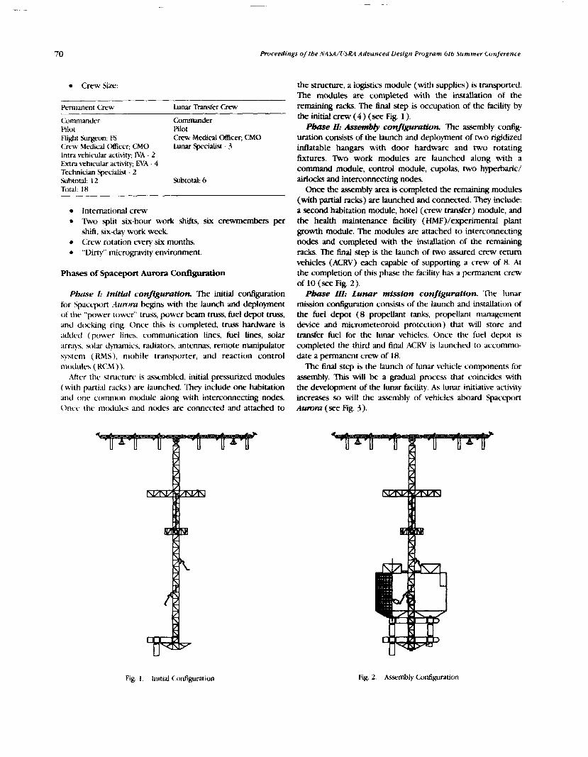
Proceedings ofthe NASA/OSRA Adz~anced Design Program 6th Summer Conference
Crew Size:
- Pc'rmanent Crew Lunar Transfer Crew
<:onimander Commander Pi lor Pilot Flight Surgeon; FS Crew Medical OEicer; CMO Crew Medical Officer; CMO Lunar Specialist - 3 lntrd vehicular activity; IVA - 2 Extra veh~rular activity; EVA - 4 Technician Sprcialist - 2 Subtotai: 12 Subtotal: 6 Total 18
International crew ltvo split six-hour work shifts, six crewmembers per shift, six-day work week. Crew rotation wery six months. "Dirty" microgmvity environment.
Phases of Spaceport Aurora Configuration
Pbuse I: IniNaC configuration. The initial configuration for Spaceport t i~rrrmr begins with the launch and deployment of the "power tower' truss, power beam truss, fuel depot truss, and d t ~ h n g ring. Once this is completed, truss hardware is addcd (power lines, communication lines, fuel Lines, solar mqs. SOIN jllamics, radiators, antennas, remote manipulator systrm ( K M S ) , mobile transporter, and reaction control modules ( KCM ) ).
.4ttcr thc stnicturr is asumbled. initial pressurized modules (with ~xutid r~cks ) iue launched. They include one habitation and one common module along with interconnecting nodes. Once the rntxiules and nodes are connected and attached to
the structure, a logistics module (with supplies) is transported. The modules are completed with the installation of the remaining racks. The final step is occupation of the facility by the initial crew (4) (see Fig. 1 ).
P h e U: Assembly configumtion. The assembly config- uration consists of the launch and deployment of two rigidized inflatable hangars with door hardware and two rotating fixtures. %o work modules are launched along with a command module, control module, cupolas, two hyperbaric/ airlocks and interconnecting nodes.
Once the assembly area is completed the remaining modules (with partial racks) are launched and connected. They include: a second habitation module, hotel (crew transfer) module, and the health maintenance facility (HMF)/experimental plant growth module. The modules are attached to interconnecting nodes and completed with the installation of the remaining racks. m e final step is the launch of two assured crew return vehicles (ACRV) each capable of supporting a crew of 8. At the completion of this phase the Edcility has a permanent crew of 10 (see Fig. 2).
Pbase 111: Lunar mission configuration. The lunar mission configuntion consists of the launch and installation of the fuel depot (8 propellant tanks, propellant management device and micrometeoroid protection) that will store and transfer fuel for the lunar vehicles. Once the fuel depot is completed the third and final ACRV is launched to accommo- date a permanent crew of 18.
The final step is the launch of lunar vehicle components for assembly. This will be a gradual process that coincides with the development of the lunar facility. As lunar initiative activity increases so will the assembly of vehicles aboard Spaceport Aurom (see Fig. 3).
Fig. 1 . Initial Configuration Fig. 2. k m b l y Configuration

P O W E R B E A M
F U E L D E P O T
D O C K I N G R I N G
A S S E M B L Y A R E A
H A B I T A T I O \ A R E A
Fig. 3. I.unar Mission Configuration
Refer to Fig. 4 for total mass transported and total shuttle flights required per completion of phase.
DESIGN
The research on individual components provided a guideline for the overall configuration of the spaceport as well as the components themselves.
Facility Configuration
Coals. Spaceport A u m a is an orbiting transportation node with a hands-on environment involving routine and risk. With such operations occurring on a continuous level certain gods become apparent:
Provide a productive working and living environment Provide redundant systems for safety and maintainability Provide for senicing of vehicles Provide a configuration that reduces orbital sufidce &ag Provide for modularity within existing space infrastructure
Concepts. To provide a productive working and living environment a separation of the two activities is necessary. Both activities (working and living) require zoning of spaces as private or public.
To reduce orbital drag the components with the largest fi-ontal surface area should be positioned parailel with the orbital path (x-axis)(2). To reduce fuel consumption the m a s of the spaceport should be balanced along the z-axis, creating a gravity gradient stabilized facili# ".
Desfgn solution. The "power tower" configuration is chosen becau.~ it probides a gravity gradient stabilized facility (which will assist in the transfer of propellant) with minimal orbital surface drag. The power tower provides an efficient structure using a modular construction system that will accommodate components of the existing space i&a.qtructure. The power tower truss measures 560' ( 170.7 m ) in length using a 17'6" (5.3 m) by 17'6" (5.3 m) bay mtdule and the power beam measures 400' (121.9 m) in length using an 8' (2.4 m) by 8' (2.4 m) bay module . The power tower serves as the spine supporting the various facilit). components of Spaceport Aumm
Fig. 4. Spaceport Aurord Configuration; Shuttle Rights and Mas\
3
PHASE In: Lunar Mlsslon
dddd dddd dddd dddd dddd dddd dddd
Subtotal: 32 Total Flights: 52
dddd,
PHASE 1: Lltlal
d d d dd
Subtotal: 8
138,900 kg* 240,200 kg* 744,400 kg* Total Mass: 1,123,500 kg*
P H A S E 11: Assembly
dd dd d d dd d
Subtotal: 12

72 Roceedfngs of tbe NASA/USRA Advanced Design Program 6th Summer Conference
Assembly
Gads. Because of hazardous working surroundings and continuous monitoring, the assembly area must be a productive environment. The following goals are essential:
Provide a safe working area in space Provide service and assembly capabilities Provide expedient construction Minimize EVA
Concepts To ensure crew safety and minimize EVA time, redundant automated systems and telerobotics are necessary. In order to maintain EVA productivity during vehicle assembly, the hangar should be completely enclosed Another safety factor within the hangar is protection from micrometeoroids. A double-insulated skin made of aluminum and Kevlar is necessary to keep meteoroid penetration at a
A clear unobtrusive viewing area for EVA and telerobotic observation is required. This N A station should be in close proximity to the vehicles serviced. Communication and monitoring throughout the hcility is accomplished through audio/visual equipment.
DesCgn soidon. Rigidized intlatable hangars are incorpo- rated to reduce shuttle flights, construction time and EVA time. The hangars are compac3 and placed within the orbiter cargo bay. Rvo hangars 85' (25.9 m) in diameter by 120' (36.6 m) in length are incorporated rather than one to increase the number of vehicles repaired and to reduce turnaround time. The control module 14'6" (4.4 m) in diameter by 25' (7.6 m) in length is located perpendicular to the two hangan providing dual, separate work cupolas on opposite sides for tcleroboticv supervision and observation. The assembly cupolas are located 10' ( 3 m) from the vehicle which is under repair within the hangar, providing a clear unobstructed view for IVA personnel. The command module, adjacent to the control module, 14'6" (4.4 m) in diameter by 34' (10.4 m) in length is the control center for the entire facility. The command
BRIEFING AREA
REMOTE MAMrVLATOR ARM
CONTROL MODULE
WORKSTATION
VIEWING A I M
EVA EQUIPMENT STOWAGE
COMMAND MODULE
Fig. 5. (:ommand Module. Control Mcxlule md Hyperbaric Airlock
module monitors facility communications, navigation, energy levels, environmental systems and propellant supplies. The command module also provides a (EVA repair) viewing area within the hangars. The work modules 14'6" (4.4 m ) in diameter by 34' ( 10.4 m) provide IVA repair of components which are too small and/or tedious for EVA within the hangars (see Fig. 5).
EVA access to the hangars is accomplished through the rotating drums or through the hyperbaric airlock. This provides direct access for EVA personnel into the hangars (an enclosed volume) reducing safety risks.
Both pressurized and unpressurized docking is needed. A docking ring 60' (18.3 m) in diameter with a hard dock is used for transfer of propellant and replacement parts. A pressurized doc- node is used for transfer of lunar and spaceport crews. Thus, the cargo delivery does not disturb the habitation modules.
Habitation
Goals. The habitation area is the central meeting place for group interaction. Positive psychological and physiological environments are desirable. The habitation goals are:
To increase productivity To utilize space dciently To provide a safe environment
Concepts. The habitation area supports various functions which are inter-related yet Merent. Activities within the habitation modules include:
geepins Personal ~ ~ e n e Recreation Eating Drinking Meetings studying Personal Stowage Relaxation Tcaining Meal Clean-Up Communir~tions Private Conkrences Clothing Maintenance Dressing
Separation of the habitation activities is important. Zoning from private to public is necessary.
To utilize space efficiently, interchangeable partitions for accommodating transfer crews provide flexible interiors. The permanent crew has sleeping quarters 28 ft2 (8.5 mZ) which are larger than the transfer crew 14 ft2 (4.3 m2) who are on board for a shorter period of time ( 5 ?
A consistent local orientation throughout the facility is an important factor to consider ( 6 ) . This will assist the permanent crew in performing daily activities, provide the transfer crew in adapting more quickly to their surroundings and, therefore, increasing productivity. Design solutton. MI pressurized modules within the
facility are 14'6" (4.4 m) in diameter by 34' (10.4 m) in length. This length is based on: ( 1 ) minimizing visibility distance from assembly cupola to vehicle in hangar; (2) configuration of modules within the power truss bays 17'6" (5.3 m); and (3) modularity for maintenance. Althougi~ the modules are shorter than standard S. S. Freedom, their length is consistent throughout the facility (for flexibility) and they are transported with partial racks p r a ~ m b l e d .

Un~uersity of Houston College of Architecture
Assured crew safety and health Increased function of airlocks Increased privacy Improved patient care
Concepts. The HMF requires a large separate facility because of the large crew and the split work sh i i . The flight surgeon is trained for preventive care, diagnostic care and therapeutic care(8). The Bight surgeon will monitor and record crew behavior, which will serve z a data bank for future long term missions (lunar and Mars). Because of the diverse
Fig. 6. Habitation Module (Permanent Crew) medical functions, the health facility is zoned according to
Fig. 7. Earth Viewing Wardroom Cupola
Because of split work shifts, dual habitation modules for crew sleeping quarters provide privacy and redundancy. Each module has a separate hygiene facility that serves as a backup (and improves maintainability) in case of malfunction (see Fig. 6).
A common module is centrally located to accommodate crew activity such as dining, housekeeping, recreation, etc. A hotel module accommodates transfer crews (lunar and spaceport) and serves as a backup for common module house. keeping activities (cooking, laundry, dining, etc.).
A consistent orientation is maintained throughout the facility except when entering the Earth viewing wardroom cupola and the control module. Both the Earth viewing cupola and control module are unique spaces that require a change in orientation for maximum viewing capabilities. The Earth cupola is an area h e r e "sharing a unique experience can relieve some of the stress of a confined environment"(') (see Fig. 7).
Health Maintenance Facility (HMF)
Goals. The HMF provides the crew with physiological and psychological treatment. When compared to S. S. Fmabrn, the following goals for Spaceport Aurora HMF are:
Fig. 8. Exercise Area
Fig. 9. Medical Area
Fig. 10. Quarantine/Recowry Arcs

74 Prrrcrrrlings of the .W.SA/lI.SKA Adf,urrced I)c>sig?r Progrlinr 6th Jummt,r Cor~f t~rrnce
activity Imel to provide improved individual patient care and increawd privacy. Design sduHon The HMF is a separate module sha rd
with the experimental testbed. The HMF occupies 65% of a habitation module 14'6" (4.4 m) in diameter by 22' (6.7 m) in length. It is lmxted adjacent to an assured crew return vehicle (ACRV) for expedient patient cwcuation.
'Ihe HMF facility is zoned according to activity function: ( 1 ) exercise adjacent to the entrance of the module (most active); (2) medical and health monitoring I t~a t ed at center of the module (mcxkrdtety active); and (3 ) recovery and/or quarantine adjacent to testbed (inactive) (see Figs. 8, 9, and 10).
Exercise as prc~entive care is particularly stressed. The bicycle ergometer and treadmill are cited as the most efficient devices. The exam table is redesigned as a restraining apparatus for impnwed patient comfort in microgravity. The airlock adjacent to the HMF also serves as a hyperbaric chamber in caw of EVA decompression.
Because of the dangers of a hands-on environment in space, a Btality may occur. Preparation for such an event is neither pleasant nor predictable. In order to maintain crew safety, a rack system in the recovery area is designed as a temporary
Assured Crew Return Vehicle (ACRV)
GoaLs. The goals for ACRV are to provide a simple, reliable vchicle that requires minimum crcw training. The vehicle should be volume efficient, provide buoyancy (for water landing), reasonable loiter time (return trip time), and minimal g-stress upon reentry (for a deconditioned or injured crewmemkr). concepts.
Apouo Station crew return alternative module (SCRAM) Reference configuration, Discoverer shaped Iangley lifting hody (we Fig. 1 1 - 14 ).
Design solurion Bawd on ACRV comparisons the "Refer- ence" Discoverer design is chosen. It is 13'6" (4.1 m ) in diameter by 11'6" (3.5 rn) in length based on passenger capacity (6) with injured crewmember (8) uninjured crewmembers, 24-hour loiter time, single flotation point for buoyancy, minimal g-stress upon reentry and minimal crew interface("'. A total of three vehicles are necessary for complete evacuation of facility personnel (see Figs. I5 and 16).
Power Systems morgue using refrigeration techniques ( t o preserve the GoaLs. power goals are to hi& output, decc';twd crewmemkr and contain the w a d of dixaw) until reliability, rtficiency, low weiRht md and rwlation the kxty is transferred to Earth. of heat build up.
Fig. I I . Apollo-derived Vrhicle' " ' Fig. 13. Krfrrence!I)ixoverc-r-Sh.dprdC" '
Fig. 12. S(:RAM ~ehiclc("' Fig. 14. lm@ey Idling BoaA'''
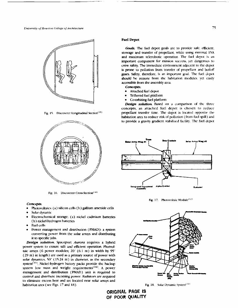
Unir1ersit.y of Houston College oJArchitecture
Fig. 15. Discoverer I~ngitudinal section( ""
Fuel Depot
Coals. The fuel depot goals are to provide safe, efficient, stowage and transfer of propllant, while using minimal EVA and maximum telerobotic operation. The fuel depot i3 an important component for mission succes, yet dangerous to crew safety. The immediate environment adjacent to the depot is prone to pollution from transfer of propellant and boiloff gases. Safety, therefore, is an important goal The fuel depot should be remote from the habitation modules, yet ea\ily accessible from the assembly area.
concepts:. Attached fuel depot Tethered fuel platform Co-orbiting fuel platform
Design sduHon Based on a comparison of the three concepts, an attached fuel depot is chosen to reduce propellant transfer time. The depot is located opposite the habitation area to reduce risk of pollution (from hel spill) and to provide a gravity gradient stabilized facility. The fuel depot
Fig. 16. Discoverer ~ r o s - s e c t i o n ( "I)
Fig. 17. Photovoltaic ~ c d u l e ( I"
Concepts. Photovoltaics: (a) silicon cells (b) galhum arsenide cells Solar dynamic Electrochemical storage: (a) nickel cadmium batteries (b) nickel-hydrcgen batteries Fuel cells Power management and distribution (PMAD): a system converting power from the solar arrays and distributing it to specific jobs.
Design solutton. Spaceport Aurora requires a hybrid power system to ensure safe and efficient operation. Phoml- taic arrays (6 power modules; 20' (6.1 m) in width by 95' (29 m) in length) are used as a primary source of power with solar -cs, 50' (15.24 m) in diameter, as the secondary system('". Nickel-hydrogen battery packs provide the backup system low mass and weight requirements(I4). A power management and distribution (PMAD) unit is required to - C r -
-- control and distribute incoming power. Radiators are required -
CI to eliminate excess heat and are Itx-ated near solar arrays and habitation area (see Figs. 17 and 18). Fig. 18. Solar l))namic System' " '
ORIGINAL PAGE IS OF POOR QUALm

Proceedings of tbe NASA/USRA Adaanced Design Program 6tb Summer Conference
PROPELLANT TR attached to the docking ring, transfer of propellant to the fuel rLUl0 S ~ S T C M S depot occurs through transfer lines which connect to the BOIL-OTF TANK transfer propellant tank. This operation is automated and BOIL-DrF TRANS
monitored by a fuel specialist from within the command module; there is no need for EVA supervision for this activity. After the process is complete, the orbiter returns the transfer tank to Earth where it will be insjxctd and replenished with propellant.
Refueling of vehicles occurs after the vehicle has been seniced and repaired in the hangar. Vehicles within the hangars will contain no fuel to reduce risks to EVA personnel and to reduce pollution to nearby viewing cupolas. The RMS transport. the vehicle toward the docking ring, where it is
FUCI LKPOT SIP~CTJPE connected to a hard dock with propellant transfer lines. Once the vehicle is fueled, it is deployed with an attached OMV (acting as a space tug) and launched within the vicinity of
SIDE E L E V A T I O N Spaceport Aurora.
Fig. 19. Furl l)tw)t
consists of 8 prc~pellant tank5 (each containing an oxygen and lrydrcgen tank) 14'6" (4.4 m) in diameter by 44' (13.4 m) in length each containing 100,000 Ib of propellant. The depot also contains a propellant mimagement dwice (on either side of the truss), fluid transfer lines (refrigeration and heat lines), and is enclosed uith a Kc~lar micrometeoroid double skin(') (.we Fig. 19 ).
'Ihc propellant tank will be partially filled for the initial launch, since the orbiter's maximunl cargo capacity is limited to 55,000 Ib. Once connected to the fuel depot structure, each propellant tank will require two shuttle trips for maximum stowage capability ( 100,000 Ib). The orbiter will transport a reusable transfer propellant tank to IEO, where the shuttle mill rendezvous with Spaceport Aztrorcr. Once the shuttle is
Experimental Plant Growth Facility
Coals. The primary goal of the plant growth facility is to gather data on the effects of micrt)gravity on plants. A second goal is to provide an Earth-like environment to serve as a morale booster. concepts.
Hydroponics: root is grown in nutrient solution('5' Aeroponics: root is grown in air( I")
Design sdurion. The plant growth facility is adjacent to the HMF occupying 35% of a habitation module 14'6" (4.4 m) in diameter by 12' (3.7 m) in length. Two standard racks are incorporated for growing plants using the aeroponic method. The aeroponic methtxi consists of a nutrient solution line that sprays the plant root area within an enclosed membrane. A nutrient solution collector and return line
Plant Moisture Return
F l t e r
Aeroponic Plant Cosmg
Delivery L Return Nutrient Systen
Filter
Return AP Duct
Lonp Bank
Rack Honde
Safety Plexiglass Rock
Carbon Dioxide L Oxy~en
Door
I Supply
ORIGINAL PAGE IS OF POOR QUALITY
Fig. LO Plant tirowth Rack: Aeroponic Method
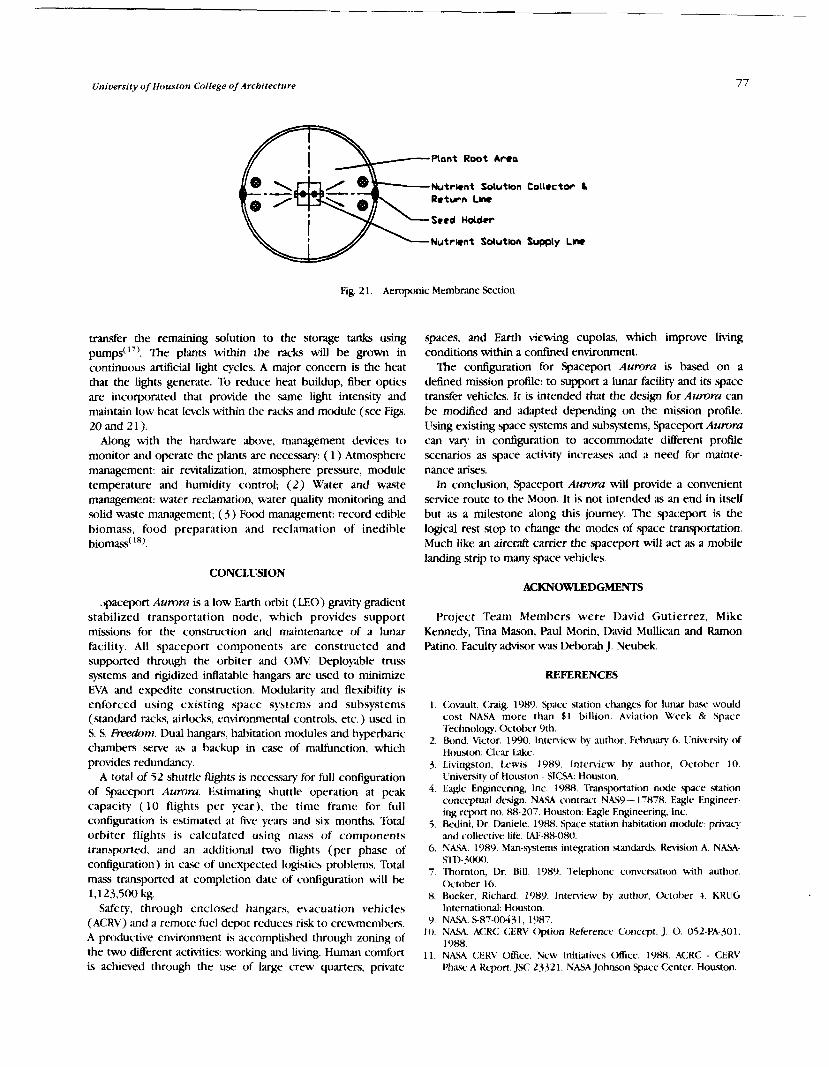
Universitj~ of Houston College oJArchitecture
-----plant Root Area
-seed Holder
Nutrent Solutlon
Fig. 2 1 . Aeroponic Membrane Section
transfer the remaining solution to the storage tanks using The plants within the racks will be grown in
continuous artificial light cycles. A major concern is the heat that the tights generate. To reduce heat buildup, fiber optics are incorporated that provide the same light intensity and maintain low heat levels within the racks and module (see Figs. 20 and 21).
Along with the hardware above, management devices to monitor and operate the plants are necessary: ( 1 ) Atmosphere management: air revitalization, atmosphere pressure, module temperature and humidity control; (2) Water and waste management: water reclamation, water quality monitoring and solid waste management; (5) Food management: record edible biomass, food preparation and reclamation of inedible biomass( '').
spaces, and Earth viewing cupolas, which improve living conditions within a confined environment.
The configuration for Spaceport Aumra is based on a defined mission profile: to support a lunar facility and its space transfer vehicles. It is intended that the design for Aurora can be modified and adapted depending on the mission profile. Using existing space systems and subsystems, Spaceport A u m can vary in configuration to accommodate different profile scenarios as space activity increases and a need for mainte- nance arises.
In conclllsion, Spaceport Aurora will provide a convenient service route to the Moon. It is not intended as an end in itself but as a milestone along this journey. The spaceport is the logical rest stop to change the modes of space transportation. Much like an aircraft camer the spaceport will act as a mobile landing strip to many space vehicles.
CONCLUSION ACKNOWLEDGMENTS
~paceport Aurora is a low Earth orbit (LEO) gravity gradient stabilized transportation node, which provides support missions for the construction and maintenance of a lunar facility. All spaceport components are constructed and supported through the orbiter and OMV. Deployable truss systems and rigidized inflatable hangars are used to minimize EVA and expedite construction. Mcdularity and flexibility is enforced using existing space systems and subsystems (standard racks, airlocks, environmental controls, etc.) used in S. S. FreeaOnl. Dual hangars, habitation mtKiules and hyperbaric chambers serve as a backup in case of malfunction, which provides redundancy.
A total of 52 shuttle flights is neceswy for full configuration of Spaceport Aumra. Estimating shuttle operation at peak capacity (10 flights per year), the time frame for full configuration is estimated at five years and six months. Total orbiter flights is calculated using mass of components transported, and an additional two flights (per phase of configuration) in case of unexpected logistics problems. Total mass transported at completion date of configuration will be 1,123,500 kg.
Safety, through enclosed hangars, evacuation vehicles (ACRV) and a remote fuel depot reduces risk to crewmemhers. A prtxtuctive environment is accomplished through zoning of the two different activities: working and living. Human comfort is achieved through the use of large crew quarters, private
Project Team Members were David Gutierrez, Mike Kennedy, Mason, Paul Morin, David Mullican and Ramon Patino. Faculty advisor was Deborah J. Neubek.
REFERENCES
I . <:ovault, <:raig. 1989. Space station changes for lunar ba. would cost NASA more than $1 billion. Aviation Week & Space Technology. October 9th.
2. Bond, Victor. 1990. Inteniew by author. February 6. Ilniversity of Houston: Clear Lake.
3. I.ivingston, I.ewis. 1989. Interview by author, October 10. Llniversity of Houston - SICSA: Houston.
4. Eagle Engineering, Inc. 1088. Transportation node pace station concrptual design. NASA contract NAS9- 17878. Eaglc Engineer- ing rcprt no. 88-207. Houston: Eagle Engneering. Inc.
5. Redini, Dr. I>aniele. 1988. Space station habitation module: pri\acy and collective life. W-88-080.
6. NASA. 1989. Man-systems integration standards. Rmision A. NASA- Sl1)-3000.
7, Thornton, Dr. Bill. 1989. Telephone ctmversation with author. ( k t o k r 16.
8. Rueker, Kichard. 1989. Inteniew by author, October 4. KRUG International: Houston.
9. NASA. S-87-00431. 1987. 1 0 . NASA. A<:R<: <:ER\' Option Reference Concept, J . 0. 052-PA-301,
1988. 1 1 . NASA (:ER\' Clffice. New Initiatives Office. 1988. ACRC - CERV
Phase A R q n . )X:-23321. NASA Johnson Space Center. Houston.

Roceedlnar oJlbe NASA/USRA Advanced Drrlgn Program 61b Summer Conference
12. NASA. Space Station Freedom Media Handbook, 1989. 13. Baraona, Cosmo R. 1986. The space station power system.
Cleveland, Ohio. 14. Cwhran, TH. and TL Iabus. 1987. Space station electrical power
system. 38th Congress of the International Astronautical Ftulerdtion. IAF-87-234. 10-17 Oct., at Brighton, United Kirrgdom.
15. Greene. Joseph. 1989. Bioregcnerative l ie support systems and space flight. NASA Educational Publication.
16. Robbin., Jim. 1987. St.cond nature. The Sunday Tunes Magazine lundon. June 28th.
17. Schwatzkopf, Steven H.. Me1 W. Oleson, Hatice S. Cullingford. 1989. Conceptual design of a closed loop nutrient solution delivery *em for CElSS implementation in a micro-gravity emironment. 19th ylntersociety Conference on Environmental System 24-26 July, at San Diego, CA.
18. Hmninger, D. L 1989. Life Support Systems Research at the Johnson Space Center. Lunar Base Anhitecture: .%LF fix PIant GtDwtb, Madison, WI. ASA-CSSA-SSSA.
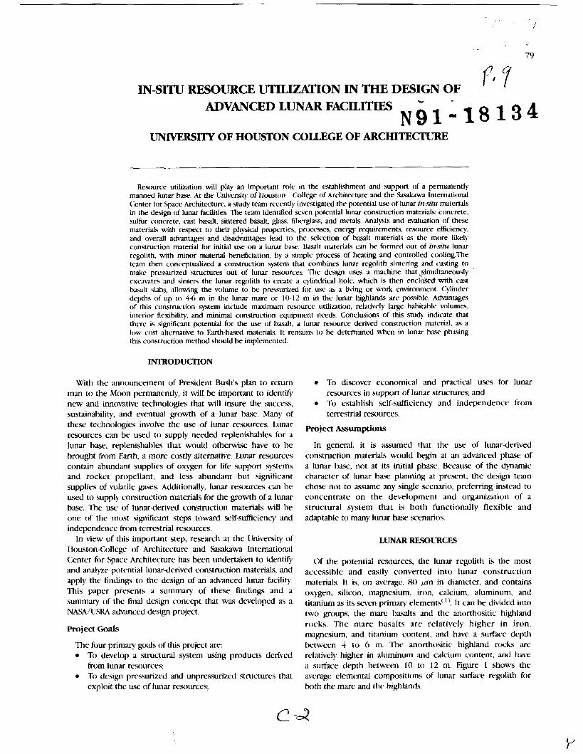
IN-SITU RESOURCE UTILIZATION IN THE DESIGN OF Y l 7
ADVANCED LUNAR FACILITIES N g 1 - 1 8 1 3 4 UNIVERSITY OF HOUSTON COLLEGE OF ARCHITECTURE
Resource utilization will play an important role in the establishment and support of a pmanently manned lunar h a . . At the University of Houston - College of Architecture and the Sacakawa International Center for Space Architecmre, a study team recently investigated the potential use of lunar in-situ materials in the design of lunar facilities. The team identified seven potential lunar construction materials: concrete, sulfur concrete, cast basalt, sintered basalt, glass, fiberglass, and metals. Analysis and naluation of these materials with respect to their physicd properties. procesxs, energy requirements, resource eficiency, and overall advantages and disadvantages lead to the selection of basalt materials as the more likely construction material for initial use on a lunar baxl. Basalt m~teriaks can be formed out of in-silu lunar regolith, with minor material bmeficiation, by a simple process of heating and controlled cooling.The team then conceptualized a construction system that combines lunar regolith sintering and cxting to make pressurized Structures out of lunar resources. The design uses a machine that ~~imultaneously excdmtes and sinters the lunar regolith to create a cylindrical hole, which is then encloSect with cast basalt slabs, allowing the volume to be presurized for use as a living or work environment. Cylinder depths of up to 4-6 m in the lunar mare or 10-12 m in the lunar highlands are possible. Advantages of this construction system include maximum resource utilization, relatively large habitable volumes, interior flexibility, and minimal construction equipment needs. Conclusions of this study indicate that there is sigdcant potential for the use of basalt, a lunar resource derived construction materid, as a low cost alternative to Earth-based materials. It remains to he determined when in lunar base phasing this construction methtxl should k implemented.
INTRODUCTION
With the announcement of President Bush's plan to return man to the Moon permanently, it will be important to identify new and innovative technologies that will insure the success, sustainability, and eventual growth of a lunar base. Many of these technolcq$es involve the use of lunar resources. 1,unar resources can be used to supply needed replenishablcs for a lunar base, replenishables that would otherwise have to be brought from Earth, a more costly alternative. Lunar resources contain abundant supplies of oxygen for life support sytems and rocket propellant, and less abundant but significant supplies of volatile gases. Additionally, lunar resources can be used to supply construction materials for the growth of a lunar base. The use of lunar-derived construction materials will be one of the most significant steps toward self-sufficiency and independence from terrestrial resources.
In view of this important step, research at the University of Houston-CoUeg of Architecture and Sasakawa International Center for .Space Architecture has been undertaken to identify and anal)ze potential lunar-derived construction materials, and apply the findings to the design of an advanced lunar facility. This paper presents a summary of these findings and a summary of the final design concept that was developed as a NASA/IISRA advanced design project.
Project Goals
The four primary goals of this project are: To develop a structural system using products derived from lunar resources; To design pressurized and unpressurized structures that exploit the use of lunar resources;
To discover economical and practical uses for lunar resources in support of lunar structures; and To establish self-sufficiency and independence from terrestrial resources.
Project Assumptions
In general, it is as.umed that the use of lunar-derived construction materials would begin at an advanced phase of a lunar base, not at its initial phase. Because of the dynamic character of lunar b a x planning at present, the design team chose not to assume any single scenario, preferring instead to concentrate on the development and organization of a structural system that is both functionally flexible and adaptable to many lunar base scenarios.
LUNAR RESOURCES
Of the potential resources, the lunar regolith is the most accessible and easily converted into lunar construction materials. It is, on average, 80 pm in diameter, and contains oxygen, silicon, magnesium, iron, calcium, aluminum, and titanium as its . w e n primary elements( ' '. It can be divided into two groups, the mare b a d t s and the anorthositic highland rocks. The mare basalts a re relatively higher in iron, magnesium, and titanium content, and h m a surface d q t h between 4 to 6 m. The anorthositic highland rocks are relatively higher in aluminum and calcium content, and have a surface depth between 10 to 12 m. Figure 1 shows the average elemental compositions o f lunar surface regolith for both the mare and the highlands.

' " I
Maria
Highlands
C Si Ti Al Fe Mg Q F$
Elements
Fig 1 . Average Elemental Compositions of Lunar Surface Regolith
CONSTRUCTION MATERIAIS
The research team identified seven possible construction materials that can be derived tiom lunar ra)urces. These materials include two varieties of basalt, cast and sintered; two varieties of glass, cast and fiber: concrete; sulfur-based concrete; and metals. Each construction material was evaluated on criteria that included physical properties, production processes, energy requirements. material resource yields, prtducts, applications, and miscellaneous requiren~ents of the material such as dependence on terrestrial resources. A very brief ovefiiew of each construction material is given helow.
prtxessing is that the ctn)ling rate of glacs is much higher. Glass, when manufactured in the anhydrous vacuum conditions of the lunar environment, attains extremely high compressive and tensile strengths. Ilnfortunately, i t lost's much of its strength when exposed to air, has very high energy require- ments for processing, is very brittle, and requires organic bonding agents when produced as fibergl;~\s.
Concrete
Lunar concrete is very similar to Rwtland cement concrete used here on Earth. Advantages of this construction material include its relatively simple production, low energy require- ments, high abrasion resistance, and e-~.sy castability. The major disadvantage of lunar concrete is that it requires water, or in the cast. of lunar oxygen production, hydrogen to be supplied from the Earth. Additional disad\mtages include its low tensile strength, long curing time, and the requirement of pressurized processing.
Sulfur-based Concrete
ks the name implies, sulfur-bawd concrete uses sulfur as the binding agent. Advantages include its high early strength, resistance to corrosion, and its independence from terrestrial resources. Disadvantagrs include material deterioration at lunar daytime temperatures, low sulfur )iel& from the lunar regolith, and flamn~abiliy of the sulfur.
Metals
Rasalt can be formed in two different ways, casting, a process by which regolith is heated until molten, poured into molds, and then ctwled in a slow. controlled manner, and sintering, a process by which regolith is heated under pressure (below the melting point), causing the regolith material to bind together. Basalts, in general, have high compressive strengths. involve simple processing techniques, are resistant to chemicals and abrsion, have good resource yields, and -xc easily cxst, Disach-antages of basalt include its brittleness, low tensile strength, and the need for metal molds in precision casting.
Glass
(;lass can he cast into blocks and panels, or it can be spun into fiben. The primary diaerence between glass and basalt
As was shown earlier, a number of metals t Kist in the lunar regolith including iron, magnesium, aluminum, and titanium. These metals, becau .~ of their high tensile and compressive strengths and their ability t o be formed into small, intricate parts, would be ideal for comtruction materials for lunar applications. Unfortunately, extraction of metals on the Moon is an extremely complicated and high energy process, with relatively low yields. Only if metal extraction were linked with another process, such as the reduction d ilmenite for oxygen, would the process approach effectiveness.
Table I shows the physical properties of candidate construction materials. Iron was chosen as a representative metal beause it is easier to extract than other metals and, therefore, a more likely candidate for a lunar construction material.
Figure 2 presents a summary of candidate construction materials. Each material was given grades for processing
Table I . Ph)sical Properties --
Glas:\ H w a l t <:oncrete Arlfur Con. Iron
Cornprtjsrve Strength ( M h ) 620 540 '6 5 5 - Tens~lr Strength ( M R ) 5000 55 - ' I 2 70 Mtxlulus of t..la\t~c~ty GPa) 870 110 2 I - 196 b n s ~ t y ( e ~ c m ' ) 2 2 9 2.1 2 r H Melt~ng pornt ("C) 1500 1300 (a0 115 1537 C w h g polnt ( "C) HOO - - - 'lhrmalFxpans~on(cm/cm~C) 4 2 ~ 1 0 " ' 8 x 1 0 ' I 9 1 1 4 4 - 1 0 ' 1 2 * 1 0 '
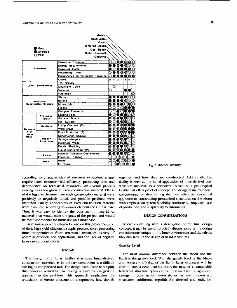
Univers i f j~ of HOUS~(J?I College of Architecture
0- Average
0 Poor
Sinlered Basalt
Sulfur Concrete Concrete,
according to characteristics of resource extraction, energy requirements, resource yield efficiency, processing time, and dependence on terrestrial resources. An overall process ranking was then given to each construction material. Effects of the lunar environment on each construction material were positively or negatively noted, and possible products were identified. Finally, applications of each construction material were evaluated according to various elements of a lunar base. Thus, it was easy to identify the construction material or materials that would meet the goals of the project and would be more appropriate for initial use on a lunar base.
Basalt materials were chosen for use on this project because of their high yield efficiency, simple process, short processing time, independence from terrestrial resources, variety of potential products and applications, and the lack of negative lunar environment effects.
Lun8r tnvlronmbnt
Fig. 2. Material Summar).
together, and how they are constructed. Additionally, the facility is seen as the initial application of lunar-derived con- struction materials to a pressurized structure, a prototypical facility that offers proof of concept. The design team, therefore, concentrated on determining the most effective conceptual approach to constructing pressurized structures on the Moon with emphasis on system flexibility, mtdularity, simplicity, caw of production, and adaptability to automation.
Vacuum 0
Overall 116 Gravlty Dg
DESIGN CONSIDERATIONS
Before continuing with a description of the final design concept, it may be useful to briefly discuss some of the design considerations unique to the lunar environment and the effects they may have on the design of basalt structures.
0
Gravity Level
5 4 2 1 3 6 7
DESIGN
The design of a lunar facility that uses lunar-derived construction materials as its primary component is a dillicult and highly complicated task. The design team chose to simplify this process somewhat by taking a systems integration approach to the problem. This approach emphasizes the articulation of various construction components, how they fit
The most obvious difference between the Moon and the Earth is the gravity I t~e l . With the gravity level of the Moon approximately 1/6 that of the Earth, lunar structures will be able to c q a dead load six times the mass of a comparable terrestrial structure. Spans can be increased with a sigruIicant savings in construction materials, or, as with pressurized structures, additional regolith for thermal and radiation

82 Proceedings of tbe NASA/USRA Advanced Design Program 6th Summer Conference
protection can be supported. Lunar basalts can be cast in sizes Vacuum and shapes that will be optimal for lunar construction. Additionally, construction equipment can be downsized Besides affecting lunar basalt fabrication processes and because of the lower gravity level, which will offer signiticant product strength(*), vacuum conditions also atfect long-term wings in transportation costs. structural properties. Without an atmosphere, the Moon is
d m i d of most of the harmful effects of terrestrial weathering Radiation Shielding This, combined with the fact that basalt is highly resistant to
corrosion and abrasion, will give lunar structures extremely Protection h m the harmful efkcts of radiation will play an long lifespans, and will alleviate many of the problems of
important role in the design of lunar structures. It has been continued maintenance. shown that 0.5 meters of lunar regolith is needed to reduce radiation dosages to safe and acceptable levels for short-term Lunar Dust stays('). Long-term missions will require additional protection. The lunar basalt structure must be able to support this Lunar dust is a highly abrasive, electrostatically charged additional mass in case of depressurization. Definition of high material. As was shown by the ApoUo progt-dm, the lunar dust use areas, both pressurized and unprewrhed, must be made has a negative effect on operations and could present a serious in order to determine which structures should receive threat to astronaut safety through degradation of equipment radiation shielding. and hardware. Cast basalt, because of its high abrasion
resistance, is an ideal structural material for the lunar surface. Thermal Shielding
Automation In some situations, such as habitats and equipment storage
structures, thermal shielding should be provided. Measured Considering the harsh conditions of the lunar surface, temperatures on the lunar surface range between l l l °C and automated and teleoperated capabilities will need to be - 17 1 "c(~). Lunar basalt is capable of handling these extremes maximized for lunar construction. EVA time will be limited, in temperature without physical or structural degradation.
EXCAVATION AR
SlNTERlNG ARM
VERTICAL AUGE
IGH SPEED TURBINE
SECTION SECTION

University of Houston College of Architecture
UTILITY CAP
unLlTY CORE
CAST ROOF PANELS
WORK QUARTERS
CAST FLOOR PANELS
CUPOLA
SINTERED CYLINDER
AIRLOCK
LIVING QUARTERS
BOllOM PLATE
Fig. 4.
therefore expanding the need for robotic and telerobotic construction techniques. systems should be developed that can easily adapt to Merent shapes and sizes of lunar basalt materials. In pressurized structures, p i t s should be minimized to ease assembly and accelerate the c o m a i o n process. Manufacturing and construction systems should allow for quality control testing of construction materials and joints.
AwfU;yr Systems and lntdxe
Auxiliary systems, such as environmental conrrol systems, will need special attach points and interfaces allowing penetration through the structural cavity. There may be a need for modular inserts that can accommodate a number of different systems Preswized structures will require additional support around penetrations, increasing the size and mass of the basalt materials.
DESIGN DESCRIPTION
Numerous design concepts were considered before the fhal solution was realized. These design concepts were classified
into one of three types: monolithic systems, panel systems, or block systems. Monolithic systems, in general, are built-up in a slngle step process, forming an integral shell-like structure. Block and panel systems, on the other hand, are built from p&ricated pieces, which are then assembled on site, the only difkence between the two being the size of their pieces. The fbd design solution incorporates construction processes fmm monolithic and panel systems. The key ingredient of the h a l design solution is the Regolith
Excavation and Sintering Machine (RESM) which, as the name implies, excavates and sinters a cylindrical hole in the lunar &e. Figure 3 shows a plan and two sections of the machine. The RESM's excavation arm first sweeps up the regolith in a circular pattern transferring it to a vertical auger that mows the regolith to the top of the machine where a high speed turbine throws the regolith out and away from the construction site. As the excavation arm continues removal of the regolith, the sintering arm follows closely behind turning the walls of the excavated hole into sintered basalt. The final output of the machine is a cylindrical hole with walls of sintered basalt, 10-1 5 m in diameter and 6-1 2 m in depth, depending on the location of the construction site.

u4 Proceedings of fbe NASAIUSRA Advanced Design Program 6tb Summer Conference
'lhe KESM is an easily dtployable structure (the leg.. retract and fold during transport) that has been designed to fit into the cargo bay of the current Space Transportation System. Operation has k e n automated as much as possible, reducing EVA time and construction expense. Additionally, the RESM, as a primary reusable component of the construction system, significantly reduces continuing construction costs.
Advantages of constructing a subsurface facility are numerous. The surrounding regolith helps to equalize the internal forces of a pressurized structure relieving loads on the shell structure. A subsurface facility also reduces the amount of surface area that must be protected by transferred regolith b m cosmic and solar radiation. Regolith that is removed in the construction process is simply piled back on top of the completed structure, alleviating the need for the complicated processes and equipment of above surface protection systems. Additionally, subsurface facilities utilize the regolith in-, transforming the regolith into a primary building component, which in turn minimizes energy usage and EVA time.
Figure 4 shows an exploded isometric of the completed facility. This cyitndrical facility, designed for an unspecified lunar mare site, is 10 m in diameter and 6 m in depth, and consists of 2 floors, the upper codgured as work quarters, and the lower as living quarters. The middle floor and roof arc comprised of precast, pie-shaped basalt panels that rest on a prepackaged utility core. The utility core, shipped &om Earth as a single package, provides the necessary struc%ural rigidity
for the pressurized facility, while allowing complicated utility .systems to be packaged as a single unit. %o airlocks are provided (Fig. 4 shows only one for visual clarity) for requirements of dual egress. The airlcrh are constructed from six equally sized cast basalt panels to minimize formwork, each containing metal inserts for necessary interfaces, such as hatch doors, etc.
The design team concentrated on a systems approach to the problem. Interior layout and functionality of the presented concept is only one of many possible contigurations. Flexibility is a key aspect of the design. Con6guration of the interior building Vterns lends itself to manipulation for changing uses of the facility. Organization around a central utility core maximizes the amount of usable space, and provides a degree of geometric modularity. Modular cast basalt partitions can be used to separate individual crew quarters and work areas, reducing the amount of interior components that must be brought from Earth. Additionally, these interior partitions can be designed and cast to support a variety of attachable htures.
Figure 5 shows a sectionlelevation of the completed facility. Cupolas have been placed above the airlock to allow viewing of the lunar landscape and obsenation of telerobotic and automated systems. Circulation between floors is provided by a simple ladder, and equipment can be lowered into the first level by a mechanical pulley system. A modular rack system can be used to simplify equipment changeout, much like what is planned for use on the Space Station Freeciom.
CUPOLA \ --I
i \-- SINERED CYLINDER
Fig. 5.

Cinioersity of Houston College of Architecture
FACILITY ASSEMBLY (4
The h t step in the construction of the advanced lunar facility is the digsing of trenches for the airlocks. In the final design configuration, these are set at an angle of 180' to each other, allowing minimum distance to egress in emergency situations. Regolith is moved by bulldozing equipment that is already present on the lunar base for mining of oxygen, thus improving the cost efficiency of the equipment and the facility. The cast panels adjacent to the cylinder walls are set in place. This will allow the RESM to structurally integrate the cast panels with the finished sintered walls of the cylinder, forming a monolithic structure, (Fig. 6a).
Fig. 6. (a)-(h) Facility Assembly

wdsdlngs of tbe NASA/USRA Adwanred Dsatg* Program 616 Summer Conference
The Regolith Excavation and Sintering Machine is lowered into place by the lunar base crane. The legs are unfolded and extended to the proper length, and the excavation and sintering arms are attached The machine begm the excavation of the cylinder, transferring the removed regolith to the surrounding landscape. The removed regolith will be eventually used to cowr the facility for radiation and thermal protection required for human habitats. The sintering arm follows closely behind the excavation arm, applying heat and pressure to the regolith walls forming a 10-20 em crust of basalt. Ledges are sintered in place, allowing easy placement and support of the cast basalt floor and roof slabs by the lunar base crane (Fig. 6b).
Excavation and sintering continues. If a large object is encountered, teeth on the excavation arm simply move the object to a basket located behind the arm. Ihe design team chose a facility depth of 6 m, allowing accommodation of a two-level W t y , the upper sening as crew work area and the lower serving as crew living area. After the walls are sintered, a bottom structural plate is buried in the regolith. This plate will serve as an attach point for the utility core. The floor of the cylinder is then sintered, integrating the bottom plate into the monolithic structure. The arms are then detached and brought out of the hole, and the crane moves the RESM to the next construction site (Fig. 6c).
Next, the utility core is brought to the site by a lunar utility vehicle, hoisted by the lunar base crane, and lowered into the cylindrical cavity. The utility core is care!Uy attached to the bottom plate. The utility core, a pre-packaged system brought from Earth, contains all essential systems for the facility, includmg the life support, air handling, electrical, communi- cations, and heat control systems. The utility core is also a primary component of the facilities structure. The utility core will be wrapped in a protective covering (not shown), keeping the equipment from the q g effects of lunar dust (Fig. w.
'Ihe middle floor pieces, eight total, are then lowered into place. The floor pieces are made of pie-shaped cast basalt and are set into preconstructed notches in the sintered wall and the utility core. This enables easy installation, requiring minimal EVA time for crane operation. Additionally, the basalt floor pieces are the same size and shape, allowing one metal mold to cast all pieces, thus saving additional transportation costs and eliminating unnecessary waste. The middle floor is separate from the structure enabling, if necessary, the removal of pieces for other interior configurations (Fig. be).
University of Houston College of Architecture 87
The cast basalt roof panels are then placed into the preconstructed notches located on the top of the utility core and the side of the sintered cylinder wall. The cast panels contain grooves on abutting edges, which allow the pouring of superheated molten regolith to join the panels together. The superheated regolith partially melts the surrounding cast basalt, fusing the panels together into a single unit, thus allowing the completed facility to act as a monolithic structure. The surrounding regolith helps alleviate much of the stress on the structure, and outward forces on the cyIinder top are held in check by the structural integrity of the utility core (Fig. 6f).
The utility core and the cylinder top are then capped with a prefabricated metal piece which is the final structural component of the utility core and the lunar facility (Fig. 6g). The observation cupola is also set in place at this time. The cupola, delivered from Earth, will d o w for the monitoring of telerobotic systems and the viewing of space and the lunar environment. Exterior viewing will meet some of the psychological needs of the crew and eliminate many of the negative characteristics of subsurface structures. The structure can now be pressurized and interior systems can be delivered and assembled in a shirtsleeve environment. If necessary, an interior vapor barrier can be applied at this time.
Covering the facility with regolith is the final step in the assembly process. The regolith, which was excavated from the cylinder, is pushed by a bulldozer over the top of the facility to a depth of at least three meters giving more than adequate protection from both solar and cosmic radiation to the inhabitants below (Fig. 6h). Fial assembly and checkout of the interior systems occurs, and the facility is ready for use. Additional facilities can be constructed with the same
from Earth. Other facilities may require less equipment, depending on their function, saving additional transportation cargo space for other needs.
CONCLUSIONS
Lunar resource utilization will play an important and ever- increasing role in the sustainability and growth of a lunar base. After lengthy analpis, the design team determined that basalt, a construction material that can be derived from lunar regolith, will best support the needs of both pressurized and unpres- surized structures. The design solution presented in this paper offers a system of simplicity, modularity, and flexibility, achievable in an economic and cost effective manner.
Further research is necessary on basalt structures, in general, and the effects of the lunar environment on basalt processing. Additionally, research must begin on joining techniques, especially between sintered and cast components. Eventually, more accurate studies will need to be conducted on the proper phasing of basalt structures into a lunar base scenario.
Study team members were M. G. Fahey, P C. Spana, and T. K. Wise. Faculty advisors were L. Bell, G. Trotti, and D. Neubeck with Dr. A. Binder, consultant.
REFERENCES
1 . Binder, Alan B. 1988. Lunar Resources: What is known and expected. Engrgrneening, construction, and operations in w e . Johnson, Stewart W. and Wetzel, John P., editors. American Society of Civil Engineers, New York, New York pp. 48-54.
2. Nealy, John E., John W. Wilson, and Iawrence W. Townsend. 1988. SoIm-@re shielding with regolith at a lunm&ase site. NASA Technical paper 2869.
3. Schmin, Hanison. 1988. Constraints on lunar base construction. Engrgrneen'ng construction, and operations hi m e . Johnson, Stewart W. and Wetzel, John P., editors. American Society of Civil Engineers. New Yo* New Yo& pp.35-45.
4. Dalton, Charles and Edward Hohmann, editors. 1972. Design of a IUMT colony. Report prepared by the University of Houston, NASA Manned acetlight Center and Rice University under NASA
equipment and the necessary prepackaged systems shipped grant NGT~~-065- 1 14.''


PRELIMINARY GREENHOUSE DESIGN FOR A MARTIAN COLONY: STRUCTURAL, SOLAR COLLECTION AM) LIGHT DISTRIBUTION SYSTEMS
UNIVERSITY OF IDAHO
The design of a greenhouse that will be a component of a long-term habitat on Man is presented. The greenhouse will be the pl-imary food source for people stationed on Mars. The food will be grown in three identical underground modules, pressurized at 1 atm to d o w a shirt-sleeve environment within the greenhouse. The underground location will support the structure, moderate the large environmental miations on the surface, and protect the crops from cosmic radiation. The design effort is concentrated on the outer structure and the lighting system for the greenhouse. The suuaure is inflatable and made of a Kevlar 49lEpoxy composite and a pipe-arched system that is comgated to increase stitfnes. This composite is pliable in an uncured state, which allows it to be efficiently packaged for transport. The lighting system consists of several Bat-plate fiber optic solar collectors with dual-axis tracking systems that will continually track the sun. ?his design is modeled after the Himawari collector, which was designed by Dr. Kei Mori and is currently in use in Japan. The light will pass through Fresnel lenses that filter o u t @ d ~ e ~ l e n g t h s and send the light into the greenhouses by way of fiber optic cables. When thP Tight arrives at the greenhouse, it is dispersed to the plants via a waveguide and diffuser system.
INTRODUCTION
The greenhouse is intended to be the primary food source fix a Mars-based habitat. The food will be grown in three identical modules that are located underground. The design effort is concentrated on the outer structure and a lighting system for the greenhouse. The structure is inflatable, made of a Kevlar 49/Epoxy composite that is comgated to increase sti!hess. The lighting system consists of several tlat plate fiber optic collectors with dual-axis trackmg systems that continually follow the sun. The light passes through Fresnel lenses that filter out undesirable wavelengths and send the l@t into junction boxes in the top of the structures by way of fiber optic cables. The Light is then taken from the junction boxes and dispersed to the plants by a waveguide and diffuser system.
The composite chosen for the structure of the greenhouse is Kevlar 49/Epoxy. Kevlar 49lEpoxy has excellent material properties, including its specific tensile strength, specific stilhess, and impact strength. This composite also has a high potential for structural use as well as a high repairability rating('). The structural properties of Kevlar 49/Epoxy compare well to other structural materials (see Table 1 ).
Table 1. Materials C~mparison
spec Tensile Spec
Density Strey SiIhess Repara- S/lb Material (lb/in3) (X 1 in) (X losin) bility (88)
STRUCTURAL DESIGN
The design of the outer structure of the food production W e m consists of three identical modules, each having the capabiity of producing 50% of the food required by the Mars colony. The modules will be located at a depth of 4 m below the martian surface. This underground location will shield the plants and colonists against harmful radiation, support the structure, and assist in moderating the extreme emironmental miations that occur on the surface of Mars. The structure will be pressurized at 1 am, or 101.3 kPa, in order to maintain a shirt-sleeve environment in which the colonists can work without requiring the use of a presswized spacesuit.
The structure of the greenhouse is inflatable and is made of prepreg composite material that can be cured to a permanent, solid structure. An inflatable structure has several advantages over a rigid design including the ease with which it can be packaged and transported, as well as the reduction of workload associated with the construction of the green- house. Most importantly, however, is the fact that an inflatable structure made of a composite that is pliable in an uncured state can be inflated and tested on Earth, and then deflated and packaged for transport to Mars.
,%inless Steel 0.29 0.86 1.03 moderate 2.46 A1 2024-T6 0.10 0.57 1.05 moderate 1.87 Ti-6Al-4V 0.16 0.81 0.99 IOW 20 Graphite/AI 0.09 1.14 2.33 moderate 1000 Kevlar 49 0.05 5 2.2 high 15
Growing Area
The growing area that is required for this application has been detefmined by an USRA-sponsored design team at the University of Florida(2). In that study, the food supply was to support a colony of eight people. The current design is to support 10 colonists, so the growing area has been increased proportionaUy. The total growing area required is 534 mZ. This area incorporates a safety factor of 1.5 into the design.
Dimensions
Three separate modules are required for food produdion, each with dimensions of 7 . 6 2 ~ 15.24m. Because of the excellent loadcarrying ability as both a pressure vessel and an underground structure, a domed-shaped cyiinder is used for the modules. The ends of the structures are also domed, yielding a total floor area of 136.66 m2. The domed ends
PRECEDING PAGE BLAPSK NOT FiLAllED

ngs of the NASA/USRA Advanced Design Program 6tb Summer Conference
provide area for activities not accounted for in the growing area estimation, such as germination and harvesting. The total internal volume of each module is 463.26 m3.
The walls of the structure are corrugated to increase rigidity and stability in a loss-of-pressure situation within the green- house. Before inflation of the structure is completed, an in- ternal floor kame is inserted to help the structure retain its shape during the installation process. The internal flooring provides space for irrigation, heating, electrical, and other greenhouse-related systems.
In determining a suitable wall thickness for the struaute, two loading scenarios are considered. For the first condition, the greenhouse is modeled as a pressure vessel(3). This analysis is applicable under normal operating conditions; however, a second approach must be considered in the event of a loss- of-pressure situation in the greenhouse. For the second condition, the greenhouse is modeled as an undagro~nd culvert. This analysis involves two procedures for culvert design: ( 1) a culvert design code(*) and ( 2 ) a soilcuhrert interaction method5). From these analyses it was determined that the loss-of-pressure situation is the limiting factor in the design. Using a 15.24 cm X 5.08 cm cormgation, as shown in Fig. 1, and incorporating a safety factor of 2, the required wall thickness is 0.89 cm.
The steady-state heat losses were determined by modeling the greenhouse as a cylinder without ends, having the same surface area as the greenhouse. When the structure is buried 4 m beneath the surface, the natural insulation of the martian regolith holds the steady-state heat transfer to 1.1 kW. Because of the foreseen difficulty of burying the structure at a depth of 4 m, the heat loss has been analyzed at different depths. Figure 2 shows the plot of the steady-state heat transfer vs. the depth at which the structure is buried. At a more practical depth of 2 m, the heat loss is still remarkably low at a value of 1.7 kW.
The large temperature gradient across the wall of the structure and the depth at which the structure is buried make the transient heat losses an important part of the heat transfer
~ , / / / , / , / / , / , , / ~ , / , I / / / / / J I I ~ ~ / ~ ~ / / / / / / ~ ~ A Fig. 1 . Structure ConGguration and Cross-Section
5lEAOY STATE H t A T TRANSFEY VS DEPTH BUKif D
Fig. 2. Steady-state Heat Transfer vs. Depth Buried
analysis. To approximate the time required for the soil to reach steady state, the soil around the structure is modeled as a semi- infinite slab with a sudden wall temperature change. Figure 3 shows that steady-state conditions are reached in approxi- mately 25 weeks, but the losscs are less than 2 kW after only 6 weeks. At a depth of 2 m, steady-state heat loss, which is 1.7 kW, is reached in only 8 weeks. The steady-state heat loss is 55% higher at the 2-m depth, but takes onty one-third of the time to reach steady state. The tradeotb between power requirements for heatmg and the ditliculty in burying the structure need to be examined to determine the optimal depth for the greenhouse.
SOLAR COLLECIlON UNIT
The greenhouse is supplied with natural light that is col- lected on the surface and transported to the underground modules via fiber optic cables and light waveguides. The growing environment within the greenhouse is maintained at 30°C with a c;ut>on dioxide concentraton approximately 4
O 5 + m r - , .T--T -., 7 r7.7 -7.7. n - 7 F-F-r7--~--m 0 3 L 8 '0 1 5 'I, 1 H ?C1 23 25 28 30
r I 1s ' I!" k ;; Fig. 3. Transient Heat Loss at 4-m Depth

times greater than Earth levels. 'Ihis improves photcqnthetic &ciency, which reduces the amount of Ught required for plant growth from 300 W/m2 to 100 ~ / m ~ ( ~ ) .
The amount of collector surface area and the shape of the collector are dictated by the latitudhd location on Mars. A conceptual study conducted by an USRA-sponsored design team at the Unklsity of Wisconsin determined that a location 20° North of the martian equator is optimal('). The seasonal intensity is much more d h r m at this latitude, and martian dust storms occur less frequently in the northem hemisphere.
The solar light collector is modeled after the Himawad collector that is currently in use in Japan. The Himawad collector has a honeycomb contiguration of Lightcollecting cells. The light is concentrated through Fresnel lenses onto the ends of fiber optic cable bundles. The ends of the collection unit are supported by bearings attached to a base that swivels for two axes of tracking. The entire unit is enclosed in an ac@c dome, which aids in filtering ultraviolet radiation and protects the system from weather and dust.
To meet the lighting requirements of the greenhouse, 119 m2 of collector area is needed for each growing module. Six collectors are required for each module, with each having an incident collection surface area of 20 m2. The shape of the collector is trapezoidal, as shown in Fig. 4, with the skewed edge parallel to the ground at sunrise and sunset. The shape of the design is specific to a martian location of 20' N.
Using a two-axis equatorial tracking system, a 20"-O0 (horizontal) motor axis will follow the dady solar movement. The annual motor axis will make small daily adjustments to complete 50' of rotation between seasonal extremes.
Sensors are positioned in the panel of the collectors to provide feedback to a central computer system in each growing module. The motorized system makes small adjust- ments to the daily schedule when misalignment occurs, and automatically resets the collector after sunset.
Hybrid stepper motors are coupled to harmonic gear drives for adjustments to both axes. The characteristics of this motor make it ideally suited for high-torque applications requiring incremental motion and holding capability. When this type of motor is supplied from an electronic drive, accurate position control and precis speed control is maintained The harmonic
Collector Plate Detal!
Fig. 4. Collector Plate
gear can have as much as a 400:l gear reduction for high torque loads. Harmonic gears have long life cycles and require little or no maintenance.
The collector and tracking axis are mounted on a 4 k m - diameter support column that houses the optic cables and computer link to the controls. The plate is constructed of a rigid honeycomb composite and reinforced by four radial flange beams.
The m;ucimum stresses were approximated by modeling the worstcase loading conditions in a finite element analysis. The collector was modeled as turned on its side and perpendicular to a 100-m/sec wind. A model of the lower hinge showed a maximum stress of 26.2 MPa, which yields a factor of safety of 8. The maximum stresses in the support column are 5.5 MPa.
LIGHT DISTRIBUTION SYSTEM
Light enters the greenhouse via bundles of fiber optic cables that extend from the light collector on the planet surface. The fiber bundles enter through the top of the greenhouse at six junction boxes. tight emanating from the end of the 317.5- mm-diameter fiber bundle is channeled into a 60-mm-diameter, hollow dielectric pipe. This pipe, precisely machined into an optical waveguide, is made of tempered, low-expansion borosilicate. The light travels through the waveguide and is sent into a light-diffusing pipe that is placed over the plant beds. The di&sr is a hollow dielectric tube made of clear, fused silica The upper section inside the tube is coated with magnesium oxide. As the light passes through the diffuser, it strikes the coating and is reflected downward to the plants.
Waveguide Theory
Light entering the optical waveguide is transmitted down the pipe by way of small angle reflections. The light enters the pipe at an acceptance angle of 1". If the light comes in at an angle greater than lo0, it suffers high losses down the waveguide. Any light entering at less than a 10" angle travels through the pipe until it hits the reflective material, then it is reflected down the pipe.
The hollow waveguide used in this design is made of borosilicate glass tubing that is honed to a uniform diameter. The inside of the pipe is a vacuum, which allows light to travel without any of it being absorbed or scattered. The outside of the pipe is coated with a thin aluminum oxide film that will serve to direct light that radiates into the glass back into the tube. A webbed sheathing, which protects the tube, is placed over this film while allowing adequate ventilation for heat dissipation.
The light diffuser is designed to distribute the light from the pipe down to the plants in a uniform and efficient manner. For this application, a downward light W s e r is used in

92 Proceedings of tbe NASA/USRA Advanced Design Program 6rb Summer Conference
conjunction with a reflector panel that is placed above the pipe to capture my light that may be lost through the top or sides of the pipe.
The diffuser is made of clear, fused silica, which has very good transmission characteristics at all wavelengths(8). The upper inside surface of the tube is coated with magnesium- oxide powder, which is 98% eficient for diffuse light reflection'"'.
In order to get an even intensity of light over the entire plant bed, the coating is placed at a 30" arc at the point where light enters the diffuser. The arc increases linearly down the length of the pipe, reaching a 180" arc at the end of the diffuser. The coarseness of the powder increases as it is applied down the length o f the p i p in order to reflect more light.
The dfiser consists of two pieces of hollow dielectric tubing, each piece king 7.62 m long. The pipes are coupled together, and the ends of the pipes are sealed with lenses that allow the light to pass through while keeping a mcuurn inside each portion of the dBuser. The upper difFuser is connected to a support above the upper plant bed and the lower diffuser is connected t o the hottom of the upper plant bed.
CONCLUSION
extreme environmental variations on the surface. The proposed lighting system provides all the necessary light for photosyn- thesis with little external power demand. These considerations make the proposed greenhouse design a viable means of providing an ongoing food supply for a martian colony.
REFERENCES
1 . Adams, D. E, "Descriptions of Candidate Materials of all l)lx~," Clnivefsity of Wyoming, 1987.
2. NeviU, "Design Study of a Prototype Closed Loop Life Support System," Uniyersity of Florida, Dept. of Aerospacr Engineering, Mechanics and Engineering Sciences, k c . 1988.
3 Megyesy, E. E, Rr?~~tlre Vesel Handbxk, 6th edition. Pressure Vessel Handbook Publishing Co., July, 1983.
4. American Iron and Steel Institute, Modern &uer Design, 1985. 5. Duncm, J. M. "Soil-Culvert Interaction Method for Design of Metal
Cukrts," University of California Berkeley, 1978. 6. Milthorpe and Moorby, An InPmducEion to Cn@ Priysiok~gy,
Cambridge University Ress, London, 1974. 7 . Graf, J . , Leroy. S., Monyette. T., and Myrhurn, M. "Providing Light
for a Mars Plant Growth Module," IJniversity of Wisconsin, 1985. 8. McLeUan and Shand. Glass Eng'neen'ng Hamikmk, McCraw-HiU,
1984. 9. Smith, W. J., Modern (@tical Engineen'ng: ?be Design of Optical
Systems, McGraw-Hill, 1966.
The inflatable structure serves as an ideal greenhouse while being feasible to transport and easy to as..rnble on Mars. Imating the structure underground protects it from the

AN UNMANNED PROBE TO PLUTO N
UNIVERSITY OF ILLINOIS, URBANA-CHAMPAIGN
Now that Vo_-agcr 11 has completed its grand tour of the _)lar sTstem, all the planets in the solar_,_tem, with the exception of Pluto, have been studied. Even now, missions to return to Mercur T, Venus,Mars, Jupiter, and Saturn are currently flying or are planned. However, a mission to explore Pluto isnot, at the pre._nt time, being considered ,_riously. The design problem presented to the students wasvery general, i.e., design an unmanned mission to Pluto with a launch window constraint of the years2000-2010. All other charactcristics of the mission, .such ms mission t39e (fl}_)y, orbiter, lander,penetrator), _'ientific objectives and payload, and the propulsion s)_tem were to be determined by thedesign teams. The design studies cxt)o._d several general problems to bc solved. Due to the extremedistance to Pluto (and a corresponding travel time in the range of 10 to 25 }'ears), the spacecr;_ hadto Ix" lighter and more robust than current spacecraft designs. In addition, advanced propulsion conceptshad to be considered. Them included the ncw geneeation of launch vehicles and upper stages and nuclear
electric propulsion. The_probe design offered an abundance of sTnthesis and analysis problems. 'lhc_"included sizing trade studFCs, ,_lection of subsTstem comtxmcnts, an',d_sis of spacecraft dynan]ics stabilityand control, structural design and material _qcction, trajectot T design, and ,_lection of scientificequipment. Since the characteristics of the mission, excluding the launch window, were to hc determined
by the design teanls, the s()lutions varied widely.
INTRODUCTION
Although missions to return to Mercury, Venus, Mars, Jupiter,
Saturn, and comets are planned or currently flying, a mission
to Pluto is not planned until "after 2010. The first step in the
exploration of Pluto will occur when Hubble Space Tele_'ope
becomes active. This instrument should provide clearer
pictures of Pluto and Charon than currently exist. However,
even this clarie s" will not be sufficient to perform the an',dyses
necessary to an,saver the current questions about Pluto and
Charon.
To provide ,_ientists with the data required to perform
those analyses, a mission to Pluto and Charon is necessa_'.
There are three clas,_s of missions that can be flown: ( 1 ) flyby,
(2) urbitcr, and (3) lander. Flyby missions have an inherent
limitation in the amount of time spent in the vicinity of the
area of interest. However, they are the easiest to design and
the !east exlx-nsive to build and fly.
Orbiter missions are inherently more costly than flyby
mi,_sions I')ccau_ - (ff the requirement to cnter orbit about the
Ix)dy of interest. However, this t3T)C of mission provides more
time to study the body of interest, allowing additional and
more exact experiments to be performed. Becau._ of the
distance ti'om Earth to Pluto, this t}pe of mission must he ahle
to adapt to the cm4ronment thc spacecraft encounters.
The most costly mi,s,sion cl_,s,s is the lander. There exist two
suhcla_s,ses of landers: a lander, which lands _fftly on the
surface of the I_)dy in question, and a penctrator, which
explores the area under the surface of the txMy. A lander
mission provides the most accurate and largest quantity of data
about another body. For this t3pe of mission, an important
question is which body to land <)n, Pluto or Charon?
PROJECT BACKGROUND
Forty-two undergraduate students, divided into ,seven groups,
were enrolled in the spacecraft section of Aeronautical and
Astronautical Engineering (AAE) 241, Flight Vehicle Design, in
the spring 1990 _mestcr. This paper summarizes the work of
tho,_ student groups ms submitted in their final design rtq0orts.
Ttxlay, little is known about plutonian space and current
discoveries rai,_ more questions than they answer. The Hubble
Spacc Telescope should be able to answer some of the
questions, but the only way to answ¢cr most of the questions
is to _-nd a spacecraft to Pluto to cake data first hand.
Pluto, thc ninth planet in our solar s3_tem, was di._.vered
in March 1930, using photographic plates taken in Januai T of
that year. ('baron, Pluto's only known _tellite, wzts di_'overcd
in July 1978, but not recognized until 1985. With an
eccentricity of 0.25 and a perihelion of 29.6 A.It., Pluto h,Ls
an orbit',d pcri()d of 248 years.
Pluto it,_lf is estimated to weigh about 1/400 of the m:tss
of the Earth, with a diameter of approximately 2300 kin. The
composition of the planet is estimated to be abottt 70% rock
and 30% water ice and methane ice. "ll)e atmosphere is
believed to be composed mostly of methane, which is
sublimating from the surface, with traces of headset gases such
ms argon, neon, and nitrogen. Due to the large eccentriciD _ of
the orbit and the distance from the sun, the atmosphere of
Pluto is thought to fi)rm and collap_" cyclically ;ks a fimcti()n
of the orbital period. The next collap_- is expected to occtwaround 2025.
PROJECT OBJECTIVE
The project objective was to deveh)p a conceptual design
for a spacecraft to perform an unmanned scientific study of
plutonian space to be launched _mlctime in the first decade
of the 21st centuu'. Performance, weight, and cost art' yen,important to the acceptance of this t)l_e of mission, so
approaches were taken that optimize these parameters in
design tradeoffs. The spacecraft had to bc reliable and um off
the-shelf hardware whenever a_tilable. The use of materials or
techniques expected to bc a_tilahle after 1999 w_s prohibited.
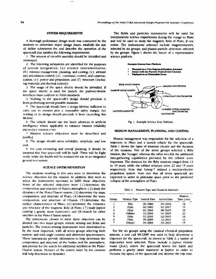
Proceedings of tbe NASA/USRA Aduanced Design Program 6tb Summer Conference
A thorough preliminary design study was conducted by the students to determine major design issues, establish the size of, define subsystems for, and describe the operation of the spacecraft that satisfies the following requirements:
1. The amount of on-orbit assembly should be identifled and minimized.
2. The following subsystems are identified for the purposes of system integration: ( a ) science instrumentation; (b) mission management, planning, and costing; (c) attitude and articulation control; (d) command, control, and comrnun- ication; ( e ) power and propulsion; and (f) structure (includ- ing materials and thermal control).
3. The u.sage of the space shuttle should be identified. If the space shuttle is used for launch, the payload/shuttle interfaces must conform to NASA standards.
4. Nothing in the spacecraft's design should preclude it from performing seved possible missions.
5. The spacecraft should have a design Lifetime sutficient to c a q out its mission plus a reasonable safety margin, but nothing in its design should preclude it from exceeding this lifetime.
6. The vehicle should use the latest a-ces in artificial intelligence where applicxble to enhance mission reliability and reduce mission costs.
7. Mission science objectives must be described and justified. 8. The design should stress reliability, simplicity, and low
cost. 9. For cost estimating and overall planning, it should be
assumed that four spacecraft will be built. Three will be fight ready, while the fourth will be retained for use in an integrated ground-test sTxtem.
SCIENCE INSTRUMENTATION
The students working in this awa were to determine the science objectives for the mission. In addition, they were to select the instruments necessaxy to fulfill these objectives. Some of the selected objectives were (1)determine the con~p)sition and structure of Pluto's atmosphere; (2) study the dynamics of the Ruto/Charon system; (3) determine the mass, composition. and structure of Pluto; (4 ) determine the m s , composition, and structure of Charon; (5) determine the surf.ace characteristics of Pluto; (6) determine the existence and structure of the magnetic field of Pluto; (7) study Jupiter (during a gravity assist maneuver); and (8) search for other satellites in the Pluto/<:haron sytem.
The instruments chosen to meet these objectives can be divided into two major groups, remote sensing and fields and particles. The remote-sensing instruments were determined to be the most important, with all seven groups selecting both narrow- and wide-angle cameras and ultraviolet spectrometers. The.% instruments provide information to help determine the cornpaition and structure of the bodies and the atmosphere, and provide for the search for additional satellites in the Pluto/ Charon system. Pictures of the sytem taken by the cameras will help determine its dynamics.
The fields and particles instruments will be used for interplanetary science experiments during the Myage to Pluto and will be used to study the magnetic field of Pluto, if one exists. The instruments selected include magnetometers, selected by six groups, and plasma particle detectors, selected by six groups. Figure 1 shows the layout of a representative science platform.
RADIOMETER
Fig. 1. Example Science Scan Platform
MlSSION MANAGEMENT, PLANNING, AND COSTING
Mission management was responsible for the selection of a trajectory to Pluto and a launch vehicle for the spacecraft. Table I shows the types of missions chosen and the duration of the missions. Five of the seven groups selected a flyby mission, like Voyager, hereas the other two felt the additional data-gathering capabilities provided by the orbiter were important. The duration for the fiyby missions ranged from 13 to 19 years, while the orbiter missions were 22 and 15 years respectively. Note that Group 7 utilized a nuclear-electric propulsion system. Note also that all seven spacecraft are expected to arrive in plutonian space prior to the predicted cwllapse of the atmosphere of Pluto.
Table I . Mission 7)pe and Duration Summary
Group
1 2 3 4 5 6 7
Mission 7Lpe
flby flyby m y
Orbiter flyt,~ flyt,~
Orbiter
Launch Date
Oc>/2000 02/2002 0 1 /2002 12/2004 01 /2003 05/2009 04/2004
Arrival Date Mission
lime ( yrs)
For the six groups using the classical chemical propulsion systems, a tool call MULIMP was used to help determine a trajectory for the spacecraft. As shown in Table 2, a variety of trajectories were selected. These include a Jupiter Gravity Assist (JGA), where the spacecraft leaves the Earth and performs a gravity assist maneuver at Jupiter in order to increase the speed of the spacecraft and shorten the trip time.
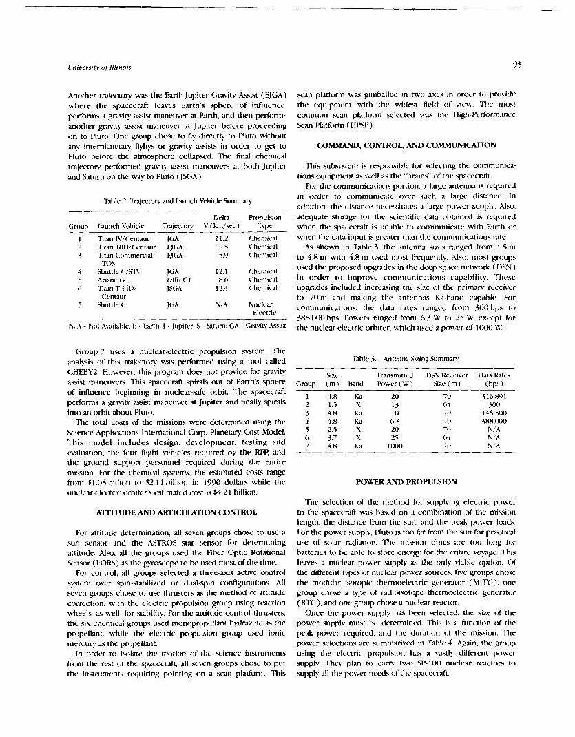
i~ni t lers t fy of Illinois 95
Another trajectoq was the Earth-Jupiter Gravity Assist (EJGA) where the spacecraft leaves Earth's sphere of influence, performs a gravity assist maneuver at Earth, and then performs another gravity a-ist maneuver at Jupiter before proceeding on to Pluto. One group chose to fly directly to Pluto without an\. interplanetary flybys or gravity assists in order to get to Pluto before the atmosphere collapsed. The final chemical trajectory performed qavity assist maneuvers at both Jupiter and Saturn on the way t o Pluto (JSGA).
Table 2 Trajectory and launch Vehicle Summary
Delta Prcqxtlsion Group Launch \'chicle Trajectory V (km/scc) Typc
Titan IVi'(:entaur JGA Titan Illl>,'(:entaur EJGA Titan (:ommercid,' EJGA TOS
Shuttle (:/STY JGA Arimc W DIRECT 'lltan 1'.3411/ JSGA
(:entaur Shuttle <: JGA
Not Availal>lc.; E - Earth; J -Jupiter; S - Saturn; GA
Chemical Chemical <:hemica1
Chemical Chemical <:hcmic-al
Nuclear Electric
- <;rdVit)' kssist
Group 7 uses a nuclear-electric propulsion system. The analysis of this trajectory was performed using a tool called CHEBY2. However, this program does not provide for pa\it): assist maneuvers. This spacecraft spirals out of Earth's sphere of influence beginning in nuclear-safe orbit. The spacecraft performs a gravity assist maneuver at Jupiter and finally spirals into an orbit about Pluto.
The total costs of the missions were determined using the Science Applications International Corp. P l a n e t q Cost Model. This model includes design, development, testing and waluation, the four flight vehicles required by the RFV and the ground support personnel required during the entire mission. For the chemical systems, the estimated costs range from $1.03 billion to 512.1 1 billion in 1990 doLlm while the nuclear-electric orbiter's estimated cost is $4.2 1 billion.
ATIlTUDE AND ARTICULI\TION CONTROL
For attitude determination, all seven groups chose to use a sun sensor and the ASTROS star sensor for determining attitude. Also, all the groups used the Fiber Optic Rotational Sensor (FORS) as the gyroscope to be used most of the time.
For control, all groups selected a three-axis active control system w e r spin-stabilized or dual-spin configurations. All seven groups chose to use thrusters as the method of attitude correction, with the electric propulsion group using reaction wheels, as well, for stability. For the attitude contn)l thrusters, the six chemical groups uscd monopropellant hydrazine as the propellant, while the electric propulsion group used ionic mercury as the propellant.
In order to isolate the motion of the science instruments from the rest of the spacecraft, all .w\ren groups chose to put the instruments requiring pointing on a scan platform. This
scan platform was gimballed in two ;Lues in order to pro\ide the equipment with the widest field of view. The most common wan platform selected was the Hij$Performance Scan Platform (HPSP).
COMMAND, CONTROL, AND COMMUNICATION
This subsystem is responsible for selecting the communica- tions equipment as well as the "brains" of the spacecrali.
For the communications portion, a large antenna 1s required in order to communicate over such a large distance. In addition, the distance necessitates a large power supply. Also, adequate storage for the scientific data obtained is required when the spacecraft is unable to communicate with Earth or when the data input is greater than the communications rdte.
As shown in Table 3. the antenna sizes ranged from 1.5 m to 4.8 m with 4.8 m used most frequently. Also, most groups used the pn)posed upgrades in the deep space network (DSN) in order t o improve communications capability. Thesc upgrades included increasing the size of the primary receiver to 70 rn and making the antennas Ka-hand capable. For communications, the data rates r a n g d from 300 bps to 388,000 bps. Powers ranged from 6.3 W to 25 W, except for the nuclear-electric orbiter. which used a power of 1000 W.
Table 3. Antenna Sizing Summary
Size Transmitted 1)SN Kccciver Ihta Katc.5 Group (m) Hand Powar ( W ) Size (m) (bps )
POWER AND PROPUISION
The selection of the method for supplying electric power to the spacecraft was based on a combination of the mission length, the distance kom the sun, ,and the peak power loads. For the power supply, Pluto is ton far from the sun for practical use of solar radiation. The mission times arc too long for batteries to be able to store energy for the entire voyage. This leaves a nuclear power supply as the only blable option. Of the different types of nuclear power sources, five groups chosc the modular isotopic thermoelectric generator (MITG), one group cho.w a type of radioisotope thermoelectric generator (RTG), and one group chose a nuclear reactor.
Once the power supply has been selected, the size of the power supply must be determined. This is a function of the peak power required, and the duration of the mission. The power selections are summarized in Table 4. Again. the group using the electric propulsion has a vastly different power supply. They plan to carry two SP-100 nuclear reactors to supply all the power needs of the spacecraft.

% Proceed1
Table 4. Power Supply Summary
Group
1 2 3 4 5 h 7
Mission
* Y ~ Y fl*y n,*y
Orbiter flyby MY
Orbiter
Mission Duration
Om) Peak hwer
Power ( W) Supply
297 MITG 256 MITG 165 MITG 237 RTG 373 MlTG 2'90 MITG
80,500 Reaczor
Number Mass of Slices (kg)
MITG = Modular Isotopic Thermoelectric Gmerator. !TG = Radioisotope Themc~iectric Generator.
Indicates the number of power units where slices ate not applicable.
The responsibilities in the propulsion area were propellant selection, propellant tank sizing, and orbit insertion propulsion for the two orbiters. For this mission, four chemical propulsion options were considered: cold gas, .solids, monopropellants, and bipropellants. Cold gas and solids are not applicable to the mission. Three groups selected the monopropellant hydrazine because it is simple, reliable, storable, and has relatively low cost. The other three chemical groups chose the more complex, but higher I, hipropellant, hydrazine and nitrogen tetroxide.
The nuclear-electric propulsion system is different. The propellant options investigated for this system include cesium, xenon, argon, and mercury. Of the four options, mercury vms selected k c a u s e it provides the best tradeoff between cost, storability, and I,.
For the chemical systems, the propelkant mass ranged from 473 kg to 2000 kg for the flyby missions and 3 120 kg for the orbiter. The nuclear-electric mission had a propellant maKs of 12,000 kg.
This subsystem WAS responsible for locating the components, determining the mass properties, and thermal control. Figures 2 through 4 show the layout of three representative spacecrafii: Fig. 2 is a flyby, Fig. 3 is an orbiter, and Fig. 4 is the nuclear-electric propulsion orbiter.
In~xt ing the components and determining the mass prop- erties must be performed together. The components should be arranged on the spacecraft to minimize the cross product of inertia about the axes of the thrusters. This is the principle reawn for the arrangements shown in Figs. 2 through 4.
Thermal control is required in order to maintain the temperature within acceptable limits for all components within the spacecraft. Various methods were employed by the groups. The most widely selected method was the placement of thermal heaters throughout the interior of the spacecraft. Radioisotope heating units, where the energy from nuclear decay is used to heat nearby components, were also common. The nuclear-electric orbiter used high-temperature rddiators to remove the wAste heat from the nuclear rcactor.
For the chcbmical flyby missions the structure (dry) m a w s rdngc from 445 kg to 756 kg with the total m a w s ranging
ings of the NASA/I/SRA Adoanced Design Progrum 6 t h Summer Conference
b m 1093 kg to 2500 kg. The chemical orbiter has a dry mass of 3243 kg and a total mass of 6363 kg. The nuclear-electric orbiter has a dry mass of 8914 kg and a total mass of 20,914 kg.
Fig. 2. Bottom View of an Example Flyby Spaceclafi
AItihrde Thnutcn (one one each side of tank)
Fig. 3. Side View of an Example Orbiter Spacecrdft

University of Illinois
POWER MODULE
2 Reactors Reactor I dr C Shield Heal Transport System Power Conversion High Temperature Radiator
(HTR) panels a.k.8, heat nject ion panels
PROPULSION Propellant Tank 6 Main Thrusters
PAYLOAD Main Platform (AAC houslnl) Science C C3 Hourins HGA (4.8m diameter) LG A MAG boom (13m)
Fig. 4. Side View of the Nuclear-Electric Orbiter ?+acecraft


AUTOMATION OF CLOSED ENVIRONMENTS IN SPACE FOR HUMAN COMFORT AM) SAIrETY -
KANSAS STATE UN][VE~Sl"Y ~ 9 1 - 1 8 1 3 7
INTRODUCTION
Project Description
The Environmental Control and Life Support System (ECLqS) for the Space Station Freedom and future colonization of the Moon and Mars presents new challenges for present technol- ogies. Current plans call for a crew of 8 to live in a safe, shirt- sleeve environment for 90 days without ground support. Because of these requirements, all life support systems must be .self-sufkient and reliable.
The ECLSS is composed of six subsystems. The temperature and humidity control (THC) subsystem maintains the cabin temperature and humidity at a comfortable level. The atmosphere control and supply (ACS) subsystem insures proper cabin pressure and partial pressures of oxygen and nitrogen. To protect the space station from fire damage, the fire detection and suppression (FDS) subsystem provides fire sensing alarms and extinguishers. The waste management (WM) subsystem compacts solid wastes for return to Earth. and collects urine for water recovery.
Becausc it is impractical, if not impossible, to supply the station with enough fresh air and water for the duration of the space station's extended mission, these elements are recycled. The atmosphere revitalization (AR) subsystem remclves C 0 2 and other dangerous contaminants from the air. The water recovery and management (WRM) subsystem collects and filters condensate from the cabin to replenish potable water supplies, and processes urine and other waste waters to replenish hygiene water supplies.
These subsystems are not fully automated at this time. Furthermore, the control of these subsystems is not presently integrated; they are largely independent of one another. A fully integrated and automated ECISS would increase astronauts' productivity and contribute to their safety and comfort.
THREE-PHASE DESIGN PLAN
The Kana5 State University Advanced Design Team is in the process of researching and designing controls for the automation of the ECLSS for Space Station Freedom and beyond. The approach chosen to solve this problem is to divide the design into three phases.
The first phase is to research the ECISS as a whole Vstem and then concentrate efforts on the automation of a single subsystem The AR sub-system was chosen for our focus.
During the second phase, the system control process will then be applied to the AR subsystem. To aid in tht: develop- ment of automatic controls for each subsystem and the overall
ECLSS, mathematical models are used for sysTem simulation on a computer. Once the simulation has been completed, various methods of control can he tested. (king the AK subs?.stem control system as a 'prtx)f of concept," the other E(:I,'L" sub- .systems will be automated.
Finally, during phase three. the six suhsystem control systems wil l be combined to fomi a control ystem for E<:I-SS. The control sytem will perform routine control duties a\ well as provide fault diagnosis and isolation.
The Kansas State I.niversity Iksign Team has completed phase one and is currently in the midst of phase t\vo. Mathematid mtKicls haw been developed and numerows AH subassembly components have been simulated on a computer. Phase two dc~elopment will continue through the next tu.o
semesters. Phase threc will be initiaterf upon the coniplction of the second phase.
This paper describes a portion of the work done at Kansas Statc liniversity during the 1989i90 academic .school yc:tr. First. the componmts of the AR system arc discussed. Ihen the paper focuses on the four-heil molec.ular s i c ~ e . whie~lt is descr ikd in derail along with a proposcil con tn~l sc.hcme. 'lhc mathematical models of the AK components developed I>y the group arc not discussed in this papcr, but can he founil in thc complete report. Simil;ir work wras done for thc other components of the AK subsystem. That work also is diwussed in the complete report.
DESIGN TEAM DESCRIPTION
The Kansas Statc Ilnivcrsity Advanced Ilcsign '1-cam is compo,wd of engineering students from sevtLral clisciplincs, ;i
student from general science and education, a graduate st~rilent assistant, and engineering Faculty menll>crs. Chemical, electrical, indirstrial, and mechanical cnginecring di.wipli~ics arc represented by both students and f;tc~lity.
To complete the first semester's work, the design team appointed three lead engineers to work with the f;~cult)~ :mil teaching assistant to organize and direct thc activities of the group Initial breakdown of the group assigned two o r thrce students to each ECI..%! subsystem to collect infomiation Oncc this preliminary investigation had takcn place, the i i K subsystem was selected for further study.
During the second semester. thc design teanl w a organized into three groups to study the hK subs?.stern in detail. One group focused on mathematical models, another group studied control strategies, while the third concentrated on physical operations.
PReCEDlNG PAGE BLANK NOT FILMED

ATMOSPHERE REVITMJZATION CARBON DIOXIDE REMOVAL
Figure 1 is a diagram of' the AK subsytem. 7he subsystem's purpose is t o produce oxygen for respiration. The AK subsystem removes water vapor, <XI,, and trace contaminants from the cabin atmosphere. It produces oxygen and potable water. The subsytem is composed of four parts, the CO, r e m o d system, the (:OL reduction system (<:R!!), the oxygen genention assembly (OGA). and the trace contaminant control system (TCCS). Only the CO, rerno\,;il system is discussed here.
Metabolic <:O, is removed from the cabin atmosphere by a four-bed molecular sieve. The siclr consists of two desiccant beds to remove water vapor from the incoming air, two <:OL adsorption beds, a blower to force the air through the system, a CO, pump, a C 0 2 accumulator, a precooler, and five multiple-flow selector valves.
Figure t is a diagrani of the four-bed molecular siwe. During a typical actu~rption cycle. air enters the four-bed molecular sieve from the temperature and humidity control ( 'I 'HC:) subsystem (1) . After passing through a directional con tn~l valve (L), the air enters the desicc,ant bed (3). Dry air leaves the desiccant bed and p m s through another directional control \alve (-t ) before passing through the blower (5). 'Ihe air, which has been warmed hy the desiccant bed and blower. then passes through a precooler (6). After leaving the prectx)ler and passing through a third directional control valve ( 7 ) , the air enters an adsorbent bed (8). 'the (:02 adsctrhent bed, which WL\ hrated to release CO, earlier, now cools as it adsorbs <:O,. Air Iraves the adsorknt bed. passes through a check valve (9), then enters the second desiccant bed (10). 'lhis warm dry air evaporates water accumulated in the desiccant bed during its adsorption cycle. 'lhis humid, cool air passes through a final directional control valve ( 1 1 ) before returning to the THC subvstcm ( 12 ).
While one hed is adsorb~ng (:O, (X), the other bed ( I4 ) is desorbing C 0 2 . The dcsorbing begins tvith an initial punipcio\vn of the k d to draw of residual air. .4 check valve
Fig 2. l i)i ir-lkd hlolc.c~~l;u 51,ia.c.
( 1 3 ) prtlvcnts pumping air through the desiccant bed during the desorption cycle. The COL pump ( 1 6 ) punips air through a valve (15) and hack to the THC subsystem through a directional control \dve ( 17). After the initial pumpdown, the pump is shut oB while heat is steadily applied to the COL sorption bed by electric heaters. After the bed is sufficiently heated, the pump is restarted. Now the directional valve ( 17) is wt to scnd (:O, to the pressurized, fixed-volume accumu- lator ( 18).
After the desorption is complete, the valves switch positions and the COL-free desorl3ing I x d becomes the adsorbing bed, and the C0,-filled adsorbing bed becomes the desorbing bed. I.ikewise, the now water-filled adsorbing desiccant bed becomes the desorbing k d , and the dricr desorbing bed becotnes the adsorbing desiccant bed.
Desiccant Bed
Each desiccant bed is filled with a uater-adsorbent material. '1%~ aduxhent materials used in these k d s are zeolite 13X and silica gel. Silica gel and zeolite 13X are placed in sepwate layers and the incoming air stream passes over both layers. These two layers are necessary because the silica gel adsorbs water vapor well at high relative humidities. but its e6cienc-y decreases for relative humidities of less than SO'k,. Zeolite 13X, however, is more ctficient for relative humidities o f 3 5 % or less. In tests performed by NASA, the combination of these two layers removed nrarly 100'k of the water vapor in the incoming stream. A. a result of this water removal, the temperature of the ;tir stream increases. 7hc.w adsorbents reaclily dcsorb water when the warm air stremi from the C O beds p ~ w over them.
Blower
'Ihc blower is a motor-driven centrifug;~l Fan. The motor is designed to opente with I I SI.220-V A(:, three-phaw, 400-Hz power. 1)eswirl vanes help convert swirl energy into useful static pressure. The blower is made of corrosion-resistant ~iiaterial with l,carings designed to isolate grease from working air.
'Ihc precoolcr is a double-pass coolant and single-pass Fig. I . Arnlosphcrc Kc-\italication Hkwk I)iav.~ni process-air-flow hcat exchanger that is made o f stainless steel.
ORIGINAL PAGE IS OF POOR QUALITY
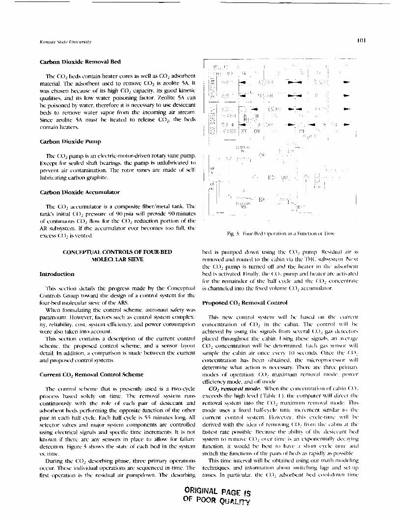
Carbon Dioxide Removal Bed
The C 0 2 beds contain heater cores as well as C 0 2 adsorbent material. The adsorbent used to remove C 0 2 is zeolite iA. It was chosen because of its high C 0 2 capacity, its good kinetic qualities, and its low water poisoning factor. Zeolite 5A can be poisoned by water, therefore it is necessary to use desiccant beds to remove water vapor from the incoming air stream. Since zeolite 5A must be heated to release C02 , the beds contain heaters.
Carbon Dioxide Pump
The <:02 pump is an electric-motor-driven n)tq vane pump. Exccpt for waled shaft bearings, the pump is unlubricated to prevent air contanmination. The rotor vanes arc made of self- lubricating c u b o n graphite.
Carbon Dioxide Accumulator
The ( : O accumulator is a composite fiber/metal tank. The tank's initial (:(I2 pressure of 90 psia will provide 90 minutes of con t inuo~~s (:a flow for the (:() reduction portion of the AR subsystem. If the accuniulator c w r becomes ttn) full, the excess <:() is vented.
CONCEITUAL CONTROLS OF FOUR-BED MOLECULAR SIEVE
Introduction
l h i s scction details the progress n ~ a d e by the Conceptual Controls Group toward the design of a contn)l system for the four-bed niolccular sieve of thc ARS.
When formulating the control scheme, astronaut safety was pxaniount. tiowever, factors such as control system complex- it)., reliability, cost% syste~~m eficiency, and power consumption were also taken into account.
This section contains 3 description of the current control .scheme. the proposcd control scheme, and a sensor layout detail. In addition, a comparison is made between the current and pn)p)scd control sytems.
Current CO, Removal Control Scheme
The control scheme that is prcscntly used is a two-cycle process based solely on time. 'Ihe removal systenm runs continuously with the role of each pair of desiccmt and adsorbent beds perfomling the opposite function of the other pair in cach half cycle. Each half cycle is 55 minutes long. All sclcctor vitlves and major system components are controlletl using electrical signals and specific time increments. It is not known if there arc :uny sensors in place to allow for failure detection. Figure 3 shows the state of cach bed in the system vs. time.
[luring the <:OL desorbing p h ; ~ ~ ' , three primary operations txrcur. These individ~ral operations are sequenced in time. The first operation is thc. residual air purnpdo~m. The dcsorbing
Ixd is pumped down using the (:OL pu~lip. Kcsiclu;~l air is removed and routed to thc c;thin vi:i the 'l'H<: s~~l>s!,stcnl. Nc\t the <:OL punip is turned off ;tnd the lmcatcr in the ;~daorl>cnt bed is act i~i tcd. Finally. the (:OL pump ;lnd hGrter arc ;rcti\~atcti for the remainder of the 11:tlf c!cle ;mi1 the ( I ( ) c,oncxmtr:rtc is channeled into the fixed volumc (:OL ;tccumul;~tor.
Proposed CO, Removal Control
'Ihis new control syterrl will I,c, 1):tsc.rl on thc c.crrri.rit concentration of (:OL in the cal>in. 'lhc control \ \ i l l I>c achieved by using lhc signals froni sc\~er:11 (:OL K;L\ r l c t ~ ~ c ~ o r s p1acc.d throu#lout thc c.ahin. I :sing 111c.u. sig11;1la, ;In ;I\ i.r;rgi, <:<IL concentration will I>c detcrnlinc.rl. t<;rcli gas sensor \\.ill sample the cal,in air once even 1 0 scconds. Once the (:O,
concentration ha\ I>ee~i ol?t;~ineil, tlmc ~mlic.roj>roceksor \ \ i l l determine what action is necessary 'llierc are thrcc pri111;tn modes of oper;rtion: <:OL ~ ~ i ; t x i ~ l i ~ ~ ~ ~ i rc~~ioval ~iiodc. poM.cr eficienc? mode. ;~tid off nioclc.
GO2 rm~ol!rr/ mode. N'hen the conccntr;~tiori of c;rhin (:02 exceeds the high Ievcl ('lhhlc 1 ). the computer \\.ill dircc,t the removal ?stern into the (:O, nl;tsirnum rc~iioral mode .Illis mode uses a fixecl half-i~clc timc increment simil:tr t c t the current control syste111. llo\vc\er. this c!,c.lc-time \ \ . i l l hi. derived with the irlc;t of remo\,ing (10 fionl tllc c;~l>in ;it the fastest rate possil>le. 13cca~1se the :~ l> i l i t \ , ol' the rlesicc~atit heel system to removc <:() o\,cr timc is ;ui csponcnti;rll!. tlcc.,~!ing fi~nction, it wrould I>c I>cst to h ~ v c ;I \1io11 c.!.clc ti~iic .~ntl switch the filnctions of the p;~irs ofI>c~l\ :is r;tpiclly ;is po4il~Ic..
This tinic intcnal will he ol>t;rincd using our m;ith motfcling tcchniques, and i~lforniation about s\vitc.hing lags and sct-111) times. In particular, the (:OL ; t~I~)rI>crit I>rd cool-don.n tirilc
ORlGlNAL PAGE IS OF POOR P(jR!-!TY

102 Proceedings of the .VASAA,'f '.SM Adtvrnced I)esig)z Progranr 6th Summer Cf~~tference
rts it relates to efficiency, urill k important. The goal will be to remove the greatest amount of C 0 2 per unit time.
This nmcxle would be used when large amounts of C 0 2 are present in the cabin, for example, during emergency situations of increased astronaut numbers.
Table 1 CO, Operating Modes
I.c~el Mode C 0 2 Concentration (ppm)'
tli (:OL Krmo\-al 2 loo0 1.0 Power Etficienc) 300 < '< <: loo0 ( )B < 300
('oncentration Ievrls wrrc fc)rmtllatrd using standard threshold limit \;~lucr ;rnd ~rdornration from I)r Stt~h;m Konz, Kan.%s State Ilniversiry.
Pouwr efficiency mode. W'hen the level of cabin CO, is l~envecn the Hi and 1.0 levels indicated in Table 1, the poRrer etficiency modc would be activated. This mcxle uses a &xed half-cycle time that al1ou.i for adequate CO, rm~)va l , but niinirnizes the amount of electrical power used per unit of C 0 2 remo\,ed. Illis time intenal will lx detemmined in a Fashion similar to the mmner in which the time internal for the CO, rchnio\-;ll mcxle w ~ \ found.
'I'his modc will he usehrl when electrical power is limited on the station, fix cs;~mple, when a solar panel is damaged or ;I p n v t ~ shortage occurs.
OfJ' ttio~de. I > ~ ~ r i n g this operation the rmmo\al sytem will not bc. oper.~ting. This woultl allow astronauts to make repairs o n the 3-tern.
Syssem Monitoring Scheme
t3elon. is a list o f all the major system components in the <:01 rcmowl s~rbsystcril. h sensor is described for rach c,onmponent. This monitoring scheme will allow the system to he c~ontrolled. ;I.\ outlined above. ;md also allow component Iliilures to bc clctccted. For a c h component, the output of the hetlsor( s ) will be con~parcd with :I desired output and an error sign;iI \vtIl he generated. 'Ihe monitoring microprt~essor, using arm ;~rtific.ial intel1igcnc.c progr:lm. will determine if a cc )rimponent hil~rre hrt\ occ~rrred. In the evmt of failure, the ;a tr t )~uuts \volrld hc alerted \<a a computer terminal. Figure 4 is a pic.to~ial of the systcni monitoring schmme.
Oitbitr. (:O, g;rs scn.u~rs \xill be placed throughout the c.;ll>in to obtain an averdgc ( : O g;ts concentration. Using this iriri)rrn;~tion the niic~roproccswr will select the appropriate opc";rting nmcdc for the (:01 rerno\.xl system.
Air. srlec-!or ~y~l t~es . 'These val\res have end-of-position \\\.itcties th;rt can IK IISC'CI to detcrrnine if they have been c.ornpletely s~vitched into a valid position. 'lhis also allows the c.urrelit position of the \.alve to I>c Iuiown.
I>esicru~r! bed. A humidiq s m w r will be placed just in front of the blower to measure the water content of the air strc;lm 'Ihe system requires that a dew point of -70°F be m;~intained for air entering the adsorbent. This senst)r %ill indicate if a desiccant hed has malfunctioned.
Blotcfw. t\ pressure sensor will be placed in front of the hlo\vcr ;tnd directly downstream h m the blower to measure the pressure drop. A power sensor will be used to monitor
Fig. 4. Ropoxd C:O, Krmo\al Sensor L~xations
the power consumed by the blower. tising the information from thew sources it will be p~ssible to determine if the blower is h-iction dragging, turning too slowly, o r otherwise failed.
Precools. A temperature sc-nsor will be placed on the airstream line after the precooler to deternmine if the air entering the adsorbent bed is ccxol enough to allow for effective adsorption.
GO2 adsorbent bed. A <:02 gas sensor will bc placed on the air-return-to-cabin pipe. By comparing the gas conccntra- tion at the hcd exit with the gas concentration in the cabin it will tx. possihlc to detemline if the bed is saturated or malfunctioning. A sensor will be used to monitor the power consumption of the adsorbent bed hvater.
Check tfal/le. An air-flow-rate sensor will be placed between the check valve and the C 0 2 adsorbent bed to deternmine if the valve is leaking. The check va l~c assures that cabin air is not drawn directly into the s??item and stored in the <:O, iiccumulator.
GO2 pump. A pressure sensor will iw phced between the pump and the <:02 .wlector \alve. This sensor will allow Ie&s to k detected in the (:OL selector valve, check valve, post- prectwler air .wlect valve, and adsorbent bed. This sensor will also aid in monitoring the pump. The pump's power consumption will a l ~ ) be monitored using a wnx)r.
CO, accumulator, An air-flow-rate sensor will be placed directly on both sides of the ( 7 0 : accumulator to allow leaks to be detected.
Comparison of Control Schemes
The newly devised control scheme has several advantages over the current method. The primary a&rmtage is that the new system has feedback. It operates on mcasured cabin C O , gcs concentration. 'This allows the system to operate on a situational basis. The addition of three operating modes allows the new qstenm to respond to diBerent levels of C 0 2 in the most effective manner. When C 0 2 levels are high and threaten crew safety, the .c)lstem mill operate to remove C 0 2 as rapidly

as possible, mlth power consumption by the removal system The proposed control scheme has two main disadvantages being of secondary importance. When cabin COL concentra- over the old: it will be more complex and costly to implement. tions atc between high and low, (Table 1 ) the CO, remo\.al The new method will require a study to determine the cycle system will focus on power efficiency, freeing up power for times for the CO, removal and power efficiency modes. The higher priority needs. Finally, the <:O, removal system will be cost of the new system monitoring scheme may also hc a completely shut down if the cabin < X I L level is very low. drawhack.


PROJECT EXODUS
'Tn 1492, Cdumbus knew less about tbe far Atlantic fhan ue do about tbe haaYenF,yefbecbosenottosaUwWIaflotiUaof,flessnthree~. . . soit
is with intepkznefmy aphnatbn: it m t be done on the grand &."
- Wemher Von Braun Das Marsprojekt, 1952
In 1952, Von Braun envisioned the fht mission to Mars. He compiled a document entitled Das Marsprojekt that called for passenger and cargo ships as well as a Ian* d. His idea was that the first mission would require many ships to reach the Red Planet.
Project Exodus is an indepth study intended to identify and address the basic problems of such a mission. The most important problems concern propulsion, life support, struc- ture, trajectory, and 6nance. Exodus, which means "mass migration" or "mass departure," will employ a passenger ship, cargo ship, and landmg craft for the journey to Mars.
Project Exodus is scheduled for the year 2025. Cotwmction of the vehicles will be perbrmed at the Space Station. First, the cargo ship will be launched and then the passenger ship, known as the waverider, will be launched depending on the arrival of the cargo ship. The wavefider, carrying 10 astronauts, will use the Venus atmosphere to perform an aerogravity assist for deflection angle and delta velocity &gs for the trip to Mars. It will dock in low Mars orbit (LMO) with the cargo ship and the astronauts will descend to the martian surface using the landing craft, the Nuclear Rocket Using Indigenous Martian Fuel (NIMF shuttle). After three to five months on the surface of Mars the astronauts will again use the waverider to return to Earth and dock with the Space Station.
The cargo ship wi l l transport the unassembled martian base, NIMF shuttle, surface life support, and return fuel and engine to LMO. The cargo ship is a very long truss to which the payload it attached. It is propelled in a spiral trajectory to Mars using a Nuclear Electric Propulsion (NEP) system.
The NIMF shuttle is used to transport the astronauts to the martian surface as well as around the planet. It is powered by a solid core nuclear engine that can use C02 as a propellant. The NIMF shuttle has a range of 650 miles, and will be used to bring the astronauts back to LMO with the waverider.
While on the surface the astronauts will construct a dome base that will be mostly underground to help shield against solar radiation. They will explore the planet, perform experiments, and attempt to extract d substances, such as water, from the planet. The base will be the start for possible colonization.
This report presents the three major components of the design mission separately. Within each component the design characteristics of structures, trajectory, and propulsion are addressed. The design characteristics of life support are mentioned only in those sections requiring it.
The waverider is the hypersonic, manned vehicle designed to transport astronauts to Mars. It will use an aemassist maneuver at Venus and then return them to Earth via a sprint mission.
The design process for the waverider begtns by placing a generic shape such a5 a cone or wedge in a flow field to create a shock wave. The waverider leading edge is then created so that it is everywhere attached to the shock. Subsequentty, the lower surface is designed along the streamlines present in the flow field. Finally, the upper surface is constructed along the firestream streamlines so that the pressure acting along the upper surface is simply the freestream pressure. Sice each leading edge design corresponds to a unique waverider, an infinite number of waveriders are possible for each shock However, software written at the University of Maryland can generate specific, optimized waveriders for a particular condition. Generally, these conditions are maximum lift-todrag ratio, minimum coefficient of drag, and volumetric efficiency.
The particular shape chosen was optimized for a maximum L/D while also considering volumetric efficiency. The waverider has a VD of 8.47, a length of 60 m, a maximum height of 6.01 m and maximum width of 16.43 m (Fig. 1).
The waverider will approach Venus with a velocity (relative to Venus) of 14 km/sec. lhis corresponds to a local Mach number of 71 (based on freestream temperature). It will experience intense aerodynamic heating effects during its passage through the Cytherean atmosphere. Designing an integrated structure and thermal protection system capable of withstan* the severe heating conditions represents a major technical hurdle.
me-dimenvional Advanced Carbon-Carbon (ACC) was chosen as the waverider structural material. ACC outperforms all other materials above 1250 K It has a high emissivity, which
PRECEDING PAGE BLANK NOT FILMED

Proceedings of tbe NASAIUSRA A d ~ ~ a n c e d Design Program 6tb Summer Conference
- 16 mete-
Fig 1 . Waverider Configuration
is a key in reducing surface temperature. ACC is extremely lightweight, with a density of about 1.7 g/cm? To maintain aerodynamic integrity of the vehicle, ablation will not be used to control the temperature. Instead, a combination of chemistry effects, radiative energy, and condu~zion (active coolug) will be employed. An active, heat pipe design will be integrated into the leading edge. The heat pipes are extremely thin tubes of tungsten with the liquid metal, lithium, as the working fluid
The waverider will have a double leading edge design (Fig. 2 ) . The original leading edge will conform to the computer-generated waverider shape. 'Ihis leading edge will comprise the the fust 25 m of the waverider and will have its own heat pipe system. In essence, the waverider's first 25 m will simply be a shell to provide the proper waverider configuration. This ori@ leading edge will perform the aeroassist maneuver at Venus and the aerobrake at Mars. While in LMO, this leading edge will be pyrotechnically separated &om the remainder of the vehicle. The new vehicle wiLl consist of the new leading edge, complete with its own heat pipe system and the life support module. Seveml reasons exist for using a double leading edge design. While performing two atmospheric maneuvers, the original leading edge could conceivably suffer some damage that would affect its aerodynamic capability. Thus the waverider will have a new Fig. 2. Waverider Double Leading Edge with Heat Pipe Configuration

leading edge for its return trip to Earth, which is particularly important for aerobraking. In addition, the new leading edge will be more blunt than the original. This will not only reduce the maximum temperature and heating values, but will also increase drag, thus reducing the amount of time needed to slow down in Earth's atmosphere. Finally, by separating the original leading edge, the waverider mas.. will be greatly reduced. This will reduce the amount of fuel that must be transported by the cargo ship to Mars for the return trip to Earth.
With regard to the manned Mars mission prwct, a new approach must be considered: the aerogravity assist (AGA). Gravity-only assists rely simply on celestial mechanics, whereas an AGA also depends on aerodynamics. This maneuver incorporates a vehicle with high aerodynamic lift such that this Lifting force augments gravity in balancing the centrihrgal force on the vehicle by f l p g upside down. This equilibrium allows the vehicle to fly through the planetary atmosphere at a constant altitude. With a high lift-to-drag ratio, the amount of time in the atmosphere can be maximized as desired. This aspect of the maneuver is particularly applicable to the waverider configuration. Lift-to-drag ratios of 7-10 have been demonstrated and an L/D of 15 has even been exhibited for the Cytherean atmosphere. Such a maneuver can reduce the AV required or the time of flight to a given destination.
Since the shortest time to Mars was desired, the fastest trajectories possible were selected as candidates for the flight out. These were subjected to the constraints that a maximum AV of 9 km/sec is available for LEO departure and a maximum AV of 14 km/sec can be achieved with an aerobrake at Mars (the g-forces for higher speeds become intolerable). The time of flight (TOF) for the trip out is lO8days with a stay time of 0-220 days on the surface of Mars. The TOF for the return trip is 178 days.
The waverider will be propelled to Mars by a chemical engine using W X and LH, as fuel and it will be propelled back to Earth by a solid-core, nuclear engine using LH2 as fuel. The nuclear engine has an 1, of 1150 sec and requires 89,101 kg of fuel to power a 50,000-kg waverider, while a chemical engine, with an I, of 450 sec requires 436,262 kg of fuel to power the same waverider. Because of volume restrictions, the waverider propulsion system has to be external to the ship (Fig. 3) and must be detached before entering the atmosphere of Venus. Even though the nuclear engine outperforms the chemical engine, the chemical engine was chosen for the flight to Mars because it would cost less to discard one, instead of two nuclear engines. The nuclear engine is the better choice for the return trip because it requires less fuel, an amount within the limits of the cargo ship payload capacity.
A mapr concern for any mission in space is providing enough food, water, and oxygen for the astronauts to survive the mission. To provide these life support supplies, an integrated regeneration system, also known as a closed loop system, is proposed. An integrated regeneration system is very complex. It involves carbon dioxide removal and concentra- tion, carbon dioxide reduction, oxygen generation, water reclamation, solid waste removal and processing, nitrogen generation, and storage for all of these processes. Storage is
Fig. 3. Waverider with Chemical Booster
very important because the output of one subsystem is the input to another. Matching flow rates will be very difficult. Providing storage for each subsystem helps to eliminate this problem. The same type of regeneration q5terns used on the waverider will be used on the martian base. The power supply for these Wterns and all other .systems on the waverider will be a 300 W/kg solar array.
During a manned Mars mission the astronauts will require shielding from Van Allen belt radiation, galactic cosmic rays, and solar cosmic rays (also known as solar flares). Shielding for radiation from the nuclear engine will be incorporated in the design of the engine. A bunker area will be incorporated into the waverider design to protect the astronauts during solar flares.
CARGO SHIP
The cargo ship, as its name implies, is an unmanned, interplanetary vehicle that carries supplies and equipment needed by astronauts on the surface of Mars (Fig. 4). It will be assembled at the Space Station with several components that will be constructed in the space environment near the Space Station. The waverider will leave low Ear th orbit when the cargo ship successfully arrives at Mars where it will remain in LMO until rendezvous with the waverider. At this juncture, the astronauts will disa.%mble the components of the cargo ship needed on Mars and send them down to the surface.
The cargo ship is made up of several component.. including the nuclear reactor, radiation shield, heat radiator, argon fuel for magnetoplasma~dmic (MPD) thrusters, six ion attitude control thrusters, and seven MPD main thrusters. Payload includes the return hydrogen fuel and nuclear engine for the waverider, the NIMF shuttle, and two cargo capsules containing martian base supplies and surface Life support.
Fig. 4. Cargo t'ehiclc
!fngs of tbe NASA/LrSRA Adrianced Design Program 6tb Summer Conference
'Ihc cargo ship is a vehicle connected by a truss to give flexibility in the arrangement and accessibility of each component. It is a desirable structure because of the loads that it sust;dns. Its main force of action is along its axis, which allows for a design to withstand optimal tensile and compres- sive stresses. Buckling loads on the members are more significant than tensile and conlpressive loads, thus the design is to disallow buckling (and axial stresses).
The materials considered for truss members are titanium and graphite epoxy. Titanium is used for nodes (connection rlements) of the truss. In using the composite, graphite epoxy, for the individual truss members, strength increases while density decreases, therefore weight decreases. The members are also clad with aluminum to prevent erosion.
The cargo cysules that will be sent down to the surface of Mars will have the configuration of the Apollo capsules. This shape offers several desired characteristics. It has a high drag coefficient, which is required for the rapid deceleration in thin mmian atmosphere. It decreases heating on the undersurface of the capsule because of the large radius of cunature, which increases the distance between the surface and the shock Also, if designed correctly, the structure will be stable about one orientation only. This means that during initial reentry, no matter what the attitude of the vehicle is, it will stabilize about the nose fomard orientation without an attitude control .?stem.
Reentry will utilize two decelerators: parachutes and retrorockets. The parachutes will be stowed in a small compartment at the apex of the capsule. After deployment of the chutes, the Landing gear w i U be extended and the heat shield for the retro rockets will be discarded exposing the noirzles, which will fire to decelerate to a soft landing velocity.
The materials considered for the capsules are carbon-carbon compclsitrs and aluminum alloys. 'I'he composites are used for the undersurface of the capsule. which experiences the g r ~ ~ t e s t heat. I t was calculated that 1400 I< would be reached, which can he rasily withstocd by the composite material. The i~~a.structure of the capsules will prohahly be made out of materials such a\ boron-alunlinum,
The purpose of the cargo ship is to cieliver a maximum payload both efficiently and inexpensively to Mars. Since mission time is not of great importance, a low-thrust orbital nrmeLnver can k considered for this cargo vehicle. A nuclear- electric propulsion ??item was compared to both advanced chen~ical bcw)sters and a nuclear-thermal rocket as possible options for this mission.
A nuclear-electric propulsion (NEP) system was determined to he the most attr~ctive propulsion option. It consists of a multimegnvatt nuclear power plant that generates electricity necesury to owrate the MPD thrusters. The MPD thrusters generate an electrical arc between an anode and a cathode that ionizes the propellant. The resulting plasma is then rlectn)magnetically accelerated through the MPD nozzle to crrate thrust. The resulting exhaust velocity is extremely high, :uld specific impi~lse v;dues ranging kern 3000 to 9000 sec can Iw attained.
Sincc l'i~cl mass is related exponentially and inversely to specific impulse.. I;uge fuel savings can k achieved by using
an NEP system. In order to transport a 200,000-kg payload from LEO to martian parking orbit, only 134,000 kg of fuel would be required. This is sigtllficantly less than the fuel required for chemical (855,770 kg) and nuclear-thermal (235,406 kg) propulsion systems.
The spiral trajectory consists of three separate legs: Earth escape spiral, outbound coast, and martian capture spiral. The transfer begms with the 52-day Earth escape spiral during which the cargo vehicle slowly escapes the Earth's gravitational well by making many splraltng orbits. The spacecraft then coasts for several months until it refires its engines to straighten its orbit. When the cargo vehicle approaches Mars, it begm to spiral over a period of 39 days until it reaches martian parking orbit.
Since the spiral trajectory is a low-thrust maneuver, the total mission time is 601 days, or 1.65yea1-s. This is si@cantly longer than a high-energy Hohmann transfer. A faster trip is not required, since the payload is only cargo; it is only necessary for the cargo ship to reach martian parking orbit before the waverider vehicle.
The main component of the nuclear-electric propulsion system is the nuclear power plant, which generates all the power necessary for the MPD thrusters and the onboard power systems. The nuclear reactor is a 5 MW,/20 MW, distributed heat transport design. This type of reactor is favored over conventional solid-core reactors for safety reasons. The absence of a core pressure vessel increases the chances of core burn- up in case of an accidental atmospheric reentry. Also, in case of land impact, the core reactor will be in a subcritical configuration. The curved structure of the reflector prevents core compression in the case of impact.
The main engines for the cargo ship will be MPD thrusters. These engines ionize propellant and electromagnetically accelerate the resulting plasma to very high speeds. The plasma is then expanded out through a nozzle to produce thrust. Although MPD thrusters are presently still in the development stages, the prospect of using them in cargo-type, low-thrust missions is extremely attractive.
Exhaust velocities have been measured ranging from 15,000 to 80,000 m/xc in laboratory conditions. These can provide extremely high spec-itic impulse values on the order of 1500 to 8000 sec. Thus the required fuel mass is sigtllficantly less than comparable chemical or nuclear-thermal systems. For this mission, seven MPD thrusters will be fired individually in succession. This will provide the necessuy AV for a constant, low acceleration necessary to complete the s p d trajectory. A thrust of 1 15 N will be assumed for an I, of 4000 sec. The MPD thrusters will use argon as a propellant.
SURFACE MISSION
The major components of the surface mission are the NIMF shuttle, the 5-MW nuclear reactor power supply, the main dome, the two landing capsules, the Life support and recycling equipment, the scientific payload, the rover, the extraction equipment, and miscellaneous piping, wiring, and tankages. The surface mis5ion will last about three months. It will entail a large number of short-range, 2-5 km missions around the

Liniversity of Matyland
main base and multiple long-range missions to several sites of interest. During these missions, experiments will be set up and samples will be collected at the various sites.
A geodesic dome was chosen for the martian base (Fig. 5). The most volume-efficient structure was sought so that interior living space could be maximized while minimizing total surface area. Therefore, the material mass required to be tramported to the martian surface will be minimal. The sphere is the most volume-efficient shape and this can be conveniently repres- ented by a geodesic dome. To achieve the volume necessary to house 10 astronauts, required life support, and miscellane- ous equipment, a 518 dome of 7.62-m (254) radius was selected (5/8 refers to a dome Larger than a hemisphere). The dome will be partially buried and sandbags will be used to cover the upper portion in order to shield against ~ildiation. Shell construction can be completed by 10 people in 1-3 days.
A vehicle using indigenous fuel as a propellant in a nuclear thermal engine is a NIMF (Fig. 6). The MMF shuttle will have three primary functions. First, it will be used to tmnsp~rt the 10 astronauts from LMO to the martian surface. Second, the NIMF will be used for exploratory missions, traveling about the martian surface refueling itself with liquid C02. When the surface mission is over, the NIMF will transport the 10 astronauts back to IMO to rendezvous with the waverider.
COST ANALYSIS
The costing model for this mission was broken up into two parts: waverider and cargo mission. This model generates a bottom-line cost based on the mass of the two interplanetary vehicles. Personnel costs are derived ftom the bottom-line cost. Since the vehicles for this mission will be constructed and launched from the Space Station, cost estimates had to be calculated for Earth-to-Space-Station launches, construction at the Space Station, and fuel storage costs. All cost estimates are added to the bottom-line cost and the values are inflated to the year 20 12 values.
The wdverider is estimated to cost $92.56 bUon and the cargo ship is estimated to cost $101.243 billion Total cost of the mission is estimated at $193.803 billion for the year 2012.
Fig. 5. (ktxlesic I>omc. for the Martian Haw
Fig. 6. NlMF Lander
CONCLUSION
The Request For Proposal called for the use of a hypersonic waverider to transport 10 astronauts to Mars for a 3 to 5 month exploratory mission by the year 2025, It also called for using the waverider for an aerogravity assist through the atmosphere of Venus. Other criteria for the Request For Proposal were minimum time of flight, minimum cost, minimum launch mass from Earth, maximum payload delivery to Mars, safe human environment, and practicality of accomplishment with projected technology in the desired timeframe.
The waverider will be constructed entirely of advanced carbon-carbon (ACC), which is lightweight but very durable. The waverider will experience extreme temperatures in the atmospheres of Venus, M a n , and Earth because of very high relative velocities. ACC was chosen as the best material to handle all loads encountered and keep the vehicle mass at a minimum. By performing the aerogravity assist through the atmosphere of Venus, the waverider achieves a deflection angle and AV i n c r e a ~ for the trip to Mars, as well as a launch window for a return trip, which is open for 7.5 months. The Venus gravity assist also allows for sequential launches of the cargo ship and waverider that will not require the cargo ship to stay in orbit for a couple of years before the waverider can dock with it. The waverider will be constructed with a double leading edge so that the outer portion can be removed after the Mars aerobrake maneuver. Removal of the outer leading edge reduces the vehicle mass and therefore reduces the return trip fuel mass requirements. The return propulsion system will be a nuclear solid core engine that uses H2 as a propellant. The engine performance characteristics far outweigh thox of a chemical engine and the he1 mass requirements are con5iderably less. The aerobrake maneuvers at Mars and Earth eliminate the need for a propulsion system for deceleration. Life support aboard the waverider will incorporate an integrated regeneration system instead of all stored supplies. Life support also includes the design of an artificial gravity centrifuge to help counteract the effects of microgravity.
The cargo ship, which is a long truss with all the payload attached to it, travels to Mars on a spiral trajectory using a nuclear electric propulsion system. The NEP system consists

110 Proceedings of tbe NASAIUSRA Advanced Desfgn Program 61b Summer Conference
of a nuclcar electric power plant, MPD thrusters, and ion attitude control engines. The MPD thrusters and ion engines both u.w argon for a propellant. The NEP system requires a longer mission time than any of the other propulsion systems considered; however, it also requires the least he1 mass. The nuclear electric engine that powers the cargo ship has an operating lifetime of .seven years. This engine will also be the power plant for the Mars base.
The Mars base will be constructed mostfy underground to shield from solar radiation. It is also constructed from ACC. The base is a 5/8 dome that cxn be constructed in 1-3 days. It will provide a .shhsleeve environment for the astronauts as weU as a permanent structure for future missions. The NIMF shuttle, which is propelled by essentially the same engine used to return the waverider to Earth, will be used to tramport the astronaut? to and from LMO as well as around the planet. The
shuttle uses C 0 2 as a propellant, which will be extracted from the martian atmosphere and compressed into liquid form. The NIMF shuttle makes it possible to study a wide range of locations on the planet, allowing extensive search for useful extractable materials that could lead to possible colonization of Mars.
The effort to reduce cost began by keeping mass at a minimum. With production scheduled to begin by the year 2012, financing a mission of this size will have to be done on an international scale. Much of the new technology such as the waverider, nuclear solid-core engine, MPD thrusters and total regenerative life support systems will require more research. Pushing technology is the key to reaching the point that the first stone cm be laid for a mission Like this. Without a tremendous push for more research and development, man may never set foot on Mars.

MANNED MARS MISSION
UNIVERSITY OF MARYLAND N91-18139
INTRODUCTION
Terrapin Technologies is pleased to propose a Manned Mars Mission (M3) design study. The purpose of hi3 is to transport ten people and a habitat with all required support systems and supplies from low Earth orbit (LEO) to the surface of Mars and, after an eight-man surface expedition of three months, to return the personnel safely to LEO. The proposed hardware design is based on s)stems and components of demonstrated high capability and reliability. The mission design builds on past mission experience but incorporates innovative design approaches to achieve mission priorities. Those priorities, in decreasing order of importance, are safety, reliability, minimum personne1,transfer time, minimum weight, and minimum cost. The design demonstrates the feasibility and flexibility of a waverider transfer module.
MISSION OVERVIEW
The M~ W n s with the departure of the Landing/Launch Vehicle Module (LLVM) from LEO on a transfer trajectory to Mars. The UVM is comprised of three submodules: ( 1 ) the LLVM Departure/Return Stage, (2 ) the Lander/Launcher/ Habitat Submodule, and (3) the Supply Stage (SS). The Departure/Return Stage provides propulsion and control for the bum out of LEO, as well as propulsion and control for primary bums to achieve a low Mars orbit (LMO) and propulsion and control for the bum to return the waverider to LEO. The Lander/Launcher/Habitat Submodule provides all life support, logistics, and equipment for the suhce expedition as well as propulsion, thermal protection, parachute braking system, and control for descent to the Mars surface and propulsion and control for liftoff and rendezvous with the Departure/Retum Stage in LMO. Finally, the SS carries supplies for the Waverider Orbital Personnel Module (WOPM) return to LEO.
Following departure of the LLVM fiom LEO and checkout of all systems in Mars orbit, the WOPM departs LEO for Venus. The WOPM is composed of two submodules: ( 1) the WOPM Departure Stage, which provides propulsion and control for the bum out at LEO and separates after that bum is complete, and (2) the waverider, which provides propulsion and control for transfer into LMO, thermal protection for an aeroassist maneuver in the Venus atmosphere, guidance for all phases of the mission, and accommodations for the ten passengers on both departure and return legs of the mission. After separation
from the WOPM near Venus, the Departure Stage, with propulsion produced by a nuclear generator, will return autonomously to LEO to be reused for future missions. The LLVM Departure/Return Stage and the WOPM Departure Stage are of the same design, and, for generic discussions, will be referred to as "the booster."
After transferring 6rom Venus to LMO, the WOPM performs an aerobrake maneuver and carries out a rendezvous with the LLVM, already in Mars parking orbit at 170 km. Systems are checked out, and the waverider, SS, and Return Stage, now docked together, are separated from the Iander/Launcher, which then descends to the martian surface with eight of the ten crewmembers. The other two crewmembers remain on board the waverider to monitor the habitat on Mars and maintain frequent communication with the ground stations on Earth. They will also be responsible for performing scientific experiments and transferring supplies for the return voyage &om the SS portion of the LLVM.
After the three-month expedition is complete, the Liftoff Submodule rejoins the WOPM in LMO. Personnel transfer to the waverider, and the empty SS is jettisoned. This allows the WOPM to return to Earth without the added weight of the SS, thereby decreasing the necessary amount of return fuel. Finally, the WOPM departs for Earth with the Return Stage providing propulsion.
VEHICLE DESIGN AND FUNCTION
The LLVM is designed to carry all necessary supplies for the surface mission and retum voyage since the crew would not have need of them until LMO is achieved. In addition, the thin, aerodynamic structure of a waverider of reasonable propor- tions is not capable of vansporting such large volumes and still achieving the high values of L/D required for the Venus fly- by portion of the mission.
As noted previously, the boosters for the WOPM and the LLVM are of identical design and will be recovered at the end of the mission.
The Launcher/Lander/Habitat is a blunt, lifting cone and thus provides a compact, efficient volume for the crew dwelling on the surface.
The WOPM is designed to carry the ten-person crew and all the supplies and equipment needed to reach LMO from LEO. When the Liftoff Subsystem returns to LMO for

'rigs of tbe .V.4SA/LT.SRA Adtmunced Deslgn Program 6tb Summer Conference
rendezvous, the WOPM must be cxpable of adjusting it5 trajectory to meet that of the Liftoff Module. Once the remaining crew reenters the waverider, it will dock with the booster portion of the LLVM in the proper contiguration for the return trip.
The trajectory of the waverider consists of leaving Earth orbit on an elliptical transfer orbit to Venus, performing an aero- gravity assist (AGA) manewer at Venus, and then traveling to Mars on a new, elliptical orbit. After the three-month s h c e mission, the waverider is placed on an elliptical transfer orbit back to Earth, where a velocity increment is applied to slow the vehicle down and place it into orbit about the Earth.
The advantage of using the waverider for this application lies in the fact that it is a lifting body. A waverider is a vehicle built so that it can create a shock wave that does not separate h m the leading edge. Becxuse it "rides" on its own shock wave and avoids the usual pressure losses, the vehicle can achieve much better aerodynamic performance for a given high-speed condition.
Since its structure is tailored to "ride" the shock wave at a certain fight condition, the waverider can enter and fly through the planet's atmosphere without experiencing excessive velocity loss due to drag. ALso, it can remain at a constant altitude during the atmospheric passage, thus allowing almost any desired angular deflection. Thus an AGA maneuver can be used to provide a high angular deflection about Venus with minimal loss in velocity.
Considering all the variables, the Earth-Venus-Mars trakctory was then determined by trial and error runs of a computer code. This trajectory allows the waverider to reach Mars in 135 days, with a required deflection angle of 82' through the atmosphere of Venus. An elliptical transfer orbit with a duration of 137 da)s aas selected for the return trip to Earth. The manned mission totals only 362 days. This trajectory meets the requirements of the Request for Proposal, in that it provides the minimum time of Bight to Mars within two years of the specifled year, 2025. Table 1 describes the final trajectory for the entire mission of the waverider.
Table 1. Final Trajx%ory of Waverider
launch Date Planet V, Bend anele
8/22/2026 Evth 6.6 km/sec - 10/28/2026 Venus 16.0 W s c c 82' 1/02/2027 Mars -13.2 km/sect - 4/02/2027 Mars 6.0 km/scc - 8/ 17/2027 Evth 5.0 krn/xct -
'v, is giwn as the relative velocity to the corresponding planet. The negative sign indicates the velocity is to be lost at the given
planet.
The SS trajectory will consist of placing the vehicle on a Hohmann transfer orbit to Mars, where it will then be placed in a circular orbit about Mars and remain there until it docks with the waverider. The time of flight to Mars via a Hohmann transfer is 258 days.
The entry phase of the landing trajectory was chosen for moderate entry velocity and heating alleviation. A shallow flight path at entry is maintained to reduce heating and increase range to permit &ag to reduce velocity. A5 a means of reducing propellant required for landing, parachutes will be deployed. The final profile chosen involves a moderate entry initiated ftom a 170-km circular parkmg orbit, entry velocity of 3.61 km/.sec at '90 km, guidance for thermal control and velocity reduction from 90 km until conditions are reached to allow parachute deployment, three-stage parachute deploy- ment beghung at Mach 2.6, and a final powered fight, hover/ landing phase initiated at 0.5 km.
The launcher Submodule is contained within the Launcher/ Lander Module and provides the transfer from the martian surface to a parking orbit where it will rendezvous with the waverider to transfer personnel and scientific samples for the return to Earth. The final launch trajectory determined iteratively by computer requires a gravity tum of 200 sec after an initial period of 0.4' /sec constant turn rate to gain altitude.
WAVERIDER STRUtTUlU3 AND MATERIALS
Design of the sue and shape of the waverider was done by computer generation. A program written at the University of Maryland allows the user to input the expected flight conditions and desired physical characteristics (it . , length, size constraints) for a vehicle and will output the size, shape, and aerodynamic characteristics of a corresponding waverider. In order to accomplish our trip in the shortest possible time, volume optimizing and designing for an WD of at least 7 -5 found to produce the best final design. The £inaI design for the waverider is shown in Fig. 1. The vehicle had a L/D of 6.89 and an internal volume of 5300 m'.
The waverider will experience severe heating rates, temperatures, and structural loading when it passes through the atmospheres of Venus, Mars, and Earth. These will vary on different surfaces of the waverider, so different parts of the waverider are designed accordingly.
The upper surface of the waverider will experience relatively low temperatures, since it is parallel to the keestream air flow. It will be protected with a hot structure system.
Vtentry): 17 km/sec Mach : 76 Alt: 30 km
Length: 8Om i Fig. 1 . Waverider Design

Unit~ersity of Maryland 113
The lower surface of the waverider will experience different temperatures and heating rates at different locations. The inner part of the surface that experiences temperatures below 2500K will be covered with a t h d protection system consisting of thermal tiles made of three-dimensional carbon- carbon composites, the structural materid with the highest specific strength above 1200 K
Since carboncarbon can only withstand temperatures up to 2500 K, the area behind the nose and leading edges will need an active cooling system. The structure wd consist of carbon- carbon composites surrounding refractory metal heat pipes. Liquld hydrogen will pass through these p i e , absorbing heat 6rom the structure and amying it to the rear where it can be expelled out of a nozzle to provide a propulsive thrust to help overcome some of the drag. To protect the structure d q the encounter with Venus, 5000 kg of hydrogen will be needed and an additional 5000 kg will M needed for Mars. The hydrogen will be heated to a temperature of 1000 K and expelled through two nozzles at a mass flow rate of 13.89 kgl sec. This will provide an extra 75,000 N of thrust.
The nose and the leading edges of the waverider will experience heating rates of up to 3 3 , 5 0 0 ~ / c m ~ . This corresponds to a temperature of 9000 K, the highest expe- rienced anywhere on the vehicle. Carbon phenolic, the ablative material used on the Galileo probe, was selected to protect the vehicle because it can withstand temperatures over 11,000 K During the martian encounter, the last of the ablative material will bum away, exposing the active cooling system.
specifications for the waverider booster are given in Table 2. The acronym NEBIT refers to Nuclear ~nGne Booster for Interplanetary Travel, and WR stands for the waverider.
Table 2. Waverider Boaster Specficationrs
Booster Length Booster Width Booster Mass (fueled)
Fuel Mass (maximum) 'Ihrust Specific Impulse Delta V (with WR) Total Mas
(NEBIT + WR)
426,440 kg 2,352,000 N 1,200 sec 10,523 m/s
Tank Imngth 30 rn TrussLength 35 rn Miscellaneous
M ~ S 15,000 Reactor Mass 15,000 kg Tank Mars 2 ~ , 0 0 0 kg Tank Diameter 8.7 m Truss Diameter 4 rn
A CerMet (ceramic metal) fuel element w selected for our reactor. The mass of the core, pressure vessel, and reflector will be approximately 20,000 kg. The specacations of the supply ship boosters are given in Table 3.
Table 3. Supply Ship &xstster Spec~fications
Booster kngth 40 rn Tank Length 30 m Booster Width 35 rn Truss Length 35 rn Booster Mass (fueled) 1,032,880 kg Miscellaneous
Mass 15,000 kg Fuel Mass (maximum) 852,880 kg Reactor Ma. 15,000 kg lhrust 2,352,000 N Tank Mas3 20,000 kg Specilic Impulse 1,200 sec Tank Diameter 8.7 m Delta V (with SS) 5,621 rn/sec Truss Diameter 4 rn
This will reduce the WD ratio for the martian aerobraking, Total Mass which will allow for a quicker reduction in speed (NEBIT + SS) 1,332,880 kg
The hot structure making up the upper surface of the waverider will have a mass of 19.6kg/m2. The thermal protection system and active cooling system on the lower surface will have a mass of 34.2 kg/m2. The total structural mas. of the waverider will be 93,050 kg.
WAVERIDER PROPULSION
In order to meet mission requirements, our propulsive system-embodied in a booster-can be used for both the SS and the waverider by changing the amount of hel. Since the main showcase of this mission will be the use of the waverider, it is in this area that development costs will be the highest. To cotmterbalance this, our propulsion systems emphasize cost and development efficiency over risky technologies.
The pro~ulsion requirements for this mission are primarity safe% reusability, and low development cost. Because we are using nuclear engines, it is extremely important that the mission be safe and successful for the future of space exploration.
Our final engine choice was a solid core nuclear rocket. The major safety hazard of this system is from radiation, which is easily shielded by use of a shadow shield-a barrier of shield material that is between the reactor and the endangered areas. The reactor will be of bimodal design, it., the engine generates electricity as well as thrust, but does not do so simultaneously. Such an output would require 3500 kg of helium. The
WAVERIDER LIFE SUPPORT
One of the major problems that the astronauts on the Mars mission will have to overcome is the effect that a zero-gravity environment will have on the human body. The effects of prolonged weightlessness on the human body include: decalcification of bones, shmkage of the heart, decreaw in blood volume, and loss of muscle mass.
As a solution to the problem, the crew will make use of both an exercise program (interactive) and an artificial gravity system (passive).
For the exercise program, each astronaut will be scheduled for up to 2 hr of strenuous exercise per day. The familiar treadmill and exercycle will appear on the ship, as well as fluid resistance workout machines.
For the artificial gravity system, the Terrapin Technologies gravity-bed system is being planned. This device is essentially a rotating disk to which the astronaut will be strapped while sleeping. An &hr sleep shift whiie strapped to the gravity bed will provide the needed stress on the bones. This stress will be an axial force acting primarily on the long, load-bearing members (arm, leg bones, and spine). In addition to the bones, the heart and other muscles will gain benefit from the pull of gravity. The primary design of the gravity bed calls for all parts to be made of aluminum.
ORlGlNAL PAGE IS OF POOR QUALITY

114 Proceedings oftbe NASAmRA Advanced Llesfgn Program 61b Summer Conference
Another of the major problems that will have to be dealt with is the exposure of the astronauts to radiation. W radiation will come from several sources: radiation from the nuclear engines on the ship, radiation from primary cosmic rays, and radiation from solar flares. This radiation could be of four main types: energetic protons, fast neutrons, X-rays, and gamma rays.
The fast neutron radiation from the nuclear engines on the ship is taken care of by means of a shadow shield discussed above. According to our radiation model, no additional shielding is required to protect the waverider crew from cosmic rays.
The problem of solar flares is slightly more complicated to deal with, since the only way to protect against these high- energy protons is to have a large amount of shielding. By orienting the waverider so that the reactor (with its own shieldmg) is between the sun and the astronauts, the amount of lead shielding needed to protect the astronauts would be reduced. A protective wall that the astronauts can hide behind during a solar flare was also designed.
SUPPLY STAGE STRUCTIJRES
The size of the SS was based on supply volumes and the need to accommodate the ascent/descent module. However, the SS was designed to be as low in volume and weight as possible to facilitate the transport from LEO to LMO and to minimize costs.
Since the SS must dock with the waverider in LMO, the con- figuration was developed in conjunction with the waverider and booster systems. The supply ship must be 25 to 30 m long. Since nothing large will be brought back from the surface of Mars, it is .suKicient that the entrance/exit of the ascent/de- scent module be 2 m. The SS configuration is shown in Fig. 2.
SUPPLY TANK (02 ar N2l . . .. -. . - - -. . -
NNNEL '
'MARS UNDER
Fig. 2. Supply Vehicle Configuration, Cross-Sectional View
During the planning phase of the landing segment of the mission, a decision was made to perform only one landing. This was based on the need to keep all the supplies centrally located on the planet surface. A low-mass structure is also desired since the lander must be tramported to Mars. Since fuel requirements and overall cost increase with mass, lightweight, composite materials will be used.
Atmospheric entry at hypersonic speeds will produce high heating due to the viscous &em of atmospheric molecules interacting with the surface of the vehicle. An aeroshell similar to that used on the Vilung spacecraft will be employed to protect the lander from the heat loads. Carbon-carbon composites will be used for the aeroshell, eliminating the need for an ablative material. The aeroshell will be designed as a lifting body that will decelerate the lander until parachutes cm be used to h ihe r slow the descent.
A single atmospheric entry dictates the need for the lander to contain an ascent module as well as the supplies for the three-month stay and the necessary living and working space within the habitat. The fuel tanks for the ascent module are placed above the combustion chamber and nozzle. The design employs the ascent engine during the descent phase of the mission.
The ascent stage has a mass of 11 50 kg. The radius of the module is 2.1 m. While the eight astronauts may be cramped, they will be able to fit into this module for the duration of its fights. The astronauts will lie on their backs such that they will radiate from the center of the craft like spokes on a wheel.
The lander vehicle will be utilized as the crew's living quarters for the three-month stay on the surface of Mars. The power system will consist of GaAs solar amys during dayhght hours in tandem with regenerative fuel cells and NiH, batteries
Fig. 3. lander/launcher Module, Crm-Sectional View
University oJMaryland
at night and during dust storm periods. The entire system will weigh 196.5 kg (Fig. 3).
The primary design goal of the ascent and descent module propulsion systems is reliability. In propulsion systems, the pumps are the most common and likely failure. This weak link is eliminated by using a blowdown system.
The lander and ascent module will be aboard the supply ship for up to a year and a half before being used Therefore, storable fuels like hydrazine or its derivatives [specifically a 50- 50 mix of unsymmetrical dimethyihydrazine (UDMH) and hydrazine] are utilized. Because of its relatively high freezhg point, the oxidizer tanks will have to be temperature controlled by a heater/thermal blanket. There will be three small descent engines as well as one large ascentldescent engine included in the configuration.
Since this engine is used for descent deceleration, some maneuvering to adjust the landing site is desirable. This requires variable thrust capabilities; therefore, thrusters are included in the design.
LANDER LIFE SUPPORT
Life support concerns for the Mars lander are simplified due to the 0.38-g martian environment. Even though the duration of the visit to the surface will be short, an emphasis on regenerative systems, particularly for water, is still critical. These and other requirements were considered in developing a life support system to accommodate the needs of the crew.
l b o types of radiation are present on the surface of Mars: ultmiolet and ionjzing. Since the astronauts will never be exposed directly to the atmosphere, ultraviolet radiation is not a major concern. However, ionizing radiation in the form of solar flares is a major problem. Equipment will be placed on the waverider to constantly monitor the sun to w a n of threatening solar activity.
Mars has a weak electromagnetic field and a thin atmos- phere, so most of the incident radiation due to a solar h r e will arrive at the surface. Shielding to protect against solar Bares would make the lander too heavy to fty (and land safely). The only reasonable solution seems to be to abort the mission in case of a solar flare that would affect the lander. The lander would boost to orbit and dock with the wawrider, which would be in the safety configuration.
The lander will have two levels. The upper deck will be the private quarters and contain the bathmom; the lower deck will have work stations and the galley. The galley unit will contain a washer, dryer, microwave oven, sink, trash compactor, reffigerator, freezer, and storage space. This level will contain the airlock for outside excursions as well as work space, an exercise area, and storage space for the EVA suits. Total life- support weight for the lander and ascent modules is 3904 kg.
While on Mars, the astronauts will collect rock and soil samples from different depths to determine composition and water content. The trip to Mars will most likely be a precursor to a permanent base, and this mission will show how well people can adapt to the environment. Therefore, the need to assess resource potential is the most critical for this mission.
Terp Tech's philosophy is to keep the ground crew in contact with the Bight crew as long as possible. The LLVM will be directed by Mission Control and thus needs to be in contact with Earth at all times. Communications with the waverider will be lost during the AGA at Venus and during aerobrakfng at Mars.
The LLVM must carry a sophisticated communications system. It will be used as a platform to do indepth studies of martian geology, meteorology, and atmosphere to be transferred to Eanh before the waverider arrives.
Communications, the only link between crew and Earth, will be fundamental to completing the mission. Especially before the critical maneuvers, AGA and aerobrake, the crew will compare instrument readmgs with ground control. Lag time is a sigru6cant problem. The maximum lag time will be 2 0 min, but the combination of lag and AGA blackout time will result in longer periods without communication.
The M~ system must be light, low in power consumption, able to handle large amounts of data, transmit with minimal error, and be reliable.
COST
Cost for the M~ was estimated from costs for a Mars reference mission with similar hardware complexity (all costs in 1990 dollars). The waverider and hardware costs were determined by scaling the STS orbiter development cost by mass. Costs of the LLW and the WOPM Departure Stage were determined by scaling costs from the reference mission by mass. The WOPM and U W would be launched into LEO by a large, expendable vehicle. The STS/Centaur G' was selected as the most cost effective. In summary, the total program cost is $105 billion. This compares to $96 billion development cost for the Apollo program.
SUMMARY
In summary, T w i n Technologies has met the require- ments of the RFP, as demonstrated by the following key features of the proposed design:
Minfmma Nme of nru, &$DL The waverider trajectory selected allows the crew to reach Mars in 135 days, 125 dav earlier than the arrival time for a Hohmann trajectory.
M~~ us& The boosters for both the LLVM md WOBkl vehicles are of the same design, and both return to Earth so that they may be reused in future missions The dual flight design, with the WOPM and LLVM nylng separately to Mars, allows reduction in the size and volume of the more complex, manned waverider. Regenerative Life support systems reduce the amount of life-support supplies needed on the mission.

1 1 6 Proceedfngs of tbe NASA/USRA Advanced Design Program 6ib Summer Conference
F'@asfMH)y tn tfme sca€e The mission has been planned as if it were the fiist Manned Mars Mission. A nuclear engine will be proven technology in the early 21st century. Composites will be sufficiently advanced and affordable for these types of missions.
Journg, compdble W bumrrrrs. The guiding principle behind the entire mission design is the safety and comfort of the crew. Sleeping, eating, resting, and working habits of the
crew were considered carefully. The design focuses on the facts that this is a manned mission and that it is crucial that the crew return safely.
Stretddng &be tecbndogy enveCope. Terrapin Technolo- gies has proven that a waverider can be built, flown, and equipped for a crew and that solid reactor rockets can be used to explore the inner solar system. With these two technologies, the exploration of the planets lies within our grasp.

WALKING ROBOT: A DESIGN PROJECT FOR UNDERGRADUATE STUDENTS
UNIVERSITY OF MARYLAND DEPARTMENT OF MECHANICAL ENGINEERING
~ 9 1 - 1 8 1 4 0
The design and construction of the University of Maryland walking machine was completed during the 1989-1990 academic year. It mas required that the machine be capable of completing a numbcr of tasks including waking in a straight line, turning to change direction, and maneuvering over an obstacle such as a set of stairs. The machine consists of two sets of four telescoping legs that alternately support the entire structure. A gear-box and crank-arm assembly is connected to the leg sets to provide the power required for the translational motion of the machine. By retracting all eight legs, the robot comes to rest on a central "Bigfmt" support. Turning is accomplished by rotating the machine about this support The machine can he controlled by using either a user-operated remote tether or the onboard computcr for the execution of control commands. Absolute encoders are attached to all motors (leg, main drive, and Bigfoot) to prtnide the control computer with information regarding the status of the motors (up- dov.n motion, forward or rcwrsc. rotation). 1x)ng- and short-range infrared sensors pro\ide the computer with feedback information regarding the machine's position relative to a =ties of strips and rcflcc.tor\. Ihew infrxed xnwr5 simulate how the robot might x n w and gain information about thc cinlronmcnt 0 s x1;1,-5.
INTRODUCTION
The Ilniversity of Maryland waking machine, Prototerp W, was designed to bc a marrian planetary rover. Among the design requirements were that the machine be able to support itself on a set of niovable legs and not depend on rollers or wheels for its maneu\~erability. In addition, it was required that the machine be able to ''walk" in a straight line and turn to change the direction of motion. These requirements allow the machine to follow any path as well as walk over an irregular surface. The Ilniversity of Maryland Planetary Rover has the capability to obtain control feedback information rcxarding its immediate envin)nment and thus can autonomously compute any desired and obtainable path.
'The machinc was designed and built hy the senior Mechanical and Electrical Engineering students of ENME 408 over the hvo-semester peritd of the 1989- 1990 academic yrar. The motivation behind building Prototerp IV was to provide the students with practical experience to improve and refine their engineering skills by combining their talents as they worked toward a common goal. In addition, this project aimed to provide an en\ironment where the students Iran about robotic systmls and apply their creativity to construction of their walking m;tchinc.
Prototcrp I\' required tuu) semesters to e\~olvc. I h e machine was dcsigncd in the fall of 1989, ;~ntl construction was completed in the spring of 1990. For both semesters, the students werc diiidcd into groi~ps that wcre to addres.5 a particular aspect of the project.
In the first semester, the students proposed the initial design. 'lhcrc- were four groups: ( I ) the chassis group, which was responsihlc for the chassis, drive-line, m d the Rigftx~t; ( 2 ) the leg groi~p, which was responsible for the designing of the legs; ( 3 ) the control group, which was responsible for the control hardware ;tnd sotiware as well ;LS the xlcction o f ;ill motors; and ( 4 ) the sensors group. nrhich as responsible for the selection of rotation, position, and \ision ,sensors.
In the second semester. the students werc responsible for the actual construction of the u,alking machine. As in the first semester, the students were split into groups that were responsible for reviewing the design proposal o f the prc\ious semester and suggesting changes to improve the overall design of the machinc. There werc five groups involvcd during the .second ,semester: ( I ) the chassis aid Highn)t group; ( 2 ) the leg group; (3 ) the drive-line group; ( 4 ) the control hardw;~re groi~p; and ( 5 ) the control soft\v;lre group.
CHASSIS AND BIGFOOT
The chassis of Prototerp b' provides a rigid support to which all other components arc attached. Prim;q considerations for the chassis design include durabilit)., hnctionality, wcight, balance, and safety.
Many materials nlere considered for the design of' the chacsis. Preliminary c.alcuhtions indicated that the robot would weigh approximately 150 Ib. In order to prevent bending or flexing along the length or width of the chassis, it was determined that a 2" ic 3" 1024 aiuminunt box channel would k best suited to f i l l f i l l the requirer~icnts' ' '. I h c adrantages of using aluniinunl include its high strength-to-weight ratio and the raw with which it can be nrachined to proper dimensions.
'the overall shape of the hcdy rcsenibles a composite I-helull. ?b allow for the placement of the gearbox, crank ;Lsscmblies. computer. and po\vcr-packs, the w.el1 of the co~nposite I-heam is made of two sections of box channel wpwated hy a rlistmcc of I I ". Mounted on the outer edge of 'cch web section. nrar the center, are two leg a%!embly slider rod support brackets (Fig. I). Initially, thew support brac.kcts wcre to be a single piece of aluminum channel that hi.sected the web at the midpoint. [ h i s cffcctivelp cut the chassis into hvo pieces. It

Proceedings of the NA.SA/fISRA Adi~uncrd Design Progrum 6th Sumnrrr Conference
SLIDER ROD SUPPORT BRACKETS 7
Fig. I. Ch~xsis
w;ls then determined that this design would significantly reduce the rigidity of the robot, which could result in buckling and failure. Upon raiew, it was decided that the best approach was to make web sections continuous, and mount the slider rod support brackets and slider rods directly to them.
It is important that the charsis remains properly aligned with 90" angles at each comer. Further, a crucial requirement for the Icx assembly slider rods is that they should be parallel to one another to reduce drag during each stride (Fig. 2). To ensure that these conditions are met, connections between the sections of the chassis must remain rigid. Therefore, a 3" X 3" aluminum angle was used as a brace at the inside of each section with four bolts at each leg of the brace. The junctions were tc3ted with a design factor of safety of 5 to ensure that the supports would hold under the repetitive torsional and bending loads.
There are many components that will ride on the chassis including the onboard computer, main-drive gearbox, Bigfoot motor, eight leg motors. photo-interrupter, encoders, infrared sensors, and battery packs. The gearbox is the heaviest component and is I t~a t ed a. close as possible to the center of gravity. The remainder of the free-floating parts are positioned carefully to distribute the weight as evenly as possible throughout the chassis and to locate the center of q ~ v i t y of the robot close to the ground for stability. For safety in the design, all components are securely fastened to the chassis and all sharp edges are rounded off. The powerful crank arms and gearbox are cc)vered with a platic shell to prevent them from catching anything as they move the connecting nwis.
The design of PrototerplV incorporates the use of a centrally located "Bigfwt" on which the robot pivots when executing a turn. Because of this design feature, the bocfy is required to be symmetric about the centroidal axes to ensure balance and reduce friction. This Bigfwt consists of a fixed shaft on which a geared collar rotates. The "legs" of the Bigfoot are two 1/2"-square, 2"-long pieces of aluminum channel that are connected directly to the bottom of the collar. At the ends
SLIDER ROD \
Fig. 2. Slider HtxLs
of each channel are threaded posts that act as "feet." They have rubber caps attached at the ends to provide a nonslip contact with the floor as the robot is turning. The Bigfoot motor shaft is geared directly to the Bigfoot assembly by a collar. The Bigfwt is capable of tuming the robot 90" in 5 sec.
DRIVE-LINE
It is the function of the drive-line to provide the fotward locomotive force for Prototerp lV. Sc~eral different designs were considered throughout the evolution of the machine. The final design consists of a gearbox and crank-arm assembly that transmit force Erom a single motor to the leg groups.
The prime mover of the drive-line is the gearbox assembly. The driving force of the gearbox is provided by a 1/20-hp electric motor. This motor operates on 12 V DC, and has a built-in 36.7:l gear reduction transmission. Attached to the output shaft of the motor is a J", 72-tooth spur gear that meshes in line with two identical spur gears. The second and third g e m were each connected by a shaft and kcy to a chain sprocket (Fig. 3).
A length of chain was used to transmit the motive force from the gearbox to the 5.41 "-long crank arms through the use of sprockets. Using this configuration, it was possible to create
Fig. 3. (;earbox
SPUR GEAR

CFAR BOX CRAVK ARMS
CONhEcTlNC
Fig. 4. <:rank Am1 and Connecting Ucxl Replacement Fig. 5. Pulley Amngemcnt
opposing rotation of the crank arms. Connecting rtxk were then attached between the crank arms and each of the f o w x d , innermost lrx support brackets. ?his design translates the rotational motion of the crank arm to linear motion of the legs (Fig. 4 ).
To achieve the gwal of moving the eight legs in two groups of four, a series of connecting rtxts, pulleys, and cables was used. The connecting rcds were attached between forward and n - rear leg brackets in such a way that the inner and outer sets of legs mow independently, but in tandem. Cable was then
GROUP A GROUP B routed around pulleys so that the inner group of legs on one side of the robot was connected to the outer group of legs on the other side ( Fig. 5 ).
LEGS
Prototerp Ws leg assembly has been designed on the premise that the machine will always he resting on four of its eight legs while walking. This approach to the walking problem provides excellent stability during all p h x s of maneuvering. During a Qpical uralk maneuver, the first set of the machine's four legs is supporting all the weight while the second .set of four legs is transitioning to the next position. Once this position is reached, the second set of legs supports the machine while the first set then moves t o the next position. Since all eight legs are coupled together, and are horizontally translated by one motor, the horizontal motion of the machine is continuous.
The transitioning set of legs remaim above the suppxting set of legs due to the vertical telescoping leg design. This vertical telescoping motion is adjusted hy a single motor that is attached t o the top of each leg. The vertical and horizontal drive mechanisms achieve the lift and translate motion that enable the machine to walk.
The following description contains the basic sequence that constitutes a stcy. The typical walk cycle has the machine initially supported by one .set of legs. The other set is moving horizontally relative to the kxiy at a lad of about three inches
Fig. 6. Walk Routine
above the floor. When the machine reaches the desired horizontal position, the transitioning legs are lowered and the supporting legs are then raised and lxgin to transition to the next desired horizontal position (Fig. 6 ) .
Vertical translations of the legs are made possible by a telescoping design that incorporates the lower, keyed part of the leg to be driven either into or out of the upper, slotted part of the leg. A motor fixed to the top of the leg rotates a ball screw through a worm gear ascmhly. The ball .screw, supported by bearings, drives a hall nut along the screw. This ball nut is fixed to thc louver portion of the leg, the inner tubing, which is keyed to fit into the slotted upper portion of the leg. The key, a delrin strip fixed to the lower part of the leg, and slot, the linear bearing of the upper leg, allow for the hall nut to remain fixed with respect to the ball screw. Thus, the leg is driven in a telescoping fashion.
The exploded diagram (Fig. 7) of the entire assembly illustrates the mechanisms that are involved in the above process. At the top of the assembly, a Pitman motor, operating at 12 V, drives the worm. An aluminum couple joins the motor shaft to the worm shaft. The other end of the worm shaft is supported by a bearing mounted on the inside of the aluminum gear box. The gear box is screwed to the top of the bearing housing. The worm drives a worn1 gear that is fixed to the ball .screw and is supported by two bearings that are contained
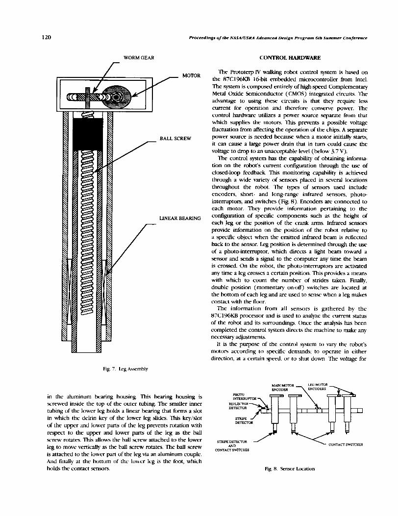
Proceedings of tbe NASA/USRA Advanced Design Program 611, Summer Conference
WORM GEAR
BALL SCREW
LINEAR BEARING
Fig. 7 . 1 . q kwmhly
in the aluminum bearing housing. This bearing housing is screwed inside the top of the outer tubing. The smaller inner tubing of the lower leg holds a linear bearing that forms a slot in which the delrin key of the lower leg slides. This key/slot of the upper and lower parts of the leg prevents rotation with respect to the upper and lower parts of the leg as the ball screw rotates. This allows the ball screw attached to the lower leg to move vertically as the ball scrcw rotates. The ball screw is attached to the lower part of the leg via an aluminum couple. And finally at the bottom of the lower leg is the foot, which holds the contact .sensors.
CONTROL HARDWARE
The Prototerp IV walking robot control system is based on the 87C 196KB 16-bit embedded microcontroller fbm Intel. The system is composed entirely of high-speed Complementary Metal Oxide Semiconductor (CMOS) integrated circuits. The advantage to using these circuits is that they require less current for operation and therefore conserve power. The control hardware utilizes a power source separate lrom that which supplies the motors. This prevents a possible voltage fluctuation from affecting the operation of the chips. A separate power source is needed because when a motor initially starts, it can cause a large power drain that in turn could cause the voltage to drop to an unacceptable level (below 3.7 V).
The control system has the capability of obtaining informa- tion on the robot's current configuration through the use of closed-loop feedback. This monitoring capability is achieved through a wide variety of sensors placed in several locations throughout the robot. The types of sensors used include encoders, short- and long-range infrared sensors, photo- intemptors, and switches (Fig. 8). Encoders are connected to each motor. They provide information pertaining to the configuration of specific components such as the height of each leg or the position of the crank arms. Intixed sensors provide information on the position of the robot relative to a specific object when the emitted infixed beam is reflected back to the sensor. Leg position is determined through the use of a photo-interruptor, which direczs a light beam toward a sensor and sends a signal to the computer any time the beam is crossed. On the robot, the photo-intemptors are activated any time a leg crosses a certain position. This provides a means with which to count the number of strides taken. Finally, double position (momentary on-off) switches are located at the bottom of each leg and are used to senx when a leg makes contact with the fltxlr.
The information from all sensors is gathered by the 87C196KB processor and is used to analyze the current status of the robot and its surroundings. Once the analysis has been completed the control system directs the machine to make any necessary adjustments.
It is the purpose of the control system to vary the robot's motors according to specific demands; to operate in either direction, at a certain speed, or to shut down. The voltage for
MAIN M O m R LEG MOTOR ER \ ENCODERS 1.
DE-R2 "u9 v STRIPE D E I U I I V R
AND CONTACT SWITCHES
CONTACT SWITCHES
Fig. 8. Sensor lmt ion

l1nioersit.y of Maryland
PROPORTIONAL VOLTAGE = [ I - (time offhime on) 1 x V Max
Fig. 9. FWM Waveform
the motor is controlled by a pulse-width-modulated (PWM) wave created by the control system. An illustration of a PWM wave form is shown in Fig. 9.
The PWM hardware achieves the variable .speed control of a motor by adjusting the time onhime off ratio of each period of the wave form. These adjustments are repeated thousands of times per .second. As the motor is incapable of reacting to these fluctuations, it interprets the signal as a percentage of the maximum voltage where the percentage is proportional to the on time of the PWM wave form.
CONTROL SOFIW.ARE
It is the purpose of control software to regulate all motors of the robot. These motors include ( I ) the main drive motor, (2) the Bigfoot motor, and (3) each of the eight leg motors.
An absolute encoder is mounted onto each motor to provide positional information about the motor. The resolution of each encoder varies from motor to motor (the resolution is 2400 counts per inch of movement of the telescoping legs, 1024 counts per revolution of the main drive motor, and 365 counts per revolution of the Bigfoot). This is an important consideration as far as control software is concerned. The Merent encoder resolutions imply separate yet interactive software routines for integrated operation of all motors.
There are four separate software routines designed to control the motors and coordinate their operation in performing various tasks that a planetary rover might need, such as walking, turning, or climbing.
The first-level routine is the most basic of the four. Its function is to control the operation of the motors. This is accomplished by varying the cycle time of the Pulse Width Modulators. The PWM can be varied fiom 0% (totally o m to 100% (full speed operation).
The second-level routine is dedicated to the interpretation of the closed-loop feedback information. This feedback information is provided through all the sensors including the infrared sensors, the motor encoders, and the leg stride photo- intemptor. Information from these .sensors will be used to determine motor regulation.
The third-level routines are dedicated to the execvtion of the walk routines. This software incorporates all information gathered by the .sensors (second-level software) and coordi- nates the operation of the motors (first-level software).
The fourth and final level of software is designed to control the robot during autonomous operation. This routine has programmed into it a series of commands that will allow the robot to walk through a figure eight or walk up stairs thus demonstrating autonomous roving possibilities.
As previously stated, the robot walks on two groups of four legs. At any one time, only four legs are in contact with the ground. As each leg is mechanically linked to the drive motor, the horizontal leg location is a function of the angular position of the crank arms. The positional information of the crank arms, and thus the horizontal position of the leg assembly, is provided by the main drive motor encoder and the information regarding the vertical position of the foot is provided by the leg motor encoders. Therefore, the vertical and horizontal position of the base of the l e g c m be calculated at any time.
The path of the leg foot as it transitions from the nonsupporting return stroke to the supporting walk stroke was designed to follow a form based on a second-degree equation (Fig. 10). There are benefits to using a second-degree equation for the travel path of the leg feet. At some point all feet are simultaneously on the ground and by using an asymptotic approach trajectory for the foot as it finishes the return stroke, a smooth transition between stride changes is assured. Since the leg groups travel with di8erent relative velocities most of the time, it becomes important to keep the time spent on the ground by all legs at a minimum. A second-degree decay h~ffills two requirements: ( 1 ) the vertical foot positioning is at ground level for the transition; and (2) the vertical foot velocity is at a minimum when contact is made.
The control of the Bigfoot turning motor incorporates a slightly different approach to that of the legs. A proportional feedback system acts to determine the appropriate Bigfoot motor speed based on the actual and ideal robot paition. By calculating the maximum angular acceleration and decelera- tion of the robot a it is turning, it is possible to calculate the
LOW I 0 180
y = H x ( I - xf l )"2 H = max height Velocity= 0 @ x = l I = decay stride length
Fig. 10. Izg Height m. Angular Position of (:r~nk Am1
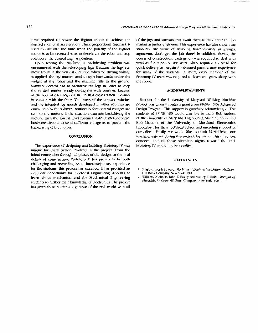
Proceedings of tbe MASA/USRA Advanced Design Program 6 fb Summer Conference
time required to power the Bigfoot motor to achieve the desired rotational acceleration. Then, proportional feedback is used to calculate the time when the polarity of the Bigttwt motor is to be reversed so as to decelerate the robot and stop roution at the desired angular position.
Upon testing the machine, a backdriving problem was encountered with the telescoping legs. Becau-se the legs can move freely in the vertical direction when no driving voltage is applied, the leg motors tend to spin backwards under the weight of the robot and the machine falls to the ground. Software control had to backdrive the legs in order to keep the vertical motion steady during the walk routines. Located in the foot of each leg is a .switch that closes when it comes in contact with the floor. The status of the contact switches and the intended leg speeds developed in other routines are considered by the s o k e routines before control voltages are .writ to the motors. If the situation warrants backdriving the motors, then the lowest lwel routines instruct motor-control hardware circuits to send s d c i e n t voltage as to prevent the hackdriving of the motors.
CONCLUSION
The experience of designing and building Prototerp N was unique for every person involved in the project. From the initial conception through all phases of the design, to the final details of construction, Prototerp N has proven to be both challenging and rewarding. As an interdisciplinary experiencc for the students, this project has excelled. It has provided an excellent opportunity for Electricd Engineering students to learn about mechanics, and for Mechanical Engineering students to further their knowledge of electronics. The project has given these students a glimpse of the real world with all
of the joys and sorrows that await then1 as they enter the job market as junior engineers. This experience has also shown the students the value of working harmoniously in groups; arguments don't get the job donc! In addition, during the course of construction, each group was required to deal with vendors for supplies. We were often required to plead for quick delivery or batgain for donated parts, a new experience for many of the students. In short, every member of the Prototerp IV tm was required to 1e;u-n and grow along with the robot.
ACKNOWLEDGMENTS
Support for the University of Mqland Walking Machine project was given through a p t from NASA/C'SRA Advanced Design Program. This support is gratefully acknowledged. The students of EMNE 480 would also like to thank Rob Anders, of the University of Maryland Engineering Machine Shop, and Bob Lincoln, of the liniversity of Maryland Electronics Laboratory, for their technical advice and unending support of our efforts. Finally, we would like to thank Mark liebel, our teaching assistant during this project, for without his direction, concern, and all those sleepless nights toward the end, Prototerp T' would not be a reality.
REFERENCES
1. Shigley, Joseph Edward. Mecbunical Et~giif l~-~m'~~g fk~r'gn. McGrdw- Hill Book Company. New York. 1989.
2. Willems, Nicholay, John T. Easley and Stanlq 'I: RoLfe. Sttw~gth of MateriaIs. McGraw-Hill &)ok <:ompany, New *ri)rk. 198 1.
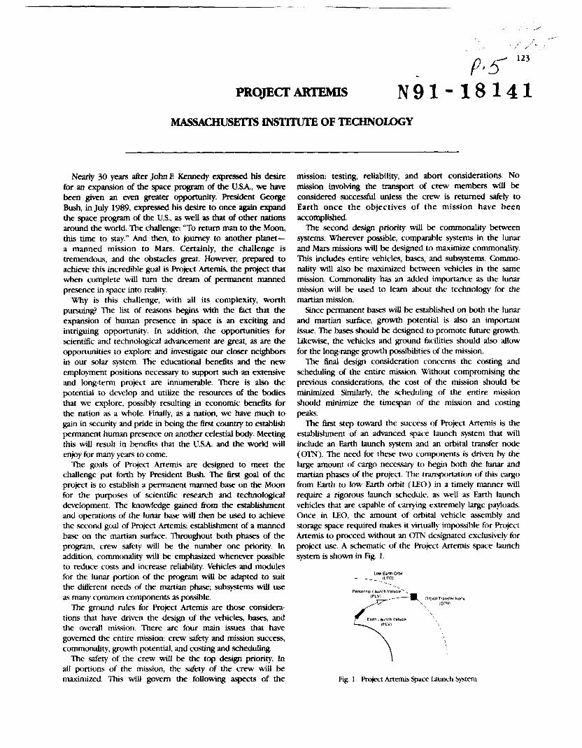
PROJECT ARTEMIS
MASSACHUSMTS INSTITUTE OF TECHNOIQGY
Nearly 30 years after John E Kennedy expressed his desire for an expansion of the space program of the U . S h , we have been given an even greater opportunity. President George Bush, in July 1989, expressed his desire to once again expand the space program of the U.S., as well as that of other nations around the world. The challenge: "To return man to the Moon, this time to stay." And then, to journey to another planet- a manned mission to Mars. Certainly, the challenge is tremendous, and the obstacles great. However, prepclred to achieve this incredible goal is Project Artemis, the project that when complete wiU turn the dream of permanent manned presence in space into reality.
Why is this challenge, with all its complexity, worth pursuing? The list of reasons begm with the fact that the expansion of human presence in space is an exciting and intriguing opponunity. In addition, the opportunities for scientific and technological advancement are great, as are the oppormnities to explore and investigate our closer nelgbors in our solar system. The educational benefits and the new employment positions necessary to support such an extensive and long-term project are innumerable. There is also the potential to develop and utilize the resources of the bodies that we explore, possibly resulting in economic benefits for the nation as a whole. Finally, as a nation, we have much to gain in security and pride in being the first country to establish permanent human presence on another celestial body. Meeting this will result in benefits that the USA. and the world will enpy for many years to come.
The gods of Project Artemis are designed to meet the challenge put forth by President Bush. The first goal of the project is to establish a permanent manned base on the Moon for the purposes of scientific research and technological development. The knowledge gained from the establishment and operations of the lunar base will then be used to achieve the second goal of Project Artemis: establishment of a manned base on the martian surface. Throughout both phases of the program, crew safety will be the number one priority. In addition, commonality will be emphasized whenever possible to reduce costs and increase reliability. Vehicles and modules for the lunar portion of the program will be adapted to suit the different needs of the martian phase; subsysems will use as many common components as possible.
The ground rules for Project Artemis are those considera- tions that have driven the design of the vehicles, bases, and the overall mission. There are four main issues that have governed the entire mission: crew safety and mission success, commonality, growth potential, and costing and scheduling.
The safety of the crew will be the top design priority. In all portions of the mission, the safety of the crew will be maximized. This will govern the following aspects of the
mission: testing, reliability, and abort considerations. No mission involving the transport of crew members will be considered successful unless the crew is returned safely to Earth once the objectives of the mission have been accomplished.
The second design priority will be commonality between systems. Wherever possible, comparable systems in the lunar and Mars missions will be designed to maximize commonality. This includes entire vehicles, bases, and subsystems. Commo- nality will also be maximized between vehicles in the same mission. Commonality has an added importance as the lunar mission will be used to learn about the technology for the martian mission.
Since permanent bases will be established on both the lunar and martian surface, growth potential is also an important issue. The bases should be designed to promote future growth. Likewise, the vehicles and ground facilities should also allow for the long-range growth possibilities of the mission.
The final desik consideration concerns the costing and scheduling of the entire mission. Without compromising the previous considerations, the cost of the mission should be minimized. Similarly, the scheduling of the entire mission should minimize the timespan of the mission and costing peaks.
The first step toward the success of Project Artemis is the establishment of an advanced space launch v t e m that will include an Earth launch system and an orbital transfer node ((Yl'N). The need for these two components is driven by the large amount of cargo necessary to begin both the lunar and martian phases of the project. The transportation of this cargo from Earth to low Earth orbit (LEO) in a timely manner will require a rigorous launch schedule, as well as Earth launch vehicles that are capable of carrying extremely large payloads. Once in LEO, the amount of orbital vehicle assembly and storage space required makes it virtually impossible for Project Artemis to proceed without an CTN designated exclusively for project us; A schematic of the Project kernis space launch system is shown in Fig. 1.
Low Esnh Oml - - - - (LEO) . . .
Psmonn~l Launch Venrde',
Omla Tlanrler Made IOTNI
IELVI
Fig. 1. Project Artemis Space Launch System

1.21 Proceedings of the ,'VA.YA,/lr.\R.4 Adr2rrnci.d Dvsigtr frogrum 6 th Slcmmer Co?rfi.r@nrr
A typical mission begin5 with the launch of cargo from Earth. The Earth launch vehicle (EIN) (shown in Fig. 2 ) is designed to rneet the Project Artemis Earth launch requirements. The ELV is a hybrid liquid/solid multistage rocket c ~ a b l e of carrying a nominal payload of 125,OOO kg to LEO. Eight solid rocket h x t e r s comprise the first stage of the ELV. A liquid core using liquid hydrogen and liquid oxygen as fuel makes up the second stage. The upper stage is liquid as well, and it also u x s liquid hydrogen and liquid oxygen propellents.
Personnel are transported to LEO in the personnel launch vehicle (Pi.V), which will be hcx)sted into orbit on a Titan n/ The PLV is capable of carrying a crew of eight to LEO and back again to Earth. A schematic of the P1.V is shown in Fig. 3.
Once in LEO, both the cargo and the P1.V can be picked up by one of two orbital maneuvering vehicles (OMVs) situated in LEO. The OMVs arc NASA vehicles, designed for Space Station Freedom, and will not bc desc.ribed in dcpth within the context of this repon.
Once it h-AS picked up its cargo (either mission cargo or the PLV) the OMV transports the cargo to the (YI'N. ?he (Y IN is essentially a space station orbiting the Earth at an altitude of 470 km, and an inclination of 28.5'. Included in the configuration of the CYIN are a habitation mtdule, a command module, a vehicle assembly area, a c q o "warehouse," and three vehicle docking interfaces. The (X'N is illustrated in Fig. 4. AU Project Artemib vchicles are equipped with common
docking interfaces (CDls). The CDls ease the docking operations between vehicles and providc a location where the crew can exit one vehicle and enter another.
Once the Project Arternis space launch system is established, the Erst phax of the lunar mission will take place. The purposc of the lunar mission is to establish a permanently manned base on the Moon. Commonality between the lunar and martian missions is stressed at all times during this process. Since the lunar program will be functional before the martian program, waluation of the progress of the lunar mission will enable the implementation of necessary modifications to the martian
ELV Systems Ovwvlew mission. c4nnguaUcm LHaLOX mntal m e snpe and
uppr 5 ~ 9 ~ mm o 10 a para~a~-tircd The lunar mission commences in LEO with necessary mapa W rocket Woroters. Nomlrul deugn has lcur bmstws. vehicles and materials provided by the Earth launch sytem
PaylOPd CapaMllly 89.000 to 149.000 kg discussed proiously. Figure 5 shows the lunar mission pmfile.
(125.000 Q ncinlnrl)
Toni #Qht 1 W m wilh standard falrlng
Momurn Cross Sedional Dtameter 14 m
G r a r Unof! Wmght 2.200.m kg
hull Thrust IeWeight Ralb 1 8
Paykud Mass FraRKm 0 053 to 0 055 (0 056 mmlml)
1 0 m
Fig. 2. Earth launch Vehicle
Center Line
Fig. 4. Orbital .Iiansfer IVtKle
Lunar Lunar Orbnal AscentiDescent Transfer Vehicle
Fig. 3. k'crsonnel launch I'rhicle
\ Fig 5 1 . u ~ Mission Profile

Mussachusetts Institute of Technolng~~ 125
Vehicles used for the lunar phase are the lunar orbital transfer vehicle ( L W ) , crew transport module (CTM), and the lunar ascent/descent vehicle (LADV).
The transfer from LEO to low lunar orbit (LLO) will be made in one of three identical LOWS. Each of these vehicles is propelled by a particle bed reactor (PBR) engine and is capable of carrying a payload of 47,000 kg. Figure 6 shows a more detailed L O W The first 10 L W missions, each taking about 4 days to reach LLO, will transport necessary cargo. Then, the IA0711 will begin its manned journey, transporting a crew of five astronauts to LLO. During transit, the crew will travel in the CTM, which is attached to the LOTV in the payload section.
After firing the L O W engine to insert into LLO, the cargo or crew wiil be transferred to the LADV through use of a common docking interface. The LADV is shown in Fig. 7. Each of the three reusable LADVs is propelled by hydrazine and is capable of transporting a payload of 13,000 kg to the lunar surface, and a payload of 9,000 kg off the lunar surface. After a successful transfer, the IADV will transport the crew or c - o to the lunar surface and preparations for assembly of the lunar base will begin.
The lunar base consists of four prefabricated modules connected together providing habitation, communication, health maintenance, and laboratory research facilities. The
\ RCS Pscksge
Fig. 6. Lunar Orhital Transfcr Vehicle
Cargo L RCS jea i
Top V w
24 & mm Sids view
Fig. 7 . Lunar AwentlDescent Vehicle
modules are cylindrical, measuring 6 m in diameter and 1 0 m in length. The layout of the lunar base is shown in Fig. 8 and will be fully constructed within two weeks of the actronauts' arrival on the lunar surface.
In order to provide support for the base, resupply missions must carry 13,000 kg of supplies to the base every 6 months. In addition, crew rotation will occur every four to six months with an overlap of some crew members to insure familiarity with base operations. During the first operational stage, the base will support 5 to 15 crew members at one time. After the lunar base becomes fully operational, approximately five years into the program, the Mars portion of Project Artemis will W n . The Mars mission will incorporate improvements deemed necessary for project success from the d u a t i o n of the lunar mission progress.
The purpose of the Mars portion of Project Artemis is to use the technology developed for the lunar mission to establish a permanent manned base on Mars. In order to meet this goal, commonality with the lunar mission will be maximized in every area possible. As a result, the phases of the Mars mission closely parallel the phases of the lunar mission. A schematic of a typical Mars mission is shown in Fig. 9.
Landinp Site (1 .S km) Fbadwaw
Mars
f \
1 , 3 B I u ?
\ / -,
Habihwn Module
u
Fig. 8. Lunar Base
Mars OtbltA Transfer Veh~cle
:arm 111t11 (LEO)
Fig. 9. Mars Mission Schematic

126 Proceodimgs of t_ NASA/USRA Advanced Design Pro&ram 6tb Summer Conference
The mission begins in LEO at the OTN. At the commence-
merit of the mL_on, cargo is carried to low Mars orbit (LMO)
on the cargo version of the Mars orbital transfer vehicle
(MOTV). This vehicle is shown in more detail in Fig 10. The
transfer of cargo from LEO to LMO takes approximately
280 days. The MOTV is propelled by the same PBR system
utilized by the _ in the transfer portion of the lunar
mission, and is capable of _rting a payload of up to
44,000 kg.
In order to transport all the necessary start-up cargo to LMO,
Project Artemis will use six cargo MOTVs, which are
expendable. Personnel will be _ed to LMO on the
personnel MOT_, which is shown in Fig. 11. The personnel
Mo'rv can transport a crew of five, uses a PBR engine, and
is reusable.
Once it arrives in LMO, the cargo MOTV will aerobrake in
order to attain an acceptable parking orbit. Initial payloads of
the cargo MOTV will include the Mars ascent/descent vehicles
(MADVs), which are the vehicles that transport cargo and
personnel to and from the martian surface. The cargo MADV
is shown in Fig 12. Both MADVs are fiquid chemical engines.
The cargo MADV can carry a payload of 13,000 kg, and is
fueled by liquid hydrogen and liquid oxygen. The personnel
MADV can carry five people, and is fueled by monomethylhy-
drazine and nitrogen tetraoxide. The 11 cargo MADVs are
expendable, while the 2 personnel MADVs are reusable. As
MADVs
Avionics Package
Solar
Panel
13m
4.2 m
PBR5 m Cluster
soon as the payload of the MOTV has been transferred m the
appropriate MADV, the MADV begins its descent to the martian
surface.
Once the initial cargo is on the surface and trenching and
lolling operations have been completed by the unmanned
mvet_ base assembly can begin. Like the lunar base, the Mars
base consists of prefabricated modules, which are attached toone another by common nodes. The Mars base modules are
identical in size and structure to the lunar modules shown in
Fig 8; only the interior layout differs, due to the increased
storage needs of the Mars base. Like the lunar base, the Mars
base includes areas for habitation, communication, laboratoryresearch, and health maintenance.
Crew Modules Aerobr_d_o Solar Panels
COl
Outbound Tank
Inbound Tank
Avionics Package
PBR Cluster
Fig 11. Mars Orbital Transfer Vehicle - Personnel
Loading Ramp Parachute Storage
/71
6.6m///_ PAYLOAD RCS
,d°''Clearance '
Shield _- )1 lm
6.5m
1.5m
Fig. 10. Mars Orbital Transfer Vehicle - Cargo Fig. 12. Mars Ascent Descent Vehicle - Cargo

Massachusetts Institute of Technology 127
Initially, a crew of five will construct and operate the Mars base. Crew rotations and resupply will occur every 14 months. The long duration of each rotation is because launch windows only occur every two years. Also, the transfer time for the personnel MOTV takes approximately six months. Eventually, the crew size will increase from 5 to 10, and the base will be its full operational capacity.
Project Artemis presents technological and logistical problems. Questions of availability of necessary technology, in addition to the cost and time commitments demanded from a single nation for success of this project, need to be addressed before a national endeavor is begun. The project requires the
nation's interest, priorities, and resources for a long period of time. Although in this respect the demands of this project are great, the value of the advancement of human knowledge of our solar system through the completion of Probct Artemis would be tremendous.
ACKNOWDGMENTS This report was prepared by Shawn Birchenough, Denise
Kato, and Fred Kennedy with Professor David Akin n*o thank Professor Joseph Shea, Professor James Mar, and Teaching Assistant, Howard Eisen.


PROJECT EGRESS: THE DESIGN OF AN ASSURED CREW RETURN VEHICLE FOR THE SPACE STATION -
UNIVERSITY OF MICHIGAN ~ 9 1 - 1 8 1 4 2
Keeping preliminary studies by NASA and indusuy in mind, including the official Request for Proposal (RFP) published by NASA Johnson Space Center, a conceptual design of an Assured Crew Return Vehicle (ACRV) has been developed. The system allows the escape of one or more crewmembers from Space Station Freedom in case of emergency. The design of the vehicle addresses propulsion, orbital operations, reentry, landing and recovery, power and communication, and life support. In light of recent modifications in Space Station design, Project EGRESS (Earthbound Guaranteed ReEnuy from Space Station) pays particular attention to its impact on Space Station operations, interfaces and docking facilities, and maintenance needs. A water-landing, medium-lift vehicle was found to best satisfy projec't goals of simplicity and cost efficiency without sacrificing the safety and reliability requirements of the RFP With a single vehicle, one seriously injured crewmember could be returned to an Earth-based health facility with minimal pilot involvement. Since the craft is capable of returning up to five crewmembers, taro such permanently docked vehicles would allow a full evacuation of the Space Station. The craft could be constructed entirely with available 1990 technology, and launched aboard a shuttle orbiter.
NASA has a longstanding dedication to the concept of Assured Crew Return Capability (ACRC). The first trajectories of the Mercury and Gemini programs assured the return of the capsule into the atmosphere. The dedication to ACRC continued during the Apollo missions, which flew in a "free return" trajectory. This trajectory allowed the capsule to circle the Moon and return to Earth automatically in the event of an emergency. Furthermore, the Lunar Module had the capacity to serve as an emergency vehicle. On November 13, 1970, the explosion of an oxygen tank aboard the ApoUo 13 Senice Module mortally damaged the tanks and sptems inside the vehicle, and forced the crew to use the Lunar Module for the retum to Earth.
NASA continued to assure the return of any space-based crew during the Skylab missions. Crew return was assured by the Apollo capsule, which transported the crew to Skylab and remained docked at the orbiting lab throughout the mission. In addition, NASA configured an Apollo capsule to cany five crewmembers (the norrnal capacity of an Apollo capsule was three crewmembers) so that two crewmembers could travel to skyiab and return to Earth with the Skyiab crew.
Howwer, unlike the Apollo capsule on Skylab, the crew transportation vehicle for Space Station Fmdom (the space shuttle) will not remain docked at the station during the crew work cycle (approximately 90 days). NASA o r i w y planned for the space shuttle to assure the return of FmdOmS crew. However, the tragic explosion of the Space Shuttle C2dknger over the Atlantic Ocean on January 28, 1986, forced NASA to reevaluate the means of assuring the return of any or all of Fmdorn's crew. In order to assure the safe return to Earth
of the Space Station crew, NASA proposed and issued a Request For Proposal (RFP) for an Assured Crew Return Vehicle ( ACRV).
MISSION OVERVIEW
The ACRV will serve as an alternative retum vehicle from the Space Station. The ACRV will be permanently docked at Space Station Freeriom and will serve Freedom in three primary design reference missions: (1 ) The return of the entire Space Station crew (eight crewmembers) in the event that the space shuttle is unavailable; ( 2 ) the retum of the entire Space Station crew in the went rapid evacuation from Space Station Freedom is required; and (3) the return of an injured or ill crewmember in the event that rapid retum is required.
The goal of the EGRES team was to design a vehicle that would be simple, reliable, and would minimize impact on existing programs. Simplicity and reliability are always goals in the design of a .space vehicle, but even more so for an emergency vehicle. In order to reduce impact on existing programs the design of the vehicle would need to minimize both crew training and maintenance requirements and maximize independence from the Space Station.
Keeping in mind the old adage "what goes up must come down," the EGRESS design team needed to determine how the vehicle would return to Earth. The primary concerns were the Lift-to-drag ratio (L/D) and the vehicle's landing mode. Initially, a high Lift-to-drag, such as the shuttle or an aeroplane, was researched by the team. A high lift-to-drag vehicle encounters low forces during reentry and is very maneuverable; however,
~ E J 3 9 INTENUONAUI B L A H PRNEDiNG PAGE BLANK NOT FILMED

130 Proceedfngs of the NASA/USRA Adtjanced Design Program 6th Summer Conference
it would require wings to genetate Lift. The RFP requires that the ACRV fit into the space shuttle cargo bay, which has a diameter of 15 ft. 'Ihis stipulation would require a winged ACRV to have retractable wings, which are both mechanically and structurally complicated In addition, such a vehicle con6guration would require complicated control surfaces to cmntrol yaw, pitch, and roll rnanewers. F i , a high WD would require extensive initial training and continuous r&esher training for pilots of the vehicle. On the other hand, a low WD vehicle is simpler to operate and requires less training time. Since the Mercury, Gemini, and Apollo vehicles were all low WD vehicles, a low WD vehicle uses tlight-proven hardware. However, low WD vehicles encounter high reentry forces and have limited, if any, manewerabiity. Thus, the design team chose a medium WD for the EGRESS vehicle. This contigumtion will encounter mild reentry forces and have modest maneuverability, while still being simple to operate.
After the decision to design a medium VD vehicle was made, the team needed to determine the landing mode of the EGRESS vehicle. The two possible places for a vehicle to land are on land or in the water. A land landmg vehicle would allow for landing site selection in close proximity to a health care facility allowing rapid transportation of an injured or ill crewmember to the facility. In addition, a land landing vehicle would be reusable since it would not sulfer the corrosive effects of salt water. However, since the vehicle was to have a medium WD it would not be capable of @ding to a landing site as the space shuttle does. Instead, the vehicle would need to deploy parachutes to slow its descent, and then use an impact system (such as retro rockets or airbags) to minimize its impact with the ground. This configuration would still encounter large impact loads at touchdown. Since the EGRESS vehicle must have the capability to return an injured or ill crewmember, it is desirable to minimize the impact loads experienced by the occupants of the vehicle. Furthermore, a land landing vehicle would require extensive training in order to complete the precise maneuvers required for an accurate landing.
The impact loads encountered during a water landing are less than those of a land landing, which makes the water landing more desirable for the return of an injured or ill crewmember. Furthermore, a water landing does not require the accuracy of a land landing, and will not require the extensive training for landing procedures. Thus the EGRESS team chose to design a medium lift-todrag vehicle that will land in the water.
The specific locations of the landing sites were determined from the adability of recovery forces and health care facilities, and the groundtrack The limiting factor in the recovery forces proved to be the aMilability of a heavy Lift helicopter capable of Lifting 10,000 Ib, the weight of EGRESS. In addition to the weight constraints of the recovery forces, the groundtrack imposed further constraints on the landing site selection process. Only a small portion of the groundtrack goes over the United States or coastal areas with nearby U.S. militaq bases. The second Design Reference Mission requires the craft to leave with relatively short notice; therefore it is desirable to have the craft land at a primary landing site Erom any of its
orbits. With these criteria in mind, Pearl Harbor (Hawaii), Okinawa (Japan), and Kennedy Space Center (Florida) were chosen as the primary landing sites, and Guam was chosen as a secondary site. The health cxre facilities aMilable at the landing sites are Pearl Harbor Naval Hospital, Kadena Naval Hospital, Patrick Air Force Hospital, and Anderson Air Force Hospital, respectively. Two vehicles will be stationed at M r n , while four vehicles will be on the ground to provide both support and redundancy. In addition to replacing used vehicles, the ground-based vehicles will allow the spacecraft to be updated. The two vehicles aboard the Space Station will be placed at nodes 1 and 2 of the Space Station, resulting in ease of departure from the station and minimum interference to the Space !kition operations.
The remainder of this report discvsses the structure of the EGRESS vehicle, the internal configuration, mission -is, and training requirements.
VEHICLE !D'RUClWRE
The design of the vehicle structure consisted in consolidat- ing the varied requirements of a space vehicle. After the design process leading to the h a 1 configuration is presented, the two additional components of Project EGRESS are described.
Design Process
To adhere to the design goals of simplicity and reliability, a vehicle based close@ upon the Apollo reentry capsule was envisioned. However, the Apollo provided only a low WD. The EGRESS vehicle needed to feature medium-lift capabilities. This was accomplished with the use of a bent-nose biconic reenuy vehicle. The Apollo module was a conic vehicle. A biconic would be formed if the nose cone of the Apollo were stretched into a longer cone, with the rest of the vehicle unchanged, and then bent at an angle to the rest of the vehicle. EGRESS was designed to be a medium-lift vehicle thus capable of a cross-range travel much greater than that of an Apollo vehicle. In addition, EGRESS will have better thermal emissivity characteristics and lower reentry accelerations than Apollo.
To achieve the desired aerodynarmc characteristics, the vehicle required certain shape constraints and a minimum wetted surface area One of the shape constraints imposed by atmospheric reentry was that the vehicle's hatch be protected h m teentry burn-up by placing it behind the vehicle's nose from an angle of impingement of 60". The shape of the vehicle was designed to meet all these requirements, as well as to fulfill the mission guidelines. EGRESS was first transformed into a flattened bent biconic and then slowly transformed into what was referred to as a "raft" shaped vehicle.
The final codiguration developed from an amalgamation of existing and experimental reentry vehicles. The EGRESS vehicle is squat with a rounded, triangular body that is 13.5 ft long, 6 ft high, and 9ft wide, that weighs 8018.83 Ib, and that has an exterior volume of 355 cu ft and an interior volume of 250 cu ft. In addition to the reentry vehicle, the EGRESS system has a deorbit propulsion package that is detachable from the vrhicle. These components are shown in Fig. 1. An airlock was also designed.

Unfuersity of Mlcblgan
Fig. 1 . Components of Roject EGRESS
Dutrng normal Space Station operations, astronauts will be conducting regular Extra Vehicular Activity (EVA) missions in pain. The EVA astronauts can enter the Space Station through designated EVA airlocks at only a few nodes. If a Space Station catastrophic failure terminates either the Space Station power system or any nodes between the astronauts' entrance airlock and the EGRESS, the EVA astronauts will not be able to enter the EGRESS. In order to assure that EVA astronauts will be able to enter the EGRESS during a station integrity failure, EGRESS must have its own airlock
The airlock is a short cylinder with length 6.25 f t and diameter of 8 ft, an inner volume of 332 cu ft, a total mass of 32821b, and the ability to contain and to sustain two spacesuited astronauts. The airlock is double-hulled to protect it h m meteoroid impact that would cause habitable airlock lifetime to diminish.
Propulsion Package
EGRESS'S engines, fuel, and pumping systems will be contained in a jettisonable structure separate from the main body of EGRESS, as shown in Fig. 1. This structure will be jettisoned following the deorbit bum for two reasons. F i t , dumping the propulsion pack will decrease both the mass and the drag of the vehicle. Second, placing the propulsion pack in a safe orbit will allow the pack to be reused. EGRESS will perform a small separation manewer after which the structure will use some of the remaining fuel to put itself in a safe orbit where it will be retrieved later.
The propulsion package consists of three rocket engines and a box framework. EGRESS will use thee R-40 engines in a straight line to accomplish the deorbit bum. With this arrangement a normal bum would be performed with all three engines In the event that the center engine fails, the two outside engines would be ignited. In the event that one of the end engines fails, two options exist: burning only the center engine or buming the center and remaining engine while compensating for induced moments by RCS jets. The framework houses two sets of fuel and two sets of oxidizer in four spherical tanks, two sets of helium propellant-feed also in spherical tanks, and four reaction control system thruster clusters. The box fi-amework is 7.8 ft tall, 7.4 f t wide, 3.4 ft thick, and weighs 108 Ib. The total weight of the propulsion package is 2275 Ib.
INTERNAL C O N F I G ~ O N
Since the EGRESS vehicle must transport humans, the internal configuration of the craft is as important as the external structure. Internal configuration consists of design and layout of the crew cabin, determination of crew size, and design of Life support systems.
Crew Cabin Design
Each EGRESS vehicle will be configured to return up to five crew members. The crew size is based upon both the basic configuration requirements and the duties of the merent crewmembers. The primary crew of a pilot, a patient, and a medical technician will be seated in the rear "top rod' while

the secondary crewmembers wiil sit in the jump seats in the "bottom row" of the cabin. These configurations will allow easy access to necessary controls and provisions, easy entry and exit of the vehicle, and maximum center of gravity stabilization during the Bight. The crew configuration in the EGRESS vehicle is shown in Fig. 1.
Pockets on the sides of the cabin will cany pressurized pens. cLipboards, notepaper, and "cue cads" outlining £light and medical procedures for use during an EGRESS flight. Food will also be stored in these pockets. Flashlights and penhghts will be provided for use during systems checkouts, EGRESS Bights, and recovery. Waste management equipment and supplies are stored under the medical technickan's seat on the flwr of the crew cabin. The majority of the critical care medical equipment, including one package of ventilator tubing, two liters of lactated Ringers solution, and intravenous lines, will be stored in a medical supply kit on the floor of the crew cabin when not needed. "Trauma pants" with ineatable leg chambers, also stored in this kit, will allow a patient to better withstand the g forces of reentry. General-use medical supplies, including bandages, alcohol prep-pads, needles, and syringes, are located in pockets on the wall of the crew cabin next to the medical technician. Tkvo fire extinguishers, one locxted within reach of the pilot and another in the rear of the craft, will give the crewmembers the ability to quickly control and put out fires in the crew cabin. An emergency suppiy kit will carry five automaticdy inflatable life jackets, a flare gun with flares, and other provisions needed to ensure the safety and survival of the crew during a wait for recovery. In addition, an automatically ineatable five-person raft, stored behind the jump seats at the front of the crew cabin, will allow the crew safe exit from the EGRESS vehicle if required.
Crew size
EGRESS is capable of retumtng three to 6ve crewmembers from the Space Station. For the return of an injured or ill crewmember, at least two crewmembers are needed to support the injured aewmember as stated previously. After such a mission, five crewmembers would be left aboard M m to continue normal operations; thus a .second EGRESS vehicle must be capable of returning the remaining five crewmembers to avoid the need for a third vehicle. All crewmembers must be evacuated from the station on the two EGRESS vehicles attached to the Space Station. Assuming a Space Station crew of eight, three crewmembers will ride in one vehicle and 6ve in the other. The EGRESS spacecraft canying three crew members will be used to transport critical experiments and equipment back to Eanh, if necessary.
Life Suppost Systems
Absolutely essential to the successful utilization of the EGRESS spacecraft is the presence of a simple but efficient Environmental Control and Life Support System (ECLSS) on the vehicle. The EGRESS ECLSS is composed of two main systems: an environmental and atmospheric control system, and
a life support system. Other supporting .systems included a waste management system and a crew water and food provisioning system.
The Atmospheric Supply and Pressurization System will provide a cabin pressure of 14.7psi and a 21% oxygen, 79% nitrogen atmosphere in order to provide a safe, comfortable environment for the crew during a normal flight of the EGRESS vehicle. In addition, the system contains redundancy and emergency features to allow environmental support in emergency situations. Constant monitoring of the total cabin pressure and oxygen partial pressure will Ix. done by the Main Environmental Control System. In addition, EGRESS will provides a patient a higher oqgen concentration through a Patient Environmental Control System, a separate environmen- tal loop that procesxs exhaled air for up to 48 hr.
The Life support system will meet all the physiological requirements of up to five crewmembers for 24 hr. Medical systems will allow advanced life support for one iU or injured crew memher on btsard the EGRESS for up to 48 hr. The interior gstems, including the .wats, control panels, windows, and general probisions, were all designed and placed within the EGWX crew cabin according to the hasic physiological, ergonomic, and psychological requirements of five crew- members.
Because space travel and reentry into the atmosphere inherently involve risks to human life, criteria for use were developed to ensure that the EGRESS vehicle will only be used when remaining on the Space Station would pose greater risks than would returning to Earth. These criteria were also used as a hasis for defining the necessdn crew systems and provisions according to the u. of the vehicle.
MISSION ANALYSIS
If the EGRESS vehicle were to be used, its mission would follow an established sequence of events. The mission would consist of startup, orbital maneuvers, atmospheric reentry, and landing and recovery. After the recovery and processing of the vehicle, a new vehicle will be launched into orbit. Like the original two vehicles aboard the Space Station, any new vehicles will enter the established maintenance cycles.
EGRESS is powered by primary, nonrechargeable batteries during its operations. Power will also he provided to EGRESS from Space Station FrmaOrn using a rechargeable nickel- hydrogen battery system as a reservoir. Power will be distributed to EGRESS systems using four main buses. Two major interface areas are present in the power distribution system, one between EGRESS and the propulsion module, and the other between EGRESS and the Space Station. Power will be distributed and monitored using state-of-the-art software in order to help detect problems before they develop, and isolate problems that may surface.
The communication system is primarily based on S-band radio transmissions. This system will use the Tracking and Data Relay Satellite System (TDRSS), which is currently used by the

University of Michigan 133
space shuttle, to relay signals to the ground. EGRESS will also use a Very-High Frequency (VHF) system to communicate with search and rescue forces. The VHF system could serve as a backup for voice communications if there are problems with the primary S-band system. L-band communications will also be used to receive signals from the Global Positioning System satellites in order to accomn~odate the navigation system described below.
The EGRESS computer system, which is in control of most of the EGRESS subsystems throughout a crew return mission, is designed for reliability. The processing units, high-powered space-rated IBM APlOlS general purpose computers, are Linked in a triple redundant conftguration. The computers are connected to an optical disk mass storage device and the rest of the vehicle's subsystems, through a 24-bit data bus. Under control of the EGRESS Automated Software Environment, the system is responsible for regulating the power and life support systems, as well as x n W g as the flight management system and controlling most of the vehicle's operatiom.
In order for the EGRESS vehicle to accomplish its various missions, it is important that the vehicle have accurate navigation and guidance for control. The navigation system consists of an inertial navigation system (INS) that is augmented by the Global Positioning System (GI%). The Honeywell CG1320 INS, based on a ring laser gyroscope, is used to provide highly accurate attitude information. By incorporating G R into the system, a precise position can be determined to within 15 m. Though the system is normally initialized while the EGRESS vehicle is docked, initialization can take place after separation in the rapid evacuation scenario.
Orbital Maneuvers
The EGRESS vehicle's mission will begin with separation from the Space Station. This separation will consist of two phases. The first phase is a 1 ft/.sec positive radial bum that will last approximately three minutes. EGRESS will u x a gaseous nitrogen system to separate from the station. Two clusters of two I-lbf cold gas thrusters will be placed on either side of the vehicle to allow separation at 1 ft/sec from either node 1 or node 2.
When EGRESS reaches a height of 150 ft above the station, the second phase of separation will begin. This maneuver will consist of a 2 ft/sec retrograde burn that will put the EGRESS in proper position for the deorbit bum after approximately 40 min. For on-orbit maneuvers, EGRESS will be equipped with 42 reaczion control jets. There will be one cluster of 16 across the nose of the vehicle and two clusters of 11 each in the aft section of EGRESS.
The deorbit bum will be a retrograde bum, and the transfer will resemble a Hohmann transfer. The retrograde motion will allow the EGRESS vehicle to transfer from the station's orbit to the 400,000-ft atmospheric boundary. The time and velocity change required for the maneuver depends on the station's altitude. At the minimum altitude of 140 n.m.. the required AV is 227ft/sec, and the maneuver will take 24.4 min. At the maximum altitude of 270 n.m., the required AV is 391 ft/sec, and the maneuver will take 36.6 min. EGRESS will use three
Marquardt R-40 engines to deorbit. I h e R-40 is a liquid bipropellant engine using monontethyl hydrazinc as the fuel and nitrogen tetroxide (N,H.,) as the oxidizer. The vehic~le m i l l have three engines, but will be capahlc of deorbiting using only one, as stated previously.
In order to insure proper fuel flow to the engines, a rubher bladder pressurization system will he used. This system employs rubber "bags" inside spherical tanks in order t o separale the fuel (or oxidizer) from the pressurizing grt4. 'this design will allow up to 99% fuel expulsion from the tarks in a zero-g environment.
Reentry
The EGRESS vehicle must be pn)tected from thc intense heat generated as the vehicle's kinetic cnerg). is imparted t o the atmosphere. The primary concerns werc the n t e of heat transfer to the vehicle and the maximum temperature experienced during reentry. A ceramic thermal protection system will be employed by EGRESS. The '1% of the EGRESS will consist of HRSl tiles covering the underbelly and nose xca of the craft with an AFRSI blanket covering the remaining area.;. This type of ceramic TPS is Lightweight, has a high-tenlperaturc capability, will not degrade in orbit, and would be reusable if not damaged on impact with the ocean.
Additional concerns include calculation of the aertdynarmc flow field about the EGRESS vehicle and the aen+arnic forces exerted by that field on the vehicle. A computer program to calculate Newtonian flow was written to proridc this information. As a result of computer analysis, the EGRESS vehicle was shown to be statically stable, have a L/D of 0.7, and reenter the atmosphere at 40" angle of attack.
The attitude control system of the vehicle guides the EGRESS to its landing location. Attitude control is provided by two 65- Ibf thrusters. The effects of attitude control were analyzed by another computer program that integrated the flight trdjectory of the EGRESS vehicle. This trajectory analpis shows that the vehicle is capable of a cross-range of 500n.m., which guarantees the ability of the vehicle to land at any primary landing site on either of two successive orbital passes. Furthermore, a simple flight algorithm was created that k c ~ t the g loads throughout reentry below 4 g, the g-loading limits of the RFP.
Landing and Recovery
The EGRESS vehicle uses a conventional deceleration svtem of two drogue parachutes and three tat circular parachutes , that are deployed by means of three smaller pilot parachutes An attenuation system that would provide increased deceler- ation right before impact is not needed since the conventional parachutes will slow the craft to an impact deceleration within the specifications of the which allows a maximum impact loading of no more than l o g through the chest of an injured crewmember.
When the EGRESS splahes down, a self-righting sytenl will automatically dqloy to right the vehicle The uprighting system will use air bags to change the center of buoyancy.

ngs of tbe NASA/USRA Advanced Design Program 6tb Summer Conference
causing the cnft to right itself. A manual backup switch is available in the m t that the automatic system f h h The self- righting system will provide additional dynamic stabiUty to the EGRESS in heavy seas beyond the stadc stabUty of EGRESS. The center of buoyancy of the vehicle was pu6itioned to provide a natunl stabUty to the EGRESS vehicle allowing It to sit "nose up" in the water after landing Design Rebence W o n 3, return of an yured awv.
member, requires the crew to be removed and rapidly transported to a health care Wty (HCF). For this reason, the Coast Guard was selected to remove the crew using either the HH-65A (Dolphin) or the Hue- (Bell UH-1H). ?he Navy was selected to recover the EGRESS d using the CH-53E (Super Stallion). The Navy would also retrieve the crew If the Coast Guard is unavailable. The EGRESS vehicle will be able to land at night with minimal dmges to daylight procedure, while extremely poor weather would force a landing at another site. In the event that the only available hdmg sites haw poor weather, a modified recovery procedure would be used in which the entire EGRESS would be lifted out of the water and transported to a HCF, with the crew inside. This procedure would avoid the possibility of the c& being swamped once the hatch is opened.
Post-Recovery Processing
Ground operations are needed to support the craft while on-orbit. Areas of ground operations include storage of replacement vehicles, mission control, and post-recovery operations. Since there will be four on-ground spares for the EGRESS vehicle, an EGRESS operations center is recommended to house the ground fleet as well as any spare parts and official documentation pertaining to the EGRESS projec't.
Ground control for an EGRESS mission will be handled from the mission control center for the Space Statioa All EGRESS mission control personnel positions will be filled h m either normal Space Station ground operations staff or any backup personnel stationed at ground control. In the event an EGRESS vehicle is used and a replacement needs to be sent in its place, the issue of replacing the ground spare was also considered Research showed that the most cost effective alternative for replacement for the ground spare would be the construction of a new EGRESS vehicle that would reuse any properly functioning subsystems from the used vehicle. Although most of the EGRESS spacecraft will not be salvageable, certain systems inside the vehicle could be reused. However, since the craft will sit low in the water, water may spill into the cabin compartment damaging many of the systems inside the cabin area. To minimize water entry the hatch can remain closed until the crew must exit the vehicle. Attitude thrusters and separation burners will not be reusable due to salt water contamination. The displays and readouts may be damaged by salt water contamination; however, the main computers, which contain the navigation, flight operations, communications and E<:ISS, will be sealed from the pressurized interior of the vehicle and wiU thus be protected h m water damage. The parachutes used in the landing will be reusable with only minimal cleaning required. Testing and verification will need
to be m i m e d on all reusable systems to insure no damage was sustained during landing If the systems check out then they will be used in the construction of a new EGRESS vehicle.
The primary launch system for the EGRESS craft was specified by the RFP to be the Space T r a q m w o n !jystem. Thls requinment placed certain constraints on dimensions and possible exterior configuntioy for placement in the payload bay. If the space shuttle were unavailable, a backup system in the form of an expendable booster was also considered The Martin-Marietta Titan UI was the most cost effective alternative and met all the necessary spedfications.
The s p a c d will be attached in the space shuttle payload bay by means of a h e . This Gnme will attach to the payload bay by means of a longeron and keel attachments using a seven- point attachment scheme due to the weight of EGRESS. The attachment points will be connected to hard points on EGRESS'S hame accessible by indented handholds so that EGRESS may be tkely removed h m the bay with the space shuttle's or with the Space Station's Remote Manipulator System (RMS). The fixme will be made born aluminum with a diameter of approximately 2 in. The keel and longeron uunions will be made h m chrome-plated steel with diameters of 3 and 3.25 in, respectively. The total frame weight is 1050 Ibm. The airlock for EGRESS cannot be mounted to the vehicle while the vehicle is in the shuttle bay; therefore, it too will be mounted within the shuttle bay in a separate fixmework assembly. Like EGRESS, the airlock will be mounted by means of a seven-point attachment scheme using longerons and keels.
Placement
Since the EGRESS vehicle will be docked on Space Station Rwdum, the vehicle will impact the station and crew in many ways including do&ns/berthq, crew training, and station drills. The procedure for dockmg the EGRESS vehicle will be handled completely by remote manipulator arms of the Space Station. The vehicle will be extracted from the shuttle cargo bay by the Space Station's Remote Manipulator System (RMS), which will place the vehicle in its proper location on the station.
The first step in determining a location for the vehicles was the identification of ports on the Space Station that were already occupied Ports 3 and 6 are re-served for space shuttle docking, and port 8 is an alternate location for &e&rn's logistics module. Ports 1, 2, 4, and 5 were considered less desirable due to their proximity to the shuttle docking locations. Vehicles placed on these ports might interfere with the l o a m and unloadmg of payloads from the shuttle's cargo bay. In addition, vehicles placed at these locations would interfere with the field of vision from the cupolas, which will be the workstations from which Fn?edom's remote manipulator @em will be operated Thus ports 7 and 9, on nodes 1 and 2, were chosen for EGRESS placement. The vehicles are shown in their proper locations in Fig. 2.

Fig. 2. Placement of EGRESS whicles on Space Station F?x%&rn
Maintenance
To minimize the effects of contaminants in the environment aboard the vehicle, as well as other primary sources of failure in equipment, the vehicle will be placed in a dormant state with its hatch closed while on-orbit. Remote-controlled diagnostic tests will be run periodically to detect any failure in the systems and results will be sent to ground control for -is. Extensive maintenance check-ups will be performed semiannually for a complete inspection of all the components aboard EGRESS.
TRAINING
In order to minimize crew trahing aboard Space Station Freedom, all initial training will be performed on the ground with a proposed mock-up of an EGRESS to familiarize the pilot and crew with the vehicle systems and its internal configura- tion. Training will include piloting and navigation as well as use of aU other systems onboard the EGRESS vehicle. Pilot training will also include Eamiliarization with the back-up manual system. Basic repaits of the vehicle's main systems, maintenance, and checkout procedures will also be covered.
The space shuttle crew will undergo Apollo-type simulator training in addition to normal training in order to learn the EGRESS procedures. Each phase of Ap@Uo training consisted of 1-hr oral briefings and 3-hr simulator exercises. The total training time was 200 hr of simulator exercises and 60 hr of briefings. The simulators were used for entry, rendezvous, and docking practice and were also used to simulate emergency situations. Thus, an EGRESS simulator environment must be designed and constructed for this training.
In order to properly utilize the EGRESS medical systems and supplies, the medical technician must be properly trained in both general medical procedures and in the use of the EGRESS equipment. Because present plans do not include a physlaan on Space Station FrePdom, NASA will require the following medical training for the space station crewmembers: ( 1 ) All Space Station crewmembers shall be trained in basic first aid and Basic Life Support, including CPR; (2) Two crewmembers will have extensive medical training, such that one crew- member has specialized vaining equivalent to that of an emergency medical technician and an anesthetist/surgical assistant, and one crewmember has at least 100 hr of general medical training.
In the event that the EGRESS vehicle is used to vansport an ill or injured crewmember to Earth, an EGRESS medical technician will be chosen from the two Space Station crewmembers wfio have had the most medical training and experience. Periodic on-orbit vaining will also be needed for the crew to maintain a basic knowledge of the operational procedures of the EGRESS vehicle. Subsequent pilot trahng will also be needed to insure proficiency in the manual backup system and maintain pilot Euniliarity with the cockpit. A simulator for piloting the vehicle should be provided aboard Freedom. Manuals and contiguration drawings of the vehicle will also need to be available on the station for maintenance checkout and simple repairs.
Project EGRESS has designed a craft that meets the requirements of Johnson Space Center's Request for Pro@. The design was simple, reliable, and provided means for the evacuation of the Space Station or the return of an injured crewmember.
Three primary areas have been identi6ed as needing further research. First, since the EGRESS will spend at least two years in the space emironrnent, the effects of long-duration exposure on structural strength and life support systems must be determined. Second, procedures must be developed for retrieving the jettisonable propulsion pack after the deorbit bum. Third, the dynamic stability of the EGRESS within the supersonic flight regime must be addressed
The authors acknowledge the students of the Aero 483 Space System Design class at the University of Michigan for their hard work and dedication. Special gratitude is due Prof. Harm Buning and teaching assistant Laura Kistler for their guidance in the design process.


ARS CW CRV FRCI HABP V D LRB OMS OMV PUX RCS S F SSRMS TABI TPS UPLOG
BICOMC CARGO RETURN VEHICLE WITH AN ADVANCED RECOVERY SYSTEM
UNIVERSITY OF MINNESOTA
The current Space Exploration Initiatiw is focused around the development of the Space Station Fm&m (SSF). Regular resupply missions mud w r t a WI crew on the station. 'The present mission capacity of the shuttle is insut8dcnt, making it necessary to seek an alternative. One altecnatk is a reusable Cargo Retum Vehicle (CRV). The design suggested in this report is a biconic-shaped, dry-land recovery CRV with an khmced Recowry system (ARS). Liquid rocket boosters will insert the CRV into a low Earth orbit. Three onboard liquid hydrogen/liquid oxygen engines are used to reach the orbit of the station. The CRV will dock to the station and the cvgo exchange will take place. Within the Command and Control Zone (CU), the CRV will be controUed by a gaseous nitrogen Reaction Conml System (RCS). Altematkly, the CRV will have the capability to exchange the payload with the Orbital Maneuvering Vehicle ( O W ) . Ihe bent biconic shape will give the CRV d c i e n t crossrange to reach Edwards Air Force Base and several alternatiw sites. Near the landing site, a parafoii-shaped ARS is deployed The CRV is designed to cvry a payload of 40 Idb, and has an unloaded weight of 35 klb.
ACRONYMS
Advanced Recovery System Command and Control Zone Cargo Return Vehicle Fibrous ReGactory Composite Insulation Supersonic/Hypersonic Arbitrary Body Prognm Lift-to-Drag Ratio Liquid Rocket Booster Orbital Maneuvering System Orbital Maneuvering Vehicle Presmixd Logistics Module Reaction Control System Space Station I.)pedom Space Station Remote Manipulator System Tailorable Advanced Blanket Insubtion 'Iherrnal Protection System Unpresnvized logistics Module
Between the years 2000 and 2010, space station Reedom (SF) is projected to be fuYr operational. Cwrently, the space shuttle is the onty way to resupply the Space Station However, SSF requires a yearly resupply of 2 14,000 ib, and since the shuttle can only support 5 missions a year, with a total upcatgo of 178,185 lb, NASA is looking at Cargo Return Vehicles (CRVs) as a way to augment the shuttle's capacity. This report outlines the design of a biconic CRV pmpa%d to Ell this mission.
Requirements
1. The primary operational period will be between the years 2000 and 2020.
2. The CRV will be unmanned
3. 'Ihe primary mission will be to meet the resupply/retum needs of S F (in orbit at 220 nm. and 28.5* inchtion).
4. AU payload supplied or returned from SSF will be transported in a Pressurized -tics Module (PLOG) or Unpressurized Logistics Module (UPLOG).
5. The CRV will use shuttlecompatible payload interface methods.
6. The CRV will have an upcargo capability of 40,000 Ib. 7. The CRV will be partially reusable. 8. The CRV will have a dry-land recovery using a runway
of not more than 10,000 ft. 9. The primary landmg site will be Edwards Air Force Base. 10. 'Ihe CRV will be able to transfer cargo both by direct
docking and using the Orbital Manewering Vehicle (OMV).
Design Criteria
'Ihe design of the biconic CRV took place in three stages. First a trade study was conducted, then a conceptual design, and finally models were built and tested to verify the conceptual design's results.
As a result of the trade study, it was decided that the the CRV would consist of a bent-axis biconic (see Figs. Ia,b), with a two-stage reentry phase.
The main objective is to achieve a highly reusable vehicle, minimizing weight and size.
During the first stage of reentq, the CRV will be reentering the atmosphere. The split axis serves to provide enough lift to allow the biconic to come to within a few miles of the landing site. At this point the parafoii is deployed.
To minimize the weight, size, and drag, it was decided that the ARS would be nonrigid and internally stored.
Design considerations in the area of prapulsion sought to integrate the CRV with an already existing, or planned, launch vehicle. The design of launch boosters was beyond the scope ofthisproject.
PREXEBING PAGE BLANK NCT F!LMED

Proceedings of the NASA/USRA Advanced Design Program 6th Summer Conference
With this in mind, the Hohmann transfer was selected for this mission. While it is a lengthy transfer operation, it is also most energy eflicient. Here the craft is set into an elliptical orbit. When this orbit brings the CRV closest to a circular orbit, a bum takes place to reach and maintain the latter orbit. The problem with time, then, is that in order to enter the desired orbit at the appropriate place, there has to be a certain waiting period while the two orbits are out of phase.
20 The liquid rocket booster (LRB) will deliver the CRV into a 50 X 100-n.m. elliptical orbit; then four more bums, using the CRVs Orbital Maneuvering Systems (OMS) engines, will bring it to the SSF (see Table 1 ).
(a)
Fig. 1. Dimensions of the CRV. (a) Side View of the CRV; (b) Top View of the CRV
MiSSION OPERATIONS
The nominal mission scenario for the CRV is a rendezvous and cargo exchange with Space Station Freedom at its orbit of 220 n.m. with an inclination of 28.5'. The CRV will launch h m Kennedy Space Center.
The Launch
A number of assumptions about the dynamics of the CRV had to be made. The Earth-toorbit phase was modeled as a standard two-body problem. Further, the assumption that velocity changes (AVs) are instantaneous, was made. Since the burn times are small compared to the duration of the manewers achieved, the assumption is legitimate.
In determining the magnitude and time of the AVs necessary to reach the station's orbit, two factors had to be weighed against each other: mission time vs. fuel consumption. Because fuel is heavy and one of the CRV design objectives is to minimize weight, minimizing the AVs at the expense of time is a good trade in most cases (if the time is too long the weight of the batteries required to maintain the vehicle may offset the
Table I . Orbit Bums.
Manewer AV (ft/sec)
50 X 100- 110 transfer 100 110-210 transfer 180 2 10 circularize bum 180 210-220 transfer 20 220 circularize bum 20 Proximity maneuvers (non-OMV) 58 Proximity manewers ( O W ) 40 220 deorbit 317 Total 895 (non-OMV)
877 ( O W )
To avoid out-of-plane burns, the CRV will have phasing waits. Ignoring phase delays, there is one launch opportunity for the CRV every day. This window offers a minimum phase delay (0 hr) every fourth day or 62 orbits. At most, the delay is 33 hr. Coupled with a reentry phasing delay of 0 to 20 hr, the total mission time wries between 18.35 and 75.35 hr non-OMV, and 19.85-76.85 hr OW. It is assumed that small out-of-plane perturbations can be corrected by the CRVs Reaction Control System (RCS).
Proximity Operations
All operations close to the Space Station are carefully monitored and avoided if possible. Surrounding the SSF is what is known as the Command Control Zone (CCZ), which extends 5 n.m. above and below the station, and 20 n.m. all around it. Any object entering this zone can endanger the safety of SSF, and is therefore required to follow many safety guidelines. For the sake of simplicity and safety, original NASA requirements stated that the CRV would not be allowed to enter the CCZ, making cargo transfers possible only using the Orbital Maneuvering Vehicle (OW).
To transfer payloads with the OW, the CRV would park itself behind SSF outside the CCZ. The O W would then retrieve the cargo module &om the CRV and tow it back to the station. To save orbit time, while the OMV is towing the PLOG/UPLOG, the CRV would reposition itself in front of the SF, remaining outside the CW. Then, the OMV would bring the return cargo to this new position while the CRV is phasing
benefit derived h m the reduced fuel consumption). for the deorbit burn.

University of Minnesota
Sice the OMV program has been scaled back, it has become Contingency Plans important that the CRV be able to venture safely into the CCZ and dock to SSE This is accomplished with two short jumps Contingency plans have been developed in case any of the inside the CW, that can be modeled as Hohmann transfers onarbit maneuvers should fail to be completed on schedule. (see Fig. 2). This might occur in the event of engine mahnctions or
In order for the CRV to dock directly to SF, a special systems failure. doclung mast was designed (see Fig. 3). Only one manewer requires sigtzlficant correction: the 1 10-
Requirements of the docking mechanisms include the ability 210-n.m uansfer, which is timed to bring the CRV behind the to physically support the CRV and interface monitoring with Space Station. The AVs required to reposition in such an event S F systems, and compactness. Also to be considered is the are shown in Fig. 5. Any other errors can be resolved by either positioning of the rnast such that the Space Station Remote waiting for the phase difference to correct itself, or by small Manipulator System (SSRMS) be able to reach the cargo bay perturbations methods. and effectuate a W e r while the CRV is soft docked at the cupola node (see Fig. 4).
In the biconic CRY the docking mechanism is located in h n t of the cargo bay. This is to allow the latter to dock to S F vertically (Fig. 4 ) , thereby insuring not ody a good reach u~t.,lNG
by the SRMS, but also good stability characteristics. Mecha- m~ nism design resulted in a short rnast that rotates back into the CRV for storage when it is not docked to the Space Station (Fig. 3).
CRV Proximity Opomhm Proflks -Llmpck.
10 HABITATION h MtllE
1 : g' : 0 ' .....,....,... . F/ tl*Ca*a, PRIMARY WCKINC,
" ,... WV.!!??"
M R S E a M A R Y N 3 0 q
G W R E m E
is 0 UL OMUGOHS LPRY)XUATED N FEET 40 -20 0 20
Dbbnco Along OrbH (nm9
Fig. 2. CRV Position Relative to SSF During Proximity operations urn Fig. 4. Vertical Docking of the CRV at S F
Fig. 3. The Docking Mast Fig. 5. Phaw Correction Burn

Prc>ceedrngs ofthe lVATA/l'.TRA Adtlanced Desrgn Program 6th 5ummer (otzference
Reentry
The initial deorbit burns require a 0-20-hr phase delay. After this initial bum, the dynamics of the CRV are governed by the atmosphere during an unpowered rwntq. More detail on this phase is offered in the aeroctynamics section of this report.
Ground Operations
While on the ground, the CRV has been designed to be compatible with all space shuttle processing facilities except the hunch pad vertical payload integration bay.
The primary landing site is Edwards Air Force Base, while the launch site is Kennedy Space Center. This raises the problem of transporting the CRV hack to KSC after landing. One of the objectives of design dealt with this problem. The CRV was designed to be as small as possible, and as a result it is possible to fit the CRk7 inside the Roeing Supewppy's cqo hay.
'!'he prtxtlising scenario of the CHV has been modeled to follow that of most unmanned spacecraft, with a few minor changes. The predicted maintenance op-ration? for the CRV are estimated t o require 23 days, with a prt~essing turnaround time of (dj d;l?3 and a 7-day layover for transportation back t o K!( :. making the landing-to-takeoff turnaround 73 days.
Repulsion is a part of almost all the CRkrs phases of op<lration. It starts with the hunch, continues with on-orbit transfers and proximity operations, and ends with the deorbit bum; A r r which the remtq- is supported by aerodynamic lift only.
I h e CKV h ~ s k e n designed to launch vertically integrated with singlc-core expendable llZHs (see Fig. 6). As has already k c n specified, designing a iaunch vehicle was beyond the .scope of this project. Instead, a choice was made from already existing systems. Ilesign considerations include a 4.0-g maximum acceleration title to PI.C)G constraints.
'Ihe IRBs u.wd for the launch are being designed by NASA and, m*ile not yet in existence, are planned for senice well ahrad of time of the CRVs operational peritd. The.% rockets have a bcn>ster-out capability in excess of 85 klb. Since the CRV has a maximun~ takeoff weight of 74 Idb, its safety is assured.
The kx)ster?l will insert the CRV at a 50 X 100-n.m. orbit and then reenter the atmosphere.
The <:RV also ha5 three Orbital Maneuvering Swem (OMS) engines, which arc c-apable of producing the large AVs needed to move the CHV from the low Earth orbit up to its 220 X 220 x 28.5" final orbit. The OMS engines are heled by a liquid hydrc~enioxygen mixture, and weigh only 86.65 Ib each, with a sqwcific impulse (vac) of 4 14.4 set.
'Ihe amount of hcl needed to support the burns was a very important factor in choosing: the OMS. The propulsion system
conceptual design showed that a ram-air parafoil would make a very efficient ARS in terms of size and weight. The ram-air parafoil also showed good control characteristics and soft landing capabilities. Its low range, however, made a two-stage reentry a must.
Stage 1 -Atmospheric Reentry
During the first stage of reentry, the CRV enters the atmosphere. It is in this stage that the CRV is expected to cover most of its range. To help the CRV meet its crossrange
- v is desigietl with a ZO0tr fuel reserve.
REENTRY LU~WDYNAMICS AND CONTROL I000 f1
1 Reentry of a biconic CRV cannot be aided by a fixed rigid
wing, w Ad\-mced Recoveq System (ARS) is needed. Trade studies coriducteci cwly in the development of this biconic's
?
Fig. 6. launch Confiption
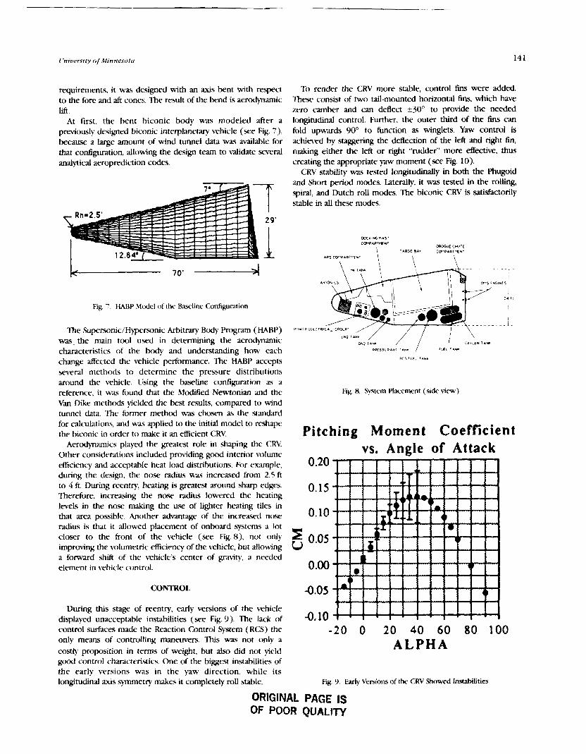
requirements, it was designed with an axis bent with respect to the fore and aft cones. The result of the bend is aerodynamic lift.
At first, the bent biconic body was modeled after a previously designed biconic interplanetary vehicle (see Fig. 7), because a large amount of wind tunnel data was available for that configuration, allowing the design team to validate several analytical aeroprediction codes.
Fig. 7 . HARP Mtxlel of the Baseline Cndguration
The Superwnic/Hprsonic Arbitrary Body Program (HARP) was. the main tool used in determining the aerodynamic characteristics of the body and understanding how each change atfected the vehicle performance. The HABP accepts several methods to determine the pressure distributions around the vehicle. Using the baseline configuration as a reference, it was found that the M d e d Newtonian and the Van Dike methmh yielded the best results, compared to wind tunnel data Thc former method was chosen as the standard
Tb render the CRV more stable, control fins were added. Thee consist of two tail-mounted horizontal Ens, which have zero camber and can deflect k30° to provide the needed longitudinal control. Further, the outer third of the fins c m fold upwards 90° to function as winglets. Yaw control is achieved by staggering the deflection of the left and right fin, making either the left or right "rudder" more effective, thus creating the appropriate yaw moment (see Fig. 10).
CRV stability was tested longitudinally in both the Phugoid and Short period modes. Laterally, it was tested in the rolling, spiral, and Dutch roll modes. The biconic CRV is satisfactorily stable in all these modes.
Fig. 8. Sptem Placement (side view)
for calculations, and was applied to the initial model to reshape the biconic in order to make it an efficient CRV Pitching Moment Coefficient
Aerodymrnics played the greatest role in shaping the CRV Other considerations included providing good interior volume efficiency and acceptable heat load distributions. For example, during the design, the nose radius wa.s incra5ed from 2.5 ft to 4 ft. During reentry, heating is greatest around sharp edges. Therefore, increasing the nose radius lowered the heating levels in the nose making the use of Lighter heating tiles in that area possible. Another advantage of the increased nose radius is that it allowed placement of onboard systems a lot closer to the front of the vehicle (see Fig. a), not only improving the volumetric efficiency of the vehicle, but allowing a forward shift of the vehicle's center of gravity, a needed element in vehicle control.
CONTROL
During this stage of reentry, early versions of the vehicle dimlaved unaccmtable instabilities (see Fig. 9). The lack of
- vs. Angle of Attack
s 2
control surfaces made the Reaction Control System (RCS) the -20 0 20 40 60 80 100 only means of controlling maneuvers. This was not only a costly propsition in terms of weight, but also did not yield A L P H A good control characteristics. One of the biggest instabilities of the early versions was in the yaw direction, while its longitudinal axis symmetry makes it completely roll stable. Fig. 9. Early Versions of the CRV Showed Instabilities
ORIGINAL PAGE IS OF POOR QUALITY
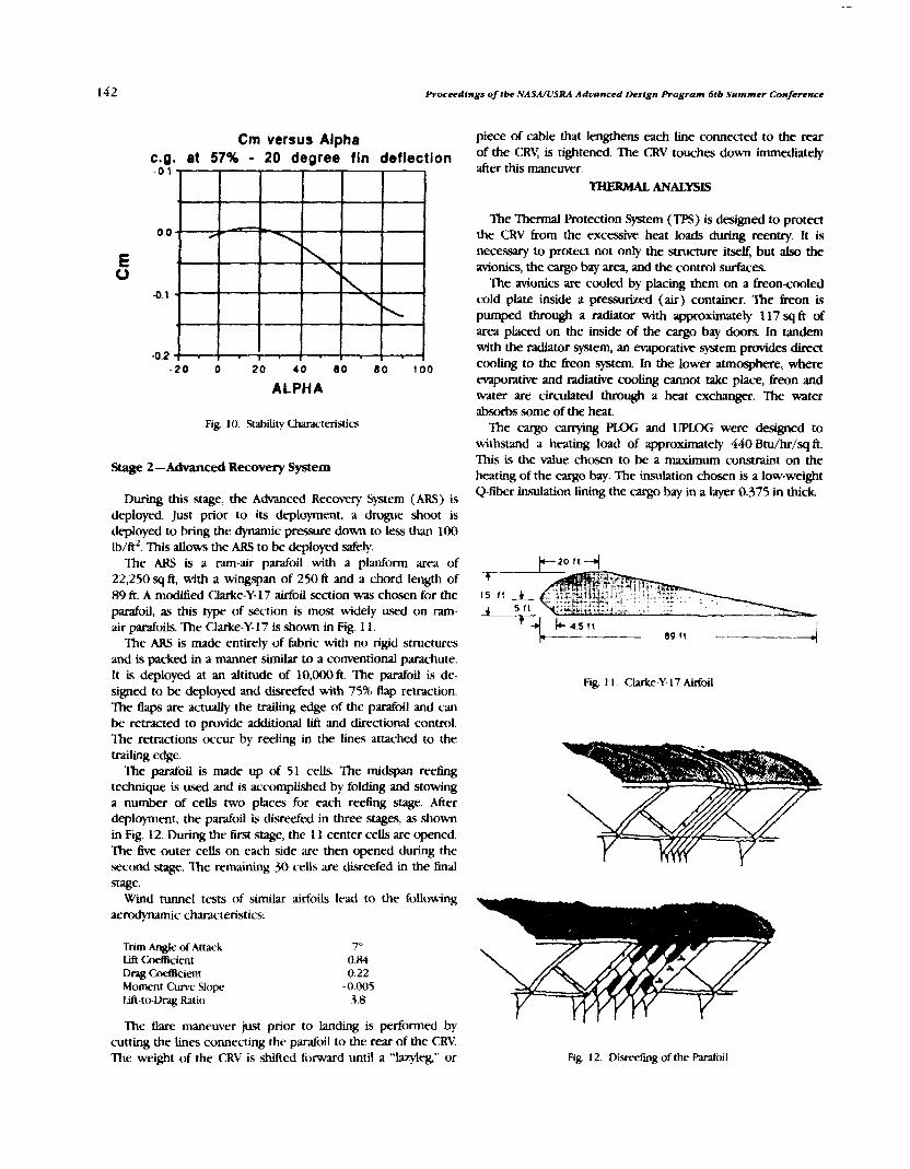
Proceedings of (be NASA/USRA Advanced Design Program 6tb Summer Conference
Cm versus Alpha c.g. at 57% - 20 degree fin deflection
- 2 0 0 20 4 0 8 0 80 100
ALPHA
Fig. 10. Stability Characteristics
Stage 2 -Advanced Recovery System
During this stage, the Advanced Recovery System (ARS) is deployed. Just prior to its deployment, a drogue shoot is deployed to bring the dynamic pressure down to less than 100 Ib/ft2. This allows the ARS to be deployed safely.
The ARS is a ram-air parafoil with a planform area of 22,250 sq ft, with a wingspan of 250 ft and a chord length of 89 ft. A modified Clarke-Y-17 airfoil section was chosen for the parafoil, as this type of section is most widely used on ram- air parafoils. The Clarke-Y- 17 is shown in Fig. 1 1.
The ARS is made entirely of fabric with no rigid structures and is packed in a manner similar to a conventional parachute. It is deployed at an altitude of 10,000 ft. The padoil Ls de- signed to be deployed and disreefed with 75% flap retraction. The flaps are actually the trailing edge of the parafoil and can be retracted to provide additional lift and directional control. The retractions occur by reeling in the lines attached to the trailing edge.
The parafoil is made up of 51 cells. The midspan reefing technique is used and is accomplished by folding and stowing a number of cells two places for each reeling stage. After deployment, the parafoil is disreefed in three stages, as shown in Fig. 12. During the lkst .stage, the 1 1 center cells are opened. The five outer cells on each side are then opened during the second stage. The remaining 30 cells are disreefed in the Enal stage.
Wind tunnel tests of similar airfoils lead to the following aerodynamic chwacteristics:
Trim Angle of Attack Lift CoefIicicnt Drag C d c i e n t Moment Curve Slope lift-to-Drag Ratio
The &are maneuver just prior to landing is performed by cutting the lines connecting the parafoil to the rear of the CRV. The weight of the CRV is shifted forward until a "lazyleg," or
piece of cable that lengthens each line connected to the rear of the CRY is tightened. The CRV touches down immediately after this maneuver.
THERMAL ANALYSE
The Thermal Protection System (TPS) is designed to protect the CRV from the excessive heat loads during reentry. It is necessary to protec* not only the structure itself, but also the avionics, the cargo bay area, and the control surfaces.
The avionics are cooled by placing them on a freoncooled cold plate inside a presuckd (air) container. The freon is pumped through a radiator with approximately 117 sq ft of area placed on the inside of the cargo bay doors. In tandem with the radiator system, an emporative system provides direct cooling to the 6reon system. In the lower atmosphere, where evaporative and mdiative coohng cannot take place, h n and water are circulated through a heat exchanger. The water absorbs some of the heat.
The cargo canying PLOG and LJPLOG were designed to withstand a heating load of approximately 440 Btu/hr/sqfi. 'This is the value chosen to be a maximum constraint on the heating of the cargo bay. The insulation chosen is a low-weight Q-fiber insulation Lining the cargo bay in a layer 0.375 in thick
Fig 1 1. Clarke-Y- 17 Airfoil
Fig. 12. Disrrefing of the Parafoil

University of Minnesota
The program MINIVER was used to determine the external heating loads along the surface of the vehicle and on the control surfaces. Using this program, the maximum tempera- ture was found to be 2775OF in the nose of the vehicle and along the leading edges of the control surfaces. These areas are covered by LI-2200 in 6-in by 6-in tiles at an angle of 18' to the airflow. The tiles were put at an angle to prevent them from being ripped off the way they are on the space shuttle. 'Ihe tiles vary in thickness from 2.5 in near the flow stagnation area to 2 in toward the rear of the vehicle.
The underside of the vehicle experiences the next highest heating loads. Fibrous Refractory Composite Insulation (FRCI) will cover this area as well as the remainder of the control surfaces. These tiles are also 6 in by 6 in at an angle of 18' to the flow. The thickness decreases from approximately 2 in to 1.5 in moving towards the rear of the CRY
The rest of the vehicle is covered by Tailorable Advanced Blanket Insulation (TABI). These tiles are approximately 2 ft by 2 fi and decrease in thickness from 1.5 in to 0.75 in moving toward the rear. The different insulations are shown on the CRV in Fig. 1 3.
The tiles are attached to the CRV by two different methods. AU tiles are directly or indirectly connected to the outer skin of the structure by the cost-effective adhesive, RTV-560. However, due to the frequent replacement of tiles, a "hook- and-loop" method is used to attach the TABI tiles. Fig. 14 shows the three types of insulation and their attachments.
STRUCTURAL DESIGN
The fuselage substructure, the cargo bay support structure, the outer skin, and the ARS Docking Mechanism and Drogue Chute compartments were some of the substructures designed by the structural design team. This was a very critical part in the design of the CRY All substructures must be designed to withstand any applied load.
The fuselage support structure consists of a system of ring frames and stringers. There are 32 box-shaped ring frames spaced 22 in apart from the nose to the rear. There are 74 Z- shaped stringers surrounding and supporting every ring frame, except for the first 6 rings, which only require 37 stringers. The stringers are spaced approximately 12 in apart at the largest diameter of the CRV and converge slowly a s the diameter decreases.
The cargo bay support structure designed to support the PLOG or UPLOG is a series of half rings just over 15 ft in diameter. There are 14 of these half rings coplanar with outside rings numbers 15-28 from the front, also spaced 22 in apart. The inside rings are all box shaped and are arranged as shown in Fig. 15.
t y v ,re ramr5w 2 "00, .m LOO" . I . r C " n l N l 1
Fig. 14. TF5 Materials and Attachment Methods 5140 V l D W
Fig 13. CRV Insulated 'liles Fig 15. Payload Bay Support Structure

144 Proceedings of tbe NASA/USRA Adtranced Design Program 6tb Summer Conference
The outer skin is made of HRH-327 honeycomb with aluminum 2219 facing material on each side. The reason for using the honeycomb structure is that it is the most efficient way to get the maximum strength out of the lightest material. The honeycomb panel consists of five layers of material, as shown in Fig. 16. The layers consist of an aluminum face sheet on the inner and outer surfaces attached to the HRH-327 honeycomb by an adhesive, as shown in Fig. 16. Each aluminum face sheet is 0.02 in thick and the honeycomb is 0.05 in thick
Wtth the given ARS design, a 69.05-cu-ft compartment would be necessary to pack the chute. A 25% margin of error and an additional 10 cu ft for the deployment chute were also added, making the necessary volume of the ARS storage compartment 96.3 cu ft. Due to the location and size of the cargo bay, it was necessary to place the compartment in the fore cone of the vehicle. The compartment is 3.2 ft deep, 4.5 ft wide, and has a maximum length of 8.3 ft on the surface, tapering off towards the center of the CRV to 5.1 ft. The taper is at a 45' angle.
The drogue chute compartment is placed near the rear of the CRV on the top surface just behind the cargo bay. Its volume is 15 cu ft, including a 50% margin of error. The compartment is 3.42 ft wide with a depth and length of 2.17 ft.
The docking mechanism compartment was uniquely designed to fit the shape of the mechanism. It is also placed in the fore cone of the CRV between the ARS compartment and the cargo bay. The compartment is 8 ft wide, 1 1 ft long, and has a maximum depth of 10 ft, as shown in Fig. 3.
CONCLUSION
necessitate downscaling the maximum payload. This is undesirable. Second, volume constraints in the backup system bay are such that the size of the secondary chute would have to be limited; given these limits, the touchdown velocity of the CRV, in case of main system Eailwe, would have to be greater than desiied, L-using some systems to be damaged on impact. Third, the high reliability of the ram-air ARS does not m m n t the penalty weight of a back-up system.
INPORM.MlON SUMMARY
Bent-axis biconic with a ram-air Mated parafoil ARS (WD)Hm= 1.5 (WD)kh,c = 3.8 -ARS Weight Unloaded = 34.06 klb Cargo Capacrty = 40 klb Crossrange = 700 n.m.
The advanced recovery system Planform Area = 22,250 ft2 (250 ft X 89 ft) Deployed at 10,000 fr altitude Midspan reefing in three stages
Vehicle dimensions Length = 59 ft Diameter nose = 7.7 ft Diameter max = 24.4 ft
Supersonic reentry control is via tail-mounted adjustable deflection fins, with folding wmglets.
Worthy of mention is the absence of a backup recovery The CRV will be capable of docking directly to SSF as well system to the ARS. A design for such a system was actually as being OMV compatible. carried out, but it was decided not to include it as part of the design for several reasons. First, the extra weight would Mission time with OMV = 19.85-76.85 hr
Mission time non-OMV = 18.35-75.35 hr
Propulsion Top-mounted launch on dual-booster/single-core LRBs Orbit insertion at 50 n.m. X 100 n.m. at 28.5' Three OMS engines
LH2/L02 propellant and oxidizer Weight = 86.65 Ib (each) g, ,=414.4 sec 'rhm& = 1600 lbf
The RCS system uses LH2/L02 outside the CCZ and GN2 ADHES'VE inside, as spe&ed by SSF requirements.
Transportation of the CRV back to KSC will be via the Boeing HoNEvcone Superguppy. CRV turnaround time is 66 days.
FACE SHEET
Fig 16. Honeycomb SUucture

AFSRI CCZ CRV FRCI GLOW GPS HABP IMU YD LEO LM LRB MSBIS OMS OMV RCC RCS SPDS SSF SSRMS TPS
WINGED CARGO RETURN VEHICLE CONCEPTUAL DESIGN -
UNIVJW3ITY OF MINNESOTA
NASA is committed to placing a permanent space station in E d orbit in the 1990s. Space Station hxdom (SF) will be located in a circular 220 nm. orbit at 28.5O inclination. The Wmged Cargo Return Vehicle's (CRV) primary mission is to support the SF crew by flying regular resupply missions. The Winged CRV is designed to be reusable, dry-land recoverable, and unmanned. 'lhe CRV will be launched inline on three liquid hydrogen/oxygen rocket boasters with a payload capability of 1 13,000 Ib. Ihe three boosters will take the CRV to an orbit of 50 x 110 n.m. From this altitude the orbital maneuvering engine will place the vehicle in synduonous orbit with the Space Station. The Winged CRV wiU deliver cargo modules to the Space Station by direct docking or by remaining outside the SSF command zone and using the orbital manewering vehicle to transfer cargo. The CRV will be piloted by SSF crew while in the command zone. Aner unloading/loadin& the CRV will deorbit and By back to Kennedy Space Center The W q e d CRV has a wing span of 57.8 h, a length of 76.0 ft, and a dry weight of 61 5 klb. The cargo capacity of the vehicle is 44.4 klb. The vehicle has lift/- ratio of 1.28 (hypersonic) and 6.00 (subsonic) resulting in a 1351-n.m crass-range. The overall mission length ranges between 18.8 and 80.5 hr. The operational period will be the years 2000-2020.
Advanced Flexible Reusable Surface Insulation Command Control Zone Cargo Return Vehicle Fibrous R e k t o r y Composite Insulation Gross Lift Off Weight Global Positioning System Hypersonic Arbitrary Body Rogram Inertial Measuring Unit Lift-to-Drag Ratio Low Earth Orbit Logistics Module Liquid Rocket Booster Microwave Scan Beam Landing System Orbital Manewering System Orbital Maneuvering Vehicle Reinforced Carbon Carbon Reaction Control System Stabilize Payload Deployment System Space Station !+ee&rn Space Station Remote Manipulator System Thermal Protection System
The Cargo Return Vehicle Design project was performed by students in the senior design class at the University of Minnesota. The project is intended to help supply Space Station Freedom (SSF) with its loj$stics needs. With development of the SSF, NASA has calculated that there will be logistic problems in supplying the station with enough to support a permanent manned contingent. It is with this shodall in mind that a new vehicle was proposed Currently NASA predicts that the S F will need 8 Bights per year and 250,709 Ib of payioad to support it. Currently the space shuttle can only be committed to 5 Bights per year and 178,285 Ib of cargo. This leaves the Space Station with a shortfall of three Bights and
71,929 lb of payload per year. It is with this basic requirement that the project was undertaken. The project was conducted in three parts: Trade Study, Conceptual Design, and Testing and Analysis. The first phase, the trade study, considered a lifting body, a biconic, and a winged configuration based on performance, reliability, and availability of technology. The trade studies were also used to determine major vehicle systems, and preliminary mission profile. The conf%gurations chosen were the winged and biconic configurations.
The second phase of the project was a conceptual design of the vehicle. To conduct this the class was divided into two design teams, one for each configuration considered. The remainder of this summary will fccws primady on the design and testing of the winged configuration. The winged contiguration design team was further broken down into eleven discipline groups: System Integration, which oversaw the design pmess of the vehicle as well as the overall management of the design team; System Layout, which was responsible for the placement of systems, vehicle drawings, and the mass properties of the vehicle; Mission Operations, which was responsible for the orbital mechanics, mission prome, space station operations and ground operations; Reentry Dynamics, which was responsible for the flight profile from reentry to ground; Aerodynamics, which was responsible for the analysis of the vehicle aerodynamically, includq the Mtious control devices considered such as winglets, canards, and the vertical tail; Stability and Control, which calculated the stability derivatives as well as examining the control require- ments on orbit and in the atmosphere; Thermal Protection and Control, which was responsible for thermal analysis of the vehicle and the placement of thermal protection; Avionics and Power, which was responsible for the choice of avionics and power systems needed by the vehicle; Propulsion, which selected the number of engines, engine type, and the launch *em; Structures, which determined the overall layout of structural members; and Cost and Optimization, which

146 Proceedings of tbe NASA/USRA Advanced Design Program Gtb Summer Conference
examined optimization of some of the systems on the vehicle. The disciplines each met individually twice each week; the team as a whole met once a week There was also a weekty meeting of the configuration control board whose responsibil- ity it was to define the vehicle design and to settle all disputes between discipline groups over the tlnal design of the vehicle. The overall vehicle designed by the group had physical characteristics as given in Table 1.
Table 1. Vehicle Physical Characteristics
Lw3t" spgn Height
Lw3t" Width Height
weight (dty) Weight (launch) C o d l e s Weight (landmg)
P a y l a
O v w l l L n w n s 76.0 feet 57.8 feet 19.8 feet
CmxoBay- 30.0 feet 19.8 feet 19.8 feet
V i l e Weights 61,5% Ib
1 13,000 Ib 5,568 b
106.012 Ib 44.4 16 Ib
Mapr systems on the vehicle are given in Table 2.
Table 2. Major Systems
Launch system Main Orbital RCS ( n o d ) RCS (special)
Guidance and Navigation
Communic-ations and T M g
Autoland Control
Avionics Controb
-n Liquid Rocket Booster system 1 OMS Engine 28 NTO/MMH thrusters 24 Cold Gas 'Ihrusters (for use around SSF)
Avionicr S y s m Global Positioning System (GPS), Star Tracker, Mu
Tracking and Data Relay Satellite %tern (TDRSS)
Microwaw Beam Scan h d m g System Elemo-Servo Actuators
hum System Fuel Cells Ni Cad Batteries
The vehicle contains many other subsystems that will be explained later in the summary. The he vehicle c o ~ t i o n can be seen in Fig. 1. The configuration features a delta-wing planform with a strake and winglets for lateral stability and control. The cargo bay is similar in design and length to the space shuttle so as to be compatible with all the same cargo handling systems. There is a docking ring bay located ahead
of the cargo bay to Eacilitate docking of the vehicle to SSF without affecting pgyioad capability or placement in the cargo bay. The vehicle will glide in to land on cyclical landmg gear (not shown).
The third stage of the Project was the Testing and Analysis Stage. The class was again broken into eleven discipline groups: System Integration, Integration Staff, Modem, Wind b e l Testing, Wmd k e l Data Analysis, Water h e 1 Testing, Structural Analysis, Cost and Optimization, and Marketing and Promotion The main function at this stage was to w e more completely the design of the vehicle. The System Integration group acted as the project managers while the Integration Staff prunarily worked on editing the contractor reports. Ihe Wmd k e l groups worked on anaipng the vehicles' lift-to-drag ratio and some of the stability derivatives to determine if they coinaded with the calculated ones found dwing the design phase. The Water Tbnel group examined qualitatively the flow around the vehicle examining the effects of the strakes and m e t s . The Modem group worked with both testing groups building the test models as well as building a display mock-up for the Marketing group. The Structural Analysis group worked on analyzing the structure of the vehicle using the program NASTRAN in order to fkdize the size of the structural members. The Marketing group was responsible for the promotion, public relations, and the displays of the vehicle for the ADP Summer Conference as well as at the university. Cost and Optimization examined the feasibility of the overall concept as well as performing a justification study. The testing and analysis conhned much of the work done earlier.
smTEMs LAYOUT
The systems layout discipline's major responsibilities were to keep track of the placement of the various systems through vehicle drawings, and to calculate the mass properties of the vehicle. The vehicle final weight statement can be seen in Table 3.
Table 3. CRV Finalized Weight Statement
w w* Thermal Control System Propulsion System Avionics and Power landing Gear Docking Module Growth Dry Weight P a y i d RCS Propellent OMS RupeUent Cold Gas Propellent Adapter
Total launch We@t
LessGlnsumables Less Adapter
Fig. 1 . lluee Mew Ihawing of Vehicle Total landing Weiht 106,012 Ib

University of Minnesota 147
MISSIONS OPERATIONS Tble 4. Flight Profile
The total mass in orbit will increase approximately 833% h m 1998 to 2006. The S F must receive approximately 115,000 lb of cargo per year. Of this cargo, 76% would be returnable and the other 24% would be trash. The !SF will need tluids for continued growth and for use in experiments to be conducted on the station. For growth to occur there is a need for 12 flights per year by the year 2004. The U.S. will bt. responsible for curying 42% of the cvgo to the S E The CRV must have the ability to meet S F cargo fvqukments. The station will have of 275 KW of power, 24 crewmembem, and 5 or more modules. Cargo transfers must be of the otder of 200 metric tons per year, which can be provided by 9 enhanced CRV flights per year.
- -
The CRV will be capable of performing the required mission ut- one of two possible mission plans-denoted nominal (primary) and alternate (secondary).
In the nominal mission, the CRV would leave a 110-n.m. injection orbit, en route to a stabilized "parking orbit" at the rear edge of the Space Station fkwbm Command and Convol Zone (CU). An Orbital Maneuvering Vehicle (OMV) would be dispatched h m the S F and perform two round-trips In the process of transferring and exchanging the Logistics Modules (LM). LM pickup and dropoff at the CRV would take approximately 30 min each and would be simpMed by the inclusion of a Stabilized Payioad Deployment System (PIX). LM exchange at the SF would normnally be perbrmed solely by the OMV (-1 hr exchange time) and contingently by the OMV with the aid of the SSRMS (-2-3 hr exchange time). The o v d nominal mission would be completed in 18.8 hr.
In the alternate mission plan, the CRV would leave the injection orbit and proceed directly to the S F and dock with the help of the SSRMS. The SRMS would berth and deberth the CRV and perform al l LM exchange maneuvers. The CRV would be required to stay docked to the SF for at least 6 hr, until a launch window opens. As a result, the alternate mission plan would take considerably longer to perform.
In either mission plan, the &ght would be directed by several ground control centers and the S F crew. Any vehicle inside the CCZ would be controlled by the S F crew and any vehicle outside the C U would be controlled by ground crews.
REENTRY GUIDANCE AND DYNAMICS
Ewnt
De-orbit Bum Blzckout Maximum Heating Exit Blackout Begin Energy Management systems Initiate Autolvrd grStem Initiate Rc&re Complete Flare Landing Gear Down Tou-
-- -
Tune to ~ouch-down Altitude (ft
1 hr Wmin 20 min 12 min 5min
1.5 min 30 sec 15 sec 10 sec osec
Velocity (fi/=)
hkh 26 23,900 19,350 13,500 1,900
650 580 450 400 320
AERODYNAMICS
The aeFodynamics dwipline group was in charge of defining the wing shape, camber, and essential body surface designs. The group used a Hypersonic Arbitrary Body Program (HABP) to evaluate the winged CRVs aerodynamic characteristics in the hypersonic and supersonic regions (Table 5). The HABP program is capable of calculating aerodynamic charaaeristics of arbitrary 3-D shapes in both the hypersonic and supersonic regions. For the subsonic -cs the Boeing computer program AIRFZ was used to estimate chamcteristics of all Bight regimes, from subsonic to supersonic. Another program, k l o p e d at the Uniwrsity of Minnesota, ULTIMATE, was employed to reveal Bight qualities that AIREZ was not capable of perbrming. Also studied was the possibility of employing canard &es for longitudinal control.
Table 5. Maximum V D Characteristics
Mach AlREZ HABP HABP F i i and Tail w/Strake
1.2 1.83 NA NA 1.5 1.66 NA NA 2.0 1.58 1.36 1.66 5.5 1.39 1.29 1.58 10.5 1.50 1.28 NA. 20.5 1.52 1.28 1.28
S w q = 47O NowLmgth=27ft W q Taper = 0.28~ Nose Dia = 19.9 ft S = 1888 FtZ EEect Dia. = 2 1.6 ft Fin Taper = 0 . 3 4 ~ Nose Droop= -2 ft Ems= 170R.2 Nose Radius = 1.8t Sake = 70.76' Thick Ratio= 1.1
The main purpose of the discipline was to define the CRVs flight profile, determine the g-loading, maximum dynamic pressure on the vehicle, and cross range -ts. They were also responsible for defining the minimum lift-to-drag ratio for the vehicle to reach the primary landing sites and determining the cross range. The cross range was calculated using standard empirical approximation. The cross range was determined to be 1351 n.m. The maximum g-logding was found to be 2.25 g and occurs during Sturn, maneuvers used to decelerate the vehicle. The flight p d e is shown in Table 4.
Throughout the trade study and conceptual design phases the CRV body was continually changed and redefined The CRV began with vertical tail, deployable canards, and variable winglets. Based on the determination that a subsonic WD of 6 would be adequate for approach and landing, a variable winglet option was eliminated. The performance of the winglet-only and vertical-tail-only configurations in the hypersonic and supersonic regions were found to be comparable. Therefore, use of both wing fins and a vertical tail was redundant, and the vertical tail was dropped from the body design. Theoretically the use of fins should increase the WD

148 Proceedings of tbe NASA/USRA Adzlanced Design Program 6tb Summer Conference
favorably in the subsonic region due to a reduction in induced drag. Fins also are less susceptible to blanketing during reentry. Finally, the use of fins allows flexibility in docking with the .Space Station. As a result of these benefits the winglet-only configuration was chosen to be the h a l form for the CRV
STABILITY AND CONTROL
The stability anafysis of the vehicle was performed using two main computer programs, the MINNEMAC program for computation of root loci for different stability modes and the Stability Analysis Program, which computed the aemdymmjc derivatives. The analysis was performed in hypersonic/ supersonic and subsonic flight regimes. The neutral and maneuver points for the different fight regimes are listed in Table 6.
design incorporates three fuel cells for system redundancy. The fuel cells are self-cooling units with their own oxidizer and fuel supply. They are located in the bottom of the vehicle along with their fuel and oxidizer tanks. (A separate fuel supply is required because fuel cells need a much higher grade of fuel than that used for propulsion.) The hydrogen/oxygen fuel exits the cells as water at about 140°F This water could be used for heating or cooling other components.
Servo Actuator Poww Supply
The servo power supply comes ftom a separate battery system because these servos require too high a peak load to be powered by the fuel cells. The type chosen were NiCad batteries because of their weight, volume, and performance characteristics.
Table 6. Neutral and Manewer ~o in ts ' Guidance and Navigation -
Reme Neutral Wit (ft) Manewer Point (R) Subsonic 45.05 46.08 Hyper/Supemnic 53.40 54.43
'All points meawed h m the nose of the vehicle.
From the calculation of the neutral points and the center- of-gravity envelopes from the system layout discipline it was determined that the vehicle would be stable throughout the hypersonic and supersonic ranges but would be unstable in the subsonic regime. This was decided to be acceptable since current lly-by-wire technology exists to control unstable flight.
The other function of the group was to examine control systems and size the control surfaces. The overall control of the vehicle would be accomplished by the RCS engines while on orbit and during reentry until the dynamic pressure on the CRV reached 10 psf At this point the aerodynamic control .surfaces would bqm to be used and the RCS would be phased out. The vehicle would rely totally on aerodynamic surfaces by the time the dynamic pressure reached 170 pst The control surfaces were sized using both a xaleddown space shuttle approximation, and deflection and moment constraints for refinements.
POWER AND AVIONICS S-
Power Supply
The power system on the CRV must satisfy several requirements. The most crucial aspect of any power supply for the Winged CRV is reliability. Power supply must be flexible regarding length of operation and must be cost effective. Of the power systems available, fuel cells satisfied the requirements.
Avionics have a peak usage of approximately 2.0 kW during thrusting maneuvers. If a pressurized logistics module is on board then an additional 1.5 kW would be required This produces a peak power need of about 6 kW depending on the type and number of other components in use. Current fuel cells produce 7 kW continuous and 12 kW peak One fuel cell could supply all the power required for the vehicle, but the
The major components of this subsystem are the Global Positioning System (GPS) receiver, Inertial Measuring Units (IMU), and a star tracker. The GPS system determines the position of the vehicle relative to the Earth and SSE The GPS works in either an arbitraty three-axis system or with latitude, longitude, and altitude. By giving a continuous update of the position, the GPS also provides a constantly updated velocity vector. The IMUs are the primary sensor for the guidance and navigation system. They sense both lateral and longitudinal rotational acceleration and detect rotational velocity. The CRV would incorporate 2-4 IMUs. The star tmcker mounts directly on the hull of the CRV and would have a small view port. Each component feeds into a digital integration unit and then is sent to the main data handling computers.
Automatic Landing System
The main components of the auto landing system are the Microwave Scan Beam Landing System (MSBLS), a radar altimeter, the landing gear, steering and braking systems, and television cameras for remote control. The main functions of this subsystem are to capture and track lateral guidance path, ap twe and track the vertical guidance path, provide sideslip maneuvers prior to landing, drop landing gear automatically, and steer and brake while on the ground. The MSBLS is the primary navigation device. It is activated at 10,000 to 14,000 fi when the vehicle is parallel to the runway and provides azimuth angle, elevation angle, and distance during final approach and landing. The on-board radar altimeter provides height above the ground up to 5480 fi.
THERMAL PRCYI'ECTION SYSFEMS
The following materials were selected: Reinforced Carbon- carbon (RCC), Fibrous Refractory Composite Insulation (FRCI), and Advanced Flexible Reusable SurEace Insulation (AFSRI). Approximate thermal calculations were made to iustify the TPS placement on the vehicle.

Cinioersity of Minnesota
The TPS for the Winged CRV is bawd primarily on the effective protection of the substructure while considering weight penalties. The aeroheating effects were defined from a computer program, MINIVER, approximate calculations, and space shuttle data. The protection materials chosen were RCC, carbon-carbon tiles, Fibrous Refractory Composite Insulation- 8, and Tailorable Advanced Blanket Insulation (for the shunle- type heat sink and hot structure system). The placement of the materials can be seen in Fig. 2. The total weight is 11,609 1b. Future use of an active cooling system appeared promising for use in connection with improved hot structures.
To efEctively apply thermal protection to the CRV accurate analysis of the temperature and heating rate along a trajectory is required. To fulfill this requirement, the program MINIVER was used. Using the trajectory established by the Reentry Dynamics group, and models for the various body sections, the thermal environment encountered by the CRV was estimated. The CRV was split into five sections for modeling purposes. These sections consisted of the nose, body, wing tips, wing section one (sweep = 68' ), and wing section two (sweep = 54' ) . The models for each of these sections were input into MINIVER and analped twice; once, at laminar flow, and once, at turbulent flow. From the Reynolds number data in the MINIVER output, it was found that the air flow would remain laminar for this trajectory. This was based on transition begmning at Re = 3 X lo5, and fully turbulent flow at 4 X 10'. From this methodology the TPS was chosen and placed in each of the five regions. From Fig. 2 and Table 7 an accurate idea of the vehicle protection regions can be analyzed.
Table 7. Material Key
- --
Region Temperature Material
1 2000-3000°F RCC 1 -Tie 2000-2700°F Carbon-Carbon Tde 2 1500-2300°F FRCI-8 3 800- 1500" F TAB1 4 <mO F TAB1
PROPULSION
The objective of the propulsion discipline was to design a propulsion wtem for the CRV to meet all the mission requirements. The primary design inputs were thrust level, AV requirements, and total dry weight of the CRY The two possible propulsion codgutations for the CRV include a system with SSF control zone capabilities, and one without.
Orbital Maneuver System Engine Selection
The Orbital Maneuvering System (OMS) of the CRV serves two main purposes. First the system must produce the necessary thrust to propel the CRV from a 100-n.m. to a 210- n.m. orbit after booster shutdown. Second, the system must produce sutficient AV for de-orbit.
Based on a theoretical engine, it was concluded that the current space shuttle OMS would satisfy all the requirements. The Aerojet AJ10-190 was chosen for the use in the CRY The dimensions of the engine are given in the following sections.
Readon Control System
The Reaction Control System (RCS) 611- the Winged CRV is responsible for fine orbital and attitude adjustments in space and will not be used in the lower atmosphere. The system consists of 52 thrusters positioned as shown in Fig. 3.
Fig. 2. TPS Placement Fig. 3. RCS Placement

150 Proceedings of the NA&4/USRA Advanced Design Program 6th Sum raer Conference
RCS AUXUL_
SSF regulations prohibit all but the use of cold gas
propellents within the SSF control zone. To meet this
requirement an auxiliary RCS system was designed to be used
within the SSF control zone. The system was designed with
the possibility of hard-docking to SSE
Number of RCS Thrusters and Placement
For effective six-axis control, 24 cold gas and 28 NTO/MMH
thrusters were placed as shown in Fig. 3. Each main thruster
will produce 40Olb of thrust. All thrusters will be fired
individually except in emergencies. This number of thrusters
allows for at least one degree of redundancy for each axis of
motion. The thrusters will also be located to allow for paired-
thruster operation if needed.
_&System
The launch system must deliver the loaded CRV to a
100 n.m. insertion orbit. The launch system was chosen on the
basis of payload to low Earth orbit, the mounting procedure
of the CRV and the fuel type. The final decision was a delivery
system consisting of two liquid rocket boosters (LRB)
mounted on each side of one core unit, each with its own
engines and fuel (Fig. 4 ). The core would also carry all of the
avionics and controls. The fuel used for this system is liquid
hydrogen (LH2) and liquid oxygen (LOX). The engines for this
application would be space shuttle main engines (SSME).
T/ \
railU ,i
_5
Table 8. Launch System Data"
Height ( w/o CRV) 178'Payload to LEO 12%O0O IbGLOW 2,600,000 }b
Engines 10-SSME
"For further description see System Mass Comparison.
STRUCTURAL DESIGN AND ANALYSIS
The structural design was completed during the design
phase of the project. The vehicle was intentionally over-
designed so that the elements would not fail. The mainstructural materials chosen for the vehicle were aluminum
TA2219 for the construction of the frames, aluminum TA2024
honeycomb for the skin of the vehicle, and a Graphite/Epoxy
composite was chosen for the cargo bay doors, since they do
not contribute to the overall strength of the airframe. The
design was divided into four sections, fi'ont, middle and aft
fuselage, and the wing, The fuselage sections were connected
by means of two main structural bulkheads fore and aft of the
mid fuselage section (see Fig. 5).
The front fuselage was based on a semi-monocoque design
similar to conventional aircraft. This design utilized TA2219 for
the majority of the structure. The front fuselage houses the
front Landing gear, the avionics bays,and the docking module
bay.
The wing is a conventional wing design consisting of spars,
webs, and honeycomb skin. The wing is constructed from
aluminum TA2219 except for the skin, which is TA2024. The
aft landing gear base was placed within the wing structure.
The mid fuselage consists of a 30-ft-long primary load-
carrying structure housing the payload bay. The mid fuselage
is a truss frame construction of aluminum TA2219 that
includes a wing carry-through structure and the payload bay
doors. The payload bay doors are constructed entirely out of
a graphite epoxy composite.
J
p
Fig. 4. Launch System FiFr5. Structural Layout

The aft fuselage consists of an external shell structure and an internal thrust structure. Both are constructed primarily out of aluminum TA2219 along with boron epoxy laminates and titanium reinforcements. The section houses the OMS engine and was designed to transfer the thrust and launch loads to the mid f u d g e .
The analysis phase involved using the NASTRAN program to examine the design from the previous quarter. The program used finite element methods to determine forces and stresses on the different elements in the vehicle. To perform the analysis the vehicle was divided into two main sections, the fuselage and the wing. Dynamic pressure data from HABP runs were used as input for the program. The stresses were then used to determine which of the elements failed and which were overdesigned so that the croswctions and shapes of the materials could be refined.
DESIGN OPlUlIZATION AND COST ANALYSIS
During the second phase of the project the optimization group worked on the optimization of two systems on the CRY the CRV/Booster interface and the propulsion system.
The optimization of the interface focused on defining the - material used on the structure, the crosssection of the members in the structure, and the number of vertical members in the structure. The most important parameter to optimize was weight. The propulsion system optimization, sizing of fuel tanks and feedlines, was done by determining the ideal sizes and then looking for existing hardware.
During the second phase of the project, optimization focused on the overall justification of the CRV project as well as deciding which vehicle to go ahead with. Optimization groups from both the Winged and Biconic teams worked together, and examined reusable and expendable launch vehicles. The primary vehicles examined were Atlas Centaur, Shuttle C, both the Winged and Biconic CRVs, and increasing the shuttle's commitment to the Space Station. Criteria were cost per pound to orbit, reusability, reliability, and availability. Conclusions were that the CRV and, more spcifically, the winged version, was the most viable option.
MODELING
The primary responsibility of the Modeling Group was to build models for physical testing of the vehicle. The testing group entered surface location ctmrdinates into a CAD/CAM system and models were milled on a numerically controlled milling machine.
Rvo models were made for the testing of the vehicle. A wooden model wa.5 constructed for wind tunnel testing, and an aluminum model was used for water tunnel testing. The group also worked on constructing a display model for the ADP Summer Conference.
WIND TUNNEL TESTING
The Wind Tunnel Testing Group was responsible for developing and implementing the test plan. The group constructed and instrumented the setting and conducted the testing.
The primary purpose of the testing was to find the lift/drag ratio of the vehicle as well as various aerodynamic derivatives. Testing was conducted in the University of Minnesota's Aerospace Engineering Department subsonic, continuous flow tunnel. The test plan included running the model in the tunnel at two different velocities and at six different angles of attack (between 0' and 25'). The vehicle was also tested at three different sideslip angles.
WIND TUNNEL DATA ANALYSIS
The objective of the Wind Tunnel testing group was to calculate stability derivatives from data obtained imm the wind tunnel testing group. The stability derivatives calculated included the lift-to-dmg ratio, L/D; lift curve slope, C,,; C,,,; and weathercock stabiity, C,,p.
The results were compared with computed values from aerodynamics and stability studies performed during the design phase of the project. Table 9 gives a comparison between the tested values and computed values.
Table 9. Test Results
Testing Computed
IJD 5.846 5.96 cia 0.1055 1.929 Cma -0.1158 -0.3968 Cn, 0.0907 1 0.07106
The two sets of values compare fairly well, particularly, the lift-to-drag ratio. The lack of correlation in the other values probably results kom the very low speeds at which the tests were conducted.
WATER TUNNEL TESTING
The Water Tunnel Group was responsible for a quahative analysis of the flow around the vehicle. Tests were conducted at the St. Anthony Falls Hydraulics Lab at the University of Minnesota. The tests were made at seved different angles of attack, Reynolds numbers, and sideslip angles. The vehicle was pulled through a stationary water tank. The flow was examined to determine the effect of the winglets, strake, and the rest of the vehicle. From the tests no unusual effects were found. The Bow behaved as expected; the angle of attack at stall was approximately 25". This closely matches what was predicted by the Aerodpmics Group.
CONCLUSIONS
The Wmged CRV met all the speci6cations and requirements that were set out for it. The conclusions of the design project were that the Winged CRV could easily provide the necessary cargo to supply Space Station Free&>rn with its logistics needs. The CRV also appears to be the most cost effective option available to accomplish this task


HIGH-LATITUDE COMMUNICATIONS SATELLITE (HILACS)
NAVAL POSTGRADUATE SCHOOL N 9 1 a 1 8 1 4 5
The Naval Postpduate School in the AE 4871 Advanced Spacecraft Design course has designed a communications satellite (HIUGS) that will provide a continuous UHF communicxtions link between stations located north of the region covered by geosynchronous communications satellites. This area (above approximately 60° N) will be served via a relay net control station (NCS) located with access to both the HIUCS and geosynchronous communications satellites. The communication. payload will operate only for that portion of the orbit necessary to provide specified coverage. The satellite orbit is elliptic with perigee at 1204 km in the southern hemisphere and apogee at 14,930 km with 63.4" inclination. h a @ s and design for each of the subsystems was done to the extent possible within the constraints of an 11-week quarter and the design and anal~is tools available. Work was completed in orbital ulatysis, the reaction control subsystem (RCS), attitude control subsystem (ACS), electric power subsystem (EPS), telemetry, tracking, and control (TT&C), thennal control subsystem, and the structures subsystem. The design team consisted of 12 students. Additional suppon was provided by the Jet Propulsion laboratory and the Naval Research Laboratory.
The High-Latitude Communications Satellite (HILACS) will provide a continuous UHF communications link between stations located nonh of the region covered by geosynchro- nous communications satellites, i.e., the area above approxi- mately 60° N latitude. HILACS will also provide a communi- cations link to stations below 60 N via a relay net control station (NCS), which is located with access to both the HIIACS and geosynchronous communications satellites. The commun- ications payload will operate only for that portion of the orbit necessaty to provide specifled coverage.
The satellite orbit is elliptic with perigee at 1204 km in the southern hemisphere and apogee at 14,930km. The orbit inclination is 63.4O to eliminate rotation of the line of apsides. The orbit period is 4.8 hr, during which each spacecnft will be operating approximately 1.6 hr. The complete constellation will consist of three spacecraft equally spaced in mean anomaly.
The reaction control subsystems (RCS) and the stationkeep- ing propulsion subsystem is a monopropellant hydrazine system. There are four 38-N thrusters for the initial apogee adjustment and twelve 2-N thrusters for the RCS and stationkeeping. The propellant is contained in four tanks with internal pressurant bladders.
The satellite is three-&stabilized by four reaction wheels with thrusters providing redundancy and reaction wheel desaturation. The spacecraft is nadir-pointing with antenna- pointing accuracy of k0.5'. The satellite rotates about its yaw axis so as to maintain the solar panel axis (roll axis) normal to the sun line, providing maximum solar power efficiency. The attitude control subsystem (ACS) will utilize four sun sensors, two Earth sensors, and a three-axis rate-sensing gyroscope. The orientation of the four reaction wheels provides redundant operation.
The electric power subsystem (EPS) is a s@e bus, fully regulated system with bus voltage of 28V The EPS consists of two solar array panels, a 16-cell, 12 amp-hour nickel-
hydrogen battery, power control circuitry, and a shunt resistor bank The EPS provides 343 W at end-of-life (EOL) at aphelion with a 10% margin. The solar array is comprised of GaAs solar cells, selected for their superior radiation tolerance.
The telemetry, tracking, and control (TT&C) subsystem design provides for both autonomous operations and direct control by a midlatitude groundcontrol station. The NCS will also be able to perform some TT&C functions.
The thermal control subsystem is primarily a passive system, with radiators on the satellite Edces mounting the solar army panels, which will always be oriented parallel with the sun line. The other surfdces of the spacecraft will be insulated to maintain internal temperatures within acceptable limits. The passive system is augmented by heaters for equipment/ locations requiring unique treatment.
The primary spacecraft structural support is the central tube, which provides the load-bearing structure for the equipment panels and fuel tanks. The central tube is also designed to provide for the design loads resulting from stacking of three satellites for launch.
Launch and Oibit Sequence
Figure 1 shows the launch configuration. AU three satellites will be launched simultaneously on a single Delta/S'lAR 48 launch vehicle. The launch will take place h m the Kennedy Space Center, and will place the three satellites initially into a 15,729 km X 1204 km orbit at the desired inclination (Fig. 2). The launch vehicle final stage will provide active control for stabilization for the three stacked spacecraft while in ascent, elliptical parking orbit, and prior to each s p a c e d ' s separation. As each satellite is separated from the final stage it will be spinning about a stable axis, eliminating the need for additional stabilization during the sun/Earth acquisition phase. Again, attitude stability is provided by the final stage of the launch vehicle for the stiU attached spacecraft. In this initial
PRECEDING PAGE BLANK NOT FILMED

Proceedings of tbe NASA/USRA Advanced Dexlgn Program 6tb Summer Conference
Fig. 1. launch Coneguntion
I I, I I - - - - - I
I 3 M .
I I I
I I
4 es. Unim I
I ' I ' I 1
T*a Ads E m I
I ~ r * o r i u.
I
F i 2. Transfer Orbit Sequence
orbit, each spacecraft will acquire the sun and then the Earth to assume their Earth-pointing, three-axis stabilized configura- tion The following sequence will then occur: solar arrays deploy, allowing electrical and thermal stability; the trailing satellite in the launch orbit will be reoriented and perform a perigee burn of 1.73 min using the four 38-N thrusters (-42.2 m/sec AV); orbit insertion of spacecraft into the 14,933 km X 1204 km mission orbit. Since the mission orbit has a 4.8 hr period compared to the 5.0 hr period of the launch orbit, the second spacecraft will be aligned for insertion 8 h i t s later, with the fld spacecraft aligned foUowing an additional 8 orbits. This sequence will put the entire plane of satellites in position 80 hr after the initial s p a c d is inserted into the mission orbit. This relatively long period between the insertion of each satellite also provides for the accurate determination of orbital parameters of the preceding spacecraft and adjustment on subsequent insertions as needed. The s p a c d on-orbit contiguration is shown in Fig. 3.
The time rate of change of inclination due to the gravita- tional efects of the Moon and the Sun were computed. In both cases, the rate is periodic in the right ascension of the orbit-
Unlt
A
Unlt
Fig. 3. On-Orbit Configuration
ascendq node, f i c h is decreasing at the daily rate of -0.425O. This causes the inclination rate to cycle completely in 847 days, with a maximum value of 0.1 175O/yr throughout the 3-year lifetime of the satellite. Since this represents the worst case alignment of the sun and the Moon during the mission, the actual values should be computed for these bodies based on their true positions for a given launch date recogniziq that the resulting perhubation would actuaUy be no larger than 0.1175O/yr. The error in inclination that would accumulate would only be that which represents the satellite life beyond one of the 847day cycles. With this small change in inclination there is no need to budget propellant for station keeping due to inclination drift.
Argument of Perigee
Even though the satellites will be placed at the critical inclination, there will be drift of the argument of perigee due to higher-order effects. The long-period dynamic equations (normalizing the system to remove those short-period terms dependent only on mean anomaly) of the mission orbit were numerically integrated using a Runge-Kutta 4th-order fixed- step integrator. The analysis included perturbations to a Keplerian orbit due to the 52, 33, 54, J5 zonal harmonics. Although the mission orbit proves to be very stable in argument of perigee having drifi through 360' with a period of 1100yr, 0.33O/yr, the orbit is very sensitive to errors in inclination. A 0.1 error in inclination increases circulation of the argument to a rate of 1,44O/year. There is no need to budget propellant to correct for this small amount of drift for

Nawl Postgraduate Scbool
the three-year lifetime. Ropellvlt has bem btdgdcd to comctdrlftoftheargumcntofpcrigecthio~ghfouryevs slncc the solar array has the capacity to provide power for more than the planned three-ycu d t e lik. Thts stltion keeping will require a change in direction d the qmmcdt velocity vector of 1.44' each year, reptwenting a change in velodty of 133.7 m/scc. Us@ the attitude control thrustas, thls will require a total of 81.8 kg (180 lbm) of propellant cnvr 4 years. 'Ihe current satellite design provides ldcqulte clpldty for this requirement as well as approximately 50lq of additional propellant as margin.
The satellite is required to be Earth poindng and haw solar arrayindirectviewofthesunTheamountofylwrequired each orbit is a function of the angle B between the solar orbit plane and the satellite ohit plane. This relati- is ghm in the following equation(')
where @ = orbit plane illumination angle; A = sin (i); i = o&it inclination = 63.435"; B = cos (e); e = solar orbit inclina- tion = 23.44"; C = cos (i) sin (e); y = sun central angle (measured ccw from vernal equinox to current position of sun relative to Earth); R = right ascension of the satellite orbit ascendmg node.
The angle between the solar array normal and the incident s d @ t is given by the following equationC2)
cos a sin p sin 7 cos b )
where cos 8 =angle between array nonnal and incident sunlight; cr = array articulation angle between the array nonnal axis and the local horizontal, measured positive away kom the Earth; p = spacecraft yaw angle measured ccw 6rom inertial north; ,l3 = orbit plane illumination angle (see above); and T = angle from solar noon, measured in the direction of the satellite orbit from the point on the orbit closest to the sun (local noon).
Batteries will be needed to provide power &,uing solat eclipse. With a perigee of 1204 kin, this will occur when orbit plane illumination angles are less than 57.3O (-(Re/ (Re + 650))). Starting at zero for the orbit right ascen- sion (n), and 180" for the sun central angle (y), there will be 90 1 days out of the 1095 day planned lifetime during which the spacerraft will experience an eclipse of some duration. The resulting maximum solar eclipse period is 37.5 min during which the solar arrays are not illuminated At 5 orbits per day, this specifies the need for batteries that can provide spacecd bus power for up to 37.5 min through 4500 or mote cycles
SPmCRAFl' CONFIGURATION
The primary consldcntions involved in developing the HIIACS conBpdon were (a) to size the satellite for the Delta launch vehicle; (b) to shape the satellite and distribute masses to achieve the p r o p moment of inertia ratio for stability during a transfer orbit phase if required, (c) to use the east and west faces as equipment panels for thermal considerations since these faces will always be oriented parallel to the sun -or; and (d) to maintain as much modularity in the equipment layout as possible (see F i g . 4-7).
Four fuel tanks were used to achieve redundancy and to m b u t e the fuel mass The basic shape of the satellite (1.9mX1.3mX0.7m)wasdrivenbythegmm~ofpla~ the fwr fuel tanks around the center tube within the Delta p a y i d d o p e . A fuel tank is mounted in each comer along the center line in height. The panels and component distribution are conflgwed as shown in the figures for the spacecraft conQxation
The s p a c e d s t n t m design is requved to support the weight of three s p a c e d under design loads for a Delta II (Table 1). The spacecraft employs identical design. for all three spaceuaft, which forces an overdesigned structure for two of the three. Aluminum 6061-T6 was chosen for ease of machlrung and a ENOrable strength-to-weight ratio. The design qqwrts loads through the central support assembly consisting of a fiustum cone shell attached to the Delta I1 3712B interface, a central cylindrical shell, and a similar fiustum cone shell at the top of the s p a c d that attaches to the interface betweeneachspacea;lft.
Table 1. Design Constraints for Delta U launch - --
Natural Freqwncies
spaceaaft Equipment Panel Solar Panel Limit Lads Max Lateral Condition Max, Axial IatedqaarmcLoads FactorofSafety= 1.5 Maff&ofSakty= 10%
L a t d Axial
15 Hz 35 Hz 25 Hz 35 Hz 35 Hz
A majority of the equipment mass is located on the east and west panels, which are designed to withstand 30g and have a fundamental frequency above 25 Hz. The panels were designed to support 92.2 kg each of equipment mass. Load paths are provided to the central support assembly by means of panels attached to the north and south ends of the equipment panels. These support panels are also used to secure the four propellant tanks for axial loads. The panels are made of aluminum honeycomb material with core thickness 9.525 rnm, and face thickness 0.912 mm. The same honeycomb

Proceedings of tbe NASAIUSRA Advanced Design Program 6fb Summer Conference
Fig. 4. East-Facing Panel
[m-- Propellant Ffll/Dram valve
Primary set Redundancy set
Fig. 6. Earth-Facing Panel
Fig. 5. View of Major Interior Elements
Fig. 7. West-Facing Panel
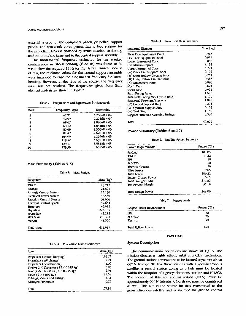
Naval Postgraduate School
material is used for the equipment panels, propellant support panels, and spacecraft cover panels. Lateral load support for the propellant tanks is provided by struts attached to the top and bottom of the tanks and to the central support assembly.
The fundamental frequency estimated for the stacked configuration in lateral bending (6.22 Hz) was found to be well below the required 15 Hz for the Delta I1 launch. Because of this, the thickness values for the central support assembly were ina-d to raise the fundamental frequency for lateral bending. However, in the time of the course, the frequency issue was not resolved. The frequencies given from finite element analysis are shown in Table 2.
Table 2. Frequencies and Eigenvalues for Spacecraft
Mode Frequency ( c ~ s ) Eigenvalue
ass Summary (Tables 3-5)
Table 3. Mass Budget
Subsystem
?T&C P a y i d Attitude Control System Electrical Power System Reaction Control System Thermal Control System Structure Dry Mass Propellant Wet Mass Margin
Total Mass 41 1.917
Table 4. Fmpulsion Mass Breakdown
Propellant (station keeping) Propellant ( AV change) Propellant (desaturation) 'helve 2-N lhmsters ( 12 X 0.319 kg) Four 38-N Thrusters ( 4 X 0.735 kg) Tanks (4 x 5.897 kg) Wings, V a h s , and Fittings Nitrogen Ressurant
Total 179.88
Table 5. Structural Mass Summary
Structural Element
West Face Equipment Panel East Face Equipment Panel Lower Frustum of Cone Cyhdrical Support Upper Frustum of Cone (4) Propellant Support Panel (8) Short Hollow Circular Strut (8) Long Hollow Circdar Strut (4) Attachment Panel North Face South Face Earth-Facing Panel Anti-Earth-Facing Panel (with hole) Structural Fasteners/Brackets (2) Conical Support Rmg (2) Cylinder Support Ring (4) Tank Ring Support Structure Assembly Fittings
(kg)
0.918 0.918 9.082 8.192 5.22 1 0.162 0.271 0.383 0.086 0.624 0.624 1.670 1.179 1.840 0.274 0.163 1.180 4.536
Total 46.622
Power Summary (Tables 6 and 7)
Table 6. S;ltellite Power Summary
Power Requirernentf Power (W)
W o Q d 101.05 Tr&C 11.22 EPS 20 ACS/RCS 70 Thermal Control 50 W e Losses 7.05 Total Loads 259.32 Battery Charge Power 52.5 Total Sunlight Load 31 1.82 Ten Percent Margin 31.18
Total Design Power 343.00
Table 7. Eclipse Loads
Eclipse Power Requirements Power (W)
EPS 20 ACS/RCS 70 Thermal 50
Total Eclipse Loads 140
PAYLOAD
System Desdption
The communications operations are shown in Fig. 8. The mission dictates a h@y elliptic orbit at a 63.4' inclination. The ground stations are assumed to be located anmere above 60" N latitude. To link these stations with a geosynchronous satellite, a central station acting as a hub must be located within the footprint of a geosynchronous satellite and HIIACS. The location of this net control station (NCS), must be approximately 6 0 O N latitude. A fourth site must be considered as well. This site is the source for data transmitted to the geosynchronous satellite and is assumed the ground control
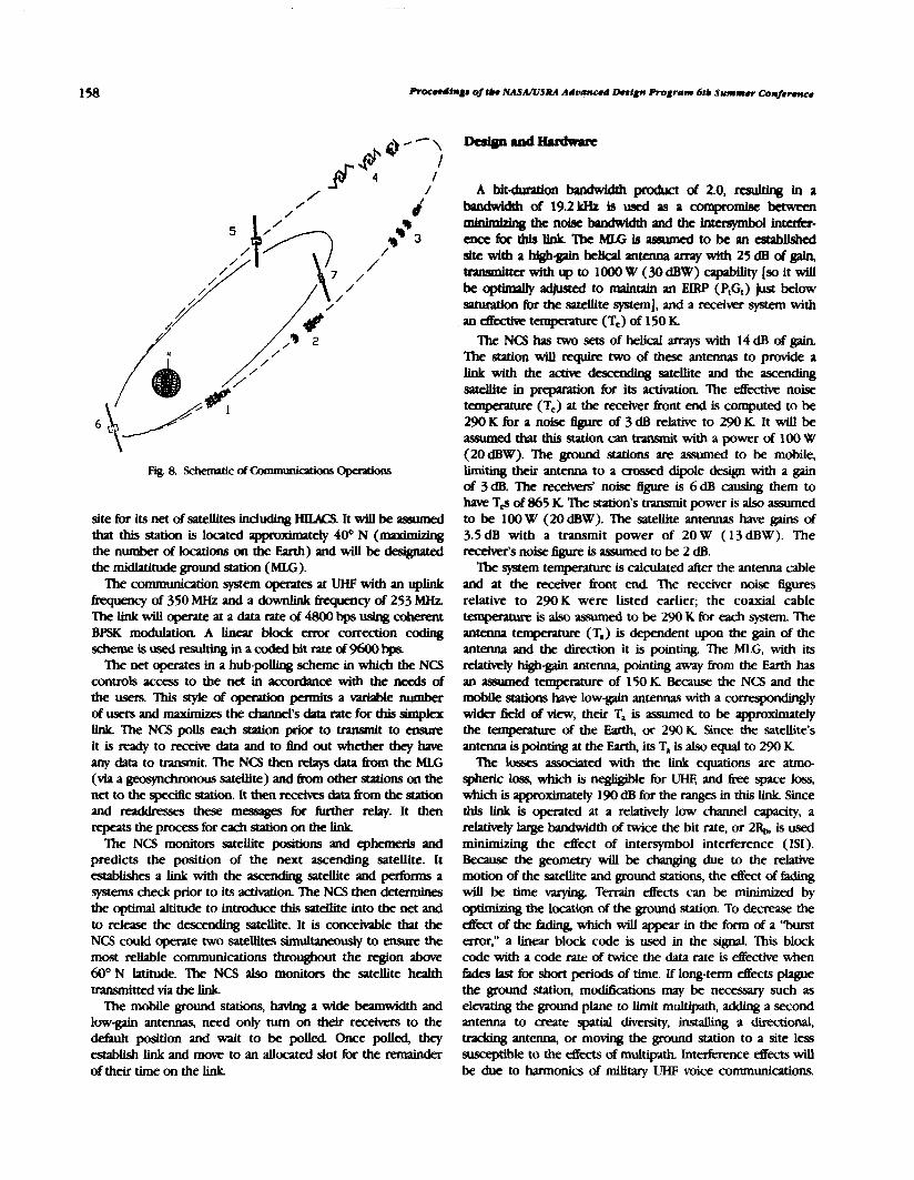
Procudin~8 af tb . NASANSRA Advanced Dnlprc Program 6tb Summw Confrrmce
site fw its net of satellites including HILUX It will be assumed that this station is located approximately 40" N (maxbhhg the number of locations on the Earth) and will be designated the midlatitude ground station (MU;). The communication system aperates at UHF with an uplink
6requencyof350MHzandadownlink~cyof253MHz The linkwill operate ata datarateof4800bpsuslngcohgent BPSK modukuion A linear block error correction coding schemeisusedresultinginamdedMtrateof9600bps
Ihe net operates in a hub-poUing scheme in which the NCS controls access to the net in acmdame with the needs of the users. This style of opedon pem~Its a miable number of users and maximizes the channel's data rate for this simplex link The NCS poUs each station prior to vvumit to ensure it is ready to receive data and to 6nd out whether they hne any data to transmit. The NCS then relay data from the MLG (via a jpxpchronous satellite) and 6rwn orher stations on the net to the specific station. It then receives data km the station and reakhsm these messages for hrrher relay. It then repeats the process for each station on the link.
The NCS monitors satellite positbm and ephemeris and predicts the position of the next ascending satellite. It establishes a link with the ascemhg satellite and perfom a systems check prior to its acthation The NCS then determines the optimal altitude to introduce this satellite into the net and to release the descending satellite. It is conceivlble that the NCS could q?erate two satellites simul- to ensure the most reliable communications throughout the region a h 60" N latitude. The NCS also monitors the satellite health transmitted via the link
The mobile ground stations, having a wide W d t h and low-galn antennas, need only turn on their recehm to the M u l t position and wait to be polled. Once polled, they establishlinkandmovetoanallocatedslotf0rtherem;linder of their time on the link
A bitducation bandwfdth product of 2.0, resulting in a bPndwiQh d 19.21rHz is used as a c~npromlsc betwten d n h i z d q the nolsc bPndwldth and the imc~spbol intafa- cnceEorrhtsElnlrIheMU;isassumcdtobeancstab~ site with a highgain helid antenna array with 25 dB of gain, tmmdtter with up to 1000 W (30 dBW) capability [so it will bc opthdy adjused to maintain an ElRP (P,G,) just below satumion for the satellite system], and a receiwr system with an eikctk tanperawe (T,) of 150 K
The NCS has two sets of helical arrays with 14 dB of gain. The station will require two of these antemas to provide a link with the actk descending satellite and the ascending satellite in pqamion for its activation. The eEedk noise teqmmm (T,) at the receiver h n t end is computed to be 290K for a ndse figwe of 3dB relark to 290K It will be ;Issumed that this station can transnit with a power of 100 W (20dBW). The ground stations are asswned to be mobile, limiting their antenna to a crossed dipole design with a gain of 3 dB. The received noise figure is 6 dB causing them to have T* of 865 K The station's transmit power is also assumed to be 100 W (20 dBW). Ihe satellite antennas haw! gains of 3.5dB with a transmit power of 20W (13dBW). The lWXh'&~1~)isef@UItk3assumedt0be2dB.
The system temperature is calculated after the antenna cable and at the receiver kont end The receiver noise figures relative to 290K were listed earlier; the coaxial cable temperature is also assumed to be 290 K for each system The antenna teqmmm (T,) is dependent upon the gain of the antenna and the direction it is pointing. The MLG, with its rehively high-gain antenna, pointing away from the Earth has an assumed temperature of 150K Because the NCS and the mobile stations have low-gain antennas with a correspondingly wider field of view, their T, is assumed to be approximately the temperature of the Earth, or 290 K Since the satellite's antenna is pointing at the Earth, its T, is also equal to 290 K
'Ihe losses associated with the link equations are auno- spheric loss, which is neghgible for UHF, and free space loss, which is approxhatety 190 dB for the ranges in this link Since this link is operated at a relatively low channel capacity, a relatively large bandwidth of twice the bit rate, or 2RL, is used minimizing the effect of intersymbol interference (ISI). Because the geometry will be changrng due to the relative motion of the satellite and ground stations, the effect of fitding will be time Mlying. Terrain effects can be minimized . . . by opmuq the location of the ground station. To decrease the -ofthe-whichwillappearinthefonnofa%burst error," a linear block code is used in the signal. This block code with a code rate of twice the data rate is eEectke when Gdes last for short periods of time. If long-term effects plague the ground station, moditications may be necessary such as elmting the ground plane to limit multipath, adding a second antenna to create spatial diversity, mdmg a directional, traclang antenna, or moving the ground station to a site less suscepuble to the effects of mulcipath. Interference effects will be due to harmonics of military UHF voice communications.

Naval Postgraduate School 159
These effects will be more transient than the Eading effects, so the block coding should eBectjveIy minimize this interfer- ence effea.
For ideal st* of the satellites on the launch vehicle, a maximum separation of 0.3 m was required. A resonant quadrifilar helix antenna chosen since it is compact, has a wide beamwidth (approximately 1 lo0), is simple in design, and has cir& polarization d t s in determining that quarter-turn, half-wavelength antennas with dimensions of approximately one-quarter wavelength for axial length and diameter are optimal for the dimensional cons&raints
A crossed dipole antenna is used as a bgckup for the quad- helixes and as the transmit and receive antenna for the TT&C system. It is composed of two orthogonal, center-fed, half- wmlength antennas(3). The antenna is sized for the downlink frequency of 253 MHz, for a length of 0.593 m. It has a resonating circuit (a trap) that electrically shortens the antenna for the higher uplink frequency of 350MHz or 0.429 m. The antenna is placed at 0.15 m above the ground plane to create the required radiation
ELECI'RICAL POWER SYSTEM DESIGN
The electrical power system (EPS) performs the functions of electrical power generation, storage, conditioning, and distribution for the on-orbit opetation of the satellite. f i e majority of the generated power is consumed by the communications payload, with the balance used for the general operation of the spacecraft bus, attitude c o n t d thermal control, IT&C, and the e l e c a l power system itself. The communications payload system will operate only when the satellite ground track is above 50' N latitude. The TT&C system will operate only dunng sunlight periods of the cycle. The remaining systems will require power throughout the orbit.
The subsystem will be arranged as shown in Fig. 9. The shunt regulator wiU maintain the bus voltage at 28V during sunlight periods and the battery charge/discharge unit is
I I I J
1.36 Sou th
t A n t i - E a r t h
Fig. 9. Functional Block Diagram of EPS System
responsible for maintaining eclipse loads and chargmg the battery. f i e arrays are switchable to allow for single array operation during periods when the required power is less than one array can supply. Auxiliary voltage levels of 32 and 42 V for use by the propulsion and attitude control subsystems will be generated from the 28-V bus using DC-DC converters.
EPS Design and Hardware Description
The solar arrays maintain n o d incidence to the sun by having two degrees of freedom in the system: (1) satellite rotation about the yaw axis, and (2) solar array rotation about the array longitudinal axis. The mys will be split into two independent, switchable systems with one array switched off- line until bus voltage demands. The cells used in the array have the foIIowing capabilities under AM0 conditions:
I, = 232.0 mA V, = 1014.0 mV I,=219.5 mA V,, = 876.0 mV P, = 192.3 mW Efficiency = 17.83%
Radiation effects on the solar cells are extreme due to passage through the lower portion of the Van Allen belts and represent the primary limiting faaor of the satellite lifetime. Radiation received by the cells was calculated using tabulated data prorated for the hction of time spent in orbit altitudes and summing the amounts received from the panel h n t and back wer the three-year period The array subscrate thick- nesses and shieldmg effectiveness are listed in Table @).
Table 8. Array Substrate Radiation Elkcts
structure Thickness (cm) Shield Effectiveness (mm)
Thermal Paint 0.0043 0.03 A1 Facesheet 0.013 0.16 Core Adhesive 0.007 0.06 Al Core 1.6 0.19 Core Adhesive 0.007 0.06 A1 Facesheet 0.013 0.16 Epoxy/Glass 0.01 0.08 KN-118 0.007 0.03 Total Thickness 1.6613 0.77 Back Shield Thick- 30.315 ness (in ml)
For an expected on-orbit life of three years, the total radiation received in one-MeV-equivalent electrons for front and back exposure is 5.14E + 15 for voltage and power and 2.82E + 15 for current. This equivalent radiation exposure results in degradation percentages for 12 ml liquid phase epitaxy (LPE) GaAs solar cells listed in Table 9. The radiation degradation experienced by 6-ml cells will be lower-resulting in higher EOL performance.

160 Proceedfngs of lbe NASA/USRA Advanced &sign Program 6tb Summer Conference
Table 9. Radiation Degradation Results
Cell Parameter F i Parameter Percentages
An advantage of the GaAs cells over silicon cells is their stability at higher temperature. This stability becomes imponant as the array temperatures increase toward the end- of-Life with decreasing array etficiencies. The design was itetated until the required EOL output power was achieved at an operating temperature consistent with the design array area. Worst case solar flux at aphelion with an array pointing error of 8.5' (0.15 rad) was assumed The final design results are given in Table 10.
The power values for the satellite if launched at perihelion vice aphelion are a BOL power of 540 W and an EOL power of 382 W.
Table lo. F i Array Design
Crlls in Series Cells in W e 1 Total Number of Cells Total Array Area with Intercell Spacing h e 1 Dimensions (2.5 crn boundvy on all sides)
m Worst Cue Operating Temperature Minimum Eclipse Temperature Max. Power Output at 30.9 V Minimum Power at EOL
The battery for eclipse power is a 12 amphour nickel- hydrogen battery manufiaured by Eagle Picher. This battery is provided in a mecell common presure vessel ( C W ) contipanon. The battery voltage per CW cell varies from 2.2 V to 3.2 V at fidl charge. For the bus configuration of a buck converter for constant current charge and a boost converter to maintain the line voltage, the number of C W cells is limited to 8 for the 28-V bus. This gives a maximum battery voltage of 25.6 V and a minimum of 17.6 V
The battery requirements are obtained from the eclipse load requirement of 140W With the boost converter dciency of 85%, the actual power supplied by the battery duting the eclipseperiodwillbe 164W.nKmaximumeclipseperiodis 37 min of the 4-hr-48-min orbit. This gives a minimum recharge time of 4 hr 1 1 min. For the three-year projected mission lifethe, the satellite will experience a maximum of 4500 eclipse periods. Nickel-hydrogen batteries provide the highest capability of withstanding a lvge number of discharge cycles while still able to undeqo large depths of discharge.
For a LEO satellite for which the charge and didurge cycles are numerous, the amount of energy that is removed from the battery must be replaced by an additional 10%. 'lhe charge rate chosen for this satellite is C/7. At this rate, the chargq current is 1.7 A, and the maximum power required for charge,
including charger &ciencies, is 52.5 W. The time required for charging the b a t t q after a dscharge of 164 W at 17.6 V minimum for 37 min is determined by calculating the number of amp hours removed and ad- 10%. For this design, 5.74 amp hours have been removed and will be replaced by 6.32 amp hours. Chaqtng at 1.7 A yields a required charge time of 3.7 hr.
The power electronics control section of the power subsystem is responsible for maintaining the proper level of voltage for the satellite bus. The bus will be a fully regulated bus at 2 8 V 'Ihis regulation is accomplished by employing a shunt regulator for periods d e n the solar array is powering the spacecraft and by using a boost regulator for periods when the battery system is supplying the power. The bus voltage regulwon accounts for a 1.3-V drop h m the array slip ring and 0.8V diode drops on each array and on each series suing. A desired 30.9 V is then achieved at the array.
AlTlTUDE CONTROL
The requirements for attitude dynamics and control (ADCS) are that the satellite be nadir pointing and three-axis stabilized The communications system requires 12' pointing accuracy. Tbe ADCS system contiguration (Fig. 10) is designed for a pointing ac- of + 0.5'. A monopropellant propulsion system is used that &cts despin and desaturation, and sun- sensing capability to maxhize solar array efficiency. The system is designed to be single-fault tolerant.
The ADCS performs in two modes, transfer orbit and on- orbit. The satellite will be ejected h m the Delta b c h vehicle with between 30 and lOOrpm during W e r orbit. The system will then despin the satellite after ejection, acquire the sun with sun sensors, despin completely, and acquire the Earth. After despin, the solar cells will deploy, and the reaction wheels and gyros will activate. The ADCS will maintain three- axis stabilization during transfer orbit bum to maintain solar power. Once on orbit, the ADCS will reacquire the Earth with the Earth sensor, and the satellite will be oriented for full operation.
rThruster Center Tube
Fuel
Fig. 10. hDCS Block Diagnm

Naval Postgraduate Scbool
A four-reaction-wheel control actuator was chosen with three wheels along the roll, pitch, and yaw axis (initial spacecraft coordinates) and one wheel at a 45" angle for redundancy. The spacecraft will have additional redundancy for the control actuators provided by the thruster. The 2-N thrusters will be fired to desaturate the reaction wheels, despin the satellite and provide redundancy. The ADCS senses disturbance torques, due either to internally generated, solar pressure, or magnetic/gravitational torques, and provides the necessary attitude corrections. Internal torques are the dominant forces in wheel saturation. The internally generated torques arise from internal friction and instabilities. Thrusters will be able to desaturate the wheels quickly, with minimum pointing error.
The sensors for HILACS consist of an Earth (horizon) sensor, sun sensors, and rate gyros. The Earth sensor is a two-axis scanning conical-horizon sensor located near the antenna on the Earth face. Accuracy for a worst case pitch and roll error of k0.07" at 1204 lan can be achieved. Four two-axis sun sensors are mounted two each on the Earth and anti-Earth faces. The sun sensors provide yaw sensing with worst case error of k0.01 O . One sun sensor will be able to give an accurate sun angle independent of the other sensor. This allows for nearly 47-r steradians of coverage for the satellite. The redundant element is a three-gyro inertial-reference unit mounted inside the spacecraft. The outputs from the sensors are fed into the control computer for onboard processing. Commands are then sent to the actuators.
Components chosen for the ADCS are space qualified parts with pedigree charasterized by previous flight performance. The sun sensors used are the coarse sun sensors flown on the INTELSAT VII satellite. The Earth sensors are manufactured by Barnes and well hardened for radiation tolerance. The rate measuring assembly was flown on INTELSAT V. The reaction wheels are made by Honeywell and were flown on DSCS 111. The computer is a Mil Standard 1750 that is capable of providing autonomous control of the spacecraft.
The highly elliptic orbit with inclination of 63.4" prevents continuous control of the satellite kom the MLG station. The lT&C must, therefore, be capable of controlling the satellite operations for a significant part of its life (see Fig. 1 I ) . When the satellite is in line of sight with the MLG it must be able to downlink its telemetry as well as respond to commands. These commands include initial maneuvers into operating orbit, modifications to current functions, and modilkations to onboard programs to adapt the satellite to changes in operating conditions. Since the satellite cannot be continuously controlled by ground for many of its orbits, it will have the ability to link to the NCS during its operating cycle. During the time that it is linked to the NCS it will be polled as any other mobile station (MS). Once polled, it will downlink telemetry data specific to its operations such as transponder status and power system information
The RTU interfaces with the telemetry antenna and the remote command unit (RCU). It performs all the functions of
. % L N o r t h
West
Fig. 1 1. lT&C Block Diagram
a transceiver including RF distribution to the single antenna, modulation, demodulation, and encoding/decoding of the telemetry data. The RTU uplink is at 350 MHz and its downlink is 253 MHz. The information is transmitted at a 1200-bps data rate, resulting in a 2400-bps transmission rate after encoding.
The RCU performs satellite control operations through the use of coded algorithms resident in memory. Dual micropro- cessors perform redundant operations based on these algorithms and their commands are correlated to remove the possibility of destabilizing operations due to single-event upsets (SEU). The RCU formats and relays telemetry to the RTU and acts on this telemetry in performing autonomous control of the satellite. The RCU also receives command signals from the RTU and performs these operations, which have priority over onboard generated commands.
The RTU uses a crossed-dipole hybrid antenna resonant at 350 MHz and 253 MHz. The RTU receives formatted com- mands from the RCU that are then encoded to modulation to the downlink frequency and transmitted. The RTU also demodulates and decodes uplinked telemetry commands to the acceptable format for the RCU. The RTU sends Limited telemetry data to the NCS while performing transponder operations.
The RCU receives analog information from various sensors. It samples and performs pulse code modulation on the signals and then relays this data to the microprocessors for control functions.
The RCU commands heater operation based on temperature sensor data, and monitors voltages and currents to control the m y drives, battery charging, solar array switching, and current regulation via the shunt regulator. The RCU also monitors the attitude control system and propulsion system operations by receiving data from the momentum wheels, Earth/sun sensors, thruster actuators, and propellant tank pressure sensors. The automatic gain control for the receiver and the transmit power of the transponder are monitored by the RCU.
PROPULSION SUBSYSTEM
The propulsion subsystem is a catalytic monopropellant hydrazine subsystem. The subsystem consists of four propellant

ngs of tbe NASA/USRA Advanced Design Program 6tb Summer Conference
tanks with positive expulsion elastomeric diaphragms separat- ing the pressurant from the propellant as shown in Fig 12. The tanks are manifolded to two redundant sets of thrusters. The two sets of thrusters are interconnected and isolated by latching dws to provide redundancy for all on-orbit control h c t i o m
After Delta I1 separation, the &st of the three satellites will be slowed down to achieve the fkd orbit. Four 3&N thrusters and four 2-N thrusters will be fired at perigee to slow down the &st satellite. The same procedure is repeated for each of the remaining two satellites for orbit insertion. rhen only the 2-N thrusters will be used for roll, pitch, yaw desatwation, and despin.
The entire propulsion subsystem consists of four 38-N and twelve 2-N thrusters, four propellant/pressurant tanks made of titanium alloy, Wdnin Mh.es for propellant and presurmt, latchmg isolation vdves, Nters, pressure regulators, pressure transducers, and lines made of titanium alloy.
The Delta 11 launch vehicle was chosen primarily because of its adaptability and cost. 'lhe Taurus and Atlas U launch vehicles will also s a w the launch requirements.
Ihe Delta 11 7925 upper stage consists of the Morton lhiokol Star 48B solid rocket motor, a cyIindrid payload attach fitting with clamp assembly and four separation springs, a spin table with bearing assembly, and motor separation system. The upper stage also contains a nutation control system (NCS).
The Delta 11 3712B attach fitting is the interface between the upper-stage motor and the spacecraft. It supports the clamp assembly that atlaches the spacecraft to the upper stage and allows the spacecraft to be released at separation. It mounts the four separation springs, two electrid disconnects, even sequencing system, upper stage telemeuy, and the NCS.
THERMAL CONTROL
Passive thermal control techniques are used throughout the satellite. Ibo radiators made of optical solar reflector material, each 0.9 x 0.7 m2 are placed on the east and west faces of the
0 5 6 -- I
0 - 1 d - N o r r h : 36 ---
I Y
--I 1 I
A n r - E n r t h
Fig. 12. Propulsion Subsystem
spaced. These faca are always edge on to the sun, thus receiving albedo and Earth radiated flux, but no solar flux AU electronic modules are located on the equipment panels
that are mounted back-to-back with the OSR to minimize conductive paths. The equipment panel is of aluminum honeycomb construction with aluminum heat sinks as required No detailed thermal analysis of the substrates was attempted
Multilayer Insulation (ML.I)
MU is used throughout to thermally isolate components. "hv" temperature applications use Mil with outside layers of aluminum kapton (spacecraft sides, etc.). "Hot" temperature locations use MLI with outside layers of titanium kapton (thrusters). A nominal thickness of 10 layers was used throughout. T-ture ranges for components are given in Table 1 1.
Table 1 1. Temperature Ranges for Components
Component Operating Temp. ( O C)
Electric power Control unit -25/ + 30 Solar arraY -160/+80 Shunt -45/ + 60 B a t t ~ O/ + 40
woad Receiver elecmnics -20/ + 45 Transmitter electronics -15/+45 Antenna -170/+90
Attitude control Earth/sun sensors -25/ + 60 Angular rate assembly - l o / + @ Reaction wheels - l o / + 55
Propulsion Tank -5/ +60 Vah.es - 5 / + 6 0 Thrusters -5/ + 60
Tkvo basic types of heaters are used: redundant and replacement. Redundant heaters are used as additional sources of thermal dissipation to maintain certain equipment (tanks, lines, valves, etc.) above minimum operating temperature. These consist of heat filament elements wound in layered material such as kapton. The other type of heater is the replacement heater, which is turned on when certain equipment (payload transmitter) is turned off in order to minimize thermal excursions. The former require additional power requirements whereas the latter do not. Thrusters have their own heaters for their catalytic beds. Heater control is either by enable/disable command from the ground, or once enabled, automatic control by thermistor to maintain tempaanues within the allowed range.
Thermal design encompasses four phases of a satellite's life, namely prelaunch, launch, tfansfer orbit, and on-orbit. Only the on-orbit case was considered for this report. Analysis invoked the two hot and cold steady-state cases. Internal sources include electronic equipment and soak-back !?om engine firings. External sources include solar, albedo, and Earth radiation. A thermal model was created identify~ng locations

dcmane tanpa;mucs for the satellite. Only a few iterations were done due to time amstmints and av&bUty of sdtwuc tools.
MLNmmxxamm
nKpPojtCtt~~~llwuuldliktothankProf.B.Agt?wllfor h i s g U i d u l ~ ~ u l d s u p p ~ n ~ t t h i S & ~ W ~ h w v l t u , tbulkMRKolu,RW.MLer,G.hMyas,uldhKr;lus , of the N a d Postpduate School fw their ashnce. The following personnel 6rom the Naval Resevch Laboratory also contributed to the success of the project: Mike Brown, Shannon Coffey, Chris Gamer, Maw Levinson, and Tom Kawecld F h d y , we would like to thank Mr. J. D. Burke, our NASA center representative b m the Jet Prcpulsion Iabofatory UPL), and Dr. J. H. Kwok also from JPL
1. fW.U S&r W Amry Des4pn H m d w o h , VoL I, equPtian 9.10- 18, Oaokr, 1976.
2. Ms4 Solar GaArrqyDeslgn HandrodZ V d I, equation 9.10- 27, Octok, 1976.
3, John D. k a q Antenmas, 2nd Ed, USA, McGmw-HLU, 1988. 4. B r u c c S H a l e , 7 b e A R R L H ~ ~ t b e R a r l Y o A m a l o u r , ~
d x t h F d . , ~ , A m a l ~ R a d i o R c l y ~ , 1986. 5. JPL and NASA, Sdar CeU Atmy L&&gn H a M k x k , Volumes 1, p.
12.2-1.jPL hbli~1ti0n SP 43-38. O c t W 1976


PROPCT WISH: THE EMERALD CITY
INTRODUCTION
When Project WISH (Wandering Interplanetary Space Harbor) was initiated as a multi-year project, several design requirements were specified. The space station must have a lifetime of at least 50 years, be autonomous and independent of Earth resources, be capable of traveling throughout the solar system within a maximum flight time of three years, and have a population of 500- 1000 people. The purpose for the station is to provide a permanent home for space colonists and to serve as a service station for space missions.
In the process of designing the Emerald City, given the stated design requirements, the following systems were studied: Orbital Mechanics, Propulsion, Vehicle Dynamics and Control, Life Support, Communications, Support Systems. Power, Thermal Control, and Configuration. The travel times and necessary velocity changes to move throughout the solar system were determined in orbital studies. The Propulsion System Study then focused on the necessary impulse and thrust levels to provide the velocity changes derived by the Ohital Mechanics group. Vehicle Dynamics and Control considered the station's flexible dynamics and rigid attitude behavior. This analysis provides information for orbit selection, body shape and configuration, and propulsion requirements for station keeping in a nominal orbit. The Life Support System must satisfy all the physical needs of the inhabitants. It will provide the air, water, waste management, and food requirements for the crew and passengers. The Support Systems are commun- ication, shuttles, and maintenance. The Communication system will provide the colonists with a means of talking to other colonists and sending valuable scientitic data to earth. Shuttles will move people and supplies to and kom the station. Repair and upkeep of the various systems on the station will be provided by the Maintenance Subsystem. AU the electrical power used to run and maintain the station will be supplied by the Power System. The temperature ranges required by the people and equipment will be controlled by the Thermal Control System. Finally, everything is put together and an initial configuration of the station, the Emerald City, is described.
ORBlTAL MECHANICS
Orbital mechanics determined whether the Emerald City could travel anywhere throughout the solar system within the mission requirement of three years. Using a trajectory optimization comptlter prograin obtained from NASA Lewis Research Center, velocity chahges (AVs) for many orbital transfers were calculated. Adjusting for gravitational effects by roughly multiplying by a Eactor of two, the highest mission AVs were compared and checked against propulsion feasibilities.
From this, an outer limit was choscn to bc the orbit of Saturn This came from comparing the worst caws of planet to planet transfers. The AV from Saturn to Jupiter is about 100 km/sec, and frorn Uranus to Saturn is about LOO km/scc. The propulsion sptem cannot reach numbers of 200 km:'xc, in general, for the anticipated mass of the ship. Also, a nominal orbit was selected. A of orbital shapc's
and uses were examined. A circular orbit at 3.2 A,[!. was chosen because it put the ship clo.w to both the asteroid k l t and Jupiter, so that raw materials for resupply and repair could be reached. It was located on the ecliptic plane to minimize z-directional velocity changes.
The nominal orbit will also senfe as a place to do maintenance and to rest between missions. It will also he advantageous for communications, since colonies that need the ship will h o w its approximate location. There may be other reasons for having a nominal orbit and work continues in finding an optimized place for the ship to stay.
PROPULSION SYSTEM
The propulsion system of the Emerald City was one of the major subsystems that has k e n studied during the first yrlu of Project WISH. It should also hc one of the key areas of development in the project because, without an effective propulsion scheme, the Emerald City will be unablc to accomplish its mission of supporting colonies on distant worlds and gathering data &om prc~iously inaccessible sclurces.
The propulsion system study for the Emcrald City was divided into five phases. In the first phase, the mission requirement.? of Project WISH were broken down and studied in order to determine their effect on propulsion. Two influences on the selection of a propulsion unit were the three- year flight time and the ma.5 of the station. Thew will determine the specific impulse that must he generated to accomplish the missions.
In the second phase, equations w r e dclrloped that could relate how much of an effect thc demands of the mission would have on the propulsion gsteni. Equations relating the payload mass ratio, propellant mass ratio, and in~pulsc to imp)rtant design criteria such as the specific impulse and specific power were then u . ~ d to compare the capahilities o f different propulsion gstems for given missions.
The third phase consisted of sytem comparisons for four propulsion concepts: chemical, electrical, nuclear, and antimatter. Only nuclear and antimatter were found to offer the combination of high thrust and high specific impulse that would be required for Project WISH.
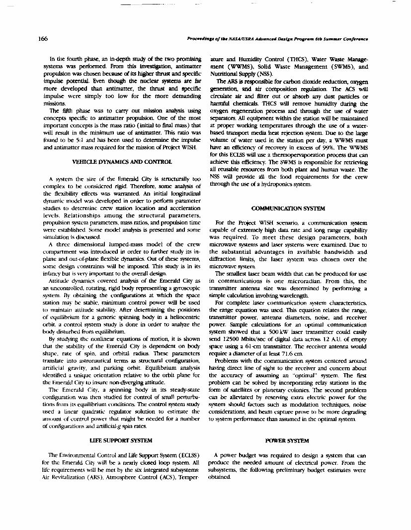
In tile fourth phase, an in-depth study of the two promising systems was performed. From this iwdgation, antimatter propulsion was chosen because of its higher thrust and spedac impulse potentiaL Even though the nuclear system are far more developed than antimatter, the thrust and speciAc impulse were simply too low for the more demanding missions.
IIhe fifth phase was to carry out mission vlafysis using concepts specitic to antimatter propulsion One of the most important concepts is the mass ratio (initial to final mass) that will result in the minimum use of antimatter. This ratio was found to be 5 1 and has been used to determine the impulse and antimatter mass required for the mission of Project WISH.
VEHICLE DYNAMICS A ' CONTROL
A system the size of the Emerald City is struckrally too complex to be considered rigid. Therefore, some analysis of the flexibility effects was warranted. An initial longitudinal dynamic model was developed in order to perform parameter studies to determine crew station location and acceleration levels. Relationships among the structural parameters, propulsion system parameters, mass ratios, and propulsion time were established. .%me model analysis is presented and some simulation is dixussed.
A three dimensional lumped-mass model of the crew conlpartment was introduced in order to further study its in- plane and out-of-plane flexible dynamics. Out of these systems, some design constraints will be imposed. This study is in its infancy but is very important to the overall design.
Attitude dynamics covered analysis of the Emerald City as an uncontrolled, rotating, rigid body representing a gyroscopic sytem. By obtaining the configurations at which the space station may be stable, minimum control power will be used to maintain attitude stability. After determining the positions of equilibrium for a generic spinning body in a heliocentric orbit, a control system study is done in order to analyze the body disturbed from equhbrium.
By stuctytng the nonlinear equations of motion, it is shown that the stability of the Emerald City is dependent on body shape, rate of spin, and orbital radius. These parameters tmslate into astronautical terms as structural configuration, artiftcial gravity, and parking orbit. Equilibrium analysis dentilled a unique orientation relative to the orbit plane for the Emerald City to insure non- attitude.
The Emerald City, a spinning body in its steady-state configuration wds then studied for control of small perturba- tions from its equilibrium conditions. The control system study uwd a linear quadratic regulator solution to estimate the amount of control power that might be needed for a number of configurations and artificialg spin rates.
ature and Humidity Control (THCS), Water Wslste Manage- ment (WWMS), Solid Waste Management (SWMS), and Nutritional Supply (NS).
'Ihe ARS is rrsponsible for carbon dioxide reduction, ox= generation, and air composition regulation. The ACS wiU drculate air and filter out or absorb any dust particles or harmful chemicals. THCS will remove humidity during the oxygen regeneration process and through the use of water separatofs. All equipment within the station will be maintained at proper working temperatures through the use of a water- based tramport media heat rejection system. Due to the large volume of water used in the station per day, a WWMS must have an &ciency of recowry in excess of 99% The WWMS for this ECLSS will use a thermopemaporation process that can achieve this &ciency. 'lhe SWMS is responsible for retrieving all reusable resources from both plant and human waste. The NSS will provide all the food requirements for the crew through the use of a hydroponics system.
C O ~ ~ O N SYSTEM
For the Project WISH scenario, a communication system capable of extremely high data rate and long range capability was required. To meet these design parameters, both microwave systems and laser systems were examined. Due to the substantial advantages in available bandwidth and diffraction limits, the laser system was chosen over the microwave system.
The d e s t laser beam width that can be produced for use in communications is one microradian. From this, the uiuwnitter antenna size was determined by performing a simple calculation involving wavelength.
For complete laser communication system characteristics, the range equation was used. This equation relates the range, transmitter power, antenna diameters, noise, and receiver power. Sample c a l d o n s for an optimal communication system showed that a 500 kW laser transmitter could easily send 12500 Mbits/sec of W t a l data across 12 A.U. of empty space using a 6 lcm transmitter. The receiver antenna would require a diameter of at least 71.6 cm.
Problems with the communication system centered around having direct line of sight to the receiver and concern about the accuracy of assuming an "optimal" system. The first problem can be solved by incorporating relay stations in the form of satellites or planetary colonies. The second problem can be alleviated by reserving extra electric power for the system should hctors such as modulation techniques, noise considerations, and beam capture prove to be more degrading to system performance than assumed in the optimal system.
LIFE SUPPORT SYSTEM P O W E R S Y ~
The Environmental Control and Life Support System (ECLSS) A power budget was required to design a system that can for the Emerald City will be a nearly closed loop system. AU produce the needed amount of electrical power. From the life requirements will be met by the six integrated subsystems: subsystems, the following preliminary budget estimates were Air Revitalization (ARS), Atmosphere Control (ACS), Temper- obtained.

Obio State Unive+sity
Estimated Power Budget:
1. Propulsion (storage) several GWe 2. Life Support 3 m e 3. Communications 10 MWe 4. Dynamics and Control several GWe 5. HeatTransfer 0.6 GWe 6. Shuttle and Maint. 5 W e 7. Misc. Power 5 W e
The parameters of fission and fusion reactors were reviewed to identlfy a power system that would provide the elecMcal power required by the Emerald City. Based on mass, specific power, and stability, the power source for the Emerald City will be a rotating particle bed reactor. However, if the power budget does increase to the tera-watt range, a fusion reactor would then be needed since these reactors have the potential of supplying an essentially inexhaustible source of energy. In this case, the considerations of mass and specific power will not be important compared to total power achieved.
THERMAL SYSTEM
The thermal control system of the Emerald City will use active and passive systems to control the temperature of the station. An active thermal control system employs radiators or a mass conversion system to dissipate waste thermal energy. On the other hand, a passive thermal control system uses paints, coatings, and insulations to control the station temperatures.
The Emerald City will use a radiator to control most of the waste heat produced by the power system and other subsystems. A radiator, similar to the Rotating Bubble Membrane Radiator (RBMR), was chosen. It differs fiom a RBMR in that it wraps around the cyiinder of the station forming a torus rather than a sphere. The radiator wiLl use nozzles to spray molten metal on a surrounding envelope or bubble. As the droplets hit the envelope, they radiate thermal energy. Since the bubble will be attached to the spinning section of the station, the centrifiql force will move the droplets to a trough where they are collected and recirculated.
This type of radiator was chosen over other types because of mass and meteoroid protection. The tiny droplets of fluid and the bubble will provide the needed surface area to dissipate the waste heat. Because the droplets are so tiny, they have very low mass and the mass of the total system is much lower compared to conventional heat pipes. In addition, meteoroid protection is provided by the bubble. If a meteoroid hits the radiator, it passes through the bubble and continues on its course. However, the bubble is made of a self-sealing material, .so that any rips or tears repair themselves and there is Little loss of the circulating fluid. This type of meteoroid protection provides additional mass savings because armoring, typical in convention sytems, is not needed.
CONFIGURATION
To determine a feasible configuration, all of the subsy3tems had to be accommodated. Not only does each of the subsystems have to be in an appropriate place with respect to the others, but the entire unit has to meet the stability and control requirements. At this stage in development, the requirements ate very general. This configuration is a place to start rather than a final design.
The systems that need to be integrated are the shuttle, communications, habitat, power, thermal control, and propulsion. These systems must be pieced together so that the stability requirements are met and construction is feasible.
The habitat must protect the crew from the hazards of space. These hazards include micrometeors, solar and cosmic radiation, and near-vacuum conditions. Besides being a protective shelter, the habitat must also accommodate agriculture and life support systems in an architecture that will avoid unnecessary stresses for its human occupants.
The propulsion system must be able to access the large amounts of hydrogen it will use as a working gas. The drive will emit large amounts of gamma rays, which are lethal to living organisms without shielding.
The design will be composed of various section roughly correlating to the subsystems. These sections include the habitat, power and propulsion, fuel tankage, radiator, de-spun platform, and the connecting pieces. This configuration is pictured in Fig. 1.
At this point in the project, the habitat is conceived as a torus with an outside diameter of 600 m and a tubular radius of 60 m to provide 0.8 g at a spin rate of 1.6 rpm. However, larger torus diameters such as 1850 m with I-g at 1 rpm may have to be considered when all subsystem designs are to be integrated optimally for the overall system. If this structure is made of a medium grade aluminum alloy, then the minimum thickness of the shell will correspond to radiation shielding of 3000 kglm2, just over the 2800 kg/m2 required for galactic radiation protection. Certainly, psychological considerations
s ) ( w ~ UVLNG QUAKTSRS
COYUUNICATIOHS
s ) ( w ~ UVLNG QUAKTSRS
COYUUNICATIOHS
- . J 7 0 N E
FUEL CL(U-5
Fig. 1. Configuration

168 Proceedings of tbe NASNUSRA Advanced Design Program 6tb Summer Conference
will play a large role in designing the interior architecture of the torus.
Ihe propulsion system is placed on one end to transfer all of the thrust force through the axis of the spacecraft. Each set of fuel tanks will be connected to a main, loadcarrying structure. Each fuel section will also have plumbii for the fuel, power transmission, heat pipes, and communication capabilities.
On the very end will be the radiator and the de-spun section containing the shuttle and the communications platform. The connections between the de-spun and spun sections are mechanical, power, fuel, and personnel transport. The connections are not complex and can be produced reliably.
The main support structure that runs through the hel cells will connect directly to the radiator. This structure will also run through the nuclear reactor and connect to the propulsion system. Although the structure could be made out of any strong material, it may be advantageous to make it out of reinforced concrete. This material has a very large compressive strength to weight ratio.
The torus will be connected to the main structure with a large number of spokes, similar to a bicycle wheel. There will also be two pressurized tubes connecting the habitat with similar tubes in the main structure. lhese tubes will be the meam of transportation between the habitat and the shuttles
CONCLUSION
Hard work in researching and performing parametric studies to make the Emerald City of P r q c t WISH realizable has taken place by starting from scratch and creating a sketch of a possible design for the space oasis. With such an undertaking, the more that is learned merely reveals how much more needs to be learned. Since Roject WISH began, an initial decision on propulsion and power systems has been made, parameters for life support systems have been established, various subsystems have been analyzed, and necessary orbital restrictions have been determined. An initial configuration has been produced and work on detailed subsystem studies has begun. Project WISH will continue over the next two years, relining studies begun this year and incorporating additional aspects not yet considered.

DESIGN OF AN AUTONOMOUS LUNAR C O N S T R U C ~ ~ O N U T I L I T Y ~ ~ E ~ g 1 - 1 8 1 4 7
OLD DOMINION UNIVERSITY
In order to prepare a site for a manned lunar base, an autonomously operated conmction vehicle is necessary. In this report, a Lunv Construction Utility Vehicle (LCUV), which uses interchangeable construction irnplemeng has been designed conceptually. Some elements of the machine have been studied in greater detail and are the focus of this repon. Design of an elastic loop track system has admnced to the testing stage. A standard coupling device has been designed to insure a proper connection between the different construaion tools and the LCUV. Autonomous control of the track drive motors has been simulated successfully through the use of a joystick and computer interface. A study of hydrogen- o a e n fuel cells has produced estimates of reactant and product requirements and has identified multdayer insulation nee& b c h on a l W k W heat rejection system has determined that it is necessary to uansport the &tor panel on a utility trailer. Extensive logistical support for a 720-hr use cycle requires further study.
INTRODUCTION
Resident George Bush has made human missions to the Moon and Mars national goals. He has directed the National Aeronautics and Space Adminisvation to develop the necessary technologies and planning that will ultimately lead to permanent bases on the Moon and Mats. A lunar base will likely e v o k Erst because of its relative closeness to Earth. Regardless of the evolution, initial construction of these bases will rely on autonomous and teleoperated construction vehicles to reduce hazards to humans.
A rugged and reliable construction vehicle capable of performing a range of construction tasks is needed. Old Dominion University has investigated a lunar construction utility vehicle during the last two years as part of the USRA program. This vehicle is designed to perform several construction tasks by interchanging tools autonomously. The evolution of the LCUV has proceeded from a conceptual design of the overall system to a more detailed design of the coupling system for interchangeable construction implements, power generation trade-off studies, a heat rejection system design, control system strategies, and tracked locomotion design refinements. The report that follows is a current owrview of the LCUV design.
AUrONOMOUS COUPLING DESIGN
One of the major purposes of the LCUV is to prepcue a lunar base site for construction. To complete this task, several different operations need to be performed. However, it is advantageous to use one type of vehicle for many construction activities so that the number of machines required on the Moon is minimized It is therefore necessary to have a vehicle (the LCUV) that is able to interchange tools for specified functions. To do so, a standard coupling device is needed for proper connection between the tools and the L W
Initially it was assumed the coup@ would be attached to a robotic arm mounted on top of the LCUV. However, after
consideration of the dynamic and static loadings that will occur, it was determined that resulting reaction forces and torques would be too great for robotic arms using current technology. Thus the coupling system design that has evolved anticipates mounting implements on the front of the LCU\!
The coupling design is configured as a three-point system. The receiving end of the coupling is located on the tool implement. The receiving end consists basically of a shell-like triangular box. The face of the box is open to facilitate the insertion of the lockmg mechanism. The locking mechanism, which is located on the front of the LCUV, attaches to an implement by rotating three levers into the tool receiving box. Each of the three levers will be driven by worm gears. Worm gears were chosen over luzkages because of their ability to mow the arms through greater angles. The ability to rotate the arms through an angle greater than 180' is necessary to allow for large positioning tolerances. The coupling device will be able to lift a tool vertically by raising three linkages that attach the coupler to the LCUV. The coupling will be able to rotate about the fore-and-aft axis to make the coupling and tool movement more dexterous. After the three locking levers are inserted into the box, they rotate outward and around the outside of the box, grasping pins at the outermost corners of the implement's receiving box (see Fig. 1 ). As the levers swing around, they pull the implement up to the coupler that is attached to the LCU\! It is then locked into position. A picture of the coupling as it would look mounted on the LCW is shown in Fig. 2.
Provisions are made for connecting cooling fluid, data links, and electrical power lines to the implement via connections within the implement box. An interface located centrally on the coupling device mates with a female socket on the implement receiving box. A feasible design can be derived from the quick-disconnect coupling as shown in Fig. 3(' ). W~th further investigation, this design may be the start of an appropriate power connection lead.
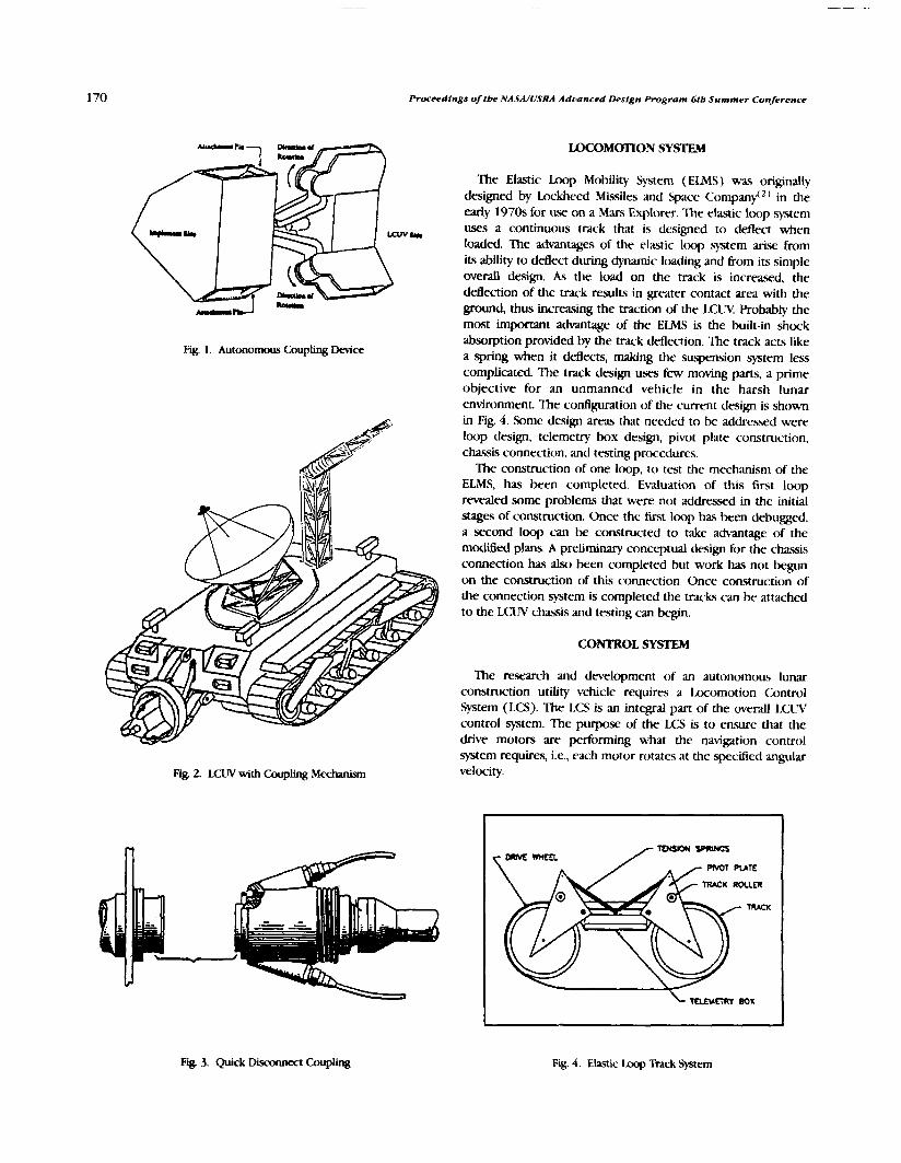
Proceedings of tbe NASA/USRA Advanced Design Program 6tb Summer ConJerence
LOCOMOTION SYSTEM
The Elastic Loop Mobility System (ELMS) was originally designed by Lockheed Missiles and Space ~ o m p a n f ~ ) in the early 1970s for use on a Mars Explorer. The elastic loop system uses a continuous track that is designed to deflect when loaded. The advantages of the elastic loop system arise from its ability to deflect during dynamic loading and from its simple overall design. As the load on the track is increased, the deflection of the track results in greater contact area with the ground, thus increasing the traction of the LCW Probably the most important advantage of the ELMS is the built-in shock absorption provided by the track deflection. The track acts like
Fig. 1. Autonomous Coupling Device a spring when it deflects, making the suspension system less complicated. The track design uses few moving parts, a prime objective for an unmanned vehicle in the harsh lunar environment. The configuration of the current design is shown in Fig. 4. Some design areas that needed to be addressed were loop design, telemetry box design, pivot plate construction, chassis connection, and testing procedures.
The construction of one loop, to test the mechanism of the ELMS, has been completed. Evaluation of this first loop revealed some problems that were not addressed in the initial stages of construction. Once the first loop has been debugged, a second loop can be constructed to take ad\antage of the m&ed plans. A preliminary conceptual design for the chassis connection has also been completed but work has not begun on the construction of this connection. Once construction of the connection system is completed the tracks can be attached to the LCUV chasis and testing can W n .
CONTROL msTEM
The research and development of an autonomous lunar construction utility vehicle requires a homotion Control System (LCS). The LCS is an integral part of the overall LCUV control system. The purpose of the LCS is to ensure that the drive motors are performing what the navigation control system requires, i.e., each motor rotates at the .specified angular
Fig 2. LCUV with Coup@ Mechanism velocity.
I
T W K ROCLER
u r n BOX
Fig. 3. Quck Discmect Coupling Fig. 4. Elastic Loop Track System

Old Dominion 0niflersit.y 171
The LCS must operate under the iunar environmental extremes and maintain the vehicle's autonomy of operation as e5ciently and reliably as possible. The task of developing this control system is explained in this section. Also, the areas of command input, control mode, output mode, and feedback measurement have been analyzed and modified. The project covers five major areas: sptem constraints, control system research, hardware requirements, s o h e requirements, and problems and solutions.
The use of digital control was determined to be the best in accuracy, versatility, and cost effectiveness. A standard 286 personal computer interfaced with a Keithley 570 D/A and A/ D conversion board was used as the primary control hardware. A visual representation of the control model is available in Fig. 5.
To simulate the autonomous operation of the drive motors, a joystick was used as the source of navigational information. The joystick information is scanned by the computer and the control software operates from this information in the following manner:
1. The joystick information is scanned by the computer. 2. This information is then translated into the desired
an@ velocity for each motor. 3. The desired angular velocity is then W e m d to the
Keithley board and sent to each respective motor in terms of voltage.
4. Once this voltage is applied to the motors, they rotate at a specific angular velocity, thus rotating the tachometers mounted on the drive shaft of each motor.
5. The rotation of each tachometer causes them to create a voltage.
6. This voltage is then input to the computer via the Keithley board.
-rnp fix- -
Fig. 5. Motor Controller Diagram
7. The relationship between angular velocity and voltagc is linear. This relationship is described below (for a tachometer)
Voltage " =- Y
8. Now the computer has the values of the desired angular velocity and the actual anplar velocity. The control error is then calculated. The error is the ditference between these two values.
9. The control effort, U, is then determined kom the error reading found by the computer. 'lhis effort is determined through the relationship
10. Step 3 is resumed by the control program until there is no error or until the computer receives new navigational information, in which event the processor would start with step 1.
POWER SUPPLY
The proposed LCW requires a sustainable source of power for 720 hr of continuous operation. Analysis must he performed on the LCWs requirements to determine the kind of power supply a d a b l e using existing technology. When a power system for the LCUV is determined, the limitations and resources of the environment within which it operates must be taken into account. Energy kom hydrogen-oxygen fuel cells was considered in the present study.
The fuel cell is a fairly simple electrochemical dwice. Its primary parts consist of an anode, a cathode, and an electrolyte(3). The energy conversion occurs at the anode where the fuel (hydrogen) enters and is ionized. As this occurs, electrons are removed and travel across a load, which generates a current. The hydrogen ions then diffuse across the electrolyte. At the cathode, oxygen enters and combines with the hydrogen ions and the electrons that traverse the load. This recombination forms water, which is removed from the system. Each fuel cell can be placed in series to form a fuel cell stack which delivers a desired combined power output and voltage.
The design chosen for the reactant and product storage tanks consists of having the containers with several layers of radiation insulation mounted around their surfaces, as shown in Fig. 6. With this set-up, the outermost layer wiU absorb the radiation from the sun and will increase in temperature. The outer layer will radiate energy to the layer beneath it. In this process, every layer will transfer heat to the layer directly below it. This process continues until the heat reaches the surface of the tank Therefore, by selecting the number of layers and the ernissivity of the shielding material, heat transfer can be controlled. Some heat gain can be tolerated by allowing

Proceedings of tbe NASA/USRA Aduanced Design Program 6tb Summer Conference
Fig. 6. Multi-layer Insulation (Sectional View)
tlle liquid inside the tanks to boil. Specifically, a backgmund or hawline rate of power generation becomes an insulation design constrdint.
The insulation .shield would bc composed of highly polished llluminun~ film having low emissivity d u e s . [.ow emissivity is required because resistances associated with the radiation shield become very large when emissivities are smd. This would mean that lower heating rates are received by the cryogenic fluid(". Also, polished aluminum is currently available with high solar reflectance, good durability, and high flexibility.
HEAT REJECTION SYSTEM CARRIAGE
The only effective way to release heat in a lunar environment is by a radiator. To optimize the operation of the LCW, a log~stics tcliler is designed to be u.wd for housing the power supply md the heat rejection si tem. In order to supply ctx)lant fluid md power to the LCLN from the camage, a telescoping tniss structure is incorporated to support the line%.
The licat rejection carriage was determined to be twice the size of the [.<:IT! This assumption of a 6 nl by 6 m by 3-m clec~ vchicle was to allow for added stability.
Another major assumption was that when the radiator is fully deployed, its support platform will remain stationary in a predetermined location during a particulx operation. This stationuy configuration requires a collapsible truss type system to couple the mdiator to the LCUV. This collapsible truss systm~ will allow the I.C1hr to operate in a predetermined radius w u n d the radiator and will alw) provide protection for the Lines that c , q the fluid and power to the radiator and it?, cwriage.
The design of the truss selected for fiuzher consideration was a miation on a fire truck extension ladder. The ladder design possessed many of the qualities that are necessary to satisfy the design requirements that apply to the LCW and heat-rejection unit.
For a 110-ft-long Emergency-One ladder at full extension and O0 inclination (horizontal) under an 800-lb point load at the free end, the maximum deflection was 18 id5). For application to the heat-rejection unit, distributed loads are more of a concern than point loads. The distributive loading consists of the structure's own weight, along with the weight of the fluid and power lines. Also for the LCCV, the extension unit will be supported at each end, thus deflection will occur in the center and not at the end. Due to this fact, greater extension lengths may be achieved and the extension unit can serve as an overhead crane.
HEAT R&JECTION SYSTEM RADIATOR
The LCW has a major problem with its ability to reject excess thermal energy. The solution to this problem is not an easy one; however, it is attainable through the use of a radiator. This radiator would need to be of considerable size and complexity in order to meet the heat rejection needs of the LCW operating in the harsh lunar environment. The goal of this group has been to research the problems associated with the development of a daytime heat rejection unit that will meet the requirements of an LCW working under the worst possible conditions on the lunar surface.
The research and design for the heat rejection unit has been carried out subject to limiting assumptions. The first assumption was that the LClJV should have the ability to perform heavy construction in the honest lunar environment. This means that the heat rejection unit will be designed to operate at ncxm on the lunar equator and reject sutficient thermal energy to allow for productive I.CW operation.
The amount of thermal energy that realistially needs to be rejected is assumed to be 100kW. This is a generous assumption and is intentionally large to prevent design shortfalls.
It is desired to operate the radiator at the lowest possible return temperature, which was determined to be approxi- mately 340 K This requires a radiator that is 50 ft (15 m) in length and 50 ft high. Operating the radiator much below this temperature is not feasible because it was determined that it was not possible to assume radiator surface temperatures below 340 K at lunar noon.
The radiator's large size will require it to be collapsible. It will be collapsed when the heat rejection unit is being transported along the lunar surface. If the radiator were not collapsible, considerable vibration problems would arise during transportation. The emisaged radiator can unfold in five hinged vertical panels. This will require pipe connections between the panels that can pivot to allow for this motion. The panels will be lifted from the top by one solid member that is hoisted by a cable and pulley system.
' h o sides of the radiator will have vertical truss sections similar to the collapsible truss discussed for use between the LCUV and the heat rejection unit. When this truss is fully de-

Old Dominion University 173
ployed after being unloaded onto the lunar surface, the vertical trusses will extend upward to approximately 55 ft (17 m) and will remain bed. These members will carry the radiator panel's load and will also act as guides for the radiator as it is raised and lowered.
A pulley system will be placed on top of each truss system that will be used to deploy the radiator. The cables will run from the panels up through the vertical trusses and into the carriage body where a hoist mechanism will either release or reel in the cable.
CONCLUSIONS
An autonomously operated 35-kW, lunar construction utility vehicle (LCW) design has been studied. The vehicle is intended for unmanned, heavy construction operations that will occur during the establishment of permanent lunar facilities and during many types of mining activities. The LCUV design study assumed continuous vehicle operation for 30 terrestrial days between refuehg. ydrogen-oxygen fuel cells were chosen as the 30- power source, assuming a centfaI solar-cell or nuclear power plant system is available to collect water (produced by the fuel cells) and to resupply the vehicle with liquid hydrogen and liquid oxygen.
A three-point coupling system was designed that could enable autonomous coupling of heavy construction implements without requiring precise positioning. An estimated mating tolerance of 10 cm in all directions appears feasible.
A continuous, elastic loop track design has progressed to the preliminary testing phase. Individual components have been subjected to preprototype design and testing as they have been developed. The track system continues to show desirable attributes for heavy construction operations. Interactions between the track system and control system teams produced the conclusion that only one drive motor should be used per
track, rather than the original assumption of two. A control system design has evolved that uses a joy stick to generate digital signals that can simulate the command stream that will occur during lunar operations. Successful control of two motors has been demonstrated
Ihe heat rejection system was designed under a worst-case scenario. It was determined that the LCUV could generate 100 kW of heat on the Moon's equator. A radiator that could reject this heat would have to be approximately 50 ft long by 50 ft high. A sepGuate Logistics trailer has been c o n c e p ~ to house the heat rejection unit because the radiator's large size would restrict the LCWs capabilities. A tNss type of structure was incorporated in the design to support the power and coolant lines between the trailer and the LCUV.
More research is needed in the power and heat rejection systems. The large size of the fuel tanks and radiator require an independent, self-contained unit to support the LCW. One way to reduce the size would be to use a solv power system, operated only during lunar daythe, instead of continuous operation with fuel cells. ?his would reduce the mrall weight of the vehicle by eliminating the large fuel tanks as well as remove the central power station requirement. However, a solar panel of nearly the same dimensions as the radiator would be needed. This alternate design needs further investigation.
REFERENCES
1. Paine, momas, AUan McDougal, and Dough Davis. "Quick- Disconnect Couphg;' US Patent No. 3,656,781, Apr. 18, 1972.
2. Tmutwein, W. "Design, Fabrication, and Deliwry of an Impmved w e EIastic b o p Mobility System (ELMS)," W e e d Missiles and Space Co., NASA Contractor Rpt, NASA-CR-12384 1, July 1972.
3. Panish, M. A. "Fuel Cells-A Survey," Matenbls in E@nem'ng. Vol. 2, No. 2, pp. 68-72, Dec. 1980.
4. Incropera, Frank I?, and David I? Dewitt. Arndamentalr of Haal and Mass %fer, John Wiley and Sons, New York, 1985.
5. Aiken, Je8, Project Engineer, Emergency-One Inc., Ocala, Fla, Personal Interview, March 30, 1990.


PRELIMINARY SUBSYSTEM DESIGNS FOR THE MURED CREW RETURN VEHICLE (ACRV)
PENNSYLVANIA STATE UNIVERSITY N91-18148
Ihcrihed herein is a series of design studies concerning the Assured Crew Return Vehicle (ACRV). Study topics, dtveloped with the aid of NAWJohnson Space Center's ACRV Program Office, include a braking and landing -tern for the ACRV, ACRV growth options, and the design impacts of the ACRVs mle as a medical emergency vehicle. Four alternate designs are presented for the ACRV braking and landing system. Options presented include ballistic and Ming body reentries; the use of high-lift, high- payload aerodynarmc decelerators, as well as conventional parachutes; landing systems designed for water landings, land landings, or both; and an aerial recovery system. All four design options presented combine some or all of the above attributes, and all meet performance requirements established hy the ACRV Program Office. Rvo studies of ACRV growth options are alw presented. Uses of the ACRV or a similarly designed vehicle in several roles for possible future space missions arc dixussed, along with the required changes to a basic ACRV to allow it to perform these missions optimally. The outcome of these studies is a set of rccornmendations to thc ACRV Program Office describing the vehicle cbdcteristics of the basic ACRV that lend themsrlves most readily to adaptation for usc in other missions. Finally, the impacts on the design of the ACRV due to it5 role as a medical emergency vehicle were studied and are presented herein. The ux. of the ACRV in this manner will impact its shape, internal configuration, and equipmcnt. 'Ihis study included the design of a stretcher-like *tern to transport an ill or injured crewmemkr safcly within the ACRV; a compilation of necessary medical equipment and the decisions on where and how to store it; and recommendations about internal and external vehicle characteristics that will ca!! the transpart of the ill or injured crewmember and allow for mift and easy ingrc.ss/egress of the vehicle.
LIST OF ACRONYMS respund in time; and (3) the NSTS is forced to halt fights for
ACIS any reason, meaning it is not available to resupply or transport
Air Cushion Imding System the station's crew. NASA has bewn the design of the Assured
ACRC kxsured Crew Return Capability ACRV
Crew Return Vehicle (ACRV) to meet these contingencies. Awured Crew Return Vehicle
CERV Through USRA's Advanced Design Program, Penn State
Crew Emergency Rex-ue Vehicle (former became associated with the ACRV Program Office at Johnson
designation for ACRV) Space Center in 1989. Prior to the 1989-90 academic year,
JSC Johnson Space Center several ACRV design topics were identilied by Pem State
MSFC Marshall Space Flight Center NSTS
faculty and ACRV Program Office personnel. During the past Space Transportation System academic year, 49 seniors in Pem State's Aerospace Engineer-
Shuttle) SPRD
ing Department were divided into 7 project groups and Srjtem Performance Requirements Document pursued 3 of these topics: the design of a braking and landing
(JSC-31017) S F
system for the ACRV, the investigation of ACRV growth options, Space Station Freedom
TPS and the investigation of the ACRV's role as a medical
Thermal Protecrion System emergency vehicle and how this impacts its overall design.
INTRODUCTION This report .summarizes the results of these three studies.
Since the begnning of the space program, NASA has been ACRV BRAKLNG AND LANDING dedicated to the design philosophy of assured crew return capability (ACRC). This philosophy has meant that every For the purposes of this investigation, the braking and manned program in NASA's history has had some method of landing system of the ACRV was defined as those dwices and returning the astronauts safely to Earth in the event of a failure vehicle characteristics that slow the vehlcle upon atmospheric of the primary return .system. The commitment to ACRC reentxy and allow it to land safely on the Earth's surface. This continues in the design of Space Station m d o m . The primary did not necessarily include a propulsion system for a deorbit return method for the space station's crew is the National bum or an attitude control system, but some of the project Space Transportation System (NSTS), but NASA has foreseen groups felt it necessary to examine these systems also. the need for a dedicated, space-based return vehicle at The braking and landing system of a reentry craft provides Freeabm to act as a "lifeboat" in at least three circumstances: an interesting design challenge due to the large variety of (1 ) a catastrophic event occurs on the space station, the crew alternatives available to the designers. It also involves some of is forced to aacuate immediately, and the shuttle is not at the most important design decisions, since this system may Freedom; ( 2 ) there is a medical emergency that exceeds the impose size, shape, and weight constraints on the vehicle's capability of the space station's facilities, and the shuttle cannot other systems.
e b ~ ~ l ~ '! INTENUONAUY BLANK
PRECEDING PAGE BLANK NOT FILMED

176 Proceedings of tbe NASA/U.SRA Advanced Design Program 6tb Summer Conference
The project groups had certain restrictions imposed on their design by the ACRV System Performance Requirements Document (SPRD; JSC 31017). This document, written by the ACRV Program Office, was developed to provide guidelines for the ACRV design, but was intentionally left as Mgue as possible to allow for the maximum creativity on the part of the designers. Several of the more important requirement.. are
1. The hlly construczed ACRV must be able to be launched in the shuttle payload bay.
2. In its role as a medical emergency vehicle, the ACRV .Wem (including recovery forces) must be able to deliver the returning astronauts to a suitable medical care facility on the ground within 24 hours of the decision to leave the .space station. Of this time, no more than six hours may be spent in transit. This allows for up to 18 hours to be spent on-orbit awaiting an appropriate reentry window.
3. Reentry accelerations must be limited to 4 g for all crewmembers. Impact accelerations and total impulses upon landing must be Limited to 15g and 3g-sec for healthy crewmembers. and l o g and 2g-sec for an ill or injured crewrnemlxr.
4. The ACRV must be able to be operated by a decondi- tioned crew.
5. To maximize the reliability of the system, proven "off-the- shelf' hardware should be used whenever possible.
Four of the seven student project groups did p r e h i n q and detailed designs of an ACRV braking and landing system, the first of which incorporates the use of a lifting body reentry shape, an expendable ablative heat shield, a parafoil gliding parachute, and an air cushion landing system (ACLS). The Lifting body shape chosen was the M2-F3 configuration (see Fig. 1 ). This shape provides a number of advantages, including a high Lift-to-drag ratio (approximately 1.2), high volumetric efficiency, and a tested prototype with a large database. The high U D gives the vehicle a large crossrange, enabling it to
Fig. I . An M2-F3 Lifting body with air cmhion landing s35fem
reach the continental U.S. kom a large percentage of its orbits, and also reduces the reentry g-forces to considectbiy below the limits set forth in the SPRD. The high volumetric efficiency means that even with the size constraints of the shuttle's payload bay, there will be sufiicient room for up to eight astronauts (the crew complement of Freedom). The fact that the M2-F3 shape has been extensively tested in the past and has proven reliable also gives it a distinct advantage aver other coniigurations because this reduces the amount of prelaunch flight testing required.
The chosen thermal protection system (TPS) is an expendable, ablative heat shield. The M2-F3 configuration experiences sufEciently high temperatures at its stagnation points to require the higher temperature resistance of an ablative TPS (as compared to ceramic tiles). Additionally, the curved lower surface of the M2-F3 shape, which experiences reentry temperatures low enough to allow the use of the reusable tiles, could not easily be integrated with the tiles' flat surfaces. For these reasons, an ablative TPS was chosen. The desired landing system, described below, required that the heat shield be detachable. While this limits the choice of landing sites, the advantages of the landing system were deemed .ficient to merit a detachable TPS.
A high-payload ram-air inflated parafoil was chosen as the preferred aerodynamic decelerator. High-payload parafoils are currently being researched by Pioneer Aerospace Corporation and NASA's Marshall Space Flight Center; flight test5 have already been conducted with a 10,000-lb payload. These tests have proved successful, even when the parafoil suffered minor canopy and suspension-line damage. Further tests will increase the payload to 60,000 1b. The landing system chosen imposed a sink rate at landing of 12 ft/sec. This rate can be achieved for a vehicle weighmg 12,500 lb (the estimated weight of the ACRV) by using a 300-ft parafoil wing span. Parafoils of this size have successfully been deployed by Pioneer and MSFC.
The chosen landing device is an air cushion landing system (ACIS). This system is composed of an inelastic cushion that is inflated from the underside of the ACRV. When intlated, it forms an isosceles triangular shape along the perimeter of the ACRVs lower surface, with the tip of the triangle at the fiont of the vehicle and the base at the rear. After inflation, air flows out of small holes in the lower surface of the cushion, creating a clearance height (typically 1 in). When in ground effect, this flow creates a higher presscue within the cushion cmity, supporting the vehicle and reducing friction between the trunk and the ground. This device has been tested and proven reliable on aircraft weighmg up to 4 1,000 Ib and over a large variety of landing surfaces (water, sand, concrete, grass, and rough land with small tree stumps).
AdditionaUy, the ACLS has also proved able to perform satisfactorily with sigmficant damage to the cushion (tests were performed by cutting a 3500-sq-in hole in the cushion surface).
The second proposed design differs from the first in several ways. First, it does not impose a vehicle shape on the ACRV, but instead suggests a heat-shield shape. The heat shield suggested is ablative, and its shape is the same as an aerobrake being studied at Johnson Space Center USC) as part of an Aeroassist Space Transfer Vehicle. This shape was chosen due

Pennsylvania State University 17
to its design for a low heating rate and integration into the shuttle's payload bay. Additionally, researchers at JSC have already performed experiments on the aerobrake, so its awodynamic and heating &ects have already been studied, and a future test fight on the shuttle is planned Since a vehicle shape is not imposed on the ACRV, the shape can be optimized for the other onboard systems, providing a significant advantage. Using this shield, the ACRV will reenter using a hybrid lifting-ballistic trajectory similar to that used by the Apollo spacecraft. This means the crew will experience g- forces near but below the SPRD requirements mentioned above.
After reentry, a set of drogue parachutes is deployed to slow and stabilize the ACRV, after which the heat shield is s e p t e d from the vehicle proper (see Fig. 2). The shield is connected to the main body of the craft by four aluminum struts that are pined using pyrotechnic bolts. These allow the heat shield to be detached from the rest of the vehicle at the appropriate time. The heat shield has its own parachute, which is deployed after separation, allowing a more controlled descent into the ocean.
Once the heat shield has been separated, the ACRV deploys a high-payload parawing. This device works similarly to a hangghder, and allows the ACRV to have a slow, controlled
Parachutes deployed and
15krn, 257.7 mls. De-orblt Initiation 120 km, 8 km/s.
-
7 Parawing Deployment
Heat shield lands in ocean
L ACRV lands on runway
descent to a runway landing. Such a device has already been tested using a Mercury capsule for a payioad The parawing will be triangular, with a length of 86 m and a width of 75 m.
On approach to the runway, landmg gear will be lowered h m the bottom of the craft to allow for a conventional-type landing. The landing gear is similar to that used on a Learjet 24. A study was performed to show that parawing velocities and estimated vehicle weight would allow the use of such gear. To accommodate a deconditioned crew, the ACRV will have a control system that can be remotely piloted throughout its fight.
The third braking and landing proposal comprises a lifting- body design with a lift-to-drag ratio near 1.0, a thermal protection system, a set of conventional canopy chutes, and a water landing. Rather than employing a previously used shape for its vehicle, this design contains a new Lifting body shape with an WD near 1.0 (see Fig. 3). m e aerodynamic charac- teristics of this shape are defined such that it will meet all SPRD requirements with regard to size and g-loading.
While a specilk thermal protection system was not included in the design, the desired properties of the vehicle's TPS were speci6ed as high specilic heat, high emiss~ty, and low thermal conductivity. Given these desired characteristics, a TPS can be designed that is adequate for the ACRVs needs.
The ltfttng characteristics of the chosen shape for this design will slow the ACRV to approximately Mach 1.5 before any supplemental braking devices are used. After this velocity has been achieved, two conical ribbon drogue parachutes will be deployed to slow the ACRV to subsonic speeds, then, three 88-ft triconical canopy chutes are used to slow the vehicle for landing. This design calls for a water landing, wllich greatly simplifies the design and lowers the cost.
The fourth and final braking and landing proposal differs in several ways from the others. The proposed system is composed of a lifting body, ceramic tiles for thermal protection, conventional parachutes for further deceleration, and an aerial recovery. Additionally, this project group
Approximate Surface Area: 800 ( ~ 2 ) Approximate Volume: 1500 (R3) Predicted LA): 1 .O Predicted Ballistic Coefficient: 55 to 75 ( 1 ~ ~ 2 )
Fig. 2. A parawing and detachable heat shield configuration Fig. 3. An alternative lifting body shape with L/D = 1
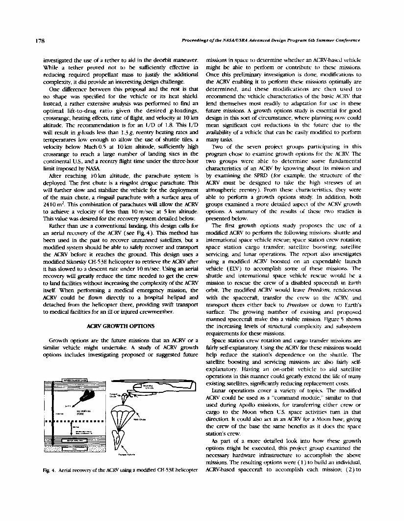
178 Proceedings of tbe NASA/USRA Advanced Design Program 6tb Summer Conjerence
investigated the use of a tether to aid in the deorbit manewer. While a tether proved not to be sufliciently effective in reducing required propellant mass to justify the additional complexity, it did provide an interesting design challenge.
One difference between this proposal and the rest is that no shape was specified for the vehicle or its heat shield Instead, a rather extensive analysis was performed to find an optimal lift-to-drag ratio given the desired g-loadings, crossrange, heating effects, time of flight, and velocity at 10 km altitude. The recommendation is for an WD of 1.8. This WD will result in g-loads less than 1.3g, reentry heating rates and temperatures low enough to allow the use of shuttle tiles, a velocity below Mach 0.5 at 10 km altitude, sufficiently high crossmnge to reach a large number of landing sites in the continental U.S., and a reentry flight time under the three-hour limit imposed by NASA
After reaching 10 kin altitude, the parachute system is deployed. The first chute is a ringslot drogue parachute. This will W e r slow and stabilize the vehicle for the deployment of the main chute, a ringsad parachute with a surEace area of 24 10 mZ. This combination of parachutes will allow the ACRV to achieve a velocity of less than 10 m/sec at 5 km altitude. This value was desired for the recovery system detailed below.
Rather than use a conventional landing, this design calls for an aerial recovery of the ACRV (see Fig. 4). This method has been used in the past to recover unmanned satellites, but a modified system should be able to safely recover and transport the ACRV before it reaches the ground. This design uses a modified Sikorsky CH-53E helicopter to retrieve the ACRV after it has slowed to a descent rate under 10 mlsec. Using an aerial recovery will greatly reduce the time needed to get the crew to land facilities without increasing the complexity of the ACRV itself. When performing a medical emergency mission, the ACRV could be flown directly to a hospital helipad and detached from the helicopter there, providing swift vansport to medical facilities for an ill or injured crewmember.
K R V GRO- OPTIONS
Growth options are the future missions that an ACRV or a similar vehicle might undertake. A study of ACRV growth options includes investigating proposed or suggested future
missions in space to determine whether an ACRV-based vehicle might be able to perform or contribute to these missions. Once this preliminary investigation is done, moditications to the ACRV enabling it to perform these missions optimally are determined, and these modifications are then used to recommend the vehicle characteristics of the basic ACRV that lend themselves most readily to adaptation for use in these future missions. A growth options study is csxntial for good design in this sort of circumstance, where planning now could mean s i m c a n t cost reductions in the future due to the availability of a vehicle that can be easily mtdified to perform many tasks.
Tkvo of the seven project groups participating in this program chose to examine growth options for the ACRV. The two groups were able to determine some fundamental characteristics of an ACRV by knowing about its mission and by examining the SPRD (for example, the structure of the ACRV must be designed to take the high stresses of an atmospheric reentry). From these characteristics, they were able to perform a growth options study. In addition, both groups examined a more detailed aspect of the ACRV growth options. A summary of the results of thew two studies is presented below.
The first growth options study propo~ws the use of a modified ACRV to perform the following missions: shuttle and international space vehicle rescue; space station crew rotation; space station cargo transfer; satellite boosting; satellite servicing; and lunar operations. The report also investigates using a modified ACRV boosted on an expendable launch vehicle (ELV) to accomplish some of these missions. The shuttle and international space vehicle rescue would be a mission to rescue the crcw of a disabled spacecraft in Earth orbit. The moditled ACRV would leave Freednm, rendezvous with the spacecraft, transfer the crew to the ACRV, and transport them either back to Freedom or down to Earth's surface. The growing number of existing and proposed manned spacecraft make this a viable mission. Figure 5 shows the increasing levels of structural complexity and subsytem requirements for these missions.
Space station crew rotation and cargo transfer missions are fairly self-explanatory. Using the ACRV for these missions would help reduce the station's dependence on the shuttle. The satellite boosting and servicing missions are also fairly self- explanatory. Having an on-orbit vehicle to aid satellite - operations in this manner could greatly extend the life of many existing satellites, sigmficantly reducing replacement costs.
Lunar operations cover a variety of topics. The modified ACRV could be used as a "command module," similar to that used during Apollo missions, for transferring either crew or cargo to the Moon when U.S. space activities turn in that direction. It could also act as an ACRV for a Mcwn baw, giving the crew of the base the same benefits as it dtxs the space station's crew.
As part of a more detailed look into how thex growth options might be executed, this project group examined the
r.Lg. V.hrb necessary hardware infrastructure to accomplish the above missions. The resulting options were ( 1 ) to build an individual,
Fig 4. Aerial recovery of the ACRV using a modi6ed CH-53E helicopter ACRV-based spacecraft to accomplish each mission; (2) to
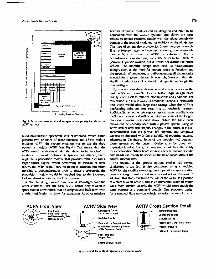
Pennsylvania State university 179
I w lncreas~ng Structural Changes
Fig. 5. Increasing structural and subsystem complexity for altemvive ACRV missions
build multimission spacecraft, still ACRV-b0sed, which could perform two or more of these missions; and (3) to build a modular ACRY. The recommendation was to use the third option-a modular ACRV (see Fig. 6). This means that the ACRV would be designed with the ability to be attadxd to modules that would enhance its systems. For instance, there might be a propulsion module that provides extra fuel and a larger thrust engine. When performing its mission of crew return, the ACRV would have no W e s artlcfrca but when traveling to geosynchronous orbit to repair a spacecraft, the propulsion module would be attached due to the increased fuel and thrust requirements of the mission.
A modular design would have several advantages avw the other solutions. First, the basic ACRV, whose only mission is space station crew return, can be designed and built now, with a little modification to allow for expandon. As other missions
ACRV Front View
become deskable, modules can be designed and built to be compatible with the ACWs systems. This allows the basic vehicle to remain relatively simple, with the added complexity coming in the fbrm of modules, not revisions to the old design. This type of system also provides for future, unforeseen needs. If an unforeseen mission becomes necessary, a new module can be built to allow the ACRV to perform it. Also, a breakdown in a module may cause the ACRV to be unable to peifopm a specific mission, but it would not disable the entire vehicle. 'ihe modular design does have its disadvantages, though, such as the need for storage space at Freedom and the necessity of connecting and disconnecting all the modules needed hr a given mission It was felt, however, that the significant advantages of a modular design Ear outweigh the disadvultages.
To execute a modular design, several characteristics in the basic ACRV are desirable. First, a ballistic-type design more readily lends itself to exterior modifications and additions. For this reason, a bclllistic ACRV is desirable. Second, a removable heat shield would allow large mass savings when the ACRV is performing missions not requiring atmospheric reentry. Additionally, an active life support system more readily lends itself to expansion, and will be required on some of the longer- duration missions mentioned above. While the basic crew return can be accomplished with a passive system, using an active system now will sirnplrfy changes in the future. It is also recommended that the power, life support, and computer systems be des- with the possibility of requiring external additions in the future. Some of the modules will augment these systems, so the current design must be done with expansion in mind Lastly, the computer should have the ability to acammodate ''black box" additions, where mission-qxdlc commands can r e d I y be added to the basic cawli t ies of the control mechanisms
The second of the growth options studies had several similarities to the fh% It also considered using a modified KRV for the satellite servicing, lunar operations, space station crew and cargo tt;mskrs, and international rescue missions. In addition, this study examined the use of the ACRV as a portion of a Mars mission vehicle, and as an unmanned asteroid miner. On a Mars mission vehicle, the ACRV would serve much the same purpose as a command module. One proposed design for a manned Mars mission vehicle includes the use of a small
ACRV Side View Heat Shleld Connecting Tunnel and Maneuvering Jets and Maneuverlng Jels Modulo (2 0r4) Modulrs (2 or 4)
Extended Llte Support Modules Pressurized Connecting Tunnel ACRV Command Section
Fuel Tanks m d Supporl Truss
Englne Exhaust Nozzle
ACRV Cross Section Detail Maneuverlng Jets
Connecllng Tunnel
Modules (2 or 4)
Pressurtzed Connecting Tunnel
Pressure Doors (4)
Extended Life Support Tanks
Fig. 6. A modular ACRV design for altemathrc missions

180 Proceedings of the NASA/lJSRA AdvancedDesign Program 616 Summer Conference
crew vehicle that would be detached from the main ship upon Earth approach and would decelerate using an aerobraking maneuver. A modified ACRV could perform well in this role. As an unmanned aszeroid miner, the ACRV would By to a near- Earth asteroid that was chosen for mining operations. There, it would load itself with ore mined from the asteroid and would return to Earth, reentering the atmosphere to deliver its cargo.
A quantitative approach ww taken to assess the ability of an ACRV to perform each of the missions by estimating the deviation of the major subsystems fkm the norm of the crew return mission requirements. Using this method, the most compatible growth options were found to be the space station crew and cargo transfer missions, the international space vehicle rescue mission, and the lunar operations missions. Based upon this analysis, recommendations for the basic ACRV configuration include a ballistic shape, a detachable heat shield, and the ability of the subsystems to be readily expanded to handle long-duration missions. Figure 7 depicts the results of this study.
As part of a mow detailed look into the growth option possibilities for the ACRV, this project p u p did a prelimirxary design of an ACRV-bawd lunar operations vehicle. The base ACRV is an Apollo-like command module, which is supple- mented by a transfer vehicle and a landing platform. The crew remains in the command module for the entire mission. During trips between low Earth orbits and low lunar orbit, the unmanned transfer vehicle provides the propulsion for the command module. The landing platform stays in low lunar orbit. Following rendezvous of the command module/transfer module vehicle with the platform, the command module detaches from the transfer vehicle, attaches to the lander, and proceeds to the lunar surface. On the return trip, the lander transports the comand module to lunar orbit, where it docks with the transfer vehicle, and then returns back to low Earth orbit, where it may either reenter Earth's atmosphere or dock with the space station. A preliminary design of the subsystems of the command module was a l so performed.
L
Internal
ss SSI
unar
;F Crew Rotation
= Cargo Rotation
Mars Mssion
Transfer Vehlcle
Lunar ACRV
Rescue Vehicle
GEOshack
Asteroid Mlning
0.0 0.5 1 .O 1.5 2.0
/ Deviat~on From ACRV /
X R V MEDICAL MISSION
The medical mission of the ACRV arises if a space station crewmember becomes ill or injured requiring time-critical medical treatment beyond the capability of the space station's hcilities, and the shuttle cannot respond in time to transport the crewmember. This mission places spedal restrictions on the ACRV design because, as stated earlier, the ACRV is required to perform this mission within 24 hours of the decision that the trip is necessary, and the portion of that time spent in transit cannot exceed 6 hours. Additionally, there are &rent impact impulse requirements for healthy and ill or injured crew. For the purpose of this analysis, it was determined that the ACRV itself met only the restrictions for healthy crewmembers, and that special equipment was necessary to protect the ill or injured occupant.
The assignment for the project group performing this study was to assess the impacts that the medical mission makes on the ACRV. This mission will affect the shape, internal contiguration, and equipment of the entire vehicle. Addition- ally, the group was asked to design the actual stretcher-like system for transporting the crew member safely.
First, the decbiom on what medical equipment to include were made by examining the current state of the art in medical emergency care and transportation. To this end, the group investigated the medical equipment currently used in ambulances and medical helicopter transports. This led to an extensive list of necessary medications and daices for proper care of an ill or injured individual. This List included special devices for dealing with the fluctuating gravity environment and devices that could transmit data on the ill or injured crew member to Mission Control for evaluation by the on-duty flight surgeon.
The next task was the design of the stretcher mechanism. It was decided that the optimal design would comprise two parts: a base and a substretcher (see Fig. 8). The base is
--- I ,7
, 'T 1 - A 4
I '
b -9 BATTERV PACK
'MONITOR OXYGEN MISCELLANEOUS SUPPLY EQUIPMENT
Fig. '. Dc7iivion of major subq~tems from baseline ACRV design for alternative missions Fig. 8. Base and sub-stretcher for the medical mission

Pennsyloania State Unioersity 181
permanently mounted to the floor of the ACRV, and contains within it shock absorbing mechanisms to protect the patient during impact. Additionally, the base contains storage space for the above-mentioned equipment and pharmaceuticals. The substretcher consists of a device called a vacuum splint. This dwice is a bag filled with flexible beads. When inflated around a patient, the splint conforms to his or her shape. The air is subsequently evacuated, and the vacuum splint becomes rigid, immobilizing the patient's entire body. Most of the anterior side of the patient is still exposed, to allow for the connection of monitoring equipment and/or IV tubing. This procedure is performed on the space station, and the patient remains in the splint until reaching the ground-based medical facility. This allows easy, safe transport of the patient 6rom the space station
to the ACRV, to the surface transport vehicle, and to the hospital. Onboard the ACRV, the vacvum splint is placed in the base, and a number of restraints will keep the splint firmly in place. The top of the bax is concave to allow easy and secure positioning of the patient.
Several recommendations on the design of the rest of the vehicle were also made. Due to the low reently forces, a gliding or Lifting-body reentry shape was recommended. A runway or similar type of landing was also recommended due to the lower impact loads experienced by the crew in such a landing. Additionally, this study showed that a hatch should be installed on the top surface of the ACRV, and that this hatch should be large enough to allow an immobilized patient to be evacuated in a horizontal position.

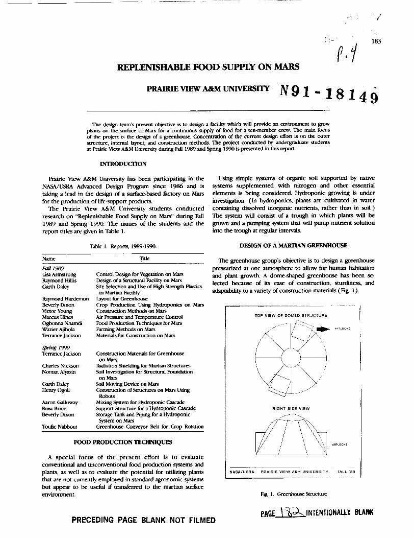
REPLENISHABLE FOOD SUPPLY ON MARS
The design team's present obpctive is to design a facility which will provide an environment to grow plants on the &e of Mars for a continuous supply of food for a ten-member crew. The main focus of the project is the design of a greenhouse. Concentration of the current design d o n is on the outer structure, internal layout, and construction methods. The project conducted by undergraduate students at Prairie View A&M University during Fall 1989 and Spring 1990 is presented in this report.
Prairie Wew A&M University has been participating in the NASA/USRA Advanced Design Program since 1986 and is taking a lead in the design of a &e-based factory on Mars for the production of life-support products.
The Prairie View A&M University students conducted research on "Replenishable Food Supply on Mars" during Fall 1989 and Spring 1990. The names of the students and the report titles are given in Table 1.
Table 1 . Reports, 1989- 1990.
Name ntle
Fall 1989 Lisa Armstrong Raymond Wis Ganh Daley
Raymond Hardemon M r l y Dixon Victor Young Marcus Hines Ogbonna Nnarndi Wazier Ajibola T m c e Jackson
W n g 1990 Terrance Jackson
Charles Nickson Noman Alpin
chdl Ddey Henry Ogoli
Aaron Galloway Rosa Brice Bamly Dixon
T d c Nabbout
Control Design for Vegetation on Mars Design of a Structural Facility on Mars Site Selection and Use of High Strength Plastics in Martian Facility
layout for Greenhouse Crop Production Using Hydroponics on Mars Construction Methods on Mars Air Ressure and Tempemhm Control Food Production Techniques for Mars Fanning Methods on Mars Materials for Construction on Mars
Consuuction Materials for Greenhouse on Mars
Radiation Shielding for Martian Structures Sod Inveaigation for Suuctural Foundation on Mars
Sod Moving Device on Mars Construction of Structures on Mars Using Robots
Mmng System for Hydqmnic Cascade Support structure for a Hydroponic Cascade Storage Tank and Piping for a Hydqmnic
System on Mars Greenhouse C o m r Belt for Crop Rotation
FOOD PRODUCTION TECHNIQUES
A special focus of the present effort is to evaluate conventional and unconventional food production systems and plants, as well as to evaluate the for utilizing plants that are not currently employed in standard agronomic systems but appear to be useful if &erred to the martian &e environment.
Using simple systems of organic soil supported by native systems supplemented with nitrogen and other essential elements is being considered. Hydroponic growing is under investigation. (In hydroponics, plants are cultinted in water containing dissolved inorganic nutrients, rather than in soil.) 'Ihe system will consist of a trough in which plants will be grown and a pumping system that will pump nutrient solution into the trough at regular intervals.
DESIGN OF A MARTIAN GREENHOUSE
PRECEDING PAGE BLANK NOT FILMED
'Ihe greenhouse group's objective is to design a greenhouse presfllrized at one atmosphere to allow for human habitation and plant growth. A dome-shaped greenhouse has been se- lected because of its ease of construction, sturdiness, and adaptability to a variety of construction materials (Fig. 1 ).
- - -- - -
TOP VlEW OF DOMED STRUCTURE I - - I
RIGHT SIDE VlEW
ALM UNIVERSITY FALL 89 ---=-
Fig 1. Greenhouse Structure
eAGE \ INTENUOIAUY BLAH

Proceedings of tbe NASA/USRA Aduanced Design Program 6tb Summer Conference
The site chosen for the greenhouse is the Tharsis plain on Mars. The site, located between latitudes O0 and 20' and lon- gitudes 60° and 1 20° East, sat.i.de the criteria of soil stability, area for expansion, nonundulating terrain, and infrequent sudsorm activity.
MMFXUAU OF CONSTRUCTION
Lightweight materials resistant to radiation with high .wen@ and low d&rmability are criteria for construction materials for the greenhouse. The materials should also be able to withstand pressure difhences between the interior and exterior &es of the fadlity.
Fiber rehhrced plastics (FRPs) will be used These are classified in five main groups: ( I ) nylons, which are long strands of arnines and are formed by reacting a diadd with a diarnine; (2) acetals, which are compounds formed from a diethyl aldehyde base, and polyester resins, which are produced by reacting phaltyhahc acid with glycerol; (3) polycarbonates, which are formed from chains of &nates; (4) blends of polyqmne, which are compounds formed h m chains of styrene or phenylthylene and (5) polyphenyiene oxides.
RADIATION SHIELDING
The objective is a feasible plan that will protecz humans and plants from martian radiation.
criteria
1. The shielding should protect humans and plants h m radiation.
2. The shielding should be incorporated into the structure.
Another focus of this project was to investigate the methods that might be useful in the construction of the greenhouse. One method b e i investigated for lifting is via airbags. As illustrated in Fig. 2, a panel is laid across the airbag and air
-- -- ~- A-
1 P.n.1 Air bap 1
I NASAIVSRA PRAIRIE VIEW ALM UNIVERSITY FALL '89
is released h m the tank into the bag As the bag is inflated, the panel is slowly raised upward into position Once the bag is filled, the air tank is removed and a support is added to hold the p e l in place while it is bemg &ued into the foundation of the greenhouse. The procedure is repeated until all of the panels are in place.
Since there will be limited manpower during the building of the greenhouse and other habitation U t i e s on Mars, con- struction using robots is also being investigated Robots will be able to perform such manewers a. lifting, drilling, hammer- ing, etc.
ENVIRONMENTAL CONTROL
The development of a conditioning system fot soil-grown plants is one of the goals of the environmental controb group. Plants will be grown on a conveyor belt system, which will allow for easy rotation of crops into the mom where they receive nutrients.
This system must have the capability to monitor and control anironmental conditions in addition to tight such as humidity, temperature, oxygen and &n dioxide l m k , pressure, water tension in the soil, and presence of metabolites or toxicants.
The entire system is composed of a recognition device, a computer, and an automated pumping system (Fig. 3). The recognition device was modeled after the bar codmg technique currently used on packaged grocery items. The code for each crop will be different. The plant's moisture, nutrient, and @ht content requhments will be coded and stored by the com- puter.
Another element is a control feedback loop that will consist of the following components: a process, a measuring sensor and transducer, a controller, and a final control element with the associated electropneumatic converter and transmission lines for the process measurement and the control command signal.
The h a l stage of the conditioning process will be the activation of an automated pumping system to open the w k s of the nutrient pipes. Once the crop has been properly
1 Crop Recognition and Nutrit~on System 1 b For So11 M a n u f a c t u r e d V e g e t a t ~ o n
i
I NASA/USRA PRAIRIE VIEW 11M UNIVERSITY FALL 8 9 1 Fig. 2. Conaruaion Method Fig. 3. Crop Recognition and Nutrition System
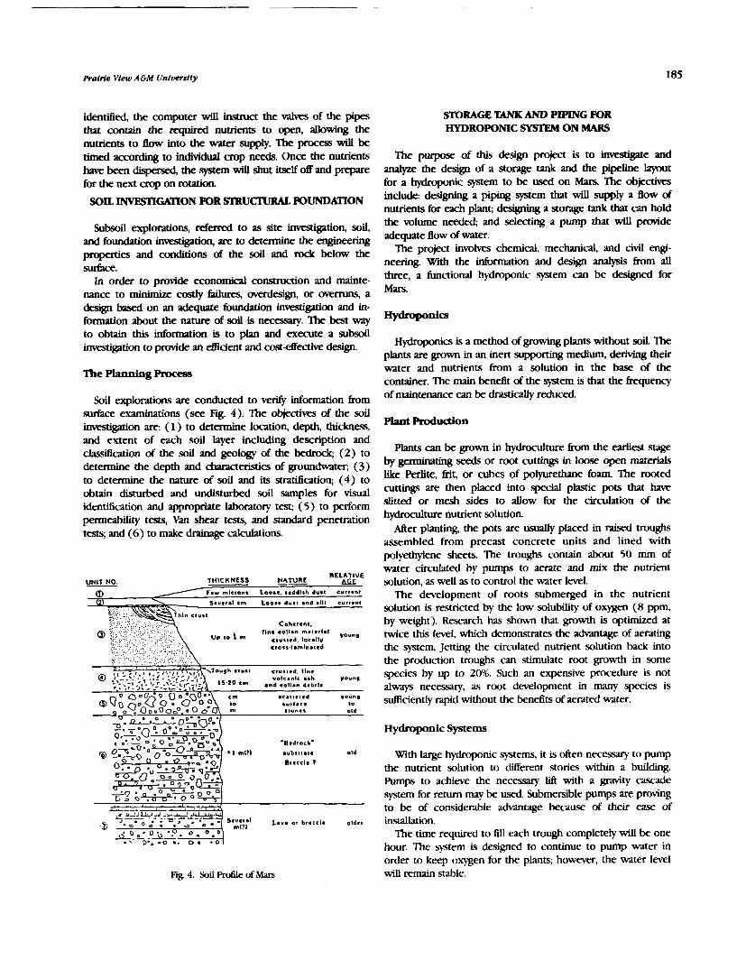
Prairie Vfew A 6 M University
identified, the computer will instruct the valves of the pipes that contain the required nutrients to open, allowing the nutrients to flow into the water supply. The process will be timed according to individual crop needs. Once the nutrients have been dqemed, the system will shut itself off and prepare for the next crop on rotation.
SOIL lNvEsTIMON FOR S T R U ~ POUNDATlON
Subsoil explorations, referred to as site hveSigation, soil, and foundation investigbtion, are to determine the engkering properties and conditions of the soil and rock below the surface.
In order to provide economical consvuction and mainte- nance to minimize costly failures, averdesign, or overmns, a design based on an adequate foundation investigation and in- formation about the nature of soil is necessary. The best way to obtain this information is to plan and execute a subsoil investigation to praide an efticient and cost-effective design.
The Planning Proces
Soil explorations are conducted to verify information h m surface examhations (see Fig. 4). The objectives of the soil investigation are ( 1 ) to determine location, depth, thickness, and extent of each soil layer including description and classification of the soil and geology of the bedrock; (2) to determine the depth and characteristics of groundwater, (3) to determine the nature of soil and its stratification; ( 4 ) to obtain disturbed and undisturbed soil samples for visual identification and appropriate laboratory test, ( 5 ) to perform permeability tests, Van shear tests, and standard penetration tests; and (6) to make drainage calculations.
U m . THICKNESS NATURE nELAT'VE hGf
0 / Few micron. Loo... teddlsh dust current
3 S.v.r.1 em Loose dust mnd .Ill curt.nt
Coher*nt.
,r lo , 1I.e eollan mal*rlal crulted locally young
\ ctors-lamlna~ed
Y O I C ~ ~ I C ash Vouns and .ollan debrll
s lont l old
---.--
-u.o;"= -n*d,ocL-
BU~SI I * I . old
nrecci. r
- 3 1
* Lmv. of br.ccl. older
Fig. 4. Soil Profile of Mars
STORAGE 'CANK rn PIPING FOR HYDROPONIC SYSTEM ON MARS
The purpose of this design project is to investigate and andpe the design of a storage tank and the pipeline layout for a W n i c system to be used on Mars. The objedws include: designing a piping system that will supply a flow of nutrients for each plant; designing a storage tank that can hold the volume needed; and selecting a pump that will provide adequate Bow of water.
The project involves chemical, mechanical, and civil engi- neering. With the information and design analysis h m all three, a functional hydroponic system can be designed for Mars.
Hydroponics is a method of growing plants without soil. 'Ihe plants are grown in an inert supporting medium, deriving their water and nutrients from a solution in the base of the container. The main benelit of the system is that the frequency of maintenance can be drastically reduced.
Plant Ptodudon
Plants can be grown in hydroculture h m the earliest stage by germinating seeds or root cuttings in loose open materials like Perlite, fiit, or cubes of polyurethane foam. The rooted cuttings are then placed into special plastic pots that have slitted or mesh sides to allow for the circulation of the hydroculture nutrient solution.
After planting, the pots are usualty placed in raised troughs assembled from precast concrete units and lined with polyethylene sheets. The troughs contain about 50 rnm of water circulated by pumps to aerate and mix the nutrient solution, as well as to control the water level.
The development of roots submerged in the nutrient solution is restricted by the low solubility of oxygen (8 ppm, by weight). Researdl has shown that growth is optimized at twice this level, which demonstrates the advantage of aerating the system. Jetting the circulated nutrient solution back into the produaion troughs can stimulate root growth in some species by up to 20%. Such an expensive procedure is not always necessary, as root development in many species is ~~Eciently rapid without the ben&ts of aerated water.
With large hydroponic systems, it is often necessary to pump the nutrient solution to different stories within a building. Pumps to achieve the necessary lift with a gravity cascade system for return may be used Submersible pumps are proving to be of considerable advantage because of their ease of insallation.
The time required to fill each trough completely will be one hour. The system is designed to continue to pump water in order to keep oxygen for the plants, however, the water level will remain stable.
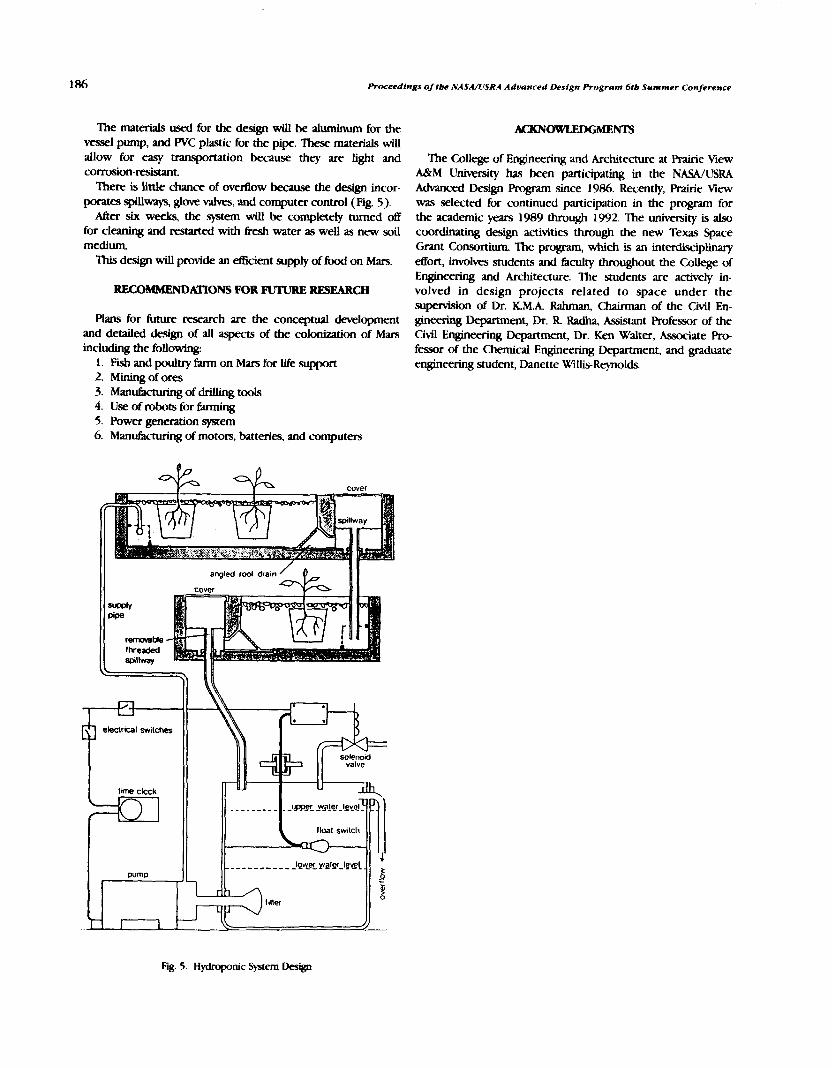
186 Proceedings of Ibe NASA/USRA Advanced Desfgn Program 6tb Summer Conference
The materials used for the design wiU be aluminum for the wssel pump, and WC plastic for the pipe. These materials will allow for easy transportation beause they are light and corrosion-reskuant.
There is little chance of overflow because the design incor- porates spillways, glove &, and computer control (Fig. 5).
After six week the system will be completely turned off for cleaning and restarted with fresh water a. well as new soil medium. This design will provide an efficient supply of fwd on Mars.
RECOMMFNDATIONS FOR FUTURE RESEARCH
Plans for future research are the conceptual development and detailed design of all aspects of the colonization of Mars including the following:
1. Fish and poultry farm on Mars for life support 2. Mining of ores 3. Man- of dnhng tools 4. Use of robots for far- 5. Power generation system 6. Manufacturing of motors, batteries, and computers
'Ihe College of Engineering and Architecture at Prairie %ew A&M Uniwrsity has been participating in the NASA/USRA Advanced Design Program since 1986. Recently, Prairie Mew mas selected for continued participation in the program for the academic years 1989 through 1992. 'Ihe university is also coordinating design activities through the new Texas Space Grant Consortium The program, which is an interdisciplinary effort, involves students and faculty throughout the College of Engineering and Architecture. The students are actively in- volved in design projects related to space under the supervision of Dr. KM.A Rahman, Chairman of the Civil En- gineering Department, Dr. R Radha, Assistant Professor of the Civil Engineering Department, Dr. Ken Walter, Associate Pro- fessor of the Chemical Engineering Department, and graduate engineering student, Danette Willis-Reynolds.

UNIVERSITY OF PUEWIY) RICO SCHOOL OF ARCHlTECIURE
N91-18150
there- &I be a permanent mvtian outpost in apention. 'Ihnspocting personnel to it will be accomplished by sending pasengem through a shuttle to a vehicle in a heliocentric elliptical orbit intersecting both Earth's and Mars' orbits, while it in terrestrial p r o d t y . Passengers will land on Mars a month and a half later through a tmns€ec shuttle that will h exchange J3cth-bound passengers to the vehicle ceachmg perigee again in 22 months. Such a vehicle was odgmaNy conceived at the
Engineering Department of the Univefsity of Mi- in 1987 aspart of the NAWUSRAAdvanced Design Program It was d e d m, an acronym for Cvculaang Aut-t Mars-Earth Luxurious Orbital Transport. It housed 17 passengers and a crew of 3 in a 3.6 m x 7.3 m tect?ngular aoss-section toroid of 34.1 m radius, thus providing a volume of 284.8 m3 per person, including the Closed Environmental Life Support System (CELSS). It creared an vtificial gravity of 0.4 g by-rotating the ring at a rate of 3.22 rpm.
Dunng 1988-89 the NASA/USRA Advanced Design Rogram sponsored research and design elforts at the School of Architecture of the University of Puerto Rico aimed at developing habitability criteria and at dehing a habitability concept as a useful tool in understanding and evaluating dwellings for prolonged stay in extraterrestrial space. CAMELOT was studied as a case in *ch the srudents would try to enhance the quality of life of the inhabitants by applying architectural design methodology. 'Zhus, a pmcea of transfor- mation of the onginal CAh4Em took place and the CAMELOT I11 presented to NWUSRA's Advanced Design Prognm
HABITABILITY CONCEPT D-ON
The study proposed 14 habitability criteria considered necessary to fdM the defined habitability concept, which is "that state of equihbrium that results 6rom the interaction between components of the Individual Architecture Mission Complex, which allows a person to sustain physiological homeostasis, adequate performance, and acceptable d relationsh@."
?he habitability criteria can be summatized as follows: 1. Personal Indentification: Refers to the possibility of
allowing the individual to inftuence the arrangement of his/ her personal areas.
2. Social Interaction: To satisfy the need for companionship.
3. Aleatoric Conditions: To avoid excessive routine, providing pleasant surprises
4. Contact with Nature: Is a b e to d e n the impact of a totally enconpasing Wdal environment and developing a new sense of MOOT-outdoor.
5. Mental Ian- To h e memofie% symbols, and lzqeciences of terrestrial life.
6 . Prhr;lcy: A private place for ewyone on prolonged stay in an enclosed habitation is necess;uy to maintain harmony in interpecmnal relatjofd~@ and self-reliance.
7. Equalitarian Conditions. Dilhences among passenger Edcilities should d e c t purpose and function, as well as lndhidual ptrkences, rather than rank or hiemthy.
8. Variability: Environmental stress can be o\lercome by introducing a variety of elements, shapes, decor, color, ma- terials, and textures.
9. Functionality: A "habitable" place must perform well in the physiological-quantitative sense for the sustenance of human life beyond the l m l of mere d
10. Sensorial Stimulation: Cogmtlve proceses depend on all senses; therefore, visual stimuli are to be complemented by an envhnment rich in positive auditory, tactile, olfiaory, and g u s t a t o r y ~ r s a n d ~ t s .
11. Music and Environmental Sound: The problem of ahsolute silence in extraterrestrial space has to be dealt with to prevent trawlers from being stactled by their own vixenl motions and by any minor unexpectd noise, as well as to control access to communications.
12. W i t y and Security: Muscle tone and visual-motor caordinaton developed under terrestrial conditions will find alien an environment where there ace gravity gcacbents, Coriolis and gyroscopic forces, and constant torque on the anatomy. 'Zhe emironment must be designed to compensate fw these conditions
13. Comfort. Includes conditions such as illumination, temperatuff, humidity, presswe, and atmospheric composition, wfiich can be quantitatively determined according to standards
14. Sense of Orientation: The architectural design of floors, walls, and ceiltngs must create a new sense of up and down, east and west, north and south to reinfwce orientation
ARCHlTECI'URAL DESIGN DEVELOPMENT
A s e r i e s o f d e s i g n h c t o r s a n d a r c h i ~ ~ e s w e r e considered in making the following changes to the orighd CAMELOT:
ngs of the NASA/USRA Adoanced Design Program 6th Summw Conference
1. The single-level toroid ring of a 12'x 24' cross-section was changed to a two-level, true torus of 24' section diameter, keeping the 1 12' rotational radius.
2. Consequentty, the volume increased by 41% to allow for quality of life enhancements.
3. The CELSS was reorganized by moving it to the lower level of the torus, which is also its outer level, and was com- partmentalized in a system of drawers that ran along the sides of the main comdor of the vessel, providing for circumferential access and u;lnsportation.
4 . The areas of the vessel were reorganized into three main sectors (instead of four), thus using only three spoke elevators to provide access to and from the central core. The areas were organized as the dwelling .seaor, which includes cabins for passengers and crew members; the work sector, which includes laboratories, torus control mom, medical center, and a master CELSS; and the leisure sector, including a galley, dining-conference room, library-lounge, recreation-gymnasium, and a chapel.
5. Additionally, the three spoke elevators were placed in a lobby, under which the safe havens were located, contauung facilities for dwelling while the vessel is under the influence of extreme radiation because of solar Bare activity or some other hazardous condition that would require such protection. The Safe Havens cmnsist of a series of cubicles measuring 8' X 4' X 4' high that are highly shielded, have food supplies for at least 24 hr, allow access to communications, computers, and entertainment, and contain supplies for clothing changes, a personal toilet, and a couch for sleeping or sitting.
6. The circumferential corridor provided a continuous means of circulation along the lower level of the entire torus, Banked on one side by a carousel-type transport for cargo or injured humans, and a means of reaching every room in the vessel. Access to rooms was always through vertical ladders and hatches on the ceiling to pmmote upper body tonification by requiring its use for locomotion.
7. lnterior gardens were provided as an external CELSS feature in several two-story locations along the dwelhng and leisure sectors.
REFINEMEMSANDREVISION!TO IMPROVE QUALITY OF LIFE
Considering that several of the habitability criteria were dependent on qualitative, rather than quantitative factors, it was deemed necessary to develop them further in order to ensure and pmmote greater obetivity in evaluating habitats for prolonged stay in extraterrestrial space. CAMELOT 111 was also found underdesigned as Eu as (1) the nature of the enveloping membrane, which was required to withstand pressures of 2000 Ib per sq ft to hold the required internal atmosphere of the vessel; (2) the assembly process in Earth orbit for such a vessel (robotics and EVA processes); (3) the serwity systems for emergency and accidental conditions of operation; (4) the need for a detailed example of lighting, texture, materials, and color scheme to illustrate the application of the habitability criteria; and (5) the design of its furniture, which was found to be stilt too prejudiced by 1 -g living conditions.
These provided the working agenda for the Space Research and Design Studio during academic year 1989-90.
NEW INSIGHTS ON ARTIFICIAL GRAVITY
From the available data, it soon became evident that artificial gravity is necessary to overcome physiological and even anatomical deterioration of humans on prolonged stay in space. During research, however, further insight was gained regarding the architectural implications of such artificial gravity in environments, disclosing conditions such as ( I) Coriolis and p o p i c effects over all bodies in motion (north-south movements), which are 4000 times greater than those experienced on the surface of Earth; (2) weight gains and losses related to east-west movements of sigruficant magnitude due to the addition or subtraction to the circumferential speed, which causes the centripetal force that creates the artificial gravity effect, (3) gravitational gradients due to upward and downwacd movements (toward or away from the center of rotation movements); in fact, due to the conditions of CAMEW, the person who would experience 0.4 g on his/ her feet, would also be experiencing 0.37 g on the top of his/ her head, (4) discomfort due to dislocation of reflexes relating to normal visual input and its correlative input kom the inner- ear fluid motion. (In the September 1962 issue of Astmmtics, a chart was published relating the rotational parameters to a comfort zone for the design of artificial gravity manned space stations. CAMELOT was designed t a k q into account such parameters. However, more recent research has made corrections in relation to the rotational parameters, leaving CAMELOT just outside the comfort zone.); (5) excessive variations in local verticals that create confusion and disorientation; (6) unfamiliar behavior of objects and bodies that tend to move in straight paths, while the environment or the frame of reference is rotating. (It is conceiwble that in C A M E W a body suspended unrestrained for one second would not only experience a lateral displacement due to inertia, but could also rotate up to 58" relative to the envelope); and (7) large anatomical stresses as a consequence of such rotational and lateral displacements. For example, if the passenger were to rely on feet and balance alone to stand erect, assuming he/she has become accustomed to the moving environment, the torque exerted by the gluteous maximus over the trocanter bone in the sagittal plane would be 700 times that of normal anatomical stresses.
FORM AM) CONSTRUCTION PROBLEMS
Additionally, construction and form difficulties were found, such as
1. Large periods of time and numbers of people will be needed for extravehicular activity (EVA) in low Earth orbit (LEO) for the assembly of the skin of the vessel.
2. It will be diflicult to attain air tightness in the membrane assembled in orbit due to the great number of joints.
3. Due to fluctuations in the upper atmosphere, orbit decay is an ever-present danger during LEO assembly until the vessel has attained enough structural integrity to make orbital corrections possible.

University of Puerto Rico 189
4. A relatively small torus like CAMELOT ( 1 1 2' radius), cannot !iAfiU the promise of spatial continuity because floors curve up too steeply and are perceived as walls at a distance. Ceilings bend away in horizons, which seem to meet the floors, to visually enclose the volume, thus malung it impossible to view really large expanses of areas.
5. The monolithic integrity of the toroidal form does not lend itself to the modular redundancy principle aimed at providing subsistence in case of failure of life support systems, fire, decompression, puncture of the membrane, fixture of the structure, or any other similar emergency or accident.
6. Extreme limitation of the capacity for passengers, wfiile requiring 14,000 ft3 of volume per passenger (including CELSS), makes the vessel too luxurious or uneconomical.
7. The extreme Coriolis and gyroscopic effects on a passenger moving on the hallway, as mentioned before, would require design of handrails and other grab bars to ensure a means of personal locomotion, using the upper body and not only the legs as in terrestrial environments, in order to exert control over such a motion and to relieve the body of extreme anatomical stresses.
8. The period between the warning of solar flare radiation and its actual arrival can be as little as 20 sec. Therefore, Safe Havens cannot be concentrated in a given location, but must be dispersed throughout the vessel, so that they can be reached b m any location in such a short time.
A NEW VESSEL, SIMILAR CONCEIT
To solve those problems, a new version, called CAMELOT N, has been designed It consists of 12 shuttle external tank (ET) envelopes on an array of 3 groups of 4, tethered from a common core. The passenger capacity has been tripled to 60 persons and therefore its volume has also increased. The array rotates at a 1-km radius (instead of 30 m) at a speed of 0.6 rpm (instead of 3.22 rpm). Thus, gravitational and locomotion conditions become 80-90%, similar to those experienced on Earth. The tether arms are built using Buckminster Fuller's concept of "tensegrity" and are 1 km long with a section 30.38 X 30.38 m supporting a solar energy collector array of 24,000 m3. They carry up to four elemtors to the microgravity sector in the central hub, which in turn houses laboratories, the nomtating interface for passengers, supplies, and cargo access. That core also houses the observatory, the command bridge, part of the antenna, and an ejectable nuclear reactor array.
The idea of tensegrity was promoted by R Buckminster Fuller, the inventor of geodesic geometry, as a means of achieving very versatile, lightweight structures in which the members in compression are minimized and are discontinuous, whereas the members in tension are continuous and very slender, giving the structures an appearance of Boatability.
The solar energy collector array was arrived at after consideration of several alternatives. The first one was to place a dish with a radius of 87.4 m around the central core. It was discarded because it required additional structural support. For the same reason, the idea of a 4-m-wide ring at 1 krn radius was rejected. 'Ihe proposed solution of an 8-m-wide strip of
solar panels attached along the length of the tensegrity tether arms seemed to be the most practical solution.
The orbital trajectory design developed at Michigan was kept with two new enhancements proposed: ( 1) the requirement that the main plane of the vessel that contains the solar energy panel array will always be facing towards the Sun; (2) that a 24-hr precession motion be introduced to the axis of rotation to create a sense of daily cycles in the "natural" illumination through ceiling panels and windows. This would help maintain the circadian cycles of crew and passengers as they live on the vessel.
It is envisioned that an antenna array would allow 360' rotation so that some would always be facing Earth base, whereas the others would always be pointing toward the martian base.
Four shuttle liquid hydrogen external tanks have the equivalent volume of the original CAMEUrT: Conceivably, they could be recycled and refurbished for use in such a vessel, rather than wasting their sturdy and airtight skin by burning it in the atmosphere, which is the current procedure. It is proposed that they be redesigned so that access be made possible to their interior for construction of habitable quarters in a higher orbit, where they could be stored until the time that NASA is ready to build CAMEL(TT:
Instead of using counterweights to balance the tethers of CAMEm N, it is proposed that the capacity of the vessel be increased in order to subdivide the community in modules similar in size to the oti@ CAMEIMI; so that instead of 20 people, there would be 60, or three arrays of four ETs for 20 people each. Each ET envelope will contain its own CELSS. Organization into three sectors, dwelling, work, and leisure, will be conserved to grant a sense of mobility to the passengers, even within their own particular array. Circulation between ETs of one array is accomplished through 12'X 12' cylinder connectors. Transportation between arrays and the central microgravity core is through the four tensegrity tether aim elevators.
The dwelling sector ET array now proposed consists of two ET envelopes (the recyclmg of a shuttle's Liquid hydrogen tank). They would be organized in three Boors. Each dwelling ET will house 10 cabins, and a meeting area on the center floor. There will be a torus control room in one of them. Safe havens will be located in the upper level and a CELSS along the lower level comdor.
The work sector will consist of only one ET envelope to be located north of the dwelling sector. It will house four laboratories, a medical center and a master CELSS, al l of which will be distributed in the two upper floors. The lower Boor will also house a CELSS along the corridor.
The leisure sector ET will also be one tank located south of the dwellings, containing galley, dining-conference rwm, library-lounge area, a double-height gymnasium-recreation room, and a chapel. AU sectors will have double- and triple-height gardens at the
rounded ends of the envelopes. The recycled conical liquid oxygen tanks and the collar connectors of the shuttle ETs could be used for assembhg the microgravity labratones and other facilities in the core.

190 h d q s of I& N A W S R 4 Advanced DeJfgn Program 6tb Summer Conference
S p d v ~ ~ ~ ~ w l l l c o ~ o f ~ ~ c y l t n d a s t h ; l t - on cables loc?tcd wlthin the t e t y techa stnrture between the ET vrys lad the cenhnl core.
THE FINAL
CAMEIlJTNispresentedhcreinatdpodal~on, but conceivrMy it is a form that a l l ow fw gmwth lad expansion It amkt be exploded to a multiple-urn army, as l o n g a s t h e r e i s m e a n s o f c o l m t ~ t h c t c d K t s a d t h e s p i n i s e o n t r o l l c d t o a t t a c h ? d d l ~ ~ t o r a c h ~ ~ h > m o f l h r a c ! i u s B y t h ; l t c i m c t h t ~ ~ n d ~ S p n o c Exploration Initiative will be a subject d study fw hismiam CAMEIXJTwoukidKnhrve lOf$vrysof4ETsadwouid b e t n n s p o n i n g ~ ~ o f ~ 2 0 0 0 ~ l e b c r w e e n Mars and Earth, two of the planets jnhabftcd by a muldpivre- t a l y h u m v l s p e d e s ~ f w t h e s t v s
APPENDIX I l l d m to Camelot TV are included m this
Appendix
Rhrippl Pllthas inclQd W. ~leqdn, A Barngm, M. Carro, E &a, L GoaAez, JA Mercldo, N. Negr6n, D. L@m, LA. R i K n , M . R i v a r , J - ~ ~ , O . R o d r i g u e z , J . ~ P . ~ , H. Torres, and E Y i 'Ihqr were assisted by teachq adstants 0. Wda and R M e W , and Prof. h E Andino.
Radial g's
.Ql .035 0.1 .35
RoWmtal Rnmtas and Comfort Zone
CAMELOT 3.22
CENTRIPETAL lCCt lERlT lON (g)
camclot II. hxonomeeic
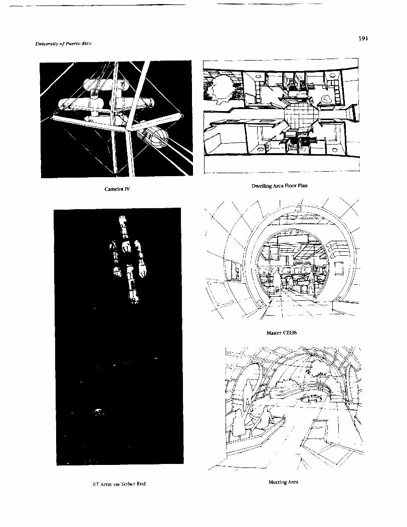
University of Puerto Rico 191
Dwelling Area Floor Pian Camelot IV
Master CELSS
ET m a y on Tether End Meeting Area

Proceedfngr of tbe NASAlUSRA Advanced Deslgn Program 616 Summer Conference
\
Library
Laboratories ET Control System
Gmtrol Area mey

University of Puerto Rico
Dining-Gderence Room
,, , '/ ,---<-- Chapel


INVWI"I'GATI0NS INTO A POTENTIAL "LASER-NASP" P* a
TRANSPORT TECHNOLOGY ~ 9 1 - 1 8 1 5 1
RENSELAER POLYTECHNIC INSTITUTE
In this fourth year of the " ~ ~ ~ l l o tightcraft Project" at RPI, the following question is asked of laser- boosted spacecraft technology: Can this technology aLw be used to repiace domestic and international jet flights? Clearly, if ker propulsion technology is lrsf polluting than present jet ~amports, then it could become a major element in helping to reduce the problem of global warming. Also, if Lightcraft (or *laser-NASP") engines can be designed around solar satellite power sources and renewable propellants (e.g., air, LH2, LN2, HzO, etc.), then an enormous savings in hydrocarbon resources would be reahable.
This 1989-1990 annual report on RPI's design project begtns with a Em-order economic analysis of just such a beam-powered global transport system-based upon a fleet of 10,000 Lightcraft. designed to carry one, two, or tive passengers in minimum volume capsules. A detailed conceptual design is pre- sented for an on-place Mercury Lightcraft; other designs are briefly explored for l q e r , 15-place Executive tightcraft, and 150- to 350-passenger Jumbo Lightcraft.
Various other teams in the class conducted experiments or performed theoretical analyses on various aspects of the tightcraft propulsive engine and vehicle technology. One p u p machined an accurate, 6"-diameter model of the hypersonic air inlet (using a CNC lathe), ingrumented it with PCB pressure transducers, and tested it from Mach 10 to 25 in RPI's W r s o n i c shock tunnel. Another group simulated the inlet a e r w c performance with a computational fluid dynamic (CFD) code called PAR<: 2D. Analpically predicted shock positions and pressure distributions were then compared with Schlieren photographs and presswe data taken during the experiment.
One other group designed a laser propulsion experiment that will be carried out by the 1990-lW1 design class. Another designed superconducting magnets for the lawr-heated MHD-Fanjet engine, which accelerates a Lightcraft from Mach 10 to orbital velocity. Others built and tested a I-1/4"-diameter Lightcraft inlet in RPI's Mach 3 wind tunnel, and analyzed the performance of the primary optics of a Mercury tightcraft. Perhaps the most profound analytical achievement was the analysis of a laser-heated, rocket-driven MHD generator using 20,000°K hydrogen as thc working fluid; the method employed a combined simultaneous solution of a quasi- ID Mtlt) cede with a 31) radiation code.
In summary, the class design team made exct~tlon;ti i)rogrcks\ in continuing to climb the steep learning curve on laser-propelled Bightluansport technolon.
Technological innovation has repeatedly caused drastic revolutions in world travel patterns. The schooner, steamship, diri@le, and airplane all had their profound effects. Here we present an economic analysis of yet another new transport mode that will make the m c e s of these former modes seem like microscopic progress. We are talking about the Apollo Lightcraft, a technology that will allow people to travel half- way around the world, essentially door-todoor in 45 minutes. It will make trips possible that simply cannot be made today except by astronauts. And ow economic analysis tends to show that the operating and capital costs of system can be recovered once the Lightcraft technology is mature.
BACKGROUND
It is well recognized that mankind's quest for increased speed has not yet abated, not even with the introduction of the supersonic Concorde. In fact, the Concorde has merely whetted ow appetite for faster, futuristic flight. People want to reach their destination as quickly as possible. W o recent proposals have heightened ow interest in travel time savings: the High Speed Civil Transport (HSCT) and the Hypersonic Aircraft (HA)('). The HSCT is the next step in the development
of supersonic transports and the Hypersonic Aircraft is a jump beyond the HSCT The HSCT is much closer to today's technology, and advanctvt studies have been conducted on the marketability of this technology in the growing international transportation market(2,3,"5.('.:.R)
But these advances in high speed transport technology have generated an interesting dilemma-namely, while the systems must be cost effective to be saleable, increasing speed also increases costs. This "Catch-22" is readily apparent when considering the HSCT. While it has been proposed that the HSCT needs a range of at least 7500 n.m. to he profitable (the range of current 747-400 technology), at this range and at Mach 2.5, it requires twice the fuel of the 747 to carry the .same number of passengers, and at Mach 3.5 it needs nearly four times the fuel. It seems that as range increases, fuel requirements grow at an exponential rate (see Fig. 1 )(').
Clearly the success of the HSCT and other super- or hypersonic transports is dependent on an ability to produce these travel-time savings. Fuel consumption is a major problem, but the real trouble is that the time savings cm only be pushed to a certain limit, beyond which access and egress times (i.e., the times spent going to and kom the airports) become the real liability. Also, since supersonic speeds are possible only
PRECEDING PAGE B W K NOT FILMED

Proceedings of the NA.SA/IISRA Adr~u?tced I l rs igt l Prf~grunz 6th Summer Conference
40'00 ' 5000 6000 7000
Range (NN)
Fig. 1 . H!KT Fuel Consumption (Weight ) vs. ~ange'' '
over water, only certain city pairs cm benefit from the time savings that can be achieved. The inability to fly supersonic over land also has serious impacts on Bight paths. A Q h t from Paris to Tokyo, for example, requires either a subsonic track over land, or an extended diversion to fly completely over water. Moreover, travel becomes complicated as more changeovers at intermediate airports become necessary.
For these reasons, while the HSCT may increase flight speed over water by a hctor of three, it may reduce overall travel time by only 50% or less. Note that the over-water Bight time is not total travel time, but merely over-water air time; over- land air time and access and egress times are additional. This becomes quite important when one considers how man); airports will be capable of supporting an HSCT system. If an HSCT network is only partially implemented, access and egre.ss times to HSCT port cities could be quite long. This inability to effect major travel time savings will clearly Limit the marketability of the HSCT and other such super- or hypersonic transPo*.
HSCT proponents hope to capture the top 25% of the international travel market in spite of these limitations. And they think they can do this in spite of what they expect to be a 30% differential in fares. Helping the HSCT is an assumption that the reduced travel times will stimulate demand. Historically, reduced travel times have stimulated travel by a factor of 1 .25 to 1.5( 5 ) .
A P O m LIGHTCRAFC TECHNOLOGY
The real question is not whether the HSCT (or some other high speed tramport) c m be developed in the near term, but how much longer we will or should continue to base future air transport schemes on large aircraft and fossil fuels. This is where the ApoUo Lightcraft technology fits in('0~"*'2). 'lhe Lightcraft (see Fig. 2) is not an extension of current aircraft into the next century, but a categorically different technology because of many unique features. Fi, and most obviously, a Lightcraft has a propulsion system that is not powered by fossil- hek. It uses laser beams transmitted from satellite solar power stations ( sPs) ( '~ ) '~ ) , for the propulsive energy source (see Fig. 3). Size is another difference. A Lightcraft is designed to carry
Fig. 2. Family of Iascr &w>sted Iightcraft' ' ' '
Fig. 3. 7 GW, Satellite Solar Power Station
only one to five persons. Second, it is designed to take off and land from any airport equipped with a Lightcraft landing pad (see Fig. 4). Third, its range is unlimited. In fact, it becomes more cost effective the further it travels. Unlike the HSCT and hypersonic aircraft, it does not carry its own energy source,
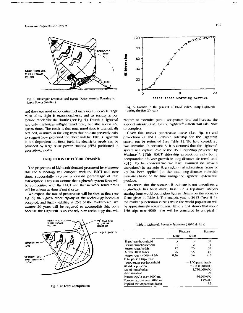
Rensselaer Polytechnic Institute
Fig. 4. Pasxnger Entrance and Egress (Gear Permits Pointing to Laser Power Satellite)
Years after Starting Service
Fig. 6. Growth in the percent of H S ( T riden using lightcraft and does not need exponential fuel increases to increase range. during the first 2 0 years
Most of its flight is exoatmospheric, and its reentry is per- formed much like the shuttle (see Fig. 5). Fourth, a Lightcraft require an extended public accqtance time and because the not only minimizes intlight travel time, but also access and support inkastructure for the Lightcraft s-ystem will take time egress times. The result is that total travel time is dramatically to complete. reduced, so much so for long trips that no data presently exist Given this market penetration curve (i.e., Fig. 6) and to suggest how profound the effect will be. Fifth, a Lightcraft projections of HSCT demand, ridership for the Lightcraft is not dependent on fossil fuels. Its electricity needs can be .system can be estimated (see Table 1). We have considercci provided by large solar power stations (SPS) positioned in two scenarios. In scenario A, it is assumed that the 1.ightcraft geostationary orbit. system will capture 25% of the H.KT tidership projected by
~as iu ta( ' ) . (This HSCT ridership projection calls for a PROJECTION OF FUTURE DEMAND compounded 4%/year growth in long-distance air travel until
2015. To be conservative we have assumed no growth The projectons of Lightcraft demand presented here assume thereafter.) In scenario B, an additional stimulation factor of
that the technology will compete with the HSCT and, over 2.5 has been applied (to the total long-distance ridership time, successfully capture a certain percentage of that estimate) based on the time saving the tightcraft system uill marketplace. They also assume that Lightcraft system fires will be competitive with the HSCT and that network travel times will be at least as short if not shorter.
We expect the rate of penetration will be slow at &st (see Fig. 6) then grow more rapidly as the technology becomes accepted, and finally stabilize at 25% of the marketplace. We assume 20 years will be required to accomplish this, both because the Lightcraft is an entirely new technology that will
HEAT SHIELD
In uui
Fig. 5. Re-Entry Conliguration
produce. To ensure that the scenario R estimate is not unrealistic, a
cross-check has been made, based on a top-down analysis scenario starting from world population figures. Details on thi., .
C are given in Table 2. The analysis year is 2015 (Yrar 0 for the market penetration curve) when the world population will be approximately seven billion. Table 2 h t shows that about 1.56 trips over 4000 miles will be generated by a typical 4
Table 1. lightcraft Revenue Estimates ( I989 dollars)
Trips/yrar/household Person/trip/household Person-trips/yr/hh. 5% over 4000 miles Person trip> 4000 mi/hh Total person trips over 4000 miles per household
World population No. of households %-hh invohred Person-trip& over 4000 mi Person-triddav over 4000 mi . . Implied trip expansion factor
Plcdwre Bus~ne\\ Long Short
3 10 30 4 2 I
1 2 2 0 3 0 3'b 3% 2%
0 36 0 6 0 6
= 1.56 pas Ifamtly =7,000,000,00()
1,750.000.O(K) 2%
54,600,0()0 1 4 9 . 0

Proceedings of the NASA/CISRA Advanced Design Program 6tb Summer Conference
Year
1 2 3 4 5 6 7 8 9
10 11 12 13 14 15 16 17 18 19 20 Total
Table 2. Calculations for Scenvio C
Revenue A
$217 S850
$1,849 $3,136 14,618 &,I94 $7,773 $9,274
$10,637 $1 1,825 $1 2,82 1 $13,625 $14,253 $14,726 $15,071 $15,314 S 15,481 $15,591 $1 5,662 $1 5,768
$204,684
W o f A
$20 17 1
$141 $217 $291 1355 $405 1439 5458 a63 5456 144 1 1419 $394 1366 $338 $311 $285 $260 5238
16369
person household. With world population at 7 billion (implying 1.75 billion such households), and with 2% of these households malung such trips, the number of person-trips per year over 4000 miles is estimated to be 54.6 million. On a daily basis, this is 149,600 uips. Compared with the total long- distance air travel projections presented(7), this implies a trip expansion factor of 2.5. While these estimates are crude, they do show that scenario B is not impossible, and, if the jumps in ridership seen in the past repeat themselves, a growth Eactor of 2.5 may occur, given the time savings that the Wtcraft system will produce.
To estimate annuat revenues, we have taken the ridership estimates presented in Table 1 and multiplied by SO.12 per passenger mile, a revenue estimate that has been used in the HXX analyd7). We have also assumed an average trip length of 5000 miles.
To estimate the net present value of these revenues, for either scenario A or B, a discount rate of 210% has been used, as is typical for somewhat risky investment opportunities and/ or programs involvmg the use of governmental funds. Under scenario A, the net present value of the revenues is thus $204 billion in 1989 dollars; for scenario B, it is $5 11 billion
!j'I'RUCTURE OF THE LIGHT- DIDUSTRY
We foresee a commercialization of the Lightcraft network similar to that of the present automobile rental industry for the following reasons. First, Lightcraft will tend to be used like rental cars. Small groups of people will use them on an occ-ional basis to make very long distance trips. Table 2 suggests that for scenario C (described earlier) only 1.566 passenger trips per year will be generated on average by the typical four-member Lightcraft-user household. At this rate, only a few households will use them enough to Iustify owning them privately.
Second, I.@tcraft will be very different b m existing wide body aircraft, more closely resembl~ng the Eunily car, thus airlines are not Likely to be interested in them. Economies of scale due to vehicle size, to which the airlines have become accustomed, simply will not exist In fact, since Lightaaft will be able to take off and land at virtually any airport, (i.e., any one equipped with a proper vertipad) the Lightcmft network will effectively become a longdistance, high-speed extension of the present private (auto) transportation system. Third, the capital cost of a Lightcraft will be high. Relatiw to the cost of a presentday commercial airplane, Lightcraft will be in- expensive, having a cost per pound about on par with corporate business jets (see discussion below), mainly due to the fkct that a hghtcraft will not have to carry its own propulsion plant. (It will usually be a capsule moved by &cient beamed-energy engines around the planet and/or into space.) But, nonetheless, corporate, rather than private, individual financing will probably be required to purchase them, and rental companies will be well poised to afiange for such h c i n g .
SUPPLY ANALYSIS
In the supply analysis, we have attempted to determine the net present value of the costs of mating and operating the Lightcraft system over a 20-year time horizon (2015 to 2035). ?Xis is the timeframe over which implementation of the system is expected.
We have assumed that remote energy sources (i.e., SPSs) will be available to power the Lightcraft system, that 500 will eventually be required, and that the vehicle technology will alreadybemature.
The cost analysis was accomplished by estimating capital expedtures and then anal@ng operating costs. The operating cost of a Lightcraft depends basically on the beamed energy requirement plus a small quantity of liquid hydrogen needed for energy conversion during Laser boost. It should be noted that very little hydrogen is needed on short endoatmospheric flights where the Lightcraft does not reach hypersonic velocities. In addition to the energy requirements, maintenance expenditures will be required, but this is covered in the capital costs. In theory, the Lightcraft should have a low maintenance cmt because of its combined-cycle engine, which has no moving parts. One sensitive area is the tatge receptive laser mirror, which may require maintenance of its adaptive surface actuators, or repair of minor scratches or marring of the surface.
For purposes of this analysis, the assumed cost for the liquid hydrogen is $975 for a five-person Lightcraft txmelmg half-way around the globe. This number is based on 1987 dollar values for liquid hydrogen. It has been suggested that liquid hydrogen prices will decrease with increased demand (especially if the "hydrogen economy" materializes). This is one of the founding philosophies behind the push for hypersonic transport, where it has been assumed that fuel prices will be cut in half. The present study assumes that liquid hydrogen prices will remain at their 1987 levels. The price used for electricity is 5.017/ kwh, fkom estimates for the SPS electric power sources

Rensselaer Polytechnic Institute
mentioned previously. It includes price surcharges that would be added t i the base kwh charge to account for fluctuations in demand.
Table 3 shows a chart of the energy and hydrogen costs for various trip lengths in the three Werent Lghtcraft sizes. Obviously, these data are an estimation of costs at the prices mentioned above. The costs incorporate predicted losses in the conversion of electricity into laser light at the power source. Also, they represent a linear extrapolation of cost for a trip to the farthest point on Earth in the five-person Apollo Lightcraft. The linear reduction in cost with decreasing trip length is a conservative projection because the costs for the 12,000-mile trip are actually those required for the Apollo Lightcraft to achieve orbit; thus any of thk shorter missions will not need more hydrogen, and will require considerably less electricity than a linear extrapolation. As Ear as the vehicle sizes are concerned, the two-person "Gemhi" vehicle (see Fig. 2) is estimated to need 1/2 the energy of the five-pawn vehicle (as opposed to 2/5 based on the number of passengers). S i l y , the single-passenger Mercury unit is assumed to require 1/3, instead of 1/5. Obviously, these assumptions are based on the increased e5ciency of canying more passengers in a single vehicle, since the payload is only 9% of the takeoff weight for the largest Lightcraft. It should be noted, however, that this logic cannot be extended indefinitely. In fact, calculations have shown that a five-person Apollo vehicle is close to being the largest feasible craft due to the 2.5-GW propulsive laser beam needed from a 7-GW SPS with a 40% dcient laser and 90% beam transmission dciency. Addition- ally, these direct operating costs include a $100 landing fee per flight.
Table 3. Energy Costs for Various Trip Lengths
Trip Length (mi) tightcraft capacity (passengers) 5 2 I
Figure 7 shows estimated group sizes for Lightcraft fights. These are used to calculate the number of vehicles required for each vehicle size. Distribution among the various craft sizes is based upon the above estimates plus additional conditions that 10% of the single passengers will team up to form doubles and that 5% of the doubles will group to form four- (or five-) member flights. Table 4 shows the number of daily revenue flights necessary to senice the passenger groups shown above. These figures are based on 150,000 passengers per day, the number corresponding to scenario B, and must be upwardly adjusted to compensate for repositioning, spares, and peak demand. Then, the Beet size can be calculated. Finally, capital expenditures can be estimated to show investment in fleet according to W c diversion, so that capital costs can be estimated on a per fight basis.
The timt adjustment that must be applied is for repositioning. In our analysis, we have assumed that 50% of all flights must be repositioned. This is conservative in light of most
Fig. 7. Assumed Passenger Gmping
automobile rental company experience, but provides a reasonable worstcase scenario for estimating cost. As tra5ic increases, the repositioning factor will eventually diminish to a much smaller value (e.g, 5-lo%), thus reducing costs with a greater number of flights (this has not been taken into account here). It is assumed that the energy costs for repositioning would be charged to the users. This will tend to encourage passengers to fly to well-traveled areas, while retaining the ability to fly nearly everywhere. The resulting Bights are as follows: 40,500 singles, 47,250 doubles, and 29,500 quintuples.
After adjusting the number of flights for repositioning, a lirst estimate of the fleet size can be prepared, ignoring peaking in demand and spares. Since the longest Bight will take approximately 45 minutes, Lightcraft should be able to fly every 2 hours, leaving the remaining time for loading, unloading, and any routine inspections or maintenance that must be done. This results in 12 flights per day per Lightcraft. The fleet size at this stage would be 3375 sqles , 3938 doubles, and 2438 quintuples.
From this fleet size, the number of vehicles must be adjusted upward to account for peaking in demand. The first reason for doing so is that demand will be higher on some days than others. Day of the week and month of the year will both have an effect, let alone variations from year to year for a given day. Peaking due to religious and national holidays can be ignored
Table 4. Daily Flights by Lightcraft Sue in Year 20 '
Group No. of 1 person 2 person 5 person size Passengem craft craft craft
1 30,000 27,000 3,000 2 60,m 28,500 1,500 3 37,500 12,750 4 15,000 3,750 5 7,500 1,500 Revenue Flights 27,000 31,500 19,500
'These 78,000 flights per day represent 150,000 Bights per year and 15,000 payload tons lifted into space each day.

200 Proceedings of the NASA/USRA Advanced Design Pmgram 6th Summer Conference
because we are dealing with the entire world population. Peakqp in such demand will tend to offset one another. Non- M a n s , for example, will still be willing to travel on Christmas, while non-Americans will want to travel on Thanksgivmg. The result will be that national religious holidays will not have a siflcant dec t on Lightcraft travel. Rather than deal with these phenomena at a detailed level, a 3Oaday year has been assumed. This means adjusting the fleet size upward by a factor of 365/300, resulting in an approximate 20% increase. Once this number has been calculated, an adjustment must also be made for spares. A 10% spare ratio has been assumed. This means 10% of the fleet be out of service for repair, implying the fleet size must be increased by another 9%.
Finally, estimates must be made for the cost of the tightcraft vehicles. This is perhaps the most diflicult task In the long run, with mass production, Lightcraft might become quite inexpensive. For the time being, however, we have assumed that today's typical business jet and propjet prices will pertain (i.e., $250/lb). At S250/lb, the one-passenger Mercury Lightcraft would cost $0.717 million, the two passenger Gemini, $1.43 million, and the Apollo vehicle, $3.06 million.
Given these assumptions and calculations, Table 5 shows that the &-person unit could actually become the cheapest means of &sportation in the long-distance travel market. Even the single-capacity Mercury will be competitive with the HSCT. I€ so, the implications are tremendous. The tightcraft network might be capable of cqturing the entire long-distance international market, rather than just the 25% of the HSCT market a s we assumed. This would considerably change the results presented here.
The Einal information presented in Tables 6 and 7 pertains to the total costs involved. This is useful not only for showing the capital expenditures required throughout the implemen- tation of the Lightcraft network, but also for comparison to the revenue estimates made previously. Using the same dixount rate of lo%, the values obtained from this table should hold the same present value as tho% derived from
revenue estimates. The present values are important because expenditures will precede revenues. Table 6 shows that capital costs will occur over a period of 16 years, 4 years less than the 20 years analyzed in the revenue estimates. The mainte- nance and operating cost expenditures given in Table 7, however, will logically coincide with revenue.
The total present value of costs for the Lightcraft system is $12,982 million. This can be compared with net present value of 5 15,923 million for the revenue estimate.
This paper has examined the economic prospects for a revolutionary new aerospace transport system based upon the Lightcraft technology, which, when operational, will enable people to By half-way around the world in 45 minutes. Based on what we know to date, it appears the new technology will be able to cover both its operating and capital costs, with at leasf an 18% margin to spare, allowing ticket prices below any other Mach 1 or higher transport options. Developers should be encouraged to push L @ t d prototype work through to completion in the next half decade, because it is simply a matter of time before this mode becomes the principal means for long-distance international travel.
Figure 8 shows the number of satellite solar power stations (SPSs) and launches per day needed to satisfy projected demands for the Lightcraft network The calculations assume 50% repositioning and a &e-minute boost duration, 7GW, SPS capacity with 40% laser-to-electric power conversion a- ciency, and 90% beam transmission efficiency for continuous global senice. Note that in Year 20, 509 SPS6 are required to provide this service, which represents 25% of the total world market. If the tightcraft network captures the complete world market, roughly 2000 SPSs will be required by Year 20.
It is interesting to compare this result with current 1989 U.S. and world energy consumption. The present U.S. ground
Table 5. Development of Costs per Passenger per Flight, by lightcraft Size ( 1989 dollars)
Trip Len Veh. Cost 10% Maint RevFVyr Cap Cast Fl ODer. Tot&=
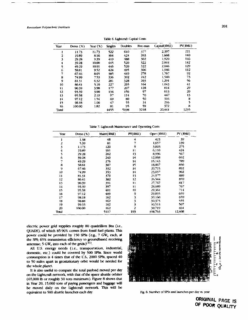
Rensselaer Polytechnic Institute
Table 6. Lightcdt Capital Costs
Year DMsn (%) Year (%) Singles Doubles Fi-man Capital(SMi1) W(SMU)
I 11.73 11.73 522 610 377 2,397 22 1 2 19.89 8.16 366 424 263 1,668 140 3 29.28 9.39 419 488 302 1,920 146 4 39.28 10.00 445 520 322 2,044 142 5 49.29 10.01 446 520 322 2,046 129 6 58.81 9.52 424 495 306 1,946 112 7 67.46 8.65 385 278 1,767 92
449 242 8 74.99 7.53 3% 392 1,540 73 9 81.31 6.32 281 328 203 1,291 56
10 86.4 1 5.10 227 265 164 1,043 41 11 90.39 3.98 177 207 128 814 29 12 93.39 3.00 134 156 97 613 20
95.58 2.19 97 114 70 447 13 14 l3 97.12 1.54 69 80 50 316 8 15 98.18 1.06 47 55 34 216 5 16 100.00 1.82 8 1 95 59 372 8
Total 4455 5198 32 18 20.44 1 1235
Table 7. Lightmft Maintenance and Operating Costs
Year DMsn (%) Maint(SMi) W(SMi1) Oper ($Mil) W ($Mil)
1 1.38 48 4 423 39 2 5.39 8 1 7 1,657 139 3 1.173 120 9 3,603 275 4 19.89 161 11 6,110 424 5 29.28 202 13 8,996 567 6 39.28 240 14 12,068 692 7 49.29 276 14 15,143 789 8 58.81 307 15 18,067 856 9 67.46 332 14 20,723 892
10 74.99 353 14 23,037 902 11 81.31 370 13 24,977 889 12 86.4 1 382 12 26,544 859 13 90.39 39 l 11 27,767 817 14 93.39 397 11 28,689 767 15 95.58 40 1 10 29,.%1 714 16 97.12 409 9 29,835 659 17 98.18 162 3 30,160 659 18 98.88 162 3 30,375 555 19 99.33 162 3 30.5 13 507 20 100.00 162 2 30,7 19 46.1
Total 5117 193 398,763 12,408
electric power grid supplies roughly 80 quadrillion Btu (i.e., OUADS). of which 85-90% comes from fossil fuel vlants. This , . power could be provided by 150 SPSs (e.8, 7 G% each, at the SPS; 65% transmission aciency to groundbased receiving antennae; 5 GWe into each of the grids)(13).
All U.S. energy needs (i.e., transportation, industrial, domestic, etc.) could be cavered by 500 SPSs Since world consumption is 4 times that of the U.S., 2000 SPSs, spaced 40 to 50 h e s apart in geostationary orbit would be needed for the whole planet.
It is also useful to compGve the total payload moved per day on the Lightcraft network, with that of the space shuttle orbiter (65,000 lb or roughly 30 tons maximum). Figure 8 shows that in Year 20, 15,000 tons of paying pasengem and baggage will - . - -
be moved daily on the Lightcraft network. This will be equivalent to 500 shuttle launches each day. Fig. 8. Number of SP% and launches per day vs. year
ORIGINAL PAGE IS OF WOR QUALTTy

Proceedings of tbe NASA/USRA Advanced Design Program 6tb Summer Conference
1. Loomis, J. (ed), Higb Commercial e b t : h r n Inquiry to Action. P m m d q s of the Second High Speed Commercial Fhght Symposium, Columbus, OH, October 1988, Battelle Press, Columbus, OH, 1989, pp. 83-97.
2. Kaldahl, W., "Remarks Regardmg Operations and Markets," in Loomis J. (ed), High $m?d Cornmerdd Wght: ISwn Inquiry to Action, Proceedmgs of the Second High Speed Co- Fhght Symposium, Columbus OH, October 1988, Battelle Press, Columbus, OH. 1989, pp. 77-82.
3. KoeIle, D., "On the Optimum Cruise Speed of a Hypemonic A i r d , " in Webb, D. (ed.), R v a d n g s of tbe Hrst I n t m n a i G m f m e on n n t k Wght in tbe 21st century, ISBN 0- 9608700-1-6, Depanment of Space W e , Uniwrsity of N o d Dakota, Grand Forks, ND, January 1989, pp. 278-283.
4. Iacalli, R and H. Oman, "Economics of H-nic Flight," in Webb, D. ( ed. ), Rwedings of the Fkt International Conference on m t d c PXght in the 21st CPntmy, ISBN 0-9623700-1-6, Deparrment of Space Studies, University of Nonh Dakota, Grand Fo&, ND, Jan- 1989 p ~ . 284-289.
5. Mizuno, H., "Remuks Regardmg Operations and Markets," in Loomis, J. (ed.), High 4xxc-i Cornmenial Flight: I.)wn InquiLy to Acrdon, Proceedin@ of the Second High Speed Commercial Flight Symposium, Columbus, OH, October 1988, Battelle Press, Columbus, OH, 1989, pp. 83-97.
6. Swihan J., Cost Effective 7jnmqmmhbn and High Tedmology, Boeing Commercial Avplane Company, November 1 984.
7. Wasiuta, H., "Hypersonic Flight - ~uture Commercial Potential," in Webb, D. (ed), AoceezaYngs of the First Intemutabnal C o n f m e on H)pemnic Rfgbt in tbe i l s t Cenrury, ISBN 0-9623j00-16, Department of Space Studies, University of North Dakota, Grand Forks, ND, January 1989, pp. 301-306.
8. Wood, R, "Hypersonic Flight and World Tourism," in Webb, D. (ed.), Itoceedings of the Flrst Internafional Conference on H@monic FUgbt in the 21st Century, ISBN 0-9608700- 1 6 , Department of Space Studies, University of North Dakota, Grand Forks, ND, January 1989, pp. 290-300.
9. Williams, L, "Remarks Regarding Aircraft Research and Develop- ment," in Loomis, J. (sd) , High @eed Commercial mgbt: Iiom Inquiry to Action, Proceedings of the Second High Speed Commercial Fhght Symposium, Columbus, OH, October 1988, BatteIle Press, Columbus, OH, 1989, pp. 40-52.
lo. Myrabo, L and W. Smith (ed.), ApoUo tigbtrefl IJvjtxt Annual RepOrt W U S R A 3rd Annual Summer Conference, Washington, DC, June 1987.
11. Myrabo, L (editor), Apoh Dghtrrafl Rvject Annud Report, W U S R A 5th Annual Summer Conference, Marshall Space Flight Center, Huntsville, AL, June 1989.
12. Myrabo, L (editor), Apollo Lightcraft Project Annual Report, W U S R A 5th Annual Summer Conference, Marshall Space Flight Center, Huntsville, AL, June 1989.
13. Brown, W, "Beamed Power Transmission and Transportation Systems in the Equatorial Ptane," draft of paper prepared for presentation at the 9th Biennial SSI/Pninceton Conference on Space Manufrtunng, May 1989.
14. Walbridge, E., Laser Satellite R)wer Syskrm, Report No. A W E S 92, A r g 0 ~ e National Laboratory, Argome, I I January 1980.
THE UNIBWGITY OF TEXAS, AUSTIN DEPARTMENT OF AEROSP- ENGINEERING AND ENGINEERING MECHANICS
There were two NWUSRA-sponsored A h c e d Design &rts at UT Austin during the 1989-90 academic year, both assodated with space design. 7he aerospace e n w r i n g program is a sustaining program and the mechanical engineering program is a new effort. Interactions between the two programs are suong, with hculty from each department acting as consultants to students from the other department. Both programs are now coordinating their activities through the new Texas Space Grant Consortium, a consortium of wivemities across the state of Texas 'Ihe aerospace engineering space design program is now coordhting with the depuunent's airaaft design coutse, and abstnas of the spring aircraft design projects are included in this document. U d q m i u a t e s in the spring undergraduate design comes used subsystem design notes developed by graduate students in a fdl 1989 graduate spacecraft design course. The aerospace engineering program has expanded its outreadh considerably, pubhhq a newsletter, invohmg Dr. Harlan Smith of the UT Depvuncnt of Astronomy in a fall design, bringing in a high-school intern to work with an undergraduate design team, using an undergraduate student from tJx humanities as a manber of a hll design tteam, and hawq a student from ENSAE (Sup'Aero) in France work as a member of a spring d e w team. A new aeraspPce engineering graduate level design course was taught in fall 1989 in wfiich preliminary designs for I k ditkffnt s p a c e d were developed Student designs sunmarked here include two undergnduate space designs and Bve graduate space designs h m Eall 1989 plus four undeqduate designs and four undergraduate air& designs from spring 1990.
GEOSlXTlONAKY MlXUlTE SERVICING FXILITY UNDERGRADUATE. FALL 1989
The objective of this study is to create a preliminary design for a man-tendable orbiting Senicing and repair facility for geostationary satellites. The facility is composed of two major elements: a habitation module and the satellite service bay. Satellite Retrieval Vehicles (SRVs) will be based at the facility and will rendezvous with satellites needing retrieval and repair. These satellites will be returned to the facility where their problems will be diagnosed telembotidty and then they will be stored. When several satellites have been r e t r i m and their problems analyzed telerobotically, a manned servicing vehicle will be sent, carrying the requ id parts, to etfect the needed repairs. The repair crew will return to the Earth and the satellites will be returned to operational orbits.
The design features a nonpressurized service bay of oaagonal cmssection connected to a presnuized cylindrical habitation module. The facility is powered by solar arrays on both sides of the station, mounted on long booms that also provide support for radiators. The design katures a manipu- lator arm that is used in the repair and storage of satellites. Satellites awaiting repair can be stored outside the service bay.
LUNAR FARSLDE OBSERVATORY AND SCIENCE BASE UNDERGRADUATE, FALL 1989
'Ihe objective of this study is to estabLish requkments for an observatory and science base on the farside of the Moon. A lunar observatory will allow highly accurate astronomical observations free h m radio and atmospheric interkrence from the Earth. Such a U t y will also serve as a base 6rom which to conduct other scientific studies, thus allowing a nearside base to be designed for dedicated propellant
production The lunar observatory is designed as a man- tendable facility that can be assembled using autonomous and teleoperated robotics.
The design features an Arecibo-type antenna array for radio mnomy, a VLF array, optical telescopes, a solar obsenation package, and selenographic experimentation package. The base includes a nuclear power plant and habitation modules for a crew of four. The base was designed to operate for a year in the untended mode. Crew visits would last 90 days once per year.
TEXAS EDUCATIONAL W GRADUATE, FALL 1989
The goal of this study is to design a communication satellite, the Lone Star Satellite, to link unixrsities, indusfry, research Eacilities, and high schools throughout the state of Texas. The services provided by this satellite could be expanded to include other southwestern states such as Louisiana, Oklahoma, and New Mexico to allow for cost sharmg. Such a satellite would greatly enhance higher education by allowing univer- sities and research centers to share lectures and seminars remotely via television It would also provide an educational outreach program by allowing universities to broadcast lectures and programs to high schools. Communications capacity not used by the state and its agencies might be leased to the private sector to reduce the overall cost of the satellite. The primary mquimnent for the Lone Star Satellite (LSS) is to p&& 24channel capacity dedicated to TV signals only. An optional capability includes a steerable antenna to provide cowrage of areas outside the main footprint. Another optional

Proceedin ~ g s of tbe NASMUSRA Advanced Design Program 61b Summer Conference
capability is the inclusion of voice telecommunication channels for use by sate agencies both from fixed bases and from mobile units.
The design features a three-axis stabilized, solar powered satellite similar to the commercial communications satellites currently in geostationary orbit. The satellite, on orbit, has a mas of about ( 5 kg. The satellite is powered by solar panels and is launched on a Deltaclass booster.
ASTEROID RENDEZVOUS VEHICLE GRADUATE, FALL 1989
The primary objectives of the proposed Multiple Asteroid Rendezvous Tracker and Explorer (MARTE) are to anaiyre the composition and characterize the motion of five asteroids. To achieve these objectives, the spgcecrafi will be composed of two major components: a laboratory lander crafi and five minispacecraft. The laboratory Lander will be equipped with a complete sample analysis laboratory along with multiple external sensors. Each of the five minispacecraft will be much smaller than the main lab and contain only a few instruments. The minispacecraft will be targeted to five separate asteroids where they will land and perform a preliminary surface analysis. The laboratory lander will then proceed to and land upon the asteroid deemed to be the most interesting as a result of the minispacecraft's findings, where it will perform a much more detailed analysis, including sampling.
There were a number of design issues that required study in the design of MARTE. First, the asteroids in the asteroid belt are in dissimilar orbits with widely ranging orbital elements. For this analysis, an arbitrary group of about 30 asteroids with semimajor axes less than 3 k U . and inclinations of less than lo was chosen. Five asteroids were chosen from these 30 as a target p u p based solely on their relative positions during the three-year period between 1998 and 2000. Since the shape and rotation rates of most asteroids are unknown, cameras will be placed onboard the minispacecraft to provide visual identification of the shapes and to determine the rotation rates from pictures taken during the approach. Another design i.ssue is the need for a senliautonomous control for these spacecraft. Since the roundtrip time delay for signals between the spacecraft and Earth can be over 20 minutes, control of the spacecraft from Earth would be impractical. The use of multiple minispacecraft was a major design decision. Since obtaining data on a number of asteroids is the primary objective of MARTE, and since transfer of a single spacecraft between asteroids would require large velocity changes, a single spacecraft that performs rendezvous with multiple asteroids was found to be impractical. Thus, the multiple minispacecraft scenario was adopted.
TITAN PROBE GRADIIATE, FALL 1989
The objective of this study is to design a probe to study Titan, Saturn's largest mcwn. 'Iitan possesses a significant atmosphere that is composed primarily of diatomic niu-ogen; the sulface prmure on Titan is 1.6 times that of Earth. Titan's
atmosphere is compositionally similar to Earth's early atmosphere-primarily nitrogen with traces of organic chemicals, some of which are thought to have played a si@cant role in the development of Life on Earth. The mission objective is to gather information about Titan's meteorology, geology, and history. The spacecraft chosen for this mission consists of two portions: an orbiter and a lander. The orbiter is based on the Mariner Mark I1 design that will be used for the CRAF and Cassini missions. Because a design exists for the orbiter, most of our effort is directed toward developing the Lander. The main constraints for this mission will be sirnilat to previous planetary missions: total weight and trajectory limitations. Additional constraints will be imposed on the lander due to atmospheric reentry and Xtan's extreme suiface conditions. The Mark II probe is a modular design and our design for the lander is modular, with all subsystems broken into functional packages. This allows for the inevitable budget cuts and mission reclefition. Major subsystems present on the Titan probe include power, propulsion, thermal management, aerodynamic deceleration, landing (both soft landing and penetrators), sensors, guidance and control, attitude control, and structure. The design relies heavily on past JPL successes, but is flexible enough to incorporate current and near-future technology.
SUBSYSTEMS COMMONALITY ASSESSMENT FOR LUNAR/MARS LANDERS
GRADUATE, FALL 1989
The focus of this project is to identify commonality in components of four di&srent extraterrestrial lander vehicles that are likely to be used in the lunar/Mars program and to incorporate this information in common subsystem designs. The vehicles are the lunar piloted lander (LPL), the lunar cargo lander (LCL), Mars piloted lander (MPL), and Mars cargo lander (MCL). The LPL and MPL are both expected to carry four crewmembers from orbit to the surface and back The MPI however, will be expected to be a base of operations for several days on the k t several missions to the martian surface. The LCI. and MCL are similar in cxrgo capacity but differ in that the MCL is not expected to return to orbit.
The majority of the effort in this design project is directed toward the spacecraft subsystems since it is not expected that a single vehicle design will adequately handle all four missions. The subsystems examined are structures; propulsion; ECLSS; sensors; guidance, navigation, and control; computers; power; and thermal control. Commonality of subsystem design between the lunar/Mars program lander vehicles and the Earth- Mars crew &er vehicle, which is the subject of a parallel study, are also examined. Cost savings in both the design and operations phases of a program can be achieved by setting commonality and maintainability goals early in a vehicle development program. In this study each lander vehicle's subsystem requirements and physical parameters are researched in detail and conceptual designs for the four landers are presented. Key enabling technologies are identified. By examining the four lander vehicles as a family of spacecraft constructed 6rom common components, it is hoped that design considerations that &ect program costs have been identified.
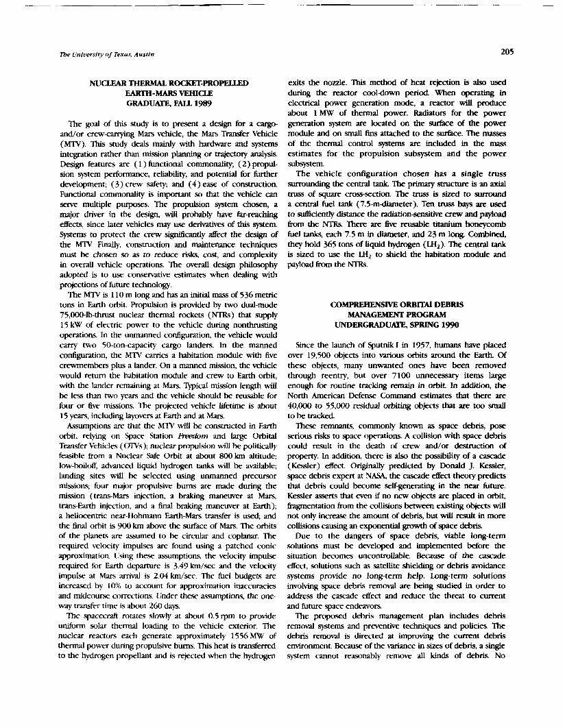
Tbe University of Texas, Austin
NUCLEAR THERMAL. ROCKET-PROPELLED EARTH-MARS VEHICLE GRADUATE, FALL 1989
The goal of this study is to present a design for a cargo- and/or crew-caqing Mars vehicle, the Mars Transfer Vehicle (MTV). This study deals manly with hardware and systems integration rather than mission planning or tmjectory analysis. Design features are ( 1 ) functional commonality, (2) propul- sion system performance, reliability, and potential for further development; (3) crew safety, and (4) ease of construction. Functional commonality is important so that the vehicle can setve multiple purposes. The propulsion system chosen, a major driver in the design, will probgbly have Eu-reachq effects, since later vehicles may use derivatives of this system. *ems to protect the crew sigruficantly affect the design of the M n ! Finally, construction and maintenance techniques must be chosen so as to reduce risks, cost, and complexity in overall vehicle operations. The overall design philosophy adopted is to use conservative estimates when deahg with projections of future technology.
The MTV is 110 m long and has an initial mass of 536 metric tons in Earth orbit. Propulsion is provided by two dual-mode 75,000-lb-thrust nuclear thermal rockets (NTRs) that supply 15 kW of electric power to the vehicle during nonthrusting operations. In the unmanned configuration, the vehicle would carry two 50-ton-capacity cargo landers. In the manned configuration, the MTV carries a habitation module with five crewmembers plus a lander. On a manned mission, the vehicle would return the habitation module and crew to Earth orbit, with the lander remaining at Mars. 'Qpical mission length will be less than two years and the vehicle should be reusable for four or five missions. The projected vehicle lifetime is about 15 years, including layovers at Earth and at Mars.
Assumptions are that the MTV will be constructed in Earth orbit, relylng on Space Station Rtvabrn and large Orbital Transfer Vehicles ( W s ) ; nuclear propulsion will be politically feasible from a Nuclear Safe Orbit at about 800 km altitude; low-boiloff, advanced liquid hydrogen tanks will be available; landing sites will be selected using unmanned precursor missions; four major propuLsive bums are made during the mission (trans-Mars injection, a braking manewer at Mars, trans-Earth injection, and a 6nal braking maneuver at Earth); a heliocentric near-Hohmann Earth-Mars transfer is used; and the f h d orbit is 900 km above the surface of Mars. The orbits of the planets are assumed to be cir& and coplanar. The required velocity impulses are found using a patched conic approximation. lJsing these assumptions, the velocity impuLse required for Earth departure is 3.49 krn/sec and the velocity impulse at Mars arrival is 2.04 km/.sec. The fuel budgets are increased by 10% to account for approximation inaccuracies and midcourse corrections. Under these assumptions, the one- way transfer time is about 260 days.
The spacecd rotates slowly at about 0.5 rpm to provide uniform solar thermal loading to the vehicle exterior. The nuclear reactors each generate approximately 1556 MW of thermal power during propulsive burns. This heat is transferred to the hydrogen propellant and is rejected when the hydrogen
exits the nozzle. This method of heat rejection is also used during the reactor cooldown period When operating in electrical power generation mode, a reactor will produce about 1 MW of thermal power. Radiators for the power generation system are located on the surface of the power module and on small fins attached to the su.rfkce. The masses of the thermal control systems are included in the mass estimates for the propulsion subsystem and the power subsystem.
The vehicle configuration chosen has a single truss m u n d i n g the central tank The primary structure is an axial truss of square am-section The truss is sized to surround a central fuel tank (7.5-m-diameter). Ten truss bays are used to sufficiently distance the radiation-sensitive mew and payJoad from the NTRs There are !ke reusable titanium honeycomb fuel tanks, each 7.5 m in diameter, and 23 m long. Combined, they hold 365 tons of liquid hydrogen (LH,). The central tank is sized to use the LH, to shield the habitation module and payload from the NTRs.
COMPREHENSIVE O R B m DEBRIS MANAGEMENT PROGRAM
UNDERGRADUATE, SPRING 1990
Since the launch of Sputnik I in 1957, humans have placed over 19,500 objects into various orbits around the Earth. Of these objects, many unwanted ones have been removed through reentry, but over 7100 unnecessary items large enough for routine tracking remain in orbit. In addition, the North American Defense Command estimates that there are 40,000 to 55,000 residual orbiting objects that are too small to be tracked. These remnants, commonly known as space debris, pose
serious risks to space operations. A collision with space debris could result in the death of crew and/or destruction of property. In addition, there is also the possibility of a cascade (Kessler) effect. Originidly predicted by Donald J. Kessler, space debris expert at NASA, the cascade effect theory predicts that debris could become self-generating in the near future. Kessler asserts that even if no new objects are placed in ohit, hgmentation from the collisions between existing objects will not only increase the amount of debris, but will resuIt in more collisions causing an exponential growth of space debris.
Due to the dangers of space debris, viable long-term solutions must be developed and implemented before the situation becomes uncontrollable. Because of the cascade effect, solutions such as satellite shielding or debris avoidance systems provide no long-term help. Long-term solutions involving space debris removal are being studied in order to address the cascade effect and reduce the threat to current and future space endeavors.
The proposed debris management plan includes debris removal systems and preventive techniques and policies. The debris removal is directed at improving the current debris environment. Because of the variance in sizes of debris, a s w e system cannot reasonably remove all kinds of debris. No

206 Proceedi lngs oJtbe NASA/USRA Advanced Llesfgn Program 611, Summer Conference
&&e system is currently available to remove the debris . d e r than 10 cm in diameter. However, an active removal system, which deliberately retrieves targeted debris from known orbits, was determined to be effective in the disposal of the larger debris that can be tracked directly from Earth.
A roving debris-removal vehicle, based on the OMV, has been designed to rendezvous with large debris pieces, attaching deorbit propulsion modules. The roving debris-removal vehicle has two arms and "glues" the deorbit propulsion system to the debris pieces. Telerobotic control is used on the roving vehicle. The vehicle is periodidly resupplied using a launch- ondemand refueling vehicle. The reheling vehicle deorbits itself after transferring the supplies and fuel to the roving debris-removal vehicle.
The second part of debris management is its prevention. This prevention program is intended to protect the orbital environment from future abuses. This portion of the plan involves various methods and rules for future prevention of debris. The preventive techniques are protective methds that cxn be used in future design of payloads. In order to encouragi: launching states to employ these preventive measures, several international treaties have also been proposed.
MICROCRAW FREE-FLYERS FOR SPKE STATION UNDERGRADUATE. SPRING 1990
The goal of this project is to design a spacecraft that will be used with .Space Station M m to provide the best possible environment for microgravity experiments. Astronauts, pumps, and other vibration-causing entities onboard Fnxabrn cause this environment to be degraded substantially. A kee- flyer W be designed to overcome these disturbances by being removed from Freeclom while microgravity experiments are running The mas.. of the experiments will be up to 1000 kg, with experiment lifetimes up to 2 years. The free-flyer will automatically deploy, maintain stability, reboost when necessary, and return to I.)reedom for changing experiments.
A typical mission pro6le will consist of placing experiments onboard, performing a check-out of the systems, deploying the free-tlyer, controlling the attitude and orbit, sending experi- mental data to Fmdom, reboosting when necessary, returmng to FLeerdom, docking, and changing experiments. Each aspect of the mission presents problems. The level of human interaction-that is, how much of the astronauts' time will be required-will have to be determined by the free-flyer. Experiments will haw: to be fitted to each free-flyer -ion. bwer requirements, communication requirements, micrograv- ity tolerances, and duration requirements must be considered for each experiment onboard the free-flyer. Compatible experiments will then be fitted together. The &-flyer should be s t a b i i with minimum acceleration and vibration.
The kee-flyer is designed to be placed in orbit by the space shuttle and to 5y up to five q r i m e n t modules. The core vehicle contains one or more power modules, a variable capability propulsion module, a thermal management system, and an attitude control system. Any module can be replaced using the Space Station mobile manipulator arm.
ALGTFXM EDUCATlONAL !#lmmTE SYSTEM UNDERGRADUATE. SPRING 1990
In an effort to unite educational resources throughout the state of Texas, the 1989 Texas Senate passed Senate Confer- ence Resolution No. 23. This resolution directs the Automated Information and Telecommunications Council to study the feasibility of a state-sponsored educational satellite project. The objective is to design a satellite communications system ( T E X M ) that will enhance the educational productivity in Texas. Such a system will enhance education at all levels throughout the state. The design team has designed TMSWR, an educational satellite communications system that will be considered a means of equalizing the distribution of educa- tional resources throughout the state. TEXSTAR will be capable of broadcasting Live lectures and documentaries, in addition to transmitting data from a centralized receiving-transmitting station. Included in the design of TEXSChR are system and subsystem design for the satellite and design of ground stations. The launch vehicle used will be the Texas-built Conestoga 42 1 - 48. The TEXSrPlR system incorporates a cluster of three small satellites in slightly inclined geosynchronous orbits. Ekcame of the configuration and spacing of these satellites, the system will be accessed from ground stations as if it were one large, geostationary satellite.
To fulfill all senice objectives, TEXSTAR must be able to relay 20 video signals simultaneously, providing uninterrupted cowrage to the entire state 24 hours per day. Transponder number and size, however, must be weighed against the mass and cost of the satellite. This effort is designed to benefit not only the Texas educational system, but also the Texas economy. Therefore, satellite components and launch vehicles designed and built in Texas will be used as much as possible. The success of the TEXSTAR project will provide better services, create jobs, and attract national attention to this innovative solution to our educational dilemma
LUNAR CORING LANDER SEARCHING FORWATERfU'THELUNARPOLES UNDERGRADUATE, SPRING 1990
As a new era in manned qace exploration of the solar system begins, NASA is turning its sight back to the Moon. Plans to build a lunar base are presently being studied One of the most important considerations is qd@ing and quan. tifying the presence of water on the Moon. The existence of water on the Moon implies that future lunar settlements may be able to use this resource to produce thin@ such as drinking water and rocket fuel. Because of the very high cost of trans- porting these materials, in-dCu production could save billions of dollars in operating costs of the lunar base.
Scientists have suggested that the polar regions of the Moon may contain some amounts of water ice in the regolith. This report suggests six possible mission scenarios that would allow lunar polar soil samples to be collected for *is. The options presented are a remote sensing satellite; two unmanned robotic lunar coring missions (one is a sample return and one is a data return only); two combined manned and robotic polar coring missions; and one fully manned core

Tbe University of Texas, Austin 207
retrieval mission. Each mission has its own advantages and all are considered to be viable with little or no required advancement of the present state of technology.
One of the combined manned and robotic missions has been singled out for detailed analysis. This project proposes sending at least three unmanned robotic landers to the lunar pole to take core samples as deep as 15 m. Upon successful comple- tion of the coring operations, a manned mission would be sent to retrieve the samples and perform extensive experiments in the polar region. The lander subsystems are descent propul- sion, automatic landing site selection system, self-leveling landing gear, power, thermal management, drilling and core handling, sample module axent propulsion, sample return vehicle guidance, sample landing propulsion, and sample package landing gear.
m AIRCRAFI-BUSHWHACKER PROJEcr LOW-INTENSITY CONFLICT AIR- (LICA)
UNDERGRADUATE, SPRING 1990
The Gatekeeper will be a new drug-interdiction aircraft combining the drug-interdiction capabilities of the Citation I1 and the Blackhawk Gatekeeper will be designed to intercept a wide variety of adversary aircraft. The DC-3, Cessna 310, and the Cessna 172 (all used to smuggle drugs) will be used to set Gatekeeper performance requirements.
Gatekeeper will have ( 1 ) sufficient payload to carry advanced radar for traclung illegal drug aircraft, (2) long endurance to allow sustained surveillance, and (3) a fight envelope wider than the composite envelope of the three competitor aircraft mentioned above. This will enable Gatekeeper to apprehend drug smugglers and should seme as a potent deterrent to the import of illegal drugs in the U.S. The Gatekeeper design features a span of 62 ft, a length of 42 ft, a cruise speed of 120 mph, with a maximum speed of 0.78 Mach. Its design cruise altitude is 7000 ft and its range is 1970 n.m. The Gatekeeper weighs 23,000 lb at takeoff, and carries 7300 lb of fuel and a payload of 2500 Ib. It is powered by two 3300-hp turboprops with counterrotating propellers. It has an aspect ratio of 9 and a wing area of 429 sq ft. Specific
During the 1 9 8 0 ~ ~ the tramition from emphasis on full-scale fuel consumption is ,36 Ib,hr/lb at cruise, battles to localized low-intensity conflicts created a demand for a low-cost aircraft designed for close-air support against a lightly armed opposition. The Bushwhacker project focused on developing an aircraft that falls between the capability of a counterinsurgency aircraft such as the North American OV-10 developed in the 1960s and the present battlefield tank killer, the Fairchild A-10 developed in the 1970s. Its primary task will be forward air control, which consists of a defined loiter time combined with a series of attack runs to deliver rockets, machine-gun fire, and other antipersonnel ordnances. The low- intensity conflict aircraft (LICA) will be marketed for the U.S. Anned Forces and U.S. allies in the Central American region. The project trade studies are directed toward developing a maneuverable and w e aircraft whose cost does not outweigh its military worth.
The LICA is a straight-wing, twin-turboprop-powered aircraft with a maximum takeoff weight of 16,650 lb, a span of 46.6 ft, a length of 43 ft, and a wing area of 333 sqft. It cames a payload of 1620 Ib, has a maximum attack speed of 325 kt and a stall speed of 132 kt. The sea-level rate of climb is 3500 ft/ min. Its takeoff distance is 1000 ft and its landing distance is 700 ft.
THE "-" i+fmmasION ANTI-DRUG AIR-
UNDERGRADUATE, SPRING 1990
The flow of illegal narcotics has become an uncontrollable problem. Current drug interdiction methods are failing to curb large amounts of narcotics entering the U.S. onboard light aircraft. Drug-laden aircraft reguhIy elude radar and evade capture to deliver drugs. U.S. Customs relies on multiple aircraft to perform drug interdiction. Presently, Customs uses radar-equipped E-2C Hawkeyes to search for smugglers. The E-2C guides a Cessna Citation I1 to a potential q e t for identification and possible pursuit. If a drug drop is observed, a HU-60 Blackhawk helicopter is directed to apprehend smugglers on the ground
THE PEREGRINE I, A FUTURlSTIC COMPETITION SAEPLANE
UNDERGRADUATE, SPRING 1990
In 2050, technological advancements in fields including metallurgy and aircraft design will allow new and innovative ideas to flourish in the public and private arenas. Soaring will replace yachting as the ultimate in international competition, spurring American industry to take the reins in an effort to gain superiority in the highIy competitive sport. The goal of this project is to extrapolate the results of current research and use them to conceptually design the Peregrinel, a futuristic sailplane that will lead the United States to preem- inence in international competitive soaring Efforts are made to incorporate the vertical and horizontal tail contigurations into the fuselage and wings. To soar competitively using this unconventional no-tail design, the sailplane will employ miniature onboard fight computers. Enormous strides in the study of engineering materials will allow the use of composites to reduce aircraft weight. Additionally, boundary layer control mechanisms and advanced airfoil and wing designs will be considered for the sailplane design. The availability of advanced technologies is being anticipated to conceptually design a futuristic sailplane that will bring the United States to dominance in international soaring competition.
THE "BALLISTIC0"-A PLATFORM FOR MICROGRAVITY EXPEiuMENm
UNDERGRADUATE, SPRING 1990
The objective of this study is to provide an alternative aircraft to the NASA KC-135 aircraft presently used to conduct parabolic microgravity flights. The purpose of this aircraft is to provide a limited microgravity environment for research applications such as biomedical and human-adaptation studies, materials processing, fluid physics, life sciences, and spaceflight hardware testing. The mission performed by the KC-135

R o c c a d f n g s of tbe NASANSRA Advanced Design Program 6tb Summer Cmfermce
consists of 40 parabolas with a micrognvity time of 25 set/ The BaUistiw a i t d is a 230,000-lb (takeoff weight), four- pachla The WCO'S mission requhments ue to conduct engine aircraft with four Rob Royce RB211-535C engines at 72 parabolic manewem with a micqpvity time of 28 set/ 37,000 Ib thrust each at sea 1-1 The a i r d carries a 24,900- parabola The aim-aft is simllv in design to the KC-135 with Ib plyload and has a ceiling of 37,000 ft. The wing area is the capacity fw 20-25 pgssengers and 20,000 Ib of research 1716 sq ft, the span is 115 ft, and the length is 156 ft. The equipment. cruise speed is Mach 0.82 at 25,000 ft.
PROJECT SUMMARIES
THE UNIVERSITY OF TEXAS, AUSTIN
INTRODUCTION
The Mechanical Engineering Design Projects Program (MEDPP) at The University of Texas at Austin is the capstone engineering course in the Mechanical Engineering curriculum. Teams of three or four students work together for one semester on industry-sponsored engine- project% projects are typically sponsored when the sponsoring company does not have the time or resources to s o k a problem, wants independent verification of in-house studies, or wants a bresh and uninhibited approach to a desgn problem.
A number of NASA projects (sponsored by Jdulson Space Center, Houston, Texas) were undertaken by student teams in the MEDPP from 1984 through 1987. Additional space projects were sponsored by USRA through the Advanced Design Program in a cooperative effort with the Aerospace and Engineering Mechanics Department at The University of Texas at Austin h m 1986 through 1989.
In June 1989, the MEDPP became a participating member in the USRA Advanced Design Program. Four p r w were completed during the f h t semester as a participating member and three projects were completed during the second. The first project discussed deals with the use of satellite data in managing the use of Earth resources. The remaining six projects focus on the design of vehicles and equipment for use in NASA's proposed lunar base. A discussion on the lunar base precedes the project descriptions to clarify assumptions used in the design process.
D m P M E N T OF A COMPUTER SIWJUTION MODEL FOR PREDICTING VESSEL STATION-KEEPING
REQ- IN THE GULF OF MWCO
Satellite data are currently used in a variety of ways, ranging tkom meteorology and weather foremhg, communications, and monitoring trends in the use of Earth resources. Satellites can also be used to accurately measure the distance from the Earth's d c e (either land or water) to the satellite. Knowing the satellite's altitude at all points in the o&it allows satellite altimeter data to be conwrted into a height above or below a chosen reference level. One use of satellite altimeter data is for the determination
of wave heights in a body of water. Wave height data indicate waterspeedanddirection,sotheyareusefulintrack@major water currents (such as the Loop Current in the Gulf of Mexico) and eddies (large columns of rotating water spawned by major water currents). Wind velocity can also be determined from wave height data; therefore, weather predictions can also be made using the data h m satellite altimeters.
Development of a computer simulation model for predicting vessel station-keeping requirements was the goal of this project. An existing code, used in predicting station-keeping requirements for oil drilling platforms operating in North Shore (Alaska) waters was used as the basis for the computer simulation. M&cations were made to the existing code to adapt it for use in simulating conditions found in the Gulf of Mexico (e.g., location of land masses, major water currents, etc. ).
The input data to the model consists of satellite altimeter readings and water velocity rea- from buoys stationed in the Gulf of Mexico. The satellite data consist of altimeter readings (wave height) taken during the spring of 1989. Each satellite image records wave height data in a 1-km2 area of the Gulf of Mexico. In addition, the groundtrack of the satellite repeats every 16 days indicating that data taken during the current orbital pass is 22.5O west of the previous data. There. fore, smoothing techniques were used to account for the spatial and temporal separation of the satellite data in developing a complete input file for the computer model.
Buoys are periodically placed in the Gulf of Mexico to track the direction and speed of the water at various points. Available buoy data is used to verify the water velocity and direction prediaed by the computer simulation.
The simulation model predicts water velocity and direction, and wind velocity. Knowledge of these parameters is uxd to determine vessel station-keeping requirements and weather forecasts. The simulation model can also be used as a resource- minimhtion tool. Fuel consumption can be greatly reduced through the proper location of vessels in areas of low water velocity.
LUNAR BASE PROJECTS
The concept of a manned lunar base has intrigued mankind for many years. Current mission scenarios call for the establishment of a lunar base hegtnrung soon after the turn of this centuty. ?he reasons for establishing a lunar base can be broken down into scientific, resource production, and technology development considerations. The primary lunar resource production effort is focused on the extraction of oxygen from the lunar soil. The production of lunar oxygen (LUNOX) is considered essential for manned exploration of the solar system and beyond.
While the designs were being developed, the following assumptions concerning existing facilities and technologies were made. First, it was assumed that an operational space

Proceedtngs of tbe NASA/USRA Adwnced Ikstgn Program 61b Summer Conference
station is in low Earth orbit (LEO). A space station is needed as a staging point for the vehicles that will carry crews and cargo to the Moon. Crew cabs and cargo will be d e d on lunar Ian- vehicles resembhng the Lunat Excursion Module (LEM) used during the Apollo program. 'Ihe landmg vehicle will be propelled h m LEO to low lunar orbit ( W ) using a transport vehicle. Once in W, the lunar landing and vansport vehicles will separate, with the lander continuing on to the lunar surface.
Second, it was assumed that missions to the Moon will be scheduled approximately six months apart. Using this timetable, lunar cargo landers are required to sit unattended in the lunar environment for long periods of time until the next manned mission arrives to off-load the cargo. Under the present mission scenarios, the lunar landing vehicles are considered expendable until the lunar base becomes manned, at which point the vehicles can be designed with multimission capabilities.
Once the lunar base becomes somewhat developed, launch and Ian- facilities will be established at some distance 6rom the habitation modules, laboratories, and power plant. This is necessary in order to minimize the danger of landing and launching vehicles in populated areas and because soil particles lofted by the lander engine blast can cause damage to equipment and vehicles.
All the struczures and equipment malung up the lunar base must be protected h m the harsh lunar environment, which includes solar and galactic radiation, extreme temperature fluctuations, periodic micrometeorite impacts, and the constant presence of intrusive and abrasive lunar dust. In order for the lunar base to be a feasible project, innovative designs are needed that will minimize the weight, space, power consumption, manpower, and operation times of the struc- tures, equipment, and vehicles for the lunar base.
Reconfigureable Lunar C q o Lander
The establishment of a lunar base will require large amounts of equipment and material to be rransported to the Moon. During the Apollo lunar missions and in the current lunar base scenario, much of the lunar vehicle is discarded after performing its intended function. The high cost of transporting equipment from the Earth to the Moon makes dispsal of any equipment extremely undesirable. Therefore, a lunar landing vehicle that reconfigures into another machine will aid in minimizing the mass to be transported to the Moon during the establishment of a lunar base.
A lunar cargo lander has been designed that can be reconfigured to form the structure over a habitation module; the structure will support the regolith layer used for radiation and thermal protection of the crew and equipment. The lander consists of four legs attached to a central platform. The habitation module and associated internal payioad are mounted along one centerline of the platform. Propellent tanks and instrumentation ate mounted to the platform in the areas around the habitation module. The lander engines are mounted on the underside of the cenval platform; the platform
prevents damage to the vehicle components during h n g of the engines by isolating them from the engine blast.
After the habitation module, propellent tanks, i n m e n t a - tion, and engines have been removed from the lander, the I* and central platform are recodgured such that the lander "straddles" the habitation module. The lander structure will be covered with a fine mesh or blanket and then covered with regolith. The design of the lander also permits multiplexing of the habitation modules in any array desired. Therefore, for every cargo lander sent to the Moon, a payload is delivered and a habitation module (complete with radiation and thermal protection) is produced
Thermal and Micrometeorite Pmtection System
As mentioned in the background section, the assumption was made that lunar cargo landers will sit unattended in the lunar environment for long periods of time between successive missions. The lunar cargo lander and payload must be able to endure the lunar environment, which is chacterized by large temperature changes and periodic impacts by micrometeorites. A system is required that will protect lunar cargo landers and payloads in these conditions.
A thermal and micrometeorite system that deploys after landing has been designed The system consists of a composite blanket that is stowed in compact form during transport to the lunar surface. The composite blanket, in the deployed configuration, will provide thermal and micrometeorite protection for the lunar cargo lander. Compressed air "struts" are built into the blanket and are used to deploy the protection system and stiffen the blanket in the deployed position, so that it does not rest against any part of the lander.
Compressed air for the protection system is obtained by boiling off the liquid oxygen (LOX) remaining in the propellent tanks. Air pressure in the struts is maintained using a simple boiler device and dves that regulate the flow of air into and out of the struts. Pressure regulation is required since it is anticipated that the air pressure in the struts will change in response to changes in the ambient conditions.
Once the lander has been off-loaded and the protection Wtem is no longer required, the system can be reconfigured for use as ( 1 ) the covering for the structure over the habitation module prior to the addition of the regolith or (2) the exterior covering for a lunar base garage, maintenance facility, or similar structure.
Versatile L1Ztlng Machine wtth Robotic Capabilities
The establishment and operation of a lunar base will require machines with Lifting capabilities for loading and unloadmg cargo, and robotic capabilities for dextrous operations. A single machine, capable of performing a &ety of lifting operations as well as robotic activities, would increase the rate of lunar base development by minimizing the amount of equipment vansported to the Moon.
A versatile lifting machine has been designed that is capable of heavy-lift and robotic operations. The machine consists of a chassis, telescoping boom attached to a rotating turntable, robotic manipulator, outriggers (stabilizing legs), and wheels.

me Utziwrsity of Texas, Austfn
The boom is a truss structure composed of three separate sections that telescope to suit the particular ojmation. The boom is equipped with a hook and cable assembly for general lifting operations sirnilat to cranes on Earth. m e robot manipu- lator is a serial mechanism with 7 degrees of W o r n ; the manipulator is attached to the end of the boom to aid in a t t a w the cable to payloads as well as for perhrming dextrous operations. Attaching the manipulator to the boom allows the manipulator to be positioned within a large work envelope. The manipulator end-efkaor is a simple three-jaw gripper that permits a wide variety of robotic tasks to be performed
Four telescoping o u t r i w are attached to the chassis to stabiie the machine during Lifting operations. The outriggers are retracted during transport (to the Moon and on the lunar sudkce) of the lifting machine. 'Ibe wheels for the lifting machine are cone-shaped wheels selected for their good performance characteristics in the lunar soil. A hitch is mounted to the lifting machine chassis allowing it to be towed behind a drive vehicle.
Cw30 T v * System
A lunar base will likely consist of a number of developed areas (e.g., habitation, laboratory, launch and landing facility, power plant) set apart from each other due to safety considerations. A point-to-point cargo transport system linking the various areas of the lunar base could reduce the power consumption and the manpower needed to mow cargo and equipment kom one part of the base to another.
A cargo transport system has been designed that consists of an autonomous vehicle that travels on a self-repositioning track The vehicle consists of an enclosed cargo compartment attached to a chassis; the batteries, drive train, and instnunen- tation are mounted to the chassis beneath the cargo bay. A serial manipulator is mounted at each end of the vehicle with a conveyor belt running between the two manipulators.
The vehicle is driven by two wheel assemblies located beneath the vehicle. The direction of trawl is controlled by guide wheels located on the wheel assemblies that are in contact with a guide rail at the center of each track section. The vehicle drives on a track that is made up of individual track sections connected by a coupling device; track sections are continuously repositioned using the procedure that follows.
A s the vehicle moves forward, the rear robotic arm picks up the track section over which the vehicle has just passed and places it on the conveyor belt. At the same time, the forward robotic arm takes a track section off the conveyor belt and attaches it to the track sections already on the ground The conveyor belt is used to transport track sections from the rear of the vehicle to the forward end
Direction of travel for the vehicle is determined by the positioning of the track sections. W n g the vehicle is accomplished by laying successive track sections at an angle to the previous sections specified by the desired Nning radius The use of this design will permit energy-ellicient transport of cargo and equipment between various areas of a lunar base without a developed roadway.
Lkdgn of a Road ConsUudon System for a Lunar Base
The operation of a lunar resource production facility will require the tramport of large amounts of raw and processed materials to ditkrent areas of a lunar b. In the event that an autonomous transport *em (such as the one described above) cannot MfU the transportation requirements, a system of roads and the associated construction machinery will be requiffd to minimize the energy expended in tramp- materials to different areas of the base. A design for a road construction system satisfying these needs is discussed below.
T h e ~ s t e p i n t h e p ~ e c t w a s t o d e t ~ e t h e r o a d t y p e best suited to the needs of a lunar base. I)pes of roads considered included concrete, pawd, sintered-soil gravel, and dirt. Consideration was given to the materials and energy required to build each type of road as well as the road maintenance requirements and ease of repair. A compacted- dirt road was determined to be the most suitable.
The next step was to identify the machine functions required to produce a compacted-dirt road. The functions identified were excavating and leveling of the regolith, distributing regolith in the excavated roadway, and compacting the regolith to produce a smooth, hard sutface. Background research was ptbrmed to identlfy the existing terrestrial machines used to perform these funaions as well as any conceptual designs proposed during lunar base studies.
The road construction system selected consists of a main drive unit, a grader attachment, and a vibratory compactor. The main drive unit is a general purpose vehicle that can be used for a variety of operations in addition to its intended use in road construction. Four dome-shaped wheels, a wide wheel- base, and a low center of gravity provide excellent stability for the vehicle while performing any number of operations. A ballast area is provided that can be filled with regolith to increase the vehicle traction forces. A hitch is mounted to the rear of the chassis for towing vehicles.
The grader attachment connects to the front of the main drive unit and the vibratory compactor is towed behind the drive unit. The grader is designed to permit easy adjustment of the cutting blade (e.g, depth of cut, bite angle, and orientation of blade with respect to direction of travel). Vibratory compaction is achieved using a roller and oscillating weight combination. AU equipment is designed for operation by base personnel; however, provisions for teleoperation of the road construction system were made during the design of the w-. Design of a Device for Removing Lunar Dust h m m ~ s u r f a c e s
The Apollo lunar missions showed that lunar dust caused a variety of problems ranging from damage to equipment to endangering crew health. The dust was found to be extremely abrasive and to be selectively attracted to a number of materials. The first part of this project was devoted to the characterization of physical properties of lunar dust, and the second to the design of a device for removing the dust firom material surfaces.

Proceedings of tbe NASA/USRA Advanced Design Program 6tb Summer Conference
Ihe dust attaches to material surfaces through mechanical bonding and electrostatic forces. In addition, the dust has a strong Snity for painted metal and plastics. Once the forces holding the dust on surfaces and the materials to which the dust has an affinity were identified, methods for brealung the bonds attaching the dust to a material were proposed.
Since the dust is held to a surface using primarily mechanical and electrostatic forces, three general methods (mechanical, electrostatic, and chemical) for removing the dust were identified. Mechanical methods for dust removal include vibration, xraping'brushing, air jet, and suction (for use in pressurized emironments only). E l m t i c methods include both passive (grounding the material surface) and active (prekrentiayl attraaing the dust to a stronger electric field). Fhdly, chemical means for dust removal consist of breaking the bonds using a liquid solution.
The target application for the dust r e m d device is a spacesuit used in lunar base operations. This application requires that the device work on difkrent materials as well as equipment with irregular geometries.
The final design consists of a brush-blower device designed for use in a nonpremuhd environment. A brush, consisting of rows of flexible plastic bristles, is mounted on the end of the device. Gas nodes are located such that the dust is blown a w y from the material surface once the brush has loosened
the dust. Small amounts of a waste gas (carbon dioxide) are needed for operation of the device.
The dust-removal device i5 designed for ease-of-use by personnel wearing spacesuits. Control of the gas flow is achieved using a variable-flow needle valve. In addition, a "dead man" feature is provided that prevents the accidental loss of gas in the event that the device is dropped.
One of the primary goals of the USRA Advanced Design Program is to foster student interest in space activities and engineering. Working on the space design projects allows students to u n m d the challenges of designing equipment and vehicles for various missions and environments. In addition, other activities of the USRA give students the oppomty to present their work to an audience outside their unkrsity through mid-semester reviews as well as the Summer Conference.
The benefits of the ADP are not limited to the students working on the project. The graduate Teaching Assistant and faculty members involved with the program also benefit through their contact with students, other faculty, and NASA marchers. The ADP undoubtedly creates an interest and excitement in space engineering extending far beyond the university campus.

MIMES AND GEOSHACK
UNITED STATES NAVAL ACADEMY N91-18154
MlJnwm IhTEGRxrED MICROSP.4cEcRAFr MPLORATION SYSTEM
It is the goal of mankind to eventually visit Mars. Before such a visit occurs, it would be valuable to gain scientific oynamlc Falrin@
information about the planet. The Multiple Integrated Microspacecraft Exploration System (MIMES) is designed for that very purpose. The MIMES mission will send to Mars a spacecraft carrying five probes, each of which will descend to seconder^
Nitrogen- the martian surface to engage in scientific experiments. mere Tatroxlda Tan
will be two types of probes: a penetrator that will embed itself Primary
in the martian surface, and a soft lander. The probes will N i t r o ~ e n -
transmit scientific data to the carrier spacecraft, which in turn, TetrO"da (FOUI)
will relay the information to Earth. Phased Array Antenna
Launch Vehicle Star Tracker EerlhIMlrn SenSOr
MIMES includes a 115-kg carrier spacecraft, or bus, and five 15-kg probes. Each probe is a microspacecraft, which can be
Att Clrl Tank
defined as a space vehicle with a mass under 20 kg. The entire package will be carried by a Taurus launch vehicle (see Fig. soft Lnnder
1 ), which is being developed jointly by the Hercules Aerospace 1220mm 380mm
Company, the Defense Advanced Research Projects Agency 127omm 1 (DARPA), and Orbital Sciences Corporation. Its upper three stages are currently used on the Pegasus, an air-launched vehicle that uses a wing to provide lift. The first stage of the Fig. 1 . Bus and Probes in Taurus Fairing
Taurus is the booster used on the MX Peacekeeper missile of the U.S. Air Force.
Propulsion
The MIMES bus will travel to Mars by means of a Hohmann Solar Pansla
transfer orbit. It will use a Liquid bipropellant for the escape *'*' T"ek*r
and capture burns. The fuel consists of monomethyl-hydrazine and nitrogen-tetroxide, The total mass of this fuel is 914 kg,
Antenna and it is carried in four groups of tanks, with a primary and secondary group for each constituent (see Fig. 2).
Orbital Mechanics
The bus will enter a circular parking orbit about the Earth at an altitude of 460 km, maintaining three-axis stabilization Monomethy l -
with monopropellant hydrazine thrusters. It will then execute Hydrazlne Tank8 (Four)
the escape bum, entering a Hohmann transfer orbit about the Sun. During this stage, the bus will communicate with a ground station on the Earth by means of four omnidirectional whip antennas. It will receive its power from solar cells attached to its sides. After the bus enters the sphere of influence of Mars, but before it executes the capture burn, it Fig. 2. Interplanetary Transfer Configuration
ORIGINAL PAGE IS OF POOR QUALITY

214 Proceedings of tbe NASAIUSRA Adt~anced Design Program 6tb Summer Confmence
will deploy the five probes. Each probe will be ejected out the top of the bus by the use of a spring. This will occur at a distance of approximately 40,000 km from Mars. ( ~ l t c h Axls )
( Roll Axis )
Atmospheric Entry
After W i g deployed, the probes will approach Mars and descend into the atmosphere of the planet. The probes will haw heat shields made of a flexible carbon fabric coated with an ablative material, which will provide protection and aid deceleration. Each probe will separate from its heat shield and deploy a parachute. The parachutes will be designed to allow the penetrators and the soft landers to descend at speeds of ( Yaw Axls ) - 135-165 m/sec (490-590 km/hr) and 18 m/sec (65 km/hr), Z respectively. The penetrators, which are built of titanium, will
Direction
be able to survive an impact of up to 300 g. The soft landers, of
made of aluminum, will each have an airbag to dissipate energy Travel
on impact. Fig. 3. Mars Orhital Configuration
Penetrator Instrumentation
After embedding themselves in the martian surface, the penetrators will b e p scientific experiments. Upon entry, accelerometers will be used to determine the deceleration profiles of the penemtors. In addition, gamma-ray spectrome- ters will be used to analyze the martian soil. Thermal probes will also be used, determining ambient temperatures, near- surface thermal conductivity, and ambient headlow. Finally, seismometers will be used to determine the interior structure of Mars. Ultimately, an eritire network of seismic station. may be established with additional MIMES missions.
Soft Lander Instrumentation
The soft landers will conduct a variety of experiments. Each will have an atmospheric descent package that will measure temperature, pressure, density, and high-altitude wind speeds. On the ground the soft landers will become meteorological stations that measure temperature, wind speed and direction, pressure, humidity, and atmospheric dust loads. The soft landers will be able to conduct more experiments than the penetrators becxuse they have a larger volume, yet a lower structural mass.
After deploying the probes, the bus will execute a capture burn to enter a polar circular parking orbit at a 4500-km altitude. This altitude is high enough to avoid aemdymmic drag and signiscant gravity-gmhent distwbance torques. It is also low enough to accommodate data received from forty probes simuitaneously. Initially, the bus will not be able to receive transmissions from the probes because its phased-array antenna will be blocked by the fuel tanks. After the capture burn, the tanks will be jettisoned by means of explosive bolts, uncovering the antenna (see Fig. 3). The bus will then maintain three-axis stabilization by means of monopropellant hydrazine thrusters, contained in four small tanks within the
bus. These thrusters will also be used to orient the phased- array antenna toward Earth, allowing stored data to be transmitted. Data will not be transmitted while the bus is in the shadow of Mars, as the bus will only be able to draw power kom nickelcadmiurn back-up batteries.
summary
MIMES involves the use of microspacecraft for a mission that in the past has required vehicles with thousand-kilogram masses. While the MIMES penetrators and soft landers will not carry as many instruments as would such larger spacecraft, MIMES does provide the opportunity for multiple missions. Follow-on launches, with buses that do not require capture bums, would provide enough instruments on Mars' surface to collect as much data as the larger spacecraft. In addition, the MIMES probes would be carried aloft on several launches, reducing the risk of losing an entire sytem on a failed launch. These factors make MIMES an important consideration in the exploration of Mars.
GeoShack, the Geosynchronous Operations Support Center, is a maflned spacecraft intended for use in geostationary orbit (see Fig. 4). Due to the high cost of satellites in geosyn- chronous equatorial orbit (CEO), their numerous and Mlied missiom, and the heavy use of geostationary orbit, it would be beneficial to have a manned spacecraft with the specific purpose of senicing and maintaining satellites in that orbit. The spacecraft would be stationed at GEO. In effect, GeoShack would be a small space station outpost. It would possess all standard crew support and servicing equipment needed for short duration missions. Astronauts would be trans€erred from the space station to GeoShack and return to the space station using a Space Transfer Vehicle (W).

United States Naval Academj'
Fig. 4. GEOSHACK Orbital Configuration
Introduction
The mission of GeoShack is to senice geostationary satellites and thus extend the lifetime of hardware in an increasingly crowded orbit. GeoShack was designed on the premise that it would be a long-life spacecraft that would begin functioning in the late 1990s. Imperative to this design is the presumption that the space station is manned and functional; a majority of GeoShack will be assembled at the space station.
In the design of this spacecraft, topics were divided into the following subsystems: structure, interior design, launch and assembly, propulsion, attitude control, power, thermal control, life support, communications, command and telemetry, rendezvous and docking, telerohotics and Remote Manipulator Arm (RMA), and Extravehicular Activity.
Mapr design constraints include: 1. Ability to rendezvous, capture, and berth spacecraft
with an RMA. 2. Provide power and attitude control to the STV and
attached satellites.
3. A lifetime of at least 25 years. 4. A maximum mission duration of twelve days. 5. A maximum of f i e EVA per mission. 6. A maximum of two satellites serviced per mission. 7. To remain unmanned for up to three years. 8. To support a maximum of four missions per year. 9. Provide a shirt-sleeve working environment.
10. Satellites will have docking interfaces and grapple furtures.
11. Orbital transfers of the GeoShacWSTV will be con- trolled by the STY
12. The maximum merence in longitude of two satellites will be 30'.
13. CeoShack should not contribute to orbital debris. 14. Design should be modular with high growth potential.
Primary structure of GeoShack consists of exterior structural rings, walls of the two cylindrical modules, and four end caps. Secondary structure consists of the interior flooring and walls, which subdivide GeoShack External structure is composed of all attachments, supports, booms, and trusses.
Interior Design
Interior design is composed primarily of the cylmdrical habitat (see Fig. 5 ) and laboratory (see Fig. 6) modules, the major living areas. These spaces are designed with the consideration of astronaut comfort and hygiene, food preparation, growth potential, and accomplishment of the task of satellite servicing and repair.
Launch and Assembly
GeoShack will be lifted into orbit by three space shuttle launches and assembled at the space station. The first launch will carry the laboratory module, the second launch the habitat module, and the third launch solar panels, radiators, and other external structures. GeoShack will be transferred to geostation- ary orbit using a Space Transfer Vehicle.
Propulsion
Shack will utilize a redundant hydrazine thruster system for repositioning during satellite intercept, for space debris and collision avoidance, and during docking maneuvers.
Attitude Determination and Control
GeoShack will also use the hydrazine thruster system for its attitude control system. Solar pressure and gravity gradient are the primary disturbance torques.
Power
This spacecraft will require approximately 35 kW of power. Primary power is provided by galbum arsenide solar cells on panels. Secondary power is supplied by an energy storage

Proceedings oftbe NASA/(ISRA Advanced Dcrtgn Progranr 6tb Sum- Conference
4 38' 0" I 38' 0' w
Fig. 5. Habitation Module Interior
Fig. 6. Laboratory Module Interior
wheel system. An emergency backup system composed of nickel-hydrogen batteries exists to power necessary life support systems.
The thermal control system consists of two basic loops. Equipment waste heat loads will be acquired via cold plates and transported to heat pipe radiators by a pumped two-phase ammonia loop. Metabolic loads will be acquired via basic air- water heat exchangers. ?his waste heat will be used in life support systems, and any excess heat will be transferred to the primary thermal control system for rejection.
Environmental Control and Life Support System
Satellite Rendezvous
The primary function of GeoShack is satellite repair. The first step of this process is rendezvous. Rendezvous is accomplished through use of range and range-rate sensors, which determine distance, range rate, and be- to the target spacecraft.
Teleiobotics/Remote Manipulator Arm
GeoShack possesses several automated systems to reduce the requited EVA time of its astronauts. These include a four- jointed remote manipulator arm and two telerobots. These systems will be remotely controlled from within GeoShack, will make maximum use of existing technology, and will be upgradable.
This sptem monitors and controls all systems necessary for EVA System maintaining an environment conducive to safe and healthy biological functioning of the astronauts on GeoShack. Extravehicular activity is a driving factor in GeoShack Components are temperature and humidity controls, ptessur- Satellite repair will dictate that large amounts of time be spent ization and atmospheric revitalization systems, and water and in EVA. The system is composed of an airlock, an Exmvrhic- waste management functions. ular Mobility Unit, Advanced Manned Maneuvering Units, and
.several hard suits Communications, Command and Telemetry, and Data Management ACKNavLFDGMEhTS
The communications subsystem provides GeoShack with the MIMES team members are David Bouknight, Karl Jensen, mice, daq and video links necessary for successful operation. John Kracht, Steve Ohmstede, and Jeff Wilson. GEOSHACK The system utilizes a one-meter parabolic dish at GeoShack and team members are Frank Blackbum, Thomas Feddo, Brian a seric5 of three ground stations for all communications. Gray, Kelly Hansen, and Keny Hollenbeck

MICROSPACECRAFT AND EARTH OBSERVATION: ELECrrUCAL FIELD (ELF) MEASUREMENT PROJECT
UTAH STATE UNIVERSITY
Past attempts to map the Earth's electrical field have been severely limited by the lack of simultaneous global measure- ments. Previous measurements have been made by sounding rocket- and satellite-borne sensors, but these measurements have covered ody singular points in the field. These satellite observations are augmented by ground-radar (incoherent scatter) plasma-drift measurements; however, onIy six ground- bgsed installations are producing such local electrical-field maps. f i e expansion of this ground-based radar network to meet a global objective is politically and llnancially impossible. Global electrical-field maps constructed by forcing mathemat- ically formulated models to fit this limited set of data points are not only inaccurate, but the degree of inaccuracy is impossible to evaluate('). Therefore, we see a need for an inexpensive, extensive, long-lasting global electrical-field measurement system (ELF).
The primary performance driver for this mission is the need to measure the attitude of each s p a c e d very accurately. In addition, it is necessary to know the electrical charge generated by the satellite as it crosses the magnetic field lines (E = V x B). This value must be ktored out of the measure- ments It will not be necessary to control the attitude of the satellite precisely, but the attitude will have to be known to within *lo to achieve the desired accuracy. Also, the payload sensing booms must rotate in order to balance photoelectric effects and aid in the measurement of the V X B bias.
In order to achieve the desired global coverage, a constel- lation of about 50 satellites in at least 18 difhent orbits will be used as shown by the artist's conception in Fig. 1. To reduce the cost of each satellite, off-the-shelf, proven technology will be used wherever possible. We set a limit of 25 kg and $500,000 per satellite. We expect the program cost, including the deployment of the entire constellation, to be less than $1 00 million. The minimum projected mission life is five years.
Design Evolution
Several designs were considered for the ELF satellite: ( I ) gravity gradient satellite; (2) dual spinner satellite; and (3) simple spinner satellite.
CravUy gradient satel#te. The lks design considered was a @ty grad~ent satellite. This is a satellite in which, because of its mass distribution, one face of the satellite constantly points at the Earth. Because this is a very stable cdguration, there is no need for an active attitude control system. This
Fig. 1. Artist's conception of the ELF conqtellation surrounding the Earth.
design was discarded due to the electrical-field sensor requirement that it must spin. Drull spinner satellite. Second, a dual spinner satellite
such as those used for communication purposes was consi- dered. This was in order to satisfy the sensor requirement of spinning as well as to have a face of the satellite constantly Earth-pointing for ease of communication. We abandoned this design due to the unnecessary complications caused by having to interface between the rapidly spinning and slowly spinning platforms of the satellite.
Simple spinner sateWte. h t , a simple spinner satellite was considered. With this design, the complexities of interfacing between two platforms spinning at different rates do not exist, yet the sensor requirements are still satisfied. The rest of this document describes this Einal design codguration.
Electrical-Field Sensing System
The electrical-field sensing Vtem will consist of three orthogonal sets of insulated booms with conductive spheres attached to the ends, as shown by Fig. 2. The electrical potential across each pair of conductive spheres will be

ngs of the NASA/LISRA Adt~anced Design Program 6tb Summer Conference
Fig. 2. Close-up exterior view of an ELF satelhte
measured to get the three-dimensional electrical-field measurement at a point. The boom system must be rotating in order to mitigate the photoelectric charge build-up caused by exposure to the sun. To achieve the desired accuracy, the spheres must be separated by at least 1 m and be rotating at no more than 10 rad per xc. Since the rotation causes a sinusoidal variation in the output, potential readings must be taken at least every 0.1 sec to get the desired resolution.
Mission Description
The most dynarmc electrical-field activity around the Earth occurs near the poles in the 50" to 70" latitude regions. It is in this region that phenomena such as the aurora are observed most kequently. Little acTivity of interest occurs in the equatorial regions. Mefore , the ELF satellites will be placed in orbits with inclinations between 45' and 90". This placement gives good coverage of the poles as well as some coverage of the equatorial regions.
The ELF satellites will be placed at altitudes between 500 and 1000 km. In this range, the Earth's electrical field does not change dramatic'alty with a change in altitude. Also, 500 km is high enough to give the lowest satellite a minimum mission Life of 5 years before the orbit decays, and 1000 krn is low enough to exqx the radiation kom the Van Allen belts.
ELF Constellation Deployment
?tvo deployment scenarios are being considered. The first considers using Orbital Sciences Corporation's Pegasus as a dedicated launch vehicle. The second option looks at piggyback opportunities on McDomeU Douglas's Delta 11 launch vehicle.
If the Pegasus is used, six satellites will be launched at a time. When the proper orbit is reached, one of the six satellites will be ejected from the Pegasus upper stage. The rest of the cluster will remain attached to the stage. This concept is shown in Fig. 3. The stage will then be maneuvered to a slightly different altitude (about 75 km higher) or a slightly different inclination (about 2.5" difference) where another ELF satellite will be ejected. This sequence will be repeated until al l six satellites have been ejected. launching the satellites in clusters like this reduces the required number of launches. By slightly changing either the altitude or inclination of each satellite in the cluster, the satellites will be dispersed even further by orbital perturbations caused by the Earth's oblateness. Tkis will result in the required global coverage.
The Delta I1 has the room for four ELF satellites to piggyback on it. The major problem with using this launch vehicle is that the satellites will go to wherever the primary payload dictates. Few polar launches are planned for the 1990s; most launches will be to inclinations below about 35". Therefore, some sort of onboard propulsion for each ELF satellite will be required to get it into the proper type of orbit and altitude. However, there does not appear to he enough room for such a propulsion system. A possible alternative might be to use a tether deployment system. The detds and requirements for this type of launch are still being investigated.
Upon insertion into orbit, a radio signal will be sent to the satellites to activate then]. A progrdrnmed routine on board the spacecraft will cause the sensor bourns to deploy and the attitude control jets to fire, spinning the satellite.
Fig. 3. Artist's conception of an E l f satellite Wig ejected from the Pepsus's upper stage.
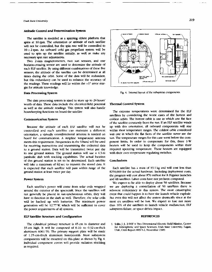
Utab State University
Attitude Control and -on System
The satellite is modeled as a spinning oblate platform that spins at 10rpm. The orientation or attitude of each satellite will not be controlled, but the spin rate will be controlled to 10 i 2 rpm. An onboard cold gas propellant system will be used to spin up the satellite initdly, as well as make any necessary spin rate adjustments.
l k o 2-axis magnetometers, two sun sensors, and one horizon-crossing sensor are used to determine the attitude of each ELF satellite. By using different combinations of these five sensors, the attitude of the satellite can be determined at a l l times during the orbit. Some of the data will be redundant, but this redundancy can be used to enhance the accuracy of the readings. These readings will lie within the i1° error mar- gin for attitude knowledge.
Data Processing System Fig. 4. Internal layout of the subsystem components
The data processing system is sized to store up to 24-hours' worth of data. These data include the electrical-field potential as well as the attitude readings. This system will also handle housekeeping functions on board the satellite.
Communication System
Because the attitude of each ELF satellite will not be controlled and each satellite can maintain a different orientation, a wtually omnidirectional antenna is needed on board for communication. A stripline wraparound antenna meets this requirement. Frequencies in the Sband will be used for receiving instructions and transmitting the collected data to a ground station. Data will be transmitted twice per day to one ground station. The ground station will use a 4.3-m parabolic dish with tracking capabilities. The actual location of this ground station is yet to be determined. Each satellite will take a maximum of 82 sec to transmit the stored data. It is expected that each satellite will pass within range of the ground station at least twice per day.
Power System
Each satellite's power will come b m solar cells w p p e d around the exterior of the spacecraft. Since the satellites will not generally be placed in sun-synchronous orbits, they will have to function in the dark as well. Therefore, the solar cells will be backed up with batteries. The minimum power generation will be 12.77 W, which will be sutlicient to cover the power requirements of all systems.
Thermal Control System
The extreme temperatures were determined for the ELF satellites by considering the worst cases of the hottest and coldest orbits. The hottest orbit is one in which one Bat face of the satellite constantly faces the sun. If an ELF satellite winds up with this orientation, all onboard components will stay within their temperature ranges. The coldest orbit considered was one in which the flat faces of the satellite never see the sun. The temperature ranges for this case went below the com- ponent Limits. In order to compensate for this, three 1-W heaters will be used to keep the components within their required operating temperature. These heaters are equipped with their own temperature regulating switches.
Conclusions
Each satellite has a mass of 19.1 kg and will cost less than $250,000 for the actual hardware. Including deployment costs, the program will cost about 570 million for 8 Pegasus launches and 48 satellites. Iabor costs have not yet been computed.
We expect to be able to deploy about 50 satellites. Because we are deploying a constellation of 50 satellites there is inherent redundancy in this system. The most catastrophic event that could happen is to have the launch vehicle explode. But even this will not affect the system drastically since at the most six satellites will be lost. We expect to lose not more than 10% of the satellites to launch vehicle mahnction, ELF subsystem failure, or space debris impact.
ELF Satellite Structure and Codgumtion REFERENCES
The cylindrical primary structure is 45 cm in diameter and 1. Soh, J . J., 2-DEF A b o Dimensional Electric Field Mission, Center 35 cm high. ~t be compo.wd of 0.16- to 0.32cm-thick for Atmospheric and Space Sciences. Utah State University,
aluminum 6061-T6. The primary support plate will be made Utah, CASS Report U89-5-2. November 1989.
of 1.25-cm-thick aluminum honeycomb. Most subsystem components will be mounted on this plate as shown by Fig. 4. Individual component covers will provide radiation shielding as required.


'IIIREE ORBITAL TRANSFER VEHICLE4\1 g 1 , 1 8 1 5 6 VIRGINLA POLYTECHNIC INSTITUTE AND STATE UNIVERSITY
Aerospace Engineering students at the V i a Polytechnic Institute and State University undertook three design projects under the sponsorship of the N W U S R A Advanced Space Design Program. AU three projects a d d r d cargo and/or crew transportation between LEO and GEO. Project SPARC presents a preluninary design of a fully reusable, chemically-powered aeroassisted vehicle for a transfer of crew of five and a 6,000-20,000 Ib payioad. The ASIV project outlines a chemically-powered aeroassisted contiguration which uses m l e tanks and a relatively small aerobrake to realize propellant saGn@. The third project, LOCOST, involves a reusable, hybrid laser/chemical vehicle designed for large cargo (up to 88,200 Ib) transportation.
SPKJi-BASED AEROASSISTED REUSABLE CRAFT D e l t a V ' r L l h r u 6
(PROJJXX SPARC)
Mission Rquirements/Objectives
Project SPARC is designed to transfer crew and cargo between the Space Station at LEO (inclination = 28.5') and Gashack at GEO (inclination = 0'). There are three mission scenarios: the "small" mission, a round trip transfer for a crew of live and a 6,000-lbm payload; the standard mission, a round trip transfer for a crew of five and delivery of a 20,000-lbm payload to GEO; and the expendable mission, a one-way transfer of a 28,000-lbm payload to GEO disposing of the vehicle into a higher orbit. Objectives of the project are to design one basic vehicle for all three missions, a reusable aerobrake, and removable components (aerobrake, crew module, and payload bays) to be saved during the expendable mission.
Orbital Mechanics
Hohmann transfers are used for the major impulses required for the mission and a single aeropass is used on the return trip (Fig.1). The minimum altitude of the aeropass is 262,470 ft. Total AV required is 22,570 fps, a 26.5% savings over a com- parable all-propulsive mission. Total time of Bight is 10.6 hr and the synodic period between LEO and GEO is 1.6 hr. A Bight summary for the standard mission is shown in Table 1.
Table 1 . Flight Plan (Standard Mission)
Imvulse Maneuver Tune (hr)/
Delta V (bLM) -- -- - -
1 Decircularize-LEO LEO-GEO flight
2 Plane change (28.5") 3 Circularize-GEO
Minimum stay at GEO 4 Decircularize-GEO 5 Plane change (23.82' )
GEO-atmospheric entry Aeropass with 4.68" plane change Atmospheric exit-LEO
6 Circularize-LEO
TOTALS 11.04/22570
Fig. 1 . Flight Path
The standard SPARC confjguration is shown in Fig. 2. Its major components include the truss structure, aerobrake, propellant tanks, a crew module, payload bays, and engines. The main truss structure consists of twelve graphite polyimide networks oriented in a grid pattern to provide maximum support for the vehicle components. The truss strucmre is designed with the same shape as the aerobrake to facilitate connection of the two, and it is self-sufficient, allowing vehicle operation without the aerobrake. The truss members have outer radii ranging h m 1" to 1.25" with thicknesses from 0.1" to 0.89". members are connected with titanium silicon carbide joiners.
The aerobrake is constructed with an ellipsoidal nose tangent to an elliptical cone and connected to a toroidal base skirt. The cone is raked at 73" to form a circular base plane 45 ft in diameter. The shell is a rigid graphite polyimide honeycomb sandwich structure supported by graphite polyimide Lbeam ribbing mounted flush to the inner surface of the shell at 45' to the longitudinal axis of the base plane. The aerobrake is attached to the main truss structure with graphite polyimide surface mounts. The thermal protection
PRECEDING PAGE BLANK NOT FILMED
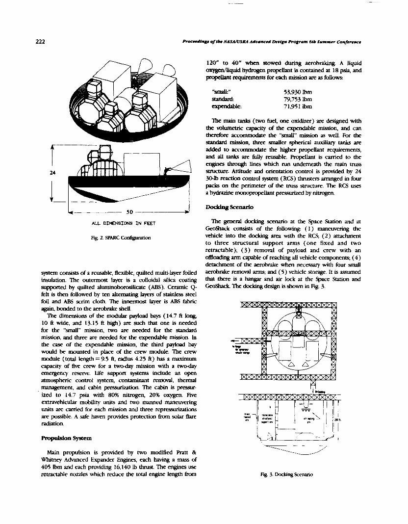
L 50 ------+I
ALL DIHWSIONS IN FEET
system consists of a reusable, flexible, quilted multi-layer foiled insulation. The outermost layer is a colloidal silica coating supported by qutlted aluminobodcate (ABS). Ceramic Q- klt is then followed by ten alemating layers of stainless steel foil and ABS saim cloth. The innermost layer is ABS Eabric again, bonded to the aerobrake shell.
The dimensions of the modular payioad bays ( 14.7 fi long, 10 fi wide, and 13.15 ft high) are such that one is needed for the "small" mission, two are needed for the standard mission, and three are needed for the expendable mission. In the case of the expendable mission, the third payload bay would be mounted in place of the crew module. The crew module (total length = 9.5 ft, radius 4.25 fi) has a maximum capacity of five crew for a two-day mission with a twoday emergency reserve. Life support systems include an open atmospheric control system, contaminant removal, thermal management, and cabin pmsurization. The cabin is pressur- ized to 14.7 psia with 80% nitrogen, 20% oxygen. Five extravehicular mobility units and two manned maneuvering units are carried for each mission and three repressurizations are possible. A safe haven provides proteczion h m solar flare radiation.
Propulsion System
120" to 40" when stowed during aerobraking. A liquid oxygcn/liquid hydrogen propellant is contained at 18 psia, and propellvlt reqllkments for each mission are as follows:
53,930 Ibrn 79,753 Ibrn 71,951 Ibrn
The main tanks (two fuel, one oxidizer) are designed with the volumetric capcity of the expedable mission, and can therefore accommodate the "mall" mission as well. For the standard mission, three smaller spherical auxiliary tanks are added to accommodate the higher propellant requirements, and all tanks are fuyr reusable. PmjxUant is carried to the engines through lines which run underneath the main truss structure. Attitude and orientation control is provided by 24 30-lb reaction control system (RCS) thrusters arranged in four packs on the perimeter of the truss structure. The RCS uses a hydrazine monopropellant pressurized by nitrogen.
The general docking scenario at the Space Station and at GeoShack consists of the following: (1) manewering the vehicle into the docking area with the RCS; (2) attachment to three structural support arms (one fixed and two retractable); (3) removal of payload and crew with an doading arm capable of r edmg all vehicle components; (4) detachment of the aerobrake when necessary with four small aerobrake removal arms; and (5) vehicle storage. It is assumed that there is a hangar and air lock at the Space Station and GeoShack 'Zhe dodung design is shown in Fig. 3.
Main propulsion is provided by two modified Pratt & Whimey Advanced Expander Engines, each having a mass of 405 Ibrn and each providing 16,140 Ib thrust. The engines use retractable nozzles which reduce the total engine length from
- Fig. 3. Docking

Virginia Polytechnic Institute and State Universfty 223
Calculations and Performance Characteristics
Vehicle design and performance calculations included: ( 1 ) orbital mechanics; (2) atmospheric heat loading and perigee altitude obtained from an approximate solution by Desautel; (e) nozzle flow calculations obtained from Naval Ordinance Test Station (NOIS); (4) tank insulation and boiloff; (5) aerodynamic and longitudinal stability calculations using modified Newtonian Theory; (6) center of gravity; (7) mass moments of in- (8) RCS characteristics derived kom the mass moments of inertia values; (9) crew module and payload bay radiation protection; and ( 10) structural ad)%s obtained firom Structural Analysis Software for Micfocomputers (SASM).
The SPARC performance characteristics are listed in Table 2.
Conclusions
Our report has summarized the design specifications of Project SPARC, and results of this design indicate that an aemassisted vehicle is an attractive mode of orbital transfer. It is expected that the required technical advances in turbomachinery, materials, thermal protection, and other areas will be completed by the time the Spgce Station is operational, justlfylng the continuation of research and development of these transfer vehicles.
Table 2. SPARC Perfofmance Characteristics
An approximate analysis of projeded costs for the chrrty mission life ASN using (a) reusable tank con6guration and (b) dsposable tank con6guration (with $1000 per Ib cost of delivery to LEO projected for 2010) indicated that sigdicant savings can be realized with a disposable tank version.
A typical mission originates at the Space Station with a separation maneuver and a phasing orbit injection followed by an approximate Hohrnann elliptical transfer to CEO. Upon reaching GEO, circularization and the 28.5' plane change will be accomplished via single AV impulse. At GEO, the vehicle will rendezvous with the GeoShack and the payload will be deployed during which time the ASrV will receive life support from the GeoShack While in CEO, the vehicle will be able to reach one or more locations for repair or service of satellites and spacecraft. The transfer from CEO back to LEO will begn with a deorbiting impulse to bring the vehicle back into the Earth's atmosphere and to make the plane change from 0.0" to 26.3' inclination. Upon entering the atmosphere, the vehicle will use the lift and drag generated by the aerobrake to achieve the remaining 2.2' of inclination and a decrease in speed of 7690.6 ft/sec. After exiting the atmosphere, the vehicle is placed into a phasing orbit at 350 miles followed by a Hohmann t&er to LEO.
Figures 4 and 5 show a typical ASTV configuration. Shown are the reduced size aerobrake, the large disposable tank, and the mission modules. A mass breakdown is provided in Table 3.
Characteristic
Aopulsion: Main engine I, (sec) Propellant flow rate (lbm/sec) Main engine thrust (lbf) Mixture ratio ( W f l , ) RCS I, (sec) RCS thrust (Ibf) Masses (Ibm): Vehicle dry mass, M, Payload, LEO-GEO, M I Payload, GEO-LEO, M I 2 Propellant used LEO-CEO, M,, PropeUant used GEO-LEO, M,, Perjiinmance: Payload-Mass ratio, LEO-GEO
~M,l/(Mpl+Ms)I Payload-Mas ratio, GEO-LEO
(M12/(hlpl+MaJ Structural c&cient
Small
487 35.86 16,140 6/ 1 225 30 each
18,577 m 6,000 40,627 13,303
0.101
0.188
0.2 56
Standard
487 35.86 16,140 6/ 1 225 30 each
20,535 20,000 0 68,960 10,793
0.233
0.0
0.205
Expend.
487 35.86 16,140 6/ 1 225 30 each
AEROBRAKLNG S P m TRANSFER VEHICLE
\ r . 1 r a
Fig. 4. ASW Conl ip t ion
The Aerobraking Space Transport Vehicle (ASTV) is a cost effective, reusable orbital transport vehicle to be used in conjunction with the space shuttle, the Space Station, and the GeoShack to transport a payload and/or a crew between the Space Station and the GeoShack.
Three mipion scenarios are: ( 1) deliver 6000 Ibm round trip, (2) delli.er 20,000 Ibrn to GeoShack and return empty, and (3) deliver 28,000 Ibrn to GeoShack and dispose of the vehicle into a higher orbit. The main objectives used as a guide driving the ASnT design process were: ( 1 ) reliability and safety,
' (2 ) minimize mission costs, and (3) maximize flexibility. Fig. 5. kYT\.' Isometric View
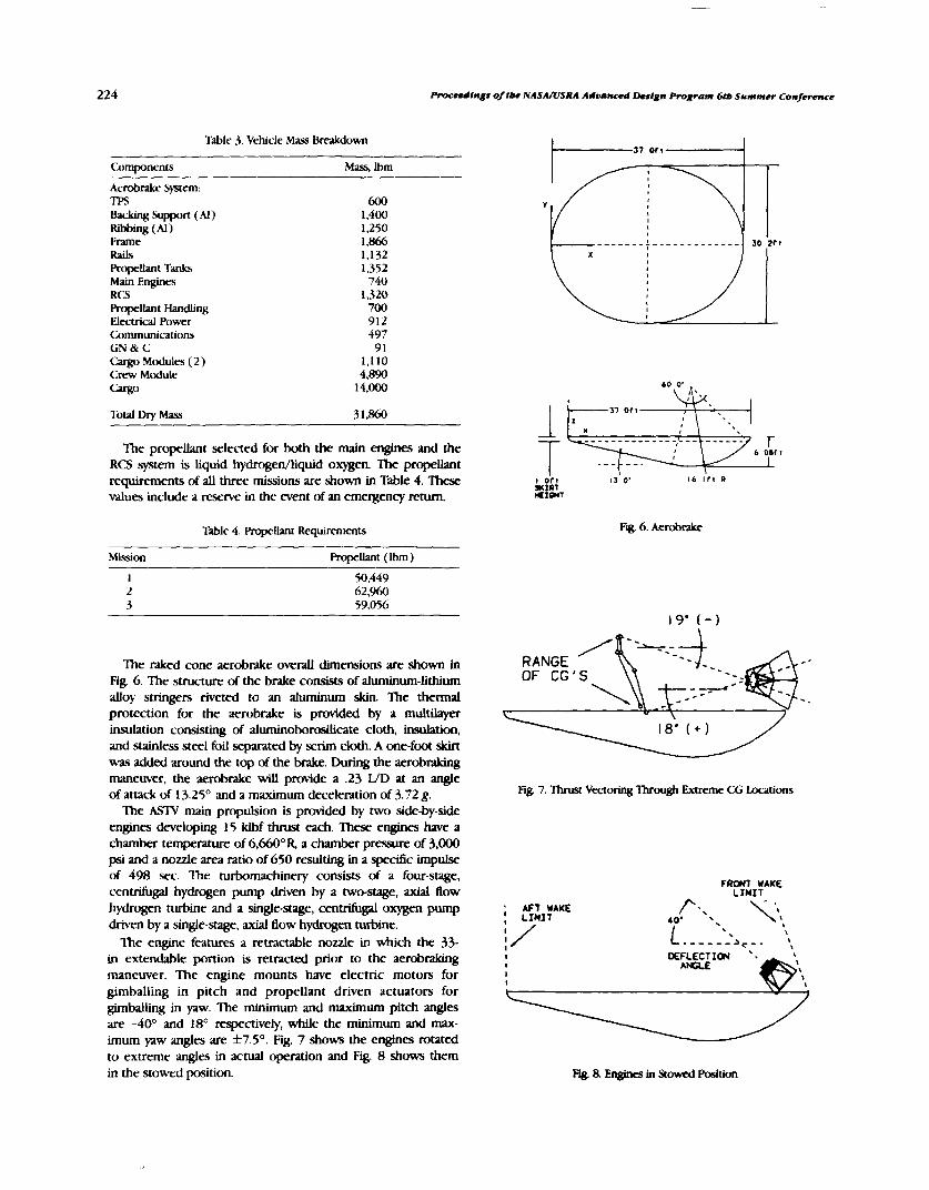
Procndfngr of tbe NAS.UUSR-4 Adoa~~ed Lkrtgn Program 6rb Summer Conference
Table 3. Vehicle Mass Breakdown
Camponmts Mass, lbrn
Aerobrake System. TPS 600 Backing Support (Al) 1,400 Ribbing (Al) 1,250 Frame 1,866 Rails 1,132 Ropetant Tanks 1,352 Main Engines 740 RCS 1,320 Ropellant Handling 700 Electrical Power 912 Communications 497 G N & C 9 1 Cargo Modules ( 2) 1,110 Crew Module 4,890 cW30 14,000
Total Dly Mass 3 1 , W
The propellant selected for both the main engines and the RCS system is Liquid hydmgedliquid oxygen. The propellant requirements of all three missions are shown in Table 4. These values include a reserve in the event of an emergency return.
Table 4. Propellant Requirements
37 O f t
Fig. 6. A d r a k e
Mission m u a n t (Ibm)
I 50,449 2 62,960 3 59,056
The raked cone aerobrake overall dimensions are shown in Fig. 6. The structure of the brake consists of aluminum-lithium alloy stringers riveted to an aluminum skin. The thermal protection for the aerobrake is provided by a multilayer insulation consisting of aluminoborosilicate cloth, insulation, and stainless steel foil separated by scrim cloth. A one-foot skirt was added around the top of the brake. During the aerobraking maneuver, the aerobrake will provide a .23 WD at an angle of attack of 13.25' and a maximum deceleration of 3.72 g. Fig. 7. Thrust Vectoring 'Ihrough Extreme CG Locations
The ASlV main propulsion is provided by two side-by-side engines developing 15 klbf thrust each. These engines have a chamber temperature of 6,660°R a chamber pressure of 3,000 psi and a nozzle area ratio of 650 resulting in a spectfic impulse of 498 sec. The turbomachinery consists of a four-stage,
FRONT WAKE centrifugal hydrogen pump driven by a two-stage, axial flow LIMIT hydrogen turbine and a single-stage, centrifugal oxygen pump ; *FT WAKE
driven by a single-stage, axial flow hydrogen turbine. The engine features a retractable nozzle in which the 33-
in extendable portion is retracted prior to the aerobdung maneuver. The engine mounts have electric motors for gimballing in pitch and propellant driven actuators for gimballing in yaw. The minimum and maximum pitch angles are -40' and 18' respectively, while the minimum and max- imum yaw angles are 57.5'. Fig. 7 shows the engines rotated to extreme angles in actual operation and Fig. 8 shows them in the stowed position. Fg. 8. En@a in Stowed Position

Virginia Polytechnic Institute andstate Unfverslty
The ASrV comprises four mapr structural components: a frame, mission modules, propellant tanks and aerobrake supporting structure. The frame is composed of HT graphite/ epoxy composite tubes and one square member that are joined at 65 nodes by aluminum endfittings (Fig. 9). 'lkro 27-ft-long aluminum rails are used as a cradle for the mission modules. The frame is connected to the aerobrake via aluminum attachment accessories connected to 11 "Z" type duminum- lithium stringers.
The propellant tanks fall into two categories: dqosable and reusable. There are four large disposable tanks pnxmrized to 20 psi: two hydrogen and two oxygen tanks. These tanks will be detached by using explosive bolts and a solid rocket motor. A solid shield protects the craft &om the rocket blast. The permanent tanks consist of 6ve hydrogen and five oxygen tanks pressurized to 500 psi by a helium-filled bladder. These tanks contain propellant responsible for all maneuvers following the aeropass plus reserve. Insulation and impact protection are provided by stainless steel foils interleaved with Nextel (MU).
Mission payloads are carried in 8-ft-long by 14-ft-diameter cylindrical cargo modules made of aluminum-lithium. The cargo modules provide mounting platforms, impact and radiation protection and selective positioning for the payload. Up to three modules may be connected to form one 24-ft-long unit, or all three modules could be individually capped, and of course other combinations of modules can be used to fit the needs of the cargo. The cxgo modules are mounted to the rails which have connection points spaced at eight-in intervals so that the modules may be connected in a wide range of positions along the length of the rails and thereby adjust the c.g. location.
The crew module is basically a cargo module designed for human transport. The crew module shares the same overall dimensions as the cargo modules so that it too may be connected to other modules and m m d around within the ASrV. The crew module can support three adults in an ideal Earth atmosphere for 48 hours with the capability for one full repressurization. A solar flare shelter and a thermal control system are included in the design.
Rails ,
Fig. 9. ASlV Frame
Reaction Control System (RCS) comprises two different sizes of thrusters, 60 Ibf and 10 lbf. Overall there are 50 thrusters (34/60 Ibf and 16/10 Ibf providing double redun- dancy) located in four clusters around the top of the aerobrake. The clusters are mounted to retractors which draw them inside the aerobrake when not in use.
Navigation is performed by an autonomous inertial system having interfaces with the ground or space stations.
Communication data is transmitted and received to/&om the ground, the space shuttle, and the Space Station via K band Link
The electrical power is generated by two 4 k W LOX/LH, he1 cells (three during manned missions). The oxygen and hydrogen are drawn from the small permanent tanks. Tkvo nickel/hydrogen batteries are also included.
LASER OR CHEMICAL HYBRID ORBlTAL SPWE TRANSFER (PROJECT LOCOST)
Project LOCO!3T is an unmanned khicle that utilizes a hybrid laser/chemical propulsion system to vansfer cargo between the Space Station at LEO (inclination = 28.5') and the GeoShack at GEO (inclination = O0 ). The baseline mission scenario is to transfer 20,000 kg of cargo out to GEO and bring 6,000 kg back to LEO. A scenario in which the maximum 40,000 kg of cargo is vansferred each way is also analyzed. 'Ihe laser propulsion system is powered by a Laser Power Station (LPS) orbiting at an altitude of one Earth radius and an inclination of 0'. The basic LOCOST specitications are listed in Table. 5.
Table 5. LOCOST Basic Spedcations
Orbit Transfer Tine 2-3 weeks * Mass ~,000-4O,oOO kg Direct Solar
Pumped Iodide l v e r Wavelength 1.313 rm Laser Power 12 MW Chemical Rockets %=480sec laser Rocket b= 1500sec Technolagy Level 2010
Orbital Mechanics
The laser propulsion system is used to tGlnsfer between LEO and GEO on a spiral trajectory. The chemical system is used for circularizations and plane changes. Tko Energy Relay Units (ERU), placed 120' ahead of and behind the LPS, allow continuous power for the LOCOST while the LPS is not blocked by the Earth's shadow. A summary of the baseline mission anaIysis is presented in Table 6.
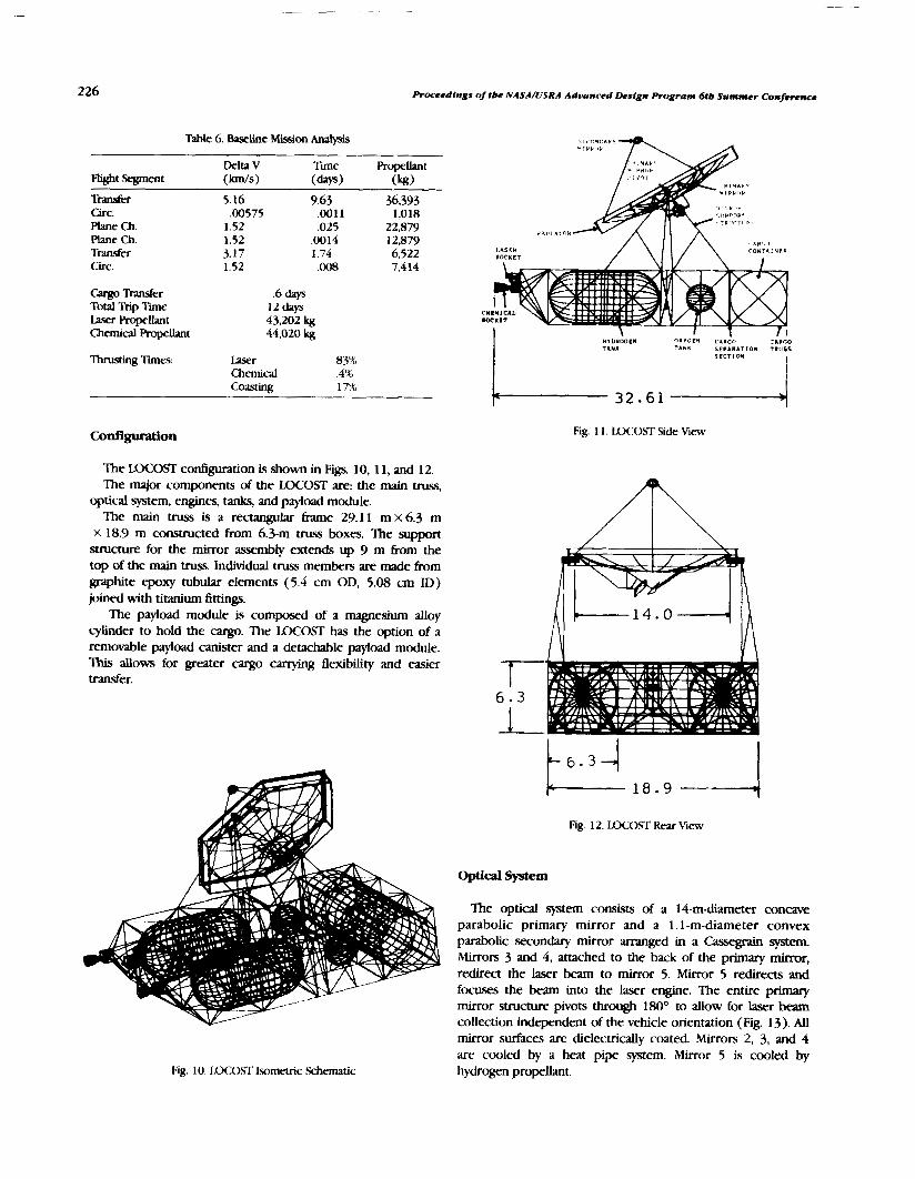
Proceedings of tbe NASMLISRA Advanced Deslgn Program 6tb Summer Conf'e
Table 6. Baseline W o n Analysis
Delta V T i Ropellant Flight Segment (km.1~) (days) (kg)
tram ti^ 5.16 9.63 36,393 Circ. ,00575 ,001 1 1,018 Plane Ch. 1.52 ,025 22,879 Plane Ch. 1.52 ,0014 12,879 Trader 3.17 1.74 6,522 Circ. 1.52 .008 7,4 14
Cargo Transfer Total Trip Tme
days I2days C N I M I C A L
laser Ropellant 43,202 kg Chemical Ropellant 44,020 kg
HVDIf f iEN OXVOCN CARGO :ADGO S C P A I A T I O N T l l i l S
'Ihrusting Tmes: h e r 8YX1 5CCTlON
Chemical .4% Coasting 17%
The LOCOST codiguration is shown in Figs. 10,11, and 12. The mapr components of the LOCOST are: the main truss,
optical system, engines, tanks, and payload module. The main truss is a reaangular h e 29.1 1 m x 6.3 m
x 18.9 m constructed from 6.3-m vuss boxes. The support structure for the mirror assembly extends up 9 m h m the top of the main truss. Individual truss members are made h m graphite epoxy tubular elements (5.4 cm OD, 5.08 cm ID) joined with titanium fittings.
The payload module is composed of a magnesium alloy cylinder to hold the cargo. The LOCOST has the option of a removable payload canister and a detachable payload module. 'Zhis allows for greater cargo carrying flexibility and easier transfer.
Fig. 10. LOCOST Isometric Schematic
Fig. 1 1 . LOCOST Side View
Fig. 12. LQCOST Rear View
Optical System
The optical system consists of a 14-m-diameter concave parabolic primary mirror and a I. 1 -m-diameter convex parabolic secondary mirror arranged in a Cassegrain system. Mirrors 3 and 4 , attached to the back of the primary mirror, redirect the laser beam to mirror 5. Mirror 5 redirects and focuses the beam into the laser engine. The entire primary mirror structure pivots through 180' to allow for laser beam collection independent of the vehicle orientation (Fig. 13). AU mirror surfaces are dielectrically coated. Mirrors 2, 3, and 4 are cooled by a heat pipe system. Mirror 5 is cooled by hydrogen propellant.

Virginla Polytecbnfc Institute and State Uniuersity
Fig. 13. Primary Mirror Rotation
Propulsion
The laser propulsion system employs the inverse Bremsstrah- lung process to couple the laser energy to the thennal energy of the hydrogen propellant. The engine produces a thrust of 768 N. The engine is regeneratively cooled and has a plano- convex sapphire window lens to focus the incident laser beam inside the chamber. The engine is mounted inside a mobile rocket basket which allows for thrust vectoring through the vehicle's center of mass.
The chemical propulsion system consists of two symmetri- cally placed Liquid hydrogen/oxygen rockets. Each engine produces a thrust of 25,000 N. The nozzles of the engines gunbal to track the center of mass.
The hydrogen is stored in two cylindrical tanks with spherical endcaps. The oxygen is stored in two spherical tanks. The tanks are insulated and maintained at an internal pressure of35 kPa
Attitude and orientation control is provided by four advanced control moment gyroscopes (CMGs) and eight sets of three hydrazine/oxygen RCS rockets.
Vehicle charactetlsda and PerFormance
Vehicle design and performance calculations included: (1) orbital mechanics; (2) optical system analysis using ray tracing techniques; (3) laser engine performance evaluation; (4) cooling analysis; (5) chemical engine nozzle flow calculations obtained from NOIS; (7) tank insulation and boiloff evaluation; (7) mas and moments of inertia calculations (8) structural analysis obtained with SASM; (9) thermal analysis; (10) estimates of RCS and CMG characteristics derived from the mass and moment5 of inertia values, and roll rates of the vehicle. A summary of the LOCOST mass breakdown is given in Table 7.
Table 7 . LOCOST Ma% Breakdown
Ma.= (kg)
Structure Main T m ! 423
Optical System Primary Mirror w/support 21 1 0 Secondaq Mirror 90 Mirrors 3,4,5 300
Repulsion Chemic-al Rockets 422 Fuel Lines & Mount.. 154 Laser Rocket 75 Fuel Iines & Mounts 75
RCSs & CMGs 1 100 Ikxking 50 Communications 110 Payload Mtxlulc 1 I t M )
Total Vehicle Dry Ma% 6682
The LOCOST performance characteristics are listed in Table 8.
Table 8. LOCOST Characteristics
Propulsion Laser
Specific Impulse 1500 sec Propellant Flow Rate ,0522 w s e c Thrust 7<% N
Chemical Spcf ic Impulse 480 .wc Propellant Flow Rate 5.2 k g / . ~ c ?hrust 25,000 N
Masses Vehicle Dry Mass WZkR Payload LEO-GEO 20,000 kg Payload GEO-LEO 6OiN) Iawr Propellant Used 43,202 kg Chemicd Propellant Clscd 44,020 kg
Performance Payload Ma% Ratio .2X
Conclusions
This report hay outlined an initial configuration study of a hybrid lawr/chemical orbital transfer vehicle. The study has indicated that the hybrid propulsion system may be attractive for cargo transportation in the IEO/GEO sphere and that further rewarch is justified.


MEGAWm SOLAR POWER SYSTEMS FOR LUNAR SURFACE OPERATIONS
UNIVERSITY OF WASHINGTON ~ 9 1 - 18 1 5 7
Lunar surface operations require habitation, tiansportatior., life support, scientific, and manufacturing systems, all of which require some form of power. Nuclear thermal power is often considered to be the only type of power system which can provide a lunar base with power on the megawatt level, but political and technological obstacles may severely limit the application of nuclear power in space. As an alternative to nuclear power, this report focuses on the development of a modular, one-megawatt solar power @em, examining both photovoltaic and dynamic cycle conversion methods, along with energy storage, heat r+ction, and power backup subsystems For photovoltaic power conversion, two systems are examined Fi, a substantial increase in photovoltaic conversion efficiency is realized with the use of new GaAs/GaSb tandem photovoltaic cells, offering an impressive overall anay eaciency. d 23.5%. Sice these new cells are still in the experimental phase of development, a currently awlable GaAs cell providmg 18% &ciency is examined as an alternate to the experimental cells. Both Biayton and Stir@ cycles, powered by linear parabolic solar concentrators, are examined for dpanuc cycle power conversion. The Brayton cycle is studied in depth since it is already weU developed and can provide high power levels fairly efficiently in a compact, low mass system The dynamic conversion system requires large scale waste heat rejection capability. To provide this heat rejection, a comparison is made between a heat pipe/radiative 6n system using admnced composites, and a potentially less miw liquid droplet radiator system. To supply power through the lunar night, both a low temperature alkaline he1 cell system and an experimental h@ temperature monolithic solid-oxide fuel cell system are considered. The reactants for the fuel cells are stored cryogenically in order to avoid the high tankage mass required by conventional gaseous storage. In addition, it is proposed that the propellant tanks from a spent. prototype lunar excursion vehicle be used for this pupme, therefore, d t i n g in a sigruficant overall reduction in dective storage system mass. Emergency backup power is supplied by a nickel-hydrogen battery system derived from the energy storage system to be used on Space Station Fmedonr, in order to save on development casts and to provide one of the most reliable *ems available. Structural elements for the entire power system are made of composites and aluminum, keeping system mass to a minimum. M components of the system are designed for transport to low Earth orbit in modular units aboard the Shuttle-C launch vehicle.
Plans for lunar development will ultimate& require a large Neither of these power sources will, of c o w , provide power system to suppo~ all of the planned activities. Nuclear power during the lunar night and, thus, energy is stored using energy has usually been the assumed power source due to the a fuel cell system. Fuel cells similar to those used on the space high power densities offered, yet nuclear power is kr h m shuttle, along with cryogenic hydrogen and oxygen stored in ideal. There are many problems, including startup of the plant, the tanks of a spent lunar lander, are employed as the energy the large amounts of radiation produced and the need for a storage system. Energy storage is relatively massive, so in order large area set aside permanen* as a result, the impossibility to keep the overall mass of the lunar power system Erom of maintenance, and very low eBciency. The Space Systems becoming excessively large, the nighttime energy storage Design Course at the University of Washington has, therefore, system will provide just 50 kW, rather than a full megawatt. performed this design study on the hamessing of solar power This nighttime power reduction may be ofk t by adding more for use on the Moon as a cleaner, safer alternative to nuclear photovoltaic arrays or dynam~c cycle units, which are far less power. massive, for increased daytime power production. This study looks at two ba5ic methods of converting solar The entire power system is designed to be modular,
energy into electrical power, with the objective of providing contigured in such a way that no single point failures are one rnmwatt of electrical power. The t3st method is the use possible. In the rare event of cata$trophic hilure, however, - of direct electrical conversion of solar energy using a new, emergency power for repair and m~vation procedures is highly efficient solar cell developed by the Wing Corporation. provided. For development, cost, and reliability reasons, the The second method is the use of a dynamic cycle opera- energy storage system from the Space Station Freedrm was on enetgy supplied by a solar concentrator system. The Brayton reconfigured to provide the required emergency backup cycle was chosen for this study for its relatively hidl efficiency power. i d its aMilability in the timeframe of the lunar base as a vroven and reliable unit. This cycle will also require an SOLAR PHOTOVOUXIC POWER SUPPLY SYSTEh4
^extensive heat rejection capability provided by on; of two As mentioned above, one of the power generation systems systems examined in this study: an advanced technology heat considered makes use of direct conversion via photovoltaic pipe radiator, or a liquid droplet radiator. cells. 'Qpical photovoltaic cells used in space and terrestrial
PRECEDING PAGE BLAW NOT FiCMED PAGE s 2 INTENTIONALLY M M

'ngs of tbeNAsA/vSRA Advanced Design Pmgram 6 t b Summer Conference
applications are IIlldc af gidlium iusalidc (W) or sillcon (Si) and c o r n onlyput ofthe available radiation spectrum intoelectrlcalpowtr.lhesccellsusualiyattainasdu~ comm eflildency between 14% and 21%. A new tandem -ll(Fig. 1 ) ~ e i n g ~ o p e d b y B o e i n g h c r o e p ; l c e ~ ~ ~ the present design and cwsists of two & d di&rmt materials, mechanically sacked on top of one d l ) . 'Ihe qpercell,macieofGaAs,absortwphotonswithenagiesabove 1.42 eVand has been made tmnqxent to M k e d radiation Infkedradiationpasseschmughtheuppercelltoalowercell made of gallium antimonide (GaSb), which absorbs photons with energies as low as 0.72 el! GaSb wm chosen as the infraffdsensitivebcustercellbeauseitisadirectbmdg;lp material that generates higher currents, its bandgap is significantly lower than that of GaAs, and the vdt?ge produced is nearly one-third that of the GaAs cell(2), allowing it to be voltage matched with GaAs in a 3: 1 mtio series-parallel amnge- ment to produce a 1.0 V triplet(3), as shown in Fig. 1.
Individual cell efficiencies are enh?nced by the addition of prismaticcaverslidesthatfit~the~upPerdlinesonea& cell and direct light toward the cell &e, itway fbm the gridlines. This minimizes reflection losses and increases efficiency by 10% per When tested at a light concentration ratio of 100 times solar intensity (100 suns) in air-mass-zero (AMO) conditions, the hdMdual performam?e of the GaAs cell was 23.9%, and that of the GaSb cell was 6.9%, for a total of 30.8% solar enagy c o d ~ n ( ~ ) .
CTIVE GaAs CELL RlDLlNESlCOVERSLlDE
ER GRIDLINES
HEAT SPREADER
GRIDLINESICOVER SLIDE
ACTIVE GaSb CELL
1 .O VOLTS
Fi. I . Cell Assembly and Triplet Formation
To concentnte incoming sunlight to 100 suns, domed FrrsnellarsesrmdtbyEntech,InczrcusedThescligh~t 91l1coneknscshnneapnism;loicund~,dcslgnedtofocus light at the center of the cell. A l;ryer of protectbe miacglass Islvnirmtedclkctlytothecwrduppersurfaceofthelens to protect it 6rom solar pmon flares and mimmeteorite damage. Together, the mimlaoglass and silicone comprise 27.8% of the totai panel mad5).
'Ihe lenses (which have a 3.75-u~-square c ~ ~ ~ s z c t i o n ) are fitted into a square aluminum honeycomb housing, so that the lenses lie below the top of the housing. The honeycomb housing is made of 0.15-mm-thick aluminum, 4.05 an high, with small extensiotts in the corners to support the lenses(5). The photovoltaic cells and wiring are attached to a thin aluminum backing which is placed underneath the honey- comb and lens assembly, as shown in Fig. 2. This backing, coated with alumina for high emhivity, acts as a thermal mdhtor, Fejecting excess heat When wired into triplets and placed under the concentrating lenses, the entire assembly conmts solar radiation to electricity with an overall efficiency of23.5%, opgating at a temperature of 80"d3).
To size the array using the above efliaency, it is necessvy to determine what power the Lunar base requires and what other subsystem inefficiencies apply. This design was conf@ed for a baseline output of 1.0 MW, dwmg the day and 50 kW, at night, provided to the users. During the day, powet will be channeled directly through transmission lines which have an efficiency of 94.4%. During the night, energy must be provided b m a storage facility which, along with tnnsmission and power conditioning, has an ef6.ciency of 43.2%. Therefore, 1.175 M W , are needed h m the array during the day.
The cells are arranged in panels, 12.5 m X 3.0 m each. Individual panel dimensions am determined by structural and maintenance considerations In the m t of a breakdown, the panels will need to be repaired by an astronaut on site. A width of 3.0 m was chosen, therefore, to allow an astronaut to reach each half of the paneL 'Ihe panels are supported close to the ground by a central truss, and rotated 0.54' per hour to track the sun, using single-axis tracldng. A panel length of 12.5 m
TRANSPARENTLENSES
4 :-: BACK RADIATOR 3.75 cm
Fig. 2. Honeycomb Section Dimensions

University of Washington
was chosen to minimize amctud weight. 'Wo panels are mounted on a support structute with a motor in the center to fonn a panel set producing 23.85 kW, at a mass of 183 kg (not inchling structural members).
Fifty panel sets ate requmd to provide the baseline power output of 1 MW,. These are mmged in 5 rows of 10 sets each, at a spacing of 15 m to minimize mutual shading etkcts. When panels ate placed in rows faclng sunrise or sunset, all panels behind the h n t row are shaded until the sun teaches a certain angle above the horizon. For a total of 50 panels atranged in 5 rows, the minimum is calculated to be 15 rn. In this arrangement, the total artay has a mass of 9,150 kg (not including structutes) and requires a land area of 19,748 mZ (4.9 acres).
Since the tandem cell developed by Boeing Aerospace has not been fully tested, an altemak array was also configured using an unconcentrated, single cell produced by TRW. This is intended to provide a comparison using existing technology. The alternative cell is made of GaAs deposited on a germanium substrate and offers an efficiency of 18%(@. The cells are reaangular (2.0 cm x 4.0 an x 0.2 mrn thick) and require no concentrating lenses or extra housing. They can simply be secured to a radiative backing, placed close together, and wired in series.
The GaAs cells have toughly the same mass as the tandem cells (170 Wpanel set), but due to their lower &ciency, 65 panels are required to provide the same amount of power. Panel sizes ate the same as for the tandem cell array 12.5 m x 3.0 m. This means 15 extra panels are re& which is an addition of 1900 kg to the total system mass (not including structures), or an increase of 21% over the GaAs/ GaSb cell array. The panels are arranged in 8 rows of 8 sets each, with one additional panel in the fkont, at a row spacing of 17 m to minimize shading effects. The total array mass is 11,066 kg (not including structures) and uses a land area of 27,171 mZ (6.7 acres).
A comparison of the two alternative arrays is shown in Table 1. Note that the difference in efficiencies of the two cells significantly a&cts the power density. While the single GaAs cells are appealing in terms of simplicity and availability, the tandem cells, with a higher efficiency, require less mass. Mass is at a premium when all system components must be lifted to orbit, and the lighter weight tandem cell array is recorn- mended.
Table 1. Cell Comparison Summary
Tandem Cell GaAs Cell
Array EIEciency 23.5% 18.0% Concentration Ratio 100 1 .O
BRAYTON DYNAMIC POWER SUPPLY SYSTEM
The second power unit considered in this study is the Brayton dynamic cycle conversion system powered by solar radiation concentrated by a parabolic trough collector. Tbe total conversion system is composed of BM modules, each with a 250 kW, output. As shown in Fig. 3, each conversion module is made up of three main elements: the solar collection unit, the dynamic power module, and a heat tejection system. The system configuration was determined by manipulating the Brayton cycle pacameten to obtain a system of minimum mass.
SADIATOR
6 0 m-I
COLLECTOR 1 - .
CONVERSION UNIT
Fig. 3. Dynanuc Conversion System Iayout
Ihe solar collection unit is designed to concentrate solar radiation onto a receiver through which the system working fluid passes 'Ibis fluid is thus heated for delivery to the turbine of the dynamic power module. Ihe solar collection unit comisrs of two patabolic trough collectors, each 60 rn long. Each collector pmesses half of the required mass Bow rate of the system wotlang fluid The trough collectors ate made up of a parabolic dec to r surEace and a receiver duct mounted at the line focus of the dector. The dector consists of a rigid structure that supports a reflective surface of aluminum foil. The &lector has an aperture of 7.0 m and a focal length of 1.0 m. For this design a dectivity for aluminum foil of 86% was usedc7).
The teceivet consists of a 5-cm-diameter duct made of UDE MET 700 alloy with a s p e w selective coating of cobalt oxide that is electroplated onto the duct. It serves to reduce the reradiative loss from the receiver by providmg a low surface erniss~ty at the receiver operating temperature of 780 to 1000 K The selective nature of the cobalt oxide coating is such that it has a high emiss~ty for radiation of wavelengths below 3 pm and a low emiss~ty at longer wavelengths('). ?his prwides a solar absorptivity of 95%, with an effective emiss~ty from 18% to 32% over the entire length of the collector. 'This
Power/Area ( wJrn2) 318 243.3 allows an efficiencv of 63% to be achieved by the collector , -
Total ~ e ~ u & d Afea (m2) 3750 4825 The dynamic power module consists of a regenerative Number of Panel Sets 50 65 Cell Mass (kg/m2) 2.44 2.27 Brayton cycle conversion unit. The cycle p m e t e r s used for
Mass/Panel Set (kg) 183 1 70 the optimization of the system were the compressor and Power/Panel Set CkwC) 23.85 18.26 turbine inlet tempetatures and the compressor pressure ratio. Total Array Mass (kg) 9150 1 1066 The operating temperature range is determined by considering Power Density (W,/kg) 130.3 107.3 system mass versus overall cycle efficiency. The compressor

232 Proceedings of tbe NASA/USRA Advanced Design Program 6tb Summer Conference
inlet tempemwe was made as low as possible (330 K) without pushing the radiator mass to extremely htgh levels. nK turbine inlet temperanvc is driven by two opposing hctoi~.Thistemperatureshouldbeashi&aspossjbletogive a high cycle &aency. Howwer, the etBaency of the coUector decreasesas i t saverage~temq~nrurc inaeasex 'Ih is wests that there is an optimum tuhine inlet tanperature. A s F f g . 4 s ; h o w s , t h i s o p t i m u m ~ o c c u r s a t - l o O o K Based on the selection of the compressor and hubine inlet tanpaatures, the Elrayton cycle &* is then mwimized with respea to the c o m p m r pressure ratio. The optimum pressure ratio was found to be 1.85 and resulted in a cycle &deny of 36%.
For the dyn;unic power module, the comptessor and turbine are mounted on the same shaft along with an alternator to produce the electrical powcr. The mdmmchhtry cho6en for thisstudyconsistsofa~comprcssorandar;adiat~ine. Thischoicewasmadebec?llxofthelowmassflowrateof the working fluid Rdial c o m p m require fewer stages than axial flow c o m p m to obtain the same pressure Inarase. Also, radial flow txmpments are lighter and more rugged than axial Bow c v t s
Scvenl Eaaors a&ct the choice of the working fluid. the extreme cold experienced during the -week l w @t, the need for a noncorrosive gas to limit erosion and breakdown of system co14xmm4 and the need for a high spedec heat to minimize the mass flow rate. Helium was cho6en as the working fhdd because it does not betome liquid atthetemperrtureseduringlunarnight ,andithasa high spedlc heat. Heat engines have higher component &dencies using working fluids of hi&r molecular wetght, howem, any gases heavier than Mum wlll condense out of the mixture at the low temperature of 116 Kn;lched during l w night.
T h different heat rejection systems were dM for thissrudy.Themisahe;lt*ndiatorandthesecondis a Uquld droplet radiator. Each requim a different heat
54 6 0 0 7 0 0 8 0 0 SO0 1 0 0 0 1 1 0 0 1 2 0 0
TURBINE INLET TEMPERATURE (K)
Fig. 4. Variation of Collector Length With Turbine Inlet Temperature
exdmgtx for the heat rejection firom the dynamic power module worlung fluid The heat pipe radiator requires a heat exchanger consiseing of tubes immersed in the heat pipe fluid through which the helium passes. The Liquid droplet radiator requires a heat exchanger that allows the helium to Bow around tubes containing the liquid droplet radiator Buid
The dynamic power conversion system has an overall 6dency of 23% of the incident solar energy. Ihe mass of d o u s components of the cycle, including the waste heat exchanger is given in Table 2, and will be used later to compare the dynamic conversion system to the photovoltaic syst-.
Table 2. Brayton Engine Mass Breakdown
I\lrbomachinety Rcgenaztor LDR H a t Exchanger H P R H a t E x d m g m -suppb Total Mass (LDR) T d Mass (HPR)
Rdkctor Material Rcceiwr Duct Pipins support- T0ra.I Mass
THERMAL MANAGEMENT
In any power genemting system there will be a nquimnent for the disposat of a certain amount of waste heat. In the design of a lunar power system, additional complications vlse firom the lunv environment. The only viable method of heat rejection in the l w emironment is radiation, since the lack of an atmosphere precludes the use of convection and -tion as methods of rejecting the waste energy. Also, the thermal conductivity of the Moon is very poor, which eliminates the use of co-on of waste heat to the l w regolith. llx waste heat rejection system must take into account any additional background radiation given off by the lunar surface. In addition, the radiator must have a high radiated power-t@mass ratio to minimize its mass, since al l the mamhl for the generation lunar base must be transported !komEarth
The amount of waste heat to be rejected by the radiator varies dramadc?Uy between the two power generation systems. The photovoltaic power system is able to reject its own waste heat via the aluminum backing plate on each array, as noted earlier, slnd does not require a separate heat n$xtion system On the other hand, the radiator for the dynamic cycle will be required to radiate away a significant percentage of the incoming solar energy due to the thermal efficiency of the cycle. In order to reject this heat, two possible radiator concepts are considered In this q. the Heat Pipe Radiator (HPR) and the Liquid Droplet Radiator (IDR).

University of Washington
HPRs have been under development since the late 1960s~~). The device designed for the present purpose uses a horhntd "mother" heat pipe (MHP) to conduct heat to a series of vertical heat pipes (VHP) which are connected to it and aligned with the dd, as shown in Fl 5. h e VHP units conduct thermal energy to the attached fins, which radiate the waste heat to space. Suitable shadurg and dec thg sudaees are employed to minimix background input to the -or. The HPR makes use of low density materials (pyrolitic graphite and graphite epoxy) for weight minimhtion.
The heat pipe radiator system has many distinct W t a & p over other heat rejection systems. Heat pipes do not require the use of pumps or moving pacts, since they operate via vapor flow and capillary action. The individual VHP sections are independent of one another as well as of the MHP and are, therefore, resistant to angle point failure. Another important aspect of the HPR's unique design is its utilization of available technology, reducing the amount of research and development necessary before implementation of the system.
The LDR utilizes a sheet of k l y M h g liquid droplets to radiate the waste heat(''- "). A schematic of the LDR system is shown in Fig. 6. The worlang fluid receiws the waste heat h m the power cycle at the heat exchanger. The fluid is pumped up through pipes to an emitter, which sprays the fluid as a vertical sheet of small spherical droplets. The droplets are then captured by a collector at the base of the WR, and the fluid is recycled through the system Tbe most attractive aspect of the LDR system is the high surface area to volume ratio of the small spherical coolant droplets, which results in radiating power to mass ratio of 250 W,/kg for this design. There are also a number of potential disadvantages with the
LDR system. First of all, lunar dust may present a problem by plugging the emitter, which is designed with very d holes in order to form the desired size of droplets in the sheet. Due to the centralized nature of the fluid transfer system, the LDR is not resistant to single point failure in the fluid handling system and the entire radiator would have to be shut down in the event of a system failure. For this design the pumps for the LDR would consume about 10% of the usable power f b n the Brayton cycle engines, which decreases the total power
VERTICAL HEAT PIPES FINS
HEAT F'WE
Fig. 5. Lunar HPR Configuration
Fig 6. Liquid Droplet Radiator Schematic
to mass ratio of the lunar power system. A majority of the present research into the LDR is for space-based appLications; however, additional research i s netessary before this system becomes a viable alternative heat rejection system.
ENERGY S'IORAGE
Using solar energy to power a manned lunar outpa@ has one major disadwntage: keeping the outpost fully opemtiod at a 1 MW, level during the long night would require the storage o f m m t h a n o n e t r i l l i o n ~ o f e n e r g y . ~ e n ~ s t o n g e tends to be extremely heavy, nighttime operation is limited to 50 kW, for Uk-support, astronomy, and reduced research activities.
Recent advances have made the qpmmtive fuel cell the prime cvldidate for high power, longterm storage systems(12). Though fuel cells come in a variety of codgmtions and operateatvarioustemperatures,eachhasabasicpurpose:the g e n d m of electrical p o w through the pn>cesslng of chemical reactants. During the night hours the chemical reactants, HZ and 02, enter the fuel cell, where they react to produce electric power and water as a byproduct. During the day, the water produced in the fuel cell is separated back into H2 and 0 2 by electrolysis, wblch is basically a fuel cell run in reverse. Thls requkesanextermlenergysource (Warmy or solardynamic cycle) to supply the voltage needed for dhsodation of the H20.
A schematic drawing of the 50 kWe system is shown in Fig. 7. It is comprised of two 25 kW, units, each with separate reactant storage tanks. If one unit wwe to malhnction, the

Proceedings of tbe NASA/USRA Advanced Design Program 6tb Summer Conference
Fig. 7 . 50 KWe Energy Storage Schematic
other is capable of providing life-support for the assumed base crew of 8 astronauts ( 1.5 kW,/astronaut) plus 13 kW, which can be used to repair the other unit or for reduced astronomy and research activities.
Two different fuel cells have been considered: the experi- mental high temperature, monolithic solid-oxide fuel cell (MSOFC)('~), and today's state-of-the-art low temperature alkaline fuel cell that is used on the space shuttle('4). Table 3 summarizes the system properties associated with each type of fuel ceU design. The system masses include the W array necessary for the recharging of the cell along with the related structures, reactants, and the associated fuel cells. lhe table shows that the MSOFC does not have an advantage wer the alkaline cell. The primary advantage of the low temperature fuel cell is the fact that its reliable operation has been proven and that it is currently in use. Development of MSOFC still faces problems with fabrication and processing of this sophisticated unit. The low temperature fuel cell, due to its availability and reliability, along with an adequate efficiency, was selected for the storage of energy on the Moon.
Table 3. Mass Summarj for a 50 kW, System
Alkaline Cell MSOFC
Chem. to Electrical efficiency 70% 60% Round Trip dciency 55% 40% W ~ Y 1460 kg Reactant Mass 7125 kg
kg 8315 kg
Fuel cell and electrolysis 748 kg Total Mass
6 kg 9333 kg 10,329 kg
In conventional energy storage systems, reactants are stored as gases in heavy, pressurized tanks. Satellites in low Earth orbit require storage periods of approximately 40 minutes. In these systems, using Inconel tanks, the tankage mass accounts for only 5.5% of the total system mas... Lunar missions, however, require storage for approximately 360 hours. Here, Inconel tanks account for 83% of the total system mass. Substituting lightweight filament-wound Kevlar 49/epoxy tanks reduces the hction to 65%. However, by storing the reactants as cryogenic liquids, the tankage mass can be reduced sigdcantly. In a report by L Kohout of NASA's Lewis Research Center (LeRC), a conceptual design showed that tanks used in storing cryogenic reactants have a mass only 7.4% that of the Kevlar tanks used in the gaseous storage system(I2).
Storing the reactants as cryogenic liquids does require the additional mass of drying and liquefaction plants, as well as additional energy to power them, which means an increase in W array mass or Brayton unit mass. As the hydrogen and oxygen streams leave the electrolysis unit, they contain a small amount of water q o r that was not completely electrolyzed This water vapor must be removed before the gases are liqui6ed so that the water does not freeze and block the flow of reactants. Each dryer (one per 25 kW, unit) has a daytime energy requirement of 0.3 kW, and a m a . of 28 kg. The liquefaction plants convert the reactants to a cryogenic liquid through a series of compressions and expansions. A reversed Brayton refrigeration cycle was chosen over Stirling, Vuilleum- ier, and other cycles because it has a lower mass and volume at higher refrigeration capacities. Each H2 liquefaction unit (one per 25 kW, unit) has a daytime e n q y requirement of 3.88 kW, and a mass of 428 kg. Each 0, unit has a daytime energy requirement of 1.84 kW, and a rnass of 136 kg(I5). However, even with these additional masses the total system mass is reduced by 50% due to the reduced tank mass.
Kohout proposes the construction of special, lightweight tanks for storing the cryogenic fluids, but an oveniew of the lunar development scenario reveals that there may be no need to design and build tanks especially for energy storage, as a variety of such tanks will be already available. In a conceptual report h m Martin ~ariet ta( '~) , the lunar transit and excursion vehicles (LTV and LEV) will undergo a series of unmanned flight tests from Space Station Fneedom. On the fourth and h a l test flight, an LEV will be loaded with cargo and will then land and remain on the Moon while the LTV renuns to Space Station Freedom. This LEV can provide the reactant tankage for the 50 kW, energy storage system.
An LEV lands with two LH2 and two LOX tanks. Each LH2 tank is capable of storing 1.44 tons of hydrogen and each LOX tank is capable of storing 8.68 tons of oxygen. For the 50 kW, nighttime power requirement, these tanks will be less than half full (396 kg H, and 3166 kg 02) . They remain attached to the LEV, which provides the necessary structural support.
In addition to the LEV tanks, tanks are needed to store the water formed in the fuel cell until it can be electrolyzed in the daytime. The same tanks that were used to transport the reactants (in the form of water) from Earth can be used. These tanks have a volume 110% of that required by the water to accommodate keezing during transportation. Once the energy

University of Washington
storage system is engaged, there will be a constant d u x of warm water from the fuel cell during the lunar night, and the water is not expected to freeze. The tanks are made h m filament-wound Keviar/epoxy, and the mass is found to be 148 kg by scaling from Kohout's system using the square-cube rule( l2 ).
The present design is compared to systems storing the reactants as high pressure gases and Kohout's baseline system utilizing cryogenic storage. Where storing the reactants as cryogenic Liquids cuts the total energy storage system in half, the design presented here has an additional 5% reduction in system mass. Using Boeing's tandem photovoltaic cell as the power source for the electrolper unit, the PV array mass is reduced. Replacing the pumped loop radiators in the liquefaction plant and storing the cryogenic liquids in the propellant tanks of a spent LEV further reduces the mass.
array and the user, and a 14-kg inverter will be requued to convert the 50 kW, nighttime output of the fuel ceUs into AC for the base(").
Aluminum cables were chosen for their superior conductiv- ity per unit mass over copper cables (14,240 m2/n-kg, compared to 6683 m*/n-kg)(18), and it is suggested that the cables be buried in the lunar regolith to avoid any resistivity variations due to temperature changes during the day/night cycle.
For the 1.175 MW, transmitted (direct power for the base plus chatging power for energy storage), the power condition- ing mass is roughly 300 kg, and the total mass of the vansmission system is 950 kg. This is roughly 5% of the power generation system mass. Note, however, that a distance of ody 1000 m between the solar arrays and the base would require a much more complicated system to transmit the power eiEciently (see Fig. 9).
P<IWER TRANSMISSION STRUCTURAL DESIGNS
The storage and transmission of energy require difkient types of power. For transmission at reasonable voltage over long distances (greater than 200 m), the current must be alternating, at or below a few thousand Hz For energy storage, the current must be direct. The photmltaic panels in this study produce direct current at 200 V, which is ideal for the proposed electrolysis units, but not for long-distance transmission. The solar dynamic engines considered in the study produce alternating current at 50 Hz and can be fitted with generators yielding 200 V 'Ihis power must be c o r n e d to DC for storage, and to higher voltage for long-range trans- mission. Converting between DC and AC is accomplished with an inverter.
For this study, short (-100 m) transmission distances are used, as a simple power distribution system that operates at the voltage generated by the solar cells requires less mass than a more complicated arrangement that uses high voltage in the lines (see Fig. 8). Also, the only power conditioning required is an inverter between the solar array and the user, plus a smaller inverter downstream of the fuel cells for nighttime power. A 280-kg inverter wiU be needed between the solar
24 I
Mass i (tons) 22 r
I
I I'DC Transmission . , 21 c
20 1 50 100 150 200 250 300
Transmission Dirlance (In)
Fig 8. Effect of Transmission Distance on Total System Mass for AC or DC Transmission
The s t r u m designs for the lunar base power system were developed with three primary characteristics in mind These ate that the structural supports for all systems should be easily assembled, they should require no maintenance, and they should be Edbricated from materials with the highest specific strength and durability available. All designs take into account the size and mass capacity of the Shuttle-C cargo bay (25 m X 4.6 m diameter, 71-metric-ton payload capacity) on the
SHORT DISTANCE DC LONG DISTANCE AC
TRANSFORMER 1100 Kg
i o I BASE
STORAGE
TO BASE
ALL INVERTERS 97.5 % EFF
ALL TRANSFORMERS 98.5% EFF
BASE
STORAGE
INVERTER
t TO
BASE
Fig. 9. Solax Photovoltaic Power Transmission

'ngs o f the NASARl.SRA Adt~urtceJ Design hogrunt 6 th .Summer Cc~ttference
;i.<sumptiotl that this is the vehiclc that will be available for thc deliver).. of large payloads to low Earth orbit (LEO). Another important criterion in developing the large truss structures was that as few different types of truss members as possible Ix used, so that a scheme of keeping track of each q p (such as color-coding) can be made rts simple as possible. Kobotic assembly of large truss structures has not been researched in depth for this report, so it was assumed that nluch of the construction will be performed by astronauts. The four major design sections corresponding to the primary components of the lunar power station are: (1) solar photovoltaic array structural design, (2) solar dynamic parabolic trough collector structural design, (3) thermal management structural designs (including both the HPR and LDR), and (4) lunar concrete structural designs.
The support structure for the solar photovoltaic arrays consists of four different types of members, all fabricated of adcanced composite materials. Approximately 3750 m2 of Bwing high-efficiency cells are required for the lunar power system, indicating that 50 individual rotating arrays ( 2 panels X 12.5 m x 3 m) will be needed to achieve this surface area. The design concept is termed "backbone and rib" structure and is similar to a human backbone. The "backbone" is a solid, square graphite epoxy composite tube supported on both ends and in the center by rotating bearings (see Fig. 10). A row of graphite epoxy "ribs" filled with a honeycomb core are fitted through the "backbone" at constant intervals, and locked into place. A thin wue mesh is attached to the top of these ribs. and the cell housings themselves are supported by this mesh and the "ribs." This is then supported on each end by a tetrahedral truss structure and in the center by a triangular truss structure. A mass inventoiy for this design is given in Table 4.
The structural designs for the solar dynarmc cycle centered on the design of the parabolic trough collector (xr Fig. 11). Approximately 1 I0 m of solar collector is required per engine. This Icngth is divided into 5-m xgments, and the basic stmc.t~iraI unit is bawd on this length. Five meters uFas chosen to minimize unsrtblc bending in the reflecting panels (four around the perimeter of the pardbctla) while being lifted into
-!I COLLECTOR
Fig. 1 1 . Isometric View of Solar Trough Collector
position within the support framework This framework is a system of trusses connected to two stiff graphite epoxy ribs and three support members. The framework holds the shape of the parabola and is strong enough to support the four reflecting panels. In addition, the framework was designed to place the center of mass of the 5-m segment at the point 1 m directly above the apex of the panbola, i t . , the focus. Thus, the concentrator has a mass distribution such that it can be easily rotated about the fluid duct. The reflecting surface will simpiy be a thin coating over the graphite epoxy honeycomb sandwich panels in order to minimize the mass of the system.
Table 4. Structural Mass Inventory for Solar Array
Member T)pe Total Mass Per Array (kg)
Box Beam 70 Ribs 50 ~ P P ~ 38 Ekarhgs and Nodes 4 5 Total Mass 203
The four reflecting panels within each 5-m segment have a small space between them and there is a gap between each segment for support structure (a region in which the fluid temperature may drop slightly), both diminishing the system efficiency. To make up for this, two additional 5-m segments are added to the solar collector for each engine, resulting in a total length of 120 m per engine. Thus, twelve 5-m segments will lie on either side of each engine and be supported by tetrahedral trusses at the two ends and triangular trusses in between.
The heat pipe radiator, shown in Fig. 12, consists of four major components: ( 1 ) a v-shaped roof, (2) horizontal members that provide lateral stability, (3 ) vertical members that support the roof, and (4) base support brackets to hold the mother heat pipe and support members. AU components are fabricated from advanced composite materials, and designed so that assembly is fast and efficient. The base support brackets are located every 17.5 m along the span of the radiator. The mother heat pipe is laid between these with the vertical h a t pipes projecting out of it. The horizontal support members extend out of the bracket along the lunar surface and a guy wire is attached to each, running from the ends to
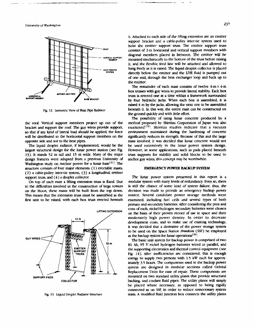
University of Wasbington 237
MOTHER MEAT PPE
SUPPORT MEUlER
-ROOF
VERTLCAL suwom MEMBER
HEAT PIPEIFIN SVSTEY
Fig. 12. Isometric View of Heat Pipe Radiator
the roof. Vertical support members project up out of the bracket and support the roof The guy wires provide support, so that if any kind of lateral load should be applied, the force will be distributed to the horizontal support members on the opposite side and not to the heat pipes.
The liquid droplet radiator, if implemented, would be the largest structural design for the lunar power station (see Fig. 13). It stands 52 m tall and 15 m wide. Many of the major design features were adopted from a previous University of Washington study on nuclear power for a lunar bad"). The structure consists of four major elements: ( 1 ) erectable masts, (2) a cable-pulley inter-tie system, (3) a longitudinal emitter support truss, and (4) a droplet collector.
On top of each mast a lifting extension truss is hed . Due to the difficulties involved in the construction of large towers on the Moon, these masts will be built from the top down 'Ibis means that the extension truss must be assembled as the first unit to be raised, with each box truss erected beneath
LIFTING EXTENSION
SUPPORT PADS
Fig. 13. Liquid Droplet Radiator Structure
it. Attached to each side of the h f ~ q extension are an emitter support bracket and a cable-pulley inter-tie system used to hoist the emitter support truss. The emitter support truss consists of 2-m horizontal and vertical support members with diagonal members placed in between. Ihe emitter will be mounted mechanically to the bottom of the truss before raising it, and the flexible feed line will be attached and allowed to hang freely as it is raised. The liquid droplet collector is placed directly below the emitter and the LDR fluid is pumped out of one end, through the heat exchanger loop and back up to the emitter.
The remainder of each mast consists of twelve 4-m X 4-m box trusses with guy wires to provide lateral stability. Each box truss is erected one at a time within a framework surrounded by four hydraulic jacks. When each box is assembled, it is raised 4 m by the jacks, allowing the next one to be assembled beneath it. In this way, the entire mast can be c o m c t e d on the ground quickly and with little effort.
The possibility of using lunar concrete produced by a method proposed by Shimizu Corporation of Japan was also examined(I9). Shimizu studies indicate that a vacuum emironrnent maintained during the hardening of concrete &gdficantly reduces its strength. Because of this and the large mass invoived, it was decided that lunar concrete would not be used extensively in the lunar power system design. However, in some applications, such as pads placed beneath truss supports for stability and solid blocks to be used to anchor guy wires, this concept may be worthwhile.
EMERGENCY POWER BACKUF' SYSl'JW
'Ihe lunar power system presented in this report is a modular system with many levels of redundancy. E y so, there is still the chance of some kind of system failure; thus, the decision was made to provide an emergency backup power source. Several candidate power storage methods were examined, including fuel cells and several types of both primary and secondary batteries. After considering the pros and cons of each, nickel-hydrogen secondq batteries were chosen on the basis of their proven record of use in space and their moderately high power density. In order to decrease development costs, and to make use of existing technology, it was decided that a derivative of the power storage system to be used on the Space Station M m (SSF) be employed as the backup system for lunar operations(20).
The basic unit system for backup power is comprised of two 81 Ah, 95 V nickel hydrogen batteries wired in parallel, and the supporting electronics and thermal control equipment (see Fig. 14). After inefliciencies are considered, this is enough energy to supply two persons with 1.5 k W each for appmx- imately 3.5 hours. The components used in the backup power system are designed in modular sections called Orbital Replacement Units for ease of repair. These components are mounted on two standard utility plates that provide structural baclung, and coolant fluid pipes. The utility plates will simply be placed where necessary, as opposed to being rigidly connected as on SSF, in order to reduce unnecessary system mass. A modified fluid junction box connects the utility phtes

lngs of tbe NASA/LISRA Advanced Design Program 61, Summer Conference
PLATE
RADIATOR
FLUID JUNCTION BOX
-
-{ EEU BATTERY ORU
-1, EEU
BATTERY BATTERY ORU
-
EEU: ELECTRICAL EQUIPMENT UNrr
Fig. 14 Space Stat~on /+&J~N Eneqg Stordgr System
with the pumped Itw ammonia radiator, completmg the the& control loop, as well as the b=ic unit. These two- person-rated systems may be combined in sutlicient quantities, once givcn the number of occupants at the lunar base.
'Ihis battery system turns out to be relatively massive (see Table 5) due to the relatively low energy density of batteries a5 opposed to fuel cell storage. As stated earlier, the nickel- hydrogen system -5 chosen because it will be extremely reliable. However, fuel cell systems, when configured in a highly redundant manner, may provide the same power as batteries at a great mass savings, but with increawd complex- ity. When the lunar base is constructed, mission planners will have to decide whether the high mass of the batteries is justified or if some type of fuel cell system should be supplied for emergency backup.
Table 5. Lunar Emergency Backup Powcr Sprm Components
Mass Parasitic Energy Quantity Cnmponmr (k) Power(kW) (kwh)
Battery ORU 146 3 4 EElJ 76 0.140 2 Utility Plate 136 2 TCS Pump ORL' 36 0 125 I I-1u1d Juncz~on Rox 2 1 I Radiator I25 1
CONCLUSION
The work presented here shows that a solar power system can provide power on the order of one megawatt to a lunar base with a fairly high specific power. The main drawback to using solar power is still the high mass, and, therefore, cost of supplying energy storage through the lunar night. The w of cryogenic reactant storage in a fuel cell system, however, greatly reduces the total system mass over conventional energy storage schemes.
As shown in Table 6, the advanced new tandem GaAs/GaSb photovoltaic cells provide a specific power nearly four times that of the dynamic cycle conversion scheme. This comparison takes into account all necessary structural, thermal control, and solar collector masses, and suggests that the photovoltaic system is the best system to use. Additionalty, the solar cells are passive, with the only moving part being the solar-tracking motor, thereby increasing the system reliability. For these reasons, the photovoltaic m y is recommended for use over the dynamic power system.
Table 6. Comparison of Solar Power Systems
Photovoltaic Arrarj
Photovoltaic Amy Mass 9,150 kg Structural Mass ( W) 10,150 kg HPR Brayton Engines (5) Solar Collector (5) Radiator (HPR) ( 5 ) Total Power Supplied 1,175 kW Total Specific P m r 61.7 W/kg
Brayton Cycle
Obviously, the solar cells produce no power during the night, and since energy storage for the lunar night is so massive when compared to daytime power, cutting back on power during the lunar night is highty recommended. In this system, 50 kW was chosen as the minimum nighttime power in order to greatly reduce overall system mass while still allowing enough power for scientific experimentation. Making use of the spent cryogenic tanks kom a lunar excursion vehicle reduces the net mass of the storage system, but not enough to make high power at night economically feasible.
If the dynamic conversion system is used, thermal manage- ment should be provided by the heat pipe radiator system because of its fairly high specific thermal power dissipation, and because heat pipe radiator technology is well developed. The liquid droplet radiator is a very promising concept, and may one day surpass conventional systems in performance, but more research needs to be performed first.
If, for some reason, the power system is shut down, a maditied version of the Space Station Freedom energy storage system is employed to provide the base inhabitants with enough emergency power to escape from the base. This system turned out to be quite massive, and so systems with slightly less reliability may be preferable to help reduce overall system mass.
In conclusion, technology has adwnced to the point where a solar power system may now be seriously considered for high power applications on the Moon, as this report has shown. Given all of the problems, both political and technological, with nuclear power, it may be time to reexamine the old idea of using the sun to power the lunar base.
Student authors are £3. Adams, S. Alhadeff, S. Beard, D. CarIile, D. Cook, C. Dougla5, D. Garcia, D. Gillespie, R Golingo, D. Gonzalez, I? Gurevich, C. Hansen, W. Hopkins, J. Iacometti, M. Jardin, T. Lipscomb, S. Love, T Montague, J. Nelson, and D.

University of Washington 239
Ritter. Editors are David CarliJe, John Iacometti, and Matt 10. Mattick A. T and Hertzberg, A, "Advanced Radtator Systems for
Jardin. They were assisted by Professors Adam P. Bruckner, and SpacePower", IAF 87-230 38th Congress of the International
Abraham Hertzberg, and Teaching Assistant Tem Schmitt. Astronautical Federation, Brighton, United Kingdom, October 10- 17. 1987.
REFERENCES
Fraas. L, "Tandem Solar Cells with 31% (AMO) and 37% (AM1.5) Energy Conversion Efficiencies", IEEE Aerospace & Electronic Systems Magazine, Volume 4, Number 1 1, November, 1989, p. 3- 9. Henderson, B.W., "Boeing Achieves Major Advance in Space Solar Cell Efficiency", Aviation Week and Space Technology, October 23, 1989, p ~ . 61 -63. Fraas, L., "Boeing High EBiciency Solar Cells", Lecture, University of Waslungton, January 3 1, 1990. O'Neill, M., Entech, Inc., Personal communication, April 25, 1990. O'Neill, M.J. and Piszczar, M.F. "Development of a Dome Fresnel Lens/Gallium Arsenide Photovoltaic Concentrator for Space Applications", Entech, Inc., 1987. h e r , M.,TRW, Personal communication, May 7, 1990. Duffie, J.A., and Beckman, WA Solar Engineering of Thermal Recesses, John Wiley & Sons, 1980, p. 168. Van der Leij, M., Spectral-Selective Surfaces for the Thermal Conversion of Solar Energy, Delft University Press, 1979, pp.64- 96 Werner, R W. and Carlson, G. A., "Heat Pipe Radiation for Space Power Plants," IECEC 1968 Record, LEEE, Piscataway, NJ, pp. 487- 50 1, 1968.
AA 4201499 Design Group, "Multimegawatt Nuclear Power System for Lunar Base Application", University of Washjngton, Department of Aeronautics and Astronautics, NASA/USRA - University Pilot Program. Final Report, June 1986. Kohout, L.L., "Cryogenic Reactant Storage for Lunar Base Regenerative Fuel Cells," Lewis Research Center, NASA TM 011980, June 1989. McPheeters, C.C., et al., "Recent Advances in Monolithic Solid Oxide Fuel Cell Development." IECEC 889207, 1988. O'DomeU, I?, Deputy Branch Chief, Electrochemical Technology Branch, NASA Lewis Research Center, Private Communication, May, 1990. Bock, E.H., and Fisher, J.G., "In-Space Propellant Processing Using Water Delivered as Shuttle Contingency Payload," AIAA Paper 78- 941, July 1978. Mitchel, I?, hnar/Mars Outpost: Interim Review #1, MCR 89- 7505, Martin Marietta Company, 1989 Dickerson, A, California Polytechnic Institute, Pomona. Private Comrnunic2tion, Februq, 1990. Grifliths, DJ., Introduction to Electrodynarmcs, Prentice-Hall, Inc., Englewood ClifEi, NJ., 1981. Namba. H., et. al., "Concrete Pmduaion Method for Construction of Lunar Bases," Academic Papers Regarding Concrete on the Moon, Shimizu Corporation, Tokyo Japan, 1990. Brandhorst, H. "Challenges for Future Space Power Systems." NASA-TM-102063, Cl~eland, OH, Oct. 1989.


PI 17 Gl!.NBIS LUNAR OUTPOST: AN EVOLUTIONARY LUNAR HABITAT
~ R S I T Y OF WISCONSIN-MILWAUKEE N91-18158
Students at the University of Wisconsin-Milwaukee Department of Architecture undertook a series of studies of lunar habitats during the 1989-90 academic year. Undergraduate students from architecture and mechanical and structural engineering with previous backgrounds also in interior design, biology, and construction technology were involved in a seminar in the fall semester followed by a design studio in the spring. The studies resulted in thmz design alternatives for lunar habitation, and an intepted design for a early stage Lunar Outpost.
EARLY STAGE LUNAR OUIlWX
On the 20th anniversary of "One giant leap for mankind," President Bush announced the goal of Ian- people on the Moon by 2005, and this time to stay. Project Gene& is proposed as the first early stage, permanently occupied habitat on the Moon.
Research, design, and development of Project Genesis was initiated in 1989 by the University of Wisconsin-Milwaukee (UWM) Center for Architecture and Urban Planning Research and Department of Architecture in cooperation with the College of Engineering and Applied Science. UWM/Architec- ture is one of only 3 architecture schools in the 44-university NASA/USRA University Advanced Design Program. The program stresses the systems approach to design in which the clas.. works together on a major "real world project. The objective this year was to design a lunar outpost for the year 2005 based on environment-behavior, architectural, and engineering design concepts.
Genesis is proposed as an evolutionary, long-term testbed for all materials, processes, and development strategies to be employed in a mature lunar colony for the next 20 years, and as a testbed for all processes to be employed in the exploration and settlement of Mars.
Following guidelines provided by aerospace engineers and scientists at NASA's Johnson Space Center (NASA/JSC) and its prime contractors, the UWM Space Architecture Design Group designed Genesis for a full-time crew of 8 to 12 persons on rotations of 6 to 9 months with a maximum duration of 20 months. Gender, nationality, and ethnicity are expected to vary as the consortium of world aerospace partners all become involved in free-flowing scientific communication.
Five mission objectives were identified for Project Genesis: (1) lunar surface mining and production a&%is; (2) lunar construction technology and materials testbed; (3) closed ecological life-support system (CELSS) test facility, (4) lunar farside observatory; and (5) human factors and environment- behavior research facility.
The first crewed mission to establish the outpost, which is expected to land on the Moon in 2005, could last as little as 14 days. The astronauts, architects, and engineers will live inside their lunar landing vehicle (LLV) and spend much of each day performing extra vehicular a c t ~ t i e s (EVA) involved in base construction. A pressurized construction module will
be the first order of business, followed by the evolutionary development of the rest of Genesis. Once all systems, subsystems, and backups have been verified, and the initial operation configuration (IOC) has been put in place, crew change-outs will occur every 9months to a year as the astronauts and their partners perform research and manufac- turing operations.
PROJECr GOALS
This year's project had three goals: I . Design soluttotts. To develop creative yet realistic
architectural and engineering solutions to space design issues in response to human factors and environment-behavior issues, safety, energy, construction technology, and the utilization of nahlfal resources.
2. Currkrtrlum development and pedagogy. To enhance, further develop, and maintain courses and studios in the area of space architecture and related subjects in the School of Architecture and Urban Planning in conjunction with the College of Engineering and Applied Science at the University of Wisconsin-Milwaukee, and also to offer the design student the opportunity to become weU versed in space and high technology.
3. Useful JnformaHon. To produce information and design solutions useful to the aerospace community, NASA, its prime contractors and subcontractors, and NASA/USRA schools on long-duration habitation design, and to publish this information and disseminate it in a manner that makes is accessible and timely to these communities.
LUNAR BASE MISSION OVERVIEW
A lunar outpost has eight major objectives to satisfy('.'):
1. Located at an Earth-facing equatorial location. 2. Constmcted of lightweight, durable materials that require
little EVA time. 3. Contained within the next generation of Earth-lunar
transport systems: (a) U.S. space transport shuttle system, (b) heavy-lift launch vehicle such as the autonomous Shuttle C with cargo capacity of 69,000 kg ( 150,000 Ib) and cargo bay 25 m x 4.5 m diameter (82 X 15 ft), (c) low-Earth-orbit Space
PAGE ~'~~ INTENTIONAUY BLANK
PRECEDING PAGE PLANK NOT F!'..PIIE3

242 Proceedi ngs of tbe N A W U S R A Advanced Design Program 6tb Summer Conference
Station r;Leedom (SF) and associated platforms, and (d) the planned cislunar transport system consisting of an ohital trans- fer vehicle (ON) and a separate reusable lunar lander.
4. Capable of housing 8- 12 astronauts of different national- ities, gendm, and specialties for periods up to 20 months with a normal change-out of6-9 months.
5. Provision for all life-support systems including (a) human Eactors, (b) health and safety, (c) environment-behavior issues, (d) habitability of crew areas, crew support, operations of base, and design for productivity, and (e) Controlled Ecological Life- Support Systems (CEISS) and Environmentally Controlled Life- m r t systems ( ECISS).
6. Integration of advanced technologies (a) space construc- tion technology, (b) advanced systems of energy use and en- ergy conservation, and (c) advanced mechanical systems in- cludmg power, thermal, air movement, and hydraulic systems.
7. Understanding and response to the physics, geology, and natural environment of the Moon, lunar resource utilization, and appropriate "urban" design to retain the natural qualities of the Moon.
8. Support for five main mission research operations: (a)lunar surface mining and production analysis for lunar oxygen (LUNOX), helium 3 (H3), and other minerals; (b) lunar construction technology and materials testbed for testing high-technology construction with intlatables, the use of lunar regolith for radiation shieldmg, lunar glass, lunar concrete, and sintering techniques using advanced telerobotic systems, (c) CELSS test Eacility; (d) lunar farside observatory; and (e) human factors and environment-behavior research facility including ongoing post-occupancy evaluations (POEs) of Gemsis itself.
DESIGN METHODOLOGY
To achieve these goals, the project team proceeded in three phases:
1. Fall semester senofttar. The project began with a fall semester seminar (Architecture 392/792). 'helve students from architecture, interior design, mechanical and structural engineering, and liberal arts/pre-architecture had a series of lectures, extensive readings, and simple sketch designs to leam the material needed to design a lunar habitat The seminar was under the leadership of Edwin Cordes, a recent graduate of the UWM Mkch. program and of the International Space University in Strasbourg, France, and Dr. Gary Moore, a research architect and environmental psychologist, the overall project director. The teaching assistant was Mr. 'Ilmothy Hansmann, who had been a NAWUSRA intern at JSC. The product was a programmmg/requirements document( I ) .
2. Sprtng design studio: Ptdirnfnary &sign on abreP dedgn altanatives. A space architecture design studio (Architecture 690) was conducted in the spring semester of 1990. Eleven students, most of whom had been in the fall seminar, were drawn from architecture, interior design, and mechanical and structural engineering. Issues included anthropametrics, human Eactors, health and safety, psycholog- ical and social issues, habitability, energy systems, construction
technology, internal and external base apentions, and base master planrung and phasing. After p r e h m q exploration of different mbsytems of the base (research module, manufac- turing areas, habitat module, base planning and layout), three alternative deqns were explored in detail and presented at a prelutllnary design review (PDR) in February 1990 attended by representatives of W J S C , USRA, industry, and academia. Each team was made up of architects and engineers with spe- cialties in environment-behavior studies, interior design, structural or mechanical engineering, and construction technology. This division-vertically by subsystem and horizontally by specialty-insured that each subsystem responded to all design &ors and that all subsystems would contribute to an integrated solution
The product was a set of design drawqp and presentation boards, together with a slide presentation. It was presented at several regional and national meetings and received a special student design award fkom the Emironmental Mi Research Association at its 2 1st annual conference.
3. Sprhrg datgn studio: D 4 J f g n deYelopnrent of final irrtegrated design soiadtm The design concepts and ideas selected at the PDR were M e r developed. A number of technical issues needed further m c h , analysis, and design exploration: materials, j o i i systems, hatches and gaskets, structural system, deployment systems, and regolith contain- ment systems. Each was explored in depth by one or two members of the team with critical input from our NASA/JSC consultants and industry representatives The project team was subdivided into teams for the further exploration and design development of parts of the overall Genesis Lunar Outpost. The three teams were site and master phnhg , interior configu- ration, and c o r n o n technology.
'Ihree extracredit students served as team leaders for the design teams; all are now working for NASA or NASA contmctors. The product was a set of design development drawings and slide presentation that was presented at the NASAAJSRA 6th Annual Advanced Design Program Summer Conference, W L e w i s Research Center, and elsewhere in this country and ovemeas.
THREE DESIGN ALTERNATIVES
As a Erst design phase, three design alternatives were e@ored in detail based on d&ring sets of engineering and architeaural assumptions: (1) Space Station Freedom (SF) rigid space structures using clusters of space station-sized pressure vessels, aluminum alloy domes, and interconnect nodes; (2) underground architecture using the natural lunar craters and lava tubes; and (3) inflatables using a laminated Kevlar bladder with a space firame structure.
In each design alternative, separate modules were designed for laboratory and habitation functions. The entire faciity was designed to be buried under a sdicient amount of lunar regolith (0.5 to 1.5 m) for proper radiation protection and thermal control.
Concerns of the design teams included provision of public and private spaces for all functions, design for 1/6 gravity of the Moon, systems for multiple uses to conserve space and

University of Wfscondn-Milwaukee
weight, accedbility to all areas and c o m v t s , graphic coding to allow ease of identification by aPwmembers, and interior configuration, which includes provisions for life support and power supply systems. The laboratory area includes w o ~ o m for eight crewmembers, an exercise facility, a limited hygene facility, a system fw holdmg a variety of experiments, command and control center, and a storage system for consumables, excess equipment, and pas01111 items. The habitation area includes sleeping and personal areas for the @t crewmembers, hygiene M t i e s for full body and hand cleansing, meal preparation area, dining area with W t i e s for teleconfeffnces and meethgs, crew health care and emergency medical W t y , and storage system for food, medical supplies, and personal items.
ThefimdesignaltemativefocusedontheuseofSSF-type hanl modules with connectors and M A chvnbers (see Fig. 1). 'lhe floor plan has a central command center flanked by science and medical Mties , domestic management, central large domed mearch and tel- and aew quarters Each ofthe larger moduleswas designed to fit ih a standard space shuttle cargo bay, and would be outfitted prior to lift&
'Ihis alcernatiw would develop through a series of phases (see 2) with each speded in terms of the number of ~ t s w i t h c r e w a n d l ~ c s p a y I o a d s t o ~ c t & p h a s e up to IOC Phases A, B, and C are the three subph;lses of
Fig 1. Design altematiw 1 : Ri@d construction-base floor plan

Proceedings of tbe NASMUSRA Advanced Design Program 6tb Summer Conference
11-- ---- - - - - .---- -- _I
ORIGINAL PAGE IS OF POOR QUALITY

University of Wisconsin-Milwaukee
Phase 1 IOC. The IOC involves a dome habitat center command center inside the upper entrance of the lava tube. constructed from prefabricated Earth-based construction The waUs are formed from a rigidizing foam wall system. As technology (aluminum sheets, self-rigidizing foam, etc.). the lava tube continues its steep descent, an electromagnetic
elevator system would be installed. Lunar Craters and Lava nbes The large, natural, open volume of the lava tube can be
The second design alternative explored the posibilitia of converted into a two-story habitat with crew quarters, laundry, using lunar craters and associated lava tube systems. The design meal preparation area, biosphere, conference and libmy area, uses a descending in tube opening (see Fig. 3) with a laboratory, exercise area, and ball court (see Fig. 4).
Fig. 3. Design alternative 2: laM tube cons~uaion-entrance to the lava tube from a lunar crater, command center on the surface level, wal l section, and electromagnetic elaator
ORlGlNAL PAGE IS OF POOR QUALm

Procccdtngr of #be N A S N S R A Advanced Detfgn Program 6tb Summer Com@rmce
-4. ~ ~ ~ ~ ~ ~ m d s c c r i o n d t h e ~ n a t u b c ~ a l ~ . n K ~ e n d s d r M s p l v l u d ~ connectwith the two lownendsdthcelmtor hlbes
ORIGINAL PAC!: p6ofa QUAU7-Y
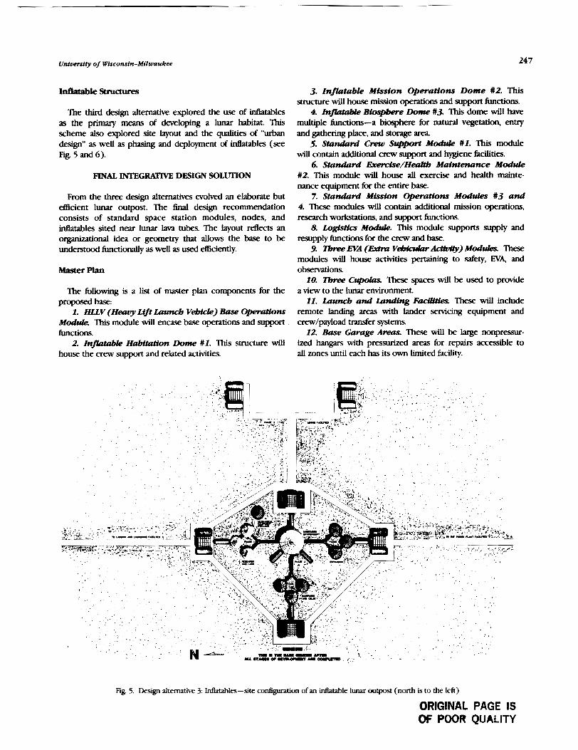
University of Wisconsfn-Milwaukee 247
The third design alternative explored the use of ineatables a . the primary means of developing a lunar habitat. This scheme also explored site layout and the qualities of "urban design" as well as phasing and deployment of intlatables (see Fig. 5 and 6).
FINAL INTEGRAl'lVE DESIGN S O L ~ O N
From the three design alternatives evolved an elaborate but e5icient lunar outpost. The final design recommendation consists of standard space station modules, nodes, and idlatables sited near lunar lam tubes. The layout reflects an organizational idea or geometry that allows the base to be understood functionally as well as used efEaently.
Mastet Plan
The following is a l i t of master plan components for the proposed base:
1. m v (Heavy Lift Launcb VeMcCe) Base Opere#ons Module. This module will encase base operations and support functions.
2. Infkztkzble Habitution Dome #I. This structure will house the crew support and related activities.
3. I n . t a b k M i s s i o n O p e r a t i o n s Dome $2. This structure will house mission operations and support functions.
4. InflataMe BIospbere Dolne #3. Tiis dome will have multiple functions-a biosphere for natural vegetation, envy and &hering place, and storage area.
5. Standad C m Support Module $1. This module will contain additional crew support and m e n e fidities.
6. Standard Eretccfse/HealYb M a i n t e n a n c e Module #2. 'Ihis module will house all exercise and health mainte- nance equipment for the entire base.
7. Standad Mission Operations Modules $3 and 4. These modules will contain additional mission operations, research workstations, and support functions.
8. Logistics Module. This module supports supply and resupply functions for the crew and base.
9. IEme EVA (IMm VeJMcularAdc@) Modula . These modules will house activities pertaining to safety, EVA, and obsemtions.
10. T h w Cupdas. 'Ihese spaces will be used to provide a view to the lunar environment.
11. Launcb and Landing F a d W e s . These will include remote landing areas with lander servicing equipment and aew/payload transfer systems
12. Base G a r a g e Areurs. These will be large nonpressur- ized hangars with pressurized areas for repairs accessible to all zones until each has its own limited facility.
Fig. 5. Design alternative 3: Matables-site con6guration of an intlatable lunar ouepost (north is to the left)
ORIGINAL PAGE IS OF POOR QUALITY

248 Proceedings of tbe NASA/USRA Advanced Design Program 6tb Summer Conference
Fig 6. Pha!ied dewlopment d the inflatable site from initial base setup through Phase 1 IOC
in s p t e ~ ~ mese. will provide surfice tmmpmtion to travel to the more distant base elements as w e l l a s ~ p e y l o c L d s o r c r e w .
14. -face Mitting and Plloduc#on Anaiysis Opera- rJoru Minmg and refinement of metlls, isotopes (helium-3), lunaroxygen,andothertnaterials
15. thWmdon T-~erbndogy Testbed and T- Rsaarab -. These will support high-technology conanmion methods and consmaion of robotic systems.
16. Power Plant. This will consist of a number of redundant systems including solv army fields, an SP-100 and 550 nuclear poww hcility, and he1 cells
Thelunaroutpostconsistsoffwrmajorareas(seeEig.7). The Brst is the centraUy located habitat/t.eseuch area The second is the pcnnvlent power h d t y louted to the north (I&, in Fig. 7). The is the mining and production H t y located to the west. 'lhe fourth area is dedicated to the launch andlvldingfacilitypositionedtothesouth. Thepowkrphtisapproximately l h tothenorthofthe
habitat. It consists of a small nuclear power generator ( SP- 1 00) that wUI be employed in the middle phases of the base development, and a more permanent nuclear kility (550) that
will be set into place at IOC. These hdlities are either piaccd in a crater or surrounded by a lunar berm to provide protection fFom any leakage of radiation
The mining and production plant is also located just cnna 1hfromthehabitattopiovidesakryhmdustorobjects that may be ejected into the atmosphere. An area of 92 m x 92 m x 2 m has been projected for an annull mining ~ t i o n I n t h i s a r e a , t h e p ~ o n o f l u n v o x y g e n d o r . . chemicah will be produced to provide Genesis with thc means of bcromiag self-cent.
l k f e will be two types oflaunch and lvrdingkditiles 'Ihe Em will be temporary sites to provide ease of construction nKse sites will be 250-400m awayhm the base loation Thesecondtypeof!%litieswUlbethepermanentlwnchud landing pads. These sites will be located no less than 3 and preknMy about 5km from the bese. 'These pads will be located in close proximity to rho6e areas ofthe base most frequently served, i.e., logistics and storage areas. The orientation of the base on the lunar s u h x was determined by the link It has with Ear& The lunar landers will dcscad east-west6romlunarorbiturdmusthmcaclarpathtothc p a d s . g r ~ t h e ~ ~ ~ - s o u t h ( ~ ~ the lander a t ) and placing the pads to the south, no base component will be endvrgered if a landa ovashoots its objective.
ORIGINAL PAGE. IS OF POOR QUALhY

University of Wisconsin-Milwaukee
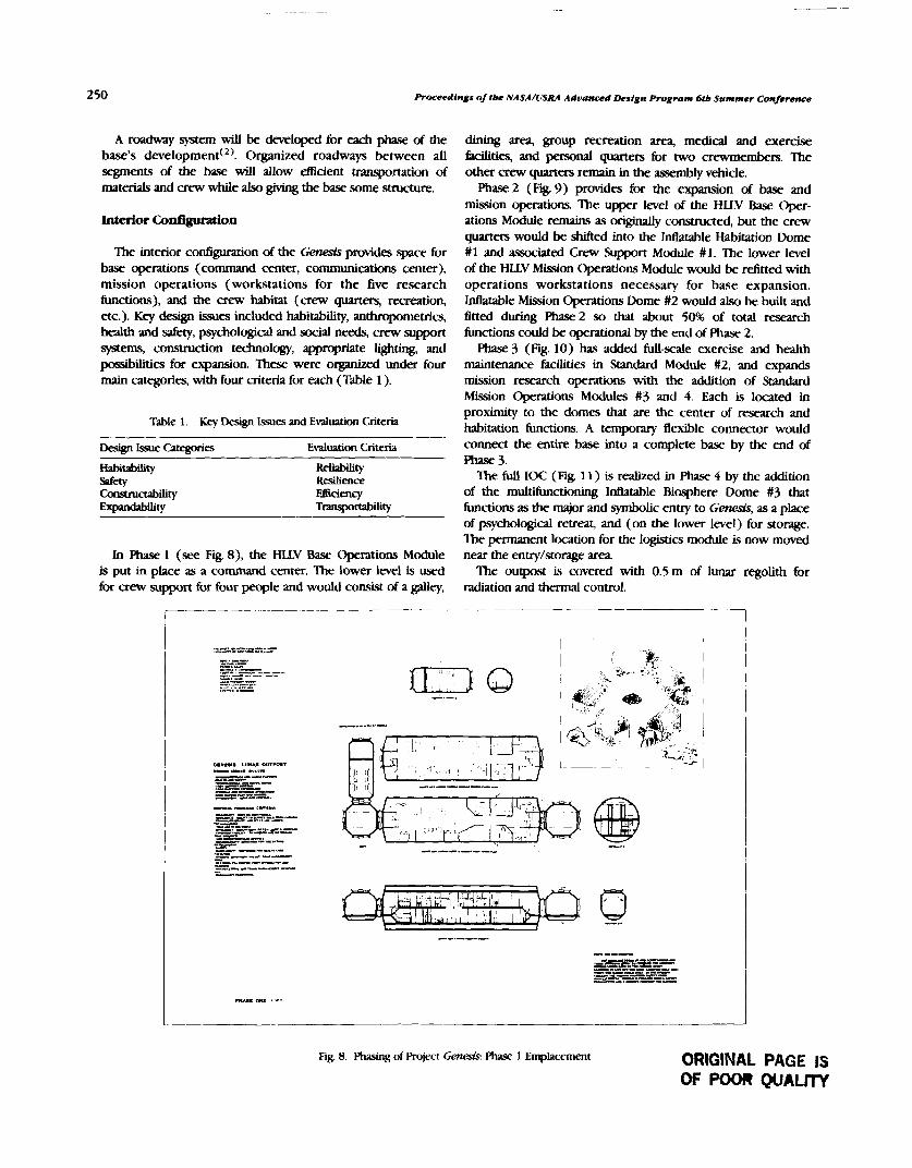
250 Proceedings of tbe NASA/USRA Aduanced Design R o g r a m 6tb Summer Conference
A roadway system will be developed for each phase of the base's deve~opment(~). Organized roadways between all segments of the base will &ow &dent transportation of materials and crew while also giving the base some structure.
The interior configuration of the Genesis provides space for base operations (command center, communications center), mission operations (workstations for the five research functions), and the crew habitat (crew quarters, recreation, etc.). Key design issues included habitability, anthropometrics, health and safety, psychological and social needs, crew support systems, construction technology, appropriate lighting, and pmsib'ities for expansion. These were organized under four main categories, with four criteria for each (Table 1).
Table 1. Key Design Issues and Evrluation Criteria
Design Issue Categories Evaluation Criteria
Habitability Reliability - Resilience Consvuaability m e ~ y
duung area, group recreation area, medical and exercise Wties, and personat quarters for two crewmenhem. The other crew quarters remain in the assembly vehicle.
Phase 2 (Fig. 9) provides for the expansion of base and mission operations. The upper level of the HLLV Base Oper- ations Module remains as origmally constructed, but the crew quarters would be shifted into the Mtatable Habitation Dome #1 and associated Crew Support Module # 1. The lower level of the HLLV Mission Operations Module would be r&tted with operations workstations necessary for base expansion. Mlatable Mission Operations Dome #2 would also be built and fitted during &2 so that about 50% of total research functions could be operational by the end of Phase 2.
Phase 3 (Fig. 10) has added full-scale exercise and health maintenance tacilities in Standard Module #2, and expands mission research operations with the addition of Standard Mission Operations Modules #3 and 4. Each is located in proximity to the domes that are the center of research and habitation functions. A temporary flexible connector would connect the entire base into a complete base by the end of Phase 3.
'Ihe full IOC (Fig. 11) is realized in Phase 4 by the addition of the multifunctioning Mlatable Biosphere Dome #3 that
Expandability Transportability functions as the major and symbolic entry to Gem&, as a place of psychological retreat, and (on the lower level) for storage. The permanent location for the logistics module is now moved
In Phase 1 (see Fig. 8), the HLLV Base Operations Module near the entry/storage area is put in place as a command center. The lower level is used The ourpost is covered with 0.5 m of lunar regolith for for crew support for four people and would consist of a galley, radiation and thermal control.
Fig 8 ~hasmg of Project ~ e m s k Phase 1 Emplacement ORIGINAL PAGE IS OF POOR QUAL17Y
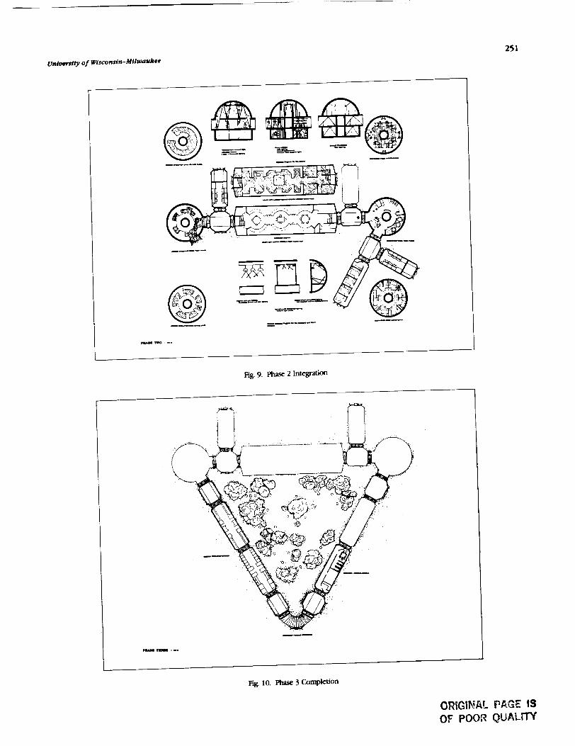
Fig. 9. Phase 2 Integration
ng. 10. phase 3 Completion
OWIGIP!AL PAGE IS OF POOR Q U A L m
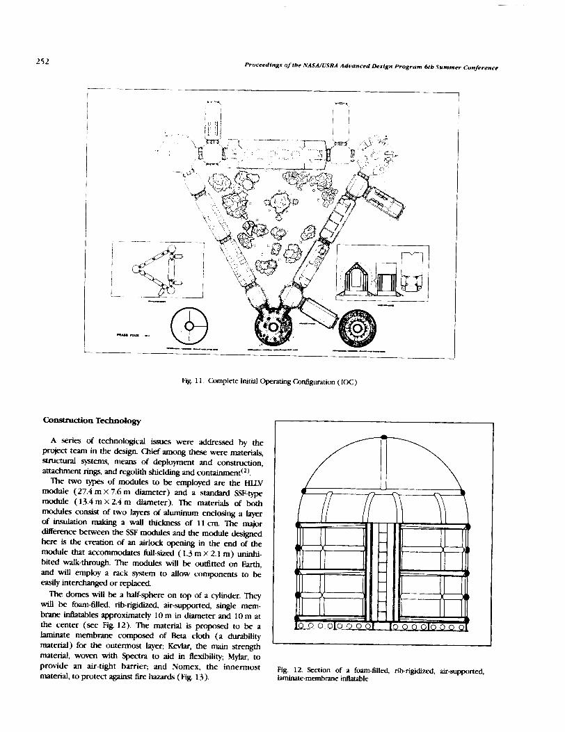
Fig. 1 1 . Complete Initial Operating Cor&guration (IOC)
Construction Technology I A series of technologicai issues were addressed by the
project team in the design. Chief among these were materiak, Srmrnvll systems, means of deployment and construction, attachment rings, and regolith shieldmg and containment(*).
The two types of modules to be employed am the HLLV module (27.4 m x 7.6 m diameter) and a standard SSF-type module (13.4 m X 2.4 m diameter). The materials of both modules consist of two layem of aluminum enclosing a layer of insulation making a MU thickness of I 1 cm. The major dserence bemeen the S F modules and the module designed here is the creation of an airlock opening in the end of the module that accommodates full-sized ( 1.3 m X 2.1 m) uninhi- bited walk-through. The modules will be oudtted on Earth, and will employ a rack system to altow components to be e a d y interchanged or replaced.
The domes will be a half-sphere on top of a cylinder T h q will be foam-filled, rib-rigidized, air-supported, single mem- brane inflatables approxirnateb 10 m in diameter and 10 m at the center (see Fig. 12). The material is proposed to be a laminate membrane compmed of Beta cloth (a d w i l i r y material) for the outermost layer; m, the am@ material, woven with Spectra to aid in flexibility; Mylar, to provide an air-tight barrier; and Nomex, the innermost material, to protect against lire hazards (Fig. 13).
L I
Fig. 12. Section of a foam-filled, rib-rigidized, air-supported, laminate-membrane idatable

University of Wisconsin-Milwaukee 253
constructed with the necessary opening left in the membrane. The membrane will have a bead formed at the point where
BETA CLOTH the rib fits into the ring. This bead will be sandwiched between the two metal pieces when they are joined to form an airtight
KEVLAR SPECTRA seal.
MYLAR Regolith shielding will be needed for protection @nst
COATED NOMEX radiation, micrometeoroid impacts, and thermal regulation. The thickness required has been calculated to be approxi- mately 50cm. The regolith shielding will be in the form of
Fig. 13. Inflatable Material Iaminate Beta cloth bags tilled with regolith and stacked upon the structures. A specially designed machine will gather regolith, bag it, and transfer these bags to a conveyor that will lift the
A Nd platform will spread the weight Of the structure Over bags into position (see Fig. IS), thus completing the the subregolith and stabilize and level the structures. The construction of Lunar foundation will be composed of auger-type bits telerobotically threaded into the regolith. The framework for the base of the inflatable is a lightweight space frame truss (see Fig. 14). The truss radiates outward from a central ring and can fold together for launch and deployment. The truss will be made of aluminum plates and welded channels. The tlat fluface that covers the truss is made of pie-shaped aluminum panels.
The idatable membrane will be continuous except for two airlock openings. These openings will be sealed so the entire structure becomes a pressure vessel in which air will be placed at 10855 mbar. The inside of the membrane will be lined with ribs formed by chemicaUy welding the same material to the membrane so a grid is formed The inside of the ribs will be lined with the two components of the foam, and separated by a form of resin-gel. When the inflatable is ready for deploy- ment, the ribs will be opened to a vacuum, the gel will evacuate, and the components will interact to form a rigid foam. Expanding these ribs will lift the membrane into its approximate form.
The proposed method for attaching a hard module to an inflatable is by using a sandwiched metal ring that will be attached to the inflatable on Earth. The inflatable will be
Fig. 15. Concept drawing for lunar regolith bagging and assembly procedure
FUTURE CONSIDERATIONS
There is considerable work still to be done to better understand and design the first lunar habitat. Among the most central issues that need consideration are the following:
1. Comparative, in-depth study of the lunar (versus martian) environment with special attention to atmosphere. radiation levels, solar flares, in-situ materials, topography, power sources, temperature extremes, etc.
2. Basic research on long-term effects of reduced gravity and design studies on different approaches to 1/6 gravity.
3. Mass calculations, studies of ways to reduce mass, and rough order-of-rnagnitude cost estimates.
4. Analysis of total number of flights based on minimum mass calculations.
5. Space allocation study including human factors analysis of the minimum space required for different habitation and research hctions.
6. Detailed trade studies of different areas of the lunar habitat, e.g., the health maintenance facility, exercise facility, crew quarters, air locks, and workstation rack designs. Design development studies of these different areas including through
Fig. 14. Lightweight Deployable Space Frame Truss study perspectives and/or models.

254 Proceedings of the NASA/USRA Advanced Design Program 6th Summer Conference
7. Replacement studies of how to replace/renovate/expandparts of the habitat.
8. Comparative analysis and extraction of deslgn.relevantfindings and implkatiom from prtwious space exixrience,analogous situations, and simulatiom, e.&, M/r and _V/aO,Antarctica and Navy submarines, and T_tf_e, respectively.
9. In-depth mechanical study including more carefulradiatorstudy to remove body and _ heat from underthe_
10. Studies of different ways of getting natural light into aregoilth-covered lunar habitat without admitting gamma rayparticles, including but not limited to partiallycovered ct_las,flexible light pipes, pertscep_ etc.
11. Precise regoUth depth studies to protect lunar habitatsfrom radiation and micrometeoroids.
12. Habitability study of the short, and long-term effects oftatdetgrmagl envinmngnts and windowless _t_
13. Des_ studies of regolith containment systems, second-generation regolith barging machines, and processes (includ-ing _) of habitat
14. Structural calculations for all structural members
including but not limited to the structure of lunar inflatabledongs
15. Study of various construction techniques for lunarapplication including, but not limited to, prefabricatedmodules, rigid structures, inflatables, and /n-am resourceutilization.
16. Study of materials for lunar habitat application,especially elastomers and thin films, e.&, Keviars, Mylars,Spectra, Nomex, aluminums, titaniums, rigldizing foams, and/n-
s/tu vesout_ utilization of lunar regoUth.
These stu_es will be conducted in subsequent years und_USRAand (hepefimy) other fundir_ They wilt be of two basictypes: research and analysis studies, and design and develop-
ment studies. The results will be reported in future reportsand palxax
ACKNOWLEDGMENTS
Designs and illustrations by the Space Architecture DesignGroup: DinoJ. Baschiera, Joe Paul Fieber, Patrick Groff,Michele Gfuenlx'tg_, Susan E. Moss, Janis Huebner Moths,Kerry Lynn Paruleski, Scott A. Schleicher, and Curtis W.
Schroeder; Teaching Assistant Timothy Hansmann. Papercompiled and written by Gary T Moore, Faculty Advisor, withDino Baschiera, Joe Fieber, and Janis Moths. This project wassupported by an Advanced Design Program grant from NASA/Universities Space Research Association. This paper is ammmary of a larger document, Genesis Lunar OuqTo.¢: Criteriaand Deagn (Hansmann and Moore, 1990) available from the
authors. Our thanks to James Burke, NASA/Jet PropulsionLaboratory, and Stephen Paddack, NASA/Goddard Space FlightCenter for critical comments.
REFERENCES
I. mscmera, D. J. et a_ (1989). Gemm Lunar OtOxm: Program/R_ oocumeat for an _ stage Ltmar ou0x_.Milwaukee: University of Wisconsin-Milwaukee, Center forArct_tecture and UrbanPlanningResearcl_
2. Hanstmam, T and Moore, G. T. (Eds.) (1990). Genes/s Datar
Outpost: O/tet_ and Des/gn. Milwaukee: Universityof Wiscomin-Milwaukee, Omter for Ardfltecture and Urban PlanningRcseardx

INTEGRATED SUPPOFtT STRUCTURE FOR GASCAN I1 P . lo
Ihe focus of the WPI Advanced Space Design Program was the p r e l i m i q design of the Integrated Support Structure for GASCAN 11, a Get Away Special canister donated to WPI by the MITRE Corporation. Two teams of three students each worked on the support structure: the structural design team and the thermal design team. 'Ihe structure will carry three experiments also undergoing preliminary design this year: the wg Ignition Experiment, the Rotational Flow in Low Gravity Experiment, and the Ionospheric R.operties and -tion Experiment. 'lhe structural design team was responsible for the layout of the GASCAN and the p r e m design of the structure itself. They produced the physical interface spedcations d e w g the baseline weights and volumes for the equipment and produced layout drawings of the system. The team performed static and modal finite-element analysis of the structure using ANSTS. The t h d design team was responsible for the power and timing requirements of the payload and for identification and preliminary analps of potential thermal problems. The team produced the power, timing and enagy interface specifications and assisted in the development of the specification of the battery pack 'Ihe thennal parameters for each experiment were cataloged and the experiments were subjected to 'Worst case" heat transfer scenarios. These analyses will be integrated by next year's thermal design team to model the overall performance of the system.
WPI's Get Away Specla1 Canister (GASCAN) Program is now in its eighth year. This program is the result of a cooperative effort by WPI and the MITRE Corporation of Bedford, Mass. MITRE purchased and donated two GASCANs to WPI. The first of these canisters is now scheduled for launch in August of 1990. The second canister, GASCAN I1 is now undergoing prelirninaty design. Since 1986, the design of GASCAN I1 has also been part of the NAWUSRA Advanced Space Design
Rogram. The task of designing this payload has been divided into the
two groups: experiment design and support s t r u a design. The experiments are described in the Payload Description Section. The focus of the AY1989-90 program is the thermal and structural design of the integrated support structure of the GASCAN.
PAYLOAD DESCRIPTION
Size and Weight
The maximum volume of our payload will be 5.0 fit? .e maximum weight will be 200 Ib.
We are developing four experiment packages. Each experiment will operate in a stand-alone mode as completeky as possible. A brief description of each experiment is presented below. The experiments are as follows:
1. Ionospheric Properties and Propagation Experiment 2. Microgravity Ignition Experiment 3. Rotational Fluid Flow in Microgravity Experiment 4 . Environmental Data Acquisition System
Ionospheric Properties and Propagation Experiment (IPPE)
The purpose of the IPPE is to correlate the occurrence of radio wave ducting with electron density. This will be accomplished by measuring the electron density in the ionosphere and the signal strength of a 15 MHz signal (radio station WWV in Colorado and Hawaii). Electron density will be determined using an Electrostatic Analyzer (ESA). A radio receiver tuned to 15 MHz will provide the signal strength data.
Radio wave duc-ting occurs when a high frequency signal is trapped between two ionospheric layers. Theory predicts that ionospheric layers with high electron density will reflect radio waves. If a radio wave is trapped in a layer with a low electron density between two layers with a higher elec-tron density, then that wave will be "ducted." A ducted radio signal will expe- rience less attenuation than a non-ducted signal. The data from the IPPE radio receiver will be analyzed in order to find changes in signal strength attenuation. These changes will indicate ducting of the radio signal.
The basic IPPE system is shown in Fig. 1. The system has four main components: radio receiver, radio antenna, Electrostatic Analyzer (ESA), and a control assembly. Both the ESA probe and the radio antenna will be mounted external to the canister lid (Fig. 2).

Procdbdin&s of tbe NASUUSRA Advamcud Design Program 6th Summer Conference
Fig 1. Schematic of the IPPE
4
RADIO ELECTROSTATIC
'% /
GASCAN
h
Fig 2. External Vim of the Canister
The unit will be turned on by a shuttle crewmember fol- lowing the completion of the Rotational Fluid Flow Experi- ment. At this point the experiment will begm sampling WWV signal strength and ion density at regular intends.
In order for this experiment to be able to take proper readhgs within the ionosphere, it must be flown on a high- inclination shuttle @ht.
'Ihe initiation of combustion on Evth is largely controlled by the presence of gravity since natural convection and buoy- ancy are functions of gravity. Eiy neutdmng the effects of gravity, other mechanisms should become dominant Wars in the @tion process ' Ihepupxeofthisexperhat is tocom- pare the ignition characteristics of a m a t d in a micmpvity experiment with ignition characteristics established from laboratory experimentation in a I-g environment.
TZhe experiment has two major subsystems: the combustion chambers and the control system, as shown in Fig 3. There will be four airtight combustion canisters capable of withstanding fk atmospheres of internal pressure. Each of the four containers will have an identical paper target (alpha cellulose) that will be ignited using a h@-intensity lamp. Data will be collected Erom the chambers using temperature, pressure, and heat flux sensois. In addition, an ion sensor will be Located above the target to serve as a Bame detector.
The control system will contain a microprocessor and an EPROM card for data storage. This system will be responsible for monitoring the experiments and talung appropriate action to shut down a canister if a hazardous condition arises.
This experiment should be turned on by a shuttle crew- member during a period of relative inactivity. Upon activation, this experiment will enter a "sleep mode" for a predetermined time period. At the end of this "sleep phase," the micropro- cessor will begin the ignition experiments.
The ESA probe consists of two concentric sphereq the outer sphere is constructed of gold-plated steel mesh, and the inner sphere is a gold-plated hollow aluminum ball. For the exper- iment to function properly, a voltage potential is maintained between the two spheres. When electrons are drawn onto the inner sphere, a negative current in the range of 10-lo to amperes will be produced. The radio antenna is composed of spring steel. Both the ESA probe and the radio antenna will be mounted to the GASCAN endcap using surface mounts and hgh impedance vacuum feedthroughs.
?he Electrostatic Analyzer circuit inputs the signal h m the ESA probe and uses a log electrometer to convert the currents into a 0-5 V range. The control assembly then takes this in- formation, processes the signal as required by the experiment, and stores the necessary information onto an Erasable Pro- grammable Read Only Memory (EPROM). Fig. 3. Schematic of the Micmgmity Ignition Fxperiment
IGNITION CANISTERS (1 -4)
+

Worcester Polytecbnic Institute 257
Rotational Fluid Flow in Mi- Expetlment
When a fluid rotates with the axis of rotaton nonnal to a @rational field, the rotation is accompanied by a decrease in the d e elevation of the 0uid at the center of rotation This phenomenon is referred to as a vortex. Vortex formation is govaned by the fluid's angular velocity, viscosity and surface tension. The objective of this experiment is to examine the behavior of a k e mrbce vlortar in a micmgmity environment.
'Ihis experiment has four main components the rotating platform, the fluid system, the data acquisition assembly, and the control asse!nbly (Figs. 4 and 5). A rotating platform will allow the experiment to utilize its microgravity environment to simulate other gravities, within the range of to 2.0 g's.
The fluid system will be composed of a tank, connecting tubes, and a pump. The working fluid will either be a silicon- based oil or a water/glycerol mixture that will not 6reeze in the cold of the GASCAN. The fluid will be injected tangentially
Fig. 4. Schematic of the Rotational Fluid Flow Experiment
into the upper end of the cylinder and drained kom the bottom of the tank 'Ihis process will induce an angular velocity into the fluid and create the vortex.
The data acquisition assembly will collect data using a camera, an ultrasonic device, and temperature sensors. ?he ultrasonic sensors will be used for measuring the velocity, and hence circulation, of the fluid within the tank The camera will be used to measure the actual size of the vortex and will function as a second measure of vortex strength. Not shown in the figures is the gas entrainment detector, which will be located along the piping between the tank outlet and the pump. This daice examines the fluid for gas bubbles. If gas is detected within the tubing, the control system stops data collection for that trial.
The control system will use a set of accelerometers to monitor and control the platform's angular velocity. The accelerometers will be aligned to measure the platform's centripetal acceleration. This experiment will be turned on by a shuttle crewmember
by the same switch as the miaogmity ignition experiment. Upon actiwtion, this experiment will enter a "sleep mode" until the ignition experiment is finished.
Environmental Data Acquisition System
The Emironmental Data Acquisition System (EDAS) collects data describing the environment internal to the canister from just after launch until all of the experiments are turned off. The system will be activated by the baroswitch as the shuttle passes through an altitude of 70,000 ft. The system will then begin to sample data for the entire time that experiments are running in the canister. These data will be available for posttlight analysis of the experimental data.
STRUCTURAL DESIGN
The objectii of the paybad structural design group is to integrate al l the experiments into a complete package inside the GASCAN I1 canister while conforming to all NASA structural design requirements. The project is in the preliminary design phase. Emphasis is on adequate structural support of the payload to ensure reliability and safety during flight operation.
General Requirements
Container corz.&w&m The standard GA!3 canister is made of aluminum. There is thermal insulation on the exterior. The top may or may not be insulated dependmg on the particular shuttle mission and needs of the experimenter. The standard circular endplates are 5/8-in-thick aluminum. The bottom 3 in of the container are reserved for NASA interface equipment such as command decoders and pressure regulating systems. This volume is not included in the space available to the experimenter.
Container sire. The container has a volume of 5 ft3. The user size is 28.25 in in height and 19.75 in in diameter. The
Fig. 5. Rotational FLuid FLOW Experiment laput maximum user weight is 200 Ib.

258 Proreedjngs o j tbe NASA/USRA A d t ~ n c e d Deslgn Program 6tb Summer Conference
&perfmen.! nrounzjng plate. The experiment mounting Inltial Design and Design Changes plate serves three purposes: it seals the upper end of the standard W container, provides a mounting su&ce for the This design team inherited a design by the previous payload experimental equipment, and acts as a thermal absorption and integration structural team which was a year out of date. mere radiation surface. The inner mounting plate is fitted with 45 were many details that needed to be changed a s quickly as holes to accept 10-32 UNF stainless steel screws to a depth possible to allow the other Advanced Space Design project o f 0.51 in. There are two purge ports for venting gases from teams to progress with their parts of the design. the battery pack. The first team had incorrectly allocated the space for the
Venting. Batteries, which can produce a combustible experiment mounting plate within the user interface space. mixture of gases, must be housed in a sealed, corrosion proof, The plate is 5/8-in thick and, therefore, detracted from the vented battery box. Plumbing for the venting of the battery amount of space midable for the experiments. Also, the box is to be supplied by the experimenter. The battery box previous team had not fully specified how the flange/ must be vented through the mounting plate and through two centerpost assembly would be attached to the mounting plate. 15-psi differential pressure relief kalves provided by NASA. All In order to redesign the top of the support structure, the plumbing should be stainless steel. major concern was to do so without altering the space already
Lafend load sup@wt Because the experiment structure designated for the IPPE and microgravity combustion will be cantilevered kom the experiment mounting plate, experiments. Since it was established that the experiment radial support of the free end of the experiment struc&emust mounting plate should not have been included in the design, be provided by at least three equally spaced bumpers between this gave the height of the usable space an additional 5/8 in. the experiment structure and the standard GAS container. Clearance for both the IPPE and microgravity combustion was
already sufficient and could only benefit from the additional height. With the exterior components of the IPPE, it was
Load Spedflcatiom decided that the Banges could be altered such that the IPPE bunch: normal: 3 g RMS, 20-2000 Hz team could have access to the entire diameter to allow them
adverse: 12gRMS,20-1000Hz Orbit: normal: negligible vibration, 0.1 g with thrusters to run their electrical leads to the ion collector and antenna Landing: n&,gib]e vibration. 5 static along ads AS this idea developed, it was also discovered that the previous
group had not finished the design of the venting mechanism for the battery. From the outset, it was assumed that the
Payload Integration
Each experiment has characteristics that affect the design. ?his section will address these design issues and describe the payload layout that will give a structural integrity that meets NASA specifications.
IPPE Experiment. This experiment has some unique requirements that must be adapted into the support structure. Tk.0 components, an ion collector and an antenna, are to be protruding out of the experiment mounting plate. These components will be located at a yet to be determined position on the mounting plate and could be anywhere on the diameter. Thus, these components must have access to the entire diameter and must be closely coupled to the IPPE controller box. With these considerations, it is necessary to place the IPPE controller box at the top of the GASCAN I1 support
venting would be done through the centerpost; however, the routing and connection to the mounting plate had not been established.
Further review of the NASA specifications showed that the battery vent had to be lead to a location within a plumbing circle section of the mounting plate. The mounting plate did not have to be oriented at any particular angle around the diameter; therefore, the team specified that it be oriented above one of the three compartments of the top section of the payload. The next concern was route of the venting Line from the centerpost to the plumbing circle.
Taking both the venting and mounting to the mounting plate into account, the top of the support structure was then redesigned. The flanges and centerpost were reduced by 3 in.
This 3-in clearance would allow vent lines to exit the centerpost and be directed to the venting apparatus inside the
stmcture. plumbing circle. It would also allow IPPE wiring access Rota#onal/low vortex apedmenf. The experiment is anywhere on the plate with the exception of the plumbing
completely enclosed within a rotating section of the GASCAN circle. The next design change was the mounting of the assembly. The experimenters have requested the maximum support structure. Since GASCAN I1 utilized the same three- diameter available in the GASCAN (19.75 in). This will flange design as GASCAN I, it was decided to use the same necessitate the placement of support bumpers both above and type of mounting brackets. below the experiment. The next design consideration was the supports around the
Battery and battery bar The battery weight is currently rotational Bow experiment. The earlier design used braces to estimated at 79 Ib. The battery box must be removable &om support the shelves above and below the experiment. The the structure for installation, checkout, and repair. Vent lines experiment group requested access to the entire diameter of and electrical leads must be accommodated. the canister. Therefore, it was decided that the supports of the
Mfcn,gmvQ ignition The four ignition chambers must old design could be removed and replaced by bumpers above be removable and their installation must allow connection of or below the rotationaf area which would give the same electrical and data lines to the experiment controller. support that the previous design would give.

Worcester Polylecbnic Institute
As energy and power requirements for the experiment were developed, it was estimated that 99 Ib of batteries and battery box would be required. This weight was much greater than the earlier estimate of 42.6 Ib. This discovery caused an immediate review of many of the design aspects. The o r i w design located the battery box as far as possible from the mounting plate. This resulted in a substantial amount of weight supported solely by the centerpost. With this weight so far Grom the fixed end, the natural frequency of the entire structure would be low, possibly below the minimum requirement of 51 Hz. To help alleviate this problem, the battery box was switched with the rotational flow experiment. 'IXis would move the bulk of the weight up the cantilevered structure, increasing the frequency and giving a firmer mounting orientation. This orientation also simplified the instaUation of the rotational flow device, since the platform will be supported by bearings above and below the system.
The battery box can be slotted to slip over the centerpost and be bolted around the entire diameter of the centerplate. To give the battery box some support at the centerpost, a support ring with a set screw will be welded into place. This ring will also serve as a rigid support for the rotational flow bearing mounts.
Bumpers to stabilize the support structure were the next concern. It was decided that the bumpers could be positioned above the battery box at the ends of the tlanges and an additional set could be installed beneath the rotational flow platform and above the bottom plate.
m e final layout is shown in Fig. 6.
Fig. 6. GASCAN I1 Layout
ANSYS Introduction
To insure structural integrity of GASCAN 11, finite-element analysis was performed using ANSYS. The analysis begins with the orientation of the can with respect to the space shuttle coordinate system. It is along these axes that the loadings are detined.
The most important factor for design purposes is the loadings. These loadings are split into three categories, limit, yield, and ultimate loads. The limit loads are the worst possible loadings that actually may occur. The yield loads are used to insure that the design, within a specified margin of safety, will not undergo plastic deformations. Ihe ultimate loadings are used to insure that the design will be safe when comparing actual loads with the ultimate allowable loads for the materials of the can.
For GASCAN I1 to become space-qualified, certain safety re- quirements must be met. The factor of safety is the allowable stress divided by the applied stress. NASA requires that the GASCAN I1 to meet a Yield F.S. = 1.5 and an IJltimate ES. = 2.0.
Results and Conclusions
Several strucfural questions, which would have been d icu l t or impossible with hand calculations, were addressed using ANSYS. The final models were made using the beam element. the plate element, and the mass element. These elements mtdeled the experiments and other parts of the can with a minimum amount of input. This w ~ s necessary since the ANSUk'S programs on the WPI campus had a limitation on the size of the model that could be analyzed, and also there *as a limit on the time and space available to us on the larger ANSYS p r c v at the MITRE Corporation.
The beam element was used in three places on the can. The first was the center shaft. This element was ided for the analysis since it gave moments and deflections at the two plates and between the two plates. It aLw reduced the number of elements necessary to model the center shaft, allowing us to use WPI's computer facilities. The second use of beam elements was in the modeling of the experiments. The element was given a density of near zero and sti&ess large enough to eliminate internal deflections in the beam which allowed us to translate the acceleration of a ma% into moments and forces at the fastening locations. This provided stresses and deflections in the plates at the experiment locations. The last place the beam element am used was for the mounting brackets, which allowed any forces and moments induced within the beams to be tranzferred to the plate elements of the flanges.
The plate element was used to model the plates and flanges of GASCAN 11. Mass elements were used to represent the masses of the experiments and were attached to the beams as mentioned above. ,411 the elements were then compatible with each other and the mtdel was analyzed.
m e first model developed of the can, Model I, consisted of the plates, flanges and center post. To develop forces on GASCAN 11, we calculated the force that would be required to accelerate the mass of each experiment at 4 g's. These forces were then applied to GASCAN II at appropriate
ORIGINAL PAGE IS OF PooR QUALm
260 Proceed: ngs of tbe NASMUSRA Aduanced Design Program 6tb Summer Conference
locations. The largest deflection that occurred was at node 45, on the outer edge of the bottom plate, and occurred in the z direction. 'The largest stress in a component direction was at node 140, on the upper comer of a flange, and occurred in the y direction. 'Ihis was also the location of the highest principal stress. All other high stresses occurred at the bumpers and upper flange locations, the points where the degrees of freedom were fixed. We were not able to determine stresses in the center shaft, but deflections were low, which indicated low stresses. All the stresses that occurred were low in comparison to yield stress and ultimate stress limits, but a more accurate model of the system wa.. required.
The second and third models were identid in structure with the exception of the loation of the battery box. The second had the battery box underneath the bottom plate and the third had the battery box above the rotational fluid flow experiment. Additional elements were added to repre.sent the experiments and the mounting brackets, since the first model neglected moments induced by the acceleration of the experiments. These moments added to the stresses in the structure. Another improvement was to accelerate the whole model to take into account the body forces that cxcur in the parts of the structure.
A further reason for the two models s7as to compare structural rigidity and vibrational stability. For design reasons, mainly the fastening arrangement of the battery box, the battery box was positioned above the rotational fluid flow experiment. Both designs were analyzed to see if moving the battery box affected the struc-tural integrity of GASCAN 11.
As expected, the stresses that occurred in these improved models were much higher than in the simple one. The highest stresses that resulted in both cases were in the direction of the principal stresses for all acceleration directions.
The highest stresxs occurred where the nodes were fixed, due to the fact that stress is generally inversely proportional to area. At these points the area is reduced to almost zero and the stresses increase.
The stresses also depended on direction of acceleration and the type of model. The first type was with the battery box on the bottom and the bumpers fixed in all directions. The second type was with the battery box on the bottom and the bumpers free in the z direction. The third wa.5 with the battery box above the rotational fluid flow experiment and the bumpers fixed in all directions and the fourth was with the battery box above the rotational fluid flow experiment and the bumpers free in the z direction. The models were each accelerated in the x, y, and z directions.
The lowest stresses occurred when GASCAN I1 was accelerated in the y direction. Away from the area5 around the !bed points, the strews are in the range of 2000 psi to 5000 psi which is well wihn the acceptable range for aluminum. The maximum allowable stress for aluminum is 37,000 psi in tension and compression. At the bumpers and mounting brackets, where GASCAN [I is fixed, the strews are in the range of 15,000 psi to 20,OW psi, which is still in the acceptable range. For accelerdtions in the y direction, the stresses are all within the acceptable range for dl four conditions mentioned.
The accelerations in the x direction yielded high stresses at the bumper locations and the mounting brackets. Away from the area that were fixed, the stresses ranged from 10,000 psi to 13,000 psi. At the bumper locations, the stresws were in the 60,000 psi to 90,000 psi range. In one model the stresses were considerably lower. This was the condition with the battery box above the rotational fluid flow experiment and the bumpers !bed in all directions. The stre.'isc-s in this mcdel ranged from 2000 psi away from the bumpers to 33,000 psi at the bumper locations. This result was good because it jus- tified moving the battery box above the rotational flow plat- form.
The accelerations in the z direction were the most important because this is the direction of maximum acceler- ation requirement. This is also the direction that the bumpers were fkee to slide. Any movement in the x and y directions would only be from torque. The main concern was the location of the battery box above the rotational fluid flow experiment. In our worst case, where the bumpers would fail and slip, stresses were low in the plates. They were below 7000 psi in the bottom plate, and between 7 0 0 psi and 14,000 psi in the middle plate. The high stresses occurred at the mounting brackets. These were the only three points keeping the entire can from moving and stresses reached the 60,000 psi range, again because of small areas. The.% stresses carried into the flanges and the shelf and ranged between 25,000 psi and 48,000 psi. Some of thest. numbers were ahow the allowed maximums, but might he lower with improved modeling of the bumpers. We found that moving the battery box would not disrupt the structural integrity of GAX'AN 11. Under certain conditions the stresses were slightly higher, on the order of 1000 psi to 2000 psi, but in others it was considerably lower. To sum up the results, the design ~ i t h the battery box above the rotational flow platfwm should meet NASA safety specifications, but must be further analyzed with a finer mesh. Further detailed design of the can should proceed from this design taking into account the problcm areas specified above.
THERMAL DESIGN
Introduction
The purpose of the thermal portion of the preliminat). design is to identify potential thermal problems and to suggt3t possible solutions to these problems. In order to identify potential thermal problems, we looked at the thermal energy balance of each experiment and the interaction o f each experiment with the surrounding hardware. Through this analysis, we determined if the exjxrimcnts might fail due to temperature extremes. A s a secondary task, this project team was responsible for coordinating and documenting electrical interfaces for GASCAN 11, including power requirements, timing of that power, and the subsequent energy requirements. The preliminary electrical interface specification is also part of this project.
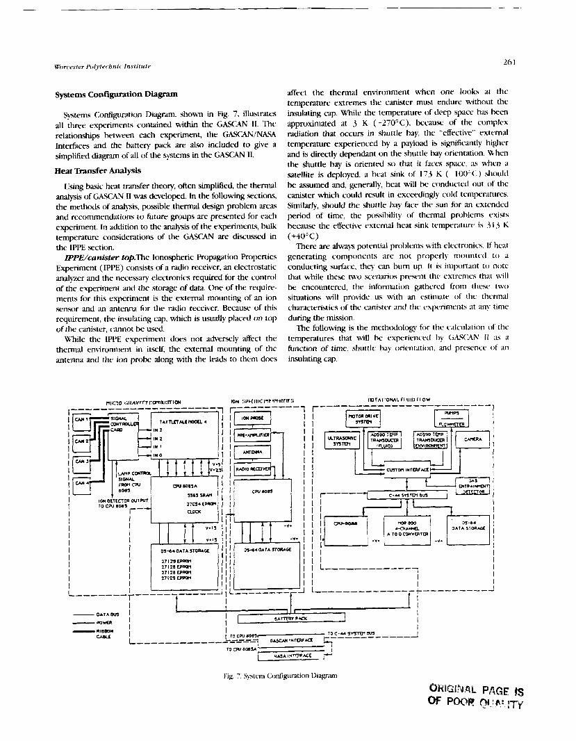
Worcester Pol.ytechnic Institute 26 1
Systems Configuration Diagram
Systems Configuration Diagram, shown in Fig. 7, illustrates all three experiments contained within the GASCAN 11. The relationships between each experiment, the GASCAWNASA Interfaces and the battery pack are also included to give a simplified diagram of all of the systems in the GASCAN 11.
Heat Transfer Analysis
Using basic heat transfer theory, often simplified, the thermal analysis of GASCAN I1 was developcd. In the following sections, the methods of analysis, possible thermal design problem areas and reconlmendations to future groups are presented for each experiment. In addition to the analysis of the experiments, bulk temperature considerations of the GASCAN are discussed in the IPPE section.
IPPE/canister top.The Ionospheric Propagation Roperties Experiment (IPPE) consists of a radio receiver, an electrostatic analyzer and the necessary electronics required for the control of the experiment and the storage of data. One of the require- ments for this experiment is the external mounting of an ion sensor and an antenna for the radio receiver. Because of this requirement, the insulating cap, which is usually placed cm top of the canister, cannot be used.
While the IPPE experiment does not adversely affect the thermal environment in itself, the external mounting of the antenna and the ion prohe along with the leads to them does
affect the thermal environment when one looks at the temperature extremes the m i s t e r must endure without the insulating cap. While the temperature of deep space has been approximated at 3 K (-27O0C), becausc of the complex radiation that occurs in shuttle hay, the "effective" external temperature experienced by a payload is significuitly higher and is directly dependant on the shuttle bay orientation. When the shuttle bay is oriented so that i t faces space, as when a satellite is deployed, a h a t sink of 173 K ( 10O0(:) should be assumed and, generally, heat will be conducted out of the canister which could result in exceedingly cold ternpcratures. Similarly, should the shuttle bay face the sun for an extended period of time, the possibility of thermal problems exists because the effective external heat sink temperature is 3 1.3 K (+4OoC)
There are always potential problems with electronics. If hrat generating components are not properly mounted to a
- -
conducting surface, thcy can bum up. It is important to note that while these tu.0 scenarios pre,scnt the extremes that will be encountered, the information gathered from thew two situations will provide us with an estimate of thc thcrnml characteristics of the canister and thc cxperimcnts at any timc during the mission.
Thi following is the methodology for thc calculation o f the temperatures that will he experienced by C;hS<j\N I I ;IS a function of timc, shuttle bay orientation, and prcwncc of an insulating cap.
'I' I

262 Proceedings oJ tbe NASAKXRA Adtxanced Design Program 6tb Summer Conference
Bulk GASCAN I1 Tempemhue Calculations In order to determine the temperature of GASCAN 11 as a
function of time and shuttle bay orientation, the following nitdel was taken from Appendix A of the Get Away Special (GAS) Thermal Design Summary. The following infomation represents the internal temperature of GASCAN I1 as a function of time for different shuttle bay orientations for an insulated m d uninsulated GASCXN 11. It is important to note these temperatures are bulk temperatures for GASCAN I1 and d o not represent the temperature of any individual component. The basic assumption of this analysis is the entire GAS canister is considered to be one thermal mass with the same temperature at any spot in the canister. Obviously temperature variations uill exist both from the outside to the inside of the canister as w l l as the areas around heat generating components.
The resulting differential equations were solved using the ASDEQ, a user friendly, difTerential equation solver from the Engineering Department of LiSMA. West Point. The equations are modeled with block diagrams similar to analog computer wiring diagrams. The equation and the resulting ASDEQ block di.dgr.rn1 are shown in Fig. X. After input of the blocks into the p r c v m , A.I)EQ solves the equation5 using a fourth order Runge-Kutta scheme and presents data in column or plot formats. Plots of the averdge GA!!AN temperature for three orientations using insulated and uninsulated configurations are shown in Figs. 9, 10, and 1 1.
For an Earth orientation, the uninsulated GASCAN reaches an equilibrium temperature of 15OC in 70 hr. In comparison, thc insulated model docs not reach its equilibrium tempera- tllrc of 5°C: even after 150 hr. Similarly, in the sun orientation the un ins~~la ted GASCAN reaches equilibrium with the environment after ($1 hr at a temperature of 30°C The insu- lated canister approaches its equilibrium temperature of 40°C: aftcr I LO hr. Finally in analyzing the space orientation, one sees even after 150 hr neither the uninsulated nor the insulated (;kS('AN reach their respective equilibrium temperatures of - 1 10°C and 100°C. The uninsulated canister does, however, c(wI off much more rapidly and a long duration in this orientation will p c ~ problems for (;ASC9N 11.
In all sets of data, there is a "hunlp" which exists from T+ 15 until 7'+30. This increase in temperature is due to the operation of the experiments. One i-an see a direct correlation het\vren this "hump" and the power requirements for the canister.
Ir is important to note these calculations assume a shuttle lifioff and subxquent bay orientation immediately after the shuttle is in space. Combinations of these orientations will exist in rcality; therefore, the <;A!TXN may already be at equilibrium in, say, the Earth orientation and then change to a space orientation. This would lead to an initial temperature of i0<: instead of the 27°C modeled here, therefore, reducing the time necessary for the GASCAN t o reach critical temperatures. Thew represent extremes of what could happen to the payload during the shuttle fight.
Thermal Analysis: Microgravity lgnition Experiment I h e Microgravity Ignition Experiment consists of four
i~iindrical canisters each containing a heat lamp, ion detector,
where:
A Surface Area C. Average Specific Heat 1 Total Mass ~ , d Internal Heat Generation Ti EnvironmentaI Temperature Tz Mean GASCAN Tempvature t T i e c Effective Emittance a Stephan-Boltzmann Constant
Valuea of Environmental Temperature, T, Viewin Uaiarul.rcd
Values of Effective Emittance. e 0.06s
ASDEQ MODEL
Fig. 8. Thermal Equation and ASDEQ Block Diagram
o l L h : ~ : l n : ~ : ~ : L m : u : ~ : ~ : n ~ J 0 IS JO 4s oa 7s oo 10s I= I= trn
TIME (HOURS) - SUN I N S U L R l E D - S U N U N I N S U L A T Y D
Fig. 9. Thermal Responx for Sun Viewing

Worcester Polytechnic Institute 263
x -10 '
- m 2 ' m : ' * : ~ ~ : - i : ~ a ~ o : n , o IS JD u a ~5 QO 10s. m IS lea
TIME ( H O U R 3 - INSULATLD - L A n U U N l N S U L A t m
Fig. 10. Thermal Response for Earth Viewing
7 T M P CCELSI US) 4 0 r I
. . . . . . . . . . . . . . . . . . . . . . . -12ol o IS 50 4s a 7s w 1 la, IS l a
TIME (HOUIZ)
Fig. 11. Thermal Response for Space Wewing
and pressure transducer, as well as material that will be ignited. A custom designed control card, and a Tattletale computer will be used for the control of the experiment as well as data storage. The two major thermal design concerns for this experiment are the presence of four 250-W lamps and the ignition of the combustible material in each of the canisters. Both the lamps and the heat released from the ignited materid will cause locd hot spots. Analysis of these areas will provide information on the thermal. environment of the experiment and its interaction with the other experiments in GASCAN 11.
The combination of the lamps and the ignited material will generate heat within each container that could be radiated throughout the compartments the containers are placed in. The electronics for this experiment, primarily the computer component.., were determined to generate a minimum amount of heat, which for this analysis is neghgible.
The Microgravity Ignition Experiment involves the heating and combustion of a cellulose material inside an aluminum container. The lamp in each of the four canisters will be on for a t'naximum of 30 sec. It must be determined if for this period of time the temperature rise of the outside of the aluminum chamber will be a safety concern.
The analysis of each individual canister will determine the amount of heat the immediate outside environment must reject from the radiating body (the combustion chamber) assuming
all of the heat generated (from the 250-W lamp and combustion of material) will be radiated through the chamber. Since there is no convection, and conduction is considered to be minimal, this will represent a worst case scenario. The worst case assumptions used are (1 ) steady state conditions; (2) convection and conduction is minimal; and (3) all of the produced heat is immediately transferred to the environment by means of the aluminum chamber. The heat generated, Q, for 30 seconds inside the chamber is: Q,,,ld=10285 J which results in a temperature rise of the chamber of 16" R.
ErlTpt3nrpntal resub for cornbudon cbamber. Once the approximate temperature rise for the outside of the com- bustion canister was established, and the components to the microgravity ignition experiment were machined and as- sembled, a test was performed to determine if the temperature rise calculations were accurate. The experiment was con- ducted with a thermocouple attached to the outside of the combustion chamber to determine the actual temperature r i x due to the heat created by the 250-W lamp for a period of 30 xc.
The results of the experiment yielded only a 4" temperature rise outside of the chamber at the end of the allotted time period. This would support the assumption that there is a minimal temperature rise outside of the combustion chambers. The ditference between the analysis and the actual temperature rise is likely because the actual heat release from the paper was very low. Also, the paper mount is an additional mass inside of the combustion chamber and is not considered in the analysis.
Heat Transfer Analysis: Rotational Fluid Flow Experiment
The rotational fluid experiment is the third experiment in the GASCAN I1 cylinder. The experiment will be isolated from the rest of the GASCAN, in that all of its equipment will be located within the rotating structure. The power supply and interface connections will be the only connections outside the rotational area.
The experiment has possible thermal problems that need to be addressed. The first problem concerns the isolation of the experiment from the rest of the GASCAN. Unlike the other experiments, this experiment is designed so that its interaction with the rest of the canister is minimal. This configuration was chosen to allow smoother rotation of the platform, with less chance of interference from the other experiments. Although this is the desired design, it may create a critical thermal problem. Energy may need to be channelled to or hom the experiment to prevent overheating or keezing.
When discussing the channelling of energy, one must realize that in microgravity there is very Little natural convection. The amount of free convection is directly related to the gravita- tional force present. Therefore, in space the amount of free convection will be very close to zero. This prediction is valid for the GASCAN only when the rotational flow experiment is not in operation. During its operation, the initial speed of the platform will create an outer acceleration of approximately 2 g. This will directly affect the convective coefficients and the rate of convection. By doubling the gravitational force, the

264 Proceedlm~s 01th NASA/USRA Advanced Design Program 61b Summer Conference
Grashof number, Nusselt and Rayleigh numbers will be kreased This increase will raise the rate of free convection at the initial rotation speed in the e q d m e n t .
The second potential problem area is the pump and motor- drive systems. With properly instrumented Earth-based t- the pump system is not expected to be a problem. However, the temperam within the flow experiment compartment must not exceed the acceptable operating temperature spectmm of the pump, which is 2 10°E
The motor-drive system is not anticipated to be a problem over the operating time of the experiment. Initially the motor will be brought up to full power. As the experiment continues, the motor speed will be decreased, thereby decreasing heat generation.
Other areas of interest are the beanngs in the rotational hub, the camera system, and the viscosity of the fluid The latter is not anticipated as a problem by the rotational flow MQP team. The viscosity of the fluid remains Eairly constant over a wide range of temperatures. The bearings on the other hand may present a problem. If they experience a high degree of Eriaion while in microgravity, heat will result. This heat would then be conducted outward increasing the platform temperature.
Finally the camera system presents a potential problem. The problem does not lie in heat generation, but rather energy absorption. The critical area is the ilhn. Most films can operate
in a temperature spearurn of -10 to 40°C. If the rotational compvtment will not be in that temperature range, either an impmrd thermal design or alternate photography methods w be necessary.
Computer Thermal Anatysls
UlthUeIy, the thermal design of the GASCAN will requite a complete thermal anzlysls, which will show if any of the expedmmts inside the canister will due to temperature extrema.
In order to calculate temperature distribution versus time, a simulation program is needed that keeps track of time varying situations such as ambient conditions and power dissipation. nK program S S m (SimpWed Space Payload Analyzer),
which was provided to previous groups, not only solves transient problems but also pmides view faaors. Given the material properties, geometry, power dissipation and orbital orientation, S S m will allow calculation of temperatures and view factors for each thermal node at specified time intervals. S S m can take up to 999 surfaces and 600 thermal nodes.
It is our recommendation that followon design teams pro- ceed with the full thermal analysis using S S m or similar analysis programs. Paniahr attention should be paid to those potential thermal problems identified by this design team.

Aeronautics Projects


AUBURN UNIVERSITY
bur design projects were completed at Auburn University this year under sponsorship of the N W U S R A Advanced Design Program. These projects are summarized below. Three of the topics were suggested by Mr. Shelby J. Moms, NASA mentor at Iangley Research Center, and one was chosen from the AlAA design competition topics. The topics were (1) design of a high-speed civil transport; (2) design of a 79- passenger, h@-efticiency, commercial transport; (3) design of a low-cost short-takeoff vertical-landing export fighter; and (4) design of an ozone monitoring vehicle.
HIGH-SPEED CIYLL. TRANSPORT
The High Speed Civil Tramport (HSCT) shown in Fig. 1 is designed to carry 300 passengers at Mach 3 at an altitude of 70,000 ft and have a range in excess of 6000 n.m. Three major areas of concern were configuration, materials, and propulsion.
The primary goal in configuration design is to minimize drag while maximizing lift. Two wing configurations were consi- dered: a variable-sweep wing and a double-delta planfom. The double delta was chosen because of the weight and complexity penalties of the variable-sweep wing. The wing has an area of 9556 sq ft and an aspect ratio of 1.41. Inboard sweep is 85' while the outboard panel is swept 65". The airfoil is a double wedge airfoil with 5% thickness.
The fuselage is 300 ft long with a diameter of 15 ft. For stability purposes a fight trim fuel tank is located forward of the aircraft center of gravity beneath the passenger compartment.
The HSCT incorporates a vertical tail but no horizontal tail.
Materials
The HSCT will be constructed almost entirely of advanced fiber-reinforced composite materials. Driving forces are the abilities of composites to handle the severe thermal effects induced at Mach 3, and the high strength- and stiffness-to- weight ratios required to keep the weight down. High- temperature area. will use carbon/carbon composites while graphite/epoxy composites will be uxd wherever possible to reduce cost. Regions susceptible to erosion due to collisions - with microscopic materials will be coated with silicon carbide.
Propulsion
Three highly promising engine confipxtions have been considered: the variable stream control engine (V.KE), the double bypass engine (DBE), and the supersonic through-flow fan engine (m). The STFF was chosen because of its lighter weight and better performance over the various flight regimes. The STFF engine concept differs from conventional turbofan designs because the airflow at the fan is supersonic. A schematic of the STFF is shown in Fig. 2. Directly aft of the fan is the engine core inlet. At this point some of the airflow is bypassed while the rest enters the core inlet and is diffused
+ r t to subsonic speed before reaching the compressor. Weight saving. are seen in the STFF engine in three main
areas: the shorter inlet, the simpler single-stage fan, and a ' lighter, simpler nozzle. The total engine weight savings over
the conventional turbofan is estimated at about 31%. A Fig 1. Basic Configuration of the HSCT supersonic transport with a gross weight of 760,000 1b is
PRECEDING PAGE BLANK NOT RLMED
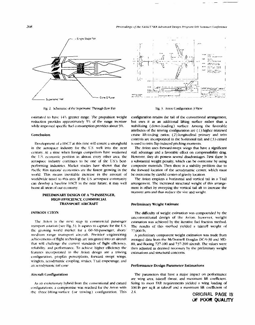
/- - Single Stage Fan
I (.I,.
1
,'
I I, ,
<., ,.,," .,.. , . -,, .r I
1 .? ,,,- \::::-:..-::-::::::::: .-..-. :::::-----. :A ! ,, ,mwp'~~ -1
--i b:;'": r
I I
:~,FZ-.X=$~-~,, -a3 ~~yj~jvic~~~pu~ t 1 ., .,- . - " ' L L - - ~ J . - Z -3 - A i l l l i i l n : I ~ , , < " 7
,, ..,- ". , - ~., . ,,, "I""" -- ,.,, . .,, - '" - . - - - , w 8 , . J'--.l..;j-i:jy
Fig. 2. Schematic of the Supersonic Through-flow Fan Fig. 3. Akion Configuration 3-Mew
estimated to have 148 greater range. The propulsion weight reduction provides approximately 5% of the range increase while improved specific fuel consumption provides about 9%.
Conclusion
Dc~eloprncnt of a HSCT at this time will ensure a stronghold in the aerospace industry for the US. well into the next century At a time when foreign competitors have weakened the IT.S. economic position in almost every other arra, the aerospace industry continues to k one of the C!.S.'s best- performing industries. Markct studies have shown that the Pacific Rim nations' economies rue the hstest growing in the world. This means inevitable increase in the amount of worldwide travel to this area. If the U.S. aerospace community can develop a b ~ w l i n e H W in the near future, it may well btx)st all areas of our economy.
PRELIMXNARY DESIGN OF A 79-PASSENGER, HIGH-EFFICIENCY, COMMERC W
TRANSPORT AIRCRAFT
' lhc Avic~n is thc next srcp in commercial passenger tr.mspon akiation (see Fig. 3) . It aspires to capture for the 1i.S. thc growing worltl market for a 60-90-passenger, short/ medium range transport aircraft. Premier engineering achic~cments of flight technology are intcxnted into an aircraft that will c.hallcngc the current standards of flight efficiency, reli~bilit).. rmd pcrtormrancr. To achieve higher efficiency the fcaturcs incorporated in thc Abion design are a triwing configuration, propfan powerplants, forward swtp wings, ainglcts, aertxtyxan~ic coupling, str&cs, T-t;lil empennage, and ;~n acrtdynamic tail cone.
configuration retains the tail of the conventional arrangement, but uses it as an additional lifting surface rather than a stabilizing (down-loading) surface. Among the favorable attributes of the triwing configuration are ( I ) higher trimmed cruise lift-to-drag ratios; (2) longitudinal primary and trim controls are incorporated in the horizontal tail; and ( 3 ) canard is used to trim flap-induced pitching moments.
The Avion uses forward-swept wings that have a sigruticant stall advantage and a favorable effect on compressibility drag. However, they d o poses5 several disadvantages. Fitst there is a substantial weight penalty, which can be overcome by using composite materials. Then there is a stability problem due to the forward location of the aerodynamic center, which must be overcome by careful center-of-gravity location.
The Avion employs a horizontal and vertical tail in a T-tail arrangement. The increased structural weight of this arrange- ment is offset by sweeping the vertical tail aft to increase the moment arm and thus reduce the size and weight.
Preliminary Weight Estimate
The dficulty of weight estimation was compounded by the unconventional design of t h e Avion; however, weight estimation was achieved by the iterative fuel fraction methcd. The results o f this method yielded a takeoff weight of 77,000 Ih.
A preliminary component weight estimation was made from averaged &ta from the McDonneU Douglas DC-9-30 and MD- 80, and Boeing 727-100 and 737-200 aircraft. The values were then adjusted as deemed necessary by the preliminary weight estimations and structural concerns.
Performance Design Patameter Estimations
Aircraft Conflgul-ation The parameten that have a major impact on performance are wing area, takeoff thrust, and maximum lift coefficient.
As w o l u t i o n q hybrid from the conventional ;md canard Sizing to meet FAR requirements yielded a wing loading of configurations. a compromise um reached for the Avion with 100 1h per .q ft at takeoff and a maximum Lift ccxfficient of the thrcc-1ifting.surFace ( o r triwing) configuration. This 2.4. QRIGSNBL PAGE IS

Propulsion System Integfation
Propfans are one of the most promising dwelopments for raising propulsive efficiencies at high subsonic Mach numbers. Demonstrations of this new technology on test aircraft have shown that propfans are clearly superior to current turbofan engines in the arc- of efficiency while still meeting rigid FAR requirements. Two 12,500-lb thrust engines will be used.
After careful consideration, the decision was made to mount the engines at the rear of the fuselage on pylons. This position alleviates the ditticulties of exhaust and slipstream interference while maintaining excellent accessibility of the engines for maintenance and repair.
Propfan propulsion is still an evolving technology. Currently, there are no propfans that meet the thrust and configuration requirements of the Avion; therefore, it is assumed that a power plant will be dweloped for the Avion.
Conclusions
research and analysis, a final design for the supersonic STOVL aircraft (the Gremlin) was achieved (see Fig. 4).
The major design features of this aircraft are a. follows: 1. Two seats for reduced workload and reduced vulnerabil-
ity, as well as the ability to be used a5 a trainer. 2. Improved Pegasus-type, four-poster, low-bypass turbofan
engine. 3. Elliptical under-fuselage air intake for efficient airflow at
high angles of attack. 4. Highly swept thin wings for low wave drag at supersonic
speeds. 5. Folding w-ings, with folded semispan of 10 ft to reduce
storage space. 6. One-piece acrylic bubble canopy for excellent crew
visibility. 7. Avoidance of complex curvature to reduce fabrication
costs. 8. Incorporation of easy-access panels to simplify
maintenance.
The Avion has evolved from its initial conception into a Methods of Analysis promising aircraft design. However, there are .several areas that need further attention and were not addressed due to time Many analyses of the systems comprising the Gremlin were constraints. Some of these areas are ( I ) control surface sizing, performed during the design period. An initial analysis of most (2) landing gear sizing, (3) dynamic stability and control systems was performed using either historical data or rule-of- analysis, (4) internal structural design, and (5) aircraft systems thumb guesses. The purpose of these initial analyses was to (e.g., fuel, hydraulic, electrical). provide a basis for more detailed analyses that followed.
DESIGN OF A LOW-COST SHORT-TAKEOFF VERTICAGL4NDING EXpoRT FIGHTER/ATTACK A I R C m
In response to the need for a supersonic short takeoff and vertical landing (STOVL) aircraft, AIAA has sponsored a request for proposals (RFP) for a low-cost aircraft meeting these requirements that would be suitable for export and would fill the dual role of a fighter/attack aircraft. These requirements pose .several unique design challenges.
Unique Problems of STOVL Design
Since the cost of an aircraft is a function of the amount of new technology that is involved in its development and construction, it is obvious that it will be a major challenge to keep the cost within the range of "low cost." Because of weight minimization needed for vertical flight, lightweight and oftentimes expensive exotic materials will be needed. Also, a new generation of vectored thrust engines will have to be developed since there are no engines on the market that will produce the performance required. One method to contain cost, however, is to use existing avionics packages.
Final Design
After consideration of the many complex design problems concerning ST<>\?. aircraft, and after a considerable amount of
GREML l N
Fig. 4. Gremlin 3-Xew
ORIGINAL PAGE IS OF POOR QUALITY

18s of the lVASA/f,SRA Advanced Design Program 6 th Summer Conference
Main Systems
I h c n ~ l n ystems of the Gremlin supersonic STOM. aircraft ;Ire as follo%s:
At~ionics. In order to reduce costs, current production systenis mill be employed. Since the F-18's dual-role mission is very sinlilar to that desired for the Gremlin, its avionics systems will be used.
Fuel system I h c fuel gstem is Itrated as near as possible t o the aircraft's center of gravity. A disadvantage of this situation is the proxinliv of the fuel tanks to the engine. This wlnerdhility c;in bc reduced by the use of self-sealing fuel tanks and an inert gas to fill voids t o reduce the chance of cornbu\tion.
Landing gear. '[he landing gear system consists of two sets of main fuselag gear designed to absorb most of the stress of impact, m d two outbo;ud g a r s designed to maintain the balance and stability o f the aircraft during vertical flight landing\.
Weapons. ' lhc weapons c d e d by the Gremlin will be c.ontrollcd by either the front o r rc-ar pilot. Wig t ip launching rails can carry the AIM-9L Sidewinder missile, and the hardpoint closest to the fuselage on either wing will c~ thrcr Mk-Xt 500-lb 1n)rtibs on a nii~ltiple ejector rdck. Another hardpoint will bc Itrated farther out on either wing for additional stores.
Performance Requirements
In order to nicct the RFP requirenient for c n ~ i s c at a Mach number of I .i for 250 nautical miles, a slight$' more powertirl Pegasus-qpe engine is required. This engine will allow bcrtical takeoff in the air-superiority configuration and requires a tikcoff roll of o1i1y LOO fi in the ground support configur~tion. thus ha t ing the KFI' rc*quirernent of a 300 ft takeoff roll.
Cost and Management
The AIAA RFP expeczed a production run of 500 aircraft. By having a large production run the average cost per aircraft is reduced. These aircraft will be produced over a period of five years. Before produczion W n s , one year will be spent in research a n a l ~ i n g test data. Production then begu-~~ at the start of the second year by manufacturing two Gremlins each of the first four months. The first four aircraft will be for flight tests. Evaluation of the test flights will begtn the thud month of production. After testing is completed, full-xde manufac- turing of 10 Gremlins per month will occur for production months 9 through 54. As the production schedule nears completion, the rate of production will decrease to allow for personnel to transfer to new programs.
The average cost per Gremlin aircraft for a production run of 500 aircraft was calculated to be $18.2 million (1990 dollars).
Conclusions and Recommendations
This design group has concluded that the low-cost Gremlin supersonic STOVI. fightedattack aircraft is a viable design. It is expected that the engine technology required for this design will be available by the projected delivery date of 2005. Although the aerodynamic evaluation is not complete, the preliminary analysis predicts very promising performance.
The potential market for such an aircraft is growing. The large nunlber of Hamers and Hornets sold to other countries is an indication of this trend.
HIGH-ALTITUDE OZONE RESEARCH BALLOON
Introduction Material Selection
The combination of vertical flight and o ther high- perfornlancc requirenients suggested the use of exotic materials. klowrver, the RFP also required that the S'I'OVl. dcsign he "low cost" to Ix suitable for export. The Harrier A\'-8B u.ws approximately $0'2)'!1, composites throughout the aircrdft structure. Many of the experiences learned in the design p r c ~ . c ~ s of the Hamer could ht. applied t o the Gremlin. However, the supersonic warlire o f the Gremlin requires that tempcrriturc liniitations o f composites be talcen into account.
rUuminuni is still thc material of choice when constructing airh-mics and wing In)xcs. Its rclativc low cost and ax. of fabrication make i t an ideal material for restricting the cost of this ; i i r c r i . ~ ~ t a n i u m , although expensive and complicated to m:tchine, will IN used in the high-tenipcnture arras of the aircraft. such ;IS around the engine nozzles.
(hecdl, thc weight of the (;remlin is expected to k around 35':) composite materials. (.0"%, traditional aluminum alloq?;, m d thc reniaining miount various specialized materials such as hi@-strength steel, titanium, and high-strength plastics.
The ozone layer shields the Earth from harmful solar radiation that can cause skin cxncer, destroy acids in DNA molecules, and have harmful effects on world climate and vegetation. Kex.arch has indicated that a seasonal depletion of ozone concentration exists over Antarctica. Can we conclude that this depletion is a natural occurrence, o r are w e witnessing a decline in ozone concentration that will appear later in other regions of the world?
Because 97% of the ozone molecules are located in the stratosphere, analpis methods are extremely expensive, time consuming, and inadequate. Moreover, atmospheric scientists -are concerned with the possible further destruction of the ozone concentration due t o the chemical contaminants released from ozone monitoring vehicles. These concerns have caused a renewed emphasis in the development of high- altitude ozone research balloons. However, limited flight duration and lack of vertical and lateral control have severely limited the widespryad acceptance of high-altitude research balltmns as the primary method for ozone observation and analysis.

Auburn Cinit>ersit.y
Current Limitations
Ozone research requires a vehicle capable of delivering and supporting a scientific payload at ,an altitude above 25 km. Also, ozone research analysts emphasize the need for variable altitude profile sampling in order to obtain a representative model of ozone concentration. In addition, a long flight duration is desired in order to reduce production costs and increase the amount of data collected per flight.
Presently used high-altitude ozone research balloon.. are very limited in flight duration. They maintain their altitude by venting helium and dropping ballast. Thus, the length of the mission is limited by the amount of reserve helium and ballast p that is initially carried on the support structure of the balltwn.
During the day, the balloon is heated by solar radiation' impinging on the surface of the balloon film. As the temperature of the film increases, the temperature of the helium within the balloon increases due to natural convection. As a consequence, the helium expands and the balkwn riscs. When the balloon ax-ends to an altitude above the desired sampling range, the balloon is remotely vented and helium is released. As the mass of helium is reduced the balloon descends. When the balloon descends below the minimum range of interest, the researchers cxn either rele~se ballast or perform a controlled addition of reserve helium.
This cycle of venting and ballasting continues throughout the mission. After dtpletion of ballast and reserve helium, the mission must k terminated. Currently, average flight times for these types of zero-pressure balloons are three to seven days.
HAORB Design Improvements
In order to lengthen flight duration, the conventional method of vertical control must be improved. The High Altitude Ozone Research Balloon (HAORB) is designed to provide this improvement. It will ax-end at a slower rate than its conventional counterpart. Consequently, the venting and ballasting process will occur less frequently and the mission duration will be dramatically increawd.
The focus of the HAORB design is the control of heat transfer to the balloon film. The polyethylene balloon film is continually heated during the day by direct and indirect solar radiation along with the reflected radiation from the Earth. As the temperature of the balloon film increases, the helium temperature and its volume subsequently increaw. This results in a net upward acceleration of the HAORB that is equibalent to its conventional counterpart. The vertical speed of the HAORB will be controlled by removing the heat that is transferred to the balloon film. By limiting the increase in balloon film temperature, less heat is transferred to the helium. Thus, vertical control is achieved by the u x of a cooling hytem on the HAORB.
Cooling System Operation
HEAT
DUCT
TRANSF
C O O L I N G A I R INTfiYL
YY I!
Fig. 5. <:onfiguration of the HAORB at High Altitudc
The cooling .system cools both the film and the helium. Four cooling ducts are formed by sealing additional panels on the outer surface of the balloon. The four cooling ducts cover approximately one-fourth of the surface area of the ballcx)n, therefore reducing the amount of film surface in contact with the helium that is exposed to solar radiation. The forced circulation of cooler atmospheric air provided by the rotary circulation fans removes heat that nlould be transferred to the helium from the outer film.
The cooling system receives input from an accelerometer. This information is then used to determine the vertical velocity of the HAORB. As the temperature of the helium increaws, the HAORB begins to accelerate upward. When the upward velocity exceeds 0.27 m/sec, the fans are energized. The fans cause forced convection heat tmsfer Erom the film to the air. This cools the helium and reduces the acceleration. When the velocity falls below 0.2 m/sec, the fans are secured.
Results
A FORTRAN program was written to facilitate the stepwise integration of the equations describing the vertical motion of both the HAORB and a conventional balloon. The initial conditions assunle that the initial velocity and acceleration are zero, thc initial film temperature is 5 O above atmospheric, and altitude is 26 km. For the test profile conducted from 26 km to 34 km, the HAORB with additional weight of fans, batteries, and solar cells had a substantially longer (about 9 times) mission duration than the conventional balloon with the .same restrve helium and ballast.
The cooling system uses ctx)ling ducts and rotary circulation fans to maintain a balance between the temperature of the atmosphere and the temperature of the helium (see Fig. 5).


AUTONOMOUS MAIMlAN FLYING ROVER ' P J N91-18161
CALIFORNIA STATE UNMB!3ITY, NORTHRIDGE
Future solar Vtem exploration is expected to include manned missions to Mars. The success of these missions can be enhanced through detailed close encounter, precursor su~veys of the near-surface environment. A remoteky repro- grarnmable, autonomous tlying rover is proposed to extensively survey and map the martian surface environment.
A Mach .3, solar-powered, modified flying wing could cover roughly a 2000-mi range during martian daylight hours. Multiple craft, launched b m an orbiting mother ship could provide near-global coverage. Each craft is envisioned to fly at about 1 km above the surface and measure atmospheric composition, pressure and temperature, map surface topo- graphy, and remotely penetrate the near subsurface looking for water (ice) and perhaps evidence of life. Data collected are relayed to Earth via the orbiting mother ship. Near-surface guidance and control capability is an adaptation of current cruise missile technology.
The 35-km scientific payload. plus communications and control electronics, is distributed spanwise inside the flying wing, eliminating the need for a traditional fuselage and reducing structural requirements. Mission reliability and, hence, the probability of success are improved by adding a telescoping tail boom that passively enhances flight stability. h. is provided with a two-bladed propeller driven by an electric motor powered from high efficiency solar cells supplemented with batteries. Roughly 90% of the required energy comes from the Sun. The final configuration ha. a payload plus communications-to-gross-weight ratio of 80%.
In summary, a solar powered aircraft, designed to tly in the low-temperature, lowdensity, c d n dioxide atmosphere near the martian surface appears feasible. Future efforts will optimize the configuration and develop a flying prototype scaled to the Earth's gravity environment.
PAGE^^ INTENTIONALLY BtAM


CALIFORNIA STATE POLYTECHNIC UNIVERSW, POMONA
At the equator, the ozone layer ranges from 65,000 to 130,000+ ft which is beyond the capabilities of the ER-2, NASA's current high altitude reconnaissance a i r d . The Universities Space Research Association, in cooperation with NASA, is sponsoring an undergraduate prognm which is geared to designing an aircraft that can study the ozone layer at the equator. This aircraft must be able to cruise at 130,000 ft for 6 hr at Mach 0.7 while carrying 3,000 lb. of Ppyload in addition, the aircrdft must have a minimum of a 6,000-mile range. The low Mach number, payload, and long cruising time are aU constmints imposed by the air sampling equipment. In consideration of the novel nature of this pm@t, a pilot must be able to take control in the event of unfo- Wculties. Three aircraft conligurations have been determined to be the most suitable for meeting the above requirements, a pined-win& a biplane, and a twin-boom conventional airplane. Although an innovative approach that pushes the limits of existing technology is inherent in the nature of this project, the techniques used have been deemed m n a b l e within the limits of 1990 technology. The performance of each configuration is a d p d to investigate the feasibility of the project. In the event that a requirement cannot be obtained within the given constraints, recommendations for proposal modifications are given.
The recent discovery of the ozone hole above the North Pole has prompted the scientific community to accelerate its efforts in investigating man's impact on his environment. The existence of the ozone hole has brought about concern that the predictions of stratospheric scientists may come me. In 1974, two chemists from the University of California, F. Sherwood and Mario Molina, theorized that the ozone layer was being destroyed by chlorofluorocarbons. Unless the ozone depletion in the Eanh's atmosphere is controlled, radiation levels at the surface may increase to harmful levels. At the tropics, the ozone layer ranges 6rom 65,000 ft to 130,000+ ft which is beyond the capabilities of the ER-2, NASA's current high altitude reconnaissance aircraft. Therefore, to effectively investigate the ozone layer, NASA needs to develop a high- altitude aircraft that will reach altitudes of 130,000+ ft. To hasten the development of the technology and methodology required to develop an aircraft that can reach these altitudes, the NASA/USRA program has been working closely with industry and universities. Perhaps, with the data retrieved from this aircraft, scientists and politicians will be able to formulate
propulsion, and structures. After a short break, the groups reconvened during the winter quarter to decide on the best possible configurations and commence their design. The final design iteration was completed, and the final report was compiled in the spring quarter.
The three fall quarter groups were given the Request for Propod and instructed to identify the potential problems in their area of expertise. Once the problem areas were identified, possible solutions were considered and a d p e d in detail. From this analysis, the design process was established, and possible configurations were determined. The pros and cons of each configuration as it pertained to the specialty groups of aerodynamics, propulsion, and structures were collected.
At the begnnmg of winter quarter, the three most plausible designs were chosen based upon the analysis of the previous quarter. For reasons discussed later, the three configurations selected were a conventional twin-boom monoplane design, a joined-wing design, and a biplane design. The three groups were then reassembled into three new teams based upon the configuration of each individual's preference. At the same time, the team leaders from the original groups were assigned to
an emissions control plan that will diminish the rate of consult the groups on any problem areas that were investigated degeneration of the ozone layer. the previous quarter. If all the groups sacred 6rom the same
difliculty during the quarter, the consultant was authorized to DESIGN PROCESS
The 1989-1990 school year was the second in a three-year, ongoing design project geared to the design of a high-altitude reconnaissance aircraft. California State Polytechnic University, Pomona, has its yearly design sequence sepamted into three consecutive quarters. Rasically, the assignment at the beguuung of each year is to do a preliminary design analysis to determine the air& that best fits the Request for Proposal requirements.
temporarily reassemble his original team in an attempt to solve the most common and pressing problems quickly and efficiently. In this manner, the students were given the experience of working with a matrix management system on a small scale.
As the spring quarter commenced, the final configurations were set. Each group wrote a 100-page report on their preliminary design findings. These were assembled into three volumes and made available through the USRA program.
If such an aircraft is not deemed feasible, the aircraft must still be designed, with those aspects which are not approachable DESIGN SPECIFICATIONS indicated in the concluding comments. Suggestions for making the Request for Proposal feasible are also requested. During Ideally, the scientific community would like an aircraft that the fall quarter, three grqups were formed, aerodynamics, meets the following spe&cations:
PRECEDING PAGE BLANK NOT FILMED

276 Proceedings o f tbe NASA/USR4 Advanced Design Program 6th Summer Conference
RFP Spedacations
1. The cruise altitude is1 30,000 ft 2. The payload capacity is 3,000 Ib. 3. The design cruise Mach number is 0.7. 4. The cruise is a minimum of 6 hr. 5. The range is a minimum of 6,000 miles. 6. There is a minimum of one pilot. 7. The aircraft is to be designed with present technology.
These specifications meet the most optimistic demands of the stratospheric scientists. The results of previous studies have shown that Bight at 100,000 ft with a range of 3250 n.m. is possible. Unfortunately, a mlsslon at the lower altitudes would not give an accurate &mate of the chemical activity within the ozone layer at the equator. Ihe oume layer at the tropics is in the mnge of 65,000 to 130,000+ ft, as opposed to 50,000 to 100,000 ft at the mid-latitudes and 35,000 to 95,000 ft at the poles. The largest perturbulons of the ozone are eqxcted to be at 130,000 ft at the mid-latitudes. This f2ct coupled wtth an airplane's ability to follow an experimenter chosen path makes an airplane meetlng the above specifications an Ideal ozone testiq platform( I ) .
Some of the constraints on the Request for Propod are imposed by the sampling equipment, which is a mdcation of that in current use on the ER-~(*). The increase in air temperature and the dissodation in the flow cause air samples to loose accuracy as compressibility effects become sipiflcant; therefore, the Mach number must be below the transonic regime. At the same time, the low air density (0.00003211 slugs/ft3) at altitude implies low wing loadings and high wing planform areas. Figure 1 illustrates the Mliation of air density with altitude. All of these adverse effects become more
I 12 hour. 6000 mile cruise a1 130.000 ft. altitude)
I 4 hr ascent
to 130.000 f~ altitude
Total mlsslon ranse 6.000 + m~les
Number d crew Two
Fersibll~ty and Pavk~ad Requuements bkt
significant wtth dccmshg Mach number. A Mach number of 0.7 was chosen to balance the contradicting effects of compressibility and air density. The air sampling equipment also dictates the cruise time and q e . Stratospheric scientists are unable to obtain an accurate mapping of the ozone layer without extensive measurements that span a large area. The 6,000-mile range is easily accomplished within the specitled minimum time constraints. As shown in Fig. 2, the total mission time is in fact on the order of 18 hours with a 12-hour cruise. The long mission time prompted the groups to design for two pilots in order to diminish fatigue.
The present technology requirement is desirable in order to acquire the miurimum utility &om this vehicle. In mid-1993, the Cryogenic Limb Array Etalon Spectrometer (CLAES), an instrument designed to monitor the ozone layer on the Upper Atmosphere Research Satellite scheduled for launch in 1991, will become inoperational. The first Earth Observing System (EOS) sensors are scheduled to become operational in 1996, at the earliest. It is during this testing gap that the results from a high altitude aircraft will be most crucial. After the EOS comes on-line, the aircraft will be used to crosscalibrate the measurements from the EOS and ground-based sensing instruments' ).
CONFIGURATIONS
1 \ 1 The configurations considered for this aircraft are ( 1) F@ng wing, (2) Monoplane-conventional, (3) Monoplane-twin- boom, (4) Canard, (5) Joined wing, and (6) Biplane-twin- boom.
The 0ymg wing has a high aerodynamic efliciency due to the lack of a horizontal tail. However, it has the disadvantage of stability problems coupled with poor takeoff rotation. These
1 ktors rendered this design undesitable. o The monoplane with the conventional fuselage tends to be 0 '2 4 6 8 1 0 1 2 1 4
Altltod.(lt) 110'4 stable and predictable. The large wingspan required would produce excessive bending moments that a single fuselage could not counteract. On the other hand, a twin boom fuselage
Fig. 1. Air Density n. Altitude structure w d d relieve the structural loads wfiie maintaining

Fig. 3. Globd Senby
the advantages of stability and ease of analysis. The final design for the twin-boom monoplane is shown in Fig. 3(3).
A canard configuration is sImtlar to a flying wing in that it has many of the same advantages and disadvantages. No justiecation for using a canard configuration could be found.
The joined wing aircraft at k t seems ideal with Its high aerodynarmc efficiency and high structural strength. Unfortu- nately, a joined wing aircraft is not a proven design. Therefore, the extra testing may render it not cost dective. Despite this possible failure, the aircraft appears to be worth anatyLing. The three-view for this aircraft is shown in Fig. 4(4).
A twin-boom biplane is structurally sound, minimizes the span, has good propeller clearance, and has a large fkontal area Its only apparent disadvantage is the interference from the wing struts. Considering the possibility that the strut interference may not be d c i e n t to undermine the advantages of the design, this aircraft is being considered further. Figure 5 shows a three-view.
In summary, the three designs chosen for further investiga- tion were the twin-boom monoplane, the joined wing, and the twin-boom biplane. The three projects are called Clobd Senby, Icurus, and Hi-Bi, respectively.
Airfoil Design
The airfoil design criteria are high lift and low drag at cruise conditions. In addition, the rarefied flow at the cruise altitude introduces low Reynolds number aerodynamic phenomena. For this reawn, the airfoil has a tendency toward laminar separation bubbles and compressibility effects, which must be avoided. For the conventional configuration, a low pitching moment is required, but for the joined wing contiguration it is not so crucial, since the moment can be balanced with the other wing. To accommodate fuel storage requirements, a maximum thickness ratio at 10% of the chord is preferred
In general, supercritical airfoils conform to these criteria A modification of Richard Eppler and Dan M. Somers' ES989 was found to best suit the needs of all three conligurations. A computer code authored by Mark Drela called XFOIL was used to modlfy and analyze the airfoil. The code was able to tailor the pressure distribution to reduce shocks and flow separation. The resulting pressure distribution is shown in Fig. 6. XFOIL is prone to errors in integration. This manifests itself in excessive peaks in the pressure distribution at the lead@ edge and a slightly higher Mach number distribution as compared to test data for similar airfoils. However, despite these potential problems the performance characteristics of the final modification compare well with published data for similar airfoils designed for low Reynolds number
Propeller Design
Initially, XFOIL's counterpart, XROIDR, was considered for the propeller design. Unfortunately, it was found that XR(JTOR's tendency to optimize the propeller blade loading produced excessive propeller root chords on the order of 50 ft. As a result, the propellers were hand designed. 'Ihey were optimized to produce the lowest section drag coefEicients. 'Ihere were two main criteria for designing the propellers. The h t and foremost ~5 that the tip velocities can not exceed
AERODYNAMICS -+7 0.88
d
The two design drivers in the area of aerodynamics are _.__-__I /-
_i_- _ __ - ___=-< =---
==-- airfoil selection and propeller design. 9 -=----
-\
Fig. 4 . lcmus High Altitude Aircraft Fig. 5. Hi-Bi
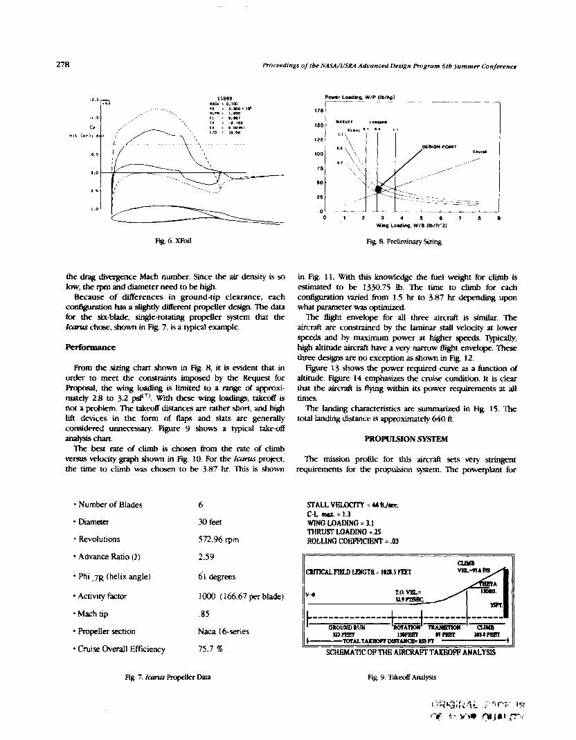
Proceedings of tbe NASA/USRA Advanced Design Program 6tb Summer Conference
Fig. 6. mil Rg. 8. Re- S i g
the drag divergence htach number. Since the air density is so low, the rpm and diameter need to be high.
Because of daerences in ground-tip clearance, each c o ~ o n has a slightly ditkrent propeller design. The data for the six-blade, smgle-rotating propeller system that the lwaur chose, shown in Fig. 7, is a typical example.
Performance
From the sizing chart shown in Fig. 8, it is evident that in order to meet the consmints imposed by the Request for Proposal, the wing loading is Limited to a range of approxi- mately 2.8 to 3.2 pd7). With these wing I-, takeoff is not a problem. The t a k d distances are rather short, and high lift devices in the form of flaps and slats are generally considered unnecessary. Figure 9 shows a typical take-off aMlysis chan. Ihe best rate of climb is chosen from the rate of climb
versus velocity graph shown in Fig. 10. For the 1cmw.s project, the time to climb was chosen to be 3.87 hr. This is shown
Number of Blades 6
Diameter 30 feet
Revolutions 572.96 rpm
Advance Ratio (J) 2.59
in Fig. 11. With this lcnowfedge the fuel weight for climb is estimated to be 1330.75 Ib. The time to climb for each c o n f i ~ o n varied h m 1.5 hr to 3.87 hr depending upon what parameter was optimized.
The Bight envelope for all three aircraft is similar. The aircraft are constrained by the laminar stall velocity at lower speeds and by maximum power at hlgher speeds. mica&, high altitude aiKTaft have a very narrow Bight emlope. These three designs are no exception as shown in Fig. 12.
Figure 13 shows the power required curve as a function of altitude. Figure 14 emphasizes the cruise condition. It is clear that the aircraft is flymg within its power requirements at al l times.
'Ihe landing characteristics are summarized in Fig. 15. The total landing distance is approximately 640 ft.
P R O ~ I O N SYSTEM
The mission profile for this aircraft sets very stringent requirements for the propulsion system. 'Ihe powerplant for
STALL V E U X T Y = U ftJmx. C-L = 1.3 WING LOADING = 3.1 THRUU LOADING =.25 ROLLING COEFFICIENT = .03
C B m C A L ~ L P Y G T E = IOa.3FPET VB14lh Hi4 Phi . 7 ~ (helix angle) 61 degrees
Activity factor 1000 ( 166.67 per blade) V4 n) ~ 1 8 8 ~
Mach tip .85
Propeller section Naca 16-series rnm 1- n m mtnw ~-~ALIAIBWTDMANCE=YT)R ---------t
Cruise Overall Efficiency 75.7 % SCHEMATIC OP THE AIRCRAFT TAKEOW ANALYSIS
Fig. 7. Icmus Rupeller Data Fig. 9. Takeoff Amdysts

California State Polytecbnic University, Pomona
4MO
4 W 0
3m
- a € 3 m
2m P i
0 : MOO
u t y (ftlr) -+ h=OK + C26k + h=S& 1m
+ h=74k + h=100k + C130k IWO
Fig 10 Rate of C h b as A Functlon of Auspeed and Altitude
0 150 -
B im- . -
Y L, 00
v.loclly (nfue)
F I ~ 13 Power Requued Curve
POWER (HP) $000
so00
4000
0 50 100 150 200 250 roo 8000
Tim. (mlnl 2000
Fig 1 1 T i e to Chmb 1000
0
-- -
-
- -
-
h- -
87 houn) z * - - f 5Q- /
160000 0 0 2 0.4 0.6 0 8 1
140000 CRUISE MACH NUMBER
120000 - REQD. POWER + M I L . POWER
h
E 100000 Fig 14 Power Optunmtion V
STALL VELOCITY = 33.85 ftJsec C-L maz = 1.3 WING LOADING =1.92 THRUST LOADING = .2 BRAKING COEPPICIENT = .1
VELOCITY (ftlr)
Fig 12 Ha-Bi fight Envelope TDVEL = a 9 RlSPXl
this aircraft must be able to operate with a low speciEc air consumption. The 6,000-mile range requirement necessitates that the powerplants have a low specikic fuel consumption to MMPEA 1167 PEA reduce the amount and weight of fuel needed to complete the LANDDIG D I S T A N ~ -26 I
mission Since the aircraft operates at subsonic velocities and -
SCHEMATIC OF THE AIRCRAFT LANDING ANALYSIS very high altitudes, the aircraft's wings are large and heavy This requires an engine that is capable of producing large amounts Fig 15 Landrng Analysis
ORlGlNAL PAGE IS
0- - '
(130 000 It in 3
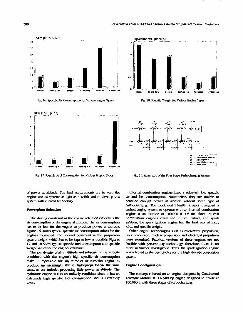
Proceedings o/ tbe NASA/L'SRA Advanced Design Program 6tb Summer Conpmnce
SAC [lb/Hp-hr] Specll lc WI. (Ib/Hp) 35 I =
- - - - 1
SG
I 25 .
10 I
I5
I0
- 7 I
Turboprop hrbolet Wmrar~nm
Fig. 16. Specific Air Consumption for Various Engine T)pes Fig. 18. Specific Weight for Various Engine T)pes
SFC Ifb/Hp-hrl
Fig 17. Spc-itic Fuel Consumption for Various Engine T)pes Fig. 19. Schematic of the Four Stage b h h r g h g System
of power at altitude. The M requirements are to keep the engine and its systems as light as possible and to develop this system with current technology.
Ibverplant Selection
The driving constraint in the engine selection process is the air consumption of the engine at altitude. The air consumption has to be low for the engine to produce power at altitude. Figure 16 shows typical air consumption values for the engines examined T%e second constraint is the propulsion system weight, which has to be kept as low as possible. Figures 17 and 18 show typical spedfic hKI consumption and specific weight values for the engines examined
The low density of air at altitude and subsonic cruise velocity combined with the engine's high specitic air consumption make it mpomible for any turbojet or turbofan engine to produce any meaningful thrust. lbhoprops follow the same trend as the turbojet producing little power at altitude. The hydr;lzine engine is also an unlikely candidate since it has an extremely high specific fuel consumption and is extremely toxic.
Internal combustion engines have a relativeiy low speci6c air and fuel consumption. Nonetheless, they are unable to produce enough power at altitude without some type of turbocharging The Lockheed HAARP Project designed a turbocharging system to operate with an internal combustion engine at an altitude of 100,000 ft. Of the three internal combustion engines examined, diesel, rotary, and spark ignition, the spark ignition engine had the best mix of sac., sf.c., and specific w-t.
Other engine technologies such as microwave propulsion, laser propulsion, nuclear propulsion, and electrical propulsion were examined. Practical versions of these engines are not feasible with present day technology; therefore, there is no merit in further investigation. Thus, the spark ignition engine was selected as the best choice for the high altitude propulsion system.
Engine Codgumdon
The concept is besed on an engine designed by Continental Teledyne Motors. It is a 500 hp engine designed to cruise at 100,000 f t with three stages of n u k & w p g

California Slate Aolytecbnlc Unfvffsity, Pomona
Turbocharger Type Radfal Over All Pressure Ratlo 432:l 1st Stage Pressure Ratlo 3:l 2nd Stage Pressure Ratlo 4:1 3rd Stage Pressure Ratio 6:l 4th Stage Pressure Rcrtlo 6:l Maxlmum Mass Flow Rate 120.5 (Ib/mln) Maxlmum Pressum
Obtained at 130,000 11. 1788 (psfa) Inlet Slae 8.7 (11-2) Syakm Welght 900 (lb]
Fig 20. Specifications of the Four Stage -er System
Englne Type Number 01 Cyllnderr Cy llnder Arrangement Bore ond S l m b Dlrplacement Comprvrslon Ratio Wldth a n d Helght. Engine Wldth a n d Height, Inrlalled Length a n d Frontal Area. Englne b n g l h a n d Frontal Area. lnst. Englne Welghl Total Weight, Installed Welght/Honepower f u e l Grade SFC. Crulre a n d Max Power SAC. Crul8e a n d Max Power
Crulse Power Max Power
I t Spark lgnlllon 8 Horlwnlal Opposed 525 In a n d 6.5 In 1125 cu In 1O:l 38 In a n d 29 25 In 41 In a n d 59.8 In 33.6 In a n d 7.7 rq It 696 in a n d 164 rq 11 11177 Ib 2077 Ib 189 lb/Hp 100 L L 0.357 a n d 0.383 lb/Hp-hr 5.484 a n d 5.45 Jb/Hp-hr
961 Hp/3900 RPM 130k 11 1194.9 Hp/425ORPM S.L. 1100 Hp/4250 RPM 130k I1
Fig. 2 1. Performance Specfications, 960 hp Engine
The engine designed for this project uses four stages of t w k d m g q to allow it to operate at a higher altitude. ' b h d x q q was selected over superchargrng so that the minimum engine power is required to run the engine. Figure 19 shows a schematic of the system. Figure 20 tabulates the specitlcations of the system. 'Ihe turbochargers are each composed of a radial compressor and a radial turbine. Each of the four turbocharger stages are intercooled with a crossflow air to air heat exchanger.
The high altitude engine is arranged in a horizontal opposed con6guration to reduce frontal area and allow an aerodynamic cowlug to be fitted around the engine. The block is composed of two forged aluminum alloy pieces bolted together vertically. The crank shaft is a forged steel, eight-throw, one-piece design and is supported by 6ve purnal bearhgs. The engine has eight, 10:l compression ratio, aluminum alloy pistons displacing 1125 cu in.
The powerplant is modeled on a modified engine pro- gram''). Figure 21 shows the specifications and performance for the engine. Figure 22 gives the cycle information.
WEIGZFCS AND !TlXUCTURES
with the joint at 70% of the semi-span and graphite/epoxy honeycomb sandwich spars. The composite fiber orientation is 0, 45, 90, -45, 0, -45, 90, 45, 0. The wing codguration, wing box, shear force and bending moment diagrams are shown in Fig. 23-25. The maximum deflection is 10.4 feet at the tip of the kont wing. 'Ihe total gross takeoff weight is 4 1.200 Ib.
RELIABILITY
Figure 26 shows the results of a reliability analysis for the Global Sentry. All three aircraft yield comparable results. 'Ihe graph indicates the probability of a component h h g as a function of mission time. Generally, the mission would have to be aborted 43% of the time( lo).
CONCLUSIONS
The mission would be more likely to succeed if the Request for Proposal is modified. There is some doubt as to whether the aircraft necessary to meet the constraints can be built using present technology. This conclusion concurs with parallel an- being conducted by NASA and ~ockheed('~~).
Pressure (psll I -;-
1 ~ 0 0 ~
I
" 0 20 40 60 80 100 120 I40 160
Volume (111-3) cruise C o n d l t l o n s Displacement 1115 c u . l n
Fig. 22. Pressure vs. Volume Diagram, 960 hp Engine
Of the three contigurations, the pined wing was found to be the most structurally sound. It was modeled on N A W Fig. 23. Wing Box for Joined Wlng

Proceedings of !be NASA/USRA Adaanced Design Program 6tb Summer Conference
100
Wing Station (R)
Fig. 24. Shear Form Diagram RELFOR MISSION TIME
4- Mx + Mx wtnoback wing
S e - 8 -
5e.8-
2 e . 8 -
30
Wing Station (R)
Fig. 25. Bending Moment Diagram
Fig. 26. Reliability Analysis of the G h h i Sentry
Lisa Alemdru, the group leaders. We would also like to acknowledge the hard work of the individud team members. Our NASA sponsor George Kidwell did much to keep us on track Bob Antoniewin and many others at NASA gave their time and energy to assist us. The USRA staff gave us the opportunity to participate in the program and then taught us how to make the most of the opportunity. The Lockheed Corporation as well as Hughes Air& provided us with insight into the problem from industry's standpoiit. We were akw privileged this year to have two wonderful instructors, Professor PA. Lord and Professor C.E Newberry.
Suggested m&cations to the Request for Proposal ate as 1 "Global Stratospheric Change," NASA Conference Publication
follows: 10041, July 15-16,1989. 2. Memorandum dated July 13, 1988- To: Distribution, From: SSG/ the cruise 'Ititude 1007000 ft with possible Chief, Atmospheric Experiments Branch, Subject: Very-High-
ZOO^ to 130,000 ft. Altitude Platform Aircraft Exploratory Studies. Reply to Attn of: 2. %Lit the mission into a 6,000-mile unmanned mission W Z 4 5 - 5 / 136.
and a chow manned Won. 3. Decrease the cruise Mach number to 0.6. These modifications should act to decrease the span which
in tum makes the aircraft manufacturable and increases suuctulal integrity. The present spans, which range h m 400 to 450 feet, render it impossible to land at most airports. It would be more reasonable to design for a 150-ft-wide runway with four foot-htgh obstacles located 20 ft off the runwxy. Furthermore, the reliability will increase with the decrease in mission time. The four-stage, rubockqed propulsion system could be brought down to three stages, which are generally considered possible. Some work has been done on a three- stage engine in recent years but none on the four-stage.
Cronin. Donald L and Selberg, Bruce I?, "Aerodynamc-Structural Study of Canard, Dual Wing and Conventional Wing System7 for General Aviation Applications," NASA CR- 172529, February, 1985. Wolkaitch, J., "The Joined Wing: An Overview," Journal of Akrmft, V&me 23, Number 3, March 1986, p. 161 -1 78. Drek Muk. XFOlL and XROTOR software, M E Miley, SJ., "A Catalog of Low Reynolds Number Airfoil Data for Wind M i n e Applications," Rockwell International Corporation, Subcontractor No. PN12781-W, Februaty 1982. Roskam, Jan, Aitphne Design Pmt I: &litninmy Sizing of Akphnes, RRoskam Aviation and Engineering Corporation, Ottawa, Kulsas, 1985. Benson, RS., and Whitehouse, N.D., lnt& Combustion Engines., Pergamon Press Inc., New York, 1979. "High Altitude Atmospheric Research Platform, Information Package," The Lockheed Corporation, Burhank, California, February 1990. Myer, Peter, Hughs Aircraft Corpomtion.
The authors, Renee Anna Yazdo and David Moller, thank Chris Higa, Tai Kim, Hector Lopez, Michael Medici, and Mona-
A DESIGN SUMMARY N91-18163 CALIFORNIA POLYTECHMC S'JXI'E UNIVERSITY, SAN LUIS OBISPO
The systems approach to engineering design demands that any factor that may have some bearing on the project be identitied, evaluated, and allowed to influence the design. The extent of this influence needs to be determined through a logical analysis of all competing factors. To this end a design group was assembled to tind and research criteria relevant to the design of a California Comdor Transportation System. The efforts of this group included defining the problem, conducting a market analysis, formulation of a demand model, identifica- tion and evaluation of design drivers, and the systematic development of a solution. The results are summarized in the following pages.
The California Comdor contains a complex, expanding system of transportation, with requirements set by a wide variety of system users. The corridor is defined as a region where sigruficant demand for transportation exists, along a line between major cities. This definition incorporates transporta- tion demands both within and surrounding these cities. For the purposes of this study, California was selected, because of its intrinsic, generic qualities, and four of its major cities, Sacramento, San Francisco, Los Angeles, and San Diego, for the axis. The users are loosely categorized under the headings of commuters, transients, miscellaneous travelers, and freight, while the types of trips they take are categorized as capillary trips, intra-corridor, and inter-corridor.
The problems of the current .system were anwed and used to determine "design drivers," which were divided into the broad categories of cost, convenience, feasibility, environment, safety, and social impact. The relative importance of individual problems was addressed, resulting in a "hierarchy" of design drivers. Where possible, methods of evaluating the relative merit of proposed systems with respect to each driver were developed.
THE SYSTEM
The system envisioned by the design team is brought about through a controlled evolution of the present day system.
Beginning in the near future, a measured series of changes are proposed that will offer consistent improvements in the areas of each design driver, eventually bringing to the corridor in the year 2020 a transportation system that better serves the interests of the citizen.
This gradual evolution begins in the year 1995, with a ground transportation network of highly efficient jitneys and buses, offering near door-todoor service on a scheduled basis for metropolitan commuters. Both these vehicles are relined versions of existing technology, using clean-burning, com-
pressed natural gas for fuel, and following closed routes through neighborhoods and along reserved highway lanes. They interact with each other and with other forms of transportation through specially designed modeports, strateg- ically located near the intersections of major freeways, in order to reduce the time and inconvenience of transferring &om one vehicle to another.
Longer distance travelers are accommodated by a new aircraft, the QSTOL, which stands for Quiet, Short-Takeoff-and- Landing. The QSTOL carries 100 passengers, and is configured with 3 lifting surfaces and countemrating propfans. It is specifically designed to minimize environmental impact, offering improvements in its noise signature and pollution levels, as well as enhanced abilities to serve smaller, more numerous airports. By utilizing these, air t d i c congestion will be diffused over wider regions, providing larger margins of safety without raising community noise levels or building new airports.
Ten years later, in 2005, significant advances are made with the introduction of two innovative new public transportation modes. The first is a group of giant, hybrid aircraft, called CCATs for Corridor Combined Aircraft Transit System. These semi-buoyant helipsoids are turboprop-driven lifting bodies, reminiscent of airships and capable of carrying 600 p m g e t s in luxury, comfort, and safety. These aircraft will fly closed routes, like great, airborne buses, over major cities and along the length of the comdor. Immense savings in time and cost are gained through the procedure of maintaining the aircraft in constant tlight, boarding passengers and frei@t with tiltrotor shuttles that ferry between a boarding port on the upper surface of the aircraft and conveniently located ground stations. The ability of this Beet to transport vast numbers of people will be essential to meet the large increases in demand anticipated in the foreseeable future.
The Personal Rapid Transit (PRT), will introduce a quick, convenient, and cost effective method for everyday travelers to get around in congested downtown areas, where the jitney's effectiveness is reduced by the same congestion that makes automobiles so inefficient. PRTs are four-passenger, automated, electric rail coaches that travel along elewted monorails at speeds up to 40 mph. They offer the privacy and convenience of automobiles, high average speeds in congested areas, minimal noise and pollution, freedom b m parking headaches, and the luxury of travel time spent as leisure.
Five years after this, in 20 10, the completion of two Comdor Access Ports (CAPs) are anticipated. Situated near the extremities of the corridor, the CAPs are gigantic, high-capacity

284 Procee 'dings of tbe NASA/USRA Advanced Design Program 6tb Summer Conference
airports, designed to eliminate congestion from the skies over larger cities by rerouting all transient and out-of-comdor t d c away from major metropolitan airports. They will be capable of expanding to meet the needs of the future without contlicting with the surrounding communities and will act as ports-of-entry for the entire southwest coast. The CAPS will be served by the QSTOL, the CCATS tiltrotor, long-distance conventional aircraft (CTOLs) going out of the comdor, and another new mode of mass transportation, the magnetically levitated train.
Expected to become fully operational at the same time as the CAPs, the mag-lev trains will ~ x r y 250 passengers at an average speed of 230 mph. They will follow a route along the inland MLleys of the comdor that leads from the Los Angeles basin to the Bay Area. Fast, quiet, and clean, the mag-lev train is designed to offer a groundbased alternative to the CCAT and the QSrOL
The final step in the implementation of the system is in 2020, when the Chicken Air Taxi senice is expected to become fully operational. Bepming with a design philosophy of "a chicken in every pot, and a tiltrotor in every garage," (hence the name) the original concept was intended to eclipse the automobile in its lwel of personal senice and independ- ence. The design eventually evolved, through a series of compromises $th the design drivers, into a single seat, fully automated, electric helicopter taxi that will take the discriminating traveler where he wants to go, when he wants to go there. Operating under the constant surveillance of an omnipotent air traffic control system based on the interaction between satellites and computers, the Chickens will operate between literally thousands of destinations throughout metropolitan areas.
Thus, over a period of 25 years, the comdor transportation system is seen to evolve from its present state of inef16cienc-y and congestion to one of mstly improved service, satisfying the needs of travelers of all income levels, and covering a wide spectrum of destinations. The expense of implementing the .system is rendered inconsequential when one compares the benefits of the invigorated economy this system will help to promote, to the losses, waste, and damage California will endure, should we choose to remain idle. Among the anticipated benefits are s i m c a n t improvements in the quality of life and the environment. as well as increaxd F&,nal liberty.
CONCLUSION
The approach taken in designing the California Transporta- tion System is concerned with the needs of California. The solution addresses the demand for all levels of transportation, wit& between, and out of major metropolitan areas. The solution deals with both the present demands and those anticipated in the future. It is an approach concerned with the "total picture" of transportation, and as such, it is a model for other transportation studies both in other regions and in the future.
Transportation is a dynamic enterprise, and must be asce.ssed on a continuous, systemwidc basis. I t is emphasized that studies of transportation system integration, impact, and
evolution must be continued, and that the resulting solutions be designed and implemented in a macroscopic fashion. Only by applying a system- approach to transportation engineering can problems be solved without creating others.
ADDITIONAL PROJECTS
Phoenix
As a senior design project, the Hybrid Tandem Fan team was required to design a low-cost, export, short-takeoff, vertical- landing (STOVL) supersonic fighter. The specifications used were acquired from the 1989/ 1990 AIAA/General Dynamics Corporation Team Aircraft Design <;ompetition's request for proposal. The Phoenix (Fig. 1 ) is our team's design answer to this proposal.
The propulsion system we have selected is the Hybrid Tandem Fan (HTF). The HTF is similar to conventional turbofan jet engines, but includes two separate compression h. There are two modes in which the engine can operate; parallel and series. Parallel mode is used for takeoff, landing, and subsonic cruise. Series mode, which provides about 20% more thrust, is used for acceleration, supersonic flight and high-g maneuvers. The side and rear nozzles are all vectorable for vertical flight and combat maneuvers. The side and rear nozzles are all vectorable for vertical flight and combat maneuvers. The Phoenix can cruise at a maximum speed of Mach 1.5. It has a statically stable fight control system for lower cost and ease of maintainability.
In our preliminary design, we are using conventional vertical and horizontal tails and a forward swept wing. We chose a forward swept wing (FSW) configuration because of its better performance in the transonic flight regime, higher lift coefficient, more effective ailerons, since a FSW stalls at the roots first, and reduced suckdown during vertical landing. However, there is a weight penalty with a forward swept wing due to structural divergence. The use of composites will help to lower the weight.
The Phoenix answers the need for a low cost, highty maneuverable, and extremely versatile airplane for export to less economically and technically advanced countries.
ASTOVL - Veaored Thrust Concept
The Ariel, a low cost, Advanced Short-Takeoff-Vertical h d i n g (ASTOVL) supersonic fighter, is a proposal for the 1989/1990 AIAA/C;eneral Dynarmcs Corporation Team Aircraft Design Competition. The Ariel incorporates an advanced turbofan engine with three full-vectoring nozzles, two fore, with plenum-chamber burning, and one a f t . to achic~e the vertical thrust used in take-off/landing and increased maneuv- erability in combat. The intent of this design is to provide a low-cost, high-performance aircraft for export to countries without the means to build their own, and yet retain s a c i e n t range, maneuverability, and weapons payload to be competitive in today's combat arena.
Figure 2 shows a three-view representation of the Ariel and provides some of its important geometric parameters. The maximum range, which compensates for ascent to and descent

California Polytechnic State University, Sun Luis Ohispo
~m. , rnn l 2 7 7 1 8 , 56 5
ion (ll 3% 2 I 2 UlC I l l s o I S 4 69 -I)ID 353 1 0 2 55
LC s ."eIaWl 30 441 6 2
Iu-M n, YS " 11.2 Roolcwaml 1 3 2 6.
T ~ C m m r n I .I] 4- 2 4 1 - M m 04 04
80 :P 0 I
"."mu &rial IW."C52l CCQ4 DDOI
Fig. 1. The Phoenix
Fig. 2. Ariel
ORIGINAL PAGE IS OF-WAVN

Proceedfngs oftbe NASA/USRA Advancrd LJesfgn Program 6tb Summer Conference
Table of Geometry
Fuselage length, I = 50.6 ft. Center of gravity location, x(cg) = 28.2 ft.
(from aircraft nose) Wing span, b = 26.4 ft. Wing area. S = 200 ft. Aspect ratio, AR = 3.3 Taper ratio. 1 = .33 Sweep angle at 114 chord, A = 30.0 deg. Sweep angle at leading edge, A = 22.9 deg. Sweep angle at trailing edge. A = 46.1 deg. Mean aerodynamic chord, c = 7.56 ft.
Fig. 3. Sea Hawk
&om the best cruise altitude of 40,000 ft and best cruise Mach is 0.89. The Ariel was designed to take off in less than 300 feet and to land vertically; however, with a thrust to weight ratio of 1.26, a vertical takeoff is possible if necessary. The maximum shift in c.g. location during the Air-Ground mission is 1.2" which is only a 1.1% change in static stabiity, and during the Air Superiority mission the shift is 1.9", a static change 1.7%. 'Ibex small changes in the static margin will not noticeably affect handling qualities throughout the range of Bight.
The Ariel is designed to be a low-cost, high-performance military tighter. At under 15 million 1990 dollars, the Ariel is in the optimum price range for third world countries' military needs. At the same time, the Ariel has the capability to perform high-speed Air Superiority and Air-Ground missions. It can also sustain speeds of Mach 1.5 in both cruise and constant altitude turn. Another major advantage of Ariel is its STOVL capability. l l e Ariel has the ability to hover and land vertically, thereby reducing the amount of landing area required by the airplane.
Ejector Concept Design: "Sea Hawk"
The Sea Hawk is powered by an advanced concept turbofan engine similar to the h a and Whitney F100-220 turbofan. This provides a static sealevel thrust of 24,000 Ibs giving the Sea Hawk a thrust loading at takeoff of 1.2. Vertical thrust is attained through the use of an ejector vertical thrust system similar to that on the E-7 experimental airctaft. The ejector system consists of a primary jet shrouded by a difher duct. The primary flow entrains a secondary flow which increases the mass flow rate through the diflkr and hence, increases the thrust of the ejector. Forward swept wings were utilized to decrease transonic and supersonic drag, provide sacient stability, and give the agility needed for a fighter aircraft. The wings are strengthened by the use of composites and titanium. Agility is also improved through the use of a 2-D vectorable nozzle and through the use of forward canards, which are also used for trim. Tfvin, cmted vertical tails are used for lateral- directional control. A reverse thruster and a reaction control system are used to aid maneuverability in the hover mode. These components combine to create a new advanced STOVL fighter at a low cost of approximately 16 million 1989 US dollars.
The Sea Hawk is a low cost, export, supersonic short-takeoff and vertical-landing (STOVL) jet fighter (Fig. 3). The design mas based on the AIAA Team Aircraft Design competition request for proposal.

0-THREE: A HIGH ALTITUDE, REMOTELY PIUSTED VEHICLE
INTRODUCTION FINAL DESIGN
A conceptual design for a remotely pilotely Mhicle to be used for ozone research above 80,000 ft was developed as part of the one-semester NA!WUSRA Aerospace Design course at Case Western Reserve University in Fall 1989.
The 0-THREE design team chose as its mission require- ments: a cruise altitude of 100,000 ft, a range of 1000 n.m., an endurance of 6 hr, a 1,000-b payioad, and a power to payload of 2 kW These are based on the Boeing requirements for an ozone research vehicle. In addition, the vehicle should not be restricted to operation over any particular global location. Efforts were made to minimize atmospheric contamination that might increase the rate of ozone depletion and could cause discrepgncies in data accuracy. Design was not limited to today's level of technology.
The design team was divided into four groups: Propulsion, Aerodynamics, Structures, and Stabiity and Control. Each group faced a unique design problem resulting from the unusual mission requirements. The Propulsion Group was concerned with the ability to aperate at 100,000 ft where the density of air is 1/70th that of sea level. Because of the low dynamic pressure, the main Aerodynamic Group design goal was to h d a high lift coefficient, low Reynolds number airfoil. The primary issue facing the Suuctures Group was to fkd strong, lightweight materials
The h a l configuration can be found in Fig. 1. Speci6cations and weights are given in Tables 1 and 2, fqxdvcly. W o r - rnance estimates for cruise at altitude are Listed in Table 3.
DISCUSSION
The Propulsion Group investigated possible propulsion devices and power sources to select a feasible propulsion system. Feasible was defined as a system capable of pducing the required thrust at the working altitude. This was accomplished by a joint iterative process with the Aerodynam- ics Group.
From among the list of potential propulsion devices (turbofan, tubprop, turbojet, internal combustion engine, rocket, balloon, Stirling engine, electric motor) the electric motor was chosen for its high efficiency, low s p e d c weight, and minimum environmental impact. The final airplane configuration necessitated the use of two motors, one per fuselage. Samarium-cobalt electric motors were selected. These motors use rare-earth permanent magnets to achieve efficien- cies of 90-95% and lightweight composite materials for an expected specitic weight of 0.57 lb/hp. Their brushless design eliminates the arcing problems associated with conventional motors -rating in such a low-density atmosphere.
TOP VIEW
Fig. 1. Vehicle Conliguration

Proceedings oft& NASA/CISRA Advanced Drslgn Program 611, Summer ConJerence
Airfbil Power p h t Engines Weight at take13 Weight at cruise Weight empty wing spvl wing - Aspect ratio Distance between fuselages Fuselagediameter Fuselage 1- Srmll propeller diameter lvgc w l l a diameter
-
W I W A Solid oxide he1 cells Samarium cobalt electric motors 8198 Ib 7853 Ib 5558 Ib 136ft 1402 A2 17.6 A 50 A 3 A 30 A 8 A 26 ft
canard spyl 50 A Chord 7 A Area 350 A2 Max thidEness 0.9 ft
Midsection wing spyl 50 A Chord 9 A Area 450 ft2 Max thickness 1.2 A
swept wing spyl 43 A Chord 7 A Area 283 ft2 sweep angle 20° Taper ratio 1 .O
Table 2. 0-THREE Weight Distribution, Cruise W t i m
(Ib)
Fuel oxygen(^) 2040 Ydroge"(gueous) 2%
Electric motors (2) 400' Fitel c e b (12) 1000' Electric c o m e r s (2) 100: % pmpeum (2) 200 smd propellers (2) 100'
Struaures Midsection wing 523 w w i n g ( 2 ) 909 Cvlvd 438 Vertical &/winglet (2) 100 W e (2) 607
Other kdi"i3 g a ( 4 ) 120' Payload 1000 Gmmis 60'
Total 7853
'Allorxted weight
Table 3. Performance Chvzcteristics
Takeo~T velocity 44 rnph Endurance at cruise ( 100,000 A) 6hrs Cruise velocity 0.55 Mach p o w e r r e q u Y e d ( ~ ) 250 kW Lift-todrag ratio (cruise) 25 w 1930 am. Glide angle 2.3'
The possible power sources were constrained by the choice of pn>pulsion device to those that produced electric power. From the list of potential power sources (solar, hydrocarbon fuels, laser-plasma, microwave, nuclear, battery, fuel cells) fuel cells were chosen, since cutting edge fuel cell technology provided the highest speafic power, the best competitive overall aaency, and the most compact package of any power source inwsigated
The AIResearch Division of the Garrett Corporation (Torrance, CA) has developed a monolithic solid-oxide fuel cell design that urilizes a ceramic honeycomb structure to provide a cornpea package. Garrett's goal for the 1990s is a 9-in x 9-in cross-section producing an output of 67 hp. The fuel cell's specific power is about 0.37 hp/lb. This is 4.5 times greater than the speciflc power for a diesel gemtor and 7.5 times greater than that of a conventional fuel cell. Fuel cells tested have demonstrated a 60-70% efficiency. The only product generated by the reaction is water. This solves the concern over polluting the atmosphere. Argome National Iaboratories has operated cells for up to 700 hr without any noticeable depdat~on. F i i , the fuel cells are modular so that units can be stacked to increase power output, while the monolithic design provides a strong structure and the ability to automatidy seal at the edges.
The 6nal propulsion system configuration would consist of the following:
1. Monolithic solid-oxide fuel cells utilizing hydrogen and oxygen as fuel and oxidizer, respectively;
2. Power conversion units to transform the fuel cell e l m d output to an acceptable motor electrical input;
3. M samariumcobalt permanent magnet electric motors; 4. Reduction gear box to match each motor with the
nec==y propeller speeds; 5. ' h o pairs of pusher propellers, one size for takeoff and
the other for cruise.
Subsonic Bight at 100,000 A posed several unique aerody- namic problems.
Afrfd selecflon Low dynamic pressure is the conse- quence of uuising at 100,000 A near the minimum power required condition. Bslsed on prehmary estimates, chord Reynolds numbers were expected to range between 200,000 and 600,000. Therefore, a broad search of the technical literature on low Reynolds number airfoils was conducted The criteria used for selecting an airfoil were: ( 1 ) high lift c&cient, CL> 1; (2) predictable performance at Reynolds numbers between 200,000 and 600,000, and (3) minimum thickness-tochord ratio. A high lift c d c i e n t was sought to reduce the wing area and Bight speed. The second criterion was established to eliminate any airfoil -laying lift hysteresis at the cruise Reynolds numbers. In general, lift hysteresis was a concern only at Reynolds numbers below 375,000. Minimum thickness-tochord ratio was desired to reduce weight. The Liebeck airfoil, LNV109A, was one that met all three conditions. Maximum performance for this airfoil occurred for Reynolds numbers greater than 400,000. The characteristics of the LNV109A can be found in Fig. 2. The operating lift c d c i e n t was chosen to be 1.2 at an angle of attack of 8'.
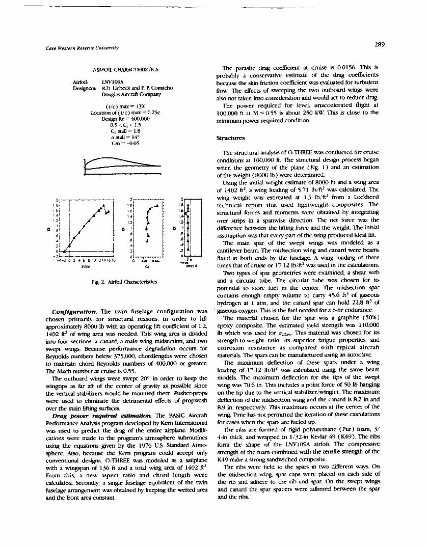
Case Western Reserve liniversity
AIRFOIL CHARACTERlSnCS
Airfoil: LNV 109A Designers: RH. Liebeck and P. P. Comacho
Douglas Air& Company
(t/c) max = 13% Location of (t/c) max = 0 . 2 5 ~
Design Re = 400,000 0.5 < C L < 1.5 CL Sfall = 1.8 a ~ t a l l = 1 4 ~ Cm = -0.05
Fig. 2. Airfoil Characteristics
Configuration. The twin fuselage configuration was chosen primarily for structural reasons. In order to lift approximately 8000 Ib with an operating lift c d c i e n t of 1.2, 1402 ft2 of wing area was needed. This wing area is divided into four sections: a canard, a main wing midsection, and two swept wings. Because performance degradation occurs for Reynolds numbers below 375,000, chordlengths were chosen to maintain chord Reynolds numbers of 400,000 or greater. The Mach number at cruise is 0.55.
The outboard wings were swept 20" in order to keep the wingtips as far aft of the center of gravity as possible since the vertical stabilizers would be mounted there. Pusher-props were used to eliminate the detrimental effects of propwash over the main lifting surfaces. Drag power t-equfd esiimation The BASIC Aircraft
Performance Analpis program developed by Kern International was used to predict the drag of the entire airplane. M d - cations were made to the program's atmosphere subroutines using the equations given by the 1976 U.S. Standard Atmo- sphere. Also, because the Kern program could accept only conventional designs, 0-THREE was modeled as a sailplane with a wingspan of 136 ft and a total wing area of 1402 ftz. From this, a new aspect ratio and chord length were calculated. Secondly, a single fuselage equivalent of the twin fuselage arrangement was obtained by keeping the wetted area and the front area constant.
The parasite drag coefficient at cruise is 0.0156. This is probably a conservative estimate of the drag c d c i e n t s because the skin friction coefficient was evaluated for turbulent flow. The effects of sweeping the two outboard wings were also not taken into consideration and would act to reduce drag.
The power required for level, unaccelerated flight at 100,000 ft at M =0.55 is about 250 kW. This is close to the minimum power required condition.
The structural analysis of 0-THREE was conducted for cruise conditions at 100,000 ft. The structural design process began when the geometry of the plane (Fig. 1 ) and an estimation of the weight (8000 Ib) were determined.
Using the initial weight estimate of 8000 Ib and a wing area of 1402 ft2, a wing loading of 5.71 Ib/ft2 was calculated. The wing weight was estimated at 1.3 lb/ft2 bom a Lockheed technical report that used lightweight composites. The structural forces and moments were obtained by integrating over strips in a spanwise direction. The net force was the Merence between the lifting force and the weight. The initial assumption was that every part of the wing produced ideal lift.
The main spar of the swept wings was modeled as a cantilever beam. The midsection wing and canard were beams fixed at both ends by the fuselage. A wing loading of three times that of cruise or 17.12 lb/ft2 was used in the calculations.
Rvo types of spar geometries were examined, a shear web and a circular tube. The circular tube was chosen for its potential to store fuel in the center. The midsection spar contains enough empty volume to carry 45.6 ft3 of gaseous hydrogen at 1 atm, and the canard spar can hold 22.8 ft3 of gaseous oxygen. This is the fuel needed for a 6-hr endurance.
The material chosen for the spar was a graphite (50%) epoxy composite. The estimated yield strength was 110,000 Ib which was used for u ~ , . This material was chosen for its strength-to-weight ratio, its superior fatigue properties, and corrosion resistance as compared with typical aircraft materials. The spars can be manufactured using an autoclave.
'Ihe maximum deflection of these spars under a wing loading of 17.12 1b/ft2 was calculated using the same beam models. The maximum deflection for the tips of the swept wing was 70.6 in. This includes a point force of 50 Ib hanging on the tip due to the verticd stabilizer/winglet. The maximum deflection of the midseczion wing and the canard is 8.2 in and 8.9 in, respectively. This maximum occurs at the center of the wing. T i e has not permitted the iteration of these calculations for cases when the spars are fueled up.
The ribs are formed of rigid polyurethane (Pur) foam, 3/ 4-in thick, and wrapped in 1132-in Keviar 49 (K49). The ribs form the shape of the LNVlO9A airfoil. The compressive strength of the foam combined with the tensile strength of the K49 make a strong sandwiched composite.
The ribs were held to the spars in two different ways. On the midsection wing, spar caps were placed on each side of the rib and adhere to the rib and spar. On the swept wings and canard the spar spacers were adhered between the spar and the ribs.
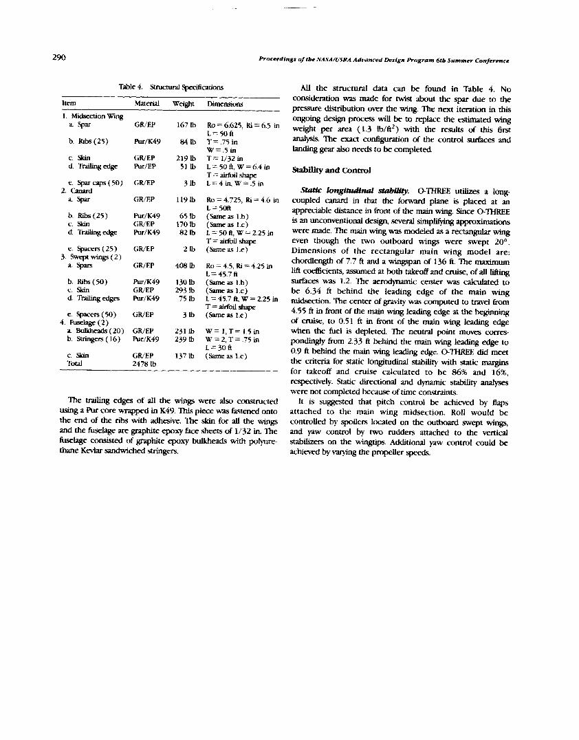
Proceedl ngs of tbe NASA/USRA Advanced Design Program 616 Summer Conference
Table 4. Structural Speafications
ltem Material Weight Dimensions
1. Midsection Wing
b. Ribs (25)
c. Skin d Trailingedge
b. Ribs (25) c. Skin d. Tnilingedge
e. Spacers (25) 3. Swept wings ( 2 )
" S p a r s
b. Ribs (50) c. Skin d. Trailing edges
e. spacers (50) 4. Fuselage (2 )
a Bulkheads (20) b. Stringers ( 16)
c. Skin Total
GWEP
h / K 4 9
GRIEP Pur/EP
GWEP
GWEP
Ulr/K49 GRIEP PurIK49
GR/EP
GWEP
Ptu/K49 GRIEP Ru/K49
GRIEP
GWEP Pur/K49
GWEP 2478 lb
Ro = 6.625, Ri = 6.5 in L=50fi T=.75 in W=.5 in T = 1/32 in L=50ft,W=6.4in T = airfoil shape L=4in, W=.5in
Ro = 4.725, Ri = 4.6 in L=5Oft (Same as 1.b) (same as 1.c) L=50ft, W=2.25in T = airfoil shape (Same as I .e)
Ro = 4.5, Ri = 4.25 in L = 45.7 fi (Same as I .b) (Same as 1.c) L = 45.7 ft, W = 2.25 in T=lirfoilshape (Same as 1.e)
W= 1 ,T= 1.5in W=2,T=.75 in L=30fi (Same as 1.c)
The t d m g edges of all the wings were also constructed using a Pur core wrapped in K49. This piece was Eastened onto the end of the ribs with adhesive. The .skin for all the wings and the fuselage are graphite epoxy face sheets of 1/32 in. Ihe fuselage consisted of graphite epoxy bulkheads with poiyure- thane Kevlar sandwiched stringers.
All the structural data can be found in Table 4. No consideration was made for twist about the spar due to the pressure distribution over the wing. The next iteration in this ongoing design process will be to replace the estimated wing weight per area (1.3 1b/ft2) with the results of this &st analysis. The exact configuration of the control surfaces and landing gear also needs to be completed.
stab* and Control
S d c longitudinal st&Wy. 0-THREE utilizes a long- coupled canard in that the forward plane is placed at an appreciable distance in front of the main wing. Since 0-THREE is an unconventional design, several simp- approximatiom were made. The main wing was modeled as a rectangular wing even though the two outboard wings were swept 20°. Dimensions of the rectangular main wing model are: chordlength of 7.7 ft and a wingspan of 136 ft. The maximum Lift coetEicients, assumed at both takeoff and cruise, of all lifting surfaces was 1.2. The aerodynarmc center was calculated to be 6.34 ft behind the leading edge of the main wing midseaion. The center of gravity was computed to travel h r n 4.55 ft in front of the main wing leading edge at the bepning of cruise, to 0.51 ft in front of the main wing leading edge when the fuel is depleted. The neutral point moves corres- pondingly fkom 2.33 ft behind the main wing lea- edge to 0.9 f t behind the main wing leading edge. 0-THREE did meet the criteria for static longitudinal stability with static margins for takeoff and cruise calculated to be 86% and 16%, respectively. Static directional and dynamic stability analyses were not completed because of time constraints.
It is suggested that pitch control be achieved by flaps attached to the main wing midsection. Roll would be controlled by spoilers located on the outboard swept wings, and yaw control by two rudders attached to the vertical stabilizers on the wingtips. Additional yaw control could be achieved by varying the propeller speeds.

BAI CA c.g. FS HFCT LIFT MFVT n.m. STOVL
PRELIMINARY DESIGN OF A SUPERSONIC SHORT-TAKEOW AND VERTICALLANDING (STOVL) FIGHTER AIRCRAFT
UNIVERSITY OF KANSAS, LAWRENCE N91-18165
A preliminary design study of a supersonic short-takeoff and vertical-landing (STOVI) fighter i5 presented. W e configurations (a Lift + b l ? / c ~ i s conccpt, a hybrid fan-vectored thrust co~ccpt. and a mixed.flow-vectored thrust concept) were initially investigated with one configuration selected for further design analysis. The selected configuration (the Ilft + M/cruist. conccpt) was successfully integrated to accommodate the powered-lift short takeoff and vertical landing requirements as well as thc demanding supersonic cruise and point performance requirements. A supersonic fighter aircrah nith a short takcoff and vertical landing capability using the Lift + lift/cruise engine conccpt seems a viable option h)r the next generation fighter.
NOMENCLATURE PHASE I AIRCRAFT STUDY
Battlefield Air Interdiction Counter Air
Mission Profiles and Specification
Center of Gravity ? h e mission profiles for the Wax I study (Figs. I ;md 2) Fuselage Station show thc design defensive counter air superiority mission and Hybrid Fan-Vectored Thrust the fallout battlefield air interdiction mission. The mission Lift + I ~ / C r u i s e specification (Table 1 ) shows the armament carried for each Mixed-Flow-Vectored Thrust mission and the point performance rcquiremcnts. Nautical Mile Short Takeoff, Vertical Ianding
INTRODUCTION 5 h i
4/ The survivabihty of long, hard-surface runways at Air Force , 2 . ,/
i D* I , "
Main Operating Bases 1s fundamental to the current operations iF-- l 5 i l h\(-l(! hbf 0 NMC-----ISI! NU-
of the & ~ o t c e Tactical Air Command. Without the use of these runways, the effectiveness of the Tactical Air Command ,. rnurvr ~ n n r . , r < n n - < , ~ 7. S U P ~ ~ S O ~ I C cnutsr our - rr . I.‘. II . JO.OOO r r
is severely degraded(". One possible solution to this runway I""
1 I!* denial situation is to include a short takeoff and vertical landing , , ,,,,, capability in a supersonic fighter/attack vehicle. An aircraft with this capability is envisioned as the next multirole fighter to replace the F-16 in the 2000-2010 time period(').
Design teams at the University of Kansas, through the sponsorship of the NASA/IJSRA Advanced Design Program, have completed a conceptual design study of a supersonic STOW. aircraft. Phase I of the study began with a brief his- torical survey of powered-lift vehicles followed by a technology assessment of the latest supersonic STOVL engine cycles under consideration by industry and government in the U.S. and ILK A survey of operational fighter/attack aircraft and the modern battlefield scenario was completed to darelop, respectively, the performance requirements and mission profiles for the stu@"*'.T'hree aircraft were considered for initial investiga- t i o n ~ ( ~ ~ " . ~ h e y employed the following engine cycles: a lift + lift/cruise cycle, a hybrid fan-vectored thrust cycle, and a mixed-flow-vectored thrust cycle. Phase I1 of the study consisted of comparing the three configurations of Phase I and selecting one configuration for further design analysis. This paper ( I ) briefly presents the results of the Phase I aircrali study, (2 ) discusses the considerations for the .selection of and modifications made for the Phase I1 aircraft; and (3) presents the design analysis performed on the Phase I1 aircraft.
Fig. I . Counter Air Mission Profile
. EN I ~ I N E s ~ A ~ ~ / I Y A I I I I - U P I. IYEAPONS DIIDP I I M I ~ LOAD!
~ A A I 8. O 1511 IN
s r o 9. CLI I IO 1 0 cncllsE IN A L r l r u u E
~ ~ l l l l l r0 CIIUISE U I / T A L T I ~ I I I ) E 10. OCIl/.i CRUISE IN
B C I I / ~ CRUISE our 1 1 . 1 0 I I ~ N U ~ E ~ o l r ~ n . 1.000 F T
OASII O U ~ I? . ONE 1IIIIUrE IIOVER
I J LAND I V I ~ I I sr lNrrn#AL ~ U C L
Fig. 2. Battlefield Air Interdiction Mission Profile
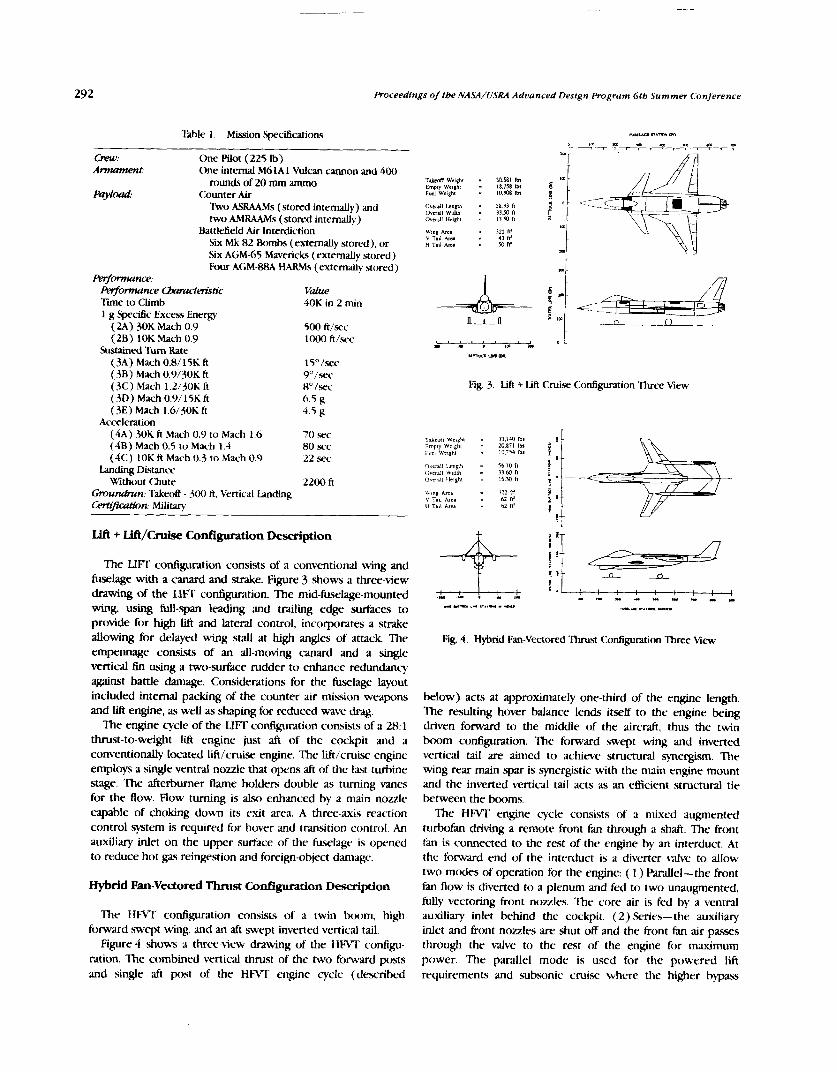
292 Proceedings of tbe NASA/USRA Advanced Design Program 6th Summe7 Conference
Table I . Mission Specifications M.lAol nrm (4
D f m m ) . p . . I O ) P m
m y --- -7 7 -1 , , r -77
Crew: One Pilot (225 Ib) Armament: One internal M6lAl Vulcan cannon and 400
rounds of 20 mm ammo Payload: Counter Air
W o ASRAAMs (stored internally) and Oreill1 l r n g V l - 58 33 f! O~erdl Wldth = 31 50 f,
two AMRAAMs (stored internally) ovcni~ mlghl = 13 50 n
Battlefield Air Interdiction wing ~ r c . - 322 w
Six Mk 82 Bombs (externally stored), or H * "' ~.il .&ma - = 43 54 fr' fl'
Six AGM-65 Mavericks (externally stored) Four AGM-88A HARMS (externally stored) ,n
Fwfmnce: FWf'ncr avlmct&tic value Tine to Climb 40K in 2 min 1 g Specific Excess Energy
( 2A) 30K Mach 0.9 500 ft/sec ( 2 ~ ) 10K Mach 0.9
Sustained b Rate (M) Mach 0.8/15K ft (38) Mach 0.9/3OK ft (3C) Mach I.2/30K ft (3D) Mach 0.9/ 15K ti (3E) Mach 1.6/3OK ft
Acceleration (4A) 30K ft Mach 0.9 to Mach 1.6 (48 ) Mach 0.5 to Mach 1.4 (4C) 10K ft Mach 0.3 to Mach 0.9
Landing Distance wthout Chute
Gmu&n: Takeoff - 300 ft, Vertical b d q Cert@&n: Military
loo0 ft/src
15" /sec 9"/st.c H0 /sec 6.5 g 4.5 g
70 sec 80 sec 22 sec
2200 ft
Llft + IJft/Ch&e Configuration Description
The LIFT c o n t i p t i o n consists of a conventional wing and fuselage with a canard and strake. Figure 3 shows a three-view drawing of the LIFT configuration. The mid-fuselage-mounted wing, using full-span leading and trailing edge surfaces to provide for high Lift and lateral control, incorporates a strake allowing for delayed wing stall at high angles of attack The empennage consists of an all-moving canard and a single vertical fin using a two-surface rudder to enhance redundancy against battle damage. Considerations for the fuselage layout included internal packing of the counter air mission weapons and lift engine, as well as shaping for reduced wave drag.
The engine cycle of the LIFT c o n t i p t i o n consists of a 28:l thrust-to-weight lift engine just aft of the cockpit and a conventionally located lift/cruix engine. The lift/cruise engine e m p l o ~ a single ventral nozzle that opens aft of the last turbine stage. The afterburner flame holders double as turning vanes for the flow. Flow turning is also enhanced by a main nozzle capable of choking down its exit area. A three-axis reaction control system is required for hover and transition control. An auxiliary inlet on the upper surface of the fuselage is opened to reduce hot pps reingestion and foreign-object damage.
Hybnld Fan-Vectored Thrust Configuration Description
The HFVT configuration consists o f a twin boom, high forward swept wing, and an aft swept inverted vertical tail.
Figure 4 shows a three-view drawing of the HFVT confip- ration. The combined vertical thrust of the two forward posts and single aft post of the HFVT engine cycle (described
Fig. 3. Lift + Lift Cruise Configuration Three View
Fig. 4. Hybrid Fan-Vectored Thrust Configuration Three View
below) acts at approximately one-third of the engine length. The resulting hover balance lends itself to the engine being driven forward to the middle of the aircraft, thus the twin boom configuration. The forward swept wing and inverted vertical tail are aimed to achieve structural synergism. The wing rear main spar is synergistic with the main engine mount and the inverted vertical tail acts as an escient structural tie between the booms.
The HFVT engine cycle consists of a mixed augmented turbofan driving a remote front fan through a shaft. The front fan is connected to the rest of the engine by an interduct. At the forward end of the interduct is a diverter wive to allow two modes of operation for the engine: ( 1 ) Parallel-the front fan flow is diverted to a plenum and fed to two unaugmented, fully vectoring front nozzles. The core air is fed by a ventral auxiliary inlet behind the cockpit. (2) Series- the auxiliary inlet and front nozzles are shut off and the front fan air passes through the valve to the rest of the engine for maximum power. The parallel mode is used for the powered lift requirements and subsonic cruise where the higher bypass

ratio may improve the specific fuel consumption. The series mode is for point performance and supersonic fight where the fkont nozzles are faired in by a retractable ramp to minimize drag. A two-axis reaction control system is required as the front nozzles differentially vector to provide lateral control.
Mixed-Flow-Vectored Thrust Configuration Description
The MFVT conlipration consists of a high aft swept wing, twin vertical tails, and all moving horizontal stabilators. Figure 5 shows a three-view of the MRiT configuration. The large flow transfer ducts required for the MFVT engine cycle (described below) dictated the middle and aft fuselage width, while the cockpit and radar volume sized the forward fu.wlage. Fuel volume and internal bays for the medium-range missiles sized the fuselage length. Volume beneath the engine inlet and ducts m s dedicated to the main landing gear and internal short-range missiles. A conventional aft swept wing was selected for simple construction with adequate performance. The strake provides improved aircraft lift and maintains adequate airflow to the bifurcated inlet at high angles of attack.
The MFVT engine cycle consists of a single cruise engine with a bltwk-and-rum main nozzle and two flow transfer ducts. In powered-lift operation, the mixed turbine and byyass flow, completely blocked by the main nozzle, is transferred forward to the c.g of the aircraft and e,xhausted. The two-variable arcs, vectoring exhaust nozzles, along with the 5%-thrust, longitud- inal trim ~a lve , provide complete control in hover, eliminating the need for a reaction control system. In up-and-away flight, the forward exhaust nozzles are stowed and the transfer ducts are closed off t o allow for conventional operation.
PHASE I1 AIRCRAFT STUDY
Selection of Phase 11 Airrraft
The LIFT configuration was 1400 1b lighter than the MRT and 2400 Ib lighter than the HFVT. The added cost of thc Lift engine negated its lighter weight ;IS the cost of the three configurations was similar.
The more conventional internal packaging of the I.lI-7' configuration compared to the other conccpts allo~ved it a favorable area rule distribution. The H F W configur,ttion area distribution sutfered due to the large loss o f cross-wctional area in the boom region. The large transfer ducts required by the M l 3 T cycle increased the mid and -aft fi~wlage width resulting in a large gap in cross-sectional area hetwcc'n the canopy and mid fuwlagc-.
The component weights and volumes required for the short takeoff and vertical landing capability of rach configuration were estimated. The results are shown in Table 2. The Hl%T configuration suffers the most from the STO\.rI. equipment for two reawns. First, the engine components required for tlow shifting are heal.). and require a largc volume (the a n n u l ; ~ inverter valve and interduct). k c o n d , t l ~ c cnginc thrust split requires a mid-aircraft-niountcd engine mil th~15 some wrt of boom configuration. ' f i e I.IFI' and MI-TT configuration5 ha\r similar weight penalties but the MF\T hr~\ a larger volurnc penalty due to the transfer ducts.
ModHications for the Phase I1 Study
The lessons learned in Phase I werc adapted to the !dt~cIy plan of Phaw 11. Modifications wcre made regartling ( I ) the mission profiles and specifications and ( 2 ) the ot,crall configuration of the lift + lifticruise aircraft
The fuel fractions (file1 weight/takeoff mright ) for the Phzw I aircraft werc unrealistically high('). The tlcsign <A mission was scaled doum t o a 100-n.m. subsonic cruise wit11 a 50-n.m. supersonic cn~ise. 'Ihc fallout 13AI mi~sion tv~\ waled t o ;I 100- n.m. subsonic hi&-level cruisc with a 80-n.m, low-lcvel clash.
The I.IFT configuration was selected for the Phase I1 aircraft study bawd on a comparison of the Phaw I aircraft using the 'i'ahlc 2. Weights and Volumes for (:ornponcnrb
Rcquircd f i ~ r S1'0\'1. (:;~p~hilit!. following considerations: ( I ) aircraft weight and cost, - -- . -
(2 ) aircraft area rule distribution, and (3) aircraft components Volume (ft') Wc~gtit ( I l l ) -- required for STOVI. capability.
Lift Ii!? Engine I I 04 - Ventral I V O ~ I C . and ' I i l r ~ t ~ ~ ~ g \';incs 0 0
1 ! VbO lbr IY.8W Ib, 111 5 - 5 ,,s
Total
' - &--==I Flow Switching hlcc.h;~nisni ant1 Extended f'owcr Sl>;di
Front \k.ctoring No~zlc4 Rrdr Vcctorint? Nozlc
K(:S Systcrn 'l\>t;ll
8..
0 ~ ~ ~ - - .-_-i--. ~ L rl.l++.+rrci.c+t,i.+.+,~+++~,t.,.t.~,~ : ST-. .+.... ,..-+--..~.+-~,~~.+t.++c+~c-t.~..r.-t+..+-~~r.+*+.*+ttrtl . W f l T ' a . - I '" "" """4 "0 m "0 '" " x. .'" 4' .P 7- 7% .DO .U
,-LA., . ,Arm ",. -. t%ltx.k and 'l'urn Nozzle .,s,x. ,- -, Transfer I)LICI>
Front Cl;lniahcll No//lc\ 'Iixal
Fig. 5. Mixed-Flow-Vectored Thrust Configuration Ihree Men,
I I - I I I - ' 0 --
i 2.3 -- 1t )H -'XH(>
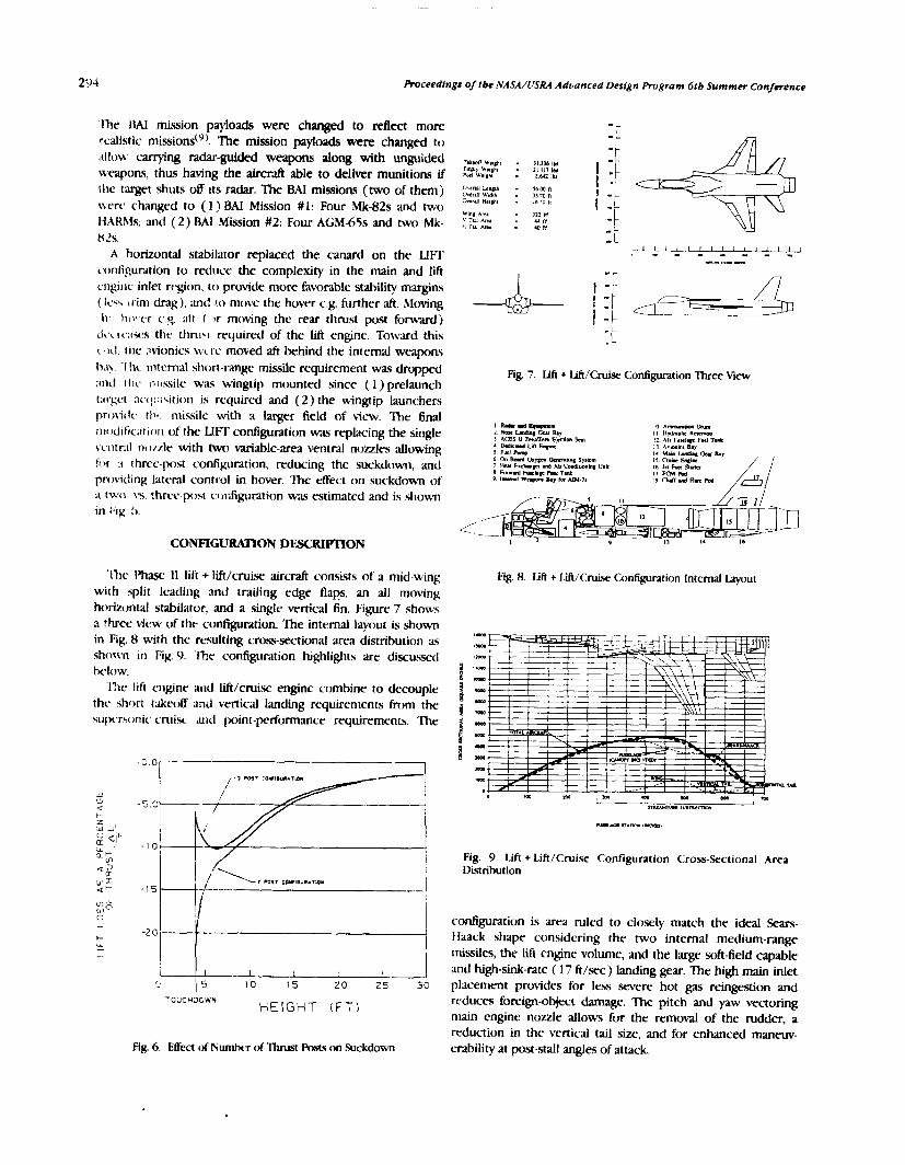
294 Proceedings of tbe NASA/USRA Advanced Design Program 6th Summer Conference
' f i e IIAI mission payloads were changed to r d e c t more realistic missions(Y). The mission payloads were changed to ;tilow carrying radar-guided weapons along with unguided weapons, thus having the aircraft able to deliver munitions if the target shuts 08 ~ t s radar. The BAI missions (two of them j ivcrc changed to ( I ) BAI Mission # 1 : Four Mk-82s and two It ARhls, and (2 ) BAI Mission #2: Four AGM-65s and two Mk- 82s.
A horizontal stabilator replaced the canard on the LIFT ~.onfi'guration to reduce the complexity in the main and liti c-ngirlc inlet region, to provide more favorable stability margins ( Icq.. irim drag), anti ro move the hover c.g. further aft. hltning h- h~,t.er c.q. aft I S ) r moving the rear thrust post forward)
!-c.;~ses thr thn1.i required of the Lift engine. To\r.;lrd this C,II!. tile ;ivionics lvc-re moved aft behind the internal weapons IyCi> .lh intcrnal short-mnge missile requirement was dropped ;und r tic ~-i!~ssile was wingtip mounted since ( I ) prelaunch t:crgct :~ccl:;icitiotl is required and (2 ) the wingip launchers provirlt- t l l q missile with a larger field of view. The final 1111 ,dific;~r ion of the LliT configuration was replacing the single vcntr;~l ri~)/zle with hKO variable-area ventral nuzzles allowing htr .I three-post configuration, reducing the suckdown, and pnnicfing lateral control in hover. The effect on suckdown of r two. \s. thrcc-post col-Sguration was estimated and is shown ill Fix :>.
Fig. 7. Lift + Lift/Cruise Configuration Three view
10 A-im mm I I Ilr*.olr R a n a r 12 A l l Fuel.- Flrl Tank I 3 A v ~ o n r s Bay I4 Mu" b b y 15 crwr Enalrr I6 IU hCI Sl- II ECM W I8 OuSl".im.mW
Ilw Phase I1 Lift + lift/cruise aircraft consists of a mid-wing Fig. 8. Ldi + Lift/Cruise Cnnfiguration Internal layout with split leading and trailing edge flaps, an all moving horizontal stabilator, and a single vertical fin. Figure 7 Fhows 3 view of the configuration. The internal layout is shown in Fig. 8 with the rc?;ulting cnx.5-sectional area distribution as shoxcn in Fig 9. m e configuration highlights are discusseI k l o w .
Ike lift engine arid Lift/crui.se engine combine to decouple thc short takwff and vertical landing requirements from the supcr~o!~ic-crui,u ; u ~ l [mint-performance requirements. 'fie
- n r m I-,
-L
.x Fig. 9 Lift + Llft/Crulse Configurat~on Cross-Sect~onal Area < -' a Dlstnbut~on u1 .rr -15
! 411 C O I I I U I A I I O ~
;; >; C -I configuration is area ruled to closely match the ideal Sears- e tlaack shape considering the two internal medium-range 12- i ~russiles, the lift engine volume, and the large soft-field capable I and high-sink-rate ( 17 R/sec) landing gear. The high main inlet
30 placement provides for less severe hot gas reingestion and TOUCHDGWN
HEIGHT ( F T ) rcduces foreign-obwt damage. 'lhe pitch and yaw vectoring nlain engine nozzle allows for the removal of the rudder, a reduction in the vertical tail size, and for enhanced manew-
Fig. 6. Effect of Nunlkr of Thrust Posts on Suckdown rrability at post-stall angles of attack

University of Ku?rsas
WEIGHT DATA n The weight data are shown in Table 3. STOVL equipment
weight includes that of the Lift engine and nozzles, the lift/ cruise engine nozzles, the reaction control system ducting and nozzles, and the lift/cruise engine tailpipe extension.
Table 3. Weight Statement (lh)
Structure Fu.~lage Wing Tails - Vertical
- Canard Landing Ckar - Main
- Nose Launch Mechanisms (lnt. Weap)
ASRAAV AMRAAM
Ventral Clamshell Nozzles
I h ~ p u h o n Cruise Engine Lift Engine Cruise Engne Tailpipe Ext Cruise Engine Nozzle Air Induction Fuel Bladder Fuel Dumping Engine Controls Starting System
Fired Equipmwt Flight Control Avionics Electrical Sptem Air Conditioning Oxygen System APLl Furnishing Gun and Provisions Auxilary Ckar. Paint RCS Ducting and Nozzles
Fig. 10. Propulsion System Integration
The lift/cruise engine,("" sized by the point-performance requirements, has a maximum sea-level static thrust of 35,573 1b. For hover, the dry thrust required included the following: ( 1 ) 1.00 g to counter the aircraft weight, ( 2 ) 0.10 g to arrest a sink rate, (3)0.13g to counter suckdown (assumed), and (4 ) 0.07 g to support reaction control (assumed). The calculated required thrust loss due to suckdown and bleed required for reaction control were less than that assumed and so resizing wa. not required.
The ventral nozzles are of the clamshell type. Figure 11 shows the integration of the ventral nozzles and the tailpipe extension. In powered-lift operation, while the main nozzle blocks the flow, the turning m e s direct the flow through the transfer ducts to the clamshells. In conventional flight, the turning vanes block off the transfer ducts and the clamshell nozzles are retracted into the fuselage. This nozzle arrange- ment allows for a three-post configuration as well as lateral control in hover, thus reducing the required reaction control bleed.
Total E v q W W w t 21,117 21,117 21,117 ALI. DIMENSIONS I
225 225 225 IN I N C ~ I E S Crew 'Total Fuel 8,CAZ Armament (1,196) (4.074) (3.316)
ASHAAMS 332 AMRAkVS 654 HARM 1,614 Mk-82s 2,240 1,120 Maverick5 1,976 Ammo - (200 rounds) 2 20 220 200 ELECTROMECHANICAL
Tdeof f Weight 31,336 34,400 33,642
TO AIRFRAME
PROPULSION SYSTEM INTEGRATION
The overall propulsion system integration is shown in XIMUM AREA 15 2 7 8 IN '
Fig. 10. The integration consists of aW/cruise engine with two ventral nozzles and a main pitch and yaw vectoring nozzle, and NlMUM AREA 15 1 6 5 IN
a L i engine with a pitch vectoring nozzle. Auxiliary inlets art: used for the lift/cruise engine to accommodate the increased m a s flow required for powered-lift operation. Fig. 1 1 . Lift/Cruise Engine Ventd Nozzles
ORIGINAL PAGE IS OF pm!t Q l j A I . i N

Proceedings of tbe NASA/USRA Advanced Design Program 6tb Summer Conference
The lift/auise engine main n o d e has 20' pitch vectoring and 25" yaw vectoring, with a block and turn capabity. Figure 12 shows the lift/& engine main n d . Ihe yaw capability of the n o d e was calculated to have enough control power to e h h a t e the rudder and to provide adequate Wity to reduce the size of the vertical tail by 30%. Removing the rudder reduces the complexity and cost of the flight control system and reducing the verdcal tail size allows a more favorable afi end area distribution. The pitch vanes of the nozzle close t e to block the flow and turn its direction fix hava and transition.
The lift engine("), sized by the hover balance, has a maximum installed thrust of 12,105 Lb. The Lift engine along with its noale arrangement is shown In Fig. 13. The unmixed turbohn employs a large amount of admnced composites, which enables the u n i d e d thrust-to-weight to reach 28. To achieve the lightest possible engine while maintaining acceptable jet exhaust conditions, a high bypass ratio (1.5) is implemented A d e r diameter engine with a higher speci6c thrust could have been used to decrease the engine volume, but this would have led to an increase in engine weight and/ or more severe exhaust conditions.
In conventional fight, the lift engine nozzle vanes were designed to fold into the fuselage underside to avoid fuselage doom The 20° fore and aft capability of the nozzle was included to assist in pitch control in takeoff and transition.
-OR, T'RANSI'TION, AND HOVER ANALYSIS
At brake release the main engine, operating at maximum dry thrust, has its nozzle vectored sli@tIy downward to bakance the thrust of the idling lift engine. During groundroll the lift engine reaches maximum t . while the main engine thrust is M e d &om the main nozzles to the ventral nozzles. When the combined M t q force of the engines and wing reaches the weight of the alrcraft, the lift engine retards its thrust while the main engine thrust is shifted back to the main nozzle. During the groundroll, the composite thrust forces are balanced independently of the aerodynamic forces on the aircraft. Rotation was not investigated since the ventral nozzles, not capable of vectoring, would produce a component of thrust to counter the forwad motion of the aircraft
The resulting takeoff groundroll distances for CA, BAI, and an overload mission are shown in Fig. 14.
Transition
. ,... .:..' The transition of the aircraft between powered-lift and
Q wingborne flight was investigated using a time-stepping technique. Figure 15 shows an example of the transition
- - - ---- ---- between powered-lift to wingborne flight, sming with t a k d . __..;.. ...: :.., An effort was made to achieve gross thrust vectoring with the
combination of the lift/ciuise engine main and wntral nozzles
kLL O I H E ~ S I O ~ S i.. L,,.I ... and the lift engine nozzle. Idling back the lift engine thrust IN I ~ C ~ E S and transferring the main engine thrust bom the ventral to
SIDE V I E W SCALE i 3 0 TOP V~~~ main nozzle occurs at a rate at which the aircraft remains at
a constant altitude since the decrease in vertical thrust equals F i i 12. cruise Engine hfain Nozzle the increase in lift h m the wing.
0 2 0 0 4 0 0 6 0 0 8 0 0 1 0 0 0 I200 1400
TAKEOFF GROUND R O L L D ISTANCE ( F T )
Fig. 14. Tak& Ground Run Distances

University of Kansas 297
S C A L E 1 / 5 o o V E C T O R MAGNITUDE Digitally controlled stability augmentation systems were A L L DIMENSIONS INCHES I INCH = 50,000 L B S designed for each of the three aircraft axe. pitch, roll, and N O T E S M A L L VECTORS ARE THE THRUST FROM E A C H NOZZLE
AND THE LARGE V E C T O R s THE E ~ V ~ V A L E N T THRUST A q lh lg m e n c y of loo* Mp1e-m for the digital controllers. The directional stiibility augmentation system block diagram is shown in Fig. 18. As shown, yaw rate
T - 0 0 SEC T = 6 2 SEC H - o FT H = 52 F T T O is derived by ( 1) the deflected thrust of the yaw vanes and
(2) the aerodynamic force produced by the yaw vanes as thqr are ddected The unaugmented z-plane root locus, shown in
T - 10.0 SEC T = 16.4 SEC H = 100 FT H = 1 1 4 F T
(WING-BORNE FLIGHT1
-&=-
Fi 15. Take& to W-me Transition
Control requirements and the pilot workload for SIOVL aircraft are higher than that of conventional airrraft thus a digital fly-by-wire flight-control system with advanced software and integrated propulsion control is re+
Hover Fig. 16. Reaction Control System Layout
A reaction control system maintains control about the pitch and yaw axes in hover. The Level 1 flying qualities for hover control h m AGARD 577 and MILF-83300 were used to maw W W
calculate the required engme mass flow bleed rate. A total of 2% of the lift/cruise engine mass flow rate is required for adequate control in hover, 1.2% for pitch control and 0.8% for yaw control. The reaction control system layout is shown in Fig. 16.
The hot gas reingestion (HGR) problem is very configurationdependent and thus diBcult to identify without extensive theoretical research and experimentation. However, major determinants of the severity of HGR are the number and location of the vertical jet exhaust nozzles. Figure 17 show a top view of the a i r d with the location of its nozzles and the fountain created by the jet exhaust. The flow walls do not concentrate themselves in an inlet region and thus it is predicted that the aircraft will not have severe HGR problems.
STABILITY AND CONTROL Fi 17. FlowWaU.sdrheJetExhwst
The stability and control derivatives were calculated for seven flight conditions that were selected to represent critical points in the flight envelope. Pitch trim diagrams were plotted to assure that the aircraft was longitudvlally trimmable at each SERVO r....
Bight condition. The aircraft was verified to not have severe spin-departure characteristics and the inertia coupling of the T~m~yz-==&2. PLUME frapu.
aircraft was alleviated with feedback to compensate the short DYNMICS
period and dutch roll frequencies and damping ratios. A low- WASHOUT FILTER GYRO
RATE
level ride qualities analysis indicated that the aircraft may need a ride quality augmentation system throughout most of the flight envelope. Fig. 18. D i r e c t i d Stability Augmentation System Block Diagrdm
ORIGINAL PAGE IS OF POOR Q u A L ~ ~ ~
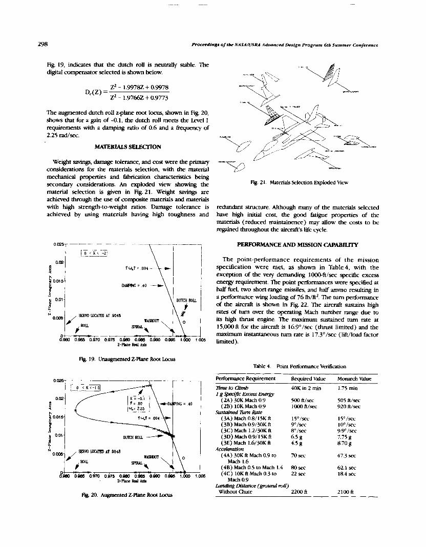
h e e d i n g s of ;be NASA/USRA Advanced Design Program 6tb Summer Conference
Fig. 19, indicates that the dutch roll is neuvally stable. The digital compensator selected is shown below.
The augmented dutch roll z-plane root locus, shown in Fig. 20, shows that for a gain of -0.1, the dutch roll meets the Level 1 requirements with a damping ratio of 0.6 and a tkequency of 2.25 Wsec.
Weight savings, damage tolerance, and cost were the primary considerations for the materials selection, with the material mechanical properties and fabrication characteristics b e i secondary considerations. An exploded view showing the material selection is given in Fig. 21. Weight savings are achieved through the use of cotnposite materials and materials with high strength-to-weight ratios. Damage tolerance is achieved by using materials having high toughness and
Fig. 2 1. Materials Selection Exploded View
redundant structure. Although many of the materials selected have high initial cost, the good fatigue properties of the materials (reduced maintainence) may allow the costs to be regained throughout the aircraft's Life cycle.
PERFORMANCE AND MISSION CAPABILITY
The point-performance requirements of the mission specification were met, as shown in Table4, with the exception of the very demanding 1000-ft/sec specific excess energy requirement. The point performances were specitled at half fuel, two short-range missiles, and half ammo resulting in a performance wing loading of 76 Ib/ft2. The turn performance of the air& is shown in Fig. 22. The aircraft sustains high rates of turn wet the operating Mach number range due to its high thrust engine. The maximum sustained turn rate at 15,000 ft for the aircraft is 16.9O/sec (thrust limited) and the maximum instantaneous turn rate is 17.3O/sec (lift/load factor limited).
Fig. 19. Unwgmented Z-Plane Root Lacus Table 4. Point Performance Vefication
Fig. 20. Augmented Z-Phnc Root Locus
Performance Requirement Required Value Monarch Value
lime to Qimb 40K in 2 min I g WSrc ~ ' x - ss Energy
(2A) 30K Mach 0.9 500 ft/xc (2B) 10K Mach 0.9 lo00 ft/sec
Sustained 7tun Rate (M) Mach 0.8/15K ft 15O/sec (3B) Mach 0.9/30K h 9"/sec (3C) Mach 1.2/30K ft 8" Isec (3D) Mach 0.9/15K ft 6.5 g (3E) Mach 1.6/30K ft 4.5 g
AcoeleraHon (4A) 30K fi Mach 0.9 to 70 x c
Mach 1.6 (4B) Mach 0.5 to Mach 1.4 80 sec (4C) 10K ft Mach 0.3 to 22 sec
Mach 0.9 Landing m n c e (ground rdl)
Without Chute 2200 ft
1.75 min
505 ft/sec 920 h/xc
15"/sec 1 oO /sec 9.9" /xc 7.75 g 8.70 g
47.3 sec
62.1 sec 18.4 sec
2100 fi

University of Kansas
Table 5. CA Mission Fuel Usage
MACH NUMBER
FQ. 22. rn performance at 15,000 ft
---
Phase Fuel - Engine StartWnn IJp Taxi Short ~&&ff Acceleration to Climb Speed Climb Subsonic Cruise - 200 n.m. Sea L~mel Dash In - 80 n.m. strafe Run Sea Level Dash Out - 80 n.m. Climb Subsooic Cruise - 200 n.m. Hover
The 1-g specific excess energy for the Bight envelope is shown in Fig. 23. The aircraft has a 1000 ftlsec s p e d c excess energy capability at high subsonic Mach numbers and altitudes below 10,000 ft. As shown, a specific excess energy of 600 ftl sec is achievable over a wide portion of the Bight envelope.
The mission capability of the aircraft was measured by ( 1 ) venfylng the CA and BAI mission pmfiles and (2) taking the aircraft through typical fighterlattack missions to determine the aircraft's capability as a multirole fighter. Tables 5 and 6, respectiveb, show the CA and BAI (heaviest ordnance) mission fuel usage. As shown, the supersonics (acceleration to and sustakhg supersonic Bight) of the CA mission and the low-level dash of the BAI mission dominate the aircraft fuel usage. Figures 24 and 25, respeczivev, show the aircraft's capability in a mass intercept mission and a STOM- two-stage mission. The two-stage mission shows the advantage of a mVL aircraft in that it can operate from dispersed bases and thus save fuel and cut down on response time.
MACH NUMBER
Bum (Ib) -- 327 307 376 3(N3 5 38
1331 I204 864
i l l ! ) 326
112-4 246 . ..
Table 6. BAI Mission Fuel Usage
Phase -.
Engine Start/Watm Up T& Short Takeoff Acceleration to Climb Speed Climb Subsonic Cruise - 100 n.m. Acceleration to Suprjonic Cruise Supersonic Cruise - 50 n.m. Combat Supersonic Cruise - 50 n.m. Subxlnic Cruise - 100 n.m.
Fuel Bum i 11))
i L I Hover Landing 114 Rc~erveS 432
Total 8634
NPUSONK cnulsk
A-RATION C W B A T
SHOOT SMI(h)
0 81 I I J
RIIXUS(NM)
Fig. 24. Mw intercept Mission
W A -- DASH
\ / --7
Fig. 23. S p e d c Excess Ene%y Fig. 25. SZDVL W- MMOn

ngs of :be NASA/USRA Advanced Deslgn Program 611, Summer Conference
LIFE C1%LE COST ANALYSIS
?he life cycle cost of the aircraft was estimated. The results are siummari~vd in Table 7 with a life cycle cost breakdown shown in Fig 26. Thr results s h o w are for a production run (IF 500 aircrA 'and in 2005 dollars. l l e average estimated price per fighter is $32.6 million.
Table 7 5iummq of Lde Cycle Cost
Research. Dewlopment, Test, and Evaluation Number of Airplanes Built for RDTE = 10 Engineering Manhow Rate = S 105.00 Manufaauring Manhour Rate = 69.00 T o o h Manhour Rate = $83.00 RDTE Cost = $3.716 Billion
Acquisl tion Number of Aircraft Produced Per Month = 10 Test Flight Hours Brfore Delivery = 20
ACQ Cost = 11 2.206 Billion
Operating Number of Flight Hours Per Year = 325 Number of Years in Actiw Duty = 25 OW = 528.88 Billion
Disposal 1 % Program Life Cycle Cost
- DlSP = $0.456 Billion
28.880 Billion
Fig. 26. Life Cycle Cost Breakdown
CONCLUSIONS AND RECOMMEh'DATIONS
7he results of an investigation of three STOM, configurations indicated that a lift + lift/cruise concept was the most promising c<)nfiguratiorl for continued design analysis. The lift + lift/crui.w aircraft suffered the least penalty due to eqilipment required for S'I'OVL capability. The aircraft's engine cyclc, consisting of a lift engine and a lift/cruise engine, dt-co~~plcs the short takeoff and verticd landing requirements and thc supersonic requirements. Flexihle nozzle integration allows for a thrw-post desijp that is critical to acceptable suckdo%n and to control power requirements in powered-lift operation. The aircraft has the ability to take off in short distances. tra~itictn to uingk~rnr fight, complete its mission, transition to powered lift, and land vertically. Inertial coupling
and spin departure tendencies were reduced via the digital By- by-wire Bight control system. Materials for the aircraft were selected by balancing their high initial cost with their increased performance throughout the aircraft's life cycle. The aircraft does not suffer b m the STOVL requirement as shown by its high level of performance. Also, the aircraft's mission capability is adequate to the point that it may be considered a multirole fighter.
Further design analyses are necessary to determine if the hot exhaust gases interfere with the engine operation in close proximity to the ground and to develop h@Iy redundant integrated &ght and propulsion controls to assure successful takeoff and transition of the aircraft.
The following are recognized as contributors to the success of this design study the students of the AE 621 and AE 622 design courses for their design analyses, the members of the Technology Assessment Division of the Wright Research and Dewlopment Center (particularly Lieutenant Gerald M) for their (his) technical support and data packages, the members of the Powered Lifi Branch of NASA Arnes Research Center (particularly Andrew Hahn) for their (his) technical support and data packages, Dr. Roskam for his guidance and support to the design team, Shelby J. Morris as t!!e NASA monitor, and the Universities Space Research Association for sponsoring the Advanced Design Program.
REFERENCES
1. wes, J. M. and Low, R B., Views on V/STOL Tactical Fighter Aircraft: Technology Needs and Relationships to the Runway Denial Problem, AGARD Conference, Proceedings, Number 313 June 1984.
2. Tamplin, G. C., Hammond, D. L, and Fredette, R E., Assessment of A Post 2000 SMM. Fighter, SAE Aerospace Atlantic Paper 90 103 1, April, 1990.
3. Cox, Brian, et al., Preliminary Performance Assessment for a Supersonic STOVL Fighter, University o f Kansas, AE 621, Seotember. 1989.
4. cdx, Brian, et al., Battlefield Arena in 1995-2000, LJniversity of Kansas, AE 62 1 , September 1989.
5. Cox, Brian, et. al., Preliminary Jksign of a Supersonic .STOW. Aircraft Using a Hybrid Fan Vectored Thrust Engine Cycle, University of Kansas, AE 62 1, December 1989.
6. Cox, Brian, et. al., Preliminary Design of a Supersonic S70VI. Aircraft Using a Lift + LiftlCruise Engine, CJniversity of Kansas, AE 62 1, December 1989.
7. Cox, Brian, et. al.. Preliminary Design of a Supersonic STOM. Aircraft Using a Mixed Flow Vectored Thrust Engine Cycle, University of Kansas, AE 6 2 1, December 1089.
8. USAF Wright Research and Development Center Presentation at the Uniwrsity of Kansas, Resenter: Ray Fredette, Ciniwrsity of Kansas, January, 1990.
9. NASA Ames Research Center Presentation at the University of Kansas, Presenter: Andrew Hahn, University of Kansas, February 1990.
10. Watt and Whitney Advanced Engines Performance, Weights and Dimensions Model, Fighter/Attack/Interceptor Applications, Pmided by Public Release Erorn Wright R m c h and Develop- ment Center, Januaq 1Wo.
1 1 . Rolls-Royce, ASTOVL Direct Lift Engine, Performance and Installation Data Package, July 1989.

DESIGN OF A REMOTELY P m D VEHICLE FOR A LOW REYNo~Ds NUMBER STATION KEEPING MISSION
Six teams of senior level Aerospace Engineering undergraduates were p e n a request for proposal, asking for a design concept for a remotely piloted vehicle (W). This RW was to be designed to fly at a target Reynolds number of I x lo5. The craft was to maximize loiter time and perform an indoor, closed-course flight. As part of the proposal, each team was required to construct a prototype and validate their design with a Bight demonstration.
INTRODUCTION
There has been a growing interest in flight applications in the low Reynolds number range, speciacally near 10'. At these low Reynoids nwnbers, many ditkrent phenomena occur. One particular example is litl hysteresis. As an airfoil increases angle of attack in this flow regime, separation bubbles form that alter boundary layer development and influence both Ilft and drag performance, Through a small angle-of-attack range, these bubbles augment the overall lift of the &foil. At higher angles of attack, the bubbles break down and may cause a sudden decrease in lift. If the angle of attack is then slowly decreased the bubble may reform and the increase in lift would again be present. There are also sigmficant form-drag penalties associated with this Reynolds number regime.
Another problem faced in this particular application is that of weight constraints. Sice the aircraft is flymg a constrained, closed course and loiter time is to be maximized, optimally the cruise velocity should be kept to a minimum. This will keep the chord length, and hence the aircraft size, in a Limited range. Therefore, for a given velocity range and limited planform size, there is a finite amount of lift that can generated by the craft. Therefore, to take off and maneuver, it is critical that the RPV is weight efficient. This requires selecting a proper propulsion system and aerodynamic configuration for this specialized mission.
There are several applications for which low Re RWs may be used, both at high and low altitudes. At high altitudes they could be used for meteorological, communications, or reconnaissance purposes. At lower altitudes they could be used for surveillance, or in a rescue mission to locate survivors. Sice this study involved nonconventional (nonairbreathing) propulsion systems, they could be used in any hostile environment, ranging from martian topography mapping to volcanic monitoring on Earth. Another use for these RWs is
specltications. The design teams were notifled that certain aspects of the mission were open for modification, @en suttlclent justltication for these changes.
FLIGHT AT VERY LOW REYNOLDS NUMBERS: A STATION KEEPING MISSION
Most conventional 5ight vehicles are designed to operate in a flight regime such that the Reynolds number based on mean wing chord is in excess of lo6 and some currently operate approaching 10'. Recently there has been interest e x p m d in vehicles that would operate at much lower Reynolds numbers, less than lo5. Particular applications are low-speed fight at very high altitudes, low-altitude flight of very small aircraft, and flight in the atmospheres of other planets atmospheres such as Mars. There are many unique problems associated with low-.speed Bight that pose challenges to the aircraft designer and that must be addressed in order to understand how to exploit this low Reynolds number Bight regime. Since many of the anticipated missions for this type of aircraft are unmanned, it is necessary to couple develop- ments in unmanned aircraft development with our knowledge of low Reynolds number aerodynamics in order to develop an aircraft that can fly as slowly as possible at sea-level conditions. This study will help to better understand the problems associated with flight at these very low Reynolds numbers. Considering the potential applications, the aircraft must also be very robust in its control and be highly durable.
in radiation-contankated would be unsafe.
areas where human-operated craft 1. Develop a proposal for an aircraft and associated flight
control svstem that must be able to (a)Maintain level controlled fight and fly a closed-cou& at flight speeds
REQUEST FOR PROPOSALS corresponding to Reynolds numbers less than 2 X lo5 and as close to 1 x lo5 as possible. The greatest measure of merit is
The mission and semester project details were defined in associated with achieving the lowest mean chord Reynolds the following request for proposals. This request placed some number possible and maximizing the loiter time on a closed additional requirements and constraints on the basic mission course. (b) Be maneuverable and controllable so that it can

gs of tbe NASA/IISRA Advanced Design Program 616 Summer Conference
tly a closed pattern and remain within a limited airspace. (c) Use a propulsion system that is nonairbreathing and does not emit any mass. (d) Be able to be remotely controlled by a pilot with minimal flying experience or an autonomous onboard control system. (e) Carry an instrument package payioad that weighs 2.002 and is 2" X 2" X 2" in size.
2. Take full advantage of the latest technologies associated with lightweight, low-cost radio-controlled aircraft and unconventional propulsion systems.
3. All possible considerations must be taken to avoid damage to surrounding or personal injury in case of system malfunction.
4. Develop a Bying prototype for the Wtem defhed above. The prototype must be capable of demonstrating the flightworthiness of the basic vehicle and Bight control system. The prototype will be required to fly a closed figure-eight course within a highly constrained envelope. A basic test program for the prototype must be developed and demon- strdted with Bight tests.
5. Evaluate the feasibility of the extension of the a i r d dc~eloped under this project to high-altitude station keeping application for atmospheric sarnphg.
System Requirements and Consttaints
The system design shall satisfy the following: ( 1 ) a l l basic operation will be line-of-sight with a fixed ground-based pilot, although automatic control or other system. can be consi- dered; ( 2 ) the aircrdft must be able to take off from the ground and land on the ground; (3) the aircraft must be able to maximize loiter time within a restricted altitude range on a figure-eight course with a spacing of 150 ft between the two pylons that define the course; and (4) the complete aircraft must be able to be disassembled for transportation and storage and fit within a storage container no larger than 2' X 2' X 4'.
In order to successfully satislj the mission objectives, Design Requirements and Objectives (DR&O) were established by each design team. Principally, the constraints imposed by the confined tlight course (see Fig. 1 ), by maximizing loiter time, and by the necessity for ease of instabtion and assembly had to be addressed and target parameters identified.
Eduation of the mission requirements enabled each group to categorize the primary constraints. The ability to take off and land in a 150-ft strip, to establish effective stability and control for all flight s ~ e d s , and to execute low-speed turns while maintaining altitude were of extreme importance to satisfy the confined environment constraints. The ability to climb to cruising altitude in a reasonable time and to complete three figure eight patterns around two pyions were main consideratiom to sati.s@ the endurance requirements. Ease of installation of the instrument package and compactness for transportation were necessary to satisfy assembly constraints.
General guidelines allowed for minimum performance limits for the RWs capabilities to be determined. The mission was to simulate low-speed flight at high altitudes, low-altitude flight of very small aircraft, or fight in another planet's atmosphere. In order to approximate these conditions, most groups chose a target Reynolds number of lo5.
Warm-up or POSlllonlnp L ~ P
Pylon i e k e o r r o~stanc. - 75 11.
Fig. 1 . Schematic of Closed Figure "8" Course
CONCEPT DESCRIPTIONS
The following summaries provide an overview of each of the six concepts. These sunurmies describe the final concept and address specific technical merits and limitations. Included are selected three-view representations of the aircraft. These summaries are meant to give a brief description of each design, and further technical detail on each proposal is amilable upon request.
The Drag-n-Fly
The Drag-n-Fly (see Fig. 2) is a remotely piloted, low Reynolds number vehicle. It was designed to maintain level controlled flight and fly a closed course at flight speeds corresponding to Reynolds number of 1 x lo5. The success of the mission will be associated with achieving the lowest mean chord Reynolds number possible and maximizing loiter time on the course. The Bight plan for the Drag-n-Fly calls for the vehicle to climb to a cruise altitude of 25 ft. Once achieved, the Drag-n-Fty will fly within a restricted altitude range on a figure eight course, complete three laps, and then a final o d to bring the RW back around in preparation for landing.
The Drag-n-Fly is a high-wing, high-aspect ratio monoplane. The airfoil selected for the Drag-n-Fly was a Spica chosen for its high lift coefficient at low Reynolds number. The wing span is 8.5 ft with total surface area of 6 sq ft and aspect ratio of 12. There is no sweep or twist associated with the wing and the taper ratio is 1 .O. The wing loading is approximately 7.1 oz/ ft2.
The propulsion system for the Drag-n-Fly consists of a 10"- diameter propeller mounted on the front of the vehicle. The 10-6 propeller is driven by the ASTRO 05 electric motor using eight 500 MAH nickelcadmium batteries. This motor/battery combination was selected not only because it is capable of

Universfty of Norre Dame 303
Fig. 2. Drag-n-Fly
providing the thrust needed to accomplish the mission, but also because of its light weight. An electronic speed control was also used to maintain altitude through the turns.
The primary fuselage structure was provided by four longerons running the length of the fuselage. The strongest part of the aircraft is the forward fuselage, since the motor and avionics are located in this region. This area will be reinforced by panels to increase the strength of the front fuselage. The spar/multirib wing design was selected for light weight and durability.
The vertical tail area is 0.5 sq ft and the horizontal tail area is 1.05sqft. N o movable control surfaces are used for maneuver control. A rudder will be implemented to control yaw and an elevator to control the pitch during the flight course, and both control surfaces will be actuated by rnircosemos. Pitch-yaw coupling through wind dihedral is used.
The design for the Drag-n-Fly will meet the criteria for the present mission. Some areas of concern are accurate wing construction, control of the aircraft in flight (will the control surhces deflect enough to maneuver the aircraft?), and very limited fabrication experience by the entire team.
variety of applications. These potential low Reynolds number applications include high-altitude atmospheric sampling and search-and-rexue operations.
The completed prototype is designed to operate within a confined, closed course. Briefly, this course requires an unassisted ground takeoff followed by a climb to cruise altitude of 20 ft, in position to make the first left hand turn. Upon completion of the turn, a slight loss of altitude is predicted; however, during the straight auise portion of the fight, this lost altitude can be regained. A similar right-hand turn and subsequent straight cruise completes one full lap around the course. Upon the completion of three full laps around the course, the Stealth Biplane will need to loiter back to the opposite end of the fieid for the landing run, where a full-stop ground landing will then be executed. 7his flight plan fulfilb a l l imposed design requirements for normal operation.
Safe operation around such a course can be accomplished by an experienced ground-based pilot, but the pilot workload should be sufficiently light such that even an amateur can control the Stealth Biplane. In order to successfully rotate the Stealth Biplane and ascend to the mission altitude of 20 ft, a powerful propulsion system is required.
The electric motor that was selected to fulfill all the mission requirements was the Peck Sihrer Streak 035M electric motor, capable of producing a maximum static thrust of 11 N and a maximum power of 95 W At this power setting, the engine operates at 13,000 rpm and uses an 8-in diameter, 4-in pitch propeller. This propulsion system derives its power from a power pack of 10 AA nickel-cadmium 1.2-V, 600-MAH rechargeable batteries. This entire powerplant will allow the aircraft to achieve its required cruising velocity of 28 ft/sec, with a maximum velocity of 40 ft/sec. This propulsion system was selected for its relatively low weight of only 10.6oz,
The Stealth Biplane
The Stealth Biplane (see Fig. 3) was developed to serve as a remotely piloted vehicle designed to navigate a low-level figure-eight course at a target Reynolds number of lo5. The 1 Ft basic biplane configuration was selected in order to increase u the wing area while maintaining the required mean chord and still satisfying the "storage" requirements. This fight vehicle will combine the latest in lightweight radio-controlled hardware in conjunction with current low Reynold5 number a e m c research to demonstrate feasible operation in a Fig. 3. Stealth Biplane
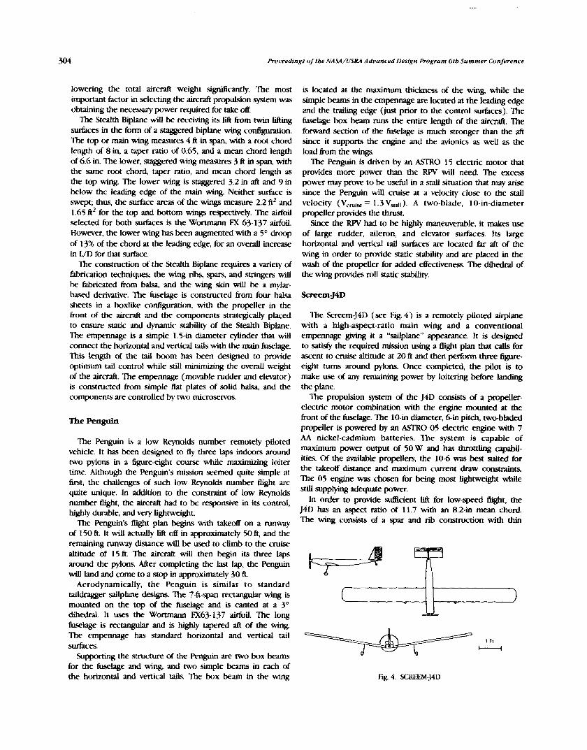
Pruceedi ngs of tbe NASA/USRA Advanced Design Program 6 t b Summer Conference
lowering the total aircraft weight sipficantly. The most important factor in selecting the aircraft propulsion system was obtaining the necessary power required for take off.
The Stealth Biplane wiJl be receiving its lift from twin lifting surfaces in the form of a staggered biplane wing configuration. The top or main wing measures 4 ft in span, with a root chord length of 8 in, a taper ratio of 0.65, and a mean chord length of 6.6 in. The lower, staggered wing measures 3 ft in span, with the same root chord, taper ratio, and mean chord length as the top wing. The lower wing is staggered 3.2 in aft and 9 in below the leading edge of the main wing. Neither surface is swept; thus, the surface areas of the wings measure 2.2 ft2 and 1.65 ft2 for the top and bottom wings mpectively. The airfoil selec-d for both surfaces is the Wortmann FX 63-137 airfoil. However, the lower wing has been augmented with a 5' droop of 13% of the chord at the leading edge, for an werall increase in WD for that surface.
The construction of the Stealth Biplane requires a variety of fabrication techniques, the wing ribs, spars, and stringers will be fabricated from balsa, and the wing skin will be a mylar- based derivative. The fuselage is constructed from four balsa sheets in a boxlike configuration, with the propeller in the front of the aircraft and the components strategically placed to erwre static and dynamic stability of the Stealth Biplane. The empennage is a simple 1.5-in diameter cyiinder that will connect the horizontal and vertical tails with the main fuselage. This length of the tail boom has been designed to provide optimum tail control white stiU minimizing the overall weight of the aircraft. The empennage (movable rudder and elevator) is constructed from simple flat plates of solid balsa, and the components are controlled by two microservos.
The Penguln
The Penguin is a low Reynolds number remotely piloted vehicle. It has been designed to fly three laps indoors around two pylons in a figure-eight course while maximizing loiter time. Although the Penguin's mission seemed quite simple at first, the challenges of such low Reynolds number Bight are quite unique. In addition to the constraint of low Reynolds number Bight, the aircraft had to be responsive in its control, highly durable, and very lightweight.
The Penguin's Bight plan begins with takeoff on a runway of 150 ft. It will actually lift off in approximately 50 ft, and the remaining runway distance will be used to climb to the cruise altitude of 15 ft. The aircraft will then begin its three laps around the pylons. Mer completing the last lap, the Penguin will land and come to a stop in appmxirnately 30 ft.
Aerodynamically, the Penguin is similar to standard taildragger sailplane designs. The 7-ft-span rectangular wing is mounted on the top of the fuselage and is canted at a 3 O dihedral. It uses the Worunann FX63-137 airfoil. The long fuselage is rectangular and is highly tapered aft of the wing. The empennage has standard horizontal and vertical tail surfaces.
Supporting the structure of the Penguin are two box beams for the fuselage and wing, and two simple beams in each of the horizontal and vertical tails. The box beam in the wing
is located at the maximum thickness of the wing, while the simple beams in the empennage are located at the leading edge and the traihg edge (just prior to the control surfaces). The fuselage box beam runs the entire length of the aircraft. The forward section of the fuselage is much stronger than the aft since it supports the engine and the avionics as well as the load from the wings.
The Penguin is driven by an ASTRO 15 electric motor that provides more power than the RW will need. The excess power may prove to be useful in a srall situation that may arise since the Penguin will cruise at a velocity close to the stall velocity (V,,,,, = 1.3 V,,,a). A two-blade, 10-in-diameter propeller provides the thrust.
Since the RW had to be highly maneuverable, it makes use of large rudder, aileron, and elevator surfaces. Its large horizontal and vertical tail surfaces are located far aft of the wing in order to provide static stability and are placed in the wash of the propeller for added effectiveness. The dihedral of the wing provides mil static stability.
The Screem-J4D (see Fig. 4 ) is a remotely piloted airplane with a high-aspect-ratio main wing and a conventional empennage giving it a "sadplane" appearance. It is designed to satis@ the required mission using a flight plan that calls for ascent to cruise altitude at 20 ft and then perform three figure- eight turns around pylons. Once completed, the pilot is to make use of any remaining power by loitering before landing the plane.
'The propulsion system of the J4D consists of a propeller- electric motor combination with the engine mounted at the h n t of the fuselage. The 10-in diameter, 6-in pitch, two-bladed propeller is powered by an A!XRO 05 electric engine with 7 AA nickel-cadmium batteries. The system is capable of maximum power output of 50 W and has throttlrng capabil- ities. Of the available propellers, the 106 was best suited for the takeoff distance and maximum current draw c o m a . The 05 engine was chosen for being most lightweight while still supplying adequate power.
In order to provide sufficient lift for low-speed @@t, the J4D has an aspect ratio of 11.7 with an 8.2-in mean chord The wing consists of a spar and rib construction with thin
Fig. 4. SCREEM-J4D

University of Notre Dame
plastic film skin. Its low mount and dihedral, in combition with the vertical tail, were designed to augment manewera- bility. A major problem, however, is that due to the nature of a low-speed mission, there is little margin for error betsveen the cruise and stall velocities. A square fuselage will contain the servos, engine, and payload, with adequate excess space so that the c.g. of the airplane is kept at about 33% of the chord
A combination of directional and longitudinal control will enable the J4D to perform the figure-eight maneuvers. However, in order to avoid the construction and sem weight of ailerons, the rudder was designed to be over one-half the size of the vertical tail to insure that the proper roll control could be attained
The Dawdler
. The Dawdler (see Fig. 5) is a remotely piloted airplane designed to By at low Reynolds numben (lo5). The airplane will be flying a closed course in a controlled environment. The purpose of the design is to study the difficulties that arise in the design of a low Reynolds number aircraft. The Dawdler is a canard con€i@ aircraft. It can also be considered a tandem wing configuration. The canard is designed to produce 30% of the total lift necessary to keep the aircraft in steady level fight. This configuration was chosen in order to atfain an upward lifting force from the horizontal stabilizer.
The aircraft is designed to tly at 25 ftlsec, which requires a relatively small amount of power from the engine. However, a large amount of power is required for the air& to climb to the design altitude of 20ft. Neglecting the takeoff performance of the aircraft, it was decided that the A!TI'RO 035 motor would supply enough power to keep the aircraft in steady level Bight. One of the main reasons for picktng the engine is its relatively light welght.
The takeoff will be accomplished via a remotely controlled, motorized cart assisted launch. The aircraft will be placed on top of a motorized cart that will accelerate the aircraft to a velocity of 45 ft/sec. At this speed, the aircraft will have enough kinetic energy to lift itself up to its cruise altitude. Once the aircraft reaches this velocity, the pilot can begin to raise the nose to lift it off the cart.
The Dawdler has a vertical tail mounted behind the wing for lateral stability and a rudder for yaw control. A 13" dihedral angle will be incorporated into the wings to assist roll control.
Fig 5. Dawdler
Ailerons have been omitted from the design to reduce the number of servos and the associated struaural complexity and welght. The canard will be fully movable for pitch control.
'Ihe FX/90 is a remotely piloted vehicle designed to satisfy the mission requirements and to investigate the unique problems involved in low Reynolds number flight. The aircraft will operate in a steady flight environment, free h m signrficant atmospheric turbulence and weather effects. The a i r d will take off within 75 ft, and will climb to an altitude of 20 ft within an additional 90 ft of ground distance. The aircraft will then commence its Bight plan, wbich consists of three figure- eight loops around two pylons spgced 150ft apart. Upon completion of the three laps, the aircraft will travel around the tlight envelope and return to the pit area for Ian-. It can do so under powered Bight, or it can travel an additional 60 ft and then ghde the remaining distance.
The F-90 has a 39-in fuselage constructed of balsa and plywood. The fuselage consists of two sections. The forward section is a 3.5 in X 3.5 in X 17 in rectangular structure in which the propulsion and fhght control systems are located The rear section is a 22-in boom with a truss structure and a square cross section that tapers to a point. The boom provides a moment arm for the tail &es. The length of 22 in is a compromise between the advantages of a longer moment arm and the disadvantages of the associated increase in weight. The truss construction was chosen for its high svength and torsional stihess with minimal weight.
The landing gear for the aircraft is a detachable carriage on which the aircraft rests prior to takeoff. The aircraft accelerates for takeoff while on the carriage. At takeo& the aircraft lifts off the caniage, and completes its Bight plan without landing gear. Landing is accomplished by setting down on the smooth lower surface of the fuselage. The propulsion system uses a foldable propeller to prevent damage during landmg
The aerodynarmc planform is a rectangular wing (no taper or sweep) with a chord of 9 in, a wingspan of 72 in, and is constn~cted entirely out of styofoam. Styrofoam was chosen for its low weight and relative ease of construction. "Aircraft quality" Styrofoam was chosen for its high strength and hardness and its smooth surface, which eliminates the need for a coating material. Special care must be taken when handling the wings, particularly the thin trailing edges.
The propulsion system consists of an A!STRO 05 engine and a 10-6 two-bladed propeller. The A!XRO 05 engine was chosen for its light weight and adequate available power. The 10-6 propeller was chosen for its efficiency in conjunction with the 05 engine and for its moderate diameter. The maximum velocity and rate of climb, as well as the maximum range and endurance, al l exceed the design requirements due to an excess of available power and battery energy storage.
Control of the aircraft is accomplished through the use of two movable control surfaces: elevators for pitch control and a rudder for yaw control. In addition, a large dihedral angle was used to couple the yaw and roll axis. This allows for roll maneuvers to be accomplished through the use of the rudder,

306 Proceedfngs of tbe NASAiUSRA Aduamced Drrfgn Program 6tb Summer Confwence
as well as providing adequate spiral stability. Ample rudder was provided in order to allow a high manewerabity, as required by the Bight plan.
There are several areas of concern. At takeoff, the landing gear wiU detach while traveling at approximately 24 ft/sec, which is a safety concern The air& flies at a high angle of attack, giving the aitcraft a low tolerance to gusts, and is near stall during manewers. The impact of a landing without landing gear, as well as its effects on components of the aircraft, is relatively uncertain. Finally, the performance of the foldable propeller is not weU documented, and its influence on the propeller performance was not evaluated.
System Technical Areas
The following brief sections address the problems in the five major technical areas: weights, structures, propulsion, aerodynamics, and stabiitylcontrol. A 6nal paragraph will then describe the concept prototypes and their flight demonstra- tions. Some of the basic parameters can be found in Table 1.
Weights
Each team was concerned about keeping the overall weight to a minimum. Table 1 also shows the overall aircraft weights. Each team used various means to cut weight. The RV90 used detachable landing gear, while the Dawdler, which has no gear, was launched from a radiocontrolled cart. Some teams chose smaller engines, while others built their fuselages with a hghtweight truss design. The results were six strong aircraft with a maximum weight of 50.7 oz Table 2 shows the weight firactions for each aircraft.
Parameter
v,, (fi /xc) Endurance (min) Weight (02)
(R2) span (fi) Length ( in AR Airfoil
The structural problems consisted of constructing a lightweight aircraft that could withstand the I& required during flight, especially t a k d and turns, and the structures needed to be both lightweight and durable. Another problem consisted of providing adequate interior space to keep the center of gravity at the designed location. Material selection was a crucial part of the structural design, and Table 3 shows the materials used in each aircraft. Most of the truss configurations were modeled and examined using a finite element analysis program.
Propulsion
Perhaps one of the most areas was propulsion. Each team needed an adequate propulsion system that would satisfy the nonairbreathing requirement. Electric, stored mechanical energy (rubber band) and stored compressed gas (CO,) systems were considered Only the electric systems appeared to provide the duration needed for this mission. Limited technical data were available on the lightweight, DC electric motors. Integration of the battery storage, electric motor performance and propeller selection proved to be critical in determining the success of the concepts. Takeoff power requirements far exceeded the low-speed steady-cruise requirements. Three groups decided on the ASTRO 05 engine, one chose the ASTRO 035, one the ASIllO 15, and one group used a Peck S i r Streak 035M. Some of the propulsion characteristics are found in Table 4.
Table 1 . Basic Air& Parameters
Stealth Biplane Penguin
Screem- J4D Dawdler FX/90
23.0 25.0 24.0 3.9 3.2 8.5 48.0 37.2 45.3 5.46 3.25 4.38 8.0 5.0 5.8 37.0 37.0 43.0 11.7 7.7 7.8 NACA 44 15 C l ~ k Y m63- 137
Table 2. SUuctural Component Weight Percentages
Fuselage Aircraft Propulsion Wing Empen.
Landing Geu Avionia Payload
Dmg-n-Fly 30.7 19.2 19.2 Stealth Biplane 28.0 26.7 5.3 Penguin 34.1 16.8 21.9 Screem-J4D 33.7 28.5 20.2 Dawdler 29.5 21.4 21.2 W W 29.5 22.2 28.5

Unfuenfty of Norre Dame 307
~primarypurposeofthedesignpropawastoevlluate the influence that the very low Reynolds number Btgt regime wwld have on the aircraft design Some of the problems in aerodynamics dealt with choosing an airfoil that would produce high lift coefficients without the risk of stall throughout the mission. Airfoil selection then involved . . m r s q q q lift hysteresis, minimizing drag, and choosing the planform parameters. The airfoils that were selected ranged Som the Wortrnann FX63-137 (improved aemdymmics), to a traditional Clark-Y (ease of manufacturing). P d I e drag prediction was complicated by the lack of data in this Reynolds number r;mge particularly in the area of interference &ects. Induced drag was minimized primady by using the high- aspect-ratio wing planforms. In hinds@, the low Reynolds number aspect of the mission primarily influenced the selection of the mean chord since cruise speed requkments were dictated by initial minimum weight estimates and predicted aMilable C, ,.
Stability and Control
Control concerns were primarily those of maintaining adequate static-pitch stability and the roll control necessary to perform the closed-course maneuvers. This was usually accomplished with two channels of control elaator and rudder, in order to eliminate the weight and complexity of the additional control for ailerons. This was accomplished by using large dihedral and oversized rudders. This allowed the aircraft to turn by coupling the yaw and roll axes. The main concern in the area of stability involved static, longitudinal stability.
Static matgins were kept at 5-lo%, and the centerdflty location was crucial to the success of each airaaft. Subseqwnt Btgt tests indicated that acceptable remote pilot control required even greater static margins
Each design team constructed their prototypes during the last three weeks of the project. They were issued Futaba Attack 4 radio systems, as well as their respective engines. AU construction took place in the Notre Dame Aerodpace Desi%fl Lab, where simple construction equipment was provided for the students At the end of the three we&+, a series of taxi tests was performed to test the systems and to check the air& for basic fightwotthiness and controllability. AU six aircraft experienced problems, especially in the areas of center- of-gravity placement, tuning of the control surfaces, landing gear s t i f k s s and aligment, and propulsion system battery performance.
On 4 May, 1990, the Bight demonstrations were held. F i of the six craft successfully performed at least a single complete figure eight. The sixth aircraft the Stealth Biplane, was underpowered and could not takeoff unassisted A hand launch was attempted that proved unsuccessful. Thfte of the aircraft, Drag-n-m, Saeem-J4D, and the FX-90 exceeded the range requirements completing as many a 10 laps of the course. Most appeared to exceed their target cruise speeds but handled very well under the control of an experienced pilot. Consideriq the lack of experience of the builders and the time constraints placed on the teams, this fight demonstration was considered a great success, and showed the students the Merence between a conceptual success and success in the real world
Table 3. Svuaunl Materials
Aircraft wmg p u s e k e Empennase
Dra%-n-% Spruce/B;llsl Spruce/Bals Spwe/Balsa
Stealth Biplane Eialsa Prywood
Bals Bals pensuin Spmce/BaIsa Spnrce/Balsa Spruce/Bals sCreem-J4D Spruce/Balsa Spruce/Balsa Spmce/Msa
Dawdler plywood
Spwe/Balsa Bals Bals no90 -foam f'lywmd/Balsa Baisl
Table 4. RopulYon Systems
Aircraft Motor 'Ijpe Prop Batteries
Drap-n-W Astro05 10-6 8X500mah M NiCad
StealthBiplvle Peck035 8-4 1 0 x O m a h M NiCad
Penguin -15 10-4 13X270rmh M NiCad
Smm-J4D Astro 05 10-6 7x600 mah M NiCad
Dawdler AstroO5 9 6 5 ~ 5 0 0 m a h W90 Astro05 10-6 7 x 500mah
M NiCad
Volts *em Weight F n c - Weight (02) tion (%)
11.3 34.8

Proroedings oft& NASNSRA Advanced Deslgn Rogram 616 Summer Conference
CONCLUSIONS A C K N m
The purpose of this course is multifaceted. The students entered the course with the knowledge required to complete the mission. The learning process involved the ability to incorporate that information into a design. They were shown the design process b m start (the request for proposals) to finish (the prototype). They were immersed into many real world problems faced by engineem These included worlung in a team and integrating seven engineers' ideas and work into one design. They were given the ojprtmity to experience the comtruction process, and how one must "bridge the gap" between a concept on paper and a Bightworthy aircraft.
The students' results, namely their proposals and prototypes, indicate that the goals were achieved. Although they may soon forget their aimaft's design, hopefully what they hne learned will help them wherever their careers take them.
This project was supported by NASA/USRA Advanced Aeronautics Design Program. Technical assistance and guidance was provided by the Boeing Company under the coordination of Mr. Cal Watson and Mr. Robert Wickemeyer. The course was presented by Dr. Stephen M. Batill, and graduate teaclung asshtants David M. Carey and Todd \! Graves. Sections of this report have been edited from the final proposals submitted by each design group. thanks must go to Mr. Joseph Mergen, Mr. Joel Preston, and Mr. Mike Swadener for their technical assistance and advice throughout the semester.

A HYPERSONIC RESEARCH VEHICLE TO D E V W P SC-T ENGINES
Four student design teams produced conceptual designs for a r e s a r h vehicle to develop the supersonic combustion ramjet (scramjet) engines necessary for dc ien t hypersonic Bight. lhis research a i r d would provide Q h t test data for prototype scramjets that is not &able in groundbased test facilities The design specifications call for a march aircraft to be launched from a carrier aircraft at 40,000 ft and a Mach number of 0.8. The airct;lft must accelemte to Mach 6 while climbing to a 100,000- ft altitude and then ignite the w e n d scramjet engines for acceleration to Mach 10. The research vehicle must then be recowred for another Bight. The students responded with four ditkrent designs, two piloted, -rider contigurations, and two unmanned vehicles, one with a blended wing-body cdguration, the other a delta wing shape. M lircnft made use of an engine database provided by the General Electric Aircnft Engine Group; both tuddmmmjet and a n d j e t engine performance using liquid hydrogen fuel was presented This paper describes the students' conceptual designs, and the -c and propulsion concepts that made their designs practical, as well as touching upon interesting problems that wkud during the design process.
The Ohio State University (OSU) Advanced Aeronautical Design Program (ADP) has focussed upon hypersonic vehicle design concepts for the last three years. With the assistance of staff from the NASA Iawis Research Center, OSU has developed conceptual hypersonic designs of both commercial, 250-passenger aircraft and 10-passenger executive jets. These craft, weighmg near one million pounds and 200,000 pounds, respectively, could cross the Paci6c in less than three hours. 'Ihis year, the design project continues the hypersonic tradition with the task of designing a Hypersonic Research Vehicle (HRV) that would be used to develop and fight test the spe- cialized air-breathing, supersonic combustion ramjet engine called a scramjet.
The earlier OSU design concepts operated at Mach numbers below Mach 6, a flight regime that allows variable-cycle air- breathing engines that can use subsonic combustion processes. However, as flight Mach numbers increase above Mach 6, scramjet engines become the only viable air-breathing concept as shown in Fig. 1, a graph of specific impulse versus flight
Mach number for several candidate engines. Conceptual designs at these high Mach numbers must, therefore, employ xramjets. The National Aerospace Plane (NASP), for example, now scheduled for W flight in the later part of this decade uses scramjets to accelerate to near orbital speeds.
Although the concept of scramjet engines has been studied for many years, the practical application of the supawnic combustion process has not been tested extensively. One reason is the lack of adequate ground simulation fkilities that can duplicate the high t e m p e r a m and pressures the engine will encounter during hypersonic Bight. Figure 2 illustrates the went and descent trajectories of a single stage to orbit (SSIY))
air breather and superimposes the groundbased facilities presently available to these scramjet propulsion concepts. The newest facility, the Rocketdyne Hypersonic Flow Laboratoty (RHYFL) appears to cover a reasonable range of flight conditions, but its duration of operation is in the millisecond range, making engine testing dBcult. Before risking new aircraft designs on a relatively undeveloped engine concept, it
Fig. 1. Propulsion System Operatmg Regimes Fig. 2. Ground Test Facility Capability
ORlGlNAL PAGE IS OF POOR QUALITY

ORIGINAL PAGE IS of POOR WALm
310 Proceedings ;'be NASA'uSRA A d ~ ~ @ n c e d Design R o g r n n 6tb Summer Conference
appears prudent to develop a test vehicle that can expose the scramjet to the actual fight environment.
The OSU design spcdcation (Table 1) evolved born this desire to provide just such a grlng platform to test the scramjet engines. In an &rt to reduce costs and fuel weight, the HRV is to be carried to altitude by another aircraft, dropped at Mach 0.8, and then acceladte and climb to Mach 10 at 100,000 ft. The HRV must maintain steady, level Bight for two minutes to allow engine performance data to be recorded and then return to base. The vehicle may be either piloted or unmanned, but the intent was for an aircraft that would be well instrumented and used for many engine development Bights nK means to accelerate from Mach 0.8 to Mach 6 was not m e d
Table 1. HRV Speci6cations
Ah lifted and dropped from carrier air& at Mach 0.8 and 40,000 A Accelerate and climb to Mach 6 and 100,000 ft Ignite scrvcja engine(s) and accelerate to Mach 10 Maintain Mach 10 at 100,000 ft for two minutes Remmuldluldatbase
Four design teams were formed to develop the HRV to these tpedications. lbo teams chose to design manned vehicles, two selected unmanned concepts. AU design groups had engine data packages 6rom the General Electric Aircraft Engine Group. 'Ihe packages provided engine net thrust, air flow, and he1 flow rates for two types of engines, a turbokmamjet and a scramjet. Full-scale tuhdkmmjets, shown in Fig. 3, can produce 20,000 Ib of thrust at Mach 0.8 and 40,000 ft, and can opente to Mach 6 at 100,000 ft. The scramjet module, also shown in Fig. 3, produces 5,000 Ib of thrust at Mach 10 and 100,000 fi. GE also provided the scahg laws to allow the design groups to tailor the engines for their particular conBguntion The four design concepts are presented in the following
section. The teams were designated Red, White, Blue, and Gold with the Red and White groups w o w on the manned aircraft and the Blue and Gold teams developing unmanned vehicles.
The air& that would drop the HRV was not considered by the OSU student teams. In a unique international co- operative &rt, students h m Ecole Polytechnique Feminine desigr~ed the carrier airaaft.
AIR- DESIGNS
The Red group aircraft, Figure 4% is a waverider configu- ration to take advantage of the high lift-todq ratios that can be obtained using this shape. It is a manned aircraft; therefore, it must carry life support systems. The Red team's con6gwation is the largest aircraft having a planform area of 2,300 sq ft and a drop wemt of 59,000 Ib. It uses two turbo-, d e d at 65%, outboard of four scramjet modules. Since the turbofanramjets are outboard, they are not completely contained in the waverider shape. This separation of engines allows the inlets for each propulsion system to be optimized for its own operating range.
The White group's aircraft is also a waverider and is shown in Fig. 4b. It has a drop weight of 53,000 b and a planlbrrn area of 2,100 sq fi. Five scramjet modules are located on the bottom surface of the body under the two, 80%-scaled turbobmmjets, providmg an over-under engine con&mtion. A slngle inlet for both engine systems is possible with this arrangement and the turbofanramjets can be completely contained in the wmrider body. lhis is the setond manned configuration.
The major design thrust of the Blue group was to design a small aircraft to make the carrier's job easier. This was accomplished using the blended wing-body contiguration shown in Fig. 4c and a rocket assist. Drop weight is 44,000 lb and planform area is 1,711 sq ft. A feature of this a i d is its separate inlets for the three scramjet modules and the 92% hhohmnje t . The turbotimanjet engine is located on the bottom surface of the body; conversely, smmjets are on the top surEace of the body. For each system the inlet and the tespeaive forebody are integrated to give the best system performance. This configuration is the Grst of the tmmamed air&.
The Gold team designed a delta m f t g u d o n (Fi 4d). It uses one, 100% ludxhmmjet and four scramjet modules to power the vehicle. As with the Blue team they use a rocket assist for the initial acceleration h m the drop. This was done to minimize fuel usage and to increase acceleration in going to the test conditions. Higher accelerations om be used because it is the second unmanned configmuion The drop weight of 62,000 Ib includes the welght of the solid rocket boosters; the pfanform area is 720 sq ft
General Electric Turbofanra General Electric Scramjet Module
pel- Yovn# -,,,,- (Y"UO.hl &*u
Fig. 3. w o n Srst-
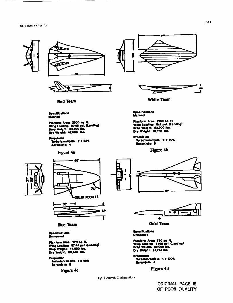
Obio State University
Red Tern White Team
phtornk..: ljOOB&fi W l q L#dh a0.m Pol. adw Drop mlghk aD.000 Ik. Dry W4bht: 47COO b8.
Figure 4a
Figure 4c
M k r m kor t(OO W. ft W l q W l n O : m.0 Pol. (Lmdlfie)
Wbht: 15.000 Ibr Wobhb aa.na I-
F i e 4b
Figure 4d
Fig. 4. Aircraft ConfiWonS
ORIGINAL PAGE IS OF Pi- V J A J m

Proceedings of tbe NASA/USRA Advanced Design Program 6th Summff Conference
DESIGN RESWIS
Each design group dkl a comprehensive study of their configuration weight, aerodynamics, propulsion system (including inlet con@&on), and heating. There is not space to review all the details of each design here; instead iepffsentativeresultsfromtheteams'designswillbediscussed to p d d e a Bavw of the HKV design process.
Sevenl we@t estimating methods were used by the design groups Methods in ~icoi;li(') and ~oskun(') texts and a NASA Lewis Reseatch Center WM'IS ~ r o g n m ( ~ ) provided empty and
weight estimates. ?he HRVs dmp weights ranged from 44,000 Ib to 62,000 lb. 'Ihe unmvlned whicles had the lowest empty weights, 30,400 Ib and 36,800 Ib for the Blue and Gold team cespeaively, while the manned whicle empty weights were 47,500 Ib and 39,200 Ib for the Red and White designs
Figure 5a i l l m t e s the component weight distribution fw the White and Blue team designs The heavier White manned ;liraaft had a sbuaure and engine we@t of 28% and 32% of the total drop weight of 53,000 lb. The unmvuKd Blue HRV had a structural and engine weight of 13% and 22% for its drop wdght of 44,000 Ib. The distribution of the fuel used for the three phases of powered @ht: acceleration under
to Mach 6, acceleration of Mach 10 during scramjet apecation, and the fuel used during the twominute, steady &&t, is also shown in Fig. 5b. While the mmider uses
Fig. 5a Weight Percentage M u t i o n
47% of its fuel during aaderation, the un- manned Blue HRV uses but 31% since the Blue vehicle uses a short mcket boost. On the other hand, the Blue HRV burns 720 Ib in two minutes at Mach 10, whereas the White, low- drag waverider, uses but 600 Ib.
One of the first considerations when deciding on the propulsion system was the type of fuel to be used Figure 6a shows a comparison of mass energy density and volumetric energy density for three fuels liquid hydrogen (I&), liquid methane (LC)4), and Jet h Although LH2 has a high mass density, a penalty is paid because of its low volumetric density. Ihe Candidate Engine Performance presented earlier indicates good pefbimance for all the engine systems using hydrogen fuel; therefore, all pups decided to use the LH, and take the volumetric penalty. nK Candidate Engine Perbrmance Chart also shows the performance of solid rockets in the range of the proposed mission Euly in their design studies, the teams found that if their airazft were to use solid rockets exclusively for the acceleration, the fuel weight would be prohibitively high because of the low specitic impulse of rockets. None of the four configurations used solid rockets as the only acceleration system.
Because of the volume penalty when using liquid hydrog~ the design groups used sAwal methods for reducing the fuel weight. A large portion of the f k l is used during the xrampt burn dunng the acceleration from M = 6 to M = 10. The White team did a trade study to determine the optimum number of scramjet engines to minimize the fuel while limiting the weight penalty of additional scramjet modules Figure 6b shows the number of engines versus the fuel weight to accelerate the HI&! A s modules are added the required fuel weight is reduced The students determined that the optimum number of scramjets is five because the weight penalty paid for having the sixth scramjet module is greater than the fuel =i"fF.
Fi 5b. Fuel Weight Percentage Distribution

OM0 State Unlvml ty 313
Fig 6b. Number of Engines vs Fuel Weight for O r j e t Operation
?Lpical performance data obtained from the engine data for the two types of engines ace presented in Fig. 7. The thrust as a hction of Mach number for the -w is shown as a function of altitude. The engine thrust increases with Mach ' number, but decreases significantly with altitude. The scramjet engine Mach number performance is shown as a function of Q, the dynamic pressure, a convenience, since many climb mjectories are perhrmed at constant Q. Again, the decrease in net thrust with altitude (lower Q at tixed Mach number) isobserved
An integral part of the propulsion indlation is the inlet design. Each group had different inlet designs; inlet configu- rations varied from complete@ sepgtate engine systems, as in the Blue design, to common inlets for both engine types, as in the White design The inlet designs shown in F i i 8 are repmentatk of the inlet configurations examined by the student teams. AU are -1e geometry inlets, n v to accommodate the changitlg clpture areas required for the lvge range of Mach numbers and altitudes An example of the pressure recovery for two inlets is shown, one for the twbohmnjet and another for the scramjet inlet. lhe Ggure is for the Red &craft which had separate inlets for both engines; the turbo- inlet is axQmetric, while the scramjet inlets are two-dimensional.
0 l I 0.000 2.000 4.000 6.000
Mach Number
Fig 8a Scramjet Inlet M = 6.0
Fig. 8b. Scramjet Inlet M = 10.0
Fig. 7a nYbo-let P e r f o m e
0 0 2 4 6 8 10
Mach Number Mach Number
Fig. 7b. Scramjet Performance Fig. &. Inlet Pressure Recovery

Procerdlngs of tbe NASA/USRA Advanced Design Program 61b Summer Conference
A vital part of the design is the vehicle aemdymmics. Be- cause each aircnft tlies through subsonic, supersonic, and hypeswnic regimes, several methods were used to determine the aerodynamic characteristics. Primarily, the methods outlined in Nicoiai's book, I;utukmenkJs ofAfm@ Des&dl) were used to determine the subsonic and supersonic characteristics. Other methods incorporated included shock expansion theory and Newtonian methods for hypersonic flows.
The two manned aircraft that used a waverider con6guration developed the shape using a program called MAXWARP developed by Dr. S. Corda and Dr. J. Andaon at the University of ~aryiand(*). Since a waverider is optimized for a certain Mach number and altitude, initially there was a question of the valdity of using a wdverider shape for these aircraft since they will not be at any paxticuku Mach number for an extended period of time. Figure 9 shows a cornpatison of waverider shapes at Mach numbers of 6,8, and 10. After comparing these shapes and consulting with the University of Maryland, it was determined that the offdesign characteristics of the wmwiders will be good enough to lustify their use in the designs. Using the methods discussed above, plots of the Red group's waverider drag polar and lift-to-drag ratios versus Mach number were generated and are shown in Fig. 10. Note the
thrust "pinch as the vehicle accelerates through Mach 1 and the increasing lift-todrag ratio as the waverider reaches its design flight condition.
A model test of the Red group's waverider was conducted in the OSU 3' x 5' subsonic wind tunnel using a 1/72 xale model. ti& and drag coetlicients were found as a function of angle of attack using a three-component balance. These data, shorn in Fig. 11, agree well with the subsonic aerodynamic e5timates.
Heating and GwIlng
In any hypersonic design, aerodynamic heating is an important concern. Since the HRV is to fly at hypersonic speeds for less than 15 minutes, questions were raised about the time required to reach equilibrium skin temperature. After discussing this problem with engineers at NASA Lewis Research Center, the OSU mentor center, it was determined that the vehicles could heat to steady state in less than a second and there would be no need to account for unsteady heat transfer. The worst case of steady-state heating was considered by each group; that is, the highest skin temperature was &ed when the conwctive heat input was balanced by radiative output. This eqdibriwn temperature distribution for the Red team's air& is shown in Fig. 12.
Because of these high temperatures, over 3500°F at the nose and inlets, special materials and several methods for cooluvg are required. Wherever possible radiative cooling of the structure is used because it requires no coolant to be carried Hastelloy-x is used in these areas. Other systems incorporated are liquid comctive cooling and a carbon/carbon integrated heat pipe structure for the leading edges, shown in Fig. 12. At the nose, a JTA graphite composite must used. While this material can sustain high temperatures, it must be replaced after a few Bights.
One of the interesting operational aspects of this project was th tlight prose of a t p i d w t . 4.
optimizing the climb trajectory, a substantial saving in fuel can be obtained. Figure 13 shows one of the& optimized
Fig. 9. Waverider Comparison
O . m -. 8 -0 kbmolc Y-0.8
[email protected] Y-2.0 0.400 .. A-A H)tp.rroalc Y-10.0
ar
O8ubwnic Theory Sup.t.onhc theory
&..render -run
P
I m 0 L 4 1 80
Mach Number
Fig. 10. Theoretical A-cs

Obio State University
Lift Coefficient vs. Angle of Attack Drad Coefficient vr. Angle of Attack
Fig. 1 1. Wind lbmel Data
Fig 12. Equilibrium Temperatwe Distribution and Materials
Altitude V. Mach Number Ascent Altitude V. Distance
Mach Number Distance (miles)
Fig, 1 3. Flight Profile
ORIGINAL PAGE IS OF POOR QUMrrY

316 Proceedings oftbe NASA/USRA Adtlanced Design Program 6tb Summer Conference
trajectories. Also shown is the transition from turbofanramjet to scramjet operation. A somewhat unexpected result is the distance required for a research Bight. Accelerating to Mach 10 and maintaining Mach 10 for two minutes requires a s&raight line distance in excess of 1500 miles.
The large distance to accelerate and slow down creates a problem of where to By the research vehicle. Rvo prospective Bight paths are depicted in Fig. 14. One path is a drop just off the coast of Alaska with a landing at NASA Dryden Flight Testing Center; the other is a drop in Maine and a landing at NASA Kennedy Space Center in Florida. At this time the west coast site would probably be used, because all four of the research vehicle designs have skids for landing gear and the Dtyden site is the dry lake bed rather than concrete. The drop location also impacts the tamer aircraft design, requiring the carrier aircraft to kly out a considerable distance with the HRV.
A final observdtion is that the Bight paths are all over water. This is done so that any sonic booms created by the aircraft do not disturb populated area. An estimate of the largest overpressure caused by a sonic boom is shown in Fig. 14. Of interest is the overpressure of one Ib/ft2 which may be a tolerable sonic boom preswre over land.
SUMMARY
Four conceptual designs for a hypersonic research vehicle have been developed by four design teams. ' b o concepts are manned vehicles, two are pilotless. ?he motivation behind these designs was to allow supersonic combustion ramjets to be tested and refined in the actual flight environment, since ground based facilities cannot duplicate the extreme pressures and temperatures of hypersonic tlight. Characteristics of the four configurations are presented in Fig. 15.
The summary table (Fig. 15) pre.wnts a comparison of pertinent performance data for the four HRVs. For example, the low wing loading of the waveriders in contrast to the unmanned vehicles can be noted on the order of 20 lb/ft
AP vs Altitude
Boom Presswe
97,000 Ib.. 47,000 Iba- Empty Weight 47.600 Ibr 39,172 Ibr 30.400 Ibr 38.774 Ibw. Length W It 86 ft 80 ft 86 I t 8o.n .48 ft 48 ft 37 ft 40 11 wj5 (Ld lng ) 20.6 prf W.8 0.1 37.4 pol 61.0 yuf T IW (hop) 0.42 0.67 169 . 12
0.36 a* 0.44 LID (WlO) 6.6 6.2 4.6 12
-with booster rock~ts -*without bmtmr m c b t r
Fig. 15. Aircrafr Summary
compared with double that value for the unmanned aircraft. The low wing loading, of course, will allow low landing .speeds for the waveriders. Similarly, the thrust-to-weight ratios for the w-dveriders are sipficantly lower than the rocket-boosted, unmanned HRVs, requiring longer acceleration times and increased hydrogen fuel usage. On the other hand, the effic-ient lift-to-drag ratios near L/D = 6 of the waveriders can be compared with the lower L/D values of the more convention- ally configured aircraft.
Cost of producing a single research aircraft is also shown in Fig. 15, with the manned aircraft approximately a billion dollars more expensive than the unmanned HRVs. Whether this cost can be borne by the United States over the next five for six years to develop an operational scrarnjet engine with the potential for efficient air breathing flight to near orbital speed was not a consideration for the students. The students did consider the merits of a manned machine versus an unpiloted vehicle with rach group supporting its design view. Manned
Flight 1 - v-1 a - - & f a I r--,.tlpnl(la-- -
Fig. 16. Sonic Boom Overpressure and Flight Path

Obio State University
vehicles would be flexible with pilots handling unexpected REFERENCES engine problems and research opportunities at the expense of weight and life support systems, while unmanned vehicles 1, Nicolai, LM., Fundamentds of Ahre@ Design. San Jose, cA:
would not endanger a pilot's Life, be cheaper and lighter in -Inc.* 1974. 2. Roskam, J., AIrphne Design. University of Kansas, 1986. wei*t. a manned HRV would provide much 3. Glatt, C.E, Weights Analysis of Adwr~ced Tmqortation Systems.
operational hypersonic Bight experience, once the engines N ~ C R - 2 4 2 0 . were proven. While these questions remain, the design task 4. Corda, S., 'Vious Optimized Hypersonic Waveriders Designed
certainly worth the student &fort, with the results h m Horn over Cones and Minimum Drag Bodies". University of
a contribution to this controversial problem. Mvyland 1988.


CARRIER AIRCRAFT
ECOLE POLYTECHNIQUE J3MININE N 9 i - k 8 1 6 8
'Ibis year the Ohio State University planned to conduct a conceptual design of a single research aircraft that could be used to explore the fight regime from Mach 6 to Mach 12.
Since this aircraft will be a special purpose vehicle, it need not take otT and land in a conventional manner. Indeed, if this aircraft were launched from a larger aircraft that carried it to altitude, then conventional landing gear would not be needed, and the extra weight of the fuel to take off and climb into the stratosphere would be eliminated.
The focus of EPF students' project was on the design of a carrier air& answering to the specifications. Its mission is
PReCEDlNG PAGE BLANK NOT FILMED
to take ofT with the research aircraft from runways of less than 15,000 ft, climb to 40,000 ft, and release the hypersonic aircraft at the speed of Mach 0.8, and return to base. The range of this mission is 2000 n.m.
This study includes the conception of an optimized aircraft (geometry, weights, propulsion, aerodynamics, interactions between the two aircraft, etc.), the longitudinal stability of the composite, and the separation critical phase.


OR\OINAC PAGE IS .-.
DESIGN OF A HIGH SPEED BUS- TRANSOR'I' 1 , 7 PURDUE UNIVERSITY
The design of a High Speed Business Transport, the HSBT, was considered by the Aeronautical Design Class during the academic year 1989-90. The project was chosen to offer an opportunity to develop user friendliness for some computer codes such as WAVE DRAG, supplied by NAWIangley, and to experiment with several design lessons developed by Dr. John McMasters and his coUeagues at Boeing. Cenval to these design lessons, used at the begmmg of each semester, was an appeal to marketing and feasibility considerations 6rom the very beginning and the emphasis upon simplified analytical techniques to study trades and to stimulate creative thinking before cornmining to extensive analytical activity. AU design teams considered the same general category of
aircraft, one that was to fly supersonically to foreign business regions. Neither the Mach number nor the range were specified by the instructor. The choice of number of passengers was also undefined initially. As a result, no design group developed exactly the same RFP. A l thou a number of excellent designs were developed, two designs stood out above all the rest because of the depth of thought and consideration of alternatives. These two designs used quite &erent methods to meet approximately the same RFP
One design, the Aurora, used a fixed wing design to sat* the design mission, while the other design, the Viero, used a swing wing configuration to overcome problems related to overland supersonic Bight. The Aurora design was composed of seven students led by Mr. Lyle Dailey, while the Viero group consisted of tive students led by Mr. Dan Cler. What follows is a summary of each of those designs.
AURORA DESIGN SUMMARY
A Request For Propod (RFP) was developed for a Mach 2.2, 8-passenger business transport with a range of 4980 n.m. capable of sening transpacitlc business routes. ?he Aurora will have an approach speed of 160 kts. The target date for delivery of the Aurora is the year 2005. The Aurora cm deliver passengers from Los Angeles to Tokyo in 4.43 hours, -gproximately one-thud the travel time of current subsonic aircraft. d p e 1 provides a three-view of the Aurora together with sevwal cabin arrangements.
The Aurora has an ovetall length of 110 ft and wing span of 47.2 ft. The external hull diameter is 6.5 ft at its maximum dimension. The cabin section has a length of 24 ft 8 in (including flight deck) and an internal diameter of 5 ft 8 in, allowing an aisle height of 5 ft 6 in. The cabin has first class seating with an l&in aisle width and 44-in seat pitch.
A three engine configuration is used to satisfy FAR 25 one- engine-inoperative safety requirements for transoceanic flight.
One podded engine is located under each wing, with the third engine placed on top of the aft fuselage extending through the vertical tail.
R
PRECEDING PAGE P:.WFslK NOT FSLPdED
Fig. 1. Aurora Three View and Cabin Layout
Aurora Design Features
A long-range supersonic transport such as the Aurora requires high aerodynamic efficiency, measured by the lift-to- drag ratio (L/D) during supersonic cruise, to minimize fuel requirements and to maximize range. However, supersonic vansports must also operate effectively at subsonic speeds, especially for takeoff and landing.
Because of these requirements, a highly swept, low aspect ratio, modified arrow wing was selected because of its low supersonic cruise drag. Wing geometry information is contained in Table I . The Aurora has a trimmed supersonic L/D of 7.07 at cruise.
~AG~X; ~ r u i ~~JI~USIAUY BUM
ORIGINAL PAGE 18 OF POOR QUALITY
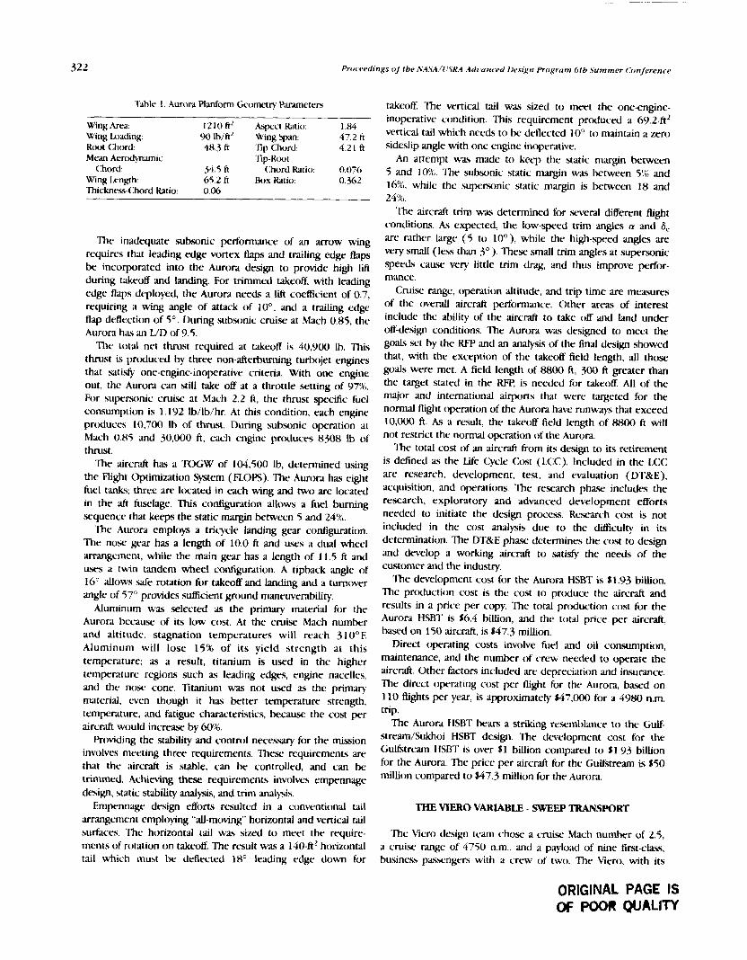
Proceedings I/ the NASA/(rSRA Adr 'u~ iced Ilesig?~ Program 6th Summer <,-onji.rrnce
'Vhlr 1. Aurar.! Planform Geometry Parameters - -
Wing Ara: 1210 ftL Aspect Ratio: 1 .W Wing 1~r;iding: lb/ftL wing ~ p m : 47.2 ft Root Chord: 48.3 ft 'rip Chord. 4.21 ft Mean Aeroct)namic Tip-Root
Chord: 54.5 ft Chord Ratio: 0.076 Wing Imngth: 65.2 fi Rox ktio. 0.362 Thicknrss-Chord Ratio: 0.06
The inadequate subsonic performance of an arrow wing requires that leading edge vortex flaps and trailing edge flaps be incorporated into the A m r a design to provide high lift during takeoff and landing. For trimmed takeoff, with leading edge flaps deployed, the Aurora needs a lift coefficient of 0.7, requiring a wing angle of attack of lo0, and a trailing edge flap deflection of 5' . During subsonic c n t i x at Mach 0.85, the Aurora has an L/D of 9.5.
The total nct thrust required at takeoff is 40,900 Ib. This thrust is prtduced by three non-afterburning turbojet engines that .satis@ one-engine-inoperative criteria. With one engine out, the Aurora can still take off at a throttle setting of 97%. For supersonic cruise at Mach 2.2 ft , the thrust specitic fuel consumption is 1.192 Ib/lb/hr. At this condition, each engine prcduces 10,700 Ih of thrust. During subsonic operation at Mach 0.85 and 30,000 ft, each engine prtduces 8308 Ib of thrust.
The aircraft has a TOGW of 104,500 Ib, determined using the Flight Optimization System (FLOPS). The A u ~ ~ r a has eight fuel tanks; three are located in each wing and two are located in the aft fuxlage. This configuration allows a fuel burning .sequence that keeps the static margin between 5 and 24%.
The Aurord employs a tricycle landing gear configuration. The no.= gear has a length of 10.0 ft and u.ws a dual wheel m g c m e n t , while the main gear has a length of 11.5 ft and uscs a twin tandem wheel configuration. A tipback angle of 16" allows safe rotation for takeoff and landing and a turnover angle of 57" provides sufEcient ground maneuverability.
Aluminum wa selected as the primary material for the Aurora hecause of its low cost. At the cruise Mach number and altitude, stagnation temperatures will reach 310°F. Aluminum will lose 15% of its yield strength at this temperature; as a result, titanium is used in the higher temperature regions such as leading edges, engine nacelles, and the nosr cone. TItanium was not w d as the primary material, wen though it has better temperature strength, temperature, and Edtigue chardcteristics, hecause the cost per aircraft would i n c r a w by 60%.
Providing the stability and control necessary for the mission involves meeting three requirements. T h e requirements are that the aircraft is stable, can be controlled, and can be trimmed. Achiwing these requirements involves empennqe design, static stability analysis, ;md trim analysis.
Empennage design efforts resulted in a conventional tail arrangement employing "all-moving" horizontal and vertical tail surfaces. The horizontal tail was sized to meet the require- ments of rotation on takeoff. The result was a 140-ft2 horizontal tail which must be deflected 18' leading edge down for
takeoff. The vertical tail was sized to meet the one-engine- inoperative condition. This requirement produced a 69.2-ftz vertical tail which needs to be deflected 10" to maintain a zero sideslip angle with one engine inoperative.
An attempt was made to kecp the static margin between 5 and IOR,. The subsonic static margin was between 5% and 16% while the supersonic static margin is between 18 and 24%.
The aircraft trim was determined for .several different flight conditions. As expected, the low-speed trim angles a! and 6, arc rather large (5 to lo0), while the high-speed angles are very small (leis than 3"). These small trim angles at supersonic speeds c x u x very little trim drag, and thus improve perfor- mance.
Cruise range, operation altitude, and trip time are mcmures of the overall aircraft performance. Other areas of interest include the ability of the aircraft to take off and land under off-design conditions. The Aurora was designed to meet the goals set by the RFP and an analysis of the final design showed that, with the exception of the takeoff field length, all those goals were met. A field length of 8800 ft, 300 ft greater than the target stated in the RFe is needed for takeoff. AU of the major and international airpons that were targeted for the normal flight operation of the Aurora have runways that exceed 10,000 ft. As a result, the takeoff field length of 8800 f t will not restrict the normal operation of the Aurora.
The total cost of an aircraft kom its design to its retirement is defined as the Life Cycle Cost (LC<:). Included in the LCC are research, development, test, and evaluation (DTBrE), acquisition, and operations. The research phase includes the research, exploratory and advanced development efforts needed to initiate the design proce?is. Research cost is not included in the cost analysis due to the difEculty in its determination. The DT&E phase determines the cost to design and develop a working aircraft to satisfy the needs of the customer and the industry.
The development cost for the Aurora HSBT is 11.93 billion. The production cost is the cost to prcduce the aircraft and results in a price per copy. The total production cost for the Aurora HSBT is 16.4 billion, and the total price per aircraft, based on 150 aircraft, is $47.3 million.
Direct operating costs involve fuel and oil consumption, maintenance, and the number of crew needed t o operate the aircraft. Other factors included are depreciation and insurance. The direct operating cost per flight for the Aurora, bawd on 110 flights per year, is approximately $47,000 for a 4980 n.m. trip.
The Aurora HSBT hears a striking resembkance to the Gulf- stream/Sukhoi HSBT design. The development cost for the Guktream HSBT is over S 1 billion compared to $1 93 billion for the Aurora. The price per aircraft for the Guktream is 150 million compared to $47.3 million for the Aurora.
THE VIER0 VARLQBLE - SWEEP TRANSPORT
The Viero design team chose a c m i . ~ Mach number of 2.5, a crui.se range of 4750 n.m., and a payload of nine first-cias.., business pawngers with a crew of two. The Viero, with its
ORIGINAL PAGE IS W Poolr QlJALTTY

&able-sweep wing shown in Fig. 2, was designed to meet the needs of fast and long-range business travel. It also must have a substantially better subsonic cruise efticiency than a typical supersonic transport to be competitive with currcnt business aircraft. Table 2 presents performance parameters of the Viero.
Scak I -10
Fig. 2. Three-View of the Mero Executive Jet
Table 2. Mero Performance Pardmeters
2500 Maximum Passengers
* Zoo0 3 \
RANGE (NM)
Fig. 3. Mero Payload-Range Curve
The Viero's takeoff and landing field lengths allow the use of smaller airports. The FAR 25 balanced takeoff distance is 3300 ft. The balanced landing distance is 4700 ft.
Figure 4 shows the fuel burned during a \'iero mission per trip cost is more than 617,700, since 73,700 Ib of JP8 fuel are used bawd on $1.50 per gallon (t)picd private aircraft fuel costs).
The Viero is compared to the Concorde in Fig. 5. The structure of the Viero is designed to k c t ~ the mmpty weight to a minimum. Ry using integrally stiffened skin panels and lightweight composite materials for the structural cover, ttlc weight is reduced hy about lo%, when compared to a similar aircraft constructed of aluminum.
The cabin layout shown in Fig. 6 will %at nine first-cl&*c,
Cruix Mach Number 2.5 business paxwngers. Se\feral aspects of the Viero make it stand Cruise Altitude 73,000 A (supersonic) out from other HSRTs. The high cruisc wing loading crratcs
35,000 A (subsonic) a smtn~th and comfortable ride by not k i n g so sensitive to
Takeoff Gross Weight 128,348 Ibs Payload 1,881 1bs Operating Empty Weight 54,264 Ibs Fuel Burned 73,724 lbs (JW)
atmospheric disturb;inces. The swing wing utilized on thc V'iero not only allows for supersonic flight but enables cficicnt subsonic cruise over land where supersonic flight is not allowed. The \atiable-swecy, wing allows takeo& and landings
Block Tlme Block Fuel
Takroff Distance Takeoff g's landing Distance
Rate of Climb
from smaller. less congested airports. 5,262 n.m. (including rewrves) Bawd on an operating empty weight of 52,000 Ib, a design
4 hrs 34 ,,,in (including rewwes) s p e d of Mach 2.5 , and an estimated production quantit) o f 72,2(K, Itm 200 between the yrars 2(X)2 and 2016. the k'icro cost is
3,357 fi 0.12 g's 4.610 ft
j-000 A/s (cruise) 9,300 fils ( x a level )
Thrust 17,000 Ibs per engine Cruise Specific Fuel Consumption 1.192 Ibs/lbs/hr(supc~~(>~c)
0.8 Ibs/lbs/hr (subsonic )
Wing Refermce Area 1,032 A' Wing Spans 89 f t (unswcpt ). 55 A (swept ) Aspect Ratio 7.624 (unswcpt), 2 93 1 (swcpt)
W i g loading 120.9 IbslftL (ma) Cruise Lift-To-Drag Ratio 6.3 (supxjonic), 14.7 (subsonic )
The Viero payload-range curve (Fig. 3) indicates that the Men, payload has little effect on range because the maximum payload is less than 1.5% of the takeoff gross weight. For most commercial transports the payload can comprise almost 504, of the takeoff gross weight.
TAXI OUT
TAKE OFF
CZIMB
CRUISE
DESCENT
RESERVES
TAXI IN
Fig. 4. \Tero Fuel Burned as Percentage

Proceed(ngs of tbe NASMUSRA Advanced Desfgn Program 6tb Summer Conference
estimated to be 547.5 million. With engine costs of around $1
S,yle 1 "=70 ' million each, this brings the Viero's selling price up to $5 1.5 million. Initial estimates of quantity to produce and orders to be taken indicate a project net present value (year 2002) of over $60 million. Direct operating costs based on 11.50 per gallon of fuel are shown in Tahle 3.
Table 3. Direct Operating Costs ( 1980 dollars)
S 16,870 $1.045 f 1,329 $8,141 $577 S27,%3
Cost Per Passeneer 13,107 Seat-Miles FIOG Fig. 5. Planform Comparison: C'icro rtnd AerospatiaIe/BAC Concorde DOC/Mile (I/Miic) DOC/Seat-Mile O/ASLM)
PLOT
CABIN CUTAWAY VIEW
These costs combined with comparable indirea operating costs (overhead, ground facilities depreciation, customer service, etc.) lead to a round trip ticket price per passenger of around 56,000, competitive with that of the Concorde.
SUMMARY
lfvo designs for a High Speed Business Transport were developed in response to a similar RFP. 'Ikese design efforts showed the enormity of the cost of such a project. The integrated use of empirical estimation techniques, together with sophisticxted analytical prediction enhanced the design effort. Inclusion of cost estimation at the earliest possible time emphasized the design trade-offs.
L*,J Fig. 6. <:ahin h y u t of thc V'iero

HIGH ALTITUDE, MICROWAVE-POWERED ATMOSPHERIC SAMPL~NG AIRCRAFT
N91-18170 WORCESTER POLYTECHNIC INSTITUTE
The preliminary design of a high-altitude, remotely piloted, atmospheric sampling aircraft powered by microwave energy beamed from a ground-based antenna has been completed. The vehicle has a gross weight of 6720 Ib, and is sized to cany a 1000-lb payload at an altitude of 100,000 ft. The underside of the wing serves as the surface of a rectenna designed to receive microwave energy at a power density of 700 W per m2; the wing has a planfom area of 3634 sq ft to absorb the required power at an optimum Mach number, M = 0.44, and an airplane lift coefficient, CI = 0.65. The aircraft utilizes a horizontal tail and a canard for longitudinal control and to enhance the structural rigidity of the twin fuselage contigura- tion. The wing structure is designed to withstand a gust- induced load factor, n = 3, at cruise altitude. but the low wing
loading of the aircraft makes it very sensitive to gusts at lower altitudes, where induced load factors may be in exces of LO. A structural load allc+ation gststem is, therefore, proposed to limit actual loads to the designed structural limit. I~)sses uill require transmitted power on the order of megawatts t o be radiated to the aircraft from the ground station, presenting environmental problems. Since the transmitting antenna would have a diameter o f several hundred ft, it would not be rcadily transportahlc, so we propose that a single antenna I>e constructed at a site from which the aircr,& is flown. The aircraft would be towed aloft to an initial altitude at which the microwave power would be utilized. The aircraft would climb to cn1i.w altitude in a spiral flight path and then orbit the transmitter in a g n t l e turn.


Alumni Projects
PRECEDING PAGE BLANK NOT FILMED PAGE INTENTJONAUY BUNK


ORBITAL. DEBRIS REMOVAL AND SALVAGE SYSTEM l N c L l N n l i o N
. . . . . 1 2
. . . . . . .
I 0
0
10' 10' I ou I O 5 ALl I I U D € IKHI
Orbitil lkhris I>istribution ;I\ a R1nction of Altitude and Orhitil Inclination
. . . . , .
"Bird?-Eye" View of NcfiEanh ,%tellitc>
The near-Earth environment is becoming increasingly hazardous. There are at least 10,000 known debris objects in orbit that are larger than 4 cm in diameter and the number of objects smaller than 4 cm is expected to he c w n greater. The situation has become so desperate that a critical part of satellite design is protection from debris. One instance of d m a g from debris collision was a I-cm pit in the window o f the space shuttle caused by a 0.2-mm kagment of paint. It is estimated that the Hubble Space Telescope has a 1 % chance of k i n g destroyed by a collision during its lifetime. The prc~bability of satellite destruction mill continue to incrczw as more and more launches are performed annually. At this point in time, the danger is not large enough to necessitate countermeasures. However. by the early- t o mid-went)'-first century. countermeasures will he imperative.
The purpose of this design is to eliminate a majority of the orbital debris. The Orbital Ikbris Removal and Salvage System (ODRASS) will push the smaller particles into lower orbits where their orbits will decay at a higher ratc. This will hc- done with momentum transfer via a lastrr. The salvageable satellites will be delivered to the Space Station by an Orbital Transfer Vehicle. The rest of the debris will k collected by .Salvage I . This will provide an active means of orbi tal debr i s management.
Acknoulledgments. Project 'kam Members were Todd Shelton, Doug Cramer, and Matt Dougherty
DESIGN OF A SPACE-BASED SATELLITE SYSTEM TO PREVENT THE DEPLETION OF
ATMOSPHERIC OZONE/OPI-e-
The first p u p ) . w of this design is to attack one of the many problems hcing the environment and explore a possible solution. Our design group hay cho.wn to ftx'us on the problem of ozone dcq-detion in the Antarctic. We propost. using a space- bawd system to interact u.th the stratospheric region over the Antarctic. This task will be accomplished by using an orbiting solar array system designed to t r~nsmit microwaves at a frequency of 21 (;Hz over the region in order t o dissipate polar stratospheric clouds (I%:) that forni during the months beginning in August and ending in October. The solar sTsten1 will k driven by a satellite system in a polar orbit at an altitude of 1000 knl (521.4 mi). This altitude corresponds to m orbital period o f 105.0 minutes. At an altitude of IOOO krn, the solar satellite system will be able to k a m microwaves into the I'SC for 32.7 minutes c w r y orbit. We have determined that the ;unount of microwave energy necessary to dissipate the PSC is approximately 3.46 >. 10"' J W have calculated that a PS(: can lx. dissipated in approxinratclp 38.8 days by a system incorporating two microwave emitting satellites inputting 5 x I O ' ~ J every 32.7 minutes tv ry orbit. Each satellite will collect energy using a g?item incorporating solar cells in conjunction with storage batteries for nine months of the ycar. The energy will he transferred to flp..heels that will tx sized to discharge e n c w at a rate of 25.5 (;Wlorbit for the rt-quired three-month pr iod .
The second purpose of this environmental intenrention design study is to provide a fundamental understanding of the chemistry of ozone depletion over the An~rctic. We hope that
~ A G L -3 a I N I tNi10lAUy ~ i *
PRmEDiNG PAGE BLANK NOT FILMED

Proceedings of the NASA/USR4 Advanced Design Program 6th Summer Conference
Results of Hurricane Seeding Experiment
Hurricane Dates Number of A# (kg) Maximum wind seedings chanse (%)
U ~ a m e d 13 Oct 1947 1 Unknown U~lknown Esther 16 Sep 1%1 1 35 -10 Esther 17 Sep 1 9 6 1 1 35 0' Beulah 23 Aug 1963 1 220 0' Beulah 24 Aug 1%3 1 335 -14 Debbie 18 Aug 1969 5 185 -30 Debbie 20 Aug 1969 1 a6 -15' Ginger 26 Sep 1971 2 7 Ot Ginger 28 Sep 1971 3 96 decreaset
Suitable clouds not seeded ' Large old decaying storm with few seedable clouds
the ideas presented within our paper will spark creative new ideas. It is also our hope that ow work will encourage others to look more closely into the problems facing our world. We hope to promote an awareness of the problems mankind has bequeathed to future inhabitants of the planet Earth.
PROJECT POSEIDON: A CONCEPTUAL DESIGN OF A SPMX-BASED HURRICANE CONTROL SYSlW
Project Poseidon is a conceptual design for a space-based humcane control system. The project was undertaken in response to an initiative from Lyle M. Jenkins of the Johnson Space Center on the topic of environmental intervention from space. Project Poxidon consists of a network of 21 low- orbiting laser platforms arranged in three rings designed to heat the upper atmosphere of a developing tropical depression. Fusion power plants are proposed to provide power to the lasers. The necessary tracking information will be provided by existing weather satellites and ground stations. Cooling for the optics and electronic components will be provided by sorption refrigeration. The target launch date for the proposed network is 2025 to 2050. Necessary arsumptions were made in the conceptual design phase on the achievable technology level by this time period.
~ c k n o w l e d ' Project Members were Kyle Cooper, Jorge Frank, and Michael Kalinowski.
Reduction in Destructive Force with Respect to Wind Speed
Reduction in wind speed (%) Reduction in destructive force (%)
the freighter will be assembled at the first libration point ( L l ) of the Earth-Moon system. The ship will be consrructed with materials supplied by Heavy Lift Launch Vehicles (HLLVs) 6rom Earth and from Orbital Transfer Vehicles (OTVs) from the large lunar base.
Donatello will utilize an antimatter propulsion system that will drastically reduce Mars trip time and the fuel mass
52 U I , 4 . : 1-
C 610 4 I Donatello: SuperfiP~ghter to Mars
Llthlurn Bath w l t b LHZ CwllnalPrtheat
- - - - - - - - - - - - I Expnaec View of Fuel ,
PROJECT DONATELLO: A PROPOSED MARS I ~ y i ect on:nlet I L - - - - - - - - - - A
EXPLORATION LNlTIATIVE FOR THE YEAR 2050 +nt l~rotmstrem iCeotcr Clrrlci
This project is a conceptual design for a futuristic superfreighter that will transport large numbers of people and
SuDerConduC ttng at ~nto nagnets - 0 @
supplies to ~m for the conmaion of a full-scale scientilic Anti-proton/Liquid Hydrogen Annihilation Repulsion Engine (A/LH- and manufacturing complex. Code named "Project Donatello," APE)

Alumnae Abstracts
requirements of the ship. Upon arrival at Mars, two smaller The canisters will contain construction materials for an W e r ships will cany railroad boxcar sized payload canisters advanced Mars base, including material processing compo- into the martian atmosphere and to the vicinity of the existing nents, airshells, life support systems, power supplies, scientiEic Mars outpost. The canisters will be parachuted to the surface and industrial equipment, and food production systems. allowing the ttansfer ships to make numerous runs with low A c k n o w & d m ProjecT Members were John G. Vande- fuel consumption. The vehicles will also have vertical takeoff grift, Kenneth, E. Brutsen, Timothy F. Dawn, and Brian H. and landmg ( W L ) capabilities when tmpor t ing fuselage Kendall. cvlisters containing the Mars base personnel.


N91-181'72 UNn7ERSITY OF WISCONSIN-MADISON
FII UNn7ERSITY OF WISCONSIN-MADISON
MARS PENETRATOR SAMPLE RETRIEYAL SYSTEM
Because of the high probability of manned Mars expeditions in the future, a greater understanding of the planet's subsurface conditions has become necessary. NASA is considering using a penetrator to acquire and analyze soil samples fkom a region approximately 15-30 ft below the martian surface. The purpose of this study is to propose and describe a drilling mechanism that will be used in a penetrator to collect and deliver an uncontaminated, thermally unaltered soil sample to the penetrator instrumentation for analysis. A preliminary design, utilizing a percussive drilling motion, was the basis for a prototype model in mhich design principles were analyzed and tested. This unique design uses a drill bit with three cutting tips arranged in a radially terraced formation. The bit is indexed after each percussion, excavating a terraced hole. Curved scoops on the drill head encourage soil particles to enter the drill tube where the sample retrieval system, using the percussive action of the drill, migrates sample backwards through the drill and out exit holes. Special conditions unique to a martian penetrator sampling system have been recognized in this design. They include size and weight limitations, temperature restrictions, extremely high g loads and the ability to dispose of contaminated soil. Our paper describes the drill design, prototype test set-up, and methods of analysis.
Acknowledgments. Project members were James R. Bilodeau, Christopher W. Byme, Stephan J. Caravella, Cynthia G. Kurek, Andy J. Provenza, and Kristin C. Schad
MARS EGG
One of NASA's primary areas of interest in the near future is the determination of martian surface properties in preparation for a sample return mission or manned mission to Mars. The Mars Egg is a small surface analyzer that would be dropped on the surface of Mars from an orbiter and would a n w e the gases present in the surface soil over a period of
one martian year to determine the difksivity of the soil. Our study includes analysis of reentry dynamics, impact with the Mars surface, repositioning after impact to access undisturbed soil, and actuation of the test apparatus. The egg contains a gas chromatograph, radio transmitter, and the necessary power supplies.
Upon deployment of the egg fkom an orbiting satellite, the egg free falls until it reaches the martian atmosphere. The probe is protected by an ablative heat shield that dissipates most of the heat caused by fiction with the atmosphere during reentry. A ballute and parachute system is used for speed reduction during reentry. The ablative shield is released when the parachute is deployed, and the egg is slowed to an impact velocity of < 10 m/s. To obtain the gas samples, a porous hollow tube is inserted into uncontaminated soil and gases are evohred by heating the soil with resistive coils. The gases are drawn into the probe and analyzed by a gas chromatograph. The output signal of the chromatograph is then transmitted to the orbiting satellite.
DESIGN OF A GEOSHAGK
The purpose of the study is to present the initial design of a Geosynchronous Operations Support Center, or GeoShack A GeoShack is a manned or unmanned "mini-space station" in geosynchronous orbit, designed for the repair, attitude correction, and general upkeep of satellites stationed in geosynchronous orbit. Our paper presents the conceptual design and initial engineering design of several components of the vehicle, including the pressure vessel, satellite berthing structure, and payload berthing pins for accommodation in the shuttle orbiter bay. In addition, engineering studies of material selection, attitude control, orbital stability, and a remote manipulator are presented. Our paper represents engineering design strategies taught by the University of Wisconsin- Madison Engineering Mechanics Department.
PAGE 33.& INTENUONAUY BLAH
FR2CE3lXG PAGE 6LAF;K NGT FXME?

Report Documentation Page 1 Report No.
NASA CR- 18704 1
Proceedings of the 6th Annual Summer Conference: NASAIUSRA University Advanced Design Program
I I -
November 1990
2. Government Accession No.
4. Tttle and Subtitle
3. Recipient's Catalog No.
5. Report Date
7. Aulhor(s) 8. Performing Organization Report No.
None
I 10. Work Unit No.
9. Performing Organizat~on Name and Address
Universities Space Research Association (USRA) 17225 El Camino Real, Suite 450
National Aeronautics and Space Administration Washington, D.C. 20546-0001
505-90-53
11. Contract or Grant No.
NASW-4435
Houston. Texas 77058
12. Sponsor~ng Agency Name and Address
14. Sponsoring Agency Code c 13. Type of Report and Period Covered
Contractor Report Final
I
15. Supplementary Notes
/ Project Manager, Sheree McGee. University Programs, NASA Headquarters. I
16. Abstract
This document contains the reports presented at the Sixth Annual Summer Conference of the NASAIUSRA University Advanced Design Program, cosponsored by NASA and USRA, and hosted by NASA Lewis Research Center, on June 11-15, 1990. The University Advanced Design Program brings together NASA engineers, students, and faculty from United States engineering schools by integrating current and future NASA space/ aeronautics engineering design projects into the university curriculum. Topics studied cover a broad range of potential space and aeronautics projects which could be undertaken during a 20- to 30-year period beginning with the deployment of Space Station Freedom scheduled for the mid-1990s. Both manned and unmanned endeavors arc embraced, and the systems approach to the design problem is emphasized.
Words (Suggested by Author@)) 18. Distribution Statement
Aerospace engineering; Aircraft design; Manned orbital laboratories; Orbit transfer vehicles; Space habitats; Space stations; Spacecraft design: Space probes
Unclassified - Unlimited Subject Category 12
19. Securlty Classif. (of this report)
Unclassified
NASA FORM 1626 OCT 86 'For sale by the National Technical Information Service. Springfield, Virginia 22161
21. No. of pages
319 20. Security Classif. (of this page)
Unclassified 22. Price'
A 14