
Advanced thermal models for improved design of counter flow ...
147
Louisiana Tech University Louisiana Tech Digital Commons Doctoral Dissertations Graduate School Spring 2011 Advanced thermal models for improved design of counter flow microchannel heat exchangers Bobby Mathew Follow this and additional works at: hps://digitalcommons.latech.edu/dissertations Part of the Mechanical Engineering Commons
-
Upload
khangminh22 -
Category
Documents
-
view
0 -
download
0
Transcript of Advanced thermal models for improved design of counter flow ...

Louisiana Tech UniversityLouisiana Tech Digital Commons
Doctoral Dissertations Graduate School
Spring 2011
Advanced thermal models for improved design ofcounter flow microchannel heat exchangersBobby Mathew
Follow this and additional works at: https://digitalcommons.latech.edu/dissertations
Part of the Mechanical Engineering Commons

ADVANCED THERMAL MODELS FOR IMPROVED DESIGN OF
COUNTER FLOW MICROCHANNEL HEAT EXCHANGERS
by
Bobby Mathew, M. S., B. Tech
A Dissertation Presented in Partial Fulfillment of the Requirements for the Degree
Doctor of Philosophy
COLLEGE OF ENGINEERING AND SCIENCE LOUISIANA TECH UNIVERSITY
May 2011

UMI Number: 3451827
All rights reserved
INFORMATION TO ALL USERS The quality of this reproduction is dependent upon the quality of the copy submitted.
In the unlikely event that the author did not send a complete manuscript and there are missing pages, these will be noted. Also, if material had to be removed,
a note will indicate the deletion.
UMI Dissertation Publishing
UMI 3451827 Copyright 2011 by ProQuest LLC.
All rights reserved. This edition of the work is protected against unauthorized copying under Title 17, United States Code.
uest ProQuest LLC
789 East Eisenhower Parkway P.O. Box 1346
Ann Arbor, Ml 48106-1346

LOUISIANA TECH UNIVERSITY
THE GRADUATE SCHOOL
May 2011
by
Date
We hereby recommend that the dissertation prepared under our supervision
Bobby Mathew
entitled
ADVANCED THERMAL MODELS FOR IMPROVED DESIGN OF
COUNTER FLOW MICROCHANNEL HEAT EXCHANGERS
be accepted in partial fulfillment of the requirements for the Degree of
Doctor of Philosophy
Recommendation concurred in
£ * k s f e £ l*)HJ#M
Jirector of Graduate Studies
^tt*« Dean of the CoJrege
Head of Department Engineering
Advisory Committee
Approved:
Dean of the Graduate*School
Department
GS Form 13a (6/07)

ABSTRACT
Theoretical models of counter flow microchannel heat exchangers subjected to
scaling and secondary effects are developed in this dissertation. The scaling effects
studied include axial heat conduction and viscous dissipation, while the secondary effects
considered in this dissertation is that of external heat transfer via heat flux and
temperature. The theoretical models developed are one-dimensional and consist primarily
of ordinary governing equations that describe the axial variation of hot and cold fluid. For
the case of axial heat conduction, the axial variation of wall temperature is also modeled.
The models are dependent on various factors, such as Reynolds number, Prandtl number,
microchannel hydraulic diameter, microchannel length, microchannel profile, substrate
spacing, thermal conductivities of the fluids and wall, and fluid inlet temperature
difference. The individual effect of all these parameters with respect to each of the
scaling and secondary effects is studied using each model. The governing equations are
solved using numerical method, specifically finite difference method.
Studies are done for Reynolds number between 1 and 1500 for thermal models on
axial heat conduction, and external heat transfer. On the other hand, the Reynolds number
for the model studying viscous dissipation is varied between 1 and 1000. The effect of
Prandtl number on the models is analyzed using air, ethylene glycol and water. The
influence of profile on the thermal performance of microchannel heat exchanger is
studied using rectangular, trapezoidal and triangular microchannels. The aspect ratio of
iii

iv
rectangular microchannels is varied between 1 and 0.125, while that of trapezoidal
microchannels considered are 0.5, 0.25 and 0.125. Only one aspect ratio for triangular
microchannels is considered in this study due to the manufacturing constraints on silicon
based microchannel heat exchangers. It is 1.414. The effect of microchannel hydraulic
diameter is studied for hydraulic diameter of lOOum, 200um and 300um for all models
except that for viscous dissipation. For the model analyzing viscous dissipation, the
influence of hydraulic diameter is studied using microchannels with hydraulic diameter
of 200um, 300um and 400um. The effect of substrate spacing for all models is analyzed
by varying this parameter is between lOOum and 300um in increments of lOOum. The
length is varied between 2.54cm to 5.08cm to 7.62cm in order to study the effect of
length on the thermal performance of microchannel heat exchangers of each model. The
effect of difference between the inlet temperatures of the fluids on the model is also
studied primarily for temperature differences of 25°C, 50°C, and 75°C.
All these effects except viscous dissipation are prominent at low Reynolds numbers;
at high Reynolds numbers these effects have little influence on the effectiveness of the
fluids. Viscous dissipation, is influential at high Reynolds numbers rather than at low
Reynolds numbers. In addition it is observed from the solutions of the models that all
these effects have the strongest influence on gases rather than on liquids. Based on the
analysis of solutions, it can be generalized that square microchannels have the best
performance between rectangular, trapezoidal and triangular microchannels under similar
operating conditions.

APPROVAL FOR SCHOLARLY DISSEMINATION
The author grants to the Prescott Memorial Library of Louisiana Tech University the right to
reproduce, by appropriate methods, upon request, any or all portions of this Dissertation It is understood
that "proper request" consists of the agreement, on the part of the requesting party, that said reproduction
is for his personal use and that subsequent reproduction will not occur without written approval of the
author of this Dissertation Further, any portions of the Dissertation used in books, papers, and other
works must be appropriately referenced to this Dissertation
Finally, the author of this Dissertation reserves the right to publish freely, in the literature, at
any time, any or all portions of this Dissertation
Author
Date
GS Form 14 (5/03)

TABLE OF CONTENTS
ABSTRACT iii
LIST OF FIGURES viii
ACKNOWLEDGEMENT xi
CHAPTER 1 INTRODUCTION 1
1.1. Heat Exchangers 1
1.2. Microchannels 2
1.3. Scaling Effects 3
1.4. Secondary Effects 5
1.5. Research Approach 7
CHAPTER 2 LITERATURE REVIEW 8
2.1. Scaling Effects 8
2.2. Secondary Effects 14
CHAPTER 3 THERMAL MODELS 18
3.1. Model for Axial Heat Conduction 19
3.2. Model for Viscous Dissipation 27
3.3. Model for External Heat Flux Condition 31
3.4. Model for External Temperature Condition 33
3.5. Limitation of Models 36
CHAPTER 4 EXPERIMENTAL PROCEDURE 38
vi

vii
4.1. MicroChannel Heat Exchanger Fabrication 38
4.2. Experimental Set Up and Test Procedure 43
4.3. Experimental Data Analysis 48
CHAPTER 5 RESULTS AND DISCUSSIONS 51
5.1. Idealized MicroChannel Heat Exchanger 51
5.2. Axial Heat Conduction 66
5.3. Viscous Dissipation 75
5.4. External Heat Flux Condition 88
5.5. External Temperature Condition 107
CHAPTER 6 CONCLUSIONS AND FUTURE WORK 122
APPENDIX A 125
REFERENCES 129

LIST OF FIGURES
Figure 3.1 MicroChannel heat exchanger subjected to axial heat conduction 20
Figure 3.2 MicroChannel heat exchanger subjected to viscous dissipation 28
Figure 3.3 Average thermal resistance path and cross-sectional area to heat flow 31
Figure 3.4 MicroChannel heat exchanger subjected to external heat flux 32
Figure 3.5 MicroChannel heat exchanger subjected to external temperature 34
Figure 4.1 Process layout of fabrication 41
Figure 4.2 Photographs of a microchannel heat exchanger 43
Figure 4.3 Block diagram of experimental set up 45
Figure 5.1 Validation of model using trapezoidal microchannel 52
Figure 5.2 Validation of model using triangular microchannel 53
Figure 5.3 Variation of £ with Reh and Dhy (idealized heat exchanger) 55
Figure 5.4 Variation of e with Reh and Pr (idealized heat exchanger) 56
Figure 5.5 Variation of Ewith Reh and LCh (idealized heat exchanger) 58
Figure 5.6 Variation of e with Reh and Ww (idealized heat exchanger) 59
Figure 5.7 Variation of £ with Reh and Ww (idealized heat exchanger) 61
Figure 5.8 Variation of £ with Reh and kw (idealized heat exchanger) 62
Figure 5.9 Variation of £ with Reh and profiles (idealized heat exchanger) 63
Figure 5.10 Variation of E with Reh and At, (idealized heat exchanger) 66
Figure 5.11 Variation of £ with Reh and Dhy (axial heat conduction) 67
viii

ix
Figure 5.12 Variation of e with Reh and Pr (axial heat conduction) 69
Figure 5.13 Variation of 8 with Reh and LCh (axial heat conduction) 71
Figure 5.14 Variation of 8 with Reh and profile (axial heat conduction) 72
Figure 5.15 Variation of 8 with profile for low Reh (axial heat conduction) 73
Figure 5.16 Variation of 8 with Reh and D]iy (viscous dissipation) 76
Figure 5.17 Variation of 8 with Reh and Pr(viscous dissipation) 79
Figure 5.18 Variation of s with Reh and LCh (viscous dissipation) 81
Figure 5.19 Variation of s with Reh and Ww (viscous dissipation) 82
Figure 5.20 Variation of 8 with Reh and profile (viscous dissipation) 84
Figure 5.21 Variation of 8 with Reh and At, (viscous dissipation) 88
Figure 5.22 Experimental data of variation of 8 with Reh (external heat flux) 89
Figure 5.23 Validation of external heat flux model using trapezoidal microchannel 90
Figure 5.24 Validation of external heat flux model using trapezoidal microchannel 91
Figure 5.25 Variation of 8 with Reh and Dhy (external heat flux condition) 92
Figure 5.26 Variation of s with Reh and Pr (external heat flux condition) 95
Figure 5.27 Variation of s with Pr for low Reh (external heat flux condition) 95
Figure 5.28 Variation of 8 with Reh and Ww (external heat flux condition) 97
Figure 5.29 Variation of 8 with Reh and LCh (external heat flux condition) 99
Figure 5.30 Variation of swith Reh and profile (external heat flux condition) 100
Figure 5.31 Variation of s with profile for low Reh (external heat flux condition) 103
Figure 5.32 Variation of swith Reh and At, (external heat flux condition) 105
Figure 5.33 Variation of ewith Reh and q" (external heat flux condition) 106
Figure 5.34 Experimental variation of swith Reh (external temperature condition) 108

X
Figure 5.35 Variation of E with Reh and D)iy (external temperature condition) 109
Figure 5.36 Variation of £ with Reh and Pr (external temperature condition) 112
Figure 5.37 Variation of £ with Reh and Ww (external temperature condition) 114
Figure 5.38 Variation of £ with Ww at low Rei, (external temperature condition) 114
Figure 5.39 Variation of £ with Reh and LCh (external temperature condition) 116
Figure 5.40 Variation of £ with Reh and profile (external temperature condition) 117
Figure 5.41 Variation of £ with Reh and profile (external temperature condition) 117
Figure 5.42 Variation of £ with profile for low Reh (external temperature condition) ... 118
Figure 5.43 Variation of £ with profile for low Reh (external temperature condition) ... 119

ACKNOWLEDGEMENT
During the course of my graduate studies at Louisiana Tech University I have met
many people who have influenced my professional life. First among them is Dr. Hisham
Hegab. whom I want to thank for being my advisor and mentor. The freedom he gave me
over the years has helped me become a better researcher. I want to thank him for not
micro-managing my research activities as this would have hindered me from becoming as
independent as I have become during my graduate studies. I also want to express my
appreciation for the financial funding Dr. Hisham Hegab has provided me during my stay
at Louisiana Tech University. I also want to thank Dr. James Palmer for being on my
dissertation committee and especially for making me realize, at a very early stage of my
research, the important fact of using data for corroborating hypothesis. Dr. Chester
Wilson, who is also a member of my dissertation committee, had been the instructor of
several courses I took on the topic of microfabrication. His classes have been extremely
interesting and I have gained immensely from them. I want to thank him for teaching me
the basics of microfabrication and for the belief he has shown in me over the past years as
well as for agreeing to be on my dissertation committee. Over the last few years I have
learned a lot about numerical computation methods for which I will always be indebted to
Dr. Weizhong Dai. His courses on numerical/computational methods have taught me a lot
about this vast topic and have given me the knowledge and courage to use
xi

xii
these techniques on my own. I want to also thank him for being on my dissertation
committee. Dr. Despina Davis of the Chemical Engineering Program has been kind to
agree to be on my dissertation committee and for this I am very thankful to her.
I want to thank my colleague and friend, Dr. Tom John, for the several times he has
provided a perspective different from that of mine on many of topics, including those
related to the research, I have dealt with in the last few years. I also want to thank my
other friends, Ancy Kunjumon, Joel Soman. Joseph Nealy and Dr. Kunal Kupwade-Patil,
for the support they have provided me over the years.
I owe perpetual thanks to all members of my family, especially my father and mother,
Dr. K. S. Mathew and Saramma Mathew, for the immense support they have given me
throughout these past years. I want to also thank my fiance, Juvy Orfiana, for the patience
and support she has shown me over these years.
I want to conclude this section by thanking all those people whose names I have
inadvertently left out. This dissertation would not have been possible without your help
and support, Thank you!

CHAPTER 1
INTRODUCTION
This dissertation documents the research conducted at Louisiana Tech University in
developing advanced models for designing counter flow microchannel heat exchangers.
These newer models account for the influence of scaling and secondary effects on the
thermal performance of microchannel heat exchangers. Chapter 1 provides the readers
with an introduction to this topic by explaining key terms/concepts associated with this
project, such as heat exchangers, microchannels, scaling effects, and secondary effects. In
addition, a brief outline of the approach taken in analyzing this problem is also provided
in this chapter.
1.1. Heat Exchangers
Heat exchangers are key components in systems like air conditioning and refrigeration
units, IC engines, gas turbines, milk pasteurization plants, nuclear plants, cryocoolers and
chemical reactors, to name a few [1-4]. A heat exchanger can be broadly defined as a
device for exchanging heat between two or more entities which are at different
temperatures but in thermal contact with each other [5]. Heat exchangers can be classified
in several ways but primarily it is done based on flow configuration [5]. According to this
classification, heat exchangers can be divided into counter, parallel and cross flow. In
counter flow heat exchangers, the fluids flow opposite to one another while in parallel
1

2
flow heat exchangers the fluids flow in the same direction. In cross flow heat exchangers,
the direction of flow of fluids is perpendicular to one another. Thermal performance of
heat exchangers is quantified using the parameter termed as effectiveness. It is the ratio
of the heat exchanged between the fluids to the maximum heat that can be transferred
between the fluids. The important operating parameter with respect to heat exchangers is
NTU (number-of-transfer-units), which is the combination of three other operating
parameters. NTU is the ratio of the product of overall heat transfer coefficient and heat
transfer surface area to the minimum heat capacity in the heat exchanger. In physical
terms, NTU indicates either the heat exchanger size and in turn the heat transfer surface
area, or residence time [5]. With regard to heat exchangers, the ratio of the heat capacities
is an important operating parameter and is defined in as the ratio of the minimum heat
capacity to the maximum heat capacity. Heat exchangers can be operated under balanced
and unbalanced flow conditions depending on the heat capacity of the fluids. A balanced
flow condition indicates that the heat capacity of the hot fluid is equal to that of the cold
fluid. On the contrary, if the heat capacities are different, then it is referred as an
unbalanced flow condition. The effectiveness increases with increase in NTU or
reduction in heat capacity ratio or the combination of both [5]. Shah and Sekulic [5] have
provided a detailed introduction to the topic of heat exchangers, and interested readers are
guided to Reference 5 for further reading.
1.2. Microchannels
Channels with a hydraulic diameter smaller than 1 mm or 1000 urn are classified as
microchannels. The use of microchannels has gained popularity due to 1) increased heat
transfer coefficient 2) increased surface area per unit volume, 3) increased functional

3
integration, 4) parallelization, 5) miniaturization, 5) faster time-to-result, and 7) novel
analytical functions [6]. The first two merits are the important ones for heat transfer
devices. These two merits mean that it is possible to either increase heat transfer for a
specific volume of the heat transfer device or reduce the volume of the heat transfer
device for a specific heat duty [7]. As opposed to these merits, two demerits of
microfluidic heat transfer devices are increased pressure drop and fouling. Microchannels
can take several different cross-sectional profiles like square, rectangular, semi-circular,
trapezoidal, and triangular. Microchannels can be made using materials like glass,
Plexiglas®, silicon, aluminum, copper, PDMS, alumina, and silicon carbide [8]. The
material of choice depends on operating parameters such as temperature, pressure and
chemical inertness. Microchannels are made using microfabrication techniques such as
chemical etching, stereolithography, mechanical micromachining, sand blasting,
electrodeposition, laser micromachining, molding, LIGA, anodic bonding, and fusion
bonding [8].
1.3. Scaling Effects
Scaling effects refer to the phenomena that attain prominence in a system when it is
scaled down in size. In a heat exchanger, two effects attain importance when scaled down
to create microchannel heat exchangers. These phenomena are 1) axial heat conduction,
and 2) viscous dissipation. Axial heat conduction in heat exchangers refers to the
conduction of heat in the axial direction through the wall separating the fluids. Axial heat
conduction is undesirable as it can degrade the performance of a heat exchanger by
altering the heat transfer in the transverse direction through the wall [5]. With regard to a
microchannel heat exchanger, axial heat conduction is more pronounced than in macro

4
scale heat exchangers. This is because with scaling, i.e. reduction in size, the axial
temperature gradient for a specific heat transfer becomes steeper, leading to increased
axial heat conduction. A second characteristic of axial heat conduction that is unique to
microchannel heat exchangers due to manufacturing constraints is the physical contact
between the ends of the wall separating the fluids and either the substrate or the manifold.
This implies that the ends of the wall are in thermal contact with either the substrate or
the manifold. Therefore there will be heat transfer between the fluids in the manifold and
the wall (separating the fluids) due to axial heat conduction. In macroscale heat
exchangers it is possible to insulate the ends of the walls, thereby eliminating any
possible heat transfer between the heat exchanger and the external environment. This
dissertation studied the effect of axial heat conduction coupled with heat transfer with the
external environment that is unique to microchannel heat exchangers.
Viscous dissipation is the term given to the phenomenon of irreversible conversion of
mechanical work needed for transporting the fluid into heat [9]. In a heat exchanger, no
useful work is done during the motion of fluid trough the channels; thus, pumping work
is entirely converted into heat as dictated by the first law of thermodynamics [10].
Pumping work is required to push the liquid against friction between the fluid and the
channel as well as that between each layer (lamina) of the fluid. Therefore heat is
generated throughout the entire volume of the fluid due to the relative motion between
the fluid layer adjacent to the wall and the wall itself, and between adjacent fluid layers.
Maximum and minimum heat is generated on the surface of the fluid/channel and the
center of the fluid/channel, respectively [11]. Thus, viscous dissipation is a non-uniform
volumetric heat generation phenomenon. The amount of heat generated between the inlet

5
and outlet section of a channel is mathematically equivalent to the pumping power, based
on 1st law of thermodynamics, required for moving the fluid through the channel [10].
The heat thus generated is added to the fluids. This can affect the heat transfer between
the two fluids of a heat exchanger, thereby making it an important consideration while
designing such devices. With microchannel heat exchangers, the effect of viscous
dissipation is more prominent than in macro scale heat exchangers. This is because the
viscous dissipation which is equivalent to pumping power increases with reduction in
channel size because of the associated increase in pumping pressure for a specific flow
rate. Also, for a specific Reynolds number, the pumping pressure is inversely
proportional to the third power of the hydraulic diameter of a channel, thereby becoming
significant when channels are scaled down to the order of few hundred micrometers. This
is the reason for considering viscous dissipation as a scaling effect. The effect of viscous
dissipation on the performance of microchannel heat exchangers has received only
limited attention, which is why it is analyzed in this dissertation.
1.4. Secondary Effects
Secondary effects encompass those phenomena such as flow maldistribution and
external heat transfer, which affect the performance of heat exchangers of all sizes.
However, the influence of these effects is more prominent on microchannel heat
exchangers than on conventional heat exchangers and thus not accounted for while
developing the conventional design equations [5]. Flow maldistibution refers to the
situation where fluid entering the device is unequally distributed to the channels that
make up the heat exchanger. This leads to an undesired effect of varying performance
between the channels of the same heat exchanger. Flow maldistribution is a concern in

6
microchannel heat exchangers because these devices are multi-channeled and planar,
which leads to positioning the main inlet of the device at odd locations with respect to the
inlet of the microchannels. The effect of flow maldistribution is not studied as part of this
project and will not be discussed further. External heat transfer, another secondary effect,
becomes important while designing a heat exchanger because of the heat transfer between
the fluids it carries and an external heat source. The external heat source can be either a
heat flux or temperature source. The presence of an external heat source can affect the
heat transfer between the fluids to the extent that it can no longer be predicted using
conventional heat exchanger design equations [5]. Interaction with an external heat
source can be minimized by insulting heat exchangers. However, unlike macro scale heat
exchangers, microchannel heat exchangers cannot be properly insulated without affecting
the overall size and, in turn the suitability for integration with other microdevices.
Therefore, a microchannel heat exchanger can only have moderate insulation, creating
the need to consider this effect while designing microchannel heat exchangers. Examples
of scenarios in which external heat transfer has affected the thermal performance of
microscale heat exchangers can be found in the literature [12-15]. Velasquez-Garcia et
al. [12] and Hill et al. [13] found that the microchannel heat exchanger they used in
conjunction with a microreactor for the cooling of chemical products took 10 W of heat
from the ambient for a desired heat transfer, between the fluids, of 3.5 W [13]. Shah and
Besser [14] studied the influence of heat loss from micro fuel cells and found it to be a
significant portion of the heat input for the chemical reaction. The heat loss under
ambient conditions was 2.4 W for a total heat input of 4.3 W. While being inside a
vacuum package maintained at 50 mTorr, the external heat transfer reduced to 2.3 W

7
[14]. The reduced external heat transfer was achieved at the obvious cost of increased
overall size of the micro fuel cell, which is always the disadvantage of packaging.
Moreover, from the heat loss quantified here it can be seen that even when a heat transfer
device is placed inside a vacuum, it is not possible to entire eliminate external heat
transfer. Recently, White et al. [15] developed a microscale matrix heat exchanger using
silicon and glass for cryogenic applications. Glass acted as the spacer material while
silicon acted as the conductive material. While testing this device they experienced heat
loss, which led to the development of an advanced model for designing a microscale heat
exchanger [15]. These examples show beyond any doubt that external heat transfer is an
important parameter that needs to be considered while designing microchannel heat
exchangers. Thus, models accounting for these effects are developed in this study.
1.5. Research Approach
The influence of the above mentioned phenomena on the effectiveness of
microchannel heat exchangers is studied primarily using one-dimensional (ID)
theoretical models. Experiments are conducted to validate the theoretical models
developed as part of this study. Counter flow configurations are analyzed as part of this
study. The theoretical study is to be carried out for understanding the effect of hydraulic
diameter, channel profile, symmetricity of flow, and type of fluid on heat exchangers
subjected to the scaling and secondary effects. In addition, the theoretical study is also
conducted to understand the effect of the substrate material on the effectiveness of the
heat exchanger when subjected to scaling and secondary effects. Further details of the
development and solutions of theoretical models are provided in Chapter 3 and Chapter 5,
respectively.

CHAPTER 2
LITERATURE REVIEW
The purpose of this chapter is to make the readers aware of the recent developments
in the field of heat exchangers, especially those related to scaling and secondary effects.
Moreover, based on the information provided in this chapter, it will be clear to the
readers of the research gap this work has attempted to fill. This chapter is divided into
two sections; the first section analyzes articles related to scaling effects while the other is
dedicated to those dealing with secondary effects. In both sections, only those articles
related to microchannel heat exchangers are reviewed.
2.1. Scaling Effects
Peterson [16] numerically studied the effect of axial heat conduction on the hot fluid
effectiveness of a counter flow microchannel heat exchanger in which the two end walls
are maintained at specific temperatures. The end wall at the inlet section of the hot fluid
is kept at the hot fluid inlet temperature while the other end wall is maintained at the cold
fluid inlet temperature. The effect of axial heat conduction on the hot fluid effectiveness
with respect to axial heat conduction parameter (k), for a specific NTU, is meager when
the end walls are maintained at these temperatures. Peterson [16] also studied heat loss,
due to heat transfer through the end walls and non-unity effectiveness, from these heat
8

9
exchangers and found it to decrease with NTU for a specific L However, for a specific
NTU the heat loss from the heat exchanger increased with increase in X. Based on these
observations Peterson [16] suggested using materials of low thermal conductivity for
fabricating microchannel heat exchangers.
Venkatarathnam and Narayanan [17] carried out theoretical studies on the thermal
performance of a microchannel counter flow heat exchanger in which the end wall at the
inlet section of the hot fluid is insulated while the other end wall is maintained at the
same temperature as the cold fluid inlet temperature. Venkatarathnam and Narayanan
[17] developed analytical solutions of the model. They observed that for both balanced
and unbalanced flow conditions, the hot and cold fluid outlet temperature decreased with
an increase in X for a specific NTU. For unbalanced flow conditions, the reduction in the
outlet temperature of the fluids is more pronounced when the cold fluid had the lowest
heat capacity for a specific heat capacity ratio. Based on these observations, they
suggested using mixed refrigerants in which the cold fluid would have a higher specific
heat than the hot fluid.
The effect of axial heat conduction in a microchannel heat exchanger with insulated
end walls has been studied by Stief et al. [18]. The effect of axial heat conduction through
the fluids, as well as through the wall separating the fluids, on the effectiveness of the
fluids is analyzed in this study. Stief et al. [18] solved the model using numerical
techniques to study the influence of wall thermal conductivity, wall thickness and flow
rate on the effectiveness of micro heat exchangers. Stief et al. [18] compared several
materials on the basis of thermal conductivity for a microchannel heat exchanger of
channel width = 500um, channel height = 50um, wall thickness in transverse directions =

10
100 and 250um and mass flow rate = 780ug/sec. They found that the best performance as
for micro heat exchangers made of glass and ceramics, i.e. materials of low thermal
conductivity. The influence of wall thickness on optimal thermal conductivity is studied
by varying the above mentioned parameters from half to double of the stated values. The
findings indicate that the influence of wall thickness on optimal thermal conductivity is
meager. Stief et al. [18] also found that with an increase in flow rate, the optimal thermal
conductivity of the wall material also increased. Like Peterson [16], Stief et al. [18] also
advised, based on the solution of the model, using materials of low thermal conductivity
for making microchannel heat exchangers in order to avert the ill effects due to axial heat
conduction on the effectiveness of the fluids.
Moreno et al. [19] studied the effect of axial heat conduction in microchannel heat
exchangers with/without chemical reactions. Moreno et al. [19] analyzed the heat
exchanger by maintaining the ends of the wall separating the fluid at both adiabatic as
well as isothermal conditions. For isothermal condition, the end walls are maintained at
the same temperature as the inlet temperature of the fluids. In the absence of chemical
reactions, the findings of Moreno et al. [19] are same that of Kroeger [20] and Stief et al.
[18] for microchannel heat exchangers with adiabatic end walls. In the case where the
end walls are maintained at isothermal condition, the performance of the microchannel
heat exchanger is similar to that observed by Peterson [16]. The results obtained by
Moreno et al. [19] with chemical reactions are not presented here as such a heat
exchanger is outside the interest of this study.
Mathew and Hegab [21, 22] have carried out studies on the individual as well as
combined effect of axial heat conduction and viscous dissipation on counter flow

11
microchannel heat exchangers operating under balanced flow conditions. The ends of the
wall separating the fluids are not considered to be insulated in these models but are
maintained at isothermal conditions. Mathew and Hegab [21. 22] used such a condition at
the end wall of microchannel heat exchangers because these walls, which are hard to
insulate due to fabrication constraints, are always part of either the manifold or the
substrate. In Mathew and Hegab [21] the end walls are subjected to Dirichlet boundary
condition while in another study by the same authors the end walls of the heat exchanger
are subjected to Robin boundary condition [22]. Analytical solutions were developed for
the model describing the effect of axial heat conduction in counter flow microchannel
heat exchangers [21, 22]. Mathew and Hegab [21], observed that an increase in X can lead
to an increase in effectiveness of the fluids for a specific NTU when the end walls at the
hot and cold fluid inlet section are maintained at the inlet temperature of the hot and cold
fluid, respectively. Also, for these end wall temperatures, the effectiveness of the fluids
increased with an increase in NTU for a specific X. The effect of end wall temperature is
further studied for different sets of temperatures. For Tw | x=o = 1 and Tw | x=i = 0.3, the
effectiveness of the hot and cold fluid with increase in X for a specific NTU decreased
and increased, respectively. For another case where Tw | x=o = 0.8 and Tw | x=i = 0.0, the
hot and cold fluid effectiveness, with increase in X for a specific NTU, increased and
decreased, respectively. Nevertheless, the effectiveness of the fluids increased with an
increase in NTU for a specific X for these two sets of end wall temperatures. These
variations mentioned in effectiveness for different heat exchangers are attributed to the
transfer of heat between the heat exchanger and its surroundings, which in turn depends
on the end wall temperatures.

12
Mathew and Hegab [22] also studied the effect of axial heat conduction in a counter
flow microchannel heat exchanger in which the end walls are subjected to Robin
boundary condition. In this model, the end wall temperatures are related to the
temperature in the manifold and would be more realistic in comparison with the Dirchilet
boundary conditions in terms of the temperature of the end walls. Also, this model is the
most generic of all models that consider the effect of axial heat conduction in
microchannel heat exchangers. By adjusting the coefficients associated with the Robin
boundary conditions, it is possible to transform it to either Neumann or Dirichlet
boundary condition [22].
Viscous dissipation is the second scaling effect that is analyzed in this study. Articles
dealing with the effect of viscous dissipation in counter flow microchannel heat
exchangers are discussed in this section. Viscous dissipation has received only a little
attention with respect to macroscale heat exchangers. Mathew and Hegab [23] were
among the first to develop theoretical models dealing with viscous dissipation in counter
flow microchannel heat exchangers. The viscous dissipation phenomenon is taken to be
equivalent to pumping power in these models as mathematically proven by Morini [24].
These thermal models of balanced counter flow microchannel heat exchanger account for
the combined effect of axial heat conduction and viscous dissipation. In these models the
ends of the wall separating the fluids are subjected to boundary condition of the first kind.
The effect of axial heat conduction in a microchannel heat exchanger subjected to viscous
dissipation can lead to either improvement or degradation of the effectiveness of the
fluids, depending on the end wall temperatures which leads to the transfer of heat to or
from it to the external environment. On the other hand, viscous dissipation in a

13
microchannel heat exchanger subjected to axial heat conduction will always lead to
further degradation and improvement in the hot and cold fluid effectiveness, respectively.
The authors, Mathew and Hegab [23], discovered from their models that the combined
effect of axial heat conduction and viscous dissipation can either improve or degrade the
effectiveness of the fluids depending on whether these phenomena lead to the addition or
subtraction of heat from the fluids.
All the articles reviewed in this section are based on theoretical models dealing with
scaling effects as there is hardly any experimental work available on understanding the
influence of scaling effects on the performance of microchannel heat exchangers.
Moreover, this is true for even macroscale heat exchangers. For experimentally
investigating the effect of axial heat conduction it is necessary to obtain information
regarding the axial variation of wall temperature. This has to be done using non-contact
type measurement techniques, such as an infrared thermography, and cannot be done
using contact measurement techniques since the wall thickness is smaller than most
commercially available temperature sensors. Nevertheless, even if microsensors are
custom built, contact type measurement techniques cannot be considered a viable option
for studies in microchannels because the incorporation of such sensors on the walls of
microchannels can lead to the disruption of flow, which would otherwise be absent,
thereby leading to erroneous results. In regards to viscous dissipation, the serious issue of
external heat transfer (heat transfer between the fluids and the ambient) plagues any
experimental attempt at confirming the phenomenon viscous dissipation. In the presence
of external heat transfer, the heat loss of the hot fluid as determined by using the
temperature at inlet and outlet of the channel is different from the heat gain of the cold

14
fluid which should otherwise be equal in the absence of viscous dissipation. For example,
in a recent study done by Koyama and Asako [25] on heat transfer characteristics of gas-
to-gas microchannel heat exchanger, the ratio of heat gain by the cold fluid to the heat
loss by the hot fluid is between 0.92 and 1.25, indicating the strong influence of external
heat transfer on the working of these devices. Moreover, the presence of two fluids makes
it is hard to estimate the heat transfer from the ambient to each of the fluids though it is
possible to find the total heat transfer to the heat exchanger. In addition, the external heat
transfer becomes severe with a reduction in flow rate [25]. In the presence of viscous
dissipation, the heat loss associated with the hot fluid is different from the heat gain
associated with the cold fluid even in the absence of external heat transfer. As the end
effect, i.e. heat loss from the hot fluid is different from the heat gain of the cold fluid, of
external heat transfer and viscous dissipation are same, the individual influence of
viscous dissipation is hard to experimentally quantify. Moreover, the fact that
microchannel heat exchangers operate with low mass flow rates aggravates external heat
transfer even in the presence of viscous dissipation. The work of Koyama and Asako [25]
is an indication of the influence of external heat transfer on the working of microchannel
heat exchangers.
2.2. Secondary Effects
MicroChannel heat exchangers subjected to external heat transfer are also analyzed in
this study. Few researchers, including the author of this study, have analyzed this topic in
depth. Peterson and Vanderhoff [26] studied the combined effect of axial heat conduction
and external heat transfer via radiation in a bayonet type counter flow microchannel heat
exchanger. The ends of the wall separating the fluids are maintained at temperatures that

15
are functions of local fluid temperatures as well as that of the surroundings. Peterson and
Vanderhoff [26] just analyzed the hot fluid effectiveness of this heat exchanger. The heat
loss from the microchannel heat exchanger due to non-unity effectiveness, conduction
through the cold fluid end wall and external heat transfer via radiation was estimated with
respect to operating parameters such as NTU. X and NTU (ratio of thermal conductance
between the ambient and the fluids to the minimum heat capacity). In this problem, NTU
is a variable that depends on the local temperature of the wall, thus the maximum value
of NTU is estimated and used for simplifying the thermal model. The heat loss, while
maintaining NTU constant, decreased with an increase in NTU for low values of X but it
increased with NTU at high values of A.. On the other hand, for a specific X, the heat loss
decreased with an increase in NTU for low values of NTU while for higher values of
NTU the heat loss initially decreased, reached a minimum and then increased with NTU.
Peterson and Vanderhoff [26] also showed that with an increase in the inlet temperature
of the hot fluid, the local temperature of the wall dropped below that of a microchannel
heat exchanger without external heat transfer via radiation.
Mathew and Hegab [27] developed an analytical solution for counter flow
microchannel heat exchanger subjected to external heat flux while operating under
balanced and unbalanced flow conditions. With the addition of heat from the external
heat source, the effectiveness of hot and cold fluid decreased and increased, respectively.
The effectiveness of the fluids increased with an increase in NTU for a specific heat
input. In regards to unbalanced flow conditions, the effectiveness of the fluids in the
presence of external heat flux at a specific heat capacity ratio is higher when the hot fluid
has the lowest heat capacity.

16
Studies have also been conducted by Mathew and co-workers [28-30] on the
performance of microchannel heat exchangers subjected to either external heat transfer
and axial heat conduction or external heat transfer and viscous dissipation. For the case of
axial heat conduction, the ends of the wall separating the fluids were assumed to be
insulated. Thus axial heat conduction in a microchannel heat exchanger subjected to a
constant heat source lead to degradation of the effectiveness of the fluids. The effect of
viscous dissipation in a microchannel heat exchanger operating in the presence of a heat
source always degrades the effectiveness of the hot fluid while improving that of the cold
fluid.
Spann and Ameel [31] have developed the most recent model for accessing the
combined influence of axial heat conduction and external heat transfer, from a constant
temperature source, on the thermal performance of counter and parallel flow microscale
heat exchanger with different types of end walls. These researchers developed an
analytical model for determining the effectiveness of the fluids subjected to external heat
transfer and axial heat conduction. The model can assume either an adiabatic or isoflux
condition at the ends of the wall separating the fluids. The results are primarily presented
in terms of the temperature profile. Based on the results, the temperature of the fluids and
the wall dropped below that in a heat exchanger without these effects, with an increase in
external heat transfer and axial heat conduction with the end walls being insulated.
However, when the end of the wall at the inlet of the fluid of the same heat exchanger is
subjected to heat flux condition, the temperature profile of the fluids showed very similar
behavior. With an increase in heat capacity of the cold fluid with respect to that of the hot
fluid, the effectiveness of the fluids decreased in the presence of external heat transfer

17
and axial heat conduction. With a reduction in A. the temperature profile of the heat
exchanger subjected to external heat transfer and axial heat conduction dropped for cases
where the ends of the wall are kept insulated.
Based on a review of the articles in this chapter, it has become clear that currently
available models use NTU as the independent parameter. Though NTU depends on
parameters such as Reynolds number, Prandtl number, microchannel hydraulic diameter
and length and microchannel profile, the influence of these parameters cannot be
explicitly inferred from the magnitude of NTU. Thus, for a designer it would be more
useful to have a thermal model that takes into account the individual effects of these
parameters rather than their combined effect through NTU. Therefore, this work attempts
to develop models which consider each of these parameters as independent variables in
order to improve understanding of the relevance of these parameters on the thermal
performance of microchannel heat exchangers. Such models would help develop a more
direct optimization process with respect to the desired parameter.

CHAPTER 3
THERMAL MODELS
This chapter is dedicated to the development of the theoretical models of counter flow
microchannel heat exchangers subjected to scaling and secondary effects. One-
dimensional (ID) models that can be used irrespective of microchannel profile, hydraulic
diameter, and thermophysical properties of fluids are developed in this chapter. The
equations used for modeling microchannel heat exchangers are based on the principles of
continuum mechanics, as the flow in the microchannels considered in this study are still
within the continuum regime as classified based on Knudsen number (kn), i.e. kn < 10'
[32]. Moreover, the flow in microchannels has been proven to be within the continuum
regime by researchers [33-37].
ID models consist of just the energy equation which is formulated by balancing the
energy entering and exiting a differential element of the microchannel heat exchanger.
The continuity equation and momentum equations are not considered in ID models as the
flow is assumed to take place only in the axial direction, thereby eliminating the
transverse velocities as well as the transverse gradients of axial velocity. Moreover, the
velocity in the axial direction is averaged across the cross-sectional area, and its
magnitude can be determined based on volumetric flow rate and the cross-sectional area
of microchannel without requiring the momentum equations as in three-dimensional
18

19
models. ID thermal models are based on certain assumptions, such as 1) microchannel
heat exchanger operates under steady state conditions, 2) temperature of the fluids vary
only in the axial direction, 3) fluids do no undergo phase change in microchannels, 4)
flow velocity on the microchannel walls is assumed to be zero. 5) compression and
rarefaction effects are neglected especially when gases are used as the fluids, i.e. Ma <
0.3 and kn < 10"3 [38], 6) negligible axial heat conduction in fluids, and 7) microchannel
heat exchangers do not suffer from flow maldistribution. This chapter is divided into four
sections, with each section addressing one of either scaling or secondary effects described
in Chapter 1. Section 3.1 and Section 3.2 deal with developing the thermal model of
microchannel heat exchangers subjected to axial heat conduction and viscous dissipation,
respectively. The details of the development of thermal models of microchannel heat
exchangers subjected to external heat transfer are provided in Section 3.3 and Section 3.4.
3.1. Model for Axial Heat Conduction
This section deals with the development of thermal model of microchannel heat
exchangers subjected to axial heat conduction through the wall separating the fluids.
Figure 3.1 represent a transversely lumped, axially differential element of the counter
flow microchannel heat exchanger subjected to axial heat conduction. In Figure 3.1 the
direction of each arrow represents the direction of flow of energy associated with that
arrow. In addition to the assumptions made earlier in this chapter, one additional
assumption is made while formulating the governing equations for a microchannel heat
exchanger subjected to axial heat conduction. The transverse thermal resistance of the
wall separating the fluids is negligible compared to the convective thermal resistances of
the microchannels. This is a reasonable assumption for microchannel heat exchangers

20
where the wall is never wider than a few hundred micrometers. The governing equations
of the counter flow heat exchanger are presented in Equation (3.1), Equation (3.2) and
Equation (3.3). Equation (3.1) and Equation (3.2) are the governing equations of the
fluids while Equation (3.3) is that of the wall of the substrate separating the fluids.
ChTh •
Qcond x *
CtTt«-
f h d ^ h - T w )
IhdAfZ Tw)
-*ChTh + AChTh
dx
" ^ Qcond | x+dx
- CCTC+ ACCTC
Figure 3.1 MicroChannel heat exchanger subjected to axial heat conduction
dX • +
4NuhPi hfdi,hl
RehVh{DlnILch)pc h wl
dT -*- +
dX
4Nucpc h,ht
Re cPr t (ZV Lth)p, th,wt
(Th-TJ = 0
(Tw-Tc) = 0
d2T
dX2 + Nu„
•Kt
ch,hl
(Dhy/LLh) ' 4 , (Th~Tw)-
Nu. K, A, chJu
(Dhv/Lch)K2 A
(3.1)
(3.2)
( 7 H - r c ) = 0 (3.3)
The first term on the left hand side of Equation (3.1) and Equation (3.2) represents the
axial variation of fluid temperature. The second term on the left hand side of each of
these equations accounts for the heat transfer between each fluid and the wall. The
coefficient of the second term of these equations is the ratio of the calorific thermal

21
resistance to the convective thermal resistance of the particular fluid. In research papers
and heat exchangers text books, these coefficients are usually referred to as NTU [5, 15-
17, 19-23, 26-31]. In Equation (3.3). the first term on the left hand side represents the
axial variation of the axial gradient of wall temperature. The second and third terms
represent the heat transfer between each of the fluids and the wall. The coefficient of
these terms represents the ratio of conduction thermal resistance in the axial direction
through the wall to the convective thermal resistance of each fluid.
Also, from these equations it is clearly evident that the thermal performance of a
microchannel heat exchanger is dependent on the hydraulic diameter of the
microchannels constituting the flow passages as well as the thermophysical properties of
the fluids and substrate material employed. The effect of microchannel profile on the
thermal performance of heat exchangers is embedded in the Nusselt number. These three
equations, though dimensionless, employ several dimensional terms like microchannel
hydraulic diameter, perimeter and wall thickness, thermophysical properties, cross-
sectional and surface area and inlet temperatures. The model made up of these equations,
Equation (3.1) - Equation (3.3), can be used for both balanced and unbalanced flow
conditions. Depending on the heat capacity ratio, the Reynolds number associated with
the cold fluid can be determined as shown in either Equation (3.4) or Equation (3.5).
Equation (3.4) should be used if the cold fluid has the lowest heat capacity while Eq.
(3.5) can be used when the hot fluid has the lowest heat capacity. In both these equations,
Equation (3.4) and Equation (3.5), it is assumed that the hot fluid Reynolds number is
operating constraint, i.e. a known input parameter. However, in the case where the cold
fluid Reynolds number is the operating constraint, it might be necessary to use it to

22
determine the hot fluid Reynolds number. In such cases Equation (3.4) and Equation (3.5)
can be rewritten to obtain the hot fluid Reynolds number from that of the cold fluid.
Re„ = R e , C
Re, = *
CPh Vh
C ph Mh Cr [Cpc Mc
(3.4)
(3.5)
The convective and diffusive terms of the system of governing equations are
discretized using a second order difference scheme [39]. For the interior nodes, second
order central difference schemes are used. The nodes at the boundary are discretized
using backward and forward second order schemes for the hot and cold fluid,
respectively. The difference form of the differential equations are presented in Equation
(3.6) - Equation (3.8). Equation (3.6) and Eq. (3.7) are that of the hot and cold fluid,
respectively. On the other hand, Eq. (3.8) represents the difference equation of the wall.
T, =
T\ = 1 /
KehY>rh{DhJLch)Pchhl
WuhPh,Mt
f^c?rc{DlnILch)p,h^
i,-i ij+i
2AX 2AX
^uLp^, ly+l T. \j-\
2AX 2AX
+ T„
+ T..
(3.6)
(3.7)
T„ Nu,
AX' (Dhy/Lch) K, ch,s
• + Nu, * . Ac
{DhyILch)K2AWM
T \ T \ + •
AX AX'
Nu„ •K,
ch s
{DhILch) >AV
TA +• Nu, Kx Ach s
(Dhy/Lch)K2A^cr c | (3.8)

23
Boundary conditions are necessary for solving these equations. The number of
boundary conditions needed for each governing equation is equal to the order of the
governing equation. Thus, one boundary condition each is needed for the hot and cold
fluid while for the wall, two boundary conditions are needed. The boundary condition of
each fluid is its temperature at the inlet to the microchannel. The nondimensional form of
the boundary condition of each fluid is presented in Equation (3.9) and Equation (3.10).
Th.,n=l (3-9)
TCM=0 (3.10)
Two boundary conditions of the wall are needed since the governing equation is
second order in nature. These can either be known temperatures or known heat fluxes. If
the temperatures at the ends of this wall are known then they can be mathematically
represented as in Equation (3.11) and Equation (3.12). To and Ti symbolize the
temperature of the ends of the wall separating the fluids, and it is a variable that can
assume any desired value.
T*\x=o=T° (3-11)
T»\x=i=Ti < 3 - 1 2 )
On the other hand, Equation (3.13) and Equation (3.14) mathematically represents the
thermal situation when heat flux is imposed at the ends of the wall separating the fluids.
Equation (3.13) and Equation (3.14) are nondimensional though they contain parameters
such as length, thermal conductivity and temperatures.
dTw
dX x=o K& <7o (3.13)

dT
dX
24
<1\ (3.14)
The difference equation for the fluids has to be solved for all nodes except for the one
at the inlet of the microchannel. For the difference equation of the node closest to the
inlet of the microchannel, the temperature at the inlet has to be used and, as it is a known
parameter it can be directly substituted into the difference equation of this neighboring
node. The difference equation of the nodes of the wall is solved to obtain the temperature
only for interior nodes, i.e. the temperature of the node at the ends of the wall is not
solved. If the ends of the wall separating the fluids are subjected to a constant
temperature boundary condition, then the temperature at these nodes is known a priori
and does not require solving. On the other hand, if the thermal scenario at the ends of the
wall separating the fluids is that of imposed heat flux, then the temperature of the interior
nodes is first determined, and a few of these temperatures are then used to determine the
temperature of the nodes at the ends of the wall. However, from Equation (3.8) it can be
seen that the temperature at the ends of the wall is required for determining the
temperature of the interior nodes, especially for the one nearest to the node at the ends of
the wall. This is overcome by discretizing the left hand side of Equation (3.13) and
Equation (3.14) to obtain the relationship between the temperature of the node at each
end of the wall in terms of neighboring interior nodes. This relationship is mathematically
represented as shown in Equation (3.15) and Equation (3.16).
AT I — 7" I -) A V T

25
The thermal performance of microscale heat exchangers is gauged using a parameter
referred to as effectiveness (e). Effectiveness of both the fluids is estimated in this study.
The mathematical representation of the effectiveness of the hot and cold fluid is
presented in Equation (3.17) and Equation (3.18), respectively.
m i / l R e * " * C » ' Rec fit C
PC J ML) (3.17)
£.. = m i n 1 R e c Mc Cpc
' R e / , Mh CPh J
(T\ ) (3.18)
The heat transfer between the wall and each of the fluids can be determined based on
the local temperatures of these entities. Equation (3.19) and Equation (3.20) provide the
mathematical formulae for estimating this heat transfer. The integral of the local
temperature difference over the length of the microchannel is carried out using
Composite Simpsons Rule, a numerical integration technique [40]. The final forms of
Equation (3.19) and Equation (3.20) are provided in Equation (3.21) and Equation (3.22).
yJh^w ^ 4NuhPchhl
\(Dhy ILch)Pch,w,
(
max 1 K,
vRe ;,Pr, RecPrc
x=\ \{Th-Tw)dX (3.19)
x=o
( Q
4Nucp cfch,hl
\ \^hy ' ^ch )Pch,wi max V ^ R e . P r , RecPrc
x=\ \{TK-Tc)dX (3.20)
x=o
Q, h-*w
( WuhPchht ^
iDhyILch)Pch,< V
1 K, mas -i R e . P r , Re,Pr( h J
j=N/2
I 4Z(7i-M2,-.4<7i-T4. (3.21)
Q^c = WucPch,
(DhyILch)p, \ \ hy ch.wt
(
max v ^ R e , P r , Re,Pre,
j=NI2 1
(Tw-Tc)\j=o+2 llTK-Tc)\2j +

26
I 7=1
4t,(T~-TXJ-i+<T»-Tc]J. (3.22)
Concepts of consistency, stability and convergence have to be checked for the
governing equations of the model developed above. For consistency to be checked, the
truncation error associated with each of the governing equations after the application of
numerical schemes needs to be determined. Equation (3.23) and Eq. (3.24) represents the
truncation error of the hot and cold fluid, respectively. Equation (3.25) represents the
truncation error of the wall.
T F =
T-K, =
(AX)2 d3Th
3! dX3
(AX)2 d%
5! dX5
(Axy d%
T.E„
3! dX3
(AX)2 d3T„
+ (AX)2 d'TL
5! dX5
3! dX3 + (AX)2 d%
5! dX5
+ H.O.T
+ HOT
+ HOT
(3.23)
(3.24)
(3.25)
From these truncation errors it can be seen that the difference equations reduce to the
differential equations as AX—>0. Thus these numerical schemes are consistent and the
order of the numerical scheme is 0(AX ) .
Numerical solutions suffer from what is often referred to discretization errors [41,
42]. Discretization error exits due to the fact that the derivatives of temperature are
replaced only by a finite number terms of the Taylor series expansion. The unused terms
of the Taylor series expansion is collectively referred to as truncation error. This
difference between the differential and difference form of the governing equations is the
cause for discretization. Mathematically, discretization and truncation error are the same.

27
From the truncation error provided in Equation (3.23) - Equation (3.25) it can be seen
that it is inversely dependent on the node distance, i.e. it decreases with a reduction in the
distance between nodes. Moreover, it is important to check the influence of discretization
error on results. Discretization error is commonly checked by a process referred to as a
grid refinement study [41, 42]. This consists of continuously refining the grid and the
solution on the current grid is compared with the solution obtained based on the grid prior
to the last refinement. If the difference between these solutions is within acceptable
limits, it indicates that the discretization error is negligible. The acceptable limit has to be
defined by the researcher. There are no hard and fast rules to what constitutes an
acceptable limit of discretization error.
3.2. Model for Viscous Dissipation
This section provides the thermal model of counter flow microchannel heat
exchangers subjected to viscous dissipation. Figure 3.2 is a schematic of the differential
element of the heat exchanger subjected to viscous dissipation. The dots inside the
microchannels represent viscous dissipation, and it is a phenomenon occurring
continuously between the inlet and outlet of each microchannel.

28
ChT, M I T
CCTC <-
UdA(Th-Tc)
# # * * # * # * #
dx
•>ChTh + AChTh
CCTC+ ACCTC
Figure 3.2 MicroChannel heat exchanger subjected to viscous dissipation
Equation (3.26) and Equation (3.27) represent the governing equation of the hot and
cold fluid, respectively. The effect of axial heat conduction through the wall separating
the fluids is not considered in this section as the primary importance is on understanding
the influence of viscous dissipation. Thus, the governing equation of the wall is not
included in the thermal model of the heat exchanger. The terms on the left hand side of
these equations are very similar to that of Equation (3.1) and Equation (3.2). The term on
the right hand side of Equation (3.26) and Equation (3.27) are not present in Equation
(3.1) and Equation (3.2) and it accounts for the viscous dissipation.
dX • +
*P, ch.hl
^h^h(D,/Lch)p( h,wt
1 - + -
K, ch,ht
Nuh Nuc DhyS,^c
K,
(Th-Tc) = 2C'RehM2hLch
CphDlyp2
hAt, (3.26)
dT^ dX - +
4pc h,hi
RecPrc(Dhy/Lch)pchwl
1
KxNuh - + -
1
Nu„ • + -
\hJii Kn
A,A_C K,
(T„-Te) = - 2C'Rec //X (3.27)

29
The coefficient of the second term on the left hand side of Eq. (3.26) and Eq. (3.27) is
commonly referred to as NTU in literature [5, 15-17, 19-23, 26-31]. The difference form
of Equation (3.26) and Equation (3.27) is presented in Equation (3.28) and Equation
(3.29), respectively. The numerical scheme and associated truncation error are the same
as those provided in Equation (3.23) and Equation (3.24). The governing equations are
first order differential equations, and thus only one boundary condition is needed for each
of the governing equations. These boundary conditions are the inlet temperature of the
fluids as presented in Equation (3.9) and Equation (3.10). Discretization error is
determined for every case studied in this dissertation using the method mentioned in
Section 3.1.
^h¥rh(DhyILLh)pchMI (
4PLH,
1 K, • + - K,
Nuh Nuc DhvSh^ J
r*U r*U + 2CRe/; n\L ̂ch
2AX CphDlp2hAt,
+ T\ (3.28)
T<\r Re c Pr t (ZV4JPc„„ ,
4Pch h,
(T\ -T\
A. - + - - + -
h hi K^
KK,Nuh Nuc Dh)S^cK,j
2CRehriL 2, ^
V 2AZ capita,
+ r, (3.29)
The effectiveness of the fluids of the microchannel heat exchanger subjected to
viscous dissipation is determined using Equation (3.17) and Equation (3.18). The heat
transferred between the fluids is calculated in the manner similar to that presented in
Equation (3.19) and Equation (3.20). Equation (3.30) is the mathematical representation
of the heat transferred between the fluids. Integration is numerically performed as shown

30
in Eq. (3.31) using Composite Simpsons Method [40].
Qh max
ch hi *PcH,
Re„ Ph DhyPch,„ RecPrcA,^/,„ 1 Kt A
• + -ch.hl
yNuh Nuc DhvSh^
x=\
•K, 1
+ -1 A
• + • ii in A\
K,Nuh Nuc DhSh^c Kx
\(Th-Tc)dX (3.30)
v=o
Qh^ = max
4p. hhl 4p£„ ch hi
Reh P rA A,vA/,,w< Rec Prt DhvP,,
1 Nu, Nu„
A • + -
c/7,/»
Dhv^h.c •K,
A
K,Nuh + M/.
• + -A,A/ * ,
A, sh_ K i 7
I y=i
( T ; - T : ) U + 2 J (7;-T;)|2J+4 2 ( 7 ; - 7 : ) | 2 ^ + ( 7 ; - T C ) | ^ J=N/2
7=1
(3.31)
In the governing equations of this model, Equation (3.26) and Equation (3.27),
conduction thermal resistance between the two microchannels is required. Conduction
thermal resistance between any location on the heat transfer surface of the hot fluid
microchannel and the corresponding location on the heat transfer surface of the cold fluid
microchannel is not a constant and is varied along the heat transfer surface. Thus the
average of the conduction thermal resistance between the two surfaces is used in
Equation (3.26) and Equation (3.27). The average conduction thermal resistance depends
on the average of the thermal path as well as cross-sectional area for heat flow between
the two surfaces. Figure 3.3 provides necessary information to determine the average of
the thermal path and cross-sectional area for heat flow for rectangular and trapezoidal
microchannel profile.

31
Wchj |Ww| iWch
w c h w w wc h •4 • < —
w b w w b w b
tavg = (Wch+Ww)
Aavg = Lch(2Dsub-Dch)/2
<-avg 2(Wch+Ww+Wwb+Wb)/3
Aavg _ Lch(2Dsub-DCh)/2
Figure 3.3 Average thermal resistance path and cross-sectional area to heat flow
3.3. Model for External Heat Flux Condition
The previous two sections dealt with scaling effects, i.e. axial heat conduction and
viscous dissipation. This section and the next are dedicated to the analysis of the
influence of secondary effects on microchannel heat exchangers. Figure 3.4 provides the
schematic representation of microchannel heat exchangers subjected to external heat
transfer via heat flux. The governing equations of the hot and cold fluid are provided in
Equation (3.32) and Equation (3.33), respectively.

32
C h T h •
C C T C <«-
->x
q'h
1 1 1 1 1 1 1 1
UdA(Th-Tc)
t t t t t t t q"c
dx
*ChTh + AChT|
« CCTC+ ACCTC
Figure 3.4 MicroChannel heat exchanger subjected to external heat flux
dX - +
*P. ch,hl
^^hi^JLJp,,
Nu,. + K, A
• + -•chJil
Nuc DhySh^c
-# ,
(Th~Tc) = *Q»j.
RehPa,»,CphVhto,
dT -̂ +
dX
*Pt hJit
RecPrc(Dhy/Lch)pt ch.-wt
K,Nuh
• + -1 ch.ht * ,
Nuc DhySh^cKx
(T,-Tt) = - *Qai
^cPch^Cp^At,
(3.32)
(3.33)
The first and second terms on the left hand side of Equation (3.32) and Equation (3.33)
are same as that of the governing equations of Section 3.1 and Section 3.2 and have been
explained earlier. The term on the right hand side of Equation (3.32) and Equation (3.33)
address the total heat transfer between each fluid and the external heat source via heat
flux. The difference form of these governing equations is mathematically provided in
Equation (3.34) and Equation (3.35). Equation (3.34) and Equation (3.35) are the
difference form of Equation (3.32) and Equation (3.33), respectively. The numerical

33
schemes needed for discretizing the convective term of the Eq. (3.1) and Eq. (3.2) is used
in this case as well.
T = ^hVrh{DhJLch)PchMI
(
4Pi„,H
1 K, ch,hr -Kn
yNuh+ Nut
+DhvSh^ J
T -T \J+\
2AZ + -
4<2, x h
Re,, pCphM,A<, + T,\ (3.34)
T l = RecPrc(D,/Lcl,)pd,„,
*Pik>
T\ -T\
2AX
KK,Nuh
4Qa*
Nu^ • + -
th,hl Kn
DhiSh^K,j
R e c pCpcM^, + T„\ (3.35)
The boundary conditions needed for solving the system of governing equations are the
inlet temperature of the fluids. The inlet temperature of the fluids is same as that is
provided in Equation (3.9) and Equation (3.10). Also the heat transfer between the fluids
can be determined from Equation (3.31) even for the case of external heat transfer via
heat flux. The effectiveness of the fluids for this case is determined using Equation (3.17)
and Equation (3.18).
3.4. Model for External Temperature Condition
Figure 3.4 represents the differential element of a microchannel heat exchanger
subjected to external heat transfer via temperature boundary condition. In this case,
instead of applying uniform heat flux to the fluids from the external heat source, the
fluids are subjected to uniform temperature from an external heat source. The
temperature of the ambient is represented by Tex. Figure 3.5 represents the differential
element of the microchannel heat exchanger subjected to external heat transfer from the

34
temperature source. The governing equations of counter flow microchannel heat
exchanger are presented in Equation (3.36) and Equation (3.37).
Te
ChT, M i l •
C C T 0 * -
->x
I (UdA)e(Te x-Th)
UdA(Th-T c)
t (UdA)e(Tex-Tc)
dx •
-•ChTh + AChT,
« CCTC+ ACLTC
Figure 3.5 MicroChannel heat exchanger subjected to external temperature
dX
*P. ch hi
KQhVrh{DhyILch)pc th.wl
1 K,
Nuu Nu„ + •
chhl
DhySh^c
•K,
(Th-Tc) =
*P, h,ht
^h^h(Dhy/Lch)pd^t
1 -^3 Lch pchhl ch,h!
Nuh Nuex D, pt ex hy ¥ex.ht n <7 ^hy^h^ex
-# ,
(Tex-Th) (3.36)
dX
*Pck,,
Re e Pr c (£ ) M /4 ; , ) j . ( ch,wt
1 1
K,Nuh Nu, + •
*ch,ht K2
DhySh_ K,
(Th-Tc) =

35
4A h hi
RecPrt(D. /Lch)pihMl
1 | 1 K3 LLh pLhh, |
Nuc NueK2DlnPc^
A, h hi K,
A A ~ , K,
(Ta-Tt) (3.37)
The terms on the left hand side of Equation (3.36) and Equation (3.37) are same as
that of Equation (3.1) and Equation (3.2). However, the term on the right hand side of
Equation (3.36) and Equation (3.37) is different from that of previously presented
governing equations because of the difference in the boundary condition. The term on the
right hand side of Equation (3.36) and Equation (3.37) represents external heat transfer
from a constant temperature source to the corresponding fluid. The discretized form of
the Equation (3.36) and Equation (3.37) are presented in Equation (3.38) and Equation
(3.39), respectively. The convective terms are discretized using second order difference
schemes [39].
r. (DhJKh)
+ K,
Re* Pr„
+ •
+ -Nuh NuL DhvShc
K, 1 , Ke Le Pc» , th s
Nuh Nue D, pe DhvS„ K
hv' h,c J
T\ -T i / + i
2AX + Re,Pr„(A,v/^,)
1 + -
K,
Nuh Nuc +
Aiv^*->c K,
+ Re, Pr,
Nu, + K3 4 'th A th,s
XuL Dh) pe DhvShu
•K,
T.. (3.38)

36
Tc
Re.Pr,
(Dhv/Lch) i
KNuh
+ • K,
+ Nu, D -A:,
hy Nuc Nue Kf Dhy pe D,, K f J
Tc Th I+I / - i
2AZ + 1 ^ / 5 „ + —— + K Nuu Nu, D hy
Re, Pr, K,
Nu, Nu, D P*_ + A_K
hy Pe Du
(3.39)
The effectiveness of the fluids can be determined using Equation (3.17) and Equation
(3.18) while the heat transfer between the fluids can be calculated using Equation (3.31).
3.5. Limitation of Models
The main limitation of most models, including the ones developed in this study,
applied to microfluidic devices is that these are based on the principles of continuum
mechanics [32]. The assumption of zero fluid velocity on the walls of the microchannel is
made because of the fact that the device is operated within the continuum regime.
Therefore, there is a lower limit on the hydraulic diameter of the microchannels below
which these models become invalid, especially when gases are employed. The lower limit
on the hydraulic diameter depends on the gases used and can be determined based on the
classification of Knudsen number (kn). According to the classification, continuum
principles are valid in a device as long as kn < 10"3. Many researchers have even raised

37
this upper limit of kn to 10" . Thus, based on this definition, if air is used as the working
fluid in microchannels then the theory developed in this study would be valid for all
microchannel heat exchangers with a hydraulic diameter greater than 66 urn [43]. On the
other hand, if helium is used, then the lower limit of hydraulic diameter is 195 |im [43].
A review of commercially available microchannel heat exchangers has shown that the
hydraulic diameters of most microfluidics devices are well above the lower limit imposed
by kn. The lower limit of the hydraulic diameter for any gas can be determined as in
Equation (3.40).
A v ^ A n e a n i r e e p a f t ( 3 - 4 0 )
An additional limitation exists for the model developed for microchannel heat
exchangers subjected to axial heat conduction; it is on the substrate spacing. It is
mentioned prior to the development of this model that the conduction thermal resistance
in the transverse direction is negligible. As transverse conduction thermal resistance is
directly proportional to the substrate spacing, there is a limitation on the maximum width
that is allowable for substrate spacing to keep valid the assumption of negligible
transverse thermal conduction. The upper limit of substrate spacing can be determined as
provided in Equation (3.41).
n A d« A
1 + . *•
Nu„K2 NucK2
(3.41)

CHAPTER 4
EXPERIMENTAL PROCEDURE
It was mentioned earlier that this study includes experimental validation of the thermal
models developed in Chapter 3. This chapter provides details of the several steps
undertaken to carry out experimental validation starting with a section on the fabrication
of the microchannel heat exchangers, which is followed by a section on the experimental
set up and test procedure. The third section details the analysis of experimental data. No
comparison between the experimental and theoretical results is provided in this chapter.
This is provided in Chapter 5.
4.1. MicroChannel Heat Exchanger Fabrication
The microchannel heat exchangers used in this study are made using 100mm <100>
silicon wafers. The silicon wafers are coated with a thin layer of silicon dioxide. The
silicon dioxide is 2um thick. The surface of silicon beneath the silicon dioxide layer is
polished to a mirror-like finish. The other surface is grinded and not polished to a mirror
like finish. MicroChannel heat exchangers with trapezoidal and triangular channels are
fabricated using the anisotropic wet etching technique. The microchannel heat exchanger
fabrication process starts with photolithography, followed by the etching of silicon
dioxide mask and then silicon etching. The wafers are first cleaned using acetone and
38

39
isopropyl alcohol to remove any undesired polymer layers on the surface of the wafer.
Commonly encountered undesired polymer layers are unpatterned/patterned photoresist
layers from previous fabrication attempts, finger prints, and other polymer based layers
which could transfer to the wafer surface during handling. The wafer is then rinsed with
De-Ionized water (Dl-water) and dried using compressed air. This is followed by baking
of the wafer on a hot plate at 250°C for 15-20 minutes. This step helps remove sub-
microscopic droplets of water adhered to the surface of the wafer. This step is aptly
termed dehydration bake. After dehydration bake, the wafer is cooled to room
temperature prior to the next step. The cooled wafer is transported to the vacuum chuck
of a spinner (Laurel Technologies Solutions WS^100B-6NPP/LITE) for coating
photoresist on its surface. Prior to coating photoresist, the wafer surface is conditioned to
improve adhesion to the photoresists. This is done by coating a material commonly
referred to as primer on the surface of the wafer. The primer used in the lab is
Hexamethly disilazane (HMDS). HMDS in liquid form is poured on top of the wafer
using a pipette. About 2/3rd of the wafer is covered with HMDS. The liquid layer of
HMDS should be free of air bubbles; otherwise the air bubbles can get embedded in the
HMDS layer and later affect the pattern. The vacuum chuck is then rotated at a specified
speed to obtain a uniform layer of HMDS on the wafer surface. The speeds of rotation are
selected from the data sheet supplied with HMDS. Photoresist is poured on the surface of
the wafer immediately after the chuck stops rotating. The photoresist used in this project
is PR 1813 (positive photoresist). About 2/3rd of the wafer has to be covered with
photoresist in order to obtain a uniform coating. The wafer is rotated to obtain a
photoresist layer of uniform thickness. Prior to rotating the wafer, the puddle of

40
photoresist on the wafer is visually inspected for air bubbles and particles that are
agglomerations of photoresist. It is crucial that the photoresist layer be free of air bubbles
so that the photoresist pattern is free of defects due to release of these air bubbles during
development. The wafer is then baked at 115°C for 90 seconds on a hot plate. This step is
referred to as soft bake. After completion of this step the mask is aligned on top of the
wafer. Alignment is very crucial if wet etching is used for etching silicon. This is because
wet etching is an orientation dependent etching technique [8].The mask is aligned with
the major flat of the wafer. After the mask is aligned on top of the wafer, the combination
of wafer and mask is moved into the chamber of the machine that generates UV light.
The wafer-mask combination is irradiated with UV light for 65-70 seconds. This range of
irradiation time is found to be the best based on the experience of the researcher. The
wafer is then separated from the wafer-mask combination and submerged in a bath of the
developer. The developer for PR 1813 is MF 319. The wafer is agitated while submerged
in the developer. This is continued until the exposed regions of the photoresist are etched
away to expose the silicon dioxide layer beneath it. The wafer is then removed from the
developer and washed in DI water and dried with compressed air. The pattern on the
wafer is then examined under the microscope, and measurements of the width are taken.
If the quality of the pattern is found to be acceptable during the inspection step the wafer
is baked on a hot plate at 115°C for 90 seconds. This ends the step of photolithography.
The process layout of the fabrication process is shown in Figure 4.1. Steps 1-3 are steps
of photolithography.

41
Figure 4.1 Process layout of fabrication
At the end of photolithography, the wafer is transferred to a bath of Buffer-Oxide-
Etchant (BOE) for removing the silicon dioxide layer in areas without photoresist. The
concentration of BOE used for this project is HF:H20 = 1:10 (VWR Chemical Supplies).
The etch rate of silicon dioxide associated with this particular BOE is 600nm/min at room
temperature, and thus the etch duration is approximately 45 minutes. After this duration,
the wafer is removed from the BOE bath and rinsed in DI water, washed in acetone to
remove photoresist and dried using compressed air. This wafer after BOE etching is
schematically represented by Step 4 of Figure 4.1.
The next step in the fabrication process is the etching of silicon to generate
microchannels. Liquid chemicals are used for etching silicon to generate the desired
trapezoidal and triangular microchannels. The liquid chemical used for etching of silicon
is 50% W/V KOH (VWR Chemical Supplies). Etching is carried out in a reflux

42
condenser at 60°C. The bath is maintained at this temperature using a hot plate which is
also used for continuously stirring the bath for uniformity of temperature and
concentration. The etch rate depends on the concentration and temperature of the bath.
Based on experience, it is observed that the etch rate available in literature is different
from that actually obtained in the lab. Thus, the etch rate is determined during etching of
every wafer in the lab. The etch rate is determined by measuring the depth of the
microchannel after three to four hours after the etch process has been initiated. The total
etch time is then calculated based on the etch rate just determined and etching is
continued for the reminder of the total etch time. The cross sectional profile of the
substrate after wet etching step is show in Figure 4.1 as Step 5.
Once the wafer is etched to the desired depth, the planar dimensions at several
locations of the microchannels are measured using a microscope. Measurements are taken
at roughly 40-50 locations along the length of the microchannels. The depth is
determined using a profilometer. After measuring the dimensions, the wafer is diced. At
this stage the planar dimensions of each of the devices are 2 inches by 1.5 inch. The final
step of the fabrication process is to bond each device onto a glass plate which is 3 inches
by 2 inches by 0.25 inch. Bonding can only take place between the glass and silicon, and
for this, all remaining silicon dioxide from the surface of the substrate is removed. This is
done by dipping the substrates in BOE for 45 minutes. The substrate is then washed in DI
water, dried using compressed air and baked on a hot plate at 250°C for about 20 minutes.
The glass plate is also cleaned using acetone and isopropyl alcohol. The glass plate is
then rinsed with Dl-water and dried using air. The glass plate is also baked on the hot
plate along with the substrate. Once the glass plate and the substrate are cooled to room

43
temperature, they are moved onto a different hot plate for bonding. The glass plate is
aligned on top of the substrate and heated to a temperature of 400°C. After this
temperature is attained, an electric potential is applied across the combination of glass
and substrate. When the electric potential is between 300V and 500V, the substrate starts
to bond onto the glass plate. With a further increase in electric potential, the rate of
bonding fastens. The electric potential is maintained between 700V and 800V for
approximately 20 minutes to complete the bonding process. This fabrication process is
represented by Step 6 of Figure 4.1. Prior to bonding the substrate to the glass plate, vias
are made in the glass plate. The vias are drilled in the glass plate using diamond drill bits
that are 0.25 inch in diameter. Each of these vias acts as interface between the
microchannel and the external environment. Nylon tubes with an outer diameter of 0.25
inch are glued into these vias. At this stage, the devices are fully fabricated and ready to
be tested. A few photographs of the fabricated devices are shown in Figure 4.2.
Figure 4.2 Photographs of a microchannel heat exchanger.
4.2. Experimental Set Up and Test Procedure
The experimental test step up is shown in Figure 4.3. Syringe pumps are used for
transporting fluid through each channel of the microchannel heat exchanger. Water is

44
used as the fluid in this study. Water from each syringe pump passes through a double
pipe copper heat exchanger prior to entering the microchannels. Water from the syringe
pumps is conditioned to the desired temperature using these copper heat exchangers. The
inlet temperature of the hot fluid prior to entering is raised to between 68°C and 69°C
while that of the cold fluid is lowered to between 12°C and 13°C. It is important to keep
inlet temperatures the same irrespective of Reynolds number so as to keep effectiveness
as a function of just the Reynolds number and prevent it from being influenced by
changes in thermophysical properties. The temperatures of the fluids are measured using
thin gauge thermocouples planted inside the manifolds. The syringe pumps are calibrated
before conducting the experiments. Nevertheless, the flow rate is estimated for every test
run. For experiments involving the application of external heat flux, a thin film electric
heater (Omegalux® KHLV-101/10-P) is used to generate heat flux on the back side of
the device. The heater is glued onto the backside of the substrate as shown in Figure 4.2.
The heating coil of the heater travels in serpentine fashion throughout the entire area of
the heater thereby uniformly generating heat over the entire area of the heater. On the
other hand, when the effect of a constant temperature source is studied, the microchannel
heat exchanger is placed in physical contact with a heated square aluminum block with
the dimensions of 1 inch by 1 inch by 1 inch. The aluminum block is heated using a 1
inch by 1 inch square thin film electric heater. The heater is placed on the face of the
aluminum cube that is opposite to the face in contact with the heat exchanger. The high
thermal conductivity of the aluminum block acts to homogenize its temperature at every
cross section along its height. The heat input to the heater can be adjusted to obtain the
desired temperature on the face of the aluminum cube that is in contact with the heat

45
exchanger. A hole that is 2mm in diameter is drilled in the aluminum cube very close to
the face of the aluminum cube in contact with the heat exchanger for measuring its
temperature using a thin gauge thermocouple. Experiments are done at three different
temperatures, i.e. 40°C, 50°C and 60°C. The effectiveness and NTU of the heat
exchanger in the absence of externally imposed temperature is the same as that obtained
as part of the previous experiments of externally imposed heat flux.
DAQ
B
f#™J
HXh
P, - -
4
4 Test Section
_ J L _
i
HXC
i
*
* P c
T
Bc
i
Ph
B: Bath HX: Heat Exchanger P: P*
-
-
Syringe Pump : Peristaltic Pump
i ncmiocoupic — • Hot fluid line • ~ " Cold fluid line
S:Sink c: cold luid h: hot fluid
Cable
Figure 4.3 Block diagram of experimental set up
For every heat exchanger, tests are conducted by varying the flow rate. The operating
parameter, Reynolds number, varies with flow rate and thus flow rate is varied to obtain
different test data. The upper limit of flow rate possible for a heat exchanger depends on

46
the pumping capability of the pump. The lower limit is not dictated by the pumping
capabilities of the pump but rather by the quality of data that can be obtained at low flow
rates. With a reduction in flow rate, it becomes increasingly hard to limit the heat transfer
in a heat exchanger to that between the two fluids as the fluids start to thermally interact
with the ambient. This thermal interaction of the fluids with the ambient is different from
the forcefully induced external heat transfer which is the main focus of this study. Also,
with the reduction in flow rates, the temperature change for a particular fluid increases
thereby leading to an increase in uncertainty. These two undesired effects dictate the
lowest possible flow rate for a particular heat exchanger. The flow corresponding to the
hot fluid and cold fluid Reynolds number is determined as provided in Equation (4.1) and
Equation (4.2).
0* =
Qc =
V DhvPh j 4 A C (4-1)
'Re./O 4*e, (4-2)
An A ,
Heat transfer experiments are always plagued by undesired heat transfer from the
fluids and substrate to the surroundings, which could be the ambient or parts of the
experimental set up. This undesired heat transfer is different from that which would be
forcefully imposed on the heat exchanger as part of this study. Thus, it is important to
collect experimental data which is either free of this external effect or deduce and remove
the influence of this effect from collected experimental data. The second option is hard in
a microchannel heat exchanger because of the presence of two fluids. Thus, experiments
have to be conducted in such a way that the influence of this external heat transfer is
minimal. For this purpose, a term referred to heat exchanger efficiency, r\\, is coined in

47
this research and is defined in Equation (4.3). The magnitude of this term can be used to
estimate the quality of experimental data.
Vi
1rr +r T ^
r T +C T xlOO % (4.3)
n,i represents the ratio of thermal energy leaving the microchannel heat exchanger to
the thermal energy entering the microchannel heat exchanger. In the absence of undesired
heat transfers, m = ] 00%. Thus, experimental data can be regarded as high quality data if
98% < r|i < 102%. This range of nj is considered as acceptable because from experiments
it has been observed that when m = 98-102%, the difference between the hot and cold
fluid effectiveness is within the uncertainty of these parameters. Thus, when m = 98-
102%, it cannot be established as to whether the difference in effectiveness is because of
undesired heat transfer or due to uncertainty of the temperature sensors. Moreover, when
r|i is between 98% and 102%, the ratio of temperature difference of the fluids is within
±2% of the heat capacity ratio. The above mentioned definition of m is sufficient for all
microchannel heat exchangers which are operated in the absence of externally imposed
secondary effects. However, for the experiments conducted as part of this dissertation,
secondary effects would be present and it is important to account for the heat supplied to
the microchannel heat exchanger. For this, the current definition of m is not sufficient
and is thus modified as shown in Equation (4.4).
^2 = C T +C T +VI xlOO % (4.4)

48
4.3. Experimental Data Analysis
Once experimental data is obtained, it is processed to determine the effectiveness and
NTU. Effectiveness of the fluids is determined using the inlet and outlet temperature of
the fluids and the heat capacity ratio. NTU is in turn estimated using the effectiveness and
heat capacity ratio. The equations needed for estimating the effectiveness of the hot and
cold fluid are provided in Equation (4.5) and Equation (4.6). These equations are valid
for both counter and parallel flow microchannel heat exchanger irrespective of the heat
capacity ratio.
T -T
£..= C, c,o C,l
V h,i 1 c,i J
= C
= c ' A T N
X^T.J
(4.5)
(4.6)
NTU for the balanced flow counter flow microchannel heat exchanger is provided in
Equation (4.7) while that for unbalanced flow is presented in Equation (4.8).
NTU- avg
l~£av8
( NTU =
1 ^Rbavg
\-c In
R J \-e.
(4.7)
(4.8) avg J
The uncertainty associated with Reynolds number can be determined from the
uncertainty associated with the hydraulic diameter and velocity of flow. Equation (4.9)
provides the mathematical expression for determining the uncertainty in Reynolds
number. Hydraulic diameter is a parameter that depends on microchannel width and
depth, while velocity of flow depends on flow rate and cross sectional area. The
uncertainty associated with the above determined effectiveness can be estimated using

49
the uncertainty associated with the fluid temperatures, and heat capacity ratio. The
uncertainty associated with NTU is determined based on the uncertainty in effectiveness.
The equations pertaining to the uncertainty in effectiveness is shown in Equation (4.10)
and Equation (4.11) for both counter and parallel flow microchannel heat exchanger
irrespective of the heat capacity ratio. The uncertainty in NTU for balanced flow counter
flow microchannel heat exchanger is presented in Equation (4.12) while that of counter
flow microchannel heat exchanger when operating under unbalanced flow conditions is
shown in Equation (4.13).
Ph ZR,„ = -^ ^UXn„)2 + (D
hyXuY
X£
^-RXA:
AT + ^RXAT^A-I h
AT2
V r ~ c : ^ 2
+ AT
(4.9)
(4.10)
Xe
C'RX AT;
A7, AT + ' J
AT
XNTU %e„
( l -^ g ) 2
XNTU Xe.,
(4.11)
(4.12)
(4.13)
The uncertainty in temperature measurement is ±0.5°C for the thermocouples (Omega
TT-T-36-SLE) used in this project. The uncertainty in effectiveness and, in turn that
associated with NTU when determined using the above mentioned value of uncertainty in
temperature, is large. Thus it is desired to reduce uncertainty in temperature below
±0.5°C. In this study, the uncertainty in temperature measurement is reduced by using

50
temperature difference instead of absolute temperature for calculating effectiveness [44].
Such an approach helps reduce bias error as one the sensors which measure the
temperature used in estimating the temperature difference (AT) can be calibrated against
the sensor which provides the other temperature of the equation. The maximum
calibration error is found to be ±0.2°C [44]. Also, based on experiments, it is found that
the precision error for 80 readings is always less than ±0.2°C. Thus, the uncertainty
associated with ATh, ATC and ATS for 95% C.I. can be calculated to be ±0.25°C [44, 45].
On the other hand, the syringe pumps upon calibration have been determined to have an
uncertainty of 0.05ml/min for both cold and hot fluid. Calibration of the syringe pumps is
done by comparing the reading on the flow rate meter of the syringe pump with the actual
flow rate. The reading on the flow rate meter of the syringe pump is the input and the
actual flow rate is the output of the calibration process. Calibration is done by setting the
flow rate meter on the syringe pumps to the desired value and the liquid dispensed is
collected for a specific period of time. The actual flow rate is determined using the mass
of the liquid dispensed and the collection time. This is done for the range of flow rates
between lml/min and 25 m/min. Using these information the calibration graph is plotted
and from the plot the maximum calibration error is determined to be 0.05ml/min. The
calibration error is taken to the uncertainty of the syringe pump. The heater power
uncertainty can be determined using the uncertainty in current and voltage. The
uncertainty in current measurement is 0.01A while that in voltage is 0.001V for the
particular multimeters (Fluke 189 True RMS Multimeter) used for this project.

CHAPTER 5
RESULTS AND DISCUSSIONS
The models developed in Chapter 3 are numerically solved to obtain a detailed
understanding of the working of counter flow microchannel heat exchangers subjected to
scaling and secondary effects. The solutions of the governing equations are used to
understand the influence of independent parameters on the thermal performance of these
devices. This chapter is divided into five sections, with the first section detailing the
performance of a microchannel heat exchanger free of scaling and secondary effects.
Each of the other sections is dedicated to one of the four phenomena studied. The order in
which the phenomena are analyzed is axial heat conduction, viscous dissipation, external
heat transfer via heat flux and external heat transfer via constant temperature.
5.1. Idealized MicroChannel Heat Exchanger
From the governing equations developed in Chapter 3, it can be seen that the thermal
performance of microchannel heat exchangers depend on parameters such as Reynolds
numbers (Re), microchannel hydraulic diameter (Dhy), Prandtl numbers (Pr),
microchannel length (LCh), substrate spacing (WSUb), and thermal conductivities of fluids
and wall. These parameters influence the performance of microchannel heat exchangers
even when these devices are free of scaling and secondary effects. Thus this
51

52
section is dedicated to the understanding of the above mentioned parameters on the
thermal performance of microchannel heat exchangers free of scaling and secondary
effects as a prelude to the other sections of this chapter.
Prior to the study of the influence of these several parameters on the effectiveness of
the fluids, it is important to verify the theoretical model. The comparison between the
theoretical predictions and experimental data of a microchannel heat exchanger with
trapezoidal microchannel with hydraulic diameter of 278um is shown in Figure 5.1.
0.45
0.4
0.35
0.3
\ 0.25 and
0.2
0.15
0.1
0.05
0
400
q
•
* •
' 1 - 2 0 %
600 800
+ 20 %
/
• •
1000 Reh
•
• Theoretical
• Experimental
~ q - -n o „ • •
1200
• •
1400 1600
Figure 5.1 Validation of model using trapezoidal microchannel
From Figure 5.1 it can be seen that the experimental results is within ±20% of the
theoretical predictions. This difference is because of the heat transfer between the
manifolds of the device is not accounted for in the theoretical predictions. Moreover, this
is confirmed by the fact that all experimental data are greater than theoretical predictions.
Figure 5.2 shows the verification of the idealized heat exchanger model using a

53
microchannel heat exchanger with triangular microchannel. The hydraulic diameter of the
triangular microchannel is also 278um. Even for this plot, the difference between
experimental and theoretical predictions is within ±20% of the theoretical predictions.
Moreover, all experimental data is greater than theoretical data similar to that in Figure
5.1. The difference of ±20% is considered acceptable in heat transfer experiments as
observed from literature, primarily due to the difficulty in providing the thermal models
with accurate thermal conductance of the heat exchanger [15, 46-48]. Therefore this
exercise validates the idealized heat exchanger model developed in this study.
0.45
0.4
0.35
0.3
£h ,0.25 and
0.2
0.15
0.1
0.05
0
400
a
• ""~D--Q. •
• * •
"" I - 20 %
600 800
+ 20 %
/ /
• •
1000 Reh
• • •
1200
• Theoretical
D Experimental
""o-o • •
1400 1600
Figure 5.2 Validation of model using triangular microchannel
Figure 5.3 provides the relationship of Reynolds number and hydraulic diameter with
effectiveness. Reynolds number varies between 1 and 1500, while the hydraulic diameter
of silicon based square microchannel varies from lOOum to 300u,m in increments of
lOOum. The substrate thickness is kept at 500um for all these different hydraulic

54
diameters. It can be seen from Figure 5.3 that with an increase in Reynolds number, the
effectiveness of the fluids decreased irrespective of the hydraulic diameter. This is
because, for a specific hydraulic diameter, with an increase in Reynolds number the flow
rate increases thereby leading to reduced residence time. Reduction in residence time
leads to reduced time for heat transfer between the fluids. This reduction in heat transfer
is the cause for the drop in effectiveness with an increase in Reynolds number for a
specific hydraulic diameter.
On the other hand, reduction in hydraulic diameter leads to improvement in
effectiveness for a specific Reynolds number. This is because with a decrease in
hydraulic diameter, the convective heat transfer coefficient associated with the hot and
cold microchannels increase while the heat transfer surface area reduces. On the other
hand, with an increase in hydraulic diameter, the mass flow rate and in turn the heat
capacity increases due to an increase in the cross-sectional area though the velocity of
flow decreases. Increase in heat transfer coefficient and heat transfer surface area has a
positive impact on effectiveness due to the associated reduction in convective thermal
resistance. Regarding heat capacity, increase in heat capacity will lead to a reduction in
effectiveness due to an increase in calorific thermal resistance. Thus, to have
improvement in effectiveness, the heat transfer coefficient and heat transfer surface area
should increase along with the reduction in heat capacity. With a reduction in hydraulic
diameter heat transfer coefficient increases while the other two parameters decrease.
Thus, it is the combined effects of these parameters that have to be analyzed to
understand the cause behind the variation of effectiveness with hydraulic diameter for a
The term heat transfer used in this chapter refers to the thermal energy gain/loss by each fluid that is defined as the percentage of the maximum thermal energy exchange possible between the fluids.

55
specific Reynolds number The combined effect can be understood by taking the ratio of
calorific thermal resistance to convective thermal resistance. It is found that this ratio
increases with a reduction in hydraulic diameter thereby bringing about the observed
increase in effectiveness
Figure 5 3 Variation of s with Reh and Dhy (idealized heat exchanger)
Figure 5 4 provides the variation of effectiveness with Prandtl number for Reynolds
number between 1 and 1000. The fluids considered include air, ethylene glycol (25%),
and water. These fluids have been selected based on the respective Prandtl number at
30°C. The Prandtl number of air is 0 706. On the other hand, the Prandtl number of
ethylene glycol and water are 11 6 and 5.49, respectively. Reynolds number is kept below
1000 so that compressibility of air will not contribute to the results of this study The
influence of Prandtl number is investigated using a silicon based microchannel heat
exchanger with the microchannel (square profile) hydraulic diameter and the substrate

56
spacing kept at 200um and lOOum, respectively. The substrate thickness is 500um. From
Figure 5.4 it can be seen that with reduction in Prandtl number, the effectiveness of the
fluids increased for a specific Reynolds number.
Figure 5.4 Variation of s with Reh and Pr (idealized heat exchanger)
The observed reduction in effectiveness with an increase in Prandtl number is because
of the associated changes in thermophysical properties. It is observed from data sheets
that when Prandtl number is increased the properties such as density, viscosities
(dynamic and kinematic), and thermal conductivity also increase [49]. These properties
of ethylene glycol are greater than that of water; the above mentioned thermophysical
properties of air are lower than that of water. The reduction in these properties with the
decrease in Prandtl number in turn indicates that with a reduction in Prandtl number, the
flow rate needed for maintaining the specific Reynolds number in a microchannel of
constant cross-sectional area is reduced. Thus the reduction in flow rate brought about by

57
the reduction in properties like viscosities, and density with Prandtl number when
coupled with specific heat capacity means that the heat capacity for a specific Reynolds
number would be the lowest for air followed by that for water. The highest would be for
ethylene glycol. The reduced thermophysical properties also indicate that the convective
thermal resistance associated with the microchannels would be the highest for the fluid
with the lowest Prandtl number. The reduction in heat capacity will have a positive
influence on the effectiveness of the fluids, while the increase in convective thermal
resistance will bring about a negative influence on the effectiveness of the fluids. Thus,
with a reduction in Prandtl number, two counteracting effects come into play, i.e. reduced
heat capacity and increased convective thermal resistance. However, the increase in
convective thermal resistance associated with the reduction in Prandtl number is smaller
than the reduction in heat capacity due to the same, thereby bringing about the observed
increase in effectiveness. This can also be mathematically verified by considering the
ratio of thermophysical properties. The ratio of convective thermal resistances, associated
with the microchannels, of air to water is equivalent to the ratio of thermal conductivities
of air to that of water. On the other hand, the ratio of heat capacities of air to that of water
is equal to the ratio of the products of viscosity and specific heat of air to that of water. If
it is assumed that the thermal resistances between the two microchannels is dominated by
the convective thermal resistances, associated with the microchannels, then the operating
parameter NTU can be determined to be the ratio of thermal conductance to that of heat
capacity of the working fluid. Thus, the ratio of NTUs of air to that of water is equal to
the ratio of Prandtl number of water to that of air, i.e. NTU is inversely proportional to
Prandtl number. The Prandtl number of water is greater than that of air, which leads to

58
the conclusion that the NTU of air would be higher than that of water for the same
operating conditions. Thus, fluids with a lower Prandtl number operate at higher NTU,
and thus at higher effectiveness than fluids with lower NTU. The same trend can be
observed by comparing the NTUs of water and ethylene glycol
Figure 5.5 deals with the relationship between the effectiveness of the fluids and the
length of the microchannel for Reynolds numbers between 1 and 1500 This study is done
using square microchannels with a hydraulic diameter and substrate spacing of lOOum
using water as the fluids. The length of each microchannel is varied from 2.54cm to
7 62cm in increments of 2 54cm The thickness of the substrate is kept at 500um
i
0.8
0.6
Eh
and
0.4
02
0
0 300 600 900 1200 1500
Re„
Figure 5.5 Variation of s with Ret, and LCh (idealized heat exchanger)
It can be seen from Figure 5.5 that with an increase in microchannel length, the
effectiveness of the fluids increase for a specific Reynolds number With an increase in
length, the residence time for a specific Reynolds number increases. Increase in residence
— Lch = 2.54 cm • — Lch = 5.08 cm — Lch = 7.62 cm

59
time reduces the local temperature difference between the fluids, thereby reducing the
potential for heat transfer. However, this reduction in potential for heat transfer is
compensated by the increased time available for heat transfer inside the heat exchanger.
Thus, increased residence time will lead to increased heat transfer and improve the
effectiveness of the fluids with an increase in length for a specific Reynolds number.
Figure 5.6 and Figure 5.7 shows the variation of effectiveness with Reynolds number
for silicon and glass based heat exchanger with substrate spacing. Water and air are used
as the fluids in Figure 5.6 and Figure 5.7, respectively. For water, the Reynolds number is
between 1 and 1500, while for air it varies between 1 and 1000. The microchannel
hydraulic diameter is kept at 200um for this study. The substrate thickness is kept at
500um.
l
0.8
0.6
Eh
and
0.4
0.2
0
0 300 600 900 1200 1500
Re„
Figure 5.6 Variation of e with Rej, and Ww (idealized heat exchanger)
W„ = 100fim W„ = 200nm W„ = 300nm

60
From Figure 5.6 it can be seen that the variation of effectiveness for a specific
Reynolds number is negligible with respect to the substrate spacing for a silicon based
heat exchanger. On the other hand, the effect of substrate thickness with respect to a
microchannel heat exchanger made of glass is not negligible. The downward shift in
effectiveness with a change in the substrate from silicon to glass is due to the increase in
conduction thermal resistance between the microchannels because of the reduction in
thermal conductivity. This happens irrespective of the substrate spacing.
In changing the substrate from silicon to glass, the parameter that changes is the
conduction thermal resistance between the two microchannels. From the governing
equations provided in Chapter 3 it can be seen that conduction thermal resistance is
dependent on conduction shape factor between the microchannels, heat transfer surface
area of the microchannel, thermal conductivities of substrate and fluids. A reduction in
the conduction shape factor will increase the conduction thermal resistance while an
increase in thermal conductivity leads to a reduction in the conduction thermal resistance.
When the substrate spacing is increased, the conduction shape factor reduces. However,
if silicon is used as the substrate, the negative effect brought about by a reduction in the
conduction shape factor is nullified by the high thermal conductivity of the substrate and
thus the observed independence of effectiveness from substrate spacing. On the other
hand, if the substrate is made of glass, the increase in conduction thermal resistance due
to reduction in conduction shape factor cannot be counteracted by its thermal
conductivity, which is two orders of magnitude smaller than that of silicon. It is for this
matter that substrate spacing has a significant effect on the effectiveness of the fluids in
heat exchangers made of materials of low thermal conductivity.
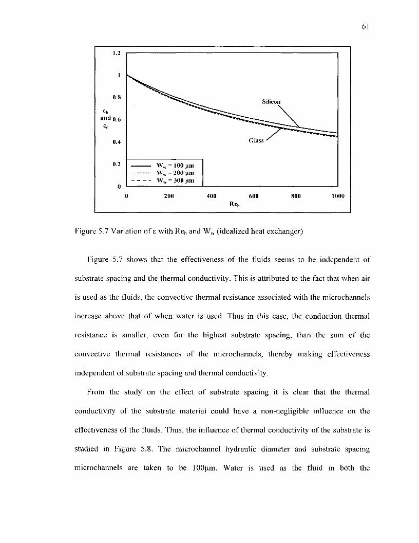
61
Figure 5.7 Variation of £ with Re^ and Ww (idealized heat exchanger)
Figure 5.7 shows that the effectiveness of the fluids seems to be independent of
substrate spacing and the thermal conductivity. This is attributed to the fact that when air
is used as the fluids, the convective thermal resistance associated with the microchannels
increase above that of when water is used. Thus in this case, the conduction thermal
resistance is smaller, even for the highest substrate spacing, than the sum of the
convective thermal resistances of the microchannels, thereby making effectiveness
independent of substrate spacing and thermal conductivity.
From the study on the effect of substrate spacing it is clear that the thermal
conductivity of the substrate material could have a non-negligible influence on the
effectiveness of the fluids. Thus, the influence of thermal conductivity of the substrate is
studied in Figure 5.8. The microchannel hydraulic diameter and substrate spacing
microchannels are taken to be lOOum. Water is used as the fluid in both the

62
microchannels. The substrate thickness is 500um. The different substrate materials
studied include glass (kw = 1.4W/m2K), silicon nitride (kw = 16W/m2K), titanium (kw =
21.9W/m2K), silicon (kw = 148W/m2K), aluminum (kw = 237W/m2K), gold (kw = 317
W/m2K), copper (kw = 401 W/m2K), and silicon carbide (kw = 490W/m2K) [50].
1.4
1.2
1 <
0.8 '
and 0.6
• 0.4
< •
0.2 • <
0
O Glass
A Aluminum
>HO
HO
>*
>*
HO
>*> > >
0 100
+ Silicon Nitride
- G o l d
X A X A X A
X A
X A
X A X A
X A
200
OTitanium
X Copper
— —
"
^
-
300
K
X Silicon
• Silicon Carbide
X • R e h = l X D Re h =50 X O Reh=100
X • Reh = 200
X • Reh=400
X • Re„ = 600 X D Re„=800
X D Reh=1200
400 500 600
Figure 5.8 Variation of s with Reh and kw (idealized heat exchanger)
From Figure 5.8 it can be seen that thermal conductivity of the substrate material is
influential on the effectiveness of the fluids only if it is very low, like that of glass or
silicon nitride and operating at high Reynolds number. For substrates with higher thermal
conductivities, the effectiveness of the fluids for a specific Reynolds number is
independent of thermal conductivity. This is because beyond this range of thermal
conductivity, i.e. lower than 20W/mK, the conduction thermal resistance, for a specific
Reynolds number and substrate spacing, between the microchannels is small relative to
the convective thermal resistance associated with the microchannels.

63
Figure 5.9 represents the influence of microchannel profile and Reynolds number on
the effectiveness of the fluids. The profiles studied include rectangular (a = 0.125, 0.25,
0.5, and 1), trapezoidal (a = 0.125, 0.25, and 0.5) and triangular (a = 1.414). The
hydraulic diameter and substrate spacing are kept constant for all microchannel profiles at
200um and lOOfim, respectively. Silicon with a thickness of 500um is used as the
substrate in this study. The Reynolds number is varied between 1 and 1500 for all
microchannel profiles.
Figure 5.9 Variation of 8 with Reh and profiles (idealized heat exchanger)
From Figure 5.9 shows that the lowest thermal performance is for microchannels of a
rectangular profile with the lowest aspect ratio, i.e. 0.125, while the highest performance
is observed for a rectangular microchannel with aspect ratio of unity. With respect to
rectangular microchannels, the best performance is for aspect ratio of unity while the
worst performance is for rectangular microchannels of aspect ratio 0.125, i.e. the

64
effectiveness reduces with reduction in aspect ratio. For trapezoidal microchannels the
variation between performance and aspect ratio follows the same order as that of
rectangular microchannels.
With change in aspect ratio, Nusselt number, heat transfer surface area and heat
capacity, parameters affecting the performance of microchannel heat exchangers change.
For rectangular microchannels, the reduction in aspect ratio from unity initially reduces
the Nusselt number to its lowest value. Any further reduction in aspect ratio from there is
accompanied by an increase in Nusselt number which approaches its maximum value as
aspect ratio nears zero [51]. Nusselt number is the highest for rectangular microchannels
with an aspect ratio of 0.125. The second highest is observed when the aspect ratio is
unity, which is followed by rectangular microchannels with aspect ratio of 0.5 and 0.25.
Thus, if every other parameter remains constant the effectiveness of the fluids would be
highest for rectangular microchannels with an aspect ratio 0.125 which would then be
followed by rectangular microchannels of aspect ratio of 1, 0.5 and 0.25. However, as
mentioned earlier, two other parameters change while aspect ratio is varied. Changes in
heat capacity occur due to the change in the cross-sectional area that is associated with
the reduction in aspect ratio. With reduction in aspect ratio, the cross-sectional area
available for flow, at a specific Reynolds number, increases. This increase leads to an
increase in heat capacity, which has a negative effect on the effectiveness of the fluids. If
the effectiveness is solely based on the cross-sectional area, then the order of reduction in
effectiveness with respect to aspect ratio would be 1, 0.5, 0.25 and 0.125. The effect of
variation of heat transfer surface area with aspect ratio increases with a decrease in aspect
ratio. Thus, if the heat transfer surface area is the only parameter affecting the

65
effectiveness of the fluids, then it would increase with a reduction in aspect ratio.
However, as effectiveness depends on both these parameters, the variation of
effectiveness with aspect ratio depends on the parameter(s) that has the dominating effect
among the three. Based on calculations, it is observed between cross-sectional area is the
dominating parameter among the three, and thus the effectiveness reduces with reduction
in aspect ratio. The same argument holds true with the observed variation of effectiveness
with the aspect ratio of trapezoidal microchannels, as well as the observed trend in the
effectiveness with regard to microchannel profiles of constant aspect ratio.
Figure 5.10 shows the variation of effectiveness with Reynolds number and the
difference of inlet temperatures. The cold fluid inlet temperature is maintained at 25°C.
while the hot fluid inlet temperature is varied from 50°C to 75°C to 100°C. Water is used
as the fluid in both microchannels. Even at 100°C, water is in liquid form and will not
change phase while in the microchannel due to being cooled by heat transfer with the
cold fluid. A square microchannel with hydraulic diameter of lOOum made in silicon is
used for this study. The substrate spacing and thickness are maintained at lOOum and
500um, respectively. From Figure 5.10 it can be seen that with an increase in difference
of inlet temperatures, the effectiveness of the fluids increased. This is because of the
reduction in thermophysical properties of the hot fluid. The thermal conductivity
increases while the specific heat capacity reduces with an increase in temperature of the
hot fluid. An increase in thermal conductivity reduces the thermal resistance between the
fluids, while reduction specific heat capacity reduces the heat capacity. Both affect the
effectiveness in a positive way. Thus, these changes in thermophysical properties

66
enhance the heat transfer between the two for a specific Reynolds number, and thereby
improve effectiveness.
1.2
1
0.8
£h
and 0.6 Ec
0.4
0.2
0
(
\ N \ N
^ - ->5 0£ At, = 50°C At, = 75°C
) 300
"* ^ ^ ~ ^
~ ~ ~ - _ ^
600
R e „
"~ — ^
900
— — «. ^
1200
"" "" *~
1500
Figure 5.10 Variation of e with Ret, and At, (idealized heat exchanger)
5.2. Axial Heat Conduction
The influence of axial heat conduction through the wall separating the fluids on the
effectiveness of the fluids is studied in this section. From the governing equations,
Equation (3.1), Equation (3.2) and Equation (3.3), of the heat exchanger subjected to
axial heat conduction, it can be seen that the local temperature of the fluids and wall
depend on parameters such as Reynolds number, microchannel hydraulic diameter and
length, Prandtl number, and thermal conductivities of fluid and wall. The individual
influence of these parameters on the effectiveness of the fluids is studied in this section.
The heat flux through the ends of the wall is taken to be zero in this section.

67
Figure 5.11 shows the variation of effectiveness with Reynolds number and hydraulic
diameter. The Reynolds number is varied between 1 and 1500 while the hydraulic
diameter is varied between lOOum and 300um in increments of lOOum. A silicon based
microchannel heat exchanger employing square microchannels, 2.54cm in length with
substrate spacing of lOOum and substrate thickness of 500um, is used for this study.
Water is used the fluid in both the microchannels. It can be seen from this figure that,
over the major portion of the range of Reynolds number considered in this study, with an
increase in Reynolds number, the effectiveness of the fluids reduced just like in an
idealized heat exchanger. Also with an increase in hydraulic diameter, the effectiveness
of the fluids reduced, very similar to that seen in an idealized heat exchanger. The inset of
Figure 5.11 shows the variation of effectiveness with a hydraulic diameter for very low
Reynolds number, i.e. from 1 to 20, and it shows a different trend than that over the
major portion of Reynolds number.
2.8
2.4
2
£h 1-6 and
1.2
0.8
0.4
0
0 300 600 900 1200 1500 Reh
Figure 5.11 Variation of £ with Reh and Dhy (axial heat conduction)

68
From the inset of Figure 5.11 it can be seen that a decrease in Reynolds number to
very low values brings about a reduction in effectiveness for a specific hydraulic
diameter. This trend in effectiveness with regard to Reynolds number is different from
that observed over the major portion of the Reynolds number considered in this study, as
well as that in an idealized heat exchanger for the same Reynolds number. This occurs
because with reduction in Reynolds number, the axially conducted heat increases relative
of the heat conducted in the lateral direction. When an idealized heat exchanger is
operated at low Reynolds number, irrespective of the hydraulic diameter, the difference
in local temperature of the fluids is very small, leading to reduced potential for heat
transfer between the two; however, the increased effectiveness is due to the greater time
available for heat transfer. In the presence of axial heat conduction, a new path for heat
transfer is established in the wall in addition to the one existing in the lateral direction.
The presence of this new path removes a portion of the heat originally transferred
between the fluids, thereby reducing the effectiveness as seen in Figure 5.11.
Regarding the variation of effectiveness of the fluids with hydraulic diameter for a
specific Reynolds number, a reduction in hydraulic diameter brought about a reduction in
effectiveness. From Figure 5.3 it is known that with an increase in hydraulic diameter, the
effectiveness reduces. This means that with an increase in hydraulic diameter the
difference in the local temperature of the fluids would be higher at a specific Reynolds
number which could maintain a higher potential for heat transfer. Thus, even in the
presence of axial heat conduction, the higher potential for heat transfer between the two
fluids helps reduce the heat conducted in the axial direction, and thereby increase the
effectiveness with an increase in hydraulic diameter.

69
Figure 5.12 shows the effect of Prandtl number on the thermal performance of
microchannel heat exchangers. Studies are done for three different fluids: air, ethylene
glycol and water. Silicon based microchannel heat exchanger employing square
microchannels with hydraulic diameter of 200um and substrate spacing of lOOum is used
in this study. The effect of Prandtl number on effectiveness is studied for Reynolds
number between 1 and 1000. The substrate is taken to be 500um thick.
4
3.5
3
2.5
and 2 E c
1.5
1
0.5
0
0 200 400 600 800 1000 RC
Figure 5.12 Variation of z with Reh and Pr (axial heat conduction)
The effectiveness of the fluids decrease with an increase in Prandtl number over the
major portion of the Reynolds number range studied. This is similar to that in an
idealized heat exchanger, Figure 5.4. Moreover, there is no observable difference in the
effectiveness of the fluids due to axial heat conduction over this range of Reynolds
numbers. An exception to this behavior is observed at low Reynolds number as shown in
the inset of Figure 5.12. At low Reynolds number the effectiveness of the hot fluid is
l
0.8
£h 0.6 and
0.4
0.2
Air (Pr = 0.706) Water (Pr = 5.49) Ethylene Glycol (Pr = 11.6 )
Cold Fluid

70
greater than that of the cold fluid for a specific Reynolds number. Moreover, in this range
of Reynolds number, the effectiveness increases with an increase in Prandtl number. This
is because with an increase in Prandtl number, the heat capacity of the fluid increases,
which is attributed to the increase in kinematic viscosity associated with an increase in
Prandtl number. When heat capacity reduces the residence time increases. This reduces
the local temperature difference between the hot and cold fluid lowers and also reduces
the heat transfer potential between the two. The reduction in heat transfer potential
between the hot and cold fluid, coupled with the introduction of a heat transfer path, i.e.
through the wall in the axial direction, carries a portion of the heat transfer between the
fluids, thereby leading to reduction in effectiveness as seen in Figure 5.12.
Figure 5.13 shows the variation of effectiveness with Reynolds number and length of
the microchannel. The lengths studied are 2.54cm, 5.08cm and 7.62cm. A silicon based
microchannel heat exchanger composed of square microchannels with a hydraulic
diameter of lOOum is used in this study. The Reynolds number is varied between 1 and
1500 while using water as the fluids. The spacing between the microchannels is
maintained at lOOum while the substrate thickness is kept at 500um. It can be seen from
Figure 5.13 that, over the major portion of the range of Reynolds number studied, with an
increase in microchannel length, the effectiveness of the fluids increased for a specific
Reynolds number as in an idealized heat exchanger. The decrease in effectiveness with
increase in Reynolds number for a specific length is because of the decreased residence
time which reduces the local heat transfer potential between the fluids. However, from
the inset of Figure 5.13 it can also be seen that at very low Reynolds number, the
effectiveness of the fluids decreased with an increase in length for a specific Reynolds

71
number and vice versa. The observed trend in effectiveness of the fluids when operated at
very low Reynolds number is because of the increase in the relative importance of axial
heat conduction with respect to transverse heat conduction. The reason for this is same as
that explained earlier in this Section in conjunction with Figure 5.11.
3.2
2.9
2.6
2.3
2
and . -, £ t
1.4
1.1
0.8
0.5
0.2
Figure 5.13 Variation of £ with Reh and Lch (axial heat conduction)
From Figure 5.13 it can also be seen that when operated at low Reynolds number, an
increase in microchannel length leads to reduction in effectiveness for a specific
Reynolds number. When the length is increased, the residence time increases for a
specific Reynolds number. This leads to a reduction in the difference of local temperature
of the fluids. This reduction in temperature of the fluids reduces the local heat transfer.
However, a reduction in local temperature difference does not imply that the local
temperatures are low. Thus when an additional heat transfer path through the wall is
introduced, a portion of the heat originally transferred between the fluids is siphoned
300 600 900 1200 1500 Re„

72
through it. Thus, with an increase in length, axial heat conduction relative to transverse
heat conduction increases. This leads to observed reduction in effectiveness with length.
Figure 5.14 provides the trend in the variation of effectiveness with variation in
microchannel profile of silicon based microchannel heat exchangers with substrate
spacing and thickness of lOOum and 500um, respectively. Water is used as the fluid in
both the microchannels. Rectangular (a = 0.125, 0.25, 0.5 and 1), trapezoidal (a = 0.125,
0.25, and 0.5) and triangular (a = 1.4141) microchannels with hydraulic diameter of
200um are studied as part of this assignment. Figure 5.15 shows the variation of
effectiveness with an aspect ratio for low Reynolds number. In this range, the
effectiveness is different from that observed in the major portion of Reynolds number.
l
0.8
0.6
Eh
and E c
0.4
0.2
0
0 300 600 900 1200 1500 Reh
Figure 5.14 Variation of e with Reh and profile (axial heat conduction)
I \ \ % \ \ V<Kv Trapezoidal
v % ^Ss>S^ microchannel „ . . \ ^ / < t S $ V -*r Rectangular \ \V *&&5<7 microchannel
a = 0.125 a = 0.25
a = 1.414
Triangular ""*— "*•*——»*"*•*——^^^^T7 "d "̂""*u"**"••«—•5

0.95
0.9
and 0.85
0.8
0.75
0.7
10 20 Reh
30 40
Figure 5.15 Variation of 8 with profile for low Reh (axial heat conduction)

74
From Figure 5.14 it can be seen that with an increase in aspect ratio, the effectiveness
of the fluids increased for trapezoidal microchannels over the major portion of the range
of Reynolds number studied. On the other hand, for rectangular microchannels, the
highest effectiveness is observed for an aspect ratio of 0.125. The effectiveness of the
other rectangular profiles varies with an aspect ratio in the order of 1, 0.5 and 0.25. This
is same as that observed in an idealized heat exchanger. From Figure 5.14 it can be seen
that with a decrease in Reynolds number, the effectiveness of the fluids decreased for a
specific aspect ratio. The reason for this is the relative increase in axial heat conduction
with respect to lateral heat conduction for the reasons explained in conjunction with
Figure 5.11. Even at a low Reynolds number range, the effectiveness varies with the
aspect ratio in the same order as observed over the major portion of Reynolds number.
Based on the analysis done in this section, it is clear that the trend in the dependence
of effectiveness on input parameters (hydraulic diameter, length, substrate spacing etc.)
changes at a particular Reynolds number. Thus it would be of interest to the designer to
know this particular Reynolds number. Beyond this Reynolds number, the effectiveness
of the fluids is similar to that in an idealized heat exchanger. This implies that beyond
this specific Reynolds number, the heat conducted in the axial direction is negligible in
comparison with the heat transferred between the fluids. Thus, if these two heat transfers
can be quantified then it would be possible to determine the Reynolds number beyond
which axial heat conduction is negligible. The heat transferred between the fluids in the
presence of negligible axial heat conduction can be obtained from standard textbooks in
terms of NTU [5, 7, 50]. The coefficient of the second term of Equation (3.1) and
Equation (3.2) represents NTU. The mathematical formula needed for determining the

75
heat transferred between the fluids in the absence of axial heat conduction is provided in
Equation (5.1) and Equation (5.2). Equation (5.1) should be used for balanced flow
condition while Equation (5.2) should be used under unbalanced flow conditions. The
heat transferred in the axial direction is hard to quantify as it depends on local
temperatures of the wall. However, it would be possible to determine the maximum heat
transfer possible through the wall in the axial direction since the maximum and minimum
temperature in the heat transfer is known. The maximum temperature in the heat
exchanger is the inlet temperature of the hot fluid while the minimum is that of the cold
fluid. Thus, based on this information as well as the thermal resistance in the axial
direction, it would be possible to determine the maximum heat conducted in the axial
direction. It is mathematically equivalent to -kwAAtj/Cmm- Thus, by equating the ratio of
the axial conducted heat to the heat transfer between the fluids to 0.05 or 0.01, it would
be possible to determine the Reynolds number beyond which the heat exchanger with
axial heat conduction behaves just like an idealized heat exchanger.
NTU Q = (5-1)
l + NTU l_e-NTU(]+Cr) Q-^^r <5-2)
5.3.Viscous Dissipation
This section deals with the effect of viscous dissipation on the thermal performance
of microchannel heat exchangers. Viscous dissipation is a volumetric heat generation
phenomenon. The heat generated is dependent on Reynolds number, hydraulic diameter
and length of the microchannel, and thermophysical properties of the fluids as seen from

76
Equation (3 29) and Equation (3 30) of Chapter 3 This section studies the effect of
parameters such as Reynolds number, Prandtl number, microchannel hydraulic diameter,
and microchannel profile on the thermal performance of counter flow microchannel heat
exchangers subjected to viscous dissipation
Figure 5 16 shows the variation of hot and cold fluid effectiveness with respect to
Reynolds number for different hydraulic diameters Reynolds number is varied between 1
and 1000, and the hydraulic diameters studied are 200um, 300um and 400um Air is used
as the fluid in this study The substrate spacing of the silicon based microchannel heat
exchanger is maintained at 1 OOum, and air as the fluid in the microchannels A substrate
which is 500um thick is used for this study
1.2
1
08
06 Eh
and Q 4
02
0
-0.2
-0.4
0 200 400 600 800 1000 Re^
Figure 5 16 Variation of e with Reh and Dhy (viscous dissipation)
In contrast to the trends of Figure 5 3, the effectiveness of the hot and cold fluid are
not equal for a specific Reynolds number and hydraulic diameter In a physical sense, this
is because of the presence of viscous dissipation Mathematically, this difference is due to

77
the existence of the term on the right hand side of the governing equations, Equation
(3.29) and Equation (3.30). Viscous dissipation indicates generation of heat within the
microchannels which lead to heating of the fluids. This heating of the hot and cold fluid
causes the corresponding effectiveness to reduce and improve, respectively. Also, it can
be seen from Figure 5.16 that with an increase in Reynolds number, the effectiveness of
the hot and cold fluid decreased and increased, respectively. This observed trend is
acceptable as viscous dissipation, which is directly proportional to the pumping power
increases with an increase in Reynolds number. With an increase in Reynolds number,
for a specific hydraulic diameter and fluid, the flow rate through the microchannel
increases, thereby leading to increased pressure drop and in turn increased pumping
power. Increased pumping power leads to increased heat generation inside the
microchannels through the phenomenon of viscous dissipation.
From Figure 5.16 it can also be seen that at low Reynolds number, the hot fluid
effectiveness increases with a reduction in hydraulic diameter just like in the idealized
heat exchanger studied in Section 5.1. This can be clearly seen by comparing the
effectiveness of the fluids for hydraulic diameters of either 200|am and 400|o.m or 300um
and 400u.ni. This is because, in this range of Reynolds numbers, the positive effect
brought about by heat transfer between the fluids on the hot fluid effectiveness is greater
than the negative effect on it due to viscous dissipation. Heat transfer between the fluids
is inversely proportional to Reynolds number, while viscous dissipation is proportional to
Reynolds number. Thus, heat transfer between the fluids increase with a reduction in
Reynolds number along with a reduction in viscous dissipation thereby leading to the
observed trend in hot fluid effectiveness. The cold fluid effectiveness increases with a

78
reduction in the hydraulic diameter for a specific Reynolds number. This is because the
heat transferred to the cold fluid from the hot fluid, and viscous dissipation has a positive
effect on the effectiveness of the cold fluid.
From Figure 5.16 it can also be seen that with an increase in Reynolds number, the
cold fluid effectiveness of the microchannel with hydraulic diameter of 200um decreases
and attains its minimum before increasing. This is because with an increase in Reynolds
number, the heat transfer between the fluids reduces while increasing the heat generated
inside the cold fluid. If the drop in effectiveness due to a reduction in heat transfer
between the fluids is due to change in Reynolds number. It can be compensated for by the
heat generated within the cold fluid. Then there would be no variation in cold fluid
effectiveness with Reynolds number. On the other hand, if the heat generated is lower
than the drop in heat transferred between the fluids, then the cold fluid effectiveness will
drop with Reynolds number. Similarly, if the heat generated between the fluids is greater
than the drop in heat transfer with a change in Reynolds number, then the cold fluid
effectiveness will an increase with increase in Reynolds number. With regard to the cold
fluid effectiveness of Figure 5.16, the initial drop in cold fluid effectiveness is because
the heat generated is smaller than the reduction in heat transfer between the fluids. On the
other hand, the increase in cold fluid effectiveness from its minimum with an increase in
Reynolds number is due to the fact that the heat generated due to viscous dissipation
more than compensates for the reduction in heat transfer due to increase in Reynolds
number. With regard to the cold fluid effectiveness of microchannels with hydraulic
diameter of 300um and 400um, the cold fluid effectiveness continuously decreases with
an increase in Reynolds number. This is because with an increase in the hydraulic

79
diameter of the microchannels, the drop in heat transfer between the fluids increases
while decreasing the heat generated through viscous dissipation. Thus for the range of
Reynolds number studied in Figure 5.16, the phenomenon of viscous dissipation cannot
compensate for the drop in heat transfer between the fluids, and thus the continuous drop
in effectiveness.
Figure 5.17 represents the relationship between the effectiveness of the fluids and
Prandtl number. The fluids investigated are air, water and ethylene glycol. The
microchannel hydraulic diameter is 200um, while the substrate spacing and thickness are
maintained at lOOum and 500um for all fluids. The interesting trend in this graph is that
of the reduction in the effect of viscous dissipation on the effectiveness of the fluids, for
as specific Reynolds number, with an increase in Prandtl number. Viscous dissipation is
the highest for air and is negligible for water and ethylene glycol.
Figure 5.17 Variation of s with Rei, and Pr (viscous dissipation)

80
From the term on the right hand side of Equation (3.29) and Equation (3.30) it can be
seen that viscous dissipation is directly proportional to kinematic viscosity and inversely
proportional to specific heat. With an increase in Prandtl number, the kinematic viscosity
and heat capacity increase for the fluids considered in this study. This upward trend in
kinematic viscosity means that velocity of flow increases with a reduction in Prandtl
number for a specific Reynolds number and hydraulic diameter. This leads to increased
pressured drop with a reduction in Prandtl number under similar operating conditions.
Therefore the heat generated is increased and so is the temperature change within the
microchannel. Moreover, fluids with a higher Prandtl number would have a lower rise in
temperature for a specific heat input. This can minimize any influence viscous dissipation
might have on effectiveness. Therefore for fluid with a low Prandtl number, the effect of
kinematic viscosity and specific heat capacity tend to increase the effect of viscous
dissipation on effectiveness of the fluids.
Figure 5.18 provides the trend in the relationship of effectiveness to Reynolds number
and length of silicon based microchannel heat exchanger subjected to viscous dissipation.
The length of the microchannel is varied between 2.54cm to 7.62cm in increments of
2.54cm. Air is used as the fluid, and the microchannel hydraulic diameter and substrate
spacing is kept at 200um and lOOum, respectively. Studies are conducted for Reynolds
number between 1 and 1000. The substrate is taken to be 500um thick.

81
2.8
2.4
2
1.6
1.2
£h 0.8 and
£c 0.4
0
-04
-0.8
-1.2
-1.6
Figure 5.18 Variation of 8 with Reh and Lch (viscous dissipation)
With an increase in the length of microchannels, the heat generated through viscous
dissipation increases. This can be mathematically verified from the terms on the right
hand side of Equation (3.29) and Equation (3 30) which represents the total heat
generated between the inlet and outlet of each microchannel. An increase in the length of
the microchannel also increases the heat transfer between fluids. Thus, the cold fluid
effectiveness increases with an increase in length for a specific Reynolds number.
However, the hot fluid effectiveness decreases with an increase in length because the heat
generated through viscous dissipation is greater than the heat exchanged between fluids
for a specific Reynolds number.
Figure 5.19 plots the trend regarding the influence of substrate spacing on the
effectiveness of the fluids in silicon and glass based microchannel heat exchangers
subjected to viscous dissipation. The hydraulic diameter of the microchannels is kept at
200 400 600 800 1000
Reh

82
200um while varying the substrate spacing from lOOjxm to 200um to 300um. The
thickness of the substrate is 500um. Air is used as the fluid in both microchannels.
Figure 5.19 Variation of 8 with Ret, and Ww (viscous dissipation)
The hot fluid effectiveness decreases with an increase in Reynolds number for all
different substrate spacing, while that of the cold fluid increases over the same range of
substrate spacing irrespective of the substrate material. The influence of substrate spacing
is negligible in this case and is almost independent of the thermal conductivity of the
substrate material. This is similar to that observed in Figure 5.6 and Figure 5.7. The
reason for the little influence that the substrate spacing has on effectiveness of the fluids
is due to the fact that the convective thermal resistance associated with the microchannels
is higher than the conduction thermal resistance between the two. Convective thermal
resistance is higher with air than with water because of the lower thermal conductivity of
air in comparison to that of water. Thus convective thermal resistance dominates the

83
overall thermal resistance between the two, thereby nullifying any influence of substrate
spacing on the thermal performance of the microchannel heat exchangers subjected to
viscous dissipation.
The effect of the profile of the microchannel on the effectiveness of the fluids for the
range of Reynolds number is studied in Figure 5.20. The different microchannel profiles
analyzed are square, rectangular (a = 0.125, 0.25 and 0.5), trapezoidal (a = 0.125, 0.25,
0.5) and triangular (a = 1.414). Air is used as the fluid for all the different profiles, and
silicon that is 500um in thickness is used as the substrate material. The hydraulic
diameter for all the different profiles is kept the same at 200um, and the substrate spacing
is maintained at lOOum. In Section 5.1, the effect of the profile on the effectiveness of the
fluids is only influenced by Nusselt number, heat transfer surface area and cross-sectional
area. In this case, the effect of the friction constant has to be considered as well as it is
dependent on the aspect ratio. For rectangular microchannels, friction constant increases
with a reduction in the aspect ratio. Based on just the friction constant, the highest cold
fluid effectiveness and the lowest hot fluid effectiveness should be in rectangular
microchannels with the highest friction constant, i.e. microchannels, with the lowest
aspect ratio. However, as four parameters are involved, the one with the variation of
effectiveness with the aspect ratio will be controlled by the parameter(s) dominant among
the four involved.

1.2
0.8
0.6
sh 0.4
and
0.2
0
-0.2
-0.4
-0.6 200 400 600 800 1000
Reh
Figure 5.20 Variation of s with Ret, and profile (viscous dissipation) 00

85
Among rectangular microcharmels, the best hot fluid effectiveness is in
microcharmels with an aspect ratio of 0.125, which is followed by that with aspect ratio
of 1, 0.5 and 0.25. Though the highest friction constant is for rectangular microchannels
with an aspect ratio of 0.125, it still has the best hot fluid effectiveness among all
rectangular microchannels. This is because this particular microchannel has the highest
heat capacity for a specific Reynolds number among all rectangular microchannels. The
high heat capacity helps minimize the increase in fluid temperature, thereby maintaining
high effectiveness in comparison with other rectangular microchannels. Compared to the
other three rectangular microchannels, the lowest friction constant is in rectangular
microchannels with aspect ratio of unity. It is followed by that with an aspect ratio of 0.5
and 0.25. Also, the heat capacity in rectangular microchannels for a specific Reynolds
number increases in the same order. Thus, both these effects which are favorable for
effectiveness bring about the observed trend in the variation of effectiveness with an
aspect ratio for a specific Reynolds number.
The hot fluid effectiveness of trapezoidal microchannels has negligible variation of
effectiveness with changes in aspect ratio. The friction constant and Nusselt number is
the highest in microchannels with an aspect ratio of 0.5, which is followed by those with
an aspect ratio of 0.25. The least is that in trapezoidal microchannels with an aspect ratio
of 0.125. The relationship between heat capacity and aspect ratio follows the opposite
order, with the highest heat capacity in a trapezoidal microchannel of an aspect ratio of
0.125. This observed trend in the hot fluid effectiveness can be understood by
considering the variation of friction constant, Nusselt number, cross-sectional area and
heat transfer surface area between the three. For the trapezoidal microchannel with an

86
aspect ratio of 0.5 the two parameters that can bring about improvement in effectiveness
are its higher Nusselt number and its smaller cross-sectional area. On the other hand, the
fact that this particular microchannel has the smallest heat transfer area and the highest
friction constant works to degrade its effectiveness. Similar conclusions can be made
regarding the influence of these four parameters on the effectiveness of fluids in the other
two trapezoidal microchannels. The overall influence of these four parameters on the
effectiveness of the fluids for the two microchannels with a different aspect ratio can be
determined by finding the ratio of the product of all parameters that are a direct influence
on the effectiveness to the product of all parameters that have an inverse effect on the
effectiveness of the fluids. Calculations show that this ratio for all microchannels is
comparable. This implies that for every trapezoidal microchannel the improvement
achieved by parameters affecting it positively is counteracted by parameters influencing
it in a negative manner, thereby bring about the observed trend in effectiveness.
On the other hand the cold fluid effectiveness of the trapezoidal microchannels with
an aspect ratio of 0.5 is higher than that of trapezoidal microchannels with a lower aspect
ratio. This is because the friction constant is highest in the trapezoidal microchannel with
an aspect ratio of 0.5. Also the higher heat transfer between the hot and cold fluid for
trapezoidal microchannel with an aspect ratio of 0.5 also helps raise the effectiveness of
the cold fluid above that of trapezoidal microchannels with a lower aspect ratio. The fact
that the hot fluid effectiveness is independent of aspect ratio does not imply that the heat
transfer between the fluids should also be independent of this parameter. Two factors, i.e.
Nusselt number and cross-sectional area, help increase heat transfer between the fluids,
while only one parameter, i.e. heat transfer surface area, affects heat transfer negatively.

87
By determining the ratio of the product of Nusselt number and cross-sectional area to
heat transfer surface area, it can be seen that the heat transfer in trapezoidal
microchannels with an aspect ratio of 0.5 is much greater than that in the other two
microchannels with trapezoidal profile. Thus heat transfer is not independent of aspect
ratio, and it acts to enhance the effectiveness of the cold fluid in trapezoidal microchannel
of aspect ratio of 0.5 above that in other two trapezoidal microchannels. The cold fluid
effectiveness of the other trapezoidal microchannels, i.e. a = 0.25 and 0.125, is almost
equal for all values of Reynolds number. The reason for this is the same as that
mentioned for the case of hot fluid effectiveness.
From Equation (3.26) and Equation (3.27) it can be seen that the term on the right
hand side of these equations is a function of the differences of the inlet temperature of the
fluids. Figure 5.18 shows the variation of effectiveness with Reynolds number and
difference of inlet temperatures. This study is conducted using a silicon based square
microchannel heat exchanger with a hydraulic diameter of 200um and substrate spacing
of lOOum. Air is used as the fluid in both microchannels. The substrate thickness is
500um. The effectiveness of the fluids for inlet temperature difference of 25°C, 50°C and
100°C are plotted in Figure 5.21.

88
Figure 5.21 Variation of £ with Ret, and At, (viscous dissipation)
From Figure 5 21 it can be seen that with an increase in the difference of the inlet
temperatures, the difference in the effectiveness of the fluids decreased. The hot and cold
fluid effectiveness improved and degraded, respectively This is because the heat
generated within the microchannels due to viscous dissipation gets smaller in comparison
with the heat transferred between the fluids with an increase in the difference of inlet
temperatures for a specific Reynolds number. Therefore, this degrading influence of
viscous dissipation leads to a reduction in the difference between the hot and cold fluid
effectiveness thereby tending the heat exchanger to behave like an idealized one.
5.4. External Heat Flux Condition
External heat transfer from a heat flux source is one the secondary effects studied in
this dissertation. Initial parts of this section detail the experimental results obtained by
conducting the experiments mentioned in Chapter 4. Figure 5.22 plots the variation of hot

89
and cold fluid effectiveness with Reynolds number for a trapezoidal microchannel with a
hydraulic diameter 278um. The data points were obtained by operating the heat
exchanger under balanced flow conditions.
0.6
0.5
0.4
c 0.3
0.2
0.1
0
400 600 800 1000 1200 1400 1600
R£h
Figure 5.22 Experimental data of variation of 8 with Reh (external heat flux)
From Figure 5.22 it can be seen that with an increase in Reynolds number the
effectiveness of the fluids for a specific heat input decreased for a specific heat input.
Also the effectiveness of the hot fluid decreased with an increase in heat input for a
specific Reynolds number. Similarly the cold fluid effectiveness increased with an
increase in heat input for a specific Reynolds number.
In this section the influence of external heat flux on the thermal performance of
microchannel heat exchangers with respect to parameters such as Reynolds number,
Prandtl number, microchannel hydraulic diameter and length, substrate spacing, and
thermal conductivities of fluids and wall is studied. Prior to engaging in this study, the
• Q, = 0% A A Q,= 15% • O Q, = 30%

90
validity of the thermal model is checked. Figure 5.23 shows the comparison between
experimental data and theoretical predictions for 15% and 30% external heat transfer for
a microchannel heat exchanger employing trapezoidal microchannels with a hydraulic
diameter of 278um. In this study, the NTU determined experimentally for the same heat
exchanger for 0% external heat transfer is used as the input parameter. The procedure of
experimental determination of NTU is provided in Section 4.3 of Chapter 4.
0.6
0.5
0.4
Eh
and 0.3
cc
0.2
0.1
0
41
i
B
•
fl
)0
•
B
B
a
i
B
a • •
600
1 I
"V
« FT
a fl
800
• •'T <••
J> + 15% ^ ^
B n
5 a a ^ +30%
1000
+30%
i
•
B
fl
1200
i
B
a
a
• Theoretical
• Experimental
1400 1600
Figure 5.23 Validation of external heat flux model using trapezoidal microchannel
In Figure 5.23 the experimental data and theoretical predictions match very well,
thereby validating the theoretical model. Figure 5.24 shows the comparison between
experimental and theoretical data for a trapezoidal microchannel with a hydraulic
diameter of 231 urn. Even for this plot, the experimentally determined NTU is used in the
theoretical model. From this plot it can be seen that there is good agreement between
theoretical predictions and experimental results.

0.7
0.6
0.5
and Ec
0.4
0.3
0.2
0.1
400 600
91
• i = a B
• B
a B
a fl
i •
• B
H «
o fl
^ + 3 0 % /
" • i 1 B a
\ B B B
_S^> +15%
0 m H • H
0 - M.
\ H fl a ^ +30%
I
•
g
B
• Theoretical
* Experimental
8 N B a > , h
800 1000
Reh
1200 1400 1600
Figure 5.24 Validation of external heat flux model using trapezoidal microchannel
As in the previous sections of this chapter, this section too starts with the
investigation of thermal performance with respect to Reynolds number and hydraulic
diameter of microchannels. For this study, silicon based microchannel heat exchangers
composed of square microchannels with substrate spacing of lOOum are used. The fluid
in both the microchannels is water, and the Reynolds number is varied between 1 and
1500. A study is conducted for external heat flux of lkW/m . Equation (3.35) and
Equation (3.36) requires the total heat input to the fluids to be specified. Thus, based on
the heat transfer surface area and the heat flux, the total heat input to the fluids can be
determined for use in Equation (3.35) and Equation (3.36). The hydraulic diameters
studied include lOOum, 200um and 300um. Figure 5.25 provides the results of this study.
The details of the variation of effectiveness for low Reynolds number are provided as an
inset of Figure 5.25.

92
2
1.8
1.6
1.4
1.2 Eh
and j
Ec
0.8
0.6
0.4
0.2
0 0 300 600 900 1200 1500
Reh
Figure 5.25 Variation of e with Reh and Dhy (external heat flux condition)
From Figure 5.25 it can be seen that the effect of external heat transfer via heat flux is
only prominent at low Reynolds numbers. At high Reynolds numbers the effect of
external heat transfer via heat flux is negligible, and the trend in the variation of
effectiveness with hydraulic diameter is similar to that of an idealized heat exchanger.
The application of constant heat flux implies that irrespective of the Reynolds
number, the total heat input to the fluids remain the same provided the hydraulic diameter
is maintained constant. The heat input to the fluids will only change if the hydraulic
diameter of the microchannels is varied. The effect of external heat transfer via heat flux
is most prominent at low Reynolds numbers, as seen from the inset of Figure 5.25. In the
low Reynolds number regime, there is prominent difference between the effectiveness of
the hot and cold fluid. At, low Reynolds number the flow rate is low due to which the
heat exchanged between the fluids is either lower or comparable to the heat supplied
Cold Fluid
Dh y= 100 nin Dhy = 200 |itn Dhy = 300 fim

93
externally to the fluids leading to appreciable changes in its effectiveness with respect to
its effectiveness in the absence of an external heat transfer. As the flow rate is the lowest
at the smallest Reynolds number the hot fluid has the worst effectiveness at this Reynolds
number. On the other hand, for the cold fluid the highest temperature rise occurs at the
smallest Reynolds number ,as the flow rate is the lowest in this case. Thus, the highest
effectiveness is for this case.
The effect of external heat transfer via heat flux decreases with an increase in
Reynolds number due to the fact that the heat supplied to the fluids from the external heat
source is small in comparison with the heat exchanged between the fluids. Thus with an
increase in Reynolds number the heat transferred between fluids becomes the dominant
of the two heat transfers associated with the fluids. Therefore, the temperature change of
the fluids remains almost same as that in an idealized microchannel heat exchanger, and
the difference in temperature change reduces with increase in Reynolds number. Once
this happens, the heat exchanger subjected to external heat transfer will behave in the
same manner as an idealized heat exchanger in which an increase in Reynolds number is
accompanied by a decrease in effectiveness, as seen in Figure 5.1.
With an increase in Reynolds number, the hot fluid effectiveness increases, reaches a
maximum and then starts to decrease. This trend in effectiveness can be seen clearly in
Figure 5.19. This happens because, as the Reynolds number is increased from unity, the
influence of external heat transfer via heat flux on the hot fluid effectiveness reduces due
to the reasons already mentioned. This increase will continue till the effect of external
heat flux is completely nullified. Beyond the Reynolds number at which the effect of
external heat flux is nullified, the effectiveness will behave just like that in an idealized

94
heat exchanger. In an idealized heat exchanger, the effectiveness decreases with an
increase in Reynolds number. The maximum effectiveness thus occurs at the Reynolds
number where the transition between the rise in effectiveness and the drop in
effectiveness occurs.
The effect of Prandtl number and Reynolds number on the effectiveness of the fluids
is studied next. This study is conducted using a silicon based microchannel heat
exchanger employing square microchannels with hydraulic diameter of 200u.m and
substrate spacing of lOOum. The substrate is 500um thick. The fluids studied are air,
ethylene glycol and water. All the different fluids are subjected to external heat flux of
lkW/m . Figure 5.26 shows the relationship of effectiveness with Reynolds number and
Prandtl number for the Reynolds number range of 1 to 1000. Figure 5.27 shows the
details of the variation of effectiveness with Prandtl number for low Reynolds number of
all three fluids. The inset of Figure 5.27 shows the variation of effectiveness with Prandtl
number for low Reynolds number for ethylene glycol and water.
From these figures, Figure 5.26 and Figure 5.27, it can be seen that the greatest
variation in effectiveness occurs at low Reynolds numbers. With an increase in Reynolds
number, the effect of external heat transfer is nullified and the thermal performance is
same as that in an idealized microchannel heat exchanger. The reason for this is the same
as that explained earlier in conjunction with Figure 5.25 of Section 5.4.

100
80
60
40
El> 20 and
e c ()
-20
-40
-60
-80
i
i
i
f
1
1
0 200 400 Reh
- Air (Pr = 0.706) — Water (Pr = 5.49)
600 800
= 11.6)
1000
gure 5.26 Variation of e with Reh and Pr (external heat flux condition)
200
160
120
£h 80 and
c 40
-40
-80
2
1.5
E" 1 and
Air (Pr = 0.706) Water (Pr = 5.49) Ethylene Glycol (Pr = 11.6)
gure 5.27 Variation of 8 with Pr for low Reh (external heat flux condition)

96
Air, due to its low mass flow rate and low specific heat capacity, has the highest
temperature change at a low Reynolds number in comparison with other two fluids for a
specific heat input, i.e. lkW/m . Thus it has the greatest change in effectiveness with
respect to that in an idealized heat exchanger. Since the heat capacity of water is lower
than that of ethylene glycol for a specific Reynolds number, its effectiveness has the
second highest change at low Reynolds number, as shown in Figure 5.27, as compared to
the change in effectiveness for ethylene glycol.
With an increase in Reynolds number, the difference between the hot and cold fluid
effectiveness of all the fluids reduces, and with a further increase in Reynolds number
this difference vanishes. Also, the hot fluid effectiveness of the fluids has its peak value
while transitioning from the low Reynolds number regime to the high Reynolds number
regime. The reason for this is the same as that mentioned earlier in this section for the
case of the variation of effectiveness with Reynolds number and hydraulic diameter.
Thus, with an increase in Prandtl number, the effectiveness of the hot fluid increases for a
low Reynolds number while that of the cold fluid decreases. On the other hand, at a high
Reynolds number, there is no difference between the hot and cold effectiveness increase
with a reduction in Prandtl number, which is similar to that in an idealized heat
exchanger.
Figure 5.28 shows the variation of effectiveness with Reynolds number and substrate
spacing. MicroChannel heat exchangers made silicon and glass employing microchannels
with hydraulic diameter of 1 OOum are used for this study. Water is used as the hot and
cold fluid in both microchannels and the Reynolds number is varied between 1 and 1500.
The substrate spacing is varied from lOOum to 300um in increments of lOOum.

97
Calculations are done for an external heat flux of lkW/m2 The effectiveness of the fluids
in silicon based microchannel heat exchangers is independent of substrate spacing while
that in a glass based microchannel heat exchanger is influenced by the substrate spacing,
which is similar to that in an idealized heat exchanger
Figure 5.28 Variation of 8 with Reh and Ww (external heat flux condition)
The inset of Figure 5.28 shows the detailed view of the variation of effectiveness with
respect to substrate spacing for low Reynolds numbers. It can be seen from this figure
that at very low Reynolds numbers, i.e. between 1 and 5, the effectiveness of the hot and
cold fluid is almost independent of the substrate spacing and substrate thermal
conductivity This is because between these Reynolds numbers, the heat transferred
between the fluids is much smaller than that the heat added to the fluids from the external
heat flux source The dominant of the two heat transfers associated with the fluids has the
upper hand in influencing the behavior of effectiveness. The changes in conduction

98
thermal resistance due to changes in substrate spacing, which has a controlling influence
on the overall thermal resistance between the fluids, is insignificant in influencing
effectiveness since the heat transferred between the fluids itself is insignificant in
comparison to the externally supplied heat. Moreover, the external heat transfer is
constant irrespective of the Reynolds number. Thus, external heat transfer is dominant of
the two heat transfers. Moreover, the fact that external heat transfer is constant keeps the
effectiveness of the fluids independent of thermal conductivity and substrate spacing at
low Reynolds numbers.
Even in this case, i.e. the influence of substrate spacing on effectiveness, the
effectiveness of a hot fluid has its peak value at the Reynolds number where the low
Reynolds number operating range shifts to the high Reynolds number operating range.
The reason for this same as that provided in connection with Figure 5.25.
The influence of microchannel length on the effectiveness of a microchannel heat
exchanger that is subjected to external heat transfer via heat flux is analyzed next in this
section. The study is conducted using a silicon based microchannel heat exchanger
employing square microchannels with a hydraulic diameter of lOOum and substrate
spacing of lOOum. The substrate thickness is kept at 500um. The heat flux to the fluids is
maintained constant at IkW/m . The length of the microchannels is varied from 2.54cm
to 5.08cm to 7.62cm. Figure 5.29 shows the variation of effectiveness with respect to
Reynolds number and microchannel length. It can be seen from this figure that over the
major portion of the Reynolds number, the effectiveness of the fluids decreased with a
decrease in length in a manner similar to that seen in an idealized heat exchanger. This is
because with an increase in length the heat transfer between the fluids also increases. An

99
increase in the heat transfer surface area as well as due to increased residence time, leads
to the observed improvement in the effectiveness of the fluids with an increase in length.
Also, from this figure it can be seen that there are no noticeable differences between the
hot and cold fluid effectiveness of the fluids over the major portion of the range of
Reynolds numbers studied.
Eh
and
c 0 Cold Fluid
Cold Fluid
Lch = 2.54 cm L c h=5.08cm
— LCh= 7-62 cm
l $ S 4 i S « i * i k » M * a « i i
Hot Fluid
300 600 900 1200 1500
Reh
Figure 5.29 Variation of £ with Reh and Lch (external heat flux condition)
The inset of Figure 5.29 shows the variation of effectiveness with microchannel
length at low Reynolds number. It is interesting to note here that at very low Reynolds
numbers the effectiveness of the hot fluid increases with a decrease in length. This is
because with an increase in the length of the microchannel, the total heat supplied to the
fluids increases due to the increase in surface area of the microchannel. Moreover, the
heat transferred between the fluids also increases with an increase in length. However,
the increase in heat supplied to the fluids with an increase in length is greater than the

100
heat transferred between the fluids, which lead to the reduction in hot fluid effectiveness
with length as observed in the inset of Figure 5.29. For the cold fluid, no such shift in
effectiveness is observed because the addition of heat always affects the effectiveness in
a positive way. Figure 5.29 shows that the highest effectiveness is observed at the
transition from low to high Reynolds numbers regime.
The next part of this section deals with the influence of microchannel profile on the
effectiveness of heat exchangers The profiles considered are rectangular (a = 1. 0.5,
0.25, 0.125), trapezoidal (a = 0.5, 0.25, and 0.125) and triangular (a = 1.414). A silicon
based microchannel heat exchanger consisting of microchannels with a hydraulic
diameter of 200[im and substrate spacing of lOOum is used in this study. The substrate
thickness is 500um. Figure 5.30 shows the variation of effectiveness with Reynolds
number and microchannel profile.
Figure 5.30 Variation of e with Reh and profile (external heat flux condition)

101
It can be seen from Figure 5.30 that microchannels with a rectangular profile has the
best performance, over the major portion of the Reynolds number regime, among the
three profiles considered when the heat exchanger is subjected to external heat transfer.
On the other hand, the effectiveness of the fluids, for a specific Reynolds number,
increases with an increase in the aspect ratio for trapezoidal microchannels. The
performance of triangular microchannels is between that of a trapezoidal microchannel of
aspect ratio of 0.5 and 0.25.
Over the major portion of the range of Reynolds number considered in this study, the
thermal performance of rectangular microchannels decreases with a reduction in the
aspect ratio. The best performance is for square microchannels and the least is for a
rectangular microchannel with an aspect ratio of 0.125. The reason for this can be
explained by considering the variation of parameters such as Nusselt number, cross-
sectional area, heat transfer surface, and external heat transfer with Reynolds number.
External heat transfer is not constant for the microchannels considered in this case as the
heat transfer surface area of microchannels depends on the profile as well as the aspect
ratio. With an increase in the aspect ratio, the heat transfer surface area for both
rectangular and trapezoidal microchannels increases. This increase in heat transfer
surface area leads to increase in the external heat transfer to the fluids for the specific
heat flux of IkW/m . Moreover, from Figure 5.9 it can be seen that the effectiveness of
rectangular and trapezoidal microchannels is reduced with a reduction in the aspect ratio
for a specific Reynolds number. The reason for this is explained in Section 5.1 which
considers the influence of parameters such as Nusselt number, heat transfer surface area
and cross-sectional area. In addition, if external heat transfer is present, then the trend in

102
the hot fluid effectiveness with respect to the aspect would remain the same because
external heat transfer brings about negative effect on hot fluid effectiveness. On the other
hand, for the cold fluid effectiveness, a similar trend would hold true only if the heat
supplied to the fluids is independent of aspect ratio. However, the heat supplied to the
fluids increases with a reduction in the aspect ratio. Though the effect of this on the hot
fluid effectiveness is easily understandable, the same cannot be directly concluded for the
cold fluid effectiveness. For cold fluid, the increase in externally supplied heat should
have positive effect on its effectiveness. Nevertheless, the trend in the variation of cold
fluid effectiveness with respect to aspect ratio remains the same as that of the hot fluid
effectiveness as well as that of the fluids in an idealized heat exchanger. This is because
the additional heat from the external heat source that is supplied to the fluids does not
bring about a proportional rise in fluid temperature because heat capacity also increases
with a reduction in the aspect ratio. Therefore, the effectiveness of the cold fluids is
prevented from rising with the decrease in aspect ratio. The same arguments holds true
for the trends in the hot and cold fluid effectiveness of trapezoidal microchannels.
Figure 5.31 plots the variation of effectiveness with respect to the profile for low
Reynolds numbers. The relationship between cold fluid effectiveness and aspect ratio
remains the same over the entire range of Reynolds number. However, the hot fluid
effectiveness experiences a complete reversal in its relationship with aspect ratio in
comparison with that existing over the major portion of the range of Reynolds number
considered in this study.

1.5
Rectangular microchannel
Eh
and
0.5
a = 0.125 a = 0.25 a = 0.50 a = 1.00 a = 1.414
^^SSSS^^mmm
Trapezoidal microchannel Triangular
microchannel
20 40 60 80 100
Re,
Figure 5.31 Variation of s with profile for low Reh (external heat flux condition)

104
The hot fluid effectiveness increases with a reduction in the aspect ratio at low
Reynolds numbers. This trend can be understood by investigating the influence of a
reduction in aspect ratio on heat capacity and external heat transfer. With a reduction in
the aspect ratio, the heat capacity and external heat transfer increases. However, the
increase is not the same for both these parameters. The heat capacity increases at a
greater rate than the external heat transfer. Therefore, as the aspect ratio is reduced, the
increase in heat capacity is greater than the increase in external heat transfer. Even
though the amount of heat added to microchannels increases with a reduction in the
aspect ratio, the temperature rise is reduced with a reduction in the aspect ratio due to the
associated increase in heat capacity. Thus, among rectangular microchannels, the highest
temperature rise would be for the one with an aspect ratio of unity and the lowest would
be for the one with an aspect ratio of 0.125, leading researchers to observe a trend in
effectiveness at low Reynolds numbers. A similar trend exists with trapezoidal
microchannels for the same reason.
Figure 5.32 plots the variation of effectiveness with Reynolds number and difference
of inlet temperatures. The cold fluid inlet temperature is maintained at 25°C while that of
the hot fluid is varied from 50°C, 75°C, and 100°C. Thus, the differences of the inlet
temperatures considered are 25°C, 50°C, and 75°C. A silicon based microchannel heat
exchanger employing square microchannels with a hydraulic diameter of lOOum and
substrate spacing of lOOum is used in this study. Water is used as the fluid in both
microchannels. From Figure 5.32 it can be seen that with an increase in the difference of
inlet temperatures, the influence of external heat transfer via heat flux is reduced,
especially for low Reynolds numbers. This is primarily due to the fact that an increase in

105
the difference of inlet temperatures leads to increased heat transfer between the fluids as
seen in Figure 5.32 thereby reducing the influence of external heat transfer as seen in
Figure 5.32.
2.4
2
1.6
1.2
and
Cc 0.8
0.4
0
-0.4
0 300 600 900 1200 1500
Reh
Figure 5.32 Variation of z with Reh and At, (external heat flux condition)
The effect of variation in heat flux and Reynolds number on the effectiveness of the
fluids is studied in Figure 5.33. The heat fluxes studied include 1, 2, 4, 8 and 12kW/m2.
The heat exchanger is made of silicon, and the fluid used is water. The heat exchanger is
made up of square microchannels with a hydraulic diameter of lOOum and substrate
spacing of lOOum. The substrate has a thickness of 500|im. From Figure 5.33 it can be
seen that external heat flux does not have a substantial influence on the effectiveness of
fluids over the major portion of the range of Reynolds numbers studied.

106
19
16
13
10
* 7
and
Et 4
1
-2
-5
-8 0 300 600 900 1200 1500
Reh
Figure 5.33 Variation of 8 with Reh and q" (external heat flux condition)
From Figure 5.33 it can also be seen that the greatest influence of heat flux on the
effectiveness of the fluids is felt at very low Reynolds numbers. It can be seen from
Figure 5.33 that low Reynolds numbers the effectiveness of the fluids is strongly
dependent on heat flux. From Figure 5.33 it can be seen that with an increase in heat flux,
the effectiveness of the hot and cold fluid decreases and increases, respectively. This
trend is expected as the addition of greater amounts of heat to the hot fluid that is
accompanied by the increase in heat flux should lead to a reduction in its effectiveness
for a specific Reynolds number, including those in the low Reynolds number regime. On
the other hand, increasing the amount of heat added to the cold fluid should lead to an
increase in its effectiveness at a particular Reynolds number.
From the figures provided in this section it is clear that the trend in effectiveness of
the fluids, with respect to parameters such as hydraulic diameter, length, Prandtl number

107
etc., changes while transitioning between the low and high Reynolds numbers regime.
Thus it might be of use to determine the point of transition between the two regimes. The
change in trend in the effectiveness occurs at the Reynolds number where the external
heat transfer is negligible in comparison with the heat exchanged between the fluids. At
this Reynolds number the heat exchanged between the fluids of a heat exchanger
subjected to external heat flux is same as that of an idealized heat exchanger. The heat
transfer between the fluids of an idealized heat exchanger can be determined using NTU
which is same as the coefficient of the second term of the Equation (3.32) and Equation
(3.33). The heat transferred to the hot fluid from the external heat source is the term on
the right hand side of Equation (3.32) and Equation (3.33). The heat transferred between
the fluids can be determined using Equation (5.1) and Equation (5.2). The ratio of heat
transfers can be equated to either 0.01 or 0.05 to approximate the Reynolds number at
transition.
5.5.External Temperature Condition
The last previous section, Section 5.4, analyzes the effect of external heat transfer via
heat flux. This section analyzes the effect of external heat transfer due to temperature
boundary condition. The governing equations of the microchannel heat exchanger which
is subjected to external heat transfer from a temperature source are provided in Equation
(3.39) and Equation (3.40). Figure 5.34 shows the variation of effectiveness with respect
to Reynolds number for external temperatures of 40°C, 50.5°C and 62.5°C. For the cold
fluid, the effectiveness increases with an increase in temperature for a specific Reynolds
number, while for the cold fluid it decreases with an increase in temperature for a specific
Reynolds number.

108
0.7
0.6
0.5
0.4
0.3
0.2
0.1
0
400 600 800 1000 1200 1400
R£h
Figure 5.34 Experimental variation of £ with Ret, (external temperature condition)
Comparisons between experimental and theoretical predictions are not provided for
this model because of the inability to accurately predict the thermal resistance between
each fluid and the external environment. As seen in Figure 5.1, Figure 5.2, Figure 5.23
and Figure 5.24 it is very important to have an accurate estimate of the thermal
resistances for making successfully comparing the theoretical and experimental data.
Thus it is not possible to compare the experimental data of Figure 5.34 with the model
due to the unavailability of accurate thermal resistance.
As in the previous sections of this chapter, this section also deals with understanding
the influence of various parameters on the performance of microchannel heat exchangers
subjected to external heat transfer. The different parameters considered in this study
include Reynolds number, hydraulic diameter, Prandtl number, substrate spacing,

109
microchannel length, microchannel profile, external temperature and the thermal
boundary condition between the microchannels and the temperature source.
Figure 5.35 provides the variation of effectiveness with Reynolds number and
hydraulic diameter. Microchannels with a hydraulic diameter of lOOum, 200um and
300(j.m are studied in this section. Studies are done using a silicon based microchannel
heat exchanger with square microchannels for two different external temperatures, i.e.
40°C and 60°C. Air flowing at lm/sec is taken to be the external temperature source in
this study. The spacing between the microchannels is kept at lOOum, and water is used as
the fluid in both microchannels. The Reynolds number is varied between 1 and 1500 for
the different hydraulic diameters considered.
Figure 5.35 Variation of s with Rei, and Dhy (external temperature condition)
From Figure 5.35 it can be seen that the effectiveness of the fluids is reduced with an
increase in Reynolds number as well as hydraulic diameter for both external temperatures

110
similar to that seen with respect to the idealized heat exchanger. The effectiveness of the
fluids is reduced with an increase in hydraulic diameter because of the reduction in heat
transfer between the fluids as well as that between each of the fluids and the external heat
source. This reduction in heat transfer occurs due to the increase in the convective
thermal resistance associated with each of the microchannels. Convective thermal
resistance is directly proportional to the hydraulic diameter of the microchannels and this
increases with an increase in hydraulic diameter.
It can also be seen from the Figure 5.35 that the effectiveness of the hot fluid is
different from that of the cold fluid due to the addition of heat from the external heat
source. Depending on the temperature of the external heat source, the difference between
the effectiveness of the fluids can be either positive or negative. When the temperature of
the external heat source is 40°C, the effectiveness of the hot fluid is greater than that of
the cold fluid for a specific Reynolds number. On the other hand, the cold fluid is greater
than the hot fluid effectiveness when the temperature of the external heat source is 60°C.
Thus, depending on the ambient temperature, the effectiveness of the fluids can either
increase or decrease below that occurring in an idealized heat exchanger. The hot fluid
effectiveness increases when the ambient temperature is 40°C because of the greater
overall heat loss it has due to the presence of the external temperature source. On the
other hand, the effectiveness of the cold fluid is reduced because of the decrease in the
overall heat gain. The cold fluid gains heat from the hot fluid as well as from the external
heat source, and this raises its temperature at a faster rate than it would have in an
idealized heat exchanger. This faster rate of rise of the cold fluid temperature reduces its
potential for heat transfer between the fluids. Also, this rate of the rise of the temperature

I l l
of the cold fluid brings its temperature closer to that of the external heat source. A this
time, the hot fluid preferentially transfers heat to the external heat source due to lower
thermal resistance between the two. The thermal resistance between the hot fluid and the
ambient is smaller than that between the fluids primarily because the surface area
available for heat transfer between the external heat source and the hot fluid is much
higher than that between the fluids. A similar argument holds true for the increase in cold
fluid effectiveness and decrease in hot fluid effectiveness when the temperature of the
external heat source is 60°C.
From Figure 5.35 it can also be seen that the effectiveness of the cold fluid at 40°C is
the same as that of the cold fluid at 60°C and vice versa. These temperatures are ±10°C
from the average of the inlet temperatures of the fluids. Therefore, the temperature
difference between the cold fluid and external heat source that is maintained at 60°C is
the same as that between the hot fluid and the external heat source when it is kept at
40°C. Similarly, the temperature difference between the hot fluid and the external heat
source at 60°C is equal to the temperature difference between the cold fluid and the
external heat source that is at 40°C. Thus, when the temperature of the external heat
source is changed from 40°C to 60°C, the potential for heat transfer in terms of
temperature difference existing between the hot fluid and the external heat source is equal
to that between the cold fluid and the external heat source and vice versa. This shift in
heat transfer potential between each fluid and the external heat source maintains the hot
fluid effectiveness at 40°C, the same as that of the cold fluid at 60°C. It also helps
maintain the hot fluid effectiveness at 60°C, which is also the same as that of the cold
fluid at 40°C.

112
One of the interesting features of the variation of effectiveness with Reynolds number
is that with an increase in Reynolds number, the effectiveness of the fluids tends to be
independent of the temperature of the external heat source. This is because with an
increase in Reynolds number, the residence time decreases. This reduces the heat transfer
between the fluids as well as that between each fluid and the external heat source.
Figure 5.36 shows the variation of effectiveness with respect to Prandtl number and
Reynolds number. The fluids considered are air, ethylene glycol and water. A silicon
based microchannel heat exchanger composed of square microchannels with a hydraulic
diameter of 200um and substrate spacing of lOOum is used for this study. The Reynolds
number for this study is kept between 1 and 1000. The results for two different external
heat source temperatures of 40°C and 60°C, are provide in Figure 5.36.
3
2.75
2.5
2.25
2
a n d 1.5 Ec
1.25
1
0.75
0.5
0.25
0
Figure 5.36 Variation of 8 with Reh and Pr (external temperature condition)
200 400 600 800 1000 Re„

113
It can be observed from this figure that with an increase in Prandtl number the
effectiveness of the fluids decreased for almost the entire range of Reynolds number
considered. The exception is observed at very low Reynolds number where the highest
effectiveness is for water and the lowest is for air. Also, it can be seen that the difference
in the effectiveness of the fluids for a specific Reynolds number is highest for the fluid
with the lowest Prandtl number, irrespective of the temperature of the external heat
source.
The next study is on the effect of substrate spacing and Reynolds number on the
effectiveness of each fluid. The substrate spacing is varied from lOOum to 300um in
increments of 100pm in silicon and glass based microchannel heat exchangers employing
square microchannels of 100pm. Water is used as the fluid in all the cases studied. The
range of Reynolds number studied is from 1 to 1500. Studies are done for two different
temperatures, 40°C and 60°C, of the external heat source. The substrate has a thickness of
500p.m. Figure 5.37 plots the effect of substrate spacing and Reynolds number on the
effectiveness of the fluids. Figure 5.38 plots the variation of effectiveness with substrate
spacing for low Reynolds number.
From Figure 5.37 it is clearly evident that in silicon based microchannel heat
exchangers, the effect of change in substrate on effectiveness is minimal. This is because
the high thermal conductivity of silicon nullifies the increase in conduction thermal
resistance that is brought about by the increase in substrate spacing. This trend is very
similar to that observed for the case of an idealized heat exchanger.

0.8
Eh
and
0.6
0.4
0.2
to\ ^ v Silicon
V \ \ ^ ^ \
Ww = 200jim Ww = 300 nm
300 600 900
Re„ 1200 1500
jure 5.37 Variation of e with Reh and Ww (external temperature condition).
0.95
Eh
and
£t 0.9
0.85
0.8
10 15 20 25 Reh
gure 5.38 Variation of £ with Ww at low Reh (external temperature condition).

115
For the case of a glass based microchannel heat exchanger, the effectiveness of the
fluids shows a substantial reduction with an increase in substrate spacing. In this case, the
increase in the conduction shape factor which is accompanied by an increase in substrate
spacing dominates the effect of the low thermal conductivity of glass, thereby bringing
about the observed reduction in effectiveness for a specific Reynolds number. Even in
this figure, it can be seen that with an increase in Reynolds number, irrespective of the
substrate spacing, the difference in the effectiveness of the fluids is reduced, indicating
the waning influence of external heat transfer.
Figure 5.39 shows the effect of microchannel length on the thermal performance of a
microchannel heat exchanger subjected to external heat transfer from an external heat
source maintained at a constant temperature. The study is conducted using a silicon based
microchannel heat exchanger with microchannel hydraulic diameter and substrate
spacing of lOOum. Water is used as the fluid, and the heat exchanger is operated over the
Reynolds number range of 1 to 1500. The substrate thickness is maintained at 500um.
The length of the microchannel is varied from 2.54cm to 5.08cm to 7.62cm. Based on the
trends, it can be seen that the effectiveness of the fluids, for a specific Reynolds number,
increased with an increase in microchannel length. With an increase in microchannel
length, the heat transfer between the fluids as well as that between each fluid and the
external heat source, increase. However, the increase in heat transfer between the fluids is
greater than the heat transfer between each fluid and the external heat source, which leads
to the observed trend of an increase in effectiveness with an increase in length. This trend
exits irrespective of the temperature of the external heat source.

116
Figure 5.39 Variation of £ with Ret, and LCh (external temperature condition)
Figure 5.40 and Figure 5.41 show the variation of effectiveness with Reynolds
number and microchannel profile for external temperatures of 60°C and 40°C,
respectively. The hydraulic diameter of the microchannels made in silicon is kept at
200pm, and the substrate spacing is maintained at 100pm. Water is used as the fluid in
both microchannels. The substrate has thickness of 500pm. From Figure 5.40 and Figure
5.41 it can be seen that the effectiveness of the fluids is reduced with an increase in
Reynolds number, irrespective of the microchannel profile and aspect ratio. From these
figures. Figure 5.40 and Figure 5.41, it can be seen that the effectiveness of the hot and
cold fluid are equal over the major portion of the Reynolds number considered in the
study for a particular microchannel profile. Moreover, the best effectiveness is for a
rectangular microchannel with an aspect ratio of unity while the lowest is for a
trapezoidal microchannel with an aspect ratio of 0.125 for both the external temperatures

117
considered in this study Figure 5 42 and Figure 5 43 show the variation of effectiveness
for low Reynolds numbers for an external temperature of 60°C and 40°C, respectively
o • • 0 300 600 900 1200 1S00
Figure 5 40 Variation of 8 with Reh and profile (external temperature condition)
Figure 5 41 Variation of e with Reh and profile (external temperature condition)

0.95
and o.9
0.85
0.8
Cold Fluid
a = 0.125 a = 0.25 a = 0.50 a = 1.00 a = 1.414
Tex = 60°C
Hot Fluid
Trapezoidal microchannel
Rectangular microchannel
Triangular microchannel
10 15 20
Reh
25 30 35 40
Figure 5.42 Variation of e with profile for low Reh (external temperature condition)

1
0.95
£h and 0 9
0.85
0.8
s~C=--~ " H o t
—4̂ fenr̂ ^̂ Fluid
T I ' - ' t i t . . . . \ > ^ ^ ^ " . * - . ^«>x.
a - 0 . 1 2 5 a = 0.25 n — n tin « — 1 nn
a = 1.414 Tex = 40 °C
I _~7 ^""•"^iii~.,:-V.. l '-^x'^ftfc. '" '-- ^^"^^
» \ "Ul ^ / V«' ti-j. - •••> " ^ 7^»w ^ ^ - ^ Cold \ 1 f^/V ^ V ' ' , ^ , / ^ O s ^ Fluid \ //**+ " - S * V * ; v ^ > - « ^ ^ > ^
Trapezoidal / 7 ^ x ^p^^^^*^.^^'^--.. '''•X^^~^~~~^. microchannel /// ^><r^^^^ y^.:*v'vi-*i2_>^v----. '•••. ^"^^^^
Rectangular / s " ^ ' " ^ ^ ° V £ y ^ N ^ V * microchannel / * ^ "^ " • i' - . -ti**1
X "x ^s. >. x. —
Triangular " ^ v v ^ -» ̂ >
microchannel ^ - x , , "^"O
0 5 10 15 20 25 30 35 40
Reh
Figure 5.43 Variation of s with profile for low Reh (external temperature condition)

120
Regarding the influence of microchannel profiles on hot fluid effectiveness
shown in Figure 5.42, the hot fluid effectiveness of rectangular microchannels
increased with an increase in the aspect ratio for a specific Reynolds number.
Similarly, for trapezoidal microchannels, the hot fluid effectiveness increases with
an increase in the aspect ratio. This trend is exactly the same as that observed in
an idealized heat exchanger. The reason for the observed trend is because with a
reduction in the aspect ratio the width of the microchannels increases. This leads
to an increase in the surface area available for external heat transfer. Since heat
transfer is a surface phenomenon an increase in surface area leads to increase in
external heat transfer and thereby reducing the hot fluid effectiveness with a
reduction in the aspect ratio. The reason for the reduction in hot fluid
effectiveness of the trapezoidal microchannels with a reduction in the aspect ratio
is also the same. Similarly, the cold fluid effectiveness of the microchannels
shown in Figure 4.43 also reduces with a reduction in the aspect ratio because of
the increased heat transfer with the external environment due to the associated
increase in heat transfer surface with a reduction the in aspect ratio.
Even for external heat transfer from a constant temperature source the trend in
the effectiveness of the fluids is different at low Reynolds numbers in comparison
with that at high Reynolds numbers. At high Reynolds numbers the effectiveness
is same as that in an idealized heat exchanger. Thus it is of interest to know the
Reynolds number beyond which the effectiveness behaves in the same manner as
in an idealized heat exchanger. This can be achieved in the same fashion as
presented in Section 5.4. Even for this case the Reynolds number at which the

121
externally supplied heat becomes negligible in comparison with the heat transfer
between the fluids need to be determined. The actual heat transfer between the
fluids is provided in Equation (5.1) and Equation (5.2). The externally supplied
heat is equal to the term on the right hand side of Equation (3.39) and Equation
(3.40). By equating the ratio of these two heat transfers to either 0.01 or 0.05 it
would be possible to determine the Reynolds number beyond which a
microchannel heat exchanger which is subjected to external heat transfer behaves
just like an idealized heat exchangers.

CHAPTER 6
CONCLUSIONS AND FUTURE WORK
Theoretical models for improved design of counter flow microchannel heat
exchangers subjected to scaling and secondary effects have been developed in this study.
The models can be applied to a wide range of applications for which currently there are
no satisfactory theoretical models. Some of the applications include modeling of
microchannel heat exchangers used in microreactors, micro fuel cells, and micro
cryocoolers. The models developed are functions of Reynolds number, Prandtl number,
microchannel hydraulic diameter, microchannel length, microchannel profile, substrate
spacing and thermal conductivities of fluids and wall. Using these models made it
possible to study the effect of the above mentioned parameters on the effectiveness of the
fluids. The influence of axial heat conduction on the effectiveness of the fluids has been
shown to have the strongest influence on effectiveness at low Reynolds number. This is
primarily due to the fact that lateral heat transfer through the wall becomes either smaller
than or comparable to the heat transferred axially through the wall. With an increase in
Reynolds number, the laterally transferred heat becomes higher than the axially
transferred heat, which in turn leads to reduced influence of axial heat conduction on the
effectiveness of the fluids. In the case of viscous dissipation its effect on effectiveness is
proportional to the Reynolds number. This implies that an increase in Reynolds number
122

123
will lead to greater deviation in effectiveness from that observed in the absence of this
phenomenon. The effect of viscous dissipation is to always degrade the hot fluid
effectiveness, while always improving the cold fluid effectiveness. This is because
viscous dissipation always generates heat inside the microchannel. This has an adverse
effect on the cooling of the hot fluid while having a positive effect on the heating of the
cold fluid.
The influence of external heat transfer via heat flux is also significant at low Reynolds
number for a specific heat flux. This is because at low Reynolds number, the heat
transferred between the fluids is either comparable to or lower than the heat transferred to
the fluids from the external heat source in the form of heat flux. Similarly, external heat
transfer from a temperature source is also more significant at low Reynolds number than
at high Reynolds number. With an increase in Reynolds number, the influence of external
heat transfer from the temperature source becomes negligible because of the reduction in
heat transfer between each fluid and the heat source. In comparison, the heat transfer
between the fluids is greater than the heat transfer between each fluid and the external
heat source. The method for determining the Reynolds number beyond which a
microchannel heat exchanger subjected to external heat transfer will behave like an
idealized heat exchanger is provided in this study.
The rest of this section provides suggestions on the type of work that can be preferred
as an extension of that presented in this study. Though the models developed in this
research are more advanced than existing ones, some of these can be further improved.
The model developed for counter flow heat exchangers subjected to axial heat conduction
is one such model. This model assumes conduction thermal resistance through the wall in

124
the lateral direction to be negligible. This is a reasonable assumption as long as the
substrate spacing is thin, as mentioned in Section 3.5. However, this assumption limits
the applicability of the model, and it can be improved by accounting for this effect. For
this, the governing equation of the wall has to be converted from its present form of one-
dimensional ordinary differential equation into a two-dimensional partial differential
equation. This modification of the governing equation of the wall will allow the model to
be applied to parallel plate counter flow microchannel heat exchangers.
In this disseration the effects have been studied. In certain scenarios it might be
necessary to consider the combined effect of phenomena. The models developed are of
only limited use in such situations. Thus, these models can be modified to account for
more than one phenomenon.
Future work could also include the development of models for cross-flow and parallel
flow microchannel heat exchangers that are similar to the one developed for counter flow
microchannel heat exchangers. For parallel flow microchannel heat exchangers, the
governing equations are similar to those of counter flow microchannel heat exchangers.
However, for cross flow microchannel heat exchangers, the governing equations would
consist of partial differential equations since the fluids flow perpendicular to one another.

APPENDIX A
NOMENCLATURE
125

126
A : area (m )
C : heat capacity (W/K)
Cp : specific heat capacitu (W/kg K)
C r : heat capacity ratio (Cm,n/Cmax)
C : friction constant based on Fanning friction factor
D| iy : hydraulic diameter (urn or m)
d : substrate spacing (um or m)
H.O.T : higher order terms
h : heat transfer coefficient (W/m K)
1 : current (A)
K, : thermal conductivity ratio used in thermal models (K) = kh/kc)
K.2 : thermal conductivity ratio used in thermal models (Ki = kh/kc)
K3 : thermal conductivity ratio used in thermal models (Ki = kh/kex)
kn : Kundsen number (kn = characteristic length/Dhy)
k : thermal conductivity (W/m K)
L : length (m)
N : number of control volumes in computational domain
Nu : Nusselt number
N T U : number of transfer units (NTU = UA/Cm i n)
Pr : Prandtl number (Pr = u€ p /k )
Q : heat transfer (W)
q" : heat flux (W/m2)
Re : Reynolds number (Re = upDhy/u)

S : shape conduction factor (m)
V : voltage (V)
u : velocity (m/sec)
T : nondimensional temperature
T.E : truncation error
At : temperature difference (°K or °C)
t : temperature (°K or °C)
X : nondimensionahzed axial distance (0 < X < 1)
AX : nondimensional internode distance
Greek Symbols:
a : aspect ratio (width/depth)
s : effectiveness
r| : microchannel heat exchanger effectiveness
X : axial heat conduction parameter
|i : viscosity (Pa. sec)
p : density (kg/m3)
X : uncertainty
Subscripts:
c : cold fluid
c<->ex : between heat transfer surface of cold microchannel and external body
ch :channel
ex : external
h : hot fluid

128
ht : heat transfer
h—>c : between heat transfer surface of hot and cold microchannel
h<-+ex : between heat transfer surface of hot microchannel and external body
i : inlet
j : node location
o : outlet
w : wall
wt : wetted

REFERENCES
1. Sunden, B., Xie, G., 2010, "Gas Turbine Blade Tip Heat Transfer and Cooling: A Literature Survery," Heat Transfer Engineering. 31 (7), pp. 527-554.
2. Li, Q., Ju, Y. L., 2010, "Design and Analysis of Liquefaction Process for Offshore Associated Gas Resource," Applied Thermal Engineering, 30 (16), pp. 2518-2525.
3. Oh, C. P., Kim, E. S., and Patterson, M.. 2010, "Design Option of Heat Exchanger for the Next Generation Nuclear Plants.'" Journal of Engineering for Gas Turbines and Power, 132 (3), pp. 032903:1-9.
4. Brander, J. J., Bohn, L., Henning, T., Schygulla, U., Schubert, K., 2007, "Microstructure Heat Exchanger Applications in Laboratory and Industry," Heat Transfer Engineering, 28 (8-9), pp. 761-771.
5. Shah, R. K., and Seculik, D. P. 2003, Fundamentals of Heat Exchanger Design, John Wiley and Sons, New Jersey, USA.
6. Kutter, J. P., and Fintschenko, Y., 2005, Separation Methods in Microanalytical Systems, CRC Press, Boca Raton, FL, USA.
7. Kakac, S., and Liu, H., 2002, Heat Exchangers Selection, Rating and Thermal Design, CRC Press, Boca Raton, FL, USA.
8. Madou, M., 1998, Fundamentals of Microfabrication, CRC Press, Boca Raton, FL, USA.
9. Bar-Chohen, A., and Kraus, A. D., 1990, Advances in Thermal Modeling of Electronic Components and Systems: Vol. 2, ASME, New York, USA.
10. Sonntag, R. E., and Van Wylen, G. J., 1991, Introduction of Thermodynamics, Classical and Statistical, John Wiley and Sons, New York, USA.
11. Streeter, V. L., 1951, Fluid Mechanics, McGraw Hill, New Jersey, USA.
12. Velasquez-Garcia, Hill, T. F., Wilhite, B. A., Jensen, K. F., Epstein, A. H., and Livermore, C, 2007, "A MEMS Singlet Oxygen Generator - Part I: Device Fabrication and Proof of Concept Demonstration," Journal of Microelectro-mechanical Systems, 16 (6), pp. 1482-1491.
129

130
13. Hill, T. F., Velasquez-Garcia, L.F., Wilhite, B. A., Rawlins, W. T., Lee, S., Davis, S. J., Jensen, K. F., Epstein, A. H., and Livermore, C, 2007, "A MEMS Singlet Oxygen Generator - Part II: Experimental Exploration of the Performance Space," Journal of Microelectromechanical Systems, 16 (6), pp. 1492-1505.
14. Shah, K., and Besser, R. S., 2008, "Understanding Thermal Integration Issues and Heat Loss Pathways in a Planar Microscale Fuel Processor: Demonstration of an Integrated Silicon Microreactor-Based-Methanol Steam Reformer," Chemical Engineering Journal, 135 (SI), pp. S46-S56.
15. White, M. J.. Nellis, G., F., Klein, S. A., Zhu, W., and Gianchandani, Y., 2010, "An Experimentally Validated Numerical Modeling Technique for Perforated Plate Heat Exchanger," Journal of Heat Transfer, 132 (11), 111801 :l-9.
16. Peterson. R. B., 1999, "Numerical Modeling of Conduction Effects in Microscale Counter Flow Heat Exchangers," Microscale Thermophysical Engineering, 3(1), pp. 17-30.
17. Narayanan, P. S., and Venkatarathnam, G., 1999, "Performance of a Counterflow Heat Exchanger with Heat Loss through the Wall at the Cold End," Cryogenics, 39 (1), pp. 43-52.
18. Stief, T., Otto-Ulrich, L., and Klaus, S., 1999, "Numerical Investigation of Optimal Heat Conductivity in Micro Heat Exchangers," Chemical Engineering and Technology, 22 (4), pp. 297-303.
19. Moreno, A., Murphy, K., and Wilhite, B. A., 2008, "Parametric Study of Solid-Phase Axial Heat Conduction in Thermally Integrated MicroChannel Networks," Industrial and Engineering Chemistry Research, 47 (23), pp. 9040-9054.
20. Kroger, P. G., 1967, "Performance Deterioration in High Effectiveness Heat Exchangers due to Axial Heat Conduction," Advances in Cryogenic Engineering, 16, pp. 363-372.
21. Mathew, B., and Hegab, H., 2007, "The Effectiveness-NTU Relationship of MicroChannel Counter Flow Heat Exchangers with Axial Heat Conduction," IMECE2007^3938, Proceedings of 2007 ASME International Mechanical Engineering Congress and Exposition, ASME, Seattle, WA, USA, pp.527-536
22. Mathew, B., and Hegab, H., 2008, "Axial Heat Conduction in Counter Flow MicroChannel Heat Exchangers," HT2008-56305, Proceedings of 2008 ASME Summer Heat Transfer Conference, ASME, Jacksonville, FL, USA, pp. 165-174.
23. Mathew, B., and Hegab, H., 2010, "Effect of Axial Heat Conduction and Internal Heat Generation on the Effectiveness of Counter Flow MicroChannel Heat Exchangers," AIAA-2010-4767, Proceedings of the 10th AIAA/ASME Joint Thermophysics and Heat Transfer Conference, AIAA, Chicago, IL, USA.

131
24. Morini, G. L., 2005, "Viscous Heating in Liquid Flows in Micro-Channels," International Journal of Heat and Mass Transfer, 48 (17), pp. 3637-3647.
25. Koyama, K., and Asako, Y., 2010, "Experimental Investigation on Heat Transfer Characteristics of a Gas-to-Gas Counterflow MicroChannel Heat Exchanger," Experimental Heat Transfer, 23 (2), pp. 130-143.
26. Peterson, R. P., and Vanderhoff, J., 2001, "Analysis of Bayonet-Type Counterflow Heat Exchanger with Axial Heat Conduction and Radiative Heat Loss," Numerical Heat Transfer, Part A, 40 (3), pp. 203-219.
27. Mathew, B., and Hegab, H., 2010, "Performance of Counterflow MicroChannel Heat Exchangers Subjected to External Heat Transfer," Heat Transfer Engineering, 31 (3), pp. 168-178.
28. Mathew, B., John, T. J., and Hegab, H., 2009, "Effectiveness of Counter Flow MicroChannel Heat Exchangers Subjected to External Heat Transfer and Internal heat generation," HT2009-88167, Proceedings of 2009 ASME Summer Heat Transfer Conference, ASME, San Francisco, CA, USA, pp. 637-646.
29. Mathew B., and Hegab, H., 2009, "Thermal Performance of Counter Flow MicroChannel Heat Exchangers Subjected to Axial Heat Conduction and External Heat Transfer," HT2009-88250, Proceedings of 2009 ASME Summer Heat Transfer Conference, ASME, San Francisco, CA, USA, pp. 637-646.
30. Kunjumon, A., Mathew, B., John, T. J., and Hegab, H., 2009, "Modeling a Non-Adiabatic Counter Flow MicroChannel Heat Exchanger with Axial Heat Conduction," IMECE2009-11765, Proceedings of 2009 ASME International Mechanical Engineering Congress and Exposition, ASME, Orlando, FL, USA, pp. 1139-1147.
31.Spann, B., and Ameel, T., 2010, "An Analytical Model of a Microscale Heat Exchanger: Ambient Interaction and General End-Wall Boundary Conditions," IMECE2010-39445, Proceedings of 2010 ASME International Mechanical Engineering Congress and Exposition, ASME, Vancouver, British Columbia, Canada.
32. White, F. M., 2006, Viscous Fluid Flow, McGraw-Hill, New York, USA.
33. Steinke, M., and Kandlikar, S. G., 2005, "Single-Phase Liquid Friction Factor in Microchannels," ICMM2005-75112, Proceedings of the ASME 3rd International Conference on Microchannels and Minichannels, ASME, Toronto, Ontario, Canada, pp. 291-302.
34. Steinke, M., and Kandlikar, S. G., 2005, "Single-Phase Liquid Heat Transfer in Microchannels," ICMM2005-75114, Proceedings of the ASME 3rd International Conference on Microchannels and Minichannels, Toronto, ASME, Ontario, Canada, pp. 667-678.

132
35. Baviere, R., Favre-Marinet, M., and Person, S. L., 2006, "Bias Effects on Heat Transfer Measurements in MicroChannel Flows," International Journal of Heat and Mass Transfer, 49 (19-20), pp. 3325-3337.
36. Mokrani, O., Bourouga, B., Castelain, C , Peerhossaini, H., 2009, "Fluid Flow and Convective Heat Transfer in Flow Microchannels," International Journal of Heat and Mass Transfer, 52 (5-6), pp. 1337-1352.
37. Natrajan, V. K., and Christensen, K. T., 2010, "Non-Intrusive Measurements of Convective Heat Transfer in Smooth- and Rough-Wall Microchannels: Laminar Flow," Experiments in Fluids, 49 (5), pp. 1021-1037.
38. Mahulikar. S. P., Herwig, H., and Hausner, O., 2007, "Study of Gas Microconvection for Synthesis of Rarefaction and Nonrarefaction Effects," Journal of Microelectromechanical Systems, 16 (6), pp. 1543-1556.
39. Burden, R. L., and Faires, J. D., 2005, Numerical Analysis, Thomson Books/Cole, USA.
40. Morton, K. W., and Mayers, D. F., 2005, Numerical Solution of Partial Differential Equations, Cambridge University Press, Cambridge, UK.
41.Versteeg, H. K., and Malalasekera, W., 2007, An Introduction to Computational Fluid Dynamics: The Finite Volume Method, Prentice Hall. New Jersey, USA.
42. Ferziger, J. H., and Peric, M., 1999, Computational Methods for Fluid Dynamics, Springer, Berlin. Germany.
43. Kandlikar, S., and Grande, W. J., 2003, "Evolution of MicroChannel Flow Passages -Thermohydraulic Performance and Fabrication Technology," Heat Transfer Engineering, 24 (1), pp. 3-17.
44. Holman, J. P., 2000, Mechanical Measurements for Engineers, McGraw-Hill, New York, USA.
45. Wheeler, A. J., and Ganji, A. R., 1996, Introduction to Engineering Experimentation, Prentice Hall, New Jersey, USA.
46. Wang, G., Hao, L., and Cheng, P., 2008, "An Experimental and Numerical Study of Forced Convection in a MicroChannel with Negligible Axial Heat Conduction," International Journal of Heat and Mass Transfer, 52 (3^4), pp. 1070-1074.
47. Koyama, K., and Asako, Y., 2010, "Experimental Investigation of Heat Transfer Characteristics on a Gas-to-Gas Parallel Flow MicroChannel Heat Exchanger," The Open Transport Phenomena Journal, 2, pp. 1-8
48. Nacke, R., Northcutt, B., and Mudawar, I., 2011, "Theory and Experimental Validation of Cross-Flow Micro-Channel Heat Exchanger Module with Reference to

133
High Mach Aircraft Gas Turbine Engines," Internationa] Journal of Heat and Mass Transfer, 54 (5-6), pp. 1224-1235.
49. Yaws, C. L., 1999, Chemical Properties Handbook, McGraw-Hill, New York, USA.
50. Incorpera, F. P., and Dewitt, D. P., 2001, Fundamentals of Heat and Mass Transfer, John Wiley and Sons, New Jersey, USA
51. Kandlikar, S. G., Garimella, S., Li, D., Colin, S., and King, M. R., 2006, Heat Transfer and Fluid Flow in Minichannels and Microchannels, Elsevier Ltd., Amsterdam, Netherlands.